L Edit User Guide Manual
User Manual:
Open the PDF directly: View PDF ![]() .
.
Page Count: 1644 [warning: Documents this large are best viewed by clicking the View PDF Link!]
- L-Edit User Guide -- Contents
- Section 1: Layout Editing
- 1 Introduction to Layout Editing
- 2 Working with Files
- 3 Application and Design Setup
- 4 Viewing the Layout
- 5 Importing and Exporting Files
- 6 Drawing and Editing Objects
- Object Types
- Selecting a Layer
- Selecting a Drawing Tool
- Drawing Objects
- Editing Objects
- Drawing in Outline Mode
- Resizing and Reshaping
- Stretch Editing
- Object Snapping
- Aligning and Distributing Objects
- Adding Vertices
- Adding Wire Sections
- Slicing
- Merging Objects
- Nibbling
- Boolean and Grow Operations
- Converting Objects to Polygons
- Converting Polygons to Orthogonal or 45˚ Edged Geometry
- Snapping Objects to the Manufacturing Grid
- Removing Curves from Polygons
- Fracturing Polygons
- Wire Utilities
- Editing Objects Using Numerical Values
- Command Line Editing
- 7 Working with Cells
- Design Navigator
- Creating Cells
- Opening Cells
- Reverting Cells
- Renaming Cells
- Copying Cells
- Deleting Cells
- Cell Information
- Operations on Multiple Cells
- Instancing Cells
- Editing Instances
- XrefCells
- Specifying the Fabrication Cell
- 8 Generated Cells
- 9 Working with Objects
- 10 Generating Layers
- 11 Cross-Section Viewer
- 12 Interactive DRC
- 13 Node Highlighting
- 14 Add-Ins
- 15 Schematic-Driven Layout (SDL) Navigator
- Section 2: Placement and Routing
- 16 Introduction to Placement and Routing
- 17 Placing and Routing Standard Cell Designs
- 18 Standard Cell Library Designer’s Guide
- 19 Place and Route File Formats
- Section 3: Design Verification
- 20 Introduction to Design Verification
- 21 DRC Setup
- 22 DRC Standard Rules
- 23 HiPer Verify: Calibre Command Files
- Introduction
- Environment Setup
- Operating Commands
- Hierarchy Modification Commands
- Geometry Flags
- Drawn Layer Definitions
- Net Creation and Naming
- Connect and Connectivity Related Commands
- Antenna Rules
- Polygon Boolean Operations
- Utility Layer Generation Operations
- Polygon Size Operations
- Two Layer Polygon Selection Operations
- Single Layer Polygon Selection Operations
- Polygon Area Operations
- Polygon-Edge Operations
- Edge Length and Angle Operations
- Edge Selection Operations
- Dimensional Check Operations
- Text Based Operations
- Netlist Extraction Operations
- Optimizing Performance
- Summary and Classification of Commands
- Command File Examples
- Unsupported Commands
- 24 HiPer Verify: Dracula Command Files
- 25 Layout vs. Layout
- 26 Extracting Layout
- 27 Verification Results
- 28 Getting Started with LVS
- 29 LVS Output Tutorial
- 30 Design Verification File Formats
- 31 Netlist Comparison
- 32 LVS Command-Line Syntax
- Running LVS from the Command Prompt
- Options
- Ignore Bulk Nodes (b)
- Consider Parameters (cnnnn)
- Maximum Value Difference (dv n)
- Maximum Geometrical Difference (-dg n)
- Element Description File (-e "file")
- Output File Display Options (-f[fapr])
- Granularity (-%g=n)
- Flattened Schematic Netlist (-h "file")
- Fast Iteration (-i)
- Delete Disconnected Devices (-k)
- List Elements and Nodes (-l "file")
- Merge Devices (-mdevice {ALL | model_list})
- Nonpolarized Elements (-n[rcl])
- Output file (o"file")
- Prematch File (p "file")
- Input SPICE Syntax (pspice, -phspice, -hpspice)
- Merge Series MOSFETs (r {ALL | model_list})
- Remove Parasitics (-s test=value)
- Flattened Layout Netlist (-t"file")
- Remove Device Models (-u /model1//model2//.../)
- Screen Display Options(v[fpar])
- Delete Shorted Devices (-x)
- Yes to All Questions (y[12])
- Short Out Device Models (-z /model1//model2//.../)
- 33 LVS Glossary
- Section 4: User-Programmable Interface
- 34 Introduction to Programming the User Interface
- Introduction
- How UPI Works
- UPI Include Files
- Running an Interpreted (.c) Macro
- Running a Compiled (.dll) Macro
- Interpreted Macro Example
- Creating a Compiled Macro (DLL)
- Binding Macros to Hot Keys
- Binding Macros to Menu Items
- Debugging Interpreted Macros
- Debugging Compiled Macros
- Creating a Layout Palette
- Copy-Protecting Macro DLLs
- 35 UPI Functions Reference
- Introduction
- Interface Functions
- Dialog Functions
- LDialog_MsgBox
- LDialog_MultiLineMsgBox
- LDialog_AlertBox
- LDialog_YesNoBox
- LDialog_InputBox
- LDialog_MultiLineInputBox
- LDialog_PickList
- LDialog_File
- Cursor and Display Functions
- LCursor_GetPosition
- LCursor_GetPositionEx99
- LCursor_GetSnappedPosition
- LDisplay_Refresh
- LStatusBar_SetMsg
- LCell_HomeView
- LCell_GetVisible
- LCell_GetLastVisible
- LCell_MakeVisible
- LCell_MakeVisibleNoRefresh
- UPI Macro Functions
- LMacro_Register
- LMacro_BindToHotKey
- LMacro_BindToMenu
- LMacro_BindToMenuAndHotKey_v9_30
- LMacro_IsLoaded
- LMacro_Load
- LMacro_LoadEx1200
- LMacro_UnLoad
- LMacro_GetNewTCell
- LUpi_GetSerialNumber
- LUpi_SetQuietMode
- LUpi_InQuietMode
- LUpi_SetSelectionTool
- LUpi_SetDrawingTool
- LUpi_InsertMenuItemSeparator
- LUpi_SetReturnCode
- LUpi_GetReturnCode
- LUpi_SetUpdateDisplayMode
- LUpi_GetUpdateDisplayMode
- LFormat
- LFormatV
- Windows Functions
- LWindow_GetVisible
- LWindow_GetList
- LWindow_GetNext
- LWindow_IsLast
- LWindow_MakeVisible
- LWindow_Close
- LWindow_CloseAll
- LWindow_EditInPlacePushIn
- LWindow_EditInPlacePopOut
- LWindow_EditInPlacePopToTop
- LWindow_GetType
- LWindow_GetFile
- LWindow_GetCell
- LWindow_GetEditTransform
- LWindow_GetTopCell
- LWindow_GetParameters
- LWindow_GetWindowHandle
- LWindow_NewTextWindow
- LWindow_LoadTextFile
- LWindow_SaveToFile
- LWindow_GetText
- LWindow_SetText
- LWindow_GetName
- LWindow_SetName
- Database Functions
- Application Functions
- LApp_GetCacheInstances
- LApp_GetCacheInstancesSmallerThanNumOfPixels
- LApp_GetFillObjectsDuringDrawing
- LApp_GetHideInstanceInsidesIfLessThanNumOfPixels
- LApp_GetHideObjectsSmallerThanNumOfPixels
- LApp_GetHideSmallInstanceInsides
- LApp_GetHideSmallObjects
- LApp_GetInterruptableRendering
- LApp_GetRedrawAllWindows
- LApp_GetVersion
- LApp_GetVersionDateTime
- LApp_GetFullVersion
- LApp_GetShowDesignWhileRendering
- LApp_GetShowDesignFirstTimeIncrement
- LApp_GetShowDesignNextTimeIncrement
- LApp_GetRenderingUseCPUForColorMixing
- LApp_GetRenderingUseMMX
- LApp_GetRenderingUsePatBltForPatterns
- LApp_GetAllowSelectionOnLockedLayers
- LApp_SetCacheInstances
- LApp_SetCacheInstancesSmallerThanNumOfPixels
- LApp_SetExportMaskDataExportHiddenObjects
- LApp_SetFillObjectsDuringDrawing
- LApp_SetHideInstanceInsidesIfLessThanNumOfPixels
- LApp_SetHideObjectsSmallerThanNumOfPixels
- LApp_SetHideSmallInstanceInsides
- LApp_SetHideSmallObjects
- LApp_SetInterruptableRendering
- LApp_SetRedrawAllWindows
- LApp_SetShowDesignWhileRendering
- LApp_SetShowDesignTimeIncrement
- LApp_SetRenderingUseCPUForColorMixing
- LApp_SetRenderingUseMMX
- LApp_SetRenderingUsePatBltForPatterns
- LApp_SetAllowSelectionOnLockedLayers
- LApp_ExitAfterCompletion
- File Functions
- LFile_New
- LFile_Open
- LFile_OpenCell
- LFile_Save
- LFile_SaveAs
- LFile_Close
- LFile_Find
- LFile_GetList
- LFile_GetNext
- LFile_GetLock
- LFile_SetLock
- LFile_IsChanged
- LFile_GetName
- LFile_GetAuthor
- LFile_SetAuthor
- LFile_GetFabricationCell
- LFile_SetFabricationCell
- LFile_GetOrganization
- LFile_SetOrganization
- LFile_GetLayoutVersion
- LFile_SetLayoutVersion
- LFile_GetSetupVersion
- LFile_SetSetupVersion
- LFile_GetInfoText
- LFile_SetInfoText
- LFile_GetEnvironment
- LFile_SetEnvironment
- LFile_GetGrid
- LFile_GetGridEx840
- LFile_GetGrid_v10_00
- LFile_SetGrid_v10_00
- LFile_SetGrid
- LFile_SetGridEx840
- LFile_GetCurveSetup
- LFile_SetCurveSetup
- LFile_GetSelectionParam
- LFile_SetSelectionParam
- LFile_GetUserData
- LFile_SetUserData
- LFile_DeleteUserData
- LFile_ClearUserData
- LFile_DisplayCellBrowser
- LFile_SetLastCurrent
- LFile_GetDesignRuleFlags
- LFile_SetDesignRuleFlags
- LFile_GetResolvedFileName
- LFile_GetVisible
- LFile_IntUtoLocU
- LFile_LocUtoIntU
- LFile_SetChanged
- LFile_GetDisplayUnitInfo
- LFile_SetDisplayUnit
- LFile_IntUtoDispU
- LFile_DispUtoIntU
- LFile_IntUtoMicrons
- LFile_MicronsToIntU
- Cell Functions
- LCell_New
- LCell_Delete
- LCell_Copy
- LCell_Find
- LCell_GetFile
- LCell_GetList
- LCell_GetNext
- LCell_GetLock
- LCell_SetLock
- LCell_GetName
- LCell_SetName
- LCell_GetAuthor
- LCell_SetAuthor
- LCell_GetOrganization
- LCell_SetOrganization
- LCell_GetInfoText
- LCell_SetInfoText
- LCell_GetVersion
- LCell_SetVersion
- LCell_GetCreatedTime
- LCell_GetModifiedTime
- LCell_IsChanged
- LCell_GetView
- LCell_SetView
- LCell_GetMbb
- LCell_GetMbbAll
- LCell_Flatten
- LCell_ClearUserData
- LCell_GetUserData
- LCell_SetUserData
- LCell_DeleteUserData
- LCell_GenerateLayersEx830
- LCell_GenerateLayersEx99
- LCell_GenerateLayers_v10_00
- LCell_GenerateLayers_v11_10
- LCell_SetChanged
- LCell_RunDRCEx00
- LCell_RunDRC
- LCell_RunDRCEx01
- LCell_ClearUndoLists
- LCell_GetParameter
- LCell_GetTCellPreviousValue
- LCell_SetShowInLists
- LCell_GetShowInLists
- LCell_CalcMBB
- LCell_AddMarker
- LCell_RemoveMarker
- LCell_RemoveAllMarkers
- LCell_BooleanOperation
- LCell_Slice
- Instance Functions
- LInstance_New
- LInstance_New_Ex99
- LInstance_Delete
- LInstance_Set
- LInstance_Set_Ex99
- LInstance_Find
- LInstance_FindNext
- LInstance_GetList
- LInstance_GetNext
- LInstance_GetName
- LInstance_SetName
- LInstance_GetCell
- LInstance_GetTransform
- LInstance_GetTransform_Ex99
- LInstance_GetRepeatCount
- LInstance_GetDelta
- LInstance_GetMbb
- LInstance_Generate
- LInstance_GenerateV
- Entity Functions
- LEntity_PropertyExists
- LEntity_GetPropertyType
- LEntity_GetPropertyValueSize
- LEntity_GetPropertyValue
- LEntity_AssignProperty
- LEntity_AssignBlobProperty
- LEntity_DeleteProperty
- LEntity_DeleteAllProperties
- LEntity_CopyAllProperties
- LEntity_GetFirstProperty
- LEntity_GetNextProperty
- LEntity_SetCurrentProperty
- LEntity_BrowseProperties
- LEntity_LoadBlobProperty
- LEntity_SaveBlobProperty
- LEntity_ReadPropertiesFromFile
- LEntity_StringToValidPropertyName
- LEntity_ValidPropertyNameToString
- LEntity_WritePropertiesToFile
- LEntity_StoreAsCompressedBlob
- LEntity_DecompressBlobToFile
- Object Functions
- LObject_Delete
- LObject_GetList
- LObject_GetNext
- LObject_Transform
- LObject_Transform_Ex99
- LObject_GetInstance
- LObject_GetMbb
- LObject_GetShape
- LObject_GetGeometry
- LObject_GetVertexList
- LObject_Area
- LObject_Perimeter
- LObject_GetLayer
- LObject_GetGDSIIDataType
- LObject_SetGDSIIDataType
- LObject_ChangeLayer
- LObject_ConvertToPolygon
- LObject_Copy
- LObject_DistanceToPoint
- LVertex_GetCount
- LVertex_GetArray
- LVertex_GetNext
- LVertex_GetPoint
- LVertex_SetPoint
- LVertex_Add
- LVertex_Delete
- LVertex_AddCurve
- LVertex_GetCurve
- LVertex_GetCurveEX
- LVertex_GetCurveExactCenter
- LVertex_HasCurve
- LVertex_SetCurve
- LVertex_RemoveCurve
- LBox_New
- LBox_Set
- LBox_GetRect
- LCircle_New
- LCircle_Set
- LCircle_GetCenter
- LCircle_GetRadius
- LCircle_GetRect
- LPie_CreateNew
- LPie_GetParams
- LPie_SetParams
- LTorus_CreateNew
- LTorus_GetParams
- LTorus_SetParams
- LWire_New
- LWire_GetWidth
- LWire_GetCapType
- LWire_GetJoinType
- LWire_GetMiterAngle
- LWire_GetLength
- LWire_GetSquares
- LWire_GetResistance
- LWire_SetWidth
- LWire_SetJoinType
- LWire_SetCapType
- LWire_SetMiterAngle
- LPolygon_New
- LPolygon_WireToPolygon
- LPolygon_CircleToPolygon
- LPolygon_HasCurve
- LPolygon_RemoveAllCurves
- LPolygon_StraightenAllCurves
- LPort_New
- LPort_Delete
- LPort_Find
- LPort_FindNext
- LPort_GetList
- LPort_GetNext
- LPort_GetText
- LPort_SetText
- LPort_GetTextSize
- LPort_GetLayer
- LPort_GetMbb
- LPort_GetRect
- LPort_Set
- LPort_SetTextSize
- LPort_GetTextAlignment
- LPort_SetTextAlignment
- Selection Functions
- LSelection_Cut
- LSelection_Copy
- LSelection_Paste
- LSelection_PasteToLayer
- LSelection_Clear
- LSelection_SelectAll
- LSelection_DeselectAll
- LSelection_AddObject
- LSelection_RemoveObject
- LSelection_GetObject
- LSelection_AddAllObjectsOnLayer
- LSelection_RemoveAllObjectsOnLayer
- LSelection_AddAllObjectsInRect
- LSelection_RemoveAllObjectsInRect
- LSelection_GetList
- LSelection_GetNext
- LSelection_GetLayer
- LSelection_ChangeLayer
- LSelection_Move
- LSelection_Duplicate
- LSelection_Group
- LSelection_UnGroup
- LSelection_Flatten
- LSelection_Merge
- LSelection_FlipHorizontal
- LSelection_FlipVertical
- LSelection_SliceHorizontal
- LSelection_SliceVertical
- LSelection_Rotate
- LSelection_RotateAroundPoint
- Layer Functions
- LLayer_New
- LLayer_Delete
- LLayer_Find
- LLayer_FindGDS
- LLayer_GetList
- LLayer_GetNext
- LLayer_PrecedingLayer
- LLayer_PrecedingLayerEx99
- LLayer_GetName
- LLayer_SetName
- LLayer_GetParameters
- LLayer_GetParametersEx830
- LLayer_SetParameters
- LLayer_SetParametersEx830
- LLayer_GetCap
- LLayer_SetCap
- LLayer_GetRho
- LLayer_SetRho
- LLayer_GetCurrent
- LLayer_SetCurrent
- LLayer_GetSpecial
- LLayer_SetSpecial
- LLayer_MoveLayer
- LLayer_Copy
- LLayer_GetDerivedList
- LLayer_GetDerivedNext
- LLayer_IsDerived
- LLayer_EnableAllDerived
- LLayer_DisableAllDerived
- LLayer_GetDerivedParameters
- LLayer_GetDerivedParametersEx830
- LLayer_SetDerivedParameters
- LLayer_SetDerivedParametersEx830
- LLayer_DestroyDerivedParameter
- LLayer_DestroyDerivedParameterEx840
- LCell_GenerateLayers
- LCell_ClearGenerateLayers
- LPass_New
- LPass_GetList
- LPass_GetNext
- LPass_GetParameters
- LPass_SetParameters
- LLayer_GetRenderingAttribute
- LLayer_SetRenderingAttribute
- LLayer_GetRenderingObjectName
- Technology Setup Functions
- LFile_GetTechnology
- LFile_SetTechnology
- LFile_SetTechnologyName
- LFile_SetTechnologyUnitNum
- LFile_SetTechnologyUnitDenom
- LFile_SetTechnologyLambdaNum
- LFile_SetTechnologyLambdaDenom
- LFile_GetTechnologyEx840
- LFile_SetTechnologyEx840
- LFile_SetTechnologyUnitName
- LFile_GetColorPalette
- LFile_GetColorPaletteNumColors
- LFile_GetColorPaletteSortBy
- LFile_SetColorPalette
- LFile_SetColorPaletteNumColors
- LFile_SetColorPaletteSortBy
- Import/Export Functions
- LFile_GetCIFParameters
- LFile_SetCIFParameters
- LFile_GetGDSParameters
- LFile_SetGDSParameters
- DRC Functions
- LDrcRule_Add
- LDrcRule_Delete
- LDrcRule_Find
- LDrcRule_GetList
- LDrcRule_GetNext
- LDrcRule_SetRuleSet
- LDrcRule_SetTolerance
- LDrcRule_GetParameters
- LDrcRule_SetParameters
- LDRCRule_DestroyParameter
- LDRC_Run
- LFile_GetBinSize
- LFile_SetBinSize
- LFile_GetDrcFlags
- LFile_SetDrcFlags
- LCell_OpenDRCSummary
- LCell_OpenDRCStatistics
- LCell_GetDRCNumErrors
- LCell_GetDRCStatus
- Extract Functions
- LExtract_Run
- LExtract_Run_Dialog
- LExtract_Run_Ex98
- LExtract_RunEx840
- LExtract_GetOptions_Ex98
- LExtract_GetOptionsEx840
- LExtract_SetOptionsEx840
- Core Functions
- LCore_GetCore
- LCore_GetLLHCap
- LCore_SetLLHCap
- LCore_GetLLVCap
- LCore_SetLLVCap
- Utility Functions
- LPoint_Set
- LPoint_Add
- LPoint_Subtract
- LPoint_Transform
- LPoint_Transform_Ex99
- LRect_Set
- LRect_Transform
- LRect_Transform_Ex99
- LTransform_Set
- LTransform_Set_Ex99
- LTransform_Zero
- LTransform_Zero_Ex99
- LTransform_Add
- LTransform_Add_Ex99
- LTransform_Subtract
- LTransform_Subtract_Ex99
- LTransform_GetInverse
- LCSV_Run
- Data Types and Typedefs
- LAmbiguousFillType
- LArcDirection
- LBoolean
- LBooleanOperation
- LCapType
- LCell
- LCIFParam
- LColor
- LCoord
- LCore
- LCursorType
- LCurve
- LDerivedLayerAreaOperation
- LDerivedLayerBoolOperation
- LDerivedLayerDensityOperation
- LDerivedLayerParam
- LDerivedLayerParamEx830
- LDerivedLayerSelectOperation
- LDesignRuleFlags
- LDesignRuleParam
- LDialogItem
- LDisplayUnitInfo
- LDrcFlags
- LDrcRule
- LDrcRuleType
- LDrcStatus
- LEntity
- LEnvironment
- LExtractOptions
- LExtractOptionsEx840
- LFile
- LFileType
- LGDSParam
- LGeomType
- LGrid
- LGridEx840
- LGrid_V10_00
- LInstance
- LJoinType
- LLayer
- LLayerParam
- LLayerParamEx830
- LLayerViewStatus
- LLen
- LMagnification
- LMarker
- LMarkerParam
- LObject
- LOrientation
- LOrientation_Ex99
- LOutlineStyle
- LPalette
- LPass
- LPassMode
- LPassParam
- LPassType
- LPieParams
- LPoint
- LPort
- LPropertyType
- LRect
- LRenderingAttribute
- LRenderingAttributeIndex
- LSelection
- LSelectionParam
- LShapeType
- LSpecialLayer
- LStatus
- LStipple
- tech_unit_type
- LTechnology
- LTechnologyEx840
- LTorusParams
- LTransform
- LTransform_Ex99
- LVertex
- LWindow
- LWindowType
- LWireConfig
- LWireConfigBits
- LWireParam
- UPIDrawingToolType
- 36 Alphabetical List of UPI Functions
- 37 LComp Functions Reference
- Introduction
- State Functions
- LC_SetReferencePoint
- LC_GetReferencePoint
- LC_SetAbutmentType
- LC_GetAbutmentType
- LC_SetPlacementOrientation
- LC_GetPlacementOrientation
- LC_AddPlacementOrientation
- LC_SubtractPlacementOrientation
- LC_SetCompositionDirection
- LC_GetCompositionDirection
- LC_SetPlacementOverlap
- LC_GetPlacementOverlap
- LC_SetXYPlacementPosition
- LC_GetXYPlacementPosition
- LC_SetXPlacementPosition
- LC_GetXPlacementPosition
- LC_SetYPlacementPosition
- LC_GetYPlacementPosition
- LC_IncrementXPlacementPosition
- LC_IncrementYPlacementPosition
- Placement Functions
- Position Functions
- Geometry Functions
- Utility Functions
- Examples
- 34 Introduction to Programming the User Interface
- Index
- Credits

L-Edit User Guide—Contents
L-Edit 13 User Guide 1
1 Introduction to Layout Editing 35
Launching L-Edit ....................................................................................35
Setup Files ......................................................................................35
Command-Line Arguments .............................................................35
Elements of the User Interface..............................................................36
Title Bar and Menu Bar ...................................................................37
Arranging Windows .........................................................................38
Getting Help .....................................................................................38
Opening the Documentation .....................................................................38
Displaying the Product Version and Contacting Customer Support .........39
Diagnostics for Customer Support ............................................................39
Installing Examples ...................................................................................40
Managing Commuter Licensing ................................................................40
Toolbars ..........................................................................................41
Standard Toolbar .............................................................................42
Editing Toolbar ................................................................................42
Drawing Toolbar ..............................................................................43
Verification Toolbar ..........................................................................44
Alignment Toolbar ...........................................................................44
MultiGrid Toolbar .............................................................................44
Base Point Toolbar ..........................................................................45
Object Snap Toolbar ........................................................................45
Node Highlighting Toolbar ...............................................................45
Layer Palettes .................................................................................46
Using the Compact Layer Palette ....................................................46
Using the Layer Palette ...................................................................48
Layer Palette Shortcuts ............................................................................50
Creating and Saving Palettes ...................................................................50
Status Bars .....................................................................................51
Status Bar ........................................................................................51
Mouse Button Bar ............................................................................52
Locator .............................................................................................52
Aerial View ......................................................................................53
Layout Area ....................................................................................54
Coordinate System ..........................................................................54
Text Editor ......................................................................................54
Command Line Interface .................................................................55
Verification Error Navigator .............................................................55
SDL Navigator ................................................................................55
2 Working with Files 56
Files..........................................................................................................56
Creating Files..........................................................................................56
Setup Files .......................................................................................57
Opening Files..........................................................................................57
Closing Files ...........................................................................................59
Saving Files.............................................................................................59
TDB File Format ..............................................................................60
Printing ....................................................................................................61
Layout Print Options ........................................................................63
Print Setup ......................................................................................64
Print Preview ...................................................................................66
File Information.......................................................................................67

L-Edit User Guide—Contents (Continued)
L-Edit 13 User Guide 2
Listing Object Types by Layer .........................................................67
Transferring File Information to Cells ..............................................68
Properties................................................................................................68
Property Types ...............................................................................68
Viewing and Editing Properties .......................................................68
Adding Properties ............................................................................70
Deleting Properties ..........................................................................71
Renaming Properties .......................................................................71
Deleting Values ...............................................................................71
Editing Values ..................................................................................71
Organizing Properties in a Hierarchy ...............................................71
Adding a Copyright, Logo or Text to a File..........................................72
Adding True Type Fonts to a Design ...............................................72
Using the alphabet.tdb File ..............................................................73
Exiting L-Edit...........................................................................................74
3 Application and Design Setup 75
Replacing the Setup ...............................................................................75
Importing a Setup from Virtuoso .....................................................77
Merging Layer Setups .....................................................................78
Color Parameters....................................................................................79
Application Parameters..........................................................................80
Configuration Files ..........................................................................80
Workgroup and User Configuration Files ........................................80
Editing Configuration Files ...............................................................81
Contents of Configuration Files .......................................................81
General ...........................................................................................82
Keyboard Customization .................................................................84
Mouse .............................................................................................85
Warnings .........................................................................................86
UPI ..................................................................................................87
Rendering .......................................................................................88
Advanced Performance Settings .....................................................89
Selection .........................................................................................91
Setting Zoom/Selection Box Size ....................................................92
Text Editor ......................................................................................92
Files Modified Outside the Text Editor .............................................93
Text Style ........................................................................................94
Adding Keywords to a Group ...........................................................95
Design Setup...........................................................................................95
Internal Units, Display Units, and Technology Units .......................95
Technology Parameters ..................................................................96
Grid Parameters ..............................................................................97
Grid Rendering ................................................................................98
Multigrid Toolbar ..............................................................................99
Selection Parameters ....................................................................100
Selection and Deselection Ranges ................................................100
Drawing Parameters .....................................................................101
Cross Reference File Designation ................................................102
Snap Parameters ..........................................................................103
Interactive DRC Parameters .........................................................104
Layer Setup ...........................................................................................104

L-Edit User Guide—Contents (Continued)
L-Edit 13 User Guide 3
To Add a New Layer .....................................................................104
Options for Defining Layers ..........................................................104
General Layer Parameters ............................................................105
Derivation Layer Parameters ........................................................106
Rendering Layer Parameters ........................................................106
Mode ..............................................................................................108
Pass ...............................................................................................110
Pattern ...........................................................................................110
Color ..............................................................................................111
Outline Style ..................................................................................112
Listing GDS Information for Layers in a File .................................112
Deleting Multiple Layers ................................................................112
Special Layers.......................................................................................113
Wire Styles ............................................................................................114
End Styles and Join Styles ...........................................................115
Wire Style Defaults .......................................................................116
Rescaling a Design...............................................................................117
4 Viewing the Layout 119
Displaying Layout Interface Elements................................................119
Showing and Hiding Objects...............................................................120
Showing and Hiding Layers.................................................................122
Viewing Layout Hierarchy....................................................................125
Instance Insides ............................................................................126
Displaying Instance Insides While Drawing and Editing ................127
Refreshing the Screen ..................................................................127
Zooming and Panning..........................................................................127
Zooming ........................................................................................127
Zooming While Editing In-Place ....................................................128
Panning .........................................................................................128
Zooming and Panning with the Mouse ..........................................130
Mouse Wheel Functions ................................................................130
Auto-Panning .................................................................................130
Moving to Specified Coordinates ..................................................131
Exchanging Views ........................................................................131
5 Importing and Exporting Files 132
Importing Files......................................................................................132
Importing GDS Files ......................................................................132
Prompt if unknown layers are found ..............................................133
GDSII Data Type ...........................................................................133
Database Resolution .....................................................................134
XrefCells ........................................................................................134
Importing CIF Files ........................................................................134
Importing DXF Files ......................................................................135
Draw > Convert > Connect Segments ....................................................136
Importing Graphics ........................................................................136
Merging and Dithering Options ......................................................137
Exporting Files......................................................................................138
Exporting GDS Files .....................................................................138
Polygons with Too Many Vertices .................................................139
Exporting CIF Files .......................................................................140

L-Edit User Guide—Contents (Continued)
L-Edit 13 User Guide 4
Exporting DXF Files ......................................................................142
Exporting PostScript Masks ..........................................................142
CIF File Formatting...............................................................................143
Symbols .........................................................................................143
Calls (Instances) ............................................................................143
Geometric Primitives .....................................................................144
Layers ............................................................................................145
Fabrication Cell .............................................................................146
Restrictions ...................................................................................146
Extensions ....................................................................................146
Wires .............................................................................................147
Scaling ..........................................................................................147
GDSII File Formatting...........................................................................147
GDSII Properties ...........................................................................148
GDSII Naming ...............................................................................149
GDSII Date Formats ......................................................................149
GDSII Shape Definition .................................................................150
GDSII Data Type ..........................................................................150
Assigning Data Types ....................................................................150
Wires .............................................................................................151
Ports and Port Text .......................................................................152
Resizing Port Text .........................................................................152
6 Drawing and Editing Objects 154
Object Types .........................................................................................154
Selecting a Layer ..................................................................................155
Selecting a Drawing Tool.....................................................................155
Selecting Angle Constraints for Drawing Tools .............................156
Drawing Objects ...................................................................................156
Boxes ............................................................................................156
Circles ...........................................................................................157
Pie Wedges ..................................................................................157
Tori ................................................................................................157
Polygons and Wires ......................................................................157
Self-Intersecting Polygons and Wires ...........................................158
Self-Intersecting Polygons .............................................................158
Ambiguous Fill Polygons ...............................................................158
Winding Number ............................................................................159
Curves ..........................................................................................160
How to Convert a Straight Polygon Edge to a Curve ....................160
Curve Height ..................................................................................161
Chamfers and Fillets ......................................................................162
How the “Distance” Value Sets the Size of a Chamfer or Fillet ..............163
Ports .............................................................................................163
Rulers ...........................................................................................164
Editing Objects .....................................................................................164
Drawing in Outline Mode ...............................................................164
Resizing and Reshaping ...............................................................164
Pie Wedges and Tori .....................................................................165
Stretch Editing ..............................................................................165
Object Snapping ...........................................................................165
Object Snap Toolbar ......................................................................166
Object Snapping Options ........................................................................167

L-Edit User Guide—Contents (Continued)
L-Edit 13 User Guide 5
Aligning and Distributing Objects ..................................................169
Bounding Box and Snapping Options ............................................169
Minimum and Abutment Bounding Boxes ...............................................170
Alignment Commands ...................................................................170
Distribution Options .......................................................................172
Distribution Commands .................................................................173
Tiling Options .................................................................................174
Tile Commands .............................................................................175
Adding Vertices .............................................................................175
Adding Wire Sections ....................................................................175
Slicing ...........................................................................................176
Merging Objects ...........................................................................176
Nibbling .........................................................................................177
Boolean and Grow Operations ......................................................178
Converting Objects to Polygons ....................................................180
Converting Polygons to Orthogonal or 45° Edged Geometry .......180
Snapping Objects to the Manufacturing Grid ................................182
Removing Curves from Polygons .................................................182
Fracturing Polygons ......................................................................182
Wire Utilities ..................................................................................183
Joining Wires .................................................................................183
Slicing Wires ..................................................................................185
Extending Wires ............................................................................185
Editing Objects Using Numerical Values ...........................................186
Edit > Edit Object(s) ......................................................................186
Multiple Object Editing ..................................................................187
Boxes ............................................................................................188
Corners ..........................................................................................188
Bottom Left Corner and Dimensions .............................................189
Center and Dimensions .................................................................190
Polygons .......................................................................................191
Wires .............................................................................................192
Circles ...........................................................................................193
Pie Wedges ..................................................................................194
Sweep Angle .................................................................................194
Tori ................................................................................................195
Ports .............................................................................................196
Rulers ...........................................................................................197
Instances ......................................................................................198
Command Line Editing.........................................................................198
Opening the Command Window ....................................................198
Using the Command Window ........................................................198
Syntax ...........................................................................................199
Coordinate Entry Options ..............................................................199
Command Completion Using the Mouse .......................................200
Reference Point Location ..............................................................200
Special Characters ........................................................................201
Keyboard Shortcuts .......................................................................201
Command Reference ....................................................................202
!! .....................................................................................................202
¦ , Ø ................................................................................................202
<Esc> ............................................................................................202
Array ..............................................................................................202

L-Edit User Guide—Contents (Continued)
L-Edit 13 User Guide 6
Box ................................................................................................203
Copy ..............................................................................................203
Goto ...............................................................................................204
Instance .........................................................................................204
Layer ..............................................................................................205
Move ..............................................................................................205
Path ...............................................................................................205
Paste .............................................................................................206
Polygon ..........................................................................................206
Rotate ............................................................................................207
Run ................................................................................................207
Text ................................................................................................207
Width .............................................................................................208
Command Scripting .......................................................................208
7 Working with Cells 209
Design Navigator ..................................................................................209
Symbols in the Design Navigator for Cell Type and Cell State .....210
Design Navigator Sort and Display Modes ...................................210
Top down - all cells ........................................................................211
Bottom up - all cells .......................................................................212
Top down - non-instanced .............................................................212
By date modified ............................................................................213
DRC Status ....................................................................................213
DRC Status Icons ...................................................................................214
Copy Display to Text View .............................................................214
Performing Cell Operations with the Design Navigator .................214
Locking and Unlocking Cells Hierarchically ...................................215
Copying and Instancing from the Design Navigator ......................216
Printing Cell Hierarchy from the Design Navigator ........................216
Creating Cells........................................................................................216
Opening Cells........................................................................................218
Reverting Cells......................................................................................219
Renaming Cells.....................................................................................219
Copying Cells........................................................................................220
Resolving Conflicts When Copying Cells ......................................222
Saving a Cell to Another File .........................................................223
Copying a Piece of a Cell to Another Cell .....................................224
Deleting Cells........................................................................................225
Cell Information ....................................................................................226
Listing the Object Types and Layers Used in a Cell .....................227
Operations on Multiple Cells ...............................................................228
Deleting Multiple Cells ...................................................................229
Instancing Cells ....................................................................................230
Setting Instance Selectability ..................................................................230
Creating Instances ........................................................................230
Searching for Cell Names Alphabetically ......................................232
Aligning Instances by Abut Ports ...................................................232
Creating Arrays using Edit > Object(s) .........................................233
Creating Arrays using the Mouse ..................................................234
Editing Instances..................................................................................235
Flattening Instances ......................................................................235
Assigning Names to Instances (Tools > Assign Instance Names) 236
Replacing Instances .....................................................................238

L-Edit User Guide—Contents (Continued)
L-Edit 13 User Guide 7
Replacing Multiple Instances .........................................................239
Editing Instances “In-Place” ..........................................................239
Push to Object ...............................................................................239
Editing Instances Using Text ........................................................240
XrefCells ................................................................................................241
Instancing XrefCells .......................................................................242
Managing XrefCells .......................................................................242
Updating XrefCells .........................................................................242
XrefCells and GDSII ......................................................................243
Examining XrefCells ......................................................................243
Deleting XrefCells ..........................................................................245
Opening TDB Files Older than v13 that Contain XrefCells ............245
Specifying the Fabrication Cell ...........................................................245
Finding I/O Pads in the Fabrication Cell .......................................246
8 Generated Cells 247
Cells from Layout Generating Code—T-Cells....................................247
Creating T-Cells ............................................................................247
T-Cell Parameter Types ..........................................................................248
T-Cell Code Templates ..................................................................248
Opening T-Cells ............................................................................249
Closing T-Cells ..............................................................................250
Instancing T-Cells .........................................................................250
Regenerating T-Cell Instances .....................................................251
T-Cell Callbacks ............................................................................252
Generating T-Cell Code from Layout Views—T-Cell Builder............253
Defining Stretch Ports for the T-Cell Builder .................................253
Constructing a T-Cell with Stretch Parameters—MOSFET Example ..
254
Parameter Types in the T-Cell Builder ....................................................255
Repeating Elements with the T-Cell Builder ..................................256
Setting the Layer as a T-Cell Builder Parameter ...........................257
Defining Conditional Inclusion as a T-Cell Builder Parameter .......258
Finding Objects that have T-Cell Builder Parameters ...................259
Automatically Generated Contact Cells and Vias..............................259
Creating Generated Contact Cells ................................................259
Using the Fracture Option .......................................................................260
Using the Area Option ............................................................................261
Editing Generated Contact Cells ...................................................261
Using Generated Contacts and Vias to Speed Routing ................261
Which Contact Cell or Via Will L-Edit Use? ............................................262
Using Generated Contacts and Vias for Automatic Arrays ............262
Automatically Generating a Guard Ring .......................................263
Deleting a Guard Ring ...................................................................265
9 Working with Objects 266
Selecting Objects..................................................................................266
Explicit Selection ...........................................................................266
Implicit Selection ...........................................................................268
Extend Selection ...........................................................................268
Cycle Selection .............................................................................268
Edge Selection ..............................................................................268
Universal Selection .......................................................................270

L-Edit User Guide—Contents (Continued)
L-Edit 13 User Guide 8
Deselecting Objects .............................................................................271
Explicit Deselection .......................................................................271
Implicit Deselection .......................................................................271
Hidden Deselection .......................................................................271
Universal Deselection ...................................................................271
Finding Objects.....................................................................................271
Find Next/Find Previous ................................................................272
Grouping and Ungrouping Objects.....................................................272
Grouping Instances to Create an Array ........................................273
Ungrouping Instances ...................................................................273
Undoing Draw > Group and Draw > Ungroup ...............................274
Moving Objects.....................................................................................274
Repositioning ................................................................................274
Move By .........................................................................................275
Behavior of the Move By Options ...........................................................275
Nudge ............................................................................................276
Force Move Mode ..........................................................................276
Base Point Mode ...........................................................................277
Setting the Base Point ............................................................................277
Move and Copy/Paste Operations in Base Point Mode ..........................277
Reorienting ...................................................................................278
Specifying Rotation Parameters ....................................................279
Moving Objects from One Layer to Another ..................................280
Copying and Duplicating Objects .......................................................280
Copying Objects ...........................................................................280
Duplicating Objects .......................................................................280
Copying to the Clipboard ..............................................................281
Pasting Objects.....................................................................................281
Paste to Cursor Feature ................................................................281
Deleting Objects ...................................................................................281
Undoing Operations .............................................................................282
Redo .............................................................................................282
10 Generating Layers 284
Introduction to Derived Layers............................................................284
Setting Up Standard-Derived Layers ..................................................284
Derivation Steps ...........................................................................285
Drawn and Derived Layer Types ..................................................285
Boolean Layer Derivations ............................................................286
AND ...............................................................................................287
OR .................................................................................................287
NOT ...............................................................................................287
Grow ..............................................................................................288
Order of Operations ......................................................................288
Select Layer Derivations ...............................................................290
Inside .............................................................................................291
Outside ..........................................................................................292
Hole ...............................................................................................292
Cut .................................................................................................293
Touch .............................................................................................294
Enclose ..........................................................................................294
Overlap ..........................................................................................294
Vertex ............................................................................................295

L-Edit User Guide—Contents (Continued)
L-Edit 13 User Guide 9
Area Layer Derivations .................................................................295
Density Layer Derivations .............................................................296
Setting Up Command File Derived Layers .........................................297
Generating Derived Layers..................................................................297
Working with Derived Layers ..............................................................299
Showing, Hiding, and Locking Generated Layers .........................300
Removing Generated Layers ........................................................300
Automatic Layer Generation with DRC and Extract ......................300
11 Cross-Section Viewer 301
Implementation .....................................................................................301
Grow/Deposit ................................................................................301
Etch ...............................................................................................301
Implant/Diffuse ..............................................................................302
Operation...............................................................................................302
Display ..........................................................................................304
Single-Step Display .......................................................................304
Process Definition Files.......................................................................306
Syntax ...........................................................................................306
Example ........................................................................................307
12 Interactive DRC 308
Introduction...........................................................................................308
Setting Up Interactive DRC Rules .......................................................309
Width .............................................................................................310
Spacing .........................................................................................310
Surround .......................................................................................311
Overlap .........................................................................................312
Extension ......................................................................................312
Running Interactive DRC .....................................................................313
13 Node Highlighting 314
Introduction...........................................................................................314
Node Highlighting Setup......................................................................314
Using Node Highlighting......................................................................316
14 Add-Ins 318
Repeat Macro ........................................................................................318
Macro .....................................................................................................319
Area Calculator .....................................................................................319
Count Objects .......................................................................................320
Mark Cells for Flattening During DRC ................................................320
15 Schematic-Driven Layout (SDL) Navigator 321
Introduction...........................................................................................321
User Interface........................................................................................321
Loading a Netlist...................................................................................321
Netlist format and structure ...........................................................322
Case sensitivity .............................................................................323
Clear Netlist ..................................................................................323

L-Edit User Guide—Contents (Continued)
L-Edit 13 User Guide 10
Automatically generating layout elements.........................................323
Add instances for missing subcircuits ...........................................323
Add instances of T-Cells for missing devices ...............................324
Remove device designator (X,M,R,...) from instance names ........325
Add missing I/O ports ....................................................................325
Update parameters of T-Cells .......................................................325
Create template cells for subcircuits whose cell does not exist ....325
Navigating the Netlist and Layout.......................................................325
Netlist View ...................................................................................326
Load Netlist ...................................................................................326
Marker ...........................................................................................326
Flyline ...........................................................................................327
Zoom .............................................................................................328
Route All .......................................................................................328
Command Menu ...........................................................................328
Toggle Markers .............................................................................329
Remove All Markers ......................................................................329
Context-Sensitive Menu ................................................................329
SDL Router............................................................................................330
SDL Router Setup .........................................................................331
Routing Layers and Via Cells ..................................................................332
Routing Area ...........................................................................................332
Routing Grid ............................................................................................332
Using the Automatic Router ..........................................................335
Trace Width Computation ..............................................................335
Connection to Ports on Routing Layers .........................................336
Tagging Nets ................................................................................338
Engineering Change Orders................................................................339
Alternative Netlist Format....................................................................339
Section 2: Placement and Routing
16 Introduction to Placement and Routing 341
Placement and Routing in L-Edit ........................................................341
Standard Cell Place and Route (SPR).................................................341
17 Placing and Routing Standard Cell Designs 343
Introduction...........................................................................................343
Required Files.......................................................................................344
SPR Process Overview ........................................................................344
Design Tips ...................................................................................346
Core Generation and Pad Routing......................................................347
Padframe Generation and Pad Routing..............................................348
SPR Port Annotation .....................................................................348
Generating a Padframe from a Netlist with Pad Cells ...................349
Generating a Padframe Without a Netlist or Without Pad Cells ....349
Global Input Signal Routing (Clock Routing).....................................349
SPR Setup .............................................................................................351
Mapping Table ..............................................................................353
Initializing Setup ............................................................................354
SPR Core Setup ....................................................................................354

L-Edit User Guide—Contents (Continued)
L-Edit 13 User Guide 11
SPR Core Setup–General .............................................................355
SPR Core Setup–Layers ...............................................................356
Over-the-Cell Routing ....................................................................357
SPR Core Setup–Design Rules ....................................................358
SPR Core Setup–Placement ........................................................360
Assigning Net Criticality .................................................................360
Clustering Standard Cells ..............................................................361
SPR Core Setup–Global Signals ..................................................362
SPR Core Setup–Power ...............................................................363
SPR Core Setup–I/O Signals ........................................................363
SPR Padframe Setup............................................................................365
SPR Padframe Setup–General .....................................................365
SPR Padframe Setup–Layout .......................................................366
Adding Pads ..................................................................................367
Pad Naming and Ordering .............................................................367
Mirroring ........................................................................................369
SPR Pad Route Setup...........................................................................369
SPR Pad Route Setup–General ...................................................371
SPR Pad Route Setup–Layers .....................................................371
SPR Pad Route Setup–Design Rules ...........................................372
SPR Pad Route Setup–Core Signals ............................................374
SPR Pad Route Setup–Padframe Signals ....................................375
Standard Cell Place and Route............................................................376
Indent Middle Rows .......................................................................378
Placement Optimization .................................................................379
Optimization Factor .......................................................................379
Output Options .....................................................................................380
Label Nodes ..................................................................................380
Nodal Capacitance Files (CAP) ....................................................381
Two-Layer Example .......................................................................382
Standard Delay Format Files (SDF) ..............................................383
Pin-to-Pin Delay Calculation ..........................................................385
SDF Driver Properties ..........................................................................386
Import .LIB Timing Data ................................................................386
Edit Pin Characteristics .................................................................387
References ............................................................................................387
18 Standard Cell Library Designer’s Guide 388
Standard Cell Library ...........................................................................388
Standard Cells.......................................................................................388
Abutment Ports .............................................................................388
Power Ports ..................................................................................388
Signal Ports ..................................................................................389
Row Crosser Ports ........................................................................390
Special Standard Cells.........................................................................391
Pad Cells................................................................................................392
Abutment Ports .............................................................................392
Connection Ports Between Pad Cells ...........................................392
Signals from Pad to Layout Core ..................................................393
Power Supply Pads ......................................................................393
Corner Pad Cells ...........................................................................393
Pad Cells Without Bond Pads .......................................................394

L-Edit User Guide—Contents (Continued)
L-Edit 13 User Guide 12
Pad Orientations ...........................................................................394
Mirror Ports ...................................................................................395
Designing Cells for Global Signal Routing ........................................395
Global Signal Port Definitions .......................................................395
Buffer Cell Input Ports ...................................................................396
19 Place and Route File Formats 397
TPR Files ...............................................................................................397
Syntax ...........................................................................................397
Interpretation .................................................................................398
EDIF Files ..............................................................................................398
Syntax ...........................................................................................399
Interpretation: Pads ......................................................................400
Interpretation: I/O Signals .............................................................400
Interpretation: Criticality ................................................................401
Additional Notes ............................................................................401
References ...................................................................................402
SDF Files ...............................................................................................402
Pin-to-Pin Delay Syntax ................................................................402
Interpretation .................................................................................402
CAP Files...............................................................................................403
Syntax ...........................................................................................403
Interpretation .................................................................................403
Section 3: Design Verification
20 Introduction to Design Verification 405
Design Verification in L-Edit................................................................405
21 DRC Setup 406
Design Rule Sets ..................................................................................406
Setting Up DRC.....................................................................................406
Running DRC ........................................................................................408
Design Rule Check on a Full Cell ..................................................408
Region-Only Design Rule Check ...................................................409
Single Rule Check from a Command File .....................................409
DRC Progress ...............................................................................410
Notification of DRC Completion .....................................................411
Command File Syntax Checking.........................................................411
DRC Status............................................................................................412
Excluding Cells from DRC ...................................................................412
Debugging DRC Results with Generated Layers...............................412
Generating Layers .........................................................................412
Generate Layers directly from a Command File ............................413
22 DRC Standard Rules 414
Design Rule Sets ..................................................................................414
Setups ...........................................................................................414
Copying Setup Information to a New File ......................................414
Combining Rules from Different Files ............................................414

L-Edit User Guide—Contents (Continued)
L-Edit 13 User Guide 13
Generated Layers .........................................................................415
Exporting DRC Standard Rules to Calibre Format .......................415
Design Rule Types................................................................................415
Minimum Width .............................................................................416
Exact Width ...................................................................................416
Not Exist .......................................................................................416
Spacing .........................................................................................416
Surround .......................................................................................417
Overlap .........................................................................................417
Extension ......................................................................................417
Density ..........................................................................................418
Rule Exceptions ............................................................................418
Acute Angles .................................................................................419
Flag to Append Special Commands ..............................................420
Standard DRC rule: ................................................................................420
Equivalent Calibre format rule: ................................................................421
Specifying DRC Standard Design Rules ............................................422
Geometry Flags .............................................................................423
Optimizing Performance ......................................................................425
Checking Incrementally .................................................................425
Hiding Layers ................................................................................425
Disabling Rules .............................................................................425
23 HiPer Verify: Calibre Command Files 426
Introduction...........................................................................................426
Function Overview ........................................................................426
Case Sensitivity ............................................................................427
New Line Insensitivity ...................................................................427
Preprocessor Commands .............................................................427
Comments ....................................................................................427
Constraints ....................................................................................427
Numeric Expressions ....................................................................427
Reserved Symbols ........................................................................428
Reserved Keywords ......................................................................428
Intermediate Layer Rules ..............................................................430
Edge Directed Output .............................................................................430
Polygon Directed Output .........................................................................430
Environment Setup...............................................................................431
TITLE . . . . . . . . . . . . . . . . . . . . . . . . . . . . . . . . . . . . . . . . . . . . . . 432
PRECISION . . . . . . . . . . . . . . . . . . . . . . . . . . . . . . . . . . . . . . . . . 433
RESOLUTION . . . . . . . . . . . . . . . . . . . . . . . . . . . . . . . . . . . . . . . 434
Operating Commands ..........................................................................435
DMACRO and CMACRO . . . . . . . . . . . . . . . . . . . . . . . . . . . . . . . 436
DRC MAXIMUM RESULTS . . . . . . . . . . . . . . . . . . . . . . . . . . . . . 439
DRC PRINT AREA . . . . . . . . . . . . . . . . . . . . . . . . . . . . . . . . . . . . 440
DRC PRINT PERIMETER . . . . . . . . . . . . . . . . . . . . . . . . . . . . . . 441
DRC SELECT CHECK . . . . . . . . . . . . . . . . . . . . . . . . . . . . . . . . . 442
DRC TOLERANCE FACTOR . . . . . . . . . . . . . . . . . . . . . . . . . . . . 443
DRC UNSELECT CHECK . . . . . . . . . . . . . . . . . . . . . . . . . . . . . . 444
GROUP . . . . . . . . . . . . . . . . . . . . . . . . . . . . . . . . . . . . . . . . . . . . 445
INCLUDE . . . . . . . . . . . . . . . . . . . . . . . . . . . . . . . . . . . . . . . . . . . 446
SVRF ERROR . . . . . . . . . . . . . . . . . . . . . . . . . . . . . . . . . . . . . . . 447
VARIABLE . . . . . . . . . . . . . . . . . . . . . . . . . . . . . . . . . . . . . . . . . . 448

L-Edit User Guide—Contents (Continued)
L-Edit 13 User Guide 14
Hierarchy Modification Commands ....................................................449
EXCLUDE CELL . . . . . . . . . . . . . . . . . . . . . . . . . . . . . . . . . . . . . . 450
FLATTEN CELL . . . . . . . . . . . . . . . . . . . . . . . . . . . . . . . . . . . . . . 451
FLATTEN INSIDE CELL . . . . . . . . . . . . . . . . . . . . . . . . . . . . . . . . 452
FLATTEN . . . . . . . . . . . . . . . . . . . . . . . . . . . . . . . . . . . . . . . . . . . 453
MERGE . . . . . . . . . . . . . . . . . . . . . . . . . . . . . . . . . . . . . . . . . . . . 454
Geometry Flags.....................................................................................455
FLAG ACUTE . . . . . . . . . . . . . . . . . . . . . . . . . . . . . . . . . . . . . . . . 456
FLAG NONSIMPLE . . . . . . . . . . . . . . . . . . . . . . . . . . . . . . . . . . . 457
FLAG OFFGRID . . . . . . . . . . . . . . . . . . . . . . . . . . . . . . . . . . . . . . 458
FLAG POLYGONVERTEXLIMIT . . . . . . . . . . . . . . . . . . . . . . . . . 459
FLAG SKEW . . . . . . . . . . . . . . . . . . . . . . . . . . . . . . . . . . . . . . . . . 460
FLAG WIREVERTEXLIMIT . . . . . . . . . . . . . . . . . . . . . . . . . . . . . 461
FLAG ZEROWIDTHWIRES . . . . . . . . . . . . . . . . . . . . . . . . . . . . . 462
DRAWN ACUTE . . . . . . . . . . . . . . . . . . . . . . . . . . . . . . . . . . . . . . 463
DRAWN OFFGRID . . . . . . . . . . . . . . . . . . . . . . . . . . . . . . . . . . . . 464
DRAWN SKEW . . . . . . . . . . . . . . . . . . . . . . . . . . . . . . . . . . . . . . 465
LAYER RESOLUTION . . . . . . . . . . . . . . . . . . . . . . . . . . . . . . . . . 466
OFFGRID . . . . . . . . . . . . . . . . . . . . . . . . . . . . . . . . . . . . . . . . . . . 467
Drawn Layer Definitions.......................................................................468
LAYER . . . . . . . . . . . . . . . . . . . . . . . . . . . . . . . . . . . . . . . . . . . . . 469
LAYER MAP . . . . . . . . . . . . . . . . . . . . . . . . . . . . . . . . . . . . . . . . . 470
POLYGON . . . . . . . . . . . . . . . . . . . . . . . . . . . . . . . . . . . . . . . . . . 471
Net Creation and Naming.....................................................................472
Database Specification Commands for Net naming .....................472
Priority Rules for Attachment of Net Names .................................472
Connect and Connectivity Related Commands.................................474
ATTACH . . . . . . . . . . . . . . . . . . . . . . . . . . . . . . . . . . . . . . . . . . . . 475
CONNECT . . . . . . . . . . . . . . . . . . . . . . . . . . . . . . . . . . . . . . . . . . 476
DISCONNECT . . . . . . . . . . . . . . . . . . . . . . . . . . . . . . . . . . . . . . . 477
DRC INCREMENTAL CONNECT . . . . . . . . . . . . . . . . . . . . . . . . 478
LABEL ORDER . . . . . . . . . . . . . . . . . . . . . . . . . . . . . . . . . . . . . . 479
NET . . . . . . . . . . . . . . . . . . . . . . . . . . . . . . . . . . . . . . . . . . . . . . . 480
SCONNECT . . . . . . . . . . . . . . . . . . . . . . . . . . . . . . . . . . . . . . . . . 481
STAMP . . . . . . . . . . . . . . . . . . . . . . . . . . . . . . . . . . . . . . . . . . . . . 483
TEXT DEPTH . . . . . . . . . . . . . . . . . . . . . . . . . . . . . . . . . . . . . . . . 484
TEXT LAYER . . . . . . . . . . . . . . . . . . . . . . . . . . . . . . . . . . . . . . . . 485
VIRTUAL CONNECT NAME . . . . . . . . . . . . . . . . . . . . . . . . . . . . 486
VIRTUAL CONNECT COLON . . . . . . . . . . . . . . . . . . . . . . . . . . . 487
VIRTUAL CONNECT SEMICOLON AS COLON . . . . . . . . . . . . . 488
Antenna Rules.......................................................................................489
NET AREA . . . . . . . . . . . . . . . . . . . . . . . . . . . . . . . . . . . . . . . . . . 490
NET AREA RATIO . . . . . . . . . . . . . . . . . . . . . . . . . . . . . . . . . . . . 491
NET AREA RATIO PRINT . . . . . . . . . . . . . . . . . . . . . . . . . . . . . . 499
ORNET . . . . . . . . . . . . . . . . . . . . . . . . . . . . . . . . . . . . . . . . . . . . . 500
POLYNET . . . . . . . . . . . . . . . . . . . . . . . . . . . . . . . . . . . . . . . . . . . 501
Polygon Boolean Operations ..............................................................502
AND . . . . . . . . . . . . . . . . . . . . . . . . . . . . . . . . . . . . . . . . . . . . . . . 503
NOT . . . . . . . . . . . . . . . . . . . . . . . . . . . . . . . . . . . . . . . . . . . . . . . 504
OR . . . . . . . . . . . . . . . . . . . . . . . . . . . . . . . . . . . . . . . . . . . . . . . . 505
XOR . . . . . . . . . . . . . . . . . . . . . . . . . . . . . . . . . . . . . . . . . . . . . . . 506
Utility Layer Generation Operations ...................................................507
COPY . . . . . . . . . . . . . . . . . . . . . . . . . . . . . . . . . . . . . . . . . . . . . . 508
EXTENT . . . . . . . . . . . . . . . . . . . . . . . . . . . . . . . . . . . . . . . . . . . . 509
EXTENTS . . . . . . . . . . . . . . . . . . . . . . . . . . . . . . . . . . . . . . . . . . . 510

L-Edit User Guide—Contents (Continued)
L-Edit 13 User Guide 15
HOLES . . . . . . . . . . . . . . . . . . . . . . . . . . . . . . . . . . . . . . . . . . . . . 511
INSIDE CELL . . . . . . . . . . . . . . . . . . . . . . . . . . . . . . . . . . . . . . . . 512
RECTANGLES . . . . . . . . . . . . . . . . . . . . . . . . . . . . . . . . . . . . . . . 513
SNAP . . . . . . . . . . . . . . . . . . . . . . . . . . . . . . . . . . . . . . . . . . . . . . 514
Polygon Size Operations .....................................................................515
GROW . . . . . . . . . . . . . . . . . . . . . . . . . . . . . . . . . . . . . . . . . . . . . 516
SHRINK . . . . . . . . . . . . . . . . . . . . . . . . . . . . . . . . . . . . . . . . . . . . 517
SIZE . . . . . . . . . . . . . . . . . . . . . . . . . . . . . . . . . . . . . . . . . . . . . . . 518
WITH WIDTH . . . . . . . . . . . . . . . . . . . . . . . . . . . . . . . . . . . . . . . . 519
Two Layer Polygon Selection Operations..........................................520
CUT . . . . . . . . . . . . . . . . . . . . . . . . . . . . . . . . . . . . . . . . . . . . . . . 521
ENCLOSE . . . . . . . . . . . . . . . . . . . . . . . . . . . . . . . . . . . . . . . . . . 522
INSIDE . . . . . . . . . . . . . . . . . . . . . . . . . . . . . . . . . . . . . . . . . . . . . 523
INTERACT . . . . . . . . . . . . . . . . . . . . . . . . . . . . . . . . . . . . . . . . . . 524
OUTSIDE . . . . . . . . . . . . . . . . . . . . . . . . . . . . . . . . . . . . . . . . . . . 525
TOUCH . . . . . . . . . . . . . . . . . . . . . . . . . . . . . . . . . . . . . . . . . . . . . 526
RECTANGLE ENCLOSURE . . . . . . . . . . . . . . . . . . . . . . . . . . . . 527
Single Layer Polygon Selection Operations ......................................530
DONUT . . . . . . . . . . . . . . . . . . . . . . . . . . . . . . . . . . . . . . . . . . . . . 531
ENCLOSE RECTANGLE . . . . . . . . . . . . . . . . . . . . . . . . . . . . . . . 532
PERIMETER . . . . . . . . . . . . . . . . . . . . . . . . . . . . . . . . . . . . . . . . . 533
RECTANGLE . . . . . . . . . . . . . . . . . . . . . . . . . . . . . . . . . . . . . . . . 534
OR . . . . . . . . . . . . . . . . . . . . . . . . . . . . . . . . . . . . . . . . . . . . . . . . 535
VERTEX . . . . . . . . . . . . . . . . . . . . . . . . . . . . . . . . . . . . . . . . . . . . 536
Polygon Area Operations.....................................................................537
AREA . . . . . . . . . . . . . . . . . . . . . . . . . . . . . . . . . . . . . . . . . . . . . . 538
DENSITY . . . . . . . . . . . . . . . . . . . . . . . . . . . . . . . . . . . . . . . . . . . 539
Polygon-Edge Operations....................................................................542
WITH EDGE . . . . . . . . . . . . . . . . . . . . . . . . . . . . . . . . . . . . . . . . . 543
EXPAND EDGE . . . . . . . . . . . . . . . . . . . . . . . . . . . . . . . . . . . . . . 544
Edge Length and Angle Operations....................................................546
ANGLE . . . . . . . . . . . . . . . . . . . . . . . . . . . . . . . . . . . . . . . . . . . . . 547
CONVEX EDGE . . . . . . . . . . . . . . . . . . . . . . . . . . . . . . . . . . . . . . 548
Detailed Endpoint Specification ....................................................548
LENGTH . . . . . . . . . . . . . . . . . . . . . . . . . . . . . . . . . . . . . . . . . . . . 550
PATH LENGTH . . . . . . . . . . . . . . . . . . . . . . . . . . . . . . . . . . . . . . 551
Edge Selection Operations..................................................................552
COINCIDENT EDGE . . . . . . . . . . . . . . . . . . . . . . . . . . . . . . . . . . 553
COINCIDENT INSIDE EDGE . . . . . . . . . . . . . . . . . . . . . . . . . . . . 554
COINCIDENT OUTSIDE EDGE . . . . . . . . . . . . . . . . . . . . . . . . . . 555
INSIDE EDGE . . . . . . . . . . . . . . . . . . . . . . . . . . . . . . . . . . . . . . . 556
OUTSIDE EDGE . . . . . . . . . . . . . . . . . . . . . . . . . . . . . . . . . . . . . 557
TOUCH EDGE . . . . . . . . . . . . . . . . . . . . . . . . . . . . . . . . . . . . . . . 558
TOUCH INSIDE EDGE . . . . . . . . . . . . . . . . . . . . . . . . . . . . . . . . . 559
TOUCH OUTSIDE EDGE . . . . . . . . . . . . . . . . . . . . . . . . . . . . . . . 560
Dimensional Check Operations...........................................................561
Measurement Metrics ...................................................................561
ENC . . . . . . . . . . . . . . . . . . . . . . . . . . . . . . . . . . . . . . . . . . . . . . . 563
EXT . . . . . . . . . . . . . . . . . . . . . . . . . . . . . . . . . . . . . . . . . . . . . . . . 568
INT . . . . . . . . . . . . . . . . . . . . . . . . . . . . . . . . . . . . . . . . . . . . . . . . 573
Text Based Operations.........................................................................578
EXPAND TEXT . . . . . . . . . . . . . . . . . . . . . . . . . . . . . . . . . . . . . . . 579
WITH TEXT . . . . . . . . . . . . . . . . . . . . . . . . . . . . . . . . . . . . . . . . . 580
Netlist Extraction Operations ..............................................................581

L-Edit User Guide—Contents (Continued)
L-Edit 13 User Guide 16
DEVICE . . . . . . . . . . . . . . . . . . . . . . . . . . . . . . . . . . . . . . . . . . . . 582
Optimizing Performance ......................................................................586
Size ...............................................................................................586
Summary and Classification of Commands.......................................587
Polygon Layer Selectors ...............................................................587
Edge Layer Selectors ...................................................................587
Layer Constructors ........................................................................588
Command File Examples .....................................................................590
A Minimal Command File ..............................................................590
A Basic Command File .................................................................590
Unsupported Commands.....................................................................592
Omitted Commands ......................................................................592
24 HiPer Verify: Dracula Command Files 594
Introduction...........................................................................................594
Structure of a Dracula File ............................................................594
Simple Example of a Dracula File .................................................594
Command Usage ..........................................................................595
Conjunctive Rules .........................................................................595
Environment Setup...............................................................................596
RESOLUTION . . . . . . . . . . . . . . . . . . . . . . . . . . . . . . . . . . . . . . . 597
SCALE . . . . . . . . . . . . . . . . . . . . . . . . . . . . . . . . . . . . . . . . . . . . . 598
DELCEL . . . . . . . . . . . . . . . . . . . . . . . . . . . . . . . . . . . . . . . . . . . . 599
Geometry Flags.....................................................................................600
FLAG-ACUTEANGLE . . . . . . . . . . . . . . . . . . . . . . . . . . . . . . . . . . 601
FLAG-NON45 . . . . . . . . . . . . . . . . . . . . . . . . . . . . . . . . . . . . . . . . 602
FLAG-OFFGRID/FLAG-PTH-OFFGRID . . . . . . . . . . . . . . . . . . . . 603
FLAG-SELFINTERS/FLAG-SELFTOUCH . . . . . . . . . . . . . . . . . . 604
Text Processing Definitions ................................................................605
TEXT-LEVEL . . . . . . . . . . . . . . . . . . . . . . . . . . . . . . . . . . . . . . . . 606
TEXT-PRI-ONLY . . . . . . . . . . . . . . . . . . . . . . . . . . . . . . . . . . . . . 607
Drawn Layer Definitions.......................................................................608
Attaching Text . . . . . . . . . . . . . . . . . . . . . . . . . . . . . . . . . . . . . . . . 609
Layer Assignment . . . . . . . . . . . . . . . . . . . . . . . . . . . . . . . . . . . . . 610
Layer-Name Definition . . . . . . . . . . . . . . . . . . . . . . . . . . . . . . . . . 612
Text Layer Definitions ..........................................................................615
CONNECT LAYER . . . . . . . . . . . . . . . . . . . . . . . . . . . . . . . . . . . . 616
IDTEXT . . . . . . . . . . . . . . . . . . . . . . . . . . . . . . . . . . . . . . . . . . . . . 617
TEXTSEQUENCE . . . . . . . . . . . . . . . . . . . . . . . . . . . . . . . . . . . . 618
Connect and Connectivity Related Commands.................................619
CONNECT . . . . . . . . . . . . . . . . . . . . . . . . . . . . . . . . . . . . . . . . . . 621
SCONNECT . . . . . . . . . . . . . . . . . . . . . . . . . . . . . . . . . . . . . . . . . 622
STAMP . . . . . . . . . . . . . . . . . . . . . . . . . . . . . . . . . . . . . . . . . . . . . 623
Polygon Boolean Operations ..............................................................624
AND . . . . . . . . . . . . . . . . . . . . . . . . . . . . . . . . . . . . . . . . . . . . . . . 625
NOT . . . . . . . . . . . . . . . . . . . . . . . . . . . . . . . . . . . . . . . . . . . . . . . 626
OR . . . . . . . . . . . . . . . . . . . . . . . . . . . . . . . . . . . . . . . . . . . . . . . . 627
XOR . . . . . . . . . . . . . . . . . . . . . . . . . . . . . . . . . . . . . . . . . . . . . . . 628
ANDNOT . . . . . . . . . . . . . . . . . . . . . . . . . . . . . . . . . . . . . . . . . . . 629
Utility Layer Generation Operations ...................................................630
CAT . . . . . . . . . . . . . . . . . . . . . . . . . . . . . . . . . . . . . . . . . . . . . . . 631
CORNER . . . . . . . . . . . . . . . . . . . . . . . . . . . . . . . . . . . . . . . . . . . 632
OCTBIAS . . . . . . . . . . . . . . . . . . . . . . . . . . . . . . . . . . . . . . . . . . . 633

L-Edit User Guide—Contents (Continued)
L-Edit 13 User Guide 17
SNAP . . . . . . . . . . . . . . . . . . . . . . . . . . . . . . . . . . . . . . . . . . . . . . 634
HOLE . . . . . . . . . . . . . . . . . . . . . . . . . . . . . . . . . . . . . . . . . . . . . . 635
Polygon Size Operations .....................................................................636
GROW . . . . . . . . . . . . . . . . . . . . . . . . . . . . . . . . . . . . . . . . . . . . . 637
SHRINK . . . . . . . . . . . . . . . . . . . . . . . . . . . . . . . . . . . . . . . . . . . . 638
SIZE . . . . . . . . . . . . . . . . . . . . . . . . . . . . . . . . . . . . . . . . . . . . . . . 639
Polygon Selection Operations.............................................................640
SELECT ANGLE . . . . . . . . . . . . . . . . . . . . . . . . . . . . . . . . . . . . . 641
SELECT INSIDE, OUTSIDE, HOLE . . . . . . . . . . . . . . . . . . . . . . . 642
SELECT CUT, TOUCH, ENCLOSE, OVERLAP . . . . . . . . . . . . . 643
SELECT CONN . . . . . . . . . . . . . . . . . . . . . . . . . . . . . . . . . . . . . . 645
SELECT LABEL . . . . . . . . . . . . . . . . . . . . . . . . . . . . . . . . . . . . . . 646
SELECT BY LABEL . . . . . . . . . . . . . . . . . . . . . . . . . . . . . . . . . . . 647
SELECT VERTEX . . . . . . . . . . . . . . . . . . . . . . . . . . . . . . . . . . . . 648
Polygon Area Operations.....................................................................649
AREA . . . . . . . . . . . . . . . . . . . . . . . . . . . . . . . . . . . . . . . . . . . . . . 650
COVERAGE . . . . . . . . . . . . . . . . . . . . . . . . . . . . . . . . . . . . . . . . . 651
Edge Selection Operations..................................................................653
LENGTH . . . . . . . . . . . . . . . . . . . . . . . . . . . . . . . . . . . . . . . . . . . . 654
PLENGTH . . . . . . . . . . . . . . . . . . . . . . . . . . . . . . . . . . . . . . . . . . . 655
Dimensional Check Operations...........................................................656
ENC . . . . . . . . . . . . . . . . . . . . . . . . . . . . . . . . . . . . . . . . . . . . . . . 657
EXT . . . . . . . . . . . . . . . . . . . . . . . . . . . . . . . . . . . . . . . . . . . . . . . . 663
INT . . . . . . . . . . . . . . . . . . . . . . . . . . . . . . . . . . . . . . . . . . . . . . . . 668
WIDTH . . . . . . . . . . . . . . . . . . . . . . . . . . . . . . . . . . . . . . . . . . . . . 672
RECTCHK . . . . . . . . . . . . . . . . . . . . . . . . . . . . . . . . . . . . . . . . . . 676
EDGECHK . . . . . . . . . . . . . . . . . . . . . . . . . . . . . . . . . . . . . . . . . . 677
25 Layout vs. Layout 678
Select Files to Compare ................................................................678
Select Cells and Layers to Compare ............................................679
View LVL Results ..........................................................................679
LVL Log File ............................................................................................680
LVL_Results TDB File .............................................................................680
Layout vs. Layout Example ...........................................................681
26 Extracting Layout 685
Configuring the Extractor ....................................................................685
Setup Extract—General .................................................................686
Setup Extract—Options .................................................................687
Setting Up the Standard Extract Rule Set .....................................688
Setup Extract Standard Rule Set–General ....................................689
Setup Extract Standard Rule Set–Output ......................................690
Setup Extract Standard Rule Set–Subcircuit .................................692
Devices and Connections....................................................................694
Finding Devices and Nodes ...........................................................694
Generated Layers .........................................................................696
Manual (L-Edit V9) Layer Generation ............................................696
Extracting Resistor and Capacitors ...............................................697
Working with 45° Objects ..............................................................698
Wires .............................................................................................699
Extract Definition File ....................................................................699
Node Names .................................................................................700

L-Edit User Guide—Contents (Continued)
L-Edit 13 User Guide 18
Configuration Example ........................................................................700
Device Definition ............................................................................701
Recognition Layers ........................................................................701
Pin Layers ......................................................................................701
Detecting Soft Connections ..........................................................702
Adding User Parameters to Extracted Devices .................................703
Using SUBCKT in the EXT File to Extract Non-standard Devices 704
Subcircuit Recognition ........................................................................705
Activating Subcircuit Recognition ..................................................705
Designing Subcircuit Cells ............................................................706
Subcircuit Recognition Polygons ...................................................706
Subcircuit Connection Ports ..........................................................706
Connecting to a Subcircuit Instance ..............................................707
Crossing Over a Subcircuit Instance .............................................709
SPICE OUTPUT Properties ..................................................................710
Property Tokens ...........................................................................710
Application Example .....................................................................711
Extract Definition File Format..............................................................711
Comment Statements ...................................................................711
Connection Statements ................................................................712
Substrate Node Statement ...........................................................712
Device Statements–General Format .............................................712
Device Statements–Specific Formats ...........................................713
Capacitor .......................................................................................714
Resistor .........................................................................................714
Inductor ..........................................................................................715
BJT ................................................................................................715
Diode .............................................................................................716
GAASFET/MESFET 1 ...................................................................716
GAASFET/MESFET 2 ...................................................................717
JFET ..............................................................................................717
MOSFET ........................................................................................718
Subcircuit .......................................................................................719
27 Verification Results 721
The Verification Error Navigator .........................................................721
Verification Error Navigator for DRC .............................................721
Verification Error Navigator for Extract ..........................................721
Error Navigator Toolbar .................................................................722
Using Checkmarks ........................................................................723
Viewing Errors ...............................................................................723
Viewing “Job” Runs .......................................................................724
Cell Context ...................................................................................724
Verification Navigator Command Menu .........................................724
Verification Navigator Context Menu .............................................726
Placing Error Markers ...................................................................726
Setting the Color of DRC Markers ..........................................................727
Finding Error Markers ....................................................................728
Clearing Error Markers ..................................................................728
Error Display Options ....................................................................729
Viewing Options .............................................................................729
Sorting Options ..............................................................................730
DRC Report Files ..................................................................................730

L-Edit User Guide—Contents (Continued)
L-Edit 13 User Guide 19
DRC Summary Report ..................................................................730
DRC Runtime Statistics Report .....................................................732
Exporting a Text File .....................................................................733
Displaying Calibre® DRC Results ................................................733
Extract Report Files..............................................................................733
Extract Summary Report ...............................................................734
Extract Runtime Statistics Report .................................................736
28 Getting Started with LVS 740
LVS Features ................................................................................740
Launching LVS......................................................................................740
Input and Output Files..........................................................................741
File Locking ...................................................................................741
Backup Files .................................................................................741
User Interface........................................................................................741
Menus ...........................................................................................742
Toolbar ..........................................................................................743
Status Bar .....................................................................................743
Setup Window ...............................................................................743
Setup—Input ..................................................................................744
Setup—Output ...............................................................................745
Setup—Device Parameters ...........................................................747
Setup—Merge Devices ..................................................................748
Setup Window—Parasitics ............................................................750
Setup—Options .............................................................................752
Detecting Soft Connections with LVS .....................................................753
Setup—Performance .....................................................................754
Text Window .................................................................................755
Using Find and Replace ................................................................756
Using Go To ..................................................................................757
Verification Window ......................................................................758
Verification Queue ........................................................................759
Using LVS in Batch Mode ....................................................................761
Creating a Batch File ....................................................................761
Tutorial...................................................................................................762
Creating a Verification Setup ........................................................762
Creating a Verification Queue .......................................................764
Running LVS in Batch Mode .........................................................764
29 LVS Output Tutorial 766
Introduction...........................................................................................766
Parsing Information..............................................................................766
Parameter Matching Example..............................................................767
Automorph Class Example..................................................................767
Resolving Fragmentation of an Automorph Class ........................769
Fragmented Class Example.................................................................771
Resolving a Fragmented Class .....................................................772
Using Device Parameters to Resolve Fragmented Classes .........775
Element Description File Example......................................................776
30 Design Verification File Formats 778
Element Description File Format.........................................................779

L-Edit User Guide—Contents (Continued)
L-Edit 13 User Guide 20
Syntax ...........................................................................................779
Permutability Statements ..............................................................779
Element Description Examples .....................................................779
Extract Definition File Format ........................................................780
LVS Output File Format........................................................................781
Prematch File Format...........................................................................782
Syntax ...........................................................................................782
Node and Element List Format............................................................783
Syntax ...........................................................................................783
SPICE File Format.................................................................................784
Device Statements ........................................................................784
Subcircuit Instances ......................................................................787
Subcircuit Definitions .....................................................................788
SPICE Statements ........................................................................788
.INCLUDE ......................................................................................788
.MODEL .........................................................................................789
Auto-declaration of Models in LVS ..........................................................789
.GLOBAL .......................................................................................789
.OPTION ........................................................................................790
.PARAM .........................................................................................790
.END ..............................................................................................791
Parameters ...................................................................................791
Comments ....................................................................................792
CDL Files ......................................................................................792
Restrictions and Extensions ..........................................................793
31 Netlist Comparison 794
Flattened Netlists ..........................................................................794
Multiplicity Parameters ..................................................................794
Netlist Comparison Basics ..................................................................795
Fragmented Classes.............................................................................795
Resolving Fragmented Classes ....................................................796
Automorph Classes..............................................................................796
Resolving Automorph Classes ......................................................797
Preiteration Matching .....................................................................797
Detailed Trial Matching ..................................................................797
Parameter Matching ......................................................................798
Permuted Classes in Digital Designs .................................................798
Avoiding Permuted Classes ..........................................................799
LVS Algorithms and Limitations .........................................................799
Resolving Discrepancies .....................................................................800
32 LVS Command-Line Syntax 802
Running LVS from the Command Prompt..........................................802
Batch-File Syntax ..........................................................................802
Running a Batch File ....................................................................802
Options ..................................................................................................803
Ignore Bulk Nodes (-b) ..................................................................803
Consider Parameters (-cnnnn) ......................................................803
Maximum Value Difference (-dv n) ...............................................804
Maximum Geometrical Difference (-dg n) .....................................804
Element Description File (-e "file") ................................................804

L-Edit User Guide—Contents (Continued)
L-Edit 13 User Guide 21
Output File Display Options (-f[fapr]) ............................................804
Granularity (-%g=n) ......................................................................805
Flattened Schematic Netlist (-h "file") ...........................................805
Fast Iteration (-i) ............................................................................806
Delete Disconnected Devices (-k) .................................................806
List Elements and Nodes (-l "file") ................................................806
Merge Devices (-mdevice {ALL | model_list}) ...............................806
Merging Nonpolarized Devices ......................................................807
Nonpolarized Elements (-n[rcl]) ....................................................808
Output file (-o"file") ........................................................................808
Prematch File (-p "file") .................................................................809
Input SPICE Syntax (-pspice, -phspice, -hpspice) ........................809
Merge Series MOSFETs (-r {ALL | model_list}) ............................809
Remove Parasitics (-s test=value) ................................................810
Flattened Layout Netlist (-t"file") ...................................................810
Remove Device Models (-u /model1//model2//.../) ........................811
Screen Display Options(-v[fpar]) ...................................................811
Delete Shorted Devices (-x) ..........................................................812
Yes to All Questions (-y[12]) .........................................................812
Short Out Device Models (-z /model1//model2//.../) ......................812
33 LVS Glossary 813
Section 4: User-Programmable Interface
34 Introduction to Programming the User Interface 815
Introduction...........................................................................................815
How UPI Works .....................................................................................815
Macro Interface .............................................................................816
Loading a Macro ...........................................................................817
Interpreter Setup ...........................................................................817
UPI Include Files...................................................................................818
Running an Interpreted (.c) Macro ......................................................819
Running a Compiled (.dll) Macro.........................................................819
Interpreted Macro Example..................................................................820
Module Outline ..............................................................................820
Displaying a message box .............................................................821
Registering the function as a macro ..............................................821
Creating a Compiled Macro (DLL).......................................................822
Compiling the DLL ........................................................................823
Create a new project .....................................................................823
Add project source files .................................................................824
Specify include and library file directories .....................................824
Set Project Settings .......................................................................825
Build the DLL .................................................................................827
Binding Macros to Hot Keys................................................................827
Binding Macros to Menu Items............................................................828
Debugging Interpreted Macros............................................................828
Debugging Compiled Macros..............................................................829
Creating a Layout Palette.....................................................................830
Creating Resources ......................................................................831

L-Edit User Guide—Contents (Continued)
L-Edit 13 User Guide 22
UPI_Entry_Point() Function ..........................................................832
Displaying and Managing the Palette ...........................................832
Macro Definitions ..........................................................................834
Compiling the DLL ........................................................................835
Copy-Protecting Macro DLLs ..............................................................835
Using a Copy-Protected DLL ........................................................836
Creating a Copy-Protected DLL ....................................................836
initiating Password Verification ......................................................836
Verifying the Password ..................................................................837
Additional Support Routines ..........................................................838
Compiling the DLL .........................................................................839
35 UPI Functions Reference 840
Introduction...........................................................................................840
Function Overview ........................................................................840
Interface .........................................................................................840
Database Functions .......................................................................840
Data Types and Typedefs .............................................................841
Data Relationships ........................................................................841
Numerical Limits ...........................................................................842
Obsolete Functions .......................................................................842
Interface Functions...............................................................................843
Dialog Functions . . . . . . . . . . . . . . . . . . . . . . . . . . . . . . . . . . . . . .844
LDialog_MsgBox ...........................................................................845
LDialog_MultiLineMsgBox .............................................................846
LDialog_AlertBox ...........................................................................847
LDialog_YesNoBox .......................................................................848
LDialog_InputBox ..........................................................................849
LDialog_MultiLineInputBox ............................................................850
LDialog_PickList ............................................................................851
LDialog_File ...................................................................................852
Cursor and Display Functions . . . . . . . . . . . . . . . . . . . . . . . . . . .856
LCursor_GetPosition .....................................................................857
LCursor_GetPositionEx99 .............................................................858
LCursor_GetSnappedPosition .......................................................859
LDisplay_Refresh ..........................................................................860
LStatusBar_SetMsg .......................................................................861
LCell_HomeView ...........................................................................862
LCell_GetVisible ............................................................................863
LCell_GetLastVisible .....................................................................864
LCell_MakeVisible .........................................................................865
LCell_MakeVisibleNoRefresh ........................................................866
UPI Macro Functions . . . . . . . . . . . . . . . . . . . . . . . . . . . . . . . . . .867
LMacro_Register ...........................................................................868
LMacro_BindToHotKey .................................................................869
LMacro_BindToMenu ....................................................................870
LMacro_BindToMenuAndHotKey_v9_30 ......................................871
LMacro_IsLoaded ..........................................................................876
LMacro_Load .................................................................................877
LMacro_LoadEx1200 ....................................................................878
LMacro_UnLoad ............................................................................879
LMacro_GetNewTCell ...................................................................880
LUpi_GetSerialNumber .................................................................881
LUpi_SetQuietMode ......................................................................882

L-Edit User Guide—Contents (Continued)
L-Edit 13 User Guide 23
LUpi_InQuietMode .........................................................................883
LUpi_SetSelectionTool ..................................................................884
LUpi_SetDrawingTool ....................................................................885
LUpi_InsertMenuItemSeparator ....................................................886
LUpi_SetReturnCode ....................................................................887
LUpi_GetReturnCode ....................................................................888
LUpi_SetUpdateDisplayMode .......................................................890
LUpi_GetUpdateDisplayMode .......................................................891
LFormat .........................................................................................892
LFormatV .......................................................................................893
Windows Functions . . . . . . . . . . . . . . . . . . . . . . . . . . . . . . . . . . . .894
LWindow_GetVisible .....................................................................895
LWindow_GetList ..........................................................................896
LWindow_GetNext .........................................................................897
LWindow_IsLast ............................................................................898
LWindow_MakeVisible ..................................................................899
LWindow_Close .............................................................................900
LWindow_CloseAll .........................................................................901
LWindow_EditInPlacePushIn ........................................................902
LWindow_EditInPlacePopOut .......................................................903
LWindow_EditInPlacePopToTop ...................................................904
LWindow_GetType ........................................................................905
LWindow_GetFile ..........................................................................906
LWindow_GetCell ..........................................................................907
LWindow_GetEditTransform .........................................................908
LWindow_GetTopCell ....................................................................909
LWindow_GetParameters .............................................................910
LWindow_GetWindowHandle ........................................................911
LWindow_NewTextWindow ...........................................................912
LWindow_LoadTextFile .................................................................913
LWindow_SaveToFile ....................................................................914
LWindow_GetText .........................................................................915
LWindow_SetText .........................................................................916
LWindow_GetName ......................................................................917
LWindow_SetName .......................................................................918
Database Functions..............................................................................919
Application Functions . . . . . . . . . . . . . . . . . . . . . . . . . . . . . . . . . .920
LApp_GetCacheInstances .............................................................921
LApp_GetCacheInstancesSmallerThanNumOfPixels ...................922
LApp_GetFillObjectsDuringDrawing ..............................................923
LApp_GetHideInstanceInsidesIfLessThanNumOfPixels ...............924
LApp_GetHideObjectsSmallerThanNumOfPixels .........................926
LApp_GetHideSmallInstanceInsides .............................................927
LApp_GetHideSmallObjects ..........................................................928
LApp_GetInterruptableRendering ..................................................929
LApp_GetRedrawAllWindows .......................................................930
LApp_GetVersion ..........................................................................931
LApp_GetVersionDateTime ...........................................................932
LApp_GetFullVersion ....................................................................933
LApp_GetShowDesignWhileRendering .........................................934
LApp_GetShowDesignFirstTimeIncrement ...................................935
LApp_GetShowDesignNextTimeIncrement ...................................936
LApp_GetRenderingUseCPUForColorMixing ...............................937
LApp_GetRenderingUseMMX .......................................................938
LApp_GetRenderingUsePatBltForPatterns ...................................939

L-Edit User Guide—Contents (Continued)
L-Edit 13 User Guide 24
LApp_GetAllowSelectionOnLockedLayers ....................................940
LApp_SetCacheInstances .............................................................941
LApp_SetCacheInstancesSmallerThanNumOfPixels ....................942
LApp_SetExportMaskDataExportHiddenObjects ..........................943
LApp_SetFillObjectsDuringDrawing ..............................................944
LApp_SetHideInstanceInsidesIfLessThanNumOfPixels ................945
LApp_SetHideObjectsSmallerThanNumOfPixels ..........................947
LApp_SetHideSmallInstanceInsides .............................................948
LApp_SetHideSmallObjects ..........................................................949
LApp_SetInterruptableRendering ..................................................950
LApp_SetRedrawAllWindows ........................................................951
LApp_SetShowDesignWhileRendering .........................................952
LApp_SetShowDesignTimeIncrement ...........................................953
LApp_SetRenderingUseCPUForColorMixing ................................954
LApp_SetRenderingUseMMX .......................................................955
LApp_SetRenderingUsePatBltForPatterns ...................................956
LApp_SetAllowSelectionOnLockedLayers ....................................957
LApp_ExitAfterCompletion ............................................................958
File Functions . . . . . . . . . . . . . . . . . . . . . . . . . . . . . . . . . . . . . . . .959
LFile_New ......................................................................................961
LFile_Open ....................................................................................962
LFile_OpenCell ..............................................................................963
LFile_Save .....................................................................................964
LFile_SaveAs ................................................................................965
LFile_Close ....................................................................................966
LFile_Find ......................................................................................967
LFile_GetList .................................................................................968
LFile_GetNext ................................................................................969
LFile_GetLock ...............................................................................970
LFile_SetLock ................................................................................971
LFile_IsChanged ...........................................................................972
LFile_GetName .............................................................................973
LFile_GetAuthor ............................................................................974
LFile_SetAuthor .............................................................................975
LFile_GetFabricationCell ...............................................................976
LFile_SetFabricationCell ...............................................................977
LFile_GetOrganization ...................................................................978
LFile_SetOrganization ...................................................................979
LFile_GetLayoutVersion ................................................................980
LFile_SetLayoutVersion ................................................................981
LFile_GetSetupVersion .................................................................982
LFile_SetSetupVersion ..................................................................983
LFile_GetInfoText ..........................................................................984
LFile_SetInfoText ..........................................................................985
LFile_GetEnvironment ...................................................................986
LFile_SetEnvironment ...................................................................987
LFile_GetGrid ................................................................................988
LFile_GetGridEx840 ......................................................................989
LFile_GetGrid_v10_00 ..................................................................990
LFile_SetGrid_v10_00 ...................................................................991
LFile_SetGrid .................................................................................993
LFile_SetGridEx840 ......................................................................994
LFile_GetCurveSetup ....................................................................996
LFile_SetCurveSetup ....................................................................997
LFile_GetSelectionParam ..............................................................999

L-Edit User Guide—Contents (Continued)
L-Edit 13 User Guide 25
LFile_SetSelectionParam ............................................................1000
LFile_GetUserData ......................................................................1001
LFile_SetUserData ......................................................................1002
LFile_DeleteUserData .................................................................1003
LFile_ClearUserData ...................................................................1004
LFile_DisplayCellBrowser ............................................................1005
LFile_SetLastCurrent ...................................................................1006
LFile_GetDesignRuleFlags ..........................................................1007
LFile_SetDesignRuleFlags ..........................................................1008
LFile_GetResolvedFileName .......................................................1009
LFile_GetVisible ..........................................................................1011
LFile_IntUtoLocU .........................................................................1012
LFile_LocUtoIntU .........................................................................1013
LFile_SetChanged .......................................................................1014
LFile_GetDisplayUnitInfo .............................................................1015
LFile_SetDisplayUnit ...................................................................1016
LFile_IntUtoDispU .......................................................................1017
LFile_DispUtoIntU .......................................................................1018
LFile_IntUtoMicrons .....................................................................1019
LFile_MicronsToIntU ...................................................................1020
Cell Functions . . . . . . . . . . . . . . . . . . . . . . . . . . . . . . . . . . . . . . .1021
LCell_New ...................................................................................1022
LCell_Delete ................................................................................1023
LCell_Copy ..................................................................................1024
LCell_Find ...................................................................................1025
LCell_GetFile ...............................................................................1026
LCell_GetList ...............................................................................1027
LCell_GetNext ............................................................................. 1028
LCell_GetLock .............................................................................1029
LCell_SetLock .............................................................................1030
LCell_GetName ...........................................................................1031
LCell_SetName ...........................................................................1032
LCell_GetAuthor ..........................................................................1033
LCell_SetAuthor ..........................................................................1034
LCell_GetOrganization ................................................................1035
LCell_SetOrganization .................................................................1036
LCell_GetInfoText ........................................................................1037
LCell_SetInfoText ........................................................................1038
LCell_GetVersion ........................................................................1039
LCell_SetVersion .........................................................................1040
LCell_GetCreatedTime ................................................................1041
LCell_GetModifiedTime ...............................................................1042
LCell_IsChanged .........................................................................1043
LCell_GetView .............................................................................1044
LCell_SetView .............................................................................1045
LCell_GetMbb ..............................................................................1046
LCell_GetMbbAll ..........................................................................1047
LCell_Flatten ...............................................................................1048
LCell_ClearUserData ...................................................................1049
LCell_GetUserData .....................................................................1050
LCell_SetUserData ......................................................................1051
LCell_DeleteUserData .................................................................1052
LCell_GenerateLayersEx830 ......................................................1053
LCell_GenerateLayersEx99 ........................................................1055
LCell_GenerateLayers_v10_00 ...................................................1056

L-Edit User Guide—Contents (Continued)
L-Edit 13 User Guide 26
LCell_GenerateLayers_v11_10 ...................................................1058
LCell_SetChanged ......................................................................1059
LCell_RunDRCEx00 ....................................................................1060
LCell_RunDRC ............................................................................1062
LCell_RunDRCEx01 ....................................................................1063
LCell_ClearUndoLists ..................................................................1065
LCell_GetParameter .................................................................... 1066
LCell_GetTCellPreviousValue .....................................................1067
LCell_SetShowInLists ..................................................................1069
LCell_GetShowInLists .................................................................1070
LCell_CalcMBB ...........................................................................1071
LCell_AddMarker ......................................................................... 1072
LCell_RemoveMarker ..................................................................1073
LCell_RemoveAllMarkers ............................................................1074
LCell_BooleanOperation .............................................................1075
LCell_Slice ...................................................................................1076
Instance Functions . . . . . . . . . . . . . . . . . . . . . . . . . . . . . . . . . . .1077
LInstance_New ............................................................................1078
LInstance_New_Ex99 ..................................................................1079
LInstance_Delete .........................................................................1080
LInstance_Set ..............................................................................1081
LInstance_Set_Ex99 ...................................................................1082
LInstance_Find ............................................................................1083
LInstance_FindNext .....................................................................1084
LInstance_GetList ........................................................................1085
LInstance_GetNext ......................................................................1086
LInstance_GetName ....................................................................1087
LInstance_SetName ....................................................................1088
LInstance_GetCell .......................................................................1089
LInstance_GetTransform .............................................................1090
LInstance_GetTransform_Ex99 ...................................................1091
LInstance_GetRepeatCount ........................................................1092
LInstance_GetDelta .....................................................................1093
LInstance_GetMbb ......................................................................1094
LInstance_Generate ....................................................................1095
LInstance_GenerateV ..................................................................1096
Entity Functions . . . . . . . . . . . . . . . . . . . . . . . . . . . . . . . . . . . . .1098
LEntity_PropertyExists ................................................................1099
LEntity_GetPropertyType ............................................................1100
LEntity_GetPropertyValueSize ....................................................1101
LEntity_GetPropertyValue ...........................................................1102
LEntity_AssignProperty ...............................................................1103
LEntity_AssignBlobProperty ........................................................1104
LEntity_DeleteProperty ................................................................1105
LEntity_DeleteAllProperties .........................................................1106
LEntity_CopyAllProperties ...........................................................1107
LEntity_GetFirstProperty .............................................................1108
LEntity_GetNextProperty .............................................................1109
LEntity_SetCurrentProperty .........................................................1110
LEntity_BrowseProperties ...........................................................1111
LEntity_LoadBlobProperty ...........................................................1112
LEntity_SaveBlobProperty ...........................................................1113
LEntity_ReadPropertiesFromFile ................................................ 1114
LEntity_StringToValidPropertyName ...........................................1116
LEntity_ValidPropertyNameToString ........................................... 1118

L-Edit User Guide—Contents (Continued)
L-Edit 13 User Guide 27
LEntity_WritePropertiesToFile .....................................................1120
LEntity_StoreAsCompressedBlob ...............................................1122
LEntity_DecompressBlobToFile ..................................................1123
Object Functions . . . . . . . . . . . . . . . . . . . . . . . . . . . . . . . . . . . . .1124
LObject_Delete ............................................................................1125
LObject_GetList ...........................................................................1126
LObject_GetNext .........................................................................1127
LObject_Transform ......................................................................1128
LObject_Transform_Ex99 ............................................................1129
LObject_GetInstance ...................................................................1130
LObject_GetMbb .........................................................................1131
LObject_GetShape ......................................................................1132
LObject_GetGeometry .................................................................1133
LObject_GetVertexList ................................................................1134
LObject_Area ...............................................................................1135
LObject_Perimeter .......................................................................1136
LObject_GetLayer .......................................................................1137
LObject_GetGDSIIDataType .......................................................1138
LObject_SetGDSIIDataType .......................................................1139
LObject_ChangeLayer ................................................................. 1141
LObject_ConvertToPolygon ........................................................1143
LObject_Copy ..............................................................................1144
LObject_DistanceToPoint ............................................................1145
LVertex_GetCount ....................................................................... 1147
LVertex_GetArray ........................................................................1148
LVertex_GetNext .........................................................................1149
LVertex_GetPoint ........................................................................1150
LVertex_SetPoint ......................................................................... 1151
LVertex_Add ................................................................................1152
LVertex_Delete ............................................................................1153
LVertex_AddCurve ......................................................................1154
LVertex_GetCurve .......................................................................1155
LVertex_GetCurveEX ..................................................................1156
LVertex_GetCurveExactCenter ...................................................1157
LVertex_HasCurve ......................................................................1158
LVertex_SetCurve ....................................................................... 1159
LVertex_RemoveCurve ...............................................................1160
LBox_New ...................................................................................1162
LBox_Set .....................................................................................1163
LBox_GetRect .............................................................................1164
LCircle_New ................................................................................1166
LCircle_Set ..................................................................................1167
LCircle_GetCenter .......................................................................1168
LCircle_GetRadius ......................................................................1169
LCircle_GetRect .......................................................................... 1170
LPie_CreateNew .........................................................................1172
LPie_GetParams .........................................................................1174
LPie_SetParams .......................................................................... 1175
LTorus_CreateNew .....................................................................1177
LTorus_GetParams .....................................................................1179
LTorus_SetParams ......................................................................1180
LWire_New ..................................................................................1183
LWire_GetWidth ..........................................................................1184
LWire_GetCapType .....................................................................1185
LWire_GetJoinType .....................................................................1186

L-Edit User Guide—Contents (Continued)
L-Edit 13 User Guide 28
LWire_GetMiterAngle ..................................................................1187
LWire_GetLength ........................................................................1188
LWire_GetSquares ......................................................................1189
LWire_GetResistance ..................................................................1190
LWire_SetWidth ...........................................................................1191
LWire_SetJoinType .....................................................................1192
LWire_SetCapType .....................................................................1193
LWire_SetMiterAngle ................................................................... 1194
LPolygon_New ............................................................................ 1196
LPolygon_WireToPolygon ...........................................................1197
LPolygon_CircleToPolygon .........................................................1198
LPolygon_HasCurve ....................................................................1199
LPolygon_RemoveAllCurves .......................................................1200
LPolygon_StraightenAllCurves ....................................................1201
LPort_New ...................................................................................1203
LPort_Delete ................................................................................1204
LPort_Find ...................................................................................1205
LPort_FindNext ............................................................................1206
LPort_GetList ...............................................................................1207
LPort_GetNext .............................................................................1208
LPort_GetText .............................................................................1209
LPort_SetText ..............................................................................1210
LPort_GetTextSize ......................................................................1211
LPort_GetLayer ...........................................................................1212
LPort_GetMbb .............................................................................1213
LPort_GetRect .............................................................................1214
LPort_Set .....................................................................................1215
LPort_SetTextSize ....................................................................... 1216
LPort_GetTextAlignment .............................................................1217
LPort_SetTextAlignment ..............................................................1218
Selection Functions . . . . . . . . . . . . . . . . . . . . . . . . . . . . . . . . . .1220
LSelection_Cut ............................................................................ 1221
LSelection_Copy ......................................................................... 1222
LSelection_Paste .........................................................................1223
LSelection_PasteToLayer ...........................................................1224
LSelection_Clear .........................................................................1225
LSelection_SelectAll ....................................................................1226
LSelection_DeselectAll ................................................................1227
LSelection_AddObject .................................................................1228
LSelection_RemoveObject ..........................................................1229
LSelection_GetObject ..................................................................1230
LSelection_AddAllObjectsOnLayer .............................................1231
LSelection_RemoveAllObjectsOnLayer ......................................1232
LSelection_AddAllObjectsInRect .................................................1233
LSelection_RemoveAllObjectsInRect ..........................................1234
LSelection_GetList ......................................................................1235
LSelection_GetNext ..................................................................... 1236
LSelection_GetLayer ...................................................................1237
LSelection_ChangeLayer ............................................................1238
LSelection_Move .........................................................................1239
LSelection_Duplicate ...................................................................1240
LSelection_Group ........................................................................ 1241
LSelection_UnGroup ...................................................................1242
LSelection_Flatten .......................................................................1243
LSelection_Merge ........................................................................1244

L-Edit User Guide—Contents (Continued)
L-Edit 13 User Guide 29
LSelection_FlipHorizontal ............................................................1245
LSelection_FlipVertical ................................................................1246
LSelection_SliceHorizontal ..........................................................1247
LSelection_SliceVertical ..............................................................1248
LSelection_Rotate .......................................................................1249
LSelection_RotateAroundPoint ...................................................1250
Layer Functions . . . . . . . . . . . . . . . . . . . . . . . . . . . . . . . . . . . . .1252
LLayer_New ................................................................................1254
LLayer_Delete .............................................................................1255
LLayer_Find .................................................................................1256
LLayer_FindGDS .........................................................................1257
LLayer_GetList ............................................................................ 1258
LLayer_GetNext .......................................................................... 1259
LLayer_PrecedingLayer ..............................................................1260
LLayer_PrecedingLayerEx99 ......................................................1261
LLayer_GetName ........................................................................1262
LLayer_SetName .........................................................................1263
LLayer_GetParameters ...............................................................1264
LLayer_GetParametersEx830 .....................................................1265
LLayer_SetParameters ................................................................1267
LLayer_SetParametersEx830 .....................................................1268
LLayer_GetCap ...........................................................................1270
LLayer_SetCap ............................................................................1271
LLayer_GetRho ...........................................................................1272
LLayer_SetRho ............................................................................1273
LLayer_GetCurrent ......................................................................1274
LLayer_SetCurrent ......................................................................1275
LLayer_GetSpecial ......................................................................1276
LLayer_SetSpecial ......................................................................1277
LLayer_MoveLayer ......................................................................1278
LLayer_Copy ...............................................................................1279
LLayer_GetDerivedList ................................................................1281
LLayer_GetDerivedNext ..............................................................1282
LLayer_IsDerived ........................................................................ 1283
LLayer_EnableAllDerived ............................................................1284
LLayer_DisableAllDerived ...........................................................1285
LLayer_GetDerivedParameters ...................................................1286
LLayer_GetDerivedParametersEx830 .........................................1287
LLayer_SetDerivedParameters ...................................................1288
LLayer_SetDerivedParametersEx830 .........................................1289
LLayer_DestroyDerivedParameter ..............................................1290
LLayer_DestroyDerivedParameterEx840 ....................................1292
LCell_GenerateLayers .................................................................1293
LCell_ClearGenerateLayers ........................................................1294
LPass_New .................................................................................1296
LPass_GetList ............................................................................. 1297
LPass_GetNext ...........................................................................1298
LPass_GetParameters ................................................................1299
LPass_SetParameters ................................................................. 1300
LLayer_GetRenderingAttribute ....................................................1301
LLayer_SetRenderingAttribute ....................................................1302
LLayer_GetRenderingObjectName .............................................1303
Technology Setup Functions . . . . . . . . . . . . . . . . . . . . . . . . . . .1304
LFile_GetTechnology ..................................................................1305
LFile_SetTechnology ...................................................................1306

L-Edit User Guide—Contents (Continued)
L-Edit 13 User Guide 30
LFile_SetTechnologyName .........................................................1307
LFile_SetTechnologyUnitNum .....................................................1308
LFile_SetTechnologyUnitDenom .................................................1309
LFile_SetTechnologyLambdaNum ..............................................1310
LFile_SetTechnologyLambdaDenom ..........................................1311
LFile_GetTechnologyEx840 ........................................................1312
LFile_SetTechnologyEx840 .........................................................1313
LFile_SetTechnologyUnitName ...................................................1314
LFile_GetColorPalette .................................................................1316
LFile_GetColorPaletteNumColors ...............................................1317
LFile_GetColorPaletteSortBy ......................................................1318
LFile_SetColorPalette ..................................................................1319
LFile_SetColorPaletteNumColors ................................................1320
LFile_SetColorPaletteSortBy .......................................................1321
Import/Export Functions . . . . . . . . . . . . . . . . . . . . . . . . . . . . . . .1322
LFile_GetCIFParameters .............................................................1324
LFile_SetCIFParameters .............................................................1325
LFile_GetGDSParameters ...........................................................1327
LFile_SetGDSParameters ...........................................................1328
DRC Functions . . . . . . . . . . . . . . . . . . . . . . . . . . . . . . . . . . . . . .1329
LDrcRule_Add .............................................................................1330
LDrcRule_Delete .........................................................................1331
LDrcRule_Find .............................................................................1332
LDrcRule_GetList ........................................................................ 1333
LDrcRule_GetNext ......................................................................1334
LDrcRule_SetRuleSet .................................................................1335
LDrcRule_SetTolerance ..............................................................1336
LDrcRule_GetParameters ...........................................................1337
LDrcRule_SetParameters ............................................................1338
LDRCRule_DestroyParameter ....................................................1339
LDRC_Run ..................................................................................1341
LFile_GetBinSize .........................................................................1342
LFile_SetBinSize .........................................................................1343
LFile_GetDrcFlags .......................................................................1344
LFile_SetDrcFlags .......................................................................1345
LCell_OpenDRCSummary ..........................................................1346
LCell_OpenDRCStatistics ...........................................................1347
LCell_GetDRCNumErrors ...........................................................1348
LCell_GetDRCStatus ...................................................................1349
Extract Functions . . . . . . . . . . . . . . . . . . . . . . . . . . . . . . . . . . . .1350
LExtract_Run ...............................................................................1351
LExtract_Run_Dialog ...................................................................1352
LExtract_Run_Ex98 .....................................................................1353
LExtract_RunEx840 .....................................................................1354
LExtract_GetOptions_Ex98 .........................................................1356
LExtract_GetOptionsEx840 .........................................................1357
LExtract_SetOptionsEx840 .........................................................1359
Core Functions . . . . . . . . . . . . . . . . . . . . . . . . . . . . . . . . . . . . . .1361
LCore_GetCore ...........................................................................1362
LCore_GetLLHCap ......................................................................1363
LCore_SetLLHCap ......................................................................1364
LCore_GetLLVCap ...................................................................... 1365
LCore_SetLLVCap ......................................................................1366
Utility Functions . . . . . . . . . . . . . . . . . . . . . . . . . . . . . . . . . . . . . .1367
LPoint_Set ...................................................................................1369

L-Edit User Guide—Contents (Continued)
L-Edit 13 User Guide 31
LPoint_Add ..................................................................................1370
LPoint_Subtract ...........................................................................1371
LPoint_Transform ........................................................................1372
LPoint_Transform_Ex99 ..............................................................1373
LRect_Set ....................................................................................1375
LRect_Transform .........................................................................1376
LRect_Transform_Ex99 ...............................................................1377
LTransform_Set ...........................................................................1379
LTransform_Set_Ex99 .................................................................1380
LTransform_Zero .........................................................................1381
LTransform_Zero_Ex99 ...............................................................1382
LTransform_Add ..........................................................................1383
LTransform_Add_Ex99 ................................................................1384
LTransform_Subtract ...................................................................1385
LTransform_Subtract_Ex99 .........................................................1386
LTransform_GetInverse ...............................................................1387
LCSV_Run ...................................................................................1389
Data Types and Typedefs ..................................................................1390
LAmbiguousFillType ....................................................................1392
LArcDirection ...............................................................................1393
LBoolean .....................................................................................1394
LBooleanOperation ......................................................................1395
LCapType ....................................................................................1396
LCell ............................................................................................1397
LCIFParam ..................................................................................1398
LColor ..........................................................................................1399
LCoord .........................................................................................1400
LCore ...........................................................................................1401
LCursorType ................................................................................1402
LCurve .........................................................................................1403
LDerivedLayerAreaOperation ......................................................1404
LDerivedLayerBoolOperation ......................................................1406
LDerivedLayerDensityOperation .................................................1407
LDerivedLayerParam ...................................................................1408
LDerivedLayerParamEx830 ........................................................1409
LDerivedLayerSelectOperation ...................................................1411
LDesignRuleFlags .......................................................................1413
LDesignRuleParam .....................................................................1414
LDialogItem .................................................................................1415
LDisplayUnitInfo .......................................................................... 1416
LDrcFlags ....................................................................................1417
LDrcRule ......................................................................................1418
LDrcRuleType ..............................................................................1419
LDrcStatus ...................................................................................1420
LEntity ..........................................................................................1421
LEnvironment ..............................................................................1422
LExtractOptions ...........................................................................1423
LExtractOptionsEx840 .................................................................1425
LFile ............................................................................................. 1428
LFileType .....................................................................................1429
LGDSParam ................................................................................1430
LGeomType .................................................................................1431
LGrid ............................................................................................1432
LGridEx840 ..................................................................................1433
LGrid_V10_00 .............................................................................1435

L-Edit User Guide—Contents (Continued)
L-Edit 13 User Guide 32
LInstance .....................................................................................1437
LJoinType ....................................................................................1438
LLayer ..........................................................................................1439
LLayerParam ...............................................................................1440
LLayerParamEx830 ..................................................................... 1441
LLayerViewStatus ........................................................................1443
LLen .............................................................................................1444
LMagnification .............................................................................1445
LMarker .......................................................................................1446
LMarkerParam .............................................................................1447
LObject ........................................................................................1448
LOrientation .................................................................................1449
LOrientation_Ex99 .......................................................................1450
LOutlineStyle ............................................................................... 1451
LPalette .......................................................................................1452
LPass ...........................................................................................1453
LPassMode ..................................................................................1454
LPassParam ................................................................................1455
LPassType ................................................................................... 1456
LPieParams ................................................................................. 1457
LPoint ..........................................................................................1458
LPort ............................................................................................1459
LPropertyType ............................................................................. 1460
LRect ...........................................................................................1461
LRenderingAttribute .....................................................................1462
LRenderingAttributeIndex ............................................................1463
LSelection ....................................................................................1464
LSelectionParam .........................................................................1465
LShapeType ................................................................................1466
LSpecialLayer ..............................................................................1467
LStatus ........................................................................................1468
LStipple ........................................................................................1469
tech_unit_type .............................................................................1470
LTechnology ................................................................................1471
LTechnologyEx840 ......................................................................1472
LTorusParams .............................................................................1473
LTransform .................................................................................. 1474
LTransform_Ex99 ........................................................................ 1475
LVertex ........................................................................................1476
LWindow ......................................................................................1477
LWindowType ..............................................................................1478
LWireConfig .................................................................................1479
LWireConfigBits ...........................................................................1480
LWireParam ................................................................................. 1481
UPIDrawingToolType ..................................................................1482
36 Alphabetical List of UPI Functions 1530
37 LComp Functions Reference 1542
Introduction.........................................................................................1542
Composition with LComp ............................................................1542
Initializing LComp ........................................................................1542
Elements ...................................................................................... 1543
State Variables ............................................................................1544
State Functions...................................................................................1545

L-Edit User Guide—Contents (Continued)
L-Edit 13 User Guide 33
LC_SetReferencePoint ................................................................1546
LC_GetReferencePoint ............................................................... 1547
LC_SetAbutmentType .................................................................1548
LC_GetAbutmentType .................................................................1549
LC_SetPlacementOrientation ......................................................1550
LC_GetPlacementOrientation ......................................................1551
LC_AddPlacementOrientation .....................................................1552
LC_SubtractPlacementOrientation ..............................................1553
LC_SetCompositionDirection ......................................................1554
LC_GetCompositionDirection ......................................................1555
LC_SetPlacementOverlap ...........................................................1556
LC_GetPlacementOverlap ...........................................................1557
LC_SetXYPlacementPosition ......................................................1558
LC_GetXYPlacementPosition ...................................................... 1559
LC_SetXPlacementPosition ........................................................1560
LC_GetXPlacementPosition ........................................................1561
LC_SetYPlacementPosition ........................................................1562
LC_GetYPlacementPosition ........................................................1563
LC_IncrementXPlacementPosition ..............................................1564
LC_IncrementYPlacementPosition ..............................................1565
Placement Functions..........................................................................1566
LC_Position ................................................................................. 1567
LC_Instance ................................................................................1568
LC_Generate ...............................................................................1569
LC_Align ......................................................................................1570
LC_InstanceAlign ........................................................................1571
LC_GenerateAlign .......................................................................1572
Position Functions .............................................................................1573
LC_GetPoint ................................................................................1574
LC_GetPointEX ...........................................................................1575
LC_GetPlacementRect ................................................................1576
LC_GetPlacementRectEX ...........................................................1577
LC_GetElementWidth ..................................................................1578
LC_GetElementHeight .................................................................1579
Geometry Functions...........................................................................1580
LC_StartWire ...............................................................................1581
LC_AddWirePoint ........................................................................1582
LC_EndWire ................................................................................ 1583
LC_CreateBox .............................................................................1584
LC_CreateCircle ..........................................................................1585
LC_CreatePort .............................................................................1586
LC_StartPolygon .........................................................................1587
LC_AddPolygonPoint ..................................................................1588
LC_EndPolygon ........................................................................... 1589
Utility Functions..................................................................................1590
LC_Push ......................................................................................1591
LC_Pop ........................................................................................1592
LC_DiskFileExists ........................................................................1593
LC_DiskFileDelete .......................................................................1594
LC_DiskFileRename ....................................................................1595
LC_Lambda .................................................................................1596
LC_Microns .................................................................................1597
LC_InMicrons .............................................................................. 1598
LC_CellOpen ...............................................................................1599
LC_CellNew .................................................................................1600

L-Edit User Guide—Contents (Continued)
L-Edit 13 User Guide 34
LC_CellClose ...............................................................................1601
LC_CellExists .............................................................................. 1602
LC_PropagatePorts ..................................................................... 1603
LC_Trace .....................................................................................1604
LC_TraceFile ...............................................................................1605
LC_PlaceMarkerAtCurrentPos ....................................................1606
Typedefs ......................................................................................1607
AbutTo .........................................................................................1608
CompositionDirectionType ..........................................................1609
RelativeTo ...................................................................................1610
Examples.............................................................................................1611
Logo Generator ...........................................................................1612
Buffer ...........................................................................................1614
Matched Dual Capacitor Array ....................................................1616
Decoder .......................................................................................1623
Index 1629
Credits 1644
L-Edit 13 User Guide Section 1 35L-Edit 13 User Guide Section 1 35
1 Introduction to Layout Editing
Launching L-Edit
To launch L-Edit, click the Start button on the Windows taskbar and navigate to the L-Edit directory in
the Tanner EDA directory.
You can also double-click the L-Edit icon on your desktop, which looks like this:
Setup Files
Every L-Edit design file contains basic information such as a layer list, technology settings, and
module-specific options for SPR, DRC, and Extract. Collectively, this information is known as the
“setup.” You can transfer this information between design files using File > Replace Setup and
File > Export Setup. See “Application and Design Setup” on page 75 for further information.
When you launch L-Edit, the program attempts to locate the file ledit.tdb and read it for setup
information. If it does not find this file in the current directory, L-Edit searches the directory where the
executable is located. If L-Edit does not locate ledit.tdb, it displays a warning.
With or without setup information from ledit.tdb, when L-Edit launches it creates a new file (Layout1)
with one cell, Cell0. To start L-Edit with a specific TDB file, double-click the TDB file in Windows
Explorer.
Command-Line Arguments
L-Edit may be launched with or without command-line arguments. If a command-line TDB File is not
specified in the command line, L-Edit starts with a new empty layout file modeled after ledit.tdb.
To launch L-Edit with a command-line argument, click the Start button on the Windows taskbar and
select Run. Use the Browse button and navigate to the directory that contains ledit.exe. Command line
options can also be put into a program shortcut by editing the shortcut properties.
L-Edit uses the following command-line arguments:
Arguments Description
file1.tdb, file2.tdb, ... The names of the TDB files to open. TDB files specified on the
command line open with the number of layout windows they had
when last saved.
-d Prevents L-Edit from changing the current directory. Without this
flag, L-Edit sets the current directory to that of the last TDB file that
was opened in L-Edit.
Section 1Section 1: Introduction to Layout Editing

L-Edit 13 User Guide Section 1 36
Chapter 1: Introduction to Layout Editing Elements of the User Interface
Elements of the User Interface
The L-Edit interface has the following major components:
Menu bar (adjoined to the title bar)
Toolbars for drawing, editing, verification, object snapping, etc.
Layer palettes
Status Bar
Mouse button bar
Locator
Aerial view
Layout area
Command line interface
Verification Error Navigator
The application interface is displayed on the next page. Each of the components is described in the
following sections.
-d <dir name> Changes the current directory to the one specified.
-f Instructs L-Edit to ignore workgroup and user configuration files. For
more information, see “Application Parameters” on page 80.
-n Hides the splash screen. The L-Edit splash screen will not be
displayed during product startup.
-r This command associates TDB files with the version of L-Edit shown
on the command line, then exits without launching L-Edit. By default,
L-Edit associates itself with the TDB file extension every time it is
launched, whether or not the -r option is set on the command line.
L-Edit will not associate itself with TDB if it is a beta version. This
flag can be used in batch scripts. It cannot be used with -s flag.
-s Prevents file association. Normally, L-Edit sets the file association for
TDB files to itself whenever it is launched. The -s option prevents this
automatic file association. This option is useful, for example, if you
have L-Edit version 8.3 but prefer that your TDB files launch version
8.22. In that case you would run L-Edit version 8.22 normally to
establish the file association. Then, each time you launch version 8.3
you would do so from the command line using the -s flag to prevent a
new file association.
-u <filename>Loads the specified macro file. Multiple -u options can be used to
load multiple macro files. For more information, see “Macro
Interface” on page 816.
-U <filename>Loads the specified macro file and executes the first macro registered
in UPI_Entry_Point. Only one macro can be executed, but that macro
can be used to call other macros.
Arguments Description
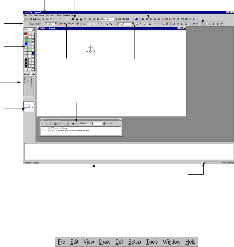
L-Edit 13 User Guide Section 1 37
Chapter 1: Introduction to Layout Editing Elements of the User Interface
Title Bar and Menu Bar
The title bar indicates the active file and cell. The menu bar, the horizontal space at the top of the
screen, contains the titles of the L-Edit command menus.
File Commands for creating, opening, saving, and printing files
Edit Commands for copying, deleting, selecting, finding, and textual
editing
View Commands for expanding, contracting, and shifting the view
Draw Commands for transforming design elements
Cell Commands for creating, manipulating, and instancing cells
Setup Commands for customizing setup parameters for the application,
design, layers, color palette, and tools
Tools Commands for examining XrefCells, creating and clearing generated
layers, DRC, placing and routing the design, extracting a netlist,
viewing a cross-section, and running L-Edit macros
Window Commands for displaying document windows
Compact
Layer Palette
Mouse
button bar Layout area
Locator
Standard toolbar Editing toolbar Alignment toolbar
Verification toolbar
Status bar
Menu bar
Layout area
Details button
Command line Command line window
Aerial View
Drawing toolbar
Verification Error
Navigator window
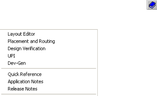
L-Edit 13 User Guide Section 1 38
Chapter 1: Introduction to Layout Editing Elements of the User Interface
Arranging Windows
The Window menu contains commands for manipulating L-Edit document windows and text windows.
Getting Help
The Help menu has commands that open product documentation, provide links and diagnostic functions
for customer support, display version infomation, manage commuter licensing and to install the
example files that are shipped with L-Edit.
Opening the Documentation
To open the user guides and manuals, press the help button ( ) or select one of the Help menu
commands shown below. L-Edit will launch Adobe Acrobat™ Reader and open the selected manual in
.pdf format.
Help Commands for accessing online user guides and general information
about L-Edit and Tanner EDA
Window > Cascade Arranges windows in overlapping fashion, starting from the top left
corner of the display area, so that the title bars are visible. The active
window remains active (in front).
Window > Tile Horizontally Arranges windows from top to bottom in non-overlapping fashion,
resizing them to fill the display area.
Window > Tile Vertically Arranges windows from left to right in non-overlapping fashion,
resizing them to fill the display area.
Window > Arrange Icons Arranges icons of minimized windows in rows starting at the bottom
left of the display area.
Window > Close All Except
Active Closes all open windows except for the active window.
Window > (open window
list) Lists all open files in the order they were opened. The active file is
indicated with a check (√).
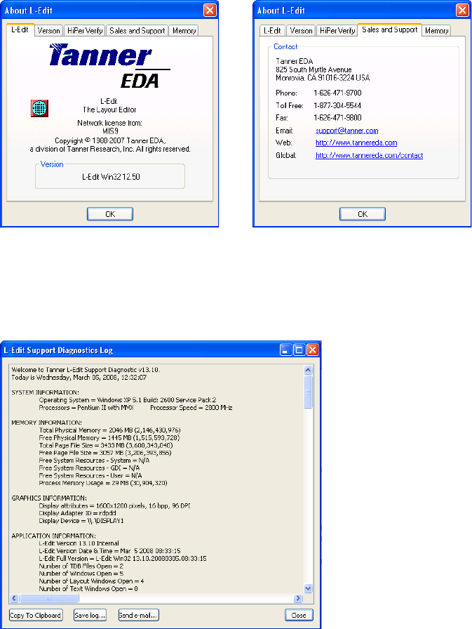
L-Edit 13 User Guide Section 1 39
Chapter 1: Introduction to Layout Editing Elements of the User Interface
Displaying the Product Version and Contacting Customer Support
To determine what version of L-Edit you are using or to find contact information for the Tanner EDA
Sales and Support departments, choose from the tabs in Help > About L-Edit. .
Diagnostics for Customer Support
Click Help > Support Diagnostics to perform a system check which you will need if you contact
Tanner’s technical support.
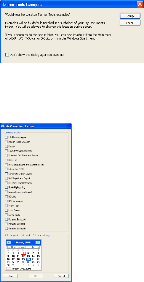
L-Edit 13 User Guide Section 1 40
Chapter 1: Introduction to Layout Editing Elements of the User Interface
Installing Examples
Click Help > Setup Examples to install the example and tutorial files that are included with L-Edit.
Managing Commuter Licensing
A commuter license is a portable license in a multi-seat environment that can be transferred from the
system where L-Edit is installed another computer, for example to a laptop for travel purposes. Use
Help > Commuter Licenses to obtain and return commuter licenses or to check on the licensing status
of L-Edit modules.
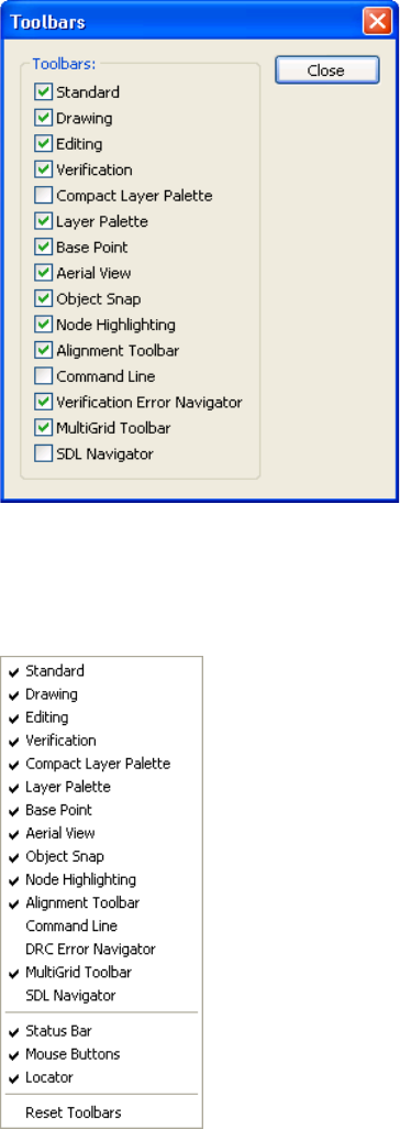
L-Edit 13 User Guide Section 1 41
Chapter 1: Introduction to Layout Editing Elements of the User Interface
Toolbars
L-Edit provides numerous toolbars to speed editing, which you can show or hide using
View > Toolbars.
You can also show and hide toolbars through a context-sensitive menu. To activate the menu, position
the pointer anywhere in a toolbar and click the right mouse button. The menu is dynamic and will reflect
whatever toolbars and options are available for your product configuration.
You can move and resize all toolbars. To undock a toolbar, click on one of its edges and drag it to
another position. L-Edit maintains whatever changes you make to a toolbar’s location and size when
you exit the program. If you move or resize toolbars within an L-Edit session and want to return them to
the positions they occupied at the start of the session, use Reset Toolbars in the pop-up menu shown
above.
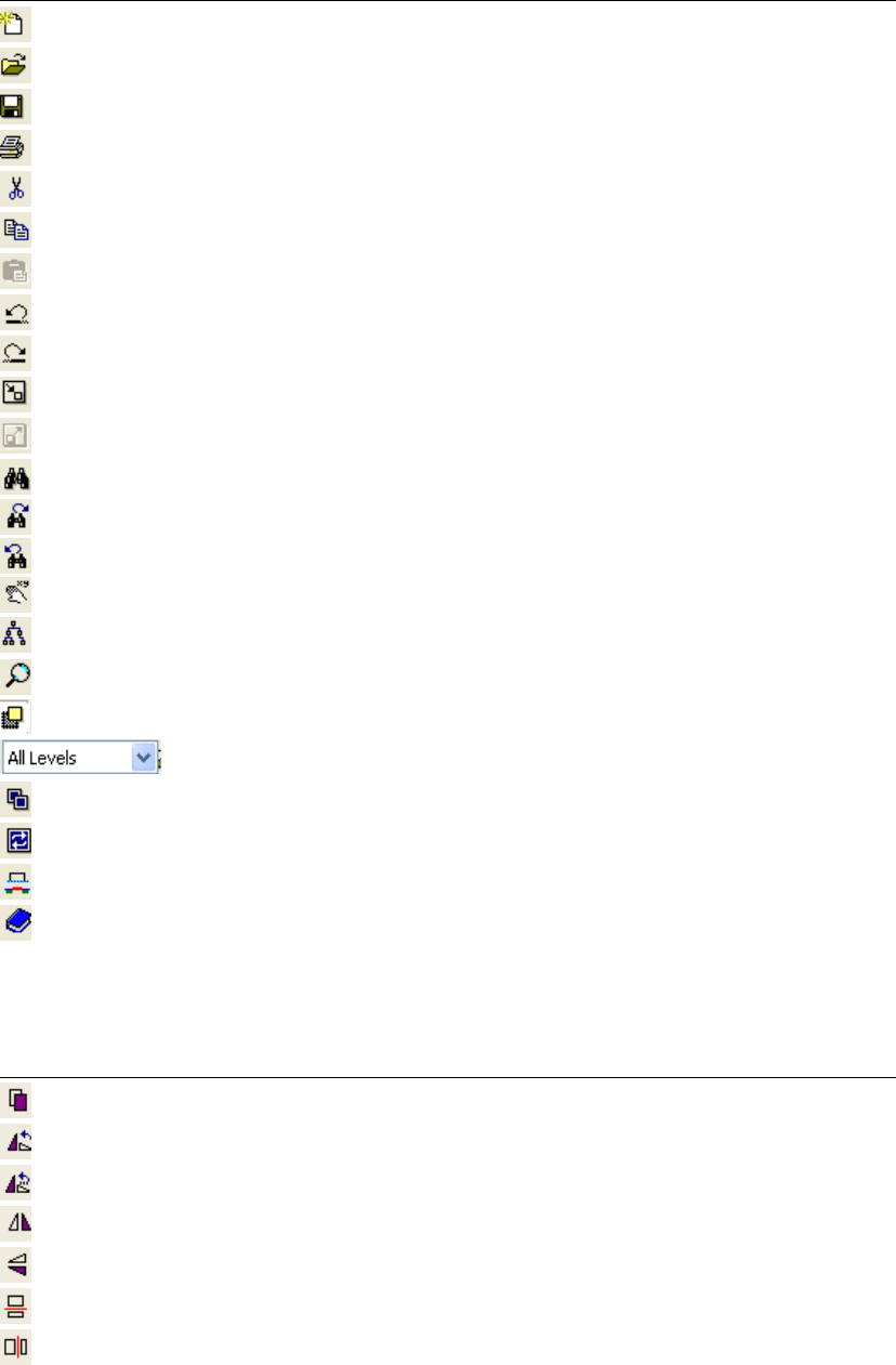
L-Edit 13 User Guide Section 1 42
Chapter 1: Introduction to Layout Editing Elements of the User Interface
Standard Toolbar
Editing Toolbar
Button Menu Command
File > New
File > Open
File > Save
File > Print
Edit > Cut
Edit > Copy
Edit > Paste
Edit > Undo
Edit > Redo
Edit > Edit In-Place > Push Into
Edit > Edit In-Place > Pop Out
Edit > Find
Edit > Find Next
Edit > Find Previous
View > Goto
View > Design Navigator
View > Zoom > Mouse
View > Insides > Toggle Insides
View > Hierarchy Level
Cell > Open
Cell > Copy
Tools > Cross-Section
Help > L-Edit User Guide
Button Menu Command
Edit > Duplicate
Draw > Rotate > 90 degrees
Draw > Rotate > Rotate
Draw > Flip > Horizontal
Draw>Flip>Vertical
Draw>Slice>Horizontal
Draw > Slice > Vertical
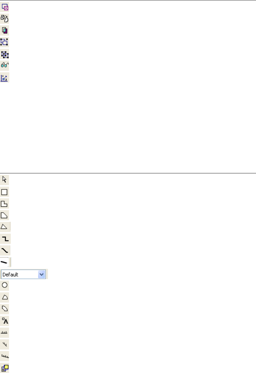
L-Edit 13 User Guide Section 1 43
Chapter 1: Introduction to Layout Editing Elements of the User Interface
Drawing Toolbar
The Drawing toolbar contains buttons for orthogonal, 45 degree, and all angle objects. To display only a
single set of the buttons, right-click the Drawing toolbar and select Orthogonal, 45 Degrees, or All
Angle from the resulting menu. For information on Show, Show All, and Hide All in the Drawing
toolbar pop-up menu, see “Showing and Hiding Objects” on page 120.
The following buttons are available on the Drawing toolbar:
Draw > Nibble
Draw > Merge
Draw > Boolean Grow/Shrink Operations
Draw > Group
Draw > Ungroup
Edit > Edit Object(s)
Draw > Move By
Button Object
Cursor tool
Box
Orthogonal polygon
45-degree polygon
All-angle polygon
Orthogonal wire
45-degree wire
All-angle wire
Wire width
Circle
Pie Wedge
Torus
Port
90 degree ruler
45 degree ruler
All angle ruler
Instance (Cell > Instance)
Button Menu Command
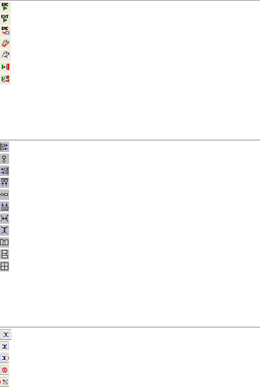
L-Edit 13 User Guide Section 1 44
Chapter 1: Introduction to Layout Editing Elements of the User Interface
Verification Toolbar
Alignment Toolbar
See “Aligning and Distributing Objects” on page 169 for a description of this toolbar
MultiGrid Toolbar
See “Multigrid Toolbar” on page 99 for a description of this toolbar.
Button Menu Command
Tools > DRC
Tools> Extract
Tools > DRC Box
Tools > DRC Setup
Tools > Extract Setup
Tools > Enable Interactive DRC
Setup > Design > Interactive DRC
Button Menu Command
Draw>Align>Left
Draw>Align>Middle
Draw>Align>Right
Draw>Align>Top
Draw>Align>Center
Draw>Align>Bottom
Draw > Align > Distribute Horizontally
Draw > Align > Distribute Vertically
Draw>Align>Tile Horizontally
Draw > Align > Tile Vertically
Draw > Align > Tile as a 2D Array
Button Menu Command
Mouse Grid 1
Mouse Grid 2
Mouse Grid 3
Max Grid
Manufacturing Grid
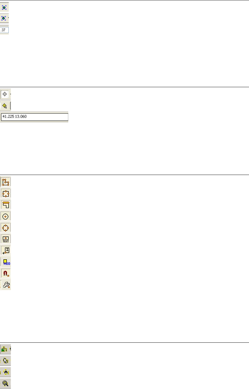
L-Edit 13 User Guide Section 1 45
Chapter 1: Introduction to Layout Editing Elements of the User Interface
Base Point Toolbar
See “Base Point Mode” on page 277 for how to use this toolbar.
Object Snap Toolbar
See “Object Snapping” on page 165 for how to use this toolbar.
Node Highlighting Toolbar
See “Using Node Highlighting” on page 316 for how to use this toolbar.
Make Coarser
Make Finer
Mouse Snap Grid
Button Menu Command
Use Base Point
Pick Base Point
(untitled) Enter coordinates to locate a base point.
Button Menu Command
Vertex
Midpoint
Edge
Center
Quadrant
Pin
Instance
Instance MBB
Enable Object Snap
Setup Object Snap
Button Menu Command
Extract Connectivity
Highlight Node
Highlight by Name
Zoom to Node
Button Menu Command
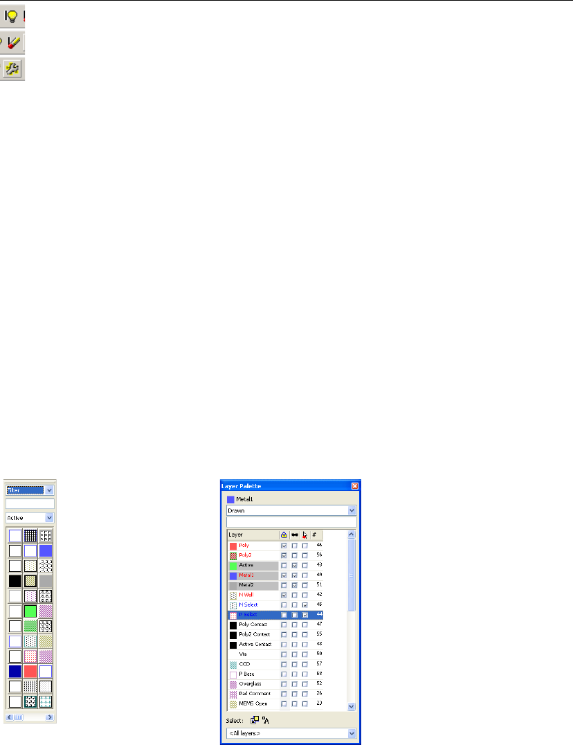
L-Edit 13 User Guide Section 1 46
Chapter 1: Introduction to Layout Editing Elements of the User Interface
Layer Palettes
L-Edit supports an unlimited number of technology layers. They can be displayed using either of two
layer “palettes.”
The Compact Layer Palette, a grid of icons that replicate each layer’s color and pattern, provides a
quick way to select layers.
The Layer Palette is also used for layer selection, but provides additional features for layer display and
manipulation.
Either or both palettes can be open at once, and can float or be docked. You can resize the palettes or
use the scroll bars to view layers not visible in the current display.
Both can be filtered using a pull-down category list to display just those layers that are just those
Drawn, In Use, Generated or Special.
You can also select Filter then enter text in the entry field to limit display to layers that include the
exactly the characters entered, anywhere in the layer name.
Using the Compact Layer Palette
As the pointer moves over an icon in the Compact Layer palette, the name of the layer will appear in the
status bar.
Toggle Markers
Clear Markers
Node Highlight Setup
Button Menu Command
Compact Layer Palette Layer Palette
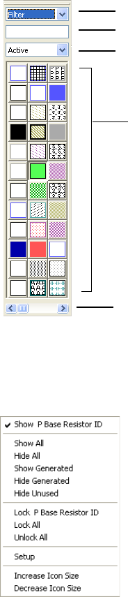
L-Edit 13 User Guide Section 1 47
Chapter 1: Introduction to Layout Editing Elements of the User Interface
Icons in the Compact Layer palette are displayed in the same order as they are listed in the Setup
Layers dialog, arrayed from top to bottom and left to right.
You can show, hide, or lock layers; open the Setup Layers dialog, and change the size of the icons in
the Compact Layer palette by right-clicking on any layer icon to open the menu shown below.
See “Showing and Hiding Layers” on page 122 for information on the Show [Layer name], Show All,
Hide All, Show Generated, and Hide Generated options.
Setup opens the Setup Layers dialog. You can also open Setup Layers directly to a specific layer by
double-clicking on that layer’s icon in the Compact Layer palette (see “Layer Setup” on page 104).
Use Increase Icon Size or Decrease Icon Size to change the size of the layer icons by two pixels each
time you select the command.
Compact layer palette scroll bar
Filter field
Layer category pull-down
Layer icons
Compact layer palette scroll bar
Compact Layer palette context-sensitive menu.
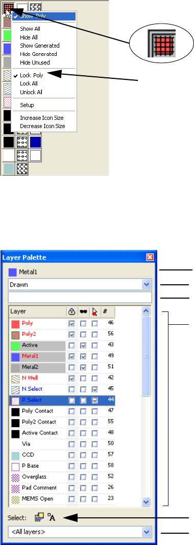
L-Edit 13 User Guide Section 1 48
Chapter 1: Introduction to Layout Editing Elements of the User Interface
Locking Layers
Lock [Layer name] refers to the layer icon the pointer is positioned over at the time you activate the
menu. When a layer is locked, you cannot draw, move, or edit objects on that layer. Use Lock All or
Unlock All to lock or unlock all layers, respectively.
Using the Layer Palette
Use the Layer Palette to manage layer settings and display properties.
When a layer is locked, L-Edit indicates this status in two ways.
The layer icon is cross-hatched as shown above (enlarged),
and a check mark appears next to Lock [Layer name] in the
context-sensitive menu.
Category field
Filter field
Header — shows the currently selected layer
and opens a context-sensitive menu
Layers list:
Red text indicates hidden — the layer is not
displayed in layout.
Grey shading indicates locked — geometry
on the layer cannot be drawn, moved, or
edited.
Blue text indicates protected — objects on
the layer cannot be selected.
Currently loaded palette
Toggle buttons for instance and port selectability
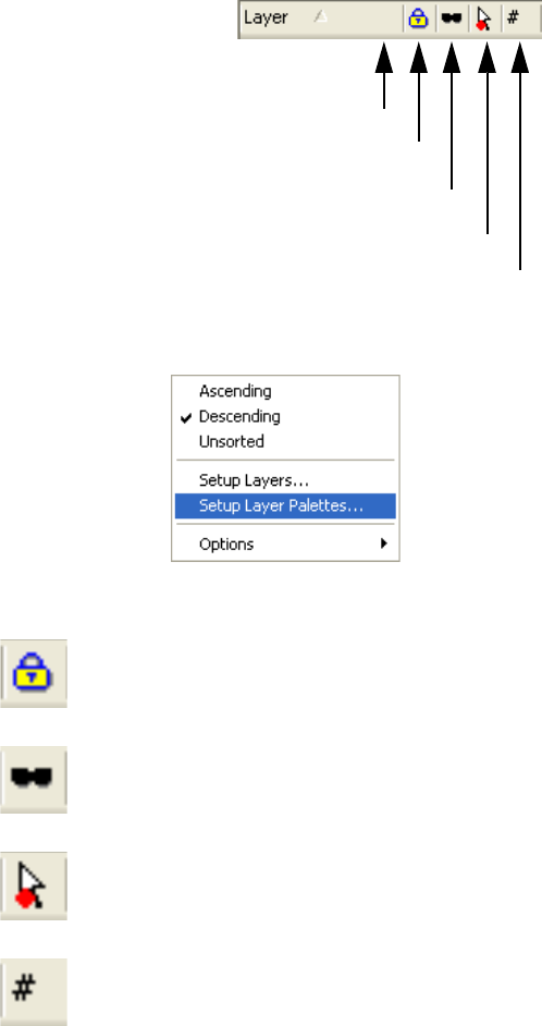
L-Edit 13 User Guide Section 1 49
Chapter 1: Introduction to Layout Editing Elements of the User Interface
(currently selected layer) This header area indicates the currently selected layer. Right-clicking
here opens a context-sensitive menu (see “Layer Palette Shortcuts” on
page 50).
(Category field) Select a layer category — All, Drawn, In Use, Generated or Special
to limit the list to just that type of layer. Choosing Filter in this field
lets you filter the displayed list by name.
(Filter field) Filters the layer list within the current display to show only those
layers that contain the characters in this field anyplace in their name.
For example, "la" in the filter field will display layers "label" and
"glass" and any others with "al" any place in their name.
Layers List Use the buttons in the layers list to sort the list. Click in a checkbox to
apply a layer setting.
Right-clicking on any of the buttons opens this menu:.
Locked When a box in this column is checked, the layer is locked so that
geometry cannot be drawn, moved, or edited. Grey shading indicates
a layer is locked.
Hidden When a box in this column is checked, the layer is hidden (not
displayed in layout). Red text indicates a layer is hidden.
Protected When a box in this column is checked, the layer is protected (so that
objects on the layer cannot be selected.) Blue text indicates a layer is
protected.
GDSII number This column displays the GDSII layer number.
Sort by layer name
Sort by locked status
Sort by hidden status
Sort by protected status
Sort by GDSII number
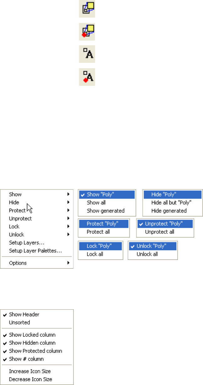
L-Edit 13 User Guide Section 1 50
Chapter 1: Introduction to Layout Editing Elements of the User Interface
Layer Palette Shortcuts
Right-click in the Layer Palette header or on any layer name in the list to open the following shortcut
menu. The layer controls vary as shown.
Pick Options to control the columns that will be displayed in a palette and the size of icons. You can
access the Options menu with a right-click anywhere in the Layer Palette.
Creating and Saving Palettes
Setup Layer Palettes lets you name and save layer display choices for future reuse.
Select Use these buttons to toggle selectability for the active design.
Indicates that instances can be selected.
Indicates that instances cannot be selected
Indicates that ports can be selected.
Indicates that ports cannot be selected
(currently loaded palette) This field displays the name of the palette that is currently loaded.
<All layers> is the default.
It is also a pull-down menu you can use to select previously saved
palettes, or to create and save palettes using the <Setup> option (see
“Creating and Saving Palettes” on page 50).
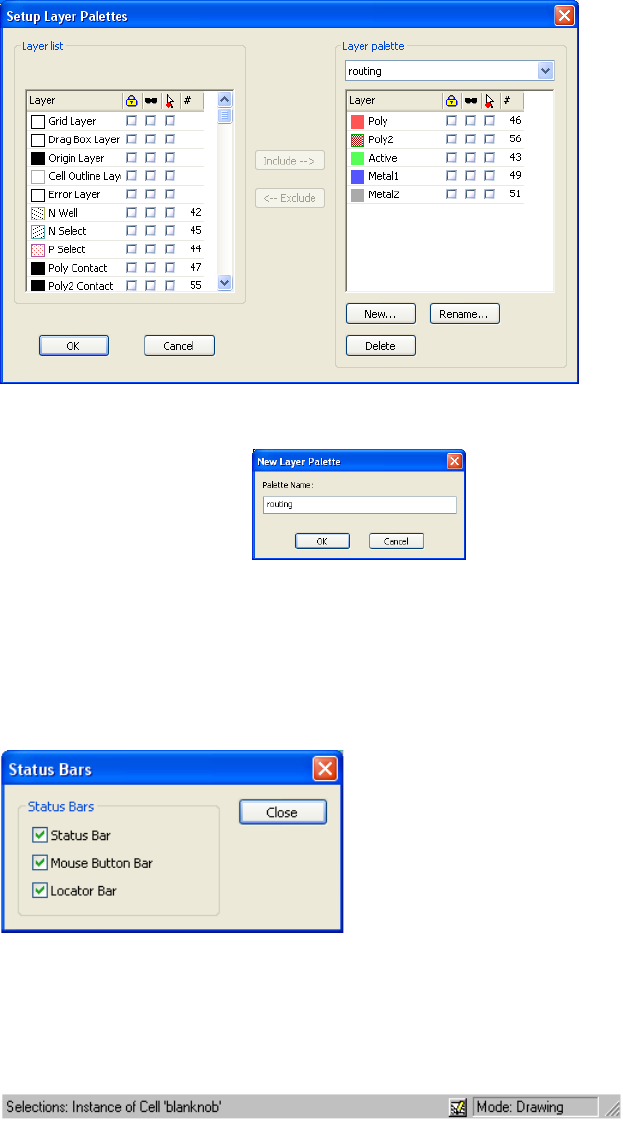
L-Edit 13 User Guide Section 1 51
Chapter 1: Introduction to Layout Editing Elements of the User Interface
Highlight layers in the right pane using the Shift and Ctrl buttons for multiple selection. Use the
<--Exclude button to remove and the Include--> button to keep layers in a specific palette. You can also
lock, hide or protect layers using the checkboxes.
Status Bars
There are three status bars associated with L-Edit: the status bar, the mouse button bar, and the locator.
To show and hide a status bar, use View > Status Bars.
Status Bar
The status bar, located at the bottom of the L-Edit window, displays context-sensitive information
about items in the interface.
New Opens the dialog where you assign a name to the layers included
L-Edit 13 User Guide Section 1 52
Chapter 1: Introduction to Layout Editing Elements of the User Interface
The status bar contains two panes. The left pane displays regular L-Edit status as indicated in the
following table:
The Details button ( )creates a text file containing a textual description of the selected object, such as
Box, A=1082.25, P=154.0000, W=58.5000, H=18.5000 on Layer 'Poly'.
The right pane displays the L-Edit mode. Possible modes are:
Drawing (default)
Nibble
DRC Box
Zoom Box (for View > Zoom > Mouse command)
Mouse Button Bar
The mouse button bar displays the current function of each mouse button.
The mouse buttons function differently depending on the location of the mouse in the application and
the current L-Edit mode (drawing, editing, zooming, etc.).
Locator
In default mode, the locator provides the location of the pointer relative to the absolute origin in display
units. The absolute origin is at the coordinates (0,0), and it is indicated by a cross in the layout area.
You can display sizes, distances, and positions in any of six physical units, called display units:
Microns, Mils, Millimeters, Centimeters, Inches, or a custom unit (if one is defined). Custom units are
Action Description
When the pointer is in the
Compact Layer palette: The name of the layer pointed to. For generated layers, the Boolean
formula for that layer.
When a menu command is
highlighted: A description of the command
When a single object is
selected: The type, layer, and size of the object. For cell instances and arrays,
the name of the instanced cell.
When multiple objects are
selected: The count, by type, of the selected items (for example, 4 boxes, 1
circle, 3 ports, and 1 instance).
When the pointer is in a
toolbar: The function of the pointed-to tool.
All other times: Ready
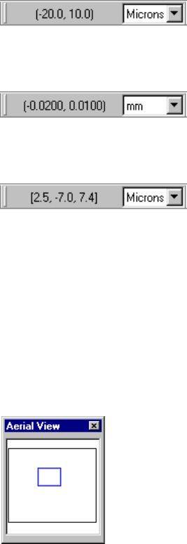
L-Edit 13 User Guide Section 1 53
Chapter 1: Introduction to Layout Editing Elements of the User Interface
defined in the Setup Design—Technology dialog. (For more information, see “Technology
Parameters” on page 96.) This dialog also lets you set the default value of display units. A pull-down
menu in the locator bar allows you to change the display units.
Display units do not affect the physical dimensions of your layout. Rather, they determine the system of
units in which L-Edit reports physical lengths, areas, and positions. Display units also determine the
units used to specify spatial parameters in various L-Edit dialogs.
For example, if display units are set to microns, (a, b) refers to coordinates microns.
If you change the display units to millimeters, the same coordinates (a, b) will be shown in millimeters:
When you press Q, the locator changes to relative coordinate display mode.
In this mode, the locator displays the coordinates of the pointer’s position relative to its initial position
when Q was pressed. The third number represents the distance between the pointer’s current position
and its initial position when Q was pressed. When you press Q again, the display goes back to the
default mode.
Aerial View
The aerial view toolbar shows the position of the current viewing window relative to the cell boundary.
The viewing window is shown in blue outline, and the cell boundary is depicted in either black or white,
depending on the background color of the layout window.
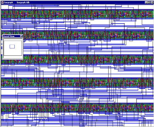
L-Edit 13 User Guide Section 1 54
Chapter 1: Introduction to Layout Editing Elements of the User Interface
You can use aerial view toolbar as a navigation device; simply click within it to pan to aC location in
the viewing window.
Layout Area
The area available for drawing objects is called the layout area. The origin of the coordinate system
(0,0) is indicated with a cross-hair marker, which you can hide or display using
View > Display > Origin. Optional displays of major and minor grids provide a set of convenient
locating points, which you can hide or display using View > Display > Major Grid and
View > Display > Minor Grid. You can adjust the spacing of the major and minor grid points using
Setup Design—Grid.
Coordinate System
L-Edit uses display units to report object dimensions and coordinates. The program also uses display
units to set the display grids and mouse snap grid.
For its own computation, L-Edit uses internal units (30-bit signed integers). The relation between
internal units and physical (technology) units is defined in the following manner: Physical units are
mapped to internal units in Setup Design—Technology.
For further information on defining these units, see “Technology Parameters” on page 96.
Text Editor
L-Edit provides a text editor with syntax highlighting for several file types. The File > New command
automatically launches the text editor if you have picked any of the following file types:
Text
UPI Macro
SPICE netlist
Calibre command file
Dracula command file
L-Edit 13 User Guide Section 1 55
Chapter 1: Introduction to Layout Editing Elements of the User Interface
See “Text Style” on page 94 and “Text Editor” on page 92 for the setup options that control this
window.
Command Line Interface
In addition to menu items and keyboard shortcuts, L-Edit includes a command line interface that allows
textual entry of basic commands and their associated coordinates. This window allows for repeatable,
coordinate-specific object manipulations and command scripting with text files.
See “Command Line Editing” on page 198 for instructions on using this tool.
Verification Error Navigator
The Verification Error Navigator is a toolbar that displays a scrollable tree of DRC rules and violations
for the active cell. After running DRC, you can use the Verification Error Navigator to step through and
display errors in the active layout.
See “The Verification Error Navigator” on page 721 for instructions on using this tool.
SDL Navigator
The schematic-driven layout (SDL) navigator let you associate a netlist with any layout cell, and
provides navigation tools to identify required interconnections. It also can automatically generate layout
corresponding to subcircuits and devices. Please see “Schematic-Driven Layout (SDL) Navigator” on
page 321 for more details.
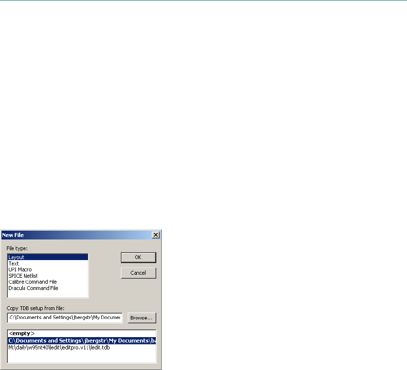
L-Edit 13 User Guide Section 1 56L-Edit 13 User Guide 56
2 Working with Files
Files
A complete L-Edit design is composed of cells contained in a design file. You can open as many design
files simultaneously as your hardware allows. The name of the active file appears in the L-Edit title bar.
Creating Files
Create new files by choosing File > New, which opens the New File dialog:.
L-Edit will open a layout window or the Tanner text editor, depending upon the file type you have
selected.
You can also drag and drop a text file into the layout window to open it. If you use the right mouse
button to drag and drop the file, you can open a text file as a specific type. L-Edit will prompt you to
indicate the document type and also show the expected type in a bold font.
1

L-Edit 13 User Guide Section 1 57
Chapter 2: Working with Files Opening Files
Options include:
Setup Files
The list of predefined setup files will contain:
<empty>—this is a standard empty setup (this is the default setup with white background, single
layer and no DRC rules).
The list of currently loaded TDB files (displayed in bold face).
The list of TDB setup files found in the predefined setup directories. You can specify the TDB
setup path in the Setup Application dialog.
When you create a new file, L-Edit will assign it a default name (ex. Text or Spice), followed by a
number, e.g., Text2 or Spice5, depending on the history of the current session. When you first save the
new file, you will be prompted to change the filename, if needed.
After creating a file, you can specify additional information using the File Information dialog (see “File
Information” on page 67).
Opening Files
Use one of the following to open a file:
Select File > Open or press Ctrl+O
Click the open file button ( )
File type The type of file to create.
Layout opens a Tanner Database (TDB) file in a layout window.
The remaining options open the L-Edit text editor:
Text creates an ASCII text file for normal text editing.
UPI Macro creates a new UPI macro template file with syntax
highlighting and commented-out coding guidelines.
SPICE netlist opens a blank text screen that will highlight
syntax when a SPICE netlist is opened or entered.
Calibre Command File creates a new Calibre template file with
syntax highlighting and commented-out coding guidelines.
Dracula Command File creates a new Dracula template file
See “Text Editor” on page 92 for a description of keywords that will
be highlighted for each file type, and their predefined styles.
Copy TDB setup from file For Layout files, the TDB file from which to take setup information
for the new file. You can choose a setup file by selecting one from the
list of predefined setup files, by typing the name of the file into the
text field, or by browsing. If you do not select a setup file, the new file
is opened with the default <empty> setup.
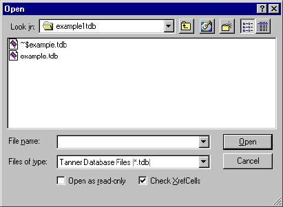
L-Edit 13 User Guide Section 1 58
Chapter 2: Working with Files Opening Files
Drag and drop a file icon from Windows explorer.
Open a recently used file by selecting its name from the bottom of the File menu.
Look in The source directory.
File name The name of the file to be opened. The wildcard character (*) can be
used to narrow down the list of available files. (For example, to list
only TDB files whose names begin with the letter a, type a*.tdb and
press Enter.) Only one file can be opened at a time. All files of the
specified type in the source directory are listed in the space above this
field.
Files of type The type of file listed. Predefined file types include:
Tanner Database Files (*.tdb)
Extract Definition Files (*.ext)
Netlist Files (*.tpr; *.ed)
Spice Files (*.sp;*.spc)
Design Rule Errors Text Files (*.drc)
Design Rule Text Files (*.rul)
Cross-Section Process Definition Files (*.xst.)
Nodal Capacitance Files (*.cap)
Standard Delay Format Files (*.sdf)
Application Configuration Files (*.ini)
Error Files (*.err)
All Files (*.*)
All file types in the source directory (*.*) can be displayed; however,
only TDB or text files can be opened with the File > Open command.
Open as read-only Opens the selected file as read-only. When this option is checked,
changes made to the file cannot be saved. This option is only
supported for TDB files.
Check XrefCells Verifies that cells referenced from other files are current. If they are
not, the Examine XrefCell Links dialog appears. See “Examining
XrefCells” on page 243 for further information.
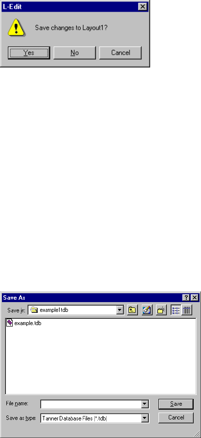
L-Edit 13 User Guide Section 1 59
Chapter 2: Working with Files Closing Files
Closing Files
To close the current file, choose File > Close or press Ctrl+W. If a file contains any unsaved changes,
L-Edit will prompt you to save them.
Clicking Yes saves the file. If the file is new, the Save As dialog appears (see “Saving Files,”
below).
Clicking No closes the file and discards all unsaved changes.
Clicking Cancel cancels the close operation.
Saving Files
To save the current file, choose File > Save or press Ctrl+S. L-Edit saves the file using its current
filename and path.
To save a file using a different name or location, choose File > Save As. L-Edit displays the Save As
dialog.
Options include:
Save in The target directory.
File name The name under which the file corresponding to the active window is
to be saved. The space above this field lists all files of the specified
type in the target directory. If you choose a name that already belongs
to an existing file, L-Edit prompts you for permission to overwrite the
existing file.
L-Edit 13 User Guide Section 1 60
Chapter 2: Working with Files Saving Files
L-Edit saves the following information for each file:
Size and location of all layout windows opened in this file
Which cells are open
The following viewing options:
Zoom levels of open cells
Visibility of origin and grid
Visibility of arrays and ports
Last view
Visibility of layers
TDB File Format
Tanner Database (TDB) is a proprietary, machine-readable format optimized for the Tanner Tools
environment. TDB files are saved with the .tdb filename extension. By default, the scrollable list
displays TDB files.
Along with the design itself, a TDB file contains setup information including layer rendering
information, CIF and GDSII setup information, design rules, and L-Edit configuration settings. Setup
information can be read into L-Edit with File > Replace Setup.
When a file is saved, L-Edit automatically backs up previously-saved versions of the file with a .tdo
extension.
Save as type The type of file listed. By default, the active file is saved in its current
type—e.g., TDB, etc. If the active window contains a text file, the
only available option is All Files (*).
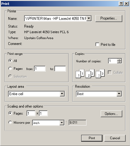
L-Edit 13 User Guide Section 1 61
Chapter 2: Working with Files Printing
Printing
You can print files in L-Edit by choosing File > Print or pressing Ctrl+P. For TDB files, the following
dialog appears:
Options include:
Name The device to which the data in the active file will be printed.
Properties Opens the Printer Properties dialog.
Print to file Prints to a file instead of the physical printer. If this option is checked,
clicking OK opens the Print to File dialog.
Print range The set of pages to be printed.
Copies The number of copies to be printed, with the option to collate.
Layout area Drop-down menu that gives the option to print
Entire cell
Current window only
Resolution Printer resolution in dots per inch (dpi). Options include:
Best (matches printer resolution)
600 x 600
300 x 300
150 x 150
75 x 75
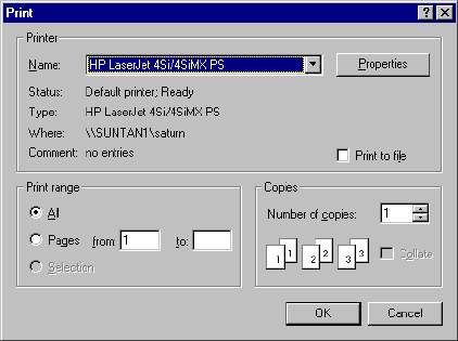
L-Edit 13 User Guide Section 1 62
Chapter 2: Working with Files Printing
For text files, the dialog appears without the options for Layout area, Resolution, and Scaling:
Scaling Option buttons control the magnification of the layout on the printed
page. Options include:
Pages—the number of pages (width × height) that the printed
layout will occupy. For example, a 3×2 page scale will result in a
layout that spans 6 printed pages: 3 wide and 2 high. Multiple
pages can be pasted together after printing to create the layout as
on the screen.
Display Units per—the ratio of display units to physical units on
the page. (To specify display units, use the pull-down menu in
the locator bar.) Options are Inch and centimeter. Selecting this
option will activate the field where you specify the number of
display units per the specified physical unit.
Options Opens the Layout Print Options dialog (see “Layout Print Options,”
below).
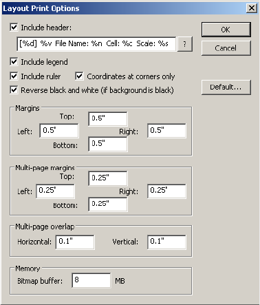
L-Edit 13 User Guide Section 1 63
Chapter 2: Working with Files Printing
Layout Print Options
This dialog lets you control print legends, margins and page overlaps, as well as how much print
information will be stored in the L-Edit internal buffer.
Options include:
Include header Lets you select whether a header will be printed (at the top left of the
plot) and what it will contain. Possible values are:
\n — new line
%c — cell name
%d — current date and time
%n — file name
%p — fine path
%s — scale
%v — L-Edit version
\\ — back slash
%% — percent sign
Include legend Toggles printing of a default legend for the layers shown in the plot,
positioned below the header.
Include ruler Toggles printing of vertical and horizontal rulers showing major and
minor tick marks, along the image edge.
Coordinates at corners
only Toggles printing of tick mark values at the corners of the image only
(checked) or along the entire length of the rulers.
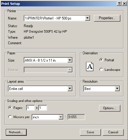
L-Edit 13 User Guide Section 1 64
Chapter 2: Working with Files Printing
Print Setup
To set up printing parameters, choose File > Print Setup. For TDB files, the following dialog appears:
Reverse black and white (if
background is black) Allows you to invert black and white rendering in the plot (as
compared to the onscreen rendering) for layouts with a black
background. Note that only true black (red=0, green=0, blue=0)
values will be reversed to white.
All other colors will be printed as they are rendered onscreen.
Margins Controls the margin sizes for single page printing.
Multi-page margins Controls the margin sizes for mutli-page printing.
Multi-page overlap Controls the amount of image overlap on each page during multi-page
printing.
Memory Sets the size of the internal L-Edit memory buffer for bitmap
information sent to the printer, in megabytes.
L-Edit prepares the entire bitmap that represents a plot in computer
memory and then sends it to the printer driver. Most printer drivers
limit the size of such a bitmap, but not many can accurately measure
what this limit should be. Due to this limit, when printing large plots,
L-Edit splits the bitmap into sections and sends them one by one to
the printer driver. L-Edit uses the “bitmap buffer” value to calculate
how many sections it needs. The bigger the value the fewer sections
needed and the faster L-Edit will print in almost all cases.
8 MB is the best value for most printers, but some plotters benefit
from a higher value. Some older printers can handle only 1MB
sections.
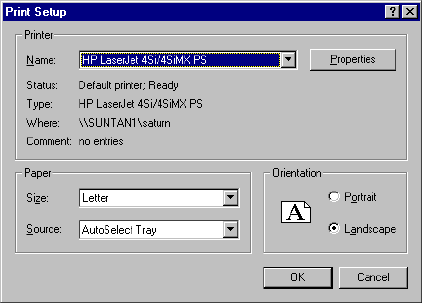
L-Edit 13 User Guide Section 1 65
Chapter 2: Working with Files Printing
For text files, the dialog appears without the options for Layout area, Resolution, and Scaling:
Options include:
Printer The default device to which the active text file will be printed. The
drop-down list shows available printers.
Properties Opens the Printer Properties dialog.
Paper Specifies the paper size and source.
Orientation Specifies the orientation of the printed page as portrait or landscape.
Layout area Drop-down menu that gives the option to print the entire cell or just
that part of the cell displayed on your monitor.
Resolution Printer resolution in dots per inch (dpi). Options include:
Best (matches printer resolution)
600 x 600
300 x 300
150 x 150
75 x 75
Scaling Option buttons control the default magnification of the layout on the
printed page. Options include:
Pages—the number of pages (width × height) that the printed
layout will occupy. For example, a 3×2 page scale will result in a
layout that spans 6 printed pages: 3 wide and 2 high. Multiple
pages can be pasted together after printing to create the layout as
on the screen.
Display Units per—the ratio of display units to physical units on
the page. (To specify display units, use the pull-down menu in
the locator bar.) Options are Inch and centimeter. Selecting this
option will activate the field where you specify the number of
display units per the specified physical unit.
Options Opens the Layout Print Options dialog (see “Layout Print Options”
on page 63).
Network Opens the Connect to Printer dialog, which allows you to connect to
printers in your shared environment.
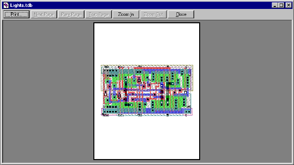
L-Edit 13 User Guide Section 1 66
Chapter 2: Working with Files Printing
Print Preview
File > Print Preview displays the active cell as it will be printed in full-page mode. Cells cannot be
edited in Print Preview.
Options include:
In addition to layouts, you can also preview text or a Design Navigator display.
Print Opens the Print dialog (see “Printing” on page 61).
Next Page Displays the next page in the window.
Prev Page Displays the previous page in the window.
Two Page Displays two pages in the window.
Zoom In Magnifies the display.
Zoom Out De-magnifies the display.
Close Closes the Print Preview dialog.
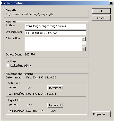
L-Edit 13 User Guide Section 1 67
Chapter 2: Working with Files File Information
File Information
Access information about the current file by choosing File > Info. The following dialog appears:
Options include:
Listing Object Types by Layer
Use File > File Object Summary to generate a text file listing the number of boxes, polygons, wires,
circles, pie wedges, tori, ports and rulers on each layer of a file.
File path The path and filename of the active file.
File info Includes Author, Organization, and Information (notes or messages)
for the active document. Information can contain a maximum of 256
characters. Object Count shows the total number of polygons in a
file. (You can also use “Count Objects” (page 320) to determine this
value at any time.)
File flags Locks the current file. Locked files cannot be edited, but data from
the file can be copied to another file.
File dates and versions The date and time the file was created and last revised. Setup info
and Layout info include version numbers. The version numbering
system provides an internal accounting method for tracking layout
design and file setup changes. Major numbers are increased by
clicking the Increment button; minor numbers are automatically
incremented each time changes in the file are saved.
Properties Accesses the Properties dialog. For more information on file
properties, see “Properties” on page 68.
L-Edit 13 User Guide Section 1 68
Chapter 2: Working with Files Properties
Transferring File Information to Cells
Use Tools > Add-Ins > Transfer File Info to Cells to copy just the author and organization information
from the file information to the information dialog for all cells in the file.
Properties
L-Edit properties are comprised of a name and value and are used to store information. You can attach
properties to L-Edit objects, layers, instances, cells, and files.
When you attach a property to a cell or instance, it is local to that cell or instance only. Properties
attached to primitive cells do not propagate throughout the design hierarchy.
If you copy a cell, however (using Cell > Copy), the copied cell will contain any properties created in
the original.
Properties are classified by type and can be arranged in hierarchical groups. Properties have many
applications, including:
Netlist extraction—you can use properties to control the information extracted from a layout.
Design management—in conjunction with a UPI macro, you can use properties for such tasks as
counting the instances of a cell.
Design documentation—you can load a text file or other document into a property attached to a file,
cell, layer, or other object.
Property Types
Valid property data types include the following:
Viewing and Editing Properties
Properties are viewed and edited using the Properties dialog. For layout objects, you can access this
dialog in the following way:
;Select the object of interest.
None Property without a value—often used simply to create a level of
hierarchy.
Integer Signed integer from -2,147,483,648–2,147,483,647.
Byte Unsigned integer from 0–255.
Real Floating point (8-byte) number from 1.7E +/- 308.
String Alphanumeric string.
Logical Boolean with values True or False.
Pointer Address of a location in RAM memory.
BLOB Binary large object.
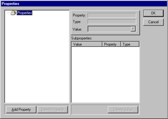
L-Edit 13 User Guide Section 1 69
Chapter 2: Working with Files Properties
;Choose Edit > Edit Object(s).
;In the Edit Object(s) dialog, click Properties.
For layers, you can access the Properties dialog in the following way:
;Choose the menu command Setup > Layers.
;In the Setup Layers dialog, click Properties.
For files and cells, you can access the Properties dialog in the following way:
;Open the file or cell of interest.
;Choose the menu command File > Info or Cell > Info, as appropriate.
;In the File Information or Cell Information dialog, click Properties.
For any object, L-Edit displays the Properties dialog:
The Properties dialog has two major areas—the Properties tree on the left and the value fields on the
right.
The Properties tree displays the properties for the selected file, cell, layer, or object. Properties with
subproperties appear in the tree with folder icons; properties without subproperties appear with small
white rectangles. A plus sign next to a folder indicates that the property can be expanded; a minus sign
indicates that it can be collapsed.
When you select a property, its name, type, and value are displayed in the fields Property, Type, and
Value to the right of the Properties tree. You can use the Values field to type values for a selected
property or to choose values from the list of previous entries.
When you select a property with subproperties, those subproperties are displayed in the Subproperties
list.
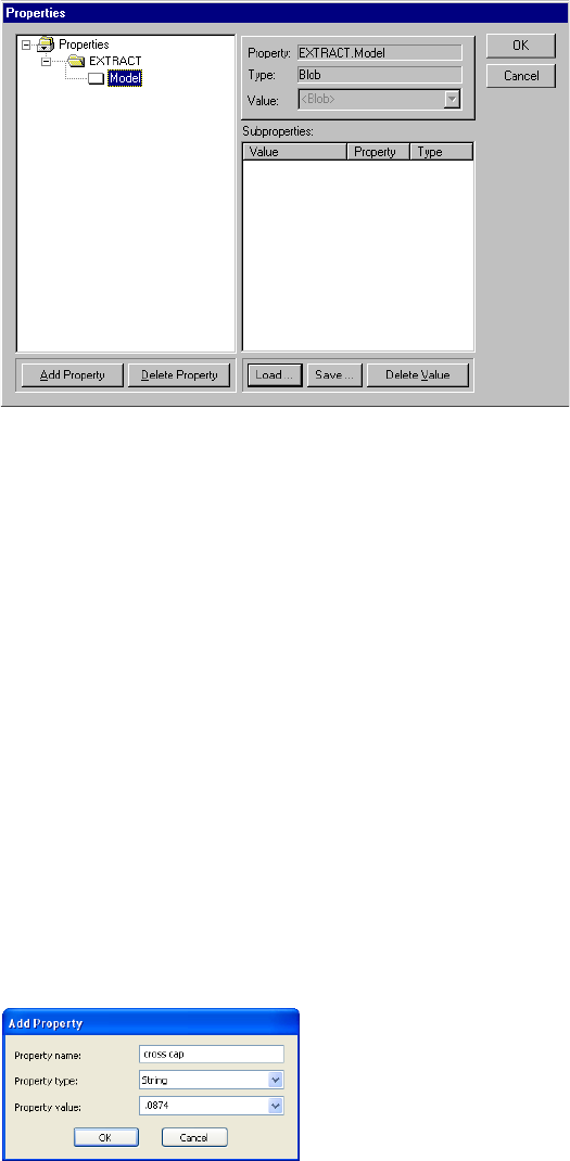
L-Edit 13 User Guide Section 1 70
Chapter 2: Working with Files Properties
When you select or create a property of the type binary large object (BLOB), the Load and Save
buttons appear below the Subproperties list:
Adding Properties
To add a property, select a property in the Properties tree that you want to be the parent for the new
property. Then perform one of the following actions:
Click Add Property.
Right-click and select Add property from the pop-up menu.
Press the Insert key (Ins).
L-Edit displays the Add Property dialog:
Specify the following:
Load Accesses a standard Windows file browser in which you navigate to
the object to be loaded into a BLOB property.
Save Accesses a standard Windows file browser in which you specify the
filename and path of the file to which the BLOB will be written. The
default filename extension is .blo.
Property name Full name of the new property.
Property type Data type of the new property. For further information, see “Property
Types” on page 68.
L-Edit 13 User Guide Section 1 71
Chapter 2: Working with Files Properties
Deleting Properties
To delete a property, select it in the Properties tree and perform one of the following three actions:
Click Delete Property.
Right-click and select Delete property from the pop-up menu.
Press the Delete key (Del).
Renaming Properties
To rename a property, select it in the Properties tree and perform one of the following three actions:
Right-click and select Rename property from the pop-up menu.
Press F2.
Deleting Values
To delete a property’s value, perform one of the following actions:
Select the icon in the Properties tree and click Delete Value.
Select the subproperty in the Subproperties list and click Delete Value.
Select the subproperty in the Subproperties list and press Del.
Select the subproperty in the Subproperties list, right-click, and choose Delete Value in the
resulting pop-up menu.
Editing Values
When you select a property in the Properties tree, you can edit its value in the Value field. You can also
edit values for subproperties of the selected property in the Value column of the Subproperties list.
Select an item in the Subproperties list and press F2. Alternatively, you can right-click the item and
select Modify value in the resulting pop-up menu.
Organizing Properties in a Hierarchy
You can create a hierarchy by selecting a property in the Properties tree and adding subproperties
beneath it. The selected property is then shown as a folder icon, and properties shown beneath it are
grouped at a deeper level (or levels) of hierarchy.
L-Edit uses a period (.) to separate levels of hierarchy in the Properties tree. For example, the path
EXTRACT.W contains the property EXTRACT and the subproperty W.
Property value Value of the new property. Type the value in this field or click the
arrow to select from a list of previously used values.
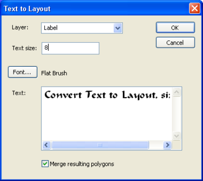
L-Edit 13 User Guide Section 1 72
Chapter 2: Working with Files Adding a Copyright, Logo or Text to a File
Adding a Copyright, Logo or Text to a File
L-Edit provides several methods for adding text to your layout. The Text to Layout feature lets you add
text in any of the fonts on your PC, by rendering the characters as bitmaps and creating box geometry
for each pixel. You can also use the Layout Text Generator to generate text or a logo. The associated
alphabet.tdb file is required for this macro to function.
Adding True Type Fonts to a Design
Use the Draw > Layout Generators > Convert Formatted Text to Layout command to add text in any
of the fonts available to your PC. Text is created as layout geometry by producing a box corresponding
to each pixel of a character after it has been rendered as a bitmap.
Layer Select the layer on which the text geometry will be drawn.
Text size Enter a size for the text.
Note: You may need to experiment with this value to get the text size
you prefer as it will be relative to the scale of your design.
Font Click this button to select from the available fonts.
Bold and italic styles are supported when available. The Font dialog
shows a preset font size of 16, but it is the Text Size field on the Text
to Layout dialog that controls text size.
Text Enter the text string you want to add as layout.
Merge resulting polygons By default (with this option off) L-Edit will merge rows of contiguous
pixels to reduce file size and processing time. When this option is on,
the resulting layout can be merged into non-contiguous polygons of
any shape.
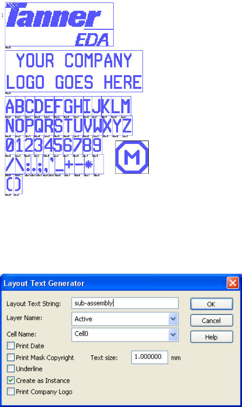
L-Edit 13 User Guide Section 1 73
Chapter 2: Working with Files Adding a Copyright, Logo or Text to a File
Point size is not an absolute value but differs for every font, as it is a value based upon the distance
between lines of set type and the difference between the highest ascender and lowest descender in a
given font.
One convention is to specify the height of the capital M as 72% of the font height. This works fairly
well for most Roman style fonts but is not as consistent for other font styles.
Using the alphabet.tdb File
alphabet.tdb is a special file containing cell instances for the letters in the alphabet, numerals and
special characters plus cells for a copyright and a logo. It is shipped with L-Edit in the
C:\Documents and Settings\username\My Documents\Tanner EDA\Tanner Tools v xx.yy\L-Edit\
AddIns directory.
(See also the UPI macro “Logo Generator” (page 1612).)
The Draw > Layout Generators > Layout Text Generator command takes cells from alphabet.tdb,
and adds them as layout geometry to your current design.
L-Edit 13 User Guide Section 1 74
Chapter 2: Working with Files Exiting L-Edit
Exiting L-Edit
Choose File > Exit to exit L-Edit. A warning prompts you to save changes in each unsaved file.
Layout Text String Enter your text here. A maximum of 1024 characters is allowed. You
can use the following formatting codes:
&c - Center text
&l - Align text left
&r - Align text right
\\n - Insert new line
&d - Insert current date
&t - Insert company logo
&m - Insert mask copyright
Layer Name The layer on which to generate the text. The layer must exist in the
current technology setup.
Cell name Cell in which the text will be generated. (This field is enabled only
when Create as Instance is checked.)
Print Date Prints the current date.
Print Mask Copyright Prints the copyright symbol from the Mask Copyright Symbol cell in
the alphabet.tdb file.
Underline Underlines the text string and, if used, date. This feature is useful
when you need to etch away the material underneath the text.
Create as Instance Generates the text as an instance of a new cell, which will replace the
contents of the current cell. Use the Cell Name field to specify the
name of the new cell.
Print Company Logo Prints the contents of the Company Logo cell in the alphabet.tdb
file. To print your own company logo simply save your logo file to
the Company Logo cell in alphabet.tdb.
Text Size Enter the desired text size in the current display units. You may need
to experiment with this value to get the text size you prefer as it will
be relative to the scale of your design.
In alphabet.tbd, though the height of MBB of each character is 1
micron, the characters of that block capital alphabet do not span that
full height. So, if you enter a text size of 1 in a design using microns
as the display unit, the text itself will not be a full micron high. The
extra space is needed for the ascenders and descenders in lowercase
and non-block lettering.
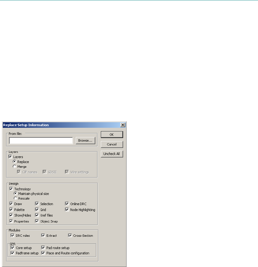
L-Edit 13 User Guide Section 1 75L-Edit 13 User Guide Section 1 75
3 Application and Design Setup
Replacing the Setup
Every L-Edit design file contains basic information such as a layer list, technology settings, and
module-specific options for SPR, DRC, and Extract. Collectively, this information is known as the
“setup.”
File > Replace Setup transfers setup information from a file (the source file) to the current file (the
destination file).
Options include:
From file Name of the TDB file whose setup is to be imported. Click Browse to
navigate to an existing file.
1
L-Edit 13 User Guide Section 1 76
Chapter 3: Application and Design Setup Replacing the Setup
Layers Imports layer setup from the specified file.
Replace deletes the layers in the destination file and replaces
them with the layers from the source file.
Merge adds the layers from the source file to the list of available
layers in the destination file. Source file layers not present in the
destination file are appended to the layer list in the destination
file. If a layer in the source file has the same name as a layer in
the destination file, the position it has in the destination file is
maintained. For further information, see Merging Layer Setups
on page 78.
Additional layer-specific setup options include:
CIF names
GDS II numbers
Wire settings
Technology Options include:
Maintain physical size—With this option, L-Edit checks all
objects in all cells and unit-specific parameters entered in other
dialogs to determine if the layout will be truncated when it is
rescaled. L-Edit presents one warning for each cell and set of
parameters if a truncation will occur. If you answer Yes to all the
warnings, or if no truncation will occur, L-Edit rescales the
design. If you answer No to any of the warnings, L-Edit cancels
the rescaling operation.
Rescale—L-Edit rescales the design by applying technology
scaling parameters in the source file to objects in the destination
file.
Draw Transfers the parameters entered in Setup Design—Drawing. See
Drawing Parameters on page 101).
Palette Transfers the color parameters entered in Setup Colors. See Color
Parameters on page 79.
Show/Hides Transfers the view settings for grid, origin, ports, and other objects.
Properties If checked, replaces the System and other parameters set in File >
Info—Properties. See Properties on page 68).
Selection Transfers the parameters entered in Setup Design—Selection. See
Selection Parameters on page 100).
Grid Transfers the parameters for the display grid and mouse snap grid.
See Grid Parameters on page 97).
Xref files If checked, replaces the TDB files that will be used as cross-reference
of library files, as set in Setup > Design—Xref files. See Cross
Reference File Designation on page 102).
Modules Check the corresponding box to replace setup information for:
DRC rules
Extract
Cross-Section
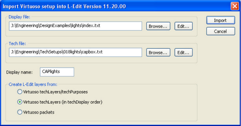
L-Edit 13 User Guide Section 1 77
Chapter 3: Application and Design Setup Replacing the Setup
Importing a Setup from Virtuoso
This import feature simplifies transitions of designs from the Cadence Virtuoso to the Tanner L-Edit
design environment. Importing a Virtuoso setup always creates a new L-Edit file. The display and tech
files are concatenated and read as one.
The Setup > Import Virtuoso® Setup command creates an L-Edit technology setup by reading a
Virtuoso technology file. Imported elements include palette colors, background color, grid colors,
layers (including rendering information, GDS layer number and GDS datatype) and manufacturing grid.
L-Edit elements that are missing from Virtuoso (such as user-defined rendering) are automatically
generated.
SPR Check the corresponding box to replace setup information for:
Core setup (see SPR Core Setup on page 354)
Padframe setup (see SPR Padframe Setup on page 365)
Pad route setup (see SPR Pad Route Setup on page 369)
Place and Route configuration (see SPR Setup on page 351)
Uncheck All Deselects all options
Display file Specifies rendering information (palette colors and stipple patterns.)
Tech file Specifies technology information (layers, purposes, and bindings
between these and display data).
Display name In Virtuoso, “displays” are used to identify particular drawing styles,
often optimized for specific display devices (e.g., screen, plotter,
printer). One of these displays must be selected to import into L-Edit.

L-Edit 13 User Guide Section 1 78
Chapter 3: Application and Design Setup Replacing the Setup
Merging Layer Setups
When you merge layer setups, L-Edit adds source-file layers to the layer list in the destination file. If the
source file has layers not present in the destination file, L-Edit appends them to the destination-file layer
list. If the source file and destination file have a layer with the same name, the layer maintains its
position in the destination file’s layer list.
For example, a source file contains layers A, B, and C (in that order), and a destination file contains
layers B, D, and E (in that order). After replacing, the destination file will contain layers A, B, and C.
After merging, the destination file will contain layers B, D, E, A, and C. (The destination file’s
information on layer B is replaced with the source file’s information on layer B.)
Note: Importing a layer setup also transfers a layer’s lock status from the source file to the
target file. For example, if you lock Metal1 in the source file, it will be locked in the
target file. Conversely, if you lock Metal1 in the target file but unlock it in the source
file, it will then be unlocked in the target file after you replace the layer setup.
Create L-Edit layers from: L-Edit layers can be created from any of three sources:
Virtuoso techLayers/techPurposes—An L-Edit layer can be
created for each pair of Virtuoso layer / purpose. A Virtuoso
“purpose” identifies an application of a given layer; for example,
layer “metal” can have two purposes: “contact” and “wire”. Each
layer-purpose pair has its own rendering information, GDS
number, etc.
Virtuoso techLayers (in techDisplay order)—An L-Edit layer
can be created for each Virtuoso layer. The rendering information
is taken from the first packet bound to that layer, for the
particular display specified.
Virtuoso packets—Rendering information in Virtuoso (line
styles, colors and weights, fill colors and stipples) is grouped into
“packets”. An L-Edit layer can be created for each Virtuoso
packet.
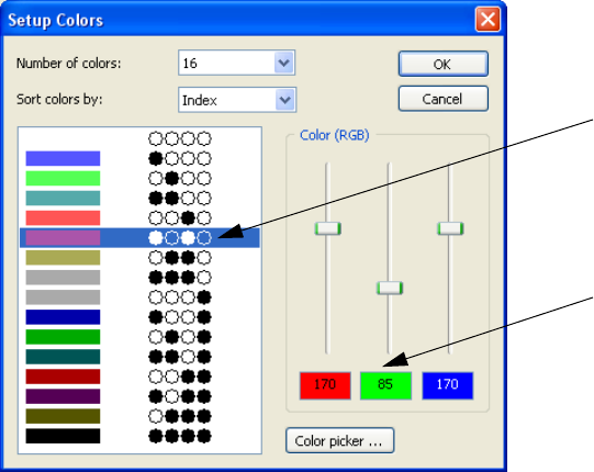
L-Edit 13 User Guide Section 1 79
Chapter 3: Application and Design Setup Color Parameters
Color Parameters
You can display an L-Edit design file using 16, 32, 64, 128, or 256 colors in your palette. You use the
Setup > Colors command to set the number of and RGB definition of your design colors.
Each color has two attributes, a unique identifying binary code and an RGB color definition. The Setup
Colors dialog provides the following options:
Number of colors Select the number of colors that will be available for defining layer
colors. Options are 16, 32, 64, 128, or 256 (True Color mode) colors.
Sort colors by Select how colors will be sorted. This setting applies to both this
dialog and the Setup Layers dialog. Options are:
Index—sorts by index number, which is the binary value of a
color.
Number of bits—sorts by the number of bits used to define a
color and then by index number if the number of bits set is equal.
Hue—sorts by hue, then saturation, then luminosity, then index
number.
Brightness—sorts by luminosity in descending order, then hue,
then saturation, then index number.
(left pane) Shows a sample of each defined color and the associated 4- to 8- bit
binary code used to assign a unique color index number to that color.
The number of bits used in each color depends on the number of
colors available in the file (for example, 4 bits are used in a 16 color
file).
Binary code for the color, in this
case purple.
RGB values for the color, in this
case R=170, G=85, B=170.
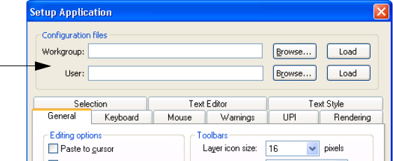
L-Edit 13 User Guide Section 1 80
Chapter 3: Application and Design Setup Application Parameters
Application Parameters
To modify application-level settings in L-Edit, choose Setup > Application. Application-level settings
are divided into nine categories, which appear on separate tabs—General, Keyboard, Mouse,
Warnings, UPI, Rendering, Selection, Text Editor and Text Style.
Configuration Files
Application settings are saved in application configuration (.ini) files. You specify configuration file
options in the top portion of the Setup Application dialog.
Configuration files are ASCII files containing application-wide setup information that can be edited and
shared among multiple users. To load settings from an existing file, enter the name of the file in the
Workgroup or User field, or choose from available files using the Browse button next to the desired
field. Click Load to load the settings into L-Edit.
Workgroup and User Configuration Files
L-Edit can load configuration information from either a Workgroup or a User file. Workgroup files are
intended to be shared by multiple users; for example, they may contain key remapping sequences that
will be used by many users. User files are intended to contain preferences specific to a particular
individual.
Changes in the Setup Application dialog can only be saved to User configuration files. Therefore, an
INI file loaded as a Workgroup file is protected from accidentally being changed. When both
workgroup and user files are specified in Setup Application, settings from the user file override
settings in the workgroup file.
To create a workgroup configuration file, first save the desired settings in a user configuration file. You
can then copy the user configuration file to a new name to create a workgroup file.
Color (RGB) Displays the composition of each color as a function of its Red,
Green, and Blue values, which can range from 0 to 255.
You can use the slider controls or type a number in the red, green and
blue colored boxes to modify a color.
Color Picker Opens the standard Windows Color dialog that allows you to select
and define colors.
Configuration
File Options

L-Edit 13 User Guide Section 1 81
Chapter 3: Application and Design Setup Application Parameters
Editing Configuration Files
Tanner INI files use the Windows INI file format and can be edited with any text editor. To write out the
user configuration file, press Shift+Enter or hold the Shift key while clicking OK in the Setup
Application dialog.
Contents of Configuration Files
The following L-Edit parameters are saved in an INI file:
Parameters Refer to Section:
General options, including:
Mouse settings Mouse (page 85)
Recently used file list
and TDB Setup Path
General (page 82)
Examine Xref Cells
during loading
Examining XrefCells (page 243)
Enable keyboard
shortcuts in the Design
Navigator
Design Navigator (page 209)
Show Verification Error
Navigator after running
DRC
Optimizing Performance (page 425)
Toolbar settings General (page 82)
Editing options, including:
Autopan,
rubberbanding, Paste to
cursor
General (page 82)
Instance rendering and
caching
Rendering (page 88)
Warnings Warnings (page 86)
CIF import and export
options
Importing CIF Files (page 134) and Exporting CIF Files (page 140)
GDSII import and export
options
Importing GDS Files (page 132) and Exporting GDS Files (page
138)
Keyboard remapping
settings
Keyboard Customization (page 84)
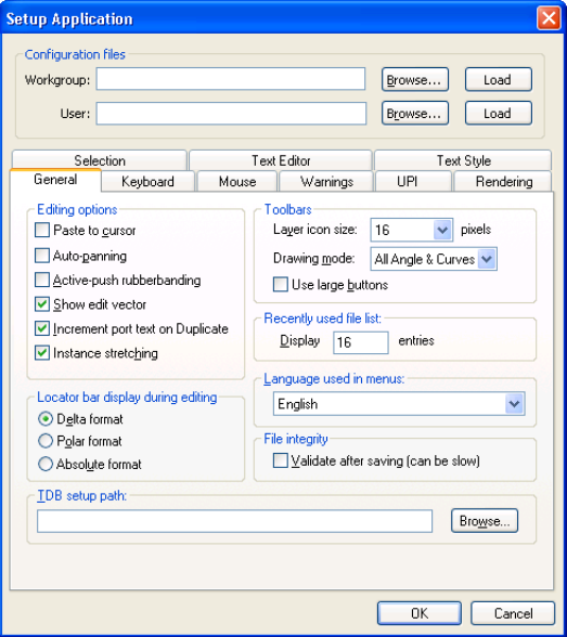
L-Edit 13 User Guide Section 1 82
Chapter 3: Application and Design Setup Application Parameters
General
Use the General tab to customize editing options, toolbar display, and other general application
parameters.
Paste to cursor When this option is checked, objects placed in the layout with
Edit > Paste move with the pointer until any mouse button is clicked.
They are then “dropped” into place at the location of the pointer. See
Paste to Cursor Feature (page 281). Before objects are dropped in
their final position, they can be rotated or flipped using keyboard
command shortcuts. See Reorienting (page 278).
Auto-panning When this option is checked, L-Edit automatically pans the view
when the pointer touches an edge of the window during a draw, move,
or edit operation.
Active-push
rubberbanding When this option is checked, it is unnecessary to hold down the
mouse button during a drag operation. For example, when drawing a
box, you can click and release the DRAW button at one corner of the
box, move the pointer to the opposite corner of the box, then click the
DRAW button again to complete the operation.
Show edit vector When this option is checked, L-Edit draws a rubberband line during a
move or edit operation from the cursor start position to its current
during the click-and-drag operation.
L-Edit 13 User Guide Section 1 83
Chapter 3: Application and Design Setup Application Parameters
increment port text on
Duplicate When this option is checked, and the last character in the port name
field is a numeral, L-Edit automatically increments the port label by
one with each port that is placed.
instance stretching When this option is checked, dragging an edge or corner of an
instance with the middle mouse button stretches the instance.
For instances of regular cells, this converts the instance into an
array.
For instances of T-Cells, this means regenerating the instance
with updated stretching parameters. (T-Cell parameters have an
option for this purpose.)
For array instances, it stretches by changing the number of rows
and columns to best fit the edit.
Locator bar display during
editing:
Delta format
When this option is selected, then during editing the locator bar
displays coordinates in (delta-x, delta-y, delta) format relative to the
start of the edit. Pressing Shift+F will toggle the different locator bar
display types.
From the layout, pressing Q will toggle the locator bar display to
relative coordinate mode with respect to the position of the cursor
when Q was pressed. When you press Q again, the display goes back
to the default mode.
Polar format When this option is selected, then during editing the locator bar
displays coordinates in polar format (delta, angle) relative to the start
of the edit. When not editing, coordinates are also displaced in polar
format relative to the origin of the cell. Pressing Shift+F will toggle
the different locator bar display types.
Absolute format When this option is selected, then during editing the locator bar
displays the values of the x and y coordinates of the current position
of the mouse. Pressing Shift+F will toggle the different locator bar
display types.
Toolbars:
Layer icon size
Sets the default pixel size of icons on the Layer palettes. You can
increase or decrease the icon size in two-pixel increments at any time
by right-clicking on any layer name, in either Palette, and selecting
Options.
Drawing mode Sets the default display of drawing tools on the Drawing toolbar.
When Orthogonal or 45 Degrees is chosen, only those tools fitting
that description will be displayed. When All Angle is selected, all
tools are displayed.
Use large buttons When checked, increases the size of all toolbar buttons by 50 percent.
Recently used file list Controls the number of recently used files displayed in the File menu.
Language used in menus Select the language for menus. Choosing Windows in this entry will
put menus in the language based on Windows settings.
File Integrity:
Validate after saving (can
be slow)
If checked, L-Edit reads the tdb file immediately after writing.
If it detects errors it reports them and reverses the write operation by
renaming the .tdx (backup of backup) file to .tdo, and the .tdo
(backup) file to .tdb. As noted, this can be a time comsuming process.
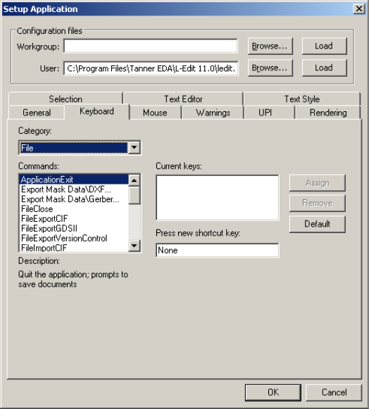
L-Edit 13 User Guide Section 1 84
Chapter 3: Application and Design Setup Application Parameters
Keyboard Customization
Use the Keyboard tab to customize keyboard shortcuts.
Options include:
TDB setup path Predefined directories for TDB setup files. TDB files in these
directories are listed in the Copy TDB setup from file field in the
File > New and File > Import Mask Data dialogs.
Category Command categories corresponding to L-Edit menu items. To select a
category, highlight an item in the drop-down list.
Commands The set of commands for the selected category. Highlight a command
from the list to select it. Additional commands may be viewed by
moving the scrollbar up or down.
Description A description of the command highlighted in the Commands list.
Current keys The current shortcut key combination for the command highlighted in
the Commands list. To delete a shortcut, highlight the shortcut and
click Remove.
Press new shortcut key With the cursor in this field, press the desired shortcut on the
keyboard, which will then be textually represented in the field. Click
Assign to register the new shortcut.
Default Reassigns all shortcut key assignments in the current editor to their
default settings.
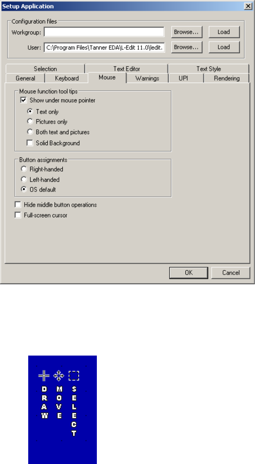
L-Edit 13 User Guide Section 1 85
Chapter 3: Application and Design Setup Application Parameters
Not that only user-defined keyboard assignments are saved in the user configuration file. To write all
keyboard assignments to the user configuration file, press Shift+Enter or hold the Shift key while
clicking OK
Mouse
Use the Mouse tab to customize mouse button assignments and mouse tooltip display options.
Options include:
Show under mouse pointer When checked, the mouse pointer displays a persistent tooltip
showing the operation associated with each mouse button.
Text only displays vertical text describing each button operation.
Pictures only displays icons indicating each button operation.
Both text and pictures displays tooltip text and icons with the
mouse pointer.
When Solid Background is checked, L-Edit encloses the mouse
tooltips in a box with solid fill.
Note: You can toggle mouse tooltips display at any time using
View > Display > Mouse Hints.
Button Assignments Determines the order in which mouse button assignments are
displayed in tooltips and in the Mouse Button bar. You can select a
Right-handed or Left-handed mouse, or choose OS default to use
the default setting for your operating system.
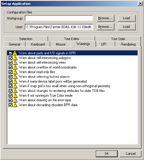
L-Edit 13 User Guide Section 1 86
Chapter 3: Application and Design Setup Application Parameters
Warnings
Use the Warnings tab to enable and disable optional warnings and explanations that you may encounter
while editing a design file.
Hide middle button
operations When selected, hides the middle button reference in the mouse
tooltips and the Mouse Button Bar. Use this feature to show the
functionality of a two-button mouse.
Full-screen cursor When this option is selected, the cursor is displayed as vertical and
horizontal lines extending across the full extent of the layout window.
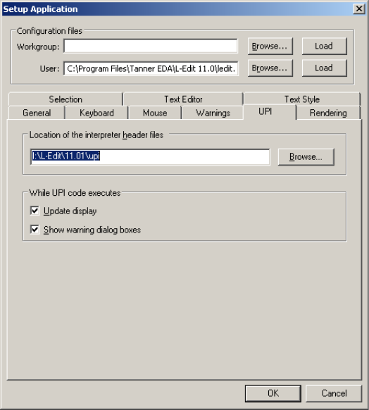
L-Edit 13 User Guide Section 1 87
Chapter 3: Application and Design Setup Application Parameters
UPI
Choosing the UPI tab in the Setup Application dialog allows you to set a path to the header files that
L-Edit uses when running an interpreted macro. This dialog is also used to set a path to the log file
where UPI writes macro errors.
Options include:
Location of the interpreter
header files The complete path of the directory containing the L-Edit interpreter
header files. Clicking Browse next to this field calls a standard
Windows directory browser.
Note: The path name in this field is limited to a maximum of 75
characters. Therefore, you should not keep interpreter header
files in highly nested subdirectories.
Update display When checked, L-Edit updates the display while UPI code is
executing. When unchecked (default), L-Edit does not update the
display during the execution of a macro or T-Cell generator.
Show warning dialog
boxes When checked (default), L-Edit displays warning dialog boxes in the
user interface. When unchecked, L-Edit runs in quiet mode, in which
warning dialog boxes are not displayed.
Note: Batch processing must be run in quiet mode.
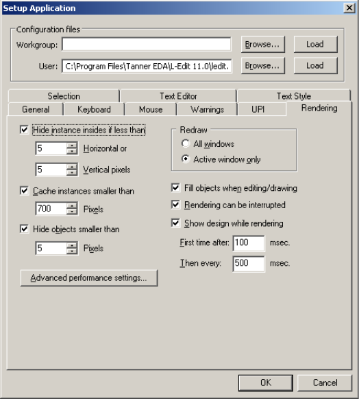
L-Edit 13 User Guide Section 1 88
Chapter 3: Application and Design Setup Application Parameters
Rendering
Use the Rendering tab to establish basic display behavior.
Hide instance insides if
less than Defines the minimum size (in pixels) that an instance must be to be
completely drawn on the screen. If the instance width is smaller than
the Horizontal parameter or the instance height is smaller than the
Vertical parameter, it is drawn in outline mode—its insides are not
shown.
Suppressing the display of instance insides can enhance screen redraw
times and clarify the layout if the screen is zoomed out to a relatively
small magnification.
Cache instances smaller
than When checked, defines the maximum size (in pixels) that an instance
may be to be cached. Cached instances are are rendered once and then
copied for each instance reference. They can be subsequently
redrawn at much higher speeds than non-cached instances but may
display alignment artifacts at the instance boundaries.
Very large cached instances may exhaust the available memory. The
default maximum size is 700 pixels.
Hide objects smaller than When checked, defines the minimum size (in pixels) that an object
must be to be drawn on the screen.
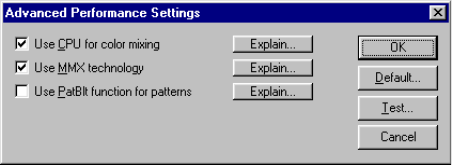
L-Edit 13 User Guide Section 1 89
Chapter 3: Application and Design Setup Application Parameters
Advanced Performance Settings
Redraw Choose All windows to redraw, for example, instances of a cell in
other windows when the cell itself is modified, or Active window to
redraw just what is displayed in the currently active window. L-Edit
will redraw other windows as soon as they are activated. Redrawing
the active window only can substantially improve rendering speed.
Fill objects when
editing/drawing When unchecked, renders objects in outline mode during drawing or
editing operations.
Rendering can be
interrupted When checked, rendering can be interrupted with any mouse click or
key stoke so that a full redraw does not have to be completed between
each operation.
Show design while
rendering When checked, periodically updates the design display during
rendering. The First time after field specifies the elapsed time from
the start of a rendering operation to the first display update. L-Edit
then periodically updates the display at the interval specified in Then
every until rendering is complete. Both times are defined in msec.
When Show design while rendering is not checked, L-Edit waits to
complete a rendering operation before updating the display. This
setting allows for faster rendering, but with less immediate feedback
during screen refresh operations.
Advanced performance
settings Opens Advanced Performance Settings, which allows you to set
and test system performance options that affect L-Edit rendering
speed. (See Advanced Performance Settings, below.)
Use CPU for color mixing Affects rendering performance by allowing your CPU or video card to
handle the process of color mixing.
L-Edit mixes layer colors to produce the proper color display where
objects overlap. When relatively few objects are drawn on a relatively
large number of layers, performance can degrade.
Unless you have very powerful video card, this option should be
checked to perform color mixing on the CPU.
Use MMX technology If the CPU is used for color mixing, MMX technology generally
provides optimal performance. However, occasionally an unusual
system configuration produces better performance with this option
disabled.
L-Edit 13 User Guide Section 1 90
Chapter 3: Application and Design Setup Application Parameters
Use PatBlt function for
patterns L-Edit uses a fast Win32 function called PatBlt when rendering layers
with objects having patterned fill or outlines. However, video driver
manufacturers may implement this function in a non-optimal or
unpredictable manner. If you find that patterns are not rendered
correctly when this option is checked, try unchecking it.
Note that for Windows 95/98/ME it is recommended that this option
be disabled.
Default Restore the default settings, which are best for most system
configurations.
Test Performs a rendering test by measuring how long it takes to redraw
the top layout window ten times. Use this test to analyze different
performance settings.
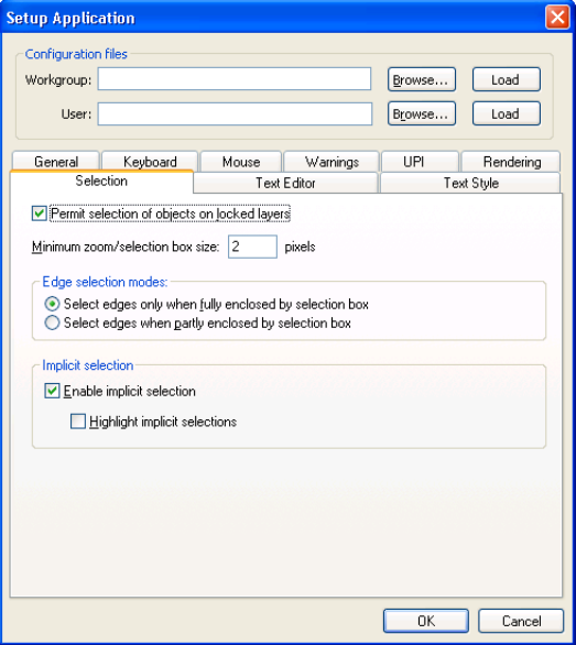
L-Edit 13 User Guide Section 1 91
Chapter 3: Application and Design Setup Application Parameters
Selection
Use the Selection tab to specify edge selection modes and general selection parameters.
Options include:
Permit selection of objects
on locked layers When this option is on, objects on locked layers may be selected and
their properties may be inspected. When off, objects on locked layers
will not be selectable.
Minimum zoom/selection
box size Specifies the minimum area, in pixels, of a zoom or selection box. See
Setting Zoom/Selection Box Size, below.
Edge selection modes Governs edge selection behavior. Options include:
Select edges only when fully enclosed by selection box
Select edges when partly enclosed by selection box
See Setting Zoom/Selection Box Size, below.
Enable implicit selections When implicit selection is enabled, a click-and-drag of the middle
mouse button while near or over an object or object edge will
implicitly select that object. When this option is not checked, you
must select objects explicitly.
Highlight implicit
selections Implicit selections are highlighted with dashed outline as the mouse is
positioned over an object or an edge. This gives an indication which
object or edge an implicit edit will act upon. A useful feature is that
cell and instance names will be displayed when the mouse is moved
over an instance, when this option is on.
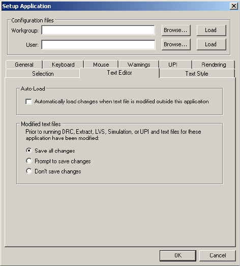
L-Edit 13 User Guide Section 1 92
Chapter 3: Application and Design Setup Application Parameters
Setting Zoom/Selection Box Size
The zoom/selection box is a construct L-Edit uses in zooming to a specified view and selecting objects.
A zoom box defines the boundaries of the view during a zoom operation. When you choose
View > Zoom and draw a box, for example, L-Edit zooms to a view corresponding to that box. If you
choose Zoom > View and simply click the mouse, L-Edit magnifies the area around the pointer by a
factor of two.
A selection box specifies an area within which L-Edit selects objects. When you drag a selection box
around a polygon or wire, for example, L-Edit selects all or part of that object, depending on the edge
selection mode specified under Selection Modes in Setup > Application—Selection. If you simply
click the mouse repeatedly without moving it, L-Edit selects objects in cycle, as described in Cycle
Selection on page 268.
If your mouse is not perfectly stable, you can use the option Minimum zoom/selection box size to
specify the minimum size of this box. Use a relatively small value, such as 2 or 3 pixels, to prevent
L-Edit from misinterpreting small, accidental mouse movements as a zoom or selection box.
Text Editor
Use the Text Editor tab to control how files are saved from the text editor.
When the L-Edit text editor loads a file it does not lock it. It checks the stored version of a file for
modifications when files are saved, first changed, and when the text window or application becomes
active or is closed. If a stored file has not changed, nothing will happen. The options in this tab control
what will happen when a file has been modified outside the text editor.
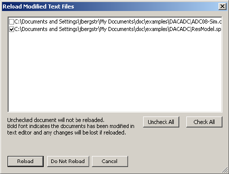
L-Edit 13 User Guide Section 1 93
Chapter 3: Application and Design Setup Application Parameters
Files Modified Outside the Text Editor
When Auto-Load is disabled, L-Edit will open a checklist of all the files open in the text editor that
have been modified elsewhere. You will have the option to reload modified files (checked) or not. Files
that have also been modified in the text editor will be highlighted. Similarly, when Prompt to save
changes is selected, L-Edit will open a checklist of the modified files associated with the operation you
are running.
Auto-Load When enabled, L-Edit automatically updates the text files that have
been modified outside of the text editor when those files have not
been modified within the text editor.
Modified text files If documents that will be used during DRC, extract, LVS, simulation
or UPI have been modified before any of these operations are started:
Save all changes—silently saves only those files directly
associated with the operation.
Prompt to save changes—opens a dialog indicating which files
have been modified, with the option to save them.
Don’t save changes—modified files will not be saved and the
operation will use the stored version of those files.
The file types that will be checked for each operation are as follows:
DRC—command files
Extract—ext files
LVS—layout netlist files, schematic netlist files, prematch files
& element description files
Simulation—main circuit files
UPI—C macro files
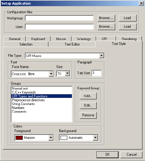
L-Edit 13 User Guide Section 1 94
Chapter 3: Application and Design Setup Application Parameters
Text Style
Use the Text Style tab to define the types of text (keyword groups) that will be highlighted in the text
editor, and their appearance.
Each file type has a set of predefined keyword groups that cannot be edited or deleted. Use this tab to
view those settings, and to add or remove your own keyword groups with customized characteristics.
File Type A drop down list of the file types for which keywords are or can be
defined.
Font Allows you to set the typeface (Face Name) and point Size in which
a given keyword group will appear.
Paragraph Allows you to set the increment, in spaces, of the Tab Size used by
the text editor.
Groups Displays the keyword groups defined for a given file type. Use Add to
enter the name of a new keyword group. Use Edit to enter the
keywords belonging to a group. Use Remove to delete a keyword
group.
Colors Use Foreground and Background to set the respective colors for a
keyword group.
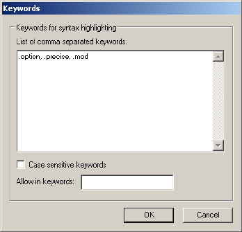
L-Edit 13 User Guide Section 1 95
Chapter 3: Application and Design Setup Design Setup
Adding Keywords to a Group
Edit keyword groups opens the Keywords dialog, which allows you to enter keywords and to specify
whether the case is evaluated (Case sensitive keywords checkbox enabled) when highlighting is
applied.
Design Setup
To modify design-level settings in L-Edit, choose Setup > Design. This command opens the Design
Setup dialog, which has tabs that allow you to manipulate design parameters in five categories:
Technology (Technology Parameters on page 96)
Grid (Grid Parameters on page 97)
Selection (Selection Parameters on page 100)
Drawing (Drawing Parameters on page 101)
Xref files (Cross Reference File Designation on page 102)
Internal Units, Display Units, and Technology Units
L-Edit uses display units to report object dimensions and coordinates. The program also uses display
units to set the display grids and mouse snap grid. You can choose to display units of microns, mils,
millimeters, centimeters, inches, or a custom unit. (Custom units can be defined on the Setup > Grid—
Technology dialog.) The choice of display units does not affect the scaling of your design.
For its own computation, L-Edit uses internal units (30-bit signed integers). Before beginning your
design, you should define the relation between L-Edit’s internal units and physical, or technology, units,
as it will determine the extent of the layout area and the smallest object that can be drawn. This relation
is also critical when you replace your design setup or export a design to CIF or GDSII format. Defining
this relationship sets the scale of the design file.
The L-Edit layout area extends from -536,870,912 to +536,870,912 internal units in both the x-
(horizontal) and y- (vertical) directions. Thus, if 1 internal unit = 0.001 micron, the largest possible
design is 1,073,741 microns (almost 42.3 inches) on a side. Similarly, the smallest dimension L-Edit
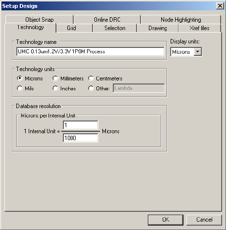
L-Edit 13 User Guide Section 1 96
Chapter 3: Application and Design Setup Design Setup
can define is 1 internal unit. If 1 internal unit = 0.001 micron, the smallest possible feature size would be
0.001 micron. (In practical terms, of course, 0.001 micron is an unrealistically small feature size.)
In practice, you might also wish to adjust other settings based on your minimum feature size. If you use
the display grid as a visual aid while drawing, you may wish to adjust its spacing. To achieve adequate
resolution, you may wish to adjust the spacing of the mouse snap grid or turn it off altogether. You can
enter new values for these settings on the Setup Design—Grid tab. If you change the display units,
L-Edit will automatically convert these numbers to the new unit system.
See Grid Parameters on page 97 for further information on setting the display grid and the mouse snap
grid.
Technology Parameters
To specify technology parameters, choose Setup > Design. The Setup Design dialog with the
Technology tab displayed appears:
Options include:
Technology name Used to determine whether two design files are compatible. If you
attempt to copy a cell from a file with a technology name different
from that of the current cell, L-Edit presents a warning.
Display units Specifies the units that L-Edit uses in displaying distance and area
values, as well as the units in which physical distances are specified in
other user dialogs. For example, you may wish to define a technology
unit that corresponds to a manufacturing specification, such as a
fraction of a micron. You can still choose display units of microns, so
that all distances will be displayed in a familiar unit system.
Changing the display units does not change the scale of your design.
You can use any of the predefined units (Microns, Mils, Millimeters,
Centimeters, or Inches), or a custom unit (if one is defined).
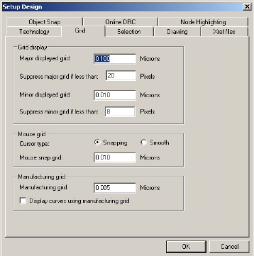
L-Edit 13 User Guide Section 1 97
Chapter 3: Application and Design Setup Design Setup
Grid Parameters
To aid the viewing, drawing, and editing of objects, L-Edit provides three independent grids—the
displayed grids, the mouse snap grid, and the manufacturing grid—each of which divides the layout
area into equal squares whose corners are gridpoints.
The display grid provides a set of convenient locating points. L-Edit can display both a major grid
and a minor grid.
The mouse snap grid determines the pointer’s freedom of movement.
The manufacturing grid corresponds to the resolution at which the manufacturer can produce
circuit elements.
Grid parameters are specified using Setup > Design—Grid. Parameters that represent physical
distances are always specified in the current display units. You can set display units on the Setup
Design—Technology tab. When you change display units, L-Edit automatically converts the grid
settings to the new display units.
Setup > Design—Grid
Technology units A technology is described by a specific unit of measurement. Select
one of the predefined units (Microns, Mils, Millimeters,
Centimeters, or Inches), or a custom unit (Other). If you choose a
custom unit, you must also specify its equivalent in microns and in
internal units (for CIF/GDS II output, design rule checking, and other
purposes) under Technology Setup. See CIF File Formatting on page
143 or GDSII File Formatting on page 147 for more information.
Database Resolution Defines the relationship between internal units and technology
(physical) units.
Note: Changing the database resolution will rescale your design.
This operation cannot be undone.
Technology to micron
mapping For custom units, defines the relationship between microns and the
custom unit. For example, you might want to work in technology
units equal to a fraction of a micron, such as 0.18. Under Technology
Units, click Other. You can type a name for the new units, or accept
the default name of Lambda. Then, under Technology to micron
mapping, define 1 Lambda = 18/100 Microns.
L-Edit 13 User Guide Section 1 98
Chapter 3: Application and Design Setup Design Setup
Options include:
Grid Rendering
L-Edit renders both major and minor grids on a Grid layer, which is specified in Setup > Special
Layers (see Rescaling a Design on page 117). Major and minor grid colors are rendering parameters of
the grid layer in Setup > Layers—Rendering.
The major and minor grids take the colors specified for Object Outline and Object Fill, respectively, on
the grid layer. If there is no outline, both major and minor grids are displayed in the Object Fill color.
Similarly, if there is no fill, both grids are displayed in the Object Outline color. If neither fill nor
outline exists on the grid layer, then no grids are rendered.
Rendering setup options are discussed in Rendering on page 88.
Major displayed grid The absolute spacing of the major grid display. The value entered in
this field is the distance, in display units, between major grid points.
For more information about grid display, see Grid Rendering on page
98.
Suppress major grid if less
than The apparent spacing of the displayed grid varies with the
magnification of the Layout Area. If the number of screen pixels
between major grid points is less than the value entered in this field,
then the major grid is hidden.
Minor displayed grid The absolute spacing of the minor grid display. The value entered in
this field is the distance, in display units, between minor grid points.
For more information about grid display, see Grid Rendering on page
98.
Suppress minor grid if less
than The number of screen pixels between minor grid points below which
the minor grid is hidden.
Cursor type Snapping—Causes the cursor to snap to the gridpoints specified
in Mouse snap grid.
Smooth—Allows the cursor to move unconstrained. Points
picked during drawing and editing operations are still snapped to
the mouse snap grid when the cursor type is Smooth.
Mouse snap grid Absolute spacing of the mouse snap grid. The value entered in this
field is the minimum resolution, in display units, allowed during
drawing and editing operations. All drawing and editing coordinates
are snapped to this grid size.
You can use the Multigrid Toolbar on page 99 to toggle mouse
snapping on or off and to jump to up to three preset grid values.
Manufacturing Grid Sets the absolute spacing of the manufacturing grid.
The DRC option Flag off-grid identifies vertices and instances that
are not on the manufacturing grid.
Display curves using
manufacturing grid When checked, curved objects (circles, tori, and pie wedges) will be
displayed as vertices that snap to the manufacturing grid rather than as
smooth curves. See Flag to Append Special Commands on page 420
to modify DRC error reporting on approximated curves.
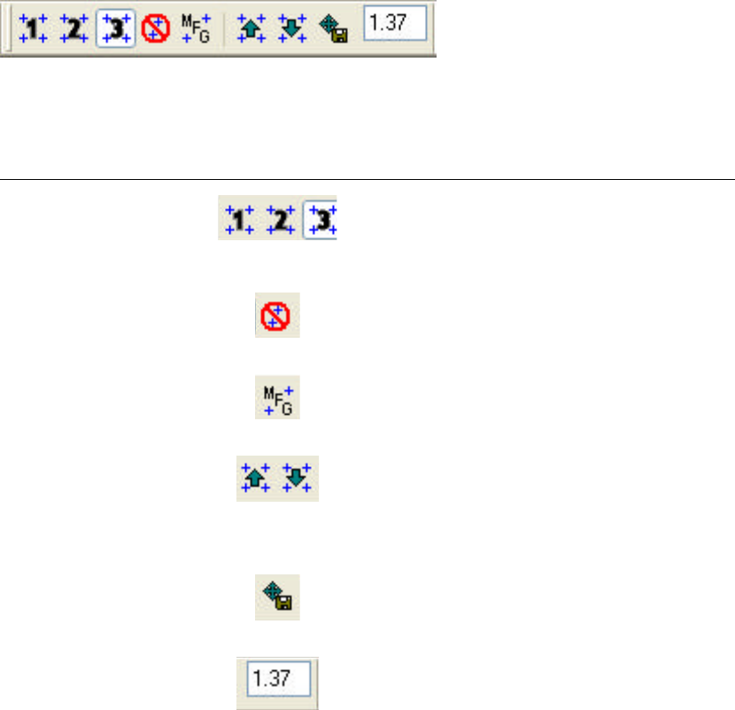
L-Edit 13 User Guide Section 1 99
Chapter 3: Application and Design Setup Design Setup
Multigrid Toolbar
The Multigrid toolbar provides a convenient way to change the current mouse snap grid and the nudge
distance, and also to switch between several predefined grid sizes. It is particularly helpful when you
have a large change in zoom level.
You can enable or disable this toolbar using the View > Toolbars menu item, or by right-clicking in the
toolbar area of the application.
The first five buttons from the left set the current mouse snap grid. These buttons are modal—only one
can be active at a time.
Function Icon Description
Mouse Grid 1, 2 & 3 These buttons let you set three predefined mouse
snap grid values. Simply click on one of the
buttons and enter a value in Mouse Snap Grid
field.
Max grid Sets the mouse snap grid to be one internal unit.
Manufacturing grid
Sets the mouse snap grid to the same value as the
manufacturing grid.
Make Coarser
Make Finer
Increments the value in the Mouse Snap Grid
field upwards or downwards respectively to make
the grid coarser or finer, in steps of 1, 2, 5, and 10
display units. This command is not available if
the grid is set to “finest” or “manufacturing grid”.
Set Nudge From Snap
Grid Sets the nudge amount to the current Mouse
Snap Grid value.
Mouse Snap Grid Use this numeric field to enter the mouse snap
grid values for the buttons 1, 2 & 3, or, when the
Set Nudge From Snap Grid button is pressed,
the nudge distance.
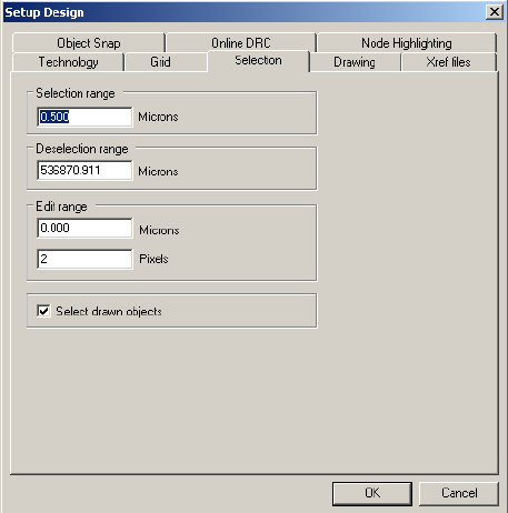
L-Edit 13 User Guide Section 1 100
Chapter 3: Application and Design Setup Design Setup
Selection Parameters
You can modify object selection parameters in the Setup Design—Selection dialog.
Options include:
Selection and Deselection Ranges
The values set for Selection range and Deselection range govern the operation of the implicit
selection feature (see Implicit Selection on page 268). When you click the MOVE-EDIT mouse button,
L-Edit selects geometry within the selection range and deselects geometry outside the deselection
range. In the following illustration, the selection range is bounded by a heavy black outline (not drawn
to scale).
Selection range A positive integer s such that: if the pointer is outside an object but is
still within s display units of any of the object’s edges, then the object
can still be selected. See Selection and Deselection Ranges, below.
Deselection range A positive integer d such that: if a mouse button is clicked (for
example, to initiate a move, edit, or copy operation) when the distance
between the pointer and a selected object is greater than d display
units, then the selected object is deselected. The deselection range is
set by default to the largest possible number (to indicate infinity), so
that a selected object is never automatically deselected.
Edit range A positive integer e such that: if the pointer is within e display units of
an edge or vertex of the selected object, then clicking the Move-Edit
mouse button will execute the edit operation; otherwise it is a move
operation. Two numbers are supplied: one in display units, the other
in pixels. e takes the value that results in a larger on-screen distance.
Select drawn objects Instructs L-Edit to automatically select an object after it is created.
This is useful for designers who like to position or edit objects after
creating them instead of while drawing them.
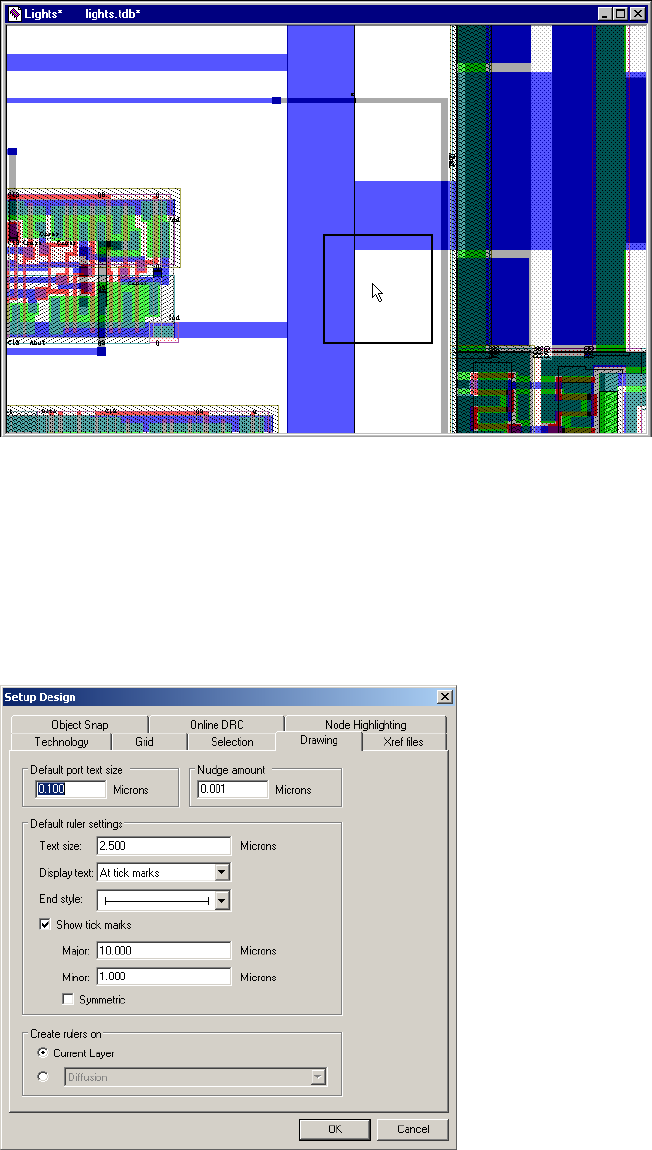
L-Edit 13 User Guide Section 1 101
Chapter 3: Application and Design Setup Design Setup
When multiple objects are within the selection range, L-Edit determines which object to select using the
following priority: (1) objects the pointer is inside, ordered by the closest edge; (2) objects the pointer is
outside, yet still within the selection range, ordered by the closest edge.
Drawing Parameters
You can modify drawing parameters in the Setup Design—Drawing dialog.
Options include:
Default port text size Default text size in display units for ports.
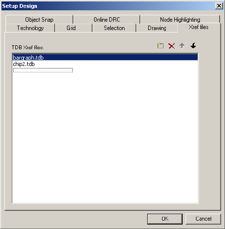
L-Edit 13 User Guide Section 1 102
Chapter 3: Application and Design Setup Design Setup
Cross Reference File Designation
Use Setup > Design—Xref files to list the files you want to use as cross reference or library files.
Nudge amount Amount (in display units) to move objects during the nudge
operation.
Text size The default letter height, in display units, for text associated with
rulers.
Display text Ruler text can be displayed in one of four ways: No text, Centered,
At end points, or At tick marks. Select the desired option from the
drop-down list.
End style Ruler lines contain one of two end styles: arrows or tick marks.
Highlight the illustration in the drop-down list to select the default
end style.
Show tick marks Toggles the display of tick marks. To change the position of Major
and Minor tick marks (in display units), type the desired spacing in
the appropriate field. Major tick marks are twice as long as Minor.
Symmetric When this box is checked, tick marks extend above and below the
ruler.
Create rulers on The default layer for rulers. The Current Layer option places rulers
on whichever layer is currently selected. To set rulers to a specific
layer, click the second option button and select a layer from the
drop-down list.
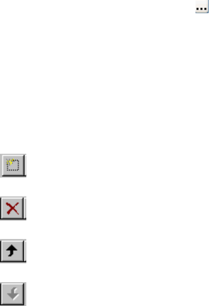
L-Edit 13 User Guide Section 1 103
Chapter 3: Application and Design Setup Design Setup
Options include:
To cross-reference cells when exporting to GDSII, you need to first specify which files will be library
files by listing them in the Setup > Design—Xref files dialog. A library file, called an xref file in L-Edit
terminology, is any TDB file containing cells which are referenced from another file.
Once a file is linked to a design, its cells can be cross-referenced using the Cell Instance dialog, or by
dragging it from the Design Navigator and dropping it into your layout. Conversely, when you instance
a cell from a different file into your current file, L-Edit opens Setup > Design—Xref files with the
source file added to the Xref files list. Cells from an Xref file are called XrefCells.
Xref file names and paths are stored in your TDB design file, and are transferred during a File > Import
Mask Data, File > Replace Setup or File > New operation.
Library files can also be referenced when you import a GDSII file (see Use File > Import Mask
Data > GDSII to import GDSII files into L-Edit. on page 132).
Snap Parameters
Object snapping snaps the cursor to to user selected snap points on objects. Snap points include object
vertices, edge midpoints, edges, wire centerlines, box and circle center points, instances, and ports. See
Object Snapping (page 165) for setting up and using Object Snapping.
TDB Xref files Enter a path and file name by using a slow click (click and hold the
mouse button briefly before releasing) within the entry area to initiate
edit mode. If you use relative paths, they will be relative to the
location of the design file in which you are working. To browse for a
file, click the ellipsis button ( ).
The order in which you list files in this dialog is critical. L-Edit will
check files for cross-referenced cells in this order during GDSII
import. To speed L-Edit processing, list files with the most cross
referenced cells higher in this list. Files are also listed in this order in
the Cell Instance dialog and the Design Navigator.
Double-clicking on a file name opens the Properties window for that
file.
The file list has four buttons:
Adds a new file to the list and puts you in edit mode for that file.
Deletes the selected Xref library file from the list.
Moves the selected Xref library file up on the list.
Moves the selected Xref library file down on the list.
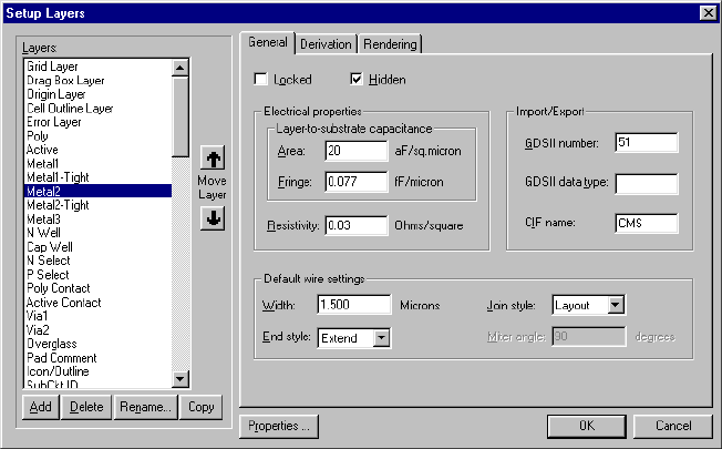
L-Edit 13 User Guide Section 1 104
Chapter 3: Application and Design Setup Layer Setup
Interactive DRC Parameters
Interactive DRC allows DRC rules to be checked in real time, while polygons are being drawn or
edited. See Interactive DRC (page 308) for setting up and using interactive DRC.
Layer Setup
An L-Edit setup contains an ordered list of layers. To edit the layer structure in the active file, open the
Setup Layers dialog by choosing Setup > Layers, right-clicking from either of the layer palettes, or
double-clicking anywhere on the Compact Layer palette.
The Layers list on the left shows all the defined layers in the active file.
To Add a New Layer
;Click Add. A layer named “New Layer [n]” (where n is the number of the new layer) will be added to
the layer list, with all values in each of the three Setup Layers cleared.
;Click Rename to edit the layer name. Note that no two layers can have the same name. Derived layers
must be positioned in the list below the layers from which they are derived. You can also rename a layer
by double clicking on it in the layer list.
Options for Defining Layers
There are three tabs in the Setup Layers dialog: General, Derivation, and Rendering. The following
common controls for the layer list are available with each of these tabs:
Add To add a layer to the list, click the Add button. A New Layer [n]
(where [n] is the number of the new layer) will be added to the layer
list; this name can be edited by clicking Rename.
L-Edit 13 User Guide Section 1 105
Chapter 3: Application and Design Setup Layer Setup
General Layer Parameters
The General tab, shown in the previous figure, allows you to set the following layer properties:
Delete To delete a layer, highlight the layer in the list and click Delete. A
layer can only be deleted if it contains no geometry.
Rename Opens a dialog that allows you to enter a new name for the
highlighted layer.
Copy To add a copy of an existing layer, highlight the layer in the list and
click Copy. The new layer is placed below the selected layer, with
“Copy of” preceding the layer name.
Note: GDSII number, GDSII data type, and CIF name are not copied
to the new layer.
Move Layer Click on the up or down arrow to reposition the highlighted layer in
the list.
Properties Opens the Properties dialog, where you can define and attach any
number of properties to the layer.
Locked When this box is checked, geometry on a layer cannot be drawn,
moved, or edited.
Hidden When this box is checked, the layer is hidden (not displayed).
Layer-to-substrate
capacitance Specifies the Area capacitance between the layer and the substrate (in
aF/sq. micron), and the Fringe capacitance (in fF/micron).
Resistivity Specify the resistivity (resistance per square unit area) of the layer
material in Ohms/square.
Import/Export To edit the import/export parameters of the selected layer, enter
values in these fields as appropriate:
GDSII number—an integer that indicates the GDSII layer
number
GDSII data type—an integer that can be used in combination
with the GDSII number to identify an additional layer. For
further information, see GDSII Data Type on page 150.
CIF name
Default wire settings Set the default Width (in display units), End style, and Join style for
the layer’s wire settings. See End Styles and Join Styles on page 115
for more information on wire settings.
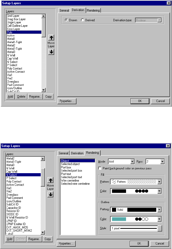
L-Edit 13 User Guide Section 1 106
Chapter 3: Application and Design Setup Layer Setup
Derivation Layer Parameters
The Derivation tab allows you to define new layers that are derived from existing ones using logical
and selective operations. Derivation settings are discussed in Generating Layers on page 284.
Rendering Layer Parameters
The options on the Rendering tab control layer appearance.
A layer’s appearance is determined by when it is drawn with respect to the other layers in the design—
its pass value, and whether its color is added, subtracted, or replaces the colors of the layers that are
drawn before it—its mode.
For each layer, you can also specify a color and a pattern for the fill and outline of drawn elements in
normal state and in selected state. The elements for which color and pattern can be set are:
Object
Selected object

L-Edit 13 User Guide Section 1 107
Chapter 3: Application and Design Setup Layer Setup
Port box
Selected port box
Port text
Selected port text
Wire centerline
Selected wire centerline
Note: Wire centerlines, whether or not the wire is selected, are always rendered in a 1 pixel
wide solid pattern.
Rendering options include:
Mode Use Mode to control how a layer affects the appearance of the layers
with which it overlaps. Options are:
Add—use a logical OR operation
Subtract—use a logical AND NOT operation
Paint—use a logical OVERWRITE operation
(See Mode on page 108 for more information.)
Pass Use Pass to control the order in which layers are rendered. Pass
values range from 1 to 10, where 1 is rendered first and 10 is rendered
last. (See Pass on page 110 for more information.)
Paint background color on
previous pass Use this option to properly render stacked vias. When this box is
checked, the layout background color clears all layers with a pass
value less than that of the active layer prior to rendering of a patterned
object.
This option is available only for non-selected objects with a non-solid
fill, for layers with a pass value greater than one.
Pattern
(for Fill and Outline)Select one of the predefined patterns from the drop-down list or use
Other to create one of your own. (See Pattern on page 110 for more
information.)
None fills in none of the pixel elements used to create a pattern, Solid
fills them all in.
Color
(for Fill and Outline)To set rendering color, click one of the bars or bit codes in the
drop-down list. (See Color on page 111.)
(The number of colors available and how they are sorted is controlled
in the Setup Colors dialog. See Color Parameters on page 79 for
more information.)
Style
(for Outline only) Click on the ellipsis (…) to set the outline style for the selected
element. L-Edit opens the Outline Style dialog where you can specify
a line style, line width, and the line width unit of measure. (See
Outline Style on page 112.)
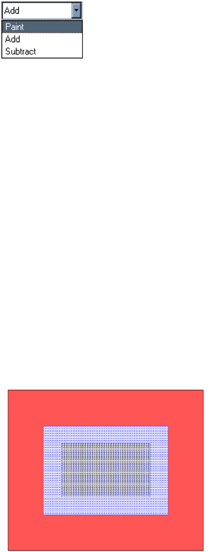
L-Edit 13 User Guide Section 1 108
Chapter 3: Application and Design Setup Layer Setup
Mode
L-Edit objects can be rendered in one of three drawing modes: Paint, Add, or Subtract. These different
modes are used to control how layers are rendered, particularly when they overlap.
The drawing mode applies to fill, or to outline if the layer has no fill. If a layer has fill and outline, the
outline is always rendered in Paint mode, no matter which mode is selected for the fill. Objects that are
selected are always rendered in Paint mode and cannot be set to another mode.
Object colors and patterns are combined as layers are drawn. Overlapping objects produce entirely new
colors and patterns. This mechanism ensures that regions of overlap are displayed in a meaningful way
without obscuring the presence of other objects.
In Paint mode, the color of regions of overlap and all drawn objects is determined by a logical
OVERWRITE operation. The bit values of a layer always overwrite the bit values of the layers drawn
before it (i.e. with equal or lower Pass values). For layers with the same pass value, rendering proceeds
in layer list order.
However, if the Paint background color on previous pass checkbox is enabled, a layer is rendered in
two passes. The first pass clears the layer with a pass value lower than that of the active layer and
replaces it with the background color of the layout window. The second pass then draws the stipple
pattern for the layer as usual. This option is only available to layers with a non-solid fill pattern and a
pass value greater than one.
For example, in the illustration below, both via layers are set to paint the background on previous layer
passes. Layer Via 2 (black stipple pattern C, with a pass value higher than the others) is rendered over
the layer Poly (red, with a pass value lower than Via 2) and Via 1 (blue stipple pattern R, with a pass
value lower than via 2) layers.
In Add mode, the color of regions of overlap is determined by a logical OR between the bits of the color
code for each layer. (This corresponds to the “set” mode in previous versions of L-Edit.)
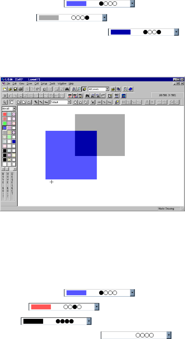
L-Edit 13 User Guide Section 1 109
Chapter 3: Application and Design Setup Layer Setup
The bit values of an Add layer are added to the bit values of those layers drawn before it.
For example, if Metal1 is with a Pass value of 1
and Metal2 is with a Pass value of 2,
their overlapping areas will be rendered as in Add mode, as shown in
the figure below.
The region of Metal1 and Metal2 overlap is shown by a third darker color created by the logical OR
(Add) operation.
In Subtract mode, the color of regions of overlap is determined by a logical AND NOT. The
complement of the bit values of a Subtract layer are subtracted from the bit values of those layers drawn
before it. (This corresponds to the “clear” mode in previous version of L-Edit.)
Note that a subtract layer “clears” colors rendered before it but has no effect on the appearance of
objects on layers rendered after it.
For example, if Metal1 is with a Pass value of 1 and Add mode,
P Select is with a Pass value of 2 and Add mode, and
Via1 is with a Pass value of 2 and Subtract mode, then
objects on Via1 will be rendered as , as shown in the following
illustration.
To define vias that appear transparent, the via layer Pass value must be higher than that of the metal
layers (2 or higher), so that the via layer color operation will affect them, or the via layer should come
after the metal layers in the layer list. The mode should be Subtract and the color 1111 (black). With a
color bit code of 1111, subtract mode yields the logical operation AND NOT of 1111—or the logical
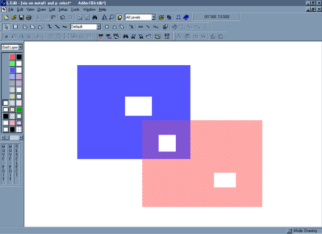
L-Edit 13 User Guide Section 1 110
Chapter 3: Application and Design Setup Layer Setup
AND of 0000, the complement of 1111. The logical AND of 0000 and any other color will be 0000, so
the drawn color will always be 0000.
A box on Via1 layer has the same color everywhere it overlaps other layers, because its bits are
subtracting all previously rendered bits.
Pass
Each layer is rendered in one pass. The order in which layers are rendered is determined first by position
in the layer list and then by the pass value. Lower pass values are rendered first, with possible values
ranging from one to ten.
You can set your rendering passes so that objects will be drawn in a way that parallels the
manufacturing processes or simply to control rendering of overlaps. However, a layer that is derived
from other layers must be below all its source layers in the layer list.
For layers with both fill and an outline, fill is rendered first, then the outline, and both will be completed
before the fill for the next layer is started. Selection is always rendered with the last pass (10).
Note that for rendering, pass order will take precedence over layer order in the Layers list.
Pattern
To change the stipple pattern, select one of the predefined patterns from the drop-down list. None fills
in none of the pixel elements used to create a pattern—a None pattern for fill yields no fill, a None
pattern for outline yields no outline. A Solid fills in all pixel elements.
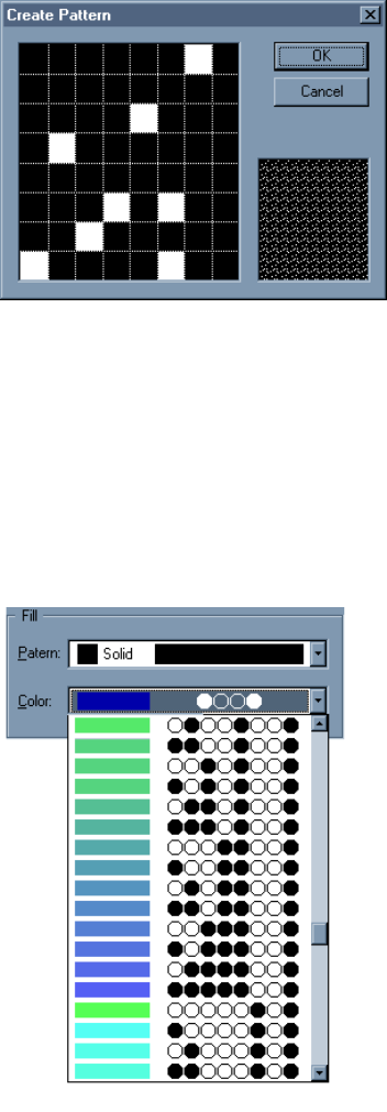
L-Edit 13 User Guide Section 1 111
Chapter 3: Application and Design Setup Layer Setup
You can also pick Other to open the Create Pattern dialog, where you can design a new pattern.
New patterns are added to the bottom of the drop-down list with the label “custom.”
Color
To set rendering color, click one of the bars or bit codes in the drop-down list.
The number of colors available and how they are sorted is controlled in the Setup Colors dialog. (See
Color Parameters on page 79 for more information.)
To outline an object when it is selected, click on the “Selected...” element name in the list, define an
outline style, and set the fill pattern to None.
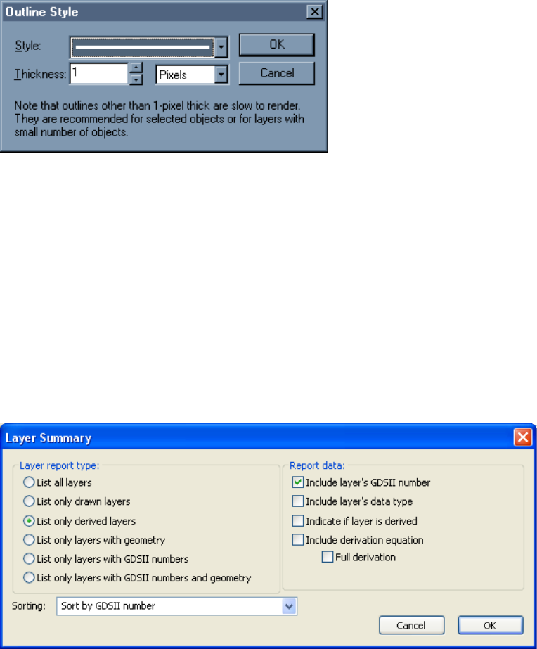
L-Edit 13 User Guide Section 1 112
Chapter 3: Application and Design Setup Layer Setup
Outline Style
You can set both a line style and width for outlines. Line width can be measured in either pixels or
display units.
For curved geometry, outline thickness is displayed at a fixed value of 1 pixel.
Note that boxes and rectangular polygons are rendered so that all edges include the snap grid pixels.
When two such drawn objects coincide, they will therefore overlap by a width of one pixel. Such an
overlap will be rendered in a distinct color, creating a visible line, unless you use a layer setup where the
outline is the same color as the fill.
Listing GDS Information for Layers in a File
Use File > Layer Summary to generate reports on the layers in a design. You can specify the layer types
to list, the sort order and the level of detail to include (GDSII number, data type, derivation equation,
etc.)
Deleting Multiple Layers
Setup > Delete Layers… allows you to delete multiple layers even if they have geometry on them or
they are locked. The layer list is sorted with drawn layers first, then derived layers, then external layers,
and then special layers. Layer are subsorted alphabetically within each group.
When a layer cannot be deleted it will appear grayed out. When you set your options so a layer with
geometry, a locked layer or a locked layer with geometry can be deleted, it is shown in a darker version
of its normal display color:
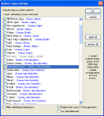
L-Edit 13 User Guide Section 1 113
Chapter 3: Application and Design Setup Special Layers
Drawn—black/dark green if locked
Derived—red/dark red if locked
External—green/dark green if locked
Special—magenta/dark magenta if locked
Special Layers
Special layers are used to represent L-Edit layout elements such as the display grid, origin, drag boxes,
and so on. They are treated just like other layers—you define them using Setup > Layers, draw objects
on them, and can specify design rules for them. In fact, they may be identical to layers used for other
Mark All Checks all the layers in the dialog.
Unmark All Removes the check from all layers in the dialog.
Allow deleting locked
layers When this option is checked it is possible to check and delete a layer
even though it is locked.
Delete layer even if it has
geometry When this option is checked, it is possible to check and delete a layer
even though it contains geometry.
Sort alphabetically Sorts the layers alphabetically rather than by status.
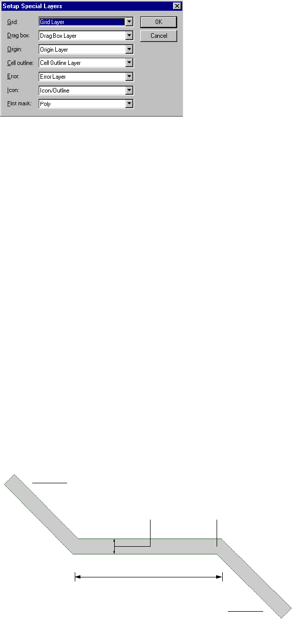
L-Edit 13 User Guide Section 1 114
Chapter 3: Application and Design Setup Wire Styles
purposes (for example, Poly can be designated as the Grid layer). Choose Setup > Special Layers to
designate special layers. Select an appropriate layer from the drop-down menu next to each field.
Options include:
Wire Styles
An L-Edit wire consists of one or more rectangular segments joined at common ends. All segments in
the wire have the same width, but each segment can have a different length. The point where two
segments meet is called a join. The endpoints of a wire are the two segment ends which are not involved
in joins.
Grid The layer on which the displayed grid points are drawn.
Drag box The layer on which the boxes displayed during a drag operation are
drawn and on which the nibbling wire is drawn.
Origin The layer on which the crosshair marker representing the coordinate
system origin is drawn.
Cell outline The layer on which instanced cell outlines are drawn.
Error The layer on which DRC and SPR error markers are drawn.
Icon The layer on which non-fabricating comment items are drawn.
First mask The layer on which the first fabrication mask is drawn.
Endpoint
Join
Length
Width
Endpoint
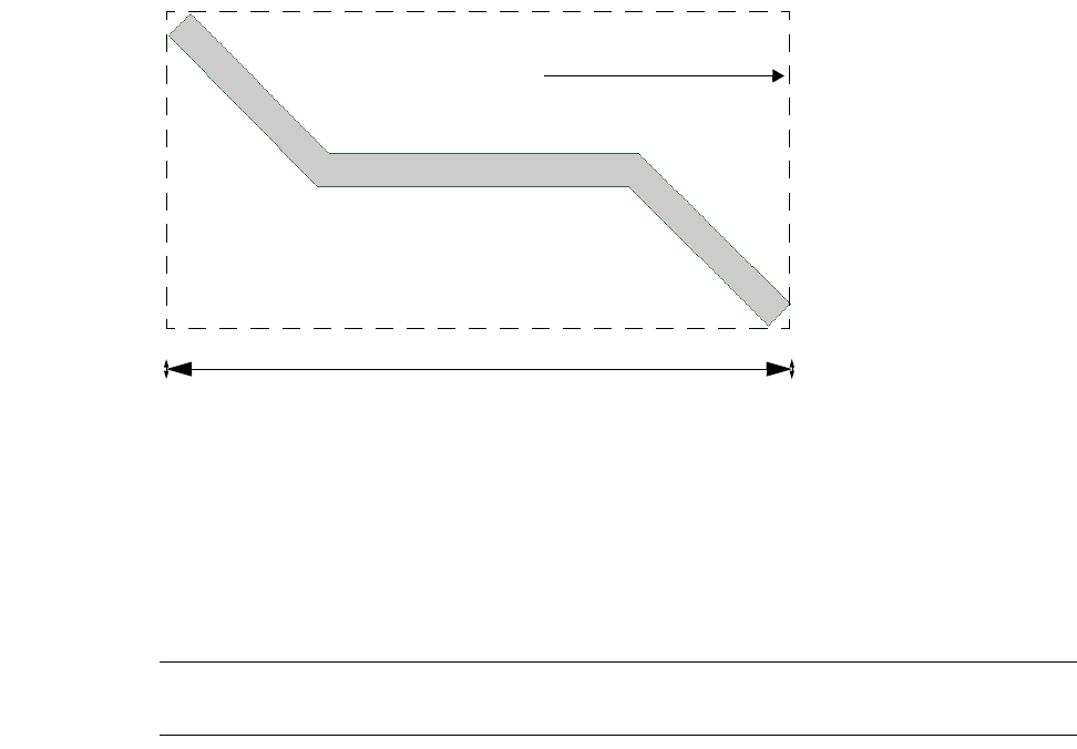
L-Edit 13 User Guide Section 1 115
Chapter 3: Application and Design Setup Wire Styles
A wire is characterized by a style, consisting of three properties:
Width (in display units—different from the “width” reported in the status bar when a wire is
selected).
End style (the appearance of the wire’s endpoints).
Join style (the appearance of the wire’s joins).
When you select a wire, the width value reported in the status bar is the x-width of the minimum
bounding box of the whole wire, as shown here:
End Styles and Join Styles
L-Edit recognizes three end styles and four join styles. These styles affect the appearance of wires on
the screen only, and changing a wire’s style does not affect its endpoint or vertex coordinates. Contact
your fabricator to determine the actual method of fabricating wires and what end and join styles the
fabricator supports.
Warning: It is critical to verify that your fabricator interprets wires in the same manner as your layout. Otherwise
the actual chip fabricated may be very different from what you wanted.
End styles include:
End styles Description
Butt Flush with the endpoint.
Round “Capped” with a half-circle whose diameter equals the wire width.
Extend Extended past the endpoint for a distance equal to half the wire width.
Width reported in status bar
Minimum bounding box
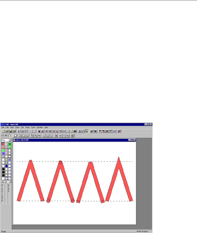
L-Edit 13 User Guide Section 1 116
Chapter 3: Application and Design Setup Wire Styles
Join styles include:
The figure below illustrates various end and join styles.
Wire Style Defaults
When a wire is first created, its style is taken from the default setting for the layer on which the wire is
drawn, specified by choosing Setup > Layers. You may change the wire style parameters in the Default
wire setting area in the Setup Layers dialog.
Before you draw wires for the first time, or if you are setting up technology files for others who may use
wires, set the wire defaults for each layer according to whether your likely output format will be CIF or
GDS II.
Join styles Description
Layout The adjoining segment ends are extended to a distance equal to half
the wire width. The resulting gap is filled with a triangle. This is the
default join style.
This join style corresponds most closely to the interpretation of wires
used by most fabricators. We recommend using this join style
exclusively in your designs. (Wires created in versions of L-Edit
previous to version 5 are automatically converted to the join layout
style.)
Round The adjoining segment ends take on the round style.
Bevel The adjoining segment ends take on the butt style. The resulting gap
is filled with a triangle.
Miter The adjoining segment ends are extended until their outer edges meet.
If the angle between the two segments is less than the user-specified
miter angle, a bevel join is used instead.
Butt ends Round ends Extend ends
Layout join Round join Bevel join Miter join
Butt ends
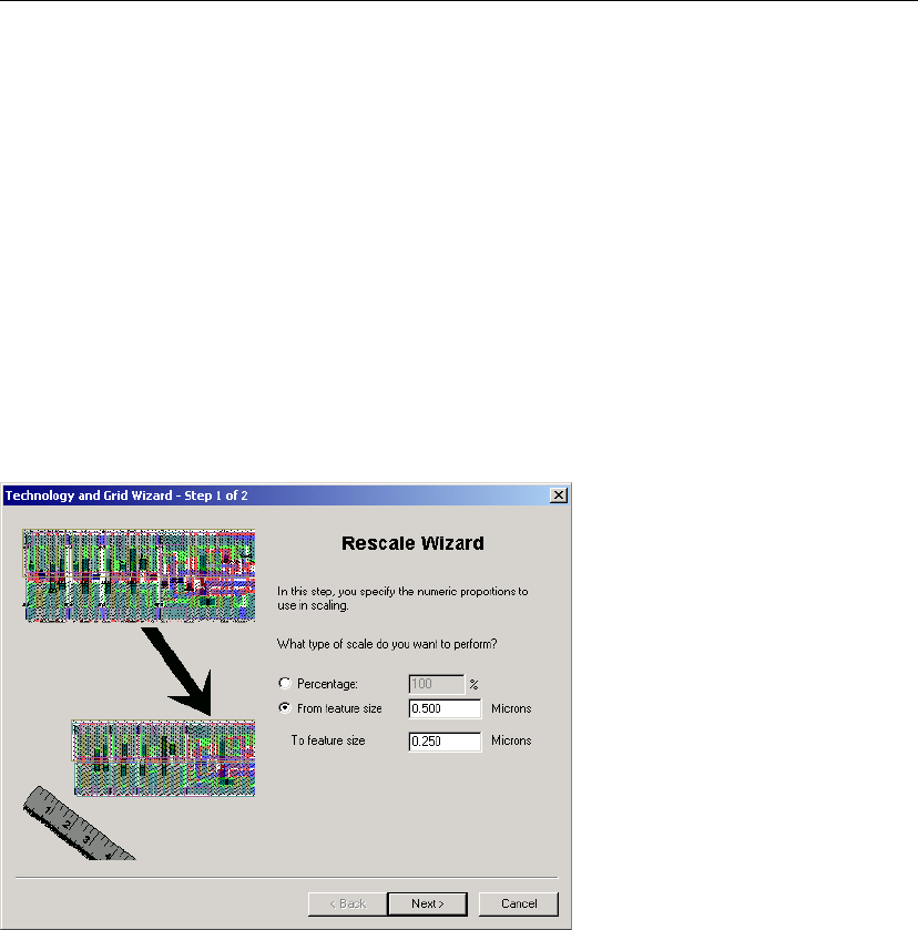
L-Edit 13 User Guide Section 1 117
Chapter 3: Application and Design Setup Rescaling a Design
For CIF, use wires with the extend end style and the layout join style.
For GDSII, allowable combinations of end and join styles are shown in the table below. All other
combinations of end and join styles will produce an error message when exporting to a GDSII file.
After you draw an individual wire you can change its individual style with Edit > Edit Objects.
Rescaling a Design
A design scaling wizard, Setup > Rescale Wizard... is available to assist in rescaling a design, either by
specifying a current and a new feature size, or by specifying a percentage to scale the design. In the first
step of the Rescale Wizard you specify how much you want to rescale the design
In the second step of the Rescale Wizard you specify which quantities you want to rescale. You also
choose the method used to rescale the design. Rescaling by changing the database resolution will
rescale all geometry and settings, with no truncation. Rescaling without changing the database
resolution can cause truncation as geometry coordinates and settings will be multiplied by the ratio of
End style Join style
Butt Layout
Round Round
Extend Layout
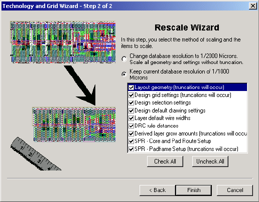
L-Edit 13 User Guide Section 1 118
Chapter 3: Application and Design Setup Rescaling a Design
From feature size/To feature size. Quantities that will be truncated are indicated in the Rescale wizard
dialog.

L-Edit 13 User Guide Section 1 119L-Edit 13 User Guide Section 1 119
4 Viewing the Layout
At times you may want to display only a portion of your design. Hiding various layout elements can be
useful in two ways:
It speeds up screen redraw by reducing the amount of geometry that must be rendered on screen.
It allows you to focus more effectively on the particular geometry you are working with.
This chapter explains how to show and hide layout interface elements, layers, objects, and instance
contents. It also explains how to view different levels of hierarchy and zoom and pan in the design. All
commands apply to all cells in the active file.
Displaying Layout Interface Elements
Use View > Display to turn the display on and off for each layout interface element. A check mark next
to the item indicates the item is on (displayed).
Icon Turns the visibility of lower-level geometry on and off when
View > Insides > Toggle Insides is off. (See “Instance Insides” on
page 126.) When Icon is on, L-Edit displays objects that reside on the
Icon layer within an instance but hides the rest of the instance’s
contents.
Many IC fabricators allow the identification of an Icon layer whose
geometry is ignored during fabrication. To specify exactly one L-Edit
layer as the Icon layer, use Setup > Special Layers (see “Rescaling a
Design” on page 117). Objects on the Icon layer can be used to
annotate an instanced cell or highlight one cell’s relationship to
another.
Arrays Turns the visibility on and off for instance contents in arrays in the
active cell. When on, all arrays are shown in full, with all repeated
instances visible. When off, each array is displayed as an outline in
which only the first instance is rendered.
Ports Turns the visibility on and off for ports within the first level of
hierarchy for all displayed instances. This command does not affect
top-level ports, which are always shown, or ports on hidden layers,
which are never shown.
Major Grid Turns the visibility of the major grid display on and off when the Grid
layer is shown. (For information on showing and hiding layers, see
“Showing and Hiding Layers” on page 122.) The displayed grid is not
visible under all magnifications.
1
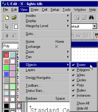
L-Edit 13 User Guide Section 1 120
Chapter 4: Viewing the Layout Showing and Hiding Objects
Showing and Hiding Objects
You can show or hide all objects of a specific type in a design. When you hide objects, L-Edit indicates
the hidden state by shading the object icon on the Drawing toolbar. While objects are hidden, you
cannot draw, select, edit, move, or delete them.
To show and hide objects, you can:
Choose View > Objects
Click an object icon on the Drawing toolbar with the middle mouse button
Right-click on the Drawing toolbar to access a pop-up menu.
Each of these methods is described below.
When you select View > Objects, L-Edit displays the following menu:
A check by each object type indicates the object is currently visible in the design. To make all objects
visible, select Show All. To hide all objects in the design, select Hide All. Pie wedges and tori are
treated as polygons. To show/hide pie wedges and tori, select View > Objects > Polygons.
Minor Grid Turns the visibility of the minor grid display on and off when the
Grid layer is shown. The displayed grid is not visible under all
magnifications.
Origin Turns on and off the visibility of the crosshair marker that indicates
the origin (0,0) when the Origin layer is shown. (For information on
showing and hiding layers, see “Showing and Hiding Layers” on page
122.)
Mouse Hints Turns on and off the visibility of mouse tooltips displayed beneath the
mouse pointer in layout windows. Mouse hints show the operation
associated with each mouse button as vertical text, icons, or both.
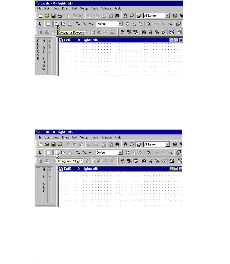
L-Edit 13 User Guide Section 1 121
Chapter 4: Viewing the Layout Showing and Hiding Objects
You can also hide or show objects directly from the Drawing toolbar.
To hide or show all objects of a particular type, position the pointer directly over the desired object icon
in the Drawing toolbar and click the HIDE/SHOW (middle) mouse button.
When all objects are shown, to hide all objects except for a particular object, position the pointer
directly over the desired object icon in the Drawing toolbar and click the H/S ALL (Ctrl+HIDE/SHOW)
mouse button.
Note: When you show or hide any type of polygon or wire, the command operates on all
objects of the specified type—orthogonal, 45°, or all-angle.
Point at an object and click HIDE/SHOW. The object type indicated by the
pointer will be shown (if currently hidden) or hidden (if currently shown).
Point at an object and click H/S ALL (Ctrl + middle-click). All objects except
for the one indicated by the pointer will be hidden. If one or more objects are
hidden, to show all objects, position the pointer over any object icon and click
the H/S ALL mouse button.
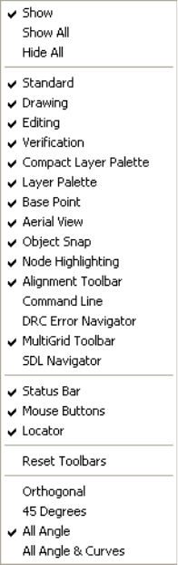
L-Edit 13 User Guide Section 1 122
Chapter 4: Viewing the Layout Showing and Hiding Layers
Finally, you can also show and hide objects via a context-sensitive menu. To access this menu, position
the pointer over any object icon in the Drawing toolbar and click the MENU (right) mouse button.
L-Edit displays the following menu:
The menu is context-sensitive. Show pertains to the specific object icon the pointer is over at the time
you activate the menu. A check mark next to Show indicates that objects of that type are currently
visible in the design; no check mark indicates that objects of that type are hidden.
To make all objects visible, select Show All. To hide all objects except for a particular object type,
position the pointer directly over the desired object and select Hide All.
Showing and Hiding Layers
You can show or hide all objects on a specific layer in a design. You cannot draw, select, edit, move, or
delete objects on a hidden layer. L-Edit indicates a hidden state on the layer palettes, with diagonal
hatching on icons in the Compact Layer palette and gray shading on the layer name in the Layer Palette.
To show and hide layers, you can choose View > Layers, click a layer icon on the one of the layer
palettes, access a context-sensitive menu, or check the Hidden option in the Setup Layers dialog. Each
of these methods is described below.
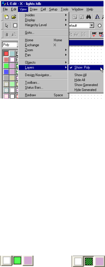
L-Edit 13 User Guide Section 1 123
Chapter 4: Viewing the Layout Showing and Hiding Layers
When you select View > Layers, L-Edit displays the following menu:
Show [Layer name] refers to the active layer (the layer currently selected). A check mark next to Show
[Layer name] indicates that objects on that layer are currently visible in the design; no check mark
indicates the objects on that layer are hidden. Other commands function as follows:
You can also hide or show layers directly from the Compact Layer palette.
To hide or show an individual layer, position the pointer directly over the desired layer icon in the
Compact Layer palette and click the HIDE/SHOW (middle) mouse button. L-Edit will show the layer
indicated by the pointer (if currently hidden) or hide it (if currently shown). The indicator for the hidden
state is diagonal lines through an icon, as shown below.
Show All Makes objects on all layers visible
Hide All Hides objects on all layers except those on the active layer
Show Generated Shows objects on all generated layers. For information on generated
layers, see “Generating Layers” on page 284.
Hide Generated Hides objects on all generated layers except the active layer if the
active layer is a generated layer
Point at a layer in the palette and click the HIDE/SHOW
(middle) button.
All layers showing. Middle layer locked.
Point at a layer in the palette and click the HIDE/SHOW
(middle) button.
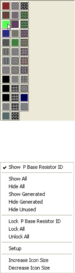
L-Edit 13 User Guide Section 1 124
Chapter 4: Viewing the Layout Showing and Hiding Layers
When all layers are showing, you can hide all but one by clicking the H/S ALL (Ctrl+HIDE/SHOW)
mouse button over the desired layer icon.
You can also show and hide objects via a context-sensitive menu. To access this menu, position the
pointer over any layer icon in the Compact Layer palette and right-click (MOUSE). L-Edit displays the
following context-sensitive menu,
To make objects on all layers visible, select Show All. To hide objects on all layers except those on a
particular layer, position the pointer directly over the desired layer icon in the Compact Layer palette
and select Hide All.
Show Generated shows objects on all generated layers. Hide Generated hides objects on all generated
layers except the layer indicated by the pointer if the indicated layer is a generated layer. (For
information on generated layers, see “Generating Layers” on page 284.)
Click the H/S ALL mouse button
(Ctrl+HIDE/SHOW) over the desired layer icon.
L-Edit will hide all layers except the one
indicated by the pointer.
The layer in Show [Layer name] at the top of the menu
corresponds to the layer icon the pointer was over when the menu
was activated.
A check next to Show [Layer name] indicates objects on that layer
are currently visible in the design; no check indicates the objects on
that layer are hidden.
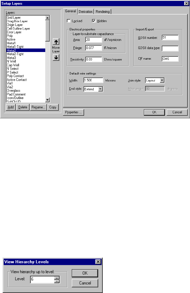
L-Edit 13 User Guide Section 1 125
Chapter 4: Viewing the Layout Viewing Layout Hierarchy
Finally, you can hide or show a layer using the Setup Layers dialog. To access this dialog, choose
Setup > Layers, double-click an icon in the Compact Layer palette or use the context-sensitive menus
in the Layer palette.
Place a check in the Hidden check box and click OK. For more information on the Setup Layers dialog,
see “Layer Setup” on page 104.
Viewing Layout Hierarchy
To clarify different parts of your design, you can show and hide different levels of hierarchy. Select one
of the following commands:
View > Hierarchy Level > Show one more level
View > Hierarchy Level > Show one less level
To display a specific number of levels, select View > Hierarchy Level > View hierarchy level. L-Edit
displays the View Hierarchy Levels dialog.
The view level is relative to the top level of the cell. If you specify zero or a number higher than the
number of levels that exist in the design, L-Edit displays all hierarchy levels.
You can also select the number of levels to show from the drop-down list in the Standard toolbar,
illustrated below. However you set the view hierarchy, L-Edit saves the information in the TDB file.
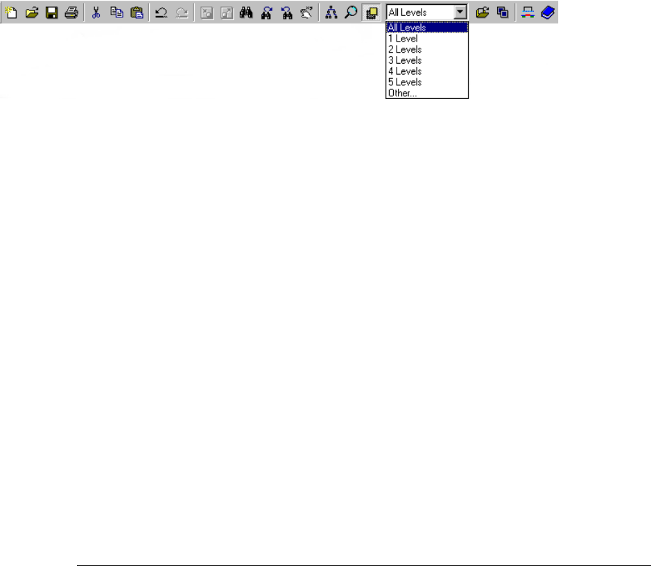
L-Edit 13 User Guide Section 1 126
Chapter 4: Viewing the Layout Viewing Layout Hierarchy
You can also use the Design Navigator (page 209) to display a hierarchical list of all cells in the design,
including information such as whether the cell is locked, which instances it contains, its DRC status,
etc.
Use View > Arrange Design Navigator to quickly arrange all open windows with the Design Navigator
to one side and the layout windows, each the same size, on the other.
Instance Insides
There are two ways to display instances in your design:
Completely, so that you can see all of the objects (the insides) in the instanced cells
As outlines with just the name of the instanced cell. Displaying instances as outlines decreases the
amount of time L-Edit takes to redraw the screen and can help clarify different portions of the
design.
There is a set of View commands that control the visibility of insides in a design for either all instances,
only selected instances, or only leaf-level cells. (A leaf-level cell contains no instanced cells.)
The following table describes these commands.
You can also use Setup > Application—Rendering to set a default pixel size below which instance
insides will be hidden. (See “Rendering” on page 88 for information on this option.)
Command Keyboard Shortcut Description
View > Insides > Toggle
Insides Ctrl+I or Tab Shows or hides the insides of all instances
at all levels of the hierarchy. When insides
are hidden, ports one level down in the
hierarchy remain visible.
View > Insides > Show Cell
Insides SShows the insides of the selected
instance(s).
View>Insides>Hide Cell
Insides DHides the insides of the selected
instance(s).
View>Insides>Show
Leaves Alt+B Shows the insides of all leaf-level cells in
the design.
View>Insides>Hide
Leaves Alt+LHides the insides of all leaf-level cells in
the design.
Click the menu in the Standard toolbar to specify how many levels of hierarchy you want to
display. Selecting Other opens the View Hierarchy Levels dialog.

L-Edit 13 User Guide Section 1 127
Chapter 4: Viewing the Layout Zooming and Panning
Displaying Instance Insides While Drawing and Editing
During drawing operations, the Tab key toggles display of the object being drawn from fill mode, where
objects are rendered completely filled, to outline mode, where objects are rendering with their insides
hidden.
To set outline mode as the default during drawing, uncheck the Fill objects when editing/drawing
checkbox in Setup > Application—Rendering.
After the drawing operation is completed the drawing mode will revert to the default setting.
Similarly, when an instance is being moved, the Tab key acts as a three state button that cycles through
the following display levels:
outline only
outline of the instance and outlines of all first level objects inside the instance
outline of the instance and fills of all first level objects inside the instance, with the exception of
other instances.
Refreshing the Screen
Use View > Redraw or press the Space bar on the keyboard to refresh the screen. L-Edit redraws the
layout in the current view.
Zooming and Panning
You can zoom into or out of the current view to see more or less of the design. You can also move (pan)
around the design to see different portions of it at the current level of magnification. All commands
affect only the active cell.
Zooming
There are four L-Edit commands related to zooming. All of them change the magnification of the
current view and do not affect the position and location of objects in the design. Increasing the
magnification (zooming in) causes the objects to look larger; decreasing the magnification (zooming
out) causes the objects to look smaller. The following table describes each command.
Command Keyboard Shortcut Description
View > Home Home Changes the magnification so that the
view includes all objects in the cell.
View > Zoom > In + Magnifies the view by a factor of two.
View > Zoom > Out – Reduces the magnification of the view by
a factor of two.

L-Edit 13 User Guide Section 1 128
Chapter 4: Viewing the Layout Zooming and Panning
Zooming While Editing In-Place
When you are editing an instance in-place you can zoom to the home view of the cell you are currently
editing or the home view of the top cell in the instance hierarchy. To zoom to the home view of the cell
you are currently editing, use View > Home or press the Home key. To zoom to the home view of the
top cell in the instance hierarchy use Edit > Edit In-Place > View Top Cell or press the End key.
For more information on editing in-place, see “Editing In-Place” on page 288.
Panning
There are nine L-Edit commands related to panning. All of them change the current view and do not
affect the position and location of objects in the design. The following table describes each command.
View > Zoom > Zoom By... Alt+Z Zooms in/out by a specific amount. The
zoom amount is relative zoom factor
change. Values less than 1, zoom in, while
values greater than 1, zoom out. For
example, 2 will zoom out by 2x while 0.5
will zoom in by 2x.
View > Zoom > To
Selections WChanges the magnification so that the
view includes only selected objects in the
cell.
Command Keyboard Shortcut Description
View > Pan > To Selections Y Centers the view over the selected objects.
Depending on the magnification, all selected
objects may not be visible in the resulting
view.
View>Pan>Left ←Moves the view to the left by one-quarter of
its width.
View>Pan>Right →Moves the view to the right by one-quarter
of its width
View>Pan>Up ↑Moves the view up by one-quarter of its
height.
View>Pan>Down ↓Moves the view down by one quarter of its
height.
View > Pan > Pan By... Alt+F 0 > Right Up < 0 Down Left DX DY space
comma or tab delimited.
View > Pan > Object
Pan > Left JPans to the left side of an object. For wires, it
pans to the leftmost endpoint. For boxes and
polygons, it pans to the center of the left size
of the object’s minimum bounding box
(MBB).
Command Keyboard Shortcut Description
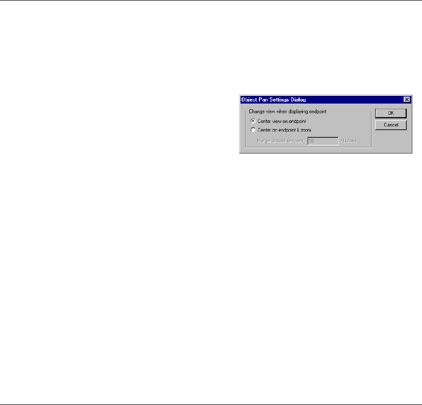
L-Edit 13 User Guide Section 1 129
Chapter 4: Viewing the Layout Zooming and Panning
View > Pan > To Cell Edge shifts the view so that the edge of the view is flush with the edge of the
contents of the cell.
View > Pan > Object
Pan > Right KPans to the right side of an object. For wires,
it pans to the rightmost endpoint. For boxes
and polygons, it pans to the center of the
right size of the object’s minimum bounding
box (MBB).
View > Pan > Object
Pan > Settings... Displays the Object Pan Settings dialog.
Center view on endpoint - Centers the
display on the object’s endpoint, without
changing the zoom level.
Center on endpoint and zoom -
Centers the display on the object’s
endpoint and zooms in or out until the
object’s endpoint and a specified margin
(see below) fill the active window.
Margin around endpoint - Sets the
margin, in display units, to be displayed
around the object’s endpoint when
automatic zoom is active.
Command Keyboard Shortcut Description
View>Pan>To Cell
Edge > Left Shift + ←Shifts the view so that the left edge of the
view is flush with the left edge of the
contents of the cell.
View>Pan>To Cell
Edge > Right Shift + →Shifts the view so that the right edge of the
view is flush with the right edge of the
contents of the cell.
View>Pan>To Cell
Edge > Up Shift + ↑Shifts the view so that the top edge of the
view is flush with the top edge of the
contents of the cell.
View>Pan>To Cell
Edge > Down Shift + ↓Shifts the view so that the bottom edge of the
view is flush with the bottom edge of the
contents of the cell.
Command Keyboard Shortcut Description

L-Edit 13 User Guide Section 1 130
Chapter 4: Viewing the Layout Zooming and Panning
Zooming and Panning with the Mouse
Use View > Zoom > Mouse, click the mouse zoom button ( ), or press Z to change the functions of
the mouse buttons for a single operation. The three buttons become ZOOM BOX (left), PAN (middle),
and ZOOM OUT (right). The following table describes each button function.
After a mouse-controlled viewing operation, the mouse buttons revert to their previous functions.
Mouse Wheel Functions
The mouse wheel works to scroll up and down through any layout, cross section, text or navigator
window in L-Edit if no keys are used.
In a layout window, CTRL + mouse wheel zooms the window in or out with the cursor location as the
center, and SHIFT + mouse wheel scrolls the window left or right.
In a cross section window, the mouse wheel will step up or down through process layers.
In a non-window area (title bars, toolbars, etc.) the mouse wheel will scroll through all open document
windows and CTRL + mouse wheel will scroll through only the windows in the active file.
Auto-Panning
Auto-panning involves using the mouse to continually pan the view. To activate auto-panning, use
Setup > Application—General and check the Auto-panning option. With auto-panning on, when you
draw on object or a selection marquee to the edge of the current view the view automatically pans
beyond the edge.
Button Action
ZOOM BOX Click at a single point to magnify the area around the pointer by a
factor of two.
Click and drag the pointer to specify a rectangular area to which
the view will be zoomed. The height-to-width ratio is maintained
as closely as possible to the original view.
PAN Click to pan the view so that the new center is located at the
pointer’s position.
Click and drag the pointer to pan the view in the direction and
through the distance of the pointer’s motion (when the button is
released).
ZOOM OUT Click to zoom the display window out from the location of the
pointer.
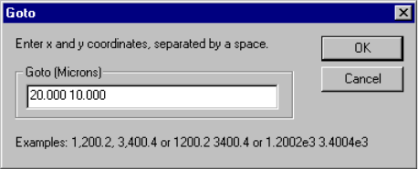
L-Edit 13 User Guide Section 1 131
Chapter 4: Viewing the Layout Zooming and Panning
Moving to Specified Coordinates
Use View > Goto to center the view on specific coordinates in the layout.
The coordinates are in display units, separated by a space or a comma, and are relative to the origin.
Coordinates can be typed or copy-pasted into the field. (For information on how to set the mouse snap
grid see “Grid Parameters” on page 97.)
Exchanging Views
Use View > Exchange or press X to return to the previous view after you execute any zoom or pan
command. You can use this command to go back and forth between two views.
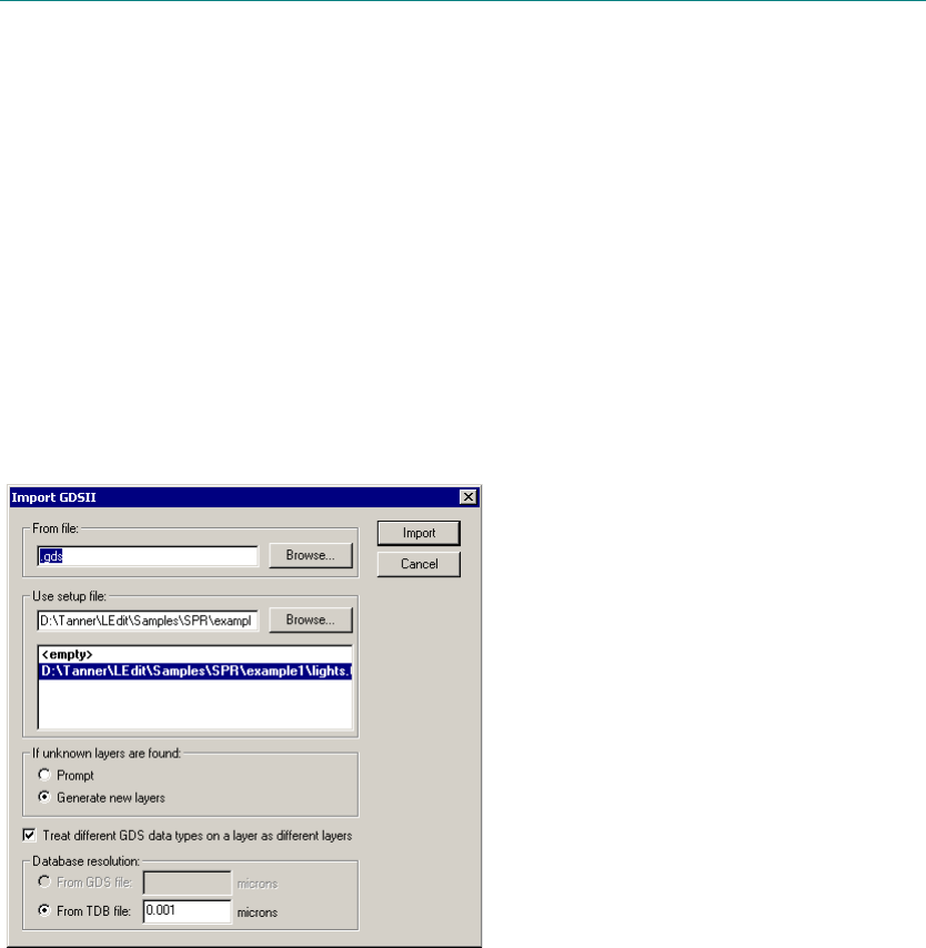
L-Edit 13 User Guide Section 1 132
Chapter 5: Importing and Exporting Files
L-Edit 13 User Guide 132
5 Importing and Exporting Files
Importing Files
You can import GDSII, CIF and DXF format files, as well as the bitmap formats GIF, JPEG, TIFF and
BMP into an L-Edit file. You can also import a Cadence Virtuoso® technology file into L-Edit (see
“Importing a Setup from Virtuoso” on page 77).
Importing GDS Files
Use File > Import Mask Data > GDSII to import GDSII files into L-Edit.
Options include:
From file Name of the file containing the design data to be imported.
Use setup file Specifies a TDB setup file containing the necessary layer setup
information.
If Unknown Layers are
found If GDS layer numbers are found that are not in the setup file then
prompt to ask how to map the layer, or automatically generate new
layers.
Treat different GDS data
types on a layer as
different layers
If this option is checked then layers with the same GDS layer number
but different data types will be placed on different layers. The layers
will have the same GDS number but different names and different
data types. If not checked then layers with the same GDS number but
different data types will be placed on the same layer.
1
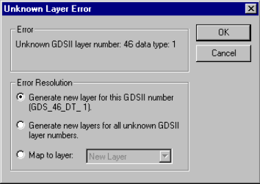
L-Edit 13 User Guide Section 1 133
Chapter 5: Importing and Exporting Files Importing Files
Prompt if unknown layers are found
If you selected to prompt for unknown layers then L-Edit will display the dialog shown below if your
design has a layer for which there is no corresponding layer in the setup file,
Options include:
Creating a new layer for the unknown value
Generating a new layer for all unknown values
Mapping the unknown value to an existing layer
After importing a GDSII file, L-Edit produces a log file summarizing settings, showing status, and
providing detailed warning and error messages.
GDSII Data Type
If the option Treat different GDS data types on a layer as different layers is selected, then:
If an object has a combination of GDSII layer number and data type that corresponds to an existing
layer in the TDB setup file, L-Edit maps the object to that layer.
If a layer does not exist corresponding to the GDS number and data type of the object, or you are
importing into an empty setup, a new layer will be created and the object will be mapped to that
layer.
If this option is not selected then L-Edit will map the object to the first layer with the corresponding
GDS number and will ignore the data type. If a layer with the GDS number does not exist it will be
created.
Database resolution: From
GDS file This field displays the database resolution in the GDS file and may
not be modified. This option may be chosen when importing using an
empty setup file.
Database resolution:
Custom/From TDB file When a TDB setup file is specified, this field displays the resolution
of the setup file which is used for import. When an empty setup file is
specified this field allows you to specify a custom resolution
Import Imports the specified file
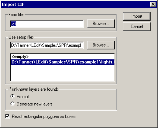
L-Edit 13 User Guide Section 1 134
Chapter 5: Importing and Exporting Files Importing Files
Database Resolution
When importing a GDS file you may specify a file to use as a setup file, or import with an empty setup
file. When importing using a specified setup file, the database resolution used will be the resolution in
the setup file. If the resolution in the setup file is different to the resolution in the GDS file, then the
GDS data is scaled to maintain the physical size of the layout. When importing using an empty setup
file, you have the choice of using the resolution in the GDS file or specifying your own custom
resolution.
XrefCells
During GDSII import, L-Edit will create an XrefCell for each external cell and will attempt to
automatically establish a link by locating the cell using its cell name in each Xref file. The files will be
searched in the order that they are listed in the Setup > Design—Xref files dialog (see “Cross
Reference File Designation” on page 102). Once L-Edit finds a matching cell name, the link is
established and no further searching is done.
If L-Edit does not find the referenced external cell in any of the cross-referenced TDB libraries, it will
create a blank cell and open the Examine XrefCell Links dialog to allow you to redirect the missing cell
definition at the end of the GDSII import operation (see “Examining XrefCells” on page 243).
Importing CIF Files
Use File > Import Mask Data > CIF to import CIF files into L-Edit. Note that to avoid errors, rotated
boxes should be entered as polygons.
From file Name of the file containing the design data to be imported.
Use setup file Specifies a TDB setup file containing the necessary layer setup
information.
If Unknown Layers are
found If CIF layer names are found that are not in the setup file then prompt
to ask how to map the layer, or automatically generate new layers.
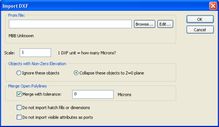
L-Edit 13 User Guide Section 1 135
Chapter 5: Importing and Exporting Files Importing Files
Importing DXF Files
Use File > Import Mask Data > DXF to import DXF files into L-Edit.
L-Edit will attempt to read the specified DXF file into a new L-Edit file. The technology settings for the
new file are taken from the L-Edit file open at the time the import is executed. L-Edit generates a log
file detailing conversion issues.
DXF ARCs are imported as zero-area curved polygons; DXF LINEs and open POLYLINEs are
imported as wires of zero width. If the open POLYLINE has curved segments, the wire will contain a
multi-segment approximation to the curved edge, not exceeding 256 segments.
Read rectangular polygons
as boxes Rectangular polygons in CIF will be converted to boxes in L-Edit if
this option is checked. This option speeds processing, as boxes
consume less memory and are drawn faster than polygons.
Import Imports the specified file
From file Name of the file containing the design data to be imported.
Scale DXF files do not contain explicit scaling information. Thus, you must
specify how many display units each DXF unit corresponds to.
Objects with Non-Zero
Elevation DXF files can contain 3-D data. If Ignore these objects is selected,
only objects with Z=0 coordinates will be read in; this filter is applied
on a vertex-by-vertex basis. If Collapse these objects to Z=0 plane
is selected, the Z value of each vertex is ignored.
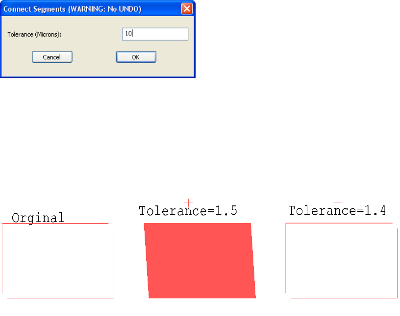
L-Edit 13 User Guide Section 1 136
Chapter 5: Importing and Exporting Files Importing Files
Draw > Convert > Connect Segments
Use this command after a DXF file is imported into L-Edit to fix unresolved polygons.
Geometry in a DXF design that is drawn using polylines is replaced with zero-width wires when
imported to L-Edit. Occasionally, depending upon the original drawing and the merge tolerance setting
during import, some polylines intended to circumscribe a polygon may remain unconnected in L-Edit.
To edit such an anomaly, select the unconnected zero-width wires, making sure the layer on which the
polygon is to be drawn is selected. If the polylines are closer together than the value in the Tolerance
field of Connect Segments, the lines will connect to form a polygon on the selected layer.
Importing Graphics
You can use L-Edit to import a GIF, JPEG, TIFF or BMP format raster graphic into your design file.
L-Edit converts the bitmap into layout geometry by drawing a corresponding box for each pixel in the
image.
Merge Open Polylines DXF objects are sometimes exploded into their constituent segments.
Often, you will want to merge these segments into polygons. When
this option is selected, L-Edit will search for segments having
endpoints within the specified tolerance, and try to build closed paths
of such segments. If a closed path is found, the individual segments
are replaced by a single L-Edit polygon.
Note: The search for possible closed paths is not exhaustive, so
selecting as small a tolerance value as possible is the best
strategy. See “Draw > Convert > Connect Segments” (page
136).
Do not import hatch fills or
dimension When checked, omits hatch fills and dimensions from the information
imported to L-Edit.
Do not import visible
attributes as ports When checked, visible attributes in the DXF file will not be
considered ports in L-Edit.
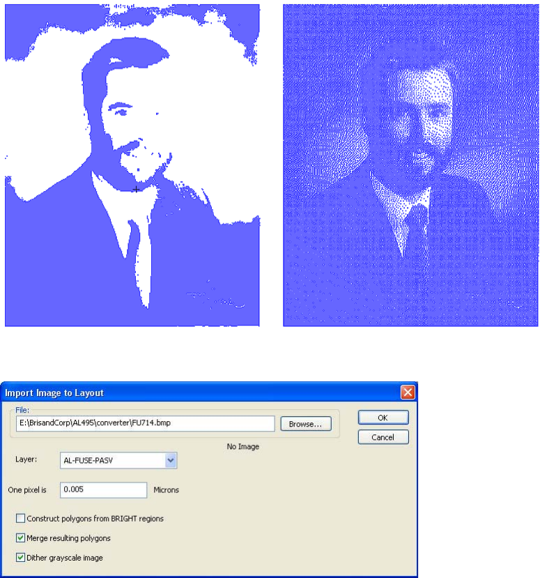
L-Edit 13 User Guide Section 1 137
Chapter 5: Importing and Exporting Files Importing Files
Merging and Dithering Options
Import options include dithering, for photographs or other images with many colors or high resolution,
and merging, which reduces the number of polygons that are drawn, as shown below
Use the menu command Draw > Layout Generators > Import Image to set your import options.
File Name of the file to import. Valid formats are GIF, JPEG, TIFF and
BMP.
Layer Select the layer on which the image geometry will be drawn.
Pixel size L-Edit draws a square corresponding to each pixel of the imported
bitmap. Use this field to enter the dimension of that square. For
example, if the pixel size is set to 1um and the image is 594 pixels
wide, then the resulting layout will be 594um long. This field is
initialized to the manufacturing grid.
Construct Polygons from
BRIGHT regions Creates layout for a negative of the imported image.
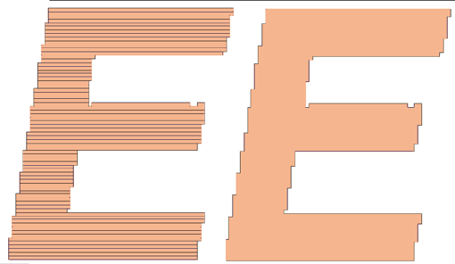
L-Edit 13 User Guide Section 1 138
Chapter 5: Importing and Exporting Files Exporting Files
Exporting Files
You can export GDSII, CIF and DXF format files from an L-Edit file.
Exporting GDS Files
L-Edit accepts and preserves non-standard GDSII numbers when importing and exporting GDSII files.
For further information on assigning and propagating GDSII data types, see “Assigning Data Types” on
page 150.
After exporting a GDSII file, L-Edit produces a log file with detailed warning and error messages.
However, L-Edit does not create backups for GDSII files. If you try to write to an existing GDSII file,
L-Edit will warn that you are about to overwrite a file.
L-Edit assigns a number to each layer in the design in order to conform to GDSII syntax. To modify a
GDSII layer number prior to exporting the file, use Setup > Layers—General. Select a layer in the
Layers list and enter the appropriate value in the GDSII number field.
Merge resulting polygons
(See illustration below.)
With this option on, the resulting layout can be merged into
non-contiguous polygons of any shape (see illustration). Such
merging can take a long time for images with an area larger than 300
x 300 pixels; L-Edit will request confirmation before merging files of
this size and larger.
With this option off (the default), L-Edit will merge contiguous pixels
into rows to reduce file size and processing time. No other geometry
is created.
Dither grayscale image Performs a non-weighted Floyd-Steinberg error diffusion dithering to
the image before converting it to layout.
Merge resulting polygons off
L-Edit merges contiguous
pixels into rows to reduce
file size and processing time.
Merge resulting polygons on
L-Edit merges pixels into larger
polygons of any shape.

L-Edit 13 User Guide Section 1 139
Chapter 5: Importing and Exporting Files Exporting Files
Polygons with Too Many Vertices
GDSII files do not contain curves. L-Edit automatically converts circles, pie wedges, tori and
curved-sided polygons to straight-sided polygons when writing out GDSII. (For information on the
parameters, see “Cross Reference File Designation” on page 102.)
Wires and polygons in a GDSII file cannot contain more than 200 vertices. If your design contains a
wire or polygon with more than 200 vertices, L-Edit will write a warning to the GDS Export log.
To resolve this problem, you can fracture a polygon having a large numbers of vertices into many
polygons with fewer vertices using Draw > Convert > Fracture Polygons. Note that the fracture
operation will not modify wires, circles, pie wedges, or tori. (See “Fracturing Polygons” on page 182.)
Use File > Export Mask Data > GDSII to export GDSII files from L-Edit.
To file Name of the file to which you want to export GDSII.
Log file Enter a file name and directory location for the export log file.
Open in log window When this option is checked, the log file will open in the L-Edit text
editor.
Do not export hidden
objects When this option is checked, L-Edit will not write any objects that are
hidden either by object type or by layer. When this option is off, all
objects will be written to the GDSII file, whether hidden or not.
Overwrite object data type
with layer data type When this box is checked, an object will be written to the GDSII file
with the data type of the layer on which it is drawn. If the layer does
not have a data type, the object retains its data type. For further
information, see “Assigning Data Types” on page 150.
Calculate MOSIS
Checksum Calculate checksum required for submitting GDSII files to MOSIS.
L-Edit 13 User Guide Section 1 140
Chapter 5: Importing and Exporting Files Exporting Files
Exporting CIF Files
L-Edit cannot export layers without legal CIF names. L-Edit does not create backup files for CIF files.
If you try to write to an existing CIF file, L-Edit will warn that you are about to overwrite a file.
Check for self-intersecting
polygons and wires When this box is checked, polygons and wires will be checked for self
intersections, and self intersections will be reported to the GDS export
log. This option can significantly slow down time required for export.
Write XRefCells as links When this option is checked, L-Edit will export XrefCells as cell
references only; their contents will not be included. An XrefCell that
is not instanced will not be written out. When this option is not
checked, L-Edit will write all cell references and their contents to the
GDSII file, whether the cell is an XrefCell or not.
Note: only the cell name is exported, not the contents of the cell. All
cells that are linked must have a local cell name that is the same as
their XrefCell name for GDSII to successfully export when using this
option. If a local cell name is not the same as its external cell name
when the Write XrefCells as links option is on, the GDSII export
operation will report an error and abort.
Fracture polygons with
more than n vertices Polygons with more than n vertices will be split into multiple
polygons with less than or equal to n vertices. Circles, Arcs, and Tori
will also be fractured if their vertex count exceeds n when they are
converted to polygons for GDS export.
GDSII default (1 database
unit = 0.001 microns) When selected, L-Edit converts object dimensions into units of 0.001
micron (the default GDSII database unit) when exporting a GDSII
file. For example, a 10×10 box with 1 internal unit = 1 lambda = 1
micron in the L-Edit layout would be recorded in the GDSII file as
having dimensions of 10,000×10,000 database units.
Custom Check this option and enter a value to convert object dimensions to
database units of other than 0.001 microns, or to user units when
exporting a GDSII file.
Cell names Select Preserve Case to leave the case of cell names unmodified,
Upper Case to convert cell names to upper case or Lower Case to
convert cell names to lower case (note that some GDSII systems do
not recognize lowercase letters).
Restrict cell names Select 32 characters to conform to the GDS standard. Cell names
will be truncated to 32 characters and if needed, modified to avoid
name collisions, in which case a warning will be written to the GDSII
exportlLog. Select 128 characters to conform to Cadence Virtuoso®
GDS import capability, where truncation will occur at 128 characters.
Select Unlimited for no truncation.
Export cell:
All cells Exports all cells to the GDSII file.
Export cell:
Selected cell and its
hierarchy
Exports just the specified cell and all cells instanced in it, and
instantiated in those cells, etc. to the base of the cell's hierarchy.
Export Exports the specified file.
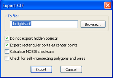
L-Edit 13 User Guide Section 1 141
Chapter 5: Importing and Exporting Files Exporting Files
CIF files support circles, therefore they are not approximated during the export process. Curves,
however, are not supported. If your design contains curves they are automatically approximated during
export. For more information on the related parameters, see “Cross Reference File Designation” on
page 102.
Tanner reads either CIF extensions 85 or 91 to attach the instance name to a cell, but writes 91.
Use File > Export Mask Data > CIF to export CIF files from L-Edit.
To file Name of the file to which you want to export CIF.
Do not export hidden
objects When this option is checked, L-Edit will not write any objects that are
hidden either by object type or by layer. When this option is off, all
objects will be written to the CIF file, whether hidden or not.
Export rectangular ports as
center points L-Edit writes out ports using the .cif extension, where the port’s label
is written along with the location of the port. When this option is
checked L-Edit writes the coordinates of rectangular shaped ports as a
single point at the center. When this option is unchecked, L-Edit
writes rectangular shaped ports using the center/length/width syntax
of CIF boxes. The unchecked option does not conform to standard
CIF syntax. For more information see “Extensions” on page 146.
Calculate MOSIS
Checksum Calculate checksum required for submitting CIF files to MOSIS.
Check for self-intersecting
polygons and wires When this box is checked, polygons and wires will be checked for self
intersections. This option can significantly slow down time required
for export.
Export Exports the specified file
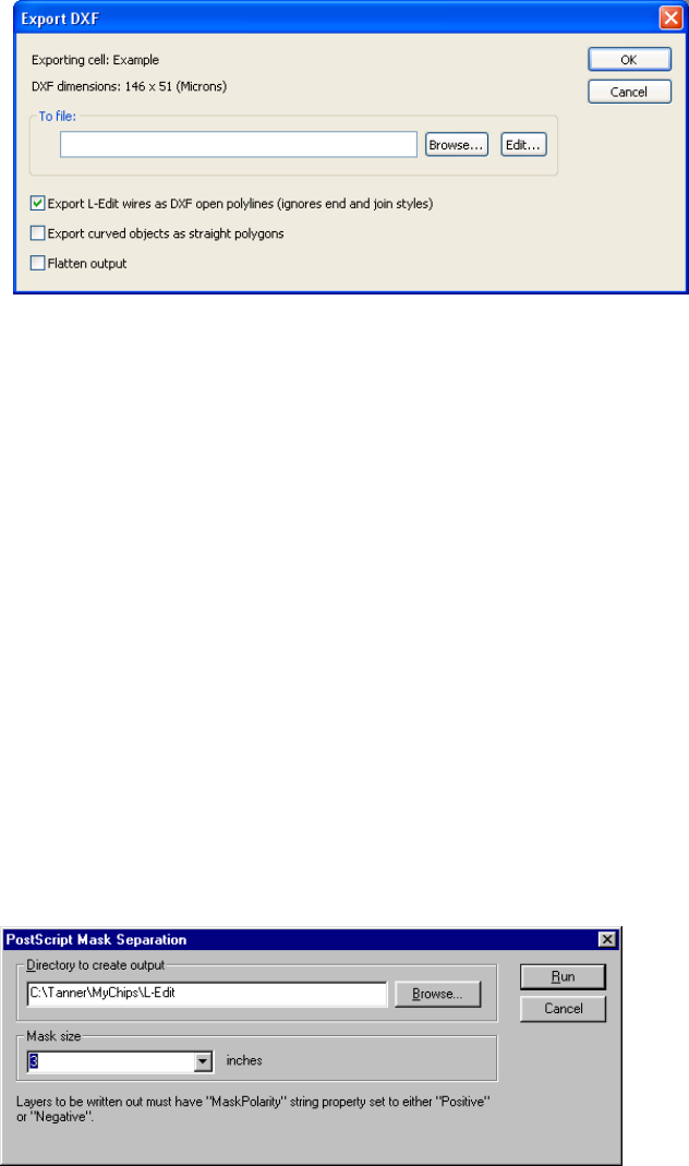
L-Edit 13 User Guide Section 1 142
Chapter 5: Importing and Exporting Files Exporting Files
Exporting DXF Files
L-Edit will attempt to create legal DXF names for cells and layers by replacing illegal characters with
"_". Use File > Export Mask Data > DXF to export DXF files from L-Edit.
Exporting PostScript Masks
The Tools > Add-Ins > PostScript Mask Separation command generates individual PostScript files
from the layout database. The masks are one-to-one scale, and are either positive or negative polarity.
All layers that have a MaskPolarity string property set are written out. If the value of this property is
Negative, a negative mask is written; otherwise, a positive mask is written. The user geometry is
centered on the mask. The mask size, if given, sets the clipping boundary for the generated PostScript.
If not set, the entire page is used (an A4/ 8.5" by 11" page size is assumed).
To file Name of the file to which you want to export DXF.
Export L-Edit wires as DXF
open polylines (ignores
end and join styles)
When this option is checked, all wire is exported as an "open
polyline" (the DXF name for a path), which is simply a series of
vertices and a width. End style and join style information is lost.
Otherwise, the wire is converted to a polygon, and a "closed polyline"
(the DXF name for a polygon) is written out. This shape accurately
reflects the outline of the original L-Edit wire.
Export curved objects as
straight polygons When this option is checked, circles and curved objects will be
exported as polygons, with the vertices of the polygons on the
manufacturing grid. Otherwise, curved objects are exported to DXF
as true circles and curves.
Flatten output When this option is checked, data will be flatten during export to the
DXF file.
L-Edit 13 User Guide Section 1 143
Chapter 5: Importing and Exporting Files CIF File Formatting
CIF File Formatting
Caltech Intermediate Form (CIF) is an ASCII file format for the interchange of mask geometry
information among IC designers and foundries. CIF is defined in Introduction to VLSI Systems by Mead
and Conway (Addison-Wesley, 1980). CIF files are typically saved with the .cif extension.
A CIF file may contain a single design or a library of designs. CIF assumes a right-handed geometry,
with the x-axis increasing to the right and the y-axis increasing upward. The basic unit of measurement
is 0.01 micron.
Commands may be used to scale object sizes, use different layers, and change the placement of objects.
Comments may be added to a CIF file by enclosing them in parentheses. All CIF commands and
comments must be terminated with semicolons.
L-Edit reads either CIF extension 85 or 91 to attach instance names to cells, and writes 91.
Symbols
CIF symbols are defined with the DS and DF commands. DS begins a symbol definition:
DS nnn a b;
where nnn is the symbol number and a and b are the (optional) scaling factors. All commands that
follow the DS command and precede the DF command are included in the symbol. CIF symbols are
always given numeric names.
The optional scaling factors a and b are applied to the integer coordinates and distances within a symbol
by multiplying each value by a and then dividing the result by b. Scaling helps to shorten the length of
CIF files by eliminating trailing zeros. By default, coordinates and distances in CIF are specified in
units of 0.01 micron; a = 100 and b = 1 would allow values to be specified in microns instead. The
coordinates (10,6) with a = 100 and b = 1, for example, are equivalent to (1000,600) with a = 1 and b =
1. If a and b are not specified, then they are both assumed to be 1, and all integers are mapped to the
0.01 micron standard.
The DF command ends the last open DS command:
DF; (end of symbol definition);
If no symbol is open when a DF command is encountered, then a warning message is generated.
Symbols may be instanced within other symbols and are functionally equivalent to L-Edit cells.
Calls (Instances)
Once a symbol is defined, it may be instanced with the C (call) command. In addition to instancing the
named symbol, the C command also permits a variety of optional transformations to be applied:
C integer transformation;
where integer is the number of the symbol being called and transformation is an optional
transformation. A transformation may be composed of several translations, mirrors, or rotations.
Combinations of transformation operations are unambiguously applied from left to right as they are
encountered within the command. Great care should be exercised when determining the order of
transformation operations since the commutative property does not hold.

L-Edit 13 User Guide Section 1 144
Chapter 5: Importing and Exporting Files CIF File Formatting
The translation operation specifies a coordinate. The coordinate represents the endpoint of a vector
originating at (0,0). For example:
C 55 T -100,10; (call command with translation);
calls symbol 55 and translates it 100 units in the negative x direction and 10 units in the positive y
direction.
The mirroring operations, MX and MY, correspond to multiplying the x and y coordinates by –1,
respectively. For example:
C 99 MX; (call symbol 99 and flip horizontally);
C 22 MY; (call symbol 22 and flip vertically);
The rotation operation rotates the called symbol in the specified direction. Direction is indicated by a
direction vector: a coordinate whose vector from the origin (0,0) sets the angle to which the symbol’s
x-axis is rotated. Only the direction of the vector is significant; the magnitude is ignored. For example:
C 44 R 0,1; (call command with rotation);
calls symbol 44 and rotates its x-axis by 90°.
Geometric Primitives
CIF provides commands for creating four types of geometric primitives: boxes, polygons, roundflashes
(circles), and wires.
The B (box) command defines a rectangular box of fixed length and width. The center coordinates
locate the box, and a direction vector indicates its orientation. For example:
B 25 60 80,40 -20,20; (box command);
describes a box of length 25 and width 60, with center at (80,40) and direction vector (–20,20). The
length of the box is parallel to the direction vector, and its width is perpendicular to the direction.
The P (polygon) command defines a polygon with a certain number of sides and vertices. P accepts a
path of coordinates and creates the enclosed polygonal region in the order in which the vertices are
specified (the edge connecting the last vertex with the first is implied). For example:
P 0,0 0,40 20,40 20,20 40,20 40,0;
describes an L-shaped polygon with vertices at (0,0), (0,40), (20,40), (20,20), (40,20), and (40,0).
(40,20)
(40,0)
(0,40) (20,40)
(20,20)
(0,0)
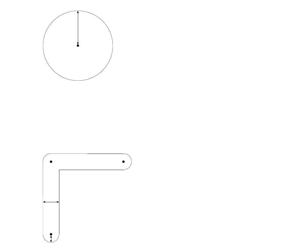
L-Edit 13 User Guide Section 1 145
Chapter 5: Importing and Exporting Files CIF File Formatting
To convert rectangular polygons to boxes when reading CIF into L-Edit, you must check the Read
rectangular polygons as boxes option in the Import CIF dialog.
The R (roundflash) command defines a roundflash (circle) of fixed diameter and position. For example:
R 100 -200,350; (roundflash command);
describes a circle of diameter 100 with center at (–200,350).
The W (wire) command defines a wire with fixed width along a specified path. A wire can be described
as a long run of uniform width; ideally, the locus of points within one-half width of the given centerline
or path and one-half width of the endpoints (semicircular caps). For example:
W 40 0,0 0,100 100,100; (wire command);
describes a wire of width 40 with centerline vertices at (0,0), (0,100), and (100,100).
Layers
All primitive geometry elements must be associated with a particular fabrication mask or technology
layer. Layers are specified with the L (layer) command. Primitives created after an L command belong
to that layer until the layer is reset by the next L command. The form of the L command is:
L shortname; (layer command);
where shortname is the 1–4 character layer name. Layer names must be unique and correspond to
fabrication masks being constructed. You should therefore take care that the layer names you use accord
with the conventions established by your fabricator. The General tab of the Setup Layers dialog
correlates CIF layer names and technology layers; the CIF names are used instead of the L-Edit layer
(–200,350)
50
40
20
(0,100) (100,100)
(0,0)

L-Edit 13 User Guide Section 1 146
Chapter 5: Importing and Exporting Files CIF File Formatting
L-Edit 13 User Guide Section 1 146
Chapter 5: Importing and Exporting Files CIF File Formatting
names during the conversion of the design file into CIF. Layer names that do not conform to legal CIF
syntax must be modified before saving. Layer name specifications are preserved across symbol calls.
Layer names in the setup file must agree with the layer names of CIF files read in; otherwise, the
geometry information on the non-matching layers in the CIF file will be transferred to the Icon layer.
Your fabricator may apply additional restrictions and extensions to the CIF standard.
Fabrication Cell
One piece of information which must be supplied to your fabricator is the name of the cell which
represents the top level of your design. The fabricator will typically choose the top-level cell in your
design, if it is the only such cell. However, if you do not specify this information and your fabricator has
a choice about which cell to fabricate, the wrong one might be chosen.
L-Edit does not accept geometry other than CIF symbols. A CIF call (instance) to the top level of a
design is achieved by choosing Cell > Fabricate. Fabricate causes a CIF C command (or call to the
selected cell) to be created at the top level, effectively identifying that cell as the cell to be fabricated.
L-Edit only allows a single call outside of a symbol definition. If any rotations or transformations are
embedded in this outside call, L-Edit suppresses them when the file is read.
Warning: Once a fabrication cell has been chosen, it will remain the fabrication cell until a new one is chosen,
even if it ceases to be the top-level cell in your design. Be sure to check the fabrication cell before
writing a CIF file!
Restrictions
L-Edit accepts forward references (symbol calls before the symbol definitions they reference), but
removes them during conversion of the design into CIF.
L-Edit does not support the CIF DD (delete symbol definition) command.
Extensions
L-Edit supports two user extensions to the basic CIF syntax. The first extension is a cell name extension
of the form:
9 cellname;
where cellname is the name of the currently open CIF symbol. This command can only appear within
the context of an open symbol (between a DS/DF command pair). The cell name may contain spaces
and must be terminated with a semicolon. Duplicate, zero-length, and null cell names are not permitted.
If a CIF file does not define cell names for CIF symbols, then L-Edit automatically assigns as the cell
name the expression:
(DS nnn)
where nnn is the CIF symbol number. This definition is suppressed when the CIF file is written out.
You should therefore avoid naming cells with this syntax, or else the name will be suppressed during
CIF file conversion. L-Edit reads out-of-order cell numbers, but always orders cells by number while
writing out the design in CIF.
The second user extension is a port extension of the form:
L-Edit 13 User Guide Section 1 147
Chapter 5: Importing and Exporting Files GDSII File Formatting
94 portname width height center_x center_y layer;
where portname is the name of the port (label), x and y are the coordinates of the port, and layer is the
name of the port’s layer. This is a relatively standard port or label user extension to CIF. However, it is
not as flexible as L-Edit’s definition of a port. An L-Edit port can be a point, a line, or a box, and the
text can be rotated in a variety of ways; this CIF user extension can only represent a single point, with
no information on the position or rotation of the associated text. When L-Edit writes a port into a CIF
file, it computes the centerpoint of the port and records this in the CIF file as the position of the port.
You can preserve the box associated with the port in CIF as written by L-Edit by unchecking the Export
rectangular ports as center points option in the dialog. This results in the use of nonstandard notation
for ports, and other software tools may not be able to read this form of CIF.
Wires
CIF was developed at a time when masks were usually created by Gerber photoplotters. Such plotters
could make wires by opening a circular aperture and moving it along a pathway. The resulting wire
would therefore have rounded corners and ends. This fabrication method gave rise to the CIF
specification for rounded wires. However, present-day mask making is almost entirely raster-based, and
thus has a strong affinity toward orthogonal structures.
Many fabricators assume CIF wires to have extended wire end styles with mitered corners. Thus to
adhere to the fabricators’ implementation of wires, all your CIF wires should be of extend end style and
layout join style. Fabricators such as MOSIS and Orbit often run CIF and GDSII files through a
high-end program called CATS, which is used to produce formats for specific mask-making equipment
from both those layout file formats. CATS uses its own clipping algorithm for acute angle CIF wires
and GDSII paths with a pathtype of 0 or 2. This algorithm corresponds exactly with the L-Edit wire
layout join style (the default), which employs a miter length of one-half the width of the wire for wires
with an acute join angle. You should check with your fabricator concerning the exact method of
fabrication used for wires before using wires in your layout.
Scaling
Apart from the user-selectable scaling of L-Edit internal units, L-Edit incorporates an implicit scaling
factor while writing CIF files. Due to the manner in which geometric objects are represented in CIF, it is
necessary for L-Edit to apply an implicit multiplication factor of two to all geometry as it is written out
to CIF. The reason for this scaling is that CIF represents boxes with integer length, width, and center
coordinates. L-Edit, however, can create boxes with fractional center coordinates: a box of width and
length 3 with lower left corner at (0,0) has its center at (1.5,1.5), for example. L-Edit circumvents this
problem by multiplying all coordinates by two when writing a CIF file. The same box, after being
written out to a CIF file, would have a length and width of 6 and be centered at (3,3). L-Edit
incorporates this multiplication by 2 into the scaling factors recorded in the CIF file, so that when the
file is read in by a CIF reader it is scaled correctly.
GDSII File Formatting
GDSII stream format is a binary file format for interchanging mask geometry information between
different IC CAD systems. The L-Edit implementation of GDSII file reading and writing conforms to
the Calma Stream Format, GDSII release 6.0, with some limitations. GDSII files are typically saved
with the .gds extension.
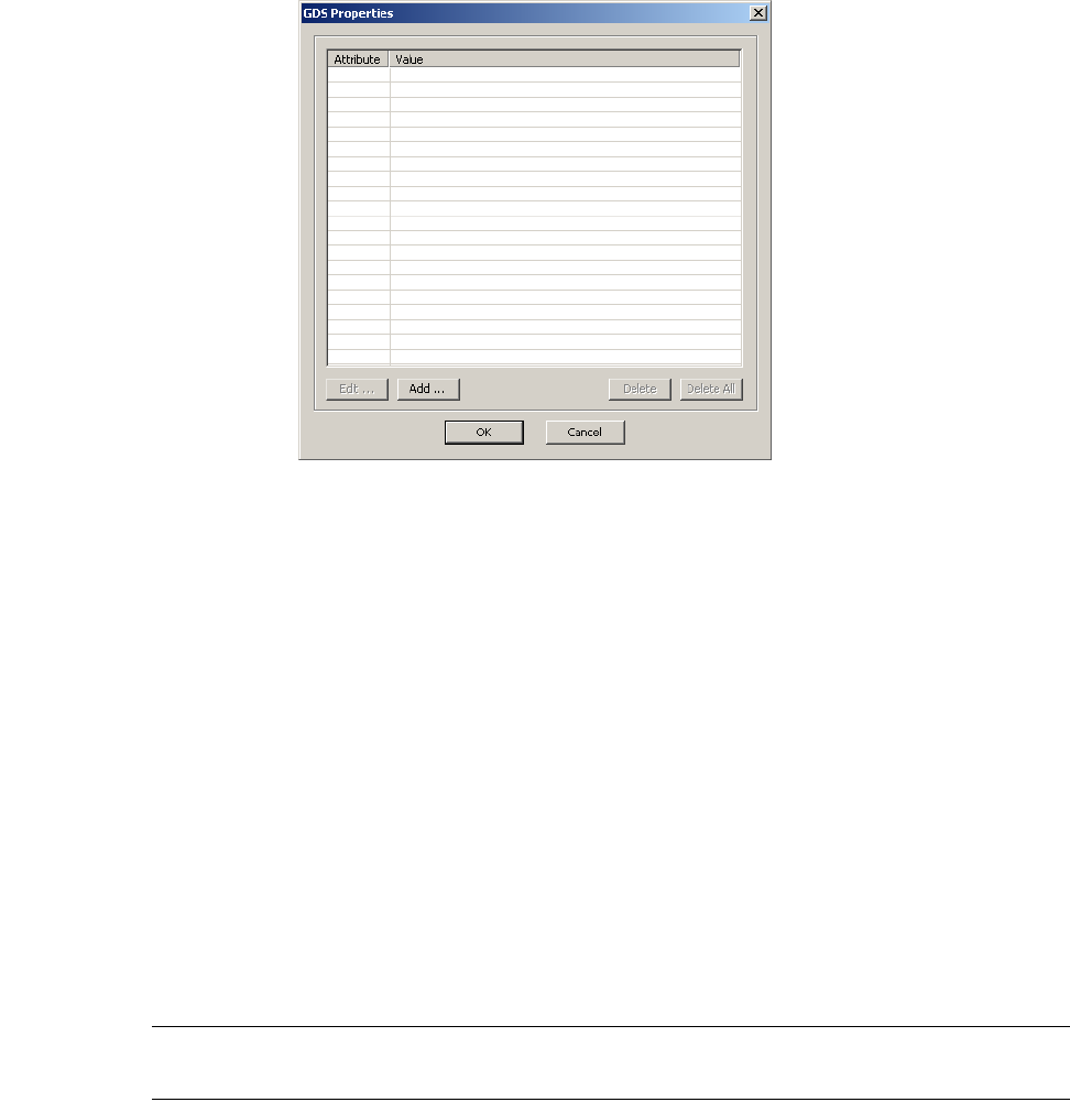
L-Edit 13 User Guide Section 1 148
Chapter 5: Importing and Exporting Files GDSII File Formatting
A GDSII file may contain a single design or a library of designs. GDSII assumes right-handed
geometry, with the x-axis increasing to the right and the y-axis increasing upward. The basic unit is set
to the GDSII default (user unit = 1 micron and 1000 database units per user unit).
Most L-Edit elements have a one-to-one correspondence with elements of GDSII stream files. GDSII
last access time information is not supported by L-Edit. L-Edit circles are approximated by GDSII
polygons. L-Edit cell names may be modified on export to GDSII.
GDSII Properties
The GDSII properties of objects may be examined and edited using the GDS Properties macro. To edit
the properties of an object, first select the object and choose Tools > Add-Ins > GDS Properties, or use
the shortcut Alt+P.
Options include:
GDS properties are supported and transferred for any instance, box, polygon, wire, circles, pie wedge,
and torus.
Circles, pie wedges and tori are automatically converted to polygons when GDS mask data is exported,
using the manufacturing grid. (Refer to “Converting Objects to Polygons” on page 180 and “Snapping
Objects to the Manufacturing Grid” on page 182 for a description of how curves are converted.
Warning: If you plan to export to GDSII format, it is best to “Display curves using manufacturing grid” (page
98) in the layout rather than as smooth curves.
Edit Opens the Edit GDS Property dialog where you can edit the Attribute
and Value of the property.
Add Opens the Add GDS Property dialog where you can enter an
Attribute and Value for a new property.
Delete Deletes the highlighted property.
Delete All Deletes all properties assigned to an object.

L-Edit 13 User Guide Section 1 149
Chapter 5: Importing and Exporting Files GDSII File Formatting
GDSII Naming
The table below shows the correspondence between L-Edit elements and their GDSII names. GDSII
data types for L-Edit boxes, wires, and polygons can be viewed and edited in the Edit Object(s) dialog
with Edit > Edit Object(s).
* L-Edit boxes are written to GDSII files as 4-sided boundaries (polygons). When reading boundaries from a GDSII file, L-Edit
checks each one to see if it is a 4-sided orthogonal polygon, and if so, represents it as an L-Edit box.
** GDSII boxes are not intended to be mask geometry and are generally discarded by mask-making software. If L-Edit
encounters GDSII boxes while reading a GDSII file, a dialog is presented with two options: discard all GDSII boxes or convert
them to L-Edit boxes (mask geometry).
GDSII allows only the following restricted set of characters in cell names. “a” … “z”, “A” … “Z”, “0”
… “9”, underscore “_”, question mark “?”, and dollar sign “$”. L-Edit cell names may include a fuller
set of characters, some of which would be illegal in GDSII. Therefore, L-Edit checks each cell name
before writing it out to a GDSII file. If any spaces “ ” are found, L-Edit replaces them with underscores
“_” in the GDSII file. If any other illegal characters are found, L-Edit will replace them with
underscores and write a message to the GDS log.
Some GDSII systems do not recognize lower case letters in cell names. For interfacing with these
systems, L-Edit provides the capability to write all cell names to a GDSII file in upper case. This option
is enabled by selecting Upper case in the Cell names box in the Export GDS dialog.
GDSII Date Formats
The GDSII format allows for the year to be stored in one of three formats:
current year (e.g. 103 representing the year 2003)
full representation (e.g., 1999)
last two digits of the year (e.g., 32 representing the year 2032 or 1932)
When a year is read from a GDSII file, it may need to be modified to represent the correct year,
depending on which date format is used. The current year format is the default. If the last two digits of
L-Edit GDSII
File Stream file
Cell Definition Structure
Box Boundary *
Box ** Box
Polygon Boundary
Wire Path
Circle Boundary
Instance SRef
Array ARef
Port Text
Data type Data type

L-Edit 13 User Guide Section 1 150
Chapter 5: Importing and Exporting Files GDSII File Formatting
the year is detected during GDSII import, L-Edit will use the algorithm shown below to modify the date
that was read.
for years less than 60, add 2000 to the year
for years greater than or equal to 60 or less than or equal to 1960, add 1900 to the year
for years greater than 60, do not modify the year
This approach will handle all three date formats until the year 2060.
GDSII Shape Definition
Warning: GDSII does not contain a specification for circles. Therefore, L-Edit approximates circles using
64-sided polygons. Thus, circles are not preserved when a GDSII file is written and read back in.
L-Edit supports all-angle rotations of instances and 90° rotations of text.
L-Edit treats four-sided polygons as boxes. If you export, then reimport, a design that contains
four-sided polygons that are orthogonally oriented rectangles, L-Edit will convert them into boxes. For
the purposes of fabrication, there may be no difference between a box and its equivalent polygon.
Many different versions of GDSII readers and writers exist. Some newer versions produce elements
which are not compatible with older versions of GDSII. The elements in L-Edit are confined to
elements which are common to all.
GDSII Data Type
GDSII layers are identified by the GDSII number assigned to that layer or, alternately, by the
combination of the assigned GDSII number and GDSII data type. You can use this data type in
conjunction with the GDSII layer number to overcome the 64-layer limitation in the GDSII database.
The GDSII specification indicates that the GDSII layer number and GDSII data type should have a
range of 0 to 255. However, L-Edit supports non-standard GDSII layer number and GDSII data type
values in the range of -32,768 to 32,767 for compatibility with other tools that are able to output
numbers outside the 0-255 range. L-Edit will write a warning to the log file during import and export
indicating that the GDSII file that was read or written does not adhere to the GDSII Stream
Specification.
Assigning Data Types
Use Setup > Layers—General to assign a data type to a layer, Edit > Edit Object to assign a data type
to an object, or Draw > Assign GDSII Data Types to propagate a layer’s data type value to all objects
on that layer.
When you assign a GDSII data type to a layer, all objects subsequently drawn on that layer will acquire
that data type. If you subsequently change the data type for a layer, however, the new data type will only
be applied to objects drawn after the change.
If you merge intersecting objects with different GDSII data types, L-Edit replaces their respective data
type values with the data type for the layer (or 0 if no data type is set for the layer) without a warning.
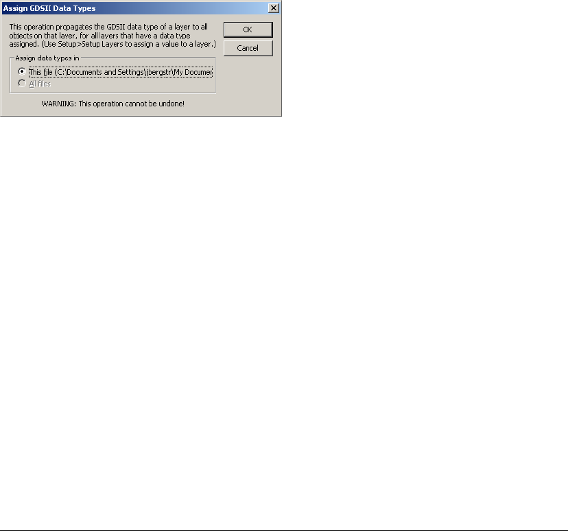
L-Edit 13 User Guide Section 1 151
Chapter 5: Importing and Exporting Files GDSII File Formatting
To propagate a layer’s data type value to all objects currently drawn on that layer, use Draw > Assign
GDSII Data Types, shown below.
This command propagates the data type for a layer to all objects on that layer, overwriting any current
values, for all layers in a design. You can perform this operation for the active file or all open files.
Wires
The GDSII layout format allows for three different types of wires (paths), each with a unique pathtype
value:
pathtype 0: butt ends and square corners (corresponds to L-Edit Round end style with Round join
style)
pathtype 1: round ends and round corners (corresponds to L-Edit Butt end style with Layout join
style)
pathtype 2: extended ends and square corners (corresponds to L-Edit Extend end style with Layout
join style)
These GDSII pathtypes correspond directly to three of the twelve possible L-Edit wires. When reading
GDSII files, L-Edit sets wire end styles and join styles to match the three GDSII pathtypes. When
creating GDSII output, L-Edit assigns a GDSII pathtype according to the following table. When the end
styles and join styles do not correspond exactly to a GDSII pathtype (indcated in the table with an
asterisk), L-Edit will provide a warning message.
End style Join style GDS II pathtype
Butt Layout 0
Butt Miter 0 *
Butt Round 0 *
Butt Bevel 0 *
Round Layout 1 *
Round Miter 1 *
Round Round 1
Round Bevel 1 *
Extend Layout 2
Extend Miter 2 *
Extend Round 2 *
Extend Bevel 2 *
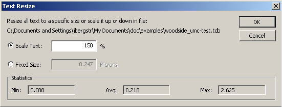
L-Edit 13 User Guide Section 1 152
Chapter 5: Importing and Exporting Files GDSII File Formatting
Many fabricators such as MOSIS and Orbit run GDSII files through CATS (a high-end program used to
produce formats for specific mask-making equipment from GDSII layout files). CATS uses its own
clipping algorithm for acute angle GDSII paths with a pathtype of 0 or 2. This algorithm corresponds
exactly to the L-Edit layout wire join style, the default wire join style. Layout join style employs a fixed
miter length of one-half the width of the wire for wires with an acute join angle.
When you are about to use wires for the first time or you are setting up the technology files for others
who may use wires, take a moment to set up the wire defaults for each layer according to whether your
likely output format will be GDSII. For GDSII, use one of the three legitimate combinations of end
style and join style. It is also strongly recommended that you contact your fabricator before you define
the wire styles for your design to understand how they will interpret GDSII wires.
Ports and Port Text
L-Edit uses the default port text size as a reference during import and export. On export, L-Edit
calculates the ratio between the default text size and a port’s actual text size and writes that value to the
GDSII file. On import, it determines the absolute text size for a given port by multiplying the default
port text size by the magnification factor in the GDSII file.
To change the text size of ports in exported GDSII files, decrease or increase the default port text size
prior to exporting the design, using Setup > Design—Drawing (see “Drawing Parameters” on page
101) or “Resizing Port Text” (page 152), below.
To change the text size of ports in a design imported from GDSII, modify the default port text size in the
setup file before importing the design from GDSII.
Resizing Port Text
The Tools > Add-Ins > Text Resize command works on all ports within the active TDB file to either
scale the text size or set the text size to a specific size.
Options include:
Scale Text Scales port text size. The default value is 50%. Scale values less than
100 decrease the text size; values above 100 increase the text size.
Fixed Size Enter a port text size in locator units. The default value is the default
text size for the active TDB file.
Statistics Displays the minimum, average, and maximum port text sizes used in
the active file.
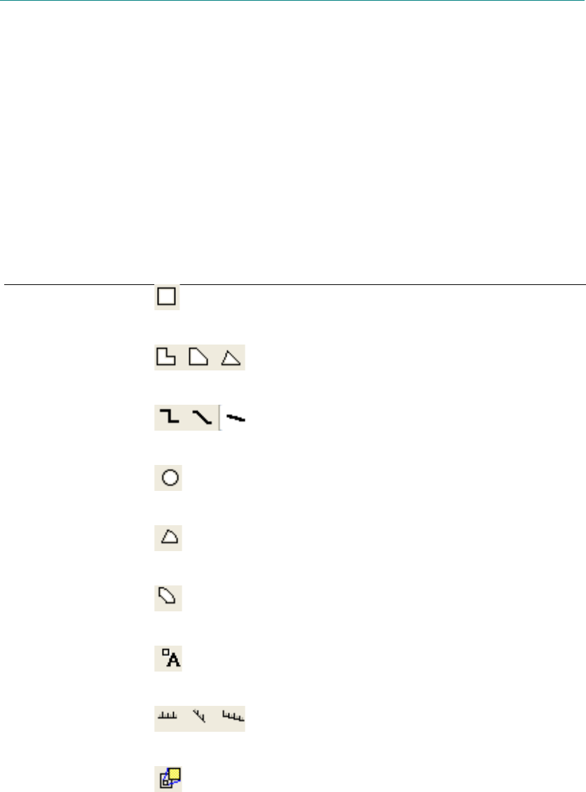
L-Edit 13 User Guide Section 1 154L-Edit 13 User Guide Section 1 154
6 Drawing and Editing Objects
Object Types
The basic task in designing layout is drawing objects, which represent the elements and patterns of the
circuitry to be fabricated.
There are several types of objects you can draw. Each object type is associated with a tool on the
Drawing toolbar which you use to draw the corresponding object.
Object type Icon Description
Box A shape characterized by four 90° corners.
Polygon A shape characterized by an arbitrary number of
vertices connected by straight edges to form a
closed (possibly self-intersecting) figure.
Wire A shape consisting of one or more rectangular
segments, of equal width, joined at common ends.
Circle A shape characterized by a center (point) and a
radius.
Pie Wedge A section of a circle characterized by a center, a
radius, and a sweep angle.
Torus A section of a circle characterized by a center,
two radii (inner and outer), and a sweep angle.
Port A point or box with associated text, used to label
layout for documentation purposes.
Ruler A line with a choice of end styles and optional
tick marks, used to measure layout.
Instance A symbolic representation of a cell at a specific
location and orientation in another cell. For
information on how to create an instance, see
“Creating Instances” on page 283.
1
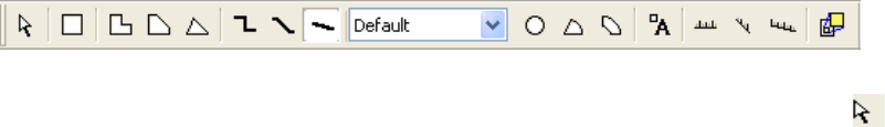
L-Edit 13 User Guide Section 1 155
Chapter 6: Drawing and Editing Objects Selecting a Layer
Selecting a Layer
Before you draw an object, you must select a layer. When a layer is selected, the layer icon in the
Compact Layer palette is outlined, and the name of the layer appears at the top of the Layer Palette. (See
“Layer Palettes” on page 46.) Any objects you create during a draw operation will be on the selected
layer and will display the color and pattern specified for that layer.
You can select a layer in three ways:
Click an icon or pick a layer from the drop-down list in the Compact Layer palette.
Select the desired layer from the list in the Layer palette.
Choose Draw > Pick Layer (shortcut key A) to change the current layer to the layer of the object
which the cursor is over, whether instanced geometry or not and regardless of any object selected.
After you specify a layer, drawing an object involves two basic steps: (1) selecting a drawing tool and
(2) executing a drawing operation.
Selecting a Drawing Tool
To select a drawing tool, click on a button in the Drawing toolbar (see “Drawing Toolbar” on page 43).
You will remain in the same drawing mode until you select another tool. Use the selection tool ( ) to
select objects in the layout.
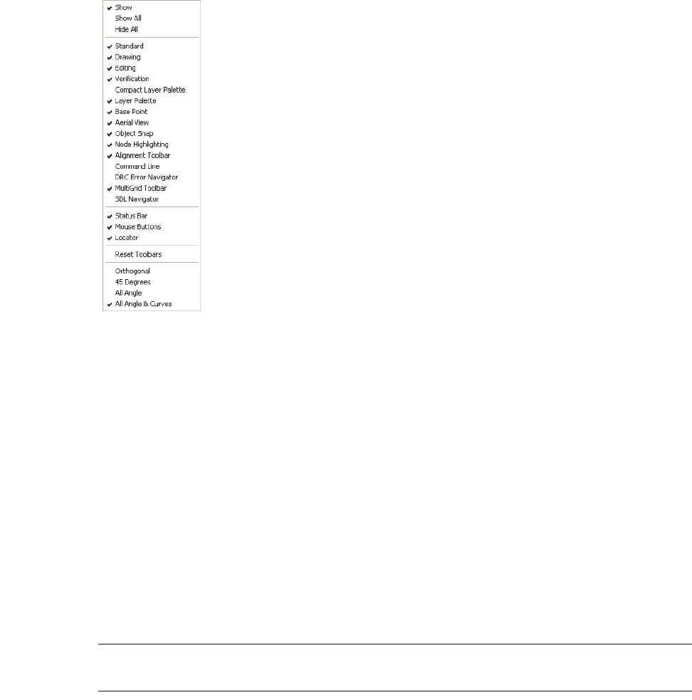
L-Edit 13 User Guide Section 1 156
Chapter 6: Drawing and Editing Objects Drawing Objects
Selecting Angle Constraints for Drawing Tools
You can limit the range of tools displayed in the Drawing toolbar to match your design, either by
right-clicking in the Drawing toolbar, or using the Drawing mode field in Setup > Application—
General to choose Orthogonal, 45 Degrees, All Angle or All Angle & Curves.
Drawing Objects
The starting point for drawing any object is its anchor point. To draw an object, select a drawing tool
and position the crosshair pointer where you want the anchor point to be. Click the DRAW (left) mouse
button to begin drawing the object.
In order to draw circles or other curves, you must set the Drawing toolbar to All Angle & Curves.
While you are drawing or editing an object you can toggle rendering of that object from filled mode to a
transparent outline-only mode so that the objects below remain visible.
Use the Tab key (or Ctrl+I) to perform this toggle. (See “Displaying Instance Insides While Drawing
and Editing” on page 127 for more information.)
Note: You cannot draw on a layer that is currently locked. For further information on
locking and unlocking layers, see “Layer Palettes” on page 46.
Boxes
The anchor point is one of the corners of the box.
Hold the DRAW mouse button and drag the pointer away from the anchor point to determine the
opposite corner (and therefore the length and width) of the box. Release the DRAW button at the
desired opposite corner.
L-Edit 13 User Guide Section 1 157
Chapter 6: Drawing and Editing Objects Drawing Objects
For information on editing boxes textually, see “Boxes” on page 188.
Circles
The anchor point is the center of the circle.
Hold the DRAW mouse button and drag the pointer away from the anchor point to determine the radius
of the circle. Release the DRAW button at the desired radius.
For information on editing circles textually, see “Circles” on page 193.
Pie Wedges
The anchor point is the center of the pie wedge. The mouse buttons become VERTEX, BACKUP, and
END, respectively.
To create a pie wedge, click the VERTEX (left) mouse button at the anchor point and drag the pointer
away from the anchor point to determine the radius of the pie wedge (indicated by a thin line). Click or
release the VERTEX mouse button at the desired radius. Drag the pointer again to determine the end
angle of the pie wedge. The angle is always calculated counterclockwise. Click the VERTEX or END
(right) mouse button to complete the pie wedge. Click the BACKUP mouse button to reverse each step
before the pie wedge is completed.
For information on editing pie wedges textually, see “Pie Wedges” on page 194.
Tori
The anchor point is the center of the torus. The mouse buttons become VERTEX, BACKUP, and END
respectively.
To create a torus, click the VERTEX (left) mouse button at the anchor point and drag the pointer away
from the anchor point to determine the first radius of the torus (indicated by a thin line). Click or release
the VERTEX mouse button at the desired first radius. Drag the pointer again to determine the sweep
angle and the second radius of the torus. Click the VERTEX or END (right) mouse button to complete
the torus. Click the BACKUP mouse button to reverse each step before the torus is completed.
For information on editing tori textually, see “Tori” on page 195.
Polygons and Wires
The anchor point is the first vertex of the polygon or wire. Polygons and wires can have any number of
vertices. The mouse buttons become VERTEX, BACKUP, and END, respectively.
To create a polygon or wire, click the VERTEX (left) mouse button at the anchor point and drag the
pointer away from the anchor point to determine the second vertex. Repeat the process for each
successive vertex. Click the BACKUP mouse button to remove the last vertex that was placed.
Click the END mouse button at the last vertex to complete the object. When you click the END button,
coincident vertices (two or more vertices occupying the same location) and colinear vertices (three or
more vertices lying on the same straight line) are eliminated.
For information on editing polygons and wires textually, see “Polygons” on page 191 and “Wires” on
page 192.
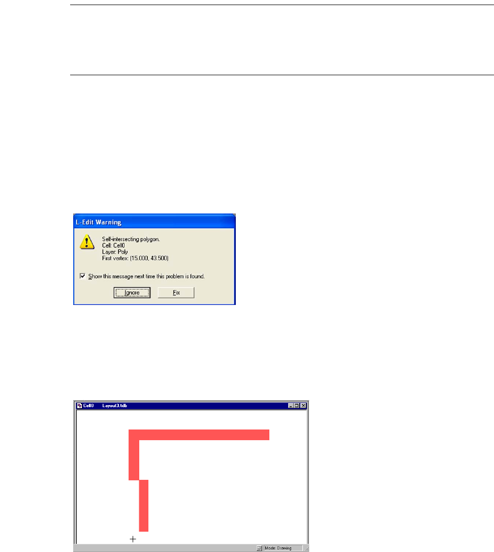
L-Edit 13 User Guide Section 1 158
Chapter 6: Drawing and Editing Objects Drawing Objects
Warning: The appearance of a wire on the screen does not guarantee it will form a connection with an object when
the chip is fabricated. Check with your manufacturer regarding the type of join and end styles to use in
your design. (For information on available styles see “End Styles and Join Styles” on page 115. For
information on wire style requirements for CIF and GDSII file formats see “Wires” on page 147 and
“Wires” on page 151, respectively.)
Self-Intersecting Polygons and Wires
Two common design errors involve self-intersecting polygons and polygons with ambiguous fills.
Either could be misinterpreted by the manufacturer and result in an incorrect object mask.
L-Edit will display a warning when drawing or editing a polygon if the polygon intersects itself at any
point. You have the option to fix the polygon which will break the polygon up into multiple polygons at
its self-intersecting points. A similar warning is displayed for self intersecting wires.
You can turn off these and other warnings with Setup > Application—Warnings.
Self-Intersecting Polygons
An example of a self-intersecting polygon is shown below:
Ambiguous Fill Polygons
Certain types of self intersecting polygons result in an ambiguous definition of the filled area of the
polygon. An example of a polygon with an ambiguous fill is shown in the following illustration.
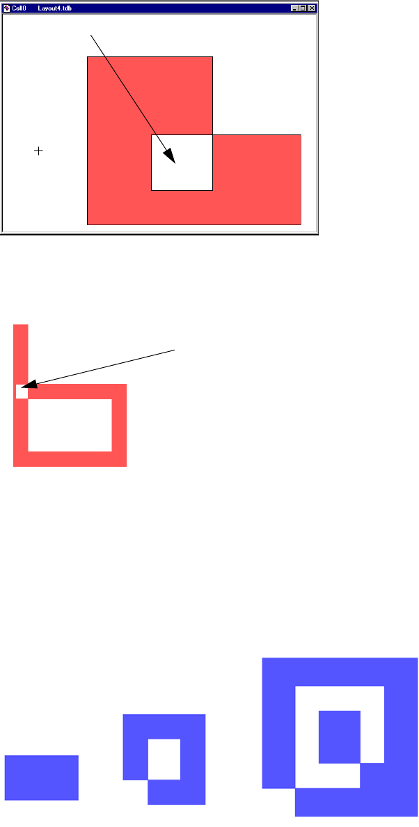
L-Edit 13 User Guide Section 1 159
Chapter 6: Drawing and Editing Objects Drawing Objects
Depending upon the manufacturer’s convention, the white enclosed box might or might not be filled
when fabricated.
Similarly, in the figure below the desired fill in the region of intersection cannot be determined
unambiguously.
Winding Number
The areas of a self intersecting polygon can be classified by a winding number. In the illustration below,
each value represents the winding number—the number of times that a point in the polygon is
circumscribed when the figure is traced in one direction around its perimeter.
ambiguous fill
ambiguous fill
1
0
0
1
2
0
1
2
3
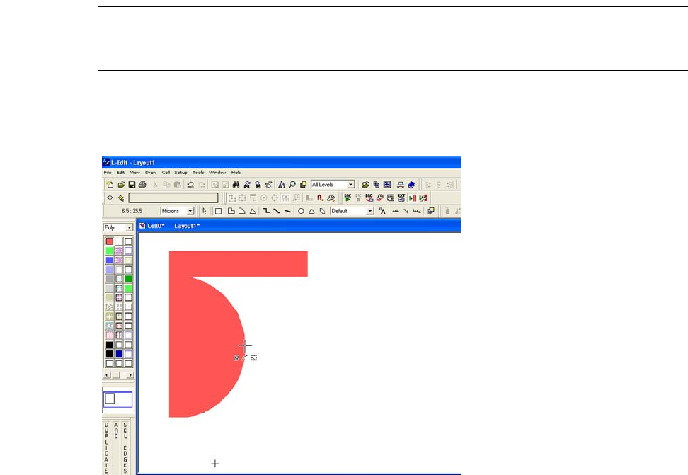
L-Edit 13 User Guide Section 1 160
Chapter 6: Drawing and Editing Objects Drawing Objects
L-Edit interprets an area with winding number equal to zero as unfilled, an area with an odd winding
number as filled, and an area with an even number as unfilled. Polygons with a winding number greater
than or equal to two are identified as ambiguous polygons, since other CAD systems may interpret the
filled area differently.
Curves
Using an all-angle tool and the ARC mouse shortcut, you can convert an edge of an existing orthogonal,
45-degree, or all-angle polygon to a curved edge (the portion of a circular arc with endpoints at the two
vertices of the original edge). Boxes cannot be converted to curves.
This operation is only possible on existing polygons—you cannot directly draw a polygon with curved
edges. (See “Chamfers and Fillets” on page 162 for converting the shape of vertices.)
How to Convert a Straight Polygon Edge to a Curve
;Select the All Angle & Curves display mode.
;Using the SEL EDGES mouse button (Ctrl+LEFT), click to select a single edge of the polygon.
Note: To convert an edge to a curve, you must select only the edge of an object, not the
entire object. If you select the entire object, it is only possible to add a vertex to any of
its edges.
;Using the ARC mouse button (Ctrl+MIDDLE or Alt+Ctrl+LEFT), drag the cursor to increase or decrease
the curvature of the arc.
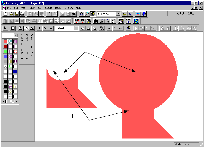
L-Edit 13 User Guide Section 1 161
Chapter 6: Drawing and Editing Objects Drawing Objects
Curve Height
Each curve is defined by a specific curve height, illustrated in the following diagram:
Curve height is the perpendicular distance, in display units, between the chord that connects the two
endpoints of the curve and the midpoint of the curve. The curve height will be positive or negative
depending on the order in which the vertices of the polygon were created.
For more information about setting curve height and editing curves textually, see “Polygons” on page
191.
chord
curve height
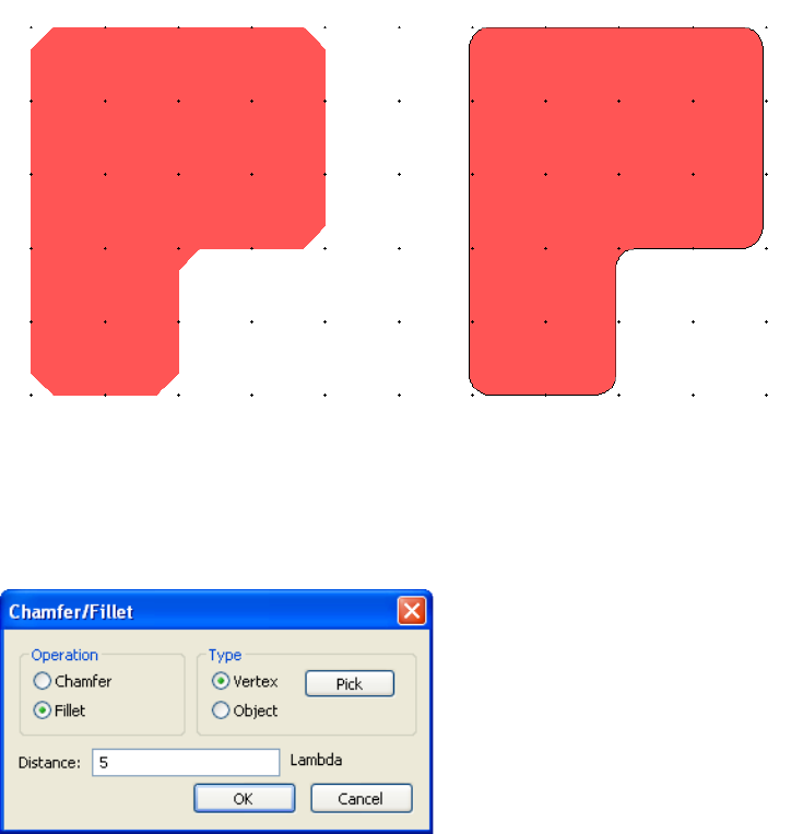
L-Edit 13 User Guide Section 1 162
Chapter 6: Drawing and Editing Objects Drawing Objects
Chamfers and Fillets
A chamfer is a beveled edge connecting two surfaces. If the surfaces are at right angles, the chamfer
will typically be symmetrical at 45 degrees. Similarly, a fillet is a curved connection between two
surfaces, which is concave for an interior corner and convex for an exterior corner as shown below.
First select an object, then use Draw > Curve Tools > Chamfer... or Draw > Curve Tools > Fillet... to
open the Chamfer/Fillet dialog.
Operation Select Chamfer or Fillet.
Type Select Vertex and then use the Pick button choose a single vertex of
the selected object.
Select Object to chamfer or fillet all vertices on the object.
Distance Enter a value (by default, in display units) of the perpendicular
distance between the endpoints of the chamfer or fillet.
(See “How the “Distance” Value Sets the Size of a Chamfer or Fillet,”
below).
Chamfered edges Filleted edges
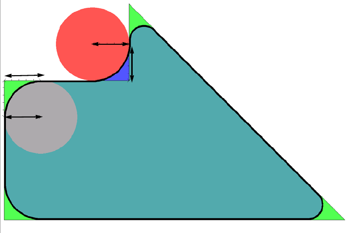
L-Edit 13 User Guide Section 1 163
Chapter 6: Drawing and Editing Objects Drawing Objects
How the “Distance” Value Sets the Size of a Chamfer or Fillet
The radius of a fillet (or the cut of a chamfer) is determined by the intersection, at two points, of the
polygon and a circle established by the Distance value.
On the polygon below, the Distance value along each edge of a vertex (A) intersects with the diameter
of a circle having a radius of the same Distance value (B) to create the fillet radius.
Ports
A port can be a point, a line, or a two-dimensional box.
The anchor point is the location of the port. The anchor point of a point or line port is a corner of the
port.
To draw a point port, position the pointer at the anchor point and press the DRAW mouse button.
To draw a box port, hold the DRAW mouse button and drag the pointer away from the anchor point to
determine the opposite corner (and therefore the length and width) of the box. Release the DRAW
button at the desired location of the opposite corner.
To draw a line port, hold the DRAW mouse button and drag the pointer away from the anchor point in a
vertical or horizontal line. Release the DRAW button at the desired location of the opposite end of the
line port.
When you release the DRAW mouse button, the Edit Object(s)—Ports dialog appears and prompts for
the Port name. At this point you can also modify other attributes of the port, including GDSII data type,
text size, coordinates, text orientation, and text alignment. If you don’t specify a placement
The 45 degree polygon is the initial geometry (bright green).
The curved polygon is the result of the fillet operation (teal green).
The red and gray circles demonstrate how the curve of the fillet is set by the distance
value.
B
B
AA
L-Edit 13 User Guide Section 1 164
Chapter 6: Drawing and Editing Objects Editing Objects
configuration, the text is automatically placed horizontally on the screen at the lower center of the port.
The Port name will be initialized to the last entered text and the last numerical sequence in the text will
be incremented by 1. For example, if you created a port with its Port name equal to
DATA16bit-Line3bc then the next port you create will have its Port name initialized with
DATA16bit-Line4bc.
For more information on editing ports, see “Ports” on page 196.
Rulers
The anchor point is one of the endpoints of the ruler. Hold the DRAW mouse button and drag the
pointer away from the anchor point to determine the other endpoint (and therefore the length and
orientation) of the ruler. Release the DRAW button at the desired endpoint.
You can draw rulers on a dedicated special layer or on any other layer. To modify default ruler settings
including the layer on which rulers are drawn, text size, end style, and tick mark settings, use
Setup > Design—Drawing.
For information on editing rulers, see “Rulers” on page 197.
Editing Objects
You can edit objects graphically, using your keyboard and mouse. You can resize and reshape objects,
perform stretch editing, add vertices to polygons or wires, and slice, merge, or nibble objects.
Drawing in Outline Mode
While you are drawing or editing an object you can toggle rendering of that object from filled mode to a
transparent outline-only mode so that objects below remain visible. Use the Tab key or Ctrl+I to
perform this toggle. (See “Displaying Instance Insides While Drawing and Editing” on page 127 for
more information.)
Resizing and Reshaping
You can resize a box, port, or polygon by moving a vertex or an edge to change the object’s dimensions.
You can resize a circle by dragging its edge towards or away from the center, which changes the radius.
You can resize a wire by selecting a wire edge and dragging it; you can add vertices to a wire by
selecting it and choosing Draw > Add Wire Section. To change the width of a wire, however, you must
use the Edit Object—Wire dialog (see “Editing Objects Using Numerical Values” on page 186).
To resize or reshape an object, position the pointer on or near a vertex or edge. Click the MOVE/EDIT
mouse button and drag the vertex or edge to the desired position.
The distance between the cursor and the edge or vertex of an object determines which operation, MOVE
or EDIT, will be performed. You set this distance using the Edit range fields in the with
Setup > Design—Selection dialog.
For explicit selection, you can set whether an entire edge needs to be enclosed, or just a part of it, using
Setup > Application—Selection
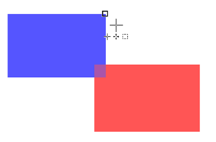
L-Edit 13 User Guide Section 1 165
Chapter 6: Drawing and Editing Objects Editing Objects
If no other objects are selected, clicking the MOVE/EDIT (middle) mouse button within the selection
range of an object will implicitly select it. If you implicitly select an object it is automatically deselected
after the operation. (For more information on selecting objects, see “Selecting Objects” on page 266.)
Pie Wedges and Tori
When you use the mouse to reshape and resize a pie wedge or torus, you can change the sweep angle or
the radii. To change the sweep angle, position the pointer on one straight edge of the selected object,
click the MOVE/EDIT mouse button and drag the mouse in the desired direction. To change the radii,
place the pointer on the curved edge and drag it to the desired position. You can change either radius of
a torus.
Stretch Editing
You can resize or reshape one or more boxes, polygons, wires, pie wedges, tori, or ports simultaneously
by selecting and moving sets of their edges.
Select the edges of the desired objects. (For information on how to select an object’s edge see “Edge
Selection” on page 268.) To modify the selected objects, drag the edges in the desired direction with the
MOVE/EDIT mouse button. All selected edges and objects will move the same direction and distance,
subject to any constraints imposed by the objects themselves. Holding the Shift key after starting a
MOVE/EDIT mouse button forces the operation to be orthogonal, where edges can only be moved in
the horizontal or vertical directions.
Object Snapping
During drawing or editing, you can snap the mouse to vertices, edges, and midpoints of objects. This is
called Object Snapping. L-Edit will snap to locations down the hierarchy on unmerged geometry.
L-Edit will not snap to hidden geometry such as a hidden layer or an instance with its inside hidden.
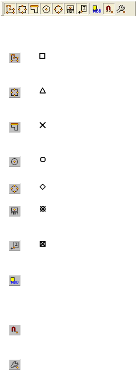
L-Edit 13 User Guide Section 1 166
Chapter 6: Drawing and Editing Objects Editing Objects
Object Snap Toolbar
Object snaps can be enabled or disabled with the Object Snap toolbar or with hotkeys.
Toolbar
button Marker
Symbol Description
Vertex snapping - Snaps the mouse to vertices of boxes, polygons,
wire centerlines, pie wedges, tori, and port boxes. During a drawing
or editing command, this snap mode can be toggle by pressing
Shift+V.
Midpoint snapping - Snaps the mouse to the midpoint of edges of
boxes, polygons, wire centerlines, pie wedges, tori, and port boxes.
During a drawing or editing command, this snap mode can be toggle
by pressing Shift+D.
Edge snapping - Snaps the mouse to nearest point on the edge of
boxes, polygons, wire centerlines, pie wedges, tori, and port boxes.
During a drawing or editing command, this snap mode can be toggle
by pressing Shift+E.
Center snapping - Snaps the mouse to the center of circles, boxes,
pie wedges, tori, and curved edges of polygons. During a drawing or
editing command, this snap mode can be toggle by pressing Shift+C.
Quadrant snapping - Snaps the mouse to nearest quadrant on a
curved edge of circles, pie wedges, tori, and curved polygons.
Pin snapping - Snaps the mouse to nearest point on the edge of
boxes, polygons, wire centerlines, pie wedges, tori, and port boxes.
During a drawing or editing command, this snap mode can be toggle
by pressing Shift+T.
Instance snapping - Snaps the mouse to nearest point on the edge of
boxes, polygons, wire centerlines, pie wedges, tori, and port boxes.
During a drawing or editing command, this snap mode can be toggle
by pressing Shift+S.
Switch between Instance MBB or Abut MBB - When snapping to
instances, you can toggle between using the instance’s minimum
bounding box (MBB of all objects in the cell of the instance) or the
instance’s abutment bounding box (MBB of all objects in the cell of
the instance on the Icon/Outline special layer). The abutment
bounding box is useful when snapping to overlap markers in cells.
Enable Object Snapping - Enables or disables object snapping.
When disabled no object snapping while occur regardless if the
individual snaps are turned on. During a drawing or editing command,
this snap mode can be toggle by pressing Alt+S or F9.
Setup Object Snapping - Shows the Object Snap tab of Setup
Design so you can change object snapping options. (See “Object
Snapping Options,” below.)
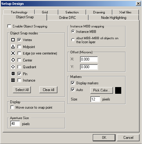
L-Edit 13 User Guide Section 1 167
Chapter 6: Drawing and Editing Objects Editing Objects
Object Snapping Options
Object snap options are set in the Setup Design—Object Snap dialog.
Enable Object Snapping Enables or disables object snapping. When disabled no object
snapping while occur regardless if the individual snaps are turned on.
Vertex See Vertex Snapping on page 166.
Midpoint See Midpoint Snapping on page 166.
Edge (or wire centerline) See Edge Snapping on page 166.
Center See Center Snapping on page 166.
Quadrant See Quadrant Snapping on page 166.
Pin See Pin Snapping on page 166.
Instance See Instance Snapping on page 166.
Move cursor to snap point When this option is enabled, the mouse cursor will move to or snap to
the snap location if the cursor moves within an area the size of the
marker for that snap location.
Aperture Size Aperture Size is the area of influence of a snap location. When you
move the mouse cursor within an area the size of the aperture, the
cursor will snap to that location. Increasing the Aperture Size will
will allow you to be further away from the snap location to snap to it.
Instance MBB snapping See Switch between Instance MBB or Abut MBB on page 166.
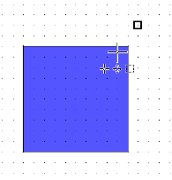
L-Edit 13 User Guide Section 1 168
Chapter 6: Drawing and Editing Objects Editing Objects
When multiple snap points exist in the aperture, the following shows the order of precedence for the
snap types.
Box
[1]Vertex
[2]Midpoint
[3]Center
[4]Edge
Polygon
[5]Vertex
[6]Midpoint
[7]Edge
Wire
[1]Vertex of the wire’s centerline
[2]Midpoint of the wire’s centerline
[3]Edge of the wire’s centerline
Circle
[1]Center
[2]Quadrant
Pie Wedge, Torus, or Curved Polygon
[1]Vertex
[2]Midpoint
[3]Quadrant
[4]Center
[5]Edge
Offset Offsets the snap location by the specified amount. This can be used to
snap by an overlap amount. For example, if the offset set is set to 0.15
0.15, L-Edit will snap to a snap location (i.e. vertex) plus an extra
0.15 in the x direction and extra 0.15 in the y direction.
Display Markers Displays the context sensitive snap markers while drawing, selecting,
or editing.
Auto Sets the color of the markers to be the last color in the color palette for
that TDB with a one pixel halo in the first color in the color palette.
This usually sets the marker color to black.
Pick Color... Color of the markers.
Marker Size Size of the markers in pixels.
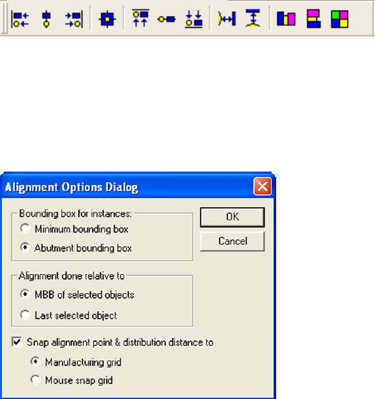
L-Edit 13 User Guide Section 1 169
Chapter 6: Drawing and Editing Objects Editing Objects
Port
[1]Pin - Center of the port box
[2]Vertex - Vertex of a port box
[3]Midpoint - Midpoint of a port box
Instance
[1]Endpoint
[2]Midpoint
[3]Instance boundary or origin
Aligning and Distributing Objects
You can align, distribute, or tile objects using the alignment commands from either the menu or the
Alignment toolbar.
Bounding Box and Snapping Options
Use Draw>Align>Options to set basic parameters for the alignment, distribution and tiling
operations.
Bounding Box for
instances Controls how instances are selected for aligning, tiling, or distributing
(see “Minimum and Abutment Bounding Boxes,” below).
Minimum bounding box—use the minimum bounding box of all
objects in the cell.
Abutment bounding box—use the minimum bounding box of
all objects in the cell on the Icon special layer.
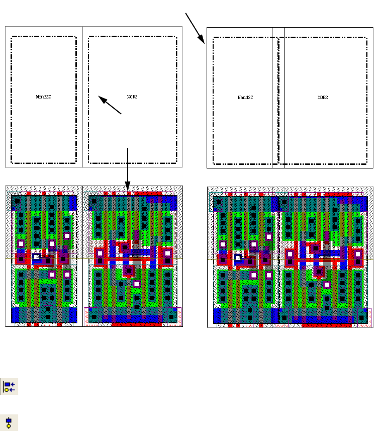
L-Edit 13 User Guide Section 1 170
Chapter 6: Drawing and Editing Objects Editing Objects
Minimum and Abutment Bounding Boxes
For alignment, tiling, and distributing, you have the option to use either the minimum bounding box
(MBB) of all objects in the cell or the abutment bounding box which is the MBB of all objects in the
cell on the Icon/Outline special layer. The abutment bounding box is useful when tiling standard cells
that need to be overlapped.
Alignment Commands
Align Left - Aligns the left edge of objects to the left edge of the bounding box (MBB) of the
selected objects or the left edge of the last selected object.
Align Horizontal Centers - Aligns objects vertically to the center of the MBB of the selected
objects or the center of the last selected object.
Alignment done relative to Controls which set of objects are included in the MBB that acts as the
point of reference for alignment operations.
MBB of selected objects—use the MBB of the currently
selected objects.
Last selected object—use the MBB of the last selected object.
Snap alignment point &
distribution distance When checked, prevents objects from be placed off-grid. All
alignment points and distribution distances will be snapped to either
the Manufacturing grid or the Mouse snap grid.
Minimum Bounding Box Abutment Bounding Box
Cell MBB
box on
Icon/Outline
layer
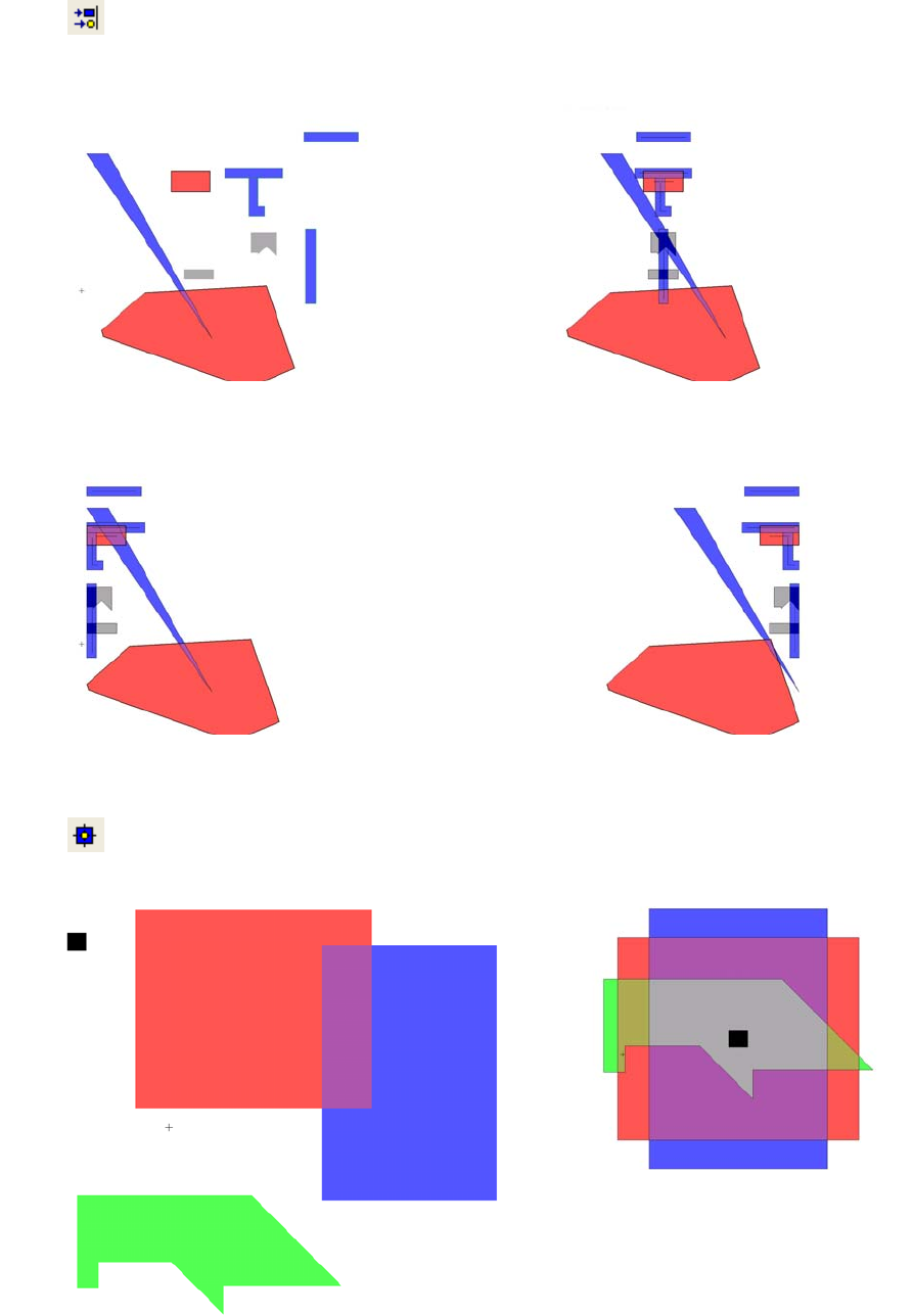
L-Edit 13 User Guide Section 1 171
Chapter 6: Drawing and Editing Objects Editing Objects
Align Right - Aligns objects to the right edge of the MBB of the selected objects or the right edge
of the last selected object.
Align Vertical and Horizontal Centers- Aligns the horizontal and vertical centers of objects to the
center of the MBB (of either the selected objects or the center of the last selected object).
Align Horizontal Centers
Align Right
Align Left
before
after—centers aligned
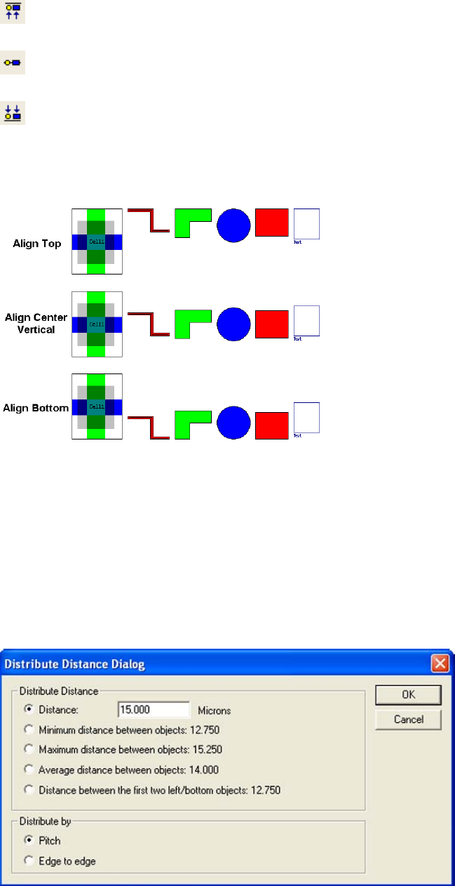
L-Edit 13 User Guide Section 1 172
Chapter 6: Drawing and Editing Objects Editing Objects
Align Tops - Aligns objects to the top edge of the MBB of the selected objects or the top edge of
the last selected object.
Align Vertical Centers- Aligns objects horizontally to the center of the MBB of the selected
objects or the center of the last selected object.
Align Bottoms - Aligns objects to the bottom edge of the MBB of the selected objects or the
bottom edge of the last selected object.
Distribution Options
The anchor of a distribution operation is determined by the objects having a MBB with the least x value
and then the objects having a MBB with the least y value. If two or more objects have the same
minimum x or y value for their MBB, the largest of these objects is given the left most or bottom most
position.
If two or more objects have the same minimum x or y value for their MBB and are the same size, the
object whose layer is highest in the layer list is selected for the left most or bottom most position
Distribute Distance Distance—Spaces the objects by a specific amount.
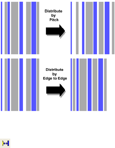
L-Edit 13 User Guide Section 1 173
Chapter 6: Drawing and Editing Objects Editing Objects
Distribution Commands
Distribute Horizontally - Equally spaces all objects horizontally starting with the left most, bottom
most object. When you run this command, a dialog will appear asking how you want to space the
objects. No alignment is performed on the distributed objects.
Minimum distance between objects—Spaces the objects by the
minimum distance or pitch between all objects.
Maximum distance between objects—Spaces the objects by the
maximum distance or pitch between all objects as the value to space
the objects.
Average distance between objects—Spaces the objects by the
average distance or pitch between all objects as the value to space the
objects.
Distance between the first two left/bottom objects—Spaces the
objects by the distance or pitch between the two objects that are the
left most, bottom most objects.
Distribute by Pitch—Evenly spaces the center of the objects’ MBB
Edge to Edge—Evenly spaces the outside edge to outside edge of the
objects’ MBB. (See illustration that follows.)
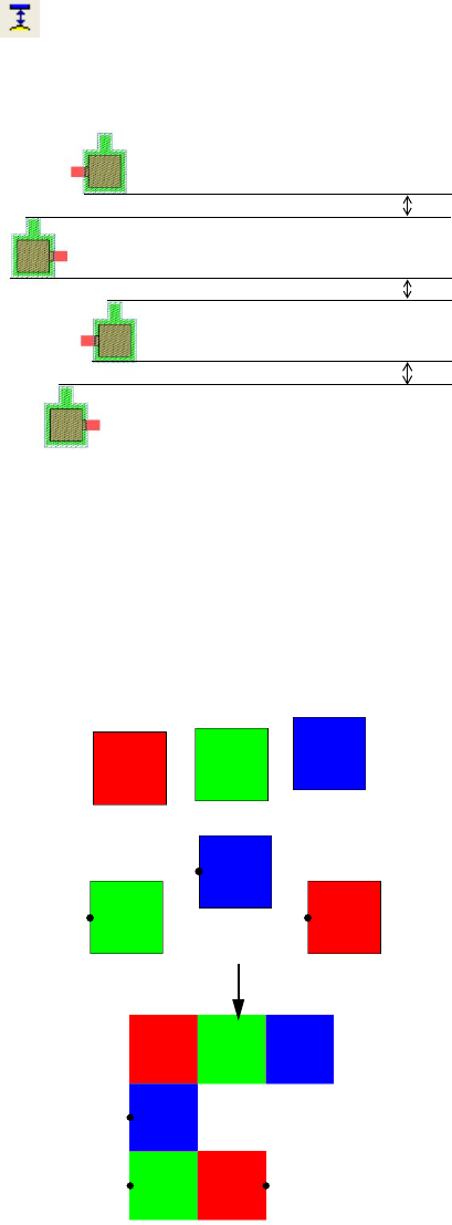
L-Edit 13 User Guide Section 1 174
Chapter 6: Drawing and Editing Objects Editing Objects
Distribute Vertically - Equally spaces all objects vertically starting with the left most, bottom most
object. When you run this command, a dialog will appear asking how you want to space the objects. No
alignment is performed on the distributed objects.
Tiling Options
Objects for tiling are sorted into rows and columns according to a MBB around them. For two objects to
be on the same row, the midpoint of each object has to be within the MBB of the other object. In the
example below, the midpoint of the central blue box is above the MBB of the lower green and red box,
so it will be on the second row.
Row 1
Row 3
Row 2
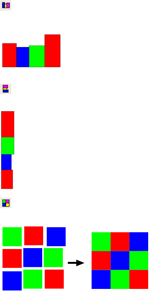
L-Edit 13 User Guide Section 1 175
Chapter 6: Drawing and Editing Objects Editing Objects
Tile Commands
Tile Horizontally - Tiles or stacks the objects horizontally so that each objects is next to each other
with the bottom of their MBB’s aligned. For sorting order, see Distribute Horizontally.
Tile Vertically - Tiles or stacks the objects vertically so that each objects is next to each other with
the bottom of their MBB’s aligned. For sorting order, see Distribute Horizontally.
Tile as a 2D Array - Tiles or stacks the objects horizontally so that each objects is next to each
other with the bottom of their MBB’s aligned.
Adding Vertices
You can add vertices to all-angle polygons or wires after you create them. To add a vertex, select the
object and position the pointer on the edge where you want the new vertex to be. Hold Ctrl+the
MOVE/EDIT mouse button while dragging the new vertex into position.
Adding Wire Sections
You can insert new wire sections into an existing orthogonal or 45° wire. First select an orthogonal or
45° wire to enable the command. Use Draw > Add Wire Section to switch to Add Section mode, and
click on the selected wire at the point where you want to add a new wire section. L-Edit automatically
draws the new section on the same layer on which the existing wire is drawn. To return to drawing
mode, use the CANCEL mouse button. Areas where the wire intersects itself will be displayed as white.
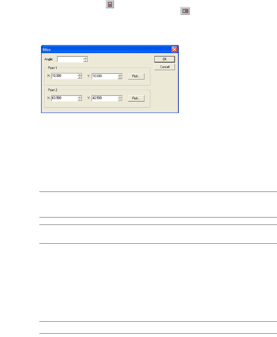
L-Edit 13 User Guide Section 1 176
Chapter 6: Drawing and Editing Objects Editing Objects
Slicing
Divide selected objects along a horizontal line by choosing Draw>Slice>Horizontal or clicking the
horizontal slice button ( ). Divide selected objects along a vertical line by choosing
Draw > Slice > Vertical or clicking the vertical slice button ( ).
Divide selected objects along a line at any angle by choosing Draw>Slice>All Angle, then specify the
slice line in the dialog.
You can specify the slice line for an all angle slice by either specifying two points on the line, or by
specifying one point and an angle. To slice using two points, select Point1 and Point 2 in the Slice
dialog, to slice using one point and an angle, select Point 1 and the desired angle.
When you execute a slice command, the view automatically zooms to include all selected objects and a
horizontal or vertical line appears, indicating where to slice (divide) the objects. The line moves with
the pointer until you place it by clicking any mouse button, at which time each object splits into two
new objects with coincident edges.
Note: When slicing, circles, pie wedges, tori, and curved polygons are approximated by an
all angle polygon within a tolerance given by the Manufacturing Grid, see “Grid
Parameters” on page 97.
Note: Ports, rulers, and instances cannot be sliced. If you select objects of these types,
L-Edit ignores them during a slice operation.
Merging Objects
Use Draw > Merge to merge multiple selected intersecting boxes, polygons (90°, 45°, all-angle, and
curved polygons), or wires (90°, 45°, and all-angle), circles, pie wedges, and tori into one object. You
can only merge intersecting objects that lie on the same layer. If you select objects from more than one
layer, L-Edit merges each set of overlapping selected objects on the same layer into one object. Circles,
pie wedges, tori, and curved polygons are approximated by an all angle polygon within a tolerance
given by the Manufacturing Grid, see “Grid Parameters” on page 97.
Note: When a wire is merged with another object it becomes a polygon.
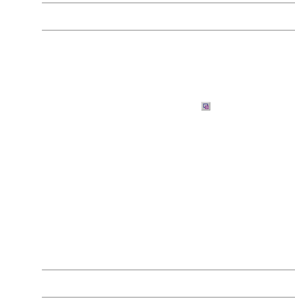
L-Edit 13 User Guide Section 1 177
Chapter 6: Drawing and Editing Objects Editing Objects
Warning: If you merge intersecting objects with different GDSII data types, L-Edit replaces their respective data
type values with the data type for the layer (or to “0” if a data type has not been set for the layer) without
a warning.
Nibbling
To nibble, or cut out, an area from selected objects in the active cell, perform the following steps:
;Select the desired objects. They may be on multiple layers.
;Select the drawing tool to use for nibbling.
;Choose Draw > Nibble, press Alt+X, or click the nibble button ( ) to draw the shape to nibble from
the selected objects. An area equal to the shape is deleted from the objects.
You can only nibble certain objects. These are the same objects you can use as a nibbling tool. These
objects are:
Box
90°, 45°, all-angle, and curved polygon
90°, 45°, and all-angle wire
Circle
Pie Wedge
Torus
L-Edit ignores attempts to nibble ports, rulers, and instances.
When you use a wire as a nibbling tool, the default wire width for the Drag Box Layer must be set to the
width of the nibbling wire. (For information on changing wire parameters for a specific layer, see “End
Styles and Join Styles” on page 115.) If the wire width for the Drag Box Layer is set to zero, you will
not be able to use wires to nibble other objects.
Note: When nibbling, circles, pie wedges, tori, and curved polygons are approximated by an
all angle polygon within a tolerance given by the Manufacturing Grid, see “Grid
Parameters” on page 97.
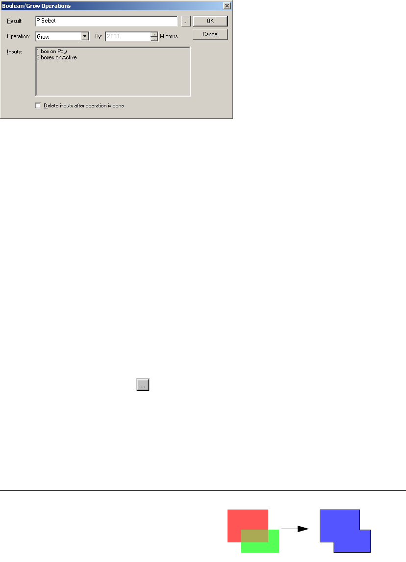
L-Edit 13 User Guide Section 1 178
Chapter 6: Drawing and Editing Objects Editing Objects
Boolean and Grow Operations
You create new polygons by applying logical operations to one or more drawn objects using
Draw > Boolean/Grow Operations. Note that L-Edit does not support Boolean operations on instances.
To perform a Boolean operation, select one or more objects on the layout and then choose
Draw > Boolean/Grow Operations from the L-Edit menu (or use the shortcut B). Valid objects for this
operation include boxes, all-angle polygons, wires, circles, pie wedges, and tori. When you click OK to
perform the Boolean operation, L-Edit creates one or more polygons on the Result layer.
The Inputs field shows the number and type of objects selected on each layer.
The operations And, Xor, Subtract (A-B), and Subtract (B-A) require that exactly two inputs be
specified. If this condition is not met, the Inputs field displays an error message; you must select
exactly two inputs or choose another operation. You can specify two inputs, A and B, in the following
ways:
Select exactly two objects on the same or different layers. L-Edit assigns the input names A and B
to the objects, and displays these assignments in the Inputs field.
Select any number of objects on exactly two layers. L-Edit assigns all selections on one layer to
input A, and all selections on the other layer to input B. The corresponding layer for each input is
shown in the Inputs field.
In the Result field, select the layer on which to create the resulting polygon(s). You can type a valid
layer name in this field, or click ( ) to open the Setup Layers dialog and choose from the Layers
list.
To replace the input objects with the resulting polygon(s), check the option labeled Delete inputs after
operation is done. To preserve all input objects, leave this box unchecked (default).
In the Operation field, choose one of the following Boolean operations:
Operation Description Illustration
Or A | B
Takes the union of all inputs.
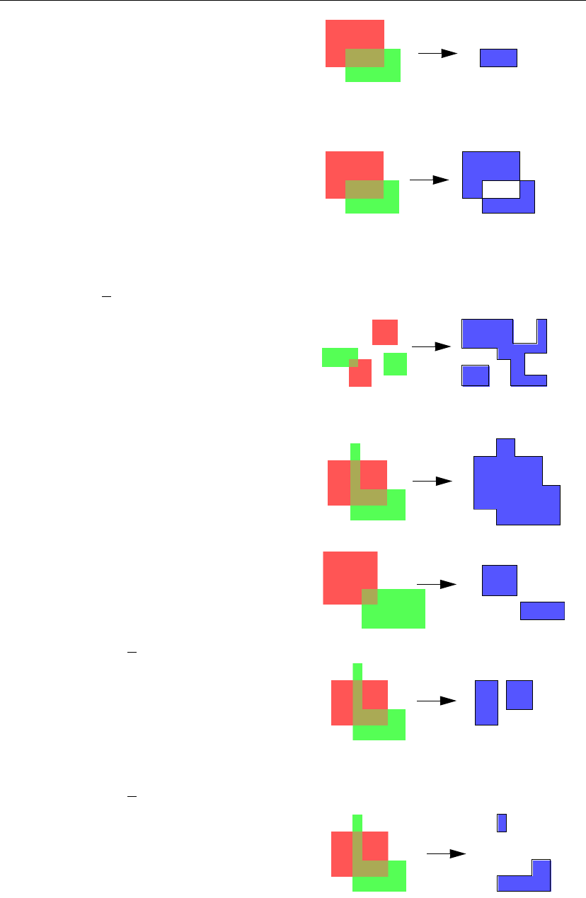
L-Edit 13 User Guide Section 1 179
Chapter 6: Drawing and Editing Objects Editing Objects
And A & B
Takes the intersection of inputs A
and B. This function can be
applied to exactly two objects, or
to any number of objects on
exactly two layers.
Xor A ⊗ B
Represents the area occupied by
exactly one input (A or B),
excluding all areas of
intersection. This function can be
applied to exactly two objects, or
to any number of objects on
exactly two layers.
Not A
Represents the outside, or
inverse, of all input objects
within the region defined by their
collective minimum bounding
box.
Grow Takes the union of all input
objects, then displaces each edge
outward by the distance specified
in the By field. (Default: 1.000)
Shrink Takes the union of all input
objects, then displaces each edge
inward by the distance specified
in the By field. (Default: 1.000)
Subtract (A-B) A & B
Represents the portion of input A
that does not intersect with input
B. This function can be applied to
exactly two objects, or to any
number of objects on exactly two
layers.
Subtract (B-A) B & A
Represents the portion of input B
that does not intersect with input
A. This function can be applied to
exactly two objects, or to any
number of objects on exactly two
layers.
Operation Description Illustration
a
b
a
b
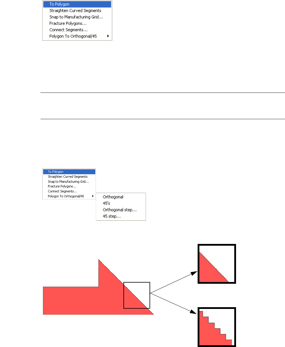
L-Edit 13 User Guide Section 1 180
Chapter 6: Drawing and Editing Objects Editing Objects
Converting Objects to Polygons
You can convert boxes, wires, circles, pie wedges, tori, and polygons with curved sides to straight sided
polygons. First select the objects, then choose Draw>Convert>To Polygon.
Circles, polygons with curved edges, the curved parts of pie wedges and tori will be approximated by
creating new vertices and snapping these vertices to the manufacturing grid. (Vertices are added within
a distance of less than the manufacturing grid of the original shape. See “Grid Parameters” on page 97.)
Vertices on non-curved segments are not modified.
Note: L-Edit automatically converts circles, pie wedges, tori, and curved-sided polygons to
straight-sided polygons when writing out GDSII. When writing out CIF, L-Edit
converts the same shapes except circles.
Converting Polygons to Orthogonal or 45° Edged Geometry
You can convert a straight-edged polygon to a polygon with either orthogonal or 45° edges using the
Draw > Convert > Polygon To Orthogonal/45 command.
The Orthogonal and 45’s commands convert polygons using a predetermined step size.
Before - polygon with straight edges
After - polygon with orthogonal edges

L-Edit 13 User Guide Section 1 181
Chapter 6: Drawing and Editing Objects Editing Objects
Draw > Convert > Polygon To Orthogonal/45 > 45’s
Selecting either Orthogonal Step or 45 Step lets you control the size of the new edges (the angle,
however, remains fixed.)
Before - polygon with straight edges After - polygon with 45° edges
Small orthogonal step size.
Large orthogonal step size.
Small 45° step size.
Large 45° step size.
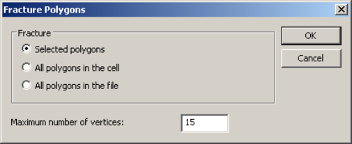
L-Edit 13 User Guide Section 1 182
Chapter 6: Drawing and Editing Objects Editing Objects
Snapping Objects to the Manufacturing Grid
You can snap the vertices and other control parameters of objects to the Manufacturing Grid using
Draw > Convert > Snap to Manufacturing Grid. Snapping to the manufacturing grid does not change
the type of an object.
Vertices of boxes, polygons, ports, and rulers are snapped to the manufacturing grid.
Vertices on wire centerlines are snapped.
Instance origins are snapped, and array delta values are snapped such that the origin of array
elements are on the manufacturing grid.
The curve height of curved segments of polygons are snapped to an integer multiple of the
manufacturing grid, and the radius of pie wedges and tori are snapped to an integer multiple of the
manufacturing grid.
The center of a circle is snapped to the manufacturing grid, and the radius is snapped to an integer
multiple of the manufacturing grid.
Snapping to the manufacturing grid is an effective way to remove vertices from polygons with very
high resolution of vertices, while still maintaining the shape of the original polygon. The snapped
polygon will not deviate from the original polygon by more than the snap grid.
Alternately, polygons with too many vertices can be fractured into several smaller polygons with fewer
vertices (see “Fracturing Polygons” on page 182.)
Removing Curves from Polygons
You can straighten the curved segments of polygons using Draw>Convert>Straighten Curved
Segments. This operation will remove the curvature from all segments of all selected polygons.
Circles, pie wedges and tori are not affected.
Fracturing Polygons
The Draw > Convert > Fracture Polygons command divides polygons with a large numbers of
vertices into several polygons with fewer vertices. The polygons are fractured according to the
maximum number of vertices you specify. Note that this operation does not modify wires, circles, pie
wedges, or tori.
Fracture You can choose to fracture only the polygon(s) you have selected, all
the polygons in a cell, or all polygons in the file.
Maximum Number of
vertices Sets the maximum number of allowable vertices for the selected
polygons.
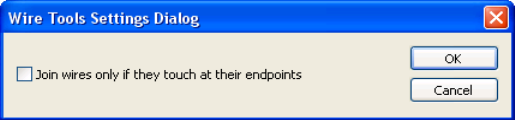
L-Edit 13 User Guide Section 1 183
Chapter 6: Drawing and Editing Objects Editing Objects
Wire Utilities
L-Edit provides several utilities to make editing wires easier. Draw > Wire Utilities allows you to join
two or more wires together into one wire, extend the end segment of several wires to a new location, or
slice one wire into two wires.
Joining Wires
The Join command connects two or more selected wires. Draw > Wire Utilities > Settings lets you set
whether wires must be touching to be joined.
Join wires only if they
touch at their endpoints When this option is checked, two wires will only be joined if their
endpoints are touching. End style is ignored.
As shown in the following illustration, a wire segment is inserted
from endpoint to endpoint. Thus, if the two endpoints do not have a
common x or y value, an all-angle wire segment will be added.
When this option is not checked, all wires in the selection list will be
joined by creating a wire segment between each closest two
endpoints.
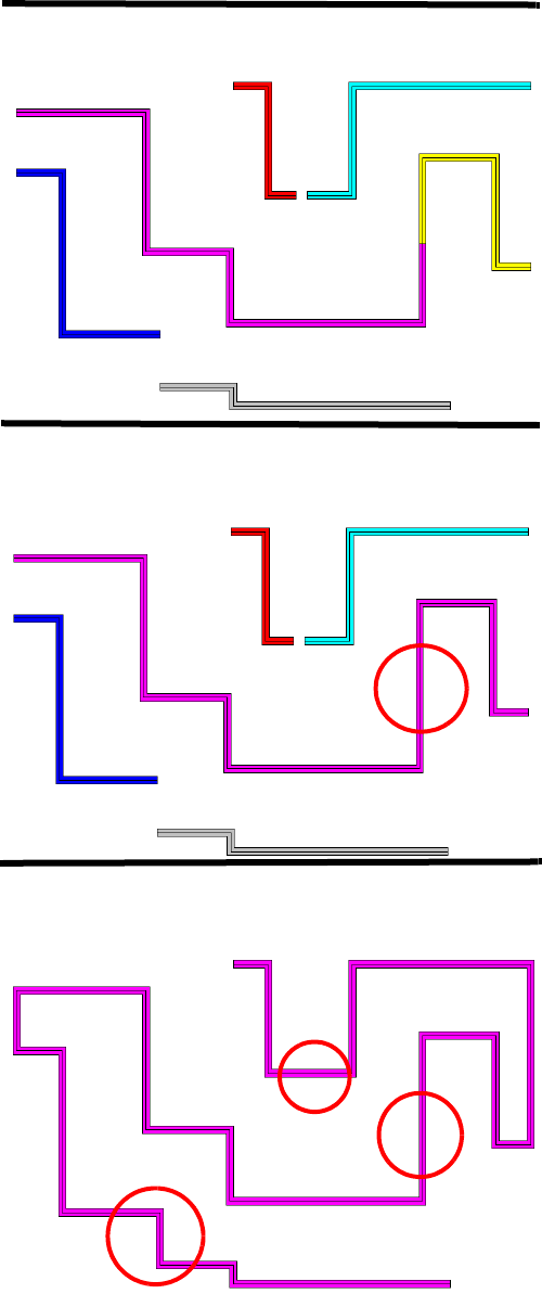
L-Edit 13 User Guide Section 1 184
Chapter 6: Drawing and Editing Objects Editing Objects
Before join:
After, with Join wires only if they touch at their endpoints
checked.
After, with Join wires only if they touch at their endpoints
unchecked.
Only wires that touch are joined.
All wires are joined.
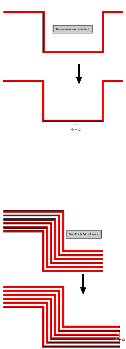
L-Edit 13 User Guide Section 1 185
Chapter 6: Drawing and Editing Objects Editing Objects
Slicing Wires
Slice will break a single wire into two wires. Use Draw > Wire Utilities > Slice to slice a wire. It will
ask you to click where you want to slice the wire. It will then slice the wire at the closest point on the
wire to where you clicked.
Extending Wires
Extend will extend the end segment of the selected wires to the point where you click. Use
Draw > Wire Utilities > Extend to extend the selected wires. It will ask you to click where you want to
extend the wires to. It will then extend the closest end segment of each wire to point where you clicked.
Extend will not change the angle of the end segment. For non-orthogonal end segments, it will extend
them to the intersection point between the end segment and the line that is perpendicular to the end
segment and goes through the clicked point.
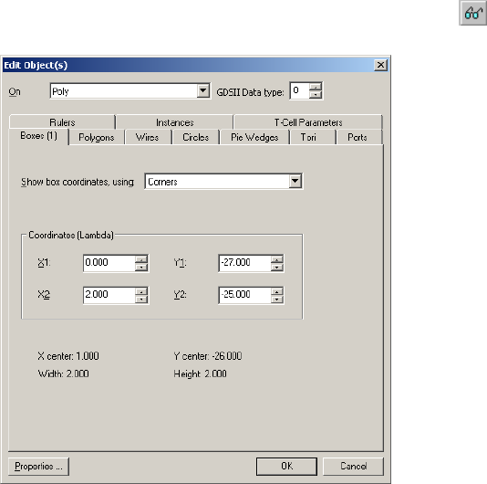
L-Edit 13 User Guide Section 1 186
Chapter 6: Drawing and Editing Objects Editing Objects Using Numerical Values
Editing Objects Using Numerical Values
You can use text and data values to edit many drawn object in L-Edit.
Edit > Edit Object(s)
To edit an object textually, select it and choose Edit > Edit Object(s), press Ctrl+E, double-click the
MOVE/EDIT mouse button, or click the edit object(s) button ( ):
On layer and GDSII Data type are universal to all selected objects. If you select objects on different
layers or with different data types, both fields will have a mixed-value appearance (see “Multiple Object
Editing,” below).
The Edit Object(s) dialog contains the following tabs:
Boxes (see “Boxes” on page 188)
Polygons (see “Polygons” on page 191)
On layer The current layer on which the objects reside. This can be changed by
selecting a layer from the drop-down list; all selected objects will
convert to the new layer.
GDSII Data type An integer ranging from 0-63, used primarily by GDSII database
users who intend to export a GDSII file from L-Edit and read it into
another program requiring additional information. Use this field to
assign or reassign a GDSII data type value to the selected object(s).
Properties Opens the Properties dialog for the selected object. The button is
only available when a single object is selected; if more than one
object is selected the button will be unavailable. For more information
on object properties, see “Properties” on page 68.
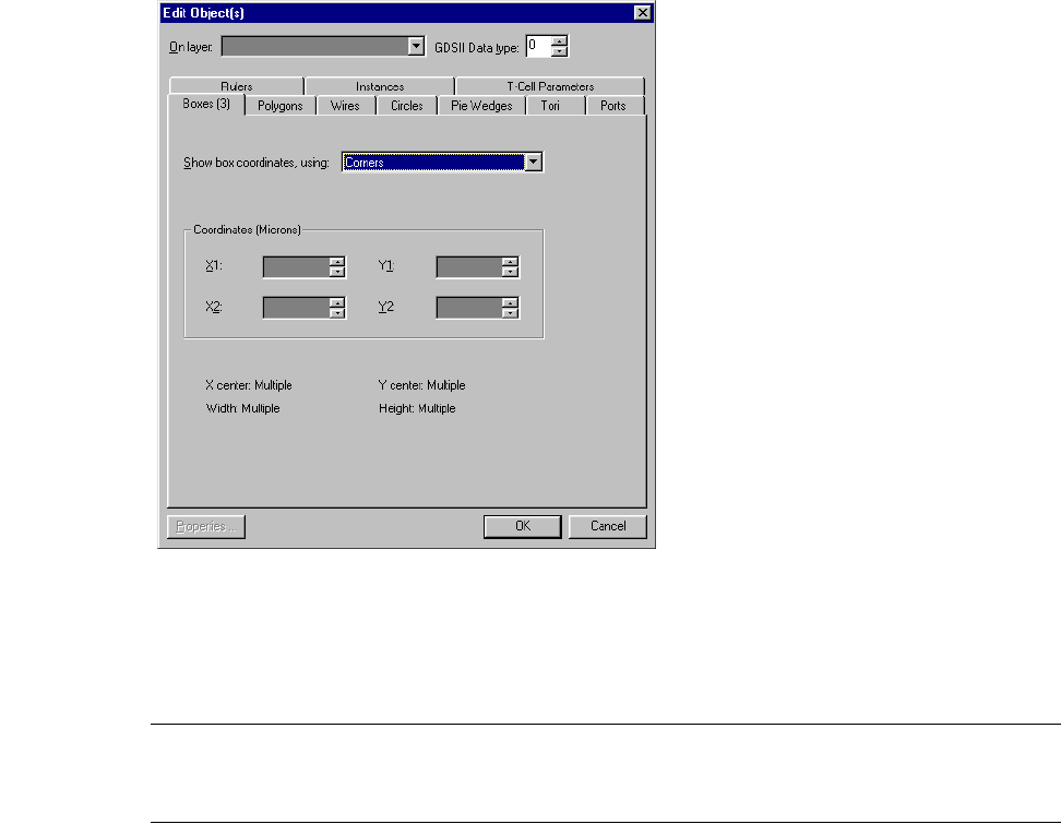
L-Edit 13 User Guide Section 1 187
Chapter 6: Drawing and Editing Objects Editing Objects Using Numerical Values
Wires (see “Wires” on page 192)
Circles (see “Circles” on page 193)
Pie Wedges (see “Pie Wedges” on page 194)
Tori (see “Tori” on page 195)
Ports (see “Ports” on page 196)
Rulers (see “Rulers” on page 197)
Instances (see “Instances” on page 198)
T-Cell Parameters (see “Opening Cells” on page 218)
Multiple Object Editing
You can use the Edit Object(s) dialog to modify multiple selected objects simultaneously.
Each tab in the Edit Object(s) dialog contains the number of selected objects of that type next to the
name on the tab. When multiple objects with different properties are selected, the affected fields appear
as dark gray to represent that multiple values exist for those properties:
This is called mixed-value appearance. Unlike disabled (“grayed-out”) fields, which you cannot edit,
mixed-value fields accept new data, and all selected objects take on the value entered. For example, if
you modify the options On layer, GDSII Data type, or any of the box coordinates, all selected objects
will take on the entered values.
Note: In the preceding illustration, Center and Dimensions are read-only fields showing
coordinates and dimensions derived from the values entered in the Coordinates
group. No values can be entered in these fields.
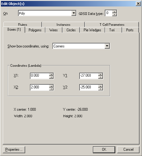
L-Edit 13 User Guide Section 1 188
Chapter 6: Drawing and Editing Objects Editing Objects Using Numerical Values
Boxes
To change the coordinates or dimensions of a box, choose the Edit Object(s)—Boxes tab. This dialog
provides three methods of displaying box coordinates and/or dimensions, which you choose from the
menu Show box coordinates, using. Options include:
Corners
Bottom left corner and dimensions
Center and dimensions
The read-only fields in the bottom half of the dialog display coordinates and/or dimensions derived
from the values entered in the Coordinates group. The text can be selected and copied. After you edit a
value in the Coordinates group, click any of the read-only fields to update it.
Corners
If you choose Corners, the dialog looks like this:
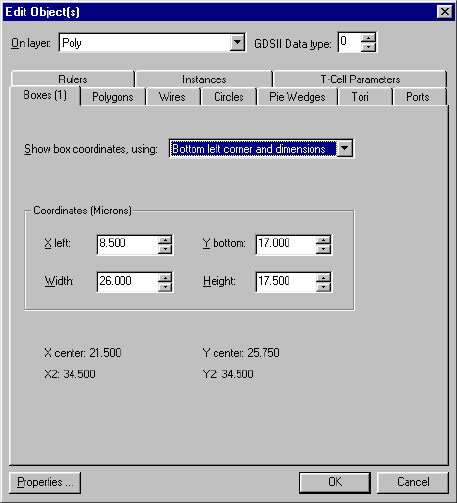
L-Edit 13 User Guide Section 1 189
Chapter 6: Drawing and Editing Objects Editing Objects Using Numerical Values
Options include:
Read-only fields include:
Bottom Left Corner and Dimensions
If you choose Bottom left corner and dimensions, the dialog looks like this:
Coordinates (Display
Units)Coordinates of the selected box or boxes, in display units. Values to
be entered include:
X1—X-axis position of the lower left corner of the selected box
or boxes
Y1—Y-axis position of the lower left corner of the selected box
or boxes
X2—Y-axis position of the upper right corner of the selected box
or boxes
Y2—Y-axis position of the upper right corner of the selected box
or boxes
X center and Y center X- and Y-axis coordinates of the center of the selected box or boxes
Width and Height Width and height of the selected box or boxes
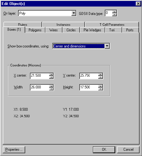
L-Edit 13 User Guide Section 1 190
Chapter 6: Drawing and Editing Objects Editing Objects Using Numerical Values
Options include:
Read-only fields include:
Center and Dimensions
If you choose Center and dimensions, the dialog looks like this:
Coordinates (Display
Units)Coordinates and dimensions of the selected box or boxes, in display
units. Values to be entered include:
X Left—X-axis position of the left edge of the selected box or
boxes
Y Top—Y-axis position of the top edge of the selected box or
boxes
Width—Width of the selected box or boxes
Height—Height of the selected box or boxes
X center and Y center X- and Y-axis coordinates of the center of the selected box or boxes
X2 and Y2 X- and Y-axis coordinates of the upper-right corner of the selected
box or boxes
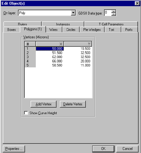
L-Edit 13 User Guide Section 1 191
Chapter 6: Drawing and Editing Objects Editing Objects Using Numerical Values
Options include:
Read-only fields include:
Polygons
To modify a polygon, choose the Edit Object(s)—Polygons tab. This tab allows you to add, delete, or
modify vertices and curves.
Coordinates (Display
Units)Coordinates and dimensions of the selected box or boxes, in display
units. Values to be entered include:
X center—X-axis coordinate of the center of the selected box or
boxes
Y center—Y-axis coordinate of the center of the selected box or
boxes
Width—Width of the selected box or boxes
Height—Height of the selected box or boxes
X1 and Y1 X- and Y-axis coordinates of the bottom-left corner of the selected
box or boxes
X2 and Y2 X- and Y-axis coordinates of the upper-right corner of the selected
box or boxes
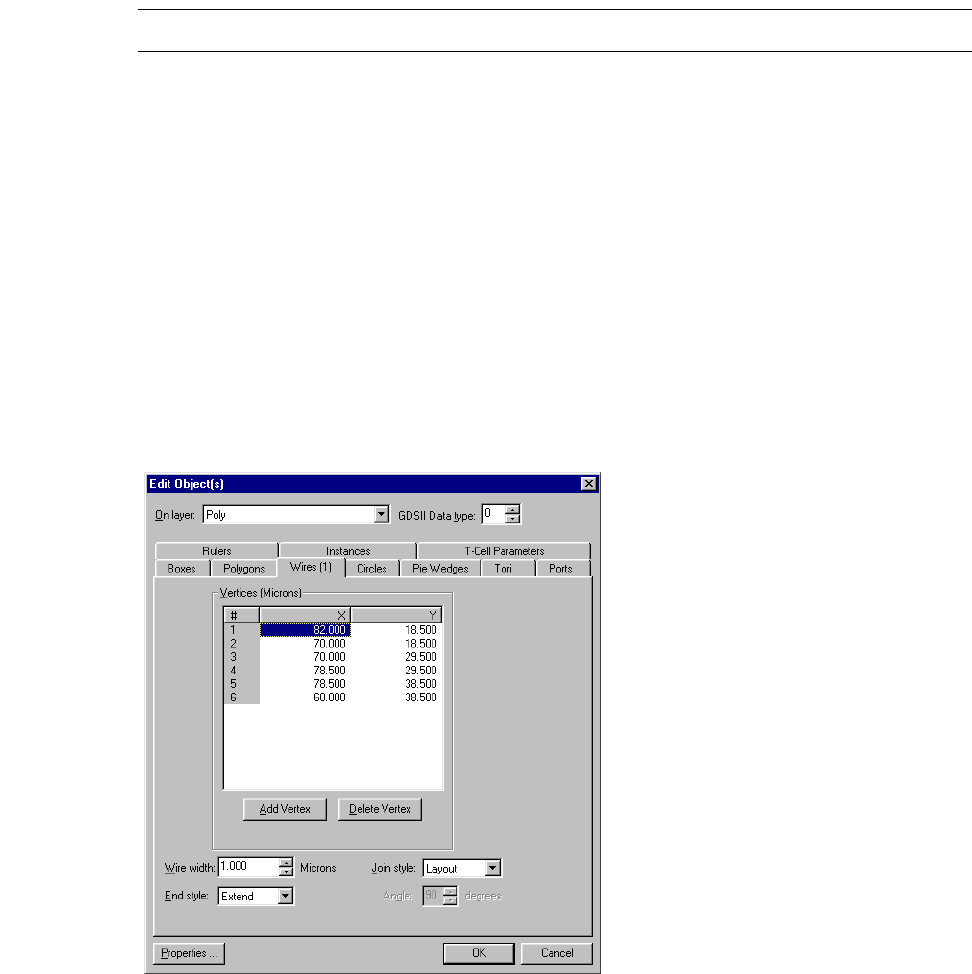
L-Edit 13 User Guide Section 1 192
Chapter 6: Drawing and Editing Objects Editing Objects Using Numerical Values
Note: If multiple polygons are selected, the Vertices list is disabled.
Wires
To modify, add, or delete a wire’s vertices, or change a wire’s width, end, or join styles, choose the Edit
Object(s)—Wires tab.
The following options are included. Refer to “End Styles and Join Styles” on page 115 for more detailed
information these options. Note that if multiple wires are selected, the Vertices list is disabled.
Vertices (Display Units)The X and Y coordinates of the vertices of the selected polygon. For
convenience, the pound sign (#) numbers the vertices.
Add Vertex Creates a new vertex with the selected coordinates.
Delete Vertex Removes the selected vertex from the object.
Show Curve Height If checked, column Curve Height is displayed in the Vertices list.
(For a definition of curve height, see “Curve Height” on page 161.)
Vertices (Display Units)The X and Y coordinates of the selected wire’s vertices. Add Vertex
creates a new vertex with the selected coordinates. Delete vertex
removes the selected vertex from the object.
Wire width The width of selected wires in display units. Use Setup > Layers to
set the default wire width, end style, and join style for each layer. See
“Layer Setup” on page 104 for more information on layer setups.
Join style The type of join for the wires. A drop-down menu lists four styles:
Layout, Round, Bevel, or Miter.
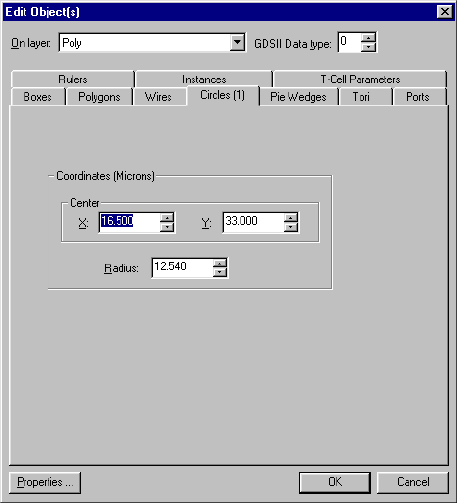
L-Edit 13 User Guide Section 1 193
Chapter 6: Drawing and Editing Objects Editing Objects Using Numerical Values
Circles
To modify the coordinates of the center and the radius of a circle, choose the Edit Object(s)—Circles
tab.
Options include:
End style The type of end for the wires. A drop-down menu lists three styles:
Butt, Round, or Extend.
Angle The angle between two segments in a miter style join.
Coordinates (Display
Units)Individual coordinate fields include:
X and Y coordinates of the center of the selected circle
Radius of the selected circle
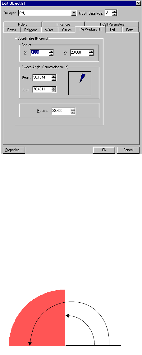
L-Edit 13 User Guide Section 1 194
Chapter 6: Drawing and Editing Objects Editing Objects Using Numerical Values
Pie Wedges
To modify the coordinates of the center of a pie wedge, its sweep angle, and its radius, choose the Edit
Object(s)—Pie Wedges tab.
Options include:
Sweep Angle
The Sweep Angle is calculated counterclockwise as the angle from the horizontal (0°) to the Begin and
End of the pie wedge. In the illustration below, the Begin angle is 90° and the End angle is 180°.
Center Coordinates
(Display Units)The X and Y coordinates of the center of the selected pie wedge.
Sweep Angle
(Counterclockwise) The angle from the horizontal (0°) to the Begin and End of the pie
wedge.
Radius The radius of the pie wedge.
Begin
End
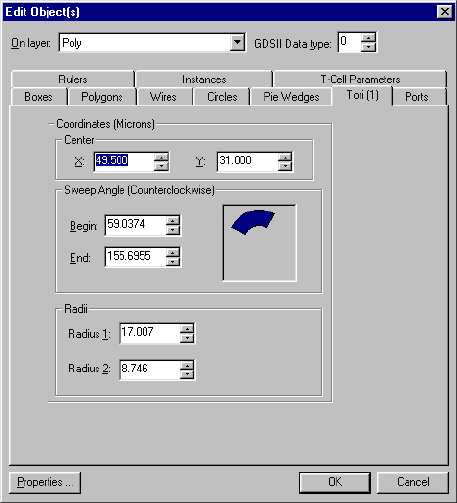
L-Edit 13 User Guide Section 1 195
Chapter 6: Drawing and Editing Objects Editing Objects Using Numerical Values
Tori
To modify the coordinates of the center of a torus, its sweep angle, and its radii, choose the Edit
Object(s)—Tori tab.
Options include:
For information on how L-Edit calculates the Sweep Angle, see “Sweep Angle” on page 194.
Center Coordinates
(Display units)The X and Y coordinates of the center of the selected torus.
Sweep Angle
(Counterclockwise) The angle from the horizontal (0°) to the Begin and End of the
selected torus.
Radii Radius 1 is the first radius you create, whether it is to the inner or
outer edge of the torus.
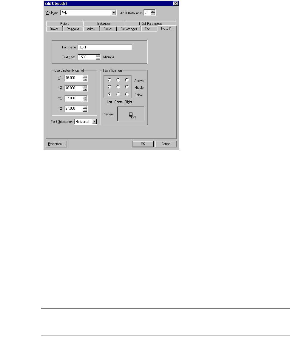
L-Edit 13 User Guide Section 1 196
Chapter 6: Drawing and Editing Objects Editing Objects Using Numerical Values
Ports
To create a port or change the attributes of a port, choose the Edit Object(s)—Ports tab.
Options include:
Note: If you change layers while creating a port, the GDSII data type will change
accordingly. If you change layers while editing a port, however, the GDSII data type
will not change unless you explicitly reset it.
Port name The visible text associated with the port.
Text size The size of the on-screen text. Use Setup > Design—Drawing to
change the default port text size.
Coordinates (Display units)The coordinates of the lower-left and upper-right vertices of the port.
If the port is a point, the coordinates are the same.
Text Orientation Specifies the orientation of port text. Options are Vertical and
Horizontal.
Text Alignment The position of the text in relation to the port. For horizontal
alignment, the options are Left, Center, and Right. For vertical
alignment, the options are Above, Middle, and Below. The default
position is the below the port and left-aligned.
Preview Demonstrates options selected for Text Orientation and Text
Alignment.
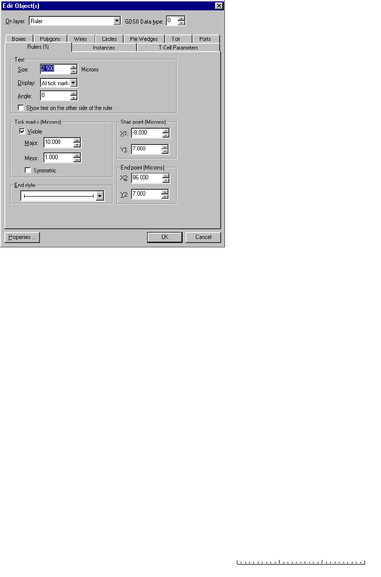
L-Edit 13 User Guide Section 1 197
Chapter 6: Drawing and Editing Objects Editing Objects Using Numerical Values
Rulers
To change the attributes of a ruler, choose the Edit Object(s)—Rulers tab.
Options include:
In the Display drop-down list you can choose one of four display types:
Text Specifies the size, display style, and character angle of the text and
numbers associated with the selected ruler.
Show text on the other side
of the ruler Causes numbers and tick marks to appear on the opposite side of the
selected ruler.
Tick marks (Display units)Specifies the distance between major and minor tick marks in the
Major and Minor fields, respectively.
Visible Displays tick marks for the selected ruler
Symmetric Displays tick marks on both sides of the selected ruler.
End style Specifies the end style for the selected ruler. Options include butt and
arrow style.
Start point Specifies the X and Y coordinates of the selected ruler’s start point.
End point Specifies the X and Y coordinates of the selected ruler’s end point.
No text No numbers are visible.
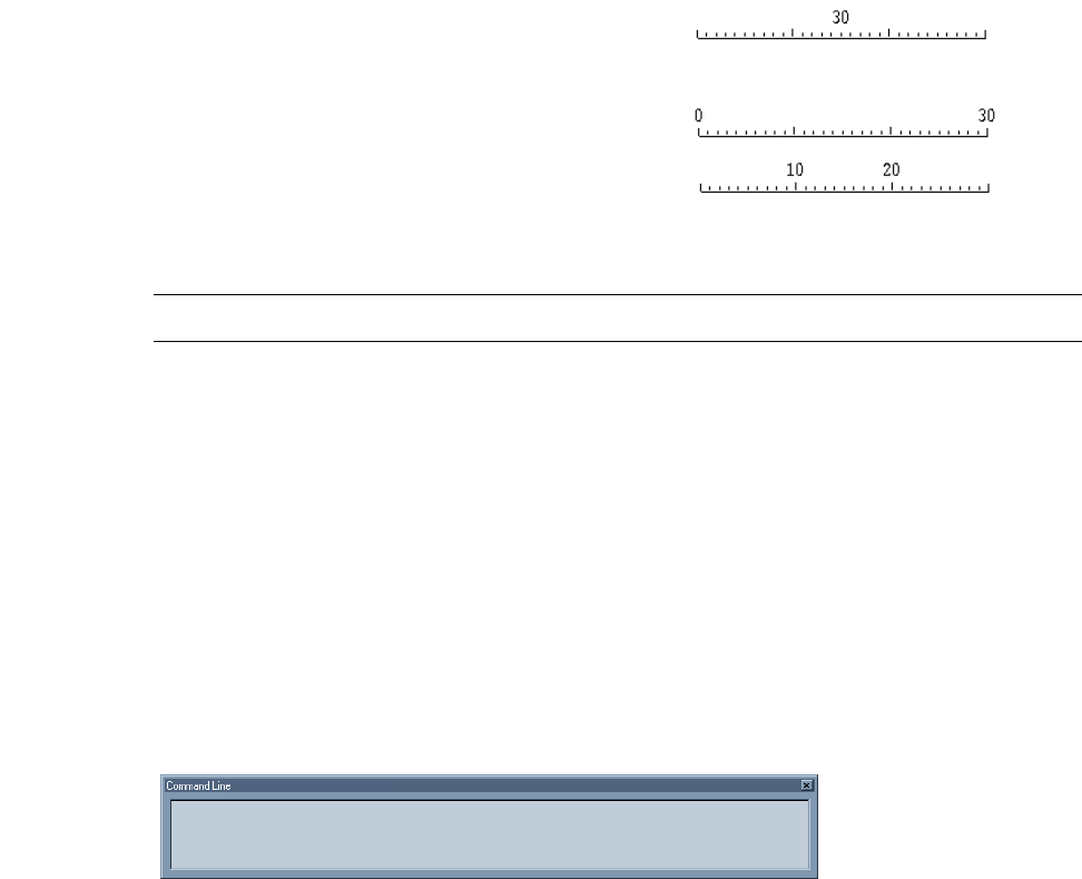
L-Edit 13 User Guide Section 1 198
Chapter 6: Drawing and Editing Objects Command Line Editing
Note: To set default ruler settings, use Setup > Design—Drawing.
Instances
To edit an instance as an object, choose the Edit Object(s)—Instances tab (see “Editing Instances
Using Text” on page 240).
Command Line Editing
L-Edit includes a command line interface that allows you to use basic textual commands and their
associated coordinates so that you can enter precise and repeatable object drawing and editing
operations and perform command scripting with text files.
Opening the Command Window
To open the Command Line window, select Tools > Activate Command Line. The Command Line
window will initially appear docked at the bottom of the application window, but can be moved by
dragging any corner or edge.
You can also use the ‘ key (grave accent, found below the tilde (~)) to toggle the command line window
open and closed.
Using the Command Window
Click inside the window to make it active. Commands are entered at the command prompt (a flashing
cursor) and are applied only to the layout window that is currently active.
The command window behaves much like a toolbar. It can be dragged to any locations on the desktop
and hidden using either Tools > Activate Command Line, View > Toolbars > Command Line, or the
hot key ‘ (grave accent, found below the tilde (~)). This same hot key also toggles focus between the
command line window and the layout window.
Centered The total length of the ruler is
displayed in the center of the
ruler.
At end points Numbers are displayed at the
start and end points of the ruler.
At tick marks Numbers are displayed at each
major tick mark along the ruler
(default display).
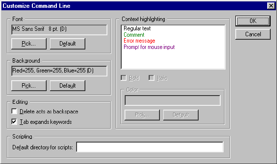
L-Edit 13 User Guide Section 1 199
Chapter 6: Drawing and Editing Objects Command Line Editing
A log of previous commands is kept for display and reuse. Use the up and down (↑, ↓) arrow keys to
scroll through and display prior commands. Text can also be copied and pasted to form new commands.
Use the Esc key to cancel a command.
Command scripting is also supported; refer to “Command Scripting” on page 208 for details.
A right-click in the command line window opens a context-sensitive menu for performing the
following functions:
Customize Command Line is a dialog for configuring font size, color and background of the
Command Line window. It also allows specification of a default directory for command scripts.
Syntax
The basic command syntax is as follows:
command <arguments> <options> <mouse click>
Coordinate Entry Options
Arguments typically include a list of coordinates. Coordinates are relative by default (x1, y1). An
exclamation point is used to designate absolute coordinates (!x, !y). Display units are used for relative
and absolute coordinates.
Paste Paste from Windows clipboard into Command Line window. Only
first command is pasted if multiple lines were previously copied.
Copy Copy selected text from Command Line window into the Windows
clipboard. Text can then be pasted into another editor or into the
Command window.
Copy to file Save selected text to a .tco (Tanner command file) script file. For
more information on object properties, see “Command Scripting” on
page 208.
Delete last line Delete the last line of text.
Clear all Clears all commands from the command log.
Customize Opens the Customize Command Line dialog (see below).
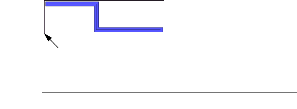
L-Edit 13 User Guide Section 1 200
Chapter 6: Drawing and Editing Objects Command Line Editing
For commands that support the entry of multiple coordinate pairs, the use of absolute coordinates sets
the reference point for the relative coordinates that follow. For example:
box !x1 !y1 x2 y2
will draw a box with its reference point at absolute location x1,y1 and opposing corner at (x1 + x2, y1 +
y2).
A -! used in an argument specifies that all values that follow are in absolute coordinates. For example:
box -! x1 y1 x2 y2
will draw a box with one corner at absolute location x1, y1 and the opposing corner at absolute location
x2, y2.
Command Completion Using the Mouse
Some commands support coordinate entry using the mouse. In this case, after the partial command is
typed it must be followed by the Enter key and then one or more mouse clicks to complete the
command.
When multiple mouse clicks are required you use a left mouse button click to enter multiple coordinate
locations, and a right mouse button click to complete the coordinate entry and execute the command.
Once the command is executed, the coordinate values entered using the mouse are displayed in the
Command Line window. The Esc key can be used during mouse entry to abort a command.
Reference Point Location
The commands copy, move, paste, and rotate require a reference point for locating the new object
position. In each command, you can keep the default reference point, specify an offset from the default
reference point, or specify the reference point in absolute coordinates. The default reference point
differs depending upon the command and whether or not multiple objects are selected.
When a single primitive object is selected for copy, move, or paste commands, the default reference
point is the lower left corner of the minimum bounding box.
When a single instance is selected, the default reference point is the instance origin.
Note: Note that the reference point does not snap to the grid.
Reference point of single
wire.
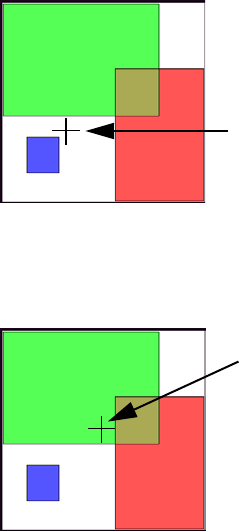
L-Edit 13 User Guide Section 1 201
Chapter 6: Drawing and Editing Objects Command Line Editing
When multiple primitive objects are selected for copy, move, or paste commands, the reference point
is determined by a mouse click. In this case, the reference point may be specified at any location within
the minimum bounding box for the objects.
When any number of primitive objects are selected for the rotate command, the default reference point
is the center of the minimum bounding box for the objects.
Special Characters
The special characters slash (/), space ( ), and quotes (") cannot be used in an argument. To use these
characters you must either enclose the entire string in double quotes or precede each individual special
character with the backslash (\) escape character.
For example, the layer name Not Poly may be entered as "Not Poly" or Not\ Poly. Similarly, to include
a pathname C:\TEMP\NEWFILE.TDB you would enter "C:\TEMP\NEWFILE.TDB" or
"C:\\TEMP\\NEWFILE.TDB".
If a cell name includes a space or comma, it must be enclosed in quotes.
Keyboard Shortcuts
The TAB key functions as a position-sensitive shortcut within the command window. Depending on the
cursor position in a command, TAB will cycle through the available values for commands, layer names,
cell names, and file names. For example, in the command:
box !24 !14 !4 !1 -l <TAB>
pressing the TAB key will display the defined layer names in layer list order.
Typing a letter prior to using the TAB key will scroll the display to the first list element starting with
that letter.
A mouse click determines the reference
point that will be used for multiple
selected objects.
For rotate commands, the default
reference point is always located at the
center of the minimum bounding box for
the selected objects.
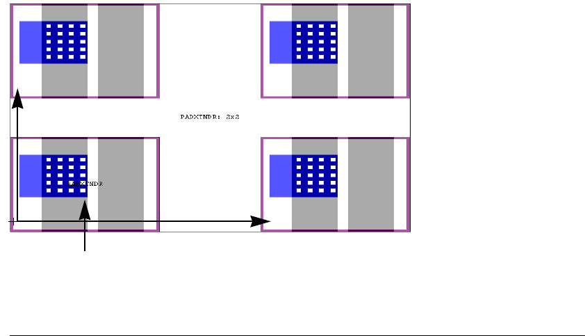
L-Edit 13 User Guide Section 1 202
Chapter 6: Drawing and Editing Objects Command Line Editing
Command Reference
The following commands are available for the Command Line.
!!
Repeat and execute the last command. If the command requires mouse entry, that portion of the
command is not executed.
¦ , Ø
Scroll up or down through the log of command entries.
<Esc>
The Esc key cancels the current command.
Array
Create an array of the selected instance(s) with the designated number of rows and columns. The
argument Xp Yp determines the distance between the origin of each element in the array.
Argument Example
array Rows Cols Xp Yp array 4 6 10 14
original instance
Xp
Yp
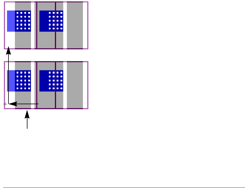
L-Edit 13 User Guide Section 1 203
Chapter 6: Drawing and Editing Objects Command Line Editing
For positive pitch, array is performed in the positive x and y direction. For negative pitch, the array is
performed in the negative x and y direction regardless of overlap, as shown below.
Box
Draw a box as follows. The option -l changes the designated layer.
Copy
Copy the selected object(s) as follows. The option -l changes the designated layer. The option -R
followed by two relative coordinates specifies an offset of the reference point from the lower left corner
of the minimum bounding box.
Argument Description
box w h <mouse click> Draw a box of width w and height h with its center at the mouse click
position.
Example: box 4 10 -l Metal1 <mouse click>
box !x1 !y1 <mouse click> Draw a box with corners at (x1, y1) and the mouse click position.
Example: box 4 10
box !x1 !y1 !x2 !y2 Draw a box with corners at absolute locations (x1, y1) and (x2, y2).
Example: box !42 !51 !46 !61
box !x1 !y1 x2 y2 Draw a box with corners at absolute location (x1, y1) and relative
location (x1+x
2, y1 + y2).
Example: box !42 !51 49 62
box -! x1 y1 x2 y2 Draw a box with corners at absolute locations (x1, y1) and (x2, y2).
Example: box -! 42 51 49 62
original instance
-Xp
Yp

L-Edit 13 User Guide Section 1 204
Chapter 6: Drawing and Editing Objects Command Line Editing
If multiple objects are selected, this command prompts for a mouse click to determine the reference
point that will be used when the objects are pasted.
Goto
Shift the screen display.
Instance
Create an instance of the selected cell. This command supports the use of Xref cells with the -f filename
option, which creates an XrefCell instance of a cell from the specified file. If a cell name includes a
space or comma, it must be enclosed in quotes.
Example:
instance "NAND 1" !14 !22 -f mainlib.tdb
creates a referenced instance of cell NAND from the mainlib.tdb file, with its origin at (14, 22).
Argument Description
copy Store the selected object(s) in the paste buffer.
copy x y Copy the selected object(s) and paste with reference point at (∆x, ∆y).
Example: copy 4 6
copy !x !y Copy the selected object(s) and paste reference point at absolute
location (x, y).
Example: copy 4 10 -l Metal1 <mouse click>
copy -! x y Copy selected object(s) and paste reference point at the absolute
location (x, y).
Example: box 4 10 -l Metal1 <mouse click>
Argument Description
goto x y Shift screen center by (∆x, ∆y).
goto !x !y Move screen center to absolute coordinate (x, y).
goto -! x y Move screen center to absolute coordinate (x, y).
Argument Description
instance cName x y Instance cell cName, placing the cell's origin at position ∆x, ∆y
relative to screen center.
Example: instance "DFF R2" 0 3
instance cName !x !y Instance cell cName, placing the cell's origin at position x, y.
Example: instance DFF !42 !136
instance cName -! x y Instance cell cName, placing the cell's origin at position x, y.
Example: instance DFF -! 42 136

L-Edit 13 User Guide Section 1 205
Chapter 6: Drawing and Editing Objects Command Line Editing
Layer
Change the active layer to the layer designated using either the layer name or GDSII layer number.
Move
Move the selected object(s). The option -R followed by two relative coordinates specifies an offset of
the reference point from the lower left corner of the minimum bounding box.
Path
Draw a wire between mouse click points in the layout or absolute coordinate points. The option -l
changes the designated layer. The option -pw changes the wire width.
instance cName <mouse
click>Instance cell cName, placing the cell's origin at the position given by
the mouse click.
Argument Description
layer LayNum Change active layer to the designated GDSII layer number.
Example: layer 42
layer LayName Change active layer to the designated layer name.
Example: layer "SubCkt ID"
Argument Description
move x y Move selected object(s) by ∆x, ∆y.
Example: move -40 -32
move !x !y Move the lower left corner of the selected object to (x, y). If multiple
objects are selected, this command prompts for a mouse click to
determine the reference point for the translation to (x, y).
Example: move !42 !136 <mouse click>
move -! x y Move the lower left corner of the selected object(s) to the absolute
location (x, y). If multiple objects are selected, this command prompts
for a mouse click to determine the reference point for the translation
to (x, y).
Example: move -! 42 136
Argument Description
path <mouse click(s)>
<right mouse click> Draw a wire segment between mouse click points. Drawing is ended
with a right mouse click. Note that wires are drawn in outline mode
until the drawing is complete.
Example: path -l Metal1 -pw 12 <mouse click> <mouse click> <right mouse click>
path !x !y <mouse click(s)>
<right mouse click> Draw a wire from absolute location (!x, !y) to selected mouse click
points, ending with a right mouse click.

L-Edit 13 User Guide Section 1 206
Chapter 6: Drawing and Editing Objects Command Line Editing
Paste
Paste the selected object(s) into the layout. The option -l changes the designated layer.
Polygon
Draw an all-angle polygon at the indicated absolute vertices. The option -l changes the designated layer.
Example: path !1092 !476 <mouse click> <mouse click> <right mouse click>
path !x1 !y1 !x2 !y2 ... Draw a wire with vertices at the absolute locations (!xn,!y
n) entered.
Example: path !-12 !-14 !79.5 !16 !80.5 !9.5 !50 !-4.5 !23.5 !-15.5 !48.5 !-22.5
path -! x1 y1 x2 y2 ... Draw a wire with vertices at the absolute locations (!xn,!y
n) entered.
Example: path -! 4 10 11 15 20 20 30 45 45 60
Argument Description
paste x. y Paste the selected object(s), translating the reference point of the
objects in the paste buffer by (∆x, ∆y).
Example: paste 15 25
paste !x !y Paste the selected object(s), translating the reference point of the
objects in the paste buffer to the absolute location (x, y).
Example: paste !1092 !476
paste -! x y Paste the selected object(s), translating the reference point of the
objects in the paste buffer to the absolute location (x, y).
Example: paste -! -12 -14
paste <mouse click> Paste the selected object(s) with the reference point of the objects in
the paste buffer to the mouse click point.
Example: paste <mouse click>
Argument Description
polygon !x1 !y1 !x2 !y2 ... Draw a polygon with vertices at the indicated absolute coordinates.
Example: polygon 15 25
polygon -! x1 y1 x2 y2 ... Draw a polygon with vertices at the indicated absolute coordinates.
Example: polygon -! -12 -14
polygon !x1 !y1 <mouse
click> Draw a polygon with first vertex at (x1 y1) and additional vertices
indicated by mouse clicks. A right mouse click completes the
command.
Example: polygon !1092 !476
polygon <mouse click> Draw a polygon with all vertices indicated by mouse clicks. A right
mouse click completes the command.
Example: polygon <mouse click>

L-Edit 13 User Guide Section 1 207
Chapter 6: Drawing and Editing Objects Command Line Editing
Rotate
Rotate the selected object(s) counterclockwise across an angular distance (in degrees) with respect to
the specified point. The value of angle must be between -360 and +360 degrees, exclusively.
Run
Execute the sequence of commands in the specified file.
Text
Create a point port at the specified location. The option -l changes the designated layer.
Argument Description
rotate angle x y Rotate the selection counter-clockwise by angle (degrees) with
respect to the point offset from the selection’s center by (
∆
x,
∆
y).
Example: rotate 90 0 0
rotate angle !x !y Rotate the selection counter-clockwise by the angle (degrees) with
respect to the absolute coordinates (x, y).
Example: rotate 120 !1092 !476
rotate angle -! x y Rotate the selection counter-clockwise by angle (degrees) with
respect to the absolute coordinates (x, y).
Example: rotate 45 -! -12 26
rotate angle <mouse click> Rotate the selection counter-clockwise by angle (degrees) with
respect to the point indicated by mouse click.
Example: rotate 240 <mouse click>
Argument Example
run filename run repwire.tco
Argument Description
text label !x !y Create a port at location (x , y) with the text string label.
Example: text Gnd !4 !10 -lMet1
text label -!x y Create a port at location (x , y) with the text string label.
Example: text Gnd -! 4 10 -lMet1
label <mouse click> Create a port at the mouse click position with the text string label.
Example: txt Gnd

L-Edit 13 User Guide Section 1 208
Chapter 6: Drawing and Editing Objects Command Line Editing
Width
Set the wire width (in Display Units).
Command Scripting
Command scripting is supported through the use of a run command that opens and executes a text file
containing a list of commands. The file format for this command list is Tanner Command Files with a
.tco extension.
You can use the Copy to file command (Ctrl+L from within the command line window) to save
highlighted text from the command window directly to a .tco script file.
C++ style comments are supported in command script files. The run command cannot be nested. Note
that commands using mouse completion are not generally supported in command scripts.
Argument Option
width Sets the wire width to the default value for the active layer.
Example: width
width wire width Sets the wire width to the specified value.
Example: width 3
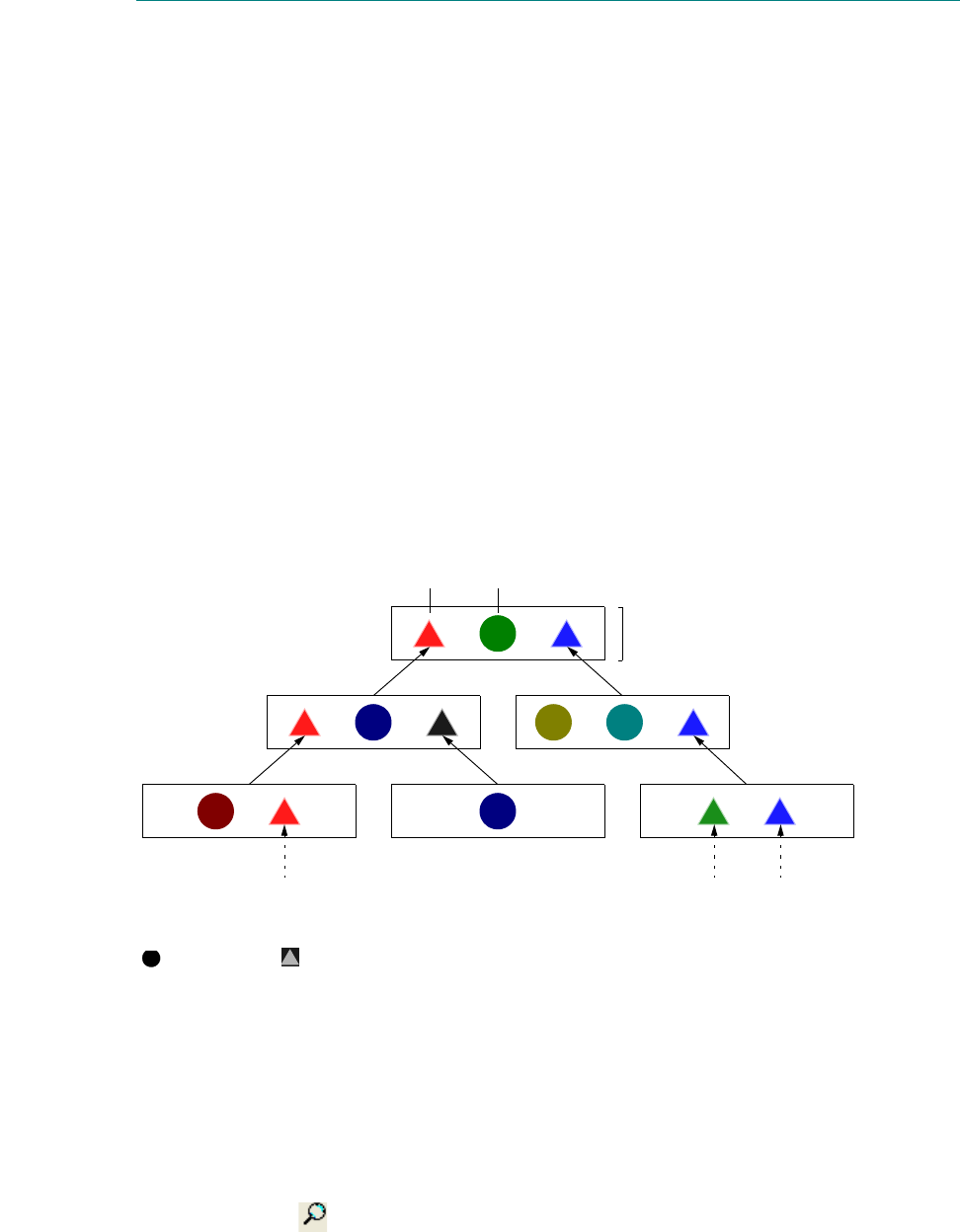
L-Edit 13 User Guide Section 1 209L-Edit 13 User Guide Section 1 209
7 Working with Cells
The cell is the basic building block of an integrated circuit design. A cell in L-Edit can contain three
types of components:
Primitives—geometrical objects created in the cell
T-Cell code and parameters—instructions to generate layout in another cell (discussed in the
chapter “Generated Cells” on page 247).
Instances—references to other cells
In an efficient design, cells, primitives, and instances form a treelike hierarchical structure. The most
elementary cells reside near the “bottom” of the hierarchy; the subsystem cells, composed largely of
instances, reside near the “top.” Actions on a particular cell affect all of its instances in cells “above” it
in the hierarchy.
The figure below illustrates a design hierarchy:
Design Navigator
The Design Navigator lists all cells in a design in a hierarchical structure, including information on
instances, XrefCells and files, and fabrication cells. To open the Design Navigator, use View > Design
Navigator, or click in the standard toolbar.
1
Instance Primitive
Cell
= primitive = instance
source cell source cells
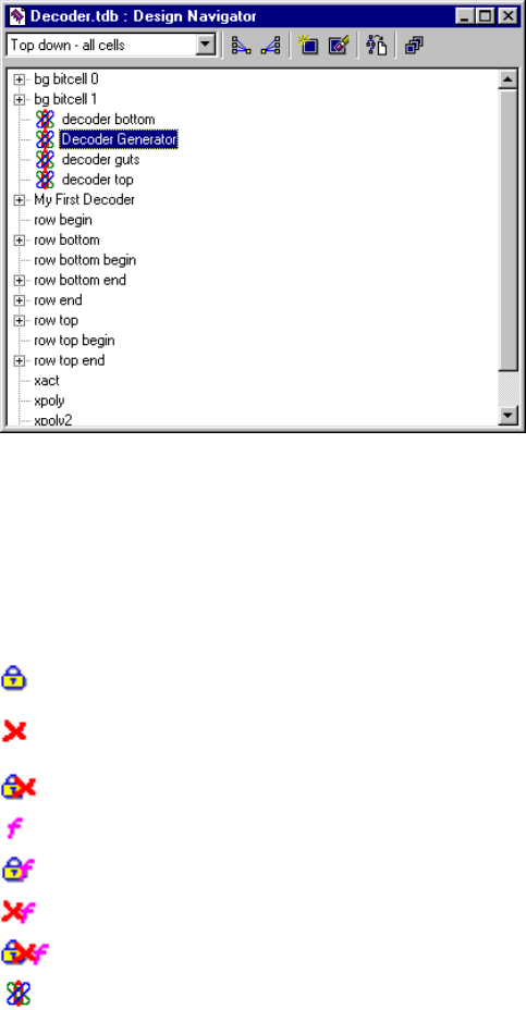
L-Edit 13 User Guide Section 1 210
Chapter 7: Working with Cells Design Navigator
You can use View > Arrange Design Navigator to arrange all open windows with the Design
Navigator docked to one side and the layout windows, each the same size, on the other.
The Design Navigator always opens in Top down - all cells display mode. The default list order is
alphabetical. You can also sort by date modified or DRC status (see “Design Navigator Sort and
Display Modes” on page 210).
A + icon indicates a collapsed state and a - icon indicates an expanded state. To expand or collapse the
cell list click the + or - icon.
Symbols in the Design Navigator for Cell Type and Cell State
In each of the dialogs you access with the Cell menu commands, L-Edit uses these symbols to identify
cells .
Design Navigator Sort and Display Modes
You can view the Design Navigator in the following modes:
Cell0 Cells with unsaved changes are in bold.
A locked cell.
In the
Select Cell to Delete dialog, a cell that cannot be deleted. In
the Select Cell to Instance dialog, a cell that cannot be instanced.
A locked cell that cannot be deleted or instanced.
The fabrication cell.
A locked fabrication cell.
A fabrication cell that cannot be deleted or instanced.
A locked fabrication cell that cannot be deleted or instanced.
T-Cell are shown with a generator icon.
Cell_foo1 Xref files and their cells are displayed in blue.
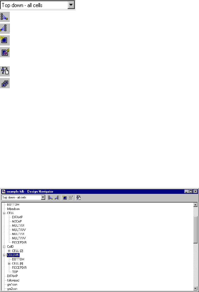
L-Edit 13 User Guide Section 1 211
Chapter 7: Working with Cells Design Navigator
“Top down - all cells” (page 211)
“Bottom up - all cells” (page 212)
“Top down - non-instanced” (page 212)
“By date modified” (page 213)
“DRC Status” (page 213)
Use the drop-down list on the Design Navigator toolbar to select a display mode.
Top down - all cells
In this mode cells are hierarchically listed in terms of instances they contain. When a cell contains
instances and is collapsed, it is marked with a plus icon (+). When you expand the cell, the instanced
cells are listed below it. Numbers in brackets indicate the number of times the particular cell is
instanced in the higher cell.
In the illustration above, COLUMN contains instances of four cells: BOTTOM, CELL, RECEPTDIR, and
TOP. CELL is instanced eight times in COLUMN, and CELL contains instances of other cells as well
(indicated by the + icon).
Select the desired display mode from the drop-down list.
Collapse all cells to display only the top level.
Expand all cells to display all levels of instancing.
Create a new cell.
Delete the selected cell. This operation is only available when the
selected cell is not instanced in another cell.
Copy the display to text view.
Shows all cells in the list, including hidden cells. When unselected,
does not show hidden cells. You can make a cell hidden by
deselecting the Show in Lists option in Cell > Info—Cell
Information. Cells generated by a T-Cell are automatically hidden by
L-Edit.
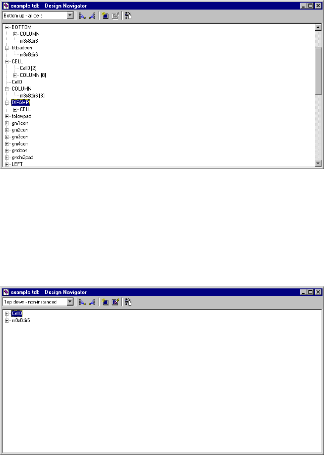
L-Edit 13 User Guide Section 1 212
Chapter 7: Working with Cells Design Navigator
Bottom up - all cells
In this mode cells are listed in terms of where they are instanced. When a cell is instanced in other cells
it is marked with a + and the cells which contain it as an instance are listed below it. Numbers in
brackets indicate the number of times the higher-level cell is instanced in the particular cell.
In this illustration, cell CELL is instanced in two other cells: Twice in Cell0 and eight times in
COLUMN. COLUMN is also instanced in other cells (indicated by the + icon).
Top down - non-instanced
Only cells which are not instanced in other cells are listed in this mode.
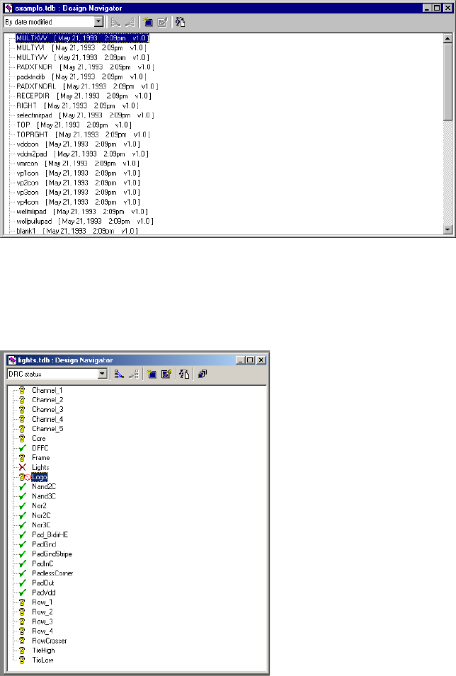
L-Edit 13 User Guide Section 1 213
Chapter 7: Working with Cells Design Navigator
By date modified
All cells are displayed and sorted by modification date/time. The newest cells are at the top; the oldest
are at the bottom. Version is displayed for reference only. Subcells are not displayed in this mode.
DRC Status
In this display mode, all cells are listed in alphabetical order with an icon indicating their DRC status
(see “DRC Status” on page 412. )
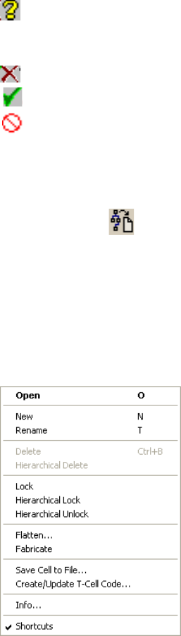
L-Edit 13 User Guide Section 1 214
Chapter 7: Working with Cells Design Navigator
DRC Status Icons
Copy Display to Text View
The Design Navigator can convert its cell tree display to a text representation by pressing the Copy To
Text View button ( ) on the Design Navigator tool bar. The text view will formatted to reflect the
displayed cell tree. For example, if the displayed cell tree is in top down - all cells mode, the text view
will also be ordered that way. If the cell is locked, the word “locked” will appear in brackets to the right
of the cell name.
Performing Cell Operations with the Design Navigator
To access the context-sensitive menu of available commands for the Design Navigator, select a cell and
click the right mouse button.
DRC Needed. DRC has not been run on this cell, changes have been
made to this cell since the last DRC run, or the DRC setup has
changed since the last DRC run.
DRC Failed. DRC has been run on this cell, and errors were found.
DRC Passed. DRC has been run on this cell and no errors were found.
Exclude all instances of this cell from DRC.
Open Opens the selected cell.
New Creates a new cell.
Rename Renames the selected cell.
Delete Deletes the selected cell. This command is only available when the
selected cell is not instanced in another cell.
Hierarchical Delete Deletes the selected cell and all cells instanced in it. This command is
only available when the instanced cells are not instanced anywhere
else.
Lock Locks/unlocks the selected cell.
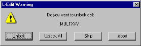
L-Edit 13 User Guide Section 1 215
Chapter 7: Working with Cells Design Navigator
Locking and Unlocking Cells Hierarchically
Hierarchical locking and unlocking allows you to lock and unlock cells and all of their instanced cells
so that a locked cell cannot be modified during an edit in-place operation.
In hierarchical unlocking, the top-level cell is unlocked and L-Edit prompts you for permission to
individually unlock each cell that is instanced in it. The dialog also gives the option to unlock all
instanced cells.
Locking and unlocking will always be exclusive. For example, if cell A and cell B both instance cell C,
and hierarchical lock is performed on cells A and B, all three cells will be locked. If cell A is
subsequently hierarchically unlocked, cell C will be unlocked, including its instance in cell B.
Depending on the state of the selected cell and the associated file, some menu items will be disabled:
Hierarchical lock Locks the selected cell and all cells that are instanced in it (see
“Locking and Unlocking Cells Hierarchically,” below).
Hierarchical unlock Unlocks the selected cell and invokes a warning dialog that asks if the
user wants to individually unlock each cell that is instanced in it. The
dialog also gives the option to unlock all instanced cells (see
“Locking and Unlocking Cells Hierarchically,” below).
Flatten Flattens the hierarchy of the selected cell.
Fabricate Marks the selected cell for fabrication.
Save Cell to File Opens a dialog to save the selected cell to a TDB file. The default
filename is CellName.tdb.
Create/Update T-Cell
Code... Creates a new T-Cell code template for the selected cell. If the cell
already has T-Cell code, L-Edit displays a warning and asks if you
want to replace the existing code.
Info Displays the Cell Information dialog for the selected cell.
Shortcuts Sets whether keyboard shortcuts will be active in the Design
Navigator.
On—Keyboard shortcuts are active, i.e. pressing O will open the
selected cell, not cycle the selection to the first cell that begins
with the letter O.
Off—Keyboard shortcuts are inactive to allow cycle selection by
typing the first few letters of a cell name.
If file is locked: All items except for Open, Info are disabled.
If selected cell is instanced in
another cell:
Delete, Hierarchical Delete are disabled.
If selected cell is locked: Flatten, Rename, Delete, Hierarchical Delete are disabled.
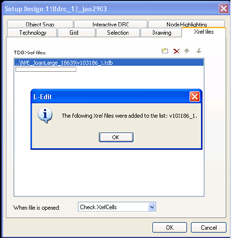
L-Edit 13 User Guide Section 1 216
Chapter 7: Working with Cells Creating Cells
Copying and Instancing from the Design Navigator
You can copy and instance cells to another file directly from the Design Navigator through
drag-and-drop operations:
If you drag and drop a cell from the Design Navigator onto the layout of the same file, L-Edit
creates an instance of the cell.
If you drag and drop a cell from the Design Navigator onto the Design Navigator of another file,
L-Edit creates a copy of the cell in the other file.
If you drag and drop a cell from the Design Navigator onto layout of another file, L-Edit will
prompt you to either copy and instance, copy, create an XrefCell, or instance or create an XrefCell,
For example:
If you drag and drop a cell from an Xref file that is already in the active TDB file, then the instance
is set to the existing XrefCell.
Printing Cell Hierarchy from the Design Navigator
You can print the cell hierarchy when the Design Navigator is the active window. The hierarchy will be
printed in its current state, using + and - to indicate the state of the branches. Each level of the cell
hierarchy will be shifted from the previous one to the right by three characters.
Information that the cell is locked or selected for fabrication will be displayed in brackets after the cell
name, in the form [Locked] or [Fabricate].
Creating Cells
To create a new cell, choose Cell > New or press N. The General tab allows you to enter identification
information about the cell. If the cell will contain only primitives and instances, click OK. To add
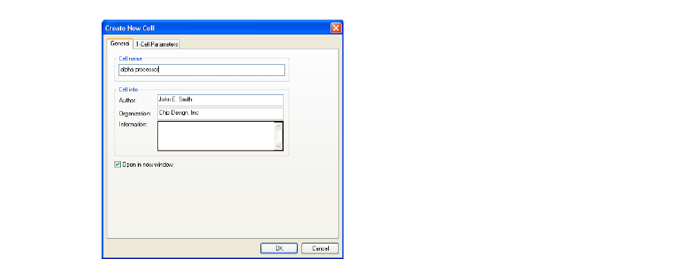
L-Edit 13 User Guide Section 1 217
Chapter 7: Working with Cells Creating Cells
parameters and UPI code for a T-Cell, click the T-Cell Parameters tab (see “Creating T-Cells” on page
247).
Options include:
Cell name The name of the new cell. Each component cell of a file must have a
unique name.
Cell info Includes Author, Organization, and Information (notes or messages)
for the active cell.
Open in new window Instructs L-Edit to open the cell in a new layout window. The Select
Cell To Edit dialog (accessed with Cell > Open) has an identical
option. Setting this option in either dialog controls the behavior for
both commands. L-Edit saves last state of this check box when you
exit the application.
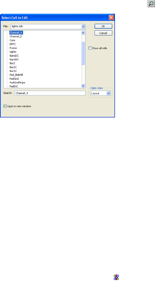
L-Edit 13 User Guide Section 1 218
Chapter 7: Working with Cells Opening Cells
Opening Cells
To open a cell, choose Cell > Open, press O, or click the open cell button ( ).
Options include:
If a cell name is in boldface type, it indicates that the cell has been edited but that the changes have not
yet been saved. T-Cells are shown with a generator icon ( ) next to them.
If an instance is selected in the layout, its name will be highlighted in the Open Cell dialog. If multiple
instances are selected, the referenced cell of the first instance in the selection will be highlighted. If no
instance is selected, the last cell opened will be highlighted.
File The name of the current file (default) or of any other open file.
Cell list The specified file’s component cells are displayed in the scrollable
list. To open a cell, select it and click OK or double-click it.
Open in new window Instructs L-Edit to open a cell in a new layout window. The Create
New Cell dialog (accessed with Cell > New) has an identical option.
Setting this option in either dialog controls the behavior for both
commands. L-Edit saves last state of this check box when you exit the
application.
Open View Instructs L-Edit to open either the cell Layout or a text window
containing T-Cell Code for the selected cell. If the selected cell is not
already a generator cell, the option T-Cell Code will open a blank
code window.
Show all cells When checked, shows all cells in the list, including hidden cells.
When unchecked, does not show hidden cells. You can make a cell
hidden by deselecting the Show in Lists option in Cell > Info—Cell
Information. Cells generated by a T-Cell are automatically hidden by
L-Edit.
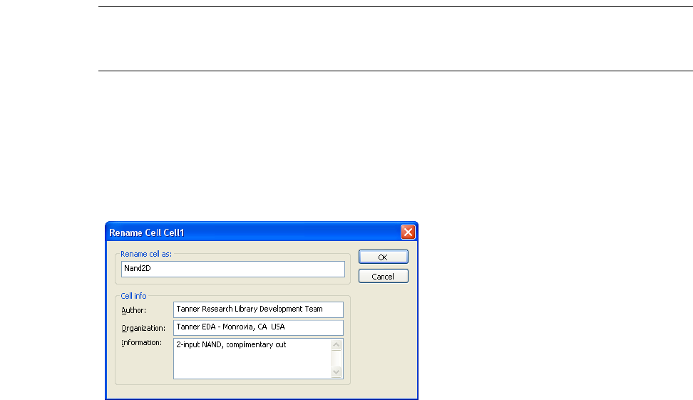
L-Edit 13 User Guide Section 1 219
Chapter 7: Working with Cells Reverting Cells
Cell names can be selected by typing in the Search field. As you type letters in the Search field, L-Edit
automatically highlights the first name in the list beginning with the (case-insensitive) partial name
being entered. For example, typing a g causes the first cell name beginning with g or G to be
highlighted; adding a u highlights the first cell beginning with gu, Gu, gU, or GU; and so on.
You can open multiple views of a cell by reopening the same cell. L-Edit will display and update each
view of the cell in a separate layout window. The name of a cell is found in the title bar.
Reverting Cells
Cell > Revert Cell allows you to reverse all changes made to the layout of the active cell after any the
following operations:
File > Save
Tools > Generate Layers
Tools > DRC
Tools > Extract
Draw > Assign GDSII Data Types
Draw > Clear Rulers
Tools > Clear Generate Layers
Tools > Clear Error Layers
Warning: The Revert Cell command does not reverse changes to T-Cell code.
The Revert Cell command cannot be undone using Edit > Undo.
Renaming Cells
To rename the current cell, choose Cell > Rename (or press T).
Rename cell as The new name of the active cell.
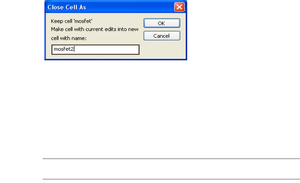
L-Edit 13 User Guide Section 1 220
Chapter 7: Working with Cells Copying Cells
The renamed cell stays open when you click OK.
Before netlist extract, it is possible to have two instances with the same instance name. However, after
netlist extraction, L-Edit will force each instance to have a unique name.
You can also use Cell > Close As, which copies the cell with all current changes to a cell with a new
name. Cell > Close As closes the original — without saving layout changes since the previous save
operation — and opens the newly named cell.
The Close Cell As dialog contains a field to enter the new cell’s name.
Copying Cells
Cells may be copied within a file or copied to the current file from other open files. When a cell is
copied, a new cell (not an instance) is created, including all primitives and instances defined by the
original cell. If a cell is copied from another file, all cell definitions of the instances in the copied cell
are also copied. Since cells cannot have duplicate names, it may be necessary to rename the cell and
possibly some or all of its instances.
Note: Note that L-Edit does not automatically rename a non-unique instance when you copy
a cell instance.
L-Edit can also copy a portion of a cell and paste it into a new cell created for that “clip out;” see
“Copying a Piece of a Cell to Another Cell” on page 224.
Cell info Includes editable text fields for Author, Organization, and
Information (notes or messages) for the active cell.
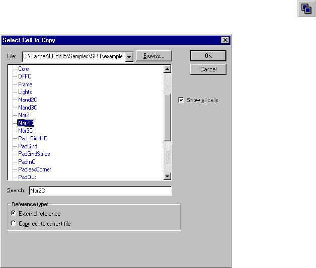
L-Edit 13 User Guide Section 1 221
Chapter 7: Working with Cells Copying Cells
To copy cells, choose Cell > Copy, press C, or click the copy cell button ( ).
Options include:
If an instance is selected in the layout, the referenced cell will be highlighted in the Select Cell to Copy
dialog. If multiple instances are selected, the referenced cell of the first instance in the selection will be
highlighted. If no instance is selected, the current cell will be highlighted.
File Name of the active file (default) or any other file specified from the
drop-down list. In the drop-down list, TDB files that are open but not
active are displayed in red, cross-referenced TDB files are displayed
in blue.
Search Enter the cell’s name here, or highlight it on the scrollable list of the
specified file’s component cells, which is displayed in the above this
field. Click OK or double-click a highlighted cell name to open the
Cell Copy dialog.
Reference type Options include:
External reference—creates an XrefCell, as described in
“Instancing Cells” on page 230
Copy cell to current file—creates a copy of the specified cell in
the current file
Both options are unavailable when copying a cell contained in the
active TDB file.
Show all cells When checked, shows all cells in the list, including hidden cells.
When unchecked, does not show hidden cells. You can make a cell
hidden by deselecting the Show in Lists option in Cell > Info—Cell
Information. Cells generated by a T-Cell are automatically hidden by
L-Edit.
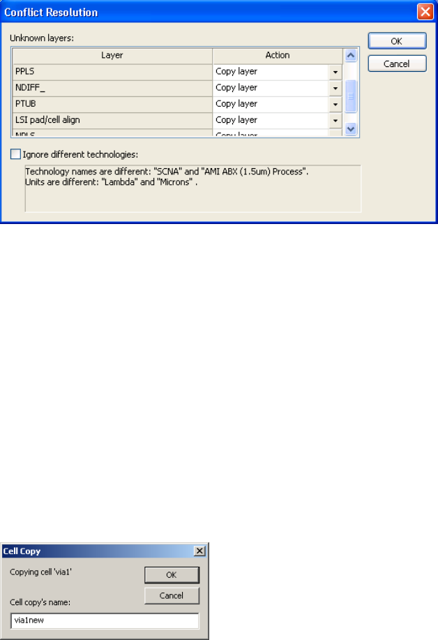
L-Edit 13 User Guide Section 1 222
Chapter 7: Working with Cells Copying Cells
Click OK to proceed with the cell copy. If you are copying a cell from one file to another, L-Edit checks
the destination file setup for conflicts with the cell to be copied. Conflicts are reported in a Conflict
Resolution dialog, such as the one shown below:
If the cell being copied includes layers that are not defined in the current file, L-Edit lists these as
Unknown layers. For each unknown layer, select an Action from the drop-down list to resolve the
conflict. You can either copy the layer definition from the file containing the cell to the current file, or
you can map the unknown layer to a layer that is defined in the current file.
Resolving Conflicts When Copying Cells
If the cell being copied and the current file use different technologies, these differences will also be
listed in the Conflict Resolution dialog. To ignore the differences and proceed with copying the cell,
check Ignore different technologies and click OK. To resolve different technologies, click Cancel and
edit the technology setup information for one of the two files. L-Edit will copy a cell with different
technology setup if Ignore different technologies is checked.
If the cell being copied resides within the current file, then a new name is required. (The original cell
name is not permitted. You must rename the copy.) In the Cell Copy dialog, enter a new name for the
copy and click OK.
If the cell being copied resides in a different file, then the copy proceeds automatically unless a name
conflict is detected. When L-Edit detects a name conflict, it prompts you to select an action required to
complete the copy. You can specify options separately for each name conflict that occurs. Name
conflicts can arise for the cell being copied or for any cell contained within the copied cell.
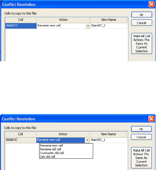
L-Edit 13 User Guide Section 1 223
Chapter 7: Working with Cells Copying Cells
When Reference type: External Reference is selected in the Cell > Copy dialog, you must rename the
cells that cause a conflict in order to proceed with the copy. In this case, L-Edit displays name conflicts
in a Conflict Resolution dialog, where you can select new names for the conflicting cells:
The default name for the Xref Cell causing a name conflict is CellName_New. You can enter a new cell
name by editing the field labeled New Name.
When Reference type: Copy cell to current file is selected in the Cell > Copy dialog, the Action field
for each name conflict will contain a drop-down list of possible resolutions.
For each name conflict, select one of the following options:
Saving a Cell to Another File
Save Cell to file saves a single cell and its hierarchy to a new TDB file. To save a single cell to TDB
use Cell > Save Cell to File.... The Save Cell to File dialog shown below allows you to choose the cell
Rename new cell
(default) Rename the cell being copied from the source file. When this option
is selected, you can enter a new cell name in the field labeled New
Name. The default name is CellName_New.
Rename old cell Rename the cell residing in the current (destination) file. When this
option is selected, you can enter a new cell name in the field labeled
New Name. The default name is CellName_New
Overwrite old cell The cell in the current file is overwritten by the copied cell.
Use old cell The source cell causing a name conflict is not copied.
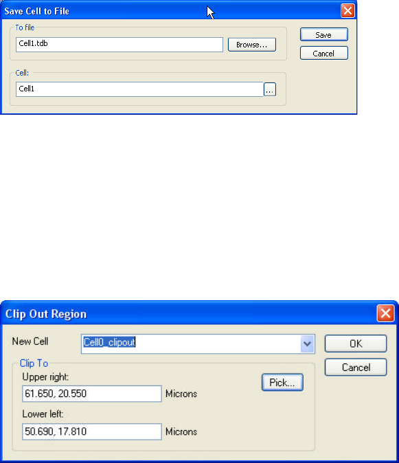
L-Edit 13 User Guide Section 1 224
Chapter 7: Working with Cells Copying Cells
to save and the file to which it will be saved. The Browse button opens a standard Windows Save As
dialog.
Copying a Piece of a Cell to Another Cell
The command Draw > Clip Out Region... copies a rectangular region of a cell and saves that region and
its hierarchy to a new cell. All geometry within the boundary of the clipped rectangle and all instances
completely inside the clip rectangle will retain their hierarchy. Objects on hidden layers will be copied.
The Clip Out Region dialog shown below lets you name the new cell and specify the portion to be
copied.
New Cell Name Name of the new cell where the clipped region will be saved. L-Edit
appends “_clipcut” to the name of the source cell and will use the
appended name if nothing else is entered in this field.
Clip To Define the rectangle to be copied, either by entering absolute x, y
coordinates for the corners, or by clicking on the Pick... button.
Pick... Click on this button to return to the layout to use the mouse to select
the clipping rectangle. The first click selects the lower left point, the
second click selects the upper right point of the rectangle to be copied.
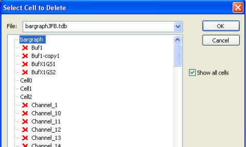
L-Edit 13 User Guide Section 1 225
Chapter 7: Working with Cells Deleting Cells
Deleting Cells
To delete a cell, choose Cell > Delete or press B. L-Edit displays the Select Cell To Delete dialog:
Options include:
File The name of the active TDB file (default). All open TDB files are
listed in the drop-down list.
Cell The specified file’s component cells are displayed in the scrollable
list. Cells which cannot be deleted (due to being instanced in other
cells) have a red (x) next to them. Highlight an available cell and click
OK to delete the cell.
Hierarchical delete Checking this box causes all cells instanced within the selected cell to
also be deleted, unless they are instanced in additional cells.
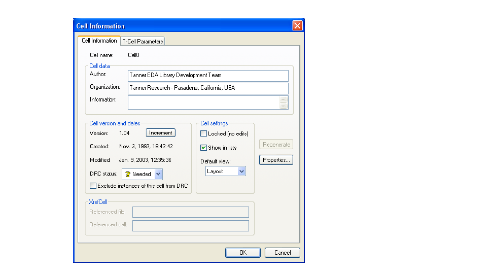
L-Edit 13 User Guide Section 1 226
Chapter 7: Working with Cells Cell Information
Cell Information
Use Cell > Info to edit information on the active cell. (See “Creating T-Cells” on page 247 for how to
use the T-Cells Parameters tab.
Cell name Name of the active cell
Cell data Includes Author, Organization, and Information (notes or messages)
for the active cell. Information can contain a maximum of 256
characters.
Cell version and dates The date and time the cell was created and last modified. The version
numbering system provides an internal accounting method for
tracking changes. Increment increases the version number to the next
major version (for example, 3.08 to 4.00). L-Edit automatically
increments the minor version number (for example, 3.08 to 3.09) each
time changes to the cell are saved.
Use Alt+K to decrement version numbers (for example, 3.27 to 3.00
then 2.00).
Use Alt+L to increment the minor version (for example, 3.27 to 3.29).
DRC Status The DRC status of the cell, either Needed, Passed, or Failed.
Exclude instances of this
cell from DRC Check this checkbox to exclude all instances of this cell from all DRC
runs. See “Excluding Cells from DRC” on page 412
Cell locked Switches the cell between locked and unlocked states. Locked cells
cannot be edited, but objects in them may be selected and copied to
other cells, and the cell can be instanced in other cells.
L-Edit 13 User Guide Section 1 227
Chapter 7: Working with Cells Cell Information
Listing the Object Types and Layers Used in a Cell
Cell > Cell Object Summary counts the type and number of objects on each layer used in a cell, for the
top level of the cell and all objects in the hierarchy. Each object is counted only once.
Cell > Layer-Cell Cross Reference lists the layers in a design file that have geometry on them and
gives the name of the cells that contain the geometry.
For example:
Layer-Cell Cross-Reference
Layer "Active"
DFFC
Nand2C
Nor2
Nor2C
Pad_BidirHE
PadGnd
PadVdd
RowCrosser
TieHigh
TieLow
Show in lists If checked, the cell will appear in cell lists, such as the Design
Navigator, Cell >Instance, etc. If unchecked, the cell will be
suppressed from these lists.
Default view Select the default view when opening this cell. Choose Layout to
open the layout view of this cell by default, or choose T-Cell to open
the code view of this cell by default.
XRefCell If the cell is an XRefCell, Referenced file is the name and path of the
TDB file which contains the referenced cell. Referenced cell is the
name of the referenced cell. All of the information in the Cell
Information dialog for an XrefCell pertains to the referenced cell and
is read-only and cannot be edited.
Properties Opens the Properties dialog for the cell. For information on cell
properties, see “Properties” on page 68.
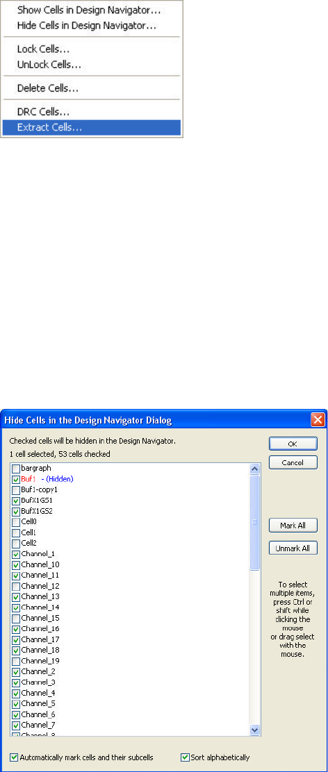
L-Edit 13 User Guide Section 1 228
Chapter 7: Working with Cells Operations on Multiple Cells
Operations on Multiple Cells
The Cell > Multiple Cell Operations commands let you perform certain operations on more than one
cell at once. In each of the multiple cell dialogs, cells that are not instanced are listed before those that
are, sorted alphabetically within each group. Possible multiple cell operations are:
Show Cells in the Design Navigator—All cells that are checked will be shown in the Design
Navigator when “Show All Cells” is turned off. Cells are sorted with shown first, then hidden.
Hide Cells in the Design Navigator—All cells that are checked will be hidden in the Design
Navigator when “Show All Cells” is turned off. Cells are sorted with shown first, then hidden.
Lock Cells—All checked cells will be locked. Cells are sorted with unlocked first, then locked.
Unlock Cells—All checked cells will be unlocked. Cells are sorted with unlocked first, then
locked.
Delete Cells—see “Deleting Multiple Cells” (page 229)
DRC Cells—Performs DRC on all cells that are checked using the current DRC setup.
Extract Cells—Performs Extract on all cells that are checked using the current extract setup for
each cell.
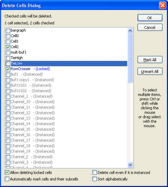
L-Edit 13 User Guide Section 1 229
Chapter 7: Working with Cells Operations on Multiple Cells
The following controls are common to all the multiple cell operations (showing, hiding, locking,
unlocking, running DRC and running Extract):
Deleting Multiple Cells
The Delete Cells Dialog has two additional checkboxes.
When a cell is not available for deletion it will appear grayed out. When locked cells, instanced cells, or
locked and instanced cells are available for deletion, their display colors are:
Unlocked, not instanced—black
Mark All Checks all the cells in the list.
Unmark All Removes the check from all cells in the dialog.
Automatically mark cells
and their subcells With this option is checked, if you check a cell L-Edit will
automatically check all of the cells instanced in that cell.
Sort alphabetically Sorts the cells alphabetically rather than by status.
Allow deleting locked cells When this option is checked, it is possible to check and delete a cell
even though it is locked.
Delete cell even if it is
instanced When this option is checked, it is possible to check and delete a cell
even though it is instanced in another cell. The instances are deleted
before the source cell is deleted.
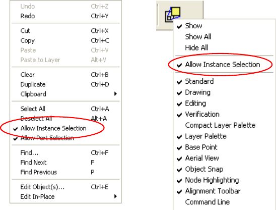
L-Edit 13 User Guide Section 1 230
Chapter 7: Working with Cells Instancing Cells
Locked, not instanced—dark blue
Unlocked, instanced—red
Locked, instanced—dark red
Instancing Cells
An instance is a representation of a cell in a particular location and orientation in another cell. An
instance can reference a cell composed of primitives, other instances, or a combination of primitives and
instances. An instance can also reference a cell generated from T-Cell code, called an auto-generated
cell. However, a cell cannot instance itself—that is, you cannot create an instance of a cell in the cell
itself.
An “instancing” cell contains such a representation; an “instanced” cell is the source, or referenced, cell.
Changes made to the instanced (source) cell are automatically propagated to all instances of that cell.
Changes made to a T-Cell, which L-Edit uses to generate source cells, cause all auto-generated cells and
their instances to be flagged “out of date.” You can update T-Cell instances using the
Tools > Regenerate T-Cells command.
Layouts that use instances consume less memory than “flat” designs, where all the features exist as
originally drawn objects.
Setting Instance Selectability
Note that it is possible to set L-Edit so that instances cannot be selected. Use either the Allow Instance
Selection option in the Edit menu, or right-click on the Instance button in the Drawing toolbar to
access the same command.
Creating Instances
You can instance a cell from the active TDB file or another TDB file (XrefCell).
Drag and drop the original cell from the Design Navigator into the current cell. (See “Performing
Cell Operations with the Design Navigator” on page 214.)
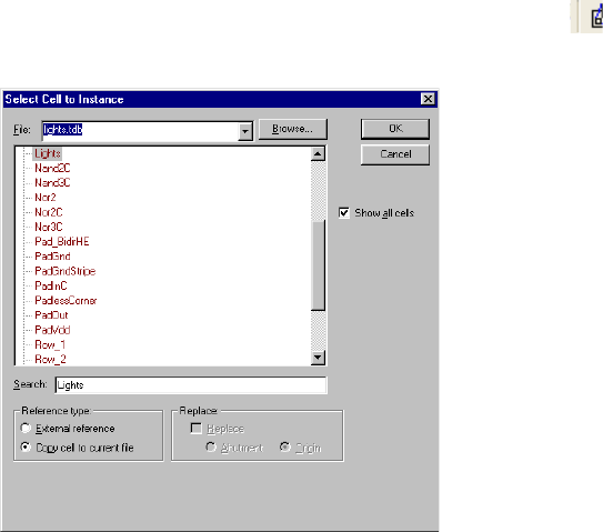
L-Edit 13 User Guide Section 1 231
Chapter 7: Working with Cells Instancing Cells
Use Cell > Instance, press I, or click on the Instance icon in the Drawing toolbar to open the
Select Cell to Instance dialog.
Options include:
File Name of the active file (default) or any other file specified from the
drop-down list. In the drop-down list, red indicates a TDB file that is
open but not active, blue indicates a cross-referenced TDB file. To
view a file not currently open, click the Browse button.
Cell Name of the cell currently selected in the cell list. To select a cell,
highlight its name in the cell list. Double-click or click OK to create
an instance of the cell.
Note: Each instance in a cell must have a unique name after netlist
extraction. Before netlist extract, you can have two instances
with the same instance name. However, after netlist extraction,
L-Edit will force each instance to have a unique name.
Reference type Available when you instance a cell from a file other than the active
file—that is, an Xref file. You can instance cells from other files in
two ways:
External reference creates an XrefCell and then updates the
instance whenever the XrefCell is changed (as long as the link to
the XrefCell is not broken).
Copy cell to current file copies the cell to the active file and
creates an instance of that local cell (see “Copying and
Duplicating Objects” on page 280).
If you try to instance a cell from an Xref file but the cell is already in
your active file, the instance will be made from the existing Xref cell.
(For more information on XrefCells, see “Instancing Cells” on page
230.)
Replace Replaces the instance in the layout area with an instance of the
specified cell. See also “Replacing Multiple Instances” on page 239.
When this option is checked, two other options become available:

L-Edit 13 User Guide Section 1 232
Chapter 7: Working with Cells Instancing Cells
Searching for Cell Names Alphabetically
In the cell list, bold font indicates that a cell has been edited but the changes have not been saved.
You can use the search feature to select cell names by typing instead of scrolling and clicking. As you
type letters in the Cell field, L-Edit automatically selects the first name in the list beginning with the
(case-insensitive) pattern entered.
For example, typing a g causes the first cell name beginning with g or G to be highlighted; adding a u
highlights the first cell beginning with gu, Gu, gU, or GU; and so on.
Note: A cell cannot instance itself—that is, you cannot create an instance of a cell in the cell
itself.
Aligning Instances by Abut Ports
When you select an instance and replace it, you have the option of aligning the selected instance and the
replacement instance according to their origins or abut ports.
An abut port is a box port with text that matches the Abutment field in the dialog SPR Core Setup—
General. When you replace an instance and specify alignment by abut port, L-Edit examines the
selected instance and the instance you are replacing it with to see if their abut ports match. The check of
abut port names is case-sensitive.
If the abut ports in the two cells have matching names and dimensions, L-Edit places the new instance
in exactly the same position as the previous one. If the abut ports in the two cells do not match, or if
Abutment—aligns the instance selected in the layout with the
replacement instance according to their abut ports. For a detailed
description, see “Aligning Instances by Abut Ports” on page 232.
Origin—aligns the instance selected in the layout with the
replacement instance according to their origins. With this option,
the replaced instance maintains the position of the previous
instance with respect to the origin (position 0,0) of the coordinate
system.
Show all cells When checked, shows all cells in the list, including hidden cells.
When unchecked, does not show hidden cells. You can make a cell
hidden by deselecting the Show in Lists option in Cell > Info—Cell
Information. Cells generated by a T-Cell are automatically hidden by
L-Edit.
If you have selected an instance in the layout of a cell that is not set to
Show in lists in Cell > Info, you must enable Show all cells to be
able to instance that cell.
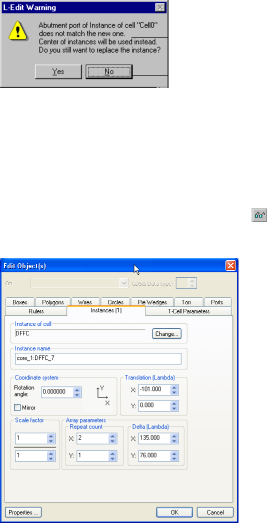
L-Edit 13 User Guide Section 1 233
Chapter 7: Working with Cells Instancing Cells
there are no abut ports in either cell, L-Edit will prompt you with the following dialog for permission to
align on the instances on their centers.
For further information on abut ports, see “SPR Core Setup–General” (page 355).
Creating Arrays using Edit >Object(s)
An array is a two-dimensional arrangement of objects, offset in the vertical and/or horizontal directions
by specified amounts. A single instance is equivalent to a 1x1 array.
To create an array, select the instance and choose Edit > Edit Object(s), press Ctrl+E, double-click the
MOVE/EDIT mouse button, or click the edit object(s) button ( ).
In the Edit Object dialog, select the Instances tab.
In the Array parameters area, enter the horizontal and vertical repeat count and the X and Y spacing
(Delta) between array elements.
You can also create an array by grouping instances (see “Grouping and Ungrouping Objects” on page
272) or by duplicating objects (see “Copying and Duplicating Objects” on page 280.)
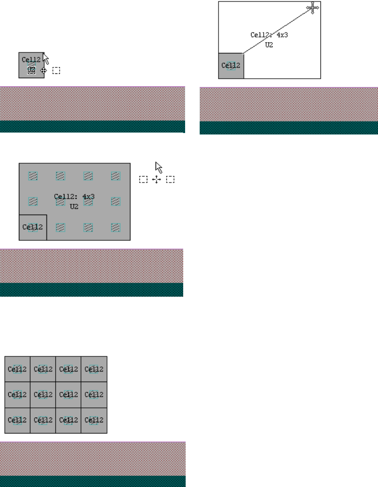
L-Edit 13 User Guide Section 1 234
Chapter 7: Working with Cells Instancing Cells
Creating Arrays using the Mouse
You can quickly create an array of any instance by selecting an edge or corner and using the Move
operation. The newly-created array will be an instance itself.
Simply select the edge of an instance and drag the mouse to create an array in one direction or select a
corner to create an array in both the x- and y-directions, as illustrated below.
You can use Draw > Ungroup to convert the array to its component instances.
L-Edit 13 User Guide Section 1 235
Chapter 7: Working with Cells Editing Instances
Editing Instances
With certain exceptions, to edit the contents of an instance, you must edit the cell it refers to. An
instance cannot be reshaped, sliced, or merged, and vertices and edges cannot be individually edited.
However, an instance as a whole can be:
Moved
Rotated or flipped (see “Reorienting” on page 278)
Edited textually (see “Editing Instances Using Text” on page 240)
Replaced (see “Replacing Instances” on page 238)
An instance cannot be edited or moved if it contains objects that are drawn on a locked layer. To edit or
move such an instance, you must first unlock any locked layers.
You can edit the contents of an instance or array in two ways:
Return to the original cell and make the desired changes there
Use Edit > Edit In-Place (see “Editing Instances “In-Place”” on page 239)
Changes made in an original layout cell (or auto-generated T-Cell) are automatically propagated to all
instances and arrays of that cell.
Flattening Instances
Cell > Flatten removes the hierarchy of a cell. This is done by replacing all instances with the objects
from the cell that they reference. The effects of this command cannot be reversed using the Undo
command.
To flatten an instance by only one level, select it and use Draw > Ungroup. This command can be
undone.
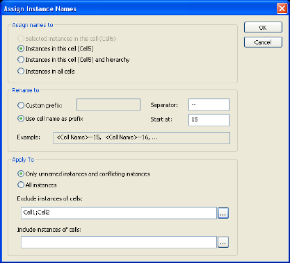
L-Edit 13 User Guide Section 1 236
Chapter 7: Working with Cells Editing Instances
Assigning Names to Instances (Tools > Assign Instance Names)
You can quickly assign unique names to individual instances throughout the hierarchy using the
Tools > Assign Instance Names command. Instance names are assigned using contents of the selected
prefix field, plus the Separator (if any), plus the Start at value.
Assign names to Use these buttons to set the range of the name changes:
Selected instances in this cell—renames just the instances in
the active cell that are selected.
Instances in this cell—renames all instances in the current cell.
Instances in this cell and hierarchy—renames all instances in
the current cell and each of the instances up the hierarchy to the
parent cells.
Instances in all cells—renames cell instances in the entire
design.
Custom prefix When checked, uses the characters in the entry field as the first part of
the instance name. You may enter characters of any type or leave this
field blank.
Use cell name as prefix When checked, uses the instance’s master cell name as a prefix for the
new name.
Separator Enter characters of any type that will be used to separate the cell name
from its “Start at” value. You may leave this field empty.
Start at Enter the beginning value of the cell name suffix, which will
increment by one. You must enter a positive integer.
Example Shows an example of what the new cell names will look like.
L-Edit 13 User Guide Section 1 237
Chapter 7: Working with Cells Editing Instances
After the operation is complete L-Edit opens a simple log of the name reassignments as shown below,
which lists the instances included in and excluded from assignment.
Assigning names to instances in all cells.
Prefix: TSM65
Separator: -
Start index: 99
Apply to: All instances
Exclude instances of cells:
(empty)
Include instances of cells:
(empty)
Cell Cell0
Cell Cell1
Cell Cell2
Cell2/U52 -> TSM65-99
Cell Cell3
Cell3/U53 -> TSM65-99
Cell Cell4
Cell4/cel7-C -> TSM65-99
Cell4/cel6-B -> TSM65-100
Cell4/cel6-A -> TSM65-101
Cell4/cel5-A -> TSM65-102
Cell4/cel1-A -> TSM65-103
Cell Cell5
Cell Cell6
Total renamed: 7
Apply to Use these buttons to filter instance selection:
Only unnamed instances and conflicting instances—renames
just the instances that have either have no name or conflicting
names.
All Instances—renames all instances.
You can also filter by cell name using one, none or both of the
following fields. Use the browse button to pick from the list, and a
comma or semicolon to separate cell names.
Exclude instances of cells—if a cell name is in this list,
instances of that cell will not be renamed, regardless of any other
selection criteria.
Include Instances of cells—if a cell name is in this list,
instances of that cell will be renamed, regardless of any other
selection criteria.
The exclude list has priority over the include list—if a cell name is in
both lists, it will be excluded. If you enter an invalid cell name L-Edit
will display a warning.
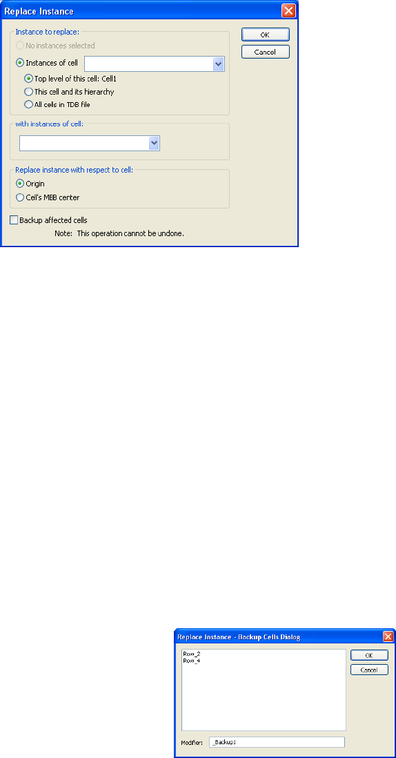
L-Edit 13 User Guide Section 1 238
Chapter 7: Working with Cells Editing Instances
Replacing Instances
Cell > Replace Instance replaces all instances of one type with another, either in the top level of a cell,
in a cell and down its hierarchy, or in all cells. Note that this operation cannot be undone.
1 selected instance
regardless of it’s parent
cell
Replaces just the one instance selected.
Instance to replace Instance of cell—use this pull-down menu to select the instance to be
replaced.
Pick one of these to set the scope of the replacement:
Top level of this cell—replaces instances in just the selected
cell.
This cell and its hierarchy—replaces in the selected cell and all
instances it comprises.
All cells in the TDB file—replaces every instance of the selected
cell in the entire design.
with instances of cell Name of the cell that will replace the original cell.
Replace instance with
respect to cell Origin aligns the origins of the two cell, Center aligns the center of
the MBB of the two cells.
Backup affected cells This option allows you to save the existing versions of the cells that
will change, with “_Backup1” as the default appended text.
L-Edit 13 User Guide Section 1 239
Chapter 7: Working with Cells Editing Instances
Replacing Multiple Instances
You can also use the Edit Object—Instances dialog to replace multiple selected instances, whether the
same or different, with another instance. When multiple instance are selected, the Instance of cell and
Instance name fields will be disabled, but you can click on the Change button to open the Select Cell
to Instance dialog.
Use the cell list to pick the cell that will replace those selected in the layout (self-referential cells will be
disabled).
Editing Instances “In-Place”
Editing in-place allows you to edit an instance without opening the original cell. Note that editing
in-place is not available for instances that have been rotated by a non-orthogonal angle or for instances
of XrefCells. To edit an instance in place:
[1] Select the instance to edit.
[2] Choose Edit > Edit In-Place > Push Into, press Page Down, or click the edit in-place button ( ) to
“step down” into the instance.
After you have stepped down into an instance you can edit the contents of the instance as if you had
opened the original cell. The original cell will also show the changes made to the instance.
Editing a T-Cell instance in-place allows you to edit the contents of the auto-generated cell
corresponding to the selected instance. Editing a T-Cell instance in-place automatically propagates
changes to all instances of the T-Cell that were created with the same parameters.
While editing in-place you can only select or edit objects contained in the instance. This includes
regular geometry as well as other instances or arrays. Editing in-place does not allow you to change
T-Cell code.
You can step down multiple levels in an instance. Continue selecting instances and use Edit > Edit
In-Place > Push Into as described above.
To step up in the hierarchy and end the edit in-place session, use Edit > Edit In-Place > Pop Up, press
Page Up, or click the pop edit in-place button ( ) on the Standard toolbar.
When you are editing in-place, you can use Edit > Edit In-Place > View Top Cell or press the End key
to go to the home view of the top cell. Use View > Home or press the Home key to go to the home view
of the cell currently being edited in the instance hierarchy.
Push to Object
You can step through the design hierarchy multiple instances at a time using Edit > Edit
In-Place > Push to Object, or pressing Ctrl+PageDown. Push to Object will push the editing context
though multiple hierarchy levels and will select the object that the mouse pointer is currently over.
Invoking Push to Object repeatedly will cycle though selecting objects that the cursor is over, moving
up and down hierarchy as necessary.
Selecting Edit > Edit In-Place > Pop to Top Cell, or Ctrl+Page Up will step up the hierarchy to the top
cell.
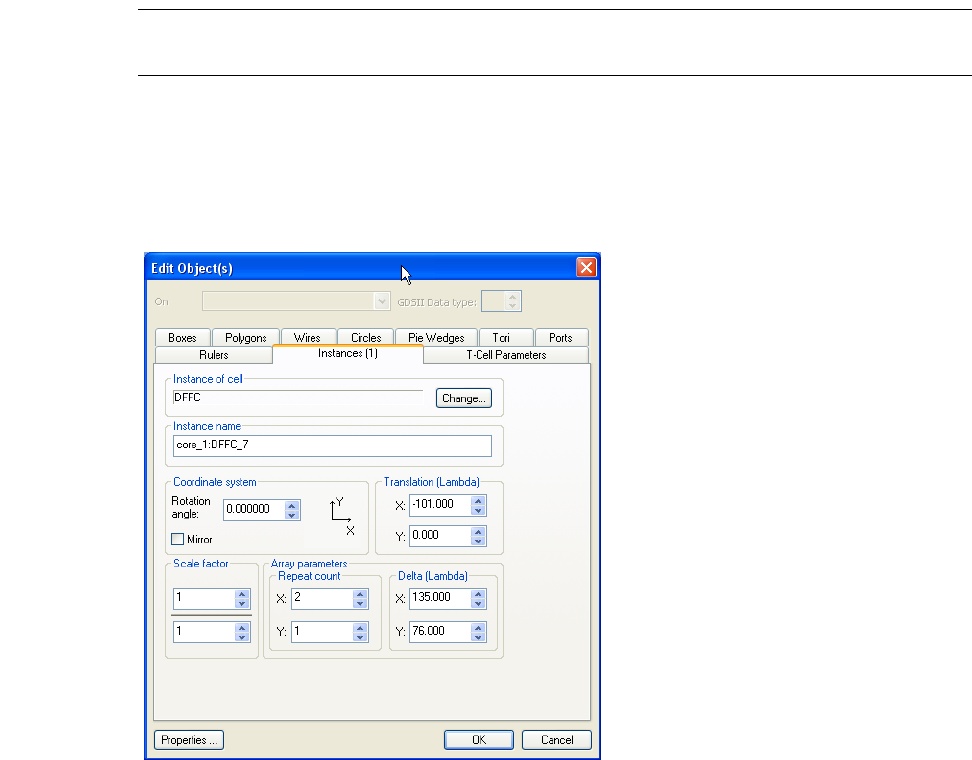
L-Edit 13 User Guide Section 1 240
Chapter 7: Working with Cells Editing Instances
Note: Changes made to a T-Cell instance using Edit > Edit In-Place will be lost if you
regenerate the T-Cell.
Editing Instances Using Text
To edit an instance as an object, choose the Edit Object(s)—Instances tab. You can change the name of
the instance and factors that affect the display of the instance.
Options include:
Instance of cell Name of the instanced cell. Disabled when multiple instances are
selected.
To instance a different cell, click the Change button to open the
Select cell to instance dialog.
Instance name Identifies the selected instance or array. Disabled when multiple
instances are selected. L-Edit automatically assigns a name if you
leave this field blank.
Note: Each instance in a cell must have a unique name after netlist
extraction. Before netlist extract, you can have two instances
with the same instance name. However, after netlist extraction,
L-Edit will force each instance to have a unique name.

L-Edit 13 User Guide Section 1 241
Chapter 7: Working with Cells XrefCells
Note: Instances are not affected by On layer or GDSII Data type changes in the Edit
Object(s) dialog.
XrefCells
An XrefCell is a cell that is linked to a cell in another TDB file. XRef cells point to the final target cell
in a chain of references. For example if File1:Cell(A) instances File2:Cell(B) and File2:Cell(B)
instances File3: Cell(C), Cell(A) Xref cells in File1 will point directly to File3: Cell(3).
XrefCells have names of the form cellname:libraryname, where the library name is the basename of the
TDB file from which the referenced cell originates. The XrefCell must have a unique name within the
local file. If the name of the XrefCell conflicts with an existing cell in the active file, L-Edit will prompt
you to rename the XrefCell.
Coordinate system Sets two options controlling the rotation of selected instances and
their coordinate system.
Rotation angle—the angle by which the instance is rotated, in
increments up to .01 degree. The coordinate axes illustration is
updated as the angle is changed. Coordinates of arrays are
specified with respect to the instanced cell. If the underlying
subgrid is insufficient for accurate rendering of the rotated
instance, a warning appears, suggesting the grid be rescaled. This
occurs if the mouse snap grid parameter is less than 100. The
physical sizes of objects are unchanged.
Mirror—when checked, flips the instance coordinate system
horizontally. The coordinate axes illustration reflects the change.
Translation (Display units)The position of the instance with respect to the origin of the
instancing cell. When you first create an instance, L-Edit places it at
the center of the visible layout area. Moving the instance changes the
x- and y- coordinates.
Scale factor A fraction that defines the scaling of the instance relative to the
original cell. This factor is applied to the X and Y coordinates of all
objects in the instanced cell. Scaled instances maintain their
proportions and geometry in both GDSII and CIF formats, but CIF
output results in the creation of new cells which are scaled versions of
the originals.
Array parameters Repeat count—number of times the instance is arrayed in the X
and Y directions of the instanced cell’s coordinate system.
Delta—X and Y spacing between array elements. L-Edit
measures the distance from the lower left corner of each array
element in the instanced cell’s coordinate system: Dx increases to
the right, Dy increases upwards. If both of these numbers are
zero, all of the array elements are placed exactly on top of one
another.

L-Edit 13 User Guide Section 1 242
Chapter 7: Working with Cells XrefCells
XrefCells are identified with a “link” icon ( ) in the Design Navigator and other cell dialogs. You
can view and open XrefCells as you would other cells. However, XrefCells are read-only and cannot be
edited in the local tdb file. To modify one you must edit the source cell in the referenced file and then
also update the link.
Instancing XrefCells
There are many ways to create an XrefCell in your active file:
Use the Design Navigator to instance a cell from an existing library (see “Design Navigator” on
page 209)
Use the Design Navigator to drag-and-drop a cell from another file into the active layout window
Use the Design Navigator to drag-and-drop a cell from one file into the Design Navigator for
another file
Use Cell > Copy with the option Move cell to current file
By instancing a cell from another file using the external reference option (see “Creating Instances”
on page 283)
When you create an XrefCell, L-Edit takes a “snapshot” of the referenced cell and places it in the active
file, with a link to the referenced cell. This "snapshot" allows the active file to be subsequently opened
and edited, even if the library file is not available.
By default, the "snapshot" cell does not appear in cell lists in dialogs. However, you can display the cell
by selecting Show All Cells or by individually setting the Show in Lists attribute of the XrefCell.
When you create or update an XrefCell, the XrefCell acquires the following information from the
referenced cell:
The current version number of the cell
The date and time the cell was last modified
Geometric design changes to the cell, including changes on special layers or generated layers
Extract options
Managing XrefCells
L-Edit keeps track of XrefFiles, which resolve the library name to the path to the library file. XrefFiles
are listed in the Setup > Design—Xref files dialog (see “Cross Reference File Designation” on page
102). This dialog can be used to redirect XrefCells to different versions of the same library.
Updating XrefCells
L-Edit does not update XrefCells automatically when changes are made to their referenced cells. To
update XrefCells, you must either:
Select Check XrefCells or Update XrefCells in the Setup > Design—Xref files dialog, to trigger
the desired action each time the TDB file is opened.
Execute Cell > Update Xref Cells
Open the Examine XrefCell Links dialog, select the XrefCells to update, and click Update. (See
“Examining XrefCells” on page 243.)
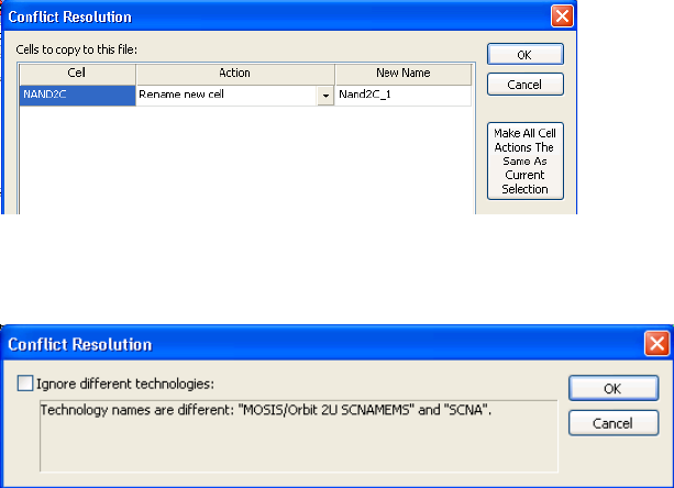
L-Edit 13 User Guide Section 1 243
Chapter 7: Working with Cells XrefCells
L-Edit verifies that the referenced cell and the referenced file still exist. If they do not, or if their names
have been changed, L-Edit displays a warning.
In some cases, the local file and the referenced file may have conflicting layers, or technologies, as
shown in the example below. If such a conflict occurs, L-Edit will prompt you to resolve it.
XrefCells and GDSII
L-Edit supports a library concept in the use of GDSII files. If a cell reference is in the GDSII file but the
cell’s contents (structure and layout) are not, then that cell is considered an XrefCell.
In this case, during GDSII import, L-Edit will create an XrefCell reference and will attempt to
automatically establish the link by locating the cell using its cell name in each Xref file. L-Edit searches
the TDB files in the order in which they are listed in the Setup > Design—Xref files dialog. Once
L-Edit finds a matching cell name, the link is established and no further searching is done.
If L-Edit does not find the referenced external cell in any of the cross-referenced TDB libraries, it will
create a blank cell and open the Examine XrefCell Links dialog to allow you to redirect the missing cell
definition at the end of the GDSII import operation (see “Examining XrefCells,” below.)
Examining XrefCells
The Examine XrefCell Links dialog lists all XrefCells in the file, and indicates any differences between
the XrefCells and the source cells they reference. You use this dialog to:
Examine the update status of an XrefCell
Update one or more XrefCells
Manage the list of Xref files—you can unlink an XrefCell and convert it to an ordinary cell, change
a referenced cell by referencing a different cell in the same Xref file, or redirect an XrefCell by
changing the filename and/or path to the referenced file
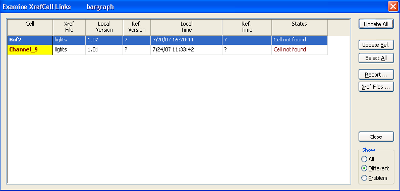
L-Edit 13 User Guide Section 1 244
Chapter 7: Working with Cells XrefCells
Use Cell > Examine XrefCell Links to open the Examine XrefCell Links dialog. (This dialog will also
open automatically whenever you open a TDB file that has Check XrefCells or Update XrefCells
selected in the Setup > Design—Xref files dialog.)
Cell The name of the XrefCell.
Yellow shading indicates that a difference exists between the
XrefCell and the referenced cell.
Black boldface type indicates that the referenced cell has a more
recent version or time than the XrefCell.
Red type indicates that the referenced cell no longer exists.
Green type indicates that the XrefCell has a more recent version
and time than the referenced cell.
Xref File The name of the library file that contains the referenced cell.
Local Version The version of the snapshot of the referenced cell.
Boldface type indicates that the XrefCell has a higher version
number than the referenced cell.
Ref. Version The current version of the referenced cell.
Boldface type indicates that the referenced cell has a higher
version number than the XrefCell.
Local Time The date and time of the snapshot of the referenced cell.
Boldface type indicates that Local Time is later than Referenced
Time.
Ref. Time The date and time that the referenced cell was last modified.
Boldface type indicates that Referenced Time is later than Local
Time.
Status Displays the status of the XrefCell.
L-Edit 13 User Guide Section 1 245
Chapter 7: Working with Cells Specifying the Fabrication Cell
Control buttons are:
Deleting XrefCells
You can delete an XrefCell from the Design Navigator or by using Cell > Delete.
Opening TDB Files Older than v13 that Contain XrefCells
The implementation of XrefCells in files prior to version 13 is converted to the new XrefCell
mechanism. In most cases, this conversion will be transparent. If XrefFiles were not specified in the old
TDB file, they will need to be specified in the new design. In the (very rare) case that a circular
dependency existed between files in the pre-version13 TDB file, this circular dependency will be
broken, and the cell hierarchy will have to be redesigned.
Specifying the Fabrication Cell
Before fabricating your design, you must supply your fabricator with the name of the cell that represents
the top level of your design. If you do not specify this information, your fabricator may incorrectly
identify this cell.
Identifying the fabrication cell instructs L-Edit to tag the cell as such when it exports a CIF file. The
identified cell becomes the only top-level cell in the CIF file. (This feature is only available for CIF
files. The GDS II format does not contain top-level cell information.)
Once a fabrication cell has been chosen, it will remain the fabrication cell until a new one is chosen,
even if it ceases to be the top-level cell in your design. Be sure to identify the fabrication cell before
writing a CIF file!
Update All Updates all XrefCells with the latest information from their source
files. (See “Updating XrefCells” on page 242.) This function is the
same as the Cell > Update Xref Cells command.
Update Sel. Updates the selected XrefCell(s) with the latest information from their
source files.
Select All Selects all XrefCells in the list.
Report Exports a text file that shows all the data in the dialog.
Xref Files Opens the Setup > Design—Xref files dialog.
Show All—sets display to show all XrefCells.
Different—sets display to show only XrefCells that require
updating.
Problem—sets display to show only XrefCells that failed to
update or for which no reference file was found.
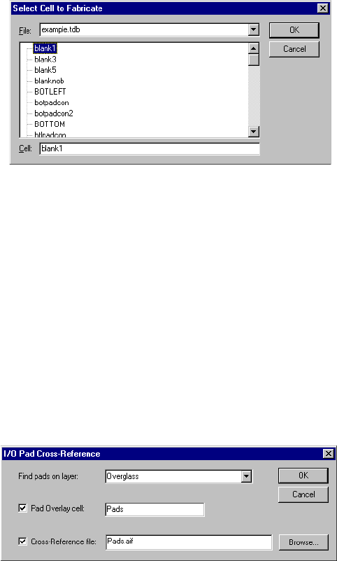
L-Edit 13 User Guide Section 1 246
Chapter 7: Working with Cells Specifying the Fabrication Cell
Identify the cell to fabricate by choosing Cell > Fabricate.
Options include:
Finding I/O Pads in the Fabrication Cell
The Tools > Add-Ins > I/O Pad Crossreference... is a feature that can automatically generate the pad
coordinates for probe cards or bonding diagrams that are generally required by the packaging houses. It
analyzes the layout of the currently specified fabrication cell, and finds all I/O ports (pads) in that cell.
Pads are recognized as objects on the user-specified layer (typically Overglass).
Besides counting and reporting the number of pads, this command has two options:
An overlay cell can be generated. An overlay cell is a new cell (the user must specify the name of
this cell), containing box objects on the I/O pad recognition layer. Also, if a port is found within the
pad box, on any layer, on any level of hierarchy, that name becomes associated with that pad. The
overlay cell contains ports with this same name, assigned sizes and text directions that produce a
visually appealing layout. This pad overlay cell is useful for communicating with package houses /
bonding houses.
The second option is to create a Cross Reference disk file containing the pad list information. This file
can be in either of two formats, determined by the file extension specified. .txt files are simply
tab-delimited lines containing the pad position, the pad name, and the x- and y- locations of the center
of each pad. .aif files are in AIF format, a text format promoted by packaging houses (specifically
Amkor); in addition to pad names and location, the AIF file contains the dimensions of the pad. If the
AIF format is selected then the coordinates are relative to the middle of the cell's MBB, but if the TXT
file is selected then the coordinate space of the cell (i.e. the cell origin) is used.
File Name of the active TDB file (default). All open TDB files are listed.
Cell The specified file’s component cells are displayed in the scrollable
list. Highlight a cell and click OK to tag it.
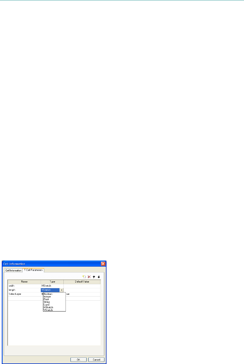
L-Edit 13 User Guide Section 1 247L-Edit 13 User Guide Section 1 247
8 Generated Cells
L-Edit has several different processes for automatically generating cell or device layout that can also
include electrical parameters, layer configurations and design rules.
T-Cells are cells that are generated from UPI code. Because L-Edit’s UPI is so powerful, T-Cells
can be very complex. L-Edit also provides a callback feature that can check the validity of T-Cell
parameters or modify other values when a related one changes.
T-Cell Builder lets you automatically create simple T-Cell code views from layout geometry. The
resulting T-Cells are parameterized, and can be modified with these parameters.
Cells from Layout Generating Code—T-Cells
Cells that contain layout-generating code are called T-Cells. T-Cells are parameterized, allowing a
single T-Cell to represent different layout configurations when you generate instances of that T-Cell
that have different parameter values.
Creating T-Cells
The T-Cell Parameters tab of the Create New Cell dialog contains a table in which you can list
parameters as input to generate T-Cell instances. For example, parameters for a decoder generator cell
might include a user-specified number of outputs, number of bits, and pitch, and presence or absence of
spacers.
To create a new T-Cell, use Cell > New to enter parameters in the list on the T-Cell Parameters tab.
You can also create a new T-Cell by right-clicking on a cell in the Design Navigator and choosing
Create/Update T-Cell Code. If the cell already has T-Cell code, L-Edit will display a warning and ask
if you want to replace the existing code.
1
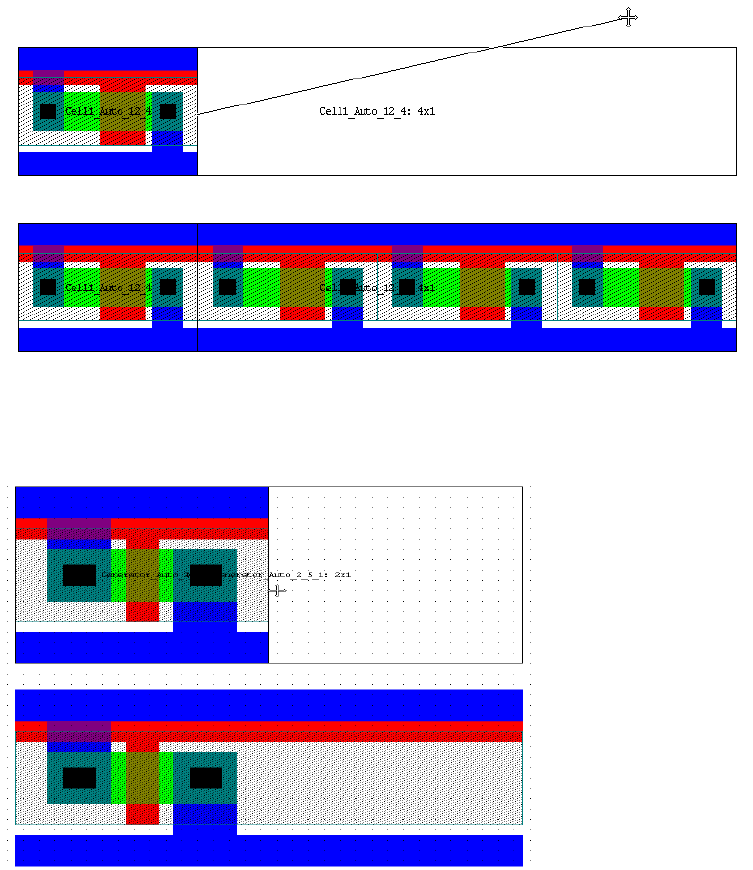
L-Edit 13 User Guide Section 1 248
Chapter 8: Generated Cells Cells from Layout Generating Code—T-Cells
T-Cell Parameter Types
To enter a new parameter, first type a parameter name in the Name field. In the Type field, use the
drop-down list provided, or type the first letter of a data type to select it. T-Cell code can accept the
following data types: Boolean, Integer, Float, String, or Layer and HStretch or VStretch.
The HStretch and VStretch types set cell behavior when you select and drag an edge.
The default select-and-drag behavior is to replicate the T-Cell instance, creating an array:
When you set the parameter Type to HStretch or VStretch, the edge select-and-drag behavior is to
extend the dimension of that parameter:
In the Default Value field, enter the default value of the parameter. For Boolean and Layer data types,
a drop-down list of possible entries is provided.
T-Cell Code Templates
After you have finished entering parameters in the T-Cell Parameters tab, click OK to generate a T-Cell
code template. A T-Cell code template is a block of text that contains the outline for a UPI interpreted
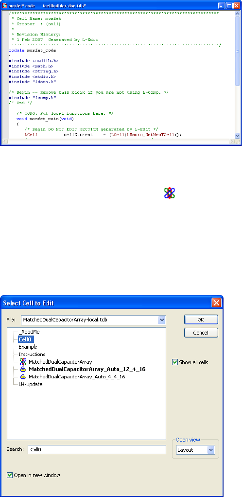
L-Edit 13 User Guide Section 1 249
Chapter 8: Generated Cells Cells from Layout Generating Code—T-Cells
macro. This text is the skeleton of your T-Cell code. You can edit the template to encode your T-Cell
with additional UPI functions.
Opening T-Cells
T-Cells are shown with a generator icon ( ) next to them in cell lists. Note that Auto-generated cells
are automatically hidden from the Design Navigator and other cell lists. To show auto-generated cells,
select Show All Cells in the Design Navigator.
To open a T-Cell, choose Cell > Open (shortcut O) and select T-Cell Code in the Open view menu.
You can also open a T-Cell by right-clicking in the Design Navigator and choosing Create/Update
T-Cell Code.code templates for L-Edit will open a text window containing the T-Cell code for the cell,
or a blank code window if the selected cell is not already a generator cell.
If an instance is selected in the layout, its name will be highlighted in the Open Cell dialog. If multiple
instances are selected, the referenced cell of the first instance in the selection will be highlighted. If no
instance is selected, the last cell opened will be highlighted.
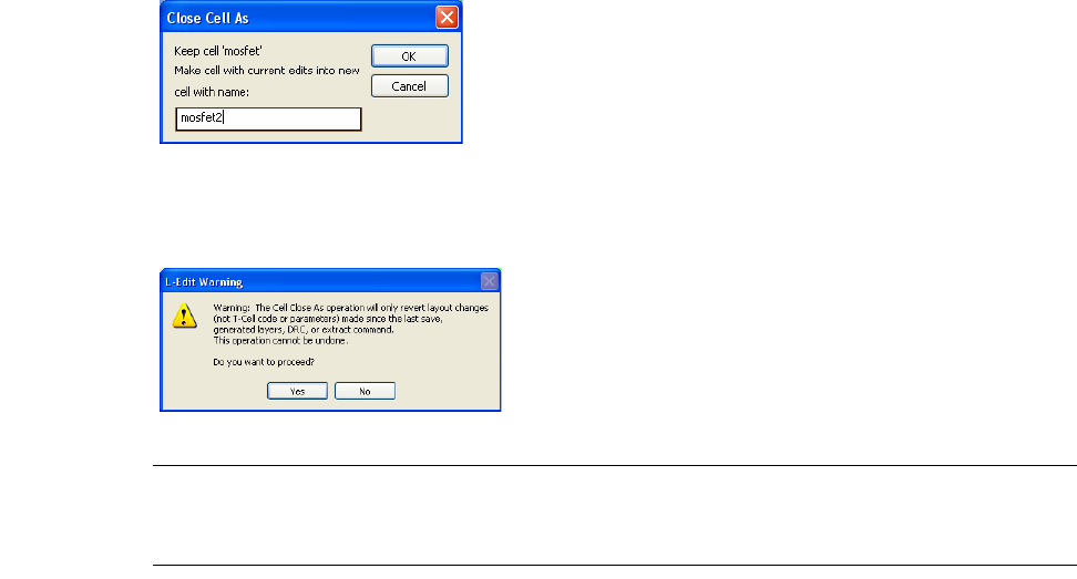
L-Edit 13 User Guide Section 1 250
Chapter 8: Generated Cells Cells from Layout Generating Code—T-Cells
Closing T-Cells
The Close Cell As dialog contains a field to enter the new cell’s name.
When you use Cell > Close As to copy a T-Cell, all changes to the T-Cell code view are preserved in
both the original cell and the copy, regardless of when the last save operation occurred.
Note: Changes made to a T-Cell instance using Edit > Edit In-Place will be lost if you
regenerate the T-Cell. The Revert Cell command does not reverse changes to T-Cell
code.
Instancing T-Cells
An instance is a representation of a cell in a particular location and orientation in another cell. An
instance can reference a cell composed of primitives, other instances, a combination of primitives and
instances or a cell generated from T-Cell code, also referred to as a generated cell. A T-Cell does not
have geometry until it is instanced.
A quick way to instance a T-Cell is to click and drag it from the Design Navigator into a new cell. When
you instance a T-Cell for which parameters have been defined, L-Edit opens the T-Cell Parameters
dialog where you can accept or edit the existing parameter values.
When instancing a T-Cell, L-Edit first generates a new cell containing the geometry specified by the
T-Cell. This cell, called an auto-generated cell, is the source cell for the instance. The auto-generated
cell is named by appending parameter values to the original T-Cell name. For example, the dialog
shown below creates an instance of an auto-generated cell, named
MatchedDualCapacitorArray_Auto_12_4_16. Changes made to a T-Cell, which L-Edit uses to
generate source cells, cause all auto-generated cells and their instances to be flagged “out of date.”
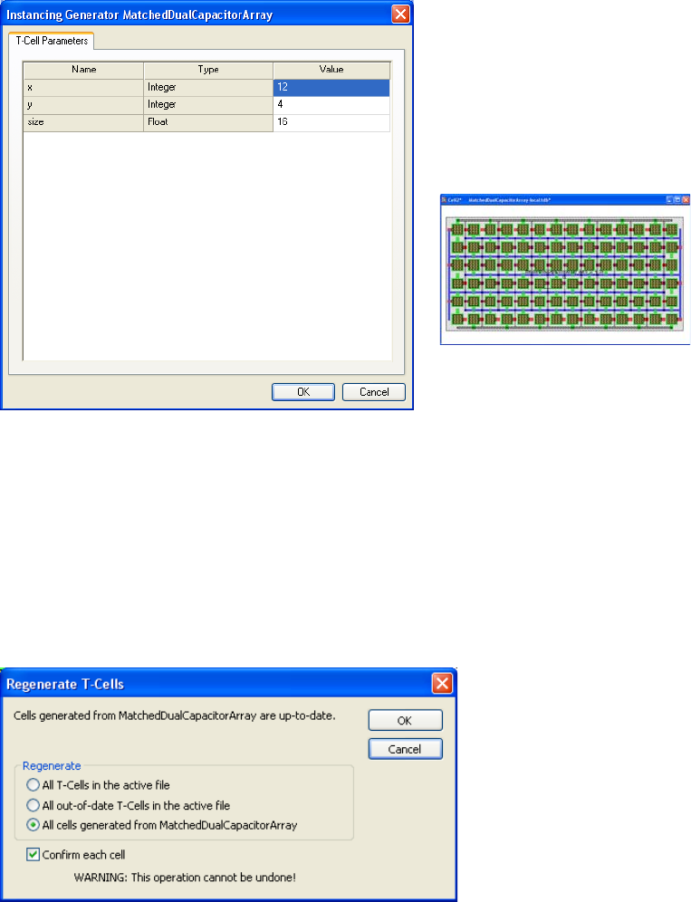
L-Edit 13 User Guide Section 1 251
Chapter 8: Generated Cells Cells from Layout Generating Code—T-Cells
You can update T-Cell instances using the Tools > Regenerate T-Cells command (see Regenerating
T-Cell Instances, below).
Regenerating T-Cell Instances
T-Cell instances are references to auto-generated cells, which contain geometry generated by the T-Cell
with a specific set of parameters. When you edit T-Cell instances using Edit > Edit In-Place, changes
are only propagated to other instances that were created with identical parameter values.
To edit the contents of all instances of a T-Cell, open the original T-Cell and make the desired changes.
When you are finished, instances of the T-Cell will be flagged “out of date.” To propagate changes in
the T-Cell to its instances, select Tools > Regenerate T-Cells from the L-Edit menu.
The top of the Regenerate T-Cells dialog gives a message indicating if the most recently viewed T-Cell
is out-of-date. To regenerate (update instances of) T-Cell, select one of the following options:
All T-Cells in the active file Replaces all T-Cell instances in the active file with new instances that
reflect the most current version of each T-Cell. Instances are
re-created with the same parameters they originally used.
The T-Cell generator
“MatchedDualCapacitorArray” has
T-Cell parameters x, y, and size.
When instanced into Cell2 with x=16,
L-Edit creates the instance and names it
“MatchedDualCapacitorArray_Auto_12_
4_16” as shown below.
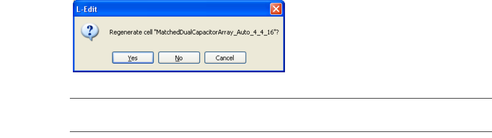
L-Edit 13 User Guide Section 1 252
Chapter 8: Generated Cells Cells from Layout Generating Code—T-Cells
When Confirm each cell is checked, L-Edit will prompt you to confirm updates of each T-Cell and
parameter set. One or more instances that represent a given T-Cell and parameters are listed using the
naming convention:
Name_Auto_param1_param2_...
Parameters are listed in the order in which they appear in the T-Cell Parameters dialog. (See Instancing
T-Cells on page 250.) String parameters are not included in T-Cell names. For example, the dialog
shown below requests permission to update all instances of the T-Cell MatchedDualCapacitorArray
that were created with parameters 4, 4, and 16,
Note: Regenerating T-Cell instances replaces all auto-generated cells. Therefore, all
changes made to auto-generated source cells (using Edit > Edit In-Place) will be lost.
T-Cell Callbacks
The UPI function LCell_GetTCellPreviousValue (page 1067) lets you retrieve the previous value of a
T-Cell parameter, which is the value used the last time the T-Cell was created or modified. This
function has an identical signature to LCell_SetTCellDefaultValue which can be used in conjunction
with LCell_GetTCellPreviousValue to implement “callbacks,” in which a T-Cell can validate and
modify the parameters that are passed to it.
LCell_GetTCellPreviousValue is used to obtain the previous value of a T-Cell parameter the last time
the T-Cell was created or modified. If the T-Cell is newly created, an empty string is returned.
The following examples show how LCell_GetTCellPreviousValue can be used to determine whether a
particular parameter has changed since the previous invocation of the T-Cell.
int HasChanged( LCell pCell, char *param_name )
{
char old_val[1024], new_val[1024];
LCell_GetTCellPreviousValue(pCell, param_name, old_val, sizeof(old_val));
LCell_GetTCellDefaultValue(pCell, param_name, new_val, sizeof(new_val));
return strcmp( old_val, new_val );
}
Then, in the main T-Cell code body, we can use this information to modify other parameters. For
example, suppose we had a resistor that was parameterized by R, L and W. The values of these three
All out-of-date T-Cells in
the active file Updates only those T-Cell that are flagged “out-of-date.” A T-Cell is
out-of-date when it contains changes that have not been propagated to
its instances.
All cells generated from
TCell_Name Updates only those instances that refer to the most recently active
T-Cell.
L-Edit 13 User Guide Section 1 253
Chapter 8: Generated Cells Generating T-Cell Code from Layout Views—T-Cell Builder
parameters need to be consistent, so we need to modify one of them to enforce this consistency. One
possible solution would be the following:
// update new parameters accordingly
char new_val[1024];
if ( HasChanged(cellCurrent, "L" ) && HasChanged(cellCurrent, "W" ) )
{
R = L / W * resistivity;
sprintf( new_val, "%g", R );
LCell_SetTCellDefaultValue(cellCurrent, "R", new_val);
}
else if ( HasChanged(cellCurrent, "L" ) )
{
W = L * resistivity / R;
sprintf( new_val, "%g", W );
LCell_SetTCellDefaultValue(cellCurrent, "W", new_val);
}
else
{
L = W * R / resistivity;
sprintf( new_val, "%g", L );
LCell_SetTCellDefaultValue(cellCurrent, "L", new_val);
}
Generating T-Cell Code from Layout Views—T-Cell Builder
The T-Cell Builder, accessed from the Cell > T-Cell menu, allows you to automatically generate T-Cell
code views from existing layout views.
The resulting T-Cells are parameterized, and contain geometry elements whose appearance can depend
on these parameters. Because you do not need to write any UPI code directly, this feature is very useful
if you are unfamiliar with UPI programming.
A cell must contain stretch ports in its layout to trigger the T-Cell builder. A T-Cell code view is
constructed when you indicate the layer on which the stretch ports are drawn and analyze the geometry
of the cell by executing the Cell > T-Cell > Construct T-Cell command. You can then keep or overwrite
the parameters in that code view.
Once the cell has a code view, you can create parameterized layout by instancing it like any other
T-Cell. Each time you add or change a parameter you must execute Cell > T-Cell > Construct T-Cell to
apply the changes.
The T-Cell Builder can create parameters to either stretch (the default), move or repeat geometry
according to the values you enter. The T-Cell Builder can also construct a parameter that sets the layer
on which geometry is drawn, and a parameter for simple TRUE/FALSE conditions by which geometry
is included when the T-Cell is instanced.
Defining Stretch Ports for the T-Cell Builder
The stretch axis parameters are defined by special stretch ports on a user-selected layer. These ports
define the name of the parameter that controls the stretch, the direction of the stretch, and the default
value of the stretch. These ports may be drawn on any layer, but you must choose that layer as the
stretch port layer when you construct your T-Cell.
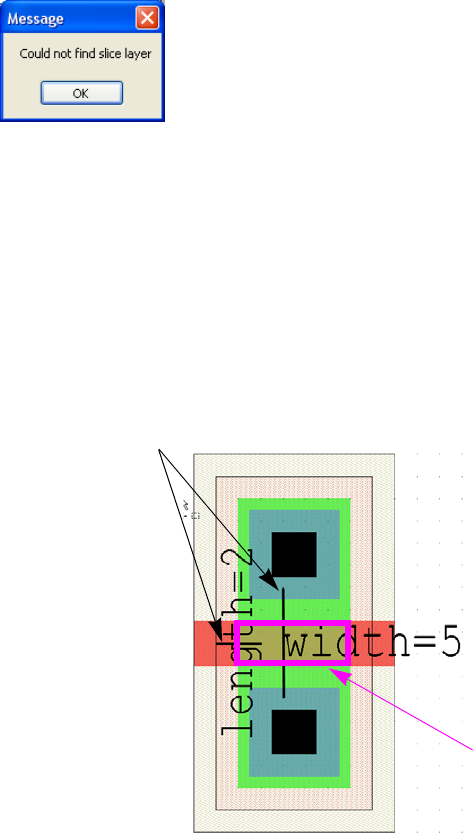
L-Edit 13 User Guide Section 1 254
Chapter 8: Generated Cells Generating T-Cell Code from Layout Views—T-Cell Builder
Stretch ports must be line ports (i.e. have exactly one dimension and be non-zero). Stretch ports control
stretch perpendicular to the direction in which they are drawn. In T-Cell builder processing, the port line
is extended to the cell perimeter in both directions and any object it intersects is stretched by the value
indicated in the port text. Objects that are entirely on one side of the port may be moved, depending on
the direction of the stretch.
The default value of the parameter is taken from the size of the port, or by declaring it in the port string,
in the form “parameterName=defaultValue.”
When stretch ports are incorrectly defined or not defined at all, L-Edit displays this message:
Constructing a T-Cell with Stretch Parameters—MOSFET Example
A commonly-desired operation is for one or more dimensions of an object to be set by a cell parameter.
For example, a simple MOSFET is often parameterized by its channel length and width. To create a
parameterized MOSFET T-Cell, you first create the cell layout shown below.
Note the one-dimensional ports “length=2” and “width=5.” These ports, which can be on any layer you
select, define the axes with respect to which cell elements will be stretched.
Stretching is the default operation if no other is specified.
Once you have the raw geometry and ports in a cell, you can invoke Cell > T-Cell > Construct T-Cell to
generate T-Cell code from that layout.
The one-dimensional
ports are the
reference points for
stretch operations.
The channel resulting from the Boolean
operation "Active AND Poly" has a width of
5 and length of 2.
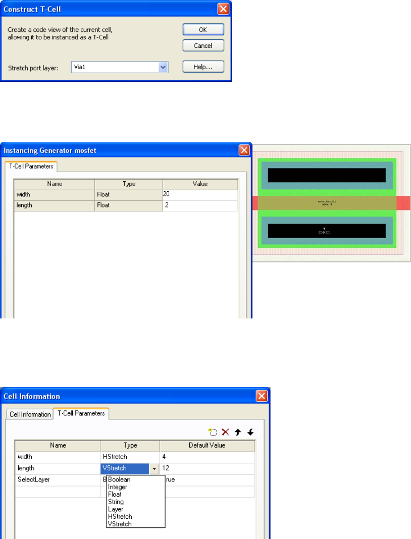
L-Edit 13 User Guide Section 1 255
Chapter 8: Generated Cells Generating T-Cell Code from Layout Views—T-Cell Builder
L-Edit will prompt you to enter the Stretch port layer, which must be the layer on which the stretch
ports are drawn. If there is preexisting T-Cell code, L-Edit will also confirm that you want to overwrite
it.
After L-Edit constructs the T-Cell code you can instance the MOSFET into layout using the
conventional Cell > Instance command, and change the values of the parameters as desired.
Parameter Types in the T-Cell Builder
T-Cell builder parameters are characterized by certain types, as shown in the menu below. The
HStretch and VStretch types are described in T-Cell Parameter Types on page 248.
Instance of the T-Cell MOSFET with
width=20 and length=2.
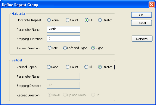
L-Edit 13 User Guide Section 1 256
Chapter 8: Generated Cells Generating T-Cell Code from Layout Views—T-Cell Builder
Repeating Elements with the T-Cell Builder
To repeat rather than stretch elements in a constructed T-Cell, first select the layout objects you want to
repeat, then invoke Cell > T-Cell > Define Repeat Group.
Returning to the MOSFET example, you would select the four contact boxes, use Cell > T-Cell > Define
Repeat Group to enter the repeat parameters shown in the Define Repeat Group dialog above, use
Repeat
Horizontal and Vertical
Stretch—this is the default, and confirms that the object is free to
stretch in the indicated direction as long as it is intersected by a
stretch axis.
None—if selected, the object in question is neither repeated, nor
is it stretched. This choice is appropriate for items such as
contacts, which must remain a specific size.
Count—the parameter is taken to be an integer, and determines
the number of times the object is repeated.
Fill—the object is iterated to fill the distance specified by the
named parameter.
Parameter Name The parameter that controls the selected option.
Stepping Distance The pitch between adjacent repeated objects.
Repeat Direction The direction in which the operation will occur with respect to the
original object. In the Horizontal direction, objects are repeated or
stretched to the left, right, or equally from the center (left and right).
In the Vertical direction, objects are repeated or stretched up, down or
equally from the center (up and down).
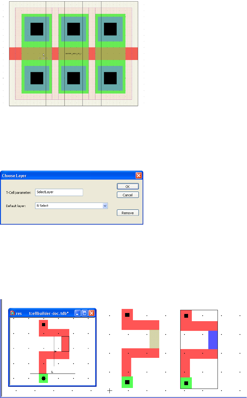
L-Edit 13 User Guide Section 1 257
Chapter 8: Generated Cells Generating T-Cell Code from Layout Views—T-Cell Builder
Cell > T-Cell > Construct T-Cell to update and apply the parameters, and then instance the cell.
Entering a width parameter value of 20 creates the mosfet_Auto_20_2 cell shown below.
Setting the Layer as a T-Cell Builder Parameter
The layer on which an object is placed can be made into a parameter of the T-Cell by selecting the
object and invoking Cell > T-Cell > Choose Layer. Only the objects that are selected when you open
the Choose Layer dialog will have their layer parameterized.
For example, in the resistor shown below, one segment is selected for Choose Layer parameterization.
Once the T-Cell is (re)constructed you can instance cell res and choose the layer on which the segment
is drawn.
T-Cell parameter Enter a name for the layer parameter.
Default layer Pick a default layer for the choose layer parameter.
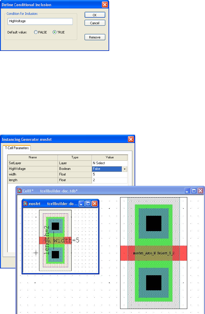
L-Edit 13 User Guide Section 1 258
Chapter 8: Generated Cells Generating T-Cell Code from Layout Views—T-Cell Builder
Defining Conditional Inclusion as a T-Cell Builder Parameter
You can use T-Cell builder to define parameter for an object such that it will be included or excluded
based on a Boolean or logical condition.
A conditional exclusion can also be based on a logical expression if the expression uses a parameter that
has been previously defined by ports on the layout. If the condition is true then the object is included.
For example, if you have a stretch port width you can use the logical expression width > 10. (In this
case the default value is not relevant.)
For example, in cell MOSFET select the box on layer HV Oxide, define a condition parameter called
HighVoltage, and regenerate the T-Cell. When you instance MOSFET and select value FALSE for
parameter HighVoltage, the selected box will not be drawn.
Condition for Inclusion Enter a name for the condition or an expression that uses defined
parameters.
Default value Select FALSE or TRUE as a default value.
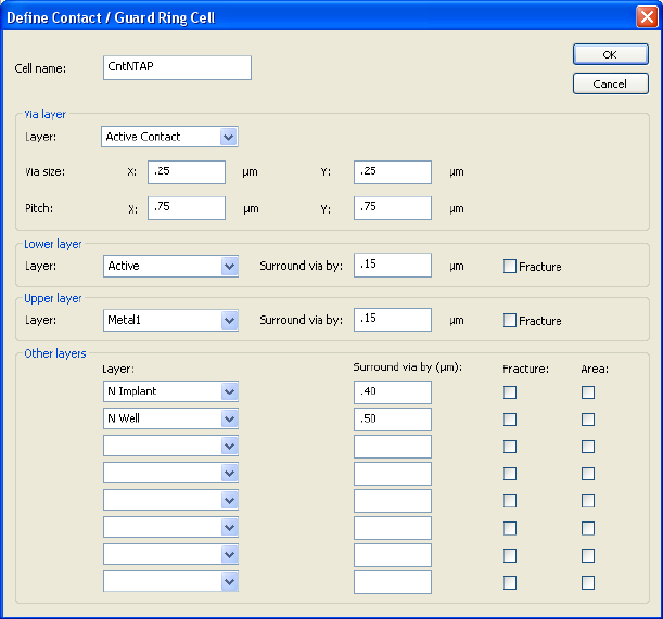
L-Edit 13 User Guide Section 1 259
Chapter 8: Generated Cells Automatically Generated Contact Cells and Vias
Finding Objects that have T-Cell Builder Parameters
This function selects all the objects in a builder T-Cell for which a repeat group, conditional inclusion or
layer parameter is defined. It is a useful shortcut since there is no visual indication of the objects in a
T-Cell that have parameters
Automatically Generated Contact Cells and Vias
L-Edit includes a feature for automatically generating contact cells or vias with special coding that
speeds routing. You can import these cells from Virtuoso or define them in L-Edit.
You can instantly generate an array of these cells, or use them to create a guard ring, a collection of
contact cells or vias forming a perimeter around the geometry you have selected. The guard ring feature
can also produce geometry covering the entire area of the selected objects (a Boolean OR union).
Creating Generated Contact Cells
Use Draw > Contacts > Define Contact Cell to open the Define Contact / Guard Ring Cell dialog.
Cell name Enter or edit the name of the contact cell.
Via Layer Select a Layer for the contact or via, and enter X- and Y- values for
the Via size and Pitch (the minimum distance between the two
contacts.)
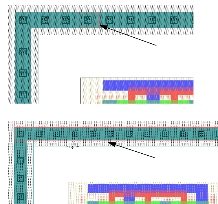
L-Edit 13 User Guide Section 1 260
Chapter 8: Generated Cells Automatically Generated Contact Cells and Vias
Using the Fracture Option
When you check Fracture for a given layer in the Define Contact / Guard Ring Cell dialog, L-Edit will
create separate rather than merged geometry on that layer whenever it places the cell.
Lower Layer Select the lower contact layer from the Layer menu. The value in
Surround via by is the minimum amount by which the layer must
surround the contact.
When L-Edit generates a guard ring, the default is to merge contact
cell geometry on every layer. Check Fracture (for any layer but the
via layer) to generate separate geometry on that layer for each
individual contact cell. (See Using the Fracture Option on page 260
for an illustration.)
Upper Layer Select the upper layer from the Layer menu. The value in Surround
via by is the minimum amount by which the layer must surround the
contact.
Other Layers Select any other layers on which to generate geometry and enter the
minimum contact surround value.
Check Area to generate geometry that will cover the entire area of the
geometry selected for guard ring placement. (See Using the Area
Option on page 261 for an illustration.)
With Fracture, each box on layer
Active is separate.
Geometry on layer Active is merged
when the fracture option is not
checked.
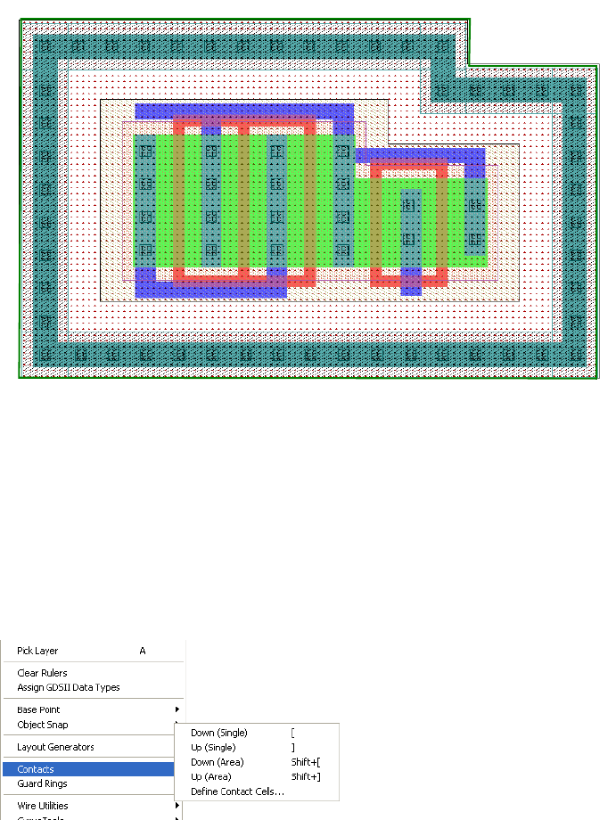
L-Edit 13 User Guide Section 1 261
Chapter 8: Generated Cells Automatically Generated Contact Cells and Vias
Using the Area Option
The Area option (for layers other than those used for the via and routing) in a generated contact cell will
draw geometry surrounding the union of all the selected geometry in a cell, with the additional
surrounding area you specify.
Editing Generated Contact Cells
To edit an existing contact cell or via the cell must be the currently active cell. When you open the
Define Contact / Guard Ring Cell dialog it will contain the current settings for that cell.
Using Generated Contacts and Vias to Speed Routing
Once generated contact cells and vias are defined, you can use shortcut keys while routing to
simultaneously place a via and switch between the upper and lower routing layers used in that contact
cell.
While drawing with a wire tool, if the current layer is the upper layer, use Draw > Contacts > Down
(Single) (shortcut key left bracket [ ) to simultaneously instance a contact cell and switch from the
current layer to the lower routing layer of that contact. If the current layer is the lower layer, use
Guard ring
using a cell
with the Area
option checked
for one layer.
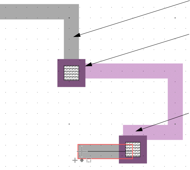
L-Edit 13 User Guide Section 1 262
Chapter 8: Generated Cells Automatically Generated Contact Cells and Vias
Draw > Contacts > Up (Single) (shortcut key right bracket ] ) to instance a contact and switch to the
upper routing layer.
Which Contact Cell or Via Will L-Edit Use?
L-Edit chooses the first generated contact cell, alphabetically, that includes the layer that is active when
you are in wire mode.
Using Generated Contacts and Vias for Automatic Arrays
You can also use shortcut commands to select an area inside of which L-Edit will automatically
instance an array of the active contact cell or via. Use Draw > Contacts > Down (Area) (shortcut
The first wire is drawn on
layer Metal2.
Generated via ViaM2M3
is defined such that:
Via layer = Via2
Lower layer = Metal2
Upper layer = Metal3
The shortcut key ] places
ViaM2M3 and switches
the active layer to Metal3.
The second wire is drawn
on layer Metal3.
Shortcut key [ instances
ViaM2M3 and switches
the active layer to Metal2.
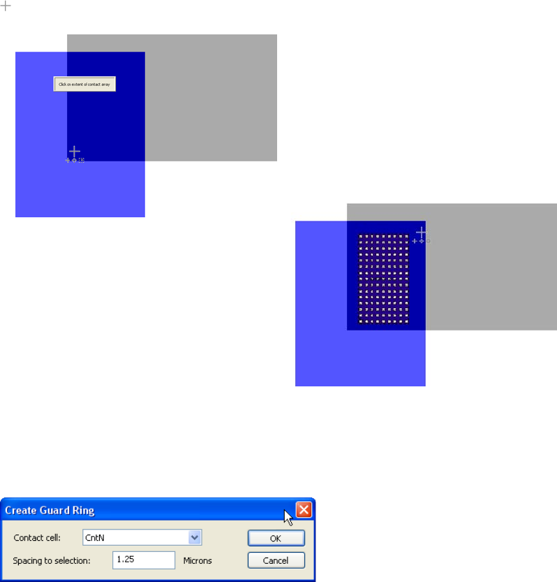
L-Edit 13 User Guide Section 1 263
Chapter 8: Generated Cells Automatically Generated Contact Cells and Vias
Shift+[ ) and Draw > Contacts > Up (Area) (shortcut Shift+] ) to place an array of contact cells in the
area between the current layer and lower or upper layer, respectively, of the active contact.
Automatically Generating a Guard Ring
L-Edit will automatically create a guard ring around geometry that is selected when you use the
Draw > Guard Rings > Draw Guard Ring Around Selection command.
Contact cell Enter the name of the contact cell that will comprise the guard ring.
Spacing to selection Enter the orthogonal distance from the selected geometry to the inner
edge of the guard ring.
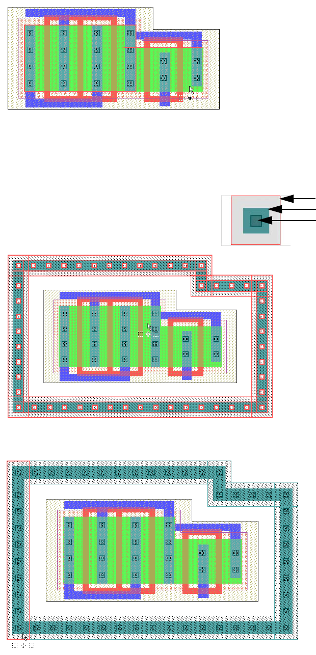
L-Edit 13 User Guide Section 1 264
Chapter 8: Generated Cells Automatically Generated Contact Cells and Vias
The two polygons on layer Active are selected:
CntN is chosen as the contact cell for the generated guard ring. As shown below, the guard ring remains
selected after Draw Guard Ring Around Selection is executed.
The guard ring geometry is merged in orthogonal sections on layers N Implant and Active.
Contact cell CntN:
N Implant layer
Active layer
Contact layer
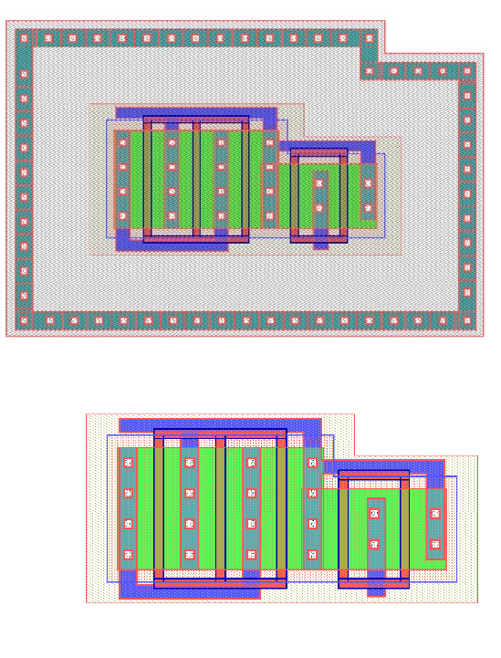
L-Edit 13 User Guide Section 1 265
Chapter 8: Generated Cells Automatically Generated Contact Cells and Vias
Deleting a Guard Ring
Because L-Edit recognizes its own generated cells, you can select an entire cell including its guard ring
and only the guard ring will be deleted when you use Draw > Guard Rings > Delete.
The entire cell and the
guard ring are selected.
After the Draw > Guard
Rings > Delete
operation, the cell
remains intact—only the
guard ring has been
deleted.
L-Edit 13 User Guide Section 1 266L-Edit 13 User Guide Section 1 266
9 Working with Objects
Selecting Objects
Selecting an object specifies that subsequent editing operations affect that object specifically. More than
one object may be selected at a time.
By default, selected objects are outlined. It is possible to change the manner in which selection is
displayed on any given layer by modifying the layer setup (see “Layer Setup” on page 104).
When multiple views of the same cell are open, selected objects are displayed as such in all of the
views.
When a selected object is part of an instance, it is only displayed as selected in its original (instanced)
cell.
For information on the selection range, see “Selection Parameters” on page 100.
L-Edit provides several ways to select an object using the selection tool on the Drawing toolbar,
summarized in the table below.
Explicit Selection
To explicitly select an object, position the pointer over the object to be selected and click the SELECT
button. Any previously selected objects are automatically deselected.
You can also explicitly select a set of objects by dragging a selection box around them, as follows:
;Position the pointer outside the set of objects to be selected.
;Drag the pointer with the SELECT mouse button held, forming a selection marquee around the objects.
;Position the opposite corner of the selection marquee so that the marquee completely encloses all the
objects to be selected but does not completely enclose any other objects, and release the SELECT
mouse button.
Action Mouse button
Explicitly select an object or
set of objects before an
operation is performed.
SELECT
Implicitly select an object in
the process of performing an
operation on it.
MOVE/EDIT
Add an object to a set of
selected objects. EXTEND SELECT
(Shift+SELECT)
1
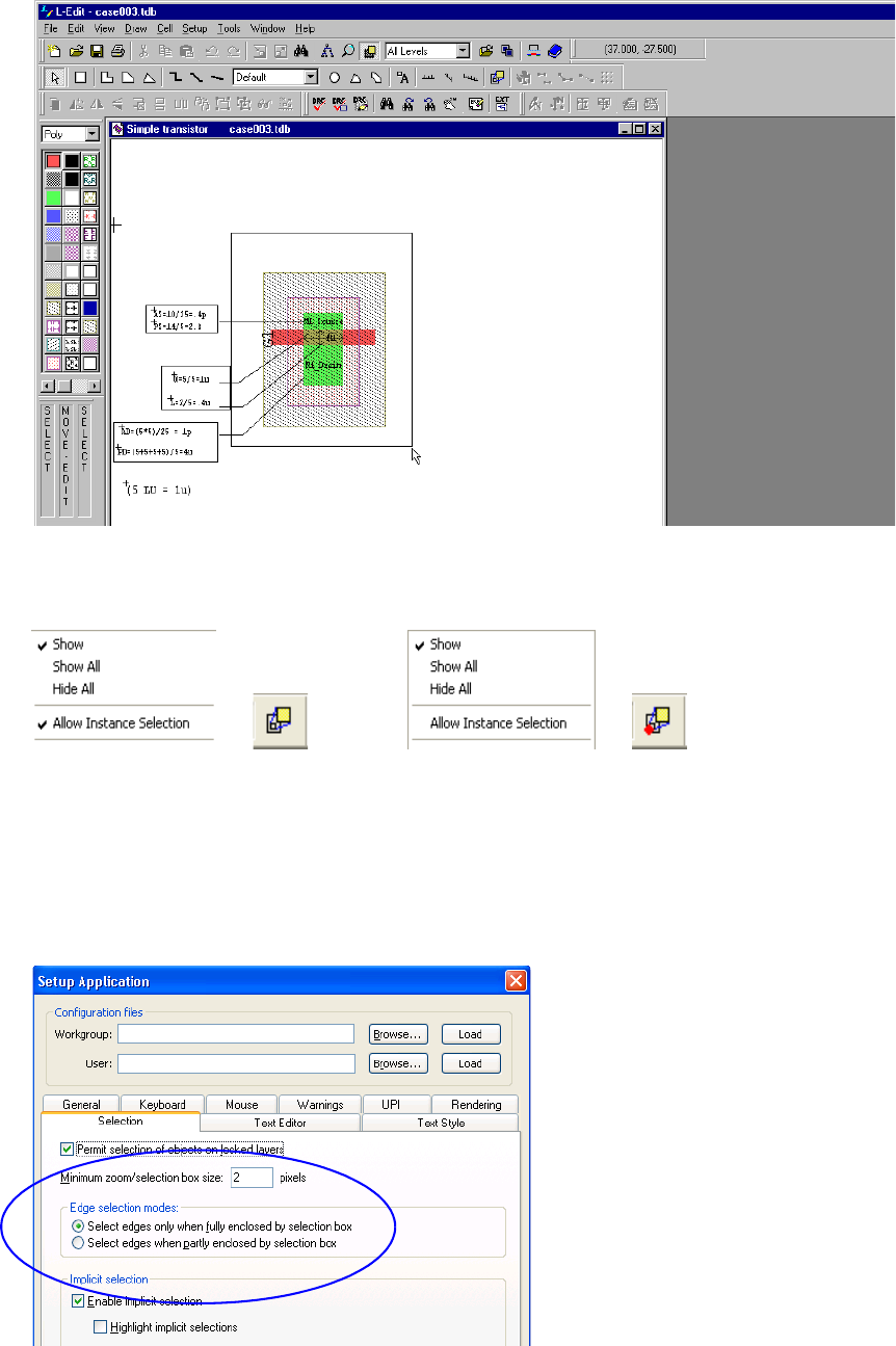
L-Edit 13 User Guide Section 1 267
Chapter 9: Working with Objects Selecting Objects
You can set instances so they cannot be selected by right-clicking on the Instance icon of the Drawing
toolbar. When
You can control the behavior of the selection box using the Edge selection modes options in
Setup > Application—Selection.
The instance icon showing that
icons can be selected.
A red dot on the instance icon
indicates that icons cannot be
selected.
L-Edit 13 User Guide Section 1 268
Chapter 9: Working with Objects Selecting Objects
If you choose Select edges only when fully enclosed by selection box, L-Edit will only select
objects completely contained within the selection box. Any previously selected objects will be
deselected.
If you choose Select edges when partly enclosed by selection box, L-Edit will select all objects
completely or partly contained within the selection box.
Implicit Selection
If no other objects are selected, pressing and holding the MOVE/EDIT mouse button in or near an
object (within the selection range) selects that object and begins a move or edit operation.
Note that implicit selection is governed by the values set for selection range and deselection range. (See
“Selection Parameters” on page 100.) Depending on these values, you may accidentally include
previously selected objects (outside the deselection range) when you select another object implicitly.
There are two ways to avoid this potential problem:
Use Edit > Deselect All to deselect all objects before you perform implicit selection.
Set the deselection range appropriately.
Extend Selection
You can extend a selection by including another object or group of objects in the set of already selected
objects. Select the additional object(s) with the EXTEND SELECT (Shift+SELECT) mouse button.
Previously selected objects are not deselected.
Cycle Selection
When you click repeatedly within the selection range of several objects, L-Edit selects each object in
turn. The first click selects the closest object. The next click with the pointer in the same spot deselects
the object just selected and selects the next closest object (within the selection range).
Repeated clicks progressively select nearby objects until there are no more objects within the selection
range. The next click deselects all objects. The following click repeats the cycle, beginning with the
closest object.
A message at the left end of the status bar reports which object is selected.
Edge Selection
In addition to selecting whole objects, you can also select individual edges of one or more objects. The
following illustrations explain these techniques.
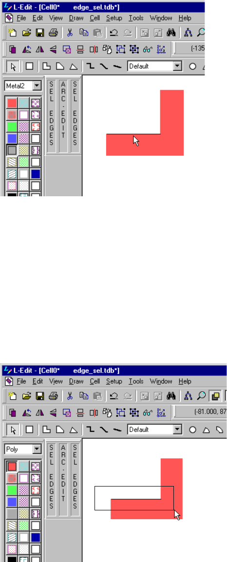
L-Edit 13 User Guide Section 1 269
Chapter 9: Working with Objects Selecting Objects
You can directly select the edge of an object by clicking it:
You can also select an edge by pressing the SELECT EDGES mouse button (Ctrl+Right SELECT) and
dragging a selection box around the desired edge(s). In this case, L-Edit will select a single edge or
multiple edges, according to edge selection mode chosen in Setup Application—Selection (see
“Selection” on page 91).
If you choose the selection mode Select edges only when fully enclosed by selection box, you must
drag the selection box completely around the edge you wish to select:
Select the edge of an object by clicking it with the SELECT EDGES mouse button
(Ctrl+Right SELECT)
Select an edge by pressing the SELECT EDGES mouse button (Ctrl+Right
SELECT) and dragging a selection box around the desired edge(s)
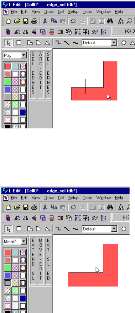
L-Edit 13 User Guide Section 1 270
Chapter 9: Working with Objects Selecting Objects
If you choose the selection mode Select edges when partly enclosed by selection box, you need only
partly enclose the edge you wish to select. Use this technique to select multiple adjacent edges:
Finally, you can cyclically select one or more edges, as the following illustration demonstrates:
Universal Selection
You can select all objects in the active cell by choosing Edit > Select All or pressing Ctrl+A.
Select multiple edges by pressing the SELECT EDGES mouse button
(Ctrl+Right SELECT) and dragging a selection box that partly encloses
the desired edge(s)
Click the SELECT EDGES (Ctrl+Right SELECT) mouse button within
the selection range of the desired edge. To extend the selection to
include additional edges, use Shift+SELECT EDGES (Shift+Ctrl+Right
SELECT).
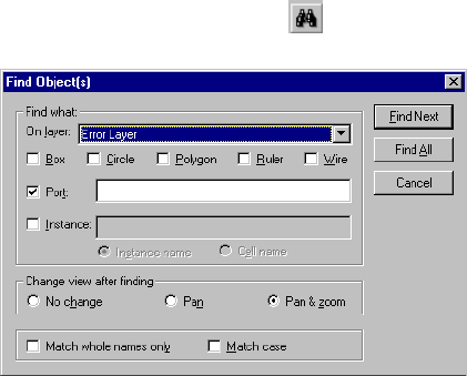
L-Edit 13 User Guide Section 1 271
Chapter 9: Working with Objects Deselecting Objects
Deselecting Objects
Deselecting objects causes them to no longer be available for editing operations.
A deselection range ensures that selected objects will not accidentally be deselected before an operation
is performed. For information on the deselection range, see “Selection Parameters” on page 100.
Explicit Deselection
To deselect a selected object without affecting other selected objects, place the pointer within the
selection range of the object and use the DESELECT (Alt+right SELECT) mouse button.
Clicking the DESELECT button near an object which is not selected or outside the selection range of all
selected objects has no effect.
Implicit Deselection
Clicking the SELECT button outside the selection range of selected objects automatically deselects the
objects.
Hidden Deselection
When a layer is hidden, all selected objects on that layer are automatically deselected. This prevents
hidden objects from being moved or edited. These objects remain deselected even after they are made
visible again.
Universal Deselection
You can deselect all objects in the active cell by choosing Edit > Deselect All or pressing Alt+A.
Finding Objects
To search for geometric objects or for ports or instances of a particular name, choose Edit > Find, press
Ctrl+F, or click the find button ( ).
L-Edit 13 User Guide Section 1 272
Chapter 9: Working with Objects Grouping and Ungrouping Objects
Options include:
During an L-Edit session, search parameters typed in the Find Object(s) dialog remain in memory and
are used for all subsequent Find operations. The search parameters are not cleared when you switch
between cells and files.
Find Next/Find Previous
When an object has been found, you can search for the next object or for the previously found object.
Choosing Edit > Find Next, pressing F, or clicking the find next button ( ) prompts L-Edit to search
for and select the next object satisfying the current search criteria.
Choosing Edit > Find Previous, pressing P, or clicking the find previous button ( ) prompts L-Edit
to search for and select the previous object satisfying the current search criteria.
If the Find command has not yet been executed, the Find Object(s) dialog is opened. The Find Next
and Find Previous operations use the current search criteria, even if those criteria were originally set in
a different cell or file.
The Find Next and Find Previous operations select objects in a cyclical manner. When the last object
matching the search parameters is found, L-Edit repeats the search, beginning with the first object
found.
Grouping and Ungrouping Objects
The Group command creates a new cell containing any objects and instances that are currently selected.
This new cell is instanced into the active cell. If the selected objects are all instances of the same cell
Find what A Box, Circle, Polygon, Ruler, and/or Wire search finds the object(s)
on the layer specified in the On layer field. A Port search finds ports
by name on the layer specified in the Port field. When no layer is
specified, L-Edit searches for the specified items on all layers. An
Instance search finds instances by the Instance name or the
originating Cell name specified in the Instance field.
Change view after finding Controls the view when L-Edit finds the specified object.
Pan centers the view on the found object.
Pan & Zoom centers the view on the found object and zooms in
or out so that the object fills the active layout window.
No change leaves the view unchanged.
Match whole names only Instructs L-Edit to select only objects whose names exactly match the
specified text. Without this option, L-Edit selects any port or instance
containing the search term as a portion of the full name.
Match case Instructs L-Edit to perform a case-sensitive search.
Find Next Finds and selects the next matching item.
Find All Finds and selects all matching items at once.
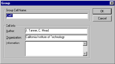
L-Edit 13 User Guide Section 1 273
Chapter 9: Working with Objects Grouping and Ungrouping Objects
and meet additional criteria, the command will instead create an array as described in “Grouping
Instances to Create an Array” on page 273.
Choose Draw > Group or press Ctrl+G to execute this command.
Options include:
Grouping Instances to Create an Array
Any type of object (geometry, ports, instances) may be grouped. The command can also be used to
create an array from selected instances of the same cell, under certain conditions. The selected instances
must be:
Of the same cell.
Have no repeat values.
Have the same orthogonal transformations and regular translations. (Nonorthogonally rotated
instances cannot be grouped.)
In other words, Draw > Group (Ctrl+G) can transform a collection of instances that already have the
appearance and spacing of an array into a single object that L-Edit recognizes as an array. If these
conditions are met, an array is automatically formed. If not, L-Edit prompts for the name of the new cell
to be created from the selected objects.
Ungrouping Instances
Draw > Ungroup (Ctrl+U) flattens the selected instances into their component objects, without deleting
the cell created by Draw > Group. When used on an array, the command “explodes” the array into its
component instances.
Draw > Ungroup works independently of the Group command, and can be used to remove an array
from any existing instance, however it was created. In other words, it works like Cell > Flatten, except
that Flatten will flatten an entire cell, including all its instances, but Ungroup will flatten just one level
down (only the selected instance or set of instances).
When you ungroup an array in L-Edit, each individual instance does not automatically inherit the
instance name. However, if more than one instances have the same instance name before netlist
Group Cell Name The name of the new cell.
Cell info Includes Author, Organization, and Information (notes or messages)
for the new cell.

L-Edit 13 User Guide Section 1 274
Chapter 9: Working with Objects Moving Objects
extraction, L-Edit automatically assigns them unique instance names after netlist extraction by
appending “_n” to each of the remaining instances, incrementing n by one for each instance.
For example, if three instances have the instance name “CAP” in the layout, after netlist extraction one
of the instances will keep the instance name “CAP,” the second instance name is “CAP_2” and the third
instance name is “CAP_3.”
Undoing Draw > Group and Draw > Ungroup
Both Draw > Group and Draw > Ungroup can be reversed with the Undo command.
Executing Undo immediately after Draw > Ungroup results in the selected objects being grouped
again, as if the Draw > Group command had just been used for the first time.
Executing Undo immediately after Draw > Group, however, is not a complete reversal of
Draw > Group. The cell created by Draw > Group is not deleted.
Moving Objects
You can reposition and reorient objects in L-Edit graphically with the mouse and keyboard; textually by
entering coordinates and other values; or by using the command line interface or UPI macros.
Note: If an object is drawn on a locked layer, it cannot be edited or moved. To edit or move
such an object, you must first unlock the currently locked layer or layers.
Repositioning
To move an object, select it and position the pointer anywhere except on a vertex or edge of the selected
object. Holding the MOVE/EDIT button, drag the object to its new position.
Note that the MOVE/EDIT button function depends on the position of the pointer:
If the pointer is within the edit range set for the current design, an EDIT is performed.
If the pointer is beyond the edit range, a MOVE is performed.
The edit range is specified in the Setup Design dialog under the Selection tab (see “Selection” on page
91). However, you can “force” a move rather than an edit operation using the Draw > Force Move
command (default hotkey Alt+M) (see “Force Move Mode” on page 276.
A single object can be implicitly selected and moved by clicking the MOVE/EDIT button in or near it
(but not on a vertex or edge) and dragging the object to its new position. The object is automatically
deselected after the move.
Multiple objects to be moved simultaneously must all be explicitly selected. The pointer may be
initially positioned anywhere, including on any vertex or edge. When moved, the selected objects’
relative positions are maintained.
To constrain movement to the horizontal or vertical directions only, hold the Shift key down while
using the MOVE/EDIT button.
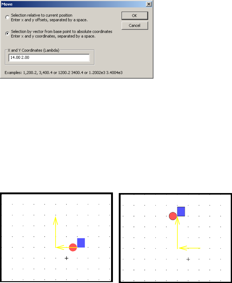
L-Edit 13 User Guide Section 1 275
Chapter 9: Working with Objects Moving Objects
Move By
You can move selected objects a specified distance using the Move dialog, which you open by choosing
Draw > Move By. “Behavior of the Move By Options” on page 275 illustrates the behavior of the two
options.
Behavior of the Move By Options
Move by operation using Selection relate to current position (drawing mode):
Selection relative to
current position Moves the selected object(s) by the x, y values entered, relative to
their current position(s).
Selection by vector from
base point to absolute
coordinates
Moves the selected object(s) as determined by a vector from the base
point to the absolute coordinate specified by the x, y value entered.
Note: This option is only available when a base point is picked.
Selection relative to current position moves the selection by ∆x, ∆y relative to the origin of
the current position (-20, 30 in this example).
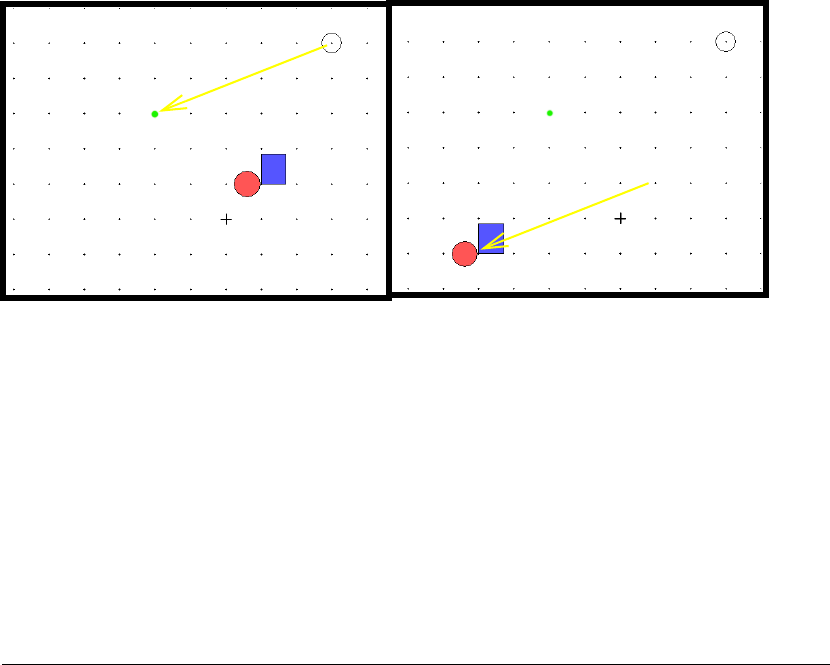
L-Edit 13 User Guide Section 1 276
Chapter 9: Working with Objects Moving Objects
Move by operation in Selection by vector from base point to absolute coordinates (base point
mode):
Nudge
Use this feature to incrementally move (nudge) a selected object or objects a predetermined distance.
The movement increment is the same is every direction.
You specify nudge distance in the Nudge amount field of the Setup Design—Drawing dialog (see
“Drawing Parameters” on page 101)
Force Move Mode
In normal drawing mode, the EDIT command is active when the cursor is within an object’s edit range
parameter (see “Edit range” on page 100), and the MOVE command is active when the cursor is outside
that range. When you use the Draw > Force Move mode (default hotkey Alt+M) L-Edit will perform a
MOVE operation regardless of the cursor position (the status bar will show Mode: Move.)
If no objects are selected prior to using this command, the move adheres to the selection range for
implicit selection—nothing will happen unless you are within the selection range. After the move
operation is finished, L-Edit reverts to normal drawing mode (Mode: Drawing in the status bar), or you
can cancel the force move operation by pressing ESC.
Command Shortcut
Draw > Nudge > Left Ctrl + ←
Draw > Nudge > Right Ctrl + →
Draw > Nudge > Up Ctrl + ↑
Draw > Nudge > Down Ctrl + ↓
In Base Point mode the Move By operation moves the selection along a vector drawn from the
base point position to the absolute position indicated by the x, y coordinates entered (-20, 30 in
this example).
-20, 30
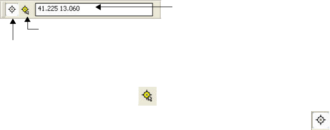
L-Edit 13 User Guide Section 1 277
Chapter 9: Working with Objects Moving Objects
Base Point Mode
The base point feature enables a user-specified reference point for editing operations, which change as
follows when L-Edit is in base point mode. After an editing operation is performed in base point mode,
L-Edit will return to the previous mode.
Setting the Base Point
The base point toolbar displays the location of the base point in an editable field you can use to type in
coordinates.
To simultaneously place the base point at the cursor’s current location and turn on base point mode, use
Draw > Base Point > Place Base Point at cursor or the keyboard shortcut Ctrl+Q. To use your cursor
to pick a base point, use the icon or Draw > Base Point > Pick Base Point.
Once a base point is set you can toggle the mode on and off with the icon , the keyboard shortcut
Shift+Q, by using Draw > Base Point > Use Base Point.
Move and Copy/Paste Operations in Base Point Mode
When you cut or copy and then paste an object(s) in base point mode, L-Edit uses the base point as the
reference point. When you paste in base point mode but no reference point was set explicitly during the
last copy operation, the lower left corner of the copied object(s) is pasted at the base point.
The base point feature can also be used to control positioning of a pasted object during a cut or copy
command. To do so, select an object, then place the base point at the desired location. The origin of the
object will be pasted at the base point rather than at the middle of the layout window (the normal
default).
Operation Result
Move Moves the selection from the base point to the current cursor location.
Edit Edits (stretches) the selection from the base point to the current cursor
location.
Rotate Rotates the selection around the base point.
Flip Flips the selection with respect to the base point.
Instance Instances the cell with its origin at the base point.
Cut, Copy Pastes the object at the base point. You can also use the base point to
set the origin of the object being cut or copied.
coordinate entry field
Draw > Base Point > Use Base Point icon - use to toggle base point mode on and off.
Draw > Base Point > Pick Base Point icon - use to set a base point with the cursor.
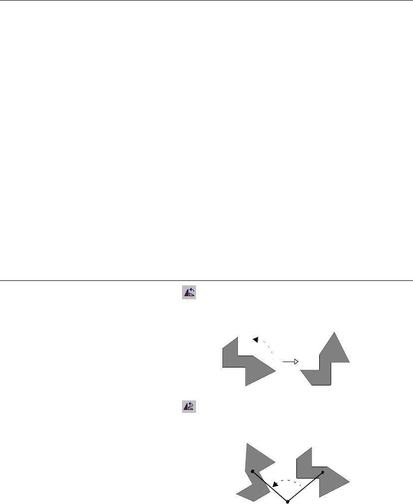
L-Edit 13 User Guide Section 1 278
Chapter 9: Working with Objects Moving Objects
You can also use the base point to pick an origin for an object before the cut/copy command. You must
use the base point to pick a paste origin point, otherwise L-Edit will simply paste the object using its
default origin in the default location.
The move command (middle mouse button) moves the selected objects according to the values set in
the Move dialog (see “Behavior of the Move By Options” on page 275).
Reorienting
These commands change the orientation of selected objects.
Copy/Cut... Paste...
base point ON base point ON:
The base point is the reference during the copy operation and that
reference point is the base point during the paste operation.
base point ON base point OFF:
The base point is the reference during the copy operation but the
center of the copied objects is pasted at the center of the screen.
base point OFF base point ON:
The the lower left corner of the copied objects is pasted at the base
point.
base point OFF base point OFF:
Normal cut/paste behavior.
Command Shortcut Button Description
Draw > Rotate > 90
degrees RRotates the selected object 90°
counterclockwise about its geometrical
center.
Draw > Rotate > Rotate Ctrl+R Opens a dialog to rotate the selected object
counter-clockwise by n degrees with respect
to a specified point.
See “Specifying Rotation Parameters” on
page 279 for instruction in using the
Draw > Rotate > Rotate command.
n°
(x, y)
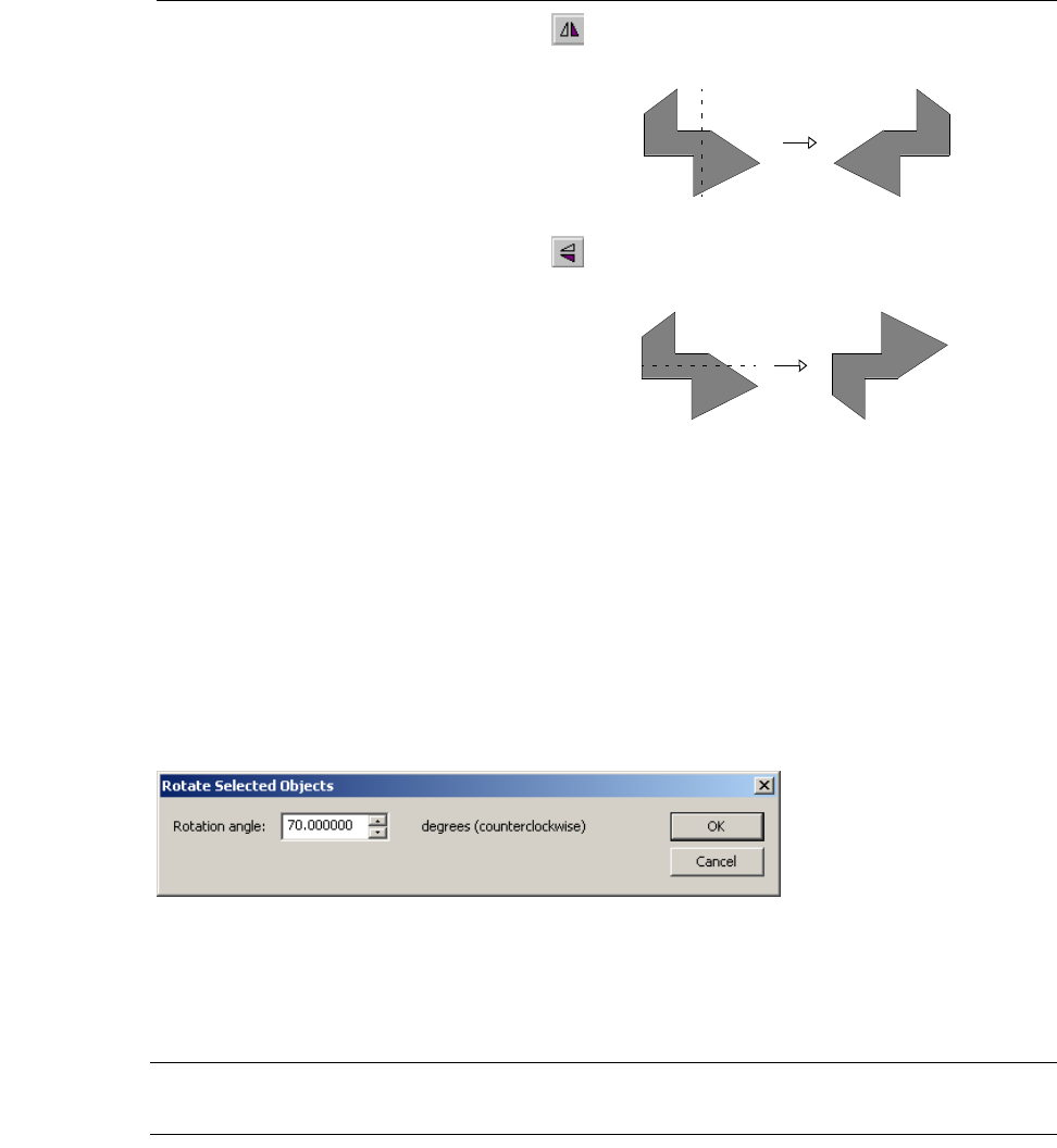
L-Edit 13 User Guide Section 1 279
Chapter 9: Working with Objects Moving Objects
When multiple objects are selected, the rotation or flip occurs about the geometrical center of the
selected group.
Specifying Rotation Parameters
The Rotate Selected Objects dialog allows you to specify the angle and reference point around which
to rotate the selected object.
To access this dialog, select an object or objects, then choose Draw > Rotate > Rotate or press Ctrl+R.
Enter a value (degrees) in the Rotation angle field to specify the angular distance around which to
rotate the selected object. The angle must be between -360 and +360 degrees, exclusive. The rotation
angle can have up to 6 decimals of accuracy.
Note: You can use the up and down arrows to step through multiples of 90 degrees between
-270 and 270. Other values can be typed directly in the editing field.
You can also use the base point feature (see “Base Point Mode” on page 277) to specify the reference
point around which L-Edit will rotate the selected object(s).
Draw > Flip > Horizontal H Flips the selected object about the vertical
axis through its geometrical center.
Draw>Flip>Vertical V Flips the selected object about the horizontal
axis through its geometrical center.
Command Shortcut Button Description
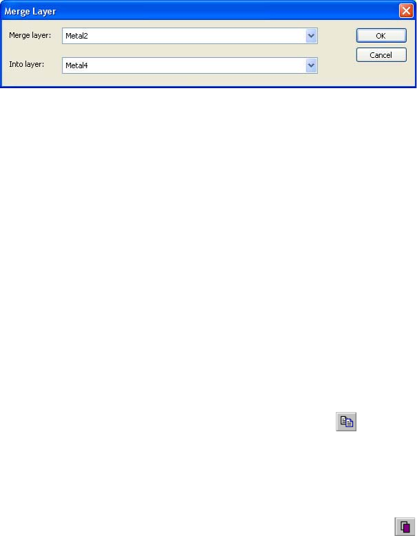
L-Edit 13 User Guide Section 1 280
Chapter 9: Working with Objects Copying and Duplicating Objects
Moving Objects from One Layer to Another
Use Setup > Merge Layers to transfer all objects on one layer, regardless of cell, onto another layer.
Copying and Duplicating Objects
You can copy objects in two ways. Note that to copy multiple objects simultaneously, you must
explicitly select them. (For more information see “Explicit Selection” on page 266.)
Copying Objects
Chose Edit > Copy, press Ctrl+C, or click the copy button ( ). The copy operation saves a copy of
the selected object(s) to the internal clipboard. The copied objects must be placed using the paste
operation command (see “Pasting Objects” on page 281).
Duplicating Objects
Chose Edit > Duplicate, press Ctrl+D, or click the duplicate button ( ). The Duplicate operation
copies the selected object(s) and pastes them, as the current selection, exactly over the original(s) in the
active cell. The Duplicate command also saves the x- and y- translation when you drag the duplicated
objects to a new position immediately after they are duplicated. (The duplicate objects remain selected
until you explicitly select something else.)
Since the Duplicate command stores the offset as well as the objects, subsequent use of the command
allows you to create regular structures quickly and accurately.
Keep in mind that multiple placement of the same object can be useful in making arrays, but it can also
result in designs that use a great deal of memory and are difficult to update. Multiple placement of the
same object should not be used as a substitute for good hierarchical design using instantiation.
Duplicate does not affect the contents of the internal L-Edit clipboard, so objects placed on the
clipboard using Copy can still be pasted to layout.
Merge layer Select the layer from which objects will be moved. (Only those layers
that have geometry on them are included in the drop-down list.)
Into layer Select from the list of defined, generated (in red), and special (in
green) layers to which objects will be moved.
L-Edit 13 User Guide Section 1 281
Chapter 9: Working with Objects Pasting Objects
Copying to the Clipboard
Large areas of the layout can be copied as a bitmap to the external Windows clipboard by choosing
Edit > Clipboard > Copy Window. These bitmap images can be pasted into other applications, but they
cannot be pasted back into L-Edit. The resolution of the bitmap is the same as that of the screen.
Pasting Objects
L-Edit maintains an internal clipboard that stores cut and copied objects. It can be used to transfer
objects between cells or between layers within a file.
Choosing Edit > Paste, pressing Ctrl+V, or clicking the paste button ( ) places the stored object(s) in
the center of the active layout window, unless the Paste to cursor feature (see below) is enabled.
Choosing Edit > Paste to Layer or pressing Alt+V also places the stored object in the center of the
layout window of the active cell (unless the Paste to cursor feature is enabled). In addition, this
command places the object on the currently selected layer. If you select multiple objects on separate
layers, they will all be pasted to the single layer specified with the Paste to Layer command. Pasted
objects are automatically selected after execution of the paste command.
The contents of the internal clipboard can be pasted multiple times. Objects remain in the clipboard
until another object is cut or copied, or until the file is closed.
Note: When you paste an object to a layer, L-Edit will overwrite the object’s GDSII data
type with the data type of the target layer. If the target layer has no GDSII data type
assigned, the pasted object will retain its original data type.
Paste to Cursor Feature
If the Paste to cursor box in the Setup Application—General dialog (see “General” on page 82) is
turned on, the contents of the clipboard appear in the layout window but move with the pointer until any
mouse button is clicked. The objects are then positioned at the location of the cursor when the paste
command is executed. Before clicking the mouse button, you can flip or rotate the objects horizontally
or vertically by using the keyboard shortcut commands. (See “Reorienting” on page 278 for a list of
default shortcut commands.)
You can also set a base point to control the origin of the copy or copied object and the location of the
origin to which it is pasted. See “Base Point Mode” on page 277.
Deleting Objects
You can remove objects from the layout in two ways:
Choosing Edit > Cut, pressing Ctrl+X, or clicking the cut button ( )
Choosing Edit > Clear, or pressing Delete or Backspace
L-Edit 13 User Guide Section 1 282
Chapter 9: Working with Objects Undoing Operations
The Cut command puts the deleted objects into the internal clipboard. From there they can be restored
to the current cell or pasted into another cell in the same file (see “Pasting Objects” on page 281).
The clear operation does not put the deleted objects into the internal clipboard. They can be restored to
the active cell only with the Undo command (see “Undoing Operations,” below).
Undoing Operations
L-Edit maintains a list of edited objects and operations on a per cell basis in the undo buffer. Choosing
Edit > Undo, pressing Ctrl+Z, or clicking the Undo button ( ) reverses the last operation performed
in a cell. You may continue undoing your operations in reverse order, one at a time, up to and including
the first operation on the cell since opening or saving it. L-Edit maintains a separate undo buffer for
each cell. Only those operations that directly affect objects—drawing, copying, editing, moving,
instancing, grouping, flipping, rotating, slicing, and merging—can be undone.
Undo reverses mouse-based draw, move, edit, and copy operations. It also reverses the following
commands:
Edit > Cut
Edit > Paste
Draw > Group
Draw > Ungroup
Draw > Rotate
Draw > Flip > Horizontal
Draw>Flip>Vertical
Draw>Slice>Horizontal
Draw > Slice > Vertical
Draw > Merge
Cell > Instance
The following operations clear the undo buffer:
File > Save
File > Save As
File > Replace Setup
Cell > Revert Cell
Cell > Flatten
Tools > Generate Layers
Tools > DRC
Editing performed prior to any of these operations cannot be reversed with the Undo command.
Redo
You can reverse an Undo command by choosing Edit > Redo, pressing Ctrl+Y, or clicking the redo
button ( ).
L-Edit 13 User Guide Section 1 283
Chapter 9: Working with Objects Undoing Operations
After an Undo operation is performed, the object or operation goes into a redo buffer, also maintained
by L-Edit on a per-cell basis. After executing an Undo command, you can use the Redo command to
revert the cell to its state before the Undo command was executed. For example, if you draw a box and
then click Undo, the box disappears from the layout. Clicking Redo causes the box to reappear.
Like the undo buffer, the redo buffer is maintained separately for each cell. The redo buffer is subject to
the same guidelines and restrictions as the undo buffer, and it is cleared by the same methods. When
editing continues, the redo buffer is cleared.
The depth of both buffers is limited only by computer resources.
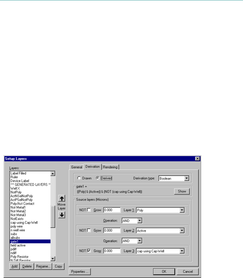
L-Edit 13 User Guide Section 1 284L-Edit 13 User Guide Section 1 284
10 Generating Layers
Introduction to Derived Layers
L-Edit allows you to develop derived layers based on operations and selections made to existing layers.
Derived layers can be setup using a graphical interface in the Setup Layers dialog, or using a textual
command file.
Setting Up Standard-Derived Layers
You define Standard-Derived layers with the Setup Layers dialog. To open this dialog, choose
Setup > Layers, or double-click anywhere on the layers palette.
Standard-Derived layers can be created using the following operations:
Boolean — Applies the logical AND, OR, and NOT operators to a combination of source layers.
Select — Selects polygons based on their area relationships between source layers.
Area — Selects polygons that are either equal to a specified area or within a specified area range.
Density — Selects polygons based on the relative density of two source layers.
Each derivation type includes a Boolean NOT case; this provides the complimentary output of a given
operation.
1

L-Edit 13 User Guide Section 1 285
Chapter 10: Generating Layers Setting Up Standard-Derived Layers
Note: Polygons on source layers are automatically merged during layer generation.
Derivation Steps
To create a derived layer, first add a name for the derived layer to the layer list, and then define its
characteristics. The target layer—the layer on which the operation results will be drawn—is always the
layer that is highlighted in the Layers list.
Any previously listed layer, including other derived layers, may be used in the definition of a derived
layer. The new layer name must be inserted in the layer list after the names of the layers that are used to
create it. For example, if you define a Gate layer as Poly AND Active, then Gate must come after Poly
and Active in the layer list.
To generate derived layers, select Tools > Generate Layers. Objects on derived layers are
automatically created (generated) during the generate layers operation (see “Generating Derived
Layers” on page 297.)
Drawn and Derived Layer Types
There are two types of layers, Drawn layers and Derived layers. A drawn layer is a layer that the
designer will draw on, a derived layer is generated by L-Edit. While you can draw on a derived layer, all
polygons on a derived layer will be deleted prior to generation if generate layers is run on that layer.
A derived layer can be changed to a drawn layer by simply changing it’s type on the Setup Layers
dialog, Derivation tab. The derivation will be saved, in case the layer is changed back to Derived.
The following actions are available for derived layers:
Tools > Clear Generated Layers.
Tools > Generate Layers.
Toggling visibility using View > Layers > Show Generated Layers and Hide Generated Layers.
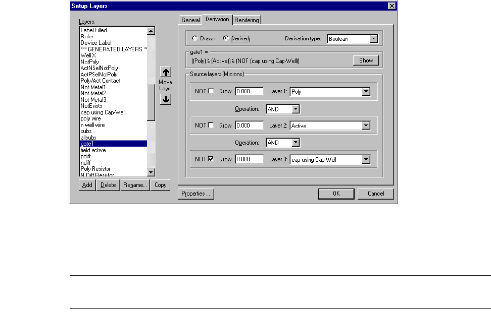
L-Edit 13 User Guide Section 1 286
Chapter 10: Generating Layers Setting Up Standard-Derived Layers
Boolean Layer Derivations
To define derived layers using Boolean operators, click on the Derivation tab in Setup Layers and
select Boolean from the Derivation Type drop-down menu.
Use this dialog to pick the name of the derived layer, specify up to three source layers, and compose the
Boolean operations performed to create the new layer. Note that operations are always evaluated from
top to bottom.
Note: The derived layer must be positioned in the Layers list below each of its source
layers.
The options used in designating the source layers are as follows:
Type Choose the Boolean derivation type from the drop-down list.
Show Opens the dialog Full Derivation, which shows the derivation for the
selected layer and all of its source layers in terms of drawn (mask)
layers.
Source layers (Display
Units)Existing layers from which the new layer will be created (derived).
Select each source layer (Layer 1, Layer 2, Layer 3) from the
drop-down list. Only layers listed above the target layer are available.
Two operations can be applied to each source layer:
NOT—when this box is checked, the complement of the source
layer is used.
GROW—enter a positive or negative integer for the amount, in
Display units, by which objects on the source layer are grown or
shrunk on the derived layer. Objects grow or shrink uniformly by
the given quantity.
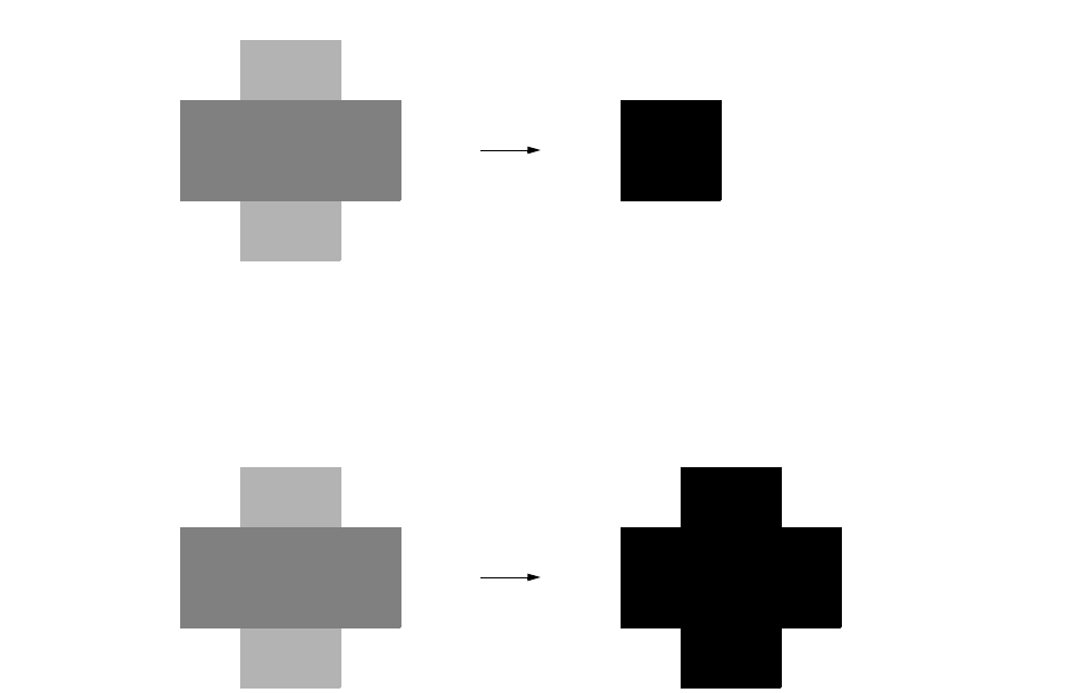
L-Edit 13 User Guide Section 1 287
Chapter 10: Generating Layers Setting Up Standard-Derived Layers
Three elementary Boolean operations can be applied to previously defined layers: AND, OR, and NOT.
L-Edit also performs the “Grow” (page 288) operation, used to oversize or undersize (shrink) objects.
These operations can be used individually or combined to produce more complex formulas.
AND
The AND operation (abbreviated &) creates objects on a derived layer from the intersection of objects on
two other layers.
OR
The OR operation (abbreviated |) creates objects on a derived layer from the union of objects on two
other layers.
NOT
The NOT operation creates objects on a derived layer based on the absence, or inverse, of objects on
another layer. Mathematically, the derived layer should extend throughout the layout area wherever the
Operation Select a Boolean AND or OR from the drop-down lists between layers
to specify pairwise operations. For example, if Layer 1 is Poly and
Layer 2 is Active, choosing AND between them results in Poly &
Active for the derived layer.
a
ba & b
a
b
a | b
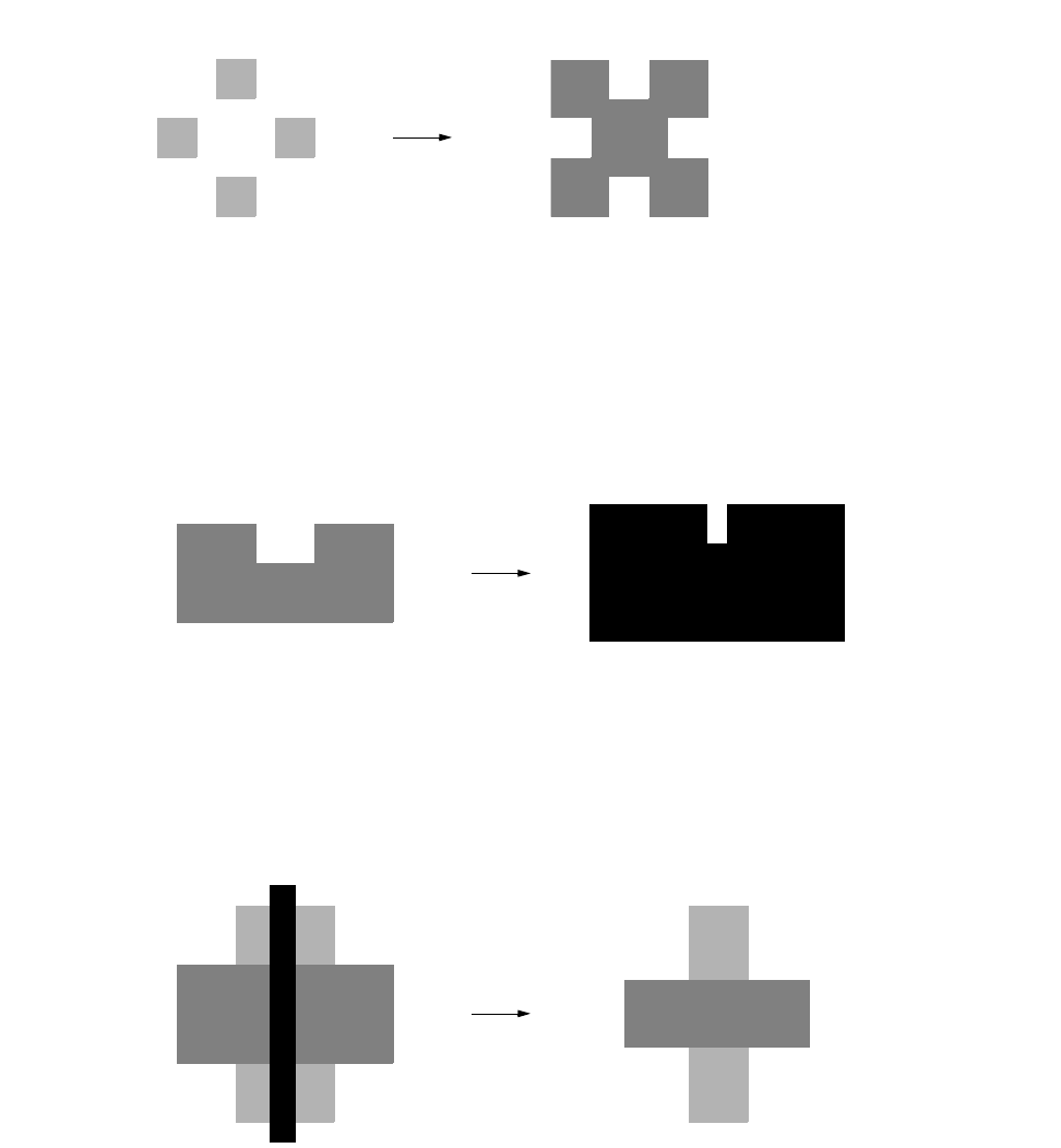
L-Edit 13 User Guide Section 1 288
Chapter 10: Generating Layers Setting Up Standard-Derived Layers
original layer does not exist. Because the layout area is not explicitly defined, L-Edit applies the NOT
operation within the minimum bounding box that encompasses all existing objects.
Grow
The Grow operation creates objects on a derived layer by increasing the size of each object on the
original layer. Specifically, a Grow operation displaces each edge by the specified number distance (in
display units).
A negative Grow parameter yields a shrink operation, creating objects on a derived layer by displacing
the edge of each object on the original layer inward by the specified distance (in display units).
If any dimension of an object is less than or equal to twice the shrink amount, a new object will not be
created on the derived layer.
Order of Operations
Boolean operations are performed on the source layers in the following order:
[4] Grow (individually)
[5] NOT (individually)
[6] AND/OR (first to last)
aNOT a
b
Grow b
a
bshrink b
c shrink c (not created)
shrink a
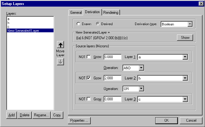
L-Edit 13 User Guide Section 1 289
Chapter 10: Generating Layers Setting Up Standard-Derived Layers
AND has higher precedence than OR. For example, a AND b OR c is read as (aAND b) OR c, and c OR
a AND b is read as c OR (a AND b).
In the following example, the source layers consist of layers a, b, and c, with the following operations:
NOT and Grow 2 on b; AND between a and b; OR between b and c. The total derivation can be
expressed as (a AND (NOT(Grow 2 b))) OR c.
In this case, the operations are performed as follows:
[1] Grow 2 on b
[2] NOT on the result of step 1
[3] AND between a and the result of step 2
[4] OR between the result of step 3 and c.
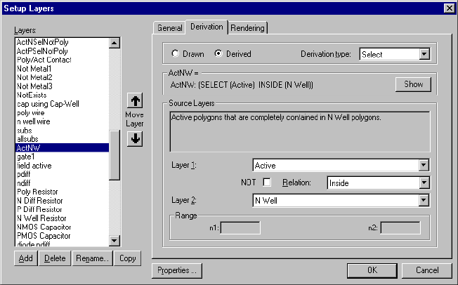
L-Edit 13 User Guide Section 1 290
Chapter 10: Generating Layers Setting Up Standard-Derived Layers
Select Layer Derivations
Select operations allow you to define a relationship that selects a group of polygons from a layer and
creates a new layer with the results. These operations allow you to create rules that cannot be made with
logical operations, such as spacing checks and sizing checks.
The options used in designating the select layer are:
Type Choose the Select derivation type from the drop-down list.
Show Opens the dialog Full Derivation, which shows the derivation for the
selected layer and all of its source layers in terms of drawn (mask)
layers.
Source Layers
Layer 1, Layer 2 Existing layers from which the new layer will be created (derived).
Select each source layer from the drop-down list. Only layers listed
prior to the target layer are available.
NOT When this box is checked, the NOT of the relation is applied.
Relation Choose one of the following select relationships from the drop-down
list:
“Inside” (page 291)
“Outside” (page 292)
“Hole” (page 292)
“Cut” (page 293)
“Touch” (page 294)
“Enclose” (page 294)
“Overlap” (page 294)
“Vertex” (page 295)
n1, n2 When the Vertex relation is selected, enter a minimum (n1) and
maximum (n2) value (exclusive) to define the vertex count range.
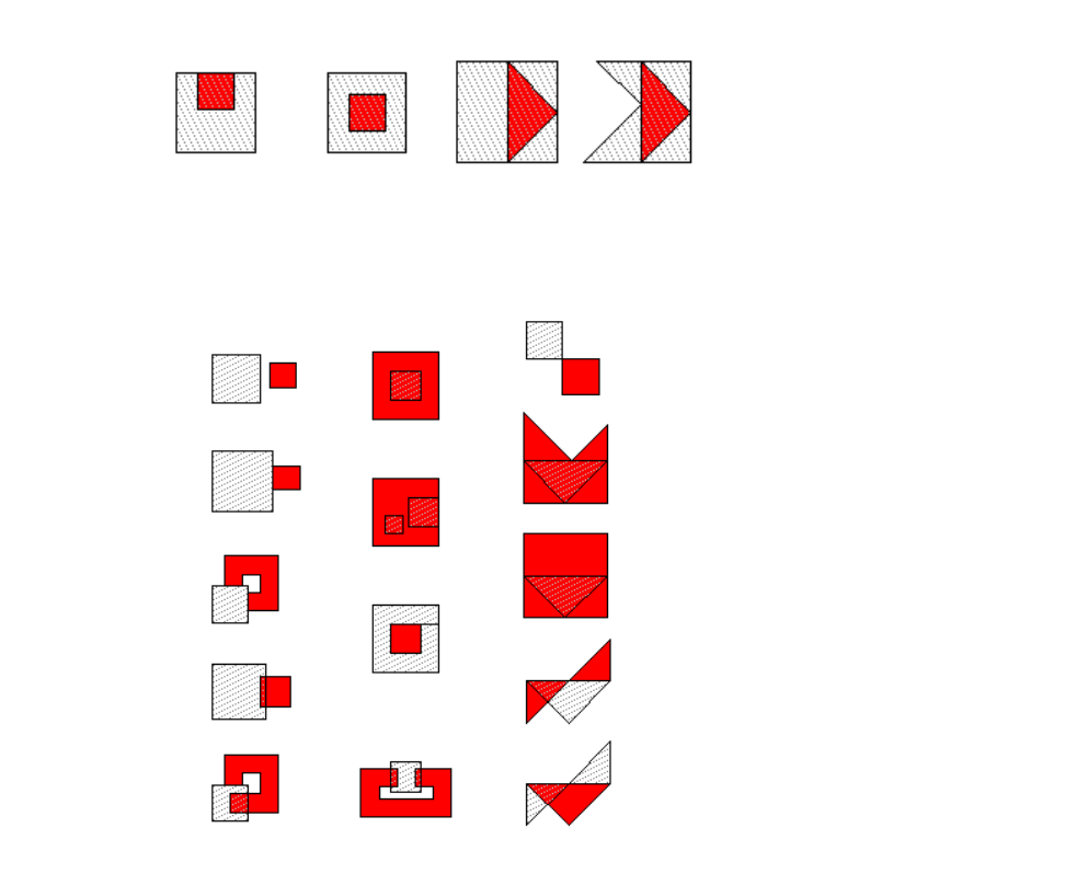
L-Edit 13 User Guide Section 1 291
Chapter 10: Generating Layers Setting Up Standard-Derived Layers
The select relationships are described and illustrated below.
Inside
The inside operation selects layer 1 polygons that are completely contained in layer 2 polygons, as
shown below (where layer 1 is red).
The not inside operation selects layer 1 polygons that are NOT completely contained in layer 2
polygons (equivalent to outside or cut), as shown below (where layer 1 is red).
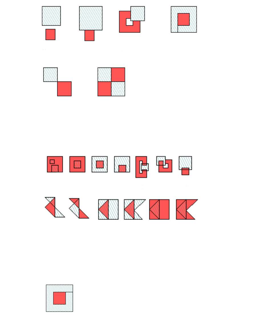
L-Edit 13 User Guide Section 1 292
Chapter 10: Generating Layers Setting Up Standard-Derived Layers
Outside
The outside operation selects layer 1 polygons that are completely outside of layer 2 polygons, as
shown below (where layer 1 is red).
The not outside operation selects layer 1 polygons that are not completely outside layer 2 polygons
(equivalent to inside or cut), as shown below (where layer 1 is red).
Hole
The hole operation selects layer 1 polygons that have their entire outside surface exactly touching the
outside surface of a layer 2 polygon, as shown below (where layer 1 is red).
The not hole operation selects any layer 1 polygons that do not exactly fill a hole in a layer 2 polygon.
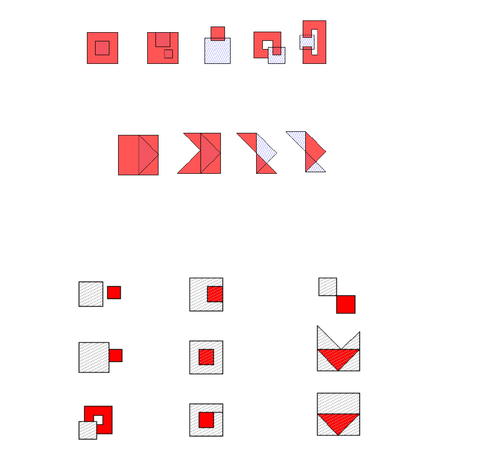
L-Edit 13 User Guide Section 1 293
Chapter 10: Generating Layers Setting Up Standard-Derived Layers
Cut
The cut operation selects layer 1 polygons that intersect but do not just touch layer 2 polygons, so that
they have areas that are both inside and outside of layer 2 polygons, as shown below (where layer 1 is
red).
The not cut operation selects layer 1 polygons that are either completely inside of or completely outside
of layer 2 polygons, as shown below (where layer 1 is red).
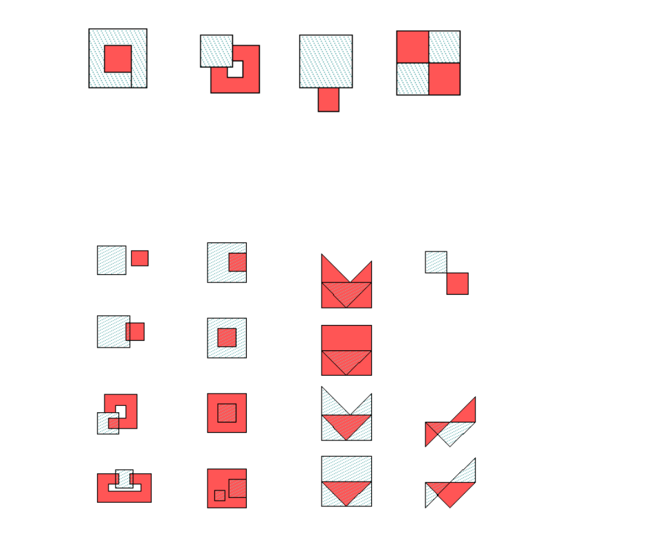
L-Edit 13 User Guide Section 1 294
Chapter 10: Generating Layers Setting Up Standard-Derived Layers
Touch
The touch operation selects layer 1 polygons that touch layer 2 polygons from the outside and do not
also cut, as shown below (where layer 1 is red).
The not touch operation selects layer 1 polygons that do not touch layer 2 polygons, as shown below
(where layer 1 is red).
Enclose
The enclose operation selects layer 1 polygons that completely enclose layer 2 polygons. This includes
layer 1 polygons that are inside and touching layer 2 polygons. The not enclose operation selects layer
1 polygons that do not completely enclose layer 2 polygons.
Overlap
The overlap operation selects layer 1 polygons that touch, cut, enclose or are inside of layer 2 polygons.
The not overlap operation selects layer 1 polygons that are entirely outside of layer 2 polygons.
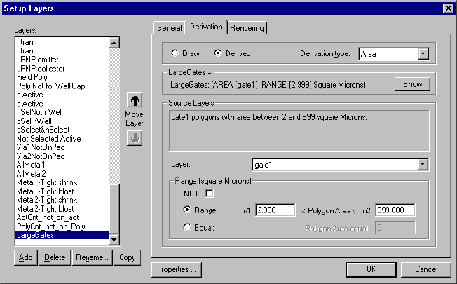
L-Edit 13 User Guide Section 1 295
Chapter 10: Generating Layers Setting Up Standard-Derived Layers
Vertex
The vertex operation selects layer 1 polygons with more than or equal to a specified minimum number
and fewer than or equal to a specified maximum number of vertices. The not vertex operation selects
layer 1 polygons with fewer than the minimum number or more than the maximum number of vertices.
Area Layer Derivations
The Area option in the Derivation tab checks polygons on the selected layer to determine if their areas
are equal to a specified area or are within a specified area range.
The parameters used in designating the minimum area check are:
Type Choose the area derivation type from the drop-down list.
Show Opens the dialog Full Derivation, which shows the derivation for the
selected layer and all of its source layers in terms of drawn (mask)
layers.
Source Layers Existing layers from which the new layer will be created (derived).
Select each source layer from the drop-down list. Only layers listed
prior to the target layer are available.
NOT When this box is checked, the NOT of the relation is used, so
polygons with area outside the specified range are flagged.
Square Display units
or
Square Lambda
Select one of these radio buttons to set the units for area calculation.
As with the rule distance in Setup Design Rules, (see “Specifying
DRC Standard Design Rules” on page 422) areas do not get rescaled
when Square Display Units is selected, but do get rescaled when
Square Lambda are used.
Range
or
Equal
Click one of these radio buttons to pick either polygons with an area
in the range specified in n1 and n2 (exclusive) or polygons equal in
area to the value entered in Equal.
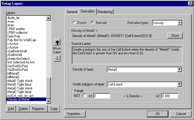
L-Edit 13 User Guide Section 1 296
Chapter 10: Generating Layers Setting Up Standard-Derived Layers
Density Layer Derivations
Certain design rules require testing of the percentage of area covered by a certain layer. The density
operation selects polygons based on the percentage of area that one layer covers in an area defined by
another layer. The selected objects can then be used in a density DRC rule.
The density operation derives boundary polygons within which the density of layout on the Density of
layer is between a minimum n1 and maximum n2 percentage. The boundary may be the cell extent, or
may be polygons on a specified layer. The density of the input layer is computed separately within each
boundary polygon by performing a Boolean AND operation of the input density layer with each
polygon on the boundary layer. Valid range values are between 0 and 100 percent, where n1 must be
less than or equal to n2.
The not density operation selects boundary polygons within which the density of layout on the input
Density of layer is less than the minimum percentage or greater than the maximum percentage.
L-Edit calculates the area density of the specified density layer that exists inside each polygon of the
boundary layer, and outputs the boundary layer polygon if the density is within the specified range.
Specifically, for each polygon P in layer 1, L-Edit calculates:
density = (area of (P AND layer 2))/(area of P) x 100%
then outputs P to the derived layer if the density is in the specified range (or not in the given range
if NOT is turned on).
The options used in designating the density layer are:
Derivation Type Choose Density from the drop-down list.
Show Opens the dialog Full Derivation, which shows the derivation for the
selected layer and all of its source layers in terms of drawn (mask)
layers.
NOT When this box is checked, the NOT of the relation is applied.
Density of layer The input layer from which the density is calculated.

L-Edit 13 User Guide Section 1 297
Chapter 10: Generating Layers Setting Up Command File Derived Layers
Setting Up Command File Derived Layers
Layers can also be defined in command files, using Dracula or Calibre command file format, using any
of the layer derivation commands. See “HiPer Verify: Calibre Command Files” on page 426 or “HiPer
Verify: Dracula Command Files” on page 594 for details.
Generating Derived Layers
After derived layers have been defined, they can be created in the active cell with Tools > Generate
Layers. To run Generate layers, you first need to Setup the command set that you want to run. To do
this,
Invoke Tools > Generate Layers
If you want to generate layers defined in the Setup Layers dialog, select Standard-Derived Layers.
If you want to generate layers defined in a command file, press the Add Command File to List
button ( ), then press the Browse button ( ) to browse to and select a command file from
disk.
Multiple command files can be setup and saved in the dialog, but only one at a time can be
generated. The derived layers defined in the Setup Layers or in the command file will be displayed
in the lower portion of the dialog, for the highlighted command set. Command files containing both
DRC statements and derived layers can be included in the list.
Highlight the command file you wish to run.
Check the checkboxes corresponding to the layers you wish to generate.
Press the Run button to generate the layers you have selected.
Inside polygons of layer The boundary polygons within which the density is measured. The
boundary can be a layer or the cell boundary.
n1, n2 Enter a minimum (n1) and maximum (n2) value (exclusive) to define
the density range.

L-Edit 13 User Guide Section 1 298
Chapter 10: Generating Layers Generating Derived Layers
Command Sets Enter the command files you wish to run, or select Standard-Derived
Layers to generate layers derived in the Setup Layers dialog. Use the
Add command file to list and Delete command file from list buttons
to add and remove files from the list.
Select the command set containing the layer definitions you wish to
generate.
Layers to generate Place a checkmark next to each layer you wish to generate. You can
mark layers individually by clicking in the checkbox next to the layer
name. To mark a group of adjacent layers, click and drag the mouse
from the first to the last layer in the group. Use Mark All and Unmark
All to add or remove checkmarks next to all layers in the list.
Only derived layers for which derivation is enabled may be generated.
Locked layers and derived layers that have the Enable Derivation
option off are not listed in this dialog. Ports on derived layers are not
deleted.
L-Edit 13 User Guide Section 1 299
Chapter 10: Generating Layers Working with Derived Layers
When you execute the Generate Layers command, L-Edit automatically deletes existing objects on
generated layers before regenerating those layers. Only those layers selected for generation will be
cleared.
When layers are generated from command files, the following behavior will occur:
If a layer does not exist in L-Edit for the layer being generated, then a new layer will be created at
the end of the layer list with the name of the layer being generated, and the geometry is put on this
layer. The layer is created as Derived, with Type External.
If a Derived layer of type External already exists in L-Edit with the same name as a layer being
generated, then this layer is reused.
If a Drawn layer exists in L-Edit with the same name as a layer being generated, then a new layer
will be created at the end of the layer list with the name of the layer being generated plus "_1"
appended, and the geometry is put on this layer. The "_1" is incremented as required to avoid name
collisions. The layer is created as Derived, with Type External.
If a Derived layer of type other than External exists in L-Edit with the same name as a layer being
generated, then it is treated the same as a Drawn Layer.
Working with Derived Layers
Objects on derived layers behave like other L-Edit objects. They can be edited, shown, locked, and
hidden in the same way.
Automatically mark
intermediate layers If the source layers for a derived layer are themselves derived layers,
checking this option causes L-Edit to automatically mark the derived
source layers. For example, consider the following derived layers:
Gate = Poly & Active
ptran = Gate & NWell
When this option is checked, marking ptran will automatically mark
the intermediate derived layer, Gate, which is required to generate
ptran.
When L-Edit generates a layer that is derived from other derived
layers, L-Edit generates the source layers internally. If the source
layer is marked, L-Edit then updates this layer with the results of
generation. If the layer is not marked, L-Edit discards the source layer
results after the marked layer is generated.
Note: L-Edit does not generate locked source layers or layers for
which derivation is disabled. In these cases, L-Edit treats the
source layers as drawn layers for the purposes of generating
the derived layer.
Merge polygons after layer
generation Causes polygons on a derived layer to be merged upon completion of
the process. This option can significantly increase processing time for
complex layouts.
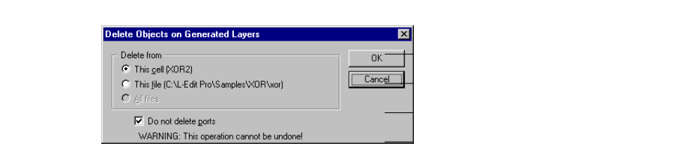
L-Edit 13 User Guide Section 1 300
Chapter 10: Generating Layers Working with Derived Layers
Showing, Hiding, and Locking Generated Layers
Use the menu commands View > Layers > Show Generated and View > Layers > Hide Generated to
show and hide derived layers. (See “Showing and Hiding Layers” on page 122.) If the current layer is a
derived layer, it will remain visible when derived layers are hidden.
You can also show or hide derived layers using the context-sensitive menus on the layer palettes, just as
you would any other layer. With the pointer over any non-derived layer icon, click the right mouse
button and choose Hide Generated. All derived layers will be hidden and their icon or name will be
shaded on the layer palettes.
To hide all derived layers except the selected layer, position the pointer over the desired derived layer
icon and choose Hide Generated in the context-sensitive menu. Choose Show Generated to display all
generated layers in all cells for the active file.
Finally, you can lock derived layers, just as you would any other layer. With the pointer over any
non-derived layer icon, click the right mouse button and choose Lock derived_layer_name.
Removing Generated Layers
Tools > Clear Generated Layers removes objects from all derived layers in the active cell, the active
file, or in all open files. All objects on derived layers are deleted, regardless of how they were created.
Ports may be optionally kept. This command cannot be undone.
Options include:
Automatic Layer Generation with DRC and Extract
L-Edit automatically generates objects on derived layers before DRC or Extract runs and clears those
objects afterwards. It only deletes objects generated during that DRC or Extract run, however—
previously generated objects remain.
This Cell (cell name)Removes derived layers in the active cell.
This File (file name)Removes derived layers in the active file.
All Files Removes derived layers in all open files.
Do not delete ports Prevents L-Edit from removing ports on the derived layers in the
specified file or cell. Use this option when your design uses a derived
layer as its extract recognition layer and you want to retain the ports
on this layer.
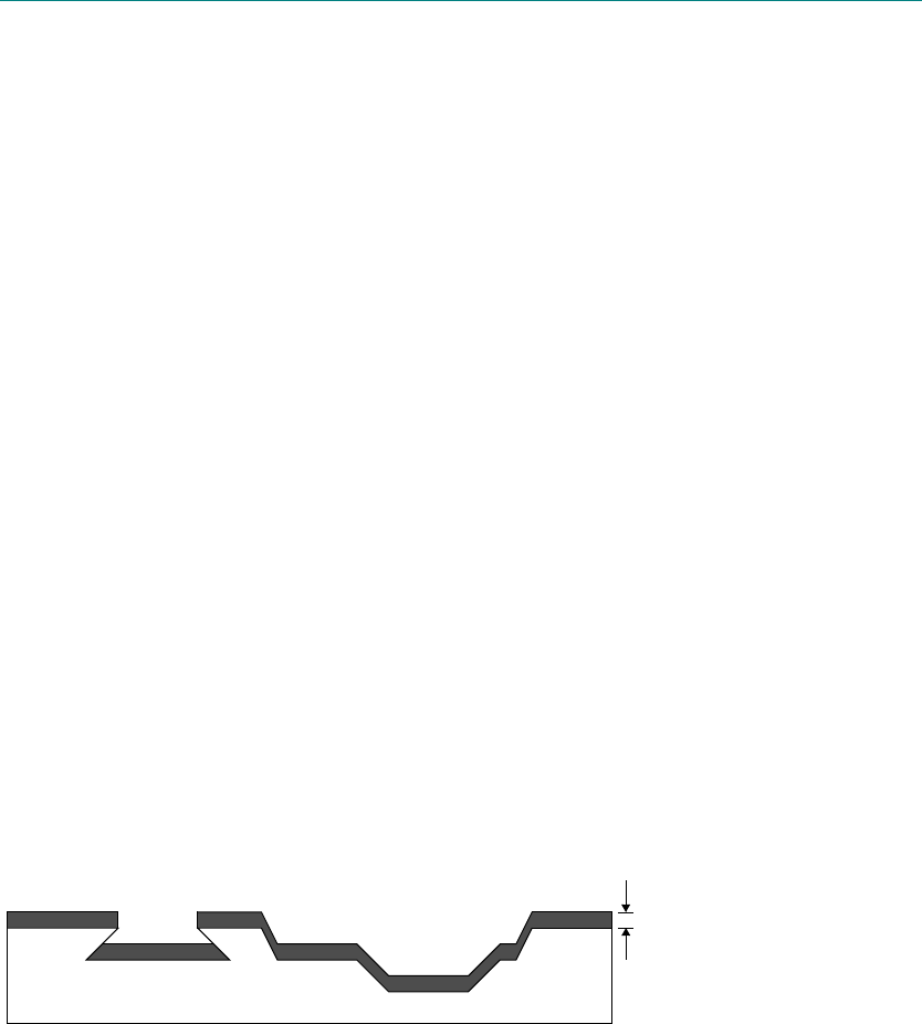
L-Edit 13 User Guide Section 1 301L-Edit 13 User Guide Section 1 301
11 Cross-Section Viewer
Implementation
L-Edit cross-section views are intended to help the circuit designer visualize the vertical structure of an
integrated circuit. This view does not provide a completely accurate representation of the physical
reality. Actual chips have a variety of properties and process artifacts, such as smooth height transitions,
bird’s beak, and planarization, which L-Edit does not model in cross-section view.
Cross-section views are generated from layout by simulating a set of process (fabrication) steps and
building the diagram from the substrate up, one layer at a time. These simplified process steps
correspond only roughly to the process steps used by the fabricator to create the chip. The process
definition is maintained in a separate text file (see “Process Definition Files” on page 306).
The cross-section viewer simulates three types of process steps:
Grow/deposit generates new material.
Etch removes material.
Implant/diffuse modifies the material nearest the surface.
Grow/Deposit
New material is generated uniformly in a grow/deposit step. The substance specified in the process step
statement is grown or deposited vertically to the specified depth (measured in technology units) on all
upward-facing surfaces. The following figure depicts new material deposited in a grow/deposit step.
Oxide growth and metal deposition are both simulated with this type of step. (In reality these fabrication
layers and the substrate are manufactured with completely different procedures, but for
cross-section-viewing purposes, the results may be modeled in the same way.)
Etch
An etch step removes material from all areas covered by the specified mask layer. The etch process
model involves up to three parameters: the depth, the undercut offset, and the angle. Depths and offsets
are measured in technology units; angles are measured in degrees. A cross-section surface resulting
1
depth
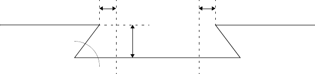
L-Edit 13 User Guide Section 1 302
Chapter 11: Cross-Section Viewer Operation
from an etch step with depth d, undercut offset u, and angle a, between points x1 and x2, is shown in the
following figure.
Typically, many of the layers to be etched will not be simple drawn mask layers, but will result from
logical operations such as AND, OR, and NOT combining several mask layers. Unlike a physical etch
that may remove some materials but not others, the simplified etch step removes all materials
uniformly. Although nonphysical, the simplified etch captures the important details of most
semiconductor fabrication processes.
Implant/Diffuse
To simulate the ion-implantation or high-temperature diffusion process that modifies the type of
semiconductor nearest the surface, an implant/diffuse step causes the color of the specified mask layer
to replace the existing ones from the top surface down to the specified depth in all areas covered by the
layer. The implant/diffuse process model involves the same parameters as in the etch model, except that
the underlying material is replaced rather than removed.
Again, the mask layer may be a logically derived one. For example, the self-aligned polysilicon gate
structure requires a combination of the polysilicon and active mask layers to determine where to show
the implanted active, which may be blocked by either field oxide (the NOT of active) or by polysilicon.
Operations on layers are specified with the Setup Layers dialog (see “Layer Setup” on page 104). The
derived layers are specified for cross-section views the same way as for DRC and extraction layers.
Operation
A process definition file must exist prior to generating a cross-section. The layer names in this file must
exactly match the layer names in the layout that you wish to view in cross-section. Sample process
definition files are provided in the tech directory, which is located in the default L-Edit install directory.
The process definition files are described in the file Index.txt, which is located in the same directory.
For information on the syntax of a process definition file, see “Process Definition Files” on page 306.
The cell for which you wish to generate the cross-section must be open. Arrange the display such that a
small region of interest (usually a few transistors) is centered in the upper portion of the layout view.
u
d
a
u
x1x2
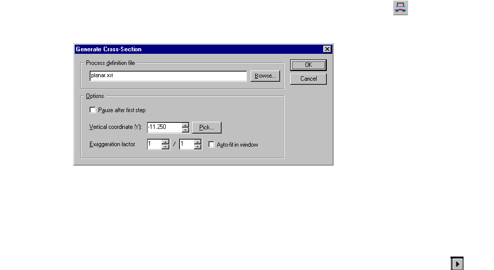
L-Edit 13 User Guide Section 1 303
Chapter 11: Cross-Section Viewer Operation
When you choose Tools > Cross-Section or press the cross-section button ( ) L-Edit displays the
following dialog:
Options include.
Process definition file Type in the name of the process definition file, or use the Browse
button to select the file.
Pause after first step Pauses cross-section generation after the first step in the process. To
resume cross-section generation, click the Next Step button ( )in
the cross-section window.
Vertical coordinate (Y) Sets the vertical coordinate along which the cross-section is
generated.
Pick Allows you to set the vertical coordinate graphically. The cursor
becomes a horizontal line that can be dragged up or down in the
layout. Clicking the mouse button over the desired position reopens
the Generate Cross-Section dialog, with the graphically selected
y-coordinate in the Vertical coordinate (Y) field.
Exaggeration factor Sets the magnification factor for the cross-section along the z-axis in
terms of a ratio. Since process depths are measured in technology
units, the displayed thicknesses of layers in cross-section scale with
the current layout magnification. At very large or very small
magnifications, it may be impossible to display cross-section views
effectively at a 1:1 horizontal-to-vertical aspect ratio. The two fields
(numerator and denominator) specify the ratio by which to compress
or expand the vertical axis of the cross-section.
Auto-fit in window Sets magnification along the z-axis for maximum visibility.
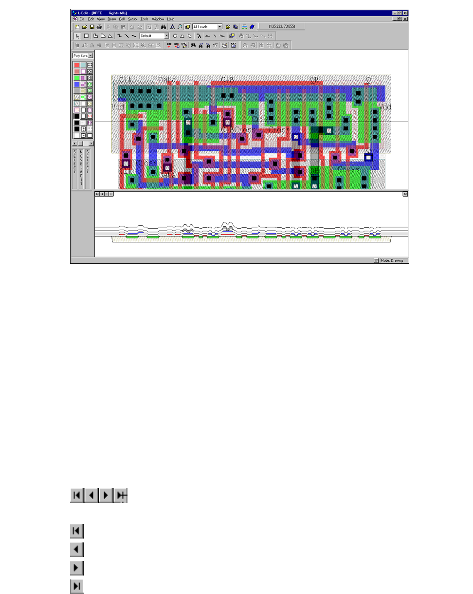
L-Edit 13 User Guide Section 1 304
Chapter 11: Cross-Section Viewer Operation
Display
L-Edit displays the cross-section view in the lower portion of the application interface.
Where the active cell displays a cross-section view:
You cannot pan, zoom, or edit in the cross-section window.
You cannot perform an editing operation in other windows associated with the file.
You cannot resize the layout window.
The split line separating layout from the generated cross-section can be dragged into another location.
Double-clicking on this line removes the cross-section view.
To continue normal layout editing, close the cross-section window.
Single-Step Display
You can step through the cross-section view one process step at a time. To do click the appropriate
button in the cross-section window:
First process step
Previous process step
Next process step
Final process step
L-Edit 13 User Guide Section 1 305
Chapter 11: Cross-Section Viewer Operation
A tooltip identifying the associated process step appears over these buttons when you point at them. The
current step is displayed in the status bar.
Single-step mode is useful for learning the steps involved in fabrication. For instruction in real
fabrication processing, a much more detailed process definition could be used.
Single-stepping through a fabrication cross-section that includes all the photoresist and other
intermediate processing steps would better communicate the full complexity of today’s fabrication
processes. For designers who only want to view final cross-sections, simpler process definitions (such
as the example in this chapter) are sufficient and easier to maintain.
Chapter 11: Cross-Section Viewer Operation
L-Edit 13 User Guide Section 1 306
Process Definition Files
Syntax
The cross-section process definition file (XST) contains a list of comment statements and process
statements. Comment statements begin with a pound sign (#) and continue to the end of the line.
Process statements have the following format:
step layer depth label [angle [offset]] [comment]
Each process statement begins with a step type, one of the following:
gd or grow/deposit
e or etch
id or implant/diffuse
Layer is the name of the involved layer. The name of the layer must match the layer name used in the
L-Edit TDB file. If the layer name begins with a digit or contains spaces, then the entire name must be
enclosed in double-quotes ("…"). The layer name describes something different for each type of step:
For grow/deposit steps: the layer to be grown/deposited
For etch steps: the layer to be etched away
For implant/diffuse steps: the layer to be diffused
A dash (-) in place of a layer name indicates that the process step has no associated rendering
information.
Depth is a (non-negative) value indicating the depth, measured in technology units. The depth also
means different things for different steps:
For grow/deposit steps: the number of units to grow upward
For etch and implant/diffuse steps: the number of units downward to apply the step
Label is optional. The label may be any string. If it contains spaces, the entire label must be enclosed in
double-quotes ("…"). A dash (-) may be used in place of a label.
If desired, two parameters that apply only to etch and implant/diffuse steps are inserted next:
Etch-implant angle (integer)
Undercut offset (non-negative floating-point or integer)
Angles are measured in degrees and must be between 0 and 180; offsets are measured in technology
units. The default values are angle = 80 and offset = 0.
Last is an optional comment. The comment begins with a pound sign (#) and continues to the end of the
line.
L-Edit 13 User Guide Section 1 307
Chapter 11: Cross-Section Viewer Operation
L-Edit 13 User Guide Section 1 307
Chapter 11: Cross-Section Viewer Operation
Example
A sample definition for an n-well, double-poly, double-metal CMOS process is shown below. Each line
(after the header) corresponds to one process step.
# File: mORBn20.xst
# For: Cross-section process definition file
# Vendor: MOSIS:Orbit Semiconductor
# Technology: 2.0U N-Well (Lambda = 1.0um, Technology = SCNA)
# Technology Setup File: mORBn20.tdb
# Copyright (c) 1991-93
# Tanner Research, Inc. All rights reserved
# ******************************************************************************
# L-Edit
# Step Layer NameDepth Label [Angle[offset]] Comment
# ------------------------------------------------------------------------------
gd - 10 p- # 1. Substrate
id "Well X”3 n- # 2. n-Well
id ActPSelNotPoly0.9p+ 75 0 # 3. p-Implant
id ActNSelNotPoly0.9n+ 75 0 # 4. n-Implant
id CCD&Act 0.4 - # 5. CCD Implant
id "P Base"2 - # 6. NPN Base Implant
gd - 0.6 - # 7. Field Oxide
e Active 0.6 - 45 # 8.
gd - 0.04 - # 9. Gate Oxide
gd Poly 0.4 - # 10. Polysilicon
e NotPoly 0.44 - 45 # 11.
gd - 0.07 - 45 # 12. 2nd Gate Oxide
gd Poly2 0.4 - # 13. 2nd Polysilicon
e NotPoly20.47 - 60 # 14.
gd - 0.9 - # 15.
e "P/P2/Act Contact"0.9- 60 # 16.
gd Metal1 0.6 - # 17. Metal 1
e "Not Metal1"0.6 - 45 # 18.
gd - 1 - # 19.
e Via 1 - 60 # 20.
gd Metal2 1.15 - # 21. Metal 2
e "Not Metal2"1.15- 45 # 22.
gd - 2 - # 23. Overglass
e Overglass2 - # 24.

L-Edit 13 User Guide Section 1 308L-Edit 13 User Guide Section 1 308
12 Interactive DRC
Introduction
Interactive DRC lets you create highly compact designs by highlighting DRC violations in real time as
polygons are drawn or edited.
When enabled, interactive DRC displays a colored outline when a polygon violates one of the defined
rules (that is, when a minimum layout distance is exceeded), and optionally, another colored outline
when a violation limit is reached. Markers are displayed while a polygon is being drawn or edited but
not after it has been placed.
The following rule types are supported:
Width
Spacing
Surround
Overlap into
Extension out of
1
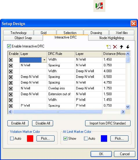
Chapter 12: Interactive DRC Setting Up Interactive DRC Rules
L-Edit 13 User Guide Section 1 309
Setting Up Interactive DRC Rules
To setup interactive DRC, invoke Setup > Design, and select the Interactive DRC tab, or click the
Setup Interactive DRC toolbar button .
Options include:
Enable Interactive DRC Enables the interactive DRC function when checked.
Enable All Enables all interactive DRC rules.
Disable All Disables all interactive DRC rules.
Import from DRC Standard Imports the built-in set of Tanner design check rules. See “DRC Rule
Sets to run” on page 407.
Violation Marker Color Auto sets the color of the violation marker to the last color in the
color palette, usually black. Pick lets you choose the marker color
using the standard Color selection dialog.
At Limit Marker Color When checked, Show enables display of an interactive DRC marker
when the boundary of a violation is reached. Auto sets the color of the
violation marker to the last color in the color palette, usually black.
Pick lets you choose the marker color using the standard Color
selection dialog.
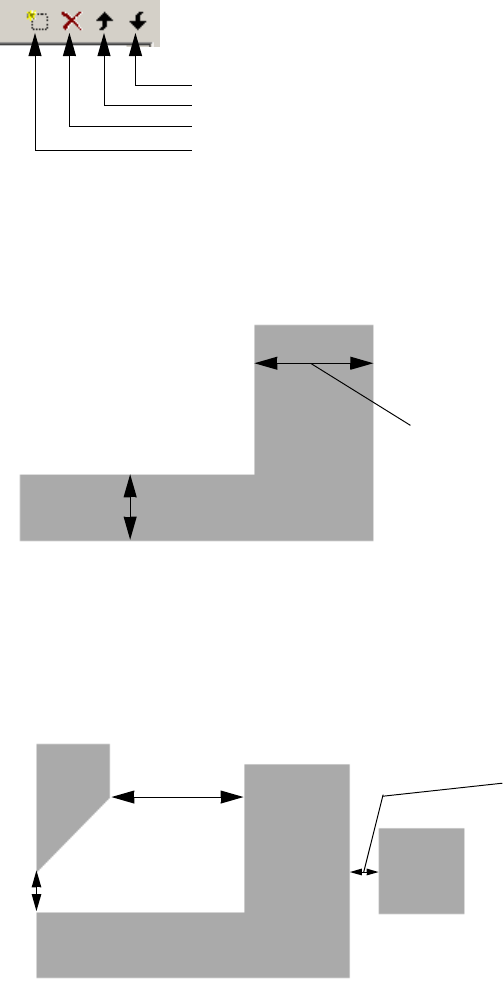
Chapter 12: Interactive DRC Setting Up Interactive DRC Rules
L-Edit 13 User Guide Section 1 310
Use the icons below to manage the rule list.
Width
Width rules specify the minimum width of all objects on the specified layer.
Spacing
The spacing rule specifies the minimum distance that should separate all pairs of objects, either on the
same layer or two different layers.
Move down
Move up
Delete Rule
New Rule
Width rule measures inside edge
to inside edge distance.
Spacing rule measures outside
edge to outside edge distance.
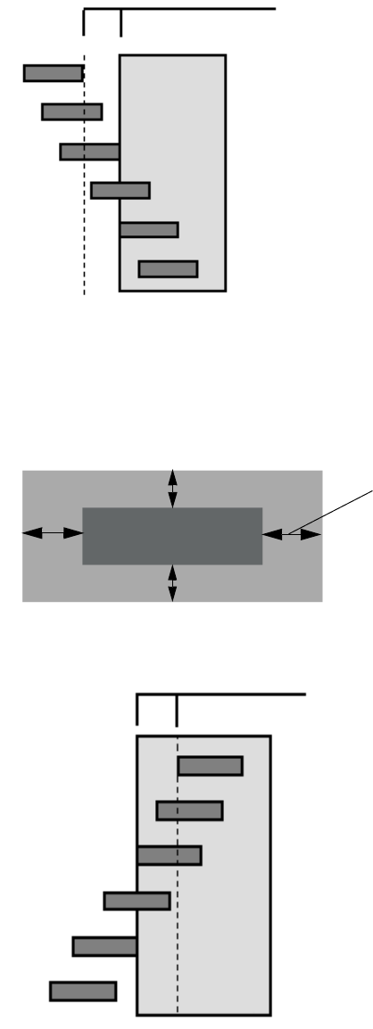
Chapter 12: Interactive DRC Setting Up Interactive DRC Rules
L-Edit 13 User Guide Section 1 311
Objects touching by coincident edges, intersecting objects, and one layer enclosing the other layer are
not are not flagged as violations by interactive DRC. Also, edges intersecting at an acute angle are not
flagged as a violation.
Surround
The Surround rule specifies that objects on one layer must be completely surrounded by objects on
another layer.
Inside layer polygons completely outside the surrounding layer are not flagged as violations by
interactive DRC.
DRC Rule Distance
Not a violation
Violation
Not a violation
Not a violation
Not a violation
Not a violation
Surround rule measures outside edge to
inside edge distance.
DRC Rule Distance
Not a violation
Violation
Violation
Violation
Violation
Not a violation
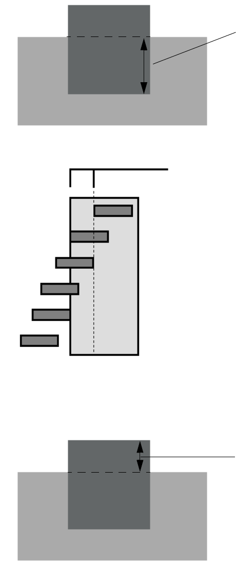
Chapter 12: Interactive DRC Setting Up Interactive DRC Rules
L-Edit 13 User Guide Section 1 312
Overlap
Overlap rules specify the minimum amount that an object on one layer must overlap an object on
another layer (when there is an overlap).
Objects which overlap more than the specified distance or whose edges coincide are not considered in
violation of overlap rules
Extension
Extension rules specify the minimum amount that an object on one layer must extend beyond the edge
of an object on another layer.
Overlap rule measures inside edge
to inside edge distance.
DRC Rule Distance
Not a violation
Not a violation
Not a violation
Violation
Not a violation
Not a violation
Extension rule measures inside edge
to outside edge distance.
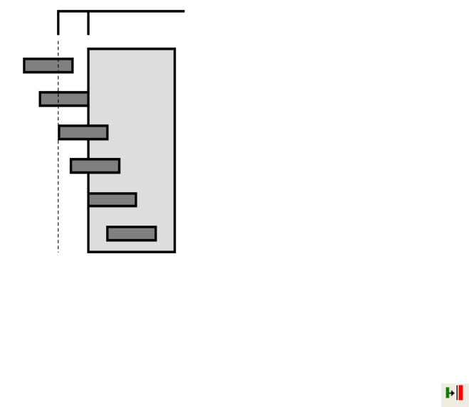
L-Edit 11 User Guide Section 1 313
Chapter 12: Interactive DRC Running Interactive DRC
One layer completely outside the other layer, or one layer completely inside but not inside coincident
with the other layer is not considered a violation.
Running Interactive DRC
To enable Interactive DRC click the Enable Interactive DRC toolbar button . After enabling
Interactive DRC begin editing your layout. Error markers will appear in the layout as soon as violations
are created.
DRC Rule Distance
Not a violation
Not a violation
Not a violation
Violation
Violation
Not a violation
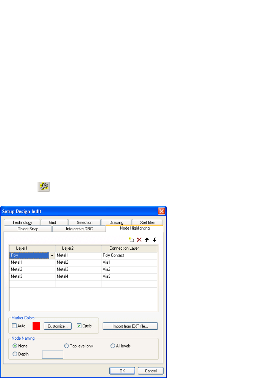
L-Edit 13 User Guide Section 1 314L-Edit 13 User Guide Section 1 314
13 Node Highlighting
Introduction
Node highlighting allows you to highlight the geometry connected to a selected net. An unlimited
number of nets may be sequentially selected. When you have selected an object from lower in the cell
hierarchy, all related connectivity from the top level cell will be displayed. If a selection touches more
than one net the potential nodes are displayed and you will be prompted to pick one.
To highlighting nodes you must first define connectivity statements using the Setup Design dialog,
then extract the connectivity data and select nodes for highlighting either using the mouse or by typing
in node names.
Node Highlighting Setup
Choose Setup > Design and select the Node Highlighting tab, or click the Node Highlight Setup
toolbar button to enter connection statements. You can enter connection statements manually or
import them from an extract definition (.ext) file.
1
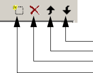
L-Edit 13 User Guide Section 1 315
Chapter 13: Node Highlighting Node Highlighting Setup
Use the icons below to manage the rule list.
Options include:.
Node highlighting works on merged objects on drawn or derived layers. If derived layers are used, they
must be set up in the TDB file before connectivity data can be extracted. (The node highlight engine
will generate any needed derived layers.)
Layer1, Layer2 The layers that are connected by the connection layer. Layer1 cannot
equal Layer2.
Connection Layer The layer through which Layer1 and Layer2 connect. If either Layer1
or 2 is equal to the Connection Layer value, the Connection Layer
should not be assigned a value.
Auto Sets the color of the node marker to the last color in the color palette,
usually black.
Customize Opens the Node Highlighting Colors dialog, which allows you to
enter an unlimited number of colors for the Cycle function. Each
color can be customized using the RBG sliding controls or by clicking
on Color picker... for advanced color controls.
Default sets the color cycle to eight pre-selected colors.
Cycle Cycles through the colors defined in the Node Highlighting Colors
dialog as nodes are selected for highlighting. The color cycle starts
with either the custom or automatic color depending on which of
these options is checked.
If this option is not checked, all selected nodes are highlighted with
the same color.
Import from EXT file... Imports the connectivity information from an extract definition (.ext)
file.
Node Naming Sets the level of hierarchy from which ports will be used for node
naming during node highlighting. Choose from None, Top level only
or All levels, or Depth. None will be the fastest setting, All levels the
slowest.
None—no ports are written to GDSII for node highlighting.
Depth—enter an integer value to specify the level of hierarchy that
will be used. A depth of zero is equivalent to top level only.
Note that the Highlight by name command can be used regardless of
the Node Naming setting.
Move down
Move up
Delete Rule
New Rule
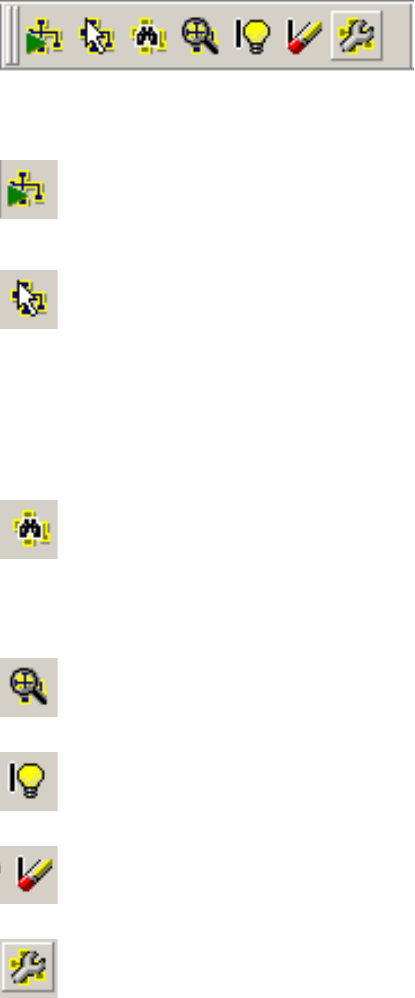
L-Edit 13 User Guide Section 1 316
Chapter 13: Node Highlighting Using Node Highlighting
Objects are defined as connected if the AND of objects on Layer1, Layer2 and the connection layer
results in geometry. Objects that touch are not considered connected. If a connection layer is not
specified, Layer1 and Layer2 must overlap to be considered connected.
Using Node Highlighting
You can run node highlighting using the menu commands in Tools > Node Highlighting or from the
Node Highlighting toolbar. The table describes the icons below from left to right:
Extract Connectivity Runs the connectivity extraction engine and saves the results in a
temporary directory. Connectivity data is not saved with the design
file. If connectivity information already exists, you will be prompted
before the data is extracted again.
Highlight Node Initiates node highlight mode. Once active, a left mouse click
highlights a node.
Each merged polygon on each of the node layers will be highlighted,
and the node name will be displayed in the status bar. Selecting a
node that is already highlighted will give you the option to remove
that highlight or change it’s color.
Previous node highlights remain when a new node is selected.
Highlight by Name Opens the Highlight Node by Name dialog which allows you to
highlight a node by name. Matching is case-insensitive. If the node
name is not found or if it matches more than one node, a warning will
indicate so and advise on how a node will be selected if it is not
unique. A history drop down list is provided for the Node Name
field.
Zoom to Node Pans and zooms to display all highlighted nodes in entirety plus a
10% margin.
Toggle Markers Toggles the display of all design markers (node highlighting, DRC,
SDL, etc.).
Clear Markers Deletes the display of all design markers (node highlighting, DRC,
SDL, etc.).
Node Highlight Setup Opens the Setup Design dialog at the Node Highlighting tab. See
“Node Highlighting Setup” on page 314 for further information.
L-Edit 13 User Guide Section 1 317
Chapter 13: Node Highlighting Using Node Highlighting
Open Connectivity
Extraction Log Opens a text window displaying the Connectivity Extraction Log.
The log lists the port name and coordinates (in internal units) of ports
found on the same net. The log file is created in a temp directory and
is erased when the TDB file with which it is associated is closed.
Data is described in the following format, where the net number is
randomly assigned:
Found port conflict in net 30358248 within cell Core:
U33/Mux2_15_2/Out at (1216000, -420000)
U33/Mux2_8_1/A at (1136000, -420000)

L-Edit 13 User Guide Section 1 318
14 Add-Ins
The Tools > Add-Ins menu contains a miscellaneous set of macros for fairly uncommon tasks. This
menu also contains the program Dev-Gen that is documented separately. Several macros are
documented in this chapter, the remainder are documented in the functional area to which they relate.
Note that you can use the shortcuts Tools > Macros and Tools > Repeat Macro to speed access to your
most commonly-used add-ins.
The macros documented in this chapter include the following:-
“Repeat Macro” (page 318)
“Macro” (page 319)
“Area Calculator” (page 319)
“Count Objects” (page 320)
“Mark Cells for Flattening During DRC” (page 320)
These macros are discussed in the sections of the manual to which they relate:
“Displaying Calibre® DRC Results” (page 733)
“Manual (L-Edit V9) Layer Generation” (page 696)
“Transferring File Information to Cells” (page 68)
“GDSII Properties” (page 148)
“Exporting PostScript Masks” (page 142)
“Resizing Port Text” (page 152)
“Importing a Setup from Virtuoso” (page 77)
“Finding I/O Pads in the Fabrication Cell” (page 246)
Repeat Macro
Tools > Repeat Macro simply re-opens the dialog of the most recently used macro.
1
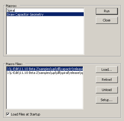
L-Edit 13 User Guide Section 1 319
Chapter 14: Add-Ins Macro
Macro
Tools > Macro opens a dialog that allows you to run any of the macros loaded to its list, and to add the
listed macros to the L-Edit Tools pulldown menu.
Area Calculator
Use Tools > Add-Ins > Area Calculator to calculate the area of all selected objects except instances.
The area calculated is the sum of a merge operation on all selected objects. All selected objects are
included, regardless of layer. The area is calculated for the resulting polygons. The area is displayed in
Macros Highlight a macro in this list to Run it. Close closes the entire dialog.
Macro Files Load—lets you browse for new .c and .dll macro files to add to
the list.
Reload—lets you reload macro using the existing path and
filename, for example when a file has been updated.
Unload—removes a macro from the list.
Setup—opens Setup Application at the UPI tab so you can
specify the location of macro interpreter header files.
Load Files at Startup Saves the currently highlighted macro to the Tools menu beneath
Add-Ins. Note that only one macro at a time will be saved.
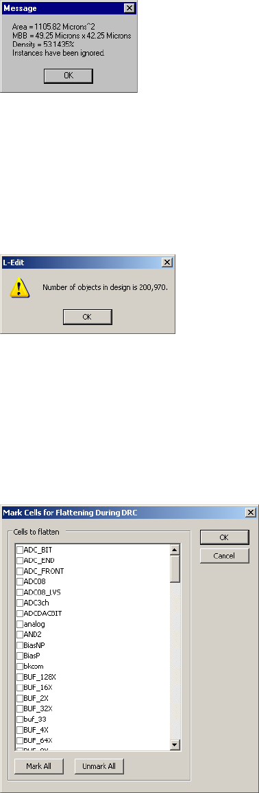
L-Edit 13 User Guide Section 1 320
Chapter 14: Add-Ins Count Objects
square display units. The Minimum Bounding Box (MBB) of the merged polygons and the density of
the merged polygons in their MBB is displayed also.
Count Objects
Tools > Add-Ins > Count Object counts all objects in a design file, except ports and rulers since they
are not manufactured.
Mark Cells for Flattening During DRC
Use this dialog to select the cells that will be assessed for flattening according to the options selected in
DRC Flattening Setup.
Cells to flatten Use this list to select the cells that will be analyzed for flattening prior
to DRC. Use the Mark All and Unmark All buttons to speed the
selection process.
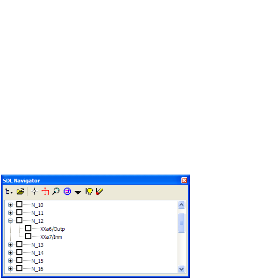
L-Edit 13 User Guide Section 1 321L-Edit 13 User Guide Section 1 321
15 Schematic-Driven Layout (SDL)
Navigator
Introduction
The L-Edit schematic-driven layout (SDL) navigator allows the designer to associate a netlist with any
layout cell, and provides navigation tools to identify required interconnections. It also can automatically
generate layout, corresponding to subcircuits and devices. Finally, an engineering-change-order (ECO)
capability allows subsequent netlists to be loaded, and highlights the differences from the original
netlist.
User Interface
The SDL Navigator is enabled from either Tools > SDL Navigator > Show SDL Navigator menu item,
the View > Toolbars... menu, or by right-clicking in the toolbar area and selecting “SDL Navigator.”.
Loading a Netlist
;Every layout cell can have its own netlist associated with it. When the active cell changes in L-Edit, the
SDL Navigator also changes to show the netlist associated with the new cell. If no netlist has yet been
associated with a cell, the navigator contains only a message to that effect. A netlist is loaded using
1
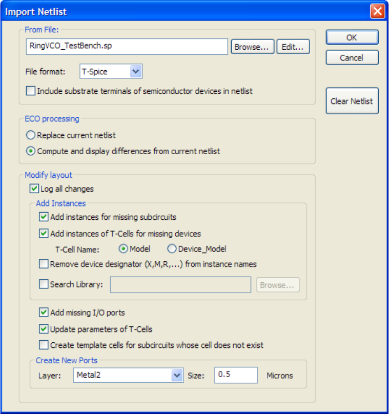
Chapter 15: Schematic-Driven Layout (SDL) Navigator Loading a Netlist
L-Edit 13 User Guide Section 1 322
either the Tools > SDL Navigator > Load Netlist menu item or the “Load Netlist” button in the SDL
Navigator toolbar, which opens the following dialog
Netlist format and structure
The netlist can be a hierarchical SPICE netlist. If a subcircuit exists in the netlist with the same name as
the currently active layout cell, then that subcircuit is used to create the netlist for the current cell. This
behavior means that the user can have all netlists for all cells in the same spice file. If a subcircuit with
the same name as the current cell does not exist in the SPICE file, then the top-level SPICE entities are
used to create the netlist. Alternately, a hierarchical Verilog netlist may be imported for SDL purposes.
The format of the input netlist is selectable between T-Spice, HSPICE, P-Spice, CDL and Verilog.
Devices are also read from the netlist. Bulk terminals of semiconductor devices (M, B, Q, J and Z) can
be optionally included in the netlist.
In the case of CDL, three-terminal resistors ("bulk resistors") are read, and mapped into subcircuits (for
example, the resistor “RR1 net1 net2 1K $SUB=VCC $[B] $W=6u” would be mapped onto “XRR1
net1 net2 VCC B R=1K W=6u” ).

Chapter 15: Schematic-Driven Layout (SDL) Navigator Automatically generating layout elements
L-Edit 13 User Guide Section 1 323
Case sensitivity
SPICE and Verilog netlists are case-insensitive.
In the SDL Navigator, port names, pin names and instance names are matched in a case-sensitive
manner.
Cell names that are read from the netlist are matched to existing L-Edit cells in a case-insensitive
manner.
Clear Netlist
Remove the association between the netlist and the current cell, and clear the node tree view from the
SDL Navigator display.
Automatically generating layout elements
When a netlist is imported, the user may optionally create various layout elements. If none of these
options are selected, the layout is not modified in any way. After import, added or modified elements
are left in the L-Edit selection list. Also, after import, a log file is displayed, showing the operations that
were performed and their success (or failure).
Add instances for missing subcircuits
If this option is selected, instances are created for missing subcircuits. For example, given the following
SPICE input:
X123 In Out INV
an instance of cell INV would be created; the instance would be called X123. The instance would be
placed in the lower-left corner of the MBB of the current cell. Subsequent instances would be placed to
the right or above; the tool attempts to keep all instances within the MBB of the current cell. In this
fashion, the user can floorplan a design, creating boxes (typically on the Icon special layer) that
correspond to the maximum sizes of various sub-blocks. The SDL import will then create instances (and
devices and ports, see below) within this box, if possible. The order of creation of instances is simply
the order they are encountered in the netllist.
If an instance with the appropriate name (e.g., X123 in our example above) already exists in the layout,
it is left untouched. If “extra” instances are found (i.e. instances that have no corresponding entry in the
SPICE netlist), they are left untouched. In other words, the SDL import will not modify existing layout,
but will merely add to it.
A “library” TDB file can also be specified. If a cell is not found in the current file, but is found in the
library file, it will be copied to the current file, and instanced upon request.
Note: If the cell exists in the current file, the library file is not checked at all, so this feature
cannot be used to update the cells in the current design file.

Chapter 15: Schematic-Driven Layout (SDL) Navigator Automatically generating layout elements
L-Edit 13 User Guide Section 1 324
Add instances of T-Cells for missing devices
If this option is selected, SPICE devices are mapped into T-Cells, and device parameters are passed to
the T-Cell. If a cell of the correct name exists, but is a regular cell (i.e., not a T-Cell), it will be used
instead. It is the user’s responsibility to ensure that the necessary cells exist in the current design.
If a “library” TDB file is specified, L-Edit will search there for missing T-Cells. The SPICE devices,
their T-Cell mappings, pin names, and the device parameters are as follows:
Device T-Cell Name Pin Names Parameters
MOSFET (M) Mosfet model name D, G, S, B (opt.) L (in meters)
W (in meters)
M
RESISTOR
(R) Resistor model name, or RES if
no model name present RP, RM R (in ohms)
M
CAPACITOR
(C) Capacitor model name, or CAP if
no model name present CP, CM C (in Farads)
M
INDUCTOR
(L) Inductor model name, or
INDUCTOR if no model name
present
LP, LM L (in Henrys)
M
DIODE (D) Diode model name DP, DM A (in square meters)
M
GAASFET (B) Gaasfet model name D, G, S, B (opt.) A (in square meters)
M
JFET (J) Jfet model name D, G, S, B (opt.) A (in square meters)
M
BJT (Q) Bjt model name C, B, E,
BULK (opt.) A (in square meters)
M
MESFET (Z) Mesfet model name D, G, S, B (opt.) A (in square meters)
L (in meters)
W (in meters)
M
Transmission
line (T) TLINE AP, AM, BP, BM Z0
TD
F
NL

Chapter 15: Schematic-Driven Layout (SDL) Navigator Navigating the Netlist and Layout
L-Edit 13 User Guide Section 1 325
Remove device designator (X,M,R,...) from instance names
If this option is selected, when an instance name starts with a letter and is followed by a non-digit, the
starting letter is stripped upon import of the netlist. For example, given the following SPICE input:
Xfoo In Out INV
an instance of cell INV would be created; with remove device designator enabled, the instance would be
called foo. Alternately, if the SPICE input was:
X123 In Out INV
with remove device designator enabled, the instance would be called X123 as the instance name is
followed by a digit.
Add missing I/O ports
If a cell is a subcircuit, it has interface ports through which it connects to nodes in the cells in which it is
instanced. If this option is enabled (and the cell is a subcircuit), any missing I/O ports will be created.
They are placed in the lower-left corner of the cell, and are located on the layer specified in the Create
New Ports Layer dropdown menu at the bottom of the dialog. The size of the ports may also be
specified in the Size field. The user will then want to move the ports to the appropriate positions.
Update parameters of T-Cells
If this option is selected, the parameters of devices created via T-Cells from devices specified in the
SPICE netlist are updated. UNDO is not available to revert this operation.
Create template cells for subcircuits whose cell does not exist
If this option is selected, a “template” cell is created for every cell that is specified as a subcircuit in the
current cell’s netlist and which does not exist in the layout database. This option is particularly useful in
conjunction with the “Add missing I/O ports” option above.
Navigating the Netlist and Layout
Once the netlist has been loaded, it appears in the SDL Navigator toolbar, and various commands are
available to identify the location of instances, pins, and nodes.
The SDL Navigator shows the list of nodes or instances present in the current cell. Expanding a node
shows all the pins connected to that node. When the view is set to view by instance, expanding an
instance shows all the nodes connected to that instance. Each pin and node contains a check box that is
available for the user’s convenience (and for displaying flylines, see below); for example, the user may
use the checkbox to indicate which pins and nodes have been “wired up”.
Note: Nodes which only connect to a single pin are not displayed in the SDL Navigator.
The data in the SDL Navigator is stored persistently in the TDB database, so it is available in
subsequent editing sessions.
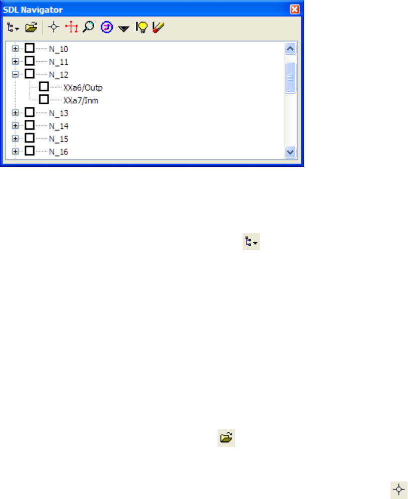
Chapter 15: Schematic-Driven Layout (SDL) Navigator Navigating the Netlist and Layout
L-Edit 13 User Guide Section 1 326
An example of the SDL Navigator with a loaded netlist is shown below:
The buttons on the toolbar are:
Netlist View
Displays a pull-down menu of SDL Navigator netlist views ( ):
By Net—Displays a list of nodes present in the current cell. Expanding a node shows all the pins
connected to that node. The format of each pin is “instance name”/“port name”. Viewing by net may
also be invoked by selecting Tools > SDL Navigator > By Net.
By Instance—Displays a list of instance names present in the current cell. Expanding an instance name
shows all the nodes connected to that instance. The format of each node is “port name”=“node name”.
Viewing by instance may also be invoked by selecting Tools > SDL Navigator > By Instance.
By Unrouted Segment—Displays a list of nodes in the current cell. Expanding a node shows the
coordinates of the segments that could not be automatically routed to each other. Viewing by unrouted
segment may also be invoked by selecting Tools > SDL Navigator > By Unrouted Segment.
Load Netlist
Open a netlist for loading (see above) or ECO update ( ).
Marker
Add (or remove) marker(s) from the currently highlighted entry in the netlist navigator tree ( ).
When viewing by net, if a node is selected in the tree view, then markers are toggled at all pins within
the node. If a single pin is selected in the tree view, then a single marker is toggled at that pin.
When viewing by instance, if an instance is selected in the tree view, then markers are toggled at all
nodes connected to that instance. If a single node is selected in the tree view, then a single marker is
toggled at the node connection point to the instance.
When viewing unrouted segments, if a node is selected in the tree view, then a set of markers will be
toggled for each unrouted segment of that node. If segment coordinates are selected in the tree view,
then a single marker is toggled at that segment.
When you move an instance while markers are displayed, the marker will update based upon the new
placement of the instance.
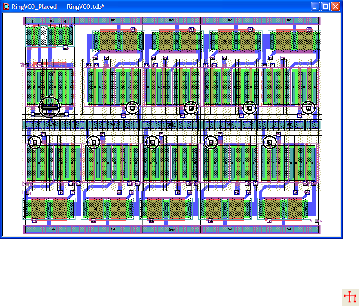
Chapter 15: Schematic-Driven Layout (SDL) Navigator Navigating the Netlist and Layout
L-Edit 13 User Guide Section 1 327
For example, turning on markers on a bias voltage signal to a differential circuit gives the following:
Flyline
When a node is highlighted, a set of flylines is displayed that connect all pins that are (i) connected to
the node, and (ii) not checked off (i.e., the checkbox in the tree view is empty) ( ). If a pin is
highlighted, the flylines for its parent node are shown. If an instance is highlighted, the flylines for all
nodes connected to that instance are shown. If unrouted segment coordinates are highlighted, the flyline
for the segment is shown.
The flyline that is displayed is a minimum spanning tree. It shows the shortest connections necessary to
connect all the desired pins together. The distance that is minimized is the Manhattan distance between
connected pins.
When you move an instance while flylines are displayed, the flyline will update based upon the new
placement of the instance.
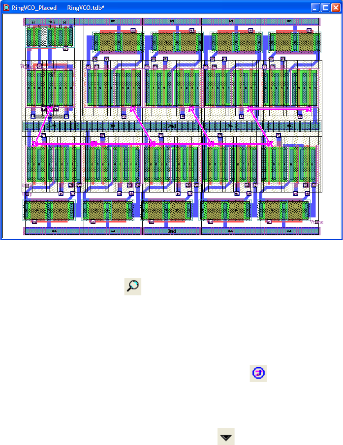
L-Edit 13 User Guide Section 1 328
Chapter 15: Schematic-Driven Layout (SDL) Navigator Navigating the Netlist and Layout
In the previous example, turning on flylines results in:
Zoom
Zoom to the highlighted entry ( ). If the entry is a pin, zoom to the pin. If the entry is a node, zoom
to the MBB of all the pins on the node. If the entry is an instance, zoom to the instance. If the entry is an
unrouted segment, zoom to the the MBB of the coordinates of the segment. Note that you can also zoom
to markers and flylines using the “w” hotkey (as long as there is an empty selection list).
Route All
Routes all unchecked nodes using the SDL automatic router ( ). See “SDL Router” on page 330.
Routing all may also be invoked by selecting Tools > SDL Navigator > Route All.
Command Menu
Displays a pull-down menu of SDL Navigator actions ( ):
Add Selection Flyline—Adds flylines for all nodes in the active layout selection. Selecting CTRL+A in
the layout to select all and using this command will show all flylines for the cell. Adding flylines from
the current selection may also be invoked by selecting Tools > SDL Navigator > Add Selection
Flyline.
Tag Selections with active net—Tags any selected objects in the layout with the active net. See
“Tagging Nets,” below.
Pick Closest Pin—The user is prompted to click the mouse in the layout window. The pin closest to
that point will be highlighted in the netlist tree view. This command is particularly useful to identify
nodes, and then, with the assistance of the flyline tool, show interconnections. Picking the closest pin to
the mouse click may also be invoked by selecting Tools > SDL Navigator > Pick Closest Pin.
Ripup All Nets—Removes all objects tagged with routing node names. See “SDL Router” on page 330.
Ripping up all nets may also be invoked by selecting Tools > SDL Navigator > Ripup All Nets.
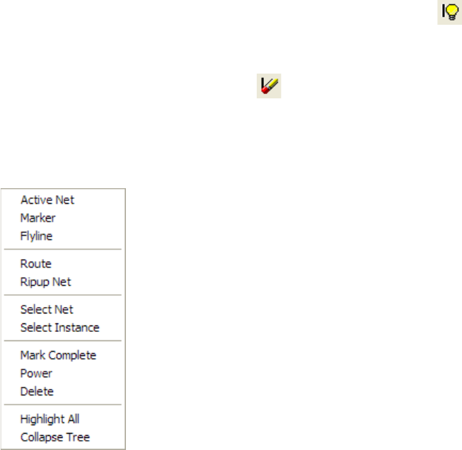
L-Edit 13 User Guide Section 1 329
Chapter 15: Schematic-Driven Layout (SDL) Navigator Navigating the Netlist and Layout
Remove ECO status—Removes the ECO icon indicators and updates the SDL Navigator using the
latest ECO netlist.
Export Wire List...—Exports the SDL Navigator node list in a simple text netlist format (see
“Alternative Netlist Format” on page 339)
Setup Router...—Opens the Setup Router dialog (see “SDL Router Setup” on page 331). Setting up
the Router settings may also be invoked by selecting Tools > SDL Navigator > Setup Router....
By Net—Displays a list of nodes present in the current cell. Expanding a node shows all the pins
connected to that node. The format of each pin is “instance name”/“port name”. Viewing by net may
also be invoked by selecting Tools > SDL Navigator > By Net.
By Instance—Displays a list of instance names present in the current cell. Expanding an instance name
shows all the nodes connected to that instance. The format of each node is “port name”=“node name”.
Viewing by instance may also be invoked by selecting Tools > SDL Navigator > By Instance.
By Unrouted Segment—Displays a list of nodes in the current cell. Expanding a node shows the
coordinates of the segments that could not be automatically routed to each other. Viewing by unrouted
segment may also be invoked by selecting Tools > SDL Navigator > By Unrouted Segment.
Toggle Markers
Toggles between hiding and showing all markers and flylines in the display ( ).
Remove All Markers
Clear all markers and flylines in the display ( ).
Context-Sensitive Menu
Right-click in on any node, instance or pin name in the SDL Navigator to open the following
context-sensitive menu. The controls vary as shown
Active Net—Selects (or deselects) the currently highlighted entry in the netlist navigator tree as the
active net. Selecting a node using the middle-mouse button will also toggle the node as the Active Net.
The net name will be italicized to indicate that it is the active net. Any objects or instances that are
placed in the layout while the net is active will be tagged with that net name. See “Tagging Nets” on
page 338.

L-Edit 13 User Guide Section 1 330
Chapter 15: Schematic-Driven Layout (SDL) Navigator SDL Router
Marker—Add (or remove) marker(s) from the currently highlighted entry (or entries) in the netlist
navigator tree (see Marker, above).
Flyline—Add (or remove) flylines from the currently highlighted entry (or entries) in the netlist
navigator tree (see Flyline, above). A flyline connect all pins that are (i) connected to the node, and (ii)
not checked off (i.e., the checkbox in the tree view is empty).
Route— Routes the selected node(s) using the SDL automatic router ( ). See “SDL Router” on page
330
Ripup Net— Removes all objects tagged with the selected node name (see “Tagging Nets” on page
338).
Select Net— Selects the tagged geometry in the layout associated with the highlighted entry (or entries)
in the netlist navigator tree. If a node, pin, or unrouted segment is highlighted, any tagged geometry for
their associated nets will be selected. If an instance is highlighted, all tagged geometry for the nets
connected to the instance will be selected.
Select Instance— Selects the layout instance(s) associated with the highlighted entry (or entries) in the
netlist navigator tree. If a node is highlighted, the instances the node connects to will be selected in the
layout. If a pin is highlighted, the instance the pin is connected to will be selected in the layout. If an
instance is highlighted, that instance will be selected in the layout. If an unrouted segment is
highlighted, the instances the segment connects to will be selected in the layout.
Mark Complete/Unmark Complete— Toggles the checkmark for the selected node, pin or instance to
indicate completion of routing.
Power— Toggles indication of the selected node name as the power node. This is displayed using the
“(power)” indication after the node name. Multiple nodes may be marked as a power node. This
indication is for the user’s convenience to visibly see which node is used for power.
Delete— Removes the selected node, pin or instance from the netlist navigator window. This operation
cannot be undone.
Highlight All— Highlights all nodes in the netlist navigator window when viewing by net or by
unrouted segment. Highlights all instances in the netlist navigator window when viewing by instance.
Collapse Tree— Close all open sub-trees in the netlist navigator window.
SDL Router
The Schematic Driven Layout Router is an automatic routing engine integrated into SDL that allows the
user to manually route performance critical nets or parts of nets and then let the router automatically
route the rest. It natively uses the routing geometry created by the user and runs on all or a specified
subset of nodes on each pass. Users can easily highlight and rip up nodes as well as manage the manual
and automatic routing status.
The SDL Router uses a grided area router. The routing grid can be automatically calculated by the SDL
Router or may be manually set by the user. Routing is performed on one pair of horizontal and vertical
layers at a time.
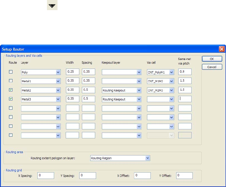
L-Edit 13 User Guide Section 1 331
Chapter 15: Schematic-Driven Layout (SDL) Navigator SDL Router
Nets which are deemed critical to a design should be treated separately from the others to satisfy
specific performance requirements. Critical nets can be routed first or early in the design process to
benefit from the maximum availability of routing resources.
Automatic routing creates routing wires and vias for all specified nets in a design. It generates
orthogonal routing according to information entered into the Setup Router dialog. To set the routing
layers, via cells, keepout layers, and design rules that will be used during automatic routing see “SDL
Router Setup,” below.
SDL Router Setup
Before using the SDL Router, the routing layers and via cells must be predefined. Optionally a routing
area, keepout layer, and routing grid may also be defined. To open the Setup Router dialog, select the
Command Menu ( ) from the SDL Navigator toolbar and choose Setup Router... or select
Tools > SDL Navigator > Setup Router.
These settings can be completed at any time prior to routing, and you may return to this dialog any time
you want to change any of the router settings.
L-Edit 13 User Guide Section 1 332
Chapter 15: Schematic-Driven Layout (SDL) Navigator SDL Router
Routing Layers and Via Cells
Routing Area
Routing Grid
The autorouter uses a gridded area router such that wires and vias placed by the router will be centered
on evenly spaced grid points. Users can specify the grid to to use or may allow the autorouter to
Route Selects whether or not the defined layer will be used for routing. If
unchecked, connections to the layer may be made using the specified
via cell but no routes will be placed using that layer.
Layer Selects the layer to use for routing. The first layer in the list with the
Route option checked will be used to route in the horizontal direction
on the layout. The second layer will route in the vertical direction.
Each successive layer will alternate between horizontal and vertical
routing. This field opens a drop-down list of all layers in the current
file.
Width Specifies the default width of the routing wires created on the selected
layer. The SDL Router will determine the appropriate trace widths
based on the size of the ports in the layout. See “Trace Width
Computation” on page 335.
Spacing Specifies the default spacing to be used by the SDL Router for the
selected layer.
Keepout layer Keepout boxes or polygons are used to define areas where the SDL
router cannot route. A unique keepout layer may be assigned to each
of the routing layers or all can be assigned with the same keepout
layer. Assignment of a keepout layer is optional.
The SDL router is a gridded router that uses the center of a routing
wire for positioning, therefore routing wires can overlap a keepout
boundary.
Via Cell Selects the via cell to be used to connect the specified layer routes to
the subsequent layer. This field opens a drop-down list of all cells in
the current file.
Same-net via pitch Specifies the closest allowed pitch (the minimum distance between
the the center of two vias) for a pair of vias added to a design on a net
by the autorouter.
This setting is used to determine the via spacing when an array of vias
is created for a transition between layers on wide metal routes. It will
also be used to determine the minimum spacing of two vias on the
same net. In this case, notches between vias will automatically be
filled in with metal.
Vias are placed on center on the routing grid.
Routing extent polygon on
layer Select the layer used to define the extent of the routing boundary.
Routing will be contained within any polygons drawn on this layer.
When no layer is specified, routing will be bounded by the minimum
bounding box containing the routing ports.
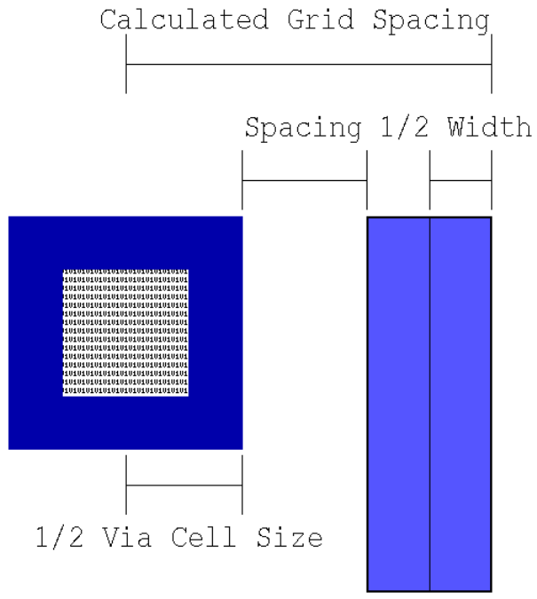
L-Edit 13 User Guide Section 1 333
Chapter 15: Schematic-Driven Layout (SDL) Navigator SDL Router
calculate the best grid based upon the router setup.
When the X Spacing, Y Spacing, X Offset, and Y Offset fields are all set to 0, the router will
automatically compute its grid based on the layer spacing, layer width, and size of the via cells specified
by the user. An grid spacing value will be calculated for each of the layers marked for routing and the
largest value will be used for the grid spacing. The grid spacing is computed for each routing layer is
based upon a via-to-wire spacing as follows:
When a grid is specified by the user in the X Spacing, Y Spacing, X Offset, and Y Offset fields, the
router will utilize the the layer spacing, layer width, and the size of the via cell specified by the user to
determine whether to use via-to-via spacing or via-to-wire spacing rules. If the grid settings are too
small to support the specified layer width, spacing, and via cell, an error will be displayed
A customized grid setting is useful when the cells are designed using a particular grid such that all ports
are centered on a grid point. In this case, setting the router grid to the same setting will yield the best
results.
GridSpacing Width
2
--------------- Spacing ViaCellWidth
2
------------------------------------++=
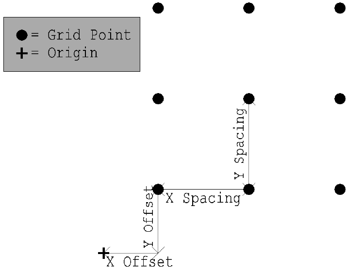
L-Edit 13 User Guide Section 1 334
Chapter 15: Schematic-Driven Layout (SDL) Navigator SDL Router
.
X Spacing Specifies the spacing along the X axis for each grid point used by the
SDL router. This is the distance between grid points in the horizontal
direction.
A setting of 0 for all Routing Grid settings will result in the autorouter
calculating and using an optimal grid size.
Y Spacing Specifies the spacing along the Y axis for each grid point used by the
SDL router. This is the distance between grid points in the vertical
direction.
A setting of 0 for all Routing Grid settings will result in the autorouter
calculating and using an optimal grid size.
X Offset Selects an offset along the X axis from the cell origin used to place a
known grid point. This setting is used in conjunction with the Y
Offset to specify a specific grid point.
A setting of 0 for all Routing Grid settings will result in the autorouter
calculating and using an optimal grid size.
Y Offset Selects an offset along the Y axis from the cell origin used to place a
known grid point. This setting is used in conjunction with the X
Offset to specify a specific grid point.
A setting of 0 for all Routing Grid settings will result in the autorouter
calculating and using an optimal grid size.
L-Edit 13 User Guide Section 1 335
Chapter 15: Schematic-Driven Layout (SDL) Navigator SDL Router
Using the Automatic Router
Automatic routing generates orthogonal routing wires and vias between the devices and I/O ports in the
netlist. The SDL Router uses a gridded router that places the center and end-points of routing wires on
grid. When a port is not on the routing grid, the router will create a small routing wire segment from the
port to the on-grid routing wire to complete wiring. Users can route single nodes, groups, or the entire
design.
Routing wires will be created using the Extend end style and the Layout join style. If connecting to
manually placed routes, any wires with an end style other than Extend will be converted to polygons.
The automatic router supports up to 8 routing layers. At least two routing layers must be specified so
routes can cross each other. The automatic router will only route to a port placed on a layer defined in
the Setup Router dialog. Arrays of vias will be used on wide metal trace layer transitions.
Automatic routing of all unchecked nodes may be invoked by selecting Tools > SDL
Navigator > Route All or by selecting the Route All icon from the SDL Navigator ( ).
Information about routing status is displayed in the SDL Navigator.
Trace Width Computation
The trace width is subject to a minimum width constraint in the setup dialog but will be computed based
upon the type and dimension of the port that it will be connected to. The trace width computation
applies the same way to both routing layers and non-routing layers. The following is a description of
each type of port that may be placed and how the trace width will be determined from the port:
When a connection is to be made between two ports with different dimensions, the smaller of the two
trace widths will be used for that connection. For example, if a point port is to be connected to a line
port, the minimum trace width defined for the layer in the Setup Router dialog will be used.
Indicates that the entire net was routed successfully.
Indicates that all or a portion of the net was unable to be routed.
Point Port Uses the minimum trace width defined for the layer in the Setup
Router dialog.
Line Port (1D) Uses the dimension of the line port as the trace width. If the
dimension of the line port is less than the minimum trace width
defined for the layer in the Setup Router dialog, the minimum trace
width will be used instead of the line port dimension.
Box Port (2D) Uses the smaller of the two dimensions of the box port as the trace
width. If the smaller dimension of the box port is less than the
minimum trace width defined for the layer in the Setup Router
dialog, the minimum trace width will be used instead of the box port
dimension.
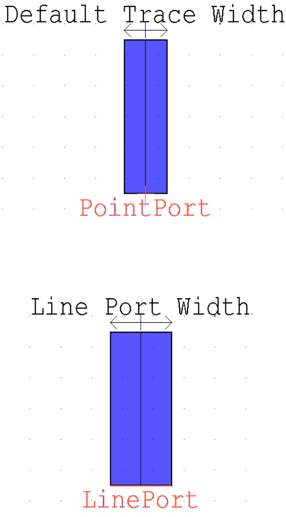
L-Edit 13 User Guide Section 1 336
Chapter 15: Schematic-Driven Layout (SDL) Navigator SDL Router
Connection to Ports on Routing Layers
Point Port The trace will be routed to a point port such that the center of the
endpoint of the wire will exactly hit the port
Line Port (1D) The trace will be routed to a line port such that the line is approached
in a direction opposite its axis and contact is made along the entire
length of the line port.
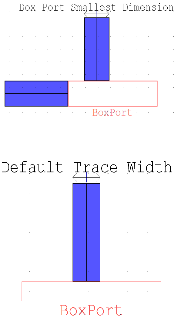
L-Edit 13 User Guide Section 1 337
Chapter 15: Schematic-Driven Layout (SDL) Navigator SDL Router
Box Port (2D) The router will assume that the box port is filled with the same layer
used to place the port and therefore will only connect to the edges of
the box port. The trace will be routed to a box port based upon one of
three scenarios as follows:
If both the length and width of the box port are greater than or equal
to the minimum trace width, the trace may approach the box port from
either axis and will contact the port along an edge equal to the width
of the trace.
If one dimension of the box port is smaller than the minimum trace
width and one is larger, the trace may approach the box port only
along the longer axis.
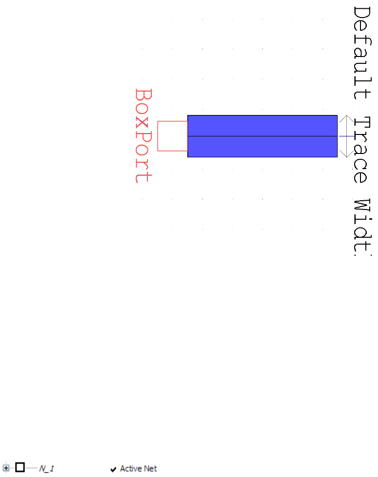
L-Edit 13 User Guide Section 1 338
Chapter 15: Schematic-Driven Layout (SDL) Navigator SDL Router
Tagging Nets
When using the automatic router, routing geometry is automatically tagged with its associated net,
allowing for easy selection and ripup of objects by net.
Tagged geometry will have its associated node name displayed in the status window when selected in
the layout. The node name will be displayed as:
Net = “Node_Name”
When routing nets manually, a net can be made active for geometry tagging by right-clicking the node
and selecting “Active Net”. Additionally, selecting a node in the SDL Navigator using the
middle-mouse button will toggle the node as the Active Net. The net name will italicized to indicate that
it is the active net. The context-sensitive menu for the net will have a checkmark to the left of “Active
Net” as shown below.
Any objects or instances that are placed in the layout while the net is active will be tagged with that net
name. To deactivate a net, either select another net as active, right-click the currently active net and
select “Active Net” again to remove the checkmark, or select the net in the SDL Navigator using the
middle-mouse button.
To tag multiple objects or instances in the layout after they have been placed:
;Activate the net you want to tag objects and instance with.
If both dimensions of the box port are smaller than the minimum trace
width, the trace may approach the box port from either axis and will
contact the port centered on the trace end.
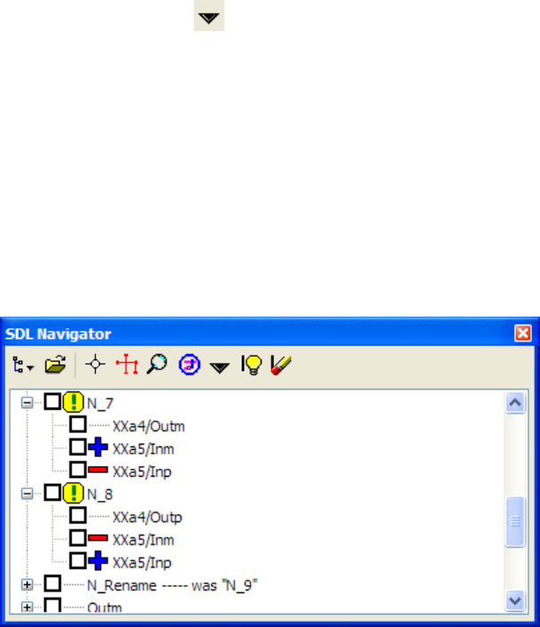
L-Edit 13 User Guide Section 1 339
Chapter 15: Schematic-Driven Layout (SDL) Navigator Engineering Change Orders
;Select the objects to be tagged the layout.
;Select the Command Menu ( ) from the SDL Navigator toolbar.
;Select “Tag Selections with active net”.
Engineering Change Orders
Managing Engineering Change Orders (ECOs) is the process of receiving an updated netlist, and
importing it into the SDL Navigator with “Compute and display differences from the current netlist”
selected in the ECO Processing options. This operation will display nodes that have changed with an
exclamation point, pins that have been deleted with a red minus sign, and pins that have been added
with a blue plus sign:
Notice that simple node renames are also displayed in this view as shown by the renaming of Node N_9
to be N_Rename. In this example, 2 pins (XXa5/Inm and XXa5/Inp) were swapped causing both a
disconnection and reconnection to nodes N_7 and N_8.
Once the ECO netlist has been imported, it is possible to use the same markers/flylines/zoom/route
buttons as before.
Subsequent ECO netlist imports will display changes relative to the most recently imported netlist. The
user can identify differences between an arbitrary pair of netlists by importing the first one (with
“replace current netlist” selected), then importing the second as an ECO netlist.
Alternative Netlist Format
Sometimes, a SPICE netlist is not conveniently available. The SDL Navigator also allows a simple text
netlist format to be imported or exported. This format is a simple wirelist format, in which each line
contains the following tab-delimited fields:
NODE NAME \t CELL NAME \t INSTANCE NAME \t PORT NAME
For I/O ports, the syntax is similar, but the cell and instance names are omitted:
L-Edit 13 User Guide Section 1 340
Chapter 15: Schematic-Driven Layout (SDL) Navigator Alternative Netlist Format
NODE NAME \t \t \t PORT NAME
In both of these cases, spaces are shown around the tab character (\t) for clarity; these spaces are not
present in the actual wirelist.
To import this wirelist format, select “Wire List (*.wrl)” from the Browse button of the Load Netlist
dialog.

L-Edit 13 User Guide Section 2 341
16 Introduction to Placement and
Routing
Placement and Routing in L-Edit
This volume of the L-Edit user guide describes the automatic standard cell place and route (SPR)
features of L-Edit.
The chapter “Placing and Routing Standard Cell Designs” on page 343 explains the three SPR modules:
core generation, pad routing, and padframe generation. It also explains global signal routing, which is
used to route as many as two I/O signals independent of other signals. The chapter “Standard Cell
Library Designer’s Guide” on page 388 provides design rules for creating standard cell libraries.
Standard Cell Place and Route (SPR)
Standard cell place and route (SPR) is a place and route package for standard cells that can
automatically lay out entire chips. It consists of three modules: a core place and route module to
generate a core cell, a padframe generator, and a pad route module to connect the padframe with the
core cell. You can run these three modules individually or together.
SPR uses standard cells and pad cells from a standard cell library. Netlists can be provided in Electronic
Design Interchange Format (EDIF) or Tanner Place and Route (TPR) format. If needed, a mapping tool
allows you to achieve consistency between the cell and pin names in your netlist and your library.
SPR generates a core, a padframe, and a chip cell in L-Edit which then can be checked for design rules
and extracted. In order to verify the delay constraints, you can generate a nodal capacitance (CAP) file
or a standard delay format (SDF) file, or both, during the place and route step.
The place and route steps are fully automated. You can use two- or three-layer routing, with the latter
including the option of over-the-cell (OTC) routing. Up to two I/O signals (e.g., clock signals) can be
routed separately to better control delay and skew when you use the global input signal routing function.
Among the many features of SPR are standard cell grouping (cell clustering) and critical nets
consideration.
Section 2Section 2: Placement and Routing
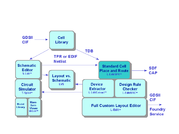
L-Edit 13 User Guide Section 2 342
Chapter 16: Introduction to Placement and Routing Standard Cell Place and Route (SPR)
The following diagram illustrates the design flow for L-Edit⁄SPR within the Tanner EDA tool suite.
Syntax and usage for the following file formats are detailed in the chapter “Place and Route File
Formats” on page 397:
CAP files—an SPR output file that lists the capacitance, area, and length of each node due to
routing.
EDIF files—a netlist format used as input for SPR.
TPR files—a netlist format used as input for SPR.
SDF file—an output file that contains interconnect delays due to routing in standard delay format.
L-Edit / SPR Design Environment

L-Edit 13 User Guide Section 2 343L-Edit 13 User Guide Section 2 343
17 Placing and Routing Standard Cell
Designs
Introduction
L-Edit⁄SPR (Standard Cell Place and Route) places and routes a design using a user-provided EDIF or
TPR netlist and a standard cell source library as input. SPR includes three options:
Core place and route generates a core cell using standard cells from a standard cell library.
Parameters for standard cell core place and route can be specified in the dialog “SPR Core Setup”
(page 354).
Padframe generation creates a user-specified padframe with pad cells from the standard cell
library. Parameters for padframe generation are specified in the dialog “SPR Padframe Setup”
(page 365).
Pad routing routes signals, including power and ground, between the layout core of a chip and its
padframe. Parameters for pad routing are specified in the dialog “SPR Pad Route Setup” (page
369).
You can perform the three SPR operations in one step or separately. L-Edit can perform a pad route
against a single pregenerated core cell or a set of core cells and/or other customized building blocks, as
long as the layout core of the chip is composed in one cell. Similarly, L-Edit can perform a pad route
against a pregenerated padframe, which can also be built in any manner, as long as it forms a single
padframe cell and conforms to SPR constraints.
2
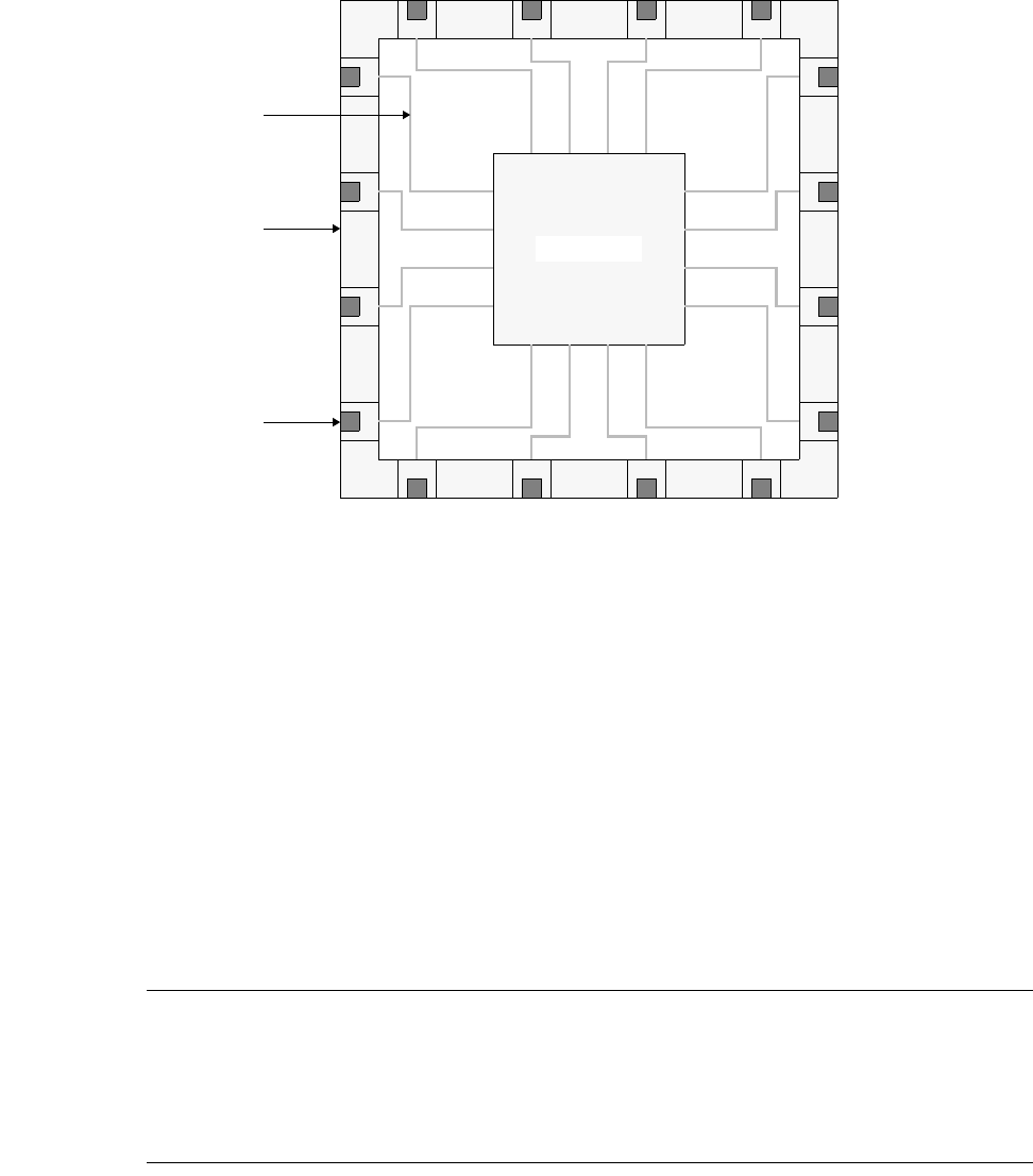
L-Edit 13 User Guide Section 2 344
Chapter 17: Placing and Routing Standard Cell Designs Required Files
Running all three operations produces a completed design like the following:
Required Files
To run SPR, the following files are required:
A design file (.tdb).
A netlist file (.tpr, .edf, .edn, or .edi). This file contains a textual description of your schematic
design and identifies the cells that are required from the standard cell library file.
A standard cell library such as morbn20d.tdb, which contains the standard cells and pad cells
required for your design. This particular file is a component of the Tanner Research standard cell
library SCMOSLib. You can also create your own standard cell library.
Note: To place and route a design, you must first define (in your design file) a technology
setup appropriate to your standard cell library. If you start L-Edit with an empty
design file, use File > New to copy the technology setup from an existing TDB file or
a technology file such as morbn20.tdb before setting up or running SPR.
Alternatively, you can simply open a design file that already contains the correct
technology setup.
SPR Process Overview
To place and route a design using L-Edit⁄SPR, you will typically perform the following steps:
Bonding pad
Padframe
Pad route
Chip with core, padframe, and pad routing.
Layout core
L-Edit 13 User Guide Section 2 345
Chapter 17: Placing and Routing Standard Cell Designs SPR Process Overview
;Create a schematic representation of your design.
;Export the schematic as either a flattened EDIF netlist or in TPR format. L-Edit supports EDIF version
2 0 0, EDIF level 0, keywordLevel 0, viewType NETLIST, or netlists with one level of hierarchy.
;Launch L-Edit. Use File > New to create your design file (layout file). Import the design information
(technology setup) from your cell library into the design file by entering your cell library file name in
the Copy TDB setup from file field of the New File dialog.
;Use File > Save to label and save your initial design file with an appropriate name.
;Choose Tools > SPR > Setup. In the SPR Setup dialog (see “SPR Setup” on page 351) specify the
names of the standard cell library file and the netlist file. Also specify the power and ground node and
port names as used in your schematic. (These names must match the names of the power and ground
ports in the standard cells.)
;Click the Initialize Setup button. This will read the netlist and initialize the following setup dialogs with
netlist information: critical nets, I/O signals, padframe layout, and core and padframe signals of the pad
route.
;Click the buttons Core Setup, Padframe Setup, and Pad Route Setup, respectively, to specify the
remaining setup parameters for core placement and routing (see “SPR Core Setup” on page 354),
padframe generation (see “SPR Padframe Setup” on page 365), and pad routing (see “SPR Pad Route
Setup” on page 369).
;Choose Tools > SPR > Place and Route. Select the appropriate option (Core place and route,
Padframe generation, or Pad route) singly or in any combination. Depending on your standard cell
design, uncheck or check the Global input signal routing option. (Global input signal routing requires
special buses to be available in your standard cells, see “Global Input Signal Routing (Clock Routing)”
on page 349 for further details). Decide on your core configuration. For example, select Square if you
want to obtain a square core shape. Check or uncheck the placement and routing optimization options.
Specify the output options—for example, whether you want to label nodes with ports (to support node
recognition during extraction) or whether you want to generate files containing nodal capacitances.
;Click the Run button. Depending on your selected options, SPR will generate up to three new cells: a
core cell, a padframe cell, and/or a chip cell (which contains the core, the padframe and the padroute). If
these cells already exist in your design file, SPR will prompt you before overwriting them.
;When processing is complete, SPR will output an SPR Complete dialog providing summary statistical
information for your design. (You can use Tools > SPR > Summary at any time to display a text file
with further details.)
;Click the OK button in the summary dialog to display the completed design. The example shown below
includes 990 standard cells (3,510 gates). On a 450 MHz Pentium II PC with 128 MB RAM, using both
placement and routing optimization, SPR can generate this design in less than ten minutes.
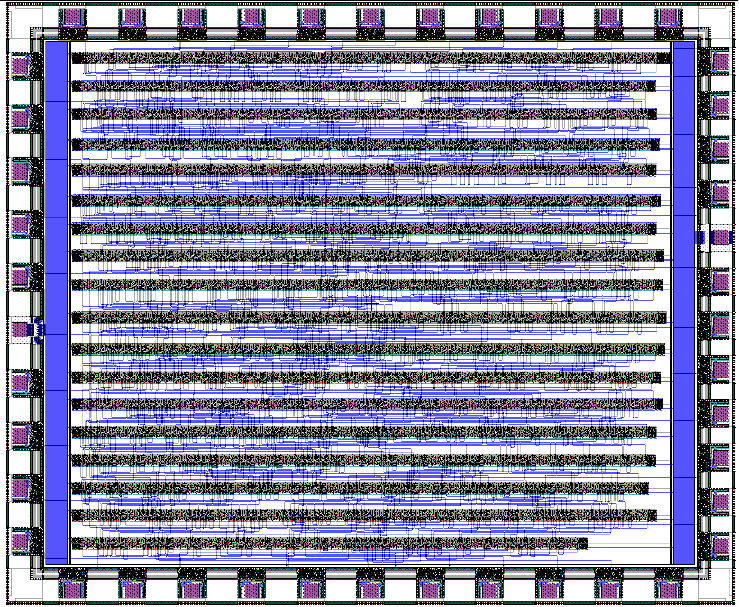
L-Edit 13 User Guide Section 2 346
Chapter 17: Placing and Routing Standard Cell Designs SPR Process Overview
;Confirm that the dimensions of the core and/or padframe fall within the size limitation imposed by your
vendor. If not, you need to re-run SPR with either a different core configuration or increased placement
and routing optimization (see “Placement Optimization” on page 379).
;Verify the design using L-Edit/DRC (see “Running DRC” on page 408) and L-Edit/Extract (see
“Setting Up the Standard Extract Rule Set” on page 688).
;Save the design in GDSII format and send it to your vendor for fabrication.
Design Tips
If you use an EDIF netlist and your netlist cell and/or port names differ from the names used in the
standard cell library, use the Mapping Table button on the SPR Setup dialog (see “Mapping Table” on
page 353) to generate a mapping table that allows you to assign the correlating names. SPR will use this
mapping information when it discovers a discrepancy between a cell or port name in your netlist and
your cell library.
Before running SPR on a new layout, use the Initialize Setup button (see “Initializing Setup” on page
354) to automatically enter pad-related information (for example, I/O signal configuration) from your
netlist into the setup dialogs. SPR will only refer to the netlist if a dialog is empty. In this case, L-Edit
will automatically fill the dialog fields with the netlist information.
We recommend that new users first generate a core separately. The dialogs that require I/O signal
information (SPR Core Setup—I/O Signals) can be filled out either manually or, if pads or I/O signals
are available in the netlist, initialized with the netlist information using the Initialize Setup feature. The
padframe should be created next, taking the core dimensions into consideration. Finally, you can
generate the new chip cell by performing a pad route using the core and padframe cells.
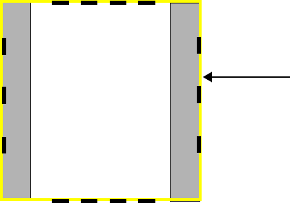
L-Edit 13 User Guide Section 2 347
Chapter 17: Placing and Routing Standard Cell Designs Core Generation and Pad Routing
Core Generation and Pad Routing
In pad routing, L-Edit routes signals only between the outer edge of the core and the inner edge of the
padframe. Therefore, the core’s position and dimensions are critical, but its internal geometry is not.
L-Edit determines the core’s position by searching for an abutment port, which defines the edges of the
core cell. The program creates the abutment port on the layer defined as the Icon layer. To define the
Icon layer, choose Setup > Special Layers. For further information, see “Rescaling a Design” on page
117.
The core and pad routing must adhere to the following constraints:
The core must contain signal ports along its edges for every signal going to the padframe.
Signal ports on the core and padframe must be ordered such that no signal running between core
and padframe crosses over another signal, except for power and ground.
However, signals may cross power or ground rails only if the materials used for routing are
different (for example, Metal2 for I/O signals and Metal1 for power and ground).
Power and ground lines are of the same material and may not cross.
The following figure illustrates the placement of signal ports along the core.
The pad router can only route a single core to the padframe. To use several core cells, you must create a
new cell, instance each core cell, manually wire the instances together and finally surround the contents
of this new cell with an abutment port and signal ports as described above. L-Edit then treats this new
cell as a “single” core for the purposes of pad routing. You specify the name of this newly created core
cell and other necessary information in the dialogs “SPR Core Setup–General” (page 355) and “SPR
Pad Route Setup–General” (page 371).
A netlist is not required if you perform a separate pad route with pregenerated core and padframe cells.
A
Vdd Gnd
Core with abutment port and signal ports (A - N).
Abutment port
B
C
NLK
M
J
I
H
DEFG
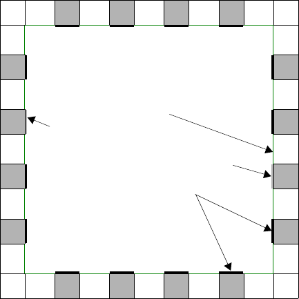
L-Edit 13 User Guide Section 2 348
Chapter 17: Placing and Routing Standard Cell Designs Padframe Generation and Pad Routing
Padframe Generation and Pad Routing
In padframe routing, L-Edit routes signals only as far as the inner edge of the padframe. Therefore, the
padframe’s position and dimensions are critical, but its internal geometry is not. To indicate the region
in which the core may be placed, L-Edit places a rectangular padframe port on the inner edge of the
padframe.
For each signal going to the core, the padframe must contain one signal port along its inner edge. Signal
ports for each signal going to the core must be placed on the padframe in the same order and on the
same side as the signal ports around the core cell. These ports may be at the top level (in the padframe
cell itself) or they may be one level lower in the hierarchy (in a pad cell instanced by the padframe).
Power and ground pads must be on different sides of the padframe. L-Edit cannot route directly between
the pads on the padframe—it can only route between the padframe and the core.
The following illustration shows a padframe with ports for signals, power, and ground.
SPR Port Annotation
The Padframe generator of SPR will create a new port for each pad, and give these ports the same name
as the netlist instance name of the corresponding pad. These new ports are particularly useful for
extract/simulation, so that the I/O pads of the resulting netlist have constant, persistent names. They are
also useful in creating bonding diagrams, and other documentation.
These ports are created in the padframe cell. These new ports are placed coincident with the ports
named “Pad” inside each pad library cell, on the same layer as the “Pad” port, with text size that is 10
times as large. If the pad cell does not contain a “Pad” port, no new port is created.
A padframe can be generated using two methods:
Padframe port
Signal ports
Padframe with ports for signals, power, and ground. The
padframe port defines the inner edge of the padframe.
Gnd
Vdd

L-Edit 13 User Guide Section 2 349
Chapter 17: Placing and Routing Standard Cell Designs Global Input Signal Routing (Clock Routing)
Generating a Padframe from a Netlist with Pad Cells
;If the netlist contains pad cells, use the Initialize Setup button to automatically include pad cell instance
names and their location in the SPR Padframe Setup—Layout dialog.
;Fill out the remaining input fields, like padframe size and padframe cell name. In the SPR Setup dialog,
provide the names of the cell library that contains the pad cells and the appropriate netlist.
;Run SPR with Padframe generation turned on.
Generating a Padframe Without a Netlist or Without Pad Cells
;If the netlist does not contain pad cells or if no netlist is available, manually input pad cell names and
their location in the SPR Padframe Setup—Layout dialog.
;Fill out the remaining input fields, like padframe size and padframe cell name.
;In the SPR Setup dialog, provide the name of the cell library that contains the pad cells and leave the
netlist input field blank.
;Run SPR with Padframe generation turned on.
Global Input Signal Routing (Clock Routing)
Global input signal routing is used to route as many as two I/O signals, such as clock nets,
independently from other signals.
For global input signal routing, standard cells must contain two global signal buses, with four global
signal ports, placed above and below the power and ground buses The following illustration shows a
standard cell (top view) with two global signal buses. GS1 and GS2 are global signal ports of this
standard cell.
VDD
GND
GS1GS1
GS2GS2
Standard cell (top view) with two global signal buses.
GS1 and GS2 are global signal ports of this standard cell.
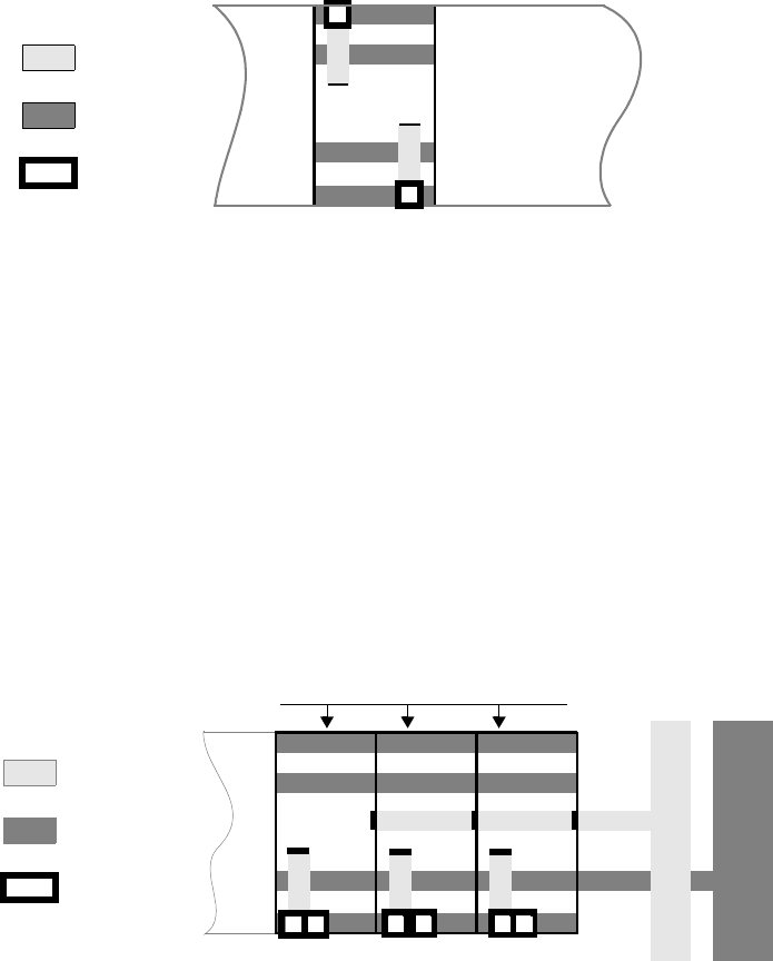
L-Edit 13 User Guide Section 2 350
Chapter 17: Placing and Routing Standard Cell Designs Global Input Signal Routing (Clock Routing)
During core routing, L-Edit connects signal ports belonging to global signal nets (labeled A and B in the
illustration below) to the dedicated global signal bus.
After placement, L-Edit adds buffer cells to both ends of the standard cell rows. L-Edit calculates the
number of buffer cells required for each row by dividing the number of standard cells connected to the
global signal nets by the driving force, which the user specifies in the dialog “SPR Core Setup–Global
Signals” (page 362).
Buffer cells are dedicated to one of the two global signal buses. Each buffer cell contains an IN port that
is accessible from the side and placed on the vertical layer. The IN port of the outermost buffer cell is
connected with the vertical global signal rail on this side.
The vertical global signal rail is placed on the vertical layer, inside of the vertical power rail. It is twice
as wide as the IN port of the buffer cell(s) on this side.
Pad routing connects the vertical global signal rails to the appropriate ports on the padframe. Layer
assignment for global signal pad routing is equivalent to the layer assignment for regular I/O signals
leaving the core. The pads of the global signal nets have to be located either on the left (for the left
global signal rail) or on the right side (for the right global signal rail).
GND
GS1GS1
GS2
GS2
Internal signal ports of the two global signal nets connected with the
dedicated global signal buses.
AB
Horizontal
Routing
Layer
Vertical
Routing
Layer
Via
VDD
OUT
OUT OUT
GS1
GS1
GS2
GS2
VDD
GND
VDD
Buffer cells (right side) and their connection with the global signal rail GS2
GND
GS2 rail GND
Row buffers (dedicated to GS2)
IN IN IN
Horizontal
Routing
Layer
Vertical
Routing
Layer
Via
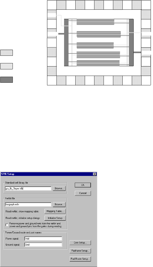
L-Edit 13 User Guide Section 2 351
Chapter 17: Placing and Routing Standard Cell Designs SPR Setup
SPR Setup
Before running SPR, you must set the appropriate options. Use Tools > SPR > Setup to open the SPR
Setup dialog.
GS1
VDD GS2
GND
Global input signal and power routing
Horizontal
Routing
Layer
Vertical
Routing
Layer
Pads
L-Edit 13 User Guide Section 2 352
Chapter 17: Placing and Routing Standard Cell Designs SPR Setup
Specify the following:
When you have typed the correct information in these fields, click the appropriate button—Core setup,
which opens “SPR Core Setup–General” (page 355), Padframe setup, which opens “SPR Padframe
Setup–General” (page 365), or Pad route setup, which opens “SPR Pad Route Setup–General”
(page 371)—to continue SPR setup.
Each of these dialogs contains a Reset button, which resets all fields and options to the values they held
when you accessed the dialog.
If you are using an EDIF netlist and it has different cell and port names than those used in the cell
library, you must map these names correctly. For additional information on this topic, see the section
“Mapping Table,” below.
Standard cell library file File containing the standard cells and pad cells that L-Edit uses to
generate your design. If your design file already contains the required
cells, you may use it instead of the standard cell library. Enter the full
pathname if the file is not in the current L-Edit directory.
Netlist file File containing a textual description of your schematic design, which
identifies the cells required from the standard cell library. This file is
always required when you place and route a core. It is optional when
you perform only pad routing or padframe generation.
SPR accepts flattened EDIF netlists or netlists with one level of
hierarchy only.
Two types of netlist files are supported:
TPR—Tanner Place and Route Format, produced by S-Edit
EDIF—EDIF version 2 0 0, EDIF level 0, keywordLevel 0,
viewType NETLIST. (Acceptable filename extensions are .edf,
.edn, and .edi.)
A SPICE netlist can also be used if it is first converted to TPR format.
Mapping Table Accesses the dialog “Mapping Table” (page 353) to map cell and port
names between the EDIF netlist and the standard cell library.
Initialize Setup Reads pad-related information from the netlist and completes the
fields in the setup dialogs that specify critical nets, padframe layout,
core signals, and padframe signals. If these fields already contain
information, SPR will prompt you to keep or overwrite the values.
(See “Initializing Setup” on page 354.)
Remove power and ground
nets from the netlist and
power and ground pins
from the gates during
reading
If power and ground pins are explicitly placed on schematic symbols,
this option should be checked to remove power and ground from the
netlist for correct place and route performance.
Power signal Schematic netlist name of the power node. The power signal must
have the same name as the power port in the standard cells.
Ground signal Schematic netlist name of the ground node. The ground signal must
have the same name as the ground port in the standard cells.
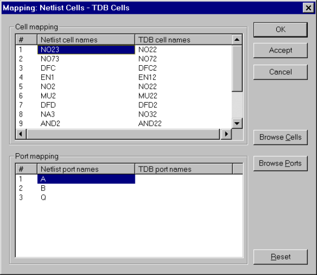
L-Edit 13 User Guide Section 2 353
Chapter 17: Placing and Routing Standard Cell Designs SPR Setup
Mapping Table
L-Edit invokes the Mapping Table dialog while processing the EDIF netlist whenever it finds a
discrepancy between the cell or port names. You can also click Mapping Table in the SPR Setup dialog
to directly generate a mapping table before running SPR.
Mapping information is saved in the design file. If you change the netlist (within the same design file),
the mapping table will display values for previously mapped cells and ports.
Use this dialog to define the correspondence between:
Cells in the EDIF netlist and cells in the standard cell library file.
Ports in the EDIF netlist and ports in the standard cell library file, within individual cells.
Port mapping is only required if a port name discrepancy occurs. However, if you map one port in
an individual cell, you must map all ports in that cell.
If your cell interface in the EDIF file contains ports which are not connected in your design, you
can label them as “not used” during the mapping process.
To map a cell, click the netlist or TDB cell name, or Browse Cells. To map a port, click the netlist or
TDB port name, or Browse Ports. L-Edit displays a dialog in which you select the correct cell or port.
Cell mapping A numbered list of cells named in the EDIF netlist.
Netlist cell names—list of cells named in the EDIF netlist.
TDB cell names—list of cells contained in the standard cell
library file.
L-Edit 13 User Guide Section 2 354
Chapter 17: Placing and Routing Standard Cell Designs SPR Core Setup
Initializing Setup
The Initialize Setup function keeps the setup dialogs and the netlist synchronized. You should use it
when you create a new design and whenever the netlist is changed or updated. When you click the
Initialize Setup button, SPR updates the following dialog values with values from the netlist:
Critical nets in SPR Core Setup—Placement, if any
I/O signal specifications in SPR Core Setup—I/O Signals
Pad route specifications in SPR Pad Route Setup—Padframe Signals and SPR Pad Route
Setup—Core Signals
Padframe specifications in SPR Padframe Setup—Layout
You cannot cancel or undo this operation.
SPR Core Setup
In this dialog, you define the parameters L-Edit will use to generate your design core. The dialog
consists of seven tabs:
General
Layers
Design Rules
Placement
Global Signals
Power
I/O Signals
To map a cell, click on a cell name, or Browse Cells. L-Edit displays
a dialog where you can select the correct cell.
Port mapping A numbered list of ports named in the specified cell in the EDIF
netlist.
Netlist port names—list of ports named in the EDIF netlist.
TDB port names—list of ports contained in the standard cell
library file.
To map a port, click on the netlist or TDB port name or Browse
Ports. L-Edit displays a dialog in which you select the correct port.
Browse Cells Opens a dialog containing a list of cells contained in the specified
standard cell library file.
Browse Ports Opens a dialog containing a list of ports for the specified cell in the
specified standard cell library file.
Accept Saves mapping input and closes the Mapping Table dialog.
OK Saves mapping input, checks that all EDIF cells and ports are
mapped, and closes the Mapping Table dialog.
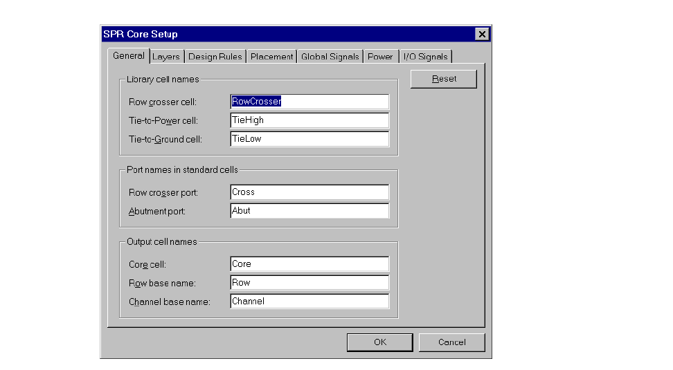
L-Edit 13 User Guide Section 2 355
Chapter 17: Placing and Routing Standard Cell Designs SPR Core Setup
Each tab contains a Reset button, which resets all fields and options to the values they held when you
accessed the dialog.
SPR Core Setup–General
The General tab contains fields used to define the library cells, standard cell ports, and output cells used
in generating the core.
L-Edit requires three special standard cells in a library set: a row crosser cell, the tie-to-power cell, and
the tie-to-ground cell. They are used for node connections only and are not included in the netlist.
Specify the following:
Library cell names Row crosser cell, Tie-to-Power cell, and Tie-to-Ground cell, as they
are named in the standard cell library. These cells must be part of the
standard cell library. For detailed design information on these cells,
see “Special Standard Cells” on page 391.
A row crosser cell contains one row cross port and is placed to make
up a cross-row pass to route wires across a standard cell.
The tie-to-power cell is needed where a standard cell has a pin
directly tied to Vdd.
The tie-to-ground cell is needed where a standard cell has a pin
directly tied to Gnd.
Port names in standard
cells Names of the Row crosser port and Abutment port as they are
named in the standard cell library.
A row crosser port defines crossing paths to route wires across a
standard cell row. This port must be placed on the vertical routing
layer.
The abutment port surrounds the standard cell and defines its edges.
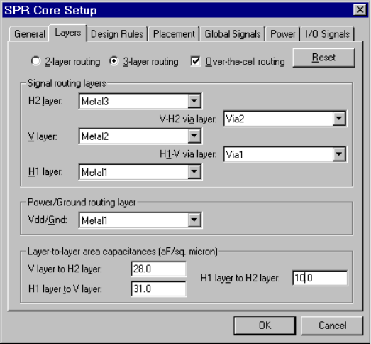
L-Edit 13 User Guide Section 2 356
Chapter 17: Placing and Routing Standard Cell Designs SPR Core Setup
SPR Core Setup–Layers
The Layers tab contains fields that define the layers L-Edit will use to route the core. You use it to
specify whether two or three layers are used for routing. If you use three layers, you can also select
over-the-cell (OTC) routing.
This tab also contains fields for the layer-to-layer capacitance between routing layers. These
capacitance values are used for extracting nodal capacitances, which are written to the CAP file (see
“Nodal Capacitance Files (CAP)” on page 381).
Click on 2-layer routing or 3-layer routing to choose a routing configuration. If you use three-layer
routing, Over-the-cell routing will be an available option.
Specify the following:
Core cell The name of the core cell to be created.
Row base name The base name of the row cells to be created.
Channel base name The base name of the channel cells to be created.
Signal routing layers Specify the routing layers and the via layer(s) to be used for channel
routing.
Power/Ground routing
layers Specify the routing layers for power and ground. This assignment
must be consistent with the layer assignment of the power and ground
buses within the standard cells (usually in the H1 layer).
Layer-to-layer area
capacitances Enter the layer-to-layer capacitances between your routing layers (in
aF/sq. micron). These values are only required if the Write CAP file
option in the Standard Cell Place and Route dialog is checked.
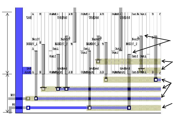
L-Edit 13 User Guide Section 2 357
Chapter 17: Placing and Routing Standard Cell Designs SPR Core Setup
Over-the-Cell Routing
Over-the-cell (OTC) routing uses tracks above the cells, in the H2 layer, between the channel edge and
the “outermost” port inside the cells, for routing.
A special algorithm sorts net segments to utilize these tracks as effectively as possible. The number of
OTC tracks depends directly on how you have placed your ports inside the standard cells. If all ports are
lined up in the center of the standard cell, a maximum number of OTC tracks can be utilized.
Layout example of three metal layers with OTC routing.
Outermost ports
inside the cell
OTC routing in
M3
Routing in M1
and M3
Routing in M3
Cell
Channel
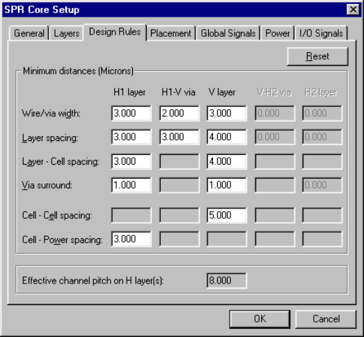
L-Edit 13 User Guide Section 2 358
Chapter 17: Placing and Routing Standard Cell Designs SPR Core Setup
SPR Core Setup–Design Rules
Use the Design Rules tab to specify the design rules L-Edit must follow to route the core in
conformance with the technology used to fabricate your design.
The figures “SPR widths, spaces, and via surrounds in 2-layer routing” on page 359 and “Minimum
cell-cell and cell-power spaces” on page 359 illustrate the application of design rules in 2-layer routing.
The letters in the dialog fields provide a key for the labels in the illustrations and the values they
represent.
This tab also displays the effective channel pitch on the H layer(s) in a read-only field. (The channel
pitch is the distance between the centerlines of two neighboring horizontal routing segments.) This
value is internally calculated according to your design rules.
ACB
DFE
G
I
H
J
K
L
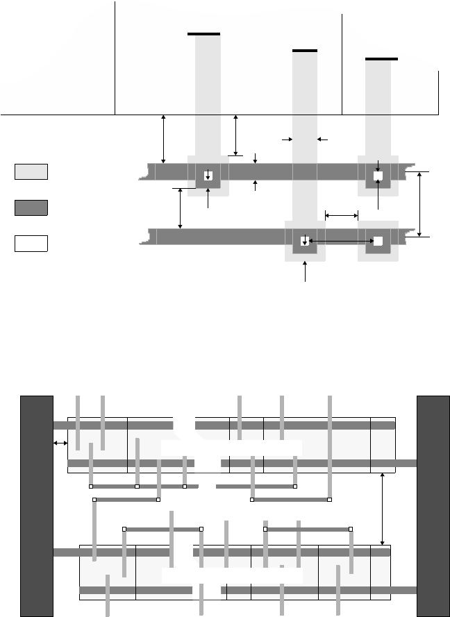
L-Edit 13 User Guide Section 2 359
Chapter 17: Placing and Routing Standard Cell Designs SPR Core Setup
Signal A
DE
HB
C
I
A
Abut
J
G
H1
Signal C
Standard
F
Signal B
Cell
B
Standard
Cell
A
Standard
Cell
C
Abut
Routing
Layer
V
Routing
Layer
Via
SPR widths, spaces, and via surrounds in 2-layer routing
Channel
pitch
K
Routing channel # n
L
Vdd Gnd
Standard cell row # n
Standard cell row # n+1
Minimum cell-cell and cell-power spaces
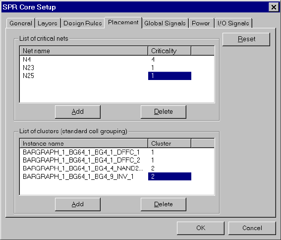
L-Edit 13 User Guide Section 2 360
Chapter 17: Placing and Routing Standard Cell Designs SPR Core Setup
SPR Core Setup–Placement
This tab contains options for controlling the outcome of the automatic placer.
Specify the following options:
Assigning Net Criticality
Nets that are critical in your layout can be specified in the List of critical nets. Criticality is expressed
as an integer value that may be positive or negative. The higher the criticality value, the higher the
priority of the net during placement. (A positive value net is given a higher priority, a negative value net
is given a lower priority during placement.) The value for any net that is not specified in this table is
zero.
The consideration of net criticality in L-Edit/SPR is based on two assumptions:
Net Name Enter a net name.
Criticality Enter an integer criticality value. A positive integer value denotes a
higher priority net, a negative integer value reduces the importance of
the net during placement. See “Assigning Net Criticality” on page
360 for further details.
To add a new critical net, click Add. To delete a critical net, select it
and click Delete.
Instance Name Instance name of a standard cell to be included in a cluster.
Cluster Enter an integer value. All cell instances with the same cluster
number are placed within one cluster. See “Clustering Standard
Cells” on page 361 for further details.
To add a new cell instance to a cluster, click Add. To delete a cell
instance from a cluster, highlight the instance name and click Delete.
L-Edit 13 User Guide Section 2 361
Chapter 17: Placing and Routing Standard Cell Designs SPR Core Setup
The numerical value of the criticality describes the relative importance of a net compared to others.
For example, if the criticality of net A is twice the criticality assigned to net B, then the placer
considers it as twice as important to reduce the length of net A compared to net B.
The critical values are scaled internally according to the largest value that has been entered, with
the largest value assigned to a fixed internal value. Hence, if net A is the only net with an assigned
criticality, than any criticality value greater than zero for this net would lead to the same result.
Net criticality can be entered either by using the EDIF netlist attribute criticality, or directly in the SPR
Core Setup—Placement dialog. If SPR finds criticality values in this dialog, it will ignore any
criticality values found in the netlist. To transfer criticality values from the netlist into this dialog, use
the Initialize Setup button (see “Initializing Setup” on page 354).
Clustering Standard Cells
The List of clusters allows you to group standard cells together. All cell instances assigned the same
cluster number are placed side by side, from left to right, in the order in which they appear in this table.
Cell clusters cannot be “broken”—they must fit on one row. Note that row crossers might be inserted
between two cells within one cluster.
Note: If you turn off placement optimization, cell clustering can also be used to place your
cells in a specific sequence. SPR always places cell instances from left to right inside
a cluster according to their sequence in the list of clusters. Without placement
optimization, clusters are placed according to their number, starting with the lowest
row, from left to right (see the figure on the following page). Cell instances that are
not included in any cluster are placed subsequently, in the sequence of the netlist.
Core with two rows containing clusters that are placed with placement
optimization turned off.
Cluster 1 Cluster 2
Cluster 3
Cell instances without a cluster
number
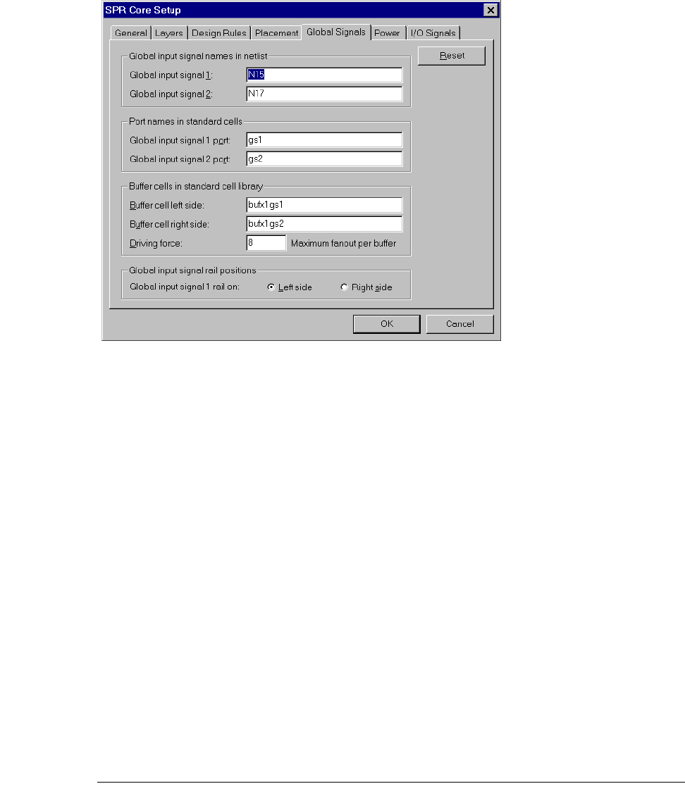
L-Edit 13 User Guide Section 2 362
Chapter 17: Placing and Routing Standard Cell Designs SPR Core Setup
SPR Core Setup–Global Signals
This tab contains options used to route global input signals. If you do not check the option Global input
signal routing in the Standard Cell Place and Route dialog (see “Standard Cell Place and Route” on
page 376), you can ignore this dialog.
Specify the following options:
Note: The assignment of global signal bus ports to each global signal net determines the
assignment of these nets to either the upper or lower global signal bus. Because buffer
cells are specifically connected to either the upper or lower global signal bus, this port
Global input signal names
in netlist Specify one or two signals for global routing.
Ports names in standard
cell Names of the bus ports in the standard cells that will be used for each
global input signal. This port name assignment subsequently defines
the bus, rail, and pad positions used to route each global signal net
(see “Global Input Signal Routing (Clock Routing)” on page 349).
Buffer cells in standard cell
library Names of the buffer cells to be placed on the left and right side of the
standard cell rows. If your design has only one global input signal,
specify one buffer cell on the same side as the global input signal rail.
Driving force Driving force is the driving capability (fanout) of one buffer cell—the
maximum number of standard cells that can be driven by this buffer
cell. The value must be greater than or equal to 1. L-Edit calculates
the number of buffer cells to place on the edge of each standard cell
row by dividing the number of driven cells in the row by this value.
Global input signal 1 rail on Click the option button for whether the Global input signal 1 rail
should be on the Left side or the Right side of the core. L-Edit will
place the rail for Global input signal 2 on the opposite side.
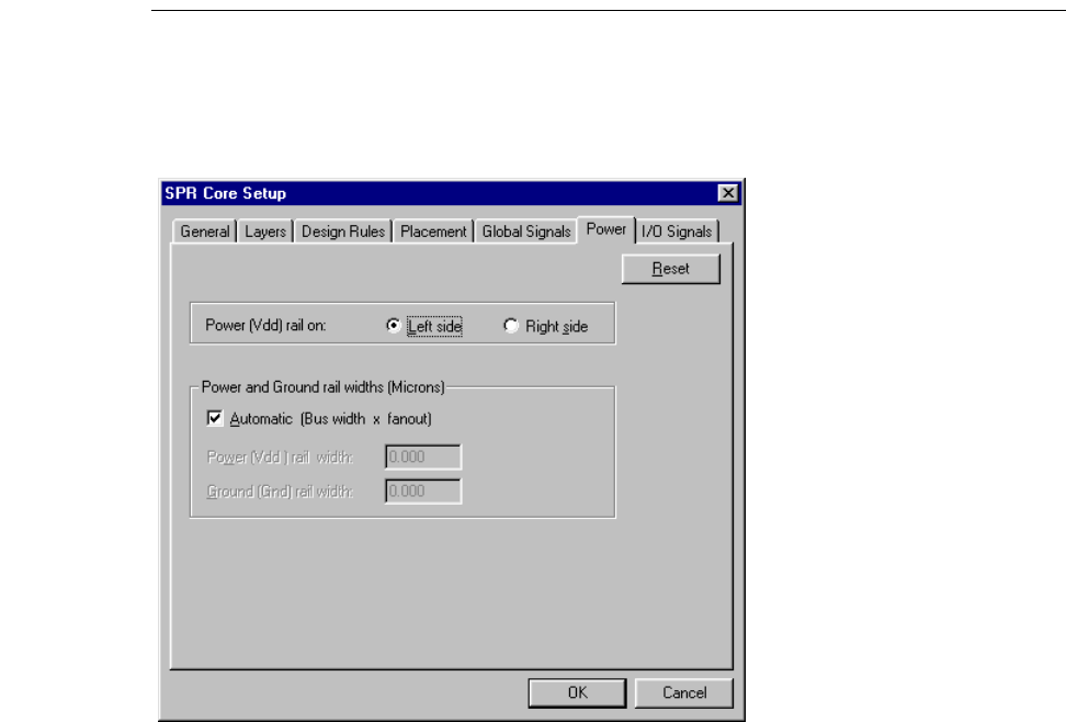
L-Edit 13 User Guide Section 2 363
Chapter 17: Placing and Routing Standard Cell Designs SPR Core Setup
assignment also determines which global signal net the left and right global signal
rails represent.
SPR Core Setup–Power
This tab contains options for the placement and width of power and ground rails.
Specify the following options:
SPR Core Setup–I/O Signals
This tab contains options for the location of input/output signals around the core. Initialize Setup will
complete this dialog automatically if your netlist contains pad connections or interface I/O signals (for
EDIF netlists only; see “EDIF Files” on page 398).
Power (Vdd) rail on: Power and ground rails can be placed either on the left or right side of
the core cell. This choice will be overwritten by the location of the
power and ground pads if the padframe is generated simultaneously
and a conflict is detected.
Automatic (Bus width x
fanout) Check here if you want your power and ground rail widths to be
calculated internally by SPR. In this case, the width is determined by
multiplying the bus width (in the rows) with the number of rows to be
driven.
Power (Vdd) rail width The width of the Vdd rail in display units (if Automatic is
unchecked).
Ground (Gdd) rail width The width of the Gnd rail in display units (if Automatic is
unchecked).
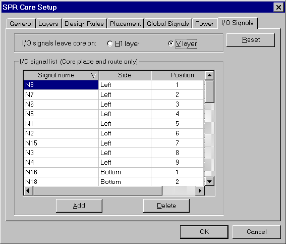
L-Edit 13 User Guide Section 2 364
Chapter 17: Placing and Routing Standard Cell Designs SPR Core Setup
You do not fill out the I/O signal list if you perform core place and route in conjunction with pad
routing and padframe generation.
Specify the following options:
I/O signals leave core on Layer (H1 or V) on which I/O signals will leave the core. Options are
H1 layer and V layer. If you perform pad routing, this layer must be
identical to the pad routing layer for I/O signals (see “SPR Pad Route
Setup–Layers” on page 371).
I/O signal list Defines the name of each I/O signal, the side from which it exits, and
its relative position on that side.
Use the Position value to specify the relative position of a signal on a
given side proceeding counter-clockwise. The higher the value, the
later a signal’s position on a side. For each side, signals are ordered as
follows:
Left:top to bottom
Bottom:left to right
Right:bottom to top
Top:right to left
Only the left and right core edges can be used for routing global input
signals. It is also recommended that you do not use the uppermost and
lowermost pads for global signals.
To add a signal to the list, click Add. A New Signal is highlighted and
can be edited. The name of the signal must be the same as in the
netlist. To delete a signal, highlight the signal in the list and click
Delete.
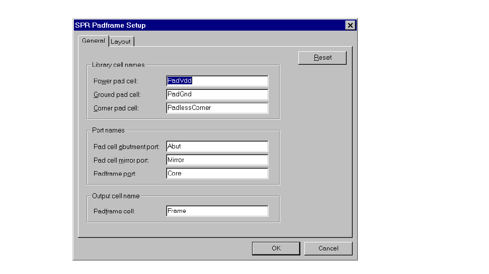
L-Edit 13 User Guide Section 2 365
Chapter 17: Placing and Routing Standard Cell Designs SPR Padframe Setup
SPR Padframe Setup
In padframe generation, L-Edit takes pad cells from the standard cell library, places them in a
rectangular ring, and if required, connects them together. The exact size and shape of this padframe is
determined by the maximum of (1) the configuration specifications of the core cell and (2) the actual
size of the padframe after all specified pads have been placed abutting one another in their respective
positions. The type of pad placed in each position depends on the name indicated in the setup procedure.
To set parameters for padframe generation, click Padframe Setup in the SPR Setup dialog. L-Edit will
display the SPR Padframe Setup dialog.
The dialog consists of two tabs—General and Layout. Each tab contains a Reset button, which will
reset all fields and options to the values they held when you accessed the tab.
SPR Padframe Setup–General
This tab contains fields used to specify the cells and ports in the standard cell library that L-Edit will use
for padframe generation.
Specify the following options:
Library cell names Specify the name of the Power pad cell, the Ground pad cell, and
the Corner pad cell to be drawn from the standard cell library.
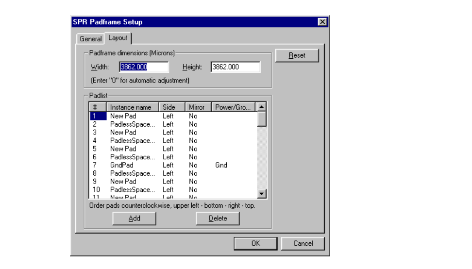
L-Edit 13 User Guide Section 2 366
Chapter 17: Placing and Routing Standard Cell Designs SPR Padframe Setup
SPR Padframe Setup–Layout
Use this tab to specify the padframe’s size and the location of the pads, plus individual characteristics of
each pad in the padframe. Initialize Setup will complete this dialog automatically if your netlist
contains pad connections.
Specify the following:
Port names Names of the ports used to define the dimensions, positions, and
orientation of the pad cells and padframe. These include the
following:
Pad cell abutment port—enter the name of the port used to
define the edge of each pad cell.
Pad cell mirror port—enter the name of the port used in the
standard cell library to designate mirror ports in pad cells (for
additional information, see “Mirror Ports” on page 395). L-Edit
will place pad cells with this port name in a special orientation.
Padframe port—enter the name of the port used to define the
inner edge of the padframe.
Output cell name Specify the name of the generated Padframe cell.
Padframe dimensions
(Display units)Width and Height of the padframe. If you enter zero for any or both of
the dimensions, L-Edit automatically determines the minimum size
required.
L-Edit 13 User Guide Section 2 367
Chapter 17: Placing and Routing Standard Cell Designs SPR Padframe Setup
The Padlist presents a numbered list of pads with their locations and attributes. Corner pads are not
listed. If the padlist is empty, L-Edit will use the pad configuration in the netlist. The padlist contains
the following columns:
Adding Pads
L-Edit automatically places corner pads. If the padframe schematic contains fewer pads than the
number required by the chip foundry for a complete padframe layout, you must complete the padframe
by one of two methods:
Adding placeholder pads at the appropriate locations in the padframe setup (for example, to have a
total of 10 pads on each side of a 40-pin frame).
Adding the required number of unconnected pad instances to the schematic, with module ports to
specify their location.
Pad Naming and Ordering
Pad names entered in the padlist must meet one of the following criteria:
The name must be exactly the same (except for case) as the instance name in the netlist file. For
example, if the pad instance name is U21_3, enter U21_3 as the pad name.
The name must match (except for case) the instance name in the netlist up to (but not including) the
first occurrence of a < in the netlist instance name. For example, if the pad instance name is
U21<1<333, enter U21 as the pad name.
#The number of the pad in the padframe. L-Edit orders pads
counterclockwise along each side according to this number.
Instance name The name of the pad instance. The name of the pad must be the same
as the instance name in the netlist file. Pad cell names can be entered
if no netlist is provided. (Padframe generation only.) See “Pad Cells”
on page 392 for naming conventions and restrictions.
To add an instance to the list, click Add. A New Pad is highlighted
and can be edited. To delete a pad, highlight it by clicking any of its
attributes and click Delete.
Side The side of the padframe on which the pad is placed. Pads must be
entered into the pad list in the order left—bottom—right—top.
Mirror Select either Yes or No. When you enter Yes for a given pad, L-Edit
mirrors the pad through its vertical axis—unless this mirroring will
conflict with mirroring information present in the cell library. For
additional information, see “Mirroring” on page 369.
Power/Ground Enter Vdd and Gnd to designate particular pads as power and ground.
Only one Vdd pad and one Gnd pad may be placed, and they must be
on different sides.
If the design requires more than one power or ground pad in the
padframe, list a “temporary” pad in your schematic or in the padframe
setup. After padframe generation, edit the layout to remove the
“temporary” pad and place a Vdd or Gnd pad in its place, making
connections as required. (See “SPR Padframe Setup” on page 365.)
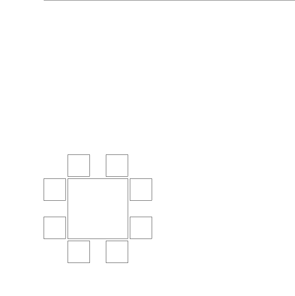
L-Edit 13 User Guide Section 2 368
Chapter 17: Placing and Routing Standard Cell Designs SPR Padframe Setup
The name must be exactly the same (except for case) as one of the pad cells in the standard cell
library—for example, OPad or VddPad. Use this criterion when you only perform padframe
generation; no netlist input is required in the SPR Setup dialog.
You can also specify pad information in the schematic (or directly in the netlist) by placing pads
connected to the appropriate signals in the design. If the pads are to be in a specific order, then attach
module ports to the PAD pins of each pad. (The PAD pin represents the location where a bonding wire
will connect this signal to a pin on the chip.) These module port names must all be in one of the
following formats. (In the following table, n is a number from 1 to the number of pads in the design, s is
the first character of a side—L for left, R for right, and so on—and x is any string of characters.)
For information on defining pads in an EDIF netlist, see “EDIF Files” on page 398.
Format Examples Results
PAD_nPAD_1
PAD_2 The pads are placed in order. For example,
PAD_1 is placed in the top of the left side
of the padframe, PAD_2 just below it, and
so on, traversing counterclockwise around
the padframe. The more detailed form
provides for port labeling. (See the figure
“Pad order—Example 1” on page 368.)
PAD_n_xPAD_1_CLOCK
PAD_2_DATA
PAD_sn PAD_L1
PAD_L2
PAD_B1
The pads are placed in counterclockwise
order on the given side. For example,
PAD_L1 is placed at the top of the left side
of the padframe, and PAD_L2 just below
it. PAD_B1 is placed on the far left of the
bottom of the padframe, and PAD_B2 just
to the right of it. The more detailed form
provides for port labeling. (See the figure
“Pad order—Example 2” on page 369.)
PAD_sn_xPAD_L1_CLOCK
PAD_T3_ENABLE
CORE
PAD_8_A2 PAD_7
PAD_6
PAD_4
PAD_5_B0PAD_2
PAD_1
PAD_3_A0
Pad order—Example 1
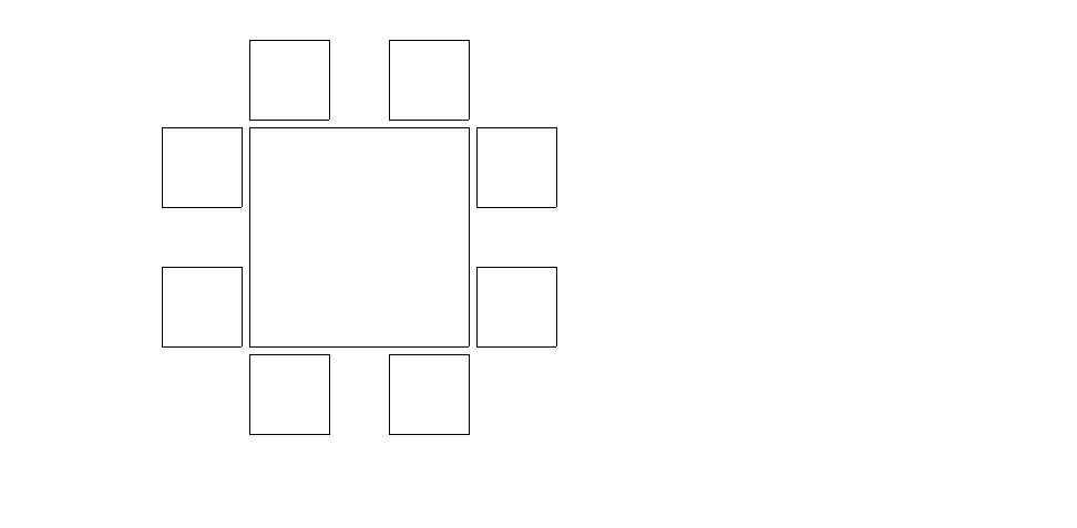
L-Edit 13 User Guide Section 2 369
Chapter 17: Placing and Routing Standard Cell Designs SPR Pad Route Setup
Mirroring
Mirroring is used to mirror pads at specific locations. Incorrect mirroring could cause your chip to
malfunction. Standard cell libraries provided by Tanner EDA contain information for automatic pad
mirroring, if required. Where more specific mirroring information is needed, it is provided in the
standard cell library file setup.
To use this information, use File > Replace Setup. Type the name of the standard cell library file in the
From file field. In the SPR group, select only Padframe setup. (For placing mirroring information into
your own pad cells, see “Pad Cells” on page 392.)
SPR Pad Route Setup
The L-Edit pad router is a two-layer router. It first routes the power bus on one layer, then the signals on
another layer. For each side of the padframe, there is a one-to-one correspondence between “connected”
signals on the padframe and “connected” signals on the core. In other words, the uppermost
“connected” signal on the left side of the padframe is routed to the uppermost “connected” signal on the
left side of the core, the next “connected” signal down on the left side of the padframe is routed to the
next “connected” signal down on the left side of the core, and so on. Each side of the padframe must
have the same number of “connected” signals as there are on the corresponding side of the core.
CORE
PAD_T2_A2 PAD_T1
PAD_R2
PAD_B2_A0
PAD_R1_B0PAD_L2
PAD_L1_A1
PAD_ B1
Pad order—Example 2
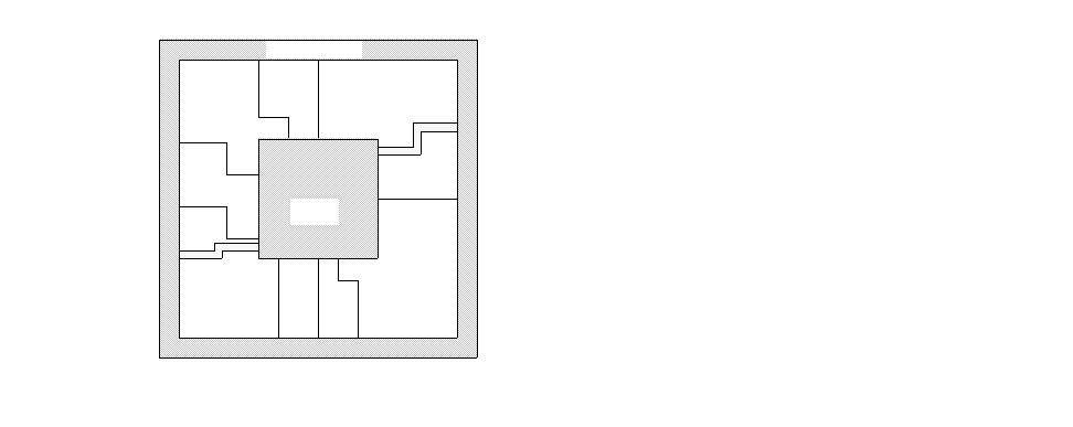
L-Edit 13 User Guide Section 2 370
Chapter 17: Placing and Routing Standard Cell Designs SPR Pad Route Setup
To set parameters for pad routing, click Pad Route Setup in the SPR Setup dialog. L-Edit will display
the SPR Pad Route Setup dialog.
The dialog consists of five tabs:
General
Layers
Design Rules
Core Signals
Padframe Signals
Each tab contains a Reset button, which resets all fields and options to the values they held when you
accessed the tab.
Padframe
Pad router example
Core
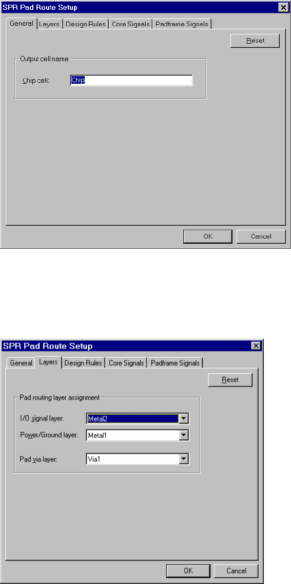
L-Edit 13 User Guide Section 2 371
Chapter 17: Placing and Routing Standard Cell Designs SPR Pad Route Setup
SPR Pad Route Setup–General
In the General tab, enter the name of the Chip cell. The chip cell contains the core and the padframe
instance, and it is where the pad routing will be placed.
SPR Pad Route Setup–Layers
The Layers tab is used to specify pad routing layers for I/O signals, power/ground signals, and pad vias
(if needed).
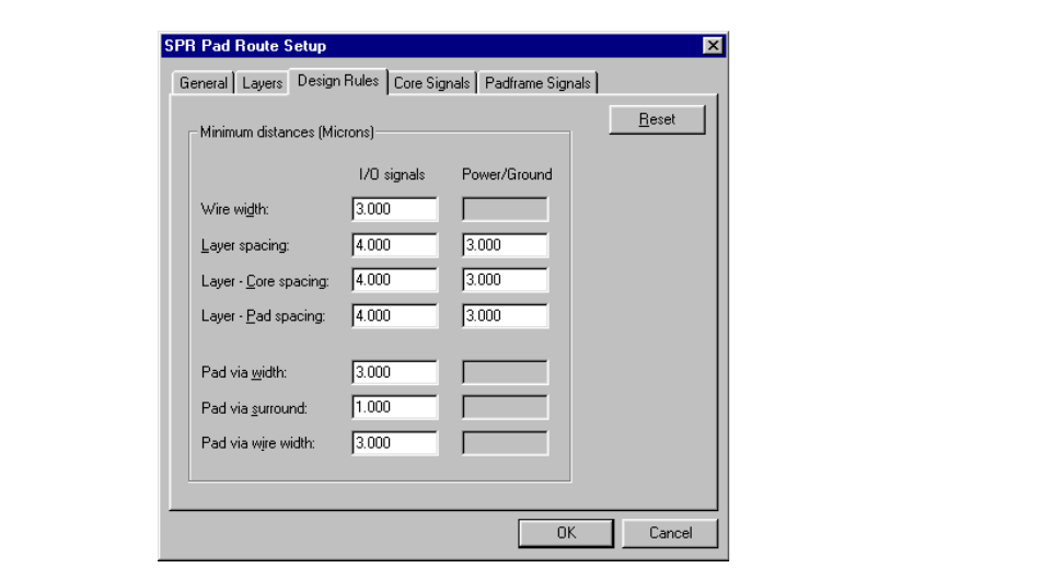
L-Edit 13 User Guide Section 2 372
Chapter 17: Placing and Routing Standard Cell Designs SPR Pad Route Setup
Specify the following options:
SPR Pad Route Setup–Design Rules
Use the Design Rules tab to specify design rule values L-Edit will use to perform pad routing that
conforms to the fabrication technology used for your design. (The letters correspond to dimensions
shown on pages 2-89 and 2-90.)
Values entered in this dialog are applied in the design as illustrated in the figures “Layer widths and
spaces used in pad routing” and “Layer, core and pad spacing used in pad routing”, below.
The letters in the dialog fields provide a key for the labels in the following illustrations and the values
they represent.
I/O signal layer Layer on which I/O signals are routed. In pad routing, I/O signals
must be assigned to the same layer as that specified in “SPR Core
Setup–I/O Signals” (page 363).
Power/ground signals Layer on which power/ground signals are routed. These must be
routed on a different layer than I/O signals.
Pad via layer Layer on which pad vias are drawn. L-Edit inserts pad vias if the ports
of all pad cells are placed on a layer other than the I/O signal layer.
A
B
F
C
E
G
H
I
J
D
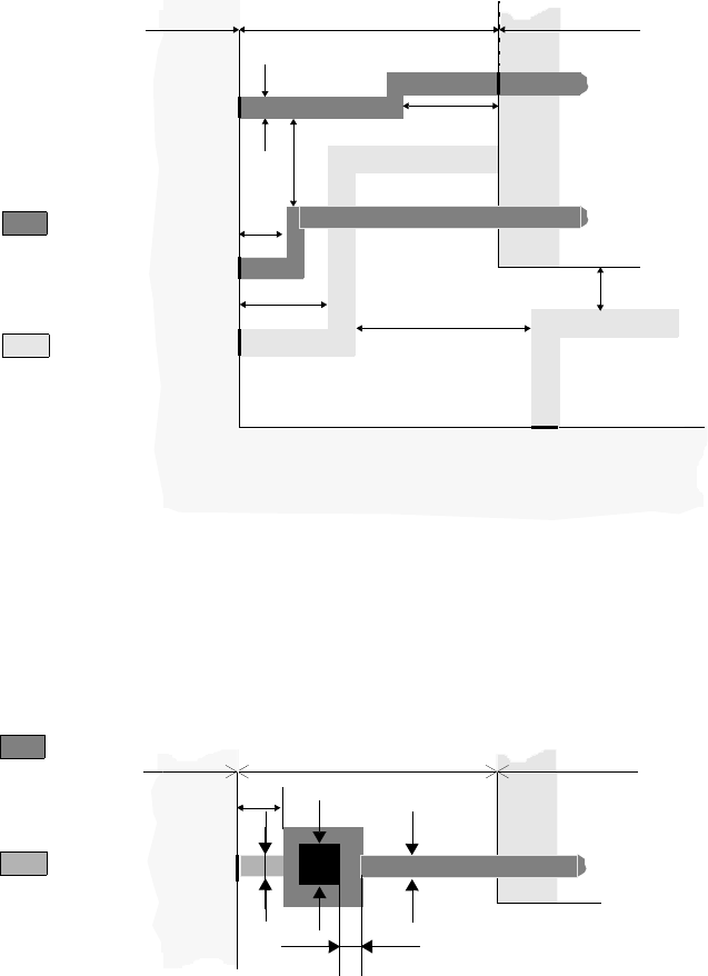
L-Edit 13 User Guide Section 2 373
Chapter 17: Placing and Routing Standard Cell Designs SPR Pad Route Setup
If the pad cell ports are on the pad routing layer, L-Edit applies the following design rules.
For I/O signals, all pad cell ports must be located on the same layer, but that layer need not coincide
with the pad routing layer. In this case, L-Edit inserts a pad via, using the design rules illustrated below.
Layer widths and spaces used in pad routing
I/O signal
layer
Power/ground
layer
Signal B
D
F
Port: Core
Pad route
Port: Frame
A
B
Signal A
Core
Signal B
Vdd pad
Signal A
C
Vdd
E
G
Padframe
I/O signal
layer
Pad port
layer
Signal C
F
Port: Core
Pad route Core
Signal C
Padframe
HA
J
I
Design rules for pad via
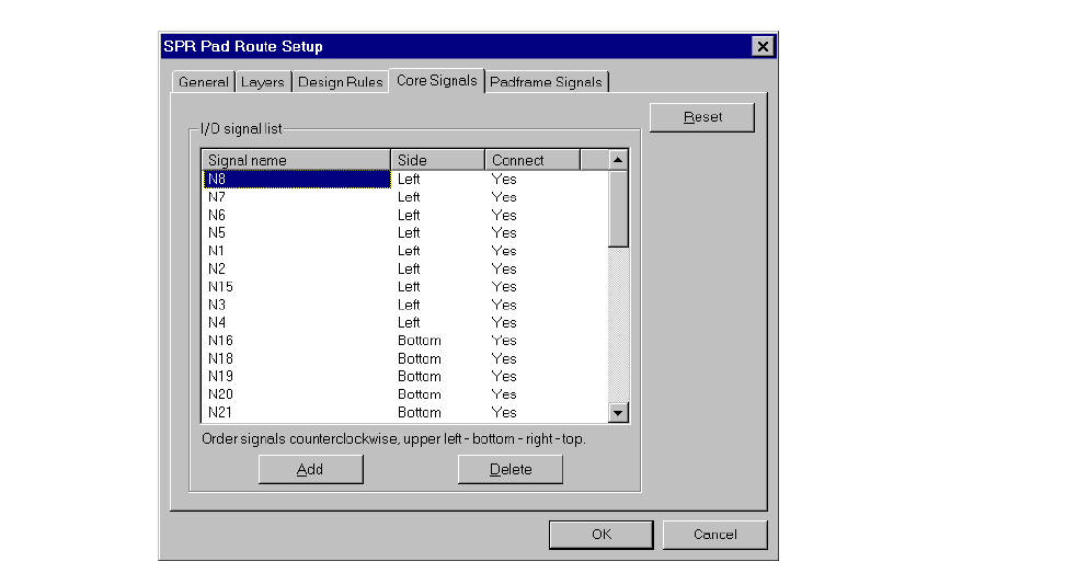
L-Edit 13 User Guide Section 2 374
Chapter 17: Placing and Routing Standard Cell Designs SPR Pad Route Setup
SPR Pad Route Setup–Core Signals
Use the Core Signals tab to specify the signals entering or exiting the core. Initialize Setup will
complete this dialog automatically if your netlist contains pad connections.
Enter the following information in the I/O signal list
Signal name Defines the names of all signals exiting or entering the core,
beginning with the first signal on the upper left side of the core and
proceeding counter-clockwise. Edit the Signal name, Side, or
Connect (Yes or No) by selecting the item and typing the desired
value.
This list must contain as many signals as there are ports around the
core.
To add a signal to the list, click Add. A New signal is highlighted and
can be edited. To delete a signal, highlight it (by clicking any of its
attributes) then click Delete.
Side Side on which the signal is routed between the core and padframe.
Options are:
Left
Bottom
Right
Top
Connect Options are Yes and No. To connect a signal to the padframe, type
Yes; otherwise type No.
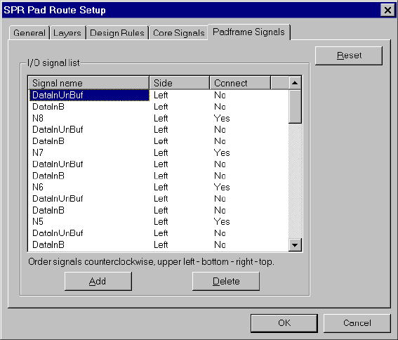
L-Edit 13 User Guide Section 2 375
Chapter 17: Placing and Routing Standard Cell Designs SPR Pad Route Setup
SPR Pad Route Setup–Padframe Signals
Use the Padframe Signals tab to specify a list of signals entering or exiting the padframe. Initialize
Setup will complete this dialog automatically if your netlist contains pad connections.
Enter the following information in the I/O signal list:
Signal name Defines the names of all signals exiting or entering the padframe,
beginning with the first signal on the upper-left side of the padframe
and proceeding counterclockwise.
This list must contain as many signals as there are pads around the
padframe.
To add a signal to the list, click Add. A New signal is highlighted and
can be edited. To delete a signal, highlight it by clicking any of its
attributes then click Delete. To edit a signal, highlight it by clicking
any of its attributes then click again to make the field editable.
Side Side on which the signal is routed between the core and padframe.
Options are:
Left
Bottom
Right
Top
Connect Options are Yes and No. To connect a signal to the padframe, type
Yes; otherwise type No.
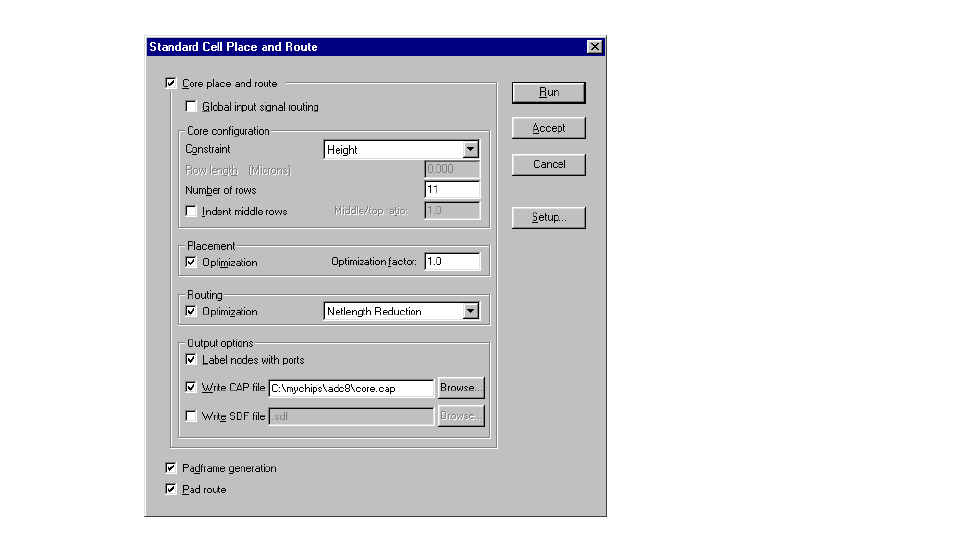
L-Edit 13 User Guide Section 2 376
Chapter 17: Placing and Routing Standard Cell Designs Standard Cell Place and Route
Standard Cell Place and Route
Use Tools > SPR > Place and Route to display the following dialog:
L-Edit 13 User Guide Section 2 377
Chapter 17: Placing and Routing Standard Cell Designs Standard Cell Place and Route
You can run the following three modules either in one step or separately:
Core place and route—generates the design core using the options specified in “SPR Core
Setup” (page 354).
Padframe generation—generates the padframe using the options specified in “SPR Padframe
Setup” (page 365).
Pad route—routes between the padframe and the core using options specified in “SPR Pad Route
Setup” (page 369).
Global input signal routing allows you to perform a separate route of up to two input signal nets. This
option is only available when you select Core place and route.
Clicking Setup opens the “SPR Setup” (page 351) dialog.
Specify the following:
Constraint Specifies the factors used to constrain core size and shape. Options
include:
Square—Generates a core with four sides of approximately
equal length.
Width—Generates a core using the specified Row length.
Height—Generates a core using the specified Number of rows.
Width and Height—Generates a core using the specified Row
length and Number of rows.
Selecting Width and Height will interrupt SPR after placement if the
program cannot meet both constraints. In such a case, L-Edit will ask
you whether you want to abort or continue the SPR run.
Row length Nominal length of rows placed in the core. Available only when
Constraint is set to Width or Width and Height. This value is only an
approximation, because the actual row length varies according to the
number of row crosser cells inserted during routing.
Number of rows Number of rows in the finished core. Available only when Constraint
is set to Height or Width and Height. Increasing the number of rows
makes the core taller and thinner; decreasing it makes the core shorter
and wider.
Indent middle rows Generates a core using the value entered in Middle/top ratio. This
value is the ratio of the target length of the middle row of cells to that
of the top and bottom rows.
Refer to “Indent Middle Rows” on page 378 for guidelines on values
for this field.
This value must be between 0 and 1 (inclusive); the default value is 1.
Using 1 for the Middle/top ratio is equivalent to turning off the
Indent middle rows option.
Optimization (in Placement
group) Reduces core size by minimizing the overall netlength. When this
option is off, L-Edit places cells according to their sequence in the
netlist.
L-Edit 13 User Guide Section 2 378
Chapter 17: Placing and Routing Standard Cell Designs Standard Cell Place and Route
Indent Middle Rows
One factor affecting the width of standard cell rows is the number of row crosser cells inserted in a row.
A row crosser is a small cell which contains a row crosser port but no logic; it simply provides a path for
a signal to move through a row. When L-Edit needs to route a signal across a row of cells and no other
cell in the row contains an unused row crosser port, the program inserts a row crosser cell.
Statistically, more row crossers are required in the middle rows of a design than in top or bottom rows,
because the middle is more congested with logic. Hence, the middle rows might become significantly
wider than they were estimated to be by the placement optimizer.
Select Indent middle rows for designs that have a significant number of row crosser cells added to their
middle rows. If an initial SPR run produces a design whose middle rows are significantly wider than the
top or bottom rows, use a Middle/top ratio of less than 1.
Optimization factor Controls the degree of optimization and thus the quality of the
placement. The higher the value, the greater the total placement time.
Available only when Optimization is checked. See “Optimization
Factor” on page 379 for guidelines on values for this field.
Optimization (in Routing
group) Optimizes routing by minimizing netlength, reducing the number of
required vias, or both. When you select Optimization in the Routing
group you must also specify one of the following options:
Netlength and Via Reduction—invokes a postrouting algorithm
that minimizes netlength (by shortening net loops) and reduces
the number of generated vias (by eliminating unnecessary layer
changes between net segments).
Netlength Reduction—invokes a postrouting algorithm that
minimizes netlength.
Via Reduction—invokes a postrouting algorithm that reduces the
number of generated vias.
Label nodes with ports Places ports with the names of nodes onto the layout. You can use this
option to extract a SPICE netlist with the original node names. This
feature is also useful when it is necessary to perform any manual
modifications to the results of the router, because it allows you to
trace individual nodes as they wind through the core. For additional
information on this option, see “Label Nodes” on page 380.
Write CAP file Writes out a file of nodal properties, including nodal capacitances,
after routing. Type the filename in the adjacent field or click Browse
to select a file from a standard file browser. For additional
information on this option, see “Nodal Capacitance Files (CAP)” on
page 381.
Write SDF file Writes out a file that lists the delays due to routing in standard delay
format (SDF). Type the filename in the adjacent field or click Browse
to select a file from a standard file browser.
Selecting the Write SDF file option gives you the delay option
Pin-to-Pin delay, which calculates the interconnection delay between
a driver pin and a receiver pin. For additional information on this
option, see “Standard Delay Format Files (SDF)” on page 383.
L-Edit 13 User Guide Section 2 379
Chapter 17: Placing and Routing Standard Cell Designs Standard Cell Place and Route
Placement Optimization
The core of a standard cell design contains rows of standard cells, which are designed to abut one
another horizontally to form power and ground connections.
You can produce a more compact design by selecting Optimization in the Placement group. With
Optimization on, L-Edit considers the positions and connections of standard cells and alters those
positions where necessary to achieve a more compact layout. For example, if the output of a DFF is
connected to the input of an inverter, the optimizer might relocate the DFF or the inverter to make the
wire between them as short as possible.
With Optimization off, L-Edit simply places cells according to their sequence in the netlist.
When you select Optimization, you must also choose an Optimization factor. This factor enables you
to control the degree of optimization and thus the quality of the placement. The higher the optimization
value, the greater the total placement time will be. For additional information on this field, see
“Optimization Factor,” below.
Optimization Factor
L-Edit uses a simulated annealing algorithm to optimize placement (described in Sechen, see
“References” on page 387). The optimizer algorithm randomly chooses pairs of cells and determines
whether their locations should be exchanged in order to reduce the overall net length.
The Optimization factor is a measure of the number of states which the optimizer looks at per cell for
every temperature step of the process, and so controls the placement time. For example, the placement
for an optimization factor of 2 should be about an order of magnitude slower than a placement for an
optimization factor of 0.2. Although it is possible to obtain better final results by increasing the factor
by one or two orders of magnitude, a factor of 1 represents a balanced trade-off between total placement
time and final core area. The following figure shows the average relationship between the final
optimized core area and the optimization factor. Clearly, the improvement to the core area is not large
for factors greater than 1.
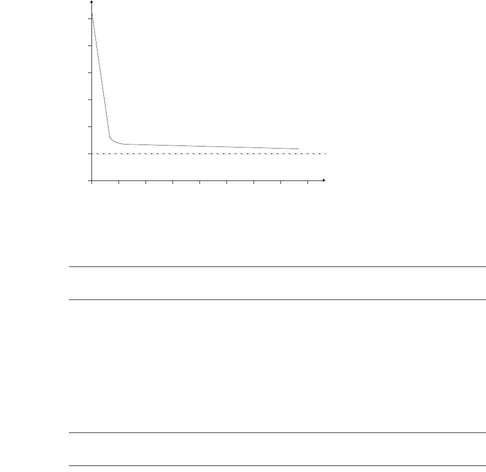
L-Edit 13 User Guide Section 2 380
Chapter 17: Placing and Routing Standard Cell Designs Output Options
Note: To minimize core size, it is best to run SPR several times with different optimization
factors of around 1 rather than running it once with a single large optimization factor.
An optimization factor of 0 is not equivalent to “no optimization.” The optimizer will still run through
placement, the row evener, global routing, and detailed routing with a minimal running time and a
minimal effect on the placement optimization of the design. This is a good value to use while
experimenting with other optimization controls (for example, changing the number of rows).
You can bypass placement optimization by clearing the Optimization check box. This is the fastest
method for generating layout, but the final core will be significantly larger than a core produced with
optimization.
Note: To avoid excessive complexity in channel routing, it is recommended that you always
turn Placement Optimization on for circuits with more than 2,000 standard cells.
Output Options
Label Nodes
The Label nodes with ports switch instructs L-Edit to place ports on the layout (in the vertical routing
layer) using the same port names as those used in the design schematic. You can use this option to
extract a SPICE netlist with the original node names. This feature is also useful when it is necessary to
perform any manual modifications to the results of the router, because it allows you to trace individual
nodes as they wind through the core.
6x
5x
4x
3x
2x
1x
654321780
Optimization
Core area
Optimal core area
The difference between the core area
when optimization factor = 1 and the core area
when optimization factor = 10 is within 5% in
most cases.
Optimization factor and core area for circuits up to 1000 standard cells.
factor
The curve of larger circuits is slightly shifted
to the right.

L-Edit 13 User Guide Section 2 381
Chapter 17: Placing and Routing Standard Cell Designs Output Options
Nodal Capacitance Files (CAP)
The option Write CAP file instructs L-Edit to compute the capacitance, length, and area added to each
node due to routing. L-Edit writes the results to a plain-text file with the filename extension .cap.
Each line in the file is in the format:
node capacitance NoOfTerminals Length AreaOnH1 AreaOnV AreaOnH2
where node is the name of the node, capacitance is an integer denoting capacitance of this node in
hundredths of a picofarad, NoOfTerminals is the number of pins attached to this node, and Length is the
length of the interconnect of this node. AreaOnH1, AreaOnV, and AreaOnH2 denote the area of the
route taken by this node on the H1, V, and H2 layers.
Note: To use this file in a simulation, you must convert it to SPICE format.
Node capacitances are calculated based on the capacitance per unit area for a particular routing layer
and the area occupied by the node. The capacitance per unit area for a layer is the capacitance between a
particular routing layer and the substrate or the capacitance between two routing layers. Node
capacitances also consider the fringe capacitance per unit length between the edges of the routing and
the substrate.
The base values for capacitance between a layer and substrate or layer and another layer, as well as the
fringe capacitance between the routing layer and the substrate, are entered by the user. These
capacitance values are process-dependent and should be available from your chip foundry.
In the following discussion, we assume the horizontal routing layers to be Metal1 and Metal3 and the
vertical routing layer to be Metal2. The capacitance on a node Cnode is computed as
(0.1)
with
(0.2)
(0.3)
(0.4)
(0.5)
(0.6)
(0.7)
Cnode CA,M1SAM1 CA,M2SAM2 CA,M3SAM3
CO,M1M2AM1M2COM1M3,AM1M3
COM2M1,AM2M1COM2M3,AM2M3
COM3M1,AM3M1COM3M2,AM3M2
+
CFM1S,PM1CFM2S,PM2CFM3S,PM3
++
++
++
+
+++
=
[non-overlap]
[overlap M1]
[overlap M2]
[overlap M3]
[fringe]
COM1M2,CAM1S,CAM1M2,
+=
COM1M3,CAM1S,CAM1M3,
+=
COM2M1,CAM1M2,
=
COM2M3,CAM2S,CAM2M3,
+=
COM3M1,CAM1M3,
=
COM3M2,CAM2M3,
=

L-Edit 13 User Guide Section 2 382
Chapter 17: Placing and Routing Standard Cell Designs Output Options
where
Two-Layer Example
It is important to know how to extract numbers from the foundry’s actual process parameter sheet for
entry in the dialog. In the following two-layer example, the process parameters are taken from a typical
2-micron N-well process. The value given for each layer (except for the last entry) is the area
capacitance between the specified layer and the substrate, in aF/µm2.
CA,MXS Area capacitance per unit area between the MetalX layer and the
substrate (entered using Setup > Layers—General).
CA,MXMY Area capacitance per unit area between the MetalX layer and the
MetalY layer (entered in the “SPR Core Setup–Layers” (page 356)
dialog).
CO,MYMX Overlap capacitance per unit area on MetalX when overlapped by
routing on MetalY (calculated by SPR).
CF,MXS Fringe capacitance per unit length between the MetalX layer and the
substrate (entered using Setup > Layers—General).
AMX Area covered by the route of this node in MetalX with no overlap to
any routing in any other layer (calculated by SPR).
AMXMY Area covered by the route of this node in MetalX that overlaps with
routing in MetalY layer (calculated by SPR).
PMX Perimeter of all routing segments of this node in MetalX (calculated
by SPR).
Layer CA
Poly—Substrate 55
N Diff—Substrate 128
P Diff—Substrate 322
Metal1— Substrate
(CA,M1S)25
Metal2—Substrate (CA,M2S)20
Metal1—Metal2 (CA,M1M2)38
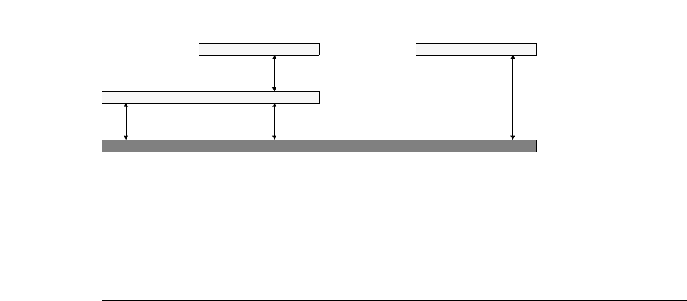
L-Edit 13 User Guide Section 2 383
Chapter 17: Placing and Routing Standard Cell Designs Output Options
Capacitance values are entered with two setup commands.
The overlap capacitances of Metal1 and Metal2 are internally calculated as follows:
An overlapping node on Metal1 sees an overlap capacitance of .
An overlapping node on Metal2 sees an overlap capacitance of CA,M1M2 only.
Thus, CO,M1M2 = CA,M1S + CA,M1M2 = 63 and CO,M2M1 = CA,M1M2 = 38.
Standard Delay Format Files (SDF)
When you run SPR with the option Write SDF file, L-Edit computes the delays due to routing and
outputs the results into a standard delay format (SDF) file with the filename extension .sdf.
The L-Edit interconnect delay calculation is based on the Elmore delay model. The capacitance and
resistance is extracted segment by segment and distributed as a π model.
Dialog Values entered
Setup Layers—General,
Layer-to-substrate [Area]
capacitance field
CA,M1S = 25 and CA,M2S = 20 are entered for Metal1 and Metal2,
respectively.
SPR Core Setup–Layers,
Layer-to-layer area
capacitance field
CA,M1M2 = 38 is entered.
Metal1 (horizontal route)
Metal2 (vertical route)
Substrate
CA,M1S (Metal1-Substrate)
CA,M1M2 (Metal1-Metal2)
CA,M1S (Metal1-Substrate)
CA,M2S (Metal2-Substrate)
Metal2 (vertical route)
Interconnect capacitances in two-layer routing
CAM1S,CA,M1M2
+
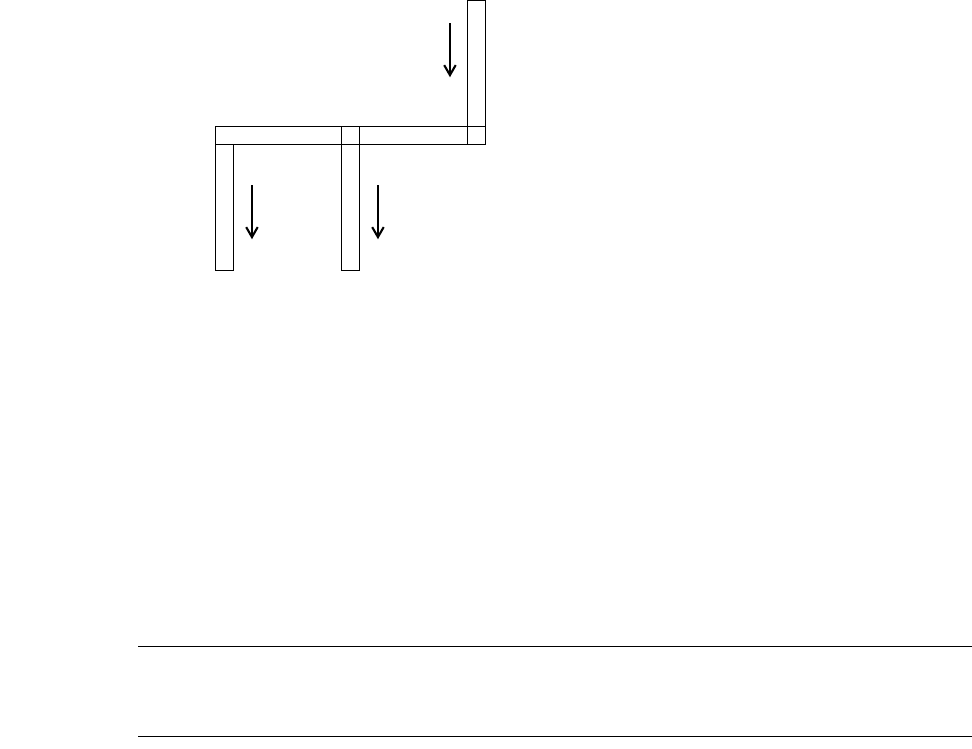
L-Edit 13 User Guide Section 2 384
Chapter 17: Placing and Routing Standard Cell Designs Output Options
Each segment of the interconnect is associated with a lumped R and C value.
The R and C values are determined by
(0.8)
(0.9)
where width of segment is defined as the wire edge that connects to the pin and
(0.10)
Note: Capacitance with respect to the substrate is the only capacitance component that is
considered. No attempt is made to include layer-to-layer or crosstalk capacitance
terms.
The detailed R and C values are calculated as follows:
For a segment located on Metaln:
(0.11)
(0.12)
where
RMnResistivity (resistance per square) of the
Metaln layer Entered in Setup Layers—General.
CA,MnSArea capacitance per unit area between
the Metaln layer and the substrate Entered in Setup Layers—General.
CF,MnSFringe capacitance per unit length
between the Metaln layer and the
substrate
Entered in Setup Layers—General.
Pin A Pin B
Pin C (OUTPUT)
Seg 2 Seg 4
Seg 5
(INPUT) (INPUT)
Seg 1 Seg 3
RR
square (Length of segment Width of segment)⁄⋅=
CC
area Area of segment Cfringe Perimeter of segment⋅+⋅=
Perimeter 2Length of segment Width of segment+()⋅=
RR
Mn Number of squares⋅RMn Lseg Wseg
⁄()⋅==
CC
AMnS,AMn CFMnS,PM
·
n
⋅+⋅=
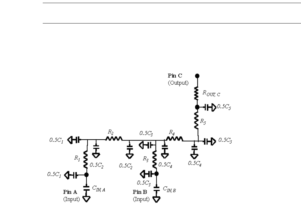
L-Edit 13 User Guide Section 2 385
Chapter 17: Placing and Routing Standard Cell Designs Output Options
Note: The area and perimeter term includes the small amount of overlap between layers.
The error resulting from this inclusion is negligible.
The R and C values for each segment are distributed as a π model. For the above interconnection, the R
and C values are distributed as follows:
Pin-to-Pin Delay Calculation
The pin-to-pin delay is the interconnection delay between a driver pin and a receiver pin. Driver pins are
all output or bidirectional pins on a net; input pins are all input or bidirectional pins on a net. In this
example, the pin C is the driver pin and A and B are the receiver pins.
Delay(Pin C to Pin A) = ROUT,C × (C5 + C4 + C3 + C2 + C1 + CIN,A + CIN,B)
+ R5 × (0.5C5 + C4 + C3 + C2 + C1 + CIN,A + CIN,B)
+ R4 × (0.5C4 + C3 + C2 + C1 + CIN,A + CIN,B)
+ R2 × (0.5C2 + C1 + CIN,A)
+ R1 × (0.5 C1 + CIN,A)
This delay calculation corresponds to the 63.2% threshold voltage of the single-pole response.
The SDF computed by L-Edit contains interconnect delays for both rising and falling edges. These are
computed using different values for the driver impedance ROUT. The values for ROUT, CIN, and COUT (if
Lseg, Wseg Length and width of the segment Calculated by SPR
AMnArea covered by the segment of this
node in MetalnCalculated by SPR
PMnPerimeter of the segment of this node in
Metaln Calculated by SPR
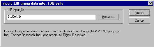
L-Edit 13 User Guide Section 2 386
Chapter 17: Placing and Routing Standard Cell Designs SDF Driver Properties
any) are obtained from properties placed on the corresponding ports of the standard cell layout used by
SPR. These properties may be modified in two ways:
You can enter them using the Tools > Add-Ins > SDF Driver Properties > “Edit Pin
Characteristics” (page 387). The resistance values are given in ohms, and capacitance values are
in Farads.
You can import the data from a Liberty timing (.lib) file using Tools > Add-Ins > SDF Driver
Properties > “Import .LIB Timing Data” (page 386). In this case, all cells found in the library file
are annotated. A fragment of a .lib file is shown below:
library (tsmm025DL) {
pulling_resistance_unit : "1kohm";
capacitive_load_unit (1.0, ff);
cell(Buf1) {
pin (A) {
direction : input;
capacitance : 0.983;
}
pin (OUT) {
direction : output
timing() {
rise_resistance : 3.70;
fall_resistance : 3.63;
}
}
}
}
SDF Driver Properties
SDF Driver Properties is a macro that allows you to specify driver/receiver data by importing a .lib file
or by editing driver/receiver properties on specific ports. SPR uses the driver/receiver properties on the
zero-height ports in the standard cell for SDF calculations. (See the Application Notes for additional
details.)
Import .LIB Timing Data
You can import timing data for SDF from a Liberty Timing File (.lib). To import a .lib file, select
Tools > SPR > SDF Driver Properties > Import .LIB Timing Data... from the L-Edit menu.
Type the name of the appropriate .lib file, or click Browse to open a standard file browser. Click import
to set the port properties specified in the .lib file.
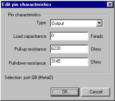
L-Edit 13 User Guide Section 2 387
Chapter 17: Placing and Routing Standard Cell Designs References
Edit Pin Characteristics
To edit driver/receiver characteristics on a selected port, choose the menu option Tools > SPR > SDF
Driver Properties > Edit Pin Characteristics....
Using the pull-down menu, choose a pin Type of Input, Output, or None.
If the pin type is Input or Output, you can edit pin characteristics in the appropriate fields. Options
include:
Pull-up and pull-down resistance are usually determined experimentally or by simulation, by measuring
the propagation delay of a given gate layout driving various values of load capacitance. The slope of
this curve is the drive impedance (pull-up or pull-down), while the delay for C=0 gives the intrinsic gate
delay (also known as the internal gate delay).
References
Sechen, Carl. 1988. VLSI Placement and Global Routing Using Simulated Annealing. Boston: Kluwer
Academic Publishers.
Load capacitance
(Input and Output pins.) The load capacitance of the selected pin.
Pull-up resistance
(Output only.) The effective drive impedance of the logic gate when it is trying to
drive a logic “1” (high voltage).
Pull-down resistance.
(Output only.) The effective drive impedance of the logic gate when it is trying to
drive a logic “0” (low voltage).

L-Edit 13 User Guide Section 2 388L-Edit 13 User Guide Section 2 388
18 Standard Cell Library Designer’s
Guide
Standard Cell Library
The cells in a standard cell library must meet certain constraints of dimension and port positions for
proper use by L-Edit. Usually, a standard cell library includes two types of cells:
Standard cells, which L-Edit can place and route.
Pad cells, an optional set, which L-Edit uses in padframe generation and routing.
Standard Cells
Abutment Ports
Each standard cell should have a special abutment port whose name is consistent with the Abutment
port entry in the “SPR Core Setup–General” (page 355) dialog. The dimensions and position of an
abutment port correspond to the boundaries of the cell to which it belongs. The abutment port must have
the same height in all standard cells in a library set. Abutment port widths should also be integer
multiples of the vertical routing pitch.
Note: Channel routing will take less time when the abutment ports are of a uniform width
and spacing.
Power Ports
Power buses enter and exit at the ends of the standard cell rows, run horizontally along the row, and
connect to power ports within each cell, which must be placed on both sides of a standard cell at the cell
boundary. Power port names are specified in the Power Signal and Ground Signal fields in the SPR
Setup dialog.
Ports for a power terminal (Vdd or Gnd) must have the same height and position relative to the
abutment port in every standard cell of a library set. The width of power ports has to be zero. The power
2
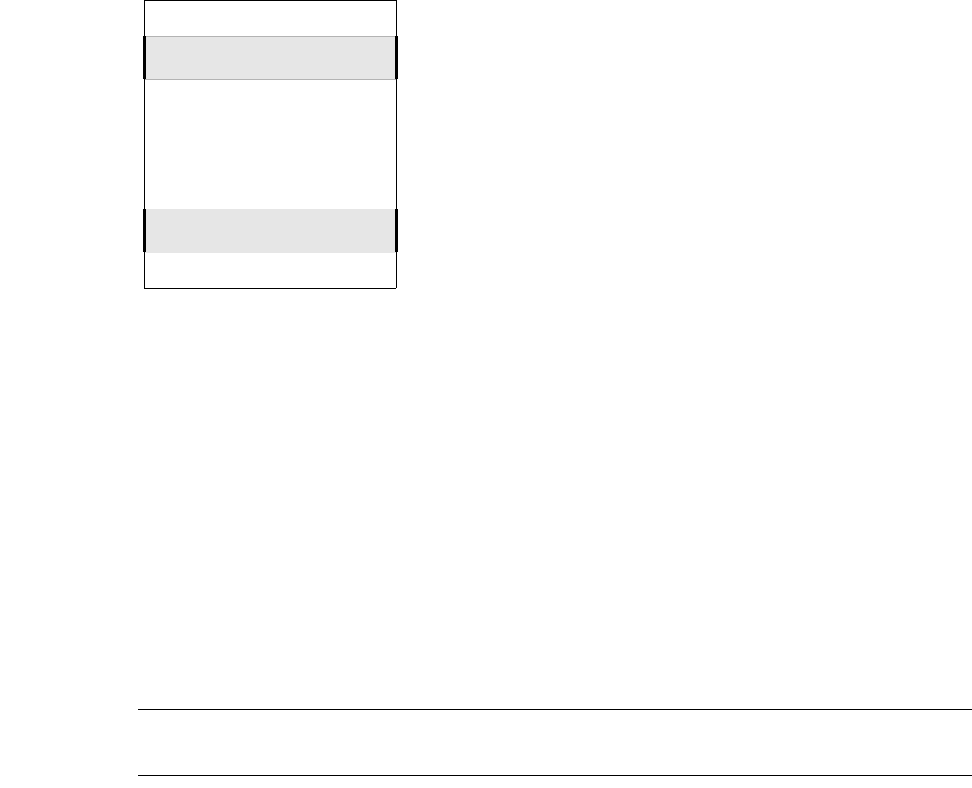
L-Edit 13 User Guide Section 2 389
Chapter 18: Standard Cell Library Designer’s Guide Standard Cells
rail can run along the left or right side of the core, as specified in the “SPR Core Setup–I/O Signals”
(page 363) dialog.
Signal Ports
Signals other than power and ground are routed to ports through the top or bottom sides of a standard
cell. A signal port must have a height of zero and a name complying with that of standard cell primitives
in the netlist, and it must be placed on the same layer as the vertical routing wires.
Signal ports for signal routings must be placed at related layout geometry where the signals are
available. Signal port positions must comply with the relevant design rules (see “SPR Core Setup–
Design Rules” (page 358)), with predefined routing width and space specifications. Signal ports can be
either inside the standard cell or on its boundary (see the illustration “Signal port positions in standard
cells” on page 390.)
Note: Channel routing will take less time when the signal ports are of a uniform width and
spacing. Signal port widths should also be integer values.
Abut
Gnd
Vdd Vdd
Gnd
Typical power bus arrangement and power port positions.
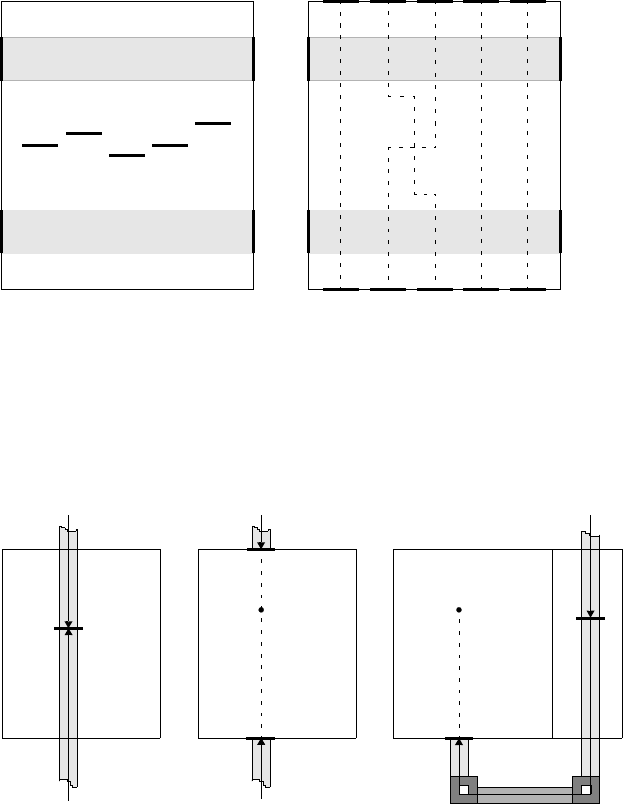
L-Edit 13 User Guide Section 2 390
Chapter 18: Standard Cell Library Designer’s Guide Standard Cells
There are three options for routing wires to fit specific layout features of a standard cell set.
Row Crosser Ports
To route wires between two routing channels—that is, across a standard cell row—L-Edit uses
user-specified row crosser ports that identify crossing paths on standard cell rows. (Row crosser ports
illustrated in figures in this chapter have the port name Cross.) The use of row crosser ports is
illustrated in a regular standard cell in the figure “Signal port positions in standard cells” on page 390
and in a dedicated row cross cell in the figure “Routing wire arrangements in standard cells” on page
(a) Signal ports in cell interior (b) Signal ports on cell edges
AB
Cross
Out
Abut
Gnd
Vdd Vdd
Gnd
Cross
ABCross Out
Abut
Gnd
Vdd Vdd
Gnd
Cross
ABCross OutCross
Signal port positions in standard cells
Option 1: Vertical routing
wires are allowed to
overlap a standard cell
and allowed to enter the
cell from the top or
bottom.
Abut
Option 2: Vertical routing
wires are not allowed to
overlap any portions of a
standard cell. They are
allowed to reach ports at
either top or bottom edges
of the cell. It is assumed
that every pair of the same
named ports relates to the
same internally connected
node.
Abut
A
Option 3: Vertical routing wires
are only allowed to reach from a
designated side of a standard
cell. In this example, a wire
coming from the upper routing
channel reaches the signal port A
(at the bottom edge of the cell)
through an additional row
crosser cell and an additional
horizontal routing wire in the
lower channel.
Abut
A
Node A Cross
Node A
A
A
Routing wire arrangements in standard cells
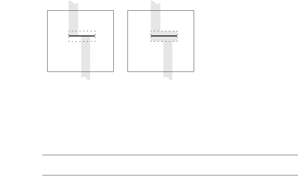
L-Edit 13 User Guide Section 2 391
Chapter 18: Standard Cell Library Designer’s Guide Special Standard Cells
390 (Option 3). In a regular standard cell, it is a good practice to place as many row crosser ports as
design rules and SPR constraints allow. This helps L-Edit increase area efficiency, because if there are
no more row crosser ports in standard cells within a certain row span, L-Edit may have to insert a row
crosser cell.
A row crosser cell is a standard cell that contains only one row crosser port and is placed only to make
up a cross-row pass. In the figure “Signal port positions in standard cells” on page 390 (b), L-Edit will
treat the pairs of port Cross as a crossing pass between the routing channels above and below the
current standard cell row. As with signal ports, it is assumed that the pair are internally connected with
layout geometry in related layers in the standard cell. L-Edit picks pairs of row crosser ports from left to
right. Dotted lines in the figure connect related upper and lower signal ports. The figure “SPR box
generation for design rule correctness of a row crosser port” on page 391 illustrates how L-Edit
automatically generates extra geometry around a row crosser port to ensure design rule correctness at
that location.
Note: Row crosser ports must be placed on the vertical routing layer. SPR will not
recognize such a port when it is placed on the horizontal routing layer.
Special Standard Cells
L-Edit requires three special standard cells to be included in a library cell set. These cells are not
standard cell primitives like the ones included in the netlist; they are for node connections only.
The Tie-to-Power Cell and Tie-to-Ground Cell are needed where a standard cell has a pin directly tied
to Vdd or Gnd. The Row Crosser Cell is a special standard cell that contains only a row crosser port. Its
sole purpose is to allow a connection between two channels located above and below a standard cell
row. The figure “Connection cells in a standard cell set,” below illustrates these three typical connection
cells.
CrossCross
Abut Abut
(b) During SPR, L-Edit
automatically generates a
box in the vertical routing
layer to ensure design rule
correctness.
(a) Dotted line indicates the
region around a cross port
where design rules may
potentially be violated
during SPR.
SPR box generation for design rule correctness of a row crosser port
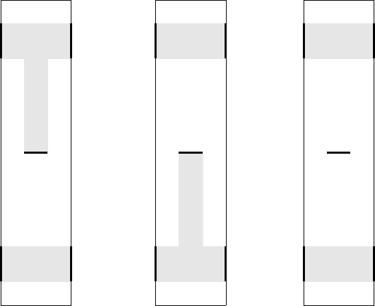
L-Edit 13 User Guide Section 2 392
Chapter 18: Standard Cell Library Designer’s Guide Pad Cells
Although a given SPR operation might not require these three cells—the use of the Tie-to-Power cell or
Tie-to-Ground cell depends on the specific netlist, and the use of row crosser cells depends on the actual
routing condition—L-Edit treats them as prerequisite and elementary parts of the standard cell library.
Specify the names of the Tie-to-Power, Tie-to-Ground, and row crosser cells in the “SPR Core Setup–
General” (page 355) dialog. L-Edit will report an error if any of these three cells are missing in the
standard cell library.
Pad Cells
Abutment Ports
Each pad cell should have a special abutment port whose name is consistent with the entry Pad cell
abutment port in the “SPR Padframe Setup–General” (page 365) dialog. The dimensions of an
abutment port geometry specify the boundaries of the cell to which it belongs. The abutment port must
have the same height in all pad cells in a library set.
Connection Ports Between Pad Cells
When pad cells are placed in a padframe, power buses and signal buses (if specified) run horizontally
across each pad cell. During padframe generation, L-Edit places pads in a user-specified padframe and
fills the gaps between pads with cell connections to assure continuity of power and/or signal buses to all
pads. These interpad connections must have dedicated ports on two sides of the pad cell boundary.
Power ports in all pad cells in a library set must have the same height and the same position along the
Vdd Vdd
Vdd
Gnd Gnd
Abut
Vdd Vdd
Gnd
Gnd Gnd
Abut
Vdd Vdd
Cross
Gnd Gnd
Abut
Tie-to-Vdd Cell Tie-to-Gnd Cell Row Crosser Cell
Connection cells in a standard cell set
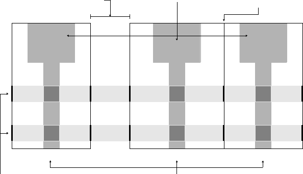
L-Edit 13 User Guide Section 2 393
Chapter 18: Standard Cell Library Designer’s Guide Pad Cells
cell boundary. The existence of interpad connection ports in a particular layer specifies a connection in
that layer.
The figure “Typical pad cells lined up in a segment of a padframe” on page 393 (simplified so that only
straight signal passes and power buses are shown) illustrates connections between pad cells A and B. In
padframe generation, L-Edit can optimize the padframe under certain conditions so that adjacent pads
are attached to each other, as shown between pad cells B and C. In this case, the abutment ports (labeled
Abut) specify the pad cell boundaries and allow L-Edit to abut and align pad cells. The same figure also
shows typical arrangements of power bus ports (on the sides) and signal ports (on the bottoms) in pad
cells.
Signals from Pad to Layout Core
In order to interface with the layout core of a chip, signal ports must be available on the bottom
boundary of a pad cell. A signal port is a zero-height port with its width equal to the layout path of the
dedicated signal.
Power Supply Pads
In padframe generation, L-Edit automatically places one Vdd pad cell and one Gnd pad cell into the
frame. Their cell names can be customized in the “SPR Padframe Setup” (page 365) dialog. A power
supply pad cell is subject to the same structure constraints as a normal signal pad. There must be at least
one pair of power supply pads in a padframe, which provide both power connections to all pads in the
padframe and to the layout core of the chip. It is not necessary to specify these power supply pad cells as
library primitives in your netlist. If your design requires secondary power supply pads, specify them in
the netlist as you would regular signal pads.
Corner Pad Cells
Standard cell libraries must include a special corner pad cell, which is required to complete a padframe.
This cell will be oriented and placed at all four corners of the padframe. A corner pad usually contains
Vdd Vdd Vdd VddVdd Vdd
Gnd Gnd Gnd GndGnd Gnd
Abut Abut Abut
Pad
Cell
A
Pad
Cell
B
Pad
Cell
C
Signal A Signal B Signal C
When two adjacent pad cells are placed
apart from each other in a padframe,
SPR automatically extends power buses
and signals labeled with side ports
Pad cell bonding areas usually SPR aligns adjacent
pad cells according to
their abutment ports
have the same dimensions
Signal ports are available at the bottom of
a pad cell’s abutment port, for routing to the
core circuits of the chip
Power buses for the padframe. The side ports
are necessary to continue signals between pad
cells when they are placed apart from each other
in a padframe
Typical pad cells lined up in a segment of a padframe
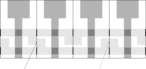
L-Edit 13 User Guide Section 2 394
Chapter 18: Standard Cell Library Designer’s Guide Pad Cells
no active circuit, signal path, or bounding area because it does not directly face the layout core. Corner
cells continue the power bus and other signal connections between two perpendicular sides of the
padframe. They may also contain certain electrostatic discharge (ESD) protection guardbands in
structures as they are built in regular pad cells. For proper extension of power buses and signals, corner
pad cells must meet the same design requirements as regular pad cells. In particular, they must contain
side ports like those created in regular pad cells.
Pad Cells Without Bond Pads
In some cases, a pad cell is needed to fill a gap in a segment of a padframe. Pad cell sets are allowed to
have pad cells without bonding pads. Such a pad will not be bondable, but it can serve as a padframe
spacer cell. L-Edit allows any such unbondable pad cells to occupy a pad slot in the padframe
specification, as specified in the “SPR Padframe Setup” (page 365) dialog. The figure “Mirror-labeled
pads in a padframe” on page 395 illustrates how pad slots are indexed in the SPR Padframe Setup—
Layout dialog. Typical uses of such spacers are as padframe corner cells and padframe spacer cells.
L-Edit requires corner cells to complete a padframe; spacer cells may be useful optional cells when
specific padframe geometry and dimensions are required by a chosen process vendor. Since no signal
paths lead to the layout core of the chip, it is not necessary to include these types of pad cells in the
netlist primitive set.
Pad Orientations
The Mirror switch in the SPR Padframe Setup—Layout dialog, set by typing Yes or No in the Mirror
column of the padlist, instructs L-Edit to mirror an individual pad when placing it in a padframe. This
feature is especially useful when a pad cell contains asymmetrical features that would affect intercell
connections. In the figure “Using a mirrored pad cell in a padframe,” below, pad cell A has a wider
ground bus on the left side and wider power bus on the right. Consequently, a power short exists
between the first pad cell A on the left and its duplicate on the right—i.e., Vdd in the left pad cell A has
been connected to Gnd in the duplicate pad cell A on the right. The power short has been avoided in the
next two duplicated pairs of pad cell A, because the third pad cell A has been placed in its mirrored
orientation.
Vdd Vdd Vdd Vdd
Gnd Gnd Gnd Gnd
Abut Abut Abut
Pad Cell
A (normal)
Signal A Signal A Signal A
Vdd Vdd
Gnd Gnd
Abut Signal A
Vdd Vdd
Gnd Gnd
Pad Cell
A (normal) Pad Cell
A (mirrored) Pad Cell
A (normal)
Using a mirrored pad cell in a padframe
Vdd and Gnd pads are shorted
when Pad Cell A’s are abutted in
normal position.
Vdd and Gnd pads are not shorted
when the duplicate Pad Cell A is
mirrored.
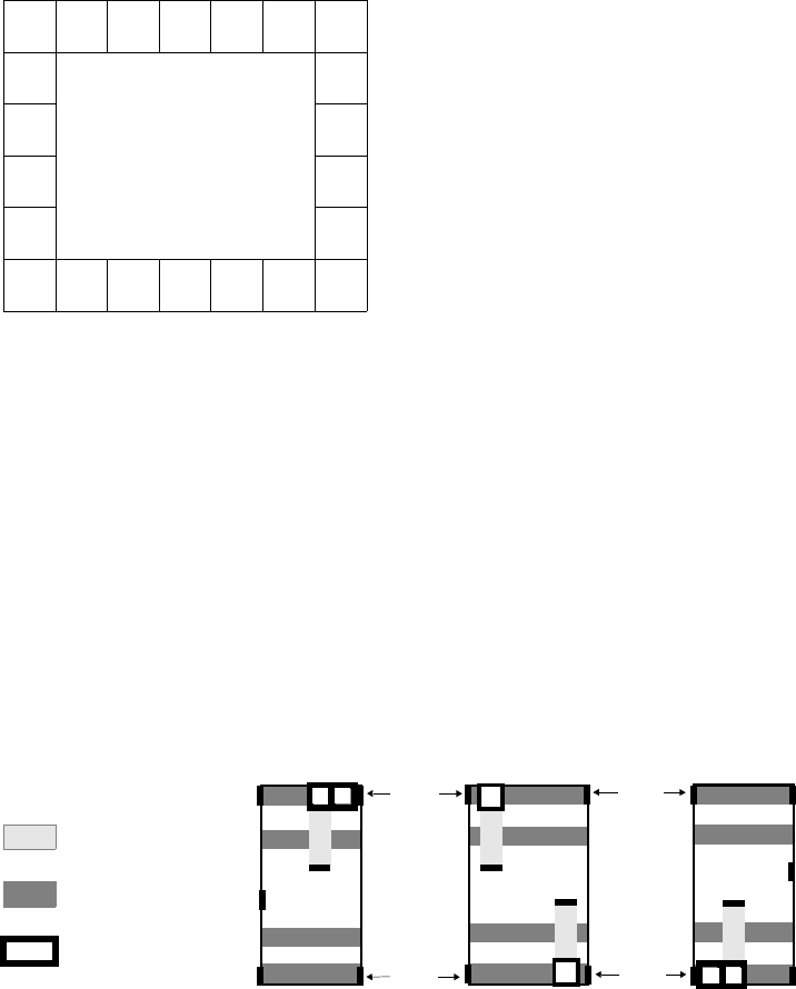
L-Edit 13 User Guide Section 2 395
Chapter 18: Standard Cell Library Designer’s Guide Designing Cells for Global Signal Routing
Mirror Ports
You can specify a Pad cell mirror port in the “SPR Padframe Setup–General” (page 365) dialog.
When L-Edit encounters a pad cell with the specified mirror port name, the program automatically
alters this pad cell’s orientation when placing it adjacent to another pad cell labeled as a mirror port. In
addition, this mirroring feature can be propagated through a padframe’s corner pad cell if the corner pad
cell has also been labeled with a mirror port.
The figure “Mirror-labeled pads in a padframe” on page 395 shows an example of an SPR-generated
padframe with some typical mirroring effects. All pad cells and padframe corner cells contain mirror
ports. Pad cells labeled m are in mirrored orientation, while other cells are on their normal orientation.
Designing Cells for Global Signal Routing
Global Signal Port Definitions
For global input signal routing, standard cells and buffer cells are extended by two global signal buses,
which are located above and below the power buses on the horizontal layer. Each bus contains two ports
(labeled GS1 and GS2 in the following figure). These port names are defined during cell design, and
they thus become part of the cell definition in the standard cell library.
22
1
2
3
4
5
21 20 19 18 17 16
15
14
13
12
67891011
m
m
m
m
mmm
mm
Mirror-labeled pads in a padframe
GS1
VDD
GND
VDD
GND
OUT
IN
GND
VDD
OUT IN
Global signal ports (GS1 and GS2) in standard cells and buffer cells
AB
(a) Left buffer
cell (c) Right
buffer cell
(b) Standard
cell
Horizontal
Routing
Layer
Vertical
Routing
Layer
Via
GS1
GS2 GS2
GS1
GS2
GS1
GS2

L-Edit 13 User Guide Section 2 396
Chapter 18: Standard Cell Library Designer’s Guide Designing Cells for Global Signal Routing
L-Edit 13 User Guide Section 2 396
Chapter 18: Standard Cell Library Designer’s Guide Designing Cells for Global Signal Routing
Global signal port names are assigned to the global input signals in the “SPR Core Setup–Global
Signals” (page 362) dialog. Note that in this dialog, SPR users also assign a specific net name to each
of the global input signals. Thus, the assignment of a global input signal port to each of the global input
signals determines which signal bus (upper or lower) represents a specific global signal net. Because
buffer cells are specifically dedicated to either the upper or lower global signal bus, this port assignment
also determines:
Which global signal rail (left or right) represents a specific global signal net.
The side of the padframe on which the pad of this net is placed.
As an example, let NetA be the name of a signal designated Global Input Signal 1. Assume that the
standard cell library contains buffer cells designed as those shown in the figure “Global signal ports
(GS1 and GS2) in standard cells and buffer cells” on page 395, with the left buffer cell connecting to the
upper global signal bus, which is labeled with the port GS1. If port GS1 is designated as the port for
Global Input Signal 1 (which is NetA), the following will occur:
In the standard cells, the internal signal port for NetA will be connected to the upper global signal
bus because GS1 is its assigned port name.
Because the left-side buffer cell is designed such that it drives the upper global signal bus, the left
global signal rail will carry NetA.
Subsequently, it will be necessary to specify that NetA exit the left padframe edge (see “SPR Pad
Route Setup–Padframe Signals” (page 375)).
Note: Because buffer cells are specifically dedicated to either the upper or lower global
signal bus, buffer cell design determines the relationship between port names and the
side on which the net associated with this port leaves the core. The buffer cell
designer thus determines the side of the padframe to which global signal ports are
ultimately connected.
Buffer Cell Input Ports
Besides meeting all general design constraints imposed on standard cells, buffer cells used in global
input signal routing must also meet the following constraints:
Each buffer cell must contain an input port located on one side of its abutment port. The left buffer
cell has its input port on the left side of its abutment port; the right buffer cell has its input port on
the right side of its abutment port.
Input ports on buffer cells must be vertical ports (height > 0, width = 0) and reside on the vertical
routing layer.
The height of the input port determines the width of the global signal rail connected with it. The width
of the global signal rail will be twice the height of the input port. Buffer cell input port names can be
arbitrary.

L-Edit 13 User Guide Section 2 397L-Edit 13 User Guide Section 2 397
19 Place and Route File Formats
L-Edit standard cell place and route accepts Tanner Place and Route (TPR) and Electronic Design
Interchange Format (EDIF) input files, and generates Standard Delay Format (SDF) and Nodal
Capacitance files (CAP) output files.
TPR Files
L-Edit can use netlist files in Tanner Place and Route (.tpr) format to generate chip layouts. TPR files
are ASCII text files that are generated automatically by the schematic editor S-Edit; they can also be
created with any text editor.
Syntax
A portion of the .tpr netlist file for the bargraph example is shown below.
In the two lines above, DataIn, DataInB, and DataInUnBuf are the names of ports in the pad cell
PadInC (PortList). N68, IPAD_9/N2, and IPAD_9/N1 are the names of nets attached to these ports
(NetList). PAD_L9_SCO is the name given to the body region of the pad. L9 identifies the position of
the pad as the ninth pad from the top on the left side of the padframe.
Comment line $ TPR written by the Tanner Research schematic editor, S-Edit
$ Version: 2.0 Beta 5 Jan 7, 1998 16:07:16
Pad cell definition
Instance definition CP PadOut DataOut Pad;
UPadOut_1 N2 PAD_B1_L31;
:
CP PadInC DataIn DataInB DataInUnBuf Pad;
UPadInC_1 N68 IPAD_9/N2 IPAD_9/N1 PAD_L9_SCO;
:
Ground pad CP PadGnd Pad;
UPadGnd_1 PAD_R8_GND;
Power pad CP PadVdd Pad;
UPadVdd_1 PAD_L6_VDD;
:
Cell definition
Instance definition C INV A Out;
UINV_3 BARGRAPH_1/BG64_2/N9 BARGRAPH_1/BG64_2/SFT3;
:
2
Chapter 19: Place and Route File Formats EDIF Files
L-Edit 13 User Guide Section 2 398
In the three lines above, A, B, Out, and Sel are ports in the standard cell Mux2 (PortList).
BARGRAPH_1/BG64_1/BG4_1/N118, BARGRAPH_1/BG64_1/BG4_1/N108, N62, and
BARGRAPH_1/BG64_1/S11 are the names of nets attached to these ports (NetList). Note that these net
names include the hierarchical structure of the schematic. This is the manner in which S-Edit creates a
“flattened” .tpr netlist. A plus sign (+) indicates a continuation of the previous line.
Interpretation
Pad cells are defined in the format:
CP <padname> <pin1> <pin2> … Pad
U<gateUID> <net1> <net2> … Pad_<PadPosition>
Standard cells are defined in the format:
C <cellname> <pin1> <pin2> …
U<gateUID> <net1> <net2> …
A .tpr file must conform to the following rules:
All signals which are to be routed within the core or from the core to the padframe are required to
be listed, with the exception of the Vdd and Gnd signal connections to pads.
For each cell, the PortList and NetList must have the same number of elements.
The name “PAD” in the PortList of a pad cell refers to the actual bonding region of the pad, and is
not actually involved in the placement and routing process. Pad cells must have a signal marked
“PAD.”
The bonding region of a pad can contain the location of the pad on the padframe. For example,
“B1” stands for the leftmost pad on the bottom side of the padframe (L = Left, B = Bottom, R =
Right, T = Top).
Power and ground pads do not have to be included in the netlist. If they are not included, SPR will
place them automatically.
The parts listed in the file must match the cells contained in the layout library. To match, the name
of the part must be identical to the name of the library cell (except for case), and every signal listed
in the part description must have at least one port of the same name somewhere in the library cell.
EDIF Files
Netlist files in Electronic Design Interchange Format (EDIF) are used by SPR to place and route a
design. EDIF netlist files typically have a filename extension of .edf, .edn, or .edi.
SPR requires flattened EDIF netlists or netlists with one level of hierarchy.
L-Edit supports flattened EDIF version 2 0 0 with EDIF level 0, keyword level 0, and netlist view—
(edifLevel 0), (keywordLevel 0), and (viewType NETLIST) files. Other view types are ignored.
C Mux2 A B Out Sel;
UMux2_1 BARGRAPH_1/BG64_1/BG4_1/N118 BARGRAPH_1/BG64_1/BG4_1/N108
N62
+ BARGRAPH_1/BG64_1/S11;
Chapter 19: Place and Route File Formats EDIF Files
L-Edit 13 User Guide Section 2 399
The netlist parser is limited to one netlist view label per netlist. If the netlist contains more than one
netlist view, L-Edit warns you and ignores subsequent, different view labels.
All cell properties will be transferred to the relating instance. Properties with no relation to a netlist
view will be ignored. L-Edit currently supports the use of properties with regard to the labeling and
positioning of pads and I/O signals. If an EDIF netlist contains both pad properties and I/O signals, only
the pads will be considered. L-Edit provides an optional warning when both appear in a netlist, which
may be disabled using Setup > Application > Warnings.
The parser is limited to one design—(design designname (…))—per EDIF netlist file.
External EDIF library definitions—(external libraryname (…))—are treated in the same way as
normal EDIF library definitions—(library libraryname (…)). Furthermore, the parser considers only
library information present in the current EDIF netlist file.
A mapping table is generated if cell names or port names in the EDIF netlist differ from those used in
the cell library. L-Edit automatically accesses the Mapping Table dialog whenever it encounters a cell
or port name discrepancy between the EDIF netlist and the standard cell library. You can also access
this dialog via the SPR Setup dialog. The mapping information is stored in the TDB design file.
Syntax
The following example shows excerpts from an EDIF netlist containing pad cells, I/O signals and
critical nets. If pad cells and I/O signals are both included in the netlist, the pad cell configuration has
precedence over I/O signals.
(edif bargraph
(edifVersion 2 0 0)
(edifLevel 0)
(keywordMap (keywordLevel 0))
(status
(written
(timestamp 1998 11 01 07 5 00)
(program "S-Edit" (version "Version 2.06"))))
(library bargraph_top
(edifLevel 0)
(technology (numberDefinition (scale 1 (E 1 -12) (unit CAPACITANCE))))
(cell bargraph_top
(cellType GENERIC)
(status
:
(view view_1
(viewType NETLIST)
(interface
(port ClB (comment "I/O Signal")
(property PIN_LOCATION (string "L2"))
(direction INPUT))
:
(instance PadInC_1
(viewRef view_1 (cellRef PadInC))
(portInstance DataIn)
(portInstance DataInB)
:
(property PAD (string "L1")) (comment "Pad")
:
(net N54
(joined
(portRef DataInB (instanceRef PadInC_5))
:
)
(criticality 100) (comment "Net criticality")
)
Chapter 19: Place and Route File Formats EDIF Files
L-Edit 13 User Guide Section 2 400
(net N55
(joined
(portRef ClB) (comment "Reference to an I/O Signal")
:
)
)
:
)
))
)
(design ROOT
(cellRef bargraph_top
(libraryRef bargraph_top)))
)
Interpretation: Pads
Pad cells are defined by creating a property named PAD with a value such as L1 in the pad cell instance.
The following formats are supported:
(property PAD (string "L1"))
or
(property PAD (string "1"))
The string value determines the position of the pad, counting counterclockwise. (In this example, the
pad is placed on the upper-left position of the padframe.) In the first format, the sides of the padframe
are labeled with L (left), B (bottom), R (right), and T (top). The subsequent number determines the
position on this side. The second format labels the pad position with only a numeric value ( > 0). The
resulting position is determined according to this value, counting counterclockwise, starting from the
upper left position on the padframe. In other words, pad position L1 is equal to pad position 1. To avoid
ambiguity, it is recommended that only one format be used in the same netlist file.
Pads with no string value attached, e.g., (property PAD (string "")), are equally distributed around the
padframe.
Interpretation: I/O Signals
If you intend to generate an SPR core cell only, you don't need to specify pad cells. In this case, ports
assigned to the top-level cell in your EDIF netlist can be assigned to I/O signals leaving the core. Please
note that I/O signals will only be considered if the netlist does not contain pad cells. (If both are present,
pad cells will be considered and I/O signals will be ignored.)
I/O signals are defined through the EDIF interface keyword. When SPR reads the netlist, it uses the
I/O signals designated in the interface section to initialize the core I/O signals setup (SPR > Setup >
Core Setup—I/O Signals dialog). You can change the signal location in this dialog to suit your design.
In most schematic editors, when you define pins or ports to a schematic or symbol, they are designated
as I/O signals. The following is an example showing the I/O signal CLK:
(interface
(port CLK
(direction INPUT)
)
Chapter 19: Place and Route File Formats EDIF Files
L-Edit 13 User Guide Section 2 401
In the above example, no pin position has been provided. In this case, the signal CLK will be equally
distributed with the other I/O signals around the core during placement. (A specific I/O signal position
can be defined in the (SPR Core Setup—I/O Signals dialog.)
Alternatively, you can also provide an I/O signal port position as shown below:
(interface
(port CLK
(direction INPUT)
(property PIN_LOCATION (string "L2"))
)
This example will place the I/O signal CLK on the second position (top to bottom) on the left side of the
core. The EDIF property PIN_LOCATION with the property value 1, 2, … or L1, L2, ...., B1, … , R1, …,
T1… indicates the relative position in which the I/O signals will be placed around the core, counting
counter-clockwise.
Interpretation: Criticality
Critical nets are defined by using the criticality construct in EDIF. SPR considers critical nets during
placement optimization. Criticality is expressed as an integer value. It may be positive (this net is given
a higher priority for placement purposes) or negative (this net is given a lower priority during
placement). The default value for any net that is not specified with a criticality value is zero.
The consideration of net criticality in SPR is based on two assumptions:
The numerical value of the criticality describes the relative importance of a net compared to others.
For example, if the criticality of net A is twice the criticality assigned to net B, then the placer
considers it twice as important to reduce the length of net A compared to net B.
The critical values are scaled internally according to the largest value that has been entered, with
the largest value assigned to a fixed internal value. For example, if net A is the only net with an
assigned criticality, then any criticality value greater than zero for this net would lead to the same
result.
Additional Notes
An EDIF netlist file must conform to the following rules:
An EDIF netlist component (e.g., cell, port) must be defined completely before it can be used.
If your cell interface in the EDIF file contains ports which are not connected in your design, you
can label them as “not used” during the mapping process.
All signals that are to be routed within the core or from the core to the padframe must be listed,
with the exception of VDD and GND signal connections to pads.
Power and ground pads do not have to be included in the netlist. If they are not included, L-Edit
places them automatically in accordance with the power and ground rails.
The range of integer numbers is –231+1 ≤ x ≤ 231-1 (32-bit signed integers). Real numbers are valid
in a range of –1 × 1035 ≤ y ≤ 1 × 1035. The length of a string is limited to 256 characters. The length
of a line is limited to 512 characters.
The array construct (array arrayname (...)) in a name definition is limited to one- or
two-dimensional arrays.
Chapter 19: Place and Route File Formats SDF Files
L-Edit 13 User Guide Section 2 402
Valid EDIF identifiers consist of alphanumeric or underscore characters, and must be preceded by
an ampersand (&) if the first character is not alphabetic. Thus, “pure” integer numbers are not
allowed as identifiers.
An ampersand (&) at the beginning of an identifier will be ignored. The case of a character is not
significant. For example, &Nand2, Nand2, and nand2 all represent the same EDIF name.
References
A complete description of the EDIF standard is contained in the Electronic Industries Association (EIA)
publication, Electronic Design Interchange Format Version 2 0 0 (ANSI/EIA Standard 548-1988),
Electronic Industries Association, 1988, ISBN 0-7908-0000-4.
SDF Files
Pin-to-Pin Delay Syntax
(DELAYFILE
(SDFVERSION "OVI Standard 3.0")
(DESIGN "bargraph")
(DATE "02/22/1999")
(VENDOR "Tanner Research, Inc.")
(PROGRAM "L-Edit/SPR")
(VERSION "8.0")
(DIVIDER /)
(VOLTAGE)
(PROCESS)
(TEMPERATURE)
(TIMESCALE 1ps)
(CELL
(CELLTYPE "bargraph")
(INSTANCE bargraph)
(DELAY
(ABSOLUTE
(INTERCONNECT NAND_1/C NOR_2/A (0.005))
(INTERCONNECT NAND_1/C NOR_2/B (0.003))
etc.
)
)
)
)
Interpretation
The pin-to-pin delay is generated in the OVI SDF Specification Standard 3.0:
INTERCONNECT <port_instance_1> <port_instance_2> (<delay>)
port_instance_1 is an output or bi-directional port. port_instance_2 is an input or bi-directional port.
delay is the interconnect delay between the output and the input ports.
The DESIGN entry in the SDF file header indicates the name of the design—that is, the name of the
TDB file.
Chapter 19: Place and Route File Formats CAP Files
L-Edit 13 User Guide Section 2 403
The CELLTYPE entry indicates the name of the cell—either the chip cell name (if pad route is included)
or the core cell name (if core route only).
CAP Files
L-Edit standard cell place and route calculates the nodal capacitances and other characteristics of the
interconnect and outputs this information to a nodal capacitance file with the extension .cap.
Syntax
The following is an example of a CAP file.
$ -------------------------------------------------------------------------------
$ Nodal Capacitance File : D:\ledit_files\v8_shipping\example3\bargraph.cap
$ SPR Date and Time: 02/27/1999 - 8:00
$
$ H1 layer-to-substrate cap. - Area : 36 aF/sq.micron Fringe : 0.086 fF/micron
$ V layer-to-substrate cap. - Area : 11 aF/sq.micron Fringe : 0.077 fF/micron
$ H2 layer-to-substrate cap. - Area : 7 aF/sq.micron Fringe : 0.031 fF/micron
$
$ H1 layer-to-V layer cap. - Area : 31 aF/sq.micron
$ V layer-to-H2 layer cap. - Area : 28 aF/sq.micron
$ H1 layer-to-H2 layer cap. - Area : 10 aF/sq.micron
$
$ 1 Locator Unit (LU) = 1/1 Lambda = 7/20 Micron(s)
$
$
$ Node CapacitanceNo ofLength Area Area Area
$ Terminalsof Nodeon H1 on V on H2
$ (1/100 pF) (LU) (LU^2) (LU^2) (LU^2)
$ --------------------------------------------------------------------------------
N4 6 9 5964.400678.000010567.20013296.000
N27 7 2 6046.000975.000012480.0009366.000
N26 2 2 2452.0000.00004479.0005754.000
N25 9 2 7589.0002373.000011829.00017130.000
N24 5 2 4062.0000.00003936.00016500.000
:::::::
N12 1 2 599.5000.00001798.5000.0000
$ --------------------------------------------------------------------------------
$
$ Length of all nets (LU) : 1893584.90
Interpretation
Each line in the file is in the format:
node capacitance NoOfTerminals Length AreaOnH1 AreaOnV AreaOnH2
where:
node Name of the node.
capacitance An integer denoting capacitance of this node in hundredth of a
picofarad.
Chapter 19: Place and Route File Formats CAP Files
L-Edit 13 User Guide Section 2 404
For a detailed description of how nodal capacitances are calculated, see “Output Options” on page 380.
NoOfTerminals Number of pins attached to the node.
Length Length of the interconnect of the node.
AreaOnH1 Area of the route taken by the node on the H1 layer.
AreaOnV Area of the route taken by this node on the H2 layer.
AreaOnH2 Area of the route taken by this node on the H2 layer.

L-Edit 13 User Guide Section 3 405
20 Introduction to Design Verification
Design Verification in L-Edit
This section of the L-Edit User Guide describes the design verification features of L-Edit:
Standard DRC — an easy to use design rule checker with setup dialog
HiPer Verify — a powerful design rule checker supporting Calibre and Dracula syntax
Extract — a netlist extraction tool
LVS — a layout-vs.-schematic comparison application
LVL — a layout-vs.-layout comparison wizard
Chapter 22, DRC Standard Rules (page 414) describes L-Edit ⁄DRC Standard. Standard DRC features
user-programmable rules and handles minimum width, exact width, minimum space, minimum
surround, non-exist, overlap, and extension rules. It can run a full-chip or region-only DRC. Error
markers allow you to quickly and easily locate design rule violations.
Chapter 23, HiPer Verify: Calibre Command Files (page 426) and Chapter 24, HiPer Verify: Dracula
Command Files (page 594) describe HiPer Verify. HiPer Verify features the ability to run Calibre and
Dracula format command files without modification or translation. HiPer Verify features a larger set of
available commands than DRC Standard, the ability to reprocess results with conjunctive rules, plus the
ability to run DRC as a background process. It is fully integrated in the layout editor, and results are
placed directly into an error navigator for viewing.
Chapter 26, Extracting Layout (page 685) describes Extract, the netlist extractor. Extract creates
SPICE-compatible circuit netlists from L-Edit layouts. It can recognize active and passive devices,
subcircuits, and the most common device parameters, including resistance, capacitance, length, width,
area, and source and drain area.
Chapter 28, Getting Started with LVS (page 740), Chapter 29, LVS Output Tutorial (page 766), Chapter
31, Netlist Comparison (page 794) and Chapter 32, LVS Command-Line Syntax (page 802) discuss
LVS, or layout versus schematic, a tool that compares two netlists to determine whether they describe
the same circuit. When they do not, LVS works in conjunction with L-Edit to identify and correct
errors.
L-Edit also provides a handy tool, layout versus layout (or LVL) which compares two L-Edit layout
files for differences in their geometry. This feature is described in Chapter 25, Layout vs. Layout (page
678).
Syntax and usage for the file formats used in design verification are detailed in Chapter 30, Design
Verification File Formats (page 778).
Section 3Section 3: Design Verification

L-Edit 13 User Guide Section 3 406
21 DRC Setup
Design rules, in their simplest form, are usually minimum allowable values for widths, separations,
extensions, and overlaps of and between geometrical objects. The exact nature of design rules is
dependent on specifications supplied by the foundry to which the design will be submitted for
fabrication.
To check a layout for design rule violations involves two basic steps:
Define the rules that are acceptable for your design.
Run the design rule checker, on the entire design or a portion of it.
The commands Tools > DRC (for whole cells) and Tools > DRC Box (for limited regions) run a design
rule checker, which determines whether a design obeys a specific set of rules. Design rule violations are
saved in the TDB file. You can then step through and display design rule violations using the
Verification Error Navigator. A summary report of design rule violations is also saved in the TDB file.
Design Rule Sets
Design rules are supported in three formats:
Tanner DRC Standard Rule Set— Tanner format, with graphical setup interface.
Mentor Graphics Calibre® compatible format — text format command file.
Cadence Dracula® compatible format — text format command file.
Setting Up DRC
To run DRC you must first load and select the rule sets you want to run. You add and select rule sets
from the Setup DRC dialog. The Tanner DRC Standard Ruleset is loaded by default. To use it, simply
click on its checkbox.
You also use this dialog to set the order in which rule checks are executed, and as a shortcut to open the
windows where rule sets can be edited.
Note that checkmarks in the Setup DRC list control only which rule sets to run. All other functions in
the setup dialog are performed on the rule set that is highlighted.
3
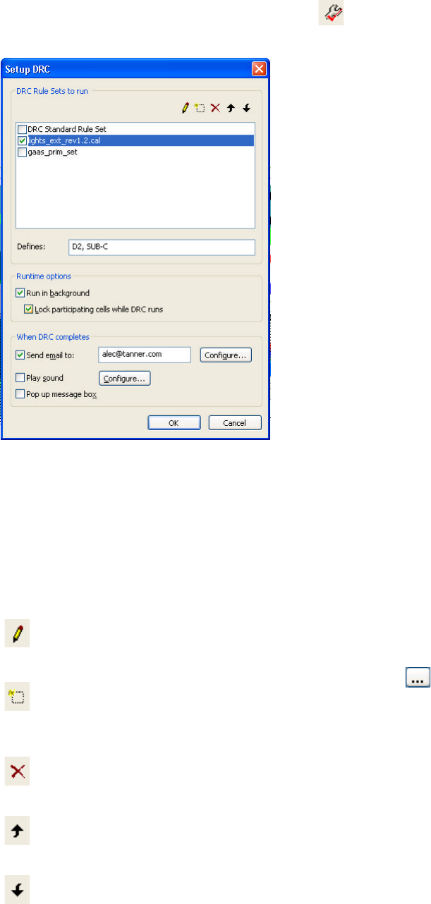
L-Edit 13 User Guide Section 3 407
Chapter 21: DRC Setup Setting Up DRC
Use Tools > DRC Setup, or press the Setup DRC icon ( ) in the verification toolbar, to open Setup
DRC.
DRC Rule Sets to run Lists the DRC command files that are loaded and available to run.
DRC Standard Rule Set is the built in Tanner rule set which is loaded
by default. It cannot be deleted from the list.
Only those rule sets that have their checkboxes in the “checked” state
will be run when DRC is invoked.
Edit selected command file
()
Opens the selected rule set for editing. If DRC Standard Rule Set is
highlighted, the Setup DRC Standard Rule Set dialog opens. If a
command file is selected, then that file opens in a text window.
Add command file to list
()
Press this button to add a new entry to the list of command files. You
can browse to and select a file with the ( ) button.
Delete command file from
list
()
Removes the highlighted command file from the list.
Move Up
()
Moves the highlighted command file up in the list.
Move Down
()
Moves the highlighted command file down in the list.
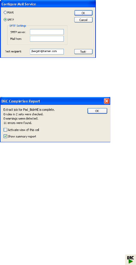
L-Edit 13 User Guide Section 3 408
Chapter 21: DRC Setup Running DRC
Running DRC
When your layout is complete, you should check for design rule violations before sending the layout to
the chip foundry for fabrication. If a chip is fabricated with design rule violations, it may fail to function
as designed.
You can run DRC against an entire cell or a specific region (“DRC box”) of the cell.
Design Rule Check on a Full Cell
To perform a rule check on the entire layout of the active cell, select Tools > DRC ( ).
Defines Use this field to enter variable or variable and value combinations to
trigger preprocessor commands that are written in the rule files using
#DEFINE and #IFDEF.
Run in background Check this box to run DRC in background. When DRC is run in
background, you can continue to edit and perform other L-Edit
operations while DRC is running. DRC results are returned as soon as
they are found, so you can browse and correct errors before the entire
DRC job is complete.
Lock participating cells
while DRC runs Locks the cell, and all hierarchy below that cell, to prevent edits while
DRC is running.
Send E-mail to: Enter an E-mail address to send notification to the specified recipient
when the Extract job is complete. Use Configure to set the E-mail
options shown below. Note that most E-mail applications will require
a response prior to sending an E-mail initiated from another
application.
Play sound Check to play a sound when DRC is complete. You can configure the
sound from the standard Windows sounds available.
Pop up message box Opens a DRC Completion Report when DRC is complete.
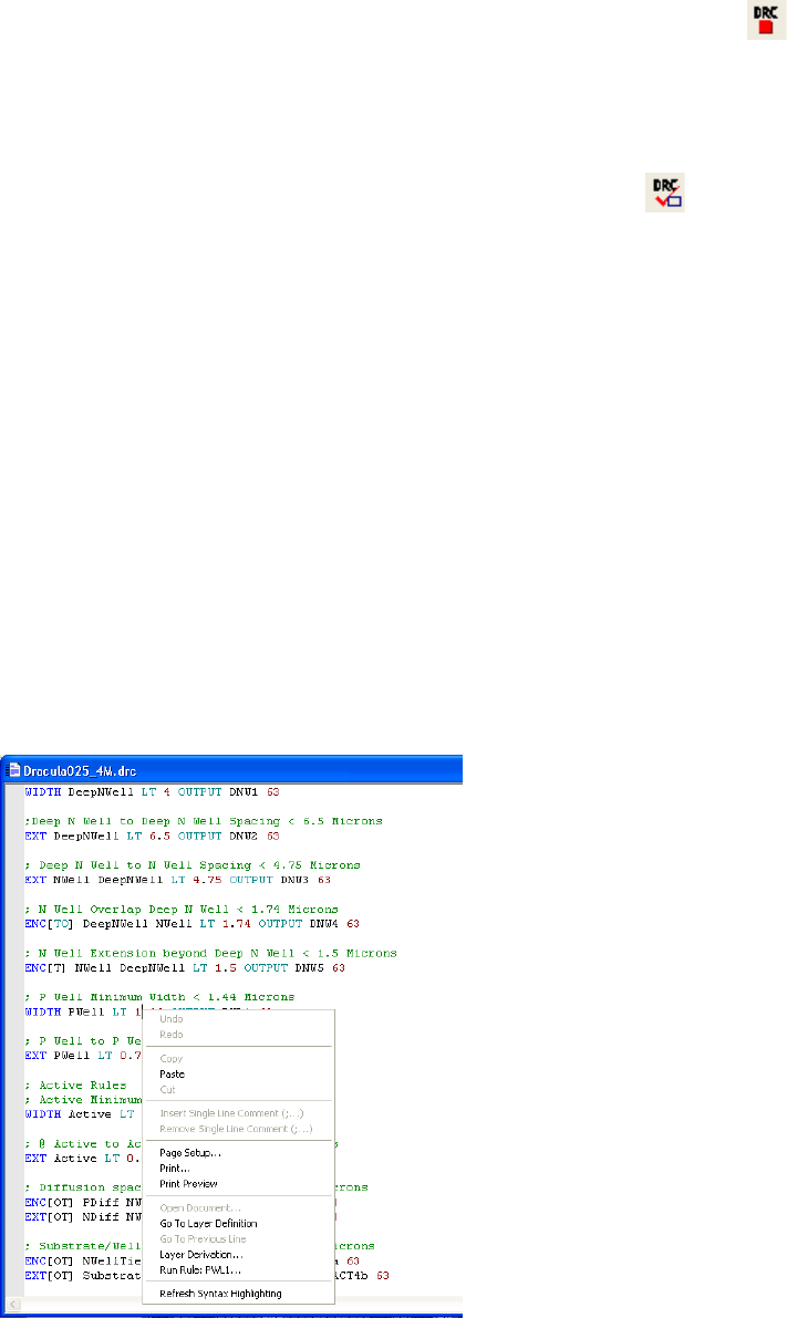
L-Edit 13 User Guide Section 3 409
Chapter 21: DRC Setup Running DRC
This button is a toggle, so that during the design check it functions as a stop button ( ). If you stop a
DRC run, L-Edit prompts for a confirmation and opens a DRC completion report indicating that the job
was terminated prior to completion.
Region-Only Design Rule Check
To perform a rule check on just an area of a cell, use Tools > DRC Box ().
Run a region-only check when a restricted area or group of objects in the layout needs to be checked for
design rule errors. A region-only check is useful for interim verification during layout creation or to
confirm that a design rule violation in a specific region has been corrected.
To perform a region-only check, select Tools > DRC Box then click and drag in the layout (you will be
using the DRAW mouse button) to outline the rectangular area of the layout to be checked. The outline
will only be visible while DRC is running.
Objects inside or intersecting the region are processed in the DRC Box check. Objects intersecting the
region are not clipped to the region. As a result, violations can be reported when running region-only
DRC that are not present when DRC is run on the entire cell, due to the exclusion of objects outside the
region. If this happens, making the region larger should reduce these false errors.
Single Rule Check from a Command File
You can run a single rule in a command file by placing the cursor on the desired rule in the command
file, right-clicking the mouse, and selecting Run Rule rulename. This will run the selected rule on the
entire cell.
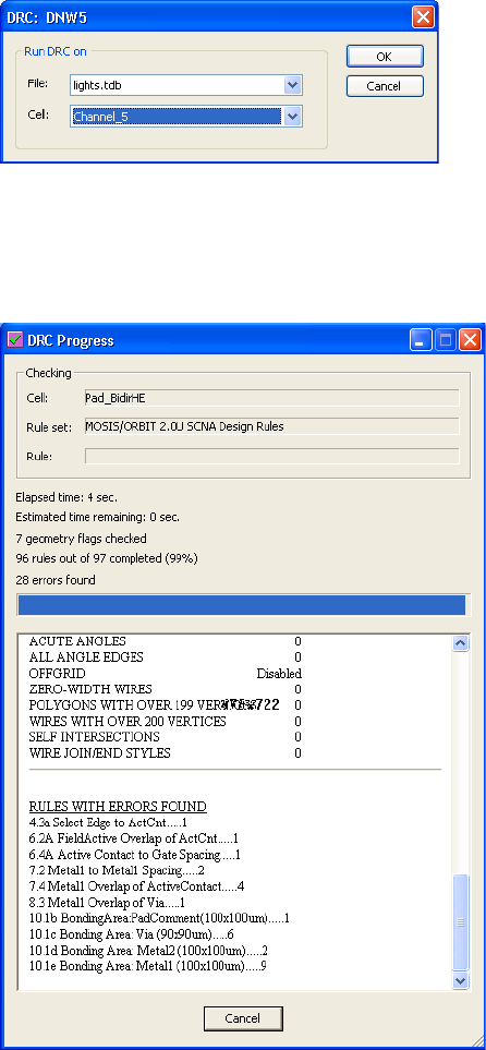
L-Edit 13 User Guide Section 3 410
Chapter 21: DRC Setup Running DRC
After you invoke Run Rule, L-Edit opens a dialog where you can choose the file and cell on which to
run the specified rule.
DRC Progress
While DRC is running, L-Edit displays a progress dialog similar to the following:
The progress dialog displays the cell, the rule set, and the name of the current rule being checked, as
well as the elapsed time, the estimated time remaining in the DRC run, the number of flags checked and
rules completed, and the number of errors found.
For each rule for which errors are found, the dialog lists the rule name and the corresponding number of
violations. The contents of the progress dialog are saved in the DRC Summary Report. The DRC
Summary Report may be opened at any time from the Verification Error Navigator, by invoking
Actions > Open DRC Summary Report.
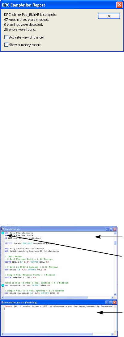
L-Edit 13 User Guide Section 3 411
Chapter 21: DRC Setup Command File Syntax Checking
Notification of DRC Completion
DRC can be configured to notify you upon completion with either a brief summary report, a sound, or
both. This is especially useful when running DRC in background. To configure DRC to present a
message box upon completion, select Pop up message box in the Setup DRC dialog. The dialog
shown below will be presented when the DRC job is complete.
To configure DRC to play a sound upon completion, select Play sound in the Setup DRC dialog. Press
the Configure button to invoke the standard Windows sound selection dialog.
Command File Syntax Checking
L-Edit DRC includes a syntax checker for checking the validity of command files. The syntax checker
should be used to verify the correctness of command files before running DRC, and also when you
create new command files. To invoke the syntax checker, select Tools > Check Syntax (shortcut key
F6).
Activate view of this cell Opens the cell that the DRC job was run on. This is useful when
running DRC in background, and a different cell may currently be
open.
Show Summary Report Displays the DRC summary report in a text window. See summary
reports, below.
Command file window
Error bookmark
Error window
L-Edit 13 User Guide Section 3 412
Chapter 21: DRC Setup DRC Status
A window will open below the command file window listing syntax errors and warnings.
Double-clicking the cursor on a line in the error window will scroll the command file window to
the corresponding error.
Bookmarks will also be placed in the command file window on the line corresponding to each
syntax error. You can use Edit > Go To Next Bookmark (shortcut key F2) and Edit > Go To
Previous Bookmark (shortcut key Shift+F2) to navigate through the errors. Edit > Clear All
Bookmarks (shortcut key Ctrl+Shift+F2) clears all bookmarks.
DRC Status
Each cell has a DRC Status setting, which can be one of the following states:
Needed — DRC has never been run on the cell, or edits have been made since last run.
Passed — DRC has been run on the cell, and no violations were found.
Failed — DRC has been run on the cell, and violations were found.
Running DRC on a cell will set the DRC Status flag for the cell to either Passed or Failed. The DRC
status flag is set only for the toplevel cell from which the DRC job is invoked, even though instances of
other cells checked in the process. Editing a cell after DRC has been run on that cell will revert it’s
status back to Needed. Any change to the DRC Setup, including changes to Layer Setup, will also
cause the DRC Status of all cells to revert to the Needed state.
The DRC status of all cells may be viewed in the Design Navigator (See “DRC Status” on page 213), or
for any single cell it may be viewed in the Cell > Info dialog (See “Cell Information” on page 226). The
DRC Status may also be manually changed in the Cell > Info dialog.
Excluding Cells from DRC
Instances of specified cells can be excluded from DRC. To mark a cell for exclusion from DRC, select
Exclude instances of this cell from DRC in the Cell > Info dialog of the cell.
Marking a cell for exclusion from DRC is particularly useful for logo cells, which typically contain
DRC violations that can be ignored.
Debugging DRC Results with Generated Layers
When debugging DRC results, it is often useful to be able to generate and visualize the derived layers
that are used in a rulecheck command.
Generating Layers
You can generate any of the derived layers within the global scope of a command file with a single
command, Tools > Generate Layers (see “Generating Derived Layers” (page 297) for more details).
Global scope consists of any definition not within the braces ({,}) of a rulecheck statement.
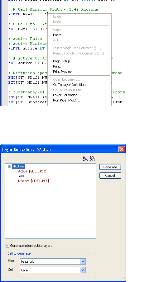
L-Edit 13 User Guide Section 3 413
Chapter 21: DRC Setup Debugging DRC Results with Generated Layers
Generate Layers directly from a Command File
You can also generate a single layer in a command file by placing the cursor on the desired layer
definition in the command file, right-clicking the mouse, and selecting Layer Derivation in the context
sensitive menu. Layers defined in either global and local scope of a rulecheck statement can be selected.
When you execute Layer Derivation from a command file, L-Edit opens a dialog that displays the
derivation tree for the layer, and allows you to generate that layer as well as intermediate layers in the
derivation. You also choose the file and cell for which to generate layers.
Pressing the Generate button will generate the selected layer. Intermediate layers in the derivation can
be included by checking the Generate intermediate layers checkbox.

L-Edit 13 User Guide Section 3 414L-Edit 13 User Guide Section 3 414
22 DRC Standard Rules
Design Rule Sets
It is not usually necessary to create design rules sets from scratch. If you have a previous design file that
uses a set of rules similar to those you want to employ in your current design, you can modify the rule
set from the previous design.
In general, you must perform the following three steps to create or edit a design rule set:
[1] Determine which rules must be specified. Fabrication services or foundries are typically able to provide
design rule sets.
[2] Determine which generated layers, if any, will be needed to implement each rule in the set. Define these
layers using Setup > Layers (see “Layer Setup” on page 104).
[3] Enter the rules in the Setup Design Rules dialog—see “Specifying DRC Standard Design Rules” on
page 422.
Setups
The design rule set is part of the setup specification that characterizes every L-Edit design. This setup
should be established before you start any new design. Again, it is not usually necessary to create this
setup from scratch. If you have a design file that uses the same or a set of rules similar to those you want
to employ in your current design, you can modify the rule set from the previous design.
To use existing rules in a new file, you can either copy a previous design setup to the new file, or you
can combine rules from different designs in a new setup. These two methods are described below.
Copying Setup Information to a New File
There are three ways to copy setup information to a new file:
Copy a design file. The copy will automatically contain the same setup information as the original
design file.
Create a new file while a file with the desired setup information is active. The new file will
automatically contain the same setup information.
Import from a TDB file. Use the command File > Replace Setup to copy the setup information
from the specified file to the active file. See “Replacing the Setup” on page 75.
If necessary, you can modify design rules in the new or copied file using the Setup Design Rules
dialog (see “Specifying DRC Standard Design Rules” on page 422).
Combining Rules from Different Files
You can combine design rules from TDB files as follows:
3
L-Edit 13 User Guide Section 3 415
Chapter 22: DRC Standard Rules Design Rule Types
Start by opening the design file into which you want to introduce additional rules. In that file, use
the Setup Design Rules dialog to delete the design rules that you do not want to keep.
Create any additional needed layers, including generated layers, and remove any unused layers.
You should be careful in this step to create all and only the required layers. Design rules associated
with missing layers will not work properly. No design rules will be specified for extra layers, so
layout errors on those layers will not be detected.
Specify the TDB file from which existing rules are to be taken in the Replace Setup Information
dialog (see “Replacing the Setup” on page 75). Enter the name of the source file, uncheck all the
options except DRC rules, and click OK. L-Edit reads the specified setup, including design rules,
into the active file.
Generated Layers
You can specify design rules for generated layers just as you would for other layers. When you use
generated layers in the specification of a design rule, L-Edit⁄DRC automatically generates objects on
those layers then deletes these objects when the check is complete.
Following the DRC run, L-Edit automatically deletes objects on generated layers that were created
during the DRC run. If Enable Derivation is off in the Setup Layers—Derivation dialog, then DRC
doesn’t generate or delete the derived layer.
For information about defining generated layers, see “Generating Layers” on page 284.
Exporting DRC Standard Rules to Calibre Format
You can export DRC setups in DRC Standard Rule format to Calibre format to use as a starting point
for writing more advanced rule sets in text file format. To export DRC Standard rule to a text file, select
Tools > DRC Setup from the menu, then highlight DRC Standard Rule Set and press the Edit button to
open the Setup DRC Standard Rule Set dialog. Press the Export to Command File button.
Design Rule Types
L-Edit supports seven types of design rules. Each of these rule types is described below, with specific
examples shown in the accompanying figures.
“Minimum Width” (page 416)
“Exact Width” (page 416)
“Not Exist” (page 416)
“Spacing” (page 416)
“Surround” (page 417)
“Overlap” (page 417)
“Extension” (page 417)
“Density” (page 418)
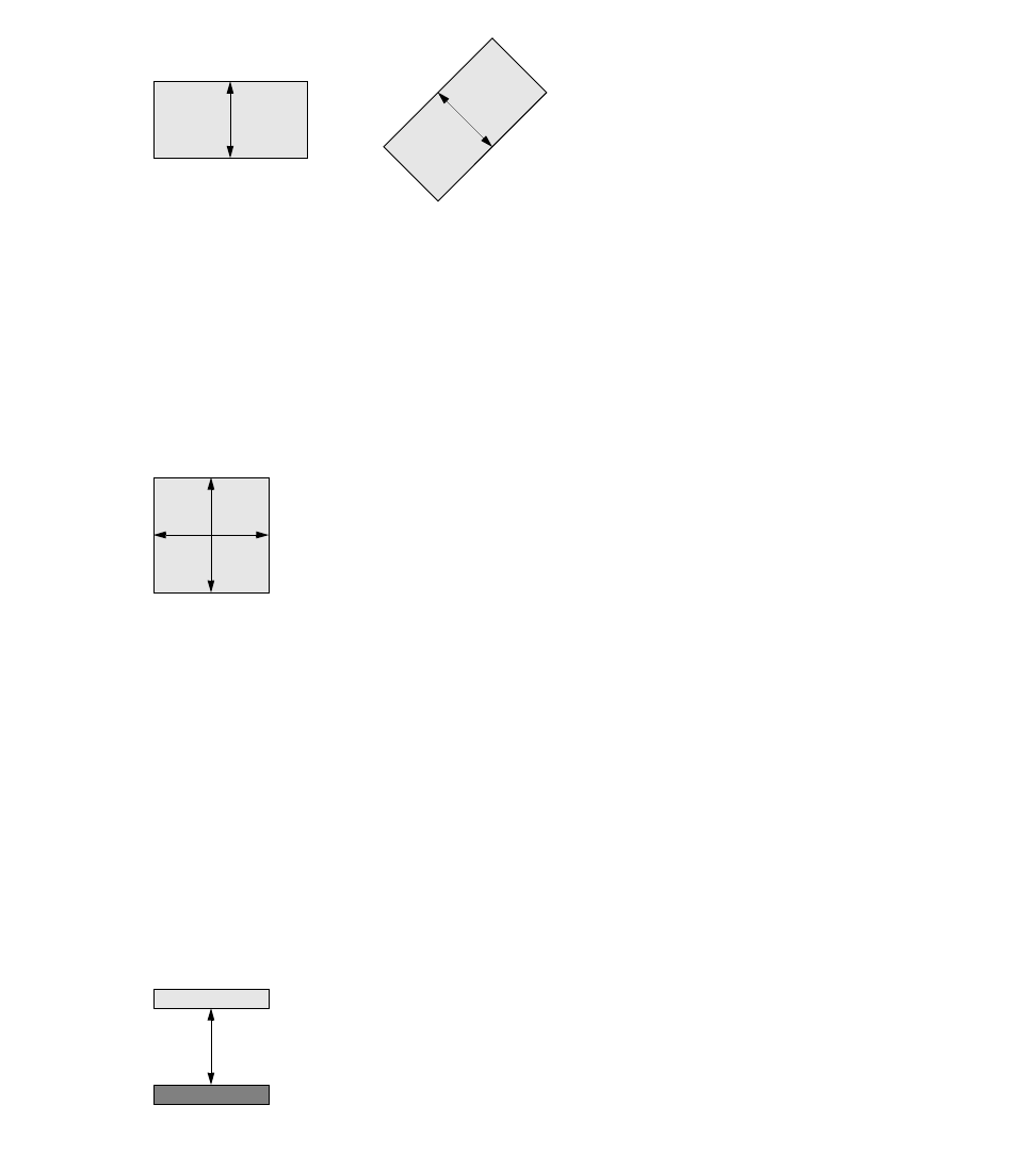
L-Edit 13 User Guide Section 3 416
Chapter 22: DRC Standard Rules Design Rule Types
Minimum Width
Minimum width rules specify the minimum width of all objects, in any direction, on the named layer.
You can specify exceptions for this rule type as described in “Rule Exceptions” on page 418.
Exact Width
Exact width rules specify the exact width of all objects on the named layer.
Not Exist
Not exist rules specify that no objects should exist on the named layer. Not exist rules are unique in
having no associated distance.
Spacing
Spacing rules specify the minimum distance that should separate all pairs of objects, either on the same
layer or two different layers.
You can specify exceptions for this rule type as described in “Rule Exceptions” on page 418.
Poly Minimum Width = 2 lambda
Poly Contact Exact Width = 2 lambda
Via to Poly Contact Spacing = 2 lambda
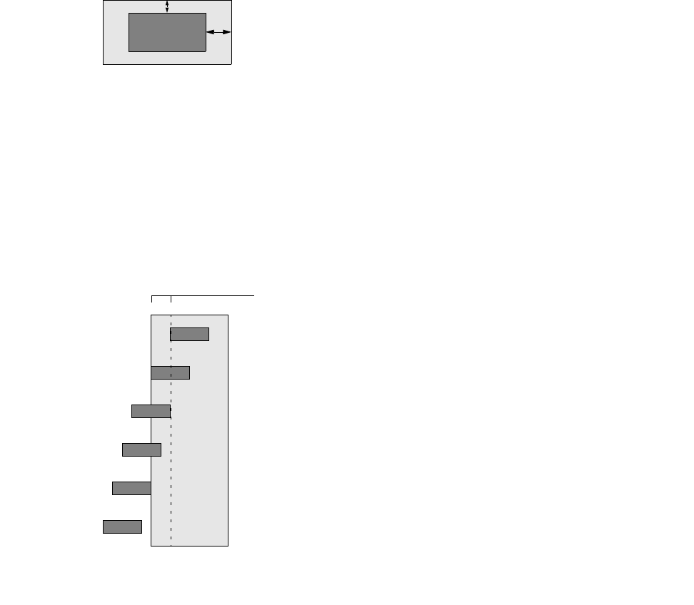
L-Edit 13 User Guide Section 3 417
Chapter 22: DRC Standard Rules Design Rule Types
Surround
Surround rules specify that objects on one layer must be completely surrounded by objects on another
layer.
You can specify exceptions for this rule type as described in “Rule Exceptions” on page 418.
Overlap
Overlap rules specify the minimum amount that an object on one layer must overlap an object on
another layer (when there is an overlap). Objects which overlap more than the specified distance or
whose edges coincide are not considered in violation of overlap rules.
Extension
Extension rules specify the minimum amount that an object on one layer must extend beyond the edge
of an object on another layer. Objects are not considered in violation of extension rules when they:
Extend more than the specified distance
Have a coincident edge but are otherwise outside
Are entirely surrounded
Metal2 Surround Via = 1 lambda
Rule distance
OK
OK
OK
Violation
OK
OK
Poly Contact Overlap Poly = 2 lambda
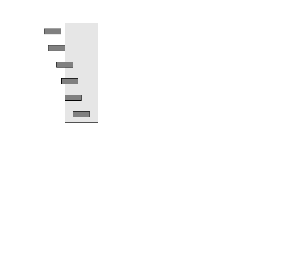
L-Edit 13 User Guide Section 3 418
Chapter 22: DRC Standard Rules Design Rule Types
Density
The density rule finds and flags objects on the derived density layer specified in Layer1. The layer
specified must be a Density type derived layer. Violations to the rule include any polygons output to a
density layer.
See “Density Layer Derivations” on page 296 for a description of density layers.
Rule Exceptions
You can fine-tune some rules by specifying particular layout conditions that are not to be reported as
violations. These conditions are represented by the Ignore options in the dialog Setup Design Rules
(see “Specifying DRC Standard Design Rules” on page 422).
Condition Description Applicable rules
Coincidences Coincident edges between objects are
ignored. Surround
Intersections Intersections between objects are ignored. Surround
If layer 2 completely
encloses layer 1 Objects on one layer entirely surrounded
by objects on another layer are ignored. Spacing
If layer 1 completely
outside layer 2 Objects on one layer entirely outside
objects on another layer are ignored. Surround
Acute angles Errors caused by acute angles (less than
90°) are ignored. Minimum width
Spacing
Surround
Rule distance
OK
OK
OK
Violation
Violation
OK
Poly Contact Extend Poly = 2 lambda
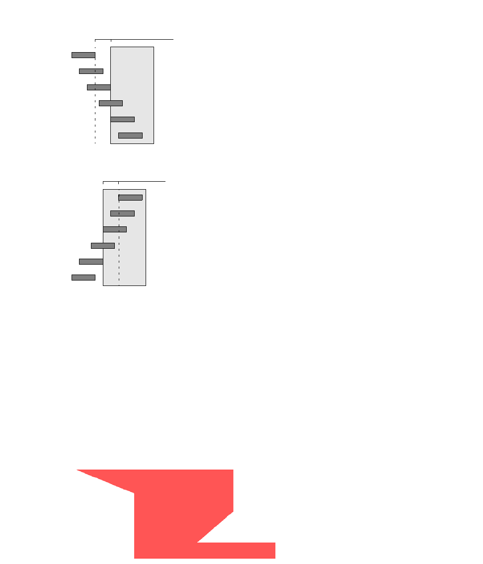
L-Edit 13 User Guide Section 3 419
Chapter 22: DRC Standard Rules Design Rule Types
The following illustration shows exception conditions for spacing and surround rules.
Acute Angles
When two consecutive edges of a polygon form an acute angle, the distance between them always goes
to zero at the vertex. This means that acute angles, by definition, will lead to violations of minimum
width and minimum spacing rules in DRC.
By checking the option Ignore: Acute angles, you can instruct L-Edit to ignore violations caused by
acute angles. This option does not exclude objects with acute angles from the design rule check. Instead,
it suppresses errors that result from an acute angle in the layout.
For example, consider the following all-angle polygon drawn on layer Poly:
Rule distance
Always OK
Always a violation
OK if Coincidences checked; otherwise a violation
OK if Intersections checked; otherwise a violation
OK if If layer 2 … encloses layer 1 checked; otherwise a violation
OK if If layer 2 … encloses layer 1 checked; otherwise a violation
Rule distance
Always OK
Always a violation
OK if Coincidences checked; otherwise a violation
OK if Intersections checked; otherwise a violation
OK if If layer 1 … outside layer 2 checked; otherwise a violation
OK if If layer 1 … outside layer 2 checked; otherwise a violation
Spacing
Surround
Rule distance
Always OK
Always a violation
OK if Coincidences checked; otherwise a violation
OK if Intersections checked; otherwise a violation
OK if If layer 1 … outside layer 2 checked; otherwise a violation
OK if If layer 1 … outside layer 2 checked; otherwise a violation
Surround
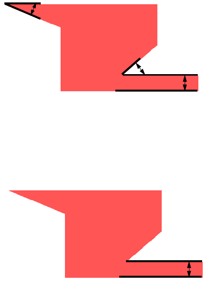
L-Edit 13 User Guide Section 3 420
Chapter 22: DRC Standard Rules Design Rule Types
Checking this object for minimum width would ordinarily yield three violations, as marked here:
Running the same design rule check with the option Ignore: Acute angles, however, ignores those
violations that are caused by an acute angle. With these errors excluded, L-Edit reports only one
violation.
Flag to Append Special Commands
When L-Edit runs a standard DRC rule, the DRC engine first converts the rule to Calibre format. You
can use the special flag “|||” after a design rule to instruct the DRC engine to append any commands that
follow the ||| characters to the Calibre rule.
For example, when Display curves using manufactured grid is checked, L-Edit will convert curved
objects to polygons, with vertices that snap to the manufacturing grid. DRC treats these segment as
separate objects, and if they cause a spacing violation will generate hundreds of violations.
While you can limit the number of errors reported for a single DRC rule, the limitation applies even
when the errors come from different cell instances. Similarly, temporarily increasing the size of the
manufacturing grid can decrease the number of DRC errors, but also changes the geometry to an
inaccurate representation of the object.
Instead, you can use the “|||” flag at the end of the name of the spacing rule to pass special conditions to
the DRC engine. In the following example, the “Projecting” command is used to instruct DRC to
consider only those edges that project onto each other by more than one manufacturing grid.
Standard DRC rule:
Rule name: Min. Permolloy Width
Type: Min Width
Rule distance: 650um
Layer1: Permolloy
Min. spacing
Min. width
Min. width
Min. width
L-Edit 13 User Guide Section 3 421
Chapter 22: DRC Standard Rules Design Rule Types
Equivalent Calibre format rule:
"Min Permalloy width" { @ < 650 Microns
INTERNAL Permalloy < 650 SINGULAR
SAVE "Min Permalloy width::Result"
}
Standard DRC rule with ||| flag:
Rule name: Min Permalloy width ||| PROJ > 5
Type: Min Width
Rule distance: 650um
Layer1: Permolloy
Equivalent Calibre format rule with ||| flag:
"Min Permalloy width" { @ < 650 Microns PROJ > 5
INTERNAL Permalloy < 650 PROJECTING SINGULAR
SAVE "Min Permalloy width::Result"
}
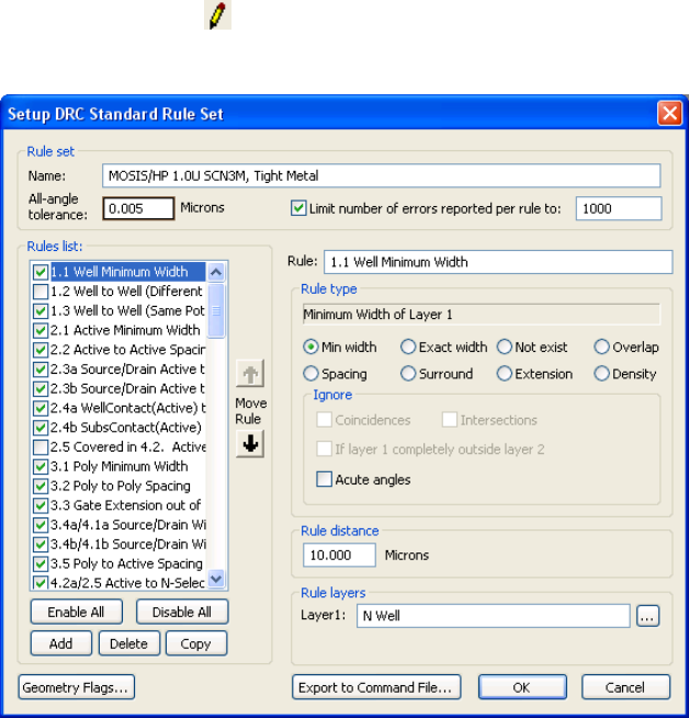
L-Edit 13 User Guide Section 3 422
Chapter 22: DRC Standard Rules Specifying DRC Standard Design Rules
Specifying DRC Standard Design Rules
Select Tools > DRC Setup from the menu, highlight DRC Standard Rule Set in the rule set list, then
press the Edit button ( ) to open the Setup DRC Standard Rule Set dialog, which allows you to
modify the DRC standard design rules.
Rule set Name identifies the design rule set.
All-angle tolerance is a value T, common to all rules in the set, which
together with the distance D for each rule (see below) determines the
precision of error checking. A distance on the layout must be less than
D- T to be flagged as a violation. The All-angle tolerance is only
applied if one of the two edges being compared is non-orthogonal.
Limit number of errors reported per rule to is an integer T, with a
default value of 1000.
L-Edit 13 User Guide Section 3 423
Chapter 22: DRC Standard Rules Specifying DRC Standard Design Rules
Geometry Flags
During DRC, each drawn layer is checked for geometry violations. Hidden layers are not checked. Use
the Geometry Flags dialog to specify geometry configurations that L-Edit will flag as errors during
Rules list The list of available rules. The checkbox next to each rule indicates if
the rule is currently enabled. Enabled rules will be checked when
DRC is run.
You can alter the Rules list with the following options:
Enable All—Enables all valid rules in the Rules list.
Disable All—Disables all rules in the Rules list.
Add—Adds a new rule to the Rules list. To add a rule, click
Add, then type the name of the new rule in the Rule field.
Delete—Deletes the highlighted rule.
Copy—Adds a copy of the highlighted rule to the Rules list. The
copy is placed underneath the original rule, with “Copy of”
preceding the rule name.
Move Rule—Click the up or down Move Rule arrows to
reposition the highlighted rule.
Rule The name of the rule highlighted in the Rules list. Rule type, Ignore,
Rule distance, and Rule layers all pertain to the uniquely named
rule.
Rule type Selected by clicking the appropriate option button. See “Design Rule
Types” on page 415 for information on the supported types.
Ignore Cases which will not be considered a design rule violation. Options
include:
Coincidences
Intersections
If layer 1 completely outside layer2
Acute angles
See “Rule Exceptions” on page 418 and “Acute Angles” on page 419
for further information on the use of these options.
Rule distance The distance value associated with a rule. Distances are measured
either in display units. You can change the display units using the
pull-down menu in the locator bar.
Rule layers DRC specifies which layers are involved in each of the design rules.
For example, selecting the Spacing rule type automatically specifies
Minimum Layer [ ] to Layer [ ] spacing. To specify a rule layer, open
the Setup Layers dialog, then choose from the layer list.
Geometry Flags... Opens the Geometry Flags dialog for flagging instances of specific
geometry configurations. (See “Geometry Flags” on page 423.)
Geometry flags are counted as errors during a DRC run.
Export to Command File Exports the DRC ruleset to a textual command file. The ruleset is
opened in a text window, which can then be saved to disk.
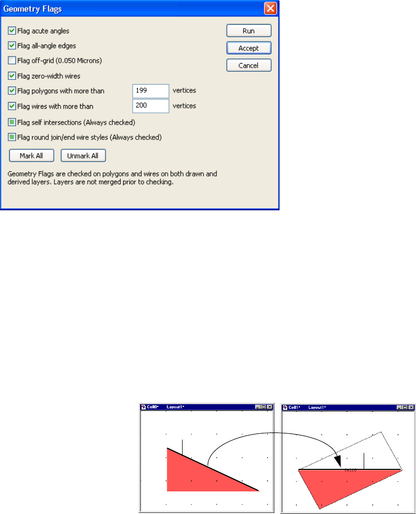
L-Edit 13 User Guide Section 3 424
Chapter 22: DRC Standard Rules Specifying DRC Standard Design Rules
DRC. To access this dialog, click the Geometry Flags button at the bottom of the Setup Design Rules
dialog.
Flag acute angles Reports an error whenever two consecutive edges of a polygon or
wire on a drawn layer form an acute angle (less than 90 degrees).
These errors are reported in a rule named “Polygons and wires with
acute angles (<900).”
Flag all-angle edges Reports an error when an all-angle edge (i.e., neither orthogonal nor
45 degrees) is found in a polygon on a drawn layer. All-angle edges
are measured in cell coordinates; an edge is flagged as all-angle if it is
neither orthogonal nor 45 degrees as it occurs in the cell in which it
was drawn.
Because angles are measured in cell coordinates, instance rotations do
not affect which edges are flagged as all-angle:
Errors are reported to a rule named “All-Angle edges.”
Flag off-grid Reports an error when an off-grid vertex or instance is found. Wires
are checked using their centerline vertices. Errors are reported to a
rule called “Offgrid objects.”
The number in parentheses gives the gridsize, in display units, used to
determine offgrid objects and vertices. The gridsize used is the
Manufacturing Grid size, which you can specify in
Setup > Application—Grid.
All-angle edge
Rotated instance
All-angle edge
L-Edit 13 User Guide Section 3 425
Chapter 22: DRC Standard Rules Optimizing Performance
Optimizing Performance
Design rule checking is a complicated, computation-intensive process that involves large numbers of
comparisons and measurements. Some DRC runs can result in very long execution times. This section
outlines several ways to achieve faster results.
Checking Incrementally
Use region-only checks at convenient stopping points in the design process. Performing region-only
checks will also help prevent compounding of errors which might require extensive layout modification
to correct. Use the full-cell check for completed cells and at least once on the final design.
Hiding Layers
DRC does not check rules involving layers hidden at execution time. Once you have examined and
repaired all violations involving particular layers, you can hide these layers and reduce execution times
for subsequent DRC runs involving other layers.
Disabling Rules
Use the checkboxes in Setup Design Rules to enable (checked) or disable (unchecked) rules you do
not need. Alternately you can use the ||| flag to append Calibre rules to —see “Flag to Append Special
Commands” on page 420.
Flag zero-width wires Reports an error whenever a wire with zero width is found on a drawn
layer.
Flag polygons with more
than N1 vertices Reports an error whenever a polygon with more than the specified
number of vertices is found on a drawn layer.
Flag wires with more than
N2 vertices Report an error whenever a wire with more than the specified number
of vertices is found on a drawn layer.
Flag self intersections
(Always checked) Reports an error whenever a self intersecting polygon or wire is found
on a drawn layer. The perimeter boundary of the wire is checked and
reported for self intersections, not the centerline. Self intersecting
polygons and wires are not processed further by the DRC engine.
Flag round join/end wire
styles (Always checked) Reports an error whenever a wire with round join/end style is found
on a drawn layer. Wires with the round join/end style are processed
by the DRC engine, but are approximated as layout style.

L-Edit 13 User Guide Section 3 426L-Edit 13 User Guide Section 3 426
23 HiPer Verify: Calibre Command
Files
Introduction
This section provides the reference to Calibre compatible DRC command file format.
Function Overview
Functions are arranged in the following categories.
“Case Sensitivity” (page 427)
“Environment Setup” (page 431)
“Operating Commands” (page 435).
“Hierarchy Modification Commands” (page 449)
“Geometry Flags” (page 455)
“Drawn Layer Definitions” (page 468)
“Connect and Connectivity Related Commands” (page 474)
“Polygon Boolean Operations” (page 502)
“Utility Layer Generation Operations” (page 507)
“Polygon Size Operations” (page 515)
“Two Layer Polygon Selection Operations” (page 520)
“Single Layer Polygon Selection Operations” (page 530)
“Polygon Area Operations” (page 537)
“Polygon-Edge Operations” (page 542)
“Edge Length and Angle Operations” (page 546)
“Edge Selection Operations” (page 552)
“Dimensional Check Operations” (page 561)
“Text Based Operations” (page 578)
“Unsupported Commands” (page 592)
3
L-Edit 13 User Guide Section 3 427
Chapter 23: HiPer Verify: Calibre Command Files
Case Sensitivity
Keywords are always case-insensitive. Names are case-insensitive unless used for cell names or file
names. RuleCheck names, layer names, net names, variable names, and so forth, are always
case-insensitive
New Line Insensitivity
The statements that appear in a rule can begin anywhere on a line and can span lines. In addition,
statements and operations need not each begin on a new line.
Preprocessor Commands
#DEFINE, #IFDEF, #ELSE, and #ENDIF are supported as a mechanism of conditionally executing
blocks of commands.
Comments
Commands may be commented out using C-Style (/* … */) and C++ Style (//) comments characters.
C-Style comments may span multiple lines. C++ Style comments extend from the comment characters
to the end of the line.
Constraints
Many operations require a mathematical constraint as one or more of the input parameters. The
constraint is usually applied to either a count of the number of some quantity, or to the measurement of
some distance. Constraints are expressed as follows:
< a
> a
<= a
>= a
= = a
!= a
> a < b
>= a < b
> a <= b
>= a <= b
Where "a" and "b" are non-negative numbers. Not all operations permit all constraints.
Numeric Expressions
A numeric expression can be used to specify any numeric parameter in any layer operation. Numeric
expressions can also be used to define variables in a Variable specification statement. A numeric
L-Edit 13 User Guide Section 3 428
Chapter 23: HiPer Verify: Calibre Command Files
expression is a combination of numeric constants, numeric variables, the unary "+" and "-" operators,
and the binary "+", "-", "*", "/", and "%" operators.
Reserved Symbols
The following are reserved symbols and may not be used in layer names or rule names in the command
file.
// @ = { } " ' ( ) [ ] < == > <= >= != - + * / ! % && || :: , /* */
Reserved Keywords
The following words are reserved keywords and may not be used as layer names or rule names in the
command file.
Command Usage
Commands can be used as layer derivation statements, or in RuleCheck statements. Layer derivations
that appear outside of Rule Check statements are referred to as “global” derivations. Layer derivations
inside of Rule Check statements are referred to as “local” derivations.
A layer derivation statement consists of directing the results of a command to a named layer.
GATE = POLY AND ACTIVE
An implicit layer definition consists of a matched pair of parenthesis containing a layer definition.
NTRAN = (POLY AND ACTIVE) NOT NWELL
abut
acute
and
angle
angled
area
by
coin
coincident
convex
copy
corner
cut
donut
drawn
drc
enc
enclose
enclosure
exclude
expand
ext
extend
extent
extents
external
factor
flag
flatten
group
grow
holes
in
include
inside
int
interact
internal
intersecting
layer
length
measure
merge
not
obtuse
offgrid
opposite
or
out
outside
overlap
para
parallel
perimeter
perp
perpendicular
polygon
precision
proj
projecting
rectangle
rectangles
region
resolution
shrink
singular
size
snap
square
step
title
touch
variable
vertex
with
xor
L-Edit 13 User Guide Section 3 429
Chapter 23: HiPer Verify: Calibre Command Files
A RuleCheck statement consists of a name followed by a left brace “{”, followed by a sequence
consisting of either layer derivations or dimensional checks, followed by a right brace “}”:
A Rule Check Statement directs the results of a command to the Verification Error Navigator, with
the specified rule name.
rule-name1 {
EXT GATE < 2.0
}
Rule check statements have the following properties:
Multiple commands within a Rule Check Statement are allowed.
rule1 {
EXT GATE < 2.0
INT GATE < 2.0
}
Layer derivations such as "Z = Layer1 AND Layer2" are allowed within a rule check statement.
Layer Z is local in scope within that rule, and can be used by commands within that rule.
rule2 {
GATE = POLY AND ACTIVE
INT GATE < 2.0
}
Any command, not only dimensional check operations, may be used to direct errors to the
Verification Error Navigator. For example
rule3 {
VIA OUTSIDE METAL
}
Rule Check comments are text following the @ symbol, to the end of the line. Multiple Rule Check
comment line are allowed. Rule check comments are displayed in the Verification Error Navigator
along with the rule name.
rule4 { @ Rule check comment
@ Second comment line
GATE = POLY AND ACTIVE
INT GATE < 2.0
}
Implicit layer definitions are allowed within dimensional check operations (ENC, EXT, INT).
Implicit layer definitions may not be used with dimensional check operations when the edge
directed output options [ ] or ( ) are used.
rule5 {
EXT (POLY AND ACTIVE) < 2.0
}
L-Edit 13 User Guide Section 3 430
Chapter 23: HiPer Verify: Calibre Command Files
Intermediate Layer Rules
Edge Directed Output
The output of a dimensional check operation (ENC, EXT, INT) can be put on an edge layer by
surrounding one of the input layers in the operation with brackets [ ] or parenthesis (). The edge layer
may then be processed by other commands.
Enclosing a layer in brackets is called positive edge-directed output, and returns the edges on the layer
that are normally flagged by the rule.
Enclosing a layer in parenthesis is called negative edge-directed output, and returns the edges on the
layer that would not normally be returned by the rule.
Only one edge-directed output specification may appear in a single dimensional check operation.
Edge-directed output specifications apply to Internal, External, and Enclosure.
rule-name {
Z = EXT [layer1] < n1
LENGTH Z > n2
}
rule-name {
Z = EXT [Layer1] Layer2 < n1
LENGTH Z < n2
}
Polygon Directed Output
The output of a dimensional check operation (ENC, EXT, INT) can also be put on a polygon layer by
using the REGION option. The polygon layer may then be processed by other commands.
rule-name {
Z = INT Metal1 < n1 REGION
EXT Z > n2
}
L-Edit 13 User Guide Section 3 432
Chapter 23: HiPer Verify: Calibre Command Files Environment Setup
TITLE
TITLE
TITLE rulesetname
Description
Specifies the title of the rule set. This command can appear only once in the command file.
Parameters
Examples
TITLE “DRC command file for 0.18 micron process”
rulesetname A text string.
L-Edit 13 User Guide Section 3 433
Chapter 23: HiPer Verify: Calibre Command Files Environment Setup
PRECISION
PRECISION
PRECISION number
Description
Specifies the ratio of user units to database internal units. This statement has the same meaning as
“Database resolution” in L-Edit Setup >Design, and must have the same value. This command can
appear only once in the command file. The default PRECISION is 1000 if this command is not present.
Parameters
Examples
PRECISION 1000 // 1000 database units per micron
number A positive integer that defines the database resolution
L-Edit 13 User Guide Section 3 434
Chapter 23: HiPer Verify: Calibre Command Files Environment Setup
RESOLUTION
RESOLUTION
RESOLUTION {s | sx sy}
Description
Specifies the grid size for offgrid checking by the FLAG OFFGRID command. This command can
appear at most once in the command file.
Parameters
Examples
RESOLUTION 100 // define a one tenth micron grid for FLAG OFFGRID
sA positive integer that specifies the x-direction and y-direction grid
size for off-grid checking.
sx A positive integer that specifies the x-direction grid size for off-grid
checking.
sy A positive integer that specifies the y-direction grid size for off-grid
checking.
L-Edit 13 User Guide Section 3 435
Chapter 23: HiPer Verify: Calibre Command Files Operating Commands
RESOLUTION
Operating Commands
Operating commands control high level aspects of the DRC job.
“DMACRO and CMACRO” (page 436)
“DRC MAXIMUM RESULTS” (page 439)
“DRC PRINT AREA” (page 440)
“DRC PRINT PERIMETER” (page 441)
“DRC SELECT CHECK” (page 442)
“DRC TOLERANCE FACTOR” (page 443)
“DRC UNSELECT CHECK” (page 444)
“GROUP” (page 445)
“INCLUDE” (page 446)
“SVRF ERROR” (page 447)
“VARIABLE” (page 448)
L-Edit 13 User Guide Section 3 436
Chapter 23: HiPer Verify: Calibre Command Files Operating Commands
DMACRO and CMACRO
DMACRO and CMACRO
Description
Macros are functional templates, similar to the macros of the C and C++ languages, that can be called
multiple times in a rule file.
Defining Macros—DMACRO
A macro definition consists of the keyword DMACRO (define macro), a name, zero or more arguments,
followed by "{" bracketing a sequence of zero or more verification statements or operations, closed by
"}".
DMACRO names must be unique, each argument must be a name, and an argument may not be
duplicated in the same DMACRO argument list.
Ordinary nesting rules for left and right braces prohibit nested DMACRO definitions.
Invoking Macros—CMACRO
A macro is invoked by the keyword CMACRO (call macro), followed by a macro name and a list of
zero or more arguments. Each argument may be either a name or a numeric constant. The name must
match that of some DMACRO definition, and a sufficient number of arguments must be present after
the CMACRO name. The DMACRO definition between the braces is placed in the CMACRO call, with
argument substitution.
When a DMACRO is instantiated in a CMACRO, the layer definition names defined in the DMACRO
are locally-scoped You do this by generating a name that is unique with in the rule file for each layer
definition in the DMACRO construct when the DMACRO is instantiated. References to layer definition
names in the DMACRO are also substituted appropriately, as shown in the shown width_checks
example.
A DMACRO definition may itself contain nested CMACROs. However, recursion is not allowed, so no
CMACRO can call a DMACRO that contains a call to that same CMACRO.
Rule Files
You can use macros to derive layers; however, a DMACRO definition used to derive layers, either
locally or globally, may not have any intermediate derived layers. For example, this is allowed:
DMACRO ex1 layer constraint {
(size layer BY constraint UNDEROVER) and layer
}
x = CMACRO ex1 metal1 .01 // global
rule_1 {
x = CMACRO ex1 metal1 .01 // local
copy x
}
Notice that DMACRO ex1 has no intermediate derived layers in it, so deriving x, as shown, will work in
either local or global scope. However, the following example demonstrates a problematic syntax:
DMACRO ex2 layer1 layer2 constraint{
int_layer = layer1 or layer2
//intermediate derived layer
L-Edit 13 User Guide Section 3 437
Chapter 23: HiPer Verify: Calibre Command Files Operating Commands
DMACRO and CMACRO
size int_layer BY constraint UNDEROVER
}
x = CMACRO ex2 in1 in2 .01
// Bad. intermediate layer exists in ex2
Notice DMACRO ex2 has an intermediate derived layer in it. This means ex2 should not be used in a
layer derivation, because the scoping of intermediate derived layers in a DMACRO cannot generally be
used to derive other layers.
Any of the rule file comment characters may be used in a macro definition; however, user comments
will not appear in the DRC results database. User comments should be placed in the rule check that calls
the DMACRO.
Examples
PRECISION 1000
RESOLUTION 100
LAYER Poly 46
LAYER Active 43
LAYER Metal1 49
LAYER Metal2 51
LAYER EmptyLayer 100
// Simple Macro
DMACRO WideLayout layer value {
(SIZE layer BY value UNDEROVER) and layer
}
WidePoly {
CMACRO WideLayout Poly 1.5
}
// Local scoping
// Example showing that layer definitions are locally scoped.
// Layers A and B are scoped locally within the macro
// so there is no confusion between the two CMACRO calls
// in the same rulecheck.
DMACRO WidthCheck layer size_val wid_val {
A = SIZE layer BY -size_val
B = SIZE A BY size_val
INT B < wid_val
}
widthChecks {
CMACRO WidthCheck Poly 1.0 5.0
CMACRO WidthCheck Metal1 1.0 5.5
}
// Nested Macros
DMACRO NarrowLayer layer size_val {
INT layer <= size_val
}
DMACRO NarrowLayout layer1 layer2 size_value {
CMACRO NarrowLayer layer1 size_value
CMACRO NarrowLayer layer2 size_value
}
L-Edit 13 User Guide Section 3 438
Chapter 23: HiPer Verify: Calibre Command Files Operating Commands
DMACRO and CMACRO
Narrows {
CMACRO NarrowLayout Metal1 Poly 1.0
}
L-Edit 13 User Guide Section 3 439
Chapter 23: HiPer Verify: Calibre Command Files Operating Commands
DRC MAXIMUM RESULTS
DRC MAXIMUM RESULTS
DRC MAXIMUM RESULTS {maxresults | ALL}
Description
Specifies the maximum number of errors that will be reported for a DRC Rule. You can only specify
this statement once in a rule file. When the maximum results are generated for a rule, a warning is
issued, and no additional results are added to the Verification Error Navigator.
For the Geometry Flags, FLAG ACUTE, FLAG OFFGRID, and FLAG SKEW, a maximum of 100
errors are always reported.
Parameters
maxresults A positive integer that specifies the maximum result count for an
individual RuleCheck in DRC execution. If this statement is not
included, the default value is 1000.
ALL A required secondary keyword that specifies that there is no
maximum result count, for an individual RuleCheck in DRC.
L-Edit 13 User Guide Section 3 440
Chapter 23: HiPer Verify: Calibre Command Files Operating Commands
DRC PRINT AREA
DRC PRINT AREA
DRC PRINT AREA layer [… layer]
Description
Prints the area of the specified layers to the DRC Summary Report. This statement can appear multiple
times.
Parameters
Examples
DRC PRINT AREA metal1 metal2
layer A drawn or derived polygon layer.
L-Edit 13 User Guide Section 3 441
Chapter 23: HiPer Verify: Calibre Command Files Operating Commands
DRC PRINT PERIMETER
DRC PRINT PERIMETER
DRC PRINT PERIMETER layer [… layer]
Prints the perimeter of the specified layers to the DRC Summary Report. This statement can appear
multiple times. This operation requires flattening the layer and can therefore be time consuming.
Parameters
Examples
DRC PRINT PERIMETER metal1 metal2
layer A drawn or derived polygon layer.
L-Edit 13 User Guide Section 3 442
Chapter 23: HiPer Verify: Calibre Command Files Operating Commands
DRC SELECT CHECK
DRC SELECT CHECK
DRC SELECT CHECK rule_check …
Description
Provides selective inclusion of specified RuleCheck statements or RuleCheck Groups in the DRC job.
By default all rules are included.
RuleCheck statements are selected for inclusion as follows:
1. If there are no DRC Select Check specification statements in the rule file then all rules are included.
Otherwise, only those RuleChecks specified in DRC Select Check statements are included.
2. All RuleChecks specified in any DRC Unselect Check specification statements in the rule file are
then excluded.
Parameters
Examples
DRC SELECT CHECK PO.S1 PO.S2 PO.S3
rule_check A list of RuleCheck or Group names.
L-Edit 13 User Guide Section 3 443
Chapter 23: HiPer Verify: Calibre Command Files Operating Commands
DRC TOLERANCE FACTOR
DRC TOLERANCE FACTOR
DRC TOLERANCE FACTOR tolerance
Description
Reduces false errors on all angle DRC rule check operations. The tolerance is applied to distance
measurement operations whose constraint is of the form “< d” when either one of two edges being
compared is non-orthogonal. In this case, the constraint value is decreased by the given tolerance (to no
more than 0) prior to the actual measurement. This command can appear only once in the command file.
Parameters
Examples
DRC TOLERANCE FACTOR 0.005
tolerance A positive real number in user units that specifies the tolerance used
in DRC when at least one of the edges is all angle. Tolerance is
assigned a default value of 1/PRECISION.
L-Edit 13 User Guide Section 3 444
Chapter 23: HiPer Verify: Calibre Command Files Operating Commands
DRC UNSELECT CHECK
DRC UNSELECT CHECK
DRC UNSELECT CHECK rule_check …
Description
Provides selective exclusion of specified RuleCheck statements or RuleCheck Groups in the DRC job.
By default all rules are included.
RuleCheck statements are selected for inclusion as follows:
1. If there are no DRC Select Check specification statements in the rule file then all rules are included.
Otherwise, only those RuleChecks specified in DRC Select Check statements are included.
2. All RuleChecks specified in any DRC Unselect Check specification statements in the rule file are
then excluded.
Parameters
Examples
DRC UNSELECT CHECK PO.S1 PO.S2 PO.S3
rule_check A list of RuleCheck or Group names.
L-Edit 13 User Guide Section 3 445
Chapter 23: HiPer Verify: Calibre Command Files Operating Commands
GROUP
GROUP
GROUP name rule_check …
Description
Names a set of RuleCheck statements. The group name can then be used in DRC SELECT CHECK and
DRC UNSELECT CHECK commands.
The (?) character is a wildcard that matches zero or more characters. Names in the body of a Group
statement can contain one or more question mark (?) characters. Wildcard matching is only applied to
RuleCheck statement names in the group definition, and not to other group names.
Parameters
Examples
GROUP POLY_SPACING_RULES PO.S1 PO.S2 PO.S3
DRC SELECT CHECK POLY_SPACING_RULES
The above GROUP statement can be written more simply using the (?)wildcard character:
GROUP POLY_SPACING_RULES PO.S?
name A text string that specifies the name of the RuleCheck group.
rule_check A RuleCheck name or group name.
L-Edit 13 User Guide Section 3 446
Chapter 23: HiPer Verify: Calibre Command Files Operating Commands
INCLUDE
INCLUDE
INCLUDE filename…
Description
Includes the specified command file into the current command file.
Parameters
filename A valid path and filename. Relative paths are resolved with respect to the
location of the topmost command file.
L-Edit 13 User Guide Section 3 447
Chapter 23: HiPer Verify: Calibre Command Files Operating Commands
SVRF ERROR
SVRF ERROR
SVRF ERROR message
Description
This specification statement, where message is a string, generates a fatal rule file compiler error with
message as the error message, if the statement is encountered during compilation. Since it always
generates an error, it should appear in a conditional statement.
Parameters
Example
#ifndef ANTENNA SET
SVRF ERROR "Do not run these rules unless ANTENNA is set"
#endif
message A text string to be displayed, typically as a message for a compilation error.
L-Edit 13 User Guide Section 3 448
Chapter 23: HiPer Verify: Calibre Command Files Operating Commands
VARIABLE
VARIABLE
VARIABLE name {value | ENVIRONMENT}
Description
Allows the use of variables in place of numeric constants in the file.
Variables can be placed inside of Rule Check comments and resolved to their value in the Verification
Error Navigator by placing a carat (^) in front of the variable name. To display the (^) character, precede
it with a backslash (\).
Parameters
Examples
The following commands:
VARIABLE POLY_WIDTH 2
Rule_PO.W { @ Poly width must be ^POLY_WIDTH microns.
INT poly < POLY_WIDTH
}
are equivalent writing:
Rule_PO.W { @ Poly width must be 2 microns.
INT poly < 2
name A string that specifies the name of a variable
value A string, which is a real number or an equation. The equation can include
references to other variables
ENVIRONMENT A keyword that specifies that name is defined as an Environment variable in
the operating system.
L-Edit 13 User Guide Section 3 449
Chapter 23: HiPer Verify: Calibre Command Files Hierarchy Modification Commands
VARIABLE
Hierarchy Modification Commands
The following commands modify cell hierarchy for all layers in the cell:
“EXCLUDE CELL” (page 450)
“FLATTEN CELL” (page 451)
“FLATTEN INSIDE CELL” (page 452)
The following commands modify the hierarchy of specified layers, across all cells:
“FLATTEN” (page 453)
“MERGE” (page 454)
L-Edit 13 User Guide Section 3 450
Chapter 23: HiPer Verify: Calibre Command Files Hierarchy Modification Commands
EXCLUDE CELL
EXCLUDE CELL
EXCLUDE CELL name …
Description
Excludes all instances of specified cells when processing DRC commands. Cells may also be excluded
from DRC processing by checking “Exclude instances of this cell from DRC” in the Cell > Info dialog
in L-Edit.
Parameters
Examples
EXCLUDE CELL logo
name The name of a cell. If a cell name has spaces, then the name is in
quotes. Name can be specified any number of times in one statement.
Wildcards are not permitted at this time.
L-Edit 13 User Guide Section 3 451
Chapter 23: HiPer Verify: Calibre Command Files Hierarchy Modification Commands
FLATTEN CELL
FLATTEN CELL
FLATTEN CELL name …
Description
Flattens instances of specified cells into their parent. Instances of the specified cells are replaced by
their flat contents.
Parameters
Examples
FLATTEN CELL cell0 cell1
name The name of a cell. If a cell name has spaces, then the name is in
quotes. Name can be specified any number of times in one statement.
Wildcards are not permitted at this time.
L-Edit 13 User Guide Section 3 452
Chapter 23: HiPer Verify: Calibre Command Files Hierarchy Modification Commands
FLATTEN INSIDE CELL
FLATTEN INSIDE CELL
FLATTEN INSIDE CELL name …
Description
Flattens the contents of specified cells. Instances of the specified cells remain in place, with their
contents flattened. Cells may also be identified for flattening using Tools >Add Inst>Mark cells for
flattening during DRC.
Parameters
Examples
Consider cell A which contains instances of cell B, and cell A is instanced in cell Top. FLATTEN
INSIDE CELL A will cause the contents of A to be flattened, but there will still be instances of A in cell
Top.
name The name of a cell. If a cell name has spaces, then the name is in
quotes. Name can be specified any number of times in one statement.
Wildcards are not permitted at this time.
L-Edit 13 User Guide Section 3 453
Chapter 23: HiPer Verify: Calibre Command Files Hierarchy Modification Commands
FLATTEN
FLATTEN
[result-layer =] FLATTEN layer1
Description
Flattens the specified layer to the top level.
Parameters
layer A drawn or derived polygon layer or a derived edge layer.
L-Edit 13 User Guide Section 3 454
Chapter 23: HiPer Verify: Calibre Command Files Hierarchy Modification Commands
MERGE
MERGE
[result-layer =] MERGE layer1 [BY 0]
Description
Promotes polygons on the specified layer up the hierarchy and merges them such that polygons on the
resultant layer are completely contained in a single cell, and are not spread over the hierarchy.
Parameters
layer A drawn or derived polygon layer or a derived edge layer.
BY 0 MERGE layer1 BY 0 does not merge polygons in different cells that
Abut, only merges polygons that overlap
L-Edit 13 User Guide Section 3 455
Chapter 23: HiPer Verify: Calibre Command Files Geometry Flags
MERGE
Geometry Flags
Geometry flags are checked on original drawn polygons and wires only. The check is performed on the
original polygons and wires on the layer, not on a merged representation of the layer. Only drawn layers
are checked, derived layers are not checked.
“DRAWN ACUTE” (page 463)
“DRAWN OFFGRID” (page 464)
“DRAWN SKEW” (page 465)
“FLAG ACUTE” (page 456)
“FLAG NONSIMPLE” (page 457)
“FLAG OFFGRID” (page 458)
“FLAG POLYGONVERTEXLIMIT” (page 459)
“FLAG WIREVERTEXLIMIT” (page 461)
“FLAG ZEROWIDTHWIRES” (page 462)
“LAYER RESOLUTION” (page 466)
“OFFGRID” (page 467)
L-Edit 13 User Guide Section 3 456
Chapter 23: HiPer Verify: Calibre Command Files Geometry Flags
FLAG ACUTE
FLAG ACUTE
FLAG ACUTE {NO | YES}
Description
Reports an error for any two consecutive edges of a drawn polygon or wire that form an acute angle.
Errors will appear in the Error Navigator with a rule name “Polygons and wires with acute angles (<
90o)”. This command can appear only once in the command file.
Parameters
Examples
FLAG ACUTE YES
NO Default. Do not report acute angles.
YES Report acute angles.
L-Edit 13 User Guide Section 3 457
Chapter 23: HiPer Verify: Calibre Command Files Geometry Flags
FLAG NONSIMPLE
FLAG NONSIMPLE
FLAG NONSIMPLE YES
Description
Reports an error if two edges on the same drawn polygon intersect or if filled region of the polygon is
ambiguous. Wires are checked for intersections based on the outer boundary of the wire.
Self intersecting polygons and wires are ignored by all layer generation and rule checking commands.
Self-intersecting polygons and wires are always reported, this command is not required. A “NO”
argument in this command will be ignored, and self intersections will be checked anyway. This
command can appear only once in the command file.
L-Edit 13 User Guide Section 3 458
Chapter 23: HiPer Verify: Calibre Command Files Geometry Flags
FLAG OFFGRID
FLAG OFFGRID
FLAG OFFGRID {NO | YES}
Description
Report an error for every offgrid vertex of drawn polygons and wires. Also report errors for offgrid
instance placements, rotated instances, and instance arrays and scaling that could result in offgrid
geometry. Checking and reporting is done in the context of the cell. The grid is defined by the
RESOLUTION command. Errors will appear in the Error Navigator with a rule name “Offgrid (grid
size) objects”. This command can appear only once in the command file.
Parameters
Examples
FLAG OFFGRID YES
NO Default. Do not report offgrid vertices and instances.
YES Report offgrid vertices and instances.
L-Edit 13 User Guide Section 3 459
Chapter 23: HiPer Verify: Calibre Command Files Geometry Flags
FLAG POLYGONVERTEXLIMIT
FLAG POLYGONVERTEXLIMIT
FLAG POLYGONVERTEXLIMIT {NO | maxvertices}
Description
Reports an error for any drawn polygon with more than a specified number of vertices. This command
can appear only once in the command file.
Parameters
Examples
Polygons in GDSII files have the last vertex repeat the first vertex, so to flag polygons that will have
more than 200 vertices when your file is saved to GDS, set maxvertices equal to 199.
FLAG POLYGONVERTEXLIMIT 199
NO Default.
maxvertices Drawn polygons with more than maxvertices are reported as an error.
A positive integer.
L-Edit 13 User Guide Section 3 460
Chapter 23: HiPer Verify: Calibre Command Files Geometry Flags
FLAG SKEW
FLAG SKEW
FLAG SKEW {NO | YES}
Description
Reports an error for any non-90 or non-45 degree edge of a drawn polygon or centerline segment of a
drawn wire. Reporting is based on the angle of the edge in its cell coordinate space, not in coordinate
space of instances of that cell. Errors will appear in the Error Navigator with a rule name “All-angle
edges”. This command can appear only once in the command file.
Parameters
Examples
FLAG SKEW YES
NO Default. Do not report skew edges
YES Report skew edges
L-Edit 13 User Guide Section 3 461
Chapter 23: HiPer Verify: Calibre Command Files Geometry Flags
FLAG WIREVERTEXLIMIT
FLAG WIREVERTEXLIMIT
FLAG WIREVERTEXLIMIT {NO | maxvertices}
Description
Reports an error for any wire with more than a specified number of vertices. This command can appear
only once in the command file.
Parameters
Examples
FLAG WIREVERTEXLIMIT 200
NO Do not report wire vertex count errors.
maxvertices Wires with more than maxvertices are reported as an error. A positive
integer.
L-Edit 13 User Guide Section 3 462
Chapter 23: HiPer Verify: Calibre Command Files Geometry Flags
FLAG ZEROWIDTHWIRES
FLAG ZEROWIDTHWIRES
FLAG ZEROWIDTHWIRES {NO | YES}
Description
Reports an error for any zero width wire. This command can appear only once in the command file.
Parameters
Examples
FLAG ZEROWIDTHWIRES YES
NO Default. Do not report zero width wires.
YES Report zero width wires.
L-Edit 13 User Guide Section 3 463
Chapter 23: HiPer Verify: Calibre Command Files Geometry Flags
DRAWN ACUTE
DRAWN ACUTE
DRAWN ACUTE
Description
Reports an error for any two consecutive edges of a drawn polygon or wire that form an acute angle.
This command produces that same output as the FLAG ACUTE command, but the drawn command
provides for a user specified rule name.
Examples
G.1 { @ Shapes with acute angles between line segments are not allowed
DRAWN ACUTE
}
L-Edit 13 User Guide Section 3 464
Chapter 23: HiPer Verify: Calibre Command Files Geometry Flags
DRAWN OFFGRID
DRAWN OFFGRID
DRAWN OFFGRID
Description
Reports an error for every offgrid vertex of drawn polygons and wires. Also reports errors for offgrid
instance placements, rotated instances, and instance arrays and scaling that could result in offgrid
geometry. Checking and reporting is done in the context of the cell. The grid is defined by the
RESOLUTION command.
This command produces that same output as the FLAG OFFGRID command, but the drawn command
provides for a user specified rule name.
Examples
G.2 { @ grid must be an integer multiple of 0.005u
DRAWN OFFGRID
}
L-Edit 13 User Guide Section 3 465
Chapter 23: HiPer Verify: Calibre Command Files Geometry Flags
DRAWN SKEW
DRAWN SKEW
DRAWN SKEW
Description
Reports an error for any non-90 or non-45 degree edge of a drawn polygon or centerline segment of a
drawn wire. Reporting is based on the angle of the edge in its cell coordinate space, not in coordinate
space of instances of that cell.
This command produces that same output as the FLAG SKEW command, but the drawn command
provides for a user specified rule name.
Examples
G.3 { @ Shapes must be orthogonal or on a 45 degree angle.
DRAWN SKEW
}
L-Edit 13 User Guide Section 3 466
Chapter 23: HiPer Verify: Calibre Command Files Geometry Flags
LAYER RESOLUTION
LAYER RESOLUTION
LAYER RESOLUTION layer1 {s | sx sy}
Description
Overrides the default RESOLUTION specification statement parameters for a specified drawn layer
during off-grid vertex checking with Flag Offgrid, Drawn Offgrid, or Snap Offgrid. During off-grid
checking, all geometries on layer1 are checked using the resolution specified in the Layer Resolution
statement rather than the default specified in the Resolution specification statement.
The statement may be specified any number of times but only once for any particular drawn layer.
Parameters
layer1 The name of a drawn layer (do not specify a layer set name).
sA positive integer in database units that specifies the x-direction and
y-direction grid size for off-grid checking for the specified layer.
sx A positive integer in database units that specifies the x-direction grid
size for off-grid checking for the specified layer.
sx A positive integer in database units that specifies the y-direction grid
size for off-grid checking for the specified layer.
L-Edit 13 User Guide Section 3 467
Chapter 23: HiPer Verify: Calibre Command Files Geometry Flags
OFFGRID
OFFGRID
OFFGRID layer1 {s | sx sy}
Description
Reports an error for every offgrid vertex of drawn polygons and wires on the specified layer and
specified grid. This command can flag off-grid vertices of merged or derived layers, whereas the Flag
Offgrid command only checks drawn layers. Original drawn layers are merged before the offgrid check
is performed. Note, this operation can be time consuming if applied to large layers. The FLAG
OFFGRID command, which does not merge layers, is a less time consuming approach.
Parameters
Example
The following checks for metal1 vertices that are not on a 0.01 micron grid (assuming 1000 database
units per user-unit)”:
Metal1_Offgrid {
OFFGRID metal1 10
}
layer1 A drawn or derived polygon layer.
{ s| sx sy } Positive integer(s) in database units, that specify the snap grid. The
value s is applied in both x and y directions, while sx is applied in the
x direction and sy in the y direction.
L-Edit 13 User Guide Section 3 469
Chapter 23: HiPer Verify: Calibre Command Files Drawn Layer Definitions
LAYER
LAYER
LAYER name {GDS# … | drawn_layer …}
Description
Specifies the name of a drawn layer in terms of its GDSII number or other previously defined names.
A LAYER statement is required in the command file in order to use a drawn layer in a layer operation
or DRC command. LAYER statements can be used to map a layer name in the L-Edit editing
environment to a different name in the DRC command file by assigning the same GDSII number to the
layer in each location.
To make a layer in the tdb file to be equal to different layer name in the DRC command file then assign
the same GDS number to that layer in Setup Layers >General in the tdb file, and to the new name in a
LAYER statement in the command file.
Parameters
Examples
LAYER Active 3 11 12
LAYER Poly1 46
LAYER Poly2 47
LAYER AllPoly Poly1 Poly2
name A drawn layer name.
GDS# A list of GDS numbers.
drawn_layer A list of previously defined layer names.
L-Edit 13 User Guide Section 3 470
Chapter 23: HiPer Verify: Calibre Command Files Drawn Layer Definitions
LAYER MAP
LAYER MAP
LAYER MAP source_layer {DATATYPE | TEXTTYPE} source_type target_layer
Description
Specifies a mapping of specified GDS number and DATATYPE or TEXTTYPE to different layers.
Parameters
When using the LAYER MAP command in a command file, there should be corresponding layers and
datatypes setup in L-Edit. Use Setup > Layers to setup GDS layer numbers and datatypes for the
layout. The datatypes in the Setup Layers dialog are used to initialize the datatype of new objects
created on a layer. Assigning a datatype to a layer will not automatically assign that datatype to
pre-existing objects on that layer. You can propagate the layer datatype to all existing objects on that
layer using Draw > Assign GDSII Datatypes.
Examples
// Layers M1 and M1_TIGHT both have GDS number 49 in L-Edit,
// but they have different datatypes. If we use the statement
// LAYER M1 49, then both M1 and M1_TIGHT will map to M1
// in DRC. By using LAYER MAP, we can distinguish each
// layer for different rules in DRC.
LAYER MAP 49 DATATYPE 0 101 // M1 layer
LAYER M1 101
LAYER MAP 49 DATATYPE 1 102 // M1_TIGHT layer
LAYER M1_TIGHT 102
M1.Spacing {
EXT M1 < 3.0
}
M1_TIGHT.Spacing {
EXT M1_TIGHT < 2.0
source_layer A positive integer or a constraint of integers that represents the GDS
layer number of the source layer. An integer specifies a single source
layer, and a constraint specifies a range of source layers.
{DATAYPE | TEXTTYPE} Use DATATYPE to map geometry and TEXTTYPE to map text
(ports).
source_type A positive integer or a constraint of integers that represents the GDS
datatype of the source layer. An integer specifies a single datatype,
and a constraint specifies a range of datatypes.
target_layer A positive integer that specifies the GDS number of the target layer.
L-Edit 13 User Guide Section 3 471
Chapter 23: HiPer Verify: Calibre Command Files Drawn Layer Definitions
POLYGON
POLYGON
POLYGON {x y} … layer1
Description
Defines a polygon having the specified coordinates on the specified layer, placed in the toplevel cell of
the design. Two (x,y) coordinate pairs are interpreted as an orthogonal rectangle. If more than two
points are specified, the first and last point are connected, and do not need to be the same. The polygon
can be specified in clockwise or counterclockwise order, but must be non self intersecting.
Parameters
Examples
LAYER EXCL 64
POLYGON –100 –220.5 100 220.5 EXCL
(x,y) A pair of real numbers in user units that specify the vertices of the
polygon
layer1 A drawn polygon layer previously defined with a LAYER statement.
L-Edit 13 User Guide Section 3 472
Chapter 23: HiPer Verify: Calibre Command Files Net Creation and Naming
POLYGON
Net Creation and Naming
A NET is formed by the CONNECT command, as shown below:
LAYER layer1 49
LAYER layer2 51
LAYER connect-layer 50
CONNECT layer1 layer2 BY connect-layer
The LAYER command will read both layout and text from the specified layer; no extra command is
required to read in text. Nets may be named by placing text labels (L-Edit ports) overlapping the
polygons that form a net, thus assigning the net a name equal to the text of the label. For text labels that
are boxes or lines, the center of the text label is used when comparing overlaps with polygons.
Database Specification Commands for Net naming
The TEXT LAYER and TEXT DEPTH commands specify the layers and the hierarchical levels from
which text labels are used for net naming, as follows:
TEXT LAYER - Only text objects on layers that are listed in the TEXT LAYER command will be
used for net naming.
TEXT DEPTH - The TEXT DEPTH command specifies the depth in the hierarchy for using text
objects for application in net naming. TEXT DEPTH ALL uses text objects from throughout the
hierarchy, TEXT DEPTH PRIMARY uses only text objects from the top-level cell, and TEXT
DEPTH n1 uses text objects n1 levels below the top-level cell. TEXT DEPTH PRIMARY is the
default. Text objects that come from lower levels of the hierarchy are flattened and transformed to
the top-level coordinate space. These text objects then behave as if they originated at the top level.
Priority Rules for Attachment of Net Names
The process of assigning label names to nets proceeds in the following order:
ATTACH - Explicit Attachment
If the rule file contains the command
ATTACH text-layer geometry-layer
connectivity extraction will assign the name of a text object on layer text-layer to a net containing a
polygon on layer geometry-layer if the polygon on layer geometry-layer completely covers the text
object. The rule file can contain more than one Attach operation for the text layer layer, such as:
ATTACH text-layer geometry-layer1
ATTACH text-layer geometry-layer2
…
ATTACH text-layer geometry-layerN
In this case, the connectivity extractor looks for polygons on any one of the target layers
geometry-layer1, …, geometry-layerN that intersect the label location. If exactly one polygon is found,
then the label name is assigned to the net that contains that polygon. If more than one polygon is found,
one is chosen arbitrarily and a warning is issued.
L-Edit 13 User Guide Section 3 473
Chapter 23: HiPer Verify: Calibre Command Files Net Creation and Naming
POLYGON
Implicit Attachment - Label and polygon on the same layer
The connectivity extractor will assign the name of a text object on a layer to a net containing a polygon
on the same layer if the polygon completely covers the text object.
Attachment by LABEL ORDER
After net naming by explicit Attach commands or Implicit Attach has taken place, the order of layers
specified by the LABEL ORDER command is used to resolve any additional net naming attachments.
The connectivity extractor will assign the name of a text object on any layers listed in the TEXT
LAYER command that have not already been explicitly or implicitly attached, to the first overlapping
polygon in the LABEL ORDER list.
If no Label Order operation is present in the rule file, or if no polygon on any of the Label Order layers
intersects the label location, then the label is ignored and a warning is issued (Unattached Label
Warning).
L-Edit 13 User Guide Section 3 474
Chapter 23: HiPer Verify: Calibre Command Files Connect and Connectivity Related Commands
POLYGON
Connect and Connectivity Related Commands
“ATTACH” (page 475)
“CONNECT” (page 476)
“DISCONNECT” (page 477)
“DRC INCREMENTAL CONNECT” (page 478)
“LABEL ORDER” (page 479)
“NET” (page 480)
“NET AREA RATIO” (page 491)
“ATTACH” (page 475)
“NET AREA RATIO” (page 491)
“NET AREA RATIO PRINT” (page 499)
“SCONNECT” (page 481)
“STAMP” (page 483)
“TEXT DEPTH” (page 484)
“TEXT LAYER” (page 485)
“VIRTUAL CONNECT NAME” (page 486)
“VIRTUAL CONNECT COLON” (page 487)
“VIRTUAL CONNECT SEMICOLON AS COLON” (page 488)
“NET AREA” (page 490)
“NET AREA RATIO” (page 491)
“NET AREA RATIO PRINT” (page 499)
“ORNET” (page 500)
“POLYNET” (page 501)
L-Edit 13 User Guide Section 3 475
Chapter 23: HiPer Verify: Calibre Command Files Connect and Connectivity Related Commands
ATTACH
ATTACH
ATTACH layer1 layer2
Description
The attach operation assigns names to extracted nets using text objects (ports) placed on the layout. It
attaches the name of a text object on layer1 to a net containing a polygon on layer2 if the polygon
completely covers the text object. The same layer1 can be used in multiple ATTACH operations with
different layer2 names.
Parameters
layer1 A drawn layer name containing net labels.
layer2 A drawn layer name or layer set or a derived polygon layer. Must
appear as an input layer to a Connect or Sconnect operation.
L-Edit 13 User Guide Section 3 476
Chapter 23: HiPer Verify: Calibre Command Files Connect and Connectivity Related Commands
CONNECT
CONNECT
Syntax 1:
CONNECT layer1 […layerN]
Syntax 2:
CONNECT layer1 layer2 […layerN] BY layerC
Description
Syntax 1 forms a connection between abutting or overlapping objects on the input layers. Connected
objects are part of the same electrical node. Syntax 2 specifies electrical connections between layer2,
layer1, and layerC objects, where layer2 (through layerN) objects have positive area overlap with both
layer1 and layerC objects.
Parameters
Description Details
The layers in the connect operation without the BY keyword may appear in any order without changing
the meaning of the operation.
A connect operation with the BY keyword specifies a connection between layer1, layerC, and one of the
layer2 through layerN objects. The connection is made to the first of the layer2 through layerN objects,
that has a positive area overlap with both layer1 and layerC objects.
layer1[… layerN] A drawn or derived layer, followed optionally by other drawn or
derived layers.
layer2[… layerN] A drawn or derived layer, followed optionally by other drawn or
derived layers.
BY layerC A required keyword for Syntax 2, followed by a drawn or derived
layer. This specifies a contact layer.
L-Edit 13 User Guide Section 3 477
Chapter 23: HiPer Verify: Calibre Command Files Connect and Connectivity Related Commands
DISCONNECT
DISCONNECT
DISCONNECT
Parameters
There are no parameters for this statement.
Description
Allows the total deletion of an existing connectivity model in an Incremental Connect sequence.
(Incremental Connect sequences occur when Connect operations are performed incrementally due to the
DRC Incremental Connect YES specification statement in the rule file.) You can specify this statement
any number of times.
See Also
“NET” (page 480), “CONNECT” (page 476), “SCONNECT” (page 481) and “DRC INCREMENTAL
CONNECT” (page 478).

L-Edit 13 User Guide Section 3 478
Chapter 23: HiPer Verify: Calibre Command Files Connect and Connectivity Related Commands
DRC INCREMENTAL CONNECT
DRC INCREMENTAL CONNECT
DRC INCREMENTAL CONNECT
Parameters
Description
Used only in DRC applications, in particular for antenna checking and other specialized connectivity
checks. Enables incremental connectivity extraction which, if used, causes the tool to connect a subset
of the interconnect layers and perform design rule checks based on the connectivity of that subset.
When enabled, L-Edit views the rule file as having the following partial front-to-back ordering so that
incremental connect rules are read first:
<layer operations> //Connectivity zone #0
<connect operations>
<layer operations> //Connectivity zone #1
<connect operations>
<layer operations> //Connectivity zone #2
...
<connect operations>
<layer operations> //Connectivity zone #N
Layer operations include the output operations of DRC. As such, operations requiring connectivity
information in connectivity zone #0 are not allowed. Operations requiring connectivity information in a
zone #x where x > 0 treat the connectivity as if only the Connect operations prior to connectivity zone
#x have been executed. They are not allowed if that connectivity can only be established by Connect
operations after connectivity zone #i.
YES Enables incremental connectivity.
NO Use this setting so that incremental connectivity is not enabled. This
is the default behavior if you do not include this statement in your rule
file.
L-Edit 13 User Guide Section 3 479
Chapter 23: HiPer Verify: Calibre Command Files Connect and Connectivity Related Commands
LABEL ORDER
LABEL ORDER
LABEL ORDER layer [… layer]
Description
LABEL ORDER defines the layer sequence in which polygons on a net are examined for intersection
and attachment with a net naming label. Only layers listed in the TEXT LAYER command are used in
net naming. The process of assigning label names to nets gives first priority to explicit ATTACH
commands, then to implicit attachment (labels on same layer as overlapping polygon), and then to the
LABEL ORDER for the remaining text labels. When multiple polygons on different nets overlap a
label, then the net with the polygon whose layer appears first in the Label Order list is labeled with the
value of the net name.
Parameters
layer A drawn layer or a derived polygon layer. This layer must appear as
an input layer to a Connect or Sconnect operation in the same
verification set. You can specify layer any number of times in one
statement
L-Edit 13 User Guide Section 3 480
Chapter 23: HiPer Verify: Calibre Command Files Connect and Connectivity Related Commands
NET
NET
[NOT] NET layer1 net_name […net_name]
Description
Produces all layer1 polygons that belong to the net having the specified netname. The connectivity on
layer1 must be established through a connectivity operation.
Parameters
layer1 A drawn layer or layer set, or a derived polygon layer.
net_name A name of a net, which can contain one or more question characters.
The ? is a wildcard character that matches zero or more characters.
You can specify net_name any number of times in one statement. The
net_name can also be a string variable (see Variable).
L-Edit 13 User Guide Section 3 481
Chapter 23: HiPer Verify: Calibre Command Files Connect and Connectivity Related Commands
SCONNECT
SCONNECT
Syntax 1:
SCONNECT upper_layer lower_layer [… lower_layer] {BY contact_layer}[LINK
name]
Syntax 2:
SCONNECT upper_layer lower_layer [LINK name] [ABUT ALSO]
Description
Establishes soft connections from the upper_layer polygons to lower_layer polygons through
contact_layer. Connections are unidirectional; node numbers are passed from upper_layer to
lower_layer, but not in the other direction.
Syntax 1:
Connections are made through the contact_layer argument if you use the BY keyword. Connectivity
information is passed from upper_layer to lower_layer, through layerC objects, where lower_layer
objects have positive overlap, with area common to both upper_layer and lower_layerC objects. Contact
(layerC) polygons receive node numbers from upper_layer geometries. If more than one lower_layer is
specified using Syntax 1, then shielding applies. The connection is made from the upper_layer to only
the first lower_layer found at the particular location, in the specified order.
Syntax 2:
Connectivity information is passed from upper_layer to lower_layer, where upper_layer objects have
positive overlap with lower_layer objects. The ABUT ALSO option allows connectivity information to
be passed when upper_layer and lower_layer objects do not have positive overlap, but abut.
If two or more electrical nodes on upper_layer form soft connections to the same lower_layer polygon,
then the electrical node that contains the largest number of polygon vertices (including contacts) is
chosen.
Polygons on lower_layer that are not connected to any upper_layer in any Sconnect operation are called
floating. Floating polygons receive unique node numbers if the secondary keyword LINK is not used, or
if the secondary keyword LINK is used, but no node exists having the specified name. A warning is
issued if the LINK keyword is used but no node exists with the specified name.
Parameters
upper_layer A required original layer or layer set, or a derived polygon layer.
lower_layer A required original layer or layer set, or a derived polygon layer. You
can specify only one lower_layer in a Syntax 2 statement. Any layer
specified as a lower_layer cannot simultaneously be a contact_layer
in any Sconnect operation. Any lower_layer may be specified as a
lower_layer in a different Sconnect operation.
BY contact_layer A required secondary keyword set used with Syntax 1, where
contact_layer is an original layer or layer set, or a derived polygon
layer. The secondary keyword BY must always precede the name of
this contact layer.
L-Edit 13 User Guide Section 3 482
Chapter 23: HiPer Verify: Calibre Command Files Connect and Connectivity Related Commands
SCONNECT
LINK name An optional secondary keyword set, where name indicates an
electrical node, that specifies the node number for floating polygons.
Floating polygons are polygons on any specified lower_layer that are
not connected to any upper_layer polygons. If a node with the name
specified in the LINK option exists in the top level cell, then floating
polygons receive this node name.
ABUT ALSO A optional secondary keyword that specifies that abutment is
considered to constitute overlap in this operation. Applies to Syntax 2
only.
L-Edit 13 User Guide Section 3 483
Chapter 23: HiPer Verify: Calibre Command Files Connect and Connectivity Related Commands
STAMP
STAMP
STAMP layer1 BY layer2 [ABUT ALSO]
Description
Produces a layer containing all layer1 polygons overlapped by layer2 polygons, and then transfers
connectivity from the layer2 polygons onto the output layer polygons. If a layer1 polygon is overlapped
by two or more layer2 polygons from different nets, or not overlapped at all, then the Stamp operation
does not output the layer1 polygon. Warning messages report missing or conflicting connections. The
ABUT ALSO option allows polygon abutment (touching at an edge) to establish a valid connection.
Parameters
layer1 A drawn or derived polygon layer.
layer2 A drawn or derived polygon layer.
ABUT ALSO Specifies that abutment of layer1 and layer2 is treated as an overlap.
L-Edit 13 User Guide Section 3 484
Chapter 23: HiPer Verify: Calibre Command Files Connect and Connectivity Related Commands
TEXT DEPTH
TEXT DEPTH
TEXT DEPTH [PRIMARY | ALL | number]
Description
The TEXT DEPTH statement specifies the hierarchical depth for using text objects from the layout
database for application in net naming. TEXT DEPTH ALL selects text objects from throughout the
hierarchy, TEXT DEPTH PRIMARY selects only text objects from the top-level cell, and TEXT
DEPTH n1 selects text objects n1 levels below the top-level cell. TEXT DEPTH PRIMARY is the
default.
Text objects that come from lower levels of the hierarchy are transformed to the top-level coordinate
space and are replicated according to the hierarchical structure of the design. Such text objects then
behave as if they originated at the top level; this is true in flat as well as hierarchical applications. This
statement supports connectivity extraction only. It does not influence text objects used by the With Text
operation.
Parameters
PRIMARY Specifies that only text objects from the toplevel cell are selected.
This is the default behavior if you do not include this statement in the
rule file.
ALL Specifies that free-standing text objects from throughout the hierarchy
are used as top-level text.
number An non-negative integer that specifies to use text objects from number
levels below the top-level cell. Specifying zero is equivalent to
PRIMARY.
L-Edit 13 User Guide Section 3 485
Chapter 23: HiPer Verify: Calibre Command Files Connect and Connectivity Related Commands
TEXT LAYER
TEXT LAYER
TEXT LAYER layer [...layer]
Description
Specifies the layers in the database from which text is used for net naming in connectivity extraction.
Only text objects on layers that appear in Text Layer specification statements will be used in net
naming. Thus, if there are no Text Layer specification statements in the rule file, then no database text
objects are used by the connectivity extractor. This statement may be specified any number of times.
This statement affects connectivity extraction only; it does not influence text objects used by With Text
or Expand Text operations in the rule file.
Parameters
Example
Ports on metal2 will not be used to label nets, because metal2 is not in the
TEXT LAYER list.
TEXT LAYER poly metal1 diff 16
layer A layer name or number of a drawn layer from which to read text.
You can specify layer any number of times in one statement. Layer
sets are allowed and are equivalent to specifying each layer of the set
individually.
L-Edit 13 User Guide Section 3 486
Chapter 23: HiPer Verify: Calibre Command Files Connect and Connectivity Related Commands
VIRTUAL CONNECT NAME
VIRTUAL CONNECT NAME
VIRTUAL CONNECT NAME net_name [... net_name]
Description
Specifies virtual connections for the specified net names. Any set of geometrically disjoint nets that
share the same name are treated as a single net, if that name appears in a Virtual Connect Name
statement. This statement can be specified any number of times. Each name is a case-insensitive net
name. If Virtual Connect Colon is also specified, then Virtual Connect Name operates on names after
all colon suffixes have been stripped off.
Virtual connections are only made on the top-level cell. You can use the question mark (?) as a wildcard
to match zero or more characters.
Parameters
Example
In the following example any set of geometrically distinct nets with the name VDD will become a
single net, and any set of distinct nets with the name VCC will become a single net.
VIRTUAL CONNECT NAME “VDD” “VCC”
net_name A net name. You can specify net_name any number of times in one
statement. The name can be a string variable.
L-Edit 13 User Guide Section 3 487
Chapter 23: HiPer Verify: Calibre Command Files Connect and Connectivity Related Commands
VIRTUAL CONNECT COLON
VIRTUAL CONNECT COLON
VIRTUAL CONNECT COLON {NO | YES}
Description
Specifies that net names containing the colon character (:) are treated as virtually connected. Any set of
geometrically disjoint nets with net labels that have the same name up to the first colon in the name are
treated as a single net, if Virtual Connect Colon Yes is specified. The colon and all characters after it are
ignored when net names are matched. Colons can appear anywhere in the name with the exception that
a colon at the beginning of a name is treated as a regular character (that is, it has no special effect).
Parameters
Examples
VIRTUAL CONNECT COLON YES
1.Two geometrically distinct nets labeled N1: and N1:will be virtually connected. The name of the
resulting net will be N1.
2.Two geometrically distinct nets labeled N1 and N1: are NOT virtually connected because the first N1
does not contain a colon. A warning is given about two nets with the same name and the name N1 is
randomly assigned to one of them.
3.Geometrically distinct nets labeled VDD:, VDD:2, VDD:3, and will be virtually connected. The name
given will be VDD.
NO Specifies for the tool to not create virtual connections for net names
containing a colon character (:). This is the default behavior when you
do not include this statement in the rule file
YES Specifies for the tool to create virtual connections for net names
containing a colon character (:).
L-Edit 13 User Guide Section 3 488
Chapter 23: HiPer Verify: Calibre Command Files Connect and Connectivity Related Commands
VIRTUAL CONNECT SEMICOLON AS COLON
VIRTUAL CONNECT SEMICOLON AS COLON
Description
See “VIRTUAL CONNECT COLON” (page 487). Treats nets having a semicolon in their name as if the
semicolon is a colon. VIRTUAL CONNECT COLON checks whether N is set to YES or NO. If
VIRTUAL CONNECT SEMICOLON is set to YES then semicolons in net names are treated as colons.
Examples
[1] VIRTUAL CONNECT COLON YES
VIRTUAL CONNECT SEMICOLON AS COLON YES
Three net segments labeled XYZ:1 XYZ:2 XYZ;3 are virtually connected as a single net when a
semicolon in a net label is treated as a colon.
[2] VIRTUAL CONNECT COLON NO
VIRTUAL CONNECT SEMICOLON AS COLON YES
or just
VIRTUAL CONNECT SEMICOLON AS COLON YES
No virtual connection will be made in three net segments labeled XYZ:1 XYZ:2 XYZ;3.
L-Edit 13 User Guide Section 3 489
Chapter 23: HiPer Verify: Calibre Command Files Antenna Rules
VIRTUAL CONNECT SEMICOLON AS COLON
Antenna Rules
Antenna checks are used to limit the damage of the thin gate oxide during the manufacturing process
due to charge accumulation on the interconnect layers (metal, polysilicon) during certain fabrication
steps like Plasma etching.
The term antenna refers to large metal interconnect, connected to a gate that is not electrically
connected to silicon or grounded, during the processing steps of the wafer. If the connection to silicon
does not exist, charges may build up on the interconnect to the point that rapid discharge takes place and
permanent physical damage results to thin transistor gate oxide. This rapid and destructive phenomenon
is known as the "antenna effect" or "Plasma Induced Damage".
The antenna ratio is defined as the ratio between the physical area of the conductors making up the
antenna to the total gate oxide area to which the antenna is electrically connected. The area of the
conductor includes both the top of the conductor as well as the side walls, although one of these might
be ignored in some checks.
“NET AREA” (page 490)
“NET AREA RATIO” (page 491)
“NET AREA RATIO PRINT” (page 499)
“ORNET” (page 500)
L-Edit 13 User Guide Section 3 490
Chapter 23: HiPer Verify: Calibre Command Files Antenna Rules
NET AREA
NET AREA
NET AREA layer constraint
Description
Selects all polygons on a specified layer that have a total area conforming to a constraint or a single net.
Parameters
See Also
“NET” (page 480), “CONNECT” (page 476), “SCONNECT” (page 481) and “STAMP” (page 483).
layer1 A drawn layer, layer set, or a derived polygon layer.
constraint A required constraint, which must be a non-negative floating-point
number and is interpreted in user units squared. (See “Constraints” on
page 427.)
L-Edit 13 User Guide Section 3 491
Chapter 23: HiPer Verify: Calibre Command Files Antenna Rules
NET AREA RATIO
NET AREA RATIO
Standard Form
NET AREA RATIO
{layer1 [SCALE BY value] {[COUNT ONLY] | [PERIMETER ONLY]}}
[...{layerN [SCALE BY value] {[COUNT ONLY] | [PERIMETER ONLY]}}]
[OVER]
{d_layer1 [SCALE BY value] {[COUNT ONLY] | [PERIMETER ONLY]}}
[...{d_layerN [SCALE BY value] {[COUNT ONLY] | [PERIMETER ONLY]}}]
[[expression]] constraint [ACCUMULATE [alayer]]
{[RDB file_name [BY LAYER]
[{rdb_layer [MAXIMUM max_polygon}]] [{rdb_layer [MAXIMUM max_polygon
...}]]]}
Single-layer Form
NET AREA RATIO layer [expression] constraint
{[RDB file_name [BY LAYER]
[{rdb_layer [MAXIMUM max_polygon}]] [{rdb_layer [MAXIMUM max_polygon
...}]]]}
ACCUMULATE-only Form
NET AREA RATIO ACCUMULATE layer1 layer2 constraint [Aexpression]
Description
Selects polygons based on the ratios of polygon areas, perimeters, and counts on the same nets,
primarily for antenna checks. The Standard form is the most general of the three. The Single-layer form
is used for finding net information about a single layer. The ACCUMULATE-only form performs ratio
accumulation calculations for two input layers. Note that the expression INSIDE OF LAYER is not
supported.
Standard Form
The Standard form operation selects all polygons from layer1 that lie on an electrical node, such that the
ratio of the total area of layerN polygons on that node to the total area of d_layerN polygons satisfies the
given constraint. The term “area” is used loosely here, as the calculated ratio can pertain to other
quantities like polygon counts or perimeters. The unit dimensions of the ratio that is calculated are
determined by the [expression], if provided; otherwise, area is used as the unit of measurement.
Note that all layer1 polygons on the node are selected if the ratio meets the constraint. The behavior is
different if you use the ACCUMULATE, rdb_layer, or BY LAYER parameters. For ACCUMULATE,
d_layer1 polygons are selected. For rdb_layer (and BY LAYER), you can specify input layers other
than layer1 or d_layer1, which can be selected for output.
Single-layer Form
An [expression] is required in the single-layer form. The input layer behaves like layer1 in the standard
form (ACCUMULATE not specified) and like d_layer1 in the standard form (ACCUMULATE is
specified). There is no == 0 constraint special case in the single-layer form. Otherwise, the semantics
are identical to the standard form. For example:

L-Edit 13 User Guide Section 3 492
Chapter 23: HiPer Verify: Calibre Command Files Antenna Rules
NET AREA RATIO
// Derive a NARAC layer where each gate polygon has its
// individual area attached:
CONNECT gate
area_gate = NET AREA RATIO gate >= 0 [ AREA( gate ) ] ACCUMULATE
ACCUMULATE-only Form
Parameters layer1 and layer2 must each be the output layer of a previous Net Area Ratio
ACCUMULATE operation. In addition, they must have the same layer of origin, just as d_layer1 and
alayer in the Standard form. The operation creates a Net Area Ratio ACCUMULATE layer consisting
of a subset of the polygons in layer1 with potentially new values attached.
The [Aexpression] is similar to the [expression] in the Standard form, except that the only function
which may be computed for the input layers is VALUE, which returns the value attached to the
polygon(s) for which the expression is computed.
Parameters
Parameter Description
layer n A drawn layer, layer set, or a derived polygon layer, which must have
connectivity information. In Standard form you can layer as often as
you like. In Single-layer form you can only specify one layer. In
ACCUMULATE-only form you can only specify two input layers,
which must be derived from previous ACCUMULATE-only
operations.
OVER This keyword must be included when you use more than one d_layer
in Standard form.
d_layer n A required drawn layer, layer set, or a derived polygon layer, which
must have extracted connectivity information. These are the layers
that are part of the ratio denominator. You can specify d_layer, along
with any optional keywords, any number of times in one Standard
form statement, but you must include the OVER keyword when you
do so.
[expression] A numeric expression that allows customizable control over the
operation computations. The expression defines calculations to be
made using the input layers. These calculations may or may not be
ratios. They cannot produce strictly negative results. The expression
must be contained in square brackets.
The [expression] is mandatory in the Single-layer form. For the
ACCUMULATE-only form, the [Aexpression] is mandatory but is
evaluated differently than an [expression]. The only function
available for this type of expression is VALUE. (See
“ACCUMULATE-only Form” on page 492.)
The expression may contain numbers, numeric variables, binary
operators (^, *, /, +, -), unary operators (+, -, !, ~), and algebraic or
transcendental functions as follows:

L-Edit 13 User Guide Section 3 493
Chapter 23: HiPer Verify: Calibre Command Files Antenna Rules
NET AREA RATIO
[expression], continued ! — returns “0” (false) if its argument is non-zero and “1” (true)
if its argument is zero. Used in front of AREA() (most efficient),
PERIMETER(), or COUNT(), the ! operator can be extremely
valuable in performance optimizations for antenna checking
where regions connected to diodes are not to be counted in
antenna area calculations, for instance.
~ — returns “0” (false) if the argument is positive and “1” (true)
if the argument is non-positive. The ~ operator is particularly
useful where the sign of the argument is of concern.
AREA(input_layer)
PERIMETER(input_layer)
COUNT(input_layer)
SQRT(x) — square root of x
EXP(x) — exponential (base e) of x
LOG(x) — natural logarithm of x
SIN(x) — sine of x radians
COS(x) — cosine of x radians
TAN(x) — tangent of x radians
Note: The input_layer is an input layer in the same Net Area Ratio
statement and is not an ACCUMULATE layer.
constraint A required string that must contain non-negative real numbers (< 0 is
not allowed). It is interpreted as the constraining value of the
operation.
ACCUMULATE [alayer] An optional keyword set that attaches Net Area Ratio values to the
derived output layer. The optional alayer is a derived layer from a
previous Net Area Ratio ACCUMULATE operation (which specifies
to add such derived output layer values from alayer to a new output
layer.) The output layer can either be a derived layer or an error layer.
RDB file_name An optional keyword set that specifies RDB output to the filename,
where file_name is a string that instructs the tool to create, as apart of
the Net Area Ratio operation, an ASCII results database (RDB) with
geometry clustered by net and detailed statistics (area, perimeter, etc.)
by net, having the given file_name. This database is in addition to the
usual DRC results database. This keyword may not be specified with
an ==0 constraint and is for use in DRC-related applications only.
If specified without the ACCUMULATE keyword, polygons come
from the first numerator layer. If specified with the ACCUMULATE
keyword, polygons come from the first denominator layer.
Additionally, the rdb_layer parameter can specify layers to appear in
the RDB database.
Note: The ONLY option is not supported.
rdb_layer Specifies an original layer, layer set, or a derived polygon layer to
appear in the RDB database. This layer must appear as a layer or
d_layer within the same Net Area Ratio operation.
Parameter Description

L-Edit 13 User Guide Section 3 494
Chapter 23: HiPer Verify: Calibre Command Files Antenna Rules
NET AREA RATIO
Examples
Basic Syntax
The basic syntax for NET AREA RATIO is:
NET AREA RATIO layer1 [...layerN] [OVER] d_layer1 [...d_layerN]
[[expression]] constraint [ACCUMULATE [alayer]]
Given the command
NET AREA RATIO L1 L2 ... Ln OVER D1 D2 ... Dm constraint
L1 L2 … Ln are numerator layers and D1 D2 … Dm are denominator layers. For each net, the NET
AREA RATIO command computes the total area of all polygons on layers L1 … Ln divided by the total
area of all polygons on layers D1… Dm, and outputs L1 polygons if the computed ratio meets the
constraint. If the NET AREA RATIO command contains an expression, then the expression is evaluated
for each net, and L1 polygons are output if the expression meets the constraint.
When ACCUMULATE is present, for example
NET AREA RATIO L1 L2 ... Ln OVER D1 D2 ... Dm constraint ACCUMULATE AC1
then D1 polygons are output.
The next three keywords are provided primarily for backward compatibility; they have largely been
replaced by the [expression]. If you do not use an [expression], Net Area Ratio uses database units for
area and perimeter measurements. This implies the Precision is multiplied by user units of length to
calculate areas and perimeters for Net Area Ratio operations not using an [expression].
SCALE BY value Optional keyword set where value is a non-zero floating-point
number that instructs the tool to multiply the nodal area, perimeter, or
count of the layer (layer or d_layer) by value prior to its use in the
calculation. This is often used with COUNT ONLY and
PERIMETER ONLY to get the units of measurement (area, length,
and polygon count) in a ratio to match.
COUNT ONLY Optional keyword that instructs the tool to use the nodal polygon
count of the layer when calculating the net ratio instead of the area,
for the associated layer. COUNT has no units of measurement, so if
you want to have COUNT related to perimeter (units of length) or
area (units of length squared), use SCALE BY and a factor
that uses your Precision specification statement (for perimeter) or
Precision squared (for area).
PERIMETER ONLY Optional keyword that instructs the tool to use the nodal perimeter in
the calculation of the net ratio instead of the area, for the associated
layer. Internal calculations of length are done in database units, so you
may need use a SCALE BY factor to relate perimeter to area for the
units of a ratio to match. Using the Precision value as part of the
factor to multiply perimeter by yields the correct dimensions of area
(length squared) in database units.
Parameter Description
L-Edit 13 User Guide Section 3 495
Chapter 23: HiPer Verify: Calibre Command Files Antenna Rules
NET AREA RATIO
Poly Check
A simple field-poly check can be written as
Gate = Poly AND Active
CONNECT Poly Gate
ANT.Poly { @ Error if Area (Poly) / Area (Gate) > 100
NET AREA RATIO Poly Gate > 100
}
ANT.Poly will flag an error if the ratio of the area of Poly to the area of Gate on any net exceeds 100.
The output of the check are the Poly regions that could cause gate failure. The sidewall areas of Poly are
ignored in this check.
Metal Layer Check
VARIABLE thickness 0.5
Gate = Poly AND Active
CONNECT Poly Gate
CONNECT Metal1 Poly BY PolyCont
ANT.Metal1 { @ Error if (sidewall area of Metal1) / (area of gate) > 100
NET AREA RATIO Metal1 Gate >100
[PERIMTER(Metal1)*thickness/AREA(Gate)]
}
ANT.Metal1 will flag an error if the ratio of the sidewall area of Metal1 to the area of Gate on a net
exceeds 100. The output of the check are the Metal1 regions that could cause gate failure. The top areas
of Metal1 are ignored in this check.
Net Area Accumulation Ratio
Antenna checks at each level of interconnect may not be sufficient to accurately check for charge
accumulation. Using INCREMENTAL CONNECT YES and the ACCUMULATE option of NET
AREA RATIO, you can model and check the accumulation of charge over multiple interconnect layers.
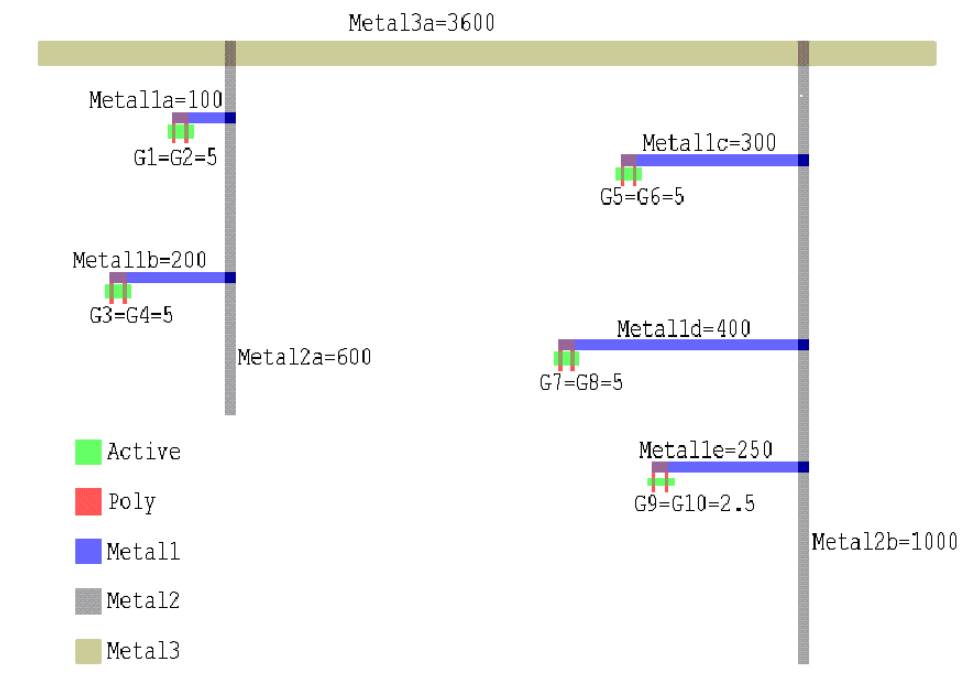
L-Edit 13 User Guide Section 3 496
Chapter 23: HiPer Verify: Calibre Command Files Antenna Rules
NET AREA RATIO
The areas of the polygons are indicated in the following figure:
The command file below models the accumulation of charge on gates through the fabrication of Metal1,
Metal2, and Metal3 interconnect layers. Area ratios of metal to gate are computed and accumulated on
gates through the fabrication of the interconnect layers, and gates whose accumulated area ratios
exceeds 150 are flagged as violations.
TITLE "Calibre NET AREA RATIO with ACCUMULATE"
DRC INCREMENTAL CONNECT YES
Gate = Poly AND Active
CONNECT Gate Poly
CONNECT Metal1 Poly BY PolyCont
//***************************
//*** Connectivity zone 1 ***
//***************************
// AC1 contains all Gate polygons, with the Metal1/Gate ratio
// attached to gate polygons.
AC1 = NET AREA RATIO Metal1 Gate >= 0 ACCUMULATE
// Write out Metal1/Gate area ratios for debug
NET AREA RATIO PRINT AC1 NAR_AC1.txt
At this point AC1 contains all Gate polygons, with the Metal1/Gate ratio attached to gate polygons.
L-Edit 13 User Guide Section 3 497
Chapter 23: HiPer Verify: Calibre Command Files Antenna Rules
NET AREA RATIO
The ratios of Metal1 area to gate area on each net (at this stage of connectivity) are computed as
follows:
Area(Metal1a)/Area(G1+G2) = 100/(5+5) = 10
Area(Metal1b)/Area(G3+G4) = 200/(5+5) = 20
Area(Metal1c)/Area(G5+G6) = 300/(5+5) = 30
Area(Metal1d)/Area(G7+G8) = 400/(5+5) = 40
Area(Metal1e)/Area(G9+G10)= 250/(2.5+2.5) = 50
At this point the area ratios on the gates are
AC1:G1 = AC1:G2 = 10
AC1:G3 = AC1:G4 = 20
AC1:G5 = AC1:G6 = 30
AC1:G7 = AC1:G8 = 40
AC1:G9 = AC1:G10 = 50
CONNECT Metal2 Metal1 By Via1
//***************************
//*** Connectivity zone 2 ***
//***************************
// AC2 contains all gate polygons, with the accumulated
// Metal/gate ratios from Metal1 and Metal2
AC2 = NET AREA RATIO Metal2 Gate >= 0 ACCUMULATE AC1
// Write out accumulated ratios for debug
NET AREA RATIO PRINT AC2 NAR_AC2.txt
The ratios of Metal2 area to Gate area on each net (at this stage of connectivity) are computed as
follows:
Area(Metal2a)/Area(G1+G2+G3+G4) = 600/(5+5+5+5) = 30
Area(Metal2b)/Area(G5+G6+G7+G8+G9+G10) = 1000/(5+5+5+5+2.5+2.5) = 40
These area ratios are added to the existing area ratios on the gates. At this point the ratios on the gate
are:
AC2:G1 = AC2:G2 = 30+10 = 40
AC2:G3 = AC2:G4 = 30+20 = 50
AC2:G5 = AC2:G6 = 40+30 = 70
AC2:G7 = AC2:G8 = 40+40 = 80
AC2:G9 = AC2:G10 = 40+50 = 90
CONNECT Metal3 Metal2 By Via2
//***************************
//*** Connectivity zone 3 ***
//***************************
NAR.1 {
// AC3 contains those gate polygons whose accumulated Metal/Gate
// ratios from Metal1, Metal2, and Metal3 exceeds 150.
AC3 = NET AREA RATIO Metal3 Gate > 150 ACCUMULATE AC2
L-Edit 13 User Guide Section 3 498
Chapter 23: HiPer Verify: Calibre Command Files Antenna Rules
NET AREA RATIO
COPY AC3
// Write out the accumulated ratios on the gate polygons in AC3
NET AREA RATIO PRINT AC3 NAR_AC3.txt
// Show the whole net as one error. Ornet performs an OR operation
// on all overlapping polygons on two input layers that are on the same net
Poly_ant = NET AREA RATIO Poly AC3 > 0
Metal1_ant = NET AREA RATIO Metal1 AC3 > 0
Metal2_ant = NET AREA RATIO Metal2 AC3 > 0
Metal3_ant = NET AREA RATIO Metal3 AC3 > 0
X = ORNET Poly_ant Metal1_ant
Y = ORNET Metal2_ant Metal3_ant
ORNET X Y
The ratios of Metal3 area to Gate area on each net (at this stage of connectivity) are computed as
follows:
Area(Metal3a)/Area(G1+G2+G3+G4+G5+G6+G7+G8+G9+G10) =
3600/(5+5+5+5+5+5+5+5+2.5+2.5) = 80
These area ratios are added to the existing area ratios on the gates. At this point the ratios on the gate
are:
AC3:G1 = AC3:G2 = 80+40=120
AC3:G3 = AC3:G4 = 80+50=130
AC3:G5 = AC3:G6 = 80+70=150
AC3:G7 = AC3:G8 = 80+80=160
AC3:G9 = AC3:G10 = 80+90=170
The rule specifies that accumulated ratios > 150 are output, so G7, G8, G9, and G10 should be output.
See Also
“NET AREA RATIO PRINT” (page 499), “NET” (page 480), and “ATTACH” (page 475)
L-Edit 13 User Guide Section 3 499
Chapter 23: HiPer Verify: Calibre Command Files Antenna Rules
NET AREA RATIO PRINT
NET AREA RATIO PRINT
NET AREA RATIO PRINT layer filename
Description
Prints the input net area ratio accumulation information to the specified file.
Each line in the destination file corresponds to a polygon in the input layer, and consists of its lower left
vertex coordinates followed by the antenna ratio associated with the polygon. These are specified in
user units. Here is an example of the filename output:
189.625 406 23.7767
217.625 68 20.814
A NET AREA RATIO operation with ACCUMULATE option must be executed prior to printing. For
example, it can be an operation in a DRC rule check that generates output:
ANT.Metal1 { X = NET AREA RATIO Metal1 Gate> 400 ACCUMULATE
NET AREA RATIO PRINT X ANT_M1.txt
}
Output from Net Area Ratio Print operations is different from Net Area Ratio RDB output. Net Area
Ratio Print does not generate a DRC results style database, and it uses only net area ratio accumulation
layers for input, and for output statistics. Also, Net Area Ratio RDB allows you to specify
non-ACCUMULATE layers for output.
Parameters
See Also
“NET AREA RATIO” (page 491), “NET” (page 480)
layer A required derived polygon layer that must be the output of a Net
Area Ratio ACCUMULATE operation.
filename A required filename for the output ASCII file. The layer must be
specified before the filename to prevent ambiguity, but the filename
parameter can contain environment variables.

L-Edit 13 User Guide Section 3 500
Chapter 23: HiPer Verify: Calibre Command Files Antenna Rules
ORNET
ORNET
ORNET layer1 layer2 [by net | by shape]
Description
Note: This operation is performed flat in hierarchical applications; it has largely been
replaced by NET AREA RATIO with the RDB option.
Performs a Boolean OR operation on all overlapping layer1 and layer2 polygons on the same net.
Generates output equivalent to the polygon data on layer2 if layer1 is empty and vice versa.
Net Area, Net Area Ratio, and other Ornet operations having the same settings are the only operations
that can have an input layer derived by Ornet because Ornet generates unmerged data. However, a layer
derived by Ornet can be output to the DRC results database (which should be its primary use.) The
connectivity on the input layers must be established.
Parameters
See Also
“NET AREA RATIO” (page 491) and “NET AREA RATIO PRINT” (page 499)
layer1 A drawn or derived layer.
layer2 A drawn or derived layer.
[BY net] An optional keyword that instructs L-Edit to merge overlapping
layer1 and layer2 polygons that are on the same net. This is the
default behavior if you do not include BY NET or BY SHAPE in the
statement.
[BY shape] An optional keyword that instructs tL-Edit not to merge any
overlapping layer1 and layer2 polygons on the same net, but to output
individual polygons instead.
L-Edit 13 User Guide Section 3 501
Chapter 23: HiPer Verify: Calibre Command Files Antenna Rules
POLYNET
POLYNET
POLYNET layer
Description
Creates a net for each layer polygon. Note that this operation is performed flat even in hierarchical
tools.
Parameters
layer A drawn or derived layer.
L-Edit 13 User Guide Section 3 503
Chapter 23: HiPer Verify: Calibre Command Files Polygon Boolean Operations
AND
AND
[polygon-layer =] layer1 AND layer2
[polygon-layer =] AND layer1 layer2
Description
Calculates the intersection of layer1 and layer2.
Parameters
layer1 A drawn or derived polygon layer
layer2 A drawn or derived polygon layer
L-Edit 13 User Guide Section 3 504
Chapter 23: HiPer Verify: Calibre Command Files Polygon Boolean Operations
NOT
NOT
[polygon-layer =] layer1 NOT layer2
[polygon-layer =] NOT layer1 layer2
Description
Calculates the region formed by layer1 minus layer2.
Parameters
layer1 A drawn or derived polygon layer
layer2 A drawn or derived polygon layer
L-Edit 13 User Guide Section 3 505
Chapter 23: HiPer Verify: Calibre Command Files Polygon Boolean Operations
OR
OR
[polygon-layer =] layer1 OR layer2
[polygon-layer =] OR layer1 layer2
[polygon-layer =] layer1 OR layer1
[polygon-layer =] OR layer1 layer1
Description
Calculates the region formed by the union of layer1 and layer2. L-Edit supports single layer OR
operations, where layer1 and layer are the same.
Parameters
layer1 A drawn or derived polygon layer
layer2 A drawn or derived polygon layer
L-Edit 13 User Guide Section 3 506
Chapter 23: HiPer Verify: Calibre Command Files Polygon Boolean Operations
XOR
XOR
[polygon-layer =] layer1 XOR layer2
[polygon-layer =] XOR layer1 layer2
Description
Calculates the region formed by both layers minus the region shared by both layers.
Parameters
layer1 A drawn or derived polygon layer
layer2 A drawn or derived polygon layer
L-Edit 13 User Guide Section 3 507
Chapter 23: HiPer Verify: Calibre Command Files Utility Layer Generation Operations
XOR
Utility Layer Generation Operations
“COPY” (page 508)
“EXTENT” (page 509)
“EXTENTS” (page 510)
“HOLES” (page 511)
“INSIDE CELL” (page 512)
“RECTANGLES” (page 513)
“SNAP” (page 514)
L-Edit 13 User Guide Section 3 508
Chapter 23: HiPer Verify: Calibre Command Files Utility Layer Generation Operations
COPY
COPY
[result-layer =] COPY [layer1]
Description
Copies a polygon or edge layer to a new layer with a different name. Can also be used to output a layer
as DRC violations.
Parameters
Examples
The COPY command can be used to output a derived layer as errors:
GATE = POLY AND ACTIVE
Gate.Out { // Rule to output GATE derived layer
COPY GATE
}
The COPY command can be used to output intermediate layers in a Rule Check
statement as errors for visualization purposes.
LongThinMetalTraces { @ Flag Metal1 traces narrower than 4.0 um
@ and longer than 100.0 um
A = INT [Metal1] < 4.0
COPY A // COPY command outputs all A edges as errors
LENGTH A > 100.0 // Errors will also be output from here.
// Comment LENGTH out if desired.
}
layer1 A drawn or derived polygon layer or a derived edge layer.
L-Edit 13 User Guide Section 3 509
Chapter 23: HiPer Verify: Calibre Command Files Utility Layer Generation Operations
EXTENT
EXTENT
[polygon-layer =] EXTENT [layer1]
Description
Produces a layer consisting of one rectangle equal to the minimum bounding box of all input layers. If
the layer1 option is present, then the resulting polygon layer consists of one rectangle equal to the
minimum bounding box of that layer.
Parameters
Examples
CHIP = EXTENT
layer1 A drawn or derived polygon layer
L-Edit 13 User Guide Section 3 510
Chapter 23: HiPer Verify: Calibre Command Files Utility Layer Generation Operations
EXTENTS
EXTENTS
[polygon-layer =] EXTENTS layer1 [CENTERS [number]]
Description
Produces a layer consisting of the (merged) minimum bounding boxes of each polygon on layer1.
Parameters
Examples
// Center-to-center pad distance must be 200 microns:
pad_center = EXTENTS pad CENTERS 2
pad_spacing {
EXT pad_center < 198 // Use 198 since centers are 2x2
}
layer1 A drawn or derived polygon layer
CENTERS Produce squares at the center of each bounding box instead of the
bounding boxes themselves.
number Specifies the size of the generated squares if CENTERS is specified.
The square will have the dimension of number user units by number
user units. The default value is 1.
L-Edit 13 User Guide Section 3 511
Chapter 23: HiPer Verify: Calibre Command Files Utility Layer Generation Operations
HOLES
HOLES
[polygon-layer =] HOLES layer1 [constraint] [INNER] [EMPTY]
Description
Produces a layer consisting of polygons that exactly fit inside the holes of layer1 polygons. Optionally,
only produce polygons whose area satisfies a constraint.
Parameters
layer1 A drawn or derived polygon layer.
constraint Constraint is any range defined by “Constraints” (page 427).
inner if a hole contains another hole, only produce the inner hole.
empty Prevents output of holes that contain polygons on the input layer.
Specifically prevent output of holes that are NOT OUTSIDE the input
layer.
L-Edit 13 User Guide Section 3 512
Chapter 23: HiPer Verify: Calibre Command Files Utility Layer Generation Operations
INSIDE CELL
INSIDE CELL
[NOT] INSIDE CELL layer1 cellname [… cellname] [PRIMARY ONLY]
Description
Produces all polygons from the input layer that are contained inside the specified cells, and the
sub-hierarchies of those cells. PRIMARY ONLY causes only top-level geometry from specified cells to
be produced. Parameters must appear in the specified command order to avoid ambiguity.
Parameters
layer1 A drawn layer.
cellname The name of a cell. Any number of cell names can be specified,
separated by a space, and cell names are case-sensitive. The name can
be a string variable (see Variable). The cellname can contain one or
more asterisk (*) wildcard characters, where the * character matches
zero or more characters. When using *, enclose the cell name in
quotes because the asterisk is a reserved symbol
PRIMARY ONLY When PRIMARY ONLY is specified, only geometry in the top level
of the specified cells is output. Geometry from the sub-hierarchy of a
specified cell may be output if it is the top level of another specified
cell.
L-Edit 13 User Guide Section 3 513
Chapter 23: HiPer Verify: Calibre Command Files Utility Layer Generation Operations
RECTANGLES
RECTANGLES
[polygon-layer =] RECTANGLES width length {spacing | {width_spacing
length_spacing} } [OFFSET {offset | {width_offset length_offset} } ] [
{INSIDE OF x1 y1 x2 y2} | {INSIDE OF LAYER layer} ] [MAINTAIN SPACING]
Description
Produces a layer consisting of a set of rectangles with specified width, spacing, and offset.
Parameters
width length The width (x-axis) and length (y-axis) of the generated rectangles in
user-units. Positive floating point numbers
spacing The spacing between rectangles in user-units. A positive floating
point number.
width_spacing
length_spacing
The x-axis and y-axis spacing, respectively, between rectangles in
user-units. Positive floating point numbers.
OFFSET A secondary keyword that specifies that rectangles are offset from the
previous row/column of rectangles by a specified amount.
offset Specifies the same offset in the x-axis and y-axis directions for each
rectangle relative to the previous row/column of rectangles
width_offset length_offset Specifies the offset in the x-axis and y-axis directions respectively for
each rectangle relative to the previous row/column of rectangles.
Positive floating point numbers.
INSIDE OF x1 y1 x2 y2 Specifies an area within the extent of the cell boundary to be filled
with the specified rectangles. The parameters x1 y1 x2 y2 are four
floating point numbers, in user-units, that indicate the lower-left (x1,
y1) and upper-right (x2, y2) corners of the extent to be filled.
Negative numbers must be in parenthesis.
INSIDE OF LAYER layer Specifies that rectangles are only produced within the boundary of the
specified layer. The parameter layer is a string that specifies a derived
or original polygon layer.
MAINTAIN SPACING Specifies that no rectangle will be generated closer to another
rectangle than the width_spacing and length_spacing parameters.
This applies to clusters of rectangles between neighboring instances.
L-Edit 13 User Guide Section 3 514
Chapter 23: HiPer Verify: Calibre Command Files Utility Layer Generation Operations
SNAP
SNAP
[polygon-layer =] SNAP layer1 {r | x y}
Description
Produces a layer by snapping the vertices of the input layer to the specified grid. 45 degree edges are
preserved.
Parameters
LAYER1 A drawn or derived polygon layer.
r | X Y Integer(s) in database units that specify the snap grid. A single value,
r, may be specified for both x and y snapping, or x and y snapping
values may be specified separately.
L-Edit 13 User Guide Section 3 516
Chapter 23: HiPer Verify: Calibre Command Files Polygon Size Operations
GROW
GROW
[polygon-layer =] GROW layer1 [RIGHT BY value] [TOP BY value] [LEFT BY
value][BOTTOM BY value]
Description
Performs outward translation of the input layer edges in the direction of the x-axis, y-axis, or both.
Parameters
layer1 An drawn or derived polygon layer or derived edge layer.
RIGHT BY value Translate the right edge(s) of each polygon on layer1, toward the
outside of each polygon layer1, by the specified value. Value is a
non-negative real number in user units.
TOP BY value Translate the top edge(s) of each polygon on layer1, toward the
outside of each polygon layer1, by the specified value. Value is a
non-negative real number in user units.
LEFT BY value Translate the left edge(s) of each polygon on layer1, toward the
outside of each polygon layer1, by the specified value. Value is a
non-negative real number in user units.
BOTTOM BY value Translate the bottom edge(s) of each polygon on layer1, toward the
outside of each polygon layer1, by the specified value. Value is a
non-negative real number in user units.
L-Edit 13 User Guide Section 3 517
Chapter 23: HiPer Verify: Calibre Command Files Polygon Size Operations
SHRINK
SHRINK
[polygon-layer =] SHRINK layer1 [RIGHT BY value] [TOP BY value] [LEFT BY
value][BOTTOM BY value]
Description
Performs inward translation of the input layer edges in the direction of the x-axis, y-axis, or both.
Parameters
layer1 An drawn or derived polygon layer or derived edge layer.
RIGHT BY value Translate the right edge(s) of each polygon on layer1, toward the
inside of each polygon layer1, by the specified value. Value is a
non-negative real number in user units.
TOP BY value Translate the top edge(s) of each polygon on layer1, toward the inside
of each polygon layer1, by the specified value. Value is a
non-negative real number in user units.
LEFT BY value Translate the left edge(s) of each polygon on layer1, toward the inside
of each polygon layer1, by the specified value. Value is a
non-negative real number in user units.
BOTTOM BY value Translate the bottom edge(s) of each polygon on layer1, toward the
inside of each polygon layer1, by the specified value. Value is a
non-negative real number in user units.
L-Edit 13 User Guide Section 3 518
Chapter 23: HiPer Verify: Calibre Command Files Polygon Size Operations
SIZE
SIZE
[polygon-layer =] SIZE layer1 BY size_value [OVERLAP ONLY|[INSIDE OF|OUTSIDE
OF] layer2 [STEP step_value]] [TRUNCATE distance]
[polygon-layer =] SIZE layer1 BY size_value [UNDEROVER|OVERUNDER] [TRUNCATE
distance]
Description
Performs a size up or size down on a layer. A positive size_value performs a size up, or grow, and a
negative size_value performs a size down, or shrink.
Parameters
layer1 A drawn or derived polygon layer
size_value The amount to grow or shrink the layer1 polygons. This value must be
positive if either UNDEROVER or OVERUNDER are specified.
UNDEROVER Undersize then oversize layer1 in a single operation.
OVERUNDER Oversize then undersize layer1 in a single operation.
OVERLAP ONLY Specifies that only the overlapping regions of the oversized polygons
are output.
INSIDE OF layer2 Constrains layer1 to travel inside layer2 when performing the SIZE
operation. size_value must be positive when this option is used.
OUTSIDE OF layer2 Constrains layer1 to travel outside layer2 when performing the SIZE
operation. size_value must be positive when this option is used
STEP step_value The step size of the sizing process. If size_value is not evenly
divisible by step_value then the last step may be smaller than
step_value in order to size by exactly size_value.
TRUNCATE distance The truncation distance to prevent large spikes when the size
operation is performed on small acute angles. The default value is
1/COS(67.5), approximately 2.61. At the default truncation distance,
corners at edges of >= 45 degree angles will not be truncated, corners
at edges of < 45 degrees will be truncated.
L-Edit 13 User Guide Section 3 519
Chapter 23: HiPer Verify: Calibre Command Files Polygon Size Operations
WITH WIDTH
WITH WIDTH
[polygon-layer =] WITH WIDTH layer1 constraint
Description
Selects those polygons or portions of polygons that satisfy the width constraint. For constraints >w and
orthogonal geometry, this is equivalent to doing a SIZE layer1 BY (w/2) UNDEROVER.
Parameters
layer1 A drawn or derived polygon layer.
Constraint Specifies the width that the selected polygon or portion of a polygons
must have in order to be produced. Constraints of type > or >= are
allowed.
L-Edit 13 User Guide Section 3 520
Chapter 23: HiPer Verify: Calibre Command Files Two Layer Polygon Selection Operations
WITH WIDTH
Two Layer Polygon Selection Operations
The following commands select polygons from an input layer based on relationships to polygons on
another input layer.
“CUT” (page 521)
“ENCLOSE” (page 522)
“INSIDE” (page 523)
“INTERACT” (page 524)
“OUTSIDE” (page 525)
“TOUCH” (page 526)
“RECTANGLE ENCLOSURE” (page 527)

L-Edit 13 User Guide Section 3 521
Chapter 23: HiPer Verify: Calibre Command Files Two Layer Polygon Selection Operations
CUT
CUT
[polygon-layer =] layer1 [NOT] CUT layer2 [constraint [BY NET]]
[polygon-layer =] [NOT] CUT layer1 layer2 [constraint [BY NET]]
Description
Produces layer1 polygons that have portions both inside and outside layer2. The NOT option produces
those layer1 polygons not produced by the corresponding CUT operation. The input layers will be
merged if the constraint option is used, and will run slower than the CUT operation with no constraint.
(This option is not yet supported.) If BY NET is specified, the constraint applies to the number of layer2
polygons on distinct nets that CUT layer1.
Parameters
Examples
layer1 A drawn or derived polygon layer
layer2 A drawn or derived polygon layer
constraint Specifies the number of layer2 polygons that layer1 must have
portions both inside and outside of, in order to be selected by the CUT
operation. Constraint is any range defined by “Constraints” (page
427) where the constraints values must be positive integers.
BY NET When the BY NET option is used, then a layer1 polygon is selected
when the specified number of layer2 polygons on distinct nets cut the
layer1 polygon. Layer2 must have connectivity.
layer1 layer2 layer1 CUT layer2
L-Edit 13 User Guide Section 3 522
Chapter 23: HiPer Verify: Calibre Command Files Two Layer Polygon Selection Operations
ENCLOSE
ENCLOSE
[polygon-layer =] layer1 [NOT] ENCLOSE layer2 [constraint [BY NET]]
[polygon-layer =] [NOT] ENCLOSE layer1 layer2 [constraint [BY NET]]
Description
Produces layer1 polygons that completely enclose any layer2 polygon. The NOT option produces those
layer1 polygons not produced by the corresponding ENCLOSE operation. The input layers will be
merged if the constraint option is used, and will run slower than the ENCLOSE operation with no
constraint.
(This option is not yet supported.) If BY NET is specified, the constraint applies to the number of layer2
polygons on distinct nets that CUT layer1.
Parameters
layer1 A drawn or derived polygon layer
layer2 A drawn or derived polygon layer
constraint Specifies the number of layer2 polygons that a layer1 polygon must
enclose, in order to be selected by the ENCLOSE operation.
Constraint is any range defined by “Constraints” (page 427) where
the constraints values must be integer.
BY NET When the BY NET option is used, then a layer1 polygon is selected
when the specified number of layer2 polygons on distinct nets enclose
the layer1 polygon. Layer2 must have connectivity.
L-Edit 13 User Guide Section 3 523
Chapter 23: HiPer Verify: Calibre Command Files Two Layer Polygon Selection Operations
INSIDE
INSIDE
[polygon-layer =] layer1 [NOT] INSIDE layer2
[polygon-layer =] [NOT] INSIDE layer1 layer2
Description
Produces all layer1 polygons that are completely inside layer2 polygons. Touching from the inside is
considered to be inside. The NOT option produces those layer1 polygons not produced by the
corresponding INSIDE operation.
Parameters
layer1 A drawn or derived polygon layer
layer2 A drawn or derived polygon layer
L-Edit 13 User Guide Section 3 524
Chapter 23: HiPer Verify: Calibre Command Files Two Layer Polygon Selection Operations
INTERACT
INTERACT
[polygon-layer =] layer1 [NOT] INTERACT layer2 [constraint [BY NET]]
[polygon-layer =] [NOT] INTERACT layer1 layer2 [constraint [BY NET]]
Description
Produces all layer1 polygons that have some or all area inside layer2 polygons or share an edge with
layer2 polygons. The NOT option produces those layer1 polygons not produced by the corresponding
INTERACT operation. The input layers will be merged if the constraint option is used, and will run
slower than the INTERACT operation with no constraint.
(This option is not yet supported.) If BY NET is specified, the constraint applies to the number of layer2
polygons on distinct nets that CUT layer1.
Parameters
layer1 A drawn or derived polygon layer
layer2 A drawn or derived polygon layer
constraint Specifies the number of layer2 polygons that a layer1 polygon must
interact with, in order to be selected by the INTERACT operation.
Constraint is any range defined by “Constraints” (page 427) where
the constraints values must be integer.
BY NET When the BY NET option is used, then a layer1 polygon is selected
when the specified number of layer2 polygons on distinct nets interact
the layer1 polygon. Layer2 must have connectivity.
L-Edit 13 User Guide Section 3 525
Chapter 23: HiPer Verify: Calibre Command Files Two Layer Polygon Selection Operations
OUTSIDE
OUTSIDE
[polygon-layer =] layer1 [NOT] OUTSIDE layer2
[polygon-layer =] [NOT] OUTSIDE layer1 layer2
Description
Produces all layer1 polygons that are completely outside layer2 polygons. Touching from the outside is
considered to be outside. The NOT option produces those layer1 polygons not produced by the
corresponding OUTSIDE operation.
Parameters
layer1 A drawn or derived polygon layer
layer2 A drawn or derived polygon layer
L-Edit 13 User Guide Section 3 526
Chapter 23: HiPer Verify: Calibre Command Files Two Layer Polygon Selection Operations
TOUCH
TOUCH
[polygon-layer =] layer1 [NOT] TOUCH layer2 [constraint [BY NET]]
[polygon-layer =] [NOT] TOUCH layer1 layer2 [constraint [BY NET]]
Description
Produces all layer1 polygons that are completely outside layer2 polygons but share an edge with layer2
polygons. The NOT option produces those layer1 polygons not produced by the corresponding TOUCH
operation. The input layers will be merged if the constraint option is used, and will run slower than the
TOUCH operation with no constraint.
(This option is not yet supported.) If BY NET is specified, the constraint applies to the number of layer2
polygons on distinct nets that CUT layer1.
Parameters
layer1 A drawn or derived polygon layer
layer2 A drawn or derived polygon layer
constraint Specifies the number of layer2 polygons that a layer1 polygon must
touch, in order to be selected by the TOUCH operation. Constraint is
any range defined by “Constraints” (page 427) where the constraints
values must be integer.
BY NET When the BY NET option is used, then a layer1 polygon is selected
when the specified number of layer2 polygons on distinct nets touch
the layer1 polygon. Layer2 must have connectivity.
L-Edit 13 User Guide Section 3 527
Chapter 23: HiPer Verify: Calibre Command Files Two Layer Polygon Selection Operations
RECTANGLE ENCLOSURE
RECTANGLE ENCLOSURE
[polygon-layer =] layer1 layer2 [intersection_filter] [OUTSIDE ALSO]]
[ORTHOGONAL ONLY] {RECTANGLE _RULE [rectangle_rule...]}
Description
Rectangle enclosure uses a sequential process of elimination to make enclosure checks more efficient
when multiple rules must be applied. Geometry is tested first to confirm rectangularity, then against the
global parameters ABUT, SINGULAR or OUTSIDE ONLY (if used), then against each of eight
rectangle rule relations (of each edge to each of four values, in both clockwise and counter-clockwise
directions), which are of the type GOOD or BAD.
GOOD type rules output rectangles that fail any one of their criteria and do not output rectangles that
satisfy all of their criteria. BAD type rules output rectangles that meet all of their criteria.
If the ABUT constraint is specified, intersecting edges will be measured. If the SINGULAR constraint
is specified, point-to-point intersections, including self-intersections will also be measured. These
options can be used together in any combination.
Parameters
layer1 A drawn or derived polygon layer
layer2 A drawn or derived polygon layer
intersection filter Optional parameters that permit intersecting edge or point pairs to be
measured using the form
ABUT [constraint] [SINGULAR]
Used when a certain distance between intersecting objects is
acceptable. You can specify any combination of these keywords in
one operation.
ABUT [constraint] Measures the separation between intersecting edges, if the angle
between them conforms to the constraint, specified in degrees.
The default value is >= 0 < 180. Optionally, you can enter a
non-negative real number less than 180. Single operator constraints
such as < 90 and > 135 are interpreted as >= 0 < 90 and > 135 < 180.
Note that if the constraint modifier includes zero in its range (for
example, < 90, == 0, >= 0 < 45), then any edges A of X and B of Y,
which are coincident inside are also output because the angle between
the exterior side of A and the interior side of B is zero. There is no
measurement involved in this event, and polygon containment criteria
are not applied.
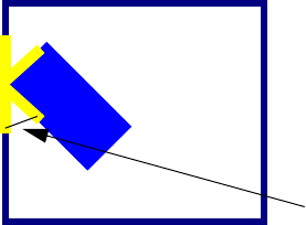
L-Edit 13 User Guide Section 3 528
Chapter 23: HiPer Verify: Calibre Command Files Two Layer Polygon Selection Operations
RECTANGLE ENCLOSURE
Examples
For example, you would use Rectangle Enclosure instead of iterations of the Enclosure rule to test the
following case:
All contacts must be enclosed by metal of .15. However, if two opposite sides are at least .5 then the two
other sides can touch, or, if two opposite sides are at least .4 the two other sides can be as close as .05, or
if two opposite sides are at least .3 the two other sides can be as close as .3. The contacts must be fully
enclosed, and acute abutments are considered errors.
You would use the following rules:
SINGULAR Includes measurement of the separation between corresponding sides
of intersecting edges at points of singularity (point-to-edge or
point-to-point intersections or self-intersections). Though normally
singularities are a design rule violation, in some cases there is a
maximum allowable dimension that geometries with singular point of
contact conform to, as shown below.
If a point of singularity is detected, all edges forming that point are
measured as if an unconstrained ABUT parameter were specified,
overriding any ABUT parameter value entered.
OUTSIDE ALSO Outputs edges on layer1 that are outside or coincident outside from
layer2.
ORTHOGONAL ONLY Limits the rectangle enclosure operation to check only those
rectangles with edges parallel to the coordinate axes of the design.
rectangle_rule Indicates how layer1 rectangles enclosed by layer2 are to be
measured. At least one rule with four values must be defined, in the
form:
GOOD | BAD {value1 [metric] value2 [metric] value3 [metric]
value4 [metric]}
GOOD rules do not output rectangles that satisfy them. BAD rules do
output rectangles that satisfy them.
Enclosure values are measured as < value, where the value is a
positive floating-point number. The default metric is Euclidean but
may be changed to OPPOSITE, OPPOSITE EXTENDED, or
SQUARE.
Note: Applying the OPPOSITE metric can use large amounts of
processing time and memory since so many more errors will
be found.
measures this distance
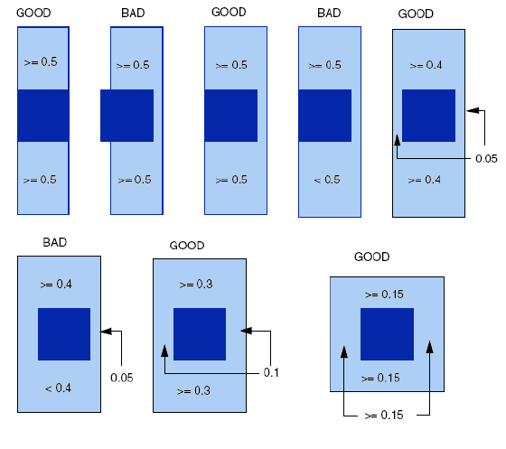
L-Edit 13 User Guide Section 3 529
Chapter 23: HiPer Verify: Calibre Command Files Two Layer Polygon Selection Operations
RECTANGLE ENCLOSURE
RECTANGLE ENCLOSURE contact metal ABUT > 0 < 90 SINGULAR OUTSIDE ALSO
GOOD 0.00 0.50 0.00 0.50
GOOD 0.05 0.40 0.05 0.40
GOOD 0.10 0.30 0.10 0.30
GOOD 0.15 0.15 0.15 0.15
The tool checks each enclosure of contact by metal against the four spacing conditions listed, in the
order the conditions appear. Any rectangle that does not satisfy at least one of the four conditions is
classified as BAD and is output. Note that you do not need to explicitly specify any BAD conditions in
order for a contact to be classified as BAD. A check having only BAD rules will output all layer1
rectangles. As such it is sufficient to specify all GOOD rules, unless there are only a few BAD
conditions to check. BAD rules are best used to filter out gross violations.
Every edge of each rectangle is examined for each rule, first in clockwise order, and then again in
counter-clockwise order. A relation satisfies a GOOD rule if all rules four elements of that relation are
GOOD. A relation satisfies a BAD rule if all rules four elements of that relation are BAD. If the value 0
is used, the result is considered GOOD in a GOOD type rule and BAD in a BAD type rule.
Some possible results are shown below.
L-Edit 13 User Guide Section 3 530
Chapter 23: HiPer Verify: Calibre Command Files Single Layer Polygon Selection Operations
RECTANGLE ENCLOSURE
Single Layer Polygon Selection Operations
The following commands select polygons from a single input layer, based on the properties of the
polygons on that layer.
“DONUT” (page 531)
“ENCLOSE RECTANGLE” (page 532)
“PERIMETER” (page 533)
“RECTANGLE” (page 534)
“VERTEX” (page 536)
L-Edit 13 User Guide Section 3 531
Chapter 23: HiPer Verify: Calibre Command Files Single Layer Polygon Selection Operations
DONUT
DONUT
[polygon-layer =] [NOT] DONUT layer1 [constraint]
Description
Produces all layer1 polygons that have a hole or holes. The NOT option produces those polygons not
produced by the corresponding DONUT operation.
Parameters
Examples
Show a polygon with a hole that touches the boundary at a point – this isn't
really a hole.
layer1 A drawn or derived polygon layer
constraint Specifies the number of holes a layer1 polygon must have in order to
be selected by the DONUT operation. Constraint is any range defined
by “Constraints” (page 427) where the constraints values must be
integer.
L-Edit 13 User Guide Section 3 532
Chapter 23: HiPer Verify: Calibre Command Files Single Layer Polygon Selection Operations
ENCLOSE RECTANGLE
ENCLOSE RECTANGLE
[polygon-layer =] ENCLOSE RECTANGLE layer1 width length [ORTHOGONAL ONLY]
Description
Selects all polygons on layer1 that can enclose a rectangle of the specified width and length dimensions.
Width may be oriented along either the x- or y- axis, but only orthogonal rectangles or rectangles at 45
degrees will be considered. To consider only orthogonally oriented rectangles, use the ORTHOGONAL
ONLY option.
Parameters
layer1 A drawn or derived polygon layer.
width A positive floating-point number interpreted in user units.
length A positive floating-point number interpreted in user units.
ORTHOGONAL ONLY Limits selection to polygons enclosing rectangles having sides that
are parallel to the x- and y- axis.
L-Edit 13 User Guide Section 3 533
Chapter 23: HiPer Verify: Calibre Command Files Single Layer Polygon Selection Operations
PERIMETER
PERIMETER
[polygon-layer =] PERIMETER layer1 constraint
Description
Produces layer1 polygons whose perimeter conforms to the constraint.
Parameters
layer1 A drawn or derived polygon layer
constraint Constraint is any range defined by “Constraints” (page 427) where
the constraints values must be a non-negative real number.
L-Edit 13 User Guide Section 3 534
Chapter 23: HiPer Verify: Calibre Command Files Single Layer Polygon Selection Operations
RECTANGLE
RECTANGLE
RECTANGLE layer [constraint1 [BY constraint2]] [ASPECT constraint3]
[ORTHOGONAL ONLY | MEASURE EXTENTS]
Description
Produces rectangles from layer1. If constraints are specified, only rectangles whose dimensions
conform to the constraint are produced. The NOT option produces layer1 rectangles not produced by
the corresponding RECTANGLE operation.
Parameters
layer1 A drawn or derived polygon layer
constraint1 Constraint is any range defined by “Constraints” (page 427) where
the constraints values must be a non-negative real number. If
constraint1 is specified but constraint2 is not specified, then the
rectangle is selected if either dimension of the rectangle satisfies the
constraint.
BY constraint2 Constraint is any range defined by “Constraints” (page 427) where
the constraints values must be a non-negative real number.
ASPECT constraint3 Specifies the ratio of the longer side to the shorter side that a rectangle
must have in order to be output.
ORTHOGONAL ONLY Restricts selection to rectangles with sides that are parallel to the
horizontal and vertical coordinate axis.
MEASURE EXTENTS Selects polygons based on their MBB. May not be specified with
ORTHOGONAL ONLY.
L-Edit 13 User Guide Section 3 535
Chapter 23: HiPer Verify: Calibre Command Files Single Layer Polygon Selection Operations
OR
OR
[polygon-layer =] OR layer1 constraint
Description
Calculates the region formed by the union of layer1 and layer2.
Parameters
layer1 A drawn or derived polygon layer
constraint Constraint is any range defined by “Constraints” (page 427) where
the constraints values must be integer.
L-Edit 13 User Guide Section 3 536
Chapter 23: HiPer Verify: Calibre Command Files Single Layer Polygon Selection Operations
VERTEX
VERTEX
[polygon-layer =] VERTEX layer1 constraint
Description
Produces layer1 polygons whose vertex count conforms to the constraint.
Parameters
layer1 A drawn or derived polygon layer
constraint Constraint is any range defined by “Constraints” (page 427) where
the constraints values must be integer.
L-Edit 13 User Guide Section 3 538
Chapter 23: HiPer Verify: Calibre Command Files Polygon Area Operations
AREA
AREA
[polygon-layer =] [NOT] AREA layer1 constraint
Description
Produces layer1 polygons whose area conforms to the constraint. The NOT option produces layer1
polygons not produced by the corresponding AREA operation.
Parameters
layer1 A drawn or derived polygon layer
constraint Constraint is any range defined by “Constraints” (page 427) where
the constraints values must be a non-negative real number.
L-Edit 13 User Guide Section 3 539
Chapter 23: HiPer Verify: Calibre Command Files Polygon Area Operations
DENSITY
DENSITY
[polygon-layer =] DENSITY layer1 [...layerN] [[density_expression]]
constraint [INSIDE OF { {x1 y1 x2 y2} | EXTENT | {LAYER layer2} } ]
[WINDOW {w | wx wy} ] [STEP {s | sx sy} ] [TRUNCATE | BACKUP|IGNORE|WRAP]
[CENTERS value] [{PRINT | PRINT ONLY} file_name]
Description
Produces rectangular boundaries within which the ratio of the area of layer1 to the area of the rectangle
meets the constraint. The boundaries within which density is calculated may be a single rectangle, or
using the WINDOW/STEP options, a sequence of rectangular windows moving across the chip can be
considered. The INSIDE OF LAYER option modifies the boundary within which density is calculated
from a rectangle to being the boundaries of the polygons on the specified layer.
Parameters
layer1 [...layerN] A drawn or derived polygon layer
[density_expression] An optional expression in brackets ( [ ] ) that allows customizable
control over the density ratio computations. The expression may
contain numbers, numeric variables, binary operators ( *, / , +, -),
unary operators (+, -, !, ~), and AREA functions of the input layers of
the form:
AREA (input_layer)
The expression must not result in negative values.
constraint Constraint is any range defined by “Constraints” (page 427) where
the constraints values must be a non-negative real number. Specifies
the ratio of the area of layer1 to the area of the specified boundary that
must exist for the boundary polygon to be produced.
INSIDE OF Defines a rectangular boundary within which a moving window will
travel. If this option is not specified, then the boundary is equal to the
database extent.
INSIDE OF X1 Y1 X2 Y2 Specifies a rectangular boundary. Negative numbers must be in
parenthesis.
INSIDE OF EXTENT Specifies that the boundary is the Extent of the input layer.
INSIDE OF LAYER layer2 Specifies that the density is calculated within the boundary of each
polygon on layer2.
WINDOW Specifies a window within which the density check is computed.
WINDOW w Specifies a square window with dimension w.
WINDOW wx wy Specifies a rectangular window with dimension wx by wy.
STEP s Specifies that window moves up and to the right by a distance s.
STEP sx sy Specifies that window moves to the right by sx and up by sy.
L-Edit 13 User Guide Section 3 540
Chapter 23: HiPer Verify: Calibre Command Files Polygon Area Operations
DENSITY
Description Details
Density is computed as a ratio of two areas:
Density = A1 / A2
If the WINDOW option is not present then:
If no INSIDE OF options are present, then A1 is the area of the input layer, layer1, and A2 is the area of
the database extent.
If INSIDE OF EXTENT is specified, then A1 is the area of the input layer, layer1, and A2 is the area of
the extent of layer1.
If INSIDE OF x1 y1 x2 y2 is present, then let R be the rectangle formed by x1 y1 x2 y2. A1 is the area
of (layer1 AND R ) and A2 is the area of R.
If INSIDE OF LAYER layer2 is specified, then for each polygon P on layer2, the density is calculated
using A1 = area of (layer1 AND P), and A2 = area of P, and the boundary of P is output if the constraint
is met.
TRUNCATE Specifies that if the rightmost or topmost windows do not exactly end
at the boundary of the database (or layer), then those windows are
truncated to fit the database (or layer), and the density calculation is
done on the reduced window size. This is the default behavior.
BACKUP Specifies that if the rightmost or topmost windows do not exactly end
at the boundary of the database (or layer), then those windows are
moved such that the rightmost or topmost boundary of the window
coincides with the boundary of the database (or layer), and the density
calculation is done on a full window size.
IGNORE Specifies that if a window overlaps the right-hand edge or the top
edge of the boundary box, the window is ignored and no data for that
window location is output.
WRAP Specifies that if if a window overlaps the right-hand edge or the top
edge of the boundary box, the boundary box and its data are
duplicated and added to the right-hand side or top side of the original
bounding box. The density measurement is then taken in the window
that intersects the duplicated boundaries.
CENTERS value Specifies that output should be squares of dimension value, located at
the center of each window that would be normally be output.
{PRINT/PRINT ONLY}
file_name
PRINT and PRINT ONLY writes the coordinates and corresponding
density of output rectangles to the specified file. The PRINT option
prints to the file and outputs to the resulting polygon layer or error
layer. The PRINT ONLY option prints to the filename but does not
output to the result layer or error layer.
A path that includes the colon character must be in quotes. If a full
path is not provided, then the path is relative to the tdb file.
L-Edit 13 User Guide Section 3 541
Chapter 23: HiPer Verify: Calibre Command Files Polygon Area Operations
DENSITY
If the WINDOW option is present:
If no INSIDE OF options are present, then a rectangle, W, specified by the WINDOW dimensions is
positioned starting at the lower left of the database extent, and subsequently positioned by moving by
the STEP amount in the x- and y- directions. For each window position, A1 is calculated as the area of
(layer1 AND W) and A2 is the area of W.
If INSIDE OF EXTENT is specified, then a rectangle, W, specified by the WINDOW dimensions is
positioned starting at the lower left of layer1 extent, and subsequently positioned by moving by the
STEP amount in the x- and y- directions. For each window position, A1 is calculated as the area of
(layer1 AND W) and A2 is the area of W.
If INSIDE OF x1 y1 x2 y2 is present, then let R be the rectangle formed by x1 y1 x2 y2. A rectangle, W,
specified by the WINDOW dimensions is positioned starting at the lower left of R, and subsequently
positioned by moving by the STEP amount in the x- and y- directions. A1 is the area of (layer1 AND R
AND W ) and A2 is the area of the rectangle formed R AND W.
IF INSIDE OF LAYER layer2 is specified then a rectangle, W, specified by the WINDOW dimensions
is positioned starting at the lower left of the extent of layer2, and subsequently positioned by moving by
the STEP amount in the x- and y- directions. For each window position, A1 is calculated as the area of
(layer1 AND layer2 AND W) and A2 is the area of W.
Examples
1.Density of POLY over the database extent must exceed 15%.
POLY_Density { @ Min. POLY area coverage 15%
DENSITY POLY < 0.15
}
2. Density of Metal1 in every 200um x200um window must exceed 25%. Windows are stepped at
100um interval, and rightmost and topmost windows are backed up. Print violating windows to a log
file.
METAL1_Density { @ METAL1 area coverage must be >= 25% over 200 um x 200 um
DENSITY METAL1 < 0.25 WINDOW 200 STEP 100 BACKUP PRINT METAL1_density.log
}
3. Density of METAL1 plus METAL2 must be greater than 40%
METAL_Density { @ METAL1 plus METAL2 area coverage must be >= 40% over
200umx200um
DENSITY METAL1 METAL1 < 0.4 WINDOW 200 STEP 100 BACKUP PRINT
METAL_density.log
[ (AREA(METAL1) + AREA(METAL2))/AREA() ]
}
L-Edit 13 User Guide Section 3 543
Chapter 23: HiPer Verify: Calibre Command Files Polygon-Edge Operations
WITH EDGE
WITH EDGE
[polygon-layer =] [NOT] WITH EDGE layer1 layer2 [constraint]
[polygon-layer =] layer1 [NOT] WITH EDGE layer2 [constraint]
Description
Produces layer1 polygons that have edges or edge segments coincident with layer2. The constraint
specifies the number of layer1 edges that a layer1 polygon must have on layer2 to be selected. The NOT
option produces layer1 polygons that are not produced by the corresponding WITH EDGE operation.
Parameters
layer1 A drawn or derived polygon layer
layer2 A derived edge layer.
constraint Constraint is any range defined by “Constraints” (page 427) where
the constraints values must be integer.
L-Edit 13 User Guide Section 3 544
Chapter 23: HiPer Verify: Calibre Command Files Polygon-Edge Operations
EXPAND EDGE
EXPAND EDGE
[polygon-layer =] EXPAND EDGE layer1 expansion_set number1 [EXTEND BY
[FACTOR] number2] [CORNER FILL]
Description
Converts all layer1 edges into rectangles by sweeping edges a specified distance, in a direction toward
the inside of the polygon, or toward the outside of the polygon from which the edge originated.
Parameters
layer1 A drawn or derived polygon layer, or a derived edge layer.
expansion_set INside BY — Expands an edge towards the inside of the polygon it
originated from by the amount specified in the number1 parameter.
This secondary keyword can be used along with OUTside BY
FACTOR.
INside BY FACTOR — Expands an edge towards the inside of the
polygon it originated from by the product of the number1 parameter
and the edge's length. This secondary keyword can be used along with
OUTside BY
OUTside BY — Expands an edge towards the outside of the polygon
it originated from by the amount specified in the number1 parameter.
This secondary keyword can be used along with INside BY
FACTOR.
OUTside BY FACTOR — Expands an edge towards the outside of
the polygon it originated from by the product of the number1
parameter and the edge's length. This secondary keyword can be used
along with INside BY.
BY — Performs expansion of both secondary keywords INside BY
and OUTside BY. You cannot use this parameter with any other
secondary keyword in this set.
BY FACTOR — Performs expansion of both secondary keywords
INside BY FACTOR and OUTside BY FACTOR. You cannot use
this parameter with any other secondary keyword in this set.
number1 A positive real number, must follow the specified secondary
keywords listed for expansion_set.
[EXTEND BY [FACTOR]
number 2]
Extends or retracts both ends of an edge prior to expanding into
rectangles. A positive number2 parameter specifies the amount to
extend both ends of an edge. A negative number2 parameter specifies
the amount to retract both ends of an edge. An edge disappears if it is
retracted more than or equal to two times its original length
L-Edit 13 User Guide Section 3 545
Chapter 23: HiPer Verify: Calibre Command Files Polygon-Edge Operations
EXPAND EDGE
[CORNER FILL] An optional secondary keyword that directs an Expand Edge
operation to fill gaps between rectangles formed by the operation at
corners of the input layer. You cannot specify CORNER FILL with a
BY FACTOR secondary keyword or an EXTEND secondary
keyword.
L-Edit 13 User Guide Section 3 547
Chapter 23: HiPer Verify: Calibre Command Files Edge Length and Angle Operations
ANGLE
ANGLE
[edge-layer =] [NOT] ANGLE layer1 constraint
Description
Produces all layer1 edges whose acute angle magnitude with the x-axis conforms to the constraint. The
NOT option produces all layer1 edges not produced by the corresponding ANGLE operation.
Parameters
layer1 A drawn or derived polygon layer.
constraint Constraint is any range defined by “Constraints” (page 427) where
the constraint's values represent an angle range in degrees. The
constraint values must be greater than or equal to 0 but less than or
equal to 90.
L-Edit 13 User Guide Section 3 548
Chapter 23: HiPer Verify: Calibre Command Files Edge Length and Angle Operations
CONVEX EDGE
CONVEX EDGE
Simple syntax:
[edge-layer =] CONVEX EDGE layer1 endpoint_constraint [WITH LENGTH
edge_length_constraint]
Detailed syntax:
[edge-layer =] CONVEX EDGE layer1
ANGLE1 angle_constraint [LENGTH1 abut_length_constraint]
ANGLE2 angle_constraint [LENGTH2 abut_length_constraint]
[WITH LENGTH edge_length_constraint]
Description
Produces an edge layer by selecting edges depending on the number of convex endpoints. Edge length,
angle of abutting edges, and length of abutting edges may also be considered. This operation is not
limited to selection of edges based purely on convexity. In most cases the convexity (or concavity) of
the endpoints of edges is a by-product of the properties you desire. This operation has two syntaxes,
simple or detailed. Both the simple and detailed specifications can include the WITH LENGTH
secondary keyword and the edge_length_constraint. The differences between simple and detailed are
discussed in the following sections.
Simple Syntax Parameters
Detailed Endpoint Specification
Edge selection may also be specified by the angles formed by adjacent edges at each endpoint of a given
edge. ANGLE1 denotes one endpoint and ANGLE2 denotes the other endpoint. LENGTH1 and
LENGTH2 additionally specify edge selection based on the length of the adjacent edges at the
endpoints of a given edge. Length parameters are associated with ANGLE1 and ANGLE2, respectively.
Angle constraints which are < 180 degrees (measured internal to the polygon) are convex. Angle
constraints which are > 180 degrees are concave. If you do not specify LENGTH1 and LENGTH2 they
default to the constraint >=0.
Detailed endpoint specification selects edges with the following algorithm.
§Designate the endpoints of the edge as A and B.
The edge is selected if the status at endpoint A satisfies the ANGLE1 and LENGTH1 constraints, and
the status at endpoint B satisfies the ANGLE2 and LENGTH2 constraints.
§If the edge is not selected from the previous test, then:
§The edge is selected if the status at endpoint B satisfies the ANGLE1 and LENGTH1 constraints and
the status at endpoint A satisfies the ANGLE2 and LENGTH2 constraints.
The tool does not select the edge if it does not meet the above requirements.
layer1 A drawn or derived polygon layer or a derived edge layer.
L-Edit 13 User Guide Section 3 549
Chapter 23: HiPer Verify: Calibre Command Files Edge Length and Angle Operations
CONVEX EDGE
Edge Layer Input
The process of edge selection needs to be refined for a derived edge input layer. This is due to the
possibility that abutting edges may not be present. For simple endpoint specification, the number of
convex endpoints is counted as before. However, if an abutting edge is absent, the endpoint is not
counted. This edge is then selected if the number of convex endpoints passes the associated constraint.
For detailed endpoint specification, the angle at an endpoint where there is no abutting edge is defined
as 0 degrees. This value can be used since edges cannot meet at an angle of 0 degrees in a layer
representing merged data. The length of the abutting edge (which is missing) to be is defined to be 0
user units. For example, if the ANGLE1 constraint includes 0, an endpoint with no abutting edge will
satisfy the ANGLE1 constraint.
Examples
The following example selects all metal1 edges which have both endpoints at
a convex corner:
CONVEX EDGE metal1 == 2
The following example selects all metal edges which have one endpoint at a
convex corner and length less than 3 user units:
CONVEX EDGE metal == 1 WITH LENGTH < 3
L-Edit 13 User Guide Section 3 550
Chapter 23: HiPer Verify: Calibre Command Files Edge Length and Angle Operations
LENGTH
LENGTH
[edge-layer =] [NOT] LENGTH layer1 constraint
Description
Produces all layer1 edges whose length conforms to the constraint. The NOT option produces all layer1
edges not produced by the corresponding LENGTH operation.
Parameters
layer1 A drawn or derived polygon layer or derived edge layer.
constraint Constraint is any range defined by “Constraints” (page 427) where
the constraints values must be a non-negative real number in user
units.
L-Edit 13 User Guide Section 3 551
Chapter 23: HiPer Verify: Calibre Command Files Edge Length and Angle Operations
PATH LENGTH
PATH LENGTH
[edge-layer =] PATH LENGTH layer constraint
Description
Produces layer1 edges where the length of a contiguous set of edges conforms to the constraint.
Parameters
layer1 A derived edge layer.
Constraint Constraint is any range defined by “Constraints” (page 427) where
the constraints values must be a non-negative real number in user
units.
L-Edit 13 User Guide Section 3 552
Chapter 23: HiPer Verify: Calibre Command Files Edge Selection Operations
PATH LENGTH
Edge Selection Operations
“COINCIDENT EDGE” (page 553)
“COINCIDENT INSIDE EDGE” (page 554)
“COINCIDENT OUTSIDE EDGE” (page 555)
“INSIDE EDGE” (page 556)
“OUTSIDE EDGE” (page 557)
“TOUCH EDGE” (page 558)
“TOUCH INSIDE EDGE” (page 559)
“TOUCH OUTSIDE EDGE” (page 560)
L-Edit 13 User Guide Section 3 553
Chapter 23: HiPer Verify: Calibre Command Files Edge Selection Operations
COINCIDENT EDGE
COINCIDENT EDGE
[edge-layer =] [NOT] COINcident EDGE layer1 layer2
[edge-layer =] layer1 [NOT] COINcident EDGE layer2
Description
Produces all layer1 edges or edge segments coincident with layer2 edges. The NOT option produces all
layer1 edges not produced by the corresponding COINCIDENT EDGE operation.
Parameters
layer1 A drawn or derived polygon layer or a derived edge layer.
layer2 A drawn or derived polygon layer or a derived edge layer.
L-Edit 13 User Guide Section 3 554
Chapter 23: HiPer Verify: Calibre Command Files Edge Selection Operations
COINCIDENT INSIDE EDGE
COINCIDENT INSIDE EDGE
[edge-layer =] [NOT] COINcident INside EDGE layer1 layer2
[edge-layer =] layer1 [NOT] COINcident INside EDGE layer2
Description
Produces all layer1 edges or edge segments coincident from the inside with layer2 edges. An edge
segment on layer1 is coincident from the inside with an edge segment on layer2 if the two edges are
coincident and interior of the two polygons corresponding to the two edges are overlapping in the
region adjacent to the two edges. The NOT option produces all layer1 edges not produced by the
corresponding COINCIDENT INSIDE EDGE operation.
Parameters
layer1 A drawn or derived polygon layer or a derived edge layer.
layer2 A drawn or derived polygon layer or a derived edge layer.
L-Edit 13 User Guide Section 3 555
Chapter 23: HiPer Verify: Calibre Command Files Edge Selection Operations
COINCIDENT OUTSIDE EDGE
COINCIDENT OUTSIDE EDGE
[edge-layer =] [NOT] COINcident OUTside EDGE layer1 layer2
[edge-layer =] layer1 [NOT] COINcident OUTside EDGE layer2
Description
Produces all layer1 edges or edge segments coincident from the outside with layer2 edges. An edge
segment on layer1 is coincident from the outside with an edge segment on layer2 if the two edges are
coincident and the polygon on layer1 is outside the polygons on layer2 in the region adjacent to the two
edges. The NOT option produces all layer1 edges not produced by the corresponding COINCIDENT
OUTSIDE EDGE operation.
Parameters
layer1 A drawn or derived polygon layer or a derived edge layer.
layer2 A drawn or derived polygon layer or a derived edge layer.
L-Edit 13 User Guide Section 3 556
Chapter 23: HiPer Verify: Calibre Command Files Edge Selection Operations
INSIDE EDGE
INSIDE EDGE
[edge-layer =] [NOT] INside EDGE layer1 layer2
[edge-layer =] layer1 [NOT] INside EDGE layer2
Description
Produces all layer1 edge segments that are completely contained inside layer2 polygons. The NOT
option produces all layer1 edges not produced by the corresponding INSIDE EDGE operation.
Parameters
layer1 A drawn or derived polygon layer or a derived edge layer.
layer2 A drawn or derived polygon layer.
L-Edit 13 User Guide Section 3 557
Chapter 23: HiPer Verify: Calibre Command Files Edge Selection Operations
OUTSIDE EDGE
OUTSIDE EDGE
[edge-layer =] [NOT] OUTside EDGE layer1 layer2
[edge-layer =] layer1 [NOT] OUTside EDGE layer2
Description
Produces all layer1 edge segments that are completely outside layer2 polygons. The NOT option
produces all layer1 edges not produced by the corresponding OUTSIDE EDGE operation.
Parameters
layer1 A drawn or derived polygon layer or a derived edge layer.
layer2 A drawn or derived polygon layer.
L-Edit 13 User Guide Section 3 558
Chapter 23: HiPer Verify: Calibre Command Files Edge Selection Operations
TOUCH EDGE
TOUCH EDGE
[edge-layer =] [NOT] TOUCH EDGE layer1 layer2
[edge-layer =] layer1 [NOT] TOUCH EDGE layer2
Description
Produces all layer1 edges that touch layer2 edges. TOUCH EDGE produces the whole edge on layer1
when part of an edge is coincident, whereas COINCIDENT EDGE will just produce that segment that
touches. The NOT option produces all layer1 edges not produced by the corresponding TOUCH EDGE
operation.
Parameters
layer1 A drawn or derived polygon layer or a derived edge layer.
layer2 A drawn or derived polygon layer or a derived edge layer.
L-Edit 13 User Guide Section 3 559
Chapter 23: HiPer Verify: Calibre Command Files Edge Selection Operations
TOUCH INSIDE EDGE
TOUCH INSIDE EDGE
[edge-layer =] [NOT] TOUCH INside EDGE layer1 layer2
[edge-layer =] layer1 [NOT] TOUCH INside EDGE layer2
Description
Produces all layer1 edges that touch layer2 edges from the inside. TOUCH INSIDE EDGE produces the
whole edge on layer1 when part of an edge is inside coincident, whereas COINCIDENT INSIDE EDGE
will just produce that segment that touches. The NOT option produces all layer1 edges not produced by
the corresponding TOUCH INSIDE EDGE operation.
Parameters
layer1 A drawn or derived polygon layer or a derived edge layer.
layer2 A drawn or derived polygon layer or a derived edge layer.
L-Edit 13 User Guide Section 3 560
Chapter 23: HiPer Verify: Calibre Command Files Edge Selection Operations
TOUCH OUTSIDE EDGE
TOUCH OUTSIDE EDGE
[edge-layer =] [NOT] TOUCH OUTside EDGE layer1 layer2
[edge-layer =] layer1 [NOT] TOUCH OUTside EDGE layer2
Description
Produces all layer1 edges that touch layer2 edges from the outside. TOUCH OUTSIDE EDGE produces
the whole edge when part of an edge is outside coincident, whereas COINCIDENT OUTSIDE EDGE
will just produce that segment that touches. The NOT option produces all layer1 edges not produced by
the corresponding TOUCH OUTSIDE EDGE operation.
Parameters
layer1 A drawn or derived polygon layer or a derived edge layer.
layer2 A drawn or derived polygon layer or a derived edge layer.
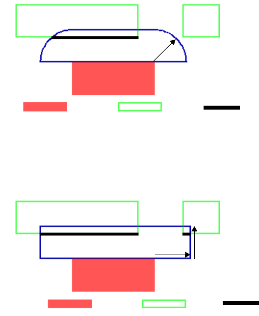
L-Edit 13 User Guide Section 3 561
Chapter 23: HiPer Verify: Calibre Command Files Dimensional Check Operations
TOUCH OUTSIDE EDGE
Dimensional Check Operations
“ENC” (page 563)
“EXT” (page 568)
“INT” (page 573)
Measurement Metrics
Dimensional edge operations (ENC, EXT, INT) measure the distance between pairs of edges of
polygons on different or the same layer, and output results if the specified distance constraint is met. To
determine the output of the measurement of the distance between a pair of edges, a region is constructed
around each edge that extends out from the edge a distance specified by the constraint amount, and with
a shape specified by the measurement metric. Portions of the opposing edge that intersect the region of
a given edge are then output.
The region construction is illustrated below for the three available measurement metrics. The region
construction is shown for one of the edges of layer1, and corresponding output from edges on layer2 is
shown. Region construction is similarly performed on layer2, and output edges from layer1 is
determined. Note that by default, perpendicular edges are not measured.
Euclidean — The Euclidean metric forms a region with quarter-circle boundaries at that extend past the
corners of the selected edges. This is the default metric.
rule_euc {EXT layer1 layer2 < 2}
Square — The Square metric forms a region with right-angle boundaries that extend past the corners of
the selected edges.
rule_sq { EXT layer1 layer2 < 2 SQUARE }.
2
Euclidean
layer1 layer2 Output
Square 2
2
layer1 layer2 Output
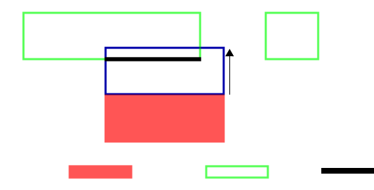
L-Edit 13 User Guide Section 3 562
Chapter 23: HiPer Verify: Calibre Command Files Dimensional Check Operations
TOUCH OUTSIDE EDGE
Opposite — The opposite metric forms a region with right-angle angle boundaries that do not extend
past the corners of the selected edges.
rule_opp { EXT layer1 layer2 < 2 OPPOSITE}.
2
Opposite
layer1 layer2 Output
L-Edit 13 User Guide Section 3 563
Chapter 23: HiPer Verify: Calibre Command Files Dimensional Check Operations
ENC
ENC
ENClosure layer1 layer2 constraint [metric] [polygon_containment]
[connectivity_filter] [orientation_filter] [projection_filter]
[angled_filter] [corner_filter] [intersection_filter] [reversal] [output]
Description
Measures the distance between the outside of layer1 and the inside of layer2 boundaries. Edge pairs that
meet the constraint are output. The ENC command is typically used for enclosure or extension checks.
Note that the behavior of the rule depends on the order of the layers. By default, intersecting or
overlapping edge pairs are not compared.
Parameters
The following parameters are common to all ENC, EXT, and INT RuleChecks.
layer1 A drawn layer, derived polygon layer, or derived edge layer.
layer2 A drawn layer, derived polygon layer, or derived edge layer.
Constraint Constraint is any range defined by “Constraints” (page 427), except
> a, >= a, or != a, where the constraints values must be a non-negative
real number in user units.
metric EUCLIDEAN (Default) — Use the euclidean metric.
OPPOSITE — Use the opposite metric.
SQUARE — Use the square metric.
polygon_containment MEASURE ALL — Specifies that all edges are compared, including
those normally not compared due to intersection, polygon
containment, or visibility blocking.
MEASURE COINcident — Specifies that edge pairs that are outside
coincident that would normally not be compared, should be
compared.
connectivity_filter CONNECTED — Specifies that only edges from the same net are
compared.
NOT CONNECTED – Specifies that only edges from different nets
are compared.
To use these filters, the input layers must posses valid connectivity.
L-Edit 13 User Guide Section 3 564
Chapter 23: HiPer Verify: Calibre Command Files Dimensional Check Operations
ENC
orientation_filter acute_filter
ACUTE ALSO — Specifies to measure edges with an
appropriate angle between 0 and 90 degrees, exclusive. This
is the default behavior if you do not specify a choice from
the acute_filter option subset.
ACUTE ONLY — Specifies to measure only edges with an
appropriate angle between 0 and 90 degrees, exclusive. You
cannot use this parameter and a parameter from the other
subsets of orientation_filter in the same Enclosure operation.
NOT ACUTE — Specifies to not measure edges with an
appropriate angle between 0 and 90 degrees.
parallel_filter
PARAllel ALSO — Specifies to measure parallel edges.
This is the default behavior if you do not specify a choice
from the parallel_filter option subset.
PARAllel ONLY — Specifies to measure only parallel
edges. You cannot use this parameter and a parameter from
the other subsets of orientation_filter in the same Enclosure
operation.
NOT PARAllel — specifies to not measure parallel edges.
perpendicular_filter
NOT PERPendicular — Specifies to not measure
perpendicular edges. This is the default behavior if you do
not specify a choice from the perpendicular_filter option
subset.
PERPendicular ONLY — Specifies to measure only
perpendicular edges. You cannot use this parameter and a
parameter from the other subsets of orientation_filter in the
same Enclosure operation.
PERPendicular ALSO — Specifies to measure
perpendicular edges.
obtuse_filter
NOT OBTUSE — Specifies to not measure edges with an
appropriate angle between 90 and 180 degrees, exclusive.
This is the default behavior if you do not specify a choice
from the obtuse_filter option subset.
OBTUSE ONLY — Specifies to measure only edges with
an appropriate angle between 90 and 180 degrees, exclusive.
You cannot use this parameter and an parameter from the
other subsets of orientation_filter in the same Enclosure
operation.
OBTUSE ALSO — Specifies to measure edges with an
appropriate angle between 90 and 180 degrees, exclusive.
L-Edit 13 User Guide Section 3 565
Chapter 23: HiPer Verify: Calibre Command Files Dimensional Check Operations
ENC
projection_filter PROJecting [constraint] — Specifies to compare the distance
between two edges only when one edge projects onto the other edge
and the length of projection conforms to the constraint. This is the
default behavior, with constraint set to “>=0”, if you do not specify a
choice from this set in the operation.
NOT PROJecting — Specifies to compare the distance between two
edges only when neither edge projects onto the other edge.
angled_filter ANGLED [constraint] — Specifies to measure the two edges only
when the number of non-orthogonal (angled) edges in the pair meets
the given constraint. The constraint is optional and when omitted,
defaults to “> 0”.
corner_filter You cannot specify this filter with an orientation, projection, or
angled filter.
CORNER TO CORNER — Specifies to measure and output errors
only for edges in a corner-to-corner configuration.
Additional options CORNER, CORNER TO EDGE, and NOT
CORNER are not supported at this time.
L-Edit 13 User Guide Section 3 566
Chapter 23: HiPer Verify: Calibre Command Files Dimensional Check Operations
ENC
intersection_filter Specifies to measure intersecting edges, and specifies exactly the
characteristics of intersecting edges that are to be measured.
Intersecting or abutting (coincident) edges are not measured by
default. Coincident or abutting edges are considered to be
intersecting. The value of intersection_filter is:
[ABUT [abut_constraint] ] [OVERLAP] [SINGULAR]
[INTERSECTING ONLY]
You can specify any combination of ABUT, OVERLAP, and
SINGULAR in one operation.
ABUT [abut_constraint] — Specifies that intersecting edges should
also be output if the angle between them conforms to the optional
constraint (interpreted in degrees). Output from the ABUT condition
is in addition to any other output the Enclosure operation generates.
The abut_constraint modifier must contain non-negative real numbers
less than 180. Single-operator constraints such as < 90 and > 135 are
interpreted as >= 0 < 90 and > 135 < 180. With no constraint
specified, the default value is >= 0 < 180.
If the abut_constraint modifier includes zero in its range then any
edges A of layer1 which are coincident inside with edges B of layer2
are also output (because the angle between the exterior side of A and
the interior side of B is zero).
OVERLAP — Specifies that output should also occur where a
polygon from one input layer crosses a polygon from the other input
layer. Edges forming the point of overlap are measured and output as
if an unconstrained ABUT parameter was specified. This overrides
any specified ABUT parameter at the point of overlap only.
This keyword cannot be used when either of the input layers is a
derived edge layer because polygons are required to determine if an
overlap condition is present. Output from the overlap condition is in
addition to any other output generated by the Enclosure operation.
SINGULAR — Specifies that intersecting edges at points of polygon
singularity should also be output. Singularities are point-to-edge or
point-to-point polygon intersections or self-intersections.
INTERSECTING ONLY — Specifies that only intersecting edge
errors are to be output. Must be preceded with at least one of the other
options in this group. The ABUT, OVERLAP, and SINGULAR
options normally add intersecting edge violations to the non
intersecting edge violations that are normally output. The
INTERSECTING ONLY option, when added to one of the other
options, causes only intersecting edge violations to be output. This
filter ignores orientation, angled, projection, and corner filters.
Output REGION [EXTENTS] — constructs polygon projections between
the error edges and then outputs them as polygon data. When you
specify REGION the polygon region is used, but when you specify
REGION EXTENTS the extents of the polygon region is used.
L-Edit 13 User Guide Section 3 567
Chapter 23: HiPer Verify: Calibre Command Files Dimensional Check Operations
ENC
The following parameter applies to ENC only.
Examples
PO.O.1 { @ Minimum POLY extension out of ACTIVE < 0.25
ENC ACTIVE POLY < 0.25 SINGULAR ABUT >=0 <90
}
VIA1.E.1 { @ Min M1 surrounding VIA1 is 0.1
ENC VIA1 M1 < 0.1 ABUT<90 SINGULAR OVERLAP OUTSIDE ALSO
}
reversal INSIDE ALSO — outputs edges from layer2 that are enclosed by the
layer1. When you specify INSIDE ALSO between layer1 and layer2,
then edges from layer2 inside, but not coincident-inside, relative to
layer1 are output by the operation. Layer1 cannot be a derived edge
layer.
The connectivity keywords CONNECTED and NOT CONNECTED
do affect the output from the INSIDE ALSO option. If you specify
NOT CONNECTED, then the INSIDE ALSO parameter does not
output an edge if the polygon containing it (or the edge coincident
inside with it) are on the same electrical node. If you specify
CONNECTED, then the INSIDE ALSO parameter does not output an
edge if the polygon containing it (or the edge coincident inside with
it) are on different electrical nodes.
OUTSIDE ALSO — outputs edges from layer1 that are not enclosed
by layer2. When you specify OUTSIDE ALSO between layer1 and
layer2, then edges from layer1 outside or coincident-outside with
layer2 are output by the operation. If layer2 is a derived edge layer,
then the semantics are restricted to coincident outside edges from
layer1.
The connectivity keywords CONNECTED and NOT CONNECTED
do not affect output from the OUTSIDE ALSO keyword in an
Enclosure operation.
L-Edit 13 User Guide Section 3 568
Chapter 23: HiPer Verify: Calibre Command Files Dimensional Check Operations
EXT
EXT
EXTernal layer1 constraint [metric] [polygon_filter][polygon_containment]
[connectivity_filter] [orientation_filter] [projection_filter]
[angled_filter] [corner_filter] [intersection_filter] [reversal] [output
]
EXTernal layer1 layer2 constraint [metric] [polygon_containment]
[connectivity_filter] [orientation_filter] [projection_filter]
[angled_filter] [corner_filter] [intersection_filter] [reversal] [output]
Description
Measures the distance between the outside of layer1 boundaries, or the distance between the outside of
layer1 and the outside of layer2 boundaries. Edge pairs that meet the constraint are output. By default,
intersecting or overlapping edge pairs are not compared.
Parameters
The following parameters are common to all ENC, EXT and INT RuleChecks.
layer1 A drawn layer, derived polygon layer, or derived edge layer.
layer2 A drawn layer, derived polygon layer, or derived edge layer.
Constraint Constraint is any range defined by “Constraints” (page 427), except
> a, >= a, or != a, where the constraints values must be a non-negative
real number in user units.
metric EUCLIDEAN (Default) — Use the euclidean metric.
OPPOSITE — Use the opposite metric.
SQUARE — Use the square metric.
polygon_containment MEASURE ALL — Specifies that all edges are compared, including
those normally not compared due to intersection, polygon
containment, or visibility blocking.
MEASURE COINcident – Specifies that edge pairs that are outside
coincident that would normally not be compared, should be
compared.
connectivity_filter CONNECTED — Specifies that only edges from the same net are
compared.
NOT CONNECTED – Specifies that only edges from different nets
are compared.
L-Edit 13 User Guide Section 3 569
Chapter 23: HiPer Verify: Calibre Command Files Dimensional Check Operations
EXT
orientation_filter acute_filter
ACUTE ALSO — Specifies to measure edges with an
appropriate angle between 0 and 90 degrees, exclusive. This
is the default behavior if you do not specify a choice from
the acute_filter option subset.
ACUTE ONLY — Specifies to measure only edges with an
appropriate angle between 0 and 90 degrees, exclusive. You
cannot use this parameter and a parameter from the other
subsets of orientation_filter in the same External operation.
NOT ACUTE — Specifies to not measure edges with an
appropriate angle between 0 and 90 degrees.
parallel_filter
PARAllel ALSO — Specifies to measure parallel edges.
This is the default behavior if you do not specify a choice
from the parallel_filter option subset.
PARAllel ONLY — Specifies to measure only parallel
edges. You cannot use this parameter and a parameter from
the other subsets of orientation_filter in the same External
operation.
NOT PARAllel — specifies to not measure parallel edges.
perpendicular_filter
NOT PERPendicular — Specifies to not measure
perpendicular edges. This is the default behavior if you do
not specify a choice from the perpendicular_filter option
subset.
PERPendicular ONLY — Specifies to measure only
perpendicular edges. You cannot use this parameter and a
parameter from the other subsets of orientation_filter in the
same External operation.
PERPendicular ALSO — Specifies to measure
perpendicular edges.
obtuse_filter
NOT OBTUSE — Specifies to not measure edges with an
appropriate angle between 90 and 180 degrees, exclusive.
This is the default behavior if you do not specify a choice
from the obtuse_filter option subset.
OBTUSE ONLY — Specifies to measure only edges with
an appropriate angle between 90 and 180 degrees, exclusive.
You cannot use this parameter and an parameter from the
other subsets of orientation_filter in the same External
operation.
OBTUSE ALSO — Specifies to measure edges with an
appropriate angle between 90 and 180 degrees, exclusive.
L-Edit 13 User Guide Section 3 570
Chapter 23: HiPer Verify: Calibre Command Files Dimensional Check Operations
EXT
projection_filter PROJecting [constraint] — Specifies to compare the distance
between two edges only when one edge projects onto the other edge
and the length of projection conforms to the constraint. This is the
default behavior, with constraint set to “>=0”, if you do not specify a
choice from this set in the operation.
NOT PROJecting — Specifies to compare the distance between two
edges only when neither edge projects onto the other edge.
angled_filter ANGLED [constraint] — Specifies to measure the two edges only
when the number of non-orthogonal (angled) edges in the pair meets
the given constraint. The constraint is optional and when omitted,
defaults to “> 0”.
corner_filter You cannot specify this filter with an orientation, projection, or
angled filter.
CORNER TO CORNER — Specifies to measure and output errors
only for edges in a corner-to-corner configuration.
Additional options CORNER, CORNER TO EDGE, and NOT
CORNER are not supported at this time.
L-Edit 13 User Guide Section 3 571
Chapter 23: HiPer Verify: Calibre Command Files Dimensional Check Operations
EXT
intersection_filter Specifies to measure intersecting edges, and specifies exactly the
characteristics of intersecting edges that are to be measured.
Intersecting or abutting (coincident) edges are not measured by
default. Coincident or abutting edges are considered to be
intersecting. The value of intersection_filter is:
[ABUT [abut_constraint] ] [OVERLAP] [SINGULAR]
[INTERSECTING ONLY]
You can specify any combination of ABUT, OVERLAP, and
SINGULAR in one operation.
ABUT [abut_constraint] — Specifies that intersecting edges should
also be output if the angle between them conforms to the optional
constraint (interpreted in degrees). Output from the ABUT condition
is in addition to any other output the External operation generates.
The abut_constraint modifier must contain non-negative real numbers
less than 180. Single-operator constraints such as < 90 and > 135 are
interpreted as >= 0 < 90 and > 135 < 180. With no constraint
specified, the default value is >= 0 < 180.
If the abut_constraint modifier includes zero in its range then any
edges A of layer1 which are coincident outside with edges B of layer2
are also output (because the angle between the exterior side of A and
the exterior side of B is zero).
OVERLAP — Specifies that output should also occur where a
polygon from one input layer crosses a polygon from the other input
layer. Edges forming the point of overlap are measured and output as
if an unconstrained ABUT parameter was specified. This overrides
any specified ABUT parameter at the point of overlap only.
This keyword cannot be used when either of the input layers is a
derived edge layer because polygons are required to determine if an
overlap condition is present. Output from the overlap condition is in
addition to any other output generated by the Enclosure operation.
SINGULAR — Specifies that intersecting edges at points of polygon
singularity should also be output. Singularities are point-to-edge or
point-to-point polygon intersections or self-intersections.
INTERSECTING ONLY — Specifies that only intersecting edge
errors are to be output. Must be preceded with at least one of the other
options in this group. The ABUT, OVERLAP, and SINGULAR
options normally add intersecting edge violations to the non
intersecting edge violations that are normally output. The
INTERSECTING ONLY option, when added to one of the other
options, causes only intersecting edge violations to be output. This
filter ignores orientation, angled, projection, and corner filters.
Output REGION [EXTENTS] — constructs polygon projections between
the error edges and then outputs them as polygon data. When you
specify REGION the polygon region is used, but when you specify
REGION EXTENTS the extents of the polygon region is used.
L-Edit 13 User Guide Section 3 572
Chapter 23: HiPer Verify: Calibre Command Files Dimensional Check Operations
EXT
The following parameters apply to EXT only.
The following parameters apply to single layer EXT only.
Examples
ACT.S.1 { @ Minimum ACTIVE spacing < 0.5
EXT ACTIVE< 0.5 SINGULAR ABUT <90
}
reversal INSIDE ALSO — outputs edges and edge segments from layer1 or
layer2 that are inside or inside-coincident of the other layer.
The connectivity keywords CONNECTED and NOT CONNECTED
do affect the output from the INSIDE ALSO option. If you specify
NOT CONNECTED, then the INSIDE ALSO parameter does not
output an edge if the polygon containing it (or the edge
coincident-inside with it) are on the same electrical node. If you
specify CONNECTED, then the INSIDE ALSO parameter does not
output an edge if the polygon containing it (or the edge coincident
inside with it) are on different electrical nodes
polygon_filter The secondary keywords in this set instruct the one-layer External
operation to measure the separation between the outsides of edges
based upon polygon membership.
NOTCH — measures the separation between the outsides of two
edges from only the same polygon.
SPACE — measures the separation between the outsides of two
edges from only different polygons.
If you do not specify either NOTCH or SPACE, then both conditions
are measured.
L-Edit 13 User Guide Section 3 573
Chapter 23: HiPer Verify: Calibre Command Files Dimensional Check Operations
INT
INT
INTernal layer1 constraint [metric] [orientation_filter] [projection_filter]
[angled_filter] [corner_filter] [intersection_filter] [output]
INTernal layer1 layer2 constraint [metric] [polygon_containment]
[connectivity_filter] [orientation_filter] [projection_filter]
[angled_filter] [corner_filter] [intersection_filter] [output]
Description
Measures the distance between the inside of layer1 boundaries, or the inside of layer1 and the inside of
layer2 boundaries. Edge pairs that meet the constraint are output. By default, intersecting or overlapping
edge pairs are not compared.
Parameters
The following parameters are common to all ENC, EXT and INT RuleChecks.
layer1 A drawn layer, derived polygon layer, or derived edge layer.
layer2 A drawn layer, derived polygon layer, or derived edge layer.
Constraint Constraint is any range defined by “Constraints” (page 427), except
> a, >= a, or != a, where the constraints values must be a non-negative
real number in user units.
metric EUCLIDEAN (Default) — Use the euclidean metric.
OPPOSITE — Use the opposite metric.
SQUARE — Use the square metric.
polygon_containment MEASURE ALL — Specifies that all edges are compared, including
those normally not compared due to intersection, polygon
containment, or visibility blocking.
MEASURE COINcident – Specifies that edge pairs that are outside
coincident that would normally not be compared, should be
compared.
connectivity_filter CONNECTED — Specifies that only edges from the same net are
compared.
NOT CONNECTED – Specifies that only edges from different nets
are compared.
L-Edit 13 User Guide Section 3 574
Chapter 23: HiPer Verify: Calibre Command Files Dimensional Check Operations
INT
orientation_filter acute_filter
ACUTE ALSO — Specifies to measure edges with an
appropriate angle between 0 and 90 degrees, exclusive. This
is the default behavior if you do not specify a choice from
the acute_filter option subset.
ACUTE ONLY — Specifies to measure only edges with an
appropriate angle between 0 and 90 degrees, exclusive. You
cannot use this parameter and a parameter from the other
subsets of orientation_filter in the same Internal operation.
NOT ACUTE — Specifies to not measure edges with an
appropriate angle between 0 and 90 degrees.
parallel_filter
PARAllel ALSO — Specifies to measure parallel edges.
This is the default behavior if you do not specify a choice
from the parallel_filter option subset.
PARAllel ONLY — Specifies to measure only parallel
edges. You cannot use this parameter and a parameter from
the other subsets of orientation_filter in the same Internal
operation.
NOT PARAllel — specifies to not measure parallel edges.
perpendicular_filter
NOT PERPendicular — Specifies to not measure
perpendicular edges. This is the default behavior if you do
not specify a choice from the perpendicular_filter option
subset.
PERPendicular ONLY — Specifies to measure only
perpendicular edges. You cannot use this parameter and a
parameter from the other subsets of orientation_filter in the
same Internal operation.
PERPendicular ALSO — Specifies to measure
perpendicular edges.
obtuse_filter
NOT OBTUSE — Specifies to not measure edges with an
appropriate angle between 90 and 180 degrees, exclusive.
This is the default behavior if you do not specify a choice
from the obtuse_filter option subset.
OBTUSE ONLY — Specifies to measure only edges with
an appropriate angle between 90 and 180 degrees, exclusive.
You cannot use this parameter and an parameter from the
other subsets of orientation_filter in the same Internal
operation.
OBTUSE ALSO — Specifies to measure edges with an
appropriate angle between 90 and 180 degrees, exclusive.
L-Edit 13 User Guide Section 3 575
Chapter 23: HiPer Verify: Calibre Command Files Dimensional Check Operations
INT
projection_filter PROJecting [constraint] — Specifies to compare the distance
between two edges only when one edge projects onto the other edge
and the length of projection conforms to the constraint. This is the
default behavior, with constraint set to “>=0”, if you do not specify a
choice from this set in the operation.
NOT PROJecting — Specifies to compare the distance between two
edges only when neither edge projects onto the other edge.
angled_filter ANGLED [constraint] — Specifies to measure the two edges only
when the number of non-orthogonal (angled) edges in the pair meets
the given constraint. The constraint is optional and when omitted,
defaults to “> 0”.
corner_filter You cannot specify this filter with an orientation, projection, or
angled filter.
CORNER TO CORNER — Specifies to measure and output errors
only for edges in a corner-to-corner configuration.
Additional options CORNER, CORNER TO EDGE, and NOT
CORNER are not supported at this time.
L-Edit 13 User Guide Section 3 576
Chapter 23: HiPer Verify: Calibre Command Files Dimensional Check Operations
INT
intersection_filter Specifies to measure intersecting edges, and specifies exactly the
characteristics of intersecting edges that are to be measured.
Intersecting or abutting (coincident) edges are not measured by
default. Coincident or abutting edges are considered to be
intersecting. The value of intersection_filter is:
[ABUT [abut_constraint] ] [OVERLAP] [SINGULAR]
[INTERSECTING ONLY]
You can specify any combination of ABUT, OVERLAP, and
SINGULAR in one operation.
ABUT [abut_constraint] — Specifies that intersecting edges should
also be output if the angle between them conforms to the optional
constraint (interpreted in degrees). Output from the ABUT condition
is in addition to any other output the Internal operation generates. The
abut_constraint modifier must contain non-negative real numbers less
than 180. Single-operator constraints such as < 90 and > 135 are
interpreted as >= 0 < 90 and > 135 < 180. With no constraint
specified, the default value is >= 0 < 180.
If the abut_constraint modifier includes zero in its range then any
edges A of layer1 which are coincident outside with edges B of layer2
are also output (because the angle between the exterior side of A and
the interior side of B is zero).
OVERLAP — Specifies that output should also occur where a
polygon from one input layer crosses a polygon from the other input
layer. Edges forming the point of overlap are measured and output as
if an unconstrained ABUT parameter was specified. This overrides
any specified ABUT parameter at the point of overlap only.
This keyword cannot be used when either of the input layers is a
derived edge layer because polygons are required to determine if an
overlap condition is present. Output from the overlap condition is in
addition to any other output generated by the Enclosure operation.
SINGULAR — Specifies that intersecting edges at points of polygon
singularity should also be output. Singularities are point-to-edge or
point-to-point polygon intersections or self-intersections.
INTERSECTING ONLY — Specifies that only intersecting edge
errors are to be output. Must be preceded with at least one of the other
options in this group. The ABUT, OVERLAP, and SINGULAR
options normally add intersecting edge violations to the non
intersecting edge violations that are normally output. The
INTERSECTING ONLY option, when added to one of the other
options, causes only intersecting edge violations to be output. This
filter ignores orientation, angled, projection, and corner filters.
Output REGION [EXTENTS] — constructs polygon projections between
the error edges and then outputs them as polygon data. When you
specify REGION the polygon region is used, but when you specify
REGION EXTENTS the extents of the polygon region is used.
L-Edit 13 User Guide Section 3 577
Chapter 23: HiPer Verify: Calibre Command Files Dimensional Check Operations
INT
Examples
M1.W.1 { @ Minimum M1 width < 0.6
INT M1 < 0.6 SINGULAR REGION ABUT < 90
}
L-Edit 13 User Guide Section 3 579
Chapter 23: HiPer Verify: Calibre Command Files Text Based Operations
EXPAND TEXT
EXPAND TEXT
EXPAND TEXT text_name [text_layer] BY number [PRIMARY ONLY]
Description
Produces a derived polygon layer containing squares centered on the locations of text objects having the
specified text_name. The sides of the squares have length equal to number.
The parameter order must be observed to avoid ambiguity. The text_name is case insensitive. The
text_name parameter can contain one or more question mark (?) wildcard characters, where the (?)
matches zero or more characters.
Parameters
text_name The name of a text object. Can be a string variable.
text_layer An optional drawn layer that contains the text_name. The text_layer
option is used to restrict the text search to the specified layer.
number A positive floating-point number in user units that specifies the size
of the squares.
PRIMARY ONLY An optional keyword that specifies only text at the top level of the
hierarchy is used.
L-Edit 13 User Guide Section 3 580
Chapter 23: HiPer Verify: Calibre Command Files Text Based Operations
WITH TEXT
WITH TEXT
[NOT] WITH TEXT layer1 text_ name [text_layer] [PRIMARY ONLY]
Description
Produces all layer1 polygons that intersect the location of text objects having the specified text_name.
The command parameter order must be observed. If text_layer is specified, then only text objects with
the specified name on layer text_layer are considered, otherwise all layers are considered.
The Text, Text Depth, and Text Layer statements have no effect on With Text operations.
Parameters
Example:
The text_layer equal to 40 in the example below means to look only on layer 40 for “TEXTPAD”,
“PROBEPAD”, and “SCRIBE”. If the “40” were not present, then look on all layers.
LAYER pad 40
pad_t = pad WITH TEXT "TESTPAD" 40
pad_p = pad WITH TEXT "PROBEPAD" 40
pad_sc = pad WITH TEXT "SCRIBE" 40
layer A drawn or derived polygon layer.
text_name The name of a text object, which can contain one or more question
mark (?) characters. The ? is a wildcard character that matches zero or
more characters. The name can be a string variable (see Variable).
text_layer A drawn layer containing text objects. Text_layer can be a layer name
or GDS number.
PRIMARY ONLY Specifies that only top-level text is to be considered.
L-Edit 13 User Guide Section 3 582
Chapter 23: HiPer Verify: Calibre Command Files Netlist Extraction Operations
DEVICE
DEVICE
DEVice {element_name [(model_name)]} device_layer {pin_layer [(pin_name)] }
[<auxiliary_layer>][BY NET | BY SHAPE][property_specification]
Description
The DEVice statement defines devices for netlist extraction, defines how devices are to be recognized,
names pins, and defines properties of devices and how they are computed.
Parameters
element_name The type of the device, which may be either built-in or user-defined.
Predefined element names specify built-in (or reserved) devices. All
other devices are user-defined (or generic).
model_name An optional string, enclosed in parentheses, that specifies the model
for the device. It is also known as the component subtype of the
device. If specified, it must immediately follow the element_name
parameter.
device_layer A required layer containing the device recognition shapes. It is also
called the seed layer. The device layer is the first layer you specify
within the operation given the recognition precedence of the
element_name as discussed previously. Device recognition is
centered around each device (or seed) shape on this layer. You can
specify the device_layer as one of the pin_layers, but not more than
once per statement. Connectivity need not be established on these
layers.
L-Edit 13 User Guide Section 3 583
Chapter 23: HiPer Verify: Calibre Command Files Netlist Extraction Operations
DEVICE
pin_layer A required layer on which pin shapes for the device are found. You
can specify multiple pin_layer names. These layers must have their
connectivity established by connectivity extraction operations. A
layer has connectivity when one of the following conditions is
satisfied:
A Connect operation contains the layer.
A net-preserving operation derives the layer from a
separate layer carrying a net number
A Stamp operation transfers net numbers to the layer.
Device recognition logic, not the connectivity extractor, associates
pin shapes to device shapes. Therefore, you do not need to connect
the pin layers to the device layer by Connect statements. To do so
would short the pins together through the device shape. Pins using the
same layer in a Device statement are interchangeable and belong to
the same pin-swap group. Note that pin shapes must touch or overlap
device recognition shapes in order for a device to be recognized.
Touching at a corner point does not satisfy this condition. Device
shapes that do not touch the correct pin layers are considered bad
devices, and are listed in the Verification Error Navigator. If the
element_name in the statement is a reserved name, then you must
specify one layer for each pin. If a device has more than one pin on a
given layer, you must repeat that layer as a parameter for each
associated pin. The same device, auxiliary, and pin layers can appear
in multiple Device statements. However, to prevent ambiguity, the
following restriction is enforced: if two statements have the same
device_layer, then it must not be possible to reorder the list of
auxiliary and pin layers in one statement so that it exactly matches the
list of auxiliary and pin layers in the other statement. In making the
comparison, the device_layer should be ignored in any list where it
appears as a pin_layer. For example:
device foo A B(p) A(q)
device bar A B(p)
causes a compilation error since
L-Edit 13 User Guide Section 3 584
Chapter 23: HiPer Verify: Calibre Command Files Netlist Extraction Operations
DEVICE
(pin_name) An optional name, enclosed in parentheses, that explicitly names each
pin in the definition of a device. The parameter pair pin_layer
(pin_name) can be specified any number of times in one statement.
If the element_name in the statement is built-in for recognition, then
default pin_names are assigned. You can specify the device_layer as
one of the pin layers, but not more than once per statement. Pin names
do not need to be explicitly provided, but if present, they must match
the default names that would have been assigned if you want to use the
built-in algorithms for property calculation. Providing pin names for
built-in-for-recognition elements makes the rule file more readable and
is recommended.
If the element has extra pins in addition to the default pins, then a
pin_name parameter must be provided following each extra pin_layer
in the Device statement. The order of the extra pin layers is
unimportant in the Device statement. For the extra pins, you can create
any pin names you wish, except reserved keywords must be enclosed
in double quotation marks.
If the element_name in the statement is user-defined, then a pin_name
parameter must be provided following each pin_layer in the Device
operation. The pin_layer order is unimportant in the Device operation
in this case. However, the order of pin layers can determine the order
in which pins are listed in an extracted netlist. You may use any pin
names as desired, except if you use a reserved keyword for a pin_name
then you must enclose the pin_name in double quotes.
The same pin_name parameter cannot be used twice in the same
Device statement, but can be reused in other statements. If the
schematic for the device uses certain pin names, then the same names
should be used in the Device operation so that LVS applications can
match correct pins.
<auxiliary_layer>
[<auxiliary_layer> ...]
An optional layer name, enclosed in angle brackets ( < > ), that
identifies non-pin layers used to classify device instances and used in
property computation. You can specify <auxiliary_layer> any number
of times in one statement. They can appear before, after, or intermixed
with the pin layers.
An auxiliary layer is a layer containing shapes that are neither seed nor
pin shapes. You can use auxiliary layers to interact with other shapes
of the device for property alteration, or to classify the device. For each
auxiliary layer present in a Device operation, at least one shape from
that layer must touch or overlap the seed shape before a device instance
can be extracted. You cannot limit the number of overlapped shapes,
although a property computation can determine the number of shapes
found to touch or overlap by using the COUNT( ) function of the
built-in property computation language.
Auxiliary layers do not need to have connectivity. Any node
information on auxiliary layers is unavailable to device extraction. An
auxiliary layer cannot appear twice in the same Device statement. You
cannot use a layer as both an <auxiliary_layer> and a pin_layer in the
same Device operation, nor in any other Device operation using the
same device_layer.
L-Edit 13 User Guide Section 3 585
Chapter 23: HiPer Verify: Calibre Command Files Netlist Extraction Operations
DEVICE
BY NET | BY SHAPE An optional keyword set that selects the pin recognition method for the
device. Two device recognition operations in the rule file with the same
device_layer must have the same pin recognition method. The possible
choices are:
BY NET — Treats pin shapes on the same layer and connected to the
same net as a single pin. This is the default behavior if you do not
include a keyword from this set. The pin fill-in algorithm is used to
supply missing pins, where applicable.
BY SHAPE — Treats pin shapes as separate pins even when they are
on the same layer and are connected to the same net. Also, no fill-in is
attempted to supply missing pins. Specifying BY SHAPE can increase
runtime significantly.
[property_specification]An optional string, enclosed in square brackets ([ ]), that specifies
which properties are to be computed for device instances and how they
are computed.
A property specification can take one of two forms: either a list of
floating-point numbers, or a short program written in a property
computation language. The list of numbers form is only applicable to
certain reserved element names.
The following is an example of each form of property specification:
DEVice R resistor_layer metal_1 metal_2 [1.1]
// resistivity is 1.1 resistance units per square
// internal default calculation is used to find
// resistance
DEVice R layer metal_1 metal_2
[
property R
R = .5*(AREA(layer)-AREA_COMMON(layer, metal_1)-
AREA_COMMON(layer, metal_2))
]
/* R is defined as the resistance of the device and
calculated as shown */
If you provide a property specification algorithm, you take on
responsibility for calculating all properties of the device. The device is
then considered user-defined, even if it has a reserved element_name.
L-Edit 13 User Guide Section 3 586
Chapter 23: HiPer Verify: Calibre Command Files Optimizing Performance
DEVICE
Optimizing Performance
Size
The SIZE command, with STEP option,
SIZE layer1 BY size_value [INSIDE OF|OUTSIDE OF] layer2 [STEP step_value]]
will perform a sequence of size operations by step_value, until a total sizing of size_value has been
achieved (the last step_value may be reduced to obtain a size of exactly size_value). Certain foundry
DRC file contain very small values of step_value, resulting in a very large number of steps and slow
performance on these commands. Temporarily removing these commands by commenting them out can
significantly improve performance of the whole DRC job. You will also need to comment out layers
that derive from these operations.
L-Edit 13 User Guide Section 3 587
Chapter 23: HiPer Verify: Calibre Command Files Summary and Classification of Commands
DEVICE
Summary and Classification of Commands
Commands can be classified as either layer selectors or layer constructors. Commands classified as
layer selectors select existing polygon or edge data from the appropriate input layer. Commands
classified as layer constructors create new polygon data.
Polygon Layer Selectors
The table below lists the polygon layer selector operations. These commands select polygons from an
input layer.
Edge Layer Selectors
The table below lists the edge layer selector operations. These commands select edge from an input
layer.
[Not] Area
Copy
[Not] Cut
[Not] Donut
[Not] Enclose
[Not] Enclose Rectangle
[Not] Inside
[Not] Interact
[Not] Net
[Not] Outside
Perimeter
[Not] Rectangle
[Not] Touch
Vertex
[Not] With Edge
[Not] With Text
[Not] With Width
[Not] Angle
[Not] Coincident Edge
[Not] Coincident Inside
Edge
[Not] Coincident Outside
Edge
Convex Edge
L-Edit 13 User Guide Section 3 588
Chapter 23: HiPer Verify: Calibre Command Files Summary and Classification of Commands
DEVICE
Layer Constructors
Operations classified as layer constructors create new polygon data. The table below lists the layer
constructor operations.
Copy
Drawn Acute*
Drawn Offgrid *
Drawn Skew*
Enclosure (edge-directed
dimensional check)
External (edge-directed
dimensional check)
[Not] Inside Edge
Internal (edge-directed
dimensional check)
[Not] Length
Offgrid*
[Not] Outside Edge
Path Length
[Not] Touch Edge
[Not] Touch Inside Edge
[Not] Touch Outside Edge
AND
[Not] Inside Cell
Density
Enclosure
(polygon-directed check)
Expand Edge
Expand Text
Extent
Extents
External (polygon-directed
check)
Flatten
Grow
Holes
Internal (polygon-directed
check)
Merge
L-Edit 13 User Guide Section 3 589
Chapter 23: HiPer Verify: Calibre Command Files Summary and Classification of Commands
DEVICE
NOT
OR
Pathchk
Rectangles
Shrink
Size
Snap
Stamp
XOR
L-Edit 13 User Guide Section 3 590
Chapter 23: HiPer Verify: Calibre Command Files Command File Examples
DEVICE
Command File Examples
“A Minimal Command File” (page 590)
“A Basic Command File” (page 590)
A Minimal Command File
The smallest command file consists of :
A PRECISION statement to define the ratio of user units to database units
LAYER statement(s) to define drawn layers
A RuleCheck statement
Note that the LAYER statement can be use to give a layer a different name in the command file
compared to the tdb file. One could have layer Metal1 with GDS number 49 in the tdb file, but define
LAYER M1 49 in the command file.
PRECISION 1000
LAYER M1 49
M1.S { @ M1 Spacing < 0.3
EXT M1 < 0.3
}
A Basic Command File
//*******************************************************************
// Sample DRC Command File
//*******************************************************************
TITLE "Sample DRC Command File"
// Setup Info
PRECISION 1000
RESOLUTION 10
FLAG ACUTE YES
FLAG SKEW YES
FLAG OFFGRID YES
FLAG NONSIMPLE YES
// Input Layers
LAYER ACTIVE 1
LAYER POLY 2
LAYER CONTACT 3
LAYER METAL1 4
// Common Derived Layers
FIELD_POLY = POLY NOT ACTIVE
POLY_CONT = CONTACT NOT OUTSIDE FIELD_POLY
DIFF_CONT = CONTACT OUTSIDE FIELD_POLY
// POLY DRC Rules
PO.1 { @ Minimum poly space < 0.38
L-Edit 13 User Guide Section 3 591
Chapter 23: HiPer Verify: Calibre Command Files Command File Examples
DEVICE
EXT POLY < 0.38 ABUT < 90
}
PO.2 { @ Minimum poly on field space to active < 0.16
EXT POLY ACTIVE < 0.16 ABUT < 90 SINGULAR
}
PO.3 { @ Minimum active extend gate < 0.6
ENC POLY ACTIVE < 0.6 SINGULAR ABUT < 90
}
// CONTACT DRC Rules
CO.1 { @ Contact width != 0.30
NOT RECTANGLE CONTACT == 0.30 BY == 0.30
}
CO.2 { @ Contact spacing < 0.30
EXT CONTACT < 0.30 SINGULAR
}
CO.3 { @ POLY contact space to active < 0.28
EXT POLY_CONT ACTIVE < 0.28 SINGULAR ABUT <90
}
CO.4 { @ Active overlap contact < 0.12, also floating contacts
ENC DIFF_CONT ACTIVE < 0.12 SINGULAR ABUT <90 OUTSIDE ALSO
}
// METAL1 DRC Rules
M1.1 { @ METAL1 width < 0.36
INT METAL1 < 0.36 SINGULAR ABUT < 90
}
M1.2 { @ METAL1 spacing < 0.36
EXT METAL1 < 0.36 ABUT < 90
}
M1.3 { @ Min METAL1 density < 30%
DENSITY METAL1 < 0.30
}
L-Edit 13 User Guide Section 3 592
Chapter 23: HiPer Verify: Calibre Command Files Unsupported Commands
DEVICE
Unsupported Commands
L-Edit does not support all of the Calibre commands, particularly if they do not relate to DRC, or all of
the options and flags in some commands.
Omitted Commands
The following environment setup commands are not supported as they are not required when running
DRC in the L-Edit environment.
The indicated options are not supported in the following commands.
DRC RESULTS DATABASE It is not necessary to specify an external results filename. Results are
saved in the tdb file.
DRC CHECK MAP This statement controls the database output structure in Calibre. It is
not required in HiPer Verify.
DRC CHECK TEXT This statement controls what components of a rule in the command
file get copied into the Calibre results database. It is not required in
HiPer Verify.
DRC EXCLUDE FALSE
NOTCH
This statement overrides the default Calibre behavior to suppress
certain false errors. It is not required in HiPer Verify.
DRC MAXIMUM VERTEX A user specified limit on the number of vertices on error polygons is
not supported. Polygon fracturing on layout is supported by the
Draw > Convert > Fracture Polygons command.
DRC RESULTS DATABASE It is not necessary to specify an external results filename. Results are
saved in the tdb file.
DRC KEEP EMPTY Specifies whether rule checks containing no errors are saved to DRC
results. HiPer always saves all rule checks so one can see the rule was
checked, even when there are no errors. Checks with no errors can be
made visible or not visible in the Verification Error Navigator.
DRC SUMMARY REPORT It is not necessary to specify an external summary file name. A
summary report is always created and saved in the tdb file. It may be
opened in a text window from the Verification Error Navigator
toolbar with Actions > Open DRC Summary Report, and then saved
to disk.
LAYOUT DEPTH Checking toplevel polygons only is not supported. The entire
hierarchy is processed.
LAYOUT PATH LAYOUT PATH is not required in HiPer Verify. DRC is run on the
currently active cell in the open tdb file.
LAYOUT PRIMARY DRC is run on the currently active cell. LAYOUT PRIMARY is not
required in HiPer Verify.
LAYOUT SYSTEM In Calibre, specifies the layout file type. Not required in HiPer Verify.
AND Single layer syntax is not supported. AND layer1 [constraint]
L-Edit 13 User Guide Section 3 593
Chapter 23: HiPer Verify: Calibre Command Files Unsupported Commands
DEVICE
EXTENT CELL EXTENT CELL is not supported.
[Not] With Neighbor Optional constraints.

L-Edit 13 User Guide Section 3 594L-Edit 13 User Guide Section 3 594
24 HiPer Verify: Dracula Command
Files
Introduction
This section provides a reference to Dracula compatible DRC command file format.
Structure of a Dracula File
A Dracula format command file has the following major sections. Each block begins with a statement
that identifies the block and ends with an *END statement. The *END statement is always the last line
in the block. The block statements begin with an asterisk (*) in the first column.
“Description Block” (page 596)
The Description block contains Environment Setup commands and Geometry Flag commands.
“Input-Layer Block” (page 608)
The Input-Layer block contains Drawn Layer and Text Layer definition commands.
“Operation Block” (page 619)
The Operation block contains the Boolean, size, selection, area, rule check and remaining
commands.
Simple Example of a Dracula File
*DESCRIPTION
; Place environment commands in the DESCRIPTION block.
SCALE = .001 MICRON
RESOLUTION = .001 MICRON
FLAGNON45 = YES
FLAG-OFFGRID = YES
*END
*INPUT-LAYER
; Define input layers in the INPUT-LAYER block.
POLY = 1
*END
*OPERATION
; Place Boolean, Select, Size, and Dimensional check operations
; in the OPTATION block
WIDTH POLY LT 0.18 OUTPUT POW1A 63
*END
3
Chapter 24: HiPer Verify: Dracula Command Files Introduction
L-Edit 13 User Guide Section 3 595
Command Usage
Commands can be used as layer derivation statements, or in rule check statements.
A layer derivation statement consists of directing the results of a command to a named layer.
AND POLY ACTIVE GATE
A rule check statement uses the OUTPUT keyword to direct the results of a command to the
Verification Error Navigator. The name after the OUTPUT keyword is the rulename that will
appear in the Verification Error Navigator. The number following the rulename is a layer number
used by Dracula.
EXT GATE LT 2.0 OUTPUT GAS1 64
Any command, not only dimensional check operations, may direct errors to the Verification Error
Navigator. For example
SEL VIA OUTSIDE METAL V1 OUTPUT V1 64
Conjunctive Rules
Errors from dimensional check operations can be reprocessed using conjunctive rule syntax. The
following commands can be used to create conjunctive rules:
ENC
EXT
INT
WIDTH
LENGTH
Consider the following sequence for finding M1 segments that are narrower than 3.0, closer than 5.0 to
other narrow segments , and longer than 10.0:
WIDTH M1 LT 3.0 &
EXT M1 LT 5.0 &
LENGTH M1 GE 10.0 OUTPUT M1_THINCLOSELONG 64
The & operator causes the results of the command to be placed on a temporary layer conjoined to M1.
Any references to M1 after the & and before the next OUTPUT keyword will use the temporary layer,
and will continue to filter the results until they are output by the OUTPUT statement. After the
OUTPUT statement, usage of M1 will refer to the original M1 layer.
Conjunctive rename allows renaming of the result of a conductive rule. Consider the following
sequence for finding M1 segments that are closer than 5.0 to other M1 segments, and longer than 10.0.
The results of the first operation are put on a layer called &M1CLOSE.
EXT M1&M1CLOSE LT 5.0 &
LENGTH &M1CLOSE GE 10.0 OUTPUT M1_CLOSELONG 64
Dimensional Check statements can also output results to a named layer, for subsequent processing using
the R or R’ flag. Consider the following sequence for finding GATE lengths less than 0.5:
AND POLY ACTIVE GATE
ENC [TR] GATE ACTIVE LT 0.001 GL
PLENGTH GL LT 0.5 OUTPUT GATELENGTH 64
Chapter 24: HiPer Verify: Dracula Command Files Environment Setup RESOLUTION
L-Edit 13 User Guide Section 3 597
RESOLUTION
RESOLUTION = step-size units
Description
Defines the grid size for offgrid checking by the FLAG-OFFGRID command. This command can
appear only once in the Description Block.
Note: L-Edit/DRC will not automatically snap offgrid vertices to the RESOLUTION grid, as Dracula
will.
Arguments
Examples
RESOLUTION = 0.010 MICRONS
Calibre Format
RESOLUTION 1/step-size
step-size A positive integer that defines the grid size for offgrid checking by
the FLAG-OFFGRID command.
units MICRONS or MILS ( MICRON, MIC, and MIL are also allowed.)
Chapter 24: HiPer Verify: Dracula Command Files Environment Setup SCALE
L-Edit 13 User Guide Section 3 598
SCALE
SCALE = unit-size units
Description
Specifies the number of internal database units that equals one layout unit. This command can appear
only once in the Description Block.
Arguments
Examples
scale= .001 MICRONS
Calibre Format
PRECISION 1/unit-size
unit-size A positive integer.
Units MICRONS or MILS ( MICRON, MIC, and MIL are also allowed.)
Chapter 24: HiPer Verify: Dracula Command Files Environment Setup DELCEL
L-Edit 13 User Guide Section 3 599
DELCEL
DELCEL = name …
Description
Excludes instances of specified cells from layout when processing DRC commands. Cells may also be
excluded from DRC processing by checking “Exclude instances of this cell from DRC” in the
Cell >Info dialog in L-Edit.
Arguments
Examples
DELCEL LOGO PICTURE
Calibre Format
EXCLUDE CELL name …
name The name of a cell. If a cell name has spaces, then the name is in
quotes. Name can be specified any number of times in one statement
Chapter 24: HiPer Verify: Dracula Command Files Geometry Flags FLAG-ACUTEANGLE
L-Edit 13 User Guide Section 3 601
FLAG-ACUTEANGLE
FLAG-ACUTEANGLE = NO | YES
Description
Reports an error for any two consecutive edges of a drawn polygon or wire that form an acute angle.
This command can appear only once in the command file.
Arguments
Examples
FLAG-ACUTE = YES
Calibre Format
FLAG ACUTE {NO | YES}
NO Default. Do not report acute angles.
YES Report acute angles.
Chapter 24: HiPer Verify: Dracula Command Files Geometry Flags FLAG-NON45
L-Edit 13 User Guide Section 3 602
FLAG-NON45
FLAG-NON45 = NO | YES
Description
Reports an error for any non-90 or non-45 degree edge of a drawn polygon or centerline segment of a
drawn wire. Reporting is based on the angle of the edge in its cell coordinate space, not in coordinate
space of instances of that cell. This command can appear only once in the command file.
Arguments
Examples
FLAG-NON45 = YES
Calibre Format
FLAG SKEW {NO | YES}
NO Default. Do not report non-90/non-45 degree edges.
YES Report non-90/non-45 degree edges.
Chapter 24: HiPer Verify: Dracula Command Files Geometry Flags FLAG-OFFGRID/FLAG-PTH-OFFGRID
L-Edit 13 User Guide Section 3 603
FLAG-OFFGRID/FLAG-PTH-OFFGRID
FLAG-OFFGRID = NO | YES {grid-value}
FLAG-PTH-OFFGRID = NO | YES
Description
Reports an error for every offgrid vertex of drawn polygons and wires. Also reports errors for offgrid
instance placements, rotated instances, and instance arrays and scaling that could result in offgrid
geometry. Checking and reporting is done in the context of the cell. The grid is defined by the
RESOLUTION command, or can be overridden by the FLAG-OFFGRID command. This command can
appear only once in the command file.
Note: L-Edit/DRC does not have separate control of offgrid checking for polygons and wires. If either
of these options are YES, then L-Edit/DRC will check polygons, wires and instances for offgrid.
Arguments
Examples
FLAG-OFFGRID = YES
Calibre Format
FLAG OFFGRID YES
NO Default. Do not report offgrid vertices and instances.
YES Report offgrid vertices and instances.
GRID-VALUE Grid value that overrides the RESOLUTION value.
Chapter 24: HiPer Verify: Dracula Command Files Geometry Flags FLAG-SELFINTERS/FLAG-SELFTOUCH
L-Edit 13 User Guide Section 3 604
FLAG-SELFINTERS/FLAG-SELFTOUCH
FLAG-SELFINTERS = YES {FULL}
Description
Report an error if two edges on the same drawn polygon intersect or if filled region of the polygon is
ambiguous. Wires are checked for intersections based on the outer boundary of the wire.
Self-intersecting polygons and wires are always reported as errors. Self intersecting polygons and wires
are ignored by all layer generation and rule checking commands. A no argument in this command will
be ignored, and self-intersections will be checked anyway. The FULL option tells DRACULA to flag
re-entrant polygons. In L-Edit DRC these are always flagged, so the FULL option is not required. This
command can appear only once in the command file.
Examples
FLAG-SELFINTERS = YES
Calibre Format
FLAG NONSIMPLE YES

Chapter 24: HiPer Verify: Dracula Command Files Text Processing Definitions TEXT-LEVEL
L-Edit 13 User Guide Section 3 606
TEXT-LEVEL
TEXT-LEVEL = n1:n2 / n
Description
Specifies the number of levels of hierarchy from which to read text. This command applies to cell and
composite texts. Count the depth levels from the primary cell or level 0.
Note: TEXT-LEVEL = 0 has the same effect as the TEXT-PRI-ONLY = YES command.
Arguments
Example
In this example, Dracula reads text from the primary cell:
TEXT-LEVEL = 0
In this example, Dracula reads text from level 0 to level 3:
TEXT-LEVEL = 3
In this example, Dracula reads text from level 3 to level 5:
TEXT-LEVEL = 3:5
In this example, Dracula reads text from level 3 only:
TEXT-LEVEL = 3:3
Translation to Calibre
TEXT-LEVEL = n
translates to: TEXT DEPTH = n
TEXT-LEVEL = n1:n2
translates to: TEXT DEPTH = >= n1 <= n2 (Not standard Calibre.)
n1:n2 The range of levels of hierarchy from which Dracula reads text.
n The range from 0 to n levels of hierarchy from which text is read.

Chapter 24: HiPer Verify: Dracula Command Files Text Processing Definitions TEXT-PRI-ONLY
L-Edit 13 User Guide Section 3 607
TEXT-PRI-ONLY
TEXT-PRI-ONLY = YES/NO
Description
Processes only the text associated with the top-level (primary) cell in the layout. This command ignores
text associated with cells nested below the top-level cell, even if the text is on the same text layer
number. If you do not specify TEXT-PRI-ONLY, Dracula places all text at the top level and processes
it. However, the TEXT-LEVEL command will override TEXT-PRI-ONLY.
Arguments
Translation to Calibre
TEXT-PRI-ONLY = YES
translates to TEXT DEPTH = PRIMARY
TEXT-PRI-ONLY = NO
translates to TEXT DEPTH = ALL (default)
Note: Dracula default is to process text from all cells. Calibre default is to process text from
toplevel (primary) cell only.
YES Translates to TEXT-DEPTH = PRIMARY.
NO Translates to TEXT-DEPTH = ALL (default).
Chapter 24: HiPer Verify: Dracula Command Files Drawn Layer Definitions Attaching Text
L-Edit 13 User Guide Section 3 609
Attaching Text
In L-Edit, you do not directly attach text strings to layout geometries. Text strings are part of a separate
layer and do not have pointers back to polygons. Dracula attaches text to its corresponding geometry
according to your definition in the Input-Layer block.
The ATTACH command attaches text to a geometry on a layer. The following command will attach text
on layer 9 to layer Metal. Text on layer 9 can now only be used to attach to metal, and will not attach to
any other layer.
* INPUT-LAYER
Metal = 9 TEXT = 9 ATTACH Metal
The following command will attach text on layer 109 to layer Metal.
* INPUT-LAYER
Metal = 9 TEXT = 109 ATTACH Metal
The ATTACH command can also be written on a separate line than the layer definition:
* INPUT-LAYER
Metal = 9
TEXT = 109 ATTACH Metal
Text that is not attached to a specific layer can attach to any layer, as specified by the
CONNECT-LAYER command, and the optional TEXTSEQUENCE COMMAND. In the following
example, text on layer 9 will label any layer, according to CONNECT-LAYER and TEXTSEQUENCE,
as there is no ATTACH command.
* INPUT-LAYER
Metal = 9 TEXT = 9
Example
*INPUT-LAYER
diffus = 2
poly = 8
metal = 9 TEXT = 60
text = 20 ATTACH metal
CONNECT-LAYER = diffus poly metal
PAD-LAYER = vapox
*END
In this example, the text on layer 60 is not specifically attached to one layer, so it attaches to one of the
connect layers. The text on layer 20 can attach only to layer metal.
Dracula attaches text in the reverse order of the CONNECT-LAYER, where the metal layer has the
highest priority and the diffusion layer the lowest. In the previous example, text strings with coordinates
within the metal geometries are attached to the metal layer and eliminated from further attachments. All
remaining text in the polysilicon is attached. Finally, the text in the diffusion is attached and Dracula
discards any text outside the three layers.
Chapter 24: HiPer Verify: Dracula Command Files Drawn Layer Definitions Layer Assignment
L-Edit 13 User Guide Section 3 610
Layer Assignment
layer-name = layer-number {OFFGRID = off-grid} {DATATYPE = data-type}
{TEXT = text-layer} {IDTEXT layer} {TEXTTYPE text-type} {ATTACH
layer-name1}
TEXT = text-layer {TEXTTYPE text-type} {ATTACH layer-name1}
Description
Defines the name of a drawn layer in terms of its GDSII number.
A layer assignment statement is required in the command file in order to use a drawn layer in a layer
derivation or DRC command when running DRC from within the L-Edit environment. Layer
assignments statements can be used to map a layer name in the L-Edit editing environment to a different
name in the DRC command file by assigning the same GDSII number to the layer in each location.
To make a layer in the tdb file to be equal to different layer name in the DRC command file then assign
the same GDS number to that layer in Setup Layers >General in the tdb file, and to the new name in a
layer assignment statement in the command file. A summary of mappings will be reported in the DRC
Summary Report for all layer names that are different in the tdb file and command file.
Arguments
Unsupported Arguments
ANGLE = ALL/90/45/NON-45/ACUTE/NON-90/NON-ACUTE
layer-name User-defined layer name. You can use the same layer name on more
than one line to group layers from different layer numbers.
layer-number The GDS number of the assigned layer in the layout CAD system.
Also, you can use inclusive range values (for example, metal = 1:3.
DATATYPE = data-type Specifies a datatype or range of datatypes for the corresponding GDS
number, to assign to the layer. A range of datatypes is specified as
DATATYPE=5:10. The default is all datatypes.
TEXT = text-layer Specifies the GDS layer number for text.
TEXTTYPE = text-type The GDS datatype or range of datatypes for the corresponding GDS
number, to assign to the layer. Text-type is the same as datatype, but
refers to text objects.
ATTACH layer-name1 The attach operation assigns names to extracted nets using text
objects (ports) placed on the layout. It attaches the name of a text
object on layer1 to a net containing a polygon on layer2 if the polygon
completely covers the text object. The layer-name1 parameter is the
layer name given to the text defined by the text-layer parameter. The
layers specified by layer-name1must appear in a CONNECT-LAYER
or TEXTSEQUENCE command.
Chapter 24: HiPer Verify: Dracula Command Files Drawn Layer Definitions Layer Assignment
L-Edit 13 User Guide Section 3 611
Examples
Example1:
Poly1 = 46
Example2: Layer OD consists of GDS layers 3, 11, and 12.
OD = 3
OD = 11
OD = 12
Example 3: Using DATATYPE
METAL1-TIGHT = 49 DATATYPE = 1
METAL1 = 49 DATATYPE 0:3
METAL1 does not contain objects from layer 49 datatype 1, as these were used by METAL1-TIGHT.
Calibre Format
// Dracula command: Layer-name = layer-number
LAYER layer-name layer-number
// Dracula command: layer-name = layer-number DATATYPE = 5:10
LAYER layer-name 1000 // 1000 is a temporary GDS number
LAYER MAP layer-number DATATYPE >=5 <= 10 1000

Chapter 24: HiPer Verify: Dracula Command Files Drawn Layer Definitions Layer-Name Definition
L-Edit 13 User Guide Section 3 612
Layer-Name Definition
layer-name = layer-number {OFFGRID = off-grid} {DATATYPE = data-type}
{TEXT = text-layer} {TEXTTYPE text-type} {ATTACH layer-name1}
{ANGLE = ALL/90/45/NON-45/ACUTE/NON-90/NON-ACUTE}
TEXT = text-layer layer-purpose {TEXTTYPE text-type} {ATTACH layer-name1}
{ANGLE = ALL/90/45/NON-45/ACUTE/NON-90/NON-ACUTE}
Description
The layer-name variable assigns names to layout layers. You can name layers from GDSII, Edge, EDIF,
or CIF formats.
Note: Dracula can read the same layer for both TEXT and CTEXT text, but you cannot
attach text in the same layer to different layers.
For example, in the following some of the text attached to MET is lost:
POLY=3 CTEXT=29 ATTACH=POLY
MET=6 CTEXT=29 ATTACH=MET
VAPOX=7 TEXT=29
Arguments
layer-name User-defined layer name.
layer-number The GDS number for the layer name.
off-grid Translate to Calibre: layer-name_offgrid {OFFGRID layer-name
off-grid}
data-type Specifies a datatype or range of datatypes for the corresponding GDS
number, to assign to the layer. A range of datatypes is specified as
DATATYPE=5:10. The default is all datatypes.
text-layer The text that is plotted when you specify the PLOT commands. Text
can be designated as a layer-name so that it is associated with a layer
number, for example, text = 60 ATTACH metal. Range value as
entered with a colon, for example, TEXT=13:44. The default is that
TEXT is not used
text-type The GDS datatype or range of datatypes for the corresponding GDS
number, to assign to the layer. Text-type is the same as datatype, but
refers to text objects.
Chapter 24: HiPer Verify: Dracula Command Files Drawn Layer Definitions Layer-Name Definition
L-Edit 13 User Guide Section 3 613
Calibre Format
Example 1:
layer-name = layer-number DATATYPE datatype TEXT = text-layer TEXTTYPE
text-type ATTACH layername1
This is the same as if the line had been separated into two lines, as shown below:
layer-name = layer-number DATATYPE datatype
TEXT = text-layer TEXTTYPE text-type ATTACH layername1
Example 2:
a)
TEXT = gds-text-layer ATTACH layer-name1
Translation:
TEXT LAYER gds-text-layer
ATTACH gds-text-layer layer-name1
b)
TEXT = 49 ATTACH Metal1
Translation:
TEXT LAYER 49
ATTACH 49 Metal1
Example3:
a)
TEXT = gds-text-layer TEXTTYPE text-type ATTACH layer-name1
Translation:
LAYER TEMP 1001
LAYERMAP == gds-text-layer TEXTTYPE constraint text-type 1001
ATTACH layer-name1 The attach operation assigns names to extracted nets using text
objects (ports) placed on the layout. It attaches the name of a text
object on layer1 to a net containing a polygon on layer2 if the polygon
completely covers the text object.
The layer-name1 parameter is the layer name given to the text defined
by the text-layer parameter. The layers specified by layer-name1 must
appear in a CONNECT-LAYER or TEXTSEQUENCE command.
Chapter 24: HiPer Verify: Dracula Command Files Drawn Layer Definitions Layer-Name Definition
L-Edit 13 User Guide Section 3 614
b)
TEXT = 49 TEXTTYPE 2 ATTACH Metal1
Translation:
LAYER TEMP 1001
LAYER MAP == 49 TEXTTYPE == 2 1001
TEXT LAYER TEMP
ATTACH TEMP Metal1

Chapter 24: HiPer Verify: Dracula Command Files Text Layer Definitions CONNECT LAYER
L-Edit 13 User Guide Section 3 616
CONNECT LAYER
CONNECT-LAYER = layer1 layer2 …
Description
CONNECT-LAYER defines the layer sequence in which polygons on a net are examined for
intersection and attachment with a net naming label. The process of assigning label names to nets gives
first priority to explicit ATTACH commands, then to implicit attachment (labels on same layer as
overlapping polygon), and then to the CONNECT-LAYER for the remaining text labels. When multiple
polygons on different nets overlap a label, then the net with the polygon whose layer appears last in the
CONNECT-LAYER list is labeled with the value of the net name. The TEXTSEQUENCE command
overrides the sequence given by CONNECT-LAYER.
If you use a CONNECT command in the Operation block, you must have a CONNECT-LAYER
command in the Input-Layer block. Only layers that appear in CONNECT commands can appear in the
CONNECT-LAYER command. Contact layers should not be listed. You can specify multiple layer
names on one line or use multiple lines.
Arguments
Translation to Calibre
Connect-Layer = layer1 layer2 layer3 … layerN
Translates to:
TEXT LAYER layer1 layer2 layer3 … layerN
LABEL ORDER layerN … layer3 layer2 layer1
Note: Note that the layer order is reversed in this translation, as required for the Label Order
specification statement in Calibre.
layer1 A drawn or derived layer.
layer2 A drawn or derived layer.
Chapter 24: HiPer Verify: Dracula Command Files Text Layer Definitions IDTEXT
L-Edit 13 User Guide Section 3 617
IDTEXT
layer1 = IDTEXT layerNumber
Description
Specifies text layers to be used with SELECT BY LABEL. The IDTEXT command is used only with
the SELECT BY LABEL {[t] | [t']} command. IDTEXT lets you add text to layers for identification
purposes. These layers are independent of connectivity. You can select polygons by idtext names from a
particular idtext layer.
Arguments
Example
*INPUT-LAYER
metal1 = 1
IDTXT8 = IDTEXT 8
*END
*OPERATION
SELECT METAL1 BY IDTXT8 LABEL[T] VDD? MT1VDD
*END
layer1 Layer name for text used by SELECT BY LABEL.
layerNumber GDS number of the layer used in the SELECT BY LABEL command.
Chapter 24: HiPer Verify: Dracula Command Files Text Layer Definitions TEXTSEQUENCE
L-Edit 13 User Guide Section 3 618
TEXTSEQUENCE
TEXTSEQUENCE = layer1 layer2...
Description
The TEXTSEQUENCE command overrides the sequence given by CONNECT-LAYER. When
multiple polygons on different nets overlap a label, then the net with the polygon whose layer appears
last in the TEXTSEQUENCE list, if it is present, is labeled with the value of the net name. Text attaches
first to the rightmost argument, then in order from right to left.
Arguments
Calibre Format
*INPUT-LAYER
metal1 = 1
IDTXT8 = IDTEXT 8
*END
*OPERATION
SELECT METAL1 BY IDTXT8 LABEL[T] VDD? MT1VDD
*END
TEXTSEQUENCE = layer1 layer2 layer3 … layerN
Translates to:
LABEL ORDER layerN … layer3 layer2 layer1
Note that the layer order is reversed in this translation, as required for the Label Order specification
statement in Calibre.
layer The name of the layer in the TEXTSEQUENCE command (excluding
contact layers).
Chapter 24: HiPer Verify: Dracula Command Files Connect and Connectivity Related Commands TEXTSEQUENCE
L-Edit 13 User Guide Section 3 619
Operation Block
Connect and Connectivity Related Commands
“CONNECT” (page 621)
“SCONNECT” (page 622)
“STAMP” (page 623)
Net Naming Rules and Conventions
Nets are formed in Dracula by the command
CONNECT layer1 layer2 BY connect-layer
Nets may be named by placing text labels (L-Edit ports) overlapping the polygons that form a net, thus
assigning the net a name equal to the text of the label. The rules describing how labels are used to name
nets in Dracula are described in this section. Note that SELECT LABEL, which selects polygons on a
layer with a specified net name, is the only Dracula DRC command that specifically uses a net name.
(This is distinct from the SELECT BY LABEL command, which selects polygons on a layer based on
overlapping text labels, and is completely unrelated to nets.)
The CONNECT-LAYER command in the Input-Layer Block defines the conductor layers of the IC
process from bottom to top. If you use a CONNECT command in the Operation block, you must use the
CONNECT-LAYER command in the Input-Layer block. Specify only the layers that appear in the
CONNECT commands (excluding the contact layers). You can specify multiple layer names on one line
or use multiple lines.
The TEXTSEQUENCE command in the Input-Layer Block redefines the text sequence generated by
the CONNECT-LAYER command. The TEXTSEQUENCE command reorders the interconnect layers
for attaching text. Text attaches first to the rightmost argument, then in order from right to left, similar
to the CONNECT-LAYER command.
Translation to Calibre:
CONNECT-LAYER = bottom-layer ... middle-layer ... top-layer
Translates to:
TEXT LAYER bottom-layer ... middle-layer ... top-layer
LABEL ORDER top-layer ... middle-layer ... bottom-layer
Note that layer order is reversed.
If TEXTSEQUENCE is present, then
CONNECT-LAYER = bottom-layer ... middle-layer ... top-layer
TEXTSEQUENCE = middle-layer ... bottom-layer
Translates to:
Chapter 24: HiPer Verify: Dracula Command Files Connect and Connectivity Related Commands TEXTSEQUENCE
L-Edit 13 User Guide Section 3 620
TEXT LAYER bottom-layer ... middle-layer ... top-layer
LABEL ORDER bottom-layer ... middle-layer ...
Note that layer order is reversed and CONNECT-LAYER is required, regardless of the
presence of TEXTSEQUENCE.
Chapter 24: HiPer Verify: Dracula Command Files Connect and Connectivity Related Commands CONNECT
L-Edit 13 User Guide Section 3 621
CONNECT
CONNECT layer1 layer2 BY connect-layer
Description
Defines a connection between overlapping objects on layer1 and layer2, where there is positive area
overlap of layer1, layer2 and connect-layer. Connected objects are part of the same electrical net.
Arguments
layer1 A drawn or derived layer.
layer2 A drawn or derived layer.
connect-layer A drawn or derived layer. This specifies a contact layer.
Chapter 24: HiPer Verify: Dracula Command Files Connect and Connectivity Related Commands SCONNECT
L-Edit 13 User Guide Section 3 622
SCONNECT
SCONNECT upper_layer lower_layer BY contact_layer {LINK label}
Description
Establishes soft connections from the upper_layer polygons to lower_layer polygons through
contact_layer polygons. Connections are unidirectional; node numbers are passed from upper_layer to
lower_layer, but not in the other direction.
Connectivity information is passed from upper_layer to lower_layer, through contact_layer objects,
where lower_layer objects have positive area overlap both contact-layer and upper_layer objects.
Contact polygons receive node numbers from upper_layer geometries.
Arguments
upper_layer A drawn or derived polygon layer.
Lower_layer A drawn or derived polygon layer.
Chapter 24: HiPer Verify: Dracula Command Files Connect and Connectivity Related Commands STAMP
L-Edit 13 User Guide Section 3 623
STAMP
STAMP layer1 BY layer2 {OUTPUT {[options]}c-name l-num { d-num}}
Description
Transfers net identification information from layer2 polygons to layer1 polygons where layer1 polygons
are overlapped by layer2 polygons from a single net. If a layer1 polygon is overlapped by two or more
layer2 polygons from different nets, or not overlapped at all, then the layer1 polygon is an undefined
net. Warning messages report missing or conflicting connections.
Arguments
layer1 A drawn or derived polygon layer.
layer2 A drawn or derived polygon layer.
contact-layer A drawn or derived polygon layer.
contact-layer An optional secondary keyword set, where name indicates an
electrical node, that specifies the node number for floating polygons.
Floating polygons are polygons on any specified lower_layer that are
not connected to any upper_layer polygons. Floating polygons
receive the node number of the electrical node having the specified
name in the top-level cell.
Chapter 24: HiPer Verify: Dracula Command Files Polygon Boolean Operations AND
L-Edit 13 User Guide Section 3 625
AND
AND layer1 layer2 result-layer {OUTPUT c-name l-num {d-num}}
Description
Calculates the intersection of layer1 and layer2.
Arguments
Calibre Format
result-layer = layer1 AND layer2
Or
c-name { @ AND layer1 layer2 l-num
AND layer1 layer2
}
layer1 A drawn or derived polygon layer
layer2 A drawn or derived polygon layer
OUTPUT If the OUTPUT option is specified, the results of the operation are
sent as errors to a rule named c-name. The input layer names and
l-num are written as a rule comment. d-num is ignored.
Chapter 24: HiPer Verify: Dracula Command Files Polygon Boolean Operations NOT
L-Edit 13 User Guide Section 3 626
NOT
NOT layer1 layer2 result-layer {OUTPUT c-name l-num {d-num}}
Description
Calculates the region formed by layer1 minus layer2.
Arguments
Calibre Format
result-layer = layer1 NOT layer2
Or
c-name { @ NOT layer1 layer2 l-num
NOT layer1 layer2
}
layer1 A drawn or derived polygon layer
layer2 A drawn or derived polygon layer
OUTPUT If the OUTPUT option is specified, the results of the operation are
sent as errors to a rule named c-name. The input layer names and
l-num are written as a rule comment. d-num is ignored.
Chapter 24: HiPer Verify: Dracula Command Files Polygon Boolean Operations OR
L-Edit 13 User Guide Section 3 627
OR
OR layer1 layer2 result-layer {OUTPUT c-name l-num {d-num}}
Description
Calculates the region formed by the union of layer1 and layer2.
Arguments
Calibre Format
result-layer = layer1 OR layer2
Or
c-name { @ OR layer1 layer2 l-num
XOR layer1 layer2
}
,layer1 A drawn or derived polygon layer
layer2 A drawn or derived polygon layer
OUTPUT If the OUTPUT option is specified, the results of the operation are
sent as errors to a rule named c-name. The input layer names and
l-num are written as a rule comment. d-num is ignored.
Chapter 24: HiPer Verify: Dracula Command Files Polygon Boolean Operations XOR
L-Edit 13 User Guide Section 3 628
XOR
XOR layer1 layer2 result-layer {OUTPUT c-name l-num {d-num}}
Description
Calculates the region formed by both layers minus the region shared by both layers.
Arguments
Calibre Format
result-layer = layer1 XOR layer2
Or
c-name { @ XOR layer1 layer2 l-num
XOR layer1 layer2
}
layer1 A drawn or derived polygon layer
layer2 A drawn or derived polygon layer
OUTPUT If the OUTPUT option is specified, the results of the operation are
sent as errors to a rule named c-name. The input layer names and
l-num are written as a rule comment. d-num is ignored
Chapter 24: HiPer Verify: Dracula Command Files Polygon Boolean Operations ANDNOT
L-Edit 13 User Guide Section 3 629
ANDNOT
ANDNOT layer1 layer2 and-result not-result
Description
Produces the AND and NOT of two input layers in a single operation.
Arguments
,layer1 A drawn or derived polygon layer.
layer2 A drawn or derived polygon layer.
and-result The result of layer1 AND layer2
not-result The result of layer1 NOT layer2
Chapter 24: HiPer Verify: Dracula Command Files Utility Layer Generation Operations CAT
L-Edit 13 User Guide Section 3 631
CAT
CAT layer1 layer2 result-layer {OUTPUT c-name l-num {d-num}}
Description
Calculates the region formed by both layers minus the region shared by both layers. Performs the same
operation as the OR command.
Arguments
,layer1 A drawn or derived polygon layer
layer2 A drawn or derived polygon layer
OUTPUT If the OUTPUT option is specified, the results of the operation are
sent as errors to a rule named c-name. The input layer names and
l-num are written as a rule comment. d-num is ignored.
Chapter 24: HiPer Verify: Dracula Command Files Utility Layer Generation Operations CORNER
L-Edit 13 User Guide Section 3 632
CORNER
CORNER {[option]} layer1 relation-a {relation-b} {CORNER-SIZE n}
result-layer {OUTPUT c-name l-num {d-num}}
Description
Identifies polygon corners and creates boxes on corner vertices.
Arguments
Calibre Format
There is no Calibre command corresponding to the Dracula CORNER command.
option A — Report 90 degree corners only.
B — Report 45 degree corners only.
C — Report any angle corners
layer1 A drawn or derived polygon layer.
relation-a INSIDE — Creates boxes on the inside of polygons.
OUTSIDE — Creates boxes on the outside of polygons.
relation-b INNER — Creates boxes on the concave side of corners
OUTER — Creates boxes on the convex side of corners
Used in combination with INSIDE or OUTSIDE, the INNER and
OUTER options filter the output to produce only those boxes that
meet both relation-a and relation-b.
CORNER-SIZE n The size of the boxes created. Default value is 2 times the
RESOLUTION, if this value is not specified.
OUTPUT If the OUTPUT option is specified, the results of the operation are
sent as errors to a rule named c-name. The input layer names and
l-num are written as a rule comment. d-num is ignored
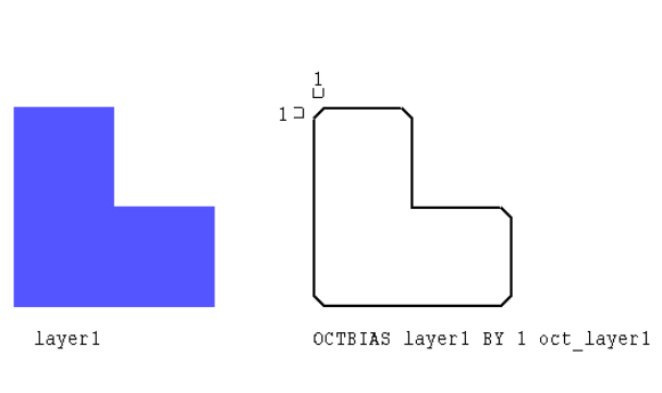
Chapter 24: HiPer Verify: Dracula Command Files Utility Layer Generation Operations OCTBIAS
L-Edit 13 User Guide Section 3 633
OCTBIAS
OCTBIAS layer1 BY n1 result-layer {OUTPUT c-name l-num)
Description
Cuts all Manhattan corners on the specified layer at a 45 degree angle, a distance of n1 from the corner.
Arguments
Examples
OCTBIAS layer1 BY 1.0 oct_layer1 OUTPUT oct_layer1
Calibre Format
There is no Calibre command corresponding to the Dracula OCTBIAS command.
layer1 A drawn or derived polygon layer.
n1 The distance by which to cut Manhattan corners
Chapter 24: HiPer Verify: Dracula Command Files Utility Layer Generation Operations SNAP
L-Edit 13 User Guide Section 3 634
SNAP
SNAP layer1 TO grid-value {result-layer}
Description
Snaps the coordinates of the geometry to a specified grid. Results are output to another layer, or can be
placed back on the original layer.
Arguments
,layer1 A drawn or derived polygon layer
lgrid-value Grid to which to snap the layer. The value must be the multiple of
the RESOLUTION specified in the Description block.
result-layer IAn optional target layer for the snapped layer. If not specified, the
snapped results overwrite layer1.
Chapter 24: HiPer Verify: Dracula Command Files Utility Layer Generation Operations HOLE
L-Edit 13 User Guide Section 3 635
HOLE
HOLE layer1 x-extent y-extent result-layer
Description
Produces a polygon layer formed by the holes of the input layer.
Arguments
Example
Z = HOLES layer1
result-layer = RECTANGLE Z < x-extent BY < y-extent MEASURE EXTENTS
,layer1 A drawn or derived polygon layer.
x-extent y-extent Holes must have the orthogonal extents larger than x-extent by
y-extent to be included in the output.
result-layer Output layer that contains holes of layer1.
Chapter 24: HiPer Verify: Dracula Command Files Polygon Size Operations GROW
L-Edit 13 User Guide Section 3 637
GROW
GROW layer1 dx dy dx1 dy1 result-layer {OUTPUT c-name l-num {d-num}}
Description
Oversizes right, left, top and bottom edges of a layer by individually specified amounts. This command
is supported only in the case of dx=dy=dx2=dy2.
Arguments
Unsupported Arguments
This command is supported only in the case of dx=dy=dx2=dy2.
Calibre Format
result-layer = SIZE layer1 BY size_value
layer1 A drawn or derived polygon layer
dx, dy, dx2, dy2 The amount to grow layer1 polygons. All values must be positive and
equal. For all angle polygons, Dracula grows all angle edges by more
than the specified grow amount. L-Edit grows all angle edges by
exactly the specified amount.
OUTPUT If the OUTPUT option is specified, the results of the operation are
sent as errors to a rule named c-name. The input layer names and
l-num are written as a rule comment. d-num is ignored
Chapter 24: HiPer Verify: Dracula Command Files Polygon Size Operations SHRINK
L-Edit 13 User Guide Section 3 638
SHRINK
SHRINK layer1 dx dy dx1 dy1 result-layer {OUTPUT c-name l-num {d-num}}
Description
Undersizes right, left, top and bottom edges of a layer by individually specified amounts. This
command is supported only in the case of dx=dy=dx2=dy2.
Arguments
Unsupported arguments
This command is supported only in the case of dx=dy=dx2=dy2.
Calibre Format
result-layer = SIZE layer1 BY size_value
layer A drawn or derived polygon layer
dx, dy, dx2, dy2 The amount to shrink layer1 polygons. All values must be positive
and equal. For all angle polygons, Dracula shrinks all angle edges by
more than the specified grow amount. L-Edit shrinks all angle edges
by exactly the specified amount.
OUTPUT If the OUTPUT option is specified, the results of the operation are
sent as errors to a rule named c-name. The input layer names and
l-num are written as a rule comment d-num is ignored.
Chapter 24: HiPer Verify: Dracula Command Files Polygon Size Operations SIZE
L-Edit 13 User Guide Section 3 639
SIZE
SIZE layer1 BY size_value {result-layer} {OUTPUT c-name l-num {d-num}}
SIZE layer1 BY size_value STEP step_value {result-layer} {OUTPUT c-name
l-num {d-num}}
SIZE layer1 WITHIN layer2 BY size_value [STEP step_value] {result-layer}
{OUTPUT c-name l-num {d-num}}
SIZE layer1 DOWN-UP BY size_value {result-layer} {OUTPUT c-name 1-num
{d-num}}
Description
Resizes a layer up or down. A positive size_value performs a size up, or grow, and a negative
size_value performs a size down, or shrink.
Arguments
Unsupported Arguments
Options B,L,N,O,P,R,S,T,W are not supported.
Calibre Format
result-layer = SIZE layer1 BY size_value INSIDE OF layer2 STEP step_value
Or
result-layer = SIZE layer1 BY size_value UNDEROVER
layer1 A drawn or derived polygon layer
size_value The amount to grow or shrink the layer1 polygons.
WITHIN layer2 Constrains layer1 to travel inside layer2 when performing the SIZE
operation. size_value must be positive when this option is used.
STEP step_value The step size of the sizing process. If size_value is not evenly
divisible by step_value then the last step may be smaller than
step_value in order to size by exactly size_value.
DOWN-UP Performs a size-down and size-up of the specified amount in a single
operation. If size_value is negative the effect is a size-up followed by
size-down.
OUTPUT If the OUTPUT option is specified, the results of the operation are
sent as errors to a rule named c-name. The input layer names and
l-num are written as a rule comment. d-num is ignored.
Chapter 24: HiPer Verify: Dracula Command Files Polygon Selection Operations SIZE
L-Edit 13 User Guide Section 3 640
Polygon Selection Operations
“SELECT ANGLE” (page 641)s
“SELECT INSIDE, OUTSIDE, HOLE” (page 642)
“SELECT CUT, TOUCH, ENCLOSE, OVERLAP” (page 643)
“SELECT CONN” (page 645)
“SELECT LABEL” (page 646)
“SELECT BY LABEL” (page 647)
“SELECT VERTEX” (page 648)
“SELECT VERTEX” (page 648)
Chapter 24: HiPer Verify: Dracula Command Files Polygon Selection Operations SELECT ANGLE
L-Edit 13 User Guide Section 3 641
SELECT ANGLE
SELECT layer1 ANGLE [n1] output-layer {OUTPUT c-name l-num {d-num}}
Description
Select polygons based on the angles of the edges forming the polygon.
Arguments
layer1 A drawn or derived polygon layer.
ANGLE [n1] n1 can be one of the following:
90 — Select polygons with all edges horizontal or vertical
45 — Select polygons with all edges horizontal or vertical or 45
degree, and containing at least on 45 degree edge.
-90 — At least one edge is not horizontal or vertical.
-45 — At least one edge is not horizontal, vertical or 45 degree.
OUTPUT If the OUTPUT option is specified, the results of the operation are
sent as errors to a rule named c-name. The input layer names and
l-num are written as a rule comment. d-num is ignored.
Chapter 24: HiPer Verify: Dracula Command Files Polygon Selection Operations SELECT INSIDE, OUTSIDE, HOLE
L-Edit 13 User Guide Section 3 642
SELECT INSIDE, OUTSIDE, HOLE
SELECT[N] {NOT} layer1 relation layer2 result-layer {OUTPUT c-name l-num
{d-num}}
Description
Selects polygons from layer1 that have a specified relation to layer2. Relations can be INSIDE,
OUTSIDE or HOLE.
Arguments
Unsupported Arguments
The N option for node based selection is not supported.
Calibre Format
result-layer = layer1 INSIDE layer2
result-layer = layer1 OUTSIDE layer2
There is no Calibre command corresponding to the Dracula HOLE command.
N The N option turns on node-based selection. Select operations with
the N option first select all polygons on layer1 that have the specified
relation to layer2, irrespective of connectivity, then adds to the
selection any other layer1 polygons that are on the same node as any
polygon in the originally selected set.
layer1 A drawn or derived polygon layer
layer2 A drawn or derived polygon layer
relation INSIDE — Produces all layer1 polygons that are completely inside
layer2 polygons. Touching from the inside is considered to be inside.
The NOT option produces those polygons not produced by the
corresponding SELECT INSIDE operation.
OUTSIDE — Produces all layer1 polygons that are completely
outside layer2 polygons. Touching from the outside is considered to
be outside. The NOT option produces those polygons not produced by
the corresponding SELECT OUTSIDE operation.
HOLE — Produces all layer1 polygons that exactly fit inside holes of
layer2 polygons. The NOT option produces those polygons not
produced by the corresponding SELECT HOLE operation.
OUTPUT If the OUTPUT option is specified, the results of the operation are
sent as errors to a rule named c-name. The input layer names and
l-num are written as a rule comment. d-num is ignored.
Chapter 24: HiPer Verify: Dracula Command Files Polygon Selection Operations SELECT CUT, TOUCH, ENCLOSE,
OVERLAP
L-Edit 13 User Guide Section 3 643
SELECT CUT, TOUCH, ENCLOSE, OVERLAP
SELECT[N] {NOT} layer1 relation {[n1:n2]} layer2 result-layer {OUTPUT c-name
l-num {d-num}}
Description
Selects polygons from layer1 that have a specified relation to layer2. Relations can be CUT, TOUCH,
ENCLOSE, or OVERLAP. A range may also be specified.
Arguments
Calibre Format
result-layer = layer1 CUT layer2 >=n1 <= n2
result-layer = layer1 TOUCH layer2 >=n1 <= n2
N The N option turns on node-based selection. Select operations with
the N option first select all polygons on layer1 that have the specified
relation to layer2, irrespective of connectivity, then adds to the
selection any other layer1 polygons that are on the same node as any
polygon in the originally selected set.
layer1 A drawn or derived polygon layer
layer2 A drawn or derived polygon layer
relation CUT — Produces layer1 polygons that have portions both inside and
outside layer2. The NOT option produces those polygons not
produced by the corresponding SELECT CUT operation.
TOUCH — Produces all layer1 polygons that are completely outside
layer2 polygons but share an edge with layer2 polygons. The NOT
option produces those polygons not produced by the corresponding
SELECT TOUCH operation
ENCLOSE — Produces layer1 polygons that completely enclose any
layer2 polygon. The NOT option produces those polygons not
produced by the corresponding SELECT ENCLOSE operation
OVERLAP — Produces all layer1 polygons that have some or all
area inside layer2 polygons or share an edge with layer2 polygons.
The NOT option produces those polygons not produced by the
corresponding OVERLAP operation
[n1:n2] Outputs layer1 polygons satisfy the relation with the specified range
of layer2 polygons. The range values (n1and n2) are inclusive and
must be integers. Zero is not allowed.
OUTPUT If the OUTPUT option is specified, the results of the operation are
sent as errors to a rule named c-name. The input layer names and
l-num are written as a rule comment. d-num is ignored.
Chapter 24: HiPer Verify: Dracula Command Files Polygon Selection Operations SELECT CUT, TOUCH, ENCLOSE,
OVERLAP
L-Edit 13 User Guide Section 3 644
result-layer = layer1 ENCLOSE layer2 >=n1 <= n2
result-layer = layer1 INTERACT layer2 >=n1 <= n2
Chapter 24: HiPer Verify: Dracula Command Files Polygon Selection Operations SELECT CONN
L-Edit 13 User Guide Section 3 645
SELECT CONN
SELECT layer1 CONN layer2 result-layer {OUTPUT c-name l-name {d-num}}
Description
Produces layer1 polygons that are connected to layer2. Select CONN first selects all layer1 polygons
that are connected to layer2, then adds to the selection any other layer1 polygons that are on the same
node as any polygons in the originally selected set. If either layer1 or layer2 do not have connectivity,
then the result is an empty layer.
Arguments
layer1 A drawn or derived polygon layer.
layer2 A drawn or derived polygon layer.
Chapter 24: HiPer Verify: Dracula Command Files Polygon Selection Operations SELECT LABEL
L-Edit 13 User Guide Section 3 646
SELECT LABEL
SELECT layer1 LABEL net_name result-layer {OUTPUT c-name l-num { d-num}}
Description
Produces all layer1 polygons that belong to the net having the specified net name. The connectivity on
layer1 must be established through a connectivity operation. Net names are given by placing text labels
(ports) on the layout.
Arguments
Calibre Format
SELECT layer1 LABEL net_name result-layer {OUTPUT c-name l-num { d-num}}
Translates to:
result-layer = NET layer1 net_name
c-name {COPY result-layer}
layer1 A drawn or derived polygon layer.
net_name The text label of the node to check.
Chapter 24: HiPer Verify: Dracula Command Files Polygon Selection Operations SELECT BY LABEL
L-Edit 13 User Guide Section 3 647
SELECT BY LABEL
SELECT layer1 BY text_layer LABEL([t] | [t']) ( label| label-list)
result-layer {OUTPUT c-name l-num { d-num}}
Description
Produces all layer1 polygons that intersect the location of text objects on layer text_layer having the
specified label name.
Arguments
Example
IDTXT8 = IDTEXT 8
SELECT METAL1 BY IDTXT8 LABEL[T] VDD? MT1VDD ;
Calibre Format
SELECT layer1 BY text_layer LABEL([t] | [t']) ( label| label-list)
result-layer {OUTPUT c-name l-num { d-num}}
Translates to:
If [t] option
result-layer = layer1 WITH TEXT label text_layer
c-name { COPY result-layer }
If [t'] option
result-layer = layer1 NOT WITH TEXT label text_layer
c-name { COPY result-layer }
If label-list is specified, then create a temp result layer for each label in the label-list, then OR the temp
layers together.
layer1 A drawn or derived polygon layer.
text_layer A layer containing text objects. This layer must have a corresponding
IDTEXT statement in the input layer block.
t Selects objects that are labeled by the specified text.
t’ Selects objects that are not labeled by the specified text.
label Any label, which can include meta characters such as ?.
label-list A list of up to a maximum of 20 labels. The list must be surrounded
by braces and labels names should be space or comma separated. ({
label1 label2 ...}).
result layer Name of the output layer.
Chapter 24: HiPer Verify: Dracula Command Files Polygon Selection Operations SELECT VERTEX
L-Edit 13 User Guide Section 3 648
SELECT VERTEX
SELECT layer1 VERTEX [n1: n2] result-layer {OUTPUT c-name {d-num}}
Description
Produces layer1 polygons that satisfy the specified vertex count range.
Arguments
Calibre Format
result-layer = layer1 VERTEX layer2 >=n1 <= n2
layer1 A drawn or derived polygon layer
layer2 A drawn or derived polygon layer
[n1:n2] The range of vertex counts. The command produces layer1 polygons
that contain between n1 and n2 vertices, inclusive of n1 and n2. The
values of n1 and n2 must be nonzero integers
OUTPUT If the OUTPUT option is specified, the results of the operation are
sent as errors to a rule named c-name. The input layer names and
l-num are written as a rule comment. d-num is ignored.
Chapter 24: HiPer Verify: Dracula Command Files Polygon Area Operations AREA
L-Edit 13 User Guide Section 3 650
AREA
AREA layer1 constraint result-layer {OUTPUT c-name l-num {d-num}}
Description
Produces layer1 polygons whose area conforms to the constraint.
Arguments
Calibre Format
result-layer = layer1 AREA layer1 >=n1 <= n2
Or
c-name {
AREA layer1 >=n1<=n2
}
layer1 A drawn or derived polygon layer
constraint NE n1— produces polygons whose area is not equal to n1.
EQ n1 — whose area is equal to n1.
RANGE n1 n2 — produces polygons with areas such that n1 < AREA
< n2. (Exclusive).
OUTPUT If the OUTPUT option is specified, the results of the operation are
sent as errors to a rule named c-name. The input layer names and
l-num are written as a rule comment. d-num is ignored
Chapter 24: HiPer Verify: Dracula Command Files Polygon Area Operations COVERAGE
L-Edit 13 User Guide Section 3 651
COVERAGE
COVERAGE layer1 constraint windowSize stepSize result-layer
COVERAGE {NOT} layer1 constraint windowSize stepSize {OUTSQU square-layer}
{SQSZ size-of-square}{result-layer} {OUTPUT c-name l-num}
COVERAGE {NOT} layer1 constraint RECT rectanglelayer {result-layer} {OUTPUT
c-name l-num}
Description
Reports an error for rectangular window within which the ratio of the area of layer1 to the area of the
window meets the constraint. Error flags are the rectangle in which the violation occurs. Results are
merged prior to output.
Arguments
layer1 A drawn or derived polygon layer.
constraint Specifies the ratio of the area of layer1 to the area of the specified
boundary that must exist for the boundary polygon to be produced.
The values p1 and p2 must be non-negative real numbers. The
following constraints can be chosen:
LT/LE p1— Output windows in which the ratio of the area of layer1
to the area of the window is < or <= to p1.
RANGE p1 p2 — Output windows in which the ratio of the area of
layer1 to the area of the window is > p1 < p2.
GT/GE p1— Output windows in which the ratio of the area of layer1
to the area of the window is >or >= to p1.
EQ p1— Output windows in which the ratio of the area of layer1 to
the area of the window is = to p1.
NOT Takes the compliment of the constraint.
windowSize Specifies a window size within which the density check is computed.
stepSize Specifies the step size for moving the window.
OUTSQU square-layer square-layer is a derived polygon layer containing squares of size
size-of-square located at the center of each violating window.
SQSZ size-of-square Specifies the size of squares on square-layer. If this parameter is not
present, the default value is the stepSize.
RECT rectanglelayer Specifies that, for each rectangle on rectanglelayer, check the ratio
(area of layer1) / ( area of rectangle), and output if the ratio meets the
specified constraint.
OUTPUT If the OUTPUT option is specified, the results of the operation are
sent as errors to a rule named c-name.
Chapter 24: HiPer Verify: Dracula Command Files Polygon Area Operations COVERAGE
L-Edit 13 User Guide Section 3 652
Calibre Format
rule-name {@ layer1 density constraint
DENSITY layer1 constraint WINDOW w STEP s
}
Chapter 24: HiPer Verify: Dracula Command Files Edge Selection Operations LENGTH
L-Edit 13 User Guide Section 3 654
LENGTH
LENGTH layer1 {&layer1} measurement {OUTPUT c-name l-num {d-num}} {&}
Description
Produces all edges of layer1 whose length conforms to the constraint. The NOT option produces all
layer1 edges not produced by the corresponding LENGTH operation.
Arguments
Examples
EXT metal1 LT 0.3 &
LENGTH metal1 GT 10.0 OUTPUT M1.C 64
Calibre Format
LENGTH layer1 constraint
layer A drawn or derived polygon layer
measurement GT/GE/ LT/LE n1 — Output edges with length that are >, >=, <, <=
the constraint value n1 respectively.
RANGE n1 n2 — Outputs edges with length that are greater than n1
and less than n2 ( > n1 < n2).
OUTPUT If the OUTPUT option is specified, the results of the operation are
sent as errors to a rule named c-name. The input layer names and
l-num are written as a rule comment. d-num is ignored
& Creates a conjunctive rule. See “Conjunctive Rules” (page 595).
Chapter 24: HiPer Verify: Dracula Command Files Edge Selection Operations PLENGTH
L-Edit 13 User Guide Section 3 655
PLENGTH
PLENGTH layer1 measurement {result-layer} {OUTPUT c-name l-num { d-num}}
Description
Produces layer1 edges where the length of a contiguous set of edges conforms to the constraint.
Arguments
Examples
INT [R] metal1 LT 0.5 thin_metal1
PLENGTH thin_metal1 RANGE 0 50.0 OUTPUT M1.D 64
Calibre Format
PATH LENGTH layer1 constraint
layer1 A drawn or derived polygon layer
measurement NE/EQ n1— Output edges with length that are not equal or equal to
the constraint value n1 respectively.
RANGE n1 n2 — Outputs edge paths with length that are greater than
n1 and less than n2 ( > n1 < n2).
OUTPUT If the OUTPUT option is specified, the results of the operation are
sent as errors to a rule named c-name. The input layer names and
l-num are written as a rule comment. d-num is ignored
Chapter 24: HiPer Verify: Dracula Command Files Dimensional Check Operations ENC
L-Edit 13 User Guide Section 3 657
ENC
ENC {[option1]} layer1 {&layer-a1}[O] layer2 {&layer-a2} measurement
{result-layer} {OUTPUT c-name l-num {d-num}} {&}
Description
Measures the distance between the outside of layer1 and the inside of layer2 boundaries and outputs the
edge pairs that meet the constraints.
Arguments
layer1 A drawn or derived polygon layer.
layer2 A drawn or derived polygon layer.
option1 The following options are common to WIDTH, ENC, EXT, and
INT:
C — Only flags the edge-pair when the edges are parallel.
C’ — Only flags the edge pair when the edges are nonparallel.
P (-) — Flags segments of edges that project onto each other. Dracula
definition is defined as: Two edges project if perpendicular lines from
a referenced edge intersect the other edge. The referenced edge is the
edge most closely aligned to the x or y axis.
P'(-) — Flags edges that do not project onto each other.
R — Constructs polygons from the projection of error edges. You
must specify only the result-layer, and not specify OUTPUT when
using this option. This option turns on the P option.
R’ — Outputs error flags in polygon format so you can reuse error
data. You can process the created layer with logical operations. The
flags are one RESOLUTION unit wide (as specified in the
Description block). You cannot specify an OUTPUT error cell.
S (+) — Flags violations on the polygon if the edges of the polygon
are within a “square boundary” inside of the other polygon edge.
N — Only flag violations on polygons that are on different nets. Use
the CONNECT command to connect nodes before using this option.
N’ — Inverse of N option. Only flag violations on polygons that are
on the same net.
(continued)
Chapter 24: HiPer Verify: Dracula Command Files Dimensional Check Operations ENC
L-Edit 13 User Guide Section 3 658
option1
(continued) X — Checks the delta value in the x direction between two edges. The
edges must project onto each other. Non-Manhattan data is not
checked.
Y — Checks the delta value in the y direction between two edges. The
edges must project onto each other. Non-Manhattan data is not
checked.
The following options are for ENC command only:
E (+) — Flags polygons from layer1 that are totally outside polygons
from layer2. Performs an enclosure test in parallel with other
functions performed by the ENC command.
O (+) — Flags layer1 polygons and layer2 polygons that cut/overlap
each other. Outputs edges from layer2 that are enclosed by layer1.
Within a conjunctive rule, only layer2 (the enclosing layer) receives
error flags.
T (+) — Flags outside segments of enclosed polygons (layer1) that
touch inside segments of enclosing polygons (layer2).
V — Check all polygon edges, ignoring shielding by polygon
containment of one layer inside another.
The O, G, and E options are only supported when directed as errors
with an OUTPUT statement, they are not supported when directed to
a layer. The O and G flags behave the same.
Chapter 24: HiPer Verify: Dracula Command Files Dimensional Check Operations ENC
L-Edit 13 User Guide Section 3 659
Unsupported Arguments
The following options are not supported:
U, U', CORNER-CORNER n2, CORNER-EDGE n3
Calibre Format
The basic Dracula rule
ENC LAYER1 LAYER2 LT 2.0 OUTPUT ENC1 63
Translates to Calibre format as:
measurement LT/LE n1 — Flags an error if the two segments are spaced less than
n1 for LT or less than or equal to n1 for LE. Does not flag an error if
the segments touch.
EQ n1 — Flags an error if the two segments are spaced equal to n1.
RANGE n1 n2 — Flags an error if the two segments are spaced less
than n2 and greater than n1. If you do not want acute-angle error
flags, you must specify the RANGE measurement.
SELLT/SELLE n1 — SELLT and SELLE output those layer1
polygons that would be flagged by using LT n1 or LE n1 with the
same options. Specify a result-layer name and do not use the
OUTPUT statement when specifying this option.
SELEQ/NE n1 — SELEQ outputs those layer1 polygons that would
be flagged by using EQ n1 with the same options. SELNE outputs
those polygons that would not be flagged by using EQ with the same
options. Specify a result-layer name and do not use the OUTPUT
statement when using this option.
SELRA n1 n2 — SELRA outputs those layer1 polygons that would
be flagged by using RANGE n1 n2 measurement with the same
options. Specify a result-layer name and do not use the OUTPUT
statement when specifying this option.
SELGT/GE n1 — SELGT and SELGE outputs those layer1
polygons that would not be flagged when you specify a LE n1 or LT
n1 measurement with the same options. Specify a result-layer name
and do not use the OUTPUT statement when using this option.
OUTPUT If the OUTPUT option is specified, the results of the operation are
sent as errors to a rule named c-name. The input layer names and
l-num are written as a rule comment. d-num is ignored.
& Creates a conjunctive rule. See “Conjunctive Rules” (page 595).
[O] The [O] option after layer1 indicates to use the original layer, not the
layer generated by the previous operation in the conjunctive rule. Use
this option only with a conjunctive rule.
Chapter 24: HiPer Verify: Dracula Command Files Dimensional Check Operations ENC
L-Edit 13 User Guide Section 3 660
ENC1 {
ENC LAYER1 LAYER2 < 2.0 ABUT >0<90 SINGULAR
}
The mapping of Dracula options to Calibre format is shown in the table below. The following options
are common to WIDTH, ENC, EXT, INT
C PARALLEL ONLY
C’ NOT PARALLEL
P PROJECTING
P’ NOT PROJECTING
R PROJECTING REGION
R’ In an ENC rule, R' is translated using EXPAND EDGE layer
OUTSIDE BY.
ENC[R'] layer1 layer2 LT d result
Translates to:
E1 = ENC [layer1] layer2 < d ABUT >0<90
E2 = ENC layer1 [layer2] < d ABUT >0<90
temp1 = EXPAND EDGE E1 OUTSIDE BY 0.01
temp2 = EXPAND EDGE E2 OUTSIDE BY 0.01
result = temp1 OR temp2
// Here 0.01 is the value of RESOLUTION
S SQUARE
LT/LE Constraint is “< n1” or “<= n1”
ENC layer1 layer2 LT d
Translates to:
ENC layer1 layer2 < dABUT >0<90 SINGULAR
EQ N1 Constraint is “== n1”
RANGE n1 n2 Constraint is “> n1 < n2”, and does not include ABUT and
SINGULAR parameters.
SELLT/SELLE ENC layer1 layer2 SELLT d result-layer
Translates to:
temp-edge-layer = ENC [layer1] layer2 < d
result-layer = layer1 WITH EDGE temp-edge-layer
Chapter 24: HiPer Verify: Dracula Command Files Dimensional Check Operations ENC
L-Edit 13 User Guide Section 3 661
The following options apply to ENC only:
SELGT/SELGE ENC layer1 layer2 SELGT d result-layer
Translates to:
temp-edge-layer = ENC [layer1] layer2 <= d
result-layer = layer1 NOT WITH EDGE temp-edge-layer
SELNE ENC layer1 layer2 SELNE d result-layer
Translates to:
temp-edge-layer = ENC [layer1] layer2 == d
result-layer = layer1 NOT WITH EDGE temp-edge-layer
N NOT CONNECTED
N’ CONNECTED
X For example, Dracula
ENC [X] layer1 LT 3 OUTPUT R2 64
INT [X] layer2 LT 3 OUTPUT R3 64
Translates to Calibre:
T0 = ANGLE layer1 == 90
T1 = ANGLE layer2 == 90
ENC T0 T1 < 3 PARALLEL ONLY PROJECTING ABUT > 0 <
90 SINGULAR
INT T0 T1 < 3 PARALLEL ONLY PROJECTING ABUT > 0 <
90 SINGULAR
Y Similarly, Y option translates to ANGLE layerx == 0, with
PROJECTING and PARALLEL ONLY options enforced.
The X and Y options are mutually exclusive.
E In the ENC rule, the E flag is translated by adding layer1 OUTSIDE
layer2 to the basic rule.
ENC[E] layer1 layer2 LT d OUTPUT result 63
Translates to:
result {
ENC layer1 layer2 < d ABUT >0<90 SINGULAR
layer1 OUTSIDE layer2
}
Chapter 24: HiPer Verify: Dracula Command Files Dimensional Check Operations ENC
L-Edit 13 User Guide Section 3 662
O In the ENC rule, the O flag is translated by adding the INSIDE ALSO
option.
ENC[O] layer1 layer2 LT d OUTPUT result 63
Translates to:
result {
ENC layer1 layer2 < d ABUT >0<90 SINGULAR INSIDE ALSO }
T Modify ABUT >0< 90 to just ABUT < 90
VMEASURE ALL
Chapter 24: HiPer Verify: Dracula Command Files Dimensional Check Operations EXT
L-Edit 13 User Guide Section 3 663
EXT
EXT{[option1]} layer1{&layer-a1}{[O]} {layer2{&layer-a2}} measurement
{result-layer} {OUTPUT c-name l-num {d-num}} {&}
Description
Measures the distance between the outside of layer1 boundaries, or the distance between the outside of
layer1 and the outside of layer2 boundaries.
Arguments
layer1 A drawn or derived polygon layer.
layer2 A drawn or derived polygon layer.
option1 The following options are common to WIDTH, ENC, EXT, and
INT:
C — Only flags the edge-pair when the edges are parallel.
C’ — Only flags the edge pair when the edges are nonparallel.
P (-) — Flags segments of edges that project onto each other. Dracula
definition is defined as: Two edges project if perpendicular lines from
a referenced edge intersect the other edge. The referenced edge is the
edge most closely aligned to the x or y axis.
P'(-) — Flags edges that do not project onto each other.
R — Constructs polygons from the projection of error edges. You
must specify only the result-layer, and not specify OUTPUT when
using this option. This option turns on the P option.
R’ — Outputs error flags in polygon format so you can reuse error
data. You can process the created layer with logical operations. The
flags are one RESOLUTION unit wide (as specified in the
Description block). You cannot specify an OUTPUT error cell.
S (+) — Flags violations on the polygon if the edges of the polygon
are within a “square boundary” inside of the other polygon edge.
N — Only flag violations on polygons that are part of different nodes.
Use the CONNECT command to connect nodes before using this
option.
N’ — Inverse of N option. Only flag violations on polygons that are
part of the same node.
(continued)
Chapter 24: HiPer Verify: Dracula Command Files Dimensional Check Operations EXT
L-Edit 13 User Guide Section 3 664
option1
(continued) X — Checks the delta value in the x direction between two edges. The
edges must project onto each other. Non-Manhattan data is not
checked.
Y — Checks the delta value in the y direction between two edges. The
edges must project onto each other. Non-Manhattan data is not
checked.
The following options are for EXT command only:
E (+) — Flags a polygon that is totally enclosed by a polygon from
the other layer.
O (+), G(+) — Flags layer1 and layer2 polygons that cut/overlap each
other. Error flags cover segments within layer1 and layer2 that outline
the overlapping area of the two polygons. The segments flagged are
the segments of these two polygons that cut the edges of the polygons.
Does not flag a polygon that fully encloses a polygon of the other
layer.
T (+) — Flags outside segments of layer1 polygons that touch outside
segments of layer2 polygons.
V — Check all polygon edges, ignoring shielding by polygon
containment of one layer inside another.
H (+) — Flags the outside edges of notched layer1 polygons that fail
the spacing check. A notch is a set of non-adjacent facing edges, or
adjacent facing edges that create an external angle of less than 90
degrees. Use this option only with a single input layer.
The O, G, and E options are only supported when directed as errors
with an OUTPUT statement, they are not supported when directed to
a layer. The O and G flags behave the same.
Chapter 24: HiPer Verify: Dracula Command Files Dimensional Check Operations EXT
L-Edit 13 User Guide Section 3 665
Unsupported Arguments
The following options are not supported:
U, U', CORNER-CORNER n2, CORNER-EDGE n3
H option is supported, absence of H is not supported. The O, G, and E options are only supported when
directed as errors with an OUTPUT statement, they are not supported when directed to a layer.
Calibre Format
The basic Dracula rule
measurement LT/LE n1 — Flags an error if the two segments are spaced less than
n1 for LT or less than or equal to n1 for LE. Does not flag an error if
the segments touch.
EQ n1 — Flags an error if the two segments are spaced equal to n1.
RANGE n1 n2 — Flags an error if the two segments are spaced less
than n2 and greater than n1. If you do not want acute-angle error
flags, you must specify the RANGE measurement.
SELLT/SELLE n1 — SELLT and SELLE output those layer1
polygons that would be flagged by using LT n1 or LE n1 with the
same options. Specify a result-layer name and do not use the
OUTPUT statement when specifying this option.
SELEQ/NE n1 — SELEQ outputs those layer1 polygons that would
be flagged by using EQ n1 with the same options. SELNE outputs
those layer1 polygons that would not be flagged by using EQ n1 with
the same options. Specify a result-layer name and do not use the
OUTPUT statement when using this option.
SELRA n1 n2 — SELRA outputs those layer1 polygons that would
be flagged by using RANGE n1 n2 measurement with the same
options. Specify a result-layer name and do not use the OUTPUT
statement when specifying this option.
SELGT/GE n1 — SELGT and SELGE outputs those layer1
polygons that would not be flagged when you specify a LE n1 or LT
n1 measurement with the same options. Specify a result-layer name
and do not use the OUTPUT statement when using this option.
OUTPUT If the OUTPUT option is specified, the results of the operation are
sent as errors to a rule named c-name. The input layer names and
l-num are written as a rule comment. d-num is ignored.
& Creates a conjunctive rule. See “Conjunctive Rules” (page 595).
[O] The [O] option after layer1 indicates to use the original layer, not the
layer generated by the previous operation in the conjunctive rule. Use
this option only with a conjunctive rule.
Chapter 24: HiPer Verify: Dracula Command Files Dimensional Check Operations EXT
L-Edit 13 User Guide Section 3 666
EXT LAYER1 LAYER2 LT 2.0 OUTPUT EXT1 63
Translates to Calibre format as:
EXT1 {
EXT LAYER1 LAYER2 < 2.0 ABUT >0<90 SINGULAR
}
The mapping of Dracula options to Calibre format is shown in the table below. The following options
are common to WIDTH, ENC, EXT, INT:
C PARALLEL ONLY
C’ NOT PARALLEL
P PROJECTING
P’ NOT PROJECTING
R PROJECTING REGION
R’ In a EXT rule, R' is translated using EXPAND EDGE layer
OUTSIDE BY.
EXT[R'] layer1 layer2 LT d result
Translates to:
E1 = EXT [layer1] layer2 < d ABUT >0<90
E2 = EXT layer1 [layer2] < d ABUT >0<90
temp1 = EXPAND EDGE E1 OUTSIDE BY 0.01
temp2 = EXPAND EDGE E2 OUTSIDE BY 0.01
result = temp1 OR temp2
// Here 0.01 is the value of RESOLUTION
S SQUARE
LT/LE < / <= n1
EXT layer1 layer2 LT 2.0
Translates to:
EXT layer1 layer2 < 2.0 ABUT >0<90 SINGULAR
EQ n1 n1
RANGE n1n2 n1 < n2, does not include ABUT SINGULAR parameters.
SELLT/SELLE EXT layer1 layer2 SELLT d result-layer
Translates to:
temp-edge-layer = EXT [layer1] layer2 < d
result-layer = layer1 WITH EDGE temp-edge-layer
N NOT CONNECTED
N’ CONNECTED SPACE
Chapter 24: HiPer Verify: Dracula Command Files Dimensional Check Operations EXT
L-Edit 13 User Guide Section 3 667
The following options apply to EXT only:
E In the EXT rule, the E flag is translated by adding (layer1 INSIDE
layer2) OR (layer2 INSIDE layer1) to the basic rule.
EXT[E] layer1 layer2 LT d OUTPUT result 63
Translates to:
result {
EXT layer1 layer2 < d ABUT >0<90 SINGULAR
(layer1 INSIDE layer2) OR (layer2 INSIDE layer1)
}
O, G In the EXT rule, the O and G flags are translated by adding (layer1
CUT layer2) AND (layer2 CUT layer1) to the basic rule.
EXT[E] layer1 layer2 LT d OUTPUT result 63
Translates to:
result {
EXT layer1 layer2 < d ABUT >0<90 SINGULAR
(layer1 CUT layer2) AND (layer2 CUT layer1))
}
OE In the EXT rule, if both E and O options are present, the rule is most
efficiently translated by adding the INSIDE ALSO option.
EXT[EO] layer1 layer2 LT d OUTPUT result 63
Translates to:
result {
EXT layer1 layer2 < d ABUT >0<90 SINGULAR INSIDE ALSO }
H “H” behavior is default Calibre behavior for single layer rule. Use
SPACE if “H” is not present
T Modify ABUT >0< 90 to just ABUT < 90
T Remove ABUT constraint
VMEASURE ALL
Chapter 24: HiPer Verify: Dracula Command Files Dimensional Check Operations INT
L-Edit 13 User Guide Section 3 668
INT
INT{[option1]} layer1{&layer-a1}{[O]} layer2{&layer-a2} measurement
{result-layer} {OUTPUT c-name l-num {d-num}} {&}
Description
Measures the distance between the inside of layer1 boundaries and the inside of layer2 boundaries.
Checks the amount by which polygons of two layers overlap
Arguments
layer1 A drawn or derived polygon layer
layer2 A drawn or derived polygon layer
option1 The following options are common to WIDTH, ENC, EXT, and
INT:
C — Only flags the edge-pair when the edges are parallel.
C’ — Only flags the edge pair when the edges are nonparallel.
P (-) — Flags segments of edges that project onto each other. Dracula
definition is defined as: Two edges project if perpendicular lines from
a referenced edge intersect the other edge. The referenced edge is the
edge most closely aligned to the x or y axis.
P'(-) — Flags edges that do not project onto each other.
R — Constructs polygons from the projection of error edges. You
must specify only the result-layer, and not specify OUTPUT when
using this option. This option turns on the P option.
R’ — Outputs error flags in polygon format so you can reuse error
data. You can process the created layer with logical operations. The
flags are one RESOLUTION unit wide (as specified in the
Description block). You cannot specify an OUTPUT error cell.
S (+) — Flags violations on the polygon if the edges of the polygon
are within a “square boundary” inside of the other polygon edge.
N — Only flag violations on polygons that are part of different nodes.
Use the CONNECT command to connect nodes before using this
option.
N’ — Inverse of N option. Only flag violations on polygons that are
part of the same node.
(continued)
Chapter 24: HiPer Verify: Dracula Command Files Dimensional Check Operations INT
L-Edit 13 User Guide Section 3 669
option1
(continued) X — Checks the delta value in the x direction between two edges. The
edges must project onto each other. Non-Manhattan data is not
checked.
Y — Checks the delta value in the y direction between two edges. The
edges must project onto each other. Non-Manhattan data is not
checked.
The following options are for INT command only:
T (+) — Flags inside segments of polygons of two layers that
coincide.
V — Checks the inside edges of layer1 to the inside edges of all
surrounding geometries of layer2. Check all polygon edges, ignoring
shielding by polygon containment of one layer inside another.
measurement LT/LE n1 — Flags an error if the two segments are spaced less than
n1 for LT or less than or equal to n1 for LE. Does not flag an error if
the segments touch.
EQ n1 — Flags an error if the two segments are spaced equal to n1.
RANGE n1 n2 — Flags an error if the two segments are spaced less
than n2 and greater than n1. If you do not want acute-angle error
flags, you must specify the RANGE measurement.
SELLT/SELLE n1 — SELLT and SELLE output those layer1
polygons that would be flagged by using LT n1 or LE n1 with the
same options. Specify a result-layer name and do not use the
OUTPUT statement when specifying this option.
SELEQ/NE n1 — SELEQ outputs those layer1 polygons that would
be flagged by using EQ n1 with the same options. SELNE outputs
those layer1 polygons that would not be flagged by using EQ n1 with
the same options. Specify a result-layer name and do not use the
OUTPUT statement when using this option.
SELRA n1 n2 — SELRA outputs those layer1 polygons that would
be flagged by using RANGE n1 n2 measurement with the same
options. Specify a result-layer name and do not use the OUTPUT
statement when specifying this option.
SELGT/GE n1 — SELGT and SELGE outputs those layer1
polygons that would not be flagged when you specify a LE n1 or LT
n1 measurement with the same options. Specify a result-layer name
and do not use the OUTPUT statement when using this option.
OUTPUT If the OUTPUT option is specified, the results of the operation are
sent as errors to a rule named c-name. The input layer names and
l-num are written as a rule comment. d-num is ignored.
& Creates a conjunctive rule. See “Conjunctive Rules” (page 595).
[O] The [O] option after layer1 indicates to use the original layer, not the
layer generated by the previous operation in the conjunctive rule. Use
this option only with a conjunctive rule.
Chapter 24: HiPer Verify: Dracula Command Files Dimensional Check Operations INT
L-Edit 13 User Guide Section 3 670
Unsupported Arguments
The following options are not supported:
U, U', CORNER-CORNER n2, CORNER-EDGE n3
Calibre Format
The basic Dracula rule
INT LAYER1 LAYER2 LT 2.0 OUTPUT INT1 63
Translates to Calibre format as:
INT1 {
INT LAYER1 LAYER2 < 2.0 ABUT >0<90 SINGULAR
}
C PARALLEL ONLY
C’ NOT PARALLEL
P PROJECTING
P’ N OT PROJECTING
R PROJECTING REGION
R’ In an INT rule, R' is translated using EXPAND EDGE layer
OUTSIDE BY.
INT[R'] layer1 layer2 LT d result
Translates to:
E1 = INT [layer1] layer2 < d ABUT >0<90
E2 = INT layer1 [layer2] < d ABUT >0<90
temp1 = EXPAND EDGE E1 OUTSIDE BY 0.01
temp2 = EXPAND EDGE E2 OUTSIDE BY 0.01
result = temp1 OR temp2
// Here 0.01 is the value of RESOLUTION
S SQUARE
LT/LE n1 < / <= n1
INT layer1 layer2 LT d
Translates to:
INT layer1 layer2 < d ABUT >0<90 SINGULAR
EQ n1 == n1
RANGE n1n2 n1 < n2, does not include ABUT SINGULAR parameters.
Chapter 24: HiPer Verify: Dracula Command Files Dimensional Check Operations INT
L-Edit 13 User Guide Section 3 671
The following options apply to INT only:
SELLT/SELLE INT layer1 layer2 SELLT d result-layer
Translates to:
temp-edge-layer = INT [layer1] layer2 < d
result-layer = layer1 WITH EDGE temp-edge-layer
N NOT CONNECTED
N’ CONNECTED
T Modify ABUT >0< 90 to just ABUT < 90
VMEASURE ALL
Chapter 24: HiPer Verify: Dracula Command Files Dimensional Check Operations WIDTH
L-Edit 13 User Guide Section 3 672
WIDTH
WIDTH {[option1]} layer1 {&layer1}{[O]} measurement ANGLE = angle-opt
{result-layer} {OUTPUT c-name l-num {d-num}} {&}
WIDTH layer1 RECT = n3 BY n4 {result-layer} {OUTPUT c-name l-num {d-num}}
Description
Measures the distance between the inside of layer1 boundaries, and outputs edge pairs that meet the
constraint.
Arguments
layer1 A drawn or derived polygon layer.
option1 The following options are common to WIDTH, ENC, EXT, and
INT:
C — Only flags the edge-pair when the edges are parallel.
C’ — Only flags the edge pair when the edges are nonparallel.
P (-) — Flags segments of edges that project onto each other. Dracula
definition is defined as: Two edges project if perpendicular lines from
a referenced edge intersect the other edge. The referenced edge is the
edge most closely aligned to the x or y axis.
P'(-) — Flags edges that do not project onto each other.
R — Constructs polygons from the projection of error edges. You
must specify only the result-layer, and not specify OUTPUT when
using this option. This option turns on the P option.
R’ — Outputs error flags in polygon format so you can reuse error
data. You can process the created layer with logical operations. The
flags are one RESOLUTION unit wide (as specified in the
Description block). You cannot specify an OUTPUT error cell.
S (+) — Flags violations on the polygon if the edges of the polygon
are within a “square boundary” inside of the other polygon edge.
X — Checks the delta value in the x direction between two edges. The
edges must project onto each other. Non-Manhattan data is not
checked.
Y — Checks the delta value in the y direction between two edges. The
edges must project onto each other. Non-Manhattan data is not
checked.
Chapter 24: HiPer Verify: Dracula Command Files Dimensional Check Operations WIDTH
L-Edit 13 User Guide Section 3 673
The following option1 options are for WIDTH command only:
D — Disables acute-angle checking.
L — The L option when used with SELEQ is useful for exact size
checks.
WIDTH [L] VIA1 SELNE 3.0 result-layer
will output VIA1 polygons that are not exactly 3.0x3.0 in dimension.
measurement LT/LE n1 — Flags an error if the two segments are spaced less than
n1 for LT or less than or equal to n1 for LE. Does not flag an error if
the segments touch.
EQ n1 — Flags an error if the two segments are spaced equal to n1.
GT/GE n1 — Flags an error if the two segments are spaced greater
than n1 for GT or greater than or equal to n1 for GE. Does not flag an
error if the segments touch.
RANGE n1 n2 — Flags an error if the two segments are spaced less
than n2 and greater than n1. If you do not want acute-angle error
flags, you must specify the RANGE measurement.
SELLT/SELLE n1 — SELLT and SELLE output those layer1
polygons that would be flagged by using LT n1 or LE n1 with the
same options. Specify a result-layer name and do not use the
OUTPUT statement when specifying this option.
SELEQ/SELNE n1 — SELEQ and SELNE output those layer1
polygons that would be flagged by using EQ n1 or an NE n1 with the
same options. Specify a result-layer name and do not use the
OUTPUT statement when using this option.
SELRA n1 n2 — SELRA outputs those layer1 polygons that would
be flagged by using RANGE n1 n2 measurement with the same
options. Specify a result-layer name and do not use the OUTPUT
statement when specifying this option.
SELGT/GE n1 — SELGT and SELGE outputs those layer1
polygons that would not be flagged when you specify a LE n1 or LT
n1 measurement with the same options. Specify a result-layer name
and do not use the OUTPUT statement when using this option.
angle-opt 45, non-45, 90, or non-90 — Specifies that only edge-pairs at the
specified angle are to be checked. When you use this option, the C
option is automatically invoked.
OUTPUT If the OUTPUT option is specified, the results of the operation are
sent as errors to a rule named c-name. The input layer names and
l-num are written as a rule comment. d-num is ignored
& Creates a conjunctive rule. See “Conjunctive Rules” (page 595).
Chapter 24: HiPer Verify: Dracula Command Files Dimensional Check Operations WIDTH
L-Edit 13 User Guide Section 3 674
The WIDTH rule with the RECT option flags rectangles that are exactly n3 by n4 in dimension.
Unsupported Arguments
The following options are not supported:
CORNER-CORNER n2, CORNER-EDGE n3
Calibre Format
The basic Dracula rule
WIDTH LAYER1 LT 2.0 OUTPUT WIDTH1 63
Translates to Calibre format as:
WIDTH1 {
INT LAYER1 < 2.0 ABUT >0<90 SINGULAR
}
The mapping of Dracula options to Calibre format is shown in the table below. The following options
are common to WIDTH, ENC, EXT, INT:
[O] The [O] option after layer1 indicates to use the original layer, not the
layer generated by the previous operation in the conjunctive rule. Use
this option only with a conjunctive rule.
C PARALLEL ONLY
C’ NOT PARALLEL
P PROJECTING
P’ N OT PROJECTING
R PROJECTING REGION
R’ In a width rule, R' is translated using EXPAND EDGE layer
OUTSIDE BY.
WIDTH[R'] layer1 LT d result
Translates to:
temp = INT [layer1] < d ABUT >0<90
result = EXPAND EDGE temp OUTSIDE BY 0.01
// Here 0.01 is the value of RESOLUTION
S SQUARE
Chapter 24: HiPer Verify: Dracula Command Files Dimensional Check Operations WIDTH
L-Edit 13 User Guide Section 3 675
The following options apply to WIDTH only:
The WIDTH rule with the RECT option translates as follows:
WIDTH layer1 RECT = n3 BY n4 {trapfile} {OUTPUT c-name l-num {d-num}}
This translates to Calibre as:
c-name { RECTANGLE layer1 ==n3 BY ==n4}
LT/LE n1 < / <= n1
WIDTH layer1 LT d
Translates to:
INT layer1 < d ABUT >0<90 SINGULAR
EQ/NE n1 == / != n1
RANGE n1 n2 > n1 < n2, does not include ABUT SINGULAR parameters.
SELLT/SELLE WIDTH layer1 SELLT d result-layer
Translates to:
temp-edge-layer = INT [layer1] < d result-layer = layer1 WITH
EDGE temp-edge-layer
angle-opt There is no direct translation to Calibre for angle-opt.
D Do not include ABUT >0< 90.
L The L option when used with SELEQ is useful for exact size checks.
WIDTH[L] layer1 SELEQ d rule-name
Translates to:
Rule-name {RECTANGLE layer1 == d BY ==d }
WIDTH[L] layer1 SELNE d rule-name
Translates to:
Rule-name { NOT RECTANGLE layer1 == d BY ==d }
Chapter 24: HiPer Verify: Dracula Command Files Dimensional Check Operations RECTCHK
L-Edit 13 User Guide Section 3 676
RECTCHK
RECTCHK[option] layer {WIDLEN NE/EQ value1 value2} {result-layer} {OUTPUT
c-name l-num}
RECTCHK[option] layer {WIDTH NE/EQ/LT/RA/GT value1 {value2}} {LENGTH
NE/EQ/LT/RA/GT value1 {value2}} {result-layer} {OUTPUT c-name l-num}
Description
Selects rectangles with specified width and height measurements.
Arguments
Option R — Select the shape only if it is a rectangle. By default, RECTCHK
selects all shapes that are not rectangular in addition to the selected
rectangles.
A — If both WIDTH and LENGTH are specified, by default the OR
of the WIDTH and LENGTH constraints must be satisfied for a
rectangle to be selected. If you use [A], then the AND of the WIDTH
and LENGTH constraints must be satisfied for a rectangle to be
selected.
T — Check rectangles that form butted trapezoids. This option is not
supported.
WIDLEN Selects rectangles of dimension equal to or not equal to value1 by
value2.
WIDTH Selects rectangles with width meeting the specified measurement.
LENGTH Selects rectangles with length meeting the specified measurement.
OUTPUT If the OUTPUT option is specified, the results of the operation are
sent as errors to a rule named c-name. The input layer names and
l-num are written as a rule comment.
Chapter 24: HiPer Verify: Dracula Command Files Dimensional Check Operations EDGECHK
L-Edit 13 User Guide Section 3 677
EDGECHK
EDGECHK[O] layer1 {ANGLE[90 | -90]} LENGTH measurement value1 {result-layer}
{OUTPUT c-name l-num {d-num}}
Description
Checks the continuous path length of all edges, only Manhattan edges, or only Non-Manhattan edges on
the input layer. Flagged edges are extended inside the input polygon by one RESOLUTION by default,
or outside the polygon if the [O] option is specified. By default, all edges are included in the check. Use
the ANGLE option to specify only Manhattan or non-Manhattan edges.
Arguments
Calibre Format
Y = layer ANGLE angle_constraint
Z = PATH LENGTH Y measurement value1
result-layer = EXPAND EDGE Z INSIDE BY resolution_value
c-name {
COPY result-layer
}
If ANGLE option is not present, translate as :
Z = LENGTH layer_constraint value1
result-layer = EXPAND EDGE Z INSIDE BY resolution_value c-name {
COPY result-layer
}
If [O] option present, use OUTSIDE BY in EXPAND EDGE
For no ANGLE option:angle_constraint is ">=0 <=90".
For ANGLE[90]:angle_constraint is "< 0.1 > 89.9"
For ANGLE[-90]:angle_constraint is " > 0.1 < 89.9"
For [O]:In EXPAND EDGE, use OUTSIDE BY rather than INSIDE BY
layer1 A drawn or derived polygon layer.
ANGLE[90] Only check Manhattan edges (parallel with X-Y axis).
ANGLE[-90] Only check non-Manhattan edges.
measurement Allowed measurements are LT, RA, GT.
[O] The output edge is extended inside the input polygon by default,
outside the input polygon if the [O] option is specified.
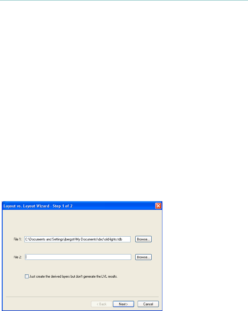
L-Edit 13 User Guide Section 3 678L-Edit 13 User Guide Section 3 678
25 Layout vs. Layout
Layout versus layout (LVL) compares two L-Edit layout files for their differences. It looks for moved,
added and deleted geometry.
Typically you compare two different layout files to discover their possible differences. You can also
compare two different cells in the same layout file. In either case, you can choose which layers L-Edit
will examine. The command File > Layout vs Layout Comparison opens a series of dialogs where you
make these choices.
There are two components to the LVL comparison results:
A log file which shows the layers being compared and uses Boolean operators to detail the
differences between the files, by layer for the layers with changes.
An LVL_Results TDB file (which is temporary unless saved). This TDB file contains a cell for
each of the input files, with generated layers containing objects that shows where and how the files
differ for the Boolean conditions—A NOT B and NOT A AND B—considered. The file layers
includes only the those selected for LVL comparison and the resulting generated layers.
Select Files to Compare
Use the first dialog of the Layout vs. Layout wizard to enter the files for L-Edit to compare.
One design file must be open.
File 1 and File 2 can be the same as well as different files.
The option “Just create the derived layers but don’t generate the LVL results” creates all the
layers that are derived during LVL but does not draw the related layout. This option allows you to
setup the layer derivation and then generate the layers as a separate step using
Tools > Add-Ins > L-Edit V9 Layer Generation. It creates a larger number of derived layers than
the full LVL process because during LVL any derived layers with no objects are deleted.
3
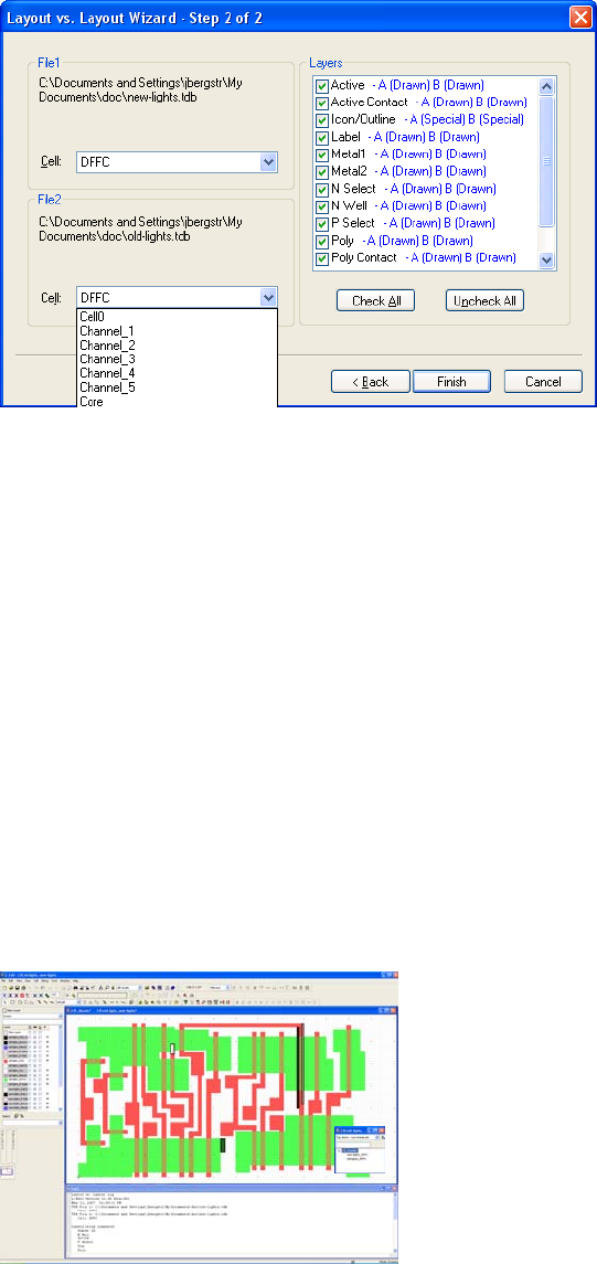
L-Edit 13 User Guide Section 3 679
Chapter 25: Layout vs. Layout Select Cells and Layers to Compare
Select Cells and Layers to Compare
Use the second dialog of the Layout vs. Layout wizard to select the cells and layers L-Edit will
compare.
The cell that was active when you launched Layout vs. Layout will be preselected in the Cell
drop-down list.
You can compare different cells as well as the same cell, or two cells from the same file.
You can compare a single layer or multiple layers, in any combination.
The Layers checklist includes layers from both of the cells being compared.
In the Layers checklist, L-Edit displays layer names in pink if the top cell does not have geometry
on the layer but the bottom cell does. (The layer is used in the B cell but not the A cell—A[not
exist] B [Drawn/Special/In Use].)
In the Layers checklist, L-Edit displays layer names in red if the top cell has geometry on the layer
but the bottom cell does not. (The layer is used in the A cell but not the B cell—
A[Drawn/Special/In Use] B [not exist].)
View LVL Results
When layout versus layout comparison is complete, L-Edit opens a log file and a temporary design file
LVL_Results LVL [File A_FileB.tdb].
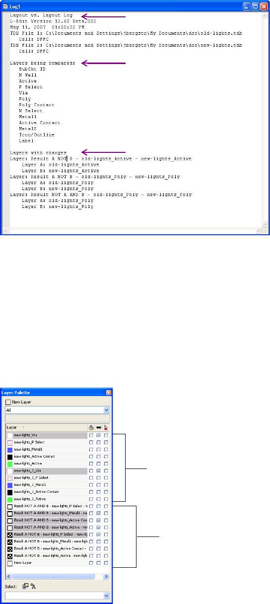
L-Edit 13 User Guide Section 3 680
Chapter 25: Layout vs. Layout View LVL Results
LVL Log File
Layout vs. Layout Log—The log header shows the L-Edit version used for LVL, the date and time
it was performed, and the file location, name and cells compared.
Layers being compared—This section of the log lists the layers selected for comparison.
Layers with changes—Details the generated layers containing objects that show the differences
between the input file layers compared.
Result A NOT B indicates an object present in Cell A but not Cell B.
Result NOT A AND B indicates an object not present in Cell A but present in Cell B.
LVL_Results TDB File
The LVL_Results file contains only the drawn layers from the input files that were selected for
comparison and the derived layers created by the LVL operation.
Input layers from File A and
File B that were compared.
Derived layer from LVL
process.
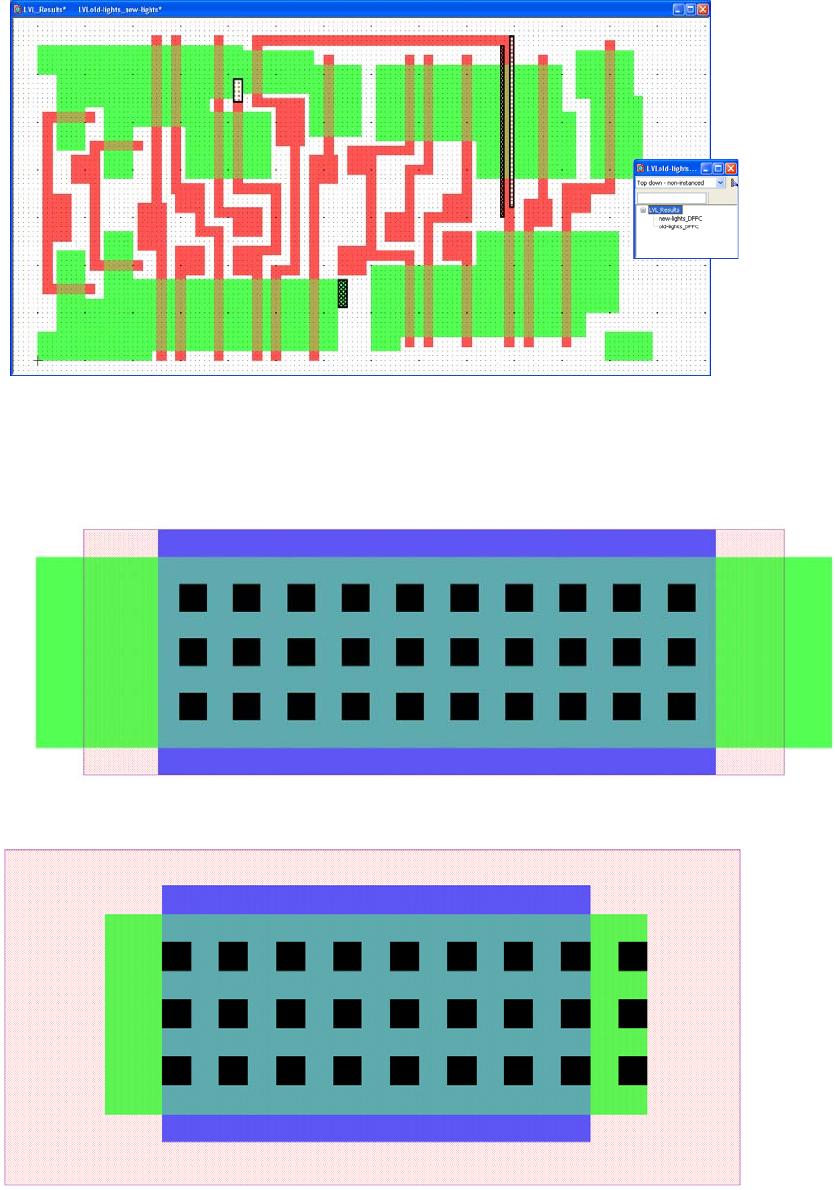
L-Edit 13 User Guide Section 3 681
Chapter 25: Layout vs. Layout Layout vs. Layout Example
In the Layer palette for the LVL_Results file, layers that do not have a difference result are hidden
(shown as grayed out in the palette) so that only the derived layers with objects resulting from
differences, and the drawn layers where the differences occurred, will be displayed.
The LVL_Results file has one cell for each of the input files, with difference results placed as
polygons on the appropriate generated layers in a third LVL_Results cell.
Layout vs. Layout Example
[1] Cell A: new-lights is compared to Cell B: new-lights_1, both from the same TDB file
Cell A: new-lights
Cell B:
new-lights_1
is the same
cell with
certain
geometry
moved, added
or removed.
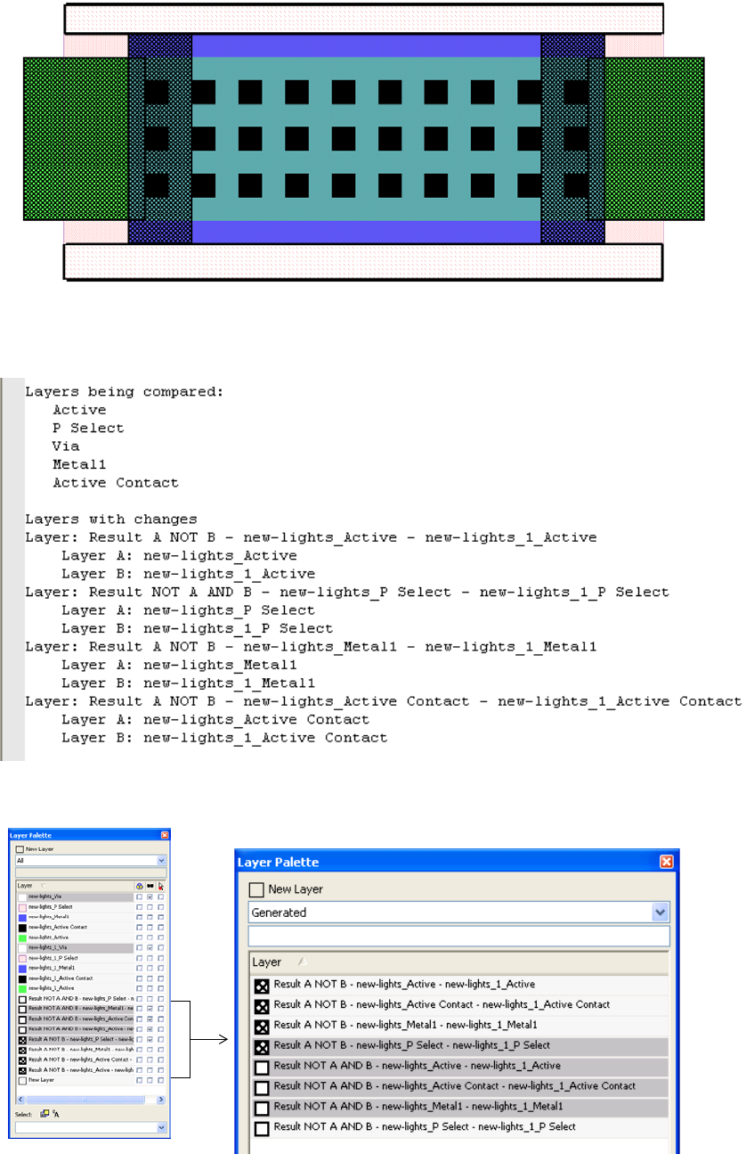
L-Edit 13 User Guide Section 3 682
Chapter 25: Layout vs. Layout Layout vs. Layout Example
[2] Cell LVL_Results LVLnew-lights_new-lights_1 contains the change objects.
[3] The log shows that layers Active, P Select, Via, Metal1 and Active Contact were compared, and that
eight derived layers were generated showing differences between the two cells.
[4] We will examine the generated layers one by one. Note the layer patterns shown in the palette.
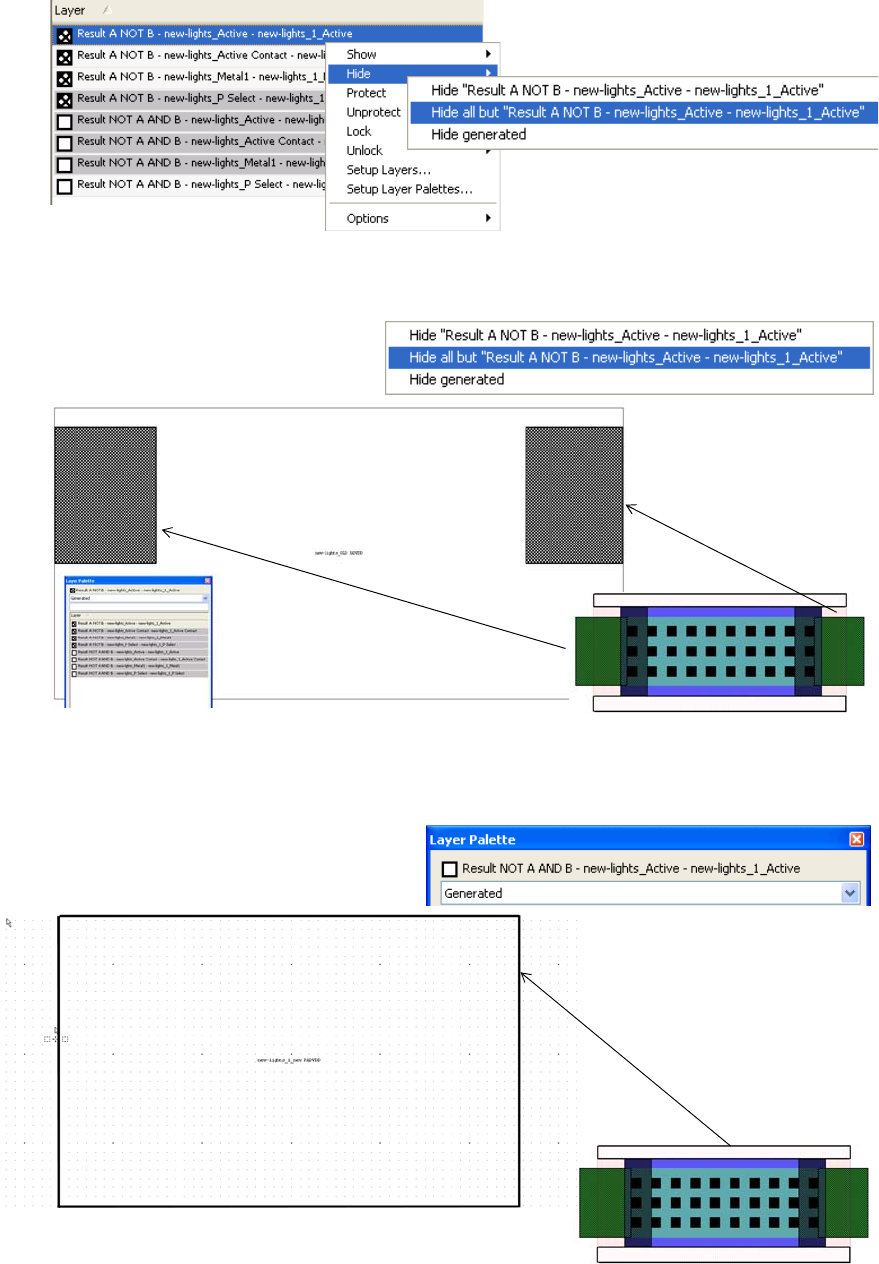
L-Edit 13 User Guide Section 3 683
Chapter 25: Layout vs. Layout Layout vs. Layout Example
[5] Right-click on a layer to open a menu where you can hide all but the selected layer.
[6] With all other layers hidden it is easy to see the objects showing differences. Here the two rectangles on
layer Active (green) show the results of A NOT B—objects that are present in Cell A but not Cell B.
[7] The results for NOT A AND B on layer Active (green)—objects that are not present in Cell A but are in
Cell B—are nil.
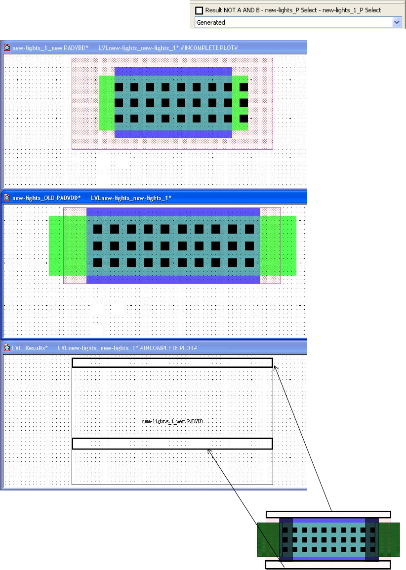
L-Edit 13 User Guide Section 3 684
Chapter 25: Layout vs. Layout Layout vs. Layout Example
[8] However, the results for NOT A AND B on layer P Select (pink checked) do show objects that are not
present in Cell A but are in Cell B.

L-Edit 13 User Guide Section 3 685L-Edit 13 User Guide Section 3 685
26 Extracting Layout
Extraction is a method of verifying a layout. The extraction process produces a netlist that describes the
circuit represented by the layout in terms of device and connectivity information.
The extraction process is defined by making associations between patterns of layout geometry and the
circuit components they represent. These associations are defined in the extract definition file.
The L-Edit general device extractor:
Recognizes active devices (BJTs, diodes, GaAsFETs, JFETs, and MOSFETs), passive devices
(capacitors, inductors, and resistors), and non-standard or compound devices by means of
subcircuit recognition.
Maintains process independence by means of an extract definition file, which describes how layers
interact electrically.
Handles large regions of layout in a memory-efficient manner by binning.
Uses device definitions that can be specified using generated layers, for a greatly expanded set of
possible definitions. Derived layers are generated and disposed of automatically.
Works with the most common device parameters, including resistance, capacitance, and device
length, width, and area. These parameters provide useful information when verifying drive, fanout,
and other circuit performance characteristics.
Creates a netlist file in Berkeley 2G6 SPICE format, usable with any tool that reads a SPICE netlist.
This netlist is ideal for use with the Tanner T-SpiceTM circuit simulator (to verify device sizes,
drive capabilities, and other circuit performance factors) or the LVS netlist comparator (to check
the equivalence of netlists generated from different sources).
See “Configuration Example” on page 700 for an illustration of the concepts described in this section.
Configuring the Extractor
To run Extract you must first load and select the extract definition files you want to run. You do this
from the Setup Extract dialog. Tools > Extract then performs netlist extraction from the active cell
using those extract rules that are checked in Setup Extract.
You also use Setup Extract to set the order in which rule checks are executed, and as a shortcut to open
the windows where rule sets can be edited.
Note: Checkmarks in the Setup Extract list only control which rule sets to run. All other
functions in the setup dialog are performed on the rule set that is highlighted.
3
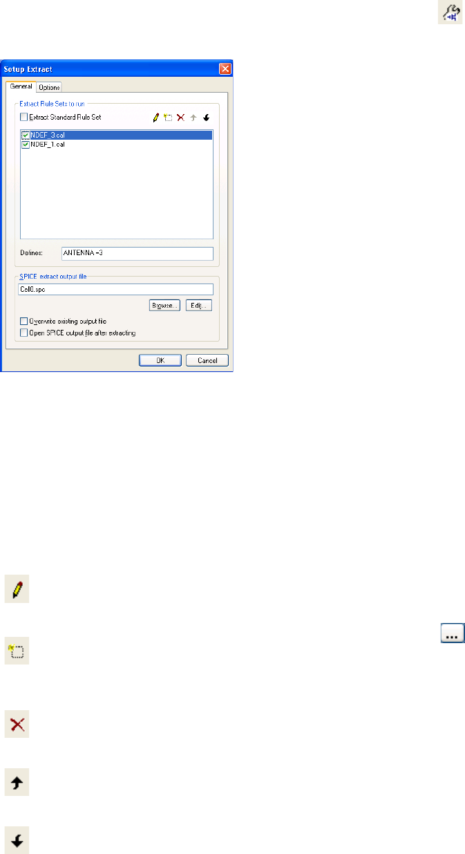
L-Edit 13 User Guide Section 3 686
Chapter 26: Extracting Layout Configuring the Extractor
Select Tools > Extract Setup from the menu or use the Setup Extract button ( ) on the verification
toolbar to open the Setup Extract dialog, which has a General and an Options tab.
Setup Extract—General
Extract Rule Sets to run Lists the Extract command files that are loaded and available to run.
Extract Standard Rule Set is the built in Tanner rule set which is
loaded by default. It cannot be run in conjunction with any other files.
Note: Only those rule sets that have their checkboxes in the
“checked” state will be run when Extract is invoked.
Edit selected command file
()
Opens the selected rule set for editing. If Extract Standard Rule Set
is highlighted, the Setup Extract Standard Rule Set dialog opens. If
a command file is selected, that file is opened in a text window.
Add command file to list
()
Press this button to add a new entry to the list of command files. You
can browse to and select a file with the browse ( ) button.
Delete command file from
list
()
Removes the highlighted file from the list.
Move Up
()
Moves the highlighted file up in the list.
Move Down
()
Moves the highlighted file down in the list.
Defines Use this field to enter variable or variable and value combination to
trigger preprocessor commands that are written in the rule files using
#DEFINE and #IFDEF.
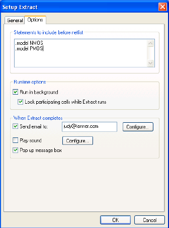
L-Edit 13 User Guide Section 3 687
Chapter 26: Extracting Layout Configuring the Extractor
Setup Extract—Options
SPICE extract output file Browse to or enter the name of the SPICE netlist generated by the
selected extractor.
Overwrite existing output
file Check this box to overwrite any existing output files of the same
name without a confirmation.
Open SPICE output file
after extracting Check this box to open the SPICE extract file after the extract run.
Statements to include
before netlist Text entered in this field is added verbatim to the netlist. For example,
enter a .include command to add a model or device name.
Run in background Check this box to run Extract in background. When Extract is run in
background, you can continue to edit and perform other L-Edit
operations while Extract is running. Extract results are returned as
soon as they are found, so you can browse and correct errors before
the entire Extract job is complete.
Lock participating cells
while Extract runs Locks the cell, and all hierarchy below that cell, to prevent edits while
Extract is running.
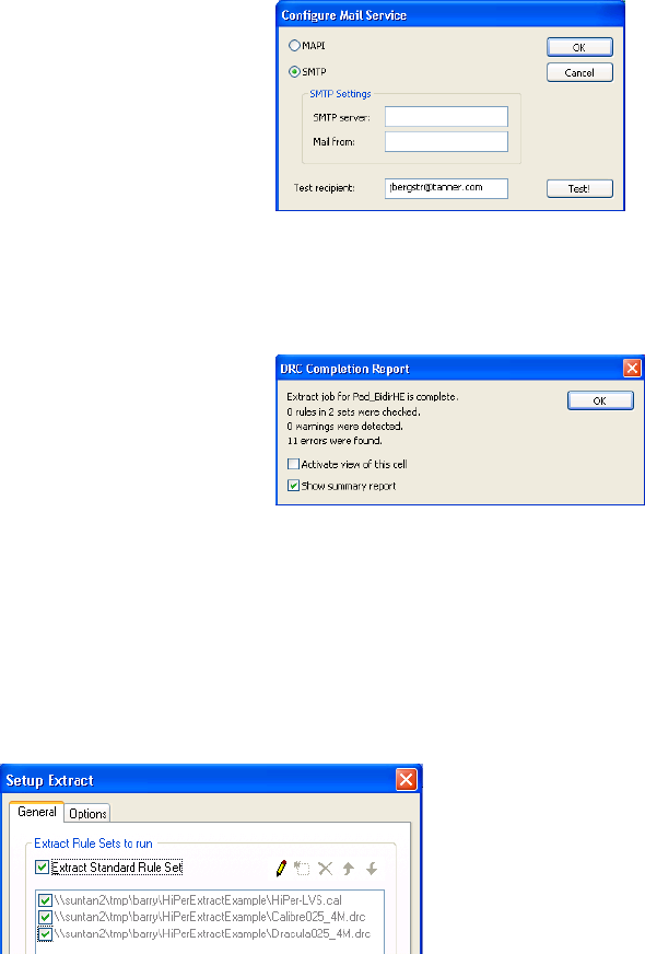
L-Edit 13 User Guide Section 3 688
Chapter 26: Extracting Layout Configuring the Extractor
Setting Up the Standard Extract Rule Set
The Standard Rule Set is pre-loaded. To use it, simply click to place a mark in its checkbox. Standard
extract does not support all-angle or hierarchical functions. When DRC Standard Extract Rule Set is
checked it is the only extract file that can run. All other setup fields pertain to HiPer files and are
non-functional.
Send E-mail to: Enter an mail address to send notification to the specified recipient
when the Extract job is complete. Use Configure to set the E-mail
options shown below. Note that most E-mail applications will require
a response prior to sending an E-mail initiated from another
application.
Play sound Check to play a sound when Extract is complete. You can configure
the sound from the standard Windows sounds available.
Pop up message box Opens an Extract Completion Report when Extract is complete.
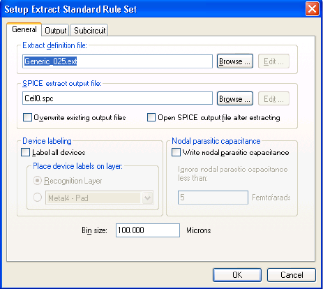
L-Edit 13 User Guide Section 3 689
Chapter 26: Extracting Layout Configuring the Extractor
Setup Extract Standard Rule Set–General
Use the fields in this tab to specify input and output file names and the bin size.
Extract definition file Name of the input file containing the extractor device and
interconnection definitions. You can choose from available files and
directories with the Browse button. You can open the file in a text
window with the Edit button. This will also close the Extract dialog.
SPICE extract output file Name of the output file containing the extracted netlist. Enter the
name (or use the default). You can choose from available files and
directories with the Browse button. You can open the file in a text
window with the Edit button. This will also close the Extract dialog.
Overwrite existing output
files When checked, causes automatic overwriting of the SPICE output
file, even if these files already exist.
Open SPICE output file
after extracting When checked, automatically opens the SPICE output file after
Extract runs.
Label all devices For each unnamed device, creates a two-dimensional port at the
location of the device. The text of the port is the text of the element
name for the device. Device labels will not be generated for devices
with user-placed labels.
The group Place device labels on layer contains options for writing
the device labels on the device-specific Recognition Layer or another
layer you select.
Write nodal parasitic
capacitance
Computes the capacitance with respect to the substrate of each node
in the circuit using the area and fringe capacitance constants specified
with “Layer Setup” (page 104). The node to substrate capacitance of
N is written to the netlist as a capacitor between N and the
substrate/ground (0). The form of this notation is Cpar1, Cpar2,
etc.
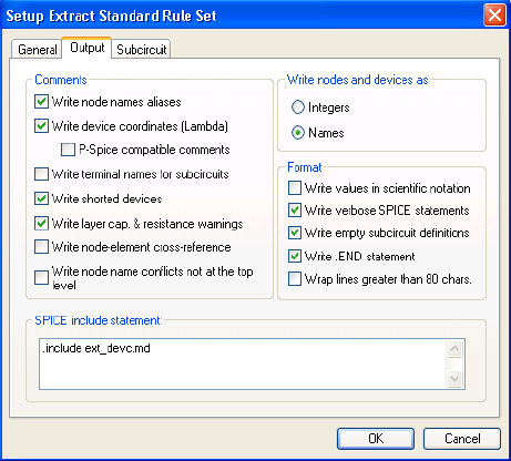
L-Edit 13 User Guide Section 3 690
Chapter 26: Extracting Layout Configuring the Extractor
Setup Extract Standard Rule Set–Output
Use the fields in this tab to specify the way in which the extracted circuit is written to the output netlist.
Write nodal parasitic capacitance is not generally turned on when a
netlist is extracted for LVS since the other netlist (typically derived
from a schematic) will not contain parasitic capacitors associated with
nodes.
Ignore nodal parasitic
capacitance less than
Specifies a limit, in femtofarads, below which the nodal parasitic
capacitance will not be written to the netlist. This field is disabled
when the Write nodal parasitic capacitance box is unchecked.
Bin size Length of one side of a bin, in display units. To improve performance,
L-Edit divides the layout into a grid of square bins and extracts each
bin individually. Devices that cross bin boundaries are extracted
properly.
Binning is not used if the Recognize subcircuit instances box in the
Subcircuit tab is checked.
Write node names aliases Writes all node names associated with each node in comments at the
beginning of the netlist file in the section NODE NAME ALIASES.
* NODE NAME ALIASES
* NODE = NODE NAME (NodeLabelX, NodeLabelY)
* 1 = U1/Out (39.5,-9)
* 2 = B (-1,23.5)
* 2 = C (-42.5,23.5)
* 2 = U0/A (13.5,-9)
* 3 = D (33.5,20)
Write device coordinates
(Display units)Writes the coordinates in display units of the lower left and upper
right corners of the device at the end of the SPICE line as a in-line
comment.
M1 1 3 5 5 PMOS L=2u W=28u $ (36.5 29 38.5 57)
L-Edit 13 User Guide Section 3 691
Chapter 26: Extracting Layout Configuring the Extractor
P-Spice compatible
comments Writes in-line comments using the ; character instead of the $
character so that they are compatible with P-Spice.
M1 1 3 5 5 PMOS L=2u W=28u ; (36.5 29 38.5 57)
Write terminal names for
subcircuits Writes the terminal names for subcircuits in a comment following
each subcircuit statement in the netlist. Terminal names of other
devices are never written to the netlist file.
X1 1 2 4 ICResPoly L=2.4u W=720n
* X1 PLUS MINUS BULK
Write shorted devices If IGNORE_SHORTS is set in the extract definition file, writes
shorted devices into the netlist as comments; otherwise, shorted
devices are ignored. If IGNORE_SHORTS is not set, a shorted device
is written to the SPICE file as a regular device.
Write layer cap. &
resistance warnings Writes warnings on missing layer capacitance and resistance values to
the specified netlist file.
* Warning: Layers with Unassigned AREA Capacitance.
* <PMOS Capacitor ID>
* Warning: Layers with Unassigned FRINGE Capacitance
* <Poly1-Poly2 Capacitor ID>
* Warning: Layers with Zero Resistance.
* <N Well Resistor ID>
Write node-element
cross-reference Writes a node-element cross-reference table in the comments of the
netlist file. Also, list are the element’s terminal, the edge between the
node and the device recognition polygon, and the device’s location.
* NODE-ELEMENT CROSS REFERENCE
* NODE = ELEMENT Terminal (PinEdgeX1 PinEdgeY1
* PinEdgeX2 PinEdgeY2) (ElemX1 ElemY1 ElemX2 ElemY2)
* 6 = R1 P (-65 20 -65 30) (-65 20 -60 30)
* U0/A = R1 N (-60 20 -60 30) (-65 20 -60 30)
* U0/A = Mn1 G (18.5 -9 20.5 19) (18.5 -9 20.5 19)
* U0/A = Mp2 G (18.5 29 20.5 57) (18.5 29 20.5 57)
* U0/Gnd = M2 B (36.5 -9 38.5 19) (36.5 -9 38.5 19)
* U0/Gnd = Mn1 B (18.5 -9 20.5 19) (18.5 -9 20.5 19)
* U0/Out = M1 D (36.5 29 36.5 57) (36.5 29 38.5 57)
The element terminal abbreviations are as follows:
Resistor, Capacitor, Inductor: P - Positive, N - Negative
Diode: P - Anode, N - Cathode
BJT: C - collector, B - Base, E - Emitter, S - Substrate.
JFETs/MESFETs: D - Drain, G - Gate, S - Source, B - Bulk
MOSFETs: D - Drain, G - Gate, S - Source, B - Bulk
For Subcircuit, the entire pin name from the EXT file is written.
* 1 = X1(MINUS) (-16 25 -16 36) (-18.5 25 -16 36)
Write node name conflicts
not at the top level Flags node name conflicts that occur in the hierarchy other than in the
top level. This is especially helpful for nodes in standard place and
route cells.
Write nodes and devices as Controls whether nodes are written as internally generated numbers
(Integers) or as descriptive strings (Names). Ports in the layout can
be used as node or element names in the netlist. For further
information, see “Node Names” on page 700.

L-Edit 13 User Guide Section 3 692
Chapter 26: Extracting Layout Configuring the Extractor
Note: L-Edit cannot determine if other nodes in the circuit are ground nodes. If other nodes
are to represent ground, then they must be renamed 0—or any of its equivalents—in
the netlist.
Setup Extract Standard Rule Set–Subcircuit
Write values in scientific
notation When checked, this option writes numerical values in scientific
notation instead of SPICE engineering units.
Option on (checked)
M1 1 3 5 5 PMOS L=2E-6 W=2.8E-5
Option off (unchecked)
M1 1 3 5 5 PMOS L=2u W=28u
Write verbose SPICE
statements Writes resistors, inductors, and capacitors to the netlist file with the
device value preceded with a R=, L=, or C=. For example, a capacitor
would have the following format: Cxxx n1 n2 modelName
C=cValue.
Write empty subcircuit
definition Writes an empty subcircuit definition block at the top of the netlist
file. Use only with Recognize subcircuit instances on “Setup
Extract Standard Rule Set–Subcircuit” (page 692).
Write .END statement Writes a .END statement at the end of the netlist
Wrap lines greater than 80
chars. Wraps SPICE lines at 80 characters and continues them on the next
line, including comments.
M189 DataInB DataInUnBuf Vdd Vdd PMOS L=2u W=13u
becomes
M189 DataInB DataInUnBuf Vdd Vdd PMOS
+ L=2u W=13u
SPICE include statement Specifies text that is written unaltered as the second line of the output
netlist. Typically, an .include file command is entered, where file
represents a model or subcircuit file name.
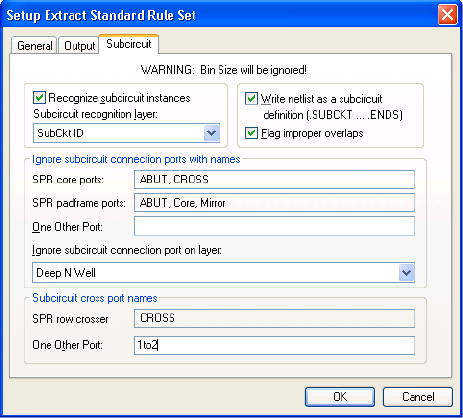
L-Edit 13 User Guide Section 3 693
Chapter 26: Extracting Layout Configuring the Extractor
Use the fields in this tab to specify parameters for subcircuit extraction.
Recognize subcircuit
instances Activates the subcircuit recognition feature.
Subcircuit recognition
layer Name of the subcircuit recognition layer (SRL). This mandatory layer
should not contain electrically significant geometry.
Write netlist as a subcircuit
definition (.SUBCKT ...
.ENDS)
When checked, this option writes the entire netlist in subcircuit
format. A .subckt command appears before the first device, and an
.ends command appears after the last device. When this option is
used, there must be a subcircuit recognition polygon at the top level
defining the subcircuit in order for Extract to proceed with subcircuit
extraction.
Flag improper overlaps Controls the reaction to geometry violations: under- or over-filled
connection ports or geometry that overlaps the subcircuit boundary.
Check to display warnings; clear to suppress warnings. Suppressing
warnings can be useful when extracting autorouted standard cell
designs with known over- and under-fill characteristics.
Ignore subcircuit
connection ports with
names
List of ports whose names are ignored in subcircuit extraction.
Contains the following fields:
SPR core ports—read-only field listing port names predefined
in SPR Core Setup—General.
SPR padframe ports—read-only field listing port names
predefined in SPR Padframe Setup—General.
One Other Port—use this field to specify one additional
subcircuit connection port to be ignored.
Ignore subcircuit connection port on layer—name of a layer
on which intruding geometry and subcircuit connection ports will
not be recognized. The netlist extractor also ignores any
geometry on the Icon layer (often used for documentation
purposes).
For more information see “Designing Subcircuit Cells” on page 706.
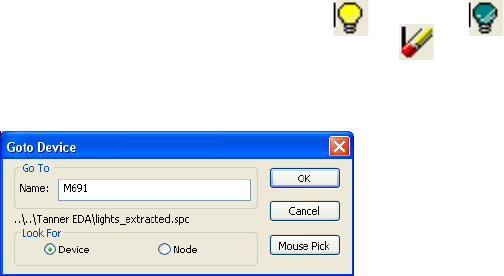
L-Edit 13 User Guide Section 3 694
Chapter 26: Extracting Layout Devices and Connections
Devices and Connections
The first step is to determine the specific classes of devices and connections that are to be extracted.
A device is any circuit element (transistor, resistor, capacitor, diode, etc.).
A connection is any electrical connectivity between two process layers, such as between the Poly
and Metal1 layers when a contact is present on the Poly Contact layer.
Only relevant devices and connections need be defined. For example, every design contains resistors,
because no process layer is a perfect conductor. But if the design to be extracted does not contain any
wire long enough for its inherent resistance to affect the circuit’s performance, then the wires do not
have to be defined and extracted as resistors.
Finding Devices and Nodes
Tools > Goto Device (Alt+G) locates a device or node from the extract output file by zooming to it and
placing a marker in the layout. You must have extracted connectivity first or pointed to the correct
SPICE file for this operation to function. The behavior is slightly different for the two search types.
You can toggle the marker display on ( ) and off ( ) with the lightbulb toolbar button and
delete all markers with the eraser toolbar button ( ).
Tools > Goto Device
Subcircuit cross port
names Lists ports whose names are ignored in subcircuit extraction. Contains
the following fields:
SPR row crosser—read-only field listing subcircuit cross ports
predefined in SPR Core Setup—General.
One Other Port—use this field to specify one additional
subcircuit cross port.
For more information see “Crossing Over a Subcircuit Instance” on
page 709.
GoTo Enter the Name of the device or node you want to locate.
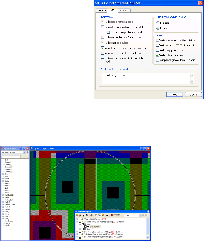
L-Edit 13 User Guide Section 3 695
Chapter 26: Extracting Layout Devices and Connections
When you enter a device, L-Edit will zoom to it as shown below.
Look for Select Device or Node.
Note: For nodes to appear in the extract output file, you must check
the Write node-element cross-reference option in the
Output tab of the Tools > Extract dialog.
Mouse Pick Click this button to select a device with a mouse click in the layout.
device marker
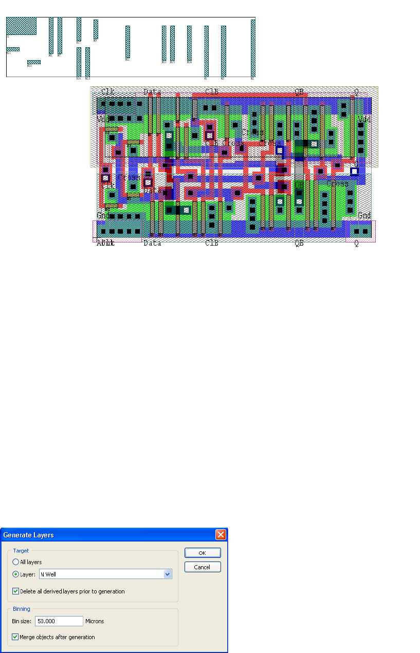
L-Edit 13 User Guide Section 3 696
Chapter 26: Extracting Layout Devices and Connections
When you enter a node, L-Edit will highlight the elements connected to that node and create disposable
ports on the error layer that you can reposition to better inspect the node.
Generated Layers
When you use generated layers in an extract definition, L-Edit automatically generates objects on those
layers before proceeding with netlist extraction. Following netlist extraction, L-Edit automatically
deletes the objects it created during that Extract run. It only deletes objects generated during that most
recent Extract run—however, previously generated objects remain.
The extractor uses the same layer generation method found in L-Edit version 9, which only operates on
boxes, and 45° and 90° polygons and wires. It does not extract circles or all-angle polygons and wires.
This behavior is different from layer generation using Tools > DRC or Tools > Generate Layers. If
you need to manually run the Extract layer generation, you can do this using “Manual (L-Edit V9)
Layer Generation,” below.
Manual (L-Edit V9) Layer Generation
Because the extractor generates layers automatically, you do not need to perform layer generation as a
separate step. However, if you wish to manually generate layers to see them as the extractor sees them,
you can do so using Tools > Add-Ins > L-Edit v9 Layer Generation:
node marker

L-Edit 13 User Guide Section 3 697
Chapter 26: Extracting Layout Devices and Connections
Options include:
Warning: If a source layer (i.e., an input to a derived layer) is hidden, L-Edit ignores objects on that layer.
When you execute the Generate Layers command, L-Edit automatically deletes existing objects on
derived layers before regenerating those layers. If you generate only a single layer, however, L-Edit does
not delete objects on other derived layers.
To delete such objects, check the option Delete all derived layers prior to generation. L-Edit does not
delete ports on derived layers. If generation is disabled for a particular layer, L-Edit does not
automatically delete objects on that layer before generating other layers.
Extracting Resistor and Capacitors
To extract resistors and capacitors, you must also enter the following three constants for each involved
layer. Use “General Layer Parameters” (page 105) to enter these values.
An area capacitance (in attofarads per square micron)
A fringe capacitance (in femtofarads per micron)
A resistivity (in ohms per unit area)
Target Layer to be generated. Options include:
All layers
Layer—a single layer, selected from the drop-down menu
If a derived layer is dependent on source layers that are themselves
derived, the source layers are recursively generated as well.
Note: L-Edit does not generate locked source layers or layers for
which derivation is disabled. In these cases, L-Edit treats the
source layers as drawn layers for the purposes of generating
the derived layer.
Delete all derived layers
prior to generation Clears objects on all derived layers. When generating a single Layer,
use this option to clear objects on other derived layers. Ports on
derived layers are not deleted.
Binning L-Edit divides the layout into a grid of square bins and performs layer
generation within each bin. Choosing the optimal bin size
significantly increases performance because objects that are distant
from one another are not involved together in layer-generation
operations.
Bin size Length, in display units, of one side of a bin.
Note that the actual bin size used to generate layers is snapped up to a
multiple of the mouse snapping grid (set in Setup Design > Grid >
Mouse snap grid) to avoid generating off-grid polygons.
Merge objects after
generation Causes objects on a generated layer to be merged upon completion of
the process. This option can significantly increase processing time for
more complex layouts.
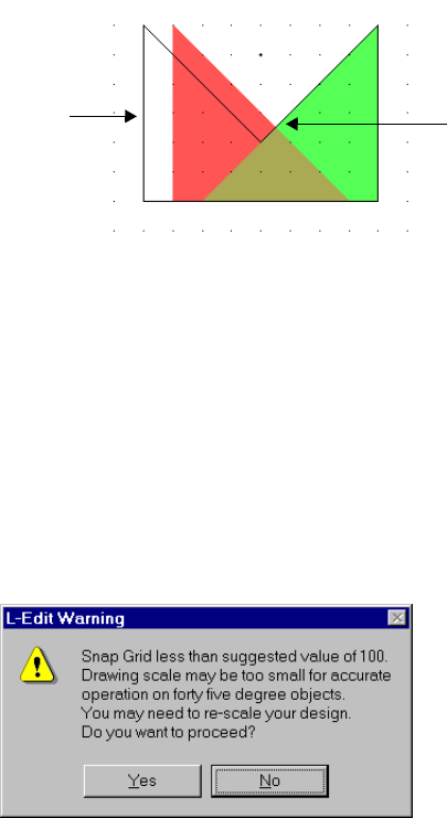
L-Edit 13 User Guide Section 3 698
Chapter 26: Extracting Layout Devices and Connections
Capacitance is the sum of two products: that of the area of the capacitor and the area capacitance, and
that of the perimeter of the capacitor and the fringe capacitance. (Capacitors are polygons on the
recognition layer.) Resistance is the product of the resistivity and the length of the resistor, divided by
the width.
Working with 45° Objects
When layers are generated with Tools > Extract, all off-grid vertices are rounded to the nearest internal
unit that preserves the angles. Off-grid vertices may result from off-grid intersections of 45° polygons,
and from conversion of 45° wires to polygons. The coordinates of off-grid vertices are rounded to the
nearest internal unit while still preserving 45° and 90° angles. If the dimensions of the source objects
(measured in internal units) are small, then the resulting polygons may be distorted.
In the following example, the polygons on layers a and b create an off-grid intersection. (The distance
between gridpoints is one internal unit). When generating a polygon equal to (a | b), L-Edit rounds the
off-grid vertex to the nearest gridpoint. To preserve 45° and 90° angles, two additional vertices must be
shifted to the left. This results in a distortion of the original shapes.
To can prevent distortion from rounding of grid coordinates, you should maintain a minimum
resolution, in internal units, for all edge lengths, wire widths, distances between objects, and Grow
distances. You can specify this minimum resolution by setting the mapping from internal units to
technology units in Setup > Design—Technology dialog (see “Technology Parameters” on page 96).
A setting of at least 100 internal units per technology unit is recommended for designs containing 45°
objects.
When you run Extract, L-Edit checks the snap grid parameter. If it is less than 100 internal units, L-Edit
assumes that edges or spacings smaller than 100 internal units may exist on the layout, and the warning
appears, suggesting that the layout may need to be rescaled.
If you are certain that no edges, wire widths, spacing, or Grow values smaller than 100 internal units
exist, then click Yes to proceed. Changing the snap parameter to an equivalent of 100 internal units
prevents the warning from appearing (see “Grid Parameters” on page 97).
ab
a OR b *Off-grid vertex
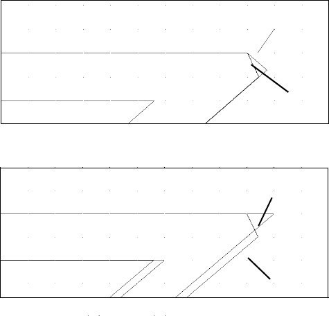
L-Edit 13 User Guide Section 3 699
Chapter 26: Extracting Layout Devices and Connections
The equivalent number of internal units is based on the snap grid value (in display units) and the
number of internal units per display unit. It is up to you to make sure that no objects smaller than the
subgrid are created; the warning depends only on the current value of the snap grid, not on the actual
size of objects in the layout. You can rescale the design by increasing the number of internal units per
technology unit.
Wires
Wires involved in layer-generation operations on the source layers are converted to polygons on the
generated layer. However, some join styles on 45° wires result in wire edges that meet at non-45°
angles. To ensure that the resulting objects are true 45° polygons when the layer is generated, the
problem joins are modified. Round joins are processed as layout joins and round ends are processed as
butt ends to satisfy the 45° polygon criteria.
Examples of a converted 45° source wire to a generated layer polygon are shown in the following
figure:
After rescaling, the finer grid resolution (more internal units per technology unit) allows the generated
polygon to approximate the source wire more closely. Without rescaling the design, the vertex of the
generated polygon in the above example is forced to the nearest internal unit that maintains a 45° angle.
Extract Definition File
The extract definition file contains a list of the connections and devices to be extracted. This file can be
used to define:
Connections between two different process layers
Devices in terms of their type, component layers, pins, and model names
The directory samples\tech\mosis contains a set of extract definition files that correspond to various
technology processes. You can modify these files as necessary to define additional connections and
devices for extraction.
Generated layer
Source layer
Generated layer
Source layer
Rescaled
Not rescaled
L-Edit 13 User Guide Section 3 700
Chapter 26: Extracting Layout Configuration Example
For a detailed reference on the syntax of the extract definition file, see “SPICE OUTPUT Properties” on
page 710.
Node Names
Extract can write out nodes as internally generated numbers (using the option Integers in Extract—
Output) or as descriptive strings (using the option Names in Extract—Output). For further information
on this dialog, see “Setup Extract Standard Rule Set–Output” (page 690).
To label a node or element for extract to a netlist, you must add a port to the layer of that node or
element, within an object (box, polygon or wire) on that layer. When Names is selected, L-Edit derives
node names from the names of ports found on the same layer as the node. It derives element names from
ports found on the device-specific recognition layer that are completely enclosed by that device. Port
labels are transferred when generating a layer for extract. For example, if you have a node name IN1 that
is on Metal 1 but in your extract definition file you use M1Wire which is Metal 1 and Not Inductor ID,
then the port on Metal 1 will be transferred to M1Wire during extract and will label the node IN1.
If you want to use the same ports for a design rule check that uses an assigned dummy layer, you can
change the layers for your ports by:
;hiding all objects except for ports
;hiding all layers except the node layer
;selecting all objects, which will be just the ports on the node layer
;using Edit > Edit Object to change the layer to the layer of your choice.
The strings produced by the extractor are the hierarchical names; each instance involved in a node is
mentioned and separated from the others by a slash (/), with the port name at the end. (Instances that are
unnamed in the layout are named automatically by the extractor.) For example, the node name
U1/alpha/in describes a port in contained by an instance alpha, which in turn is contained by an
instance U1.
Configuration Example
The following example illustrates how to configure the extractor to recognize a transistor in a CMOS
n-well process. It shows how transistors may be clearly and uniquely identified by generated layer
definitions and device statements in the extractor definition file. Other SPICE devices may be identified
in similar fashion.
An NMOS transistor in an n-well CMOS process consists of:
The channel
A source pin of n-doped diffusion material touching the channel
A gate pin of polysilicon over the channel
A drain pin of n-doped diffusion material touching the channel
A bulk pin to the substrate
L-Edit 13 User Guide Section 3 701
Chapter 26: Extracting Layout Configuration Example
When the extractor finds a configuration of polygons in the layout corresponding to this definition, it
should write an NMOS transistor statement into the output file (netlist).
Device Definition
The following statement causes a MOSFET to be generated in the output.
# NMOS transistor
device = MOSFET(
RLAYER=ntran;
Drain=ndiff, WIDTH;
Gate=Poly;
Source=ndiff, WIDTH;
Bulk=subs;
MODEL=NMOS;
)
The recognition layer is defined as ntran, and the pin layers are defined as ndiff, Poly, and subs. This
causes the extractor to recognize a MOSFET wherever it sees ntran geometry, touched by geometry on
ndiff, Poly, and subs.
However, MOSFETs are not typically created by drawing geometry on ntran, ndiff, or subs. They are
created by drawing Poly geometry over Active geometry inside NSelect geometry.
To generate correct geometry on the ntran, ndiff, and subs layers from user-drawn geometry on
Active, Poly, and N Select layers, use generated layers (see “Generating Layers” on page 284).
Recognition Layers
A transistor gate is formed on the chip when Poly geometry and Active geometry intersect on the
layout. The generated layer
gate = ( Poly ) AND ( Active )
is used to define a generic transistor gate.
However, a CMOS process will have both NMOS transistors (in the substrate) and PMOS transistors.
The gate layer definition does not differentiate between the two.
L-Edit uses a default CMOS setup that assumes a p-substrate, has a nongenerated layer (N Well) for
defining the n-well, but does not have a layer for defining the substrate surface. The generated layer
subs = NOT ( N Well )
is used to define the substrate surface.
Now, two generated layers can uniquely identify NMOS and PMOS transistor channels:
ntran = ( gate ) AND ( subs )
ptran = ( gate ) AND ( N Well )
Pin Layers
When the extractor identifies a transistor to be written to the output netlist, it looks for the pins that
should be touching the recognition layer if the device is properly constructed.
L-Edit 13 User Guide Section 3 702
Chapter 26: Extracting Layout Configuration Example
A MOSFET has four pins attached to it: drain, gate, source, and bulk. The gate is defined to be the Poly
geometry that touches the transistor. The bulk in a PMOS device is the NWell, and in an NMOS device
is the substrate (subs). For these pins, the proper layers are already defined.
In the layout, a single polygon on the Active layer stretches across the whole transistor, but in a
fabricated chip, the diffusion material will not exist under the gate. The generated layer
Field Active = ( Active ) AND ( NOT (Poly ) )
creates geometry on either side of, but not underneath, a transistor gate.
Finally, an NMOS transistor has source and drain pins made up of n-doped material, and a PMOS
transistor has source and drain pins made of p-doped material. The doping type is controlled by drawing
geometry on the N Select and P Select layers, so two generated layers can uniquely identify both pin
layers:
ndiff = ( Field Active ) AND ( N Select )
pdiff = ( Field Active ) AND ( P Select )
Detecting Soft Connections
You can configure the extractor to write special devices for each connection to a well or substrate,
called “soft connections.”
These special devices must be included in the netlist for LVS to identify soft-connected nodes (see
“Detecting Soft Connections with LVS” on page 753). By convention, these devices are 0Ω resistors
with designated model types, such as R_WELLCONTACT and R_SUBSCONTACT.
To write special devices for soft connections, make the following changes in the extract file:
To detect ohmic contacts to well and substrate, create two additional derived layers:
ohmic well contact := n well wire AND ndiff
ohmic substrate contact := subs AND pdiff
Do not connect wells and substrates to diffusions through ohmic contacts. Look through the extract
file and delete lines like the following:
connect(n well wire, ndiff, ndiff)
connect(subs, pdiff, pdiff)
Add device recognition statements for the ohmic contact special devices (resistors). For example:
# Well contact
device = RES(
RLAYER=ohmic well contact;
Plus=n well wire;
Minus=ndiff;
MODEL=WELLCONTACT;
)
# substrate contact
device = RES(
RLAYER=ohmic substrate contact;
Plus=subs;
Minus=pdiff;
MODEL=SUBSCONTACT;
)
L-Edit 13 User Guide Section 3 703
Chapter 26: Extracting Layout Adding User Parameters to Extracted Devices
Adding User Parameters to Extracted Devices
Users can annotate extracted devices with parameters that are meaningful to downstream tools. To
annotate a device, create a port on the recognition layer that overlaps the device in question. The port
should be the device name followed by user parameters that users want add. This will set the particular
name and user parameters for that device. The first word of the port will become the SPICE name for
the device and the rest of the port text as the parameters to add to the device line.
Users can add extra parameters, replace existing parameters, or use existing parameters in their
expressions of their extra parameters. The directory L-Edit Pro\Samples\Extract contains two
examples demonstrating user parameters. The following are a series of examples showing the different
results of user parameters.
No port label
R23 nodeA nodeB R=3
Port text = "Rin" - labels a device to be Rin
Rin nodeA nodeB R=3
Port text = "Rin turns=4" - labels a device to be Rin, with property "turns=4"
Rin nodeA nodeB R=3 turns=4
Port text = "turns=4" - adds property "turns=4" to auto-named device
R23 nodeA nodeB R=3 turns=4
Port text = "Rin R=10 turns=4" - labels a device to be Rin, with property "turns=4" and the "R="
property will be replaced with the value in the port text.
R23 nodeA nodeB R=10 turns=4
Port text = "Mn1" - labels a device to be Mn1 - The model name is taken from the extract definition
file.
device = MOSFET(
RLAYER=ntran;
Drain=ndiff, AREA, PERIMETER;
Gate=poly wire;
Source=ndiff, AREA, PERIMETER;
Bulk=subs;
MODEL=NMOS;
)
Mn1 nodeD nodeG nodeS nodeB NMOS L=5u W=10u
Port text = "Mn1 MODEL=MyNMOS" - labels a device to be Mn1, with the model name replaced
with the specified model name, "MyNMOS". This allows the user to override the model name in
the EXT file.
Mn1 nodeD nodeG nodeS nodeB MyNMOS L=5u W=10u
Port text = " Mn1 AD='${W}*6u' " - labels a device to be Mn1, with ${W} replaced with the width
of the transistor. This allows the user to use device parameters in expressions of other parameters.
Mn1 nodeD nodeG nodeS nodeB MyNMOS L=5u W=10u AD='5u*6u'

L-Edit 13 User Guide Section 3 704
Chapter 26: Extracting Layout Adding User Parameters to Extracted Devices
The port string can include tokens, which are references to other values and device parameters. The
following tokens are expanded when writing to the SPICE netlist. All other text is parsed without
expansion. See the previous paragraph for an example.
Using SUBCKT in the EXT File to Extract Non-standard Devices
You can use the SUBCKT device in the EXT file to extract non-standard devices such as resistors with
a bulk connection. The directory L-Edit Pro\Samples\Extract\ICResistors contains an example
demonstrating the extraction of a resistor with a bulk connection.
Here is a SPICE subcircuit that can model an IC resistor with a bulk connection.
.SUBCKT ICResPoly Plus Minus Bulk L=1 W=1
.PARAM Poly_Conduct = 140
.PARAM Rs='L/(W*Poly_Conduct)'
.PARAM Eox = '3.9*8.85E-12'
.PARAM Tox = 3.750E-7
.PARAM Cs='L*W*Eox/Tox'
R1 Plus 2 R='Rs/2'
R2 2 Minus R='Rs/2'
C1 Plus Bulk C='Cs/4'
C2 2 Bulk C='Cs/2'
C3 Minus Bulk C='Cs/4'
.ENDS
The subcircuit has three terminals and needs the length and width of the device. We can extract this
using the subcircuit device in the EXT file.
# IC Poly Resistor
device = SUBCKT(
RLAYER=PolyResistor, LW;
Plus=PolyWire, DEVICEWIDTH;
Minus=PolyWire, DEVICEWIDTH;
Bulk=Substrate;
MODEL=ICResPoly;
)
This device definition uses the layer PolyResistor for the recognition layer, which is Poly & Resistor
ID. This makes sure that we have to have both Poly and ID to have a resistor. If we used just the ID, then
there could be a chance that we create a resistor with just the ID and not the Poly. Extract will think
there is resistor there but physically there is not. The positive and negative pins use PolyWire, which is
Poly & NOT Resistor ID. If we used just Poly, the resistor would be shorted. The keyword
DEVICEWIDTH is used on the positive and negative pins so that the width of those pins will be used to
calculate the width of the device. The bulk connection use Substrate, which is NOT N Well.
Token Expansion
${property}The value of the named property (as a string). property can be
expressed using the full path—e.g., Mechanical.Length. If no path is
designated, EXTRACT is assumed.
\n \t New line (\n) or tab (\t) characters.
\\ \$ \{ \} The character after the initial backslash (instead of being interpreted
as part of a token).
L-Edit 13 User Guide Section 3 705
Chapter 26: Extracting Layout Subcircuit Recognition
When run extract, make sure to have “Write empty subcircuits definitions”, so you can .INCLUDE
your subcircuit definition for the resistor by using the “SPICE include statement” option. The result
will look like the following.
.INCLUDE ResSubs.sp
X1 1 2 4 ICResPoly L=2.4u W=720n
Subcircuit Recognition
Most physical layout designs are hierarchical. Hierarchical designs help manage complexity, encourage
the creation and reuse of library cells, and facilitate computer-aided engineering.
Extract provides a form of hierarchical extraction to automate working with hierarchical designs and to
speed up the extraction process in higher-level cells.
This is done by marking often-instanced lower-level cells as subcircuit cells, essentially making them
“black boxes,” so that every instance will not be extracted explicitly.
When not set to recognize subcircuits, Extract “flattens” instances. The extracted netlist describes all
devices at the same level, with no indication of hierarchy.
However, if subcircuit recognition is activated and there are instances of subcircuit cells, then the
extracted netlist contains:
An empty subcircuit definition block corresponding to each subcircuit cell. Each such block begins
with the .subckt command and ends with the .ends command. Subcircuit and node names in the
netlist are taken from the names of the subcircuit cells and their connection ports.
A SPICE subcircuit instance statement corresponding to each instance. Each such statement has
the form xinstance pin1 … subcircuit, where instance represents the instance name, pin1 … the
pin list, and subcircuit the subcircuit definition name. (If the instance is unnamed in the layout,
Extract automatically assigns its name in the netlist.)
Subcircuit recognition is recursive within non-subcircuit instances. If a higher-level cell contains a
non-subcircuit instance, and the instanced cell itself contains marked (subcircuit) instances, then the
subcircuit instances are properly extracted as subcircuits at any level of hierarchy, and any
non-subcircuit instances are flattened.
Activating Subcircuit Recognition
Subcircuit recognition is activated by checking the Recognize subcircuit instances option in the
dialog “Setup Extract Standard Rule Set–Subcircuit” (page 692).
If the Write netlist as a subcircuit definition option is checked, then the entire netlist is written in
subcircuit format:
A .subckt command appears before the first device statement, and an .ends command appears
after the last device statement.
Subcircuit connection ports at the top level (that is, not contained in instances) of the extracted cell
are written as SPICE subcircuit pins in the output.
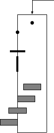
L-Edit 13 User Guide Section 3 706
Chapter 26: Extracting Layout Subcircuit Recognition
This feature can provide complete subcircuit definitions corresponding to subcircuit instance statements
generated from other cells. It requires that the subcircuit recognition polygon and the proper pin ports
exist at the top level.
As the extractor runs with subcircuit recognition activated, any errors are reported, and ports placed on
the Error layer at their locations in the layout.
Designing Subcircuit Cells
Subcircuit Recognition Polygons
A cell is marked as a subcircuit cell by the presence of a subcircuit recognition polygon (SRP) on the
subcircuit recognition layer (SRL).
The SRP is a box or a 90° polygon. It delimits the area of any of the subcircuit cell’s instances that
cannot be overlapped by geometry in the containing cell and the perimeter at which subcircuit
connection ports may be placed.
There are two exceptions to the rule against overlapping an instanced cell’s SRP:
Geometry inside subcircuit connection ports.
Geometry over cross port channels.
There may be only one SRP per subcircuit cell. If no SRP exists in the cell, then its instances are not
recognized as subcircuits; the extractor flattens them.
Any geometry in a cell that contains an SRP, including geometry outside the SRP, appears in instances
of the cell but is ignored by the extractor.
Subcircuit Connection Ports
The pins of a subcircuit instance are formed by placing subcircuit connection ports inside the subcircuit
cell on the particular layer on which connections will be made to the instance. A connection port must
both (1) be completely contained by the SRP, and (2) share an edge with the SRP. The port may be
2-dimensional or 1-dimensional (as long as it is colinear with an SRP edge), but not 0-dimensional (a
point).
The text associated with a connection port is transferred to the output netlist as the name of a signal
parameter (node) on the subcircuit definition. All connection ports, on all layers, with the same name
(within one subcircuit cell) are extracted as the same subcircuit pin. The pins of a subcircuit are written
in alphabetical, then numerical, order.
0-D: Ignored
1-D, not colinear with SRP edge: Ignored
1-D, colinear with SRP edge: Accepted as connection port
2-D, not on SRP edge: Ignored
2-D, on SRP edge: Accepted as connection port
0-D: Ignored
2-D, not totally enclosed by SRP: Ignored
2-D, not enclosed by SRP: Ignored
Subcircuit Recognition Polygon
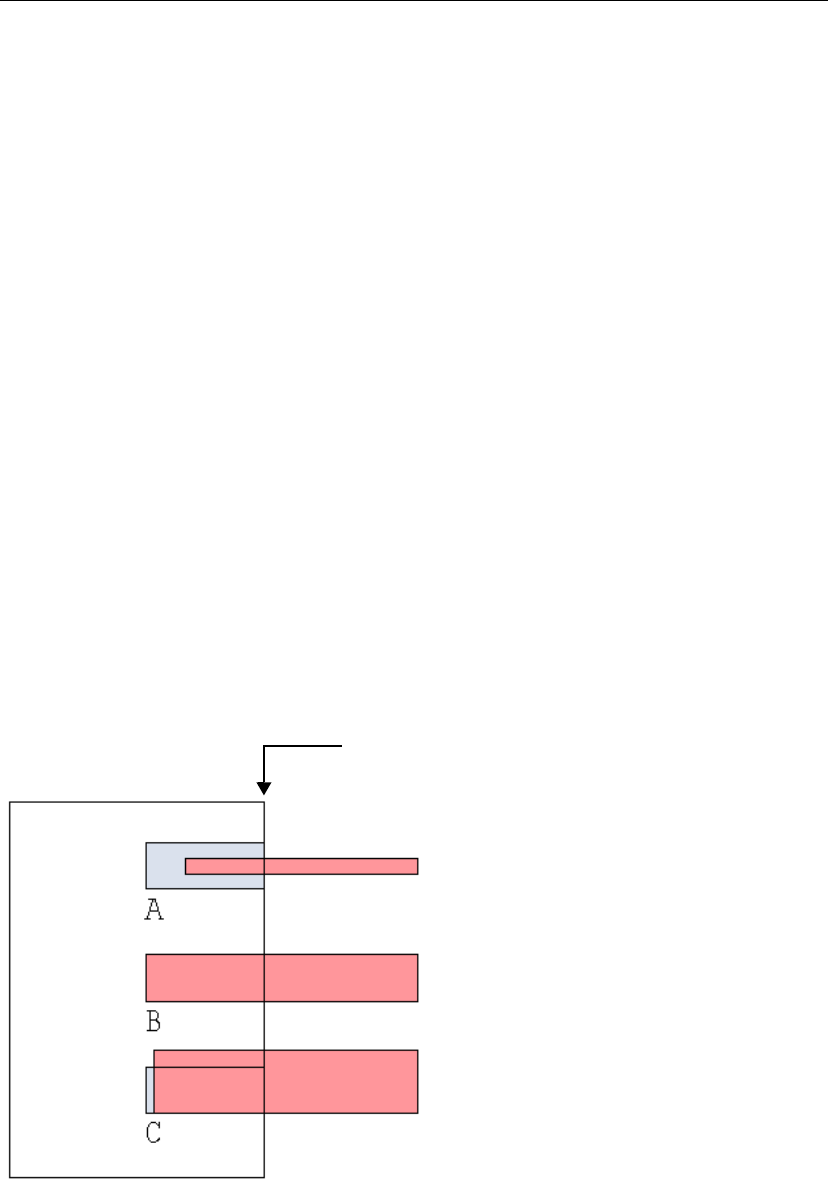
L-Edit 13 User Guide Section 3 707
Chapter 26: Extracting Layout Subcircuit Recognition
Certain named ports can be ignored as candidates for connection ports. These are shown in the dialog
“Setup Extract Standard Rule Set–Subcircuit” (page 692), in the Ignore subcircuit connection
ports with names section:
Connecting to a Subcircuit Instance
A connection to a subcircuit instance is formed by drawing an orthogonal wire, box, or polygon into a
connection port, on the same layer.
Into a 1-dimensional port, connecting geometry should be exactly as wide as the port and must
exactly abut the port without overshooting it.
Into a 2-dimensional port, connecting geometry should exactly fill the port, with neither gaps nor
spillovers.
Odd-width wires with extend or round end styles should not be used.
If the connecting geometry touches the connection port but does not exactly satisfy the above criteria,
then a connection is still specified in the output netlist, but a warning is generated.
The SRPs of multiple subcircuit instances may be abutted together; connections are formed between
abutting 1-dimensional connection ports without additional geometry.
Ignored ports How specified
SPR core ports “SPR Core Setup–General” (page 355)
SPR padframe ports “SPR Padframe Setup–General” (page 365)
Ports on the Icon layer “Rescaling a Design” (page 117)
Ports matching a single
additional name
Other text field
Ports on a single additional
layer
Ignore subcircuit connection port on layer drop-down list
Incorrect
Correct
Incorrect
Subcircuit recognition polygon
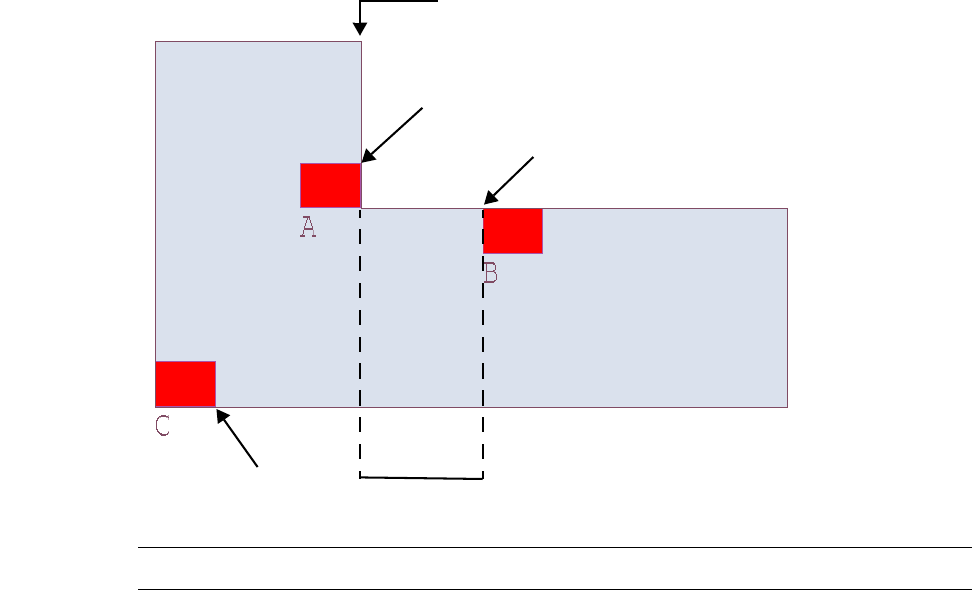
L-Edit 13 User Guide Section 3 708
Chapter 26: Extracting Layout Subcircuit Recognition
Connecting geometry should approach the SRP orthogonally for a distance at least equal to the largest
DRC spacing rule specified for the connecting layer. Non-connecting geometry should not be placed
any closer to a subcircuit instance than this distance.
A connection port should not exist on an “inside” corner of an SRP, but should be separated from the
corner by a distance D at least equal to the largest spacing rule value L specified for the layer. See the
following illustration.
Note: Extract does not check spacing rules.
Subcircuit connection ports and SPR signal connection ports have very similar functions: they mark the
locations of connections from outside to inside instances. There are, however, some important
differences.
Subcircuit connection ports may be 1- or 2-dimensional. SPR signal ports must be 1-dimensional.
2-dimensional subcircuit ports must be completely filled by connecting geometry, and
1-dimensional subcircuit ports require the connecting geometry to have the same width. SPR signal
ports can be of a different width than the connecting geometry.
SPR signal ports may be entirely within the interior of a cell. Subcircuit connection ports must
share an edge with the subcircuit recognition polygon.
Because of these factors, the port construction shown in the following figure is used in standard cell
design for use with both SPR and Extract. Moreover, running Extract with the Flag improper overlaps
option turned off eliminates subcircuit extract warnings. For further information, see “Setup Extract
Standard Rule Set–Subcircuit” (page 692).
Subcircuit recognition polygon
Correct
Correct
Incorrect
D ≥ L
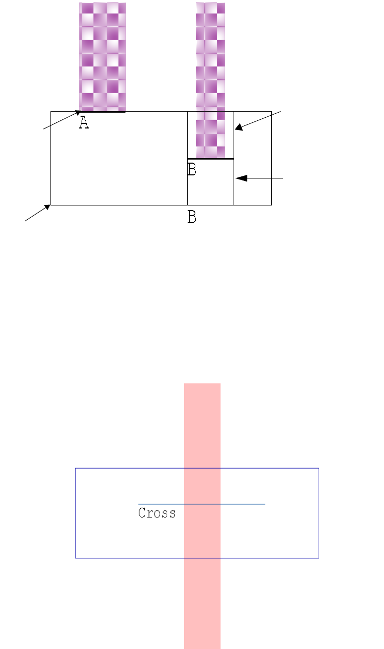
L-Edit 13 User Guide Section 3 709
Chapter 26: Extracting Layout Subcircuit Recognition
.
Crossing Over a Subcircuit Instance
A 1-dimensional cross port in a subcircuit cell defines a “channel” in the cell’s instances, over which
geometry may run without causing an overlap warning. The channel runs perpendicular to the width of
the cross port and extends from one end of the subcircuit recognition polygon to the other.
A 1-D SPR port can
be wider than a
connecting object.
Added subcircuit
connection port,
recognizing
connection from top.
Added subcircuit
connection port,
recognizing
connection from
bottom.
A 1-D subcircuit port
should be as wide as
a connecting object.
Existing 1-D SPR
signal port also
serves as a
subcircuit
connection port.
Added SRP
Existing 1-D SPR signal port for
autorouting.

L-Edit 13 User Guide Section 3 710
Chapter 26: Extracting Layout SPICE OUTPUT Properties
Extract recognizes the following as cross ports:
SPICE OUTPUT Properties
SPICE OUTPUT properties are a subset of the general purpose L-Edit properties described in
“Properties” on page 68. In subcircuit extraction, SPICE OUTPUT properties determine the device
name, connectivity, and device parameters of the subcircuit.
You can use properties to format the output of subcircuit information written to a SPICE netlist. You
can attach properties to either a parent cell or an instance. L-Edit⁄Extract searches for instance properties
first. If it does not find any, it searches for properties on the parent cell.
SPICE OUTPUT properties are only processed as part of subcircuit extraction. See “Subcircuit
Recognition” on page 705 for more information.
Property Tokens
String properties can include tokens, which are references to other values and variables. The following
tokens are expanded during subcircuit extraction. All other text is parsed without expansion.
For example, the value of the following EXTRACT.SPICE OUTPUT property:
XPlate %{right} %{left} platemodel W=${W} L=${L}
would result in the following netlist output:
XPlate 5 3 platemodel W=5e-6 L=2e-6
where EXTRACT.W=5e-6 and EXTRACT.L=2e-6.
Cross ports How specified
Row crosser ports “SPR Core Setup–General” (page 355)
Ports matching a single
additional name In “Setup Extract Standard Rule Set–Subcircuit” (page 692), in the
Subcircuit cross port names section, Other text field
Token Expansion
#An incremented integer that counts the instances of the cell. (This
token is only expanded during extract.)
${property}The value of the named property (as a string). property can be
expressed using the full path—e.g., Mechanical.Length. If no path is
designated, EXTRACT is assumed.
%{port}The name of the node to which the pin associated with the named port
is attached.
\n \t New line (\n) or tab (\t) characters.
\\ \# \$ \% \{ \} \[ \] The character after the initial backslash (instead of being interpreted
as part of a token).
L-Edit 13 User Guide Section 3 711
Chapter 26: Extracting Layout Extract Definition File Format
Application Example
In the following example, the SPICE OUTPUT property allows you to specify multiple energy domain
connections such as electrical and mechanical connections—for example, the SPICE OUTPUT property
of the following MEMS plate:
X${instance} %{PL_Left}_m %{PL_Right}_m %{PL_Bottom}_m %{PL_Top}_m
%{PL_Left}_e %{PL_Right}_e %{PL_Bottom}_e %{PL_Top}_e mass4_geo W=${W}
L=${L}
will result in the following netlist output:
Xu5 3_m 4_m 6_m 2_m
3_e 4_e 6_m 2_m
mass4_geo W=3e-3 L=2e-4
where EXTRACT.W=3e-3 and EXTRACT.L=2e-4.
Notice that all ports are referenced twice in this string using property tokens: one to specify the
mechanical connection and the other to specify the electrical connection.
Extract Definition File Format
The extract definition file contains a list of comments, connection statements, and device statements.
L-Edit is shipped with a directory containing a set of extract definition files that correspond to various
technology processes. You can modify these files as necessary to define additional connections and
devices for extraction.
Extract definition files must conform to the following restrictions:
Layer names are case-sensitive, and must match the case of layer names defined in the TDB file.
The rest of the definition file is case-insensitive; upper and lower cases can be used
interchangeably.
Layer names cannot contain commas or semicolons and they cannot be longer than 40 characters.
Layer names cannot have leading or trailing spaces.
Pin names cannot contain commas, semicolons, or spaces, and they cannot be named MODEL.
Model names cannot contain commas, semicolons, spaces, or closing parentheses.
For compatibility with existing extract definition files, the WIDTH keyword is ignored for all
devices except a GAASFET/MESFET.
IGNORE_SHORTS indicates that if the device has all of its pins connected to the same node then it
will be considered shorted and the device will be written to the extract netlist file as a comment.
Comment Statements
A comment statement begins with a pound sign (#) and continues to the end of the line:
# This is an extract definition file comment.
L-Edit 13 User Guide Section 3 712
Chapter 26: Extracting Layout Extract Definition File Format
Connection Statements
A connection statement defines a connection between two different layers. A connection always
involves three layers: the two layers being connected and the layer through which they connect.
Connection statements have the following format:
connect(Layer1, Layer2, ThroughLayer)
where Layer1 and Layer2 are the names of the layers being connected, and ThroughLayer is the name
of the connecting layer. For example:
# Connect Poly to Metal1
CONNECT(Poly, Metal1, PolyContact)
The connect statement does an AND operation of Layer1 and ThroughLayer, and the resulting
geometry has to either overlap or touch Layer2 in order for it to make a connection. Therefore, if
Layer1 and ThroughLayer are not overlapping, no connection will be made. For example, if you
wanted to connect N-Well to n diffusion you could write two separate connect statements.
# Connects N-Well to n diffusion.
# N-Well and n diffusion have to overlap to make a connection.
connect(NWell, nDiff, nDiff)
# Connects N-Well to n diffusion.
# N-Well and n diffusion have to overlap or touch to make a connection.
connect(nDiff, NWell, nDiff)
Substrate Node Statement
Nodal parasitic capacitances are referenced from the node to the substrate. You can designate the
substrate node by indicating the substrate layer. Extract will then find the first node connected to the
substrate layer and use that as the substrate node when writing the parasitic nodal capacitors. If no
substrate layer is indicated, Extract will use node 0 or ground as the substrate node. The substrate node
statement has the following format:
SUBSTRATE_NODE = SubstrateLayer;
where SubstrateLayer is the name of the substrate layer. For example:
# Use Subs as the Substrate node.
SUBSTRATE_NODE = subs;
results in the following SPICE output:
Cpar1 5 2 10f
where 2 is the substrate node.
Device Statements–General Format
A device statement defines a device. Passive (capacitors, resistors, and inductors,) active (BJTs, diodes,
GaAsFETs, JFETs, MOSFETs), and subcircuit devices are specified with the same general format.
For all device statements, it is necessary to identify a recognition layer, which is the layer Extract uses
to recognize the device. You may specify multiple devices with the same recognition layer as long as
L-Edit 13 User Guide Section 3 713
Chapter 26: Extracting Layout Extract Definition File Format
they have different pin configurations. This technique is particularly useful in extracting
multisource/drain transistors. The recognition layer is defined as follows:
RLAYER = rLayer ;
where RLAYER = is required, and rLayer is the name of the recognition layer.
Following the recognition layer is a list of pins of the device. The order of this list determines the order
of the pins in the extracted netlist. The extractor does not require any particular order, but LVS requires
that both source netlists contain pins in the same order, and SPICE simulators also have strict rules
about the order in which pins appear. We recommend following the standard SPICE orders:
BJT devices: collector—base—emitter—substrate
MOSFET, JFET, and GaAsFet/MESFET devices: drain—gate—source—bulk
Diodes, resistors, capacitors, and inductor devices: positiveNode—NegativeNode
If the pin names used in the EXT file are Collector, Base, Emitter, and Substrate (BJT devices), or
Drain, Gate, Source, and Bulk (all other active devices), they are sorted automatically in the default
SPICE order.
Pins are specified as follows:
pinName = pinLayer ;
where pinName is the name of the pin and pinLayer is the name of the associated layer.
A model definition follows the list of pins. This definition is not required for passive devices, where
MODEL =; is acceptable. The model name, if present, will be written into the extracted netlist. For
SPICE, model names are not required for capacitors, resistors, inductors, or diodes, but are required for
all other devices.
For passive devices, model statements have the form:
MODEL = [model];
For active devices, model statements have the form:
MODEL = model ;
where MODEL = is required and model is the optional model name. The empty statement MODEL =; is
still required if no model name is specified.
Device Statements–Specific Formats
In the following format specifications:
Unitalicized words and characters (except the bracket characters [ and ]) are to be entered as shown.
Words and characters enclosed by brackets ([ ]) are optional.
Words and characters enclosed by braces and separated by a vertical pipe—{option1 | option2 }—
represent alternates. You can use the syntax on the left or the right side of the pipe character.
Variables containing the string Layer represent layer names.
model represents the SPICE model name for the device.
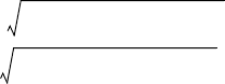
L-Edit 13 User Guide Section 3 714
Chapter 26: Extracting Layout Extract Definition File Format
Capacitor
DEVICE= CAP (
RLAYER = rLayer [,{AREA} | {LW}];
Plus = Layer1 [,AREA];
Minus = Layer2 [,AREA];
MODEL = [modelname ];
) [IGNORE_SHORTS]
A capacitor has the following format in the SPICE output statement:
AREA keyword
Cxxx n1 n2 [ModelName] [C=]cValue
LW keyword
Cxxx n1 n2 [ModelName] L=cLength W=cWidth
The following rules apply to capacitors:
The optional AREA keyword for a capacitor may be specified on only one layer (recognition or pin
layer) and is used to indicate the layer for which the capacitance will be calculated.
If no AREA keyword or LW keyword is present, the capacitance will be based on the area of the
recognition layer (rLayer).
The LW keyword cannot be used with the AREA keyword.
The LW keyword can only be used with the recognition layer (rLayer).
Capacitance is calculated as follows:
Ctotal = Carea + Cfringe
Carea = (Area of the Layer) * (Layer's Area Capacitance)
Cfringe = (Perimeter of the Layer) * (Layer's Fringe Capacitance)
The area capacitance (aF/sq. micron) and fringe capacitance (fF/micron) are specified in the Setup
Layers dialog for each specific layer (see “Layer Setup” on page 104).
Capacitor average length and width are calculated as if the capacitor was a rectangle. They are
calculated as follows:
Resistor
DEVICE=RES (
RLAYER = rLayer [, LW];
Plus = Layer1 ;
Minus = Layer2 ;
MODEL = [ModelName ];
) [IGNORE_SHORTS]
A resistor has the following format in the SPICE output statement:
Lperimeter Perimeter of the Layer=
Larea Area of the Layer=
Clength 1
4
---Lperimeter 1
4
---Lperimeter
216 Larea
•–+•=
Cwidth 1
4
---Lperimeter
•1
4
---Lperimeter
216 Larea
•––=

L-Edit 13 User Guide Section 3 715
Chapter 26: Extracting Layout Extract Definition File Format
AREA keyword
Rxxx n1 n2 [ModelName] [R=]rValue
LW keyword
Rxxx n1 n2 [ModelName] L=rLength W=rWidth
The following rules apply to resistors:
Resistance is calculated with the formula , where ρ is the sheet resistance in units
of ohms/square, l is the length of the resistor, and w is the width of the resistor.
The value of ρ is taken from the number specified with the Setup Layers dialog for the recognition
layer (rLayer) of the resistor (see “Layer Setup” on page 104).
The LW keyword can only be used with the recognition layer (rLayer).
The values of l and w are determined from the layout. The extractor computes the area of the
recognition layer and divides it by the effective width to obtain l. The width of a pin is the length of
the edge that the pin shares with the recognition layer (rLayer). The effective width is the average
of the plus pin width and minus pin width.
Inductor
DEVICE=IND (
RLAYER = rLayer ;
Plus = Layer1 ;
Minus = Layer2 ;
MODEL = [model ] ;
) [IGNORE_SHORTS]
An inductor has the following format in the SPICE output statement:
Lname n1 n2 [model] [L=]
Extract does not calculate inductance; users must add this value after netlist extraction.
BJT
DEVICE=BJT (
RLAYER = rLayer [,AREA];
Collector = cLayer [,AREA];
Base = bLayer [,AREA];
Emitter = eLayer [,AREA];
[Substrate = [sLayer ]];
MODEL = model ;
[NominalArea = areaVal ;]
Rρlw⁄()×=
Recognition
layer Minus pinPlus pin Recognition
layer Minus pinPlus pin Recognition
layer Minus pinPlus pin
Plus pin width
Minus pin width
Minus pin
L-Edit 13 User Guide Section 3 716
Chapter 26: Extracting Layout Extract Definition File Format
) [IGNORE_SHORTS]
A BJT device has the following format in the SPICE output statement:
Qname col bas emt [sub] model [AREA= {rLayerArea | pinArea } /areaVal]
The following rules apply to BJT devices:
The optional AREA keyword can be specified on only one layer (the recognition layer or the pin
layer). It is used to indicate the layer for which the area is to be calculated.
Nominal area can be expressed either in decimal or scientific notation. It has units of m2, but no
unit tag will appear after the value.
The NominalArea keyword is required if the AREA keyword is used.
If no AREA keyword is present, the area will not be written to the SPICE statement.
Diode
DEVICE=DIODE (
RLAYER = rLayer [, AREA];
Plus = Layer1 [, AREA];
Minus = Layer2 [, AREA];
MODEL = model ;
[NominalArea = areaVal ;]
) [IGNORE_SHORTS]
A diode has the following format in the SPICE output statement:
Dname n1 n2 model [AREA= {rLayerArea | pinArea } /areaVal]
The following rules apply to diodes:
The optional AREA keyword can be specified on only one layer (the recognition layer or the pin
layer). It is used to indicate the layer for which the area is to be calculated.
Nominal area can be expressed either in decimal or scientific notation. It has units of m2, but no
unit tag will appear after the value.
The NominalArea keyword is required if the AREA keyword is used.
If no AREA keyword is present, the area will not be written to the SPICE statement.
GAASFET/MESFET 1
The following syntax can be used to define a GAASFET/MESFET device using its nominal area as a
parameter.
DEVICE=GAASFET (
RLAYER = rLayer [, AREA];
Drain = dLayer [, AREA];
Gate = gLayer [, AREA];
Source = sLayer [, AREA];
[Bulk = [bLayer];]
MODEL = model;
[NominalArea = areaVal;]
) [IGNORE_SHORTS]
The GAASFET/MESFET device has the following format in the SPICE output statement:
L-Edit 13 User Guide Section 3 717
Chapter 26: Extracting Layout Extract Definition File Format
Zname drn gat src [blk] model [AREA= {rLayerArea | pinArea } /areaVal]
The following rules apply to GAASFET/MESFET devices:
The optional AREA keyword can be specified on only one layer (the recognition layer or the pin
layer). It is used to indicate the layer for which the area is to be calculated.
Nominal area can be expressed either in decimal or scientific notation. It has units of m2, but no
unit tag will appear after the value.
The NominalArea keyword is required if the AREA keyword is used.
If no AREA keyword is present, the area will not be written to the SPICE statement.
The GAASFET/MESFET 1 syntax is distinguished by the presence of the AREA, and/or
NominalArea keywords. L-Edit determines the appropriate output based on the presence of either
of these keywords.
GAASFET/MESFET 2
The following syntax can be used to define a GAASFET/MESFET device using its width as a
parameter.
DEVICE=GAASFET (
RLAYER = rLayer ;
Drain = dLayer [, WIDTH];
Gate = gLayer ;
Source = sLayer [, WIDTH];
[Bulk = [bLayer ];]
MODEL = model ;
) [IGNORE_SHORTS]
A GAASFET/MESFET device has the following format in the SPICE output statement:
Zname drn gat src [blk] model L=length W=width
The following rules apply to GAASFET/MESFET devices:
The length is the length of gate, and the width is the length of the edge that the indicated layer
shares with the recognition layer (rLayer). The length and width have units of meters.
The optional WIDTH keyword for a GAASFET/MESFET may be specified on only the drain or
source pin but not both, and is used to indicate the layer for which width will be calculated.
If no WIDTH keyword is present, the width and length will not be written to the SPICE statement.
The GAASFET/MESFET 1 syntax is distinguished by the presence of the WIDTH keyword. L-Edit
determines the appropriate output based on the presence of this keyword.
JFET
DEVICE=JFET (
RLAYER = rLayer [, AREA];
Drain = dLayer [, AREA];
Gate = gLayer [, AREA];
Source = sLayer [, AREA];
[Bulk = [bLayer ];]
MODEL = model ;
[NominalArea = areaVal ;]
) [IGNORE_SHORTS]
L-Edit 13 User Guide Section 3 718
Chapter 26: Extracting Layout Extract Definition File Format
A JFET device has the following format in the SPICE output statement:
Jname drn gat src [blk] model [AREA= {rLayerArea | pinArea } /areaVal]
The following rules apply to JFET devices:
The optional AREA keyword can be specified on only one layer (the recognition layer or the pin
layer). It is used to indicate the layer for which the area is to be calculated.
Nominal area can be expressed either in decimal or scientific notation. It has units of m2, but no
unit tag will appear after the value.
The NominalArea keyword is required if the AREA keyword is used.
If no AREA keyword is present, the area will not be written to the SPICE statement.
MOSFET
DEVICE=MOSFET (
RLAYER = rLayer ;
Drain = dLayer {[, AREA] [, PERIMETER [/GATE=#]] |
[,GEO]};
Gate = gLayer ;
Source = sLayer [, AREA] [, PERIMETER [/GATE=#]];
[Bulk = [bLayer ];]
MODEL = model ;
) [IGNORE_SHORTS]
A MOSFET device has the following format in the SPICE output statement:
Mname drn gat src [blk] model L=lengthValue W=widthValue {[AD=areaValue]
[PD=perimeterValue] [AS=areaValue] [PS=perimeterValue] | [GEO=#]}
The following rules apply to MOSFET devices:
The length is the length of gate, and the width is the average length of the edges that the source and
drain share with the recognition layer (rLayer). The length and width have units of meter.
The optional AREA keyword may be specified on the drain or source pin or both. It is used to
indicate whether the area for that layer will be calculated and written for the AD (Area of the Drain)
and AS (Area of the Source) output values.
The optional PERIMETER keyword may be specified on the drain or source pin or both, and is used
to indicate whether the perimeter for that layer will be calculated and written for the PD (Perimeter
of the Drain) and PS (Perimeter of the Source) output values. The shared edge is not included in
perimeter calculations for a source or drain.
The optional /GATE=# keyword is used with the PERIMETER keyword. It may be specified on the
drain or source pin or both, but only where the PERIMETER keyword has already been designated.
The number is a decimal value between 0.0 and 1.0, indicating the fraction of the gate width to
include in the perimeter. If the /GATE=# keyword is missing, the perimeter will include the gate
width.
The optional GEO keyword may be specified on only the drain pin. It is used to indicate that the
GEO value will be written to the SPICE statement. The GEO keyword can only be used if the
AREA and PERIMETER keywords are not used. The values of GEO written to the SPICE statement
are as follows:
GEO=0—drain and source areas are not shared
GEO=1—drain is shared
L-Edit 13 User Guide Section 3 719
Chapter 26: Extracting Layout Extract Definition File Format
GEO=2—source is shared
GEO=3—both drain and source are shared
The GEO keyword is used with the area calculation method (ACM) for modeling the source and
drain diodes. Users are encouraged to use the AREA and PERIMETER options because they yield
more accurate approximations of the area and perimeter values than those achieved using the GEO
option.
Subcircuit
Subcircuits can be defined explicitly for the extractor. This method of describing subcircuits is different
from automatic subcircuit instance recognition (see “Subcircuit Recognition” on page 705).
DEVICE=SUBCKT (
RLAYER = rLayer [, AREA] [, PERIMETER] [, LW];
pin1Name = pin1Layer [, AREA] [, PERIMETER] [, WIDTH] [, DEVICEWIDTH];
pin2Name = pin2Layer [, AREA] [, PERIMETER] [, WIDTH] [, DEVICEWIDTH];
. . .
MODEL = model ;
[NominalArea = areaVal ;]
) [IGNORE_SHORTS]
A subcircuit has the following format in the SPICE output statement:
AREA Keyword
Xzzz n1 [n2 ...] cName [AREA=rLayerArea/areaVal]
[PERI=rLayerPerimeter/areaVal]
[L=cLength W=cWidth]
[AREA_pin1Name=pin1Area/areaVal]
[PERI_pin1Name=pin1Perimeter]
[WIDTH_pin1Name=pin1Width]
[AREA_pin2Name=pin2Area/areaVal]
[PERI_pin2Name=pin2Perimeter]
[WIDTH_pin2Name=pin2Width] ...
The following rules apply to subcircuits:
The optional AREA keyword may be specified on one or more layers (recognition or pin layer). An
area will be calculated for each indicated layer.
The optional PERIMETER keyword may be specified on one or more layers (recognition or pin
layer). A perimeter will be calculated for each indicated layer.
The optional WIDTH keyword may be specified on one or more pin layers. A width of the pin layer
edge that is coincidence with the recognition layer will be calculated for each indicated layer. The
WIDTH keyword may not be used with the recognition layer.
The LW keyword can be used with the AREA and/or PERIMETER keyword.
The LW keyword can only be used with the recognition layer (rLayer).
The DEVICEWIDTH keyword can only be used if the LW keyword is present and it can only be used
with the pin layers. This affects the calculation of L and W, see below.
Nominal area can be expressed either in decimal or scientific notation. It has units of m2, but no
unit tag will appear after the value.
The NominalArea keyword is required if the AREA keyword is used.
If no AREA keyword is present, the area will not be written to the SPICE statement.
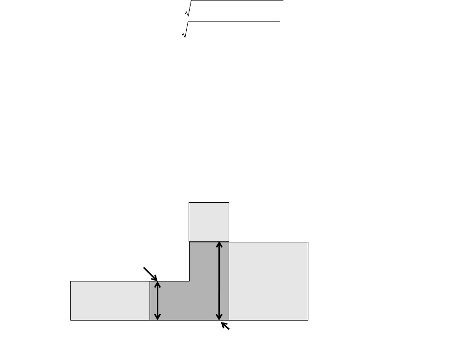
L-Edit 13 User Guide Section 3 720
Chapter 26: Extracting Layout Extract Definition File Format
If no DEVICEWIDTH keywords exist on any pin, the Subcircuit average length and width are
calculated as if the Subcircuit recognition layer geometry was a rectangle. They are calculated as
follows:
If one or more DEVICEWIDTH keywords exists on the pins, the Subcircuit average width is equal to
the average width of the pins that are marked with DEVICEWIDTH. The length is equal to the
AREA/Width. The width of a pin is the length of the shared edge between polygons on the pin
layer and polygons of the recognition layer. An example is shown below.
DEVICE=SUBCKT (
RLAYER = Recognition Layer, LW;
pin1 = pin1Layer, DEVICEWIDTH;
pin2 = pin2Layer, DEVICEWIDTH;
pin3 = pin3Layer;
MODEL = MySub;
)
Lperimeter Perimeter of the Layer=
Larea Area of the Layer=
Clength 1
4
---Lperimeter 1
4
---Lperimeter
216 Larea
•–+•=
Cwidth 1
4
---Lperimeter
•1
4
---Lperimeter
216 Larea
•––=
Recognition
layer Minus pinPlus pin Recognition
layer Minus pinPlus pin
Recognition
layer
Pin1
Pin1width
Pin2width
Pin2
Pin3
Pin1width Width of Pin 1=
Pin2width Width of Pin 2=
RLarea Area of the Recognition Layer=
Swidth
Pin1width Pin2width
+
2
------------------------------------------------------=
Slength
RLarea
Swidth
----------------=
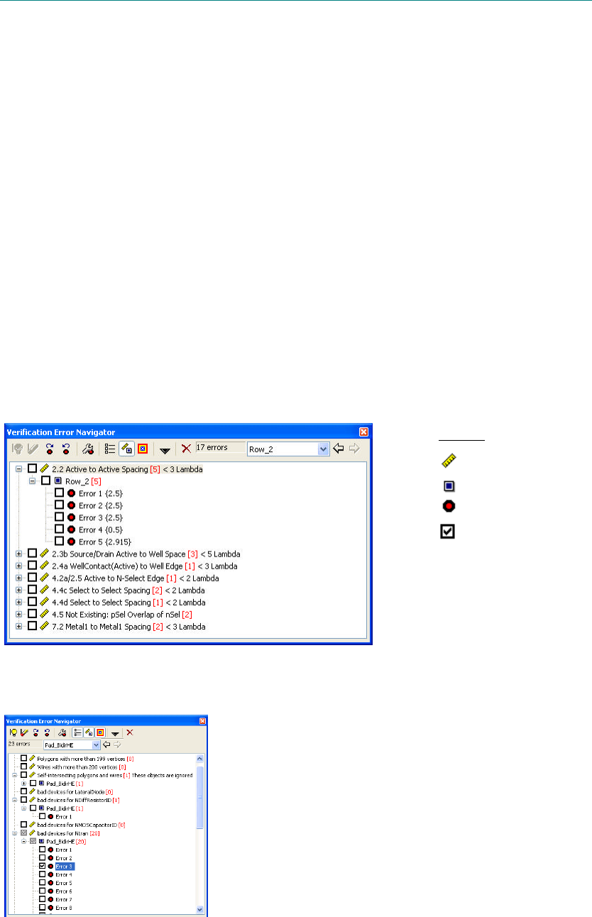
L-Edit 12 User Guide Section 3 721L-Edit 12 User Guide Section 3 721
27 Verification Results
The Verification Error Navigator
The Verification Error Navigator provides an interface with which to browse and display DRC or
Extract errors in the active layout. For both processes, the Verification Error Navigator is designed to
simplify iterations of the error correction workflow.
The Verification Error Navigator is a resizable and dockable toolbar. It contains a scrollable tree of
rules plus controls for loading errors and displaying them in the active layout. You can expand or
collapse a individual rule or device to show or hide individual errors for that rule. For each DRC rule,
L-Edit lists the number of violations in square brackets. Navigator controls are the same for both DRC
and Extract results.
To open the Verification Error Navigator, select Tools > Verification Error Navigator > Show
Verification Error Navigator from the L-Edit menu.
Verification Error Navigator for DRC
Verification Error Navigator for Extract
3
Legend:
DRC or Extract Rule
Cell name
Error name
Checkbox for
“marking” errors
[#]Number of violations
corresponding to
each rule or cell
{#} Actual distance of
each violation
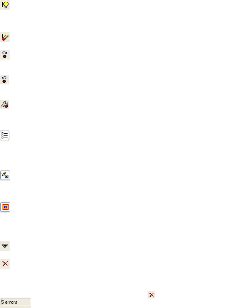
L-Edit 12 User Guide Section 3 722
Chapter 27: Verification Results The Verification Error Navigator
Error Navigator Toolbar
The following table lists the Verification Error Navigator toolbar commands. You can map shortcut
keys for all commands using Setup > Application (see “Keyboard Customization” on page 84).
Button Description
Toggles the display of error markers on the selected error. When the
display is on, L-Edit draws markers on the violating edge segments
and shows an optional circle and cross hairs, as specified in the
Verification Error Navigator Options dialog.
Removes an error marker completely, so that it can no longer be
displayed.
Displays the next error in the tree. The shortcut for this command is
the period key (.).
Equivalent to Tools > Verification Error Navigator > Next Error.
Displays the previous error in the tree. The shortcut for this command
is the comma key (,).
Equivalent to Tools Verification Error Navigator > Previous Error.
Displays the Verification Error Navigator Options dialog to specify
how errors are displayed. (See “Error Display Options” on page 729.)
Equivalent to Tools > Verification Error Navigator > Verification
Error Navigator Options.
Toggles which rules are displayed in the navigation tree. When
enabled, all rules are shown. When disabled, only rules with
violations are shown.
Equivalent to Tools > Verification Error Navigator > View All
Rules.
Toggles which rules are displayed in the navigation tree. When
selected, the top level of the tree is rules. When unselected, the top
level of the tree is cells containing violations.
Equivalent to Tools > Verification Error Navigator > View By Rule.
Displays each error in the cell in which it originally occurs. When this
option is selected, errors are shown in the cell in which they occur.
When unselected, all errors are shown in the top-level layout.
Equivalent to Tools > Verification Error Navigator > Cell Context
(see “Cell Context” on page 724.)
Displays a pull-down command menu of error navigator actions. See
“Verification Navigator Command Menu” on page 724.
Deletes the selected error from the tree and from the error layer, then
selects and displays the next error in the tree. If a rule is selected, a
dialog asks if you want to delete all errors for that rule.
Note: Deletion of errors using ( ) cannot be undone.
Number of errors found in the current extract or DRC run.
You can view the number of marked errors (errors with checkmarks
next to them) by moving the cursor over this field.
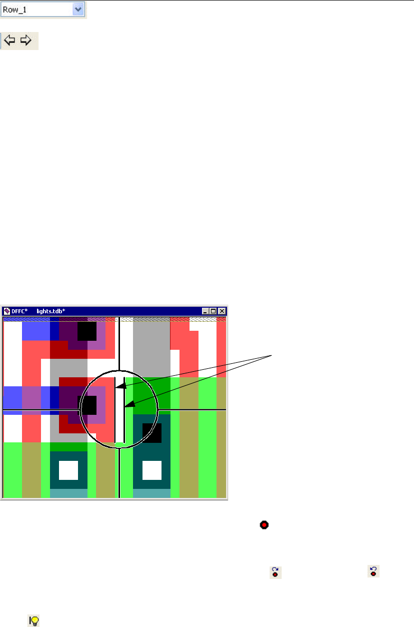
L-Edit 12 User Guide Section 3 723
Chapter 27: Verification Results The Verification Error Navigator
Using Checkmarks
Each rule, cell, and error shown in the Verification Error Navigator tree has a checkbox. You can mark
items for any reason - for example, to indicate the errors which have been fixed, or to indicate errors
that you want to review later. The Verification Error Navigator includes a number of preset actions that
you can perform on the errors that are marked (see “Verification Navigator Command Menu,” below).
To add or remove a mark next to an item, simply click in the checkbox. When some but not all of the
items in a certain group are checked, the checkbox for the parent item will have a grayed-out
background.
Viewing Errors
For each error, L-Edit draws markers over the violating edge segments. Errors can be further
highlighted with a circle and cross hairs, as illustrated below.
To display an error in the active layout, click on the Error name ( ) in the Verification Error Navigator
tree. L-Edit automatically pans and/or zooms to the error marker according to your settings in the View
or Modify Verification Error Navigator Options dialog. (See “Error Display Options” on page 729.)
To step forward or backward through errors, click the Next Error ( ) or Previous Error ( ) toolbar
buttons. (You can also select Next Error or Previous Error from the Tools > Verification Error
Navigator submenu, or use the period (.) and comma (,) for shortcut key, respectively.
Click ( ) to toggle marker display on or off for the selected error.
You can zoom in to enlarge and center the error in the layout window by pressing the shortcut key W.
To return to the default view, click again on the Error name button.
The current job, identified by the cell on which DRC or extract was
performed.
Forward and back buttons. Use these to move through recently
viewed combinations of verification job and active cell. When you
activate a new cell or load a new verification job, the forward portion
of this list of views is discarded.
Button Description
Markers show where
the violation occurs.
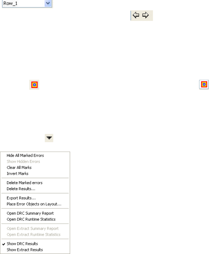
L-Edit 12 User Guide Section 3 724
Chapter 27: Verification Results The Verification Error Navigator
Viewing “Job” Runs
The cell on which DRC or Extract is run defines a job. You can have multiple jobs loaded into the error
navigator, but only one is displayed in the rule tree at a time. To switch between jobs (i.e., runs on
different cells), use the drop-down combo box in the Verification Error Navigator toolbar
( ). A job is listed by the name of the cell on which it was run.
When you use the forward and backward buttons ( ), you are scrolling through various
combinations of job runs and active cell, as you would when using a web browser. When you create a
new context by selecting a job or changing the active cell, the forward portion of the list of recent
contexts is cleared.
Cell Context
Each error found in a job can be represented in two contexts. The cell on which the job was run defines
the top-level context for that job. You can show an error as it appears in the top-level context for the
current job ( disabled), or you can show the error in the cell in which it occurs ( enabled). The
cell context is always the same for a given error, regardless of which job is active. If the error occurs in
the top-level cell for the current job, then only one context is available.
Verification Navigator Command Menu
L-Edit provides a number of preset actions for marked errors, which you can access using the dropdown
Command menu ( ) on the Verification Navigator toolbar.
Hide All Marked Errors When this mode is selected, all marked errors are automatically
hidden from the tree display. This mode is persistent—while you are
in this mode, adding a check in the checkbox for an error causes it to
be automatically hidden.
To exit the mode, select Hide all marked errors again to unmark it in
the menu. This does not change the visibility or checkmarks of hidden
errors; however, newly marked errors are not hidden when the Hide
all marked errors option is off.
Show Hidden Errors Shows errors that were previously hidden. This option does not
expand the tree. Checkmarks are left unchanged.
L-Edit 12 User Guide Section 3 725
Chapter 27: Verification Results The Verification Error Navigator
Clear All Marks Clears checkmarks from all errors in the tree. Hidden errors will
remain hidden; use Show hidden errors to display these.
Invert Marks Changes all error checkboxes to the opposite state—previously
unmarked errors become marked, and previously marked errors
become unmarked.
Delete Marked Errors Permanently removes all marked errors from the DRC results. The
Verification Error Navigator will issue a warning before deleting
hidden errors.
Delete Results Deletes all results for the current job.
Export Results Exports results for the current job to a text file. See “Exporting a Text
File” on page 733.
Place Error Objects on
Layout Places objects (polygons, wires, and/or ports) on the error layer to
highlight violations. See “Placing Error Markers,” below.
Open DRC Summary
Report Displays the DRC summary report in a text window. See “DRC
Summary Report” on page 730.
Open DRC Runtime
Statistics Displays a DRC runtime statistics report in a text window. See “DRC
Runtime Statistics Report” on page 732.
Open Extract Summary
Report Displays the Extract summary report in a text window. See “Extract
Summary Report” on page 734.
Open Extract Runtime
Statistics Displays the Extract runtime statistics report in a text window. See
“Extract Runtime Statistics Report” on page 736
Show DRC Results Check this option to display DRC results in the Verification Error
Navigator window.
Show Extract Results Check this option to display Extract results in the Verification Error
Navigator window.
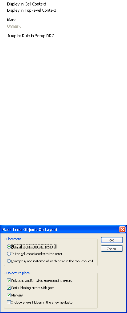
L-Edit 12 User Guide Section 3 726
Chapter 27: Verification Results The Verification Error Navigator
Verification Navigator Context Menu
Placing Error Markers
When you select an error in the Navigator tree, L-Edit automatically highlights that error in the layout.
(You can enter your preference for how a selected error is highlighted with “Error Display Options” on
page 729.) These error markers, however, are temporary. When you select a new error, L-Edit clears the
previous marker and highlights the currently selected error.
If you wish to locate all errors in the layout, you can use the Place error objects on layout command to
create error objects and/or ports for all violations. These error objects are added to the error layer and
saved with the TDB file.
Error ports and objects can be moved, deleted, hidden, and shown in the same manner as other objects.
Error objects are persistent; they are saved on the error layer of the TDB file and will remain there until
you choose to delete them.
Display in Cell Context Shows errors in the cell where they originate.
Display in Top-level
Context Shows errors in their top-level cell context.
Mark Enters a checkmark in each checkbox for the selected cell or rule and
all those below it in the hierarchy.
Unmark Clears the checkmarks in each checkbox for the selected cell or rule
and all those below it in the hierarchy.
Jump to Rule in Setup
DRC/Jump to Device
Netlist
In DRC, opens the design rule file at the highlighted cell or rule. In
Extract, opens the extract rule file at the highlighted device
L-Edit 12 User Guide Section 3 727
Chapter 27: Verification Results The Verification Error Navigator
Placement options include:
These additional options determine which objects are placed in the layout. You must select at least one
of the first two options under Objects to place (polygons or ports).
Setting the Color of DRC Markers
The error marker by default uses the last color in the color palette. The color palette can be accessed
with Setup > Colors. You can change the last color by first selecting the color in the color list and then
using the RGB slide bars or the color picker button to select an appropriate color for your error markers.
Flat, all objects on top-level
cell Places all error objects in the top-level layout for the DRC job.
In the cell associated with
the error Places error objects in the cells in which they were found.
Examples, one instance of
each error in the top level
cell
Places a single error object for each rule that was violated. If an error
is repeated in the layout, only one example will be shown with the
error object. All example objects are placed in the top-level layout for
the DRC job.
Polygons and/or wires
representing errors Places a polygon and/or wires on each error to illustrate the violation.
Ports labeling errors with
text Places a port with text labeling each error. Each error port consists of
the name of the violated design rule, the rule distance, and the spacing
or nature of the error in brackets. For example, an error port named
8.4c Via to Active Spacing < 2 [1] shows that the associated violation
involves a spacing of 1, when the minimum Via-Active spacing
should be 2.
Markers Places a circle, with crosshairs extending to the four sides of the
window, on each error.
Include errors hidden in
the error navigator Places error objects on all violations, including those that are hidden
from display in the Verification Error Navigator tree. When this
option is not checked, hidden errors are omitted from the error layer.
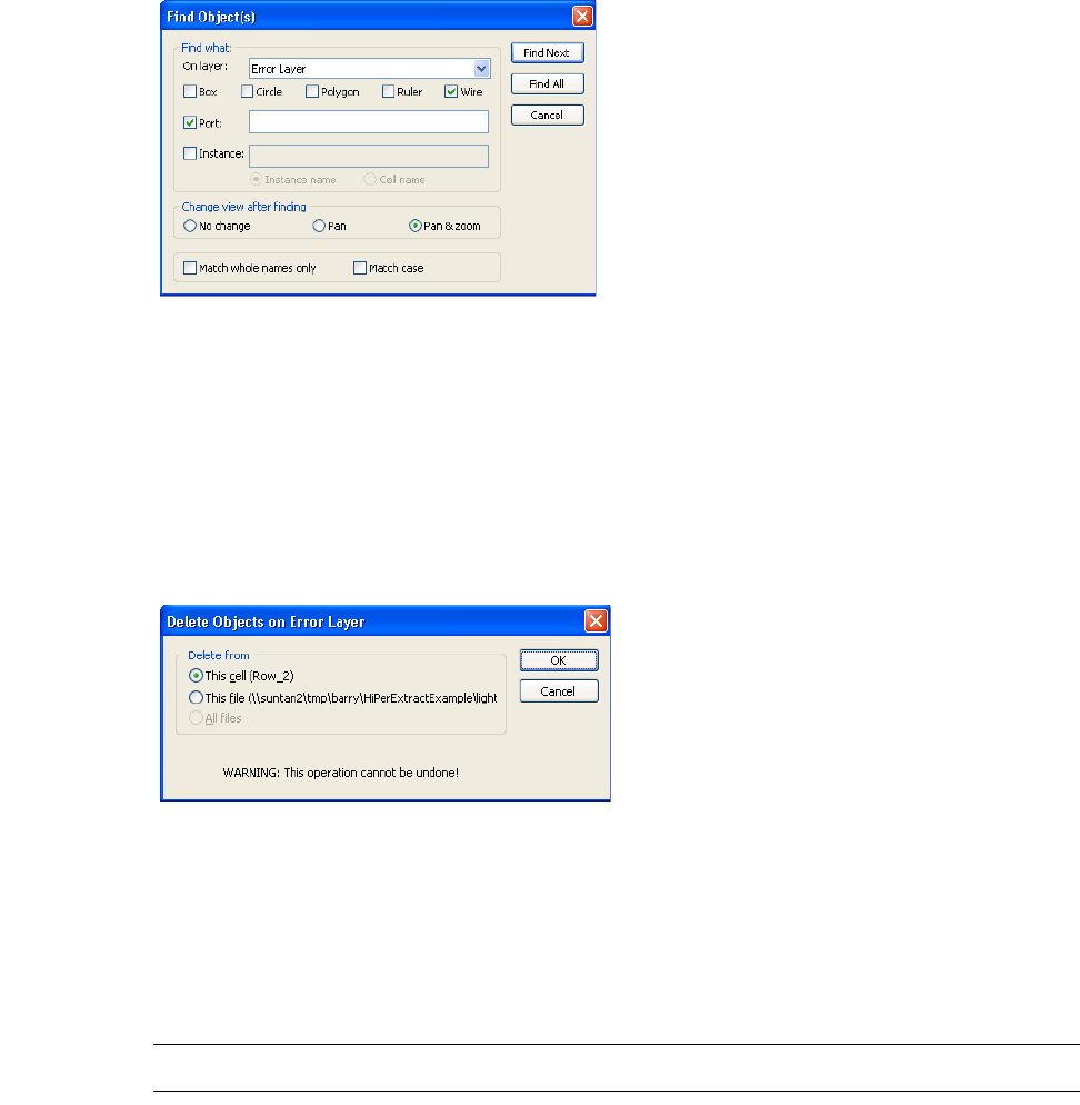
L-Edit 12 User Guide Section 3 728
Chapter 27: Verification Results The Verification Error Navigator
Finding Error Markers
You can use Edit > Find to locate marked errors. Specify a Wire search (for error objects) or a Port
search (for error ports) on the Error layer. For ease of viewing, specify Pan or Pan & zoom as the
viewing option.
Note that because of the default rendering setup of the Error layer, a port’s text is only visible when the
port is selected. Thus, as the search commands go through ports on the Error layer, the names of the
error ports become visible one at a time.
Clearing Error Markers
Tools > Clear Error Layer opens the following dialog, prompts for options, then removes error markers
(ports and objects).
Warning: This command cannot be undone.
This cell (cell name)Removes all objects on the Error layer in the active cell
This file (file name)Removes all objects on the Error layer in the active file
All files Removes all objects on the Error layer in all open files
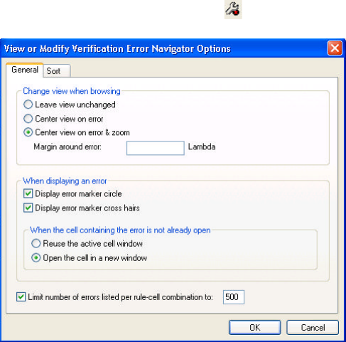
L-Edit 12 User Guide Section 3 729
Chapter 27: Verification Results The Verification Error Navigator
Error Display Options
Viewing Options
Tools > Verification Error Navigator > Verification Error Navigator Options opens a dialog with
controls for how L-Edit displays errors when they are selected in the Verification Error Navigator. You
can also access this dialog by clicking ( ) on the toolbar.
The General tab contains these browsing and display options:
Leave view unchanged Leaves the layout view unchanged when you select and display an
error.
Center view on error Centers the display on the selected error, without changing the zoom
level.
Center view on error &
zoom Centers the display on the selected error and zooms in or out until the
error and a specified margin (see below) fill the active window.
Margin around error Sets the margin, in display units, to be displayed around the selected
error when zoom is active.
Display error marker circle Instructs L-Edit to draw a circle around each error when it is being
viewed.
Display error marker cross
hairs Instructs L-Edit to draw two lines - one vertical and one horizontal -
that intersect the center point of the currently selected violation.
Reuse the active cell
window Displays the selected error in the active cell window.
Open the cell in a new
window Opens a new window when the selected error is not in the same cell as
that shown in the active window (default).
Limit number of errors
listed per rule-cell
combination to:
Specifies the maximum number of errors included in the Verification
Error Navigator tree for a single rule and cell.
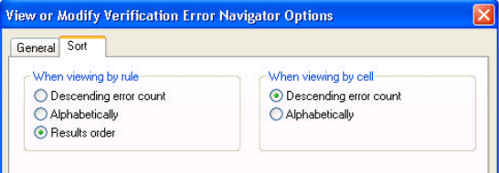
L-Edit 12 User Guide Section 3 730
Chapter 27: Verification Results DRC Report Files
Sorting Options
The Sort tab contains options for sorting rules when they are viewed either by rule or by cell.
DRC Report Files
L-Edit automatically generates both a summary report and a runtime statistics report for each DRC run.
After DRC completes, these reports are stored with the cell on which DRC was run.
You can view these reports for the selected DRC job by selecting the corresponding menu options in the
Verification Error Navigator Actions menu. You can also instruct L-Edit to display the summary report
automatically upon completion of DRC, by selecting the corresponding option in either the Design
Rule Check dialog or the DRC Progress dialog. When you display a report, L-Edit opens the report in
an L-Edit text window with the default filename “Summary of cellname.drc” or “Statistics of
cellname.drc.” You can then save the report to a text file, if desired.
DRC Summary Report
The DRC summary report contains a summary of DRC results, including the number of errors found for
each rule and each cell. The DRC summary report also gives information about memory usage, runtime,
and files.
Following is a sample DRC Summary Report.
************ RESULTS SUMMARY ************************************
DRC Errors Generated 215
CPU Time: 23:14:00
REAL Time: 00:01:00
Number of Input Objects: 5449 (70067)
Number of Rules Executed: 88
Number of Disabled Rules: 7
************ EXECUTION SUMMARY **********************************
Execution Date/Time: Jun 19 2002 10:50:49
Descending error count Lists rules or cells in descending order of error count, with rules or
cells containing the most violations listed first.
Alphabetically Lists rules or cells alphabetically.
Results order Lists rules in the order found in the DRC or Extract results (default).
This option is active when “viewing by rule” only.
L-Edit 12 User Guide Section 3 731
Chapter 27: Verification Results DRC Report Files
L-Edit Version: v10.0
Rule Set Name: MOSIS/HP 1.0U SCN3M, Tight Metal
File Name:
Cell Name: top
User Name: TannerEDA
Computer Name: TANNERPC
Memory used at start: 0K
************ GEOMETRY FLAG SUMMARY ******************************
ACUTE ANGLES............. 0
ALL ANGLE EDGES.......... 0
OFFGRID ................. Disabled
SELF INTERSECTIONS ...... 1
WIRE JOIN STYLES ........ 0
WIRE END STYLES ......... 0
************ RULES WITH ERRORS FOUND ****************************
1.3 Well to Well(Same Potential) Spacing ........................ 2
2.2 Active to Active Spacing .................................... 8
2.3b Source/Drain Active to Well Space ......................... 4
2.4a WellContact(Active) to Well Edge ........................... 2
4.2a/2.5 Active to N-Select Edge ................................ 2
4.2b/2.5 Active to P-Select Edge ................................ 2
4.3c Not Exist: ActiveContact not on act ........................ 4
...
************ RULES WITH NO ERRORS FOUND *************************
1.1 Well Minimum Width
2.1 Active Minimum Width
2.3a Source/Drain Active to Well Edge
2.4b SubsContact(Active) to Well Spacing
...
************ DISABLED RULES *************************************
1.2 Well to Well (diff potential) Not che
2.5 Covered in 4.2. Active from diff imp
10.1b BondingArea:PadComment(100x100um)
...
************ CELLS WITH ERRORS FOUND ****************************
PadVdd .......................................................... 2
Row_10 .......................................................... 2
TannerEDALogo ................................................... 80
Chip ............................................................ 2
Frame ........................................................... 75
Pad_BidirHE08 ................................................... 1
PadGnd .......................................................... 52
Core ............................................................ 1
************ INPUT LAYER SUMMARY ********************************
Active .............. Number of Geometry Objects = 155 (1577)
Active Contact ...... Number of Geometry Objects = 1222 (39830)
Cap Well ............ Number of Geometry Objects = 0 (0)
Metal1 .............. Number of Geometry Objects = 756 (3660)
...
L-Edit 12 User Guide Section 3 732
Chapter 27: Verification Results DRC Report Files
The DRC summary report is organized into the following sections:
DRC Runtime Statistics Report
When you select Open DRC Runtime Statistics from Tools > Verification Error
Navigator > Actions, L-Edit displays timing statistics for layer derivation and design rule checks in a
text window. (You can see an example of an Extract statistics report in “Extract Runtime Statistics
Report” on page 736.)
RESULTS SUMMARY The results summary includes the following information:
DRC Errors Generated—the total number of errors generated,
including Geometry Flag violations.
CPU Time and REAL Time—the cpu and wallclock times,
respectively. Each time is given in H:M:S format.
Number of input objects—Number of objects obtained by
counting each primitive object in each cell. The number of
objects that would be counted in a flattened layout is shown in
parentheses.
Number of Rules Executed—Total number of rules executed, not
counting geometry flags.
Number of Disabled Rules—Total number of disabled rules, not
counting Geometry Flags.
EXECUTION SUMMARY Lists statistics pertaining to the execution time, file and cellnames,
username, and memory usage.
GEOMETRY FLAG
SUMMARY The Geometry Flag Summary lists the number of Geometry Flags
found for acute angles, all-angle edges, off-grid vertices,
self-intersecting polygons, and wire join/end styles. Acute angles,
all-angle edges, and off-grid vertices are only counted when their
corresponding Geometry Flag options have been checked in the DRC
Setup dialog. If these options are left unchecked, then they are listed
as “disabled” in the Geometry Flag Summary. Self-intersecting
polygons and wire join/end styles are always reported.
RULES WITH ERRORS
FOUND Lists all rules for which at least one violation was found. Rules are
listed in the order they appear in the Setup DRC dialog.
RULES WITH NO ERRORS
FOUND Enabled rules for which no errors were found.
DISABLED RULES List of disabled rules.
CELLS WITH ERRORS
FOUND List of cells in which errors were found, and the number of errors in
each cell (including geometry flag violations).
INPUT LAYER SUMMARY Lists each layer used by an enabled rule, including layers that do not
contain any objects. Next to each layername, the number of geometry
objects is listed. The number of objects on the layer if the database
were flattened is included in parentheses.
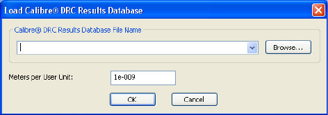
L-Edit 12 User Guide Section 3 733
Chapter 27: Verification Results Extract Report Files
Exporting a Text File
You can export the results of a DRC or Extract job to a text file by selecting the option Export results
in the Verification Error Navigator Command menu. L-Edit writes design rule errors to a text file with
the cell name as filename and the extension .dre.
Displaying Calibre® DRC Results
L-Edit allows you to load DRC errors from a Calibre® DRC results database into the Verification Error
Navigator and display them in the active layout.* The database you select must be flat (i.e., not
hierarchical) and in ASCII format to be compatible with L-Edit.
To specify the database to load, select Tools > Add-Ins > Load Calibre® DRC Results Database.
Type the Calibre DRC Results database filename in the editing field, or select Browse to navigate to the
desired file.
You need to enter scaling information based on the technology you use in the Meters per User Unit
field. For example, go to Setup > Setup Design > Technology to find your tech setup. If your tech
units are one micron and the database resolution is 1/1000, the scaling factor will be 1e-009 meters per
user units.
Click OK to display the Verification Error Navigator for the specified file. The display shown in the
error navigator depends upon the information in the Calibre file. If hierarchical information is included,
the error navigator will display an error within the cell it originates and also in the cell on which the
DRC was run.
Extract Report Files
In addition to the netlist, L-Edit automatically generates both a summary report and a runtime statistics
report for each Extract run. After Extract completes, these reports are stored with the cell on which
Extract was run.
You can view these reports for the selected Extract job by selecting the corresponding menu options in
the Verification Error Navigator Actions menu. You can also instruct L-Edit to display the summary
report automatically upon completion of Extract, by selecting the corresponding option in the Extract
Progress dialog. When you display a report, L-Edit opens the report in an L-Edit text window with the
default filename “Summary of cellname” or “Statistics of cellname.Extract.” You can then save the
report to a text file, if desired.
* Calibre is a registered trademark of Mentor Graphics Corporation.
L-Edit 12 User Guide Section 3 734
Chapter 27: Verification Results Extract Report Files
Extract Summary Report
The Extract summary report contains a summary of Extract results, including the number of errors
found for each rule and each cell. The Extract summary report also gives information about memory
usage, runtime, and files.
Following is a sample Extract Summary Report.
L-Edit EXTRACT SUMMARY REPORT
EXECUTION SUMMARY Execution Start Time Feb 15 2008 11:04:05
L-Edit Version L-Edit Win32 13.00 Beta 3.20080215.07:18:40
Build Number 3749
Rule Set Name
File Name \\suntan2\tmp\barry\HiPerExtractExample\lights.tdb
Cell Name Pad_BidirHE (Feb 15 11:03:56 2008)
User Name jbergstr
Computer Name DEV01XP
Operating System Windows XP 5.1 2600 Service Pack 2
Total physical memory 2047.0MB
Memory used at start 28.4M
----------------------------------------------------------------------------
EXTRACT JOB RESULTS SUMMARY Total EXTRACT Errors Generated 23
CPU Time 00:00:00
Real Time 00:00:08
Rules Executed 21
EXTRACT Errors Generated by Rule Set
\\suntan2\tmp\barry\HiPerExtractExample\HiPer-LVS.cal 22
\\suntan2\tmp\barry\HiPerExtractExample\Dracula025_4M.drc 1
----------------------------------------------------------------------------
RUN-TIME ERRORS AND WARNINGS
----------------------------------------------------------------------------
L-Edit EXTRACT Log
PARSING SUMMARY
Command File: \\suntan2\tmp\barry\HiPerExtractExample\HiPer-LVS.cal
Rule Set Name: Calibre LVS for Generic 0.25um process
No warnings.
Command File: \\suntan2\tmp\barry\HiPerExtractExample\Dracula025_4M.drc
Rule Set Name:
No warnings.
----------------------------------------------------------------------------
Running command file \\suntan2\tmp\barry\HiPerExtractExample\HiPer-LVS.cal
Rule Set Name Calibre LVS for Generic 0.25um process
Execution Start Time Feb 15 2008 11:04:05
Maximum Results 1000
INPUT LAYER SUMMARY Layer Name Object Count Flattened
Active 7 7
ActiveCont 410 410
Metal1 30 30
Metal2 10 10
NDiffResistorID 1 1
NMOSCapacitorID 0 0
NSelect 3 3
NWell 2 2
NWellResistorID 0 0
PDiffResistorID 0 0
PMOSCapacitorID 0 0
PSelect 4 4
L-Edit 12 User Guide Section 3 735
Chapter 27: Verification Results Extract Report Files
PadComment 1 1
Poly 13 13
PolyCont 17 17
PolyResistorID 0 0
Via1 86 86
----------------------------------------------------------------------------
EXCLUDED CELLS
None
---------------------------------------------------------------------------
GEOMETRY FLAG SUMMARY ACUTE ANGLES Disabled
ALL ANGLE EDGES Disabled
OFFGRID Disabled
ZERO-WIDTH WIRES 0
POLYGONS WITH OVER 199 VERTICES 0
WIRES WITH OVER 200 VERTICES 0
SELF INTERSECTIONS 1
WIRE JOIN/END STYLES 0
----------------------------------------------------------------------------
CELLS WITH ERRORS FOUND Pad_BidirHE 22
----------------------------------------------------------------------------
RESULTS SUMMARY Errors Generated 1
CPU Time 00:00:00
REAL Time 00:00:02
Input Objects 584 (584)
Rules Executed 14
Geometry Flags Executed 5
Disabled Rules 0
----------------------------------------------------------------------------
Running command file
\\suntan2\tmp\barry\HiPerExtractExample\Dracula025_4M.drc Rule Set Name
Execution Start Time Feb 15 2008 11:04:08
Maximum Results 1000
INPUT LAYER SUMMARY Layer Name Object Count Flattened
----------------------------------------------------------------------------
EXCLUDED CELLS
None
----------------------------------------------------------------------------
GEOMETRY FLAG SUMMARY ACUTE ANGLES Disabled
ALL ANGLE EDGES 0
OFFGRID 0
ZERO-WIDTH WIRES 0
POLYGONS WITH OVER 199 VERTICES 0
WIRES WITH OVER 200 VERTICES 0
SELF INTERSECTIONS 1
WIRE JOIN/END STYLES 0
----------------------------------------------------------------------------
CELLS WITH ERRORS FOUND Pad_BidirHE 1
----------------------------------------------------------------------------
RESULTS SUMMARY Errors Generated 23
CPU Time 00:00:00
REAL Time 00:00:06
Input Objects 0 (0)
Rules Executed 7
L-Edit 12 User Guide Section 3 736
Chapter 27: Verification Results Extract Report Files
Geometry Flags Executed 7
Disabled Rules 0
----------------------------------------------------------------------------
The Extract summary report is organized into the following sections:
Extract Runtime Statistics Report
When you select Open Extract Runtime Statistics from Tools > Verification Error
Navigator > Actions, L-Edit displays run time and memory usage statistics for layer derivation and
rules in a text window as shown in the example below:
L-Edit DRC RUNTIME STATISTICS REPORT
************ EXECUTION SUMMARY **********************************
Execution Date/Time: Feb 15 2008 11:02:00
L-Edit Version: L-Edit Win32 13.00 Beta 3.20080215.07:18:40
EXECUTION SUMMARY Lists statistics pertaining to the execution time, file and cellnames,
username, and memory usage.
RESULTS SUMMARY The results summary includes the following information:
Extract Errors Generated—the total number of errors generated.
CPU Time and REAL Time—the cpu and wallclock times,
respectively. Each time is given in H:M:S format.
be counted in a flattened layout is shown in parentheses.
Number of Rules Executed—Total number of rules executed, not
counting geometry flags.
Number of Errors Generated by Rule Set
PARSING SUMMARY Lists the command files, rules set names, and any warnings.
INPUT LAYER SUMMARY Lists each layer used by an enabled rule, including layers that do not
contain any objects. Next to each Layer Name, the number of
geometry objects (Object Count) and the number of objects on the
layer if the database were Flattened is included.
EXCLUDED CELLS Lists any cells excluded from processing.
GEOMETRY FLAG
SUMMARY Lists the number of Geometry Flags found for acute angles, all-angle
edges, off-grid vertices, zero-width wires, polygons with over 100
vertices, wires with over 200 vertices, self-intersecting polygons, and
wire join/end styles.
Acute angles, all-angle edges, and off-grid vertices are only counted
when their corresponding Geometry Flag options have been checked
in the DRC Setup dialog. If these options are left unchecked, then
they are listed as “disabled” in the Geometry Flag Summary.
Self-intersecting polygons and wire join/end styles are always
reported.
CELLS WITH ERRORS
FOUND List of cells in which errors were found, and the number of errors in
each cell (including geometry flags executed).
RESULTS SUMMARY Lists the number of Errors Generated, the CPU and REAL time, the
number of input objects, the number of rules executed, the number of
flags executed, the number of disabled rules.
L-Edit 12 User Guide Section 3 737
Chapter 27: Verification Results Extract Report Files
Build Number: 3749
Rule Set Name: Calibre LVS for Generic 0.25um process
File Name: \\suntan2\tmp\judy\HiPerExtractExample\lights.tdb
Cell Name: Lights ()
Maximum Results: 1000
User Name: jbergstr
Computer Name: DEV01XP
Operating system: Windows XP 5.1 2600 Service Pack 2
Total physical memory: 2047.0MB
Memory used at start: 17.3M
Command File: \\suntan2\tmp\judy\HiPerExtractExample\HiPer-LVS.cal
************ RUNTIME STATISTICS *********************************
Time Cumulative
Delta
(seconds) Memory (MB)
Memory
INIT, 3.675, 3.2M,
+1432K,
SIMPLIFY, 0.268, 4.3M,
+408K,
, 0.022, 4.6M,
+360K, EXTENT
, 0.110, 4.9M,
+260K, Active AND PSelect
, 0.035, 4.9M,
+36K, PActive NOT Poly
, 0.001, 4.9M, ,
NDiffResistorID OR PDiffResistorID
, 0.015, 4.9M, ,
$$IMPL0011 NOT DiffResistors
, 0.042, 5.0M,
+56K, SIZE PDiff BY 0.001
, 0.075, 5.0M,
+56K, Active AND NSelect
, 0.037, 5.0M, ,
NActive NOT Poly
, 0.017, 5.0M, ,
$$IMPL0008 NOT DiffResistors
, 0.121, 5.1M,
+108K, $$IMPL0022 AND NDiff
, 0.023, 5.1M, ,
Poly AND Active
, 0.008, 5.1M, ,
Gate NOT NWell
, 0.000, 5.1M, ,
$$IMPL0015 NOT NMOSCapacitorID
, 0.000, 5.1M, ,
NWell NOT NWellResistorID
, 0.000, 5.1M, ,
Poly NOT PolyResistorID
, 0.009, 5.1M, ,
Gate AND NWell
, 0.001, 5.1M, ,
$$IMPL0018 NOT PMOSCapacitorID
, 0.079, 5.2M,
+72K, AllSubs NOT NWell
, 0.254, 5.6M,
+448K, Metal1 CONNECT Metal2
L-Edit 12 User Guide Section 3 738
Chapter 27: Verification Results Extract Report Files
, 0.135, 5.6M,
+16K, NDiff CONNECT Metal1
, 0.092, 5.7M,
+8K, NWellWire CONNECT NDiff
, 0.120, 5.7M,
+16K, PDiff CONNECT Metal1
, 0.061, 5.7M, ,
PolyWire CONNECT Metal1
, 0.067, 5.7M,
+8K, Subs CONNECT AllSubs
, 0.091, 5.7M, ,
Subs CONNECT PDiff
, 0.032, 5.7M,
+4K, Subs CONNECT AllSubs
, 0.032, 5.7M, ,
Subs CONNECT AllSubs
, 5.812, 9.8M,
+4180K, PadComment EXTRACT Metal1 EXTRACT AllSubs EXTRACT NMOSCapacitorID
EXTRACT PolyWire EXTRACT NDiff EXTRACT PMOSCapacitorID EXTRACT PolyWire
EXTRACT PDiff EXTRACT LateralDiode EXTRACT PDiff EXTRACT NDiff EXTRACT
Ntran EXTRACT NDiff EXTRACT PolyWire EXTRACT NDiff EXTRACT Subs EXTRACT
Ptran EXTRACT PDiff EXTRACT PolyWire EXTRACT PDiff EXTRACT NWellWire
EXTRACT PolyResistorID EXTRACT PolyWire EXTRACT PolyWire EXTRACT
NDiffResistorID EXTRACT NDiff EXTRACT NDiff EXTRACT PDiffResistorID
EXTRACT PDiff EXTRACT PDiff
, 0.003, 9.8M,
+4K, $$DUMMY0035 DISJOIN $$DUMMY0031 DISJOIN $$DUMMY0027 DISJOIN
$$DUMMY0033 DISJOIN $$DUMMY0037 DISJOIN $$DUMMY0025 DISJOIN $$DUMMY0029
DISJOIN $$DUMMY0050 DISJOIN $$DUMMY0052 DISJOIN
Top Rules by Runtime:
# 30: , 5.812, 9.8M,
+4180K, PadComment EXTRACT Metal1 EXTRACT AllSubs EXTRACT NMOSCapacitorID
EXTRACT PolyWire EXTRACT NDiff EXTRACT PMOSCapacitorID EXTRACT PolyWire
EXTRACT PDiff EXTRACT LateralDiode EXTRACT PDiff EXTRACT NDiff EXTRACT
Ntran EXTRACT NDiff EXTRACT PolyWire EXTRACT NDiff EXTRACT Subs EXTRACT
Ptran EXTRACT PDiff EXTRACT PolyWire EXTRACT PDiff EXTRACT NWellWire
EXTRACT PolyResistorID EXTRACT PolyWire EXTRACT PolyWire EXTRACT
NDiffResistorID EXTRACT NDiff EXTRACT NDiff EXTRACT PDiffResistorID
EXTRACT PDiff EXTRACT PDiff
# 1: INIT, 3.675, 3.2M,
+1432K,
# 2: SIMPLIFY, 0.268, 4.3M,
+408K,
# 21: , 0.254, 5.6M,
+448K, Metal1 CONNECT Metal2
# 22: , 0.135, 5.6M,
+16K, NDiff CONNECT Metal1
# 12: , 0.121, 5.1M,
+108K, $$IMPL0022 AND NDiff
# 24: , 0.120, 5.7M,
+16K, PDiff CONNECT Metal1
# 4: , 0.110, 4.9M,
+260K, Active AND PSelect
# 23: , 0.092, 5.7M,
+8K, NWellWire CONNECT NDiff
# 27: , 0.091, 5.7M,
, Subs CONNECT PDiff
Top Rules by Memory:
L-Edit 12 User Guide Section 3 739
Chapter 27: Verification Results Extract Report Files
# 30: , 5.812, 9.8M,
+4180K, PadComment EXTRACT Metal1 EXTRACT AllSubs EXTRACT NMOSCapacitorID
EXTRACT PolyWire EXTRACT NDiff EXTRACT PMOSCapacitorID EXTRACT PolyWire
EXTRACT PDiff EXTRACT LateralDiode EXTRACT PDiff EXTRACT NDiff EXTRACT
Ntran EXTRACT NDiff EXTRACT PolyWire EXTRACT NDiff EXTRACT Subs EXTRACT
Ptran EXTRACT PDiff EXTRACT PolyWire EXTRACT PDiff EXTRACT NWellWire
EXTRACT PolyResistorID EXTRACT PolyWire EXTRACT PolyWire EXTRACT
NDiffResistorID EXTRACT NDiff EXTRACT NDiff EXTRACT PDiffResistorID
EXTRACT PDiff EXTRACT PDiff
# 1: INIT, 3.675, 3.2M,
+1432K,
# 21: , 0.254, 5.6M,
+448K, Metal1 CONNECT Metal2
# 2: SIMPLIFY, 0.268, 4.3M,
+408K,
# 3: , 0.022, 4.6M,
+360K, EXTENT
# 4: , 0.110, 4.9M,
+260K, Active AND PSelect
# 12: , 0.121, 5.1M,
+108K, $$IMPL0022 AND NDiff
# 20: , 0.079, 5.2M,
+72K, AllSubs NOT NWell
# 8: , 0.042, 5.0M,
+56K, SIZE PDiff BY 0.001
# 9: , 0.075, 5.0M,
+56K, Active AND NSelect
PeakMemoryUsage: 9.8MB
TOTAL RUNTIME: 00:00:11
Errors Generated: 0

L-Edit 13 User Guide Section 3 740L-Edit 13 User Guide Section 3 740
28 Getting Started with LVS
LVS stands for layout versus schematic. This netlist comparison tool compares two netlists to determine
whether they describe the same circuit. When they do not, LVS works in conjunction with L-Edit to
identify and correct errors.
LVS can be used to determine whether a schematic circuit matches a layout, or whether two different
schematics or layouts implement the same circuit.
LVS Features
Launching LVS
You can launch LVS by:
Clicking the Start button on the Windows toolbar and navigating to the application through the
Programs menu
Double-clicking the LVS icon from your desktop or another Tanner tool
Double-clicking an LVS verification database (.vdb) file in Windows Explorer
Double-clicking an LVS batch (.bat) file in Windows Explorer (see “Using LVS in Batch Mode”
on page 761)
Invoking LVS from a DOS command prompt (see “LVS Command-Line Syntax” on page 802.)
SPICE input format LVS accepts standard SPICE-format netlists.
Fragmentation
identification When two netlists are not equivalent, LVS can identify unresolvable
nodes and devices and assist in locating them on the original
schematic or layout.
Automorphism
resolution LVS identifies automorph classes—sets of elements or nodes (such as
devices in parallel) which cannot be distinguished from one another.
To resolve automorph classes, LVS can either employ user-supplied
prematch information or a detailed trial matching process.
Parameter comparison LVS uses topological (device types, number of connections),
parametric (resistance, capacitance), and geometric (area, length,
width) information to compare netlists. Matching thresholds can be
defined to specify how different two values can be while still
comparing equivalently. Different margins can be defined for
parametric and geometric comparisons.
Permuted class
resolution LVS can identify the switching of two elements in series.
3

L-Edit 13 User Guide Section 3 741
Chapter 28: Getting Started with LVS Input and Output Files
The LVS icon looks like this:
Input and Output Files
LVS requires two SPICE-format netlist files for input. SPICE files can be in either T-Spice or P-Spice
format. In T-Spice mode, LVS also accepts netlists in H-Spice or Berkeley Spice format.
Optional input files include prematch files and element description files.
A prematch file lists elements or nodes that may be identical, and their listing in the prematch file can
prevent the formation of an automorph class. For further information on prematch files, see “Prematch
File Format” on page 782.
An element description file defines nonprimitive SPICE devices present in the netlists. For further
information on element description files, see “Element Description File Format” on page 779.
LVS writes the verification results to an output file with the extension .out. The program can also
produce an optional node and element list with the extension .lst.
Information required for the verification run—input and output files, plus verification options—is
referred to as a verification setup. LVS saves a setup to a verification database (.vdb) file. Multiple
verification setups can be exported to a batch (.bat) file for subsequent invocation from a DOS
command prompt. See “Setup—Input” on page 744 and “Setup—Output” on page 745.
File Locking
LVS reads in all input files, including layout and schematic netlist files, element description files, and
prematch files, at the start of a verification run. You can open such files for reading at this time, but
LVS will prevent you from editing them. The verification database (.vdb) file itself is locked
throughout the verification, and you cannot edit it at any time during the run.
LVS also locks input files while processing each verification setup in a queue or batch file.
Backup Files
LVS automatically creates a backup of each verification database file, using the same filename as the
original, but with a .vdo extension. Each time you modify the .vdb file, LVS will overwrite the previous
backup of that file.
User Interface
The basic LVS user interface (shown below) consists of the following elements:
Title bar
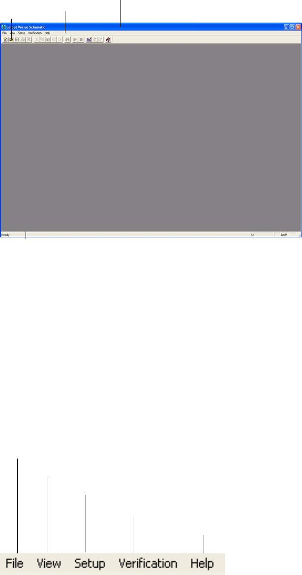
L-Edit 13 User Guide Section 3 742
Chapter 28: Getting Started with LVS User Interface
Menu bar
Toolbar (optional)
Status bar (optional)
Depending on the types of files that are currently open and the task being performed, the user interface
may also contain the following other elements:
“Setup Window” on page 743
“Text Window” on page 755
“Verification Window” on page 758
“Verification Queue” on page 759
Menus
The availability of individual menus depends on the types of files you have open in LVS. When no files
are open, the LVS menu bar will look like this:
Toolbar Menu bar Title bar
Status bar
Commands for creating, opening, saving, and printing files
Commands for displaying or hiding elements of the user interface
Commands for starting, stopping, or setting up verification runs
Commands for accessing the online documentation
Commands for starting, stopping, or setting up verification runs
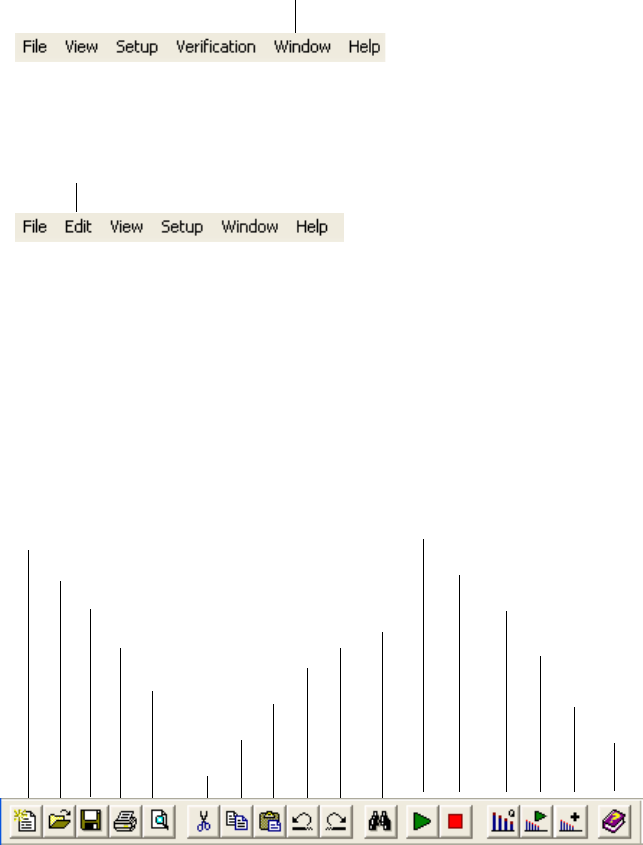
L-Edit 13 User Guide Section 3 743
Chapter 28: Getting Started with LVS User Interface
When the active window contains a setup file, the LVS menu bar will look like this:
When the active window contains a text file, the LVS menu bar will look like this:
Toolbar
You can position the toolbar anywhere within the application window or dock it against one side of the
application window. You can also display or hide the toolbar by selecting View > Toolbar.
The availability of toolbar buttons will depend on the type of file in the active window—setup or text—
and whether or not a verification queue exists.
Status Bar
When a verification window is active and the cursor is in the output file section, the status bar displays
the number of the line where the cursor is positioned. If a text window is active, the status bar displays
both the line number and column number of the cursor position.
Setup Window
When one or more LVS setup files are open, the user interface will contain one setup window for every
open setup file. The setup window contains five tabs, and it is used to specify input files and a variety of
verification options.
Commands for selecting, tiling, or cascading windows
Commands for editing and searching in text files
Cut
Copy
Paste
Undo
Find
Redo
Create a new document
Open a file
Save a file
Access online documentation
Run verification
Stop verification
Add setup to queue
Run queue
Open queue dialog
Print preview
Print
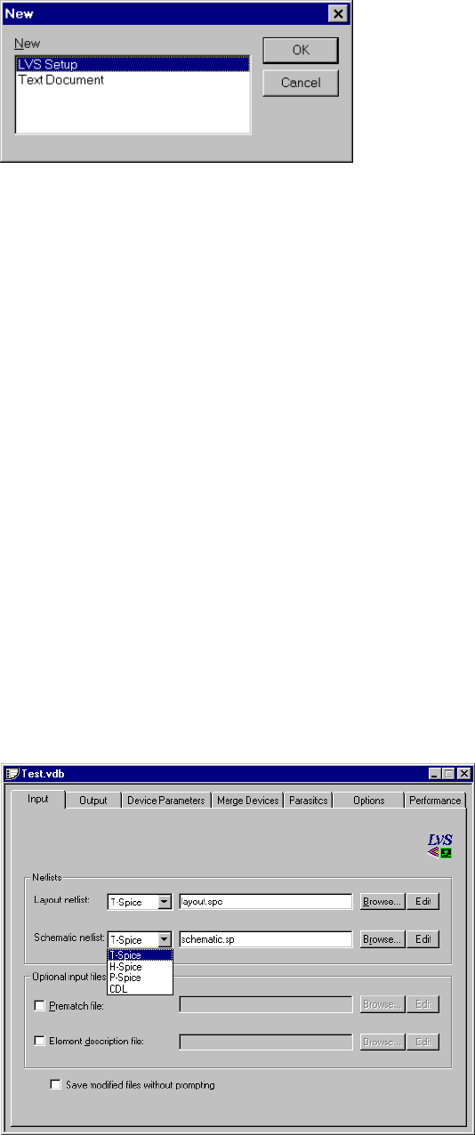
L-Edit 13 User Guide Section 3 744
Chapter 28: Getting Started with LVS User Interface
To create a new setup window, select File > New. In the New dialog, select LVS Setup and click OK.
LVS will create a new setup window with the default name Setup1, which corresponds to the setup file
Setup1.vdb. When you save the setup file for the first time, you can either use the default name or
supply your own, but you must use the .vdb extension (to ensure that Windows automatically
recognizes the files as an LVS verification database). Subsequent new setup windows will receive
similar names by default—Setup2, Setup3, etc.
To open an existing setup window, select File > Open. In the Open dialog, select the appropriate
Verification Database File (*.vdb) from the Files of type drop-down list and select an available file or
enter its name in the File name field.
“Setup—Input” on page 744
“Setup—Output” on page 745
“Setup—Device Parameters” on page 747
“Setup—Merge Devices” on page 748
“Setup Window—Parasitics” on page 750
“Setup—Options” on page 752
“Setup—Performance” on page 754
Setup—Input
The Input tab contains fields for specifying input files to be compared by LVS. You can type the correct
filename in a field, or use a Browse button to navigate to an appropriate directory. Click Edit to open
the specified file in a text window.
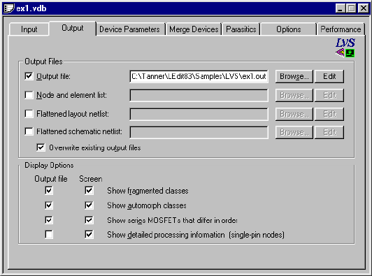
L-Edit 13 User Guide Section 3 745
Chapter 28: Getting Started with LVS User Interface
Options include:
Setup—Output
The Output tab contains fields for specifying output files and display options.
In the Output Files section, you can type the correct filename in a field, or use a Browse button to
navigate to an appropriate directory. Click Edit to open the specified file in a text window.
Layout netlist
and
Schematic netlist
The two input files to be compared. Each file must be in a SPICE
format chosen from the drop-down list provided. Options are:
T-Spice — Select T-Spice syntax. This is the default mode.
H-Spice — Select HSPICE syntax.
P-Spice — Select P-Spice syntax. This mode must be selected if
the input files were produced by P-Spice.
CDL — Select Cadence Circuit Description Language syntax.
The default filename extensions is .spc for both input netlists. (See
“SPICE File Format” on page 784.)
Prematch file An optional input file that specifies equivalent elements and nodes for
the iterative matching process. The default filename extension is .pre.
(See “Prematch File Format” on page 782.)
Element description file An optional input file containing instructions on how to deal with
custom devices. The default filename extension is .elm. (See
“Element Description File Format” on page 779.)
Save modified files without
prompting If this option is enabled, text files that are open and modified within
LVS and are required for the LVS job will be automatically saved
when “Run LVS” is pressed.
L-Edit 13 User Guide Section 3 746
Chapter 28: Getting Started with LVS User Interface
Output file options include:
The Display Options section contains options that specify which processing information LVS will
display or record during the verification run. Each option has two checkboxes:
Output file—Prints the selected information to the output file. To enable this option, you must
specify an Output file in the top portion of the dialog.
Screen—Displays the selected information in the verification window.
Options include:
Output file When checked, specifies an output file containing verification results.
The default filename extension is .out.
Node and element list An optional output file containing a node and element list. The default
filename extension is .lst.
Flattened layout netlist
and
Flattened schematic netlist
Optional output files containing the flattened layout and schematic
netlists. Each file includes only the information that LVS will use to
compare circuit descriptions. Commands, comments, and ignored
devices or parameters are omitted, and parallel or series elements are
merged as specified in the top section of the Merge Devices tab.
Note: If Merge series MOSFETs is selected on the Merge Devices
tab, the flattened netlist will not reflect collapsed series
MOSFETs. To maintain SPICE compatibility, LVS writes the
flattened netlist before merging series MOSFETs.
The default filename extensions are .spc and .sp for the flattened
layout and schematic netlists, respectively.
Overwrite existing output
files When checked, causes automatic overwriting of the output files, even
if these files already exist.
Show fragmented classes Shows information on fragmented classes of nodes and elements.
Show automorph classes Shows information on automorph classes of nodes and elements.
Show series MOSFETs that
differ in order Shows information on functionally equivalent groups of series
MOSFETS that differ in order (also known as permuted classes).
Show detailed processing
information Instructs LVS to include additional processing information:
Shows single-connection nodes.
If a prematch file is used, displays prematched elements and
elements that LVS attempts to postmatch. This is useful for
troubleshooting netlists returned as not identical due to
fragmentation after automorphism or permutability.
If an element description file is used, lists subcircuits that will not
be flattened (i.e., those designated as special elements).
Logs merged series or parallel devices.
Lists deletions of shorted and disconnected devices.
Lists parasitic devices that were removed or shorted.
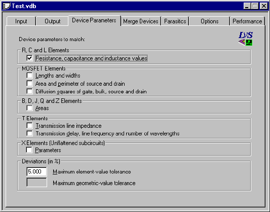
L-Edit 13 User Guide Section 3 747
Chapter 28: Getting Started with LVS User Interface
For further information on individual netlist classes, see also “Resolving Fragmented Classes” on page
796, “Resolving Automorph Classes” on page 797 and “Permuted Classes in Digital Designs” on page
798.
Setup—Device Parameters
The Device Parameters tab allows you to specify which parametric information LVS should consider
for different elements during iteration matching and detailed trial matching.
Options include:
R, C and L Elements:
Resistance,
capacitance, and
inductance values
Considers parametric information on resistance, capacitance, and
inductance elements.
MOSFET Elements:
Lengths and widths Considers MOSFET length and width parameters.
Area and perimeter of
source and drain Considers source/drain areas and perimeters of MOSFET elements.
Diffusion squares of
gate, bulk, source, and
drain
Considers parametric information about diffusion squares of
MOSFET gate, bulk, source, and drain terminals.
B, D, J and Q Elements:
Areas Considers area parameters for non-MOSFET semiconductor devices.
T Elements:
Transmission line
impedance Considers transmission line impedance.
Transmission delay,
line frequency and
number of
wavelengths
Considers transmission line parameters describing delay, frequency,
and wavelength number.

L-Edit 13 User Guide Section 3 748
Chapter 28: Getting Started with LVS User Interface
For more information, see “Parameter Matching” on page 798.
Setup—Merge Devices
Before LVS compares the two input netlists, it can eliminate potential ambiguities by reducing the total
number of devices used in each circuit. LVS does this by merging similar devices in series or parallel
configurations. When LVS merges a group of series or parallel devices, it replaces them with a single
equivalent component.
Note: In previous versions of LVS, merging devices was referred to as network
optimization.
X Elements:
Parameters Considers parameter values of unflattened or autodefined subcircuits.
These parameters are treated as “value” parameters for the purpose of
comparison tolerance. Parameters of “regular” subcircuits are passed
down the hierarchy to the contents of each subcircuit.
Deviations (in %):
Maximum
element-value
tolerance
The maximum amount (as a percentage of the larger value) by which
two parameter values may differ and still compare as equal. The
default is 5%.
This tolerance applies to:
Resistance, capacitance, and inductance values
Transmission line number of wavelengths, frequency, delay, and
impedance
MOSFET numbers of gate/source/bulk/drain diffusion squares
Maximum
geometric-value
tolerance
The maximum amount (as a percentage of the larger value) by which
two geometric shapes may differ and still compare as equal. The
default is 5%.
This tolerance applies to:
GaAsFET, diode, JFET, and BJT element areas
MOSFET length and width
MOSFET source/drain areas and perimeters

L-Edit 13 User Guide Section 3 749
Chapter 28: Getting Started with LVS User Interface
Merge options for each device type are specified in the Merge Devices dialog.
The top portion of the Merge Devices dialog controls merge options for the following device types and
configurations:
Resistors (R) — parallel and series
Inductors (L) — parallel and series
Capacitors (C) — parallel and series
GaAsFETs (B) — parallel
Diodes (D) — parallel
JFETs (J) — parallel
BJTs (Q) — parallel
MESFETs (Z) — parallel
MOSFETs (Mp, Ms) — parallel MOSFETS and stacked MOSFETS (series MOSFETS with gates
connected to the same node). For parallel MOSFETS to be merged, both devices must have the
same gate length; the gate width of the resulting device is the sum of the widths of the original
devices, and the area and perimeter of the source and drain are the sum of the respective terminal
dimensions. For stacked MOSFETS to be merged, both devices must have the same gate width; the
gate length of the resulting device is the sum of the lengths of the original devices. In the case of
merged stacked MOSFETS, the area and perimeter of the diffusion between the devices is divided
evenly between the resulting source and drain terminals.
For each device type, select one of the following options from the drop-down list:
None Leaves devices in their current configuration. LVS will not merge
devices for which None is selected.
All Merges series or parallel instances of the same device model into
equivalent single devices.
Options apply to both parallel
and series configurations of
R, L, and C devices
Options apply only to
parallel configurations of B,
D, J, M, Q, and Z devices
Applies only to series
configurations of M devices.
L-Edit 13 User Guide Section 3 750
Chapter 28: Getting Started with LVS User Interface
Click Set All or Set None to quickly change all merge settings in the top portion of the dialog to All or
None, respectively. These buttons do not affect merge options for series MOSFETs.
Additional options in the Merge Devices dialog include:
Setup Window—Parasitics
The Parasitics tab contains fields to help LVS identify parasitic capacitors and resistors that should not
be considered in the netlist comparison. Parasitics may have been added to one of the input netlists for
detailed timing simulations. These elements must be removed prior to netlist comparison.
Model When the Model option is selected, LVS merges only devices that are
instances of the specified model(s). In the text entry field, type the
models you wish to make available for merge operations. List models
with the following syntax:
type_name1, type_name2, ...
where type is the letter abbreviation for the device type, and name1,
name2, etc. are model names defined in .model statements.
Series MOSFETs Specifies merge behavior for MOSFET devices in series. If this
option is selected, the order in which series MOSFETS occur is
ignored.
Select None, All, or Model in the pull-down menu. If Model is
selected, type the names of the models to be considered for merge
operations in the editing field.
Find series MOSFETs that
differ in order or parameter
values
When Series MOSFETs is set to either All or Model, this option
instructs LVS to identify functionally equivalent groups of series
MOSFETs that occur in different orders. The default state for this
option is unchecked. Also, when this analysis is enabled, the
parameter values of the series MOSFETs are inspected after the
matching is complete: parameter mismatch warnings are given in
cases where the differences exceed the comparison tolerance
specified in the Device Parameters tab.
Note: Series MOSFETs that differ in order are also called permuted
classes. See “Permuted Classes in Digital Designs” on page
798 for further discussion.
Remove shorted devices Deletes shorted devices, in which all terminals are connected
together.
Remove disconnected
devices Deletes disconnected (open) devices. A MOSFET is considered
disconnected if the gate terminal is not connected to any other device,
and at least one source/drain terminal is not connected to any other
device. All other devices types are considered disconnected if at least
one of their terminals is not connected to any other device.
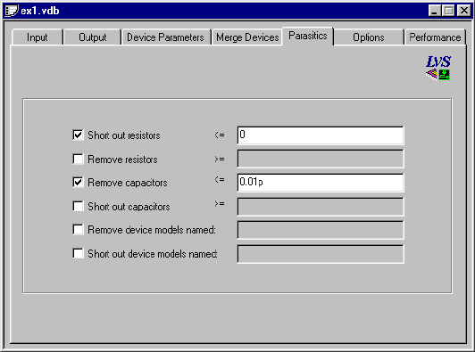
L-Edit 13 User Guide Section 3 751
Chapter 28: Getting Started with LVS User Interface
Use the Parasitics tab to set the criteria by which LVS will determine which capacitors and resistors to
remove or short. LVS shorts a device by shorting all of its terminals, then removing the device.
Options include:
Short out resistors <= Removes any resistor with resistance less than or equal to the
specified value, and connects (shorts) the two nodes that were
spanned by the device.
Remove resistors >= Removes any resistor with resistance greater than or equal to the
specified value.
Remove capacitors <= Removes any capacitor with capacitance less than or equal to the
specified value.
Short out capacitors >= Removes any capacitor with capacitance greater than or equal to the
specified value, and r and connects (shorts) the two nodes that were
spanned by the device.
Remove device models
named: Removes all instances of the device models listed in the text entry
field.
Short device models
named: Removes any instance of the device models listed, and connects the
nodes that were spanned by the device.
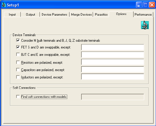
L-Edit 13 User Guide Section 3 752
Chapter 28: Getting Started with LVS User Interface
Setup—Options
The Options tab contains options for parsing files and flattening netlists, as well as an option to find
soft connections with specified models (see “Detecting Soft Connections with LVS” on page 753):
Options include:
Consider M bulk terminals
and B, J, Q, Z substrate
terminals
When checked, considers the fourth terminal on MOSFET, BJT,
GAASFET and MESFET devices during verification. If unchecked,
this terminal is ignored. The default is checked, to consider bulk
nodes.
FET S and D are
swappable, except: When checked, the source and drain terminals of FETs (MOSFETs,
GAASFETs and MESFETs) are considered to be interchangeable,
except for device models that are explicitly listed. When not checked,
the reverse is true: by default, FETs are asymmetric (e.g., LDD
devices), and symmetric device models are listed explicitly. The
default state is checked.
BJT C and E are
swappable, except: When checked, the collector and emitter terminals of BJTs are
considered to be interchangeable, except for device models that are
explicitly listed. When not checked, the reverse is true: by default,
BJTs are asymmetric, and symmetric device models are listed
explicitly. The default state is unchecked.
Resistors are polarized,
except: When checked, all resistors are regarded as polarized elements (i.e.,
the two terminals are not interchangeable), except for device models
that are explicitly listed. When not checked, the reverse is true: by
default resistors are unpolarized, and polarized models are listed
explicitly. The default state is unchecked.
Capacitors are polarized,
except: When checked, all capacitors are regarded as polarized elements (i.e.,
the two terminals are not interchangeable), except for device models
that are explicitly listed. When not checked, the reverse is true: by
default capacitors are unpolarized, and polarized models are listed
explicitly. The default state is unchecked.
L-Edit 13 User Guide Section 3 753
Chapter 28: Getting Started with LVS User Interface
Detecting Soft Connections with LVS
A MOSFET is said to be “soft connected” to a node when the only electrical connection to that node
goes through a well or a substrate. This condition can be a serious problem if, for example, instead of
being connected directly to a power supply metallization, a transistor's source is connected only to the
well (through an ohmic contact) and that well is in turn connected to the power rail (through another
ohmic contact). Soft connections can lead to reduced drive strength, longer gate propagation delays, and
susceptibility to latch-up.
LVS has an option to detect such soft connections when special devices are included in the SPICE
netlist. It is recommended that ohmic contacts to wells and substrate be extracted as zero-ohm resistors,
of type R_WELLCONTACT and R_SUBSCONTACT. (See “Detecting Soft Connections” on page 702
for information about extracting these devices.) This method allows you to simulate the extracted netlist
with T-Spice; if desired, the resistors can be removed in LVS using the options in “Setup—Merge
Devices” (page 748).
To detect soft-connected devices, check the option labeled Find soft connections with models: and
enter the model names of the devices used to identify ohmic well and substrate contacts.
Before executing the regular LVS netlist comparison algorithm, LVS searches for wells and substrate
that connect to at least one device (excluding MOSFET bulk terminals) and connect through
soft-contact devices to more than one node. LVS prints the names of all nodes that are soft-connected
through each well/substrate. LVS then shorts and removes all soft-connect devices, and proceeds with
the regular netlist comparison algorithm.
Inductors are polarized,
except: When checked, all inductors are regarded as polarized elements (i.e.,
the two terminals are not interchangeable), except for device models
that are explicitly listed. When not checked, the reverse is true: by
default inductors are unpolarized, and polarized models are listed
explicitly. The default state is unchecked.
Find soft connections with
models: When checked, LVS performs a pre-search for wells and substrate
contacts that connect as described in “Detecting Soft Connections
with LVS,” below. Enter the model names of the devices used to
identify ohmic well and substrate contacts.
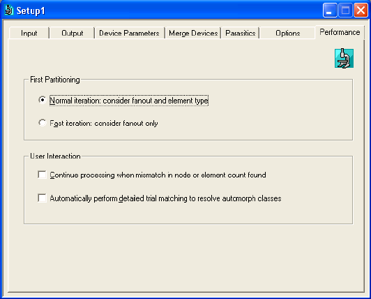
L-Edit 13 User Guide Section 3 754
Chapter 28: Getting Started with LVS User Interface
Setup—Performance
The Performance tab contains options that instruct LVS how to perform during iteration.
Normal iteration: consider
fanout and element type Considers both fanout and element type during iteration. This is the
default.
Fast iteration: consider
fanout only Considers only fanout.
Continue processing when
mismatch in node or
element count found
Continues to run even on element or node count mismatch. If this
option is not selected, LVS issues a prompt when an element/node
count mismatch occurs. In batch or queuing mode, this option is
automatically selected.
Automatically perform
detailed trial matching to
resolve automorph classes
Instructs LVS to perform detailed trial-matching when automorphed
element or node classes occur without first issuing a prompt. In batch
or queuing mode, this option is automatically selected.
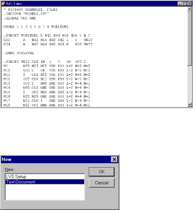
L-Edit 13 User Guide Section 3 755
Chapter 28: Getting Started with LVS User Interface
Text Window
When a SPICE file, or other text-format file, is open, the user interface will contain one or more text
windows.
The text window is used to edit text-format files, such as SPICE, prematch, or element description files.
To create a new text file (and open a new text window), select File > New. In the New dialog, select
Text Document and click OK.
LVS will create a new text window with the default name LVS1. When you save the text file, you can
either use the default name or supply your own, but you must supply an appropriate filename extension,
such as .spc or .elm. Subsequent new text windows will receive similar names by default—LVS2,
LVS3, etc.
To open an existing text file, select File > Open. In the Open dialog, select the appropriate file type
from the Files of type drop-down list and select an available file or enter its name in the File name
field.
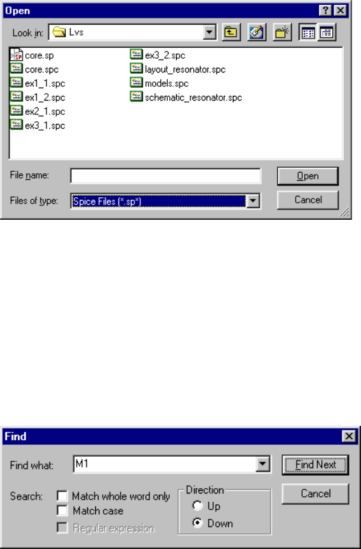
L-Edit 13 User Guide Section 3 756
Chapter 28: Getting Started with LVS User Interface
Within text files, LVS provides a full range of standard Windows editing capabilities. You can cut,
copy, and paste text as you would in any standard text editor. You can undo successive text edits by
selecting Edit > Undo, and you can reverse successive Undo commands by selecting Edit > Redo.
Using Find and Replace
You can search a text file for any string or replace all instances of a particular string with other input
you supply. To initiate a search operation, select Edit > Find (Ctrl+F). LVS will display the Find dialog:
Enter a string in the Find what field and check the options you wish to activate:
Click Find Next. LVS will search the file in the active text window of the specified string and highlight
it, if found.
Match whole word only LVS searches only for whole words that match the specified search
string.
Match case LVS performs a case-sensitive search.
Direction The direction in which LVS searches the file:
Up—searches backward in the active window.
Down—searches forward in the active window.
When LVS reaches the beginning or end of the file, it will prompt you
via a dialog box for permission to resume the search at the top or
bottom of the file, as appropriate.
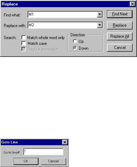
L-Edit 13 User Guide Section 3 757
Chapter 28: Getting Started with LVS User Interface
To search for additional instances of the string after the Find dialog is closed, select Edit > Find Next
(or press F3). LVS will continue searching the active text file for instances of the specified string until
the last one has been found.
To perform a search-and-replace operation, select Edit > Replace. LVS will display the Replace
dialog:
Enter a string in the Find what field and click Find Next. LVS will search the file in the active text
window for the specified string and highlight it, if found. Next, enter a replacement string in the
Replace with field. To replace a single instance of the search string with the replacement string, click
Replace. To replace all instances of the search string with the replacement string, click Replace All.
Using Go To
To move the cursor directly to a specific line in a text file, select Edit > Go To. LVS will display the
following dialog:
Enter a line number and click OK. LVS will move the cursor to the beginning of the specified line.
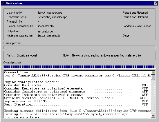
L-Edit 13 User Guide Section 3 758
Chapter 28: Getting Started with LVS User Interface
Verification Window
LVS reports its progress and the results of a verification run in the verification window.
The verification results will appear in this window whenever you run a verification. You can also
display the results of the last-performed verification by selecting View > Verification Window anytime
after the initial verification run. If you select this command before running a verification, the window
will be empty.
The verification window is divided into three sections, or panes. The uppermost section lists the input
and output files used in the verification, and the current status of each file. A graphic indicator also
displays the progress LVS has made in the current process.
The middle section of the verification window reports the result of a verification run, relevant notes, and
any errors encountered during the verification. Below the text, a graphic indicator displays the progress
LVS has made in processing the verification run as a whole.
The bottom section of the verification window contains an editable copy of the output file, which
reports input files and options set in the setup window, plus verification progress statements written
during the run. This section can be used to perform line edits on the output file using the following basic
text editing commands. Note that in the verification window these commands are only available via the
keyboard.
Ctrl+ASelect all.
Ctrl+CCopy to clipboard.
Ctrl+FFind.
Ctrl+GGo to line.
Ctrl+SSave to file.
Ctrl+VPaste from clipboard.
Ctrl+XCut to clipboard.
Ctrl+Home Position cursor on first line.

L-Edit 13 User Guide Section 3 759
Chapter 28: Getting Started with LVS User Interface
In the verification window (“Verification Window” on page 758), the bottom section shows the
command line derived from entries made in the setup window. This command line is used to initiate the
verification run:
Command line:
lvs C:\Tanner\LEdit83\Samples\LVS\layout_resonator.spc
C:\Tanner\LEdit83\Samples\LVS\schematic_resonator.spc
-o C:\Tanner\LEdit83\Samples\LVS\resonator.out
-l C:\Tanner\LEdit83\Samples\LVS\layout_resonator.lst
-e C:\Tanner\LEdit83\Samples\LVS\resonator.elm
-nrcl -y2 -fafpr
Beneath the command line, LVS displays the options chosen in the setup window:
Engine configuration report:
Consider Bulk nodes........................................ON
Consider Resistors as polarized elements........................OFF
Consider Capacitors as polarized elements.......................OFF
Consider Inductors as polarized elements........................OFF
Merge series, parallel R and C, parallel MOSFETs.
Delete shorted devices.....................................OFF
Merge series MOSFETs............................................OFF
Find series MOSFETs that differ in order........................OFF
Fast Iteration.............................................OFF
Next, the verification window displays the progress statements written during the verification run:
Reading element definitions from file
C:\Tanner\LEdit83\Samples\LVS\resonator.elm
Parsing file C:\Tanner\LEdit83\Samples\LVS\layout_resonator.spc...
Flattening netlist...
Parsing file
C:\Tanner\LEdit83\Samples\LVS\schematic_resonator.spc...
For further information on LVS verification output, see the “LVS Output Tutorial” on page 766.
You can rerun the verification whose results are reported in the verification window by clicking on the
appropriate setup window and pressing F5.
Verification Queue
You can run several verifications consecutively by creating a verification queue. Once you have created
such a queue, you can use it to run multiple verifications without additional user intervention.
To create a verification queue or add a setup to an existing queue, select Verification > Add to Queue
or click the following toolbar button:
Ctrl+End Position cursor on last line.
Page Up Scroll up through file.
Page Down Scroll down through file.
Delete Delete line.
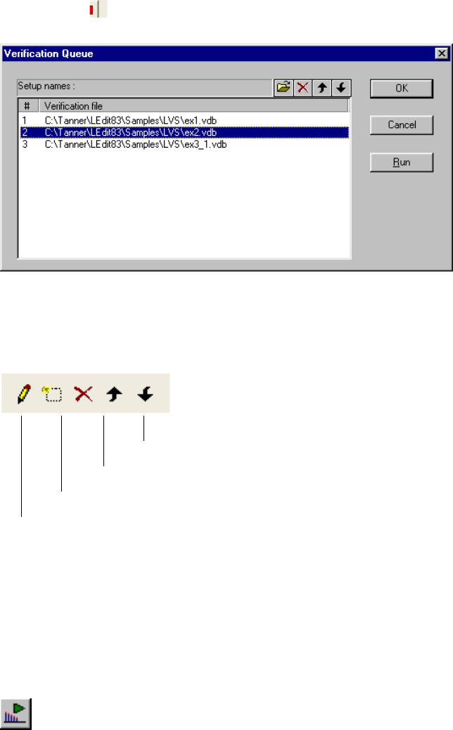
L-Edit 13 User Guide Section 3 760
Chapter 28: Getting Started with LVS User Interface
LVS will automatically add the active setup to the end of the existing queue.
To display the verification queue, select Verification > Verification Queue (F8) or click the Open
Queue Dialog ( ) button. LVS will display a dialog like this:
Each setup is listed in the Setup Names field. You can make changes to the existing queue via
keyboard shortcuts or a toolbar within the dialog. The toolbar buttons, with their functions and
corresponding keyboard shortcuts, are illustrated below:
Clicking OK saves any changes you have made to the verification queue and closes the dialog. LVS
saves the most recent verification queue in the registry, allowing you to retrieve the current settings the
next time LVS is launched.
Clicking Run initiates a verification for every setup listed in the verification queue. You can also
initiate such a verification run with the verification queue closed by selecting Verification > Start
Verification Queue (F9) or by clicking the Run Queue toolbar button:
Move selected setup down one position (Down arrow)
Move selected setup up one position (Up arrow)
Delete selected setup (Del)
Add setup to queue (Ctrl+O)
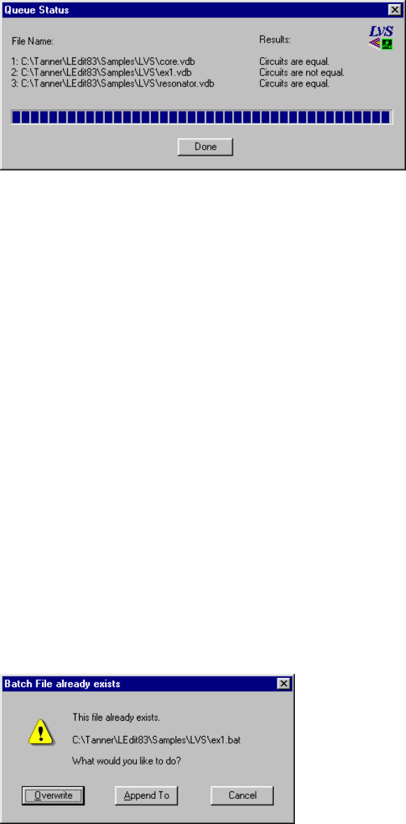
L-Edit 13 User Guide Section 3 761
Chapter 28: Getting Started with LVS Using LVS in Batch Mode
When LVS has finished running the verification queue, it will display a dialog like the following:
Using LVS in Batch Mode
Using LVS in batch mode provides another way to run multiple verifications consecutively. To run
LVS in batch mode, you must first create a batch file. A batch file is a text file containing one or more
command-line invocations of LVS and appropriate setup information—input files and verification
options—for each verification run.
Creating a Batch File
To create a batch file, select File > Export Batch File (Ctrl+E) with a setup window active. LVS will
display the Export Batch File as dialog. Navigate to the correct directory if necessary and enter the
name of the batch file in the File name field, then click Save. LVS will create a batch file with a single
invocation of LVS and command-line options derived from parameters set in the active setup window.
A simple batch file will contain text like the following:
start /w lvs "C:\LVS\Examples\Ex2_1.spc" "C:\LVS\Examples\Ex2_2.spc" -o
"C:\LVS\Examples\Ex2.out" -nrcl -c1245 -dv5.000 -dg0.010 -vfa -q
For further information on batch-file syntax, see “Batch-File Syntax” on page 802. For further
information on command-line options, see “Options” on page 803.
To add verifications to an existing batch file, select it in the Export Batch File as dialog and click
Save. LVS will prompt you with the following dialog:
To add to the current batch file, click Append To. LVS will append an appropriate command line to the
existing batch file. If you click Overwrite, LVS will overwrite the existing batch file with a new
command line using setup information derived from the current setup window.
L-Edit 13 User Guide Section 3 762
Chapter 28: Getting Started with LVS Tutorial
You can further develop a batch file by editing it in the LVS text window. For example, you can change
the names and paths of the SPICE files used in the verification, or set different command-line options.
To run an LVS batch file, double-click it in Windows Explorer or invoke it from a DOS command
prompt. Note that LVS does not support launching of multiple instances—to run a batch file, you must
first exit LVS for Windows.
For further information, see “Running a Batch File” on page 802.
Tutorial
This brief tutorial will teach you how to perform the following basic tasks in LVS:
Set up and run a verification
Create a verification queue
Create and run a verification batch file
For information on interpreting LVS output and resolving verification problems, see the “LVS Output
Tutorial” on page 766.
Creating a Verification Setup
In the following steps, you will learn to create and run an LVS verification database (.vdb) file. The file
you will create is also provided as C:\{install_dir}\Samples\LVS\ex1.vdb.
;Start LVS, if it is not already running.
;Select File > New or click the New button in the toolbar.
;In the New dialog, select LVS Setup as the file type, and click OK.
;LVS will display a setup window. In the File tab, type the names of the two netlists you wish to
compare. You can also use the Browse buttons to navigate to these files. For this tutorial, use the files
ex1_1.spc as the layout netlist and ex1_2.spc as the schematic netlist. Both of these files are located in
C:\install_dir\Samples\LVS.
;Check the Output file option and enter the name of the output file in the corresponding field. For this
tutorial, use C:\install_dir\Samples\LVS\ex1.out.
;Check the option Overwrite existing output files so that LVS will overwrite this output file on
subsequent verification runs without prompting you.
;On the Options tab, check the following options:
Consider MOSFET bulk nodes (substrate) during iteration matching
Consider resistors as polarized elements
Consider capacitors as polarized elements
Consider inductors as polarized elements

L-Edit 13 User Guide Section 3 763
Chapter 28: Getting Started with LVS Tutorial
;On the Device Parameters tab, check Resistance, capacitance, and inductance values. Enter a
Maximum element-value tolerance of 5.000.
;On the Performance tab, select Normal iteration: consider fanout and element type.
;On the Verbosity Level tab, check the following options for both Output file and Screen:
Show fragmented classes
Show automorph classes
Show series MOSFETs that differ in order
;Save your setup as ex1.vdb, or another name of your choice.
;Select Verification > Run (F5) or click the Run Verification ( ) button on the toolbar.
;This verification run will produce an element/node count mismatch. LVS will prompt you for
permission to continue iteration. Click Yes.
LVS will complete the verification run and display the following results in the verification window:
0 perfectly matched element class(es)
1 fragmented element class(es)
3 perfectly matched node class(es)
12 fragmented node class(es)
Circuits are not equal.
This verification run results in one fragmented element class and 12 fragmented node classes. It is not
necessary to resolve these fragmented classes now, but the correct procedure is described in “Resolving
a Fragmented Class” on page 772.
;Now create another verification setup using the following input files and parameters. Save your setup
file as ex2.vdb (or use the setup file supplied with LVS).
On the File tab, select C:\install_dir\Samples\LVS\ex1_2.spc as the layout netlist file and
C:\install_dir\Samples\LVS\ex2_1.spc as the schematic netlist file. Check the Output file option
and name the output file C:\install_dir\Samples\LVS\ex2.out.
On the Options tab, check the following options:
Consider MOSFET bulk nodes (substrate) during iteration matching
Consider resistors as polarized elements
Consider capacitors as polarized elements
Consider inductors as polarized elements
On the Device Parameters tab, check the following options:
Resistance, capacitance, and inductance values. Then enter a Maximum element-value
tolerance of 5.000.
Areas (in B, D, J and Q Elements). Then enter a Maximum geometric-value tolerance of
5.000.
On the Performance tab, select Normal iteration: consider fanout and element type.
On the Verbosity Level tab, check the following options for both Output file and Screen:
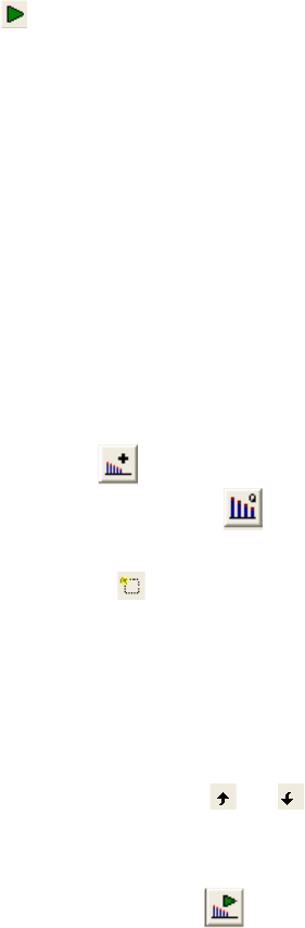
L-Edit 13 User Guide Section 3 764
Chapter 28: Getting Started with LVS Tutorial
Show fragmented classes
Show automorph classes
Show series MOSFETs that differ in order
;Select Verification > Run (F5) or click the Run Verification ( ) button on the toolbar. LVS will
complete the verification run and display the following results in the verification window:
32 perfectly matched element class(es)
18 perfectly matched node class(es)
4 fragmented node class(es)
Circuits are not equal.
;When you are finished viewing the results, close the verification window.
Creating a Verification Queue
In the following steps, you will learn how to create and run a verification queue.
;Select ex2.vdb as the active setup window.
;Select Verification > Add to Queue (F7) or click the Add to queue button ( ) on the toolbar.
;Select Verification > Verification Queue (F8) or click the Open Queue Dialog button ( ) on the
toolbar. LVS will display the Verification Queue dialog with the file ex2.vdb listed in the queue.
;Within the verification queue dialog, click the Add setup to queue button ( ) or type the shortcut
Ctrl+O. LVS will open a standard Windows file browser.
;Select the file C:\install_dir\Samples\LVS\ex1.vdb and click Open. LVS will add this setup file to the
verification queue.
;Repeat the last two steps and add file ex3_1.vdb to the queue.
;If desired, rearrange the setups in the queue, using the arrow keys or appropriate buttons ( and ) in
the Verification Queue dialog.
;To run the verification, click Run in the Verification Queue dialog, or click OK to close the dialog, then
select Verification > Start Verification Queue (F9). You can also click the Run Queue ( ) button in
the application toolbar.
LVS will run the verifications in the order listed and report the results in the Queue Status dialog. You
should see the following results (in the order you specified):
C:\Tanner\LEdit84\Samples\LVS\ex2.vdbCircuits are not equal!
C:\Tanner\LEdit84\Samples\LVS\ex1.vdbCircuits are not equal!
C:\Tanner\LEdit84\Samples\LVS\ex3_1.vdbCircuits are equal!
;Close the Verification Queue dialog, if necessary.
In the next section, you will learn how to create and run a verification batch file.
Running LVS in Batch Mode
;Select ex1.vdb as the active setup window.
L-Edit 13 User Guide Section 3 765
Chapter 28: Getting Started with LVS Tutorial
;Select File > Export Batch File (Ctrl+E).
;LVS will display the Export Batch File as dialog. Select ex1.bat or type it in the File name field. Click
Save.
;Select ex2.vdb as the active setup window.
;Select File > Export Batch File (Ctrl+E). In the Export Batch File as dialog, type ex1.bat in the File
name field and click OK.
;LVS will prompt you with the dialog Batch file already exists. Click the Append To button.
;Select ex3_1.vdb as the active setup window and repeat the last two steps to add this setup to the batch
file.
;Exit LVS and open a DOS window. Navigate to the LVS installation directory, then type
Samples\LVS\ex1.bat. For default installations, the command line should read:
C:\Tanner\LEdit84> Samples\LVS\ex1.bat
LVS will run the verifications listed in the batch file and write the results to the specified output file(s).
You can view the results using the LVS text window or any other text editor.

L-Edit 13 User Guide Section 3 766L-Edit 13 User Guide Section 3 766
29 LVS Output Tutorial
Introduction
LVS generates certain output upon execution, depending on which options are checked on the “Setup—
Output” (page 745) tab in the setup window. In the following examples, the .vdb files are opened in
LVS and run with a single invocation. If run in batch mode, user interactions, defaults, and generated
output may differ.
All files used in this chapter are available in the \install_dir\Samples\LVS\ directory.
Parsing Information
LVS first reports parsing information about both of the netlists.
Following is an example of the output ex1.out, generated by LVS for ex1.vdb. The options for Show
Fragmented Classes, Show Automorph Classes, and Show Detailed Processing Information are
checked in both Output file and Screen columns, so all information written to the output file is also
written to the verification window.
Engine configuration report:
Consider Bulk nodes.................................ON
Consider Resistors as polarized elements............ON
Consider Capacitors as polarized elements...........ON
Consider Inductors as polarized elements............ON
Optimize shorted & parallel R, C, MOSFETs;
series R and C............................OFF
Replace series MOSFETs.............................OFF
Fast Iteration.....................................OFF
Parameter comparison threshold for CAPACITORS.......5%
Parameter comparison threshold for INDUCTORS........5%
Parameter comparison threshold for RESISTORS........5%
Parsing file ex1_1.spc...
Including file MODELS.SPC
Flattening network...
Parsing file ex1_2.spc...
Including file MODELS.SPC
Flattening network...
Device ex1_1.spc ex1_2.spc Status
------- ----------- ----------- ---------
C 4 4
M_NSS 20 20
M_PSS 26 24 MISMATCH (2)
Total element 50 48 MISMATCH (2)
Total nodes 20 20
3
L-Edit 13 User Guide Section 3 767
Chapter 29: LVS Output Tutorial Parameter Matching Example
LVS begins the parsing information by stating which file was read and listing any files included in this
file. After the network is flattened, the program reports the kinds of elements found and the number of
nodes found. The program concatenates the device type with the model name to make up the element
type, as in M_NSS. This helps distinguish between elements of the same device type that use different
models.
If the program detects a numerical difference between the number of different elements and the number
of nodes between the two files, it poses a question identifying the problem and requiring instructions to
continue or exit. If the Continue processing when mismatch in node or element count found option
on the “Setup—Performance” (page 754) tab in the setup window is checked, or if LVS is invoked
from batch mode, the program does not stop at this point and continues on to the iteration.
Parameter Matching Example
Following is an example of the output ex2.out, generated by LVS for ex2.vdb. In this example, LVS is
instructed to use parameter matching (Resistance, Capacitance and Inductance values for R, C, and
L Elements and Lengths and Widths for MOSFET Elements on the “Setup—Device Parameters”
(page 747) tab), in addition to the topological characteristics. (See “Parameter Matching” on page 798
for more information on this method.)
Iterating...
5% done
10% done
...
25% done
Warning: Parametric mismatch between elements
ex1_2.spc: M346:L=2 W=5 (Not all decimals shown)
ex2_1.spc: M6(XSUBA/X34):L=2 W=6 (Not all decimals shown)
Warning: Parametric mismatch between elements
ex1_2.spc: M6:L=2 W=5 (Not all decimals shown)
ex2_1.spc: M6(XSUBA/X33):L=2 W=6 (Not all decimals shown)
50% done
...
In this example, during the iteration matching process LVS encountered elements that are topologically
matched but are parametrically different. LVS reports this as a warning, but it does not affect the
iteration process.
Automorph Class Example
When LVS finishes iteration, it reports any automorphism or fragmentation that occurs. Automorph
classes are listed first.
Following is an example of the output ex3.out, generated by LVS for ex3_1.vdb.
**************** REPORTING AUTOMORPHISM **************
L-Edit 13 User Guide Section 3 768
Chapter 29: LVS Output Tutorial Automorph Class Example
Report of elements:
*******************
Automorph class of elements
Ex3_1.spc M1(XSUBA/X34)_2fanout: BULK = 41D/S ( 3, 7) G = 7
Ex3_1.spc M1(XSUBA/X34)_1fanout: BULK = 41D/S ( 3, 7) G = 7
Ex3_2.spc M350 fanout: BULK = 41 D/S ( 3, 7) G = 7
Ex3_2.spc M341 fanout: BULK = 41 D/S ( 3, 7) G = 7
---------------------------------------------------
Automorph class of elements
...
...
...
---------------------------------------------------
Automorph class of elements
Ex3_1.spc: 4 element(s)
Ex3_2.spc: 4 element(s)
Ex3_1.spc C1(XSUBA/X34)_2 fanout: POS/NEG ( 35, 41)
Ex3_1.spc C1(XSUBA/X34)_1 fanout: POS/NEG ( 35, 41)
Ex3_1.spc C1(XSUBA/X33)_2 fanout: POS/NEG ( 35, 41)
Ex3_1.spc C1(XSUBA/X33)_1 fanout: POS/NEG ( 35, 41)
Ex3_2.spc C1_4 fanout: POS/NEG ( 35, 41)
Ex3_2.spc C1_3 fanout: POS/NEG ( 35, 41)
Ex3_2.spc C1_2 fanout: POS/NEG ( 35, 41)
Ex3_2.spc C1_1 fanout: POS/NEG ( 35, 41)
---------------------------------------------------
****************** ITERATION SUMMARY ******************
32 perfectly matched element class(es)
7 automorph element class(es)
20 perfectly matched node class(es)
Each element is listed on a separate line. For each element, the netlist file of origin is listed first
(Ex3_1.spc) followed by the unique name of the element (M1(XSUBA/X34)_2). Hierarchical
information is provided within the parentheses as well as with the appended number at the end.
Whenever LVS encounters a line such as M1 N39 N23 N25 VDD PSS L=2 W=5 M=2 (line 14 of file
Ex3_1.spc), the multiplier M=2 causes LVS to create several identical copies of an element. In this
case, two copies are made. To distinguish between them, LVS appends a number at the end of each
constructed element name.
The fanout tells what the “electrical” fanout of each terminal is. This describes the number of elements
each terminal of the element is connected to, not counting the one obvious connection to itself. For
example, element M1(XSUBA/X34)_2 has 41 elements connected to its bulk terminal, three elements to
either its drain or source terminal, seven elements to the other of drain and source, and seven elements
to its gate terminal. (LVS cannot distinguish between source and drain for FET transistors since there is
no topological distinction between them.) All elements within a single automorph class have exactly the
same fanout.
Since the Detailed Trial Matching to resolve Automorph Classes option was not checked in this
example (see “Detailed Trial Matching” on page 797), an alert box appears asking if LVS should use
detailed trial matching to try and match the elements and nodes of the automorph classes. For the file
ex3_1.vdb, detailed trial matching results in the conclusion that the circuits are equal. The output from
detailed trial matching for this example is discussed on page 3-769.
During detailed trial matching, LVS attempts to pair up the members of automorph classes. In most
cases, this resolves the automorphism and the circuits are found equal. Occasionally the trial matching
results in fragmentation; however, in the case of attempting to resolve an automorph class, it does not
L-Edit 13 User Guide Section 3 769
Chapter 29: LVS Output Tutorial Automorph Class Example
mean the two circuits are different. It only means that the particular trial matches did not resolve the
particular automorph class.
Resolving Fragmentation of an Automorph Class
When detailed trial matching causes fragmentation of an automorph class, there are usually two reasons
for this result:
The trial-matching algorithm is not able to solve the problem. In this case you should provide a
prematch file for sets of nodes and elements, giving LVS a “head start” on matching elements. (See
“Preiteration Matching” on page 797 for more information on prematch files.)
There is, in fact, a difference between the two files being compared.
In either case, the way to move towards a solution at this point is to use a prematch file. Rerun LVS with
the Show Detailed Processing Information option on the “Setup—Output” (page 745) tab in the
setup window checked. This option provides details about the various nodes and elements the detailed
trial matching procedure matches. In most cases the last matched pair of elements or nodes causes the
fragmentation. You will need to look back in your output and find a different match in the automorph
class from which this last pair comes.
For example, if the last matched pair before fragmentation was:
Matched Elements C1(XSUBA/X34)_1 and C1_1
it means that LVS attempted to match element C1(XSUBA/X34)_1 with element C1_1, and the match
failed. Therefore, you should attempt to match a different element with C1(XSUBA/X34)_1, and a
possible line in your prematch file would be:
C1(XSUBA/X34)_1 C1_4
The order in which elements and nodes are specified in a prematch file has to reflect the order in which
the respective netlist files are specified on the command line.
With this line in the prematch file, rerun LVS again. Include the prematch file on the “Setup—Input”
(page 744) tab in the setup window.
If the problem of fragmentation recurs, then repeat the process above and add more lines of information
to the prematch file.
If the two files being compared are equal, a few lines in the prematch file are all that is needed. If there
is a discrepancy between the two input files, you will need to continue adding information to the
prematch file until you are able to determine what the discrepancy is, using the methods of reasoning
outlined above.
For the file ex3_1.vdb, detailed trial matching results in the following output:
....
*************** POST ITERATION MATCHING *******************
Doing detailed trial matching... Step 1 (Match by parameters)
********************* ITERATING ***************************
Doing detailed trial matching... Step 2 (Random matches)
Matched Elements C1(XSUBA/X34)_2 and C1_4
Matched Elements C1(XSUBA/X33)_1 and C1_1
Matched Elements C1(XSUBA/X34)_1 and C1_3
L-Edit 13 User Guide Section 3 770
Chapter 29: LVS Output Tutorial Automorph Class Example
90% done
Matched Elements M10(XSUBA/X34)_1 and M3410
Matched Elements M10(XSUBA/X33)_1 and M10
Matched Elements M19(XSUBA/X33)_1 and M19
95% done
Matched Elements M1(XSUBA/X33)_2 and M3
Matched Elements M19(XSUBA/X34)_1 and M3419
Matched Elements M1(XSUBA/X34)_2 and M350
100% done
********************* FINAL RESULT ************************
Circuits are equal.
Besides providing the information that the circuits are equal, the output also gives information about
what elements were matched during the trial matching process. This information can be turned into a
prematch file to speed up the iteration process next time LVS is run. The above output is listed in the
prematch file as:
M1(XSUBA/X34)_2 M350
M19(XSUBA/X34)_1 M3419
M1(XSUBA/X33)_2 M3
M19(XSUBA/X33)_1 M19
M10(XSUBA/X33)_1 M10
M10(XSUBA/X34)_1 M3410
C1(XSUBA/X33)_1 C1_1
C1(XSUBA/X34)_1 C1_3
C1(XSUBA/X34)_2 C1_4
The name of the prematch file is ex3_1.pre, and it is entered in the Prematch File field on the “Setup—
Input” (page 744) tab in the setup window in ex3_2.vdb. Following is the output generated by LVS for
ex3_2.vdb.
....
....
Processing file C:\Tanner\LEdit83\Samples\LVS\Ex3_1.pre of matched
elements/nodes
Matched Elements M1(XSUBA/X34)_2 and M350
Matched Elements M19(XSUBA/X34)_1 and M3419
Matched Elements M1(XSUBA/X33)_2 and M3
Matched Elements M19(XSUBA/X33)_1 and M19
Matched Elements M10(XSUBA/X33)_1 and M10
Matched Elements M10(XSUBA/X34)_1 and M3410
Matched Elements C1(XSUBA/X33)_1 and C1_1
Matched Elements C1(XSUBA/X34)_1 and C1_3
Matched Elements C1(XSUBA/X34)_2 and C1_4
*********************** ITERATING ************************
Iterating...
....
....
**************** REPORTING AUTOMORPHISM ******************
Report of elements:
*******************
Automorph class of elements
Ex3_1.spc C1(XSUBA/X33)_2 fanout: POS/NEG ( 35, 41)
Ex3_2.spc C1_2 fanout: POS/NEG ( 35, 41)
---------------------------------------------------
L-Edit 13 User Guide Section 3 771
Chapter 29: LVS Output Tutorial Fragmented Class Example
**************** ITERATION SUMMARY ***********************
47 perfectly matched element class(es)
1 automorphed element class(es)
20 perfectly matched node class(es)
************** POST ITERATION MATCHING *******************
Doing detailed trial matching... Step 1 (Match by parameters)
********************* ITERATING **************************
Doing detailed trial matching... Step 2 (Random matches)
Matched Elements C1(XSUBA/X33)_2 and C1_2
********************* FINAL RESULT ***********************
Circuits are equal.
LVS matched nine out of ten of the original automorph elements before the iteration process began. In
the file ex3_3.vdb, the last element is added to the prematch file ex3_2.pre. When LVS is run, all
automorph classes are matched.
In this example only automorph classes of elements have been shown. Automorph classes of nodes are
addressed in a similar fashion.
Fragmented Class Example
Fragmentation can occur either during the regular iterative process or during the detailed trial matching
procedure in the case of previous automorphism. Following is an example of the output (ex4.out)
generated by LVS for ex4.vdb, including fragmented classes.
...
...
...
45% done
50% done
55% done
*************** REPORTING FRAGMENTATION *****************
Report of elements:
*******************
Fragmented class of elements
Ex1_1.spc: 6 element(s)
Ex1_2.spc: 4 element(s)
...
...
...
----------------------------------------------------------
Report of nodes:
Report of nodes:
****************
Fragmented class of nodes
Ex1_2.spc16 connected to1 M_NSS_D/S2 M_NSS_G
4 M_PSS_D/S4 M_PSS_G
----------------------------------------------------------
Fragmented class of nodes
L-Edit 13 User Guide Section 3 772
Chapter 29: LVS Output Tutorial Fragmented Class Example
Ex1_2.spc3 connected to3 M_NSS_D/S1 M_NSS_G
3 M_PSS_D/S1 M_PSS_G
Ex1_2.spc15 connected to3 M_NSS_D/S1 M_NSS_G
3 M_PSS_D/S1 M_PSS_G
----------------------------------------------------------
Fragmented class of nodes
Ex1_2.spc7 connected to6 M_NSS_G6 M_PSS_G
----------------------------------------------------------
Fragmented class of nodes
Ex1_2.spc5 connected to1 M_NSS_D/S2 M_NSS_G
2 M_PSS_D/S4 M_PSS_G
----------------------------------------------------------
Fragmented class of nodes
Ex1_2.spc4 connected to4 C_POS/NEG24 M_PSS_BULK
14 M_PSS_D/S
----------------------------------------------------------
Fragmented class of nodes
Ex1_1.spc5 connected to1 M_NSS_D/S2 M_NSS_G 5
M_PSS_D/S4 M_PSS_G
----------------------------------------------------------
Fragmented class of nodes
Ex1_1.spcN25(XSUBA/X33/)connected to3 M_NSS_D/S
1 M_NSS_G4 M_PSS_D/S1 M_PSS_G
Ex1_1.spcN25(XSUBA/X34/)connected to3 M_NSS_D/S
1 M_NSS_G4 M_PSS_D/S1 M_PSS_G
----------------------------------------------------------
Fragmented class of nodes
Ex1_1.spc1 connected to6 M_NSS_G8 M_PSS_G
----------------------------------------------------------
Fragmented class of nodes
Ex1_1.spc8 connected to1 M_NSS_D/S2 M_NSS_G 3
M_PSS_D/S4 M_PSS_G
----------------------------------------------------------
Fragmented class of nodes
Ex1_1.spcVDD connected to4 C_POS/NEG26 M_PSS_BULK
14 M_PSS_D/S
----------------------------------------------------------
0 perfectly matched element class(es)
1 fragmented element class(es)
4 perfectly matched node class(es)
10 fragmented node class(es)
Circuits are not equal.
****************
Fragmented element classes are listed first. In this example there are no fragmented element classes.
Node classes are listed thereafter. The first class shows node 16 from file ex1_2.spc. The node is
connected to one drain/source terminal on MOS transistors of type (model) NSS: two gate terminals of
the same kind of transistor and four drain/source terminals on MOS transistors of type (model) PSS,
and, finally, to four gate terminals of the same kind.
Resolving a Fragmented Class
If your design uses capacitors, resistors, or inductors, make sure that you treat them consistently either
as polarized or nonpolarized devices. If the polarization of resistors is important, make sure you check
the Consider Resistors as Polarized Elements option on the “Setup—Device Parameters” (page
747) tab in the setup window. If this option is not enabled, some devices may have the positive and
negative terminals switched, causing fragmentation.
L-Edit 13 User Guide Section 3 773
Chapter 29: LVS Output Tutorial Fragmented Class Example
If your design is fully digital and you have not avoided permuted inputs to gates during layout and
schematic design, fragmentation will result. LVS compares elements at a transistor level, and cannot
interpret the design at the gate level. Permuted inputs to gates are a common cause of unnecessary
fragmentation in digital designs. The Replace Series MOSFETs option on the “Setup—Device
Parameters” (page 747) tab in the setup window triggers the replacement of series-chain transistors,
such as the series of three n-transistors in a three-input NAND gate. In this case, the three n-transistors
are replaced during the iteration process with an imaginary part with three permutable input terminals,
representing the A, B, and C terminals of the gate. Since the transistors are now replaced, any
fragmentation caused by permuted inputs to gates is eliminated. If your design contains both digital and
analog parts, the digital parts need to be separated and compared separately in order to use this function.
Otherwise, the replacement routine also transforms series chain transistors in the analog part of your
design.
If your circuit files represent a typical ASIC design situation, you may have represented many parallel
MOSFETs in your layout with a single MOSFET in your schematic, with an equivalent width equal to
the sum of the widths of your layout MOSFETs. You may also have represented single capacitors and
resistors in your schematic with multiple devices in your layout. If either of these cases are applicable, it
is worth enabling the Optimize Network option on the “Setup—Device Parameters” (page 747) tab in
the setup window to optimize the networks before the iteration process begins.
Following is an example of the output generated by LVS for ex4.vdb. The output demonstrates the
report of nodes in the Fragmentation section.
Report of nodes:
****************
Fragmented class of nodes
Ex1_2.spc16 connected to1 M_NSS_D/S 2 M_NSS_G
4 M_PSS_D/S4 M_PSS_G
----------------------------------------------------------
Fragmented class of nodes
Ex1_2.spc3 connected to3 M_NSS_D/S1 M_NSS_G
3 M_PSS_D/S1 M_PSS_G
Ex1_2.spc15 connected to3 M_NSS_D/S1 M_NSS_G
3 M_PSS_D/S1 M_PSS_G
----------------------------------------------------------
Fragmented class of nodes
Ex1_2.spc7 connected to6 M_NSS_G6 M_PSS_G
----------------------------------------------------------
Fragmented class of nodes
Ex1_2.spc5 connected to1 M_NSS_D/S2 M_NSS_G
2 M_PSS_D/S4 M_PSS_G
----------------------------------------------------------
Fragmented class of nodes
Ex1_2.spc4 connected to4 C_POS/NEG24 M_PSS_BULK
14 M_PSS_D/S
----------------------------------------------------------
Fragmented class of nodes
Ex1_1.spc5 connected to1 M_NSS_D/S2 M_NSS_G
5 M_PSS_D/S4 M_PSS_G
----------------------------------------------------------
Fragmented class of nodes
Ex1_1.spcN25(XSUBA/X33/)connected to3 M_NSS_D/S
1 M_NSS_G 4 M_PSS_D/S1 M_PSS_G
Ex1_1.spcN25(XSUBA/X34/)connected to3 M_NSS_D/S
1 M_NSS_G4 M_PSS_D/S1 M_PSS_G
----------------------------------------------------------
Fragmented class of nodes
Ex1_1.spc1 connected to6 M_NSSG 8 M_PSS_G
----------------------------------------------------------
L-Edit 13 User Guide Section 3 774
Chapter 29: LVS Output Tutorial Fragmented Class Example
Fragmented class of nodes
Ex1_1.spc8 connected to1 M_NSS_D/S2 M_NSS_G 3
M_PSS_D/S4 M_PSS_G
----------------------------------------------------------
Fragmented class of nodes
Ex1_1.spcVDD connected to4 C_POS/NEG26 M_PSS_BULK
14 M_PSS_D/S
----------------------------------------------------------
0 perfectly matched element class(es)
1 fragmented element class(es)
4 perfectly matched node class(es)
10 fragmented node class(es)
Circuits are not equal.
From the output we know that there is a discrepancy in the number of elements between the two files.
File ex1_1.spc has two more M_PSS elements than ex1_2.spc. This fact is reflected in the following
two classes:
----------------------------------------------------------
Fragmented class of nodes
Ex1_1.spc VDD connected to 4 C_POS/NEG
26 M_PSS_BULK 14 M_PSS_D/S
----------------------------------------------------------
----------------------------------------------------------
Fragmented class of nodes
Ex1_2.spc 4 connected to 4 C_POS/NEG
24 M_PSS_BULK 14 M_PSS_D/S
----------------------------------------------------------
It is reasonable at this point to assume that node 4 and node VDD are supposed to be matched.
The key to finding the difference between the two files lies in concentrating on the differences in the
connectivity between the nodes in the fragmented classes. Concentrating on two particular classes, one
from each file, will quickly lead to the root of the problem:
----------------------------------------------------------
Fragmented class of nodes
Ex1_2.spc15 connected to3 M_NSS_D/S1 M_NSS_G
3 M_PSS_D/S1 M_PSS_G
Ex1_2.spc3 connected to3 M_NSS_D/S1 M_NSS_G
3 M_PSS_D/S1 M_PSS_G
----------------------------------------------------------
and
----------------------------------------------------------
Fragmented class of nodes
Ex1_1.spcN25(XSUBA/X34)connected to3 M_NSS_D/S
1 M_NSS_G4 M_PSS_D/S1 M_PSS_G
Ex1_1.spcN25(XSUBA/X33)connected to3 M_NSS_D/S
1 M_NSS_G4 M_PSS_D/S1 M_PSS_G
----------------------------------------------------------
Node N25 in subcircuit XSUBA in file ex1_1.spc in two cases has one more connection to a
drain-source terminal of a p-transistor than the potential match in the second file, ex1_2.spc. Looking
at the nodes in their respective netlist files (skipping all but drain-source connections to p-transistors)
gives:
L-Edit 13 User Guide Section 3 775
Chapter 29: LVS Output Tutorial Fragmented Class Example
ex1_1.spc:
M1 N39 N23 N25 VDD PSS L=2 W=5 M=2
M11 2 CLK N25 VDD PSS L=2 W=5 M=2
M4 N39 N25 N23 VDD PSS L=2 W=5 M=1
ex1_2.spc:
M1 1 2 3 4 PSS L=2 W=5
M3 1 2 3 4 PSS L=2 W=5
M11 5 7 3 4 PSS L=2 W=5
M4 1 3 2 4 PSS L=2 W=5
We are looking at only half the cases. From the second file, ex1_2.spc, we are only concentrating on
node 3. Similar output is generated for node 15. Looking back at the fragmented classes, we see that
node 7 of M11, a potential candidate for an error, has six connections to p-transistors. The potential
equivalent node in file ex1_1.spc, node 1 (node 1 gets mapped into the CLK node through the
hierarchy), has eight connections to p-transistors. Therefore, it is safe to assume that either M11 of file
ex1_2.spc needs to be duplicated along with the equivalent transistor for the node 15 case, M3411, or
that the multiplier M=2 of M11 in file ex1_1.spc has to be replaced with M=1. Doing one or the other
and rerunning LVS will get through the iteration process to the point of automorphism. (See
“Automorph Class Example” on page 767.)
Often there is more than one problem in a fragmented class. Since fragmentation problems tend to hide
each other, the fastest approach is to fix the identified problem and then rerun LVS. In the previous
example, only one problem caused the fragmentation.
Using Device Parameters to Resolve Fragmented Classes
When LVS reports fragmented classes, it will group together elements or nodes that are connected to
similarly sized devices. This grouping is often helpful in focusing attention to differences between the
two netlists. For example, in the following large netlist, two nodes were inadvertently shorted into a
single node. The output report contains:
Fragmented class of nodes
cs205.spc: 9 nodes
cs205.cir: 8 nodes
cs205.spc 5363 connected to 2 M_ne2_D/S 2 M_pe2_D/S
***** (cs205.spc: 1; cs205.cir: 0) *****
cs205.spc 2884 connected to 2 M_ne2_D/S 2 M_pe2_D/S
cs205.spc 2663 connected to 2 M_ne2_D/S 2 M_pe2_D/S
cs205.spc 3013 connected to 2 M_ne2_D/S 2 M_pe2_D/S
cs205.spc 3588 connected to 2 M_ne2_D/S 2 M_pe2_D/S
cs205.spc 2443 connected to 2 M_ne2_D/S 2 M_pe2_D/S
cs205.spc 2237 connected to 2 M_ne2_D/S 2 M_pe2_D/S
cs205.spc 3346 connected to 2 M_ne2_D/S 2 M_pe2_D/S
cs205.spc 2121 connected to 2 M_ne2_D/S 2 M_pe2_D/S
cs205.cir 418 connected to 2 M_ne2_D/S 2 M_pe2_D/S
cs205.cir 352 connected to 2 M_ne2_D/S 2 M_pe2_D/S
cs205.cir 461 connected to 2 M_ne2_D/S 2 M_pe2_D/S
cs205.cir 483 connected to 2 M_ne2_D/S 2 M_pe2_D/S
cs205.cir 398 connected to 2 M_ne2_D/S 2 M_pe2_D/S
cs205.cir 540 connected to 2 M_ne2_D/S 2 M_pe2_D/S
cs205.cir 377 connected to 2 M_ne2_D/S 2 M_pe2_D/S
cs205.cir 439 connected to 2 M_ne2_D/S 2 M_pe2_D/S
***** (cs205.spc: 8; cs205.cir: 8) *****
L-Edit 13 User Guide Section 3 776
Chapter 29: LVS Output Tutorial Element Description File Example
---------------------------------------------
Node 5363 in cs205.spc was singled out, because the devices that it connected to had parameters that
were different from those of the other nodes in this fragmentation class. Of course, if device parameters
are ignored, the result will be to group all these nodes into a single, undistinguished, fragmentation class
(this result is equivalent to the reporting algorithm of LVS V9 and earlier).
Element Description File Example
This example illustrates the output generated when an element description file is used during the run.
An element description file is a text file that describes specialized elements used in the design not
identified by LVS. The element description file in this example describes the specialized elements
(combs, springs, and plates) used in a resonator for a Micro Electro Mechanical System (MEMS)
design. LVS compares the elements down to the level of information provided in the element
description file. (For information on the format of this file, see “Element Description File Format” on
page 779.)
Following are the contents of the element description file resonator.elm.
|| d comb 1 2 3 4;
|| d plate4 1 2 3 4 5 6 7 8;
|| d fspring 1 2 3 4;
Following is an example of the output file resonator.out, generated by LVS for resonator.vdb. Notice
that LVS reports many of these elements as connected to only one pin. Catching nodes with only one
connection (floating pins) is a very important check to perform, because not connecting a pin (for
example, a bulk node to the substrate) can be fatal in a design. LVS identifies such problems before they
become costly.
Reading element definitions from file resonator.elm...
Parsing file layout_resonator.spc...
Flattening network...
Not resolving subckt fspring
Not resolving subckt comb
Not resolving subckt fspring
Not resolving subckt comb
Not resolving subckt plate4
Parsing file schematic_resonator.spc...
Flattening network...
Device layout_resonator.spc schematic_resonator.spc
--------------- --------------- --------------
fspring 2 2
plate4 1 1
comb 2 2
Total elements 5 5
Total nodes 16 16
Single-pin nodes 8 8
Nodes in file layout_resonator.spc connected to only one pin
*********************
4_e
...
20_m
*********************
L-Edit 13 User Guide Section 3 777
Chapter 29: LVS Output Tutorial Element Description File Example
Nodes in file schematic_resonator.spc connected to only one pin
*********************
N1
...
N5
*********************
********************** ITERATING **************************
Iterating...
5% done
10% done
...
...
100% done
***************** REPORTING AUTOMORPHISM ******************
Report of elements:
*******************
Automorph class of elements
layout resonator.spc XPlateInst_plate4
fanout: 1=1 2=1 3=1 4=1 5=1 6=1 7=1 8=1
schematicresonator.spc XMass5_plate4
fanout: 1=1 2=1 3=1 4=1 5=1 6=1 7=1 8=1
---------------------------------------------------
****************** ITERATION SUMMARY **********************
4 perfectly matched element class(es)
1 automorphed element class(es)
16 perfectly matched node class(es)
**************** POST ITERATION MATCHING ******************
Doing detailed trial matching... Step 1 (Match by parameters)
********************** ITERATING *************************
Doing detailed trial matching... Step 2 (Random matches)
Matched Elements XPlateInst_plate4 and XMass5_plate4
*********************** FINAL RESULT *********************
Note: Networks only compared as far down as specified in the element
description file.
Circuits are equal.

L-Edit 13 User Guide Section 3 778L-Edit 13 User Guide Section 3 778
30 Design Verification File Formats
This chapter describes the file formats recognized as input and produced as output by L-Edit and LVS.
Input Formats
Output Formats
Element Description File
Format
.elm—an LVS input file listing the statements defining all non-SPICE
devices present in the netlists to be compared by LVS.
Extract Definition File
Format
.ext—an Extract input file listing the comments, connection
statements, and device statements that define the elements to be
extracted from the layout.
Prematch File Format .pre—an LVS input file that specifies pairs of nodes and elements
that are to be considered equal.
SPICE File Format .sp, .spc—an Extract output used to describe an entire circuit and all
contained devices.
Node and Element List
Format
.lst—an LVS output file that names matching and unresolved nodes
and elements, by iteration, in the two compared netlists.
LVS Output File Format .lvs—a text file that contains the command line used to initiate the
verification run, verification options, progress statements written
during the verification run, and the results of the verification itself.
3
L-Edit 13 User Guide Section 3 779
Chapter 30: Design Verification File Formats Element Description File Format
Element Description File Format
The element description file contains a list of statements defining all non-SPICE devices present in the
netlists to be compared by LVS. It is only needed when the netlist files being compared contain special
devices.
Syntax
Element description statements have the following syntax:
|| d name pin [pin ...] [(perm[,perm ...])];
Permutability Statements
Pin permutability statements are used to indicate pins whose order can be swapped. For example, if you
were defining a transistor, it might not be possible to distinguish between the source and drain pins, so
you would declare them permutable. The names of the pins used in these statements must exactly match
the pin names used elsewhere in the statement, including capitalization. Pin permutability statements
can have one of two forms:
pin==
or
pin1=pin2[=pin3[=...]]
The first example states that all pins with the given name (pin) are permutable. The second statement
states that all pins in the list (pin1, pin2, pin3, …) are permutable with each other. No spaces are
allowed in either form.
Element Description Examples
|| d C POS NEG (POS=NEG) ;
The example above defines a non-polarized capacitor.
|| d DEV G1 G2 G3 DS DS (G1=G2=G3,DS==) ;
|| d An element description statement always begins with these
characters.
name The name of the element being defined. The element name must
match the subcircuit name used in the SPICE file.
pin A list of the pins for the element. There must be at least one pin.
perm An optional list of pin permutability statements, enclosed in
parentheses. If more than one permutability statement is included,
then they are separated with commas. No spaces are allowed within
the parentheses.
;An element description statement always ends with a semicolon.
L-Edit 13 User Guide Section 3 780
Chapter 30: Design Verification File Formats Element Description File Format
The example above defines a custom element, which will be called in the netlist file through a subcircuit
element statement.
Extract Definition File Format
The extract definition file contains a list of comments, connection statements, and device statements.
For a complete description of this file format, see “SPICE OUTPUT Properties” on page 710.
L-Edit 13 User Guide Section 3 781
Chapter 30: Design Verification File Formats LVS Output File Format
LVS Output File Format
An LVS file is a text file that contains the command line used to initiate the verification run, verification
options, progress statements written during the verification run, and the results of the verification itself.
In the following example, this command line is used to initiate the verification run:
Command line:
lvs layout_resonator.spc schematic_resonator.spc -o C:\test\resonator.lvs -l
layout_resonator.lst -e \\Petervpc\lvs v3.0 rel\Examples\resonator.elm -nrcl -y2
-vfpar
Beneath the command line, LVS displays the options chosen in the setup window:
Engine configuration report:
Consider Bulk nodes...................................................ON
Consider Resistors as polarized elements..............................OFF
Consider Capacitors as polarized elements.............................OFF
Consider Inductors as polarized elements..............................OFF
Optimize shorted & parallel R, C, MOSFETs; series R and C...............OFF
Replace series MOSFETs................................................OFF
Fast Iteration........................................................OFF
Next, the verification window displays the progress statements written during the verification run:
Reading element definitions from file \\Petervpc\lvs v3.0 rel\Examples\resonator.el
Parsing file layout_resonator.spc...
Not resolving subckt fspring
Not resolving subckt comb
Not resolving subckt fspring
Not resolving subckt comb
Not resolving subckt plate4
Parsing file schematic_resonator.spc...
Verification results can vary widely according to problems encountered during the verification run. For
further information on LVS verification output, see the “LVS Output Tutorial” on page 766.
L-Edit 13 User Guide Section 3 782
Chapter 30: Design Verification File Formats Prematch File Format
Prematch File Format
A prematch file is a text file that specifies pairs of nodes and elements that are to be considered equal.
LVS uses this information to resolve automorph classes.
Syntax
Each line of a prematch file names two nodes or elements that are to be considered equal:
member1a member2a
member1b member2b
member1c member3c
...
member1 … The entry on the left in each line belongs to the Layout netlist
specified in the Run LVS dialog—see “Setup—Input” on page 744.
member2 … The entry on the right in each line belongs to the Schematic netlist
specified in the Run LVS dialog—see “Setup—Input” on page 744.
L-Edit 13 User Guide Section 3 783
Chapter 30: Design Verification File Formats Node and Element List Format
Node and Element List Format
The node and element list, an optionally generated text file, names matching and unresolved nodes and
elements, by iteration, in the two compared netlists.
An element from one file cannot be equated with a node from the other file.
Syntax
For each iteration, nodes and elements are listed in the order:
Resolved nodes
Other (unresolved) nodes
Resolved elements
Other (unresolved) elements
Resolved nodes and elements are listed as follows:
member1a <=> member2a
member1b <=> member2b
...
Other (unresolved) nodes and elements are listed in single-column format.
member1 … The entry on the left in each line belongs to the Layout netlist
specified in the Run LVS dialog.
member2 … The entry on the right in each line belongs to the Schematic netlist
specified in the Run LVS dialog.

L-Edit 13 User Guide Section 3 784
Chapter 30: Design Verification File Formats SPICE File Format
SPICE File Format
By using the correct commands, an entire circuit and all contained devices can be described in SPICE
format.
The maximum number of characters per line is 80. Statements extending over multiple lines must have
the + continuation character in the first column of each line after the first.
Filenames are dependent on the operating system in use; the filename specified in an .include command
must meet operating system requirements, including maximum length and special character
requirements.
Note: File paths that contain spaces must be enclosed in single quotes.
Device Statements
Each device statement in a SPICE file begins with a key letter indicating the device type, followed by
the unique name assigned to the specified element. The combination of key letter and name define a
unique instance of a device. Device parameters are listed after the element name. They may include:
Names of the nodes connected to device terminals.
The name of a corresponding device model. Device models are declared using the .model
command (see “.MODEL” on page 789).
An electrical value such as capacitance, inductance, or resistance.
An area scale factor, [AREA=]area.
Geometric parameters such as length and width.
A multiplicity factor, [M=mult]. Multiplicity indicates the number of devices occurring in parallel;
the default value of this parameter is 1.
The following table describes the correct syntax for device statements supported by LVS.
BJT (Q) Qname collector base emitter [substrate]
+ model [[AREA=]area] [M=mult]
The parameters collector, base, emitter, and substrate (optional)
specify the nodes connected to each of these terminals.
Capacitor (C) There are three syntax options for capacitor device statements. You
can specify the capacitance directly, use a default capacitance for the
model, or calculate capacitance from length and width values.
Syntax 1 The first syntax requires that you specify the capacitance, c:
Cname node1 node2 [ model] [C=]c [ M=mult]
The use of a capacitor model is optional. However, if you do include a
model name, it must be declared in a model statement of the form:
.model modelname
Additional model parameters are optional.
L-Edit 13 User Guide Section 3 785
Chapter 30: Design Verification File Formats SPICE File Format
Syntax 2 The second syntax uses the default model capacitance:
Cname node1 node2 model
In this syntax, you must include a capacitor model for which a default
capacitance is defined. The model must be declared in a model
statement of the form:
.model modelname C CAP=val [params...]
where C is the device type and CAP is the default capacitance.
Additional model parameters are optional.
Syntax 3 The third syntax allows you to calculate capacitance using length and
width parameters and an appropriate model statement:
Cname node1 node2 modelname L=length W=width
To use this syntax, you must specify a model that is declared in a
model statement of the form:
.model modelname C [ COX=val] [CAPSW=val][params...]
where C is the device type and COX and CAPSW are used to calculate
capacitance from the length and width values. The calculated
capacitance is equal to COX×L×W+2×(L+W)×CAPSW. At least one
of COX or CAPSW must be present. Additional model parameters are
optional.
Diode (D) Dname node1 node2 model [[AREA=]area]
+ [M=mult]
The node names node1 and node2 represent the positive and
negative terminals, respectively, of the diode.
Inductor (L) Lname node1 node2 [ model] [L=]l [ M=mult]
The node names node1 and node2 represent the positive and
negative terminals, respectively, of the inductor. The inductance is
specified by the parameter [L=]l.
JFET (J) Jname drain gate source [ bulk] model
+ [[AREA=]area] [M=mult]
The parameters drain, gate, source, and bulk (optional) specify the
nodes connected to each of these terminals.
MESFET (Z) Zname drain gate source [ bulk] model
+ [[AREA=]area] [M=mult]
The parameters drain, gate, source, and bulk (optional) specify the
nodes connected to each of these terminals. (LVS also supports the B
key letter in MESFET statements.)
L-Edit 13 User Guide Section 3 786
Chapter 30: Design Verification File Formats SPICE File Format
MOSFET (M) Mname drain gate source [ bulk] model [L=length]
+ [W=width] [AD=ad] [PD=pd] [AS=as] [PS=ps]
+ [NRD=nrd] [NRS=nrs] [NRG=nrg] [NRB=nrb]
+ [M=mult]
The parameters drain, gate, source, and bulk (optional) specify the
nodes connected to each of these terminals. In addition, MOSFETs
use the following optional parameters:
length, width —Channel length and width.
ad, pd—Drain area and perimeter.
as, ps—Source area and perimeter.
nrd, nrs, nrg, nrb—Number of squares of diffusion for drain,
source, gate, and bulk.
Resistor (R) There are two syntax options for a resistor; the choice depends on
whether a sheet resistance value is required to calculate the resistance.
In both cases, node1 and node2 are the nodes spanned by the resistor.
Syntax 1 The first syntax requires that you specify the resistance, r.
Rname node1 node2 [ model] [R=]r [M=mult]
The use of a resistor model is optional. However, if you do include a
model name, it must be declared in a model statement of the form:
.model modelname [ R [ RSH=val]]
where the optional parameters R and RSH specify the model type and
sheet resistance, respectively.
Syntax 2 You can optionally specify resistor length and width instead of the
resistance (r).
Rname node1 node2 model L=length W=width [ M=mult]
To use length and width parameters, you must specify a resistor
model that corresponds to a model statement of the form:
.model modelname R RSH=val
In this syntax, the device type (R) and sheet resistance (RSH) are
required parameters.
Transmission Line (T) Tname n1a n1b n2a n2b [ Z0=z] [TD=d] [f=F] [nl=N]
Terminals n1a (+) and n1b (−) are at one end of the transmission line,
and n2a (+) and n2b (−) are at the opposite end. Additional
transmission line parameters are:
z—Impedance (ohms).
d—Transmission delay (seconds). The delay may instead be
specified indirectly from f and n.
F—Line frequency (Hertz).
N—Normalized number of wavelengths. The transmission delay
(d) is equal to n /f.

L-Edit 13 User Guide Section 3 787
Chapter 30: Design Verification File Formats SPICE File Format
Note: Only the SPICE devices and parameters relevant to LVS are listed here. A complete
list of available devices can be found in the T-Spice or H-SPICE user guides.
Subcircuit Instances
Subcircuit instance statements have the following syntax:
T-Spice / H-SPICE:
Xiname node1 [node2 ...] cname [par1=p1 par2=p2 ...]
P-SPICE:
Xiname node1 [node2 ...] cname PARAMS:[par1=p1 par2=p2 ...]
For Extract, the syntax varies as follows:
Xiname node1 [node2 ...] cname [AREA=rLayerArea/areaVal]
[AREA_pinName=pin1Area/areaVal]
[AREA_pinName=pin2Area/areaVal] ...
For example (in T-Spice or H-SPICE):
X123 N125 N253 N74 myCircuit AREA=100 Q=42 E=17
or (in P-SPICE):
X123 N125 N253 N74 myCircuit PARAMS: AREA=100 Q=42 E=17
instantiates a previously defined subcircuit called myCircuit. Its unique name, to distinguish it from
other instances of the same subcircuit, is X123. It has three pins, connected to nodes N125, N253 and
N74. It also has three parameters: AREA, Q, and E. The definition for this subcircuit is given as an
example below.
For Extract
X123 N125 N253 N74 myCircuit AREA=100 AREA_Pin1=15
iname A unique instance name.
node1 node2 Node names. There must be as many node names listed as there are in
the subcircuit definition.
par1 par2 The list of available parameters is determined by the subcircuit
definition. Parameter assignments are optional on a subcircuit
instance statement; parameters may be listed in any order. If a
parameter’s value is not specified in the instance statement, its value
is taken from the default assigned in the subcircuit definition
statement. The multiplicity parameter (M=m) is implicitly defined and
can also be listed.
cname The subcircuit name (from the definition statement).
L-Edit 13 User Guide Section 3 788
Chapter 30: Design Verification File Formats SPICE File Format
defines an instance X123 of a subcircuit called myCircuit. It has three pins, connected to nodes N125,
N253, and N74.
Subcircuit Definitions
Subcircuit definition statements have the following syntax:
T-Spice / H-SPICE:
.SUBCKT name pin1 [pin2 ...] [par1=val1 par2=val2 ...]
<subcircuit definition>
.ENDS [name]
P-SPICE:
.SUBCKT name pin1 [pin2 ...] PARAMS:[par1=val1 par2=val2 ...]
<subcircuit definition>
.ENDS [name]
The last line of the subcircuit definition can optionally contain the same subcircuit name used in the first
line of the definition (for example, .ends MYCIRCUIT).
In between the first (.subckt) and last (.ends) lines are any number of other SPICE commands and
statements (except subcircuit instance and model commands).
If the subcircuit is empty, it must be defined as an element in the special element file to be used with
LVS.
SPICE Statements
.INCLUDE
A SPICE file can include the contents of other SPICE files with the .include command.
The .include command has the following syntax:
.INCLUDE 'filename'
The filename can be the name of any other SPICE file, and can include drive and path information, if
needed. The filename must be contained within single quotes. Care should be taken to ensure that
inclusion commands do not involve logical loops (for example, fileA including fileB, which itself
includes fileA).
name The name, or type, of the circuit.
pin1 pin2 The pins (inputs and outputs) to the circuit.
par1 par2 An optional list defining the parameters whose values must be known
when the subcircuit is instantiated. A value given for a parameter here
is its default, to be assumed if the parameter is not assigned a value on
the subcircuit instance statement. The multiplicity (M=m) parameter
may not be included here.

L-Edit 13 User Guide Section 3 789
Chapter 30: Design Verification File Formats SPICE File Format
.MODEL
The .model command defines a model to be used in device statements. It can appear anywhere in the
SPICE file, even after the specified model is mentioned in an element statement.
The .model command has the following syntax:
.MODEL name type [par1=p1 par2=p2 ...]
For example:
.model mydevice nmos
specifies an NMOS MOSFET device named mydevice. The model name can be used in device
statements such as the following:
m123 42 51 7 mydevice l=2 w=28
This defines an NMOS transistor with the unique name of M123. Its drain is connected to node 42, its
gate to node 51, and its source to node 7. It has a length of 2 and a width of 28.
Auto-declaration of Models in LVS
When a device statement includes a model name, LVS looks for a corresponding .model statement in
the netlist. If the .model statement is missing, LVS can automatically add a simple model declaration
without any parameters (e.g., .model mydevice). LVS will auto-declare models for diode (D), JFET
(J), GaAsFET (B), BJT (Q), MOSFET (M), and MESFET (Z) device statements.
Auto-declared model names appear as warnings in the LVS output. For example, auto-declaration of the
MOSFET model M1 would result in the following warning:
Warning: test1.sp(4): Implicit .model definition M1
Note: LVS does not auto-declare models for resistors (R), capacitors (C), or inductors (I). In
these device statements, using a model name that is not declared with .model will
result in an error.
.GLOBAL
The .global command declares certain nodes as global throughout the SPICE file. It is used in SPICE
files containing subcircuits in order to make certain signals available to the subcircuit without explicitly
name The name of the model.
type One of the following: C (capacitor); R (resistor); L (inductor); D
(diode); NPN or PNP (BJT); NJF or PJF (JFET); NMOS or PMOS
(MOSFET); NMF or PMF (MESFET).
In LVS, this parameter is ignored and can be left off.
par1 par2 The parameters for the model are listed after the model type, and are
specific to the model type. The set of parameters determines the
SPICE behavior of the model. However, for extraction and netlist
comparison, the parameters are not used and can be left off.
L-Edit 13 User Guide Section 3 790
Chapter 30: Design Verification File Formats SPICE File Format
having to declare them in the subcircuit definition. Typical global nodes might include clocks, power,
the data bus, etc.
The .global command has the following syntax:
.global node1 node2 ...
For example:
.global clock data1 data2 data3 data4
Without .global, the clock node would be considered local to the subcircuit in which it is defined and
distinct from any other node called clock outside of the subcircuit. With .global however, every node
called clock inside or outside of a subcircuit is equivalent.
If the -pspice option is specified on the command line, LVS recognizes PSPICE global nodes.
.OPTION
The .option command has the following syntax:
.option [scale=s][parhier=local|global|tspice]
LVS scales all geometric parameters stated in device statements by the given value s. For example, a
scale value of 2 doubles the length and width parameters of all MOSFETs, and squares the area
parameter on all diodes, BJTs, etc.
The parhier option determines the precedence with which parameter values are applied. If
parhier=global, a higher level parameter definition overrides a parameter defined in lower level of the
design hierarchy. If parhier=local, the innermost scope takes precedence. Setting parhier=tspice is
similar to parhier=local, except that in a subcircuit, the parameter value defined on the .subckt line has
higher priority than a .param within the subckt definition. The default is parhier=global.
For example:
.option scale=2
.option scale=100m
.PARAM
The .param command defines symbolic parameter values so that they can be used anywhere that a
parameter value is called for.
The .param command has the following syntax:
.param symbol1=n1 symbol2=n2 ...
For example:
.param cap100=100pf tranlen=2u tranwid=28u
specifies parameter values that could then be used in statements such as:
c123 12 56 c=cap100
m43 24 54 300 nmos l=tranlen w=tranwid
.subckt mycircuit in out reset c=cap100
L-Edit 13 User Guide Section 3 791
Chapter 30: Design Verification File Formats SPICE File Format
Parameters can also be defined in terms of arithmetic expressions.
For example:
.param resistance=10
R1 1 2 R=’resistance*2’
would create a 20 ohm resistor.
Subcircuits can have parameters when defined, for example
.subckt res a b resistance=20
Subcircuit calls can also have parameters, for example
x1 1 2 res resistance=30
The order of precedence of parameter evaluation depends on the .option parhier. In the default case
(.option parhier=global), the outermost definition takes precedence.
Consider the following example:
.param resistance=A
.subckt res a b resistance=G
.param resistance=F
R1 a b R='resistance'
.ends
.subckt r a b resistance=D
.param resistance=C
x1 a b res resistance=E
.subckt
X1 1 2 r resistance=B
The order of precedence, from high to low, is (A, B, C, D, E, F, G).
If .option parhier=local, the precedence becomes (E, F, G, B, C, D, A).
if .option parhier=tspice, the order is (E, F, G, B, C, D, A)
In all cases, parameters defined on the subcircuit call have higher priority than those defined inside the
subckt using .param, which in turn have higher priority than those defined on the .subckt definition
line.
.END
A SPICE file is terminated with an .end command on the last line of the file. Anything following this
command is ignored.
The .end command has the following syntax:
.end
Parameters
Parameter values can take many forms. Some examples are:

L-Edit 13 User Guide Section 3 792
Chapter 30: Design Verification File Formats SPICE File Format
area=10 l=.001 r=3.4e-3 c=cap100
In the last example, cap100 must have previously been defined by a .param command. None of the
examples specify units, so default units are assumed (ohms for resistance, farads for capacitance, meters
for length, square meters for area, and so on).
Numbers can be followed by metric abbreviations indicating order of magnitude. The base units (s, v, a,
f, h) are implicit from the context; any characters following the metric abbreviation are ignored. For
example, the following expressions can all specify a capacitance of 10.2 picofarads:
C=10.2pF
C=10.2P
C=10.2pxyz
Acceptable metric prefix abbreviations are shown in the following table.
A commonly used abbreviation is the unit mil (or MIL), representing 10–3 inch.
Parameters listed more than once on the same statement assume the first assigned value. For example:
C12 45 123 C=10p C=20U
defines a 10 picofarad capacitor, not a 20 microfarad one.
Comments
Comment lines are designated by an asterisk (*) in the first column. In-line comments are designated by
a dollar sign ($) for T-Spice and H-Spice format netlists, or by a semi-colon (;) for P-Spice format
netlists. All text following the inline comment character up to the end of the line on which it is found is
ignored.
The first line of any SPICE file is always considered a comment, even without comment delimiters.
CDL Files
Circuit Description Language (CDL) files are regular SPICE files, with a few minor syntax changes:
Subcircuit calls contain a “/” before the name of the subcircuit being instanced.
Abbreviation Prefix Meaning
t or Ttera- 1012
g or Ggiga- 109
meg or MEG mega- 106
k or Kkilo- 103
m or Mmilli- 10–3
u or Umicro- 10–6
n or Nnano- 10–9
p or Ppico- 10–12
f or Ffemto- 10–15
L-Edit 13 User Guide Section 3 793
Chapter 30: Design Verification File Formats SPICE File Format
Resistors and capacitors contain optional models and physical sizes. For example:
“R11 net1 net2 1k $[B] $W=6u” or “C11 net1 net2 5p $[F]”.
A three terminal (bulk) resistor device is available. LVS maps these devices into subcircuits. For
example, the resistor “R11 net1 net2 1k $SUB=VCC $[B] $W=6u” becomes equivalent to the
subcircuit call: “XR11 net1 net2 VCC B R=1k W=6u”
Restrictions and Extensions
There are many varieties of SPICE, but only those conforming to the syntax described above are
supported for the purposes of netlist comparison and layout extraction.
Unsupported parameters, if present, are ignored. Default values for parameters are not supported, except
for the multiplicity parameter and subcircuit parameters. If a parameter is not specified but is needed for
a computation, an error will occur and a warning message will be displayed.
Subcircuit definitions may not have model statements or other subcircuit definitions within them.
The .bulk command is not supported.
Only certain model types are supported (see “.MODEL” (page 789)); others are ignored. Parameters for
model statements are not utilized. Any parameters listed in a model statement will be ignored.
For netlist comparison, the SPICE format supported by LVS contains an additional feature to enable
comparison of non-standard elements. This is accomplished by defining the additional elements in an
element description file, and then using the devices in the same manner as you would use a subcircuit
element.

L-Edit 13 User Guide Section 3 794L-Edit 13 User Guide Section 3 794
31 Netlist Comparison
In netlist comparison, we compare two netlists to verify their supposed equivalence. The two netlists are
usually from different sources (such as an S-Edit schematic and an L-Edit layout), but they can also be
from two schematics or two layouts; generated by different design editors but represented in the same
netlist format; or two revisions of the same schematic.
In a verification run, LVS first reads in the two netlists and compiles a list of elements and a list of
nodes. It then uses an iterative process to repeatedly divide classes of elements and nodes into smaller
and smaller classes until each element and node can be uniquely identified and compared.
Flattened Netlists
Before comparing circuits, LVS performs pre-processing on each netlist to flatten hierarchical
structures and simplify the content. Each file includes only the information that LVS will use to
compare circuit descriptions. Commands, comments, and ignored devices or parameters are omitted,
and parallel or series elements are merged as specified in the top section of “Setup—Merge Devices”
(page 748). The files generated by this processing are called flattened netlists; you can save these files
by specifying filenames for Flattened Layout Netlist and Flattened Schematic Netlist in “Setup—
Output” (page 745).
Note: If Merge series MOSFETs is selected on the Merge Devices tab, the flattened netlist
will not reflect collapsed series MOSFETs. To maintain SPICE compatibility, LVS
writes the flattened netlist before merging series MOSFETs.
Multiplicity Parameters
LVS supports the multiplicity parameter M in device statements to indicate multiple parallel devices.
When a device statement includes a multiplicity parameter with M > 1, LVS calculates new device
parameters to eliminate the multiplicity factor. For a device with M=n, this is equivalent to merging n
parallel devices. LVS always replaces devices with M>1 with a single, merged device. This step is not
affected by settings on the Merge Devices tab.
For example, the following MOSFET statement indicates three identical devices in parallel:
M1 a b c d NMOS M=3 L=5 W=10
LVS replaces this statement with a single equivalent device without multiplicity:
M1 a b c d NMOS L=5 W=30
3
L-Edit 13 User Guide Section 3 795
Chapter 31: Netlist Comparison Netlist Comparison Basics
Netlist Comparison Basics
LVS compares elements and connections for similar characteristics, not for functionality or purpose.
Therefore, it is important that the netlists being compared have the same types of basic circuit elements.
If you compared a netlist containing Boolean logic gates and a netlist containing transistors, for
example, LVS would find them unequal because it does not construct Boolean logic gates from
transistors.
LVS processes subcircuits by flattening them, then individually comparing their constituent elements
and nodes. If the two designs resolve to the same hierarchical levels, however, you can explicitly define
higher-level subcircuits as elements for comparison in an element description file. For further
information on this technique, see “Element Description File Example” on page 776.
LVS begins by reading in the two netlists and compiling a list of elements and a list of nodes. (An
element is any type of logic or circuit component, such as a transistor, resistor, or capacitor. A node
indicates a connection: a wire and anything directly attached to it.)
LVS then sorts the elements and nodes into classes. A class is a set of elements or nodes with something
in common. For example, LVS might begin by separating the elements into different classes: a
transistor class, a resistor class, and so on. Further divisions might divide the transistor class into P
transistor and N transistor classes.
Nodes are separated in a similar manner. They might be separated into classes according to the number
of elements attached to them. Further separation might be based on the types of elements attached to the
nodes.
The process of separating elements and nodes according to topological information is called topological
matching. Topological matching groups elements and nodes by types and connectivity, rather than by
capacitance or element size, which are not used in the default matching process. Topological matching
continues until no further fracturing is possible. Ideally, each class will contain only two members at
this point, one from each netlist file. If this state is achieved, the netlists are said to be topologically
equal.
If topological equality is not achieved, there can be several explanations. For further information on
resolving topological inequality, please see:
“Fragmented Classes” on page 795
“Automorph Classes” on page 796
“Permuted Classes in Digital Designs” on page 798
Fragmented Classes
After topological matching, any class remaining with a different number of members between the two
files is called a fragmented class. Fragmented classes are almost always the result of differences
between the two netlists, indicating a design error that must be resolved.
LVS cannot resolve fragmented classes because there is not a one-to-one match between elements or
nodes in the netlists. If a fragmented class occurs, you should examine the source of the netlist files to
determine and resolve the problem.
L-Edit 13 User Guide Section 3 796
Chapter 31: Netlist Comparison Automorph Classes
Resolving Fragmented Classes
When iteration produces fragmented classes, you must examine the fragmented class members and
trace them back to their origins in the netlist sources.
If you run LVS as a stand-alone application, you must trace a class member back to its origin using the
netlist. This task is much simpler if the element or node has a meaningful name or label in the source
design. You will find it helpful to generously label the design with unique, readable names that can be
extracted to the netlist.
Understanding LVS output can also help you locate an element or node. During the comparison,
hierarchy information is appended onto elements and nodes. For example, an element named M7(X3/X2)
refers to a transistor element named M7, which resides in the subcircuit X2, which is instanced from the
subcircuit X3. See the “LVS Output Tutorial” on page 766 for more information about the LVS output
format.
If you cannot identify an element or node from its LVS-generated name, try locating the element or
node in the netlist file, which may contain additional information. For example, a netlist generated with
the option Write device coordinates (in Tools > Extract—Output) might contain a line such as:
R0 1266 1269 259.6
* R0 Plus Minus ( L B R T ) A = 9.744e2, w= 2.4
The letters L, B, R, and T in the comment line represent four numbers in the netlist file. These numbers
would indicate the left, bottom, right and top boundaries of the element recognition layer, respectively.
You can look at these coordinates on your layout to find a specific element.
You can also use the option Label all devices (in Tools > Extract—Output) to label all the devices on
the layout with ports, where the port text is the device name. Using Edit > Find, you would then be able
to find a specific device in the layout.
If the fragmented class is a node, you can count the number of pins on the nodes. This will tell you how
many elements are attached to the node.
Another way to identify fragmentation problems is to compare the fragmented classes. If one netlist
produces two fragmented element classes with a fanout of one, and the other netlist file produces one
fragmented element class with a fanout of two, these three classes may represent the same element (with
one pin left without a connection). In such a case, LVS can identify floating pins if you select the option
Detailed processing information in “Setup—Output” (page 745).
Automorph Classes
After topological matching, any unresolved class containing an even number of members, half from one
netlist and half from the other, is called an automorph class. Automorph classes are not necessarily
caused by design errors—they also occur when LVS does not have enough information to distinguish
between members of a class. You should resolve automorph classes, however, to confirm the
correspondence of the two netlists.
In some cases, members of an automorph class actually do match each other, such as when a class
contains identical elements connected in parallel. Because LVS cannot distinguish such elements using
its default iteration procedure, it may be unable to resolve them during its initial verification run. For
example, LVS would be unable to distinguish two equivalent resistors connected in parallel. In practice,
however, such identification would be unnecessary, because the resistors are identical in all respects.
L-Edit 13 User Guide Section 3 797
Chapter 31: Netlist Comparison Automorph Classes
Resolving Automorph Classes
The following sections describe three methods for resolving automorph classes:
“Preiteration Matching,” below
“Detailed Trial Matching,” below
“Parameter Matching” on page 798
Preiteration Matching
In some cases, you can prevent the formation of an automorph class by providing LVS with enough
information to distinguish between the members of a class. This technique is called preiteration
matching, because LVS performs a preliminary match of specified elements or nodes before its usual
iteration.
LVS performs preiteration matching when you instruct it to use a prematch file, which contains a list of
statements that define equivalent elements or nodes. You enter these statements in a prematch file when
you know that a given pair of members are, in fact, identical. The exact format of this file is described in
“Prematch File Format” on page 782.
To specify the use of a prematch file, check the Prematch file option in “Setup—Input” (page 744) and
provide the filename and path in the adjacent field.
Note: Preiteration matching can significantly increase verification speed, especially for
large designs, but it can also prevent LVS from detecting design errors if the
prematch file contains erroneous matches. Use a prematch file only when you have
previously verified the existence of an automorph class and only when you are certain
that the specified elements or nodes are equivalent.
Detailed Trial Matching
Another means of resolving an automorph class is to instruct LVS to run detailed trial matching. In
detailed trial matching, LVS attempts to resolve automorph classes by making a “guess” match between
two class members, then resuming the iteration from that point. The program begins by matching an
automorph element pair and then iterates on the automorph node classes until no more iteration can be
done. It then matches a pair of automorph nodes and iterates on the remaining automorph elements.
LVS continues in this way, alternating between element and node classes until it can go no further.
Detailed trial matching sometimes fractures an automorph class into a fragmented class, but this result
would indicate that LVS made an incorrect trial match. In such a case, you should try one or more of the
following solutions to resolve the automorph class:
Rerun the verification with detailed trial matching enabled. LVS temporarily stores a record of its
matches in memory, but it does not save them with the VDB file. Therefore, you must make the
second attempt at detailed trial matching without closing the VDB file.
Examine the output file to discover what matching assignments LVS made. With your knowledge
of the design, you may be able to make better assignments than those made by LVS and enter them
into a prematch file.
Rerun the verification with parameter matching enabled—see “Parameter Matching,” below.

L-Edit 13 User Guide Section 3 798
Chapter 31: Netlist Comparison Permuted Classes in Digital Designs
To specify detailed trial matching, check the option Automatically perform detailed trial matching to
resolve automorph classes in “Setup—Performance” (page 754). In the event of an automorph class,
LVS will automatically proceed to detailed trial matching. If you do not check this option before the
verification run, LVS will prompt you for permission to perform detailed trial matching.
If you run the iteration in batch mode or as part of a verification queue, LVS automatically performs
detailed trial matching on all automorph classes whether you check the option or not.
Note: LVS stores element and node information internally, and the program’s matching
assignments for a particular automorph class depend on the size and location of
memory blocks available at a particular time. Therefore, results from detailed trial
matching may vary with each run.
Parameter Matching
The third method of resolving an automorph class is called parameter matching. In this method, LVS
considers additional user-specified parameters such as capacitance and element size to further
distinguish class members that would otherwise form an automorph class. For example, it may be
possible to divert automorph nodes with different capacitances into different classes, possibly resolving
the automorphism. Such a step may also convert an automorph class to a fragmented one, but you can
then take appropriate steps to correct the error that produces the fragmented class.
To specify parameter matching, select the particular parameters you want LVS to consider in the dialog
Setup—Device Parameters.
Permuted Classes in Digital Designs
If you select the option Merge Series MOSFETS, LVS can catch and identify permuted classes. A
permuted class occurs in digital designs when many digital circuits provide terminals that are
functionally equivalent, but in a different order in schematic and layout designs. In such a case, LVS
will create fragmented classes unless it considers permuted classes.
Warning: Permuted classes in an analog design could generate problems and should be avoided.
The following illustration demonstrates a permuted class. The two input NOR gate designs shown
below are functionally identical, but in topological iteration with series replacement, LVS would note
the pin permutation and report an error. The iteration invoked without series replacement would
generate four fragmented element classes, each with one element in the class.
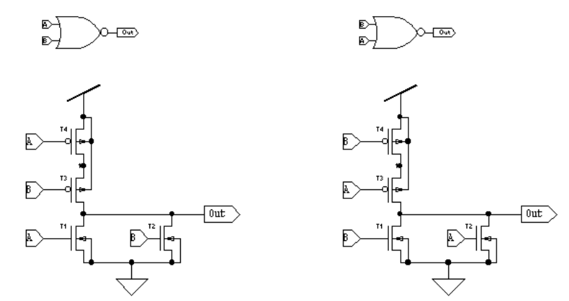
L-Edit 13 User Guide Section 3 799
Chapter 31: Netlist Comparison LVS Algorithms and Limitations
Avoiding Permuted Classes
The best way to avoid permuted classes is to standardize pin name assignments in both schematic and
layout design. Always assign A to the top pin or the pin closest to Vdd, for example, and B to the lower
pin or the pin closest to GND. Standardized pin name assignments such as these will prevent LVS from
generating permuted classes.
LVS Algorithms and Limitations
LVS uses an algorithm that repeatedly fractures the classes in an effort to generate a unique
classification of the elements and nodes in a netlist. This methodology has several important
advantages, but it also has a few limitations.
During the topological matching process, LVS continues to fragment elements and nodes into
increasingly smaller and more identifiable classes. In an ideal comparison, the iteration process ends
when each class has exactly two members whose features are known. The following diagrams illustrate
this procedure.
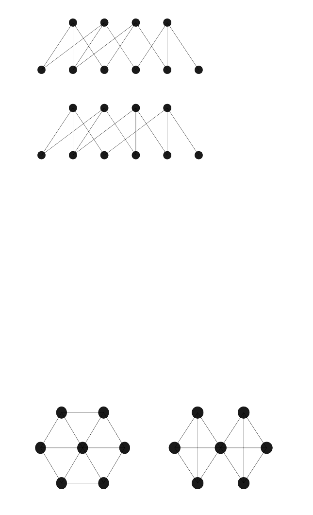
L-Edit 13 User Guide Section 3 800
Chapter 31: Netlist Comparison Resolving Discrepancies
L-Edit 13 User Guide Section 3 800
Chapter 31: Netlist Comparison Resolving Discrepancies
Notice that bulk nodes are not considered, and the two diagrams of the internal data structures are not
identical, indicating fragmented classes if LVS is run without series replacement.
There are several advantages to representing netlists in this way, including:
Isomorphism can easily be determined since each representation is unique for each circuit.
No knowledge of driving elements is required.
No knowledge of the elements and their pins is required.
There is easy recognition of shorts and opens.
One limitation to this type of netlist representation is that a highly symmetrical design will fail to
converge to fragmented classes, as in the diagram below. Exhaustive trial matching of all elements in
the second equivalent class yields no self-consistent partitions, and the data structures are not
isomorphic. The result, however, is correct.
Resolving Discrepancies
Resolving netlist comparison discrepancies can be a challenging process if the involved circuits are
large, because a single problem might create many automorph and/or fragmented classes. Here are a
few suggestions for resolving netlist comparison problems, which are applicable to the resolution of
both automorph and fragmented classes.
T1 T2 T3 T4
Vdd out A B M GND
T1 T2 T3 T4
Vdd out A B M GND
ED
F
B
C
G
A
54
6
2
3
7
1
L-Edit 13 User Guide Section 3 801
Chapter 31: Netlist Comparison Resolving Discrepancies
Liberally label the sources for your netlists. If you do not provide a name for a node or element,
LVS constructs one automatically, but the resulting name may be just a number, perhaps
concatenated onto another string. Even an LVS-generated identifier can be helpful, however—if
you recognize only a portion of a node or element name, you may still be able to identify the
problem.
If possible, recompare the netlists often. Sometimes identifying a single matching element or node
will provide LVS with enough information to complete the job. In other cases, a single problem
will create a very large fragmented class. Identifying one or two matching pairs from this class and
entering them into a prematch file will usually be sufficient for LVS to fracture the large
fragmented class into several smaller ones, thus giving you an easier task to perform.

L-Edit 13 User Guide Section 3 802L-Edit 13 User Guide Section 3 802
32 LVS Command-Line Syntax
Running LVS from the Command Prompt
You can invoke LVS from a DOS command prompt, specifying input and output files plus all
verification options on the command line, and achieve the same results as you would when running
LVS under Windows. Additionally, for batch-mode operation, LVS must be invoked from a DOS
command prompt.
To invoke LVS, change to the LVS directory on your hard disk, or make sure that the LVS directory is
in your path. Then enter the LVS command at the DOS prompt:
LVS [options] "netlist1" "netlist2"
netlist1 and netlist2 are the two netlist files to be compared. Specify the full path for any file not in the
current directory and enclose the entire filename and path in quotation marks.
Filenames and paths with spaces in them are legal, but depending on the DOS operating system version
you are using, arguments longer than 112 characters may not be allowed. Exceeding this length will
result in the error message “Unrecognized line argument” and termination of LVS processing.
options are command-line arguments, which provide additional operating instructions to LVS.
Each of these arguments is discussed in “Options” on page 803.
Batch-File Syntax
An LVS batch file will contain text similar to the following:
C:\Documents and Setings\username\My Documents\Tanner Tools vxx.yy\L-Edit
and LVS\LVS\Ex3>start /w../../../lvs ex3_1.spc ex3_2.spc -p ex3_1.pre -o
ex3_2.lvs -nrcl -vfar-fafr
Each verification listed in a batch file must begin with the command start /w. This command instructs
DOS to start LVS with the first set of options and wait for the program to exit before launching it again.
Without this command, only the first verification run listed in the batch file would succeed. LVS would
fail to run subsequent verifications.
Note that in contrast to the simple command-line example on the previous page, which lists options
before the netlist files, this batch-file example lists options following the netlist files. The command
File > Export Batch File uses this syntax in creating batch files, but in fact, either syntax is legal. If you
create a batch file directly in a text editor, you can list command-line options before or after the netlist
files. LVS accepts either syntax.
Running a Batch File
To run a batch file, enter the following command from a DOS command prompt:
3

L-Edit 13 User Guide Section 3 803
Chapter 32: LVS Command-Line Syntax Options
filename.bat
where filename.bat is the name of the batch file.
LVS will start up and run the verifications listed in the batch file. The program will create a
user-specified output file, as specified by the -o command-line option.
You can view the resulting output file using the LVS text window or any other text editor.
Note: LVS does not support launching of multiple instances. If you are running LVS under
Windows, you must first exit the program before running a batch file from the DOS
command line.
Options
Options are preceded by a dash or minus sign (-) and are separated by spaces. You can specify options
before or after the two netlist files—LVS accepts either syntax.
Where options have arguments, such as -cnnn, the option can be typed with or without a space between
the option and the argument—as -cnnn or -c nnn. LVS accepts either syntax.
Except where specifically noted, command-line options are case-insensitive.
Ignore Bulk Nodes (-b)
This option is the inverse of Consider bulk nodes (substrate) during iteration matching in the setup
window.
The -b option instructs LVS to ignore bulk (substrate) nodes on semiconductor devices during the
iteration matching process. (By default, LVS takes bulk nodes into consideration.) A typical digital
design will always have the bulk nodes of elements connected to power or ground. Ignoring the bulk
nodes while processing such files will reduce memory usage and increase processing speed.
The bulk node parameter is optional in the netlist input file. If you instruct LVS to consider bulk nodes
but all of the bulk nodes are not present in the netlists, the iteration process will result in fragmentation.
Consider Parameters (-cnnnn)
The -cnnnn option tells LVS what parametric information to consider during iteration matching and
trial matching. nnnn is a series of single-digit integers from the following list. This option corresponds
to the following options in the setup window (see “Setup—Device Parameters” (page 747).
1Consider resistance, capacitance, and inductance for R, C, and L
elements.
2Consider L and W for MOSFETs.
3Consider AS, AD, PD and PS for MOSFETs.
4Consider areas of B, D, J, and Q elements.
L-Edit 13 User Guide Section 3 804
Chapter 32: LVS Command-Line Syntax Options
For example, to consider resistance, capacitance and inductance; L and W; and NRD, NRS, NRG, and
NRB, use -c127.
Maximum Value Difference (-dv n)
This option corresponds to Maximum element-value tolerance in the setup window (see “Setup—
Device Parameters” (page 747).
The -dvn option, where n is a percent value between 0 and 100, defines the maximum amount two
parameter values may differ and still compare as equal. This value is often referred to as the slew rate.
The number is expressed as a percentage of the larger parametric value. The default is 5% (-dv5).
Noninteger values are permitted (for example, -dv4.5). This option takes effect only when the -c127
option is used.
For example, if element1 had a capacitance of 15.5 fF and element2 had a capacitance of 16.1 fF, they
would be considered equivalent with -dv4, but not with -dv3.
See also “Consider Parameters (-cnnnn)” on page 803.
Maximum Geometrical Difference (-dg n)
This option corresponds to Maximum geometric-value tolerance in the setup window (see “Setup—
Device Parameters” (page 747)).
The -dgn option works in exactly the same manner as -dvn, except that it operates on geometrical
comparisons, such as L and W for MOSFETs. The default value is 5% (-dg5). This option has an effect
only when the -c3456 option is used.
See also “Consider Parameters (-cnnnn)” on page 803.
Element Description File (-e "file")
This option corresponds to Element description file in the setup window (see “Setup—Input” (page
744).
The -e"file" option specifies the location of the element description file named file. Specify the full path
if needed, and enclose the entire filename and path in quotation marks. LVS recognizes standard SPICE
elements such as resistors, inductors, capacitors. If you use a nonstandard element, however, you will
need to define it in an element description file and use this option to instruct LVS to read in the file. The
netlist files can include elements described in the element description file by using them as a subcircuit
element.
Output File Display Options (-f[fapr])
These options control the amount of information included in the output file. They correspond to the
Display Options: Output file checkboxes in the setup window; see “Setup—Output” (page 745).
5Consider Z0 for T elements.
6Consider TD, F, and NL for T elements.
7Consider NRD, NRS, NRG, and NRB for MOSFETs.

L-Edit 13 User Guide Section 3 805
Chapter 32: LVS Command-Line Syntax Options
The -f[fapr] option instructs LVS to write processing information to the output file. Fragmented classes,
permuted classes, automorph classes, and detailed processing information can be saved using this
option. The flags f, a, p, and r may be included in any combination, as follows.
Granularity (-%g=n)
The -%g=n option controls the granularity of the percentages displayed while LVS is iterating. The
default is g = 5; LVS will report its progress to the screen in increments of 5%, based on the total
number of nodes and how many it has already processed. Setting g = 0 turns off the reporting.
Note: This option can only be set on the command line and will only affect the completion
percentage reported to the output file. Because LVS does not display the verification
window when run in batch mode, use of this option is inappropriate for that mode.
Flattened Schematic Netlist (-h "file")
This option corresponds to Flattened Schematic Netlist option in “Setup—Output” (page 745). The -h
“file” option writes a flattened version of the schematic netlist to a separate file named file. The
flattened netlist includes only the information that LVS will use to compare circuit descriptions.
Commands, comments, and ignored devices or parameters are omitted, and parallel or series elements
are merged as specified in the top portion of “Setup—Merge Devices” (page 748).
Note: If Merge series MOSFETs is selected on the Merge Devices tab, the flattened netlist
will not reflect collapsed series MOSFETs. To maintain SPICE compatibility, LVS
writes the flattened netlist before merging series MOSFETs.
fShow fragmented classes.
aShow automorph classes.
pShow permuted classes.
rShow detailed processing information:
Shows single-connection nodes.
If a prematch file is used (-p option), writes the prematched
elements to the output file, as well as those elements that the
program attempts to postmatch. This is useful for troubleshooting
netlists returned as not identical due to fragmentation after
automorphism or permutability.
If an element description file is used (-e option), lists subcircuits
that will not be flattened (i.e., those designated as special
elements).
Shows a summary of merged series or parallel devices. Logs
deletions of shorted and disconnected devices.
Lists parasitic devices that were removed or shorted.

L-Edit 13 User Guide Section 3 806
Chapter 32: LVS Command-Line Syntax Options
Fast Iteration (-i)
This option corresponds to Fast iteration: consider fanout only in the setup window; see “Setup—
Performance” (page 754).
The -i option instructs LVS to perform a fast iteration. By default LVS considers fanout and element
types when performing topological iteration, but specifying -i instructs LVS to consider only fanout
during this process.
Specifying -i increases the speed of the iteration process preparation, where LVS forms the initial
element and node classes. When performing a single verification, LVS would normally prompt the user
for permission to continue iteration on detection of a mismatch in the element or node count at this
point. In batch mode, however, LVS would always continue iteration even on an element or node count
mismatch. Therefore, specifying -i is inappropriate for batch-mode operation.
Delete Disconnected Devices (-k)
This option corresponds to Delete Disconnected Devices in the setup window; see “Setup—Merge
Devices” (page 748).
The -k option instructs LVS to delete disconnected devices, which are defined as follows:
List Elements and Nodes (-l "file")
This option corresponds to Node and element list in the setup window (see “Setup—Input” (page
744).
The -l option instructs LVS to list the nodes and elements into a file of the specified name. Specify the
full path if you wish to create this file in a directory other than the current directory.
Warning: This option will typically create a very large output file if the input circuits are even of moderate
complexity.
Merge Devices (-mdevice {ALL | model_list})
This set of options corresponds to the top portion of the Setup—Merge Devices dialog; see “Setup—
Merge Devices” (page 748).
The -m option instructs LVS to merge series or parallel devices of the same model into equivalent single
devices. You can specify the models that LVS will consider for merge operations, or you can apply the
merge option to all models of the specified device type.
MOSFETs A MOSFET is considered disconnected if both of the following
conditions are true:
The gate terminal is not connected to any other device, and
At least one source/drain terminal is not connected to any other
device.
Other device types All other device types are considered disconnected if at least one
terminal is not connected to any other device.
L-Edit 13 User Guide Section 3 807
Chapter 32: LVS Command-Line Syntax Options
For example,
-mr ALL
instructs LVS to merge instances of the same resistor model and occur in parallel or in series.
The option:
-mm /M_n1//M_p1/
instructs LVS to merge parallel n1 MOSFETs and to merge parallel p1 MOSFETs. In this case, only
MOSFETs of the n1 or p1 models can be merged; LVS leaves other MOSFET models in their original
configuration.
Each -m option corresponds to exactly one device type. To set multiple merge options, you must enter
the -m option for each relevant device type. For example:
-mr ALL -mc /C_cap1/ -md ALL ...
Arguments for the -m option are defined in the following table:
Merging Nonpolarized Devices
LVS can treat r, l, and c devices as either polarized or nonpolarized elements, as specified by the -n
option on the command line. If -n (nonpolarized treatment of r, l, and c elements) is specified, a circuit
may contain devices that can be merged in more than one way. Consider the following example:
device Device type for which you are specifying the merge option. Each
device type is represented by its letter abbreviation:
r — resistors (parallel and series)
l — inductors (parallel and series)
c — capacitors (parallel and series)
b — GaAsFETs (parallel)
d — Diodes (parallel)
j — JFETs (parallel)
m — MOSFETs (parallel)
q — BJTs (parallel)
z — MESFETs (parallel)
ALL Instructs LVS to merge devices that are instances of the same model
when they occur in parallel. For r, l, and c device types, LVS also
merges series devices of the same model.
model_list List of models that can be considered for merge operations. The name
of each model must be prefixed with the key letter of the device type,
followed by an underscore. Type a slash (/) at the beginning and end
of each model name. For example,
-md /d_d1//d_d2//d_d3/
specifies diode models d1, d2, and d3.

L-Edit 13 User Guide Section 3 808
Chapter 32: LVS Command-Line Syntax Options
C1 A B C=30pF
C2 B A C=30pF
R1 A GND 12k
It is assumed here that even if this is part of a much larger circuit node, node B has only two pins.
Merging the capacitors in series, we can replace C1 and C2 with a single capacitor C3 with an
equivalent capacitance of 15 pF:
C3 A A C=15 pF
R1 A GND 12k
Alternately, the two capacitors C1 and C2 could be considered to be in parallel, since nodes A and B are
interchangeable on a nonpolar device. In this case, merging the two parallel capacitors gives:
C3 A B C=60pF
R1 A GND 12k
Both of these are equally valid ways to merge devices. With the -n option, LVS may use two different
approaches to merge devices in the two netlists being compared. This will certainly result in
fragmentation, as the two resulting topologies are completely different. If treating elements as
nonpolarized will create ambiguous configurations, you should not use the -n option.
Nonpolarized Elements (-n[rcl])
These options correspond to the following options in “Setup—Input” (page 744):
Consider resistors as polarized elements
Consider capacitors as polarized elements
Consider inductors as polarized elements
The -n[rcl] option instructs LVS to consider resistor, capacitor, and/or inductor elements as
nonpolarized. LVS treats the two terminals of a nonpolarized element as interchangeable during the
matching process. If this option is not specified, LVS considers these elements to be polarized; that is,
the two terminals of such an element are considered topologically different during the matching
process.
The arguments r, c, and l specify which elements LVS is to consider as nonpolarized (r=capacitors,
l=inductors, and c=resistors). Specifying -n without an additional argument instructs LVS to consider
all these elements as nonpolarized; specifying -nrcl achieves the same result.
Note: In some circuits, use of the -n option may create multiple possibilities for merging
devices, leading to fragmentation. These circuits are described in “Merging
Nonpolarized Devices” on page 807.
Output file (-o"file")
This option corresponds to the Output file option in “Setup—Output” (page 745). The -o "file" option
(lowercase o required) creates a separate output file named file.
Note: In batch-mode operations, LVS does not write results to the verification window.
Therefore, an output file is required to preserve verification results.

L-Edit 13 User Guide Section 3 809
Chapter 32: LVS Command-Line Syntax Options
L-Edit 13 User Guide Section 3 809
Chapter 32: LVS Command-Line Syntax Options
Prematch File (-p "file")
This option corresponds to Prematch file in the setup window (see “Setup—Input” (page 744)).
The -p"file" option instructs LVS to equate the elements and nodes listed in the prematch file named file
before beginning the iterative matching process. Specify the full path if this file will not be created in
the current directory.
The prematch file is a text file created by the user to equate certain elements and nodes before LVS
begins its processing. For further information, see “Prematch File Format” on page 782.
Input SPICE Syntax (-pspice, -phspice, -hpspice)
These options correspond to the SPICE format options for Layout netlist and Schematic netlist in the
setup window; see “Setup—Input” (page 744). The default syntax mode for input files is
T-Spice/H-Spice. If either input file is in P-Spice syntax, you must specify one of the following options:
Merge Series MOSFETs (-r {ALL | model_list})
The -r option corresponds to the Merge series MOSFETs option, and the [s] option corresponds to Find
series MOSFETs that differ in order. Both options are found in “Setup—Merge Devices” (page 748).
The -r[s] option allows LVS to replace series chain MOSFETs (of a particular model) with equivalent
components, which reduces the processing required. (Instances of two or more different MOSFET
models are never merged.) This feature is intended only for fully digital designs, and is not meant for
netlists representing analog designs. The inclusion of the [s] flag instructs LVS to identify functionally
equivalent groups of series MOSFETs that are ordered differently in the two netlists.
Note: Series MOSFETs that differ in order are also called permuted classes. See “Permuted
Classes in Digital Designs” on page 798 for further discussion.
Arguments for the -r[s] option are:
-pspice Both input files are in P-Spice format.
-phspice The layout netlist is in P-Spice format, and the schematic netlist is in
T-Spice/H-Spice format.
-hpspice The layout netlist is in T-Spice/H-Spice format, and the schematic
netlist is in P-Spice format.
ALL Instructs LVS to merge series chain MOSFETs that are instances of
the same model.
L-Edit 13 User Guide Section 3 810
Chapter 32: LVS Command-Line Syntax Options
Remove Parasitics (-s test=value)
This option corresponds to the options in “Setup Window—Parasitics” (page 750). The -s option
specifies a criterion by which LVS can identify parasitic devices to remove or short.
Arguments for this option include:
For example, the options:
-srmin=10 -srmax=0.01p
instruct LVS to short and remove resistors with resistances less than 10 Ohms, and to remove capacitors
with capacitances greater than 0.01 pF. Use a separate -s option to specify each threshold value.
Flattened Layout Netlist (-t"file")
This option corresponds to Flattened Layout Netlist option in “Setup—Output” (page 745). The -t
"file" option writes the flattened version of the layout netlist to a separate file named file. The flattened
netlist includes only the information that LVS will use to compare circuit descriptions. Commands,
comments, and ignored devices or parameters are omitted, and parallel or series elements are merged as
specified in the top portion of “Setup—Merge Devices” (page 748).
model_list List of models that can be considered for merge operations. When this
list is given, LVS only merges series MOSFETs when they are
instances of one of the listed models.
The name of each model must be prefixed with the key letter of the
device type (m), followed by an underscore. Type a slash (/) at the
beginning and end of each model name. For example,
-r /m_n1//m_n2//m_p1/
specifies MOSFET models n1, n2, or p1 for merge operations.
test Choose one of the following options, which correspond to the
checkboxes in “Setup Window—Parasitics” (page 750):
rmin — For every resistor with resistance less than or equal to
the specified value, LVS removes the resistor and connects
(shorts) the two nodes that were spanned.
rmax — Removes any resistor with resistance greater than or
equal to the specified value.
cmin — Removes any capacitor with capacitance less than or
equal to the specified value.
cmax — For every capacitor with capacitance greater than or
equal to the specified value, LVS removes the capacitor and
connects (shorts) the two nodes that were spanned.
value Maximum or minimum value of the device parameter specified in
test.

L-Edit 13 User Guide Section 3 811
Chapter 32: LVS Command-Line Syntax Options
Note: If Merge series MOSFETs is selected on the Merge Devices tab, the flattened netlist
will not reflect collapsed series MOSFETs. To maintain SPICE compatibility, LVS
writes the flattened netlist before merging series MOSFETs.
Remove Device Models (-u /model1//model2//.../)
This option corresponds to the option Remove device models named: in “Setup Window—
Parasitics” (page 750). The -u option instructs LVS to remove all instances of the listed device models
from the input netlists.
Each device model name must be prefixed by the key letter for that device type, followed by an
underscore. Each device model name must also be enclosed in forward slashes (/). For example,
-u /M_n1//C_cap/
instructs LVS to remove instances of the MOSFET model n1 and of the capacitor model cap.
Screen Display Options(-v[fpar])
These options control the amount of information displayed on the screen. They correspond to the
Display Options: Screen checkboxes in the setup window; see “Setup—Output” (page 745).
The -v[fapr] option instructs LVS to display processing information on the screen. Fragmented classes,
permuted classes, automorph classes, and detailed processing information can be displayed using this
option. The flags f, a, p, and r may be included in any combination, as follows.
Note: These options instruct LVS to display processing information to the verification
window. Because LVS does not display the verification window when run in batch
mode, use of these options is inappropriate for that mode.
fShow fragmented classes.
aShow automorph classes.
pShow permuted classes.
rShow detailed processing information:
Displays single-connection nodes.
If a prematch file is used (-p option), LVS writes the prematched
elements to the screen, as well as those elements that the program
attempts to postmatch. This is useful for troubleshooting netlists
returned as not identical due to fragmentation after
automorphism or permutability.
If an element description file is used (-e option), LVS lists
subcircuits that will not be flattened (i.e., those designated as
special elements).
Displays a summary of merged series or parallel devices. Logs
deletions of shorted and disconnected devices.
Lists parasitic devices that were removed or shorted.
L-Edit 13 User Guide Section 3 812
Chapter 32: LVS Command-Line Syntax Options
Delete Shorted Devices (-x)
This option corresponds to the Delete shorted devices option in “Setup—Merge Devices” (page 748).
The -x option instructs LVS to delete shorted devices, in which all device terminals are connected
together.
Yes to All Questions (-y[12])
The -y[1] option corresponds to Continue on element/node count mismatch, while the -y[2] option
corresponds to Detailed trial matching to resolve automorph classes. Both are located in “Setup—
Performance” (page 754).
The -y option without any arguments is equivalent to -y12. This instructs LVS to answer “yes” to all
program prompts.
Short Out Device Models (-z /model1//model2//.../)
This option corresponds to the option Short out device models named: in “Setup Window—
Parasitics” (page 750). The -z option instructs LVS to short the terminals of the indicated devices, then
remove these devices from the netlist.
Each device model name must be prefixed by the key letter for that device type, followed by an
underscore. Each device model name must also be enclosed in forward slashes (/). For example,
-z /R_res//C_cap/
instructs LVS to short and remove instances of the resistor model res and of the capacitor model cap.

L-Edit 13 User Guide Section 3 813
Chapter 33: LVS Glossary
33 LVS Glossary
automorph class
A class with an even number of four or more members, half from each netlist, in which there is
insufficient information to further resolve the class. The members may be identical, but
additional information (such as parameters) may be necessary to differentiate the members.
batch file
A text file containing one or more command-line invocations of LVS and appropriate setup
information—input files and verification options—for each verification run.
class
A set of elements or nodes with something in common, such as topological or parametric
characteristics. Types of classes include automorph, fragmented, and permuted.
detailed trial matching
A process used by LVS to try to resolve automorph classes. LVS assigns a matching pair of
members and continues the iteration process from that match.
element
Any type of logic or circuit component (transistor, resistor, or capacitor).
element description file
A text file that describes specialized or custom elements which are used in the design but not
recognized by LVS.
fragmented class
A class with a different number of members from each netlist. This type of class is usually the
result of one or more design errors.
netlist
A textual description of the connectivity of a design.
node
An electrical connection between one or more ports, labels, or wires.
node and element list
A text file that contains lists of all the matching and unresolved nodes and elements in the two
netlists being compared. The lists are broken down by each LVS iteration.
parameters
Information in a netlist about each element and node in addition to topological characteristics.
For example, node capacitance and element size.
3
L-Edit 13 User Guide Section 3 814
Chapter 33: LVS Glossary parameter matching
parameter matching
The process of using parameters in addition to topological characteristics to differentiate
members of a class.
permuted class
A class containing series chain MOSFETs whose terminals are functionally equivalent, but in
a different order, in the designs being compared. Occurs in digital designs during the optional
replacement of series chain MOSFETs with equivalent components.
prematch file
A user-supplied text file that lists the equivalent members of an automorph class.
resolution
Classes are resolved when their members are matched (through detailed trial matching or
another process). Occurs when the members of a netlist are equivalently matched to the
members of the other netlist.
SPICE
A netlist format commonly used for circuit simulation or comparison.
slew rate
The maximum percentage by which two parameter values may differ and still compare as
equal.
topological characteristics
Information in a netlist regarding element type and connectivities of each element and node.
topological matching
The default LVS iteration process that uses topological characteristics to match elements and
nodes.
verbosity level
The amount of information displayed in the verification window during a verification run.
verification queue
A dialog that contains a list of consecutive verification runs.
verification run
The set of iterations LVS executes to compare netlists.
verification setup
Information required for an LVS verification run, including input and output files and
verification options. The information is entered in the setup dialogs and can be saved in a
verification database file.

L-Edit 13 User Guide Section 4 815
34 Introduction to Programming the
User Interface
Introduction
The L-Edit User-Programmable Interface (UPI) provides tools for automating, customizing, and
extending the L-Edit command and function set, adding enormously to its power and flexibility.
UPI is based on C-language macros that describe actions or sets of actions to be performed
automatically. Macros can draw from a large number of available functions, variables, and data types to
specify and modify the whole range of L-Edit operations.
How UPI Works
UPI can access macros as text files containing raw C code or as compiled dynamically linked libraries
(DLLs). Sets of macros can be loaded together or accessed individually.
UPI handles macros in four steps:
Loading. Macros are loaded in units of files. A macro file consists of one or more C-language
macro routines.
Registration. Macros are identified for use within L-Edit.
Binding (optional). Each macro is associated with a keyboard shortcut and/or a menu command.
Execution. L-Edit runs the macro.
Macros are written using UPI function calls, then loaded and run via the macro interface. The macro
interface also allows you to specify the UPI operating modes and interpreter setup options.
For more information on the UPI function calls, see the “UPI Functions Reference” on page 840.
Section 4Section 4: User-Programmable Interface
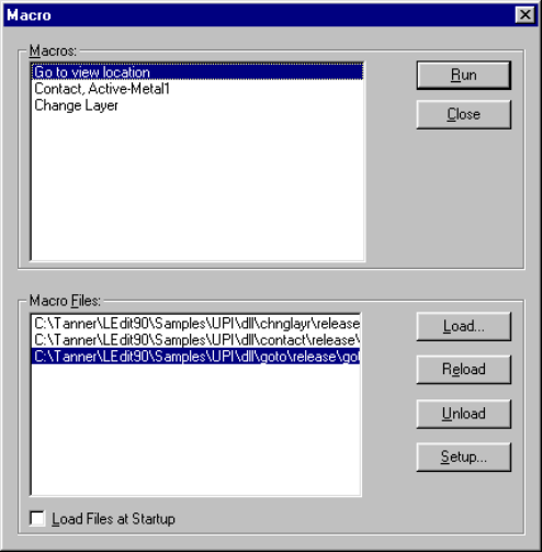
L-Edit 13 User Guide Section 4 816
Chapter 34: Introduction to Programming the User Interface How UPI Works
Macro Interface
The Macro dialog allows you to create, edit, and run macros, and set the UPI operating mode. Choose
Tools > Macro to open the Macro dialog.
Options include:
Macros The list of registered macros. Click on a macro to select it.
Macro Files The name and complete paths of all loaded macro files. Click on a
macro file to select it.
Load Files at Startup When this box is checked, the Macro Files listed are loaded when the
application is started.
Run Executes the macro highlighted in the Macros list.
Close Closes the Macro dialog.
Load Invokes the Open dialog to load a macro file and add it to the Macro
Files list.
Reload Reloads the selected macro.
Unload Unregisters all macros defined in the highlighted macro file and
unloads the file from memory.
Setup Opens the Setup Application—UPI dialog for specifying the
interpreter setup parameters. See “UPI” on page 87 for further
information.
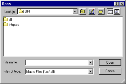
L-Edit 13 User Guide Section 4 817
Chapter 34: Introduction to Programming the User Interface How UPI Works
Loading a Macro
Clicking Load in the Macro dialog calls the Open dialog.
You can add a macro in one of two ways:
As C code which must be interpreted
As a compiled, dynamic-link library (DLL).
The difference between a C macro file and a DLL is in the speed of loading and execution. A C file
must be interpreted before its macros will appear in the Macros list of the Macro dialog. L-Edit has a
built-in C interpreter.
A DLL, however, is directly loaded into memory and all the macros appear in the Macros list
immediately. You can create a C macro with any text editor. To create a DLL macro, however, you
must use a C/C++ compiler such as Microsoft Developer Studio.
Interpreter Setup
Before running an interpreted macro, you must first set a path to the header files that L-Edit uses to
interpret a macro. You can also specify what graphics and dialogs will appear while UPI executes.
To perform these tasks, click Setup in the Macro dialog. Alternately, you can choose
Setup > Application. When L-Edit displays the Setup Application dialog, click the UPI tab:
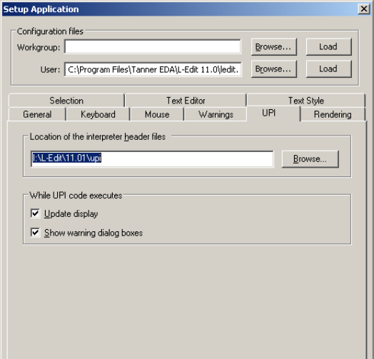
L-Edit 13 User Guide Section 4 818
Chapter 34: Introduction to Programming the User Interface UPI Include Files
Options include:
UPI Include Files
The directory <installdir>\upi\Interpreted_Include contains a number of header files required by the
L-Edit C interpreter. The L-Edit C interpreter only supports the functions defined in these header files.
The file ldata.h is a standard UPI include file that contains function prototypes of all UPI functions,
including definitions of the “Interface Functions” (page 843). The file ldata.h also contains definitions
of all the supported hot key combinations.
Location of the interpreter
header files The complete path of the directory containing the L-Edit interpreter
header files. Clicking Browse next to this field calls a standard
Windows directory browser.
Note: The path name in this field is limited to a maximum of 75
characters. Therefore, you should not keep interpreter header
files in highly nested subdirectories.
Update display When checked, L-Edit updates the display while UPI code is
executing. When unchecked (default), L-Edit does not update the
display during the execution of a macro or T-Cell generator.
Show warning dialog
boxes When checked (default), L-Edit displays warning dialog boxes in the
user interface. When unchecked, L-Edit runs in quiet mode, in which
warning dialog boxes are not displayed.
Note: Batch processing must be run in quiet mode.
L-Edit 13 User Guide Section 4 819
Chapter 34: Introduction to Programming the User Interface Running an Interpreted (.c) Macro
The files ctype.h, malloc.h, math.h, stdarg.h, stdio.h, stdlib.h, string.h, and time.h are L-Edit
versions of standard C language header files.
The files upistub.c and upistub.h are required by the L-Edit C interpreter.
Running an Interpreted (.c) Macro
The following procedure explains how to run an interpreted macro.
;Start L-Edit.
;Use File > Open to open <installdir>\Samples\UPI\upisampl.tdb.
;Select Tools > Macro to open the Macro dialog.
;Click Setup to specify interpreter parameters (the locations of the header and log files).
;Click Load and select a macro file with a .c extension. For example, load the file
<installdir>\Samples\UPI\intrpted\mosfet\mosfet.c. This macro prompts the user for MOSFET
parameters and then draws the corresponding NPN MOSFET in L-Edit.
;Select the macro from the Macros list and click Run, or double click on the macro name in the dialog to
execute it.
You can modify mosfet.c in any text editor.
Running a Compiled (.dll) Macro
This procedure explains how to run a compiled macro.
;Start L-Edit.
;Use File > Open to open <installdir>\Samples\UPI\upisampl.tdb.
;Select Tools > Macro to open the Macro dialog.
;Click Load and select a macro file with a .dll extension. For example, load the file
<installdir>\Samples\UPI\dll\resistor\release\resistor.dll. This macro draws a resistor in L-Edit using
user-specified parameters.
;Select the macro Draw Resistor Geometry from the Macros list and click Run (or double click on the
macro name in the dialog) to execute it.
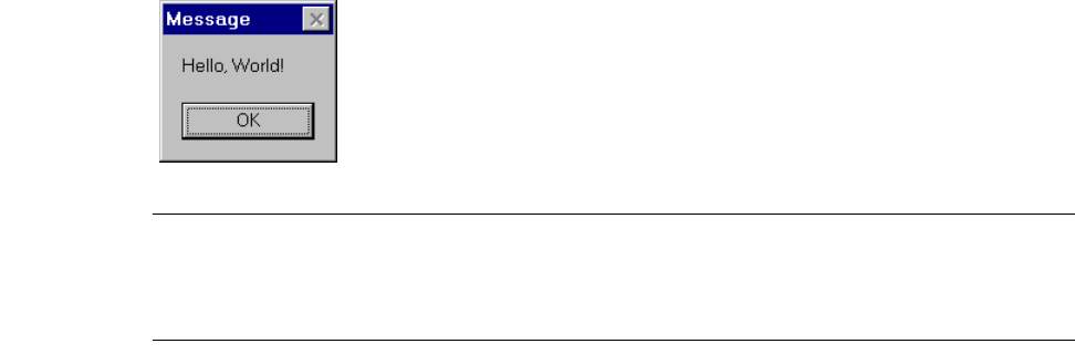
L-Edit 13 User Guide Section 4 820
Chapter 34: Introduction to Programming the User Interface Interpreted Macro Example
Interpreted Macro Example
This section reviews the structure and content of a simple interpreted UPI application called Hello,
World!. The C code for Hello, World! is provided in
<install_dir>\Samples\UPI\intrpted\hworld\hello.c. This application displays a message box like the
one shown here:
Note: You can create and edit an interpreted macro in any text editor. To begin, launch the
text editor of your choice and open a new file. To create a text file in L-Edit, select
File > New and choose Text from the File Type list. Click OK to open a new text
window.
Module Outline
An interpreted macro file consists of two sections:
A an application module containing macro function definitions.
A call to the macro registration function, which is defined within the application module.
In outline form, the code for an interpreted UPI application has the following structure:
module <modulename> {
<include files>
<macro function 1 >
<macro function 2 >
<macro function 3 >
.
.
.
<macro registration function>
}
<call to macro registration function>
The first line contains the module name. The module name should be unique so that it will not replace
another module loaded at the same time. In hello.c, the module name is Hello_World_module.
To access UPI function definitions, the module definition must include the header file ldata.h. Other
required header files should also be included at the beginning of the module definition. (For information
about header files, see “UPI Include Files” on page 818.)
The module outline for Hello, World! is as follows:
module Hello_World_module {
L-Edit 13 User Guide Section 4 821
Chapter 34: Introduction to Programming the User Interface Interpreted Macro Example
#include “ldata.h”
<Macro function to display message box>
<Macro Registration function>
}
<Call to macro registration function>
Displaying a message box
“LDialog_MsgBox” (page 845) is a UPI function that displays a message box containing the specified
text. In this example, the macro function HelloWorldMacro invokes LDialog_MsgBox to show the
string “Hello, World!” in a message box.
void HelloMacro( void )
{
LDialog_MsgBox ( “Hello, World!” );
}
Registering the function as a macro
To complete a module definition, you must register the defined macro function(s) in a macro
registration function. The macro registration function for the module Hello_World_module consists of
the following code:
void hello_world_macro_register ( void )
{
LMacro_Register ( “Hello, World!”, “HelloMacro” );
}
The function hello_world_macro_register registers the function HelloWorldMacro as an available
macro. “LMacro_Register” (page 868) registers a macro name that will be displayed in the Macros list
of the Tools > Macro dialog and associates this name with the specified function. In this example,
LMacro_Register associates the name Hello, World! in the Macro dialog with the macro function
HelloWorldMacro.
If a module includes multiple user macro functions, the macro registration function should register each
of them individually using multiple LMacro_Register function calls.
The complete code for the Hello, World! macro is shown below. Note that the last line of the macro file
calls the macro registration function.
module Hello_World_module {
#include “ldata.h”
void HelloMacro( ) {
LDialog_MsgBox ( “Hello, World!” );
}
void hello_world_macro_register ( void ){
LMacro_Register ( “Hello, World!”, “HelloMacro” );
}
}
hello_world_macro_register();
L-Edit 13 User Guide Section 4 822
Chapter 34: Introduction to Programming the User Interface Creating a Compiled Macro (DLL)
Save your code using the .c filename extension. Use this extension whenever you name a macro file that
you want L-Edit to recognize as an interpreted macro.
Creating a Compiled Macro (DLL)
This example illustrates a compiled UPI macro that draws an Active-to-Metal contact at the current
mouse location. In the steps that follow you will learn how to compile the UPI macro and bind it to a hot
key.
Creating a compiled macro is similar to creating an interpreted one, with one additional step—
compiling the DLL. That makes a total of five steps to create the Active-to-Metal DLL:
In outline form, the code for a compiled UPI macro has the following structure:
<include files>
<macro function 1 >
<macro function 2 >
<macro function 3 >
.
.
.
<UPI_Entry_Point function>
The code for the Active-to-Metal DLL is saved in your installation directory as
<install_dir>\Samples\UPI\dll\contact\contact.c. The complete code for the Active-to-Metal macro is
as follows:
#include “ldata.h”
void Contact_Active_Metal1_Macro ( )
{
LCell Cell_New = LCell_GetVisible ( );
LFile File_New = LCell_GetFile ( Cell_New );
LLayer Layer_Active = LLayer_Find ( File_New, “Active” );
LLayer Layer_Metal1 = LLayer_Find ( File_New, “Metal1” );
LLayer Layer_ActCnt = LLayer_Find ( File_New, “ActiveContact” );
LLayer Layer_N_Sel = LLayer_Find ( File_New, “N Select” );
LPoint Point_Cursor = LCursor_GetPosition ( );
LCoord X, Y;
X = Point_Cursor.x;
Y = Point_Cursor.y;
LBox_New ( Cell_New, Layer_ActCnt, -1 + X, -1 + Y, 1 + X, 1 + Y );
Box_New ( Cell_New, Layer_Metal1, -2 + X, -2 + Y, 2 + X, 2 + Y );
Box_New ( Cell_New, Layer_Active, -3 + X, -3 + Y, 3 + X, 3 + Y );
LBox_New ( Cell_New, Layer_N_Sel , -5 + X, -5 + Y, 5 + X,5 + Y );
}
int UPI_Entry_Point( void )
{
LMacro_BindToHotKey ( KEY_F1, “My Contact,
Active-Metal1”, “Contact_Active_Metal1_Macro” );
return 1;
}
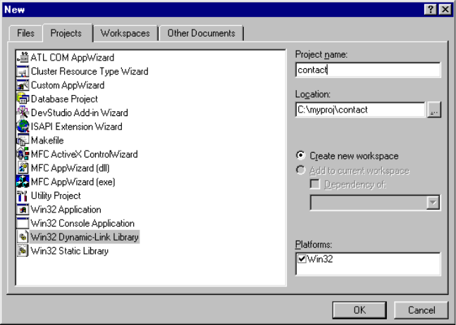
L-Edit 13 User Guide Section 4 823
Chapter 34: Introduction to Programming the User Interface Creating a Compiled Macro (DLL)
Save this code as contact.c and compile it as contact.dll.
Compiling the DLL
This section describes how to compile your C-language macros as DLLs. The lesson includes an actual
example of compiling a DLL.
To compile a DLL, you will need a C/C++ compiler such as Microsoft Visual C++ installed on your
system. These instructions are for Microsoft Visual C++ version 6.0. If you have not already installed it,
do so now.
Create a new project
;Start Microsoft Visual C++.
;Select File > New. Click the Projects tab and set the following options:
Select Win32 Dynamic Link Library as the project type.
Type contact as the Project name. The subdirectory C:\myproj\contact will be created.
Make sure the Create New Workspace option is selected.
;Click OK.
;In the Win32 Dynamic-Link Library wizard, select An empty DLL project. Click Finish.
;A New Project Information dialog will confirm the new project settings. Click OK to close this dialog.
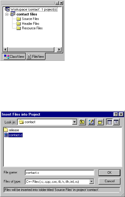
L-Edit 13 User Guide Section 4 824
Chapter 34: Introduction to Programming the User Interface Creating a Compiled Macro (DLL)
Add project source files
;Select the File View option in your Workspace window. Your current project should contain the
directories shown below.
;Right-click Source Files in the Projects tree and select Add Files to Folder from the pop-up menu.
;In the Insert Files into Project dialog, navigate to the directory <installdir>\Samples\UPI\dll\contact
and select contact.c.
;Click OK to add the source file contact.c to your current project.
;Next, create a definition file. Right-click Source Files in the Projects tree again and select Add Files
to Folder from the pop-up menu.
;In the Insert Files Into Project dialog, change the Files of Type field to Definition Files (.def).
;Navigate to the <installdir>\Samples\UPI\dll\contact directory and select contact.def. Click OK.
Specify include and library file directories
;Select Tools > Options and perform the following actions:
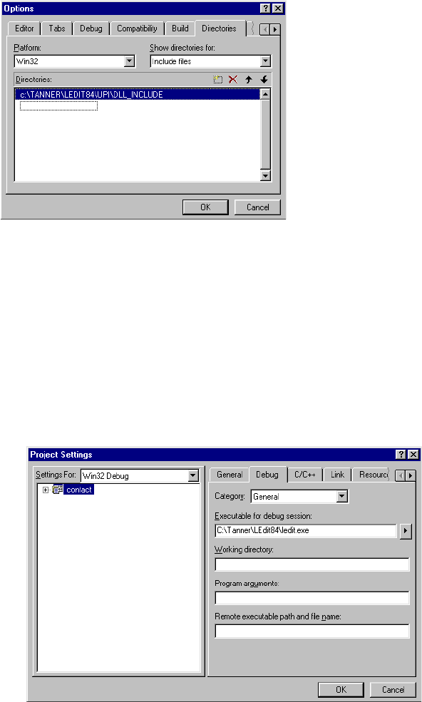
L-Edit 13 User Guide Section 4 825
Chapter 34: Introduction to Programming the User Interface Creating a Compiled Macro (DLL)
Click the Directories tab. Click the drop-down menu Show directories for and select Include
files. In the Directories list, select <installdir>\upi\DLL_include.
Click the drop-down menu Show directories for and select Library files. In the Libraries list,
select <installdir>upi\DLL_include to access upilink.lib.
Click OK.
Set Project Settings
;Select Project > Settings and perform the following actions:
Click the Debug tab. In the field Executable for debug session, enter <installdir>\ledit.exe. (For
example, C:\Tanner\LEdit83\ledit.exe.)
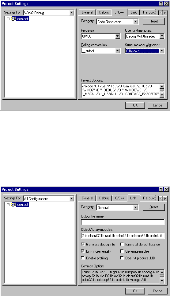
L-Edit 13 User Guide Section 4 826
Chapter 34: Introduction to Programming the User Interface Creating a Compiled Macro (DLL)
Click the C/C++ tab. From the Category drop-down menu, select Code Generation. Set processor
to 80486. Set Calling convention to __stdcall. Set Struct member alignment to 8 bytes.
From the Category drop-down menu, select General. In the Settings for list, select All
Configurations. Add /Tp at the end of Project Options. This instructs the compiler to run .c files
through the C++ compiler.
From the Category drop-down menu, select Preprocessor. Add MAKE_DLL to the Preprocessor
definitions list. Setting for should still be set to All Configurations.
Select All Configurations. Click the Link tab. Make sure that Object/library modules has
upilink.lib at the end for both the Win32 Debug and Win32 release versions.
Click OK to close the Project Settings dialog.
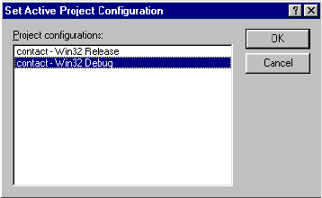
L-Edit 13 User Guide Section 4 827
Chapter 34: Introduction to Programming the User Interface Binding Macros to Hot Keys
Build the DLL
;Select Build > Set Active Configuration from the menu. In the Set Active Project Configuration
dialog, select Win32 Debug version and click OK.
;Select Build > Build contact.dll to compile your DLL.
You have just learned how to create and compile a macro DLL. In the next lesson, you will learn how to
bind your macro to a hot key.
Binding Macros to Hot Keys
You can modify the L-Edit user interface so that you can execute your macro from a hot key or a menu
item as well as from the Macro dialog. The process is known as binding the macro to a hot key or menu
item.
You bind a macro to a hot key using “LMacro_BindToHotKey” (page 869). This function registers the
macro and binds it to the specified hot key.
For example, the code:
LMacro_BindToHotKey ( KEY_F1, “Contact, Active-Metal1”,
“Contact_Active_Metal1” );
binds the macro Contact, Active-Metal1 to the F1 key.
All the allowed key codes are defined in ldata.h.
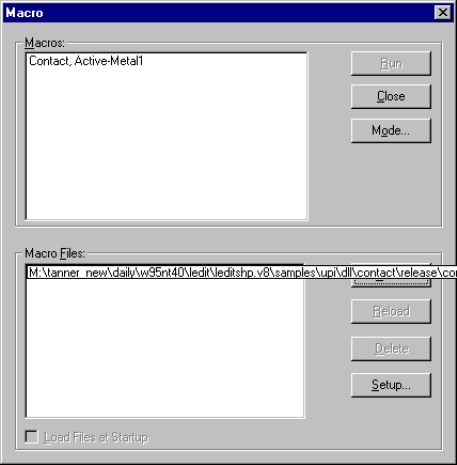
L-Edit 13 User Guide Section 4 828
Chapter 34: Introduction to Programming the User Interface Binding Macros to Menu Items
When a function contains this call, it will appear in the Macro dialog in this way:
In this example, the macro Contact, Active-Metal1 is bound to the F1 key. The macro thus overwrites
the previous F1 key binding, if any exists. To view key bindings for all macros, use “Keyboard
Customization” (page 84).
Binding Macros to Menu Items
This section describes how to make your macro accessible as an L-Edit menu command. This process is
called binding the macro to the menu item.
The UPI function “LMacro_BindToMenu” (page 870) will register the macro and bind it to a
user-specified menu item.
void LMacro_BindToMenu( char *menu, char *macro_desc, void *function);
For example, the following command will bind Contact_Active_Metal1 to the Tools menu.
LMacro_BindToMenu ( “Tools”, “My Contact, Active-Metal1”,
“Contact_Active_Metal1” );
Debugging Interpreted Macros
Here are some useful hints for debugging an interpreted macro:
Make sure that the interpreter header file location is properly set. You set the header file location
using the Setup Application dialog—see “Interpreter Setup” on page 817.
L-Edit 13 User Guide Section 4 829
Chapter 34: Introduction to Programming the User Interface Debugging Compiled Macros
Make sure the C-library functions in your code are present in the header files specified in the
Interpreter Setup dialog. If they are not present, L-Edit will not be able to interpret your code.
Make sure you have proper permissions to the directory where you create your log file.
Debugging Compiled Macros
Here are some useful hints for debugging a compiled macro:
Compile the DLL with debugging symbols.
Set a break point in the macro function definition in the DLL.
When you execute the macro, the debugger will stop at UPI_Entry_Point() function.
Although you cannot step through the UPI functions, you can see the parameters that are passed and the
entire control flow of the macro DLL.
The following example illustrates the key steps you would use to debug contact.dll in Microsoft Visual
C++.
;In the Projects tree, double-click on Source Files/contact.c to open the macro source code.
;Place the cursor on the first line of the function definition for Contact_Active_Metal1_Macro:
LCell Cell_New = LCell_GetVisible ( );
;Right-click and select Insert/Remove Breakpoint from the pop-up menu. A red circle will appear in the
left margin to indicate a breakpoint. Select File > Save Workspace to save your changes.
;Follow the instructions in “Compiling the DLL” on page 823 to compile contact.dll. Make sure that
you set Build > Set Active Configuration to Win32 Debug to include debugging symbols.
;To begin debugging, select Build > Start Debug > Go. L-Edit will automatically be launched.
;In L-Edit, run the debug version of your DLL as follows:
Select Tools > Macro from the L-Edit menu.
In the Macro dialog, click Load to open a macro file. Navigate to C:\myproj\contact\Debug and
select contact.dll. Click Open.
In the Macro dialog, select Contact, Active-Metal1 from the list of Macros and click Run.
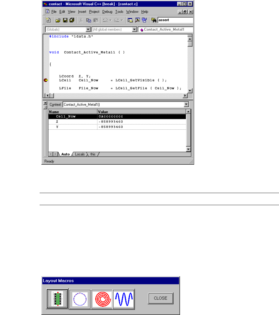
L-Edit 13 User Guide Section 4 830
Chapter 34: Introduction to Programming the User Interface Creating a Layout Palette
;In Microsoft Visual C++, parameter names and values are shown at the defined breakpoint:
;To continue to the next line of source code, select Debug > Step Over.
Note: You cannot step into the source code for individual UPI functions.
Creating a Layout Palette
In this section, you will learn to create a layout palette that always stays on screen. To follow this
lesson, you will need some knowledge of the Windows application programming interface (API).
Each button on this layout palette represents a user macro that creates layout geometry such as a
MOSFET, spiral, or gear.
The layout palette is called a modeless dialog because it can remain open while you perform other work
in L-Edit. You can use the Windows API to associate tool tips and bitmaps with its buttons.
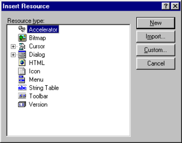
L-Edit 13 User Guide Section 4 831
Chapter 34: Introduction to Programming the User Interface Creating a Layout Palette
To implement a layout palette, you must write a DLL with a UPI_Entry_Point() function that registers
the layout palette macro. Running that macro will make the layout palette appear on your screen.
The following procedure explains how to create a DLL that brings up a layout palette.
;Use a resource editor to create resources for the layout palette.
;Create a UPI_Entry_Point() function that registers the layout palette macro.
;Write code for displaying and managing the layout palette.
;Write macros that will generate layout for every button in your layout palette—for example, gear.c,
mosfet.c, polarary.c, spiral.c, or spring.c.
;Compile the DLL. To review the procedure for compiling a DLL, see “Creating a Compiled Macro
(DLL)” on page 822.
L-Edit comes with source code that you can adapt for use with your own layout palette. The directory
<installdir>\Samples\UPI\dll\palette contains the complete source code required to create the layout
palette DLL.
Creating Resources
In order to display the graphic elements of a layout palette, including bitmaps, push buttons, and a
modeless dialog box, you must create these items as resources for your DLL project.
Visual C++ provides a resource editor to create and modify project resources. To access the resource
editor, select File >New from the Visual C++ menu. In the New dialog, choose the Files tab and select
Resource Script from the list of file types. Assign the script a name in the File Name field and click OK.
To add an existing resource script to your project, right-click on Source Files in the Projects file tree
and select Add file to folder from the pop-up menu. In the Insert Files into Project dialog, select the
desired resource file (*.rc) and click OK.
After you have added a resource file to your project, you can, create, import, and edit resources. To add
a new resource, change the Projects view to ResourceView and right-click on the resource script.
Select Insert to display a list of resource types:
From this dialog you can create a new resource or import an existing resource, such as a bitmap file. To
open a resource for editing, simply double-click the resource name in the Projects tree.
L-Edit 13 User Guide Section 4 832
Chapter 34: Introduction to Programming the User Interface Creating a Layout Palette
The resources needed to create the layout palette described in this section are provided in
<install_dir>\Samples\UPI\dll\palette\dll.rc. To load the resources, simply add dll.rc to your project
Source Files (see “Add project source files” on page 824 for instructions).
UPI_Entry_Point() Function
The following sample code contains the UPI_Entry_Point() function that registers the layout palette
macro. When executed, the layout palette macro will call MainFunction(), which displays the layout
palette.
#define STRICT
#include “windows.h”
#include “ldata.h”
extern void LWindow_GetParameters(void **hInst, void **hWnd, void **hLib);
extern void MainFunction(HINSTANCE hInst, HWND hWnd, HINSTANCE hLib);
HINSTANCE hInst=NULL;
HWND hWnd=NULL;
HINSTANCE hLib=NULL;
void LayoutPalette ( void )
{
MainFunction(hInst, hWnd, hLib);
}
int UPI_Entry_Point ( void )
{
LWindow_GetParameters( (void**)&hInst, (void**)&hWnd, (void**)&hLib);
LMacro_Register ( “Layout Palette”, “LayoutPalette” );
return 1;
}
This code is provided for you in <install_dir>\Samples\UPI\dll\palette\user.c.
Displaying and Managing the Palette
Here is sample code for a file called dll.c, which is also provided in your samples directory for this
example. This code implements MainFunction, which displays and manages the layout palette.
You can copy this code and use it to create your own layout palette.
BOOL CALLBACK DlgProc(HWND hDlg, UINT message, WPARAM wParam, LPARAM lParam
)
{
switch (message)
{
HANDLE_DLG_MSG( hDlg , WM_COMMAND , DlgOnCommand ) ;
HANDLE_DLG_MSG( hDlg , WM_INITDIALOG , OnInitDialog ) ;
}
return FALSE ;
}
void DlgOnCommand ( HWND hDlg , int iID , HWND hwndCtl , UINT uCodeNotify )
{
switch( iID )
{
case IDC_BUTTON_5:
L-Edit 13 User Guide Section 4 833
Chapter 34: Introduction to Programming the User Interface Creating a Layout Palette
MosfetMacro();
break;
}
}
BOOL OnInitDialog ( HWND hDlg , HWND hwndFocus , long lInitParam )
{
HBITMAP hBmp;
TOOLINFO info;
HWND hToolTip;
hBmp = LoadBitmap(l_hLib, MAKEINTRESOURCE(IDB_BITMAP5));
SendDlgItemMessage(hDlg, IDC_BUTTON_5, BM_SETIMAGE, 0, (LPARAM)hBmp);
FreeResource(hBmp);
return TRUE ;
}
void OnDestroy ( HWND hDlg )
{
DWORD error;
if ( hDlg )
DestroyWindow( hDlg );
l_hDlg = NULL;
}
void OnClose ( HWND hDlg )
{
DWORD error;
DestroyWindow( hDlg );
l_hDlg = NULL;
}
void MainFunction(HINSTANCE hInst, HWND hWnd, HINSTANCE hLib)
{
/* Check if the resources have already been loaded */
if (!loaded) {
HRSRC hRes;
hRes = FindResource(hLib, “PaletteDialogBox”, RT_DIALOG);
hResLoad = (HRSRC )LoadResource(hLib, hRes);
hTmpl = (DLGTEMPLATE *)LockResource(hResLoad);
hDlg = CreateDialogIndirect(Null, hTmpl, NULL, DlgProc);
l_hDlg = hDlg;
UnlockResource(hResLoad);
FreeResource(hRes);
}
loaded = 1;
hDlg = l_hDlg;
ShowWindow(hDlg, SW_NORMAL);
}
BOOL WINAPI DllMain( HANDLE hDLL, DWORD dwReason, LPVOID lpReserved )
{
switch( dwReason ) {
case DLL_PROCESS_DETACH:
if ( l_hDlg != NULL ) {
DestroyWindow(l_hDlg);
l_hDlg = NULL;
L-Edit 13 User Guide Section 4 834
Chapter 34: Introduction to Programming the User Interface Creating a Layout Palette
loaded = 0;
}
break;
}
return TRUE;
}
Macro Definitions
The following sample code creates a gear using the specified parameters. You can copy this code and
adapt it for use with your own layout palette. It is provided in your samples directory as gear.c.
void GearMacro ( void )
{
LPoint Polygon [ 100 ];
float Angle2, Angle3, R2, R3, Tooth_Angle;
LCoord R_Inner, R_Outer, Teeth_Count, Teeth_Width, Tooth;
LCell Cell_Draw = LCell_GetVisible ( );
LFile File_Draw = LCell_GetFile ( Cell_Draw );
LPoint Translation = LCursor_GetPosition ( );
LDialogItem Dialog_Items [ 3 ] = { { “Inner Radius”, “175” },
{ “Outer Radius”, “200” },
{ “Teeth Count “, “15 “ } };
do {
if ( !LDialog_MultiLineInputBox ( “Gear Properties”, Dialog_Items, 3 ))
return;
R_Inner = atol ( Dialog_Items [ 0 ].value );
R_Outer = atol ( Dialog_Items [ 1 ].value );
Teeth_Count = atol ( Dialog_Items [ 2 ].value );
Teeth_Width = 6.283185307 * R_Inner / ( 2 * Teeth_Count );
} while ( ( Teeth_Count < 3 ) || ( Teeth_Count > 25 )
|| ( Teeth_Width < 2 ) || ( R_Inner >= R_Outer )
|| ( R_Inner < 2 ) );
for ( Tooth = 0; Tooth < Teeth_Count; Tooth++ ) {
Tooth_Angle = 6.283185307 * Tooth / Teeth_Count;
R2 = sqrt ( R_Outer * R_Outer + Teeth_Width * Teeth_Width / 4.0 );
R3 = sqrt ( R_Inner * R_Inner + Teeth_Width * Teeth_Width / 4.0 );
Angle2 = atan2 ( Teeth_Width / 2.0, R_Outer );
Angle3 = atan2 ( Teeth_Width / 2.0, R_Inner );
Polygon [ 4 * Tooth + 0 ] = LPoint_Set (
R3 * sin ( Tooth_Angle - Angle3 ) + Translation.x,
R3 * cos ( Tooth_Angle - Angle3 ) + Translation.y );
Polygon [ 4 * Tooth + 1 ] = LPoint_Set (
R2 * sin ( Tooth_Angle - Angle2 ) + Translation.x,
R2 * cos ( Tooth_Angle - Angle2 ) + Translation.y );
Polygon [ 4 * Tooth + 2 ] = LPoint_Set (
R2 * sin ( Tooth_Angle + Angle2 ) + Translation.x,
R2 * cos ( Tooth_Angle + Angle2 ) + Translation.y );
Polygon [ 4 * Tooth + 3 ] = LPoint_Set (
R3 * sin ( Tooth_Angle + Angle3 ) + Translation.x,
R3 * cos ( Tooth_Angle + Angle3 ) + Translation.y );
}
LPolygon_New ( Cell_Draw, LLayer_Find ( File_Draw, “Metal1” ), Polygon, 4 *
Teeth_Count);
LCell_MakeVisible ( Cell_Draw );
LCell_HomeView(Cell_Draw);
}
L-Edit 13 User Guide Section 4 835
Chapter 34: Introduction to Programming the User Interface Copy-Protecting Macro DLLs
Compiling the DLL
Follow the instructions in “Creating a Compiled Macro (DLL)” on page 822 to compile your DLL. A
summary of the steps is provided below.
;Create a new Win32 Dynamic-Link Library project called palette.
;Copy the following files to a working directory, then add them to your project as source files. All of the
listed files are provided for you in <install_dir>\Samples\UPI\dll\palette:
;Create a new text file called palette.def, and insert the following contents:
EXPORTS
UPI_Entry_Point
LayoutPalette
Save the file.
;Specify the appropriate Include and Library file directories in Tools > Options.
;Follow the instructions given in “Set Project Settings” on page 825 to specify project settings.
;On the Project > Settings—Link tab, add the filename comctl32.lib to the list of Object/Library
Modules. This library is needed to access the Windows Common Controls used to construct your
palette.
;Build the DLL.
Copy-Protecting Macro DLLs
In this lesson, you will learn to use copy-protected UPI macro DLLs and to copy-protect your own
macro DLLs.
dll.c
dll.rc
gear.c
mosfet.c
polarary.c
spiral.c
spring.c
user.c
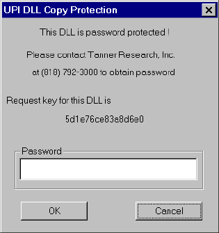
L-Edit 13 User Guide Section 4 836
Chapter 34: Introduction to Programming the User Interface Copy-Protecting Macro DLLs
Using a Copy-Protected DLL
When you load a copy-protected DLL, L-Edit will display a dialog similar to the following:
The following procedure explains how to use a copy-protected DLL.
;Call the DLL vendor and ask for a password.
;Provide the vendor with your L-Edit serial number and request a key for the DLL. The vendor will
compute the password and authorize the user by providing a function:
password = f(L-Edit Serial number, Request key for DLL)
where f() is a vendor-defined function that returns the password.
;Enter the password in the Password field. The DLL will compare the password with the internally
generated password. If they match, the DLL will be loaded.
If the password succeeds, it will be stored in the system registry. That way, you will not have to retype
the password every time you try to load the DLL.
Creating a Copy-Protected DLL
You can add copy-protection to any DLL by adding a password verification routine to the source code.
To generate copy-protection functions, you will need some knowledge of the Windows application
programming interface (API).
The following sections describe the steps involved in adding copy-protection to your DLL macro.
initiating Password Verification
UPI_Entry_Point is the first function called after the DLL initialization routines have been invoked to
set up UPI function pointers. It is thus an appropriate place for L-Edit/UPI to check for copy protection.
Use UPI_Entry_Point to perform the following functions:
;Call LWindow_GetParameters to initialize the parameters needed to create Windows dialog boxes
from within the DLL.
L-Edit 13 User Guide Section 4 837
Chapter 34: Introduction to Programming the User Interface Copy-Protecting Macro DLLs
;Call the Windows API function GetModuleFileName to return the name of the DLL file.
;Call a user-defined function named VerifyDLLPassword to get and verify a password for the DLL.
;Register the macro and optionally bind it to a hot key or menu item.
A sample version of the UPI_Entry_Point function is shown below.
HINSTANCE hMyInst; /* Application Instance */
HWND hMyWnd; /* Parent handle */
HINSTANCE hMyLib; /* Handle to the DLL */
int UPI_Entry_Point( void )
{
char filename_buf[255];
/* Initialize Graphical Window Parameters */
LWindow_GetParameters((void **)&hMyInst, (void **)&hMyWnd, (void
**)&hMyLib);
GetModuleFileName( (HMODULE )hMyLib, filename_buf, 255);
/* Verify password for this DLL */
if (!VerifyDLLPassword(filename_buf))
return 0;
/* Register the macro */
LMacro_BindToHotKey ( KEY_F2, “Contact, Active-Metal1...”,
“Contact_Active_Metal”);
return 1;
}
Verifying the Password
UPI_Entry_Point calls the user-defined function VerifyDLLPassword() to obtain and verify the user’s
password. The basic tasks of VerifyDLLPassword are:
;Internally generate a correct password for the DLL. You can use almost any algorithm to generate a
password, but it will generally be a function of the DLL filename and a unique identification number,
such as the serial number of L-Edit. You can retrieve the serial number of L-Edit using the function
LUpi_GetSerialNumber.
;Check the registry stored password corresponding to the DLL filename. If one is found, compare this to
the internally generated password. If the stored password and the generated password are identical,
return SUCCESS.
;If no password is found in the registry or if the registry password is incorrect, display a dialog box to
request a password from the user.
;Compare the user-supplied password to the internally generated password. If the user-supplied
password and the generated password are identical, store the new password in the registry and return
SUCCESS. Otherwise, return FAILURE.
In outline form, the code for the VerifyDLLPassword function looks like this:
int VerifyDLLPassword( char *dll_file_name )

L-Edit 13 User Guide Section 4 838
Chapter 34: Introduction to Programming the User Interface Copy-Protecting Macro DLLs
/* DESCRIPTION: calculate a challenge based on the dll file and request the
password from the user. If password matches with one produced internally,
then return 1; else return 0*/
{
/* Extract the filename from the input variable DLL_file_name */
_splitpath(dll_file_name, drive, dir, fname, ext);
strcat(fname, ext);
/* Generate a password from the filename and the L-Edit serial
number */
challenge = f(fname, LUpi_GetSerialNumber());
/* Check the registry for a previously entered password */
password_found_in_registry = get_password_from_registry(fname,
reg_pass);
/* If a password is found, check it against the internally generated
password (challenge). If the password fails or if no password is
found, request a password from the user. Otherwise, return
SUCCESS. */
if ( (password_found_in_registry != SUCCESS) ||
( (password_found_in_registry == SUCCESS) && (strcmp(reg_pass,
challenge) != 0)))
{
if (!GetDLLPassword(usr_pass))
return (FAILURE);
} else if (strcmp(reg_pass, challenge) = 0)
return SUCCESS;
/* Compare the user-supplied password with the internally generated
password (challenge). If they match, store the new password in the
appropriate registry key */
if (strcmp(usr_pass, challenge) == 0){
store_password_in_registry(fname, usr_pass);
return SUCCESS;
}
/* Otherwise, notify the user that the password is incorrect and
return FAILURE */
else {
LDialog_AlertBox(“Incorrect password!”);
return FAILURE;
}
}
Additional Support Routines
The outline of VerifyDLLPassword, above, relies on several additional support routines. A summary of
the necessary functions is provided below; refer to your Visual C++ documentation for help
constructing these functions.
Function Name Action
get_password_from_regist
ry( fname, reg_pass ) Checks the registry for a current password definition and retrieves it,
if one is found.
f( fname,
LUpi_GetSerialNumber( )
)
Creates an internally generated password from the DLL filename and
the user’s L-Edit serial number.

Chapter 34: Introduction to Programming the User Interface Copy-Protecting Macro DLLs
L-Edit 13 User Guide Section 4 839
Compiling the DLL
Follow the instructions in “Creating a Compiled Macro (DLL)” on page 822 to compile the DLL. Make
sure that your project settings include any Windows libraries required by your code.
store_password_in_registr
y( fname, usr_pass ) Stores the user-supplied password in the registry key that corresponds
to the DLL filename.
GetDLLPassword(
usr_pass ) Displays a dialog to request the user’s password.
Function Name Action

L-Edit 13 User Guide Section 4 840
35 UPI Functions Reference
Introduction
This section provides the reference to the L-Edit User-Programmable Interface (UPI) and its
C-language functions and datatypes.
Function Overview
Functions are arranged in three primary categories.
Interface
“Interface Functions” (page 843) allow you to create dialog boxes and other interface elements and to
register UPI macros.
Database Functions
“Database Functions” (page 919) allow you to create and manipulate a design database. Subcategories
of database functions include:
“Dialog Functions” (page 844) “Cursor and Display Functions” (page 856)
“UPI Macro Functions” (page 867) “Windows Functions” (page 894)
“Application Functions” (page 920) “File Functions” (page 959)
“Layer Functions” (page 1252) “Cell Functions” (page 1021)
“Instance Functions” (page 1077) “Entity Functions” (page 1098)
“Object Functions” (page 1124) “Vertex Functions” (page 1146)
“Box Functions” (page 1161) “Polygon Functions” (page 1195)
“Wire Functions” (page 1182) “Port Functions” (page 1202)
“Circle Functions” (page 1165) “Torus and Pie Functions” (page 1171)
“Selection Functions” (page 1220) “Technology Setup Functions” (page 1304)
“Import/Export Functions” (page 1322) “Utility Functions” (page 1367)
“Point Functions” (page 1368) “Rectangle Functions” (page 1374)
“Transformation Functions” (page
1378)
“Cross Section Functions” (page 1388)
“DRC Functions” (page 1329) “Extract Functions” (page 1350)
4
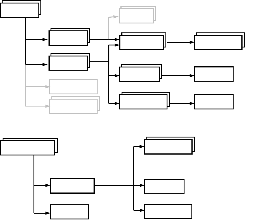
L-Edit 13 User Guide Section 4 841
Chapter 35: UPI Functions Reference
Data Types and Typedefs
“Data Types and Typedefs” (page 1390) allow you to create and manipulate data structures.
Data Relationships
UPI functions operate on many different types of data. These data correspond to the various design
components found within L-Edit (e.g., files, cells, drawing objects, selection lists, etc). The following
diagram shows the relationship between many of these components. In general, arrows denote a
“contains a” relationship, boxes are data types, and boxes with drop shadows represent lists of items.
A primary component of a design database is an L-Edit “file”. All geometry and technology information
is contained within a file.
A primary user interface component is a “selection list”. In the L-Edit UPI, this implicitly corresponds
to the selection list in the “active cell”.
LLayerLLayer
LCellLCell
LObjectLObject LVertexLVertex
(Polygons and wires only)
LPassLPass
LDrcRuleLDrcRule
LCore
LFileLFile
LLayer
LPortLPort
LCellLInstanceLInstance
LLayer
LPort
LInstance
LVertexLVertex
(Polygons and wires only)
LObject GetShape
LSelectionLSelection
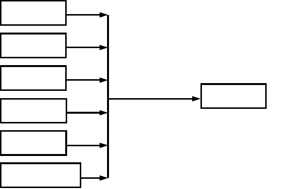
L-Edit 13 User Guide Section 4 842
Chapter 35: UPI Functions Reference
Finally, several items in L-Edit can have properties associated with them. In order to present a unified
API interface, all items that can have properties attached to them must be treated as LEntity objects,
usually via an explicit cast:
Numerical Limits
Many UPI function variables must fall within a specified range of values to be valid in L-Edit. The
following limits are pre-defined for all UPI functions:
Obsolete Functions
As the internal L-Edit database changes, some data types and UPI functions have to be updated and/or
replaced. Although we strive to maintain as much backward compatibility as possible, sometimes it is
simply not possible.
Obsolete functions are marked as such in this documentation.
Also, if a UPI program contains:
#define EXCLUDE_LEDIT_LEGACY_UPI
before #including any header files, then the obsolete UPI functions are not exposed to the user program.
WORLD_MAX The maximum positive value of an x- or y-coordinate in L-Edit.
MAX_LAYER_NAME The maximum number of characters in an L-Edit layer name.
MAX_CELL_NAME The maximum number of characters in an L-Edit cell name.
MAX_TDBFILE_NAME The maximum number of characters in an L-Edit file name.
LEntity
LLayer
LCell
LPort
LObject
LInstance
LFile
(LEntity is only used
to attach properties)
(LEntity) cast
L-Edit 13 User Guide Section 4 843
Chapter 35: UPI Functions Reference Interface Functions
Interface Functions
The first group of functions listed below are used to create graphical interface elements such as dialog
and message boxes.
Functions in the second group are used for tasks such as finding the current mouse position, displaying
a message in the status bar, or getting and setting the visible cell in L-Edit’s layout window.
Functions in the third group are used for loading, registering, and binding UPI macros.
Functions in the fourth group are used for finding the L-Edit serial number, choosing the selection tool,
and inserting a menu item separator.
“LDialog_MsgBox” (page 845) “LDialog_MultiLineMsgBox” (page 846)
“LDialog_YesNoBox” (page 848) “LDialog_AlertBox” (page 847)
“LDialog_InputBox” (page 849) “LDialog_MultiLineInputBox” (page 850)
“LDialog_PickList” (page 851) “LDialog_File” (page 852)
“LCursor_GetPositionEx99” (page 858) “LCell_HomeView” (page 862)
“LDisplay_Refresh” (page 860) “LStatusBar_SetMsg” (page 861)
“LCell_GetVisible” (page 863) “LCell_GetLastVisible” (page 864)
“LCell_MakeVisible” (page 865) “LCell_MakeVisibleNoRefresh” (page 866)
Obsolete
“LCursor_GetPosition” (page 857) “LCursor_GetSnappedPosition” (page 859)
“LMacro_Register” (page 868) “LMacro_BindToMenuAndHotKey_v9_30” (page 871)
“LMacro_Load” (page 877) “LMacro_UnLoad” (page 879)
“LMacro_IsLoaded” (page 876) “LMacro_GetNewTCell” (page 880)
“LMacro_BindToHotKey” (page 869) “LMacro_BindToMenu” (page 870)
“LUpi_InQuietMode” (page 883) “LUpi_SetQuietMode” (page 882)
“LUpi_GetUpdateDisplayMode” (page 891) “LUpi_SetUpdateDisplayMode” (page 890)
“LUpi_GetSerialNumber” (page 881) “LUpi_InsertMenuItemSeparator” (page 886)
“LUpi_GetReturnCode” (page 888) “LUpi_SetReturnCode” (page 887)
“LUpi_SetSelectionTool” (page 884) “LUpi_SetDrawingTool” (page 885)
L-Edit 13 User Guide Section 4 844
Chapter 35: UPI Functions Reference Interface Functions Dialog Functions
Dialog Functions
Dialog Button Returns
L-Edit UPI recognizes the following dialog button returns. Each is internally mapped to an integer
value.
“LDialog_MsgBox” (page 845) “LDialog_MultiLineMsgBox” (page 846)
“LDialog_YesNoBox” (page 848) “LDialog_AlertBox” (page 847)
“LDialog_InputBox” (page 849) “LDialog_MultiLineInputBox” (page 850)
“LDialog_PickList” (page 851) “LDialog_File” (page 852)
LOK Indicates that the OK button was selected.
LCANCEL Indicates that the Cancel button was selected.
LYES Indicates that the Yes button was selected.
LNO Indicates that the No button was selected.
L-Edit 13 User Guide Section 4 845
Chapter 35: UPI Functions Reference Interface Functions Dialog Functions
LDialog_MsgBox
LDialog_MsgBox
void LDialog_MsgBox(const char* szMessage)
Description
Produces a single-line message box.
Parameters
Example
LCell pCell = LCell_GetVisible();
if(Assigned(pCell))
{
char szCellName[MAX_CELL_NAME];
LCell_GetName(pCell, szCellName, sizeof(szCellName));
LDialog_MsgBox(LFormat("Active Cellname = \"%s\".", szCellName));
}
See Also
“Interface Functions” (page 843), “LDialog_MultiLineMsgBox” (page 846),
“LDialog_AlertBox” (page 847)
szMessage Specifies the message to be displayed.
L-Edit 13 User Guide Section 4 846
Chapter 35: UPI Functions Reference Interface Functions Dialog Functions
LDialog_MultiLineMsgBox
LDialog_MultiLineMsgBox
void LDialog_MultiLineMsgBox( const char* szaMessages[], int nTotalEntries
);
Description
Produces a multiple-line message dialog.
Parameters
Example
LCell pCell = LCell_GetVisible();
LFile pTDBFile = LCell_GetFile(pCell);
if(Assigned(pCell) && Assigned(pTDBFile))
{
char szCellName[MAX_CELL_NAME];
LCell_GetName(pCell, szCellName, sizeof(szCellName));
char szTDBFileName[MAX_TDBFILE_NAME];
LFile_GetName(pTDBFile, szTDBFileName, sizeof(szTDBFileName));
const char* szaMessages[2];
szaMessages[0] = szCellName;
szaMessages[1] = szTDBFileName;
LDialog_MultiLineMsgBox(szaMessages, 2);
szaMessages[0] = LFormat("Active Cellname = \"%s\".", szCellName);
szaMessages[1] = LFormat("Active TDB Filename = \"%s\".",
szTDBFileName);
LDialog_MultiLineMsgBox(szaMessages, 2);
}
See Also
“Interface Functions” (page 843), “LDialog_MsgBox” (page 845), “LDialog_AlertBox” (page 847)
szaMessages Array of strings. Each string will be displayed on a separate line in the
dialog.
nTotalEntries Number of message lines.
L-Edit 13 User Guide Section 4 847
Chapter 35: UPI Functions Reference Interface Functions Dialog Functions
LDialog_AlertBox
LDialog_AlertBox
void LDialog_AlertBox( const char* szMessage );
Description
Produces a warning dialog.
Parameters
Example
LFile pTDBFile = LFile_GetVisible();
if(Assigned(pTDBFile))
{
char szTDBFileName[MAX_TDBFILE_NAME];
LFile_GetName(pTDBFile, szTDBFileName, sizeof(szTDBFileName));
LDialog_AlertBox(LFormat("Active TDB Filename = \"%s\".",
szTDBFileName));
}
See Also
“Interface Functions” (page 843), “LDialog_MsgBox” (page 845),
“LDialog_MultiLineMsgBox” (page 846)
szMessage Warning displayed in the dialog.
L-Edit 13 User Guide Section 4 848
Chapter 35: UPI Functions Reference Interface Functions Dialog Functions
LDialog_YesNoBox
LDialog_YesNoBox
int LDialog_YesNoBox( const char *msg );
Description
Produces a query dialog. One of two choices is clicked in response to the query.
Return Values
If Yes is clicked, the function returns LYES; if No is clicked, it returns LNO.
Parameters
Example
if ( LDialog_YesNoBox(“Do you want to Continue”) ){
/*Yes is clicked - the program continues*/
}
else {
/*No is clicked - the program exits*/
}
See Also
“Interface Functions” (page 843), “Dialog Button Returns” (page 844)
msg Query to be displayed in the dialog.
L-Edit 13 User Guide Section 4 849
Chapter 35: UPI Functions Reference Interface Functions Dialog Functions
LDialog_InputBox
LDialog_InputBox
int LDialog_InputBox( const char *title, const char *msg, char *ibuf );
Description
Produces an input dialog. The value entered by the user is returned as a string. If another datatype is
needed, the string must be converted to the appropriate type.
Return Values
If OK is clicked, the function returns LOK; if Cancel is clicked, it returns LCANCEL.
Parameters
Example
/*Allocate a buffer to store the return value*/
char value_buffer[50];
/*Initialize buffer to display a default value*/
strcpy(value_buffer, “pcell”);
/*Display an input box with Cell Name Query as the title*/
if ( LDialog_InputBox(“Cell Name Query”, “Enter Name of the cell to be
instanced”, value_buffer) == 0)
return;
See Also
“Interface Functions” (page 843), “Dialog Button Returns” (page 844)
title Title of the dialog box.
msg Prompt displayed in the dialog.
ibuf A buffer used to return the value entered at the prompt.
L-Edit 13 User Guide Section 4 850
Chapter 35: UPI Functions Reference Interface Functions Dialog Functions
LDialog_MultiLineInputBox
LDialog_MultiLineInputBox
int LDialog_MultiLineInputBox( const char *title, LDialogItem ibuf[],
int total_entries );
Description
Produces a multiple-line input dialog. Several values are entered in response to prompts.
Return Values
If OK is clicked, the function returns LOK; if Cancel is clicked, then it returns LCANCEL.
Parameters
Example
/*Declare an array of dialog items to be displayed*/
LDialogItem Dialog_Items [ 3 ] =
{ { "Inner Radius", "175" },
{ "Outer Radius", "200" },
{ "Teeth Count ", "15 " } };
long R_Inner, R_Outer, Teeth_Count;
float Teeth_Width;
/*Display a multi line dialog box to display the default values of gear
properties and get the modified properties*/
if ( LDialog_MultiLineInputBox ( “Gear Properties”, Dialog_Items, 3 ) ){
/* user selected OK, so get the property value from the Dialog_Items
buffer*/
R_Inner = atol( Dialog_Items[0].value ); // get the inner radius
R_Outer = atol( Dialog_Items[1].value ); // get the outer radius
Teeth_Count = atol( Dialog_Items[2].value ); // get the teeth count
/*Calculate Teeth Width*/
Teeth_Width = 6.283185307 * R_Inner / ( 2 * Teeth_Count );
}
See Also
“LDialogItem” (page 1415), “Interface Functions” (page 843), “Dialog Button Returns” (page 844)
title Title of the dialog box.
ibuf Prompts displayed and the values entered.
total_entries Number of values expected.
L-Edit 13 User Guide Section 4 851
Chapter 35: UPI Functions Reference Interface Functions Dialog Functions
LDialog_PickList
LDialog_PickList
int LDialog_PickList( const char *title, const char *list[],
int total_entries, int default_choice );
Description
Produces an input dialog. One of a list of possibilities is chosen either by highlighting the desired item
and clicking OK, or by double-clicking the desired item.
Return Values
If OK is clicked (or the highlighted item is double-clicked), the function returns the index of the
highlighted item; if Cancel is clicked, it returns –1.
Parameters
Example
/*This example displays a pick list with three members to choose from*/
/*Declare a buffer to hold all elements of the pick list*/
char *Pick_List [ ] = {
"Inverter",
"Op-Amp",
"Transistor"
};
/*Number of elements in the pick list*/
int Pick_Count = 3;
/*Index of the item picked by user*/
int Picked;
/*Display the pick list with Inverter as the default selection*/
Picked = LDialog_PickList ("Select Element", Pick_List, Pick_Count, 0);
See Also
“Interface Functions” (page 843).
title Title of the dialog.
list Items listed.
total_entries Number of items listed.
default_choice Index of the item shown highlighted when the dialog first appears.
L-Edit 13 User Guide Section 4 852
Chapter 35: UPI Functions Reference Interface Functions Dialog Functions
LDialog_File
LDialog_File
extern void LDialog_File( const char* szDefaultName, const char* szTitle,
char* szFileNameBuffer, const char* szFiltersForBrowser, int iBrowseType,
const char* szMessage, const char* szOkText, const char* szDefaultExt,
const char* szTypeList, const LFile pFile );
Description
Call this function to display a filename edit box. The user may type a filename in the field provided, or
click the Browse button to open a standard Windows file dialog. Clicking the Browse button opens a
File Open or File Choose dialog box, depending on the value of iBrowseType.
The szFilter parameter is used to determine the type of filename a file must have to be displayed in
the file list box. The first string in the string pair describes the filter; the second string indicates the file
extension to use. Multiple extensions may be specified using a semicolon (;) as the delimiter. The string
ends with two '|' characters, followed by a NULL character.
For example, L-Edit permits users to open files with extensions .TDB (layout) or .VDB (LVS Results),
among others. The filter for L-Edit could be written as:
"Layout Files (*.tdb)|*.tdb|LVS Files (*.vdb)|*.vdb|L-Edit Files
(*.tdb;*.vdb)|*.tdb; *.vdb|All Files (*.*)|*.*||"
Return Values
None. The selected filename is written to the szFileNameBuffer input buffer.
Parameters
szFileName The initial filename that appears in the filename edit box. If NULL,
no filename initially appears.
szTitle The title of the filename edit box.
szFileNameBuffer Filename buffer to store the filename selected. If the user cancels this
is set to the empty string.
szFilterForBrowser A series of string pairs that specify filters you can apply to the file. If
you specify file filters, only selected files will appear in the Files list
box. See the description section for more information on how to work
with file filters.
iBrowseType Specifies the type of dialog opened when the user selects the Browse
button in the filename edit box:
iBrowseType = 1 opens a File Open dialog.
iBrowseType ≠ 1 opens a File Choose dialog.
szMessage Message to display in the filename edit box, such as instructions to
the user.
szOkText Text displayed on the left-hand button in the filename edit box. The
user clicks this button to accept the displayed filename.
L-Edit 13 User Guide Section 4 853
Chapter 35: UPI Functions Reference Interface Functions Dialog Functions
LDialog_File
Example
/* Parameters for the filename edit box */
char* szFileName = "default_name";
const char* szTitle = "Open File";
char szFileNameBuffer[256];
const char* szMessage = “Please select a file to open:";
const char* szDefaultExt = "tdb”;
const char* szTypeList = "*.tdb|*.vdb||";
const char* szOkText = "OK";
/* Type of Windows file dialog to open with the Browse button */
int iBrowseType = 2;
/* Parameters for the Windows file dialog */
const char* szFilterForBrowser = "Layout Files (*.tdb)|*.tdb|LVS Files
(*.vdb)|*.vdb|L-Edit Files (*.tdb;*.vdb)|*.tdb; *.vdb|All Files
(*.*)|*.*||";
LFile pFile = LFile_Find("C:/Tanner/LEdit90/Samples/T-Cells/alphabet.tdb");
/* Open the file edit box */
LDialog_File(szFileName, szTitle, szFileNameBuffer, szFilterForBrowser,
iBrowseType, szMessage, szOkText, szDefaultExt, szTypeList, pFile);
szDefaultExt The default filename extension. If the user does not include an
extension in the Filename edit box, the extension specified by
szDefaultExt is automatically appended to the filename. If this
parameter is NULL, no file extension is appended.
szTypeList A series of strings that specify file types to be listed in the File Type:
field of the filename edit box. If this parameter is set to NULL, the
File Type: field is omitted from the filename edit box.
Each string in the series indicates a single file extension, ending with
a '|' character. The series ends with two '|' characters, followed by a
NULL character. For example,
char *szTypeList = "*.tdb|*.vdb|*.txt||"
includes the TDB, VDB, and TXT file extensions in the drop-down
list of file types.
pFile Pointer to an existing file. The location of pFile is the default
directory for the File Open or File Choose dialog. When pFile is set,
szFileNameBuffer contains the selected filename and path relative to
the location of pFile.
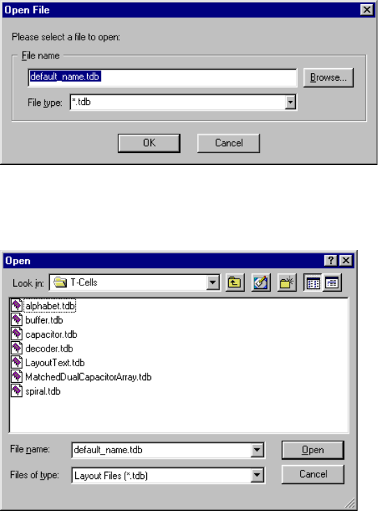
L-Edit 13 User Guide Section 4 854
Chapter 35: UPI Functions Reference Interface Functions Dialog Functions
LDialog_File
The macro shown above opens the following filename edit dialog:
If the user clicks Browse, L-Edit opens a standard file Open dialog (specified by iBrowseType = 1) in
the directory that contains pFile.
Example 2
void LDialog_File(const char* szDefaultName, const char* szTitle, char*
szFileNameBuffer,
const char* szFiltersForBrowser, int iBrowseType, const char* szMessage,
const char* szOkText, const char* szDefaultExt, const char* szTypeList,
const LFile pFile);
// BrowseType meaning:0 - "Save" dialog, 1 - "Open" dialog
// FiltersForBrowser, DefaultExt and TypeList are strings separated by '|'
character.
// Note: TypeList and DefaultExt are only meaningful for "Save" dialog.
//pFile parameter is used to better support relative file names.
//
//
// Returns: Name of the file (with a path). In case if TypeList was
provided, it returns as string consisting of a
//file name and a 0 based index into the TypeList, separated with '|'
character.
const char szFileExt[] = "*.txt";
const char szFilter[] = "Text Files (*.txt)|*.txt|All Files (*.*)|*.*||";
L-Edit 13 User Guide Section 4 855
Chapter 35: UPI Functions Reference Interface Functions Dialog Functions
LDialog_File
char szTemp[512] = "\0";
LDialog_File("MyFile.txt", // Default filename. This is the string that
is put in the browse dialog including path.
"Please select the Batch Rendering Script file.", // Dialog title
szTemp,// Variable to store the filename
szFilter, // File type file.
1, // Browse Type - 1 Open, 0 - Save As.
"Batch Rendering Script filename:",// Filename message in the Dialog.
NULL, // String for the OK button - NULL means OK.
szFileExt,// Default extension type.
NULL,// Type list - a list of extension typesto indicate which type was
selected.
NULL); // LFile pointer - if yousend a LFile to LDialog_File, then all
relative paths will be relative to the TDB referenced by LFile.
if((strlen(szTemp) > 0))
{
// The user did not cancel the dialog.
//Do my processing here.
}
// Another example
// Example:
//LDialog_File("tanner.tdb",
//"Export File",
//"Tanner Database Files (*.tdb)|*.tdb|GDSII Files (*.gds)|*.gds||",
//0,
//"Current file will be exported to this file name:",
//"&Export",
//"tdb|gds||",
//"Tanner v8 Database File|GDSII File||",
//NULL
//);
// Return value of "C:mpest.gds|1" will indicate that user selected GDSII
file.
See Also
“LFile_GetResolvedFileName” (page 1009)
L-Edit 13 User Guide Section 4 856
Chapter 35: UPI Functions Reference Interface Functions Cursor and Display Functions
Cursor and Display Functions
“LCursor_GetPositionEx99” (page 858) “LCell_HomeView” (page 862)
“LDisplay_Refresh” (page 860) “LStatusBar_SetMsg” (page 861)
“LCell_GetVisible” (page 863) “LCell_GetLastVisible” (page 864)
“LCell_MakeVisible” (page 865) “LCell_MakeVisibleNoRefresh” (page 866)
Obsolete
“LCursor_GetPosition” (page 857) “LCursor_GetSnappedPosition” (page 859)
L-Edit 13 User Guide Section 4 857
Chapter 35: UPI Functions Reference Interface Functions Cursor and Display Functions
LCursor_GetPosition
LCursor_GetPosition
LPoint LCursor_GetPosition( void );
Description
Gets the current cursor (mouse) position.
Return Value
Returns the current cursor (mouse) position.
Example
LPoint pt = LCursor_GetPosition();
LDialog_MsgBox( LFormat( “( %ld, %ld )”, pt.x, pt.y ) );
Version
As of L-Edit V9, this function has been deprecated, in favor of “LCursor_GetPositionEx99” (page
858)
See Also
“LCursor_GetPositionEx99” (page 858), “LTransform” (page 1474), “Interface Functions” (page
843).
L-Edit 13 User Guide Section 4 858
Chapter 35: UPI Functions Reference Interface Functions Cursor and Display Functions
LCursor_GetPositionEx99
LCursor_GetPositionEx99
LPoint LCursor_GetPositionEx99(
int iSnapped,
int iPauseForInput,
const char* szMessage )
Description
Gets the current cursor (mouse) position. Optionally the cursor position can be snapped to the current
snap grid settings in the Setup > Design—Grid tab. LCursor_GetPositionEx99 gets the current cursor
position and immediately returns. One can optionally pause for user input, allowing the user to press
the left mouse button to indicate the cursor position.
Return Value
Returns the current cursor (mouse) position.
Parameters
Example
// get a point from the user, and print out its coordinates
LPoint pt = LCursor_GetPositionEx99( true, true, “click desired point” );
LDialog_MsgBox( LFormat( “( %ld, %ld )”, pt.x, pt.y ) );
See Also
“LCursor_GetPosition” (page 857), “Interface Functions” (page 843).
iSnapped Snap the cursor position to the current snap settings (1 = True, 0 =
False).
iPauseForInput Pause so the user can press the mouse left button to indicate the cursor
position (1 = True, 0 = False).
szMessage Displays the message when pausing for user input. If szMessage is
NULL, then it displays "Please pick a point."
L-Edit 13 User Guide Section 4 859
Chapter 35: UPI Functions Reference Interface Functions Cursor and Display Functions
LCursor_GetSnappedPosition
LCursor_GetSnappedPosition
LPoint LCursor_GetSnappedPosition( void )
Description
Gets the current snapped cursor (mouse) position.
Return Values
Returns the current snapped cursor (mouse) position as a LPoint.
Version
As of L-Edit V9, this function has been deprecated, in favor of “LCursor_GetPositionEx99” (page
858)
See Also
“LTransform” (page 1474), “Interface Functions” (page 843)
L-Edit 13 User Guide Section 4 860
Chapter 35: UPI Functions Reference Interface Functions Cursor and Display Functions
LDisplay_Refresh
LDisplay_Refresh
void LDisplay_Refresh( void );
Description
Updates the display to show layout modifications produced by UPI calls.
See Also
“Interface Functions” (page 843)
L-Edit 13 User Guide Section 4 861
Chapter 35: UPI Functions Reference Interface Functions Cursor and Display Functions
LStatusBar_SetMsg
LStatusBar_SetMsg
void LStatusBar_SetMsg( const char *msg );
Description
Displays a message in the status bar. To clear the status bar, set msg to “” (an empty string).
Parameters
Example
int nBoxes = 5;
LStatusBar_SetMsg( LFormat( “Boxes processed = %d”, nBoxes) );
See Also
“Interface Functions” (page 843)
msg Message to be displayed.
L-Edit 13 User Guide Section 4 862
Chapter 35: UPI Functions Reference Interface Functions Cursor and Display Functions
LCell_HomeView
LCell_HomeView
LStatus LCell_HomeView( LCell cell );
Description
Displays the home view of a given cell.
Return Values
LStatusOK if successful. If an error occurs, LStatus contains the error value.
Parameters
Example
// zoom to home view and refresh display
LCell pCell = LCell_GetVisible();
if ( pCell )
{
LCell_HomeView( pCell );
LDisplay_Refresh();
}
See Also
“LStatus” (page 1468), “LObject” (page 1448), “Interface Functions” (page 843)
cell Specified cell.
L-Edit 13 User Guide Section 4 863
Chapter 35: UPI Functions Reference Interface Functions Cursor and Display Functions
LCell_GetVisible
LCell_GetVisible
LCell LCell_GetVisible( void );
Description
Gets the visible (active) cell in the layout window.
Return Values
Returns a pointer to the active cell; otherwise NULL.
Example
LCell pCell = LCell_GetVisible();
if ( pCell )
{
// print the name of the active cell
char buf[ MAX_CELL_NAME ];
LDialog_MsgBox(
LFormat( “Active cell is %s”,
LCell_GetName( pCell, buf, sizeof( buf ) )
)
);
}
See Also
“LStatus” (page 1468), “Interface Functions” (page 843)
L-Edit 13 User Guide Section 4 864
Chapter 35: UPI Functions Reference Interface Functions Cursor and Display Functions
LCell_GetLastVisible
LCell_GetLastVisible
LCell LCell_GetLastVisible( LFile file );
Description
Gets the cell last open in the specified file.
Return Values
Returns a pointer to the last open cell in the specified file, or NULL on error.
Parameters
See Also
“LObject” (page 1448), “Interface Functions” (page 843)
file Specified file.
L-Edit 13 User Guide Section 4 865
Chapter 35: UPI Functions Reference Interface Functions Cursor and Display Functions
LCell_MakeVisible
LCell_MakeVisible
LStatus LCell_MakeVisible( LCell cell );
Description
Makes the specified cell the current one and updates the display.
Return Values
LStatusOK if successful. If an error occurs, LStatus contains the error value.
Parameters
See Also
“LStatus” (page 1468), “LObject” (page 1448), “Interface Functions” (page 843)
cell Specified cell.
L-Edit 13 User Guide Section 4 866
Chapter 35: UPI Functions Reference Interface Functions Cursor and Display Functions
LCell_MakeVisibleNoRefresh
LCell_MakeVisibleNoRefresh
LStatus LCell_MakeVisibleNoRefresh( LCell cell );
Description
Makes the specified cell the current one without updating the display.
Return Values
It an error occurs, it returns LBadCell; otherwise returns LStatusOK.
Parameters
See Also
“LStatus” (page 1468), “LObject” (page 1448), “Interface Functions” (page 843)
cell Specified cell.
L-Edit 13 User Guide Section 4 867
Chapter 35: UPI Functions Reference Interface Functions UPI Macro Functions
UPI Macro Functions
“LMacro_Register” (page 868) “LMacro_BindToMenuAndHotKey_v9_30” (page 871)
“LMacro_Load” (page 877) “LMacro_UnLoad” (page 879)
“LMacro_IsLoaded” (page 876)
“LUpi_InQuietMode” (page 883) “LUpi_SetQuietMode” (page 882)
“LUpi_GetUpdateDisplayMode” (page
891)
“LUpi_SetUpdateDisplayMode” (page 890)
“LUpi_GetSerialNumber” (page 881) “LUpi_InsertMenuItemSeparator” (page 886)
“LUpi_GetReturnCode” (page 888) “LUpi_SetReturnCode” (page 887)
“LUpi_SetSelectionTool” (page 884) “LUpi_SetDrawingTool” (page 885)
“LMacro_GetNewTCell” (page 880)
Obsolete
“LMacro_BindToHotKey” (page 869) “LMacro_BindToMenu” (page 870)
L-Edit 13 User Guide Section 4 868
Chapter 35: UPI Functions Reference Interface Functions UPI Macro Functions
LMacro_Register
LMacro_Register
void LMacro_Register( char *macro_desc, char *function );
Description
Registers a user-defined macro in L-Edit.
Parameters
Example
void macro_function( void )
{
// macro code goes here
}
void UPI_Entry_Point( void )
{
LMacro_Register( “My macro’s description”, “macro_function” );
}
See Also
“Interface Functions” (page 843), “Running an Interpreted (.c) Macro” (page 819)
macro_desc Macro name that should be displayed in the Macros list.
function Name of the macro function.

L-Edit 13 User Guide Section 4 869
Chapter 35: UPI Functions Reference Interface Functions UPI Macro Functions
LMacro_BindToHotKey
LMacro_BindToHotKey
void LMacro_BindToHotKey( int keycode, char *macro_desc, char *function);
Description
Establishes a relationship between a user-defined macro and a keyboard shortcut (“hot key”) so that
user can invoke the macro by pressing the hot key. Supported key combinations (keycodes) are defined
in <install_dir>\include\lupi_usr.h.
Parameters
Note: Note that this function is superseded in L-Edit V10 and later.
See Also
“Interface Functions” (page 843), “Binding Macros to Hot Keys” (page 827)
keycode Keyboard shortcut (for example, KEY_F2 for the F2 key).
macro_desc String displayed in the Macros list of the Run Macro dialog.
function Macro function name.

L-Edit 13 User Guide Section 4 870
Chapter 35: UPI Functions Reference Interface Functions UPI Macro Functions
LMacro_BindToMenu
LMacro_BindToMenu
void LMacro_BindToMenu( char *menu, char *macro_desc, char *function );
Description
Establishes a relationship between a user-defined macro and a menu command. When the menu item is
selected, the macro is executed.
Parameters
Example
void macro1( void )
{
// macro code goes here
}
void UPI_Entry_Point( void )
{
LMacro_BindToMenu( “Tools”, “My macro”, “macro1” );
LMacro_BindToMenu( “Tools”, “Subdir\\My macro”, “macro1” );
LMacro_BindToMenu( “Tools”, “Subdir\\My macro2”, “macro2” );
}
Note: Note that this function is superseded in L-Edit V10 and later.
See Also
“Interface Functions” (page 843), “Binding Macros to Menu Items” (page 828)
menu Main L-Edit menu in which to add the entry (for example, Tools).
macro_desc Menu entry to add. If this string begins with a space, the menu entry is
preceeded by a separator line. A submenu may be specified by putting
a ‘\’ in the string (for example, “My Program\\My Macro”). The
macro_desc string is also displayed in the Macros list of the Run
Macro dialog.
function Macro function name.
L-Edit 13 User Guide Section 4 871
Chapter 35: UPI Functions Reference Interface Functions UPI Macro Functions
LMacro_BindToMenuAndHotKey_v9_30
LMacro_BindToMenuAndHotKey_v9_30
unsigned int LMacro_BindToMenuAndHotKey_v9_30(const char* szMenu,
const char* szHotKey, const char* szMacroDescription,
const char* szFunctionName, const char* szHotKeyCategory)
Description
Establishes a relationship between a user-defined macro and a menu command and/or a hotkey. When
the menu item or the hotkey is selected, the macro is executed.
Return Values
If an error occurs, it returns 0; otherwise returns the resource ID number of the binding.
Parameters
szMenu Main L-Edit menu in which to add the entry (for example, File or Edit
or Tools). If this is NULL, then the macro will not be assigned to a
menu.
szHotKey A string of the hotkey to bind the macro to. The string is the actual
key just like in Setup>Application dialog - Keyboard tab. The
following modifiers and special keys are also available:
Shift - Indicates the Shift key is pressed in conjunction with another
key.
Ctrl - Indicates the Control key is pressed in conjunction with another
key.
Alt - Indicates the Alt key is pressed in conjunction with another key.
F1 - Indicates F1 function key.
Num 0 - Indicates the zero key on the numeric key pad.
Backspace - The backspace key.
Tab - The Tab key.
Space - The spacebar.
Page Up - The page up key.
Page Down - The page down key.
End - The end key.
Home - The home key.
Left - The left arrow.
Up - The up arrow.
Right - The right arrow.
Down - The down arrow.
Ins - The insert key.
Del - The delete key.
Num * - The * key on the numeric key pad.
Num + - The + key on the numeric key pad.
Num - - The -key on the numeric key pad.
Num Del - The Delete/decimal key on the numeric key pad.
Num Lock - The Num Lock key.
Scroll Lock - The * key on the numeric key pad.
Break - The Break key.
Esc - The escape key.
Comma - The , key.
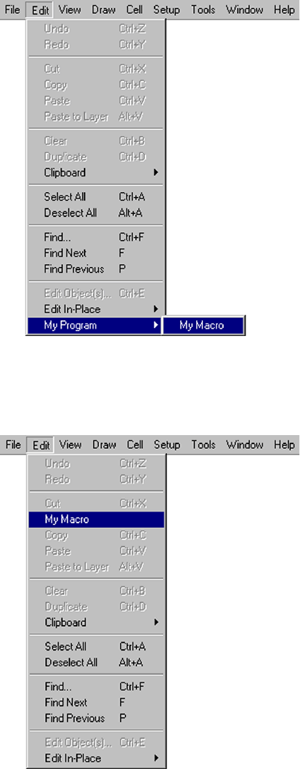
L-Edit 13 User Guide Section 4 872
Chapter 35: UPI Functions Reference Interface Functions UPI Macro Functions
LMacro_BindToMenuAndHotKey_v9_30
Period - The . key.
To assign shifted keys such as @ or <, the use Shift and the lowercase
key (for Example: @ is Shift+2 and < is Shift+Comma).
If this is NULL, then the macro will not be assigned a hotkey.
szMacroDescription Menu entry to add. If this string begins with a space, the menu entry is
preceded by a separator line. A submenu may be specified by putting
a \ in the string (for example, “My Program\\My Macro”).
The szMacroDescription string is also displayed in the Macros list of
the Tools>Macro dialog. If you want to place the macro at a specific
location in a menu then add a newline \n and the full path to the menu
item that you want your macro to be before (for example: My
Macro\nEdit\\Copy will put the My Macro menu item between Cut
and Copy on the Edit menu).
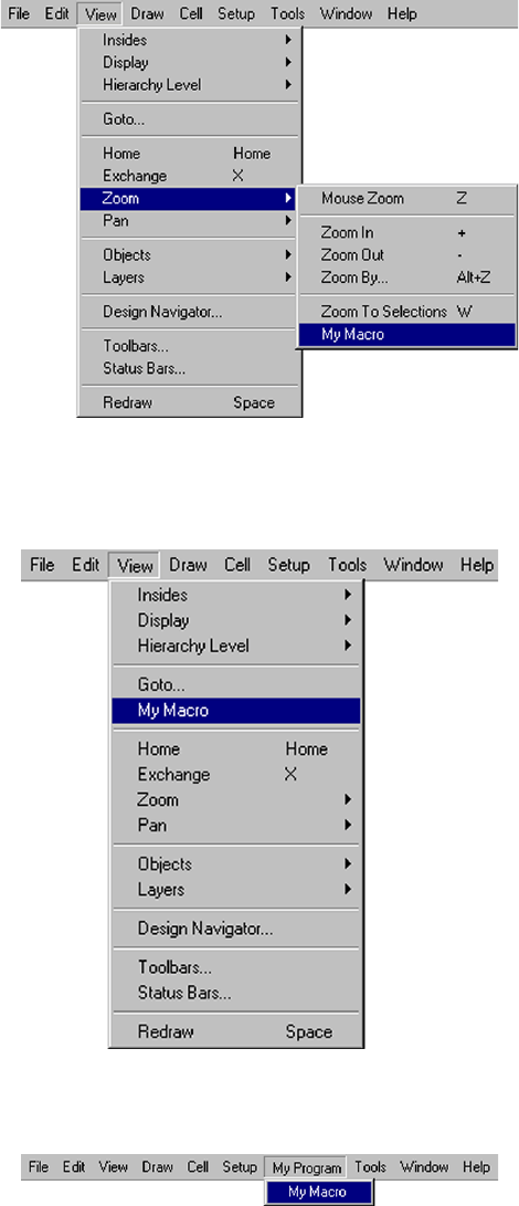
L-Edit 13 User Guide Section 4 873
Chapter 35: UPI Functions Reference Interface Functions UPI Macro Functions
LMacro_BindToMenuAndHotKey_v9_30
If the full path ends in \ then the menu item will be placed at the end
of the menu (for example: My Macro\nView\\Zoom\\ will put the My
Macro menu item at the end of the Zoom submenu after Zoom to
Selections).
If the menu item has a separator before it and if you precede the menu
item with a space, then it will put your macro before the separator,
otherwise it will put it after the separator (for example: My
Macro\nView\\ Home will put the My Macro menu item on the View
menu before the separator that is above the Home menu item).
You can also add a new menu at the top level by indicate a top level
menu to place your macro before (for example: My Program\\My
Macro\nTools puts the My Program menu item before the Tools
menu.
szFunctionName Macro function name.
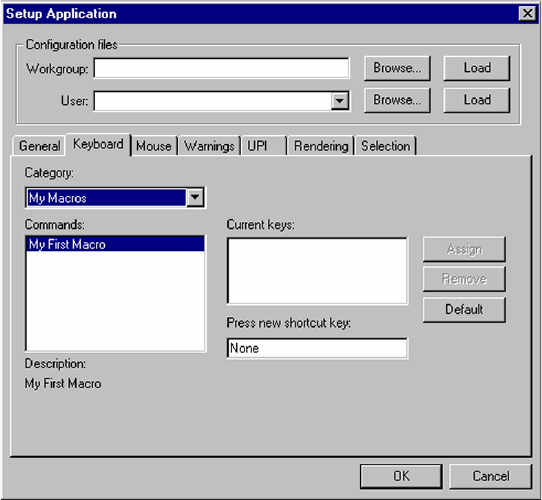
L-Edit 13 User Guide Section 4 874
Chapter 35: UPI Functions Reference Interface Functions UPI Macro Functions
LMacro_BindToMenuAndHotKey_v9_30
Example
void Macro1(void)
{
// macro code goes here
}
void UPI_Entry_Point(void)
{
LMacro_BindToMenuAndHotKey_v9_30("Edit",
"F1",
"My Program\\My Macro",
"Macro1",
"My Macros");
LMacro_BindToMenuAndHotKey_v9_30("Edit",
"Shift+2",
"My Macro\nEdit\\Copy",
"Macro2",
NULL);
LMacro_BindToMenuAndHotKey_v9_30("View",
NULL,
"My Macro\nView\\Zoom\\",
"Macro3", NULL);
LMacro_BindToMenuAndHotKey_v9_30("View",
"Shift+Comma",
"My Macro\nView\\ Home",
"Macro4",
NULL);
szHotKeyCategory This is a string of the category that the hotkey should be in the
Setup>Application dialog - Keyboard tab for remapping hotkeys
(For Example, Macro or Tools or Cell). If this is NULL, then the
category will be Macro. The category does not have to be an existing
category (for example: My Macros category would create a new
category).
L-Edit 13 User Guide Section 4 875
Chapter 35: UPI Functions Reference Interface Functions UPI Macro Functions
LMacro_BindToMenuAndHotKey_v9_30
LMacro_BindToMenuAndHotKey_v9_30(NULL,
"End",
"My Program\\My Macro\nTools",
"Macro5",
NULL);
}
Version
Available in L-Edit v10.0 and later versions.
See Also
“Interface Functions” (page 843), “Binding Macros to Menu Items” (page 828)
L-Edit 13 User Guide Section 4 876
Chapter 35: UPI Functions Reference Interface Functions UPI Macro Functions
LMacro_IsLoaded
LMacro_IsLoaded
int LMacro_IsLoaded( char *dll_path );
Description
Indicates whether a DLL macro is loaded.
Return Values
1 if macro is loaded, 0 if not.
Parameters
Example
if ( LMacro_IsLoaded("c:\\keyhole.dll") )
LMacro_UnLoad("c:\\keyhole.dll");
Version
Available in L-Edit 8.4 and later versions.
See Also
“LMacro_Load” (page 877), “LMacro_UnLoad” (page 879).
dll path Full path and file name of the macro.
L-Edit 13 User Guide Section 4 877
Chapter 35: UPI Functions Reference Interface Functions UPI Macro Functions
LMacro_Load
LMacro_Load
int LMacro_Load( char *dll_path );
Description
Loads a DLL macro.
Return Values
1 if the macro loads sucessfully, 0 if not.
Parameters
Example
LMacro_Load("c:\\keyhole.dll");
Version
Available in L-Edit 8.4 and later versions.
See Also
“LMacro_LoadEx1200” (page 878), “LMacro_IsLoaded” (page 876), “LMacro_UnLoad” (page 879)
dll path Full path and file name of the macro.
L-Edit 13 User Guide Section 4 878
Chapter 35: UPI Functions Reference Interface Functions UPI Macro Functions
LMacro_LoadEx1200
LMacro_LoadEx1200
int LMacro_LoadEx1200(const char* szDLL_Path, LBoolean bLoadAtStartUp);
Description
Loads a DLL macro and indicates whether to load that macro at startup.
Return Values
1 if the macro loads sucessfully, 0 if not.
Parameters
Example
LMacro_LoadEx1200("c:\\keyhole.dll", LTRUE);
Version
Available in L-Edit 12.00 and later versions.
See Also
“LMacro_IsLoaded” (page 876), “LMacro_UnLoad” (page 879), “LMacro_Load” (page 877)
szDLL_Path Full path and file name of the macro DLL to load.
bLoadAtStartUp LTRUE to load the macro when L-Edit starts up.
L-Edit 13 User Guide Section 4 879
Chapter 35: UPI Functions Reference Interface Functions UPI Macro Functions
LMacro_UnLoad
LMacro_UnLoad
void LMacro_UnLoad( char *dll_path );
Description
Unloads a DLL macro.
Parameters
Example
LMacro_UnLoad("c:\\keyhole.dll");
Version
Available in L-Edit 8.4 and later versions.
See Also
“LMacro_IsLoaded” (page 876), “LMacro_Load” (page 877)
dll path Full path and file name of the macro.
L-Edit 13 User Guide Section 4 880
Chapter 35: UPI Functions Reference Interface Functions UPI Macro Functions
LMacro_GetNewTCell
LMacro_GetNewTCell
LCell LMacro_GetNewTCell( void );
Description
Gets a handle to the auto-generated cell created by running T-Cell generator code. L-Edit automatically
generates a call to LMacro_GetNewTCell when it creates a T-Cell generator code template. Normally,
you will not need to add calls to this function.
Return Values
Returns a pointer to the auto-generated cell if successful. Otherwise, returns NULL.
Version
Available in L-Edit v9.0 and later versions.
See Also
“LCell_GetParameter” (page 1066), “LInstance_Generate” (page 1095), “LCell” (page 1397)
L-Edit 13 User Guide Section 4 881
Chapter 35: UPI Functions Reference Interface Functions UPI Macro Functions
LUpi_GetSerialNumber
LUpi_GetSerialNumber
long LUpi_GetSerialNumber( void );
Description
Gets the serial number of L-Edit.
Return Values
Returns the serial number or -1 on error.
See Also
“Interface Functions” (page 843), “Running an Interpreted (.c) Macro” (page 819)
L-Edit 13 User Guide Section 4 882
Chapter 35: UPI Functions Reference Interface Functions UPI Macro Functions
LUpi_SetQuietMode
LUpi_SetQuietMode
LStatus LUpi_SetQuietMode( int val );
Description
Sets the quiet mode. When the quiet mode is on, the alert boxes are suppressed. The use of quiet mode
is required for batch processing.
Return Values
LStatusOK if successful. If an error occurs, LStatus contains the error value.
Parameters
See Also
“LUpi_InQuietMode” (page 883), “Interface Functions” (page 843)
val Quiet mode control (1=ON, 0=OFF).
L-Edit 13 User Guide Section 4 883
Chapter 35: UPI Functions Reference Interface Functions UPI Macro Functions
LUpi_InQuietMode
LUpi_InQuietMode
int LUpi_InQuietMode( void );
Description
Gets the quiet mode. When the quiet mode is on, the alert boxes are suppressed. The use of quiet mode
is required for batch processing.
Return Values
1 if quiet mode is on, 0 if quiet mode is off
Example
int bQM = LUpi_InQuietMode();
// now turn off all prompts
LUpi_SetQuietMode( true );
// do the macro...
... user code goes here...
// reset original mode
LUpi_SetQuietMode( bQM );
See Also
“LUpi_SetQuietMode” (page 882), “Interface Functions” (page 843)
L-Edit 13 User Guide Section 4 884
Chapter 35: UPI Functions Reference Interface Functions UPI Macro Functions
LUpi_SetSelectionTool
LUpi_SetSelectionTool
void LUpi_SetSelectionTool( void );
Description
Selects the selection tool in L-Edit.
See Also
“Interface Functions” (page 843), “Running an Interpreted (.c) Macro” (page 819)
L-Edit 13 User Guide Section 4 885
Chapter 35: UPI Functions Reference Interface Functions UPI Macro Functions
LUpi_SetDrawingTool
LUpi_SetDrawingTool
UPIDrawingToolType LUpi_SetDrawingTool( UPIDrawingToolType eTool );
Description
Selects the specified drawing tool.
Return Values
Returns the previously selected drawing tool.
Parameters
See Also
“Interface Functions” (page 843), “UPIDrawingToolType” (page 1482)
eTool The drawing tool to select.
L-Edit 13 User Guide Section 4 886
Chapter 35: UPI Functions Reference Interface Functions UPI Macro Functions
LUpi_InsertMenuItemSeparator
LUpi_InsertMenuItemSeparator
void LUpi_InsertMenuItemSeparator( char *menu );
Description
Appends a separator in the specified L-Edit menu. This function can be used for separating menu items.
Parameters
See Also
“Interface Functions” (page 843), “Running an Interpreted (.c) Macro” (page 819)
menu Name of menu where separator is to be inserted.

L-Edit 13 User Guide Section 4 887
Chapter 35: UPI Functions Reference Interface Functions UPI Macro Functions
LUpi_SetReturnCode
LUpi_SetReturnCode
void LUpi_SetReturnCode( int nCode );
Description
Sets the UPI return code, which is global to L-Edit. It is reset to zero just before an outermost macro is
executed. An outermost macro is a macro that is not nested within another.
Note: A nested macro, such as an LC_Generate call within a T-Cell generator, will execute
its code without resetting the UPI return code.
The T-Cell mechanism in L-Edit checks the UPI return code after executing generator code for a T-Cell.
If the UPI return code is nonzero, L-Edit destroys the auto-generated cell and no instance is created.
Parameters
Example
/* This is an excerpt from a T-Cell generator code function. */
char* layername = "Polka Dot";
LFile myFile = LFile_GetVisible();
LLayer mylayer = LLayer_Find( myFile, layername );
if (mylayer == (LLayer)NULL)
{
LUpi_SetReturnCode(-1);
LDialog_MsgBox( LFormat("Could not find layer %s, cell not created.",
layername) );
return;
}
Version
Available in L-Edit 9.0 and later versions.
See Also
“LUpi_GetReturnCode” (page 888)
nCode The new value of the UPI return code.

L-Edit 13 User Guide Section 4 888
Chapter 35: UPI Functions Reference Interface Functions UPI Macro Functions
LUpi_GetReturnCode
LUpi_GetReturnCode
int LUpi_GetReturnCode( void );
Description
Gets the UPI return code, which is global to L-Edit. It is reset to zero just before an outermost macro is
executed. An outermost macro is a macro that is not nested within another.
Note: A nested macro, such as an LC_Generate call within a T-Cell generator, will execute
its code without resetting the UPI return code.
The T-Cell mechanism in L-Edit checks the UPI return code after executing generator code for a T-Cell.
If the UPI return code is nonzero, L-Edit destroys the auto-generated cell and no instance is created.
Return Values
The value of the UPI return code.
Example
/* Check for a valid UPI return code before instancing a T-Cell. */
#include "lcomp.h"
void MetaGen_main(void)
{
/* Parameter variables */
LCell cellCurrent;
LLayer MetaLayer;
/* Other variables */
char szLayerName[128];
char* params[10]; /* array of pointers to character
strings */
/* Initialize parameter variables */
cellCurrent = (LCell)LMacro_GetNewTCell();
MetaLayer= (LLayer)LCell_GetParameter(cellCurrent, "MetaLayer");
/* Initialize L-Comp */
LC_InitializeState();
LC_CurrentCell = cellCurrent;
LLayer_GetName( MetaLayer, szLayerName, sizeof(szLayerName) );
/* parameter 1, name and value */
params[0] = "BoxLayer";params[1] = szLayerName;
/* end parameter list with NULL */
params[2] = NULL;
LC_Generate( "BoxGen", "My Auto Box", params );
if (LUpi_GetReturnCode() != 0)
return;
/* more layout here */
}
L-Edit 13 User Guide Section 4 890
Chapter 35: UPI Functions Reference Interface Functions UPI Macro Functions
LUpi_SetUpdateDisplayMode
LUpi_SetUpdateDisplayMode
LStatus LUpi_SetUpdateDisplayMode( int val );
Description
Sets the update display mode for UPI. The update display mode determines whether the display is
updated during the execution of a macro or T-Cell generator.
Return Values
LStatusOK if successful. If an error occurs, LStatus contains the error value.
Parameters
Version
Available in L-Edit 9.0 and later versions.
See Also
“LUpi_GetUpdateDisplayMode” (page 891), “LStatus” (page 1468)
val Value of the update display mode. There are two possible states for
the update display mode:
When the update display mode is zero, L-Edit’s display is not
updated during the execution of a macro or T-Cell generator.
When the update display mode is nonzero, the display is updated
during macro execution.
L-Edit 13 User Guide Section 4 891
Chapter 35: UPI Functions Reference Interface Functions UPI Macro Functions
LUpi_GetUpdateDisplayMode
LUpi_GetUpdateDisplayMode
int LUpi_GetUpdateDisplayMode( void );
Definition
Gets the current UPI update display mode. The update display mode determines whether the display is
updated during the execution of a macro or T-Cell generator.
Return Values
Returns the current display mode. When the update display mode is zero, L-Edit’s display is not
updated during the execution of a macro or T-Cell generator. When it is nonzero, the display is updated
during macro execution.
Version
Available in L-Edit 9.0 and later versions.
See Also
“LUpi_SetUpdateDisplayMode” (page 890)
L-Edit 13 User Guide Section 4 892
Chapter 35: UPI Functions Reference Interface Functions UPI Macro Functions
LFormat
LFormat
const char* LFormat( const char* lpszFormat, ... );
Description
LFormat is similar to sprintf, but allocates and returns the storage for results. L-Edit deallocates this
storage automatically when the macro or T-Cell generator code finishes execution.
Return Values
Returns a pointer to the resulting text string if successful; otherwise, returns NULL.
Parameters
The first parameter, lpszFormat, is a format specification string. This is followed by the list of variables
whose values are to be inserted in the lpszFormat string.
Example
/* Generate a message using LFormat */
int Count = 5;
const char *Name = “Boxes”;
const char *Msg = LFormat( “There are %d %s.”, Count, Name );
LDialog_MsgBox(Msg);
Version
Available in L-Edit 9.0 and later versions.
L-Edit 13 User Guide Section 4 893
Chapter 35: UPI Functions Reference Interface Functions UPI Macro Functions
LFormatV
LFormatV
const char* LFormatV( const char* lpszFormat, char** argList );
L-Edit 13 User Guide Section 4 894
Chapter 35: UPI Functions Reference Interface Functions Windows Functions
Windows Functions
Functions in this group are used to manipulate multiple windows and get window parameters in L-Edit.
Windows are primarily used to create and manipulate views of cells and text files, and UI elements such
as the Design Navigator.
“LWindow_GetVisible” (page 895) “LWindow_MakeVisible” (page 899)
“LWindow_GetList” (page 896) “LWindow_GetNext” (page 897)
“LWindow_IsLast” (page 898) “LWindow_GetType” (page 905)
“LWindow_Close” (page 900) “LWindow_CloseAll” (page 901)
“LWindow_GetCell” (page 907) “LWindow_GetTopCell” (page 909)
“LWindow_GetFile” (page 906)
“LWindow_NewTextWindow” (page 912) “LWindow_LoadTextFile” (page 913)
“LWindow_SaveToFile” (page 914)
“LWindow_GetWindowHandle” (page 911)
“LWindow_GetParameters” (page 910) “LWindow_GetEditTransform” (page 908)
“LWindow_GetText” (page 915) “LWindow_SetText” (page 916)
“LWindow_GetName” (page 917) “LWindow_SetName” (page 918)
“LFile_DisplayCellBrowser” (page 1005) “LFile_OpenCell” (page 963)
“LWindow_EditInPlacePushIn” (page 902) “LWindow_EditInPlacePopOut” (page 903)
“LWindow_EditInPlacePopToTop” (page
904)
L-Edit 13 User Guide Section 4 895
Chapter 35: UPI Functions Reference Interface Functions Windows Functions
LWindow_GetVisible
LWindow_GetVisible
LWindow LWindow_GetVisible( void )
Description
Retrieves the active window.
Return Values
Returns an LWindow pointer to the active window; otherwise NULL.
Example
LWindow pWindow = LWindow_GetVisible();
if( NotAssigned( pWindow ) )
{
LDialog_AlertBox( "No windows are active." );
return;
}
See Also
“Interface Functions” (page 843), “Windows Functions” (page 894), “LWindow” (page 1477),
L-Edit 13 User Guide Section 4 896
Chapter 35: UPI Functions Reference Interface Functions Windows Functions
LWindow_GetList
LWindow_GetList
LWindow LWindow_GetList( void )
Description
Retrieves the first open window.
Return Values
Returns an LWindow pointer to the first open window. If no windows are open, returns NULL.
Example
// Count the number of layout windows that are open.
long nNumOfLayoutWindows = 0;
LWindow pWindow = NULL;
for( pWindow = LWindow_GetList(); Assigned(pWindow);
pWindow = LWindow_GetNext(pWindow) )
{
if( (LWindow_GetType(pWindow) == LAYOUT) ||
(LWindow_GetType(pWindow) == CROSS_SECTION) )
{
nNumOfLayoutWindows++;
}
}
Version
Available in L-Edit 9.0 and later versions.
See Also
“LWindow_GetList” (page 896), “Windows Functions” (page 894), “LWindow” (page 1477)
L-Edit 13 User Guide Section 4 897
Chapter 35: UPI Functions Reference Interface Functions Windows Functions
LWindow_GetNext
LWindow_GetNext
LWindow LWindow_GetNext( LWindow pWindow )
Description
Retrieves the next open window.
Return Values
Returns a pointer to the next open window. If pWindow is the last open window, returns NULL.
Parameters
Example
// Count the number of layout windows that are open.
long nNumOfLayoutWindows = 0;
LWindow pWindow = NULL;
for( pWindow = LWindow_GetList(); Assigned(pWindow);
pWindow = LWindow_GetNext(pWindow) )
{
if( (LWindow_GetType(pWindow) == LAYOUT) ||
(LWindow_GetType(pWindow) == CROSS_SECTION) )
{
nNumOfLayoutWindows++;
}
}
Version
Available in L-Edit 9.0 and later versions.
See Also
“LWindow_GetList” (page 896), “Windows Functions” (page 894), “LWindow” (page 1477)
pWindow Pointer to an L-Edit window.
L-Edit 13 User Guide Section 4 898
Chapter 35: UPI Functions Reference Interface Functions Windows Functions
LWindow_IsLast
LWindow_IsLast
int LWindow_IsLast( LWindow pWindow )
Description
Indicated if pWindow is the only currently open window in L-Edit.
Return Values
Returns 1 if pWindow is the only currently open window in L-Edit, 0 otherwise.
Parameters
Example
// Close all windows except one.
LWindow pWindow = LWindow_GetVisible();
while( Assigned(pWindow) )
{
if( LWindow_IsLast(pWindow) == 0 )
{
LWindow_Close( pWindow );
}
else
break;
pWindow = LWindow_GetVisible();
}
See Also
“Interface Functions” (page 843), “Windows Functions” (page 894), “LWindow” (page 1477)
pWindow Pointer to an L-Edit window.
L-Edit 13 User Guide Section 4 899
Chapter 35: UPI Functions Reference Interface Functions Windows Functions
LWindow_MakeVisible
LWindow_MakeVisible
LStatus LWindow_MakeVisible( LWindow pWindow )
Description
Sets the active window.
Return Values
LStatusOK if successful. If an error occurs, LStatus contains the error type with possible values:
LBadParameter - pWindow is NULL.
Parameters
Example
// Make the first layout window active.
LWindow pWindow = NULL;
for( pWindow = LWindow_GetList(); Assigned(pWindow);
pWindow = LWindow_GetNext(pWindow) )
{
if( (LWindow_GetType(pWindow) == LAYOUT) ||
(LWindow_GetType(pWindow) == CROSS_SECTION) )
{
LWindow_MakeVisible(pWindow);
break;
}
}
See Also
“Interface Functions” (page 843), “Windows Functions” (page 894), “LStatus” (page 1468),
“LWindow” (page 1477)
pWindow Pointer to an L-Edit window.
L-Edit 13 User Guide Section 4 900
Chapter 35: UPI Functions Reference Interface Functions Windows Functions
LWindow_Close
LWindow_Close
LStatus LWindow_Close( LWindow pWindow );
Description
Closes the specified window.
Return Values
LStatusOK if successful. If an error occurs, LStatus contains the error type with possible values:
LBadParameter - pWindow is NULL.
Parameters
Example
// Close the active window.
LWindow pWindow = LWindow_GetVisible();
if( Assigned( pWindow ) )
{
LWindow_Close( pWindow );
}
See Also
“Interface Functions” (page 843), “Windows Functions” (page 894), “LWindow_CloseAll” (page
901), “LStatus” (page 1468), “LWindow” (page 1477)
pWindow Window to be closed.
L-Edit 13 User Guide Section 4 901
Chapter 35: UPI Functions Reference Interface Functions Windows Functions
LWindow_CloseAll
LWindow_CloseAll
LStatus LWindow_CloseAll( void )
Description
Closes all open windows.
Return Values
LStatusOK.
Example
// Close all windows.
LWindow_CloseAll();
See Also
“Interface Functions” (page 843), “Windows Functions” (page 894), “LWindow_Close” (page 900),
“LStatus” (page 1468), “LWindow” (page 1477),
L-Edit 13 User Guide Section 4 905
Chapter 35: UPI Functions Reference Interface Functions Windows Functions
LWindow_GetType
LWindow_GetType
LWindowType LWindow_GetType( LWindow pWindow )
Description
Retrieves the window type.
Return Values
Returns the type of the specified window.
Parameters
Example
// Count the number of layout windows that are open.
long nNumOfLayoutWindows = 0;
LWindow pWindow = NULL;
for( pWindow = LWindow_GetList(); Assigned(pWindow); pWindow =
LWindow_GetNext(pWindow) )
{
if( (LWindow_GetType(pWindow) == LAYOUT) ||
(LWindow_GetType(pWindow) == CROSS_SECTION) )
{
nNumOfLayoutWindows++;
}
}
See Also
“Interface Functions” (page 843), “Windows Functions” (page 894), “LWindowType” (page 1478),
“LWindow” (page 1477)
pWindow Pointer to an L-Edit window.
L-Edit 13 User Guide Section 4 906
Chapter 35: UPI Functions Reference Interface Functions Windows Functions
LWindow_GetFile
LWindow_GetFile
LFile LWindow_GetFile( LWindow pWindow );
Description
Retrieves the TDB file associated with a window.
Return Values
Returns a pointer to the TDB file of the specified layout window. If the window is not a layout,
cross-section, or Design Navigator window, then NULL is returned.
Parameters
Example
// Get TDB file of the active window.
LWindow pWindow = LWindow_GetVisible();
if( Assigned( pWindow ) )
{
LFile pTDBFile = LWindow_GetFile( pWindow );
if( Assigned( pTDBFile ) )
{
// More Processing on the edit cell of the active window.
// ...
}
}
See Also
“Interface Functions” (page 843), “Windows Functions” (page 894), “LWindow_GetCell” (page
907), “LWindow” (page 1477), “LFile” (page 1428)
pWindow Pointer to an L-Edit window.
L-Edit 13 User Guide Section 4 907
Chapter 35: UPI Functions Reference Interface Functions Windows Functions
LWindow_GetCell
LWindow_GetCell
LCell LWindow_GetCell( LWindow pWindow )
Description
Retrieves the edit cell of a window. This is used to get the current cell that is being edited if the user is
editing in place in this window.
Return Values
Returns a pointer to the edit cell of the specified layout window. If the window is not a layout window,
then NULL is returned.
Example
// Get the edit cell of the active window.
LWindow pWindow = LWindow_GetVisible();
if( Assigned( pWindow ) )
{
LCell pCell = LWindow_GetCell( pWindow );
if( Assigned( pCell ) )
{
// More Processing on the edit cell of the active window.
// ...
}
}
Parameters
See Also
“Interface Functions” (page 843), “Cell Functions” (page 1021), “Windows Functions” (page 894),
“LCell” (page 1397), “LWindow” (page 1477)
pWindow Pointer to an L-Edit window.
L-Edit 13 User Guide Section 4 908
Chapter 35: UPI Functions Reference Interface Functions Windows Functions
LWindow_GetEditTransform
LWindow_GetEditTransform
LStatus LWindow_GetEditTransform( LWindow pWindow,
LTransform_Ex99 *pEditTransform );
Description
Retrieves the edit transform for the specified window, if that window is a layout window. The edit
transform is the transformation from the cell, which is being edited to the top-level cell. If the user is
not editing in place in this window, then the edit transform will be the unit transform.
Return Values
If no errors occur, it returns LStatusOK. Returns LBadParameters if pWindow or pEditTransform
is NULL or pWindow is not a layout window.
Example
Parameters
Version
Available in L-Edit 10.1 and later versions.
See Also
“Interface Functions” (page 843), “Windows Functions” (page 894), “Transformation Functions”
(page 1378),“LStatus” (page 1468), “LWindow” (page 1477), “LTransform_Ex99” (page 1475)
pWindow Pointer to an L-Edit layout window.
pEditTransform Pointer to the transform which will be set to the edit transform of the
specified window.
L-Edit 13 User Guide Section 4 909
Chapter 35: UPI Functions Reference Interface Functions Windows Functions
LWindow_GetTopCell
LWindow_GetTopCell
LCell LWindow_GetTopCell( LWindow pWindow )
Description
Retrieves the top-level cell of a window. This is used to get the top-level cell if the user is editing in
place in this window.
Return Values
Returns a pointer to the top-level cell of the specified layout window. If the window is not a layout
window, then NULL is returned.
Example
Parameters
Version
Available in L-Edit 10.1 and later versions.
See Also
“Interface Functions” (page 843), “Cell Functions” (page 1021), “Windows Functions” (page 894),
“LCell” (page 1397), “LWindow” (page 1477)
pWindow Pointer to an L-Edit window.
L-Edit 13 User Guide Section 4 910
Chapter 35: UPI Functions Reference Interface Functions Windows Functions
LWindow_GetParameters
LWindow_GetParameters
void LWindow_GetParameters(
void** phAppInst,
void** phParentWnd,
void** phUserDll )
Description
Retrieves the parameters of the L-Edit application window. These parameters can be used with the
Windows API. This call is only supported for compiled DLL macros.
In the example below, the UPI_Entry_Point function gets the L-Edit application window parameters.
These parameters are used by MainFunction to interface with the Windows API.
Parameters
Example
HINSTANCE hInst = NULL;
HWND hWnd = NULL;
HINSTANCE hLib = NULL;
LWindow_GetParameters(( void**)&hInst, (void**)&hWnd, (void**)&hLib );
char szModuleName[255];
GetModuleFileName( (HMODULE)hLib, szModuleName, sizeof(szModuleName) );
// More Processing
// ...
See Also
“Interface Functions” (page 843), “Windows Functions” (page 894)
HINSTANCE *phAppInst Pointer to application instance.
HWND *phParentWnd Pointer to parent window handle.
HINSTANCE *phUserDll Pointer to DLL handle.
L-Edit 13 User Guide Section 4 911
Chapter 35: UPI Functions Reference Interface Functions Windows Functions
LWindow_GetWindowHandle
LWindow_GetWindowHandle
void* LWindow_GetWindowHandle( LWindow pWindow )
Description
Retrieves the window handle to an L-Edit window, creating an interface to the Windows API. This call
is only supported for compiled DLL macros.
Return Values
Returns a windows handle, cast as a void pointer, for the window pointed to by pWindow. To use the
window handle, it must be cast to a HWND data type, as shown in the example.
Parameters
Example
LWindow pWindow = LWindow_GetVisible();
if( Assigned( pWindow ) )
{
void* pvHWnd = LWindow_GetWindowHandle( pWindow );
//Convert the Windows Handle from a void pointer to a HWND
HWND phWnd = (HWND) (pvHWnd);
// Use the Windows API to get the text in the title bar
char szTitleText[256];
GetWindowText( phWnd, szTitleText, sizeof(szTitleText) );
// More processing
// ...
}
Version
Available in L-Edit 9.0 and later versions.
See Also
“Interface Functions” (page 843), “Windows Functions” (page 894), “LWindow” (page 1477)
pWindow Pointer to an L-Edit window.
L-Edit 13 User Guide Section 4 912
Chapter 35: UPI Functions Reference Interface Functions Windows Functions
LWindow_NewTextWindow
LWindow_NewTextWindow
LWindow LWindow_NewTextWindow( const char* cszFileName,
LWindowType eWindowType );
Description
Creates a new text window in L-Edit of the type eWindowType. The type indicates the file type for
syntax highlighting. If szFileName is NULL, then a unique filename will be created.
Return Values
Returns the LWindow pointer to the new window. Returns NULL if eWindowType is not TEXT, CODE,
LW_SPICE, or LW_LOG type.
Parameters
Example
LCell pCell = LCell_GetVisible();
LFile pTDBFile = LCell_GetFile( pCell );
if( Assigned( pCell ) && Assigned( pTDBFile ))
{
char szCellName[MAX_CELL_NAME];
LCell_GetName( pCell, szCellName, sizeof(szCellName) );
char szTDBFileName[MAX_TDBFILE_NAME];
LFile_GetName( pTDBFile, szTDBFileName, sizeof( szTDBFileName ) );
const char* pszText = LFormat( "Active Cellname = \"%s\".\nActive TDB
Filename = \"%s\".", szCellName, szTDBFileName );
LWindow pWindow = LWindow_NewTextWindow( NULL, TEXT );
LWindow_SetText( pWindow, pszText );
if( LWindow_SaveToFile( pWindow, NULL ) == LStatusOK )
{
LWindow_Close( pWindow );
}
}
Version
Available in L-Edit 10.0 and later versions.
See Also
“Interface Functions” (page 843), “Windows Functions” (page 894), “LWindow” (page 1477),
“LWindowType” (page 1478)
szFileName File name including path of the new text file. If szFileName is
NULL, then a unique filename will be created.
eWindowType Window type to indicate the file type for syntax highlighting.
L-Edit 13 User Guide Section 4 913
Chapter 35: UPI Functions Reference Interface Functions Windows Functions
LWindow_LoadTextFile
LWindow_LoadTextFile
LWindow LWindow_LoadTextFile( const char* cszFileName,
LWindowType eWindowType );
Description
Loads a text file into a new text window in L-Edit. The type indicates the file type for syntax
highlighting.
Return Values
Returns the LWindow pointer to the new window. If an error occurs, NULL is returned due to one of the
following possible errors:
szFileName is NULL.
eWindowType is not TEXT, CODE, LW_SPICE, or LW_LOG type.
Parameters
Example
char szFileName[] = "C:\\MyData\\Results.dat";
LWindow pWindow = LWindow_LoadTextFile( szFileName, TEXT );
if( LWindow_MakeVisible( pWindow ) == LStatusOK )
{
// More Processing
// ...
}
Version
Available in L-Edit 10.0 and later versions.
See Also
“Interface Functions” (page 843), “Windows Functions” (page 894), “LWindow” (page 1477),
“LWindowType” (page 1478)
szFileName Name of the file to load including path.
eWindowType Window type to indicate the file type for syntax highlighting.
L-Edit 13 User Guide Section 4 914
Chapter 35: UPI Functions Reference Interface Functions Windows Functions
LWindow_SaveToFile
LWindow_SaveToFile
LStatus LWindow_SaveToFile( LWindow pWindow, const char* cszFileName );
Description
Saves an L-Edit text window to a disk file. The type indicates the file type for syntax highlighting.
Return Values
LStatusOK if successful. If an error occurs, LStatus contains the error type with possible values:
LBadParameter - pWindow is NULL.
LBadParameter - szFileName is NULL.
Parameters
Example
LCell pCell = LCell_GetVisible();
LFile pTDBFile = LCell_GetFile( pCell );
if( Assigned( pCell ) && Assigned( pTDBFile ) )
{
char szCellName[MAX_CELL_NAME];
LCell_GetName( pCell, szCellName, sizeof( szCellName ) );
char szTDBFileName[MAX_TDBFILE_NAME];
LFile_GetName( pTDBFile, szTDBFileName, sizeof( szTDBFileName ) );
const char* pszText = LFormat( "Active Cellname = \"%s\".\nActive TDB
Filename = \"%s\".", szCellName, szTDBFileName );
LWindow pWindow = LWindow_NewTextWindow( NULL, TEXT );
LWindow_SetText( pWindow, pszText );
if( LWindow_SaveToFile( pWindow, NULL ) == LStatusOK )
LWindow_Close( pWindow );
}
Version
Available in L-Edit 10.0 and later versions.
See Also
“Interface Functions” (page 843), “Windows Functions” (page 894), “LStatus” (page 1468),
“LWindow” (page 1477)
szFileName Name of the file to load including path.
eWindowType Window type to indicate the file type for syntax highlighting.
L-Edit 13 User Guide Section 4 915
Chapter 35: UPI Functions Reference Interface Functions Windows Functions
LWindow_GetText
LWindow_GetText
unsigned int LWindow_GetText( LWindow pWindow, char* szBuffer,
unsigned int nBufferLength)
Description
Retreives the contents of a text window.
Return Values
If buffer is large enough, then the number of bytes copied to buffer, including terminating zero, is
returned.
If the buffer is too small, then the size of needed buffer is returned.
If pWindow is NULL or it is not a text window, then 0 is returned.
Parameters
Example
LWindow pWindow = LWindow_GetVisible();
if( Assigned( pWindow ) )
{
char* pszText = NULL;
unsigned int nTextSize = LWindow_GetText( pWindow, pszText, 0 );
pszText = (char*)malloc( nTextSize*sizeof(char) );
LWindow_GetText( pWindow, pszText, nTextSize );
// More Processing
// ...
free( pszText );
}
Version
Available in L-Edit 10.0 and later versions.
See Also
“Interface Functions” (page 843), “Windows Functions” (page 894), “LWindow” (page 1477)
pWindow Pointer to an L-Edit window.
szBuffer Buffer string to store the context of the text window in.
nBufferLength Size of the buffer.
L-Edit 13 User Guide Section 4 916
Chapter 35: UPI Functions Reference Interface Functions Windows Functions
LWindow_SetText
LWindow_SetText
LStatus LWindow_SetText( LWindow pWindow, const char* cszText )
Description
Sets the contents of a text window.
Return Values
LStatusOK if successful. If an error occurs, LStatus contains the error type with possible values:
LBadParameter - pWindow is NULL.
LBadParameter - szText is NULL.
LBadParameter - pWindow is not a text window.
Parameters
Example
LCell pCell = LCell_GetVisible();
LFile pTDBFile = LCell_GetFile( pCell );
if( Assigned( pCell ) && Assigned( pTDBFile ) )
{
char szCellName[MAX_CELL_NAME];
LCell_GetName( pCell, szCellName, sizeof( szCellName ) );
char szTDBFileName[MAX_TDBFILE_NAME];
LFile_GetName( pTDBFile, szTDBFileName, sizeof(szTDBFileName) );
const char* pszText = LFormat( "Active Cellname = \"%s\".\nActive TDB
Filename = \"%s\".", szCellName, szTDBFileName );
LWindow pWindow = LWindow_NewTextWindow( NULL, TEXT );
LWindow_SetText( pWindow, pszText );
if(LWindow_SaveToFile( pWindow, NULL ) == LStatusOK )
LWindow_Close( pWindow );
}
Version
Available in L-Edit 10.0 and later versions.
See Also
“Interface Functions” (page 843), “Windows Functions” (page 894), “LStatus” (page 1468),
“LWindow” (page 1477)
pWindow Pointer to an L-Edit window.
szText Text to put in the L-Edit text window.
L-Edit 13 User Guide Section 4 917
Chapter 35: UPI Functions Reference Interface Functions Windows Functions
LWindow_GetName
LWindow_GetName
unsigned int LWindow_GetName( LWindow pWindow, char* szFileName, unsigned
int nBufferLength );
Description
Retrieves the filename of a text window.
Return Values
If buffer is large enough, then the number of bytes copied to buffer, including terminating zero, is
returned.
If the buffer is too small, then the size of needed buffer is returned.
If pWindow is NULL or it is not a text window, then 0 is returned.
Parameters
Example
Version
Available in L-Edit 10.1 and later versions.
See Also
“Interface Functions” (page 843), “Windows Functions” (page 894), “LWindow_SetName” (page
918), “LWindow” (page 1477)
pWindow Pointer to an L-Edit window.
szFileName Buffer string to store the filename.
nBufferLength Size of the buffer.
L-Edit 13 User Guide Section 4 918
Chapter 35: UPI Functions Reference Interface Functions Windows Functions
LWindow_SetName
LWindow_SetName
LStatus LWindow_SetName( LWindow pWindow, const char* cszFileName );
Description
Sets the filename of a text window.
Return Values
LStatusOK if successful. If an error occurs, LStatus contains the error type with possible values:
LBadParameter - pWindow is NULL.
LBadParameter - szFileName is NULL.
LBadParameter - pWindow is not a text window.
Parameters
Example
Version
Available in L-Edit 10.1 and later versions.
See Also
“Interface Functions” (page 843), “Windows Functions” (page 894), “LWindow_GetName” (page
917), “LStatus” (page 1468), “LWindow” (page 1477)
pWindow Pointer to an L-Edit window.
szFileName Filename for the text window.
L-Edit 13 User Guide Section 4 919
Chapter 35: UPI Functions Reference Database Functions
Database Functions
Database functions allow you to create and manipulate a design database. These functions are grouped
in the following categories:
“Application Functions” (page 920)
“File Functions” (page 959)
“Cell Functions” (page 1021)
“Selection Functions” (page 1220)
“Layer Functions” (page 1252)
“Technology Setup Functions” (page 1304)
“Import/Export Functions” (page 1322)
“Utility Functions” (page 1367)
L-Edit 13 User Guide Section 4 920
Chapter 35: UPI Functions Reference Database Functions Application Functions
Application Functions
“LApp_GetVersion” (page 931) “LApp_GetFullVersion” (page 933)
“LApp_GetVersionDateTime” (page 932) “LApp_SetExportMaskDataExportHiddenOb
jects” (page 943)
“LApp_GetCacheInstances” (page 921) “LApp_SetCacheInstances” (page 941)
“LApp_GetCacheInstancesSmallerThanNu
mOfPixels” (page 922)
“LApp_SetCacheInstancesSmallerThanNum
OfPixels” (page 942)
“LApp_GetFillObjectsDuringDrawing” (page
923)
“LApp_SetFillObjectsDuringDrawing” (page
944)
“LApp_GetInterruptableRendering” (page
929)
“LApp_SetInterruptableRendering” (page
950)
“LApp_GetRedrawAllWindows” (page 930) “LApp_SetRedrawAllWindows” (page 951)
“LApp_GetHideSmallObjects” (page 928) “LApp_SetHideSmallObjects” (page 949)
“LApp_GetHideObjectsSmallerThanNumOf
Pixels” (page 926)
“LApp_SetHideObjectsSmallerThanNumOfP
ixels” (page 947)
“LApp_GetHideInstanceInsidesIfLessThanN
umOfPixels” (page 924)
“LApp_SetHideInstanceInsidesIfLessThanN
umOfPixels” (page 945)
“LApp_GetHideSmallInstanceInsides” (page
927)
“LApp_SetHideSmallInstanceInsides” (page
948)
“LApp_GetShowDesignWhileRendering”
(page 934)
“LApp_SetShowDesignWhileRendering”
(page 952)
“LApp_GetShowDesignFirstTimeIncrement
” (page 935)
“LApp_SetShowDesignTimeIncrement”
(page 953)
“LApp_GetShowDesignNextTimeIncrement
” (page 936)
“LApp_GetRenderingUseCPUForColorMixin
g” (page 937)
“LApp_SetRenderingUseCPUForColorMixin
g” (page 954)
“LApp_GetRenderingUseMMX” (page 938) “LApp_SetRenderingUseMMX” (page 955)
“LApp_GetRenderingUsePatBltForPatterns
” (page 939)
“LApp_SetRenderingUsePatBltForPatterns”
(page 956)
“LApp_GetAllowSelectionOnLockedLayers”
(page 940)
“LApp_SetAllowSelectionOnLockedLayers”
(page 957)
“LApp_ExitAfterCompletion” (page 958)
L-Edit 13 User Guide Section 4 921
Chapter 35: UPI Functions Reference Database Functions Application Functions
LApp_GetCacheInstances
LApp_GetCacheInstances
LBoolean LApp_GetCacheInstances( void );
Description
Retrieves Cache Instances flag.
Return Values
LTRUE or LFALSE depending on Cache Instances flag.
Example
LBoolean bCacheInst = LApp_GetCacheInstances();
Version
Available in L-Edit 8.4 and later versions.
See Also
“LApp_GetCacheInstancesSmallerThanNumOfPixels” (page 922)
L-Edit 13 User Guide Section 4 922
Chapter 35: UPI Functions Reference Database Functions Application Functions
LApp_GetCacheInstancesSmallerThanNumOfPixels
LApp_GetCacheInstancesSmallerThanNumOfPixels
int LApp_GetCacheInstancesSmallerThanNumOfPixels( void );
Description
Retrieves maximum size of cached instances, in pixels.
Return Values
Returns the maximum size, in pixels, of cached instances.
Example
int nCacheInstSize = LApp_GetCacheInstancesSmallerThanNumOfPixels();
Version
Available in L-Edit 8.4 and later versions.
See Also
“LApp_GetCacheInstances” (page 921)
L-Edit 13 User Guide Section 4 923
Chapter 35: UPI Functions Reference Database Functions Application Functions
LApp_GetFillObjectsDuringDrawing
LApp_GetFillObjectsDuringDrawing
LBoolean LApp_GetFillObjectsDuringDrawing( void );
Description
Retrieves Fill Objects During Drawing flag.
Return Values
LTRUE or LFALSE depending on Fill Objects During Drawing flag.
Example
LBoolean bFODD = LApp_GetFillObjectsDuringDrawing();
Version
Available in L-Edit 8.4 and later versions.
See Also
“LApp_SetFillObjectsDuringDrawing” (page 944)
L-Edit 13 User Guide Section 4 924
Chapter 35: UPI Functions Reference Database Functions Application Functions
LApp_GetHideInstanceInsidesIfLessThanNumOfPixels
LApp_GetHideInstanceInsidesIfLessThanNumOfPixels
LStatus LApp_GetHideInstanceInsidesIfLessThanNumOfPixels( LPoint *pptPixelSize
);
Description
Gets the pixel size for hiding instance inside. This function stores the results in pptPixelSize. If an
instance is smaller than pptPixelSize then its insides are hidden. This gets the Hide instance
insides if less than--Horizontal and Vertical parameter on the Setup
Application > Rendering tab.
Return Values
LStatusOK if successful. If an error occurs, LStatus contains the error type with possible values:
LBadParameter—pptPixelSize is NULL.
Parameters
Example
// Save the setting.
LPoint ptCurrentPixelSize;
if( LApp_GetHideInstanceInsidesIfLessThanNumOfPixels(
&ptCurrentPixelSize ) == LStatusOK )
{
LPoint ptNewPixelSize;
ptNewPixelSize.x = 5;
ptNewPixelSize.y = 5;
if( LApp_SetHideInstanceInsidesIfLessThanNumOfPixels(
&ptNewPixelSize ) == LStatusOK )
{
// More Processing
// ...
// Reset the setting.
LApp_SetHideInstanceInsidesIfLessThanNumOfPixels(&ptCurrentPixelSize);
}
}
Version
Available in L-Edit 8.3 and later versions.
pptPixelSize Horizontal number of pixels and vertical number of pixels.
L-Edit 13 User Guide Section 4 925
Chapter 35: UPI Functions Reference Database Functions Application Functions
LApp_GetHideInstanceInsidesIfLessThanNumOfPixels
See Also
“Application Functions” on page 920, “LStatus” (page 1468), “LBoolean” (page 1394),
“LApp_GetHideInstanceInsidesIfLessThanNumOfPixels” (page 924),
“LApp_SetHideSmallInstanceInsides” (page 948),
“LApp_SetHideInstanceInsidesIfLessThanNumOfPixels” (page 945).
L-Edit 13 User Guide Section 4 926
Chapter 35: UPI Functions Reference Database Functions Application Functions
LApp_GetHideObjectsSmallerThanNumOfPixels
LApp_GetHideObjectsSmallerThanNumOfPixels
int LApp_GetHideObjectsSmallerThanNumOfPixels( void );
Description
Gets the pixel size for hiding objects. If an object is smaller than the returned number of pixels then it is
not rendered. This gets the Hide objects smaller than--Pixels parameter on the Setup
Application > Rendering tab (see “Rendering” on page 88).
Return Values
The number of pixels below which objects will be hidden.
Example
// Save the setting.
int iCurrentPixelSize = LApp_GetHideObjectsSmallerThanNumOfPixels();
if( LApp_SetHideObjectsSmallerThanNumOfPixels( 5 ) == LStatusOK )
{
// More Processing
// ...
// Reset the setting.
LApp_SetHideObjectsSmallerThanNumOfPixels( iCurrentPixelSize );
}
Version
Available in L-Edit 8.3 and later versions.
See Also
“Application Functions” on page 920, “LStatus” (page 1468),
“LApp_GetHideSmallObjects” (page 928), “LApp_SetHideSmallObjects” (page 949),
“LApp_SetHideObjectsSmallerThanNumOfPixels” (page 947).
L-Edit 13 User Guide Section 4 927
Chapter 35: UPI Functions Reference Database Functions Application Functions
LApp_GetHideSmallInstanceInsides
LApp_GetHideSmallInstanceInsides
LBoolean LApp_GetHideSmallInstanceInsides( void );
Description
Gets the flag indicating whether to hide small instance insides. This gets the Hide instance insides if
less than application setting on the Setup Application > Rendering tab (see “Rendering” on page 88).
Return Values
LTRUE if the instance insides less than a certain pixel size are hidden, LFALSE to show them.
Example
// Save the setting.
LBoolean bHideInsides = LApp_GetHideSmallInstanceInsides();
LApp_SetHideSmallInstanceInsides( LTRUE );
// More Processing
// ...
// Reset the setting.
LApp_SetHideSmallInstanceInsides( bHideInsides );
Version
Available in L-Edit 8.3 and later versions.
See Also
“Application Functions” on page 920, “LApp_SetHideSmallInstanceInsides” (page 948),
“LApp_GetHideInstanceInsidesIfLessThanNumOfPixels” (page 924),
“LApp_SetHideInstanceInsidesIfLessThanNumOfPixels” (page 945), “LStatus” (page 1468),
“LBoolean” (page 1394).
L-Edit 13 User Guide Section 4 928
Chapter 35: UPI Functions Reference Database Functions Application Functions
LApp_GetHideSmallObjects
LApp_GetHideSmallObjects
LBoolean LApp_GetHideSmallObjects( void );
Description
Gets the flag indicating whether to hide small objects. This gets the Hide objects smaller than
application setting on the Setup Application > Rendering tab (see “Rendering” on page 88).
Return Values
LTRUE if the objects smaller than a certain pixel size are hidden, LFALSE to show them.
Example
// Save the setting.
LBoolean bHideObjects = LApp_GetHideSmallObjects();
LApp_SetHideSmallObjects( LTRUE );
// More Processing
// ...
// Reset the setting.
LApp_SetHideSmallObjects( bHideObjects );
Version
Available in L-Edit 8.3 and later versions.
See Also
“Application Functions” on page 920, “LApp_SetHideSmallObjects” (page 949),
“LApp_GetHideObjectsSmallerThanNumOfPixels” (page 926),
“LApp_SetHideObjectsSmallerThanNumOfPixels” (page 947), “LStatus” (page 1468),
“LBoolean” (page 1394).
L-Edit 13 User Guide Section 4 929
Chapter 35: UPI Functions Reference Database Functions Application Functions
LApp_GetInterruptableRendering
LApp_GetInterruptableRendering
LBoolean LApp_GetInterruptableRendering( void );
Description
Retrieves Interruptable Rendering flag.
Return Values
LTRUE or LFALSE depending on Interruptable Rendering flag.
Example
LBoolean bInterruptable = LApp_GetInterruptableRendering();
Version
Available in L-Edit 8.4 and later versions.
See Also
“LApp_SetInterruptableRendering” (page 950)
L-Edit 13 User Guide Section 4 930
Chapter 35: UPI Functions Reference Database Functions Application Functions
LApp_GetRedrawAllWindows
LApp_GetRedrawAllWindows
LBoolean LApp_GetRedrawAllWindows( void );
Description
Retrieves Redraw All Windows flag.
Return Values
LTRUE or LFALSE depending on Redraw All Windows flag.
Example
LBoolean bRedrawAll = LApp_GetRedrawAllWindows();
Version
Available in L-Edit 8.4 and later versions.
See Also
“LApp_SetRedrawAllWindows” (page 951)

L-Edit 13 User Guide Section 4 931
Chapter 35: UPI Functions Reference Database Functions Application Functions
LApp_GetVersion
LApp_GetVersion
LStatus LApp_GetVersion( char *VersionString, int BufferLen );
Description
Writes the current L-Edit version number to a string.
Return Values
Returns LStatusOK if successful. If an error occurs, LStatus contains the error type with possible
values:
Parameters
Example
/* This example displays the current L-Edit version and date/time
information in a message box */
char Version[256];
char VersionDateTime[256];
if( (LApp_GetVersion(Version, 255) == LStatusOK) ) &&
(LApp_GetVersionDateTime(VersionDateTime, 255) == LStatusOK) )
{
char LEditFullVersion[600];
sprintf( LEditFullVersion, “L-Edit %s %s”, Version, VersionDateTime );
LDialog_MsgBox( LEditFullVersion );
}
Version
Available in L-Edit 8.4 and later versions.
See Also
“LApp_GetVersionDateTime” (page 932), “LStatus” (page 1468)
Value Error
LBadParameters VersionString is NULL.
LBufferTooSmall The buffer size specified by BufferLen is not large enough to store
the version string.
VersionString The string buffer in which to store the version number.
BufferLen Size of the VersionString string buffer.

L-Edit 13 User Guide Section 4 932
Chapter 35: UPI Functions Reference Database Functions Application Functions
LApp_GetVersionDateTime
LApp_GetVersionDateTime
LStatus LApp_GetVersionDateTime( char *VersionString, int BufferLen );
Description
Writes the date and time of the current L-Edit version to the specified string.
Return Values
Returns LStatusOK if successful. If an error occurs, LStatus contains the error type with possible
values:
Parameters
Example
/* This example displays the current L-Edit version and date/time
information in a message box */
char szVer[256];
char szDate[256];
if( ( LApp_GetVersion( szVer, sizeof(szVer) ) == LStatusOK ) ) &&
( LApp_GetVersionDateTime( szDate, sizeof( szDate ) ) == LStatusOK ) )
{
char LEditFullVersion[600];
sprintf( LEditFullVersion, “L-Edit %s %s”, szVer, szDate );
LDialog_MsgBox( LEditFullVersion );
}
Version
Available in L-Edit 8.4 and later versions.
See Also
“LApp_GetVersion” (page 931), “LStatus” (page 1468)
Value Error
LBadParameters VersionString is NULL.
LBufferTooSmall The buffer size specified by BufferLen is not large enough to store
the version string.
VersionString The string buffer in which to store the version date and time.
BufferLen Size of the VersionString string buffer.
L-Edit 13 User Guide Section 4 935
Chapter 35: UPI Functions Reference Database Functions Application Functions
LApp_GetShowDesignFirstTimeIncrement
LApp_GetShowDesignFirstTimeIncrement
int LApp_GetShowDesignFirstTimeIncrement( void );
L-Edit 13 User Guide Section 4 936
Chapter 35: UPI Functions Reference Database Functions Application Functions
LApp_GetShowDesignNextTimeIncrement
LApp_GetShowDesignNextTimeIncrement
int LApp_GetShowDesignNextTimeIncrement( void );
L-Edit 13 User Guide Section 4 941
Chapter 35: UPI Functions Reference Database Functions Application Functions
LApp_SetCacheInstances
LApp_SetCacheInstances
LStatus LApp_SetCacheInstances( LBoolean bCacheInstances );
Description
Sets Cache Instances flag.
Return Values
Returns LStatusOK if successful.
Parameters
Example
LApp_SetCacheInstances(LFALSE);
Version
Available in L-Edit 8.4 and later versions.
See Also
“LApp_GetCacheInstances” (page 921),
“LApp_GetCacheInstancesSmallerThanNumOfPixels” (page 922),
“LApp_SetCacheInstancesSmallerThanNumOfPixels” (page 942)
bCacheInstances LTRUE or LFALSE
L-Edit 13 User Guide Section 4 942
Chapter 35: UPI Functions Reference Database Functions Application Functions
LApp_SetCacheInstancesSmallerThanNumOfPixels
LApp_SetCacheInstancesSmallerThanNumOfPixels
LStatus LApp_SetCacheInstancesSmallerThanNumOfPixels( int iPixelSize );
Description
Sets the maximum number of pixels at which an instance will be cached.
Return Values
Returns LStatusOK if successful.
Parameters
Example
LApp_SetCacheInstancesSmallerThanNumOfPixels( 10 );
Version
Available in L-Edit 8.4 and later versions.
See Also
“LApp_GetCacheInstances” (page 921), “LApp_SetCacheInstances” (page 941),
“LApp_GetCacheInstancesSmallerThanNumOfPixels” (page 922)
iPixelSize The number of pixels at which an instance becomes cached.
L-Edit 13 User Guide Section 4 943
Chapter 35: UPI Functions Reference Database Functions Application Functions
LApp_SetExportMaskDataExportHiddenObjects
LApp_SetExportMaskDataExportHiddenObjects
LStatus LApp_SetExportMaskDataIgnoreHiddenObjects(LBoolean bOption)
Return Values
LStatusOK if successful. If an error occurs, LStatus contains the error value with possible values:
LBadParameters—is NULL.
Version
Available in L-Edit 8.2 and later versions.
See Also
“LStatus” (page 1468).
L-Edit 13 User Guide Section 4 944
Chapter 35: UPI Functions Reference Database Functions Application Functions
LApp_SetFillObjectsDuringDrawing
LApp_SetFillObjectsDuringDrawing
LStatus LApp_SetFillObjectsDuringDrawing( LBoolean bFillObjectDuringDrawing );
Description
Sets Fill Objects During Drawing flag.
Return Values
Returns LStatusOK if successful.
Parameters
Example
LApp_SetFillObjectDuringDrawing( LFALSE );
Version
Available in L-Edit 8.4 and later versions.
See Also
“LApp_GetFillObjectsDuringDrawing” (page 923)
bFillObjectDuringDrawing LTRUE or LFALSE
L-Edit 13 User Guide Section 4 945
Chapter 35: UPI Functions Reference Database Functions Application Functions
LApp_SetHideInstanceInsidesIfLessThanNumOfPixels
LApp_SetHideInstanceInsidesIfLessThanNumOfPixels
LStatus LApp_SetHideInstanceInsidesIfLessThanNumOfPixels(
const LPoint *pptPixelSize );
Description
Sets the pixel size for hiding instance inside. If an instance is smaller than pptPixelSize then its
insides are hidden. This sets the Hide instance insides if less than--Horizontal and
Vertical parameter on the Setup Application > Rendering tab (see “Rendering” on page 88).
Return Values
LStatusOK if successful. If an error occurs, LStatus contains the error type with possible values:
LBadParameter—pptPixelSize is NULL, pptPixelSize->x < 0, pptPixelSize->y < 0,
pptPixelSize->x > 32000, or pptPixelSize->y > 32000.
Parameters
Example
// Save the setting.
LPoint ptCurrentPixelSize;
if( LApp_GetHideInstanceInsidesIfLessThanNumOfPixels(
&ptCurrentPixelSize ) == LStatusOK )
{
LPoint ptNewPixelSize;
ptNewPixelSize.x = 5;
ptNewPixelSize.y = 5;
if( LApp_SetHideInstanceInsidesIfLessThanNumOfPixels(
&ptNewPixelSize) == LStatusOK )
{
// More Processing
// ...
// Reset the setting.
LApp_SetHideInstanceInsidesIfLessThanNumOfPixels(&ptCurrentPixelSize);
}
}
Version
Available in L-Edit 8.3 and later versions.
pptPixelSize Horizontal number of pixels and vertical number of pixels.
L-Edit 13 User Guide Section 4 946
Chapter 35: UPI Functions Reference Database Functions Application Functions
LApp_SetHideInstanceInsidesIfLessThanNumOfPixels
See Also
“Application Functions” on page 920, “LStatus” (page 1468), “LBoolean” (page 1394),
“LApp_GetHideInstanceInsidesIfLessThanNumOfPixels” (page 924),
“LApp_GetHideSmallInstanceInsides” (page 927),
“LApp_SetHideSmallInstanceInsides” (page 948),
“LApp_SetHideInstanceInsidesIfLessThanNumOfPixels” (page 945).
L-Edit 13 User Guide Section 4 947
Chapter 35: UPI Functions Reference Database Functions Application Functions
LApp_SetHideObjectsSmallerThanNumOfPixels
LApp_SetHideObjectsSmallerThanNumOfPixels
LStatus LApp_SetHideObjectsSmallerThanNumOfPixels( int iPixelSize );
Description
Sets the pixel size for hiding objects. If an object is smaller than iPixelSize then it is not rendered.
This sets the Hide objects smaller than--Pixels parameter on the Setup
Application > Rendering tab (see “Rendering” on page 88).
Return Values
LStatusOK if successful. If an error occurs, LStatus contains the error type with possible values:
LBadParameter —iPixelSize < 0 or iPixelSize > 32000.
Parameters
Example
// Save the setting.
int iCurrentPixelSize = LApp_GetHideObjectsSmallerThanNumOfPixels();
if( LApp_SetHideObjectsSmallerThanNumOfPixels( 5 ) == LStatusOK )
{
// More Processing
// ...
// Reset the setting.
LApp_SetHideObjectsSmallerThanNumOfPixels( iCurrentPixelSize );
}
Version
Available in L-Edit 8.3 and later versions.
See Also
“Application Functions” on page 920, “LApp_GetHideSmallObjects” (page 928),
“LApp_SetHideSmallObjects” (page 949),
“LApp_GetHideObjectsSmallerThanNumOfPixels” (page 926), “LStatus” (page 1468).
iPixelSize The number of pixels below which objects will be hidden.
L-Edit 13 User Guide Section 4 948
Chapter 35: UPI Functions Reference Database Functions Application Functions
LApp_SetHideSmallInstanceInsides
LApp_SetHideSmallInstanceInsides
LStatus LApp_SetHideSmallInstanceInsides( LBoolean bHideSmallInstanceInsides
);
Description
Sets the flag indicating whether to hide small instance insides. This sets the Hide instance insides
if less than--Pixels application parameter on the Setup Application > Rendering tab (see
“Rendering” on page 88).
Return Values
Always LStatusOK.
Parameters
Example
// Save the setting.
LBoolean bHideInsides = LApp_GetHideSmallInstanceInsides();
LApp_SetHideSmallInstanceInsides(LTRUE);
// More Processing
// ...
// Reset the setting.
LApp_SetHideSmallInstanceInsides( bHideInsides );
Version
Available in L-Edit 8.3 and later versions.
See Also
“Application Functions” on page 920, “LApp_GetHideSmallInstanceInsides” (page 927),
“LApp_GetHideInstanceInsidesIfLessThanNumOfPixels” (page 924),
“LApp_SetHideInstanceInsidesIfLessThanNumOfPixels” (page 945), “LStatus” (page 1468),
“LBoolean” (page 1394).
bHideSmallInstanceInsides LTRUE to hide instance insides, LFALSE to show instance insides.
L-Edit 13 User Guide Section 4 949
Chapter 35: UPI Functions Reference Database Functions Application Functions
LApp_SetHideSmallObjects
LApp_SetHideSmallObjects
LStatus LApp_SetHideSmallObjects( LBoolean bHideSmallObjects );
Description
Sets the flag indicating whether to hide small objects. This sets the Hide objects smaller than
application parameter on the Setup Application > Rendering tab (see “Rendering” on page 88).
Return Values
Always LStatusOK.
Parameters
Example
// Save the setting.
LBoolean bHideObjects = LApp_GetHideSmallObjects();
LApp_SetHideSmallObjects( LTRUE );
// More Processing
// ...
// Reset the setting.
LApp_SetHideSmallObjects( bHideObjects );
Version
Available in L-Edit 8.3 and later versions.
See Also
“Application Functions” on page 920, “LApp_GetHideSmallObjects” (page 928),
“LApp_GetHideObjectsSmallerThanNumOfPixels” (page 926),
“LApp_SetHideObjectsSmallerThanNumOfPixels” (page 947), “LStatus” (page 1468),
“LBoolean” (page 1394).
bHideSmallObjects LTRUE if the objects smaller than a certain pixel size are hidden,
LFALSE to show them.
L-Edit 13 User Guide Section 4 950
Chapter 35: UPI Functions Reference Database Functions Application Functions
LApp_SetInterruptableRendering
LApp_SetInterruptableRendering
LStatus LApp_SetInterruptableRendering( LBoolean bInterruptRendering );
Description
Sets the Interruptable Rendering flag.
Return Values
Always LStatusOK..
Parameters
Example
LApp_SetInterruptableRendering( LFALSE );
Version
Available in L-Edit 8.4 and later versions.
See Also
“LApp_GetInterruptableRendering” (page 929).
bInterruptRendering LTRUE if trendering can be interrupted, LFALSE if it cannot.
L-Edit 13 User Guide Section 4 951
Chapter 35: UPI Functions Reference Database Functions Application Functions
LApp_SetRedrawAllWindows
LApp_SetRedrawAllWindows
LStatus LApp_SetRedrawAllWindows( LBoolean bRedrawAllWindows );
Description
Sets the Redraw All Windows flag.
Return Values
Always LStatusOK..
Parameters
Example
LApp_SetRedrawAllWindows( LFALSE );
Version
Available in L-Edit 8.4 and later versions.
See Also
“LApp_GetRedrawAllWindows” (page 930).
bRedrawAllWindows LTRUE if windows should be redrawn, LFALSE if not.
L-Edit 13 User Guide Section 4 958
Chapter 35: UPI Functions Reference Database Functions Application Functions
LApp_ExitAfterCompletion
LApp_ExitAfterCompletion
void LApp_ExitAfterCompletion( bool bDiscardUnsavedFiles );
Description
Calling LApp_ExitAfterCompletion will cause L-Edit to exit upon the completion of the macro. Make
sure to make this call after all macros called from within the current one are completed. If
bDiscardUnsavedFiles is not set and any open documents are not saved, L-Edit will not exit.
Parameters
Example
void MyMacro
{
//perform macro-specific operations
...
//make sure all documents that need to be saved are
...
//signal L-Edit to terminate upon completion of MyMacro
LApp_ExitAfterCompletion( true );
}
Version
Available in L-Edit 8.42 and later versions.
bDiscardUnsavedFiles If bDiscardUnsavedFiles is true L-Edit will exit regardless of
whether any unsaved files (TDB, text, or other) are open. If
bDiscardUnsavedFiles is false L-Edit will exit only if there are no
open unsaved documents.
L-Edit 13 User Guide Section 4 959
Chapter 35: UPI Functions Reference Database Functions File Functions
File Functions
TDB (Tanner Database) files are design files in a Tanner Research proprietary format. A TDB file is the
highest level of the L-Edit database hierarchy. It is composed of linearly linked lists of cells and layers.
A TDB file is the highest level of the L-Edit database hierarchy. A single TDB file usually contains the
complete design for a chip or MCM, but it may also consist of a library of cells or a partial design to be
merged with other design files.
The file functions below allow the user to manipulate an L-Edit design file.
“LFile_New” (page 961) “LFile_Open” (page 962)
“LFile_Save” (page 964) “LFile_SaveAs” (page 965)
“LFile_Close” (page 966) “LFile_Find” (page 967)
“LFile_GetList” (page 968) “LFile_GetNext” (page 969)
“LFile_GetLock” (page 970) “LFile_SetLock” (page 971)
“LFile_IsChanged” (page 972) “LFile_SetChanged” (page 1014)
“LFile_GetName” (page 973) “LFile_OpenCell” (page 963)
“LFile_GetAuthor” (page 974) “LFile_SetAuthor” (page 975)
“LFile_GetOrganization” (page 978) “LFile_SetOrganization” (page 979)
“LFile_GetInfoText” (page 984) “LFile_SetInfoText” (page 985)
“LFile_GetFabricationCell” (page 976) “LFile_SetFabricationCell” (page 977)
“LFile_GetLayoutVersion” (page 980) “LFile_SetLayoutVersion” (page 981)
“LFile_GetSetupVersion” (page 982) “LFile_SetSetupVersion” (page 983)
“LFile_GetEnvironment” (page 986) “LFile_SetEnvironment” (page 987)
“LFile_GetSelectionParam” (page 999) “LFile_SetSelectionParam” (page 1000)
“LFile_GetUserData” (page 1001) “LFile_SetUserData” (page 1002)
“LFile_DeleteUserData” (page 1003) “LFile_ClearUserData” (page 1004)
“LFile_DisplayCellBrowser” (page 1005) “LFile_GetResolvedFileName” (page 1009)
“LFile_GetVisible” (page 1011) “LFile_SetLastCurrent” (page 1006)
“LFile_GetGrid_v10_00” (page 990) “LFile_SetGrid_v10_00” (page 991)
“LFile_GetDisplayUnitInfo” (page 1015) “LFile_SetDisplayUnit” (page 1016)
“LFile_IntUtoDispU” (page 1017) “LFile_DispUtoIntU” (page 1018)
“LFile_IntUtoMicrons” (page 1019) “LFile_MicronsToIntU” (page 1020)
Obsolete
“LFile_GetGrid” (page 988) “LFile_SetGrid” (page 993)
“LFile_GetGridEx840” (page 989) “LFile_SetGridEx840” (page 994)
“LFile_IntUtoLocU” (page 1012) “LFile_LocUtoIntU” (page 1013)
“LFile_GetCurveSetup” (page 996) “LFile_SetCurveSetup” (page 997)
L-Edit 13 User Guide Section 4 961
Chapter 35: UPI Functions Reference Database Functions File Functions
LFile_New
LFile_New
LFile LFile_New( LFile setup_file, char* name );
Description
Creates a new, empty layout file with a technology setup copied from the specified file.
Return Values
Returns a pointer to the new file, or NULL on error.
Parameters
Example
// make a new file, based on current file
LFile pCurFile = LFile_GetVisible();
if ( pCurFile )
{
LFile pFile = LFile_New( pCurFile, “My new file” );
if ( ! pFile )
LDialog_AlertBox( “Failed to create file” );
}
See Also
“File Functions” (page 959)
setup_file File whose setup is to be used (if NULL, then the setup of the current
file is used).
name Name of the new file.
L-Edit 13 User Guide Section 4 962
Chapter 35: UPI Functions Reference Database Functions File Functions
LFile_Open
LFile_Open
LFile LFile_Open( const char* name, LFileType type );
Description
Opens a TDB, CIF, or GDS II file.
Return Values
A pointer to the file, or NULL on error.
Parameters
Example
LFile pFile = LFile_Open( “c:\\My data\\My file”, LTdbFile );
if ( ! pFile )
LDialog_AlertBox( “File open failed” );
See Also
“LFile” (page 1428), “LFileType” (page 1429), “File Functions” (page 959)
name Name of the file to open.
type Format of the file (LTdbFile, LCifFile, or LGdsFile).
L-Edit 13 User Guide Section 4 963
Chapter 35: UPI Functions Reference Database Functions File Functions
LFile_OpenCell
LFile_OpenCell
LWindow LFile_OpenCell( LFile file, char *cell_name );
Description
Opens a layout window for the specified cell in the specified file.
Return Values
Returns a pointer to the newly created window; otherwise NULL.
Parameters
Example
if ( ! LFile_OpenWindow( LFile_GetVisible(), “my cell” ) )
LDialog_AlertBox( “Failed to open ‘my cell’” );
See Also
“UPIDrawingToolType” (page 1482), “LFile” (page 1428), “Interface Functions” (page 843)
file Specified file.
cell_name Name of the specified cell.
L-Edit 13 User Guide Section 4 964
Chapter 35: UPI Functions Reference Database Functions File Functions
LFile_Save
LFile_Save
LStatus LFile_Save( LFile file );
Description
Saves the specified file into a TDB file of the same name (with extension .tdb).
Return Values
LStatusOK if successful. If an error occurs LStatus contains the error value.
Parameters
Example
if ( LStatusOK != LFile_Save( LFile_GetVisible() ) )
LDialog_AlertBox( “Failed to save current file” );
See Also
“LStatus” (page 1468), “LFile_SaveAs” (page 965), “File Functions” (page 959)
file Pointer to the file to be saved.
L-Edit 13 User Guide Section 4 965
Chapter 35: UPI Functions Reference Database Functions File Functions
LFile_SaveAs
LFile_SaveAs
LStatus LFile_SaveAs( LFile file, const char* name, LFileType type );
Description
Saves a file as a different file with the specified name and file type.
Return Values
LStatusOK if successful. If an error occurs, LStatus contains the error value.
Parameters
Example
if ( LStatusOK != LFile_SaveAs( LFile_GetVisible(), “newname”, LTdbFile))
LDialog_AlertBox( “Failed to save new copy of current file” );
See Also
“LStatus” (page 1468), “LFileType” (page 1429), “LFile_Save” (page 964), “File Functions” (page
959)
file File to be saved.
name Name under which the file is to be saved.
type Format in which the file is to be saved (LTdbFile, LCifFile, or
LGdsFile).
L-Edit 13 User Guide Section 4 966
Chapter 35: UPI Functions Reference Database Functions File Functions
LFile_Close
LFile_Close
LStatus LFile_Close( LFile file );
Description
Closes the specified file without checking for changes.
Return Values
LStatusOK if successful. If an error occurs, LStatus contains the error value.
Parameters
Example
// NOTE: pending changes are LOST!
if ( LFile_GetVisible() )
LFile_Close( LFile_GetVisible() );
See Also
“LStatus” (page 1468), “LFile” (page 1428), “File Functions” (page 959)
file File to be closed.
L-Edit 13 User Guide Section 4 967
Chapter 35: UPI Functions Reference Database Functions File Functions
LFile_Find
LFile_Find
LFile LFile_Find( const char* name );
Description
Finds a file in a list of open files whose name matches the specified string.
Return Values
Returns a pointer to the file, if found; otherwise returns NULL.
Parameters
Example
LFile pFile = LFile_Find( “my file” );
if ( !pFile )
LDialog_AlertBox( “‘my file’ not open” );
See Also
“LFile” (page 1428), “File Functions” (page 959)
name Name (without filename extension) of the file to be searched.
L-Edit 13 User Guide Section 4 968
Chapter 35: UPI Functions Reference Database Functions File Functions
LFile_GetList
LFile_GetList
LFile LFile_GetList( void )
Description
Gets a list of currently open files.
Return Values
Returns the head of the list of open files. Returns NULL if no files are open.
Example
// count open files
int nCount = 0;
LFile pFile;
for( pFile = LFile_GetList(); pFile; pFile = LFile_GetNext( pFile ) )
{
// process each file
nCount++;
}
LDialog_MsgBox( LFormat( “%d files open”, nCount ) );
See Also
“LFile_GetNext” (page 969), “LCell_GetList” (page 1027), “LInstance_GetList” (page 1085),
“File Functions” (page 959)
L-Edit 13 User Guide Section 4 969
Chapter 35: UPI Functions Reference Database Functions File Functions
LFile_GetNext
LFile_GetNext
LFile LFile_GetNext( LFile file );
Description
Gets the next file in the list of open files after the specified file.
Return Values
Returns a pointer to the next file in the currrently opened file list. If no next file exists, it returns a
NULL.
Parameters
Example
/*This example demonstrates a simple way of traversing all the loaded
files*/
/*Declare a L-Edit file variable*/
LFile pFile;
/*Get a list of all the currently loaded files and traverse the list*/
for( pFile = LFile_GetList(); pFile; pFile = LFile_GetNext( pFile) )
{
/*Do processing specific to a file*/
}
See Also
“LFile_GetList” (page 968), “LCell_GetNext” (page 1028), “LInstance_GetNext” (page 1086),
“File Functions” (page 959)
file Pointer to a file.
L-Edit 13 User Guide Section 4 970
Chapter 35: UPI Functions Reference Database Functions File Functions
LFile_GetLock
LFile_GetLock
int LFile_GetLock( LFile file );
Description
Checks whether a file is locked or not.
Return Values
Returns zero if the specified file is unlocked; otherwise returns a nonzero value.
Parameters
See Also
“LFile” (page 1428), “File Functions” (page 959)
file File to be checked.
L-Edit 13 User Guide Section 4 971
Chapter 35: UPI Functions Reference Database Functions File Functions
LFile_SetLock
LFile_SetLock
int LFile_SetLock( LFile file, int set );
Description
Locks or unlocks the specified file. If set is nonzero, the file is locked; if set is zero, the file is
unlocked.
Return Values
A nonzero value if the file is locked.
Parameters
See Also
“LFile” (page 1428), “File Functions” (page 959)
file File to be locked or unlocked.
set Value that determines the file’s new status: zero unlocks; anything
else locks.
L-Edit 13 User Guide Section 4 972
Chapter 35: UPI Functions Reference Database Functions File Functions
LFile_IsChanged
LFile_IsChanged
int LFile_IsChanged( LFile file );
Description
Checks the specified file to determine if it has been changed since it was last saved.
Return Values
The function returns 1 if the file has been changed or zero if it has not.
Parameters
See Also
“LFile” (page 1428), “File Functions” (page 959)
file File to be checked.
L-Edit 13 User Guide Section 4 973
Chapter 35: UPI Functions Reference Database Functions File Functions
LFile_GetName
LFile_GetName
char* LFile_GetName( LFile file, char* name, const int maxlen );
Description
Gets the text of the name field in the file information summary.
Return Values
Returns a pointer to the string name; returns NULL if unsuccessful.
Parameters
Example
LFile pFile = LFile_GetVisible();
if ( pFile )
{
char filename[MAX_TDBFILE_NAME];
if ( LFile_GetName( pFile, filename, sizeof(filename) ) )
LDialog_MsgBox( LFormat(“file: %s”, filename ) );
}
See Also
“LCell_GetName” (page 1031), “LInstance_GetName” (page 1087), “File Functions” (page 959)
file File whose name is to be retrieved.
name String containing the name text (the name buffer).
maxlen Maximum length allowed for name.
L-Edit 13 User Guide Section 4 974
Chapter 35: UPI Functions Reference Database Functions File Functions
LFile_GetAuthor
LFile_GetAuthor
char* LFile_GetAuthor( LFile file, char* author, const int maxlen );
Description
Gets the text of the author field in the information summary for the specified file.
Return Values
Returns a pointer to the string author if successful; otherwise returns NULL.
Parameters
Example
LFile pFile = LFile_GetVisible();
if ( pFile )
{
char name[MAX_TDBFILE_NAME];
if ( LFile_GetAuthor( pFile, name, sizeof(name) ) )
LDialog_MsgBox( LFormat(“author: %s”, name ) );
}
See Also
“LFile” (page 1428), “File Functions” (page 959)
file File whose author is to be retrieved.
author String containing the author text.
maxlen Maximum length allowed for author.
L-Edit 13 User Guide Section 4 975
Chapter 35: UPI Functions Reference Database Functions File Functions
LFile_SetAuthor
LFile_SetAuthor
char* LFile_SetAuthor( LFile file, char* author );
Description
Sets the text of the author field in the information summary for the specified file.
Return Values
Returns a pointer to the string author if successful; otherwise NULL.
Parameters
See Also
“LFile” (page 1428), “File Functions” (page 959)
file File whose author text is to be set.
author String containing the author text.
L-Edit 13 User Guide Section 4 976
Chapter 35: UPI Functions Reference Database Functions File Functions
LFile_GetFabricationCell
LFile_GetFabricationCell
LCell LFile_GetFabricationCell( LFile file );
Description
Gets the cell marked as the “top” or “root” cell (the fabrication cell) of the specified file for foundry
fabrication.
Return Values
Returns a pointer to the fabrication cell if found; otherwise NULL.
Parameter
See Also
“LObject” (page 1448), “LFile” (page 1428), “File Functions” (page 959)
file Specified file.
L-Edit 13 User Guide Section 4 977
Chapter 35: UPI Functions Reference Database Functions File Functions
LFile_SetFabricationCell
LFile_SetFabricationCell
LStatus LFile_SetFabricationCell( LFile file, LCell cell );
Description
Marks the specified cell as the “top” or “root” cell (the fabrication cell) of the specified file for foundry
fabrication, conforming to CIF and GDS II conventions.
Return Values
Returns LStatusOK if successful. If an error occurs, LStatus contains the error value.
Parameters
See Also
“LStatus” (page 1468), “LObject” (page 1448), “LFile” (page 1428), “File Functions” (page 959)
file Specified file.
cell Cell to be set as the fabrication cell.
L-Edit 13 User Guide Section 4 978
Chapter 35: UPI Functions Reference Database Functions File Functions
LFile_GetOrganization
LFile_GetOrganization
char* LFile_GetOrganization( LFile file, char* org, const int maxlen );
Description
Gets the text of the organization field in the information summary for the specified file.
Return Values
Returns a pointer to the organization string if successful; otherwise returns NULL.
Parameters
Example
LFile pFile = LFile_GetVisible();
if ( pFile )
{
char name[MAX_TDBFILE_NAME];
if ( LFile_GetOrganization( pFile, name, sizeof(name) ) )
LDialog_MsgBox( LFormat(“organization: %s”, name ) );
}
See Also
“LFile” (page 1428), “File Functions” (page 959)
file File whose organization is to be retrieved.
org String containing the organization text.
maxlen Maximum length allowed for org.
L-Edit 13 User Guide Section 4 979
Chapter 35: UPI Functions Reference Database Functions File Functions
LFile_SetOrganization
LFile_SetOrganization
const char* LFile_SetOrganization( LFile pTDBFile, const char* szOrg )
Description
Sets the text of the organization field in the information summary for the specified file.
Return Values
Returns a pointer to the file organization buffer if successful; otherwise returns NULL.
Parameters
See Also
“LFile” (page 1428), “File Functions” (page 959)
pTDBFile File whose organization is to be set.
szOrg String containing the organization text.
L-Edit 13 User Guide Section 4 980
Chapter 35: UPI Functions Reference Database Functions File Functions
LFile_GetLayoutVersion
LFile_GetLayoutVersion
void LFile_GetLayoutVersion( LFile file, long* major, long* minor );
Description
Gets the major and minor layout version numbers of the specified file.
Parameters
See Also
“LFile” (page 1428), “File Functions” (page 959)
file File whose layout version numbers are to be retrieved.
major Pointer to the major layout version number.
minor Pointer to the minor layout version number.
L-Edit 13 User Guide Section 4 981
Chapter 35: UPI Functions Reference Database Functions File Functions
LFile_SetLayoutVersion
LFile_SetLayoutVersion
void LFile_SetLayoutVersion( LFile file, long* major, long* minor );
Description
Sets the major and minor layout version numbers of the specified file.
Parameters
See Also
“LFile” (page 1428), “File Functions” (page 959)
file file whose layout version numbers are to be set.
major Pointer to the major layout version number.
minor Pointer to the minor layout version number.
L-Edit 13 User Guide Section 4 982
Chapter 35: UPI Functions Reference Database Functions File Functions
LFile_GetSetupVersion
LFile_GetSetupVersion
void LFile_GetSetupVersion( LFile file, long* major, long* minor );
Description
Gets the major and minor setup numbers of the specified file.
Parameters
See Also
“LFile” (page 1428), “File Functions” (page 959)
file File whose setup version numbers are to be retrieved.
major Pointer to the major setup version number.
minor Pointer to the minor setup version number.
L-Edit 13 User Guide Section 4 983
Chapter 35: UPI Functions Reference Database Functions File Functions
LFile_SetSetupVersion
LFile_SetSetupVersion
void LFile_SetSetupVersion( LFile file, long* major, long* minor );
Description
Sets the major and minor setup version numbers of the specified file.
Return Values
Returns NULL on error.
Parameters
See Also
“LFile” (page 1428), “File Functions” (page 959)
file File whose setup version numbers are to be set.
major Pointer to the major setup version number.
minor Pointer to the minor setup version number.
L-Edit 13 User Guide Section 4 984
Chapter 35: UPI Functions Reference Database Functions File Functions
LFile_GetInfoText
LFile_GetInfoText
char* LFile_GetInfoText( LFile file, char* info, const int maxlen );
Description
Gets the text of the information field in the file information summary for the specified file.
Return Values
Returns a pointer to the string info if successful; otherwise returns NULL.
Parameters
Example
LFile pFile = LFile_GetVisible();
if ( pFile )
{
char name[MAX_TDBFILE_NAME];
if ( LFile_GetInfoText( pFile, name, sizeof(name) ) )
LDialog_MsgBox( LFormat(“info text: %s”, name ) );
}
See Also
“LFile” (page 1428), “File Functions” (page 959)
file File whose information is to be retrieved.
info String containing the information text.
maxlen Maximum length allowed for info.
L-Edit 13 User Guide Section 4 985
Chapter 35: UPI Functions Reference Database Functions File Functions
LFile_SetInfoText
LFile_SetInfoText
char* LFile_SetInfoText( LFile file, char* info );
Description
Sets and returns the text of the information field in the file information summary for the specified file. A
NULL value may be given.
Return Values
Returns a pointer to the string info if successful; otherwise returns NULL.
Parameters
See Also
“LFile” (page 1428), “File Functions” (page 959)
file File whose information is to be set.
info String containing the information text.
L-Edit 13 User Guide Section 4 986
Chapter 35: UPI Functions Reference Database Functions File Functions
LFile_GetEnvironment
LFile_GetEnvironment
LEnvironment *LFile_GetEnvironment( LFile file, LEnvironment *env );
Description
Gets the environment setting of the specified file.
Return Values
Returns a pointer to the structure env if successful; otherwise returns NULL.
Parameters
See Also
“LEnvironment” (page 1422), “LFile” (page 1428), “File Functions” (page 959)
file File whose environment setting is to be retrieved.
env Pointer to the file environment structure.
L-Edit 13 User Guide Section 4 987
Chapter 35: UPI Functions Reference Database Functions File Functions
LFile_SetEnvironment
LFile_SetEnvironment
LStatus LFile_SetEnvironment( LFile file, LEnvironment *env );
Description
Sets the environment of the specified file according to the parameters defined in LEnvironment.
Return Values
Returns LStatusOK if successful. If an error occurs, LStatus contains the error value.
Parameters
See Also
“LEnvironment” (page 1422), “LFile” (page 1428), “File Functions” (page 959)
file File whose environment is to be set.
env Pointer to the file environment structure.

L-Edit 13 User Guide Section 4 988
Chapter 35: UPI Functions Reference Database Functions File Functions
LFile_GetGrid
LFile_GetGrid
LGrid *LFile_GetGrid( LFile file, LGrid *grid );
Description
Gets the grid setting of the specified file.
Note: Note that this function is superseded by “LFile_GetGridEx840” (page 989).
Return Values
Returns a pointer to the grid structure if successful; otherwise returns NULL.
Parameters
See Also
“LGrid” (page 1432), “LFile” (page 1428), “File Functions” (page 959)
file File whose grid setting is to be retrieved.
grid Pointer to the grid structure.

L-Edit 13 User Guide Section 4 989
Chapter 35: UPI Functions Reference Database Functions File Functions
LFile_GetGridEx840
LFile_GetGridEx840
LStatus LFile_GetGridEx840( LFile file, LGridEx840 *grid );
Description
Gets the grid setting of the specified file.
Return Values
Returns LStatusOK if successful. If an error occurs, LStatus contains the error type with possible
values:
Parameters
Example
LGridEx840 Grid;
LFile_GetGridEx840( MyFile, &Grid );
Version
Available in L-Edit 8.4 and later versions.
Note: Note that this function is superseded in L-Edit V10 and later.
See Also
“LFile_SetGridEx840” (page 994), “LGridEx840” (page 1433)
Value Error
LBadFile file is NULL
LBadParameters grid is NULL
file File whose grid setting is to be retrieved.
grid Pointer to the grid structure.

L-Edit 13 User Guide Section 4 990
Chapter 35: UPI Functions Reference Database Functions File Functions
LFile_GetGrid_v10_00
LFile_GetGrid_v10_00
LStatus LFile_GetGrid_v10_00( LFile file, LGrid_V10_00 *grid );
Description
Gets the grid setting of the specified file.
Return Values
Returns LStatusOK if successful. If an error occurs, LStatus contains the error type with possible
values:
Parameters
See Also
“LGrid_V10_00” (page 1435), “LFile” (page 1428), “File Functions” (page 959)
Value Error
LBadFile file is NULL
LBadParameters grid is NULL
file File whose grid setting is to be retrieved.
grid Pointer to the grid structure.

L-Edit 13 User Guide Section 4 991
Chapter 35: UPI Functions Reference Database Functions File Functions
LFile_SetGrid_v10_00
LFile_SetGrid_v10_00
LStatus LFile_SetGrid_v10_00( LFile file, LGrid_V10_00 *grid );
Description
Sets the grid information of the specified file.
Return Values
Returns LStatusOK if successful. If an error occurs, LStatus contains the error type with possible
values:
Parameters
Example
/* Get the current grid setting for MyFile */
LGrid_V10_00 Grid;
LFile_GetGrid_V10_00( MyFile, &Grid );
/* Specify new grid settings */
Grid.min_majorgrid_pixels = 10 * Grid.min_grid_pixels;
Grid.displayed_majorgrid_size = 10 * Grid.displayed_grid_size;
Value Error
LBadFile file is NULL
LBadParameters One or more of the following errors:
grid is NULL
grid.displayed_grid_size < 1 or
grid.displayed_grid_size > WORLD_MAX,
grid.min_grid_pixels > 1 or
grid.min_grid_pixels > WORLD_MAX
grid.displayed_majorgrid_size < 1 or
grid.displayed_majorgrid_size > WORLD_MAX
grid.min_majorgrid_pixels < 1 or
grid.min_majorgrid_pixels > WORLD_MAX
grid.mouse_snap_grid_size < 1 or
grid.mouse_snap_grid_size > WORLD_MAX
grid.cursor_type is invalid
grid.locator_scaling < 1 or
grid.locator_scaling > WORLD_MAX
file File whose grid is to be set.
grid Pointer to the grid structure.
L-Edit 13 User Guide Section 4 992
Chapter 35: UPI Functions Reference Database Functions File Functions
LFile_SetGrid_v10_00
/* Apply the new grid structure to MyFile */
LFile_SetGrid_V10_00(MyFile, &Grid);
Version
Available in L-Edit 10 and later versions.
See also
“LFile_GetGrid_v10_00” (page 990), “LGrid_V10_00” (page 1435)

L-Edit 13 User Guide Section 4 993
Chapter 35: UPI Functions Reference Database Functions File Functions
LFile_SetGrid
LFile_SetGrid
LStatus LFile_SetGrid( LFile file, LGrid *grid );
Description
Sets the grid of the specified file.
Note: Note that this function is superseded by “LFile_SetGridEx840” (page 994).
Return Values
Returns LStatusOK if successful. If an error occurs, LStatus contains the error value.
Parameters
See Also
“LStatus” (page 1468), “LGrid” (page 1432), “LFile” (page 1428), “File Functions” (page 959)
file File whose grid is to be set.
grid Pointer to the grid structure.

L-Edit 13 User Guide Section 4 994
Chapter 35: UPI Functions Reference Database Functions File Functions
LFile_SetGridEx840
LFile_SetGridEx840
LStatus LFile_SetGridEx840( LFile file, LGridEx840 *grid );
Description
Sets the grid information of the specified file.
Return Values
Returns LStatusOK if successful. If an error occurs, LStatus contains the error type with possible
values:
Parameters
Example
/* Get the current grid setting for MyFile */
LGridEx840 Grid;
LFile_GetGridEx840( MyFile, &Grid );
/* Specify new grid settings */
Grid.min_majorgrid_pixels = 10*Grid.min_grid_pixels;
Grid.displayed_majorgrid_size = 10*Grid.displayed_grid_size;
Value Error
LBadFile file is NULL
LBadParameters One or more of the following errors:
grid is NULL
grid.displayed_grid_size < 1 or
grid.displayed_grid_size > WORLD_MAX,
grid.min_grid_pixels > 1 or
grid.min_grid_pixels > WORLD_MAX
grid.displayed_majorgrid_size < 1 or
grid.displayed_majorgrid_size > WORLD_MAX
grid.min_majorgrid_pixels < 1 or
grid.min_majorgrid_pixels > WORLD_MAX
grid.mouse_snap_grid_size < 1 or
grid.mouse_snap_grid_size > WORLD_MAX
grid.cursor_type is invalid
grid.locator_scaling < 1 or
grid.locator_scaling > WORLD_MAX
file File whose grid is to be set.
grid Pointer to the grid structure.

L-Edit 13 User Guide Section 4 995
Chapter 35: UPI Functions Reference Database Functions File Functions
LFile_SetGridEx840
/* Apply the new grid structure to MyFile */
LFile_SetGridEx840( MyFile, &Grid );
Version
Available in L-Edit 8.4 and later versions. In L-Edit V10 and later, the curve representation changed to
use the manufacturing grid, making this function unnecessary.
Note: Note that this function is superseded in L-Edit V10 and later.
See also
“LFile_GetGridEx840” (page 989), “LGridEx840” (page 1433)
L-Edit 13 User Guide Section 4 996
Chapter 35: UPI Functions Reference Database Functions File Functions
LFile_GetCurveSetup
LFile_GetCurveSetup
LCurve *LFile_GetCurveSetup( LFile file, LCurve *curve );
Description
Gets the curve properties from the specified file and writes them to the destination specified by curve.
Curve properties include the maximum number of segments per curve, the maximum segment length,
and WYSIWYG display.
Return Values
Returns a pointer to the curve setup properties in case of success; otherwise, returns NULL.
Parameters
Example
LCurve CurveSetup;
LFile_GetCurveSetup(MyFile, &CurveSetup);
Version
Available in L-Edit 8.4 and later versions. In L-Edit V10 and later, the curve representation changed to
use the manufacturing grid, making this function unnecessary.
See Also
“LFile_SetCurveSetup” (page 997), “LPolygon_StraightenAllCurves” (page 1201),
“LCurve” (page 1403)
file The specified file.
curve Pointer to the curve setup information.

L-Edit 13 User Guide Section 4 997
Chapter 35: UPI Functions Reference Database Functions File Functions
LFile_SetCurveSetup
LFile_SetCurveSetup
LStatus LFile_SetCurveSetup( LFile file, LCurve *curve );
Description
Sets the curve properties for the specified file. Curve properties include the maximum number of
segments per curve, the maximum segment length, and WYSIWYG display.
Return Values
Returns LStatusOK if successful. If an error occurs, LStatus contains the error type with possible
values:
Parameters
Example
/* Get the curve setup information for MyFile */
LCurve CurveSetup;
LFile_GetCurveSetup(MyFile, &CurveSetup);
/* Edit curve properties and */
CurveSetup.mMaxNumSegmentsPerCurve = 100;
CurveSetup.mMaxSegmentLength = 50;
/* Assign the new curve properties to MyFile */
LFile_SetCurveSetup(MyFile, &CurveSetup);
/* Straighten curves on the specified polygon */
LPolygon_StraightenAllCurves(MyCell, MyPolygon);
Version
Available in L-Edit 8.4 and later versions. In L-Edit V10 and later, the curve representation changed to
use the manufacturing grid, making this function unnecessary.
Value Error
LBadFile file is NULL.
LBadParameters Indicates one or more of the following errors:
curve is NULL
VALID PARAMETER RANGES?
file The specified file.
curve Pointer to curve setup information.
L-Edit 13 User Guide Section 4 999
Chapter 35: UPI Functions Reference Database Functions File Functions
LFile_GetSelectionParam
LFile_GetSelectionParam
LSelectionParam *LFile_GetSelectionParam( LFile file, LSelectionParam *param );
Description
Gets the selection parameters of the specified file.
Return Values
Returns a pointer to the selection structure if successful; otherwise returns NULL.
Parameters
See Also
“LWireParam” (page 1481), “File Functions” (page 959)
file File whose selection parameter are to be found.
param Pointer to the selection parameter structure.
L-Edit 13 User Guide Section 4 1000
Chapter 35: UPI Functions Reference Database Functions File Functions
LFile_SetSelectionParam
LFile_SetSelectionParam
LStatus LFile_SetSelectionParam( LFile file, LSelectionParam *param );
Description
Sets the selection parameters of the given file.
Return Values
Returns LStatusOK if successful. If an error occurs, LStatus contains the error value.
Parameters
See Also
“LStatus” (page 1468), “LWireParam” (page 1481), “File Functions” (page 959)
file File whose selection parameters are to be set.
param Pointer to the selection parameter structure.
L-Edit 13 User Guide Section 4 1001
Chapter 35: UPI Functions Reference Database Functions File Functions
LFile_GetUserData
LFile_GetUserData
void *LFile_GetUserData( LFile file );
Description
Gets a pointer to user-defined data associated with the specified file.
Return Values
Returns a pointer to the user data if successful; otherwise returns NULL.
Parameter
See Also
“LFile” (page 1428), “File Functions” (page 959)
file File whose user-defined data is needed.
L-Edit 13 User Guide Section 4 1002
Chapter 35: UPI Functions Reference Database Functions File Functions
LFile_SetUserData
LFile_SetUserData
LStatus LFile_SetUserData( LFile file, void *dataPointer );
Description
Uses a data pointer within a file to associate user-defined data with the file. Data can be integer, string,
or any other type.
Return Values
Returns LStatusOK if successful. If an error occurs, LStatus contains the error value.
Parameter
See Also
“LStatus” (page 1468), “LFile” (page 1428), “File Functions” (page 959)
file File which will contain the user-defined data.
dataPointer User-defined data.
L-Edit 13 User Guide Section 4 1003
Chapter 35: UPI Functions Reference Database Functions File Functions
LFile_DeleteUserData
LFile_DeleteUserData
LStatus LFile_DeleteUserData( LFile pTDBFile );
Description
Deletes the user-defined expansion pointer in the specified file.
Return Values
Returns LStatusOK if successful. If an error occurs, LStatus contains the error value.
Parameters
See Also
“LStatus” (page 1468), “LFile” (page 1428), “File Functions” (page 959)
pTDBFile Specified file.

L-Edit 13 User Guide Section 4 1004
Chapter 35: UPI Functions Reference Database Functions File Functions
LFile_ClearUserData
LFile_ClearUserData
LStatus LFile_ClearUserData( LFile TDBFile );
Description
Sets the user-defined data pointer in the specified TDB file to NULL without freeing it.
Return Values
Returns LStatusOK if successful. If an error occurs, LStatus contains the error type with possible
values:
Parameters
Example
/* Get the active TDB file */
LFile TDBFile = LFile_GetVisible();
if(Assigned(TDBFile))
{
/* Set the User Data */
LCell MyCell = LCell_GetVisible();
LFile_SetUserData(TDBFile, MyCell);
/* Do some processing on the TDB file */
...
/* Clear the User Data */
LFile_ClearUserData(TDBFile);
}
Version
Available in L-Edit 8.4 and later versions.
See Also
“File Functions” (page 959), “LFile_GetUserData” (page 1001), “LFile_SetUserData” (page 1002),
“LFile_DeleteUserData” (page 1003), “LFile” (page 1428)
Value Error
LBadFile TDBFile is NULL.
TDBFile The specified TDB file.
L-Edit 13 User Guide Section 4 1005
Chapter 35: UPI Functions Reference Database Functions File Functions
LFile_DisplayCellBrowser
LFile_DisplayCellBrowser
void LFile_DisplayCellBrowser( LFile file );
Description
Displays the cell browser for the specified file.
Parameters
See Also
“LFile” (page 1428), “Interface Functions” (page 843)
file Specified file.
L-Edit 13 User Guide Section 4 1006
Chapter 35: UPI Functions Reference Database Functions File Functions
LFile_SetLastCurrent
LFile_SetLastCurrent
LStatus LFile_SetLastCurrent( LFile file, LCell cell );
Description
Sets the last open cell in the specified file.
Return Values
Returns LStatusOK if successful. If an error occurs, LStatus contains the error value.
Parameters
See Also
“LStatus” (page 1468), “LFile” (page 1428), “LObject” (page 1448), “File Functions” (page 959)
file Specified file.
cell Specified cell.

L-Edit 13 User Guide Section 4 1007
Chapter 35: UPI Functions Reference Database Functions File Functions
LFile_GetDesignRuleFlags
LFile_GetDesignRuleFlags
LStatus LFile_GetDesignRuleFlags( LFile file, LDesignRuleFlags *pDRCFlags );
Description
Gets DRC flags.
Return Values
Returns LStatusOK if successful or LBadParameter if an error occurred.
Parameters
Example
LAmbiguousFillType GetActionOnPolygonsWithAmbiguousFills( LFile file )
{
LDesignRuleFlags drcFlags; // LDesignRuleFlags structure
LFile_GetDesignRuleFlags( file, &drcFlags ); // get current flags
return drcFlags.PolygonsWithAmbiguousFills; // return one of the values
}
Note: Note that this function is superseded in L-Edit V10 and later.
See Also
“LDesignRuleFlags” (page 1413), “LAmbiguousFillType” (page 1392),
“LFile_SetDesignRuleFlags” (page 1008)
file Current file.
pDRCFlags Pointer to LDesignRuleFlags.

L-Edit 13 User Guide Section 4 1008
Chapter 35: UPI Functions Reference Database Functions File Functions
LFile_SetDesignRuleFlags
LFile_SetDesignRuleFlags
LStatus LFile_SetDesignRuleFlags( LFile file, LDesignRuleFlags *pDrcFlags );
Description
Sets DRC flags.
Return Values
Returns LStatusOK if successful or LBadParameter if an error occurred.
Parameters
Example
void SetFlagIgnoredObject( LFile file, LBoolean flagIgnored )
{
LDesignRuleFlags drcFlags; // LDesignRuleFlags structure
LFile_GetDesignRuleFlags( file, &drcFlags ); //get current flags
drcFlags.FlagIgnoredObjects = flagIgnored; // change one of the flags
LFile_SetDesignRuleFlags(file, &drcFlags); // modify current flags
}
Note: Note that this function is superseded in L-Edit V10 and later.
See Also
“LDesignRuleFlags” (page 1413), “LAmbiguousFillType” (page 1392),
“LFile_GetDesignRuleFlags” (page 1007)
file Specified file.
pDRCFlags Pointer to LDesignRuleFlags.
L-Edit 13 User Guide Section 4 1009
Chapter 35: UPI Functions Reference Database Functions File Functions
LFile_GetResolvedFileName
LFile_GetResolvedFileName
LStatus LFile_GetResolvedFileName( LFile pTDBFile,
const char* szRelativeFileName, char* szAbsoluteFileNameBuffer,
int iBufferSize );
Description
Resolves a path that is relative to a TDB file to an absolute path. Absolute paths are not modified. Use
this function to resolve a path that might be relative to the TDB file, such as the extract definition file,
DRC error file, or a file returned from LDialog_File.
Return Values
LBufferTooSmall if the buffer was too small, LStatusOK otherwise.
Parameters
Example
LFile pTDBFile = LFile_GetVisible();
if(Assigned(pTDBFile))
{
// Get the filename.
char szFileName[512] = "\0";
LDialog_File(NULL, "Import Filename", szFileName,
"Text file (*.txt)|*.lys|All Files (*.*)|*.*||", 0,
"Import filename:", NULL, "*.txt", NULL, pTDBFile);
// Check if the user cancelled the dialog.
if(strlen(szFileName) > 0)
{
char szAbsoluteFileName[512] = "\0";
if(LFile_GetResolvedFileName(pTDBFile, szFileName,
szAbsoluteFileName, 511) == LStatusOK)
{
// More Processing
// ...
}
else
{
// ERROR: Not enough space in the buffer.
}
} // endif(strlen(szFileName) > 0)
} // endif(Assigned(pTDBFile))
pTDBFile The TDB file that the path might be relative to.
szRelativeFileName Path that is either absolute or relative to the TDB file.
szAbsoluteFileNameBuffer Buffer in which to store the absolute path.
iBufferSize Size o fthe buffer.
L-Edit 13 User Guide Section 4 1011
Chapter 35: UPI Functions Reference Database Functions File Functions
LFile_GetVisible
LFile_GetVisible
LFile LFile_GetVisible( void );
Description
Gets the visible (active) TDB file.
Return Values
Returns a pointer to the active TDB file; otherwise NULL. If the visible file is a text file, then NULL is
returned.
Example
LFile pFile = LFile_GetVisible();
if( Assigned( pFile ) )
{
char szFileName[256];
LFile_GetName( pFile, szFileName, 255 );
// More Processing
// ...
}
Version
Available in L-Edit 8.2 and later versions.
See Also
“File Functions” (page 959).

L-Edit 13 User Guide Section 4 1012
Chapter 35: UPI Functions Reference Database Functions File Functions
LFile_IntUtoLocU
LFile_IntUtoLocU
double LFile_IntUtoLocU( LFile pFile, LCoord lcValue )
Description
Returns the value (lcValue) in Locator Units.
Parameters
Example
LFile pFile = LFile_GetVisible();
if(Assigned(pFile))
{
double dWidth = LFile_IntUtoLocU(pFile, 1000);
// More Processing
// ...
}
Version
Available in L-Edit 8.2 and later versions.
Note: Note that this function is obsolete in L-Edit V10 and later.
See Also
“File Functions” (page 959), “LFile_LocUtoIntU” (page 1013), “LFile” (page 1428), “LCoord” (page
1400).
pFile Specified TDB file.
IcValue Value in Internal Units.

L-Edit 13 User Guide Section 4 1013
Chapter 35: UPI Functions Reference Database Functions File Functions
LFile_LocUtoIntU
LFile_LocUtoIntU
LCoord LFile_LocUtoIntU( LFile pFile, double dValue )
Description
Converts a value in Locator Units to Internal Units based on the grid mapping of a TDB file. This
function will round the value if it cannot represent the value exactly in Internal Units. For example, if
the mapping is 1 LU = 10 IU, and the value is 0.25 then it will be rounded to 0.3.
Return Values
Returns the value (dValue) in Internal Units.
Parameters
Example
LFile pFile = LFile_GetVisible();
if( Assigned( pFile ) )
{
LCoord lcWidth = LFile_LocUtoIntU( pFile, 25.75 );
// More Processing
// ...
}
Version
Available in L-Edit 8.2 and later versions.
Note: Note that this function is obsolete in L-Edit V10 and later.
See Also
“File Functions” (page 959), “LFile_IntUtoLocU” (page 1012), “LFile” (page 1428), “Technology
Setup Functions” (page 1304)
pFile Specified TDB file.
dValue Value in Locator Units.
L-Edit 13 User Guide Section 4 1014
Chapter 35: UPI Functions Reference Database Functions File Functions
LFile_SetChanged
LFile_SetChanged
void LFile_SetChanged( LFile pTDBFile );
Description
Marks the file as changed. This will also increment the minor version.
Parameters
Example
LFile pTDBFile = LFile_GetVisible();
if( Assigned( pTDBFile ) )
{
// Do some processing on pTDBFile.
// ...
// Mark the file as changed.
LFile_SetChanged( pTDBFile );
}
Version
Available in L-Edit 8.2 and later versions.
See Also
“File Functions” (page 959), “LFile” (page 1428), “LFile_IsChanged” (page 972).
pTDBFile The file to mark as changed.
L-Edit 13 User Guide Section 4 1015
Chapter 35: UPI Functions Reference Database Functions File Functions
LFile_GetDisplayUnitInfo
LFile_GetDisplayUnitInfo
LStatus LFile_GetDisplayUnitInfo( LFile file, LDisplayUnitInfo *pDispUnitInfo );
Description
Get a structure containing information about the display units.
L-Edit 13 User Guide Section 4 1021
Chapter 35: UPI Functions Reference Database Functions Cell Functions
LFile_MicronsToIntU
Cell Functions
Cell functions allow the user to manipulate an individual cell in an L-Edit design file. Subcategories of
cell functions include:
“Instance Functions” (page 1077)
“Entity Functions” (page 1098)
“Object Functions” (page 1124)
General cell functions are listed below:
“LCell_New” (page 1022) “LCell_Delete” (page 1023)
“LCell_Copy” (page 1024)
“LCell_GetFile” (page 1026) “LCell_Find” (page 1025)
“LCell_GetList” (page 1027) “LCell_GetNext” (page 1028)
“LCell_GetLock” (page 1029) “LCell_SetLock” (page 1030)
“LCell_GetName” (page 1031) “LCell_SetName” (page 1032)
“LCell_GetAuthor” (page 1033) “LCell_SetAuthor” (page 1034)
“LCell_GetOrganization” (page 1035) “LCell_SetOrganization” (page 1036)
“LCell_GetInfoText” (page 1037) “LCell_SetInfoText” (page 1038)
“LCell_GetView” (page 1044) “LCell_SetView” (page 1045)
“LCell_GetUserData” (page 1050) “LCell_SetUserData” (page 1051)
“LCell_DeleteUserData” (page 1052) “LCell_ClearUserData” (page 1049)
“LCell_GetShowInLists” (page 1070) “LCell_SetShowInLists” (page 1069)
“LCell_ClearUndoLists” (page 1065) “LCell_Flatten” (page 1048)
“LCell_IsChanged” (page 1043) “LCell_SetChanged” (page 1059)
“LCell_GetMbb” (page 1046) “LCell_GetMbbAll” (page 1047)
“LCell_CalcMBB” (page 1071) “LCell_AddMarker” (page 1072)
“LCell_RemoveMarker” (page 1073) “LCell_RemoveAllMarkers” (page 1074)
“LCell_GetParameter” (page 1066) “LCell_GetVersion” (page 1039)
“LCell_RunDRCEx01” (page 1063) “LCell_SetVersion” (page 1040)
“LCell_BooleanOperation” (page 1075) “LCell_GetCreatedTime” (page 1041)
“LCell_RunDRC” (page 1062) “LCell_GetModifiedTime” (page 1042)
“LCell_Slice” (page 1076)
Obsolete
“LCell_GenerateLayersEx830” (page 1053) “LCell_GenerateLayersEx99” (page 1055)
“LCell_RunDRCEx00” (page 1060) “LCell_GenerateLayers_v10_00” (page 1056)
L-Edit 13 User Guide Section 4 1022
Chapter 35: UPI Functions Reference Database Functions Cell Functions
LCell_New
LCell_New
LCell LCell_New( LFile file, char *name );
Description
Creates a new cell in the specified file.
Return Values
Returns a pointer to the newly created cell if successful; otherwise returns NULL.
Parameters
Example
LFile pFile = LFile_GetVisible();
if( Assigned( pFile ) )
{
LCell pCell = LCell_New( pFile, “MyCell” );
if ( pCell )
{
// More Processing
// ...
}
}
See Also
“LObject” (page 1448), “LFile” (page 1428), “Cell Functions” (page 1021)
file File where new cell need to be created.
name Name of the new cell.
L-Edit 13 User Guide Section 4 1023
Chapter 35: UPI Functions Reference Database Functions Cell Functions
LCell_Delete
LCell_Delete
LStatus LCell_Delete( LCell cell );
Description
Deletes the specified cell from the current file.
Return Values
Returns LStatusOK if successful. If an error occurs, LStatus contains the error value.
Parameter
See Also
“LStatus” (page 1468), “LObject” (page 1448), “Cell Functions” (page 1021)
cell Cell to be deleted.
L-Edit 13 User Guide Section 4 1024
Chapter 35: UPI Functions Reference Database Functions Cell Functions
LCell_Copy
LCell_Copy
LStatus LCell_Copy( LFile sourceFile, LCell sourceCell, LFile destFile,
char *destCellName );
Description
Copies a cell from one file (the “source” file) to another (the “destination” file—possibly the same) with
a new name. If a cell with the new name already exists in the destination file, it is overwritten.
Return Values
Returns LStatusOK if no name collision occurs, LCellOverWritten if there is a collision. Returns
LBadParameters if null parameters are passed or if sourceCell does not belong to sourceFile. Returns
LLayerMapsDifferent if the layer maps in sourceFile and destFile are not the same.
Parameters
See Also
“LStatus” (page 1468), “LObject” (page 1448), “LFile” (page 1428), “Cell Functions” (page 1021)
sourceFile Source file.
sourceCell Cell to be copied.
destFile Destination file.
destCellName Name of the new cell.
L-Edit 13 User Guide Section 4 1025
Chapter 35: UPI Functions Reference Database Functions Cell Functions
LCell_Find
LCell_Find
LCell LCell_Find( LFile file, const char* name );
Description
Searches for a cell of the specified name in the specified file.
Return Values
Returns a pointer to the cell if found; otherwise returns NULL.
Parameters
Example
LFile pFile = LFile_GetVisible();
if( Assigned( pFile ) )
{
LCell pCell = LCell_Find( pFile, “MyCell” );
if ( !pCell )
LDialog_AlertBox( “Cell not found” );
}
See Also
“LObject” (page 1448), “LFile” (page 1428), “Cell Functions” (page 1021)
file File to search.
name Cell name to search for.
L-Edit 13 User Guide Section 4 1026
Chapter 35: UPI Functions Reference Database Functions Cell Functions
LCell_GetFile
LCell_GetFile
LFile LCell_GetFile( LCell cell );
Description
Returns a pointer to the parent file of the specified cell. Note: this function searches the entire list of
cells in each open file, in order to match ‘cell’. This is inefficient in the case of designs with many cells.
It is usually a better idea to explicitly keep track of the file from which ‘cell’ was obtained.
Return Values
Returns a pointer to the file if found; otherwise returns NULL.
Parameters
Example
LCell pCell = LCell_GetVisible();
if ( pCell )
{
LFile pFile = LCell_GetFile( pCell );
if ( pFile != LFile_GetVisible() )
LDialog_AlertBox( “this should never happen!” );
}
See Also
“LObject” (page 1448), “LFile” (page 1428), “Cell Functions” (page 1021)
cell Specified cell.
L-Edit 13 User Guide Section 4 1027
Chapter 35: UPI Functions Reference Database Functions Cell Functions
LCell_GetList
LCell_GetList
LCell LCell_GetList( LFile file );
Description
Gets a list of cells in the specified file.
Return Values
Returns a pointer to the head of the cell list if successful; otherwise returns NULL.
Parameters
Example
LFile pFile = LFile_GetVisible();
int nCount = 0;
LCell pCell;
for ( pCell = LCell_GetList(pFile); pCell; pCell = LCell_GetNext(pCell) )
nCount ++;
LDialog_MsgBox( LFormat( “%d cells”, nCount ) );
See Also
“LCell_GetNext” (page 1028), “LFile_GetList” (page 968), “LInstance_GetList” (page 1085),
“Cell Functions” (page 1021)
file Specified file.
L-Edit 13 User Guide Section 4 1028
Chapter 35: UPI Functions Reference Database Functions Cell Functions
LCell_GetNext
LCell_GetNext
LCell LCell_GetNext( LCell cell );
Description
Gets the next cell in the current file’s list of cells after the specified cell.
Return Values
Returns a pointer to the next cell if successful; otherwise returns NULL.
Parameters
Example
LFile pFile = LFile_GetVisible();
int nCount = 0;
LCell pCell;
for ( pCell = LCell_GetList(pFile); pCell; pCell = LCell_GetNext(pCell) )
nCount ++;
LDialog_MsgBox( LFormat( “%d cells”, nCount ) );
See Also
“LCell_GetList” (page 1027), “LFile_GetNext” (page 969), “LInstance_GetNext” (page 1086),
“Cell Functions” (page 1021)
cell Specified cell.
L-Edit 13 User Guide Section 4 1029
Chapter 35: UPI Functions Reference Database Functions Cell Functions
LCell_GetLock
LCell_GetLock
int LCell_GetLock( LCell cell );
Description
Finds out if a cell is locked or not.
Return Values
Returns zero if the specified cell is unlocked; otherwise returns a nonzero value.
Parameters
See Also
“LObject” (page 1448), “Cell Functions” (page 1021)
cell Cell to be checked.
L-Edit 13 User Guide Section 4 1030
Chapter 35: UPI Functions Reference Database Functions Cell Functions
LCell_SetLock
LCell_SetLock
int LCell_SetLock( LCell cell, int set );
Description
Locks or unlocks the specified cell.
Return Values
Returns zero if the specified cell has been unlocked; otherwise returns a nonzero value.
Parameters
See Also
“LObject” (page 1448), “Cell Functions” (page 1021)
cell Cell to be locked or unlocked.
set Value that determines the cell’s new status: zero unlocks; anything
else locks.
L-Edit 13 User Guide Section 4 1031
Chapter 35: UPI Functions Reference Database Functions Cell Functions
LCell_GetName
LCell_GetName
char* LCell_GetName( LCell cell, char* name, const int maxlen );
Description
Gets the name of the specified cell.
Return Values
Returns a pointer to the string name if successful; otherwise returns NULL.
Parameters
Example
LCell pCell = LCell_GetVisible();
if ( pCell )
{
char name[MAX_CELL_NAME];
if ( LCell_GetName( pCell, name, MAX_CELL_NAME ) )
LDialog_MsgBox( name ); // print it out
}
See Also
“LObject” (page 1448), “LFile_GetName” (page 973), “LInstance_GetName” (page 1087),
“Cell Functions” (page 1021)
cell Cell whose name is to be retrieved.
name String containing the name text.
maxlen Maximum length allowed for name.
L-Edit 13 User Guide Section 4 1032
Chapter 35: UPI Functions Reference Database Functions Cell Functions
LCell_SetName
LCell_SetName
LStatus LCell_SetName( LFile file, LCell cell, const char* name );
Description
Sets the name of the specified cell in the specified file.
Return Values
Returns LStatusOK if successful. If an error occurs, LStatus contains the error value.
Parameters
See Also
“LStatus” (page 1468), “LObject” (page 1448), “LFile” (page 1428), “Cell Functions” (page 1021)
file File whose cell is being renamed.
cell Cell to be (re)named.
name New cell.
L-Edit 13 User Guide Section 4 1033
Chapter 35: UPI Functions Reference Database Functions Cell Functions
LCell_GetAuthor
LCell_GetAuthor
char* LCell_GetAuthor( LCell cell, char* author, const int maxlen );
Description
Gets the text of the string author for the specified cell.
Return Values
Returns a pointer to the string author if successful; otherwise returns NULL.
Parameters
See Also
“LObject” (page 1448), “LFile” (page 1428), “Cell Functions” (page 1021)
cell Cell whose author is to be retrieved.
author String containing the author text.
maxlen Maximum length allowed for author.
L-Edit 13 User Guide Section 4 1034
Chapter 35: UPI Functions Reference Database Functions Cell Functions
LCell_SetAuthor
LCell_SetAuthor
char* LCell_SetAuthor( LCell cell, char* author );
Description
Sets the text of the string author for the specified cell.
Return Values
Returns a pointer to the structure containing the string author if successful; otherwise returns NULL.
Parameters
See Also
“LObject” (page 1448), “Cell Functions” (page 1021)
cell Cell whose author is to be set.
author String containing the author text.
L-Edit 13 User Guide Section 4 1035
Chapter 35: UPI Functions Reference Database Functions Cell Functions
LCell_GetOrganization
LCell_GetOrganization
char* LCell_GetOrganization( LCell cell, char* org, const int maxlen );
Description
Gets the organization text associated with the specified cell.
Return Values
Returns a pointer to the cell organization buffer if successful; otherwise returns NULL.
Parameters
See Also
“LObject” (page 1448), “Cell Functions” (page 1021)
cell Cell whose organization is to be retrieved.
org String containing the organization text.
maxlen Maximum length allowed for org.
L-Edit 13 User Guide Section 4 1036
Chapter 35: UPI Functions Reference Database Functions Cell Functions
LCell_SetOrganization
LCell_SetOrganization
char* LCell_SetOrganization( LCell cell, char* org );
Description
Sets the text of the organization field in the information summary of the specified cell. A NULL value
may be given.
Return Values
Returns a pointer to the string containing the organization text if successful; otherwise returns NULL.
Parameters
See Also
“LObject” (page 1448), “Cell Functions” (page 1021)
cell Cell whose organization is to be set.
org String containing the organization text.
L-Edit 13 User Guide Section 4 1037
Chapter 35: UPI Functions Reference Database Functions Cell Functions
LCell_GetInfoText
LCell_GetInfoText
char* LCell_GetInfoText( LCell cell, char* info, const int maxlen );
Description
Gets the text of the information field in the information summary of the specified cell.
Return Values
Returns a pointer to the cell info buffer if successful; otherwise returns NULL.
Parameters
See Also
“LObject” (page 1448), “Cell Functions” (page 1021)
cell Cell whose information is to be retrieved.
info String containing the information text.
maxlen Maximum length allowed for info.
L-Edit 13 User Guide Section 4 1038
Chapter 35: UPI Functions Reference Database Functions Cell Functions
LCell_SetInfoText
LCell_SetInfoText
char* LCell_SetInfoText( LCell cell, char* info );
Description
Sets the text of the information field in the information summary of the specified cell. A NULL value
may be given.
Return Values
Returns a pointer to the string info if successful; otherwise returns NULL.
Parameters
See Also
“LObject” (page 1448), “Cell Functions” (page 1021)
cell Cell whose information is to be set.
info String containing the new information text.
L-Edit 13 User Guide Section 4 1039
Chapter 35: UPI Functions Reference Database Functions Cell Functions
LCell_GetVersion
LCell_GetVersion
LStatus LCell_GetVersion( LCell cell, long *major, long *minor );
Description
Copies the version numbers of the specified cell to the variables pointed to by the major and minor
values.
Return Values
Returns a pointer to a long integer containing the version number (in *major and *minor) and
LStatusOK if successful; otherwise returns NULL.
Parameters
See Also
“LStatus” (page 1468), “LObject” (page 1448), “Cell Functions” (page 1021)
cell Cell whose information is to be retrieved.
major String containing the major version number.
minor String containing the minor version number.
L-Edit 13 User Guide Section 4 1040
Chapter 35: UPI Functions Reference Database Functions Cell Functions
LCell_SetVersion
LCell_SetVersion
LStatus LCell_SetVersion( LCell cell, long major, long minor );
Description
Sets the field values of the specified cell to the variables pointed to in a long integer containing the
version numbers.
Return Values
Returns LStatusOK if successful; otherwise returns NULL.
Parameters
See Also
“LStatus” (page 1468), “LObject” (page 1448), “Cell Functions” (page 1021)
cell Cell whose information is to be set.
major String containing the major version number.
minor String containing the minor version number.
L-Edit 13 User Guide Section 4 1041
Chapter 35: UPI Functions Reference Database Functions Cell Functions
LCell_GetCreatedTime
LCell_GetCreatedTime
long LCell_GetCreatedTime ( LCell pCell );
Description
Gets the creation date and time associated with the specified cell.
Return Values
Returns the creation time of the specified cell.
The time value is expressed in seconds from Jan 1, 1970, and is compatible with the time_t value
returned by time( ) (in compiled UPI scripts only).
Parameters
See Also
“LObject” (page 1448), “Cell Functions” (page 1021)
pCell Cell to be queried.
L-Edit 13 User Guide Section 4 1042
Chapter 35: UPI Functions Reference Database Functions Cell Functions
LCell_GetModifiedTime
LCell_GetModifiedTime
long LCell_GetModifiedTime ( LCell pCell );
Description
Gets the most recent modification date and time for the specified cell.
Return Values
Returns the modified date and time of the specified cell.
The time value is expressed in seconds from Jan 1, 1970, and is compatible with the time_t value
returned by time( ) (in compiled UPI scripts only).
Parameters
See Also
“LObject” (page 1448), “Cell Functions” (page 1021)
pCell Cell to be queried.
L-Edit 13 User Guide Section 4 1043
Chapter 35: UPI Functions Reference Database Functions Cell Functions
LCell_IsChanged
LCell_IsChanged
int LCell_IsChanged( LCell pCell )
Description
Checks the specified cell to determine if it has been changed since it was last saved.
Return Values
The function returns 1 if the cell has been changed or 0 if it has not.
Parameters
See Also
“LObject” (page 1448), “Cell Functions” (page 1021)
pCell Cell to be checked.
L-Edit 13 User Guide Section 4 1044
Chapter 35: UPI Functions Reference Database Functions Cell Functions
LCell_GetView
LCell_GetView
LRect LCell_GetView( LCell cell );
Description
Gets the coordinates of the rectangle that defines the current view of the specified cell.
Return Values
Returns the coordinates of the viewing rectangle if successful; otherwise returns a rectangle whose
coordinates are all zeros.
Parameters
See Also
“LTransform” (page 1474), “LObject” (page 1448), “Cell Functions” (page 1021)
cell Cell whose viewing rectangle is needed.
L-Edit 13 User Guide Section 4 1045
Chapter 35: UPI Functions Reference Database Functions Cell Functions
LCell_SetView
LCell_SetView
LStatus LCell_SetView( LCell cell, LRect view );
Description
Sets the coordinates of the rectangle that defines the current view of the specified cell.
Return Values
Returns LStatusOK if successful. If an error occurs, LStatus contains the error value.
Parameters
See Also
“LStatus” (page 1468), “LTransform” (page 1474), “LObject” (page 1448), “Cell Functions” (page
1021)
cell Cell whose viewing rectangle needs to be set.
view New viewing rectangle.
L-Edit 13 User Guide Section 4 1046
Chapter 35: UPI Functions Reference Database Functions Cell Functions
LCell_GetMbb
LCell_GetMbb
LRect LCell_GetMbb( LCell cell );
Description
Gets the coordinates of the rectangle representing the minimum bounding box (Mbb) of the specified
cell, not including port text.
Return Values
Returns the Mbb if successful; otherwise returns a rectangle whose coordinates are all zeros.
Parameters
See Also
“LTransform” (page 1474), “LObject” (page 1448), “Cell Functions” (page 1021)
cell Cell whose Mbb is to be found.
L-Edit 13 User Guide Section 4 1047
Chapter 35: UPI Functions Reference Database Functions Cell Functions
LCell_GetMbbAll
LCell_GetMbbAll
LRect LCell_GetMbbAll( LCell cell );
Description
Gets the coordinates of the rectangle representing the minimum bounding box (Mbb) of the specified
cell, including port text.
Return Values
Returns the MbbAll rectangle if successful; otherwise returns a rectangle whose coordinates are all
zeros.
Parameters
See Also
“LTransform” (page 1474), “LObject” (page 1448), “Cell Functions” (page 1021)
cell Cell whose MbbAll is to be found.
L-Edit 13 User Guide Section 4 1048
Chapter 35: UPI Functions Reference Database Functions Cell Functions
LCell_Flatten
LCell_Flatten
LCell LCell_Flatten( LCell cell );
Description
Flattens the specified cell.
Return Values
Returns a pointer to the flattened cell if successful; otherwise returns NULL.
Parameters
See Also
“LObject” (page 1448), “Cell Functions” (page 1021)
cell Cell to be flattened.

L-Edit 13 User Guide Section 4 1049
Chapter 35: UPI Functions Reference Database Functions Cell Functions
LCell_ClearUserData
LCell_ClearUserData
LStatus LCell_ClearUserData( LCell cell );
Description
Sets the user-defined data pointer on the specified cell to NULL without freeing it.
Return Values
Returns LStatusOK if successful. If an error occurs, LStatus contains the error type with possible
values:
Parameters
Examples
/* Get the active cell */
LCell MyCell = LCell_GetVisible();
if(assigned(MyCell))
{
/* Set the user data */
LFile TDBFile = LFile_GetVisible();
LCell_SetUserData(MyCell, TDBFile);
/* Do some processing on MyCell */
...
/* Clear the user data */
LCell_ClearUserData(MyCell);
}
Version
Available in L-Edit 8.4 and later versions.
See Also
“Cell Functions” (page 1021), “LCell_GetUserData” (page 1050), “LCell_SetUserData” (page 1051),
“LCell_DeleteUserData” (page 1052), “LCell” (page 1397)
Value Error
LBadCell cell is NULL.
cell The specified cell.
L-Edit 13 User Guide Section 4 1050
Chapter 35: UPI Functions Reference Database Functions Cell Functions
LCell_GetUserData
LCell_GetUserData
void* LCell_GetUserData( LCell cell );
Description
Gets a pointer to user-defined data associated with the specified cell.
Return Values
Returns a pointer to the user data if successful; otherwise returns NULL.
Parameter
Example
/*Declare user-defined data to be stored in a cell*/
typedef struct {
int x;
double y;
float z;
} CellUserDataRec;
CellUserDataRec cd, *pd=NULL;
/*The Cell Pointer*/
LCell cell;
/*Get a pointer to the currently open cell*/
cell = LCell_GetVisible();
/*Fill in data into CellUserDataRec*/
cd.x = 1; cd.y = 2.0; cd.z = 1.5;
/*Store cd into cell’s data pointer*/
LCell_SetUserData( cell, (void *) (&cd));
/*Get the data back from cell’s data pointer into pd*/
pd = (CellUserDataRec *) LCell_GetUserData( cell );
/*pd now points to the user-defined data*/
See Also
“LObject” (page 1448), “Cell Functions” (page 1021)
cell Cell whose user-defined data is needed.
L-Edit 13 User Guide Section 4 1051
Chapter 35: UPI Functions Reference Database Functions Cell Functions
LCell_SetUserData
LCell_SetUserData
LStatus LCell_SetUserData( LCell cell, void* dataPointer );
Description
Uses a data pointer within a cell to associate user-defined data with the cell. Data can be integer, string,
or any other type.
Return Values
Returns LStatusOK if successful. If an error occurs, LStatus contains the error value.
Parameter
Example
/*Declare user-defined data to be stored in a cell*/
typedef struct {
int x;
double y;
float z;
} CellUserDataRec;
CellUserDataRec cd;
/*The Cell Pointer*/
LCell cell;
/*Get a pointer to the currently open cell*/
cell = LCell_GetVisible();
/*Fill in data into CellUserDataRec*/
cd.x = 1; cd.y = 2.0; cd.z = 1.5;
/*Store cd into cell’s data pointer*/
LCell_SetUserData( cell, (void *) (&cd));
See Also
“LStatus” (page 1468), “LObject” (page 1448), “Cell Functions” (page 1021)
cell Cell which will contain the user-defined data.
L-Edit 13 User Guide Section 4 1052
Chapter 35: UPI Functions Reference Database Functions Cell Functions
LCell_DeleteUserData
LCell_DeleteUserData
LStatus LCell_DeleteUserData( LCell cell );
Description
Deletes the user-defined expansion pointer in the specified cell.
Return Values
Returns LStatusOK if successful. If an error occurs, LStatus contains the error value.
Parameters
See Also
“LStatus” (page 1468), “LObject” (page 1448), “Cell Functions” (page 1021)
cell Specified cell.
L-Edit 13 User Guide Section 4 1053
Chapter 35: UPI Functions Reference Database Functions Cell Functions
LCell_GenerateLayersEx830
LCell_GenerateLayersEx830
LStatus LCell_GenerateLayersEx00( LCell pCell, int iBinSize,
LLayer pLayer, LBoolean bDeletePreviousDerivedLayers,
LBoolean bMergeObjectsAfterGeneration )
Description
Generates a layer or all layers in the specified cell.
Return Values
LStatusOK if successful. If an error occurs, LStatus contains the error value with possible values:
LBadCell —pCell is NULL
LBadParameters —iBinSize is <= 0
Parameters
Example
LCell pCell = LCell_GetVisible();
if(Assigned(pCell))
{
LFile pFile = LCell_GetFile(pCell);
if(Assigned(pFile))
{
LLayer pLayer = LLayer_Find(pFile, "ndiff");
if(Assigned(pLayer))
{
if(LCell_GenerateLayersEx00(pCell,
LFile_LocUtoIntU(pFile, 100), pLayer, LTRUE, LFALSE) == LStatusOK)
{
// More Processing
// ...
}
}
else
{
LDialog_AlertBox("Cannot find layer \"ndiff\"");
} // endif(Assigned(pLayer))
pCell Cell to generate the layers in.
ibinSize Bin size for generating layers.
pLayer Layer to generate. If pLayer is NULL then all layers are generated.
bDeletePreviousDerivedLa
yers If LTRUE, all existing derived layers will be deleted.
bMergeObjectsAfterGenera
tion If LTRUE, causes objects on the same generated layer to be merged
upon completion of the process, which can significantly increase the
processing time for more complex layouts.

L-Edit 13 User Guide Section 4 1054
Chapter 35: UPI Functions Reference Database Functions Cell Functions
LCell_GenerateLayersEx830
} // endif(Assigned(pFile))
}
Note: Note that this function is obsolete in L-Edit V10 and later.
See Also
“LCell_GenerateLayers_v11_10” (page 1058), “LCell_GenerateLayers_v10_00” (page 1056),
“LCell_GenerateLayersEx99” (page 1055), “LCell” (page 1397), “LLayer” (page 1439),
“LBoolean” (page 1394), “LStatus” (page 1468), “Generated Layer Functions” (page 1280).

L-Edit 13 User Guide Section 4 1055
Chapter 35: UPI Functions Reference Database Functions Cell Functions
LCell_GenerateLayersEx99
LCell_GenerateLayersEx99
LStatus LCell_GenerateLayersEx99( LCell pCell, int iBinSize, LLayer pLayer );
Description
Generates the layer or layers in the specified cell. To generate all layers, set pLayer to NULL.
Return Values
LStatusOK if successful. If an error occurs, LStatus contains the error value.
Parameters
Note: Note that this function is obsolete in L-Edit V10 and later.
See Also
“LCell_GenerateLayers_v11_10” (page 1058), “LCell_GenerateLayers_v10_00” (page 1056),
“LCell_GenerateLayersEx830” (page 1053), “LStatus” (page 1468), “LCell” (page 1397),
“Generated Layer Functions” (page 1280).
pCell Cell to generate the layers in.
ibinSize Bin size for generating layers.
pLayer Layer to generate. If pLayer is NULL then all layers are generated.
L-Edit 13 User Guide Section 4 1056
Chapter 35: UPI Functions Reference Database Functions Cell Functions
LCell_GenerateLayers_v10_00
LCell_GenerateLayers_v10_00
LStatus LCell_GenerateLayers_v10_00( LCell pCell, LLayer* ArrayOfLayers,
unsigned int nNumberOfLayers, LBoolean bClearAllGeneratedLayers, LBoolean
bMergeObjectsAfterGeneration );
Description
Generates a layer or all layers in the specified cell.
Return Values
LStatusOK if successful. If an error occurs, LStatus contains the error value with possible values:
LBadCell —pCell is NULL
LBadParameters —iBinSize is <= 0
Parameters
Example
LCell pCell = LCell_GetVisible();
if(Assigned(pCell))
{
LFile pFile = LCell_GetFile(pCell);
if(Assigned(pFile))
{
LLayer pLayer = LLayer_Find(pFile, "ndiff");
if(Assigned(pLayer))
{
if(LCell_GenerateLayers_v10_00( pCell, &pLayer, 1,
LTRUE, LFALSE) == LStatusOK)
{
// More Processing
// ...
}
}
else
LDialog_AlertBox("Cannot find layer \"ndiff\"");
} // endif(Assigned(pFile))
}
pCell Cell to generate the layers in.
ArrayOfLayers Layer(s) to generate.
nNumberOfLayers Number of layers to generate.
bClearAllGeneratedLayers If LTRUE, all existing derived layers will be deleted.
bMergeObjectsAfterGenera
tion If LTRUE, causes objects on the same generated layer to be merged
upon completion of the process, which can significantly increase the
processing time for more complex layouts.
L-Edit 13 User Guide Section 4 1057
Chapter 35: UPI Functions Reference Database Functions Cell Functions
LCell_GenerateLayers_v10_00
See Also
“LCell_GenerateLayers_v11_10” (page 1058), “LCell_GenerateLayersEx99” (page 1055),,
“LCell_GenerateLayersEx830” (page 1053), “LCell” (page 1397), “LLayer” (page 1439),
“LBoolean” (page 1394), “LStatus” (page 1468), “Generated Layer Functions” (page 1280).
L-Edit 13 User Guide Section 4 1058
Chapter 35: UPI Functions Reference Database Functions Cell Functions
LCell_GenerateLayers_v11_10
LCell_GenerateLayers_v11_10
LStatus LCell_GenerateLayers_v11_10(
LCell pCell,
const char* szCommandFile,
const char** pszArrayOfLayerNames,
unsigned int nNumberOfLayers
LBoolean bMergeObjectsAfterGeneration);
Description
This function works similarly to the Generate Layers dialog but instead of showing the dialog, the
layers to be generated are input through the pszArrayOfLayerNames parameter. Layers are generated
in the specified cell according to the following rules.
If a layer name does not exist in the command file, it is ignored. If a layer name does not exist in L-Edit,
it is created with its type as external.
If the layer exists in L-Edit and its type is external, it clears the layer before bringing in the generated
layers. If the layer exists in L-Edit and its type is not external, the layer is still generated but the name is
modified with "_1" appended (using appropriate name collision checking and incrementing).
Return Values
LStatusOK if successful. If an error occurs, LStatus contains the error value with possible values:
LBadCell—if pCell is NULL
LBadParameters —if iBinSize is <= 0
LCopyProtViolation—if no HiPer license exists
LOpenError—if szCommandFile does not exist
LUserAbort—if the user aborted the generate layers operation
Parameters
See Also
“LCell_GenerateLayers_v10_00” (page 1056), “LCell_GenerateLayersEx99” (page 1055),,
“LCell_GenerateLayersEx830” (page 1053), “LCell” (page 1397), “LLayer” (page 1439),
“LBoolean” (page 1394), “LStatus” (page 1468), “Generated Layer Functions” (page 1280).
pCell Cell in which to generate the layers.
CommandFile Command file to check.
ArrayOfLayerNames Layer name(s) to generate.
nNumberOfLayers Number of layers to generate.
bMergeObjectsAfterGenera
tion If LTRUE, causes objects on the same generated layer to be merged
upon completion of the process, which can significantly increase the
processing time for more complex layouts.
L-Edit 13 User Guide Section 4 1059
Chapter 35: UPI Functions Reference Database Functions Cell Functions
LCell_SetChanged
LCell_SetChanged
void LCell_SetChanged( LCell pCell )
Description
Marks the cell as changed. This will also increment the minor version.
Parameters
Example
if(Assigned(pCell))
{
// Do some processing on pCell.
// ...
// Mark the file as changed.
LCell_SetChanged(pCell);
} // endif(Assigned(pCell))
Version
Available in L-Edit 8.2 and later versions.
See Also
“Cell Functions” (page 1021), “LCell” (page 1397), “LCell_IsChanged” (page 1043).
pCell The cell to mark as changed.

L-Edit 13 User Guide Section 4 1060
Chapter 35: UPI Functions Reference Database Functions Cell Functions
LCell_RunDRCEx00
LCell_RunDRCEx00
LStatus LCell_RunDRCEx00( LCell pCell, LRect *pDRCArea, LCoord lcBinSize, const
char* szErrorFile, LBoolean bWriteErrorPorts,
LBoolean bWriteErrorObjects )
Description
Runs DRC on the entire cell or a specified area of a cell. You can specify the bin size, the DRC error
file, and whether to place error ports and objects during DRC. If Quietmode is on, then the RUN DRC
dialog and warning dialogs will not appear.
Note: Note that this function is superseded by “LCell_RunDRCEx01” (page 1063).
Return Values
LStatusOK if successful. If an error occurs, LStatus contains the error value with possible values:
LBadCell —pCell is NULL
LSystemError—L-Edit could not find an active cell layout window or an open one.
LUserAbort—The user canceled DRC while it was running.
Parameters
Example
LCell pCell = LCell_GetVisible();
if(Assigned(pCell))
{
LFile pFile = LCell_GetFile(pCell);
pCell Cell to run DRC on.
pDRCArea Rectangular area to perform DRC on. If pDRCArea is NULL, then
DRC is performed on the entire cell.
lcBinSize Bin size in Internal Units.
szErrorFile Name of the file to write DRC error to. If szErrorFile is NULL,
no errors are written to a file.
bWriteErrorPorts Instructs L- Edit to place an error port on the specified error layer at
the location of each DRC violation. An error port consists of the
name of the violated design rule and a bracketed expression; the
expression indicates the spacing or nature of the error and the rule
distance.
bWriteErrorObjects Instructs L- Edit to place marker objects on the specified error layer at
the location of each violation.

L-Edit 13 User Guide Section 4 1061
Chapter 35: UPI Functions Reference Database Functions Cell Functions
LCell_RunDRCEx00
if(Assigned(pFile))
{
if(LCell_RunDRCEx00(pCell, NULL, LFile_LocUtoIntU(pFile, 100),
NULL, LTRUE, LFALSE) == LStatusOK)
{
// More Processing
// ...
}
} // endif(Assigned(pFile))
} // endif(Assigned(pCell))
Version
Available in L-Edit 8.2 and later versions.
Note: Note that this function is obsolete in L-Edit V10 and later.
See Also
“DRC Functions” (page 1329), “LCell” (page 1397), “LRect” (page 1461), “LCoord” (page 1400),
“LBoolean” (page 1394), “LStatus” (page 1468), “LDrcRule” (page 1418).

L-Edit 13 User Guide Section 4 1063
Chapter 35: UPI Functions Reference Database Functions Cell Functions
LCell_RunDRCEx01
LCell_RunDRCEx01
LStatus LCell_RunDRCEx01( LCell pCell, LRect *pDRCArea, LCoord lcBinSize, const
char* szErrorFile, int flags)
[also LBoolean bWriteErrorPorts, LBoolean bWriteErrorObjects,
LBoolean bWriteErrors, LBoolean bWriteTimingStatistics);]
Description
LCell_RunDRCEx01 is similar to LCell_RunDRCEx00 except that it supports timing statistics and all
flags should be passed through the flags parameter.
Runs DRC on the entire cell or a specified area of a cell. You can specify the bin size, the DRC error
file, and whether to place error ports and objects during DRC. If Quietmode is on, then the RUN DRC
dialog and warning dialogs will not appear.
Note: This function supersedes “LDRC_Run” (page 1341) and “LCell_RunDRCEx00”
(page 1060). Also, LCell_RunDRCEx830 can be used interchangeably with
LCell_RunDRCEx01.
Return Values
LStatusOK if successful. If an error occurs, LStatus contains the error value with possible values:
LBadCell —pCell is NULL
LSystemError—L-Edit could not find an active cell layout window or an open one.
LUserAbort—The user canceled DRC while it was running.

L-Edit 13 User Guide Section 4 1064
Chapter 35: UPI Functions Reference Database Functions Cell Functions
LCell_RunDRCEx01
Parameters
Example
LCell pCell = LCell_GetVisible();
if(Assigned(pCell))
{
LFile pFile = LCell_GetFile(pCell);
if(Assigned(pFile))
{
if(LCell_RunDRCEx00(pCell, NULL, LFile_LocUtoIntU(pFile, 100),
NULL, LTRUE, LFALSE) == LStatusOK)
{
// More Processing
// ...
}
} // endif(Assigned(pFile))
} // endif(Assigned(pCell))
Version
Available in L-Edit 8.2 and later versions.
Note: Note that this function is obsolete in L-Edit V10 and later.
See Also
“DRC Functions” (page 1329), “LCell” (page 1397), “LRect” (page 1461), “LCoord” (page 1400),
“LBoolean” (page 1394), “LStatus” (page 1468), “LDrcRule” (page 1418).
pCell Cell to run DRC on.
pDRCArea Pointer to an LRect (page 1461) structure that specifies a rectangular
area to perform DRC on. If pDRCArea is NULL, then DRC is
performed on the entire cell.
lcBinSize Bin size in Internal Units.
szErrorFile Name of the file to write DRC error to. If szErrorFile is NULL,
no errors are written to a file.
bWriteErrors Instructs L-Edit to write errors to the specified text file.
bWriteErrorPorts Instructs L-Edit to place an error port on the specified error layer at
the location of each DRC violation. An error port consists of the
name of the violated design rule and a bracketed expression; the
expression indicates the spacing or nature of the error and the rule
distance.
bWriteErrorObjects Instructs L-Edit to place marker objects on the specified error layer at
the location of each violation.
bWriteTimingStatistics Instructs L-Edit to write the elapsed time for each layer derivation and
each DRC rule check to a text file.
L-Edit 13 User Guide Section 4 1065
Chapter 35: UPI Functions Reference Database Functions Cell Functions
LCell_ClearUndoLists
LCell_ClearUndoLists
LStatus LCell_ClearUndoLists( LCell cell );
Description
Clears the undo list for a cell. After calling this function the user can no longer undo his previous
changes.
Always call LCell_ClearUndoLists whenever the macro modifies the design in such a way that the
user's prior actions should not be undone. For example, if after manually removing the last polygon
from the layer Active the user runs a macro that removes the layer Active from the design, then
re-introducing of the removed polygon on a non-existing layer should not be permitted. This is why the
function LCell_ClearUndoLists is called internally from LLayer_Delete to prevent the user from
re-introducing invalid features by clicking Undo. It is a good practice to call LCell_ClearUndoLists at
the end of a complex macro.
Return Values
Returns LStatusOK if successful, LBadCell in case of failure.
Parameters
Example
LCell_ClearUndoLists( pCell );
Version
Available in L-Edit 8.4 and later versions.
See Also
“LLayer_Delete” (page 1255)
cell The cell for which the Undo should be cleared.
L-Edit 13 User Guide Section 4 1066
Chapter 35: UPI Functions Reference Database Functions Cell Functions
LCell_GetParameter
LCell_GetParameter
unsigned long LCell_GetParameter( LCell cell, const char *lpszParamName);
Description
Gets a T-Cell parameter value for the cell and parameter specified. If a T-Cell is specified, this function
gets the default value of the parameter. If a cell generated from a T-Cell is specified, this function gets
the parameter value used to generate the cell.
L-Edit automatically generates a call to LCell_GetParameter when it creates a T-Cell generator code
template. Normally, you will not need to add any calls to this function.
Return Values
Returns the value of the requested parameter.
Parameters
Version
Available in L-Edit 9.0 and later versions.
See Also
“LCell” (page 1397), “LInstance_Generate” (page 1095)
cell Pointer to the T-Cell or auto-generated cell
lpszParamName Name of the T-Cell parameter.
L-Edit 13 User Guide Section 4 1067
Chapter 35: UPI Functions Reference Database Functions Cell Functions
LCell_GetTCellPreviousValue
LCell_GetTCellPreviousValue
unsigned long LCell_GetTCellPreviousValue( LCell cell, const char*
cszParameterName, char* szBuffer, int nBufferLength );
Description
LCell_GetTCellPreviousValue is used to obtain the previous value of a T-Cell parameter, which is the
value the last time the T-Cell was created or modified. If the T-Cell is newly created, an empty string is
returned.
This function can be used in conjunction with LCell_SetTCellDefaultValue to implement callbacks, in
which a T-Cell can validate and modify parameters that are passed to it.
Return Values
Returns the value of the requested parameter if successful, or an empty string if the T-Cell is new.
Parameters
Example
The following utility function can be used to determine whether a particular parameter has changed
from the previous invocation of the T-Cell:
int HasChanged( LCell pCell, char *param_name )
{
char old_val[1024], new_val[1024];
LCell_GetTCellPreviousValue(pCell, param_name, old_val, sizeof(old_val));
LCell_GetTCellDefaultValue(pCell, param_name, new_val, sizeof(new_val));
return strcmp( old_val, new_val );
}
;
Then, in the main T-Cell code body, we can use this information to modify other parameters. For
example, suppose we had a resistor that was parameterized by R, L and W. We want these three to be
consistent, and we need to modify one of them to enforce this consistancy. One possible solution would
be:
// update new parameters accordingly
char new_val[1024];
if ( HasChanged(cellCurrent, "L" ) && HasChanged(cellCurrent, "W" ) )
{
R = L / W * resistivity;
sprintf( new_val, "%g", R );
cell Pointer to the T-Cell or auto-generated cell
cszParameterName Name of the T-Cell parameter.
szbuffer Previous parameter value.
nBufferLength Size of the previous paramenter.
L-Edit 13 User Guide Section 4 1068
Chapter 35: UPI Functions Reference Database Functions Cell Functions
LCell_GetTCellPreviousValue
LCell_SetTCellDefaultValue(cellCurrent, "R", new_val);
}
else if ( HasChanged(cellCurrent, "L" ) )
{
W = L * resistivity / R;
sprintf( new_val, "%g", W );
LCell_SetTCellDefaultValue(cellCurrent, "W", new_val);
}
else
{
L = W * R / resistivity;
sprintf( new_val, "%g", L );
LCell_SetTCellDefaultValue(cellCurrent, "L", new_val);
}
Version
Available in L-Edit 12.20 and later versions.
See Also
LCell_GetTCellDefaultValue
L-Edit 13 User Guide Section 4 1069
Chapter 35: UPI Functions Reference Database Functions Cell Functions
LCell_SetShowInLists
LCell_SetShowInLists
LStatus LCell_SetShowInLists( LCell cell, LBoolean show );
Description
Sets the Show in Lists cell attribute. When this attribute is TRUE, the cell is always listed in the Design
Navigator, Cell > Open, and Cell > Instance dialogs. When FALSE, the cell is hidden from lists. You
can show hidden cells by selecting Show All Cells in the Design Navigator, Cell > Open, or
Cell > Instance dialogs.
Return Values
LStatusOK if successful. If an error occurs, LStatus contains the error value.
Parameters
Version
Available in L-Edit 9.0 and later versions.
See Also
“LCell_GetShowInLists” (page 1070), “LStatus” (page 1468), “LCell” (page 1397), “LBoolean”
(page 1394)
cell Pointer to the cell.
show Show in Lists state. Possible values are:
LTRUE—Always include the cell in lists.
LFALSE—Omit the cell from cell lists, except when the Show
All Cells option is selected in L-Edit.
L-Edit 13 User Guide Section 4 1070
Chapter 35: UPI Functions Reference Database Functions Cell Functions
LCell_GetShowInLists
LCell_GetShowInLists
LBoolean LCell_GetShowInLists( LCell cell );
Description
Gets the state of the Show in Lists cell attribute. When this attribute is TRUE, the cell is always listed
in the Design Navigator, Cell > Open, and Cell > Instance dialogs. When FALSE, the cell is hidden
from lists. You can show hidden cells by selecting Show All Cells in the Design Navigator,
Cell > Open, or Cell > Instance dialogs.
Return Values
Returns the state of the Show in Lists attribute, with possible values:
LTRUE—Always include the cell in lists.
LFALSE—Omit the cell from cell lists, except when the Show All Cells option is selected in L-Edit.
Version
Available in L-Edit 9.0 and later versions.
See Also
“LCell_SetShowInLists” (page 1069), “LBoolean” (page 1394), “LCell” (page 1397)
L-Edit 13 User Guide Section 4 1075
Chapter 35: UPI Functions Reference Database Functions Cell Functions
LCell_BooleanOperation
LCell_BooleanOperation
LStatus LCell_BooleanOperation( LCell pCell, LBooleanOperation nOp,
LCoord Amount, LObject* ArrayOfObjectsA, unsigned int nNumOfObjectsA,
LObject* ArrayOfObjectsB, unsigned int nNumOfObjectsB,
LLayer pResultLayer, LBoolean bDeleteInputs );
L-Edit 13 User Guide Section 4 1077
Chapter 35: UPI Functions Reference Database Functions Instance Functions
LCell_Slice
Instance Functions
An instance is a reference to a cell (the instanced cell) from within another cell (the instancing cell).
Each instancing cell maintains a list of instances in an LInstance data structure.
Instance functions allow the user to manipulate an instance of a cell.
“LInstance_New_Ex99” (page 1079) “LInstance_Delete” (page 1080)
“LInstance_Set_Ex99” (page 1082) “LInstance_GetMbb” (page 1094)
“LInstance_Find” (page 1083) “LInstance_FindNext” (page 1084)
“LInstance_GetList” (page 1085) “LInstance_GetNext” (page 1086)
“LInstance_GetName” (page 1087) “LInstance_SetName” (page 1088)
“LInstance_GetTransform_Ex99” (page
1091)
“LInstance_GetCell” (page 1089)
“LInstance_GetRepeatCount” (page 1092) “LInstance_GetDelta” (page 1093)
“LInstance_Generate” (page 1095) “LInstance_GenerateV” (page 1096)
Obsolete:
“LInstance_New” (page 1078) “LInstance_Set” (page 1081)
“LInstance_GetTransform” (page 1090)

L-Edit 13 User Guide Section 4 1078
Chapter 35: UPI Functions Reference Database Functions Instance Functions
LInstance_New
LInstance_New
LInstance LInstance_New( LCell cell, LCell instance_cell, LTransform transform,
LPoint repeat_cnt, LPoint delta );
Description
Creates a new instance or array of instances in the specified cell. (An array is a geometrically regular
two-dimensional arrangement of instances of a single cell.)
The array repeat count specified in repeat_cnt and array spacing offset specified in delta specify how
an array of instances will be created.
The parameters cell and instance_cell must be in the same file.
Return Values
Returns a pointer to the newly created instance or array if successful; otherwise returns NULL.
Parameters
Note: Note that this function is obsolete in L-Edit V10 and later.
See Also
“LObject” (page 1448), “LTransform” (page 1474), “Instance Functions” (page 1077)
cell Instancing cell.
instance_cell Instanced cell.
transform Translation and rotation of the new instance.
repeat_cnt Ordered pair specifying the dimensions of the array. The first number
in the pair specifies rows; the second number specified columns.
Minimum value is 1,1.
delta Ordered pair specifying the spacing offset of the array.
L-Edit 13 User Guide Section 4 1079
Chapter 35: UPI Functions Reference Database Functions Instance Functions
LInstance_New_Ex99
LInstance_New_Ex99
LInstance LInstance_New_Ex99( LCell cell, LCell instance_cell, LTransform_Ex99
transform, LPoint repeat_cnt, LPoint delta );
Description
Creates a new instance or array of instances in the specified cell. (An array is a geometrically regular
two-dimensional arrangement of instances of a single cell.)
The array repeat count specified in repeat_cnt and array spacing offset specified in delta specify how
an array of instances will be created.
The parameters cell and instance_cell must be in the same file.
Return Values
Returns a pointer to the newly created instance or array if successful; otherwise returns NULL.
Parameters
See Also
“LInstance_New” (page 1078), “LObject” (page 1448), “LTransform” (page 1474),
“Instance Functions” (page 1077)
cell Instancing cell.
instance_cell Instanced cell.
transform Translation and rotation of the new instance.
repeat_cnt Ordered pair specifying the dimensions of the array. The first number
in the pair specifies rows; the second number specified columns.
Minimum value is 1,1.
delta Ordered pair specifying the spacing offset of the array.
L-Edit 13 User Guide Section 4 1080
Chapter 35: UPI Functions Reference Database Functions Instance Functions
LInstance_Delete
LInstance_Delete
LStatus LInstance_Delete( LCell cell, LInstance instance );
Description
Deletes the specified instance from the specified cell.
Return Values
Returns LStatusOK if successful. If an error occurs, LStatus contains the error value.
Parameters
See Also
“LStatus” (page 1468), “LObject” (page 1448), “Instance Functions” (page 1077)
cell Instancing cell.
instance Instance to be deleted.

L-Edit 13 User Guide Section 4 1081
Chapter 35: UPI Functions Reference Database Functions Instance Functions
LInstance_Set
LInstance_Set
LStatus LInstance_Set( LCell cell, LInstance instance,
LTransform transform, LPoint repeat_cnt, LPoint delta );
Description
Modifies the specified instance or array of instances in the specified cell with new values for translation,
rotation, dimension, and offset.
Return Values
Returns LStatusOK if successful. If an error occurs, LStatus contains the error value.
Parameters
Note: Note that this function is obsolete in L-Edit V10 and later.
See Also
“LStatus” (page 1468), “LObject” (page 1448), “LTransform” (page 1474),
“Instance Functions” (page 1077)
cell Instancing cell.
instance Instance to be modified.
transform Translation, rotation, and magnification of the instance.
repeat_cnt Dimensions of the array.
delta Spacing offset of the array.
L-Edit 13 User Guide Section 4 1082
Chapter 35: UPI Functions Reference Database Functions Instance Functions
LInstance_Set_Ex99
LInstance_Set_Ex99
LStatus LInstance_Set_Ex99( LCell cell, LInstance instance,
LTransform_Ex99 transform, LPoint repeat_cnt, LPoint delta );
Description
Modifies the specified instance or array of instances in the specified cell with new values for translation,
rotation, dimension, and offset.
Return Values
Returns LStatusOK if successful. If an error occurs, LStatus contains the error value.
Parameters
See Also
“LStatus” (page 1468), “LObject” (page 1448), “LTransform” (page 1474),“Instance Functions”
(page 1077)
cell Instancing cell.
instance Instance to be modified.
transform Translation, rotation, and magnification of the instance.
repeat_cnt Dimensions of the array.
delta Spacing offset of the array.
L-Edit 13 User Guide Section 4 1083
Chapter 35: UPI Functions Reference Database Functions Instance Functions
LInstance_Find
LInstance_Find
LInstance LInstance_Find( LCell pCell, const char* szName );
Description
Searches for an instance of the specified name in the specified cell.
Return Values
Returns a pointer to the instance if successful; otherwise returns NULL.
Parameters
See Also
“LInstance” (page 1437), “LCell” (page 1397), “Instance Functions” (page 1077)
pCell Instancing cell to search for instances.
szName Name of instance to search for.
L-Edit 13 User Guide Section 4 1084
Chapter 35: UPI Functions Reference Database Functions Instance Functions
LInstance_FindNext
LInstance_FindNext
LInstance LInstance_FindNext( LInstance instance, const char* name );
Description
Continues the search for an instance of the specified name (proceeding from the last such instance).
Return Values
Returns a pointer to the next instance if successful; otherwise returns NULL.
Parameters
See Also
“LObject” (page 1448), “Instance Functions” (page 1077)
instance Most recently found instance.
name Name of instance to search for.
L-Edit 13 User Guide Section 4 1085
Chapter 35: UPI Functions Reference Database Functions Instance Functions
LInstance_GetList
LInstance_GetList
LInstance LInstance_GetList( LCell cell );
Description
Gets the first instance in the specified cell’s list of instances.
Return Values
Returns a pointer to the instance list if successful; otherwise returns NULL.
Parameters
See Also
“LInstance_GetNext” (page 1086), “LFile_GetList” (page 968), “LCell_GetList” (page 1027),
“Instance Functions” (page 1077)
cell Instancing cell.
L-Edit 13 User Guide Section 4 1086
Chapter 35: UPI Functions Reference Database Functions Instance Functions
LInstance_GetNext
LInstance_GetNext
LInstance LInstance_GetNext( LInstance instance );
Description
Gets the next instance after the specified instance in the current cell’s list of instances.
Return Values
Returns a pointer to the next instance if successful; otherwise returns NULL.
Parameters
See Also
“LObject” (page 1448), “LInstance_GetList” (page 1085), “LFile_GetNext” (page 969),
“LCell_GetNext” (page 1028), “Instance Functions” (page 1077)
instance Specified instance.
L-Edit 13 User Guide Section 4 1087
Chapter 35: UPI Functions Reference Database Functions Instance Functions
LInstance_GetName
LInstance_GetName
char* LInstance_GetName( LInstance instance, char* name, const int maxlen );
Description
Gets the name of the specified instance as a string (up to a maximum string length).
Return Values
Returns a pointer to the instance name buffer if successful; otherwise returns NULL.
Parameters
See Also
“LObject” (page 1448), “LFile_GetName” (page 973), “LCell_GetName” (page 1031),
“Instance Functions” (page 1077)
instance Instance whose name is to be retrieved.
name String (buffer) containing the name text.
maxlen Maximum length allowed for name.
L-Edit 13 User Guide Section 4 1088
Chapter 35: UPI Functions Reference Database Functions Instance Functions
LInstance_SetName
LInstance_SetName
LStatus LInstance_SetName( LCell cell, LInstance instance, char* name );
Description
Sets the name of the specified instance in the specified cell.
Return Values
Returns LStatusOK if successful. If an error occurs, LStatus contains the error value.
Parameters
See Also
“LStatus” (page 1468), “LObject” (page 1448), “Instance Functions” (page 1077)
cell Cell containing the instance.
instance Instance to be (re)named.
name New name of the instance.
L-Edit 13 User Guide Section 4 1089
Chapter 35: UPI Functions Reference Database Functions Instance Functions
LInstance_GetCell
LInstance_GetCell
LCell LInstance_GetCell( LInstance instance );
Description
Gets the parent (instanced) cell of the specified instance.
Return Values
Returns a pointer to the parent cell if successful; otherwise returns NULL.
Parameter
See Also
“LObject” (page 1448), “Instance Functions” (page 1077)
instance Specified instance.

L-Edit 13 User Guide Section 4 1090
Chapter 35: UPI Functions Reference Database Functions Instance Functions
LInstance_GetTransform
LInstance_GetTransform
LTransform LInstance_GetTransform( LInstance instance );
Description
Gets the transformation of the specified instance.
Return Values
Returns the translation, magnification, and rotation of the specified instance; returns a zero transform on
error.
Parameters
Note: Note that this function is obsolete in L-Edit V10 and later.
See Also
“LTransform” (page 1474), “LObject” (page 1448), “Instance Functions” (page 1077)
instance Specified instance.
L-Edit 13 User Guide Section 4 1091
Chapter 35: UPI Functions Reference Database Functions Instance Functions
LInstance_GetTransform_Ex99
LInstance_GetTransform_Ex99
LTransform_Ex99 LInstance_GetTransform_Ex99( LInstance instance );
Description
Gets the transformation of the specified instance.
Return Values
Returns the translation, magnification, and rotation of the specified instance; returns a zero transform on
error.
Parameters
See Also
“LInstance_GetTransform” (page 1090), “LTransform” (page 1474), “LObject” (page 1448),
“Instance Functions” (page 1077)
instance Specified instance.
L-Edit 13 User Guide Section 4 1092
Chapter 35: UPI Functions Reference Database Functions Instance Functions
LInstance_GetRepeatCount
LInstance_GetRepeatCount
LPoint LInstance_GetRepeatCount( LInstance instance );
Description
Gets the repeat count of an instance.
Return Values
Returns the array dimensionality of the specified instance as an ordered pair, or (1,1) for non-array
instances; returns (0,0) on error.
Parameters
See Also
“LTransform” (page 1474), “LObject” (page 1448), “Instance Functions” (page 1077)
instance Specified instance.
L-Edit 13 User Guide Section 4 1093
Chapter 35: UPI Functions Reference Database Functions Instance Functions
LInstance_GetDelta
LInstance_GetDelta
LPoint LInstance_GetDelta( LInstance instance );
Description
Gets the array spacing of the specified instance as an ordered pair.
Return Values
Returns the array spacing of the specified instance as an ordered pair; returns (0,0) on error
Parameters
See Also
“LTransform” (page 1474), “LObject” (page 1448), “Instance Functions” (page 1077)
instance Specified instance.
L-Edit 13 User Guide Section 4 1094
Chapter 35: UPI Functions Reference Database Functions Instance Functions
LInstance_GetMbb
LInstance_GetMbb
LRect LInstance_GetMbb( LInstance instance );
Description
Gets the Mbb of an instance.
Return Values
Returns the coordinates of the rectangle representing the minimum bounding box (Mbb) of the specified
instance; on error returns a rectangle whose coordinates are all zeros.
Parameters
See Also
“LTransform” (page 1474), “LObject” (page 1448), “Instance Functions” (page 1077)
instance Specified instance.
L-Edit 13 User Guide Section 4 1095
Chapter 35: UPI Functions Reference Database Functions Instance Functions
LInstance_Generate
LInstance_Generate
LInstance LInstance_Generate( LCell cell, LCell TCell, params...);
Description
Creates an instance of a T-Cell in the specified cell, passing parameters to the T-Cell generator code.
Return Values
Returns a pointer to the newly created instance if successful; otherwise, returns NULL.
Parameters
Version
Available in L-Edit 9.0 and later versions.
See Also
“LCell” (page 1397), “LInstance” (page 1437), “LInstance_GenerateV” (page 1096)
cell Pointer to the cell in which to place the T-Cell instance.
TCell Pointer to the T-Cell generator to be instanced.
params... T-Cell parameters. Parameters are passed as pairs of strings (i.e.,
const char*), each representing a parameter name and
corresponding value. (See example, below.)
If you pass fewer parameters than are defined for the instanced
T-Cell, you must end the list with a NULL or empty string for the
next parameter name.
L-Edit 13 User Guide Section 4 1096
Chapter 35: UPI Functions Reference Database Functions Instance Functions
LInstance_GenerateV
LInstance_GenerateV
LInstance LInstance_GenerateV( LCell cell, LCell instance_cell, char **argList
);
Description
Creates an instance of a cell in the specified cell.
Return Values
Returns a pointer to the newly created instance if successful; otherwise, returns NULL.
Parameters
Example 1
/* This example creates an instance of cell DecoderGen, passing two
parameter values to the T-Cell generator. */
char* params[5]; /* array of pointers to character strings */
/* Initialize parameter variables*/
int Outputs = 4;
int DecoderBits = 2;
/* Create array of parameter names and values */
/* parameter 1, name and value */
params[0] = "DecoderBits"; params[1] = LFormat("%d", DecoderBits);
/* parameter 2, name and value */
params[2] = "Outputs"; params[3] = LFormat("%d", Outputs);
/* End the parameter list with NULL */
params[4] = NULL;
LInstance_Generate(MyCell, DecoderGen, params);
Example 2
int add_contact( LCell cell, char * l)
{
char *params[3];
LCell tcell;
LPoint here;
LFile file;
LTransform_Ex99 xform;
LInstance inst;
LPoint one;
params[0] = "bottom";
cell Pointer to the cell in which to place the cell instance.
LCell Pointer to the cell to be instanced.
L-Edit 13 User Guide Section 4 1097
Chapter 35: UPI Functions Reference Database Functions Instance Functions
LInstance_GenerateV
params[1] = l;
params[2] = NULL;
file = LCell_GetFile(cell);
tcell = LCell_Find( file, "contact");
here = LCursor_GetSnappedPosition();
if (tcell == NULL ) {
LDialog_AlertBox( "failed to find contact");
return 1;
}
inst = LInstance_GenerateV(cell, tcell, params);
xform = LInstance_GetTransform_Ex99(inst);
xform.translation = here;
one.y = one.x = 1.0;
LInstance_Set_Ex99(cell, inst, xform, one, one);
}
L-Edit 13 User Guide Section 4 1098
Chapter 35: UPI Functions Reference Database Functions Entity Functions
LInstance_GenerateV
Entity Functions
Entity functions control properties for LFile, LCell, LLayer, or LObject (LBox, LPolygon, LWire,
LPort, LCircle, and LInstance) entities. LFile, LCell, LLayer, and LObject must be cast to LEntity for
use with the Entity Functions.
“LEntity_PropertyExists” (page 1099) “LEntity_GetPropertyType” (page 1100)
“LEntity_GetPropertyValueSize” (page 1101) “LEntity_GetPropertyValue” (page 1102)
“LEntity_AssignProperty” (page 1103) “LEntity_AssignBlobProperty” (page 1104)
“LEntity_DeleteProperty” (page 1105) “LEntity_DeleteAllProperties” (page 1106)
“LEntity_CopyAllProperties” (page 1107)
“LEntity_GetFirstProperty” (page 1108) “LEntity_GetNextProperty” (page 1109)
“LEntity_SetCurrentProperty” (page 1110) “LEntity_BrowseProperties” (page 1111)
“LEntity_ValidPropertyNameToString” (page
1118)
“LEntity_StringToValidPropertyName” (page
1116)
“LEntity_ReadPropertiesFromFile” (page 1114) “LEntity_WritePropertiesToFile” (page 1120)
“LEntity_LoadBlobProperty” (page 1112) “LEntity_SaveBlobProperty” (page 1113)
“LEntity_StoreAsCompressedBlob” (page 1122) “LEntity_DecompressBlobToFile” (page 1123)
L-Edit 13 User Guide Section 4 1099
Chapter 35: UPI Functions Reference Database Functions Entity Functions
LEntity_PropertyExists
LEntity_PropertyExists
LStatus LEntity_PropertyExists( const LEntity entity, const char* name );
Description
Determines whether a property exists.
Return Values
Returns LStatusOK if the property is found. If an error occurs, LStatus contains the error value.
Parameters
entity A pointer to an LEnitity.
name The path of the property.
L-Edit 13 User Guide Section 4 1100
Chapter 35: UPI Functions Reference Database Functions Entity Functions
LEntity_GetPropertyType
LEntity_GetPropertyType
LStatus LEntity_GetPropertyType ( const LEntity entity, const char* name,
LPropertyType *type );
Description
Retrieves the property’s type.
Return Values
Returns LStatusOK if successful. If an error occurs, LStatus contains the error value.
Parameters
entity A pointer to an LEnitity.
name The path of the property.
type A pointer to the property type.
L-Edit 13 User Guide Section 4 1101
Chapter 35: UPI Functions Reference Database Functions Entity Functions
LEntity_GetPropertyValueSize
LEntity_GetPropertyValueSize
unsigned int LEntity_GetPropertyValueSize( const LEntity entity, const char*
name );
Description
Retrieves the size of a property’s value.
Return Values
Returns the size of the value if the property is found and it has a value; otherwise, returns zero.
Parameters
entity A pointer to an LEnitity.
name The path of the property.
L-Edit 13 User Guide Section 4 1102
Chapter 35: UPI Functions Reference Database Functions Entity Functions
LEntity_GetPropertyValue
LEntity_GetPropertyValue
LStatus LEntity_GetPropertyValue (const LEntity entity, const char* name, void*
value, unsigned int max_size)
Description
Retrieves a property’s value.
Return Values
Returns LStatusOK if successful. If an error occurs, LStatus contains the error.
Parameters
entity A pointer to an LEnitity.
name The path of the property.
value A pointer to the value.
max_size The maximum size of the buffer pointed to by the value.
L-Edit 13 User Guide Section 4 1103
Chapter 35: UPI Functions Reference Database Functions Entity Functions
LEntity_AssignProperty
LEntity_AssignProperty
LStatus LEntity_AssignProperty( LEntity entity, const char* name, LPropertyType
type, const void* value );
Description
Creates a new property and assigns a type and value, or changes or removes the value of an existing
property. An existing property’s type cannot be changed.
Return Values
Returns LStatusOK if successful. If an error occurs, LStatus contains the error.
Parameters
entity A pointer to an LEnitity.
name The path of the property.
value A pointer to the value. If NULL, no value is assigned to a new
property, or the current value of an existing property is removed.
type The property’s type.
L-Edit 13 User Guide Section 4 1104
Chapter 35: UPI Functions Reference Database Functions Entity Functions
LEntity_AssignBlobProperty
LEntity_AssignBlobProperty
LStatus LEntity_AssignBlobProperty( LEntity entity, const char* name,
const void* value, unsigned int size );
Description
Creates a new blob property and a value, changes or removes the value of an existing property.
Return Values
Returns LStatusOK if successful. If an error occurs, LStatus contains the error.
Parameters
entity A pointer to an LEnitity.
name The path of the property.
value A pointer to the value. If NULL, no value is assigned to a new
property, or the current value of an existing property is removed.
size The size of the value.
L-Edit 13 User Guide Section 4 1105
Chapter 35: UPI Functions Reference Database Functions Entity Functions
LEntity_DeleteProperty
LEntity_DeleteProperty
LStatus LEntity_DeleteProperty( LEntity entity, const char* name );
Description
Deletes a property.
Return Values
Returns LStatusOK if successful. If an error occurs, LStatus contains the error.
Parameters
entity A pointer to an LEnitity.
name The path of the property.
L-Edit 13 User Guide Section 4 1106
Chapter 35: UPI Functions Reference Database Functions Entity Functions
LEntity_DeleteAllProperties
LEntity_DeleteAllProperties
LStatus LEntity_DeleteAllProperties( LEntity entity );
Description
Deletes all properties on an entity.
Return Values
Returns LStatusOK if successful. If an error occurs, LStatus contains the error.
Parameters
entity A pointer to an LEnitity.
name The path of the property.
L-Edit 13 User Guide Section 4 1107
Chapter 35: UPI Functions Reference Database Functions Entity Functions
LEntity_CopyAllProperties
LEntity_CopyAllProperties
LStatus LEntity_CopyAllProperties( LEntity target_entity,
const LEntity source_entity );
Description
Copies all of one entity’s properties to another entity overwriting the other entity’s properties.
Return Values
Returns LStatusOK if successful. If an error occurs, LStatus contains the error.
Parameters
target_entity A pointer to the target entity.
source_entity A pointer to the source entity.
L-Edit 13 User Guide Section 4 1108
Chapter 35: UPI Functions Reference Database Functions Entity Functions
LEntity_GetFirstProperty
LEntity_GetFirstProperty
const char* LEntity_GetFirstProperty( const LEntity entity );
Description
Retrieves the first property of an entity.
Return Values
Returns the name first property on an entity or NULL if the entity has no properties.
Return Values
Returns LStatusOK if successful. If an error occurs, LStatus contains the error.
Parameters
entity A pointer to an LEnitity.

L-Edit 13 User Guide Section 4 1109
Chapter 35: UPI Functions Reference Database Functions Entity Functions
LEntity_GetNextProperty
LEntity_GetNextProperty
const char* LEntity_GetNextProperty( void );
Description
Retrieves the next property of an entity or NULL if there are no more properties on the entity.
Note: If the current property is deleted or renamed, the next call will return NULL, unless
an appropriate call to LEntity_SetCurrentProperty is made first.
Return Values
Returns the name of the next property on an entity or NULL if the entity has no more properties.
Parameters
entity A pointer to an LEnitity.
L-Edit 13 User Guide Section 4 1110
Chapter 35: UPI Functions Reference Database Functions Entity Functions
LEntity_SetCurrentProperty
LEntity_SetCurrentProperty
void LEntity_SetCurrentProperty( const char* name );
Description
Sets the name of the current property in the traversal of the property tree.
Return Values
Returns the name of the path of the current property on an entity.
Parameters
name The full path of the property.
L-Edit 13 User Guide Section 4 1111
Chapter 35: UPI Functions Reference Database Functions Entity Functions
LEntity_BrowseProperties
LEntity_BrowseProperties
LStatus LEntity_BrowseProperties( LEntity entity );
Description
Invokes the standard property browser.
Return Values
Returns LStatusOK if successful. If an error occurs, LStatus contains the error.
Parameters
entity The entity on which to invoke the browser.
L-Edit 13 User Guide Section 4 1112
Chapter 35: UPI Functions Reference Database Functions Entity Functions
LEntity_LoadBlobProperty
LEntity_LoadBlobProperty
LStatus LEntity_LoadBlobProperty( LEntity entity, const char* name, const char*
file_name )
Description
Sets a blob property from a file.
Return Values
Returns the name of the next property on an entity or NULL if the entity has no more properties.
Parameters
entity A pointer to an LEnitity.
name The path of the property
file_name The name of the file containing the value.
L-Edit 13 User Guide Section 4 1113
Chapter 35: UPI Functions Reference Database Functions Entity Functions
LEntity_SaveBlobProperty
LEntity_SaveBlobProperty
LStatus LEntity_SaveBlobProperty( const LEntity entity, const char* name, void*
value, const char* file_name)
Description
Saves a blob property’s value to a file.
Return Values
Returns the name of the next property on an entity or NULL if the entity has no more properties.
Parameters
entity A pointer to an LEnitity.
name The path of the property
file_name The name of the file containing the value.
L-Edit 13 User Guide Section 4 1114
Chapter 35: UPI Functions Reference Database Functions Entity Functions
LEntity_ReadPropertiesFromFile
LEntity_ReadPropertiesFromFile
LStatus LEntity_ReadPropertiesFromFile( LEntity pEntity, const char *szPath,
const char* szFilename)
Description
Reads a text file with property information in TTX format and assigns the properties to the indicated
property subtree on the specified entity (File, Cell, Layer, or Object).
Return Values
LStatusOK if successful. If an error occurs, LStatus contains the error value with possible values:
LBadObject —if pEntity is NULL.
LBadParameters—if szFilename is NULL.
LCreateError—if the file szFilename could not be opened for reading.
LSystemError—if tpropprs.dll could not be loaded.
LPropertyConversionError—if an error occurred during the importing of the properties from a
file.
Parameters
Example
LFile pFile = LFile_GetVisible();
if(Assigned(pFile))
{
if(LEntity_ReadPropertiesFromFile((LEntity)pFile, "MyProperties",
"MyProp.ttx") == LStatusOK)
{
// More Processing
// ...
}
} // endif(Assigned(pFile))
Version
Available in L-Edit 8.2 and later versions.
pEntity Entity that has the properties to write to the file.
szPath Path to the property subtree to write to the file. If szPath = NULL,
then all properties are written to the file.
szFileName Export filename.
L-Edit 13 User Guide Section 4 1116
Chapter 35: UPI Functions Reference Database Functions Entity Functions
LEntity_StringToValidPropertyName
LEntity_StringToValidPropertyName
LStatus LEntity_StringToValidPropertyName( const char* szString,
char *szPropertyName, int iBufferSize );
Description
Converts a string to a valid property name by replacing all underscores (_) with double underscores (__)
and all invalid characters to _## where ## is the two digit ASCII number in hexadecimal for that
character. A valid property name can consists of letters, numbers, spaces, and underscores.
Return Values
LStatusOK if successful. If an error occurs, LStatus contains the error value with possible values:
LBadParameters —One or more of the following:
szString is NULL.
szPropertyName is NULL.
iBufferSize <2.
Parameters
Example
char szPropertyName[256];
if(LEntity_StringToValidPropertyName("Metal 1 & Metal 2 - DRC",
szPropertyName, 255) == LStatusOK)
{
// szPropertyName now equals "Metal 1 _038 Metal 2 _045 DRC"
LFile pFile = LFile_GetVisible();
if(Assigned(pFile))
{
int iData = 5;
if(LEntity_AssignProperty((LEntity)pFile, szPropertyName,
L_int, &iData) == LStatusOK)
{
// More Processing
// ...
}
} // endif(Assigned(pFile))
} // endif(LEntity_StringToValidPropertyName("Metal 1 & Metal 2 - DRC",
szPropertyName, 255) == LStatusOK)
szString String to convert.
szPropertyName String buffer to store the result in.
iBufferSize Size of the szPropertyName string buffer.
L-Edit 13 User Guide Section 4 1117
Chapter 35: UPI Functions Reference Database Functions Entity Functions
LEntity_StringToValidPropertyName
Version
Available in L-Edit 8.2 and later versions.
See Also
“Entity Functions” (page 1098), “LEntity_ValidPropertyNameToString” (page 1118),
“Properties” on page 68, “LStatus” (page 1468).
L-Edit 13 User Guide Section 4 1118
Chapter 35: UPI Functions Reference Database Functions Entity Functions
LEntity_ValidPropertyNameToString
LEntity_ValidPropertyNameToString
LStatus LEntity_ValidPropertyNameToString( const char* szPropertyName, char*
szString, int iBufferSize );
Description
Converts a property name to a string by replacing all double underscores (__) with single underscores
(_) and converting _## to the ASCII character whose number is ## in hexadecimal. A valid property
name can consists of letters, numbers, spaces, and underscores. This function is used in conjunction
with LEntity_StringToValidPropertyName to store strings with invalid characters as property names.
Return Values
LStatusOK if successful. If an error occurs, LStatus contains the error value with possible values:
LBadParameters —one or more of the following:
szPropertyName is NULL.
szString is NULL.
iBufferSize <2.
Parameters
Example
LFile pFile = LFile_GetVisible();
if(Assigned(pFile))
{
// Get the first property.
const char* pszPropertyName =
LEntity_GetFirstProperty((LEntity)pFile);
char szString[256];
if(LEntity_ValidPropertyNameToString(pszPropertyName, szString, 255)
== LStatusOK)
{
// szString now equals "Metal 1 & Metal 2 - DRC"
// More Processing
// ...
} // endif(LEntity_ValidPropertyNameToString(pszPropertyName,
szString, 255) == LStatusOK)
} // endif(Assigned(pFile))
szPropertyName Property name to convert.
szString String buffer to store the result in.
iBufferSize Size of the szString string buffer.
L-Edit 13 User Guide Section 4 1119
Chapter 35: UPI Functions Reference Database Functions Entity Functions
LEntity_ValidPropertyNameToString
Version
Available in L-Edit 8.2 and later versions.
See Also
“Entity Functions” (page 1098), “LEntity_StringToValidPropertyName” (page 1116),
“Properties” on page 68, “LStatus” (page 1468).
L-Edit 13 User Guide Section 4 1120
Chapter 35: UPI Functions Reference Database Functions Entity Functions
LEntity_WritePropertiesToFile
LEntity_WritePropertiesToFile
LStatus LEntity_WritePropertiesToFile( const LEntity pEntity,
const char *szPath, const char* szFilename );
Description
Write properties from the indicated property subtree on the specified entity (File, Cell, Layer, or Object)
to a text file in TTX format.
Return Values
StatusOK if successful. If an error occurs, LStatus contains the error value with possible values:
LBadObject —if pEntity is NULL.
LBadParameters—if szFilename is NULL.
LCreateError—if the file szFilename could not be created.
LSystemError—if tpropprs.dll could not be loaded.
LPropertyConversionError—if an error occurred during the exporting of the properties to a file.
Parameters
Example
LFile pFile = LFile_GetVisible();
if(Assigned(pFile))
{
if(LEntity_WritePropertiesToFile((LEntity)pFile, "MyProperties",
"MyProp.ttx") == LStatusOK)
{
// More Processing
// ...
}
} // endif(Assigned(pFile))
Version
Available in L-Edit 8.2 and later versions.
pEntity Entity that has the properties to write to the file.
szPath Path to the property subtree to write to the file. If szPath = NULL,
then all properties are written to the file.
szFileName Export filename.
L-Edit 13 User Guide Section 4 1122
Chapter 35: UPI Functions Reference Database Functions Entity Functions
LEntity_StoreAsCompressedBlob
LEntity_StoreAsCompressedBlob
LStatus LEntity_StoreAsCompressedBlob( LEntity pEntity, const char *szFileName,
const char* szBlobPropName, const char *szUncompressedSizePropName );
L-Edit 13 User Guide Section 4 1123
Chapter 35: UPI Functions Reference Database Functions Entity Functions
LEntity_DecompressBlobToFile
LEntity_DecompressBlobToFile
LStatus LEntity_DecompressBlobToFile( LEntity pEntity, const char *szFileName,
const char* szBlobPropName, const char *szUncompressedSizePropName );
L-Edit 13 User Guide Section 4 1124
Chapter 35: UPI Functions Reference Database Functions Object Functions
LEntity_DecompressBlobToFile
Object Functions
Object functions allow the user to manipulate an object in a cell. uch objects include points, boxes,
circles, wires, and polygons. These functions do not apply to ports (see “Port Functions” on page 1202)
or instances (see “Instance Functions” on page 1077).
General object functions include:
Subcategories of object functions include:
“LObject_GetList” (page 1126) “LObject_GetNext” (page 1127)
“LObject_GetShape” (page 1132) “LObject_GetMbb” (page 1131)
“LObject_GetLayer” (page 1137) “LObject_ChangeLayer” (page 1141)
“LObject_GetGeometry” (page 1133) “LObject_GetInstance” (page 1130)
“LObject_GetVertexList” (page 1134)
“LObject_Area” (page 1135) “LObject_Perimeter” (page 1136)
“LObject_GetGDSIIDataType” (page 1138) “LObject_SetGDSIIDataType” (page 1139)
“LObject_Transform_Ex99” (page 1129) “LObject_Delete” (page 1125)
“LObject_ConvertToPolygon” (page 1143) “LObject_Copy” (page 1144)
“LObject_DistanceToPoint” (page 1145)
Obsolete:
“LObject_Transform” (page 1128)
“Vertex Functions” (page 1146) “Wire Functions” (page 1182)
“Box Functions” (page 1161) “Polygon Functions” (page 1195)
“Circle Functions” (page 1165) “Port Functions” (page 1202)
“Torus and Pie Functions” (page 1171)
L-Edit 13 User Guide Section 4 1125
Chapter 35: UPI Functions Reference Database Functions Object Functions
LObject_Delete
LObject_Delete
LStatus LObject_Delete( LCell cell, LObject object );
Description
Removes object from cell.
Return Values
Returns LStatusOK if successful. If an error occurs, LStatus contains the error value.
Parameters
See Also
“LStatus” (page 1468), “LObject” (page 1448), “Object Functions” (page 1124)
cell Cell containing the object to be deleted.
object Object to be deleted.
L-Edit 13 User Guide Section 4 1126
Chapter 35: UPI Functions Reference Database Functions Object Functions
LObject_GetList
LObject_GetList
LObject LObject_GetList( LCell cell, LLayer layer );
Description
Gets a list of objects in the specified cell on the specified layer.
Return Values
Returns a pointer to the head object in the current object list if successful; otherwise returns NULL.
Parameters
See Also
“LObject” (page 1448), “LWireParam” (page 1481), “Object Functions” (page 1124)
cell Specified cell.
layer Layer on which objects are drawn.
L-Edit 13 User Guide Section 4 1127
Chapter 35: UPI Functions Reference Database Functions Object Functions
LObject_GetNext
LObject_GetNext
LObject LObject_GetNext( LObject object );
Description
Gets the next object which follows the specified object.
Return Values
Returns a pointer to the next object in the object list if successful; otherwise returns NULL.
Parameters
See Also
“LObject” (page 1448), “Object Functions” (page 1124)
object Specified object.

L-Edit 13 User Guide Section 4 1128
Chapter 35: UPI Functions Reference Database Functions Object Functions
LObject_Transform
LObject_Transform
void LObject_Transform( LObject object, LTransform transform );
Description
Transforms an object.
Parameters
Note: Note that this function is obsolete in L-Edit V10 and later.
See Also
“LObject” (page 1448), “LTransform” (page 1474), “Object Functions” (page 1124)
object Specified object.
transform Specified transform.
L-Edit 13 User Guide Section 4 1129
Chapter 35: UPI Functions Reference Database Functions Object Functions
LObject_Transform_Ex99
LObject_Transform_Ex99
void LObject_Transform_Ex99( LObject object, LTransform_Ex99 transform );
Description
Transforms an object.
Parameters
See Also
“LObject_Transform” (page 1128), “LObject” (page 1448), “LTransform” (page 1474),
“Object Functions” (page 1124)
object Specified object.
transform Specified transform.
L-Edit 13 User Guide Section 4 1130
Chapter 35: UPI Functions Reference Database Functions Object Functions
LObject_GetInstance
LObject_GetInstance
LInstance LObject_GetInstance( LObject pObject )
Description
Converts an LObject to an LInstance if possible.
Return Values
If pObject is a LInstance then a LInstance, NULL otherwise.
Parameters
See Also
“LInstance” (page 1437), “LObject” (page 1448), “Instance Functions” (page 1077),
“Object Functions” (page 1124)
pObject Object to convert.
L-Edit 13 User Guide Section 4 1131
Chapter 35: UPI Functions Reference Database Functions Object Functions
LObject_GetMbb
LObject_GetMbb
LRect LObject_GetMbb( LObject object );
Description
Gets the minimum bounding box of an object.
Return Values
Returns the coordinates of the Mbb rectangle if successful; otherwise returns a rectangle whose
coordinates are all zeros.
Parameters
See Also
“LObject” (page 1448), “Object Functions” (page 1124)
object Specified object.
L-Edit 13 User Guide Section 4 1132
Chapter 35: UPI Functions Reference Database Functions Object Functions
LObject_GetShape
LObject_GetShape
LShapeType LObject_GetShape( LObject pObject )
Description
Gets the shape of an object.
Return Values
Returns the shape of object as an LShapeType enum. Possible values include box, circle, wire,
polygon, torus, pie wedge, instance, port, ruler, or other.
Parameters
See Also
“LShapeType” (page 1466), “LObject” (page 1448), “Object Functions” (page 1124)
pObject Specified object.
L-Edit 13 User Guide Section 4 1133
Chapter 35: UPI Functions Reference Database Functions Object Functions
LObject_GetGeometry
LObject_GetGeometry
LGeomType LObject_GetGeometry( LObject object );
Description
Gets the geometry specifications of an object.
Return Values
Returns the geometric constraint of object as an LGeomType enum. Geometry types include
orthogonal, 45-degree angle, and all-angle.
Parameters
See Also
“LTransform” (page 1474), “LObject” (page 1448), “Object Functions” (page 1124)
object Specified object.
L-Edit 13 User Guide Section 4 1134
Chapter 35: UPI Functions Reference Database Functions Object Functions
LObject_GetVertexList
LObject_GetVertexList
LVertex LObject_GetVertexList( LObject object );
Description
Retrieves the first vertex of an object. This works only on LPolygon and LWire.
Return Values
Returns a pointer to the first vertex in a polygon or wire object’s vertex list or NULL if no vertices exist
for the object.
Parameters
object The specified object.
L-Edit 13 User Guide Section 4 1135
Chapter 35: UPI Functions Reference Database Functions Object Functions
LObject_Area
LObject_Area
double LObject_Area( LObject pObject );
Description
Calculates the area of a box, polygon, wire, circle, pie wedge or torus.
Return Values
The area of the object in Internal Units squared.
Parameters
See Also
“LObject_Perimeter” (page 1136), “LObject” (page 1448), “Object Functions” (page 1124)
pObject Specified object.
L-Edit 13 User Guide Section 4 1136
Chapter 35: UPI Functions Reference Database Functions Object Functions
LObject_Perimeter
LObject_Perimeter
double LObject_Perimeter( LObject pObject );
Description
Calculates the perimeter of a box, polygon, wire, circle, pie wedge or torus.
Return Values
The perimeter of the object in Internal Units.
Parameters
See Also
“LObject_Area” (page 1135), “LObject” (page 1448), “Object Functions” (page 1124)
pObject Specified object.
L-Edit 13 User Guide Section 4 1137
Chapter 35: UPI Functions Reference Database Functions Object Functions
LObject_GetLayer
LObject_GetLayer
LLayer LObject_GetLayer( LCell pCell, LObject pObject );
Description
Retrieves the layer of the specified object.
Return Values
Returns the layer of the object if successful; otherwise returns NULL.
Parameters
See Also
“LObject” (page 1448), “Object Functions” (page 1124), “LWireParam” (page 1481)
pCell Specified cell containing the object.
pObject Specified object.
L-Edit 13 User Guide Section 4 1138
Chapter 35: UPI Functions Reference Database Functions Object Functions
LObject_GetGDSIIDataType
LObject_GetGDSIIDataType
short LObject_GetGDSIIDataType( LObject pObject );
Description
Retrieves the GDSII data type of an object.
Return Values
The GDSII data type if successful, -1 if an error occurred such as pObject is NULL or pObject is an
instance.
Parameters
Example
LFile pFile = LFile_GetVisible();
if(Assigned(pFile))
{
// Get the GDSII Data Type of the first object in the selected.
LSelection pSelection = LSelection_GetList();
if(Assigned(pSelection))
{
LObject pObject = LSelection_GetObject(pSelection);
if(Assigned(pObject))
{
short iObjectDataType =
LObject_GetGDSIIDataType(pObject);
// More Processing
// ...
}
}
}
Version
Available in L-Edit 8.2 and later versions.
See Also
“LObject_SetGDSIIDataType” (page 1139), “Object Functions” (page 1124), “LObject” (page 1448),
“LStatus” (page 1468)
pObject Specified object.
L-Edit 13 User Guide Section 4 1139
Chapter 35: UPI Functions Reference Database Functions Object Functions
LObject_SetGDSIIDataType
LObject_SetGDSIIDataType
LStatus LObject_SetGDSIIDataType( LObject pObject, short GDSIIDataType );
Description
Sets the GDSII data type of an object.
Return Values
LStatusOK if successful. If an error occurs, LStatus contains the error value with possible values:
LBadObject —one or more of the following:
pObject is NULL
pObject is an instance
Parameters
Example
LFile pFile = LFile_GetVisible();
if(Assigned(pFile))
{
LCell pCell = LCell_Find(pFile, "MyCell");
LLayer pLayer = LLayer_Find(pFile, "Poly");
if(Assigned(pCell) && Assigned(pLayer))
{
LObject pObject;
// Set the GDSII data type of each object on Poly in cell
MyCell to 12.
for(pObject = LObject_GetList(pCell, pLayer);
Assigned(pObject);
pObject = LObject_GetNext(pObject))
{
if(LObject_SetGDSIIDataType(pObject, 12) != LStatusOK)
{
// Some problem occurred.
break;
}
}
}
}
Version
Available in L-Edit 8.2 and later versions.
pObject Specified object.
GDSIIDataType GDSII data type
L-Edit 13 User Guide Section 4 1141
Chapter 35: UPI Functions Reference Database Functions Object Functions
LObject_ChangeLayer
LObject_ChangeLayer
LStatus LObject_ChangeLayer( LCell pCell, LObject pObject, LLayer pNewLayer );
Description
Changes the layer of an object to a different layer. After this function is called, the pObject pointer is no
longer valid for getting the next object (LObject_GetNext—see example below).
Return Values
LStatusOK if successful. If an error occurs, LStatus contains the error type with possible values:
LBadCell—pCell is NULL.
LBadObject—pObject is NULL, pObject is an instance, or object is corrupted.
LBadLayer —pLayer is NULL.
Parameters
Example
LCell pCell = LCell_GetVisible(); // The current cell.
if(NotAssigned(pCell))
{
LDialog_AlertBox("ERROR: Could not find a Visible Cell.");
return;
}
LFile pTDBFile = LCell_GetFile(pCell);// The TDB current file.
if(NotAssigned(pTDBFile))
{
LDialog_AlertBox("ERROR: Could not get the TDB file from the Visible
Cell.");
return;
}
// Change all objects on Poly to Metal1.
LLayer pPoly = LLayer_Find(pTDBFile, "Poly");
LLayer pMetal1 = LLayer_Find(pTDBFile, "Metal1");
if(Assigned(pPoly) && Assigned(pMetal1))
{
LObject pObject = NULL, pNextObject = NULL;
for(pObject = LObject_GetList(pCell, pPoly); Assigned(pObject);
pObject = pNextObject)
{
pCell Cell which contains the object.
pObject Object to change the layer of.
pNewLayer New layer.
L-Edit 13 User Guide Section 4 1142
Chapter 35: UPI Functions Reference Database Functions Object Functions
LObject_ChangeLayer
// After the LObject_ChangeLayer call, the pObject pointer will
no longer be valid.
// So get the next object before you change the
layer.
pNextObject = LObject_GetNext(pObject);
if(LObject_ChangeLayer(pCell, pObject, pMetal1) == LStatusOK)
{
// The layer was changed to Metal1.
}
} // endfor(pObject = LObject_GetList(pCell, pPoly);
Assigned(pObject); pObject = pNextObject)
} // endif(Assigned(pLayer))
Version
Available in L-Edit 8.3 and later versions.
See Also
“Object Functions” (page 1124), “LObject” (page 1448), “LStatus” (page 1468), “LCell” (page
1397),
“LLayer” (page 1439), “LObject_GetLayer” (page 1137), “LObject_GetNext” (page 1127)
L-Edit 13 User Guide Section 4 1146
Chapter 35: UPI Functions Reference Database Functions Object Functions Vertex Functions
Vertex Functions
“LVertex_GetCount” (page 1147) “LVertex_GetArray” (page 1148)
“LObject_GetVertexList” (page 1134) “LVertex_GetNext” (page 1149)
“LVertex_GetPoint” (page 1150) “LVertex_SetPoint” (page 1151)
“LVertex_GetCurve” (page 1155) “LVertex_GetCurveEX” (page 1156)
“LVertex_Add” (page 1152) “LVertex_Delete” (page 1153)
“LVertex_AddCurve” (page 1154) “LVertex_RemoveCurve” (page 1160)
“LVertex_HasCurve” (page 1158) “LVertex_SetCurve” (page 1159)
“LVertex_GetCurveExactCenter” (page
1157)
L-Edit 13 User Guide Section 4 1147
Chapter 35: UPI Functions Reference Database Functions Object Functions Vertex Functions
LVertex_GetCount
LVertex_GetCount
long LVertex_GetCount( LObject object );
Description
Gets the number of vertices in a polygon or wire.
Return Values
Returns the number of vertices in object of type polygon or wire; on error returns -1.
Parameters
See Also
“LObject” (page 1448), “Object Functions” (page 1124)
object Specified object.
L-Edit 13 User Guide Section 4 1148
Chapter 35: UPI Functions Reference Database Functions Object Functions Vertex Functions
LVertex_GetArray
LVertex_GetArray
long LVertex_GetArray( LObject object, LPoint point_arr[], const int maxpoints
);
Description
Fills an array with the vertices stored in an object. If the number of vertices is greater than maxpoints,
the extra vertices are ignored.
Return Values
Returns the number of vertices in object of type polygon or wire; on error returns -1.
Parameters
See Also
“LObject” (page 1448), “LTransform” (page 1474), “Object Functions” (page 1124)
cell Specified object.
point_arr Array of vertices.
maxpoints Maximum number of vertices allowed.
L-Edit 13 User Guide Section 4 1149
Chapter 35: UPI Functions Reference Database Functions Object Functions Vertex Functions
LVertex_GetNext
LVertex_GetNext
LVertex LVertex_GetNext( LVertex vertex );
Description
Gets the next vertex of an object.
Return Values
Returns a pointer to the next vertex in a polygon or wire object’s vertex list or NULL if no vertices exist
for the object.
Parameters
Example
/* for each vertex of the polygon */
for (LVertex Vertex = LObject_GetVertexList (MyPolygon);
vertex !=NULL;
Vertex = LVertex_GetNext(Vertex);
{
/* do something with the current vertex */
}
vertex The previous vertex.
L-Edit 13 User Guide Section 4 1150
Chapter 35: UPI Functions Reference Database Functions Object Functions Vertex Functions
LVertex_GetPoint
LVertex_GetPoint
LPoint LVertex_GetPoint( LVertex vertex );
Description
Gets the x and y coordinates for a vertex.
Return Values
Returns a point structure containing the coordinates. If the vertex pointer was invalid, the return value is
not defined.
Parameters
vertex A specified vertex.
L-Edit 13 User Guide Section 4 1151
Chapter 35: UPI Functions Reference Database Functions Object Functions Vertex Functions
LVertex_SetPoint
LVertex_SetPoint
LStatus LVertex_SetPoint( LVertex vertex, LPoint point );
Description
Sets the x and y coordinates for a vertex.
Return Values
Returns LStatusOK if successful. If an error occurs, LStatus contains the error value.
Parameters
Example
/* get the point information associated with MyVertex */
LPoint Point = LVertex_GetPoint(MyVertex)
/* change the position of the point */
Point.y +=10;
Point.x -=20;
/* update the position of the MyVertex */
LVertex_SetPoint(MyVertex, point);
vertex A specified vertex.
point A point structure with the x and y coordinates.
L-Edit 13 User Guide Section 4 1152
Chapter 35: UPI Functions Reference Database Functions Object Functions Vertex Functions
LVertex_Add
LVertex_Add
LVertex LVertex_Add( LObject object, const LVertex prev_vertex, LPoint point );
Description
Adds a vertex to the object. The object can be an LPolygon or LWire. prev_vertex is a pointer to the
previous vertex. If prev_vertex=NULL, the vertex is added to the head of the list.
Return Values
Returns LStatusOK if successful. If an error occurs, LStatus contains the error value.
Parameters
object Object to add vertex to.
prev_vertex The previous vertex.
point A point structure with the x and y coordinate.
L-Edit 13 User Guide Section 4 1153
Chapter 35: UPI Functions Reference Database Functions Object Functions Vertex Functions
LVertex_Delete
LVertex_Delete
LStatus LVertex_Delete( LObject object, LVertex vertex );
Description
Deletes the vertex from the object. The object can be an LPolygon or LWire. This function will delete
only if more than three vertices exist.
Return Values
Returns LStatusOK if successful. If an error occurs, LStatus contains the error value.
Parameters
object The object to delete the vertex from.
vertex The vertex to be deleted.
L-Edit 13 User Guide Section 4 1154
Chapter 35: UPI Functions Reference Database Functions Object Functions Vertex Functions
LVertex_AddCurve
LVertex_AddCurve
LStatus LVertex_AddCurve( LObject object, LVertex vertex, LPoint center,
LArcDirection dir );
Description
Adds an arc going from the vertex indicated by the vertex parameter to the next vertex
LVertex_GetNext(vertex). The arc is centered at the center parameter and has clockwise direction if
dir is CW and counterclockwise if dir is CCW.
Return Values
Returns LStatusOK if successful, LBadObject if object is NULL, or LBadParameters if vertex is either
NULL or the last one.
Parameters
Example
LVertex_AddCurve(pPolygon, pStartVertex, Center, CCW);
Version
Available in L-Edit 8.4 and later versions.
See Also
“LVertex_RemoveCurve” (page 1160), “LVertex_GetCurve” (page 1155), “LVertex_GetCurveEX”
(page 1156), “LVertex_SetCurve” (page 1159), “LVertex_GetCurveExactCenter” (page 1157).
object The polygon to add the arc to.
vertex The start of the arc that ends in LVertex_GetNext(vertex).
center The center of the arc.
dir CW for clockwise, CCW for counterclockwise.
L-Edit 13 User Guide Section 4 1155
Chapter 35: UPI Functions Reference Database Functions Object Functions Vertex Functions
LVertex_GetCurve
LVertex_GetCurve
LStatus LVertex_GetCurve( LVertex vertex, LPoint *center, LArcDirection *dir );
Description
Retrieves the center and the direction of the curve that starts from the indicated vertex.
Return Values
Returns LStatusOK if successful, LBadParameters upon failure.
Parameters
Example
LPoint Center;
LArcDirection Dir;
LVertex_GetCurve(pVertex, &Center, &Dir);
Version
Available in L-Edit 8.4 and later versions.
See Also
“LVertex_GetCurveEX” (page 1156), “LVertex_SetCurve” (page 1159), “LVertex_AddCurve” (page
1154)
vertex The start vertex of the curve.
center The destination for the center.
dir The destination for the direction, either CW for clockwise or CCW for
counterclockwise.
L-Edit 13 User Guide Section 4 1156
Chapter 35: UPI Functions Reference Database Functions Object Functions Vertex Functions
LVertex_GetCurveEX
LVertex_GetCurveEX
LStatus LVertex_GetCurveEX( LObject object, LVertex vertex, LPoint *center,
LCoord *radius, LPoint *start, LPoint *end, LArcDirection *dir );
Description
Retrieves the parameters of the curve that starts from indicated vertex.
Return Values
Returns LStatusOK if successful, LBadParameters on failure.
Parameters
Example
LPoint Center, Start, End;
LCoord Radius;
LArcDirection Dir;
LVertex_GetCurve(pPolygon, pVertex, &Center, &Radius, &Start, &End, &Dir);
Version
Available in L-Edit 8.4 and later versions.
See Also
“LVertex_GetCurve” (page 1155), “LVertex_SetCurve” (page 1159), “LVertex_AddCurve” (page
1154)
object The curved polygon.
vertex The start vertex of the curve.
center The destination for the center.
radius The destination for the radius.
start The destination for the start of the arc.
end The destination for the end of the arc.
dir The destination for the direction, either CW for clockwise or CCW for
counterclockwise.
L-Edit 13 User Guide Section 4 1157
Chapter 35: UPI Functions Reference Database Functions Object Functions Vertex Functions
LVertex_GetCurveExactCenter
LVertex_GetCurveExactCenter
DPoint LVertex_GetCurveExactCenter( LObject object, LVertex vertex,
LCoord radius, LArcDirection *dir );
Description
Retrieves the center and the direction of the curve that starts from the indicated vertex.
Return Values
Exact center as DPoint. Unlike LPoint, DPoint has coordinates as doubles, not integers.
Parameters
Example
LArcDirection Dir = CCW;
LPoint Center;
DPoint ExactCenter = LVertex_GetCurveExactCenter(pPolygon, pVertex, Radius,
&Dir);
Center.x = ExactCenter.x;
Center.x = ExactCenter.y;
LVertex_AddCurve(pPolygon, pVertex, Center, Dir);
Version
Available in L-Edit 8.4 and later versions.
See Also
“LVertex_GetCurve” (page 1155), “LVertex_SetCurve” (page 1159), “LVertex_AddCurve” (page
1154)
object The curved polygon.
vertex The start vertex of the curve.
radius The desired radius.
dir (This is supposed to be the destination for the direction but as of
L-Edit version 8.4 is not in use.)
L-Edit 13 User Guide Section 4 1158
Chapter 35: UPI Functions Reference Database Functions Object Functions Vertex Functions
LVertex_HasCurve
LVertex_HasCurve
int LVertex_HasCurve( LVertex vertex );
Description
Indicates whether the edge that follows the vertex indicated in the parameter vertex is a curve.
Return Values
1 if the edge following the vertex is a curve, 0 otherwise.
Parameters
Example
int bIsCurve = LVertex_HasCurve(pVertex);
Version
Available in L-Edit 8.4 and later versions.
See Also
“LPolygon_HasCurve” (page 1199)
vertex The start vertex of the edge to check.
L-Edit 13 User Guide Section 4 1159
Chapter 35: UPI Functions Reference Database Functions Object Functions Vertex Functions
LVertex_SetCurve
LVertex_SetCurve
LStatus LVertex_SetCurve( LVertex vertex, LPoint center, LArcDirection dir );
Description
Sets the center and the direction of the curve that starts from the indicated vertex.
Return Values
Returns LStatusOK if successful, LBadParameters on failure.
Parameters
Example
LPoint Center;
LArcDirection Dir;
Center.x = 50;
Center.y = 100;
Dir = CCW ;
LVertex_SetCurve(pVertex, Center, Dir);
Version
Available in L-Edit 8.4 and later versions.
See Also
“LVertex_GetCurve” (page 1155), “LVertex_GetCurveEX” (page 1156), “LVertex_AddCurve” (page
1154),
“LVertex_GetCurveExactCenter” (page 1157)
vertex The start vertex of the curve.
center The center of the curve.
dir The direction, either CW for clockwise or CCW for counterclockwise.
L-Edit 13 User Guide Section 4 1160
Chapter 35: UPI Functions Reference Database Functions Object Functions Vertex Functions
LVertex_RemoveCurve
LVertex_RemoveCurve
LStatus LVertex_RemoveCurve( LObject object, LVertex vertex );
Description
Straightens the edge that follows the vertex indicated in the parameter.
Return Values
Returns LStatusOK if successful, LBadParameters if the vertex is either NULL or the last one.
Parameters
Example
LVertex_RemoveCurve(pPolygon, pVertex);
Version
Available in L-Edit 8.4 and later versions.
See Also
“LVertex_HasCurve” (page 1158), “LVertex_AddCurve” (page 1154),
“LVertex_RemoveCurve” (page 1160), “LPolygon_RemoveAllCurves” (page 1200)
object The curved polygon.
vertex The start vertex of the edge to straighten.
L-Edit 13 User Guide Section 4 1162
Chapter 35: UPI Functions Reference Database Functions Object Functions Box Functions
LBox_New
LBox_New
LObject LBox_New( LCell cell, LLayer layer,
LCoord x0, LCoord y0, LCoord x1, LCoord y1 );
Description
Creates a new box object in cell on layer with the given coordinates.
Return Values
Returns a pointer to the newly created box if successful; otherwise returns NULL.
Parameters
See Also
“LObject” (page 1448), “LWireParam” (page 1481), “Box Functions” (page 1161)
cell Cell where box will be drawn.
layer Layer on which the box will be drawn.
x0 Lower left x-coordinate of box.
y0 Lower left y-coordinate of box.
x1 Upper right x-coordinate of box.
y1 Upper right y-coordinate of box.
L-Edit 13 User Guide Section 4 1163
Chapter 35: UPI Functions Reference Database Functions Object Functions Box Functions
LBox_Set
LBox_Set
LStatus LBox_Set( LCell cell, LObject object, LRect box );
Description
Modifies the coordinates of the object in cell according to the specification contained in box.
Return Values
Returns LStatusOK if successful. If an error occurs, LStatus contains the error value.
Parameters
See Also
“LStatus” (page 1468), “LObject” (page 1448), “LTransform” (page 1474), “Box Functions” (page
1161)
cell Cell that contains the box.
object Pointer to the box object.
box New coordinates of the box.
L-Edit 13 User Guide Section 4 1164
Chapter 35: UPI Functions Reference Database Functions Object Functions Box Functions
LBox_GetRect
LBox_GetRect
LRect LBox_GetRect( LObject object );
Description
Returns the minimum bounding box (MBB) of the specified box.
Return Values
If successful, an LRect structure containing the minimum bounding box (MBB) of the specified box; on
error, a rectangle whose coordinates are all zeros.
Parameters
See Also
“LObject” (page 1448), “LTransform” (page 1474), “Box Functions” (page 1161)
object Specified box object.
L-Edit 13 User Guide Section 4 1166
Chapter 35: UPI Functions Reference Database Functions Object Functions Circle Functions
LCircle_New
LCircle_New
LObject LCircle_New( LCell cell, LLayer layer, LPoint center, LCoord radius );
Description
Creates a new circle in cell on layer with the center and radius specified by center and radius.
Return Values
Returns a pointer to the newly created circle if successful; otherwise returns NULL.
Parameters
See Also
“LObject” (page 1448), “LWireParam” (page 1481), “LTransform” (page 1474),
“Circle Functions” (page 1165)
cell Cell where the new circle is to be drawn.
layer Layer on which circle is to be drawn.
center x- and y- coordinates of the center.
radius Radius of the circle.
L-Edit 13 User Guide Section 4 1167
Chapter 35: UPI Functions Reference Database Functions Object Functions Circle Functions
LCircle_Set
LCircle_Set
LStatus LCircle_Set( LCell cell, LObject object, LPoint center, LCoord radius );
Description
Modifies object in cell to the new center and radius.
Return Values
LStatusOK if successful. If an error occurs, LStatus contains the error value.
Parameters
See Also
“LStatus” (page 1468), “LObject” (page 1448), “LTransform” (page 1474), “Circle Functions” (page
1165)
cell Cell where the circle is drawn.
object Circle object.
center New x- and y- coordinates of the center.
radius New circle radius.
L-Edit 13 User Guide Section 4 1168
Chapter 35: UPI Functions Reference Database Functions Object Functions Circle Functions
LCircle_GetCenter
LCircle_GetCenter
LPoint LCircle_GetCenter( LObject object );
Description
Gets the coordinates of the center of a circle.
Return Values
Returns the center point of object, or (0,0) on error
Parameters
See Also
“LTransform” (page 1474), “LObject” (page 1448), “Circle Functions” (page 1165)
object Circle object.
L-Edit 13 User Guide Section 4 1169
Chapter 35: UPI Functions Reference Database Functions Object Functions Circle Functions
LCircle_GetRadius
LCircle_GetRadius
LCoord LCircle_GetRadius( LObject pObject );
Description
Gets the radius of a circle.
Return Values
Returns the radius of object, or (0,0) on error
Parameters
See Also
“LCoord” (page 1400), “LObject” (page 1448), “Circle Functions” (page 1165)
pObject Circle object.
L-Edit 13 User Guide Section 4 1170
Chapter 35: UPI Functions Reference Database Functions Object Functions Circle Functions
LCircle_GetRect
LCircle_GetRect
LRect LCircle_GetRect( LObject pObject );
Description
Returns the minimum bounding box (MBB) of the specified circle.
Return Values
If successful, an LRect structure containing the minimum bounding box (MBB) of the specified circle;
on error, a rectangle whose coordinates are all zeros.
Parameters
See Also
“LRect” (page 1461), “LObject” (page 1448), “Circle Functions” (page 1165)
pObject Specified circle object.
L-Edit 13 User Guide Section 4 1171
Chapter 35: UPI Functions Reference Database Functions Object Functions Torus and Pie Functions
Torus and Pie Functions
“LPie_CreateNew” (page 1172)
“LPie_GetParams” (page 1174) “LPie_SetParams” (page 1175)
“LTorus_CreateNew” (page 1177)
“LTorus_GetParams” (page 1179) “LTorus_SetParams” (page 1180)
“LTorusParams” (page 1473)

L-Edit 13 User Guide Section 4 1172
Chapter 35: UPI Functions Reference Database Functions Object Functions Torus and Pie Functions
LPie_CreateNew
LPie_CreateNew
LObject LPie_CreateNew( LCell cell, LLayer layer, LPieParams *params );
Description
Creates a new pie in cell on layer with the parameters specified by params.
Return Values
Returns LStatusOK if successful. If an error occurs, LStatus contains the error type with possible
values:
Parameters
Example
/* Define parameters of the new pie */
LPieParams pParams;
pParams.Center = {0, 0};
pParams.Radius = 50;
pParams.StartAngle = 45;
pParams.StopAngle = 90;
/* Use these parameters to define a new pie */
LObject MyPie = LPie_CreateNew(pCell, pLayer, &pParams);
/* Duplicate MyPie in a new cell and layer */
LPie_GetParams(MyPie, &pParams);
LObject NewPie = LPie_CreateNew(newCell, newLayer, &pParams);
Value Error
LBadCell cell is NULL
LBadParameters One or more of the following errors:
layer is NULL
params is NULL
|params.center.x| > WORLD_MAX or |params.center.y| >
WORLD_MAX
params.Radius ≤ 0 or params.Radius >WORLD_MAX
params.StartAngle < 0 or params.StartAngle >360
params.StopAngle < 0 or params.StopAngle >360
cell Cell where the new pie is to be drawn.
layer Layer on which the new pie is to be drawn.
params Parameters of the pie.
L-Edit 13 User Guide Section 4 1174
Chapter 35: UPI Functions Reference Database Functions Object Functions Torus and Pie Functions
LPie_GetParams
LPie_GetParams
LStatus LPie_GetParams( LObject object, LPieParams *params );
Description
Retrieves the parameters of the specified pie and writes them to the destination params.
Return Values
Returns LStatusOK if successful. If an error occurs, LStatus contains the error type with
LBadParameters. An error occurs when either object or params is NULL.
Parameters
Example
/*Write parameter values of MyPie to destination pParams*/
LPieParams pParams;
LPie_GetParams(MyPie, &pParams);
Version
Available in L-Edit 8.4 and later versions.
See Also
“LPie_SetParams” (page 1175), “LPie_CreateNew” (page 1172), “LPieParams” (page 1457)
object Specified pie object.
params Destination to which pie parameters are written.

L-Edit 13 User Guide Section 4 1175
Chapter 35: UPI Functions Reference Database Functions Object Functions Torus and Pie Functions
LPie_SetParams
LPie_SetParams
LStatus LPie_SetParams( LCell cell, LObject object, LPieParams *params );
Description
Sets the parameters of the specified pie on cell to the values defined by params.
Return Values
Returns LStatusOK if successful. If an error occurs, LStatus contains the error type with possible
values:
Parameters
Example
/* Get the current parameters of MyPie */
LPieParams pParams;
LPie_GetParams(MyPie, &pParams);
/* Change the radius of the pie */
pParams.Radius *= 2;
/* Update MyPie with the new parameters */
LPie_SetParams(pCell, MyPie, &pParams)
Value Error
LBadCell cell is NULL
LBadParameters One or more of the following errors:
object is NULL
params is NULL
|params.center.x| > WORLD_MAX or |params.center.y| >
WORLD_MAX
params.Radius ≤ 0 or params.Radius >WORLD_MAX
params.StartAngle < 0 or params.StartAngle >360
params.StopAngle < 0 or params.StopAngle >360
cell Cell containing the pie.
object Specified pie object.
params Pie parameter values.

L-Edit 13 User Guide Section 4 1177
Chapter 35: UPI Functions Reference Database Functions Object Functions Torus and Pie Functions
LTorus_CreateNew
LTorus_CreateNew
LObject LTorus_CreateNew( LCell cell, LLayer layer, LTorusParams *params );
Description
Creates a new torus in cell on layer with the parameters specified by params.
Return Values
Returns LStatusOK if successful. If an error occurs, LStatus contains the error type with possible
values:
Parameters
Example
/* Define parameters for a torus */
LTorusParams tParams;
tParams.ptCenter = LPoint_Set (0,0);
tParams.nInnerRadius = 50;
tParams.nOuterRadius = 100;
tParams.dStartAngle = 45;
tParams.dStopAngle = 90;
/* Use these parameters to define a new torus */
Value Error
LBadCell cell is NULL
LBadParameters One or more of the following errors:
layer is NULL
params is NULL
|params.center.x| > WORLD_MAX or |params.center.y| >
WORLD_MAX
params.Center ( LCoord x, LCoord y )
params.InnerRadius ≤ 0 or
params.InnerRadius >WORLD_MAX
params.OuterRadius ≤ 0 or
params.OuterRadius >WORLD_MAX
params.StartAngle < 0 or params.StartAngle >360
params.StopAngle < 0 or params.StopAngle >360
cell Cell where the new torus is to be drawn.
layer Layer on which the new torus is to be drawn.
params Torus parameter values.
L-Edit 13 User Guide Section 4 1178
Chapter 35: UPI Functions Reference Database Functions Object Functions Torus and Pie Functions
LTorus_CreateNew
LObject MyTorus = LTorus_CreateNew(tCell, tLayer, &tParams);
/*Duplicate MyTorus in a new cell and layer */
LTorus_GetParams(MyTorus, &tParams);
LObject NewTorus = LTorus_CreateNew(newCell, newLayer, &tParams);
Version
Available in L-Edit 8.4 and later versions.
See Also
“LTorus_GetParams” (page 1179), “LTorus_SetParams” (page 1180), “LTorusParams” (page
1473)
L-Edit 13 User Guide Section 4 1179
Chapter 35: UPI Functions Reference Database Functions Object Functions Torus and Pie Functions
LTorus_GetParams
LTorus_GetParams
LStatus LTorus_GetParams( LObject object, LTorusParams *params );
Description
Retrieves the parameters of the specified torus and writes them to the destination params.
Return Values
Returns LStatusOK if successful. If an error occurs, returns the error value LBadParameters . An
error occurs when object or params is NULL.
Parameters
Example
/*Write parameter values of MyTorus to destination tParams*/
LTorusParams tParams;
LTorus_GetParams(MyTorus, &tParams);
Version
Available in L-Edit 8.4 and later versions.
See Also
“LTorus_SetParams” (page 1180), “LTorus_CreateNew” (page 1177), “LTorusParams” (page 1473)
object Specified torus object.
params Destination to which torus parameters are written.

L-Edit 13 User Guide Section 4 1180
Chapter 35: UPI Functions Reference Database Functions Object Functions Torus and Pie Functions
LTorus_SetParams
LTorus_SetParams
LStatus LTorus_SetParams( LCell cell, LObject object, LTorusParams *params);
Description
Sets the parameters of the specified torus on cell to the values defined in params.
Return Values
Returns LStatusOK if successful. If an error occurs, LStatus contains the error type with possible
values:
Parameters
Example
/* Get the current parameters of MyTorus */
LTorusParams tParams;
LTorus_GetParams(MyTorus, &tParams);
/* Double the outer radius of the torus */
tParams.OuterRadius *= 2;
/* Update MyTorus with the new parameters */
LTorus_SetParams(tCell, MyTorus, &tParams)
Value Error
LBadCell cell is NULL
LBadParameters One or more of the following errors:
object is NULL
params is NULL
|params.center.x| > WORLD_MAX or |params.center.y| >
WORLD_MAX
params.InnerRadius ≤ 0 or
params.InnerRadius >WORLD_MAX
params.OuterRadius ≤ 0 or
params.OuterRadius >WORLD_MAX
params.StartAngle < 0 or params.StartAngle >360
params.StopAngle < 0 or params.StopAngle >360
cell Cell containing the torus.
object Specified torus object.
params Torus parameter values.
L-Edit 13 User Guide Section 4 1182
Chapter 35: UPI Functions Reference Database Functions Object Functions Wire Functions
Wire Functions
“LWire_New” (page 1183)
“LWire_GetWidth” (page 1184) “LWire_SetWidth” (page 1191)
“LWire_GetCapType” (page 1185) “LWire_SetCapType” (page 1193)
“LWire_GetJoinType” (page 1186) “LWire_SetJoinType” (page 1192)
“LWire_GetMiterAngle” (page 1187) “LWire_SetMiterAngle” (page 1194)
“LWire_GetLength” (page 1188)
“LWire_GetSquares” (page 1189)
“LWire_GetResistance” (page 1190)
L-Edit 13 User Guide Section 4 1183
Chapter 35: UPI Functions Reference Database Functions Object Functions Wire Functions
LWire_New
LWire_New
LObject LWire_New( LCell cell, LLayer layer, LWireConfig *config, LWireConfigBits
bits, LPoint point_arr[], const int npoints );
Description
Creates a new wire in cell on layer. The new wire will have npoints set to the values in the array
point_arr. If config is NULL or bits is zero, the wire will have the default width, join, and end styles of
the corresponding layer. If bits is set to a mask of LWireConfigBits enum values, then values from the
structure config will be used to override the defaults for the settings of bits.
Return Values
Pointer to the newly created wire if successful; NULL otherwise.
Parameters
See Also
“LObject” (page 1448), “LWireParam” (page 1481), “LWireConfig” (page 1479), “LWireConfigBits”
(page 1480), “LTransform” (page 1474), “Wire Functions” (page 1182)
cell Cell which will contain the wire.
layer Wire layer.
config Pointer to the wire configuration structure.
bit Wire configuration bits.
point_arr Array of wire vertices.
npoints Number of wire vertices.
L-Edit 13 User Guide Section 4 1184
Chapter 35: UPI Functions Reference Database Functions Object Functions Wire Functions
LWire_GetWidth
LWire_GetWidth
LCoord LWire_GetWidth( LObject object );
Description
Gets the wire width.
Return Values
Returns the width setting of the object, or zero on error.
Parameters
See Also
“LObject” (page 1448), “LTransform” (page 1474), “Wire Functions” (page 1182)
object Specified wire object.
L-Edit 13 User Guide Section 4 1185
Chapter 35: UPI Functions Reference Database Functions Object Functions Wire Functions
LWire_GetCapType
LWire_GetCapType
LCapType LWire_GetCapType( LObject pObject );
Description
Gets the wire cap type.
Return Values
Returns the wire cap style of object. The return value is undefined on error.
Parameters
See Also
“LCapType” (page 1396), “LObject” (page 1448), “Wire Functions” (page 1182)
pObject Wire object.
L-Edit 13 User Guide Section 4 1186
Chapter 35: UPI Functions Reference Database Functions Object Functions Wire Functions
LWire_GetJoinType
LWire_GetJoinType
LJoinType LWire_GetJoinType( LObject object );
Description
Gets the wire join type
Return Values
Returns the wire join style of object—miter, round, or bevel. The return value is undefined on error.
Parameters
See Also
“LPort” (page 1459), “LObject” (page 1448), “Wire Functions” (page 1182)
object Wire object.
L-Edit 13 User Guide Section 4 1187
Chapter 35: UPI Functions Reference Database Functions Object Functions Wire Functions
LWire_GetMiterAngle
LWire_GetMiterAngle
short LWire_GetMiterAngle( LObject Object );
Description
Gets the wire miter angle
Return Values
Returns the miter angle of object. It returns -1 on error.
Parameters
See Also
LObject (page 4-698), Wire Functions (page 4-400)
object Wire object.
L-Edit 13 User Guide Section 4 1188
Chapter 35: UPI Functions Reference Database Functions Object Functions Wire Functions
LWire_GetLength
LWire_GetLength
double LWire_GetLength( LObject pObject )
Description
Calculates the centerline length of the wire including end styles.
Return Values
The centerline length of the wire in Internal Units.
Parameters
See Also
“LWire_GetSquares” (page 1189), “LWire_GetResistance” (page 1190), “Wire Functions” (page
1182)
pObject Specified object.
L-Edit 13 User Guide Section 4 1189
Chapter 35: UPI Functions Reference Database Functions Object Functions Wire Functions
LWire_GetSquares
LWire_GetSquares
double LWire_GetSquares( LObject pObject );
Description
Calculates the number of squares of an orthogonal wire including end styles. In the calculation of the
number of squares, corners are counted as ½ a square.
Return Values
The number of squares of an orthogonal wire in Internal Units. If the object is not an orthogonal wire,
then zero.
Parameters
See Also
“LWire_GetLength” (page 1188), “LWire_GetResistance” (page 1190), “Wire Functions” (page
1182)
pObject Specified object.
L-Edit 13 User Guide Section 4 1190
Chapter 35: UPI Functions Reference Database Functions Object Functions Wire Functions
LWire_GetResistance
LWire_GetResistance
double LWire_GetResistance( LObject pObject );
Description
Calculates the resistance of an orthogonal wire including end styles. This uses the Resistivity on the
Setup Layers dialog and the number of squares of the wire. In the calculation of the number of squares,
corners are counted as ½ a square.
Return Values
The resistance of an orthogonal wire in Ohms. If the object is not an orthogonal wire, then zero.
Parameters
See Also
“LWire_GetLength” (page 1188), “LWire_GetSquares” (page 1189), “Wire Functions” (page 1182)
pObject Specified object.
L-Edit 13 User Guide Section 4 1195
Chapter 35: UPI Functions Reference Database Functions Object Functions Polygon Functions
Polygon Functions
“LPolygon_New” (page 1196)
“LPolygon_HasCurve” (page 1199)
“LPolygon_RemoveAllCurves” (page 1200) “LPolygon_StraightenAllCurves” (page
1201)
Obsolete:
“LPolygon_WireToPolygon” (page 1197)
“LPolygon_CircleToPolygon” (page 1198)
L-Edit 13 User Guide Section 4 1196
Chapter 35: UPI Functions Reference Database Functions Object Functions Polygon Functions
LPolygon_New
LPolygon_New
LObject LPolygon_New( LCell cell, LLayer layer, LPoint point_arr[],
const int npoints );
Description
Creates a new polygon object in cell on layer. The new polygon will have npoints vertices at locations
specified in point_arr.
Return Values
Returns a pointer to the newly created polygon if successful; NULL otherwise.
Parameters
See Also
“LObject” (page 1448), “LWireParam” (page 1481), “LTransform” (page 1474), “Polygon
Functions” (page 1195)
cell Cell which will contain the polygon.
layer Wire layer.
point_arr Array of polygon vertices.
npoints Number of polygon vertices.

L-Edit 13 User Guide Section 4 1197
Chapter 35: UPI Functions Reference Database Functions Object Functions Polygon Functions
LPolygon_WireToPolygon
LPolygon_WireToPolygon
LObject LPolygon_WireToPolygon( LCell cell, LLayer layer, LObject object );
Description
Converts a wire object to a polygon object.
Return Values
Returns a pointer to the newly converted polygon if successful; NULL otherwise.
Parameters
Note: Note that this function is superseded in L-Edit V10 and later.
See Also
“LObject” (page 1448), “LWireParam” (page 1481), “Polygon Functions” (page 1195)
cell Cell containing the wire object.
layer Wire layer.
object Wire object.

L-Edit 13 User Guide Section 4 1198
Chapter 35: UPI Functions Reference Database Functions Object Functions Polygon Functions
LPolygon_CircleToPolygon
LPolygon_CircleToPolygon
LObject LPolygon_CircleToPolygon( LCell cell, LLayer layer,
LObject object, int NumSides );
Description
Converts a circle to a polygon with the given number of sides.
Return Values
Returns a pointer to the newly converted polygon if successful; NULL otherwise.
Parameters
Note: Note that this function is superseded in L-Edit V10 and later.
See Also
“LObject” (page 1448), “LWireParam” (page 1481), “Polygon Functions” (page 1195)
cell Cell containing the circle.
layer Circle layer.
object Circle object.
NumSides Number of sides in the new polygon.
L-Edit 13 User Guide Section 4 1199
Chapter 35: UPI Functions Reference Database Functions Object Functions Polygon Functions
LPolygon_HasCurve
LPolygon_HasCurve
int LPolygon_HasCurve( LObject object );
Description
Indicates whether the specified polygon contains curves.
Return Values
1 if the polygon does contain curves; 0 otherwise.
Parameters
Example
int flagCurves = LPolygon_HasCurve(MyPolygon);
Version
Available in L-Edit 8.4 and later versions.
See Also
“LPolygon_RemoveAllCurves” (page 1200), “LPolygon_StraightenAllCurves” (page 1201)
object The polygon to be checked for curves.
L-Edit 13 User Guide Section 4 1200
Chapter 35: UPI Functions Reference Database Functions Object Functions Polygon Functions
LPolygon_RemoveAllCurves
LPolygon_RemoveAllCurves
LStatus LPolygon_RemoveAllCurves( LObject object );
Description
Removes all curved edges from the specified polygon and replaces them with straight edges. For a
better linear approximation of the curved edges, use “LPolygon_StraightenAllCurves” (page 1201).
Return Values
Returns LStatusOK if successful. If an error occurs, returns the error value LBadParameters.
Parameters
Example
LPolygon_RemoveAllCurves(MyPolygon)
Version
Available in L-Edit 8.4 and later versions.
See Also
“LPolygon_HasCurve” (page 1199), “LPolygon_StraightenAllCurves” (page 1201)
object Polygon from which all curves are removed.
L-Edit 13 User Guide Section 4 1201
Chapter 35: UPI Functions Reference Database Functions Object Functions Polygon Functions
LPolygon_StraightenAllCurves
LPolygon_StraightenAllCurves
LStatus LPolygon_StraightenAllCurves( LCell cell, LObject object );
Description
Removes all curved edges from the specified polygon on cell, and replaces them with an approximation
consisting of straight segments.
Return Values
Returns LStatusOK if successful. If an error occurs, returns the error value LBadParameters.
Parameters
Example
/* Get the current curve properties of the file */
LCurve CurveSetup;
LFile_GetCurveSetup(MyFile, &CurveSetup);
/* Change the curve properties as desired */
CurveSetup.max_segment_per_curve = 100;
CurveSetup.max_length_of_segment = 50;
/* Assign the properties defined in CurveSetup to MyFile */
LFile_SetCurveSetup(pFile, &CurveSetup);
/* Replace curves in MyPolygon with straight segments*/
LPolygon_StraightenAllCurves(pCell, MyPolygon);
Version
Available in L-Edit 8.4 and later versions.
See Also
“LPolygon_HasCurve” (page 1199), “LPolygon_RemoveAllCurves” (page 1200),
“Cell Functions” (page 1021)
cell Cell containing the specified polygon.
object Polygon in which to straighten curves.
L-Edit 13 User Guide Section 4 1202
Chapter 35: UPI Functions Reference Database Functions Object Functions Port Functions
Port Functions
“LPort_New” (page 1203) “LPort_Delete” (page 1204)
“LPort_Find” (page 1205) “LPort_FindNext” (page 1206)
“LPort_GetList” (page 1207) “LPort_GetNext” (page 1208)
“LPort_GetText” (page 1209) “LPort_SetText” (page 1210)
“LPort_GetTextSize” (page 1211) “LPort_SetTextSize” (page 1216)
“LPort_GetTextAlignment” (page 1217) “LPort_SetTextAlignment” (page 1218)
“LPort_GetRect” (page 1214) “LPort_Set” (page 1215)
“LPort_GetMbb” (page 1213)
“LPort_GetLayer” (page 1212)
L-Edit 13 User Guide Section 4 1203
Chapter 35: UPI Functions Reference Database Functions Object Functions Port Functions
LPort_New
LPort_New
LPort LPort_New( LCell cell, LLayer layer, char* text, LCoord x0,LCoord y0,
LCoord x1, LCoord y1 );
Description
Creates a new port in cell on layer with the specified text and rectangle (location) coordinates x0, y0,
x1, y1.
Return Values
Pointer to the newly created port if successful; NULL otherwise.
Parameters
See Also
“LPort” (page 1459), “LObject” (page 1448), “LWireParam” (page 1481), “LTransform” (page 1474),
“Port Functions” (page 1202)
cell Cell that will contain the port.
layer Port layer.
text Port text string.
x0 Lower left x-coordinate of port rectangle.
y0 Lower left y-coordinate of port rectangle.
x1 Upper right x-coordinate of port rectangle.
y1 Upper right y-coordinate of port rectangle.
L-Edit 13 User Guide Section 4 1204
Chapter 35: UPI Functions Reference Database Functions Object Functions Port Functions
LPort_Delete
LPort_Delete
LStatus LPort_Delete( LCell cell, LPort port );
Description
Deletes the specified port from the given cell.
Return Values
LStatusOK if successful. If an error occurs, LStatus contains the error value.
Parameters
See Also
“LStatus” (page 1468), “LPort” (page 1459), “LObject” (page 1448), “Port Functions” (page 1202)
cell Cell containing the port.
port Port to be deleted.
L-Edit 13 User Guide Section 4 1205
Chapter 35: UPI Functions Reference Database Functions Object Functions Port Functions
LPort_Find
LPort_Find
LPort LPort_Find( LCell cell, const char* name );
Description
Finds the first port in cell with the name specified in name.
Return Values
Pointer to the port if successful; NULL otherwise.
Parameters
See Also
“LPort” (page 1459), “LObject” (page 1448), “Port Functions” (page 1202)
cell Cell containing the port.
name Port string to search for.
L-Edit 13 User Guide Section 4 1206
Chapter 35: UPI Functions Reference Database Functions Object Functions Port Functions
LPort_FindNext
LPort_FindNext
LPort LPort_FindNext( LPort pPort, const char* szName );
Description
Finds the next port after pPort that has the name specified in szName.
Return Values
Pointer to the port if successful; NULL otherwise.
Parameters
See Also
“LPort” (page 1459), “Port Functions” (page 1202)
pPort Specified port.
szName Port string to search for.
L-Edit 13 User Guide Section 4 1207
Chapter 35: UPI Functions Reference Database Functions Object Functions Port Functions
LPort_GetList
LPort_GetList
LPort LPort_GetList( LCell cell );
Description
Gets a pointer to the first port in the given cell.
Return Values
Pointer to the head of the port list if successful; NULL otherwise.
Parameters
See Also
“LPort” (page 1459), “LObject” (page 1448), “Port Functions” (page 1202)
cell Specified cell.
L-Edit 13 User Guide Section 4 1208
Chapter 35: UPI Functions Reference Database Functions Object Functions Port Functions
LPort_GetNext
LPort_GetNext
LPort LPort_GetNext( LPort port );
Description
Gets a pointer to the port immediately following port in the port list.
Return Values
Pointer to the next element in the port list if successful; NULL otherwise.
Parameters
See Also
“LPort” (page 1459), “Port Functions” (page 1202)
port Specified port.
L-Edit 13 User Guide Section 4 1209
Chapter 35: UPI Functions Reference Database Functions Object Functions Port Functions
LPort_GetText
LPort_GetText
char* LPort_GetText( LPort port, char* name, const int maxlen );
Description
Gets the text of a port. It the port text is longer than maxlen, the extra characters are ignored.
Return Values
Pointer to the port text buffer if successful; NULL otherwise.
Parameters
See Also
“LPort” (page 1459), “Port Functions” (page 1202)
port Port whose text is required.
name String (buffer) containing the port text.
maxlen Maximum length allowed for port text.
L-Edit 13 User Guide Section 4 1210
Chapter 35: UPI Functions Reference Database Functions Object Functions Port Functions
LPort_SetText
LPort_SetText
char* LPort_SetText( LCell cell, LPort port, char* text, LCoord textsize );
Description
Sets the text of a port.
Return Values
Pointer to the port text string if successful; NULL otherwise.
Parameters
See Also
“LPort” (page 1459), “LObject” (page 1448), “LTransform” (page 1474), “Port Functions” (page
1202)
cell Cell containing the port.
port Port whose text is being modified.
text String (buffer) containing the port text.
textsize Port text size.
L-Edit 13 User Guide Section 4 1211
Chapter 35: UPI Functions Reference Database Functions Object Functions Port Functions
LPort_GetTextSize
LPort_GetTextSize
LCoord LPort_GetTextSize( LPort port );
Description
Gets the port text size.
Return Values
The port text size if successful; zero on error
Parameters
See Also
“LPort” (page 1459), “LTransform” (page 1474), “Port Functions” (page 1202)
port Specified port.
L-Edit 13 User Guide Section 4 1212
Chapter 35: UPI Functions Reference Database Functions Object Functions Port Functions
LPort_GetLayer
LPort_GetLayer
LLayer LPort_GetLayer( LPort port );
Description
Gets the layer that a port is drawn on.
Return Values
Pointer to the port layer if successful; NULL otherwise.
Parameters
See Also
“LWireParam” (page 1481), “LPort” (page 1459), “Port Functions” (page 1202)
port Specified port.
L-Edit 13 User Guide Section 4 1213
Chapter 35: UPI Functions Reference Database Functions Object Functions Port Functions
LPort_GetMbb
LPort_GetMbb
LRect LPort_GetMbb( LPort port );
Description
Gets the minimum bounding box (Mbb) of a port.
Return Values
The minimum bounding box if successful, or on error a rectangle whose coordinates are all zeros.
Parameters
See Also
“LTransform” (page 1474), “LPort” (page 1459), “Port Functions” (page 1202)
port Specified port.
L-Edit 13 User Guide Section 4 1214
Chapter 35: UPI Functions Reference Database Functions Object Functions Port Functions
LPort_GetRect
LPort_GetRect
LRect LPort_GetRect( LPort port );
Description
Returns the rectangle (location) of the port.
Return Values
If successful, an LRect structure containing the location of the port; on error, a rectangle whose
coordinates are all zeros.
Parameters
See Also
“LTransform” (page 1474), “LPort” (page 1459), “Port Functions” (page 1202)
port Specified port.
L-Edit 13 User Guide Section 4 1215
Chapter 35: UPI Functions Reference Database Functions Object Functions Port Functions
LPort_Set
LPort_Set
LStatus LPort_Set( LCell cell, LPort port, LRect rect );
Description
Modifies the rectangle (location) of the specified port in the specified cell according to the value
specified in rect.
Return Values
LStatusOK if successful. If an error occurs, LStatus contains the error value.
Parameters
See Also
“LStatus” (page 1468), “LObject” (page 1448), “LTransform” (page 1474), “LPort” (page 1459),
“Port Functions” (page 1202)
cell Cell containing the port.
port Port to be modified.
rect New location of the port.
L-Edit 13 User Guide Section 4 1216
Chapter 35: UPI Functions Reference Database Functions Object Functions Port Functions
LPort_SetTextSize
LPort_SetTextSize
LStatus LPort_SetTextSize( LPort pPort, LCoord lcTextSize );
Description
Sets the text size of a port.
Return Values
LStatusOK if successful. If an error occurs, LStatus contains the error value LBadParameters—
pPort is NULL.
Parameters
Example
LCell pCell = LCell_GetVisible();
if(Assigned(pCell))
{
LPort pPort = LPort_Find(pCell, "Gnd");
if(Assigned(pPort))
{
if(LPort_SetTextSize(pPort,
LFile_LocUtoIntU(LCell_GetFile(pCell), 2.5)) == LStatusOK)
{
// More Processing
// ...
} // endif(LPort_SetTextSize(pPort,
LFile_LocUtoIntU(LCell_GetFile(pCell), 2.5)) == LStatusOK)
} // endif(Assigned(pPort))
} // endif(Assigned(pCell))
Version
Available in L-Edit 8.2 and later versions.
See Also
“Port Functions” (page 1202), “LPort_GetTextSize” (page 1211), “LStatus” (page 1468),
“LPort” (page 1459), “LCoord” (page 1400)
pPort Specified port.
lcTextSize Text size in Internal Units.
L-Edit 13 User Guide Section 4 1217
Chapter 35: UPI Functions Reference Database Functions Object Functions Port Functions
LPort_GetTextAlignment
LPort_GetTextAlignment
int LPort_GetTextAlignment( LPort pPort );
Description
This function returns port text alignment.
Return Values
Returns an OR of port text alignment attributes if successful, -1 in case of failure. See “Port Alignment
Definitions” on page 1219 for details.
Parameters
Examples
Use the following for precise port text alignment:
int nAlignment = LPort_GetTextAlignment(pPort);
switch(nAlignment) { ... }
If you wish to find out whether the port text is on the bottom (regardless of the horizontal placement or
orientation) do this:
int nAlignment = LPort_GetTextAlignment(pPort);
int nVerticalPlacement = nAlignment &
(PORT_TEXT_TOP|PORT_TEXT_CENTER|PORT_TEXT_BOTTOM);
if(nVerticalPlacement == PORT_TEXT_BOTTOM) { ... }
Version
Available in L-Edit 8.3 and later versions.
See Also
“LPort_SetTextAlignment” (page 1218), “Port Alignment Definitions” on page 1219.
pPort Specified port.
L-Edit 13 User Guide Section 4 1218
Chapter 35: UPI Functions Reference Database Functions Object Functions Port Functions
LPort_SetTextAlignment
LPort_SetTextAlignment
LStatus LPort_SetTextAlignment( LPort pPort, int nAlignment );
Description
This function sets port text alignment.
Return Values
Returns LStatusOK if successful. If an error occurs, returns the error value LBadParameters .
Parameters
Example
If you want to place the text of pPort on the right bottom of the box use the following:
LPort_SetTextAlignment(pPort, PORT_TEXT_RIGHT|PORT_TEXT_BOTTOM);
If you want the text to be vertical in the middle center of the box use the following:
LPort_SetTextAlignment(pPort,
PORT_TEXT_MIDDLE|PORT_TEXT_CENTER|PORT_TEXT_VERTICAL);
LPort_GetTextAlignment and LPort_SetTextAlignment can be used together. For example, if you
want to move the text to the bottom of the box without changing the horizontal placement or orientation
you can use the following:
int nAlignment = LPort_GetTextAlignment(pPort);
//remove horizontal placement leaving other attributes intact
nAlignment &= ~(PORT_TEXT_TOP|PORT_TEXT_CENTER|PORT_TEXT_BOTTOM);
//set horizontal placement to be the bottom of the box
nAlignment |= PORT_TEXT_BOTTOM;
LPort_SetTextAlignment(pPort, nAlignment);
Version
Available in L-Edit 8.3 and later versions.
See Also
“LPort_GetTextAlignment” (page 1217), “Port Alignment Definitions” on page 1219.
pPort Specified port.
nAlignment An OR of port text alignment attributes (see “Port Alignment
Definitions” on page 1219 for details.
L-Edit 13 User Guide Section 4 1219
Chapter 35: UPI Functions Reference Database Functions Object Functions Port Functions
LPort_SetTextAlignment
Port Alignment Definitions
Port text alignment is fully specified by an OR of one definition from each group.
Port text orientation is horizontal by default, therefore PORT_TEXT_HORIZONTAL is an optional
definition.
By PORT_TEXT_MIDDLE we understand the horizontal middle and by PORT_TEXT_CENTER the
vertical center, so that you can combine left with center but not left with middle or top with center.
For example:
(PORT_TEXT_LEFT|PORT_TEXT_TOP) corresponds to horizontal text at the left top corner.
(PORT_TEXT_MIDDLE|PORT_TEXT_BOTTOM) corresponds to horizontal text in the middle of the
bottom.
(PORT_TEXT_LEFT|PORT_TEXT_CENTER|PORT_TEXT_VERTICAL) corresponds to vertical text in
the center at the left.
(PORT_TEXT_MIDDLE|PORT_TEXT_CENTER|PORT_TEXT_VERTICAL) corresponds to vertical text
centered in the middle of the port box.
horizontal placement PORT_TEXT_LEFT
PORT_TEXT_MIDDLE
PORT_TEXT_RIGHT
vertical placement PORT_TEXT_TOP
PORT_TEXT_CENTER
PORT_TEXT_BOTTOM
orientation PORT_TEXT_HORIZONTAL
PORT_TEXT_VERTICAL
L-Edit 13 User Guide Section 4 1220
Chapter 35: UPI Functions Reference Database Functions Selection Functions
Selection Functions
Selected objects may be those selected with the mouse, those falling into a drawn box, all objects on a
particular layer, or all objects of a particular cell. Once selected, they are entered into an internal
selection list. Several functions may be applied to objects found in the selection list.
Selection functions allow the user to manipulate a selection in L-Edit.
“LSelection_SelectAll” (page 1226) “LSelection_DeselectAll” (page 1227)
“LSelection_AddObject” (page 1228) “LSelection_RemoveObject” (page 1229)
“LSelection_Cut” (page 1221) “LSelection_Copy” (page 1222)
“LSelection_Paste” (page 1223) “LSelection_PasteToLayer” (page 1224)
“LSelection_Clear” (page 1225) “LSelection_Duplicate” (page 1240)
“LSelection_AddAllObjectsOnLayer” (page
1231)
“LSelection_RemoveAllObjectsOnLayer”
(page 1232)
“LSelection_AddAllObjectsInRect” (page
1233)
“LSelection_RemoveAllObjectsInRect”
(page 1234)
“LSelection_GetList” (page 1235) “LSelection_GetNext” (page 1236)
“LSelection_GetLayer” (page 1237) “LSelection_ChangeLayer” (page 1238)
“LSelection_Move” (page 1239) “LSelection_Flatten” (page 1243)
“LSelection_Group” (page 1241) “LSelection_UnGroup” (page 1242)
“LSelection_FlipHorizontal” (page 1245) “LSelection_FlipVertical” (page 1246)
“LSelection_SliceHorizontal” (page 1247) “LSelection_SliceVertical” (page 1248)
“LSelection_Rotate” (page 1249) “LSelection_RotateAroundPoint” (page
1250)
“LSelection_Merge” (page 1244) “LSelection_GetObject” (page 1230)
L-Edit 13 User Guide Section 4 1221
Chapter 35: UPI Functions Reference Database Functions
LSelection_Cut
LSelection_Cut
LStatus LSelection_Cut( void );
Description
Removes all objects in the selection and copies them into the paste buffer.
Return Values
LStatusOK if successful. If an error occurs, LStatus contains the error value.
See Also
“LStatus” (page 1468), “Selection Functions” (page 1220)
L-Edit 13 User Guide Section 4 1222
Chapter 35: UPI Functions Reference Database Functions
LSelection_Copy
LSelection_Copy
LStatus LSelection_Copy(void);
Description
Copies all objects in the selection to the paste buffer.
Return Values
LStatusOK if successful. If an error occurs, LStatus contains the error value.
See Also
“LStatus” (page 1468), “Selection Functions” (page 1220)
L-Edit 13 User Guide Section 4 1223
Chapter 35: UPI Functions Reference Database Functions
LSelection_Paste
LSelection_Paste
LStatus LSelection_Paste( void );
Description
Pastes the contents of the paste buffer into the Work Area.
Return Values
LStatusOK if successful. If an error occurs, LStatus contains the error value.
See Also
“LStatus” (page 1468), “Selection Functions” (page 1220)
L-Edit 13 User Guide Section 4 1224
Chapter 35: UPI Functions Reference Database Functions
LSelection_PasteToLayer
LSelection_PasteToLayer
LStatus LSelection_PasteToLayer( LLayer layer );
Description
Pastes the contents of the paste buffer to the given layer.
Return Values
LStatusOK if successful. If an error occurs, LStatus contains the error value.
Parameters
See Also
“LWireParam” (page 1481), “LStatus” (page 1468), “Selection Functions” (page 1220)
layer Layer on which paste buffer contents are to be pasted.
L-Edit 13 User Guide Section 4 1225
Chapter 35: UPI Functions Reference Database Functions
LSelection_Clear
LSelection_Clear
LStatus LSelection_Clear( void );
Description
Removes all objects in the current selection.
Return Values
LStatusOK if successful. If an error occurs, LStatus contains the error value.
See Also
“LStatus” (page 1468), “Selection Functions” (page 1220)
L-Edit 13 User Guide Section 4 1226
Chapter 35: UPI Functions Reference Database Functions
LSelection_SelectAll
LSelection_SelectAll
LSelection LSelection_SelectAll( void );
Description
Selects all objects in the current cell.
Return Values
Returns a pointer to the head of the selection list if successful; NULL otherwise.
See Also
“LSelection” (page 1464), “Selection Functions” (page 1220)
L-Edit 13 User Guide Section 4 1228
Chapter 35: UPI Functions Reference Database Functions
LSelection_AddObject
LSelection_AddObject
LStatus LSelection_AddObject( LObject obj );
Description
Adds an object to the selection list.
Return Values
LStatusOK if successful. If an error occurs, LStatus contains the error value.
Parameters
See Also
“LStatus” (page 1468), “LObject” (page 1448), “Selection Functions” (page 1220)
obj Object to be added to the selection list.
L-Edit 13 User Guide Section 4 1229
Chapter 35: UPI Functions Reference Database Functions
LSelection_RemoveObject
LSelection_RemoveObject
LStatus LSelection_RemoveObject( LObject obj );
Description
Removes an object from the selection list.
Return Values
LStatusOK if successful. If an error occurs, LStatus contains the error value.
Parameters
See Also
“LStatus” (page 1468), “LObject” (page 1448), “Selection Functions” (page 1220)
obj Object to be removed from the selection list.
L-Edit 13 User Guide Section 4 1230
Chapter 35: UPI Functions Reference Database Functions
LSelection_GetObject
LSelection_GetObject
LObject LSelection_GetObject( LSelection selection );
Description
Gets the object associated with a selection element.
Return Values
Pointer to the selection object if successful; NULL otherwise.
Parameters
See Also
“LObject” (page 1448), “LSelection” (page 1464), “Selection Functions” (page 1220)
selection Pointer to the selection element.
L-Edit 13 User Guide Section 4 1231
Chapter 35: UPI Functions Reference Database Functions
LSelection_AddAllObjectsOnLayer
LSelection_AddAllObjectsOnLayer
LStatus LSelection_AddAllObjectsOnLayer( LLayer layer );
Description
Adds all objects on layer to the selection list.
Return Values
LStatusOK if successful. If an error occurs, LStatus contains the error value.
Parameters
See Also
“LStatus” (page 1468), “LWireParam” (page 1481), “Selection Functions” (page 1220)
layer Layer whose objects are to be added to the selection.
L-Edit 13 User Guide Section 4 1232
Chapter 35: UPI Functions Reference Database Functions
LSelection_RemoveAllObjectsOnLayer
LSelection_RemoveAllObjectsOnLayer
LStatus LSelection_RemoveAllObjectsOnLayer( LLayer layer );
Description
Removes all objects on layer from the selection list.
Return Values
LStatusOK if successful. If an error occurs, LStatus contains the error value.
Parameters
See Also
“LStatus” (page 1468), “LWireParam” (page 1481), “Selection Functions” (page 1220)
layer Layer whose objects are to be removed from the selection.
L-Edit 13 User Guide Section 4 1233
Chapter 35: UPI Functions Reference Database Functions
LSelection_AddAllObjectsInRect
LSelection_AddAllObjectsInRect
LStatus LSelection_AddAllObjectsInRect( LRect *box );
Description
Adds all objects in rectangle box to the selection list.
Return Values
LStatusOK if successful. If an error occurs, LStatus contains the error value.
Parameters
See Also
“LStatus” (page 1468), “LTransform” (page 1474), “Selection Functions” (page 1220)
box Pointer to an LRect that specifies the coordinates of the box.
L-Edit 13 User Guide Section 4 1234
Chapter 35: UPI Functions Reference Database Functions
LSelection_RemoveAllObjectsInRect
LSelection_RemoveAllObjectsInRect
LStatus LSelection_RemoveAllObjectsInRect( LRect *box );
Description
Removes all objects in rectangle box from the selection list.
Return Values
LStatusOK if successful. If an error occurs, LStatus contains the error value.
Parameters
See Also
“LStatus” (page 1468), “LTransform” (page 1474), “Selection Functions” (page 1220)
box Pointer to an LRect that specifies the coordinates of the box.
L-Edit 13 User Guide Section 4 1235
Chapter 35: UPI Functions Reference Database Functions
LSelection_GetList
LSelection_GetList
LSelection LSelection_GetList( void );
Description
Gets the pointer to the first element in the selection list.
Return Values
Pointer to the head of the selection list if successful; NULL otherwise.
See Also
“LSelection” (page 1464), “Selection Functions” (page 1220)
L-Edit 13 User Guide Section 4 1236
Chapter 35: UPI Functions Reference Database Functions
LSelection_GetNext
LSelection_GetNext
LSelection LSelection_GetNext( LSelection selection );
Description
Gets a pointer to the next element in the selection list.
Return Values
Pointer to the next element in the selection list if successful; NULL otherwise.
Parameters
See Also
“LSelection” (page 1464), “Selection Functions” (page 1220)
selection Pointer to a selection element.
L-Edit 13 User Guide Section 4 1237
Chapter 35: UPI Functions Reference Database Functions
LSelection_GetLayer
LSelection_GetLayer
LLayer LSelection_GetLayer( LSelection selection );
Description
Gets the layer of a given selection element.
Return Values
Pointer to the layer if successful; NULL otherwise.
Parameters
See Also
“LWireParam” (page 1481), “LSelection” (page 1464), “Selection Functions” (page 1220)
selection Pointer to the selection element.
L-Edit 13 User Guide Section 4 1238
Chapter 35: UPI Functions Reference Database Functions
LSelection_ChangeLayer
LSelection_ChangeLayer
LStatus LSelection_ChangeLayer( LLayer srcLayer, LLayer dstLayer );
Description
If srcLayer is NULL, changes the layer of all objects in the selection to dstLayer. If srcLayer is not
NULL, only selected objects that are originally on srcLayer will be changed to dstLayer.
Return Values
LStatusOK if successful. If an error occurs, LStatus contains the error value.
Parameters
See Also
“LStatus” (page 1468), “LWireParam” (page 1481), “Selection Functions” (page 1220)
srcLayer Source layer. NULL is a valid entry.
dstLayer Destination layer.
L-Edit 13 User Guide Section 4 1239
Chapter 35: UPI Functions Reference Database Functions
LSelection_Move
LSelection_Move
LStatus LSelection_Move( long dx, long dy );
Description
Moves the selection by displacements dx (in the x-direction) and dy (in the y-direction).
Return Values
LStatusOK if successful. If an error occurs, LStatus contains the error value.
Parameters
See Also
“LStatus” (page 1468), “Selection Functions” (page 1220)
dx Displacement value in x-direction.
dy Displacement value in y-direction.
L-Edit 13 User Guide Section 4 1240
Chapter 35: UPI Functions Reference Database Functions
LSelection_Duplicate
LSelection_Duplicate
LStatus LSelection_Duplicate( void );
Description
Duplicates the contents of the current selection. The duplicate is placed next to the original.
Return Values
LStatusOK if successful. If an error occurs, LStatus contains the error value.
See Also
“LStatus” (page 1468), “Selection Functions” (page 1220)
L-Edit 13 User Guide Section 4 1241
Chapter 35: UPI Functions Reference Database Functions
LSelection_Group
LSelection_Group
LStatus LSelection_Group( char *group_cell_name );
Description
Creates a new cell containing the currently selected objects and an instance of the new cell in the current
cell.
Return Values
LStatusOK if successful. If an error occurs, LStatus contains the error value.
Parameters
See Also
“LStatus” (page 1468), “Selection Functions” (page 1220)
group_cell_name Name of the group cell.
L-Edit 13 User Guide Section 4 1242
Chapter 35: UPI Functions Reference Database Functions
LSelection_UnGroup
LSelection_UnGroup
LStatus LSelection_UnGroup( void );
Description
Ungroups (flattens one level of hierarchy of) the curent selection.
Return Values
LStatusOK if successful. If an error occurs, LStatus contains the error value.
See Also
“LStatus” (page 1468), “Selection Functions” (page 1220)
L-Edit 13 User Guide Section 4 1243
Chapter 35: UPI Functions Reference Database Functions
LSelection_Flatten
LSelection_Flatten
LStatus LSelection_Flatten( void );
Description
Flattens all levels of hierarchy (down to basic objects) in the current selection.
Return Values
LStatusOK if successful. If an error occurs, LStatus contains the error value.
See Also
“LStatus” (page 1468), “Selection Functions” (page 1220)
L-Edit 13 User Guide Section 4 1244
Chapter 35: UPI Functions Reference Database Functions
LSelection_Merge
LSelection_Merge
LStatus LSelection_Merge( void );
Description
Merges all objects in the current selection which share the same layer. If Quiet mode is ON, then the
merge command will automatically combine all properties of the merged objects without notification.
Return Values
LStatusOK if successful. If an error occurs, LStatus contains the error value.
See Also
“LStatus” (page 1468), “Selection Functions” (page 1220)
L-Edit 13 User Guide Section 4 1245
Chapter 35: UPI Functions Reference Database Functions
LSelection_FlipHorizontal
LSelection_FlipHorizontal
LStatus LSelection_FlipHorizontal( void );
Description
Flips all objects in current selection horizontally (left/right).
Return Values
LStatusOK if successful. If an error occurs, LStatus contains the error value.
See Also
“LStatus” (page 1468), “Selection Functions” (page 1220)
L-Edit 13 User Guide Section 4 1246
Chapter 35: UPI Functions Reference Database Functions
LSelection_FlipVertical
LSelection_FlipVertical
LStatus LSelection_FlipVertical( void );
Description
Flips all objects in current selection vertically (up/down).
Return Values
LStatusOK if successful. If an error occurs, LStatus contains the error value.
See Also
“LStatus” (page 1468), “Selection Functions” (page 1220)
L-Edit 13 User Guide Section 4 1247
Chapter 35: UPI Functions Reference Database Functions
LSelection_SliceHorizontal
LSelection_SliceHorizontal
LStatus LSelection_SliceHorizontal( LPoint *point );
Description
LSelection_SliceHorizontal slices horizontally all objects in current selection at the specified point.
Return Values
LStatusOK if successful. If an error occurs, LStatus contains the error value.
Parameters
See Also
“LStatus” (page 1468), “LTransform” (page 1474), “Selection Functions” (page 1220)
point Pointer to an LPoint structure that contains an (x,y) point on the
horizontal slice line.
L-Edit 13 User Guide Section 4 1248
Chapter 35: UPI Functions Reference Database Functions
LSelection_SliceVertical
LSelection_SliceVertical
LStatus LSelection_SliceVertical( LPoint *point );
Description
Slices vertically all objects in current selection at the specified point.
Return Values
LStatusOK if successful. If an error occurs, LStatus contains the error value.
Parameters
See Also
“LStatus” (page 1468), “LTransform” (page 1474), “Selection Functions” (page 1220)
point Pointer to an LPoint structure that contains an (x,y) point on the
vertical slice line.
L-Edit 13 User Guide Section 4 1249
Chapter 35: UPI Functions Reference Database Functions
LSelection_Rotate
LSelection_Rotate
LStatus LSelection_Rotate( void );
Description
Rotates all objects in current selection counterclockwise by 90 degrees.
Return Values
LStatusOK if successful. If an error occurs, LStatus contains the error value.
See Also
“LStatus” (page 1468), “Selection Functions” (page 1220)
L-Edit 13 User Guide Section 4 1250
Chapter 35: UPI Functions Reference Database Functions
LSelection_RotateAroundPoint
LSelection_RotateAroundPoint
LStatus LSelection_RotateAroundPoint( double angle,
LCoord x, LCoord y, LBoolean bRelativetoCenter );
Description
Rotates the selected objects counterclockwise by the specified angle (in degrees) with respect to the
indicated reference point (x, y). The reference point can be specified in absolute coordinates or as
relative distances from the selection’s center point. If the value of angle has more resolution that 6
decimal places, it will be rounded to 6 decimals places.
Return Values
Returns LStatusOK if successful. If an error occurs, LStatus contains the error type
LBadParameters. An error will occur under any of the following conditions:
|angle| ≥ 360
|x| ≥ WORLD_MAX
|y| ≥ WORLD_MAX
bRelativetoCenter is invalid
Parameters
Example
/*
Rotate 45
°
counter-clockwise around the selection center
*/
LSelection_RotateAroundPoint(45, 0, 0, LTRUE);
/* Rotate 22.5° clockwise around the point (10, 20) */
LSelection_RotateAroundPoint(-22.5, 10, 20, LFALSE);
Version
Available in L-Edit 8.4 and later versions.
angle The rotation angle in degrees. A positive angle indicates
counterclockwise rotation. Rotated boxes become polygons when the
specified angle is not orthogonal (a multiple of 90°).
x, y x- and y-coordinates of the specified center of rotation. May be given
relative to the origin or to the selection’s center point.
bRelativeToCenter If LTRUE, indicates that the coordinates (x, y) are given relative to the
selection’s center point. If LFALSE, (x, y) is interpreted relative to the
cell’s origin (i.e., in absolute coordinates).
L-Edit 13 User Guide Section 4 1252
Chapter 35: UPI Functions Reference Database Functions Layer Functions
Layer Functions
There are three categories of UPI layer functions.
“Design Layer Functions” (page 1253) allow the user to assign resistance or capacitance values or
wire setup information to a layer. These functions also allow the user to make a layer hidden or visible
in a display.
“Generated Layer Functions” (page 1280) allow the user to manipulate layers generated from other
layers according to equations defined by the user.
“Rendering Functions” (page 1295) are used to edit the information that defines how L-Edit displays a
design layer.
L-Edit 13 User Guide Section 4 1253
Chapter 35: UPI Functions Reference Database Functions Layer Functions Design Layer Functions
Design Layer Functions
L-Edit supports an unlimited number of design layers. Layers may be assigned a capacitance value, a
resistance value, and wire setup information. Layers may also be hidden or visible in the display.
Design layer functions allow the user to create and manipulate design layers in a file.
“LLayer_New” (page 1254) “LLayer_Delete” (page 1255)
“LLayer_GetList” (page 1258) “LLayer_GetNext” (page 1259)
“LLayer_Find” (page 1256)
“LLayer_PrecedingLayer” (page 1260) “LLayer_PrecedingLayerEx99” (page 1261)
“LLayer_GetName” (page 1262) “LLayer_SetName” (page 1263)
“LLayer_GetCap” (page 1270) “LLayer_SetCap” (page 1271)
“LLayer_GetRho” (page 1272) “LLayer_SetRho” (page 1273)
“LLayer_GetParameters” (page 1264) “LLayer_SetParameters” (page 1267)
“LLayer_GetParametersEx830” (page 1265) “LLayer_SetParametersEx830” (page 1268)
“LLayer_GetSpecial” (page 1276) “LLayer_SetSpecial” (page 1277)
“LLayer_GetCurrent” (page 1274) “LLayer_SetCurrent” (page 1275)
“LLayer_MoveLayer” (page 1278) “LLayer_Copy” (page 1279)
L-Edit 13 User Guide Section 4 1254
Chapter 35: UPI Functions Reference Database Functions Layer Functions Design Layer Functions
LLayer_New
LLayer_New
LStatus LLayer_New( LFile file, LLayer layer, char *name );
Description
Creates a new layer in the specified file. All layers in a file are arranged in a list. The newly created
layer is added to the layer list directly after the specified layer.
Return Values
LStatusOK if successful. If an error occurs, LStatus contains the error value.
Parameters
See Also
“LStatus” (page 1468), “LFile” (page 1428), “LWireParam” (page 1481),
“Design Layer Functions” (page 1253)
file File where new layer is to be added.
layer Layer after which the new layer is to be added.
name Name of the new layer.
L-Edit 13 User Guide Section 4 1255
Chapter 35: UPI Functions Reference Database Functions Layer Functions Design Layer Functions
LLayer_Delete
LLayer_Delete
LStatus LLayer_Delete( LFile file, LLayer layer );
Description
Deletes the specified layer from the specified file.
Return Values
LStatusOK if successful. If an error occurs, LStatus contains the error value.
Parameters
See Also
“LStatus” (page 1468), “LFile” (page 1428), “LWireParam” (page 1481),
“Design Layer Functions” (page 1253), “LCell_ClearUndoLists” (page 1065).
file File containing the layer.
layer Layer to be deleted.
L-Edit 13 User Guide Section 4 1256
Chapter 35: UPI Functions Reference Database Functions Layer Functions Design Layer Functions
LLayer_Find
LLayer_Find
LLayer LLayer_Find( LFile file, const char* name );
Description
Searches the layer list of the specified file for a layer with the given name.
Return Values
Pointer to the matching layer if successful; NULL otherwise.
Parameters
Example
The following example searches for the layer named Metal1 in the file layout.tdb:
/*This example opens layout.tdb and checks to see if it contains a layer
called Metal1*/
LFile file;
LLayer layer;
/*Open layout.tdb file*/
file = LFile_Open(“layout”, TdbFile);
/*Search for layer Metal1 in this file*/
layer = LLayer_Find(file, “Metal1”);
if ( layer == NULL ){
/*Layer not found*/
}
else {
/*layer found*/
}
The above example will return an opaque pointer layer to the layer Metal1. It thus saves the time
required to write code for browsing through all the layers using LLayer_GetList and LLayer_GetNext.
See Also
“LFile” (page 1428), “LWireParam” (page 1481), “Design Layer Functions” (page 1253)
file File whose layer list is to be searched.
name Layer name to look for.
L-Edit 13 User Guide Section 4 1257
Chapter 35: UPI Functions Reference Database Functions Layer Functions Design Layer Functions
LLayer_FindGDS
LLayer_FindGDS
LLayer LLayer_FindGDS( LFile file, const char* number );
Description
Searches the layer list of the specified file for a layer with the given GDSII number.
Return Values
Pointer to the matching layer if successful; NULL otherwise.
Parameters
Example
/*This example opens layout.tdb and checks to see if it contains a layer
with GDS #38*/
LFile file;
LLayer layer;
/*Open layout.tdb file*/
file = LFile_Open(“layout”, TdbFile);
/*Search for GDS layer 38 in this file*/
layer = LLayer_FindGDS(file, “38”);
if ( layer == NULL ){
/*Layer not found*/
}
else {
/*layer found*/
}
See Also
“LFile” (page 1428), “LLayer_Find” (page 1256), “Design Layer Functions” (page 1253)
file File whose layer list is to be searched.
number GDS layer number to look for.
L-Edit 13 User Guide Section 4 1258
Chapter 35: UPI Functions Reference Database Functions Layer Functions Design Layer Functions
LLayer_GetList
LLayer_GetList
LLayer LLayer_GetList( LFile file );
Description
Gets a pointer to the first layer in the layer list of file.
Return Values
Pointer to the head of the layer list if successful; NULL otherwise.
Parameters
See Also
“LFile” (page 1428), “LWireParam” (page 1481), “Design Layer Functions” (page 1253)
file Specified file.
L-Edit 13 User Guide Section 4 1259
Chapter 35: UPI Functions Reference Database Functions Layer Functions Design Layer Functions
LLayer_GetNext
LLayer_GetNext
LLayer LLayer_GetNext( LLayer layer );
Description
Gets a pointer to the layer immediately following a given layer in the layer list.
Return Values
Pointer to the next element in the layer list if successful; NULL otherwise.
Parameters
See Also
“LWireParam” (page 1481), “Design Layer Functions” (page 1253)
layer Specified layer.
L-Edit 13 User Guide Section 4 1260
Chapter 35: UPI Functions Reference Database Functions Layer Functions Design Layer Functions
LLayer_PrecedingLayer
LLayer_PrecedingLayer
LLayer LLayer_PrecedingLayer( LFile pFile, char* szName, LLayer pReserved);
Description
Finds the layer that precedes the specified layer’s name. Argument pReserved should set to NULL
when calling this function.
Return Values
Pointer to the preceding layer if successful; NULL otherwise.
Parameters
See Also
“LWireParam” (page 1481), “LFile” (page 1428), “Design Layer Functions” (page 1253)
pFile File whose layers are to be searched.
szName Name of the layer whose preceding layer is required.
pReserved Reserved variable. Set to NULL when calling this function.
L-Edit 13 User Guide Section 4 1261
Chapter 35: UPI Functions Reference Database Functions Layer Functions Design Layer Functions
LLayer_PrecedingLayerEx99
LLayer_PrecedingLayerEx99
LLayer LLayer_PrecedingLayerEx99( LFile pFile, LLayer pLayer );
Description
Finds the layer that precedes the specified layer.
Return Values
Pointer to the preceding layer if successful; NULL otherwise.
Parameters
See Also
“LWireParam” (page 1481), “LFile” (page 1428), “Design Layer Functions” (page 1253)
pFile File whose layers are to be searched.
pLayer Specified layer.
L-Edit 13 User Guide Section 4 1262
Chapter 35: UPI Functions Reference Database Functions Layer Functions Design Layer Functions
LLayer_GetName
LLayer_GetName
char* LLayer_GetName( LLayer layer, char* name, const int maxlen );
Description
Gets the name of a layer and fills the buffer name with the name of the layer. If the layer name is longer
than maxlen, the extra characters are ignored.
Return Values
Pointer to the layer name buffer if successful; NULL otherwise.
Parameters
Example
LFile pFile = LFile_GetVisible();
if ( pFile )
{
LLayer pLayer = LLayer_GetList( pFile );
char layername[MAX_LAYER_NAME];
if ( LLayer_GetName( pLayer, layername, sizeof( layername ) ) )
LDialog_MsgBox( layername ); // print out first layer
}
See Also
“LWireParam” (page 1481), “Design Layer Functions” (page 1253)
layer Layer whose name is to be retrieved.
name String (buffer) containing the name of the layer.
maxlen Maximum length allowed for name.
L-Edit 13 User Guide Section 4 1263
Chapter 35: UPI Functions Reference Database Functions Layer Functions Design Layer Functions
LLayer_SetName
LLayer_SetName
LStatus LLayer_SetName( LLayer layer, const char *name );
Description
Changes the name of a layer.
Return Values
LStatusOK if successful. If an error occurs, LStatus contains the error value.
Parameters
See Also
“LStatus” (page 1468), “LWireParam” (page 1481), “Design Layer Functions” (page 1253)
layer Layer whose name is to be changed.
name String (buffer) that contains the new name of the layer.
L-Edit 13 User Guide Section 4 1264
Chapter 35: UPI Functions Reference Database Functions Layer Functions Design Layer Functions
LLayer_GetParameters
LLayer_GetParameters
LLayerParam *LLayer_GetParameters( LLayer layer, LLayerParam *param );
Description
Gets the properties of layer.
Return Values
Pointer to the layer parameter structure if successful; NULL otherwise.
Parameters
See Also
“LWireParam” (page 1481), “LSpecialLayer” (page 1467), “Design Layer Functions” (page 1253)
layer Specified layer.
param Pointer to a layer parameter structure. This structure will be used for
returning data.
L-Edit 13 User Guide Section 4 1265
Chapter 35: UPI Functions Reference Database Functions Layer Functions Design Layer Functions
LLayer_GetParametersEx830
LLayer_GetParametersEx830
LStatus LLayer_GetParametersEx830( LLayer pLayer,
LLayerParamEx830 *pLayerParam)
Description
Retrieves the parameters of a layer such as CIF name, GDSII layer number, GDSII layer data type, area
and fringe capacitance, resistivity, default wire parameters, and lock and hidden states.
Return Values
LStatusOK if successful. If an error occurs, LStatus contains the error value with possible values:
LBadLayer—pLayer is NULL
LBadParameters—pLayerParam is NULL
Parameters
Version
This command is available in L-Edit V8.3 and later. It is also available as
LLayer_GetParameters_Ex00().
Example
double dAreaCap;
LFile pFile = LFile_GetVisible();
if(Assigned(pFile))
{
LLayer pLayer = LLayer_Find(pFile, "Poly");
if(Assigned(pLayer))
{
LLayerParam_Ex00 LayerParameters;
if(LLayer_GetParameters_Ex00(pLayer, &LayerParameters) ==
LStatusOK)
{
dAreaCap = LayerParameters.AreaCapacitance;
// More Processing
// ...
}
}
}
pLayer Specified layer.
pLayerParameters Pointer to an extended layer parameter structure. This structure will
be used for returning data.
L-Edit 13 User Guide Section 4 1266
Chapter 35: UPI Functions Reference Database Functions Layer Functions Design Layer Functions
LLayer_GetParametersEx830
Version
Available in L-Edit 8.2 and later versions.
See Also
“Design Layer Functions” (page 1253), “LLayer” (page 1439), “LLayerParamEx830” (page 1441),
“LLayer_SetParametersEx830” (page 1268), “LStatus” (page 1468), “Layer Setup” on page 104.
L-Edit 13 User Guide Section 4 1267
Chapter 35: UPI Functions Reference Database Functions Layer Functions Design Layer Functions
LLayer_SetParameters
LLayer_SetParameters
LStatus LLayer_SetParameters(LLayer layer, LLayerParam *param);
Description
Sets the parameters of layer.
Return Values
LStatusOK if successful. If an error occurs, LStatus contains the error value.
Parameters
See Also
“LStatus” (page 1468), “LWireParam” (page 1481), “LSpecialLayer” (page 1467),
“Design Layer Functions” (page 1253)
layer Specified layer.
param Pointer to a layer parameter structure containing the new layer
parameters.
L-Edit 13 User Guide Section 4 1268
Chapter 35: UPI Functions Reference Database Functions Layer Functions Design Layer Functions
LLayer_SetParametersEx830
LLayer_SetParametersEx830
LStatus LLayer_SetParametersEx830( LLayer pLayer, LLayerParamEx830 *pLayerParam
);
Description
Sets the parameters of a layer such as CIF name, GDSII layer number, GDSII layer data type, area and
fringe capacitance, resistivity, default wire parameters, and lock and hidden states.
Return Values
LStatusOK if successful. If an error occurs, LStatus contains the error value with possible values:
LBadLayer—pLayer is NULL.
LBadParameters—LLayer_SetParametersEx830 returns LBadParameters when the
AreaCapacitance or FringeCapacitance or Resistivity value in the structure specified by
pLayerParam is invalid. One or more of the following error values is returned:
pLayerParam is NULL.
Area Capacitance is invalid (this happens when the pLayerParam specified by
AreaCapacitance < 0 and the pLayerParam specified by AreaCapacitance ≠-1).
Fringe Capacitance is invalid (this happens when the pLayerParam specified
byFringeCapacitance <0 and the pLayerParam specified by FringeCapacitance ≠-1
Resistivity is negative (pLayerParam specified by Resistivity <0).
Invalid wire parameters are found.
Parameters
Example
LFile pFile = LFile_GetVisible();
if(Assigned(pFile))
{
LLayer pLayer = LLayer_Find(pFile, "Poly");
if(Assigned(pLayer))
{
LLayerParamEx830 LayerParameters;
if(LLayer_GetParametersEx830(pLayer, &LayerParameters) ==
LStatusOK){
LayerParameters.AreaCapacitance = 500.3;
if(LLayer_SetParametersEx830(pLayer, &LayerParameters)
== LStatusOK)
pLayer Specified layer.
pLayerParam Pointer to an extended layer parameter structure containing the new
layer parameters.
L-Edit 13 User Guide Section 4 1269
Chapter 35: UPI Functions Reference Database Functions Layer Functions Design Layer Functions
LLayer_SetParametersEx830
{
// More Processing
// ...
}
}
}
}
Version
Available in L-Edit 8.2 and later versions. It is also available as LLayer_SetParameters_Ex00().
See Also
“Design Layer Functions” (page 1253), “LLayer” (page 1439), “LLayerParamEx830” (page 1441),
“LStatus” (page 1468), “Layer Setup” on page 104.
L-Edit 13 User Guide Section 4 1270
Chapter 35: UPI Functions Reference Database Functions Layer Functions Design Layer Functions
LLayer_GetCap
LLayer_GetCap
double LLayer_GetCap( LLayer layer );
Description
Gets the capacitance of layer.
Return Values
The capacitance value of layer. It returns -1 on error.
Parameters
See Also
“LWireParam” (page 1481), “Design Layer Functions” (page 1253)
layer Specified layer.
L-Edit 13 User Guide Section 4 1271
Chapter 35: UPI Functions Reference Database Functions Layer Functions Design Layer Functions
LLayer_SetCap
LLayer_SetCap
LStatus LLayer_SetCap( LLayer layer, double cap );
Description
Changes the capacitance value of layer.
Return Values
LStatusOK if successful. If an error occurs, LStatus contains the error value.
Parameters
See Also
“LStatus” (page 1468), “LWireParam” (page 1481), “Design Layer Functions” (page 1253)
layer Specified layer.
cap Capacitance value.
L-Edit 13 User Guide Section 4 1272
Chapter 35: UPI Functions Reference Database Functions Layer Functions Design Layer Functions
LLayer_GetRho
LLayer_GetRho
double LLayer_GetRho( LLayer layer );
Description
Gets the resistance value of layer.
Return Values
The resistance value of layer. It returns -1 on error.
Parameters
See Also
“LWireParam” (page 1481), “Design Layer Functions” (page 1253)
layer Specified layer.
L-Edit 13 User Guide Section 4 1273
Chapter 35: UPI Functions Reference Database Functions Layer Functions Design Layer Functions
LLayer_SetRho
LLayer_SetRho
LStatus LLayer_SetRho( LLayer pLayer, double dRho );
Description
Changes the resistance of pLayer.
Return Values
LStatusOK if successful. If an error occurs, LStatus contains the error value.
Parameters
See Also
“LStatus” (page 1468), “LLayer” (page 1439), “Design Layer Functions” (page 1253)
pLayer Specified layer.
dRho New resistance value.
L-Edit 13 User Guide Section 4 1274
Chapter 35: UPI Functions Reference Database Functions Layer Functions Design Layer Functions
LLayer_GetCurrent
LLayer_GetCurrent
LLayer LLayer_GetCurrent( LFile file );
Description
Gets a pointer to the current layer in the specified file.
Return Values
Pointer to the current layer if successful; NULL otherwise.
Parameters
See Also
“LWireParam” (page 1481), “LFile” (page 1428), “Design Layer Functions” (page 1253)
file Specified file.
L-Edit 13 User Guide Section 4 1275
Chapter 35: UPI Functions Reference Database Functions Layer Functions Design Layer Functions
LLayer_SetCurrent
LLayer_SetCurrent
LStatus LLayer_SetCurrent( LFile file, LLayer layer );
Description
Sets the current layer in the specified file.
Return Values
LStatusOK if successful. If an error occurs, LStatus contains the error value.
Parameters
See Also
“LStatus” (page 1468), “LWireParam” (page 1481), “LFile” (page 1428),
“Design Layer Functions” (page 1253)
file Specified file.
layer Specified layer.
L-Edit 13 User Guide Section 4 1276
Chapter 35: UPI Functions Reference Database Functions Layer Functions Design Layer Functions
LLayer_GetSpecial
LLayer_GetSpecial
LLayer LLayer_GetSpecial( LFile file, LSpecialLayer specialLayer );
Description
Gets a particular type of special layer of a file. Each file employs seven layers for specific purposes
involved with graphic display. Each special layer is assigned a layer selected from the file’s layer list.
(For more information on special layers, see “Rescaling a Design” on page 117.)
Return Values
Pointer to the special layer if successful; NULL otherwise.
Parameters
See Also
“LWireParam” (page 1481), “LFile” (page 1428), “LSpecialLayer” (page 1467),
“LLayer_GetSpecial” (page 1276), “LLayer_SetSpecial” (page 1277)
file Specified file.
specialLayer Type of special layer.
L-Edit 13 User Guide Section 4 1277
Chapter 35: UPI Functions Reference Database Functions Layer Functions Design Layer Functions
LLayer_SetSpecial
LLayer_SetSpecial
LStatus LLayer_SetSpecial( LFile file, LSpecialLayer specialLayer, LLayer layer
);
Description
Sets a special layer of a given file to a particular type. Each file employs seven layers for specific
purposes involved with graphic display. Each special layer is assigned a layer selected from the file’s
layer list. (For more information on special layers, see “Rescaling a Design” on page 117.)
Return Values
LStatusOK if successful. If an error occurs, LStatus contains the error value.
Parameters
See Also
“LStatus” (page 1468), “LFile” (page 1428), “LSpecialLayer” (page 1467), “LWireParam” (page
1481),
“LLayer_GetSpecial” (page 1276), “LLayer_SetSpecial” (page 1277)
file Specified file.
specialLayer Type of special layer.
layer New special layer.
L-Edit 13 User Guide Section 4 1280
Chapter 35: UPI Functions Reference Database Functions Layer Functions Generated Layer Functions
Generated Layer Functions
Generated layers are generated from other layers according to an equation defined by the user.
Generated layer definitions are assigned to each layer in the layer list and can be directly accessed and
modified with the function calls below.
“LLayer_GetDerivedList” (page 1281) “LLayer_GetDerivedNext” (page 1282)
“LLayer_IsDerived” (page 1283)
“LLayer_EnableAllDerived” (page 1284) “LLayer_DisableAllDerived” (page 1285)
“LLayer_GetDerivedParameters” (page
1286)
“LLayer_SetDerivedParameters” (page
1288)
“LLayer_GetDerivedParametersEx830”
(page 1287)
“LLayer_SetDerivedParametersEx830”
(page 1289)
“LLayer_DestroyDerivedParameter” (page
1290)
“LLayer_DestroyDerivedParameterEx840”
(page 1292)
“LCell_GenerateLayers” (page 1293) “LCell_ClearGenerateLayers” (page 1294)
L-Edit 13 User Guide Section 4 1281
Chapter 35: UPI Functions Reference Database Functions Layer Functions Generated Layer Functions
LLayer_GetDerivedList
LLayer_GetDerivedList
LLayer LLayer_GetDerivedList( LFile file );
Description
Gets the list of generated layers in a file.
Return Values
Pointer to the head of the generated layer list if successful; NULL otherwise.
Parameters
See Also
“LWireParam” (page 1481), “LFile” (page 1428), “Generated Layer Functions” (page 1280)
file Specified file.
L-Edit 13 User Guide Section 4 1282
Chapter 35: UPI Functions Reference Database Functions Layer Functions Generated Layer Functions
LLayer_GetDerivedNext
LLayer_GetDerivedNext
LLayer LLayer_GetDerivedNext( LLayer layer );
Description
Gets the generated layer following a given generated layer.
Return Values
Pointer to the next element in the generated layer list if successful; NULL otherwise.
Parameters
See Also
“LWireParam” (page 1481), “Generated Layer Functions” (page 1280)
layer Specified layer.
L-Edit 13 User Guide Section 4 1283
Chapter 35: UPI Functions Reference Database Functions Layer Functions Generated Layer Functions
LLayer_IsDerived
LLayer_IsDerived
int LLayer_IsDerived( LLayer layer );
Description
Checks whether a layer is a generated layer or not.
Return Values
A nonzero value if the layer is a generated layer, or zero if the layer is not a generated layer.
Parameters
See Also
“LWireParam” (page 1481), “Generated Layer Functions” (page 1280)
layer Specified layer.
L-Edit 13 User Guide Section 4 1284
Chapter 35: UPI Functions Reference Database Functions Layer Functions Generated Layer Functions
LLayer_EnableAllDerived
LLayer_EnableAllDerived
LStatus LLayer_EnableAllDerived( LFile file );
Description
Enables the generated layer definition for all layers in a file.
Return Values
LStatusOK if successful. If an error occurs, LStatus contains the error value.
Parameters
See Also
“LStatus” (page 1468), “LFile” (page 1428), “Generated Layer Functions” (page 1280)
file Specified file.
L-Edit 13 User Guide Section 4 1285
Chapter 35: UPI Functions Reference Database Functions Layer Functions Generated Layer Functions
LLayer_DisableAllDerived
LLayer_DisableAllDerived
LStatus LLayer_DisableAllDerived( LFile file );
Description
Disables the generated layer definition for all layers in the specified file.
Return Values
LStatusOK if successful. If an error occurs, LStatus contains the error value.
Parameters
See Also
“LStatus” (page 1468), “LFile” (page 1428), “Generated Layer Functions” (page 1280)
file Specified file.

L-Edit 13 User Guide Section 4 1286
Chapter 35: UPI Functions Reference Database Functions Layer Functions Generated Layer Functions
LLayer_GetDerivedParameters
LLayer_GetDerivedParameters
LDerivedLayerParam *LLayer_GetDerivedParameters( LLayer layer,
LDerivedLayerParam *param );
Description
Gets the parameters of a generated layer.
Return Values
Pointer to the generated layer parameter structure if successful; NULL otherwise.
Note: Note that this function is superseded by “LLayer_GetDerivedParametersEx830”
(page 1287).
Parameters
See Also
“LSpecialLayer” (page 1467), “LWireParam” (page 1481), “Generated Layer Functions” (page
1280),
“LLayer_GetDerivedParametersEx830” (page 1287).
layer Specified layer.
param Pointer to a generated layer parameter structure.

L-Edit 13 User Guide Section 4 1287
Chapter 35: UPI Functions Reference Database Functions Layer Functions Generated Layer Functions
LLayer_GetDerivedParametersEx830
LLayer_GetDerivedParametersEx830
LDerivedLayerParamEx830* LLayer_GetDerivedParametersEx830(LLayer layer,
LDerivedLayerParamEx830 *param);
Note: LLayer_GetDerivedParametersEx830 can be used interchangeably with
LLayer_GetDerivedParametersEx00.
Description
Gets derivation parameters of the specified layer into the LDerivedLayerParamEx00 structure
pointed to by the specified parameter value.
Note: Note that this function is superseded in L-Edit V10 and later.
See Also
“LStipple” (page 1469), “LDerivedLayerAreaOperation” (page 1404),
“LDerivedLayerBoolOperation” (page 1406), “LDerivedLayerSelectOperation” (page 1411).

L-Edit 13 User Guide Section 4 1288
Chapter 35: UPI Functions Reference Database Functions Layer Functions Generated Layer Functions
LLayer_SetDerivedParameters
LLayer_SetDerivedParameters
LStatus LLayer_SetDerivedParameters(LFile file, LLayer layer, LDerivedLayerParam
*param);
Description
Sets the generated layer parameters of a layer in a given file.
Return Values
LStatusOK if successful. If an error occurs, LStatus contains the error value.
Note: Note that this function is superseded by “LLayer_GetParametersEx830” (page
1265).
Parameters
See Also
“LStatus” (page 1468), “LFile” (page 1428), “LWireParam” (page 1481), “LSpecialLayer” (page
1467),
“Generated Layer Functions” (page 1280).
file File containing the specified layer.
layer Specified layer.
param Pointer to a generated layer parameters structure that contains the new
parameter values.

L-Edit 13 User Guide Section 4 1289
Chapter 35: UPI Functions Reference Database Functions Layer Functions Generated Layer Functions
LLayer_SetDerivedParametersEx830
LLayer_SetDerivedParametersEx830
LStatus LLayer_SetDerivedParametersEx830(LFile file, LLayer layer,
LDerivedLayerParamEx830 *param)
Note: LLayer_SetDerivedParametersEx830 can be used interchangeably with
LLayer_SetDerivedParametersEx00.
Description
Sets derivation parameters of the specified layer to the values specified in the LDerivedLayerParam
structure pointed to by the specified parameter value.
Note: Note that this function is superseded in L-Edit V10 and later.
See Also
“LStipple” (page 1469), “LDerivedLayerAreaOperation” (page 1404),
“LDerivedLayerBoolOperation” (page 1406), “LDerivedLayerSelectOperation” (page 1411).

L-Edit 13 User Guide Section 4 1290
Chapter 35: UPI Functions Reference Database Functions Layer Functions Generated Layer Functions
LLayer_DestroyDerivedParameter
LLayer_DestroyDerivedParameter
LStatus LLayer_DestroyDerivedParameter(
LDerivedLayerParam* pDerivedLayerParam )
Description
Frees the memory associated with the derived layer parameter structure that was allocated by L-Edit
during an LLayer_GetDerivedParameters call.
Note: Do not call Layer_DestroyDerivedParameter if LDrcRule_GetParameter has
not been previously called with pDesignRuleParam..
Return Values
LStatusOK if successful. If an error occurs, LStatus contains the error value with possible values:
LBadParameters —pDerivedLayerParam is NULL
Example
LFile pTDBFile = LFile_GetVisible();
if(Assigned(pTDBFile))
{
LLayer pLayer = LLayer_Find(pTDBFile, "PolyCnt_And_NotPoly");
if(Assigned(pLayer))
{
LDerivedLayerParam pDerivedLayerParam;
if(Assigned(LLayer_GetDerivedParameters(pLayer,
&pDerivedLayerParam)))
{
long lGrow = pDerivedLayerParam.layer1_grow_amount;
// More Processing
// ...
LLayer_DestroyDerivedParameter(&pDerivedLayerParam);
}
} // endif(Assigned(pLayer))
} // endif(Assigned(pTDBFile))
Version
Available in L-Edit 8.2 and later versions.
Note: Note that this function is superseded in L-Edit V10 and later.
L-Edit 13 User Guide Section 4 1292
Chapter 35: UPI Functions Reference Database Functions Layer Functions Generated Layer Functions
LLayer_DestroyDerivedParameterEx840
LLayer_DestroyDerivedParameterEx840
LStatus LLayer_DestroyDerivedParameterEx840(
LDerivedLayerParamEx830 *pDerivedLayerParam );

L-Edit 13 User Guide Section 4 1293
Chapter 35: UPI Functions Reference Database Functions Layer Functions Generated Layer Functions
LCell_GenerateLayers
LCell_GenerateLayers
LStatus LCell_GenerateLayers( LCell cell, int bin_size );
Description
Generates layers in the specified cell.
Return Values
LStatusOK if successful. If an error occurs, LStatus contains the error value.
Parameters
Note: Note that this function is obsolete in L-Edit V10 and later.
See Also
“LStatus” (page 1468), “LObject” (page 1448), “Generated Layer Functions” (page 1280).
cell Specified cell.
bin_size Bin size.
L-Edit 13 User Guide Section 4 1294
Chapter 35: UPI Functions Reference Database Functions Layer Functions Generated Layer Functions
LCell_ClearGenerateLayers
LCell_ClearGenerateLayers
LStatus LCell_ClearGenerateLayers( LCell cell );
Description
Clears all generated layers from a cell.
Return Values
LStatusOK if successful. If an error occurs, LStatus contains the error value.
Parameters
See Also
“LStatus” (page 1468), “LObject” (page 1448), “Generated Layer Functions” (page 1280).
cell Specified cell.
L-Edit 13 User Guide Section 4 1295
Chapter 35: UPI Functions Reference Database Functions Layer Functions Rendering Functions
Rendering Functions
The rendering pass list contains the layer rendering information that L-Edit uses to display a layer.
Information found in this list include stipple pattern, color, pass type and write mode (set or clear). (For
additional information, see “Rendering Layer Parameters” on page 106.)
L-Edit UPI recognizes two fixed values related to rendering. You can use these constants to construct
loops that step through all possible outline styles or rendering attributes:
“LLayer_GetRenderingAttribute” (page
1301)
“LLayer_SetRenderingAttribute” (page
1302)
“LLayer_GetRenderingObjectName” (page
1303)
Obsolete:
“LPass_New” (page 1296)
“LPass_GetList” (page 1297) “LPass_GetNext” (page 1298)
“LPass_GetParameters” (page 1299) “LPass_SetParameters” (page 1300)
NumberofOutlineStyles Number of outline styles defined.
NumberofRenderingAttributes Number of rendering attributes per layer.

L-Edit 13 User Guide Section 4 1296
Chapter 35: UPI Functions Reference Database Functions Layer Functions Rendering Functions
LPass_New
LPass_New
LPass LPass_New( LPass precedingPass, LPass pass );
Description
Adds a new pass after the preceding pass.
Return Values
Pointer to the newly added pass if successful; NULL otherwise.
Parameters
Note: Note that this function is superseded in L-Edit V10 and later.
See Also
“LPass” (page 1453), “Rendering Functions” (page 1295)
precedingPass Preceding pass. The new pass will be added after precedingPass.
pass Pass to be deleted.

L-Edit 13 User Guide Section 4 1297
Chapter 35: UPI Functions Reference Database Functions Layer Functions Rendering Functions
LPass_GetList
LPass_GetList
LPass LPass_GetList( LLayer layer, LPassType passType );
Description
Gets a list of particular pass types associated with a layer.
Return Values
Pointer to the head of the pass list if successful; NULL otherwise.
Parameters
Note: Note that this function is superseded in L-Edit V10 and later.
See Also
“LPass” (page 1453), “LWireParam” (page 1481), “LPassParam” (page 1455),
“Rendering Functions” (page 1295)
layer Specified layer.
passType Type of pass.

L-Edit 13 User Guide Section 4 1298
Chapter 35: UPI Functions Reference Database Functions Layer Functions Rendering Functions
LPass_GetNext
LPass_GetNext
LPass LPass_GetNext( LPass pass );
Description
Gets the next pass in the pass list.
Return Values
Pointer to the next element in the pass list if successful; NULL otherwise.
Parameters
Note: Note that this function is superseded in L-Edit V10 and later.
See Also
“LPass” (page 1453), “Rendering Functions” (page 1295)
pass Specified pass.

L-Edit 13 User Guide Section 4 1299
Chapter 35: UPI Functions Reference Database Functions Layer Functions Rendering Functions
LPass_GetParameters
LPass_GetParameters
LPassParam *LPass_GetParameters( LPass pass, LPassParam *param );
Description
Gets the parameters of a pass.
Return Values
Pointer to the pass parameters structure if successful; NULL otherwise.
Parameters
Note: Note that this function is superseded in L-Edit V10 and later.
See Also
“LPassParam” (page 1455), “LPass” (page 1453), “Rendering Functions” (page 1295)
pass Specified pass.
param Pointer to a pass structure. This buffer will be filled with the results.

L-Edit 13 User Guide Section 4 1300
Chapter 35: UPI Functions Reference Database Functions Layer Functions Rendering Functions
LPass_SetParameters
LPass_SetParameters
LStatus LPass_SetParameters( LPass pass, LPassParam *param );
Description
Sets the parameters of a pass.
Return Values
LStatusOK if successful. If an error occurs, LStatus contains the error value.
Parameters
Note: Note that this function is superseded in L-Edit V10 and later.
See Also
“LStatus” (page 1468), “LPassParam” (page 1455), “LPass” (page 1453), “Rendering Functions”
(page 1295)
pass Specified pass.
param Pointer to a pass structure. This buffer contains the new parameter
values.
L-Edit 13 User Guide Section 4 1301
Chapter 35: UPI Functions Reference Database Functions Layer Functions Rendering Functions
LLayer_GetRenderingAttribute
LLayer_GetRenderingAttribute
LStatus LLayer_GetRenderingAttribute( LLayer layer,
LRenderingAttributeIndex index, LRenderingAttribute *pRA );
Description
This function returns a rendering attribute.
Return Values
LStatusOK if successful or LBadParameters if not.
Parameters
Example
unsigned int get_port_text_pass(LLayer layer)
{
LRenderingAttribute ra;
LLayer_GetRenderingAttribute( layer, raiPortText, &ra );
return ra.mPass;
}
See Also
“LStipple” (page 1469), “LRenderingAttribute” (page 1462),
“LLayer_GetRenderingObjectName” (page 1303), “LLayer_SetRenderingAttribute” (page 1302)
layer The layer
index The number of the rendering attribute to get.
pRA A pointer to LRenderingAttribute structure.
L-Edit 13 User Guide Section 4 1302
Chapter 35: UPI Functions Reference Database Functions Layer Functions Rendering Functions
LLayer_SetRenderingAttribute
LLayer_SetRenderingAttribute
LStatus LLayer_SetRenderingAttribute( LLayer layer,
LRenderingAttributeIndex index, LRenderingAttribute *pRA );
Description
This function sets a rendering attribute.
Return Values
LStatusOK if successful or LBadParameters if not.
Parameters
Example
void make_outline_thin(LLayer layer)
{
unsigned int n;
LRenderingAttribute ra;
for(n=raiFirstRenderingAttribute; n<=raiLastRenderingAttribute; n++)
{
LLayer_GetRenderingAttribute(layer, n; &ra);
ra.mOutlineThicknessUnits = utPixels;
ra.mOutlineThickness = 1;
LLayer_SetRenderingAttribute(layer, n; &ra);
}
}
See Also
“LStipple” (page 1469), “LRenderingAttribute” (page 1462),
“LLayer_GetRenderingObjectName” (page 1303), “LLayer_GetSpecial” (page 1276),
“LLayer_SetSpecial” (page 1277)
layer The layer
index The number of the rendering attribute to set.
pRA A pointer to LRenderingAttribute structure.
L-Edit 13 User Guide Section 4 1303
Chapter 35: UPI Functions Reference Database Functions Layer Functions Rendering Functions
LLayer_GetRenderingObjectName
LLayer_GetRenderingObjectName
LStatus LLayer_GetRenderingObjectName( LLayer layer,
LRenderingAttributeIndex index, char *nameBuf, int nameBufSize );
Description
This function is mainly for debugging purposes. It returns the name of a rendering attribute.
Return Values
LStatusOK if successful or LBadParameters if not. The possible values of nameBuf after a successful
call are: “Object,” “PortBox,” “PortText,” “WireCenterline,” “SelectedObject,” “SelectedPortBox,”
“SelectedPortText,” and “SelectedWireCenterline.”
Parameters
Example
void message_outline_thickness(LLayer layer)
{
unsigned int n;
LRenderingAttribute ra;
char nameBuf[64];
char msgBuf[NumberOfRenderingAttributes][128];
for(n=raiFirstRenderingAttribute; n<=raiLastRenderingAttribute; n++)
{
LLayer_GetRenderingObjectName(layer, n, nameBuf, sizeof(nameBuf));
LLayer_GetRenderingAttribute(layer, n; &ra);
sprintf(msgbuf[n], "Outline thickness for %s is %u %s",
nameBuf,
ra.mOutlineThickness,
(ra.mOutlineThicknessUnits==utPixels)? "Pixels" : "LU");
}
LDialog_MultiLineMsgBox(msgBuf, NumberOfRenderingAttributes);
}
See Also
“LRenderingAttribute” (page 1462), “LLayer_GetRenderingObjectName” (page 1303),
“LLayer_SetRenderingAttribute” (page 1302)
layer The layer
index The number of the rendering attribute to get.
nameBuf The buffer that will contain the rendering attribute name
nameBufSize Maximum number of characters to put into nameBuf
L-Edit 13 User Guide Section 4 1304
Chapter 35: UPI Functions Reference Database Functions Technology Setup Functions Rendering Functions
Technology Setup Functions
Technology functions allow the user to manipulate the technology of a design file. Specifically, these
functions allow the user to get, set, or change the technology setup or individual technology parameters.
“LFile_GetTechnology” (page 1305) “LFile_SetTechnology” (page 1306)
“LFile_SetTechnologyUnitNum” (page 1308) “LFile_SetTechnologyUnitDenom” (page
1309)
“LFile_SetTechnologyLambdaNum” (page
1310)
“LFile_SetTechnologyLambdaDenom” (page
1311)
“LFile_SetTechnologyName” (page 1307) “LFile_SetTechnologyUnitName” (page
1314)
“LFile_GetTechnologyEx840” (page 1312) “LFile_SetTechnologyEx840” (page 1313)

L-Edit 13 User Guide Section 4 1305
Chapter 35: UPI Functions Reference Database Functions Rendering Functions
LFile_GetTechnology
LFile_GetTechnology
LTechnology LFile_GetTechnology( LFile file );
Description
Gets the technology setup of a file.
Return Values
The LTechnology structure filled with the values of the current technology setup.
Parameters
Note: Note that this function is superseded in L-Edit V10 and later.
See Also
“LFile” (page 1428), “LTechnology” (page 1471), “Technology Setup Functions” (page 1304)
file Specified file.

L-Edit 13 User Guide Section 4 1306
Chapter 35: UPI Functions Reference Database Functions Rendering Functions
LFile_SetTechnology
LFile_SetTechnology
LStatus LFile_SetTechnology( LFile file, LTechnology *technology );
Description
Sets the technology setup of a file.
Return Values
LStatusOK if successful. If an error occurs, LStatus contains the error value.
Parameters
Note: Note that this function is superseded in L-Edit V10 and later.
See Also
“LStatus” (page 1468), “LFile” (page 1428), “LTechnology” (page 1471), “Technology Setup
Functions” (page 1304)
file Specified file.
technology Pointer to an LTechnology structure that contains the new technology
setup.
L-Edit 13 User Guide Section 4 1307
Chapter 35: UPI Functions Reference Database Functions Rendering Functions
LFile_SetTechnologyName
LFile_SetTechnologyName
char* LFile_SetTechnologyName( LFile file, char* name );
Description
Sets the technology name of file.
Return Values
Pointer to the technology name buffer if successful; NULL otherwise.
Parameters
See Also
“LFile” (page 1428), “Technology Setup Functions” (page 1304)
file Specified file.
name New technology name.
L-Edit 13 User Guide Section 4 1308
Chapter 35: UPI Functions Reference Database Functions Rendering Functions
LFile_SetTechnologyUnitNum
LFile_SetTechnologyUnitNum
LStatus LFile_SetTechnologyUnitNum( LFile file, long num );
Description
Sets the numerator of the technology unit mapping fraction in file to num.
Return Values
LStatusOK if successful. If an error occurs, LStatus contains the error value.
Parameters
See Also
“LStatus” (page 1468), “LFile” (page 1428), “Technology Setup Functions” (page 1304)
file Specified file.
num Numerator value.
L-Edit 13 User Guide Section 4 1309
Chapter 35: UPI Functions Reference Database Functions Rendering Functions
LFile_SetTechnologyUnitDenom
LFile_SetTechnologyUnitDenom
LStatus LFile_SetTechnologyUnitDenom( LFile file, long denom );
Description
Sets the denominator of the technology unit mapping fraction in file to denom.
Return Values
LStatusOK if successful. If an error occurs, LStatus contains the error value.
Parameters
See Also
“LStatus” (page 1468), “LFile” (page 1428), “Technology Setup Functions” (page 1304)
file Specified file.
denom Denominator value.
L-Edit 13 User Guide Section 4 1310
Chapter 35: UPI Functions Reference Database Functions Rendering Functions
LFile_SetTechnologyLambdaNum
LFile_SetTechnologyLambdaNum
LStatus LFile_SetTechnologyLambdaNum(LFile file, long num);
Description
Sets the numerator of the technology lambda mapping fraction in file to num.
Return Values
LStatusOK if successful. If an error occurs, LStatus contains the error value.
Parameters
See Also
“LStatus” (page 1468), “LFile” (page 1428), “Technology Setup Functions” (page 1304)
file Specified file.
num Numerator value.
L-Edit 13 User Guide Section 4 1311
Chapter 35: UPI Functions Reference Database Functions Rendering Functions
LFile_SetTechnologyLambdaDenom
LFile_SetTechnologyLambdaDenom
LStatus LFile_SetTechnologyLambdaDenom( LFile file, long denom );
Description
Sets the denominator of the technology lambda mapping fraction in file to denom.
Return Values
LStatusOK if successful. If an error occurs, LStatus contains the error value.
Parameters
See Also
“LStatus” (page 1468), “LFile” (page 1428), “Technology Setup Functions” (page 1304)
file Specified file.
denom Denominator value.
L-Edit 13 User Guide Section 4 1312
Chapter 35: UPI Functions Reference Database Functions Rendering Functions
LFile_GetTechnologyEx840
LFile_GetTechnologyEx840
LStatus LFile_GetTechnologyEx840( LFile pTDBFile, LTechnologyEx840 *pTechnology
);
Description
Gets the technology setup of a file.
Return Values
The LTechnologyEx840 structure filled with the values of the current technology setup.
Parameters
See Also
“LFile” (page 1428), “LTechnologyEx840” (page 1472), “Technology Setup Functions” (page 1304)
pTDBFile Specified file.
pTechnology pointer to a LTechnologyEx840 structure
L-Edit 13 User Guide Section 4 1313
Chapter 35: UPI Functions Reference Database Functions Rendering Functions
LFile_SetTechnologyEx840
LFile_SetTechnologyEx840
LStatus LFile_SetTechnologyEx840( LFile pTDBFile, LTechnologyEx840 *pTechnology
);
Description
Sets the technology setup of a file.
Return Values
LStatusOK if successful. If an error occurs, LStatus contains the error value.
Parameters
See Also
“LStatus” (page 1468), “LFile” (page 1428), “LTechnologyEx840” (page 1472),
“Technology Setup Functions” (page 1304)
pTDBFile Specified file.
pTechnology Pointer to an LTechnologyEx840 structure that contains the new
technology setup.
L-Edit 13 User Guide Section 4 1315
Chapter 35: UPI Functions Reference Database Functions Color Palette Functions
Color Palette Functions
L-Edit color palette can contain 16, 32, 64, 128, or 256 colors. (For further information, see “Color
Parameters” on page 79.)
These functions allow the user to manipulate the color palette of a layout.
“LFile_GetColorPalette” (page 1316) “LFile_SetColorPalette” (page 1319)
“LFile_GetColorPaletteNumColors” (page
1317)
“LFile_SetColorPaletteNumColors” (page
1320)
“LFile_GetColorPaletteSortBy” (page 1318) “LFile_SetColorPaletteSortBy” (page 1321)
L-Edit 13 User Guide Section 4 1316
Chapter 35: UPI Functions Reference Database Functions Color Palette Functions
LFile_GetColorPalette
LFile_GetColorPalette
LStatus LFile_GetColorPalette( LFile file, LColor *pColor, int index );
Description
Gets a color from the palette.
Return Values
Returns LStatusOK if successful or LBadParameter if an error occurred.
Parameters
Structure
typedef structure {
short LRed
short LBlue
short LGreen
} LColor
See Also
“LFile_SetColorPalette” (page 1319), “LFile_GetColorPaletteNumColors” (page 1317)
file Current file.
pColor Pointer to LColor.
index Index number of the color to get. Must be non-negative and less than
the number of colors in the palette.
L-Edit 13 User Guide Section 4 1317
Chapter 35: UPI Functions Reference Database Functions Color Palette Functions
LFile_GetColorPaletteNumColors
LFile_GetColorPaletteNumColors
int LFile_GetColorPaletteNumColors( LFile file );
Description
Gets the number of colors in the palette.
Return Values
Number of colors in the palette. Possible values are:
16
32
64
128
256
Returns null if there is an error.
Parameters
See Also
“LFile_SetColorPalette” (page 1319), “LFile_SetColorPaletteNumColors” (page 1320)
file Current file.
L-Edit 13 User Guide Section 4 1318
Chapter 35: UPI Functions Reference Database Functions Color Palette Functions
LFile_GetColorPaletteSortBy
LFile_GetColorPaletteSortBy
const char *LFile_GetColorPaletteSortBy( LFile file );
Description
Sets the name of the palette sort option.
Return Values
The name of the palette sort option. Possible values are:
“SortByIndex”
“SortByNumBits”
“SortByHue”
“SortByBrightness”
Returns null if an error occurred.
Parameters
See Also
“LFile_SetColorPaletteSortBy” (page 1321)
file Current file.
L-Edit 13 User Guide Section 4 1319
Chapter 35: UPI Functions Reference Database Functions Color Palette Functions
LFile_SetColorPalette
LFile_SetColorPalette
LStatus LFile_SetColorPalette( LFile file, const LColor *pcolor, int index );
Description
Sets a color specified by the index in the palette.
Return Values
Returns LStatusOK if successful or LBadParameter if an error occurred.
Parameters
Structure
typedef structure {
short LRed
short LBlue
short LGreen
} LColor
See Also
“LPalette” (page 1452), “LFile_SetColorPalette” (page 1319),
“LFile_GetColorPaletteNumColors” (page 1317)
file Current file.
pcolor Pointer to LColor.
index Index of the color to set. Must be non-negative and less than the
number of colors in the palette.
L-Edit 13 User Guide Section 4 1320
Chapter 35: UPI Functions Reference Database Functions Color Palette Functions
LFile_SetColorPaletteNumColors
LFile_SetColorPaletteNumColors
LStatus LFile_SetColorPaletteNumColors( LFile file, int numcolors );
Description
Sets the number of colors in the palette. This number must be one of the following values:
16
32
64
128
256
Return Values
Returns LStatusOK if successful or LBadParameter if an error occurred.
Parameters
See Also
“LFile_GetColorPaletteSortBy” (page 1318)
file Current file.
L-Edit 13 User Guide Section 4 1321
Chapter 35: UPI Functions Reference Database Functions Color Palette Functions
LFile_SetColorPaletteSortBy
LFile_SetColorPaletteSortBy
LStatus LFile_SetColorPaletteSortBy( LFile file, const char *sortby );
Description
Sets a name of the palette sort option. Possible values are:
“SortByIndex”
“SortByNumBits”
“SortByHue”
“SortByBrightness”
Return Values
Returns LStatusOK if successful or LBadParameter if an error occurred.
Parameters
See Also
“LFile_GetColorPaletteSortBy” (page 1318).
file Current file.
L-Edit 13 User Guide Section 4 1322
Chapter 35: UPI Functions Reference Database Functions Import/Export Functions Color Palette Functions
Import/Export Functions
L-Edit can import a layout from GDS II and CIF files or export a layout to GDS II or CIF files.
“CIF Setup Functions” (page 1323) allow the user to set CIF import/export parameters.
“GDS II Setup Functions” (page 1326) allow the user to set GDS II import/export parameters.
“DRC Functions” (page 1329) allow the user to manipulate the design rules of a layout file and run a
design rule check.
“Extract Functions” (page 1350) are used for netlist extraction.
“Core Functions” (page 1361) allow the user to manipulate the core of a layout file.
L-Edit 13 User Guide Section 4 1324
Chapter 35: UPI Functions Reference Database Functions CIF Setup Functions
LFile_GetCIFParameters
LFile_GetCIFParameters
LCIFParam *LFile_GetCIFParameters( LFile file, LCIFParam *cifparam );
Description
Gets the CIF parameters of a file.
Return Values
Pointer to the CIF parameters structure if successful; NULL otherwise.
Parameters
See Also
“LGDSParam” (page 1430), “LFile” (page 1428), “CIF Setup Functions” (page 1323)
file Specified file.
cifparam Pointer to a structure that will contain CIF parameters.
L-Edit 13 User Guide Section 4 1325
Chapter 35: UPI Functions Reference Database Functions CIF Setup Functions
LFile_SetCIFParameters
LFile_SetCIFParameters
LStatus LFile_SetCIFParameters( LFile file, LCIFParam *cifparam );
Description
Sets the CIF parameters of a file.
Return Values
LStatusOK if successful. If an error occurs, LStatus contains the error value.
Parameters
See Also
“LStatus” (page 1468), “LGDSParam” (page 1430), “LFile” (page 1428),
“CIF Setup Functions” (page 1323)
file Specified file.
cifparam Pointer to a structure that contains the new CIF parameter values.


L-Edit 13 User Guide Section 4 1327
Chapter 35: UPI Functions Reference Database Functions GDS II Setup Functions
LFile_GetGDSParameters
LFile_GetGDSParameters
LGDSParam *LFile_GetGDSParameters( LFile file, LGDSParam *gdsparam );
Version
Note: Note that this function was available in L-Edit versions 8.2 through 10. It is
superseded in L-Edit v10 and later by “LGDSParam” (page 1430).
Description
Gets GDSII parameters of a file.
Return Values
Pointer to the GDSII parameters structure if successful; LBadParameters if pGDSParam or pfile is null.
Parameters
Example
LGDSParam Params;
LFile_GetGDSParameters(File, &Params);
Params. use_defaults_units=true;
File_SetGDSParameters(File, &Params)
See Also
“LGDSParam” (page 1430), “LFile_SetGDSParameters” (page 1328), “LStatus” (page 1468),
“LFile” (page 1428)
file Specified file.
gdsparam Pointer to a structure that will contain GDS II parameters.

L-Edit 13 User Guide Section 4 1328
Chapter 35: UPI Functions Reference Database Functions GDS II Setup Functions
LFile_SetGDSParameters
LFile_SetGDSParameters
LStatus LFile_SetGDSParameters( LFile file, LGDSParam *gdsparam );
Version
Note: Note that this function was available in L-Edit versions 8.2 through 10. It is
superseded in L-Edit v10 and later by “LGDSParam” (page 1430).
Description
Sets the current GDSII parameters of a file.
Return Values
LStatusOK if successful. If an error occurs, LStatus contains the error value LBadParameters if
gdsparam or file is null.
Parameters
Example
LGDSParam Params;
LFile_GetGDSParameters(File, &Params);
Params. use_defaults_units=true;
File_SetGDSParameters(File, &Params)
See Also
“LGDSParam” (page 1430), “LFile_GetGDSParameters” (page 1327), “LStatus” (page 1468),
“LFile” (page 1428)
file Specified file.
gdsparam Pointer to a structure that contains GDSII parameters.
L-Edit 13 User Guide Section 4 1329
Chapter 35: UPI Functions Reference Database Functions DRC Functions GDS II Setup Functions
DRC Functions
DRC functions allow the user to manipulate the design rules of a layout file and run a design rule check.
“LDrcRule_Add” (page 1330) “LDrcRule_Delete” (page 1331)
“LDrcRule_GetList” (page 1333) “LDrcRule_GetNext” (page 1334)
“LDrcRule_Find” (page 1332) “LDrcRule_SetRuleSet” (page 1335)
“LDrcRule_GetParameters” (page 1337) “LDrcRule_SetParameters” (page 1338)
“LDRCRule_DestroyParameter” (page 1339) “LDrcRule_SetTolerance” (page 1336)
“LFile_GetDrcFlags” (page 1344) “LFile_SetDrcFlags” (page 1345)
“LCell_OpenDRCSummary” (page 1346) “LCell_OpenDRCStatistics” (page 1347)
“LCell_GetDRCNumErrors” (page 1348) “LCell_GetDRCStatus” (page 1349)
“LCell_RunDRCEx01” (page 1063)
Obsolete:
“LDRC_Run” (page 1341)
“LFile_GetBinSize” (page 1342) “LFile_SetBinSize” (page 1343)
L-Edit 13 User Guide Section 4 1330
Chapter 35: UPI Functions Reference Database Functions DRC Functions GDS II Setup Functions
LDrcRule_Add
LDrcRule_Add
LDrcRule LDrcRule_Add( LFile file, LDrcRule preceding_rule,
LDesignRuleParam *param );
Description
Adds a new design rule to the file. The newly added design rule will be added after the specified
preceding_rule and will have the specified parameters.
Return Values
Pointer to the newly added DRC rule if successful; NULL otherwise.
Parameters
See Also
“LGDSParam” (page 1430), “LFile” (page 1428), “DRC Functions” (page 1329)
file Specified file.
preceding_rule New rule will be added after this rule.
param Pointer to a design rule parameter structure that specifes the details of
the new rule.
L-Edit 13 User Guide Section 4 1331
Chapter 35: UPI Functions Reference Database Functions DRC Functions GDS II Setup Functions
LDrcRule_Delete
LDrcRule_Delete
LStatus LDrcRule_Delete( LFile file, LDrcRule rule );
Description
Deletes a design rule from a file.
Return Values
LStatusOK if successful. If an error occurs, LStatus contains the error value.
Parameters
See Also
“LStatus” (page 1468), “LGDSParam” (page 1430), “LFile” (page 1428), “DRC Functions” (page
1329)
file Specified file.
rule Rule to be deleted.
L-Edit 13 User Guide Section 4 1332
Chapter 35: UPI Functions Reference Database Functions DRC Functions GDS II Setup Functions
LDrcRule_Find
LDrcRule_Find
LDrcRule LDrcRule_Find( LFile file, LDrcRuleType rule_type, char *layer1, char
*layer2 );
Description
Searches for a specific design rule involving two given layers. If layer2 is the blank in the rule (as for
metal1 to metal1 spacing), it should be set to NULL. For example, LDrcRule(File, LSPACING, layer,
NULL) .
Return Values
Pointer to the DRC rule if successful; NULL otherwise.
Parameters
See Also
“LGDSParam” (page 1430), “LFile” (page 1428), “LDrcRuleType” (page 1419),
“DRC Functions” (page 1329)
file Specified file.
rule_type Type of DRC rule.
layer1 Source layer 1.
layer2 Source layer 2.
L-Edit 13 User Guide Section 4 1333
Chapter 35: UPI Functions Reference Database Functions DRC Functions GDS II Setup Functions
LDrcRule_GetList
LDrcRule_GetList
LDrcRule LDrcRule_GetList( LFile file );
Description
Gets a list of DRC rules in a file.
Return Values
Pointer to the head of the DRC rule list if successful; NULL otherwise.
Parameters
See Also
“LGDSParam” (page 1430), “LFile” (page 1428), “DRC Functions” (page 1329)
file Specified file.
L-Edit 13 User Guide Section 4 1334
Chapter 35: UPI Functions Reference Database Functions DRC Functions GDS II Setup Functions
LDrcRule_GetNext
LDrcRule_GetNext
LDrcRule LDrcRule_GetNext( LDrcRule rule );
Description
Gets the design rule that follows a given design rule.
Return Values
Pointer to the next element in the DRC rule list if successful; NULL otherwise.
Parameters
See Also
“LGDSParam” (page 1430), “DRC Functions” (page 1329)
rule Specified design rule.
L-Edit 13 User Guide Section 4 1335
Chapter 35: UPI Functions Reference Database Functions DRC Functions GDS II Setup Functions
LDrcRule_SetRuleSet
LDrcRule_SetRuleSet
LStatus LDrcRule_SetRuleSet( LFile file, char *rule_set );
Description
Sets the name of the design rule set in a file.
Return Values
LStatusOK if successful. If an error occurs, LStatus contains the error value.
Parameters
See Also
“LStatus” (page 1468), “LGDSParam” (page 1430), “LFile” (page 1428), “DRC Functions” (page
1329)
file Specified file.
rule_set Name of the rule set.
L-Edit 13 User Guide Section 4 1336
Chapter 35: UPI Functions Reference Database Functions DRC Functions GDS II Setup Functions
LDrcRule_SetTolerance
LDrcRule_SetTolerance
LStatus LDrcRule_SetTolerance( LFile file, long tolerance );
Description
Sets the tolerance of the design rule set in a file.
Return Values
LStatusOK if successful. If an error occurs, LStatus contains the error value.
Parameters
See Also
“LStatus” (page 1468), “LFile” (page 1428), “DRC Functions” (page 1329)
file Specified file.
tolerance Tolerance of the design rule set.
L-Edit 13 User Guide Section 4 1337
Chapter 35: UPI Functions Reference Database Functions DRC Functions GDS II Setup Functions
LDrcRule_GetParameters
LDrcRule_GetParameters
LDesignRuleParam *LDrcRule_GetParameters( LDrcRule rule,
LDesignRuleParam *param );
Description
Gets the parameters of a DRC rule.
Return Values
Pointer to the DRC rule parameters structure if successful; NULL otherwise.
Parameters
See Also
“LGDSParam” (page 1430), “DRC Functions” (page 1329)
rule Specified design rule.
param Pointer to a structure that will contain the parameters.
L-Edit 13 User Guide Section 4 1338
Chapter 35: UPI Functions Reference Database Functions DRC Functions GDS II Setup Functions
LDrcRule_SetParameters
LDrcRule_SetParameters
LStatus LDrcRule_SetParameters( LFile file, LDrcRule rule,
LDesignRuleParam *param );
Description
Sets the parameters of a DRC rule.
Return Values
LStatusOK if successful. If an error occurs, LStatus contains the error value.
Parameters
See Also
“LStatus” (page 1468), “LFile” (page 1428), “LGDSParam” (page 1430), “DRC Functions” (page
1329)
file Specified file.
rule Specified design rule.
param Pointer to a structure that contains the design rule parameters.

L-Edit 13 User Guide Section 4 1339
Chapter 35: UPI Functions Reference Database Functions DRC Functions GDS II Setup Functions
LDRCRule_DestroyParameter
LDRCRule_DestroyParameter
LStatus LDrcRule_DestroyParameter( LDesignRuleParam *pDesignRuleParam );
Description
Frees the memory associated with the design rule parameter structure that was allocated by L-Edit
during a LDrcRule_GetParameter call.
Note: Do not call LDrcRule_DestoryParameter if LDrcRule_GetParameter has not
been previously called with pDesignRuleParam..
Return Values
LStatusOK if successful. If an error occurs, LStatus contains the error value with possible values:
LBadParameters —pDesignRuleParam is NULL
Parameters
Example
LFile pTDBFile = LFile_GetVisible();
if(Assigned(pTDBFile))
{
LDrcRule pDRCRule = LDrcRule_Find(pTDBFile, LSPACING, "Poly", NULL);
if(Assigned(pDRCRule))
{
LDesignRuleParam pDesignRuleParameter;
if(Assigned(LDrcRule_GetParameters(pDRCRule,
&pDesignRuleParameter)))
{
long lDist = pDesignRuleParameter.distance;
// More Processing
// ...
LDrcRule_DestroyParameter(&pDesignRuleParameter);
}
} // endif(Assigned(pDRCRule))
} // endif(Assigned(pTDBFile))
Version
Available in L-Edit 8.2 and later versions.
pDesignRuleParam Pointer to a design rule parameter structure.

L-Edit 13 User Guide Section 4 1341
Chapter 35: UPI Functions Reference Database Functions DRC Functions GDS II Setup Functions
LDRC_Run
LDRC_Run
void LDRC_Run( LCell inCell, LRect* onArea, char* errfile,
int writeErrorPorts, int writeErrorObjects );
Description
Runs DRC on the specified area of a cell.
Parameters
Note: This function is superseded by “LCell_RunDRCEx01” (page 1063).
See Also
“LObject” (page 1448), “LTransform” (page 1474), “DRC Functions” (page 1329)
cell Cell on which DRC is to be run.
onArea Pointer to a LRect structure that specifies a rectangle where DRC will
be run.
errfile Name of the error file.
writeErrorPorts If 1, error ports will be drawn.
writeErrorObjects If 1, error objects will be written to the output file.

L-Edit 13 User Guide Section 4 1342
Chapter 35: UPI Functions Reference Database Functions DRC Functions GDS II Setup Functions
LFile_GetBinSize
LFile_GetBinSize
LCoord LFile_GetBinSize( LFile pFile );
Description
Gets the DRC bin size.
Return Values
The DRC bin size.
Parameters
Note: Note that this function is superseded in L-Edit V10 and later.
See Also
“LCoord” (page 1400), “LDRC_Run” (page 1341)
pFile A TDB file.

L-Edit 13 User Guide Section 4 1343
Chapter 35: UPI Functions Reference Database Functions DRC Functions GDS II Setup Functions
LFile_SetBinSize
LFile_SetBinSize
void LFile_GetBinSize( LFile pFile LCoord lBinSize);
Description
Sets the DRC bin size.
Parameters
Note: Note that this function is superseded in L-Edit V10 and later.
See Also
“LCoord” (page 1400), “LDRC_Run” (page 1341)
pFile A TDB file.
IbinSize The bin size.
L-Edit 13 User Guide Section 4 1350
Chapter 35: UPI Functions Reference Database Functions Extract Functions GDS II Setup Functions
Extract Functions
These functions are used for netlist extraction.
“LExtract_Run” (page 1351) “LExtract_RunEx840” (page 1354)
“LExtract_Run_Dialog” (page 1352)
“LExtract_GetOptionsEx840” (page 1357) “LExtract_SetOptionsEx840” (page 1359)
Obsolete:
“LExtract_GetOptions_Ex98” (page 1356)
“LExtract_Run_Ex98” (page 1353)
L-Edit 13 User Guide Section 4 1351
Chapter 35: UPI Functions Reference Database Functions Extract Functions GDS II Setup Functions
LExtract_Run
LExtract_Run
LStatus LExtract_Run( LCell cell, char *extDefFile, char *spiceOutFile,
int writeNodeName, int writeNodeCapacitance );
Description
Runs L-Edit/Extract on a given cell.
Return Values
LStatusOK if successful. If an error occurs, LStatus contains the error value.
Parameters
See Also
“LStatus” (page 1468), “LObject” (page 1448), “Extract Functions” (page 1350)
cell Cell that needs to be extracted.
ExtDefFile Name of the extract definition file.
spiceOutFile Name of the SPICE output file.
writeNodeName If 1, the SPICE node names are written to the output file.
writeNodeCapacitance If 1, node capacitances are written to the output file.
L-Edit 13 User Guide Section 4 1352
Chapter 35: UPI Functions Reference Database Functions Extract Functions GDS II Setup Functions
LExtract_Run_Dialog
LExtract_Run_Dialog
LStatus LExtract_Run_Dialog( LCell topCell );
Description
Runs L-Edit/Extract on a given cell. Invokes the Extract dialog to perform the extract operation. Note
that a layout view should be active as topCell is going to be displayed in it.
LExtract_Run_Dialog differs from LExtract_RunEx840 in that with LExtract_RunEx840 the extract
options are passed as parameters but with LExtract_Run_Dialog a dialog is invoked for user input of
the extract options.
Return Values
LStatusOK if successful, LBadParameters if there is no current layout view, LBadCell if topCell is
not assigned.
Parameters
Example
LCell Cell = LCell_GetVisible();
LExtract_Run_Dialog(Cell);
Version
Available in L-Edit 8.4 and later versions.
See Also
“LExtract_RunEx840” (page 1354), “LExtract_GetOptionsEx840” (page 1357),
“LExtract_SetOptionsEx840” (page 1359)
topcell The cell on which to perform the extract operation.

L-Edit 13 User Guide Section 4 1353
Chapter 35: UPI Functions Reference Database Functions Extract Functions GDS II Setup Functions
LExtract_Run_Ex98
LExtract_Run_Ex98
LStatus LExtract_Run_Ex98( LCell topCell, LExtractOptions *ExtOptions );
Description
Runs Extract on the topCell, using the extract options specified in ExtOptions.
Return Values
LStatusOK if successful. If an error occurs, LStatus contains the error value.
Note: Note that this function is superseded in L-Edit V10 and later.
See Also
“LStatus” (page 1468), “LObject” (page 1448), “LTechnology” (page 1471)

L-Edit 13 User Guide Section 4 1354
Chapter 35: UPI Functions Reference Database Functions Extract Functions GDS II Setup Functions
LExtract_RunEx840
LExtract_RunEx840
LStatus LExtract_RunEx840( LCell topCell, LExtractOptionsEx840 *ExtOptions );
Description
Runs Extract on the cell topCell, using the options specified in ExtOptions.
Return Values
Returns LStatusOK if successful. If an error occurs, LStatus contains the error type with possible
values:
Parameters
Examples
/* If the Extract options have previously been set, you can simply call
LExtract_RunEx840: */
LExtract_RunEx840(MyCell, NULL);
/* Otherwise, allocate a structure for the Extract options*/
LExtractOptionsEx840 ExtOptions;
ExtOptions.nMaxIncludeStmtLen = 4096;
ExtOptions.pszExtIncludeStmt = new char[ExtOptions.nMaxIncludeStmtLen];
/* Get the Extract Options for MyCell */
LExtract_GetOptionsEx840(MyCell, &ExtOptions);
/* Change the output file name */
strcpy(ExtOptions.szExtOutFile, “c:\\ExtractOutput.out”);
/* Run Extract */
Value Error
LBadCell TopCell is NULL.
LBadParameters Indicates one or more of the following errors:
There is no current view.
There is no read access to ExtOptions.szExtDefnFile.
There is no write access to ExtOptions.szExtDefnFile.
ExtOptions.dExtractBinSize ≥ 0.
ExtOptions.ParasiticCutoff < 0.
Any of the specified layers in ExtOptions is not a valid layer.
topCell The top cell on which to run Extract.
ExtOptions Pointer to the structure containing Extract options. If this pointer is
NULL, then Extract is run using the most recently set option values.
L-Edit 13 User Guide Section 4 1355
Chapter 35: UPI Functions Reference Database Functions Extract Functions GDS II Setup Functions
LExtract_RunEx840
LExtract_RunEx840(MyCell, &ExtOptions);
delete [] ExtOptions.pszExtIncludeStmt;
ExtOptions.nMaxIncludeStmtLen = 0;
Version
Available in L-Edit 8.4 and later versions.
See Also
“LCell” (page 1397), “LExtractOptionsEx840” (page 1425), “LExtract_GetOptionsEx840” (page
1357),
“LExtract_SetOptionsEx840” (page 1359)

L-Edit 13 User Guide Section 4 1356
Chapter 35: UPI Functions Reference Database Functions Extract Functions GDS II Setup Functions
LExtract_GetOptions_Ex98
LExtract_GetOptions_Ex98
LStatus LExtract_GetOptions_Ex98( LCell oCell, LExtractOptions *ExtOptions );
Description
Retrieves the L-Edit/Extract options for the given cell (topcell). The resulting extract options are stored
in ExtOptions.
Note: To properly retrieve the .include statement, the data member szExtIncludeStmt of the
structure ExtOptions must be dynamically allocated to a size big enough to hold the
expected .include statement. The data member lMaxIncludeStmtLen must be set to
the size of the allocated string szExtIncludeStmt. Failure to do so could result in a
general protection fault.
Return Values
LStatusOK if successful. If an error occurs, LStatus contains the error value.
Note: Note that this function is superseded in L-Edit V10 and later.
See Also
“LStatus” (page 1468), “LObject” (page 1448), “LTechnology” (page 1471)

L-Edit 13 User Guide Section 4 1357
Chapter 35: UPI Functions Reference Database Functions Extract Functions GDS II Setup Functions
LExtract_GetOptionsEx840
LExtract_GetOptionsEx840
LStatus LExtract_GetOptions_Ex840( LCell cell, LExtractOptionsEx840 *ExtOptions
);
Description
Retrieves the L-Edit/Extract options for the given cell (cell). The resulting Extract options are stored in
ExtOptions.
Note: In order to properly retrieve the .include statement, the data member
szExtIncludeStmt of the structure ExtOptions must be dynamically allocated to a
sufficient size. The data member nMaxIncludeStmtLen must be set to the size of the
allocated string szExtIncludeStmt. Failure to do so could result in a general
protection fault. See “LExtractOptionsEx840” (page 1425) for more information
about this data structure.
Return Values
Returns LStatusOK if successful. If an error occurs, LStatus contains the error type with possible
values:
Parameters
Examples
/* Allocate a structure for the Extract options */
LExtractOptionEx840 ExtOptions;
ExtOptions.nMaxIncludeStmtLen = 4096;
ExtOptions.pszExtIncludeStmt = new char[ExtOptions.nMaxIncludeStmtLen];
/* Write Extract options to the specified destination */
LExtract_GetOptionsEx840(MyCell, &ExtOptions);
/* Do some processing */
...
/* After processing, release the memory */
delete [] ExtOptions.pszExtIncludeStmt;
ExtOptions.nMaxIncludeStmtLen = 0;
Value Error
LBadCell cell is NULL.
LBadParameters ExtOptions is NULL.
cell The cell from which to read L-Edit/Extract options.
ExtOptions Destination for Extract options to be written.
L-Edit 13 User Guide Section 4 1358
Chapter 35: UPI Functions Reference Database Functions Extract Functions GDS II Setup Functions
LExtract_GetOptionsEx840
Version
Available in L-Edit 8.4 and later versions.
See Also
“LStatus” (page 1468), “LCell” (page 1397), “LExtract_SetOptionsEx840” (page 1359),
“LExtract_RunEx840” (page 1354), “LExtractOptionsEx840” (page 1425)

L-Edit 13 User Guide Section 4 1359
Chapter 35: UPI Functions Reference Database Functions Extract Functions GDS II Setup Functions
LExtract_SetOptionsEx840
LExtract_SetOptionsEx840
LStatus LExtract_SetOptionsEx840( LCell cell, LExtractOptionsEx840 *ExtOptions
);
Description
Sets Extract options in the specified cell using the values stored in ExtOptions.
Return Values
Returns LStatusOK if successful. If an error occurs, LStatus contains the error type with possible
values:
Parameters
Examples
/* Allocate a structure for the Extract options */
LEXtractOptionsEx840 ExtOptions;
ExtOptions.nMaxIncludeStmtLen = 4096;
ExtOptions.pszExtIncludeStmt = new char[ExtOptions.nMaxIncludeStmtLen];
/* Get Extract Options from MyCell*/
LExtract_GetOptionsEx840(MyCell, &ExtOptions);
/* Change the output file name */
strcpy(ExtOptions.szExtOutFile, “c:\\ExtractOutput.out”);
/* Set Extract options */
LExtract_SetOptionsEx840(MyCell, &ExtOptions);
/* Release memory */
delete [] ExtOptions.pszExtIncludeStmt;
ExtOptions.nMaxIncludeStmtLen = 0;
Version
Available in L-Edit 8.4 and later versions.
Value Error
LBadCell cell is NULL.
LBadParameters ExtOptions is NULL.
cell The cell in which to set L-Edit/Extract options.
ExtOptions Pointer to Extract options.
L-Edit 13 User Guide Section 4 1360
Chapter 35: UPI Functions Reference Database Functions Extract Functions GDS II Setup Functions
LExtract_SetOptionsEx840
See Also
“LExtract_GetOptionsEx840” (page 1357), “LExtract_RunEx840” (page 1354), “LCell” (page 1397),
“LExtractOptionsEx840” (page 1425), “LStatus” (page 1468)
L-Edit 13 User Guide Section 4 1361
Chapter 35: UPI Functions Reference Database Functions Core Functions GDS II Setup Functions
Core Functions
The core is the “heart” of the design, where the functional logic is contained. It may be one large block
containing all of the logic for the design, or it may be composed of several smaller blocks, which
typically each have different functions within the design.
Core functions allow the user to manipulate the core of a layout file. The first function provide a way to
check if a core exists. The other functions allow the user to get or set the layer-to-layer capacitance for
a design’s horizontal or vertical routing layer.
“LCore_GetCore” (page 1362)
“LCore_GetLLHCap” (page 1363) “LCore_SetLLHCap” (page 1364)
“LCore_GetLLVCap” (page 1365) “LCore_SetLLVCap” (page 1366)
L-Edit 13 User Guide Section 4 1362
Chapter 35: UPI Functions Reference Database Functions Core Functions GDS II Setup Functions
LCore_GetCore
LCore_GetCore
LCore LCore_GetCore( LFile file );
Description
Gets the core of the specified file.
Return Values
Pointer to the core if successful; NULL otherwise.
Parameters
See Also
“LTechnology” (page 1471), “LFile” (page 1428), “Core Functions” (page 1361)
file Specified file.
L-Edit 13 User Guide Section 4 1363
Chapter 35: UPI Functions Reference Database Functions Core Functions GDS II Setup Functions
LCore_GetLLHCap
LCore_GetLLHCap
double LCore_GetLLHCap( LCore core );
Description
Gets the layer-to-layer capacitance for the horizontal routing layer of a core.
Return Values
The capacitance value (in aF/sq. micron), or -1 on error.
Parameters
See Also
“LTechnology” (page 1471), “Core Functions” (page 1361)
core Specified core.
L-Edit 13 User Guide Section 4 1364
Chapter 35: UPI Functions Reference Database Functions Core Functions GDS II Setup Functions
LCore_SetLLHCap
LCore_SetLLHCap
LStatus LCore_SetLLHCap( LCore core, double LLHCap );
Description
Sets the layer-to-layer capacitance for the horizontal routing layer of a core.
Return Values
LStatusOK if successful. If an error occurs, LStatus contains the error value.
Parameters
See Also
“LStatus” (page 1468), “LTechnology” (page 1471), “Core Functions” (page 1361)
core Specified core.
LLHCap New capacitance value (in aF/sq. micron).
L-Edit 13 User Guide Section 4 1365
Chapter 35: UPI Functions Reference Database Functions Core Functions GDS II Setup Functions
LCore_GetLLVCap
LCore_GetLLVCap
double LCore_GetLLVCap( LCore core );
Description
Gets the layer-to-layer capacitance for the vertical routing layer of a core.
Return Values
The capacitance value (in aF/sq. micron), or -1 on error.
Parameters
See Also
“LTechnology” (page 1471), “Core Functions” (page 1361)
core Specified core.
L-Edit 13 User Guide Section 4 1366
Chapter 35: UPI Functions Reference Database Functions Core Functions GDS II Setup Functions
LCore_SetLLVCap
LCore_SetLLVCap
LStatus LCore_SetLLVCap( LCore core, double LLVCap );
Description
Sets the layer-to-layer capacitance for the vertical routing layer of a core.
Return Values
LStatusOK if successful. If an error occurs, LStatus contains the error value.
Parameters
See Also
“LStatus” (page 1468), “LTechnology” (page 1471), “Core Functions” (page 1361)
core Specified core.
LLHCap New capacitance value (in aF/sq. micron).
L-Edit 13 User Guide Section 4 1367
Chapter 35: UPI Functions Reference Database Functions Utility Functions
Utility Functions
There are three categories of utility functions.
“Point Functions” (page 1368) allow the user to create or transform a point.
“Rectangle Functions” (page 1374) allow the user to create or transform a rectangle.
“Transformation Functions” (page 1378) allow the user to adjust the translation, orientation, or
manipulation of an object.
“Cross Section Functions” (page 1388) allow the user to invoke and use the cross section dialog.
L-Edit 13 User Guide Section 4 1369
Chapter 35: UPI Functions Reference Database Functions Point Functions
LPoint_Set
LPoint_Set
LPoint LPoint_Set( LCoord x, LCoord y );
Description
Creates an LPoint type from two LCoord types with the values x and y.
Return Values
Returns the newly created LPoint.
Parameters
See Also
“LTransform” (page 1474)
x x-coordinate.
y y-coordinate.
L-Edit 13 User Guide Section 4 1370
Chapter 35: UPI Functions Reference Database Functions Point Functions
LPoint_Add
LPoint_Add
LPoint LPoint_Add( LPoint ptA, LPoint ptB );
Description
Adds two points
Return Values
The resultant point.
Parameters
See Also
“LPoint” (page 1458), “Point Functions” (page 1368)
ptA Point 1.
ptB Point 2.
L-Edit 13 User Guide Section 4 1371
Chapter 35: UPI Functions Reference Database Functions Point Functions
LPoint_Subtract
LPoint_Subtract
LPoint LPoint_Subtract( LPoint ptA, LPoint ptB );
Description
Subtracts two points
Return Values
The resultant point.
Parameters
See Also
“Point Functions” (page 1368)
ptA Point 1.
ptB Point 2.

L-Edit 13 User Guide Section 4 1372
Chapter 35: UPI Functions Reference Database Functions Point Functions
LPoint_Transform
LPoint_Transform
LPoint LPoint_Transform( LPoint point, LTransform transform );
Description
Applies transform to a point.
Return Values
Values of a new point. The original point is not modified.
Parameters
Note: Note that this function is superseded in L-Edit V10 and later.
See Also
“LTransform” (page 1474), “LPoint_Transform_Ex99” (page 1373)
point Specified point.
transform Specified transformation.
L-Edit 13 User Guide Section 4 1373
Chapter 35: UPI Functions Reference Database Functions Point Functions
LPoint_Transform_Ex99
LPoint_Transform_Ex99
LPoint LPoint_Transform_Ex99( LPoint point, LTransform_Ex99 transform );
Description
Applies transform to a point.
Return Values
Values of a new point. The original point is not modified.
Parameters
See Also
“LPoint_Transform” (page 1372), “LTransform_Ex99” (page 1475)
point Specified point.
transform Specified transformation.
L-Edit 13 User Guide Section 4 1375
Chapter 35: UPI Functions Reference Database Functions Rectangle Functions
LRect_Set
LRect_Set
LRect LRect_Set( LCoord x0, LCoord y0, LCoord x1, LCoord y1 );
Description
Creates an LRect type from the specified lower left and upper right coordinates. A rectangle can be
defined by specifying its lower left and the upper right corners.
Return Values
Returns the newly created LRect.
Parameter
See Also
“LTransform” (page 1474), “Rectangle Functions” (page 1374)
x0 x- coordinate of the lower left point
y0 y- coordinate of the lower left point
X1 x- coordinate of the upper right point
y1 y- coordinate of the upper right point

L-Edit 13 User Guide Section 4 1376
Chapter 35: UPI Functions Reference Database Functions Rectangle Functions
LRect_Transform
LRect_Transform
LRect LRect_Transform( LRect rect, LTransformtransform );
Description
Applies transform to rect.
Return Values
Returns a new transformed rectangle. Original rect is not modified.
Parameters
Note: Note that this function is superseded in L-Edit V10 and later.
See Also
“LRect_Transform_Ex99” (page 1377), “LTransform” (page 1474),
“Rectangle Functions” (page 1374)
rect Rectangle that needs to be transformed.
transform Specified transformation.
L-Edit 13 User Guide Section 4 1377
Chapter 35: UPI Functions Reference Database Functions Rectangle Functions
LRect_Transform_Ex99
LRect_Transform_Ex99
LRect LRect_Transform_Ex99( LRect rect, LTransform_Ex99 transform );
Description
Applies transform to rect.
Return Values
Returns a new transformed rectangle. Original rect is not modified.
Parameters
See Also
“Rectangle Functions” (page 1374), , “LTransform_Ex99” (page 1475)
rect Rectangle that needs to be transformed.
transform Specified transformation.
L-Edit 13 User Guide Section 4 1378
Chapter 35: UPI Functions Reference Database Functions Transformation Functions
Transformation Functions
“LTransform_Set_Ex99” (page 1380) “LTransform_Zero_Ex99” (page 1382)
“LTransform_Add_Ex99” (page 1384) “LTransform_Subtract_Ex99” (page 1386)
“LTransform_GetInverse” (page 1387)
Obsolete:
“LTransform_Set” (page 1379) “LTransform_Zero” (page 1381)
“LTransform_Add” (page 1383) “LTransform_Subtract” (page 1385)

L-Edit 13 User Guide Section 4 1379
Chapter 35: UPI Functions Reference Database Functions Transformation Functions
LTransform_Set
LTransform_Set
LTransformLTransform_Set( LCoord xtrans, LCoord ytrans, LOrientation orient,
LMagnification mag );
Description
Sets a transformation structure.
Return Values
An LTransform structure containing the specified transformation.
Parameters
Note: Note that this function is obsolete in L-Edit V10 and later.
See Also
“LTransform” (page 1474), “LOrientation” (page 1449), “LMagnification” (page 1445),
“Transformation Functions” (page 1378)
xtrans Translation amount in the x-direction.
ytrans Translation amount in the y-direction.
orient Orientation.
mag Magnification.
L-Edit 13 User Guide Section 4 1380
Chapter 35: UPI Functions Reference Database Functions Transformation Functions
LTransform_Set_Ex99
LTransform_Set_Ex99
LTransform_Ex99 LTransform_Set_Ex99( LCoord xtrans, LCoord ytrans,
LOrientation_Ex99 orient, LMagnification mag );
Description
Sets a transformation structure.
Return Values
An LTransform_Ex99 structure containing the specified transformation.
Parameters
See Also
“LTransform_Ex99” (page 1475), “LOrientation” (page 1449),
“LMagnification” (page 1445), “Transformation Functions” (page 1378)
xtrans Translation amount in the x-direction.
ytrans Translation amount in the y-direction.
orient Orientation as a real number
mag Magnification.

L-Edit 13 User Guide Section 4 1381
Chapter 35: UPI Functions Reference Database Functions Transformation Functions
LTransform_Zero
LTransform_Zero
LTransformLTransform_Zero( void );
Description
Makes an identity transformation.
Return Values
Returns the identity transformation.
Note: Note that this function is obsolete in L-Edit V10 and later.
See Also
“LTransform” (page 1474), “Transformation Functions” (page 1378)
L-Edit 13 User Guide Section 4 1382
Chapter 35: UPI Functions Reference Database Functions Transformation Functions
LTransform_Zero_Ex99
LTransform_Zero_Ex99
LTransform_Ex99 LTransform_Zero_Ex99( void );
Description
Makes an identity transformation.
Return Values
Returns the identity transformation.
See Also
“LTransform_Ex99” (page 1475), “Transformation Functions” (page 1378)

L-Edit 13 User Guide Section 4 1383
Chapter 35: UPI Functions Reference Database Functions Transformation Functions
LTransform_Add
LTransform_Add
LTransformLTransform_Add( LTransform transform_to_be_added,
LTransform current_transform );
Description
Adds two transformations. A transform is the translation, orientation, or magnification of an object.
Return Values
Returns the sum of transform_to_be_added and current_transform as an LTransform.
Parameters
Note: Note that this function is obsolete in L-Edit V10 and later.
See Also
“LTransform” (page 1474), “Transformation Functions” (page 1378)
transform_to_be_added Transformation structure 1.
current_transform Transformation structure 2.
L-Edit 13 User Guide Section 4 1384
Chapter 35: UPI Functions Reference Database Functions Transformation Functions
LTransform_Add_Ex99
LTransform_Add_Ex99
LTransform_Ex99 LTransform_Add_Ex99( LTransform_Ex99 transform_to_be_added,
LTransform_Ex99 current_transform );
Description
Adds two transformations. A transform is the translation, orientation, or magnification of an object.
Return Values
Returns the sum of transform_to_be_added and current_transform as an LTransform.
Parameters
See Also
“LTransform_Ex99” (page 1475), “Transformation Functions” (page 1378)
transform_to_be_added Transformation structure 1.
current_transform Transformation structure 2.

L-Edit 13 User Guide Section 4 1385
Chapter 35: UPI Functions Reference Database Functions Transformation Functions
LTransform_Subtract
LTransform_Subtract
LTransform LTransform_Subtract( LTransform transform_to_be_subtracted,
LTransform current_transform );
Description
Subtracts transform_to_be_subtracted from current_transform. A transform is the translation,
orientation, or magnification of an object.
Return Values
The resulting transform if successful; zero transform otherwise.
Parameters
Note: Note that this function is obsolete in L-Edit V10 and later.
See Also
“LTransform” (page 1474), “Transformation Functions” (page 1378)
transform_to_be_subtracte
dTransformation structure 1.
current_transform Transformation structure 2.
L-Edit 13 User Guide Section 4 1386
Chapter 35: UPI Functions Reference Database Functions Transformation Functions
LTransform_Subtract_Ex99
LTransform_Subtract_Ex99
LTransform_Ex99 LTransform_Subtract_Ex99(
LTransform_Ex99 transform_to_be_subtracted,
LTransform_Ex99 current_transform );
Description
Subtracts one transform from another. A transform is the translation, orientation, or magnification of an
object.
Return Values
The resulting transform if successful; zero transform otherwise.
Parameters
See Also
“LTransform_Subtract” (page 1385), “LTransform_Ex99” (page 1475),
“Transformation Functions” (page 1378).
transform_to_be_subtracte
dTransformation structure 1.
current_transform Transformation structure 2.
L-Edit 13 User Guide Section 4 1387
Chapter 35: UPI Functions Reference Database Functions Transformation Functions
LTransform_GetInverse
LTransform_GetInverse
LTransform_Ex99 LTransform_GetInverse( transform_to_be_inverted );
Description
Calculates the inverse transform of the given transform.
Parameters
Return Values
Returns the transformation inversion.
Example
LTransform_Ex99 references the cursor location for the specified layout window and retrieves the edit
transformation, where the edit transform is the transformation from the cell which is being edited to the
top-level cell. It is useful if the user is editing in place in the current window and would like to
determine top-level cell coordinates as opposed to local, as shown below.
LTransform_Ex99 oEditTransform;
LWindow_GetEditTransform(pCurrentWindow, &oEditTransform);
oEditTransform = LTransform_GetInverse(oEditTransform);
LPoint ptTranslatedCursorLoc = LPoint_Transform_Ex99(ptCursorLoc,
oEditTransform);
See Also
“LTransform_Ex99” (page 1475),LWindow_GetEditTransform, “LPoint_Transform_Ex99” (page
1373), “Transformation Functions” (page 1378)
transform_to_be_inverted Previous edit transformation.
L-Edit 13 User Guide Section 4 1389
Chapter 35: UPI Functions Reference Database Functions Cross Section Functions
LCSV_Run
LCSV_Run
void LCSV_Run( LCell incell );
Description
Invokes the Generate Cross Section dialog, retrieves its default values, waits for user input and then
runs a Cross-Section view for the given cell (incell).
Parameters
Examples
LCSV_Run(pCell);
Version
Available in L-Edit 8.4 and later versions.
incell The cell for which to generate the cross section view.
L-Edit 13 User Guide Section 4 1390
Chapter 35: UPI Functions Reference Data Types and Typedefs
LCSV_Run
Data Types and Typedefs
LAmbiguousFillType (page 1392) LArcDirection (page 1393)
LBoolean (page 1394) LBooleanOperation (page 1395)
LCapType (page 1396) LCell (page 1397)
LCIFParam (page 1398) LColor (page 1399)
LCoord (page 1400) LCore (page 1401)
LCursorType (page 1402) LCurve (page 1403)
LDerivedLayerAreaOperation (page 1404) LDerivedLayerBoolOperation (page 1406)
LDerivedLayerDensityOperation (page 1407) LDerivedLayerParam (page 1408)
LDerivedLayerParamEx830 (page 1409) LDerivedLayerSelectOperation (page 1411)
LDesignRuleFlags (page 1413) LDesignRuleParam (page 1414)
LDialogItem (page 1415) LDisplayUnitInfo (page 1416)
LDrcFlags (page 1417) LDrcRule (page 1418)
LDrcRuleType (page 1419) LDrcStatus (page 1420)
LEntity (page 1421) LEnvironment (page 1422)
LExtractOptions (page 1423) LExtractOptionsEx840 (page 1425)
LFile (page 1428) LFileType (page 1429)
LGDSParam (page 1430) (Function removed.)
LGeomType (page 1431) LGrid (page 1432)
LGrid_V10_00 (page 1435) LGridEx840 (page 1433)
LInstance (page 1437) LJoinType (page 1438)
LLayer (page 1439) LLayerParam (page 1440)
LLayerParamEx830 (page 1441) LLayerViewStatus (page 1443)
LLen (page 1444) LMagnification (page 1445)
LMarker (page 1446) LObject (page 1448)
LOrientation (page 1449) LOrientation_Ex99 (page 1450)
LOutlineStyle (page 1451) LPalette (page 1452)
LPass (page 1453) LPassMode (page 1454)
LPassParam (page 1455) LPassType (page 1456)
LPieParams (page 1457) LPoint (page 1458)
LPort (page 1459) LPropertyType (page 1460)
LRect (page 1461) LRenderingAttribute (page 1462)
LRenderingAttributeIndex (page 1463) LSelection (page 1464)
L-Edit 13 User Guide Section 4 1391
Chapter 35: UPI Functions Reference Data Types and Typedefs
LCSV_Run
LSelectionParam (page 1465) LShapeType (page 1466)
LSpecialLayer (page 1467) LStatus (page 1468)
LStipple (page 1469) tech_unit_type (page 1470)
LTechnology (page 1471) LTechnologyEx840 (page 1472)
LTorusParams (page 1473) LTransform (page 1474)
LTransform_Ex99 (page 1475) LVertex (page 1476)
LWindow (page 1477) LWindowType (page 1478)
LWireConfig (page 1479) LWireConfigBits (page 1480)
LWireParam (page 1481) UPIDrawingToolType (page 1482)

L-Edit 13 User Guide Section 4 1392
Chapter 35: UPI Functions Reference Data Types and Typedefs
LAmbiguousFillType
LAmbiguousFillType
typedef enum
{
LDo_Not_Flag = 0,
LFlag,
LFix
} LAmbiguousFillType;
Description
LDo_Not_FlagIgnore polygons with ambiguous fills
LFlagFlag polygons with ambiguous fills
LFixFix polygons with ambiguous fills
Note: Note that this data type is superseded in L-Edit V10 and later.
See Also
“LDesignRuleFlags” (page 1413), “LFile_GetDesignRuleFlags” (page 1007),
“LFile_SetDesignRuleFlags” (page 1008)
L-Edit 13 User Guide Section 4 1393
Chapter 35: UPI Functions Reference Data Types and Typedefs
LArcDirection
LArcDirection
typedef enum {
CW,
CCW
} LArcDirection;
Definition
Specifies the direction of an arc with respect to its starting vertex. Choose CW to specify a clockwise
direction or CCW to specify a counterclockwise direction.
Version
Available in L-Edit 8.4 and later versions.
See Also
“LVertex_AddCurve” (page 1154), “LVertex_GetCurve” (page 1155), “LVertex_SetCurve” (page
1159).
L-Edit 13 User Guide Section 4 1394
Chapter 35: UPI Functions Reference Data Types and Typedefs
LBoolean
LBoolean
typedef enum {LFALSE,LTRUE} LBoolean;
Description
An enumerated datatype indicating the Boolean value of an L-Edit property value.
L-Edit 13 User Guide Section 4 1395
Chapter 35: UPI Functions Reference Data Types and Typedefs
LBooleanOperation
LBooleanOperation
typedef enum
{
LBoolOp_OR,
LBoolOp_AND,
LBoolOp_XOR,
LBoolOp_NOT,
LBoolOp_GROW,
LBoolOp_SHRINK,
LBoolOp_SUBTRACT
} LBooleanOperation;
Description
This data type is used to control the boolean operation engine.
Version
This data type is available in V10 and later.
See Also
“LCell_BooleanOperation” (page 1075)
L-Edit 13 User Guide Section 4 1398
Chapter 35: UPI Functions Reference Data Types and Typedefs
LCIFParam
LCIFParam
typedef struct {
int poly_to_rect;
int port_rect;
} LCIFParam;
Description
LCIFParam is used to get and set the CIF setup of a file. Rectangular polygons are read as boxes if
poly_to_rect is 1. Port boxes are written out if port_rect is 1.
See Also
“Importing Files” (page 132)
L-Edit 13 User Guide Section 4 1401
Chapter 35: UPI Functions Reference Data Types and Typedefs
LCore
LCore
typedef struct _LCore *LCore;
Description
A pointer to an L-Edit standard cell place-and-route core, whose contents can only be accessed or
modified through UPI functions. A core is generated by the standard cell place and route utility.
See Also
“Core Functions” (page 1361)
L-Edit 13 User Guide Section 4 1402
Chapter 35: UPI Functions Reference Data Types and Typedefs
LCursorType
LCursorType
typedef enum {
LSnapping,
LSmooth
} LCursorType;
Description
Lists the cursor’s (mouse pointer’s) modes of movement: bound to the mouse snap grid points
(“snapping”) or unconstrained (“smooth”).
See Also
“LGrid_V10_00” (page 1435),

L-Edit 13 User Guide Section 4 1403
Chapter 35: UPI Functions Reference Data Types and Typedefs
LCurve
LCurve
typdef struct
{
int max_segment_per_curve;
long max_length_of_segment;
int display_as_approx;
} LCurve;
Description
Members
Version
Available in L-Edit 8.4 and later versions.
Note: Note that this function is obsolete in L-Edit V10 and later.
See Also
“LPolygon_StraightenAllCurves” (page 1201), “LFile_GetGridEx840” (page 989),
“LFile_SetCurveSetup” (page 997)
max_segment_per_curve The maximum number of line segments that will be used to replace a
curve.
max_length_of_segment The maximum length of any line segment used in replacing a curve.
display_as_approx (Currently this is always be set to true, so that curveswill be
displayed, saved and exported as a series of segments rather than as
smooth curves.)

L-Edit 13 User Guide Section 4 1404
Chapter 35: UPI Functions Reference Data Types and Typedefs
LDerivedLayerAreaOperation
LDerivedLayerAreaOperation
typedef enum
{
LDOAT_Range,
LDOAT_EQ;
}
LAreaCheckType;
typedef enum
{
LDOUT_LocatorUnits,
LDOUT_TechnologyUnits,
}
LAreaUnitType;
typedef struct _LDerivedLayerAreaOperation
{
char *layer1;
int not_flag;
double n1;
double n2;
double area;
LAreaCheckType area_check_type;
LAreaUnitType area_unit_type;
}
LDerivedLayerAreaOperation;
Description
Used to get and set the parameters of a layer generated using area operations.
Parameter Definition Values
layer1 Name of the existing layer from which
the new layer will be created (derived). The source layer must
precede the derived layer in
the layer list.
not_flag When set, the NOT of the
relation is used, so polygons with area
outsidethe specified range are flagged.
0 = area operation
1 = NOT area operation
n1, n2 Minimum and maximum values
(exclusive) of the area range. Valid only
when area_check_type is equal to
LDOAT_Range.
n1, n2 ≥ 0
area Exact area of selected polygons when
area_check_type is equal to
LDOAT_EQ.
area ≥ 0
area_check_type Indicates whether the derived layer area
operation is range or equality. Possible values are:
LDOAT_Range
LDOAT_EQ
area_unit_type Indicates whether the derived layer area is
using locator units or current technology
units.
Possible values are:
LDOUT_LocatorUnits
LDOUT_TechnologyUnits

L-Edit 13 User Guide Section 4 1406
Chapter 35: UPI Functions Reference Data Types and Typedefs
LDerivedLayerBoolOperation
LDerivedLayerBoolOperation
typedef struct _LDerivedLayerBoolOperation
{
char *src_layer1;
char *src_layer2;
char *src_layer3;
int layer1_not_op;
long layer1_grow_amount;
int layer2_not_op;
long layer2_grow_amount;
int layer3_not_op;
long layer3_grow_amount;
int layer1_bool_layer2;
int layer2_bool_layer3;
}
LDerivedLayerBoolOperation;
Description
Used to get and set the parameters of a Boolean generated layer.
See Also
“LDerivedLayerParamEx830” (page 1409), “LDerivedLayerAreaOperation” (page 1404),
“LDerivedLayerDensityOperation” (page 1407), “LDerivedLayerSelectOperation” (page 1411)
Parameter Definition Values
src_layer1,
src_layer2,
src_layer3
Names of existing layers from which the
new layer will be created (derived). All source layer names must
precede the derived layer in
the layer list.
layer1_not_op,
layer2_not_op,
layer3_not_op
When set, the complement of the
indicated source layer is used.
0 = source layer
1 = complement of source
layer (NOT)
layer1_grow_amount,
layer2_grow_amount,
layer3_grow_amount
The amount, in locator units, by which
objects on the indicated source layer are
grown or shrunk on the derived layer.
Integer values between
−WORLD_MAX and
+WORLD_MAX, inclusive.
layer1_bool_layer2,
layer2_bool_layer3 Defines the boolean operation (AND or
OR) applied to the indicated pair of
source layers.
1 = AND
0 = OR

L-Edit 13 User Guide Section 4 1407
Chapter 35: UPI Functions Reference Data Types and Typedefs
LDerivedLayerDensityOperation
LDerivedLayerDensityOperation
typedef struct _LDerivedLayerDensityOperation
{
char *layer1;
char *layer2;
int not_flag;
double d1;
double d2;
}
LDerivedLayerDensityOperation;
Description
Used to get and set the parameters of a density generated layer. Parameters include:
Version
Available in L-Edit 8.4 and later versions.
See Also
“LLayer_GetDerivedParametersEx830” (page 1287),
“LLayer_SetDerivedParametersEx830” (page 1289)
Parameter Definition Values
layer1, layer2 Names of existing layers from which the
new layer will be created (derived). The
density of layer2 is checked with respect
to layer1.
All source layer names must
precede the derived layer in
the layer list.
not_flag When set, indicates a not density
operation in which the NOT of the
density relation is applied.
0 = density operation
1 = NOT density operation
d1, d2 Minimum and maximum values
(exclusive) of the density range. Between 0 and 100 percent
(inclusive), where d1 ≤ d2.

L-Edit 13 User Guide Section 4 1408
Chapter 35: UPI Functions Reference Data Types and Typedefs
LDerivedLayerParam
LDerivedLayerParam
typedef struct _LDerivedLayerParam {
int enable_evaluation; /*if 0 evaluation disabled else enabled*/
char *name; /*Name of the derived layer*/
char *src_layer1; /*Name of the first source layer*/
char *src_layer2; /*Name of the second source layer*/
char *src_layer3; /*Name of the third source layer*/
int layer1_not_op; /*If NOT operator enabled for 1st source layer*/
long layer1_grow_amount; /*grow amount for first source layer*/
int layer2_not_op; /*If NOT operator enabled for 2nd source layer*/
long layer2_grow_amount; /*grow amount for second source layer*/
int layer3_not_op; /*If NOT operator is enabled for layer 3*/
long layer3_grow_amount; /*grow amount for third source layer*/
int layer1_bool_layer2; /*1=> AND, 0=> OR of 1st &2nd source layer*/
int layer2_bool_layer3; /*1=> AND, 0=> OR of 1st &3rd source layer*/
} LDerivedLayerParam;
Description
Used to get and set the parameters of a generated layer.
Note: Note that this function is superseded by “LDerivedLayerParamEx830” (page 1409).

L-Edit 13 User Guide Section 4 1409
Chapter 35: UPI Functions Reference Data Types and Typedefs
LDerivedLayerParamEx830
LDerivedLayerParamEx830
typedef enum {
LDOT_Bool,
LDOT_Area,
LDOT_Select,
LDOT_Density
} LDerivationType;
typedef union _LDerivedLayerOperation {
LDerivedLayerBoolOperation boolean;
LDerivedLayerSelectOperation select;
LDerivedLayerAreaOperation area;
LDerivedLayerDensityOperation density;
} LDerivedLayerOperation;
typedef struct _LDerivedLayerParamEx830 {
char *name;
int enable_evaluation;
LDerivationType derivation_type;
LDerivedLayerOperation operation;
} LDerivedLayerParamEx830;
Description
LDerivedLayerParamEx830 associates the specified layer with derivation parameters for one of four
derived layer types: Boolean, Select, Area, or Density. Its member derivation_type of type
LDerivationType indicates the derivation type of the derived layer, and its member operation of type
LDerivedLayerOperation points to the parameters.
Note: This function supersedes “LDerivedLayerParam” (page 1408). Also,
LDerivedLayerParamEx00 can be used interchangeably with
LDerivedLayerParamEx830.
Parameter Definition Values
name Name of the layer for which derivation
parameters are defined.. Any valid layer name.
enable_evaluation Flag to enable derivation on the specified
layer. When this flag is not set, the layer
is not considered derived.
0 = No derivation.
1 = Derivation enabled.
derivation_type Indicates the type of derivation for which
parameters are set. There are four
possible derivation types: Boolean, Area,
Select, and Density.
Possible values are:
LDOT_Bool
LDOT_Area
LDOT_Select
LDOT_Density
operation Pointer to derivation parameters
corresponding to the type specified by
derivation_type.
L-Edit 13 User Guide Section 4 1410
Chapter 35: UPI Functions Reference Data Types and Typedefs
LDerivedLayerParamEx830
Version
Available in L-Edit 8.3 and later versions.
See Also
“LDerivedLayerAreaOperation” (page 1404), “LDerivedLayerBoolOperation” (page 1406),
“LDerivedLayerDensityOperation” (page 1407), “LDerivedLayerSelectOperation” (page 1411),
“LLayer_GetDerivedParametersEx830” (page 1287),
“LLayer_SetDerivedParametersEx830” (page 1289)

L-Edit 13 User Guide Section 4 1411
Chapter 35: UPI Functions Reference Data Types and Typedefs
LDerivedLayerSelectOperation
LDerivedLayerSelectOperation
typedef enum {
LDOST_Inside,
LDOST_Outside,
LDOST_Hole,
LDOST_Cut,
LDOST_Touch,
LDOST_Enclose,
LDOST_Overlap,
LDOST_Vertex,
LDOST_Density
} LSelectOperationRelationType;
typdef struct _LDerivedLayerSelectOperation {
char *layer1;
char *layer2;
int not_flag;
int range_enabled_flag;
int n1;
int n2;
double d1;
double d2;
LSelectOperationRelationType relation_type;
} LDerivedLayerSelectOperation;
Description
LDerivedLayerSelectOperation is used to get and set the parameters of a layer generated using select
operations. Its member relation_type of type LSelectOperationRelationType specifies the select
relationship applied.
Parameter Definition Values
layer1, layer2 Existing layers from which the new layer
will be created (derived).
Both layer names must
precede the derived layer in
the layer list.
not_flag When set, indicates a not select
operation in which the NOT of the select
relation is applied.
0 = select operation
1 = NOT select operation
range_enabled_flag When set, indicates that the select
relationship will be defined by a range of
vertices. This flag is valid only if
relation_type is equal to LDOST_Vertex.
0 = range disabled
1 = range enabled
n1, n2 The minimum and maximum values
(exclusive) of the vertex count used for
vertex selection operations. Valid only if
range_enabled_flag is equal to 1 and
relation_type is equal to LDOST_Vertex.
Integers greater than or
equal to 0, where n1 ≤ n2.

L-Edit 13 User Guide Section 4 1412
Chapter 35: UPI Functions Reference Data Types and Typedefs
LDerivedLayerSelectOperation
Note: Note that this data type is superseded in L-Edit V10 and later.
See Also
“LDerivedLayerParamEx830” (page 1409), “LDerivedLayerAreaOperation” (page 1404),
“LDerivedLayerBoolOperation” (page 1406), “LDerivedLayerDensityOperation” (page 1407)
d1, d2 The minimum and maximum values
(exclusive) of the density range used for
density select operations. Valid only if
relation_type is equal to
LDOST_Density.
Between 0 and 100 percent
(inclusive), where d1 ≤ d2.
relation_type Specifies the type of select relationship
used for derivation. Possible values are:
LDOST_Inside
LDOST_Outside
LDOST_Hole
LDOST_Cut
LDOST_Touch
LDOST_Enclose
LDOST_Overlap
LDOST_Vertext
LDOST_Density
Parameter Definition Values
L-Edit 13 User Guide Section 4 1413
Chapter 35: UPI Functions Reference Data Types and Typedefs
LDesignRuleFlags
LDesignRuleFlags
typedef struct
{
int FlagSelfIntersection,
LAmbiguousFillType PolygonsWithAmbiguousFills,
int FlagIgnoredObjects
int FlagOffGridObjects
double GridSize
int UseLocatorUnits
}
LDesignRuleFlags;
Description
See Also
“LAmbiguousFillType” (page 1392), “LFile_GetDesignRuleFlags” (page 1007),
“LFile_SetDesignRuleFlags” (page 1008)
FlagSelfIntersection Ignore polygons with ambiguous fills.
PolygonsWithAmbiguousFil
ls Flag polygons with ambiguous fills, fix polygons with ambiguous
fills, or ignore them.
FlagIgnoredObjects Flag objects not checked by DRC.
FlagOffGridObjects Flags off-grid objects.
GridSize Used to flag off-grid objects.
UselocatorUnits Indicates whether GridSize is in technology units or locator units.
L-Edit 13 User Guide Section 4 1414
Chapter 35: UPI Functions Reference Data Types and Typedefs
LDesignRuleParam
LDesignRuleParam
typedef struct _LDesignRuleParam {
int enable; /*0=>disabled, 1=>enabled*/
char *name; /*Name of the design rule*/
LDrcRuleType rule_type; /*type of a design rule*/
int ignore_coincidences; /*0=>false, 1=>true*/
int ignore_intersections; /*0=> false, 1=>true*/
int ignore_enclosures; /*0=> false, 1=>true*/
int ignore_45_acute_angles; /*0=> false, 1=>true*/
char *layer1; /*Name of the first layer involved in in design rule*/
char *layer2; /*Name of the second layer involved in design rule*/
long distance; /*Distance value associated with a rule*/
int use_internal_units; /*0=> false, 1=>true :False=> use LAMBDA*/
} LDesignRuleParam;
Description
This structure is used to get and set parameters of a design rule.
See Also
“LDrcRule_GetParameters” (page 1337), “LDrcRule_SetParameters” (page 1338),
“LDrcRule_Add” (page 1330)
L-Edit 13 User Guide Section 4 1415
Chapter 35: UPI Functions Reference Data Types and Typedefs
LDialogItem
LDialogItem
typedef struct {
char prompt[40];
char value[21];
} LDialogItem;
Description
Defines the prompt and value fields associated with a multiple-line input dialog. This structure is used
by LDialog_MultiLineInputBox.
See Also
“Dialog Functions” (page 844)
L-Edit 13 User Guide Section 4 1416
Chapter 35: UPI Functions Reference Data Types and Typedefs
LDisplayUnitInfo
LDisplayUnitInfo
typedef struct
{
char szDispUnitName[128];
double dScaleFactor;
int nEditDecimalDigits;
int nMouseGridDecimalDigits;
} LDisplayUnitInfo;
Description
This struct is used to control the display of L-Edit internal units in the locator bar.
Version
This data type is available in V10 and later.
See Also
“LFile_GetDisplayUnitInfo” (page 1015)
szDispUnitName Name of display unit
dScaleFactor Internal units divided by dScaleFactor equals Display units.
nEditDecimalDigits Number of decimal digits to use when formatting string for editing.
nMouseGridDecimalDigits Number of decimal digits to use when formatting string for display of
mouse position.
L-Edit 13 User Guide Section 4 1417
Chapter 35: UPI Functions Reference Data Types and Typedefs
LDrcFlags
LDrcFlags
typedef struct
{
LBoolean bFlagAcuteAngles;
LBoolean bFlagAllAngleEdges;
LBoolean bFlagOffGridObjects;
} LDrcFlags;
Description
This data type is used to control the DRC tests for acute angle polygons, all-angle edges, and off-grid
vertices.
Version
This data type is available in V10 and later.
See Also
“LFile_GetDrcFlags” (page 1344), “LFile_SetDrcFlags” (page 1345)
L-Edit 13 User Guide Section 4 1418
Chapter 35: UPI Functions Reference Data Types and Typedefs
LDrcRule
LDrcRule
typedef struct _LDrcRule *LDrcRule;
Description
A pointer to an L-Edit design rule whose contents can only be accessed or modified through UPI
functions.
See Also
“LDrcRule_Find” (page 1332), “LDrcRule_GetList” (page 1333)
L-Edit 13 User Guide Section 4 1419
Chapter 35: UPI Functions Reference Data Types and Typedefs
LDrcRuleType
LDrcRuleType
typedef enum {
LMIN_WIDTH,
LEXACT_WIDTH,
LOVERLAP,
LEXTENSION,
LNOT_EXISTS,
LSPACING,
LSURROUND,
LDENSITY
} LDrcRuleType;
Description
LDrcRuleType is an enumerated datatype used to specify the type of a design rule.
See Also
“LDesignRuleParam” (page 1414)
L-Edit 13 User Guide Section 4 1420
Chapter 35: UPI Functions Reference Data Types and Typedefs
LDrcStatus
LDrcStatus
typedef enum
{
LDrcStatus_Needed,
LDrcStatus_Passed,
LDrcStatus_Failed
} LDrcStatus;
Description
This data type is used to report the DRC status of a cell.
Version
This data type is available in V10 and later.
See Also
“LCell_GetDRCStatus” (page 1349)
L-Edit 13 User Guide Section 4 1421
Chapter 35: UPI Functions Reference Data Types and Typedefs
LEntity
LEntity
typedef struct _LEntity *LEntity;
Description
A pointer to an L-Edit entity whose contents can only be accessed or modified through UPI functions.
Version
Available in L-Edit 8.4 and later versions.
See Also
“Entity Functions” (page 1098).

L-Edit 13 User Guide Section 4 1422
Chapter 35: UPI Functions Reference Data Types and Typedefs
LEnvironment
LEnvironment
typedef struct _LEnvironment {
short MenuBackgroundColor;
short MenuForegroundColor;
short MenuSelectColor;
short AlertBackgroundColor;
long DefaultPortTextSize;
int DropDownMenus;
int ActivePushRubberbanding;
int AutoPanning;
int StatusBar;
int HideInsides;
short HorizontalPixels;
short VerticalPixels;
} LEnvironment;
Description
Used to get and set the environment of a design file. All colors take values between 0 and 15. The int
quantities take values of either 0 or 1, equivalent to the off and on states of the corresponding switches
in the Setup Application dialog.
Note: The color parameters are not applicable to L-Edit for Windows.
See Also
“Application Parameters” on page 80.

L-Edit 13 User Guide Section 4 1423
Chapter 35: UPI Functions Reference Data Types and Typedefs
LExtractOptions
LExtractOptions
typedef struct _LExtractOptions
{
char szExtDefnFile[256];
char szExtOutFile[256];
double dExtractBinSize;
int iWriteNodeNames;
int iWriteDeviceCoord;
int iWriteShortedDevices;
int iWriteParasiticCap;
double dParasiticCutoff;
int iWriteNodesAs;
int iWriteSciNotation;
int iWriteVerboseSPICE;
char *szExtIncludeStmt;
int iLabelAllDevices;
LLayer oDeviceLabelLayer;
int iSubCktRecognition;
LLayer oSubCktRecogLayer;
int iUseSubCktNetlistFmt;
int iFlagImproperOverlaps;
LLayer oIgnoreConnPortLayer;
char szIgnoreConnPort[256];
char szIgnoreCrossPort[256];
long lMaxIncludeStmtLen;
} LExtractOptions;
Description
Used to get and set the extract options for a cell. The int quantities take values of either 0 or 1,
equivalent to the off and on states of the corresponding switches in the Extract dialog. All options
available in the extract dialog can be set with the above structure.
Note: Note that this data type is superseded in L-Edit V10 and later.
L-Edit 13 User Guide Section 4 1424
Chapter 35: UPI Functions Reference Data Types and Typedefs
LExtractOptions
General Options
Output Options
Subcircuit Options
Miscellaneous
szExtDefnFile Character string of the extract definition file. (256 characters max).
szExtOutFile Character string of the extract SPICE output file. (256 characters
max).
dExtractBinSize Bin size in locator units.
iWriteNodeNames Write node names in comments. (0 - False, Otherwise True).
iWriteDeviceCoord Write device coordinates in comments. (0 - False, Otherwise True).
iWriteShortedDevices Write shorted devices in comments. (0 - False, Otherwise True).
iWriteParasiticCap Write parasitic capacitances. (0 - False, Otherwise True).
dParasiticCutoff Cutoff value for parasitic capacitors. (in Femtofarads).
iWriteNodesAs Write nodes as (integers or names). (0 - Integers, Otherwise Names).
iWriteSciNotation Write values in scientific notation. (0 - False, Otherwise True).
iWriteVerboseSPICE Write R, L, C with verbose style (R=, L=, C=). (0 - False, Otherwise
True).
szExtIncludeStmt SPICE include statement.
iLabelAllDevices Create ports for all devices. (0 - False, Otherwise True).
oDeviceLabelLayer Place device labels on this layer.
iSubCktRecognition Recognize subcircuit instances. (0 - False, Otherwise True).
oSubCktRecogLayer Subcircuit recognition layer.
iUseSubCktNetlistFmt Write netlist as a subcircuit. (0 - False, Otherwise True).
iFlagImproperOverlaps Flag improper overlaps. (0 - False, Otherwise True).
oIgnoreConnPortLayer Ignore connection ports on this layer.
szIgnoreConnPort Ignore connection ports with this name.
szIgnoreCrossPort Ignore cross ports with this name.
lMaxIncludeStmtLen Length of the .include statement string.
L-Edit 13 User Guide Section 4 1425
Chapter 35: UPI Functions Reference Data Types and Typedefs
LExtractOptionsEx840
LExtractOptionsEx840
typedef struct _LExtractOptionsEx840
{
// General Options
char szExtDefnFile[256];
char szExtOutFile[256];
double dExtractBinSize;
LBoolean bLabelAllDevices;
char szDeviceLabelLayer[256];
// Output Options
LBoolean bWriteNodeNames;
LBoolean bWriteDeviceCoord;
LBoolean bWriteShortedDevices;
LBoolean bWriteCapResWarnings;
LBoolean bWriteParasiticCap;
double dParasiticCutoff;
LBoolean bWriteNodesAsNames;
LBoolean bWriteSciNotation;
LBoolean bWriteVerboseSPICE;
LBoolean bWriteSubCktDefs;
LBoolean bWriteENDStatement;
char* pszExtIncludeStmt;
// Subcircuit Options
LBoolean bSuCktRecognition;
char szSubCktRecogLayer[256];
LBoolean bUseSubCktNetlistFmt;
LBoolean bFlagImproperOverlaps;
char szIgnoreConnPortLayer[256];
char szIgnoreConnPort[256];
char szIgnoreCrossPort[256];
// Miscellaneous
long nMaxIncludeStmtLen;
} LExtractOptionsEx840
Description
Used to get and set the Extract options for a cell. All options available in the Extract dialog can be set
with the above structure.
Note: In order to properly retrieve the .include statement, the data member
pszExtIncludeStmt of this structure must be dynamically allocated to a sufficient
size. The data member nMaxIncludeStmtLen must be set to the size of the allocated
string pszExtIncludeStmt. Failure to do so could result in a general protection fault.
See sample code in the descriptions of “LExtract_RunEx840” (page 1354),
“LExtract_GetOptionsEx840” (page 1357), and “LExtract_SetOptionsEx840”
(page 1359).
L-Edit 13 User Guide Section 4 1426
Chapter 35: UPI Functions Reference Data Types and Typedefs
LExtractOptionsEx840
General Options
Output Options
Subcircuit Options
Miscellaneous
szExtDefnFile Character string of the extract definition file. (256 characters max).
szExtOutFile Character string of the extract SPICE output file. (256 characters
max).
dExtractBinSize Bin size in locator units.
szDeviceLabelLayer Character string identifying the layer on which to place device labels
(256 characters max). Leave blank for the recognition layer.
bWriteNodeNames Write node names in comments.
bWriteDeviceCoord Write device coordinates in comments.
bWriteShortedDevices Write shorted devices in comments.
bWriteCapResWarnings Write layer capacitance and resistance warnings.
bWriteParasiticCap Write parasitic capacitances.
dParasiticCutoff Cutoff value for parasitic capacitors (in Femtofarads).
bWriteNodesAsNames Write nodes as names. When false, writes nodes as integers.
bWriteSciNotation Write values in scientific notation.
bWriteVerboseSPICE Write R, L, C with verbose style (R=, L=, C=).
bWriteSubCktDefs Write empty subcircuit definitions.
bWriteENDStatement Write the .END statement.
szExtIncludeStmt Pointer to a SPICE .include statement.
bSubCktRecognition Recognize subcircuit instances.
szSubCktRecogLayer Character string identifying the subcircuit recognition layer.
bUseSubCktNetlistFmt Write netlist as a subcircuit.
bFlagImproperOverlaps Flag improper overlaps.
szIgnoreConnPortLayer Ignore connection ports on this layer, specified by a character string.
szIgnoreConnPort Ignore connection ports with this name, specified by a character
string.
szIgnoreCrossPort Ignore cross ports with this name, specified by a character string.
nMaxIncludeStmtLen Length of the .include statement string.
L-Edit 13 User Guide Section 4 1429
Chapter 35: UPI Functions Reference Data Types and Typedefs
LFileType
LFileType
typedef enum {
LTdbFile,
LCifFile,
LGdsFile,
LV6TdbFile
} LFileType;
Description
Lists the design formats supported by L-Edit: Tanner Database (TDB) format, Caltech Intermediate
Form (CIF), and GDS II (stream) format. CIF and GDS II are standard machine-readable formats for
representing IC layouts. Also, LV6TdbFile is necessary in the special case of opening L-Edit V6 or
previous TDB files.
See Also
“LFile_Open” (page 962), “LFile_SaveAs” (page 965)

L-Edit 13 User Guide Section 4 1430
Chapter 35: UPI Functions Reference Data Types and Typedefs
LGDSParam
LGDSParam
typedef struct {
int upcase_cell_name;
short circle_to_polygon_sides; (OBSOLETE)
int use_default_units;
} LGDSParam;
Description
Note: LGDSParam supersedes LFile_SetGDSParameters and LFile_SetGDSParameters for
GDS export options.
LGDSParam is used to get and set the GDSII setup of a file. If upcase_cell_name is 1, L-Edit will write
out all cells with uppercase names. Circle are written out as n-sided polygons with its vertices snapped
to the Manufacturing grid set for the design.
A log file can be generated when LFile_SaveAs is used to export in GDS format if that option is set in
the File > GDS Export dialog,
Version
In L-Edit version 10 and earlier, the structure for LGDSParam had 3 members, upcase_cell name to
write out cells with uppercase names, circle_to_polygon_sides to write circles as n-sided polygons
and use_default_units to use default GDSII units.
In L-Edit version 10 and later, the structure member circle_to_polygon_sides is no longer supported.
Instead, during GDSII export, a circles is approximated as an all-angle polygon with its vertices
snapped to the Manufacturing grid set for the design.
See Also
“Exporting Files” on page 138, “LFile_GetGDSParameters” (page 1327),
“LFile_SetGDSParameters” (page 1328)
L-Edit 13 User Guide Section 4 1431
Chapter 35: UPI Functions Reference Data Types and Typedefs
LGeomType
LGeomType
typedef enum {
LOrthogonal,
LFortyFive,
LAllAngle,
LCurved,
LNonGeometric,
LManhattan = LOrthogonal,
LBoston = LFortyFive,
} LGeomType;
Description
An enumerated datatype indicating the geometry type of an L-Edit object.
See Also
“LObject_GetGeometry” (page 1133)

L-Edit 13 User Guide Section 4 1432
Chapter 35: UPI Functions Reference Data Types and Typedefs
LGrid
LGrid
typedef struct {
long displayed_grid_size;
long min_grid_pixels;
long mouse_snap_grid_size;
LCursorType cursor_type;
long locator_scaling;
} LGrid;
Description
Used to get and set the grid parameters of the design file. The fields appear as corresponding items in
the Setup > Design—Grid.
Note: Note that this function is superseded by “LGridEx840” (page 1433) and
“LGrid_V10_00” (page 1435).
L-Edit 13 User Guide Section 4 1433
Chapter 35: UPI Functions Reference Data Types and Typedefs
LGridEx840
LGridEx840
typedef struct {
long displayed_grid_size;
long min_grid_pixels;
long displayed_majorgrid_size;
long min_majorgrid_pixels;
long mouse_snap_grid_size;
LCursorType cursor_type;
long locator_scaling;
} LGridEx840;
Description
Used to get and set the grid parameters of the design file, which appear as corresponding items in
Setup > Design—Grid.
Members
The valid range for numerical values is 1 ≤ value ≤ WORLD_MAX.
Examples
/* Get the current grid setting for MyFile */
LGridEx840 Grid;
LFile_GetGridEx840(MyFile, &Grid);
/* Specify new grid settings */
Grid.min_majorgrid_pixels = 10*Grid.min_grid_pixels;
Grid.displayed_majorgrid_size = 10*Grid.displayed_grid_size;
/* Apply the new grid structure to MyFile */
LFile_SetGridEx840(MyFile, &Grid);
displayed_grid_size The absolute spacing, in Internal Units, of the minor grid display.
min_grid_pixels The number of screen pixels per grid square side below which L-Edit
hides the minor grid.
displayed_majorgrid_size The absolute spacing, in Internal Units, of the major grid display.
min_majorgrid_pixels The number of screen pixels per grid square side below which L-Edit
hides the major grid.
mouse_snap_grid_size Absolute spacing of the mouse snap grid. The value entered in this
field is the length, in Internal Units, of a grid square side.
cursor_type Specifies behavior of the mouse pointer. Possible values are:
LSnapping—causes the pointer to snap to points on the mouse
snap grid.
LSmooth—allows the pointer to be unconstrained.
locator_scaling The number of Internal Units equivalent to one Locator Unit.

L-Edit 13 User Guide Section 4 1434
Chapter 35: UPI Functions Reference Data Types and Typedefs
LGridEx840
Version
Available in L-Edit 8.4 and later versions.
Note: Note that this data type is superseded by “LGrid_V10_00” (page 1435).
See Also
“LFile_GetGridEx840” (page 989), “LFile_SetGridEx840” (page 994), “LCursorType” (page 1402)
L-Edit 13 User Guide Section 4 1435
Chapter 35: UPI Functions Reference Data Types and Typedefs
LGrid_V10_00
LGrid_V10_00
Description
typedef struct
{
long displayed_grid_size; /* In internal units */
long min_grid_pixels;
long displayed_majorgrid_size; /* In internal units */
long min_majorgrid_pixels;
long mouse_snap_grid_size; /* In internal units */
LCursorType cursor_type;
long locator_scaling;
long manufacturing_grid_size; /* In internal units */
LBoolean display_curves_using_manufacturing_grid;
} LGrid_v10_00;
Description
Used to get and set the grid parameters of the design file, which appear as corresponding items in
Setup > Design—Grid.
Members
The valid range for numerical values is 1 ≤ value ≤ WORLD_MAX.
displayed_grid_size The absolute spacing, in Internal Units, of the minor grid display.
min_grid_pixels The number of screen pixels per grid square side below which L-Edit
hides the minor grid.
displayed_majorgrid_size The absolute spacing, in Internal Units, of the major grid display.
min_majorgrid_pixels The number of screen pixels per grid square side below which L-Edit
hides the major grid.
mouse_snap_grid_size Absolute spacing of the mouse snap grid. The value entered in this
field is the length, in Internal Units, of a grid square side.
cursor_type Specifies behavior of the mouse pointer. Possible values are:
LSnapping—causes the pointer to snap to points on the mouse
snap grid.
LSmooth—allows the pointer to be unconstrained.
locator_scaling The number of Internal Units equivalent to one Locator Unit.
manufacturing_grid_size The size of the manufacturing grid, in Internal Units
display_curves_using_ma
nufacturing_grid If true, polygonize all curve for rendering using the manufacturing
grid. This previews the effect of streaming these objects to GDSII.
L-Edit 13 User Guide Section 4 1436
Chapter 35: UPI Functions Reference Data Types and Typedefs
LGrid_V10_00
Examples
/* Get the current grid setting for MyFile */
LGrid_V10_00 Grid;
LFile_GetGrid_V10_00( MyFile, &Grid );
/* Specify new grid settings */
Grid.min_majorgrid_pixels = 10 * Grid.min_grid_pixels;
Grid.displayed_majorgrid_size = 10 * Grid.displayed_grid_size;
/* Apply the new grid structure to MyFile */
LFile_SetGrid_V10_00(MyFile, &Grid);
Version
Available in L-Edit 10 and later versions.
See Also
“LFile_GetGrid_v10_00” (page 990), “LFile_SetGrid_v10_00” (page 991), “LCursorType” (page
1402)
L-Edit 13 User Guide Section 4 1437
Chapter 35: UPI Functions Reference Data Types and Typedefs
LInstance
LInstance
typedef struct _LInstance *LInstance;
Description
A pointer to an L-Edit instance whose contents can only be accessed or modified through UPI functions.
See Also
“Instance Functions” (page 1077)
L-Edit 13 User Guide Section 4 1438
Chapter 35: UPI Functions Reference Data Types and Typedefs
LJoinType
LJoinType
typedef enum {
LJoinMiter,
LJoinRound,
LJoinBevel,
LJoinLayout
} LJoinType;
Description
Defines the join style of a wire.
See Also
“LWire_SetJoinType” (page 1192), “LWire_GetJoinType” (page 1186)

L-Edit 13 User Guide Section 4 1440
Chapter 35: UPI Functions Reference Data Types and Typedefs
LLayerParam
LLayerParam
typedef struct {
char CIFName [7];
short GDSNumber;
double cap;
double rho;
int lock;
LLayerViewStatus viewStatus;
LWireParam wireParam;
} LLayerParam;
Description
A structure where layer information can be stored. It specifies the CIF name, GDS number, capacitance,
and resistance of a layer.
Return Values
When lock is zero, a layer is locked.
Parameters
Note: Note that this data type is superseded in L-Edit V10 and later.
See Also
“LSpecialLayer” (page 1467), “LWireParam” (page 1481).
viewStatus Indicates whether a layer is visible or hidden.
wireParam Specifies the properties of a wire that can be drawn using this layer.
L-Edit 13 User Guide Section 4 1441
Chapter 35: UPI Functions Reference Data Types and Typedefs
LLayerParamEx830
LLayerParamEx830
typedef struct {
char CIFName[7];
short GDSNumber;
short GDSDataType;
double AreaCapacitance;
double FringeCapacitance;
double Resistivity;
LBoolean Locked;
LBoolean Hidden;
LWireParam WireParam;
} LLayerParamEx830;
Description
LLayerParamEx830 is an extended layer parameter structure that stores the parameters of a layer such
as CIF name, GDSII layer number, GDSII layer data type, area and fringe capacitance, resistivity,
default wire parameters, and lock and hidden states.
Members
Example
LFile pFile = LFile_GetVisible();
if(Assigned(pFile))
{
if(LLayer_New(pFile, LLayer_GetList(pFile), "Metal1") == LStatusOK)
{
LLayer pLayer = LLayer_Find(pFile, "Metal1");
if(Assigned(pLayer))
{
cifName CIF layer name. It can be 6 characters or less.
GDSNumber GDSII layer number. -32,768 <= GDSNumber <= 32,767. The GDSII
standard requires 0 <= GDSNumber <= 255.
GDSDataType GDSII data type. -32,768 <= GDSDataType <= 32,767. The GDSII
standard requires 0 <= GDSNumber <= 255. A value of -1 indicates an
unassigned GDSII data type.
AreaCapacitance Area capacitance in aF/Sq. micron from the layer to the substrate.
0<=AreaCapacitance or AreaCapacitance = -1. A value of
-1 indicates an unassigned area capacitance.
FringeCapacitance Fringe capacitance in fF/micron from the layer to the substrate.
0<=FringeCapacitance or FringeCapacitance = -1. A
value of -1 indicates an unassigned fringe capacitance.
Resistivity Sheet resistance of the layer in ohms/square. 0 <= Resistivity.
Locked Indicates whether the layer is locked.
Hidden Indicates whether the layer is hidden.
WireParam Default wire parameters of the layer.
L-Edit 13 User Guide Section 4 1442
Chapter 35: UPI Functions Reference Data Types and Typedefs
LLayerParamEx830
LLayerParamEx830 LayerParameters;
strcpy(LayerParameters.CIFName, "CMF");
LayerParameters.GDSNumber =49;
LayerParameters.GDSDataType = -1;
LayerParameters.AreaCapacitance = 36;
LayerParameters.FringeCapacitance = 0.086;
LayerParameters.Resistivity = 0.08;
LayerParameters.Locked = LFALSE;
LayerParameters.Hidden = LFALSE;
LayerParameters.WireParam.defaultWireWidth =
LFile_LocUtoIntU(pFile, 1.5);
LayerParameters.WireParam.defaultWireMiterAngle = 90;
LayerParameters.WireParam.capType = LCapExtend;
LayerParameters.WireParam.joinType = LJoinLayout;
if(LLayer_SetParametersEx830(pLayer, &LayerParameters)
== LStatusOK)
{
// More Processing
// ...
}
}
}
}
Version
Available in L-Edit 8.2 and later versions. This struct is also available as LLayerParam_Ex00
See Also
“Layer Functions” (page 1252), “LLayer_GetDerivedParametersEx830” (page 1287),
“LLayer_SetDerivedParametersEx830” (page 1289), “LBoolean” (page 1394),
“LWireParam” (page 1481), “Layer Setup” on page 104.
L-Edit 13 User Guide Section 4 1444
Chapter 35: UPI Functions Reference Data Types and Typedefs
LLen
LLen
typedef unsigned long LLen;
Description
The internal unit used for specifying the magnification ratio.
L-Edit 13 User Guide Section 4 1445
Chapter 35: UPI Functions Reference Data Types and Typedefs
LMagnification
LMagnification
typedef struct LMagnification {
LLen num;
LLen denom;
} LMagnification;
Description
Specifies the scaling of an object.
See Also
“LTransform_Ex99” (page 1475), “Transformation Functions” (page 1378)
L-Edit 13 User Guide Section 4 1447
Chapter 35: UPI Functions Reference Data Types and Typedefs
LMarkerParam
LMarkerParam
typedef struct _LMarkerParam
{
int StructureSize; // Use sizeof(LMarkerParam) to assign value to
this member
int EdgeThickness; // In pixels. Default is 3.
int EdgeStyle; // PS_... values for Windows API for Pen GUI
objects. Default is 0 for solid.
int CircleThickness; // In pixels. Default is 3. 0 means don't show
the circle.
int CrosshairThickness; // In pixels. Default is 3. 0 means don't show
the crosshair.
} LMarkerParam;
Description
The parameters that control the appearance of an L-Edit marker.
See Also
“LCell_AddMarker” (page 1072)
L-Edit 13 User Guide Section 4 1449
Chapter 35: UPI Functions Reference Data Types and Typedefs
LOrientation
LOrientation
typedef long int LOrientation;
#define LNormalOrientation 0
#define LRotate0 0
#define LRotate90 90
#define LRotate180 180
#define LRotate270 270
#define LRotate0MirrorX -360
#define LRotate90MirrorX -90
#define LRotate180MirrorX -180
#define LRotate270MirrorX -270
Version
The LOrientation data type is made obsolete by the LOrientation_Ex99 data type.
Description
A rotation and/or mirror operation that may be applied to any L-Edit objects.
L-Edit 13 User Guide Section 4 1450
Chapter 35: UPI Functions Reference Data Types and Typedefs
LOrientation_Ex99
LOrientation_Ex99
typedef float LOrientation_Ex99;
#define LNormalOrientation 0
#define LRotate0 0
#define LRotate90 90
#define LRotate180 180
#define LRotate270 270
#define LRotate0MirrorX -360
#define LRotate90MirrorX -90
#define LRotate180MirrorX -180
#define LRotate270MirrorX -270
Description
A rotation and/or mirror operation that may be applied to any L-Edit objects. Rotation can be specified
as any real number.
See Also
“LTransform_Ex99” (page 1475).
L-Edit 13 User Guide Section 4 1451
Chapter 35: UPI Functions Reference Data Types and Typedefs
LOutlineStyle
LOutlineStyle
typedef enum _LOutlineStyle
{
osUnknown = -1,
osFirstOutlineStyle = 0,
osSolid = 0,
osDotted = 1,
osShort = 2,
osShortDot = 3,
osLongDot = 4,
osLong = 5,
osLongDotDot = 6,
osLongShortShort = 7,
osLongLongShort = 8,
osLastOutlineStyle = 8
}
LOutlineStyle;
#define NumberOfOutlineStyles (osLastOutlineStyle+1)
Description
This structure defines outline styles. You must use one of the nine predefined outline styles, above;
LOutlineStyle is not available to define new styles. The constant NumberofOutlineStyles represents
the total number of predefined outline styles.
See Also
“LRenderingAttribute” (page 1462), “LStipple” (page 1469),
“LLayer_GetRenderingAttribute” (page 1301), “LLayer_SetRenderingAttribute” (page 1302),
“LLayer_GetRenderingObjectName” (page 1303)

L-Edit 13 User Guide Section 4 1453
Chapter 35: UPI Functions Reference Data Types and Typedefs
LPass
LPass
typedef struct _LPass *LPass;
Description
A pointer to a layer’s pass list, whose contents can only be accessed or modified through UPI functions.
See Also
“LPass_New” (page 1296), “LPass_GetList” (page 1297)

L-Edit 13 User Guide Section 4 1454
Chapter 35: UPI Functions Reference Data Types and Typedefs
LPassMode
LPassMode
typedef unsigned char LStipple[8];
typedef enum {
LSet=16,
LClear=8
} LPassMode;
Description
LPassMode is used to specify the write mode of a pass (set or clear).
Note: Note that this data type is superseded in L-Edit V10 and later.
See Also
“LPassParam” (page 1455)

L-Edit 13 User Guide Section 4 1455
Chapter 35: UPI Functions Reference Data Types and Typedefs
LPassParam
LPassParam
typedef struct _LPassParam {
unsigned char ColorIndex;
LPassMode WriteMode;
LStipple Stipple;
} LPassParam;
Description
Specifies the properties of a pass, including its color index, pass mode, and stipple pattern.
Note: Note that this function is superseded in L-Edit V10 and later.
See Also
“LPassMode” (page 1454).

L-Edit 13 User Guide Section 4 1456
Chapter 35: UPI Functions Reference Data Types and Typedefs
LPassType
LPassType
typedef enum {
LObjectPass,
LPortPass,
LTextPass
} LPassType;
Description
Specifies the type of a pass (object, port, or text).
Note: Note that this function is superseded in L-Edit V10 and later.
See Also
“LPass_GetList” (page 1297)
L-Edit 13 User Guide Section 4 1457
Chapter 35: UPI Functions Reference Data Types and Typedefs
LPieParams
LPieParams
typedef struct {
LPoint Center;
LCoord Radius;
double StartAngle;
double StopAngle;
} LPieParams
Description
Specifies the properties of a pie object, including its center, radius, start angle, and stop angle. The valid
ranges for pie parameters are:
−WORLD_MAX ≤ Center.x ≤ WORLD_MAX
−WORLD_MAX ≤ Center.y ≤ WORLD_MAX
0 < Radius ≤ WORLD_MAX
0 ≤ StartAngle ≤ 360
0 ≤ StopAngle ≤ 360
See Also
“Torus and Pie Functions” (page 1171)
L-Edit 13 User Guide Section 4 1459
Chapter 35: UPI Functions Reference Data Types and Typedefs
LPort
LPort
typedef struct _LPort *LPort;
Description
A pointer to an L-Edit port whose contents can only be accessed or modified through UPI functions. A
port is a text whose location in a cell is specified by a rectangle, and it is typically used for
documentation or routing purposes. Each cell has a single list of ports. Each port has a layer, text, and a
location associated with it.
See Also
“Port Functions” (page 1202)
L-Edit 13 User Guide Section 4 1460
Chapter 35: UPI Functions Reference Data Types and Typedefs
LPropertyType
LPropertyType
typedef enum
{
L_unassigned=0,
L_none,
L_int, // int
L_real, // double
L_bool, // 0 if false, otherwise true
L_string, // char *
L_enum, // not used
L_byte,// byte
L_ptr, // void *
L_blob // void *
} LPropertyType;
Description
An enumerated datatype indicating the type of an L-Edit property.
See Also
“Entity Functions” (page 1098)
L-Edit 13 User Guide Section 4 1461
Chapter 35: UPI Functions Reference Data Types and Typedefs
LRect
LRect
typedef struct {
LCoord y0, x0;
LCoord y1, x1;
} LRect;
Description
The coordinates of a rectangle in layout space. Here, (x0, y0) is the lower left corner of a rectangle and
(x1, y1) is the upper right corner.
See Also
“Rectangle Functions” (page 1374)
L-Edit 13 User Guide Section 4 1462
Chapter 35: UPI Functions Reference Data Types and Typedefs
LRenderingAttribute
LRenderingAttribute
typedef enum _LRenderingMode
{
rmPaint,
rmAdd,
rmSubtract
}
LRenderingMode;
typedef enum _LOutlineUnitType
{
utPixels = 0,
utLocatorUnits = 1
}
LOutlineUnitType;
typedef struct _LRenderingAttribute
{
LRenderingMode mMode; /* rmPaint=draw, rmAdd=OR with background,
rmSubtract=AND with background */
unsigned int mPass; /* Pass number from 1 to 10 */
LStipple mFillPattern; /* Pattern */
unsigned int mFillColorIndex; /* Color */
LStipple mOutlinePattern; /* Outline pattern */
unsigned int mOutlineColorIndex; /* Outline color */
LOutlineStyle mOutlineStyle; /* Outline style */
LOutlineUnitType mOutlineWidthUnits; /* utPixels or utLocatorUnits.
utPixels is recommended for better performance */
unsigned int mOutlineWidth; /* 1 is recommended for best
performance */
unsigned char mbBGprevPass;
}
LRenderingAttribute;
typedef LRenderingAttribute *LLRenderingAttribute;
Description
Defines rendering attributes.
See Also
“LStipple” (page 1469), “LLayer_GetRenderingObjectName” (page 1303),
“LLayer_GetRenderingAttribute” (page 1301), “LLayer_SetRenderingAttribute” (page 1302),
“LFile_GetColorPalette” (page 1316)
L-Edit 13 User Guide Section 4 1463
Chapter 35: UPI Functions Reference Data Types and Typedefs
LRenderingAttributeIndex
LRenderingAttributeIndex
typedef enum _LRenderingAttributeIndex
{
raiFirstRenderingAttribute = 0,
raiObject = 0,
raiPortBox = 1,
raiPortText = 2,
raiWireCenterline = 3,
raiSelectedObject = 4,
raiSelectedPortBox = 5,
raiSelectedPortText = 6,
raiSelectedWireCenterline = 7,
raiLastRenderingAttribute = 7
}
LRenderingAttributeIndex;
#define NumberOfRenderingAttributes (raiLastRenderingAttribute+1)
Description
Lists the available rendering attributes. The constant NumberofRenderingAttributes represents the
total number of defined rendering attributes.
See Also
“LLayer_GetRenderingAttribute” (page 1301), “LLayer_SetRenderingAttribute” (page 1302),
“LLayer_GetRenderingObjectName” (page 1303)
L-Edit 13 User Guide Section 4 1464
Chapter 35: UPI Functions Reference Data Types and Typedefs
LSelection
LSelection
typedef struct _LSelection *LSelection;
Description
A pointer to the L-Edit selection list whose contents can only be accessed or modified through UPI
functions.
See Also
“Selection Functions” (page 1220)
L-Edit 13 User Guide Section 4 1465
Chapter 35: UPI Functions Reference Data Types and Typedefs
LSelectionParam
LSelectionParam
typedef struct _LSelectionParam {
long selection_range;
long deselect_distance_2;
long deselect_distance_1;
long lambda_edit_range;
long pixel_edit_range;
int select_draws;
} LSelectionParam;
Description
Used to get and set the selection setup of file. This structure is used to specify the selection range,
deselection range, and the edit range. The switch select_draws determines if an object will be
automatically selected after it is created.
See Also
“LFile_GetSelectionParam” (page 999), “LFile_SetSelectionParam” (page 1000)
L-Edit 13 User Guide Section 4 1466
Chapter 35: UPI Functions Reference Data Types and Typedefs
LShapeType
LShapeType
typedef enum {
LBox,
LCircle,
LWire,
LPolygon,
LTorus,
LPie,
LOtherObject,
LObjInstance,
LObjPort,
LObjRuler
} LShapeType;
Description
An enumeration of the object type of an L-Edit object.
See Also
“LObject_GetShape” (page 1132)
L-Edit 13 User Guide Section 4 1467
Chapter 35: UPI Functions Reference Data Types and Typedefs
LSpecialLayer
LSpecialLayer
typedef enum {
GridLayer,
OriginLayer,
CellOutlineLayer,
ErrorLayer,
IconLayer,
FirstMaskLayer,
DragBoxLayer
} LSpecialLayer;
Description
An enumerated datatype that specifies the type of a special layer.
See Also
“Layer Functions” (page 1252)
L-Edit 13 User Guide Section 4 1468
Chapter 35: UPI Functions Reference Data Types and Typedefs
LStatus
LStatus
typedef enum {
LStatusOK,
LTooManyInits,
LOpenError,
LCloseError,
LCreateError,
LSaveError,
LBadFile,
LBadCell,
LBadLayer,
LBadParameters,
LBadObject,
LBadHierarchy,
LTmError,
LUserDataError,
LCellOverWritten,
LLayerMapsDifferent,
LNamedCellExists,
LCopyProtViolation,
LNoSelection,
LPropertyNotFound,
LPropertyHasNoValue,
LPropertyTypeMismatch,
LPropertyConversionError,
LBufferTooSmall,
LVertexNotFound,
LCantDeleteVertex,
LSystemError,
LUserAbort,
LExists,
LLayerNotEmpty,
LParameterOutOfRange
} LStatus;
Description
LStatus is an enumeration of various error returns. A return value of zero indicates no errors; a value
greater than zero indicates an error by its position in the list.
L-Edit 13 User Guide Section 4 1470
Chapter 35: UPI Functions Reference Data Types and Typedefs
tech_unit_type
tech_unit_type
Description
Specifies the units of technology measurement.
typedef enum {
MICRONS,
MILLIMETERS,
CENTIMETERS,
MILS,
INCHES,
LAMBDA,
OTHER
} tech_unit_type;
See Also
“Technology Setup Functions” (page 1304)
L-Edit 13 User Guide Section 4 1471
Chapter 35: UPI Functions Reference Data Types and Typedefs
LTechnology
LTechnology
Description
A structure where information about the technology of the design file can be stored.
typedef struct _LTechnology {
const char* name; /*Technology name*/
tech_unit_type unit_type; /*Unit of measurement*/
const char* unit_name; /*Other unit name*/
long num; /*Numerator of mapping*/
long denom; /*Denominator of mapping*/
long lambda_num; /*Numerator, lambda mapping*/
long lambda_denom; /*Denominator, Lambda mapping*/
} LTechnology;
Version
This data type is obsoleted by LTechnologyEx840
L-Edit 13 User Guide Section 4 1472
Chapter 35: UPI Functions Reference Data Types and Typedefs
LTechnologyEx840
LTechnologyEx840
Description
typedef struct _LTechnologyEx840
{
char szName[128];
tech_unit_type eUnitType;
char szUnitName[128];
long nNum;
long nDenom;
long nOtherNum;
long nOtherDenom;
} LTechnologyEx840;
See Also
“Technology Setup Functions” (page 1304)

L-Edit 13 User Guide Section 4 1473
Chapter 35: UPI Functions Reference Data Types and Typedefs
LTorusParams
LTorusParams
typedef struct
{LPoint ptCenter;
LCoord nInnerRadius;
LCoord nOuterRadius;
double dStartAngle;
double dStopAngle;
} LTorusParams;
Description
Specifies the parameters of a torus, including the center point, inner and outer radii, and start and stop
angles. The valid ranges for torus parameters are given below, where [ ] indicate inclused endpoints and
( ) indicate excluded endpoints.
See Also
“Torus and Pie Functions” (page 1171)
Parameter Valid Range
ptCenter.x [−WORLD_MAX, WORLD_MAX]
ptCenter.y [−WORLD_MAX, WORLD_MAX]
nInnerRadius (0, WORLD_MAX]
nOuterRadius (0, WORLD_MAX]
dStartAngle [0, 360]
dStopAngle [0, 360]

L-Edit 13 User Guide Section 4 1474
Chapter 35: UPI Functions Reference Data Types and Typedefs
LTransform
LTransform
typedef struct {
LPoint translation;
LOrientation orientation;
LMagnification magnification;
} LTransform;
Description
Specifies the translation, orientation, and magnification of an object. All objects, ports, and instances
can be transformed.
Note: Note that this function is obsolete in L-Edit V10 and later.
See Also
“LTransform” (page 1474), “LOrientation” (page 1449), “LMagnification” (page 1445),
“LTransform_Ex99” (page 1475)
L-Edit 13 User Guide Section 4 1475
Chapter 35: UPI Functions Reference Data Types and Typedefs
LTransform_Ex99
LTransform_Ex99
typedef struct {
LPoint translation;
LOrientation_Ex99 orientation;
LMagnification magnification;
} LTransform_Ex99;
Description
Specifies the translation, orientation as a real number, and magnification of an object. All objects, ports,
and instances can be transformed.
See Also
“LTransform” (page 1474), “LMagnification” (page 1445), “Transformation Functions” (page 1378)
L-Edit 13 User Guide Section 4 1477
Chapter 35: UPI Functions Reference Data Types and Typedefs
LWindow
LWindow
typedef struct _LWindow *LWindow;
Description
A pointer to an L-Edit window whose contents can only be accessed or modified through UPI functions.
See Also
“Interface Functions” (page 843), “Windows Functions” (page 894)
L-Edit 13 User Guide Section 4 1478
Chapter 35: UPI Functions Reference Data Types and Typedefs
LWindowType
LWindowType
typedef enum {
UNKNOWN = 0,
CELL_BROWSER,
TEXT,
LAYOUT,
CROSS_SECTION,
CODE,
LW_SPICE,
LW_COMMAND,
LW_HTML,
LW_LOG
} LWindowType;
Description
Enum of different window types that can be opened in L-Edit.
Enumerators
See Also
“Interface Functions” (page 843), “Windows Functions” (page 894), “LWindow_GetType” (page
905)
UNKNOWN Unknown window type
CELL_BROWSER Design Navigator window
TEXT General text window
LAYOUT Cell layout window
CROSS_SECTION Layout window that is displaying a cross-section
CODE A text window that is either a T-Cell Code window or a UPI macro
code window (.c file). Code windows have syntax highlighting for c
and UPI functions.
LW_SPICE A text window that contains a SPICE file (.sp, .spc, or .cir files).
SPICE windows have syntax highlighting for SPICE commands.
LW_LOG A text window that contains a log file (.log file). Log windows have
syntax highlighting for log files (Error are in red, Warnings are in
blue).
LW_COMMAND A text window that contains a Calibre or Dracula DRC command file.
LW_HTML A text window in HTML format, such as the DRC Summary Report.
L-Edit 13 User Guide Section 4 1479
Chapter 35: UPI Functions Reference Data Types and Typedefs
LWireConfig
LWireConfig
typedef struct {
LCoord width;
LJoinType join;
LCapType cap;
LCoord miter_angle;
} LWireConfig;
Description
Specifies the configuration of a wire. The configuration of a wire includes width, join type, cap type,
and miter angle.
See Also
“LWire_New” (page 1183)
L-Edit 13 User Guide Section 4 1480
Chapter 35: UPI Functions Reference Data Types and Typedefs
LWireConfigBits
LWireConfigBits
typedef enum {
LSetWireWidth = 1 << 0,
LSetWireJoin = 1 << 1,
LSetWireCap = 1 << 2,
LSetWireMiterLimit = 1 << 3,
LSetWireAll = -1
} LWireConfigBits;
Description
Used to mask out configuration properties that you do not wish to set.
See Also
“LWireConfig” (page 1479), “LWire_New” (page 1183)
L-Edit 13 User Guide Section 4 1481
Chapter 35: UPI Functions Reference Data Types and Typedefs
LWireParam
LWireParam
typedef struct {
long defaultWireWidth;
short defaultWireMiterAngle;
LCapType capType;
LJoinType joinType;
} LWireParam;
Description
Specifies the default properties of a wire: wire width, miter angle, join style, and end style.
See Also
“LLayer_SetParametersEx830” (page 1268), “LWire_New” (page 1183)
L-Edit 13 User Guide Section 4 1482
Chapter 35: UPI Functions Reference Data Types and Typedefs
UPIDrawingToolType
UPIDrawingToolType
typedef enum
{
LSelectionTool = 0; /*Selection tool*/
LBoxTool; /*Box tool*/
LPolygon90Tool; /*Orthogonal polygon tool*/
LPolygon45Tool; /*45 degree polygon tool*/
LPolygonAATool; /*All angle polygon tool*/
LWire90Tool; /*Orthogonal wire tool*/
LWire45Tool; /*45 degree wire tool*/
LWireAATool; /*All angle wire tool*/
LCircleTool; /*Circle tool*/
LPieWedgeTool; /*Pie wedge tool*/
LTorusTool; /*Torus tool*/
LPortTool; /*Port tool*/
LRuler90Tool; /*Orthogonal ruler tool*/
LRuler45Tool; /*45 degree tool*/
LRulerAATool; /*All angle tool*/
LInstanceTool; /*Instance tool (Not currently implemented*/
} UPIDrawingToolType;
L-Edit 13 User Guide Section 4 1483
Chapter 35: UPI Functions Reference Data Types and Typedefs
UPIDrawingToolType
L-Edit 13 User Guide Section 4 1484
Chapter 35: UPI Functions Reference Data Types and Typedefs
UPIDrawingToolType
L-Edit 13 User Guide Section 4 1485
Chapter 35: UPI Functions Reference Data Types and Typedefs
UPIDrawingToolType
L-Edit 13 User Guide Section 4 1486
Chapter 35: UPI Functions Reference Data Types and Typedefs
UPIDrawingToolType
L-Edit 13 User Guide Section 4 1487
Chapter 35: UPI Functions Reference Data Types and Typedefs
UPIDrawingToolType
L-Edit 13 User Guide Section 4 1488
Chapter 35: UPI Functions Reference Data Types and Typedefs
UPIDrawingToolType
L-Edit 13 User Guide Section 4 1489
Chapter 35: UPI Functions Reference Data Types and Typedefs
UPIDrawingToolType
L-Edit 13 User Guide Section 4 1490
Chapter 35: UPI Functions Reference Data Types and Typedefs
UPIDrawingToolType
L-Edit 13 User Guide Section 4 1491
Chapter 35: UPI Functions Reference Data Types and Typedefs
UPIDrawingToolType
L-Edit 13 User Guide Section 4 1492
Chapter 35: UPI Functions Reference Data Types and Typedefs
UPIDrawingToolType
L-Edit 13 User Guide Section 4 1493
Chapter 35: UPI Functions Reference Data Types and Typedefs
UPIDrawingToolType
L-Edit 13 User Guide Section 4 1494
Chapter 35: UPI Functions Reference Data Types and Typedefs
UPIDrawingToolType
L-Edit 13 User Guide Section 4 1495
Chapter 35: UPI Functions Reference Data Types and Typedefs
UPIDrawingToolType
L-Edit 13 User Guide Section 4 1496
Chapter 35: UPI Functions Reference Data Types and Typedefs
UPIDrawingToolType
L-Edit 13 User Guide Section 4 1497
Chapter 35: UPI Functions Reference Data Types and Typedefs
UPIDrawingToolType
L-Edit 13 User Guide Section 4 1498
Chapter 35: UPI Functions Reference Data Types and Typedefs
UPIDrawingToolType
L-Edit 13 User Guide Section 4 1499
Chapter 35: UPI Functions Reference Data Types and Typedefs
UPIDrawingToolType
L-Edit 13 User Guide Section 4 1500
Chapter 35: UPI Functions Reference Data Types and Typedefs
UPIDrawingToolType
L-Edit 13 User Guide Section 4 1501
Chapter 35: UPI Functions Reference Data Types and Typedefs
UPIDrawingToolType
L-Edit 13 User Guide Section 4 1502
Chapter 35: UPI Functions Reference Data Types and Typedefs
UPIDrawingToolType
L-Edit 13 User Guide Section 4 1503
Chapter 35: UPI Functions Reference Data Types and Typedefs
UPIDrawingToolType
L-Edit 13 User Guide Section 4 1504
Chapter 35: UPI Functions Reference Data Types and Typedefs
UPIDrawingToolType
L-Edit 13 User Guide Section 4 1505
Chapter 35: UPI Functions Reference Data Types and Typedefs
UPIDrawingToolType
L-Edit 13 User Guide Section 4 1506
Chapter 35: UPI Functions Reference Data Types and Typedefs
UPIDrawingToolType
L-Edit 13 User Guide Section 4 1507
Chapter 35: UPI Functions Reference Data Types and Typedefs
UPIDrawingToolType
L-Edit 13 User Guide Section 4 1508
Chapter 35: UPI Functions Reference Data Types and Typedefs
UPIDrawingToolType
L-Edit 13 User Guide Section 4 1509
Chapter 35: UPI Functions Reference Data Types and Typedefs
UPIDrawingToolType
L-Edit 13 User Guide Section 4 1510
Chapter 35: UPI Functions Reference Data Types and Typedefs
UPIDrawingToolType
L-Edit 13 User Guide Section 4 1511
Chapter 35: UPI Functions Reference Data Types and Typedefs
UPIDrawingToolType
L-Edit 13 User Guide Section 4 1512
Chapter 35: UPI Functions Reference Data Types and Typedefs
UPIDrawingToolType
L-Edit 13 User Guide Section 4 1513
Chapter 35: UPI Functions Reference Data Types and Typedefs
UPIDrawingToolType
L-Edit 13 User Guide Section 4 1514
Chapter 35: UPI Functions Reference Data Types and Typedefs
UPIDrawingToolType
L-Edit 13 User Guide Section 4 1515
Chapter 35: UPI Functions Reference Data Types and Typedefs
UPIDrawingToolType
L-Edit 13 User Guide Section 4 1516
Chapter 35: UPI Functions Reference Data Types and Typedefs
UPIDrawingToolType
L-Edit 13 User Guide Section 4 1517
Chapter 35: UPI Functions Reference Data Types and Typedefs
UPIDrawingToolType
L-Edit 13 User Guide Section 4 1518
Chapter 35: UPI Functions Reference Data Types and Typedefs
UPIDrawingToolType
L-Edit 13 User Guide Section 4 1519
Chapter 35: UPI Functions Reference Data Types and Typedefs
UPIDrawingToolType
L-Edit 13 User Guide Section 4 1520
Chapter 35: UPI Functions Reference Data Types and Typedefs
UPIDrawingToolType
L-Edit 13 User Guide Section 4 1521
Chapter 35: UPI Functions Reference Data Types and Typedefs
UPIDrawingToolType
L-Edit 13 User Guide Section 4 1522
Chapter 35: UPI Functions Reference Data Types and Typedefs
UPIDrawingToolType
L-Edit 13 User Guide Section 4 1523
Chapter 35: UPI Functions Reference Data Types and Typedefs
UPIDrawingToolType
L-Edit 13 User Guide Section 4 1524
Chapter 35: UPI Functions Reference Data Types and Typedefs
UPIDrawingToolType
L-Edit 13 User Guide Section 4 1525
Chapter 35: UPI Functions Reference Data Types and Typedefs
UPIDrawingToolType
L-Edit 13 User Guide Section 4 1526
Chapter 35: UPI Functions Reference Data Types and Typedefs
UPIDrawingToolType
L-Edit 13 User Guide Section 4 1527
Chapter 35: UPI Functions Reference Data Types and Typedefs
UPIDrawingToolType
L-Edit 13 User Guide Section 4 1528
Chapter 35: UPI Functions Reference Data Types and Typedefs
UPIDrawingToolType
L-Edit 13 User Guide Section 4 1529
Chapter 35: UPI Functions Reference Data Types and Typedefs
UPIDrawingToolType

L-Edit 13 User Guide Section 4 1530
Chapter 36: Alphabetical List of UPI Functions
36 Alphabetical List of UPI Functions
LAmbiguousFillType . . . . . . . . . . . . . . . . . . . . . . . . . 1392
LApp_ExitAfterCompletion. . . . . . . . . . . . . . . . . . . . . . 958
LApp_GetAllowSelectionOnLockedLayers . . . . . . . . . 940
LApp_GetCacheInstances. . . . . . . . . . . . . . . . . . . . . . 921
LApp_GetCacheInstancesSmallerThanNumOfPixels . 922
LApp_GetFillObjectsDuringDrawing . . . . . . . . . . . . . . 923
LApp_GetHideInstanceInsidesIfLessThanNumOfPixels 924
LApp_GetHideObjectsSmallerThanNumOfPixels . . . . 926
LApp_GetHideSmallInstanceInsides . . . . . . . . . . . . . . 927
LApp_GetHideSmallObjects . . . . . . . . . . . . . . . . . . . . 928
LApp_GetInterruptableRendering . . . . . . . . . . . . . . . . 929
LApp_GetRedrawAllWindows . . . . . . . . . . . . . . . . . . . 930
LApp_GetRenderingUseCPUForColorMixing . . . . . . . 937
LApp_GetRenderingUseMMX . . . . . . . . . . . . . . . . . . . 938
LApp_GetRenderingUsePatBltForPatterns . . . . . . . . . 939
LApp_GetShowDesignFirstTimeIncrement . . . . . . . . . 935
LApp_GetShowDesignNextTimeIncrement. . . . . . . . . 936
LApp_GetShowDesignWhileRendering. . . . . . . . . . . . 934
LApp_GetVersion . . . . . . . . . . . . . . . . . . . . . . . . . . . . 931
LApp_GetVersionDateTime. . . . . . . . . . . . . . . . . . . . . 932
LApp_SetAllowSelectionOnLockedLayers . . . . . . . . . 957
LApp_SetCacheInstances . . . . . . . . . . . . . . . . . . . . . . 941
LApp_SetExportMaskDataIgnoreHiddenObjects. . . . . 943
LApp_SetFillObjectsDuringDrawing . . . . . . . . . . . . . . 944
LApp_SetHideInstanceInsidesIfLessThanNumOfPixels 945
LApp_SetHideObjectsSmallerThanNumOfPixels . . . . 947
LApp_SetHideSmallInstanceInsides . . . . . . . . . . . . . . 948
LApp_SetHideSmallObjects . . . . . . . . . . . . . . . . . . . . 949
LApp_SetInterruptableRendering . . . . . . . . . . . . . . . . 950
LApp_SetRedrawAllWindows . . . . . . . . . . . . . . . . . . . 951
LApp_SetRenderingUseCPUForColorMixing . . . . . . . 954
LApp_SetRenderingUseMMX . . . . . . . . . . . . . . . . . . . 955
LApp_SetRenderingUsePatBltForPatterns . . . . . . . . . 956
LApp_SetShowDesignTimeIncrement. . . . . . . . . . . . . 953
LApp_SetShowDesignWhileRendering . . . . . . . . . . . . 952
LArcDirection . . . . . . . . . . . . . . . . . . . . . . . . . . . . . . . 1393
LBoolean . . . . . . . . . . . . . . . . . . . . . . . . . . . . . . . . . . 1394
LBooleanOperation . . . . . . . . . . . . . . . . . . . . . . . . . . 1395
LBox_GetRect . . . . . . . . . . . . . . . . . . . . . . . . . . . . . . 1164
LBox_New . . . . . . . . . . . . . . . . . . . . . . . . . . . . . . . . . 1162
4
L-Edit 13 User Guide Section 4 1531
Chapter 36: Alphabetical List of UPI Functions
LBox_Set . . . . . . . . . . . . . . . . . . . . . . . . . . . . . . . . . . 1163
LCapType . . . . . . . . . . . . . . . . . . . . . . . . . . . . . . . . . 1396
LCell. . . . . . . . . . . . . . . . . . . . . . . . . . . . . . . . . . . . . . 1397
LCell_AddMarker. . . . . . . . . . . . . . . . . . . . . . . . . . . . 1072
LCell_BooleanOperation . . . . . . . . . . . . . . . . . . . . . . 1075
LCell_CalcMBB . . . . . . . . . . . . . . . . . . . . . . . . . . . . . 1071
LCell_ClearGenerateLayers . . . . . . . . . . . . . . . . . . . 1294
LCell_ClearUndoLists . . . . . . . . . . . . . . . . . . . . . . . . 1065
LCell_ClearUserData. . . . . . . . . . . . . . . . . . . . . . . . . 1049
LCell_Copy . . . . . . . . . . . . . . . . . . . . . . . . . . . . . . . . 1024
LCell_Delete . . . . . . . . . . . . . . . . . . . . . . . . . . . . . . . 1023
LCell_DeleteUserData. . . . . . . . . . . . . . . . . . . . . . . . 1052
LCell_Find . . . . . . . . . . . . . . . . . . . . . . . . . . . . . . . . . 1025
LCell_Flatten . . . . . . . . . . . . . . . . . . . . . . . . . . . . . . . 1048
LCell_GenerateLayers. . . . . . . . . . . . . . . . . . . . . . . . 1293
LCell_GenerateLayers_v10_00. . . . . . . . . . . . . . . . . 1056
LCell_GenerateLayers_v10_10. . . . . . . . . . . . . . . . . 1058
LCell_GenerateLayersEx00. . . . . . . . . . . . . . . . . . . . 1053
LCell_GenerateLayersEx99. . . . . . . . . . . . . . . . . . . . 1055
LCell_GetAuthor . . . . . . . . . . . . . . . . . . . . . . . . . . . . 1033
LCell_GetCreatedTime . . . . . . . . . . . . . . . . . . . . . . . 1041
LCell_GetDRCNumErrors . . . . . . . . . . . . . . . . . . . . . 1348
LCell_GetDRCStatus. . . . . . . . . . . . . . . . . . . . . . . . . 1349
LCell_GetFile. . . . . . . . . . . . . . . . . . . . . . . . . . . . . . . 1026
LCell_GetInfoText . . . . . . . . . . . . . . . . . . . . . . . . . . . 1037
LCell_GetLastVisible . . . . . . . . . . . . . . . . . . . . . . . . . . 864
LCell_GetList . . . . . . . . . . . . . . . . . . . . . . . . . . . . . . . 1027
LCell_GetLock . . . . . . . . . . . . . . . . . . . . . . . . . . . . . . 1029
LCell_GetMbb . . . . . . . . . . . . . . . . . . . . . . . . . . . . . . 1046
LCell_GetMbbAll . . . . . . . . . . . . . . . . . . . . . . . . . . . . 1047
LCell_GetModifiedTime . . . . . . . . . . . . . . . . . . . . . . . 1042
LCell_GetName . . . . . . . . . . . . . . . . . . . . . . . . . . . . . 1031
LCell_GetNext . . . . . . . . . . . . . . . . . . . . . . . . . . . . . . 1028
LCell_GetOrganization . . . . . . . . . . . . . . . . . . . . . . . 1035
LCell_GetParameter . . . . . . . . . . . . . . . . . . . . . . . . . 1066
LCell_GetShowInLists . . . . . . . . . . . . . . . . . . . . . . . . 1070
LCell_GetTCellPreviousValue . . . . . . . . . . . . . . . . . . 1067
LCell_GetUserData . . . . . . . . . . . . . . . . . . . . . . . . . . 1050
LCell_GetVersion. . . . . . . . . . . . . . . . . . . . . . . . . . . . 1039
LCell_GetView. . . . . . . . . . . . . . . . . . . . . . . . . . . . . . 1044
LCell_GetVisible . . . . . . . . . . . . . . . . . . . . . . . . . . . . . 863
LCell_HomeView . . . . . . . . . . . . . . . . . . . . . . . . . . . . . 862
LCell_IsChanged . . . . . . . . . . . . . . . . . . . . . . . . . . . . 1043
LCell_MakeVisible . . . . . . . . . . . . . . . . . . . . . . . . . . . . 865
LCell_MakeVisibleNoRefresh . . . . . . . . . . . . . . . . . . . 866
LCell_New . . . . . . . . . . . . . . . . . . . . . . . . . . . . . . . . . 1022
LCell_OpenDRCStatistics . . . . . . . . . . . . . . . . . . . . . 1347
LCell_OpenDRCSummary. . . . . . . . . . . . . . . . . . . . . 1346
L-Edit 13 User Guide Section 4 1532
Chapter 36: Alphabetical List of UPI Functions
LCell_RemoveAllMarkers . . . . . . . . . . . . . . . . . . . . . 1074
LCell_RemoveMarker . . . . . . . . . . . . . . . . . . . . . . . . 1073
LCell_RunDRC . . . . . . . . . . . . . . . . . . . . . . . . . . . . . 1062
LCell_RunDRCEx00 . . . . . . . . . . . . . . . . . . . . . . . . . 1060
LCell_RunDRCEx01 . . . . . . . . . . . . . . . . . . . . . . . . . 1063
LCell_RunDRCEx830 . . . . . . . . . . . . . . . . . . . . . . . . 1063
LCell_SetAuthor. . . . . . . . . . . . . . . . . . . . . . . . . . . . . 1034
LCell_SetChanged. . . . . . . . . . . . . . . . . . . . . . . . . . . 1059
LCell_SetInfoText . . . . . . . . . . . . . . . . . . . . . . . . . . . 1038
LCell_SetLock . . . . . . . . . . . . . . . . . . . . . . . . . . . . . . 1030
LCell_SetName . . . . . . . . . . . . . . . . . . . . . . . . . . . . . 1032
LCell_SetOrganization. . . . . . . . . . . . . . . . . . . . . . . . 1036
LCell_SetShowInLists . . . . . . . . . . . . . . . . . . . . . . . . 1069
LCell_SetUserData . . . . . . . . . . . . . . . . . . . . . . . . . . 1051
LCell_SetVersion. . . . . . . . . . . . . . . . . . . . . . . . . . . . 1040
LCell_SetView . . . . . . . . . . . . . . . . . . . . . . . . . . . . . . 1045
LCell_Slice. . . . . . . . . . . . . . . . . . . . . . . . . . . . . . . . . 1076
LCIFParam . . . . . . . . . . . . . . . . . . . . . . . . . . . . . . . . 1398
LCircle_GetCenter. . . . . . . . . . . . . . . . . . . . . . . . . . . 1168
LCircle_GetRadius. . . . . . . . . . . . . . . . . . . . . . . . . . . 1169
LCircle_GetRect . . . . . . . . . . . . . . . . . . . . . . . . . . . . 1170
LCircle_New . . . . . . . . . . . . . . . . . . . . . . . . . . . . . . . 1166
LCircle_Set . . . . . . . . . . . . . . . . . . . . . . . . . . . . . . . . 1167
LColor . . . . . . . . . . . . . . . . . . . . . . . . . . . . . . . . . . . . 1399
LCoord. . . . . . . . . . . . . . . . . . . . . . . . . . . . . . . . . . . . 1400
LCore. . . . . . . . . . . . . . . . . . . . . . . . . . . . . . . . . . . . . 1401
LCore_GetCore . . . . . . . . . . . . . . . . . . . . . . . . . . . . . 1362
LCore_GetLLHCap . . . . . . . . . . . . . . . . . . . . . . . . . . 1363
LCore_GetLLVCap . . . . . . . . . . . . . . . . . . . . . . . . . . 1365
LCore_SetLLHCap . . . . . . . . . . . . . . . . . . . . . . . . . . 1364
LCore_SetLLVCap. . . . . . . . . . . . . . . . . . . . . . . . . . . 1366
LCSV_Run. . . . . . . . . . . . . . . . . . . . . . . . . . . . . . . . . 1389
LCursor_GetPosition . . . . . . . . . . . . . . . . . . . . . . . . . . 857
LCursor_GetPositionEx99 . . . . . . . . . . . . . . . . . . . . . . 858
LCursor_GetSnappedPosition. . . . . . . . . . . . . . . . . . . 859
LCursorType . . . . . . . . . . . . . . . . . . . . . . . . . . . . . . . 1402
LCurve . . . . . . . . . . . . . . . . . . . . . . . . . . . . . . . . . . . . 1403
LDerivationType. . . . . . . . . . . . . . . . . . . . . . . . . . . . . 1409
LDerivedLayerAreaOperation . . . . . . . . . . . . . . . . . . 1404
LDerivedLayerBoolOperation . . . . . . . . . . . . . . . . . . 1406
LDerivedLayerDensityOperation . . . . . . . . . . . . . . . . 1407
LDerivedLayerOperation . . . . . . . . . . . . . . . . . . . . . . 1406
LDerivedLayerParam. . . . . . . . . . . . . . . . . . . . . . . . . 1408
LDerivedLayerParamEx00. . . . . . . . . . . . . . . . . . . . . 1469
LDerivedLayerParamEx830. . . . . . . . . . . . . . . . . . . . 1409
LDerivedLayerSelectOperation . . . . . . . . . . . . . . . . . 1411
LDesignRuleFlags . . . . . . . . . . . . . . . . . . . . . . . . . . . 1413
LDesignRuleParam . . . . . . . . . . . . . . . . . . . . . . . . . . 1414
L-Edit 13 User Guide Section 4 1533
Chapter 36: Alphabetical List of UPI Functions
LDialog_AlertBox. . . . . . . . . . . . . . . . . . . . . . . . . . . . . 847
LDialog_File. . . . . . . . . . . . . . . . . . . . . . . . . . . . . . . . . 852
LDialog_InputBox . . . . . . . . . . . . . . . . . . . . . . . . . . . . 849
LDialog_MsgBox . . . . . . . . . . . . . . . . . . . . . . . . . . . . . 845
LDialog_MultiLineInputBox . . . . . . . . . . . . . . . . . . . . . 850
LDialog_MultiLineMsgBox . . . . . . . . . . . . . . . . . . . . . . 846
LDialog_PickList . . . . . . . . . . . . . . . . . . . . . . . . . . . . . 851
LDialog_YesNoBox . . . . . . . . . . . . . . . . . . . . . . . . . . . 848
LDialogItem . . . . . . . . . . . . . . . . . . . . . . . . . . . . . . . . 1415
LDisplay_Refresh . . . . . . . . . . . . . . . . . . . . . . . . . . . . 860
LDisplayUnitInfo. . . . . . . . . . . . . . . . . . . . . . . . . . . . . 1416
LDRC_Run . . . . . . . . . . . . . . . . . . . . . . . . . . . . . . . . 1341
LDrcFlags . . . . . . . . . . . . . . . . . . . . . . . . . . . . . . . . . 1417
LDrcRule . . . . . . . . . . . . . . . . . . . . . . . . . . . . . . . . . . 1418
LDrcRule_Add . . . . . . . . . . . . . . . . . . . . . . . . . . . . . . 1330
LDrcRule_Delete . . . . . . . . . . . . . . . . . . . . . . . . . . . . 1331
LDrcRule_DestroyParameter. . . . . . . . . . . . . . . . . . . 1339
LDrcRule_Find. . . . . . . . . . . . . . . . . . . . . . . . . . . . . . 1332
LDrcRule_GetList . . . . . . . . . . . . . . . . . . . . . . . . . . . 1333
LDrcRule_GetNext. . . . . . . . . . . . . . . . . . . . . . . . . . . 1334
LDrcRule_GetParameters . . . . . . . . . . . . . . . . . . . . . 1337
LDrcRule_SetParameters . . . . . . . . . . . . . . . . . . . . . 1338
LDrcRule_SetRuleSet . . . . . . . . . . . . . . . . . . . . . . . . 1335
LDrcRule_SetTolerance . . . . . . . . . . . . . . . . . . . . . . 1336
LDrcRuleType . . . . . . . . . . . . . . . . . . . . . . . . . . . . . . 1419
LDrcStatus. . . . . . . . . . . . . . . . . . . . . . . . . . . . . . . . . 1420
LEntity . . . . . . . . . . . . . . . . . . . . . . . . . . . . . . . . . . . . 1421
LEntity_AssignBlobProperty . . . . . . . . . . . . . . . . . . . 1104
LEntity_AssignProperty . . . . . . . . . . . . . . . . . . . . . . . 1103
LEntity_BrowseProperties . . . . . . . . . . . . . . . . . . . . . 1111
LEntity_CopyAllProperties. . . . . . . . . . . . . . . . . . . . . 1107
LEntity_DeleteAllProperties. . . . . . . . . . . . . . . . . . . . 1106
LEntity_DeleteProperty . . . . . . . . . . . . . . . . . . . . . . . 1105
LEntity_GetFirstProperty . . . . . . . . . . . . . . . . . . . . . . 1108
LEntity_GetNextProperty. . . . . . . . . . . . . . . . . . . . . . 1109
LEntity_GetPropertyType . . . . . . . . . . . . . . . . . . . . . 1100
LEntity_GetPropertyValue . . . . . . . . . . . . . . . . . . . . . 1102
LEntity_GetPropertyValueSize . . . . . . . . . . . . . . . . . 1101
LEntity_LoadBlobProperty. . . . . . . . . . . . . . . . . . . . . 1112
LEntity_PropertyExists. . . . . . . . . . . . . . . . . . . . . . . . 1099
LEntity_ReadPropertiesFromFile. . . . . . . . . . . . . . . . 1114
LEntity_SaveBlobProperty. . . . . . . . . . . . . . . . . . . . . 1113
LEntity_SetCurrentProperty. . . . . . . . . . . . . . . . . . . . 1110
LEntity_StringToValidPropertyName. . . . . . . . . . . . . 1116
LEntity_ValidPropertyNameToString. . . . . . . . . . . . . 1118
LEntity_WritePropertiesToFile. . . . . . . . . . . . . . . . . . 1120
LEnvironment. . . . . . . . . . . . . . . . . . . . . . . . . . . . . . . 1422
LExtract_GetOptions_Ex840 . . . . . . . . . . . . . . . . . . . 1357
L-Edit 13 User Guide Section 4 1534
Chapter 36: Alphabetical List of UPI Functions
LExtract_GetOptions_Ex98 . . . . . . . . . . . . . . . . . . . . 1356
LExtract_Run. . . . . . . . . . . . . . . . . . . . . . . . . . . . . . . 1351
LExtract_Run_Dialog. . . . . . . . . . . . . . . . . . . . . . . . . 1352
LExtract_Run_Ex98. . . . . . . . . . . . . . . . . . . . . . . . . . 1353
LExtract_RunEx840. . . . . . . . . . . . . . . . . . . . . . . . . . 1354
LExtract_SetOptionsEx840 . . . . . . . . . . . . . . . . . . . . 1359
LExtractOptions . . . . . . . . . . . . . . . . . . . . . . . . . . . . . 1423
LExtractOptionsEx840. . . . . . . . . . . . . . . . . . . . . . . . 1425
LFile. . . . . . . . . . . . . . . . . . . . . . . . . . . . . . . . . . . . . . 1428
LFile_ClearUserData . . . . . . . . . . . . . . . . . . . . . . . . . 1004
LFile_Close . . . . . . . . . . . . . . . . . . . . . . . . . . . . . . . . . 966
LFile_DeleteUserData . . . . . . . . . . . . . . . . . . . . . . . . 1003
LFile_DisplayCellBrowser . . . . . . . . . . . . . . . . . . . . . 1005
LFile_DispUtoIntU . . . . . . . . . . . . . . . . . . . . . . . . . . . 1018
LFile_Find . . . . . . . . . . . . . . . . . . . . . . . . . . . . . . . . . . 967
LFile_GetAuthor. . . . . . . . . . . . . . . . . . . . . . . . . . . . . . 974
LFile_GetBinSize. . . . . . . . . . . . . . . . . . . . . . . . . . . . 1342
LFile_GetCIFParameters. . . . . . . . . . . . . . . . . . . . . . 1324
LFile_GetColorPalette . . . . . . . . . . . . . . . . . . . . . . . . 1316
LFile_GetColorPaletteNumColors . . . . . . . . . . . . . . . 1317
LFile_GetColorPaletteSortBy. . . . . . . . . . . . . . . . . . . 1318
LFile_GetCurveSetup . . . . . . . . . . . . . . . . . . . . . . . . . 996
LFile_GetDesignRuleFlags . . . . . . . . . . . . . . . . . . . . 1007
LFile_GetDisplayUnitInfo. . . . . . . . . . . . . . . . . . . . . . 1015
LFile_GetDrcFlags. . . . . . . . . . . . . . . . . . . . . . . . . . . 1344
LFile_GetEnvironment. . . . . . . . . . . . . . . . . . . . . . . . . 986
LFile_GetFabricationCell . . . . . . . . . . . . . . . . . . . . . . . 976
LFile_GetGDSParameters. . . . . . . . . . . . . . . . . . . . . 1327
LFile_GetGrid . . . . . . . . . . . . . . . . . . . . . . . . . . . . . . . 988
LFile_GetGrid_v10_00. . . . . . . . . . . . . . . . . . . . . . . . . 990
LFile_GetGridEx840 . . . . . . . . . . . . . . . . . . . . . . . . . . 989
LFile_GetInfoText . . . . . . . . . . . . . . . . . . . . . . . . . . . . 984
LFile_GetLayoutVersion . . . . . . . . . . . . . . . . . . . . . . . 980
LFile_GetList . . . . . . . . . . . . . . . . . . . . . . . . . . . . . . . . 968
LFile_GetLock . . . . . . . . . . . . . . . . . . . . . . . . . . . . . . . 970
LFile_GetName . . . . . . . . . . . . . . . . . . . . . . . . . . . . . . 973
LFile_GetNext . . . . . . . . . . . . . . . . . . . . . . . . . . . . . . . 969
LFile_GetOrganization. . . . . . . . . . . . . . . . . . . . . . . . . 978
LFile_GetResolvedFileName. . . . . . . . . . . . . . . . . . . 1009
LFile_GetSelectionParam . . . . . . . . . . . . . . . . . . . . . . 999
LFile_GetSetupVersion . . . . . . . . . . . . . . . . . . . . . . . . 982
LFile_GetTechnology. . . . . . . . . . . . . . . . . . . . . . . . . 1305
LFile_GetTechnologyEx840 . . . . . . . . . . . . . . . . . . . 1312
LFile_GetUserData . . . . . . . . . . . . . . . . . . . . . . . . . . 1001
LFile_GetVisible. . . . . . . . . . . . . . . . . . . . . . . . . . . . . 1011
LFile_IntUtoDispU . . . . . . . . . . . . . . . . . . . . . . . . . . . 1017
LFile_IntUtoLocU. . . . . . . . . . . . . . . . . . . . . . . . . . . . 1012
LFile_IntUtoMicrons. . . . . . . . . . . . . . . . . . . . . . . . . . 1019
L-Edit 13 User Guide Section 4 1535
Chapter 36: Alphabetical List of UPI Functions
LFile_IsChanged . . . . . . . . . . . . . . . . . . . . . . . . . . . . . 972
LFile_LocUtoIntU. . . . . . . . . . . . . . . . . . . . . . . . . . . . 1013
LFile_MicronsToIntU . . . . . . . . . . . . . . . . . . . . . . . . . 1020
LFile_New . . . . . . . . . . . . . . . . . . . . . . . . . . . . . . . . . . 961
LFile_Open . . . . . . . . . . . . . . . . . . . . . . . . . . . . . . . . . 962
LFile_OpenCell . . . . . . . . . . . . . . . . . . . . . . . . . . . . . . 963
LFile_Save. . . . . . . . . . . . . . . . . . . . . . . . . . . . . . . . . . 964
LFile_SaveAs. . . . . . . . . . . . . . . . . . . . . . . . . . . . . . . . 965
LFile_SetAuthor. . . . . . . . . . . . . . . . . . . . . . . . . . . . . . 975
LFile_SetBinSize . . . . . . . . . . . . . . . . . . . . . . . . . . . . 1343
LFile_SetChanged. . . . . . . . . . . . . . . . . . . . . . . . . . . 1014
LFile_SetCIFParameters . . . . . . . . . . . . . . . . . . . . . . 1325
LFile_SetColorPalette . . . . . . . . . . . . . . . . . . . . . . . . 1319
LFile_SetColorPaletteNumColors . . . . . . . . . . . . . . . 1320
LFile_SetColorPaletteSortBy. . . . . . . . . . . . . . . . . . . 1321
LFile_SetCurveSetup. . . . . . . . . . . . . . . . . . . . . . . . . . 997
LFile_SetDesignRuleFlags . . . . . . . . . . . . . . . . . . . . 1008
LFile_SetDisplayUnit . . . . . . . . . . . . . . . . . . . . . . . . . 1016
LFile_SetDrcFlags . . . . . . . . . . . . . . . . . . . . . . . . . . . 1345
LFile_SetEnvironment . . . . . . . . . . . . . . . . . . . . . . . . . 987
LFile_SetFabricationCell . . . . . . . . . . . . . . . . . . . . . . . 977
LFile_SetGDSParameters . . . . . . . . . . . . . . . . . . . . . 1328
LFile_SetGrid. . . . . . . . . . . . . . . . . . . . . . . . . . . . . . . . 993
LFile_SetGrid_v10_00. . . . . . . . . . . . . . . . . . . . . . . . . 991
LFile_SetGridEx840. . . . . . . . . . . . . . . . . . . . . . . . . . . 994
LFile_SetInfoText. . . . . . . . . . . . . . . . . . . . . . . . . . . . . 985
LFile_SetLastCurrent. . . . . . . . . . . . . . . . . . . . . . . . . 1006
LFile_SetLayoutVersion. . . . . . . . . . . . . . . . . . . . . . . . 981
LFile_SetLock . . . . . . . . . . . . . . . . . . . . . . . . . . . . . . . 971
LFile_SetOrganization . . . . . . . . . . . . . . . . . . . . . . . . . 979
LFile_SetSelectionParam . . . . . . . . . . . . . . . . . . . . . 1000
LFile_SetSetupVersion . . . . . . . . . . . . . . . . . . . . . . . . 983
LFile_SetTechnology. . . . . . . . . . . . . . . . . . . . . . . . . 1306
LFile_SetTechnologyEx840. . . . . . . . . . . . . . . . . . . . 1313
LFile_SetTechnologyLambdaDenom . . . . . . . . . . . . 1311
LFile_SetTechnologyLambdaNum . . . . . . . . . . . . . . 1310
LFile_SetTechnologyName . . . . . . . . . . . . . . . . . . . . 1307
LFile_SetTechnologyUnitDenom. . . . . . . . . . . . . . . . 1309
LFile_SetTechnologyUnitName. . . . . . . . . . . . . . . . . 1314
LFile_SetTechnologyUnitNum. . . . . . . . . . . . . . . . . . 1308
LFile_SetUserData . . . . . . . . . . . . . . . . . . . . . . . . . . 1002
LFileType. . . . . . . . . . . . . . . . . . . . . . . . . . . . . . . . . . 1429
LFormat . . . . . . . . . . . . . . . . . . . . . . . . . . . . . . . . . . . . 892
LFormatV. . . . . . . . . . . . . . . . . . . . . . . . . . . . . . . . . . . 893
LGDSParam . . . . . . . . . . . . . . . . . . . . . . . . . . . . . . . 1430
LGeomType. . . . . . . . . . . . . . . . . . . . . . . . . . . . . . . . 1431
LGrid . . . . . . . . . . . . . . . . . . . . . . . . . . . . . . . . . . . . . 1432
LGrid_V10_00 . . . . . . . . . . . . . . . . . . . . . . . . . . . . . . 1435
L-Edit 13 User Guide Section 4 1536
Chapter 36: Alphabetical List of UPI Functions
LGridEx840 . . . . . . . . . . . . . . . . . . . . . . . . . . . . . . . . 1433
LInstance . . . . . . . . . . . . . . . . . . . . . . . . . . . . . . . . . . 1437
LInstance_Delete. . . . . . . . . . . . . . . . . . . . . . . . . . . . 1080
LInstance_Find . . . . . . . . . . . . . . . . . . . . . . . . . . . . . 1083
LInstance_FindNext. . . . . . . . . . . . . . . . . . . . . . . . . . 1084
LInstance_Generate . . . . . . . . . . . . . . . . . . . . . . . . . 1095
LInstance_GenerateV . . . . . . . . . . . . . . . . . . . . . . . . 1096
LInstance_GetCell . . . . . . . . . . . . . . . . . . . . . . . . . . . 1089
LInstance_GetDelta. . . . . . . . . . . . . . . . . . . . . . . . . . 1093
LInstance_GetList . . . . . . . . . . . . . . . . . . . . . . . . . . . 1085
LInstance_GetMbb . . . . . . . . . . . . . . . . . . . . . . . . . . 1094
LInstance_GetName . . . . . . . . . . . . . . . . . . . . . . . . . 1087
LInstance_GetNext . . . . . . . . . . . . . . . . . . . . . . . . . . 1086
LInstance_GetRepeatCount . . . . . . . . . . . . . . . . . . . 1092
LInstance_GetTransform. . . . . . . . . . . . . . . . . . . . . . 1090
LInstance_GetTransform_Ex99. . . . . . . . . . . . . . . . . 1091
LInstance_New . . . . . . . . . . . . . . . . . . . . . . . . . . . . . 1078
LInstance_New_Ex99 . . . . . . . . . . . . . . . . . . . . . . . . 1079
LInstance_Set . . . . . . . . . . . . . . . . . . . . . . . . . . . . . . 1081
LInstance_Set_Ex99 . . . . . . . . . . . . . . . . . . . . . . . . . 1082
LInstance_SetName . . . . . . . . . . . . . . . . . . . . . . . . . 1088
LJoinType . . . . . . . . . . . . . . . . . . . . . . . . . . . . . . . . . 1438
LLayer . . . . . . . . . . . . . . . . . . . . . . . . . . . . . . . . . . . . 1439
LLayer_Delete . . . . . . . . . . . . . . . . . . . . . . . . . . . . . . 1255
LLayer_DestroyDerivedParameter . . . . . . . . . . . . . . 1290
LLayer_DisableAllDerived . . . . . . . . . . . . . . . . . . . . . 1285
LLayer_EnableAllDerived . . . . . . . . . . . . . . . . . . . . . 1284
LLayer_Find. . . . . . . . . . . . . . . . . . . . . . . . . . . . . . . . 1256
LLayer_FindGDS. . . . . . . . . . . . . . . . . . . . . . . . . . . . 1257
LLayer_GetCap . . . . . . . . . . . . . . . . . . . . . . . . . . . . . 1270
LLayer_GetCurrent . . . . . . . . . . . . . . . . . . . . . . . . . . 1274
LLayer_GetDerivedList . . . . . . . . . . . . . . . . . . . . . . . 1281
LLayer_GetDerivedNext . . . . . . . . . . . . . . . . . . . . . . 1282
LLayer_GetDerivedParameters. . . . . . . . . . . . . . . . . 1286
LLayer_GetDerivedParametersEx830. . . . . . . . . . . . 1287
LLayer_GetList . . . . . . . . . . . . . . . . . . . . . . . . . . . . . 1258
LLayer_GetName . . . . . . . . . . . . . . . . . . . . . . . . . . . 1262
LLayer_GetNext. . . . . . . . . . . . . . . . . . . . . . . . . . . . . 1259
LLayer_GetParameters . . . . . . . . . . . . . . . . . . . . . . . 1264
LLayer_GetParametersEx830 . . . . . . . . . . . . . . . . . . 1265
LLayer_GetRenderingAttribute . . . . . . . . . . . . . . . . . 1301
LLayer_GetRenderingObjectName . . . . . . . . . . . . . . 1303
LLayer_GetRho . . . . . . . . . . . . . . . . . . . . . . . . . . . . . 1272
LLayer_GetSpecial . . . . . . . . . . . . . . . . . . . . . . . . . . 1276
LLayer_IsDerived. . . . . . . . . . . . . . . . . . . . . . . . . . . . 1283
LLayer_MoveLayer . . . . . . . . . . . . . . . . . . . . . . . . . . 1278
LLayer_New. . . . . . . . . . . . . . . . . . . . . . . . . . . . . . . . 1254
LLayer_PrecedingLayer. . . . . . . . . . . . . . . . . . . . . . . 1260
L-Edit 13 User Guide Section 4 1537
Chapter 36: Alphabetical List of UPI Functions
LLayer_PrecedingLayerEx99 . . . . . . . . . . . . . . . . . . 1261
LLayer_SetCap . . . . . . . . . . . . . . . . . . . . . . . . . . . . . 1271
LLayer_SetCurrent . . . . . . . . . . . . . . . . . . . . . . . . . . 1275
LLayer_SetDerivedParameters . . . . . . . . . . . . . . . . . 1288
LLayer_SetDerivedParametersEx00 . . . . . . . . . . . . . 1289
LLayer_SetName. . . . . . . . . . . . . . . . . . . . . . . . . . . . 1263
LLayer_SetParameters . . . . . . . . . . . . . . . . . . . . . . . 1267
LLayer_SetParametersEx830 . . . . . . . . . . . . . . . . . . 1268
LLayer_SetRenderingAttribute . . . . . . . . . . . . . . . . . 1302
LLayer_SetRenderingAttribute . . . . . . . . . . . . . . . . . 1302
LLayer_SetRho . . . . . . . . . . . . . . . . . . . . . . . . . . . . . 1273
LLayer_SetSpecial. . . . . . . . . . . . . . . . . . . . . . . . . . . 1277
LLayerParam . . . . . . . . . . . . . . . . . . . . . . . . . . . . . . . 1440
LLayerParam_Ex00. . . . . . . . . . . . . . . . . . . . . . . . . . 1441
LLayerViewStatus . . . . . . . . . . . . . . . . . . . . . . . . . . . 1443
LLen. . . . . . . . . . . . . . . . . . . . . . . . . . . . . . . . . . . . . . 1444
LMacro_BindToHotKey . . . . . . . . . . . . . . . . . . . . . . . . 869
LMacro_BindToMenu . . . . . . . . . . . . . . . . . . . . . . . . . 870
LMacro_BindToMenuAndHotKey_v9_30 . . . . . . . . . . 871
LMacro_GetNewTCell . . . . . . . . . . . . . . . . . . . . . . . . . 880
LMacro_IsLoaded . . . . . . . . . . . . . . . . . . . . . . . . . . . . 876
LMacro_Load. . . . . . . . . . . . . . . . . . . . . . . . . . . . . . . . 877
LMacro_LoadEx1200. . . . . . . . . . . . . . . . . . . . . . . . . . 878
LMacro_Register . . . . . . . . . . . . . . . . . . . . . . . . . . . . . 868
LMacro_Unload . . . . . . . . . . . . . . . . . . . . . . . . . . . . . . 879
LMagnification . . . . . . . . . . . . . . . . . . . . . . . . . . . . . . 1445
LMarker . . . . . . . . . . . . . . . . . . . . . . . . . . . . . . . . . . . 1446
LMarkerParam. . . . . . . . . . . . . . . . . . . . . . . . . . . . . . 1447
LObject . . . . . . . . . . . . . . . . . . . . . . . . . . . . . . . . . . . 1448
LObject_Area. . . . . . . . . . . . . . . . . . . . . . . . . . . . . . . 1135
LObject_ChangeLayer. . . . . . . . . . . . . . . . . . . . . . . . 1141
LObject_ConvertToPolygon. . . . . . . . . . . . . . . . . . . . 1143
LObject_Copy . . . . . . . . . . . . . . . . . . . . . . . . . . . . . . 1144
LObject_Delete . . . . . . . . . . . . . . . . . . . . . . . . . . . . . 1125
LObject_DistanceToPoint . . . . . . . . . . . . . . . . . . . . . 1145
LObject_GetGDSIIDataType . . . . . . . . . . . . . . . . . . . 1138
LObject_GetGeometry. . . . . . . . . . . . . . . . . . . . . . . . 1133
LObject_GetInstance. . . . . . . . . . . . . . . . . . . . . . . . . 1130
LObject_GetLayer . . . . . . . . . . . . . . . . . . . . . . . . . . . 1137
LObject_GetList. . . . . . . . . . . . . . . . . . . . . . . . . . . . . 1126
LObject_GetMbb . . . . . . . . . . . . . . . . . . . . . . . . . . . . 1131
LObject_GetNext . . . . . . . . . . . . . . . . . . . . . . . . . . . . 1127
LObject_GetShape . . . . . . . . . . . . . . . . . . . . . . . . . . 1132
LObject_GetVertexList. . . . . . . . . . . . . . . . . . . . . . . . 1134
LObject_Perimeter. . . . . . . . . . . . . . . . . . . . . . . . . . . 1136
LObject_SetGDSIIDataType . . . . . . . . . . . . . . . . . . . 1139
LObject_Transform . . . . . . . . . . . . . . . . . . . . . . . . . . 1128
LObject_Transform_Ex99 . . . . . . . . . . . . . . . . . . . . . 1129
L-Edit 13 User Guide Section 4 1538
Chapter 36: Alphabetical List of UPI Functions
LOrientation . . . . . . . . . . . . . . . . . . . . . . . . . . . . . . . . 1449
LOrientation_Ex99. . . . . . . . . . . . . . . . . . . . . . . . . . . 1450
LOutlineStyle . . . . . . . . . . . . . . . . . . . . . . . . . . . . . . . 1469
LPalette . . . . . . . . . . . . . . . . . . . . . . . . . . . . . . . . . . . 1452
LPass. . . . . . . . . . . . . . . . . . . . . . . . . . . . . . . . . . . . . 1453
LPass_GetList . . . . . . . . . . . . . . . . . . . . . . . . . . . . . . 1297
LPass_GetNext . . . . . . . . . . . . . . . . . . . . . . . . . . . . . 1298
LPass_GetParameters . . . . . . . . . . . . . . . . . . . . . . . 1299
LPass_New . . . . . . . . . . . . . . . . . . . . . . . . . . . . . . . . 1296
LPass_SetParameters. . . . . . . . . . . . . . . . . . . . . . . . 1300
LPassMode . . . . . . . . . . . . . . . . . . . . . . . . . . . . . . . . 1454
LPassParam . . . . . . . . . . . . . . . . . . . . . . . . . . . . . . . 1455
LPassType. . . . . . . . . . . . . . . . . . . . . . . . . . . . . . . . . 1456
LPie_CreateNew . . . . . . . . . . . . . . . . . . . . . . . . . . . . 1172
LPie_GetParams . . . . . . . . . . . . . . . . . . . . . . . . . . . . 1174
LPie_SetParams . . . . . . . . . . . . . . . . . . . . . . . . . . . . 1175
LPieParams . . . . . . . . . . . . . . . . . . . . . . . . . . . . . . . . 1457
LPoint. . . . . . . . . . . . . . . . . . . . . . . . . . . . . . . . . . . . . 1458
LPoint_Add . . . . . . . . . . . . . . . . . . . . . . . . . . . . . . . . 1370
LPoint_Set . . . . . . . . . . . . . . . . . . . . . . . . . . . . . . . . . 1369
LPoint_Subtract . . . . . . . . . . . . . . . . . . . . . . . . . . . . . 1371
LPoint_Transform . . . . . . . . . . . . . . . . . . . . . . . . . . . 1372
LPoint_Transform_Ex99 . . . . . . . . . . . . . . . . . . . . . . 1373
LPolygon_CircleToPolygon . . . . . . . . . . . . . . . . . . . . 1198
LPolygon_HasCurve . . . . . . . . . . . . . . . . . . . . . . . . . 1199
LPolygon_New. . . . . . . . . . . . . . . . . . . . . . . . . . . . . . 1196
LPolygon_RemoveAllCurves. . . . . . . . . . . . . . . . . . . 1200
LPolygon_StraightenAllCurves . . . . . . . . . . . . . . . . . 1201
LPolygon_WireToPolygon . . . . . . . . . . . . . . . . . . . . . 1197
LPort . . . . . . . . . . . . . . . . . . . . . . . . . . . . . . . . . . . . . 1459
LPort_Delete . . . . . . . . . . . . . . . . . . . . . . . . . . . . . . . 1204
LPort_Find . . . . . . . . . . . . . . . . . . . . . . . . . . . . . . . . . 1205
LPort_FindNext . . . . . . . . . . . . . . . . . . . . . . . . . . . . . 1206
LPort_GetLayer . . . . . . . . . . . . . . . . . . . . . . . . . . . . . 1212
LPort_GetList. . . . . . . . . . . . . . . . . . . . . . . . . . . . . . . 1207
LPort_GetMbb . . . . . . . . . . . . . . . . . . . . . . . . . . . . . . 1213
LPort_GetNext. . . . . . . . . . . . . . . . . . . . . . . . . . . . . . 1208
LPort_GetRect. . . . . . . . . . . . . . . . . . . . . . . . . . . . . . 1214
LPort_GetText . . . . . . . . . . . . . . . . . . . . . . . . . . . . . . 1209
LPort_GetTextAlignment . . . . . . . . . . . . . . . . . . . . . . 1217
LPort_GetTextSize . . . . . . . . . . . . . . . . . . . . . . . . . . 1211
LPort_New. . . . . . . . . . . . . . . . . . . . . . . . . . . . . . . . . 1203
LPort_Set. . . . . . . . . . . . . . . . . . . . . . . . . . . . . . . . . . 1215
LPort_SetText . . . . . . . . . . . . . . . . . . . . . . . . . . . . . . 1210
LPort_SetTextAlignment . . . . . . . . . . . . . . . . . . . . . . 1218
LPort_SetTextSize. . . . . . . . . . . . . . . . . . . . . . . . . . . 1216
LPropertyType . . . . . . . . . . . . . . . . . . . . . . . . . . . . . . 1460
LRect . . . . . . . . . . . . . . . . . . . . . . . . . . . . . . . . . . . . . 1461
L-Edit 13 User Guide Section 4 1539
Chapter 36: Alphabetical List of UPI Functions
LRect_Set . . . . . . . . . . . . . . . . . . . . . . . . . . . . . . . . . 1375
LRect_Transform. . . . . . . . . . . . . . . . . . . . . . . . . . . . 1376
LRect_Transform_Ex99. . . . . . . . . . . . . . . . . . . . . . . 1377
LRenderingAttribute. . . . . . . . . . . . . . . . . . . . . . . . . . 1462
LRenderingAttribute. . . . . . . . . . . . . . . . . . . . . . . . . . 1462
LRenderingAttributeIndex . . . . . . . . . . . . . . . . . . . . . 1463
LRenderingAttributeIndex . . . . . . . . . . . . . . . . . . . . . 1469
LSelection . . . . . . . . . . . . . . . . . . . . . . . . . . . . . . . . . 1464
LSelection_AddAllObjectsInRect. . . . . . . . . . . . . . . . 1233
LSelection_AddAllObjectsOnLayer . . . . . . . . . . . . . . 1231
LSelection_AddObject . . . . . . . . . . . . . . . . . . . . . . . . 1228
LSelection_ChangeLayer . . . . . . . . . . . . . . . . . . . . . 1238
LSelection_Clear . . . . . . . . . . . . . . . . . . . . . . . . . . . . 1225
LSelection_Copy . . . . . . . . . . . . . . . . . . . . . . . . . . . . 1222
LSelection_Cut . . . . . . . . . . . . . . . . . . . . . . . . . . . . . 1221
LSelection_DeselectAll . . . . . . . . . . . . . . . . . . . . . . . 1227
LSelection_Duplicate. . . . . . . . . . . . . . . . . . . . . . . . . 1240
LSelection_Flatten. . . . . . . . . . . . . . . . . . . . . . . . . . . 1243
LSelection_FlipHorizontal . . . . . . . . . . . . . . . . . . . . . 1245
LSelection_FlipVertical . . . . . . . . . . . . . . . . . . . . . . . 1246
LSelection_GetLayer . . . . . . . . . . . . . . . . . . . . . . . . . 1237
LSelection_GetList. . . . . . . . . . . . . . . . . . . . . . . . . . . 1235
LSelection_GetNext. . . . . . . . . . . . . . . . . . . . . . . . . . 1236
LSelection_GetObject . . . . . . . . . . . . . . . . . . . . . . . . 1230
LSelection_Group . . . . . . . . . . . . . . . . . . . . . . . . . . . 1241
LSelection_Merge . . . . . . . . . . . . . . . . . . . . . . . . . . . 1244
LSelection_Move . . . . . . . . . . . . . . . . . . . . . . . . . . . . 1239
LSelection_Paste. . . . . . . . . . . . . . . . . . . . . . . . . . . . 1223
LSelection_PasteToLayer . . . . . . . . . . . . . . . . . . . . . 1224
LSelection_RemoveAllObjectsInRect . . . . . . . . . . . . 1234
LSelection_RemoveAllObjectsOnLayer. . . . . . . . . . . 1232
LSelection_RemoveObject . . . . . . . . . . . . . . . . . . . . 1229
LSelection_Rotate . . . . . . . . . . . . . . . . . . . . . . . . . . . 1249
LSelection_RotateAroundPoint . . . . . . . . . . . . . . . . . 1250
LSelection_SelectAll . . . . . . . . . . . . . . . . . . . . . . . . . 1226
LSelection_SliceHorizontal . . . . . . . . . . . . . . . . . . . . 1247
LSelection_SliceVertical . . . . . . . . . . . . . . . . . . . . . . 1248
LSelection_UnGroup . . . . . . . . . . . . . . . . . . . . . . . . . 1242
LSelectionParam . . . . . . . . . . . . . . . . . . . . . . . . . . . . 1465
LSelectOperationRelationType . . . . . . . . . . . . . . . . . 1411
LShapeType . . . . . . . . . . . . . . . . . . . . . . . . . . . . . . . 1466
LSpecialLayer . . . . . . . . . . . . . . . . . . . . . . . . . . . . . . 1467
LStatus. . . . . . . . . . . . . . . . . . . . . . . . . . . . . . . . . . . . 1468
LStatusBar_SetMsg. . . . . . . . . . . . . . . . . . . . . . . . . . . 861
LStipple . . . . . . . . . . . . . . . . . . . . . . . . . . . . . . . . . . . 1469
LTechnology . . . . . . . . . . . . . . . . . . . . . . . . . . . . . . . 1471
LTechnologyEx840 . . . . . . . . . . . . . . . . . . . . . . . . . . 1472
LTorus_CreateNew . . . . . . . . . . . . . . . . . . . . . . . . . . 1177
L-Edit 13 User Guide Section 4 1540
Chapter 36: Alphabetical List of UPI Functions
LTorus_GetParams . . . . . . . . . . . . . . . . . . . . . . . . . . 1179
LTorus_SetParams . . . . . . . . . . . . . . . . . . . . . . . . . . 1180
LTorusParams . . . . . . . . . . . . . . . . . . . . . . . . . . . . . . 1473
LTransform . . . . . . . . . . . . . . . . . . . . . . . . . . . . . . . . 1474
LTransform_Add . . . . . . . . . . . . . . . . . . . . . . . . . . . . 1383
LTransform_Add_Ex99 . . . . . . . . . . . . . . . . . . . . . . . 1384
LTransform_Ex99 . . . . . . . . . . . . . . . . . . . . . . . . . . . 1475
LTransform_Set. . . . . . . . . . . . . . . . . . . . . . . . . . . . . 1379
LTransform_Set_Ex99. . . . . . . . . . . . . . . . . . . . . . . . 1380
LTransform_Subtract. . . . . . . . . . . . . . . . . . . . . . . . . 1385
LTransform_Subtract_Ex99. . . . . . . . . . . . . . . . . . . . 1386
LTransform_Subtract_Ex99. . . . . . . . . . . . . . . . . . . . 1387
LTransform_Zero. . . . . . . . . . . . . . . . . . . . . . . . . . . . 1381
LTransform_Zero_Ex99. . . . . . . . . . . . . . . . . . . . . . . 1382
LUpi_GetSerialNumber . . . . . . . . . . . . . . . . . . . . . . . . 881
LUpi_GetUpdateDisplayMode . . . . . . . . . . . . . . . . . . . 891
LUpi_InQuietMode. . . . . . . . . . . . . . . . . . . . . . . . . . . . 883
LUpi_InsertMenuItemSeparator. . . . . . . . . . . . . . . . . . 886
LUpi_SetDrawingTool . . . . . . . . . . . . . . . . . . . . . . . . . 885
LUpi_SetQuietMode . . . . . . . . . . . . . . . . . . . . . . . . . . 882
LUpi_SetReturnCode. . . . . . . . . . . . . . . . . . . . . . . . . . 887
LUpi_SetSelectionTool . . . . . . . . . . . . . . . . . . . . . . . . 884
LUpi_SetUpdateDisplayMode . . . . . . . . . . . . . . . . . . . 890
LVertex . . . . . . . . . . . . . . . . . . . . . . . . . . . . . . . . . . . 1476
LVertex_Add . . . . . . . . . . . . . . . . . . . . . . . . . . . . . . . 1152
LVertex_AddCurve . . . . . . . . . . . . . . . . . . . . . . . . . . 1154
LVertex_Delete . . . . . . . . . . . . . . . . . . . . . . . . . . . . . 1153
LVertex_GetArray . . . . . . . . . . . . . . . . . . . . . . . . . . . 1148
LVertex_GetCount. . . . . . . . . . . . . . . . . . . . . . . . . . . 1147
LVertex_GetCurve. . . . . . . . . . . . . . . . . . . . . . . . . . . 1155
LVertex_GetCurveEX . . . . . . . . . . . . . . . . . . . . . . . . 1156
LVertex_GetCurveExactCenter . . . . . . . . . . . . . . . . . 1157
LVertex_GetNext . . . . . . . . . . . . . . . . . . . . . . . . . . . . 1149
LVertex_GetPoint . . . . . . . . . . . . . . . . . . . . . . . . . . . 1150
LVertex_HasCurve . . . . . . . . . . . . . . . . . . . . . . . . . . 1158
LVertex_RemoveCurve . . . . . . . . . . . . . . . . . . . . . . . 1160
LVertex_SetCurve . . . . . . . . . . . . . . . . . . . . . . . . . . . 1159
LVertex_SetPoint. . . . . . . . . . . . . . . . . . . . . . . . . . . . 1151
LWindow . . . . . . . . . . . . . . . . . . . . . . . . . . . . . . . . . . 1477
LWindow_Close. . . . . . . . . . . . . . . . . . . . . . . . . . . . . . 900
LWindow_CloseAll. . . . . . . . . . . . . . . . . . . . . . . . . . . . 901
LWindow_EditInPlacePopOut . . . . . . . . . . . . . . . . . . . 903
LWindow_EditInPlacePushIn. . . . . . . . . . . . . . . . . . . . 902
LWindow_GetCell . . . . . . . . . . . . . . . . . . . . . . . . . . . . 907
LWindow_GetEditTransform . . . . . . . . . . . . . . . . . . . . 908
LWindow_GetFile . . . . . . . . . . . . . . . . . . . . . . . . . . . . 906
LWindow_GetList. . . . . . . . . . . . . . . . . . . . . . . . . . . . . 896
LWindow_GetName. . . . . . . . . . . . . . . . . . . . . . . . . . . 917
L-Edit 13 User Guide Section 4 1541
Chapter 36: Alphabetical List of UPI Functions
LWindow_GetParameters . . . . . . . . . . . . . . . . . . . . . . 910
LWindow_GetText . . . . . . . . . . . . . . . . . . . . . . . . . . . . 915
LWindow_GetTopCell . . . . . . . . . . . . . . . . . . . . . . . . . 909
LWindow_GetType . . . . . . . . . . . . . . . . . . . . . . . . . . . 905
LWindow_GetVisible . . . . . . . . . . . . . . . . . . . . . . . . . . 895
LWindow_GetWindowHandle . . . . . . . . . . . . . . . . . . . 911
LWindow_IsLast . . . . . . . . . . . . . . . . . . . . . . . . . . . . . 898
LWindow_LoadTextFile . . . . . . . . . . . . . . . . . . . . . . . . 913
LWindow_MakeVisible. . . . . . . . . . . . . . . . . . . . . . . . . 899
LWindow_NewTextWindow. . . . . . . . . . . . . . . . . . . . . 912
LWindow_SaveToFile . . . . . . . . . . . . . . . . . . . . . . . . . 914
LWindow_SetName. . . . . . . . . . . . . . . . . . . . . . . . . . . 918
LWindow_SetText . . . . . . . . . . . . . . . . . . . . . . . . . . . . 916
LWindowType . . . . . . . . . . . . . . . . . . . . . . . . . . . . . . 1478
LWire_GetCapType. . . . . . . . . . . . . . . . . . . . . . . . . . 1185
LWire_GetJoinType. . . . . . . . . . . . . . . . . . . . . . . . . . 1186
LWire_GetLength. . . . . . . . . . . . . . . . . . . . . . . . . . . . 1188
LWire_GetMiterAngle . . . . . . . . . . . . . . . . . . . . . . . . 1187
LWire_GetResistance . . . . . . . . . . . . . . . . . . . . . . . . 1190
LWire_GetSquares . . . . . . . . . . . . . . . . . . . . . . . . . . 1189
LWire_GetWidth . . . . . . . . . . . . . . . . . . . . . . . . . . . . 1184
LWire_New . . . . . . . . . . . . . . . . . . . . . . . . . . . . . . . . 1183
LWire_SetCapType . . . . . . . . . . . . . . . . . . . . . . . . . . 1193
LWire_SetJoinType . . . . . . . . . . . . . . . . . . . . . . . . . . 1192
LWire_SetMiterAngle. . . . . . . . . . . . . . . . . . . . . . . . . 1194
LWire_SetWidth. . . . . . . . . . . . . . . . . . . . . . . . . . . . . 1191
LWireConfig. . . . . . . . . . . . . . . . . . . . . . . . . . . . . . . . 1479
LWireConfigBits. . . . . . . . . . . . . . . . . . . . . . . . . . . . . 1480
LWireParam. . . . . . . . . . . . . . . . . . . . . . . . . . . . . . . . 1481
tech_unit_type . . . . . . . . . . . . . . . . . . . . . . . . . . . . . . 1470
UPIDrawingToolType. . . . . . . . . . . . . . . . . . . . . . . . . 1482

L-Edit 13 User Guide Section 4 1542
37 LComp Functions Reference
Introduction
LComp is a set of high-level C functions for L-Edit’s User Programmable Interface (UPI). LComp
functions provide a means to easily create and position instances of cells, add cell geometry, and
perform other basic cell operations with simple programming.
Functions are arranged in five primary categories:
“State Functions” (page 1545)
“Placement Functions” (page 1566)
“Position Functions” (page 1573)
“Geometry Functions” (page 1580)
“Utility Functions” (page 1590)
Composition with LComp
One of the key features of LComp is a set of functions that facilitate composition, the placement and
interconnection of cells in the layout. Because such composition often requires large-scale repetition of
a layout scheme, LComp functions use a set of state variables to determine how and where consecutive
instances will be placed. Once state variables are initialized, you can begin instancing and placing cells
without repeating key parameter values in each function call.
LComp “Placement Functions” (page 1566) allow you to easily create and/or place instances in the
active cell. Cells, instances, and ports are passed to LComp functions as elements (see “Elements,”
below). There are two basic ways to place an element in the layout:
You can position the element such that its reference point is placed at the current (x, y) position.
You can the element so that it lines up with an edge of the last placed element.
Each method uses the values of global state variables to determine factors such as instance boundaries,
orientation, and, composition direction. See “State Variables” on page 1544 for an explanation of these
parameters.
Initializing LComp
Before using LComp functions, you must first call an initialization function as follows:
LC_InitializeState();
LC_InitializeState is required to get handles to the currently open file and the currently open cell.
Composition functions that follow (such as placing an instance or creating geometry) are executed in
the current cell. LC_InitializeState also obtains the default abutment layer (see “State Variables” on
page 1544).
4
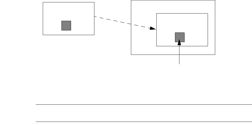
Chapter 37: LComp Functions Reference Introduction
L-Edit 13 User Guide Section 4 1543
Elements
LComp operations are performed on elements. An LComp element can be a cell, an instance, a port, or
a hierarchical combination of cell, instance, and/or port.
The general format for naming LComp elements is:
cellname/instance/port
where a slash (/) is used to separate levels of hierarchy. In addition, the following rules apply:
If an instance name is not unique within the design, then you must refer to the instance name as
source_cell:instance
A port may optionally be specified with the corresponding layername:
port:layername
If the first component of a name is a cell name, the result is in the context of that cell; otherwise, it
is in the context of the current cell.
For example, the element Top/Bottom:BotInst/Out refers to the port named Out in instance of cell
Bottom named BotInst, located in cell Top. The element Top/Bottom:BotInst/Out is illustrated below:
The instance named LastInstance refers to the last instance placed using one of the “Placement
Functions” (page 1566).
Note: To refer to an instance or port in an element name, you must use the associated
instance or port name. Unnamed instances and ports are inaccessible as elements.
Instance: BotInst
Port: Out
Cell: Top
Of Cell: Bottom
Cell: Bottom
Port: Out
“Top/Bottom:BotInst/Out”

Chapter 37: LComp Functions Reference Introduction
L-Edit 13 User Guide Section 4 1544
State Variables
LComp functions use a core set of state variables to determine how and where instances are placed in
the layout. The state variables and the key functions used to set them are listed in the following table.
See “State Functions” (page 1545) for additional functions that set or retrieve state variables.
Variable Definition Key Function
placement
position The (x, y) coordinates at which the next
instance or port will be placed. LComp has
an implicit composition capability; after an
instance is placed in the layout, the
placement position is automatically
incremented by the width or height of the
instance’s bounding box. The direction in
which the position is incremented is
determined by the composition direction (see
“LC_SetCompositionDirection” (page
1554)).
“LC_SetXYPlacementPosition”
(page 1558)
composition
direction The location in which an instance is placed
relative to the last placed instance. You can
build a layout composition in any of four
directions - up, down, left, or right.
“LC_SetCompositionDirection”
(page 1554)
reference
point The location within an instance that
corresponds to its (x, y) position in the
layout.
“LC_SetReferencePoint” (page
1546)
abutment type Determines how cell boundaries are defined.
Instances can be aligned by either their
minimum bounding boxes or by their
abutment boxes. The abutment box is the
smallest box enclosing all objects on the
abutment layer. The default abutment layer
is the Icon special layer in L-Edit.
“LC_SetAbutmentType” (page
1548)
orientation The transformation (rotation and/or
reflection) applied to instances when they
are placed in the layout.
“LC_SetPlacementOrientation”
(page 1550)
overlap The amount by which adjacent instance
boundaries overlap. Boundary definitions are
controlled by the abutment type (see
“LC_SetAbutmentType” (page 1548)).
“LC_SetPlacementOverlap” (page
1556)
Chapter 37: LComp Functions Reference State Functions
L-Edit 13 User Guide Section 4 1545
State Functions
LComp functions use a core set of global state variables to determine how and where instances are
placed in the layout. State functions allow you to set and retrieve state variable values.
“LC_SetReferencePoint” (page 1546) “LC_GetReferencePoint” (page 1547)
“LC_SetAbutmentType” (page 1548) “LC_GetAbutmentType” (page 1549)
“LC_SetPlacementOrientation” (page 1550) “LC_GetPlacementOrientation” (page 1551)
“LC_AddPlacementOrientation” (page 1552) “LC_SubtractPlacementOrientation” (page
1553)
“LC_SetCompositionDirection” (page 1554) “LC_GetCompositionDirection” (page 1555)
“LC_SetPlacementOverlap” (page 1556) “LC_GetPlacementOverlap” (page 1557)
“LC_SetXYPlacementPosition” (page 1558) “LC_GetXYPlacementPosition” (page 1559)
“LC_SetXPlacementPosition” (page 1560) “LC_GetXPlacementPosition” (page 1561)
“LC_SetYPlacementPosition” (page 1562) “LC_GetYPlacementPosition” (page 1563)
“LC_IncrementXPlacementPosition” (page
1564)
“LC_IncrementYPlacementPosition” (page
1565)

Chapter 37: LComp Functions Reference State Functions
LC_SetReferencePoint
L-Edit 13 User Guide Section 4 1546
LC_SetReferencePoint
RelativeTo LC_SetReferencePoint(RelativeTo place);
Description
Sets the current reference point for LComp placement and position functions. The reference point can
be the origin of the source cell’s coordinate system, or one of nine points on the object’s bounding box:
Return Value
Returns the previous reference point.
Parameters
The reference point place can be set to any of the nine points illustrated above (UL, TOP, UR, etc.).
When the value ORIGIN is used, the reference point is the origin of the source (instanced) cell’s
coordinate system.
See Also
“LC_GetReferencePoint” (page 1547), “LC_SetAbutmentType” (page 1548), “RelativeTo” (page
1610)
LL
UL
LEFT CENTER RIGHT
TOP
BOTTOM
UR
LR
Chapter 37: LComp Functions Reference State Functions
LC_GetReferencePoint
L-Edit 13 User Guide Section 4 1547
LC_GetReferencePoint
RelativeTo LC_GetReferencePoint(void);
Description
Returns the current reference point for LComp placement and position functions.
See Also
“LC_SetReferencePoint” (page 1546), “LC_SetAbutmentType” (page 1548), “RelativeTo” (page
1610)

Chapter 37: LComp Functions Reference State Functions
LC_SetAbutmentType
L-Edit 13 User Guide Section 4 1548
LC_SetAbutmentType
AbutTo LC_SetAbutmentType(AbutTo place);
Description
Determines how a cell’s bounding box is defined in LComp placement and position functions.
Return Value
Returns the previous abutment type.
Parameters
The parameter place can be set to either MBB (minimum bounding box) or ABUT.
When MBB is specified, the bounding box of a cell is the smallest box that encloses all geometry in the
cell, ignoring the text portions of labels. When ABUT is specified, the bounding box of a cell is the
smallest box that encloses all geometry on the abutment layer, ignoring the text portions of labels. The
default abutment layer is the Icon special layer in L-Edit; you can change the abutment layer using
LC_SetAbutmentLayer.
Note: A port is always bounded by the port box.
See Also
“LC_GetAbutmentType” (page 1549), “AbutTo” (page 1608)
Chapter 37: LComp Functions Reference State Functions
LC_SetPlacementOrientation
L-Edit 13 User Guide Section 4 1550
LC_SetPlacementOrientation
LOrientation LC_SetPlacementOrientation(LOrientation orient);
Description
Sets the orientation (rotation) in which instances or ports are placed.
Return Value
Returns the previous orientation setting.
Parameters
The parameter orient specifies a transformation (rotation and/or reflection) of the instance. Only the
following values are supported:
See Also
“LC_GetPlacementOrientation” (page 1551), “LC_AddPlacementOrientation” (page 1552),
“LC_SubtractPlacementOrientation” (page 1553), “LOrientation” (page 1449)
LNormalOrientation No transformation.
LRotate90 90 degree rotation.
LRotate180 180 degree rotation.
LRotate270 270 degree rotation.
LRotate0MirrorX Flips the instance horizontally (reflection).
LRotate90MirrorX Flips horizontally, then applies a 90 degree rotation.
LRotate180MirrorX Flips horizontally, then applies a 180 degree rotation.
LRotate270MirrorX Flips horizontally, then applies a 270 degree rotation.
Chapter 37: LComp Functions Reference State Functions
LC_GetPlacementOrientation
L-Edit 13 User Guide Section 4 1551
LC_GetPlacementOrientation
LOrientation LC_GetPlacementOrientation(void);
Description
Returns the current orientation for placing instances.
See Also
“LC_SetPlacementOrientation” (page 1550), “LC_AddPlacementOrientation” (page 1552),
“LC_SubtractPlacementOrientation” (page 1553), “LOrientation” (page 1449)
Chapter 37: LComp Functions Reference State Functions
LC_AddPlacementOrientation
L-Edit 13 User Guide Section 4 1552
LC_AddPlacementOrientation
LOrientation LC_AddPlacementOrientation(LOrientation orig, LOrientation
new_orientation);
Description
Computes the equivalent transformation obtained by following the transformation specified by orig
with the transformation specified by new_orientation.
Return Value
Returns the new orientation.
Parameters
The parameters orig and new_orientation are the first and second transformations, respectively. Only
the following transformations are supported:
See Also
“LC_SetPlacementOrientation” (page 1550), “LC_GetPlacementOrientation” (page 1551),
“LC_SubtractPlacementOrientation” (page 1553), “LOrientation” (page 1449)
LNormalOrientation No transformation.
LRotate90 90 degree rotation.
LRotate180 180 degree rotation.
LRotate270 270 degree rotation.
LRotate0MirrorX Flips the instance horizontally (reflection).
LRotate90MirrorX Flips horizontally, then applies a 90 degree rotation.
LRotate180MirrorX Flips horizontally, then applies a 180 degree rotation.
LRotate270MirrorX Flips horizontally, then applies a 270 degree rotation.
Chapter 37: LComp Functions Reference State Functions
LC_SubtractPlacementOrientation
L-Edit 13 User Guide Section 4 1553
LC_SubtractPlacementOrientation
LOrientation LC_SubtractPlacementOrientation(LOrientation orig, LOrientation
new_orientation);
Description
Computes the equivalent transformation obtained by first executing the transformation specified by
orig, then reversing the transformation specified by new_orientation.
Return Value
Returns the new orientation.
Parameters
The parameters orig and new_orientation are the original and subtracted transformations, respectively.
Only the following transformations are supported:
See Also
“LC_SetPlacementOrientation” (page 1550), “LC_GetPlacementOrientation” (page 1551),
“LC_AddPlacementOrientation” (page 1552), “LOrientation” (page 1449)
LNormalOrientation No transformation.
LRotate90 90 degree rotation.
LRotate180 180 degree rotation.
LRotate270 270 degree rotation.
LRotate0MirrorX Flips the instance horizontally (reflection).
LRotate90MirrorX Flips horizontally, then applies a 90 degree rotation.
LRotate180MirrorX Flips horizontally, then applies a 180 degree rotation.
LRotate270MirrorX Flips horizontally, then applies a 270 degree rotation.
Chapter 37: LComp Functions Reference State Functions
LC_SetCompositionDirection
L-Edit 13 User Guide Section 4 1554
LC_SetCompositionDirection
CompositionDirectionType LC_SetCompositionDirection(CompositionDirectionType
direction);
Description
Specifies the direction in which LComp places instances next to each other.
Return Value
Returns the previous composition direction.
Parameters
The parameter direction takes one of the following values:
UP (or VERTICAL)
DOWN
LEFT
RIGHT (or HORIZONTAL)
NONE
See Also
“LC_GetCompositionDirection” (page 1555), “CompositionDirectionType” (page 1609)
Chapter 37: LComp Functions Reference State Functions
LC_GetCompositionDirection
L-Edit 13 User Guide Section 4 1555
LC_GetCompositionDirection
CompositionDirectionType LC_GetCompositionDirection(void);
Description
Returns the current composition direction.
See Also
“LC_SetCompositionDirection” (page 1554), “CompositionDirectionType” (page 1609)
Chapter 37: LComp Functions Reference State Functions
LC_SetPlacementOverlap
L-Edit 13 User Guide Section 4 1556
LC_SetPlacementOverlap
LCoord LC_SetPlacementOverlap(LCoord overlap);
Description
Sets the placement overlap between instance or port boundaries in LComp positioning functions.
Return Value
Returns the previous placement overlap.
Parameters
The parameter overlap specifies a distance, in internal units, by which to overlap elements in either the
x- or y- direction. The direction of overlap (x or y) depends on the composition direction.
See Also
“LC_GetPlacementOverlap” (page 1557), “LC_SetCompositionDirection” (page 1554), “LCoord”
(page 1400)
Chapter 37: LComp Functions Reference State Functions
LC_GetPlacementOverlap
L-Edit 13 User Guide Section 4 1557
LC_GetPlacementOverlap
LCoord LC_GetPlacementOverlap(void);
Description
Returns the current placement overlap, in internal units, between instance or port boundaries in LComp
positioning functions.
See Also
“LC_GetPlacementOverlap” (page 1557), “LC_SetCompositionDirection” (page 1554), “LCoord”
(page 1400)
Chapter 37: LComp Functions Reference State Functions
LC_SetXYPlacementPosition
L-Edit 13 User Guide Section 4 1558
LC_SetXYPlacementPosition
LPoint LC_SetXYPlacementPosition(LCoord xpos, LCoord ypos);
Description
Sets the current (x, y) placement position to the point (xpos, ypos), where xpos and ypos are in
internal units.
See Also
“LC_GetXYPlacementPosition” (page 1559), “LC_SetXPlacementPosition” (page 1560),
“LC_GetXPlacementPosition” (page 1561), “LC_SetYPlacementPosition” (page 1562),
“LC_GetYPlacementPosition” (page 1563), “LC_IncrementXPlacementPosition” (page 1564),
“LC_IncrementYPlacementPosition” (page 1565)
Chapter 37: LComp Functions Reference State Functions
LC_GetXYPlacementPosition
L-Edit 13 User Guide Section 4 1559
LC_GetXYPlacementPosition
LPoint LC_GetXYPlacementPosition(void);
Description
Returns the current (x, y) placement position in internal units.
See Also
“LC_SetXYPlacementPosition” (page 1558), “LC_SetXPlacementPosition” (page 1560),
“LC_GetXPlacementPosition” (page 1561), “LC_SetYPlacementPosition” (page 1562),
“LC_GetYPlacementPosition” (page 1563), “LC_IncrementXPlacementPosition” (page 1564),
“LC_IncrementYPlacementPosition” (page 1565)
Chapter 37: LComp Functions Reference State Functions
LC_SetXPlacementPosition
L-Edit 13 User Guide Section 4 1560
LC_SetXPlacementPosition
LCoord LC_SetXPlacementPosition(LCoord newx);
Description
Sets the x-coordinate of the (x, y) placement position to newx (internal units).
See Also
“LC_SetXYPlacementPosition” (page 1558), “LC_GetXYPlacementPosition” (page 1559),
“LC_GetXPlacementPosition” (page 1561), “LC_SetYPlacementPosition” (page 1562),
“LC_GetYPlacementPosition” (page 1563), “LC_IncrementXPlacementPosition” (page 1564),
“LC_IncrementYPlacementPosition” (page 1565)
Chapter 37: LComp Functions Reference State Functions
LC_GetXPlacementPosition
L-Edit 13 User Guide Section 4 1561
LC_GetXPlacementPosition
LCoord LC_GetXPlacementPosition(void);
Description
Returns the x-coordinate of the current (x, y) placement position in internal units.
See Also
“LC_SetXYPlacementPosition” (page 1558), “LC_GetXYPlacementPosition” (page 1559),
“LC_SetXPlacementPosition” (page 1560), “LC_SetYPlacementPosition” (page 1562),
“LC_GetYPlacementPosition” (page 1563), “LC_IncrementXPlacementPosition” (page 1564),
“LC_IncrementYPlacementPosition” (page 1565)
Chapter 37: LComp Functions Reference State Functions
LC_SetYPlacementPosition
L-Edit 13 User Guide Section 4 1562
LC_SetYPlacementPosition
LCoord LC_SetYPlacementPosition(LCoord newy);
Description
Sets the y-coordinate of the (x, y) placement position to newy (internal units).
See Also
“LC_SetXYPlacementPosition” (page 1558), “LC_GetXYPlacementPosition” (page 1559),
“LC_SetXPlacementPosition” (page 1560), “LC_GetXPlacementPosition” (page 1561),
“LC_GetYPlacementPosition” (page 1563), “LC_IncrementXPlacementPosition” (page 1564),
“LC_IncrementYPlacementPosition” (page 1565)
Chapter 37: LComp Functions Reference State Functions
LC_GetYPlacementPosition
L-Edit 13 User Guide Section 4 1563
LC_GetYPlacementPosition
LCoord LC_GetYPlacementPosition(void);
Description
Returns the y-coordinate of the current (x, y) placement position.
See Also
“LC_SetXYPlacementPosition” (page 1558), “LC_GetXYPlacementPosition” (page 1559),
“LC_SetXPlacementPosition” (page 1560), “LC_GetXPlacementPosition” (page 1561),
“LC_SetYPlacementPosition” (page 1562), “LC_IncrementXPlacementPosition” (page 1564),
“LC_IncrementYPlacementPosition” (page 1565)
Chapter 37: LComp Functions Reference State Functions
LC_IncrementXPlacementPosition
L-Edit 13 User Guide Section 4 1564
LC_IncrementXPlacementPosition
LCoord LC_IncrementXPlacementPosition(LCoord newx);
Description
Increments the x-coordinate of the current (x, y) placement position by newx internal units.
See Also
“LC_SetXYPlacementPosition” (page 1558), “LC_GetXYPlacementPosition” (page 1559),
“LC_GetXPlacementPosition” (page 1561), “LC_SetYPlacementPosition” (page 1562),
“LC_GetYPlacementPosition” (page 1563), “LC_IncrementYPlacementPosition” (page 1565)
Chapter 37: LComp Functions Reference State Functions
LC_IncrementYPlacementPosition
L-Edit 13 User Guide Section 4 1565
LC_IncrementYPlacementPosition
LCoord LC_IncrementYPlacementPosition(LCoord newy);
Description
Increments the y-coordinate of the current (x, y) placement position by newy internal units.
See Also
“LC_SetXYPlacementPosition” (page 1558), “LC_GetXYPlacementPosition” (page 1559),
“LC_GetXPlacementPosition” (page 1561), “LC_SetYPlacementPosition” (page 1562),
“LC_GetYPlacementPosition” (page 1563), “LC_IncrementXPlacementPosition” (page 1564)
Chapter 37: LComp Functions Reference Placement Functions
LC_IncrementYPlacementPosition
L-Edit 13 User Guide Section 4 1566
Placement Functions
Placement functions allow you to easily create and/or place instances in the active cell. The position and
orientation of instances is determined by the state variables (see “State Functions” on page 1545).
“LC_Position” (page 1567) “LC_Instance” (page 1568)
“LC_Generate” (page 1569) “LC_Align” (page 1570)
“LC_InstanceAlign” (page 1571) “LC_GenerateAlign” (page 1572)

Chapter 37: LComp Functions Reference Placement Functions
LC_Position
L-Edit 13 User Guide Section 4 1567
LC_Position
LStatus LC_Position(char *element);
Description
Places an instance in the layout by placing the instance, a subcell, or a port at the current (x, y) position.
If a cell name is passed as an argument , LC_Position creates an instance of that cell, then places it.
After placing the instance, LC_Position updates the (x, y) placement position according to the current
composition direction.
Note: To create a named instance of a cell, use “LC_Instance” (page 1568). An instance
name is required if you wish to refer to the instance again in LComp functions.
Return Value
LStatusOK if successful. If an error occurs, returns the error value.
Parameters
The parameter element is the name of a cell, instance, or port (e.g., “Topcell/InstA/PortB”). See
“Elements” on page 1543 for an explanation of element names.
See Also
“LC_Instance” (page 1568)

Chapter 37: LComp Functions Reference Placement Functions
LC_Instance
L-Edit 13 User Guide Section 4 1568
LC_Instance
LInstance LC_Instance(char *classname, char *instname);
Description
Creates an instance named instname of the cell classname, then places the instance in the layout at the
current (x,y) position. After placing the instance, LC_Instance updates the (x, y) placement position
according to the current composition direction.
Note: To create an instance of a parameterized T-Cell, use “LC_Generate” (page 1569).
Return Value
Returns a pointer to the newly created instance if successful. If an error occurs, returns NULL.
Parameters
See Also
“LC_Position” (page 1567)
classname Name of the cell to be instanced.
instname Name of the newly created instance.
Chapter 37: LComp Functions Reference Placement Functions
LC_Generate
L-Edit 13 User Guide Section 4 1569
LC_Generate
LInstance LC_Generate(char *classname, char *instname, char **params);
Description
Creates an instance named instname of the T-Cell named classname, using the T-Cell parameter
values specified by params. After placing the instance, LC_Generate updates the (x, y) placement
position according to the current composition direction. This is similar to “LC_Instance” (page 1568),
with the addition of T-Cell parameter inputs.
Return Value
Returns a pointer to the newly created instance if successful. Otherwise, returns NULL.
Parameters
See Also
“LC_GenerateAlign” (page 1572)
classname Name of the T-Cell to be instanced.
instname Name of the newly created instance.
params T-Cell parameter values.

Chapter 37: LComp Functions Reference Placement Functions
LC_Align
L-Edit 13 User Guide Section 4 1570
LC_Align
LInstance LC_Align(char *element);
Description
Aligns the specified instance, subcell, or port next to the last placed instance. If a cell name is passed as
an argument , LC_Position creates an instance of that cell, then places it. After placing the instance,
LC_Align updates the (x, y) placement position according to the current composition direction.
Note: To create and align a named instance of a cell, use “LC_InstanceAlign” (page 1571).
An instance name is required if you wish to refer to the instance again in LComp
functions.
Return Value
Returns a pointer to the instance if successful. If an error occurs, returns NULL.
Parameters
The parameter element is the name of a cell, instance, or port (e.g., “Topcell/InstA/PortB”). See
“Elements” on page 1543 for an explanation of element names.
See Also
“LC_InstanceAlign” (page 1571)
Chapter 37: LComp Functions Reference Placement Functions
LC_InstanceAlign
L-Edit 13 User Guide Section 4 1571
LC_InstanceAlign
LInstance LC_InstanceAlign(char *classname, char *instname);
Description
Creates an instance named instname of the cell named classname, and aligns it next to the last placed
instance. This function also increments the current (x,y) position according to the current composition
direction.
Return Value
Returns a pointer to the newly created instance if successful. If an error occurs, returns NULL.
Parameters
See Also
“LC_Align” (page 1570)
classname Name of the cell to be instanced.
instname Name of the newly created instance.
Chapter 37: LComp Functions Reference Placement Functions
LC_GenerateAlign
L-Edit 13 User Guide Section 4 1572
LC_GenerateAlign
LInstance LC_GenerateAlign(char *classname, char *instname, char **params);
Description
Creates an instance of the T-Cell classname and positions it next to the last placed instance. The T-Cell
instance is created using parameter values specified by params, and it is assigned the instance name
instname. This function also increments the current (x,y) position according to the current composition
direction.
Return Value
Returns a pointer to the newly created instance.
Parameters
Example
LComp_SetPlacementOrientation(LRotate180MirrorX);
LComp_GenerateAlign("CELL", "NAME", tparams);
See Also
“LC_Generate” (page 1569)
classname Name of the T-Cell to be instanced.
instname Name of the newly created instance.
params T-Cell parameter values.
Chapter 37: LComp Functions Reference Position Functions
LC_GenerateAlign
L-Edit 13 User Guide Section 4 1573
Position Functions
Position functions allow you to retrieve information about the position or size of an element:
“LC_GetPoint” (page 1574) “LC_GetPointEX” (page 1575)
“LC_GetPlacementRect” (page 1576) “LC_GetPlacementRectEX” (page 1577)
“LC_GetElementWidth” (page 1578) “LC_GetElementHeight” (page 1579)
Chapter 37: LComp Functions Reference Position Functions
LC_GetPoint
L-Edit 13 User Guide Section 4 1574
LC_GetPoint
LPoint LC_GetPoint(char *element);
Description
Gets the (x,y) location, in internal units, of the specified element. The location is specified using the
current settings for the element boundary and reference point. To get the element’s location with respect
to particular boundary and reference point definitions, use “LC_GetPointEX” (page 1575).
Return Value
Returns an (x, y) location in internal units.
Parameters
The parameter element is the name of a cell, instance, or port (e.g., “Topcell/InstA/PortB”). See
“Elements” on page 1543 for an explanation of element names.
See Also
“LC_GetPointEX” (page 1575), “LPoint” (page 1458)
Chapter 37: LComp Functions Reference Position Functions
LC_GetPointEX
L-Edit 13 User Guide Section 4 1575
LC_GetPointEX
LPoint LC_GetPointEX(AbutTo rect, RelativeTo point, char *element);
Description
Gets the location of the specified element, using the abutment type and reference point specified by
rect and point, respectively.
Return Value
Returns the (x, y) position, in internal units, of the specified element.
Parameters
See Also
“LC_GetPoint” (page 1574), “LPoint” (page 1458)
rect Specifies the abutment type, which determines the boundary
definition for the specified element. Must be one of the following
values:
MBB—Minimum bounding box of the cell’s geometry, excluding
labels. For ports, MBB is the smallest box that encloses the port
and its associated label.
ABUT—Smallest box that encloses all geometry on the cell’s
abutment layer. For ports, ABUT is equal to the port box,
excluding its label.
point Reference point at which the element’s location is reported. Possible
values are:
LEFT—center left point of the bounding box
RIGHT—center right point of the bounding box
CENTER—center of the bounding box
TOP—upper center point of the bounding box
BOTTOM—lower center point of the bounding box
UL—upper left corner of the bounding box
LL—lower left corner of the bounding box
UR—upper right corner of the bounding box
LR—lower right corner of the bounding box
ORIGIN—origin of the instanced cell’s coordinate system
element Name of a cell, instance, or port (e.g., “Topcell/InstA/PortB”). See
“Elements” on page 1543 for an explanation of element names.
Chapter 37: LComp Functions Reference Position Functions
LC_GetPlacementRect
L-Edit 13 User Guide Section 4 1576
LC_GetPlacementRect
LRect LC_GetPlacementRect(char *element);
Description
Gets the coordinates corresponding to the rectangle that bounds the specified element. The element
boundary is defined according to the current abutment type; see “LC_SetAbutmentType” (page 1548).
Return Value
Returns two pairs of coordinates representing the upper right and lower left corners of the rectangle. See
“LRect” (page 1461) for the structure definition.
Parameters
The parameter element is the name of a cell, instance, or port (e.g., “Topcell/InstA/PortB”). See
“Elements” on page 1543 for an explanation of element names.
See Also
“LC_GetPlacementRectEX” (page 1577), “LC_GetPoint” (page 1574), “LPoint” (page 1458)
Chapter 37: LComp Functions Reference Position Functions
LC_GetPlacementRectEX
L-Edit 13 User Guide Section 4 1577
LC_GetPlacementRectEX
LRect LC_GetPlacementRectEX(AbutTo recttype, char *element);
Description
Gets the coordinates corresponding to the rectangle that bounds the specified element. The boundary
definition used (abutment or minimum bounding box) is specified by the recttype parameter.
Return Value
Returns two pairs of coordinates representing the upper right and lower left corners of the rectangle. See
“LRect” (page 1461) for the structure definition.
Parameters
See Also
“LC_GetPlacementRect” (page 1576), “LC_GetPoint” (page 1574), “LPoint” (page 1458)
recttype Specifies the abutment type, which determines the boundary
definition for the specified element. Must be one of the following
values:
MBB—Minimum bounding box of the cell’s geometry, excluding
labels. For ports, MBB is the smallest box that encloses the port
and its associated label.
ABUT—Smallest box that encloses all geometry on the cell’s
abutment layer. For ports, ABUT is equal to the port box,
excluding its label.
element Name of a cell, instance, or port (e.g., “Topcell/InstA/PortB”). See
“Elements” on page 1543 for an explanation of element names.
Chapter 37: LComp Functions Reference Position Functions
LC_GetElementWidth
L-Edit 13 User Guide Section 4 1578
LC_GetElementWidth
LCoord LC_GetElementWidth(char *element);
Definition
Gets the width, in internal units, of the default bounding box for the specified element.
Return Value
Returns the width in internal units.
Parameters
The parameter element is the name of a cell, instance, or port (e.g., “Topcell/InstA/PortB”). See
“Elements” on page 1543 for an explanation of element names.
See Also
“LC_GetElementHeight” (page 1579)
Chapter 37: LComp Functions Reference Position Functions
LC_GetElementHeight
L-Edit 13 User Guide Section 4 1579
LC_GetElementHeight
LCoord LC_GetElementHeight(char *element);
Description
Gets the height of the specified element’s default bounding box.
Return Value
Returns the height in internal units.
Parameters
The parameter element is the name of a cell, instance, or port (e.g., “Topcell/InstA/PortB”). See
“Elements” on page 1543 for an explanation of element names.
See Also
“LC_GetElementWidth” (page 1578)
Chapter 37: LComp Functions Reference Geometry Functions
LC_GetElementHeight
L-Edit 13 User Guide Section 4 1580
Geometry Functions
The following geometry functions allow you to automate creation of drawn objects in the active cell:
“LC_StartWire” (page 1581) “LC_AddWirePoint” (page 1582)
“LC_EndWire” (page 1583) “LC_CreateBox” (page 1584)
“LC_CreateCircle” (page 1585) “LC_CreatePort” (page 1586)
“LC_StartPolygon” (page 1587) “LC_AddPolygonPoint” (page 1588)
“LC_EndPolygon” (page 1589)
Chapter 37: LComp Functions Reference Geometry Functions
LC_StartWire
L-Edit 13 User Guide Section 4 1581
LC_StartWire
LStatus LC_StartWire(char *layername, LCoord width);
Description
Starts a wire of width width on the specified layername. To add points to the wire, including a start and
end point, use “LC_AddWirePoint” (page 1582).
Return Value
LStatusOK if successful. If an error occurs, returns the error value.
Parameters
See Also
“LC_AddWirePoint” (page 1582), “LC_EndWire” (page 1583)
layername Name of the layer on which to begin drawing a wire (e.g., “Metal1”).
width Width of the wire in internal units.

Chapter 37: LComp Functions Reference Geometry Functions
LC_AddWirePoint
L-Edit 13 User Guide Section 4 1582
LC_AddWirePoint
LPoint LC_AddWirePoint(LPoint point);
Description
Adds a point at location point to a wire created with “LC_StartWire” (page 1581).
Note: If a new wire has not been created with LC_StartWire, an error message is displayed.
Return Value
Returns the new wire point.
Parameters
The parameter point is the (x, y) location, in internal units, at which to create the next wire point.
See Also
“LC_StartWire” (page 1581), “LC_EndWire” (page 1583), “LPoint” (page 1458)

Chapter 37: LComp Functions Reference Geometry Functions
LC_EndWire
L-Edit 13 User Guide Section 4 1583
LC_EndWire
LObject LC_EndWire(void);
Description
Ends the wire in progress, which was created with “LC_StartWire” (page 1581).
Note: If a new wire has not been created with LC_StartWire, an error message is displayed.
Return Value
Returns a pointer to the completed wire.
See Also
“LC_StartWire” (page 1581), “LC_AddWirePoint” (page 1582), “LObject” (page 1448)
Chapter 37: LComp Functions Reference Geometry Functions
LC_CreateBox
L-Edit 13 User Guide Section 4 1584
LC_CreateBox
LObject LC_CreateBox(char *layername, LPoint lowerleft, LPoint upperright);
Description
Draws a box on the layer named layername, with the lower left and upper right corners located at the
points lowerleft and upperright, respectively.
Return Value
Returns a pointer to the box.
Parameters
See Also
“LPoint” (page 1458), “LObject” (page 1448)
layername Name of the layer on which to draw the box (e.g., “Poly”).
lowerleft Point specifying the (x,y) location, in internal units, of the lower left
corner of the box.
upperright Point specifying the (x,y) location, in internal units, of the upper right
corner of the box.
Chapter 37: LComp Functions Reference Geometry Functions
LC_CreateCircle
L-Edit 13 User Guide Section 4 1585
LC_CreateCircle
LObject LC_CreateCircle(char *layername, LPoint center, LCoord radius);
Description
Draws a circle on the layer named layername, with the specified center point and radius.
Return Value
Returns a pointer to the newly created circle.
Parameters
See Also
“LPoint” (page 1458), “LCoord” (page 1400), “LObject” (page 1448)
layername Name of the layer on which to draw the circle.
center (x, y) coordinates, in internal units, of the circle’s center point.
radius Radius, in internal units, of the circle.
Chapter 37: LComp Functions Reference Geometry Functions
LC_CreatePort
L-Edit 13 User Guide Section 4 1586
LC_CreatePort
LPort LC_CreatePort(char *layername, LPoint lowerleft, LPoint upperright,
char *portname);
Description
Creates a port named portname on layer layername. The lower left and upper right corners of the port
box are located at the points lowerleft and upperright, respectively.
Return Value
Returns a pointer to the newly created port.
Parameters
See Also
“LPoint” (page 1458), “LObject” (page 1448)
layername Layer on which to create the port.
lowerleft (x, y) coordinates, in internal units, of the lower left corner of the port
box.
upperright (x, y) coordinates, in internal units, of the upper right corner of the
port box.
portname Name of the newly created port.
Chapter 37: LComp Functions Reference Geometry Functions
LC_StartPolygon
L-Edit 13 User Guide Section 4 1587
LC_StartPolygon
LStatus LC_StartPolygon(char *layername);
Description
Starts drawing a polygon on the specified layer.
Return Value
LStatusOK if successful. If an error occurs, returns the error value.
Parameters
The parameter layername is the name of the layer on which to begin drawing a polygon.
See Also
“LC_AddPolygonPoint” (page 1588), “LC_EndPolygon” (page 1589), “LStatus” (page 1468)

Chapter 37: LComp Functions Reference Geometry Functions
LC_AddPolygonPoint
L-Edit 13 User Guide Section 4 1588
LC_AddPolygonPoint
LPoint LC_AddPolygonPoint(LPoint point);
Description
Adds a point at the location point to the current polygon, which is created with “LC_StartPolygon”
(page 1587).
Note: If a new polygon has not been created with LC_StartPolygon, an error message is
displayed.
Return Value
Returns the new polygon point.
Parameters
The parameter point is the (x,y) location, in internal units, at which to create the next polygon point.
See Also
“LC_StartPolygon” (page 1587), “LC_EndPolygon” (page 1589), “LPoint” (page 1458)

Chapter 37: LComp Functions Reference Geometry Functions
LC_EndPolygon
L-Edit 13 User Guide Section 4 1589
LC_EndPolygon
LObject LC_EndPolygon(void);
Description
Ends the polygon in progress, which was created with “LC_StartPolygon” (page 1587).
Note: If a new polygon has not been created with LC_StartPolygon, an error message is
displayed.
Return Value
Returns a pointer to the newly created polygon.
See Also
“LC_StartPolygon” (page 1587), “LC_AddPolygonPoint” (page 1588), “LObject” (page 1448)
Chapter 37: LComp Functions Reference Utility Functions
LC_EndPolygon
L-Edit 13 User Guide Section 4 1590
Utility Functions
Utility functions include file and cell management, conversions between technology units, and “push”
and “pop” functions for saving or retrieving a previous state.
“LC_Push” (page 1591) “LC_Pop” (page 1592) “LC_DiskFileExists” (page
1593)
“LC_DiskFileDelete” (page
1594)
“LC_DiskFileRename” (page
1595)
“LC_Lambda” (page 1596)
“LC_Microns” (page 1597) “LC_InMicrons” (page 1598) “LC_CellOpen” (page 1599)
“LC_CellNew” (page 1600) “LC_CellClose” (page 1601) “LC_CellExists” (page 1602)
Chapter 37: LComp Functions Reference Utility Functions
LC_Push
L-Edit 13 User Guide Section 4 1591
LC_Push
void LC_Push(void);
Description
Saves the current state to a stack, where it can be retrieved using “LC_Pop” (page 1592). LC_Push
holds the following state variables in memory:
current file and cell
last placed instance
(x,y) placement position
placement overlap
abutment type
reference point
orientation
abutment layer
See Also
“LC_Pop” (page 1592)
Chapter 37: LComp Functions Reference Utility Functions
LC_DiskFileExists
L-Edit 13 User Guide Section 4 1593
LC_DiskFileExists
int LC_DiskFileExists(char *name);
Description
Checks to see if the file name or name.tdb exists.
Return Value
Returns 1 if the file exists, 0 otherwise.
Parameters
The parameter name is the filename, in quotes, of the file being checked.
See Also
“LC_CellExists” (page 1602)
Chapter 37: LComp Functions Reference Utility Functions
LC_DiskFileDelete
L-Edit 13 User Guide Section 4 1594
LC_DiskFileDelete
LStatus LC_DiskFileDelete(char *filename);
Description
Deletes the file named filename or filename.tdb.
Return Value
LStatusOK if successful. If an error occurs, returns the error value.
Parameters
The parameter name is the filename, in quotes, of the file being deleted.
See Also
“LC_DiskFileRename” (page 1595), “LC_DiskFileExists” (page 1593), “LStatus” (page 1468)
Chapter 37: LComp Functions Reference Utility Functions
LC_DiskFileRename
L-Edit 13 User Guide Section 4 1595
LC_DiskFileRename
LStatus LC_DiskFileRename(char *from, char *to);
Description
Renames the specified file to the new name.
Return Value
LStatusOK if successful. If an error occurs, returns the error value.
Parameters
See Also
“LC_DiskFileExists” (page 1593), “LC_DiskFileDelete” (page 1594)
from Original filename, in quotes.
to New filename, in quotes.
Chapter 37: LComp Functions Reference Utility Functions
LC_Lambda
L-Edit 13 User Guide Section 4 1596
LC_Lambda
LCoord LC_Lambda(double lambda);
Description
Converts an input value from lambda units to internal units.
Return Value
Returns the input value in internal units.
Parameters
The parameter lambda is a distance expressed in “lambda” units.
See Also
“LC_Microns” (page 1597), “LC_InMicrons” (page 1598)
Chapter 37: LComp Functions Reference Utility Functions
LC_Microns
L-Edit 13 User Guide Section 4 1597
LC_Microns
LCoord LC_Microns(double dist);
Description
Converts an input value from microns to internal units.
Return Value
Returns the input value in internal units.
Parameters
The parameter dist is a distance expressed in microns.
See Also
“LC_Lambda” (page 1596), “LC_InMicrons” (page 1598)
Chapter 37: LComp Functions Reference Utility Functions
LC_InMicrons
L-Edit 13 User Guide Section 4 1598
LC_InMicrons
double LC_InMicrons(LCoord internal);
Description
Converts an input value from internal units to microns.
Return Value
Returns the input value in microns.
Parameters
The parameter internal is a distance expressed in internal units.
See Also
“LC_Lambda” (page 1596), “LC_Microns” (page 1597)
Chapter 37: LComp Functions Reference Utility Functions
LC_CellOpen
L-Edit 13 User Guide Section 4 1599
LC_CellOpen
LCell LC_CellOpen(char *cellname);
Description
Opens the cell named cellname, or creates a new cell named cellname.
Return Value
Returns a pointer to the opened cell.
Parameters
The parameter cellname is the name of the cell to be opened.
See Also
“LC_CellNew” (page 1600), “LC_CellClose” (page 1601), “LC_CellExists” (page 1602), “LCell”
(page 1397)
Chapter 37: LComp Functions Reference Utility Functions
LC_CellNew
L-Edit 13 User Guide Section 4 1600
LC_CellNew
LCell LC_CellNew(char *cellname);
Description
Creates a new cell named cellname. If a cell named cellname already exists, its contents are deleted.
Return Value
Returns a pointer to the new cell.
Parameters
The parameter cellname is the name of the new cell.
See Also
“LC_CellOpen” (page 1599), “LC_CellClose” (page 1601), “LC_CellExists” (page 1602), “LCell”
(page 1397)
Chapter 37: LComp Functions Reference Utility Functions
LC_CellClose
L-Edit 13 User Guide Section 4 1601
LC_CellClose
LStatus LC_CellClose(int flags);
/* flags for CellClose */
#define UPDATE_ABUT 1
#define LOCK_CELL 2
#define UNLOCK_CELL 4
#define NO_LIST 8
Description
Closes the current cell and applies the specified flags.
Return Value
LStatusOK if successful. If an error occurs, returns the error value.
Parameters
Any combination of the following flags may be used:
See Also
“LC_CellNew” (page 1600), “LC_CellOpen” (page 1599), “LC_CellExists” (page 1602), “LStatus”
(page 1468)
UPDATE_ABUT Updates the cell’s abutment box on the abutment layer.
LOCK_CELL Locks the cell to prevent editing.
UNLOCK_CELL Unlocks the cell to allow editing.
NO_LIST Hides the cell from the cell list in the Design Navigator and other cell
dialogs.
Chapter 37: LComp Functions Reference Utility Functions
LC_CellExists
L-Edit 13 User Guide Section 4 1602
LC_CellExists
int LC_CellExists(char *cellname);
escription
Checks to see if the cell named cellname exists in the current TDB file.
Return Value
Returns 1 if the cell exists, 0 otherwise.
Parameters
The parameter cellname is the name of the cell to be checked.
See Also
“LC_CellOpen” (page 1599), “LC_CellClose” (page 1601), “LC_CellNew” (page 1600),
“LC_DiskFileExists” (page 1593)
Chapter 37: LComp Functions Reference Utility Functions
LC_PropagatePorts
L-Edit 13 User Guide Section 4 1603
LC_PropagatePorts
LStatus LC_PropagatePorts(char *instname, char *suffix);
Description
Creates duplicates of all ports in the instance named instname and places them in the current cell. The
duplicate ports are named PORTNAMEsuffix, where PORTNAME is the name of the original port.
Return Value
LStatusOK if successful. If an error occurs, returns the error value.
Parameters
instname Name of the instance, in quotes, from which to duplicate ports.
suffix Text string that will be appended to the names of new (duplicate)
ports (e.g., “.bottom”). If the suffix is NULL, port names are
unchanged from the originals.
Chapter 37: LComp Functions Reference Utility Functions
LC_Trace
L-Edit 13 User Guide Section 4 1604
LC_Trace
void LC_Trace(int trace);
Description
Turns tracing on or off. When tracing is on, every LComp function reports its execution history to the
UPI log file. To specify a separate file for trace output, use “LC_TraceFile” (page 1605).
Parameters
See Also
“LC_TraceFile” (page 1605)
trace On or off state of LComp tracing. Only two values are supported:
ON—turns tracing on
OFF—turns tracing off
Chapter 37: LComp Functions Reference Utility Functions
LC_TraceFile
L-Edit 13 User Guide Section 4 1605
LC_TraceFile
void LC_TraceFile(char *filename);
Description
Specifies a file for trace output. When tracing is on, every LComp function traces its execution history
to the trace file filename. Use “LC_Trace” (page 1604) to turn tracing on and off.
Parameters
See Also
“LC_Trace” (page 1604)
filename Name of the file for trace output; the filename must be enclosed in
quotes.
Chapter 37: LComp Functions Reference Utility Functions
LC_PlaceMarkerAtCurrentPos
L-Edit 13 User Guide Section 4 1606
LC_PlaceMarkerAtCurrentPos
LPoint LC_PlaceMarkerAtCurrentPos(char *label);
Description
Places a point port with the text label at the current (x, y) position. Point ports can be useful for
debugging.
Return Value
Returns a pointer to the current (x, y) position.
Parameters
label Text string to label the newly created point port (e.g., “test_port”).
Chapter 37: LComp Functions Reference Utility Functions
AbutTo
L-Edit 13 User Guide Section 4 1608
AbutTo
typedef enum
{
MBB, Mbb = MBB.
ABUT, Abut = ABUT
} AbutTo;
Description
MBB Defines the bounding box of a cell as the smallest box that encloses
all geometry in the cell, ignoring port labels. For a port, the minimum
bounding box is the smallest box that encloses all of the port,
excluding its label.
ABUT Defines the bounding box of a cell as the smallest box that encloses
all geometry on the abutment layer, which is typically the Icon layer
in L-Edit. Specify the abutment layer using LC_SetAbutmentLayer.
For ports, the port box (excluding the label) is the bounding box.
Chapter 37: LComp Functions Reference Utility Functions
CompositionDirectionType
L-Edit 13 User Guide Section 4 1609
CompositionDirectionType
typedef long CompositionDirectionType;
Definition
Direction in which instances are placed consecutively. Only the following values are supported:
UP (or VERTICAL)
DOWN
LEFT
RIGHT (or HORIZONTAL)
NONE
When set to NONE, the (x, y) placement position is not incremented after placing an instance.
Chapter 37: LComp Functions Reference Utility Functions
RelativeTo
L-Edit 13 User Guide Section 4 1610
RelativeTo
typedef long RelativeTo;
Description
Reference point for LComp placement and position functions. The reference point can be the origin of
the source cell’s coordinate system, or one of nine points on the object’s bounding box:
When the value ORIGIN is used, the reference point is the origin of the source (instanced) cell’s
coordinate system.
LL
UL
LEFT CENTER RIGHT
TOP
BOTTOM
UR
LR
Chapter 37: LComp Functions Reference Examples
RelativeTo
L-Edit 13 User Guide Section 4 1611
Examples
The following pages show the T-Cell code used in four L-Edit design examples:
“Logo Generator” (page 1612)
“Buffer” (page 1614)
“Matched Dual Capacitor Array” (page 1616)
“Decoder” (page 1623)
All four examples are included as TDB sample files with L-Edit. They are located in the folder
install_dir/Samples/T-Cells, where install_dir is the directory in which L-Edit was installed.
Chapter 37: LComp Functions Reference Examples
Logo Generator
L-Edit 13 User Guide Section 4 1612
Logo Generator
The logo generator is included in the file install_dir/samples/T-Cells/LayoutText.tdb. This file
includes a set of layout cells that each represent a single character. The T-Cell LOGO converts a
user-specified text string to block letters using alphabet cells.
T-Cell Code
module LOGO_code
{
#include <stdlib.h>
#include <math.h>
#include <string.h>
#include <stdio.h>
#include "ldata.h"
#include "lcomp.h"
void PlaceCharacter(char ch)
{
if ( isalnum( ch ) )
LC_Position( LFormat("_alphabet_%c", toupper( ch )));
/* otherwise, need to special-case it */
else if (isspace( ch ))
LC_Position("_alphabet_space");
else {
switch ( ch ) {
case '+': LC_Position("_alphabet_+"); break;
case '-': LC_Position("_alphabet_-"); break;
case '_': LC_Position("_alphabet__"); break;
case '*': LC_Position("_alphabet_*"); break;
case ':': LC_Position("_alphabet_colon"); break;
case '\'': LC_Position("_alphabet_apostrophe"); break;
case '/': LC_Position("_alphabet_slash"); break;
case '\\': LC_Position("_alphabet_backslash"); break;
case '.': LC_Position("_alphabet_period"); break;
case ',': LC_Position("_alphabet_comma"); break;
case '(': LC_Position("_alphabet_("); break;
case ')': LC_Position("_alphabet_)"); break;
default:
LDialog_MsgBox ( LFormat ( "Unknown character '%c'
(code %d)\n", ch, ch ));
}
}
}
void convert_string(char *s)
{
while (*s)
{
/* note hardwired check for \ */
if (*s == 92 && *(s+1) == 'n')
{
char *f = s;
*f++ = '\n';
for ( ; *(f+1) ; f++)
*f = *(f+1);
*f = '\0';
Chapter 37: LComp Functions Reference Examples
Logo Generator
L-Edit 13 User Guide Section 4 1613
}
s++;
}
}
/* TODO: Put local variables and functions here. */
void LOGO_main(void)
{
/* Parameter variables */
LCell cellCurrent;
const char* text;
char s[1000];
char *t;
int first = 1;
/* Initialize parameter variables */
cellCurrent = (LCell)LMacro_GetNewTCell();
text = (const char*)LCell_GetParameter(cellCurrent,
"text");
/* TODO: Begin custom generator code.*/
strcpy(s, text);
convert_string(s);
LC_InitializeState();
LC_CurrentCell = cellCurrent;
LC_SetCompositionDirection(HORIZONTAL);
LC_SetReferencePoint(LL);
for (t = s; *t; t++)
{
if ( *t == '\n' )
{
LC_SetXPlacementPosition(0);
LC_IncrementYPlacementPosition(-
LC_GetElementHeight("_alphabet_A"));
}
else {
PlaceCharacter(*t);
}
}
LC_CellClose(UPDATE_ABUT);
/* End custom generator code.*/
}
}
LOGO_main();
Chapter 37: LComp Functions Reference Examples
Buffer
L-Edit 13 User Guide Section 4 1614
Buffer
The file install_dir/samples/T-Cells/buffer.tdb illustrates a buffer generator. The T-Cell buffer
contains code to generate a buffer cell with a user-specified drive value.
T-Cell Code
module BUFFER_code
{
#include <stdlib.h>
#include <math.h>
#include <string.h>
#include <stdio.h>
#include "ldata.h"
/* Begin -- Remove this block if you are not using L-Comp. */
#include "lcomp.h"
/* End */
/* TODO: Put local variables and functions here. */
void BUFFER_main(void)
{
/* Parameter variables */
LCell cellCurrent;
int DRIVE;
int in, out;
LPoint pt;
/* Initialize parameter variables */
cellCurrent = (LCell)LMacro_GetNewTCell();
DRIVE = (int)LCell_GetParameter(cellCurrent, "DRIVE");
/* Begin -- Remove this block if you not using L-Comp. */
LC_InitializeState();
LC_CurrentCell = cellCurrent;
/* End */
/* TODO: Begin custom generator code.*/
/* check for sane argument */
if (! ( DRIVE > 0 && DRIVE <= 100 ) )
{
LDialog_MsgBox("Buffer drive must be between 1 and
100");
LUpi_SetReturnCode(1); /* error */
return;
}
LC_SetAbutmentType(ABUT);
LC_SetCompositionDirection(RIGHT);
/* put down a port used for our final Abut box */
pt.x = -LC_Lambda(4.5);
pt.y = 0;
LC_CreatePort( LC_GetAbutmentLayer(), pt, pt, "Lower left");
/* first, figure out how many first-stage drivers we need */
Chapter 37: LComp Functions Reference Examples
Buffer
L-Edit 13 User Guide Section 4 1615
in = 1 + ( DRIVE - 2 ) / 3;
/* now, build the first-stage */
for ( ; in > 0; in-- )
{
if ( in & 1 ) LC_SetPlacementOrientation(NONE);
else LC_SetPlacementOrientation(LRotate0MirrorX);
LC_InstanceAlign("BUFFER_SLICE", LFormat("in_%d", in));
}
/* put down the core */
LC_InstanceAlign("BUFFER_CORE", "core");
/* build the output stage */
for (out = 0; out < DRIVE; out++ )
{
if ( out & 1 )
LC_SetPlacementOrientation(LRotate0MirrorX);
else LC_SetPlacementOrientation(NONE);
LC_InstanceAlign("BUFFER_SLICE", LFormat("out_%d",
out));
}
/* propagate the I/O ports */
LC_PropagatePorts("core", "");
/* now update the Abutment box */
/* put down a port used for our final Abut box */
pt.x = LC_x + LC_Lambda(4.5);
pt.y = 0;
LC_CreatePort( LC_GetAbutmentLayer(), pt, pt, "Lower right");
LC_CellClose(UPDATE_ABUT);
/* End custom generator code.*/
}
}
BUFFER_main();
Chapter 37: LComp Functions Reference Examples
Matched Dual Capacitor Array
L-Edit 13 User Guide Section 4 1616
Matched Dual Capacitor Array
The file for this example is install_dir/samples/T-Cells/MatchedDualCapacitorArray.tdb. The T-Cell
MatchedDualCapacitorArray creates two matched capacitors out of an array of unit capacitors. It also
creates dummy capacitors around the array to improve matching.
T-Cell Code
module capacitorarray_code
{
#include <stdlib.h>
#include <math.h>
#include <string.h>
#include <stdio.h>
#include "ldata.h"
/* Begin -- Remove this block if you are not using L-Comp. */
#include "lcomp.h"
/* End */
//*************************************************************************
//* GLOBAL Variables:
//*************************************************************************
LCoord m1width, m2width, actwidth, polywidth, cntwidth, actovercnt,
polyovercnt, m1overcnt, m2overvia, seloveract;
//*************************************************************************
//* FUNCTIONS:
//*************************************************************************
void square( char * layer, LPoint center, LCoord width )
{
LPoint pt1, pt2;
pt1.x = center.x - width / 2;
pt1.y = center.y - width / 2;
pt2.x = center.x + width / 2;
pt2.y = center.y + width / 2;
LC_CreateBox( layer, pt1, pt2);
}
/*
void cell(LPoint center, int flip, LCoord sz)
{
LPoint pt = center;
}
*/
void capacitorarray_main(void)
{
/* Parameter variables */
LCell cellCurrent;
int x;
int y;
double size;
/* Initialize parameter variables */
cellCurrent = (LCell)LMacro_GetNewTCell();
x = (int)LCell_GetParameter(cellCurrent, "x");
Chapter 37: LComp Functions Reference Examples
Matched Dual Capacitor Array
L-Edit 13 User Guide Section 4 1617
y = (int)LCell_GetParameter(cellCurrent, "y");
size = atof((const
char*)LCell_GetParameter(cellCurrent, "size"));
/* Begin -- Remove this block if you not using L-Comp. */
LC_InitializeState();
LC_CurrentCell = cellCurrent;
/* End */
/* TODO: Begin custom generator code.*/
{
LCoord sz;
int i, j;
LPoint pt;
LCoord xpitch, ypitch;
LCoord xmin, xmax, ymin, ymax;
LPoint newpt;
if(size < 16)
{
LDialog_MsgBox("Can't build T-Cell cap_cell with
dimension less than 16");
LUpi_SetReturnCode(1);
return;
}
//Warn if there are an odd number of unit capacitors.
if((x*y) % 2)
{
if(LDialog_YesNoBox("There are an odd number of
unit capacitors.\nThis will causes the a mismatch
between the two capacitors.\nDo you want to
continue?") == LCANCEL)
{
LUpi_SetReturnCode(1);
return;
}
}
/* initialize all the variables used for design rule
dimensions */
sz = LC_Microns(size);
m1width = LC_Microns(3);
m2width = LC_Microns(3);
actwidth = LC_Microns(3);
polywidth = LC_Microns(2);
cntwidth = LC_Microns(2);
actovercnt = LC_Microns(1.5);
polyovercnt = LC_Microns(1.5);
m1overcnt = LC_Microns(1);
seloveract = LC_Microns(2);
m2overvia = LC_Microns(1);
xpitch = sz + 2*polywidth + 2*polyovercnt + 2*cntwidth +
polyovercnt;
ypitch = sz + 2*polywidth + 2*actovercnt + cntwidth +
2*actwidth;
xmin = xmax = ymin = ymax = 0;
Chapter 37: LComp Functions Reference Examples
Matched Dual Capacitor Array
L-Edit 13 User Guide Section 4 1618
for(j = 0; j < y+2; j++)
{
pt.y = j * ypitch;
for (i = 0; i < x+2; i++ )
{
pt.x = i * xpitch;
/* now actually build the capacitor */
square("Poly", pt, sz);
square("Capacitor ID", pt, sz);
// Don't forget to add Cap ID to the
// section of poly
// that routes to the cap.
{
LPoint pt1, pt2;
if(j & 1)
{
pt1.x = pt.x - sz/2 -
polywidth;
pt2.x = pt.x - sz/2;
}
else
{
pt1.x = pt.x + sz/2;
pt2.x = pt.x + sz/2 +
polywidth;
}
LCoord nPolyRoutingWidth = (cntwidth
+ 2*polyovercnt);
pt1.y = pt.y - (nPolyRoutingWidth/
2);
pt2.y = pt1.y + nPolyRoutingWidth;
LC_CreateBox("Capacitor ID", pt1,
pt2);
}
square("Active", pt, sz + 2*polywidth);
// Mark the caps that are dummy caps for
// matching.
if((j==0) || (j==y+1) || (i==0) ||
(i==x+1))
{
LPoint pt1 = LPoint_Set(pt.x-sz/2,
pt.y-sz/2);
LPoint pt2 = LPoint_Set(pt1.x+sz,
pt1.y+sz);
LPort pPort = LC_CreatePort("Label",
pt1, pt2, "Dummy");
LPort_SetTextAlignment(pPort,
PORT_TEXT_MIDDLE|PORT_TEXT_CENTER);
}
/* poly connection */
newpt = pt;
if (j & 1)
newpt.x -= xpitch/2;
else
newpt.x += xpitch/2;
Chapter 37: LComp Functions Reference Examples
Matched Dual Capacitor Array
L-Edit 13 User Guide Section 4 1619
square("Poly", newpt, cntwidth +
2*polyovercnt);
LC_CreatePort("Metal1", newpt, newpt,
LFormat("A[%d][%d]", i, j));
if ( i > 0 && i <= x && j > 0 && j <= y )
{
square("Poly Contact", newpt,
cntwidth);
square("Metal1", newpt, cntwidth +
2*m1overcnt);
square("Via1", newpt, cntwidth);
square("Metal2", newpt, cntwidth +
m2overvia);
}
LC_StartWire("Poly", cntwidth +
2*polyovercnt);
LC_AddWirePoint(newpt);
LC_AddWirePoint(pt);
LC_EndWire();
if ( newpt.x < xmin ) xmin = newpt.x;
if ( newpt.x > xmax ) xmax = newpt.x;
/* active connection */
newpt = pt;
if (i & 1)
newpt.y -= ypitch/2;
else
newpt.y += ypitch/2;
square("Active", newpt, cntwidth +
2*actovercnt);
if ( i > 0 && i <= x && j > 0 && j <= y )
{
square("Active Contact", newpt,
cntwidth);
square("Metal1", newpt, cntwidth +
2*m1overcnt);
}
LC_CreatePort("Metal1", newpt, newpt,
LFormat("B[%d][%d]", i, j));
LC_StartWire("Active",
cntwidth+2*actovercnt);
LC_AddWirePoint(newpt);
LC_AddWirePoint(pt);
LC_EndWire();
if ( newpt.y < ymin ) ymin = newpt.y;
if ( newpt.y > ymax ) ymax = newpt.y;
}
}
/* now it's time to wire up the array */
/* first, vertical wires */
for ( i = 1; i < x+2; i++ )
{
LPoint a, b;
a = LC_GetPoint(LFormat("A[%d][%d]", i, 1));
LC_StartWire("Metal2", m2width);
b.x = a.x;
if (i & 1 )
{
Chapter 37: LComp Functions Reference Examples
Matched Dual Capacitor Array
L-Edit 13 User Guide Section 4 1620
b.y = ymin + ypitch;
LC_AddWirePoint(b);
b.y = ymax;
LC_AddWirePoint(b);
}
else {
b.y = ymax - ypitch;
LC_AddWirePoint(b);
b.y = ymin;
LC_AddWirePoint(b);
}
LC_EndWire();
}
/* now, the horizontal wires */
for ( j = 1; j < y+2; j++)
{
LPoint a, b;
a = LC_GetPoint(LFormat("B[%d][%d]", 1, j));
LC_StartWire("Metal1", m1width);
b.y = a.y;
if (j & 1)
{
b.x = xmin + xpitch;
LC_AddWirePoint(b);
b.x = xmax;
LC_AddWirePoint(b);
}
else {
b.x = xmax - xpitch;
LC_AddWirePoint(b);
b.x = xmin;
LC_AddWirePoint(b);
}
LC_EndWire();
}
/* wire up the outside */
/* bottom */
newpt.x = 0;
newpt.y = ymin;
LC_StartWire("Metal2", m2width);
LC_AddWirePoint(newpt);
newpt.x = xmax - xpitch/2;
LC_AddWirePoint(newpt);
LC_EndWire();
// Write the capacitance as a port, if possible.
double dUnitCapacitance = 0; // in fF.
LLayer pLayer = LLayer_Find(LC_CurrentFile, "NMOS
Capacitor");
if(Assigned(pLayer))
{
LLayerParamEx830 oLayerParameters;
LLayer_GetParametersEx830(pLayer,
&oLayerParameters);
if(oLayerParameters.AreaCapacitance > 0)
{
LCoord nPolyRoutingWidth = (cntwidth +
2*polyovercnt);
Chapter 37: LComp Functions Reference Examples
Matched Dual Capacitor Array
L-Edit 13 User Guide Section 4 1621
double dArea = size*size +
LC_InMicrons(polywidth)*LC_InMicrons(n
PolyRoutingWidth);
dUnitCapacitance +=
oLayerParameters.AreaCapacitance*dArea
/1000; // Convert to fF.
}
if(oLayerParameters.FringeCapacitance>0)
{
// We don't add nPolyRoutingWidth too the
// perimeter because one of the
// nPolyRoutingWidth sides is shared with
// the main poly capacitor
// perimeter and should not be included.
// The other nPolyRoutingWidth
// side is already included in the main
// poly capacitor perimeter.
(4*MainCapSide - Lrouting) + (2*Lrouting +
2*Wrouting - Lrouting)
double dPerimeter = 4*size +
2*LC_InMicrons(polywidth);
dUnitCapacitance +=
oLayerParameters.FringeCapacitance*dPe
rimeter;
}
} // endif(assigned(pLayer))
// The bottom wire connects to (x*y)/2 unit capacitors.
int iBottom = ((x*y)/2);
double dCapacitance = iBottom*dUnitCapacitance;
if(dCapacitance > 0)
{
LPoint pt1 = LPoint_Set(0, ymin-(m2width/2));
LPoint pt2 = LPoint_Set(xmax - xpitch/2,
ymin+(m2width/2));
LPort pPort = LC_CreatePort("Label Filled", pt1,
pt2, LFormat("Cb = %lG fF", dCapacitance));
LPort_SetTextAlignment(pPort,
PORT_TEXT_LEFT|PORT_TEXT_BOTTOM);
}
/* top */
newpt.y = ymax;
LC_StartWire("Metal2", m2width);
LC_AddWirePoint(newpt);
newpt.x = 0;
LC_AddWirePoint(newpt);
LC_EndWire();
// The top wire connects to (x*y)/2 + 1 unit capacitors
// for odd number arrays.
dCapacitance = ((x*y)-iBottom)*dUnitCapacitance;
if(dCapacitance > 0)
{
LPoint pt1 = LPoint_Set(0, ymax-(m2width/2));
LPoint pt2 = LPoint_Set(xmax - xpitch/2,
ymax+(m2width/2));
LPort pPort = LC_CreatePort("Label Filled", pt1,
pt2, LFormat("Ct = %lG fF", dCapacitance));
LPort_SetTextAlignment(pPort,
PORT_TEXT_LEFT|PORT_TEXT_TOP);
Chapter 37: LComp Functions Reference Examples
Matched Dual Capacitor Array
L-Edit 13 User Guide Section 4 1622
}
/* left */
newpt.y = 0;
newpt.x = xmin;
LC_StartWire("Metal1", m1width);
LC_AddWirePoint(newpt);
newpt.y = ymax - ypitch/2;
LC_AddWirePoint(newpt);
LC_EndWire();
/* right */
newpt.x = xmax;
LC_StartWire("Metal1", m1width);
LC_AddWirePoint(newpt);
newpt.y = 0;
LC_AddWirePoint(newpt);
LC_EndWire();
pt.x = xmin - LC_Microns(5);
pt.y = ymin - LC_Microns(5);
newpt.x = xmax + LC_Microns(5);
newpt.y = ymax + LC_Microns(5);
LC_CreateBox("N Select", pt, newpt);
}
/* End custom generator code.*/
} // End of Function: capacitorarray_main
} // End of Module: capacitorarray_code
capacitorarray_main();

Chapter 37: LComp Functions Reference Examples
Decoder
L-Edit 13 User Guide Section 4 1623
Decoder
The decoder generator in install_dir/samples/T-Cells/decoder.tdb actually uses three additional
parameterized subcells to generate a decoder cell with user-specified pitch, number of outputs, and
number of bits.
Note: When a T-Cell generates subcells that depend on parameter inputs, these subcells
must also be defined as T-Cells. Otherwise, they will be overwritten when the parent
T-Cell is generated with new parameters.
T-Cell Code: Decoder Generator
module Decoder_Generator_code
{
#include <math.h>
#include "lcomp.h"
#define odd(a) (a&1)
void main(void)
{
/* Parameter variables */
LCell cellCurrent;
int Outputs;
int DecoderBits;
int Pitch;
bool Spacers;
char* params[5]; /* array of pointers to character
strings */
LRect rect;
/* Initialize parameter variables */
cellCurrent = (LCell)LMacro_GetNewTCell();
Outputs = (int)LCell_GetParameter(cellCurrent, "Outputs");
DecoderBits = (int)LCell_GetParameter(cellCurrent,
"DecoderBits");
Pitch = (int)LCell_GetParameter(cellCurrent, "Pitch");
Spacers = (bool)LCell_GetParameter(cellCurrent, "Spacers");
/* Begin custom generator code.*/
if (DecoderBits < 1 || DecoderBits > 8)
{
LDialog_MsgBox("Input bits must be between 1 and 8");
LUpi_SetReturnCode(1);
return;
}
if (Outputs < 1)
{
LDialog_MsgBox("Output bits must be positive integer");
LUpi_SetReturnCode(1);
return;
}
if (DecoderBits < LC_Bits(Outputs-1))
{
Chapter 37: LComp Functions Reference Examples
Decoder
L-Edit 13 User Guide Section 4 1624
LDialog_MsgBox(LFormat("Not enough input bits for
specified outputs! (need %d)", LC_Bits(Outputs-1)));
LUpi_SetReturnCode(1);
return;
}
/* Optional: tracing */
// LC_TraceFile("c:\\tanner\\decoder.log");
// LC_Trace(2);
LC_InitializeState();
LC_CurrentCell = cellCurrent;
LC_SetReferencePoint( LL );
LC_SetCompositionDirection(Vertical);
LC_SetAbutmentType(ABUT);
/* parameter 1, name and value */
params[0] = "DecoderBits";params[1] = LFormat("%d",
DecoderBits);
/* end parameter list with NULL */
params[2] = NULL;
LC_Generate( "decoder bottom", "auto decoder bottom", params );
/* parameter 2, name and value */
params[2] = "Outputs"; params[3] = LFormat("%d",
Outputs);
/* end parameter list with NULL */
params[4] = NULL;
LC_Generate("decoder guts", "auto decoder guts", params);
rect = LC_GetPlacementRect("auto decoder guts");
LC_CreateBox("Metal2", LPoint_Set(rect.x0, rect.y0),
LPoint_Set(rect.x1, rect.y1));
/* end parameter list with NULL */
params[2] = NULL;
LC_Generate( "decoder top", "auto decoder top", params );
/* End custom generator code.*/
}
}
main();
T-Cell Code: decoder bottom
module decoder_bottom_code
{
#include "lcomp.h"
#define odd(a) (a&1)
/* Put local variables and functions here. */
void decoder_bottom_main(void)
{
/* Parameter variables */
LCell cellCurrent;
int DecoderBits;
int i;
/* Initialize parameter variables */
cellCurrent = (LCell)LMacro_GetNewTCell();
Chapter 37: LComp Functions Reference Examples
Decoder
L-Edit 13 User Guide Section 4 1625
DecoderBits = (int)LCell_GetParameter(cellCurrent,
"DecoderBits");
LC_InitializeState();
LC_CurrentCell = cellCurrent;
/* Begin custom generator code.*/
LC_SetCompositionDirection(Horizontal);
LC_SetAbutmentType(ABUT);
LC_Position("row bottom begin");
for (i = 0; i < DecoderBits; i++)
{
/* mirror alternating cells */
if (odd(i))
LC_SetPlacementOrientation(LRotate0MirrorX);
else
LC_SetPlacementOrientation(LNormalOrientation);
LC_Position("row bottom");
}
LC_SetPlacementOrientation(LNormalOrientation);
LC_Position("row bottom end");
LC_CellClose(UPDATE_ABUT);
/* End custom generator code.*/
}
}
decoder_bottom_main();
T-Cell Code: decoder guts
module decoder_guts_code
{
#include "lcomp.h"
#define odd(a) (a&1)
/* Put local variables and functions here. */
void decoder_guts_main(void)
{
/* Parameter variables */
LCell cellCurrent;
int Outputs;
int DecoderBits;
int Pitch;
int i, j;
long data;
LCoord minbitheight;
/* Initialize parameter variables */
cellCurrent = (LCell)LMacro_GetNewTCell();
Outputs = (int)LCell_GetParameter(cellCurrent, "Outputs");
DecoderBits = (int)LCell_GetParameter(cellCurrent,
"DecoderBits");
Pitch = (int)LCell_GetParameter(cellCurrent, "Pitch");
LC_InitializeState();
LC_CurrentCell = cellCurrent;
/* Begin custom generator code.*/
Chapter 37: LComp Functions Reference Examples
Decoder
L-Edit 13 User Guide Section 4 1626
LC_SetAbutmentType(ABUT);
Pitch = LC_Lambda(Pitch);
minbitheight = LC_GetElementHeight("bg bitcell 1");
if (Pitch < minbitheight)
{
LDialog_MsgBox("Pitch is too small");
return;
}
for (i = 0; i < Outputs; i++)
{
LC_SetCompositionDirection(NONE);
LC_SetXPlacementPosition(0);
LC_PlaceMarkerAtCurrentPos("ROW START");
LC_SetPlacementOrientation(LNormalOrientation);
LC_SetCompositionDirection(Horizontal);
LC_Instance("row begin", LFormat("begin[%d]", i));
for (j = 0, data = i; j < DecoderBits; j++, data = data
>> 1)
{
if (odd(j))
LC_SetPlacementOrientation(LRotate0MirrorX);
else
LC_SetPlacementOrientation(LNormalOrientation);
if (odd(data))
LC_Instance("bg bitcell 1",
LFormat("b[%d][%d]", j, i));
else
LC_Instance("bg bitcell 0",
LFormat("b[%d][%d]", j, i));
}
LC_SetPlacementOrientation(LNormalOrientation);
LC_Instance("row end", LFormat("end[%d]", i));
LC_IncrementYPlacementPosition( Pitch );
LC_SetXPlacementPosition(0);
}
/* wire it up */
LC_SetReferencePoint(CENTER);
for (j = 0; j < DecoderBits; j++ )
{
int l;
for (l = 0; l < 4; l++)
{
LC_StartWire("Poly", LC_Lambda(2));
LC_AddWirePoint(LC_GetPoint(LFormat("b[%d][%d]
/A[%d]", j, 0, l)));
LC_AddWirePoint(LC_GetPoint(LFormat("b[%d][%d]
/A[%d]", j, Outputs-1, l)));
Chapter 37: LComp Functions Reference Examples
Decoder
L-Edit 13 User Guide Section 4 1627
LC_EndWire();
}
LC_StartWire("N Well",
LC_GetElementWidth("b[0][0]/WELL"));
LC_AddWirePoint(LC_GetPoint(LFormat("b[%d][%d]/WELL", j,
0)));
LC_AddWirePoint(LC_GetPoint(LFormat("b[%d][%d]/WELL", j,
Outputs-1)));
LC_EndWire();
}
LC_StartWire("Metal1", LC_GetElementWidth("begin[0]/Vdd"));
LC_AddWirePoint(LC_GetPoint(LFormat("begin[%d]/Vdd", 0)));
LC_AddWirePoint(LC_GetPoint(LFormat("begin[%d]/Vdd",
Outputs-1)));
LC_EndWire();
LC_StartWire("Metal1", LC_GetElementWidth("end[0]/Gnd"));
LC_AddWirePoint(LC_GetPoint(LFormat("end[%d]/Gnd", 0)));
LC_AddWirePoint(LC_GetPoint(LFormat("end[%d]/Gnd",
Outputs-1)));
LC_EndWire();
LC_StartWire("Metal1", LC_GetElementWidth("end[0]/Vdd"));
LC_AddWirePoint(LC_GetPoint(LFormat("end[%d]/Vdd", 0)));
LC_AddWirePoint(LC_GetPoint(LFormat("end[%d]/Vdd",
Outputs-1)));
LC_EndWire();
for (j = 0; j < Outputs - 1; j++ )
{
LC_StartWire("Poly", LC_Lambda(2));
LC_AddWirePoint(LC_GetPoint(LFormat("end[%d]/NABL_top",
j)));
LC_AddWirePoint(LC_GetPoint(LFormat("end[%d]/NABL_bot",
j+1)));
LC_EndWire();
}
LC_CellClose(UPDATE_ABUT);
/* End custom generator code.*/
}
}
decoder_guts_main();
T-Cell Code: decoder top
module decoder_top_code
{
#include "lcomp.h"
#define odd(a) (a&1)
/* Put local variables and functions here. */
void decoder_top_main(void)
{
/* Parameter variables */
LCell cellCurrent;
int DecoderBits;
int j;
Chapter 37: LComp Functions Reference Examples
Decoder
L-Edit 13 User Guide Section 4 1628
/* Initialize parameter variables */
cellCurrent = (LCell)LMacro_GetNewTCell();
DecoderBits = (int)LCell_GetParameter(cellCurrent,
"DecoderBits");
LC_InitializeState();
LC_CurrentCell = cellCurrent;
/* Begin custom generator code.*/
LC_SetCompositionDirection(Horizontal);
LC_SetAbutmentType(ABUT);
LC_Position("row top begin");
for (j = 0; j < DecoderBits; j++)
{
if (odd(j))
LC_SetPlacementOrientation(LRotate0MirrorX);
else
LC_SetPlacementOrientation(LNormalOrientation);
LC_Position("row top");
}
LC_SetPlacementOrientation(LNormalOrientation);
LC_Position("row top end");
LC_CellClose(UPDATE_ABUT);
/* End custom generator code.*/
}
}
decoder_top_main();

L-Edit 13 User Guide 1629
Index
SYMBOLS
, 247
<instances
T-Cell parameters>
NUMERICS
45-degree layout
design rule checking, 408
45-degree objects in generated layers, 698
A
abutment ports
in pad cells, 392
in standard cells, 388
abutment ports (SPR)
in core cells, 347
abutment type, 1544
activating drawing tools, 155
acute angles, 419
add mode, 108
adding a macro, 817
adding wire sections, 175
Add-Ins
Area Calculator, 319
Count Objects, 320
GDS Properties, 148
I/O Pad Cross Reference, 246
L-Edit v9 Layer Generation, 696
Load Calibre® DRC Results Database, 733
PostScript Mask Separation, 142
Text Resize, 152
Transfer File Info to Cells, 68
Aerial View toolbar, 53
algorithms, 799
Alignment toolbar, 44
anchor point, 156
AND operation, 287
application parameters, 80
arrays, 233
aligning to manufacturing grid, 182
by aligning objects, 175
creating, 233, 280
creating from regular cells, 83
creating in Edit > Objects, 233
editing, 235
GDSII name for, 149
generated, 259
grouping instances to create, 273
instances, comprising, 233
instances, creating from, 233
of contact cells, 262
of vias, 262
ungrouping, 273
using the command line, 202
visibility of, 119
arrys
editing by stretching, 83
ASIC design, 773
auto-generated cells See T-Cell
automatic layer generation, 300
automorph classes, 740, 796
detailed trial matching, 797
example of detailed trial matching, 768
fanout, 768
hierarchical information, 768
output example, 767
parameter matching, 798
prematch files, 797
resolving fragmentation, 769
auto-panning, 130
B
base point
locating by coordinates, 277
moving objects with respect to, 275, 276
setting, 277
Base Point toolbar, 45
batch-file syntax, 802
batch files, 761
batch mode, 761
bevel style (wire joins), 115
bin size
with Extract, 690
with Generate Layers, 695, 697
binding macros
to hot keys, 827
to menu items, 828
Index C
L-Edit 13 User Guide 1630
BJTsyntax in EXT file, 715
Boolean operators for generated layers
AND, 287
Grow, 288
NOT, 287, 292
OR, 287, 292
order of operations, 288
shrink, 288
Boolean/Grow Operations, 178
boxes
drawing, 156
editing, 188
merging, 176
nibbling, 177
buffer cells, 350, 395, 396
input ports in, 396
butt style (wire ends), 115
C
Calibre results in L-Edit, 733
callbacks
for T-Cells, 252
CAP format, 403
capacitance, 381
calculation (SPR), 381
capacitor
syntax in EXT file, 714
CDL Files, 792
CellSave Cell to File, 223
cell listing layers with geometry, 227
Cell >
Close As, 220
Copy, 221
Delete, 225
Fabricate, 246
Flatten, 235, 236
Info, 226
Instance, 230, 231
New, 216
Open, 218
Rename, 219
Revert Cell, 219
Cell > Info, 226
cell clustering, 361
cell grouping in SPR, 361
cell hierarchy
bottom up, 212
display, 210
display, copy to text view, 214
printing, 216
top down, 211
cell information, 226
copying from file information, 68
Cell Instance, 103
cell mapping (SPR), 346, 353
cell-cell spacing (SPR), 359
cell-power spacing (SPR), 359
cells See also T-Cell
arrays, 233
buffer, 350
chip cell in SPR, 371
clustering, 361
conflict resolution in naming, 223
copying, 220
cross-referencing, 103
deleting, 225
excluding from DRC, 412
flattening, 273
generated, See T-Cells
ground pad, 365, 393
instances of, 230
instancing, 230
listing objects in by layer, 227
new, 216
opening, 218
renaming, 219
replacing, 239
reverting, 219
saving, 219
show in lists, 218
standard, 341
tie-to-ground, 355
tie-to-power, 355
version number, increasing & decreasing, 226
channel base name, 356
channel pitch, 358
chip cells in SPR, 371
CIF, 143
calls, 143
extensions, 146
geometric primitives, 144
layers, 145
names, 146
restrictions, 146
scaling, 147
symbols, 143
wires, 147
CIF files, 132, 134, 139, 141, 142, 143
Exporting CIF Files, 140
Importing CIF files, 134, 136
CIF format
compatible wire styles, 117
fabrication cell, 245
circle approximation, 140, 150
in GDSII, 148
circles
Index D
L-Edit 13 User Guide 1631
drawing, 157
editing, 193
circular dependency
in XrefCells, 245
class separations, 795
clear mode, 109
clearing objects on generated layers, 300
clock routing, 349
closing files, 59
clusters (SPR)
illustrated, 361
color index, 79
color parameters, 79
command line commands
!!, 202
array, 202
box, 203
copy, 203
goto, 204
instance, 204
layer, 205
move, 205
paste, 206
path, 205
polygon, 206
run, 207
sc, 202
text, 207
width, 208
command line scripting, 208
command-line arguments, 35
change current directoy, 36
disable file association, 36
hide splash screen, 36
ignore configuration, 36
ignore directory pointer, 35
load macro, 36
register without launch, 36
command-line invocation (for LVS), 802
commuter licenses, 40
comparing fragmented classes, 796
compiled macros
creating, 822
debugging, 829
running, 819
compiling the DLL, 823
composition, 1542
composition direction, 1544
configuration files
contents
INI files
contents, 81
editing, 81
saving, 81
conflict resolution
cell names, 223
consider parameters (LVS command-line option), 803
constraints
in SPR core generation, 377
contact cells
creating arrays of, 262
generated, 259
Converting Objects to Polygons, 180
copying
cells, 220
objects, 280
to the Windows clipboard, 281
copyrights
adding to layout, 72, 73, 74
core generation
constraints in SPR, 377
design rules, illustrated, 359
core with signal ports, illustrated, 347
corner pad cells, 394
Create/Update T-Cell Code, 215
creating
compiled macros, 822
files, 56
interpreted macros, 820
layout palette, 830
resources for layout palette, 831
critical nets, 399
in SPR, 360, 401
criticality, 360
in EDIF, 401
cross ports, 709
cross-section
with etch, 301
with grow/deposit, 301
with implant/diffuse, 302
operation of, 302
process definition files for, 301
process steps, 301
single-step display, 304
curve approximation, 182
curved polygons
straightening curves, 182
curves
drawing, 160
customized elements, 776
D
data types, 149
debugging macros
compiled, 829
interpreted, 828
default text size, 101
defining, 104
deleting
cells, 225
Index D
L-Edit 13 User Guide 1632
objects, 281
objects on generated layers, 300
density design rules, 418
derived layers, 284
deselection
cycling, 268
edge, 268
explicit, 266, 271
hidden layers, 271
implicit, 268, 271
range, 100
universal, 271
design file in SPR, 344
design flow
in SPR, 342, 344
Design Navigator, 209
Show all cells, 209
design rule checking
45-degree layout, 408
clearing error markers, 728
density rules, 418
exact width rules, 416
Excluding Cells from DRC, 412
extension rules, 417
finding error markers, 728
generated layers, 415
minimum width rules, 416
not exist rules, 416
optimization, 425
overlap rules, 417
performance optimization, 425
region-only check, 408
rule exceptions, 418
rule sets, 406
setup, 414
spacing rules, 416
surround rules, 417
types of rules, 415
design rule sets
creating, 414
editing, 414
merging, 414
design rule types, 415
design rule violations
clearing, 728
finding, 728
design rules
core (SPR), 358
density, 418
exact width, 416
exceptions, 418
extension, 417
minimum width, 416
not exist, 416
overlap, 417
pad routing, 372
spacing, 416
specifying, 422
surround, 417
designs
flat, 230
detailed trial matching, 797
example, 768
output, 769
Details button, 52
diode
syntax in EXT file, 716
display
updates to, 87, 818, 890–891
display grid, 97
displaying layout interface elements, 119
DLLcompiling, 823
Draw
Clip Out Region, 224
Layout Text Generator, 72, 73
Wire Utilities, 183
Draw >
Add Wire Section, 175
Flip, 279
Force Move, 276
Group, 273
Layout Generator, Import Images, 137
Merge, 176
Move By, 275, 276
Nibble, 177
Nudge, 276
Pick Layer, 155
Rotate, 278
Slice, 176
Ungroup, 273
draw operation
nudging at fixed amount, 276
selecting a reference point, 277
Draw>
Base Point, 277
drawing
automatic selection, 100
boxes, 156
circles, 157
curves, 160
objects, 156
pie wedges, 157
polygons, 157
ports, 163
rulers, 164
tori, 157
wires, 157
drawing objects, 209
Drawing toolbar, 43
drawing tools, 155
selecting, 155
Index E
L-Edit 13 User Guide 1633
DRC
disabling rules, 425
Excluding Cells from DRC, 412
false errors, 409
DRC rules
Hole, 290
inside, 290
outside, 290
driving force, 362
duplicating objects, 280
DXF files
converting polylines, 136
Exporting DXF Files, 142
Importing DXF files, 135
dynamic link library, 823
dynamic-link library, 817
E
edge selection, 268
EDIF format, 398
Edit >
Clear, 281
Clipboard, 281
Copy, 280
Cut, 281
Deselect All, 271
Duplicate, 280
Edit In-Place, 239
Edit Object(s), 186
Find, 267, 271
Find Next, 272
Find Previous, 272
Paste, 281
Paste to Layer, 281
Push to Object, 239
Redo, 282
Select All, 270
Undo, 282
Edit > Goto, 757
edit operations
flipping, 278
rotating, 278
editing
aligning objects, 169
boxes, 188
circles, 193
edit range, 100
graphical, 164
multiple objects, 187
objects in place, 239
polygons, 189, 190
ports, 196
rulers, 197
textual, 186
tiling objects, 169
wires, 192
effective channel pitch, 358
electrical models, 404
element description file
format, 779
element description file (LVS command-line option), 804
element description file, example, 776
elements, LComp, 1542
Elmore delay, 381
errors
design rule checking, 425
exact width design rules, 416
exchanging views, 131
explicit deselection, 271
explicit selection and deselection, 266
exporting files, 138
CIF, 139, 141, 142, 143
GDSII, 139, 141
PostScript, 182
extend style (wire ends), 115
extending selection, 268
extending wires, 185
extension design rule, 417
extension design rules, 417
Extract
General, 689
Output, 690
Subcircuit, 693
extract definition file
comments, 711
connections, 712
devices, 712
format, 780
extract definition files, 699
extraction
capabilities defined, 685
configuring, 685
defining capacitance for resistors and capacitors, 697
defining devices and connections, 694
subcircuit recognition, 703, 704, 705
F
fabrication cell, 245
fabrication cells
I/O Pad Cross Reference, 246
fanout, 768
fast iteration (LVS command-line option), 806
File >
Close, 59
Exit, 74
Export Mask Data, 139, 141, 142
Import Mask Data, 132, 134, 135
Info, 67
Index G
L-Edit 13 User Guide 1634
New, 56, 314
Open, 57
Print, 61
Print Preview, 66
Print Setup, 64
Replace Setup, 75
Save, 59
Save As, 59
file formats
CAP, 381, 403
CIF, 143
EDIF, 398
element description file, 779
extract definition file, 780
GDSII, 147
LVS output file, 781
node and element list file, 783
prematch file, 782
SDF, 366, 402
SPICE, 784
TDB, 60
TPR, 397
XST, 306
file information
accessing, 67
transfering to cells, 68
file parameters, 101, 103, 104
files, 56, 314
closing, 59
creating, 56
exiting, 74
exporting, 138
importing, 132
locking, 741
new, 56, 314
opening, 57
saving, 59
startup, 35
filtering
hiding layers
filtering, 46
Find Next/Find Previous, 272
finding, 694
extract, 694
finding devices and nodes
node, 694
finding objects, 271
flattening hierarchy, 235
Flip/Rotate commands, 278
Force Move command, 276
forcing a move over an edit, 276
Fracturing Polygons, 182
fracturing polygons, 139
fragmented classes, 795
comparing, 796
output, 771, 796
resolving, 772
fringe capacitance
in capacitance file, 381
in SDF file, 378
G
GaASFET
syntax in EXT file, 716, 717
GDII export options, 103
GDSII
circle approximation, 148
GDSII data type, 150
assignment of, 150, 281
for ports, 196
layer setup, 105
GDSII data types, 149
GDSII files, 132, 134, 139, 141
Exporting GDS Files, 138
Importing GDS Files, 132
GDSII format, 147, 149
compatible wire styles, 117
wires, 151
GDSII number, 105
GDSII numbers
listing for all layers, 112
GDSII properties
editing, 148
generated cells
See also T-Cell
arrays, 259
contact cells, 259
guard rings, 259
vias, 259
generated layers
45-degree objects and, 698
AND operation, 287
defining, 286
design rule checking, 415
for DRC and Extract, 300
Grow operation, 288
NOT operation, 287, 292
OR operation, 287, 292
removing generated layers, 300
showing and hiding, 300
shrink operation, 288
generated layers (see derived layers), 284
global input signal routing, 349, 377
cell design for, 395
illustrated, 351
global signal buses, 349
global signal ports, 349, 395
global signal rail, 350
Goto, 131, 757
granularity (LVS command-line option), 805
Index H
L-Edit 13 User Guide 1635
graphical editing, 164
graphical repositioning, 274
grid parameters, 97
ground pad cell, 365, 391, 393
ground rail width, 363
ground signal
in SPR, 352
grouping instances, 273
grouping objects, 272
Grow operation, 288
guard rings
fracturing, 260
generated, 259, 263
H
header files (for UPI), 87, 817, 818
Help, 38
Help >
About L-Edit, 39
hidden cells, 218
hidden layers
and geometry flags, 423
hiding all, 124
hiding all but one layer, 124
hiding generated layers, 124
hiding one layer, 124
in Setup Layers dialog, 125
ports on, 119
selecting and deselecting, 271
setting, 123
when copying cells, 224
hiding
insides, 126
instances, 211
layers, 122
objects, 120
T-Cells, 211
hierarchical information in automorph classes, 768
hierarchical lock/unlock, 215
hot keys
binding macros to, 827
HStretch, 248
I
I/O Pad Cross Reference, 246
I/O signals
in EDIF, 400
of SPR core, 364, 400
ignore bulk nodes (LVS command-line option), 803
implicit deselection, 271
implicit selection and deselection, 268
importing files, 132
CIF, 132, 134
GDSII, 132, 134
in GDSII, 140, 150
include files, 818
indent middle rows, 377, 378
indent ratio, 378
inductor
syntax in EXT file, 715
ini file
saving to a text file, 85
INI files
editing, 81
saving, 81
initializing setup
SPR, 354
input file types, 741
inside, 290
insides
hiding, 126
showing, 126
instances, 209, 230
arrays of, 233
creating, 230
editing, 235
excluding from DRC, 412
flattening, 235
naming, 236
selecting, 266
toggling selectivity, 267
ungrouping, 273
internal units, 95
interpad connections, 393
interpreted macros
creating, 820
debugging, 828
running, 819
J
JFET
syntax in EXT file, 717
joining wires, 183
K
keyboard assignments
writing to a configuration file, 85
keyboard settings
Setup Application, 84
keyboard shortcuts
print to a text file, 85
keyword groups, 94
keywords, 94
Index L
L-Edit 13 User Guide 1636
L
label nodes with ports, 378, 380
launching L-Edit, 35
launching LVS, 740
layer palette
filtering, 46
layer setup, 76
importing from Virtuoso, 77
layer spacing
in core routing, 359
in pad routing, 373
layer-cell spacing (SPR), 359
layer-core spacing (SPR), 359
layer-pad spacing (SPR), 359
layers, 104
adding, 104
changing palette displays, 47
choosing active, 37, 47
CIF, 145
CIF names, 146
displaying, 47
GDSII layer number display, 49
GDSII numbers for, 112
generated (derived), 284
hidden, 48, 49
hidden, deselection of, 271
hiding, 122
listing, 112
listing cells with geometry, 227
listing types of objects on, 67
locked, 48
locking, 48, 49, 274, 300
locking & unlocking, 48
merging, 280
protected, 48, 49
rendering, 106
reports on, 112
selecting, 155
setting icon size in palettes, 83
setup, 104
showing, 122
sorting in the palettes, 48
special layers, 113
layer-to-layer capacitance, 356
layout area, 54
layout comparison, 678
layout files
in SPR, 345
layout palette
creating, 830
creating resources for, 831
layout style (wire joins), 115
LComp functions, 1542
leaf-level, 126
L-Edit command menus, 37
Cell, 37
Draw, 37
Edit, 37
File, 37
Help, 38
Setup, 37
Tools, 37
View, 37
Window, 37
L-Edit program icon, 35
leyers
defining, 104
library files, 103
list elements and nodes (LVS command-line option), 806
locator, 52
coordinate system, 97
units, 52
log files (for UPI), 87
logo generation, 72, 73, 412
logos
adding to a design file, 1612
copyrights
adding to a design file, 72
adding to layout, 72, 73, 74
LVSalgorithms, 799
limitations, 799
output, 766
LVS output file format, 781
LVS probing, 796
M
Macro dialog, 816
macro dialog
adding, 817
macros, 815
adding, 817
manual placement
in SPR, 361
Manufacturing Grid, 98
mapping cells and ports (SPR), 346, 353
mapping table (SPR), 346, 353
maximum geometrical difference (LVS command-line op-
tion), 804
maximum value difference (LVS command-line option),
804
MEMS design example, 776
menu bar, 37
menu items
binding macros to, 828
menus, 742–743
merging objects, 176
MESFET
syntax in EXT file, 716, 717
Index N
L-Edit 13 User Guide 1637
minimum bounding box, 200
minimum width design rules, 416
mirror ports, 395
mirroring, 394
miter style (wire joins), 115
MOSFET
soft connections, 702, 753
syntax in EXT file, 718
MOSFETs
permuted classes, 773
mouse buttons bar, 52
Mouse snap grid, 98
mouse snap grid, 44, 97
Mouse Wheel Functions, 130
Move By, 275
move operation
entering numerically, 275
forcing, 276
moving
objects, 274
with respect to base point, 276
moving objects, 280
Multi Grid toolbar, 44
multiple object editing, 187
N
naming
LComp elements, 1542
net criticality
in EDIF, 401
in SPR, 360
net delay
calculation (SPR), 359
model formula (SPR), 381
net length in SPR, 403
net length reduction, 378
netlist comparison, 794
resolving discrepancies, 800
netlists
EDIF format, 346, 398
mapping (SPR), 346, 353
TPR format, 397
nibbling objects, 177
nodal capacitance, 356
files, 381, 403
nodal properties, 381
node and element list file, 783
node naming, 315
Nominal area, 716, 717, 718, 719
nonpolarized elements (LVS command-line option), 808
not exist design rules, 416
NOT operation, 287, 292
number of rows, 377
numerical repositioning, 275
O
Objects
Boolean/Grow Operations, 178
converting to polygon, 180
fracturing, 182
snapping to the manufacturing grid, 182
straighten curved segments, 182
objects
aligning, 169
boxes, 154
circles, 154
copying, 280
deleting, 281
deselecting, 271
drawing, 156
duplicating, 280
duplicating with an offset, 280
finding, 271
grouping and ungrouping, 272
hiding, 120
instances, 154
moving, 274
moving from layer to layer, 280
pasting, 281
pie wedges, 154
polygons, 154
ports, 154
reorienting, 278
resizing and reshaping, 164
rulers, 154
selecting, 266
showing, 120
slicing, 176
snapping, 165
tiling, 169
tori, 154
types, 154
wires, 154
opening
cells, 218
files, 57
T-Cells, 249
optimization (SPR)
factor, 379
in placement, 379
in routing, 378
optimize network, 773
optimize network (LVS command-line option), 808
optimizing design rule checking, 425
OR operation, 287, 292
orientation
LComp, 1544
origin, 54
OTC routing (SPR), 356, 357
output
Index P
L-Edit 13 User Guide 1638
automorph class example, 767
detailed trial matching, 769
fragmented class, 771
MEMS design example, 776
parameter matching example, 767
parsing, 766
output file (LVS command-line option), 808, 809
output file types, 741
overlap, 1544
overlap capacitance (SPR), 381
overlap design rules, 417
over-the-cell routing (SPR), 356, 357
P
pad cell abutment ports, 366, 392
pad cell mirror ports, 366, 395
pad cells, 392
without bond pads, 394
corner, 394
naming and ordering, 367
orientation, 394
pad contact layer, 372
pad route design rules
illustrated, 373
pad routing
to a core, 347
to a padframe, 348
pad via, 373
padframe
dimensions, 366
illustrated, 348
pad name requirements, 367
ports, 348, 366
routing, 348
setup, 365
padframe generation
with netlist, 349
without netlist, 349
padlist, 367
panning, 128
parameter matching, 767, 798
parameterized cells See T-Cell
parsing, 766
paste buffer, 281
Paste to Cursor, 281
pasting objects, 281
performance settings, 89
permuted classes, 773, 798–799
pie wedges
drawing, 157
pin-to-pin delay
calculation (SPR), 381
model formula, 377
syntax, 402
placement (SPR), 360
placement position, 1544
Polygons
fracturing, 182
polygons
adding vertices, 175
drawing, 157
editing, 189, 190
merging, 176
nibbling, 177
port construction
illustrated, 708
port mapping
in SPR, 353
port text size
in GDSII format, 152
scaling, 152
ports
definitions for global signals, 395
drawing, 163
editing, 196
mapping (SPR), 353
postiteration matching, 797
PostScript, 142
PostScript files, 182
power pad cells, 393
power ports, 388
in pad cells, 393
in standard cells, 388
power rail width, 363
power rails, 389
power signal
in SPR, 352
power supply pads, 394
predefined setup files, 57
prematch file, 797
format, 782
LVS command-line option, 809
preiteration matching, 797
prematch files
input, 770
ouput, 770
resolving fragmentation of an automorph class, 769
primitives, 209
printing, 61
headers & legends, 63
printer memory settings, 64
printing cell hierarchy, 216
Probing >
Go To, 796
Highlight, 801
probing verification results, 796
process definition files, 301, 306
process steps
etch, 301
grow/deposit, 301
Index Q
L-Edit 13 User Guide 1639
implant/diffuse, 302
program icon, 35
properties, 68
adding properties, 70
deleting properties, 71
deleting values, 71
editing properties, 68
editing values, 71
GDSII, 148
renaming properties, 71
viewing properties, 68
Properties dialog, 69
property tokens, 710
Q
quiet mode
dialog control, 87, 818
UPI controls, 882–883
R
recognition layer, 701, 713, 715
Redo, 282
redo buffer, 283
referenc point, 1542
reference point, 1544
placing a temporary, 277
user-defined, 277
reference points, 200
refreshing the screen, 127
regenerating T-Cells, 251
region-only design rule checking, 408
renaming cells, 219
rendering
color, 111
layers, 106, 108
modes, 107, 108
outlines, 112
passes, 107, 110
patterns, 110
reorienting objects, 278
replace series chain MOSFETs (LVS command-line op-
tion), 809
Replacing Multiple Instances, 239
repositioning
graphical, 274
numerical, 275
resistor
syntax in EXT file, 714
resizing and reshaping objects, 164
resolving
discrepancies, 800
fragmentation of an automorph class, 769
with prematch files, 769
fragmented classes, 772
resolving verification errors, 796, 801
Rotate/Flip commands, 278
round style (wire ends and joins), 115
routing
clock signals, 349
over-the-cell, 356, 357
shortcut keys for, 261
three-layer, 356
routing wires
in standard cells, 390
in standard cells (SPR), 390
row base name, 356
row crosser cells, 378, 391
row crosser ports, 355, 391, 709
row indent ratio, 378
row length, 377
rule exceptions, 418
rule sets, 406
rule types, 415
rulers
drawing, 164
editing, 197
running
compiled macros, 819
interpreted macros, 819
LVS batch files, 802
S
saving
cells, 219, 224
files, 59
SDF calculation, 378
SDF format, 366, 402
selection
box, 92
cycling, 268
deselecting objects, 271
edge, 268
explicit, 266
extending, 268
implicit, 268
instances, 266
of objects, 266
range, 100, 268
universal, 270
universal deselection, 271
Self-Intersecting Polygons, 158
Flag self intersections in DRC, 425
separation into classes, 795
series, elements in, 798–799
set mode, 108
Setup
Index S
L-Edit 13 User Guide 1640
Merge Layers, 280
Setup >
Application, 80
General, 82
Keyboard, 84
UPI, 87
Warnings, 85
Design, 95
Drawing, 101, 103, 104
Grid, 97
Selection, 100
Technology, 96
Xref files, 102
Layers, 104, 112, 284
General, 105
Rendering, 106
Palette, 79
Special Layers, 114, 117
Setup > Design—Xref files, 103
Setup Files, 57
setup information
design rule check, 414
Setup Layers
General, 145
setup operations
moving objects from layer to layer, 280
setup window, 743
Device Parameters, 747
Input, 744
Options, 752
Output, 745
Performance, 754
shortcut keys
writing to a configuration file, 85
Show all cells, 218
showing
insides, 126
instances, 211
layers, 122
objects, 120
T-Cells, 211
showing layers, 46
shrink operation, 288
signal ports, 393
on core cells, 347
global, 349, 395
illustrated, 390
in pad cells, 393
on padframes, 348
in standard cells, 389
slicing objects, 176
slicing wires, 185
snapping
objects, 165
snapping cursor, 98
Snapping Objects to the Manufacturing Grid, 182
snapping vertices, 182
soft connections
extracting, 702
LVS detection of, 753
spacing design rules, 416
Special Layers Setup, 117
special standard cells, 391
specialized elements, 776
specifying
design rules, 422
SPICE commands
.END, 791
.GLOBAL, 789
.INCLUDE, 788
.MODEL, 789
.OPTION, 790
.PARAM, 790
.SUBCKT, 788
SPICE file format, 784
commands, 788
comment lines, 792
device statements, 784
parameter values, 791
restrictions, 793
statements, 788
subcircuit defintions
subcircuit definitions, 788
subcircuit instances, 784, 787
SPICE OUTPUT properties, 710
example, 711
SPRdefined, 343
design files, 344
design flow, 342, 344
design tips, 346
files required for, 344
initializing setup, 354
procedure outlined, 344
setup, 351
technology setup, 344
SPR Core Setup
Design Rules, 358
General, 355
Global Signals, 362
I/O Signals, 363
Layers, 356
Placement, 360
Power, 363
SPR layout files, 345
SPR Pad Route Setup, 369
Core Signals, 374
Design Rules, 372
General, 371
Layers, 371
Padframe Signals, 375
SPR Padframe Setup
Index T
L-Edit 13 User Guide 1641
General, 365
Layout, 366
SPR Place and Route, 376
stacked vias, 107
rendering, 107
standard cells, 388
libraries, 388
special, 391
standard delay format files, 402
Standard toolbar, 41
starting L-Edit, 35
startup files, 35
state variables, 1544
status bar, 743
status bar (L-Edit), 51
straightening curved segments, 182
stretch ports
T-Cell builder, 253
subcircuit
syntax in EXT file, 719
subcircuit cell design, 706
subcircuit connection ports
illustrated, 708
subcircuit definition, 692, 693–??, 703, 704, ??–705
syntax, 788
subcircuit recognition, 703, 704, 705
activation, 705
cell design for, 706
connection ports, 706
connections, 707
cross ports, 709
subcircuit recognition layer, 693, 706
subcircuit recognition polygons, 706
illustrated, 707
subtract mode, 109
surround design rules, 417
T
Tanner Place and Route format, 397
T-Cell
callbacks, 252
code templates for, 247, 248
creating arrays with, 248
defined, 247
editing, 247
editing in place, 250
generating, 251
generating from layout, 247
hiding or showing, 249
icons indicating, 249
instancing, 250, 251
layer changing with, 257
opening, 249
parameters
parameters, parameter types, 247, 248
regenerating, 251
T-Cell builder
generating from layout, 253
locating parameters, 259
logical expressions, 258
parameter, 255
repeating elements, 256
replicating cells, 254
stretch ports, 253
T-Cells
code templates, 215
editing, 215
instancing, 230
stretching, 83
updating, 230
TDB format, 60
technology setup
importing from Virtuoso, 77
in SPR, 344
technology units, 95
text adding to a design file, 72
adding to layout, 72, 73
scaling, 72, 73
text editor
keyword groups, 94
modification conflicts, 93
setup, 92
text files
creating, 755
editing, 756
opening, 755
searching, 756–??
text window, 755
textual descriptions of objects, 52
textual editing, 186
three-layer routing, 356
tie-to-ground cell, 355, 391
tie-to-power cell, 355, 391
toolbars, 743
Aerial View, 53
Alignment, 44
Base Point, 45
Drawing, 43
Locator, 52
Multi Grid, 44
Verification, 44
Tools >
Clear Error Layer, 728
Clear Generated Layers, 300
Cross-Section, 303
DRC
Setup Design Rules, 422
Extract, 688
General, 689
Index U
L-Edit 13 User Guide 1642
Output, 690
Subcircuit, 693
Generate Layers, 298
Macro, 816
SPRPlace and Route, 376
Setup, 351
Summary, 345
Workgroup >
Examine XrefCell Links, 244
Tools > DRC, 409
Tools > DRC Box, 409
Tools > Goto Device
device, 694
Tools > Macro, 319, 816
Tools > Repeat Macro
repeat macro command, 318
topological matching, 795
tori drawing, 157
TPR format, 397
tutorial, 762–765
U
undoing operations, 282
ungrouping objects, 272
universal selection, 270
update display, 87, 818, 890–891
UPI include files, 818
UPI header files, 818
UPI operating modes, 817
user configuration file
saving to a text file, 85
user files, 80
user interface, 741–760
user-programmable interface, 815
V
.vdb files, 741
examples, 766
Vdd pad cells, 393
verification errors, 796, 801
verification options, 803–812
verification queue, 759–760
verification results
LVS, 796
Verification toolbar, 44
verification window, 759
vertices
limitations on, 139
removing, 182
vertices, adding, 175
via reduction
in SPR, 378
via surrounds (SPR), 359
via widths (SPR), 359
vias creating arrays of, 262
generated, 259
View >
Design Navigator, 210
Display, 119
Exchange, 131
Goto, 131
Hierarchy Level >
Show one less level, 125
Show one more level, 125
View hierarchy level, 125
Home, 127
Insides, 126
Layers, 123
Layers >
Hide Generated, 300
Show Generated, 300
Objects, 120
Pan >
Down, 128
Left, 128
Object Pan >
Left, 128
Right, 129
Settings, 129
Pan By, 128
Right, 128
To Cell Edge, 129
To Selections, 128
Up, 128
Redraw, 127
Toolbars, 41
Zoom >
In, 127
Mouse, 130
Out, 127
To Selections, 128
Zoom By, 128
viewing
layout hierarchy, 125
views
exchanging, 131
panning, 128
zooming, 127
VStretch, 248
W
warnings
Index X
L-Edit 13 User Guide 1643
displaying
See quiet mode
winding number, 159
Window >
Arrange Icons, 38
Cascade, 38
Close All Except Active, 38
(open window list), 38
Tile Horizontally, 38
Tile Vertically, 38
window stretch editing, 165
windows
arranging, 38
Windows clipboard
copying to, 281
Wire Utilities, 183
wire widths
in core routing, 359
Wires
extending, 185
joining, 183
slicing, 185
utilities, 183
wires
adding sections, 175
adding vertices to, 175
CIF-compatible styles, 117
default styles, 116
drawing, 157
editing, 192
end styles, 115
GDSII-compatible styles, 117
join styles, 115
merging, 176
nibbling, 177
terminology, 114
width, 115
workgroup files, 80
write CAP file, 378, 381, 403
write SDF file, 347, 366, 402
X
Xref file, 103
XrefCells, 103, 241
circular dependency, 245
deleting, 245
examining, 243
XST format, 306
Y
yes to all questions (LVS command-line option), 812
You, 211
Z
zoom/selection box, 92
zooming, 127

L-Edit 13 User Guide 1644
Credits
Software Development
David Cardoze Dan’l Leviton
Barry Dyne Mass Sivilotti
Radoslav Getov Ken Van de Houten
Alexander Ivanov Nicolas Williams
Nikita Jorniak
Quality Assurance
Luba Gromova Lena Neo
Documentation
Judy Bergstresser Barry Dyne
Karen Lujan
