LISA User Guide
User Manual:
Open the PDF directly: View PDF ![]() .
.
Page Count: 678 [warning: Documents this large are best viewed by clicking the View PDF Link!]
- LISA User Guide
- Getting Started
- Registry
- Coordinator Server
- Simulator Server
- LISA Workstation
- LISA Console
- Command-Line Utilities
- Tutorials
- Tutorial 1 - Projects, Test Cases, and Properties
- Tutorial 2 - Data Sets
- Tutorial 3 - Filters and Assertions
- Tutorial 4 - Manipulating Java Objects (POJOs)
- Tutorial 5 - Running a Demo Server Web Application
- Tutorial 6 - Testing a Website
- Tutorial 7 - Testing an Enterprise JavaBean (EJB)
- Tutorial 8 - Testing a Web Service
- Tutorial 9 - Examining and Testing a Database
- Tutorial 10 - Staging a Quick Test
- Building Test Cases
- Anatomy of a Test Case
- Properties
- Configurations
- LISA Project Configuration
- Default Configuration
- Adding a Configuration
- Marking a Configuration as Active
- Editing a Configuration
- Copying a Configuration
- Deleting a Configuration
- Renaming a Configuration
- Creating a New Configuration File
- Importing a Configuration File
- Applying a Configuration when Running a Test Case
- Filters
- Adding a Filter
- Deleting a Filter
- Reordering a Filter
- Dragging and Dropping a Filter
- Types of Filters
- Utility Filters
- Database Filters
- Messaging_ESB Filters
- HTTP_HTML Filters
- Create Resultset from HTML Table Rows
- Parse Web Page for Properties
- Parse HTML_XML Result for Specific Tag_Attributes Values
- Parse HTML Result for Specific Tag_Attribute's Value and Parse It
- Parse HTML Result for Tag's Child Text
- Parse HTML Result for HTTP Header Value
- Parse HTML Result for Attribute's Value
- Parse HTML Result for LISA Tags
- Parse HTML Result and Select Random Attribute Value
- Parse HTML into List of Attributes
- Parse HTTP Header Cookies
- Dynamic Form Filter
- Parse HTML Result by Searching Tag_Attribute Values
- XML Filters
- Web 2.0 Filters
- Java Filters
- VSE Filters
- Pathfinder Filters
- Assertions
- Adding an Assertion
- Assertions Toolbar
- Deleting an Assertion
- Reordering an Assertion
- Renaming an Assertion
- Dragging and Dropping an Assertion
- Configuring the Next Step of an Assertion
- Types of Assertions
- HTTP Assertions
- Database Assertions
- Web 2.0 Assertions
- XML Assertions
- Virtual Service Environment Assertion
- Other Assertions
- Highlight Text Content for Comparison Assertion
- Ensure Non-Empty Result Assertion
- Ensure Result Contains String Assertion
- Ensure Result Contains Expression Assertion
- Ensure Property Matches Expression Assertion
- Ensure Step Response Time Assertion
- Scripted Assertion
- Ensure Properties Are Equal Assertion
- Assert on Invocation Exception Assertion
- File Watcher Assertion Assertion
- Check Content of Collection Object Assertion
- WS-I Basic Profile 1.1 Assertion
- Messaging VSE Workflow Assertion
- Data Sets
- Global and Local Data Sets
- Random Data Sets
- Example Scenarios
- Adding a Data Set
- Deleting a Data Set
- Reordering a Data Set
- Renaming a Data Set
- Moving a Data Set
- Data Set Next Step Selection
- Data Sets and Properties
- Types of Data Sets
- Read Rows from a Delimited Data File Data Set
- Create your own Data Sheet Data Set
- Create your own Set of Large Data Data Set
- Read Rows from a JDBC Table Data Set
- Create a Numeric Counting Data Set
- Read Rows from Excel File Data Set
- Read DTOs from Excel File Data Set
- Unique Code Generator Data Set
- Random Code Generator Data Set
- Message_Correlation ID Generator Data Set
- Load a Set of File Names Data Set
- XML Data Set
- Companions
- Adding a Companion
- Companion Toolbar
- Deleting a Companion
- Reordering a Companion
- Types of Companions
- Web Browser Simulation Companion
- Browser Bandwidth Simulation Companion
- HTTP Connection Pool Companion
- Configure LISA to Use a Web Proxy Companion
- Set Up a Synchronization Point Companion
- Set Up an Aggregate Step Companion
- Java Protocol Companion
- Observed System VSE Companion
- VSE Think Scale Companion
- Create a Sandbox Class Loader for Each Step Companion
- Set Final Step to Execute Companion
- Negative Testing Companion
- Fail Test Case Companion
- XML Diff Ignored Nodes Companion
- LISA Hooks
- Complex Object Editor (COE)
- Building Test Steps
- Adding a Test Step
- Configuring Test Steps
- Adding Filters, Assertions, and Data Sets to a Step
- Common Test Step Actions
- Configuring Next Step
- Setting a Starter Step
- Generating Warnings and Errors
- Types of Steps
- Test Step Information
- Web_Web Services Steps
- Java_J2EE Steps
- Other Transaction Steps
- Utilities Steps
- Save Property as Last Response
- Output Log Message
- Write Properties to File
- Read Properties from a File
- Do-Nothing Step
- Parse Text as Response
- Audit Step
- Base64 Encoder Step
- Checksum Step
- Convert XML to Element Object
- Utilities_Compare Strings for Response Lookup Step
- Utilities Compare Strings for Next Step Lookup Step
- External_Subprocess Steps
- JMS Messaging Steps
- BEA Steps
- Sun JCAPS Steps
- Oracle Steps
- TIBCO Steps
- Sonic Steps
- webMethods Steps
- IBM Steps
- Virtual Service Environment Steps
- Custom Extension Steps
- Creating Test Cases
- Building Subprocesses
- Building Documents
- Working with Model Archives (MARs)
- Running Test Cases and Suites
- Cloud DevTest Labs
- Labs and Lab Members
- Virtual Lab Manager (VLM)
- DevTest Cloud Manager (DCM)
- Configuring LISA DCM Properties
- Configuring ServiceMesh
- Configuring vCloud Director
- Dynamic Expansion of Test Labs
- Listing the Available Labs
- Starting a Lab
- Deploying a Model Archive (MAR) to a Lab
- Stopping a Lab
- Cloud DevTest Lab Videos
- Continuous Validation Service (CVS)
- Reports
- Recorders and Test Generators
- Advanced Features
- Generating DDLs
- Appendix A - LISA Property File (lisa.properties)
- Appendix B - Custom Property Files (local.properties, site.properties)
- Getting Started
1. LISA User Guide . . . . . . . . . . . . . . . . . . . . . . . . . . . . . . . . . . . . . . . . . . . . . . . . . . . . . . . . . . . . . . . . . . . . . . . . . . . . . . . . . . . . . . . . . . . . 6
1.1 Getting Started . . . . . . . . . . . . . . . . . . . . . . . . . . . . . . . . . . . . . . . . . . . . . . . . . . . . . . . . . . . . . . . . . . . . . . . . . . . . . . . . . . . . . . . . . 6
1.1.1 Registry . . . . . . . . . . . . . . . . . . . . . . . . . . . . . . . . . . . . . . . . . . . . . . . . . . . . . . . . . . . . . . . . . . . . . . . . . . . . . . . . . . . . . . . . . . 7
1.1.1.1 Starting the Registry . . . . . . . . . . . . . . . . . . . . . . . . . . . . . . . . . . . . . . . . . . . . . . . . . . . . . . . . . . . . . . . . . . . . . . . . . . . 7
1.1.1.2 Creating a Named Registry . . . . . . . . . . . . . . . . . . . . . . . . . . . . . . . . . . . . . . . . . . . . . . . . . . . . . . . . . . . . . . . . . . . . . . 8
1.1.1.3 Changing the Registry . . . . . . . . . . . . . . . . . . . . . . . . . . . . . . . . . . . . . . . . . . . . . . . . . . . . . . . . . . . . . . . . . . . . . . . . . . 8
1.1.2 Coordinator Server . . . . . . . . . . . . . . . . . . . . . . . . . . . . . . . . . . . . . . . . . . . . . . . . . . . . . . . . . . . . . . . . . . . . . . . . . . . . . . . . . 9
1.1.2.1 Creating Coordinator Servers . . . . . . . . . . . . . . . . . . . . . . . . . . . . . . . . . . . . . . . . . . . . . . . . . . . . . . . . . . . . . . . . . . . . 9
1.1.2.2 Monitoring Coordinator Servers . . . . . . . . . . . . . . . . . . . . . . . . . . . . . . . . . . . . . . . . . . . . . . . . . . . . . . . . . . . . . . . . . . . 10
1.1.3 Simulator Server . . . . . . . . . . . . . . . . . . . . . . . . . . . . . . . . . . . . . . . . . . . . . . . . . . . . . . . . . . . . . . . . . . . . . . . . . . . . . . . . . . . 11
1.1.3.1 Creating Simulator Servers . . . . . . . . . . . . . . . . . . . . . . . . . . . . . . . . . . . . . . . . . . . . . . . . . . . . . . . . . . . . . . . . . . . . . . 11
1.1.3.2 Monitoring Simulator Servers . . . . . . . . . . . . . . . . . . . . . . . . . . . . . . . . . . . . . . . . . . . . . . . . . . . . . . . . . . . . . . . . . . . . 12
1.1.4 LISA Workstation . . . . . . . . . . . . . . . . . . . . . . . . . . . . . . . . . . . . . . . . . . . . . . . . . . . . . . . . . . . . . . . . . . . . . . . . . . . . . . . . . . . 13
1.1.4.1 Opening LISA Workstation . . . . . . . . . . . . . . . . . . . . . . . . . . . . . . . . . . . . . . . . . . . . . . . . . . . . . . . . . . . . . . . . . . . . . . 13
1.1.4.2 Main Menu . . . . . . . . . . . . . . . . . . . . . . . . . . . . . . . . . . . . . . . . . . . . . . . . . . . . . . . . . . . . . . . . . . . . . . . . . . . . . . . . . . . 14
1.1.4.2.1 File Menu . . . . . . . . . . . . . . . . . . . . . . . . . . . . . . . . . . . . . . . . . . . . . . . . . . . . . . . . . . . . . . . . . . . . . . . . . . . . . . . 15
1.1.4.2.2 Edit Menu . . . . . . . . . . . . . . . . . . . . . . . . . . . . . . . . . . . . . . . . . . . . . . . . . . . . . . . . . . . . . . . . . . . . . . . . . . . . . . . 16
1.1.4.2.3 View Menu . . . . . . . . . . . . . . . . . . . . . . . . . . . . . . . . . . . . . . . . . . . . . . . . . . . . . . . . . . . . . . . . . . . . . . . . . . . . . . 16
1.1.4.2.4 System Menu . . . . . . . . . . . . . . . . . . . . . . . . . . . . . . . . . . . . . . . . . . . . . . . . . . . . . . . . . . . . . . . . . . . . . . . . . . . . 17
1.1.4.2.5 Actions Menu . . . . . . . . . . . . . . . . . . . . . . . . . . . . . . . . . . . . . . . . . . . . . . . . . . . . . . . . . . . . . . . . . . . . . . . . . . . . 22
1.1.4.2.6 Help Menu . . . . . . . . . . . . . . . . . . . . . . . . . . . . . . . . . . . . . . . . . . . . . . . . . . . . . . . . . . . . . . . . . . . . . . . . . . . . . . 27
1.1.4.3 Main Toolbar . . . . . . . . . . . . . . . . . . . . . . . . . . . . . . . . . . . . . . . . . . . . . . . . . . . . . . . . . . . . . . . . . . . . . . . . . . . . . . . . . 34
1.1.4.4 Project Panel . . . . . . . . . . . . . . . . . . . . . . . . . . . . . . . . . . . . . . . . . . . . . . . . . . . . . . . . . . . . . . . . . . . . . . . . . . . . . . . . . 36
1.1.4.4.1 Project Overview . . . . . . . . . . . . . . . . . . . . . . . . . . . . . . . . . . . . . . . . . . . . . . . . . . . . . . . . . . . . . . . . . . . . . . . . . 36
1.1.4.4.2 Examples Project . . . . . . . . . . . . . . . . . . . . . . . . . . . . . . . . . . . . . . . . . . . . . . . . . . . . . . . . . . . . . . . . . . . . . . . . . 36
1.1.4.4.3 Creating a Project . . . . . . . . . . . . . . . . . . . . . . . . . . . . . . . . . . . . . . . . . . . . . . . . . . . . . . . . . . . . . . . . . . . . . . . . 43
1.1.4.4.4 Opening a Project . . . . . . . . . . . . . . . . . . . . . . . . . . . . . . . . . . . . . . . . . . . . . . . . . . . . . . . . . . . . . . . . . . . . . . . . 44
1.1.4.4.5 Project Panel Layout . . . . . . . . . . . . . . . . . . . . . . . . . . . . . . . . . . . . . . . . . . . . . . . . . . . . . . . . . . . . . . . . . . . . . . 45
1.1.4.4.6 Project Panel Right-Click Menu . . . . . . . . . . . . . . . . . . . . . . . . . . . . . . . . . . . . . . . . . . . . . . . . . . . . . . . . . . . . . . 46
1.1.4.5 Quick Start Window . . . . . . . . . . . . . . . . . . . . . . . . . . . . . . . . . . . . . . . . . . . . . . . . . . . . . . . . . . . . . . . . . . . . . . . . . . . . 47
1.1.4.5.1 Open Recent . . . . . . . . . . . . . . . . . . . . . . . . . . . . . . . . . . . . . . . . . . . . . . . . . . . . . . . . . . . . . . . . . . . . . . . . . . . . 47
1.1.4.5.2 New WS Test . . . . . . . . . . . . . . . . . . . . . . . . . . . . . . . . . . . . . . . . . . . . . . . . . . . . . . . . . . . . . . . . . . . . . . . . . . . . 48
1.1.4.5.3 New Web Test . . . . . . . . . . . . . . . . . . . . . . . . . . . . . . . . . . . . . . . . . . . . . . . . . . . . . . . . . . . . . . . . . . . . . . . . . . . 48
1.1.4.5.4 Send SOAP Doc . . . . . . . . . . . . . . . . . . . . . . . . . . . . . . . . . . . . . . . . . . . . . . . . . . . . . . . . . . . . . . . . . . . . . . . . . 49
1.1.4.5.5 Create VSM . . . . . . . . . . . . . . . . . . . . . . . . . . . . . . . . . . . . . . . . . . . . . . . . . . . . . . . . . . . . . . . . . . . . . . . . . . . . . 49
1.1.4.5.6 Record WS VSI . . . . . . . . . . . . . . . . . . . . . . . . . . . . . . . . . . . . . . . . . . . . . . . . . . . . . . . . . . . . . . . . . . . . . . . . . . 50
1.1.4.5.7 VSI from WSDL . . . . . . . . . . . . . . . . . . . . . . . . . . . . . . . . . . . . . . . . . . . . . . . . . . . . . . . . . . . . . . . . . . . . . . . . . . 50
1.1.4.5.8 Learn More . . . . . . . . . . . . . . . . . . . . . . . . . . . . . . . . . . . . . . . . . . . . . . . . . . . . . . . . . . . . . . . . . . . . . . . . . . . . . . 51
1.1.4.6 Tables . . . . . . . . . . . . . . . . . . . . . . . . . . . . . . . . . . . . . . . . . . . . . . . . . . . . . . . . . . . . . . . . . . . . . . . . . . . . . . . . . . . . . . 51
1.1.4.7 Tray Panels . . . . . . . . . . . . . . . . . . . . . . . . . . . . . . . . . . . . . . . . . . . . . . . . . . . . . . . . . . . . . . . . . . . . . . . . . . . . . . . . . . 58
1.1.5 LISA Console . . . . . . . . . . . . . . . . . . . . . . . . . . . . . . . . . . . . . . . . . . . . . . . . . . . . . . . . . . . . . . . . . . . . . . . . . . . . . . . . . . . . . 58
1.1.5.1 Opening the LISA Console . . . . . . . . . . . . . . . . . . . . . . . . . . . . . . . . . . . . . . . . . . . . . . . . . . . . . . . . . . . . . . . . . . . . . . 59
1.1.5.2 Web Server Timeouts . . . . . . . . . . . . . . . . . . . . . . . . . . . . . . . . . . . . . . . . . . . . . . . . . . . . . . . . . . . . . . . . . . . . . . . . . . 59
1.1.6 Command-Line Utilities . . . . . . . . . . . . . . . . . . . . . . . . . . . . . . . . . . . . . . . . . . . . . . . . . . . . . . . . . . . . . . . . . . . . . . . . . . . . . . 59
1.1.7 Tutorials . . . . . . . . . . . . . . . . . . . . . . . . . . . . . . . . . . . . . . . . . . . . . . . . . . . . . . . . . . . . . . . . . . . . . . . . . . . . . . . . . . . . . . . . . . 60
1.1.7.1 Tutorial 1 - Projects, Test Cases, and Properties . . . . . . . . . . . . . . . . . . . . . . . . . . . . . . . . . . . . . . . . . . . . . . . . . . . . . 60
1.1.7.2 Tutorial 2 - Data Sets . . . . . . . . . . . . . . . . . . . . . . . . . . . . . . . . . . . . . . . . . . . . . . . . . . . . . . . . . . . . . . . . . . . . . . . . . . . 63
1.1.7.3 Tutorial 3 - Filters and Assertions . . . . . . . . . . . . . . . . . . . . . . . . . . . . . . . . . . . . . . . . . . . . . . . . . . . . . . . . . . . . . . . . . 66
1.1.7.4 Tutorial 4 - Manipulating Java Objects (POJOs) . . . . . . . . . . . . . . . . . . . . . . . . . . . . . . . . . . . . . . . . . . . . . . . . . . . . . . 71
1.1.7.5 Tutorial 5 - Running a Demo Server Web Application . . . . . . . . . . . . . . . . . . . . . . . . . . . . . . . . . . . . . . . . . . . . . . . . . . 79
1.1.7.6 Tutorial 6 - Testing a Website . . . . . . . . . . . . . . . . . . . . . . . . . . . . . . . . . . . . . . . . . . . . . . . . . . . . . . . . . . . . . . . . . . . . 85
1.1.7.6.1 Part A - Record and Run the LISA Bank Test Case . . . . . . . . . . . . . . . . . . . . . . . . . . . . . . . . . . . . . . . . . . . . . . 86
1.1.7.6.2 Part B - Running the Test Case . . . . . . . . . . . . . . . . . . . . . . . . . . . . . . . . . . . . . . . . . . . . . . . . . . . . . . . . . . . . . . 92
1.1.7.6.3 Part C - Modifying HTTP_HTML Request Test Steps (Optional) . . . . . . . . . . . . . . . . . . . . . . . . . . . . . . . . . . . . . 93
1.1.7.7 Tutorial 7 - Testing an Enterprise JavaBean (EJB) . . . . . . . . . . . . . . . . . . . . . . . . . . . . . . . . . . . . . . . . . . . . . . . . . . . . 97
1.1.7.8 Tutorial 8 - Testing a Web Service . . . . . . . . . . . . . . . . . . . . . . . . . . . . . . . . . . . . . . . . . . . . . . . . . . . . . . . . . . . . . . . . 108
1.1.7.9 Tutorial 9 - Examining and Testing a Database . . . . . . . . . . . . . . . . . . . . . . . . . . . . . . . . . . . . . . . . . . . . . . . . . . . . . . 113
1.1.7.10 Tutorial 10 - Staging a Quick Test . . . . . . . . . . . . . . . . . . . . . . . . . . . . . . . . . . . . . . . . . . . . . . . . . . . . . . . . . . . . . . . . 122
1.2 Building Test Cases . . . . . . . . . . . . . . . . . . . . . . . . . . . . . . . . . . . . . . . . . . . . . . . . . . . . . . . . . . . . . . . . . . . . . . . . . . . . . . . . . . . . . 127
1.2.1 Anatomy of a Test Case . . . . . . . . . . . . . . . . . . . . . . . . . . . . . . . . . . . . . . . . . . . . . . . . . . . . . . . . . . . . . . . . . . . . . . . . . . . . . 127
1.2.1.1 Test Case Quick Start . . . . . . . . . . . . . . . . . . . . . . . . . . . . . . . . . . . . . . . . . . . . . . . . . . . . . . . . . . . . . . . . . . . . . . . . . . 128
1.2.1.2 Multi-tier-combo Test Case . . . . . . . . . . . . . . . . . . . . . . . . . . . . . . . . . . . . . . . . . . . . . . . . . . . . . . . . . . . . . . . . . . . . . . 131
1.2.1.3 Elements of a Test Case . . . . . . . . . . . . . . . . . . . . . . . . . . . . . . . . . . . . . . . . . . . . . . . . . . . . . . . . . . . . . . . . . . . . . . . . 132
1.2.1.4 Elements of a Test Step . . . . . . . . . . . . . . . . . . . . . . . . . . . . . . . . . . . . . . . . . . . . . . . . . . . . . . . . . . . . . . . . . . . . . . . . 134
1.2.2 Properties . . . . . . . . . . . . . . . . . . . . . . . . . . . . . . . . . . . . . . . . . . . . . . . . . . . . . . . . . . . . . . . . . . . . . . . . . . . . . . . . . . . . . . . . 136
1.2.2.1 Specifying a Property . . . . . . . . . . . . . . . . . . . . . . . . . . . . . . . . . . . . . . . . . . . . . . . . . . . . . . . . . . . . . . . . . . . . . . . . . . 136
1.2.2.2 Property Expressions . . . . . . . . . . . . . . . . . . . . . . . . . . . . . . . . . . . . . . . . . . . . . . . . . . . . . . . . . . . . . . . . . . . . . . . . . . . 136
1.2.2.3 String Patterns . . . . . . . . . . . . . . . . . . . . . . . . . . . . . . . . . . . . . . . . . . . . . . . . . . . . . . . . . . . . . . . . . . . . . . . . . . . . . . . . 137
1.2.2.4 LISA Property Sources . . . . . . . . . . . . . . . . . . . . . . . . . . . . . . . . . . . . . . . . . . . . . . . . . . . . . . . . . . . . . . . . . . . . . . . . . 141
1.2.2.5 Common LISA Properties and Environment Variables . . . . . . . . . . . . . . . . . . . . . . . . . . . . . . . . . . . . . . . . . . . . . . . . . 142
1.2.2.6 Property Files . . . . . . . . . . . . . . . . . . . . . . . . . . . . . . . . . . . . . . . . . . . . . . . . . . . . . . . . . . . . . . . . . . . . . . . . . . . . . . . . . 143
1.2.3 Configurations . . . . . . . . . . . . . . . . . . . . . . . . . . . . . . . . . . . . . . . . . . . . . . . . . . . . . . . . . . . . . . . . . . . . . . . . . . . . . . . . . . . . . 143
1.2.3.1 LISA Project Configuration . . . . . . . . . . . . . . . . . . . . . . . . . . . . . . . . . . . . . . . . . . . . . . . . . . . . . . . . . . . . . . . . . . . . . . 143
1.2.3.2 Default Configuration . . . . . . . . . . . . . . . . . . . . . . . . . . . . . . . . . . . . . . . . . . . . . . . . . . . . . . . . . . . . . . . . . . . . . . . . . . . 144
1.2.3.3 Adding a Configuration . . . . . . . . . . . . . . . . . . . . . . . . . . . . . . . . . . . . . . . . . . . . . . . . . . . . . . . . . . . . . . . . . . . . . . . . . 144
1.2.3.4 Marking a Configuration as Active . . . . . . . . . . . . . . . . . . . . . . . . . . . . . . . . . . . . . . . . . . . . . . . . . . . . . . . . . . . . . . . . . 145
1.2.3.5 Editing a Configuration . . . . . . . . . . . . . . . . . . . . . . . . . . . . . . . . . . . . . . . . . . . . . . . . . . . . . . . . . . . . . . . . . . . . . . . . . 145
1.2.3.6 Copying a Configuration . . . . . . . . . . . . . . . . . . . . . . . . . . . . . . . . . . . . . . . . . . . . . . . . . . . . . . . . . . . . . . . . . . . . . . . . 147
1.2.3.7 Deleting a Configuration . . . . . . . . . . . . . . . . . . . . . . . . . . . . . . . . . . . . . . . . . . . . . . . . . . . . . . . . . . . . . . . . . . . . . . . . 147
1.2.3.8 Renaming a Configuration . . . . . . . . . . . . . . . . . . . . . . . . . . . . . . . . . . . . . . . . . . . . . . . . . . . . . . . . . . . . . . . . . . . . . . . 148
1.2.3.9 Creating a New Configuration File . . . . . . . . . . . . . . . . . . . . . . . . . . . . . . . . . . . . . . . . . . . . . . . . . . . . . . . . . . . . . . . . . 148
1.2.3.10 Importing a Configuration File . . . . . . . . . . . . . . . . . . . . . . . . . . . . . . . . . . . . . . . . . . . . . . . . . . . . . . . . . . . . . . . . . . . 148
1.2.3.11 Applying a Configuration when Running a Test Case . . . . . . . . . . . . . . . . . . . . . . . . . . . . . . . . . . . . . . . . . . . . . . . . . 148
1.2.4 Filters . . . . . . . . . . . . . . . . . . . . . . . . . . . . . . . . . . . . . . . . . . . . . . . . . . . . . . . . . . . . . . . . . . . . . . . . . . . . . . . . . . . . . . . . . . . . 149
1.2.4.1 Adding a Filter . . . . . . . . . . . . . . . . . . . . . . . . . . . . . . . . . . . . . . . . . . . . . . . . . . . . . . . . . . . . . . . . . . . . . . . . . . . . . . . . 149
1.2.4.1.1 Adding a Filter Manually . . . . . . . . . . . . . . . . . . . . . . . . . . . . . . . . . . . . . . . . . . . . . . . . . . . . . . . . . . . . . . . . . . . 149
1.2.4.1.2 Adding a Filter from an HTTP Response . . . . . . . . . . . . . . . . . . . . . . . . . . . . . . . . . . . . . . . . . . . . . . . . . . . . . . . 150
1.2.4.1.3 Adding a Filter from a JDBC Result Set . . . . . . . . . . . . . . . . . . . . . . . . . . . . . . . . . . . . . . . . . . . . . . . . . . . . . . . 154
1.2.4.1.4 Adding a Filter from a Returned Java Object . . . . . . . . . . . . . . . . . . . . . . . . . . . . . . . . . . . . . . . . . . . . . . . . . . . . 159
1.2.4.2 Deleting a Filter . . . . . . . . . . . . . . . . . . . . . . . . . . . . . . . . . . . . . . . . . . . . . . . . . . . . . . . . . . . . . . . . . . . . . . . . . . . . . . . 161
1.2.4.3 Reordering a Filter . . . . . . . . . . . . . . . . . . . . . . . . . . . . . . . . . . . . . . . . . . . . . . . . . . . . . . . . . . . . . . . . . . . . . . . . . . . . . 161
1.2.4.4 Dragging and Dropping a Filter . . . . . . . . . . . . . . . . . . . . . . . . . . . . . . . . . . . . . . . . . . . . . . . . . . . . . . . . . . . . . . . . . . . 161
1.2.4.5 Types of Filters . . . . . . . . . . . . . . . . . . . . . . . . . . . . . . . . . . . . . . . . . . . . . . . . . . . . . . . . . . . . . . . . . . . . . . . . . . . . . . . 161
1.2.4.5.1 Utility Filters . . . . . . . . . . . . . . . . . . . . . . . . . . . . . . . . . . . . . . . . . . . . . . . . . . . . . . . . . . . . . . . . . . . . . . . . . . . . . 161
1.2.4.5.2 Database Filters . . . . . . . . . . . . . . . . . . . . . . . . . . . . . . . . . . . . . . . . . . . . . . . . . . . . . . . . . . . . . . . . . . . . . . . . . . 167
1.2.4.5.3 Messaging_ESB Filters . . . . . . . . . . . . . . . . . . . . . . . . . . . . . . . . . . . . . . . . . . . . . . . . . . . . . . . . . . . . . . . . . . . . 173
1.2.4.5.4 HTTP_HTML Filters . . . . . . . . . . . . . . . . . . . . . . . . . . . . . . . . . . . . . . . . . . . . . . . . . . . . . . . . . . . . . . . . . . . . . . . 175
1.2.4.5.5 XML Filters . . . . . . . . . . . . . . . . . . . . . . . . . . . . . . . . . . . . . . . . . . . . . . . . . . . . . . . . . . . . . . . . . . . . . . . . . . . . . . 187
1.2.4.5.6 Web 2.0 Filters . . . . . . . . . . . . . . . . . . . . . . . . . . . . . . . . . . . . . . . . . . . . . . . . . . . . . . . . . . . . . . . . . . . . . . . . . . . 192
1.2.4.5.7 Java Filters . . . . . . . . . . . . . . . . . . . . . . . . . . . . . . . . . . . . . . . . . . . . . . . . . . . . . . . . . . . . . . . . . . . . . . . . . . . . . . 193
1.2.4.5.8 VSE Filters . . . . . . . . . . . . . . . . . . . . . . . . . . . . . . . . . . . . . . . . . . . . . . . . . . . . . . . . . . . . . . . . . . . . . . . . . . . . . . 195
1.2.4.5.9 Pathfinder Filters . . . . . . . . . . . . . . . . . . . . . . . . . . . . . . . . . . . . . . . . . . . . . . . . . . . . . . . . . . . . . . . . . . . . . . . . . 196
1.2.5 Assertions . . . . . . . . . . . . . . . . . . . . . . . . . . . . . . . . . . . . . . . . . . . . . . . . . . . . . . . . . . . . . . . . . . . . . . . . . . . . . . . . . . . . . . . . 197
1.2.5.1 Adding an Assertion . . . . . . . . . . . . . . . . . . . . . . . . . . . . . . . . . . . . . . . . . . . . . . . . . . . . . . . . . . . . . . . . . . . . . . . . . . . 198
1.2.5.1.1 Adding an Assertion Manually . . . . . . . . . . . . . . . . . . . . . . . . . . . . . . . . . . . . . . . . . . . . . . . . . . . . . . . . . . . . . . . 198
1.2.5.1.2 Adding an Assertion from an HTTP Response . . . . . . . . . . . . . . . . . . . . . . . . . . . . . . . . . . . . . . . . . . . . . . . . . . 201
1.2.5.1.3 Adding an Assertion from a JDBC Result Set . . . . . . . . . . . . . . . . . . . . . . . . . . . . . . . . . . . . . . . . . . . . . . . . . . . 204
1.2.5.1.4 Adding an Assertion for Returned Java Object . . . . . . . . . . . . . . . . . . . . . . . . . . . . . . . . . . . . . . . . . . . . . . . . . . 206
1.2.5.2 Assertions Toolbar . . . . . . . . . . . . . . . . . . . . . . . . . . . . . . . . . . . . . . . . . . . . . . . . . . . . . . . . . . . . . . . . . . . . . . . . . . . . . 208
1.2.5.3 Deleting an Assertion . . . . . . . . . . . . . . . . . . . . . . . . . . . . . . . . . . . . . . . . . . . . . . . . . . . . . . . . . . . . . . . . . . . . . . . . . . 208
1.2.5.4 Reordering an Assertion . . . . . . . . . . . . . . . . . . . . . . . . . . . . . . . . . . . . . . . . . . . . . . . . . . . . . . . . . . . . . . . . . . . . . . . . 209
1.2.5.5 Renaming an Assertion . . . . . . . . . . . . . . . . . . . . . . . . . . . . . . . . . . . . . . . . . . . . . . . . . . . . . . . . . . . . . . . . . . . . . . . . . 209
1.2.5.6 Dragging and Dropping an Assertion . . . . . . . . . . . . . . . . . . . . . . . . . . . . . . . . . . . . . . . . . . . . . . . . . . . . . . . . . . . . . . 209
1.2.5.7 Configuring the Next Step of an Assertion . . . . . . . . . . . . . . . . . . . . . . . . . . . . . . . . . . . . . . . . . . . . . . . . . . . . . . . . . . 209
1.2.5.8 Types of Assertions . . . . . . . . . . . . . . . . . . . . . . . . . . . . . . . . . . . . . . . . . . . . . . . . . . . . . . . . . . . . . . . . . . . . . . . . . . . . 210
1.2.5.8.1 HTTP Assertions . . . . . . . . . . . . . . . . . . . . . . . . . . . . . . . . . . . . . . . . . . . . . . . . . . . . . . . . . . . . . . . . . . . . . . . . . 210
1.2.5.8.2 Database Assertions . . . . . . . . . . . . . . . . . . . . . . . . . . . . . . . . . . . . . . . . . . . . . . . . . . . . . . . . . . . . . . . . . . . . . . 214
1.2.5.8.3 Web 2.0 Assertions . . . . . . . . . . . . . . . . . . . . . . . . . . . . . . . . . . . . . . . . . . . . . . . . . . . . . . . . . . . . . . . . . . . . . . . 216
1.2.5.8.4 XML Assertions . . . . . . . . . . . . . . . . . . . . . . . . . . . . . . . . . . . . . . . . . . . . . . . . . . . . . . . . . . . . . . . . . . . . . . . . . . 217
1.2.5.8.5 Virtual Service Environment Assertion . . . . . . . . . . . . . . . . . . . . . . . . . . . . . . . . . . . . . . . . . . . . . . . . . . . . . . . . . 228
1.2.5.8.6 Other Assertions . . . . . . . . . . . . . . . . . . . . . . . . . . . . . . . . . . . . . . . . . . . . . . . . . . . . . . . . . . . . . . . . . . . . . . . . . 228
1.2.6 Data Sets . . . . . . . . . . . . . . . . . . . . . . . . . . . . . . . . . . . . . . . . . . . . . . . . . . . . . . . . . . . . . . . . . . . . . . . . . . . . . . . . . . . . . . . . . 237
1.2.6.1 Global and Local Data Sets . . . . . . . . . . . . . . . . . . . . . . . . . . . . . . . . . . . . . . . . . . . . . . . . . . . . . . . . . . . . . . . . . . . . . . 237
1.2.6.2 Random Data Sets . . . . . . . . . . . . . . . . . . . . . . . . . . . . . . . . . . . . . . . . . . . . . . . . . . . . . . . . . . . . . . . . . . . . . . . . . . . . 239
1.2.6.3 Example Scenarios . . . . . . . . . . . . . . . . . . . . . . . . . . . . . . . . . . . . . . . . . . . . . . . . . . . . . . . . . . . . . . . . . . . . . . . . . . . . 240
1.2.6.4 Adding a Data Set . . . . . . . . . . . . . . . . . . . . . . . . . . . . . . . . . . . . . . . . . . . . . . . . . . . . . . . . . . . . . . . . . . . . . . . . . . . . . 240
1.2.6.5 Deleting a Data Set . . . . . . . . . . . . . . . . . . . . . . . . . . . . . . . . . . . . . . . . . . . . . . . . . . . . . . . . . . . . . . . . . . . . . . . . . . . . 242
1.2.6.6 Reordering a Data Set . . . . . . . . . . . . . . . . . . . . . . . . . . . . . . . . . . . . . . . . . . . . . . . . . . . . . . . . . . . . . . . . . . . . . . . . . . 242
1.2.6.7 Renaming a Data Set . . . . . . . . . . . . . . . . . . . . . . . . . . . . . . . . . . . . . . . . . . . . . . . . . . . . . . . . . . . . . . . . . . . . . . . . . . 242
1.2.6.8 Moving a Data Set . . . . . . . . . . . . . . . . . . . . . . . . . . . . . . . . . . . . . . . . . . . . . . . . . . . . . . . . . . . . . . . . . . . . . . . . . . . . . 242
1.2.6.9 Data Set Next Step Selection . . . . . . . . . . . . . . . . . . . . . . . . . . . . . . . . . . . . . . . . . . . . . . . . . . . . . . . . . . . . . . . . . . . . 242
1.2.6.10 Data Sets and Properties . . . . . . . . . . . . . . . . . . . . . . . . . . . . . . . . . . . . . . . . . . . . . . . . . . . . . . . . . . . . . . . . . . . . . . . 242
1.2.6.11 Types of Data Sets . . . . . . . . . . . . . . . . . . . . . . . . . . . . . . . . . . . . . . . . . . . . . . . . . . . . . . . . . . . . . . . . . . . . . . . . . . . 243
1.2.6.11.1 Read Rows from a Delimited Data File Data Set . . . . . . . . . . . . . . . . . . . . . . . . . . . . . . . . . . . . . . . . . . . . . . . . 243
1.2.6.11.2 Create your own Data Sheet Data Set . . . . . . . . . . . . . . . . . . . . . . . . . . . . . . . . . . . . . . . . . . . . . . . . . . . . . . . 244
1.2.6.11.3 Create your own Set of Large Data Data Set . . . . . . . . . . . . . . . . . . . . . . . . . . . . . . . . . . . . . . . . . . . . . . . . . . 246
1.2.6.11.4 Read Rows from a JDBC Table Data Set . . . . . . . . . . . . . . . . . . . . . . . . . . . . . . . . . . . . . . . . . . . . . . . . . . . . . 247
1.2.6.11.5 Create a Numeric Counting Data Set . . . . . . . . . . . . . . . . . . . . . . . . . . . . . . . . . . . . . . . . . . . . . . . . . . . . . . . . 248
1.2.6.11.6 Read Rows from Excel File Data Set . . . . . . . . . . . . . . . . . . . . . . . . . . . . . . . . . . . . . . . . . . . . . . . . . . . . . . . . . 249
1.2.6.11.7 Read DTOs from Excel File Data Set . . . . . . . . . . . . . . . . . . . . . . . . . . . . . . . . . . . . . . . . . . . . . . . . . . . . . . . . 251
1.2.6.11.8 Unique Code Generator Data Set . . . . . . . . . . . . . . . . . . . . . . . . . . . . . . . . . . . . . . . . . . . . . . . . . . . . . . . . . . . 254
1.2.6.11.9 Random Code Generator Data Set . . . . . . . . . . . . . . . . . . . . . . . . . . . . . . . . . . . . . . . . . . . . . . . . . . . . . . . . . . 255
1.2.6.11.10 Message_Correlation ID Generator Data Set . . . . . . . . . . . . . . . . . . . . . . . . . . . . . . . . . . . . . . . . . . . . . . . . . 255
1.2.6.11.11 Load a Set of File Names Data Set . . . . . . . . . . . . . . . . . . . . . . . . . . . . . . . . . . . . . . . . . . . . . . . . . . . . . . . . . 256
1.2.6.11.12 XML Data Set . . . . . . . . . . . . . . . . . . . . . . . . . . . . . . . . . . . . . . . . . . . . . . . . . . . . . . . . . . . . . . . . . . . . . . . . . . 257
1.2.7 Companions . . . . . . . . . . . . . . . . . . . . . . . . . . . . . . . . . . . . . . . . . . . . . . . . . . . . . . . . . . . . . . . . . . . . . . . . . . . . . . . . . . . . . . 261
1.2.7.1 Adding a Companion . . . . . . . . . . . . . . . . . . . . . . . . . . . . . . . . . . . . . . . . . . . . . . . . . . . . . . . . . . . . . . . . . . . . . . . . . . . 261
1.2.7.2 Companion Toolbar . . . . . . . . . . . . . . . . . . . . . . . . . . . . . . . . . . . . . . . . . . . . . . . . . . . . . . . . . . . . . . . . . . . . . . . . . . . . 261
1.2.7.3 Deleting a Companion . . . . . . . . . . . . . . . . . . . . . . . . . . . . . . . . . . . . . . . . . . . . . . . . . . . . . . . . . . . . . . . . . . . . . . . . . . 262
1.2.7.4 Reordering a Companion . . . . . . . . . . . . . . . . . . . . . . . . . . . . . . . . . . . . . . . . . . . . . . . . . . . . . . . . . . . . . . . . . . . . . . . . 262
1.2.7.5 Types of Companions . . . . . . . . . . . . . . . . . . . . . . . . . . . . . . . . . . . . . . . . . . . . . . . . . . . . . . . . . . . . . . . . . . . . . . . . . . 262
1.2.7.5.1 Web Browser Simulation Companion . . . . . . . . . . . . . . . . . . . . . . . . . . . . . . . . . . . . . . . . . . . . . . . . . . . . . . . . . 262
1.2.7.5.2 Browser Bandwidth Simulation Companion . . . . . . . . . . . . . . . . . . . . . . . . . . . . . . . . . . . . . . . . . . . . . . . . . . . . . 263
1.2.7.5.3 HTTP Connection Pool Companion . . . . . . . . . . . . . . . . . . . . . . . . . . . . . . . . . . . . . . . . . . . . . . . . . . . . . . . . . . . 264
1.2.7.5.4 Configure LISA to Use a Web Proxy Companion . . . . . . . . . . . . . . . . . . . . . . . . . . . . . . . . . . . . . . . . . . . . . . . . 265
1.2.7.5.5 Set Up a Synchronization Point Companion . . . . . . . . . . . . . . . . . . . . . . . . . . . . . . . . . . . . . . . . . . . . . . . . . . . . 266
1.2.7.5.6 Set Up an Aggregate Step Companion . . . . . . . . . . . . . . . . . . . . . . . . . . . . . . . . . . . . . . . . . . . . . . . . . . . . . . . . 266
1.2.7.5.7 Java Protocol Companion . . . . . . . . . . . . . . . . . . . . . . . . . . . . . . . . . . . . . . . . . . . . . . . . . . . . . . . . . . . . . . . . . . 267
1.2.7.5.8 Observed System VSE Companion . . . . . . . . . . . . . . . . . . . . . . . . . . . . . . . . . . . . . . . . . . . . . . . . . . . . . . . . . . . 267
1.2.7.5.9 VSE Think Scale Companion . . . . . . . . . . . . . . . . . . . . . . . . . . . . . . . . . . . . . . . . . . . . . . . . . . . . . . . . . . . . . . . . 272
1.2.7.5.10 Create a Sandbox Class Loader for Each Step Companion . . . . . . . . . . . . . . . . . . . . . . . . . . . . . . . . . . . . . . . 274
1.2.7.5.11 Set Final Step to Execute Companion . . . . . . . . . . . . . . . . . . . . . . . . . . . . . . . . . . . . . . . . . . . . . . . . . . . . . . . . 275
1.2.7.5.12 Negative Testing Companion . . . . . . . . . . . . . . . . . . . . . . . . . . . . . . . . . . . . . . . . . . . . . . . . . . . . . . . . . . . . . . . 275
1.2.7.5.13 Fail Test Case Companion . . . . . . . . . . . . . . . . . . . . . . . . . . . . . . . . . . . . . . . . . . . . . . . . . . . . . . . . . . . . . . . . 275
1.2.7.5.14 XML Diff Ignored Nodes Companion . . . . . . . . . . . . . . . . . . . . . . . . . . . . . . . . . . . . . . . . . . . . . . . . . . . . . . . . . 275
1.2.7.6 LISA Hooks . . . . . . . . . . . . . . . . . . . . . . . . . . . . . . . . . . . . . . . . . . . . . . . . . . . . . . . . . . . . . . . . . . . . . . . . . . . . . . . . . . 276
1.2.8 Complex Object Editor (COE) . . . . . . . . . . . . . . . . . . . . . . . . . . . . . . . . . . . . . . . . . . . . . . . . . . . . . . . . . . . . . . . . . . . . . . . . . 277
1.2.8.1 Invoking the COE . . . . . . . . . . . . . . . . . . . . . . . . . . . . . . . . . . . . . . . . . . . . . . . . . . . . . . . . . . . . . . . . . . . . . . . . . . . . . 277
1.2.8.2 Object Call Tree Panel . . . . . . . . . . . . . . . . . . . . . . . . . . . . . . . . . . . . . . . . . . . . . . . . . . . . . . . . . . . . . . . . . . . . . . . . . . 279
1.2.8.3 Data Sheet and Call Sheet Panels . . . . . . . . . . . . . . . . . . . . . . . . . . . . . . . . . . . . . . . . . . . . . . . . . . . . . . . . . . . . . . . . 280
1.2.8.4 Object Interaction Panels . . . . . . . . . . . . . . . . . . . . . . . . . . . . . . . . . . . . . . . . . . . . . . . . . . . . . . . . . . . . . . . . . . . . . . . . 283
1.2.8.5 Using Data Sets in the COE . . . . . . . . . . . . . . . . . . . . . . . . . . . . . . . . . . . . . . . . . . . . . . . . . . . . . . . . . . . . . . . . . . . . . 290
1.2.8.6 Usage Scenarios for Simple Objects . . . . . . . . . . . . . . . . . . . . . . . . . . . . . . . . . . . . . . . . . . . . . . . . . . . . . . . . . . . . . . . 291
1.2.8.7 Usage Scenarios for Complex Objects . . . . . . . . . . . . . . . . . . . . . . . . . . . . . . . . . . . . . . . . . . . . . . . . . . . . . . . . . . . . . 296
1.2.9 Building Test Steps . . . . . . . . . . . . . . . . . . . . . . . . . . . . . . . . . . . . . . . . . . . . . . . . . . . . . . . . . . . . . . . . . . . . . . . . . . . . . . . . . 306
1.2.9.1 Adding a Test Step . . . . . . . . . . . . . . . . . . . . . . . . . . . . . . . . . . . . . . . . . . . . . . . . . . . . . . . . . . . . . . . . . . . . . . . . . . . . 306
1.2.9.1.1 Adding a Test Step (example) . . . . . . . . . . . . . . . . . . . . . . . . . . . . . . . . . . . . . . . . . . . . . . . . . . . . . . . . . . . . . . . 306
1.2.9.2 Configuring Test Steps . . . . . . . . . . . . . . . . . . . . . . . . . . . . . . . . . . . . . . . . . . . . . . . . . . . . . . . . . . . . . . . . . . . . . . . . . 308
1.2.9.3 Adding Filters, Assertions, and Data Sets to a Step . . . . . . . . . . . . . . . . . . . . . . . . . . . . . . . . . . . . . . . . . . . . . . . . . . . 309
1.2.9.4 Common Test Step Actions . . . . . . . . . . . . . . . . . . . . . . . . . . . . . . . . . . . . . . . . . . . . . . . . . . . . . . . . . . . . . . . . . . . . . . 310
1.2.9.5 Configuring Next Step . . . . . . . . . . . . . . . . . . . . . . . . . . . . . . . . . . . . . . . . . . . . . . . . . . . . . . . . . . . . . . . . . . . . . . . . . . 313
1.2.9.6 Setting a Starter Step . . . . . . . . . . . . . . . . . . . . . . . . . . . . . . . . . . . . . . . . . . . . . . . . . . . . . . . . . . . . . . . . . . . . . . . . . . 314
1.2.9.7 Generating Warnings and Errors . . . . . . . . . . . . . . . . . . . . . . . . . . . . . . . . . . . . . . . . . . . . . . . . . . . . . . . . . . . . . . . . . . 314
1.2.9.8 Types of Steps . . . . . . . . . . . . . . . . . . . . . . . . . . . . . . . . . . . . . . . . . . . . . . . . . . . . . . . . . . . . . . . . . . . . . . . . . . . . . . . . 315
1.2.9.8.1 Test Step Information . . . . . . . . . . . . . . . . . . . . . . . . . . . . . . . . . . . . . . . . . . . . . . . . . . . . . . . . . . . . . . . . . . . . . . 316
1.2.9.8.2 Web_Web Services Steps . . . . . . . . . . . . . . . . . . . . . . . . . . . . . . . . . . . . . . . . . . . . . . . . . . . . . . . . . . . . . . . . . . 316
1.2.9.8.3 Java_J2EE Steps . . . . . . . . . . . . . . . . . . . . . . . . . . . . . . . . . . . . . . . . . . . . . . . . . . . . . . . . . . . . . . . . . . . . . . . . . 393
1.2.9.8.4 Other Transaction Steps . . . . . . . . . . . . . . . . . . . . . . . . . . . . . . . . . . . . . . . . . . . . . . . . . . . . . . . . . . . . . . . . . . . 403
1.2.9.8.5 Utilities Steps . . . . . . . . . . . . . . . . . . . . . . . . . . . . . . . . . . . . . . . . . . . . . . . . . . . . . . . . . . . . . . . . . . . . . . . . . . . . 410
1.2.9.8.6 External_Subprocess Steps . . . . . . . . . . . . . . . . . . . . . . . . . . . . . . . . . . . . . . . . . . . . . . . . . . . . . . . . . . . . . . . . . 418
1.2.9.8.7 JMS Messaging Steps . . . . . . . . . . . . . . . . . . . . . . . . . . . . . . . . . . . . . . . . . . . . . . . . . . . . . . . . . . . . . . . . . . . . . 427
1.2.9.8.8 BEA Steps . . . . . . . . . . . . . . . . . . . . . . . . . . . . . . . . . . . . . . . . . . . . . . . . . . . . . . . . . . . . . . . . . . . . . . . . . . . . . . 436
1.2.9.8.9 Sun JCAPS Steps . . . . . . . . . . . . . . . . . . . . . . . . . . . . . . . . . . . . . . . . . . . . . . . . . . . . . . . . . . . . . . . . . . . . . . . . 440
1.2.9.8.10 Oracle Steps . . . . . . . . . . . . . . . . . . . . . . . . . . . . . . . . . . . . . . . . . . . . . . . . . . . . . . . . . . . . . . . . . . . . . . . . . . . 442
1.2.9.8.11 TIBCO Steps . . . . . . . . . . . . . . . . . . . . . . . . . . . . . . . . . . . . . . . . . . . . . . . . . . . . . . . . . . . . . . . . . . . . . . . . . . . 453
1.2.9.8.12 Sonic Steps . . . . . . . . . . . . . . . . . . . . . . . . . . . . . . . . . . . . . . . . . . . . . . . . . . . . . . . . . . . . . . . . . . . . . . . . . . . . 458
1.2.9.8.13 webMethods Steps . . . . . . . . . . . . . . . . . . . . . . . . . . . . . . . . . . . . . . . . . . . . . . . . . . . . . . . . . . . . . . . . . . . . . . 459
1.2.9.8.14 IBM Steps . . . . . . . . . . . . . . . . . . . . . . . . . . . . . . . . . . . . . . . . . . . . . . . . . . . . . . . . . . . . . . . . . . . . . . . . . . . . . 464
1.2.9.8.15 Virtual Service Environment Steps . . . . . . . . . . . . . . . . . . . . . . . . . . . . . . . . . . . . . . . . . . . . . . . . . . . . . . . . . . 467
1.2.9.8.16 Custom Extension Steps . . . . . . . . . . . . . . . . . . . . . . . . . . . . . . . . . . . . . . . . . . . . . . . . . . . . . . . . . . . . . . . . . . 467
1.2.10 Creating Test Cases . . . . . . . . . . . . . . . . . . . . . . . . . . . . . . . . . . . . . . . . . . . . . . . . . . . . . . . . . . . . . . . . . . . . . . . . . . . . . . . 472
1.2.10.1 Creating a Test Case . . . . . . . . . . . . . . . . . . . . . . . . . . . . . . . . . . . . . . . . . . . . . . . . . . . . . . . . . . . . . . . . . . . . . . . . . . 472
1.2.10.2 Opening a Test Case . . . . . . . . . . . . . . . . . . . . . . . . . . . . . . . . . . . . . . . . . . . . . . . . . . . . . . . . . . . . . . . . . . . . . . . . . . 472
1.2.10.3 Saving a Test Case . . . . . . . . . . . . . . . . . . . . . . . . . . . . . . . . . . . . . . . . . . . . . . . . . . . . . . . . . . . . . . . . . . . . . . . . . . . 473
1.2.10.4 Test Cases in Model Editor . . . . . . . . . . . . . . . . . . . . . . . . . . . . . . . . . . . . . . . . . . . . . . . . . . . . . . . . . . . . . . . . . . . . . 473
1.2.10.5 Adding Test Steps . . . . . . . . . . . . . . . . . . . . . . . . . . . . . . . . . . . . . . . . . . . . . . . . . . . . . . . . . . . . . . . . . . . . . . . . . . . . 474
1.2.10.6 Configuring the Next Step . . . . . . . . . . . . . . . . . . . . . . . . . . . . . . . . . . . . . . . . . . . . . . . . . . . . . . . . . . . . . . . . . . . . . . 474
1.2.10.7 Branching and Looping in a Test Case . . . . . . . . . . . . . . . . . . . . . . . . . . . . . . . . . . . . . . . . . . . . . . . . . . . . . . . . . . . . 476
1.2.10.8 Importing Test Cases . . . . . . . . . . . . . . . . . . . . . . . . . . . . . . . . . . . . . . . . . . . . . . . . . . . . . . . . . . . . . . . . . . . . . . . . . . 476
1.2.10.9 Response (.rsp) Documents . . . . . . . . . . . . . . . . . . . . . . . . . . . . . . . . . . . . . . . . . . . . . . . . . . . . . . . . . . . . . . . . . . . . 477
1.2.10.10 Test Case Toolbar . . . . . . . . . . . . . . . . . . . . . . . . . . . . . . . . . . . . . . . . . . . . . . . . . . . . . . . . . . . . . . . . . . . . . . . . . . . 477
1.2.11 Building Subprocesses . . . . . . . . . . . . . . . . . . . . . . . . . . . . . . . . . . . . . . . . . . . . . . . . . . . . . . . . . . . . . . . . . . . . . . . . . . . . . 478
1.2.11.1 Creating a Subprocess Test Case . . . . . . . . . . . . . . . . . . . . . . . . . . . . . . . . . . . . . . . . . . . . . . . . . . . . . . . . . . . . . . . . 480
1.2.11.2 Converting an Existing Test Case into a Subprocess . . . . . . . . . . . . . . . . . . . . . . . . . . . . . . . . . . . . . . . . . . . . . . . . . 483
1.2.11.3 Subprocess Example . . . . . . . . . . . . . . . . . . . . . . . . . . . . . . . . . . . . . . . . . . . . . . . . . . . . . . . . . . . . . . . . . . . . . . . . . . 483
1.3 Building Documents . . . . . . . . . . . . . . . . . . . . . . . . . . . . . . . . . . . . . . . . . . . . . . . . . . . . . . . . . . . . . . . . . . . . . . . . . . . . . . . . . . . . . 485
1.3.1 Building Staging Documents . . . . . . . . . . . . . . . . . . . . . . . . . . . . . . . . . . . . . . . . . . . . . . . . . . . . . . . . . . . . . . . . . . . . . . . . . . 485
1.3.1.1 Creating a Staging Document . . . . . . . . . . . . . . . . . . . . . . . . . . . . . . . . . . . . . . . . . . . . . . . . . . . . . . . . . . . . . . . . . . . . 486
1.3.1.2 Staging Document Editor . . . . . . . . . . . . . . . . . . . . . . . . . . . . . . . . . . . . . . . . . . . . . . . . . . . . . . . . . . . . . . . . . . . . . . . . 486
1.3.1.2.1 Staging Document Editor - Base Tab . . . . . . . . . . . . . . . . . . . . . . . . . . . . . . . . . . . . . . . . . . . . . . . . . . . . . . . . . 486
1.3.1.2.2 Staging Document Editor - Reports Tab . . . . . . . . . . . . . . . . . . . . . . . . . . . . . . . . . . . . . . . . . . . . . . . . . . . . . . . 495
1.3.1.2.3 Staging Document Editor - Metrics Tab . . . . . . . . . . . . . . . . . . . . . . . . . . . . . . . . . . . . . . . . . . . . . . . . . . . . . . . . 496
1.3.1.2.4 Staging Document Editor - Documentation Tab . . . . . . . . . . . . . . . . . . . . . . . . . . . . . . . . . . . . . . . . . . . . . . . . . 500
1.3.1.2.5 Staging Document Editor - IP Spoofing Tab . . . . . . . . . . . . . . . . . . . . . . . . . . . . . . . . . . . . . . . . . . . . . . . . . . . . 500
1.3.1.2.6 Staging Document Editor - Source View Tab . . . . . . . . . . . . . . . . . . . . . . . . . . . . . . . . . . . . . . . . . . . . . . . . . . . 503
1.3.1.3 Staging Document Examples . . . . . . . . . . . . . . . . . . . . . . . . . . . . . . . . . . . . . . . . . . . . . . . . . . . . . . . . . . . . . . . . . . . . 504
1.3.2 Building Audit Documents . . . . . . . . . . . . . . . . . . . . . . . . . . . . . . . . . . . . . . . . . . . . . . . . . . . . . . . . . . . . . . . . . . . . . . . . . . . . 504
1.3.3 Understanding Events . . . . . . . . . . . . . . . . . . . . . . . . . . . . . . . . . . . . . . . . . . . . . . . . . . . . . . . . . . . . . . . . . . . . . . . . . . . . . . . 506
1.3.3.1 Events Overview . . . . . . . . . . . . . . . . . . . . . . . . . . . . . . . . . . . . . . . . . . . . . . . . . . . . . . . . . . . . . . . . . . . . . . . . . . . . . . 506
1.3.3.2 Adding and Viewing Events . . . . . . . . . . . . . . . . . . . . . . . . . . . . . . . . . . . . . . . . . . . . . . . . . . . . . . . . . . . . . . . . . . . . . . 508
1.3.3.3 Types of Events . . . . . . . . . . . . . . . . . . . . . . . . . . . . . . . . . . . . . . . . . . . . . . . . . . . . . . . . . . . . . . . . . . . . . . . . . . . . . . . 512
1.3.4 Generating Metrics . . . . . . . . . . . . . . . . . . . . . . . . . . . . . . . . . . . . . . . . . . . . . . . . . . . . . . . . . . . . . . . . . . . . . . . . . . . . . . . . . 516
1.3.4.1 Types of Metrics . . . . . . . . . . . . . . . . . . . . . . . . . . . . . . . . . . . . . . . . . . . . . . . . . . . . . . . . . . . . . . . . . . . . . . . . . . . . . . 517
1.3.4.1.1 LISA Whole Test Metrics . . . . . . . . . . . . . . . . . . . . . . . . . . . . . . . . . . . . . . . . . . . . . . . . . . . . . . . . . . . . . . . . . . . 517
1.3.4.1.2 LISA Test Event Metrics . . . . . . . . . . . . . . . . . . . . . . . . . . . . . . . . . . . . . . . . . . . . . . . . . . . . . . . . . . . . . . . . . . . 517
1.3.4.1.3 SNMP Metrics . . . . . . . . . . . . . . . . . . . . . . . . . . . . . . . . . . . . . . . . . . . . . . . . . . . . . . . . . . . . . . . . . . . . . . . . . . . 517
1.3.4.1.4 JMX Metrics . . . . . . . . . . . . . . . . . . . . . . . . . . . . . . . . . . . . . . . . . . . . . . . . . . . . . . . . . . . . . . . . . . . . . . . . . . . . . 519
1.3.4.1.5 TIBCO Hawk Metrics . . . . . . . . . . . . . . . . . . . . . . . . . . . . . . . . . . . . . . . . . . . . . . . . . . . . . . . . . . . . . . . . . . . . . . 523
1.3.4.1.6 Windows Perfmon Metrics . . . . . . . . . . . . . . . . . . . . . . . . . . . . . . . . . . . . . . . . . . . . . . . . . . . . . . . . . . . . . . . . . . 527
1.3.4.1.7 UNIX Metrics Via SSH . . . . . . . . . . . . . . . . . . . . . . . . . . . . . . . . . . . . . . . . . . . . . . . . . . . . . . . . . . . . . . . . . . . . . 531
1.3.5 Building Test Suites . . . . . . . . . . . . . . . . . . . . . . . . . . . . . . . . . . . . . . . . . . . . . . . . . . . . . . . . . . . . . . . . . . . . . . . . . . . . . . . . . 533
1.3.5.1 Creating a Test Suite . . . . . . . . . . . . . . . . . . . . . . . . . . . . . . . . . . . . . . . . . . . . . . . . . . . . . . . . . . . . . . . . . . . . . . . . . . . 533
1.3.5.2 Test Suite Editor . . . . . . . . . . . . . . . . . . . . . . . . . . . . . . . . . . . . . . . . . . . . . . . . . . . . . . . . . . . . . . . . . . . . . . . . . . . . . . 533
1.3.5.2.1 Test Suite Editor - Base Tab . . . . . . . . . . . . . . . . . . . . . . . . . . . . . . . . . . . . . . . . . . . . . . . . . . . . . . . . . . . . . . . . 534
1.3.5.2.2 Test Suite Editor - Reports Tab . . . . . . . . . . . . . . . . . . . . . . . . . . . . . . . . . . . . . . . . . . . . . . . . . . . . . . . . . . . . . . 537
1.3.5.2.3 Test Suite Editor - Metrics Tab . . . . . . . . . . . . . . . . . . . . . . . . . . . . . . . . . . . . . . . . . . . . . . . . . . . . . . . . . . . . . . 537
1.3.5.2.4 Test Suite Editor - Documentation Tab . . . . . . . . . . . . . . . . . . . . . . . . . . . . . . . . . . . . . . . . . . . . . . . . . . . . . . . . 539
1.4 Working with Model Archives (MARs) . . . . . . . . . . . . . . . . . . . . . . . . . . . . . . . . . . . . . . . . . . . . . . . . . . . . . . . . . . . . . . . . . . . . . . . . 540
1.4.1 Model Archive (MAR) Overview . . . . . . . . . . . . . . . . . . . . . . . . . . . . . . . . . . . . . . . . . . . . . . . . . . . . . . . . . . . . . . . . . . . . . . . 540
1.4.2 Explicit and Implicit MAR Creation . . . . . . . . . . . . . . . . . . . . . . . . . . . . . . . . . . . . . . . . . . . . . . . . . . . . . . . . . . . . . . . . . . . . . 542
1.4.3 Creating MAR Info Files . . . . . . . . . . . . . . . . . . . . . . . . . . . . . . . . . . . . . . . . . . . . . . . . . . . . . . . . . . . . . . . . . . . . . . . . . . . . . 542
1.4.4 Creating Monitor MAR Info Files . . . . . . . . . . . . . . . . . . . . . . . . . . . . . . . . . . . . . . . . . . . . . . . . . . . . . . . . . . . . . . . . . . . . . . . 544
1.4.5 Editing MAR Info Files . . . . . . . . . . . . . . . . . . . . . . . . . . . . . . . . . . . . . . . . . . . . . . . . . . . . . . . . . . . . . . . . . . . . . . . . . . . . . . . 546
1.4.6 Building MARs . . . . . . . . . . . . . . . . . . . . . . . . . . . . . . . . . . . . . . . . . . . . . . . . . . . . . . . . . . . . . . . . . . . . . . . . . . . . . . . . . . . . . 547
1.4.7 Deploying to CVS . . . . . . . . . . . . . . . . . . . . . . . . . . . . . . . . . . . . . . . . . . . . . . . . . . . . . . . . . . . . . . . . . . . . . . . . . . . . . . . . . . 547
1.4.8 Make Mar . . . . . . . . . . . . . . . . . . . . . . . . . . . . . . . . . . . . . . . . . . . . . . . . . . . . . . . . . . . . . . . . . . . . . . . . . . . . . . . . . . . . . . . . 547
1.5 Running Test Cases and Suites . . . . . . . . . . . . . . . . . . . . . . . . . . . . . . . . . . . . . . . . . . . . . . . . . . . . . . . . . . . . . . . . . . . . . . . . . . . . 548
1.5.1 Using the Interactive Test Run (ITR) Utility . . . . . . . . . . . . . . . . . . . . . . . . . . . . . . . . . . . . . . . . . . . . . . . . . . . . . . . . . . . . . . . 548
1.5.1.1 Starting an ITR Run . . . . . . . . . . . . . . . . . . . . . . . . . . . . . . . . . . . . . . . . . . . . . . . . . . . . . . . . . . . . . . . . . . . . . . . . . . . . 549
1.5.1.2 Examining the Results of an ITR Run . . . . . . . . . . . . . . . . . . . . . . . . . . . . . . . . . . . . . . . . . . . . . . . . . . . . . . . . . . . . . . 551
1.5.1.3 Graphical Text Diff Utility . . . . . . . . . . . . . . . . . . . . . . . . . . . . . . . . . . . . . . . . . . . . . . . . . . . . . . . . . . . . . . . . . . . . . . . . 554
1.5.2 Staging Quick Tests . . . . . . . . . . . . . . . . . . . . . . . . . . . . . . . . . . . . . . . . . . . . . . . . . . . . . . . . . . . . . . . . . . . . . . . . . . . . . . . . 558
1.5.2.1 Test Monitor Window - Quick Test . . . . . . . . . . . . . . . . . . . . . . . . . . . . . . . . . . . . . . . . . . . . . . . . . . . . . . . . . . . . . . . . 559
1.5.2.2 Starting and Stopping Quick Tests . . . . . . . . . . . . . . . . . . . . . . . . . . . . . . . . . . . . . . . . . . . . . . . . . . . . . . . . . . . . . . . . 565
1.5.3 Staging Test Cases . . . . . . . . . . . . . . . . . . . . . . . . . . . . . . . . . . . . . . . . . . . . . . . . . . . . . . . . . . . . . . . . . . . . . . . . . . . . . . . . . 566
1.5.3.1 Test Monitor Window - Test Case . . . . . . . . . . . . . . . . . . . . . . . . . . . . . . . . . . . . . . . . . . . . . . . . . . . . . . . . . . . . . . . . . 566
1.5.3.2 Starting and Stopping Test Cases . . . . . . . . . . . . . . . . . . . . . . . . . . . . . . . . . . . . . . . . . . . . . . . . . . . . . . . . . . . . . . . . . 571
1.5.4 Running Test Suites . . . . . . . . . . . . . . . . . . . . . . . . . . . . . . . . . . . . . . . . . . . . . . . . . . . . . . . . . . . . . . . . . . . . . . . . . . . . . . . . 572
1.5.4.1 Stage Suite Execution . . . . . . . . . . . . . . . . . . . . . . . . . . . . . . . . . . . . . . . . . . . . . . . . . . . . . . . . . . . . . . . . . . . . . . . . . . 572
1.5.4.2 Stage Suite Execution - Events Tab . . . . . . . . . . . . . . . . . . . . . . . . . . . . . . . . . . . . . . . . . . . . . . . . . . . . . . . . . . . . . . . 573
1.5.4.3 Stage Suite Execution - Results Tab . . . . . . . . . . . . . . . . . . . . . . . . . . . . . . . . . . . . . . . . . . . . . . . . . . . . . . . . . . . . . . . 574
1.5.4.4 Using the Load Test Optimizer . . . . . . . . . . . . . . . . . . . . . . . . . . . . . . . . . . . . . . . . . . . . . . . . . . . . . . . . . . . . . . . . . . . 575
1.5.5 Test Runner . . . . . . . . . . . . . . . . . . . . . . . . . . . . . . . . . . . . . . . . . . . . . . . . . . . . . . . . . . . . . . . . . . . . . . . . . . . . . . . . . . . . . . . 576
1.5.5.1 Running a Model Archive (MAR) with Test Runner . . . . . . . . . . . . . . . . . . . . . . . . . . . . . . . . . . . . . . . . . . . . . . . . . . . . 577
1.5.5.2 Running a Test Case with Test Runner . . . . . . . . . . . . . . . . . . . . . . . . . . . . . . . . . . . . . . . . . . . . . . . . . . . . . . . . . . . . . 577
1.5.5.3 Running a Suite with Test Runner . . . . . . . . . . . . . . . . . . . . . . . . . . . . . . . . . . . . . . . . . . . . . . . . . . . . . . . . . . . . . . . . . 577
1.5.5.4 Other Test Runner Options . . . . . . . . . . . . . . . . . . . . . . . . . . . . . . . . . . . . . . . . . . . . . . . . . . . . . . . . . . . . . . . . . . . . . . 578
1.5.5.5 Multiple Test Runner Instances . . . . . . . . . . . . . . . . . . . . . . . . . . . . . . . . . . . . . . . . . . . . . . . . . . . . . . . . . . . . . . . . . . . 579
1.5.5.6 Test Runner Log File . . . . . . . . . . . . . . . . . . . . . . . . . . . . . . . . . . . . . . . . . . . . . . . . . . . . . . . . . . . . . . . . . . . . . . . . . . . 579
1.5.6 LISA Invoke . . . . . . . . . . . . . . . . . . . . . . . . . . . . . . . . . . . . . . . . . . . . . . . . . . . . . . . . . . . . . . . . . . . . . . . . . . . . . . . . . . . . . . . 579
1.6 Cloud DevTest Labs . . . . . . . . . . . . . . . . . . . . . . . . . . . . . . . . . . . . . . . . . . . . . . . . . . . . . . . . . . . . . . . . . . . . . . . . . . . . . . . . . . . . . 582
1.6.1 Labs and Lab Members . . . . . . . . . . . . . . . . . . . . . . . . . . . . . . . . . . . . . . . . . . . . . . . . . . . . . . . . . . . . . . . . . . . . . . . . . . . . . . 582
1.6.2 Virtual Lab Manager (VLM) . . . . . . . . . . . . . . . . . . . . . . . . . . . . . . . . . . . . . . . . . . . . . . . . . . . . . . . . . . . . . . . . . . . . . . . . . . . 583
1.6.3 DevTest Cloud Manager (DCM) . . . . . . . . . . . . . . . . . . . . . . . . . . . . . . . . . . . . . . . . . . . . . . . . . . . . . . . . . . . . . . . . . . . . . . . 584
1.6.4 Configuring LISA DCM Properties . . . . . . . . . . . . . . . . . . . . . . . . . . . . . . . . . . . . . . . . . . . . . . . . . . . . . . . . . . . . . . . . . . . . . . 584
1.6.5 Configuring ServiceMesh . . . . . . . . . . . . . . . . . . . . . . . . . . . . . . . . . . . . . . . . . . . . . . . . . . . . . . . . . . . . . . . . . . . . . . . . . . . . 588
1.6.6 Configuring vCloud Director . . . . . . . . . . . . . . . . . . . . . . . . . . . . . . . . . . . . . . . . . . . . . . . . . . . . . . . . . . . . . . . . . . . . . . . . . . 590
1.6.7 Dynamic Expansion of Test Labs . . . . . . . . . . . . . . . . . . . . . . . . . . . . . . . . . . . . . . . . . . . . . . . . . . . . . . . . . . . . . . . . . . . . . . 590
1.6.8 Listing the Available Labs . . . . . . . . . . . . . . . . . . . . . . . . . . . . . . . . . . . . . . . . . . . . . . . . . . . . . . . . . . . . . . . . . . . . . . . . . . . . 591
1.6.9 Starting a Lab . . . . . . . . . . . . . . . . . . . . . . . . . . . . . . . . . . . . . . . . . . . . . . . . . . . . . . . . . . . . . . . . . . . . . . . . . . . . . . . . . . . . . 592
1.6.10 Deploying a Model Archive (MAR) to a Lab . . . . . . . . . . . . . . . . . . . . . . . . . . . . . . . . . . . . . . . . . . . . . . . . . . . . . . . . . . . . . 593
1.6.11 Stopping a Lab . . . . . . . . . . . . . . . . . . . . . . . . . . . . . . . . . . . . . . . . . . . . . . . . . . . . . . . . . . . . . . . . . . . . . . . . . . . . . . . . . . . 593
1.6.12 Cloud DevTest Lab Videos . . . . . . . . . . . . . . . . . . . . . . . . . . . . . . . . . . . . . . . . . . . . . . . . . . . . . . . . . . . . . . . . . . . . . . . . . . 593
1.7 Continuous Validation Service (CVS) . . . . . . . . . . . . . . . . . . . . . . . . . . . . . . . . . . . . . . . . . . . . . . . . . . . . . . . . . . . . . . . . . . . . . . . . 594
1.7.1 Opening the CVS Dashboard . . . . . . . . . . . . . . . . . . . . . . . . . . . . . . . . . . . . . . . . . . . . . . . . . . . . . . . . . . . . . . . . . . . . . . . . . 594
1.7.2 CVS Dashboard Overview . . . . . . . . . . . . . . . . . . . . . . . . . . . . . . . . . . . . . . . . . . . . . . . . . . . . . . . . . . . . . . . . . . . . . . . . . . . . 595
1.7.2.1 Monitor Tab . . . . . . . . . . . . . . . . . . . . . . . . . . . . . . . . . . . . . . . . . . . . . . . . . . . . . . . . . . . . . . . . . . . . . . . . . . . . . . . . . . 595
1.7.2.2 Graphs Tab . . . . . . . . . . . . . . . . . . . . . . . . . . . . . . . . . . . . . . . . . . . . . . . . . . . . . . . . . . . . . . . . . . . . . . . . . . . . . . . . . . 598
1.7.2.3 Events Tab . . . . . . . . . . . . . . . . . . . . . . . . . . . . . . . . . . . . . . . . . . . . . . . . . . . . . . . . . . . . . . . . . . . . . . . . . . . . . . . . . . 599
1.7.3 Deploying a Monitor to CVS . . . . . . . . . . . . . . . . . . . . . . . . . . . . . . . . . . . . . . . . . . . . . . . . . . . . . . . . . . . . . . . . . . . . . . . . . . 601
1.7.4 Running a Monitor Immediately . . . . . . . . . . . . . . . . . . . . . . . . . . . . . . . . . . . . . . . . . . . . . . . . . . . . . . . . . . . . . . . . . . . . . . . . 603
1.7.5 Viewing Test Details . . . . . . . . . . . . . . . . . . . . . . . . . . . . . . . . . . . . . . . . . . . . . . . . . . . . . . . . . . . . . . . . . . . . . . . . . . . . . . . . 603
1.7.6 Email Notification Settings . . . . . . . . . . . . . . . . . . . . . . . . . . . . . . . . . . . . . . . . . . . . . . . . . . . . . . . . . . . . . . . . . . . . . . . . . . . . 604
1.7.7 CVS Manager . . . . . . . . . . . . . . . . . . . . . . . . . . . . . . . . . . . . . . . . . . . . . . . . . . . . . . . . . . . . . . . . . . . . . . . . . . . . . . . . . . . . . 604
1.8 Reports . . . . . . . . . . . . . . . . . . . . . . . . . . . . . . . . . . . . . . . . . . . . . . . . . . . . . . . . . . . . . . . . . . . . . . . . . . . . . . . . . . . . . . . . . . . . . . . 606
1.8.1 Report Generator Types . . . . . . . . . . . . . . . . . . . . . . . . . . . . . . . . . . . . . . . . . . . . . . . . . . . . . . . . . . . . . . . . . . . . . . . . . . . . . 606
1.8.1.1 Default Report Generator . . . . . . . . . . . . . . . . . . . . . . . . . . . . . . . . . . . . . . . . . . . . . . . . . . . . . . . . . . . . . . . . . . . . . . . 606
1.8.1.2 Load Test Report Generator . . . . . . . . . . . . . . . . . . . . . . . . . . . . . . . . . . . . . . . . . . . . . . . . . . . . . . . . . . . . . . . . . . . . . 607
1.8.1.3 XML Report Generator . . . . . . . . . . . . . . . . . . . . . . . . . . . . . . . . . . . . . . . . . . . . . . . . . . . . . . . . . . . . . . . . . . . . . . . . . 607
1.8.2 Opening the Reporting Portal . . . . . . . . . . . . . . . . . . . . . . . . . . . . . . . . . . . . . . . . . . . . . . . . . . . . . . . . . . . . . . . . . . . . . . . . . 607
1.8.3 Reporting Portal Layout . . . . . . . . . . . . . . . . . . . . . . . . . . . . . . . . . . . . . . . . . . . . . . . . . . . . . . . . . . . . . . . . . . . . . . . . . . . . . . 607
1.8.4 Filtering Reports . . . . . . . . . . . . . . . . . . . . . . . . . . . . . . . . . . . . . . . . . . . . . . . . . . . . . . . . . . . . . . . . . . . . . . . . . . . . . . . . . . . 609
1.8.5 Viewing Reports . . . . . . . . . . . . . . . . . . . . . . . . . . . . . . . . . . . . . . . . . . . . . . . . . . . . . . . . . . . . . . . . . . . . . . . . . . . . . . . . . . . 610
1.8.5.1 Reports - Graphical View . . . . . . . . . . . . . . . . . . . . . . . . . . . . . . . . . . . . . . . . . . . . . . . . . . . . . . . . . . . . . . . . . . . . . . . . 610
1.8.5.1.1 Reports - Graphical View - Examples . . . . . . . . . . . . . . . . . . . . . . . . . . . . . . . . . . . . . . . . . . . . . . . . . . . . . . . . . 615
1.8.5.2 Reports - Grid View . . . . . . . . . . . . . . . . . . . . . . . . . . . . . . . . . . . . . . . . . . . . . . . . . . . . . . . . . . . . . . . . . . . . . . . . . . . . 626
1.8.5.3 Standard LISA Reports . . . . . . . . . . . . . . . . . . . . . . . . . . . . . . . . . . . . . . . . . . . . . . . . . . . . . . . . . . . . . . . . . . . . . . . . . 629
1.8.5.4 Interpreting Reports . . . . . . . . . . . . . . . . . . . . . . . . . . . . . . . . . . . . . . . . . . . . . . . . . . . . . . . . . . . . . . . . . . . . . . . . . . . . 633
1.8.6 Exporting Reports . . . . . . . . . . . . . . . . . . . . . . . . . . . . . . . . . . . . . . . . . . . . . . . . . . . . . . . . . . . . . . . . . . . . . . . . . . . . . . . . . . 634
1.8.7 Changing Reporting Databases . . . . . . . . . . . . . . . . . . . . . . . . . . . . . . . . . . . . . . . . . . . . . . . . . . . . . . . . . . . . . . . . . . . . . . . 637
1.9 Recorders and Test Generators . . . . . . . . . . . . . . . . . . . . . . . . . . . . . . . . . . . . . . . . . . . . . . . . . . . . . . . . . . . . . . . . . . . . . . . . . . . . 637
1.9.1 Recording a Website . . . . . . . . . . . . . . . . . . . . . . . . . . . . . . . . . . . . . . . . . . . . . . . . . . . . . . . . . . . . . . . . . . . . . . . . . . . . . . . . 637
1.9.1.1 Recording a Website via HTTP Proxy . . . . . . . . . . . . . . . . . . . . . . . . . . . . . . . . . . . . . . . . . . . . . . . . . . . . . . . . . . . . . . 638
1.9.1.1.1 Configure Proxy . . . . . . . . . . . . . . . . . . . . . . . . . . . . . . . . . . . . . . . . . . . . . . . . . . . . . . . . . . . . . . . . . . . . . . . . . . 639
1.9.1.1.2 Start Recording . . . . . . . . . . . . . . . . . . . . . . . . . . . . . . . . . . . . . . . . . . . . . . . . . . . . . . . . . . . . . . . . . . . . . . . . . . 639
1.9.1.1.3 View Recorded Transactions . . . . . . . . . . . . . . . . . . . . . . . . . . . . . . . . . . . . . . . . . . . . . . . . . . . . . . . . . . . . . . . . 640
1.9.1.1.4 View in ITR . . . . . . . . . . . . . . . . . . . . . . . . . . . . . . . . . . . . . . . . . . . . . . . . . . . . . . . . . . . . . . . . . . . . . . . . . . . . . . 643
1.9.1.2 Recording a Website via DOM Events . . . . . . . . . . . . . . . . . . . . . . . . . . . . . . . . . . . . . . . . . . . . . . . . . . . . . . . . . . . . . 644
1.9.2 Generating a Web Service . . . . . . . . . . . . . . . . . . . . . . . . . . . . . . . . . . . . . . . . . . . . . . . . . . . . . . . . . . . . . . . . . . . . . . . . . . . 644
1.10 Advanced Features . . . . . . . . . . . . . . . . . . . . . . . . . . . . . . . . . . . . . . . . . . . . . . . . . . . . . . . . . . . . . . . . . . . . . . . . . . . . . . . . . . . . . 650
1.10.1 Using BeanShell in LISA . . . . . . . . . . . . . . . . . . . . . . . . . . . . . . . . . . . . . . . . . . . . . . . . . . . . . . . . . . . . . . . . . . . . . . . . . . . . 650
1.10.1.1 Using BeanShell Scripting Language . . . . . . . . . . . . . . . . . . . . . . . . . . . . . . . . . . . . . . . . . . . . . . . . . . . . . . . . . . . . . 651
1.10.1.2 Using Date Utilities . . . . . . . . . . . . . . . . . . . . . . . . . . . . . . . . . . . . . . . . . . . . . . . . . . . . . . . . . . . . . . . . . . . . . . . . . . . 652
1.10.2 Class Loader Sandbox Example . . . . . . . . . . . . . . . . . . . . . . . . . . . . . . . . . . . . . . . . . . . . . . . . . . . . . . . . . . . . . . . . . . . . . . 653
1.10.3 In-Container Testing (ICT) . . . . . . . . . . . . . . . . . . . . . . . . . . . . . . . . . . . . . . . . . . . . . . . . . . . . . . . . . . . . . . . . . . . . . . . . . . . 653
1.10.3.1 Access using EJB (J2EE Container Environments) . . . . . . . . . . . . . . . . . . . . . . . . . . . . . . . . . . . . . . . . . . . . . . . . . . 654
1.10.3.2 Access using RMI (Custom Java Server and Application Environments) . . . . . . . . . . . . . . . . . . . . . . . . . . . . . . . . . . 654
1.10.3.3 Testing your ICT Installation from LISA Workstation . . . . . . . . . . . . . . . . . . . . . . . . . . . . . . . . . . . . . . . . . . . . . . . . . . 655
1.11 Generating DDLs . . . . . . . . . . . . . . . . . . . . . . . . . . . . . . . . . . . . . . . . . . . . . . . . . . . . . . . . . . . . . . . . . . . . . . . . . . . . . . . . . . . . . . 656
1.12 Appendix A - LISA Property File (lisa.properties) . . . . . . . . . . . . . . . . . . . . . . . . . . . . . . . . . . . . . . . . . . . . . . . . . . . . . . . . . . . . . . 656
1.13 Appendix B - Custom Property Files (local.properties, site.properties) . . . . . . . . . . . . . . . . . . . . . . . . . . . . . . . . . . . . . . . . . . . . . . 671
LISA User Guide
LISA is a complete and collaborative automated testing solution.
TM
LISA provides complete test coverage, with the ability to invoke and verify the behavior of each component across the end-to-end application.
LISA provides automated testability for all the components in the technology stack.
LISA also builds portable, executable test cases that are easy to extend, easy to chain into workflows with other tests, and simple to integrate with
existing test repositories. LISA test cases are designed to be shared across different teams and environments, with the ability to easily attach prior
results and artifacts to extend them, and the ability to readily execute with different underlying data.
Several components require parameters that must be obtained from people knowledgeable about the System Under Test (SUT). This information
is identified throughout the guide. You will rarely be able to proceed with building and running the component without this information.
Getting Started: This section provides an overview of the registry, coordinator server, simulator server, LISA Workstation, the LISA
Console, and command-line utilities. In addition, this section contains a series of tutorials that illustrate various features of the
product.
Building Test Cases: This section contains information about the important building blocks of LISA test cases, such as properties,
configurations, filters, assertions, and data sets.
Building Documents: This section describes details of building various documents such as staging documents and audit
documents.
Working with Model Archives (MARs): The main deployment artifact in LISA is a type of file referred to as a Model Archive
(MAR).
Running Test Cases and Suites: There are some utilities within the Workstation that facilitate running test cases, not as
production tests, but more to validate and tune your test case. This section has information about staging and running individual
tests and test suites, in the workstation environment and on LISA Server.
Cloud DevTest Labs: You can use use cloud-based infrastructure to provision development and test environments.
Continuous Validation Service (CVS): The Continuous Validation Service (CVS) lets you schedule tests and test suites to run on
a regular basis over an extended time period.
Reports: There are a wealth of features related to the generation and capture of data for the purpose of reporting results.
Recorders and Test Generators: In addition to building test cases from the ground up, there are many tools to automate or
semi-automate the creation of a test case. These tools range from recorders that can follow your actions through a system and
produce a test case for you, to smart test generators that can build a test case for you based on some basic information. For
example, if you have the Web Service Definition Language (WSDL) file from a web service, LISA can build a test case to test that
web service.
Access Control (ACL): LISA provides role-based access control. This feature is also known as ACL.
Advanced Features: This section deals with advanced features and explains ways for Java developers to customize and extend
LISA, and use it in ways that require knowledge of Java.
Appendix A - LISA Property File (lisa.properties): This appendix lists properties in the LISA property file.
Appendix B - Custom Property Files (local.properties, site.properties): This appendix lists properties included in the two custom
property files.
Getting Started
This section provides an overview of the registry, coordinator server, simulator server, LISA Workstation, LISA Console, and command-line
utilities.
This section also contains a series of tutorials that illustrate various features.
In this section, the following topics are covered:
Registry
Coordinator Server
Simulator Server
LISA Workstation
LISA Console
Command-Line Utilities
Tutorials
1.
2.
1.
Registry
The registry provides a central location for the registration of all LISA Server and LISA Workstation components.
The registry keeps track of the locations of any LISA runtime components and provides lookup to their locations for each registered component.
The registry also provides the web consoles for server administration, reporting, CVS, and Pathfinder. The common JMS provider used for
component-to-component communication is started and run in the registry process. The broker for LISA-deployed Java agents is also in the
registry.
The fully qualified name of the registry is . For example:tcp://hostname-or-IP-address:2010/registry-name
tcp://localhost:2010/Registry
tcp://myserver:2010/Registry
tcp://myserver.example.com:2010/Registry
tcp://172.24.255.255:2010/Registry
LISA Workstation includes the , which lets you monitor the test cases, simulators, coordinators, and virtual environments for aRegistry Monitor
test suite.
The registry is associated with at least one , named the Default lab. If you create a coordinator, simulator, or VSE server without specifying alab
lab, then the server belongs to the Default lab.
Starting the Registry
Creating a Named Registry
Changing the Registry
Starting the Registry
The procedure for starting the registry depends on whether is enabled.access control (ACL)
As of release 6.0.4, the second procedure is obsolete. You do not need to provide a user name and password when ACL is
enabled.
To start the registry when ACL is not enabled
Do one of the following:
(Windows) Open a command prompt, navigate to the directory, and enter the following command:LISA_HOME\bin
Registry
(Windows) Click .Start Menu > All Programs > LISA > Registry
(Windows) Double-click the file in the directory.Registry.exe LISA_HOME\bin
(UNIX) Open a terminal window, navigate to the directory, and enter the following command:LISA_HOME/bin
./Registry
Wait until the following message appears:
LISA Registry Ready.
To start the registry when ACL is enabled
Do one of the following:
(Windows) Open a command prompt, navigate to the directory, and enter the following command:LISA_HOME\bin
Registry -u username -p password
(UNIX) Open a terminal window, navigate to the directory, and enter the following command:LISA_HOME/bin
1.
2.
1.
2.
3.
4.
./Registry -u username -p password
Wait until the following message appears:
LISA Registry Ready.
Creating a Named Registry
To create a named registry, run the registry executable with the option:-n
LISA_HOME/bin/Registry -n RegistryName
The following examples create a registry named registry1.
This example is based on a Windows installation:
cd C:\Lisa\bin
Registry -n registry1
This example is based on a UNIX installation:
cd Lisa/bin
./Registry -n registry1
Changing the Registry
While you are working in LISA Workstation, you can switch to another registry.
To change the registry
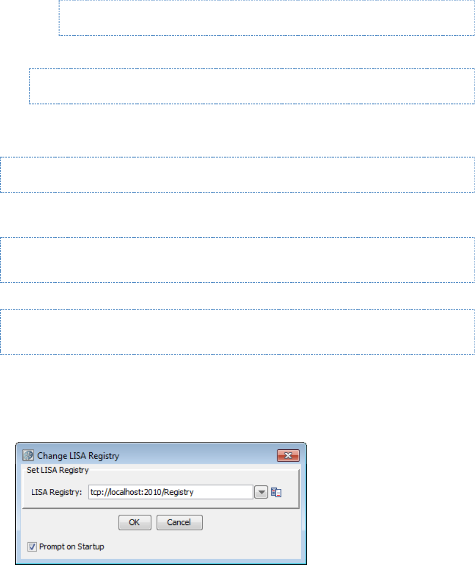
From the main menu, select System > Registry > Change LISA Registry.
The Change LISA Registry dialog appears.
Enter the registry name, or open the drop-down list and select a previously used registry.
Select or clear the Prompt on Startup check box. If the check box is selected, the Set LISA Registry dialog opens when you start LISA
Workstation. If the check box is cleared, LISA Workstation will connect to the last connected registry on start up.
Click OK.
If one or more consoles are open within LISA Workstation, a dialog indicates that the consoles will be closed.
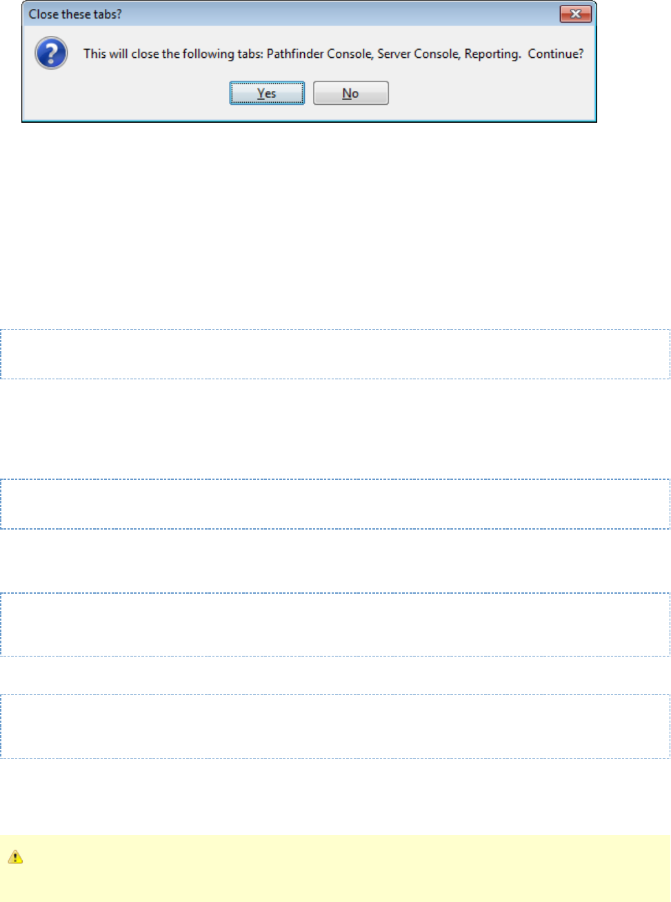
4.
5. Click Yes.
Coordinator Server
Coordinator servers receive the test run information in the form of documents, and coordinate the tests that are run on one or more simulator
.servers
The coordinator server manages metric collection and reporting, and communicates the test data to LISA Workstation for monitoring purposes. A
LISA server environment can have, and commonly does have, more than one coordinator server.
The coordinator server runs LISA tests when presented with a staging document, test case, default configuration and alternatively an alternate
config.
The default name of a coordinator server is set by the property.lisa.coordName
lisa.coordName=Coordinator
The fully qualified name of a coordinator server is .tcp:// :2011/hostname-or-IP-address coordinator-name
Creating Coordinator Servers
To create a coordinator server, run the following command:
LISA_HOME/bin/CoordinatorServer -n CoordinatorServerName -m RegistryName
The following examples create a coordinator server named .coordinator1
This example is based on a Windows installation:
cd C:\Lisa\bin
CoordinatorServer -n coordinator1 -m tcp://localhost:2010/registry1
This example is based on a UNIX installation:
cd Lisa/bin
./CoordinatorServer -n coordinator1 -m tcp://localhost:2010/registry1
You can add the coordinator to a named by using the option. If you do not specify the option, then the coordinator is added to the Defaultlab -l -l
lab.
If is enabled, use the and options to specify your user name and password.access control (ACL) -u -p
As of release 6.0.4, the and options are obsolete. You do not need to provide a user name and password when ACL is-u -p
enabled.
You can display the version number by using the option.--version
For information about running the coordinator server as a service, see .Running Server Components as Services
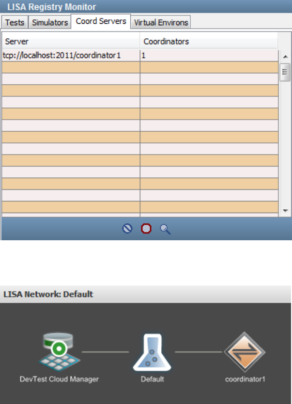
Monitoring Coordinator Servers
If LISA Workstation is attached to the associated registry, then a running coordinator server appears in the .LISA Registry Monitor
The following image shows the Coord Servers tab of the LISA Registry Monitor.
The coordinator server also appears in the network graph of the Server Console.
The following image shows an example of the network graph. The Default lab contains one coordinator.
If you click the coordinator server in the network graph, then a details window appears.
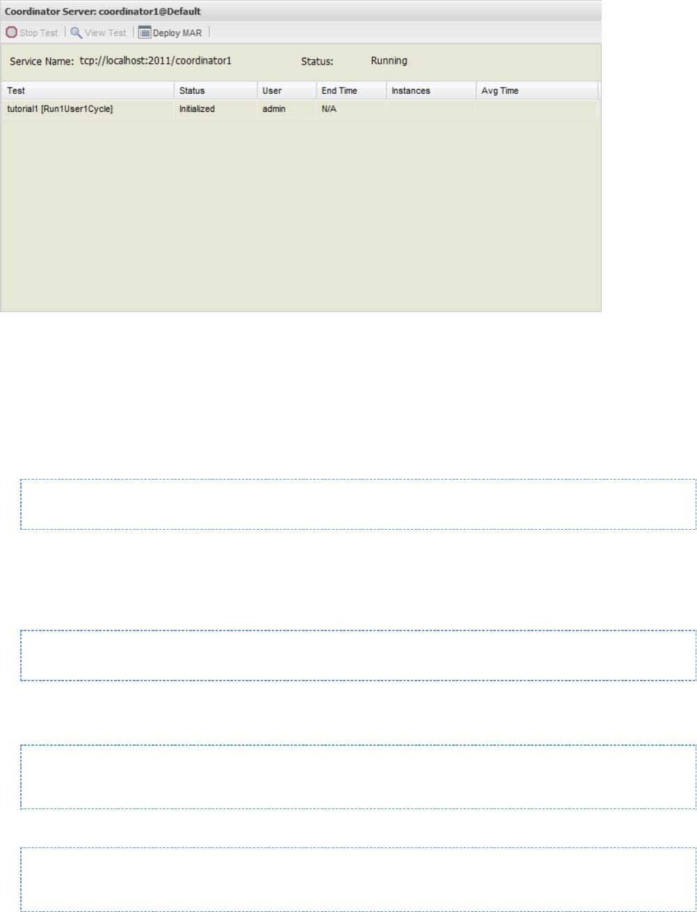
Simulator Server
Simulator servers run the tests under the supervision of the .coordinator server
Virtual users or test instances are created and run on the simulator servers. The number of virtual users, and hence the number of simulator
servers deployed, depend on the nature of the tests being performed. Each virtual user is in communication with the client system.
For large tests with many virtual users, virtual users can be distributed among several simulator servers.
The default name of a simulator server is set by the property.lisa.simulatorName
lisa.simulatorName=Simulator
The fully qualified name of a simulator server is .tcp://hostname-or-IP-address:2014/simulator-name
Creating Simulator Servers
To create a simulator, run the following command:
LISA_HOME/bin/Simulator -n SimulatorName -m RegistryName
The following examples create a simulator named .simulator1
This example is based on a Windows installation:
cd C:\Lisa\bin
Simulator -n simulator1 -m tcp://localhost:2010/registry1
This example is based on a UNIX installation:
cd Lisa/bin
./Simulator -n simulator1 -m tcp://localhost:2010/registry1
You can add the simulator to a named by using the option. If you do not specify the option, then the simulator is added to the Default lab.lab -l -l
You can specify the number of virtual users for this simulator by using the option. For example:-i
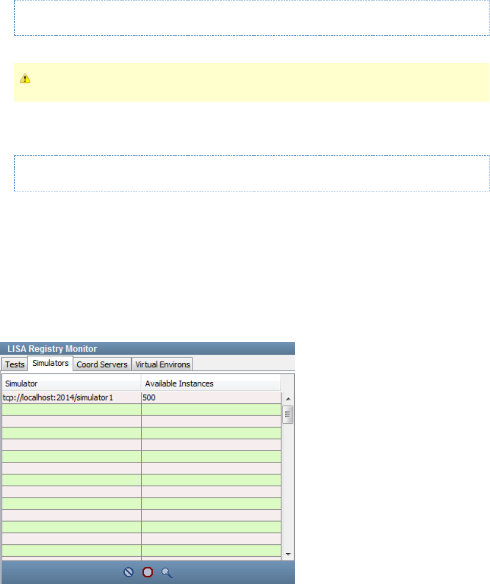
Simulator -n simulator1 -m tcp://localhost:2010/registry1 -i 100
If is enabled, use the and options to specify your user name and password.access control (ACL) -u -p
As of release 6.0.4, the and options are obsolete. You do not need to provide a user name and password when ACL is-u -p
enabled.
You can display the version number by using the option.--version
When creating a simulator, you can override the default port number by adding a colon and the non-default port number to the option. For-n
example:
Simulator -n testSim1:35001
To run multiple simulators, use the command prompt to create the simulators as shown earlier.
Simulators will try port 2014 first if the port number is not specified as part of the name. If 2014 is taken, it will try 2015, 2016, and so on, up until
port 2024 before giving up.
For more information about port usage, see .Default Port Numbers
For information about running the simulator as a service, see .Running Server Components as Services
Monitoring Simulator Servers
If LISA Workstation is attached to the associated registry, then a running simulator appears in the .LISA Registry Monitor
The following image shows the Simulators tab of the LISA Registry Monitor.
The simulator also appears in the network graph of the Server Console.
The following image shows an example of the network graph. The Default lab contains one coordinator and one simulator.
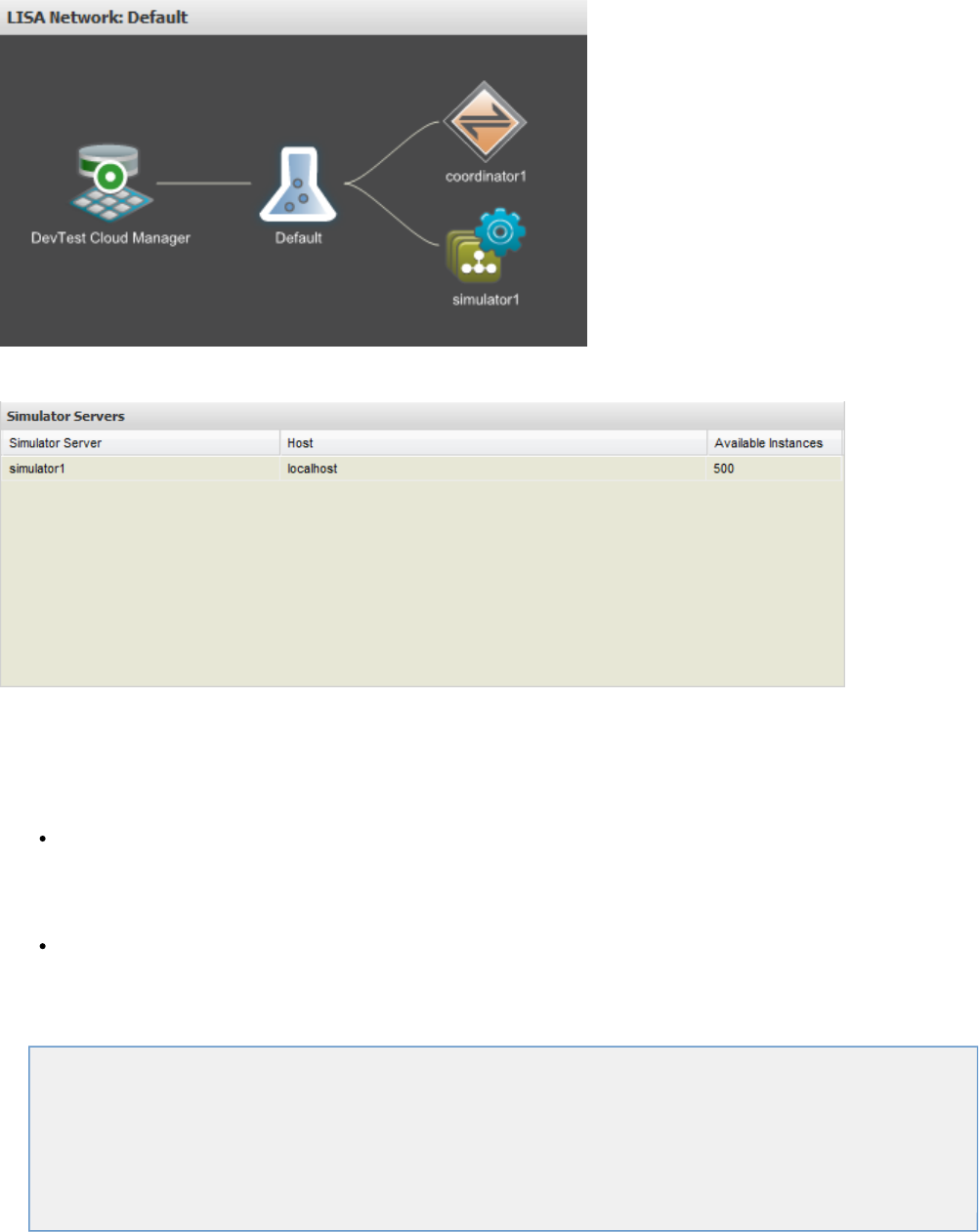
If you click the simulator in the network graph, then a details window appears.
LISA Workstation
LISA Workstation is a single, easy-to-use, integrated environment for developing, staging, and monitoring tests.
You can work in a LISA Workstation version or in a LISA Server environment.
In LISA Workstation, the tests are managed and run within the Workstation environment. LISA Workstation is a test client used by
QA/QE, development, and business analysis teams to test rich browser and web user interfaces, and the building blocks below the user
interface. LISA Workstation is used to build and stage, all in a code-less manner: unit, functional, integration, regression, and business
process testing. It requires a LISA registry to run. Tests are managed and run within the LISA Workstation environment (test authoring
IDE), which runs embedded coordinator and simulator servers.
In LISA Server, the tests are also managed and run within the Workstation environment. The workstation then connects to the server to
deploy and monitor tests that were developed in LISA Workstation.
The server-side engine for LISA test cases and virtual services (test and virtual service model authoring IDE) is used to manage, schedule, and
orchestrate LISA test cases for unit, functional, load, and performance tests on a continuous basis.
Opening LISA Workstation
Main Menu
Main Toolbar
Project Panel
Quick Start Window
Tables
Tray Panels
Opening LISA Workstation
When you open LISA Workstation, you are prompted to specify a .registry
If your computer has an installation of LISA Server, then you can use either of the following:
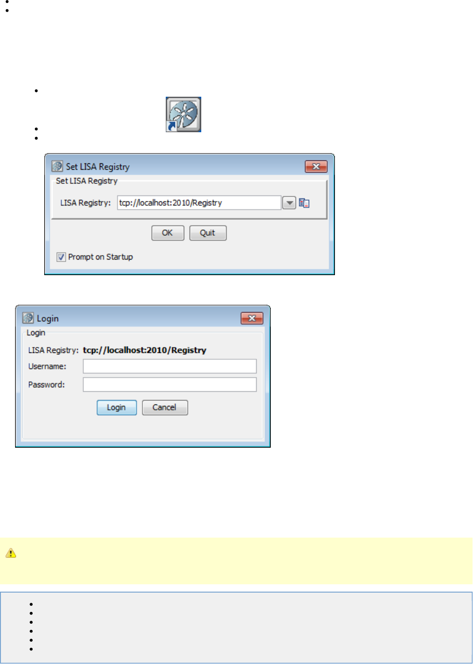
1.
2.
3.
4.
A registry that is running on your local computer
A registry that is running on a remote computer
If your computer has an installation of LISA Workstation, then you must use a registry that is running on a remote computer.
For information about how to specify the registry when SSL is enabled, see .Using SSL to Secure Communication Between Components
To open LISA Workstation
Do one of the following:
Open a command prompt, go to the directory, and run the LISA Workstation executable.LISA_HOME/bin
If you have a LISA application icon on your desktop, double-click the application icon.
(Windows) Click .Start Menu > All Programs > LISA > LISAWorkstation
The Set LISA Registry dialog appears.
Accept the default registry, or specify a different registry.
Click OK.
If is enabled, then the Login dialog appears.access control (ACL)
Enter your user name and password, and click Login.
Main Menu
The main menu includes menu options for all the major functions available in LISA Workstation. The main menu options available are dynamic to
the selections at times. They are covered in detail here for the most common choices available.
There are some varying menus and also drop-down menus and toolbars available throughout LISA Workstation.
The items on this menu are dynamic. The items available can be controlled by your LISA administrator as part of your security
profile.
File Menu
Edit Menu
View Menu
System Menu
Actions Menu
Help Menu
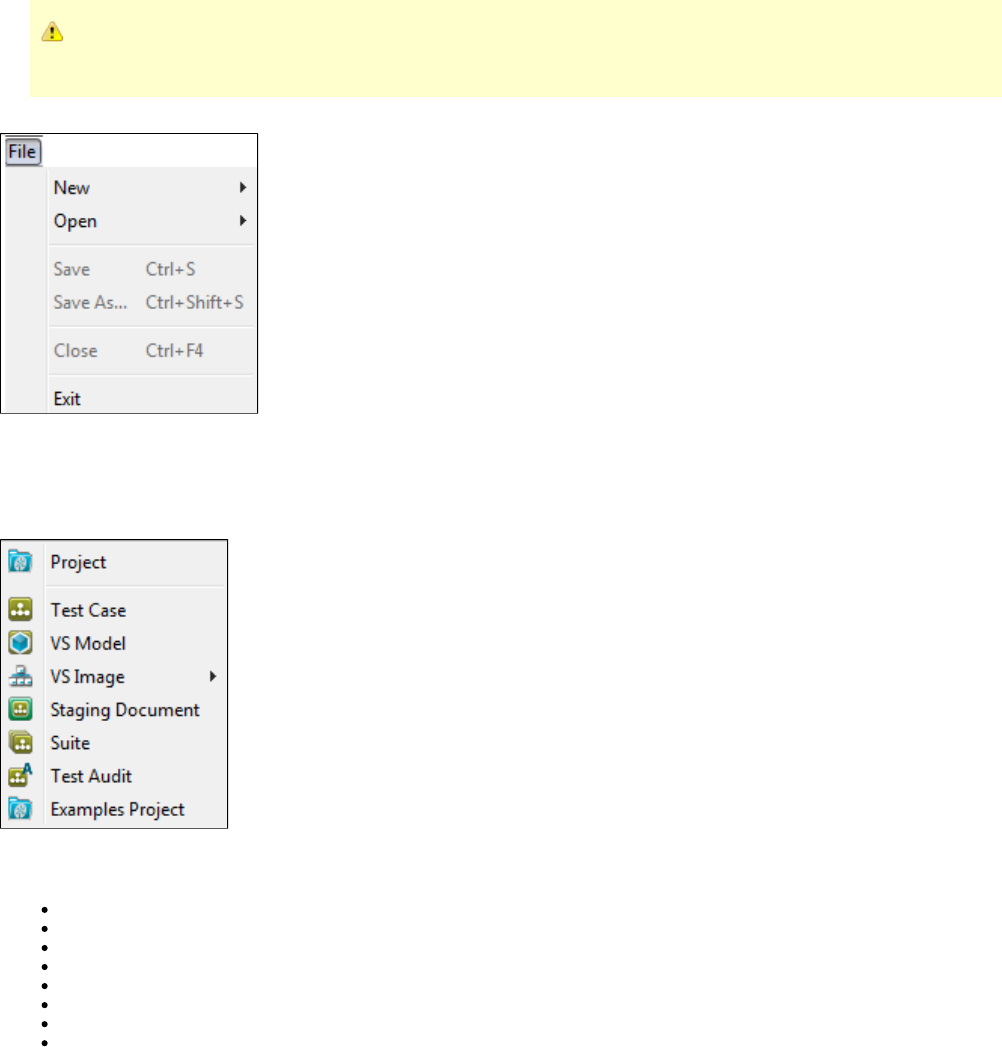
File Menu
The items on this menu are dynamic. The items available can be controlled by your LISA administrator as part of your security
profile.
The File menu has the standard items related to file manipulation.
File > New
File > New shows a secondary menu where you can create a LISA project or create one of the test documents: test case, VS model, VS image,
staging document, suite or test audit.
From this menu, you can create LISA documents within the project that is open in LISA Workstation or outside of the project. By default, the
current directory selection is the folder of the open project.Tests
Project: Creates a new project. For more information see .Creating A New Project
Test Case: For additional information see .Creating Test Cases
VS Model: . For additional information see the Requires an additional license . LISA Virtualize Guide
VS Image: . For additional information see the .Requires an additional license LISA Virtualize Guide
Staging Document: For additional information see .Building Staging Documents
Suite: For additional information see .Building Test Suites
Test Audit: For additional information see .Building Audit Documents
Examples Project: Creates a new examples project. Specify a location for the new project in the dialog, click OK, and the
LISA_HOME/examples contents will be copied into a new project.
File > Open
File > Open shows a secondary menu where you can open either an existing LISA project or one of the six major LISA documents: test case, VS
model, VS image, staging document, suite or test audit.
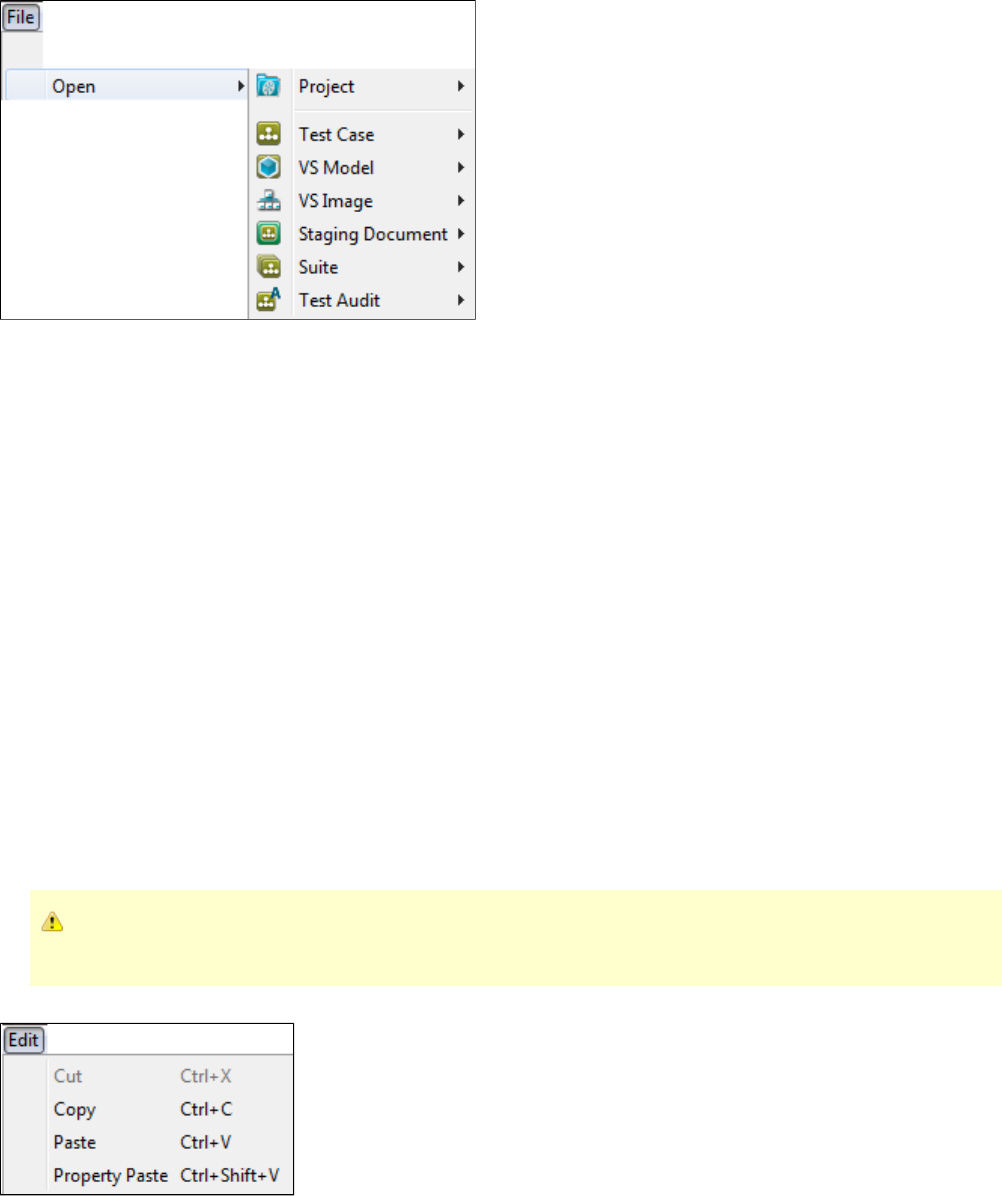
You can browse for the document to open by looking in the file system, on the LISA classpath, or as a URL. LISA keeps a record of the most
recent documents you have opened, and lists them on the Quick Start Window - Open Recent.
See for additional information on the choices available, as they are the same as File > Open.File > New
You can open any LISA document either from within a LISA project or from outside a project by using the main menu File > Open > menu option.
If you select a document from a project that is different from the currently open project, the current project will close, and the project that the
selected document resides in will open, then the document will open.
File > Save
File > Save: Saves the current document.
File > Save As
File > Save As...: Saves the current document under a different name.
File > Close
File > Close: Closes the active tab.
File > Exit
File > Exit: Exits LISA Workstation.
Edit Menu
The items on this menu are dynamic. The items available can be controlled by your LISA administrator as part of your security
profile.
The Edit menu has the normal set of editing options.
Edit > Cut: Cuts the selected text.
Edit > Copy: Copies the selected text.
Edit > Paste: Pastes the selected text in the selected area.
Edit > Property Paste: Pastes the selected text in the selected area, and surrounds the pasted text with a set of double curly braces.
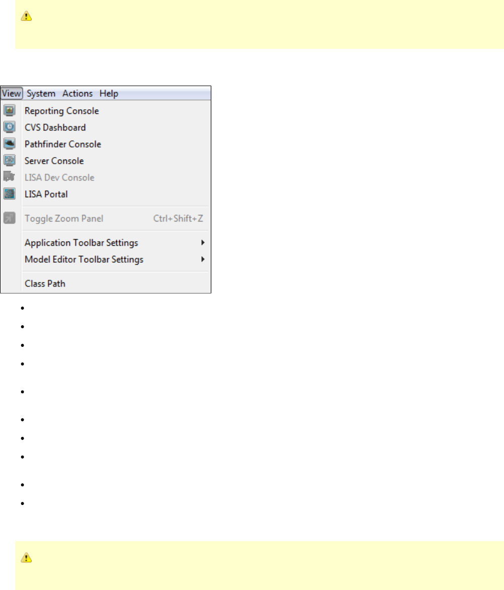
View Menu
The items on this menu are dynamic. The items available can be controlled by your LISA administrator as part of your security
profile.
The View menu contains a list of menus that deal with the viewing of the Reporting Console, CVS Dashboard, Pathfinder Console, Server
Console, LISA Dev Console, and others. You can also set the look and feel of LISA Workstation here and visit the LISA portal for more
information related to LISA.
Reporting Console: For additional information see .Reporting Console
CVS Dashboard: For additional information see .CVS Dashboard
Pathfinder Console: Invokes the Pathfinder Console. For more information, see the .Pathfinder Guide
Server Console: Provides a visual representation of the LISA network, starting with the registry, showing the connected coordinators and
their simulators, and VSE. The VSE Dashboard is accessed through the Server Console.
Dev Console: Lets you view detailed information about the workings of the LISA Agent. It also gives you the opportunity to add
extensions.
LISA Portal: Invokes the .LISA Console
Toogle Zoom Panel: Lets you toggle the Zoom panel.
Application Toolbar Settings: Lets you choose the interface of the Application Toolbar. You can select the toolbar settings to display
Icons and Labels, Icons only, Small Icons or no toolbar at all.
Model Editor Toolbar Settings: Lets you choose between large icons or smaller icons to be displayed on the LISA Model Editor menu.
Class Path: Lets you view and set the classpath.
System Menu
The items on this menu are dynamic. The items available can be controlled by your LISA administrator as part of your security
profile.
The System menu has a menu to manage the system registries and system messages. You can also edit the LISA properties, add JAR or zip files
to Hot Deploy or reset Hot Deploy Class Loader and set the tools.jar file here.
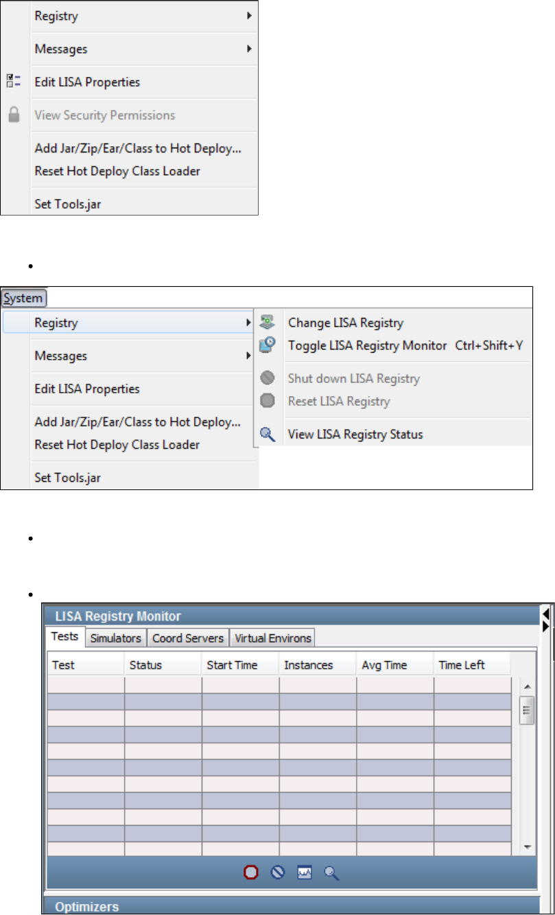
System > Registry
Registry: You can do all activities related to the LISA registry in this menu.
System > Registry > Change LISA Registry
Change LISA Registry: See for more information about this menu.Registry
System > Registry > Toggle LISA Registry Monitor
Toggle LISA Registry Monitor: You can toggle the LISA Registry Monitor, so that it can be viewed in LISA Workstation.
System > Registry > Shut Down LISA Registry
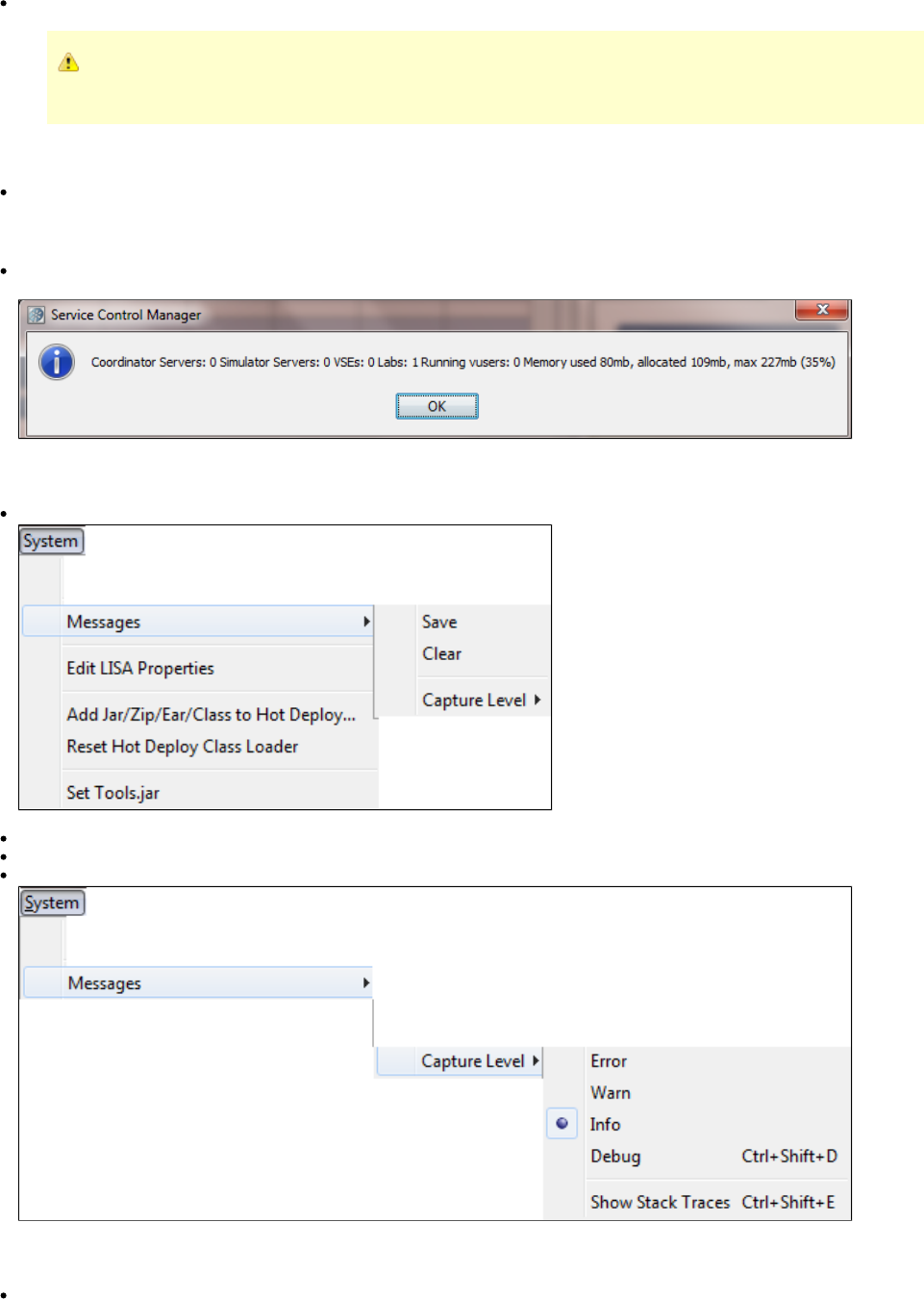
Shut Down LISA Registry: Shuts down the LISA registry.
A LISA registry is mandatory for LISA Workstation to remain open. You will be prompted to select a registry if the
registry is closed.
System > Registry > Reset LISA Registry
Reset LISA Registry: Resets the LISA registry, which will reset the registry information in the system.
System > Registry > View LISA Registry Status
View LISA Registry Status: Displays a dialog listing the number of coordinator servers and simulator servers that are attached to the
current registry.
System > Messages
Messages: This menu is for the System Message settings.
Save: Save the system messages.
Clear: Clear the system messages.
Capture Level: Select the type of system messages to view: Error, Warn, Info (selected by default), Debug, or Show Stack Traces.
System > Edit LISA Properties
Edit LISA Properties: Opens the file in an editable window.lisa.properties
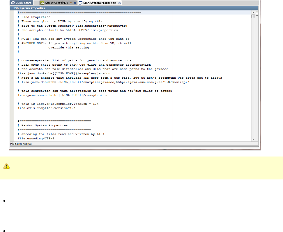
Use extreme caution if you choose to edit this file.
System > View Security Permissions
View Security Permissions: If access control (ACL) is enabled, displays the unique ID of your user name, roles that are assigned to
you, and permissions that you have.
System > Add Jar/Zip/Ear to Hot Deploy
Add Jar/Zip/Ear to Hot Deploy...: Displays a dialog to enter the name of a file to upload into the hot deploy directory. The file you upload
contains items that you want to add to LISA's classpath.
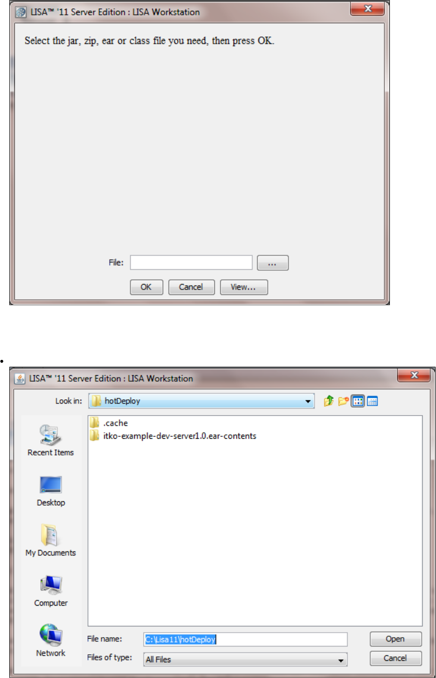
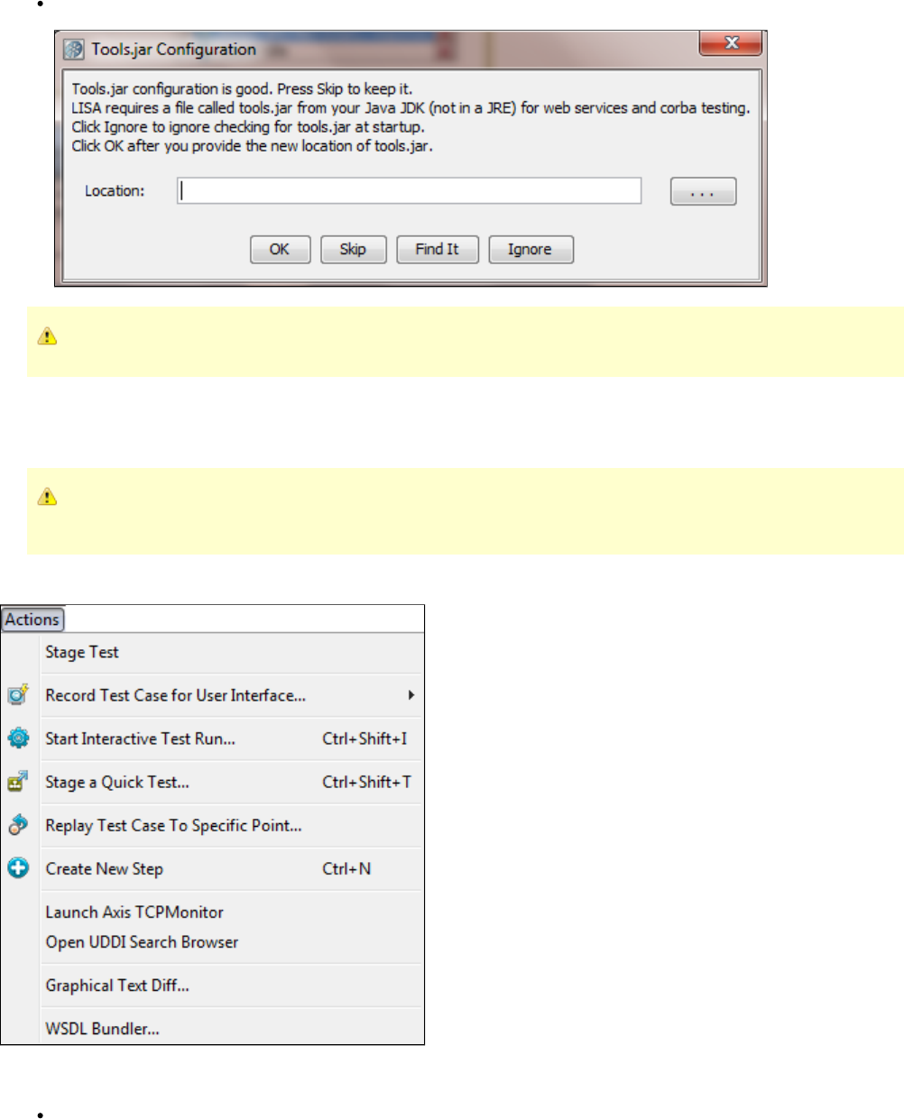
For more information see the .Installation and Configuration Guide
System > Set Tools.jar
Set Tools.jar: Displays a dialog where you can enter, or browse to the location of a Tools.jar file. This file is required Java code needs to
be compiled. Several test steps and generators need to compile code.
If a Tools.jar file is available, the dialog will indicate that.
For more information see the .Installation and Configuration Guide
Actions Menu
The items on this menu are dynamic. The items available can be controlled by your LISA administrator as part of your security
profile.
The Actions menu has items related to staging test cases, running suites, recording test cases, staging quick tests, adding test steps, and
launching various tools. You will not see the full Actions menu as shown below unless you have a test case open.
Actions > Stage Test
Stage Test: This item is available for test cases. Opens a dialog where you can start the test case execution.
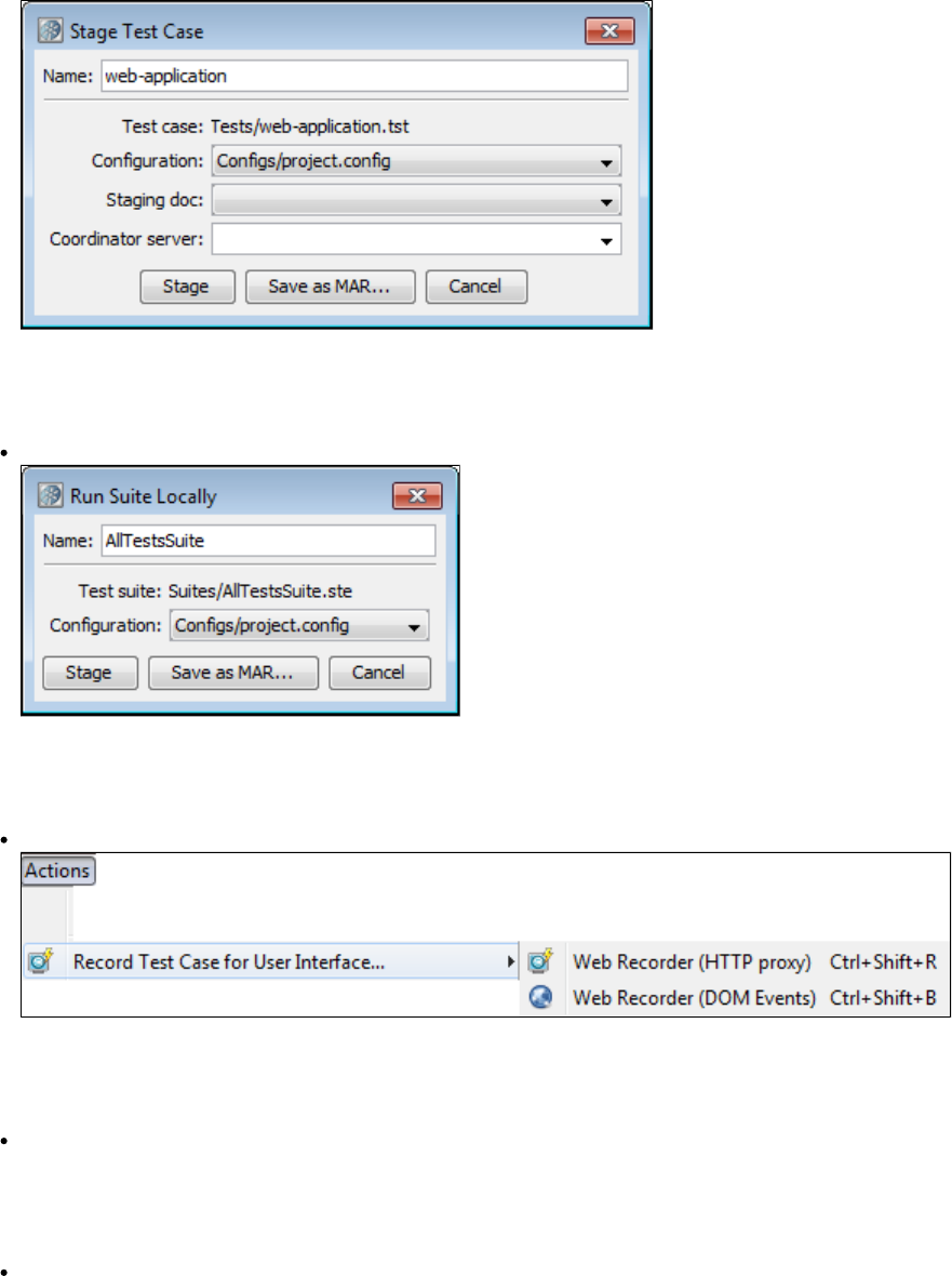
For more information, see .Staging Test Cases
Actions > Run
Run: This item is available for suites. It opens a dialog where you can configure and stage the suite.
For more information, see .Running Test Suites
Actions > Record Test Case for User Interface
Record Test Case for User Interface: Opens a new submenu to record test cases for HTTP Proxy or DOM Events.
For more information, see .Recorders and Test Generators
Actions > Start Interactive Test Run
Start Interactive Test Run (ITR): Click to start the Interactive Test Run (ITR) utility.
For more information, see .Using the Interactive Test Run (ITR) Utility
Actions > Stage a Quick Test
Stage a Quick Test: Click to stage a quick test.
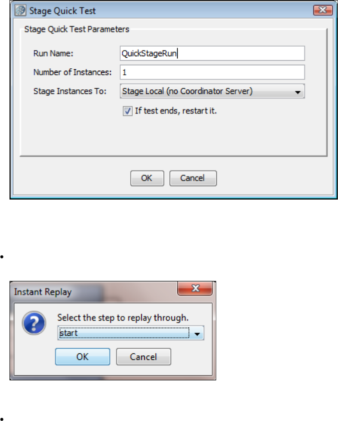
For more information, see .Staging Quick Tests
Actions > Replay Test Case to Specific Point
Replay Test Case to Specific Point: Click to run a test to a specific point in a test case. You can replay the test in the ITR utility to any
given test step. A dialog is displayed, to let you enter the last step of the replay. This will populate the known state up to that point. This is
particularly useful if you want to examine properties like LASTRESPONSE that store the value of the last step response.
Actions > Create New Step
Create New Step: Opens a Steps panel with a list of all the available test steps.
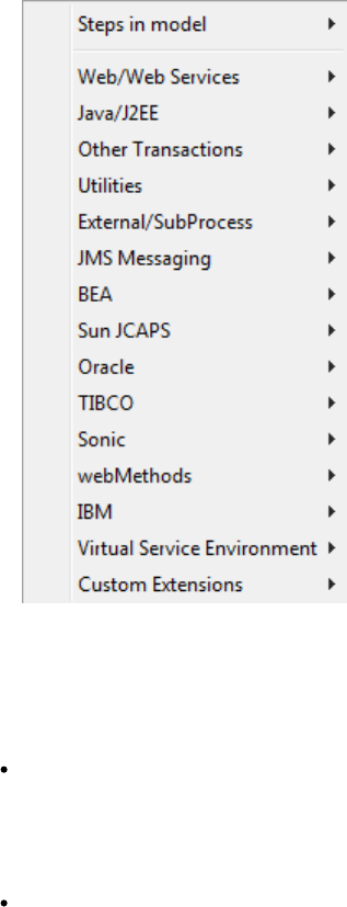
The selected step will be added to the test case.
For more information, see .Building Test Cases
Actions > Launch Axis TCPMonitor
Launch Axis TCPMonitor: Launches an external application named TCPMonitor, which lets you monitor client/server communications.
For more information, see .http://ws.apache.org/axis/
Actions > Open UDDI Search Browser
Open UDDI Search Browser: Launches a UDDI search browser.
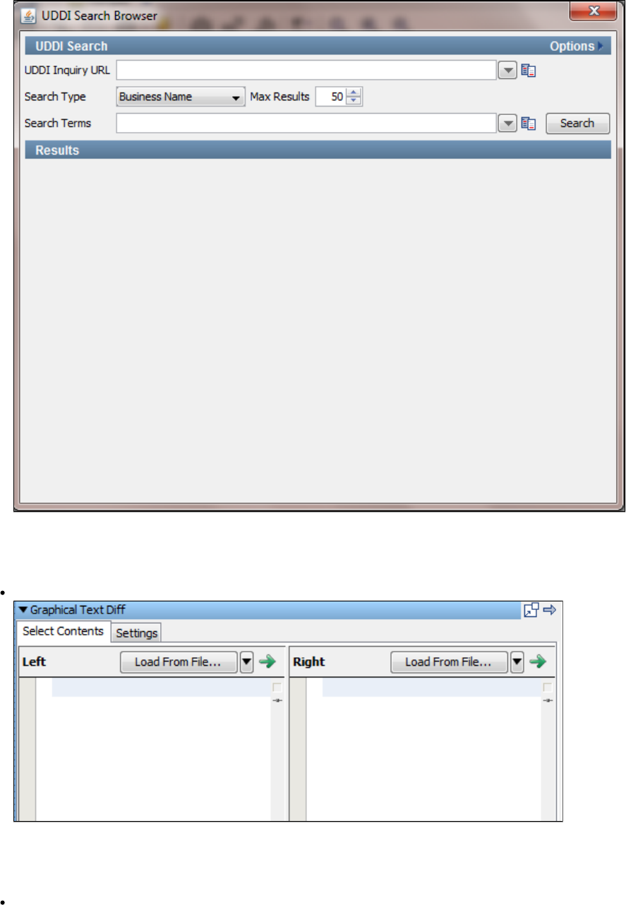
For more information, see the .Web Service test step
Actions > Graphical Text Diff
Graphical Text Diff...: Opens a graphical XML diff engine and visualizer.
For more information, see .Graphical Text Diff Utility
Actions > WSDL Bundler
WSDL Bundler: Lets you bundle a WSDL and any supporting documents into a single ZIP file. The ZIP file can be sent to ITKO Support
if you are experiencing problems using the WSDL.
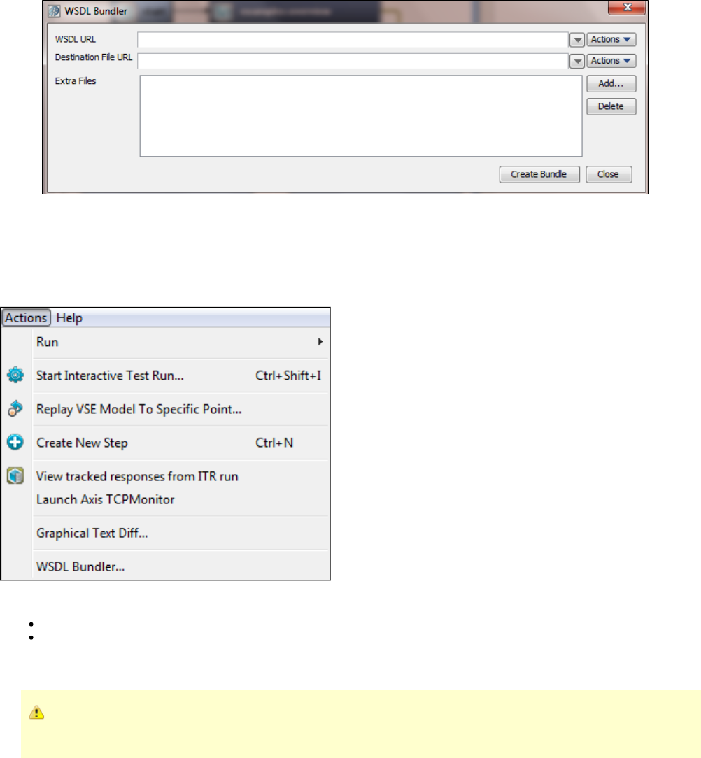
The Destination file is specified as a file URL.
VSE Actions Menu
When you are working with virtual service models or virtual service images, the Actions menu will change to display options related to LISA
Virtualize.
This menu contains additional options for VSE users:
Replay VSE Model to a specific Point: Replays the VSE model to the point selected.
View Tracked Responses from the ITR run: Enables you to see transactions tracked in the ITR.
Help Menu
The items on this menu are dynamic. The items available can be controlled by your LISA administrator as part of your security
profile.
The Help menu includes information about Documentation, Runtime Information, LISA License settings, and debuggers.
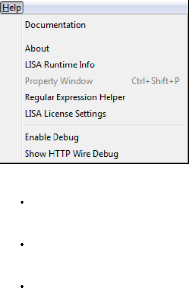
Help > Documentation
Documentation: Opens the LISA documentation page.
Help > About
About: Shows the LISA version and build numbers.
Help > LISA Runtime Info
LISA Runtime Info: Shows current runtime information in two tabs, License Info (default) and System Properties.
LISA Runtime Info - License Info Tab
This tab gives information related to the LISA license.
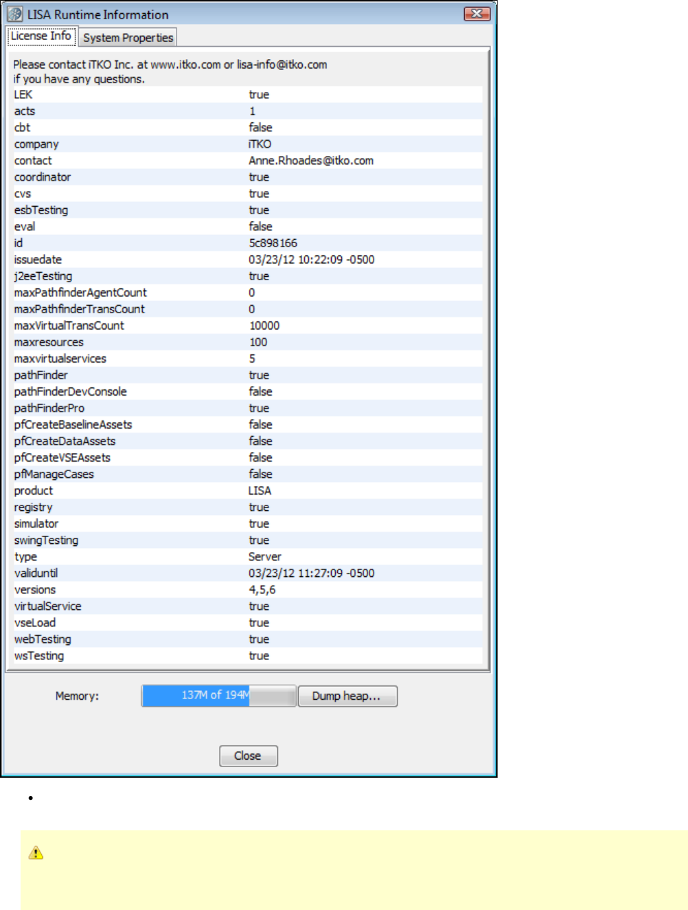
Dump Heap: You can generate a heap dump file (HProf) through the LISA runtime panel. Click the Dump Heap button to produce the
heap dump.
This functionality is available only on Sun Java 6 Java runtimes. It is a diagnostic tool that can help ITKO support determine the
causes of OutOfMemory conditions. The heap is automatically dumped if an OutOfMemory condition occurs; this button is for
manually triggering a heap dump.
After the dump is created, a message indicates that the heap dump has been taken.
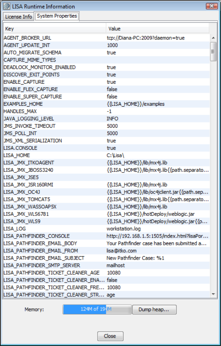
LISA Runtime Info - System Properties Tab
This tab provides information regarding the LISA system properties.
Help > Property Window
Property Window - Properties Tab
Opens up the LISA Property Window. You cannot update these values from this window.
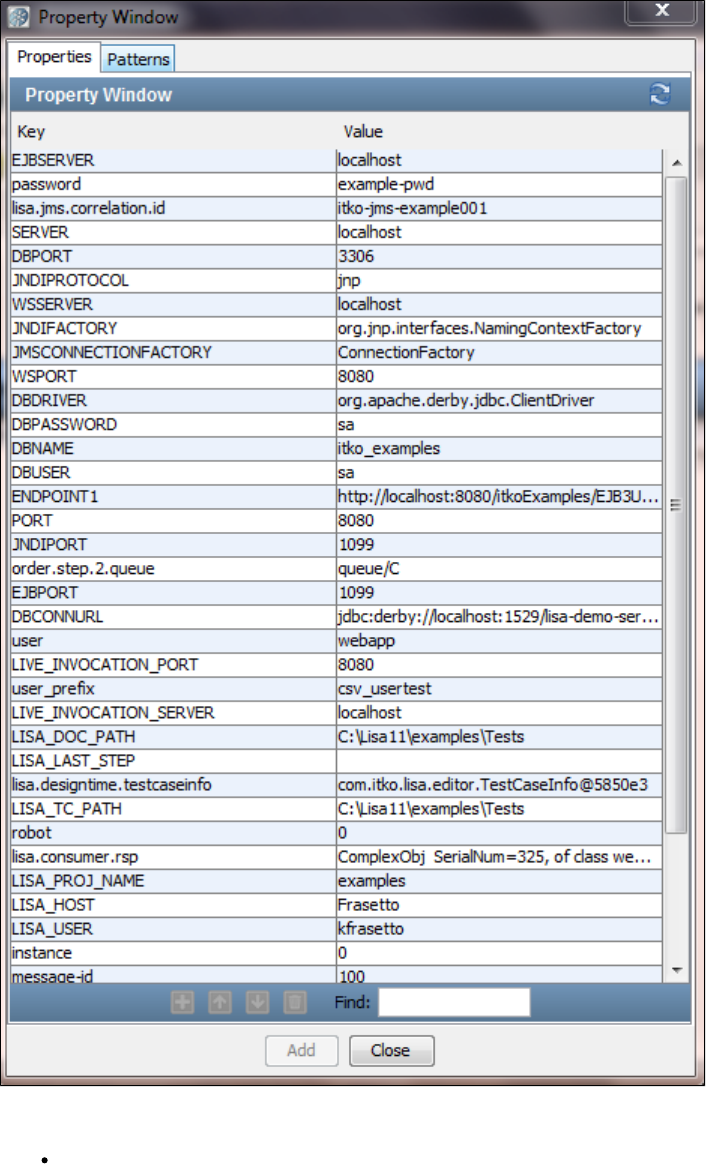
Property Window - Patterns Tab
All the LISA properties are listed here. You can also generate string patterns from the tab.Patterns
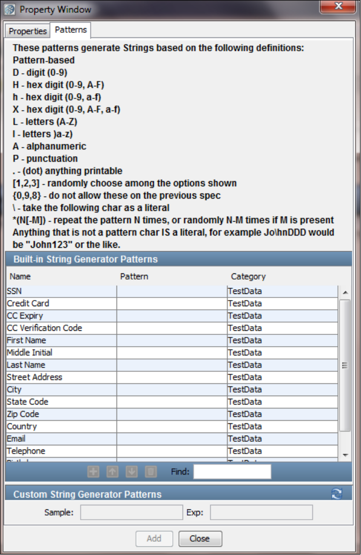
Help > Regular Expression Helper
This option displays a simple window that can be used to experiment and verify how regular expressions match against any piece of text. Here,
you enter a Regex and a target string and the dialog highlights the match spans to verify that the Regex pattern itself is actually going to correctly
match your input data.
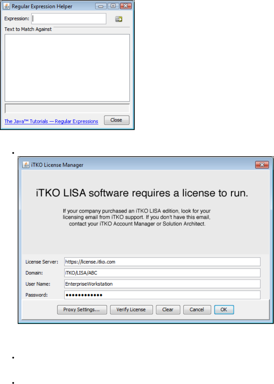
Help > LISA License Settings
LISA License Settings: Shows the current license settings.
For more information on LISA licensing and license settings, see " ."Licensing Approaches
Help > Enable Debug
Enable Debug: Turns on an extra level of debugging, and shows Java stack traces in the output log.
Help > Show HTTP Wire Debug
Show HTTP Wire Debug: Turns on a debug mode that captures all the handshaking (multiple request/responses that happen during
negotiation) to see what's happening during HTTP transactions.
The following image shows the HTTP Wire Traffic Viewer dialog.
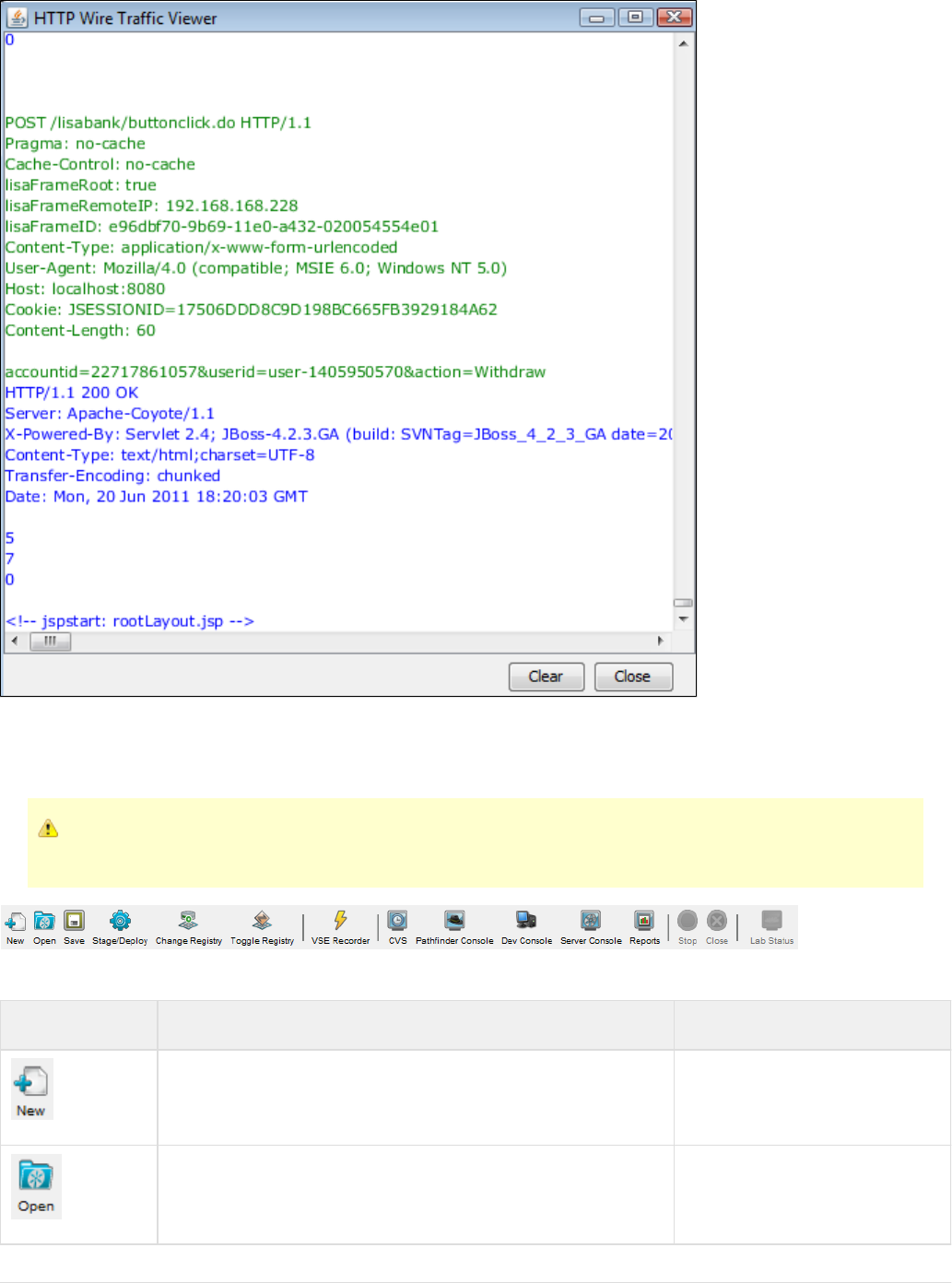
Main Toolbar
The main toolbar of LISA Workstation contains icons for common functions.
The items on this toolbar are dynamic. The items available can be controlled by your LISA administrator as part of your security
permissions.
The following table describes each icon.
Icon Description Main Menu Equivalent
Creates a new project. File > New > Project
Opens an existing project. File > Open > Project
Saves the current document. File > Save
Lets you stage and deploy a test case or suite. Actions > Stage Test and Actions >
Run
Lets you switch to another registry. System > Registry > Change LISA
Registry
Shows and hides the LISA Registry Monitor. System > Registry > Toggle LISA
Registry Monitor
Opens the LISA Virtualize Recorder. File > New > VS Image > By recording
Opens the CVS Dashboard. View > CVS Dashboard
Opens the Pathfinder Console. View > Pathfinder Console
Opens the Dev Console. View > LISA Dev Console
Opens the Server Console. View > Server Console
Opens the Reporting Console. View > Reporting Console
Stops the test run. When you run a test case, this icon becomes a Play icon
until the run finishes. Not Applicable
Closes the test run. Not Applicable
Indicates when a cloud-based lab is being provisioned and then ready. Not Applicable
Project Panel
The following topics are available.
Project Overview
Examples Project
Creating a Project
Opening a Project
Project Panel Layout
Project Panel Right-Click Menu
Project Overview
A project is a collection of related LISA assets. The assets can include test cases, suites, virtual service models, service images, configurations,
audit documents, staging documents, data sets, monitors, and MAR info files.
In LISA Workstation, only one project can be open at a time.
The directory does not exist until you create a project for the first time.LISA_HOME/Projects
All the folders in the Project panel of LISA Workstation are the same as those created in the file system. You can check the directoryLISA_HOME
to see the folder structure and files.
You can import files into a project.
Examples Project
When you start LISA Workstation for the first time, the Project panel displays a project named .examples
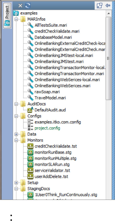
The project includes the following :examples configurations
examples.itko.com.config
project.config
The file is the initial active configuration.project.config
You can open any of the sample files by double-clicking them. The appropriate editor will open in the right panel.
The actual project files are located in the directory.LISA_HOME/examples
MARInfos
AllTestsSuite
Suite MAR that includes the test suite AllTestsSuite, with all the .tst files and accompanying data files to run the AllTestsSuite. It also
includes the 1User1Cycle0Think staging document, the DefaultAudit audit document, and the project.config configuration file.
creditCheckValidate
Test-based Monitor MAR that includes the creditCheckValidate test case and the monitorRunBase staging document.
DatabaseModel
Virtual Service MAR that includes the DatabaseModel virtual service model and virtual service image.
OnlineBankingExternalCreditCheck-local
Test-based Monitor MAR that includes test case webservices-xml-fail, staging document Run1User1Cycle and project.config.
OnlineBankingExternalCreditCheck
Test-based Monitor MAR that includes test case webservices-xml-fail, staging document Run1User1Cycle, project.config and
examples.itko.com.config.
OnlineBankingJMStest-local
Test-based Monitor MAR that includes the ansync-consumer-jms test case and Run1User1Cycle staging document.
OnlineBankingJMStest
Test-based Monitor MAR that includes the ansync-consumer-jms test case, Run1User1Cycle staging document, and project.config and
examples.itko.com.config configuration files.
OnlineBankingTransactionMonitor-local
Test Based Monitor MAR that includes the multi-tier-combo test case, Run1User1Cycle staging document, all the data files to support the
test case, and project.config.
OnlineBankingTransactionMonitor
Test Based Monitor MAR that includes the multi-tier-combo test case, Run1User1Cycle staging document, all the data files to support the
test case, and project.config and examples.itko.com.config configuration files.
OnlineBankingWebServices-local
Test-based Monitor MAR that includes the webservices-xml test case, Run1User1Cycle staging document, and the project.config
configuration file.
OnlineBankingWebServices
Test-based Monitor MAR that includes the webservices-xml test case, Run1User1Cycle staging document, and project.config and
examples.itko.com.config configuration files.
rawSoap
Test MAR that includes the rawSoap test case, the 1User0Think_RunContinuously staging document, and the project.config configuration
file.
Audit Docs
DefaultAudit
Configurations
examples.itko.com
The examples.itko.com config file should be the active configuration file when you are running your examples against the ITKO examples
server at examples,itko.com. The only difference between it and the default project.config file is that instead of pointing to servers on
localhost, it points to the ITKO examples website.
project
The project.config file contains intelligent defaults for many properties.
Data
The Data directory contains data sets, keystores, and WSDLs that you need to run some of the examples for the LISA Demo Server.
Monitors
creditCheckValidate.tst
Test case used for CVS monitor demos. Fails randomly on a specific cid.
monitorRunBase.stg
Staging document with one user, one cycle, and 100% think time, with Pathfinder not enabled and no maximum run time.
monitorRunMultiple.stg
Staging document with one user, run continously, 136% think time, with Pathfinder enabled and a maximum run time of 15 seconds.
1.
2.
3.
monitorSLARun.stg
Staging document with one user, one cycle, and 100% think time, with Pathfinder not enabled and no maximum run time. JMX and JBOSS
metrics are selected to record.
serviceValidator.tst
Used for CVS monitor demos. Fails randomly on a specific cid.
userAddDelete.tst
This test is used in the monitor setup for CVS demos.
Setup
The Setup directory in the Examples directory contains batch files to start all LISA components, stop all LISA components, and load CVS
monitors. Because these files are not LISA assets, they do not appear in the Projects Panel listing of files.
If you want to use the stop script with access control (ACL) enabled, then you must add the user name and password options to the Service
Manager commands in the script. The password will not be automatically encrypted, so be sure to protect the file by using the appropriate method
for your operating system.
Staging Documents
1User0Think_RunContinuously
This staging doc runs a single virtual user with zero think time. It also runs the test(s) "continuously," which does not necessarily mean
"forever".
If a test being run by this staging doc has ALL of the following conditions, the run will finish when the dataset runs out of data.
There is a dataset on the first step of the test.
The dataset "End of data" step is "End the test."
The data set is "global," not "local."
If there is more than one dataset matching these conditions, then the first dataset to expire will finish the run. For a good example of this,
look at the multi-tier-combo.tst test case.
1user1cycle0think
This staging document runs a test with a single user one time with a 0% think time scale.
ip-spoofing
Use this staging document to test IP spoofing support with your LISA installation. IP spoofing is enabled in this staging document in the IP
Spoofing tab. An IP spoofing test web page is available at , if you are running the examples server.http://localhost:8080/ip-spoof-test
jboss-jmx-metrics-localhost
This staging documents runs a test with three users, run continuously, with a maximum run time of 440 seconds and 100% think time. It
has all four report generator parameter checkboxes selected, and specifies all JBOSS JMX metrics to be collected.
Run1User1Cycle
This staging document runs a test with a single user one time with 100% think time scale.
Run1User1CyclePF
This staging document runs a test with a single user one time with 100% think time scale, with Pathfinder enabled.
Run1User1CycleShowAll
This staging document runs a test with a single user one time with 100% think time scale. It also turns on all four checkboxes in the default
report generator so more things will show in the web base model execution page.
Subprocesses
ws-sec-sub
This one-step test case is marked as a subprocess and can be called from any Execute Sub Process step.
Test Suites
AllTestsSuite
The AllTestsSuite runs all the tests in the LISA Tests directory, using the 1user1cycle0think staging document and a default audit document
of AuditDocs/DefaultAudit.aud. For report metrics, it only records requests and responses, and produces the default metrics.
Test Cases
AccountControlMDB
A simple JMS test that adds a new user with an account to LisaBank. We expect and assert on patterns in the responses from the two
steps.
async-consumer-jms
An example of an "async consumer" queue where the test case continually accepts messages from a response queue/topic and makes
them available to the test case in the order that the messages came in.
The first step creates the queue (internal to the LISA test).
The second step fires three messages to a JMS queue on the demo server, which should cause three messages to be received on the
async queue.
The third step validates that three messages were received by the async queue.
ejb3EJBTest
A pure EJB test of the LisaBank functionality. Usually you would test applications by recording a web browser or other UI. Those tests are
"end to end" integration tests; these sorts of tests are "lower down the food chain" and require more technical authors (though you still do
not need to write any code!)
These tests are good for the development team to use to constantly test and validate the code without having the need for a user interface,
which may not exist at all or be changing so much that the tests cannot keep up.
ejb3WSTest
This model thoroughly tests the LisaBank web services. It is almost identical in functionality to the ejb3EJB test and useful for the same
reasons (see that test case documentation).
ip-spoofing
This example test case demonstrates IP spoofing support in LISA.
It requests the URL " " using a REST step, a web page that contains the IP address of the requestinghttp://localhost:8080/ip-spoof-test
client. It then makes a SOAP request to the URL , a web service containing anhttp://localhost:8080/itko-examples/ip-spoof-test/webservice
operation that returns the IP address of the requesting client.
It executes both requests in a loop for 10 times. You can stage this test in conjunction with the IP Spoofing Test staging document
"ip-spoofing.stg". With the correct network interface configuration, you should see different IP addresses used among virtual users as they
make the HTTP and SOAP requests.
jms
Simple JMS example showing how to send XML/text messages and objects in native Java format.
Lisa_config_info
This test case fetches diagnostic information about the computer running LISA. The results can help ITKO support solve configuration
issues.
load-csv-dataset-web
This test model uses a comma separated values (CSV) file as a data set to test a web application. The demo web app that ships with LISA
lets us add and remove users from the database.
log-watcher
This example shows how to fail a test by watching a log file for ERROR or WARNing messages.
It uses a data set to feed the example AntiPattern bean two numbers to divide. About halfway through the data set we give 0 as the
operand. This, of course, causes a divide-by-zero exception to occur on the server. The AntiPattern bean logs the exception and returns -1
as a result.
This is a common anti-pattern: internal errors occurring but external parties have no idea that the result is incorrect. It believable but itlooks
is wrong. What should happen is that the EJB propagates the exception back to the caller.
If we were using Pathfinder this test case would fail because the fact that an exception was logged will be recorded by the agent and LISA
would determine that something is wrong.
An alternative to using Pathfinder/LISA Agent is to set up a Global Assertion to watch the server log file. We define what to look for as a
regular expression: in this case simply the test "ERROR". The regular expressions can be as simple or as complicated as you want.
Usually you would set the assertion to fail the test immediately. In this case we step to the "Error detected in log file" step and end the test
normally.
Applications under test should never pass if they are logging errors or warnings. Consider using an equivalent companion in your test cases
by default.
main_all_should_fail
This test is an example of negative testing. We expect test steps to fail; that is, we feed a service data that should cause an error.
The test has a companion, the NegativeTestingCompanion, which fails the test if any steps succeed.
In this case we try to create users in the demo server that already exist. We get this data from the database itself (the username dataset
queries the table directly). If any step passes, the overall test should fail.
The only step that does pass is the "quietly succeed" step; in other words you can put steps that you do expect to fail in this sort ofnot
testing scenario but you should mark them as "quiet" in the editor so that they are not included by the NegativeTestingCompanion.
main_all_should_pass
This test calls a subprocess to insert a unique username into the demo server USERS table.
The data set is interesting in that it relies on a datasheet to draw values from a unique code generator. The same thing could have been
done with a unique code generator in conjunction with a "counter" dataset but this example demonstrates how one data set can influence
another.
Data sets are evaluated in the order they are specified; each time the step is executed, the UniqueUser property is assigned a new value
and the data sheet refers to {{UniqueUser}} four times so we get five unique values.
If any of the steps fail the test fails immediately.
Compare this test to "main_all_should_fail," which is a similar test where we expect each step to fail and we fail the test if anything passes
(this is known as negative testing).
multi-tier-combo-XML
The multi-tier-combo test uses a variety of service endpoints to validate the LisaBank example. It tests SOAP, EJB, JMS and web
transactions and validates these transactions in a variety of ways including directly validating the demo server database.
The test also demonstrates how you can build complex SOAP objects from spreadsheets. The "User" dataset on the first step is backed by
a spreadsheet named "multi-tier-users.xls" in the Data folder of the project.
If you run this test in the Interactive Test Run window (ITR) it will create a single user from the first row of the spreadsheet and then the test
will finish.
If you stage the test with the example "1User0Think_RunContinuously" staging document, the test will be restarted until the end of the data
set is reached. This is the preferred way to repeatedly iterate over a large data set. You could introduce a loop in the test case that is not as
flexible.
If you let the staging document control the data set ending the test then you can spread the test over many virtual users (if you want to) or
control the pacing of the test with think times and other parameters.
The staging document "end the continuous test run" behavior is only affected by global data sets that are set on the FIRST step in the test.
If the data set is local to the test or declared elsewhere in the test, the "run continuously" behavior really does mean "run forever".
multi-tier-combo
The multi-tier-combo test uses a variety of service endpoints to validate the LisaBank example. It tests SOAP, EJB, JMS and web
transactions and validates these transactions in a variety of ways including directly validating the demo server database.
The test also demonstrates how you can build complex SOAP objects from spreadsheets. The "User" dataset on the first step is backed by
a spreadsheet named "multi-tier-users.xl"' in the Data folder of the project.
If you run this test in the Interactive Test Run window (ITR) it will create a single user from the first row of the spreadsheet and then the test
will finish.
If you stage the test with the example "1User0Think_RunContinuously" staging document, the test will be restarted until the end of the data
set is reached. This is the preferred way to repeatedly iterate over a large data set. You could introduce a loop in the test case that is not as
flexible.
If you let the staging document control the data set ending the test then you can spread the test over many virtual users (if you want to) or
control the pacing of the test with think times and other parameters.
The staging document "end the continuous test run" behavior is only affected by global data sets that are set on the FIRST step in the test.
If the data set is local to the test or declared elsewhere in the test, the "run continuously" behavior really does mean "run forever".
rawSoap
The rawSoap step is a one-step test case demonstrating a simple raw SOAP request in the "listUsers" step.
rest-example
The rest-example test demonstrates how to execute RESTful services. The LISA Demo Server contains a JAX-RS example, and each step
in this test shows how to interact with that service using both XML and JSON.
service-validation
This is a simple example of service validation. The test calls two services (one web service, one EJB service) and validates that they do
what they claim to do by inspecting the underlying database with SQL.
web-application
This is a simple web test that was generated using the web recorder. It contains some basic assertions such as "assert non-empty
response," which is automatically generated and some "assert title" assertions that were created by parsing the HTML responses for the
<title> tag and helping to ensure the page we recorded is the same page when we play back the test.
webservices-xml
This test case will add, get, and delete a user from the EJB3 web services. It uses a unique code generator to create a number prefixed by
a value {{user}} from the config file. The password is hard-coded in the config file.
webservices-xml-fail
This test case will add, get, and delete a user from the EJB3 web services. It uses a unique code generator to create a number prefixed by
a value {{user}} from the config file. The password is hard-coded in the config file.
webservices
This test case is a very basic web service example.
ws_attachments
This test case tests our ability to send and receive inline base64 encoded data blobs and XOP/MTOM attachments. Filters and assertions
on steps verify the requests and responses look correct.
ws_security
The ws_security test case shows how to use signed and encrypted SOAP messages. The first two steps should succeed and the last two
steps should fail (the calls are the same but the web service will not accept messages that are not encrypted or signed).
Virtual Services
DatabaseModel.vsi
kioskV4ServiceImage.vsi
kioskV6.vsi
si-kioskV5-dynamic.vsi
si-kioskV5.vsi
WebAppModel.vsi
WebServicesModel.vsi
DatabaseModel.vsm
kioskV4model.vsm
kioskV5.vsm
kioskV6.vsm
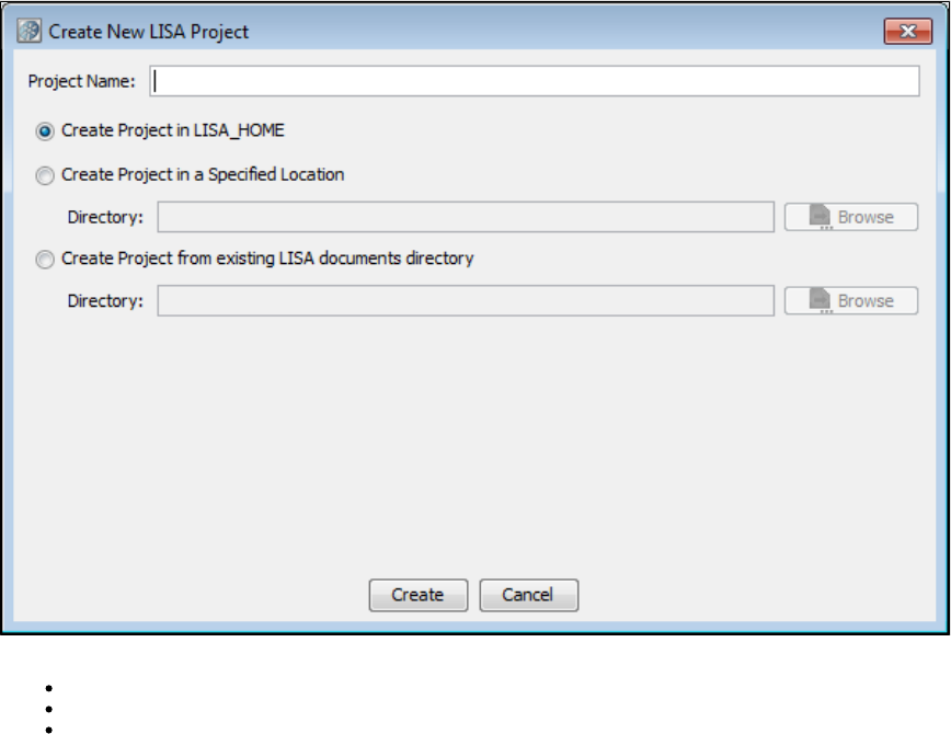
1.
2.
3.
4.
statefullATM.tst
statelessATM.tst
web-app-proxy.tst
WebAppModel.vsm
webservices-vs.vsm
WebServicesModel.vsm
Creating a Project
You create a project from within LISA Workstation.
To create a project
From the main menu, select File > New > Project.
The Create New LISA Project dialog appears.
In the Project Name field, enter the name of the project.
Select one of the following options:
Create Project in LISA_HOME: Click to create a project in the project subfolder of the LISA home directory.
Create Project in a Specified Location: Click to specify the location of the project. Click Browse to browse to the directory.
Create Project from existing LISA documents directory: Click to create a new project from an existing projects file. This
option is used for importing a projects file from another directory.
Click Create. The new project appears in the Project panel.
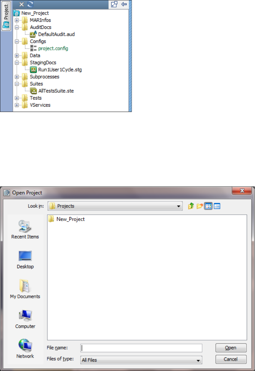
4.
1.
2.
1.
2.
Opening a Project
When you open a project, it will have a list of folders and subfolders in the left panel.
After the project is opened, hovering on the Project icon on the left of the Project panel displays a tooltip that shows the complete project path.
To open a project from LISA Workstation
From the main menu, select File > Open > Project.
If you have already opened some projects, you will see a list of recently opened projects that you can select from. After it is selected, the
project will open.
If you want to browse for a project file, you can select File System from the list of choices and the Open Project window will open.
Select the required project and click Open.
To open a project from the command line
Navigate to the directory.LISA_HOME/bin
Run the LISA Workstation executable and specify the project directory as an argument. The project directory can be an absolute path or
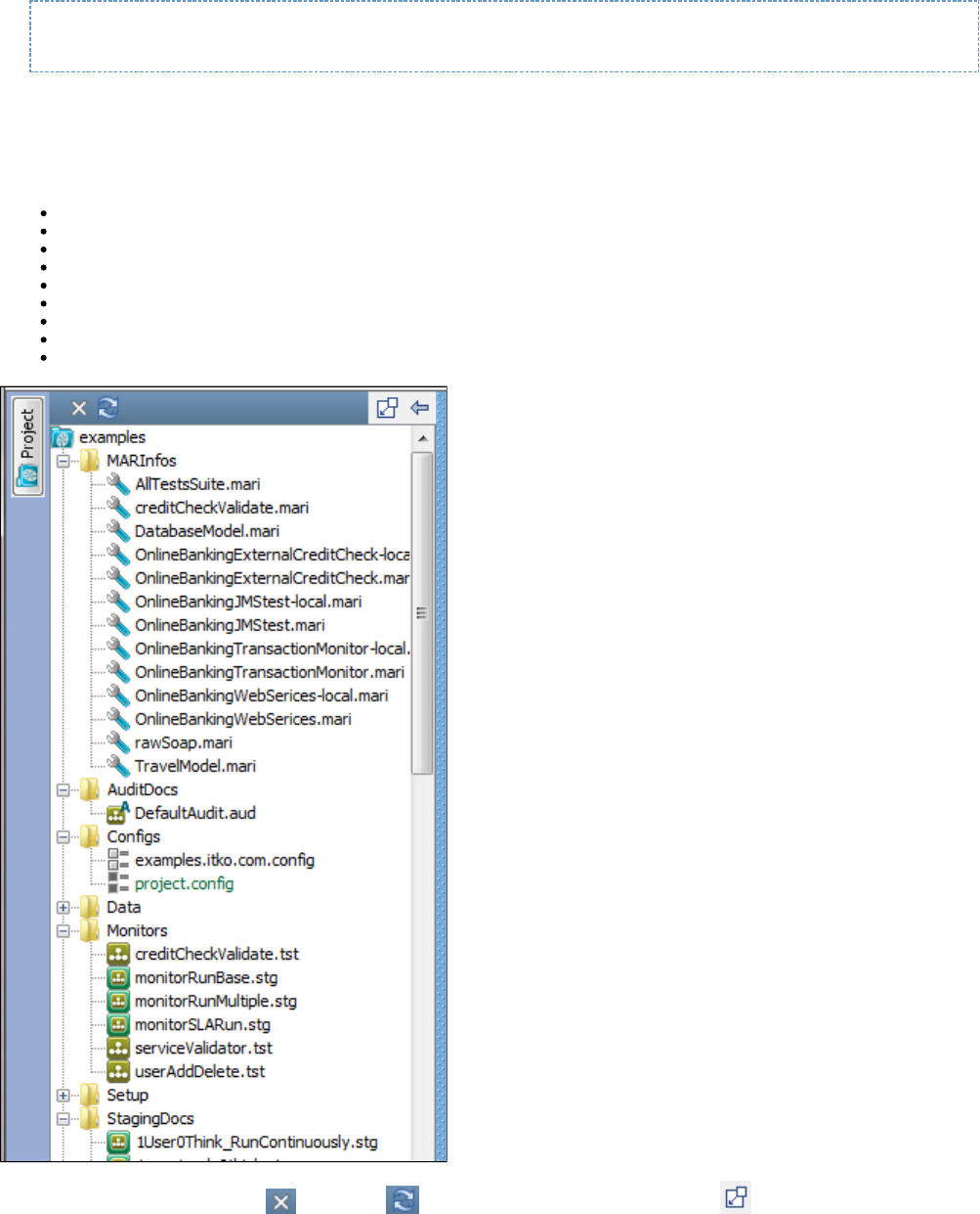
2.
a relative path. The following example uses an absolute path:
LISAWorkstation C:\Lisa\Projects\Project1
Project Panel Layout
The Project panel is dockable. You can open or close the Project panel by clicking the Project button.
The Project panel contains a project tree. For a new project created from scratch, the following folders are automatically created:
MARInfos
AuditDocs
Configs
Data
StagingDocs
Subprocesses
Suites
Tests
VServices
The Project toolbar has icons to close and refresh the project, and an icon to dock or undock the Project panel.
The configuration is included by default. This configuration can be overridden by another configuration.project.config
The project has a directory, which does not appear in the Project panel. The directory is used for saving some settings.settings .settings
internally and can be seen in the file system in the Project directory.
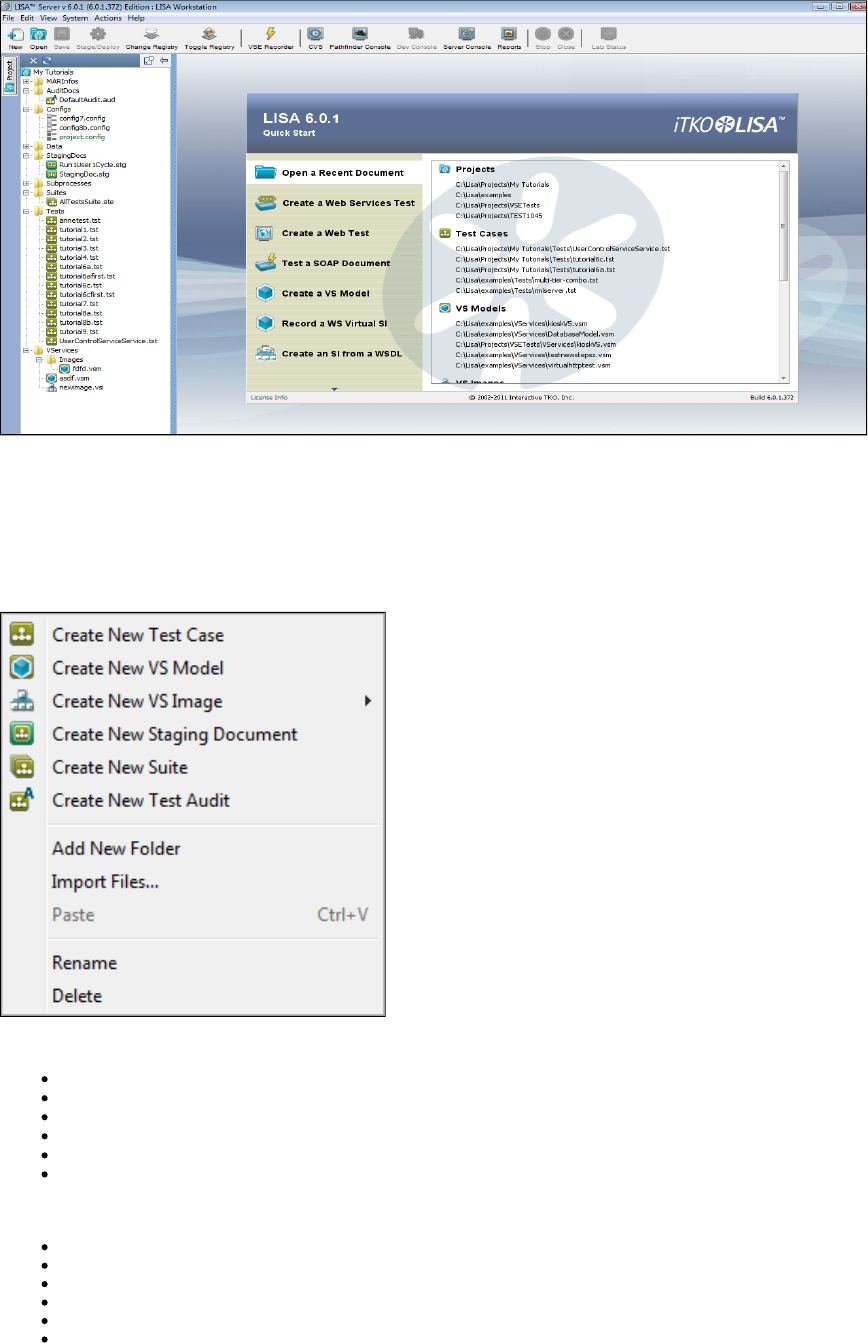
The appears in the right panel.Quick Start window
Project Panel Right-Click Menu
You can create various documents within a project from the Project panel. When you right-click a choice in the Project panel, the menu that
appears is dynamic to the selection.
The following image includes all the available choices. The order of these choices will vary depending on what choice is selected when you
right-click.
The right-click menu choices described here are also available from the main menu by selecting File > New.
Create New Test Case: For detailed information, see .Creating Test Cases
Create New VS Model: For detailed information, see . This feature requires an additional license.Working with Virtual Service Models
Create New VS Image: For detailed information, see . This feature requires an additional license.Creating Service Images
Create New Staging Document: For detailed information, see .Building Staging Documents
Create New Suite: For detailed information, see .Building Test Suites
Create New Test Audit: For detailed information, see .Building Audit Documents
One or more of the following choices may also be available:
Add New Folder
Import Files
Rename
Delete
Paste
View/Edit Project Metadata
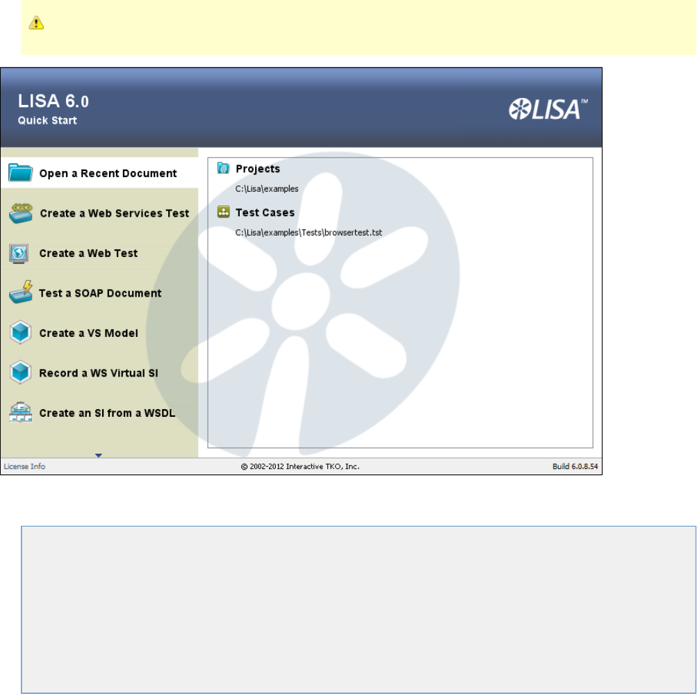
If you want the documents you create to default to the matching folder name, right-click that choice when adding. If you add a document without
being on that actual selection in the Project panel, it will be added to the project, but it will appear at the bottom of the Project panel list. You will
then have to go to the root directory and manually move the file into the correct folder and then reopen the project to correct.
You are not limited to keeping a certain kind of file (such as .tst) under the recommended folder (such as Tests). The file can stay anywhere within
the project. The only exceptions are .config files and data resources; they must be located in the Configs and Data folders, respectively.
Quick Start Window
The Quick Start window is the first one you will see when you open LISA Workstation.
The Quick Start window is always available as a tab after additional tabs are opened.
The Quick Start window has some of the most useful options listed within LISA Workstation. When you click an option, its parameters are listed
on the right side of the window.
The following choices are available on this window. Depending on your screen resolution, you may see the compact or the
expanded wording for each menu choice. You may need to click the down arrow at the bottom of the screen to see all menu
options.
Open Recent or Open a Recent Document
or Create a Web Services TestNew WS Test or Create a Web TestNew Web Test or Test a SOAP DocumentSend SOAP Doc
or Create a VS ModelCreate VSM or Record a WS Virtual SIRecord WS VSI or Create an SI from a WSDLVSI from WSDL
or Learn More About LISALearn More
Open Recent
When LISA Workstation opens, by default this option is selected. The right pane displays recently opened projects, test cases and suites, staging
documents, VS models or VS images (if applicable).
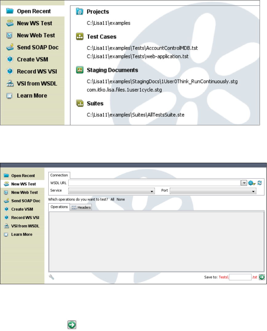
1.
2.
3.
4.
New WS Test
The option in the Quick Start window lets you create a Web Service test case. The parameters needed are displayed in the rightNew WS Test
pane.
Enter the WSDL URL, Service and Port details.
Check the operations that you want to test from or or select each item individually.All None
In the right pane, enter the name of the test and select the path where you would like to save it within the project folder. When you select
the path, it will be seen in the field. Within this pane, you can right-click on any folder and create a new one or rename or delete anPath
existing one.
Click the green arrow to create the test case.
For more information, see .Generating a Web Service
New Web Test
The option in the Quick Start window lets you create a web test.New Web Test
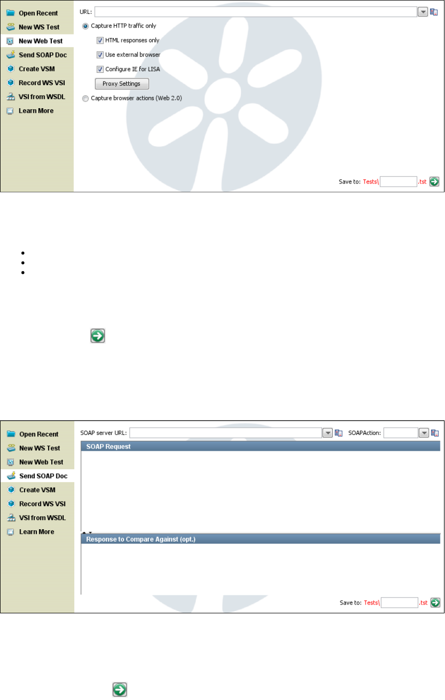
1.
2.
1.
2.
3.
4.
5.
6.
Enter the for the web test.URL
Select if you want to capture or capture .HTTP traffic Browser actions
If you select traffic, check your options in the check boxes:HTTP
HTML Responses Only: Will capture only the HTML responses.
Use External Browser: Will open an external browser window.
Configure IE for LISA: Will configure Internet Explorer for LISA.
3. In the right pane, enter the name of the test and select the path where you would like to save it in the project folder. When you select the path,
it will be seen in the Path field. Within this pane, you can right-click on any folder and create a new one or rename or delete the same as shown
previously.
4. Click the green arrow to create the test case.
For more information, see .Recording a Website
Send SOAP Doc
The option in the Quick Start window lets you create a SOAP Request test case.Send SOAP Doc
Enter the SOAP server URL and SOAP Action.
Enter the URL of the Web Service endpoint in the SOAP Server URL field.
In the SOAP Action field, enter the SOAP action as indicated in the <soap: operation> tag in the WSDL for the method being called. This
is required for SOAP 1.1 and usually required to be left blank for SOAP 1.2.
Type or paste the SOAP Request into the editor.
Enter the name of the test in the Save to field.
Click the green arrow to create the test case.
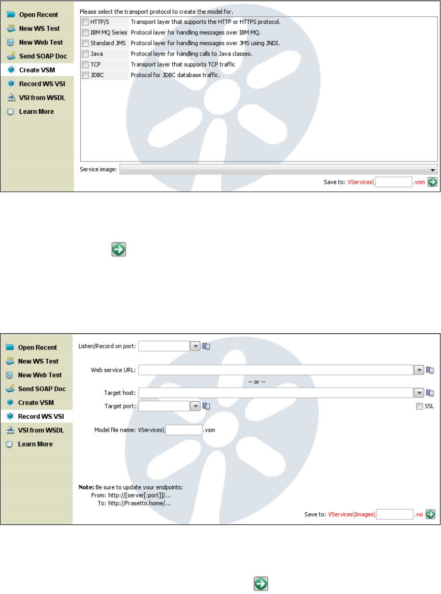
1.
2.
3.
4.
1.
2.
3.
4.
5.
Create VSM
The option in the Quick Start window lets you create a Virtual Service Model and a corresponding Virtual Service Image.Create VSM
Select the transport protocol from the list of available protocols. Your selection here will determine the next sequence of windows.
Enter the name of the Service Image.
Enter the name of the VSM and select the path where you would like to save it within the project folder. When you select the path, it will
be seen in the Path field.
Click the green arrow to go to the next screen(s).
For more detailed information about the screens and options for VSM and VSI creation, see " ."Creating Service Images
Record WS VSI
The option in the Quick Start window lets you create a web services Virtual Service Image. The parameters needed areRecord WS VSI
displayed in the right pane.
Enter a port on which to listen and record.
Enter the URL of the web service to record.
Enter the target host and port to record.
Use the SSL check box to determine whether to use SSL with this service image.
Enter the name of the VSM and SI, and click the green arrow to create the virtual service.
VSI from WSDL
The option in the Quick Start window lets you create a Virtual Service Image from a WSDL. The properties needed are displayedVSI from WSDL
in the right pane.
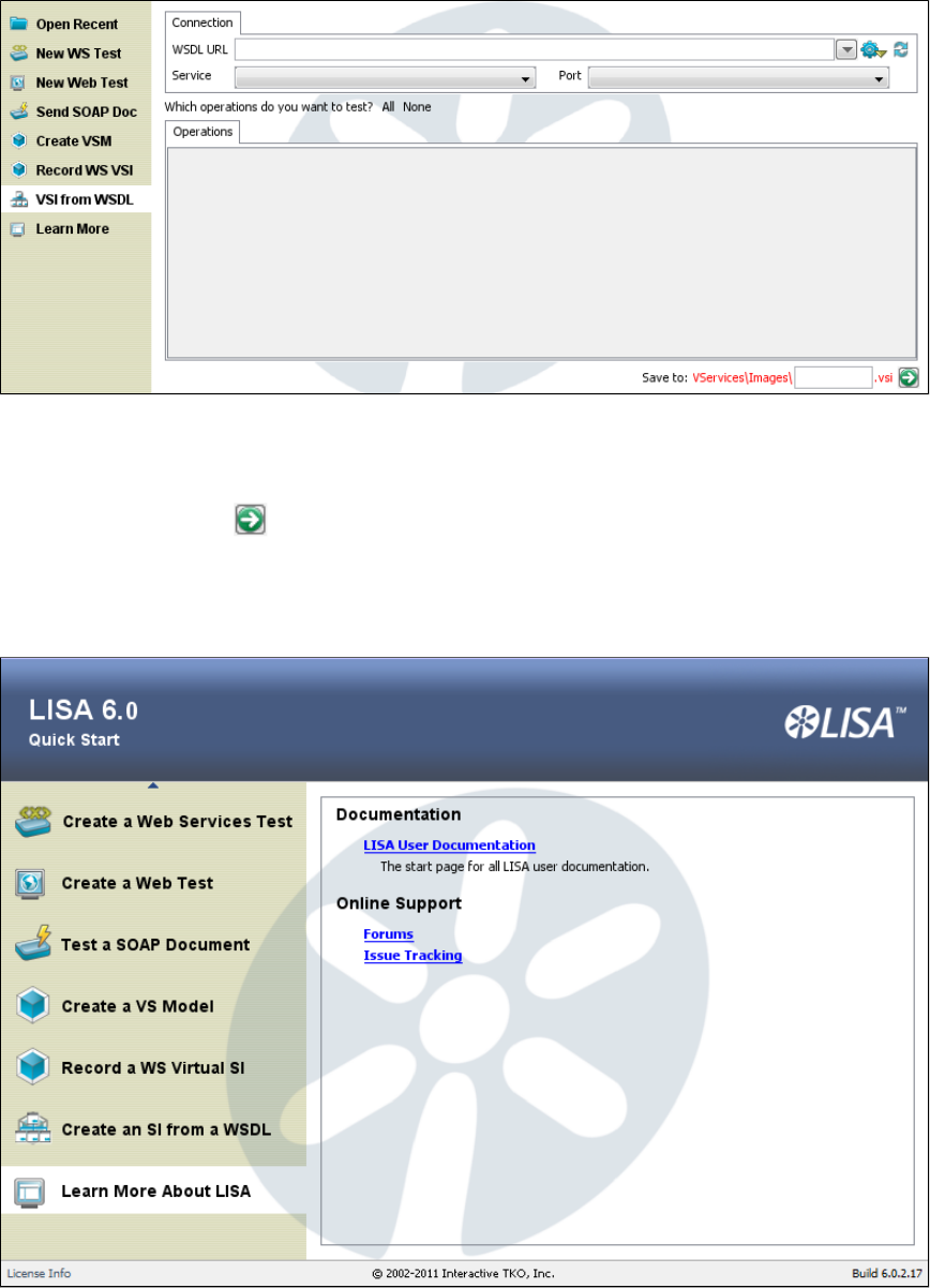
1.
2.
3.
4.
Enter the WSDL URL, Service and Port related details. If the WSDL URL you enter does not contain LISA properties in its path, Service
and Port will be populated automatically.
Check the operations that you want to test from or or select each item individually.All None
Enter the name of the service image and select the path where you would like to save it within the project folder.
Click the green arrow to create the service image.
Learn More
The option in the Quick Start window displays a link to LISA documentation and LISA online support information.Learn More
All available user documentation for LISA is accessible from this menu, and ITKO online support forums and issue tracking.
Tables
Tables in LISA Workstation have a consistent look and feel, and you can use the same features to customize the displays.
They all have the same banding.
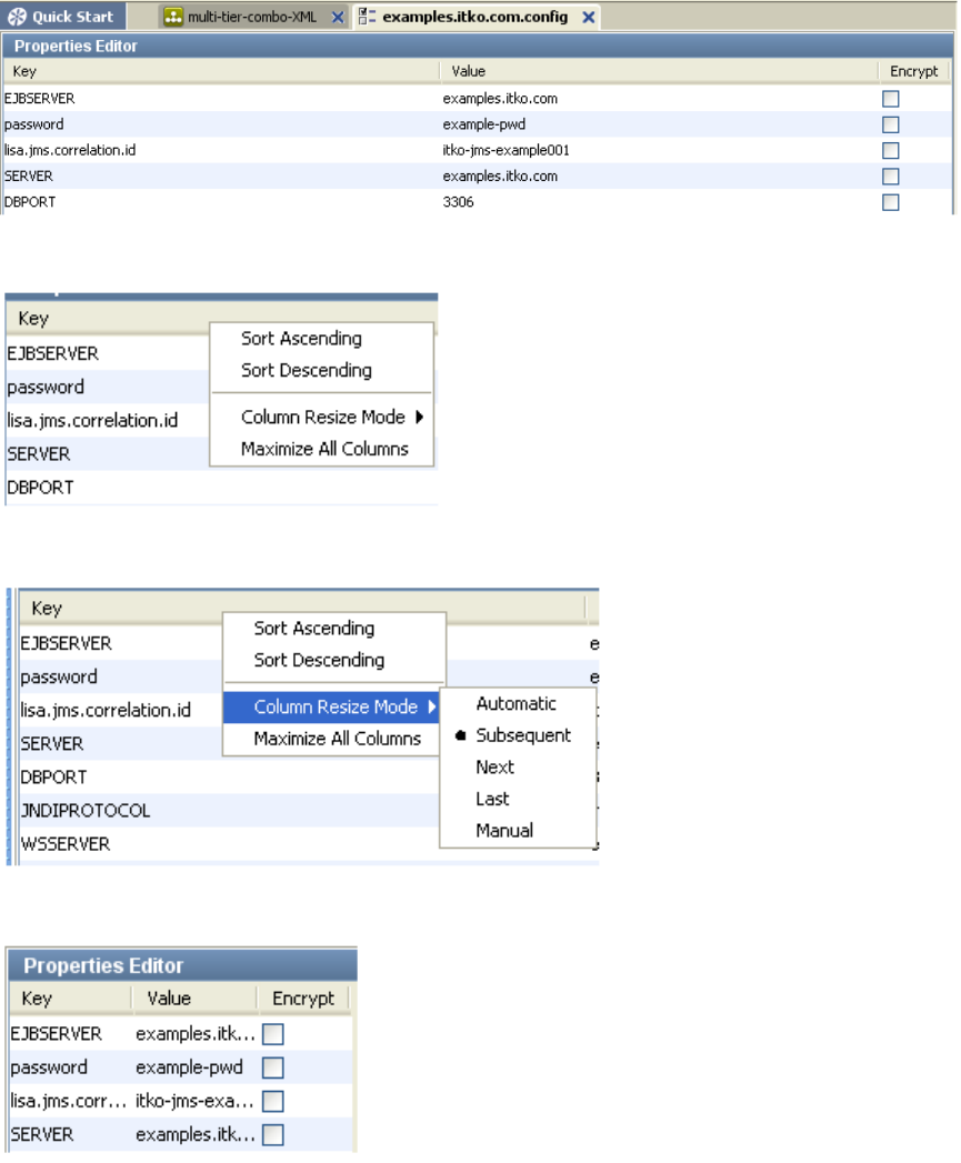
They all have the ability to change their column sizes and sorting (if sortable) through a right-click menu.
Selecting Maximizing All Columns changes the Column Resize Mode to Manual.
You can also double-click on the column resizers (the column header between columns) to maximize the current column (or selected columns).
This shows the results after double-clicking the Key column resizer.
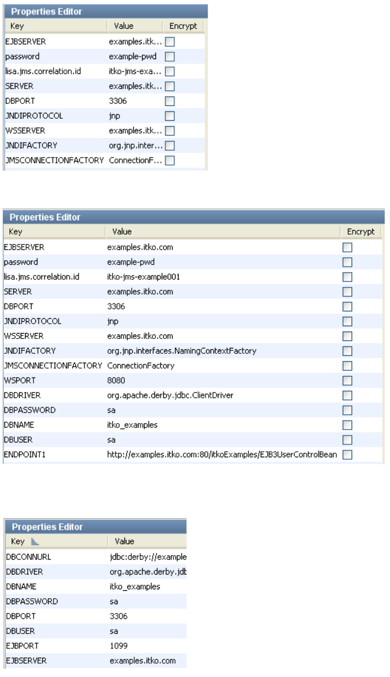
This shows the results after double-clicking the Key column resizer.
You can also click on the column header to toggle the column sort state (for sortable tables). All tables show sort indicators.
Sort Key column ascending:
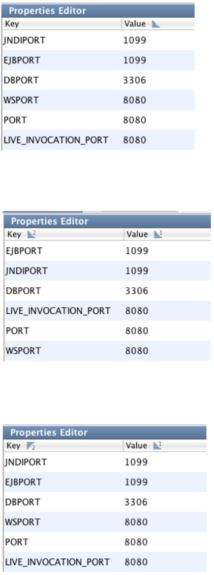
Sort Value column ascending:
You may also multi-sort by holding down the Cntl key on Windows or command key on Mac. A number will show up when multiple columns are
sorted to indicate sort order.
(Value Ascending, Key Ascending)
While holding down the control/command key it will toggle between ascending and descending (skipping the reset state), but you can
control/command right-click to bring up the menu if you want to reset the sort order.
(Value Ascending, Key Descending)
All tables are banded, even ones where the rows are colored.
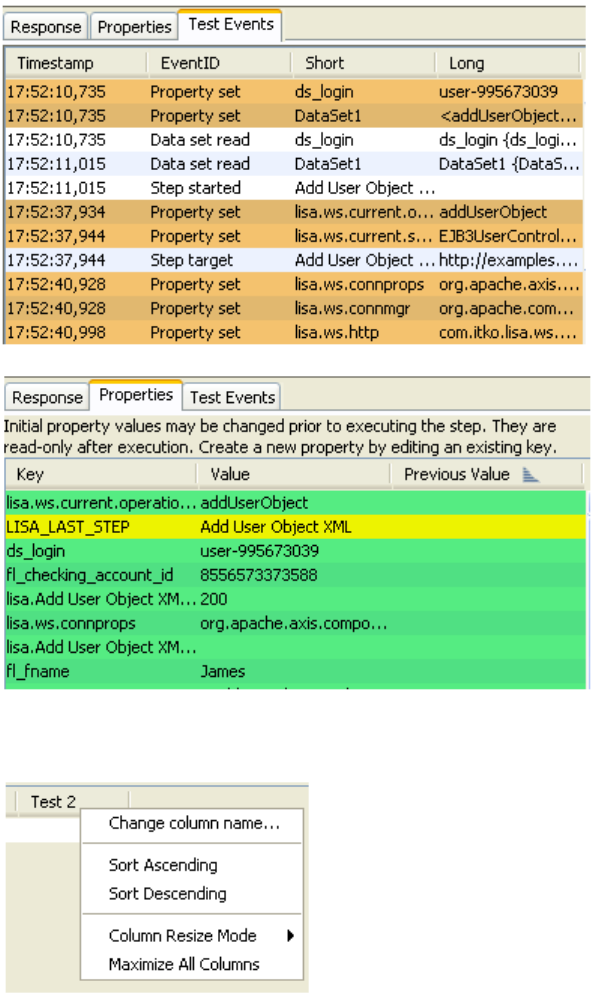
Some tables add additional actions in their right-click menu. The Data Sheet Dataset editor is shown, with a selection for changing the column
name.
The JDBC result set is shown in the following image.
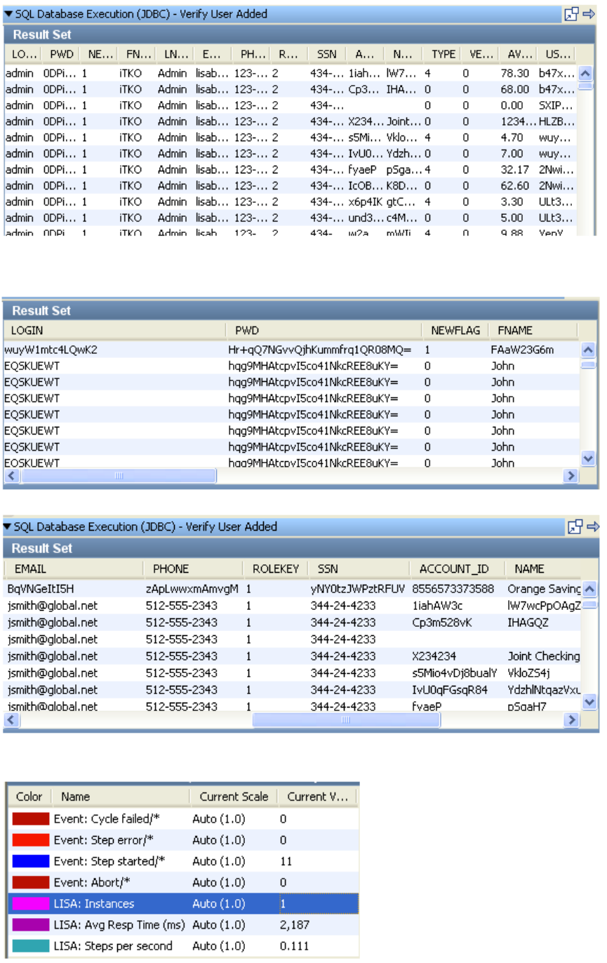
You can use the Maximize option so the columns are all displayed, and scroll bars are available.
Color object are rendered differently in tables:
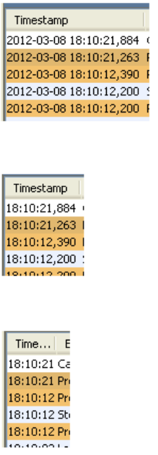
Date objects have a renderer that support smaller formats when the column shrinks.
Fullsize
Midsize (no date)
Compact (no ms)
Event Tables have a Long Info Field panel and they resize initially to maximize the first four columns and average the last two.
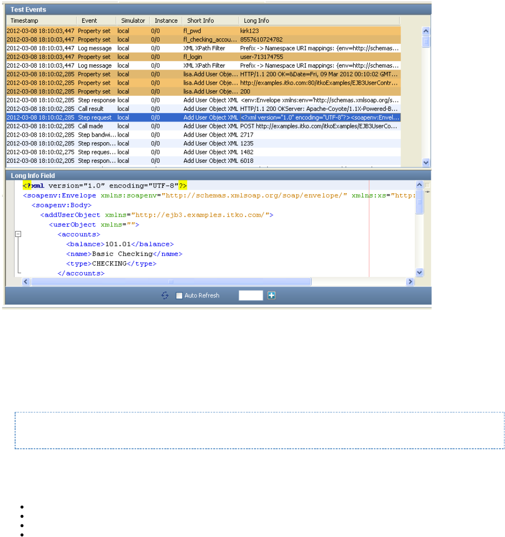
Tray Panels
LISA Workstation has tray panels for certain features, such as the step.Output Log Message
As of release 6.0.6, you can control whether the opening and closing of tray panels use animation. By default, animation is disabled to help
improve performance for users who access LISA Workstation through a remote desktop.
To enable the animation, add the following line to the or file:site.properties local.properties
lisa.ui.tray.animation=true
LISA Console
The web-based LISA Console provides access to the following consoles and dashboards:
Continuous Validation Service
LISA Pathfinder
Server Console
Reporting Dashboard
Continuous Validation Service
The Continuous Validation Service (CVS) lets you schedule tests and test suites to run on a regular basis over an extended time period.
For more information, see " ."Continuous Validation Service (CVS)
LISA Pathfinder
Pathfinder lets you probe into the system under test, to examine the components behind the initial request or method call.
For more information, see the .Pathfinder Guide
Server Console

1.
2.
1.
2.
3.
The Server Console enables you to manage labs and to configure role-based access control. The Server Console is also where you access the
VSE Dashboard.
For more information, see " ," " ," and " ."Cloud DevTest Labs Access Control (ACL) VSE Dashboard
Reporting Dashboard
A report viewer displays event and metric information, and information derived from data that was captured during the running of tests. You can
use a staging document to set the events and metrics that you want to capture for reporting purposes.
For more information, see " ."Reports
Opening the LISA Console
You can open the LISA Console from the main menu of LISA Workstation or from a web browser.
The home page of the LISA Console lets you access the Pathfinder Console, the Reporting Dashboard, the Continuous Validation Service, and
the Server Console. The lower right area of the home page displays the version number.
To open the LISA Console from the LISA Workstation main menu
From the main menu, select View > LISA Portal.
If access control (ACL) is enabled, then the LISA Console Login dialog appears.
Enter your user name and password and click Login.
The LISA Console appears.
To open the LISA Console from a web browser
Ensure that the is running.registry
Enter in a web browser. If the registry is located on a remote computer, then replace with the name orhttp://localhost:1505/ localhost
IP address of the computer.
If access control (ACL) is enabled, then the LISA Console Login dialog appears.
Enter your user name and password and click Login.
The LISA Console appears.
Web Server Timeouts
By default, the web server used by the LISA Console will wait 90 seconds for a process to run on the server. If a process takes longer than 90
seconds, then the connection will be aborted and the client application or browser should handle this appropriately.
You can change the default timeout value by adding the property to the file. The value is inlisa.webserver.socket.timeout local.properties
milliseconds. For example:
lisa.webserver.socket.timeout=120000
Command-Line Utilities
The following command-line utilities are included in the directory.LISA_HOME/bin
CVS Manager
CVS Manager lets you add or remove monitors to the CVS Dashboard through a command-line option. For more information, see .CVS Manager
Make Mar
Make Mar lets you show the contents of MAR info files (standalone or in an archive), or to create model archive files from MAR info files. For more
information, see .Make Mar
Service Image Manager
Service Image Manager is used to import transactions into a service image (new or existing), and to combine two or more service images
together. For more information, see .Service Image Manager
Service Manager
1.
Service Manager is used to check the status of, reset, or stop a running LISA server process. For more information, see .Service Manager
Test Runner
Test Runner is a "headless" version of LISA Workstation with the same functionality but no user interface. For more information, see .Test Runner
VSE Manager
VSE Manager is used for managing virtual service environments. For more information, see .VSE Manager Commands
Tutorials
This section contains a series of tutorials that illustrate various aspects of LISA. The tutorials are sequential and should be completed in order.
The first few tutorials walk you through using LISA Workstation to build simple test cases. You become familiar with basic concepts such as
projects, properties, data sets, filters, and assertions.
The subsequent tutorials illustrate deeper knowledge about how to set up test steps to interact with and test several common technologies,
including Java objects (POJOs), web pages, Enterprise JavaBeans (EJBs), web services, and databases. You also learn how to stage a quick
test.
Several of these tutorials use the LISA Demo Server as the system under test. You can use the Demo Server installed with LISA (locally on your
workstation), or you can reference a similarly configured demo server at .http://examples.itko.com/itko-examples/
For more information about installing the LISA Demo Server, see and .Downloading the Installer Installing the Demo Server
The following tutorials are available.
Tutorial 1 - Projects, Test Cases, and Properties
Tutorial 2 - Data Sets
Tutorial 3 - Filters and Assertions
Tutorial 4 - Manipulating Java Objects (POJOs)
Tutorial 5 - Running a Demo Server Web Application
Tutorial 6 - Testing a Website
Tutorial 7 - Testing an Enterprise JavaBean (EJB)
Tutorial 8 - Testing a Web Service
Tutorial 9 - Examining and Testing a Database
Tutorial 10 - Staging a Quick Test
Tutorial 1 - Projects, Test Cases, and Properties
In this tutorial, you will learn how to create a project and a test case. You will also look at the use of properties to understand the various places
from which they can originate.
LISA Concepts Discussed
In this tutorial, you do the following:
Create and save a new project
Create and save a new test case
Create properties
Add simple test steps
Use the Interactive Test Run utility
Prerequisites
LISA Workstation is installed and LISA license credentials are entered.
You have reviewed Basic Concepts
Steps
Step 1 - Start LISA Workstation
To start LISA Workstation:
Ensure that the registry is running. If your computer has an installation of LISA Server, then you can start the registry by clicking Start
and waiting until the LISA Registry Ready message appears. If your computer has anMenu > All Programs > LISA > Registry
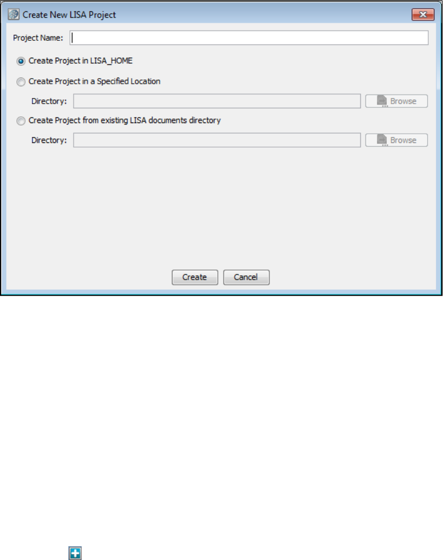
1.
2.
3.
1.
2.
3.
4.
1.
2.
3.
1.
2.
3.
4.
5.
installation of LISA Workstation, you will need to use a registry that is running on another computer.
Click .Start Menu > All Programs > LISA > LISAWorkstation
When the dialog appears, select a registry and click OK.Set LISA Registry
Step 2 - Create a Project
The project that you create will hold all the test case example files that are required for the tutorials.
To create a project:
From the LISA Workstation main menu, select . The dialog appears. File > New > Project Create New LISA Project
In the Project Name field, type .My Tutorials
Accept the default setting to create the project in the directory.LISA_HOME
Click Create. The project is created.My Tutorials
Step 3 - Create a Test Case
A test case is a specification of how to test a business component in the system under test.
To create a test case:
In the Project Panel, right-click the folder and select .Tests Create New Test Case
Set the file name to .tutorial1
Click Save. LISA Workstation opens a new tab labeled . The green arrow in the model editor represents the start of the testtutorial1
case.
Step 4 - Add a Property to the Project Configuration
In this step, you set a global property in the project configuration. You will access this property later in the tutorial.
The default configuration is named , and is created automatically for a new project. The file is located in the project.config project.config
folder in the Project Panel. You can add the properties to the file and, if required, can also create a new configuration file.Configs project.config
To add a property to the project configuration:
In the Project Panel, double-click in the > folder. The properties editor for opens.project.config My Tutorials Configs project.config
Click the Add icon at the bottom of the properties editor to add a new row.
In the field, type .Key config_prop
In the field, type .Value 42
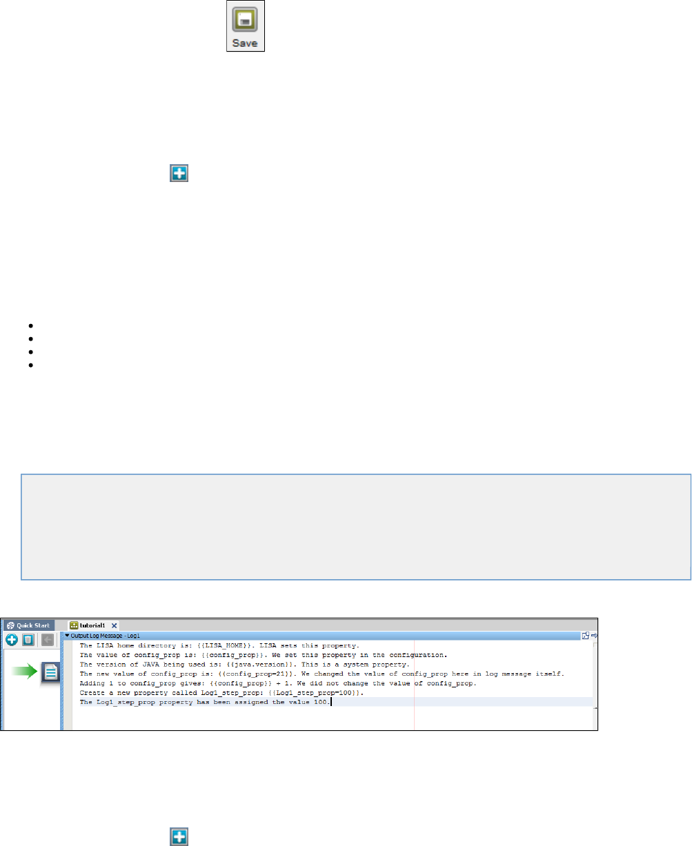
5.
1.
2.
3.
4.
1.
2.
1.
2.
3.
4.
5.
From the main toolbar, click the Save icon.
Step 5 - Add a Test Step
A test case includes one or more test steps. In this procedure, you add an Output Log Message test step to write text to the log file.
To add a test step:
Click the tab.tutorial1
Click the Add Step button , select , and select . is added to the model editor. Utilities Output Log Message Step1
Right-click and select . Change the name to .Step1 Rename Log1
Make sure that is still selected. In the right pane, click the arrow next to . The Output Log Message trayLog1 Output Log Message
opens.
Step 6 - Add a Log Message
With the log editor open, you add a log message that includes various properties.
The properties in the log message originate from several sources:
The property is automatically set.LISA_HOME
The property is a system property.java.version
You added the property to the project configuration in Step 4.config_prop
You create a new property named in the log message itself.Log1_step_prop
The syntax for a property is {{ }}.property_name
To add a log message:
In the log editor, delete the placeholder text.
Copy and paste the following text into the log editor:
The LISA home directory is: {{ }}. LISA sets this property.LISA_HOME
The value of config_prop is: {{ }}. We set this property in the configuration.config_prop
The version of Java being used is: {{ }}. This is a system property.java.version
The new value of config_prop is: {{ }}. We changed the value of config_prop here in log message itself.config_prop=21
Adding 1 to config_prop gives: {{ }} + 1. We did not change the value of config_prop.config_prop
Create a new property named Log1_step_prop: {{ }}.Log1_step_prop=100
The Log1_step_prop property has been assigned the value 100.
The log editor should look like the following image.
Step 7 - Add a Second Log Message
The second test step in the test case will write a different message to the log file.
To add a second log message:
Click the Add Step button , select , and select . is added to the model editor. Utilities Output Log Message Step1
Right-click and select . Change the name to .Step1 Rename Log2
Make sure that is still selected. In the right pane, click the arrow next to . The Output Log Message trayLog2 Output Log Message
opens.
In the log editor, delete the placeholder text.
Copy and paste the following text into the log editor:
5.
6.
1.
2.
1.
2.
1.
2.
3.
4.
The current value of config_prop is: {{ }}.config_prop
The current value of Log1_step_prop: {{ }}.Log1_step_prop
The log message does not change the values of or .config_prop Log1_step_prop
From the main application toolbar, click the Save icon, or select . File > Save
Step 8 - Run the Log1 Step
The Interactive Test Run (ITR) utility enables you to walk through and verify a test case.
To run the Log1 step:
From the toolbar, click the Start a new ITR icon . The ITR opens. The ITR contains an Execution History pane on the left and a set
of tabs on the right.
In the Execution History pane, click the Execute Next Step icon.
The step is run. The tab displays the response from the step. The properties have been replaced by actualLog1 Response Log1
values.
Step 9 - Observe Property Values
The ITR also enables you to observe how the properties are created and modified.
To observe property values:
Click the tab in the ITR.Properties
The tab displays the value of each property before and after the execution of the step.Properties Log1
A value that was created by the step is highlighted in green. A value that was modified in the step is highlighted in yellow. Notice that the
value of was changed from 42 to 21.config_prop
Compare these values with the response in Step 8.
Step 10 - Run the Log2 Step
In this procedure, you use the ITR to run the second step in the test case.
To run the Log2 step:
In the ITR, click the Execute Next Step icon to run the step.Log2
Click the tab to view the response. Even though you set to 42 in the file, you changed the valueResponse config_prop project.config
to 21 in the step, and the value did not change in the step. The value of the property also carried over fromLog1 Log2 Log1_step_prop
the step to the step.Log1 Log2
Click the tab to view the current and previous property values.Properties
When you are done, close the and tabs.tutorial1 project.config
Review
In this tutorial, you took a first look at properties. You saw that properties are denoted by using a special syntax, {{ }}. You canproperty_name
set properties by using a variation of this syntax, {{ }}. After you set a property, use or modify it in subsequent steps in aproperty_name=value
test case.
In this tutorial, you did the following:
Learned how to create and save a test case
Learned how to add a simple test step (Output Log Message)
Used a configuration to store properties
Saw a brief glimpse of the Interactive Test Run utility
Tutorial 2 - Data Sets
In this tutorial, you will learn how to create and use a simple data set. You will also learn how to provide this data set's data to a test case.
1.
2.
3.
4.
5.
1.
2.
3.
1.
2.
3.
4.
5.
LISA Concepts Discussed
In this tutorial, you do the following:
Create a simple data set
Use the data set in a variety of ways
Iterate through a series of test steps using a data set
Prerequisites
You have completed .Tutorial 1 - Projects, Test Cases, and Properties
LISA Workstation is open.
Steps
Step 1 - Create a Data Set
You will use a comma-delimited text file as the data set. This option is just one of several options available to create a data set. After you create
the text file, you import it into the project.My Tutorials
To create a data set:
In a text editor such as Notepad, create a text file. Copy and paste the following properties and values into the text editor. Do not use
spaces in the text file.
month,day,year
3,2,1956
4,7,2007
1,3,2010
5,8,{{ }}yearglobal
8,10,2004
12,11,{{ }}yearglobal
10,12,2007
3,5,2011
The first row specifies the names of the properties to which this data is assigned (month, day, year). The remaining rows specify the data
that is read and used in the test case. Two of the rows include a property named .yearglobal
Save the file as .dates.txt
In the Project panel, right-click the Data folder in the project and select Import Files.My Tutorials
Navigate to the folder where you saved the file and select the file name.dates.txt
Click Open. The file now appears in the Data folder.dates.txt
Step 2 - Create a Test Case
You will add a new test case to the project.My Tutorials
To create a test case:
In the Project panel, right-click the Tests folder and select Create New Test Case.
Set the file name to .tutorial2
Click Save.
Step 3 - Add a Property to the Project Configuration
The file includes a property named . In this procedure, you add the property to the project configuration.dates.txt yearglobal yearglobal
To add a property to the project configuration:
In the Project panel, double-click .project.config
Click the Add icon to add a new row.
In the field, enter .Key yearglobal
In the field, enter .Value 1999
Click the Save icon.
1.
2.
3.
4.
5.
6.
7.
8.
9.
1.
2.
3.
4.
5.
6.
7.
8.
1.
2.
3.
4.
1.
2.
3.
Step 4 - Add a Test Step for Output Log Message
Use a test step, the step, to write text out to the log.Output Log Message
To add a test step for Output Log Message:
Click the tab.tutorial2
Click the Add Step icon. The menu is displayed.Add step
Select and select . is added to the model editor.Utilities Output Log Message Step1
Right-click and select Rename. Change the name to .Step1 DSstep1
In the right pane, click the arrow next to . The Output Log Message tray opens.Output Log Message
Delete the placeholder text.
Enter the following log message:
Date is: {{ }}/{{ }}/{{ }}month day year
The curly brackets are important. If you do not include them, the test case will not run correctly.
Click anywhere in the model editor to close the Output Log Message tray.
Click the Save icon .
Step 5 - Create Another Output Log Message Step
Create another test step similar to the test step.DSstep1
To create another output log message step:
Click the Add Step icon. The menu is displayed.Add step
Select Utilities and select . is added to the model editor.Output Log Message Step1
Right-click and select Rename. Change the name to .Step1 DSstep2
In the right pane, click the arrow next to . The Output Log Message tray opens.Output Log Message
Delete the placeholder text.
Enter the following log message:
Date is: {{ }}/{{ }}/{{ }}month day year
Click anywhere in the model editor to close the Output Log Message tray.
Click the Save icon .
Step 6 - Execute the Test
Use the Interactive Test Run (ITR) utility to execute the test and see what happens.
To execute the test:
From the toolbar, click Start ITR. The ITR opens.
In the Execution History pane, click the Automatically execute test icon.
When the test is complete, click OK.
In the Execution History pane, click DSstep1 and DSstep2. Notice that the month, day, and year properties have not been replaced with
actual values. This result is expected, because you have not added the data set to the test case.
Step 7 - Add the Data Set
You now add the data set to the test step.dates.txt DSstep1
To add the data set:
In the model editor, select .DSstep1
In the right pane, double-click on the step element tab.Data Sets
3.
4.
5.
6.
7.
8.
9.
10.
11.
12.
13.
1.
2.
3.
4.
5.
6.
7.
8.
9.
10.
11.
12.
Click the Add icon below the Data Sets element.
From the list, select . The data set is added to the test step. The data setCommon DataSets Read rows from a delimited data file
editor opens in the right pane.
In the data set editor, set the name to .DatesDS
Click the File Location browse button , and then navigate to and select the file in the dates.txt LISA_HOME/Projects/My
directory.Tutorials/Data
Click the Test and Keep button.
If the test is successful, the window returns a "Test successful" message.Data Set Editor
Click OK.
From the toolbar, click the Start ITR button and then select the option.Start new ITR
In the Execution History pane, click the Automatically execute test icon.
When the test is complete, click OK.
In the pane, click and . The first row of data in the data set is displayed in the tab. BothExecution History DSstep1 DSstep2 Response
step responses display the same date because we read only from the data set in .DSstep1
Step 8 - Change the Data Set Behavior
You now modify the data set so that it loops through the test step until all the rows in the data set have been read.
To change the data set behavior:
In the model editor, select the test step.DSstep1
In the step element pane of , click the arrow next to under the Data Sets element. The data set editor opens.DSstep1 DatesDS
In the field, select the option.At end of data Execute
Click the drop-down arrow on the field and select from the list of choices that appear. This setting will cause theExecute End the Test
test to end when all the data rows have been read.
Click the Test and Keep button.
Click OK to close the test successful message.
In the model editor, select the test step.DSstep2
In the element tab, set the drop-down list to . This setting will cause the two test steps to loop. TheStep Information Next DSstep1
arrows in the model editor show the order of execution: , followed by , followed by .DSstep1 DSstep2 DatesDS
From the toolbar, click the Start ITR button and then select the option.Start new ITR
In the ITR, click the Automatically execute test icon.
The test case runs in a loop until there are no more data rows in the data set.
When the test is complete, click OK.
Click the Save icon .
Review
In this tutorial, you did the following:
Created a comma-delimited data set.
Used the data set for running a simple test case.
Learned how a test step accesses the data in the data set.
Tutorial 3 - Filters and Assertions
In this tutorial, you will modify the test case created in Tutorial 2 to include a filter and an assertion.
For an introduction to filters and assertions, see .Basic Concepts
LISA Concepts Discussed
In this tutorial, you do the following:
Save an existing test case with a new name.
Add an assertion to a test step.
Add a filter to a test step.
Prerequisites
You have completed .Tutorial 2 - Data Sets
LISA Workstation is open.
Steps
1.
2.
3.
4.
1.
2.
3.
4.
1.
2.
3.
4.
Step 1 - Create a New Test Case from an Existing Test Case
In this step, you open and save it as .tutorial2.tst tutorial3.tst
To create a new test case from an existing test case:
Open the test case in the project.tutorial2.tst My Tutorials
From the menu bar, select .File > Save As
In the field, enter .File name tutorial3
Click Save. The test case is created and saved under the project.tutorial3 My Tutorials
Step 2 - Change Action of Test Step
Change the Next Steps action of both test steps so that is the next step, and only the first step reads from the data set.DSstep1
To change the action of the test step:
In the model editor, select .DSstep1
In the Step Information element tab, change the step to . With this action, the output goes back to the same step .Next DSstep1 DSStep1
For the time being, alert icons appear next to .DSStep2
In the model editor, double-click and change the Output Log Message as follows:DSstep2
Date contains 1999. It is: {{ }}/{{ }}/{{ }}.month day year
The curly brackets are very important. If they are not included, the test case will not run correctly.
Click the Save icon.
Step 3 - Add an Assertion
You can add various types of assertions to a test case. In this procedure, you will add an XML assertion named .Ensure Result Contains String
The assertion logic is as follows:
If the response contains the string , then the step will be run next.1999 DSstep2
If the response does not contain the string , then the step will be run next.1999 DSstep1
To add an assertion:
In the model editor, select .DSstep1
Open the element tab.Assertions
Click the Add icon.
From the submenu, select .XML Ensure Result Contains String
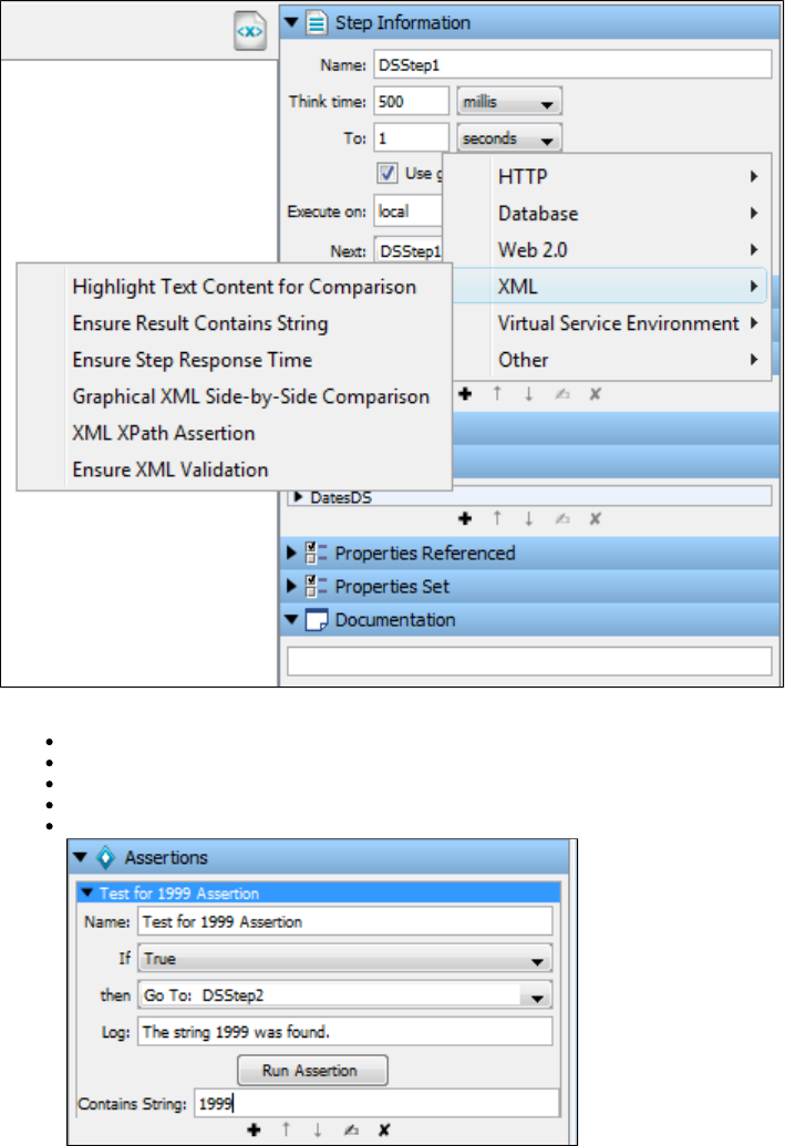
4.
5.
6.
1.
2.
3.
4.
The new assertion applied to DSstep1 is added to the tab. The assertion editor opens.Assertions
In the assertion editor, do the following:
In the field, enter .Name Test for 1999 Assertion
In the list, select .If True
In the list, select .then Go To: DSstep2
In the field, enter .Log The string 1999 was found
In the field, enter .Contains String 1999
Click the Save icon.
Step 4 - Test the Assertion
You can use the Interactive Test Run (ITR) utility to check whether the assertion works as expected.
To test the assertion:
Start a new ITR session.
In the Execution History pane, click the Automatically execute test icon.
When the test is complete, click OK.
Review the tab. Notice that when encounters a date in which the year is 1999, the test step is executedResponse DSstep1 DSstep2
next.
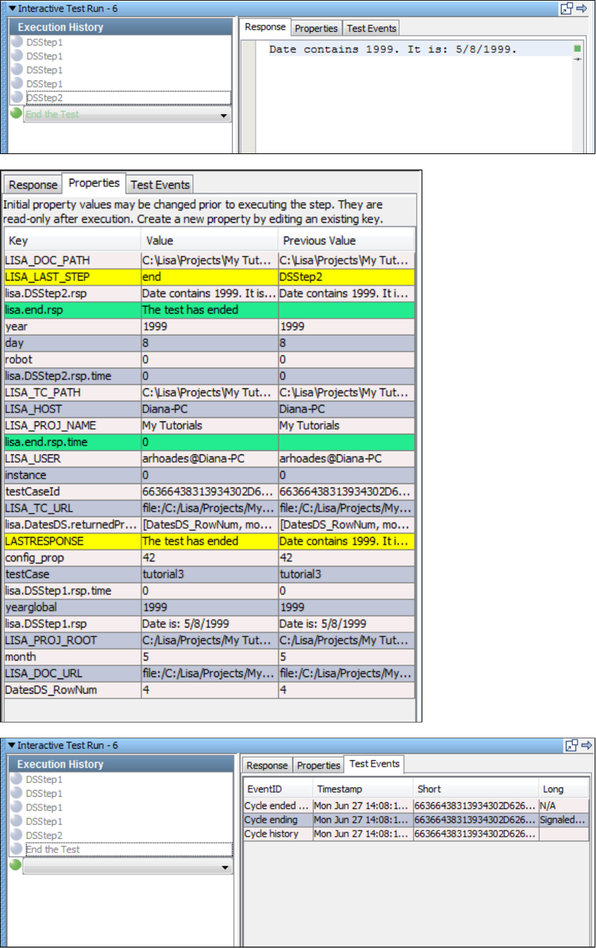
4.
5.
6.
Click the tab and review the behavior of the properties.Properties
Click the tab and review the events that were generated.Test Events
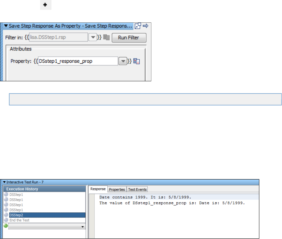
1.
2.
3.
4.
5.
6.
7.
1.
2.
3.
4.
5.
Step 5 - Add a Filter
You can add various types of filters to a test case. In this procedure, you add a utility filter named . This type of filter letsStore Step Response
you save the step response as a property.
To add a filter:
In the model editor, select .DSstep1
Open the element tab.Filters
Click the Add icon .
From the submenu, select . The filter editor opens.Utility Filters Store Step Response
In the filter editor, set the property name to . This property is where the step response will be stored.DSstep1_response_prop
In the model editor, double-click and add the following to the end of the output log message:DSstep2
The value of DSstep1_response_prop is: {{ }}.DSstep1_response_prop
Click the Save icon.
Step 6 - Test the Filter
You can use the Interactive Test Run (ITR) utility to check whether the filter works as expected.
To test the filter:
Start a new ITR session.
In the Execution History pane, click the Automatically execute test icon.
When the test is complete, click OK.
Review the tab. The test step now displays the additional text that you added to the output log message.Response DSstep2
Click the tab and observe where the property is created and modified.Properties DSstep1_response_prop

5.
6. Click the tab and review the events that were generated.Test Events
Review
In this tutorial, you did the following:
Took a first look at LISA filters and assertions.
Opened and modified an existing test case.
Learned how to add a simple assertion.
Learned how to add a simple filter.
Used the Interactive Test Run utility to check if the assertion and filter worked as expected.
More Information
LISA provides filters and assertions to cover most of the situations that you will encounter in your test case development. If there is not an
appropriate filter, LISA provides a mechanism, through the LISA Software Developer's Kit, for custom filters and assertions to be developed. See
the for more information.LISA Developers Guide
Tutorial 4 - Manipulating Java Objects (POJOs)

1.
2.
In this tutorial, you will create and manipulate a simple Java object and use the class to create a date object.java.util.Date
First, you construct the object and look at how to call methods on the object. Then you incorporate the object into a simple LISA model editor.
LISA Concepts Discussed
In this tutorial, you do the following:
Use the Dynamic Java Execution test step
Use the Complex Object Editor for simple objects
Use inline filters and save the results into a property
Prerequisites
You have completed .Tutorial 3 - Filters and Assertions
LISA Workstation is open.
Steps
Step 1 - Create a New Test Case
To create a new test case:
Within the project, create a new test case called .My Tutorials tutorial4
Step 2 - Create a Dynamic Java Execution Test Step
The Dynamic Java Execution test step lets you create a Java object from a class in the LISA classpath. In the following procedure, you use the
class.java.util.Date
To create a Dynamic Java Execution test step:
Click the Add Step icon. The menu is displayed.Add step
Point to and select .Java/J2EE Dynamic Java Execution
The Dynamic Java Execution editor opens.
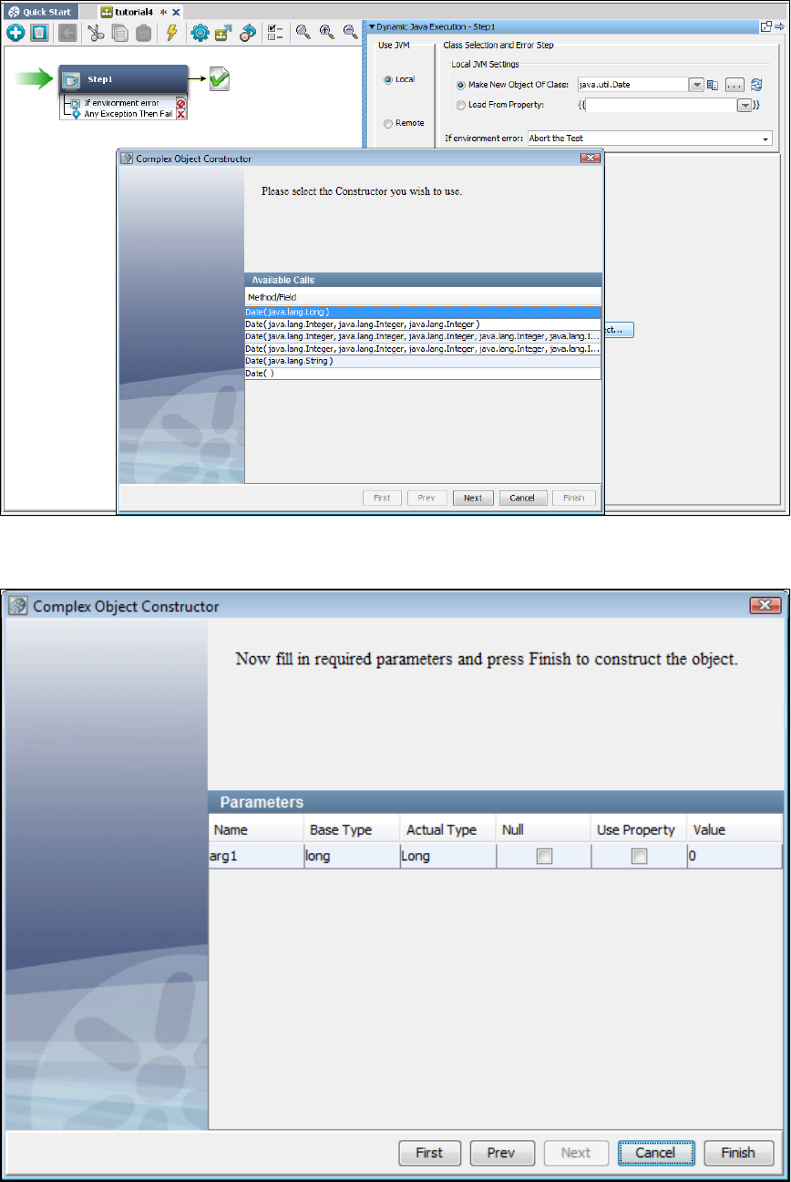
2.
3.
4.
5.
6.
7.
In the Local JVM Settings area, ensure that is selected.Make New Object of Class
In the field to the right of , type .Make New Object of Class java.util.Date
Click Construct/Load Object. The wizard appears. The first step shows the available constructors.Complex Object Constructor
Select the constructor.Date( java.lang.Long )
Click Next and Finish. The Complex Object Editor opens.
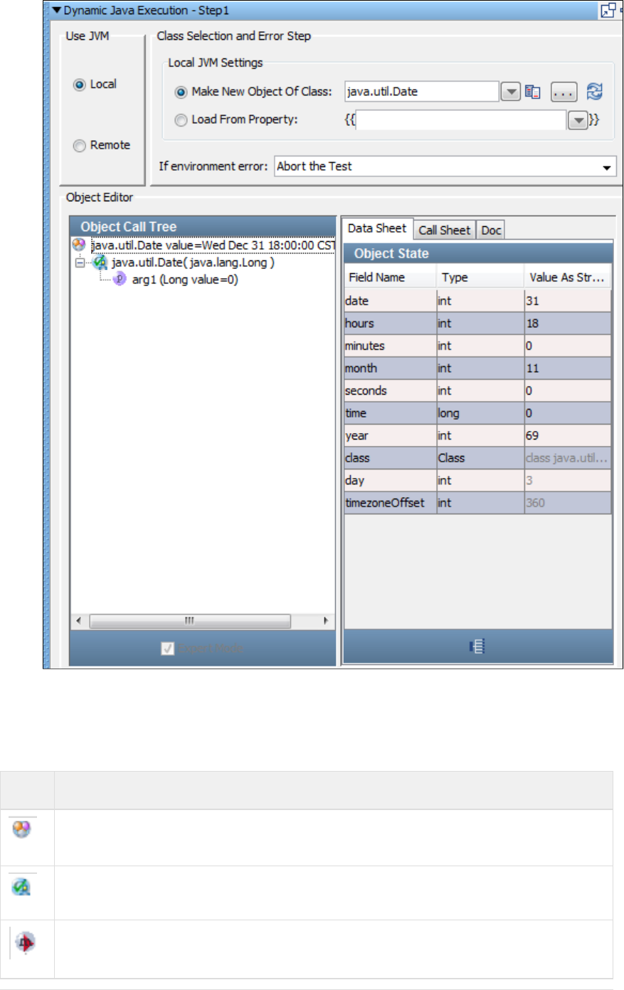
7.
Now you have a Java object to manipulate in the Complex Object Editor.
Step 3 - Make a Call on the Java Object
The Complex Object Editor is divided into two panels. The left panel contains the , which keeps track of method invocations andObject Call Tree
their input parameters and return values. The following icons are used to identify the branches in the object call tree:
Icon Description
The type (class) of the object currently loaded, followed by response from calling 'toString' method of object.
The Constructor that was called. This is shown if multiple constructors exist.
A method call that has not been executed.
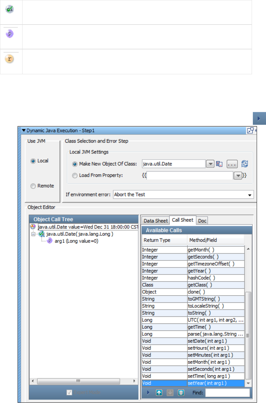
1.
2.
A method call that has been executed.
The input parameters (type and current value) for the enclosing method.
The return value (current value if call has been executed) for the enclosing method.
The contents of the right panel vary depending on what is selected in the left panel.
To make a call on the Java object:
In right panel of the Complex Object Editor, click the tab.Call Sheet
The Call Sheet tab shows the available methods that you can call.
Double-click the method. Alternately, you can select the method and click the Invoke Method icon.setYear() setYear()
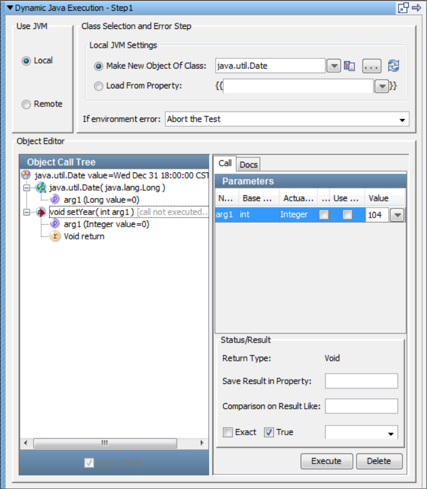
2.
3.
4.
5.
6.
The method is added to the Object Call Tree. The right panel now displays the Call tab and Docs tab.setYear()
The tab lists the argument information. In the field for , enter .Call Value arg1 104
Click Execute.
In the Object Call Tree, select the object.java.util.Date
In the tab, verify that the field is now set to .Data Sheet year 104
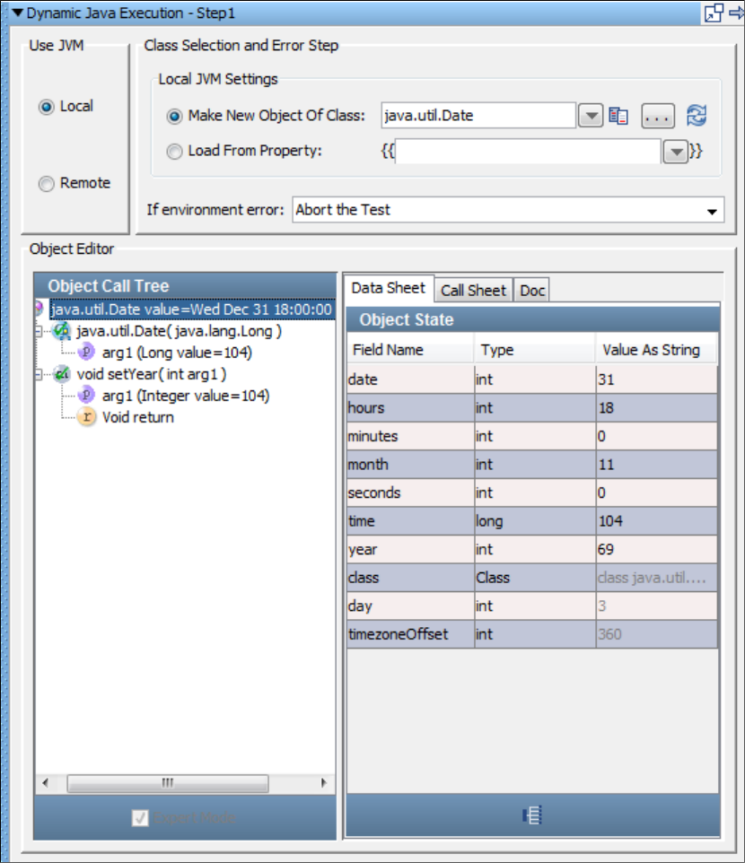
6.
1.
2.
3.
Step 4 - Add an Inline Filter
You can add an inline filter from within the Complex Object Editor. Inline filters (and assertions) do not result in a filter being added to the test step
in the element tree. Inline filter management is always done in the Complex Object Editor.
To add an inline filter:
With the object selected, click the tab.java.util.Date Call Sheet
Invoke the method to retrieve the date to be placed in a property.toString()
The right panel now displays the Call tab and Docs tab.
In the area of the Call tab, in the field, add an inline filter by entering as the propertyStatus/Result Save Result in Property Date_prop
name.
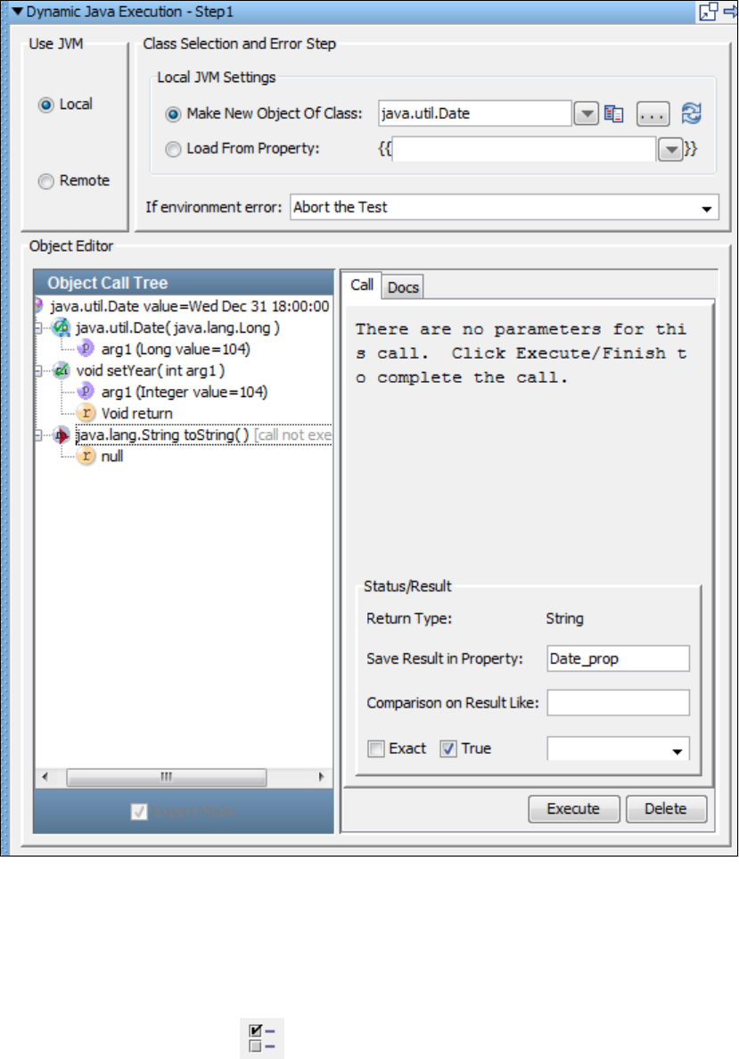
3.
4.
5.
1.
2.
Click Execute.
Click the Save icon.
Step 5 - Verify the Property Created
You can display the Property Window to verify that the property was created.Date_prop
To verify the property created:
Click the Show model properties icon on the test case toolbar. Alternately, you can choose from theHelp > Property Window
main menu.
Locate the property.Date_prop
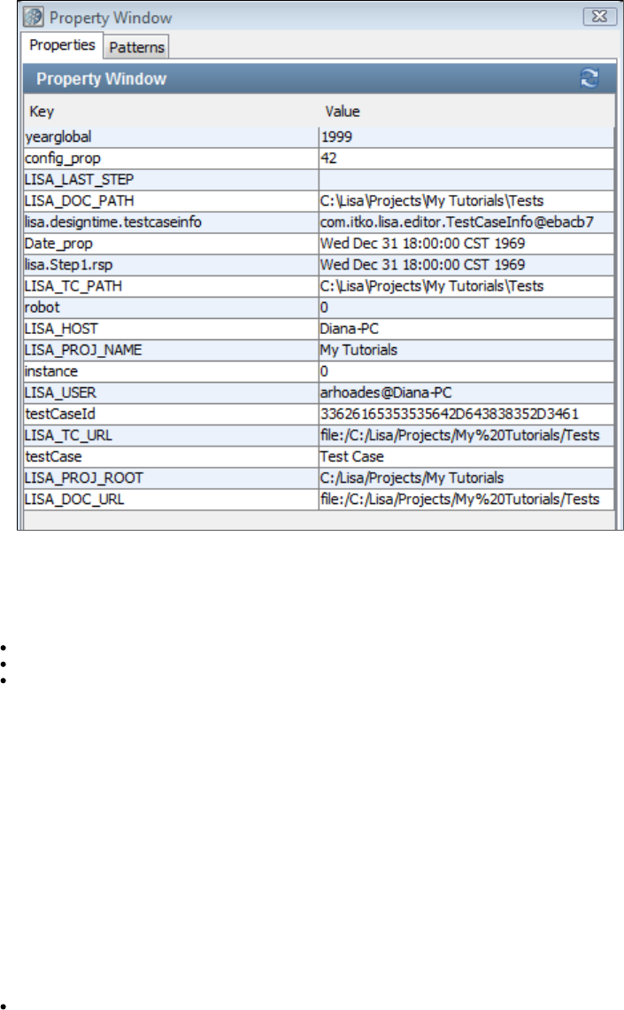
2.
3.
1.
2.
Click Close.
Review
In this tutorial, you did the following:
Created a test step to manipulate a Java object of type.java.util.Date
Used the Complex Object Editor to manipulate the Java object.
Learned how to add inline filters to objects and save results into a property.
Tutorial 5 - Running a Demo Server Web Application
In this tutorial, you will step through a simple web application that accompanies LISA.
The LISA Bank application is a simple front-end that is connected to a database table containing financial account information. The application
business logic consists of Enterprise JavaBeans and Web Services. From the web application, you can view the profile of the user, create an
account, add addresses, and so on.
The goal of this tutorial is for you to become familiar with the application. This application is used in subsequent tutorials as the system under test.
LISA Concepts Discussed
No new concepts are introduced.
Prerequisites
The LISA demo server is running.
Steps
Step 1 - Launch the Web Application
To launch the web application:
Open a new browser window.
Enter the following URL. Replace in the path with your computer's IP address.localhost
http://localhost:8080/lisabank/
The login page appears.
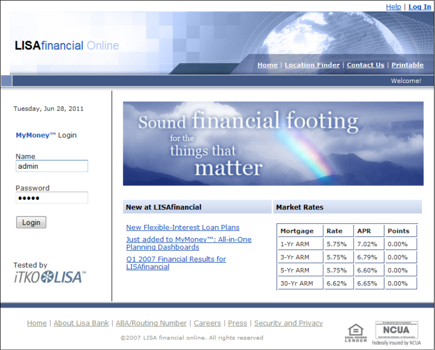
2.
1.
2.
3.
Step 2 - Log In to the Web Application
You will use the predefined user name .lisa_simpson
To log in to the web application:
In the field, enter .Name lisa_simpson
In the field, enter .Password golisa
Click Login. The welcome page appears. The left side contains buttons for various actions that you can perform: View Profile, New
, and .Account, Close Account, Add Address, Delete Address Log Out
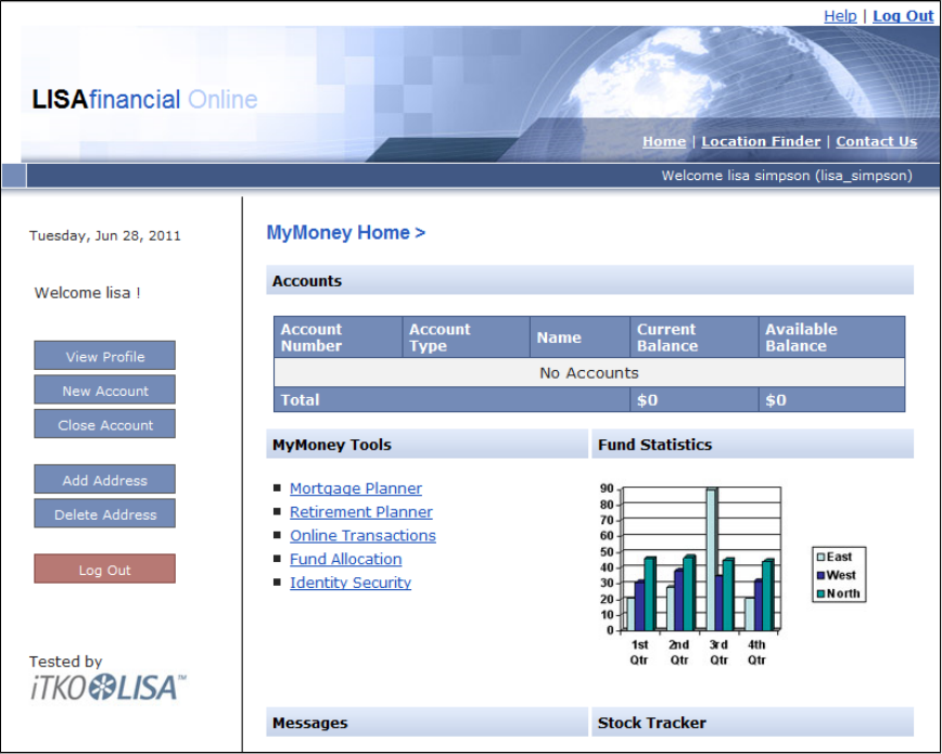
3.
1.
2.
3.
4.
5.
Step 3 - Create a New Account
Notice that the current user does not have any accounts.
To create a new account:
Click New Account.
From the list, select .Account Type SAVINGS
In the field, enter Account Name My Savings
In the field, enter .Initial Balance 100.00
Click Add Account.
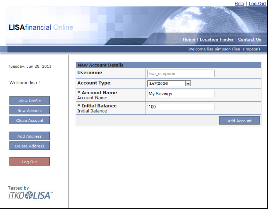
5.
The new savings account is added to the section.Accounts
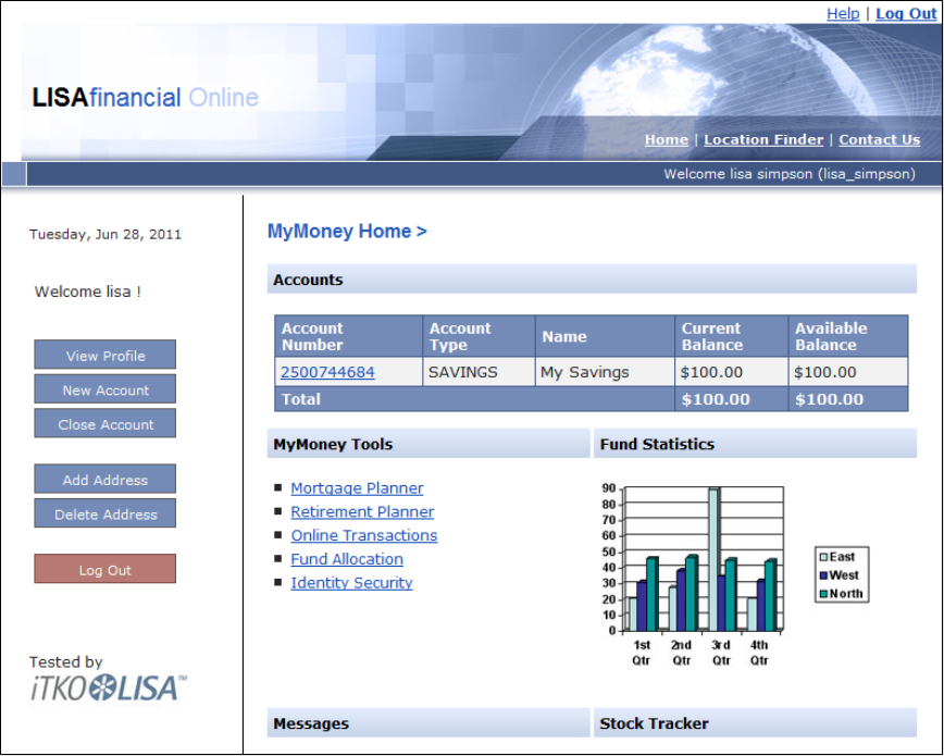
5.
6. Repeat the preceding steps to create two more accounts: and . Do not use commas in the field.Checking Auto_Loan Initial Balance
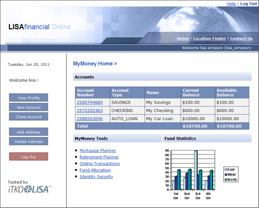
6.
1.
2.
Step 4 - Close an Account
The application lets you close accounts.
To close an account:
Click Close Account.
Select from the list and click Select Account.My Savings
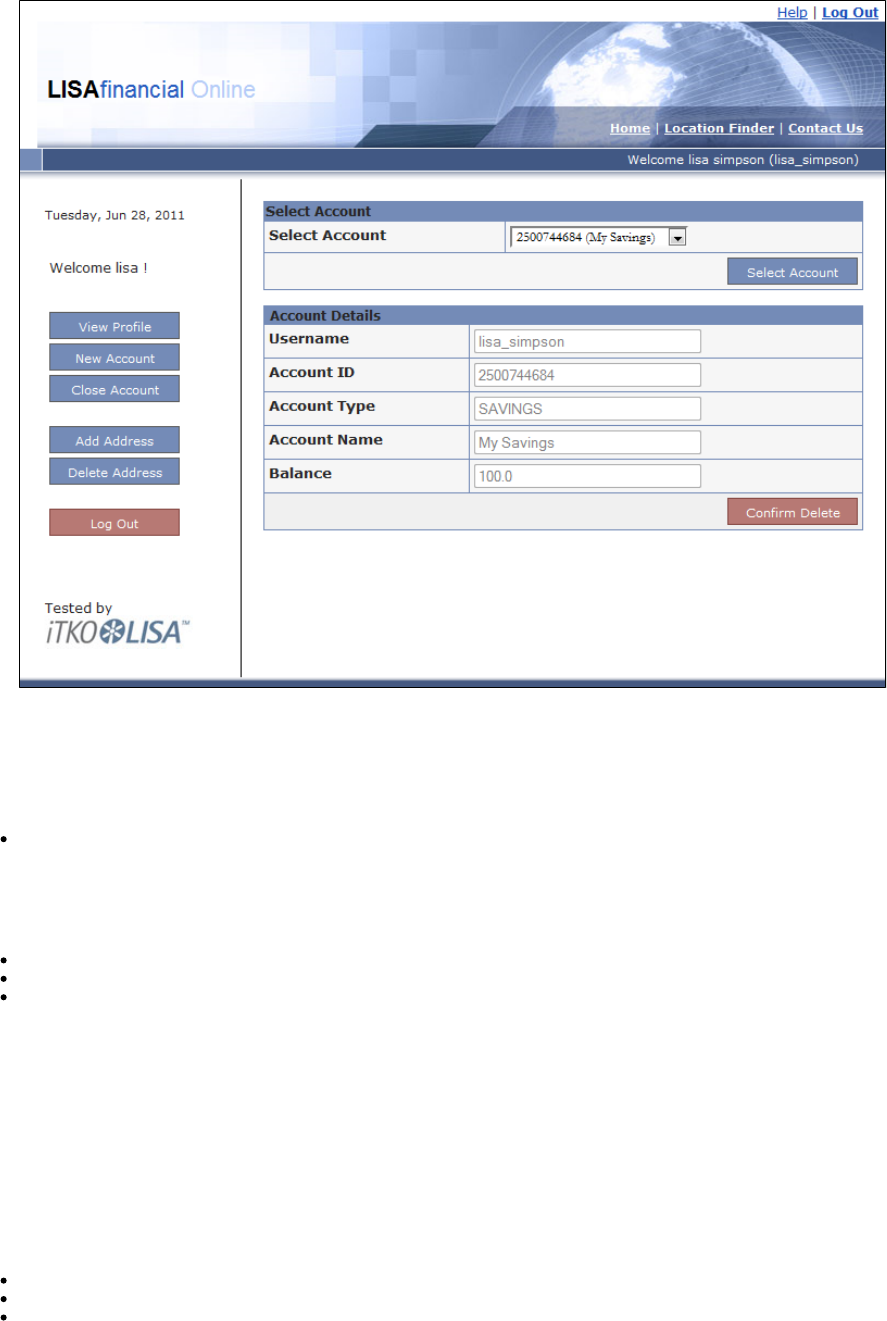
2.
3. Click Confirm Delete.
The account is removed from the the Accounts section.My Savings
Step 5 - Log Out of the Web Application
To log out of the web application:
Click Log Out.
Review
In this tutorial, you did the following:
Logged into the LISA Bank application.
Created new accounts.
Closed an account.
Tutorial 6 - Testing a Website
In this tutorial, you will use the LISA web recorder to record the path through a website and create test steps of HTTP/HTML Request for each
HTTP request/response pair.
The HTTP/HTML Request test step enables you to make requests against a web server and receive results from within a test case. Test a simple
website to verify that the pages work as expected.
LISA Concepts Discussed
In this tutorial, you do the following:
Use the LISA web recorder to create a test case containing HTTP/HTML Request steps
Edit and run the test case that the recorder produces
Add a data set to the test case
Prerequisites
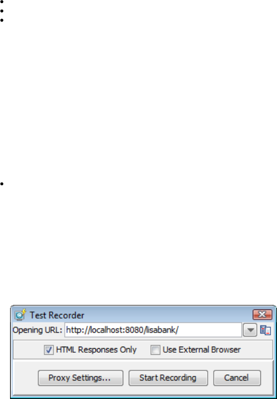
1.
2.
3.
1.
You have completed .Tutorial 5 - Running a Demo Server Web Application
LISA Workstation is open.
You have access to the demo server (either the local demo server, or the ITKO demo server).
Tutorial Parts
Part A - Record and Run the LISABank Test Case
Part B - Running the Test Case
Part C - Modifying HTTP/HTML Request Test Steps (optional)
Part A - Record and Run the LISA Bank Test Case
Use the LISA web recorder to create a test case containing HTTP/HTML Request steps.
Step 1 - Create a New Test Case
To create a new test case:
Within the project, create a new test case named in the subfolder.My Tutorials tutorial6a Tests
The model editor is opened.
Step 2 - Start the Web Recorder
There are different ways to record a website. In this tutorial, you record a website through HTTP proxy.
To start the web recorder:
From the main menu, select . The Actions > Record Test Case for User Interface > Web Recorder (HTTP proxy) Test Recorder
dialog opens.
In the field, enter the following URL. Replace in the path with your machine IP address.Opening URL localhost
http://localhost:8080/lisabank/
Click Start Recording. The Test Recorder window opens. The Test Recorder window contains two tabs: and Browser Recorded
. The login page of the LISA Bank application appears in the Browser tab.Elements
Step 3 - Record the LISA Bank Application
As you perform actions within the LISA Bank application, the request and response information for each page visited are recorded.
To record the LISA Bank application
In the field, enter . In the field, enter .Name lisa_simpson Password golisa
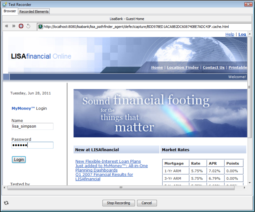
1.
2.
3.
4.
Click Login.
The welcome page appears.
In the Accounts section, click the account number of the checking account. The Account Activity screen appears.
Click Deposit.
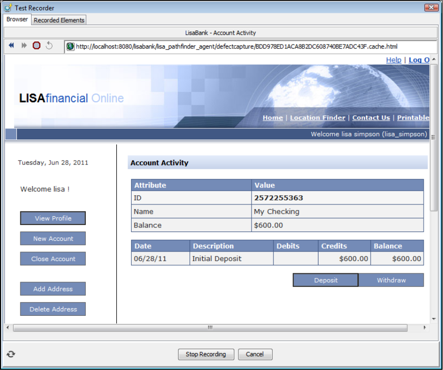
4.
5.
6. In the Deposit Money area, enter the password , a description of the transaction, and the amount for this deposit.golisa
Click Deposit.
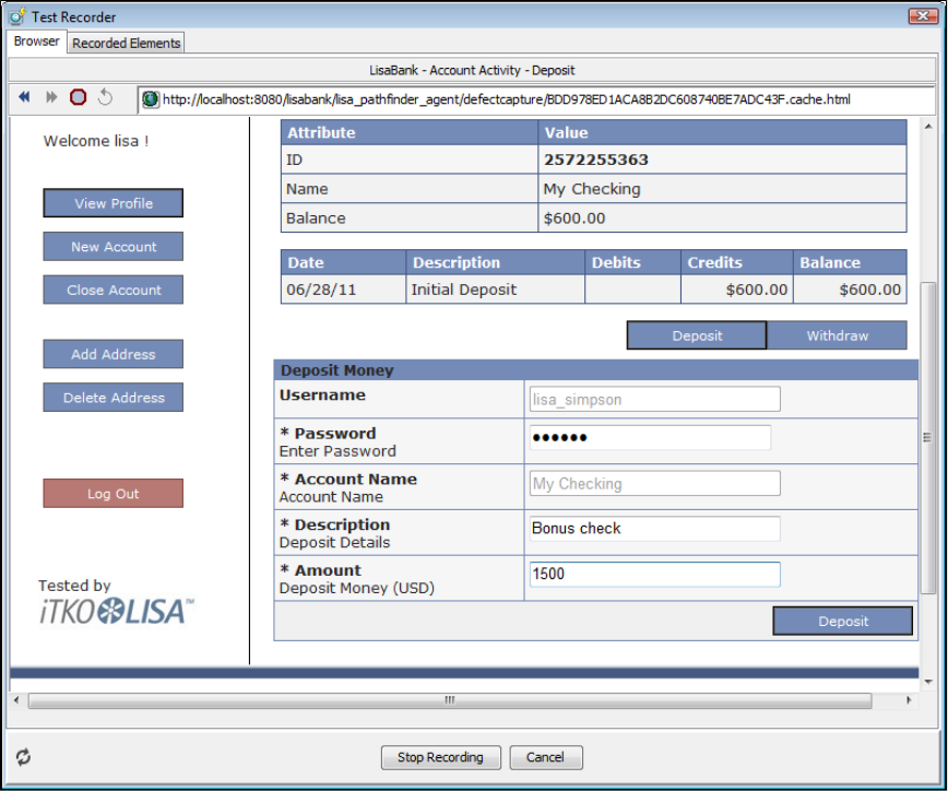
6.
The Account Activity screen shows the updated balance and a record of the deposit.
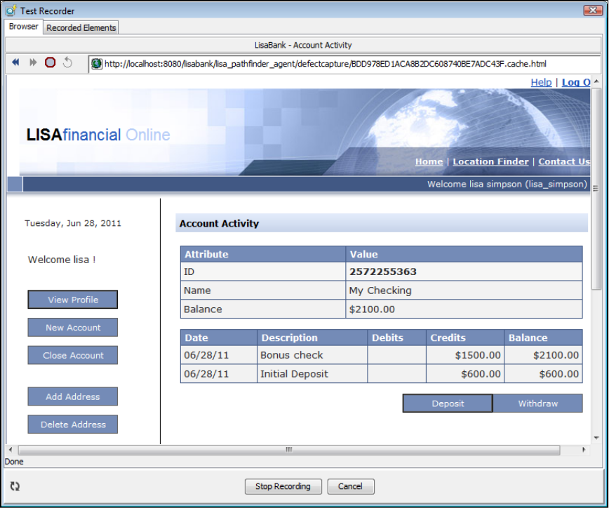
6.
7.
1.
From the left navigation pane, click Log Out.
Step 4 - Stop the Web Recorder
After you stop recording, you can view details about the transactions.
To stop the Web recorder:
At the bottom of the Test Recorder window, click Stop Recording. Filters and properties are automatically created for the web page
references. The form fields for the deposit are also displayed. The left pane shows a list of transactions (steps). The right pane shows the
step detail and response for the selected transaction.
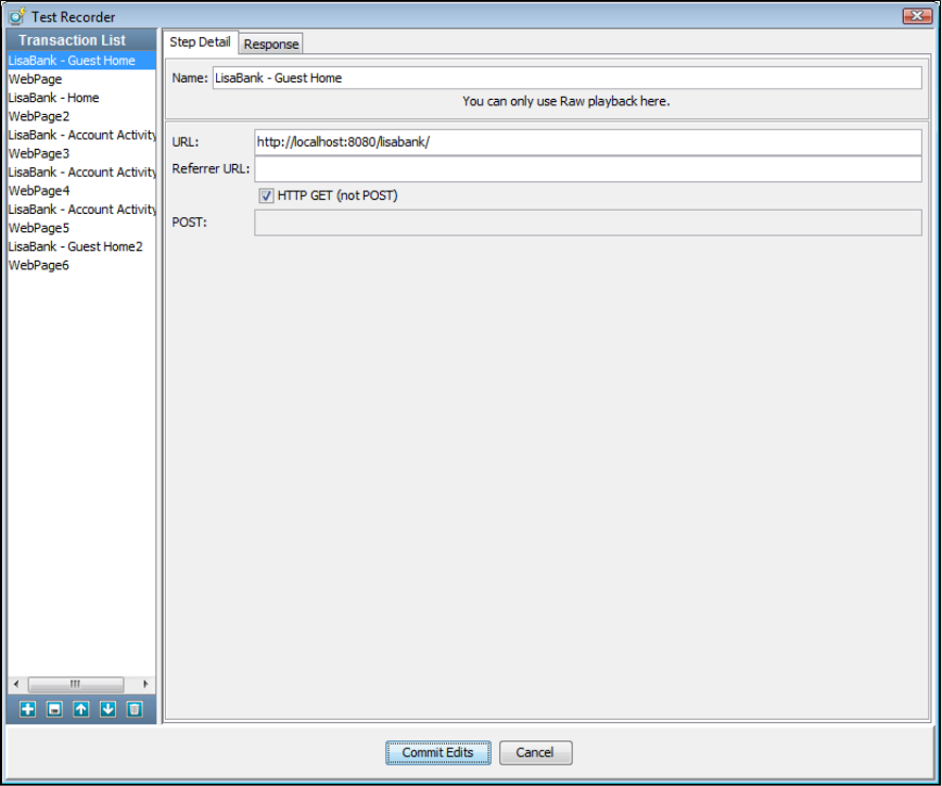
1.
2.
3. Click Commit Edits. The parameters page appears.
Click Add to Test and Close.
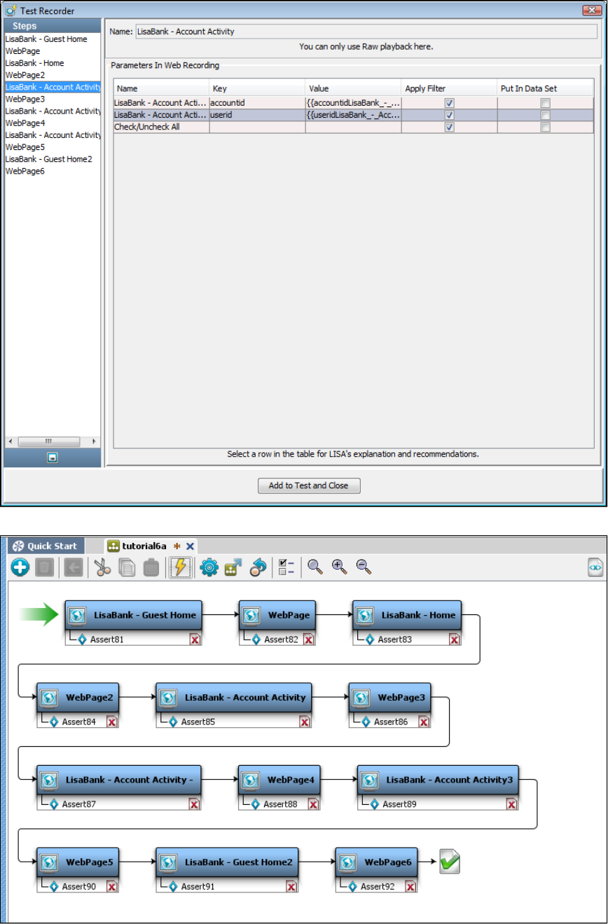
3.
4.
The model editor is populated with a new test case, having all the transaction information from the saved recording. Each test step in the
test case represents an HTTP request.
Save the test case.
Part B - Running the Test Case
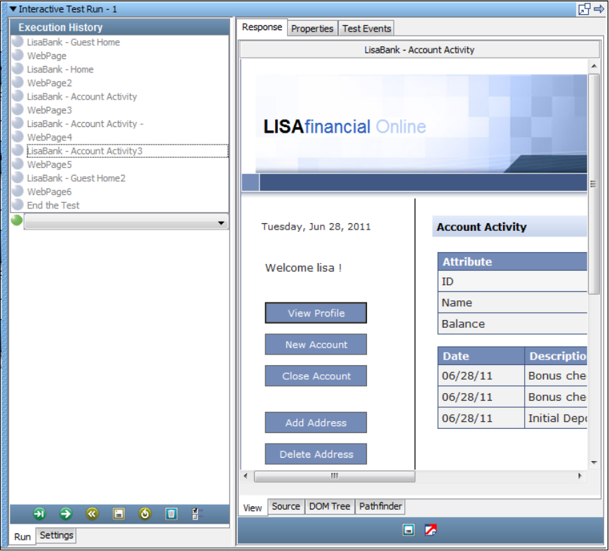
1.
2.
3.
4.
In this section, continue from to run the saved test case in the Interactive Test Run (ITR) utilityPart A - Record and Run the LISA Bank Test Case
and view the results.
To run the test case,
Start a new ITR session.
In the Execution History pane, click the Automatically execute test icon.
When the test is complete, click OK.
The tab shows the rendered pages as the ITR replays the deposit into the checking account.Response > View
The tab shows the HTML code for the page captured in the step.Response > Source
LISA acts as the browser and sends the same HTTP requests to the Web server.
Close the ITR utility.
Part C - Modifying HTTP_HTML Request Test Steps (Optional)
The web recorder produces an HTTP/HTML Request test step for each request.
You can edit and modify these test steps just like the other test steps in LISA. The recorder uses the parameters that you entered during the
recording as values for the Post and Get parameters in the request.
To generalize your LISA Bank test, replace these hard-coded description and deposit amount values (for example, "cash" and "1000.00") with
properties from a data set. You previously worked with data sets in .Tutorial 2 - Data Sets
In the test step from the recording results, the and parameters are parameterized and added to theAccount Activity3 Host Name Port
configuration. The values for and are hard-coded.description amount
The objective in this part of the tutorial is to parameterize the test case to deposit different amounts of money by using a numeric counting data
set. When you subsequently run the test case, it uses deposit values different from the ones recorded.
Step 1 - Copy a Test Case
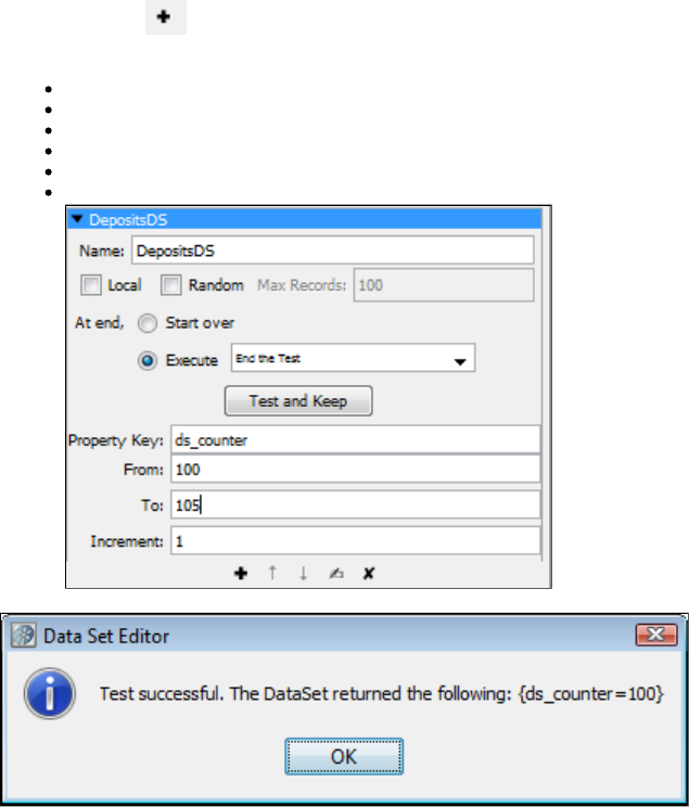
1.
2.
3.
4.
1.
2.
3.
4.
5.
6.
7.
1.
2.
3.
To copy a test case:
Ensure that the test case is open in the model editor.tutorial6a
From the menu bar, select . File > Save As
In the field, enter .File name tutorial6c
Click Save.
Step 2 - Add a Data Set
In the following procedure, you add a numeric counting data set. This type of data set enables you to assign a number to a property and change
the number by a fixed value each time the data set is used.
To add a data set:
In the model editor, select the first test step.
In the right pane, double-click the step element tab.Data Sets
Click the Add icon below the Data Sets element.
From the list, select . The data set editor opens in the right pane.Common Datasets Create a numeric counting data set
Enter the following:
In the field, enter .Name DepositsDS
In the field, select the option and select from the list.At end Execute End the Test
In the field, enter .Property Key ds_counter
In the field, enter .From 100
In the field, enter .To 105
In the field, enter .Increment 1
Click the Test and Keep button to test the data set. You will see a success message that shows the first row of data in the data set:
Click OK.
Step 3 - Modify the POST Parameters for the Recorded Deposit
You will now use the property (which you created in the data set) to specify varying amounts of money for the deposit.ds_counter
To modify the POST parameters for the recorded deposit:
In the model editor, double-click the step.LISABank - Account Activity3
In the area, change the value of the key to {{ .POST Parameters description deposit ds_counter}}
Change the value of the key to {{ .amount ds_counter}}
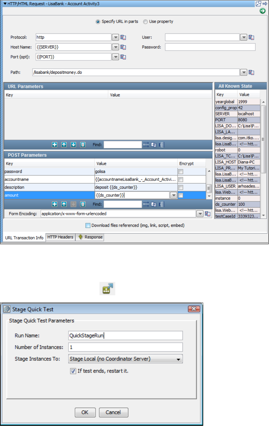
3.
4.
1.
2.
3.
Save the test case.
Step 4 - Stage the Test Case
To stage (or run) a Quick Test:
From the toolbar, click the Stage a quick test icon.
In the Stage Quick Test window, ensure that is selected.If test ends, restart it
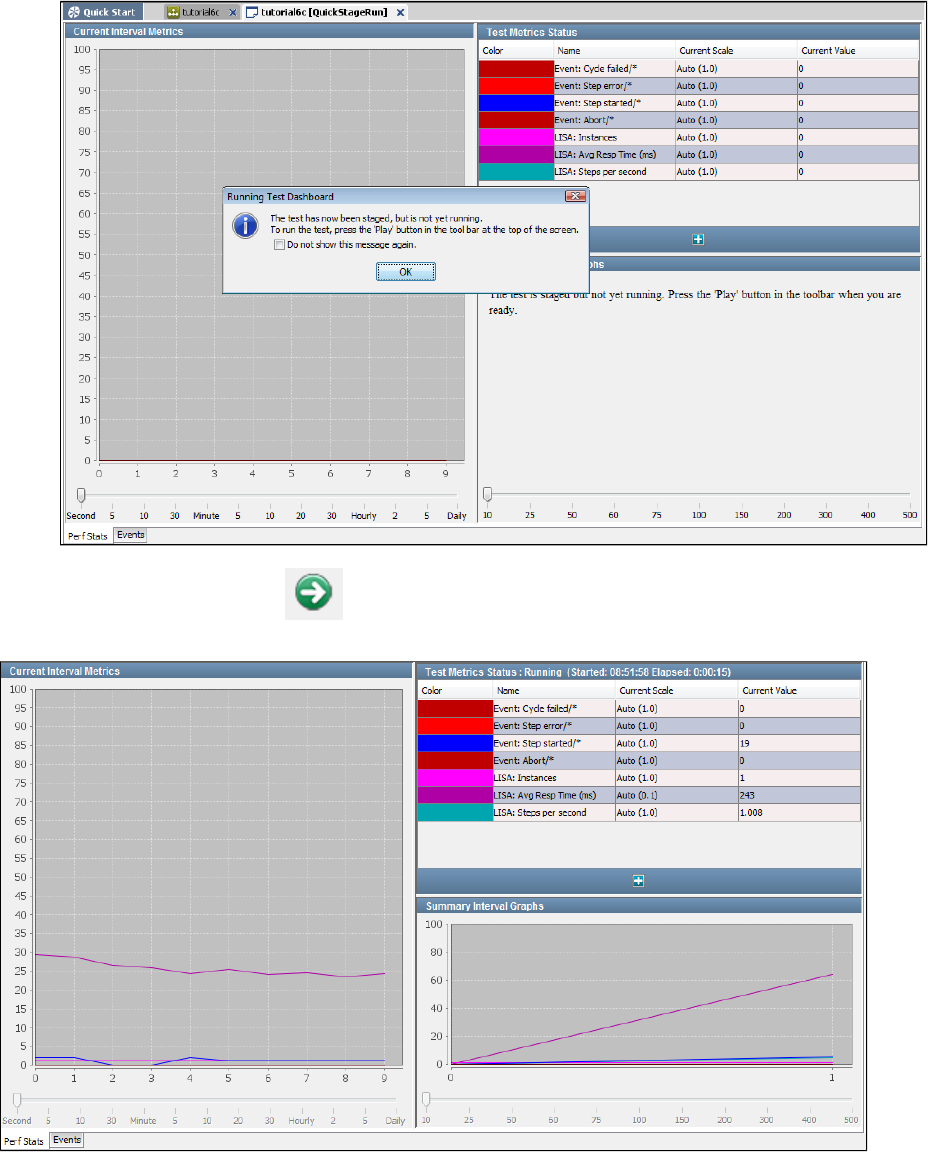
3.
4.
5.
6.
1.
2.
Click OK.
The Test Monitor is displayed, but the test has not been started yet.
Click OK.
From the toolbar, click the Play icon.
The line graphs show the progress of the test.
Step 5 - View the New Deposits in LISA Bank
To view the new deposits in LISA Bank:
Log in to the LISA Bank application again with the user and password .lisa_simpson golisa
Click the account number link for checking account to view the deposits. Notice how the deposits begin with 100 and increase by 1 until
the amount 105 is reached.
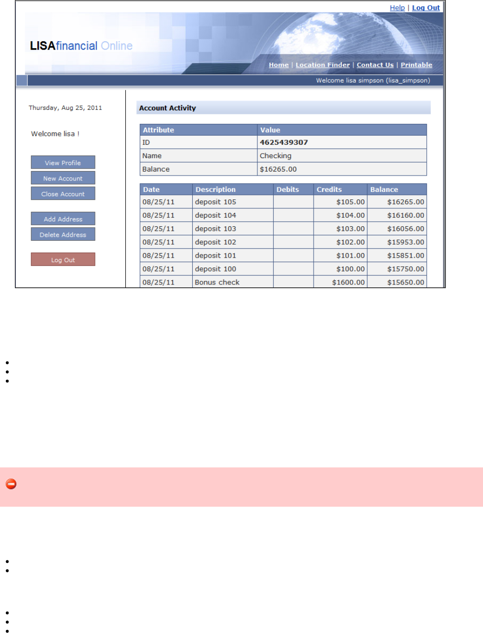
2.
Review
In this tutorial, you used a numeric counting data set to provide input to the recorded test.
You did the following:
Copied a test case and added a numeric counting data set.
Modified the POST Parameters for the recorded deposit.
Staged a quick test.
Tutorial 7 - Testing an Enterprise JavaBean (EJB)
The LISA Bank application provides a full set of EJBs to interact with an account, get the user and account information from the Java interface.
In this tutorial, you will use the test step to call EJB methods within a test case and test the response with anEnterprise JavaBean Execution
assertion. You test a simple EJB to verify that the and methods work as expected.addUser deleteUser
This tutorial is currently not working. When you click the Execute icon in Step 6 - Configure the EJB, an invocation exception
occurs.
LISA Concepts Discussed
In this tutorial, you do the following:
Use the Enterprise Java Bean Execution step.
Use the Complex Object Editor with EJB objects.
Prerequisites
You have completed .Tutorial 6 - Testing a Website
LISA Workstation is open.
You have access to the demo server (either the local Demo Server, or the ITKO demo server).
Steps
Step 1 - Create a New Test Case
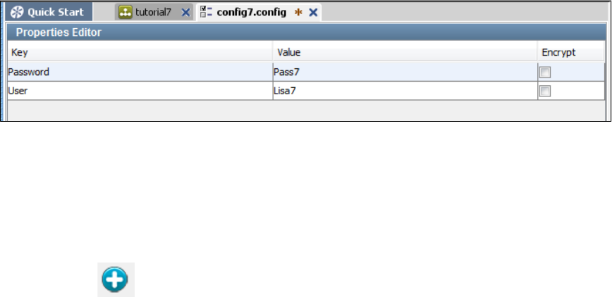
1.
2.
3.
1.
2.
3.
4.
5.
6.
7.
1.
2.
3.
To create a new test case,
In the Project pane, right-click the folder and select .Tests Create New Test Case
Set the file name to .tutorial7
Click Save.
Step 2 - Create a New Configuration
You previously worked with configurations in .Tutorial 2 - Data Sets
To create a new configuration,
Open the file.project.config
If the configuration does not contain the and properties, add these properties. You do not need to set the values.User Password
Create a new configuration named .config7
Add the property to the configuration and set the value to .User config7 Lisa7
Add the property to the configuration and set the value to .Password config7 Pass7
Click the Save icon.
In the Project pane, right-click the configuration and select . The configuration now appears in blue.config7 Make Active
Step 3 - Add an EJB Test Step
The Enterprise JavaBean Execution test step enables you to make calls on a running EJB.
To add an EJB test step,
Click the tab.tutorial7
Click the Add Step icon.
Select Java/J2EE and select . The New EJB Setup wizard appears.Enterprise JavaBean Execution
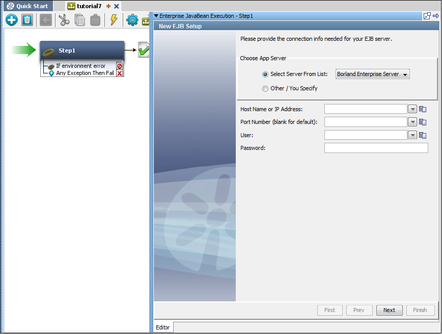
3.
1.
2.
3.
1.
Step 4 - Connect to the Server
The New EJB Setup wizard prompts you to specify connection information for the EJB server.
To connect to the server,
From the drop-down list, select .Select Server From List JBoss 3.2/4.0
In the field, enter if you are using the local demo server. Enter if you areHost Name or IP Address localhost examples.itko.com
running against the iTKO demo server.
Click Next.
The list of JNDI names is retrieved from the EJB server.
Step 5 - Locate the EJB Interface
The New EJB Setup wizard prompts you to specify the name of the EJB interface.
To locate the EJB interface,
In the tab, select .Remote EJB3UserControlBean/remote
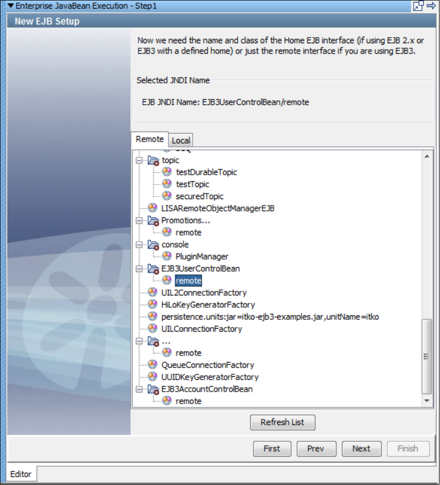
1.
2. Click Next. The Complex Object Editor opens.
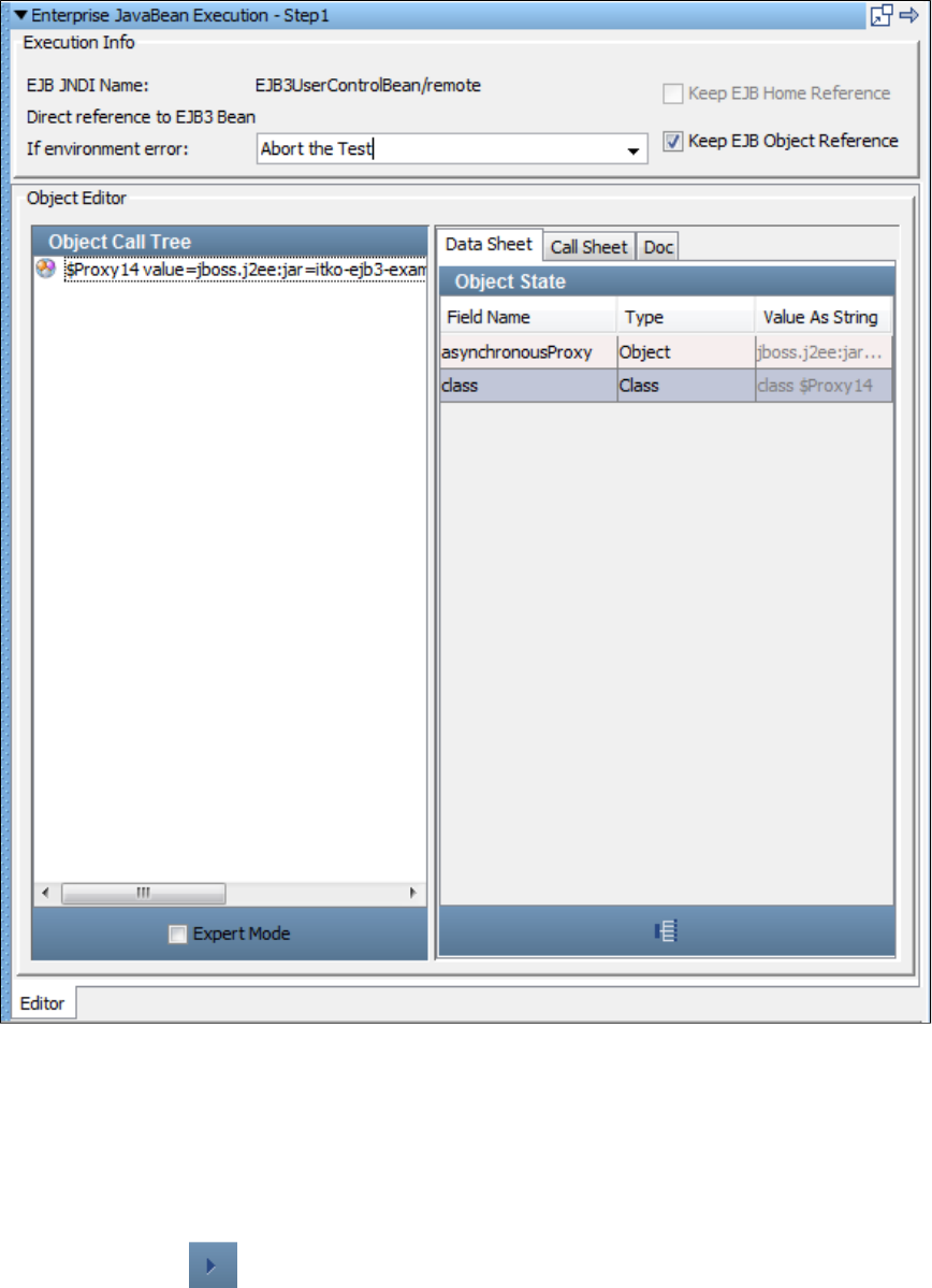
2.
1.
2.
3.
4.
Step 6 - Configure the EJB
To configure the EJB,
If you use the same EJB object and home object repeatedly, check the and the Keep EJB Home Reference Keep EJB Object
check boxes, if they are not already selected by default.Reference
Set the field to the step to execute if an exception occurs while executing this EJB Step. Select fromIf environment error Fail the Test
the list.
In the Object Editor area, select the tab and select the method.Call Sheet addUser
Click the Invoke Method icon.
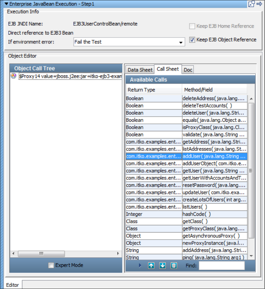
4.
The Object Call Tree now displays the method.addUser
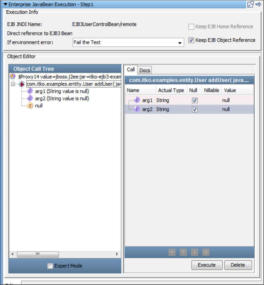
4.
5. Click the Execute icon.
The Object Call Tree now indicates that the method has been invoked.addUser
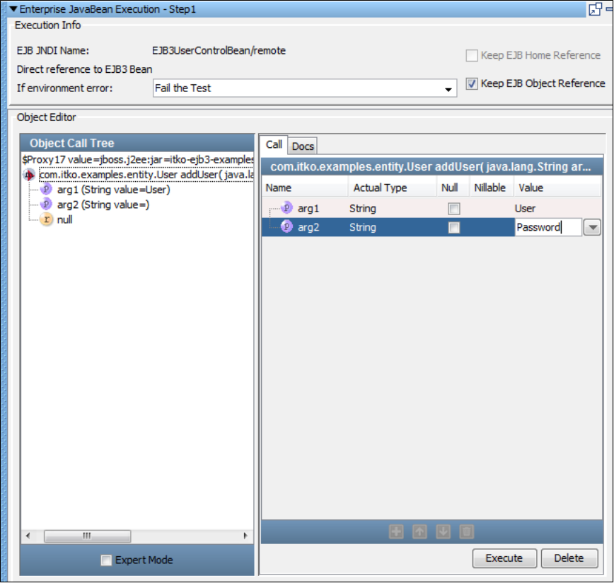
5.
1.
2.
3.
4.
5.
6.
Step 7 - Add an Assertion
To enter the method parameters and add an inline assertion,
In the Object Call Tree pane, check if it is not already enabled (see A).Expert Mode
Enter the property values for the method parameters (arg1 and arg2). Enter the and that you added to theaddUser User Password
configuration (see B).
In the area, add the inline assertion by checking and un-checking (see C).Status/Result Exact True
In the field, enter (see D).Comparison on Result NOT Exactly True
(The addUser method returns a Boolean.)
From the Exact list, select (see E).Fail the Test
(If the addUser method returns anything but true, it executes the step.)fail
Click Execute (see F).
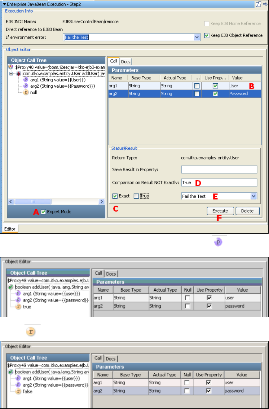
6.
7.
The parameters to the method are displayed in the Object Call Tree, next to the input parameter icon. The return value of this
method is in the Object Call Tree.true
Test the method again by clicking Execute.addUser
The return changes from to because the user has already been added.true false
Step 8 - Verify the Method Execution
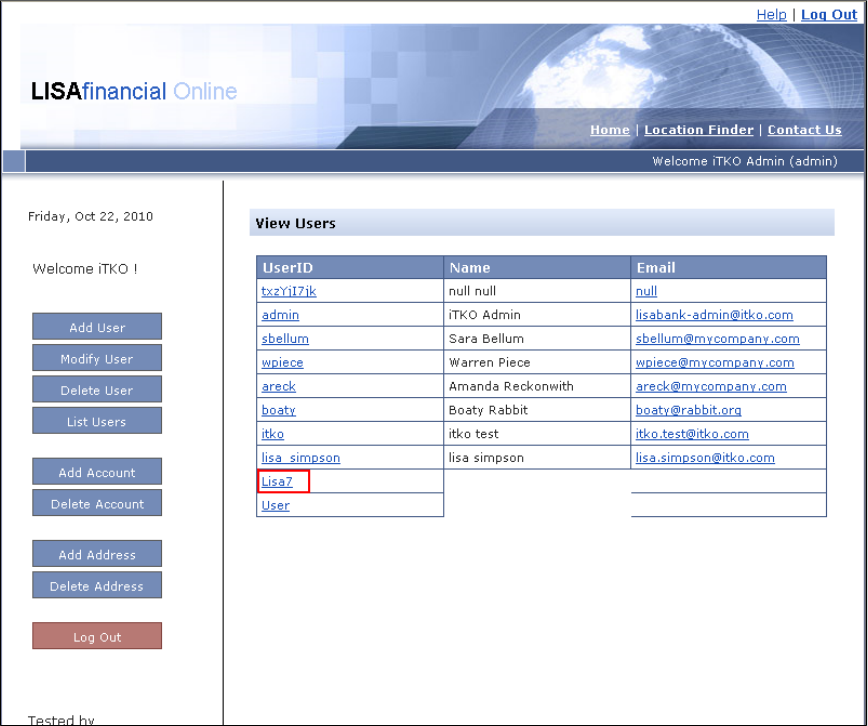
1.
2.
3.
1.
2.
From the LISA Bank application, you can verify that the user was added.
To verify the method execution,
Go to the LISA Bank application.
Login as user with the password .admin admin
View the list of users to confirm that was added.Lisa7
Step 9 - Add Another EJB Test Step
Now try the preceding steps again to invoke the method.deleteUser
To add another EJB test step,
Repeat the tutorial beginning with Step 3 to add an EJB step named .DeleteUser
Use the method parameter property .User
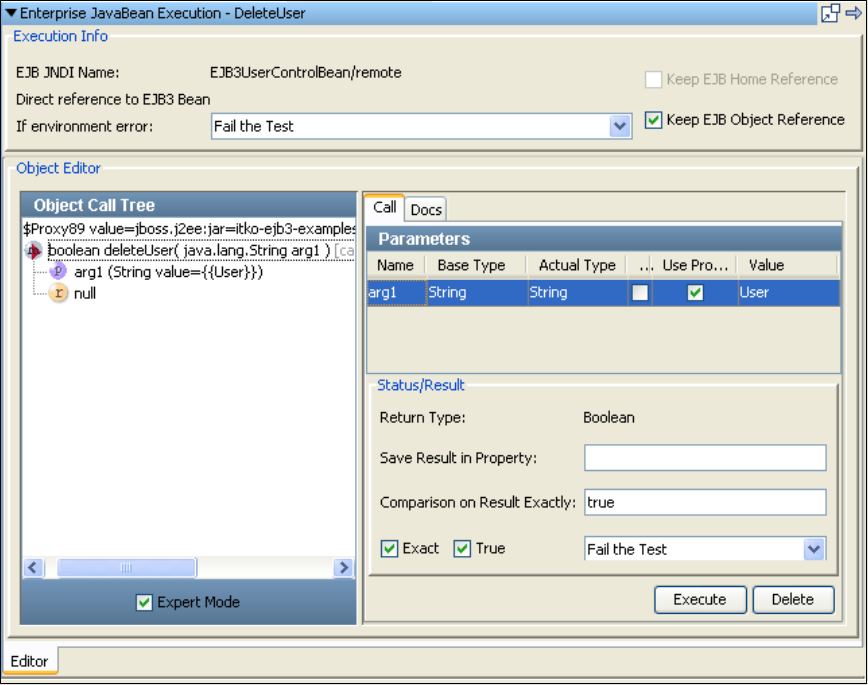
2.
3. Click Execute to execute this method and get results.
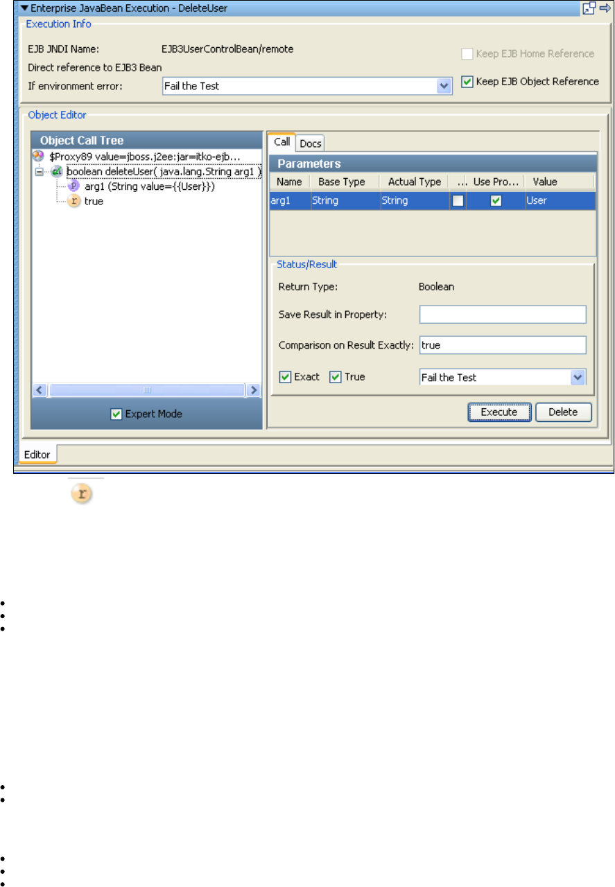
3.
4. The return is , indicating the user has been deleted.true
Click the Save icon.
Review
In this tutorial, you did the following:
Created a test case consisting of two EJB test steps. The EJB object was loaded from the example application on the demo server.
Created an EJB test step and loaded an EJB.
Used the Complex Object Editor to manipulate EJB objects.
Tutorial 8 - Testing a Web Service
In this tutorial, you will use the Web Service Execution (XML) test step to call web service operations in a test case and test the request and
response. These web service operations provide the same functionality as the equivalent method calls in the EJB used in Tutorial 7.
LISA Concepts Discussed
In this tutorial, you do the following:
Add the Web Service Execution (XML) test step.
Execute a web service operation.
Prerequisites
You have completed Tutorial 5.
LISA Workstation is open.
You have access to the demo server (either the local Demo Server, or the ITKO demo server).
Steps
Step 1 - Create a New Test Case
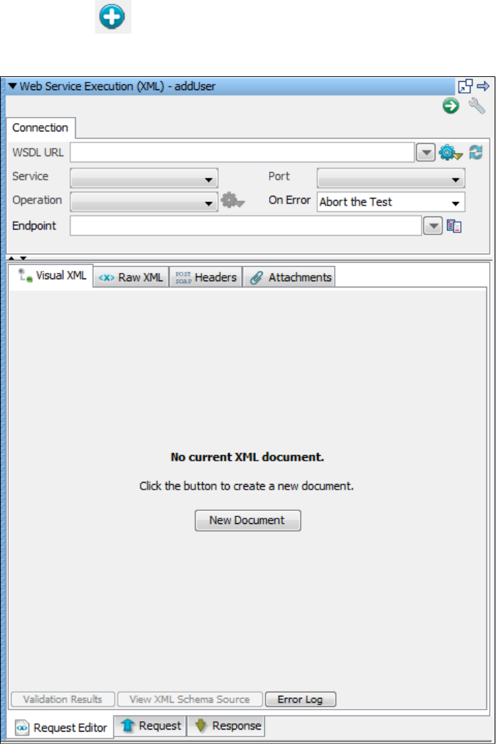
1.
2.
3.
4.
1.
2.
3.
4.
5.
6.
To create a new test case,
In the Project panel, right-click on the folder and select .Tests Create New Test Case
Set the file name to .tutorial8a
Click Save.
In the Project panel, right-click on and select .project.config Make active
Step 2 - Add a Web Service Execution (XML) Test Step
The Web Service Execution (XML) test step enables you to execute an operation on a SOAP-based web service. To add a Web Service
Execution (XML) test step,
Click the tab.tutorial8a
Click the Add Step icon.
Select and select . is added to the model editor.Web/Web Services Web Service Execution (XML) Step1
Right-click and select Rename. Change the name to .Step1 AddUser
Double-click the step to open the Web Service Execution (XML) editor.AddUser
Click the New Document button.
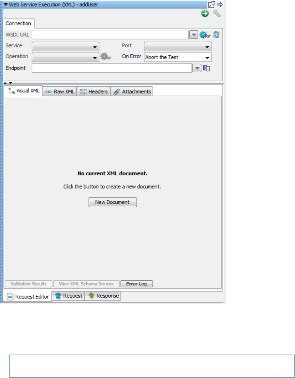
6.
1.
2.
3.
4.
5.
Step 3 - Create a Web Service Client
You now specify the operation to be called, and create a SOAP message to send to the operation. To create a web service client,
In the field, enter the following location. Notice the use of the WSSERVER and WSPORT properties to represent the serverWSDL URL
and port.
http://WSSERVER:WSPORT/itko-examples/services/UserControlService?wsdl
In the field, select .Service UserControlServiceService
In the field, select .Port UserControlService
In the field, select the operation.Operation addUser
In the field, select .On Error Abort the Test
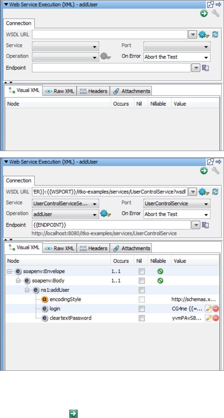
5.
6.
1.
LISA builds the Web Service client based on this criteria. The Visual XML editor shows a graphical view of the SOAP message.
Save the test case.
Step 4 - Execute the Web Service Request
To execute the web service request,
Click the Execute WS Request icon in the upper right corner. The test is executed.
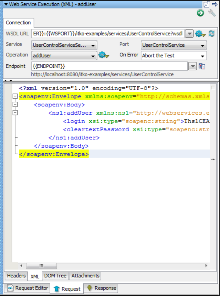
1.
2.
Step 5 - View the Request and Response
The Request tab shows the resulting request data that was sent after any post processing (for example, substituting LISA properties). The
Response tab shows the resulting response data that was received.
To view the request and response,
To view the request upon execution, click the tab.Request
To view the response upon execution, click the tab.Response
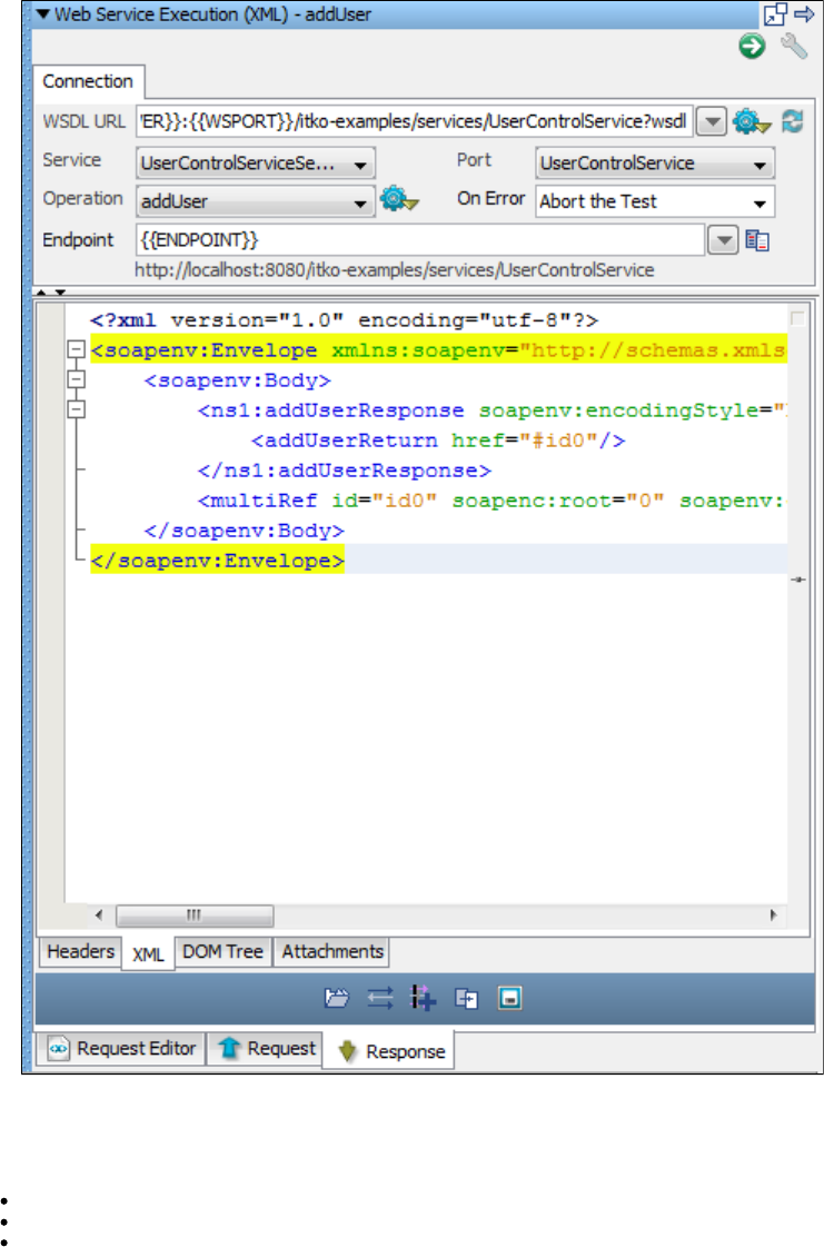
2.
Review
In this tutorial, you did the following:
Created a test case with the Web Service Execution (XML) test step.
Executed the operation.addUser
Viewed the request and response for this operation.
Tutorial 9 - Examining and Testing a Database
In this tutorial, you will examine and test a database table that is part of the web application in Tutorial 5.
You use the SQL Database Execution (JDBC) step to interact with a database within a test case and test the response with an assertion. You
examine the Users table from a Derby database that is part of the application.
LISA Concepts Discussed
In this tutorial, you do the following:
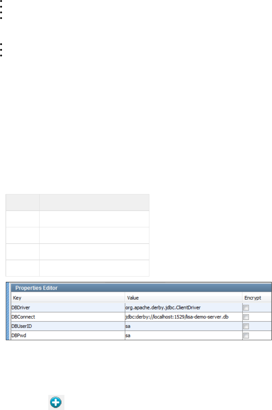
1.
2.
3.
1.
2.
3.
4.
1.
2.
3.
4.
5.
Use the SQL Database Execution (JDBC) step.
Store application properties in a configuration.
Add and modify an assertion.
Add a filter.
Prerequisites
You have completed .Tutorial 5
LISA Workstation is open.
You have access to the demo server (either the local Demo Server, or the ITKO demo server).
Steps
Step 1 - Create a New Test Case
To create a new test case,
In the Project pane, right-click on the folder and select .Tests Create New Test Case
Set the file name to .tutorial9
Click Save.
Step 2 - Add Database Properties to the Configuration
Store the properties that are needed to connect to the database in the configuration. This is a standard LISA practice that increases the portability
of test cases.
To add database properties to the configuration,
If is not the active configuration, then right-click in the Project pane and select .project.config project.config Make Active
Open the configuration.project.config
Add the following properties.
Key Value
DBDriver org.apache.derby.jdbc.ClientDriver
DBConnect jdbc:derby://localhost:1529/lisa-demo-server.db
DBUserID sa
DBPwd sa
Click the Save icon.
Step 3 - Add a SQL Database Execution (JDBC) Test Step
The SQL Database Execution (JDBC) test step enables you to connect to a database using JDBC and make SQL queries on the database. To
add a SQL Database Execution (JDBC) test step,
Click the tab.tutorial9
Click the Add Step icon.
Select and select . is added to the model editor.Other Transactions SQL Database Execution (JDBC) Step1
Right-click and select . Change the name to .Step1 Rename GetUsers
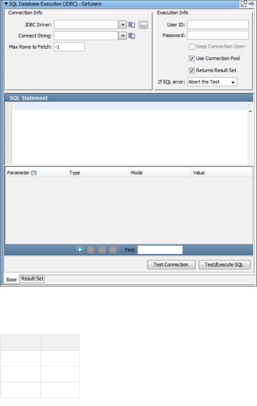
5.
1.
Double-click the step to open the step editor.GetUsers
Step 4 - Connect to the Database
Use the properties that you added to the configuration to provide connection information. To connect to the database,project.config
Enter the following values in the and areas of the step editor. Notice that when you enter the password,Connection Info Execution Info
the value is masked.
Field Value
JDBC Driver {{ }}DBDriver
Connect String {{ }}DBConnect
User ID {{ }}DBUserID
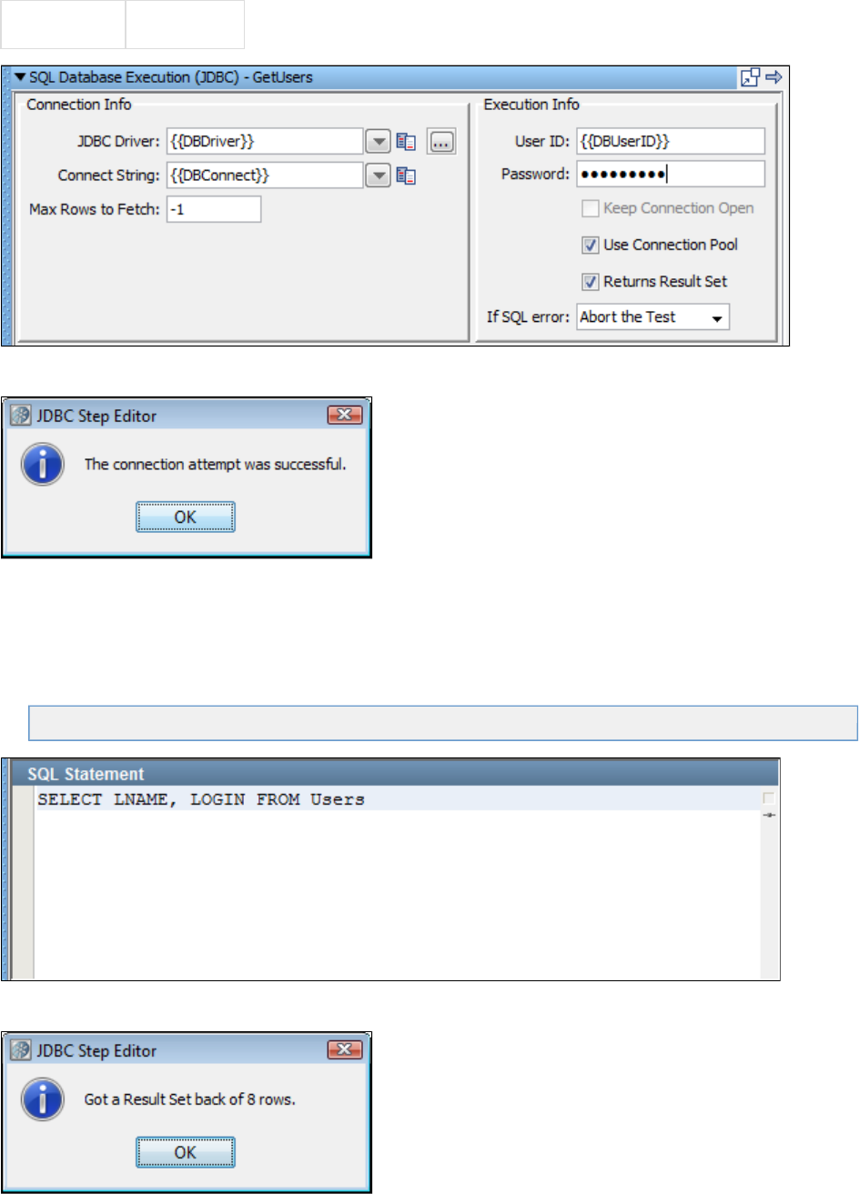
1.
2.
3.
1.
2.
3.
Password {{ }}DBPwd
Click the Test Connection button at the bottom of the step editor.
A message indicates that the connection is valid.
Click OK.
Step 5 - Execute a SQL Query
You now specify and run a SQL statement that retrieves data from the Users table. To execute a SQL query,
In the SQL Statement pane, enter the following statement:
SELECT LNAME, LOGIN FROM Users
Click the button at the bottom of the step editor. A message confirms a valid query and displays the number of rowsTest/Execute SQL
returned.
Click OK.
The tab is displayed.Result Set

3.
1.
2.
3.
Step 6 - Add an Assertion
Add an assertion to test for the presence of a specific last name in the result set. To add an assertion,
In the tab, select a cell in the column.Result Set LNAME
Click the Generate Assertion for Cell's Value icon. The dialog opens.Generate JDBC Result Set Value Assertion
From the drop-down list, select the option. If the last name that you selected is not found, then the test will fail.Fail the Test
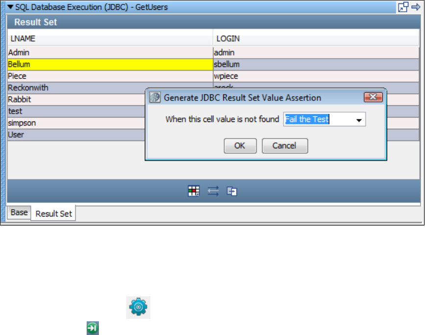
3.
4.
5.
1.
2.
Click OK.
Click the Save icon.
Step 7 - Run the Test Case
To run the test case,
From the toolbar, click the Start ITR icon.
Click Execute Next Step . The test runs successfully. The result set is shown in the tab.Response
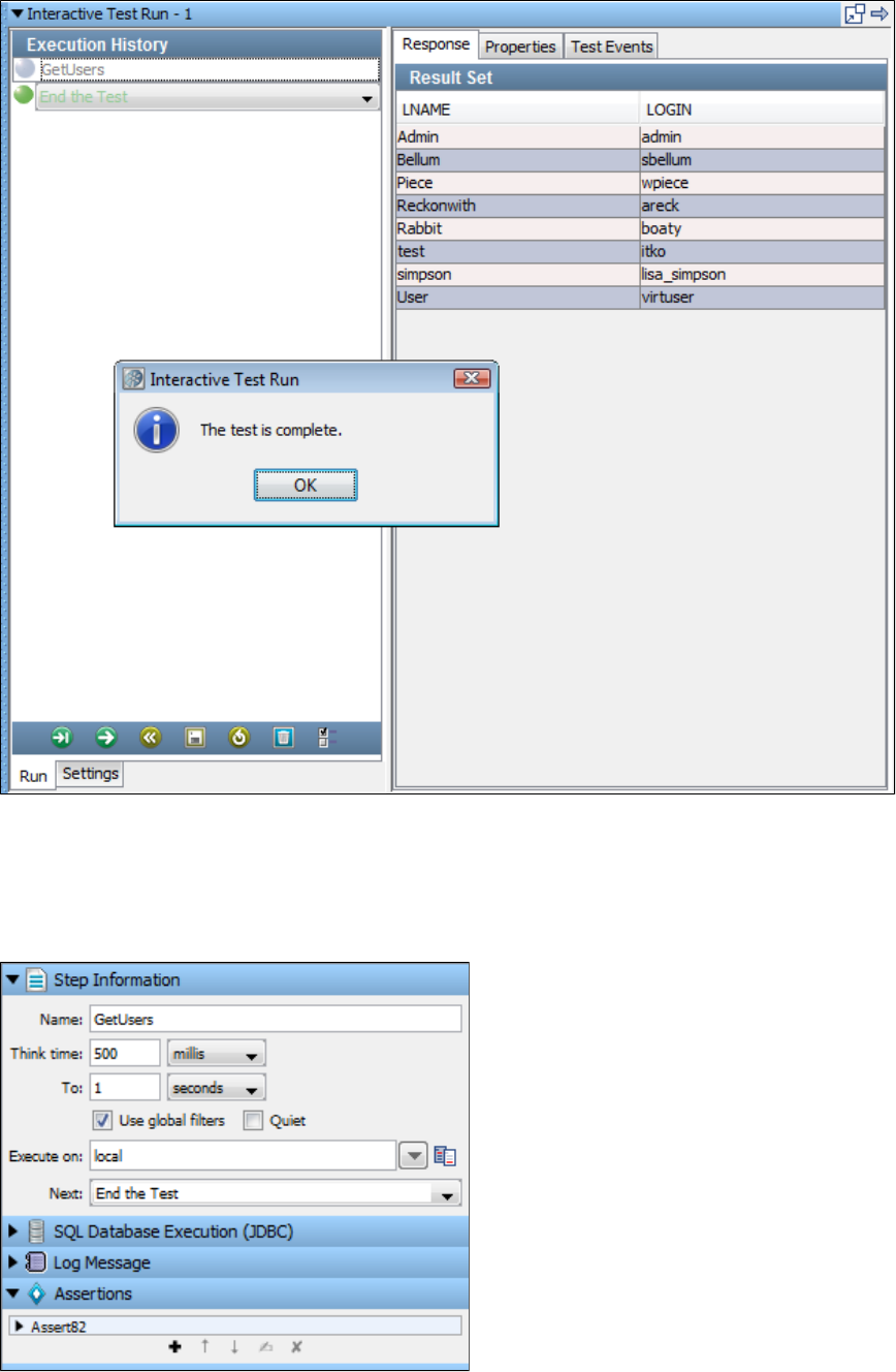
2.
3.
1.
2.
3.
4.
Retract the ITR tray.
Step 8 - Change the Assertion
You now modify the assertion to cause the test to fail. To change the assertion,
In the model editor, click the JDBC test step.
Open the tab in the Element Tree.Assertions
Double-click the assertion that you created earlier. The assertion editor is opened. The lower portion indicates that the assertion checks
the first column of the result set for the specified value.
Change the value of the Regular Expression field to .Johns
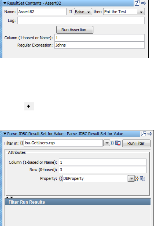
4.
5.
6.
1.
2.
3.
4.
5.
6.
7.
8.
1.
2.
3.
4.
Start a new ITR and run the test case again. The test fails.
Retract the ITR tray.
Step 9 - Add a Filter
Add a database filter to capture the value in the first column and fourth row of the result set. The value will be stored in a property. To add a filter,
In the model editor, select the JDBC test step.
Open the tab in the Element Tree.Filters
Click the Add icon.
From the submenu, select . The filter editor opens.Database Filters Extract Value from JDBC Result Set
In the field, enter . Alternatively, you can enter the actual column name, which is .Column 1 LNAME
In the field, enter . This field is zero-based. Therefore, the value refers to the fourth row.Row 3 3
In the field, enter .Property DBProperty
Click the Save icon.
Step 10 - Test the Filter and Assertion
To test the filter and assertion,
Start a new ITR and run the test case again.
The test fails because was not found in the result set.Johns
Click the tab.Test Events
Click the event. Notice that was set to the value specified by the filter.Property set DBProperty
Click the event. The Long Info Field area indicates that the assertion fired because the first column of the result set didAssertion fired
not contain the value .Johns
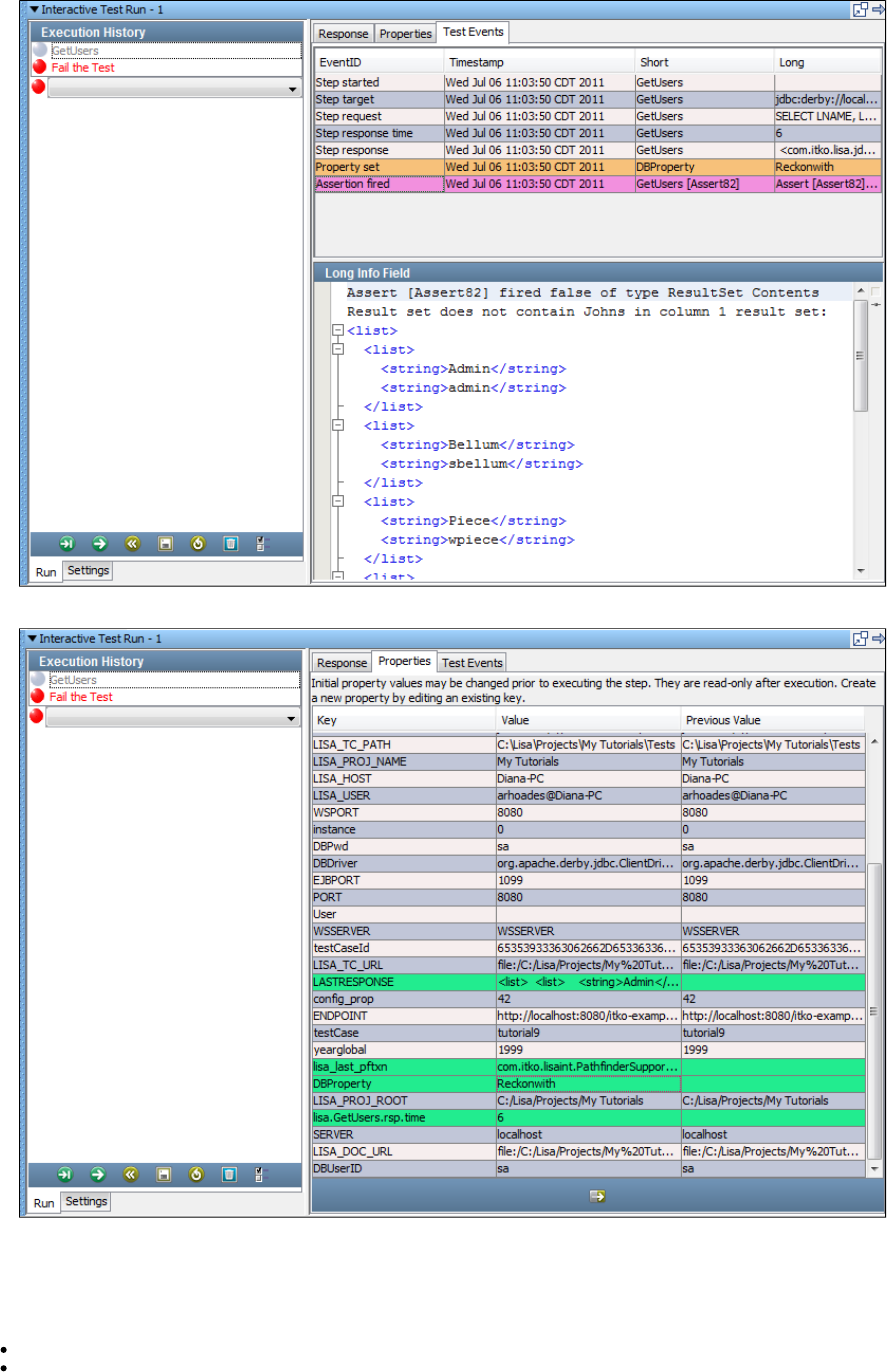
4.
5.
6. Click the tab.Properties
Locate and review the row.DBProperty
Review
In this tutorial, you created a test case to query a database. You used the Users table from the Apache Derby database that accompanies the
applications on the Demo Server. You learned how to:
Connect to the database.
Execute a SQL query against the database.

1.
2.
3.
Add assertions and filters.
Tutorial 10 - Staging a Quick Test
In this tutorial, you will use the quick staging option (quick test) to learn how to stage tests and read subsequent reports. You will run the quick test
on the example that accompanies LISA. This is the simplest way to stage a test.multi-tier-combo
LISA Concepts Discussed
In this tutorial, you do the following:
Use the multi-tier-combo test case.
Use the quick test feature.
Select and format reports.
Prerequisites
You have completed Tutorials 5 through 9.
LISA Workstation is open.
You have access to the demo server (either the local Demo Server, or the ITKO demo server).
Steps
Step 1 - Open the Test Case
We will open a test case from the examples project.
To open the test case,
From the main menu, select .File > Open > Test Case > File System
Navigate to the folder.LISA_HOME/examples/Tests
Select and click Open.multi-tier-combo
The multi-tier-combo test case opens in the model editor.
Step 2 - Review the Test Case
Take a few minutes to review the various types of test steps in this test case. For example:
Add User is a Web Service Execution (Legacy) step.
Get User is an Enterprise JavaBean Execution step.
Verify User Added is a SQL Database Execution (JDBC) step.
Deposit Money is a JMS Messaging (JNDI) step.
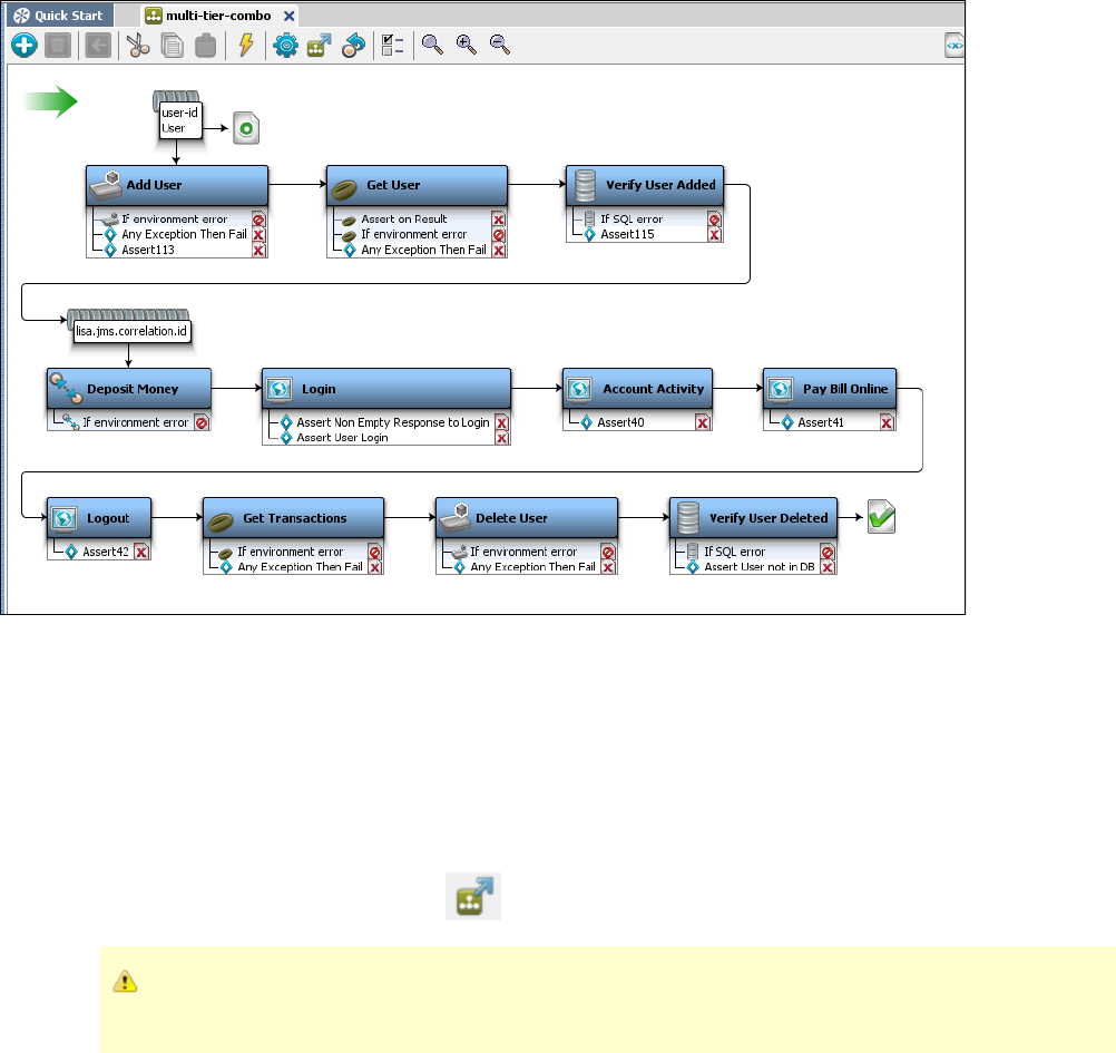
1.
You used many of these steps in tutorials 6 through 9. In this tutorial, you use all the test steps to build a more realistic test case involving several
layers of the application.
Part A - Running the Quick Test
Part B - Viewing the Generated Reports
Part A - Running a Quick Test
To run a quick test,
From the menu bar, click the Stage a quick test icon on the test case toolbar.
To stage a quick test, the example test case can be open in the model editor, or you can right-click on the test in the
Project panel and enter the parameters to stage a quick test from there.
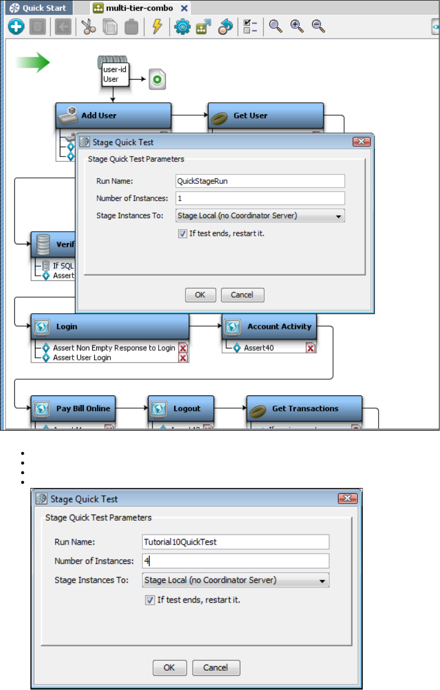
1.
2.
3.
4.
In the dialog, complete the required information as follows:Stage Quick Test
Run Name: Enter a unique name ( ).Tutorial10QuickTest
Number of Instances: Enter a number of users that you want to run the test concurrently ( ).4
Stage Instances To: Select the name of the Coordinator Server or stage it locally.
If test ends, restart it: Check this option to restart the test.
Click OK.
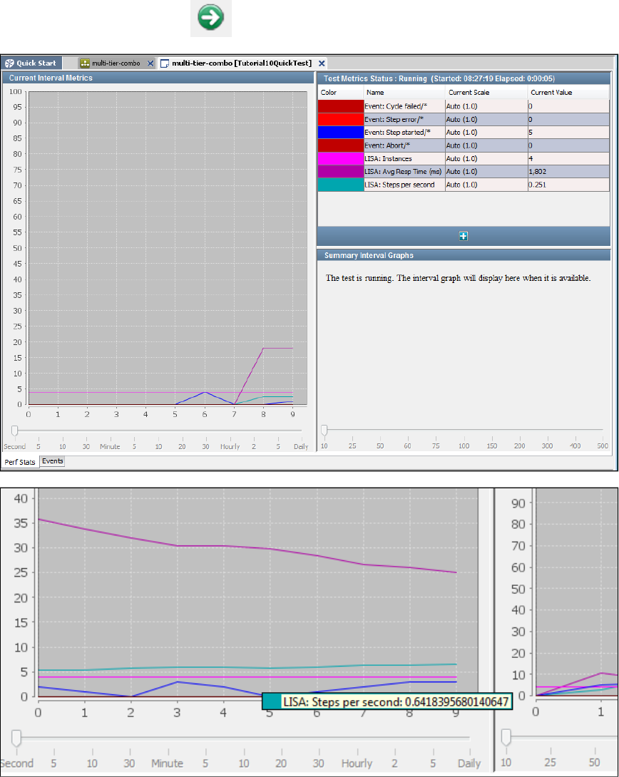
4.
5.
6.
The Test Run window opens, but the test has not started yet.
From the main toolbar, click the Start button to start the test running.
The test begins, and the graph immediately plots results.
You can roll over the graph lines to view descriptions.
Select the tab to choose which events to display.Events
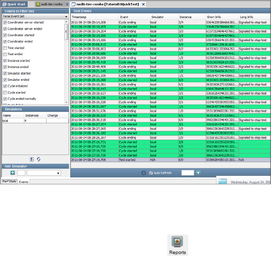
6.
1.
Part B - Viewing the Generated Reports
LISA provides a report viewer to view reports.
To view the generated reports,
From the main menu, click or click the Reports icon on the toolbar. The Report Viewer opens.View > Reporting Console
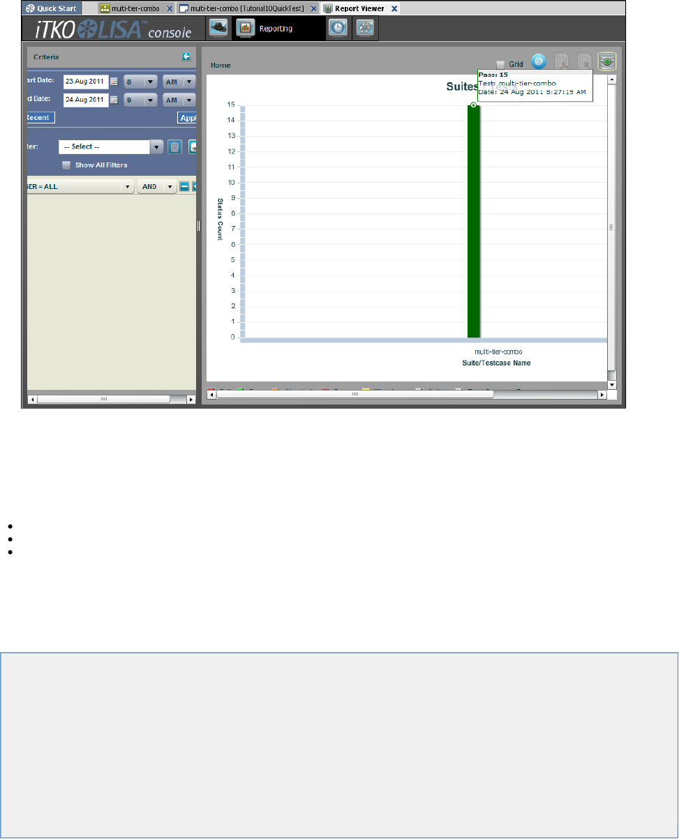
1.
2. Set the date criteria to open the graphs plotted within those dates.
In the preceding image, the graph shows that all the tests in this test case passed.
You can right-click the graph for different menus. For more information about reports, see the " " section of the .Reports User Guide
Review
In this tutorial, you tested the multi-tier-combo example using a quick test. You learned how to:
Look at a test case containing several types of test steps.
Configure and run a test in the quick test feature.
Examine a report generated from the test run.
Building Test Cases
To build test cases, you must know about setting properties, using configurations and applying them to your project, applying filters, adding
assertions, adding data sets, and adding companions. This section also introduces the Complex Object Editor.
In this section, the following topics are covered:
Anatomy of a Test Case
Properties
Configurations
Filters
Assertions
Data Sets
Companions
Complex Object Editor (COE)
Building Test Steps
Creating Test Cases
Building Subprocesses
Anatomy of a Test Case
A test case is a specification of how to test a business component in the system under test. A test case is stored as an XML document, and
contains all the information needed to test the given component or system.
A test case in LISA is a workflow with the test steps being connected by paths that represent successful and non-successful step conclusions.
may accompany the step and different paths are provided based on the firing of any of the assertions.Assertions
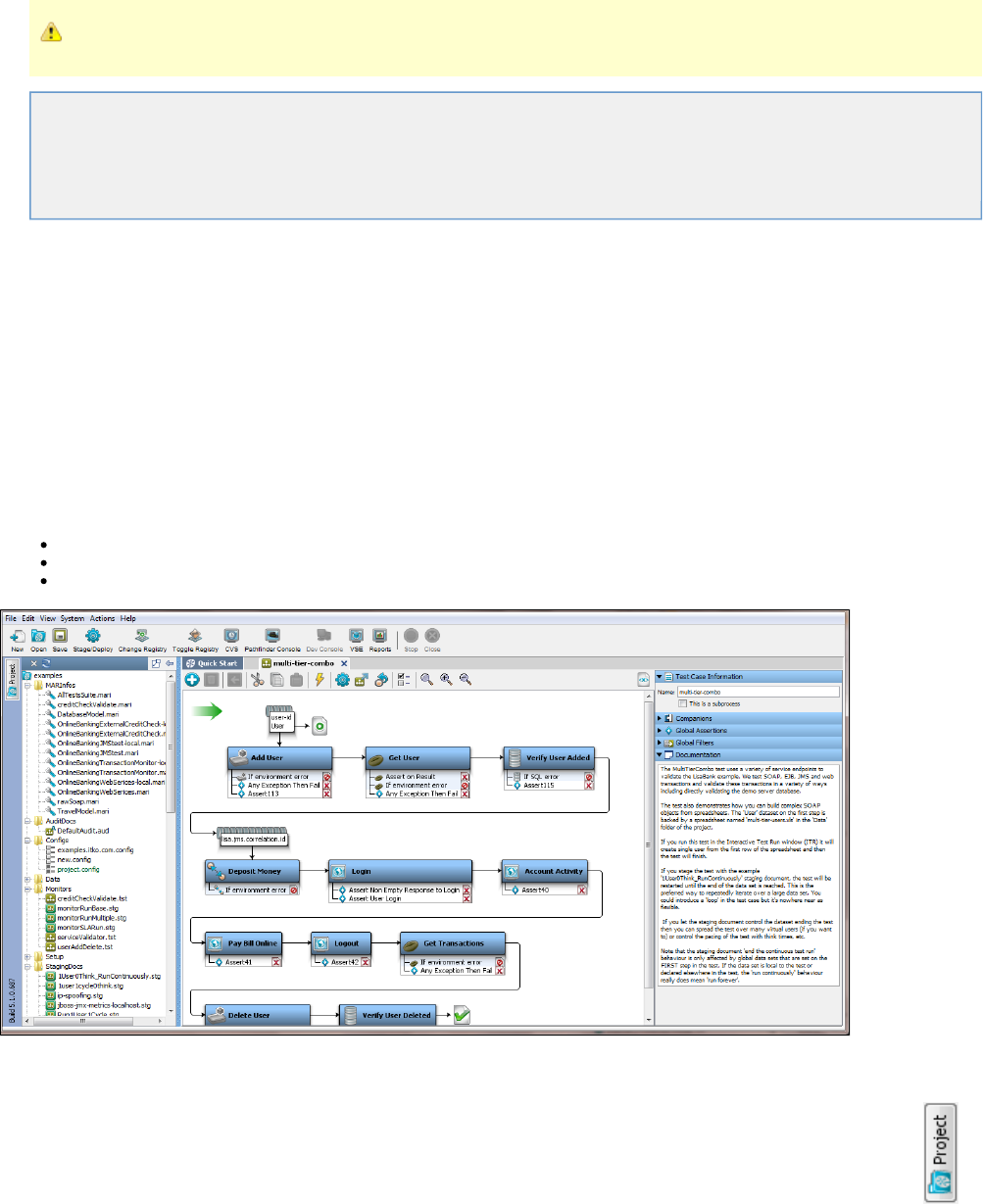
1.
2.
3.
Save your test cases regularly.
This section includes the following topics:
Test Case Quick Start
Multi-tier-combo Test Case
Elements of a Test Case
Elements of a Test Step
Test Case Quick Start
To start working with test cases
Start the registry. See .LISA Registry
Create or open a project in LISA Workstation. See .Project Panel
Create a test case within the project. See .Creating Test Cases
You can open an existing test case either from a valid LISA project or from outside a project by selecting File > Open > Test Case from the main
menu.
The test case is shown in the following images. For more information about the multi-tier-combo test case, see multi-tier-combo.tst .Multi-tier-combo Test Case
LISA Workstation is divided into three main areas (from left to right):
Project Panel
Model Editor
Element Panel
Project Panel
The Project panel, located in the left portion of the window, is dockable. You can open or close the Project panel by using the Project button
on the left.
When LISA Workstation first opens, the last project you had open will open by default.
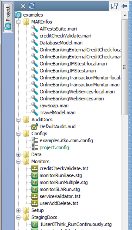
For more information, see .Project Panel
Model Editor
The Model Editor is where you create and view the test case workflow. The test case workflow consists of all test steps, filters, and assertions
applied to a particular test case.
The Model Editor is the place to create and view test cases. This is the middle portion of the window and is displayed by a tab that is the name of
the test case.
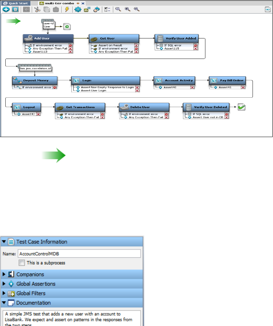
The green arrow marks the start of a test case.
The workflow in the Model Editor provides a graphical view of a test case. This is very helpful as it gives a quick visual check on the test case
workflow.
In the Model Editor, each step in the test case is represented by an icon in the workflow. The icons change according to the type of test step. For
example, if you have a database-related step, a database icon and the associated filters and assertions are attached to the step.
Element Panel
The Element panel contains the elements required for a test case or a test step.
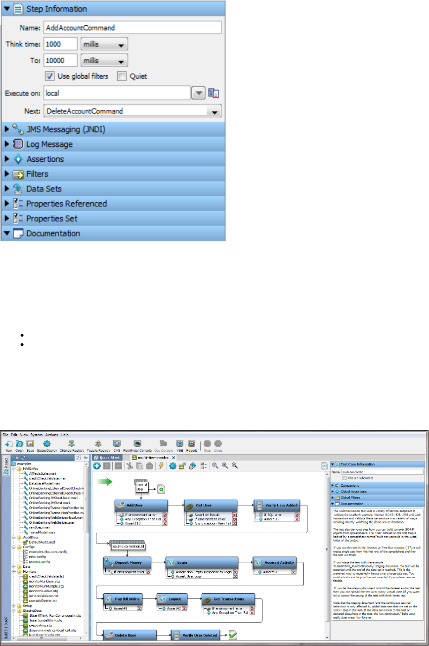
You can add or delete an element by clicking the required test case/test step element.
Some elements can be applied at the global level (to an entire test case). Some elements can be applied at a step level (only to a particular test
step).
There are some sections in which you must enter information at the beginning of a test case.
For example:
Test Case Information: Enter the test case name and check if this is a subprocess.
Documentation: Enter the documentation for the test case.
After you add steps to this test case, a workflow of steps begins to form and a new set of elements appears at a test step level in the Elements
panel.
Multi-tier-combo Test Case
The contains a test case named .examples project multi-tier-combo
This test case uses a variety of service endpoints to validate the LISA Bank demo application. It tests SOAP, EJB, JMS, and web transactions
and validates these transactions in various ways, including directly validating the demo server database.
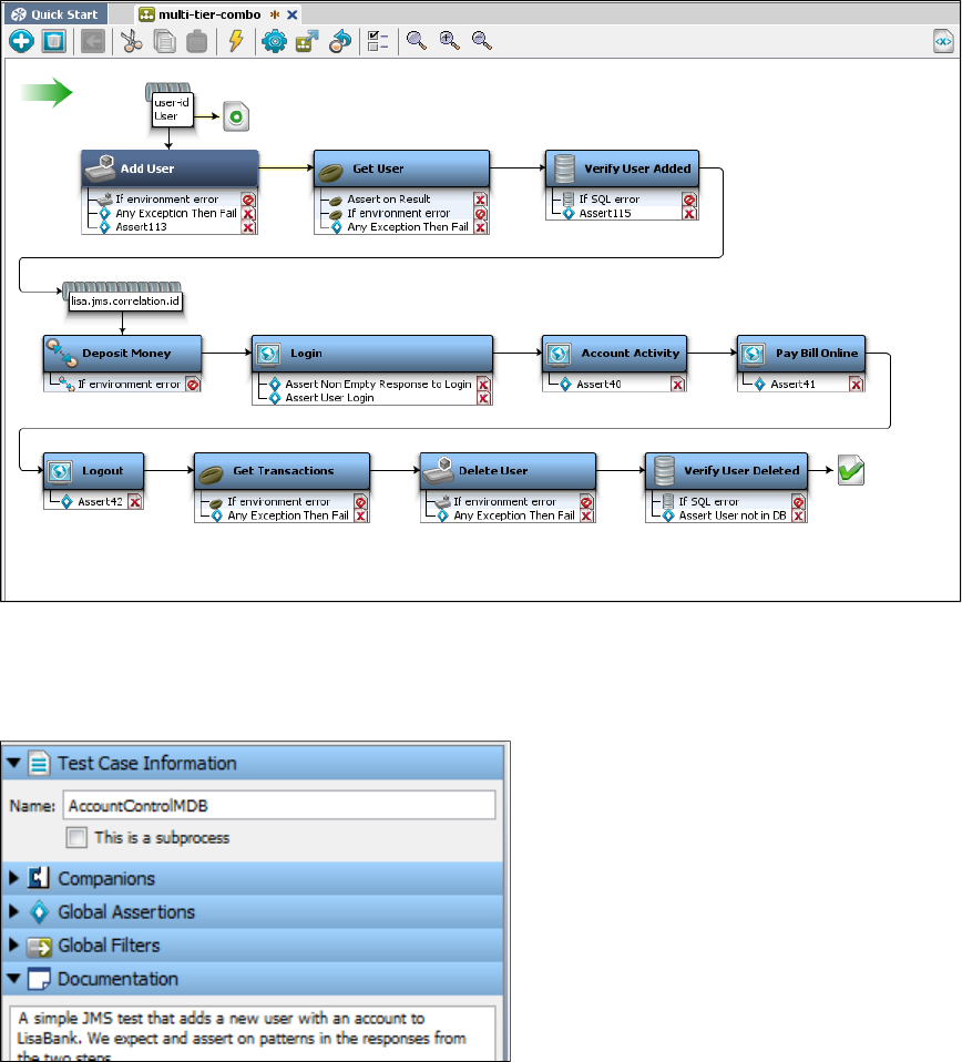
This test case also demonstrates how to build complex SOAP objects from spreadsheets. The User data set on the first step is backed by the
spreadsheet in the Data folder of the project.multi-tier-users.xls
If you run this test in the , the test will create a single user from the first row of the spreadsheet and then willInteractive Test Run (ITR) window
finish.
If you with the example staging document, the test will be restarted until the end of the data set isstage the test 1User0Think_RunContinuously
reached. This method is the preferred way to repeatedly iterate over a large data set. You can introduce a loop in the test case, but that is not as
flexible.
If you let the staging document control the data set ending the test, then you can spread the test over many virtual users or control the pacing of
the test with think times, for example.
The staging document "end the continuous test run" behavior is affected only by global data sets that are set on the first step in the test. If the
data set is local to the test or declared elsewhere in the test, the "run continuously" behavior really does mean "run forever."
Notice the project folders being opened in the Project panel and a set of test case elements in the Element panel.example
Here you can see in the Model Editor section the test case information.
Elements of a Test Case
The elements of a test case help in building the test case as a whole. Following are the test case elements as they appear in the Test Case panel
on the right side of LISA Workstation.
Test Case Information
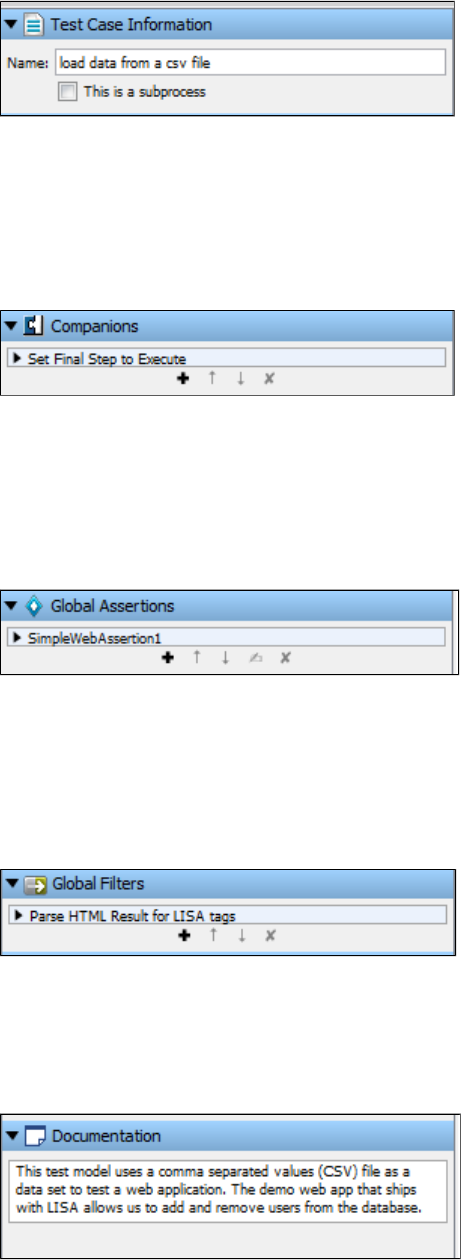
The tab is where you can change the name of a test case.Test Case Information
This tab is also used as an entry point for creating a subprocess, or converting a test case into a subprocess. A subprocess is a test case that is
designed to be called by another test case rather than to be run as a standalone test.
For more information about subprocesses, see .Building Subprocesses
Companions
A companion is an element that runs before and after every test case execution. Companions are used to configure global behavior in the test
case. A restart causes the companions to run again.
Double-click the companion in the Element tree to open its editor.
For more information, see .Companions
Global Assertions
An assertion is an element that runs after a step and all its filters have run, to verify that the results from running the step match expectations.
Global assertions are assertions that are applied to the entire test case.
Double-click the assertion in the Global Assertion list to open its editor.
For more information, see .Assertions
Global Filters
A filter is an element that runs before and after a test step, giving you the opportunity to change the data in the result, or store values in
properties. Global filters are filters that are applied to the entire test case.
Double-click the filter in the Global Filter list to open its editor.
For more information, see .Filters
Documentation
The Documentation text area lets you add documentation for your test case. This text is not used by LISA in any process, but it is a convenient
place: and more importantly, a good practice to put a description of your test case, and notes for other users who will use this test case.
If the test case is used as a subprocess, the documentation will be passed to the calling step.
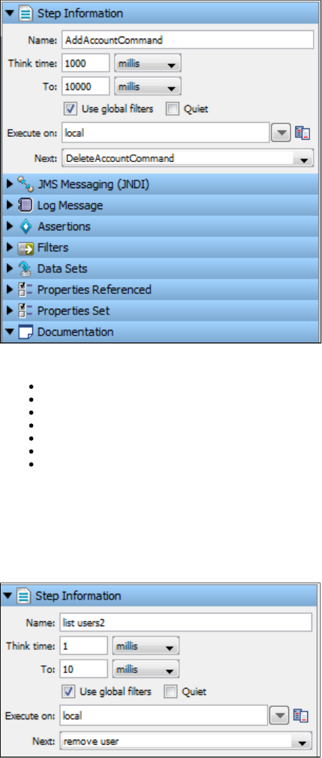
Elements of a Test Step
A test step is an element in the LISA workflow that performs a basic action to validate a business function in the system under test. Steps can be
used to invoke portions of the system under test. These steps will typically be chained together to build workflows as test cases in the Model
Editor. From within each step, you have the ability to create filters to extract data or create assertions to validate response data.
These elements are described briefly in the following sections, and discussed in detail in .Building Test Steps
Step Information
Log Message
Assertions
Filters
Data Sets
Properties Referenced
Properties Set
Step Information
The step information section provides a place to document basic information about the test step.
You can enter the step name, think time, Execute on details, and Next step details. You can also specify to run the step using global filters and to
run the step quietly.
For more information, see .Building Test Steps
Log Message
A log message is a text field in which you can enter a message for a particular step. This message will be seen upon execution of the test step or
case.
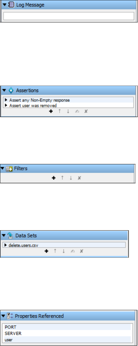
For more information, see .Test Step Logger
Assertions
An assertion is an element that runs after a step and all its filters have run, to verify that the results from running the step match expectations. The
result of an assertion is Boolean - either true or false (there are no other possibilities).
The outcome determines whether the test step passes or fails, and the next step to run in the test case. That is, the assertion can dynamically
alter the test case workflow by introducing conditional logic (branching) into the workflow.
For more information, see .Assertions
Filters
A filter is an element that runs before and after a test step, giving you the opportunity to change the data in the result, or store values in
properties.
For more information, see .Filters
Data Sets
A data set is a collection of values that can be used to set properties in a test case while a test is running. This provides a mechanism to introduce
external test data to a test case.
For more information, see .Data Sets
Properties Referenced
This section contains a list of properties used or referenced by the test step.
Select and right-click the property to open the extended view and get its variable value.
For more information, see .Properties
Properties Set
This section contains a list of properties set by the test step. The Properties Referenced and Set are for a particular step and will change when
another step is highlighted.
For more information, see .Properties
Properties
Test properties are name–value pairs, also known as key–value pairs.
The key to data independence, reusability, and portability in test cases is the ability to abstract specific data values out of the test case and
replace them with variables. These variables are referred to as . Some properties are predefined and guide how LISA operates. Otherproperties
properties are created by you while you are building your tests.
Properties are both ubiquitous and indispensable in test cases. A sound understanding of properties is vital to the creation of test cases. In the
context of a test case, any time there is something that can change, it is appropriate to use a property. This includes values in test steps and
values in configurations, for example.
Properties can be defined in several ways. After they are defined, they are available to any subsequent steps, assertions, and filters in the test
case (they are global to the test case). Properties can, with few exceptions, be overridden in a test case.
Whenever a property value is set, an event is recorded that contains the property name and value.EVENT_SETPROP
Property values are not limited to string values. A property can hold strings, numbers, XML fragments, serialized Java objects, or the complete
response from a test step. Many properties are created during a test run that are available to the subsequent test steps. For example, the
property contains the response for the step.lisa.stepname.rsp stepname
In this section, the following topics are covered:
Specifying a Property
Property Expressions
String Patterns
LISA Property Sources
Property Files
Common LISA Properties and Environment Variables
Specifying a Property
The syntax for a property is .{{property_name}}
When a property is identified and about to be used, is replaced by its current value. There are times when a property is{{property_name}}
expected, and is the only choice. Other times, you are asked for the property name explicitly. In these cases, you enter the property name without
the braces. When properties are embedded in a text string, you must use the brace notation. There is an additional syntax that allows property
to be used: or .expressions {{=expression}} {{property_name=expression}}
A property name can contain spaces. However, using spaces is not recommended. The characters that define the property syntax ( , , and ){ } =
cannot be used.
All property names that start with are reserved for internal use. Properties that start with may be hidden or deletedlisa. lisa .
If you reference a property that does not exist, the property is left in the braces to indicate that the property was not found, or it is invalid.
Property Expressions
LISA properties can store many different types of data. They can also evaluate and store expressions. These expressions can contain any valid
Java or JavaScript expressions that can be evaluated by BeanShell. BeanShell is a Java interpreter environment. Further, these expressions
could be string patterns, which give real-looking fake strings, appropriate for most given purposes.
For more information about BeanShell, see or .Using BeanShell in LISA www.beanshell.org
To use a property expression, you use the syntax or . In the first case, , BeanShell will{{ }}=expression {{ }}key=expression {{ }}expression
be used to evaluate the expression and replace by the result of the evaluation. For example, will evaluate{{ }}expression {{ }}=Math.random()
the static Java method and replace the construct with the random number that was returned. In the latter case, using {{}} {{
will set a property equal to the random number that was returned, in addition to replacing the construct with}}rand=Math.random() rand {{}}
the random number.

Existing properties can be used in a property expression. They are referenced by name only, that is, without the braces, because they are already
defined as properties. If the property is not found, the property expression is returned within braces, to indicate that there is a problem in the
expression.
String Patterns
String patterns are special types of property expressions that have a syntax For example, to format a first name, the string{{ =[:patternname:] }}.
pattern property could be . The property would evaluate to a fake first name that looks like a real name.{{ =[:First Name:] }}
This is much better than the possibility of dealing with random strings that do not look like a real name. Of course, the string pattern functionality
supports many patterns in addition to first names: last names, dates, Social Security numbers, credit card numbers, credit card expiration dates,
and many more. This fake data comes with LISA, in TESTDATA table in its reportdb database.
The recommendation is that if you need a first name in your test case, you use {{ =[:First Name:] }} in a data set. The "{{=[ " part is a signal to use
the string pattern and it has a list of things "registered" that it knows about.
As an example, if you put the following information in a log step:
{{ =[:First Name:]}} {{ =[:Middle Initial:] }} {{ =[:Last Name:] }}
{{ =[:Street Address:] }}
{{ =[:City:] }}, {{ =[:State Code:] }}
{{ =[:ZIP Code:] }} {{= [:Country:] }}
SSN: {{ =[:SSN: DDD-DD-DDDD] }}
Card: {{ =[:Credit Card:] }} Expires {{= [:CC Expiry:] }}
Phone: {{ =[:Telephone:] }}
Email: {{ =[:Email:] }}
You get the response:
Marilyn Mcguire
3071 Bailey Drive
Oelwein, IA
50662 US
SSN: 483-16-8190
Card: 4716-2361-6304-6128 Expires 3/2014
Phone: 319-283-0064
Email: Marilyn.C.Mcguire@spambob.com
If you run the step again you will get a different set of data. It will keep track of the number of rows in the test data database and randomly select a
row between 1 and N.
Select Help > Property Window > Patterns to open the following screen, which shows all existing string patterns and shows the
documentation.

Implementation Information
The data is stored by default in the reports database in the TESTDATA table.
When LISA Workstation is started, it checks to see if there is any data there and if there is no data, then com/itko/lisa/test/data/TestData.csv
inside lisa-core.jar is read to load up the database. If reports.db gets deleted for some reason, the test data will be recreated. Reading the
database is done only at startup and takes about 15 seconds.
Creating your own String Pattern
To add your own data, the only thing to be careful about is to assign the ID correctly. Start with 1 and increase with no gaps until you get to your
number of rows.
The string generator code essentially does after getting from a random object. So, ID must be the primaryselect * from testdata where id = 'n' n
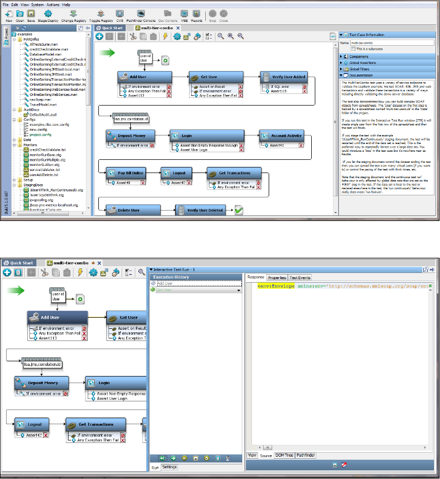
key of the table to help ensure efficient lookups.
Example
A good way to get some practice with property expressions is to build a simple test case that has a single step: an Output Log Message. Because
this step just writes to a log, and displays its response in the Interactive Test Run (ITR) Response Panel, you can experiment with using property
expressions.
The following example uses the multi-tier-combo test case in the examples directory (multi-tier-combo.tst).
This illustration shows our example in the LISA ITR utility.
These illustrations show the Properties tab in the ITR. This is for the step Get User.
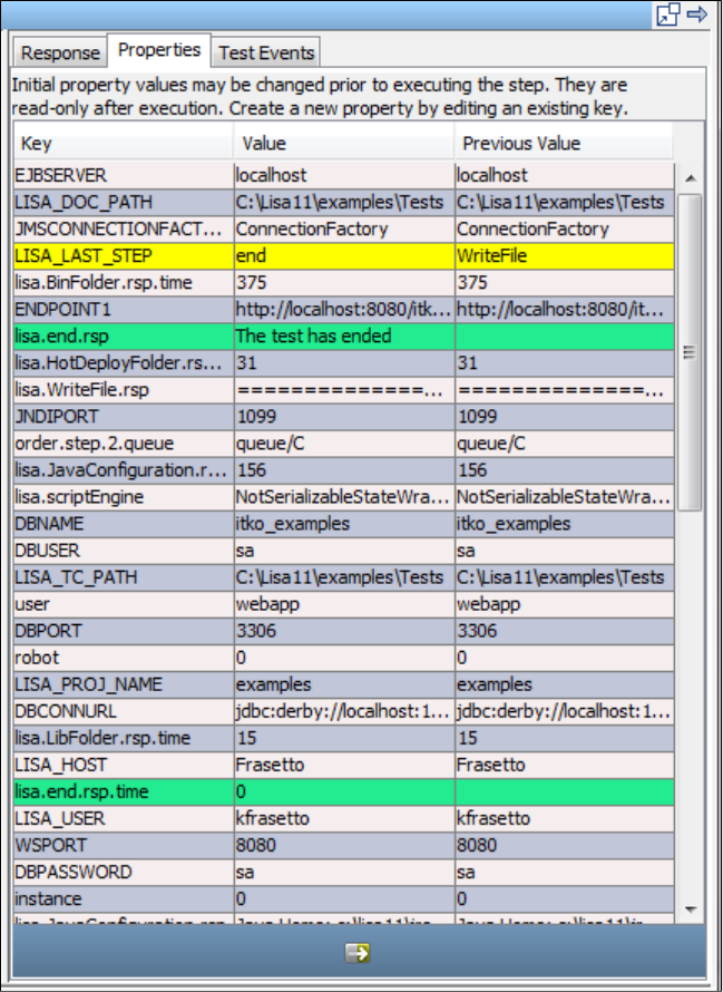
This illustration shows the Test Events tabs in the ITR.
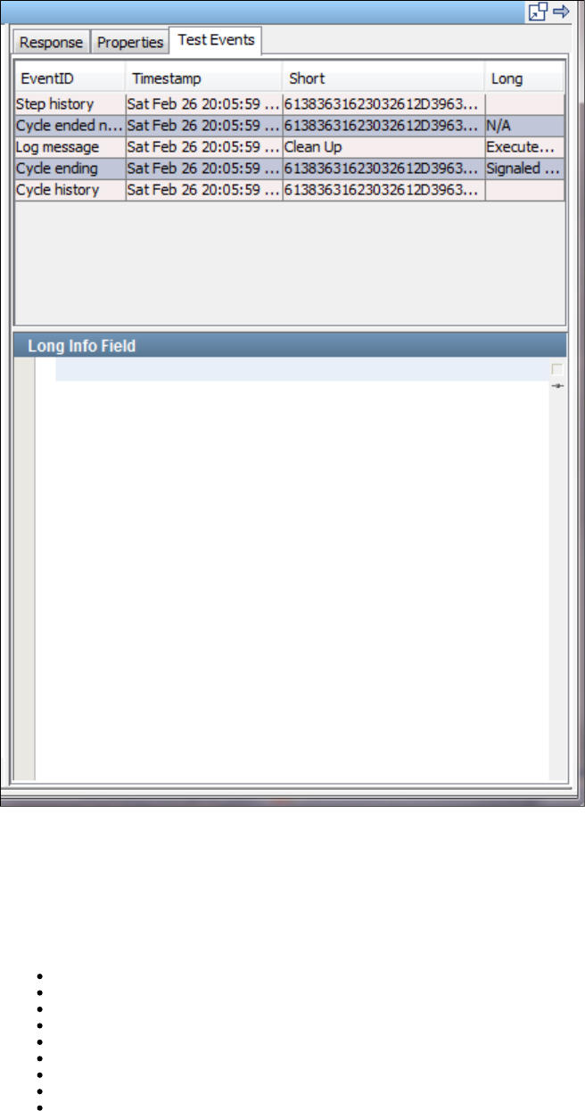
1.
2.
Look for the event Properties set in the Test Events tab.
Java developers can also take advantage of the BeanShell environment in the JavaScript step to test property expressions.
LISA Property Sources
Properties can originate from several sources that include:
LISA
Environmental variables
Command line variables on startup
Configurations
Companions
Test steps
Filters
Data sets
String patterns
Because properties can be overridden, it is important to understand the property hierarchy, or the order in which properties are read in a test
case.
The following hierarchy is used:
Properties loaded during the set up of a test

2.
3.
4.
5.
6.
7.
8.
9.
Operating system environment variables (like java.version or os.user, for example)
LISA property files
Command line attributes
The default configuration
Any alternative configuration properties (from active configuration or runtime configuration file)
Properties set during a test run
Properties in companions
Properties set during test execution (for example, in data sets, filters and steps). Remember that properties set here override values set
earlier.
Common LISA Properties and Environment Variables
HOT_DEPLOY: Points to a project-specific directory.hotDeploy
LASTRESPONSE: The response to the last executed step.
LISA_HOME: Points to the LISA install directory, and is automatically set. This value includes a final slash. To reference a directory such as
"examples", specify:
{{LISA_HOME}}examples
No slash is needed before the directory name.
LISA_HOST: The name of the system on which the testing environment is running.
LISA_JAVA_HOME: The Java VM that LISA will use. Use this only if you do not want to use the built-in VM in LISA. If there is no Java installed,
LISA uses the bundled JRE it comes with. You also must rename the directory in the LISA install directory to something like .jre jre_notinuse
LISA_POST_CLASSPATH: Used to add information after the LISA classpath. LISA does not use the OS environment CLASSPATH variable. To
add your own JARs after the LISA classpath, use LISA_POST_CLASSPATH.
LISA_PRE_CLASSPATH: Used to add information before the LISA classpath. LISA does not use the OS environment CLASSPATH variable. To
add your own JARs before the LISA classpath, use LISA_PRE_CLASSPATH.
LISA_PROJ_NAME: The name of the project to which the current document belongs.
LISA_PROJ_PATH: The fully qualified path of the project directory. The value is operating system-dependent. A backslash (\) is used as the
separator character on Windows. A forward slash (/) is used as the separator character on all other operating systems. The following example is
based on a Windows installation:
C:\Program Files\LISA\examples
There is one limitation to using LISA_PROJ_PATH in a Custom Java step: the syntax {{LISA_PROJ_PATH}} is not supported. Because the
Custom Java step invokes a Java compiler to compile the script, and Java treats backslashes as escape characters in strings, this particular
string raises a compiler error. The workaround is to use LISA_PROJ_PATH as a variable. For example:
File f = new File ( LISA_PROJ_PATH );
LISA_PROJ_ROOT: The fully qualified path of the project directory. The value is operating system-independent. A forward slash (/) is used as
the separator character on all operating systems, including Windows. The following example is based on a Windows installation:
C:/Program Files/LISA/examples
LISA_PROJ_URL: The URL of the project directory. For example:
file:/C:/Program%20Files/LISA/examples
LISA_TC_PATH: The fully qualified path of the directory where the test case is located.
LISA_TC_URL: The URL of the directory where the test case is located.
LISA_USER: The user that loaded the test case.
Property Files
The main property files are:
lisa.properties file
local.properties file
site.properties file
Detailed information about properties is available in these appendixes:
Appendix A - LISA Property File (lisa.properties)
Appendix B - Custom Property Files (local.properties, site.properties)
Configurations
A configuration is a named collection of properties that usually specify environment-specific values for the system under test.
By removing hard-coded environment data from the test case, you can run the same test against different environments by simply using a
different configuration. Configurations are used everywhere within LISA: for example, in a test case document, test suite document, staging
document, test case execution or test suite execution.
A configuration must be defined at the LISA project level. You can specify the values of these properties at the beginning of a test case.
The default configuration of any project is . You can create additional new configurations within a project and "Make it Active" for aproject.config
particular test case/suite.
If you create a new config file, you will be able to add any new keys within it. To add keys within the new config, you must add them in the not
file. You can then select the newly-defined keys added in the file from the drop-down available in the new configproject.config project.config
file.
Properties are added to your configuration automatically as you develop your test.
For example, in a web service test when you enter the name of the WSDL, the server name and the port that you entered are replaced with
properties such as and The values of these properties are automatically added to your default project configuration. Now youWSSERVER WSPORT.
can change the location of the web service merely by editing the configuration, rather than looking for hard-coded values in several test steps.
In another example, when working with Enterprise JavaBeans (EJBs) or Java objects, you may want to switch hot deploy directories, or add extra
JAR files to your class path, to use different versions of your Java code. There are standard properties for these locations: HOT_DEPLOY and
MORE_JARS. These can be set in your configuration.
For information about other standard properties, see .Properties
Configurations are for storing properties related to the system under test. Avoid using them for storage of "test-like" parameters and global
parameters. These can be stored in a .companion
Backslashes "\" are not preserved in configuration files. If you edit the config file manually and put something that has a
backslash, the file will be overwritten without the backslashes.
The following topics are available in this chapter:
LISA Project Configuration
Default Configuration
Adding a Configuration
Marking a Configuration as Active
Editing a Configuration
Copying a Configuration
Deleting a Configuration
Renaming a Configuration
Creating a New Configuration File
Importing a Configuration File
Applying a Configuration when Running a Test Case
LISA Project Configuration
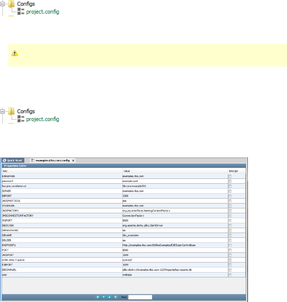
1.
2.
The configuration at the project level can be seen in the section in the Project panel.Configs
The project.config is by default the active configuration (marked in green) for any LISA project.
All newly-defined properties must be in the default project.config file. Later they can be pulled into the new configuration file.
New configurations can be applied to a test case by making them " ".Active
Configurations are defined at the project level.
Default Configuration
The default configuration of any project is . It is also the configuration for the project. It has the superset of all the keysproject.config active
defined in every other configuration.
After you open a project, the default configuration ( ) is shown in green in the Configs folder.project.config
You cannot delete or rename the default configuration.
You can change the active configuration of a project. For instructions on how to do this, see .Marking a Configuration as Active
Double-clicking will open the configuration in the Properties Editor window. The name of the tab will show the name of theproject.config
configuration.
These are standard LISA config parameters that are available in all configurations.
To add parameters in other configurations, first add them here and then select from the drop-down in the required configuration.
Adding a Configuration
A project can have many alternate configurations, but it can have only one active configuration. Any alternate configuration or the default
configuration can be made active. Alternate configurations can only override default properties.
To add a configuration
Right-click the folder in the Project panel.Configs
2.
3.
4.
1.
2.
1.
Click Create New Config.
Enter the name of the new configuration.
Click OK.
Adding Key-Value Pairs
To add keys within the new configuration, you must add them in the file. You can select the newly defined keys from theproject.config
drop-down in the new configuration file. In a new configuration file, you will be able to add any new keys.not
When you create a configuration file, the only keys that you can add are the ones that are already defined in , in addition to theproject.config
standard config keys provided with LISA.
Marking a Configuration as Active
When you want to apply a different configuration to your project, you must make it active.
Within the Configs folder, you can mark any configuration as active.
To mark a configuration as active
Right-click the required config file in the Configs folder.
Click Make Active.
A configuration can be both the default and active.
The active configuration applies to the whole project, not a single test case.
Each test case in a single project shares the active configuration applied to the project. You cannot assign a separate configuration for each test
case within a project.
The active configuration takes precedence in the Interactive Test Run (ITR) utility, but the default configuration is used in a if noStage Test Case
configuration is specified.
Editing a Configuration
In any configuration other than , you can add properties only if they exist in .project.config project.config
A best practice is to use properties in the path names stored in the configuration. Properties such as or will allowLISA_HOME LISA_PROJ_ROOT
for portability of test cases.
A property value can contain multiple lines.
The extended view consists of a dialog for editing a property value. This view can be useful when the value is long or when the value contains
multiple lines. To access the extended view, right-click the property value cell and select Launch Extended View.
To edit a configuration
Double-click the configuration in the folder. The Properties Editor appears.Config
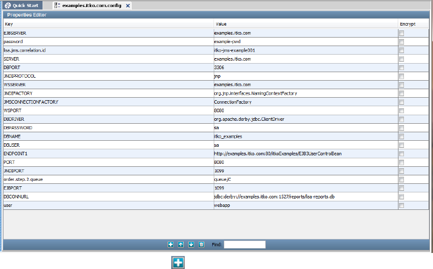
1.
2. You can add a property by clicking the Add icon at the bottom of the Properties Editor. A new line is added to the property list. Click
the drop-down to select the chosen key. Common property names, such as HOT_DEPLOY and MORE_JARS, appear in the drop-down.
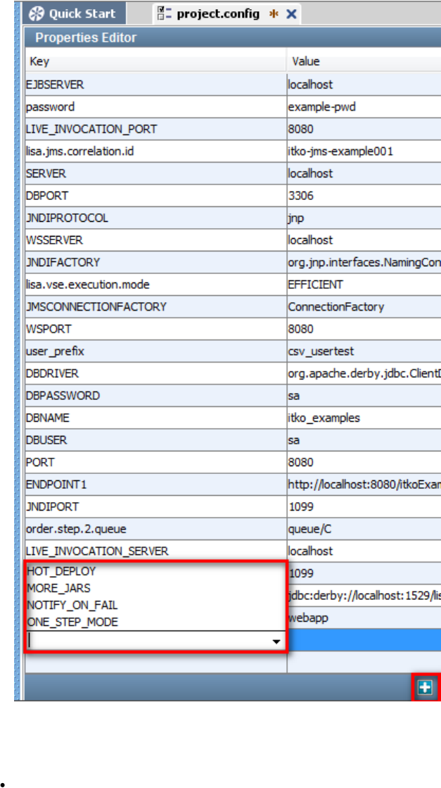
2.
1.
2.
1.
2.
Copying a Configuration
To copy a configuration
Select the configuration file to be copied, right-click and select Copy to copy the selected configuration.
To paste a configuration
Click the Configs folder, right-click and click Paste. You will be prompted to rename the pasted config because it will appear to be a
duplicate of the copied config.
Rename the configuration file and click OK to add the new configuration in the Config folder.
Deleting a Configuration
To delete a configuration
Select the configuration to be deleted and right-click.
Click Delete from the dialog.
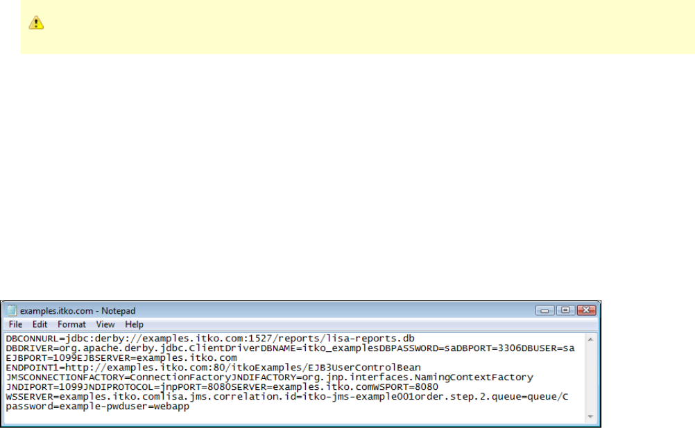
1.
2.
3.
1.
2.
3.
4.
5.
1.
You cannot delete the default configuration (project.config).
Renaming a Configuration
To rename a configuration
Select the configuration and right-click to open a menu.
Click Rename to rename the configuration.
In the window that opens, enter the new name and click OK to rename the file.
You cannot rename the default configuration (project.config) within LISA. When right-clicking on project.config, the Rename option will not appear.
Creating a New Configuration File
You may need to create a new configuration file to import into LISA.
A configuration file is a text file with a .config extension that contains the properties as key-value pairs. All configuration files are an integral part of
any test run.
Configuration files can be created, or edited in any text editor and can be saved with a config extension..
When starting a test run, you will have the opportunity to choose a configuration file of your choice. There is an example of this later in this
chapter.
We recommend that you establish a naming convention for configuration files, making identification of alternate configurations easier.
These configuration files need to be into LISA.imported
Importing a Configuration File
To import a configuration file
Select the Configs folder and right-click to open a menu.
Click Import to import a configuration file.
On the window that opens, enter the name of the configuration file to be imported and click Open to import the file.
A notification message appears explaining that a config file is being imported and a successful message also appears.
Click OK.
You will see the new configuration file imported in the list of configurations, and any new properties will also be added to .project.config
Applying a Configuration when Running a Test Case
Running a test case is one of several places where configurations are used.
To start a test case execution, you must give the test case details with the configuration to be applied.
To stage/start a test case from the main menu
Select Actions > Stage Test. The Stage Test Case dialog appears.
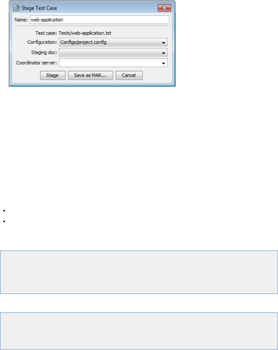
1.
2.
3.
4.
The Configuration pull-down will include all the configurations defined in the project. Assigning a configuration file here is optional. If
omitted, the default configuration in the test case document will be used.
Select the staging document to refer to while executing the test case.
Select the coordinator server.
When your selections are complete, you can either click Stage to stage the test, or Save as MAR... to create a model archive including
the test case, configuration, staging document and coordinator server information you specified here.
Filters
A filter is a LISA code element that runs before and after a test step, giving you the opportunity to change the data in the result, or store values in
properties.
Most filters execute after the step has run. A filter can be used to extract a value from a web page, XML and DOM responses, a Java object, a
text document, and many other test step responses.
After the data has been filtered, the data can be used in an assertion, or in any subsequent test step. Filters usually operate on the response of
the system under test. For example, filters are used to parse values from an HTML page, or to perform conversions on the response. Filters can
also be useful in other places; for example, to save a property value to a file, or convert a property to be the "last response".
There are two basic ways to apply a filter, as a or as a . The available filter types are the same, but how the filters areglobal filter step filter
applied differs.
Global filter: A filter defined on the level is a global filter, and executes before/after every test step that is not set to ignoretest case
global filters. You can set a step to ignore global filters in the Step Information Element of the step.
Step filter: A filter defined on a level is a step filter and executes before/after each execution of that test step.test step
You can add as many global and step filters as you need. They are executed in the order that they appear in the test case.
Filters are mainly used as property setters.
The following topics are available in this chapter.
Adding a Filter
Deleting a Filter
Reordering a Filter
Dragging and Dropping a Filter
Types of Filters
Adding a Filter
There are several ways to add filters.
Adding a Filter Manually
Adding a Filter from an HTTP Response
Adding a Filter from a JDBC Result Set
Adding a Filter from a Returned Java Object
Adding a Filter Manually
To add a filter manually, select the filter type from a list and enter the parameters for the filter.
You can add two types of filters manually: global filters and step filters.
The first method lets you add a filter at the test case level (global filter). Global filters are applicable to all the steps in the test case and are
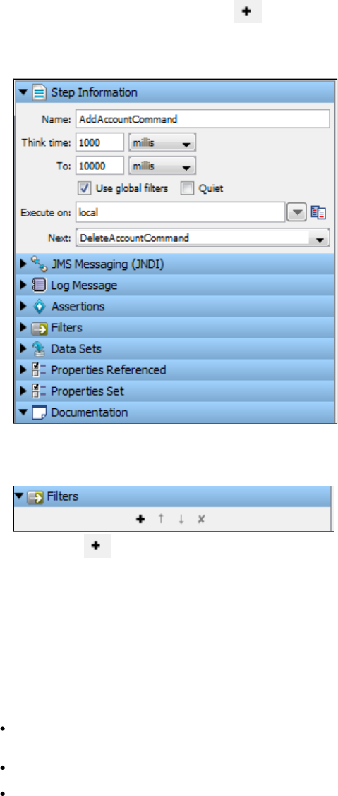
1.
2.
3.
1.
2.
automatically run for every step in the test case, unless a given step is instructed otherwise.
The second method lets you add a filter at the test step level (step filter). A filter created using this method is applicable only to that step and will
execute for that step only.
Add a Global Filter
Open a test case and click anywhere in the editor area to open the Test Case Elements panel.
On the Global Filters element, click the Add icon to add a global filter. You will be prompted to select a filter type of LISA Integration
Support for Pathfinder or LISA Integration Support for webMethods Integration Server. For more information about adding each of these
types of filters, go to or .LISA Integration Support for Pathfinder LISA Integration Support for webMethods Integration Server
When you have at least one global filter on a test case, you can see that for each step, by default the Use Global Filters check box is
selected. If you do not want to apply a global filter for a particular step, clear the box.
Add a Step Filter
Select the step for which you want to apply the filter and in the right panel, click the Filter element.
Click the Add icon of the filter element to get the list of available filters to choose from, or right-click the step and select Add Filter
and select the appropriate filter for this step.
This will open the Filter menu listing the common filters in LISA. Each filter has its own editor and applicable parameters that need to be set.
Example
This example uses the Override Last Response Property/Convert Property Value into Last Response filter.
This filter converts a property value into the last response.
To configure the filter, enter the following parameters:
Filter in (Property to Convert): The name of the property you want considered as the step's last response. The property should be in
the pull-down menu. You can type the property name if you do not find it there. The filter will give an error if it is not an existing property.
Convert to XML: Select this if you want the response to be converted to valid XML.
Run Filter: Click to run the filter.
Adding a Filter from an HTTP Response
When you have access to the response from an HTTP-based step, you can use the response to add a filter directly.
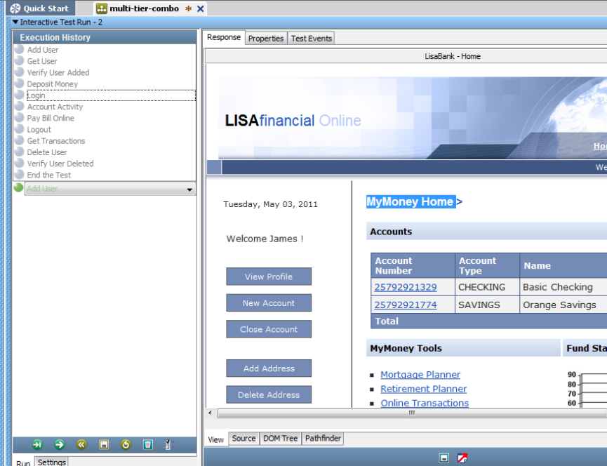
1.
2.
This example uses the response of the login step in the multi-tier-combo test case in the examples directory (multi-tier-combo.tst). The point of
this example is to capture the text where currently appears on the screen. (It will not always be the same text).MyMoney Home
Run the multi-tier-combo test case in the ITR, then select the Login test step.
Select the text in the View tab and click the DOM Tree tab to make sure that this text is selected in the tree view.MyMoney Home
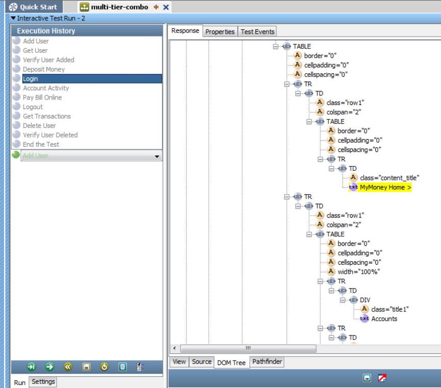
2.
3. To apply an inline filter, double-click the login step in the model editor to open the HTTP/HTML Step Editor.

3.
4.
5.
6.
7.
Move to the DOM Tree tab, find in the DOM Tree view, and select it.MyMoney Home
At the bottom of the screen, in the Select a Command box, select Parse Value Filter from the drop-down menu.
In the dialog window that is displayed, enter the name for the Property Key "wasAdded":
Click OK.
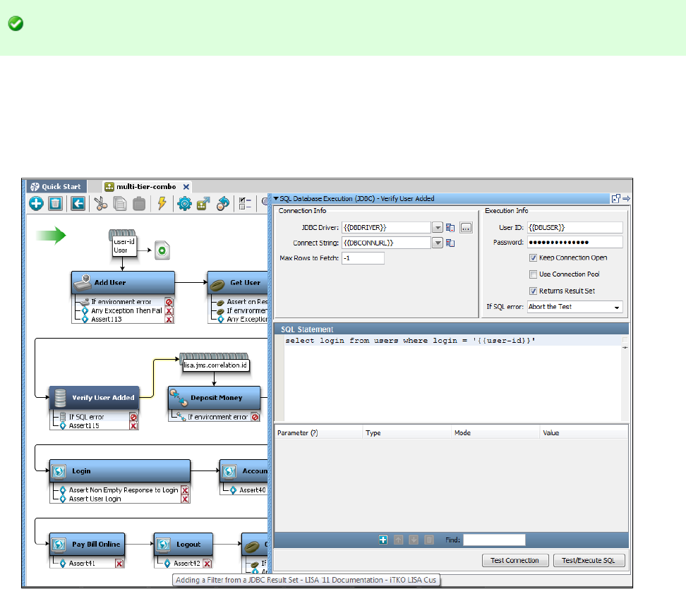
1.
2.
You can also add an assertion here. For example, you would probably want to test the value of the property "wasAdded," to see if it is in fact
equal to Added user. More information is available in .Adding Assertions
The filter that was generated can be seen as a filter in the login test step.
The same filtering capabilities are available when an HTML response is displayed in the step editor.
Adding a Filter from a JDBC Result Set
When you have access to the result set response from a JDBC step, you can use the response to add a filter directly.
Here is an example of the JDBC Result Set response, using the response of the Verify User Added step in the multi-tier-combo test case in the
examples directory (multi-tier-combo.tst).
Double-click the Verify User Added step to open its step editor.
Edit the SQL statement to read and click the Test/Execute SQL button to get values in the result set.Select * from users
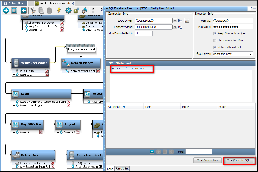
2.
3. Click the Result Set tab and click the Test/Execute SQL button to get values in the result set.
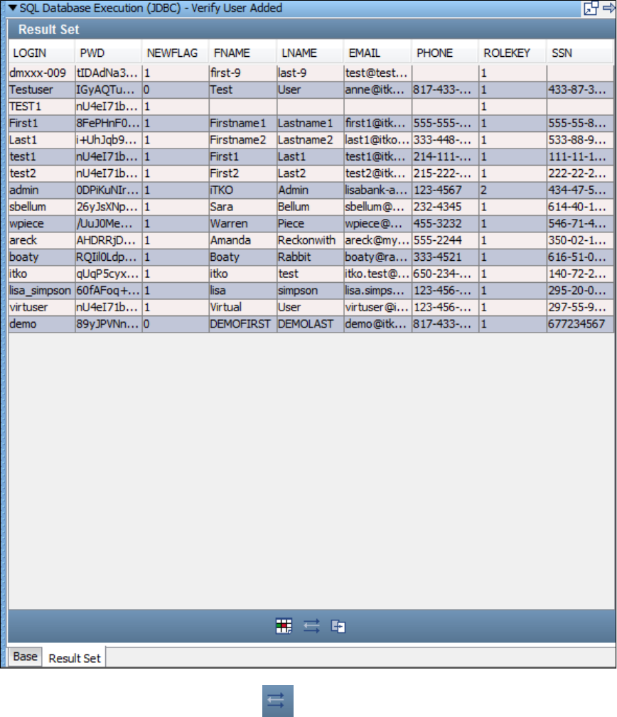
3.
4.
5.
6.
Click the cell in the result set tab that represents the location of the information you want to capture ( ).sbellum
Click the Generate Filter for Current Col/Row Value icon .
In the dialog that opens, enter the property key .theLogin

6.
7.
8. Click OK. LISA will add a filter named Parse Result Set for Value in the list user step.
Click the filter editor to see the filter.
In the example, the value in the cell in the 1 column, and 2 row, , will be stored in the property theLogin.
st nd sbellum
Applying a Second Filter
There is a second filter that can be applied here. You can look for a value in one column of the result set, and then capture a value from another
column in the same row.
From within the result set, select the two values in two different columns from the same row, using the Ctrl key.
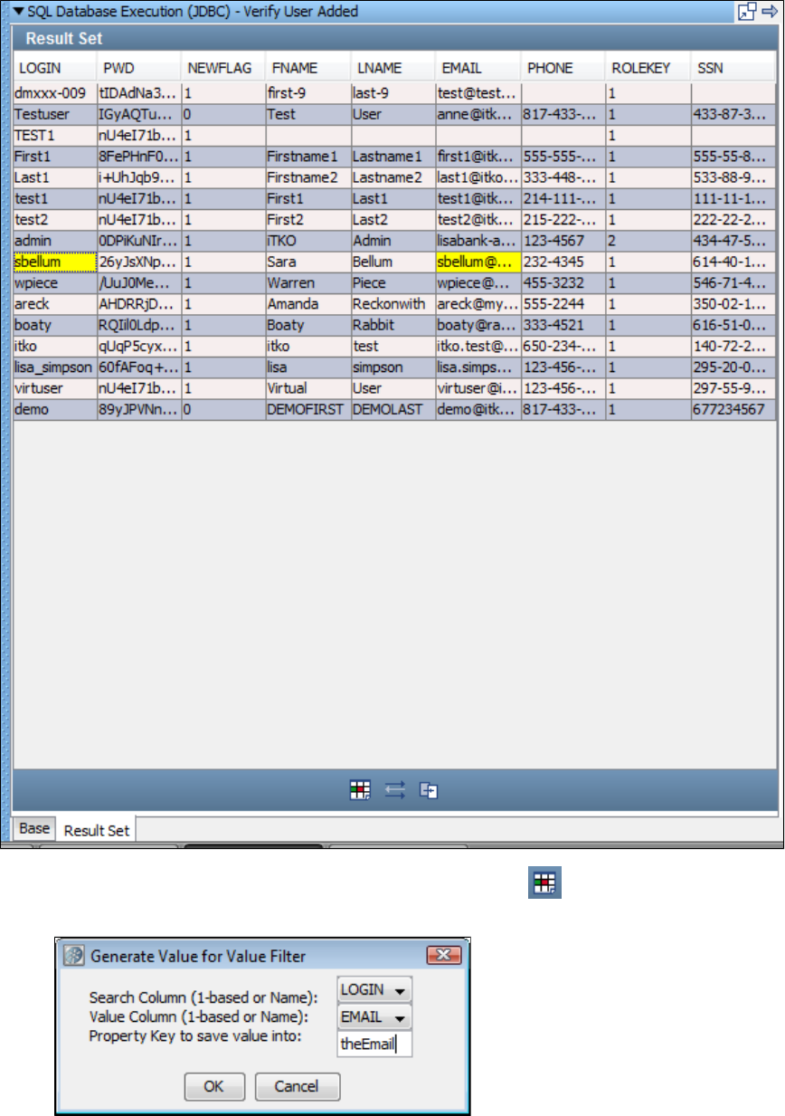
1.
2.
3.
Select Filter for a value and then get another column value filter using the icon. Select two cells in the same row to create this filter.
One will be the search column and the other will be the column whose value you want to extract.
In the dialog that opens, check or reassign the columns for the search and the value, then enter the property key .theEmail
Click OK. LISA will add a filter named in the Verify User Added step.Get Value For Another Value in a ResultSet Row
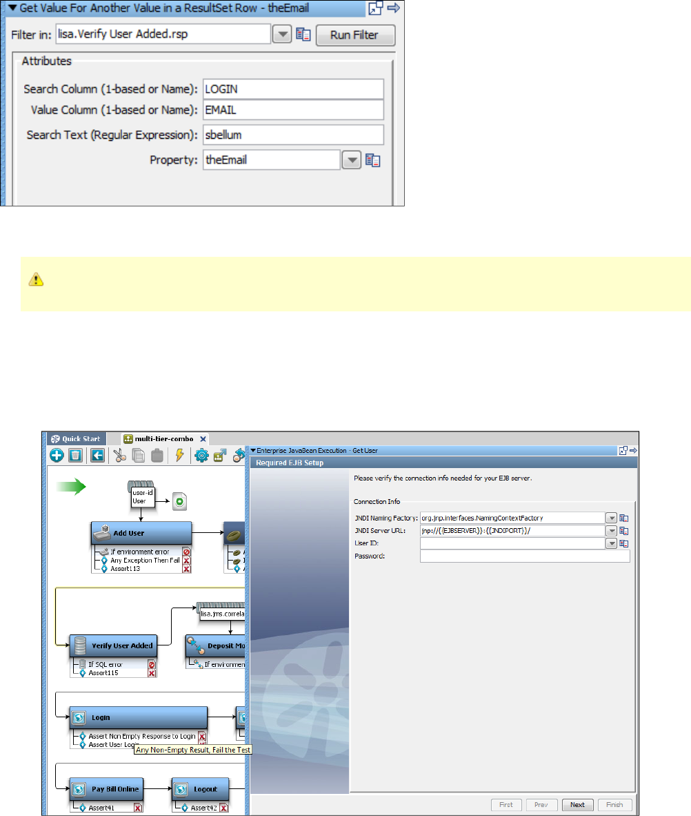
1.
2.
This filter looks for in the LOGIN column, and if found, stores the value in the EMAIL column in the same row in a property named sbellum
.theEmail
The same filtering capabilities are available when a JDBC result set is displayed in the Step Editor.
Adding a Filter from a Returned Java Object
When the result of your test step is a Java object, you can use the Inline Filter panel in the Complex Object Editor to filter the returned value from
the method call directly. Following is an example of how to add a filter this way.
This example uses the get user step (EJB step) in the multi-tier-combo test case in the examples directory.
Double-click the get user step in the workflow, to open its step editor.
Click Next. On the next screen, click Finish.
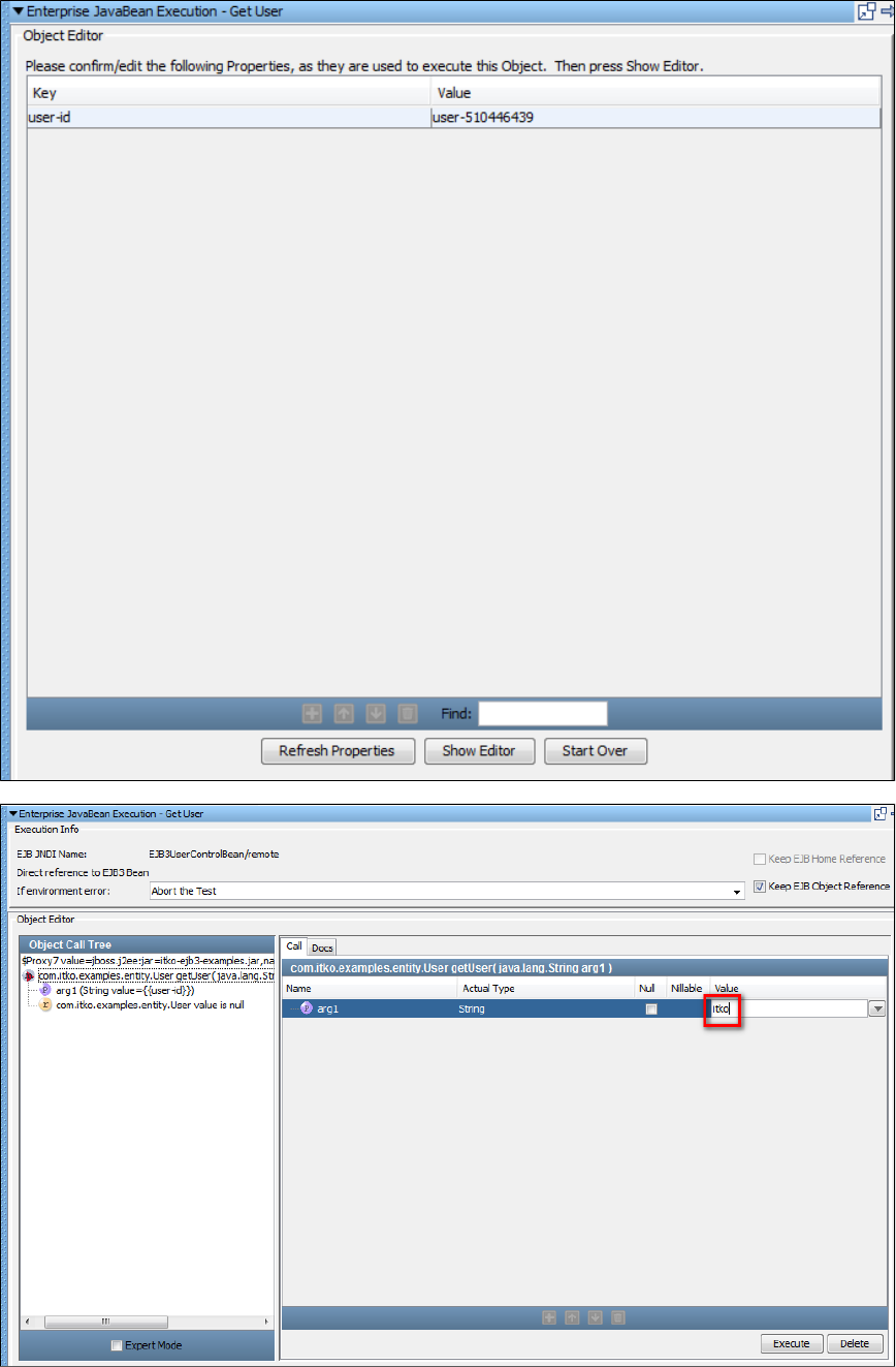
2.
3.
4.
5.
Click Show Editor to open the Object Call Tree.
Enter an input parameter "itko" in the value field.
Click Execute to execute this method.
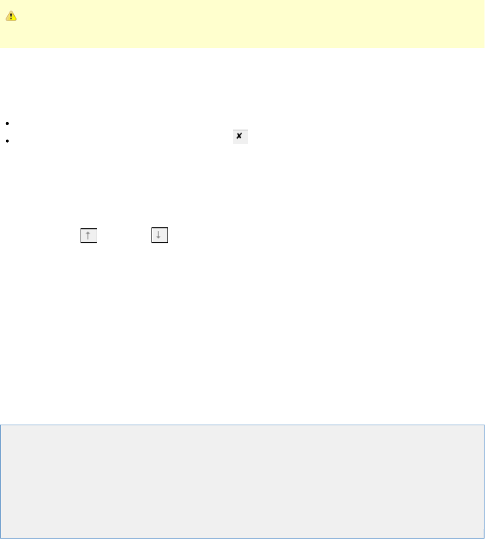
1.
2.
1.
2.
3.
The returned value upon executing the getLogin method will be stored in the property getUserObject. Notice that in this case the returned value is
an object (of type UserState). You also can add an assertion here.
In this example, you could also call a method on the returned object to get the actual login value for this user, and save the login in another
property.
Inline filters (and assertions) do not result in a filter being added to the test step in the element tree. Inline filter management is
always done in the Complex Object Editor.
For more details on the Complex Object Editor, see .Using Complex Object Editor
Deleting a Filter
To delete a filter
Select the filter in the Filter Elements tab and right-click to open a menu. Click Delete to delete the filter. Or,
Select the filter in the Filter Elements tab and click the Delete icon on the toolbar.
You cannot delete a test step that has filters attached to it.
Reordering a Filter
To reorder a filter
Select the filter in the Filter Elements tab.
Click the Move up or Move down icon on the toolbar.
Dragging and Dropping a Filter
You can drag and drop filters in the model editor from one test step to another.
To drag and drop a filter
Click the filter attached to a test step; for example, Step1.
Drag and drop that filter to another test step in the model editor; for example, Step2.
The dragged filter will then be applied to Step2.
Types of Filters
This section describes each of the filters that are available in LISA.
Regular expressions are used for comparison purposes in several filters. For more information about regular expressions, see
.http://psoug.org/reference/regexp.html
The following filters are available.
Utility Filters
Database Filters
Messaging_ESB Filters
HTTP_HTML Filters
XML Filters
Web 2.0 Filters
Java Filters
VSE Filters
Pathfinder Filters
Utility Filters
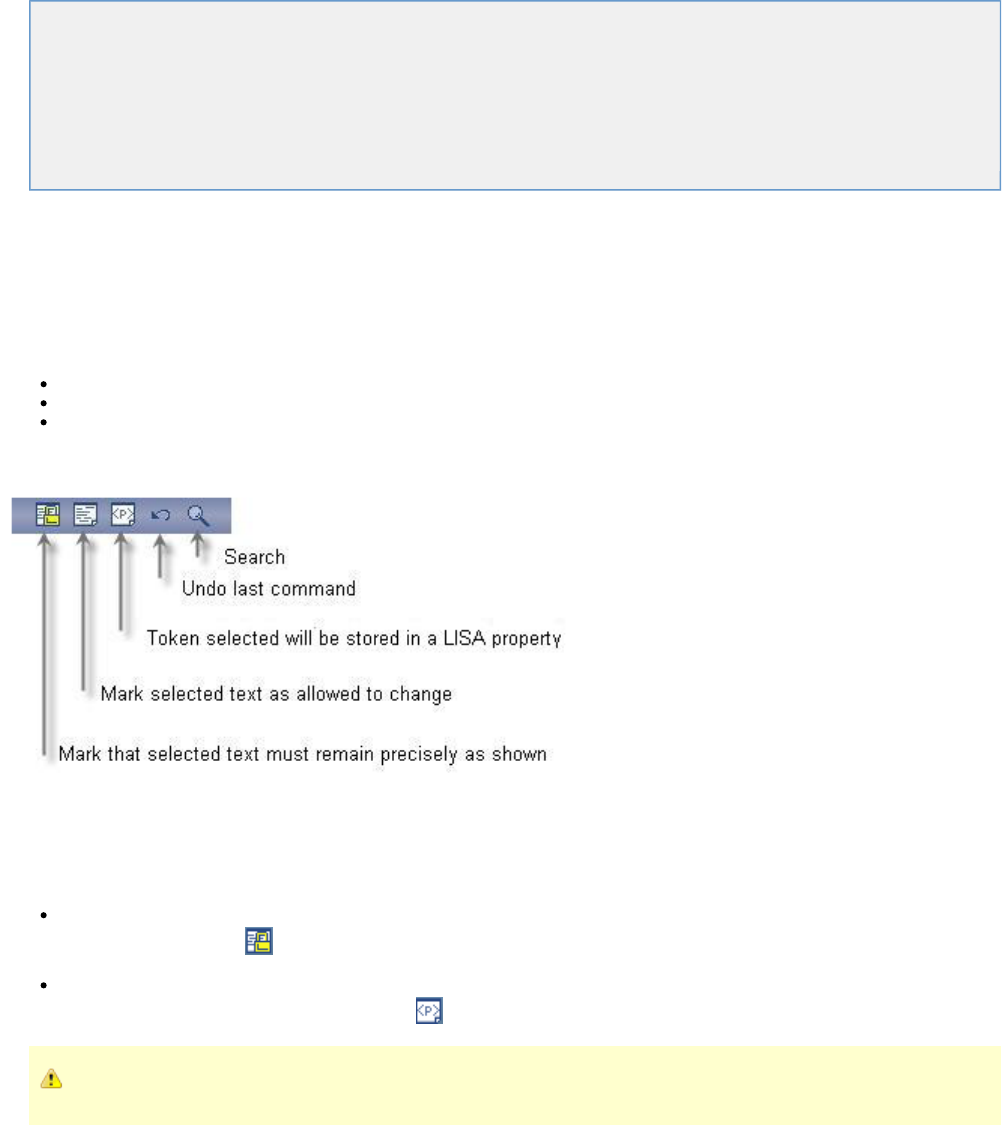
These are the filters available in the Utility Filters list for any test step.
Create Property Based on Surrounding Values
Store Step Response
Override "Last Response" Property
Save Property Value to File
Parse Property Value as Argument String
Save Property from one key to another
Time Stamp Filter
Create Property Based on Surrounding Values
The filter lets you read textual content and filter it for information to be stored in LISACreate Property Based on Surrounding Values
properties. It can be used on text, and on XML and HTML treated as text. It uses a "paint the screen" technique.
"Paint the screen" gives you great flexibility to define what in the text buffer you want to parse out as properties. There are three ways to mark the
text:
Text that must appear in the response precisely as shown: a block.Must
Text that does not have to appear in the response, or can change: an block.Any
Text that will be stored in a LISA property: a block. Property blocks must always be bounded by blocks.Property Must
The text is marked using the icons at the bottom of the editor:
This technique is best explained by example.
In the following example, the goal is to store the size of a particular file in a property.
The text is marked using the editor icons, by selecting text and then clicking the appropriate icon.
Yellow background indicates text that must appear as shown (indicated by the arrows from "Text uses ........." ). This is a block andMust
is marked using the icon.Must
Red background identifies the text that will be stored in the property entered into the dialog (indicated by a single arrow). This is a
block and is marked using the icon.Property Property
Property blocks must always be bounded by blocks.Must
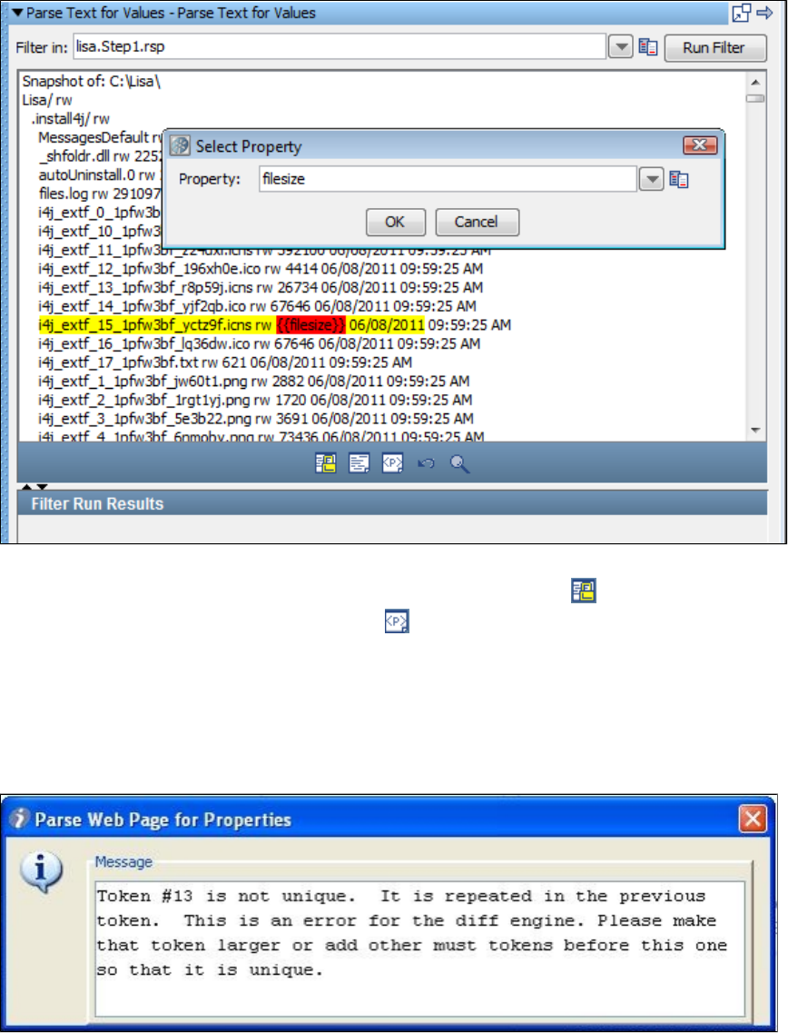
This screen shows the contents of the text buffer. The goal is to parse out the file size of the Simulator.exe file. The file size is the number that
appears after "Simulator.exe". The boundaries are set around the file size, and the icon has been clicked. The actual file size textMust
inside the selected content was selected, and the icon was clicked. The property name was then entered into the dialog. The actualProperty
value of the file size has been replaced with the name of the LISA property.
When this filter is run, the property "filesize" will be assigned the size of the Simulator.exe file.
You can repeat this process on this text buffer to have as many properties defined as you like.
Handling Non-unique Tokens
If you see the following error message, your selected token is not unique; the selection you just made is repeated in the token before it.
To solve this in most cases, simply create another token to make the prior token a token also. In other cases, when this does not work, aMust
judicious placement of another block between the two duplicate tokens will avoid the error. This will work because LISA can distinguishMust
between the two duplicate tokens based on their relative location.
Store Step Response
(Also known as Save Step Response as Property)
The filter lets you save the last response as a property, for future use.Store Step Response
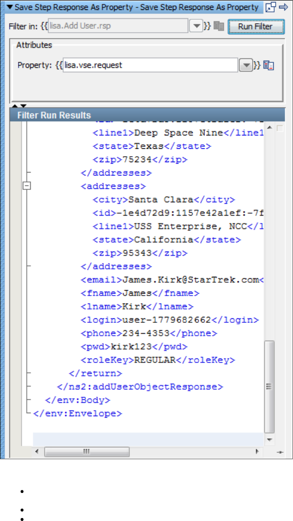
Enter the following parameters:
Filter in: Where to apply the filter. The previous illustration shows list.Add User.rsp, which means that the filter will be applied to the
response of the Add User step. You cannot change this value for this filter.
Property: The name of the property to store the last response.
Filter Run Results: Displays the property and values set as a result of running the filter.
Click the Run Filter button to execute the filter and see the results in the Filter Run Results.
Override "Last Response" Property
(Also known as Convert Property Value into Last Response)
The filter lets you replace the current value of the last response with the value of an existing LISA property.Override "Last Response" Property
For example, assume you execute an EJB, but you eventually get a value back after making some method calls on the EJB. Instead of leaving
the EJB object to be the last response, it may make more sense, in your test case, to make the result from one of your method calls the last
response. You can first save the return value from that call as a property using a filter, and then you can use that property in this filter.
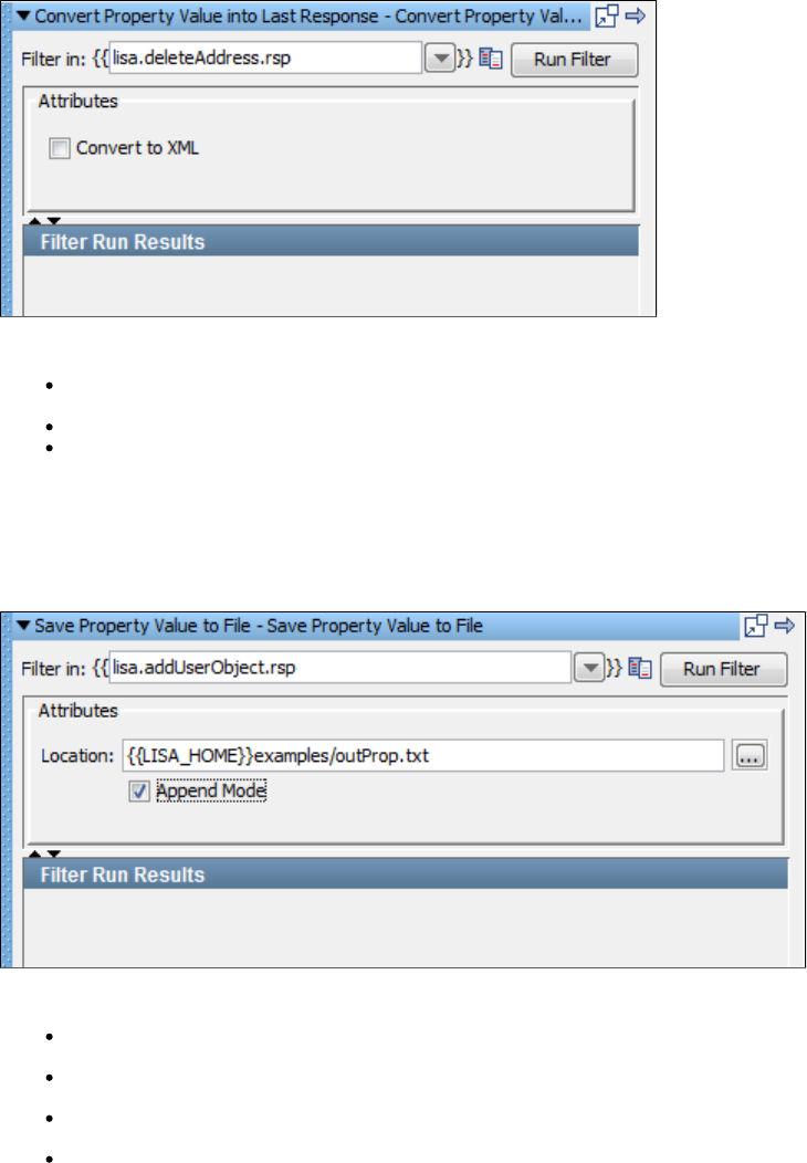
Enter the following parameters:
Filter in: The name of the property you want considered as the step's last response. The property should be in the pull-down menu; if not
you can enter it. It must be an existing property.
Convert to XML: Select this if you want the response to be converted to valid XML.
Filter Run Results: Displays the property and values set as a result of running the filter.
Click the Run Filter button to execute the filter and see the results in the Filter Run Results.
Save Property Value to File
The filter lets you save the value of an existing property to a file in your file system.Save Property Value to File
Enter the following parameters:
Filter in: The name of the property whose value you want to write to the file.
Location: The path name of the file to write the value to. You can browse to the file. You can use properties in the location.
Append Mode: Select this check box if you want to append the information to an existing file.
Filter Run Results: Displays the property and values set as a result of running the filter.
Click the Run Filter button to execute the filter and see the results in the Filter Run Results.
Parse Property Value as Argument String
The filter lets you store the text of a specific attribute in a property. This is very useful as a secondParse Property Value As Argument String
filter, where you parse a filtered value for information.
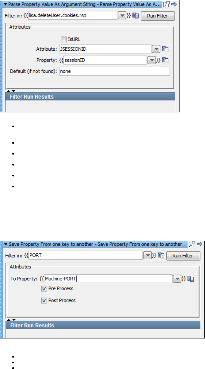
Enter the following parameters:
Filter in: The name of the existing property to parse. For example, to parse the "lisa.deleteUser.cookies.rsp" property to return the value
of the SESSIONID attribute, enter .lisa.deleteUser.cookies.rsp
IsURL: Select this check box if the property value is a URL.
Attribute: The attribute to retrieve. The example shows the JSESSIONID attribute.
Property: The name of the property to store the text of the attribute. The example shows .sessionID
Default (if not found): The default value to use if the attribute is not found.
Filter Run Results: Displays the property and values set as a result of running the filter.
Click the Run Filter button to execute the filter and see the results in the Filter Run Results.
Save Property from one key to another
The filter copies values from one key to another by reference where normal Java rules apply.Save Property from one key to another
This filter simply optimizes BeanShell overhead for simple property copy.
Enter the following parameters:
Filter in: This field accepts the property content of which will be copied in some other property. This is the input source property.
To Property: This is the property name where input property content will be copied.
Run Filter: Lets you test the filter immediately while developing test steps rather than waiting until the test case is completed.
Time Stamp Filter
The filter is used to assign the current time and date to the property so that you can use this property in the following test steps.Time Stamp
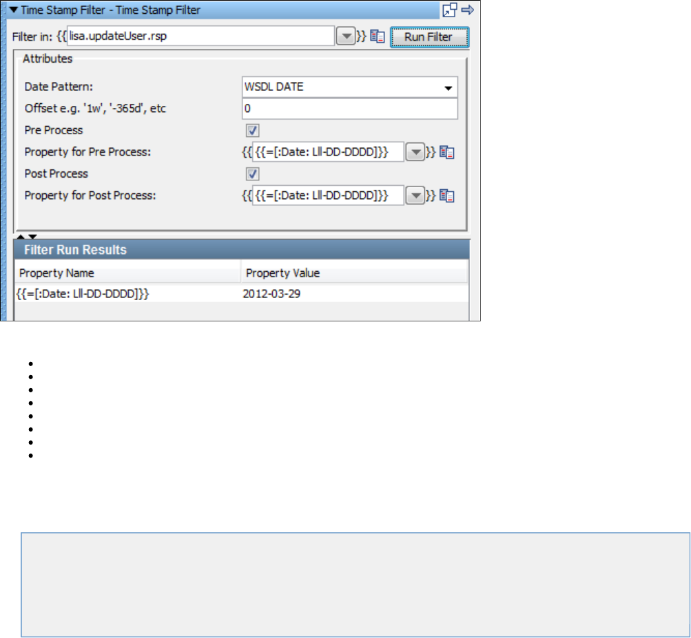
Enter the following parameters:
Filter in: The name of the existing step.
Date Pattern: Select the date pattern you want to display.
Offset: Used to offset the date to an appropriate (future or past) date based on the current date.
Pre Process: When enabled, generates a time stamp before the step runs.
Property for Pre Process: The property to store the pre time stamp.
Post Process: When enabled, generates a time stamp after the step runs.
Property for Post Process: The property to store the post time stamp.
Filter Run Results: Displays the property and values set as a result of running the filter.
Click the Run Filter button to execute the filter and see the results in the Filter Run Results.
Database Filters
These are the filters available in the Database Filters list for any test step.
Extract Value from JDBC Result Set
Simple Result Set Filter
Size of JDBC Result Set
Set Size of a Result Set to a Property
Get Value For Another Value in a ResultSet Row
Extract Value from JDBC Result Set
The filter lets you store the text of a specific JDBC result set value in a property.Extract Value from JDBC Result Set
This filter can be created in two ways; either as a manual filter from the filter list or by using the embedded filter commands on a result set
response.
Creating the filter manually
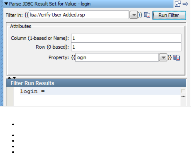
Enter the following parameters:
Filter in: The name of the property you want considered as the step's last response. The property should be in the pull down menu; if not
you can enter it. It must be an existing property.
Column (1-based or name): The index or name of the column (field).
Row (0-based): The row to retrieve the value. This is a 0-based index.
Property: The name of the property where the value in the cell at the row/column intersection is stored.
Filter Run Results: Displays the property and values set as a result of running the filter.
Click the Run Filter button to execute the filter and see the results in the Filter Run Results.
Creating the filter from a result set response
Display the step response that contains the result set. From within the result set select the cell of the value you want to store in the filter.
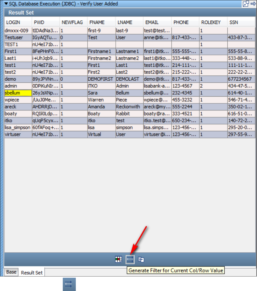
Click the Generate Filter icon , shown by the arrow in the previous example.
In the dialog, enter the property key:
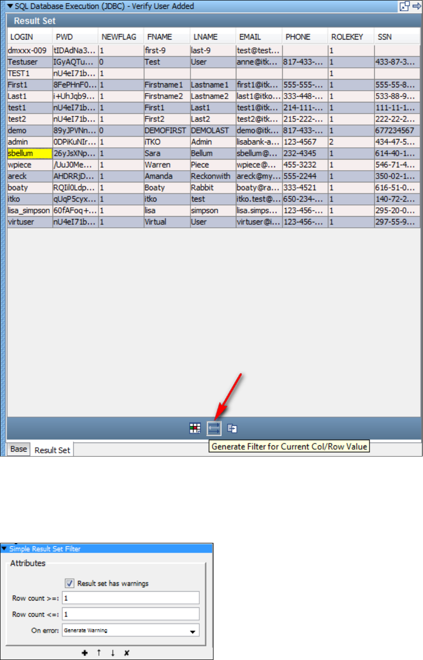
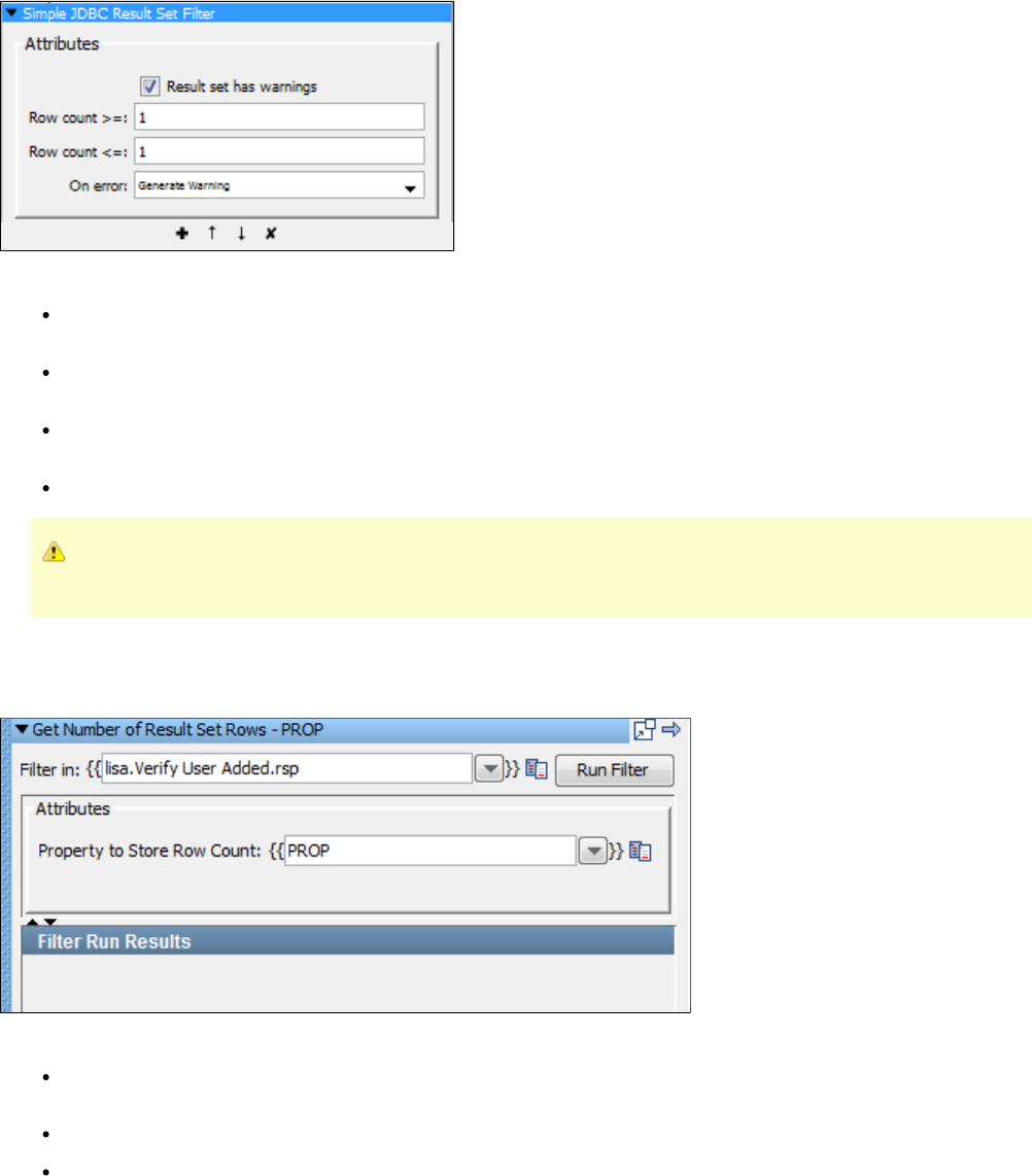
Size of JDBC Result Set
(Also known as Simple JDBC Result Set Filter)
The filter lets you check that the result set returned in each JDBC-based step matches the criteria specified. It is aSize of JDBC Result Set
simple filter to handle most common database errors automatically.
This filter does not affect non-JDBC steps, and is usually used as a global filter in a test case.
Enter the following parameters:
Result Set Has Warnings: Some databases return warnings in the result set. If your database supports this feature and you want to
make a warning fire the step for this filter, make sure the check box is selected.On error Result Set Has Warnings
Row Count At Least (>=): The minimum number of rows in the result set. If the result set contains less than this value, the filter sets the
next step to the value specified in step.On Error
Row Count No More Than (<=): The maximum number of rows in the result set. If the result set contains more than this value, the filter
sets the next step to the value specified in step.On Error
On Error: The step to execute if the conditions for this filter are not met.
This filter can serve the purpose of a general global assertion because you can choose a next step based on the presence of an
error.
Set Size of a Result Set to a Property
The filter lets you store the count of a result set to a property provided.Set Size of a Result Set to a Property
Enter the following parameters:
Filter in: The name of the property you want considered as the step's last response. The property should be in the pull-down menu; if not
you can enter it. It must be an existing property.
Property to Store Row Count: User-provided property name to store the row count. The default property name is .PROP
Filter Run Results: Displays the property and values set as a result of running the filter.
Click the Run Filter button to execute the filter and see the results in the Filter Run Results.
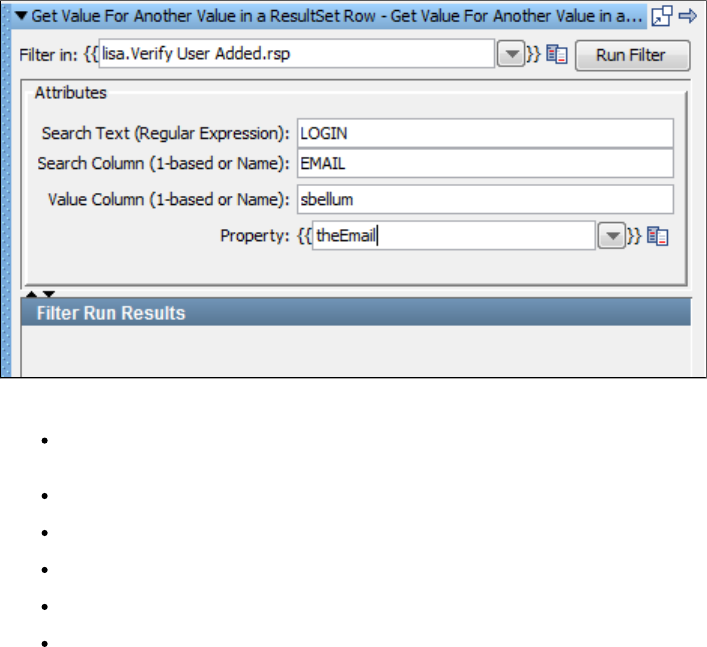
Get Value For Another Value in a ResultSet Row
The filter lets you search a column (field) in a result set for a particular value. If the value isGet Value for Another Value in a ResultSet Row
found the value in another column (field) and the same row is placed in a property.
This filter can be created in two ways, either as a manual filter from the filter list, or by using the embedded filter commands on a result set
response.
Creating the filter manually
Enter the following parameters:
Filter in: The name of the property you want considered as the step's last response. The property should be in the pull-down menu; if not
you can enter it. It must be an existing property.
Search Text (Regular Expression): The search string.
Search Column (1-based or Name): The index or name of the column to search.
Value Column (1-based or Name): The index or name of the column to extract the property value.
Property: The name of the property to store the value.
Filter Run Results: Displays the property and values set as a result of running the filter.
Click the Run Filter button to execute the filter and see the results in the Filter Run Results.
Creating the filter from a result set response
Display the step response that contains the result set. From within the result set select the two values in different columns, using the Ctrl key.
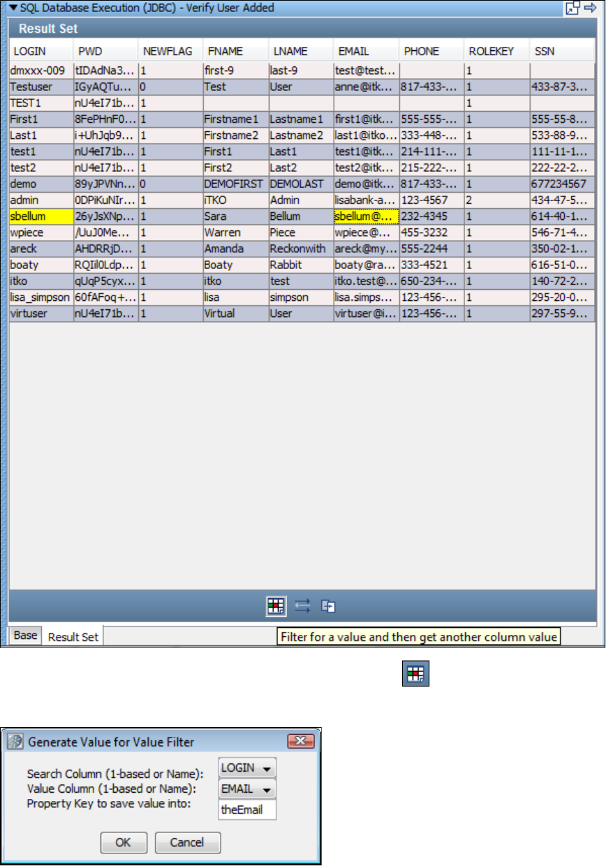
Select and then get another column value filter using the Filter icon.Filter for a value
In the dialog that opens, select or reassign the columns for the search and the value, then enter the Property Key:
Click OK.
LISA will create exactly the same filter as the one that was created manually in the previous example.
In the example, will be searched for, and if found, the value in the column of that row will be placed in the property .sbellum EMAIL theEmail
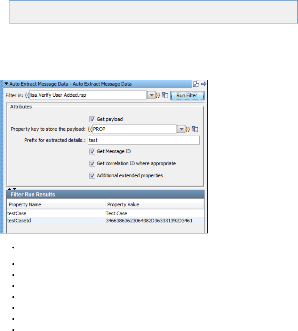
Messaging_ESB Filters
Messaging_ESB Filters
These are the filters available in the Messaging/ESB Filters list for any test step:
Extract Payload and Properties from Messages
Convert a MQ Message to a VSE Request
Convert a JMS Message to a VSE Request
Extract Payload and Properties from Messages
There are several internal properties of messages that LISA will auto extract into properties in the test step using the Extract Payload and
filter. You can also select to auto extract the payload into a property. This is a fast way to get data from a message.Properties from Messages
Different messaging platforms impose various restrictions and can be seen as warnings at execution.
The property names can default to or you can specify the prefix. You can specify an exact name for the payload.lisa.stepName.message
Enter the following parameters:
Filter in: The name of the property you want considered as the step's last response. The property should be in the pull-down menu; if not
you can enter it. It must be an existing property.
Get Payload: Select this if you require payload.
Property key to store the Payload: Enter or select the property key to be used as payload.
Prefix for extracted details: Enter the prefix to be attached to the property name in the result.
Get Message ID: Select to get the Message ID.
Get Correlation ID: Select to get the correlation ID.
Additional Extended Properties: Select to get any additional extended properties.
Run Filter: Click the Run filter button to run and execute the filter. The results can be seen in the Filter Run Results section.
Convert a MQ Message to a VSE Request
The filter is automatically added from the LISA Virtualize recorder. It serves the specific purpose thatConvert a MQ Message to a VSE Request
enables proper functioning with recordings. It should be used carefully and if it is added to a step in a VSE model, it should not usually be
removed or edited.
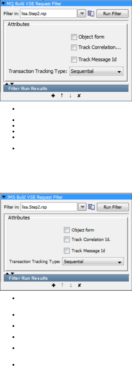
Filter In: The name of the property you want considered as the step's last response. The property should be in the pull-down menu; if not
you can enter it. It must be an existing property.
Object Form: Select to get the Object Form.
Track Correlation ID: Select to track the correlation ID.
Track Message ID: Select to track the message ID.
Transaction Tracking Type: Select the appropriate tracking type from - Sequential, Correlation ID, Message ID or Message ID to
Correlation ID.
Run Filter: Click the Run Filter button to run and execute the filter. The results can be seen in the Filter Run Results section.
Convert a JMS Message to a VSE Request
The filter is automatically added from the LISA Virtualize recorder. It serves the specific purposeConvert a JMS Message to a VSE Request
that enables proper functioning with recordings. It should be used carefully and if it isadded to a step in a VSE model, it should not usually be
removed or edited.
Filter In: The name of the property you want considered as the step's last response. The property should be in the pull-down menu; if
not, you can enter it. It must be an existing property.
Object Form: Select to get the Object Form.
Track Correlation ID: Select to track the correlation ID.
Track Message ID: Select to track the message ID.
Transaction Tracking Type: Select appropriate tracking type from: Sequential, Correlation ID, Message ID or Message ID to Correlation
ID.
Run Filter: Click the Run Filter button to run and execute the filter. The results can be seen in the Filter Run Results section.
HTTP_HTML Filters

1.
These are the filters available in the HTTP/HTML Filters list for any test step.
Create Resultset from HTML Table Rows
Parse Web Page for Properties Parse HTML_XML Result for Specific Tag_Attributes Values
Parse HTML Result for Specific Tag_Attribute's Value and Parse It
Parse HTML Result for Tag's Child Text
Parse HTML Result for HTTP Header Value
Parse HTML Result for Attribute's Value
Parse HTML Result for LISA Tags
Parse HTML Result and Select Random Attribute Value
Parse HTML into List of Attributes
Parse HTTP Header Cookies
Dynamic Form Filter
Parse HTML Result by Searching Tag_Attribute Values
Create Resultset from HTML Table Rows
The filter lets you create a result set (for example, a JDBC result set) from an HTML table returned inCreate Resultset from HTML Table Rows
the HTML response. The columns and rows of an HTML table can be selected, and LISA will create a result set from them. The result set can
then be used to generate assertions in the same way as it would in a database step.
Although you can create this filter by selecting it from the filter list and filling in the parameters, it is far easier to create it directly from the
HTTP/HTML Request step response using one of the filter commands available to that step. This is the approach we take here. The parameters
produced here, that is, the ones you would have needed to calculate to manually create this filter, are shown later in this section.
To create a filter on a table, record a web page that contains the table, go to the appropriate HTML step, and view it from the DOM tree.
Select the values that are to be placed in the table, using the Cntl key, to select multiple fields. You must select one example value from
each column in the table that you want to use in the result set.
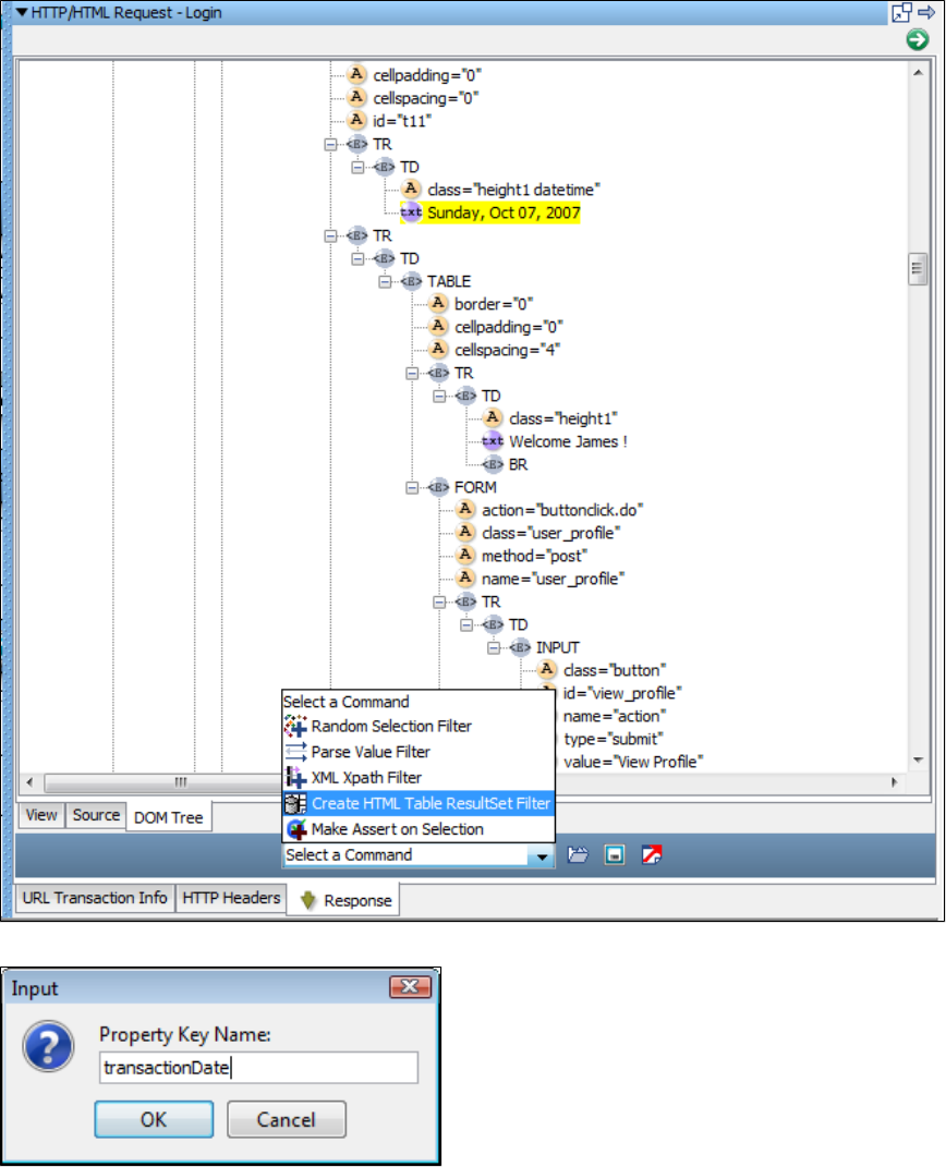
1.
2.
3.
4.
When it is highlighted, select .Create HTML Table Results Filter
Enter the property name in the window.
The property will now be available in the test case.
LISA added this property to the current step. In the following screenshot are the parameters that LISA calculated for this step. These are the
parameters you would have had to supply to manually create this filter.
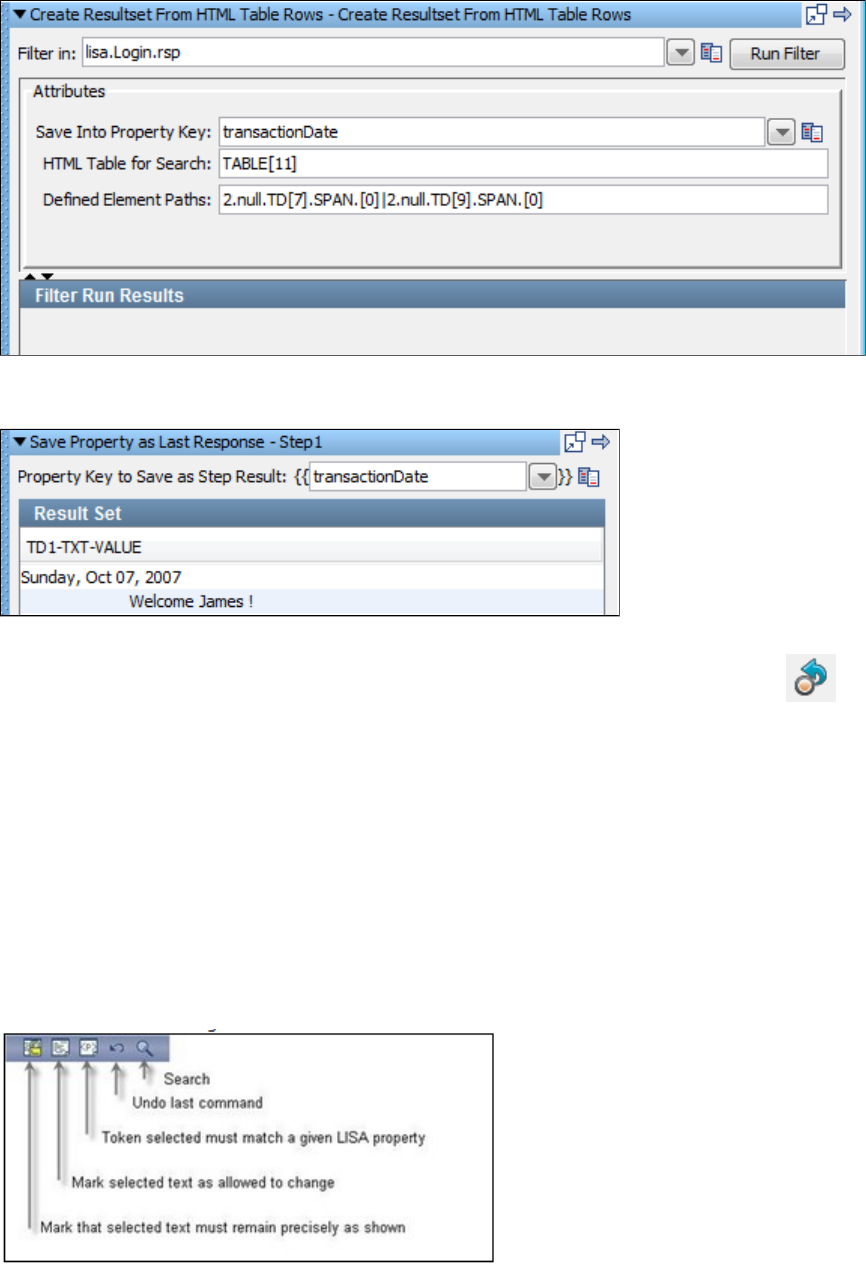
1.
2.
3.
To show the results of this filter we added a step of type and put in the property created by the filter. TheSave Property as Last Response
result set panel displays the results.
If you are editing an existing test case you may need to replay the test case to generate the property from the filter using the Replay test case to
command. The command is activated using the Replay icon on the toolbar, ora specific point Replay test case to a specific point
from the Command menu. You can now use the embedded filters and assertions that are available at the bottom of the result set window of this
step.
Parse Web Page for Properties
The filter lets you view a rendered web page to create properties from the HTML content. It uses the "paint theParse Web Page for Properties
screen" technique.
"Paint the screen" gives you great flexibility to define what in the HTML you want to parse out as properties. There are three ways to mark the
text:
Text that must appear in the response precisely as shown: a block.Must
Text that is not required to appear in the response, or can change: an block.Any
Text that will be stored in a LISA property: a block.Property
The text is marked using the icons at the bottom of the editor:
This technique is best explained by example. In the following example, see the following example. Assume that we expect that the company
name "ITKO" will change from user to user, and therefore needs to be stored as a LISA property.
We have marked the text using the editor icons, by selecting text and then clicking on the appropriate icon.
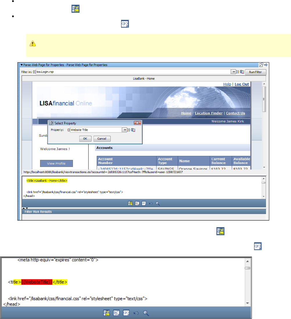
Yellow background indicates text that must appear as shown (indicated by the arrows from "Text uses ........." ). This is a block andMust
is marked using the icon.Must
Red background identifies the text that will be stored in the property entered into the dialog ( indicated by a single arrow). This is a
block and is marked using the icon.Property Property
Property blocks must always be bounded by blocks.Must
This screen shows the HTML rendered in a browser in the top panel, and the actual HTML text in the bottom panel. We want to parse out
the website title in the field. We have set the boundaries around that, and clicked the "Must" icon.title
Then we selected the website name text, "LISABank - Home," inside the highlighted content, and clicked the icon . We entered theProperty
property name into the dialog. The website name text has been replaced with the name of the LISA property.
Frequently you can do this purely from the web page view by selecting the content in the web browser. At times, it will be easier to click on the
web browser in the area that you want to select, then make your actual selection in the HTML panel.
Now when this filter is run, the property will be assigned the current value that appears on the HTML page. The website title canWebsiteTitle
change location in the text buffer and it will still be located and parsed for the property.
You can repeat this process on this text buffer to have as many properties defined as you like.
Handling Non-unique Tokens
If you see an error message such as the following:
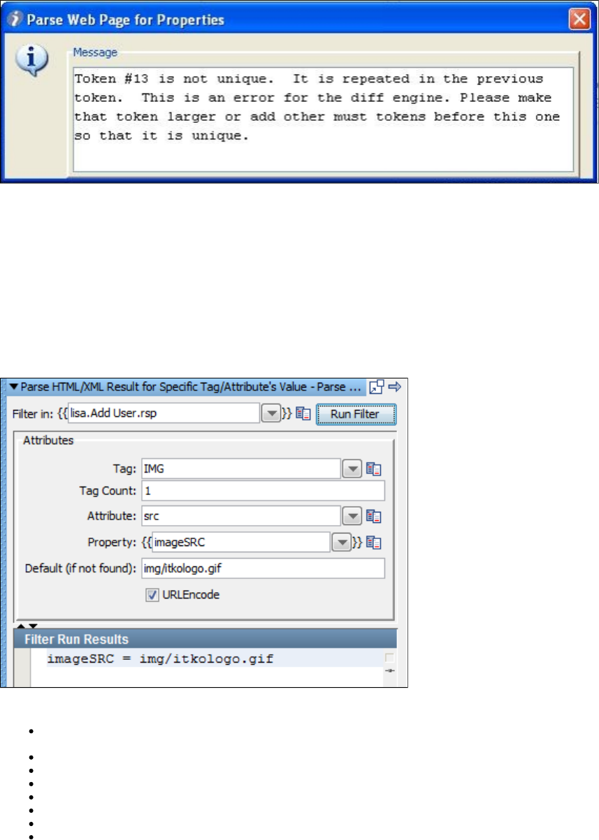
1.
1.
LISA is telling you that your selected token is not unique; the selection you just made is repeated in the token before it. To solve this in most
cases, simply create another token to make the prior token a token also. In other cases, when this does not work, a judicious placement ofMust
another block in between the two duplicate tokens should work. This will work because LISA can distinguish between the two duplicateMust
tokens based on their relative location.
Parse HTML_XML Result for Specific Tag_Attributes Values
The filter lets you parse the HTML response for a given attribute of a given tag.Parse HTML for Specific Tag/Attribute's Values
This filter can be created in two ways: either as a manual filter from the filter list or by using the embedded filter commands on a result set
response.
Creating the filter manually
Enter the following parameters:
Filter in: The name of the property you want considered as the step's last response. The property should be in the pull-down menu; if
not, you can enter it. It must be an existing property.
Tag: The name of the HTML tag; for an image tag enter .IMG
Tag Count: The occurrence of the tag from the top of response; for the first image tag enter .1
Attribute: The name of the attribute to filter; for the source attribute enter .src
Property: The property in which to store the value.
Default (if not found): The value to use if the attribute value is not found.
URLEncode: When checked, property value is URLEncoded.
Filter Run Results: Displays the property and values set as a result of running the filter.
2. Click the Run Filter button to execute the filter and see the results in the Filter Run Results.
Creating the filter from the HTTP/HTML request step response page
Display the step response that contains the HTML response.
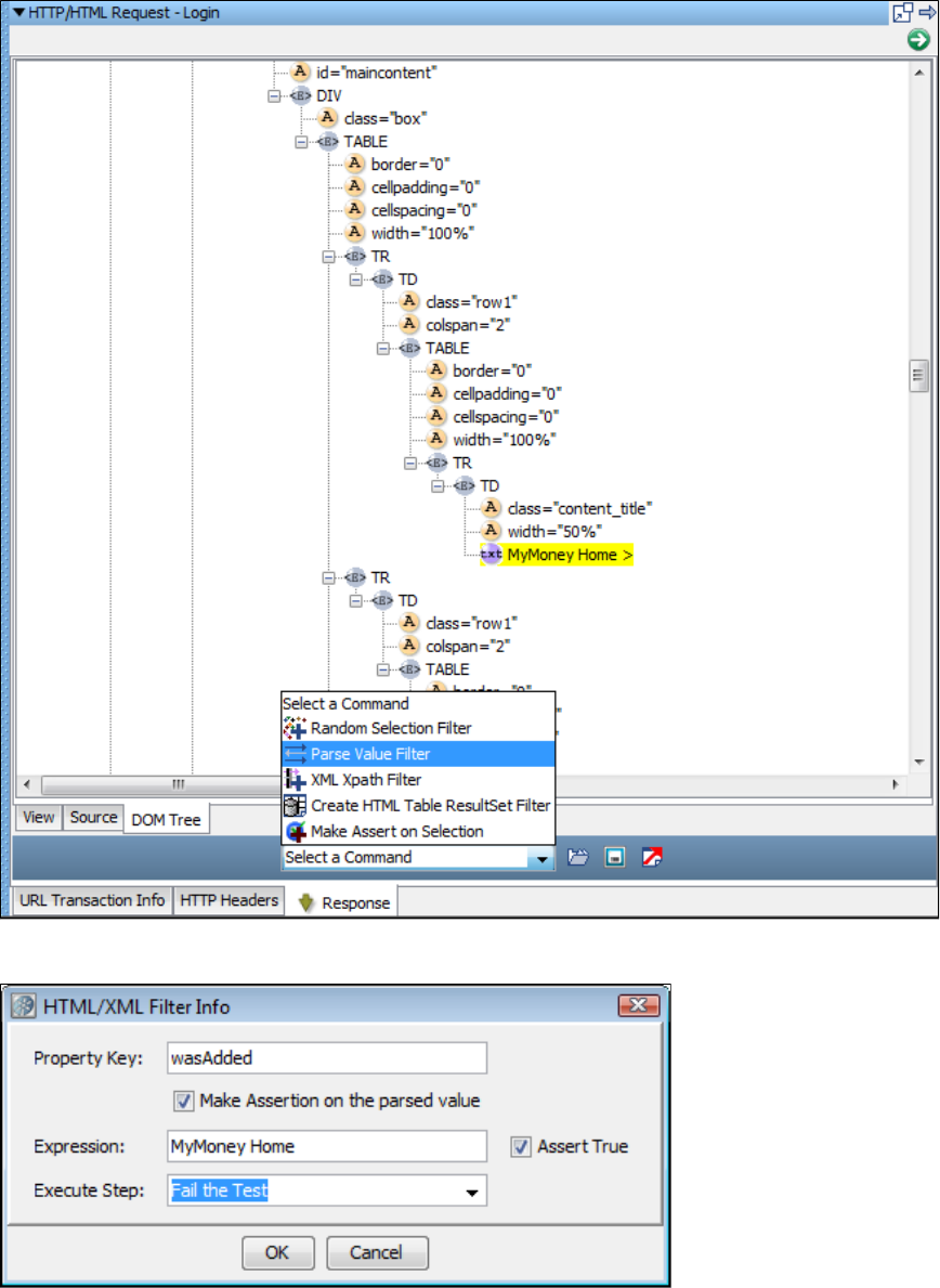
1.
2.
3.
4.
5.
From the DOM Tree view select the attribute whose value you want to store in a property.
When it is highlighted, select .Parse Value Filter
Enter the property name in the window.
Assertions can be also be added here.
Parse HTML Result for Specific Tag_Attribute's Value and Parse It
The filter is really a combination of two other filters: Parse HTML Result for Specific Tag/Attribute's Value and Parse It Parse HTML Result
and .for Attribute's Value Parse Property Value as Argument String
This filter is designed to find a certain attribute in a web page, and then further parse that attribute. If the attribute is a URL, and not just a
name-value pair, there is a function for handling that information.

In this example, we see the filter finds the seventh anchor tag's "href" attribute, which is a URL. The filter takes the "cmd" parameter and stores
that value in the .cmdlist users_KEY
Enter the following parameters:
Filter in: The name of the property you want considered as the step's last response. The property should be in the pull-down menu; if
not, you can enter it. It must be an existing property.
Tag: The name of the HTML tag; for an anchor tag enter .a
Tag Count: The occurrence of the tag from the top of response; for the seventh anchor tag enter .7
Attribute: The name of the attribute to filter; for the href attribute enter .href
IsURL: Select the check box if the attribute value is a URL.
Argument to Parse: The name of the argument to parse for its value; in this example, .cmd
Property: The property in which to store the value; in this example, .cmdlist users_KEY
URLEncode: When checked, property value is URLEncoded.
Default (if not found): The value to use if the attribute value is not found.
Filter Run Results: Displays the property and values set as a result of running the filter.
Click the Run Filter button to execute the filter and see the results in the Filter Run Results.
Parse HTML Result for Tag's Child Text
The filter lets you store the text of a tag's child text in a property.Parse HTML Result for Tag's Child Text
Enter the following parameters:
Filter in: The name of the property you want considered as the step's last response. The property should be in the pull-down menu; if
not, you can enter it. It must be an existing property.
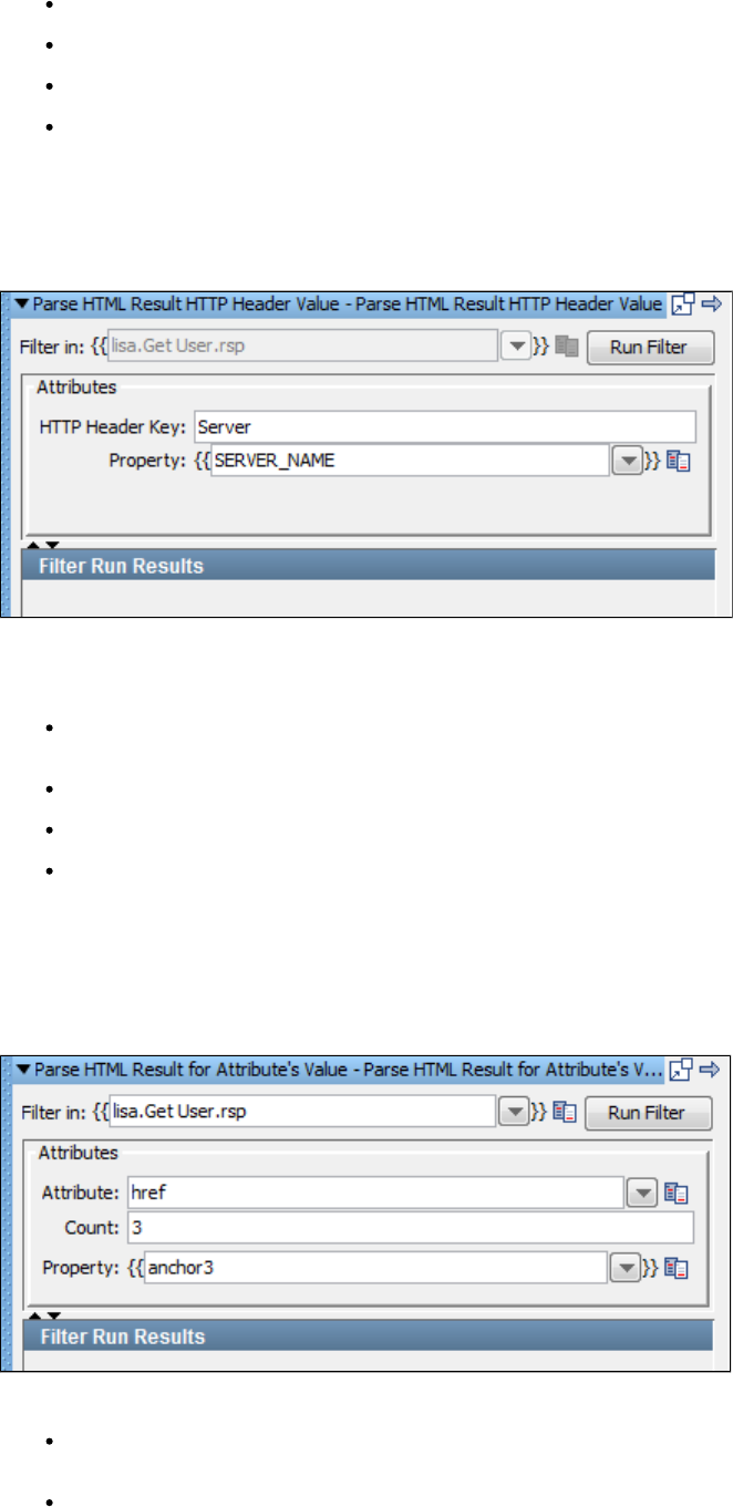
Tag: The type of the tag. For example, for an h1 tag enter .h1
Tag Count: The occurrence of the tag. For the child text of the third h1 tag, enter .3
Property: The name of the property to store the text.
Filter Run Results: Displays the property and values set as a result of running the filter.
Click the Run Filter button to execute the filter and see the results in the Filter Run Results.
Parse HTML Result for HTTP Header Value
The filter lets you store the value of a returned HTTP header key in a property.Parse HTML Result for HTTP Header Value
A common use of this filter is saving the HTTP header in a property named SERVER_NAME.Server
Enter the following parameters:
Filter in: The name of the property you want considered as the step's last response. The property should be in the pull-down menu; if
not, you can enter it. It must be an existing property.
HTTP Header Key: The name of the HTTP header; for example, Server.
Property: The property to store the header value.
Filter Run Results: Displays the property and values set as a result of running the filter.
Click the Run Filter button to execute the filter and see the results in the Filter Run Results.
Parse HTML Result for Attribute's Value
The filter lets you store the text of a specific attribute in a property. The attribute can occur anywhereParse HTML Result for Attribute's Value
in the result, including scripting code.
The parameters set are:
Filter in: The name of the property you want considered as the step's last response. The property should be in the pull-down menu; if
not, you can enter it. It must be an existing property.
Attribute: The type of attribute to retrieve. For example, if you want the URL of an anchor tag, enter .href
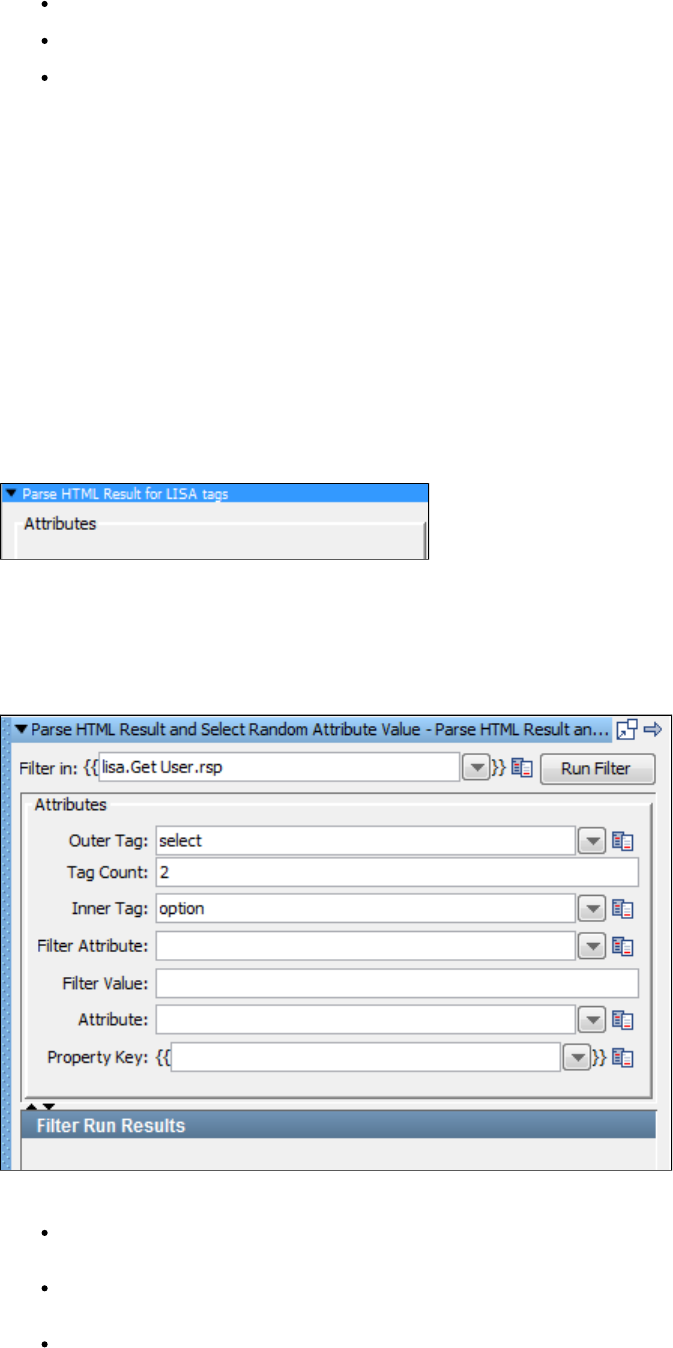
Count: The occurrence of the tag. For example, if you want the URL of the third anchor tag on the page, enter .3
Property: The property to store the text of the attribute; in this example, .anchor3
Filter Run Results: Displays the property and values set as a result of running the filter.
Click the Run Filter button to execute the filter and see the results in the Filter Run Results.
Parse HTML Result for LISA Tags
The filter provides a way for developers to test-enable their web applications. For an in-depth study onParse HTML Result for LISA Tags
test-enabling, see the . Developer's Guide (SDK)
This filter provides the ability to insert "LISAPROP" tags into your web page. The LISAPROP tag has two attributes: name and value. The
LISAPROP tags do not show up in your web pages. They function only to discretely provide valuable information about your web page to a tester.
An example of a LISAPROP might be:
<LISAPROP name="FIRST_USER" value="sbellum">.
If a tester has installed this type of filter, the property will automatically be assigned the value . This removes any need forFIRST_USER sbellum
the tester to parse for this value. This type of filter helps a developer make the testing easier.
Frequently a web page will not contain the information needed to perform proper validation, or that information is very difficult to parse. Even
when it is there, the parsing can become incorrect because of subtle changes in the HTML that is generated. This LISAPROP filter can resolve
many tedious parsing issues for web testing.
There are no parameters required.
Parse HTML Result and Select Random Attribute Value
The filter lets you store the text of a random selection from a set in a property. TheParse HTML Result and Select Random Attribute Value
attribute can occur anywhere in the result, including scripting code.
Enter the following parameters:
Filter in: The name of the property you want considered as the step's last response. The property should be in the pull-down menu; if
not, you can enter it. It must be an existing property.
Outer Tag: The outer element that contains the list from which to pick. For example, to select a drop-down menu, you would enter the
text .select
Tag Count: The occurrence of the outer tag. For example, to select the second drop-down menu, you would enter the text "2".
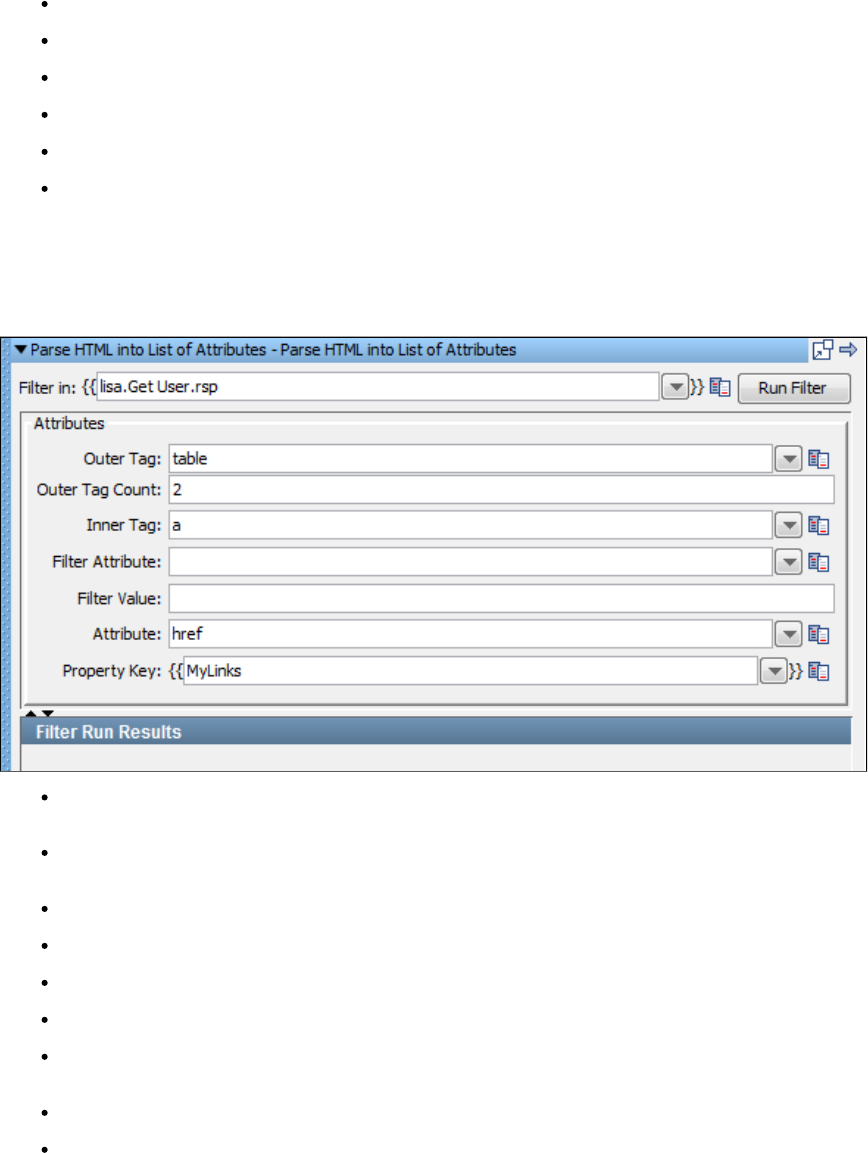
Inner Tag: The tag to randomly pick the attribute from. To pick a random item in the drop-down menu, you would enter the text .option
Filter Attribute: Optional field to specify attribute names that should not appear in the pick list.
Filter Value: Optional field to specify attribute values that should not appear in the pick list.
Attribute: The attribute from which to retrieve text. If this is blank, the child text of the inner tag is returned.
Property Key: The property to store the text of the attribute.
Filter Run Results: Displays the property and values set as a result of running the filter.
Click the Run Filter button to execute the filter and see the results in the Filter Run Results.
Parse HTML into List of Attributes
The filter lets you store the text of a set of attributes, as a list, in a property.Parse HTML into List of Attributes
Filter in: The name of the property you want considered as the step's last response. The property should be in the pull-down menu. If
not, you can enter it. It must be an existing property.
Outer Tag: The outer element that contains the list of tags to parse. For example, to store all the links from all the anchor tags in a table,
enter .table
Outer Tag Count: The occurrence of the outer tag. For the second table, enter .2
Inner Tag: The tag to retrieve the values from. For example, for all the anchor tags in the table enter .a
Filter Attribute: Optional field to specify attribute names that should not appear in the pick list.
Filter Value: Optional field to specify attribute values that should not appear in the pick list.
Attribute: The attribute of the Inner Tag to retrieve the text from. If this is blank, the child text of the Inner Tag is returned. To store all the
links from all of the anchor tags in a table, enter .href
Property Key: The name of the property to store the text of the attribute.
Filter Run Results: Displays the property and values set as a result of running the filter.
Click the Run Filter button to execute the filter and see the results in the Filter Run Results.
Parse HTTP Header Cookies
The filter lets you parse the HTTP header for cookie values, and store them in a property starting with a specificParse HTTP Header Cookies
prefix.
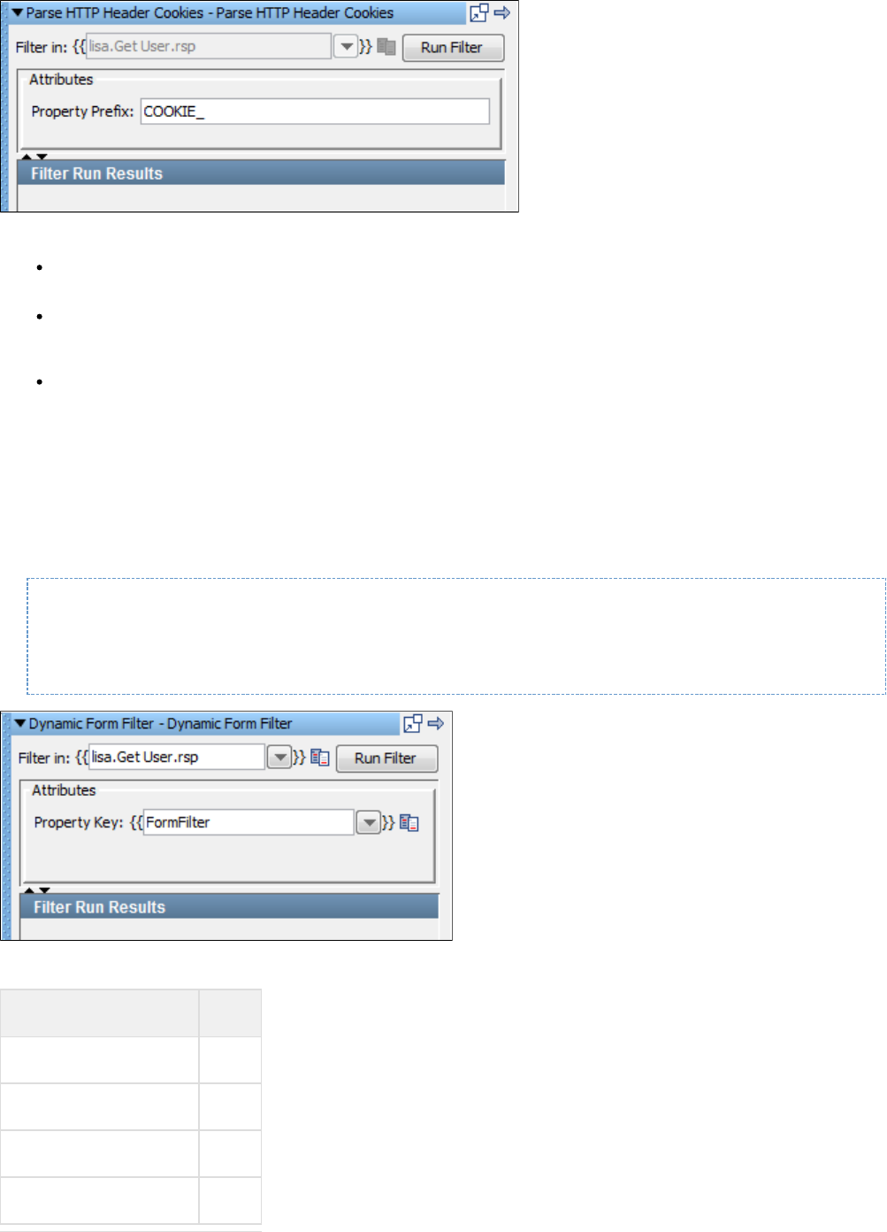
Enter the following parameters:
Filter in: The name of the property you want considered as the step's last response. The property should be in the pull-down menu; if
not, you can enter it. It must be an existing property.
Property Prefix: A text string that will be prefixed to the cookie name to provide the property name to use. The full names of these
properties are therefore dependent on the names of the cookies that have been returned. The cookie names can be identified in the
property tab of the Interactive Test Run (ITR).
Filter Run Results: Displays the property and values set as a result of running the filter.
Click the Run Filter button to execute the filter and see the results in the Filter Run Results.
Dynamic Form Filter
The filter identifies dynamically generated forms in HTML responses and parses them into a set of properties. The property keyDynamic Form
that you enter becomes part of the property name for each form element in each form. This is easier to understand by examining the example that
follows.
You might test an HTML page with two dynamically generated forms:
<form name="F001" action="index.jsp"> <input type="text" name="0001A" value="default" /> <input
type="text" name="0001B" value="" /></form>
<form name="F002" action="orders.jsp"> <input type="text" name="0002A" value=Key"" /> <input
type="text" name="0002B" value="" /></form>
Using a property key of in the filter panel would create the following key-value pairs:FormTest
Key Value
FormTest.Form1.text1.name 0001A
FormTest.Form1.text1.value default
FormTest.Form1.text2.name 0001B
FormTest.Form1.text2.value
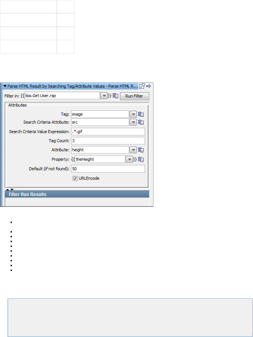
FormTest.Form2.text1.name 0002A
FormTest.Form2.text1.value
FormTest.Form2.text2.name 0002B
FormTest.Form2.text2.value
Parse HTML Result by Searching Tag_Attribute Values
The filter lets you filter the value of a tag attribute by searching for the name and valueParse HTML Result by Searching Tag/Attribute Values
of another attribute in that tag. If more than one tag fits the criteria you can specify which one you want.
The parameters set are:
Filter in: The name of the property you want considered as the step's last response. The property should be in the pull-down menu; if
not, you can enter it. It must be an existing property.
Tag: The name of the tag to search.
Search Criteria Attribute: The attribute to search for.
Search Criteria Value Expression: The attribute expression to search for.
Tag Count: The specific tag to use from those that satisfy the search criteria.
Attribute: The attribute whose value you want.
Property: The property in which to store the value.
Default (if not found): The value to use if search is not successful.
URLEncode: When selected, the value is URLEncoded.
Filter Run Results: Displays the property and values set as a result of running the filter.
Click the Run Filter button to execute the filter and see the results in the Filter Run Results.
XML Filters
These are the filters available in the XML Filters list for any test step:
Parse text from XML
Read Attribute from XML Tag
Parse XML Result for LISA Tag
Choose Random XML Attribute
XML XPath Filter
Parse text from XML
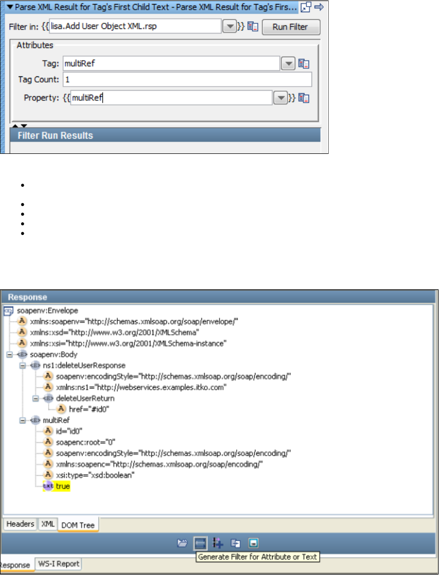
1.
1.
2.
3.
(Also known as Parse XML Result for Tag's First Child Text)
The filter stores the text of a tag's child text in a property. To define a filter, set the type of the filterParse text from XML Parse text from XML
and set the three attributes.
This filter can be created in two ways: as a manual filter from the filter list or by using the embedded filter commands on an XML response.
Creating the filter manually
Enter the following parameters:
Filter in: Where to apply the filter. This illustration shows , which means that the filter will be applied tolisa.Add User Object XML.rsp
the response of . You can edit this value for this filter.Add User Object XML
Tag: The type of the tag. For example, if you want the child text of the multiRef tag, enter .multiRef
Tag Count: The occurrence of the tag. For example, if you want the child text of the first multiRef tag, set the Count to .1
Property: The name of the property to store the text.
Filter Run Results: Displays the property and values set as a result of running the filter.
2. Click the Run Filter button to execute the filter and see the results in the Filter Run Results.
Creating the filter directly from the response page
From the DOM Tree view select the attribute whose value you want to store in a property.
After it is selected, select Generate Filter for Attribute or Text.
Enter the property name in the dialog window.
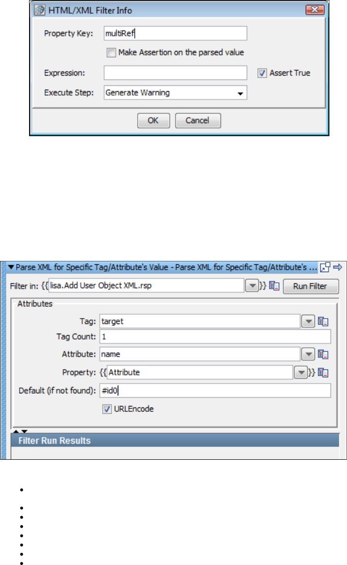
3.
1.
Assertions can also be added here.
Read Attribute from XML Tag
(Also known as Parse XML for specific Tag/Attribute's Value)
The filter lets you store the text of a specific attribute in a property. The attribute can occur anywhere in the result.Read Attribute from XML Tag
This filter can be created in two ways: either as a manual filter from the filter list, or by using the embedded filter commands on an XML response.
Creating the filter manually
Enter the following parameters:
Filter in: Where to apply the filter. The previous illustration shows , which means that the filter will belisa.Add User Object XML.rsp
applied to the response of the Add User Object step.
Tag: The name of the XML tag; for example, .target
Tag Count: The occurrence of the tag from the top of response; for the first tag enter .1
Attribute: The name of the attribute to filter; for the href attribute enter .href
Property: The property in which to store the value.
Default: The value to use if the attribute value is not found.
URLEncode: When checked, property value is URLEncoded.
Filter Run Results: Displays the property and values set as a result of running the filter.
Click the Run Filter button to execute the filter and see the results in the Filter Run Results.
Creating the filter from the response page
Display the step response that contains the XML.
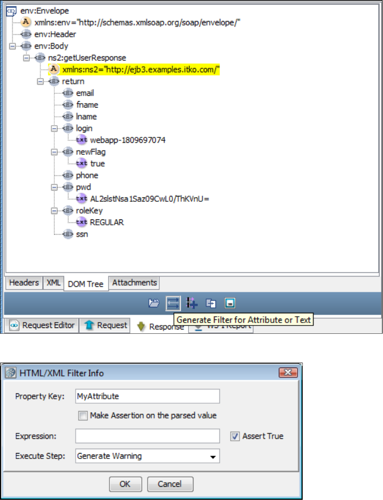
1.
2.
3.
4.
From the DOM Tree view, select the attribute whose value you want to store in a property.
When it is highlighted, select .Generate Filter for Attribute or Text
Enter the property name in the window.
You can also add an assertion at this point if you want. A Property Value Expression Assertion can be added to this step.
Parse XML Result for LISA Tag
The filter provides a way for developers to test-enable their XML applications. For an in-depth study onParse XML Result for LISA Tags
test-enabling, see the . Developer's Guide (SDK)
This filter provides the ability to insert LISAPROP tags into your XML page. The LISAPROP tag has two attributes: name and value. The
LISAPROP tags function only to discretely provide valuable information about your XML to a tester. An example of a LISAPROP might be:
<LISAPROP name="FIRST_USER" value="sbellum">.
If a tester has installed this type of filter, the property "FIRST_USER" will automatically be assigned the value "sbellum". This removes any need
on behalf of the tester to parse for this value. This type of filter helps a developer make the testing easier.
The XML may not contain the information needed to perform proper validation, or that information is very difficult to parse. Even when it is there,
the parsing can become incorrect due to subtle changes in the XML that is generated. This LISAPROP filter can resolve many tedious parsing
issues.
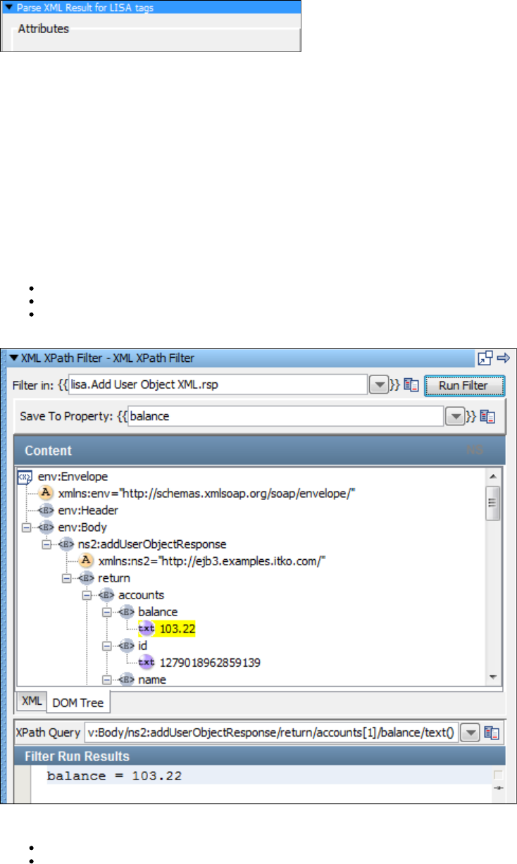
There are no parameters required.
Choose Random XML Attribute
The filter lets you store the text of a random selection from a set in a property. The attribute can occur anywhereChoose Random XML Attribute
in the result. This filter works exactly like .Parse HTML Result and Select Random Attribute Value
XML XPath Filter
The filter lets you use an XPath query that will be run on a property, or the last response and store it in a property. When this filter isXML XPath
selected, the last response is loaded into the content panel.
The response can be viewed as an XML document or as a DOM tree. However, the XPath selection can be made only from the DOM tree.
Construct the XPath query by using one of the following methods:
Manually enter the XPath expression in the XPath Query text box.
Select an element from the DOM tree and let LISA construct the XPath expression.
Select an element from the DOM tree, and then edit the XPath that is constructed. For example, you may want to modify it to use a LISA
property, or a counter data set.
Enter the following parameters:
Filter In: Enter the last response or a named property.
Save To Property: The property in which to store the result of the XPath query.
Now construct the XPath query using one of the methods described earlier.
After an XPath query has been constructed, test it by clicking Run Filter. The results of the query appear in the pane.Filter Run Results
The property controls whether the XPath function is always used duringlisa.xml.xpath.computeXPath.alwaysUseLocalName local-name()
XPath generation. The default value is , which means that the function is used only when necessary. To generate an XPathfalse local-name()
that will work regardless of an XML node's namespace, set the value to .true
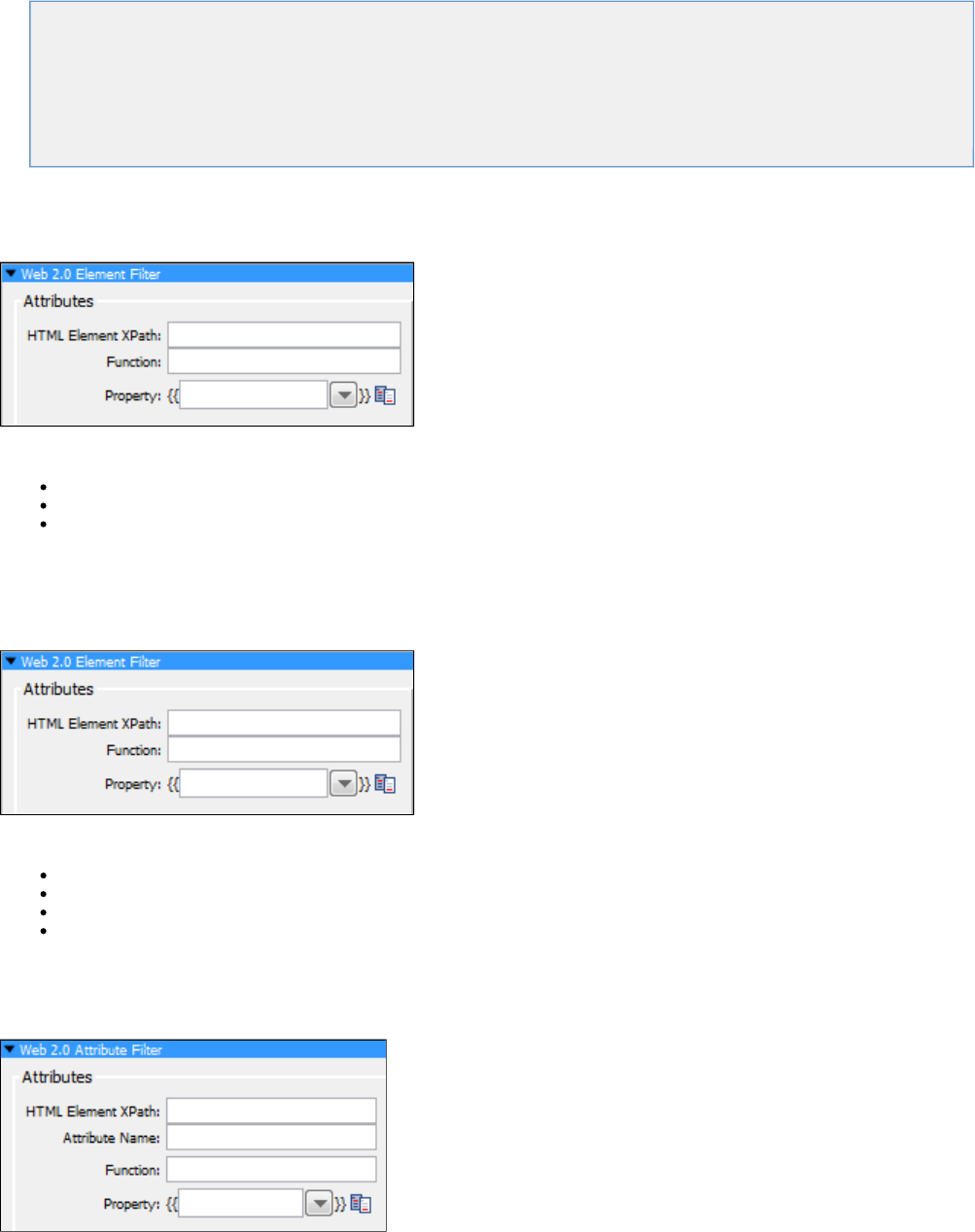
Web 2.0 Filters
These are the filters available in the Web 2.0 Filters list for any test step:
Web 2.0 Element Filter
Web 2.0 Text Filter
Web 2.0 Attribute Filter
Web 2.0 JavaScript Filter
Web 2.0 Function Filter
Web 2.0 Composite Filter
Web 2.0 Element Filter
The lets you retrieve an HTML element from the response and store it in a property.Web 2.0 Element Filter
Enter the following parameters:
HTML Element XPath: The XPath expression that uniquely identifies the DOM element that was the target of the event.
Function: Name of predefined Web 2.0 function.
Property: The name of the property to store the result.
Web 2.0 Text Filter
The lets you retrieve text from the response using an XPath expression and then a regular expression, and then store theWeb 2.0 Text Filter
text in a property.
Enter the following parameters:
HTML Element XPath: The XPath expression that uniquely identifies the DOM element that was the target of the event.
Regular Expression: A regular expression that is applied to the result of the filter to further control what gets returned.
Function: The name of a predefined Web 2.0 function.
Property: The name of the property to store the result.
Web 2.0 Attribute Filter
The lets you retrieve an HTML attribute value from the response and store it in a property.Web 2.0 Attribute Filter
Enter the following parameters:
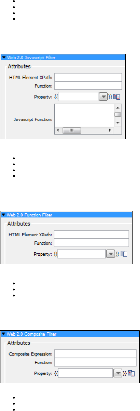
HTML Element XPath: The XPath expression that uniquely identifies the DOM element that was the target of the event.
Attribute Name:The optional DOM attribute name used to execute DOM attribute filters.
Function: The name of a predefined Web 2.0 function.
Property: The name of the property to store the last response.
Web 2.0 JavaScript Filter
The lets you retrieve arbitrary information from the response using a JavaScript expression.Web 2.0 JavaScript Filter
Enter the following parameters:
HTML Element XPath: The XPath expression that uniquely identifies the DOM element that was the target of the event.
Javascript Function: A snippet of valid JavaScript code that gets executed by the filter. It should return an object.
Function: The name of a predefined Web 2.0 function.
Property: The name of the property to store the result.
Web 2.0 Function Filter
The lets you execute a predefined Web 2.0 function.Web 2.0 Function Filter
Enter the following parameters:
HTML Element XPath: The XPath expression that uniquely identifies the DOM element that was the target of the event.
Function: The name of predefined Web 2.0 function.
Property: The name of the property to store the last response.
Web 2.0 Composite Filter
The lets you combine other Web 2.0 filters using a string or an arithmetic expression.Web 2.0 Composite Filter
Enter the following parameters:
Composite Expression: Expression with Web 2.0 filters using a string or arithmetic expression.
Function: Name of a predefined Web 2.0 function.
Property: The name of the property to store the result.
Java Filters
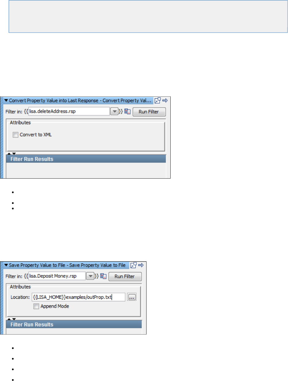
These are the filters available in the Java Filters list for any test step.
Override "Last Response" Property
Save Property Value to File
Store Step Response
Java Override "Last Response" Property Filter
There is a special property known as Last Response, which contains the response from the previous step. For example, if the previous response
was an HTTP step, the last response will be a web page that was returned.
The filter should be used if you want the last response to be something other than the default value. ThisOverride "Last Response" Property
filter lets you replace the current value of the last response with the value of an existing LISA property.
Click the filter to open its editor.
Enter the following parameters:
Filter in: The name of the property you want considered as the step's last response. The property should be in the pull-down menu; if
not, you can enter it. It must be an existing property.
Convert to XML: Check this if you want the response to be converted to valid XML.
Filter Run Results: Displays the property and values set as a result of running the filter.
Click the Run Filter button to execute the filter and see the results in the Filter Run Results section.
For more detailed information see Utility Filters: .Override Last Response Property
Java Save Property Value to File Filter
The filter lets you save the value of an existing property to a file in your file system.Save Property Value to File
Enter the following parameters:
Filter in: The name of the property whose value you want to write to the file.
Location: The path name of the file to write the value to. You can browse to the file. You can use properties in the location.
Append Mode: Select this check box if you want to append the information to an existing file.
Filter Run Results: Displays the property and values set as a result of running the filter.
Click the Run Filter button to execute the filter and see the results in the Filter Run Results.
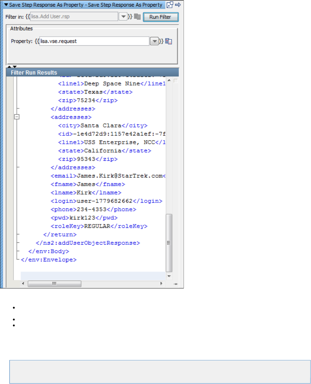
Java Store Step Response Filter
(Also known as Save Step Response as Property Filter)
The filter lets you save the last response as a property, for future use.Store Step Response as Property
Enter the following parameter:
Filter in: Enter the response to apply the filter to. The previous illustration shows , which means that the filter will belisa.Add User.rsp
applied to the response of . You cannot change this value for this filter.Add User
Property: The name of the property to store the last response.
Filter Run Results: Displays the property and values set as a result of running the filter.
Click the Run Filter button to execute the filter and see the results in the Filter Run Results.
VSE Filters
This is the filter available in the VSE Filters list for any test step.
Data Protocol Filter
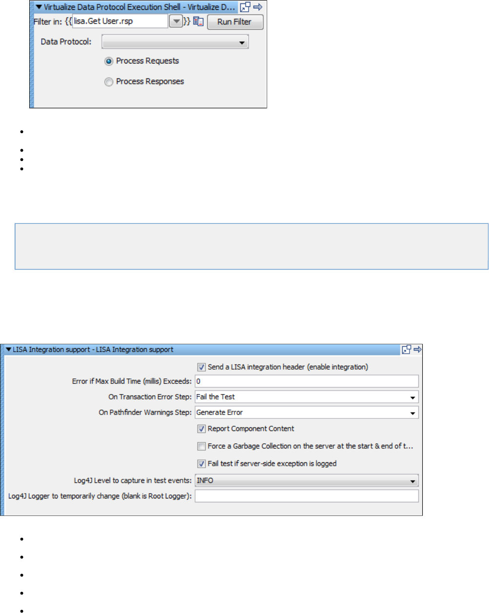
1.
2.
Data Protocol Filter
The filter is used on protocol-specific listen steps for virtual models. It provides the necessary wrapper for a data protocol to act asData Protocol
a filter, the appropriate way for things to work in the run-time side of VSE.
Click the filter to open its editor.
Enter the following parameters:
Filter in: Enter the response to apply the filter to. The previous illustration shows , which means that the filter will belisa.Get User.rsp
applied to the response of . You cannot change this value for this filter.Get User
Data Protocol: Select the appropriate data protocol to be used from the drop-down list.
Process Requests: Check to see the process request.
Process Responses: Check to see the process response.
3. Click the Run Filter button to execute the filter and see the results in the Filter Run Results section.
Pathfinder Filters
These are the filters available in the Pathfinder Filters list for any test step.
LISA Integration Support for Pathfinder
LISA Integration Support for webMethods Integration Server
LISA Integration Support for Pathfinder
The filter is a common filter to enable Pathfinder for all the technologies supported by LISA. This filterLISA Integration Support for Pathfinder
collects additional information from a Pathfinder application.
Currently LISA supports integration with web services, JMS, servlets, EJB and Java objects.
Enter the following parameters:
Error if Max Build Time (millis) Exceeds: Enter build time in milliseconds. If it exceeds the time specified, an error will be generated.
On Transaction Error Step: Select the step to redirect to on transaction error after filter is set to run.
On Pathfinder Warning Step: Select the step to redirect to on Pathfinder Warning Step after filter is set to run.
Report Component Content check box: Generate a report of the component content.
Force a Garbage Collection on the server at the start & end of the request check box: Forces a garbage collection on the server at
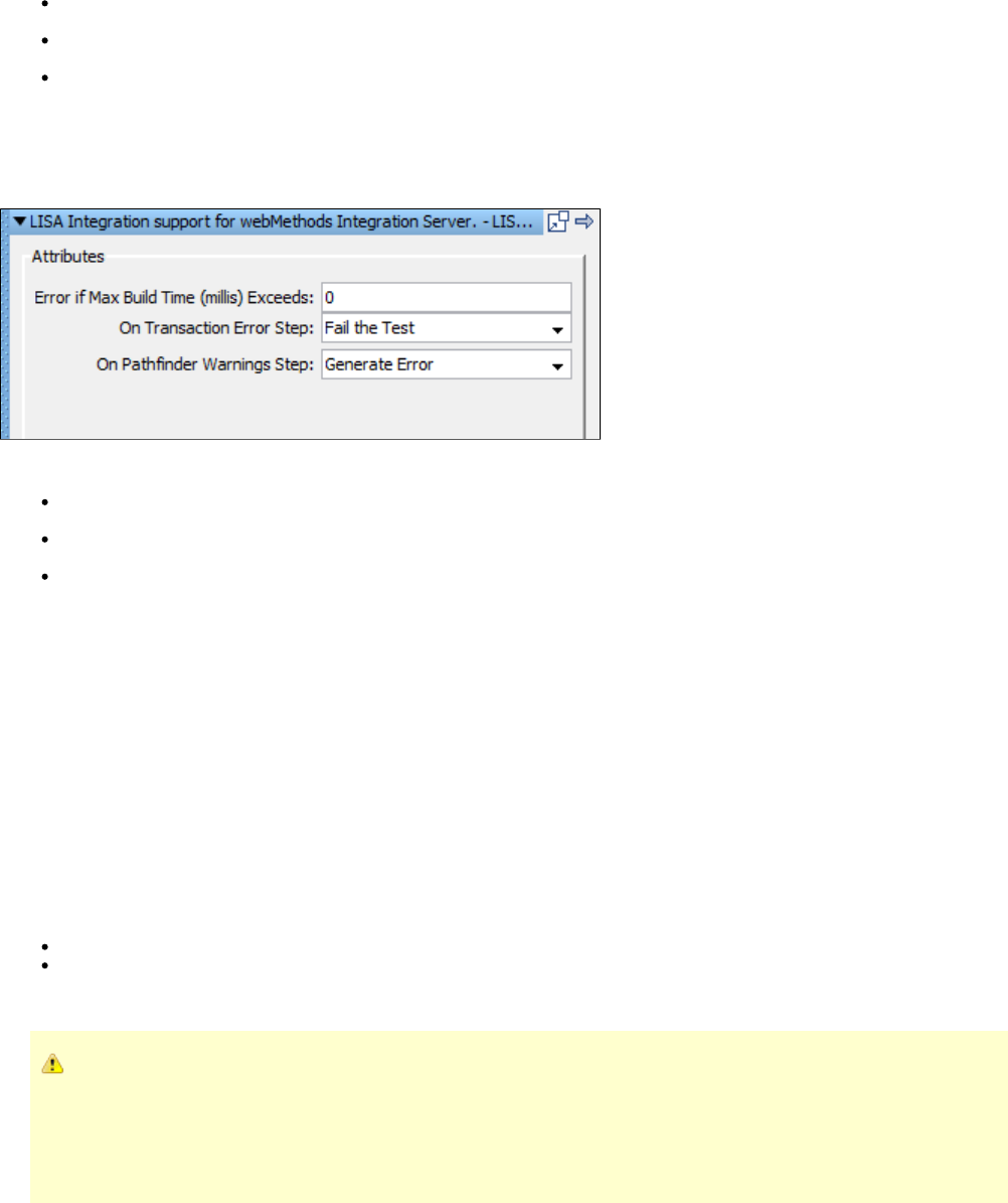
the start and end of the request.
Fail test if server-side exception is logged check box: Fail the test case if exception is thrown at the server side.
Log4J level to capture in the test events: Select the log4J level that is to be captured in the test events.
Log4J Logger to temporarily change (blank is Root Logger): Enter the name of the logger.
LISA Integration Support for webMethods Integration Server
The filter collects additional information from Pathfinder-enabled webMethodsLISA Integration Support for webMethods Integration Server
Integration Server.
Enter the following parameters:
Error if Max Build Time(millis) Exceeds: Enter build time in milliseconds. If it exceeds the time specified, an error will be generated.
On Transaction Error Step: Select the step to redirect to on transaction error after filter is set to run.
On Pathfinder Warning Step: Select the step to redirect to on Pathfinder Warning Step after filter is set to run.
Assertions
An assertion is a LISA code element that runs after a step and all its filters have run, to verify that the results from running the step match
expectations.
The result of an assertion is a Boolean value (true or false).
The outcome may determine whether the test step passes or fails, and also determines the next step to run in the test case. An assertion is used
to dynamically alter the test case workflow by introducing conditional logic (branching) into the workflow – very much like an 'if' conditional block
programming.
For example, you might create an assertion for a JDBC step that helps ensure that only one row in the result set contains a specific user name. If
the results of the JDBC step contain more than one row, the assertion changes the next step to execute. In this way, an assertion provides
conditional functionality.
The test case flow is usually modeled with one of the following two possibilities:
The next step defined for each step is the next logical step in the test case – in which case the assertions are pointing to failure; or
The next step is set to fail, and the assertions all point to the next logical step.
The choice will depend, for the most part, on the actual logic being employed.
If an assertion references an unresolved property, a model definition error will be raised. The model definition error will not
cause the test to terminate, but it will caution the test author that an unresolved property was encountered. The problem created
by an unresolved property is that an assertion cannot give the proper verdict because the assertion does not have enough
information to do so, resulting in false positives or false negatives. (Most assertions return "false" as the verdict if an unresolved
property is encountered, but that is not an enforced rule.) By running a test in the ITR and inspecting the test events panel for
model definition errors, a test author can determine if any unresolved properties exist.
You can add as many assertions as you need, giving you the capability to build a workflow of any complexity that you need. Nothing except
.assertions can change the LISA workflow
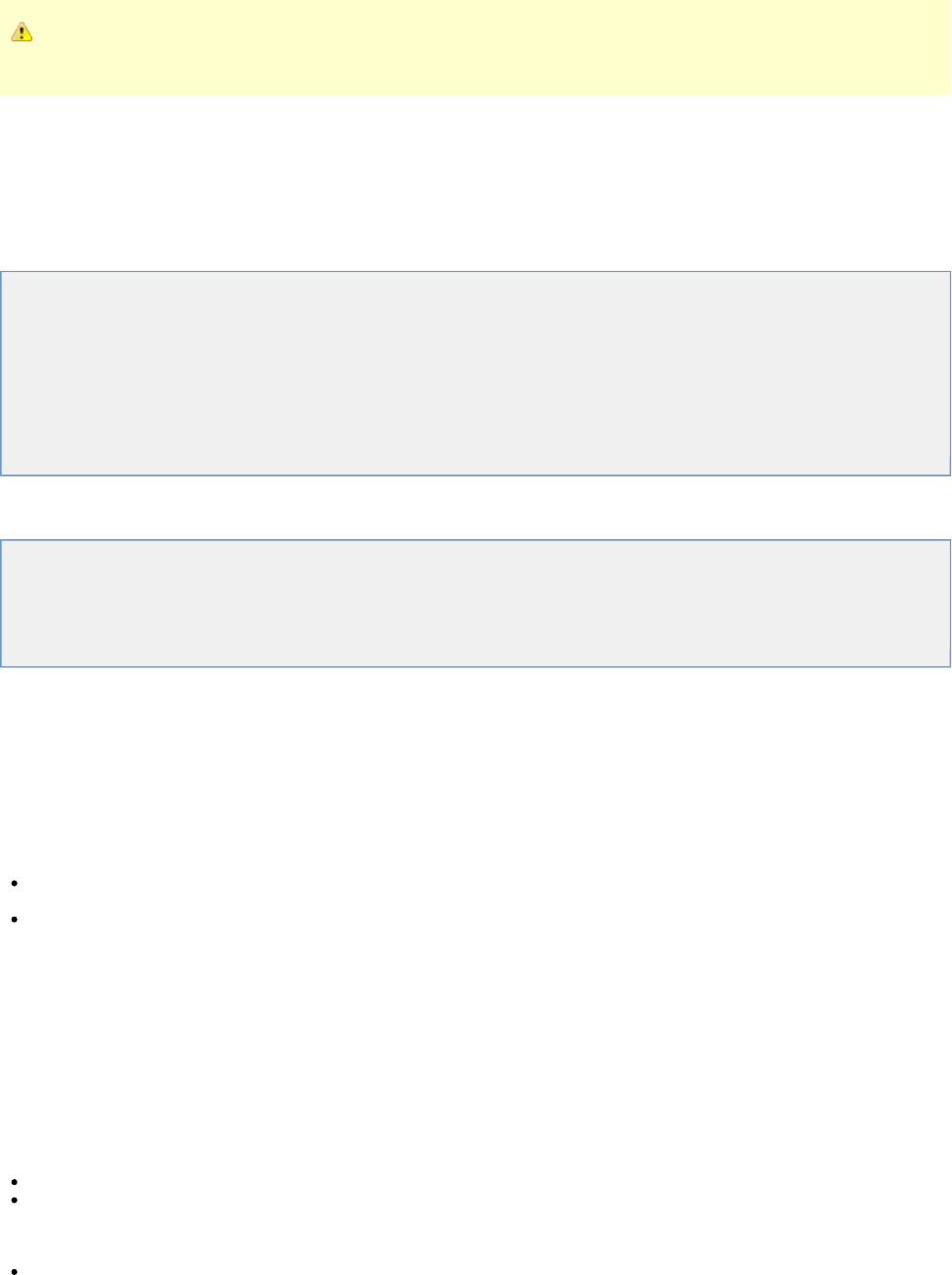
Assertions are executed in the order that they appear, and the workflow logic will usually depend on the order that the
assertions are applied.
After an assertion fires, the next step can be configured and is determined by that assertion, and the remaining assertions are ignored. An event
is generated every time an assertion is evaluated and fired.
Global and Step Assertions
Like filters, assertions can be applied as a global assertion, that is, to the entire test case cycle or as a step assertion, where they will be applied
only to a particular step.
The following topics are available in this chapter.
Adding an Assertion
Assertions Toolbar
Deleting an Assertion
Reordering an Assertion
Renaming an Assertion
Dragging and Dropping an Assertion
Configuring the Next Step of an Assertion
Types of Assertions
Adding an Assertion
There are several ways to add assertions into the test case.
Adding an Assertion Manually
Adding an Assertion from an HTTP Response
Adding an Assertion from a JDBC Result Set
Adding an Assertion for Returned Java Object
All methods except the first imply using assertions that are available for selection in the specific test step editor.
Adding an Assertion Manually
To add an assertion manually
Select the assertion type from a list and enter the parameters for the assertion.
There are two types of manual assertions:
Global assertions are defined at the test case level. This type of assertion will be applicable to all the steps in the test case and is
automatically run for every step in the test case, unless a given node is instructed otherwise.
Step assertions are defined at the test step level. This type of assertion will be applicable only to that step and will execute for that step
only.
Adding a Global Assertion
To add a global assertion
Open a test case and in the right panel click the element.Global Assertions
You can apply the following types of global assertions:
HTTP
Simple Web Assertion
Check Links on Web Responses
XML
Ensure Step Response Time
Other
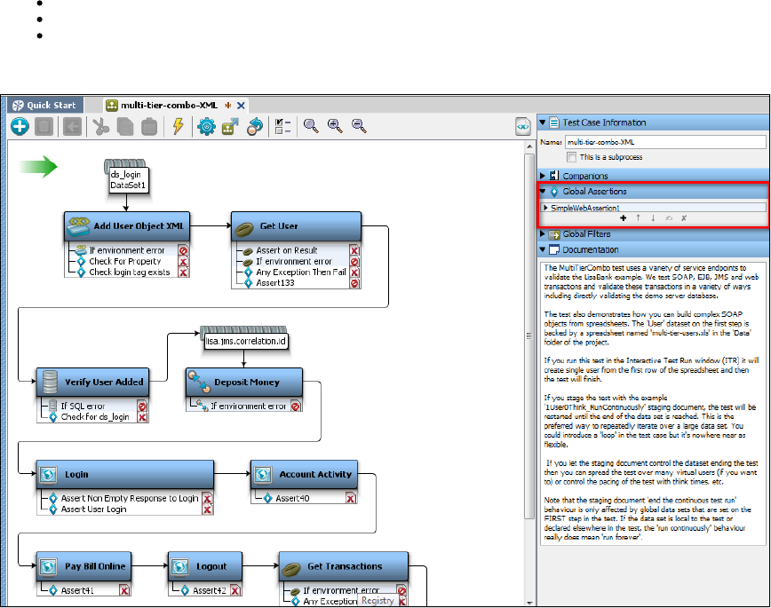
Ensure Result Contains Expression
Ensure Step Response Time
Scan a File for Content
The following image shows a global assertion applied to the test case.multi-tier-combo
Adding a Step Assertion
To add a step assertion
Select the step for which you want to apply the assertion and in the right panel click the element, or right-click the step and select Assertion Add
and select the appropriate assertion for the step.Assertion
The following image shows step assertions applied to the step in the test case.Add user multi-tier-combo
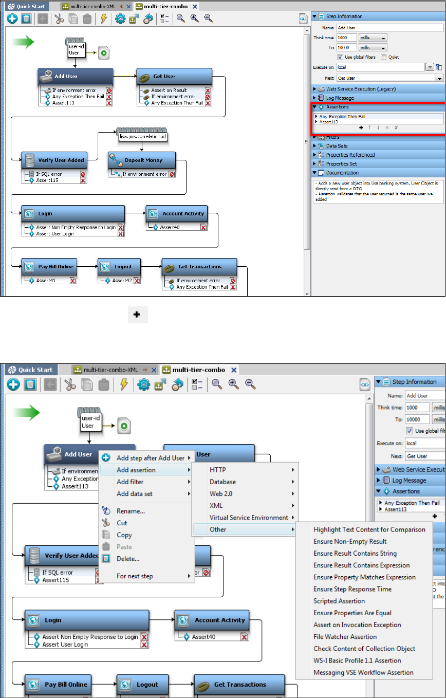
To add an assertion, click the icon on the assertion toolbar.Add
Or, you can right-click a step in the model editor to add an assertion. The assertion panel opens up and shows a menu of assertions that can be
applied to the step.
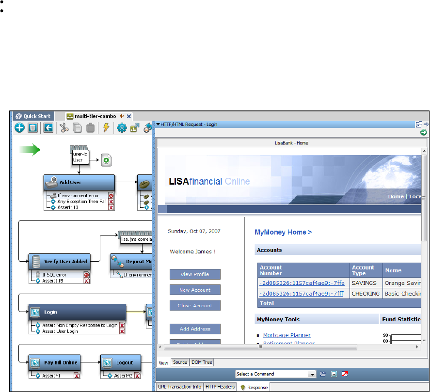
1.
2.
3.
4.
Selecting/Editing an Assertion
Click the step in the model editor to which the assertion is applied and/or click the assertion related to that step in the Assertion tab.
Double-click the assertion to open the assertion editor. The editor is unique for each type of assertion.
Adding an Assertion from an HTTP Response
When you have access to the response from an HTTP-based step, you can use the response to add an assertion directly.
This example of the HTTP/HTML response uses the login step in the multi-tier-combo test case. The point of this example is to test whether the
text "MyMoney Home" appears in the response.
Run the multi-tier-combo test case in the ITR.
Double-click the login step in the model editor.
Select the text "MyMoney Home" in the View tab.
Click the DOM Tree tab to view and make sure that this text is selected in the tree.
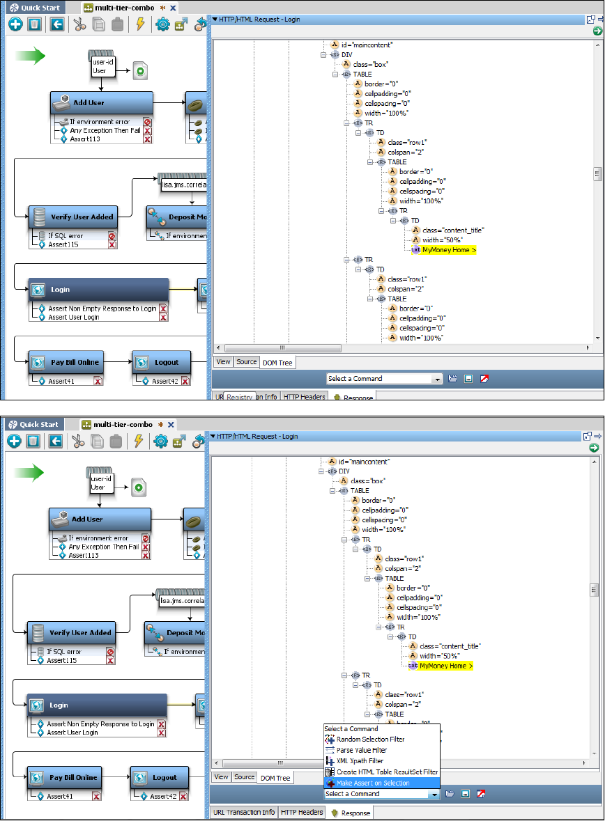
4.
5.
6.
From the Select a Command pull-down menu at the bottom of the panel, select Make Assert on Selection.
In the window that is displayed, enter the expression that the selected text should match with, and select the appropriate assertion
behavior.
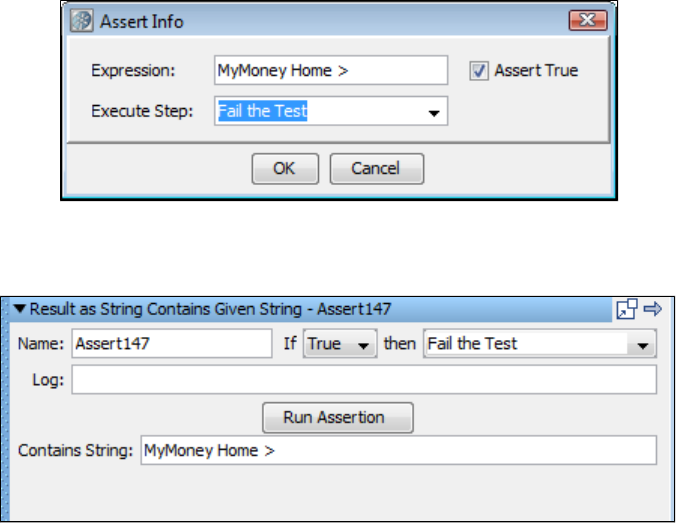
6.
7.
8. In this example, the assertion fires if the text "MyMoney Home" is not present, and then redirects to the fail step.
Click OK to save the assertion.
The assertion that was generated can be seen as an assertion in the login step.
Running one Filter and one Assertion
Alternatively, if you wanted a filter to capture the value "MyMoney Home," and then run it as an assertion, you can use the ,Parse Value Filter
which can do both things.
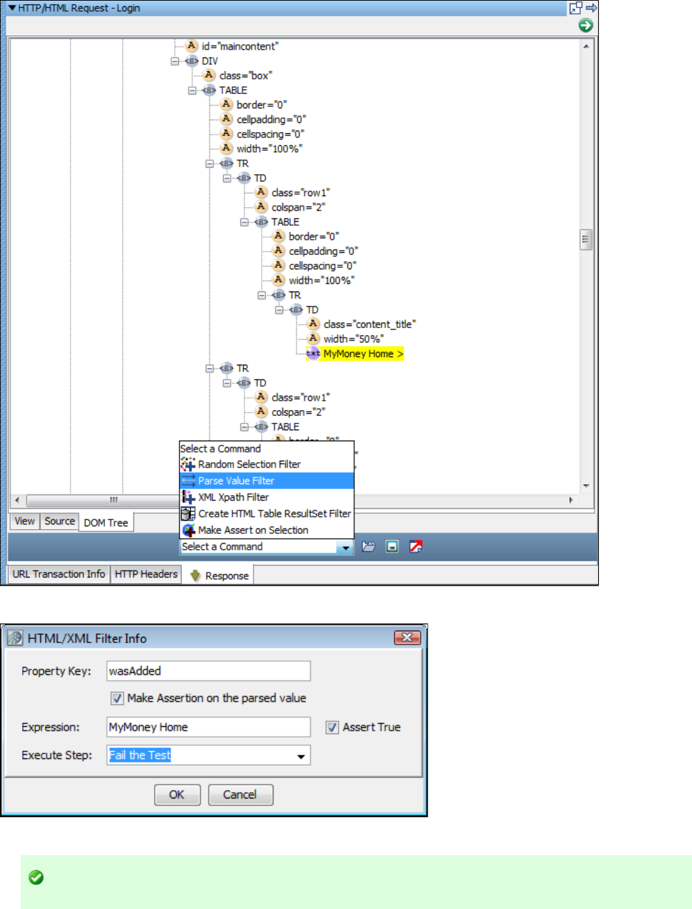
The window displayed by the Parse Value Filter shows Property Key value is the filter to be applied and Expression is the assertion to be fired.
As a result, one filter and one assertion will be added to the login step and can be seen in the model editor.
The same assertion capabilities are available when an HTML response is displayed in the step editor.
Adding an Assertion from a JDBC Result Set
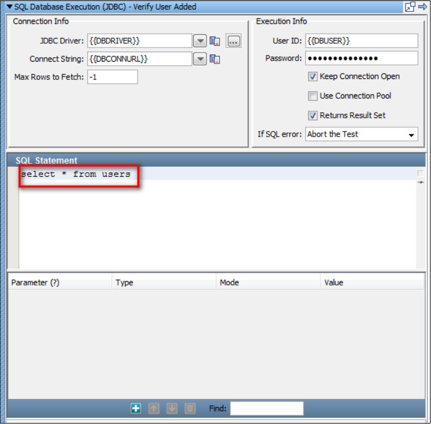
1.
2.
3.
When you have access to the Result Set response from a JDBC step, you can use the response to add an assertion directly. The following is an
example of how to add an assertion this way.
Here is an example for a result set response, using the response of Verify User Added step in multi-tier-combo test case in the examples
directory (multi-tier-combo.tst).
Select the Verify User Added step, and double-click it to open its editor window. Edit the SQL statement to read .select * from users
Click the Test/Execute SQL button to run the query.
Select the Result Set tab and click the cell in the result set that represents the information that you want to test for (for example, sbellum
).

3.
4.
5.
Click the Generate Assertions for Cell's Value icon in the toolbar below the Result set window.
We want to test that appears in a cell in the column.sbellum LOGIN
In the dialog that opens, enter the test step (fail) to redirect if the value is not found:
LISA will create an assertion named Result Set Contents in the Verify User Added step.
The same assertion capabilities are available when a JDBC result set is displayed in the step editor.
Adding an Assertion for Returned Java Object
When the result of your test step is a Java object, you can use the inline assertion panel in the Complex Object Editor to add an assertion on the
returned value from the method call directly. The following is an example of how to add an assertion this way.
Here is an example of an object in the Complex Object Editor:
This example uses the get user (an EJB step) step in multi-tier-combo test case in the examples directory (multi-tier-combo.tst).
We have entered an input parameter , and executed the method call getUser. We are now about to execute the getPwd call on the UserStateitko
object that was returned from that call.
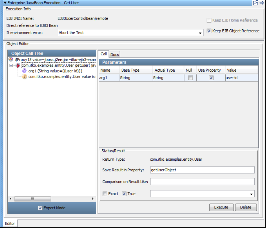
1. Select the Expert Mode check box in the left pane, to open the Status/Result pane where you can add the assertion.
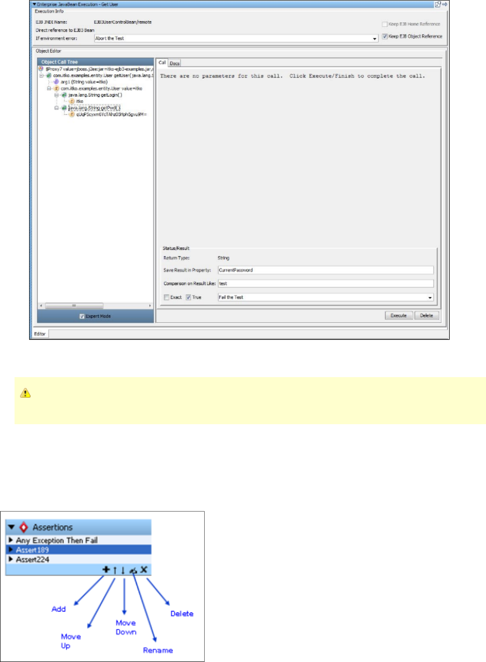
1.
2.
3.
4.
The returned value upon executing the getPwd method will be stored in the property CurrentPassword.
Add an assertion that tests to see if the returned value is equal to the string "test". If it is not that, then redirect to the Fail step.
Click Execute to execute this step.
In-line assertions (and filters) do not result in an assertion being added to the test step. In-line assertion management is always
done in the Complex Object Editor.
For old test cases, all inline assertions that were set to the Fail step, will now change to the Abort step.
For more details on the Complex Object Editor, see .Complex Object Editor (COE)
Assertions Toolbar
All the elements have their own toolbar to add/delete/reorder at the bottom of the element.
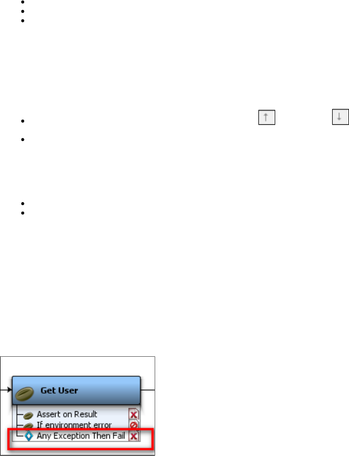
1.
2.
3.
1.
Deleting an Assertion
To delete an assertion
Right-click any assertion in the Elements tab to open a menu. Click Delete to delete the assertion.
Select the assertion in the test step and right-click to open a menu. Click Delete to delete the assertion.
Select the assertion in the Elements tab and click the Delete icon on the toolbar.
Reordering an Assertion
You may need to reorder assertions, because assertions are evaluated in the order in which they appear. Thus, changing the order of the
assertions can affect the workflow.
To reorder an assertion
Select the assertion in the Elements tab and click the Move Up or Move Down icon on the toolbar.
Drag and drop the assertion in the model editor to the target destination.
Renaming an Assertion
To rename an assertion
Select the assertion and right-click to open a menu. Click Rename to rename the assertion.
Select the assertion and click the Rename icon on the toolbar.
Dragging and Dropping an Assertion
You can drag and drop assertions in the model editor from one test step to another.
Click the assertion in one test step; for example, .Step1
Select and drag the assertion to other test step in the model editor; for example, .Step2
The dragged assertion will then be applied to .Step2
Configuring the Next Step of an Assertion
An assertion added to a step can be seen in the model editor.
After the assertion is added to a step, you can select its next step to be executed, if you want the workflow to be altered.
Right-click the assertion in the Model Editor to open the menu.
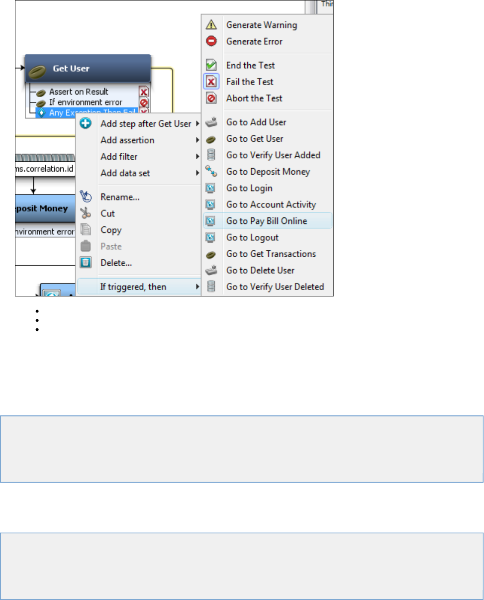
1.
2. Select and do one of the following:If triggered, then
Select to generate a warning or error.
Select to end, fail, or abort the step.
Select the next step to be executed.
Types of Assertions
This section describes each of the assertions that are available in LISA.
Regular expressions are used for comparison purposes in many assertions. For more information about regular expressions, visit
.http://download.oracle.com/javase/tutorial/essential/regex/
HTTP Assertions
Database Assertions
Web 2.0 Assertions
XML Assertions
Virtual Service Environment Assertion
Other Assertions
HTTP Assertions
The following assertions are available in the HTTP assertions list for any test step:
Highlight HTML Content for Comparison
Check HTML for Properties in Page
Ensure HTTP Header Contains Expression
Check HTTP Response Code
Simple Web Assertion
Check Links on Web Responses
Highlight HTML Content for Comparison
The assertion lets you make a comparison based on the contents on an HTML page. This assertionHighlight HTML Content for Comparison
uses the "paint the screen" technique specifically designed to work with HTML pages. For example, if there is a large HTML document, then you
can identify the data before and after the "content of interest". Then you simply identify what the "content of interest" will be compared against
(usually this would be an expected value supplied in a data set).
The text is marked using the icons at the bottom of the editor:
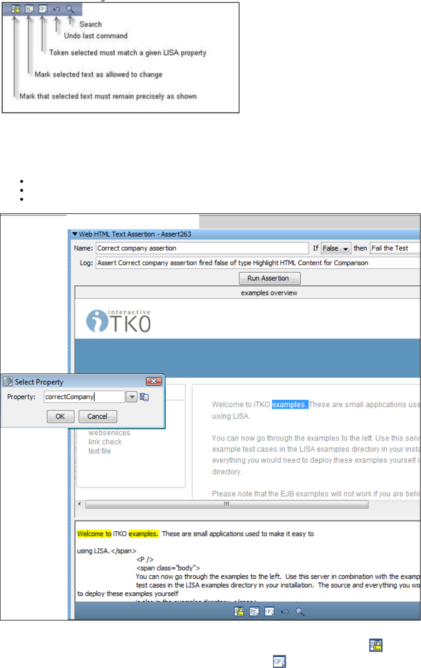
This technique is best explained by example.
In the following example, we want to make sure that the company name, currently ITKO, that appears in the phrase "Welcome to ITKO examples"
matches the value in a specified LISA property. We have marked the text, using the buttons shown previously, by selecting text and then clicking
the appropriate icon.
Yellow background indicates text that must appear as shown.
White background indicates text that need not be present, or can change.
Red background identifies the text that must match the property entered into the dialog.
This screen shows the HTML rendered in a browser in the top panel, and the actual HTML text in the bottom panel. We want to make the phrases
"Welcome to" and "examples" required. We have set the boundaries around that, and clicked the Must icon . Then we selected the company
name text, "ITKO", inside the highlighted content, and clicked the Property icon . We entered the property name into thecorrectCompany
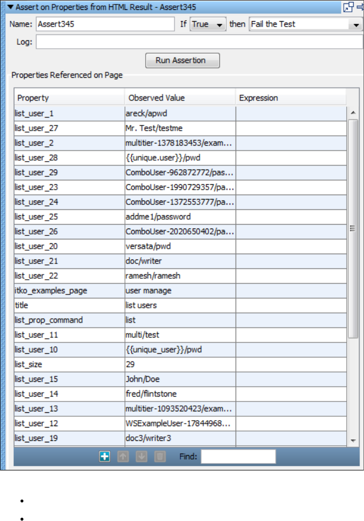
dialog. This property will be compared to the text that appears between the two bounding phrases. The company name text has been replaced
with the name of the LISA property.
Click the button to execute an assertion.Run Assertion
When this assertion is run, the value of the property will be inserted between the phrases "Welcome to" and "examples" andcorrectCompany
the resulting phrase will be compared to the corresponding phrase in the HTML response. The phrase "Welcome to examples"correctCompany
can change location in the HTML and it will still be located.
Check HTML for Properties in Page
The assertion is useful for web testing when there is property data in the web page that might be used forCheck HTML for Properties in Page
the assertion. The property data is made available for assertion by parsing the web page for meta tags, title tags, hidden form fields, and other
tags that the product can automatically parse, including <lisaprop> tags and the LISA Integration API.
Here is a sample of the available properties table.
Enter the following parameters:
Name: Enter the name of the assertion.
If: Select the behavior of the assertion using the drop-down box.
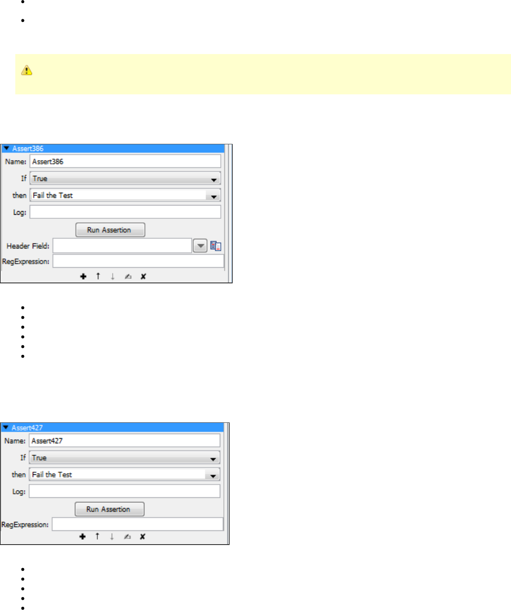
then: Select the step to redirect to if the assertion fires.
Log: The text that will be printed out as event text if the assertion fired.
Click the Run Assertion button to execute an assertion.
You may be prompted to install the filter.Parse HTML for LISA Tag
Ensure HTTP Header Contains Expression
The assertion lets you check that a specific HTTP result header contains a field that matches aEnsure HTTP Header Contains Expression
specified regular expression.
Enter the following parameters:
Name: The name of this assertion. This will help you identify events for this assertion.
If: Select the behavior of the assertion using the drop-down box.
then: Select the step to redirect to if the assertion fires.
Log: The text that will be printed out as event text if the assertion fires.
Header Field: The name of the header field.
RegExpression: The regular expression that must appear in the header field.
Click the Run Assertion button to execute an assertion.
Check HTTP Response Code
The assertion lets you check that the HTTP response code matches a specified regular expression.Check HTTP Response Code
Enter the following parameters:
Name: The name of this assertion. This will help you identify events for this assertion.
If: Select the behavior of the assertion using the drop-down box.
then: Select the step to redirect to if the assertion fires.
Log: The text that will be printed out as event text if the assertion fires.
RegExpression: The regular expression that must appear in the response code. For example, to check that the HTTP response code is
in the 400-499 range, set the RegExpression to .4\d\d
Click the Run Assertion button to execute an assertion.
Simple Web Assertion
The reads the return code from the web application.Simple Web Assertion
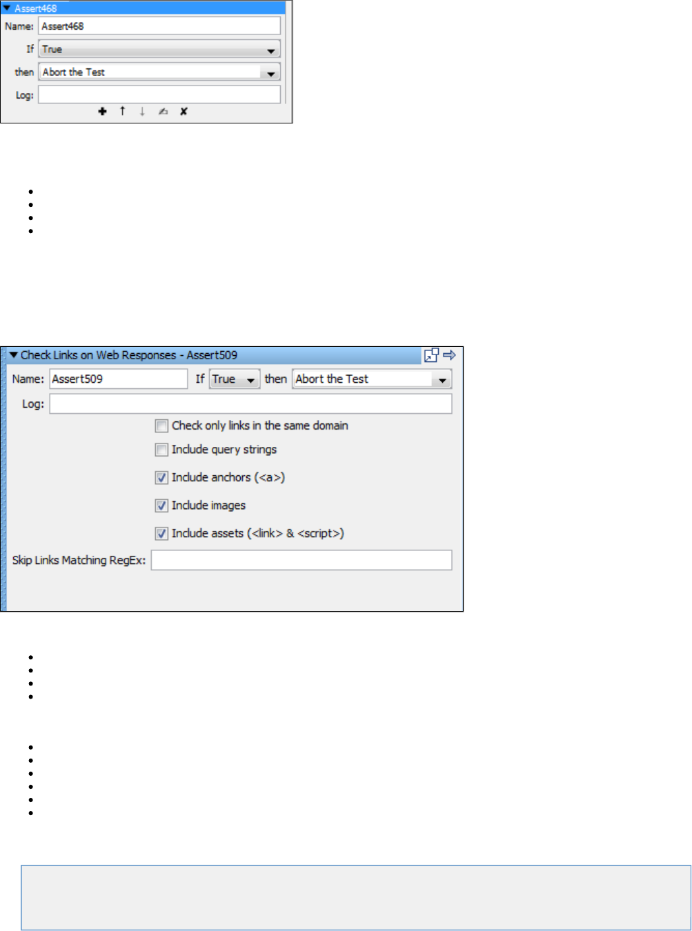
If the application returns code 404 (page not found), 500 (server error) or any other error then this assertion returns true.
The test case in the examples project has this type of assertion.multi-tier-combo
Enter the following parameters:
Name: The name of this assertion. This will help you identify events for this assertion.
If: Select the behavior of the assertion using the drop-down list.
then: Select the step to redirect to if the assertion fires.
Log: The text that will be printed out as event text if the assertion fired.
Click the Run Assertion button to run and execute the assertion.
Check Links on Web Responses
The assertion checks every link on the returned web page to make sure that it contains a valid page and doesCheck Links on Web Responses
not return an HTTP error like a 404 error, or others. This is commonly used to make sure that the links are working properly across the application
and there are no inactive links on the page.
Enter the following parameters:
Name: Enter the name of the assertion.
If: Select the behavior of the assertion using the drop-down box.
then: Select the step to redirect to if the assertion fires.
Log: The text that will be printed out as event text if the assertion fires.
The following criteria can be checked for the links:
Check only links in the same domain: Checks only links in the current domain of the returned web page.
Include query strings: If any query strings are present on the returned web page then those are checked.
Include anchors (<a>): Any anchor links in the current web page are checked.
Include images: All the images on the returned web page are checked.
Include assets (<link> & <script>): Current web page is checked for script and links.
Skip Links Matching RegEx: Enter a RegEx expression for any links you want to skip.
Database Assertions
The following assertions are available in the Database Assertions list for any test step.
Ensure Result Set Size
Ensure Result Set Contains Expression
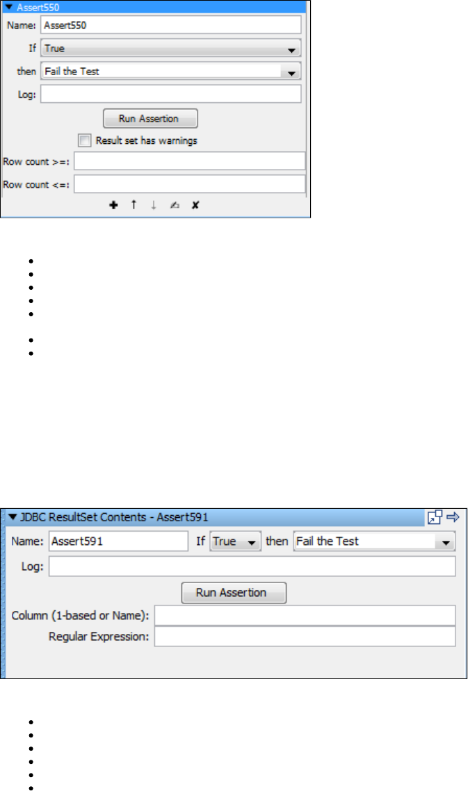
Ensure Result Set Size
The assertion will count the number of rows in a result set and verify that the size falls between an upper and lowerEnsure Result Set Size
value.
An example of this assertion could be checking to make sure the number of rows in an HTML table matches a supplied expected value from a
data set.
Enter the following parameters:
Name: The name of this assertion. This will help you identify events for this assertion.
If: Select the behavior of the assertion using the drop-down box.
then: Select the step to redirect to if the assertion fires.
Log: The text that will be printed out as event text if the assertion fires.
Result set has warnings: If checked, the database may return warnings in the result set. Check with your system administrator to
determine whether your database supports warnings in the result set.
Row Count >=: The minimum number of rows in the result set. indicates no minimum.-1
Row Count <=: The maximum number of rows in the result set. indicates no maximum.-1
Click the Run Assertion button to execute an assertion.
For example, to make sure that a Database Assertion step returns one and only one row, set the field to and the Row Count >= 1 Row Count <=
field to .1
Ensure Result Set Contains Expression
The assertion will check a particular column in a result set and ensure that the supplied expressionEnsure Result Set Contains Expression
matches at least one value.
Enter the following parameters:
Name: The name of this assertion. This will help you identify events for this assertion.
If: Select the behavior of the assertion using the drop-down box.
then: Select the step to redirect to if the assertion fires.
Log: The text that will be printed out as event text if the assertion fires.
Column: The column that contains the text to check. This can be a column name or an index.
Regular Expression: The regular expression to match in the column.
Click the Run Assertion button to execute an assertion.
For example, to check that at least one of the rows returned from a query has a login value that starts with , set the field to andwp Column login
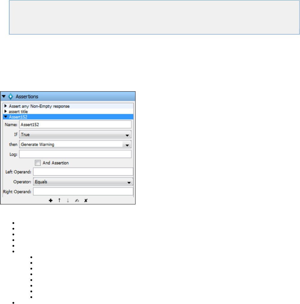
the field to *.Regular Expression wp.
Web 2.0 Assertions
The following assertions are available in the Web 2.0 assertions list for any test step.
Web 2.0 Basic Assertion
Web 2.0 Validation Assertion
Web 2.0 Branching Assertion
Web 2.0 Basic Assertion
The is intended to be created from the DOM web browser. The basic assertion provides the ability to compareWeb 2.0 Basic Assertion
properties; for example, comparing a bank balance before and after making a deposit. The basic assertion can be used to make sure the {{
+ }}.after}}EQUALS{{before deposit
The Web 2.0 Basic Assertion evaluates a unary or binary expression using predefined operators and properties. Typically, you will use a variable
created by a filter on the left side and then equal it or match it to a constant value or another variable on the right side.
Enter the following parameters:
If: Select the behavior of the assertion using the drop-down box.
then: Select the step to redirect to if the assertion fires.
Log: The text that will be printed out as event text if the assertion fires.
And Assertion: Deprecated; not being used.
Left Operand: Left side of the expression for comparison.
Operator: One of the following operators:
Equals: Compare the two sides of the expression for equality.
Not Equals: Compare the two sides of the expression for non-equality.
Matches: Attempt to match (as regular expression) the left or the right side of the expression against the other side.
Not Matches: Attempt not to match (as regular expression) the left or the right side of the expression against the other side.
Less Than: Compare the two sides of the expression as numeric values for order. Returns false on non-numeric values.
More Than: Compare the two sides of the expression as numeric values for order. Returns false on non-numeric values.
Exists: Verify if the entity represented by the left side exists in the current page context.
Evaluate: Evaluate arbitrary JavaScript code in the context of the current page. Must return a Boolean.
Right Operand: Right side of the expression for comparison, or blank if a unary comparison.
Web 2.0 Validation Assertion
The Web 2.0 Validation Assertion is intended to be created from the DOM web browser. This assertion validates the entire HTML result to verify it
complies with W3C standards. It also validates the page for errors, warnings, or broken links. This is important in Web 2.0 applications because
there can be many tools to generate the page, so it is good to verify it is standards compliant.
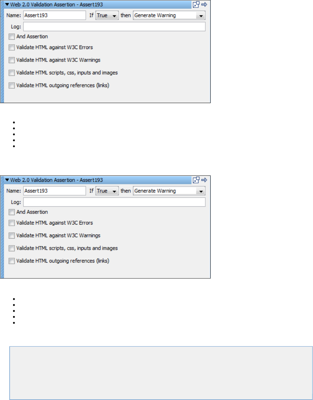
Select one or more of the following validations:
And Assertion: Deprecated; not being used.
Validate HTML against W3C Errors: HTML page is evaluated for W3C errors.
Validate HTML against W3C Warnings: HTML page is evaluated for W3C warnings.
Validate HTML scripts, css, input and images: Page is evaluated for images, css scripts and inputs.
Validate HTML outgoing references (links): HTML Page is evaluated for valid links.
Web 2.0 Branching Assertion
The assertion is created from the DOM web browser. Web 2.0 Branching
Select one or more of the following validations:
And Assertion: Deprecated; not being used.
Validate HTML against W3C Errors: HTML page is evaluated for W3C errors.
Validate HTML against W3C Warnings: HTML page is evaluated for W3C warnings.
Validate HTML scripts, css, input and images: Page is evaluated for images, css scripts and inputs.
Validate HTML outgoing references (links): HTML Page is evaluated for valid links.
XML Assertions
The following assertions are available in the XML assertions list for any test step.
Highlight Text Content for Comparison
Ensure Result Contains String
Ensure Step Response Time
Graphical XML Side-by-Side Comparison
XML XPath Assertion
Ensure XML Validation
Highlight Text Content for Comparison
The assertion uses the "paint the screen" technique specifically designed to work with HTML pages.Highlight Text Content for Comparison
For example, if there is a large HTML document, then you identify the data before and after the content of interest. Then, you simply identify what
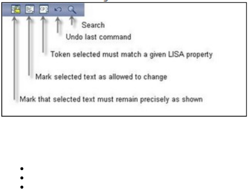
the content of interest will be compared against (usually this would be an expected value supplied in a data set).
Mark the text with the icons at the bottom of the editor:
In the following example, we want to make sure that certain files appear in the buffer, and one of the file sizes needs to be compared to the value
of a property. We have marked the text using the three icons shown in the previous illustration, by selecting text and then clicking on the
appropriate icon.
Yellow background indicates text that must appear as shown.
White background indicates text that need not be present, or can change.
Red background identifies the text that must match the property entered into the dialog.
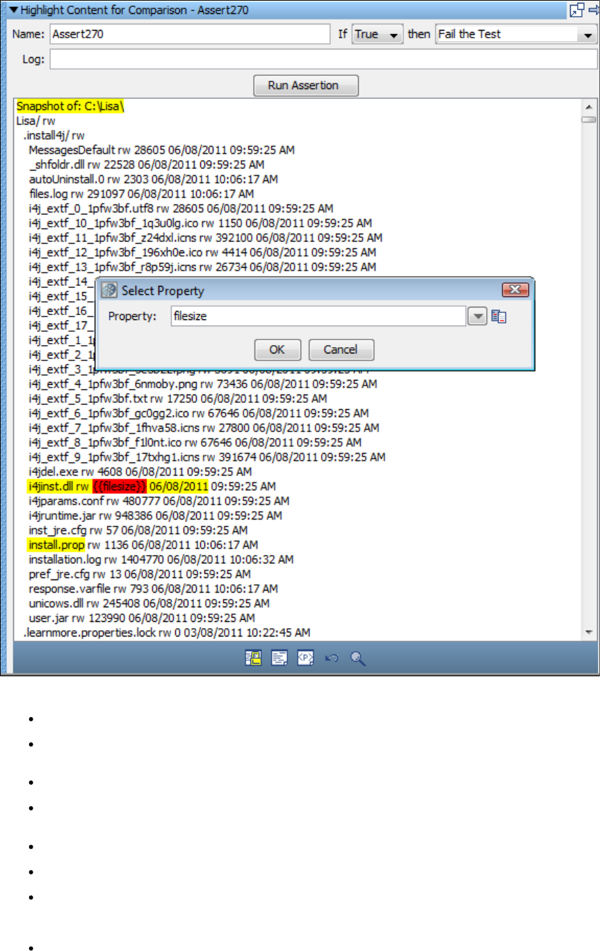
The set of tokens shown in the previous illustration can be read this way:
The buffer must start with the phrase in yellow: "Snapshot of: C:\Lisa\".
There are a number of files that may or may not be in the buffer in the next token, but because it is an "Any" token, the variance is
immaterial.
The file "i4jinst.dll" and "rw" attributes must appear.
The red means that the value associated with the property key will be swapped into the expression, then thefilesize filesize
comparison made.
The text "06/08/2011" must appear.
The file "install.prop" must appear.
The buffer can have any amount of content afterward.
After you have finished the markup, enter the following parameters:
Name: The name of this assertion. This will help you identify events for this assertion.
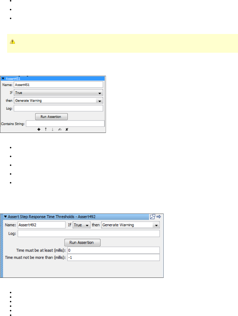
If: Select the behavior of the assertion using the drop-down box.
then: Select the step to redirect to if the assertion fires.
Log: The text that will be printed out as event text if the assertion fires.
Click the Run Assertion button to execute an assertion.
Property blocks must always be bounded by blocks.Must
Ensure Result Contains String
The assertion lets you search the response (as text) for a string.Ensure Result Contains String
Enter the following parameters:
Name: The name of this assertion. This will help you identify events for this assertion.
If: Select the behavior of the assertion using the drop-down box.
then: Select the step to redirect to if the assertion fires.
Log: The text that will be printed out as event text if the assertion fires.
Contains String: The string to search for in the step result - this can contain a property.
Ensure Step Response Time
The assertion lets you define upper and lower bounds on the response time and assert that the response time isEnsure Step Response Time
within those bounds.
Enter the following parameters:
Name: The name of this assertion. This will help you identify events for this assertion.
If: Select the behavior of the assertion using the drop-down box.
then: Select the step to redirect to if the assertion fires.
Log: The text printed out as event text if the assertion fires.
Time must be at least (millis): Enter the lower bound in milliseconds.
Time must not be more than (millis): Enter the upper bound in milliseconds. This is ignored if set to .-1
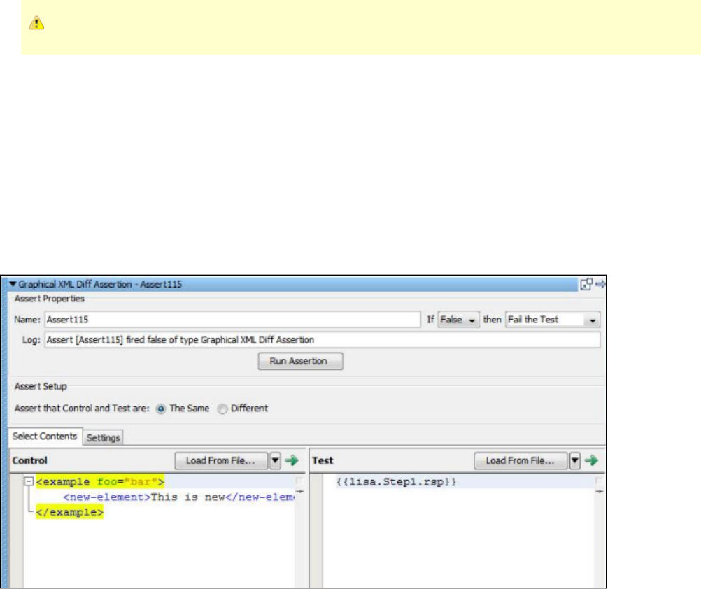
Parameters can contain properties.
Graphical XML Side-by-Side Comparison
The assertion lets you compare a test XML value received from a test with a control XML value. TheGraphical XML Side-by-Side Comparison
assertion can return true if the responses are the same or different. This provides a flexible ability to compare XML documents at various steps in
a business process to make sure they match expected criteria. This is known as "exclusive" testing where an entire response is compared except
for a few values known to change.
The assertion editor works by comparing a left and right side of XML to each other. The left side is known as Control Content and the right side as
Test Content. Control Content serves as the expected XML returned from a web service in the application under test, while the Test Content
should be actual content, for example. By default, Test Content is loaded from the last response of the test step associated with the assertion,
signified by the empty LISA property key. Otherwise, any valid LISA property key can be used and the Test Content will be loaded from it.
Alternatively, in test case authoring mode, XML can be loaded from a file or entered manually for Control and Test Content so that a quick
graphical diff can be performed.
After a diff is executed, the results appear in the visualizer in the Diff Viewer tab in the assertion editor.
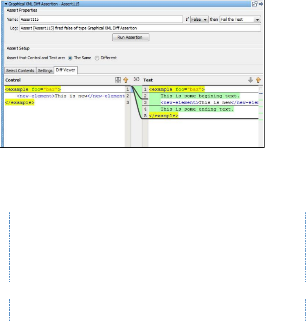
Output During Execution
When an assertion is executed, the diff results are logged as test events.
An EventID containing the XML diff results is always logged.Info message
If the assertion fires, an EventID containing the XML diff results is logged.Assertion fired
The diff results are reported in a format resembling the original UNIX diff utility. An example of a text diff report is:
Assert [Assert1] fired false of type Graphical XML Diff Assertion
XML is [Different]
=====
1,2[ELEMENT_NAME_CHANGED]1,2
<! <test2>
<! </test2>
---
>! <test>
>! </test>
Each difference is displayed with a heading of the format:
<First Start Line>, <First End Line>'['<Diff Type>']'<Second Start Line>,<Second End Line>
Then the difference in the first content is displayed, followed by the separator '---', followed by the difference in the second content.
The + character signifies addition, a deletion, and a change. When these characters are present, they indicate an actual change occurred on- !
the line of content, as opposed to a context line.
XML Compare Options
The following comparison options are available for use by the diff engine:
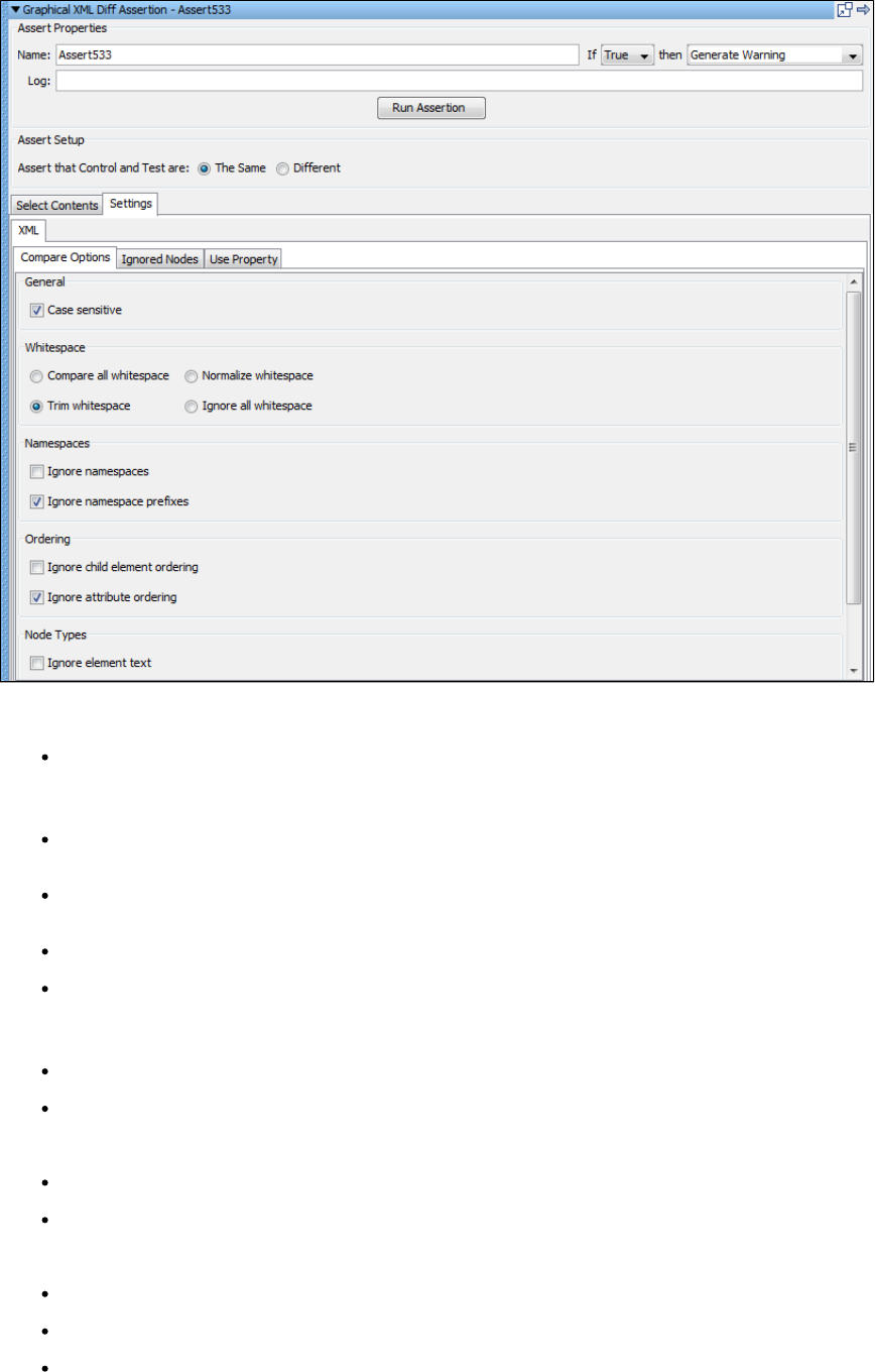
General
Case sensitive: Whether case sensitivity should be used during the comparison (enabled by default).
Whitespace
Trim whitespace: During a comparison, all leading and trailing whitespace will be removed from element text and attribute values
(enabled by default).
Collapse whitespace: In addition to trimming whitespace, any sequence of one or more whitespace characters inside text is converted
to a single space character.
Normalize whitespace: Any sequence of one or more whitespace characters is converted to a single space character.
Ignore all whitespace: All whitespace is ignored during the comparison.
Namespaces
Ignore namespaces: The namespace value of an element or attribute is ignored.
Ignore namespace prefixes: The namespace prefix of an element or attribute is ignored (enabled by default).
Ordering
Ignore child element ordering: Ignore the order of child elements in the XML document.
Ignore attribute ordering: Ignore the order of attributes in the XML document (enabled by default).
Node Types
Ignore element text: Ignore all element text.
Ignore attribute values: Compare attribute names but ignore attribute values.
Ignore attributes: Ignore attribute names and values.
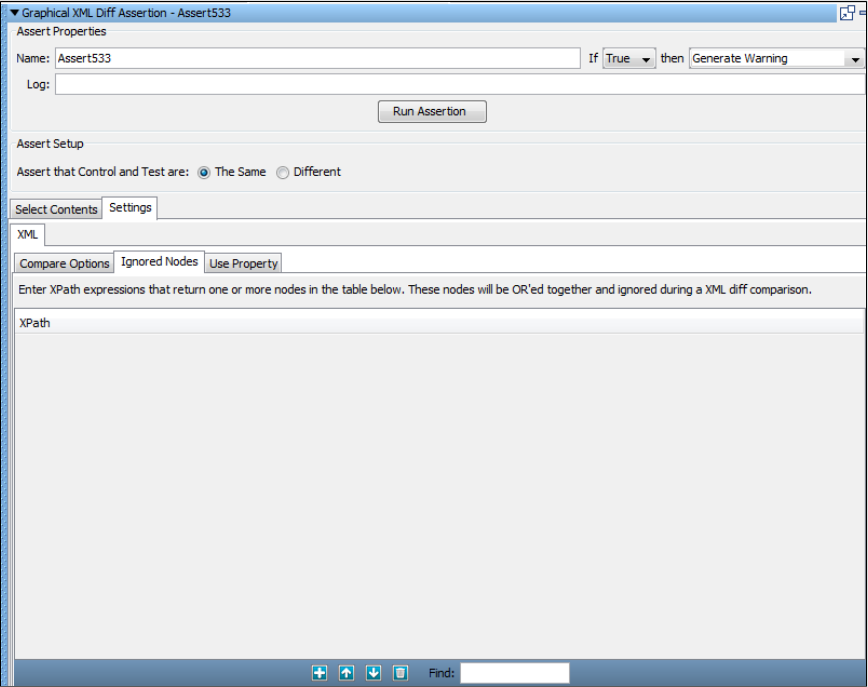
Ignored Nodes
Ignored nodes are created from a list of XPaths that are executed against the left and right documents. Each evaluated XPath that returns a node
set is aggregated. When the diff occurs, any node that is found in the aggregate set is ignored.
Ignored node XPaths can be any arbitrary query that returns a node set. For example, the XPath "//*" excludes all nodes in an XML document.
"/example/text()" excludes the first text node child of the "example" element in an XML document. "/example/@myattr" is the XPath to ignore the
"myattr" attribute, including the attribute text value, belonging to the "example" element in an XML document.
A right-click menu item also lets a node be selected directly inside a given XML document and its XPath will be added to the Ignored Nodes list.
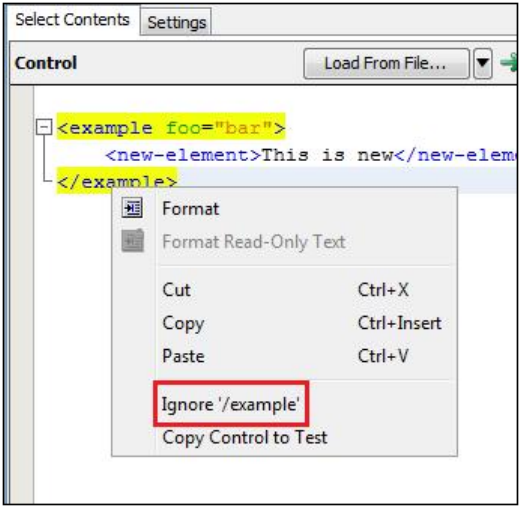
XML XPath Assertion
The assertion lets you use an XPath query that will be run on the response. When this assertion is selected, the last response isXML XPath
loaded into the content panel.
XPath can be thought of as the "SQL for XML." It is a powerful query language that makes parsing XML simple. XPath assertions are useful when
you need to validate a web service response in a more sophisticated way than simply parsing the entire result for a given string. For example, you
might want to make sure the second and third order item contains "ITKO" and the value of those line items is greater than 10.
The response can be viewed as an XML document or as a DOM Tree. However, the XPath selection can only be made from the DOM Tree view.
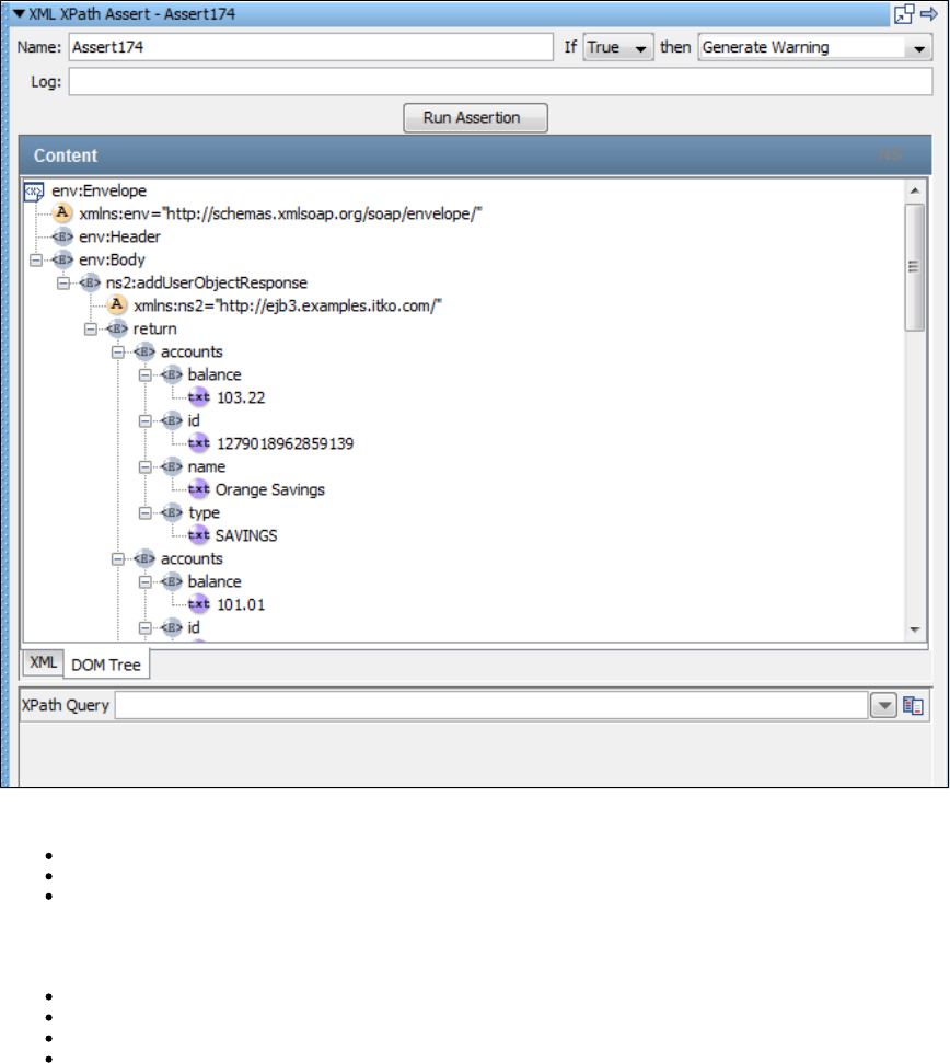
There are three ways to construct the XPath query:
Manually enter the XPath expression in the XPath Query text box.
Select an element from the DOM tree and let LISA construct the XPath expression.
Select an element from the DOM tree, and then edit the XPath that LISA constructs. For example, you may want to modify it to use a
LISA property, or a counter data set.
Enter the following parameters:
Name: The name of this assertion. This will help you identify events for this assertion.
If: Select from the drop-down True or False.
Then: Select from the drop-down Fail the Test, Abort the Test, End the Test, or Go To a step.
Log: The text that will be printed out as event text if the assertion fires.
Now construct the XPath query using one of the methods described previously.
After an XPath query has been constructed, test it by clicking the Run Assertion button on the top of the panel. The results of the query are
displayed in the Query Results panel.
The previous example uses the fourth occurrence of the tag.<wsdl:part>
It is common to select an XPath node in a web service result and compare the node to a text value to quickly assert that a response contains the
expected value. For this common use case, you can add an equality operator to the end of the initial expression that is provided. For example, if
we select the new password returned in the response ( ):BobPass
LISA builds the following XPath expression:
string(/env:Envelope/env:Body/ns2:updatePasswordResponse/[name()='return']/[name()='pwd'])=
If we add we are comparing the string of the result to the value of the LISA property we used to set the new password. If the=' ',NewPassword
equality test does not match, the assertion fails.
So the entire XPath expression becomes:
string(/env:Envelope/env:Body/ns2:updatePasswordResponse/[name()='return']/[name()='pwd'])=' 'NewPassword
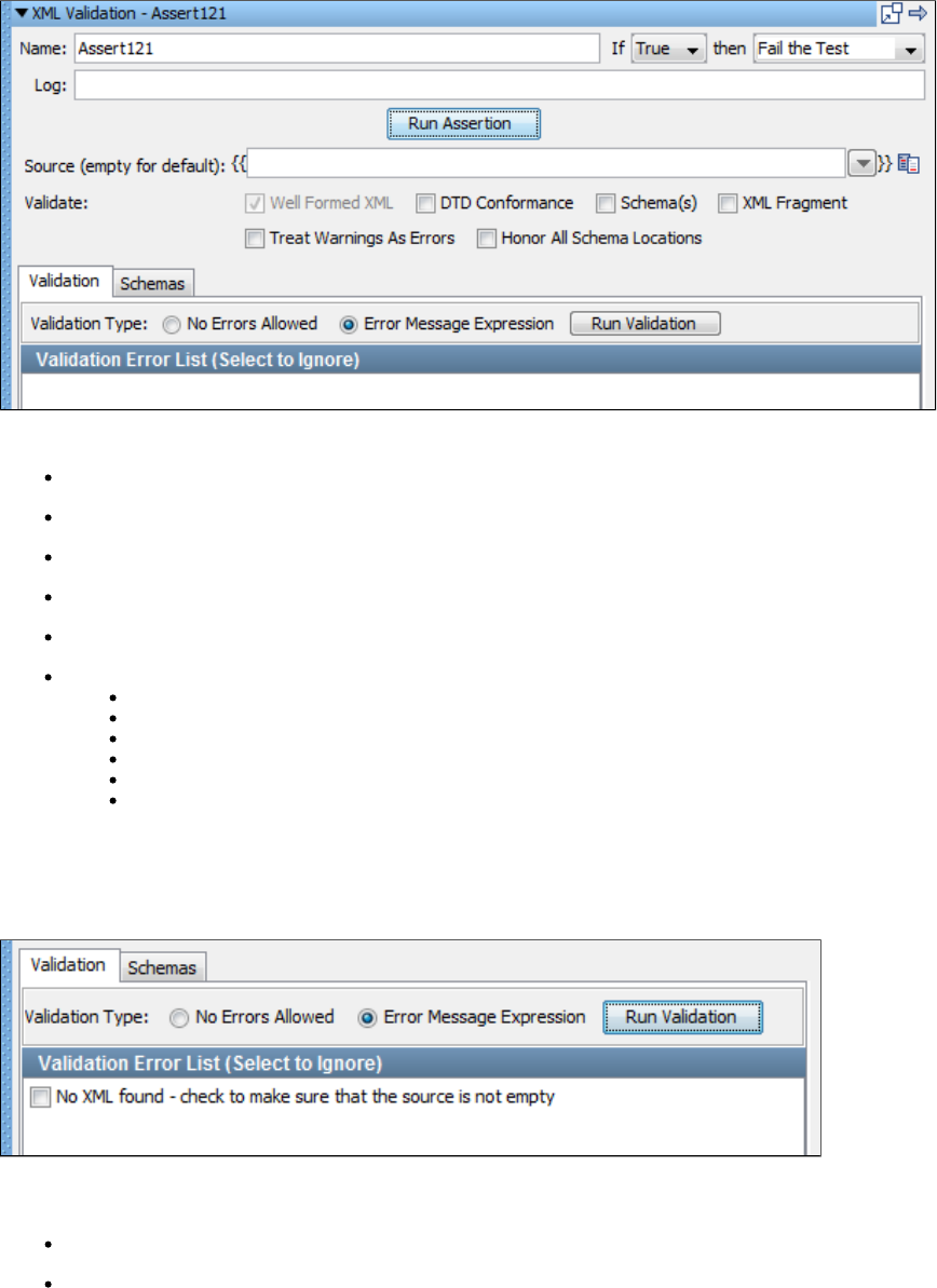
Here we are checking the web service response, looking for the new password, and making sure it matches what we think it should match.
Ensure XML Validation
The assertion lets you validate an XML document. You can check to see if the XML document is well-formed, you canEnsure XML Validation
validate against a Document Type Definition (DTD), or you can validate against one or more schemas. If you have an XML fragment, you can
choose to have LISA add the XML declaration tag. You can also specify that warnings should be treated as errors. You enter the XML to validate
as a property.
Enter the following parameters:
Name: The name of this assertion. This will help you identify events for this assertion.
If: Select the behavior of the assertion using the drop-down menu.
then: Select the step to redirect to if the assertion fires.
Log: The text that will be printed out as event text if the assertion fires.
Source: The property that contains the XML. If this is left blank, the last response is used.
Validate: Multiple validation options can be selected:
Well Formed XML: Check that XML is well-formed.
DTD Conformance: Check conformance with a DTD.
Schema(s): Check conformance with one or more schemas.
XML Fragment: If XML is a fragment, an XML declaration will be added to the top of XML fragment.
Treat Warnings As Errors: Warning will be reported as errors.
Honor All Schema Locations: If you have multiple imports for the same namespace, this option will open each schema location
instead of just the first one.
Click the Run Assertion button to execute an assertion.
Validation Tab
You can run the validation by clicking the Run Validation button. Any resulting validation errors are displayed in the . NowValidation Error List
you can use the Validation Type option buttons to choose how to handle the errors:
No Errors Allowed: The validation fails on any error.
Error Message Expressions: Errors can be marked to be ignored in the validation. The errors to ignore can be checked in the Validation
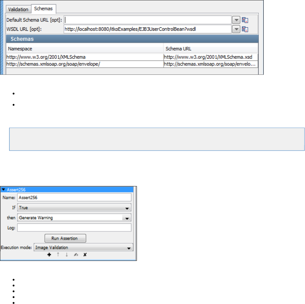
Error List if you choose this option. An error is shown in the previous example that can be ignored.
Schemas Tab
Enter the information for each schema you want to use in the validation. You can also specify the default schema:
Default Schema URL: Optionally, specify the default schema's URL.
WSDL URL: Optionally, specify a URL of a WSDL.
Virtual Service Environment Assertion
The following assertion is available in the Virtual Service Environment assertions list for any test step.
Assert on Execution Mode
Assert on Execution Mode
The assertion will check the current execution mode to its reference and fire if they match. This assertion is primarilyAssert on Execution Mode
used to control step flow for virtual service models.
Enter the following parameters:
Name: The name of this assertion. This will help you identify events for this assertion.
If: Select the behavior of the assertion using the drop-down box.
then: Select the step to redirect to if the assertion fires.
Log: The text that will be printed out as event text if the assertion fires.
Execution Mode: Select the execution mode from the available options in the drop-down. For more information about execution modes,
see the section " in the .Set the execution mode for the selected virtual service"Virtualize Guide
Click the Run Assertion button to run and execute the assertion.
Other Assertions
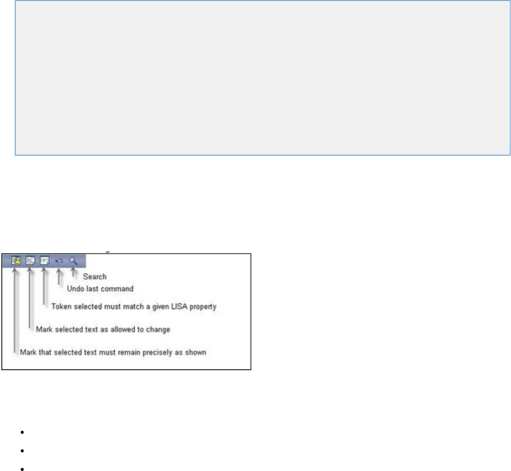
The following assertions are available in the Other assertions list for any test step.
Highlight Text Content for Comparison Assertion
Ensure Non-Empty Result Assertion
Ensure Result Contains String Assertion
Ensure Result Contains Expression Assertion
Ensure Property Matches Expression Assertion
Ensure Step Response Time Assertion
Scripted Assertion
Ensure Properties Are Equal Assertion
Assert on Invocation Exception Assertion
File Watcher Assertion Assertion
Check Content of Collection Object Assertion
WS-I Basic Profile 1.1 Assertion
Messaging VSE Workflow Assertion
Highlight Text Content for Comparison Assertion
The assertion uses the "paint the screen" technique specifically designed to work with HTML pages.Highlight Text Content for Comparison
For example, if there is a large HTML document, you identify the data before and after the content of interest. Then, you simply identify what the
"content of interest" will be compared against (usually this is an expected value supplied in a data set).
The text is marked using the icons at the bottom of the editor:
This technique is best explained by example.
In the following example, we want to make sure that certain files appear in the buffer, and one of the file sizes needs to be compared to the value
of a property. The text is marked using the three icons shown in the previous image, by selecting text and clicking on the appropriate icon.
Yellow background indicates text that must appear as shown.
White background indicates text that need not be present, or can change.
Red background identifies the text that must match the property entered into the dialog.

The set of tokens shown here can be read this way:
The buffer must start with the phrase in yellow: "Snapshot of: C:\Lisa\".
There are a number of files that may or may not be in the buffer in the next token, but because it is an "Any" token the variance is
immaterial.
The file "i4jinst.dll" and "rw" attributes must appear.
The red means that the value associated with the property key will be swapped into the expression, then thefilesize filesize
comparison made.
The text "06/08/2011" must appear.
The file "install.prop" must appear.
The buffer can have any amount of content afterward.
After you have finished the markup, enter the following parameters:
Name: The name of this assertion. This will help you identify events for this assertion.
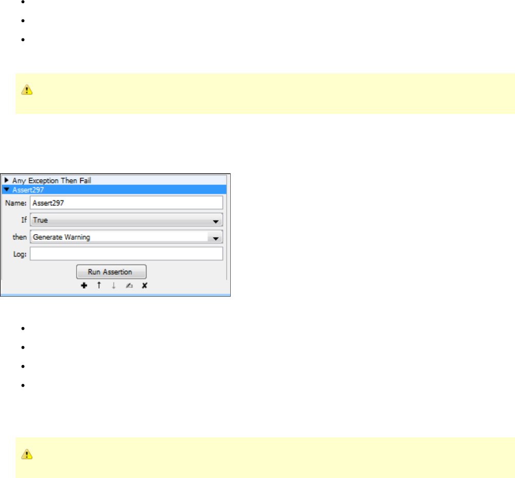
If: Select the behavior of the assertion using the drop-down box.
then: Select the step to redirect to if the assertion fires.
Log: The text that will be printed out as event text if the assertion fires.
Click the Run Assertion button to execute an assertion.
Property blocks must always be bounded by blocks.Must
Ensure Non-Empty Result Assertion
The assertion checks the return from the step to verify that some value has been returned. If there is no responseEnsure Non-Empty Result
(timeout) or a null value returned, this assertion will return true.
Enter the following parameters:
Name: The name of this assertion. This will help you identify events for this assertion.
If: Select the behavior of the assertion using the drop-down menu.
then: Select the step to redirect to if the assertion fires.
Log: The text printed out as event text if the assertion fires.
Click the Run Assertion button to execute an assertion.
No other attributes are required.
Use this assertion with caution, as it implements no content validation.
Ensure Result Contains String Assertion
The assertion will return true if the value being searched is found anywhere inside the response. This is typicallyEnsure Result Contains String
used to make sure the response contains a required value such as a unique id that was supplied during the request.
For more information see Ensure Result Contains String.
Ensure Result Contains Expression Assertion
The assertion lets you check that a specified regular expression occurs somewhere in the result, as text.Ensure Result Contains Expression
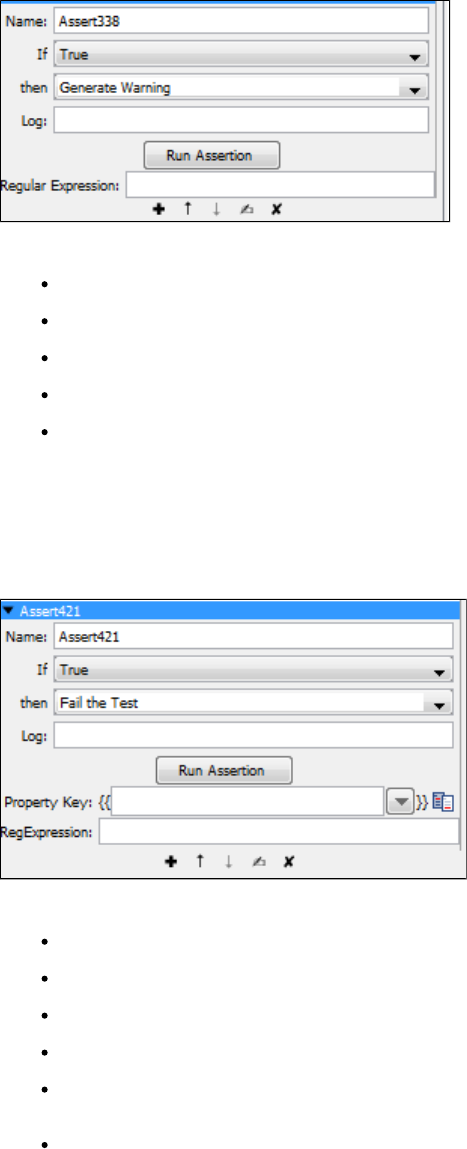
Enter the following parameters:
Name: The name of this assertion. This will help you identify events for this assertion.
If: Select the behavior of the assertion using the drop-down menu.
then: Select the step to redirect to if the assertion fires.
Log: The text that will be printed out as event text if the assertion fires.
Regular Expression: The regular expression to search for in the step result. For example, to check that a number in the 400s appears
somewhere in the result, set this parameter to .4/d/d
Click the Run Assertion button to execute an assertion.
Ensure Property Matches Expression Assertion
The assertion lets you check that the current value of a property matches a specified regular expression.Ensure Property Matches Expression
Enter the following parameters:
Name: The name of this assertion. This will help you identify events for this assertion.
If: Select the behavior of the assertion using the drop-down box.
then: Select the step to redirect to if the assertion fires.
Log: The text that will be printed out as event text if the assertion fires.
Property Key: The name of the property to be checked. Enter the property name, select from the drop-down list of properties, select an
existing string pattern, or create a new .string pattern
RegExpression: The regular expression that must appear in the current value of the property.
Click the Run Assertion button to execute an assertion.
Ensure Step Response Time Assertion
The assertion lets you define an upper and lower threshold for application response time. If the performance isEnsure Step Response Time
either too fast or too slow, the test case can be failed by using this assertion. Sometimes an application that returns a response very quickly can
be a sign that the transaction was not properly processed.
For more information see Ensure Step Response Time.
Scripted Assertion
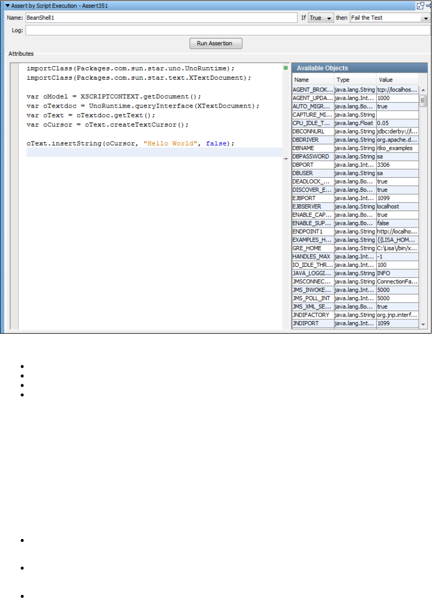
The assertion lets you write and execute Java script in the interpreter. The result must be a Boolean, or isScripted Assertion BeanShell false
returned.
Enter the following parameters:
Name: The name of this assertion. This will help you identify events for this assertion.
If: Select the behavior of the assertion using the drop-down box.
then: Select the step to redirect to if the assertion fires.
Log: The text printed out as event text if the assertion fired.
Click the Run Assertion button to execute an assertion.
Enter your script into the script editor on the left.
All the objects available for use in the script editor are listed in the Available Objects panel on the right. This includes primitive types of data like
strings and numbers, but also includes objects like any EJB response objects that have been executed in the test case. Double-click an entry in
the table to paste that variable name into the editor area.Available Objects
Click Test to open a window with the result of the script execution or a description of the errors that occurred.
When you save the test case, the assertion is checked for syntax errors.
Some things to remember:
If you use LISA properties - {{ }} - in a script, it will be substituted for the actual value of the property at run time before thesomeprop
script is executed.
If you need to get access to a property that has a "." in the name, these are imported into the script environment replacing "." with "_". So
{{ }} in a script is the same as .foo.bar foo_bar
You can produce a LISA log event inside a script step or assertion by using the object. To produce a LISA log event, code thetestExec
following line, as opposed to using the log4j logger. The method causes an actual LISA event to be raised. You can seetestExec.log()
the event in the ITR.
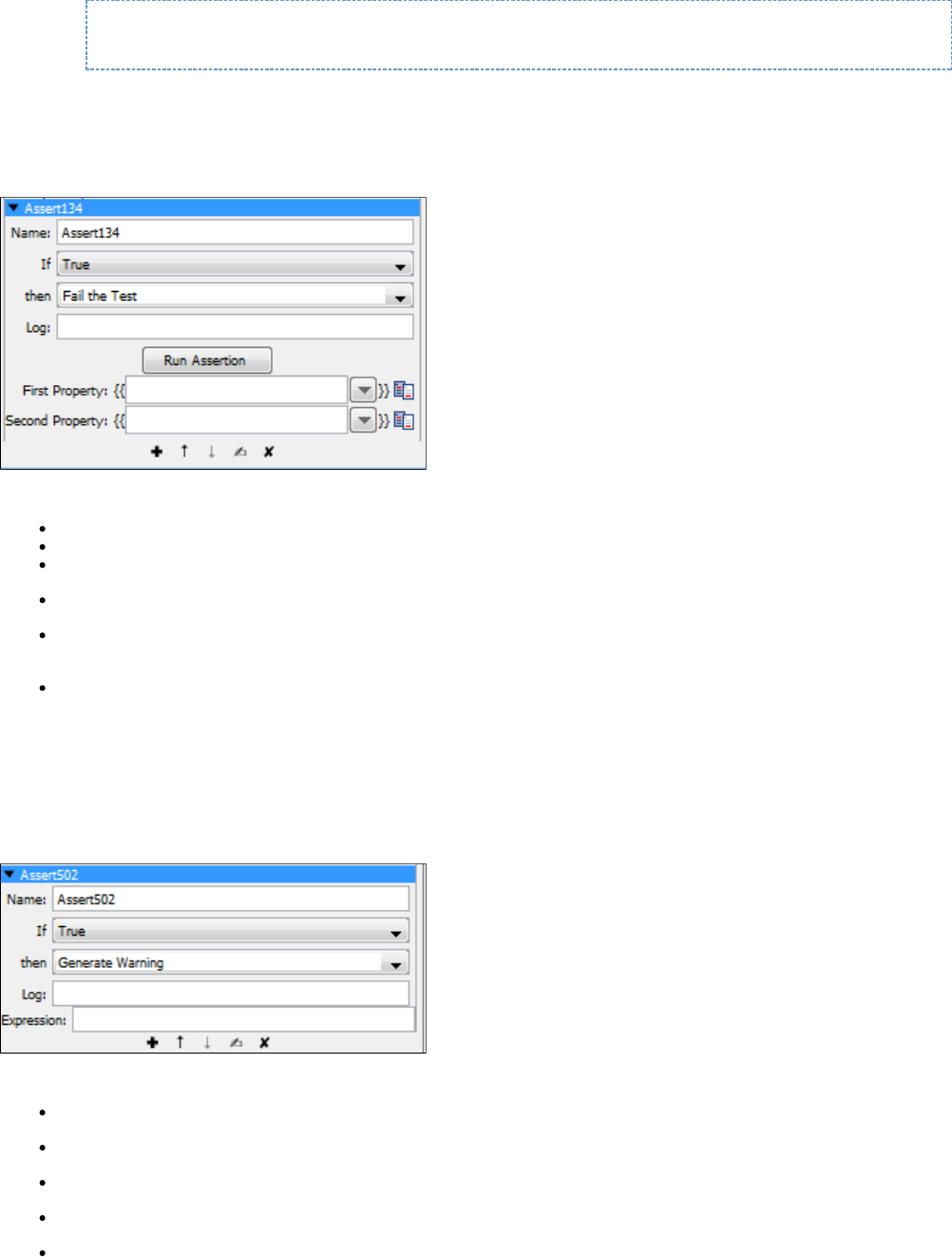
testExec.log("Got here");
Ensure Properties Are Equal Assertion
The assertion lets you compare the values of two properties to make sure that they are same. Typically this isEnsure Properties Are Equal
used with a data set and supplied "expected value" to make sure that the application functionality is correct.
Enter the following parameters:
Name: The name of this assertion. This will help you identify events for this assertion.
If: Select from the drop-down True or False.
Then: Select from the drop-down Fail the Test, Abort the Test, End the Test, or Go To a step.
Log: The text printed out as event text if the assertion fires.
First Property: The first property in the comparison. Enter the property name, select from the drop-down list of properties, select an
existing string pattern, or create a new .string pattern
Second Property: The second property in the comparison. Enter the property name, select from the drop-down list of properties, select
an existing string pattern, or create a new .string pattern
Click the Run Assertion button to test the assertion.
Assert on Invocation Exception Assertion
The assertion lets you alter the test flow based on the occurrence of a Java exception. The assertion will assertAssert on Invocation Exception
true if a particular Java exception is returned in the response.
Enter the following parameters:
Name: The name of this assertion. This will help you identify events for this assertion.
Log: The text printed out as event text if the assertion fired.
Assert: Select the behavior of the assertion using the option buttons.
Execute: Select the step to redirect to if the assertion fires.
Expression: The expression to search for in the invocation exception. It can be a regular expression. It is common to use the expression
'.*'
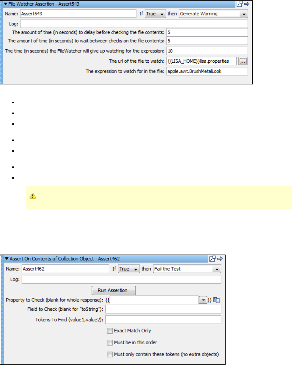
File Watcher Assertion Assertion
The assertion lets you monitor a file for given content, and react to the presence (or absence) of a given expression. This assertionFile Watcher
runs in the background while your test case is executing.
Enter the following parameters:
Name: The name of this assertion. This will help you identify events for this assertion.
Log: The text that will be printed out as event text if the assertion fired.
The amount of time (in seconds) to delay before checking the file contents: The number of seconds to wait before checking the file
at the beginning of the step that contains this assertion.
The amount of time (in seconds) to wait between checks on the file contents: The number of seconds to wait between each check.
The time (in seconds) the File Watcher will give up watching for the expression: The total number of seconds this assertion will
check for the expression.
The url of the file to watch: The URL or path to the file being watched.
The expression to watch for in the file: The regular expression being watched for in the response.
The times are in seconds and must be integers. They default to 0.
Check Content of Collection Object Assertion
The assertion lets you make simple assertions on the contents of a collection. This is a useful way to findCheck Content of Collection Object
out if certain tokens are in the collection, with the option of adding some simple constraints. For example, if one of the pieces of the data returned
from a bank web service is a list of accounts (checking, savings, loan, and so on), this assertion can check to make sure all the account IDs
match expected values.
Enter the following parameters:
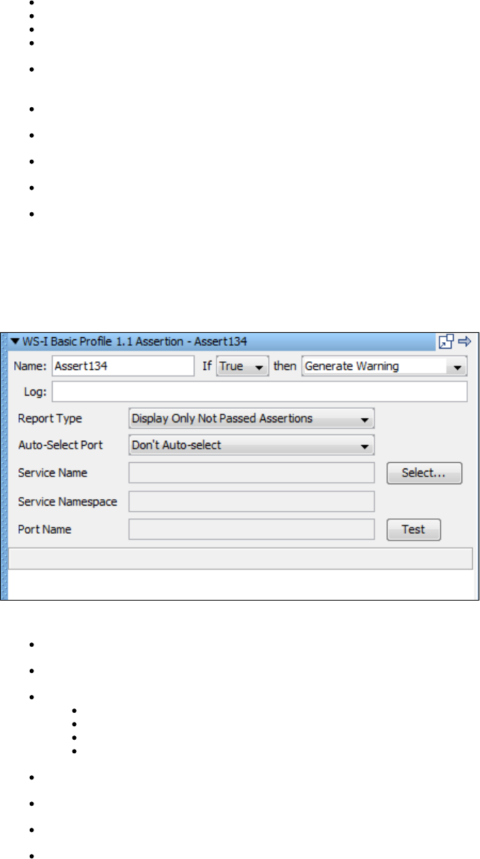
Name: The name of this assertion. This will help you identify events for this assertion.
If: Select from the drop-down True or False.
Then: Select from the drop-down Fail the Test, Abort the Test, End the Test, or Go To a step.
Log: The text printed out as event text if the assertion fired.
Property to Check (blank for whole response): The name of the property holding the object you want to use in the assertion. Leave
this blank to use the last response. The object must be of type or .Java Collection Array
Field to Check (blank for "toString"): Enter the name of a field and LISA will call its get method.
Tokens To Find (value1, value2): Comma-delimited string of tokens to check for.
Exact Match Only: The token names much match exactly.
Must be in this order: Select this check box if the tokens must be found in same order as the order in the string.Tokens To Find
Must only contain these tokens (no extra objects): The tokens in the string must be the only tokens found.Tokens To Find
Check the Run Assertion button to test the assertion.
WS-I Basic Profile 1.1 Assertion
The assertion lets you get a WS-I Basic Profile compliance report for a specific web service. This report is delivered in theWS-I Basic Profile 1.1
standard format specified by the WS-I Basic Profile specification.
Enter the following parameters:
Name: The name of this assertion. This will help you identify events for this assertion.
Log: The text that will be printed out as event text if the assertion fired.
Report Type: Select the level of (WS-I) assertions to include in the report. There are four levels:
Display All Assertions
Display All But Info Assertions
Display Only Failed Assertions
Display Only Not Passed Assertions
Auto-Select Port: Determine how the port will be selected – a specific port or .Don't Auto-select
Service Name: Select a service name from the list. This may auto-populate from the step.
Service Namespace: Is automatically populated based on the service name.
Port Name: Is automatically populated based on the service name.
Click Test to run the assertion.
Messaging VSE Workflow Assertion
The assertion is automatically added from the VSE recorder. It serves a specific purpose that enablesMessaging VSE Workflow Assertion
proper function with VSE recordings. Do not use it unless you know what you are doing, and if has been added to a step in a VSE model, do not
remove or edit it.
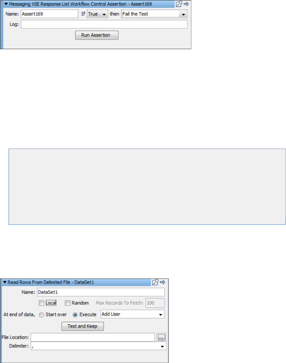
Click Run Assertion to run the assertion.
Data Sets
A is a collection of values that can be used to set properties in a test case while a test is running. This provides a mechanism todata set
introduce external test data to a test case.
Data sets are often rows of data that can be inserted into LISA properties as pairs. But this is not always the case; sometimes a dataName-Value
set will return a single property value.
Data sets can be created internal to LISA, or externally: for instance, in a file or a database table.
While a test is running, LISA will assign properties to the steps specified in the data set editor. When the last data value(s) are read from the data
set, the data can be re-used starting at the top of the data set, or the test can be re-directed to any step in the test case.
Data sets can be global or local.
The following topics are available in this chapter.
Global and Local Data Sets
Random Data Sets
Example Scenarios
Adding a Data Set
Deleting a Data Set
Reordering a Data Set
Renaming a Data Set
Moving a Data Set
Data Set Next Step Selection
Data Sets and Properties
Types of Data Sets
Global and Local Data Sets
Data sets can be global or local.
Global Data Sets
By default, a data set is global.
The coordinator server is responsible to provide data to all the test steps.
Here, all the model instances share a single instance of the data set.
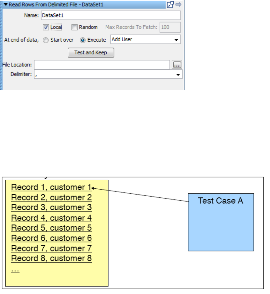
The global data set is shared and applied to all instances of the model, even if they are run in different simulators.
Local Data Sets
You can make the data set local by selecting the Local check box while building the data set.
Each instance gets (essentially) its own copy of the data set.
A local data set will provide one copy of the data set to each instance being run.
Example
There are three concurrent virtual users, a local data set with 100 rows of data, and a test case that loops over 100 rows of data and stops. Each
virtual user will see all the 100 rows of data in the data set.
For a local data set
A single run (1 vuser):Test Case A, will get the first row of data: Record 1, customer 1
A data set that is shared across virtual users is .global
For a global data set
When is staged with three virtual users or staged to run continuously, each test case will get the next row of data. LISA will share aTest Case A
data set across multiple runs given the instructions specified in the staging document.
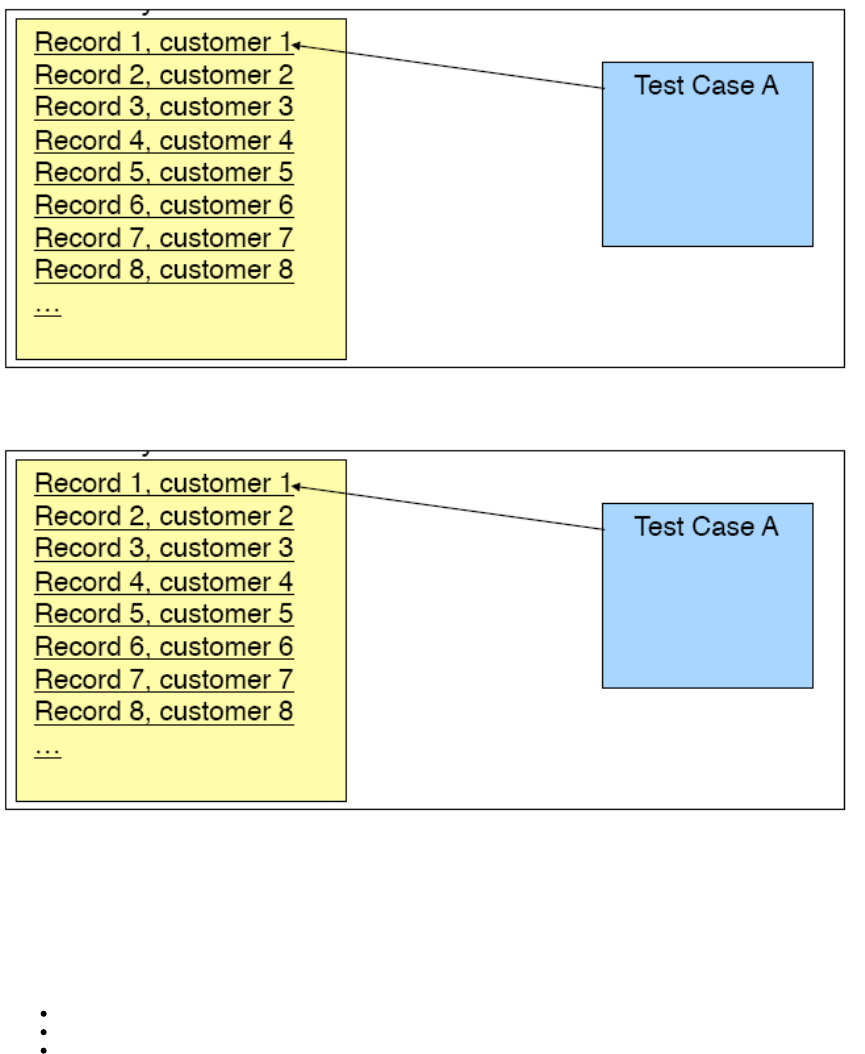
Each virtual user (instance) gets its own copy of the data set is .Local
When local is marked and Test Case A has a loop, the test will read every row of data in the data set. Each run will get its own copy of the data
set.
Test Case Looping
Often the data in a data set drives the number of times a test case is run.
This can be implemented several ways:
A test is set to finish when all the data in the data set has been exhausted.
A test is set to re-use the data set when the data has been exhausted.
A test step can call itself, or a series of steps can be configured in a loop that runs until the data in the data set has been exhausted.
A numeric counter data set can be used to cause a specific step to execute a fixed number of times, which can be set at the step-level or test
case-level.
For example, consider a test where we want to test the login functionality of our application using 100 user ID/password pairs. This can be
achieved by having a single step call itself until the data set (with 100 rows of data) has been exhausted; at which point it can redirect to the next
natural step in the test case, or perhaps the End step. Alternatively, you can use a counter data set with the user ID/password data set.
If a test case contains a global data set on the first step and the data set is set to end the test when the data set is drained, all instances of the
test will end for a staged run, overriding any other staging parameters such as steady state time. Local data sets will not end the staged run in this
fashion nor will data sets on steps other than the first test.
Random Data Sets
A random data set is a special type of data set, which can be thought as a wrapper around another data set.
In the case of random data sets, you can choose a data set to be randomized for specific steps, and also choose the maximum number of records
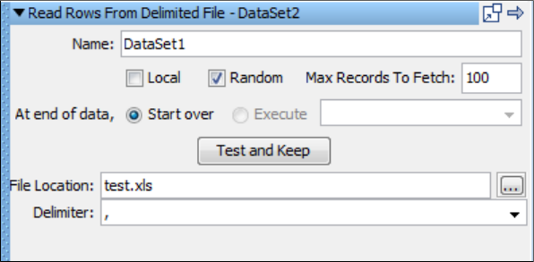
1.
2.
3.
1.
2.
3.
for randomization.
When a random wraps a data set, N copies of the data set are added to the random's list, where N = Max Number of rows. So when N=10, 10
copies of the rows from the data set are made.
When a step references the random data set, a random row is selected from the data set.
If you have a random data set named "RAND1," and it reads one column named "Fruit," and the maxRows is set to '"10," will be theRAND1
random number generated to pick a row; it will be in the range 0 through N-1. will be the value of "Fruit" column found in that row.Fruit
To make a data set random
Select the data set that you want to make as random. This example uses the Read Rows from Delimited File data set.
Select the Random check box.
Enter the Max Record to Fetch number. This number is the maximum number of records that you want from the data set. If this is larger
than the records in the data set, the smaller number will be used to create the random set.
Example Scenarios
To show the behavior of tests using data sets, consider the following scenarios:
A test has fifteen virtual users, and a data set has two rows of data.
Scenario 1: At the end of data -> Start over
The first user would read the first row of data, the second user would read the second row. The third user would start over and read the first row,
and so forth. This would continue until all fifteen users have run the test. The first row was read eight times, the second row seven times.
Scenario 2: At end of data -> Execute End step
The first user would read the first row of data, the second user would read the second row. The third user through the fifteenth user would start
the test, and immediately jump to the step.End
A test has 100 virtual users, and the data set has 1500 rows of data. Tests are running concurrently.
Scenario 1: At the end of data -> Start over
When the 100 users start, they would read the first 100 rows of data. Depending on the staging document, as cycles end the users would start
new runs of the test case and consume more rows of the data set. If all rows are consumed, and the test run has not ended, it would start over
with the first row again until the test run ends.
Scenario 2: At end of data -> Execute End step
The test run would end after 1500 cycles.
A test has ten virtual users, and the data set has 10,000 rows of data. The staging document specifies that the test should run for two
minutes.
The ten users will start and read the first ten rows of data. They will continue consuming rows of data from the 10,000 rows, and depending on
how fast they run would determine how far down the data set they go. At the two minute mark, the test would end.
Adding a Data Set
To add a data set
Select a test case in the model editor.
Expand the Data Sets tab in the right panel.
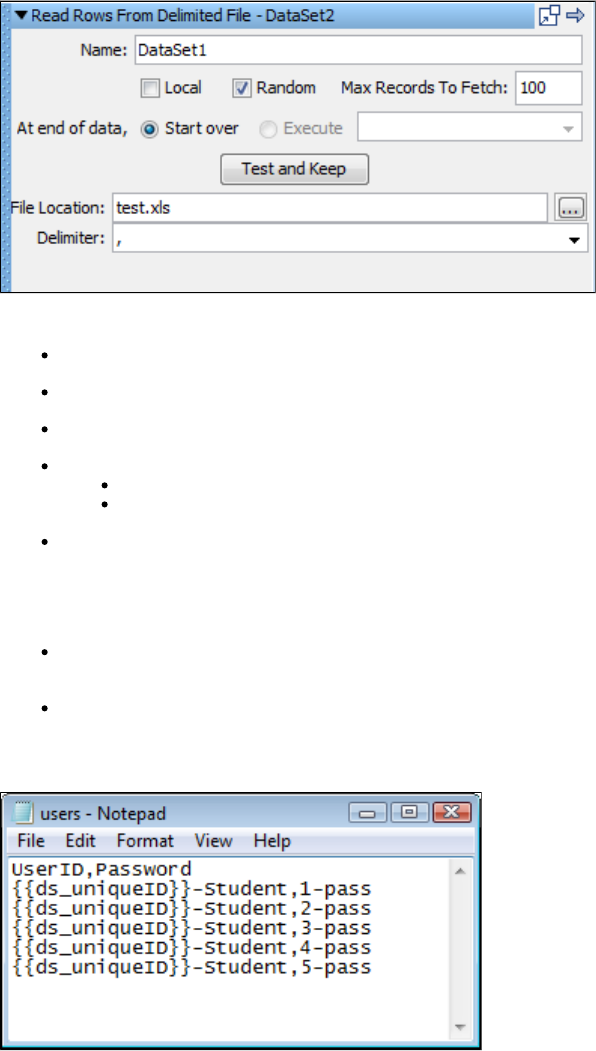
3.
4. Click the Add icon to open the data set panel listing the Common Data Sets.
Click the required data set to open the appropriate Data Set Editor. The editor is specific to each data set.
Data Set Editor Example
The following image shows the editor for the Read rows from a delimited data file data set.
The top panel of the data set editor is common to all data set types. It consists of:
Name: The name of the data set.
Local: Select the check box if you want a local data set. The default is global (not checked).
Random: Select the Random check box if you want to make this a random data set and enter the Max records to fetch number.
At end of data: Instructions for how to proceed after all the data has been read. There are two options:
Start over: Continue reading data from the top of the data set.
Execute: Select the step to execute after all the data has been read. The pull-down menu has been pre-populated with all the
available steps in the test case.
Test and Keep: After all the parameters have been entered click this button to test the data set, and to load it into the appropriate steps
in the test case
The bottom panel of the data set editor is specific to the data set being created. For the Read rows from a delimited data file data set, enter the
following:
File Location: Enter the full path name of the text file, or browse to file with the browse button. You can use a property in the path name
(for example, ).LISA_HOME
Delimiter: Enter the delimiter being used. Any value is allowed as a delimiter. Common delimiters are provided in the drop-down menu.
This data set requires a delimited text file. In the following example, the first line specifies the property names: userid and password. Subsequent
lines list the data values to be used for these properties.
When you click Test and Keep, the first row of data is loaded, and a message confirms that the data set can be read and shows the first row of
data.
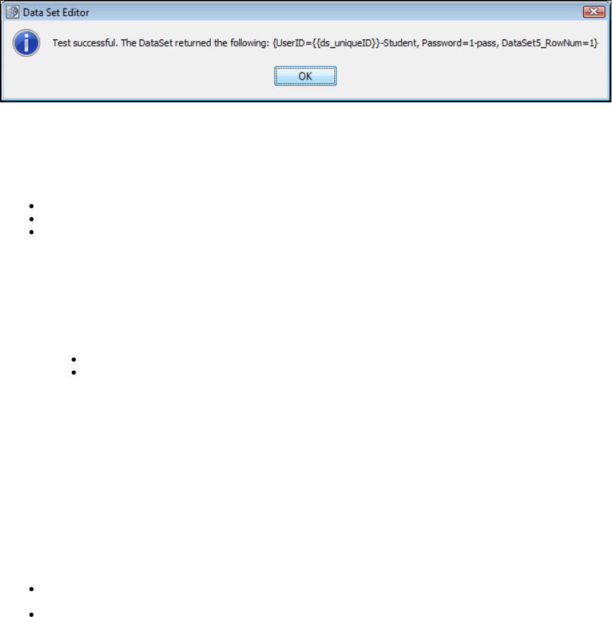
1.
2.
1.
2.
1.
2.
3.
1.
2.
This example shows a data set named DataSet1 that will be used until all the rows have been used, and then the step will be executed.end
Ending a Test Case by a Data Set
The following conditions must be met for a data set to end a test run:
The data set must be global.
The data set must be set "At end of data: Execute end".
The data set must be increased on the first step of the test case.
Be careful when you apply a global data set to the first step in a test case as it will pull down the entire staged run before completing the cycles.
Deleting a Data Set
To delete a data set
Do one of the following:
Select the data set in the Elements panel, and click the Delete icon on the toolbar.
Right-click the data set in the model editor and select Delete.
A message box appears to confirm the deletion of the data set.
Click Yes.
Reordering a Data Set
To reorder a data set
Select the data set in right panel.
Click the up or down arrow on the toolbar to move the selected data set up or down.
Renaming a Data Set
To rename a data set
Select the data set in the Elements panel and click the Rename icon on the toolbar.
Select the data set in the model editor and right-click to open a menu to rename.
Moving a Data Set
You can move data sets in the Model Editor from one test step to another by using drag and drop.
To move a data set
Click the data set attached to a test step: for example, Step 1.
Select the data set and drag it to the target test step: for example, Step 2, in the Model Editor and leave it there.
The dragged data set will then be applied to Step 2.
Data Set Next Step Selection
You can select the next step or the end step to be executed after the data set has fired.
To select the next step
Right-click the data set in the Model Editor to open the menu.
Click the At end menu and select the next step to be executed.
Data Sets and Properties
Data sets can use properties.
There are some major uses of properties:
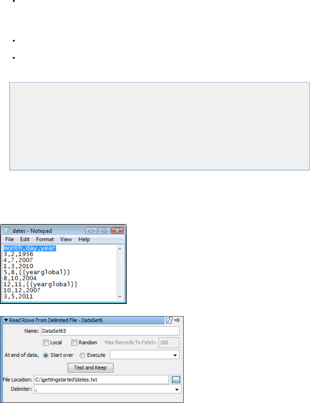
When specifying the location of an external data set, we can use a property, perhaps LISA_HOME rather than a hard coded value for the
path name. For example - LISA_HOME/myTests/myDataset.csv
This increases the portability of the data set. Properties used in this way must be specified as a system property, or be defined in a Configuration,
because they usually have to be available early in the test run. You can define a dummy value in your Configuration and modify it at a later date.
This will allow the file to be found at design time. This use of properties is important when you are running your tests on LISA Server.
Data set values can contain properties. These will be evaluated when the value is read. For example, we could set up a login value in the
data set as student _1. Then, if the current value of is , the resulting data value becomes .student Bart Bart_1
Local data sets can use properties from the test case, but global data sets cannot because they are shared by all virtual users.
Types of Data Sets
The types of data sets are documented as they appear on the menu.
Read Rows from a Delimited Data File Data Set
Create your own Data Sheet Data Set
Create your own Set of Large Data Data Set
Read Rows from a JDBC Table Data Set
Create a Numeric Counting Data Set
Read Rows from Excel File Data Set
Read DTO's from Excel File
Unique Code Generator Data Set
Random Code Generator Data Set
Message_Correlation ID Generator Data Set
Load a Set of File Names Data Set
XML Data Set
Read Rows from a Delimited Data File Data Set
The data set assigns values to properties based on the contents of a text file. This is the most commonlyRead Rows from a Delimited Data File
used type of data set in LISA. The first line of the text file specifies the names of the properties into which the data values will be stored.
Subsequent lines list the data values to be used for these properties. The text file is created using a simple text editor.
Following is an example of a comma-delimited data file. The first row, which is highlighted, shows the property names in this data set.
The Data Set Editor is used to define the data set.
In the Data Set Editor enter the following:
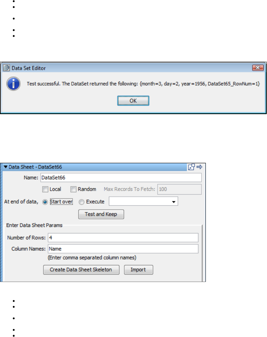
Name: Enter the name of the data set.
At End Of Data: Select whether you want to start over and read values from the start of the data set, or execute the step you select in
the pull-down menu.
Local: Designate whether this should act as a global or local data set. Global is the default. Local data sets are created
one-per-simulator; global data sets are created once and shared by all simulators.
File Location: The full path name of the text file, or browse to file with the button.Browse
Delimiter: The delimiter being used. Any character is allowed as a delimiter. There are common delimiters in the drop-down menu.
Click the Test and Keep button to test and load the data. You will get a message that confirms that the data set can be read, and shows the first
set of data.
Create your own Data Sheet Data Set
The data set lets you generate your data set data within LISA, without requiring any reference to an external file.Data Sheet
The Data Sheet consists of a data table; the column headings specify the property names and the table rows specify the data values for those
properties. The table skeleton is built by specifying the number of rows and the column names (properties).
In the Data Set Editor enter the following:
Name: The name of the data set.
At End Of Data: Select whether you want to start over and read values from the start of the data set, or execute the step you select in
the pull-down menu.
Local: Whether this should act as a global or local data set. Global is the default. Local data sets are created one-per-simulator; global
data sets are created once and shared by all simulators.
Number of Rows: Initial estimate of number of rows (it can be modified later).
Column Names: Comma delimited list of column names (these are also the property names).
Click the Create Data Sheet Skeleton button.
Enter your data into the table. Following is an example of a data sheet:
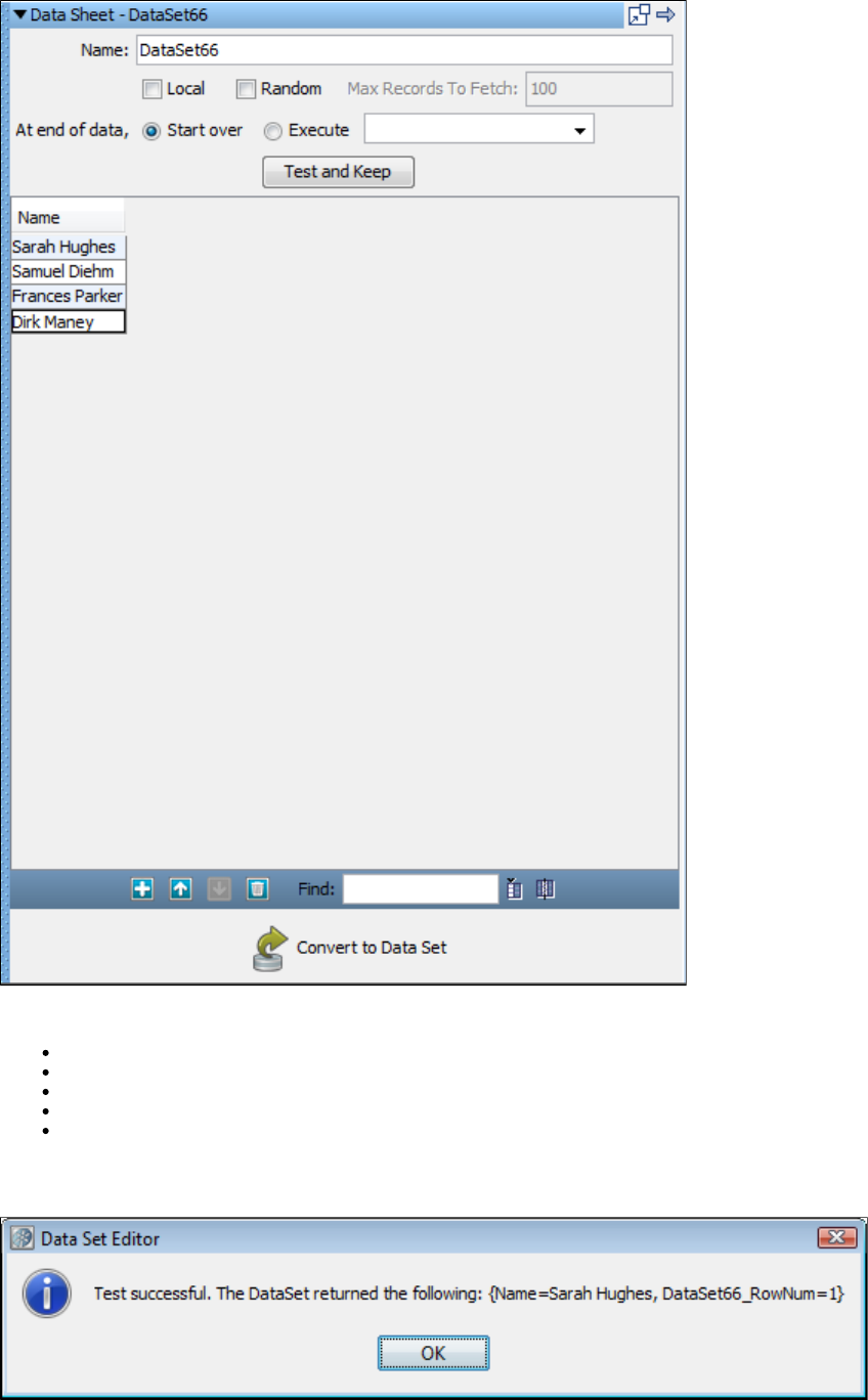
Use the functions in the bottom toolbar to create and modify the table:
Add: Add rows to the table.
Delete: Delete the selected row.
Up and Down: Select a row and move it up or down in the table.
Add Column: Add a column to your table.
Delete Column: Delete a column. Select a cell in the column you want deleted, making sure that the cell is selected for editing, and click
this button.
Click the Test & Keep button to test and load the data. You will get a message that confirms that the data set can be read, and shows the first set
of data:
You can also:
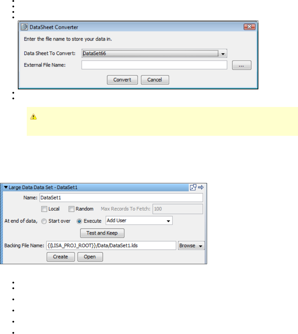
Double-click the column header to sort the rows
Right-click on the column name to change the column name
Select a cell, and then right-click on a cell to select the toolbar functions and to Launch Extended View to edit the cell
Click the Convert to Data Set button at the bottom of the panel to convert your data sheet to a data set, or a file on the file system.
Data Sheet to Convert: By default, the data sheet you just created, or select from the pull-down list.
External File Name: The name and path of the file you want to create from the datasheet.
Moving rows up or down in the table may affect the outcome of a test. The order of columns will not affect the outcome
of the test.
Select the steps that will use the data sheet.
Create your own Set of Large Data Data Set
The data set lets you define a custom data table that can be arbitrarily large. The data can have any numberCreate your own Set of Large Data
of rows and columns. A backing file name is the file in which all the data is stored.
Enter the following parameters:
Name: The data set name.
Local: Whether this should act as a global or local data set. Global is the default. Local data sets are created one-per-simulator; global
data sets are created once and shared by all simulators.
Random: Whether the record after the current record (sequential access) will be read, or a random record will be read. Sequential
reading is the default.
Max Records to Fetch: The upper bound on the number of records to fetch for random access. This text field is disabled if the Random
check box is not selected.
At end of data, Start over or Execute: Select whether you want to start over and read values from the start of the data set, or execute
the step you select in the pull-down menu
Backing file name: This is the name of the file in which data is stored. This file is created automatically and data that you supply is
inserted in it.
The Create button will bring up a panel that lets you specify additional parameters for file creation.
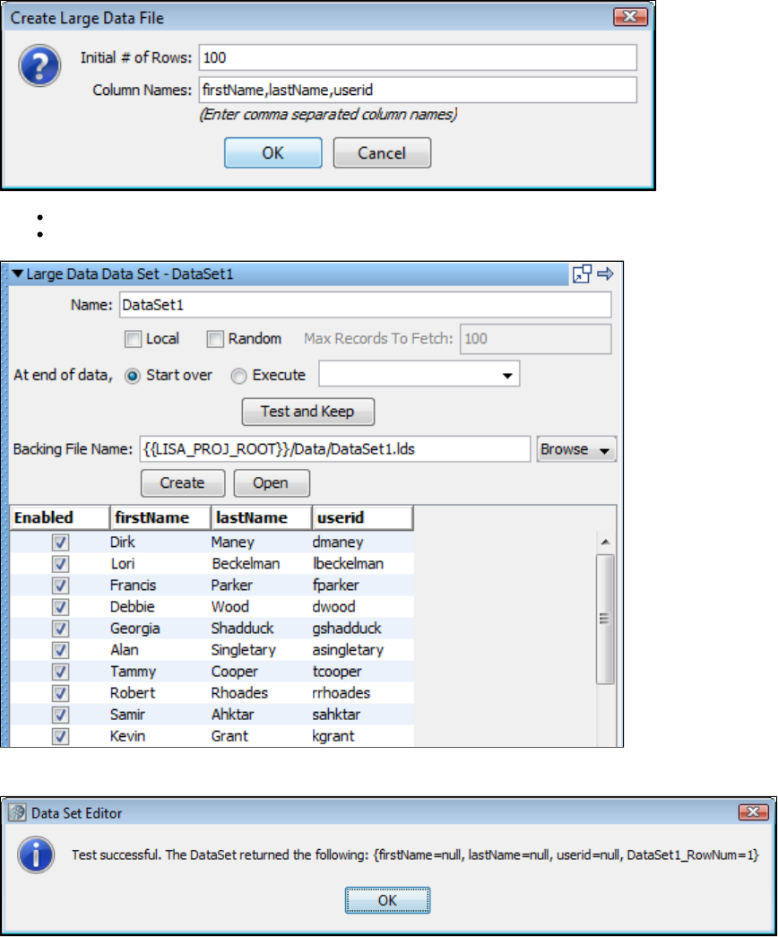
Initial # of Rows: This field gives the initial number of rows to be created. You can add additional rows using the editor.
Column Names: This field expects column names separated by commas that will go into the data set.
Pressing the Test and Keep button after entering data in the columns that we created before, data will be copied in the backing file created.
Read Rows from a JDBC Table Data Set
The data set is used to read source test case data from a database. The data is read using a JDBC driverRead Rows from a JDBC Table
(which must be supplied by the user). Each column in the table of data will be represented as a LISA property. The data set will then loop across
the rows returned from the SQL query.
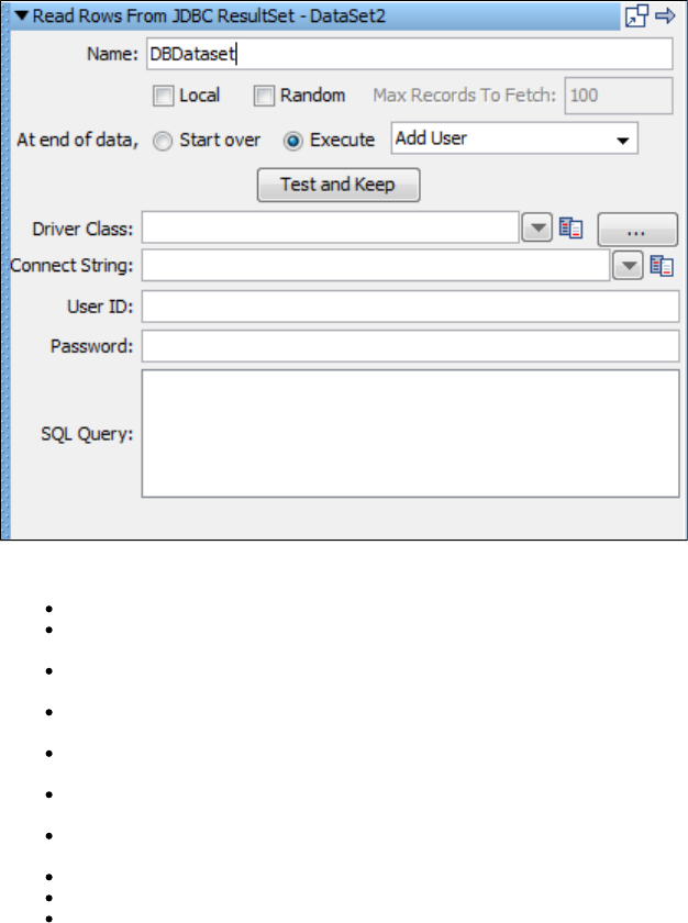
In the Data Set Editor, enter the following:
Name: The name of the data set.
Local: Whether this should act as a global or local data set. Global is the default. Local data sets are created one-per-simulator; global
data sets are created once and shared by all simulators.
Random: Whether the record after the current record (sequential access) will be read, or a random record will be read. Sequential
reading is the default.
Max Records to Fetch: The upper bound on the number of records to fetch for random access. This text field is disabled if the Random
check box is not selected.
At End Of Data: Select whether you want to Start Over and read values from the start of the data set, or Execute the step you select in
the pull-down menu.
Driver Class: Enter or select the full package name of the appropriate driver class. Standard driver classes are available in the pull-down
menu.
Connect String: This is the standard JDBC URL for your database. Enter or select the URL. JDBC URL templates for common database
managers are available in the pull-down menu.
User ID: Enter a user ID (if it is required by the database).
Password: Enter a password (if it is required by the database).
SQL Query: The SQL query used to create the data set.
Click the Test and Keep button to test and load the data. You will get a dialog window that confirms that the data set can be read, and
shows the first set of data.
Create a Numeric Counting Data Set
The data set assigns a number to a property. The number assigned starts at a given value and changes by a fixedCreate a Numeric Counting
step every time the data set is used until it exceeds a known limit. This data set is used to simulate a "for" loop, or to set the number of times
something will occur. For example, you might want to make 100 calls to the same step. The following example illustrates how to do this using the
Create a Numeric Counting Data Set.
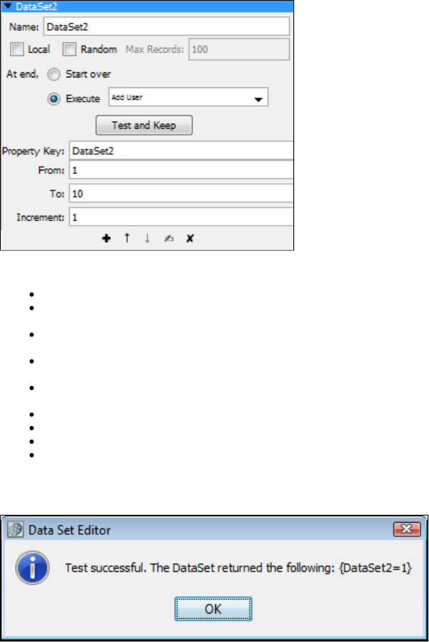
In the Data Set Editor enter the following:
Name: The name of the data set.
Local: Whether this should act as a global or local data set. Global is the default. Local data sets are created one-per-simulator; global
data sets are created once and shared by all simulators.
Random: Whether the record after the current record (sequential access) will be read, or a random record will be read. Sequential
reading is the default.
Max Records: The upper bound on the number of records to fetch for random access. This text field is disabled if the Random check box
is not selected.
At End Of Data: Select whether you want to start over and read values from the start of the data set, or execute the step you select in
the pull-down menu.
Property Key: The name of the property into which the counter value will be stored.
From: The initial counter value.
To: The final counter value.
Increment: The step increment for the counter. The counter data set can be used to count backwards by assigning a negative increment.
Click the Test and Keep button to test and load the data. You will get a message that confirms that the data set can be read, and shows the first
set of data.
Select the steps that will use the data set.
In our example, the data set is configured to start at 1, increment by 1 until it exceeds 10.
To iterate on a single step, change that step's "next step" to be itself. Do this by going to the step's Base Step Info and selecting Next for the Step
element.
Read Rows from Excel File Data Set
The data set assigns values to properties based on the contents of an Excel spreadsheet.Read Rows from Excel File
The first non-blank row of the Excel spreadsheet specifies the names of the properties to which the data values will be assigned. Subsequent
rows list the data values to be used for these properties. The first full row of empty cells is treated as the end of data.
For example, you might want to test a set of first name, last name, user ID and password combinations.
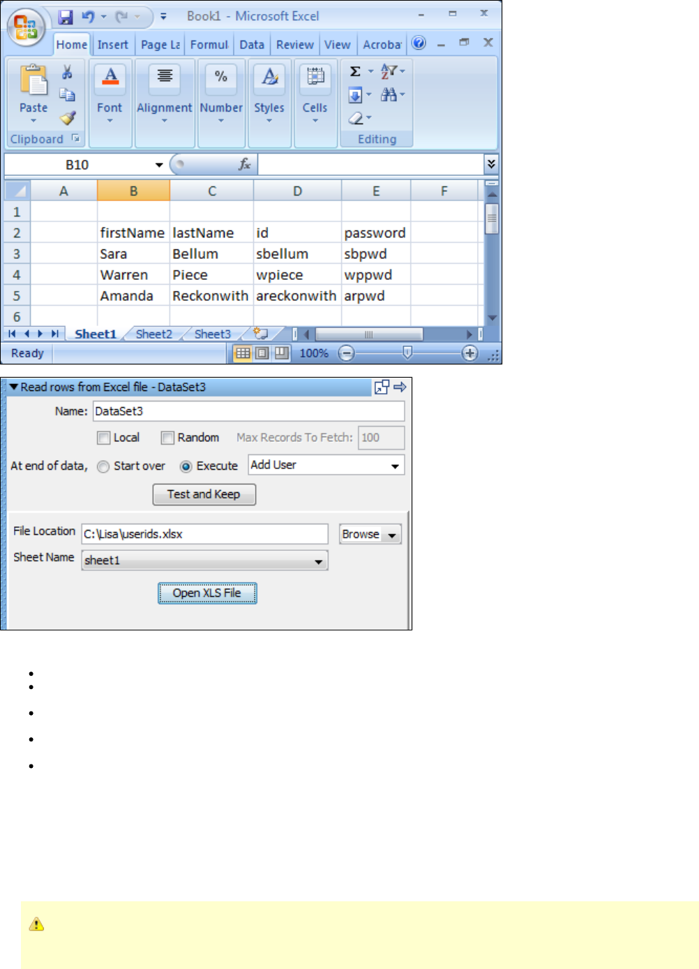
1. In the Data Set Editor enter the following parameters:
Name: Enter the name of the data set.
At End Of Data: Select whether you want to start over and read values from the start of the data set, or execute the step you select in
the pull-down menu.
Local: Select whether this should act as a global or local data set. Global is the default. Local data sets are created one-per-simulator;
global data sets are created once and shared by all simulators.
File Location: Enter the full path name of the Excel file, or browse to file with the browse button. You can use a property in the path
name ( for instance ).LISA_HOME
Sheet Name: Enter the name of the sheet in the Excel spreadsheet.
2. Click the Test and Keep button to test and load the data. You will get a message that confirms that the data set can be read, and shows the
first set of data.
3. Select the steps that will use the data set.
The previous example shows a data set named that will be used as many times as required. Data is loaded from Excel file.DataSet3
You can click the Open XLS File button to open and edit the Excel spreadsheet.
As of LISA 6.0.5, Excel 2007 spreadsheets are supported for Excel File data sets and Excel DTO data sets. Excel DTO data
sets are still created using the XLS format.
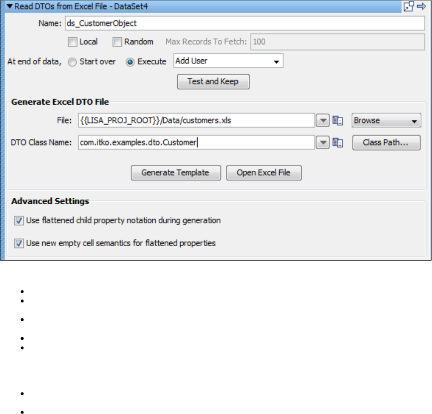
1.
Read DTOs from Excel File Data Set
The data set lets you parameterize Java data transfer objects (DTOs) in your test steps and gives you an easy way,Read DTOs from Excel File
through Excel spreadsheets, to provide data values for those parameters.
The Read DTO's from Excel file data set assigns values to the properties of a DTO and stores the object in a LISA property. This property can
then be used whenever the DTO is required as a parameter. The data in the data set can be simple data types like numbers or strings, or
complex data types such as DTOs, arrays and collections. The data represented in Excel will be converted into the proper data types
automatically when needed. The only complex part of using this data set is the initial creation of the Excel spreadsheet. Fortunately, this is done
for you. Given the package name of the DTO, a template is created, using one or more Excel sheets, that represent the object. Data types such
as primitives, strings, arrays of primitives and simple individual DTOs can be represented on a single sheet. More complex data types, such as
arrays of objects, require additional Excel sheets to represent the full DTO.
It is often the case that a web service endpoint expects complex DTOs. The Excel data set makes it very simple to create objects to use as
parameters to the web service. When the web service is first referenced, it is given a name and a URL for the WSDL. Java DTO classes in the
form are automatically generated and made available on the classpath. You can browse to thatcom.lisa.wsgen.SERVICENAME.OBJECTNAME
generated class in the DTO class browser (see the following example), generate an Excel file and simply fill in the template.
Building the data set is a two step process. First, let LISA build the template in Excel, then open the Excel spreadsheet and fill in the data fields in
all the sheets that are produced.
To build the template, enter the following in the Data Set Editor:
Name: The name of the data set. This becomes the property used to store the current DTO object.
At End Of Data: Choose whether you want to start over and read values from the start of the data set, or execute the step you select in
the pull-down menu.
Local: Whether this should act as a global or local data set. Global is the default. Local data sets are created one-per-simulator; global
data sets are created once and shared by all simulators.
File: The fully qualified path name, or browse to the Excel file using the browse pull-down menu.
DTO Class Name: The full package name, or browse to, the DTO object. The class file must be on LISA's Test Manager. Your class can
be copied to the hotDeploy directory to put it on the Test Manager.
2. Advanced Settings let you specify:
Use flattened child property notation during generation: Override child property flattening during Excel DTO data set generation. If
cleared, child properties will be generated as references with their own worksheets.
Use new empty cell semantics for flattened properties: Empty cell semantics for flattened properties means how empty cells are
interpreted in a DTO spreadsheets. For example, given the flattened properties { "prop1.subprop1", "prop1.subprop2" }, if both subprop1
and subprop2 have empty cell values, then under the new semantics the reference to "prop1" will be set to null. Under the old semantics,
prop1 would be non-null, but references to subprop1 and subprop2 would both be null. New semantics should be used by default,
especially by web services with WSDLs that use non-nillable types. If not used in the case of non-nillable types, the intermediate non-null
references for containing properties that are automatically created when reading a DTO spreadsheet may result in the generation of
invalid XML according to the schema, because cell values are empty.

3. Click the Generate Template button. The template will be built for you. In the system messages you will see a message that the file has been
built.
4. Click the Open XLS File button.
5. The spreadsheet contains everything needed to construct the object. We will show how to add data in the next section. Close the XLS file.
6. Click the Test and Keep button to test and load the data. You will see a window that confirms that the data set can be read, and shows the first
set of data.
Building the Excel spreadsheet
To facilitate this explanation, we will use an actual DTO object: . This class is included with the LISA examplescom.itko.example.dto.Customer
and can be found by browsing the Test Manager using the Browse button.
The Customer DTO has the following properties:
Property Name Type
balance Double
id int
name String
poAddr Address
since Date
types int[]
locations Address[]
The Address DTO has the following properties:
Property Name Type
city String
line1 String
line2 String
state String
zip String
The first six Customer DTO properties can appear on one Excel spreadsheet. However, the locations property, an array of Address objects,
requires a second Excel spreadsheet.
Looking at the first spreadsheet, at the top, LISA lists the DTO spec (Customer) and the current DTO object (Customer). It would also list the Java
doc location, if available. The actual data sheet appears as follows, with a row specifying property names, followed by a row specifying the data
types. The first field (column) is not a DTO property, but a special field (Primary key), that holds a unique value for each row.
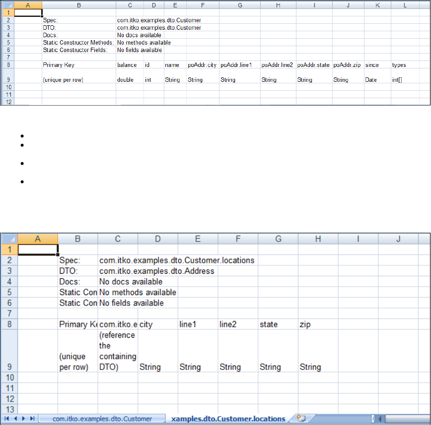
Looking at the data sheet we can see the following:
Each row contains the data for a single Customer DTO.
The poAddr property, of type Address, has been "flattened" and its properties are listed on this sheet. These properties are prefixed with
poAddr and then the property name in the address object (i.e. poAddr.city).
The since property, of type date, is prefilled with today's date. This is to show you the required format for the date mm/dd/yyyy. All dates
must have this format in the Excel template.
The types property, of type int[], is a single cell that can contain the array elements as a comma separated list. This is only possible for
arrays of primitives or strings.
The location property, of type Address[], does not appear on this sheet. It is on the second sheet in the Excel file. This is because it is an array of
objects. This sheet contains the data for an Address object in each row. There are two special fields in this sheet: "Primary Key", and the
"reference the containing DTO" field that is used to link the rows in this sheet to the rows in the primary sheet.
Because each Customer object can have several locations, several rows in the locations sheet belong to an object specified in a single row of the
Customer sheet. This is manifested in the second sheet by listing the primary key of the parent Customer object in the "reference the containing
DTO" field of each location that belongs to the Customer. You should see a similarity here to primary/foreign key relationships in databases. An
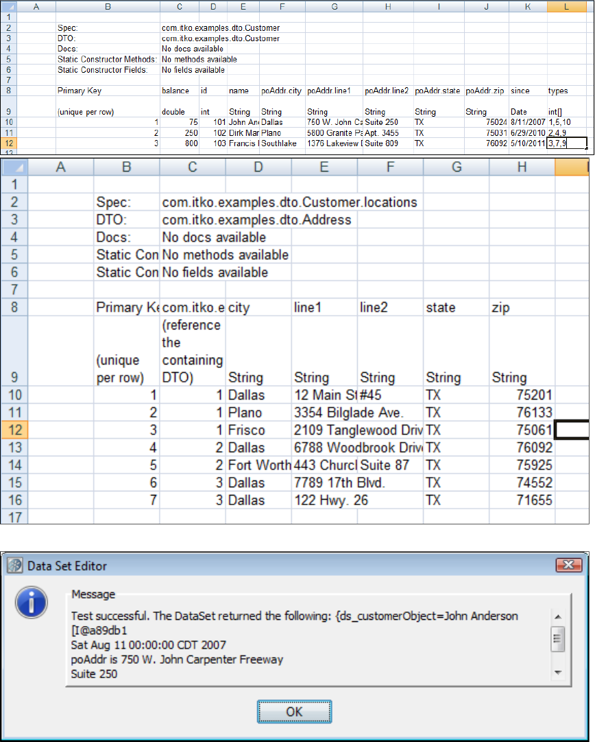
examination of the following illustrations, which have the spreadsheets filled out, should clarify the procedure.
When you save the spreadsheet and press Test and Keep in LISA, you will see the first Customer DTO in the message.
Depending on the complexity of your DTO, you could have several more Excel sheets in the Excel workbook. However, the process is the same
as the previous example.
To see how you might use this Customer DTO as a property, see the sections on testing Java objects in .Test Steps
Unique Code Generator Data Set
The data set provides a unique token (or code) each time it is called. The token can be numeric or alphanumeric, andUnique Code Generator
can have a user-defined prefix pre-pended to it. This is commonly used in testing to create new users, accounts, and so on, to help ensure they
do not use a value that is already inside a system.
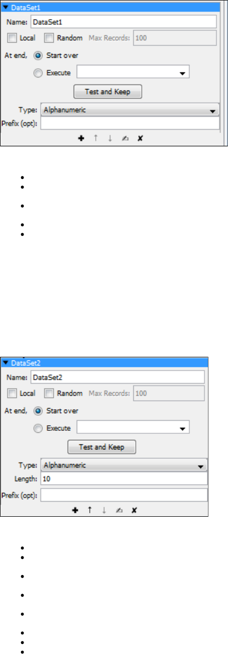
In the Data Set Editor, enter the following:
Name: The property that is assigned the value. This is also the name of the data set.
Local: Whether this should act as a global or local data set. Global is the default. Local data sets are created one-per-simulator; global
data sets are created once and shared by all simulators.
At end: Select whether you want to start over and read values from the start of the data set, or execute the step you select in the
pull-down menu.
Type: The type of token to return. Choices are number or alphanumeric.
Prefix (opt): Prefix to be pre-pended (optional)
Click the Test and Keep button to test and load the data. You will get a dialog that confirms that the data set can be read, and shows the first set
of data.
Because this data set will always return a token, the section of the Data Set Editor has no meaning for this data set type.At End of Data
Random Code Generator Data Set
The data set generates numeric or alphanumeric data randomly for use in a test case. This data set is similar to the Random Code Generator data set, but it lets you set a length for the result. This data set can be used to create a particular type of uniqueUnique Code Generator Data Set
value such as a telephone number, Social Security number, and so on.
In the Data Set Editor, enter the following:
Name: The name of the data set.
Local: Whether this should act as a global or local data set. Global is the default. Local data sets are created one-per-simulator; global
data sets are created once and shared by all simulators.
Random: Whether the record after the current record (sequential access) will be read, or a random record will be read. Sequential
reading is the default.
Max Records: The upper bound on the number of records to fetch for random access. This text field is disabled if the Random check box
is not selected.
At end: Select whether you want to start over and read values from the start of the data set, or execute the step you select in the
pull-down menu.
Prefix (opt): Adds prefix to the generated data. This field is optional.
Type: This field allows either alphanumeric or number type of data set to be generated.
Length: This field restricts the length of the random data generated to the value set here.
Click Test and Keep to test and load the data. You will get a message that confirms that the data set can be read, and shows the first set of data.
Message_Correlation ID Generator Data Set
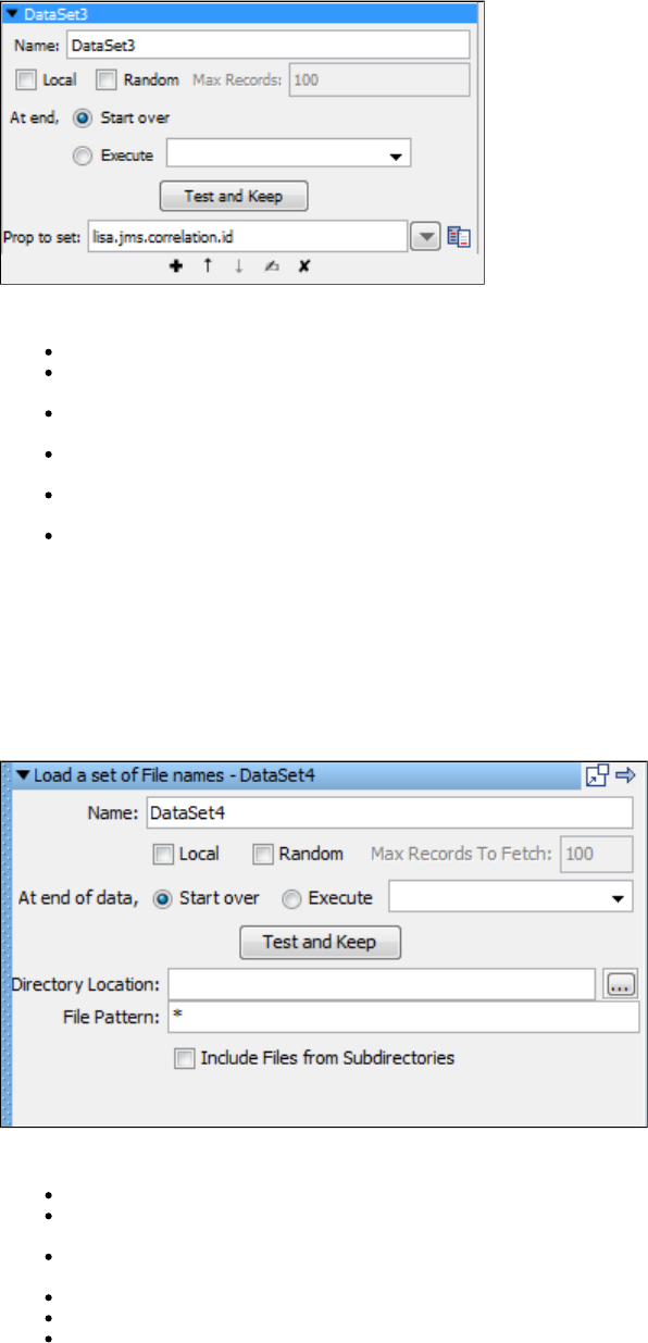
The data set is a specialized unique code generator useful for messaging. It generates a 24 byte uniqueMessage/Correlation ID Generator
code - designed specifically for IBM MQ Series correlation ID, but can also be used for any JMS provider. This data set creates or updates two
special LISA properties: and . The messaging steps recognize these properties and set thelisa.jms.correlation.id lisa.mq.correlation.id
message correlation ID appropriately.
In the Data Set Editor enter the following:
Name: The name of the data set.
Local: Whether this should act as a global or local data set. Global is the default. Local data sets are created one-per-simulator; global
data sets are created once and shared by all simulators.
Random: Whether the record after the current record (sequential access) will be read, or a random record will be read. Sequential
reading is the default.
Max Records: The upper bound on the number of records to fetch for random access. This text field is disabled if the checkRandom
box is not selected.
At End: Select whether you want to start over and read values from the start of the data set, or execute the step you select in the
pull-down menu.
Prop to set: LISA property to set. The default is lisa.jms.correlation.id.
Load a Set of File Names Data Set
The data set assigns a value to a property based on a filtered set of file names from the file system.Load a Set of File Names
The set of file names can include all the files in a given directory, or a set filtered by a "file pattern". There is also an option to recursively include
subdirectories in the set. The files are returned in a case-sensitive, alphabetical order, top directories first, followed by subdirectories (using depth
first ordering). Each time the data set is used, it returns the next file name (full path name) in the data set. This file name is stored in a property
whose name is the same as that of the data set.
In the Data Set Editor enter the following parameters:
Name: The name of the data set.
At End Of Data: Select whether you want to start over and read values from the start of the data set, or execute the step you select in
the pull-down menu.
Local: Whether this should act as a global or local data set. Global is the default. Local data sets are created one-per-simulator; global
data sets are created once and shared by all simulators.
Directory Location: The full path name of the directory to scan, or you can browse using the Browse button.
File Pattern: A filter pattern string, using an asterisk (*) as a wild card if wanted.
Include Files from Subdirectories: Check if files in subdirectories are to be listed.
Click Test and Keep to test and load the data. You will get a dialog that confirms that the data set can be read, and shows the first set of data.
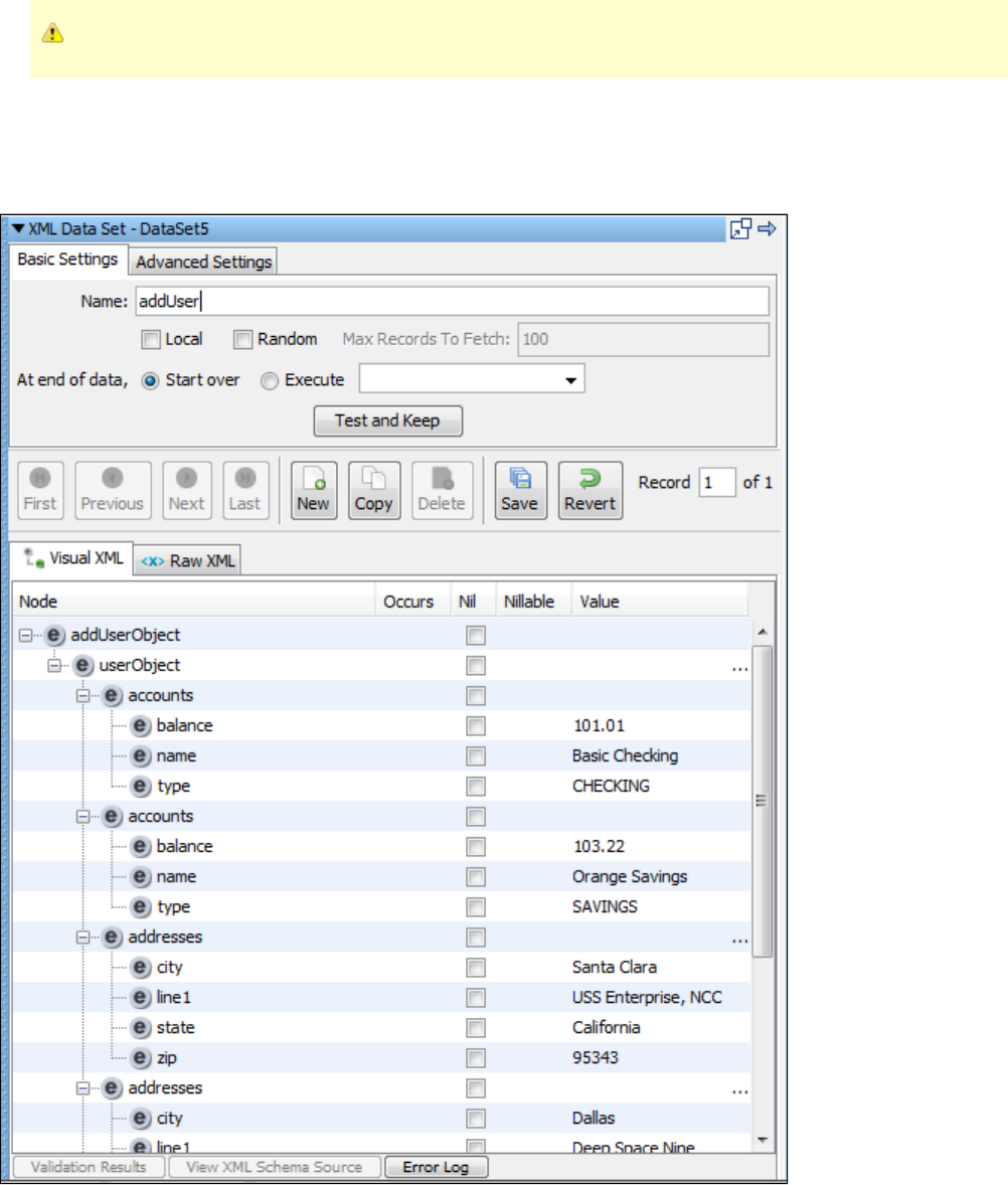
A large amount of data may take longer than you want; use the Cancel button to stop the operation.
XML Data Set
Like other data sets in LISA, the allows user-specified content to be added to distinct records. However, the XML data setXML data set
specializes in handling XML content.
At design-time, the first record of an XML Data Set populates the value for a property in LISA test state by clicking the Test and Keep button. The
LISA property name is the same as the name of the data set. For example, if the data set is named " ", then the property populated inDataSet1
the test case is "{{ }}". At run-time, all of the records can be accessed sequentially to create a data-driven test case.DataSet1
Basic Settings Tab
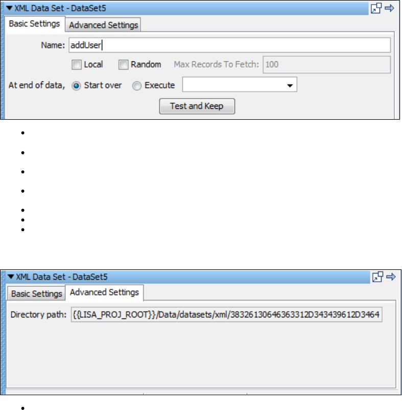
Name: The name of this data set. This value will be used as the name of the property in test step. For example, an XML Data Set named
will populate the property {{ }}.DataSet1 DataSet1
Local: Whether this should act as a global or local data set. Global is the default. Local data sets are created one-per-simulator; global
data sets are created once and shared by all simulators.
Random: Whether the record after the current record (sequential access) will be read, or a random record will be read. Sequential
reading is the default.
Max Records to Fetch: The upper bound on the number of records to fetch for random access. This text field is disabled if the Random
check box is not selected.
At end of data, Start over: After the last record is read, loop back to the very first record. This is the default behavior.
At end of data, Execute: After the last record is read, branch to the specified test step.
Test and Keep: At design-time, populate the LISA property associated with the data set in test state with the value of the first record.
Advanced Settings Tab
Directory path: This read-only value represents the directory on the file system where records are saved. There is a one-to-one mapping
between a record and a file in the directory path. If an XML data set is created within a project, the directory path will start with "{{
}} ". If no project is used, the directory path will start with "{{ }} ".LISA_PROJ_ROOT /Data/datasets/xml/ LISA_HOME /datasets/xml/
Record Editing Panel
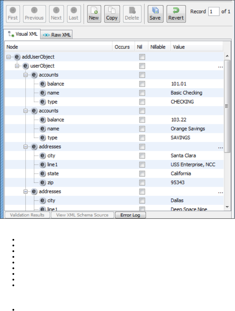
Action Buttons
First: Move to the first record in the XML data set.
Previous: Move to the previous record.
Next: Move to the next record.
Last: Move to the last record.
New: Create a new record.
Copy: Create a copy of the current record at the end of the data set and move to it.
Delete: Delete the current record.
Save: Save all pending changes.
Revert: Revert all pending changes.
Record Number Selector
Record X of X: Enter the record number to jump to a specific record.
Visual XML Tab
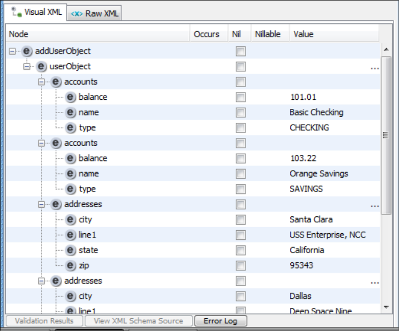
Visual XML Editor
Moving the mouse over the Node and Value columns will display a tooltip. This can help if the value in the table is too long to be fully displayed.
Raw XML Tab
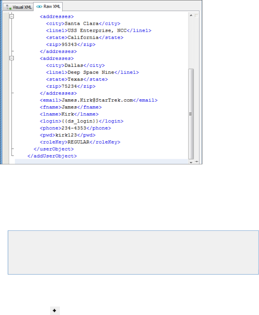
1.
2.
3.
This tab contains a raw text view of the XML contained in a record.
Double-clicking the left border will toggle the visibility of a top toolbar, line numbers bar, and bottom editing info bar in the editor.
Companions
A is a LISA element that runs before and/or after every test case execution. Companions are used to configure behavior that is globalcompanion
to the test case. These behaviors include simulating browser bandwidth and browser type, setting synchronization points in load tests and reading
properties from an external file. In a way, companions set some kind of a context for the test case execution.
Companions work as helpers for the test case, before any of the steps are executed.
The following topics are available in this section.
Adding a Companion
Companion Toolbar
Deleting a Companion
Reordering a Companion
Types of Companions
LISA Hooks
Adding a Companion
To add a companion
Open a test case and click the Companion element in the right panel.
Click the Add icon . This will open the Companion main menu.
Each companion has a different editor. Select the required companion to open the appropriate editor. Each companion type, with all its
parameters, is described in detail in .Types of Companions
Companion Toolbar
At the bottom of every element, there is a toolbar that has icons to add/delete/reorder.

1.
2.
Deleting a Companion
To delete a companion
Select the companion from the Companion tab and click the Delete icon in the toolbar. Alternately, you can right-click the
companion and select Delete.
A delete confirmation box appears.
Click Yes.
Reordering a Companion
To reorder a companion
Open the Companion tab and select the companion to be moved.
Click the Move up or Down arrows in the toolbar to set the selected companion's position.
Types of Companions
This section describes each of the companions that are available.
The following types of companions are described in this section:
Common Companions
Web Browser Simulation Companion
Browser Bandwidth Simulation Companion
HTTP Connection Pool Companion
Configure LISA to Use a Web Proxy Companion
Set Up a Synchronization Point Companion
Set Up an Aggregate Step Companion
VSE Companions
Java Protocol Companion
Observed System VSE Companion
VSE Think Scale Companion
Other Companions
Create a Sandbox Class Loader for Each Step Companion
Set Final Step to Execute Companion
Negative Testing Companion
Fail Test Case Companion
XML Diff Ignored Nodes Companion
Web Browser Simulation Companion
The companion lets you simulate a variety of web browsers. Web browsers identify themselves to a web server usingWeb Browser Simulation
the User-Agent HTTP header. You configure LISA to simulate several user-agents when you are running several virtual users in a staged test.
Each user-agent string is assigned a relative weight, allowing one browser to appear more often than others.
Use the default Browser Selection Companion Editor to specify the weights.
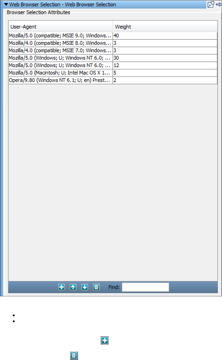
To configure the Web Browser Selection companion, enter or edit the list of browser agents and the weights:
User-Agent: The browser to simulate.
Weight: The weight for this browser. For example, to assign weights of 25%, 25% and 50% for three browsers, enter weights of 1, 1, and
2 for the three rows, and zero for the others (or delete the extra rows).
To add an additional user-agent, use the Add button.
To delete a line, use the Delete button.
Browser Bandwidth Simulation Companion
The companion lets you simulate varied bandwidths for the virtual users. Some testing scenarios call for theBrowser Bandwidth Simulation
simulations of different types of internet connections.
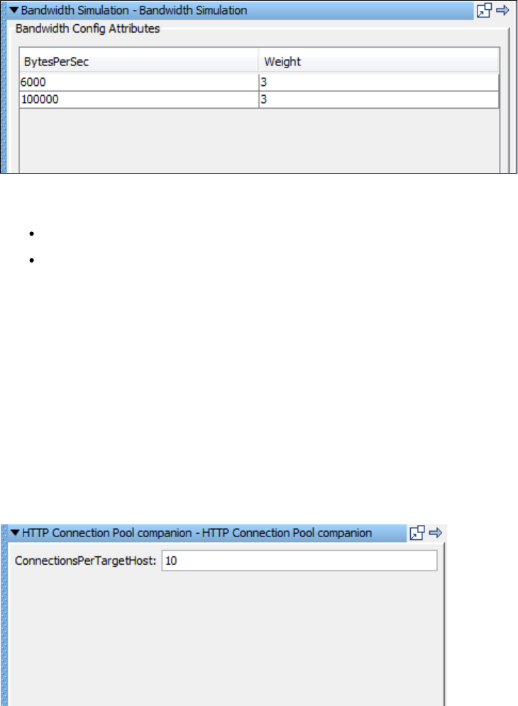
To configure the Browser Bandwidth Simulation companion
Enter the following parameters in the Browser Bandwidth Simulation Attributes editor:
BytesPerSec: The connection speed. For example, to simulate a connection speed of 56K, enter a BytesPerSec of 7000 (56000 bits / 8
bits per byte = 7000 bytes per second).
Weight: The weight given to this row. For example, to assign weights of 25%, 25% and 50% to three rows, enter values of 1, 1 and 2 on
the column of the three rows.Weight
To add a line, use the Add button.
To delete a line, use the Delete button.
HTTP Connection Pool Companion
The companion enables you to limit the number of HTTP connections per target server. This companion applies only toHTTP Connection Pool
the HTTP/HTML Request, REST, and Raw SOAP Request test steps.
LISA normally uses one HTTP connection for each virtual user. For example, if you run a test with 100 virtual users, then you would have 100
sockets open on the client and 100 sockets open on the server.
If you run a load test with thousands of virtual users per simulator, the underlying operating system might run out of available sockets. In this
scenario, consider using the HTTP Connection Pool companion.
The following image shows the editor for this companion.
The parameter specifies the number of connections to allocate to each unique endpoint.ConnectionsPerTargetHost
Assume that a test case has two steps: an http step to hit web server 1, and a second http step to hit web server 2. The test case has the HTTP
Connection Pool companion with a setting of 5 connections per target host. The staging document is configured to run 100 virtual users. There
are two simulator servers, so by default they will get 50 virtual users each.
Simulator 1 creates five connections to web server 1, and five connections to web server 2. Simulator 2 does the same thing. Each web server
now has 10 client connections. When a virtual user gets to the first http step, it must wait for one of the 5 connections to web server 1 to become
available. The virtual user uses the connection to make the HTTP call, and the connection goes back into the pool.
The following diagram illustrates this scenario. Simulator 1 has five connections to web server 1 and five connections to web server 2. Simulator 2
has five connections to web server 1 and five connections to web server 2.
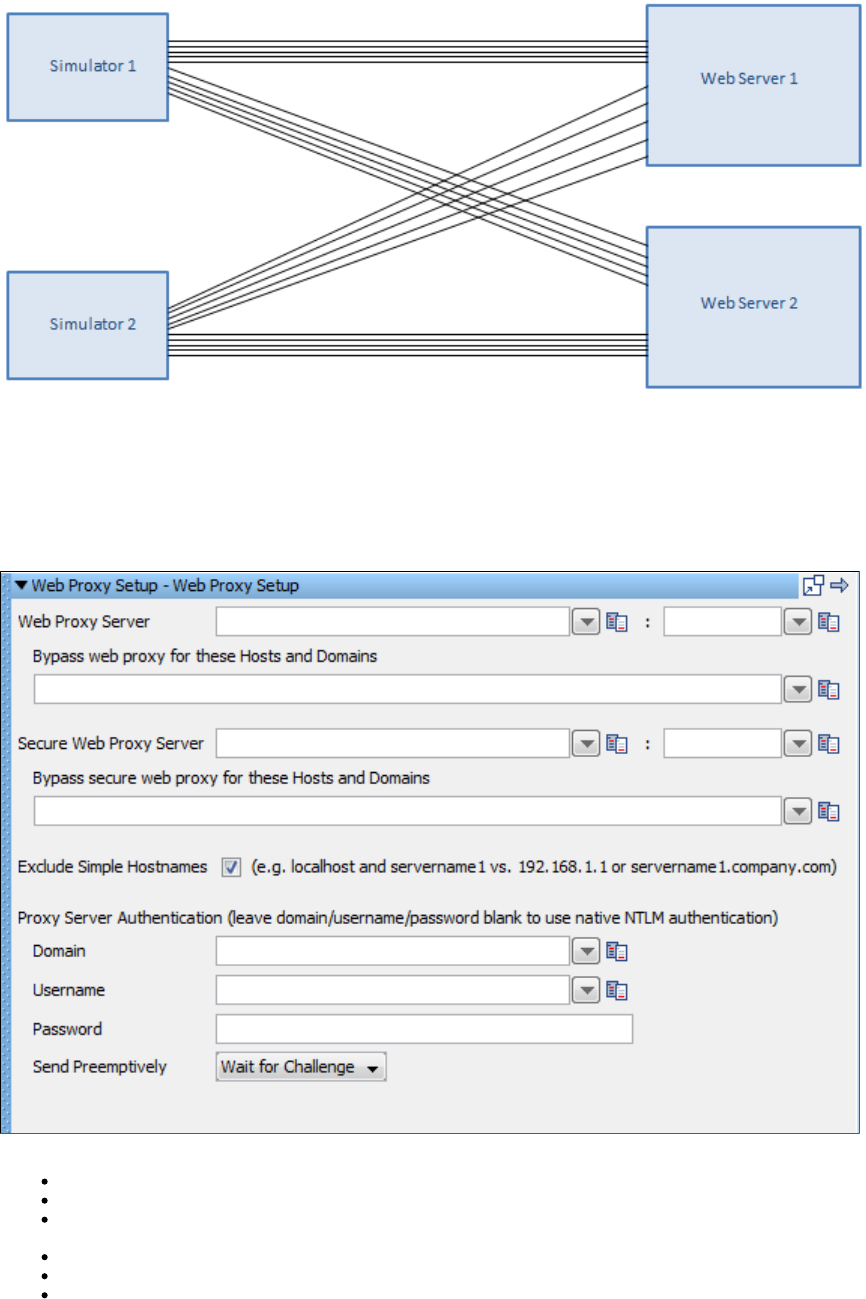
Configure LISA to Use a Web Proxy Companion
The companion lets you set up a proxy for all web testing steps. If there are times when your environmentConfigure LISA to use a Web Proxy
dictates the use of a proxy, use this companion. Proxy information is specific to your organization. Consult your operations team for your
company's proxy settings.
To configure the Web Proxy Setup companion enter the following parameters in the Web Proxy companion editor.
Web Proxy Server (Host & Port): The name or IP address of the proxy server in the first field, and the port number in the second field.
Bypass web proxy for these Hosts & Domains: Names of the domains/hosts for which you want proxy to be bypassed.
Secure Web Proxy Server (SSL Proxy Host & Port): The name or IP address of the SSL proxy server in the first field, and the port
number in the second field.
Bypass secure web proxy for these Hosts & Domains: Names of the domains/hosts for which you want secure proxy to be bypassed.
Exclude Simple Hostnames: Select to exclude hostnames like or .localhost servername.company.com
Proxy Server Authentication: Domain name with username and password if required for authenticating to proxy server.
LISA can also use its file to assign a web proxy for all test cases. This file is in the LISA home directory. Update the local.properties
and properties as appropriate and restart LISA. If you do not already have a lisa.http.webProxy.host lisa.http.webProxy.port local.properties
file in the LISA home directory, rename the existing to , and use it._local.properties local.properties
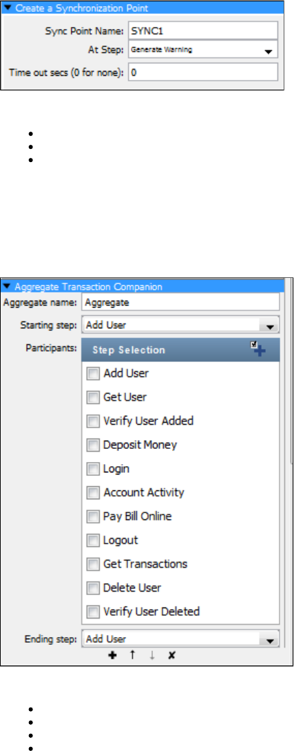
Set Up a Synchronization Point Companion
The companion lets you select a test step that will be used as a synchronization point in a test case or a testCreate a Synchronization Point
suite. At a synchronization point, virtual users will pause and wait until each one has reached this step. Then all virtual users will be released to
execute the step at the same time. This is useful when setting up load tests for concurrent testing or peak resource utilization.
For example, you could set up a 100-user test to have all users log in to your application and then all order the same seat in a theater session at
the same time.
Synchronization points apply to a single test or you can apply them to all tests within a test suite. In test suites, the Synchronization point name
must be the same across the suite, but the At Step can be different. Multiple test scenarios (and test suites) must be set to run in parallel,
because serial tests will not be able to hit the Synchronization point at the same time by definition. Multiple synchronization points can be defined
in a test case or test suite.
To configure the companion, enter the following parameters:Create a Synchronization Point
Sync Point Name: The name you specify for the synchronization point.
At Step: Select the step for the synchronization point from the drop-down list. Virtual users will pause before executing this step.
Time out secs (0 for none): The number of seconds to wait for synchronization to occur. All virtual users must reach the At Step before
the time out period elapses.
Set Up an Aggregate Step Companion
The companion lets you aggregate and report several physical test steps as one logical step for metrics collectionsSet Up an Aggregate Step
and reporting purposes. Unless you select the Quiet check box on a step, LISA also collects metrics and report events for the individual steps in
an aggregate. You can set multiple aggregation points.
Enter the following parameters in the Aggregate Transaction Companion Editor:
Aggregate name: The name of the aggregation step. Spaces are allowed.
Starting step: Select the start (first) step of the aggregation from the pull-down menu.
Participants: Check the steps to include in the aggregate (exclude the Starting and Ending steps).
Ending step: Select the end (last) step of the aggregation from the pull-down menu.
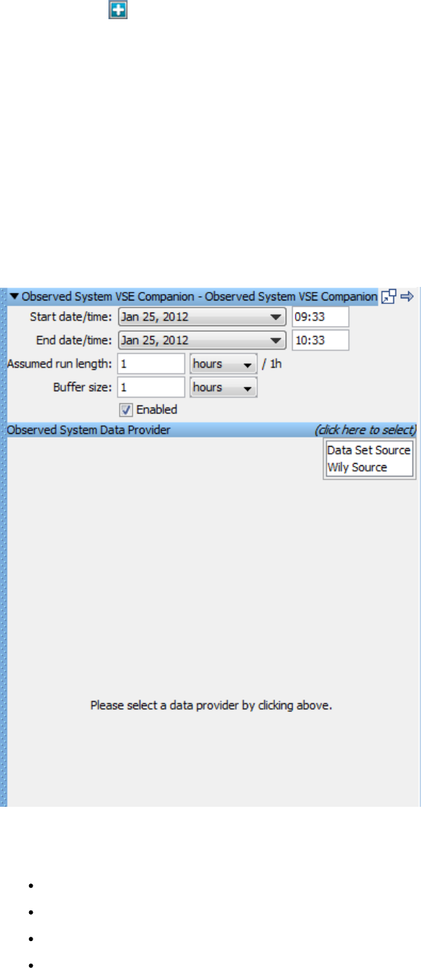
You can use the Add icon to select or clear all test steps.
All reports show the aggregate step and any individual steps that are not set to Quiet.
Java Protocol Companion
The only purpose of the Java protocol companion is to support Java virtual services. It is used only internally.
Observed System VSE Companion
Before LISA 6.0.6, the response time VSE would try to help ensure for an inbound request would come from the think time specification on the
particular response that was determined for that request. There are times, primarily during load and performance testing scenarios, where the
response times should be modeled after those from a live system. So, for example, a live system might show a drop in performance equivalent to
twice its nominal response times during peak load and it is helpful to have VSE emulate this response time curve. Further, it is helpful to allow
VSE to cover (or play back) this curve over an arbitrary time interval thus allowing for, for example, a 12 hour period of observed response time
metrics to be played out over a 3 hour testing window.
The VSE Observed System companion supports these requirements. If a virtual service is to provide this behavior, you must add and configure
this companion.
Configuration Information
The Observed System companion requires the following parameters:
Start date/time and A time "window" to read observed response times between. These time stamps are inclusive. If yourEnd date/time:
data set or data provider contains timestamp data that is outside this window, it will be ignored.
Assumed run length: This is specified as a time duration and represents the amount of time over which the virtual service should "fit"
the response time curve to. In the example mentioned earlier, this would be set to 3 hours.
Buffer size: This is also specified as a time duration and may be used to control how much of the response time data is acquired at one
time. This defaults to 1 hour of data at a time.
Observed System data provider: This tells the companion where to get the data from. We currently provide a LISA data set data
provider and a CA Application Performance Management (Wily) data provider.
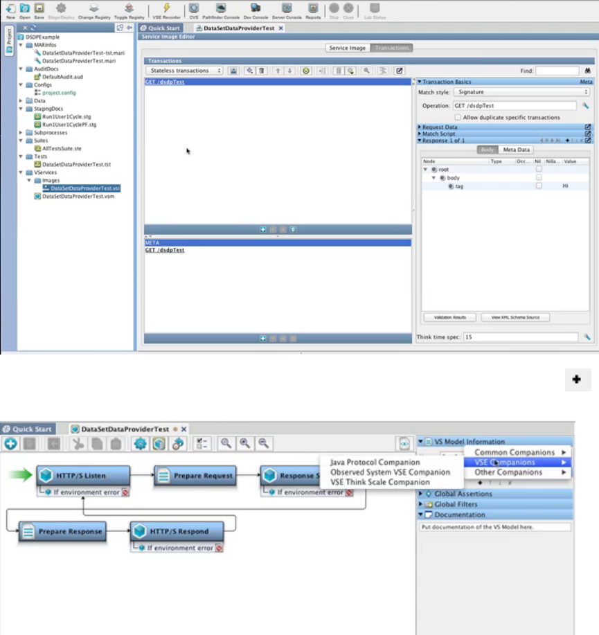
Any data provider must provide three pieces of information: an ID (which is a string), a timestamp and the response time at that timestamp. The
LISA data set data provider requires that the data set must provide these in fields labeled "id", "timestamp" and "responseTime", respectively. The
timestamp value, if not an actual Date object, must be a string in the form "yyyy-MM-dd HH: ". How the ID maps to any specifiedmm:ss.SSS
inbound request is data-provider specific. For the data set provider it must match the request's operation. The CA Application Performance
Management (Wily) provider uses a regular expression based approach.
Data Set Source Example
This example illustrates using a data set to provide the input for the Observed System VSE companion. This companion allows you to change the
response time for a transaction, or for multiple transactions over time, based on the definition of the data provided by this companion.
The service image shown contains one transaction, and the Think time spec is set to 15 milliseconds.
The virtual service model associated with this service image has a few simple steps. To add a companion, click the Add icon under the
Companions panel, and select VSE Companions > Observed System VSE Companion.
The top part of the panel provides general information about the parameters for the companion.
In this example, the Start date/time and End date/time define a two-hour window, but the Assumed run length is set to one hour, which means for
every one hour of VSE runtime, it will go through two hours of data from the data set data provider. The buffer size of 30 minutes means that VSE
will go to the data set every 30 minutes to retrieve data. That buffer size is before any scaling is done, so with a Buffer size of 30 minutes in this
example, VSE will go to the data set and retrieve data between 10:22 and 10:52, and VSE will do the scaling of, in this case, one half, so it can do
the calculations correctly. The Enabled check box can be unselected to temporarily disable the companion.
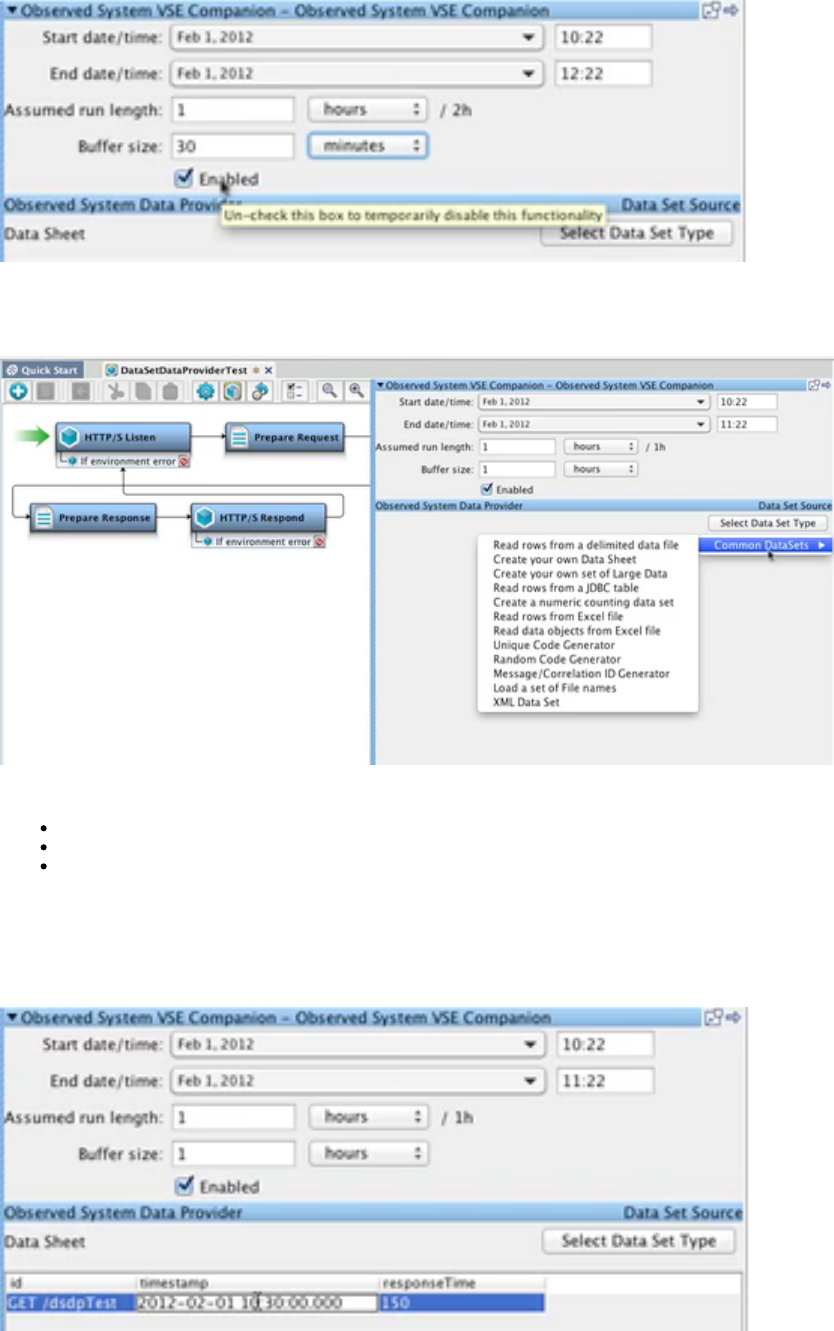
The Observed System Companion can be backed by any kind of data providers, including LISA data sets and the Wily Observed System Data
Provider. Click , select Data Set Source, and the Select Data Set Type button will appear. Click that button and select(click here to select)
Common DataSets, then select Create your own Data Sheet.
When the table for Create your own Data Sheet is opened, the columns are pre-populated with:
id: Matched against the Operation Name when the request is being processed.
timestamp:
responseTime: The response time to use during playback. This overrides the Think time spec of 15 milliseconds that was set in the
service image.
These are the columns you need to have for any type of data set provider you use to provide information for this companion.
In this example, copy the Operation Name of from the service image and enter it in the id field. In the responseTime field, enter GET / dsdpTest
.150
In the timestamp field, enter a date and time that falls into the time window defined by Start date/time and End date/time.
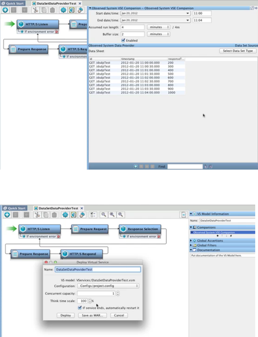
To continue the example, we will use an existing project with a pre-populated data set.
The response times in the data set define an increase of 100 milliseconds every 30 seconds, so the Think time spec set in the virtual service
model of 15 milliseconds should always be overridden by this companion.
When you deploy the virtual service, do not enter a Think time scale of 0%.
Observed System Data Provider (Wily) Source
The Observed System VSE Companion can also receive its input from the CA Application Performance Management (Wily) application. To
configure the companion to work with Wily, enter the configuration information in the top part of the panel, then click , select(click here to select)
Data Set Source of Wily Source.
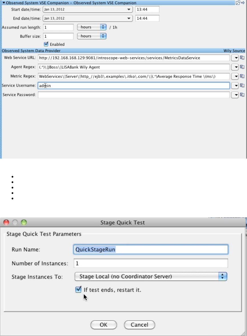
There are five parameters for the Wily Observed System companion:
Web Service URL: The URL for the Wily web service.
Agent Regex: A regular expression identifying the agent.
Metric Regex: A regular expression identifying the metric.
Service Username: The user name to access the Wily service.
Service Password: The password for the Wily service, if required.
To test the behavior of the companion, stage a quick test.
The test case in this example had one step, an output log message step. You can see the output in the Test Events tab of the Quick Stage Run
window.
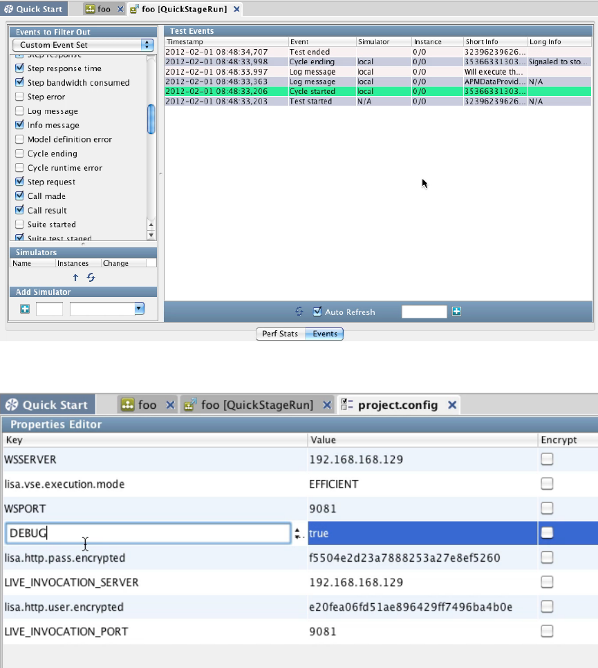
1.
2.
3.
4.
When you look at the project config file used for this test case, you can see that having the property debug set to true means you will get the log
message in the output
Runtime Priorities
The process that is followed during runtime is:
The think time specification from the VSE response will be examined at the point when the delay factor is being determined.
If the think time specification contains state (that is, a LISA double-brace expression), it will be evaluated directing and the result used as
the response time for the response.
If it does not contain state and the virtual service contains the Observed System companion, the companion will be asked to determine
the response time for the response.
If the companion is not present or not able to determine a response time, the think time specification will be used as-is as the response
time.
VSE Think Scale Companion
The VSE Think Scale Companion can be added to a virtual service model to allow the think scale percent for the service to change over time by
specifying the graph of think scale changes over time.
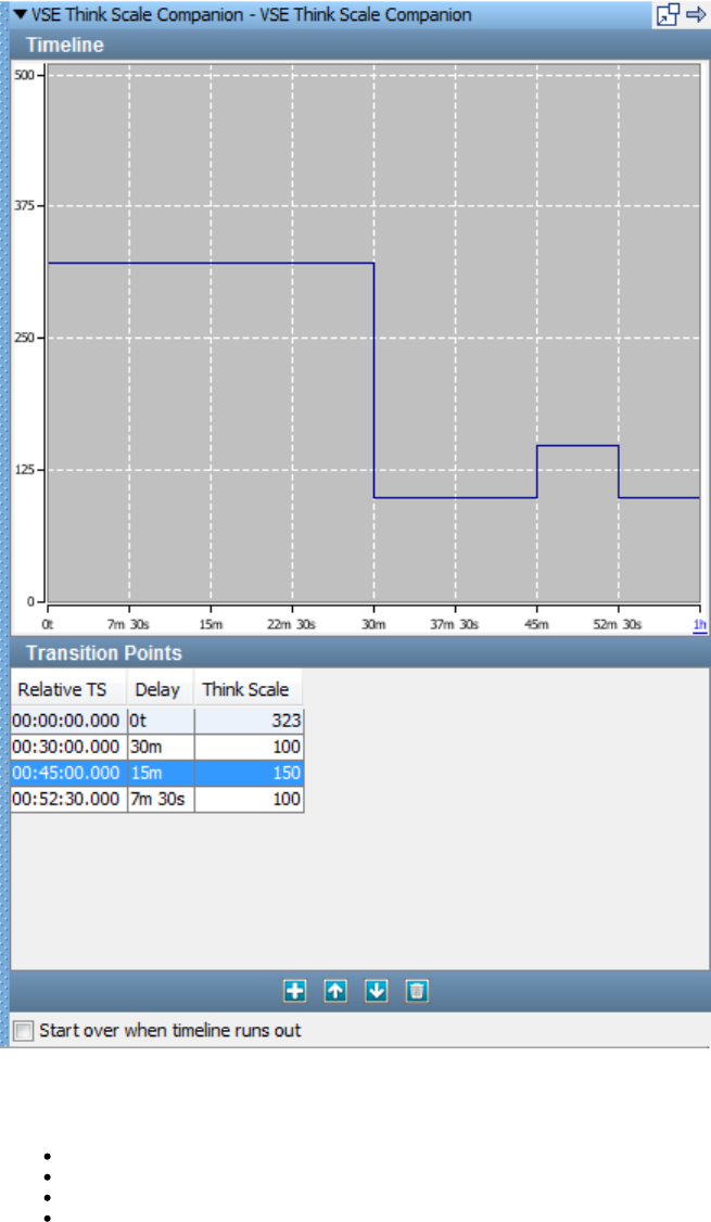
You can use the Add, Delete and Move buttons to add, delete and reorder Transition Points. You can directly edit the Delay and Think Scale
entries, or you can click and drag the lines in the Timeline display to indicate the Delay and Scale you want, and the Transition Points table will be
updated to correspond.
Relative TS: Calculated based on the Delay you enter, in format hh:mm:ss.ms.
Delay: The amount of time, in minutes and seconds, to wait before the specified Think Scale is applied.
Think Scale: The think scale is a percentage that is applied to the think times in the responses.
Start over when timeline runs out: If the end of the timeline is reached, start from the first Relative TS.
If you click the label for the right-most tick mark on the horizontal axis (in the window shown previously, the "1h" label) you can adjust the total
timeline of the companion. You will see the Update Timeline Duration dialog. If you update the timeline duration to be shorter than your transition
points, you will receive a warning that some transition points will be removed.
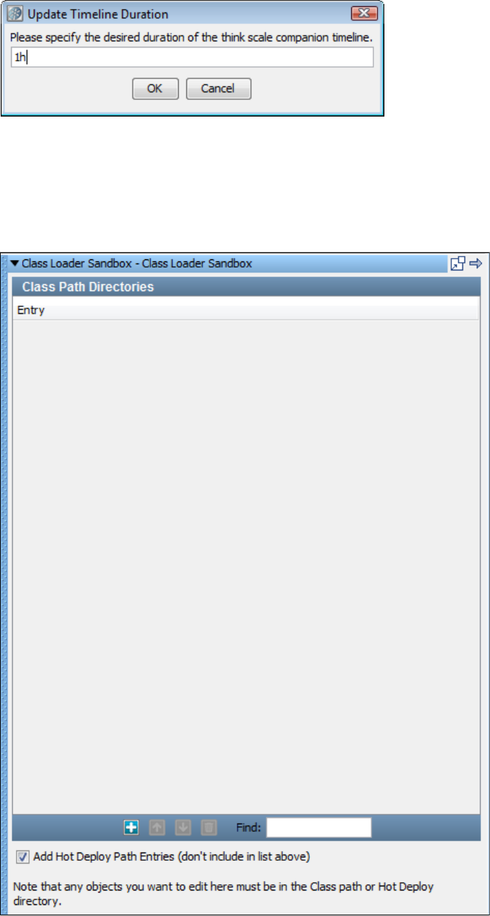
As you move your cursor over the graph, you will see that tooltips are displayed showing time on vertical lines and think scale percentages on
horizontal ones.
Create a Sandbox Class Loader for Each Step Companion
The companion lets you verify that every test run executes in its own Java Class loader (JVM). This is valuableCreate a Sandbox Class Loader
when testing local Java objects that are not designed for multi-threaded or multi-user access. Most testing will not require this companion; it is
usually only necessary when testing local Java objects with the Dynamic Java Execution step.
To configure the Class Loader Sandbox companion, use the Class Path Sandbox companion editor.
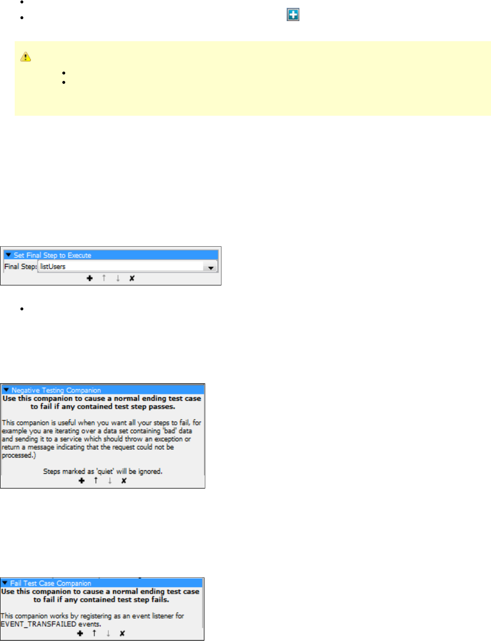
If the class you want to run is already in the directory, check the check box.hotDeploy Add Hot Deploy Path Entries
If the class you want to run is not in the directory, use the Add button to add a line in the Class Path Directories list andhotDeploy
add the appropriate class path for the class.
Any Java objects you want to edit or run:
Must be in the class path or the directory.hotDeploy
Must not be in the LISA or directories. The Class Loader Sandbox will not work because of the way the Java VMlib bin
loads classes.
Set Final Step to Execute Companion
The companion lets you verify that the system under test is left in a consistent state regardless of the outcome of theSet Final Step to Execute
test. You specify which steps are always run last when the normal test flow is circumvented.
A common use is to make sure that resources are released at the end of the test. Specifying the first step is not commonly needed, but there are
many scenarios where specifying the final step is important.
The final step will be executed even if the test case reaches an End step or the test case is instructed to end abruptly.
The final step is not shown in the list in the ITR, but the results can be seen in the tab for the last step executed.Execution History Events
The Set Final Steps companion Editor is used to set the final step.
To configure the Set Final Steps companion, enter the following parameter:
Finalize Step: Select the final step to execute from the drop-down menu.
Negative Testing Companion
the companion is useful when you want all your steps to fail. Use this companion to cause a normal-ending test case to fail ifNegative Testing
any contained test step passes.
Example:
There are no configuration parameters for this companion.
Fail Test Case Companion
The companion will mark a test case that ended normally as failed if any of the test steps failed. This would typically happen whenFail Test Case
a failed test redirected to a step other than the fail step. An event listener for the EVENT_TRANSFAILED event is registered in this companion.
An example of this would be when you have a WSDL validation assertion on a web service step. You want to be informed that the validation
failed, but you may also want to continue with the test case.
There are no configuration parameters for this companion.
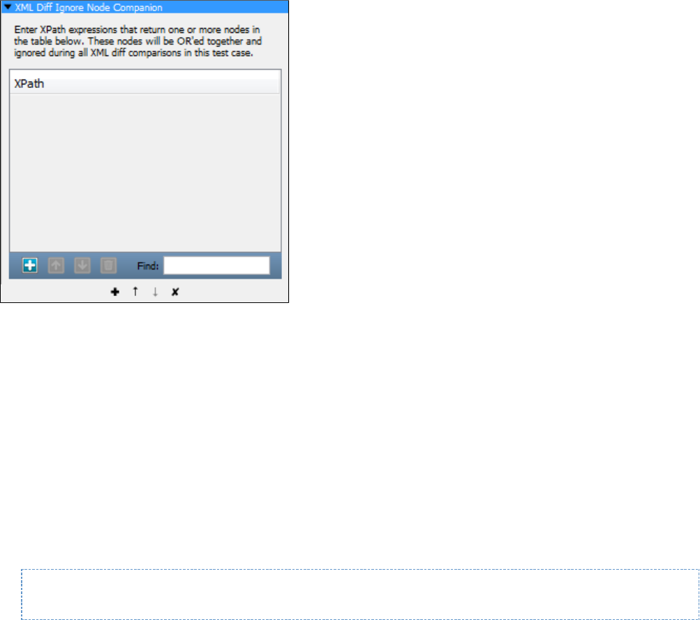
XML Diff Ignored Nodes Companion
The companion lets you enter XPath expressions that return one or more nodes in the following table. These nodes willXML Diff Ignored Nodes
be 'OR'ed together and ignored during all XML diff comparisons during this test case.
LISA Hooks
LISA hooks are an automatic global means to execute logic at start/end of a test case and applied to all test cases in the environment where the
hook is deployed.
Hooks work similarly to companions; they run before a test starts and after a test finishes.
The difference is, hooks are defined at the and every test case in LISA runs the hooks. There is no option not to run a hookLISA application level,
that is added to LISA, for any test case.
A hook is a mechanism in LISA that allows for the automatic inclusion of test setup and/or teardown logic for all the tests running in LISA. An
alternate definition of a hook is a system-wide companion. Anything that a hook can perform can be modeled as a companion in LISA.
Hooks are used to configure test environments, prevent tests from executing that are not properly configured or do not follow defined best
practices, or simply to provide common operations.
LISA hooks are Java classes that are on the LISA Class path. LISA hooks are NOT defined in .lisaextensions file, but in local.properties or
lisa.properties as
lisa.hooks=com.mypackage1.MyHook1, com.mypackage2.MyHook2
A hook is executed/invoked at the start/end of all subprocesses in a test case in addition to the test case itself. So if a test case has three
subprocesses, the hook logic will be executed four times (once for the main test and once for each of three subprocesses).
To prevent startHook and/or endHook to be executed by a subprocess, perform this check:
String marker = (String)testExec.getStateValue(TestExec.FROM_PARENT_TEST_MARKER_KEY)
"marker" is set to "true" only when it is a subprocess.
if (!"true".equals(marker))
all start/end Hook logic here that should not be executed when in sub process
Differences between Hooks and Companions
Hooks are global in scope. Testers do not specifically include a hook in their test case as is the required practice for companions. Hooks
are registered at the system level. If you need every test to include the logic and do not want users to accidentally omit it, a hook is a
better mechanism.
Hooks are deployed at the LISA install level, not at the test case level. If a test is run on two computers, one computer has a hook
registered and the other does not, then the hook will only run when the test is staged on the computer where it is explicitly deployed.
Companions defined in the test case execute regardless of any install-level configuration.
Hooks are practically invisible to the user and therefore cannot request any custom parameters from the user. They get their parameters
from properties in the configuration or from the system. Companions can have custom parameters because they are rendered in the
Model Editor.
For more details on hooks, see .LISA Advanced Features
Complex Object Editor (COE)
The lets you interact with Java objects without having to write additional Java code.Complex Object Editor (COE)
You can change the current value of an input parameter, make method calls, and examine return values. You can also do simple in-line filtering
and add simple assertions on the return value.
Many test steps involve the manipulation of Java objects. Whether you are working directly with Java objects, as in a Dynamic Java Execution
step, or an Enterprise JavaBean (EJB) step, or indirectly - such as input parameters to a web service, or return messages from an Enterprise
Service Bus (ESB), you will be working in the Complex Object Editor.
This chapter starts by describing the user interface. Then it looks at several usage scenarios that become progressively more complex.
The following topics are available in this chapter.
Invoking the COE
Object Call Tree Panel
Data Sheet and Call Sheet Panels
Object Interaction Panels
Using Data Sets in the COE
Usage Scenarios for Simple Objects
Usage Scenarios for Complex Objects
Invoking the COE
Regardless of where it appears, the Complex Object Editor (COE) has the same look and feel.
For an example, we will show the Dynamic Java Execution step, using the class. When you invoke this step, this is what you see.Customer
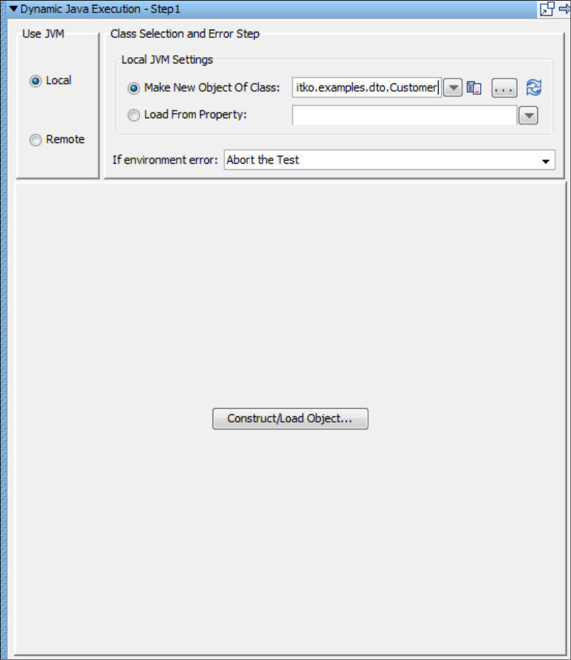
1.
2. Select to use the Local JVM and enter in the Make new object of class field.com.itko.examples.dto.Customer
Click Construct/Load Object to load the object into the object editor.
Complex Object Editor
After the object is loaded, the Complex Object Editor is invoked.
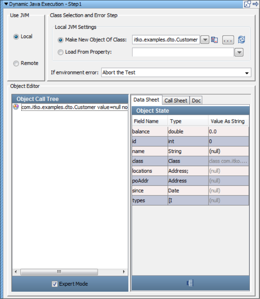
The object editor is divided into two panels. The left panel, the Object Call Tree, keeps track of method invocations, and their input parameters
and return values. The is described in detail in the next topic.Object Call Tree Panel
The right panel is the Object State, which has a set of dynamic tabs ( , , ) that will show you availableData Sheet Panel Call Sheet Panel Doc Panel
options at any given time.
The previous screen shows a Java object of type Customer loaded in the editor. This particular object was loaded using the Dynamic Java
Execution test step, but it could have been loaded as the result of any number of operations. No calls have been invoked on the object.
Object Call Tree Panel
As you manipulate your Java object ( ), the Object Call Tree will expand to keep track of the calls invoked and the associated parameterCustomer
values.
As an example, an Object Call Tree after several methods have been invoked follows:
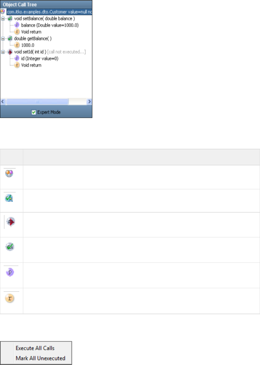
Object Call Tree icons
The following icons are used to identify the branches in the object call tree:
Icon Description
The type (class) of the object currently loaded, followed by response from calling method of object.toString
The constructor that was called. This is shown if multiple constructors exist.
A method call that has not been executed.
A method call that has been executed.
The input parameters (type and current value) for the enclosing method.
The return value (current value if call has been executed) for the enclosing method.
Clicking an item in the Object Call Tree will display the appropriate set of tabs in the Data Sheet and Call Sheet in the right panel.
Right-clicking an item in the Object Call Tree displays the following menu.
You can execute all calls or mark all calls as unexecuted in the Object Call Tree.
Data Sheet and Call Sheet Panels
Data Sheet Panel
The right panel shows three tabs, with the Data Sheet tab active by default.

Data shown in black can be edited in this tab. The data values are edited in the Value as String column. These will always be primitives or strings.
Values dimmed cannot be edited here, but there will be other screens where these objects can be edited. The address field, for example, is an
object of type Address that cannot be edited in this tab.
Call Sheet Panel
In the Call Sheet tab, the COE shows the methods/fields calls that are available, and their return types.
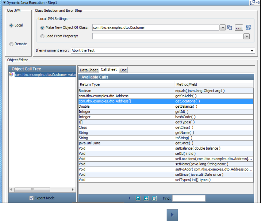
To add a method, select it in the Methods/Fields list and click the Add Method icon at the bottom of the tab. The selected method now
appears in the Object Call Tree (in the left panel).
When you are in the object call tree you can provide input parameters and invoke the method.
Doc Panel
The Doc tab displays any Java API documentation that has been made available for this class.
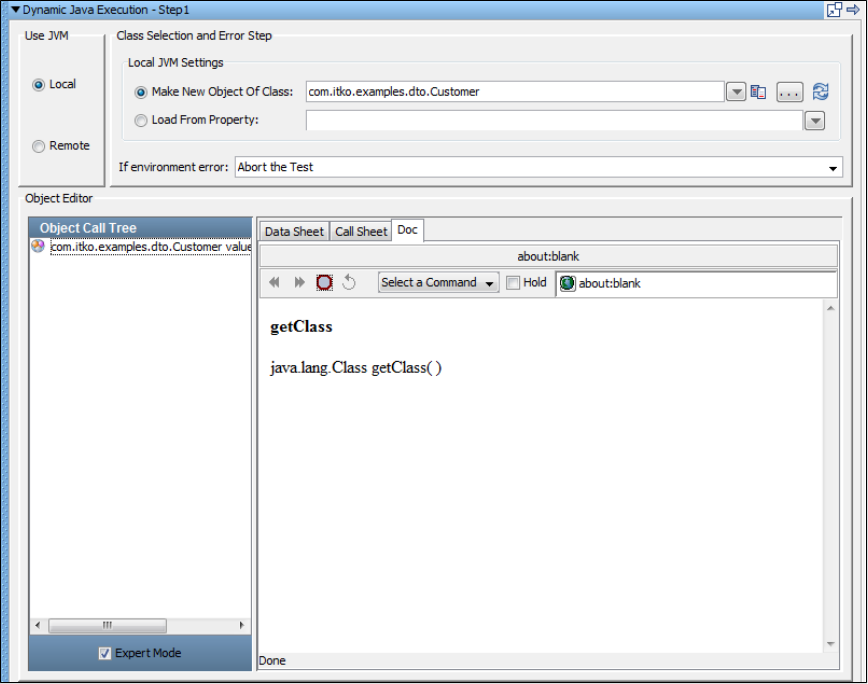
Object Interaction Panels
There is a different interface for each action that is be displayed in the Data Sheet and Call Sheet.
The tab and its interface will change depending on what you have selected in the Object Call Tree in the left panel.
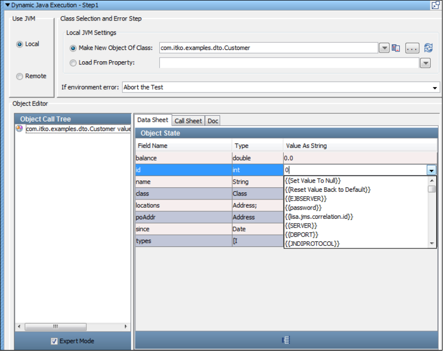
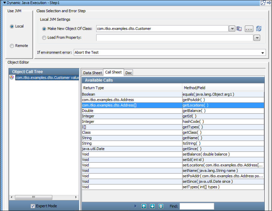
Method Call Panels
If you select a method call in the Object Call Tree, the Call and Doc tabs are available in the right panel.
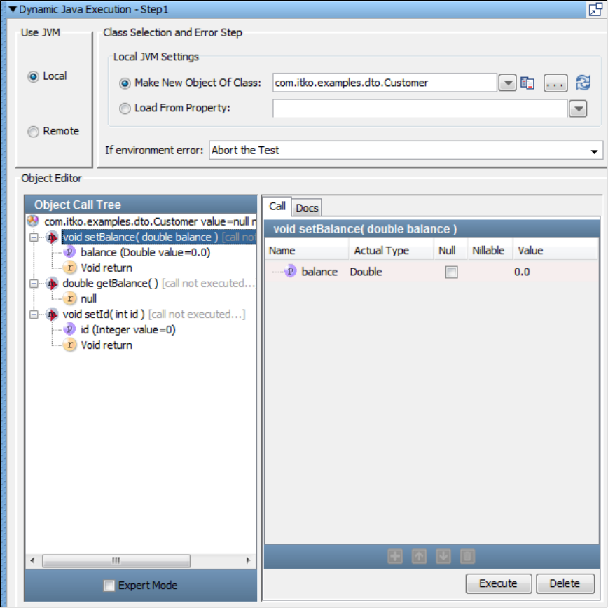
This is where you provide values for the input parameters.
The information about each parameter is provided, so you only need to supply the value. In this example, it is straightforward; the single
parameter is of type "double," so we can type in a value, or a property name in the Value column.
The pull-down menu maintains a list of the current properties. If you are required to enter an object as an input parameter this requires more work.
We will describe several approaches to providing objects in the subsequent sections.
Notice that the Expert Mode at the bottom of the left panel is not checked. This shows we are in the Simple mode.
Simple and Expert Mode
There are two editing modes available: simple and expert.
Simple Mode is useful when your object is a simple object, such as a Java Bean with just a default constructor and several setter/getter methods.
This is the classic Data Transfer Object (DTO). These are very common as inputs to web service calls. With objects of this type you can toggle
back and forth between simple and expert mode. A DTO that contains a DTO as a property can be manipulated in simple mode. We will see
examples of this later.
You must use Expert Mode for more complex objects, such as objects that have multiple constructors. Some composite objects that contain other
complex objects cannot use the simple mode, and in fact the simple mode option is disabled if the current object requires expert mode. We shall
see examples of using the expert mode later.
All the illustrations shown previously have used simple mode.
The following illustration shows the example shown in the previous illustration, but with expert mode selected.
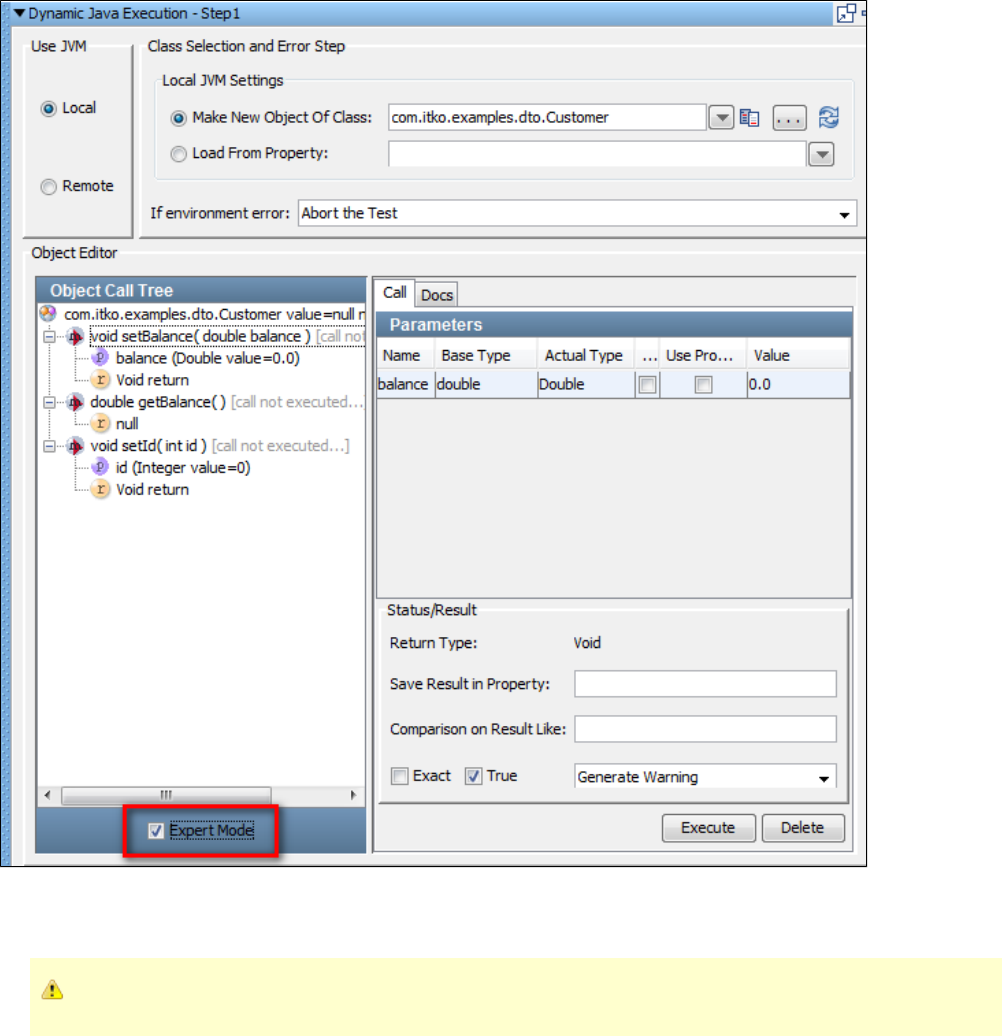
A new Status/Result panel opens up as shown.
You can now add Inline Filters (Save Result Property In) and Assertions (Comparison On Result Like) in the object editor.
The in-line filters and assertions that are applied are not seen in the filters or assertions list.
There are several other differences that will become apparent in our later examples.
Input Parameter Panels
If you select an input parameter in the Object Call Tree, the tabs available in the right panel will vary depending on the input parameter type:
Primitives/Strings or Objects.
For input parameters that are primitives and strings, the following panel will be displayed.
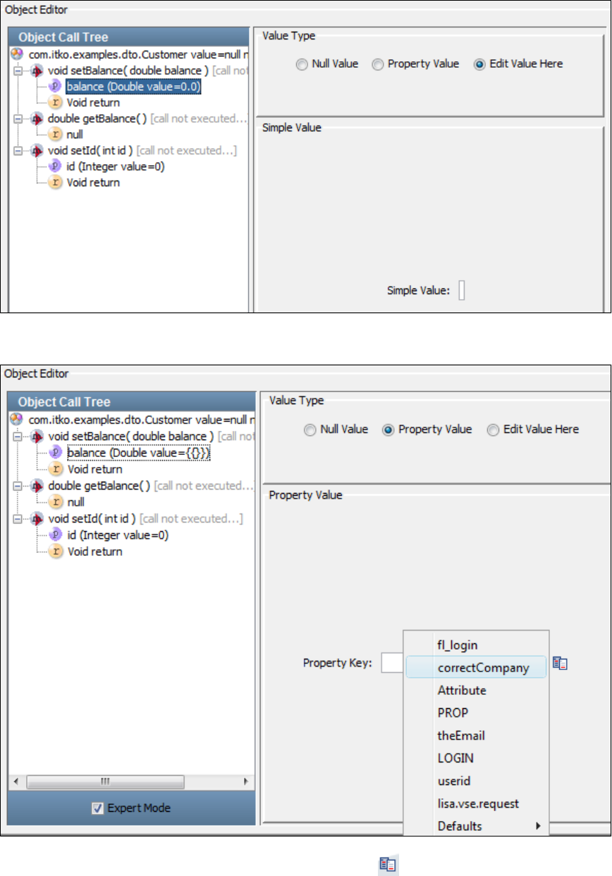
You can edit the value in this panel in Simple Value field.
If you want to use a property as the value, click the Property Value option button to display the following panel.
You can type the property name or use the pull-down menu or click the List icon to open the available property keys.
For input parameters that are objects, the following panel will be displayed.
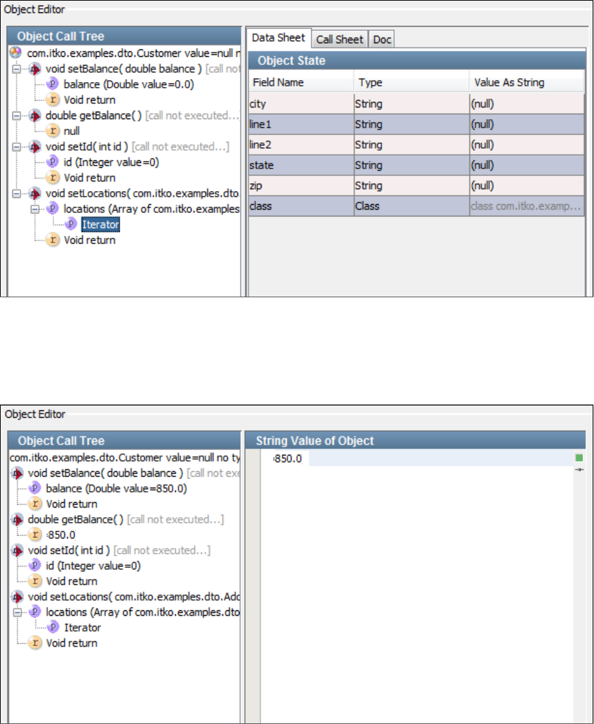
Return Value Panels
If you select a return value in the Object Call Tree, the tabs available in the right panel will vary depending on the input parameter type.
For input parameters that are primitives and strings, the following panel will be displayed.
For input parameters that are objects, the following panel is displayed.
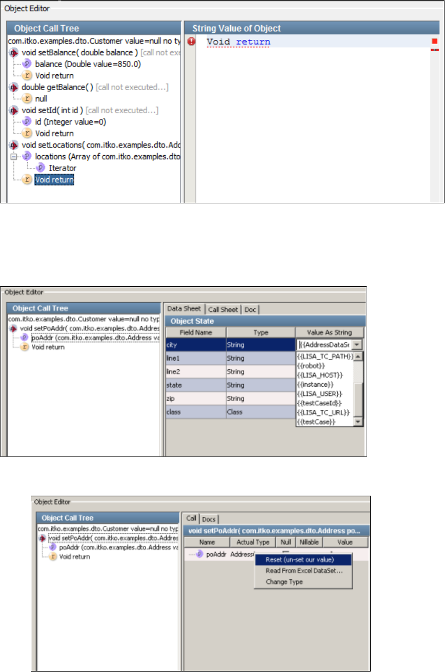
1.
2.
Using Data Sets in the COE
A common way to provide data for a Java DTO object is a data set.
A data set, Read DTOs from Excel File, is provided for this purpose.
If the Excel data set already exists, the property that contains the data set can be entered as a value for the DTO object.
You can also initiate the creation of a new DTO data set from within the object editor.
When a DTO object appears in the call list, right-click the Name or Actual Type to open a menu.
Select the data set Read From Excel Data set to display the following screen:
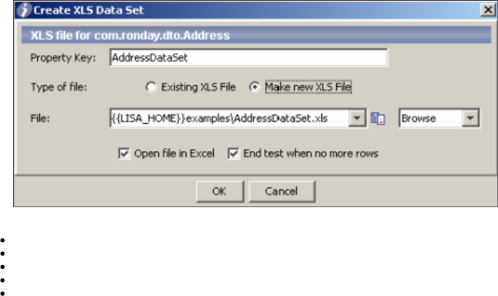
2.
3. The parameters on this screen are required to initiate the creation of this data set. Enter the following parameters:
Property Key: The property that stores the current values obtained from the data set.
Type of File: Select if it is an existing XLS file or make a new XLS file.
File: The name of the Excel file that will be the template for the DTO data.
Open file in Excel: Opens the spreadsheet in Excel.
End test when no more rows: Ends the test after all rows have been read.
Usage Scenarios for Simple Objects
The following examples are based on standard Java classes for simple objects. We have used classes from the Demo Server included with LISA.
They should be easy to reproduce in your environment.
Simple DTO Object Scenario 1
A simple DTO com.itko.examples.dto.Address has been loaded in the COE using a Dynamic Java Execution step. The Address class has simple
properties only.
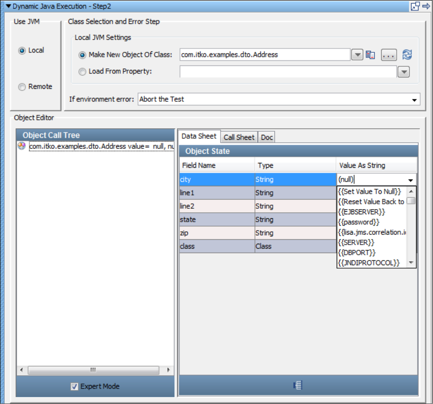
For a simple DTO, parameter values can be entered into the Data Sheet panel as fixed values or properties. In the previous example, couldcity
be set equal to the property .currentCity
Parameters can also be entered using the DTO setters in the Call sheet panel.
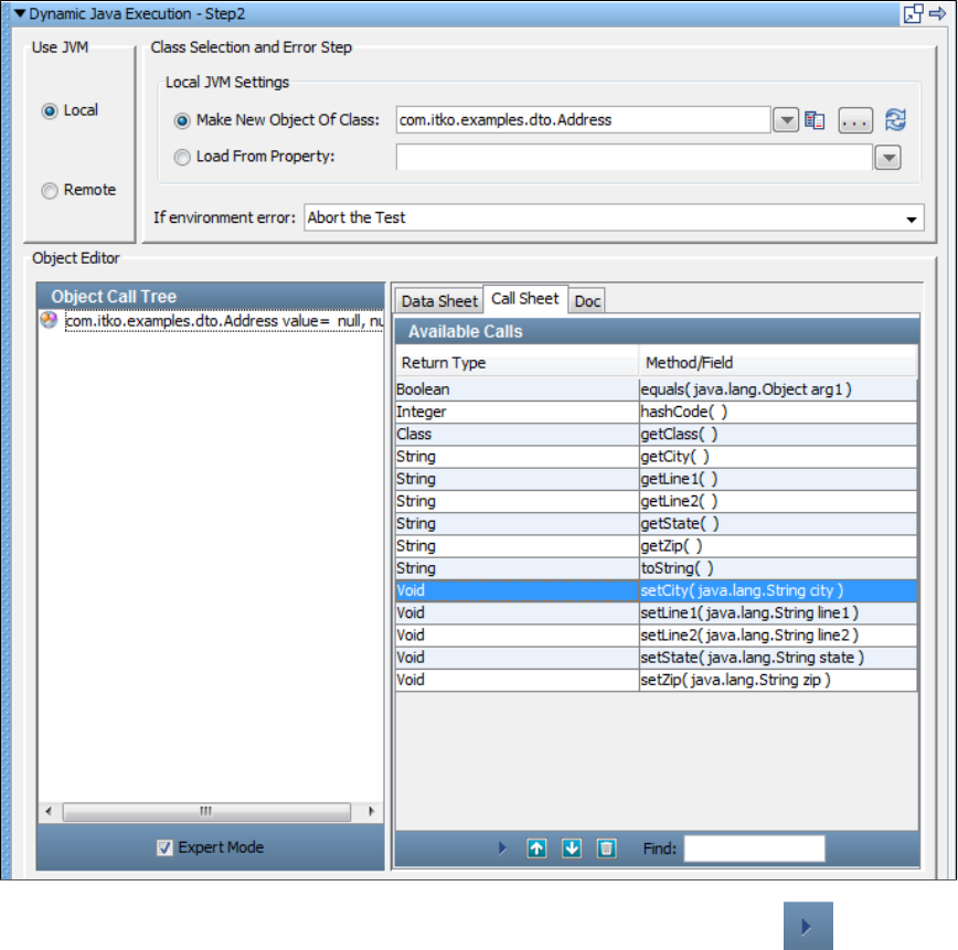
In the Call Sheet tab, select a getter, such as setCity(java.lang.String city) and click the Add Method icon. The method will run and COE
will open in the Call tab.
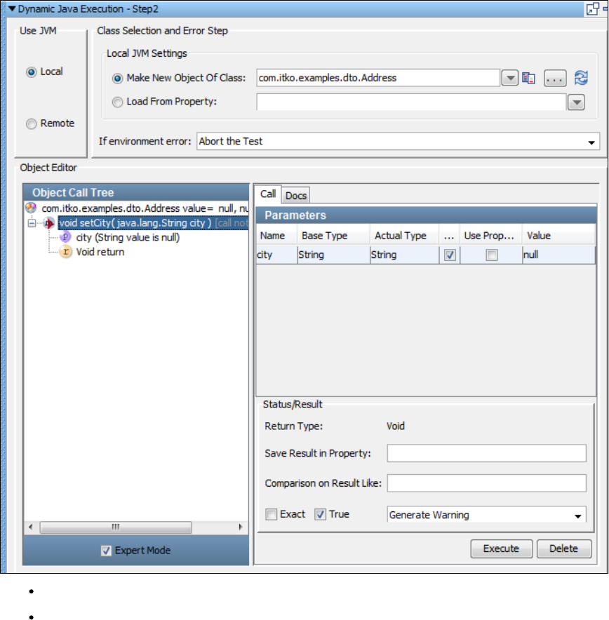
Enter the parameter value as a fixed value or a property. You must use the LISA property syntax here, .propname
Click the Execute button to invoke the method.
Repeat this procedure to set other DTO properties.
Simple Java Object Scenario 2
A simple Java object, java.util.Date, has been loaded in the COE using a Dynamic Java Execution step.
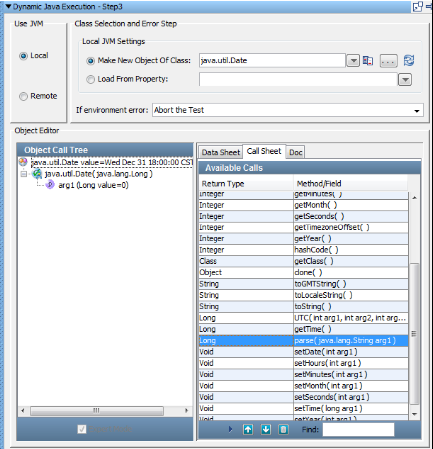
In this case we must stay in Expert Mode, because the Date type is not a DTO. In fact the COE forces us into Expert mode.
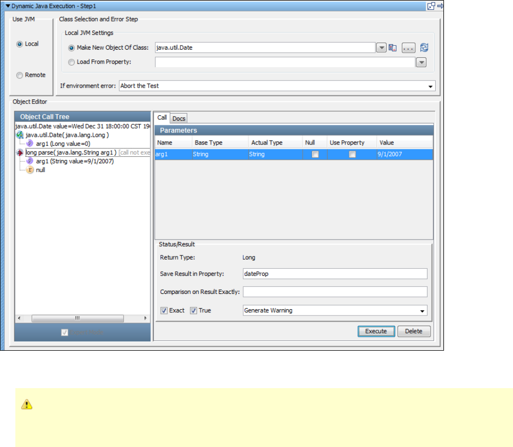
But we can still enter parameter values and invoke methods. In the previous example we execute the parse method, which requires one input
parameter. We have entered it as a string value, 9/1/2007.
In expert mode we use the Null or Use Property check box to denote the parameter type. If neither is checked will enter a fixed
value. We would not use the {{ }} property syntax here. Even if we were entering a property rather than a string value, we would
enter only the property name.
Because we are in Expert Mode we have the opportunity here to add inline filters and assertions.
Usage Scenarios for Complex Objects
The following examples are based on standard Java classes for complex objects. We have used classes from the Demo Server included with
LISA. You should have no difficulty reproducing them in your environment.
Complex DTO Object Scenario 1
A complex DTO Object, , has been loaded in the Complex Object Editor using a com.itko.examples.dto.Customer Dynamic Java Execution
step.
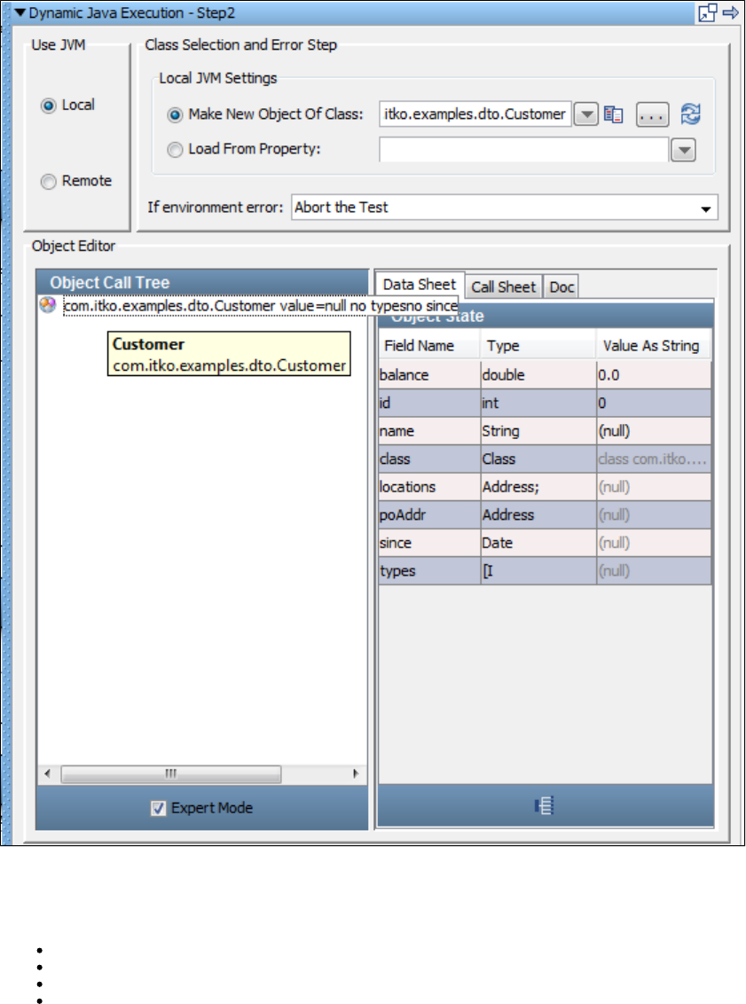
1.
This DTO is complex because its properties are not all simple values such as primitives or strings. However, because of its DTO structure we can
still use here if we want.Simple Mode
Each of the properties must be given values before the Customer object can be used.
locations: An array of Address objects
poAddr: An Address object
since: A Java Date object
types: An array of integers
Starting with the object, identify the method in the .poAddr setPoAddr Call Sheet
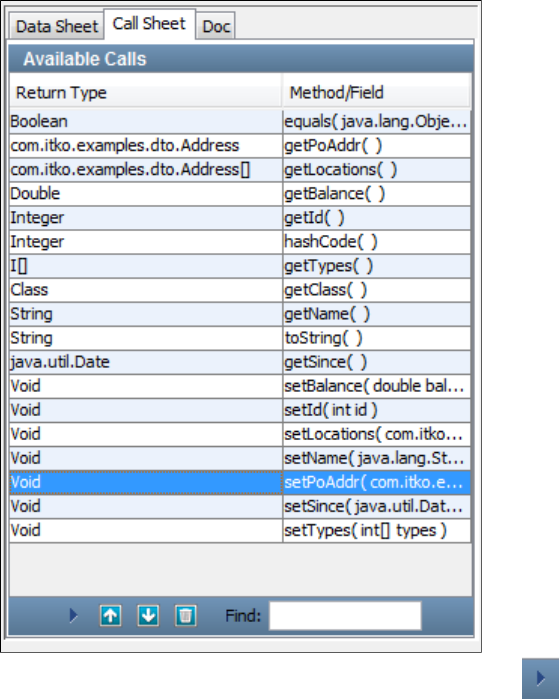
1.
2. Select the method and double-click or click the . icon to invoke/run this method.setPoAddr Add Method
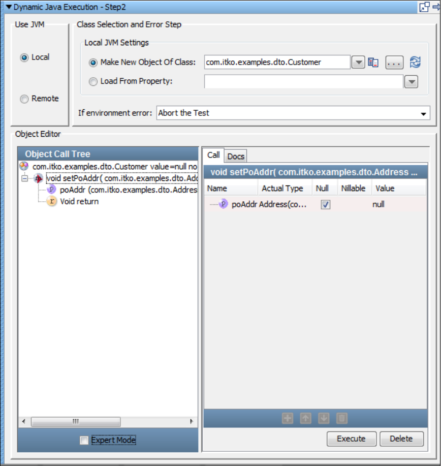
2.
3.
4.
This is a DTO that enables the use of mode, so do not select the check box. The property is identifiedSimple Expert Mode poAddress
as type Address.
In a , when you clear the parameter, the Address object is expanded to expose its properties. You know, from theSimple mode Null
previously illustrated Simple Data Object Scenario, that Address has simple properties, so you can enter them as values or LISA
properties in the column.Value
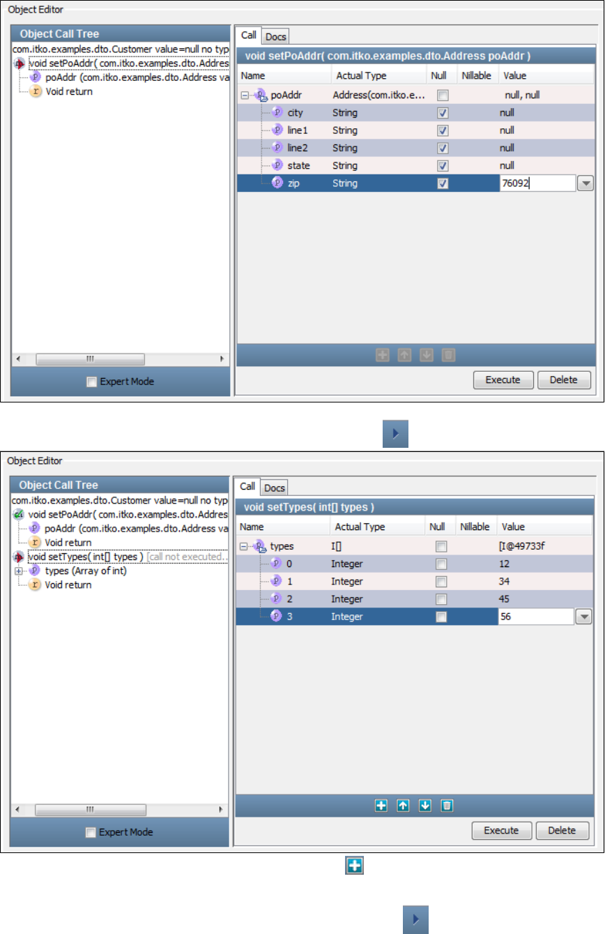
4.
5.
6.
7.
8.
9.
Click the button to invoke the method.Execute setPoAddr
Select the method on the and click the icon.setTypes Call Sheet Invoke Method
"Types" is an array of integers, so it is required that you click the icon at the bottom, to add as many elements in the array asAdd
needed. In the previous example we added four elements, and entered values for each.
Click the button to invoke the method.Execute setTypes
Select the method on the and click the icon.setLocations Call Sheet Invoke Method
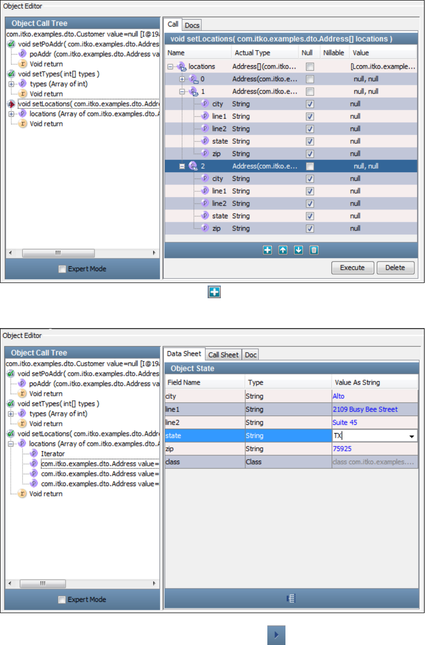
9.
10.
11.
12.
"Locations" is an array of Address objects, so click the icon to add as many elements (of type Address) as needed.Add
In the previous example we added three Address objects. Two have been complete; we are about to expand the third Address object to
enter values for the properties. When complete, click the button to invoke the method. Notice that you can clickExecute setLocations
one of the Location elements in the to display and edit its properties in the tab.Object Call Tree Data Sheet
This holds true for all the properties listed in the tree.Object Call
Select the method on the and click the icon.getSince Call Sheet Invoke Method
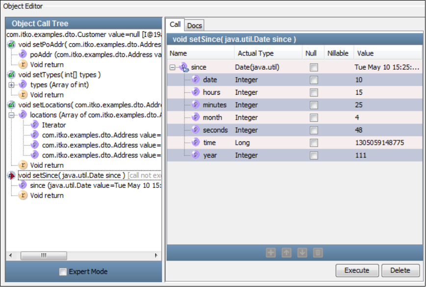
12.
13. The input parameters for the Data object are displayed and can be given values. Click the button.Execute
The Customer object is now fully specified and can be used in your test case.
Complex DTO Object Scenario 2
The last scenario shows an example that builds on the last three scenarios.
This DTO, , has a Customer object as one of its properties. This scenario shows how easy it is to build acom.itko.examples.dto.OrderDTO
Customer object in simple mode without calling any setter methods.
The object has been loaded in COE using a step.OrderDTO Dynamic Java Execution
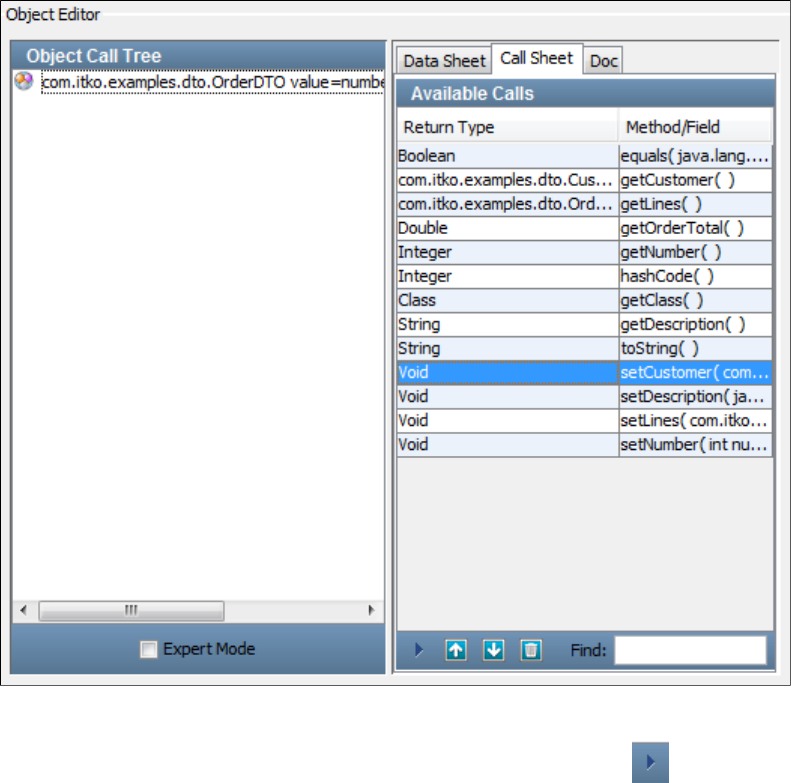
1.
Again we can use for the object.Simple Mode OrderDTO
Select the method in the and click the icon. As expected, the input parameter is asetCustomer Call Sheet Invoke Method
Customer object.

1.
2. Clear the check box in the column. The Customer row expands to expose its properties.Null
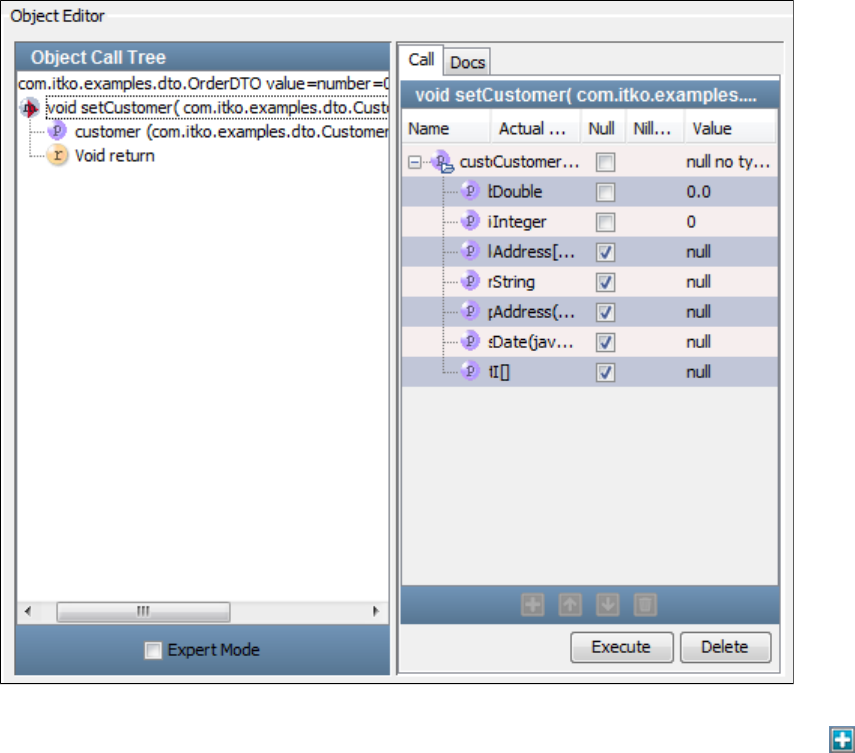
2.
3. All the properties can be edited on this screen. The Integer and String properties can be added in the Value column. The remaining
properties will expand to show their properties when you clear the box for the property. If the property is a single object it will expandNull
to expose its properties. If it is an array or collection, you can add the appropriate number of elements using the icon. ThisAdd
illustration shows a snapshot of the editing process.
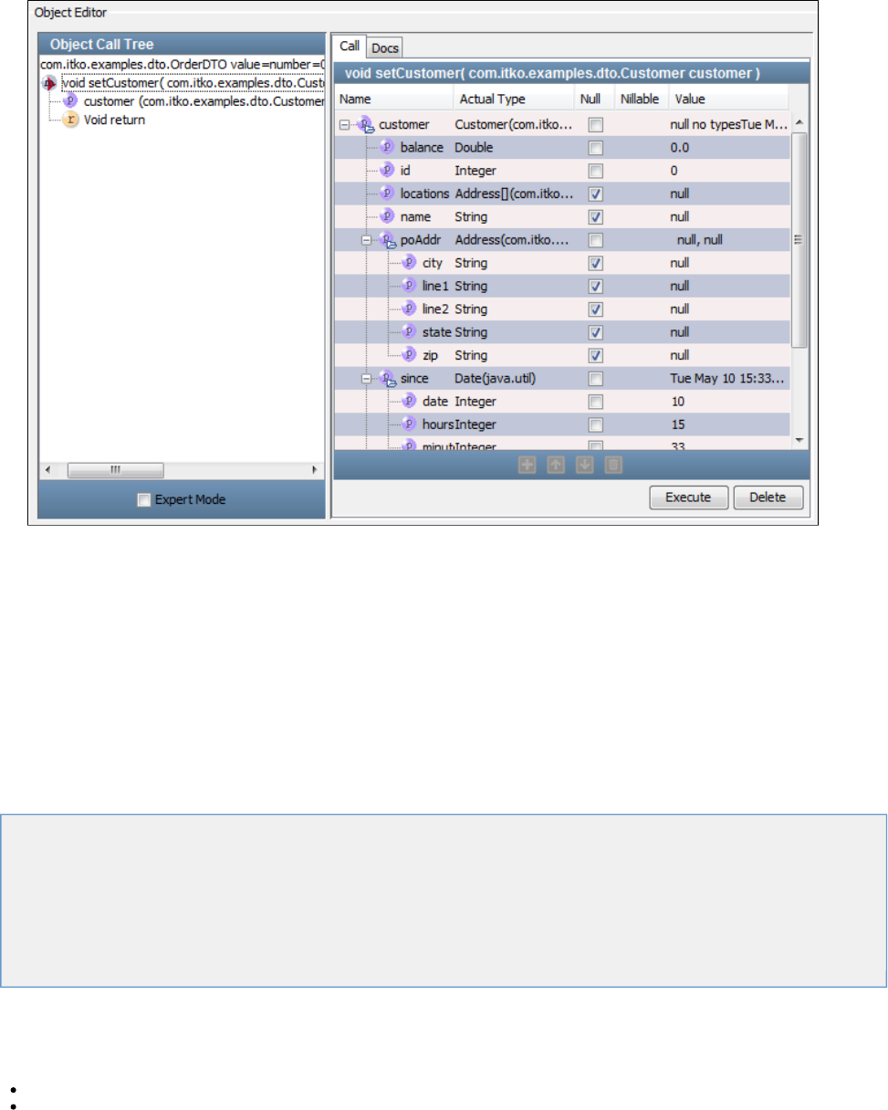
3.
The property has two elements; the property has three elements. The object is of type Address, and islocations types poAddr
expanded exposing simple string properties.
Building Test Steps
A test step is an element in the LISA test case workflow that represents a single test action that is to be performed. There are two major
categories of test steps.
Most test steps perform an action on the system under test, and evaluate the response. Some common examples are testing an Enterprise
JavaBean (EJB) method, a web service, or a message through messaging service provider.
A second category of test steps perform utility functions, such as data conversion, data manipulation (such as encoding), logging, and writing
information to files, and so on.
Both categories of steps go into the building of a test case.
The following topics are available in this section.
Adding a Test Step
Configuring Test Steps
Adding Filters, Assertions, and Data Sets to a Step
Common Test Step Actions
Configuring Next Step
Generating Warnings and Errors
Types of Steps
Adding a Test Step
To add a new test step
Click Add Step on the toolbar or
From the main menu select Commands > Create a New Step.
You can also add a step in a specific place in the workflow by right-clicking the step in the workflow to open a menu. Click Add Step After and
select the required test step.
Adding a Test Step (example)
This example adds a new step to the multi-tier-combo test case in the examples directory (multi-tier-combo.tst). A new Dynamic Java Execution
step will be added to the multi-tier-combo test case, after the Get User step.
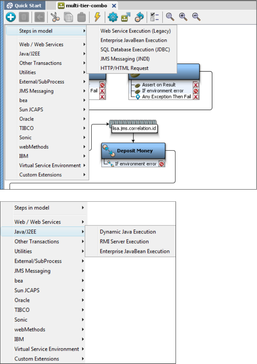
1.
2.
3.
4.
5.
Click the Add Step button to open a panel that has the listing of the common test steps. If steps have been already created in the test
case, as in this test case, the panel will show Steps in Model on top, which will list all the steps present in the test case. For a new test
case, this field is empty. When you open the multi-tier-combo test case, the steps that are in this test case are seen in the Steps in Model
box.
Select the main category of the step to be configured (for example, Web/Web Services, Java/J2EE, Utilities, and so on), which will open
the sub category.
Click the step to add it to the test case. This will open its step editor. Each step type has a different step editor.
To add a new Dynamic Java Execution step after the Get User step, right-click the Get User step to open the menu and select the
Dynamic Java Execution step.
The step is added and the Step editor for the Dynamic Java Execution step opens.
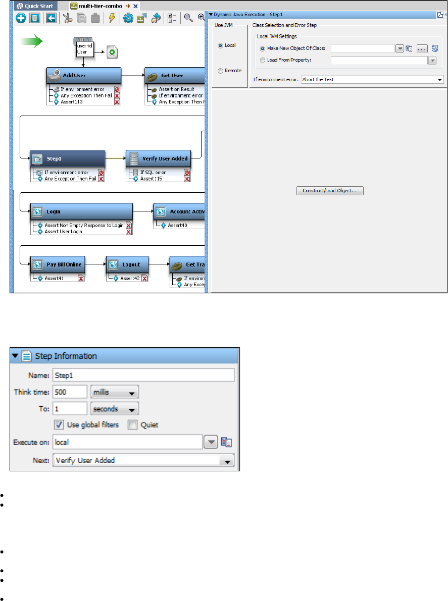
5.
1.
2.
1.
2.
Adding Step Information
To add the basic step information, open and expand the Step Information tab in the Elements tree in the right panel. The Step Information
editor opens.
Enter the following parameters:
Name: The name of the step. By default it appears as StepX (X being a number). You can rename the step in this text box.
Think Time: The amount of time the test case should wait before executing this step. This provides the ability to simulate the amount of
time it takes a user to decide what to do before taking action. To specify how the time is calculated, select the time unit by clicking the
appropriate drop-down (millis, seconds, minutes), then enter a value in the Think Time field for the starting value. In the To field, enter an
end value and a time indicator. LISA will pick a random think time within this range. For example, to simulate a user think time for a
random amount of time between 500 milliseconds and 1 second, enter "500 millis" and "1 seconds."
Use Global Filters: Select this box if the step should be instructed to use global filters. For more information on filters, see Adding a
.Filter
Quiet: Select this box if you want LISA to ignore this step for response time events, and performance calculations.
Execute On: Specifies the simulator that the step is to be run on. Specific simulators should be specified for steps that must run on a
specific computer. For example, when reading a log file the step should be run on the computer where the log resides.
Next: The next step to execute in the test. If the step in question ends the test case execution, you will not specify a next step. An
assertion that fires in this step overrides this value.
Configuring Test Steps
To configure a test step
Add the step in the LISA Model Editor. After the step is added, a different test step panel appears in the Element tree.
Configure the test step by setting the parameters in the configuration elements (assertions, filters, data sets, and so forth).
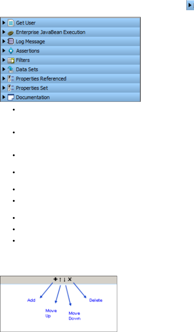
Details of the each test case/step element can be seen by clicking the element arrow next to the configuration elements to expand it.
Step Information: This is the first element in the element tree and carries the name of the step as its label (Get User in the preceding
example). After expanding it, you may be able to change the name of the test step, and set the next step to be executed after the current
step is completed. The other options are explained in .Adding a Test Step
Step Type Information: This appears next and has the title of the selected step type (Enterprise JavaBean Execution in our example).
Each step is different and has its own specific configuration requirement, and thus has a custom editor to provide the information needed
to run the step and test it (and possibly to get a response also). This custom editor opens up when the element is expanded.
Log Message: This appears after any step is added in LISA and let you set the log message that appears after the step execution is
complete.
Assertions: The addition and configuration of one or more assertions. In an assertion configuration, you also need to set the next step to
be executed when the assertion fires.
Filters: The addition and configuration of filters. Filters are added under the filter element of each test step.
Data Sets: The addition and configuration of one or more data sets that apply to the test step. Data sets are fired before executing a test
step. Any property that the data set sets, is available to the test step.
Properties Referenced: A read-only list of properties that the step references (reads).
Properties Set: A read-only list of properties the step sets (assigns a value).
Documentation: Notes accompanying the test step.
Step Element Toolbar
All elements (assertions, filters and data sets) have their own toolbar at the bottom of the Element tab.
You can add/delete an element to a step by clicking the icons at the bottom of the individual elements.
For detailed information on adding filters, see .Adding Filters
For detailed information on adding assertions, see .Adding Assertions
Adding Filters, Assertions, and Data Sets to a Step
Filters, assertions, and data sets are added under the corresponding element of each step in the right panel.
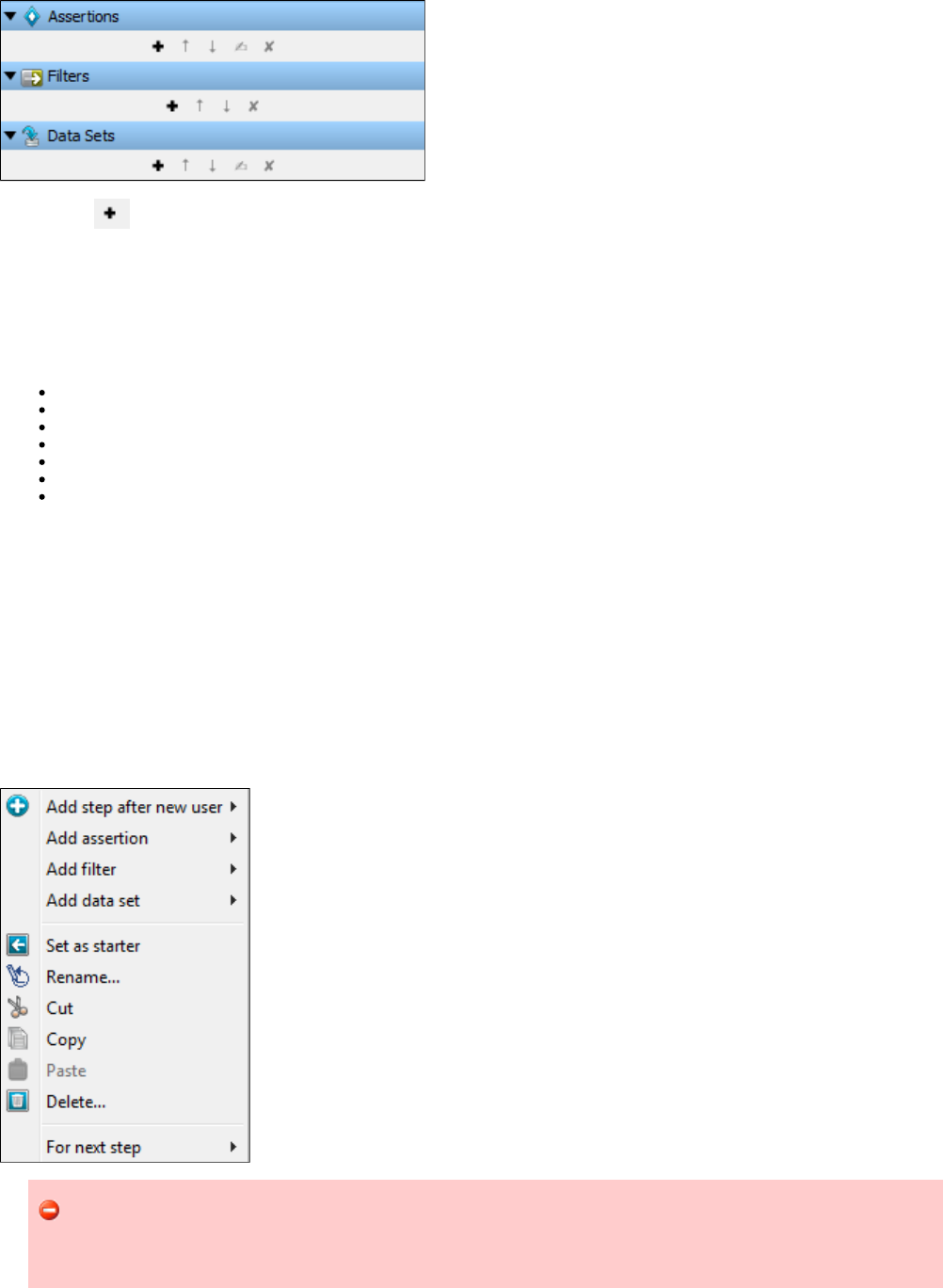
1.
2.
1.
2.
Click the Add icon on the toolbar to add a filter, assertion, or data set.
For detailed information about adding and configuring filters see . For detailed information about adding and configuring assertionsAdding Filters
see . For detailed information about adding and configuring data sets see .Adding Assertions Adding Data Sets
Common Test Step Actions
Following are some of the common test step actions:
Editing/Modifying a step
Deleting a step
Reordering a step
Renaming a step
Copying a step
Cutting a step
Pasting a step
Editing/Modifying a Step
To modify a step
Double-click the step to be modified. This will open its editor.
Modify the step as required and save the test.
Deleting a Step
To delete a step
Select the step in the workflow and right-click to open a menu.
Click Delete to delete the step.
Be careful when you want to delete a test step that has a filter associated to it. delete a test step that has filtersDo not
associated to it. Filters define properties that could be needed by other test steps, and deleting a step also means deleting the
filter.
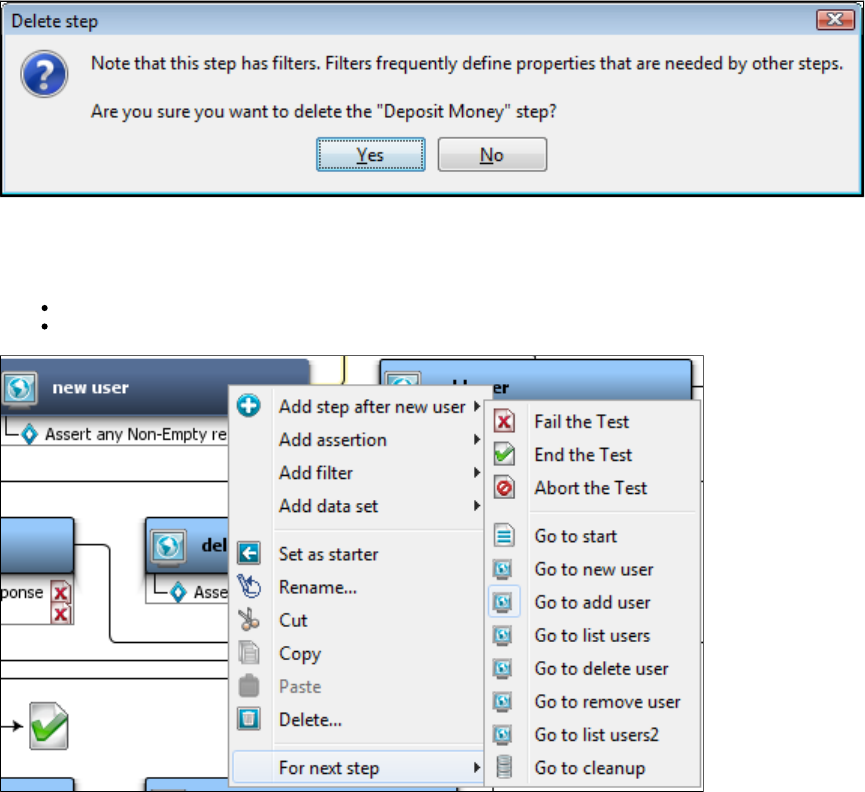
1.
2.
1.
2.
If you attempt to delete such a test step, you get the following message.
Reordering a Step
To reorder a step
Use the drag and drop facility in the model editor. Click on the step and drag it to the new location to rearrange the workflow.
Or select the step in the workflow and right-click to open a menu. Click For Next Step and select the step to reorder.
Renaming a Step
To rename a step
Right-click a step to open a menu and click Rename.
Open the Step Information panel and rename the step in the Name field.
After you rename the step in the workflow, the new name will be reflected in the Step Information tab in the right panel. Any step information
pointing to this step will be updated.
The next step is updated for linear and non-linear workflows in this case.
Copying a Step
You can copy a step and paste it anywhere within the model editor.
To copy a step
Select the step to be copied.
Right-click the step and click Copy.
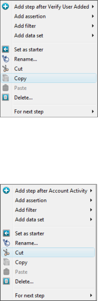
1.
2.
1.
2.
This will copy the selected test step.
Cutting a Step
You can cut a step and paste it anywhere within the model editor.
To cut a step
Select the step to be cut.
Right-click the step and click Cut.
This will cut the step from the model editor.
Pasting a Step
You can paste the step on any target step in the workflow. After you perform the paste operation, the step will be added after the selected step
within the workflow.
To paste a step
Select the step after which you need to paste the cut step.
Right-click and select Paste.
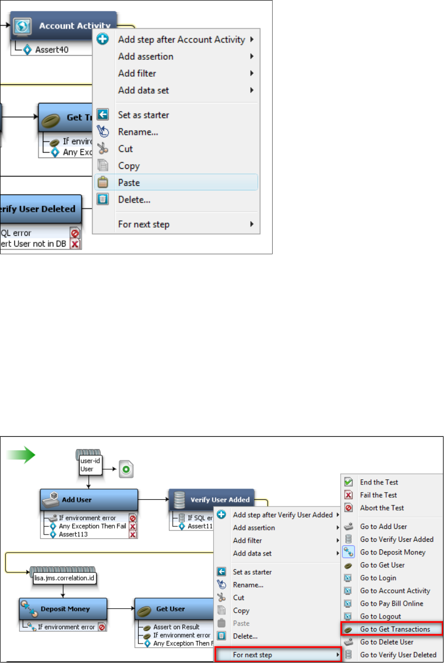
1.
2.
This will paste the step after the selected step.
Configuring Next Step
Assigning the Next Step
Within a test case workflow, you can assign the "next step" to a selected test step.
After executing the selected step in the workflow, it will then go to the defined next step for execution.
You can configure the "next step" to either go to the other steps in the workflow or direct to either end the test, fail the test or abort the test.
To assign the next step
Click the step for which you want to decide the next step. (In the example following, Verify User Added).
Right-click and select "For next Step" and click on the targeted next step (Get Transactions).
The workflow in the model editor will change. This will also change the information in the Next field in the step editor.
You can also End the test, Fail the test or Abort the test.
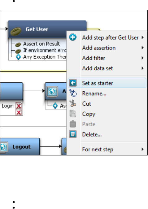
1.
2.
End Step
The End step is to bring an end to a workflow, and is run when a workflow completes successfully. The entire test case is deemed to be
successful if the execution reaches this step.
Fail Step
The Fail step is the end of a workflow, and is run when a workflow fails due to an error event. The entire test case is deemed to have failed if the
execution reaches this step. The fail step is the default for many exceptions internal to LISA (for example, an exception in an EJB), but it can be
set as the next step by assertions to fail a test case.
Abort Step
The Abort step is also the end of a workflow, and is run when a workflow is abruptly aborted. The test case is deemed to be aborted (without
completion) if this step is reached.
Setting a Starter Step
You can set any test step to be a within the workflow.starter step
This test step will then start the test case workflow.
Click the step and right-click to select Set as Starter.
This will set the selected step as the first step in the workflow. This option is not available to the first step in the test case.
Generating Warnings and Errors
There are two other types of tests that you can configure as next steps.
Generate Warning
Generate Error
For an example, we have selected the assertion in the Get User step.
Select a step and right-click on the assertion of a step to open a menu.
Select the Generate Warning option.
The test case will go to this next step (Generate Warning), only when the assertion is triggered.
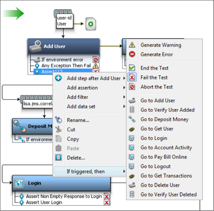
Generate Warning Step
When the test step fails, there is also an "Ignore" type of a step logic that will not raise an alarm or event. Hence this will not change the test case
workflow. This is the Generate Warning Step. This is the "Continue Quiet" step in previous versions of LISA.
Generate Error Step
Test steps can either pass or fail. When they fail they do not actually fail the test.
To fail the test, the test step sets the test case workflow to execute the "fail" step; this implicitly makes the step considered as failing.
If they explicitly fail, they generate an error and raise a NODEFAILED event and continue the test step. This is the Continue step in earlier
versions of LISA.
Types of Steps
1.
2.
1.
2.
1.
2.
The following test step types are available in LISA.
Test Step Information
Web_Web Services Steps
Java_J2EE Steps
Other Transaction Steps
Utilities Steps
External_Subprocess Steps
JMS Messaging Steps
BEA Steps
Sun JCAPS Steps
Oracle Steps
TIBCO Steps
Sonic Steps
webMethods Steps
IBM Steps
Virtual Service Environment Steps
Custom Extension Steps
Test Step Information
The following are some standard test steps.
Abort the Test
End the Test
Fail the Test
Abort the Test
To abort the test
Right-click the test step after which you want to abort the test case.
Select For Next Step > Abort the Test.
The Abort the Test step will quit the test case and mark the step as having aborted.
End the Test
To end the test
Right-click the test step after which you want to end the test case.
Select For Next Step > End the Test.
The step will complete the test and mark the test as having ended successfully.
Fail the Test
To fail the test
Right-click the test step after which you want to fail the test case.
Select For Next Step > Fail the Test.
The Fail the Test step will fail the test case and mark the test as having failed.
Web_Web Services Steps
The following steps are available in this chapter.
HTTP_HTML Request
REST Step
Web Service Execution (XML) Step
WSDL Validation
Web_ Raw SOAP Request
Base64 Encoder
Multipart MIME (Multipurpose Internet Mail Extensions) Step
SAML Assertion Query
Web_Web Service Execution (Legacy)
Start or Stop Web Server (Legacy)
HTTP_HTML Request
This step is used while testing a traditional web application to send and receive HTTP(S) requests, including GET and POST parameters and
optionally, embedded images as a response. You can also record HTTP steps using the .Website Proxy Recorder
You can manually execute the HTTP/HTML step at design time (similar to the WS step) and the Replay To functionality will save the step
responses so the step editors can display the response values.
When you add this step to a test case, the step editor includes the following tabs:
URL Transaction Info Tab
HTTP Headers Tab
Response Tab
URL Transaction Info Tab
Use the URL Transaction Info tab to specify the information used to construct the URL.
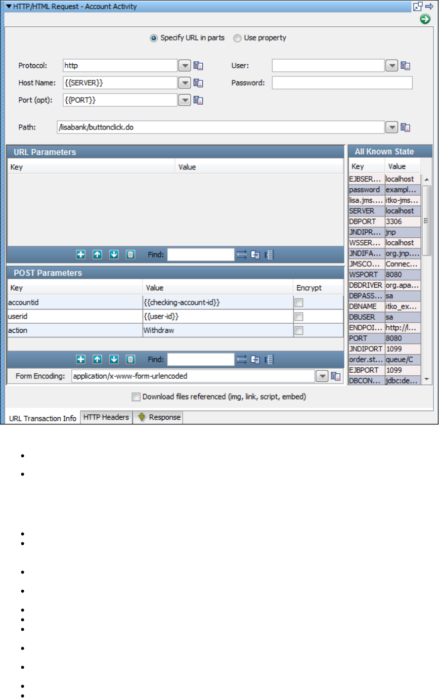
You can set up the URL transaction information with either of these options:
Specify URL in parts
Use property
Specify URL in parts
Select the Specify URL in parts option (default) to specify the URL in its essential pieces.
Protocol: The protocol that is used to communicate with the web server. The default is .http
Host Name: The host name of the web server. Use the LISA property SERVER or enter hostname or IP address of your application
server. This can be a domain name, such as or an IP address, such as 123.4.5.6. For a local web server, use thewww.mycompany.com
host name or the IP address .localhost 127.0.0.1
Port: Optional. Use the LISA property PORT or the port on the web server used to access the web server, if necessary. For example, the
port required to access the Apache Tomcat web server by default is 8080.
Path: The path to the file to access. For example, if the URL to access is , enter mysite/index.jsp inhttp://localhost:8080/mysite/index.jsp
the Path field.
User: Enter if a user ID is required for the application server.
Password: Enter if a password is required for the application server.
URL Parameters: GET (or URL) Request Parameters: these request parameters are passed as part of the URL, and so they are
exposed to the user in address bar of the web browser.
POST Parameters: POST Request Parameters: the request parameters are passed as part of the body of the page request, and so they
are not exposed to the user in the address bar of the web browser.
Form Encoding: During a step execution, parameters are URL encoded as they are sent. The MIME type used is
application/form-urlencoded.
All Known State: All known properties, such as test case properties, data sets, and filters, are listed.
Download images referenced (test bandwidth): If this element is selected, the step will download web page images into the test
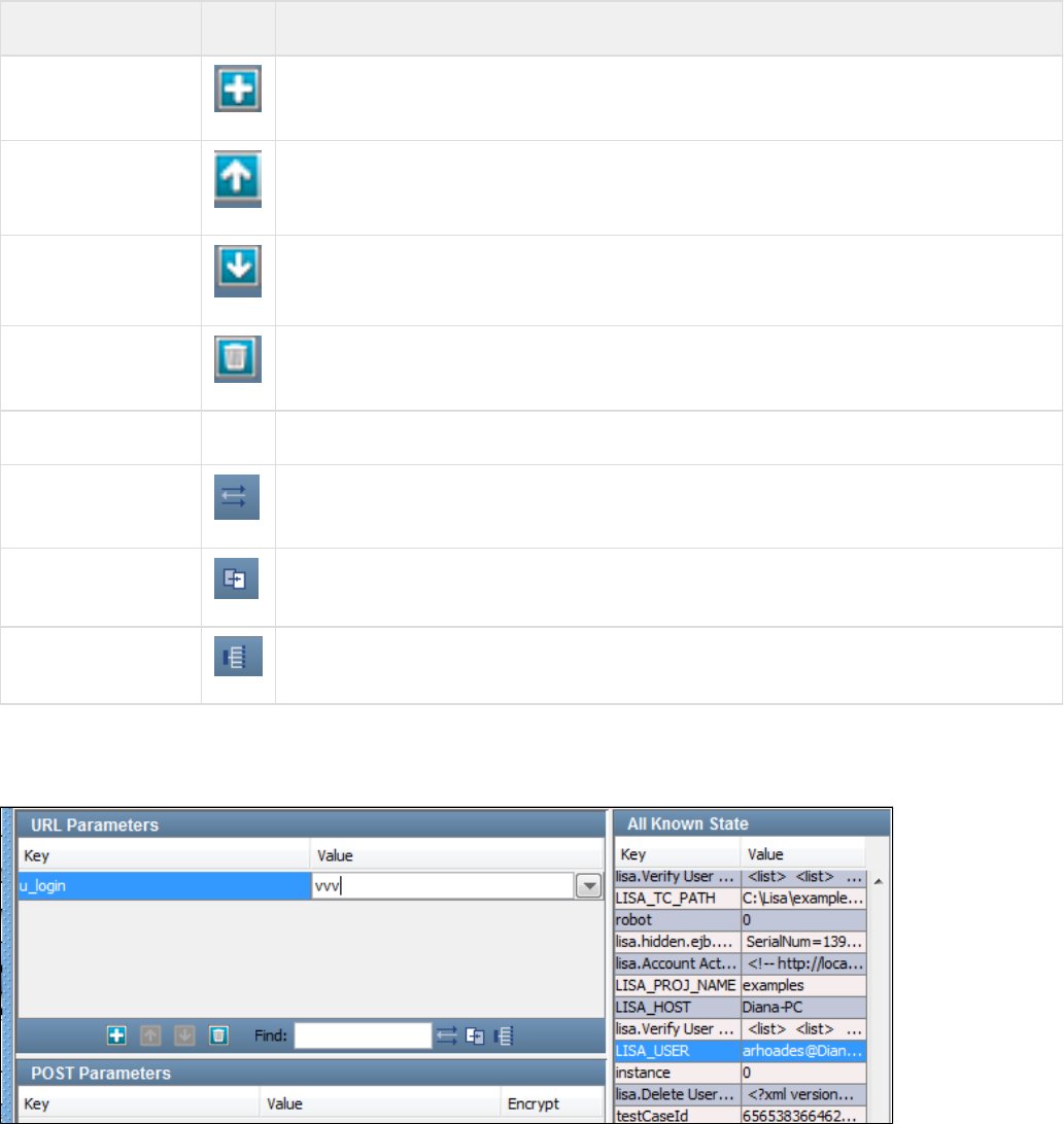
environment. If you do not select this box, there will be no images downloaded.
Other functions that are part of the toolbar available on the URL Parameters and POST Parameters sections are:
Field Icon Description
Add Add a request parameter
Up Move an existing parameter up in the list of parameters
Down Move an existing parameter down in the list of parameters
Delete Delete an existing parameter
Find Find text
Auto-Generate a Filter From the referring step to make this parameter dynamic. Create a new filter to auto-populate this
property at run time. For more information on filters, see the chapter.Filters
Apply selected All
Known State property Apply state to the parameter. For more information on applying state, see the All Known State section
that follows.
Auto Apply all Known
State properties Apply all state to all properties possible by patterns. For more information on applying state, see the All
Known State section that follows.
All Known State
All known properties, such as test case properties, data sets and filters, are displayed in the All Known State panel, as seen in the following
example in this URL Transaction element of an HTML step:
You can assign the values of properties to URL request parameters. For example, to assign the value of the LISA_USER data set key to the
u_login request parameter in the previous example, select the u_login key in the URL Parameters pane, and then the LISA_USER key in the All
Known State panel.
Then click Apply selected All Known State property to current parameter:
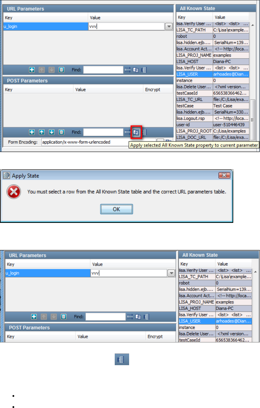
You will be warned of the impending change:
Click OK.
The new property is displayed in the URL Parameters pane:
If all the names of the URL Parameter keys are the same as the names of the All Known State keys, you can quickly assign all the properties to
the associated parameters by clicking the Apply to All icon.
Use property option
If the Use property option button is selected the following parameters can be specified:
Property Key: Specify a property that contains the connection information.
Download images referenced (test bandwidth): If this element is selected, the step will download web page images into the test
environment. If you do not select this box, there will be no images downloaded.
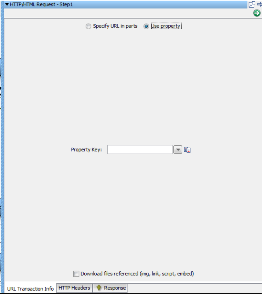
HTTP Headers Tab
On the HTTP Headers tab, create any custom HTTP headers. The top section Custom HTTP Headers (Current Only) is for headers that are only
sent to the server for this request. The bottom section Custom HTTP Headers (Persist) is for headers that are sent on this transaction and every
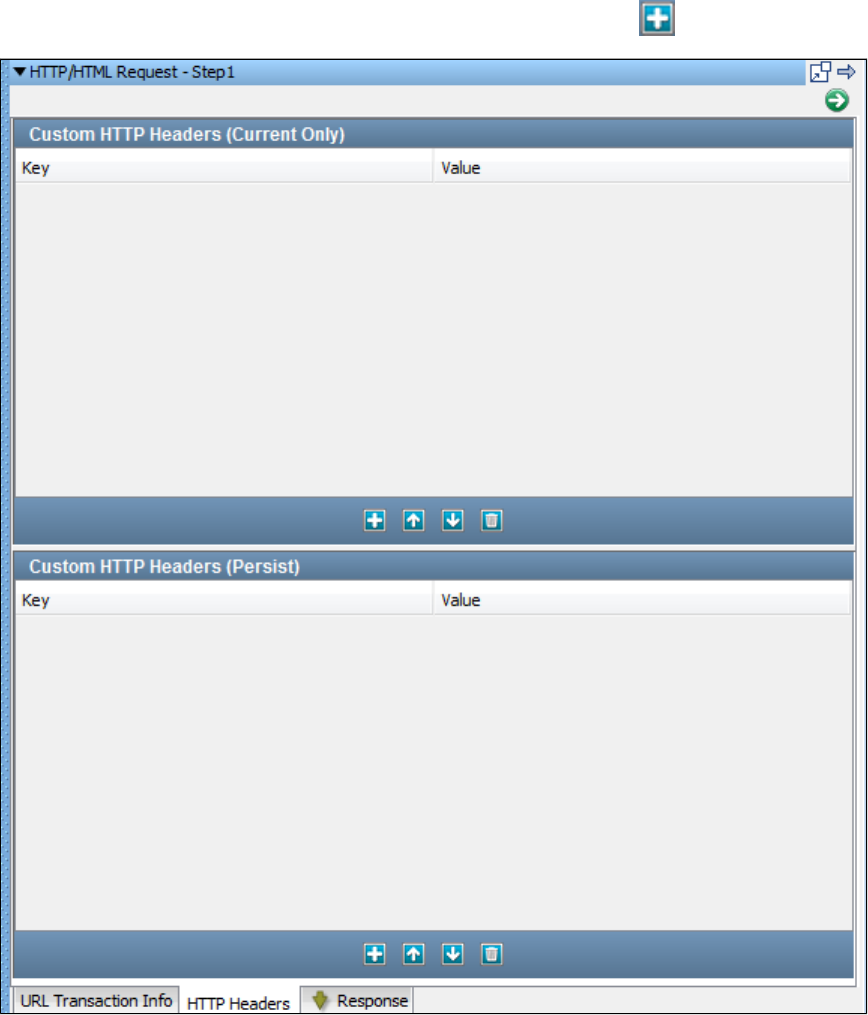
other transaction in the test. To create a request parameter in either section, click the Add icon and change the key and value to the target
values.
Response Tab
On the Response tab, view the HTTP response returned by the server when this test was recorded.
You can view the source of the response.
You can view the DOM Tree of the response.
REST Step
Use the REST step when testing REST applications.
This step is used to send and receive HTTP(S) requests, including GET and POST parameters.
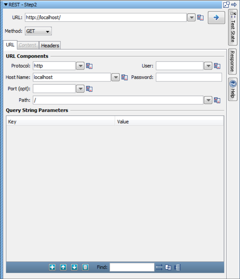
Click the Test State button on the right vertical bar to view parameters. The Test State area slides open. You can dock, pin, and hide the list.
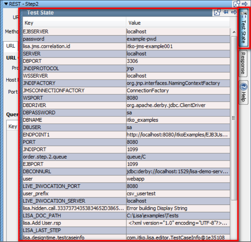
Click the Response button to view the HTTP response.
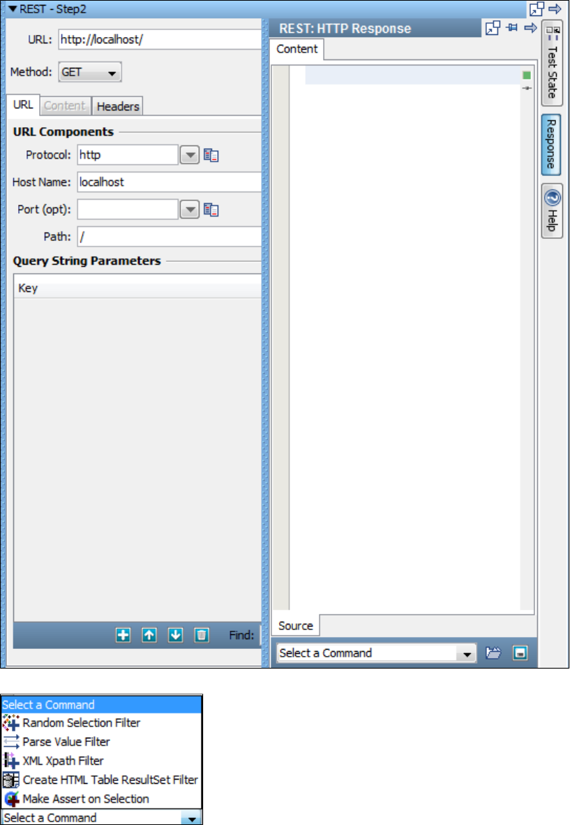
At the bottom of the Response panel is a selection of filters and an assertion that you can add to the response.
The LISA demo server contains an example of invoking a JSON service to retrieve information from the LISA Bank user database. The URL is
.http://localhost:8080/rest-example/
An example test case for the REST step is in the examples project, named rest-example.tst.
Web Service Execution (XML) Step
The Web Service Execution (XML) step is designed to execute an operation on a SOAP-based Web Service using an HTTP POST or JMS
message.
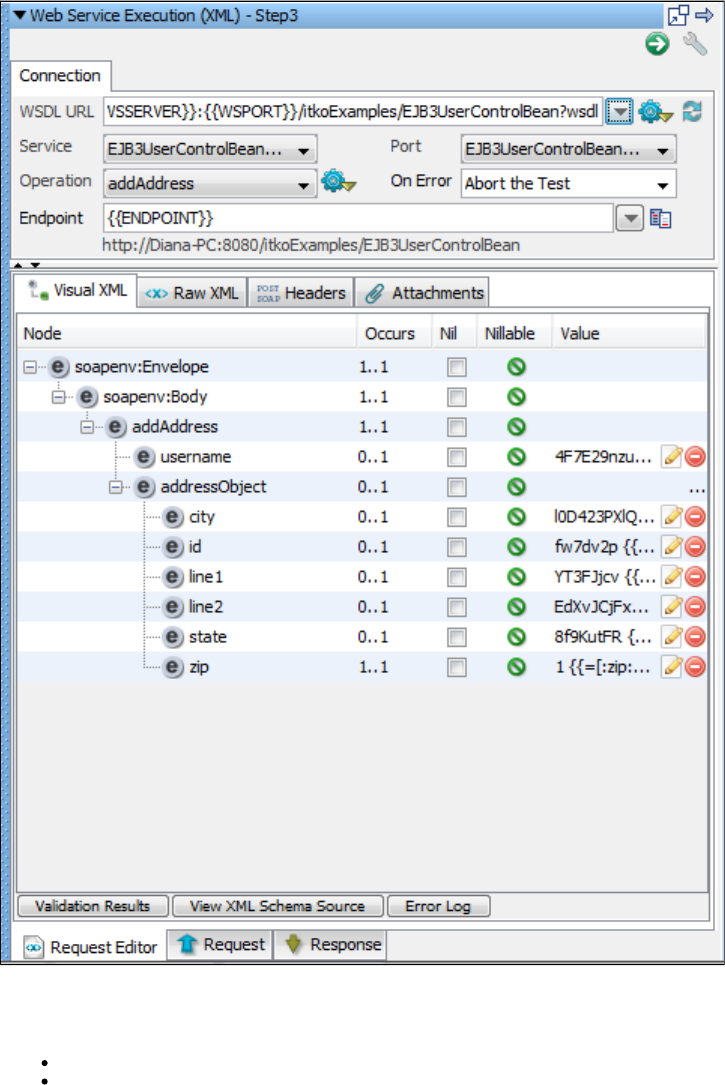
Access to a WSDL is not required; rather, it is a recommended but optional piece of configuration information. If a WSDL is configured, it helps in
the process of building a SOAP message to be sent to the service. This step lets you manipulate the raw SOAP message (XML) directly. This
gives you a great deal of flexibility and power, but does expose you to the details of how web services work.
In general, the top portion of the editor is dedicated to how and where to send the SOAP message, and the bottom portion is dedicated to what
the message will say.
After the test step opens, it has two tabs, with each tab having multiple subtabs within.
Connection Tab
The Connection tab has fields for connection. It has subtabs on the top bar and bottom bar.
Top bar - for viewing the Visual XML, Raw XML, Headers, Attachments.
Bottom bar - for Request and Response
Basic Configuration
Design Time Execution
Basic Configuration
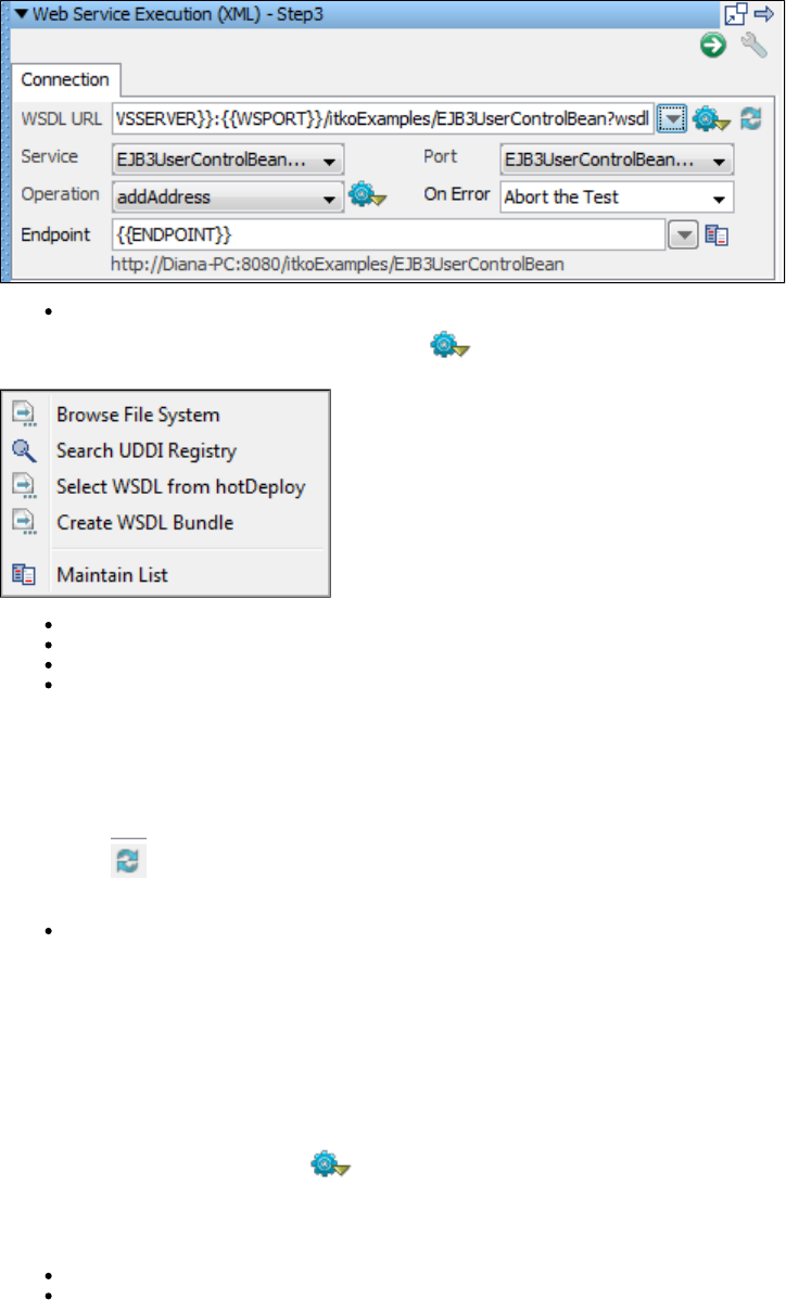
Connection
WSDL URL: The WSDL URL is an optional but recommended field (denoted by its slightly gray label). It must be a URL (either file:/,
http:/, or https:/). From the More Options menu you can choose to:
Browse the File System for a local WSDL or WSDL Bundle file.
Search a UDDI Registry (which populates the advanced UDDI access point lookup).
Select WSDL from hotDeploy to migrate from the legacy WS step.
Create and use a WSDL Bundle. Creating a WSDL Bundle can also be accessed from the Actions menu, but from here it automatically
populates the WSDL URL with the resulting WSDL Bundle's file URL. Or if you already have a WSDL URL populated, it pre-populates the
WSDL URL in the WSDL Bundle dialog.
When a WSDL URL is entered, one that is not already a WSDL Bundle, LISA will create a WSDL Bundle and stores it locally in the project's
Data/wsdls directory, caching the WSDL locally for quicker access. The WSDL is parsed and its schema is used to build sample SOAP messages
and is used by the Visual XML editor to help assist you when manually editing the SOAP Message. It will first try and load a cached WSDL Bundle
whenever processing the WSDL. If the external WSDL has changed and you want to force the local WSDL cache to update, use the Refresh
WSDL Cache button. At any time you can manually drop a WSDL Bundle into the Data/wsdls and anytime the step tries to process the 'live'
WSDL URL it will use the cached bundle instead.
Service, Port, Operation: If the WSDL URL is populated, LISA will process the WSDL and populate the Service, Port, and Operation
selection. These optional but recommended fields can be used to build a sample SOAP request message. Selecting a port also updates
the Endpoint URL to match the definition in the WSDL. Changing the WSDL URL causes these items to be refreshed, and if the Endpoint
URL and SOAP Message are unchanged, they update also to correspond to the new WSDL, service, port, and operation that are
selected.
If the Endpoint was changed and no longer matches what is defined in the WSDL, a Warning button appears next to the field. A tooltip on the
button indicates what the differences are between the entered value and the WSDL definition. Clicking the button updates the field to match the
WSDL definition.
If the SOAP Request Message no longer matches the default, it will not be updated automatically. You can force the SOAP Request Message to
be updated by using the Build Message button next to the Operation field.
: Any of the following options can be used here:Operation
Build empty SOAP request message.
Build full SOAP request message.
: When building sample SOAP messages,various build options are used to determine what to do in various situations.Build Options
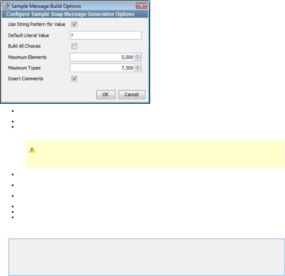
Use String Pattern for Value: When selected, it populates element values using LISA string patterns as opposed to using a hard-coded
literal value.
Default Literal Value: When not using string patterns, use this literal value for all string values.
Build All Choices: By default, only the first element in a XML schema choice is generated. Select this option to build all possible choice
elements.
It will not be a valid SOAP request if you include more than one choice element, but it will show you a sample for each
possible choice, making it easier to build a message when not using the first choice.
Maximum Elements: This indicates when to give up building the sample message if it would end up creating a enormously large
message: how many elements should it stop after.
Maximum Type: This indicates when to give up building the sample message if it would end up creating a enormously large message:
how many complex schema types should it stop after.
Insert Comments: By default, comments will be generated related to the schema (for example, when an element is optional, alternative
choices, nilable elements, and so forth). You do not see these comments in the Visual XML Editor, but they are visible in the Raw Editor.
Port: This field indicates the server port on which the service is available.
On Error: This field indicates what action to be taken when some error occurs during execution.
Endpoint: The URL to the SAML Query API of the Identity Provider.
Web Service Execution Tabs
Tabs available in the Web Service Execution editor are described here:.
Visual XML Tab
Raw XML Tab
Headers Tab
Attachments Tab
Visual XML Tab
The Visual XML Editor (or VXE) is a graphical editor for any XML document. Because a SOAP message is an XML document that conforms to the
SOAP specification (SOAP schema), you can use the editor to build and edit the SOAP message.
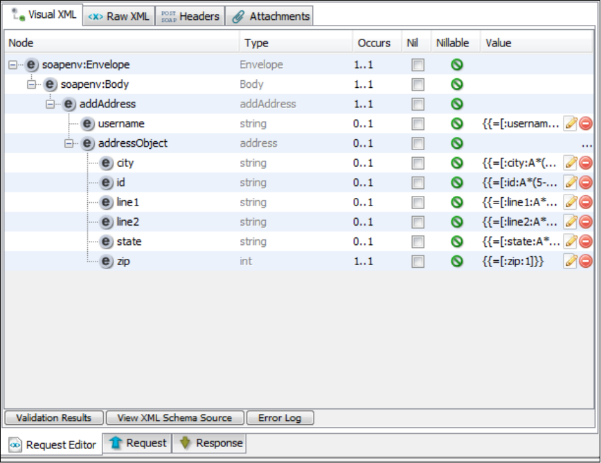
The table shows the XML document including the SOAP Envelope and Body elements.
The Type column shows the type for each element.
The Occurs column indicates how many elements are expected. The first number indicates the minimum number of times the element can occur.
Zero would mean that it is optional and can be removed. The second number indicates the maximum number of times the element can occur.
Infinity would mean there can be an unlimited number of elements of that name.
The Nil column lets you nil out or un-nil the element value. Selecting the check box will remove any element children or values but leave all
attributes alone. Clearing the check box will populate all expected children and attributes as defined in the WSDL schema.
The Nillable column indicates whether the element can be nil. It will show a red icon if the element is nil, but is non-nillable. It will show a green
icon if it is non-nillable and is not nil.
You can type element values directly into the Value column. If the element type is one of a set of known type, specialized edit buttons appear.
When you right-click the editor, a context-sensitive menu provides options for manipulating the document.
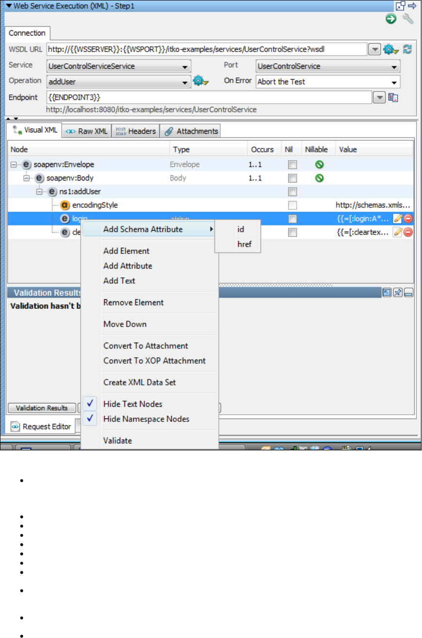
This menu contains the following options:
Add Schema Attribute/Element: Lets you select from a list of valid attributes or elements. If a schema is present, and an element or
attribute is selected in the editor, child elements and attributes are populated and can be selected for addition. If more than 20 schema
objects are available, a dialog can be used to select the schema object. This dialog contains a search text field, which makes it easier to
find a particular schema object when there are dozens of them.
Add Element: Add an element to the document.
Add Attribute: Add an attribute to the document.
Add Text
Remove Element/Attribute: Remove the selected element or attribute.
Move Up/Down: Move the selected node up or down.
Convert to Attachment: A shortcut method for creating a standard referenced attachment. For more information, see .Attachments Tab
Convert to XOP Attachment: A shortcut method for creating a standard referenced XOP Include attachment. For more information, see
.Attachments Tab
Create XML Data Set: A shortcut method for generating an XML Data Set. A typical use case would be to build a full SOAP message
then select the section of the XML document that you want as the first record of the data set. Creating an XML Data Set will automatically
populate the first record with the selected XML element tree and set the new data set LISA property as the value in the editor.
Hide Text Nodes: By default, LISA hides Text Nodes which are typically redundant (for example, white space), but on some occasions it
is useful to view them, including when the XML element is of mixed type (element that supports intermixed elements and text).
Hide Namespace Nodes: By default, LISA hides namespace declarations and namespace prefix declarations. You may want to show
them to confirm a prefix value or if you want to change prefixes or namespace scoping.
You can also use keyboard shortcuts for certain tasks:
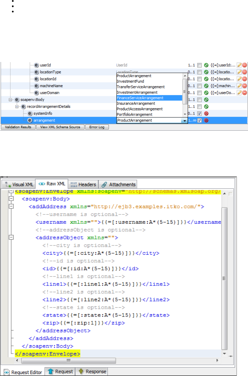
To remove the selected element or attribute on Windows, press Ctrl+Backspace.
To move the selected node up on Windows, press Ctrl+up arrow.
To move the selected node down on Windows, press Ctrl+down arrow.
Editing the Type field
The Type column shows the XML schema type (local name) and has a tooltip to show the fully qualified name (qName) with namespace. This
column is editable for derived XSD types. Only base types with derived types can be edited.
When editable, a list of available derived types and the base types are presented in a combo box. You can select a type, and the associated
element will now be associated with the selected type.
Changing the type will remove all child elements and attributes from an element and set the nil attribute on the element to nil=true.
Raw XML Tab
The Raw XML Editor is a text-based editor that is XML aware and lets you manually edit the raw XML SOAP message. Any changes that are
made will be seen when you switch back to the (and conversely).Visual XML Editor
If you make an edit that causes the document to no longer be a valid XML document, the Visual XML Editor might show an error message when
you switch back to it.
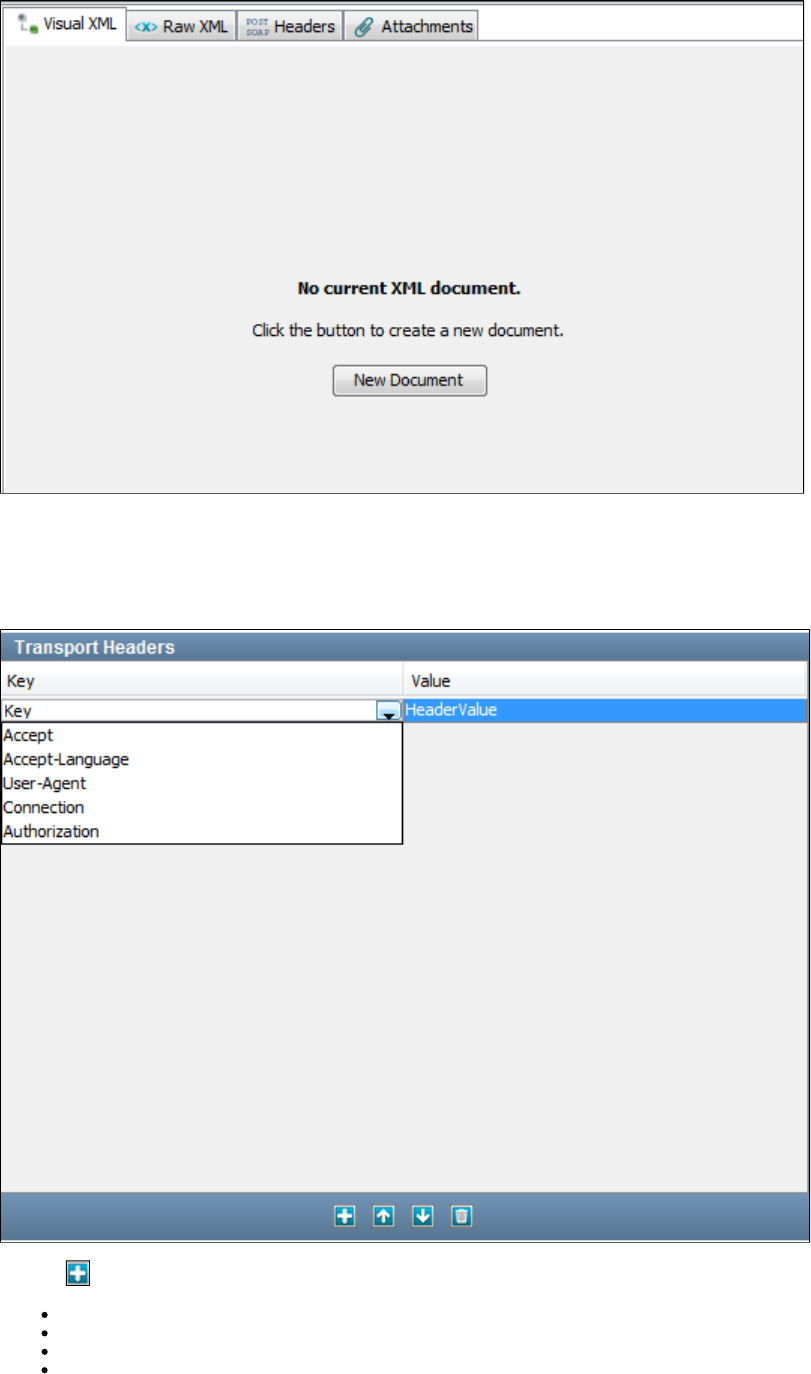
Fix your changes in the Raw XML Editor, and the Visual XML Editor will begin working again.
Headers Tab
The Headers tab lets you insert headers that will be transmitted with the SOAP message (for example, HTTP Headers or JMS properties).
Click the sign to add a header row and select a header from the drop-down list.
Accept
Accept - Language
User - Agent
Connection

Authorization
Accept
The Accept request-header field can be used to specify certain media types that are acceptable for the response. Accept headers can be used to
indicate that the request is specifically limited to a small set of desired types, as in the case of a request for an in-line image.
This field contains a semicolon-separated list of representation schemes that will be accepted in the response to this request.
Accept = "Accept" ":"
#( media-range [ accept-params ] )
If no Accept: field is present, then it is assumed that text/plain and text/html are accepted.
Accept - Language
The Accept - Language header field is similar to Accept, but lists the Language values that are preferable in the response. A response in an
unspecified language is not illegal.
Accept-Language = "Accept-Language" ":"
1#( language-range [ ";" "q" "=" qvalue ] )
language-range = ( ( 1*8ALPHA *( "-" 1*8ALPHA ) ) | "*" )
User - Agent
The User-Agent request-header field contains information about the user agent originating the request.
This is for statistical purposes, the tracing of protocol violations, and automated recognition of user agents for the sake of tailoring responses to
avoid particular user agent limitations. User agents include this field with requests.should
By convention, the product tokens are listed in order of their significance for identifying the application.
User-Agent = "User-Agent" ":" 1*( product | comment
Connection
The Connection general-header field allows the sender to specify options that are desired for that particular connection and bemust not
communicated by proxies over further connections.
Connection = "Connection" ":" 1#(connection-token)
connection-token = token
Message headers listed in the Connection header include end-to-end headers, such as Cache-Control.must not
Authorization
A user agent that wishes to authenticate itself with a server usually, but not necessarily, after receiving a 401 response, does so by including an
Authorization request-header field with the request. The Authorization field value consists of credentials containing the authentication information
of the user agent for the realm of the resource being requested.
Authorization = "Authorization" ":" credential
Attachments Tab
Explicitly showing attachments is one of the major usability differences from the legacy Web Service Execution step. In the legacy step,
attachments were handled automatically by the generated Java classes, but it could be difficult to configure the necessary Java objects to use
them properly. There is now an explicit tab dedicated to the editing of Attachment data (and a tab to show Sent/Received attachments in the
Request/Response tabs described in the following sections).

Referenced Attachments
If you plan to use referenced attachments (attachments referenced in the SOAP message), in the VXE you can right-click on the element that you
want to be the references attachment and select to Convert to Attachment (for MIME and DIME) or Convert to XOP Attachment (for MTOM/XOP
Include style). This will automatically create the necessary elements and attributes and configure the content id used to match up the element with
the attachment. It will then switch over to the Attachments tab and pre-populate a new attachment with the content id, select a default content type
and attachment type, and populate the value with any existing element data from the VXE.
Unreferenced Attachments
If you plan to use unreferenced (that is, anonymous) attachments, switch over the Attachments tab and add an attachment manually.
Use the Add, Up, Down, and Delete icons to add, remove, or rearrange the attachments in the table.
MIME DIME XOP MTOM: This controls how the attachments are sent, either using MIME, DIME, XOP. or MTOM standards. XOP sends
different content headers based on the SOAP version.
When MTOM is selected, any base64binary schema types are automatically optimized using the XOP standard. There is no need to manually add
attachments. If an element is already configured as an attachment it will be left alone. Any extra attachments added manually will also be sent.
If is selected, even if there are no base64binary elements in the document, the document will be formatted and sent as an attachmentForce
(Microsoft MTOM method).
The limitation of automatically optimizing elements is that the element must be understood by the VXE as a base64binary schema type (or
extension/restriction thereof). In the case where a Data Set or Property is used, the expanded Property or first Data Set entry must contain all
possible elements that need to be optimized (i.e., if the element that needs to be optimized isn't displayed in the VXE it won't be optimized).
cid: The Content ID that can be used in a attribute in the SOAP message to link the element to the attachment datahref
content type: The mime encoding type used to assist the server in how to process the attachment data
type value: The LISA attachment type determines how to edit and interpret the value data. Each type has its own editor.
Type Editors
XML: An XML-aware text editor to edit the attachment value.
Text: A text-based editor to edit the attachment value.
Base64 Encoded: A a text-based editor to edit the attachment value and a bytes viewer to view the decoded binary data.
Hex Encoded: A text-based editor to edit the attachment value and a bytes viewer to view the decoded binary data.

URL/Text: A URL field to edit the attachment value and a text data viewer to view the results of loading the data from the URL.
URL/XML: A URL field to edit the attachment value and a XML-aware text data viewer to view the results of loading the data from the
URL.
URL/Binary: A URL field to edit the attachment value and a binary data viewer to view the results of loading the data from the URL.
Property: A property field to edit the attachment value. If the resulting property is a string, it will send the attachment as text, otherwise it
will send it as binary data.
Property/URL: A property field to edit the attachment value. The property value is assumed to be a URL. The URL content is loaded and
sent as the attachment data.
Design Time Execution
Now that you have completed configuring the connection information and building the SOAP Request Message you can now test the step by
executing it at design time.
Execute the Web Service operation by clicking the Execute button in the upper right corner. After it has executed, the Request and
Response tabs will be populated and it will switch to the Response tab automatically.
Request Tab
The Request tab will show the resulting request data that was sent after any post processing (for example, substituting LISA properties). If the
message contained any attachment, it will not show the raw MIME or DIME encoded message, but rather the processed message and
attachments. If you want to see the raw message, use a tool like TCPMon.
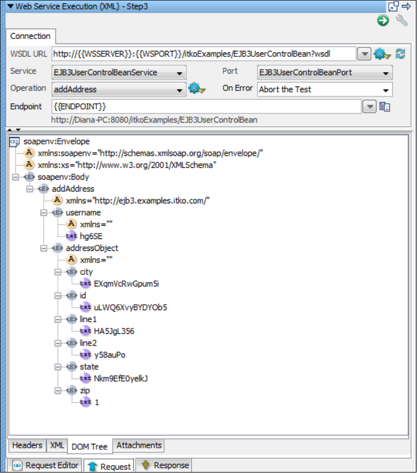
Header Tab
The Header tab shows the Transport Headers that were sent for the request.
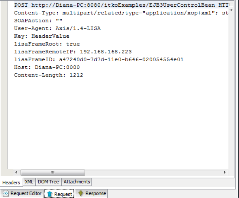
XML Tab
The XML tab shows the raw SOAP message that was sent after any advanced processing.
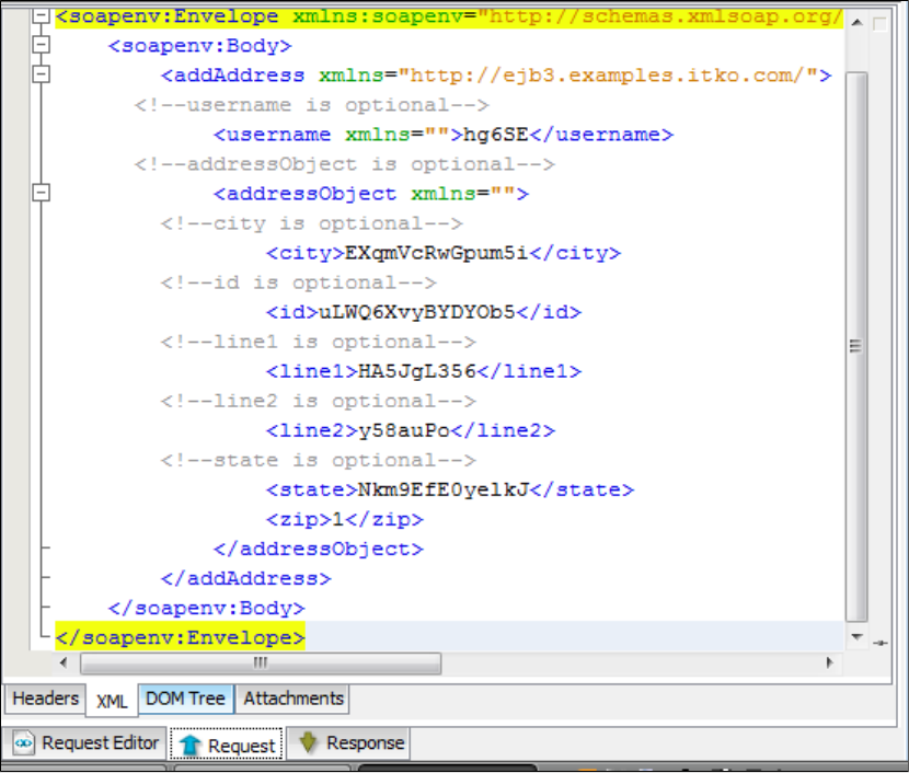
DOM Tree Tab
The DOM Tree tab shows a DOM tree for the SOAP message.
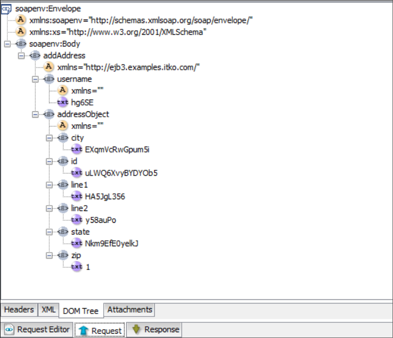
Attachments Tab
The Attachments tab shows any attachments that were sent.
Response Tab
The Response tab show the resulting response data that was received. If the message contained any attachment, it will not show the raw MIME
or DIME encoded message, but rather the processed message and attachments. To see the raw message, use a tool like TCPMon. If there are
any advanced post-processing options set (see the following window), the SOAP response message will be shown post-processed.
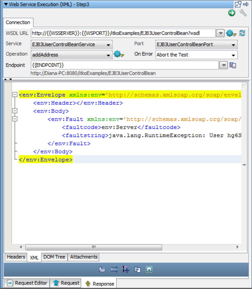
Header Tab
The Header tab shows the Transport Headers that were received from the response.
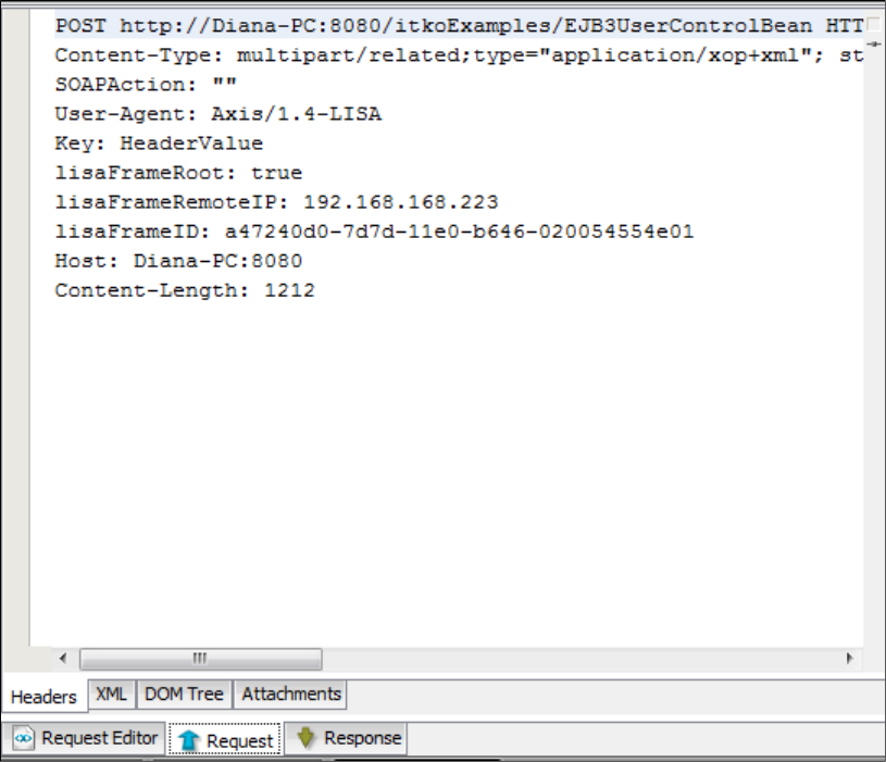
XML Tab
The XML tab shows the raw SOAP message that was received after any advanced processing.
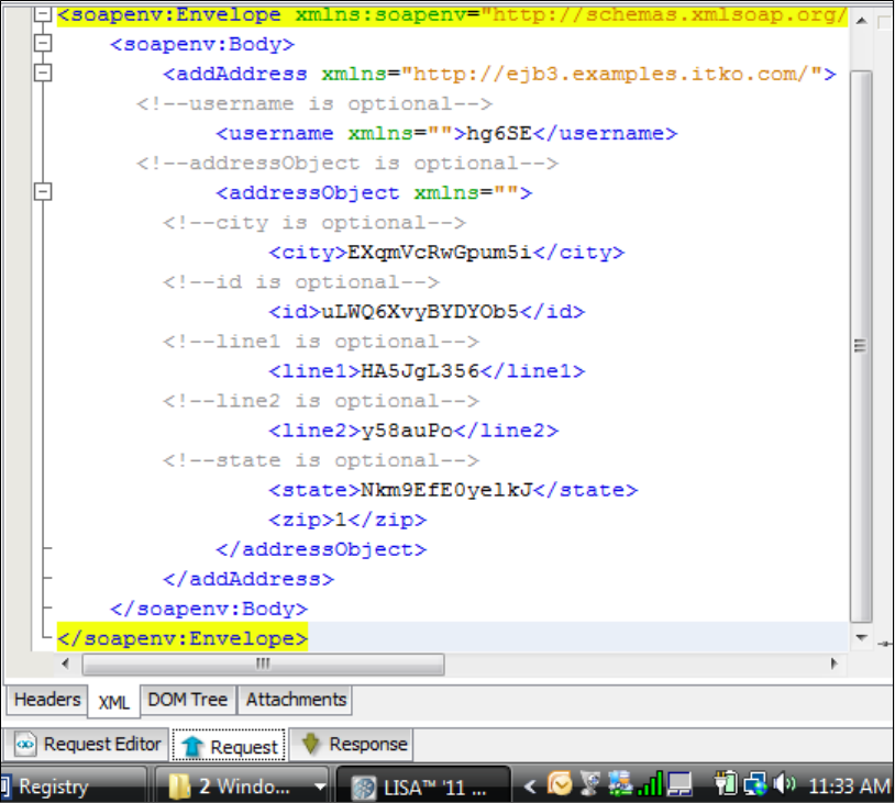
DOM Tree Tab
The DOM Tree tab shows a DOM tree for the SOAP message. From this tab you can quickly add filters and assertions on the resulting SOAP
message.
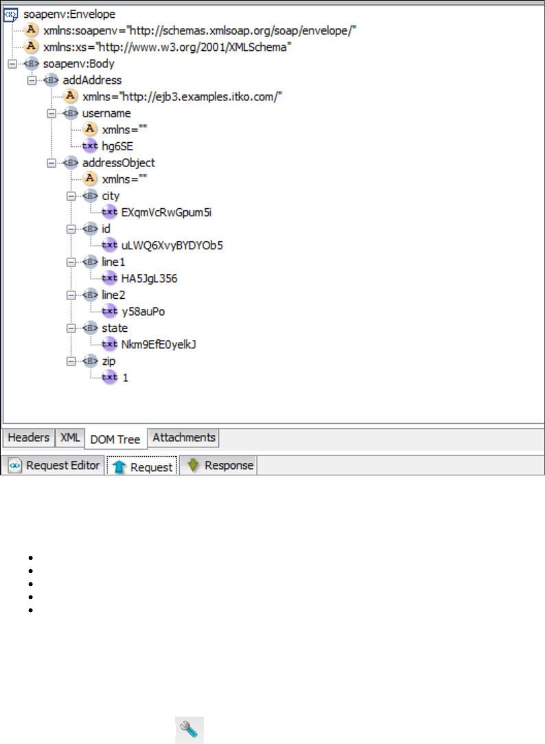
Attachments Tab
The Attachments tab shows any attachments that were received. Received attachments can be accessed using automatically generated LISA
properties (for use in later steps, filters, or assertions). For each attachment the following LISA properties are set.
lisa.<step name>.rsp.attachment.<cid>: Attachment value, byte or String
lisa.<step name>.rsp.attachment.contenttype.<cid>: Content type (mime type, for example, text/plain)
lisa.<step name>.rsp.attachment.<index>: Attachment value, byte or String
lisa.<step name>.rsp.attachment.contenttype.<index>: Content type (mime type, for example, text/plain)
lisa.<step name>.rsp.attachment.contentid.<index>: Content Id (cid)
The parameter is the LISA step name that is being executed.<step name>
The parameter is the Content ID that is usually referenced in the SOAP message.<cid>
The parameter starts at 0 and is increased for each attachment in the response attachments list.<index>
Advanced Settings
Click the Toggle Advanced Options icon to open the Advanced settings tabs. Five new tabs open in the top of the panel, and two new tabs
open at the bottom level.
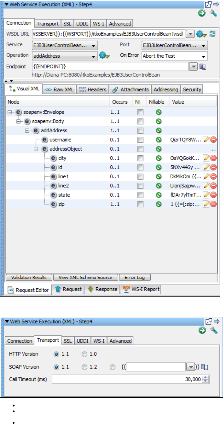
Transport Tab
HTTP Version: This is 1.1 by default and controls which HTTP protocol is used when sending the operation request.
SOAP Version: This is auto-populated based on the WSDL definition. SOAP Version will control the generation of a number of transport
headers (for example, SOAPAction and contentType).
Call Timeout (ms): This defines how to wait while trying to execute the operation. After the timeout is hit, an exception will be thrown and
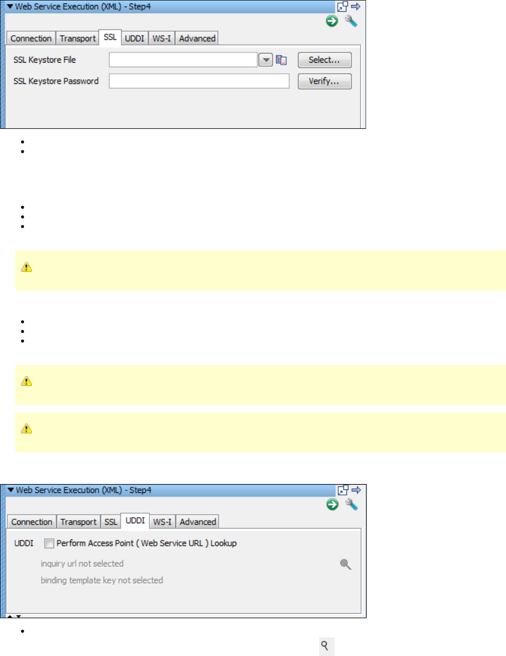
the On Error handling will occur.
SSL Tab
SSL Keystore File: The name of the keystore file where the client identity certificate is stored. It can be in jks or pkcs format.
SSL Keystore Password: The password for the keystore.
Specify global certificates properties for SSL in your file.local.properties
For global certificates (web server, raw SOAP, and web service steps):
ssl.client.cert.path: A full path to the keystore.
ssl.client.cert.pass: Password for the keystore (this password will be automatically encrypted when LISA runs).
ssl.client.key.pass: An optional password for the key entry if you are using the JKS keystore and the key has different password from
the keystore. This password will be automatically encrypted using AES (Advanced Encryption Standard) when LISA runs.
This is currently not an available option to be set in the WS Test step and if required must be set in the file.local.properties
For web service steps only certificates (not raw SOAP steps):
ws.ssl.client.cert.path: A full path to the keystore.
ws.ssl.client.cert.pass: Password for the keystore (this password will be automatically encrypted when Lisa runs).
ws.ssl.client.key.pass: An optional password for the key entry if you are using the JKS keystore and the key has different password
from the keystore. This password will be automatically encrypted using AES (Advanced Encryption Standard) when LISA runs.
This is currently not an available option to be set in the WS Test step and if required must be set in the file.local.properties
If you have duplicate values in and in the general tab, the values in the general tab will be used.local.properties
UDDI Tab
Perform Access Point (Web Service URL) Lookup
Select the Inquiry URL and Binding Template: use the Search UDDI Server Find button to navigate to the correct Binding Template
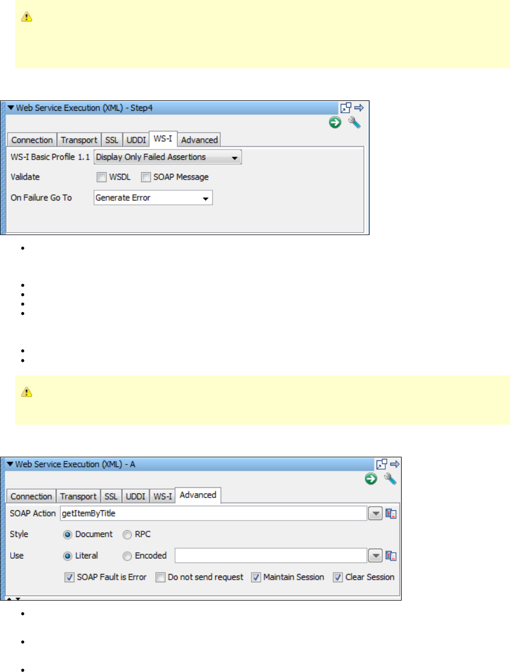
to perform the lookup.
When creating the step, if you used the UDDI Search function when specifying the Web Service WSDL URL, these values will
be automatically filled in. If the Inquiry URL is specified but the Binding Template is not, you may have performed a Model
search. To locate the Binding Template you must perform a search at a higher level of the hierarchy and drill down to the
TModel through a particular Binding Template.
WS-I Tab
WS-I Basic Profile 1.1:
You can choose four different validation levels in the pull-down menu.
Display All Assertions
Display All But Info Assertions
Display Only Failed Assertions
Display Only Not Passed Assertions
Validate: Check to validate the WSDL and/or the SOAP message.
On Failure Go To: Select the step to redirect to on error.
Validation failures are common, but usually should not affect the outcome of the test. It is good practice to set the next step to
continue so that you can complete the test.
Advanced Tab
SOAP Action: This field is auto-populated based on the WSDL operation definition. It is used as the value of the SOAPAction transport
header for SOAP 1.1 request message. Change this field manually only in rare cases.
Style: This field is auto-populated based on the WSDL operation definition. It is used to determine how a sample SOAP message is
generated. Changing this field manually should only be done in rare cases.
Use: This field is auto-populated based on the WSDL operation definition. It is used to determine how a sample SOAP message is
generated. If is selected, you can also edit the Encoded URI in the field next to the choice. Changing these fields manuallyEncoded
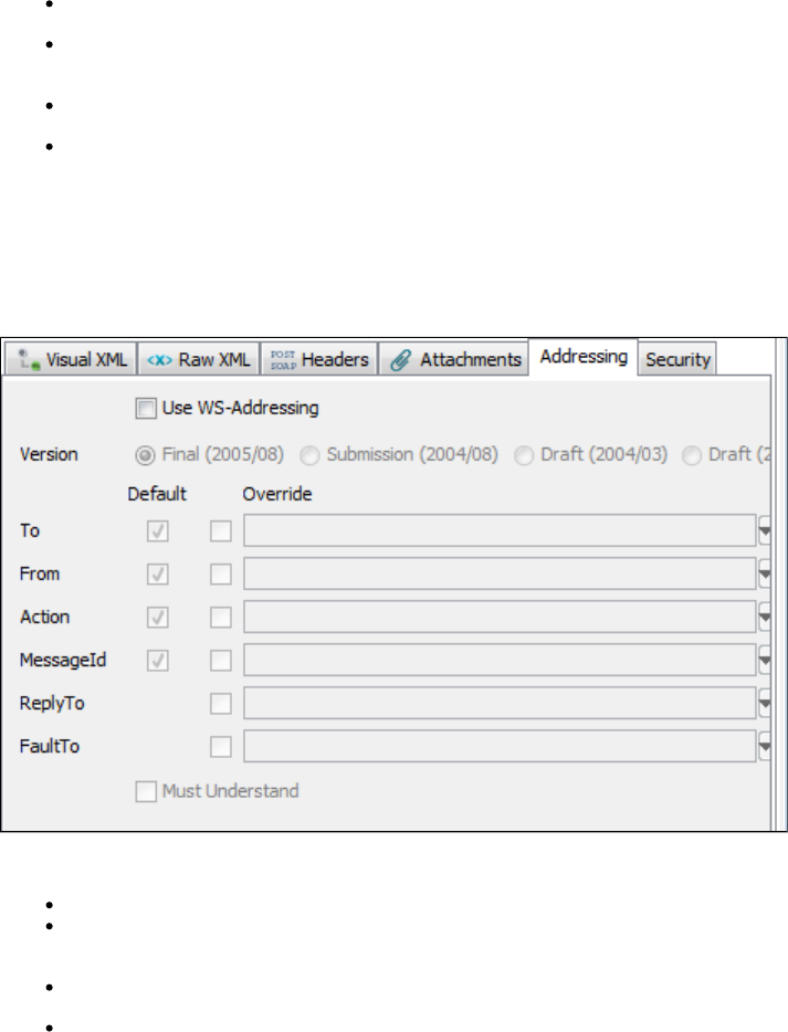
should only be done in rare cases.
SOAP Fault is Error: If a SOAP fault is returned, perform On Error handling.
Do Not Send Request: When selected, the step execution will perform all the normal SOAP message processing but will not send the
generated SOAP message. Instead it will set the response to be the request message that would have been sent.
Maintain Session: Select to maintain cookies across invocations.
Clear Session: Select to clear cookies across invocations. Clearing the session cookies will act like a new session was created. Any old
session cookies will not be used and any new cookies in the response will not be set on the session, but the session will not be cleared
so future steps can still use it.
Request Editor Tabs
Addressing Tab
You can send a WS-Addressing header with your request. The WSDL does not specify if WSAddressing information is required so you must
configure it.
Click the Addressing tab, and then specify:
Use WS-Addressing: Click to use WS-Addressing.
Version: Select appropriate version. Several versions of the WS-Addressing specification are listed as options because some web
services platforms (for example, .NET) still use the older Draft specifications. You will need to determine which your web service platform
is using.
LISA will populate as many values as it can. Then you can choose to use the default value or override it. You can choose not to send
some of the Default elements by clearing the Default check box for that element.
Click the Must Understand check box if you want to assure that the web service can understand the WSAddressing header.
Security Tab
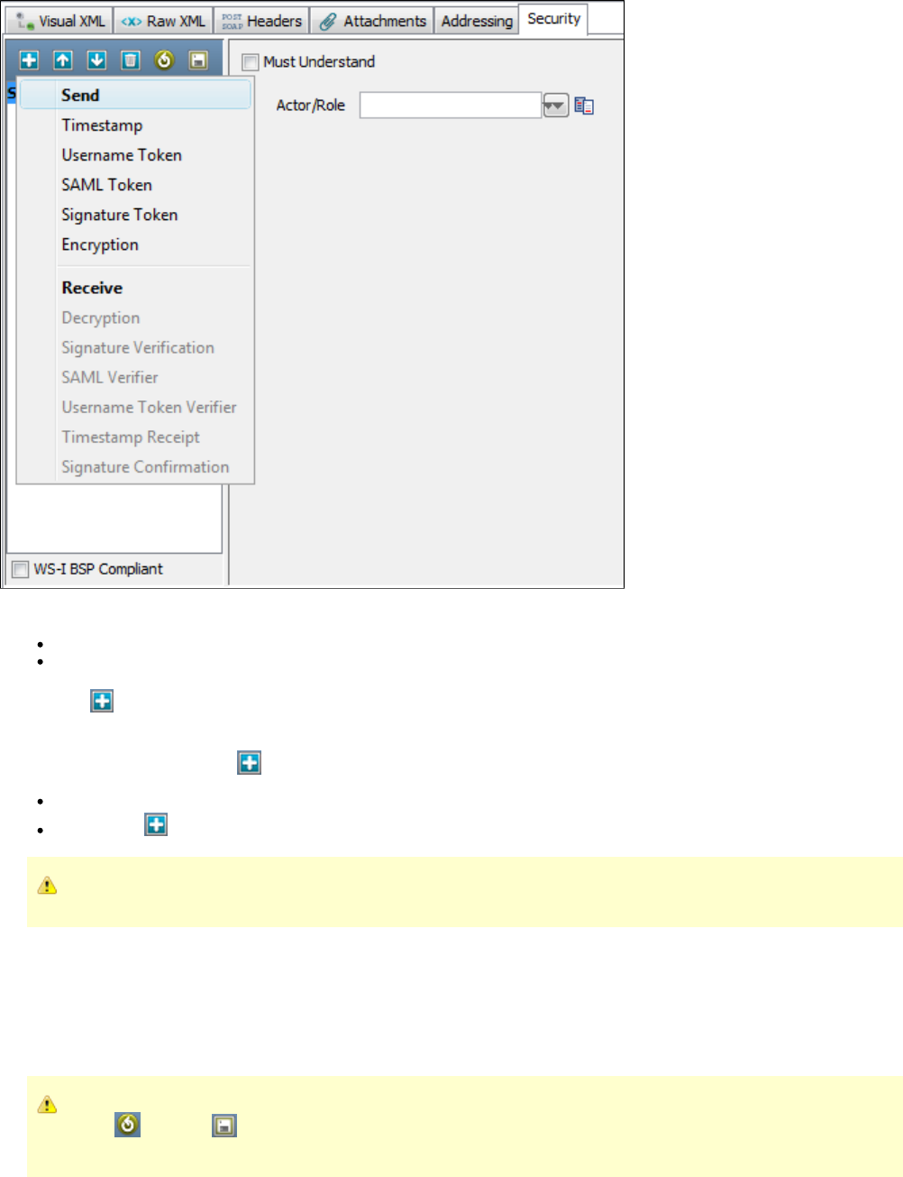
Click the Security tab. Click Send.
Must Understand: To help ensure that the WS-Security header is processed by the server.
Actor/Role: Enter name if needed: most web services do not use multiple Actors/Roles.
Click the Add icon and select the security action type to add. You will be presented with the configuration panel for that security action type.
Adding security verification to the Response is very similar:
Click the Security tab. Click the Add, icon and select Receive.
Enter the Actor/Role name (if needed)
Click the Add icon and select the security action type. You will be presented with the configuration panel for that security action type.
You can add as many security types as are needed to execute your Web Service.
When a keystore is being used in a security action type configuration, you can verify your keystore settings to make sure you are using the correct
format, password, alias and alias password. There is a Verify button on the editors for Signature, Encryption/Decryption and SAML Assertion
Token. Clicking the Verify button will invoke the Keystore Verifier, which will produce a verification report.
If you do not know the expected alias name for a WS-Security setting, you can use the Keystore Verifier to list all of the aliases in the keystore.
Leave the Keystore Alias and Alias Password boxes empty and click the Verify button. The Keystore Verifier is described at the end of this section
on WS-Security.
New in LISA 5.0.25 and LISA 6.0, you can now load and save security configuration information from/to a .wss file, using the
Load and Save icons. This allows for quick and easy creation of new steps connecting to the same service.
Security Example
This section describes the parameters needed to run the WS-security example.
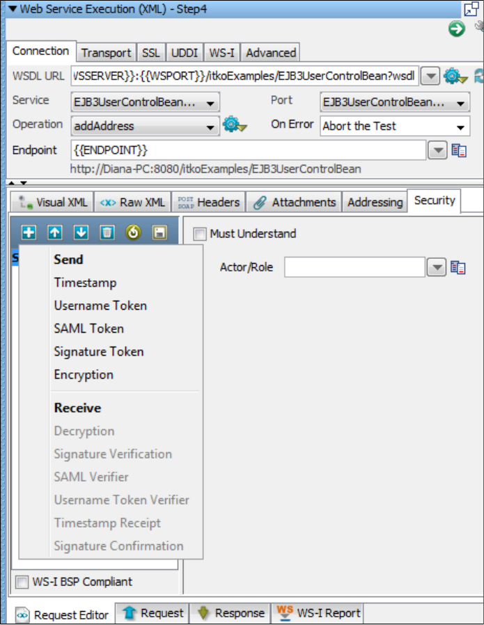
XML Encryption/Decryption
Encryption

Click the Use Encryption check box.
Keystore File: The location of the keystore file.
Keystore Type: Select Java Key Store (jks) or Personal Information Exchange (PKCS #12).
Keystore Password: Enter the password for the keystore.
Keystore Alias: Enter an alias for a public key.
Alias Password: Leave empty or make the same as Keystore Password for PKCS #12 files.
Key ID Type: Select the appropriate key ID type from the pull-down menu.
Algorithm: Select Triple DES, AES 128, AED 192, or AES 256.
Transport: Select PKCS#1: RSA Encryption Standard v1.5 or Optimal Asymmetric Encryption Padding with RSA Encryption.
The default behavior is to encrypt only the SOAP Body contents.
Encrypt Only Parts: If you want to specify different parts to encrypt. Click the Select button to identify the parts to be encrypted.
Type: Select one of the following:
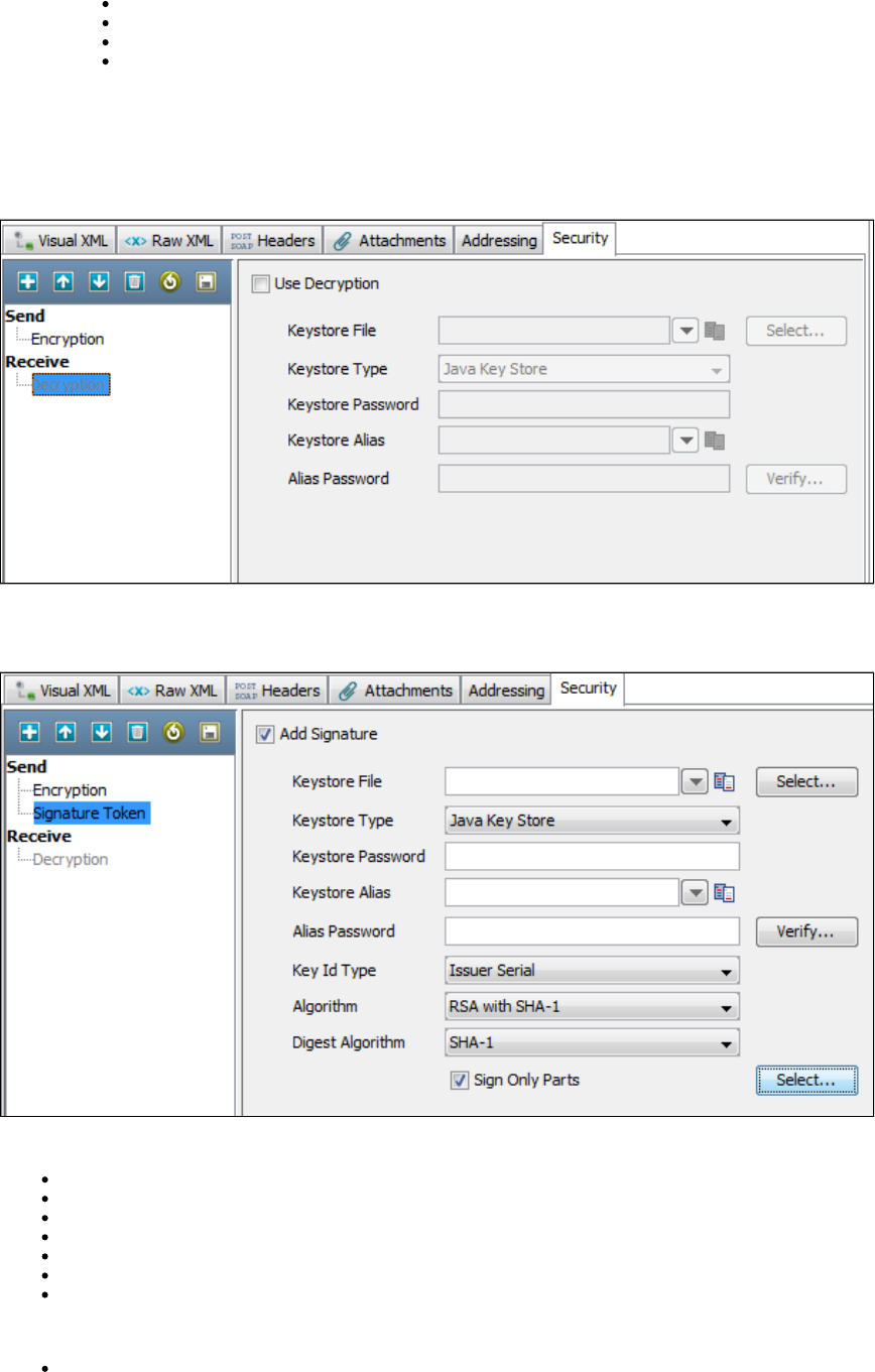
Element: Select if you want to encrypt the element and the content.
Content: Select if you want to encrypt just the content.
Namespace URL: Enter the value for the element.
Element: Enter the name of the element.
You can repeat this for as many elements as you want by clicking the Add button.
You will need to manually add the Body element if you want it to be included. If you want to include the Binary Security Token as a part, use the
Element name "Token".
Decryption
XML Signature Token/Signature Verification
Signature Token
Click the Add Signature box.
Keystore File: Enter the location of the keystore file.
Keystore Type: Select Java Key Store (jks) or Personal Information Exchange (PKCS #12).
Keystore Password: Enter the password for the keystore.
Keystore alias: Enter an alias for a private key.
Alias Password: Leave empty or enter the same as Keystore Password for PKCS #12 files.
Key ID type: Select the appropriate key ID type from the pull-down menu.
Algorithm: Select DSA with SHA-1.
The default behavior is to sign only the SOAP Body contents.
Sign Only Parts: If you want to specify different parts to sign, click the Select button to identify the parts to be signed.
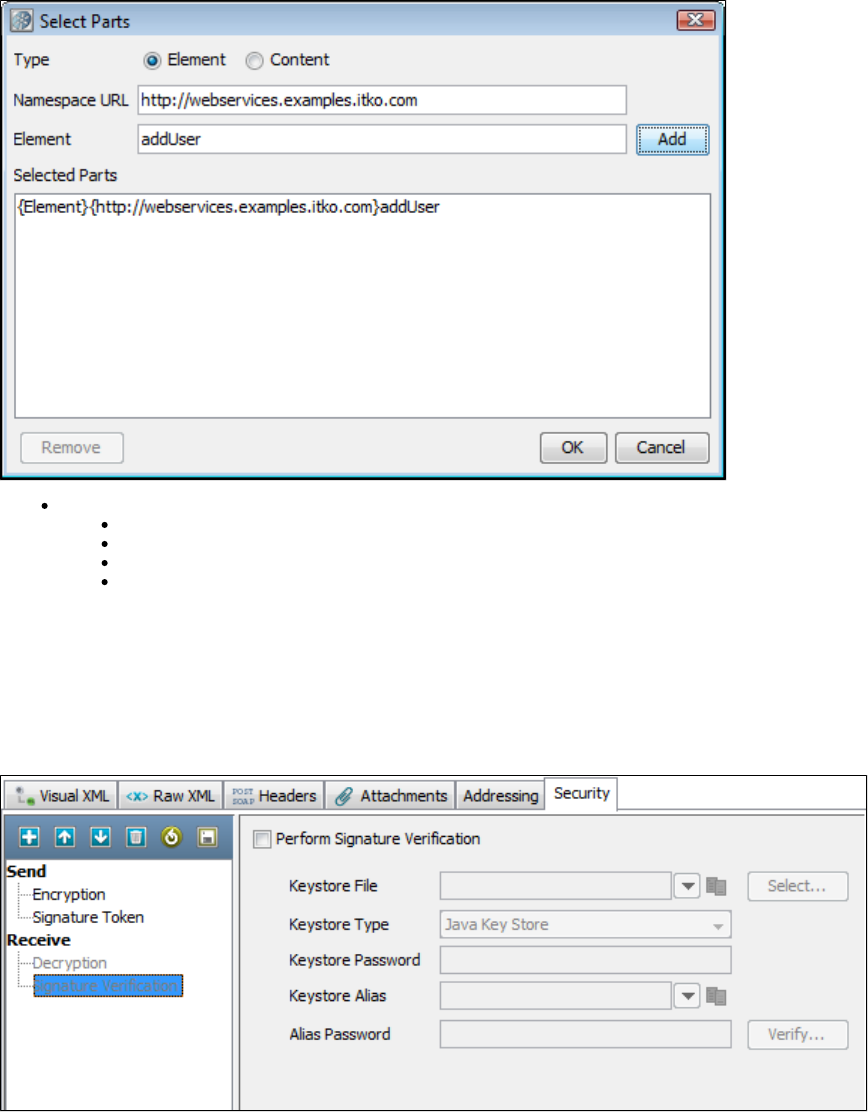
Type:Select one of the following:
Element: Select if you want to sign the element and the content.
Content: Select if you want to sign just the content.
Namespace URL: Enter the value for the element.
Element: Enter the name of the element.
You can repeat this for as many elements as you want by clicking the Add button.
You will need to manually add the Body element if you want it to be included. If you want to include the Binary Security Token as a part, use the
Element name "Token."
Signature Verification
The parameters required to configure signature verification are a subset of those required for signing.
Timestamp/Timestamp Receipt
Timestamp
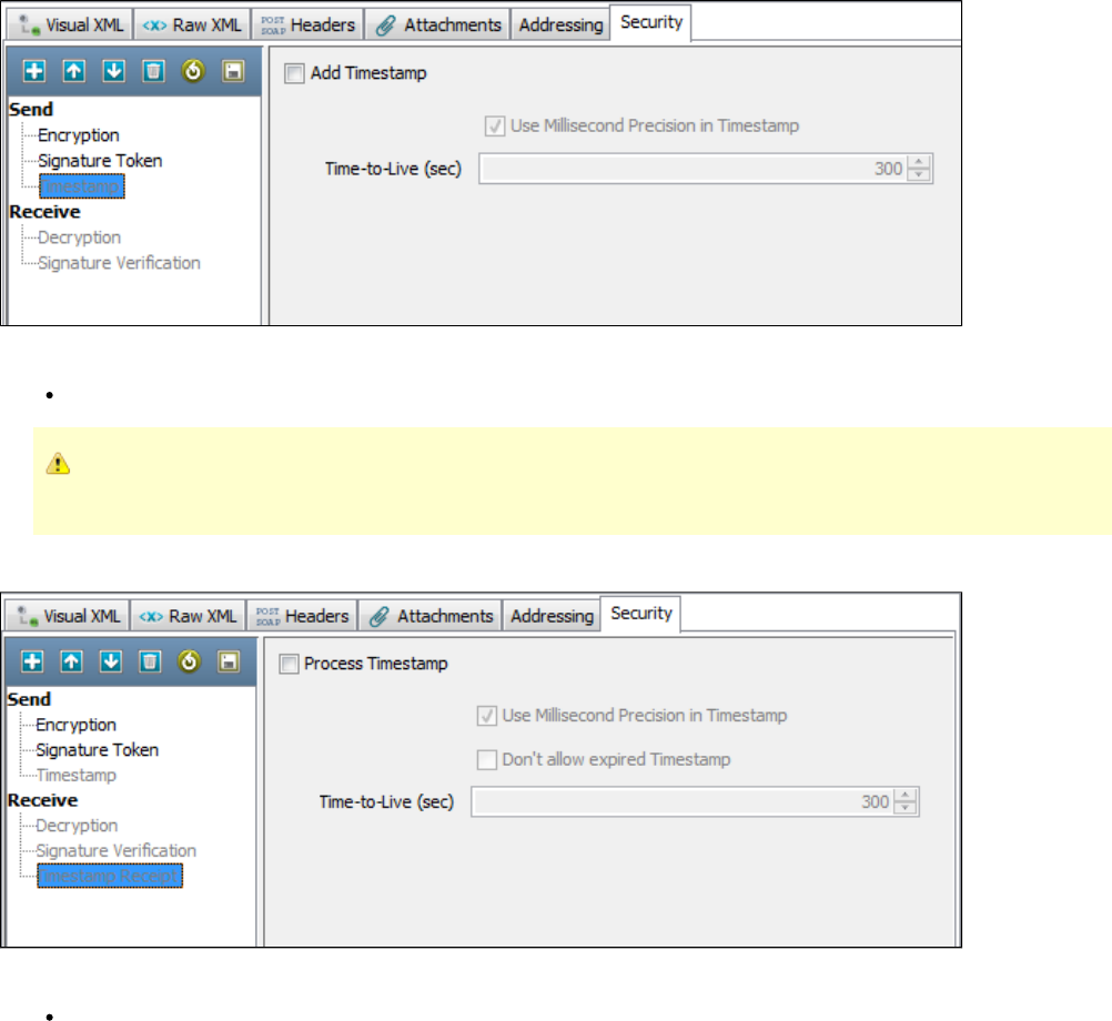
Click the Add Timestamp box.
Time-To-Live (sec): Enter the lifetime of the message in seconds. Enter 0 to not include an Expires element.
Some Web services, particularly .NET 1.x/2.0 with WSE 2.0, are not compliant with standard time stamp date formatting, and do
not allow milliseconds. For these web services, clear the check box for Use Millisecond Precision in Timestamp.
Timestamp Receipt
The parameters required for Timestamp Receipt are a super set of those required for Timestamp. The additional parameter is:
Don't allow expired: Can be checked if you do not want to allow expired timestamps.
Username Token/Username Token Verifier
Username Token
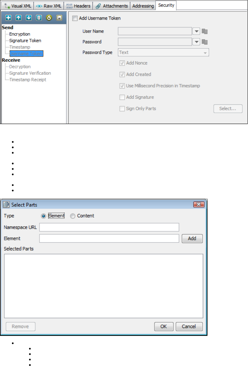
Click the box.Add Username Token
User Name: Enter the appropriate user name.
Password: Enter the appropriate password.
Password Type: Select the password type from the drop-down menu (Text, Digest, None). None is typically used with the Add Signature
option.
Add Nonce: Click if a Nonce is required – used to protect against replay attacks.
Add Created: Click if a time stamp is required.
Use Millisecond Precision in Timestamp: Select the check box to use millisecond precision. Some Web services, particularly .NET
1.x/2.0 with WSE 2.0, are not compliant with standard timestamp date formatting, and do not allow the use of milliseconds.
Add Signature: Select to add a signature built using a combination of the username and password as the key.
Sign Only Parts: Select if you want to specify different parts to sign and click the Select button to identify the parts to be signed.
Type:Select one of the following:
Element: Select if you want to encrypt the element and the content.
Content: Select if you want to encrypt just the content.
Namespace URL: Enter the value for the element.
Element: enter the name of the element.
You can repeat this for as many elements as you want by clicking the Add button.
You will need to manually add the Body element if you want it to be included. If you want to include the Binary Security Token as a part, use the
Element name "Token."
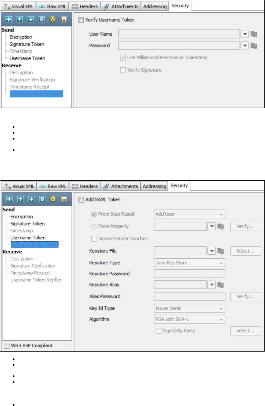
UserName Token Verifier
Click the Verify Username Token check box.
User Name: Enter the verification user name.
Password: Enter the verification password.
Use Millisecond Precision in Timestamp: Select the check box to use millisecond precision. Some Web services, particularly .NET
1.x/2.0 with WSE 2.0, are not compliant with standard time stamp date formatting, and do not allow the use of milliseconds.
Verify Signature: Click box if Signature verification is required.
SAML Assertion Token/SAML Assertion Receipt
SAML Assertion Token
Click the Add SAML Token box.
Select the From Step Results option button. Select the step whose result is an XML SAML Assertion (like a SAML Query Step or a Parse
Text Step with XML manually entered), or
Select the From Property option button and enter the LISA property that contains the XML SAML Assertion.
You can optionally select the button to have LISA parse the SAML Assertion XML and build the SAML Assertion object as it wouldVerify
when sending the SOAP request. This is useful to confirm that the SAML Assertion that may have been created manually is a valid SAML
Assertion. It will also attempt to verify any signatures associated with the assertion, but it is likely that LISA will not be able to verify the
assertion without configuring a public certificate to verify with.
Signed Sender Vouches: Select if the assertion needs to be signed by the sender (the sender vouches for its authenticity as opposed to
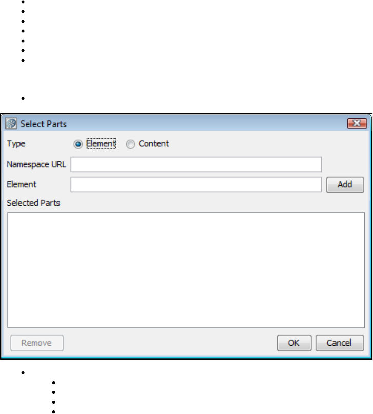
the bearer/creator of the SAML Assertion). When selected you will need to fill in the following information:
Keystore File: Enter the location of the keystore file.
Keystore Type: Select Java Key Store (jks) or Personal Information Exchange (PKCS #12).
Keystore Password: Enter the password for the keystore.
Keystore alias: Enter an alias for a private key.
Alias Password: Leave empty or enter the same as Keystore Password for PKCS #12 files.
Key ID type: Select the appropriate key ID type from the pull-down menu.
Algorithm: Select DSA with SHA-1.
The default behavior is to sign only the SOAP Body contents.
Sign Only Parts: If you want to specify different parts to sign click the Select button to identify the parts to be signed.
Type: Select one of the following:
Element: Select if you want to sign the element and the content.
Content: Select if you want to sign just the content.
Namespace URL: Enter the value for the element.
Element: Enter the name of the element.
You can repeat this for as many elements as you want by clicking the Add button. You will need to manually add the Body element if you want it
to be included.
To include the Binary Security Token as a part, use the Element name 'Token'.
SAML Assertion Receipt
Click the Process SAML Assertion check box if you want to check for a SAML Assertion Receipt header in the response. If you select this option
and there is no SAML Assertion Receipt header, an exception occurs.
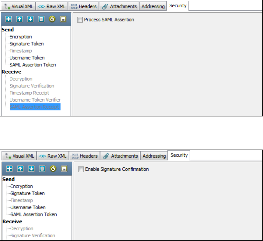
Signature Confirmation
Click the Signature confirmation check box if you want to check for a signature confirmation header in the Response. If you select this option and
there is no confirmation header, an exception occurs.
Using the Keystore Verifier
You can verify your keystore settings to make sure you are using the correct format, password, alias and alias password. There is a buttonVerify
on the editors for SSL, Signature, Encryption/Decryption and SAML settings. Clicking Verify produces a verification report.

SSL verification validates the Keystore password only and confirms that at least one of the keys in the keystore can be loaded using the keystore
password.
WS-Security verification validates the Keystore password, the alias and the alias password. Correct validation is indicated with a green entry. Any
validation errors found will be shown in red. Warnings are shown in orange.
This verification only verifies the keystore parameters. There could still be issues with the web service, such as a mismatch in
certificate sets or incorrect choice of algorithm. These issues will need to be validated independently.
Alias Search
If you do not know the expected alias name for a WS-Security setting, you can use the keystore verifier to list all of the aliases in the keystore.
Leave the Keystore Alias and Alias Password boxes empty and click the Verify button.
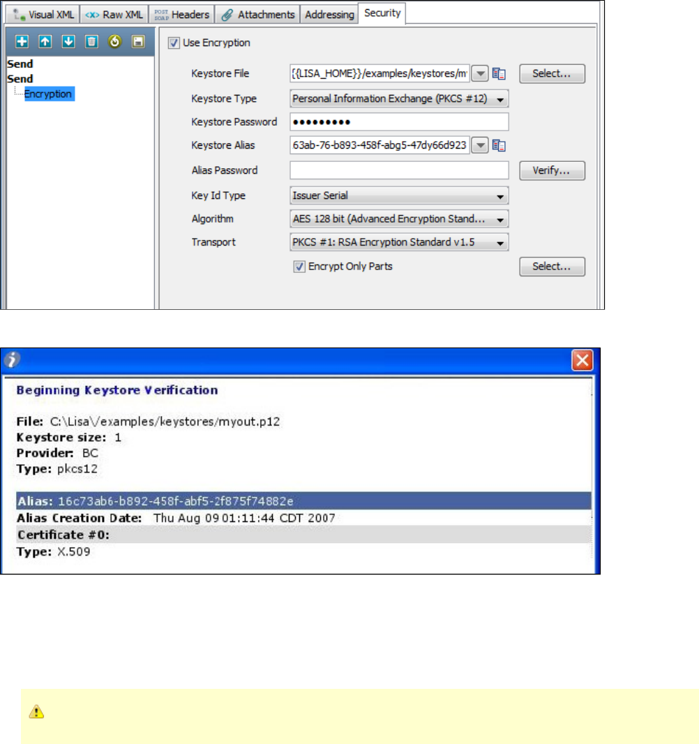
Aliases are highlighted with a blue background.
Verification will fail because the Keystore Alias and Alias Password boxes were left blank.
WS-I Report
While executing WS-I Basic profile Validation, when you click the Execute button on the Object Editor screen, the validation will be run and a
report will be generated and saved (in the reports directory in the LISA install directory). You can view the report by pressing the WS-I Report tab
at the bottom of the screen.
The format of this report is standard, and is dictated by the Web-Services-Interoperability Organization (WS-I).
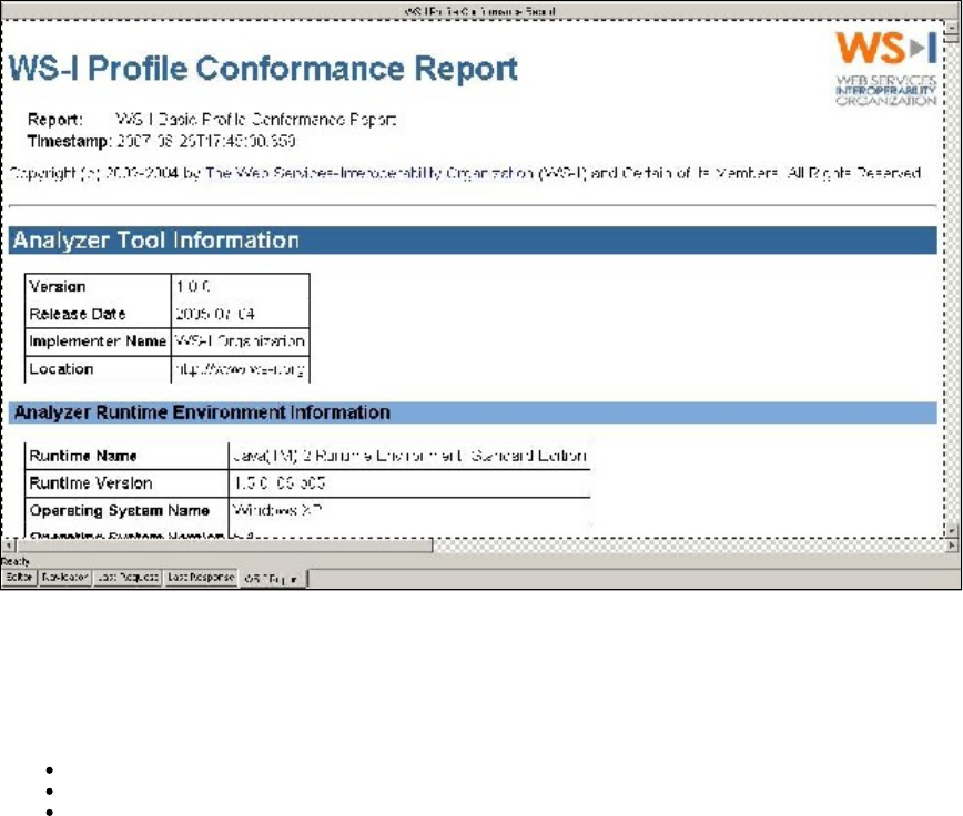
WSDL Validation
The WSDL Validation step lets you load a WSDL and add one or more assertions to validate the WSDL. This step is a little different in that it lets
you load the static WSDL file and perform assertions on it. In most steps the assertions are being made on the response.
The most useful assertions are:
XML Diff Assertion: Checks that the WSDL has not been changed by comparing it to a control copy of the original WSDL.
XML Validator: Checks for valid XML using Schema or DTD.
WS-I Basic Profile 1.1 Assertion: Checks for compliance with the WS-I Basic Profile.
These assertions are described in .Types of Assertions
Prerequisites: Familiarity with the three assertions named previously
: Location of the WSDL you want to validateParameter Requirements
To configure the WSDL Validation step, enter a WSDL in the WSDL URL field and click Load.
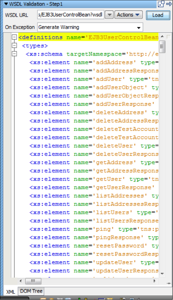
The WSDL appears in the editor. You can view it in XML or DOM View.
You are now ready to add the assertions.
Web_ Raw SOAP Request
The Raw SOAP Request step lets you test a web service by sending a raw SOAP request (raw XML). It can be used to test legacy SOAP calls or
web services that do not have a WSDL. It also lets you test a web service's reaction to data of an incorrect type (for example, sending a string
when it expects a number), which is not allowed in the Web Service Execution step. Another use for the Raw SOAP request is to reduce
overhead during intense load tests. The regular web service step has some additional overhead because it marshals an object into XML to make
the request, and unmarshals the SOAP XML response back into an object. The Raw SOAP step avoids this overhead and only deals with the raw
SOAP XML. It has less work to do, so it executes faster.
The SOAP request can be typed or pasted into the editor, or read from a file, and then parameterized using LISA properties.
There is no support for dynamic WS-Addressing or WS-Security headers. If you want to have these types of headers, they must be statically
entered as part of the SOAP request entered in the input area. If your request does contain items like a WS-Security signature token, the signed
elements cannot be parameterized or the signature will no longer be valid.
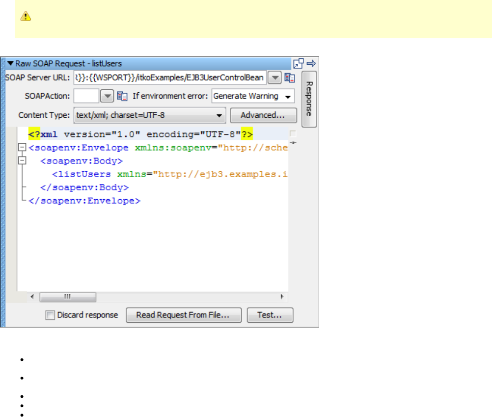
This step is not limited to SOAP calls. You can also do XML or text POSTs.
To create a Raw SOAP Request
Enter the following parameters:
SOAP Server URL: Enter the URL of the Web Service endpoint. The URL will be converted into a single property instead of just
substituting the WSSERVER and PORT properties.
SOAP Action: Fill in the SOAP action as indicated in <soap: operation> tag in the WSDL for the method being called. This is required for
SOAP 1.1 and usually required to be left blank for SOAP 1.2.
Content Type: Select the Content Type. Use text/HTML for SOAP 1.1, application/SOAP+XML for SOAP 1.2.
Advanced button: Click to add any custom HTTP headers you want to send.
Discard response: Check to discard the response, replacing it with a small valid but static SOAP text. This is meant to be used in load
testing where processing a large response limits the scalability of the load generator computers.
Type or paste the SOAP Request into the editor, or click Read Request From File and browse to the file containing the SOAP Request.
Now you can parameterize the request, if you want, with properties.
Click the Test button to execute the call.
The response can be examined by clicking the Results tab:
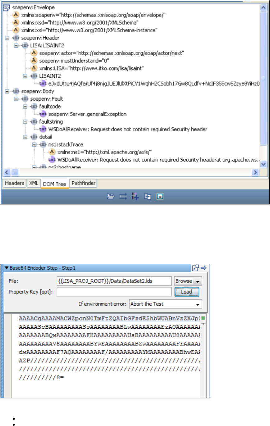
You are now ready to add filters and assertions.
Base64 Encoder
The Base64 Encoder step is used to encode a file using the Base-64 encoding algorithm. The result can be stored into a LISA property for use
elsewhere in the test case.
The Base64 Encoder step accepts a file as input and encodes the file using Base64 encoding. You can store the encoded file in a LISA property.
Click the Load button to encode a file. The Base64 encoded text displayed in the editor is read-only.
Enter the following parameters:
File: Enter the full path and path name, or browse to the file to be encoded.
Property Key: [opt]: The name of the property in which to store the encoded file.
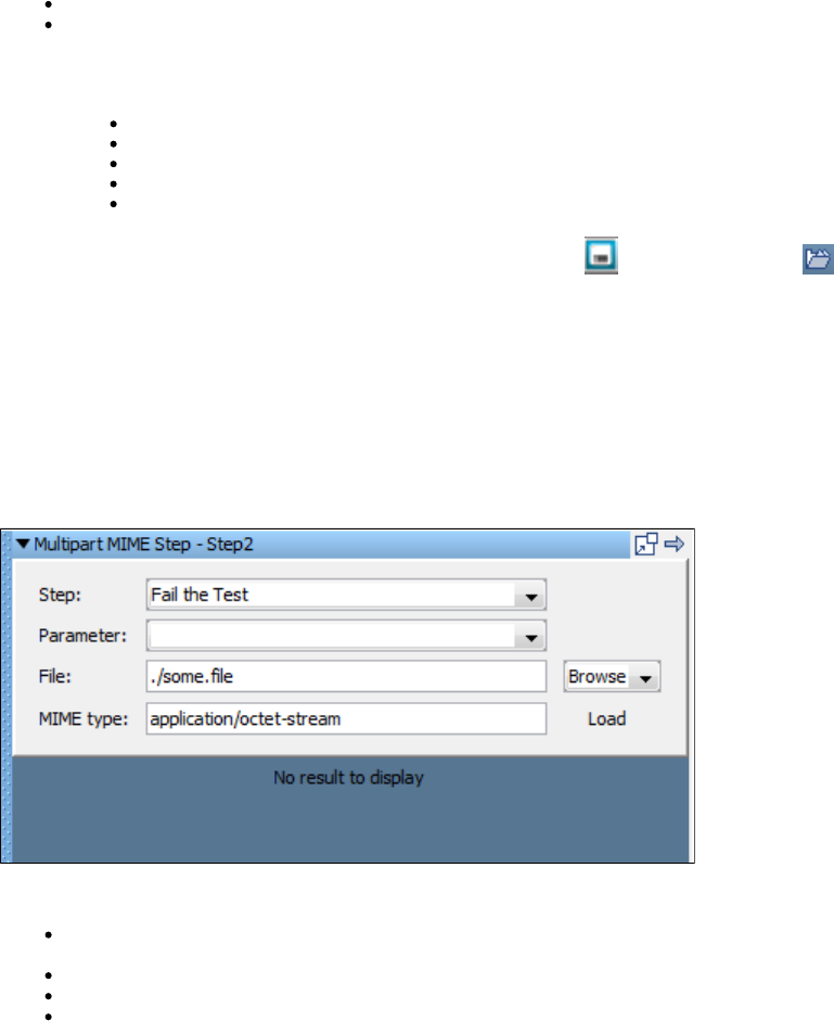
Load: Click to load and test the encoding of the file. Optionally, store it in the specified property.
If environment error: Action to take if an environment error occurs.
After the file is encoded, you can add filters and assertions. The valid options are:
Random Selection Filter
Parse Value Filter
XML Xpath Filter
Create HTML Table ResultSet Filter
Make Assert on Selection
When you have completed adding filters and assertions, you can click Load to load the file or Save to save the contents of the editor in
a new file.
Multipart MIME (Multipurpose Internet Mail Extensions) Step
The Multipart MIME step allows data to be loaded from a file, encoded, and stored in property to be used as a post parameter on an HTTP
request. The encoded document will be stored in the LISA property that has been defined previously in an HTTP/HTML Request step.
When a multipart MIME form submit request is recorded, the contents of the file that was uploaded are recorded. Subsequent playback will result
in the same content being submitted with "file upload" portion of the form again. The multipart MIME step can be used to change what file is
uploaded when the test case is played back.
Prerequisite: The HTTP/HTML Request step containing the HTTP parameter must already exist, and it must be before the Multipart MIME step.
Enter the following parameters:
Step: Select the name of the HTTP/HTML Request step, or select from the pull-down menu, the step that will receive the property
containing the encoded document.
Parameter: Select the name of the property, chosen from the pull-down menu, which is listed in the step named in the Step field.
File: Enter the pathname or browse to the document to be encoded.
MIME Type: Enter the MIME type expected by the server.
Click Load to encode the file.
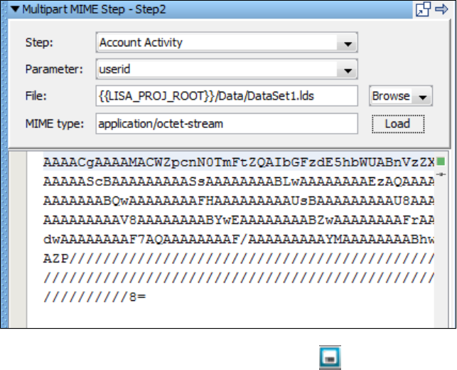
You can save the contents of the editor to a file using the Save icon.
In the example in the previous illustration, the Account Activity step has a post-parameter user id that contains the encoded version of the file
Dataset1.Ids.
SAML Assertion Query
The SAML Assertion Query step lets you obtain a SAML Assertion from an Identity Provider for later use in a Web Service Execution step that
uses a WS-Security SAML 1.x Assertion Token.
: A cursory understanding of what type of SAML Assertion Query you need to perform. This information can be obtained from eitherPrerequisites
the developer of the system that utilizes SAML Assertions as the form of identity security or from the Identity Provider administrator.
: At a minimum, you must know the URL to the Identity Providers SAML Query interface (Endpoint) and the SubjectParameter Requirements
information (who/what you want to obtain a SAML Assertion for), what type of query you want to perform, and some extra information depending
on which type of query.
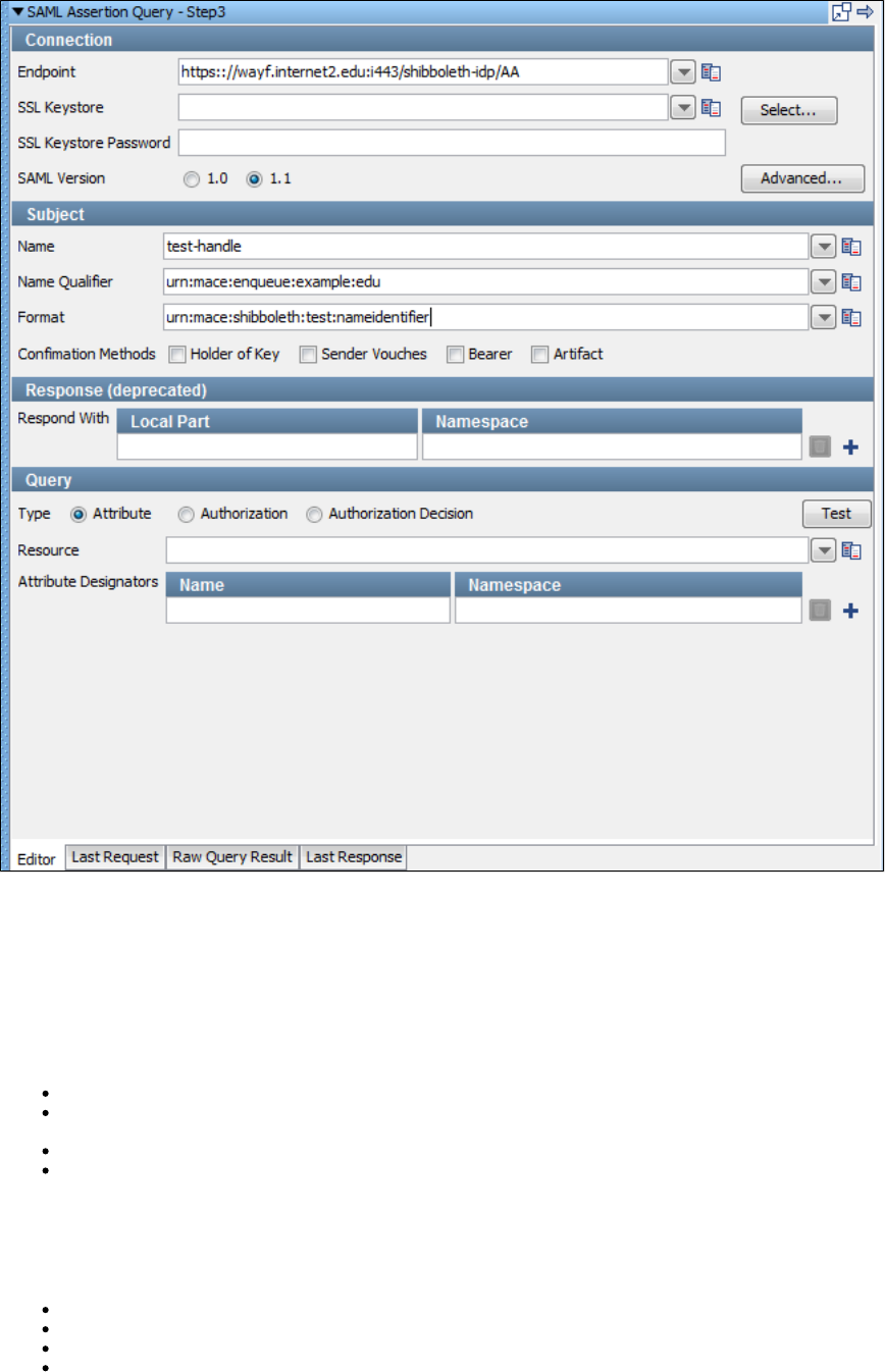
The SAML Assertion Query Editor has four tabs. The Editor tab lets you configure the query information. After doing so, you can test the query
using the Test button in the Query section of the editor. After testing the query you can view the raw request that was sent in the Last Request
tab. You can view the raw SOAP response in the Raw Query Result tab (for example, if it returned more than one assertion you can see that
here). You can view the step response in the tab. This shows, for example, what will be used in the Web Service WS-SecurityLast Response
token.
Connection
This information describes where the SAML Query API server lives and how you want to connect to it.
Endpoint: The URL to the SAML Query API of the Identity Provider.
SSL Keystore: If you must use client side identification certificates to connect to the Endpoint you can select the keystore file using the
Select button, or you can select a previously-entered item from the pull-down list or enter one manually.
SSL Keystore Password: The password for the SSL Keystore if used.
SAML Version: The SAML version you want to use to query the Identity Provider.
Subject
This information describes who or what you want to request a SAML Assertion for. This could be a user or user group or other entity for which you
want to provide an assertion about the subject's current authorization/privileges
Name: The name of the entity (for example, username).
Name Qualifier: A group or categorization used to qualify the Name (for example, domain).
Format: This describes what format the name is being sent (for example, Full Name as opposed to Username).
Confirmation Methods: Select which confirmation method types you want to include in the query. The query will only return assertions
that contain at least one of the specified types. If you leave all types cleared it will return any assertion no matter what the confirmation
method is.
Response (deprecated)
This information describes which assertion statements you want to be returned as part of the SAML Assertion. It has been deprecated as of
SAML 1.1.
Local Part: The element name (for example, AuthenticationStatement, AuthorizationDecisionStatement, and AttributeStatement).
Namespace: The element namespace (for example, urn:oasis:names:tc:SAML:1.0:assertion).
Use the Add icon button to add more XML elements to the set to be returned. Use the Delete button to remove any elements you have
already added.
Query
A description of which type of query you want to perform. There are three different query types:
Attribute
Authorization
Authorization Decision
Attribute
An attribute query responds with a set of Attribute Statements. For example, it may tell you which groups a subject is a member of.
Resource: If you want to limit your query to a particular resource (for example, a particular web service, domain, file) you can specify the
resource name.
Attribute Designators: Each attribute is identified with a name and namespace (like XML elements). You can filter the set of attribute
statements returned by specifying each attribute type you want to be returned. (for example, Name =
urn:mace:dir:attribute-def:eduPersonScopedAffiliation, Namespace = urn:mace:shibboleth:1.0:attributeNamespace:uri).
Authorization
Used to request authentication statements related to a specific Subject SAML Assertions
Authorization Method: If you want to limit your query to return Authorization Statements that are for a particular method of authorization
(for example, urn:oasis:names:tc:SAML:1.0:am:X509-PKI, urn:oasis:names:tc:SAML:1.0:am:PGP,
urn:oasis:names:tc:SAML:1.0:am:password). A set of predefined authorization methods are available from the pull-down list.
Authorization Decision
Used to request SAML Assertions for particular actions that a subject wants to perform given the evidence.
Resource: If you want to limit your query to a particular resource (for example, a particular web service, domain, file) you can specify the
resource name.
Actions: You must specify at least one action for which you want to request authorization to perform (for example, login, view, edit)
specified with a name (Data) and Namespace (like an XML element).
Evidence (Assertions): Optionally specify one or more SAML Assertion to include with the Authorization Decision Query as advice to
the Identity Provider. Specify the LISA property that holds the SAML Assertion XML. You can use the for l to use theisa.<stepname>.rsp
response from a previous step (like another SAML Assertion Query or Parse Text step).
Evidence (Reference IDs): Optionally specify assertion reference ids.
Web_Web Service Execution (Legacy)
The Web Service Execution step lets you construct a web service (SOAP protocol) test using the information in a Web Service Definition
Language file (WSDL).
After you have identified the WSDL, LISA will construct a client with method calls for each operation specified in the WSDL. You use this web
service client, and LISA's Object editor, to test the web service using your test data. Using additional information not included in the WSDL, you
can test complex secure web services easily. The additional parameters are entered using several configuration screens available at the end of
the web service execution wizard. These are discussed later in this section.
Prerequisites: Knowledge of LISA's Complex Object Editor is required to manipulate the Web Service Client built by LISA.
For more details, see the .Complex Object Editor (COE)
Parameter Requirements: At a minimum, you must know the location of the WSDL (either from a local file or through the web). For complex web
services, and secure web services there are several sets of parameters that you will need to gather before constructing your web service test
step. These parameters are known to the web service developer, and are the same parameters required to use the web service in an application.
These parameter sets will be specified when each advanced feature is discussed later in this section.
We will start by explaining how to test a simple web service, requiring only a WSDL. Then we will look at the advanced features that you may
need to use. Finally we will look at the most complex of the advanced features, configuring WS-Security for a secure web service.
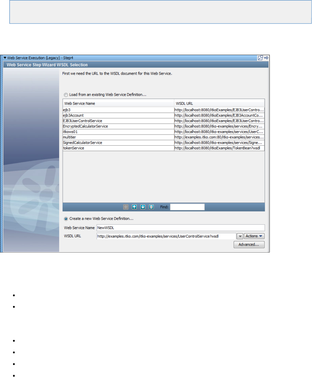
Testing a Simple Web Service
Web Services Advanced Features
WS Security
Testing a Simple Web Service
When you select the Web Service Execution step you will see the WSDL selection screen.
There are two sections on this screen selectable by option button.
The upper section lets you select a WSDL that is available on the list, and has already constructed a web service client that is available to you.
To select one of these web services:
Select Load from an existing Web Service Definition (optional: the option button is automatically selected if you select a web service
name from the list).
Click the web service name in the key column.
Click the Next button.
The lower section lets you enter a new WSDL.A client will be built corresponding to the contents of this WSDL.
Select Create a new Web Service Definition (optional: the option button will automatically be selected if you begin entering information in
the Web Service Name or WSDL URL fields)
Web Service Name: Enter the name for the new service. This name must be unique. If a group of people plan on sharing test cases it is
recommended to use a naming scheme that will help to ensure unique names for unique web services.
WSDL URL: Enter the URL of the new WSDL, or select it from the pull-down list. You can also click the Actions list to browse the file
system or search a UDDI server.
Advanced: Opens a window where you can manage your namespaces.
Namespace mapping is described in the section.Advanced Features
We will use an example that is available on the Demo Server. The WSDL location is:
or http://examples.itko.com/itko-examples/services/UserControlService?wsdl
,http://localhost:8080/itko-examples/services/UserControlService?wsdl
depending on the Demo Server you are using. We have chosen the first location in the previous illustration, and we have called the web service
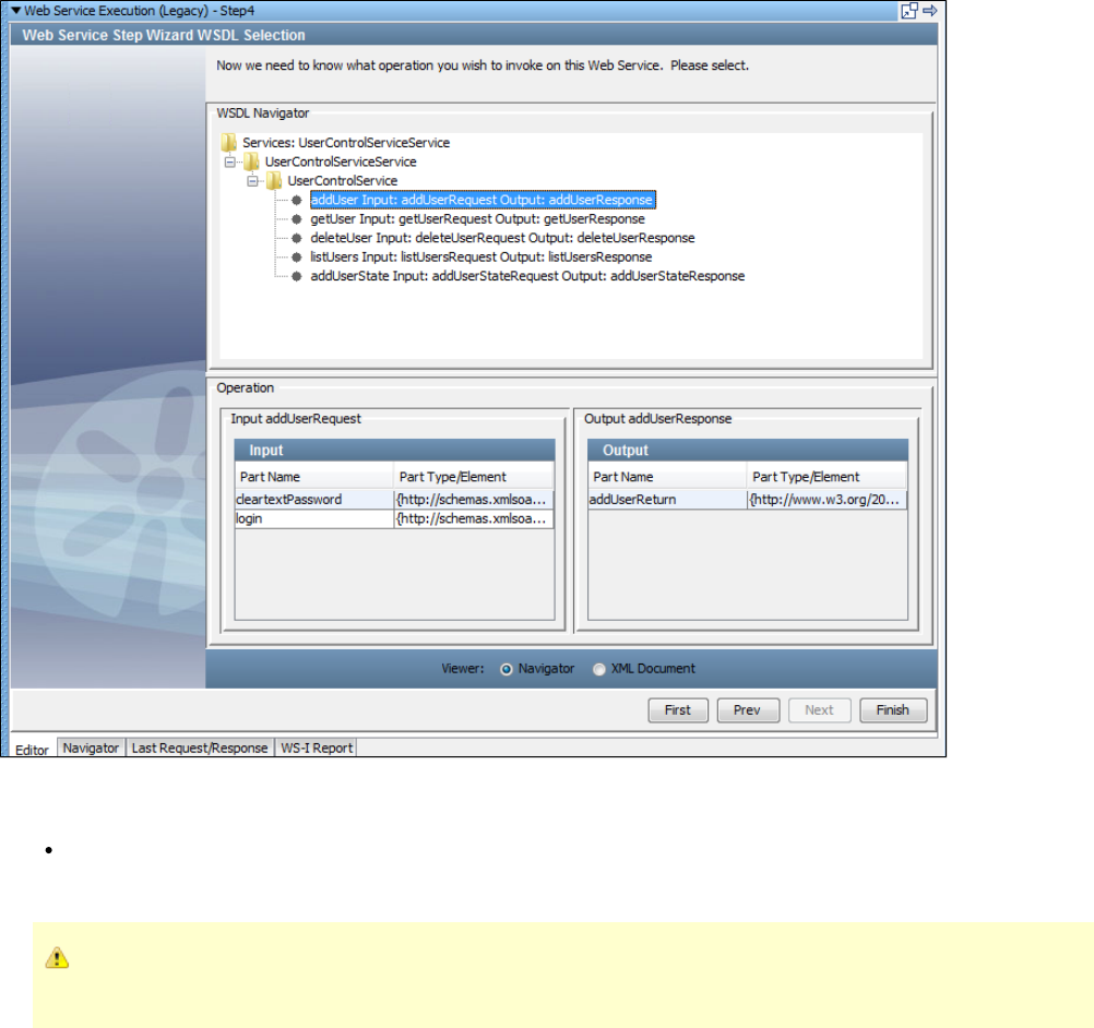
.NewWSDL
Remove any spaces in the web service name.
Click the Next button.
You will now see the WSDL Navigator screen:
The upper section of the Navigator, titled , shows a hierarchy of folders, the last of which is the web service (User ControlWSDL Navigator
Service in our case), listing all the operations available.
Select an operation to invoke on the web service; we have chosen .addUser
The lower section now displays the input and output parameter information for the operation .addUser
Part Name and Part Types are standard web service notation for the input and output parameters. These are informational only;
the only selection that needs to be made on this screen is the web service operation to execute in the WSDL Navigator.
Select the Viewer from Navigator or XML Document option. The Navigator option is the default.
Click Finish to bring up the Complex Object Editor with the panel above it.Execution Info

The Execution Info panel comes populated with all the necessary fields like WSDL URL, Package name, Web Service URL and the JAR name.
Other fields are:
If environment error: Select the next step to execute, typically fail, if an environmental error is returned by the web service. Most SOAP
faults will not trigger this workflow change.
Edit: Click the Edit button if you wish to change the web service endpoint URL.
The host (WSSERVER) and port (WSPORT) for the WSDL and Web Service URL are automatically parameterized.
Advanced: Opens a window where you can configure many advanced features associated with your web service.
The advanced features are described in the next section " ". The WS-Security options are discussed in theAdvanced Features
section after that: " "WS-Security
The Object Editor panel uses the standard Object Editor to manipulate the web service client.
The previous illustration shows the object editor in the standard mode. Selecting the Expert Mode check box reveals the expert mode view:
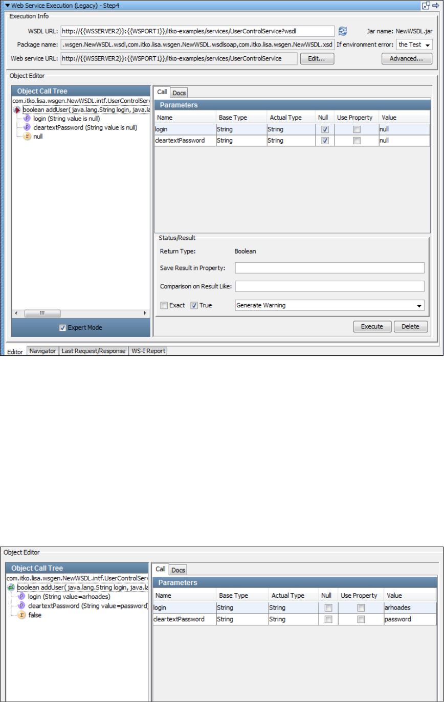
In Expert Mode you can configure inline filters and assertions. To use an inline filter, enter a property name in the Save Result in Property text
box. To add an assertion, configure it using the 'Comparison on Result Like' text box, and the Exact and Tru' check boxes.
In either mode you can supply the values for each parameter listed. In our example, the method takes two parameters, and addUser login
. These parameter values can be static values, LISA properties, or . Enter a static value by filling in the cell forcleartextPassword NULL Value
the parameter. Enter a LISA property by selecting the Use Property check box and filling in the cell with the property name. Enter byValue NULL
selecting the Null check box.
If the parameter type is a complex object, the cell shows . Press <Ctrl> and click the cell to open the Complex ObjectValue Ctrl-click to edit
Editor can enter the fields of the complex object.
If the cell displays the name of a Java interface instead of a Java class, you will have to change the Actual Type to be the name of aActual Type
Java class. An error message is displayed if you try using a Java interface. The developers of the web service should be able to provide you with
a class name that can be used in place of the interface name.
For detailed instructions on the use of the Object editor see " ."Complex Object Editor
Click Execute.
After execution, you can see the result in the in the left panel:Object Call Tree
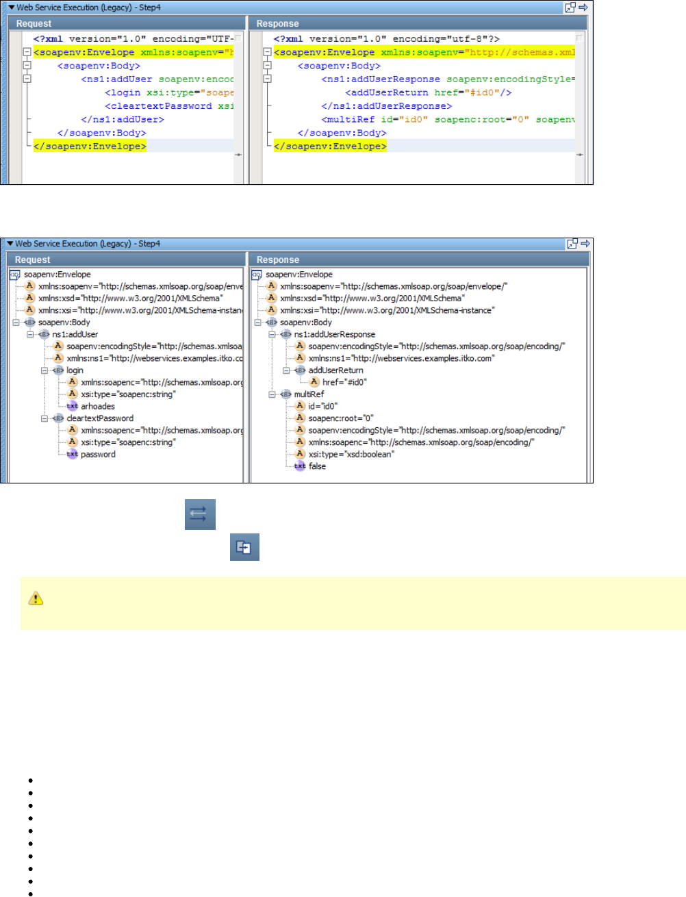
To see the actual SOAP request/ SOAP response, click the tab at the bottom of the panel:Last Request/Last Response
You can view , or examine the or the using the tabs at the bottom of the panel. The following example shows the DOMHeaders XML DOM Tree
view.
At this point, you are ready to add filters and assertions to the response.
You can add filters with the Add Filter icon, or by selecting the filter element for the current step.
You can add assertions with the Add Assertion icon, or by selecting the assertions element for the current step.
Selecting the filters or assertions elements will give you greater choices.
This test step is now complete.
You can go back to the Object Editor, and select additional calls to other procedures in the web service, and execute them in this same step. This
is useful if you need to add calls on request or response objects to "drill down" to values. The best practice for authoring test cases is to put each
web service call in a separate step. It makes a test case easier to follow and easier to pinpoint which call is causing a problem if there are errors.
Web Services Advanced Features
This section describes the advanced features available in the Web Service Execution step. The following features are covered:
Namespace mapping
UDDI access point lookup
Specific protocol requirement
Maximum wait time
Security in transport layer
WSI basic profile 1.1 validation
Advanced error handling
Custom transport headers
WS Addressing
Customer SOAP Headers
Namespace Mapping
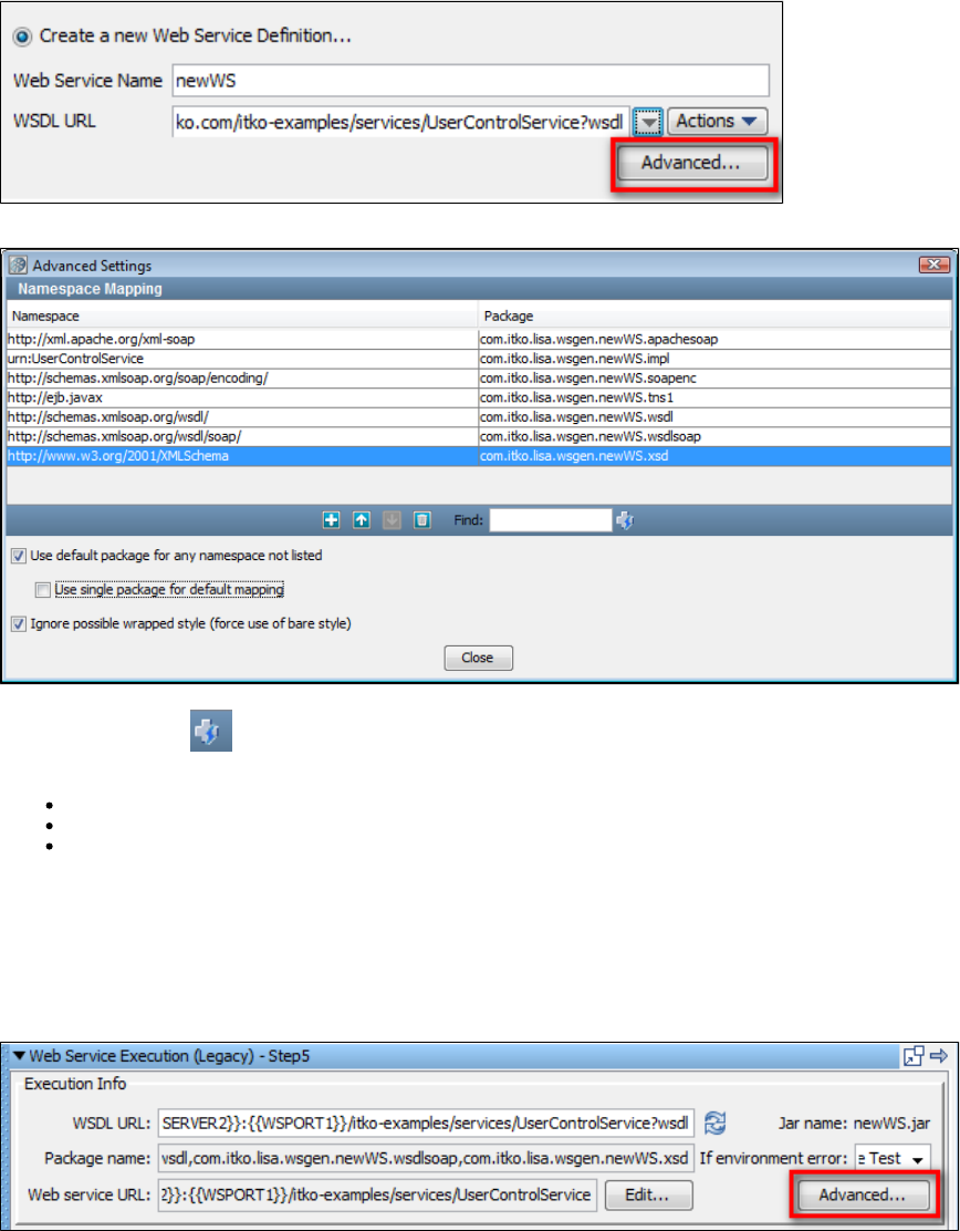
For a nontrivial WSDL with multiple namespaces, or for reuse of client side stubs, you may want to customize the namespace mappings. This
namespace mapping is used during the creation of the client classes that are used to execute the web service call. The default behavior is to
separate out each type defined in the WSDL into a unique package based on its namespace. Use this dialog to change this default behavior.
The default namespace is com.itko.wsgen.<Web service name>
For each namespace in the WSDL, the namespace prefix (or a generated unique prefix if one is not available in the WSDL) is added to the default
namespace to create a unique namespace: com.itko.wsgen.<web service name> <namespace prefix>.
To customize the namespace mappings, select the Advanced button on the WSDL Selection screen after you have entered your new Web
Service Name and WSDL URL.
The Namespace Mapping window is displayed.
Click the Auto Populate icon to list all the WSDL namespaces and to see what the default LISA mappings will be. You can now add,
remove, or edit the namespace mappings. At the bottom of the screen you can select the following options:
Use default package for any namespace not listed.
Use single package for default mapping.
Ignore possible wrapped style (force use of bare style): For every operation in the WSDL, there is an attempt to auto-detect if the WSDL
has been defined in the wrapped-style and if so, the set of parameters that are to be sent is unwrapped. For example, if you have an
operation defined in the wrapped-style and it takes an OperationRequest type parameter. If you have this option cleared (default) it will
expand the OperationRequest type and specify each of its sub-elements as parameters (for example, instead of passing an
OperationRequest, it would take it individual elements that make up an OperationRequest like param1, param2). If you check this option
it will not attempt to detect the wrapped-style and will generate the operation with the single OperationRequest parameter type. This can
be useful if you plan on generating parameters using Excel DTOs.
For the rest of the advanced features in this section you will need to select the Advanced button on the Execution Info section of the Web Service
Editor. Select the Editor tab at the bottom of the panel to show the Execution Info section.
A window with five tabs is displayed. We will be referring to four of these tabs: General, Transport Headers, Addressing, and SOAP Headers in
this section. The fifth, Security, is the topic of the next section.
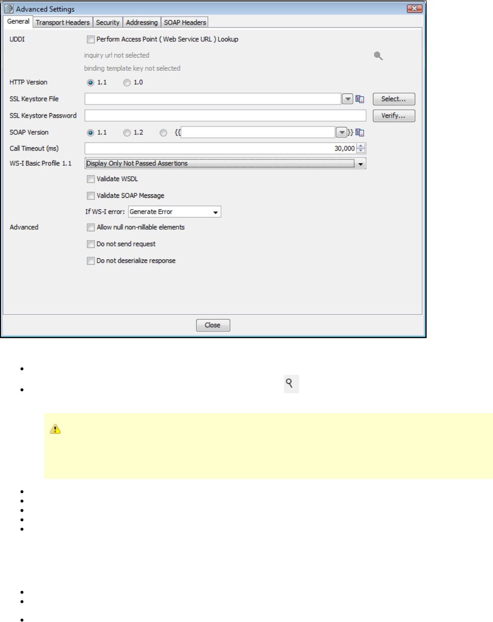
General Tab
The following parameters are available on the General Tab:
UDDI Perform Access Point (Web Service URL) Lookup
Inquiry URL and Binding Template: Use the Search UDDI Server Find button to navigate to the correct Binding Template to
perform the lookup.
When creating the step if you used the UDDI Search function when specifying the Web Service WSDL URL, these
values will be automatically filled in. If the Inquiry URL is specified but the Binding Template is not, you may have
preformed a Model search. To locate the Binding Template you need to perform a search at a higher level of the
hierarchy and drill down to the TModel through a particular Binding Template.
HTTP Version: Select version 1.0 or 1.1.
SSL Keystore File: Enter the name of the keystore file where the client identity certificate is stored. It can be in jks or pkcs format.
SSL Keystore Password: Enter the password for the keystore.
SOAP Version: Select version 1.1, 1.2, or a property to use for the version.
Call Timeout (ms): Enter the maximum wait time for a response from a web service call (milliseconds). This is especially useful when
using SOAP over JMS.
You can specify global certificates properties for SSL in your local.properties file.
For global certificates (web server, raw SOAP, and web service steps):
ssl.client.cert.path: A full path to the keystore.
ssl.client.cert.pass: Password for the keystore. This password will be automatically encrypted using AES (Advanced Encryption
Standard) when LISA runs.
ssl.client.key.pass: An optional password for the key entry if you are using the JKS keystore and the key has different password from
the keystore. This password will be automatically encrypted using AES (Advanced Encryption Standard) when LISA runs.
This is currently not an available option to be set in the WS Test step and if required must be set in the local.properties file.
For web service steps only certificates (not raw SOAP steps):
ws.ssl.client.cert.path: A full path to the keystore.
ws.ssl.client.cert.pass: Password for the keystore. This password will be automatically encrypted using AES (Advanced Encryption
Standard) when LISA runs.
ws.ssl.client.key.pass: An optional password for the key entry if you are using the JKS keystore and the key has a different password
from the keystore. This password will be automatically encrypted using AES (Advanced Encryption Standard) when LISA runs.
This is currently not an available option to be set in the WS Test step and if required must be set in the local.properties file.
If you have values in both local.properties and in the General tab, the values in the General tab will be used.
WS-I Basic Profile 1.1: You can choose four different validation levels in the pull-down menu:
Display All Assertions
Display All But Info Assertions
Display Only Failed Assertions
Display Only Not Passed Assertions
Validate WSDL: Select to validate the WSDL.
Validate SOAP Message: Select to validate the SOAP message.
If WS-I error: Select the step to redirect to on error.
Validation failures are common, but usually should not affect the outcome of the test. It is good practice to set the next step to
continue so that you can complete the test. When you click the button on the Object Editor screen, the validation willExecute
run and a report will be generated and saved (in the reports directory in the LISA install directory). You can view the report by
pressing the tab at the bottom of the screen. The format of this report is standard, and is dictated by theWS-I Report
Web-Services-Interoperability Organization (WS-I).
There are times when a valid XML SOAP response is received, but an exception is thrown when trying to process your results. The following
options should let you process, by dealing with the XML response directly rather than processing the SOAP response.
Allow null non-nillable elements: If there are non-nillable elements in the SOAP request, send the request even if the elements are
null.
Do not send request: Generate the SOAP request message, but do not send message to Web Service Endpoint. The step response will
be the SOAP request message.
Do not deserialize response: Send the SOAP request message and receive a SOAP response, but do not try to process the SOAP
response message to generate a Java response object. The step response will not be affected, but the return value of the method
invoked in the object editor will be null.
Transport Headers Tab
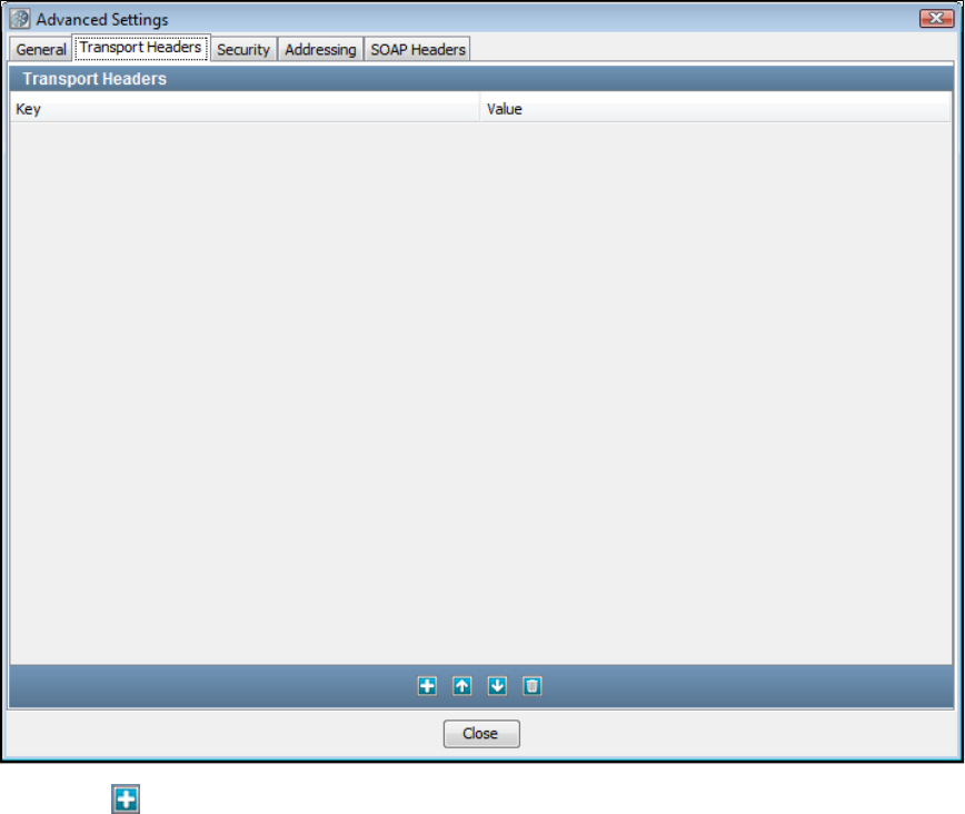
Click the Add icon and enter the header as a key/value pair. Repeat to add additional headers. These will be sent as HTTP Headers or JMS
properties, based on which protocol is used to execute the web service operation.
Addressing Tab
You can send a WS-Addressing header with your request. The WSDL does not specify if WSAddressing information is required, so you must
configure it.
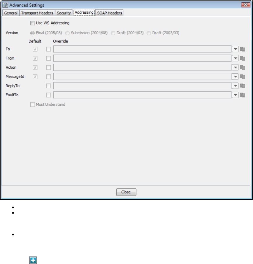
Use WS-Addressing: Select to use WS-Addressing.
Version: Select appropriate version. Several versions of the WS-Addressing specification are listed as options because some web
services platforms (for example, .Net) still use the older draft specifications. You will need to determine which your web service platform is
using. LISA will populate as many values as it can. Then you can choose to use the default value or override it. You can choose not to
send some of the default elements by clearing the default check box for that element.
Must Understand check box: Select if you want to assure that the web service can understand the WSAddressing header.
SOAP Headers Tab
Click the Add icon in the top panel and enter any namespace prefix(es) and URI(s) used in the custom header content that you want to be
defined in the SOAP envelope element tag. Then enter your custom header as a valid XML fragment.
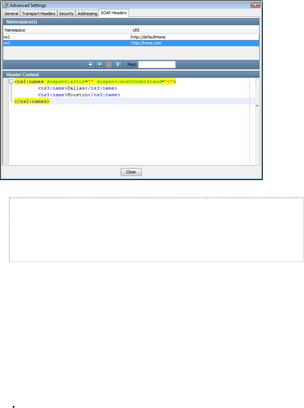
The header appears in the SOAP request:
<soapenv:Envelope xmlns:soapenv="http://schemas.xmlsoap.org/soap/envelope/"
xmlns:ns2=[http://defaulthome/]}[http://defaultHome] xmlns:ns3="http://home.com">
<soapenv:Header>
<ns2:names soapenv:actor="" soapenv:mustUnderstand="0">
<ns3:name>Dallas</ns3:name>
<ns3:name>Houston</ns3:name>
</ns2:names>
</soapenv:Header>
WS-Security
Prerequisites: Before configuring a secure web service for testing, familiarize yourself with the testing of simple web services as described in this
.section
Parameter Requirements: When testing secured web services, there are several sets of parameters you will need to gather before constructing
your web service test step. These parameters are known to the web service developer, and are the same parameters that would be required to
call the web service from an application. The parameter sets needed must be made available to you before you can configure your web service
for testing. You will need to know which security options are being used by the web service, the configuration parameter values for the options
used, and the order in which they are expected in the SOAP headers for the request and the response.
This example uses the parameters needed for the security test case available on the Demo Server. This test case, named , (locatedws_security
in the example directory), uses a timestamp, encryption and a signature token. The WSDL location is:
{+}http://localhost:8080/itko-examples/services/EncryptedCalculatorService?wsdl+, or for encryption{+}http://examples.itko.com:80/itko-examples/services/EncryptedCalculatorService?wsdl+
, or{+}http://localhost:8080/itko-examples/services/SignedCalculatorService?wsdl+ for the signature token, depending on the Demo Server{+}http://examples.itko.com:80/itko-examples/services/SignedCalculatorService?wsdl+
you are using.
The web service names are EncryptedCalculatorService and SignedCalculatorService.
LISA has extensive support for WS-Security including:
Send (request)
Encryption
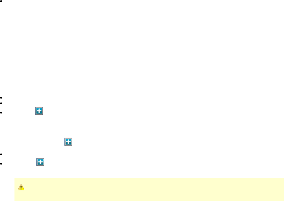
Signature Token
Timestamp
Username Token
SAML Assertion Token
Receive (response)
Decryption
Signature Verification
Timestamp Receipt
Username Token Verifier
SAML Assertion Receipt
Signature Confirmation
To add security headers to the web service request:
Select the Security tab. Click Send.
Select the Must Understand check box (if needed or if you want to verify that the WS-Security header is processed by the server).
Enter the Actor/Role name (if needed: most web services do not use multiple Actors/Roles).
Click the Add icon and select the security action type to add. You will be presented with the configuration panel for that security
action type. These are discussed in the following section.
Adding security verification to the response is very similar.
Click the Security tab. Click the Add icon and select Receive.
Enter the Actor/Role name (if needed).
Click the Add icon and select the security action type. You will be presented with the configuration panel for that security action type.
These are discussed in the following section.
You can add as many security types as are needed to execute your Web Service.
When a keystore is being used in a security action type configuration (described in the following section for each type), you can verify
your keystore settings to make sure you are using the correct format, password, alias and alias password. There is a Verify button on the
editors for Signature, Encryption/Decryption and SAML Assertion Token. Clicking the Verify button will invoke the Keystore Verifier, which
will produce a verification report.
If you do not know the expected alias name for a WS-Security setting, you can use the Keystore Verifier to list all the aliases in the keystore.
Leave the Keystore Alias and Alias Password boxes empty and click the Verify button. The Keystore Verifier is described at the end of this section
on WS-Security.
An example screen with several security types chosen is shown in the following screenshot (disabled actions are dimmed).
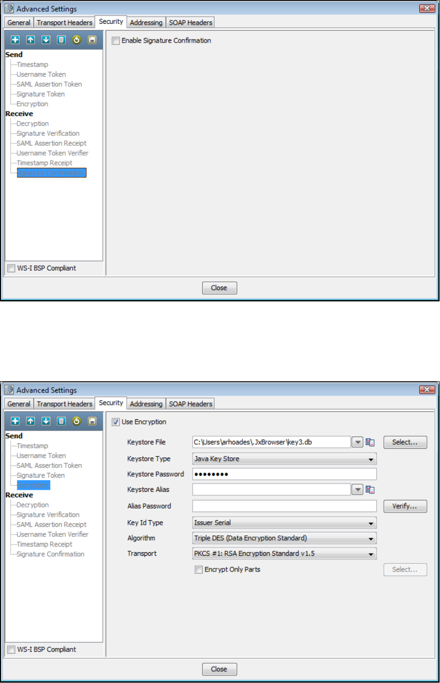
In the following sections we describe the parameters needed to run the ws-security example.
XML Encryption/Decryption
The parameters required for configuring XML Encryption and Decryption are shown here.
Encryption
Select the Use Encryption check box.
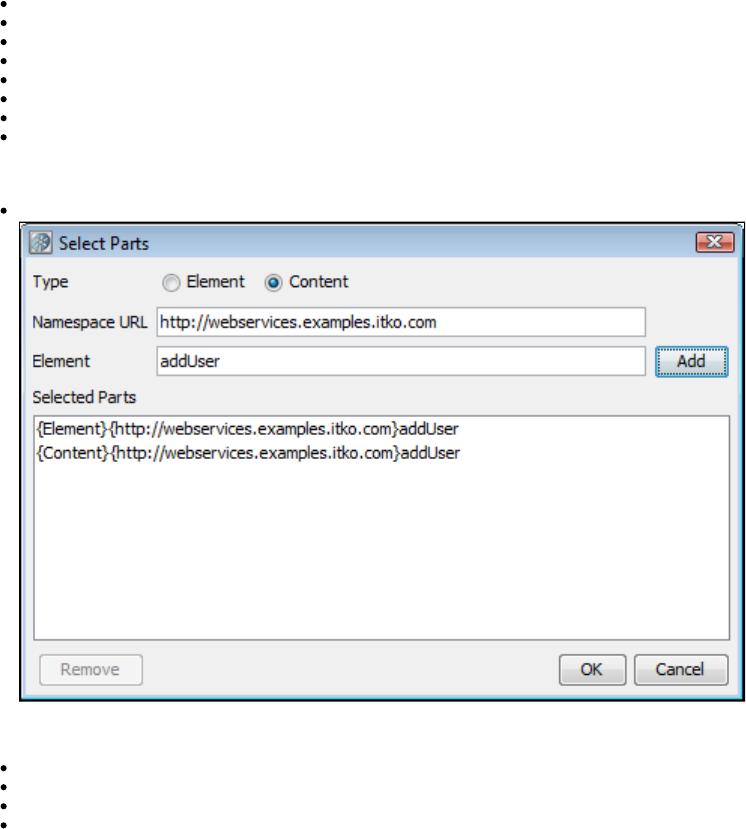
Keystore File: Enter the location of the keystore file.
Keystore Type: Select or .Java Key Store (jks) Personal Information Exchange (PKCS #12)
Keystore Password: Enter the password for the keystore.
Keystore Alias: Enter an alias for a public key.
Alias Password: Leave blank or enter the same as Keystore Password for PKCS #12 files.
Key ID Type: Select the appropriate key ID type from the pull-down menu.
Algorithm: Enter , , , or .Triple DES AES 128 AED 192 AES 236
Transport: Enter : RSA Encryption Standard v1.5 is the only option.PKCS#1
The default behavior is to encrypt only the SOAP body contents.
Encrypt Only Parts: If you want to specify different parts to encrypt click the Select button to identify the parts to be encrypted.
Type: Select one of the following:
Element: Select if you want to encrypt the element and the content.
Content: Select if you want to encrypt just the content.
Namespace URL: Enter the value for the element.
Element: Enter the name of the element.
You can repeat this for as many elements as you wish by clicking the Add button.
You will need to manually add the Body element if you wish it to be included.
If you want to include the Binary Security Token as a part, use the Element name "Token."
Decryption
The parameters required to configure decryption are a subset of those required for encryption.
XML Signature Token/Signature Verification
Signature token
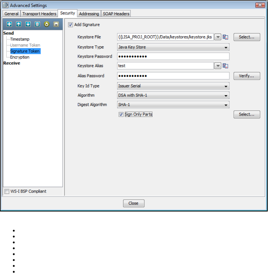
Select the Add Signature check box.
Keystore File: Enter the location of the keystore file.
Keystore Type: Select or .Java Key Store (jks) Personal Information Exchange (PKCS #12)
Keystore Password: Enter the password for the keystore.
Keystore alias: Enter an alias for a private key.
Alias Password: Leave blank, or same as Keystore Password for PKCS #12 files.
Key ID type: Select the appropriate key ID type from the pull-down menu.
Algorithm: Select .DSA with SHA-1
Digest Algorithm: Defaults to .SHA-1
The default behavior is to sign only the SOAP body contents.
Sign Only Parts: If you want to specify different parts to sign click the Select button to identify the parts to be signed.
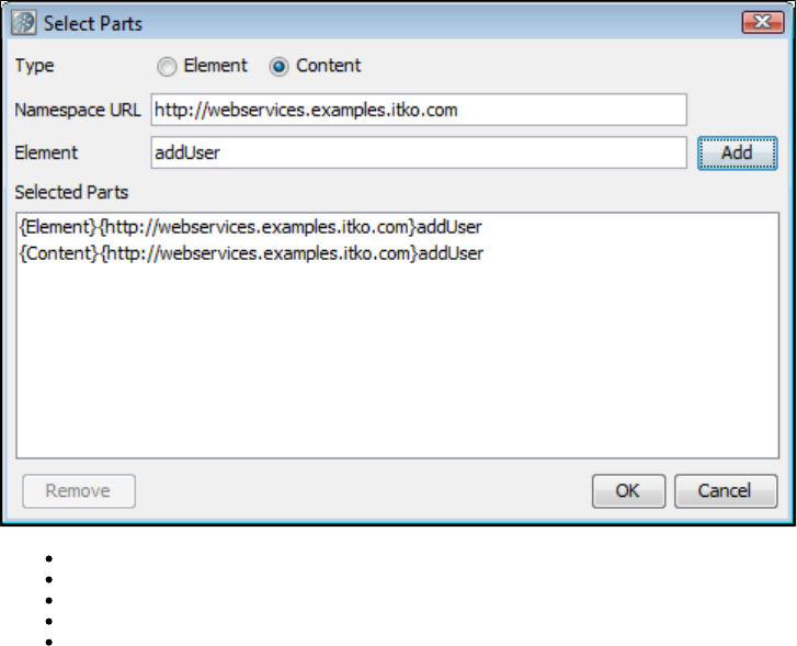
Type: Select one of the following:
Element: Select if you want to sign the element and the content.
Content: Select if you want to sign just the content.
Namespace URL: Enter the value for the element.
Element: Enter the name of the element.
You can repeat this for as many elements as you want by clicking the Add button.
You will need to manually add the Body element if you want it to be included.
If you want to include the Binary Security Token as a part, use the Element name "Token."
Signature Verification
The parameters required to configure signature verification are a subset of those required for signing.
Timestamp/Timestamp Receipt
Timestamp
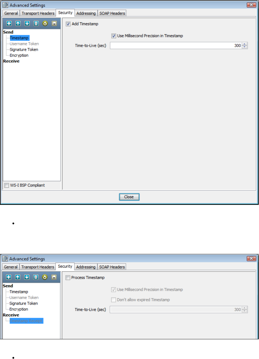
Select the Add Timestamp check box.
Time-To-Live (sec): Enter the lifetime of the message in seconds. Enter 0 to not include an Expires element.
Some Web services, particularly .NET 1.x/2.0 with WSE 2.0, are not compliant with standard timestamp date formatting, and do not allow
milliseconds. For these web services, clear the Use Millisecond Precision in Timestamp check box.
Timestamp Receipt
The parameters required for Timestamp Receipt are a superset of those required for Timestamp. The additional parameter:
Don't allow expired: Timestamp can be selected if you do not want to allow expired timestamps.
Username Token/Username Token Verifier
Username Token
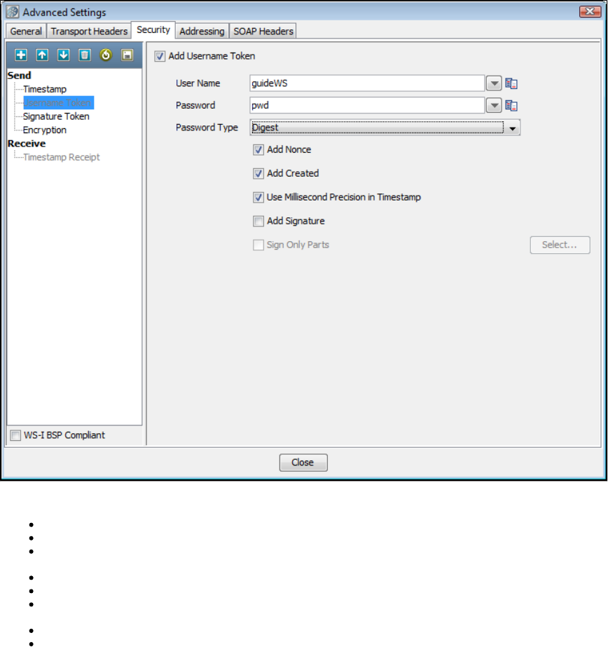
Select the Add Username Token check box.
User Name: Enter the appropriate user name.
Password: Enter the appropriate password.
Password Type: Select the password type from the drop-down menu (Text, Digest, None). None is typically used with the Add Signature
option.
Add Nonce: Click if a Nonce is required: used to protect against replay attacks.
Add Created: Click if a timestamp is required.
Use Millisecond Precision in Timestamp: Select the check box to use millisecond precision. Some Web services, particularly .NET
1.x/2.0 with WSE 2.0, are not compliant with standard timestamp date formatting, and do not allow the use of milliseconds.
Add Signature: Select to add a signature built using a combination of the user name and password as the key.
Sign Only Parts: Select if you want to specify different parts to sign and click the Select button to identify the parts to be signed.
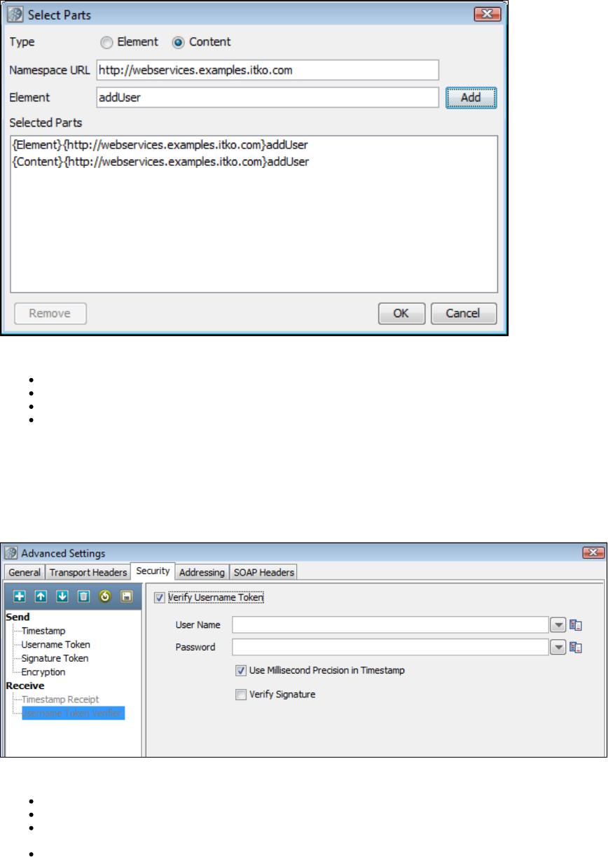
Type: select one of the following:
Element: Select if you want to encrypt the element and the content.
Content: Select if you want to encrypt just the content.
Namespace URL: Enter the value for the element.
Element: Enter the name of the element.
You can repeat this for as many elements as you wish by clicking the Add button.
You will need to manually add the Body element if you wish it to be included.
If you want to include the Binary Security Token as a part, use the Element name "Token."
UserName Token Verifier
Click the box.Verify Username Token
User Name: Enter the verification user name.
Password: Enter the verification password.
Use Millisecond Precision in Timestamp: Select the check box to use millisecond precision. Some Web services, particularly .NET
1.x/2.0 with WSE 2.0, are not compliant with standard timestamp date formatting, and do not allow the use of milliseconds.
Verify Signature: Select if Signature verification is required.
SAML Token/SAML Verifier
SAML Token
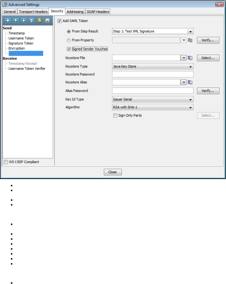
Select the Add SAML Token check box.
Select the From Step Results drop-down: Select the step whose result is an XML SAML Assertion (like a SAML Query Step or a Parse
Text Step with XML manually entered), or
Select the From Property drop-down: Enter the LISA property that contains the XML SAML Assertion.
You can optionally select the Verify button to have LISA parse the SAML Assertion XML and build the SAML Assertion object as it would
when sending the SOAP request. This is useful to confirm that the SAML Assertion that may have been created manually is a valid SAML
Assertion. It will also attempt to verify any signatures associated with the assertion, but it is likely that LISA will not be able to verify the
assertion without configuring a public certificate to verify with.
Signed Sender Vouches: If the assertion needs to be signed by the sender (the sender vouches for its authenticity as opposed to the
bearer/creator of the SAML Assertion). When selected you will need to fill in the following information:
Keystore File: Enter the location of the keystore file.
Keystore Type: Select Java Key Store (jks) or Personal Information Exchange (PKCS #12).
Keystore Password: Enter the password for the keystore.
Keystore alias: Enter an alias for a private key.
Alias Password: Leave blank or the same as Keystore Password for PKCS #12 files.
Key ID type: Select the appropriate key ID type from the pull-down menu.
Algorithm: Select .DSA with SHA-1
The default behavior is to sign only the SOAP Body contents.
Sign Only Parts: If you want to specify different parts to sign, click the Select button to identify the parts to be signed.
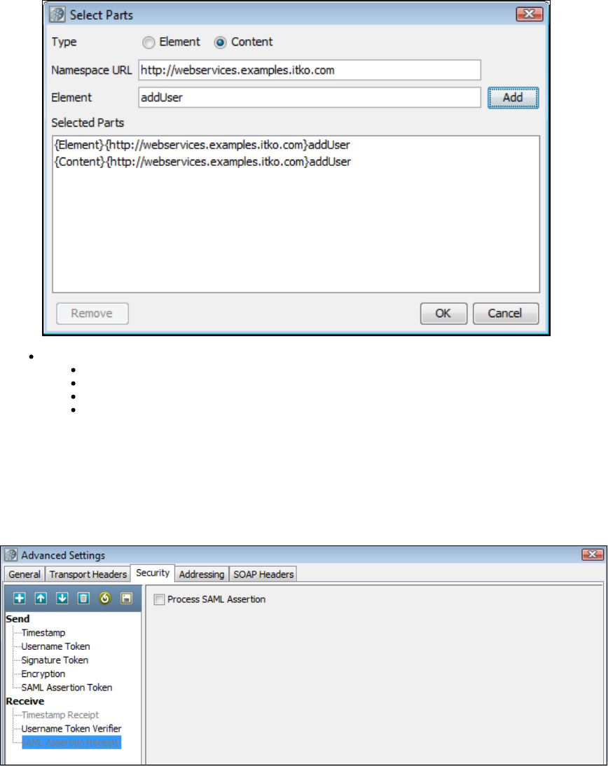
Type: Select one of the following:
Element: Select if you want to sign the element and the content.
Content: Select if you want to sign just the content.
Namespace URL: Enter the value for the element.
Element: Enter the name of the element.
You can repeat this for as many elements as you wish by clicking the Add button. You will need to manually add the Body element if you wish it to
be included.
If you want to include the Binary Security Token as a part, use the Element name "Token."
SAML Verifier
Select the Process SAML Assertion check box if you want LISA to check for a SAML Assertion Receipt header in the response. If you select this
option and there is no SAML Assertion Receipt header then an exception occurs.
Signature Confirmation
Select the Signature confirmation check box if you want LISA to check for a signature confirmation header in the response. If you select this
option and there is no confirmation header then an exception occurs.

Using the Keystore Verifier
You can verify your keystore settings to make sure you are using the correct format, password, alias and alias password. There is a Verify button
on the editors for SSL, Signature, Encryption/Decryption and SAML settings. Clicking Verify produces a verification report.
SSL verification validates the Keystore password only and confirms that at least one of the keys in the keystore can be loaded using the keystore
password.
WS-Security verification validates the Keystore password, the alias and the alias password. Correct validation is indicated with a green entry. Any
validation errors found will be shown in red. Warnings are shown in orange.
This verification only verifies the keystore parameters. There could still be issues with the web service, such as a mismatch in
certificate sets or incorrect choice of algorithm. These issues will need to be validated independently.
Alias Search
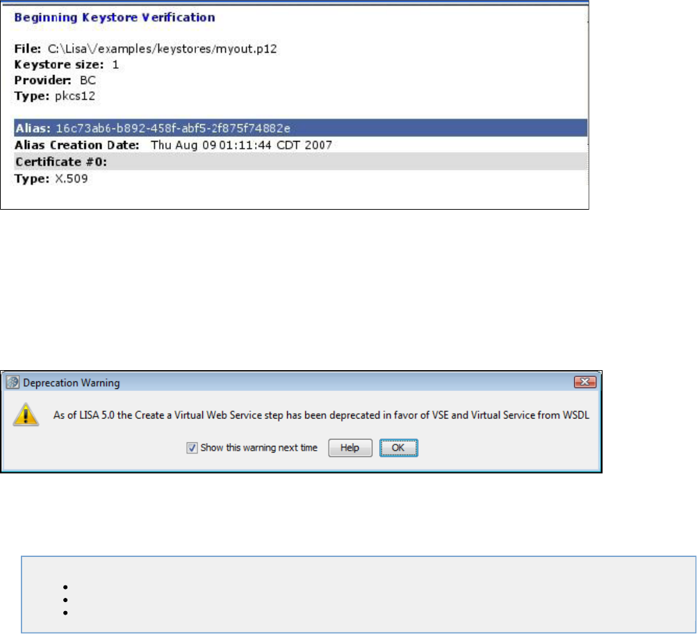
If you do not know the expected alias name for a WS-Security setting, you can use the keystore verifier to list all the aliases in the keystore. Leave
the and boxes empty and click the Verify button:Keystore Alias Alias Password
Aliases are highlighted with a blue background.
Verification will fail because the Keystore Alias and Alias Password boxes were left blank.
Start or Stop Web Server (Legacy)
In LISA 5.0 the Virtual Web Service support was deprecated in favor of using a WSDL to generate a true Virtual Service for LISA Virtual Service
Environment.
This warning appears when you open the Virtual Web Service step or the Start Web Server step. Its purpose is to make you aware of the new
VSE functionality in LISA that replaces these older virtualization steps. In the future these steps will be removed completely as virtualization will
only be possible through LISA VSE.
Clearing the check box will prevent the warning from showing up in the future for that step type. However, both the Start Web Server and
Virtualize Web Service steps will continue to log a warning to the LISA log each time they are run.
Java_J2EE Steps
The following steps are available in this chapter.
Dynamic Java Execution
RMI Server Execution
Enterprise JavaBean Execution
Dynamic Java Execution
The Dynamic Java Execution step lets you instantiate and manipulate a Java object. All Java classes on the LISA classpath are available,
including the classes in the JRE's classpath. Any user classes can be placed on the classpath by copying them into the hotdeploy directory. The
class under test is loaded into the LISA Complex Object Editor where it can be manipulated without having to write any Java code.
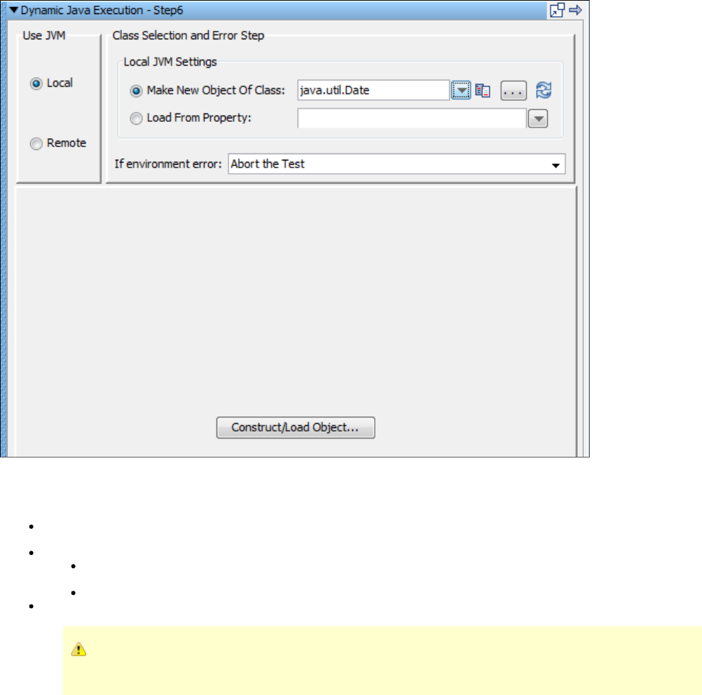
1.
In our example we are using a Java date instance of class .java.util.Date
Enter the following parameters in the Dynamic Java Execution editor:
Use JVM: Select the Local button. It is possible to execute a Java object remotely, using In-Container Testing (ICT), by clicking the
Remote option button, but this mode requires some extra setup before it can be used. This is discussed in the .Developer's Guide (SDK)
Local JVM Settings: Select one of the following option buttons:
Make New Object of Class: Click the option button and enter, select or browse to the Java class you want to instantiate. This
must be the fully qualified class name including the package of the Java class; for example, .com.example.MyClass
Load from Property: Click the option button and enter the name of the property that has the serialized object as its value.
If environment error: Select the step to redirect to if an environment error occurs while trying to create an object.
If you require that the Java object is loaded by its own classloader, you must add the companion Class Loader
.Sandbox Companion
2. Click the Construct/Load Object button.
3. The Complex Object Constructor window is now displayed listing the available constructors for your object. Select a constructor and click the
Next button.
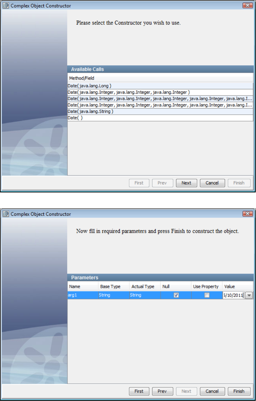
4. Enter any input parameters needed by the constructor.
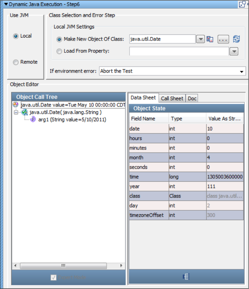
5. In this example, enter a string representation of a day (5/10/2011). You can enter a value, a property or null. LISA constructs the object and
loads it into the LISA Complex Object Editor.
6. You can now manipulate the object, and execute methods, using the LISA Complex Object Editor. For more information about how to use the
Complex Object Editor, see .Complex Object Editor (COE)
7. You can also add filters and add assertions, either by using the inline filter/assertion form (which is part of the Complex Object Editor) or
manually by selecting under your test step in the test case tree. For example, here is a screen just before we execute the before method onfilter
the Date class.
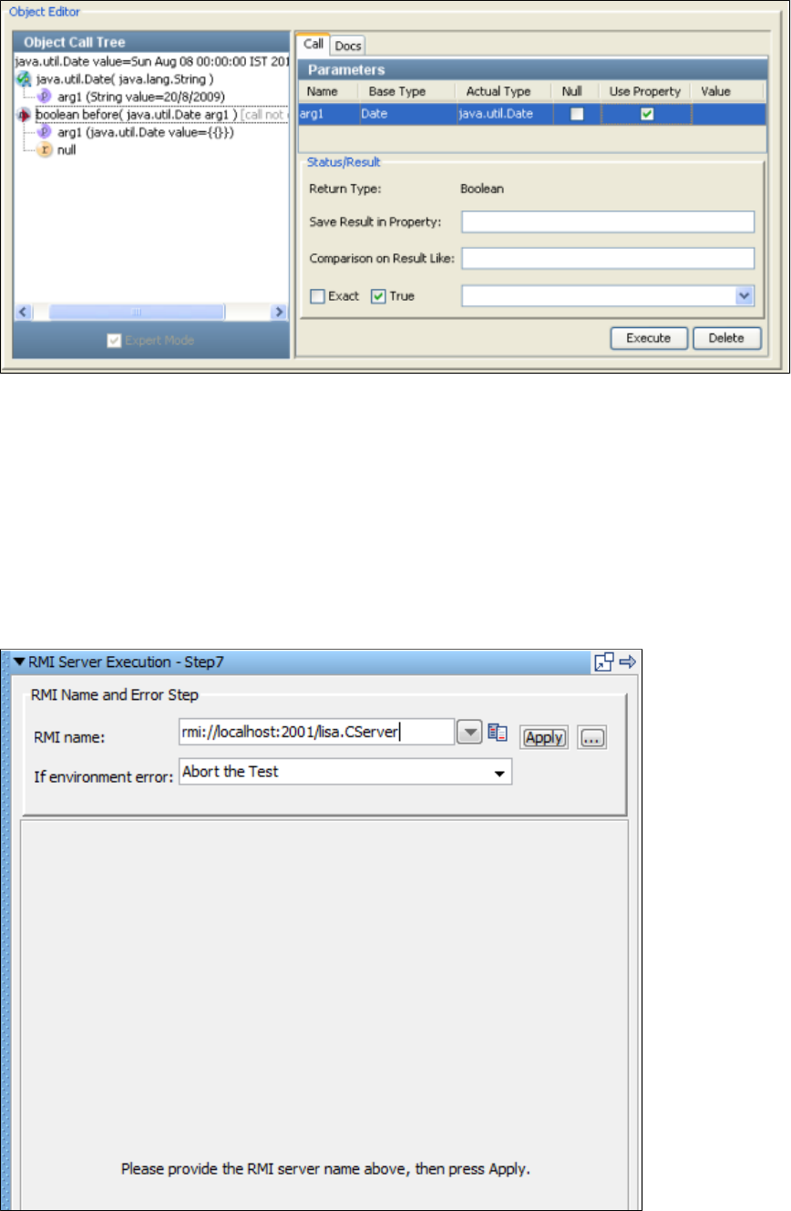
You can see the Status/Result section where you can add an inline filter, in the Save Results in Property text box, and an inline assertion, in the
Comparison on Result Like text box.
RMI Server Execution
The RMI Server Execution step lets you acquire a reference to a remote Java object through RMI (Remote method Invocation), and make calls on
the Java object.
Prerequisites: Knowledge of the LISA Complex Object Editor is assumed. You also need to copy the interface and stub classes for the remote
object into the hot deploy directory. LISA requires these to contact and interact with the remote object. Get these classes from the remote object
developer.
Parameter Requirement: You will need to know how to connect to the RMI Server, usually a host name and port, and you will need to know the
RMI name of the object you want to invoke.
The RMI Server step editor lets you enter the following parameters:
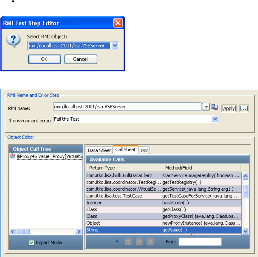
RMI Name: Enter or select the full RMI name of the object (as shown previously), or enter the RMI Server name and click the Browse
button to get a list of available objects.
LISA constructs the object and loads it into the LISA complex object editor.
You can now manipulate the object, and execute methods, using the LISA Complex Object Editor.
In the previous illustration we have selected the getName method. If we double-click it, it gets added in the Object Call Tree, and then it can be
executed using the Execute button that appears in the dialog, with any method arguments that need to be passed to the method, and information
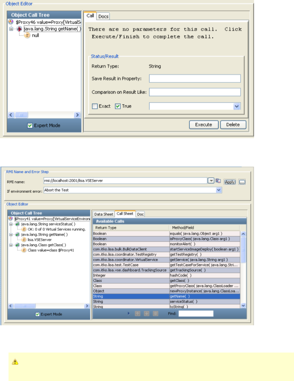
about how to process the result.
NEED UPDATED SCREEN CAPTURE
The previous illustration shows null as the return value because the method is not yet executed. After the button is clicked, it getsExecute
executed and the correct return type is shown. The following illustration shows how the Object Call Tree tracks the results of execution of several
methods.
You can also add filters and add assertions, either by using the inline filter/assertion form or manually by selecting filter under your test step in the
test case tree. You can see the section where you can add an inline filter, in the Save Results in Property textbox, and an inlineStatus/Result
assertion, in the Comparison on Result Like text box.
If you have multiple network cards, using localhost in the RMI name can cause errors. You may need to use the IP address, or
the host name that corresponds to the particular IP address.
Enterprise JavaBean Execution
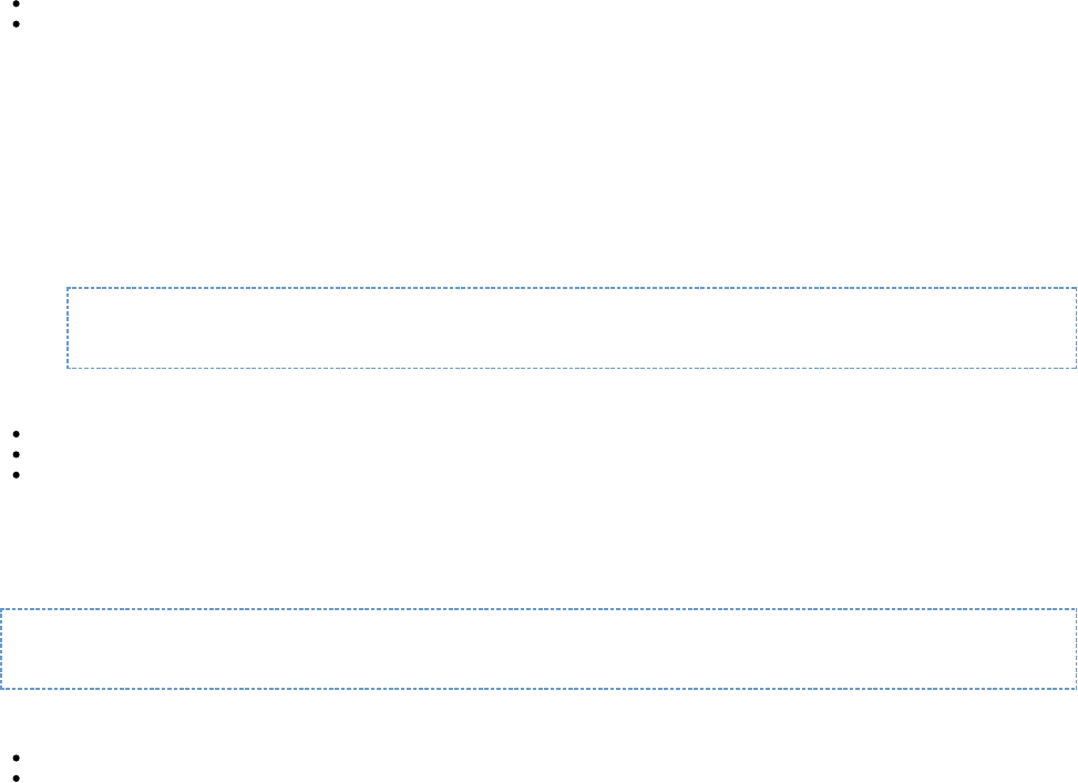
1.
2.
3.
The Enterprise JavaBean Execution step lets you acquire a reference to and make calls on an Enterprise JavaBean (EJB) running in a J2EE
application server.
Testing an EJB is similar to testing a Java object. LISA will dynamically connect to the EJB using the Home EJB interface, and then from it create
an instance of an EJB object. This process is a little different for EJBs, as they do not require a home interface. The EJB under test is loaded into
the LISA Complex Object Editor where it can be manipulated without having to write any Java code.
Prerequisites: Knowledge of the LISA Complex Object Editor is assumed. The application client JAR and client EJB JAR must be in the LISA
classpath. Both of these JAR files are usually copied into the hotDeploy directory. The LISA hotDeploy directory contains the jboss-all-client.jar file
for the JBoss application server and the LISA examples JAR file so that you can run the EJB examples immediately.
Parameter Requirements:
Server connection information (JNDI connection) and user ID and password (if required).
The global JNDI lookup name of your EJB home interface.
This information should be provided by the EJB deployer.
Connecting to WebSphere with LISA using SIBC
IBM has an EJB and JMS client that you can download and use with the Sun JVM. It is available here.
Instructions:
Download this file; then run their installer.
Issue the command
java -jar sibc_install-o0902.06.jar jms_jndi_sun <output_directory>
Get the following files from your <output_directory>:
lib\sibc.jms.jar
lib\sibc.jndi.jar
lib\sibc.orb.jar
4. Create a LISA_PRE_CLASSPATH environment variable, to reference the previous three JAR files; for example,
LISA_PRE_CLASSPATH=C:\sibc.jms.jar;C:\sibc.jndi.jar;C:\sibc.orb.jar;
5. Edit local.properties and add the following line:
com.ibm.CORBA.ORBInit=com.ibm.ws.sib.client.ORB
6. On the JMS step, use the following settings:
JNDI factory class: com.ibm.websphere.naming.WsnInitialContextFactory
JNDU URL: iiop:// :SERVER PORT
Example
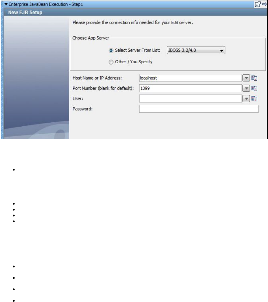
This example uses the ITKO example server, a JBoss server. To use your local Demo Server, use localhost as the host name.
1. Enter the following parameters:
Choose App Server: Select your application server from the list. If your application server is not on the list, click the Other/You Specify
option button.
2. The lower section of the editor changes, depending on your selection. The previous illustration shows the configuration panel for JBoss.
3. For the JBoss panel, enter the following parameters:
Host Name or IP Address: Enter hostname or IP address of your application server
Port Number: Enter port number
User: Enter if a User ID is required for the application server
Password: Enter if a password is required for the application server
4. Click Next.
For the Other/You Specify window:
1. Enter the following parameters:
JNDI factory: Enter or select the fully qualified JNDI factory class name for your application server.
URL: Enter or select the JNDI server name.
User: Enter if a user ID is required for the application server.
Password: Enter if a password is required for the application server.
2. Click Next.
3. The New EJB Setup window displays a list of all the JNDI names registered with the application server.
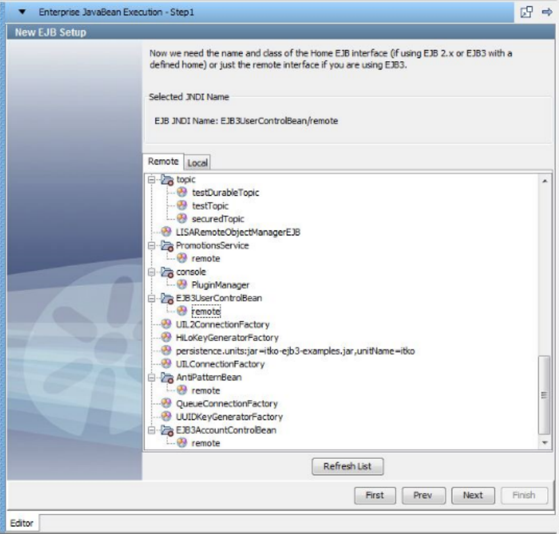
4. Select the name of the appropriate EJB home interface. In this example, the JNDI name is: com.itko.examples.ejb.UserControlBean. The EJB3
specification enables stateful and stateless beans to bind to the JNDI tree directly and not require a home interface. If this is the case, the bean
can be selected directly and LISA will not need to create a new instance.
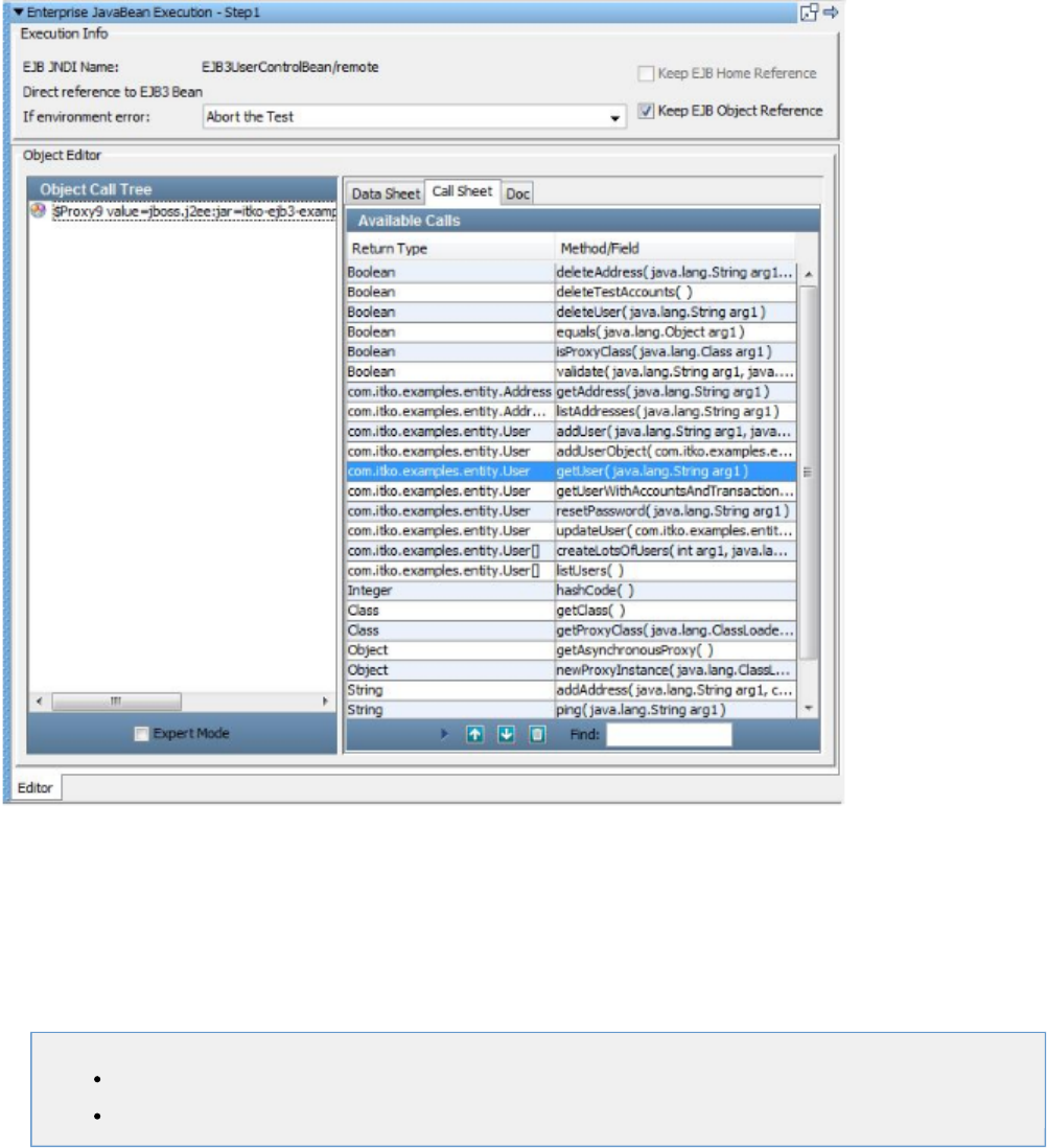
5. Click Next.
6. The object is constructed and loaded into the LISA Complex Object Editor.
7. In the Execution Info area, the current EJB information is displayed. If you plan to reuse this EJB you can keep the references to the EJB object
and the EJB Home by clicking the Keep EJB Home Reference, and Keep EJB Object Reference check boxes on the right. If the bean is an EJB3
bean without a Home interface, the Keep EJB Home Reference check box will be disabled. Set the If Exception to the step to redirect to if an
exception occurs.
8. You can now manipulate the object, and execute methods, using the LISA Complex Object Editor. The usage is the same as in the RMI Server
step.Execution
Other Transaction Steps
The following steps are available in this chapter.
SQL Database Execution (JDBC)
CORBA Execution
SQL Database Execution (JDBC)
The SQL Database Execution step lets you connect to a database using JDBC (Java Database Connectivity) and make SQL queries on the
database.
Full SQL syntax is supported, but your SQL is not validated. It is passed through to the database where it will be validated. If you get an SQL
error, it will be captured in the response so that you can assert on it. Make sure that the SQL is valid for the database manager you are using.
Prerequisites: The JDBC driver appropriate for your database must be on the LISA classpath. You can place the driver JAR file in the hot deploy
directory. The Derby client driver is included in the LISA classpath, so you do not need to add it again.
Parameter Requirements: You will need to have the name of the JDBC driver class, the JDBC URL for your database, and if required, a user ID
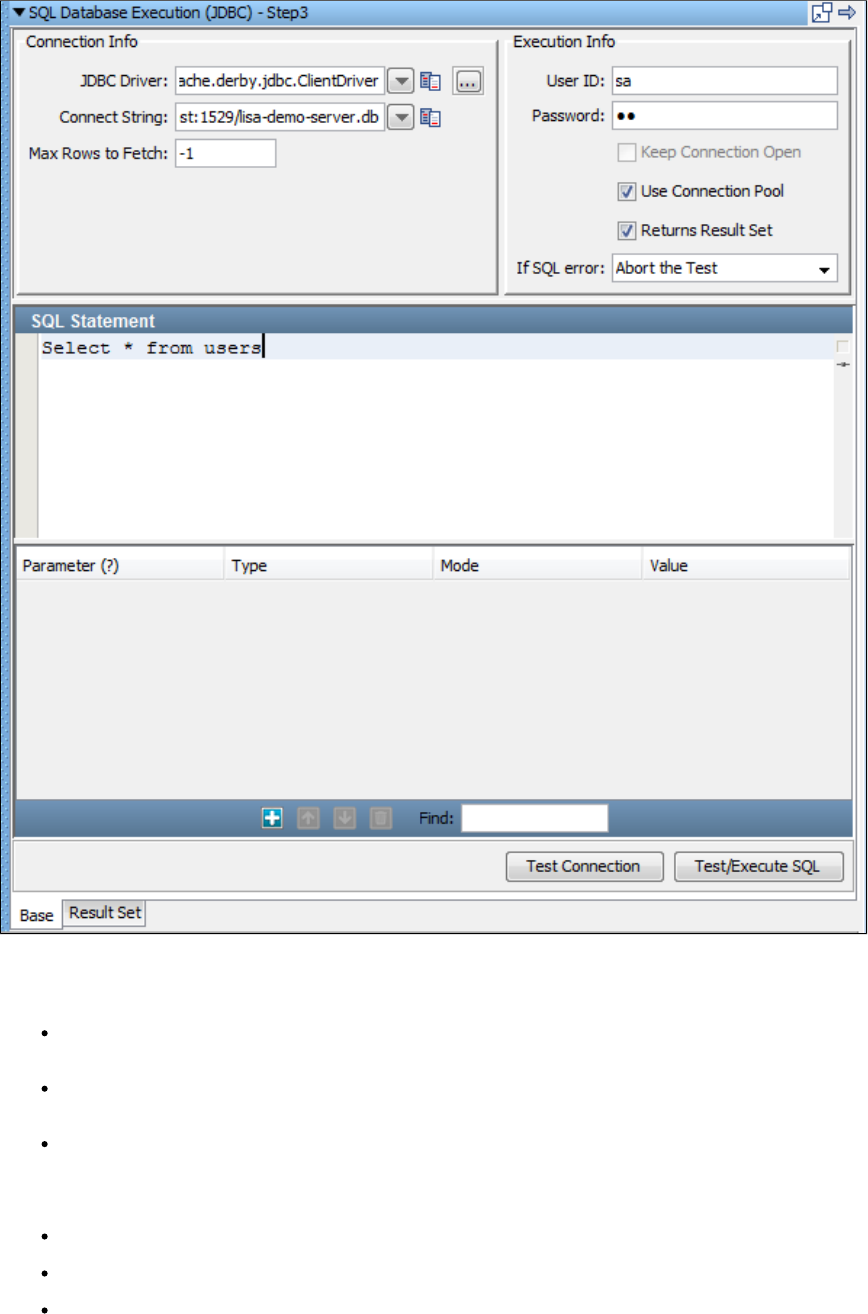
and password for the database. You will also need to know the schemas for the tables in the database to construct your SQL queries.
1. Enter the following parameters in the SQL Database step editor:
Connection Info
JDBC Driver: Enter or select the full package name of the appropriate driver class. Standard driver classes are available in the
drop-down menu. You can also use the Browse button to browse the LISA class path for the driver class.
Connect String: This is the standard JDBC URL for your database. Enter or select the URL. JDBC URL templates for common database
managers are available in the drop-down menu.
Max Rows to Fetch: Enter the maximum number of rows you want returned in the result set. This is a required field. Enter for -1
unlimited rows.
Execution Info
User ID: Enter a user ID (if it is required by the database).
Password: Enter a password (if it is required by the database).
Keep Connection Open: If selected, the database connection opened the first time the step executes is cached, and is closed when the
step is garbage collected. If Keep Connection Open is not selected, the connection is closed each time the step executes.

Returns Result Set: Select this check box if your query will result in a Result Set being returned; that is, a SELECT type query. Leave
cleared for an UPDATE, INSERT, or DELETE. Your query will cause an error if this check box is set incorrectly.
If SQL error: Select the step to redirect to if an error occurs.
To communicate with the local Demo Server, use:
JDBC Driver: org.apache.derby.jdbc.ClientDriver
Connect String: jdbc:derby://localhost:1527/reports/lisa-reports.db
User ID: sa
Password: sa
2. After you have entered the database connection information, including the user ID and password (if required), you can use the Test Connection
button to test your connection. If the information is correct, you will get a success message in a window. Otherwise you will get an error message
indicating what the problem might be.
3. You are now ready to enter your SQL statement in the lower window. Properties can be used in your SQL. LISA will make the parameter
substitution before passing the SQL string to the database.
The JDBC step supports stored procedure calls. Basic data types (strings, numbers, dates, Boolean) are supported as arguments into and
returned by a stored procedure. Click the Add icon to add a parameter. The numbers in the Parameter column are not editable. As you add,
delete, and move rows, the numbers in the Parameter column are automatically renumbered.
The JDBC step also can use JDBC prepared statements. You can use ? markers in a SQL statement and add named {{properties}} without being
concerned about the type of the argument or escaping single quotes in parameter values. A statement "insert into MYTABLE(COL1,COL2) values
(?, ?)" with a reference to {{col1}} and {{col2}} is easier to understand. The type and escape characters are automatically converted.
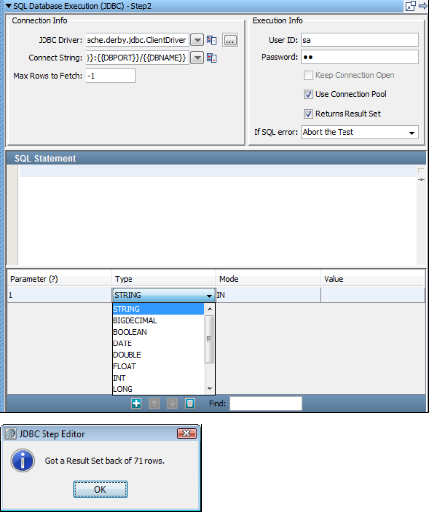
4. After you have created the SQL query, use the Test/Execute SQL button to execute the query. A message indicates the result status.
5. Click OK. Your results are displayed in the Result Set tab.
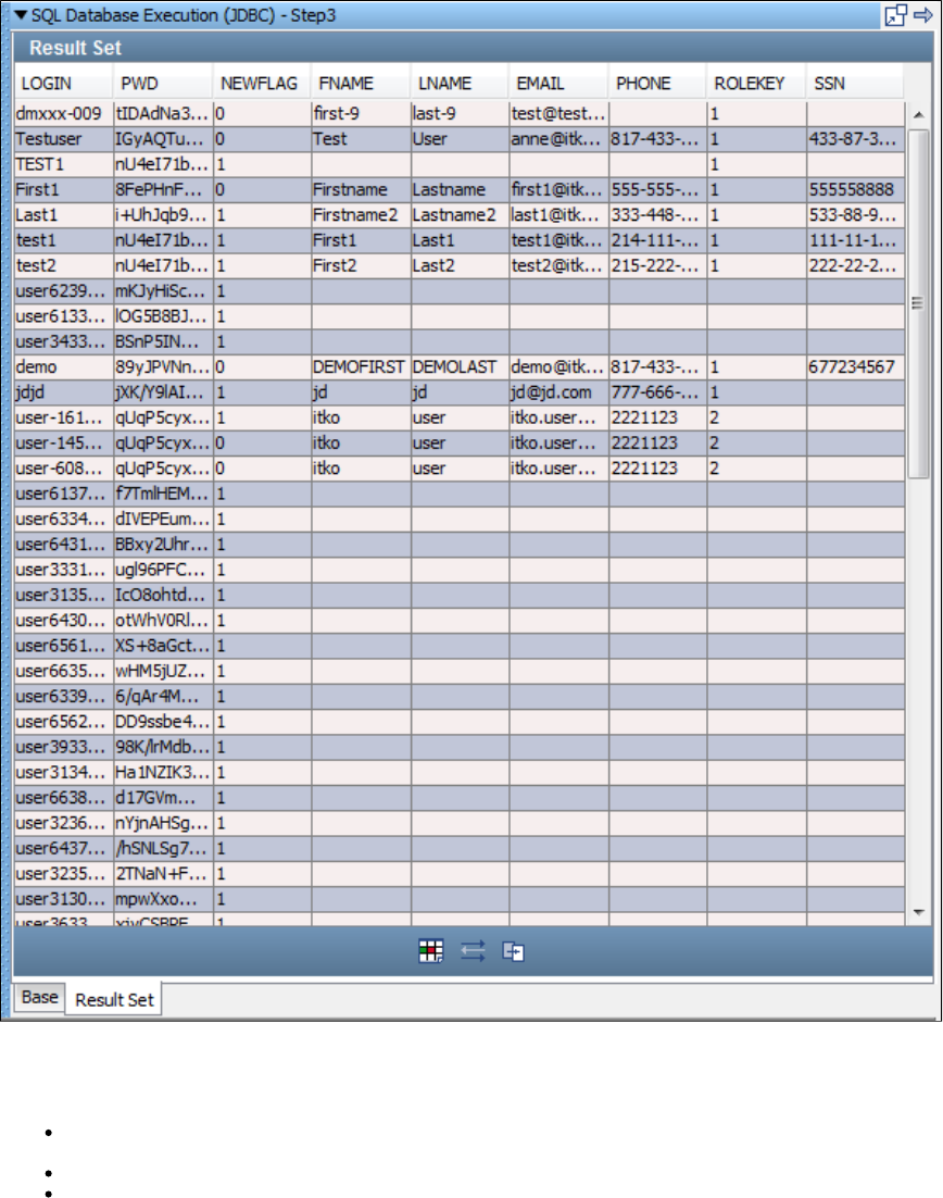
1.
2.
6. You are now ready to create filters and assertions on the result set.
The three icons on the bottom of the Result Set tab give you easy access to the following filters and assertions:
Get value for another value in a Result Set Row: You select a search field cell, a value field filter and enter a property name. If the cell
value in the search field is found, the value in the value field in that row will be set as the value of the property that is entered.
Parse Result for Value filter: The value in the selected cell will be set as the value of the property that is entered.
Result Set Contents Assertion: The values in the chosen field (column) will be compared to the regular expression that is entered.
For more information about these and other filters and assertions appropriate for result sets, see and .Types of Filters Types of Assertions
CORBA Execution
The CORBA Execution step is used to make CORBA calls using Java RMI-IIOP library. You are expected to provide appropriate skeleton
classes.
Before starting execution, copy the corbaserver.jar file (this JAR is available in CORBA server lib directory) to the LISA directory.lib
Select the CORBA step to open its editor.
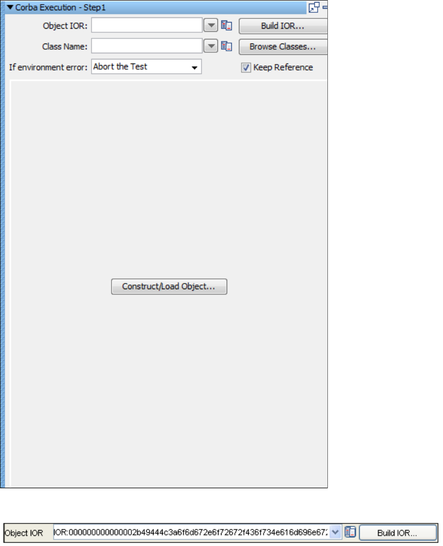
2.
3. Complete the fields.
: This field contains the raw IOR string for the object or the name service. This string can be taken from the output (generatedObject IOR
IOR) of running nameserver.sh batch file.
The entire string should not contain any spaces, which may happen if it is directly copied and pasted from nameserver printed output to
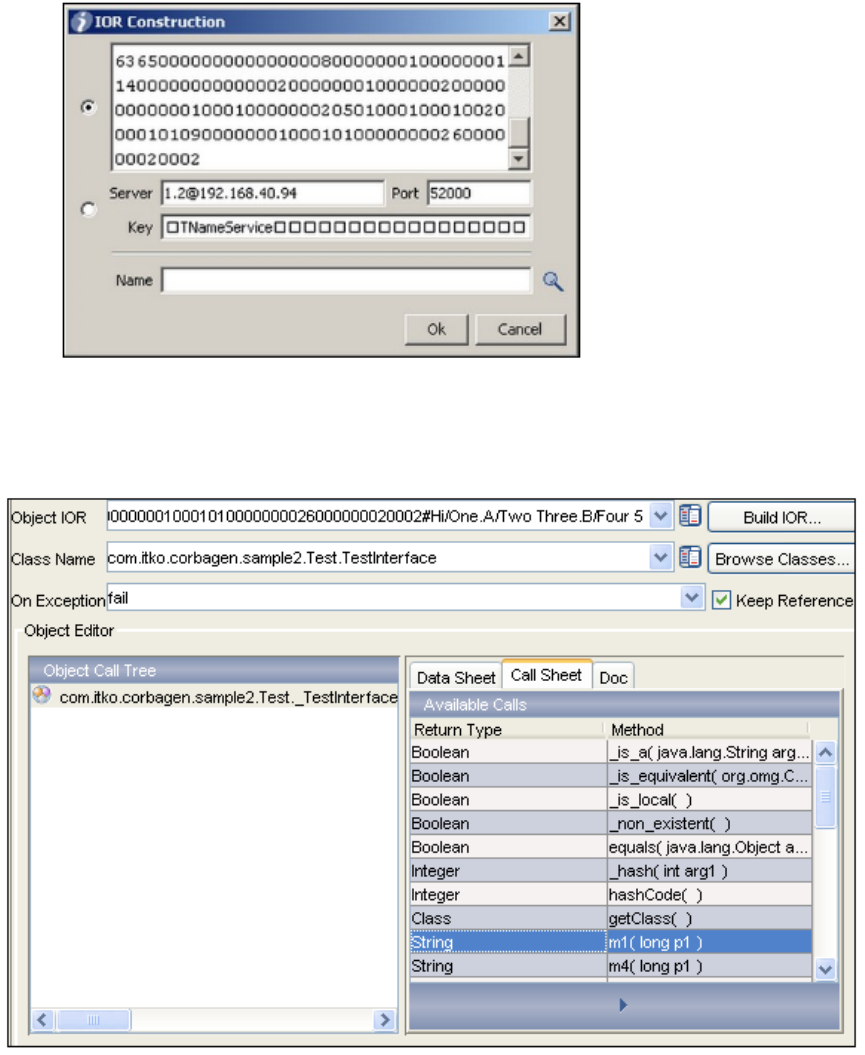
3.
the Object IOR field.
: This is the object class that IOR references.Class Name
You can also use the IOR construction dialog. When open, it will parse any IOR string entered and fill in the individual parts. Don't worry about the
strange looking key. IORs store the key in a byte format so not every byte can be displayed properly. Just don't edit the field if you want to use the
parsed version of a raw IOR.
4. Click Construct/Load Object. The dynamic object editor will show the object's call sheet.
5. Select the method you want to call and execute it.
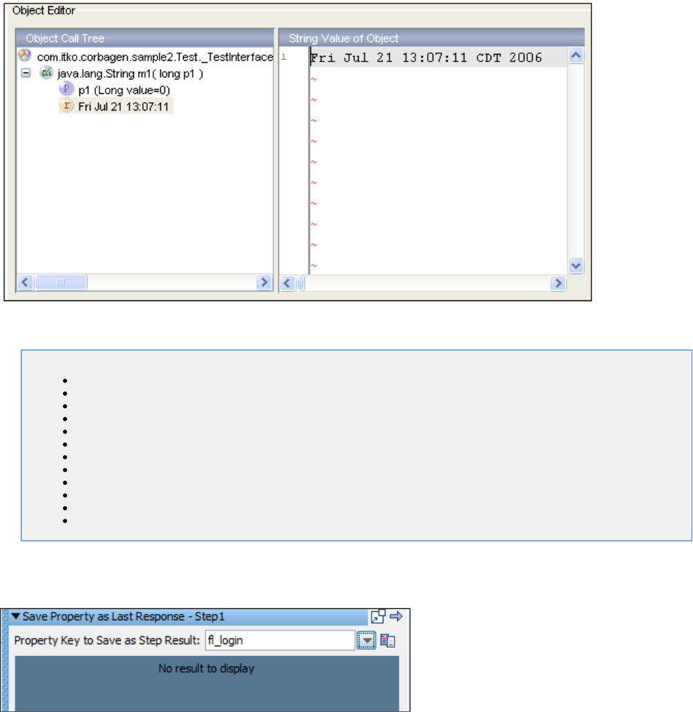
Utilities Steps
The following steps are available in this chapter.
Save Property as Last Response
Output Log Message
Write Properties to File
Read Properties from a File
Do-Nothing Step
Parse Text as Response
Audit Step
Base64 Encoder Step
Checksum Step
Convert XML to Element Object
Utilities_Compare Strings for Response Lookup Step
Utilities Compare Strings for Next Step Lookup Step
Save Property as Last Response
The Save Property as Last Response step lets you save the value of a LISA property as the last response.
Enter the property name of an existing LISA property or select it from the pull-down menu. The value of the property will be loaded as the last
response (and the step response). It can then be accessed immediately as the last response, or later in the test case using the property
lisa.thisStepname.rsp, where thisStepName is the name of the current step.
Each step in a LISA test case has a response associated with it, and when that step is executed, its response is automatically saved in two LISA
properties: and . You use this step often so that you can have filters and assertions apply to a propertyLASTRESPONSE lisa.thisStepName.rsp
value rather than the real response of the step.
Output Log Message
The Output Log Message step lets you output a text message to the log. This step is useful for tracking and logging test cases as they execute.
Your log message will usually be a combination of text and LISA properties.
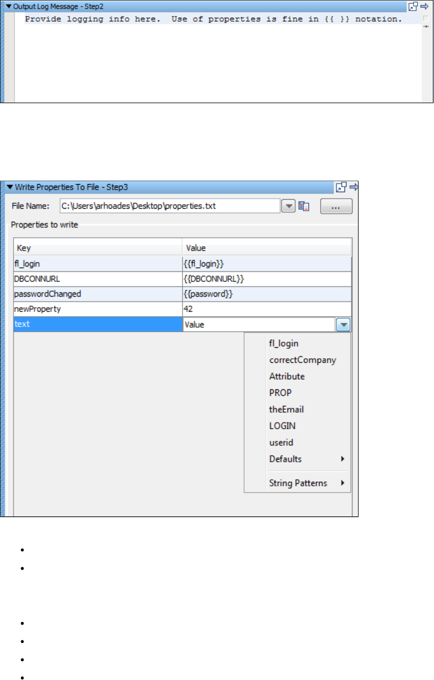
Enter your log message into the editor. This log message appears when this step executes in the Interactive Test Run (ITR), and will be logged
when during a test run.
Write Properties to File
The Write Properties to File step lets you save a list of LISA properties in a text file. The properties can be existing properties or new properties.
Existing properties can be saved under a different property name.
Enter the following:
File Name: Enter path name of file, or browse to file using the Browse button.
Properties to write: Use the Add button to add a row. Then enter the properties (Key) and corresponding values (Value) you want to
save. Your list of properties can contain existing or new properties. When specifying existing properties (Key), you can override their
current value by specifying a new value, or you can use their existing value by selecting it from the drop-down list.
In the previous example:
The first two properties were stored without change.
The third property was stored under a new name (key).
The fourth property is new.
The fifth entry is in progress showing the pull-down menu in the Value column.
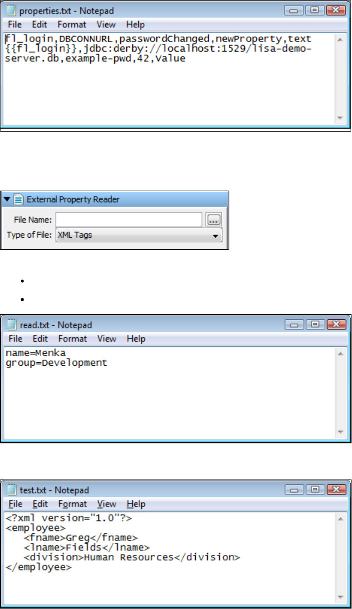
The properties are stored in a comma delimited text file where the first line in the file is the set of property names being saved, and the second
line contains the values corresponding to each of the properties. This example shows the file produced using the four properties previously
described.
Read Properties from a File
The Read Properties from a File step is used to read the properties from an external file. You can read the properties in two ways:
name-value-pairs or in XML tags.
Enter the following parameters:
File Name: Enter the file name or browse to the file containing the properties.
Type of File: Select the type of a file, depending upon the way it has stored the properties.
In the previous illustration, you can see the Name-Value-Pair type of a properties file, where is a property and is a value of the namename Menka
property.
In the previous illustration you can see the XML Tags type of properties file, where is a property and is a value of the fname property.fname Greg
Do-Nothing Step
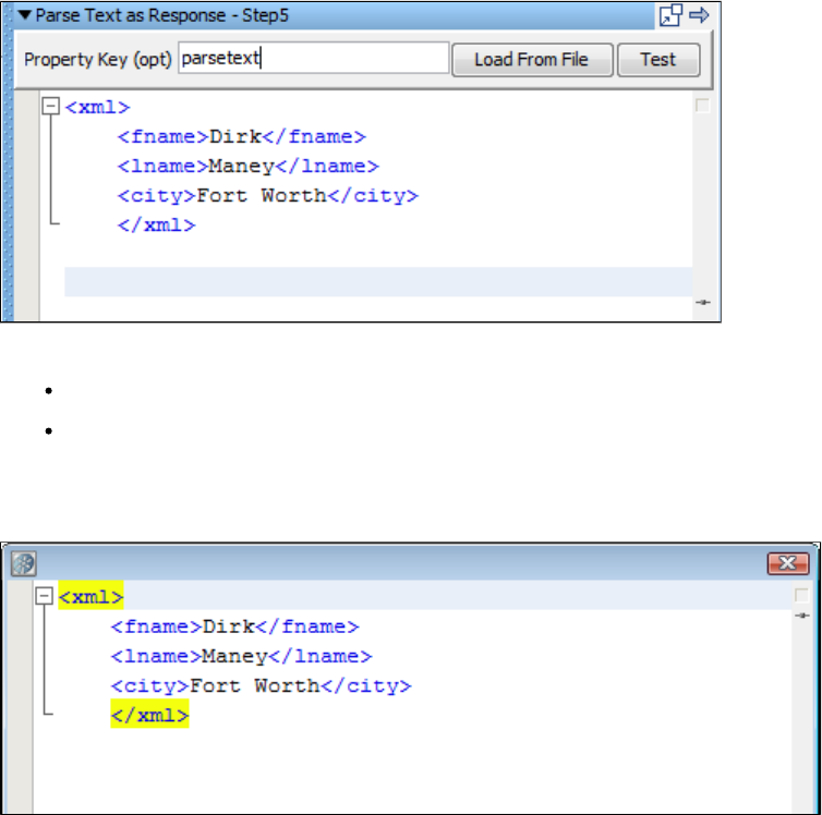
The Do-Nothing step does not take any parameters, nor does it have any functionality by itself. However, this step is useful in certain situations,
as you can add assertions to the step.
For example, you can use the scripted assertion to add a quick custom assertion, to compare numbers or dates, or some numerical comparison
test (greater than or less than).
Parse Text as Response
The Parse Text as Response step lets you enter textual content from a file that can be saved as the last response. The content can be stored in a
LISA property (optional). You can type or paste the text into the editor, or load it from a file.
Enter the following parameters:
Property Key: The name of the property to store the content (optional).
Load from File: Click to browse to the file. Otherwise type or paste the text into the editor.
The content is now available for you to parameterize, filter and add assertions.
Click the Test button to show the resulting text.
Audit Step
The Audit Step lets you apply an against a current test step, remote test, or virtual service.audit document
This allows a LISA model to be verified in terms of the events it produces during execution.
Click the step to open its editor:
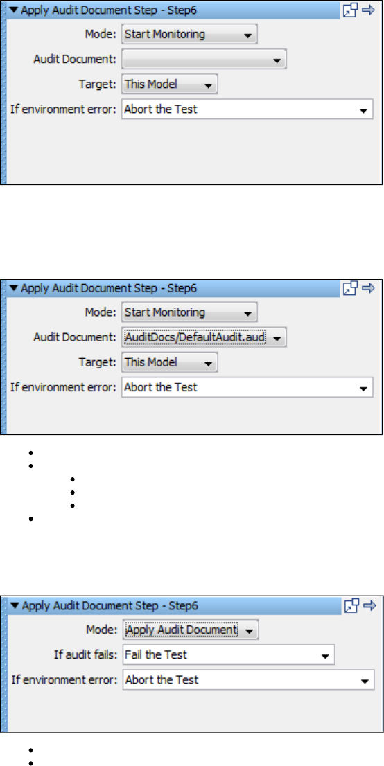
Mode: This step has two modes: Start Monitoring and Apply Audit Document.
Start Monitoring Mode
If you select the Start Monitoring Mode:
Audit Document: Enter or browse for the audit document.
Target: Select the target for the audit document:
This Model: Will apply to the current model.
Test Run: Will apply to the test run.
Virtual Model: Will apply to the virtual model.
If Environment Error: Select the step to be executed if there is an environment error.
Apply Audit Document Mode
If you select the Apply Audit document mode:
If Audit Fails: Select the step to be executed if the audit fails.
If Environment Error: Select the step to be executed if there is an environment error.
Base64 Encoder Step
Base64 Encoder Step
This step is used to encode a file using Base 64 encoding algorithm.
The result can be stored in a LISA property file to be used anywhere within the test run.
Click the step to open its editor:
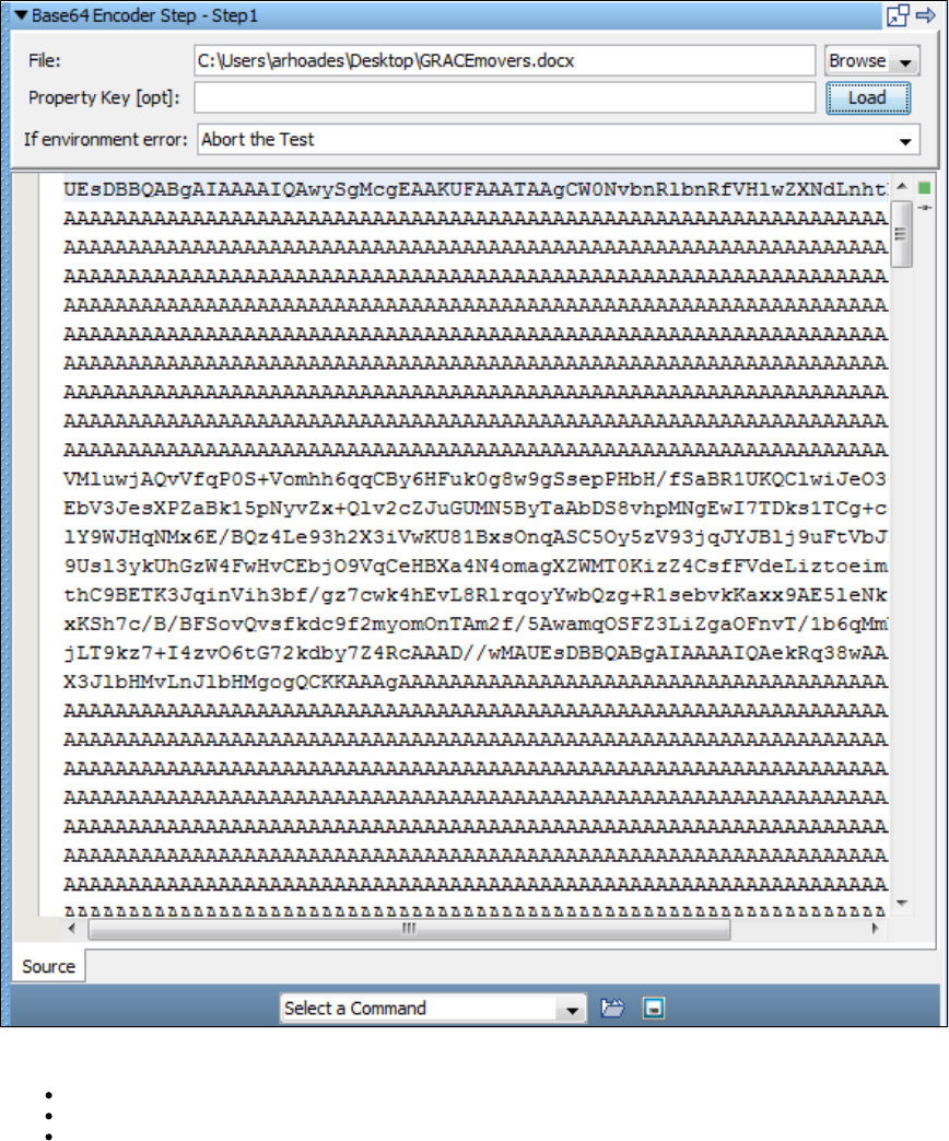
Enter the following parameters:
File: Enter the name of file to be encoded or browse to the target location.
Property Key: The name of the property to store the encoded file. This is optional.
If Environment Error: Select the step to be executed if there is an environment error.
Click the Load button to load the file in the editor.
Here you can apply filters and/or assertions if required from the Command menu at the bottom.
Checksum Step
The Checksum step calculates the checksum of a file and can save that value in a LISA property.
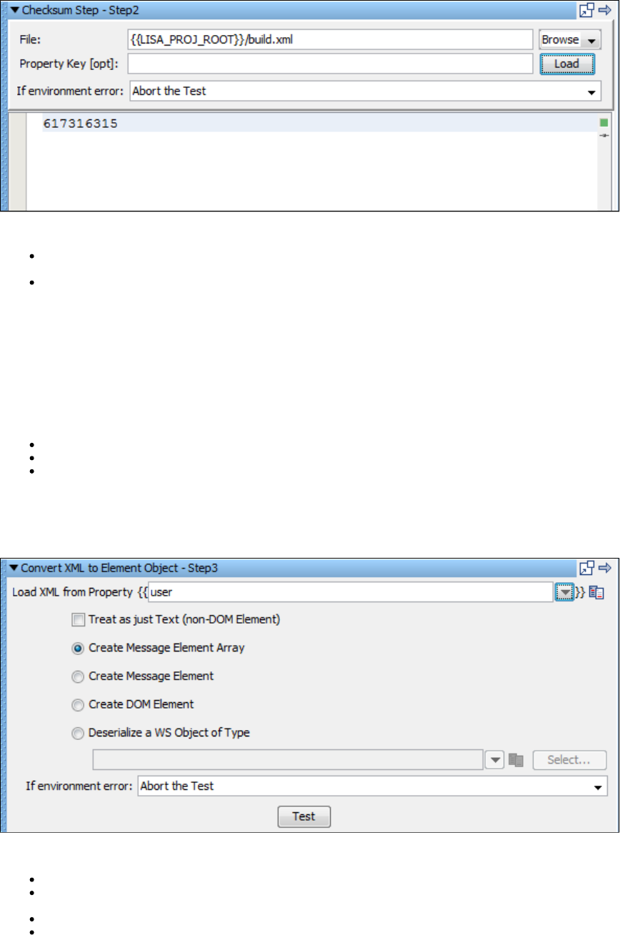
Enter the following parameters:
File: Enter the pathname or browse to the file on which you want the checksum calculated.
Property key: Enter the name of the property that will store the checksum value.
Click the Load button.
The checksum will be displayed as the response, and if a property name was entered the value will be stored in that property.
The checksum value is now available for you to filter and add assertions.
Convert XML to Element Object
The Convert XML to Element Object step converts a raw XML into an object of one of the following types:
Message Element Array
Message Element
DOM Element
This is useful when you have a web service API that takes any type using strict processing. This type of WSDL element will require a Message
Element Array as an input parameter. You can capture the raw XML from a previous step (such as Read from File or Parse Text as Response)
and store it in a LISA property. That property becomes an input parameter for this step.
Prerequisites: The XML must be already stored in a LISA property.
Enter the following parameters:
Load XML from Property: Enter the property that contains the XML. This can be a user-defined property or a built-in LISA property.
Check the Treat as just Text check box if you need to use plain text as your input rather than XML. This will result in a message element
that contains plain text.
Select the type of object you want from the available types by clicking the respective option button.
Click the Test button to do the conversion.
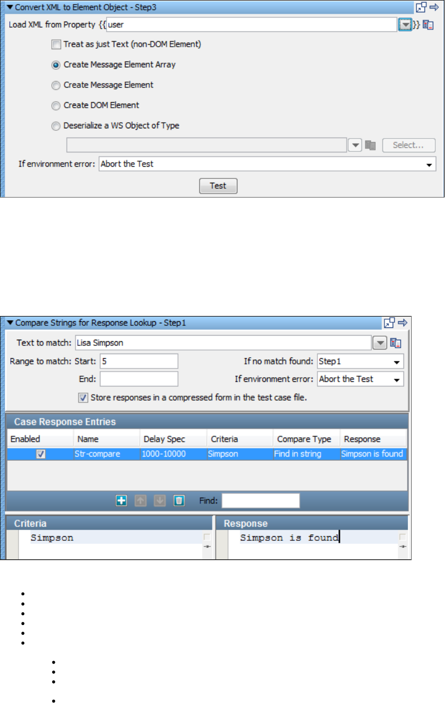
Use the response from this step when this object is required as a parameter in another step.
You can use the Save Step Response as a Property filter to save the response in a filter, or you can refer to it as lisa.<stepname>.rsp.
Utilities_Compare Strings for Response Lookup Step
The Compare Strings for Response Lookup step is used to look at an incoming request to a virtual service and determine the appropriate
response. You can match the incoming requests using partial text match, regular expression, and others.
This step is automatically filled out and added to a virtual service when using the Virtual Web Service HTTP Recorder.
Click the step to open its editor.
Enter the following parameters:
Text to match: Enter the text against which criteria should be matched. This is typically a property reference, such as .LASTRESPONSE
Range to match: Enter the Start and End of the range.
If no match found: Select the step to be executed, if no match is found.
If environment error: Select the step to be executed, if the test fails.
Store responses in a compressed form...: Selected by default. This option compresses the responses in the test case file.
Case Response Entries: In this table you can add, move, and delete entries by clicking the Add, Move and Delete icons. The columns in
the table are:
Enabled Column: Selected by default when you add an entry. Clear to ignore an entry.
Name Column: Enter a unique name for the case response entry.
Delay Spec Column: Enter the delay specification range. The default is 1000-10000, which indicates to use a randomly selected
delay time between 1000 and 10000 milliseconds. (The syntax is the same format as Think Time specifications.)
Criteria Column: This area provides the response of this step if the entry matches the Text to match field. To edit the criteria, in
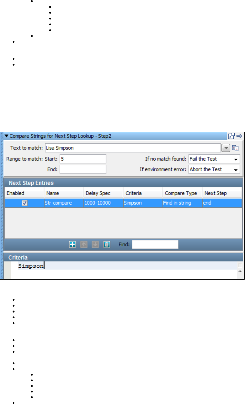
the Criteria Column area select the appropriate row, and enter a different setting in the criteria list. Click Enter to get it updated in
the row below.
Compare Type Column: Select an option for the Compare type from the list:
Find in string (default)
Regular expression
Starts with
Ends with
Exactly equals
Response Column: Allows for the update of the step response for an entry.
Response: This area provides the response of this step if the entry matches the Text to match field. To edit the response, in the Case
Response Entries, area select the appropriate row, and enter a different setting in the Response list. Click Enter to get it updated in the
row above.
Criteria: Allows for the update of the criteria string for an entry.
Response: Allows for the update of the step response for an entry.
Utilities Compare Strings for Next Step Lookup Step
This step is used to look at an incoming request and determine the appropriate next step.
You can match incoming requests using partial text match, regular expression, among others. Each matching criterion specifies the name of the
step to which to transfer if the match succeeds.
This step is automatically filled out and matches to a Virtual Service when using the JDBC Database Traffic Recorder.
Click the step to open its editor.
Enter the following parameters:
Text to match: Enter the text against which criteria should be matched. This is typically a property reference, such as .LASTRESPONSE
Range to match: Enter the Start and End of the range.
If no match found: Select the step to execute if no match is found.
If environment error: Select the step to execute if there is an environment error.
Next Step Entries: Click the Add icon to add an entry. Use the Move and Delete icons to move or delete an entry. Enter text in the Find
field to find a entry.
The columns in the Next Step Entry are:
Enabled Column: Selected by default when you add an entry. Clear to ignore an entry.
Name Column: Enter a unique name for the next step entry.
Delay Spec Column: Enter the delay specification range. The default is 1000-10000, which indicates to use a randomly selected delay
time between 1000 and 10000 milliseconds. The syntax is the same format as Think Time specifications.
Criteria Column: This area defines the criteria to compare against the Text to match field.
Compare Type Column: This has five options to select from:
Find in string (default)
Regular expression
Starts with
Ends with
Exactly equals
Criteria: Allows for the update of the criteria string for an entry.
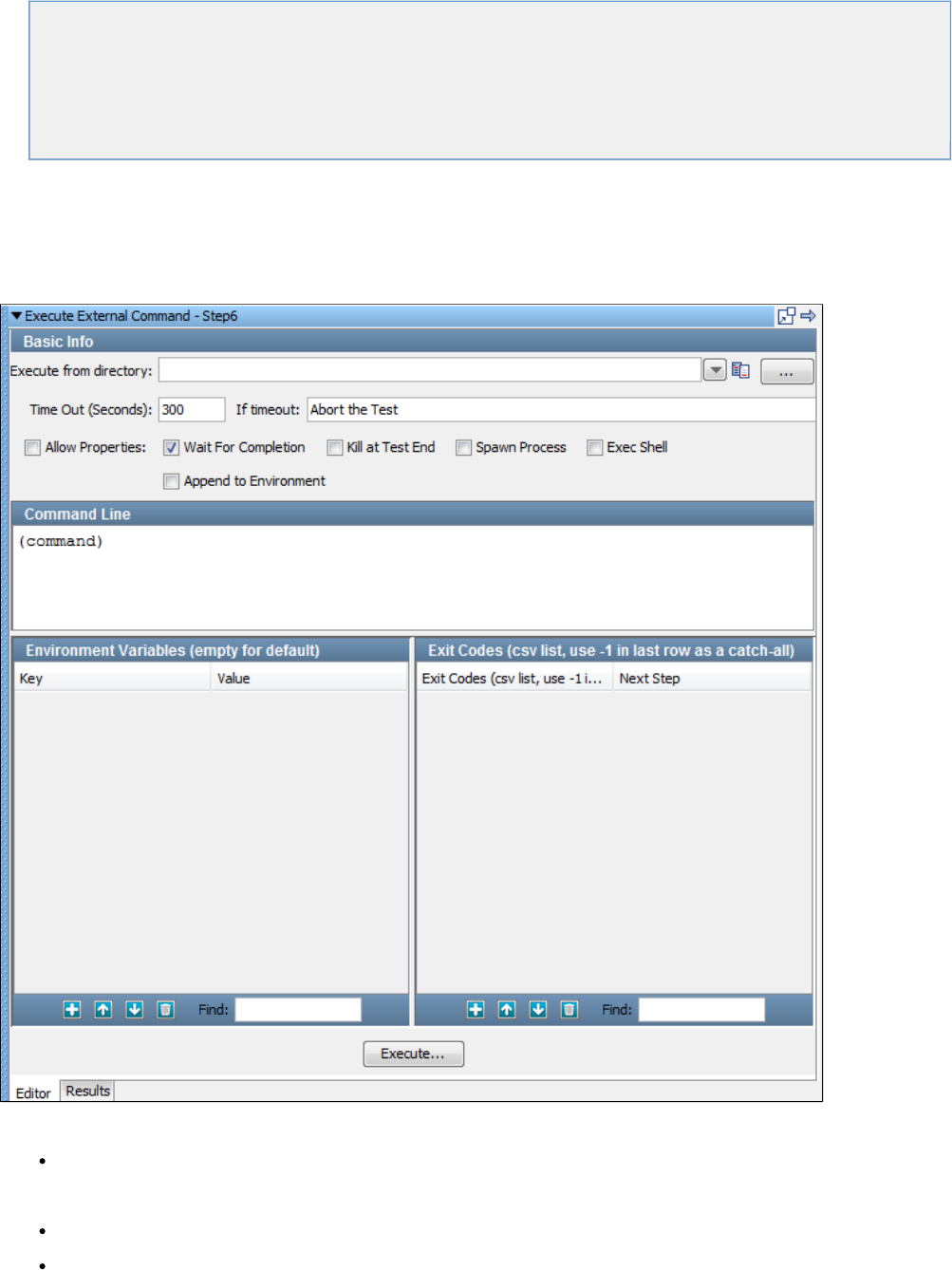
External_Subprocess Steps
The following steps are available in this chapter.
Execute External Command
File System Snapshot
Execute Subprocess
JUnit Test Case_Suite
Read a File (Disk, URL or Classpath)
External - FTP Step
Execute External Command
The Execute External Command step lets you execute an external program, such as an operating system script, an operating system command,
or an executable, and capture its contents for filtering or making assertions.
The external program syntax will depend on your operating system.
Enter the following parameters in the Execute External Command editor:
Execute from directory: The directory that will be considered current when the external command is executed. If the directory does not
exist on the system that is running the test, the directory will be created, subject to file system permissions. If the directory does not exist
and cannot be created the step will fail.
Time Out (Seconds): How long to wait before transferring to the step defined by On Time Out Execute.
If timeout: The step to execute if the external command does not complete execution before the given timeout value.
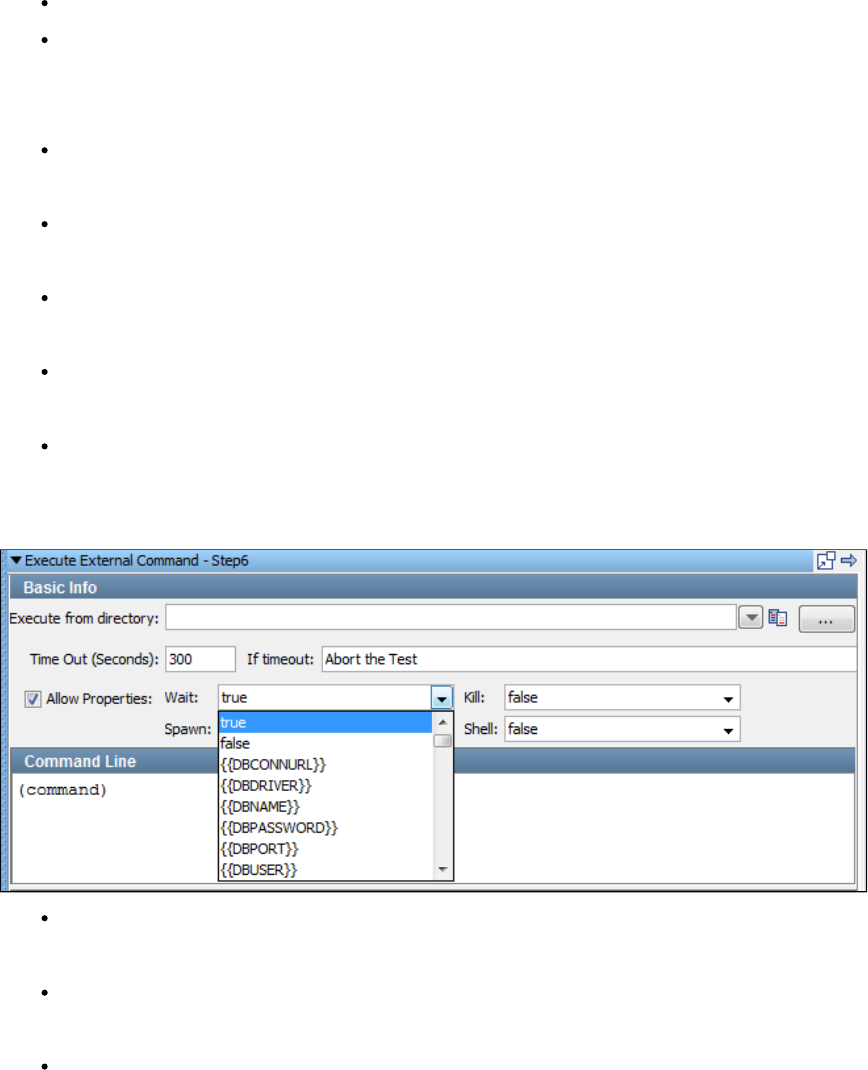
If environment error: The step to execute when an environment error occurs.
Allow Properties: This check box determines whether properties are allowed for the next four parameters. It changes the look of the
command editor interface.
With the Allow Properties check box cleared you will see five check boxes as shown in the previous illustration. Here your only choice is to select
the parameter or not.
Wait for Completion: If this check box is selected, the step waits until the execution has completed, and then the results can be filtered
or asserted upon. If this check box is not selected, filters and assertions will execute; however execution will not wait for the result of the
command being executed.
Kill at Test End: Can be used to kill the process after the test case has completed, if the box is not selected. ThisWait for Completion
lets a process run while a test case executes and then be shut down. A LISA property will contain the process ID of the started
command.
Spawn Process: Creates a new process in the operating system to run the command in. This is helpful if you want to have a
long-running background process or need to make sure that a new set of environment variables is set and nothing set by LISA is in your
environment.
Exec Shell: Lets you run the contents of the Command Line within a system shell. This is required if you need to use the features of a
shell process such as redirecting (pipe) output streams to files or other commands. Depending upon your system this option may be
required for you to run system commands like or . This must be checked for a Windows operating system.dir ls
Append to Environment: When environment variables are defined (in the step) they will be appended to the existing environment, as
opposed to creating a new empty environment where only these variables are defined.
With the check box selected, you will see pull-down menus that have the same functionality as shown previously, but eachAllow properties
parameter can now be a property.
Command Line: The external command is generally just one command written as a shell script or batch file. It is possible to execute
multiple commands when the option is also selected. The command string must be valid for the operating system that you areExec Shell
running LISA on.
Environment Variables: Allows existing environment variables to be overridden with new environment variables. If nothing is entered the
existing environment variables are used for the command. If an environment variable is specified, the new variables sets are used; the
environment variables that were used to start LISA are not used.
Exit Codes: Lets you change the outcome of the test based upon the exit code of the executed process. You can enter a
comma-delimited string of exit codes with a corresponding step to execute when the process exits with this code.
To test your command, press the button. Here is a sample of its output, when the command entered was "notepad."Execute
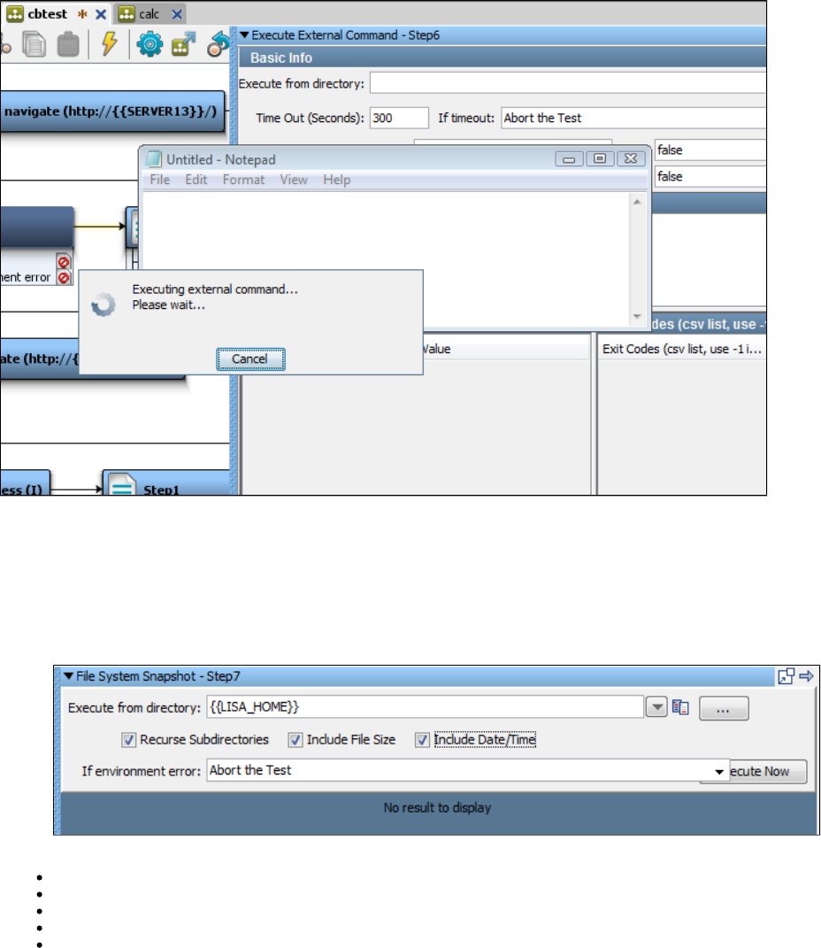
1.
2.
The content is now available for you to filter and add assertions.
File System Snapshot
The File System Snapshot step lets you list the files in a directory in a format that is operating system independent.
You can list a single file, all the files in a directory, or all the files in a directory tree.
Click the step to open its editor.
Enter the following parameters:
Execute from directory: Enter the path name or browse to the file or directory.
Recurse Subdirectories: Check if you want the complete directory tree including sub directories.
Include File Size: Check if you want the file sizes to be listed.
Include Date/Time: Check if you want the last modified date to be listed.
If environment error: Select a step to be executed if there is an environment error.
3. Click Execute Now to execute. This will start the scanning of the file system.
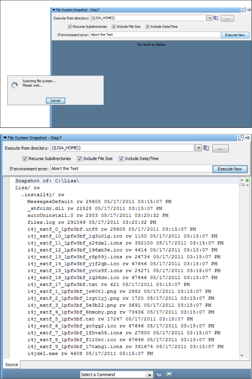
The content is now available for you to filter and add assertions.
Execute Subprocess
The Execute Subprocess step lets you execute a subprocess as a single step.
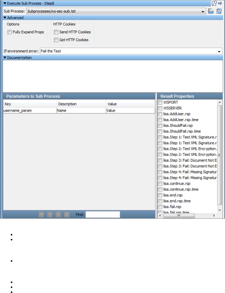
This step is used to execute a LISA subprocess and receive the outputs. This is commonly used when a certain function is performed in
numerous test cases.
For example, a particular validation may always work the same way, so a subprocess is created to perform the validation and is added to different
test cases.
For more information about subprocesses, and how to create them, see .Building Subprocesses
Parameter Requirements: Knowledge of the input and output requirements needed to execute the subprocess.
Enter the following parameters:
Subprocess: Enter the name, select from the pull-down menu, or browse to the LISA test case that is the subprocess.
Open: Use the Open button to open the subprocess test case. The subprocess test case is opened under a new project.
Options
Fully Expand Props: When parameters have nested properties, fully expand the properties before sending to the subprocess.
HTTP Cookies
Send HTTP Cookies: Select if you want to forward cookies to the subprocess.
Get HTTP Cookies: Get HTTP cookies from the subprocess.
If environment error: Select the step to redirect to if the subprocess fails.
In the Parameters to Subprocess panel there is a list of the parameters required by the subprocess. These keys and values must be present in
your current test case. Edit the values column as needed to supply the correct values.
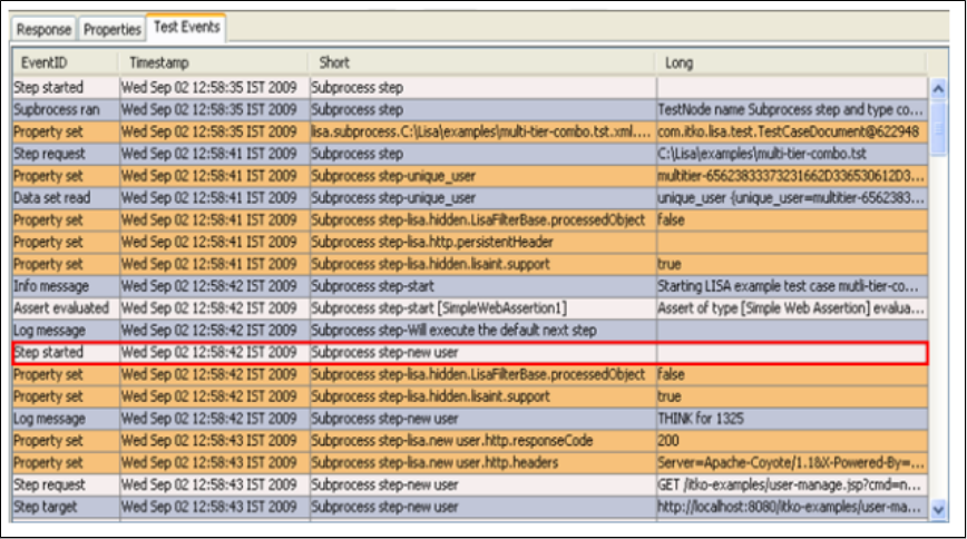
In the middle of the information screen, LISA displays the documentation that was entered into the Documentation of the subprocessSubprocess
test case.
LISA also lists all the properties produced in the subprocess in Result Properties. Select the properties you want returned from the subprocess.
These will be used in your test case. You are not limited to a single return value.
When this step is executed, it will appear to run as a single step. In the Interactive Test Run (ITR) you will be able to see the events fired during
the execution of the step. The short name of the events will be a combination of the name of the current step and the name of the subprocess
step where the event was fired.
Notice the new user notation in the column.Short
JUnit Test Case_Suite
The Execute JUnit Test Case/Suite step lets you run a JUnit test case or a JUnit test suite in a LISA step. If the JUnit test passes, then so does
the LISA step. On failure you can redirect to another LISA step.
Prerequisite: Your JUnit test must be on the classpath. Drop it into the hot deploy directory.
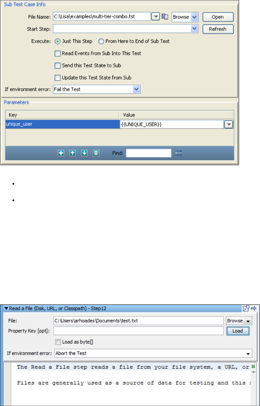
Enter the following parameters:
Test Class: Enter the package name of the JUnit test class or test suite class. You can browse the classpath using the browse button.
This will also confirm that your class is on your classpath.
If environment error: Select the step to redirect to if the JUnit test fails.
Click the Load button to load the class files. The class tree is displayed in the left panel.
Click the Execute button to execute the JUnit test. The standard JUnit results are displayed in the right panel.
The previous illustration shows the editor after the test case has been executed. The text in the right panel is set as the response for this step and
is available for you to add filters and assertions.
Read a File (Disk, URL or Classpath)
The Read a File step reads a file from your file system, a URL, or the classpath.
Files are generally used as a source of data for testing and this step can be paired with the Load a set of File Names data set to provide source
data for testing.
You can read a text file or a binary file. The contents of the file can optionally be stored in a LISA property. In previous versions of LISA, this step
was known as "Read Result from Stream".
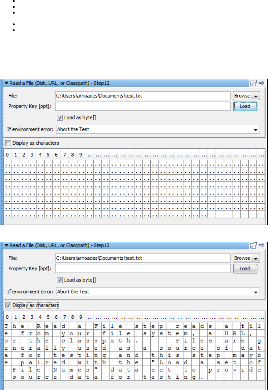
Enter the following parameters:
File: Enter the path name, a URL, or a class path, or, browse to the file using the Browse button.
Property Key: Enter the name of the property to store the file contents (optional).
Load as Byte []: Select this check box to load contents as a byte array. (This is useful when loading a file to be used as a binaryData
type in a web service execution parameter).
If environment error: Select the step to redirect to if the Read a File test fails.
Display as characters: The contents will be displayed as hexadecimal encoded bytes unless you select this check box. This check box
is only visible if the Load as Byte [] box is selected.
Click the Load button to load and display the file. The content is now ready for you to filter and add assertions.
The following illustrations show a small binary file displayed as bytes and characters respectively.
Display as Bytes:
Display as Characters:
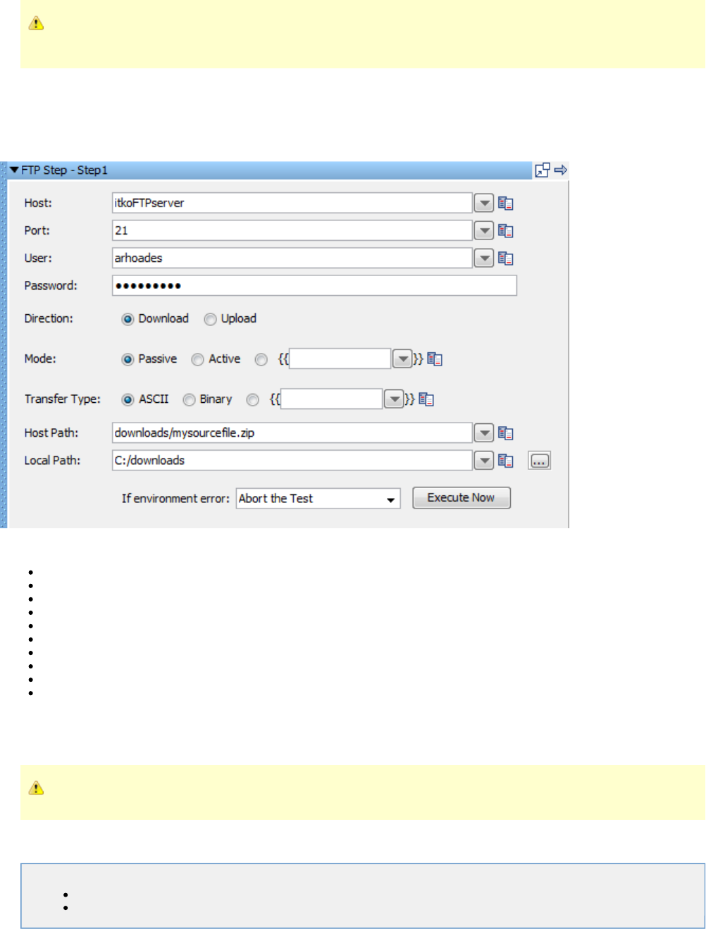
If a binary file is loaded but you do not choose to load as byte, LISA will convert the binary data into characters, many of which
will be unreadable, and the step response will be a string.
External - FTP Step
The FTP step lets you send or receive a file using FTP protocol. After entering the FTP information, user name, and user password you can either
upload a file or download a file.
On the FTP step editor screen, you may need to drag the window to the left to display the Execute Now button. Enter the following parameters:
Host: Enter the host name of the FTP server (without the protocol).
Port: Enter the port for FTP server access. A port is optional; the default port is 21.
User: Enter the user id for FTP server access.
Password: Enter the password for FTP server access.
Direction: Indicate if the data flow will be an upload or a download.
Mode: Specify passive or active FTP, or enter a LISA property that indicates passive or active.
Transfer Type: Select the file transfer type; Binary or ASCII.
Host Path: Enter the path to the source file (either on the FTP server or local computer).
Local Path: Enter the path for the destination file (either on the FTP server or local computer).
If environment error: Select the step to redirect to in the advent of an error.
Click the Execute Now button to initiate the send/receive action.
The response from a download is the file itself. The response from a successful upload is the string success.
If a file by the same name already exists, it will be overwritten without a warning message.
JMS Messaging Steps
The following steps are available in this chapter.
JMS Messaging (JNDI)
JMS Messaging - Message Consumer
JMS Messaging (JNDI)

The JMS Messaging (JNDI) step lets you send messages to, and receive messages from, topics and queues. You can also receive, modify, and
forward an existing message. The list of possible queues and topics can be browsed using JNDI. You must provide client libraries where they can
be read by LISA.
All the common message types including Empty, Text, Object, Bytes, Message, and Mapped (Extended) are supported.
The JMS Messaging (JNDI) step is configured regardless of the messaging requirements. Input options will vary on the messaging requirements.
The editor will only allow valid configurations, so when you enable certain features, others may become inactive.
Prerequisites: You must supply the necessary JAR files for your chosen configuration and connection. They will typically need to be provided in
the directory.LISA_HOME/hotDeploy
Parameter Requirements: You need the connection parameters and the queue or topic names used in the application under test. Other
parameters may be required, depending on your environment. Get these from the application developers. In most cases, you can browse for
server resources to get some of these needed parameters.
Review the test case in the examples project to illustrate what is being described in this section.jms.tst
The test case uses a publish/subscribe JMS step to send a message and listen on a temporary queue. The message is handled by ajms.tst
Message Driven Bean (MDB) on the server, which drops the message onto the temporary queue. The message type is text. It is an XML payload
that is created by inserting LISA properties dynamically into the XML elements. The properties are read from the data set. After theorder_data
response message is received, the XML from the JMS message is put into a LISA property. The next step does an assertion validating the order
ID. After this check asserts true, the existing message object is modified, and the message is sent to another JMS destination.
The test case shows how LISA can listen in and intercept messages as they move through a multi-point messaging service backbone.jms.tst
You can run this test case against the JBoss Demo Server on your computer. The application backend is available there.
The editor for the JMS Messaging (JNDI) step contains the following tabs:
The tab is where you define the connection and messaging parameters.Base
The tab lets you specify a selector query to be run when listening for a message on a queue.Selector Query
The tab is where you create the message content.Send Message Data
The tab is where the response messages are posted.Response Message
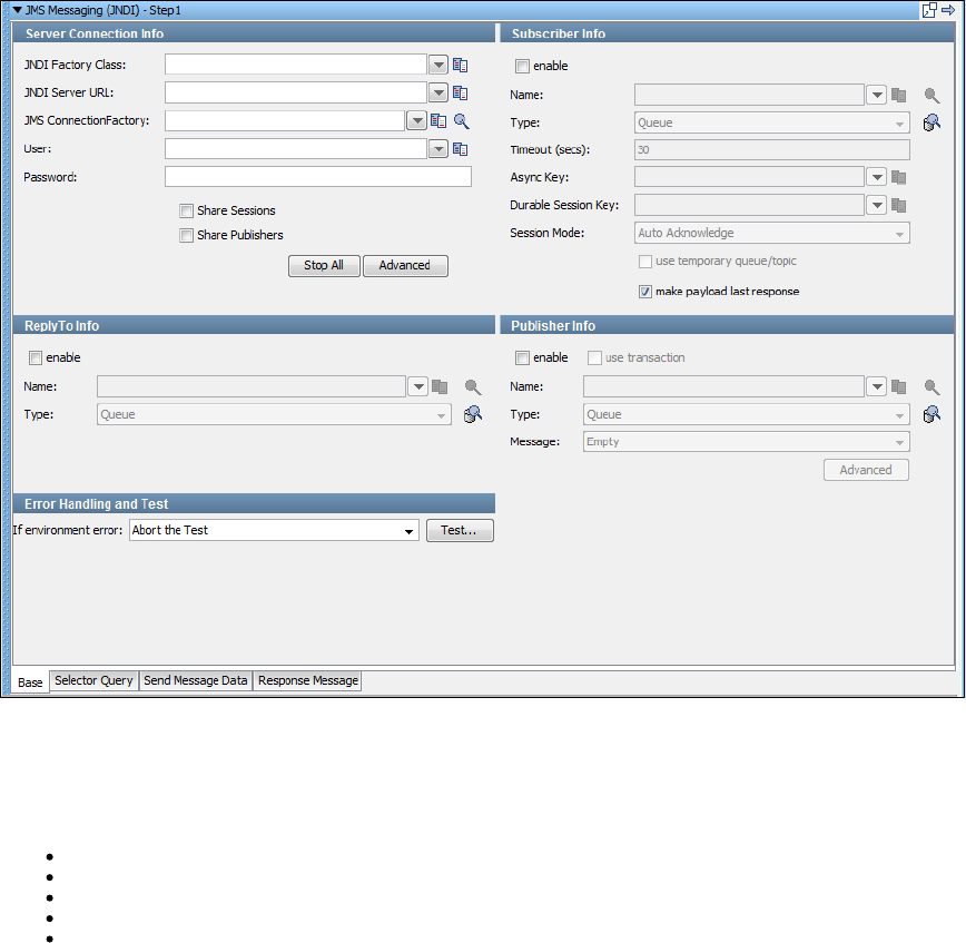
JMS Messaging: Base Tab
The Base tab is where you define the connection and messaging parameters.
The following image shows the Base tab. The tab is divided into the following sections:
Server Connection Info
Subscriber Info
ReplyTo Info
Publisher Info
Error Handling and Test
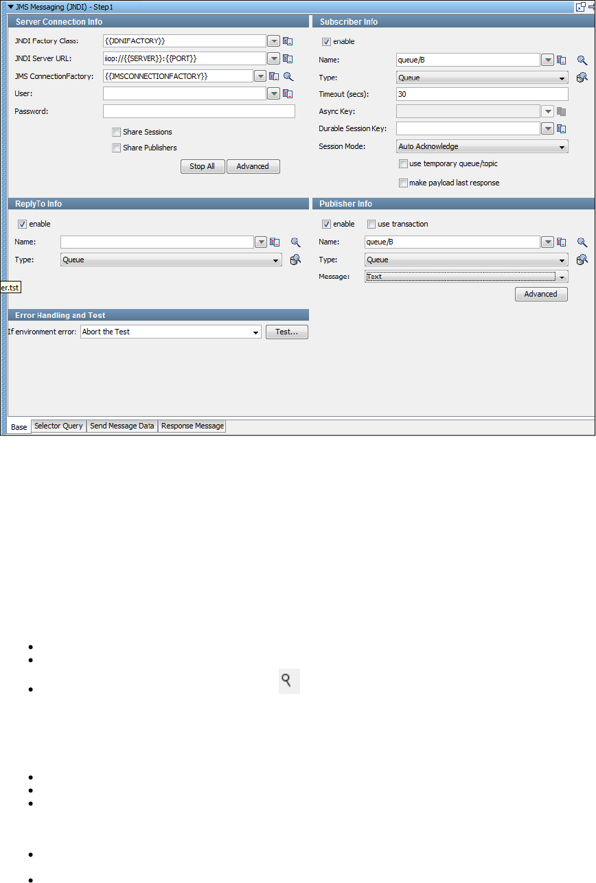
You can enable and disable the Subscriber Info, Publisher Info, and ReplyTo Info sections by using the enable check box in the top left corner of
each section. Thus, you can configure the step to be a publish step, a subscribe step, or both. You can also choose to include a JMS reply to
component in the step.
When you finish configuring the test step, use the Test button in the Error Handling and Test section to test the configuration settings.
Server Connection Info
Enter the JNDI information in the Server Connection Info section of the Base tab.
These values should be parameterized with properties that are in your configuration, making it easy to change the application under test. The
preceding image shows an example of this approach.
The following parameters should be available to you for the system under test:
JNDI Factory Class
JNDI Server URL
JMS Connection Factory: Use the Search icon to browse available resources on the server. Select or enter a connection factory
per the JMS specification to use for this step execution.
The pull-down menus contain common examples or templates for these values.
The user and password may or may not be needed.
User: The user name for connecting to the JNDI provider and getting a handle to the connection factory.
Password: The password for connecting to the JNDI provider and getting a handle to the connection factory.
Share Sessions and : These check boxes are used to share JMS sessions and publishers throughout the test case.Share Publishers
This approach can lower overhead, but does not always provide a realistic simulation because typically JMS clients want to release
resources. If you select the Share Publishers check box, the Share Sessions check box is also selected because you cannot share
publishers without sharing sessions.
Stop All: Lets you stop any listeners at design time now. This is to resolve issues during test case creation where some listeners can get
orphaned, but will still consume messages making it difficult or impossible to finish test case creation.
Advanced: Displays a panel where you can add custom properties that will be sent with the connection information, and configure
second-level authentication.
1.
2.
The user and password fields in the main Server Connection Info section are for connecting to the JNDI provider and getting a
handle to the connection factory. The user and password fields in the Second Level Authentication tab are for getting a handle
to the actual JMS connection.
Publisher Info
Select the check box to set up the ability to send messages.enable
Select the check box to execute a commit when the message is sent.use transaction
Enter the following parameters:
Name: The name of the topic or queue. Use the Search icon to browse the JNDI server for the topic or queue name.
Type: Select whether you are using a topic or queue. Use the Browse icon to the right of this field to see what messages are
waiting to be consumed from a queue (only).
Message: Select the type of message you are sending. The supported types are Empty, Text, Object, Bytes, Message, and Mapped
(Extended).
Advanced: Displays a panel where you can edit the message headers and add message properties.
Subscriber Info
Select the check box to set up the ability to receive messages.enable
Enter the following parameters:
Name: The name of the topic or queue. Use the Search icon to browse the JNDI server for the topic or queue name.
Type: Select whether you are using a topic or queue, and whether you want to listen in synchronous or asynchronous mode. For
asynchronous mode, you also must have an entry in the field. Use the Browse icon to the right of this field to seeAsync Key
what messages are waiting to be consumed from a queue.
Timeout (secs): The period to wait before there is an interrupt waiting for a message. Use 0 for no timeout.
Async Key: The value needed to identify asynchronous messages. This field is needed only in asynchronous mode. It will be used in a
subsequent Message Consumer step to retrieve asynchronous messages.
Durable Session Key: By entering a name here, you are requesting a durable session. You are also providing a key for that session. A
durable session lets you receive all of your messages from a topic even if you log off and then log on again.
Session Mode: The options available are:
Auto Acknowledge: JMS Messages are automatically acknowledged by the JMS client libraries as soon as they are received.
Client Acknowledge: JMS Messages must be explicitly acknowledged by the JMS client.
Use Transaction: The JMS Session operates under a transaction. The acknowledge mode is ignored.
Auto (Duplicates Okay): The JMS client library will automatically acknowledge at unknown intervals. As a result, duplicate
messages may be received if the automatic acknowledgment does not arrive before the JMS Provider retries the delivery.
There is no practical difference between and and . With ,Auto Acknowledge Client Acknowledge Auto (Duplicates Only) Client Acknowledge
each received message is acknowledged immediately upon receipt. The only difference is that the acknowledge call is made explicitly instead of
letting the JMS client library do it. With , the behavior is exactly the same as Auto Acknowledge except under very highAuto (Duplicates Only)
loads.
The option is not strictly an Acknowledgment mode setting. It is included in the list for two reasons:Use Transaction
If the JMS Session is operating under a transaction, then the acknowledgment modes are ignored. Messages are essentially
acknowledged by committing the session transaction.
The mode is still a way of controlling JMS's guaranteed delivery of messages. If a message is received and the sessionUse Transaction
transaction is not committed, then the message will be resent, just like if it was not acknowledged.
Use temporary queue/topic: Select this check box if you want the JMS provider to set up a temporary queue/topic on your behalf. When
a temporary queue/topic is used, LISA automatically sets the parameter of the message you send to the temporaryJMS ReplyTo
queue/topic. The temporary queue/topic feature must always be used with a publisher so that a reply can be sent. If you use a temporary
queue/topic, the section is disabled.ReplyTo
Make payload last response: Select this check box if you want to make the payload response as a last response.
ReplyTo Info
Select the check box to set up a destination queue/topic.enable
If your application needs a destination, it is set up in this section.
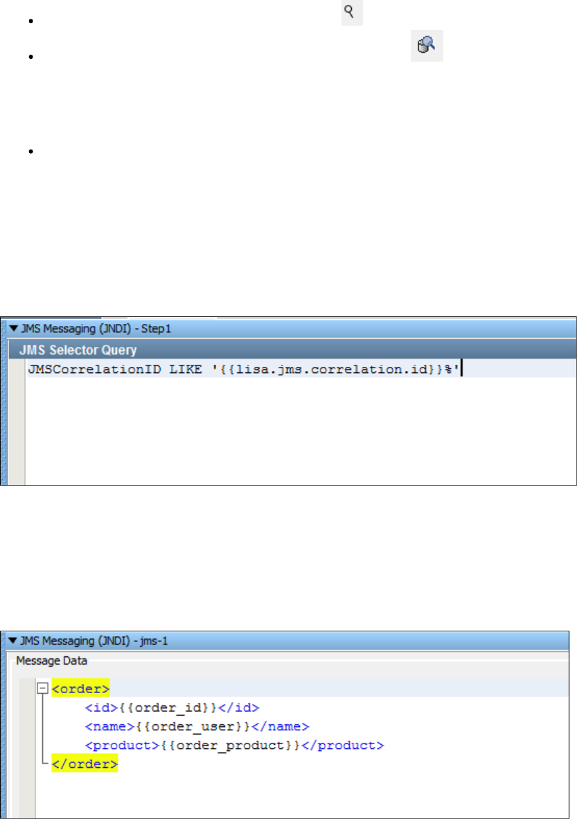
Enter the following parameters:
Name: The name of the topic or queue. Use the Search icon to browse the JNDI server for the topic or queue name.
Type: Select whether you are using a topic or queue. Use the Browse icon to the right of this field to see what messages are
waiting to be consumed from a queue (only).
Error Handling and Test
The Error Handling and Test section lets you redirect to a step if an error occurs.
If environment error: Select the step to redirect to if an environment error occurs.
Click the Test button to test your step configuration settings.
JMS Messaging: Selector Query Tab
You can enter a JMS selector query in the Selector Query tab. The syntax closely follows SQL. It is a subset of SQL92.
A JMS selector query can be specified when listening for a message on a queue that is a response to a published message.
The following image shows a query looking for a that matches the property as sent with the originalJMSCorrelationID lisa.jms.correlation.id
message.
JMS Messaging: Send Message Data Tab
If your step is configured to publish, the Send Message Data tab is where you compose the message.
The text can be typed in, or it can be read from a file using the Read Message From File button in the bottom right corner of the tab. You can also
store text in a LISA property, in which case you would place the property in the editor, for example, .{{property_name}}
The following image shows an XML fragment with LISA properties. Using properties allows the message to be created dynamically during the test
run.
JMS Messaging: Response Message Tab
If your step is configured to subscribe, the response appears in the Response Message tab after clicking the Test button in the Base tab.
The tab shows the for the returned object. The returned object varies with the type of application server. You have accessComplex Object Editor
to all the JMS parameters returned in addition to the message itself. The object is loaded into the Complex Object Editor, where it can be
manipulated like any other Java object.
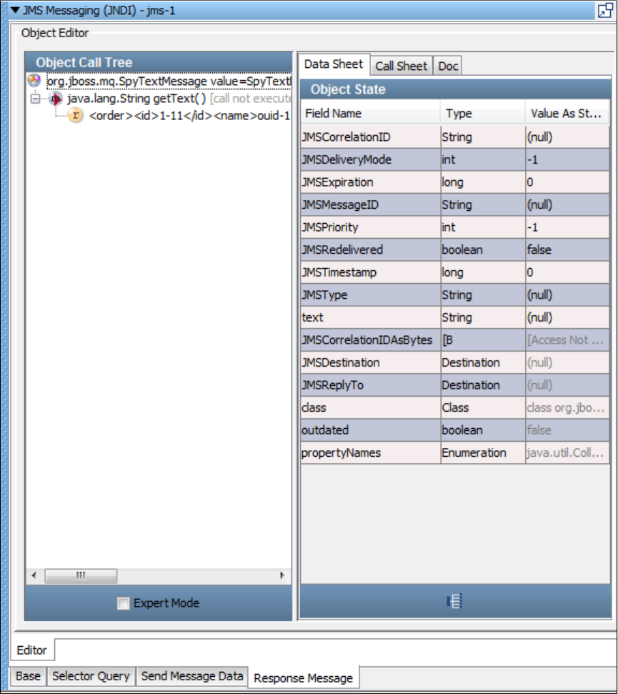
The following image shows a text response from a JBoss object.
JMS Messaging - Message Consumer
The Message Consumer step lets you consume asynchronous messages in a test case. This step can attach to a known queue/topic and get
messages posted for this subscriber. You identify yourself with a unique key. You must have already subscribed to the queue/topic and the
messages have been pushed to that destination.
Prerequisite: Before executing the example test case you must have the demo server running.
Parameter Requirements: Knowledge of the queue/topic being used in the application under test.
An example test case, , is included in the LISA examples directory. Look at that test case to illustrate what is beingasync-consumer-jms.tst
described in this section.
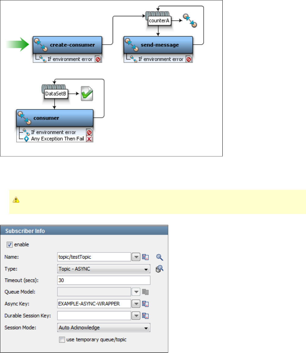
The create-consumer step subscribes to asynchronous message (topic/testTopic) using the Async Key (EXAMPLE-ASYNC-WRAPPER). The
send-message step publishes message to a queue (queue/C). The number of messages to be published is controlled using a data set (counterA).
The message consumer step has an Async queue (EXAMPLE-ASYNC-WRAPPER) using which message subscribed by the create-consumer
step is consumed. The number of messages to be consumed is controlled using the data set (DataSetB).
The Async Key specified in create-consumer and consumer steps must match.
The following illustration shows an example of the subscriber section of a step.
Select the enable check box to set up and enable the ability to listen to (subscribe to) messages.
Notice that there is an asynchronous topic specified in the Type field, and an Async Key parameter defined. This key will be needed as an input in
the current step.
This illustration shows an example of the publisher section of a step.
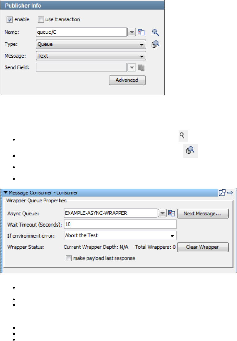
Select the enable check box to set up the ability to send (publish) messages. Select the use transaction check box to execute a commit when the
message is sent.
Enter the following parameters:
Name: Enter the name of the topic or queue to use. Use the Search icon to browse the JNDI server for the topic or queue name.
Type: Select whether you are using a topic or queue. Use the Browse icon to the right of this field to see what messages are
waiting to be consumed from a queue (only).
Message: Select the type of message you are sending from the pull-down menu. The supported messages are: Empty, Text, Object,
Bytes, Message, and Mapped (Extended).
Advanced button: Select to display a panel where you can add custom message properties to be sent with the message.
Enter the following parameters:
Async Queue: Enter or select the Async Key parameter that was named in a preceding subscriber step
(EXAMPLE-ASYNC-WRAPPER). These names must match.
Wait Timeout (Seconds): Enter the time, in seconds, to wait for the next message.
If environment error: Select the step to redirect to if an environment error occurs.
Wrapper Status contains two output status values:
Current Wrapper Depth: Number of messages left to be read in current wrapper
Total Wrappers: Number of wrappers (destinations).
Make payload last response: Select this option if you want to make the payload as the last response in the step.
If there are messages waiting, they can be read by clicking the Next Message button. This will typically show the message in the LISA Complex
Object Editor.
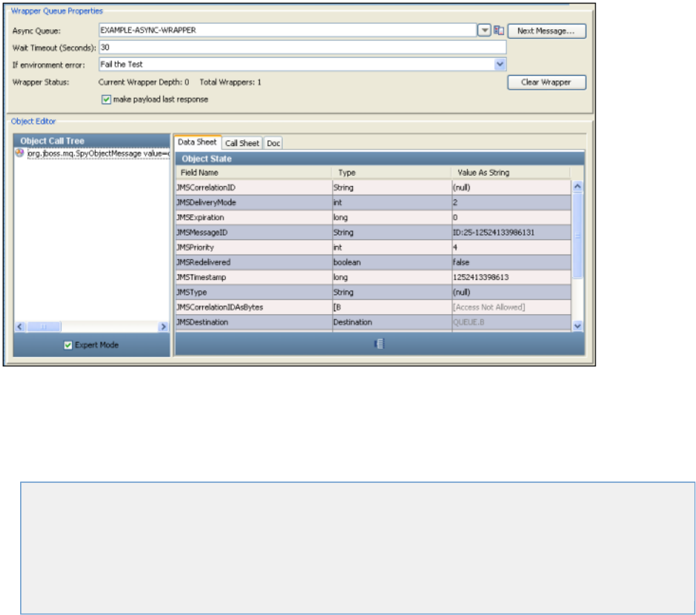
You are now ready to manipulate this object.
A wrapper is a FIFO list for holding responses from asynchronous topics and queues. It provides a place for the application to put responses for
later consumption. Messages wait in this list for subsequent LISA processing (in this Message Consumer step).
BEA Steps
The following steps are included in this chapter.
WebLogic JMS (JNDI)
Message Consumer
Read a File (Disk, URL, or Classpath)
Web Service Execution (XML)
Raw Soap Request
FTP Step
Web Service Execution (Legacy)
WebLogic JMS (JNDI)
The WebLogic JMS (JNDI) step lets you send messages to, and receive messages from, topics and queues. You can also receive, modify and
forward an existing message. WebLogic JMS (JNDI) supports all the common message types including Empty, Text, Object, Bytes, Message, and
Mapped (Extended).
The WebLogic JMS (JNDI) step is configured using a single editor regardless of the messaging requirements. Input options will vary on the
messaging requirements. The editor will only allow valid configurations, so when you enable certain features, others may become inactive.
Prerequisites: You are required to supply the necessary JAR files for your chosen configuration and connection.
WebLogic requires that the WebLogic JAR file ( ) be added to your classpath. You can put it in the hot deploy directory. There may beweblogic.jar
other JAR files required if you are using security or JMX. See the WebLogic documentation for more information about the JAR files you might
need. The JAR files can be found in the directory of the WebLogic installation.lib
Parameter Requirements: You need the connection parameters and the subject names used in the application under test. The following sections
describe the parameters that you will need. There may be other parameters required, depending on your environment. Get these from the
developers of the application.
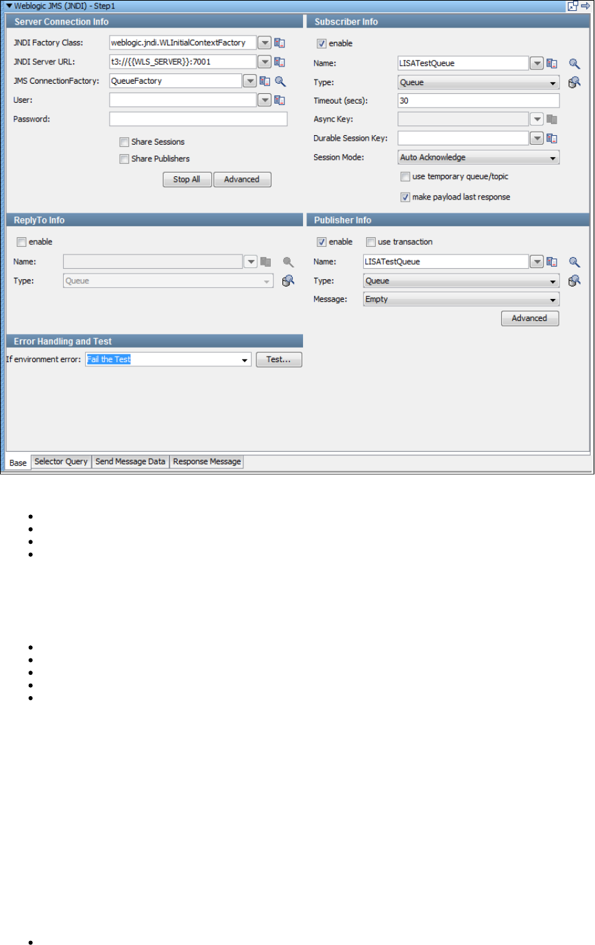
There are four tabs available at the bottom of the editor.
The is where you define your connection and messaging parameters.Base tab
The lets you specify a selector query to be run when listening for a message on a queue.Selector Query tab
The is where you create your message content.Send Message Data tab
The is where your response messages will be posted.Response Message tab
Base Tab
The Base tab view is divided into five major sections:
Server Connection Info
Subscriber Info
Publisher Info
ReplyTo Info
Error Handling and Test
The , , are always active. The and, sections can beServer Connection Info Error Handling and Test Publisher Info Subscriber Info ReplyTo Info
enabled or disabled using the enable check box in the top left corner of each section.
Using these check boxes you can configure the step to be a publish step, a subscribe step, or both. You can also choose to include a replyto
component in the step. When you have completely configured your test step, use the Test button in the Error Handling and Test section to test
your configuration settings.
Server Connection Info
Enter the JNDI information.
These values should be parameterized with properties that are in your configuration, making it easy to change the application under test. By
default the property in the JNDI Server URL is used. This property must be added to your configuration if you plan to use it.WLS_SERVER
The five parameters should be available to you for the system under test. The pull-down menus contain common examples or templates for these
values.
JNDI Factory Class: LISA pre-populates this field with the default values.
JNDI Server URL: LISA pre-populates this field with the default values.
JMS Connection Factory: Use the Search icon to browse available resources on the server. Select or type in a Connection Factory
per the JMS specification to use for this step execution.
User
Password
Share Sessions and : Use these check boxes to share JMS Sessions and Publishers throughout the test case. ThisShare Publishers
can lower overhead, but does not always provide a realistic simulation because typically JMS clients want to release resources. If you
check Share Publishers, the Share Sessions check box is also checked for you as you cannot share publishers without sharing sessions.
The button lets you stop any listeners at design time now. This is to resolve issues during test case creation where someStop All
listeners can get orphaned, but will still consume messages making it difficult or sometimes impossible to finish test case creation.
The button displays a panel where you can add custom properties that will be sent with the connection information.Advanced
Publisher Info
Select the check box to set up the ability to send (publish) messages. Click the check box to execute a commit when theenable use transaction
message is sent.
Enter the following parameters:
Name: The name of the topic or queue to use. Use the Search icon to browse the JNDI server for the topic or queue name.
Type: Select whether you are using a topic or queue. Use the Browse icon to the right of this field to see what messages are
waiting to be consumed from a queue (only).
Message: Select the type of message you are sending. The supported types are Empty, Text, Object, Bytes, Message, and Mapped
(Extended).
Advanced: Displays a panel where you can edit the message headers and add message properties.
Subscriber Info
Select the enable check box to set up to enable the ability to receive (subscribe to) messages.
Enter the following parameters:
Name: Enter the name of the topic or queue to use. Use the Search icon to browse the JNDI server for the topic or queue name.
Type: Select whether you are using a topic or queue, and whether you want to listen in synchronous or asynchronous mode. For
asynchronous mode you will also have to have an entry in the Async key field. Use the Browse icon to the right of this field to see
what messages are waiting to be consumed from a queue (only).
Timeout (secs): Enter the period to wait before the application interrupts waiting for a message (this field can be left blank for no
timeout).
Async Key: Enter the value needed to identify asynchronous messages. This is only needed in asynchronous mode. It will be used in a
subsequent Message Consumer step to retrieve asynchronous messages.
Durable Session key: By entering a name here you are requesting a durable session. You are also providing a key for that session. A
durable session lets you receive all of your messages from a topic even if you log off, and then log on again.
use transaction check box: Select the check box to execute a Commit when a message is received.use transaction
use temporary queue/topic check box: Select the check box if you want the JMS.provider to set up ause temporary queue/topic
temporary queue/topic on your behalf. When a temporary queue/topic is used, the JMS parameter of the message you send toReplyTo
the temporary queue/topic is automatically set. The temporary queue/topic feature must always be used with a publisher so that a reply
can be sent. If you use a temporary queue/topic the section is disabled.ReplyTo
make payload last response: Select this option if you want to make payload as the response of this step.
ReplyTo Info
Select the check box to set up a destination queue/topic.enable
If your application needs a destination, it is set up in this section.
Enter the following parameters:
Name: Enter the name of the topic or queue to use. Use the Search icon to browse the JNDI server for the topic or queue name.
Type: Select whether you are using a topic or queue. Use the Browse icon to the right of this field to see what messages are
waiting to be consumed from a queue (only).
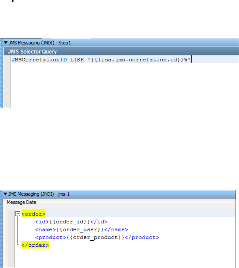
Error Handling and Test
Error Handling and Test lets you redirect to a step if an exception occurs.
If environment error: Select the step to redirect to if an error occurs.
Click the Test button to test your step configuration settings.
Selector Query Tab
You can enter a JMS selector query in this editor. The syntax closely follows SQL. It is a subset of SQL92. A JMS selector query can be specified
when listening for a message on a queue that is a response to a published message. The previous illustration shows a specific query looking for a
that matches one set in a LISA property as sent with the original message.JMSCorrelationID
There is a built-in mechanism for allowing a test creator to set the for a message before sending it. Any time before theJMSCorrelationID
message is sent you can set the correlation ID by setting the LISA property .lisa.jms.correlation.id
A non-zero value will be detected, and the message property will be set before the message is sent.JMSCorrelationID
Send Message Data Tab
If your step is configured to publish, this is where you compose your message. The Send Message Data tab view in the following example shows
a text message.
This particular example shows an XML fragment with LISA properties being used. The text can be typed in or it can be read from a file using the
Read Message from the File button in the bottom-right corner, or it can be stored in a LISA property, in which case you would just place the LISA
property in the editor: for example, .LISA_PROP
Notice that LISA properties are used in the message XML allowing the message to be created dynamically during the test run.
Response Message Tab
If your step is configured to subscribe, your response will be shown here. For more information, see .JMS Messaging (JNDI)
Message Consumer
For detailed information about this step, see .JMS Messaging - Message Consumer
Read a File (Disk, URL, or Classpath)

For detailed information about this step, see .Read a File (Disk, URL or Class Path)
Web Service Execution (XML)
For detailed information about this step, see .Web Service Execution (XML) Step
Raw Soap Request
For detailed information about this step, see .Web_ Raw SOAP Request
FTP Step
For detailed information about this step, see .External - FTP Step
Web Service Execution (Legacy)
For detailed information about this step, see .Web_Web Service Execution (Legacy)
Sun JCAPS Steps
The following steps are included in this chapter.
JCAPS Messaging (Native)
JCAPS Messaging (JNDI)
see Message Consumer
see Read a File (Disk, URL or Classpath)
see Web Service Execution (XML)
see Raw Soap Request
see SQL Database Execution (JDBC)
see FTP Step
see Web Service Execution (Legacy)
JCAPS Messaging (Native)
The JCAPS Messaging (Native) step lets you send messages to, and receive messages, from topics and queues. You can also receive, modify,
and forward an existing message.
JCAPS Messaging (Native) supports all the common message types including Empty, Text, Object, Bytes, Message, and Mapped (Extended).
The JCAPS Messaging (Native) step is configured using a single editor regardless of the messaging requirements. Input options will vary on the
messaging requirements. The editor will only allow valid configurations, so when you enable certain features others may become inactive.
Prerequisites: You are required to supply the necessary JAR files for your chosen configuration and connection.
JCAPS messaging requires that several JAR files be added to your CLASSPATH. You can put them in the hot deploy directory. Consult the
JCAPS documentation for more information about the JAR files you might need. The JAR files can be found in the lib directory of the JCAPS
installation.
Parameter Requirements: You need the connection parameters and the subject names used in the application under test. The following sections
describe the parameters that you will need. There may be other parameters required, depending on your environment. Get these from the
developers of the application.
The messaging step editor for JCAPS Messaging (Native) is used to configure this step.
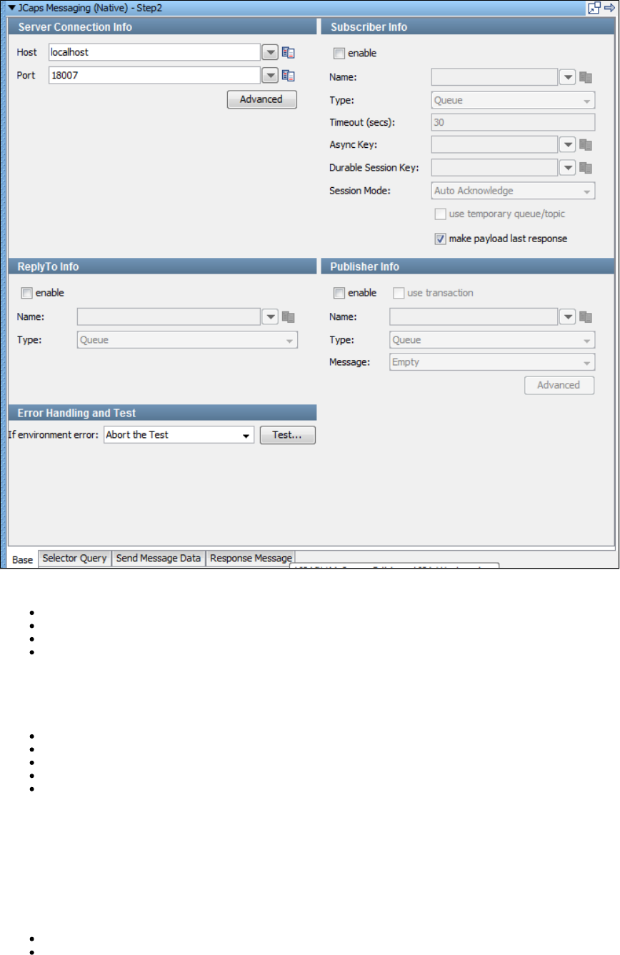
There are four tabs available at the bottom of the editor.
The Base tab is where you define your connection and messaging parameters.
The Selector Query tab lets you specify a selector query to be run when listening for a message on a queue.
The Send Message Data tab is where you create your message content.
The Response Message tab is where your response messages will be posted.
Base Information
The Base tab is divided into five major sections:
Server Connection Info
Subscriber Info
Publisher Info
ReplyTo Info
Error Handling and Test
The Server Connection Info and Error Handling and Test sections are always active. The Subscriber Info, Publisher Info, and, ReplyTo Info
sections can be enabled or disabled using the enable check box in the top left corner of each section. Using these check boxes you can configure
the step to be a publish step, a subscribe step, or both. You can also choose to include a replyto component in the step. When you have
completely configured your test step, use the Test button in the Error Handling and Test section to test your configuration settings.
Server Connection Info
The Server Connection Info section displays two parameters available to you for the system under test.
Host: The name of the JMS server.
Port: The port number the JMS server is running on.
The Advanced button displays a panel where you can add custom properties that will be sent with the connection information.

All other tabs are defined in detail in .JMS Messaging (JNDI)
JCAPS Messaging (JNDI)
The JCAPS Messaging (JNDI) step lets you send messages to, and receive messages from topics and queues. You can also receive, modify and
forward an existing message.
JCAPS Messaging (JNDI) supports all the common message types including Empty, Text, Object, Bytes, Message, and Mapped (Extended).
The JCAPS Messaging (JNDI) step is configured using a single LISA editor regardless the messaging requirements. Input options will vary on the
messaging requirements. The editor will only allow valid configurations, so when you enable certain features others may become inactive.
Prerequisites: You will be required to supply the necessary JAR files for your chosen configuration and connection. The com.stc.jms.stcjms.jar
is required.
JCAPS messaging requires that several additional JAR files be added to your classpath. You can put them in the hot deploy directory. See the
JCAPS documentation for more information about the JAR files you need. The JAR files can be found in the directory of the JCAPSlib
installation.
Parameter Requirements: You need the connection parameters and the subject names used in the application under test. There may be other
parameters required, depending on your environment. Get these from the developers of the application.
Detailed information about parameters and fields for JCAPS Messaging can be found in .JMS Messaging (JNDI)
Oracle Steps
The following steps are available in this chapter.
Oracle OC4J (JNDI)
Oracle AQ Steps
Oracle AQ (JMS)
Oracle AQ (JPUB)
see Message Consumer
see Read a File (Disk, URL or Class Path)
see Web Service Execution (XML)
see Raw Soap Request
see SQL Database Execution (JDBC)
see FTP Step
see Web Service Execution (Legacy)
Oracle OC4J (JNDI)
The Oracle OC4J (JNDI) step lets you send messages to, and receive messages from topics and queues. You can also receive, modify and
forward an existing message. Oracle OC4J (JNDI) supports all the common message types including Empty, Text, Object, Bytes, Message, and
Mapped (Extended).
The Oracle OC4J (JNDI) step is configured using a single LISA editor regardless the messaging requirements. Input options will vary on the
messaging requirements. The editor will only allow valid configurations, so when you enable certain features others may become inactive.
Prerequisites: You will be required to supply the necessary JAR files for your chosen configuration and connection.
OC4J messaging requires that the several JAR files be added to your classpath, including , , and . You can put dms.jar oc4j.jar oc4jclient.jar
them in the hot deploy directory. See the OC4J documentation for more information about the JAR files you might need. The JAR files can be
found in the lib directory of the OC4J installation.
Parameter Requirements: You need the connection parameters and the subject names used in the application under test. There may be other
parameters required, depending on your environment. Get these from the developers of the application.
LISA, by default uses the property in the JNDI Server URL. This property must be added to your configuration if you plan to use it.OC4J_SERVER
Detailed information about the parameters and fields for this step can be found in .JMS Messaging (JNDI)
Oracle AQ Steps
Oracle AQ is a messaging provider, like IBM WebSphere MQ, webMethods Broker, Tibco EMS, and others. It fits into LISA just like any of those
other messaging providers.
The Oracle AQ step can be added to the test case to allow sending messages, receiving messages, receiving messages asynchronously, or
some combination of those three.
In the case of AQ, there are two separate step types (JMS and JPUB). They have the same functionality but represent two different methods for
communicating with the Oracle AQ messaging provider.
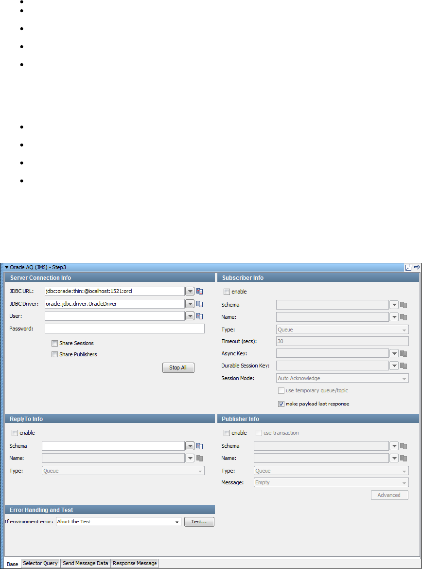
1.
2.
3.
Both Oracle AQ steps have the standard configuration sections for messaging steps.
A Connection section for configuring the connection information.
An optional Subscriber section for configuring the location from which the step should receive its message and the type of message it will
receive.
An optional Publisher section for configuring the location to which the step should send its message and the type of message it will send.
The contents of the message to send are configured in a separate tab.
When the step is executed in a test case, it will send one message and/or receive one message. It can be executed multiple times in a
loop in the same test case to send and/or receive multiple messages.
When the step is used as an asynchronous subscriber then it is only run once in a test case, and an additional Consumer step is run to
consume each message received from the provider.
There are two distinct ways to use AQ: JMS and JPUB.
JMS: Using the JMS library it works like any other normal JMS provider, with a few notable differences:
The JMS connection is not made through JNDI; it is made using a JDBC connection. It involves entering a JDBC URL, driver class name,
username, and password.
Queues and Topics are tied to schemas in the database. To send to or receive from a queue you need to give both the queue name and
queue schema.
Each Queue or Topic is restricted to a particular type of JMS Message. If a queue normally transports JMS Text Messages, then you
cannot use that same queue to transport JMS Object Messages, or JMS Byte Messages, for example.
Setting up JMS Queues and Topics in the Oracle DB involves running stored procedures.
Oracle AQ (JMS)
Oracle Advanced Queuing (AQ) is a messaging provider built into the Oracle database itself. It is used as the default JMS provider for many
Oracle products, such as Oracle Enterprise Service Bus.
One of the two ways to utilize AQ is JMS.
Using the JMS library, it works like any other normal JMS provider, with a few notable differences:
The JMS connection is not made through JNDI; it is made using a JDBC connection. It involves entering a JDBC URL, driver class name,
user name, and password. This information goes under Server Connection Info of the LISA Oracle AQ(JMS) step.
Queues and topics are tied to schemas in the database. To send to or receive from a queue, you need to give both the queue name and
queue schema.
Each queue or topic is restricted to a particular type of JMS Message. If a queue normally transports JMS Text Messages then you
cannot use that same queue to transport JMS Object Messages, or JMS Byte Messages, for example.

3.
There are four tabs available at the bottom of the editor.
The tab is where you define your connection and messaging parameters.Base
The tab lets you specify a selector query to be run when listening for a message on a queue.Selector Query
The tab is where you will create your message content.Send Message Data
The tab is where your response messages will be posted.Response Message
Base Information Tab
The Base tab view is shown in the previous example. It is divided into 5 major sections:
Server Connection Info.
Subscriber Info
Publisher Info
ReplyTo Info
Error Handling and Test
The Server Connection Info and Error Handling and Test sections are always active. The Subscriber Info, Publisher Info, and, ReplyTo Info
sections can be enabled or disabled using the enable check box in the top left corner of each section. Using these check boxes, you can
configure the step to publish a step, subscribe a step, or both. You can also choose to include a component in the step. When you havereplyto
completely configured your test step, use the Test button in the Error Handling and Test section to test your configuration settings
Server Connection Info
Here you enter the JDBC related information.
These values should be parameterized with properties that are in your configuration, making it easy to change the application under test.
LISA by default uses the oracle.jdbc.driver.OracleDriver in the JDBC Driver location.
The five parameters should be available to you for the system under test. The pull-down menus contain common examples or templates for these
values.
JDBC URL: LISA pre-populates this field with default values.
JDBC Server: LISA pre-populates this field with default values.
User: Enter the user name.
Password: Enter the password.
Share Sessions and Share Publishers check boxes are used to share JMS Sessions and Publishers throughout the test case. This can
lower overhead, but does not always provide a realistic simulation because typically JMS clients want to release resources. If you check
, the check box is also selected for you as you cannot share publishers without sharing sessions.Share Publishers Share Sessions
The Stop All button lets you stop any listeners at design time now. This is to resolve issues during test case creation where some
listeners can get orphaned, but will still consume messages making it difficult or sometimes impossible to finish test case creation.
Publisher Info
Select the enable check box to set up the ability to send (publish) messages.
Select the check box to execute a commit when the message is sent.use transaction
Enter the following parameters:
Schema: Enter the name of the schema to use.
Name: Enter the name of the topic or queue to use.
Type: Select whether you are using a topic or queue.
Message: Select the type of message you are sending from the pull-down menu. The supported messages are: Empty, Text, Object,
Bytes, Message, and Mapped (Extended).
Advanced button: Displays a panel where you can add custom message properties to be sent with the message.
Subscriber Info
Select the enable check box to set up to enable the ability to receive (subscribe to) messages.
Enter the following parameters:
Schema: Enter the name of the schema.
Name: Enter the name of the topic or queue to use.
Type: Select whether you are using a topic or queue, and whether you want to listen in synchronous or asynchronous mode. For
asynchronous mode you will also have to have an entry in the field. You can use the Browse icon, to the right of this field, toAsync key
see what messages are waiting to be consumed from a queue (only).
Timeout (secs): Enter the period to wait before LISA interrupts waiting for a message (this field can be left blank for no timeout).
Async Key: Enter the value needed to identify asynchronous messages. This is only needed in asynchronous mode. It will be used in a
subsequent Message Consumer step to retrieve asynchronous messages.
Durable Session key: By entering a name here you are requesting a durable session. You are also providing a key for that session. A

durable session lets you receive all of your messages from a topic even if you log off, and then log on again.
Session mode: Select the appropriate mode from the available options by clicking the drop-down menu. Options are: Auto Acknowledge,
Client Acknowledge, Use Transaction, Auto (Duplicates Okay).
ReplyTo Info
If your application needs a destination, it is set up in this section.
Select the enable check box to set up a destination queue/topic.
Enter the following parameters:
Schema: Enter the name of the schema to be used.
Name: Enter the name of the topic or queue to use.
Type: Select from the drop[ down, whether you want to use a topic or queue.
Error Handling and Test
Error Handling and Test section lets you redirect to a step if an error occurs.
If environment error: Select the step to redirect to if an error occurs.
Click the Test button to test your step configuration settings.
Selector Query Tab
TODO
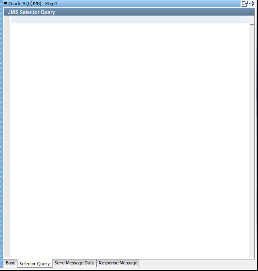
Send Message Data Tab
TODO
Response Message Tab
TODO
Oracle AQ (JPUB)
There are two distinct ways to utilize AQ; one is JMS, the other is JPUB.
Oracle AQ's JMS API is a layer built on top of a lower-level AQ API. This lower-level API is much more difficult to deal with; it acts almost nothing
like JMS.
The principal distinction is the message format. Low-level AQ messages contain a payload, which can be any type defined in the database. It
could be a varchar, or a clob, but usually it is a user-defined structured database type. Similar to AQ JMS Queues, each AQ low-level queue can
only handle one payload type.
Oracle provides a utility, named JPUB, that can generate Java objects that can deal with these user-defined structured types, in the same way
that Axis generates Java objects that utilize web services. Our low-level AQ step, named Oracle AQ JPUB, can automatically use this utility to
generate the client classes based on the queue information. The user then fills in their payload object using a standard COE.
There is no distinction between queues or topics. A client can either remove the next message from the AQ queue, making it essentially a queue,
or read the next message from the AQ queue without removing it, making it essentially a topic.
Setting up low-level AQ queues is again done through stored procedures. There is the possible additional step of creating your own user-defined
structured type in the database before creating an AQ queue around it. Technically, you can interact with AQ JMS queues using the low-level API.
The JMS queues simply have a specific payload type that's structured like a standard JMS message. However, you cannot use the AQ JMS API
to interact with low-level AQ queues, that is, those that do not use a JMS payload type.
To add an Oracle AQ (JPUB) step to a test case, click the step to open its editor:
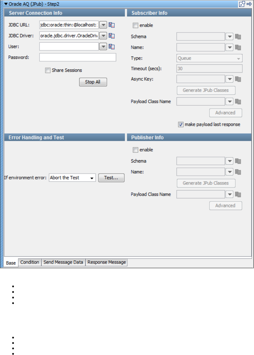
There are four tabs available at the bottom of the editor.
The tab is where you define your connection and messaging parameters.Base
The tab lets you specify a condition to be run.Condition
The tab is where you will create your message content.Send Message Data
The tab is where your response messages will be posted.Response Message
Base Information Tab
The Base tab view is the default view and is shown in the previous illustration. It is divided into four major sections:
Server Connection Info
Subscriber Info
Publisher Info
Error Handling and Test
The Server Connection Info and Error Handling and Test sections are always active. The Subscriber Info and Publisher Info sections can be
enabled or disabled using the enable check box in the top left corner of each section. Using these check boxes, you can configure the step to
publish a step, subscribe a step, or both.
When you have completely configured your test step, use the Test button in the Error Handling and Test section to test your configuration
settings.

Server Connection Info
These values should be parameterized with properties that are in your configuration, making it easy to change the application under test. By
default, the oracle.jdbc.driver.OracleDriver in the JDBC Driver location is used.
JDBC URL: This field is pre-populated with default values.
JDBC Server: This field is pre-populated with default values.
User: Enter the user name.
Password: Enter the password.
Share Sessions and Share Publishers check boxes: Used to share JMS Sessions and Publishers throughout the test case. This can
lower overhead, but does not always provide a realistic simulation because typically JMS clients want to release resources. If you check
Share Publishers, the Share Sessions check box is also selected for you as you cannot share publishers without sharing sessions.
The Stop All button lets you stop any listeners at design time now. This is to resolve issues during test case creation where some
listeners can get orphaned, but will still consume messages making it difficult or sometimes impossible to finish test case creation.
Publisher Info
Select the enable check box to set up the ability to send (publish) messages.
Enter the following parameters:
Schema: Enter the name of the schema to use.
Name: Enter the name of the topic or queue to use.
Generate JPub classes: Click to generate the JPub classes.
Payload Class Name: Enter the payload class name.
Advanced button: Click to open the Publisher Advanced dialog to enter or select the Correlation and click OK.
Subscriber Info
Select the enable check box to set up to enable the ability to receive (subscribe to) messages.
Enter the following parameters:
Schema: Enter the name of the schema.
Name: Enter the name of the topic or queue to use.
Type: Select whether you are using a topic or queue, and whether you want to listen in synchronous or asynchronous mode. For
asynchronous mode you will also have to have an entry in the Async key field.
Timeout (secs): Enter the period to wait before LISA interrupts waiting for a message. This field can be left blank for no timeout.
Async Key: Enter the value needed to identify asynchronous messages. This is only needed in asynchronous mode. It will be used in a
subsequent Message Consumer step to retrieve asynchronous messages.
Generate JPub classes: Click to generate the JPub classes.
Payload Class Name: Enter the Payload class name.
Advanced: Click to open the Subscriber Advanced dialog.
In the Advanced dialog, you can enter the Consumer Name, Correlation and Message ID.
Error Handling and Test
Error Handling and Test section lets you redirect to a step if an error occurs.
If environment error: Select the step to redirect to if an error occurs.
Click the Test button to test your step configuration settings.
Condition tab
Send Message Data tab
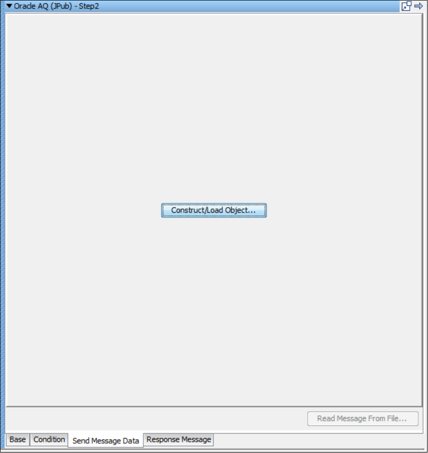
Response Message tab
TIBCO Steps
The following steps are available in this chapter.
TIBCO Rendezvous Messaging
TIBCO Direct JMS
TIBCO EMS Messaging
see Message Consumer
see Read a File (Disk, URL or Class Path)
see Web Service Execution (XML)
see Raw Soap Request
see SQL Database Execution (JDBC)
see FTP Step
see Web Service Execution (Legacy)
TIBCO Rendezvous Messaging
The TIBCO Rendezvous Messaging step lets you send messages to, and receive messages from, Rendezvous "Subjects" using Native
Rendezvous protocol. You can also receive, modify, and forward an existing message.
The TIBCO Rendezvous Messaging step is configured using a single editor regardless of the messaging requirements. Input options vary on the
messaging requirements. The editor will only allow valid configurations, so when you enable certain features others may become inactive.
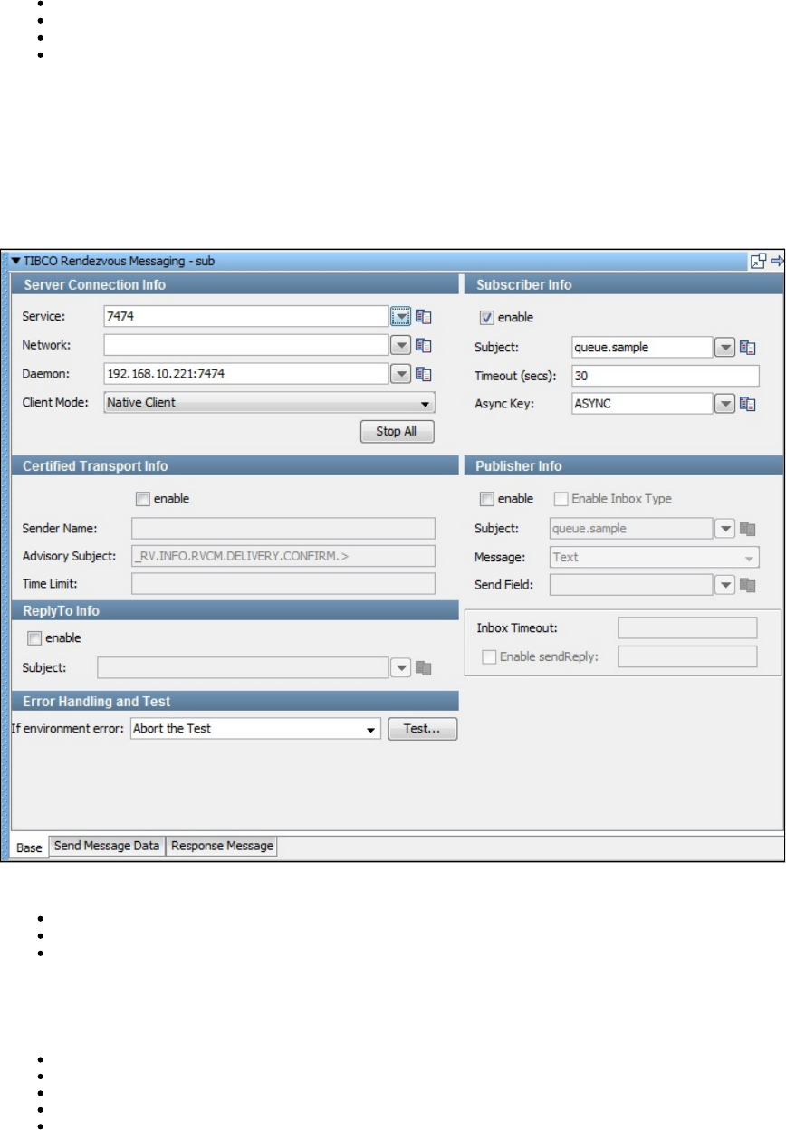
Prerequisites: You are required to supply the necessary JAR files for your chosen configuration and connection.
The TIBCO Rendezvous "bin" directory must be added to your PATH environment variable.
TIBCO Rendezvous requires that several TIBCO RV JAR files be in your classpath. The JAR files can be found in the directory of the TIBCOlib
installation:
tibjms.jar
tibjmsadmin.jar
tibjmsapps.jar
tibrvjms.jar
TIBCO classes require access to the system class loader, so it is suggested that you create a LISA_PRE_CLASSPATH environment variable in
your OS that lists the TIBCO RV JAR files.
TIBCO Rendezvous dll files are required. Copy all dll files from Rendezvous directory to the directory. Reference thehome\bin LISA\bin
location in your path environment.LISA\bin
Parameter Requirements: You need the connection parameters and the subject names used in the application under test. The following sections
describe the parameters that you will need. There may be other parameters required, depending on your environment. Get these from the
developers of the application.
There are three tabs available at the bottom of the editor:
Base tab: Where you define your connection and messaging parameters.
Send Message Data tab: Where you create your message content.
Response Message tab: Where your response messages will be posted.
Base Information (Base tab)
The Base tab is divided into six major sections:
Server Connection Info
Subscriber Info
Certified Transport Info
Publisher Info
ReplyTo Info
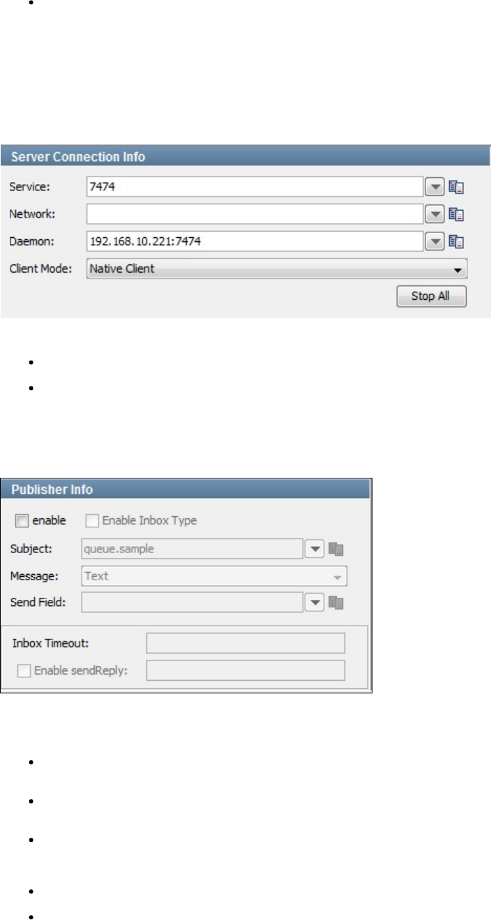
Error Handling and Test
The Server Connection Info and Error Handling and Test sections are always active. The Subscriber Info, Publisher Info, and, ReplyTo Info
sections can be enabled or disabled using the enable check box in the top left corner of each section. You can use these check boxes to
configure the step to be a publish step, a subscribe step, or both. You can also choose to include a replyto component in the step. When you have
completely configured your test step, use the Test button in the Error Handling and Test section to test your configuration settings.
Server Connection Info
Enter the connection information specific to Rendezvous information in the Server Connection Info area.
Four parameters are available to you for the system under test.
Service, Network, and Daemon: These are parameters to enable connection to the RV network you want to communicate on.
Client Mode: Choose between the Rendezvous Native client and Java Client mode. Usually you will want to use the more versatile client
mode.
These values should be parameterized with properties that are in your configuration, making it easy to change for a different system under test.
Publisher Info
Select the enable check box to set up the ability to send (publish) messages.
Enter the following parameters:
Subject: Enter the name of the subject to use. You can define your own subjects. A valid subject name is: . An invalidqueue.sample
subject name is: (null element) or (three null elements).queue…..My_Samples .My.Queue..
Message: Select the type of message you are sending from the pull-down menu. The supported messages are: Empty, Text, Object,
Bytes, Message, and Mapped (Extended).
Send Field: RV messages are actually maps of fields and values. This field is used to enable quick single field messages. When you
enter a value here the Send Message data is put into the value of a field with this name. This is overridden with Mapped (Extended) type
messages as they will let you do multiple fields and values in a single message.
Enable Inbox Type: Select the Enable Inbox Type check box to enable the Inbox timeout and Enable SendReply options.
Enable sendReply: Select the Enable Inbox Type to specify an Inbox Timeout or to enable sendReply functionality for the publisher.
Certified Transport Info
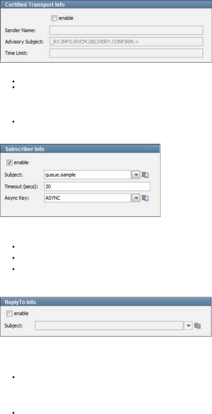
Select the check box to provide transport informationenable
Sender Name: The name that is the correspondent name of the CM transport.
Advisory Subject: Rendezvous software constructs the subject names of system advisory messages using this template:
. Rendezvous certified message delivery software constructs the subject names of advisory messages using_RV.class.SYSTEM.name
these templates: and Distributed queue _RV.class.RVCM.category.condition.subject _RV.class.RVCM.category.condition.name.
software constructs the subject names of advisory messages using this template: ._RV.class.RVCM.category.role.condition.name
Rendezvous fault tolerance software constructs the subject names of advisory messages using this template:
._RV.class.RVFT.name.group
Time Limit: Time limit in which a message will exist.
Subscriber Info
Selecting the box turns the subscriber function on. and lets you set up the ability to receive (subscribe to) messages.enable
Enter the following parameters:
Subject: Enter the name of the subject to use. You can define your own subjects.
Timeout (secs): Enter the period to wait before there is an interrupt waiting for a message (this field can be left blank for no timeout).
Async Key: Enter the value needed to identify asynchronous messages. This is only needed in asynchronous mode. It will be used in a
subsequent Message Consumer step to retrieve asynchronous messages.
ReplyTo Info
Select the enable check box to set up a destination subject.
If your application needs a destination, it is set up in this section.
Enter the following parameters:
Subject: Enter the name of the subject to use.
Error Handling and Test
Error Handling and Test lets you redirect to a step if an error occurs.
If environment error: Select the step to redirect to if an error occurs.
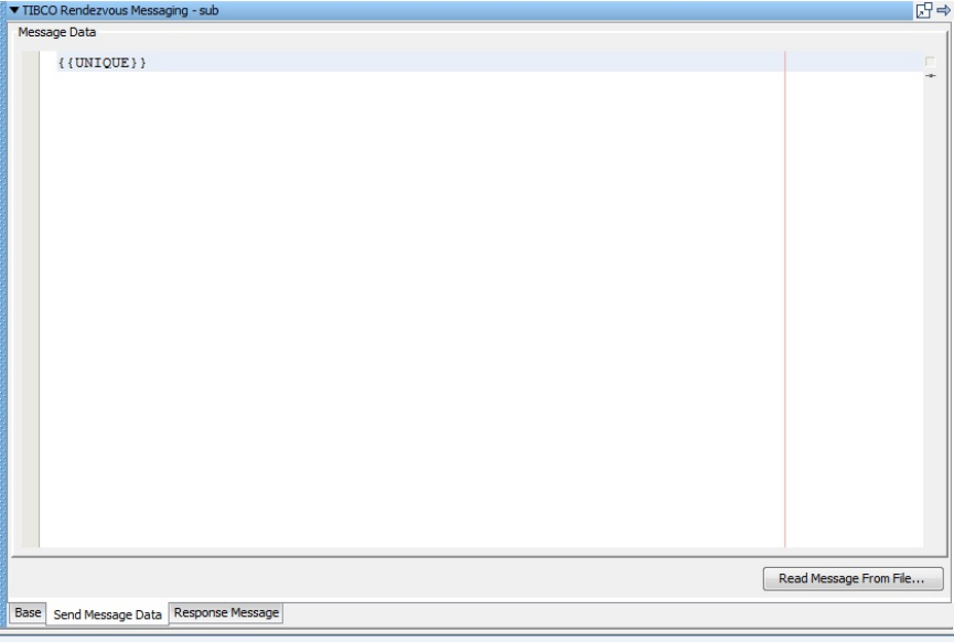
Click the Test button to test your step configuration settings.
Send Message Data
If your step is configured to publish, this is where you compose your message. The Send Message Data tab view in the following example shows
a text message.
This particular example shows an XML fragment with LISA properties being used. The text can be typed in or it can be read from a file using the
Read Message from the File button in the bottom right corner, or it can be stored in a LISA property, in which case you would place the property in
the editor: for example, .LISA_PROP
Notice that LISA properties are used in the message XML allowing the message to be created dynamically during the test run.
Response Message
If your step is configured to subscribe, your response will be shown. For more information, see JMS Messaging (JNDI).
TIBCO Direct JMS
The TIBCO Direct JMS step lets you send messages to, and receive messages from, topics and queues. You can also receive, modify, and
forward an existing message.
TIBCO Direct JMS supports all the common message types including Empty, Text, Object, Bytes, Message, and Mapped (Extended).
The TIBCO Direct JMS step is configured using a single editor regardless of the messaging requirements. Input options will vary on the
messaging requirements. The editor will only allow valid configurations, so when you enable certain features others may become inactive.
Prerequisites: You will be required to supply the necessary JAR files for your chosen configuration and connection.
TIBCO Direct JMS requires that several JAR files be added to your classpath. Check the TIBCO documentation for more information about the
JAR files you might need. These are typically found in the TIBCO install directory in for the product you are using. It is suggested to createlib
your LISA_PRE_CLASSPATH environment variable in your operating system and restart LISA. The TIBCO classes require access to the system
class loader.
Parameter Requirements: You need the connection parameters and the subject names used in the application under test. LISA, by default uses
the property in the JNDI Server URL. This property must be added to your configuration if you plan to use it. There may be otherTIBCO_SERVER
parameters required, depending on your environment. Get these from the developers of the application.
For more detailed information about parameters and fields, see .JMS Messaging (JNDI)
TIBCO EMS Messaging
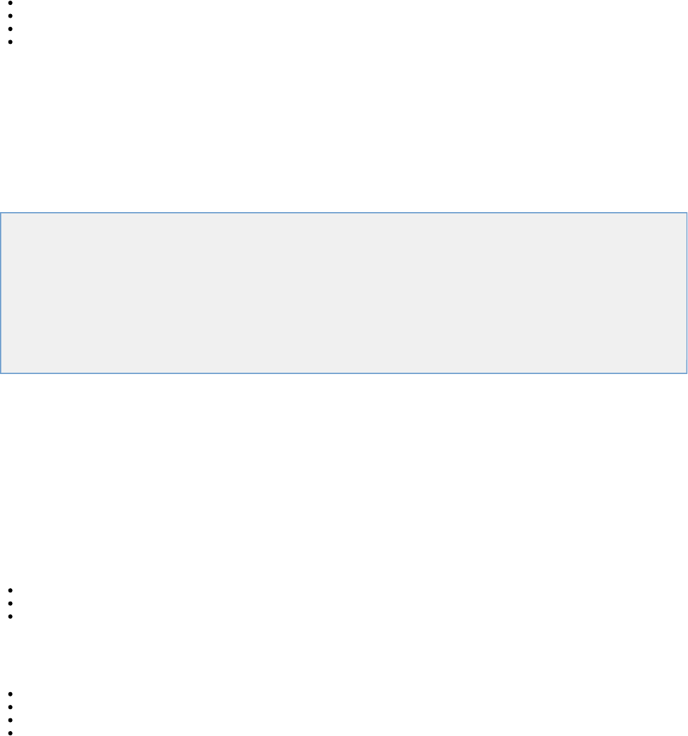
The TIBCO EMS Messaging step lets you send messages to, and receive messages from, topics and queues. You can also receive, modify, and
forward an existing message.
LISA supports all the common message types including Empty, Text, Object, Bytes, Message, and Mapped (Extended).
Prerequisites: You will be required to supply the necessary JAR files for your chosen configuration and connection.
The TIBCO Rendezvous bin directory must be added to your PATH environment variable.
TIBCO Rendezvous requires that several TIBCO RV JAR files be in your classpath. The JAR files can be found in the lib directory of the TIBCO
installation:
tibjms.jar
tibjmsadmin.jar
tibjmsapps.jar
tibrvjms.jar
TIBCO classes require access to the system class loader, so it is suggested that you create a LISA_PRE_CLASSPATH environment variable in
your OS that lists the TIBCO RV JAR files.
Parameter Requirements: You need the connection parameters and the subject names used in the application under test. The default is the
property in the JNDI Server URL. This property must be added to your configuration if you plan to use it. There may be otherTIBCO_SERVER
parameters required, depending on your environment. Get these from the developers of the application.
For more detailed information about parameters and fields, see JMS Messaging (JNDI)
Sonic Steps
The following steps are available in this chapter.
SonicMQ Messaging (Native)
SonicMQ Messaging (JNDI)
see Message Consumer
see Read a File (Disk, URL or Class Path)
see Web Service Execution (XML)
see Raw Soap Request
see SQL Database Execution (JDBC)
see FTP Step
see Web Service Execution (Legacy)
SonicMQ Messaging (Native)
The SonicMQ Messaging (Native) step lets you send messages to, and receive messages from, topics and queues, using native Sonic protocol.
You can also receive, modify, and forward an existing message.
SonicMQ Messaging (Native) supports all the common message types including Empty, Text, Object, Bytes, Message, and Mapped (Extended).
The SonicMQ Messaging (Native) step is configured using a single editor regardless of the messaging requirements. Input options will vary on the
messaging requirements. The editor will only allow valid configurations, so when you enable certain features others may become inactive.
Prerequisites: You will be required to supply the necessary JAR files for your chosen configuration and connection.
Sonic requires several JAR files to be added to your classpath. You can put them in the directory. The JAR files can be found in the libhotdeploy
directory of the Sonic installation:
mfcontext.jar
sonic_Client.jar
sonic_XA.jar
Parameter Requirements: You need the connection parameters and the subject names used in the application under test.
The four parameters should be available to you for the system under test.
Broker Host
Broker Port
User
Password
There may be other parameters required, depending on your environment. Get these from the developers of the application.
For more detailed information about parameters and fields, see JMS Messaging (JNDI)
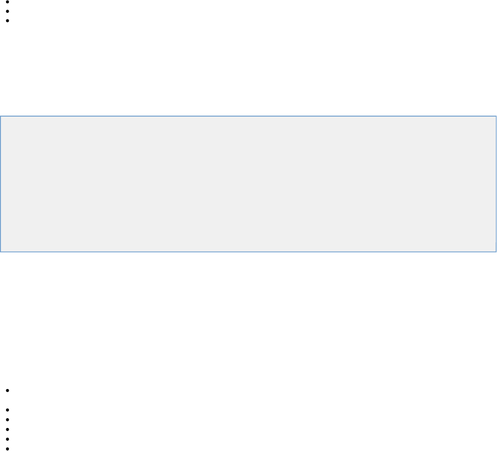
SonicMQ Messaging (JNDI)
SonicMQ Messaging (JNDI) supports all the common message types including Empty, Text, Object, Bytes, Message, and Mapped (Extended).
The SonicMQ Messaging (JNDI) step lets you send messages to, and receive messages from topics and queues. You can also receive, modify
and forward an existing message.
The SonicMQ Messaging (JNDI) step is configured using a single LISA editor regardless of the messaging requirements. Input options will vary
on the messaging requirements. The editor will only allow valid configurations, so when you enable certain features others may become inactive.
Prerequisites: You will be required to supply the necessary JAR files for your chosen configuration and connection.
Sonic requires several JAR files be added to your classpath. You can put them in the hot deploy directory. The JAR files can be found in the lib
directory of the Sonic installation:
Sonic_XA.jar
mfcontext.jar
sonic_Client.jar
Parameter Requirements: You need the connection parameters and the subject names used in the application under test. LISA, by default uses
the property in the JNDI Server URL. This property must be added to your configuration if you plan to use it. There may beSONICMQ_SERVER
other parameters required, depending on your environment. Get these from the developers of the application.
For more detailed information about parameters and fields, see .JMS Messaging (JNDI)
webMethods Steps
The following test steps are available in this chapter.
webMethods Broker
webMethods Integration Server Services
Message Consumer
Read a File (Disk, URL or Class Path)
Web Service Execution (XML)
HTTP_HTML Request
REST Step
Raw Soap Request
SQL Database Execution (JDBC)
FTP Step
Web Service Execution (Legacy)
webMethods Broker
webMethods Broker supports Mapped (Extended) messages that will create Broker Events.
The webMethods Broker step lets you send messages to, and receive messages from the Broker. You can also receive, modify and forward an
existing Broker Events/ Messages.
The webMethods Broker step is configured using a single LISA editor regardless of the messaging requirements. Input options will vary on the
messaging requirements. The step editor will only allow valid configurations, so when you enable certain features others may become inactive.
Prerequisites: You will be required to supply the necessary JAR files for your chosen configuration and connection. The webMethods Broker
requires that you put several JAR files in your classpath. The JAR files can be found in the directory of the webMethods installation.lib
For webMethods Integration Server 7.1 and later, installation_directory\common\lib\wm-isclient.jar
For Integration Server 7.0 and earlier, installation_directory\lib\client.jar
wm-enttoolkit.jar
wmbrokerclient.jar
wmjmsadmin.jar
wmjmsclient.jar
wmjmsnaming.jar
Parameter Requirements: You need the connection parameters and the subject names used in the application under test. The following sections
describe the parameters that you will need. There may be other parameters required, depending on your environment. Get these from the
developers of the application.
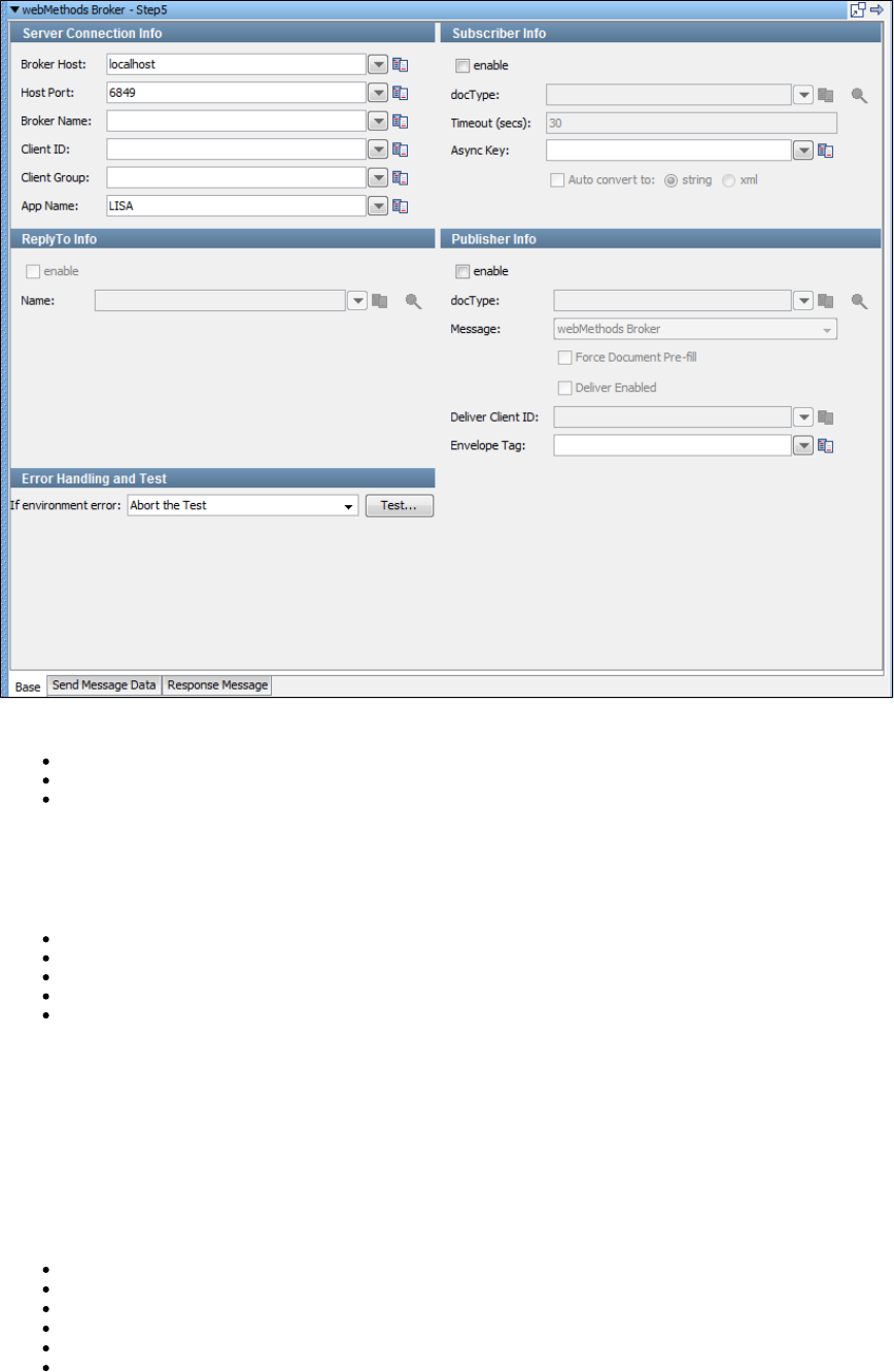
There are three tabs available at the bottom of the messaging step editor for webMethods Broker.
The tab is where you define your connection and messaging parameters.Base
The tab is where you will create your message content.Send Message Data
The tab is where your response messages will be posted.Response Message
Base Tab
The Base tab view is shown in the previous illustration. It is divided into five major sections:
Server Connection Info
Subscriber Info
Publisher Info
ReplyTo Info
Error Handling and Test
The Server Connection Info and Error Handling and Test sections are always active. The Subscriber Info, Publisher Info, and, ReplyTo Info
sections can be enabled or disabled using the enable check box in the top left corner of each section. Using these check boxes you can configure
the step to be a publish step, a subscribe step, or both. You can also include a component in the step. When you have completelyreplyto
configured your test step, use the Test button in the Error Handling and Test section to test your configuration settings.
Server Connection Info
In the Server Connection Info section, enter the connection information specific to webMethods Broker.
The four parameters must be available to you for the system under test.
Broker Host
Host Port
Broker Name
Client ID
Client Group: This is the Client group able to see the Broker destinations you wish to use.
App Name: Specify the application using the Broker here. This is an optional parameter and mostly used in server logs for debugging.
The default is "LISA". It is a good practice to do this, but if you must use something else for application logic you can.
We recommend that these values be parameterized with properties that are in your configuration, making it easy to change for a different system
under test.
Publisher Info
Check the enable check box to set up the ability to send (publish) messages.
Enter the following parameters:
docType: Enter the name of the docType to use.
Message: Select the type of message you are sending from the pull-down menu. The supported messages are: webMethods Broker,
Object, Message, and Mapped (Extended).
Force Document Pre-fill: The selected docType is inspected and ithe message with the required fields is pre-loaded. This check
box lets you have made modifications and decide you want any missing fields re-added. It will not write over existing fields with the same
name. This property is only a design time effect and does nothing at test run time.
Deliver Enabled: Select to enable the Deliver Client ID field.
Deliver Client ID: Broker's Client Identification for the connection. If the value is null, the broker generates an identifier automatically. An
error can be returned if the value is already in use by another connection.
Envelope Tag: This lets the user set the env.tag property on a broker event message.
Subscriber Info
Select the enable check box to set up to enable the ability to receive (subscribe to) messages.
Enter the following parameters:
docType: Enter the name of the docType to use.
Timeout (secs): Enter the period to wait before there is an interrupt waiting for a message (this field can be left blank for no timeout).
Async Key: Enter the value needed to identify asynchronous messages. This is only needed in asynchronous mode. It will be used in a
subsequent Message Consumer step to retrieve asynchronous messages.
Auto convert to: Enter to call the toString() function on the payload object to return its string representation; returns thestring xml
payload in XML format.
ReplyTo Info
Select the enable check box to set up a destination queue/topic.
If your application needs a destination, it is set up in this section.
Enter the following parameters:
Name: Enter the name of the topic or queue to use. The Search icon can be used to browse the JNDI server for the topic or queue
name.
Error Handling and Test
Error Handling and Test lets you redirect to a step if an error occurs.
If environment error: Select the step to redirect to if an error occurs.
Click the Test button to test your step configuration settings.
Send Message Data Tab
This particular example shows how to select an object for the message. The message is stored in a LISA property.
Response Message Tab
If your step is configured to subscribe, your response will be shown here. For more information see JMS Messaging (JNDI)
webMethods Integration Server Services
The webMethods Integration Server Services step lets you execute Integration Server services through the native Java APIs. This is done using
IData objects so it works with services not exposed through HTTP transports.
Prerequisites: You are required to supply the necessary JAR files for your chosen configuration and connection. See the list of JAR files in
.webMethods Broker
Parameter Requirements: You need the connection parameters and the subject names used in the application under test. The following sections
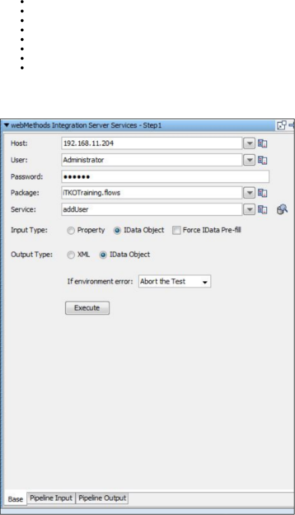
describe the parameters that you will need. There may be other parameters required, depending on your environment. Get these from the
developers of the application.
The messaging step editor for webMethods Integration Server Services has three tabs.
Base Tab: Server Connection Info
Enter the following parameters:
Host: The host name.
User: The userid.
Password: The password.
Package: The package the service is located in.
Service: The name of the actual service you want to call.
Input Type: Select type of input from , or .Property IData Object Force IData Pre-fill
Output Type: Select the Output type from or .XML IData Object
If environment error: Select the step to redirect to if an error occurs.
Click Execute to connect. You will see an object response. Export this object into a Java Execution Step to pull the payload or other properties
from the response, which is an IData object itself. This can easily be done by creating a new Java Step in LISA and loading from property
specifying the step name pattern for a last response. This is lisa.<stepName>.rsp.
Pipeline Input Tab
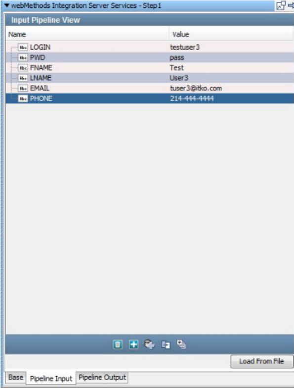
Pipeline Output Tab
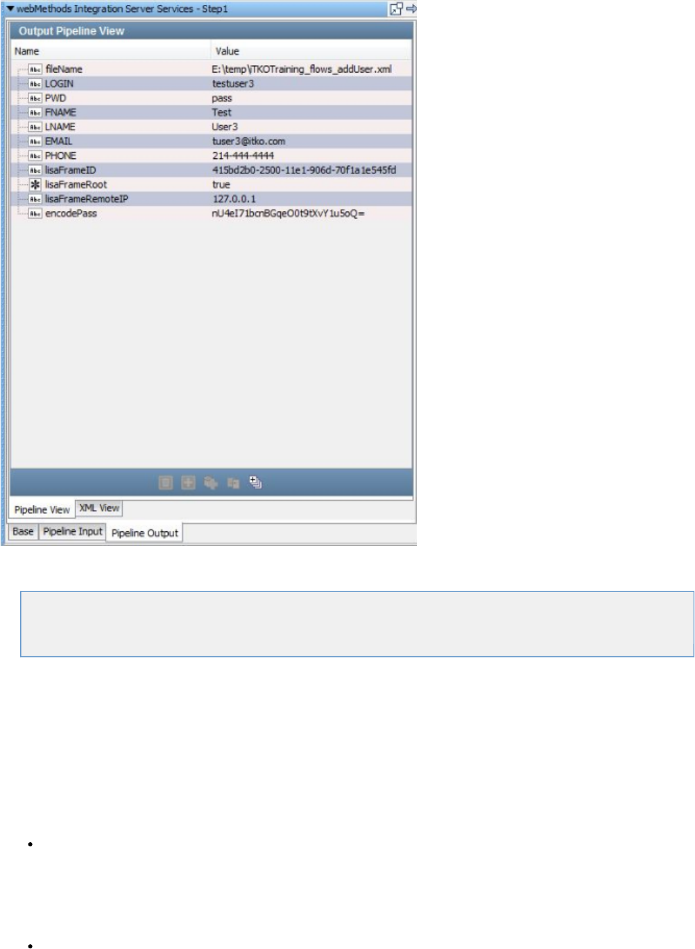
IBM Steps
The following steps are available in this chapter.
IBM WebSphere MQ
see Message Consumer
IBM WebSphere MQ
The IBM WebSphere MQ step lets you send messages to, and receive messages from, topics and queues. You can also receive, modify, and
forward an existing message.
IBM WebSphere MQ supports all the common message types including Empty, Text, Object, Bytes and Message and Mapped (Extended).
The IBM WebSphere MQ step is configured using a single editor regardless of the messaging requirements. Input options will vary on the
messaging requirements. The editor will only allow valid configurations, so when you enable certain features others may become inactive.
Prerequisites: To use WebSphere MQ, you must add several IBM JMS JAR files to the folder (or put them on the classpathLISA_HOME/lib
some other way). The JAR files you need are:
WebSphere MQ Release 5.2:
com.ibm.mqjms.jar
com.ibm.mqbind.jar
com.ibm.mq.pcf.jar
com.ibm.mq.jar
connector.jar
WebSphere MQ Release 6:
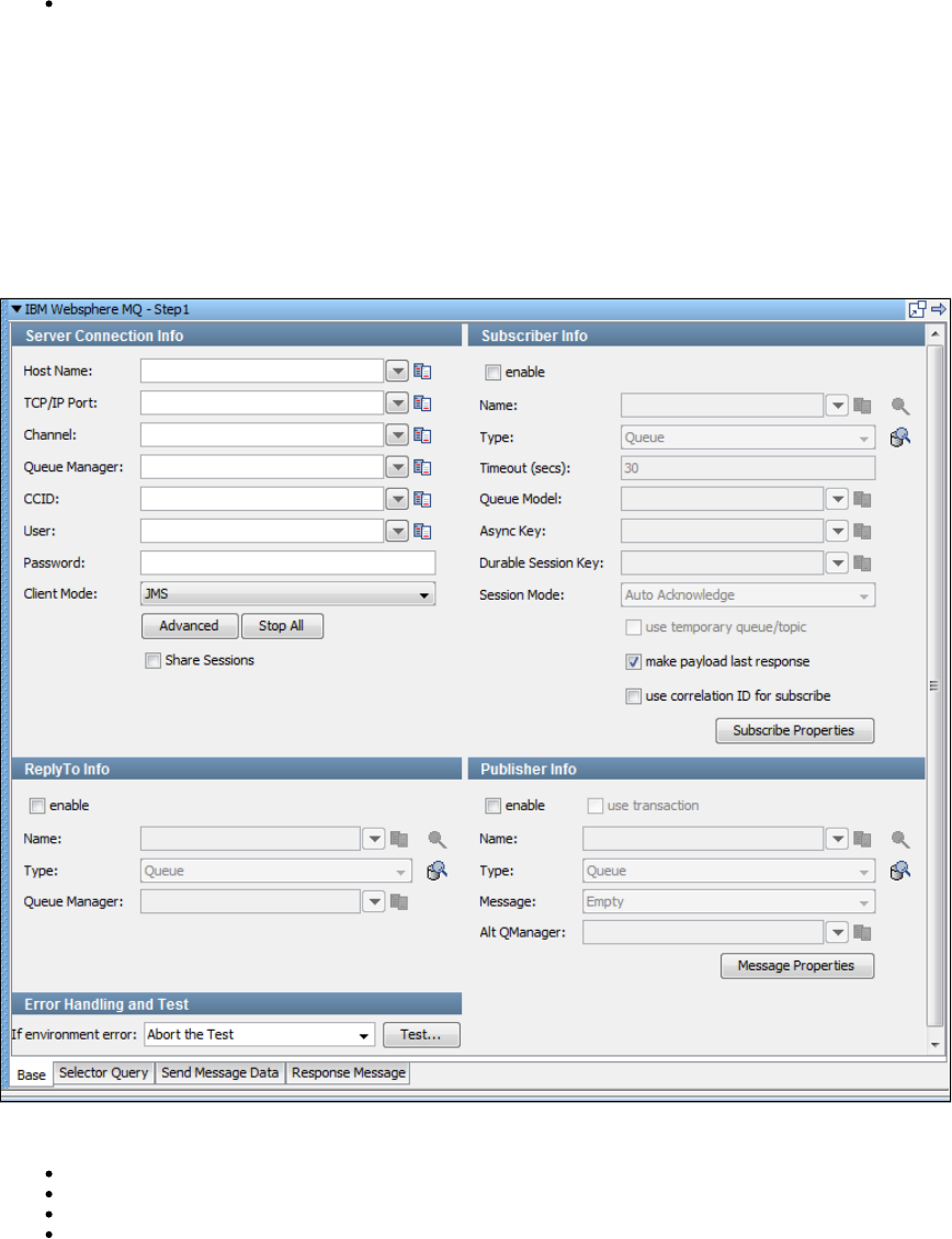
com.ibm.mq.jar
com.ibm.mq.pcf.jar
com.ibm.mqjms.jar
connector.jar
dhbcore.jar
WebSphere MQ Release 7:
com.ibm.mq.commonservices.jar
com.ibm.mq.headers.jar
com.ibm.mq.jar
com.ibm.mq.jmqi.jar
com.ibm.mq.pcf.jar
com.ibm.mqjms.jar
connector.jar
dhbcore.jar
These can be found in your WebSphere MQ installation.
Parameter Requirements: You must have the connection parameters for your system under test. The following sections describe the parameters
that you will need.
The following tabs are available at the bottom of the messaging step editor for WebSphere MQ:
The tab is where you define your connection and messaging parameters.Base
The tab lets you specify a selector query to be run when listening for a message on a queue.Selector Query
The tab is where you create your message content.Send Message Data
The tab is where your response messages will be posted.Response Message
Base Information (Base tab)
The Base tab view is shown in the previous example. It is divided into five major sections: Server Connection Info, Subscriber Info, Publisher Info,
ReplyTo Info, and Error Handling and Test.
The Server Connection Info and Error Handling and Test sections are always active.
The Subscriber Info, Publisher Info, and, ReplyTo Info sections can be enabled or disabled using the enable check box in the top left corner of
each section. Using these check boxes, you can configure the step to be a publish step, a subscribe step, or both. You can also choose to include
a replyto component in the step. When you have completely configured your test step, use the Test button in the Error Handling and Test section
to test your configuration settings.
Server Connection Info
To connect to WebSphere MQ, enter the following information:
Host Name
TCP/IP Port
Channel: Familiar to WebSphere MQ users, a connection property that is used for routing and management in the message bus.
Queue Manager: Familiar to WebSphere MQ users, a connection property that is used for routing and management.
CCID: Optional for connections and will only apply if character transformation needs to occur between the client (LISA) and server.
User
Password
Client Mode: Lets you select how you want to interact with the WebSphere MQ server.
JMS: A pure Java implementation based on the JMS specification. We recommend you use the JMS Transport Protocol instead
of MQ if you want this implementation.
Native Client: A pure Java implementation using IBM-specific APIs.
Bindings: Requires access to the native libraries from a WebSphere MQ client installation. You must make sure these libraries
are accessible by the LISA application runtime. In most cases, having these available in the PATH environment will work.
Share Sessions: Select to specify sharing everything in MQ Native Mode, including the connection.
Publisher Info
Check the enable check box to set up the ability to send (publish) messages. Click the check box to execute a commit when theuse transaction
message is sent.
Enter the following parameters:
Name: Enter the name of the topic or queue to use. Use the Search icon to browse the JNDI server for the topic or queue name.
Type: Select whether you are using a topic or queue. Use the Browse icon to the right of this field to see what messages are
waiting to be consumed from a queue (only).
Message: Select the type of message you are sending from the pull-down menu. Supported messages are: Empty, Text, Object, Bytes,
Message, and Mapped (Extended).
Alt Qmanager: TODO
Subscriber Info
Enable: Select the enable check box to set up to enable the ability to receive (subscribe to) messages.
Enter the following parameters:
Name: Enter the name of the topic or queue to use. Use the Search icon to browse the JNDI server for the topic or queue name.
Type: Select whether you are using a topic or queue, and whether you want to listen in synchronous or asynchronous mode. For
asynchronous mode you also must have an entry in the Async key field. Use the Browse icon to the right of this field to see what
messages are waiting to be consumed from a queue (only).
Timeout (secs): Enter the period to wait before LISA interrupts waiting for a message (this field can be left blank for no timeout).
Queue Model: This is required by MQ to create temporary destinations. It is configured on the MQ server. It is only active when use
temporary queue/topic is checked. In this case the ReplyTo Info section is disabled.
Async Key: Enter the value needed to identify asynchronous messages. This is only needed in asynchronous mode. It will be used in a
subsequent Message Consumer step to retrieve asynchronous messages.
Durable Session Key: By entering a name here you are requesting a durable session. You are also providing a key for that session. A
durable session lets you receive all your messages from a topic even if you log out, and then log in again.
Session Mode: Using the drop-down list, select from:
Auto Acknowledge: TODO
Client Acknowldge: TODO
Use Transaction: To execute a Commit when a message is received.
Auto (Duplicates Okay): TODO
use temporary queue/topic check box: Click the use temporary queue/topic check box if you want the JMS.provider to set up a
temporary queue/topic on your behalf. When a temporary queue/topic is used, the JMS ReplyTo parameter of the message you send to
the temporary queue/topic is automatically set. The temporary queue/topic feature must always be used with a publisher so that a reply
can be sent. If you use a temporary queue/topic the ReplyTo section is disabled.
make payload last response: Check this option if you want to make payload as the last response.
use correlation ID for subscribe: TODO.
ReplyTo Info
Select the enable check box to set up a destination queue/topic.
If your application needs a destination, it is set up in this section.
Enter the following parameters:
Name: Enter the name of the topic or queue to use. Use the Search icon to browse the JNDI server for the topic or queue name.
Type: Select whether you are using a topic or queue. Use the Browse icon to the right of this field to see what messages are
waiting to be consumed from a queue (only).
Queue Manager: allows the replyTo to be on a different Queue Manager than the Publisher (in this step).
Error Handling and Test
Error Handling and Test lets you redirect to a step if an error occurs.
If environment error: Select the step to redirect to if an error occurs.
Click the Test button to test your step configuration settings.
The other tabs contain fields and parameters that are thoroughly documented in .JMS Messaging (JNDI)
Virtual Service Environment Steps
The Virtual Service Environment test steps are available in the .Virtualize Guide
Virtual Service Router Step
Virtual Service Tracker Step
Virtual Conversational_Stateless Response Selector Step
Virtual HTTP_S Listener
Virtual HTTP_S Live Invocation Step
Virtual HTTP_S Responder Step
Virtual JDBC Listener Step
Virtual JDBC Responder Step
Socket Server Emulator Step
Messaging Virtualization Marker Step
Compare Strings for Response Lookup Step
Compare Strings for Next Step Lookup Step
Virtual Java Listener Step
Virtual Java Live Invocation Step
Virtual Java Responder Step
Virtual TCP_IP Listener
Virtual TCP_IP Responder
Custom Extension Steps
The following steps are available in this chapter.
Custom Test Step Execution
Java Script Step
Pathfinder Agent Script Step
Swing Test Step
Create a Virtual Web Service
Custom Test Step Execution
The Custom Test Step executes a test step custom written by your team using the LISA SDK. This step is documented in the Developer's Guide
.(SDK)
Java Script Step
The Java Script step gives you the flexibility of writing and executing a Java script to perform some function or procedure. Your script is executed
using the BeanShell interpreter. You have access to all the LISA properties in the test case, including built-in objects.
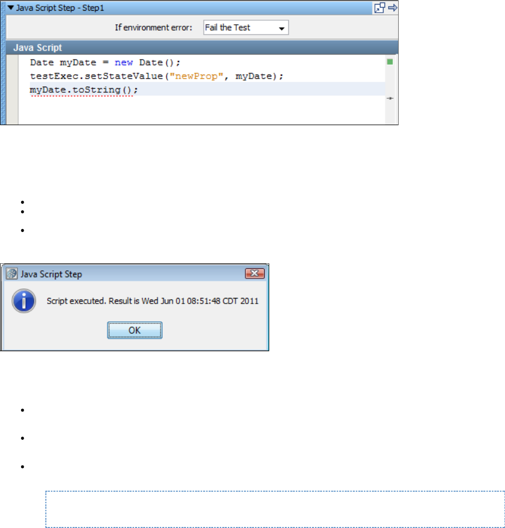
Prerequisites: Some knowledge of BeanShell. For more information on BeanShell, see .http://www.beanshell.org/
This is the script editor where you write your scripts. Double-clicking on an item in the list will paste that variable name into the editor. The last
value exposed in the script will be saved as the response of this step.
Click the Test button to test your script. You will see the result from executing the script, or an error message describing the error that occurred.
The example in the preceding illustration shows that:
A new Date object was created, initialized to the current date and time.
This object was stored in a new LISA property, , using one of LISA's exposed objects, . For more information, see the myprop testExec
.LISA Developer's Guide
The toString() value of the Date object was set as the response of the step.
On testing this script, the following screen is displayed.
LISA property name syntax is very flexible and can include spaces. Property names that are not valid Java identifiers are converted for use in this
step. Invalid characters are automatically replaced by an underscore (_).
Some things to remember:
If you use LISA properties in a script, it will be substituted for the actual value of the property at run time before{{{}exampleprop}}
the script is executed.
If you need to get access to a property that has a "." in the name, LISA imports these into the script environment replacing "." with "_". So
{{{ in a script is the same as foo_bar.}foo.bar}}
You can produce a LISA log event very easily inside a script step or assertion. There is a object that is very useful. To producetestExec
a LISA log event, you can code
testExec.log("Got here");
as opposed to using the log4j logger. The object causes an actual LISA event to be raised and you can see it in the ITR.testExec.log()
Pathfinder Agent Script Step
The Pathfinder Agent Script step is exactly the same as the , but instead of executing the supplied code inside of LISAJava Script Step
Workstation (or Simulators), it executes inside the JVM where the specified agent is installed.
The following window is the script editor.
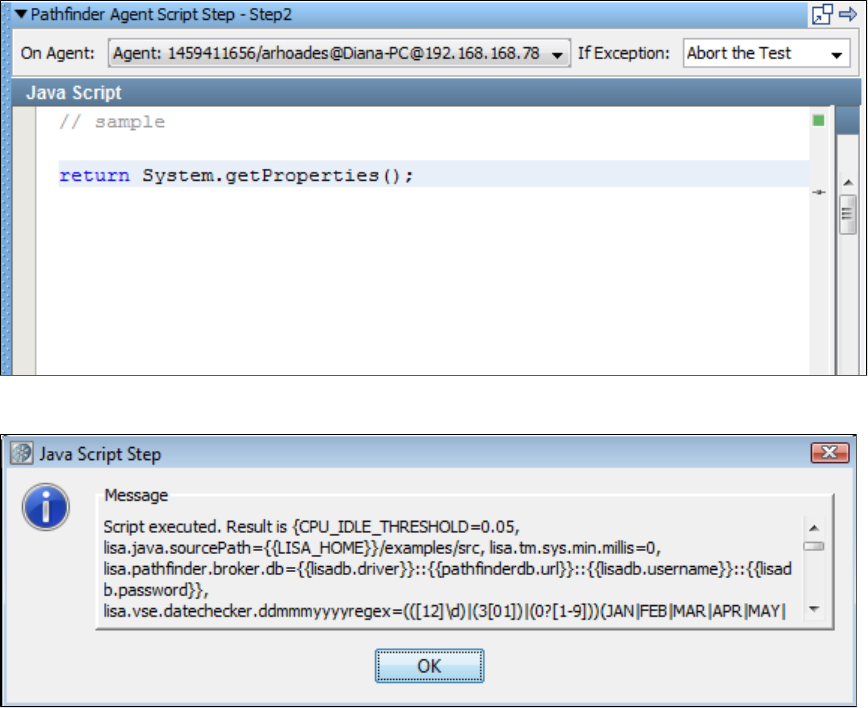
Click Test to execute the script.
Successful execution shows a completion message.
This step is used in .EJB baseline test cases
Swing Test Step
The Swing step lets LISA listen to mouse and keystrokes on a Java Swing application, record them and play them back.
To do this, LISA attaches to the AWT listener of the recorded application; the main class and JAR files for the application are required. The Swing
recorder will remotely launch the application and listen to the AWT events and then send the events back to LISA for recording. After recording is
completed the AWT events are played back to the application just as if the keyboard and mouse were being used.
A component browser is provided to look at the Java objects in the application and find information about the running object. From LISA every
property and method provided by the object can be run, filtered and then asserted on. Assertions are created by attaching to the Swing Java
object and running methods against it; for example, if a radio button isEnabled or isChecked can be validated.
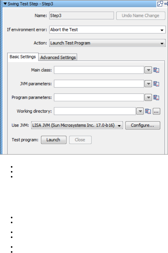
The top panel of the Swing Test Step Editor contains:
Name: Enter the fame of the test step.
If Environment Error: Select the necessary step in case of an error, from the drop-down options.
Action: Select the necessary step to be taken from the drop-down options. is created by LISA when recording mouseMouse Input
movements from the AWT listener. is created by LISA when keys are pressed and recorded from the AWT listener. Key Input Invoke
are used to attach to components (buttons, text, frames, and so on) and run methods on them.Component Methods
The Swing Test Step Editor has two tabs: Basic Settings and Advanced Settings. By default it opens in the Basic settings tab.
Basic Settings Tab
Main Class: Contains the class name with the Java main method.
JVM parameters: Any parameter to be sent to the JVM is entered here. The --classpath parameter contains all the .jar files to run the
applications. If the application jars are in the hot deploy directory, this does not need to be set.
Program parameters: Set any arguments that the application is expecting.
Working directory: Points to the directory in which the application to be tested is installed. When the application is started, it is started
from this directory.
Use JVM: This will default to the JVM that LISA is running. An alternate JVM can be specified if the application requires a different JVM.
Test program: Click the Launch button to open the application. The Close button closes the application.
Advanced Settings Tab
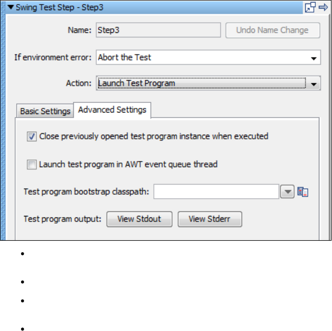
Close previously opened test program instances when executed: Close any open applications and open a new one when playing
back the steps recorded from the application. This makes sure the application always starts at the beginning of where the test case was
recorded and prevents duplicate applications from being run.
Launch test program in AWT event queue thread: The location of the AWT listener, so it can be attached to. If the Java application
does not record in LISA, clear this box and LISA will try attaching to the AWT listener in the main of the program.
Test program bootstrap classpath: This can be set for the application being tested. Only use the bootstrap if the application is getting
errors when loading classes. The classes will need to be moved from the classpath (-classpath "myjar.jar" or LISA hot deploy) to the
bootstrap.
Test program output: This allows for viewing of the Java application messages that are sent to Stdout (standard out) and Stderr
(standard error) from the launched application.
Mouse Input
A Mouse Input step is created when recording a Swing application.
The information about which button, any extra keys complementing the click and the location is recorded. The component that was clicked on is
listed in the Component window.
Pressing the Select button will navigate the component browser to the object that was clicked. When a mouse click is played back, the component
is found and the mouse is clicked in the middle of the component. This enables LISA to be tolerant to changes in a Swing User Interface.
Key Input
Key Input is recorded by LISA when a keystroke is done on the keyboard.
The recording can be an action like ALT + TAB to change between windows of the application or the typing of letters into a field. When a single
letter is typed, the Key pressed, Key typed, and Key released steps are recorded to correspond to all actions. The component that the key action
was taken on is listed and can be viewed in the component browser by pressing the Select button.
Invoke Component Methods
The Invoke Component Methods action is added by the tester when a component is available in the running application and methods of the
component are to be run. For example, if there is a frame in the application and the title of the frame is wanted. To do this, Invoke Component
Methods action is inserted into the workflow, the component is selected and the method of getTitle is available.
Component browser shows the active components of a Java application. The application must be launched from the Launch program step so that
the component browser can attach to it. If the Component Browser does not navigate to the component, verify there is not an asterisk next to the
title *Component Tree, indicating a refresh of the tree is required. The other reason a component will not show up could be that the application
has not been launched and the component is not available in the application; for example, it could be on a folder tab that is not visible.
When the Select button is pressed, the component is sent back to the LISA step with information about the object. The data sheet contains
information about the object. The call sheet will let you run methods on the object like getTitle().
Assertions can now be done on the results of the method calls just like any other object in LISA.
Create a Virtual Web Service
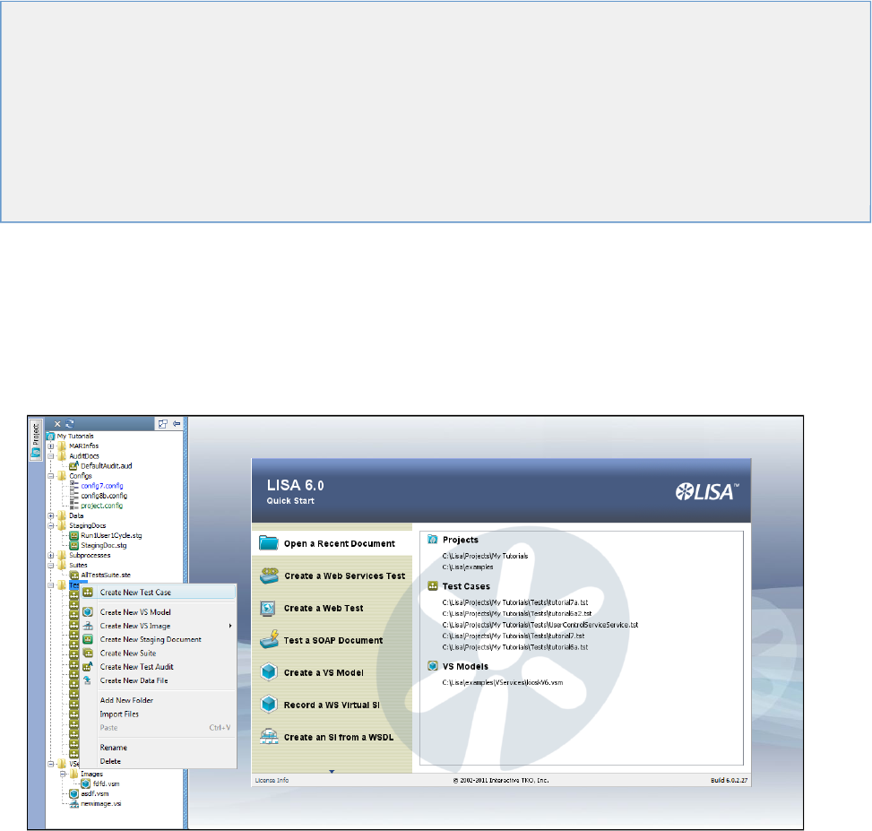
1.
2.
1.
2.
The Create Virtual Web Service test step has been deprecated in favor of VSE and Virtual Service from WSDL.
For more information, see .this tech note
Creating Test Cases
A test case is a complete specification of how to test a business component in the "system under test," or in some cases the complete "system
under test".
A test case is persisted as an XML document, and contains all the information needed to test the given component or system. Test cases are
created and maintained in LISA Workstation.
The first step in creating a LISA test case is to . Within this project, you can create single or multiple test cases.create a LISA project
The following topics are available in this chapter.
Creating a Test Case
Opening a Test Case
Saving a Test Case
Test Cases in Model Editor
Adding Test Steps
Configuring the Next Step
Branching and Looping in a Test Case
Importing Test Cases
Response (.rsp) Documents
Test Case Toolbar
Creating a Test Case
You can create a test case by opening a project or .creating a new project
For example, if you open the default project "examples" within LISA, it opens with a tree structure that has folders for Configs, Data, Staging Doc,
Suites, Tests, and others.
To create a test case
In the Project tree, right-click the Tests folder and click Create New Test Case.
In the dialog window, browse to the directory where you plan to store the test case and enter the name of the new test case.
See for more information.Test Cases in Model Editor
Opening a Test Case
To open or view an existing test case
From the main menu, select File > Open > Test Case.
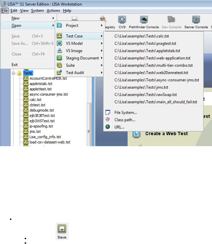
2. The recently-opened test cases are displayed. The test cases are listed in order of use; the most recently-opened is at the top of the list.
If the target test case is in the list, select it. If it is not, then browse to it by clicking File System, Class path or URL.
3. Select the file you want to open, and click Open. The selected test case will be opened and displayed in the model editor. You can also open
an existing test case by double-clicking on it from the project panel.
4. You are now ready to add new elements (filters, assertions), or modify the existing elements in the test case.
Saving a Test Case
When you save a test case, LISA also saves the results of each step in the test case to a Response document, with a suffix of ".rsp" in the same
directory. For more information, see .Response Documents
If a test step element, filter, assertion, or data set has a required field and that field is not filled in, then you cannot save the test case.
To save a test case
Do one of the following:
Click the Save icon on the toolbar.
From the main menu, select File > Save (Sample). LISA displays the original test case name for you.
Test Cases in Model Editor
Test Cases in Model Editor
When you open a test case in LISA, its graphical user interface shows a model editor, which is used to create and manage test cases.
When you open an already existing test case, the view in the Model Editor provides a graphical view of the test case, with all the test steps and
elements attached to it. For sample examples, you can open the test cases in the %LISA_HOME%/examples directory.
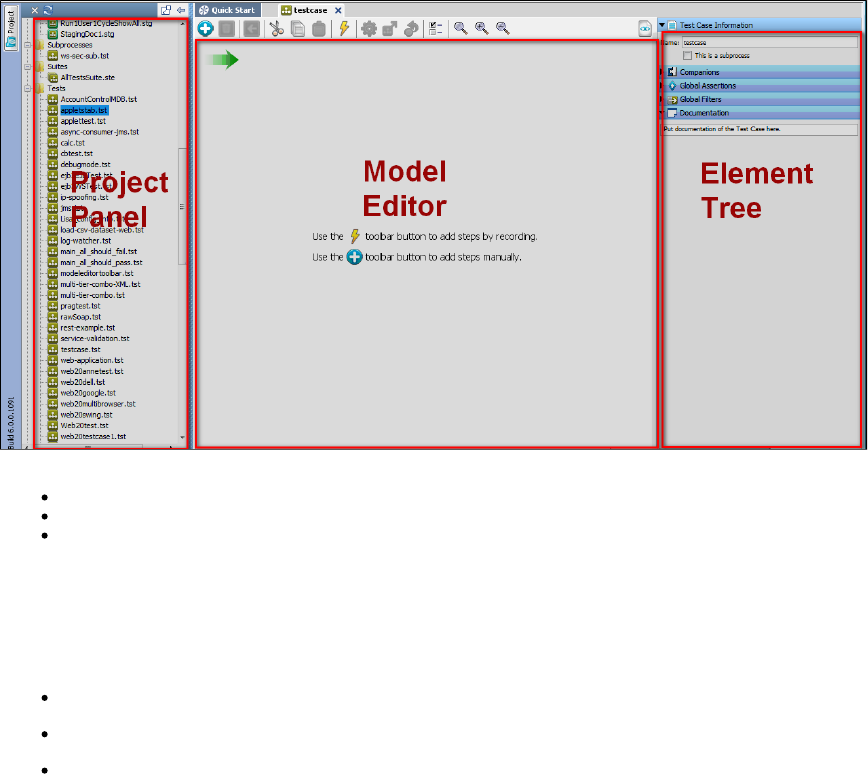
1.
2.
The model editor has three sections:
Project Panel: To create a project and under which you create, view, edit test cases or other LISA documents.
Model Editor: To add, edit, delete the test steps created for a test case.
Element Tree: To apply filters, assertions, data sets, companions to a test case or test step.
Adding Test Steps
Steps can be added in several ways.
To add a test step
From the main menu, select Commands > Create a New Step
From the Test Case toolbar, click the Add Step icon
In the workflow, right-click a step and click Add Step After. This adds a new step right after/below that step.
When a step is inserted into an existing workflow, and workflow is linear, the steps on either side of the inserted step will be updated
automatically, keeping the workflow linear.
If the workflow contains branches or loops, the next step will not be set automatically.
Configuring the Next Step
To configure the Next step within the model editor
Select the target test step and right-click to open a menu. In the following example, the Add User step was selected.
Click For next step and select the target next step.
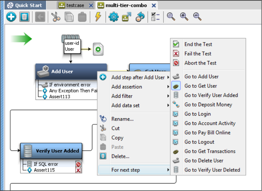
2.
1.
Reordering Test Steps Within a Test Case
To recorder the steps within the model editor
Select a step and right-click to reorder in a workflow.
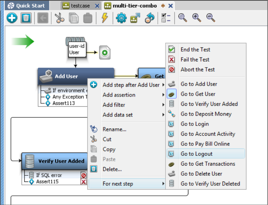
1.
2.
3. For the previous example, select the Add User step and right-click to open a new menu.
Click For next step and select the step to set as the next step.,
You can also drag and drop in the steps within the model editor. All the steps will be updated automatically if the workflow is linear. When the
workflow is non-linear, which means it contains branches and loops, the next steps will not be updated. In non-linear workflows the next step can
be updated in the Step Information tab of that step.
Branching and Looping in a Test Case
Branching in a Test Case
Branching in a test case is done using assertions.
Any number of assertions can be applied to a test step. Every assertion has a condition that evaluates to true or false. The first assertion for which
the assertion condition is satisfied gets fired, and that changes the path of the workflow. In many steps, a default error condition is automatically
created as an assertion to failure. When creating assertions, it is best to be consistent, and always branch positive, or always negative.
Assertions are described in detail in .Adding an Assertion
Looping in a Test Case
Loops are created when a test step down the flow from a given test step sends control to the test step that started the flow, as in a loop. What is
important is the ability to come out of the loops. As you may imagine, conditionally breaking out of a loop (equivalent to a "while" loop in
programming) is achieved by setting assertions on a test step participating in the loop.
The other kind of loops that execute a given number of times or until a particular data is exhausted (equivalent to "for" or "foreach" loops in
programming), are achieved with data sets. A data set is used to assign value(s) to one or more properties a finite number of times. The next step
that needs to be executed after the data set is exhausted is specified with the data set definition, and this can be used to break the loop.
For example: if a data set contains 20 rows of users that need to be logged into a system, a loop can be created to run the login step for each row
in the data set. Alternatively, a numeric counting data set can be used to cause a specific step to execute a fixed number of times.
A single step can call itself, and loop over a data set. Several steps can run in a loop, and use the data from a data set. This is accomplished
when the final step in the group of steps points to the first step in the group.
Data sets are described in detail in .Data Sets
1.
2.
3.
4.
1.
2.
3.
4.
Importing Test Cases
You can import old test cases into the current working project directory.
To import test cases
Right-click the Tests folder in the Project tree
Select the Import Files option.
Select the files to be imported into that folder.
Click OK.
The process of importing starts and copies all the files (including the files within sub-directories) to the selected folder. It also merges all the
configs from within the test cases and VS models into the project configs.
To import older versions of files (versions less than 5.0 or anything created before LISA 4.7),
From the main menu, select File > New > Project.
Select the option to Create Project from existing LISA documents directory.
Select a directory that has test cases from the older version.
Click Create.
This will create the project with all old version files converted to the new version. If a project with the same name exists, it will ask for another
name for the new project.
With other project creation messages, you will also see the auto-convert message for all the test cases and VS models that were transformed to
meet the new version's requirements.
After completion, you are able to see the following messages:
Migration of the project
Configuration change details
Test case change details
All the imported files are selected.
Response (.rsp) Documents
When you record from a website or interact with a server, LISA saves the responses into a response document, so that it can refer to the
information later.
LISA creates and maintains response documents automatically, with no effort on your part, and saves them as files with the same name as the
test case file with an extension. Like the test case files, the response documents are XML files..rsp
A response document maintains the HTTP response for each of the HTTP-based steps in a test case, the response information from web service
calls, and JDBC results from a database query.
For example, if you have executed the HTTP-based steps by using the Interactive Test Run (ITR) utility, the saved response document contains
the entire DOM tree for the result of each HTTP-based step in the test. You can use this response information to validate data, create simple
filters or create simple assertions.
For more information on using HTTP responses to create filters, see .Filters
For more information on using the HTTP response to create assertions, see .Assertions
Not all steps have results that are amenable to storage in a response document.
If you copy a test case file to another location, consider copying the associated response document also, so that you do not lose the saved
responses.
Response documents are optional, in that they are not necessary for LISA to run tests. They exist to give you the ability to view results, view DOM
Tree, view JDBC table, and more.
When you use the replay function in LISA, information is read from the response document.
Test Case Toolbar
This toolbar opens after you open a test case in the model editor. All the tasks here are specific to a test case.
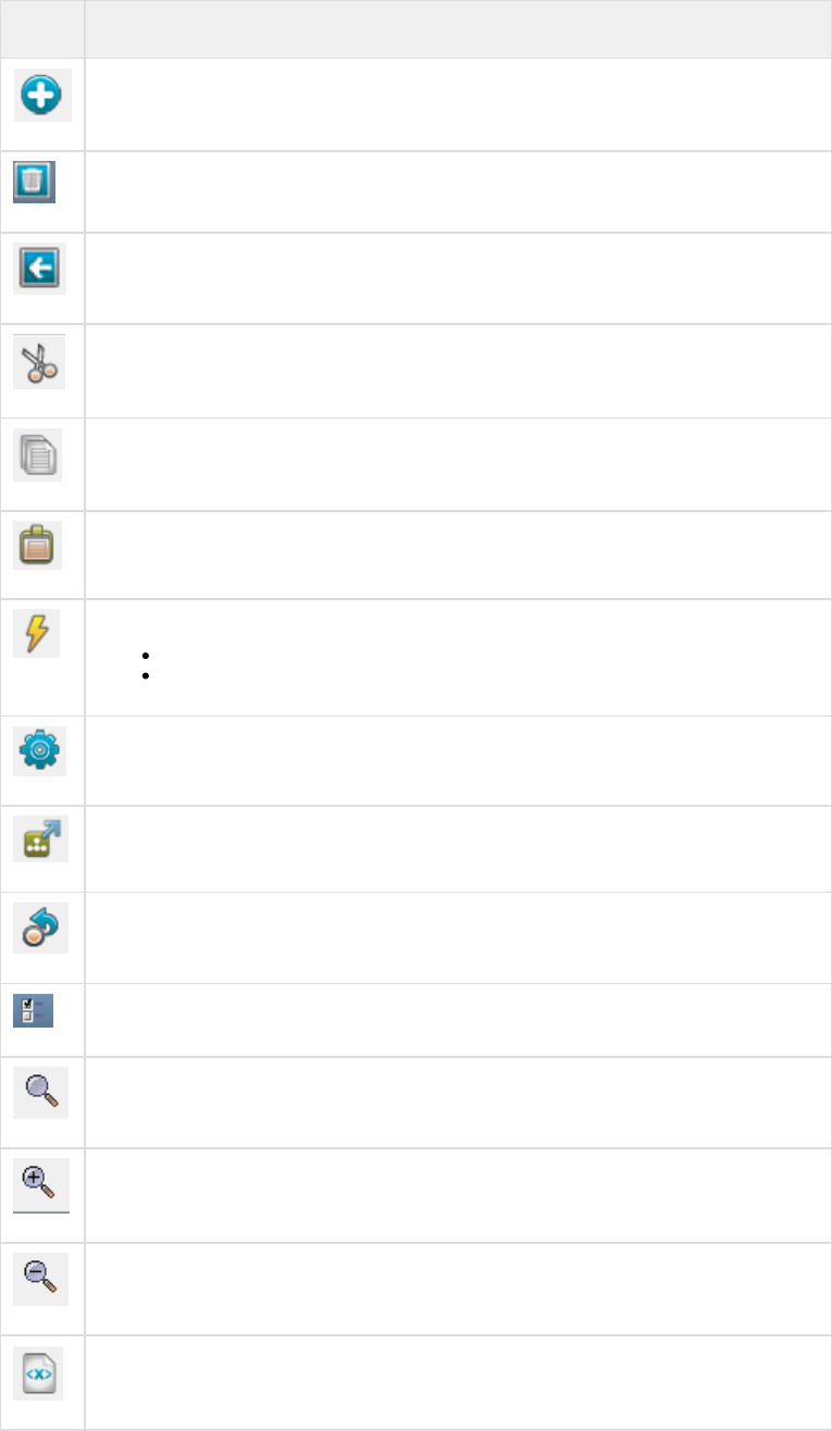
Icon Description
Create New step
Delete a test step
Set the currently selected step as the starting step in the workflow
Cut the selected text
Copy the selected text
Paste the selected text
Click to open a menu and create steps by recording a test case in the LISA browser. You can:
Record a test case via Proxy
Record a test case via DOM Events
Start a New Interactive Test Run
Stage a Quick Test
Replay Test To Specific Point
Show Model Property
Reset zoom scale to 1:1
Zoom In
Zoom Out
View XML source
Building Subprocesses
A subprocess is a test case that is designed to be called from another test case, rather than run as a stand-alone test case.
Subprocesses can be used as modules in other test cases, hence increasing their re-usability. You can build a library of subprocesses that can be
shared across many test cases.
In computer programming, a subprocess would be referred to as a function or a subroutine.
A test case must be self-contained; that is, the value for all the properties used in the test case must come from within the test case. A
subprocess expects some property values to be provided by the test step that invokes it (input properties), and when the subprocess completes, it
makes property values available to the calling step (return properties).
You can create the steps in the subprocess in the same way you would for a regular test case, with the following differences:
Mark the test case as a subprocess in the Test Case Information tab of the test case (as explained in ).Creating a Subprocess Test Case
Do not add data sets like you would in a test case. Instead, the data set should be part of the calling case, and the current values passed
to the subprocess when it is invoked. The exception here is when a data set is an integral part of the subprocess logic itself. In that
scenario, a local data set should be used.
Do not use a configuration file or a companion inside the subprocess to initialize any parameters that you expect to be passed from the
calling step. For testing purposes, we add these values elsewhere. When the subprocess is called, the calling step will pass these values.
The think time parameter in the parent test case (the test case that calls the subprocess) is propagated to the subprocess. If you
need your subprocess think times to run independently of the calling process, ensure you have a testExec property named
set to "false" to let you decide on a per-subprocess basis. For a global override,lisa.subprocess.setThinkScaleFromParent
set =false in local.properties.lisa.subprocess.setThinkScaleFromParent
You can build subprocesses from scratch, or you can convert an existing test case into a subprocess.
The test step makes it easy to call a subprocess test case.Execute Subprocess
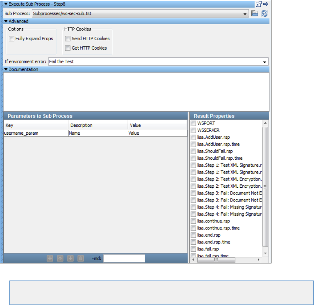
1.
2.
The following topics are available in this chapter.
Creating a Subprocess Test Case
Converting an Existing Test Case into a Subprocess
Subprocess Example
Creating a Subprocess Test Case
To create a subprocess test case
Create a new test case or open an existing one.
Open the Test Case Information tab of a test case. To open the Test Case Information tab, click anywhere in the empty space in the
model editor (no steps should be selected). The Test Case Information tab will open in the right panel.
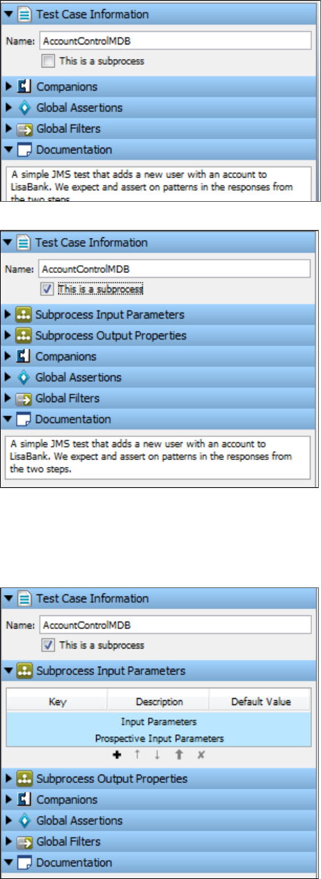
2.
3.
4.
5.
1.
2.
Select the box to make this test case a subprocess. By default, a test case is not designated to be a subprocess.This is a subprocess
New tabs for Subprocess Input and Subprocess Output Parameters are added.
In the Documentation tab, provide detailed documentation of the subprocess. This text is visible in any test step that calls the subprocess.
When you have finished adding the subprocess steps, configure the input and output properties for the subprocess.
Subprocess Input Parameters
Click the Subprocess Input Parameters tab.
In the Subprocess Input Parameters tab, define the input parameters and the prospective input parameters. A list of the parameters
needed by the subprocess appears in the Subprocess Input Parameters field. Some parameters will be added automatically, but you may
need to add some yourself.
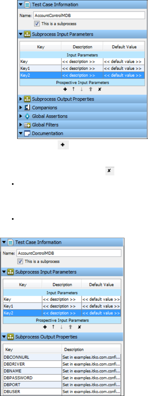
2.
3.
4.
5.
Use the Add button at the bottom of this panel to add a new property.
Enter values for Key (property name), Description, and Default Value. The default value here is used when you run the subprocess in the
Interactive Test Run facility (ITR). This lets you test the subprocess as though it was a regular test case. These default values are
ignored when the subprocess is invoked by another test step.
Remove properties using the Delete button .
Prospective Input Parameters (may be required parameters): If LISA finds a property in the subprocess that may be an input
property, but there is some doubt, the property is listed here. If it is a valid input property, use the Add button to promote this property to
the Subprocess Input Parameters list.
Subprocess Output Properties
Subprocess Output (Result) Properties: A list of all the properties set by the subprocess. A list of the parameters needed by the
subprocess appears in the Subprocess Output Parameters field. Some parameters will be added automatically, but you may need to add
some yourself.
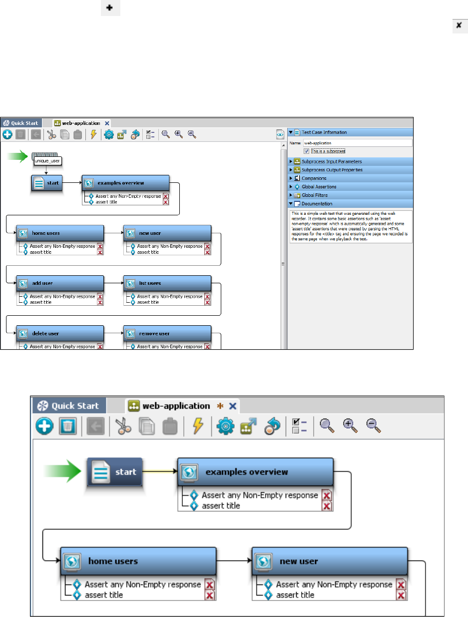
1.
2.
1.
2.
3.
4.
5.
Use the Add button at the bottom of this panel to add a new property.
If there are properties here that you do not want to be made available to the calling step, remove them using the Delete button.
After the input and return properties have been checked, and default values have been given to all the input parameters, the subprocess can be
run in the ITR.
Converting an Existing Test Case into a Subprocess
To convert an existing test case into a subprocess
Open the test case and rename it appropriately. This example converts the web-application test case from the LISA examples directory.
Mark the test case as a subprocess in the Test Case Information tab of the test case.
Remove any data sets that provide the values of properties that are to be input properties of the new subprocess. The exception here is
when a data set is an integral part of the subprocess logic itself. In our example we removed the unique_user data set.
Remove any properties from configuration files, or a companion that initializes parameters that are to be input properties of the new
subprocess.
After the input and output properties have been checked, and default values have been given to all the input parameters, the subprocess
can be run in the ITR.
Subprocess Example
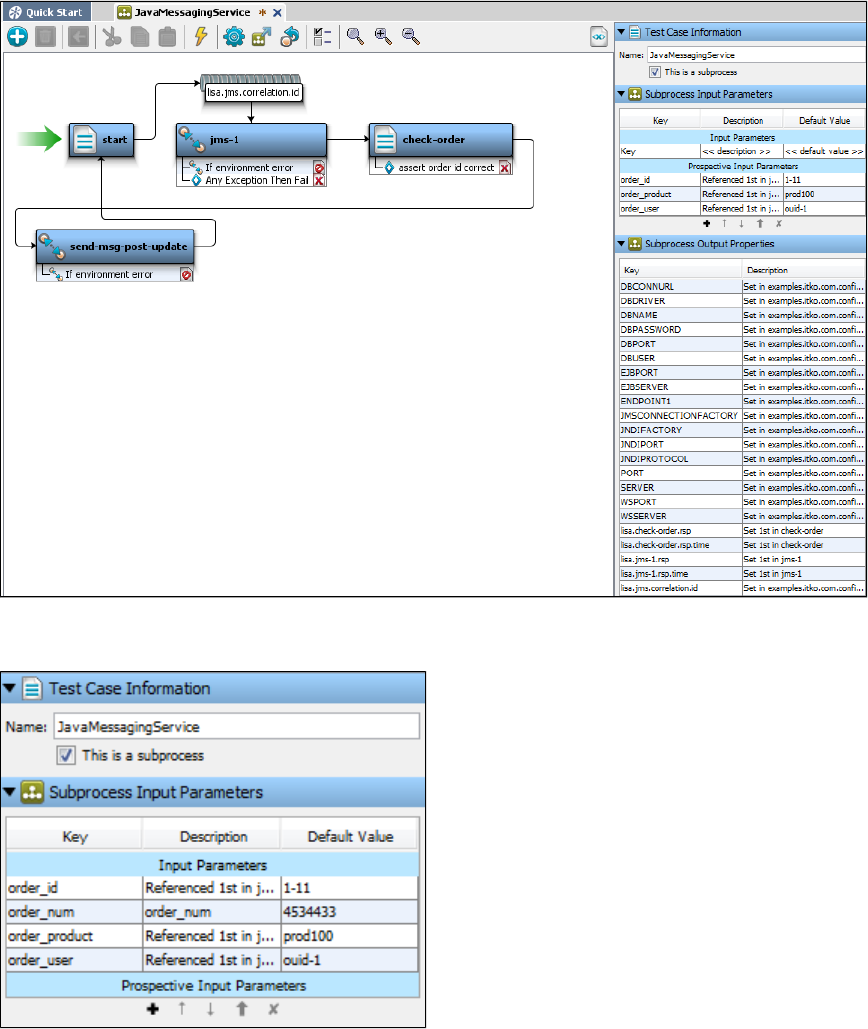
The following example shows a subprocess that was derived from the jms (jms.tst) test case in the LISA examples directory, and a test case that
calls this subprocess.
One data set, order_data, was removed from the original test case. That data set provided the values for in the original test case. Theorder_num
property is now an input property.order_num
The following illustration shows a test case with one test step: Execute Subprocess.
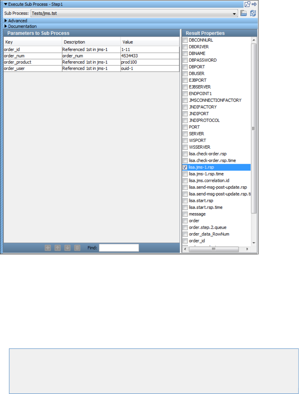
Step1 is of type Execute Sub Process, and it invokes the subprocess (which is shown previously).jms
The input property matches, and the calling step has asked for the property to be made available after the subprocess has finishedlisa.jms-1.rsp
executing.
Building Documents
A staging document contains the information about how to run a test case.
An audit document lets you set success criteria for a test case within a suite.
You can apply metrics and add events, which are used for monitoring the test case after the test run.
A suite document can be used to run a collection of test cases.
In this section, the following topics are covered:
Building Staging Documents
Building Audit Documents
Understanding Events
Generating Metrics
Building Test Suites
Building Staging Documents
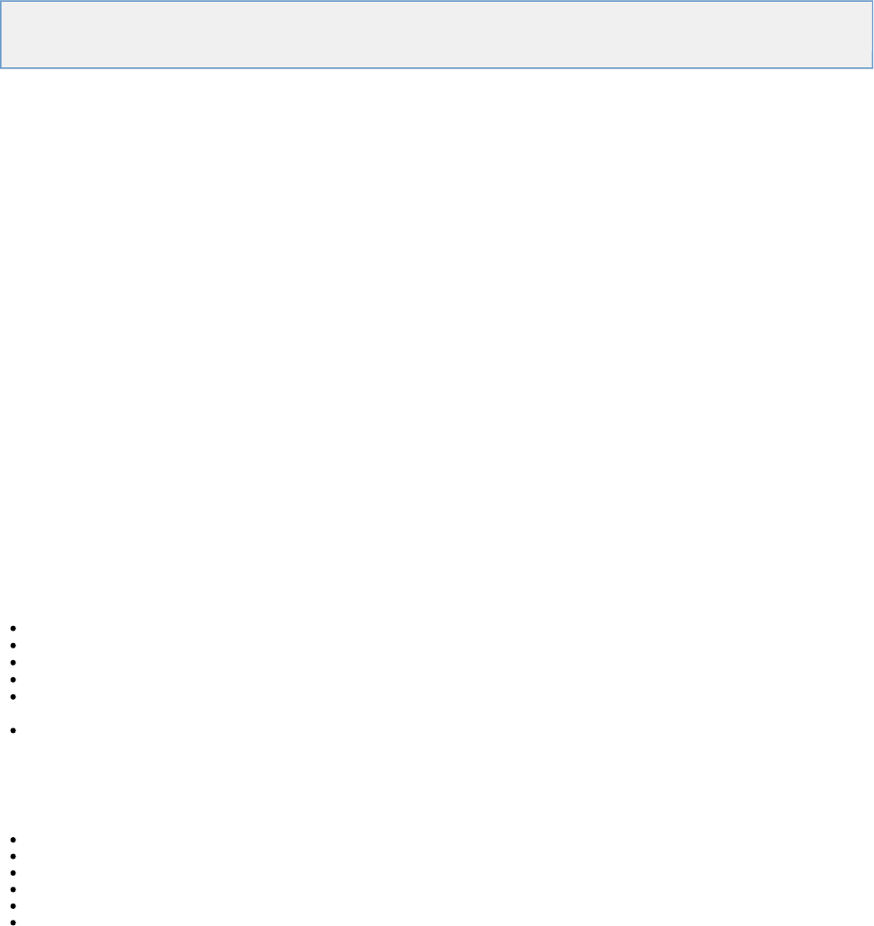
1.
2.
3.
4.
5.
6.
7.
8.
9.
10.
A staging document contains the information about how to run a test case.
Creating a Staging Document
Staging Document Editor
Staging Document Examples
Creating a Staging Document
You create staging documents from within LISA Workstation.
If a test case contains a global data set on the first step and the data set is set to end the test when the data set is drained, then all instances of
the test will end for a staged run, overriding any other staging parameters such as steady state time.
Local data sets will not end the staged run in this fashion nor will data sets on steps other than the first test.
To create a staging document
From the main menu, select File > New > Staging Document.
The New Staging Doc dialog appears.
Enter the name of the new staging document.
Click OK.
The staging document editor appears.
In the , specify basic information about the staging document. This information includes the staging document name, the loadBase tab
pattern, and the distribution pattern.
In the , specify the type of report that you want to create at runtime.Reports tab
In the , specify the metrics that you want to record at runtime.Metrics tab
In the , enter descriptive information about the staging document.Documentation tab
(Optional) In the , enable and configure IP spoofing.IP Spoofing tab
(Optional) In the , review the XML version of the staging document.Source View tab
From the main menu, select File > Save.
Staging Document Editor
The Staging Document Editor is where you specify the criteria for running test cases.
The Staging Document Editor contains the following tabs:
Base: To specify the basic parameters.
Reports: To select and add reports.
Metrics: To select metrics, and specify your sampling intervals.
Documentation: To enter descriptive information about the staging document.
IP Spoofing: To enter the IP spoofing details. IP spoofing allows multiple IP addresses on a network interface to be used when making
network requests.
Source View: To view the XML source of the staging document.
Staging Document Editor - Base Tab
The Base tab of the Staging Document Editor describes the basic parameters of a test case:
Global adjustments to think times
Duration of the test (elapsed time or number of runs)
Information to pace tests, such that a given number of tests complete in a specified time period
Number of virtual users
Load patterns for the virtual users
Distribution patterns for the virtual users
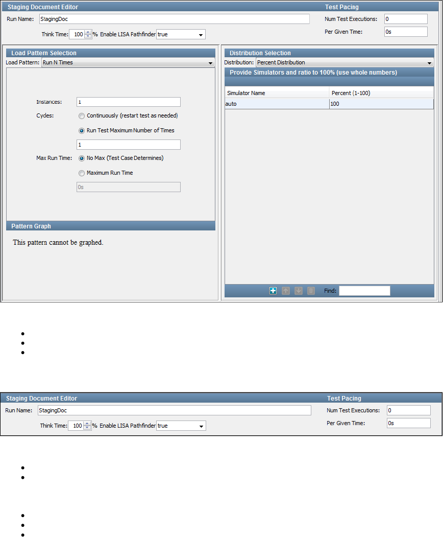
The Base tab is divided into the following panels:
Upper Panel
Load Pattern Selection Panel
Distribution Selection Panel
Upper Panel
The upper panel lets you set the following parameters:
Run Name: The name of the staging document.
Think Time: The think time in percentage, for all the test steps in the test case. Each test step can declare a think time in the step
information section. Here, you can apply a global change to these think times, as a percentage of their values. Think times can be
eliminated by setting the percentage to 0%, halved by setting it to 50%, or doubled by setting it to 200%. For example, if the percentage
is 50%, then a step's think time of 4-6 seconds will be reduced to 2-3 seconds.
Enable LISA Pathfinder: You can choose to enable or disable LISA Pathfinder.
Num Test Executions: The number of test executions that you want to complete in a given time.
Per Given Time: The time period (wall-clock) in which you want the tests to run. You can specify for hours, for minutes, or forh m s
seconds. For example, you can specify that you want LISA to adjust the time such that 2500 tests complete in 8 minutes.
LISA does not change think times to achieve the required pace.
If the test pace cannot be achieved because it is too high, LISA will run without any pause between tests. LISA will report in the log that the test is
running at a lower pace than requested.
If the test pace cannot be achieved because too few virtual users have been specified, LISA will not add more users. To estimate the number of
virtual users needed, see the Optimizer Utility.
Load Pattern Selection Panel
The Load Pattern Selection panel lets you set the duration of the test, the number of virtual users (instances), and the load pattern for those virtual
users (if you have more than one virtual user). For more information, see .Load Pattern Selection
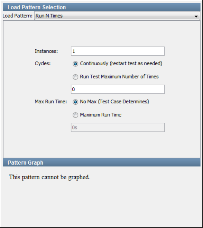
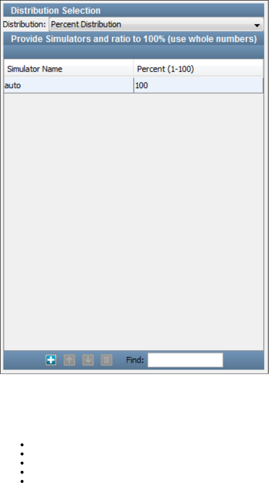
Load Pattern Selection
The Base tab of the Staging Document Editor includes a Load Pattern Selection panel.
The load pattern options are:
Immediately Ramp
Manual Load Pattern
Run N Times
Stair Steps
Weighted Average Pattern
Immediately Ramp
The Immediately Ramp pattern is applicable when you are running just a few virtual users (instances), but you want to specify how long to run the
test. You are not concerned with any loading pattern. This pattern will start all virtual users at the same time.
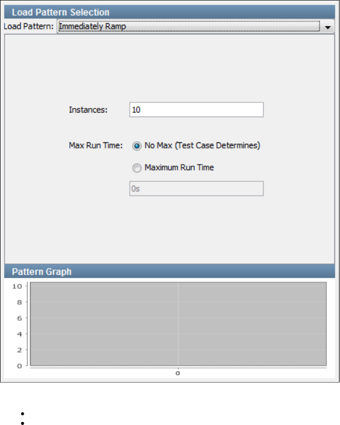
To configure this pattern, enter the following parameters:
Instances: The number of virtual users.
Max Run Time: Choose between (the time is determined by the test case) and . In the latter case, specifyNo Max Maximum Run Time
the . This will overwrite any value entered for Cycles. You can specify for hours, for minutes, (or no letter) forMaximum Run Time h m s
seconds (default).
In the preceding image, there are 10 virtual users running the test concurrently for one hour.
The graph at the bottom provides a graphical view of the pattern.
Manual Load Pattern
The Manual Load pattern gives you the most control over the loading and unloading of virtual users (instances). This pattern is similar to the Stair
Steps pattern, but it lets you specify both the number of virtual users to add, and the time interval for each step in the pattern, individually.
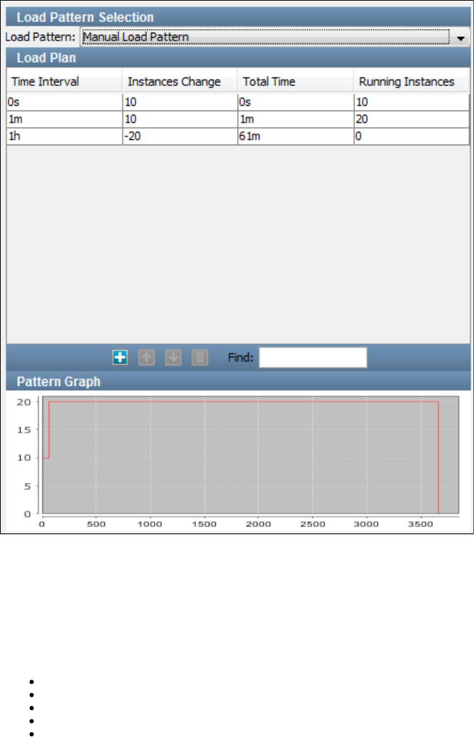
To configure this pattern, you define each step as a row in a table. In each row, you define the time interval and the number of virtual users to add
or remove (Instances Change column) for that step. The elapsed time (Total Time column) and the total number of virtual users (Running
Instances column) are automatically calculated.
In the column, enter a time followed by for hours, for minutes, (or no letter) for seconds (default).Time Interval h m s
Use the standard icons to add, remove, or change the current order of the steps from the toolbar at the bottom of the table.
You may have to scroll to see these icons. Alternatively, you can select a row and use the following short-cuts:
Add a line: Ctrl+Shift+A
Delete a line: Ctrl+Shift+D
Move line up: Ctrl+Shift+Up Arrow
Move line down: Ctrl+Shift+Down Arrow
Extended view: Ctrl+Shift+L
The graph at the bottom provides a graphical view of the pattern.
Run N Times
The Run N Times pattern is applicable when you are running only one or just a few virtual users (instances), but you want to specify how many
times the test will run. You are not concerned with any loading pattern. This pattern will start all virtual users at the same time.
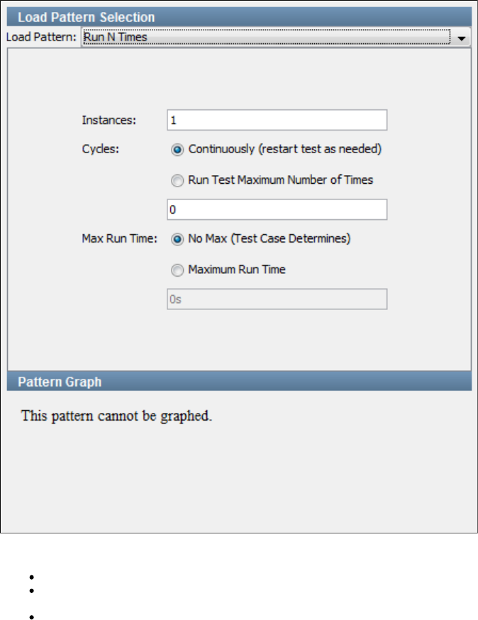
To configure this pattern, enter the following parameters:
Instances: The number of virtual users.
Cycles: Choose between running continuously until the time in the setting has been reached, or running a maximumMax Run Time
number of times.
Max Run Time: Choose between No Max (the time is determined by the test case) and Maximum Run Time. In the latter case, specify
the Maximum Run Time. This will overwrite any value entered for Cycles. You can specify for hours, for minutes, (or no letter) forh m s
seconds (default).
In the preceding image, there is a single user running the test case one time to conclusion.
Stair Steps
The Stair Steps pattern introduces virtual users (instances) to the system in well-defined steps, rather than all at once. You specify the total
number of steady state users, the ramp up and ramp down times, and the number of steps for the ramp.
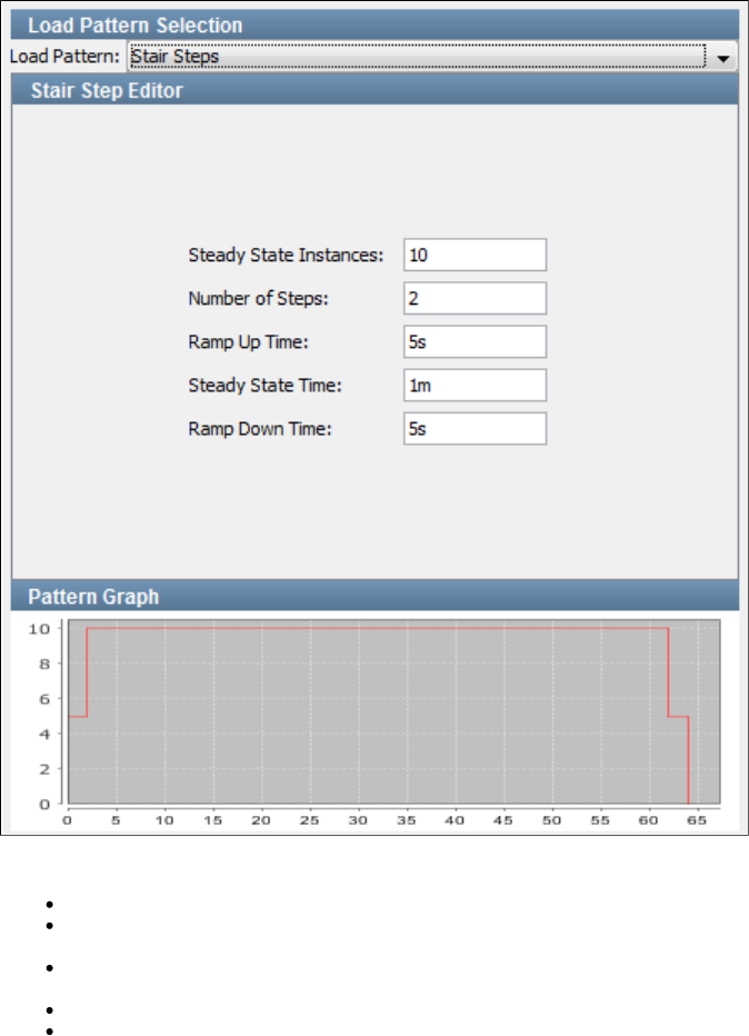
To configure this pattern, enter the following parameters:
Steady State Instances: The maximum number of virtual users to run at steady state.
Number of Steps: The number of steps to use to reach the maximum number of virtual users. The number of virtual users to introduce at
each step is: divided by .Steady State Instances Number of Steps
Ramp Up Time: The time period over which virtual users are added to reach the maximum number of virtual users. The time interval
between steps is: divided by .Ramp Up Time Number of Steps
Steady State Time: The time period of the meaningful test run.
Ramp Down Time: The time period over which virtual users are removed. Because the tests will run to completion after a "stop" request,
the ramp down times are approximate.
You can enter a time followed by for hours, for minutes, (or no letter) for seconds (default).h m s
In the preceding image, there are 10 instances and 2 steps. Therefore, 5 virtual users will be added in each step. The ramp up time is 5 seconds.
The test will run in steady state for 1 minute. Two virtual users will be removed approximately every 5 seconds.
The graph at the bottom provides a graphical view of the pattern.
Weighted Average Pattern
The Weighted Average pattern will add and remove virtual users (instances) based on a statistical calculation. LISA will calculate the number of
steps, and the time period between steps, as frequently as every second, by honoring a moving weighted average. This will approximate a bell
curve distribution, with most virtual users being added within 2 standard deviations of the mid-point of the load, or unload ramp time.
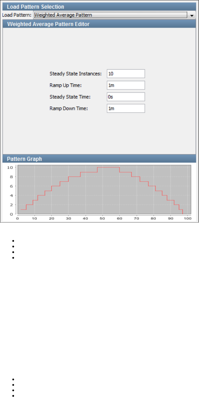
To configure this pattern, enter the following parameters:
Steady State Instances: The maximum number of virtual users to run at steady state.
Ramp Up Time: The time period over which virtual users are added to reach the maximum number of virtual users.
Steady State Time: The time period of the meaningful test run.
Ramp Down Time: The time period over which virtual users are removed. Because the tests will run to completion after a "stop" request,
the ramp down times are approximate.
You can enter a time followed by for hours, for minutes, (or no letter) for seconds (default).h m s
In the preceding image, there are 10 virtual users ramping up over 1 minute, running in a steady state for 3 minutes, before ramping down over
approximately 1 minute.
The graph at the bottom provides a graphical view of the pattern.
Distribution Selection
The Base tab of the Staging Document Editor includes a Distribution Selection panel.
If you are using LISA Workstation, you will not have use for this panel because your virtual users will be running locally (using a simulator that is
part of LISA Workstation).
If you are using LISA Server, with several simulator servers active, this panel lets you specify how to distribute your virtual users over these
simulators.
The distribution options are:
Balanced Based on Instance Capacity
Dynamic Simulator Scaling with DCM
Percent Distribution
Round Robin Distribution
Balanced Based on Instance Capacity
The Balanced Based on Instance Capacity distribution requests that LISA control the allocation of virtual users (instances), based on an
assessment of current loading (percent load on each simulator).
Each simulator is initiated with a defined number of virtual users that can be allocated. The default is 255. LISA dynamically tracks the percent
load and adds virtual users to specific simulators to try to keep the load percentage as even as possible. Therefore, the simulator with the lowest
percentage load is a candidate for the next virtual user introduced into the system.
This distribution is useful when the system is already running tests from several other testers, and you want to optimize your load distribution.
You do not need to specify any parameters.
Dynamic Simulator Scaling with DCM
The Dynamic Simulator Scaling with DCM distribution requests that LISA determine when more capacity is required to meet the needs of a
running test and then automatically expand the lab.
This distribution pattern includes the following parameters:
Checkpoint time: The interval at which LISA will evaluate whether more simulators are needed. You can enter the value in seconds (for
example, ) or minutes (for example, ).300s 5m
DCM Dynamic Lab Name: If you want to stage to an existing coordinator and the test determines that it needs more capacity to run the
test, then this parameter indicates what lab it should spin up to run more simulators. You must include the and the fullyVLM prefix
qualified lab name (for example, ).AGL:Root/MyLab
Maximum Expansion: The maximum number of simulators that will be created at the time of expansion. If you have a policy that limits
the number of simulators per user, you can use this parameter to enforce the policy. The default value of 0 means unlimited.
During the checkpoint evaluation, LISA examines the performance of the simulators that are currently running and how many more virtual users
need to be brought online. If more simulators are needed, LISA begins the process of expanding the lab. When the simulators come online, LISA
starts directing traffic to them.
Percent Distribution
The Percent Distribution distributes virtual users (instances) over the simulators based on percentages that you choose.
The names of the running simulators (plus local) are available in a drop-down menu in the column.Simulator Name
Select a simulator and specify a percentage of virtual users for the simulator. Repeat this action for all the simulators that you want to include until
you have 100 percent. You must use integer values for the percentages.
Although "Auto" appears as a choice in the drop-down menu, it is not recommended. It will result in confusing allocations of
virtual users, as it will compete with your explicit distribution choices.
Round Robin Distribution
The Round Robin Distribution requests that LISA control the allocation of virtual users (instances), based on a simple round-robin distribution
pattern.
LISA picks an arbitrary simulator and adds a user, then goes to the next simulator and adds a user, continuing to add virtual users as needed.
After all simulators have been used, the process continues with the first simulator. This distribution is useful when staging a single, large load test
on your system.
You do not need to specify any parameters.
Staging Document Editor - Reports Tab
The Reports tab of the Staging Document Editor lets you specify the report generator that you want to invoke for every test case or test suite run.
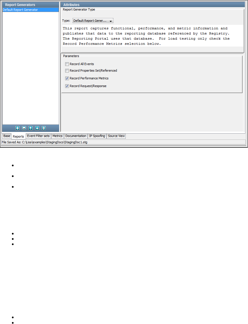
The following report generators are available:
Default Report Generator: Captures functional, performance, and metric information and publishes that data to the reporting database
referenced by the registry. The Reporting Portal uses that database.
Load Test Report Generator: Designed for load tests with thousands of virtual users. This report captures load metrics but not
step-level metrics (there would be too much data and the reporting database would slow down the test).
XML Report : Creates an XML file with all the possible data that can be captured. The captured data can be limited using theGenerator
report options. To view this report, import the file into the Reporting Portal.
Details of the data available in each report generator, viewing reports, report contents and output options are discussed in detail in .Reports
The metrics to capture for the reports are discussed more fully in .Generating Metrics
Reports can be selected in the following modules and can be seen in the Report Viewer:
Staging Quick Tests
Building Staging Documents
Running Test Suites
After they are requested, they can be viewed and managed later.
When you select a report from the drop-down, a summary of the report appears in the area below.
According to the selected report, the parameters will change. You must set the parameters as and where necessary.
The Reports tab is divided into the following areas:
Right panel: This is where you select the report to be added.
Attributes: This contains the "Report Generator Type" and the required parameters for the report.
Report Generator Type: A pull-down menu lists the available report types.
Parameters: These are the parameters required to set the selected report generator.
Left panel: This shows the list of added reports. You can add, save, move, and delete reports by using the toolbar at the bottom of the panel.
Staging Document Editor - Metrics Tab
The Metrics tab of the Staging Document Editor lets you select the test metrics that you want to record.
You can also set the sampling specifications for the collection of the metrics and set an email alert on any metric that you have selected.
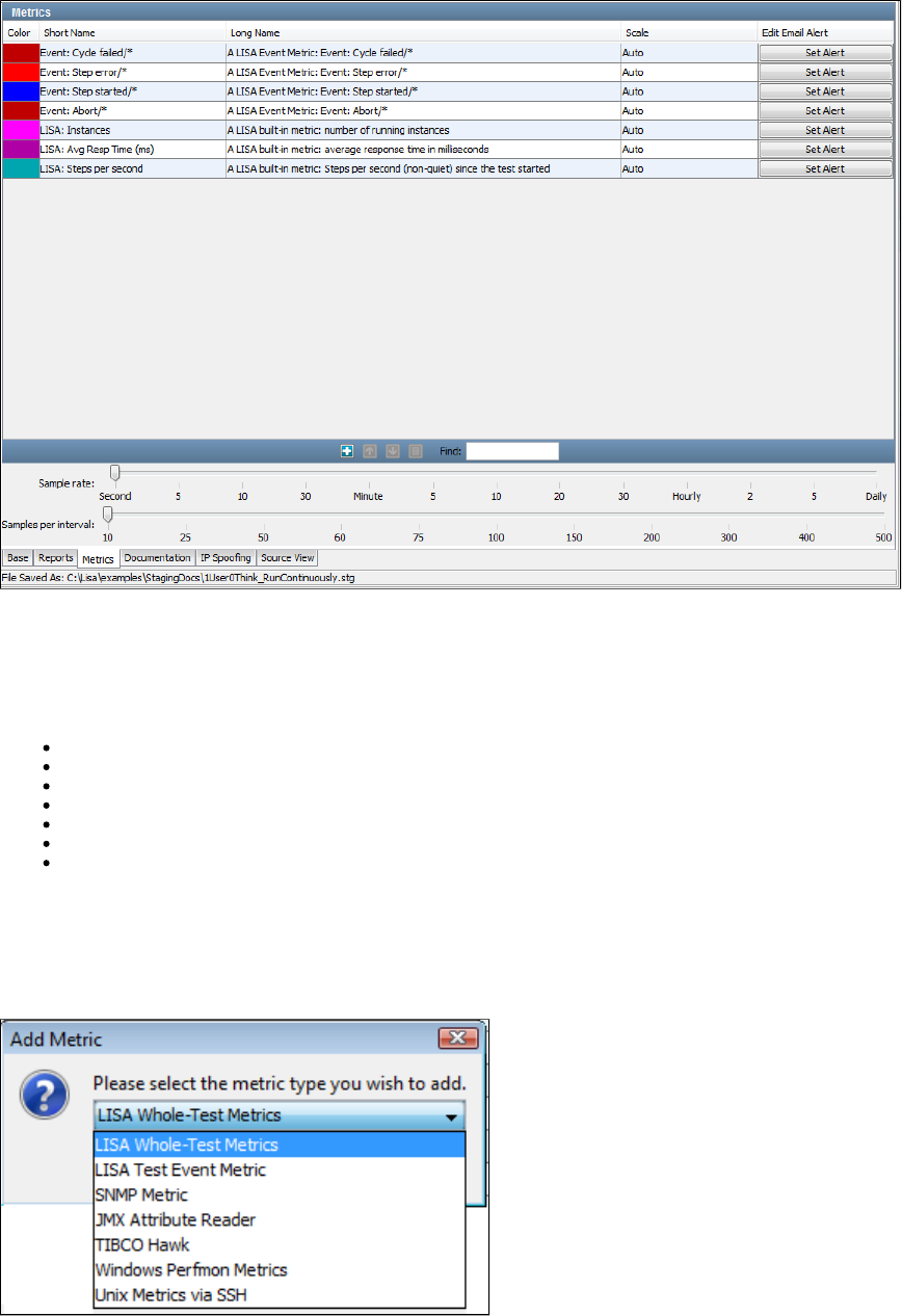
The Metrics tab is divided into two sections. The top panel has the default metrics listed, differentiated by color code. The bottom panel has the
sampling parameters.
You can add or delete metrics and set email alerts in the top panel.
The following types of metrics are available:
LISA Whole-Test Metrics
LISA Test Event Metrics
SNMP Metrics
JMX Attribute Reader (JMX metrics)
TIBCO Hawk
Windows Perfmon Metrics
UNIX Metrics via SSH
For more information about each metric, see .Types of Metrics
Add a Metric
To add a metric, click the Add icon on the toolbar. A dialog to add metrics will open up with a list of metrics that can be added.
Select the target metric type and click OK.
The Metric Selection dialog opens.
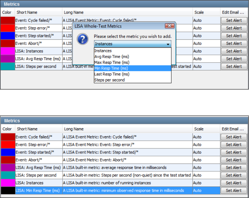
Select the target sub-category for this metric and click OK. Sub-categories are different for each metric.
The newly-added metric appears in the list of existing metrics in a different color.
Descriptions of all the metrics in all categories, and details on how to configure them for inclusion in reports, can be found in .Generating Metrics
Setting an Email Alert
To set an email alert on an individual metric, click the Set Alert button corresponding to that metric.
The Edit Alert dialog appears.
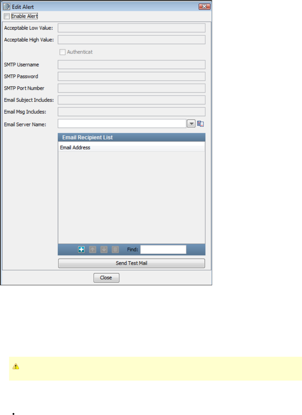
You can set the acceptable limits for the metric (low and high value), and the details to be sent in an email. You must provide the name of your
email server and a list of email addresses.
Email alerts added to staging documents store the SMTP password as an encrypted value. Also, if you open an existing staging document and
re-save it, the SMTP password is saved as an encrypted value.
Email addresses are added and removed by using the Add and Delete buttons at the bottom of the window.
When you are finished, click Close.
Notice that the Set Alert button is now an Edit Alert button on the Metrics tab.
For the email alert to work, you also need to set the SMTP server-related paths in the file.lisa.properties
Sampling Parameters
The bottom panel has two slider bars that let you set sampling parameters:
Sample rate: Specifies how often to take a sample; that is, record the value of a metric. It is specified as a time period, and is the
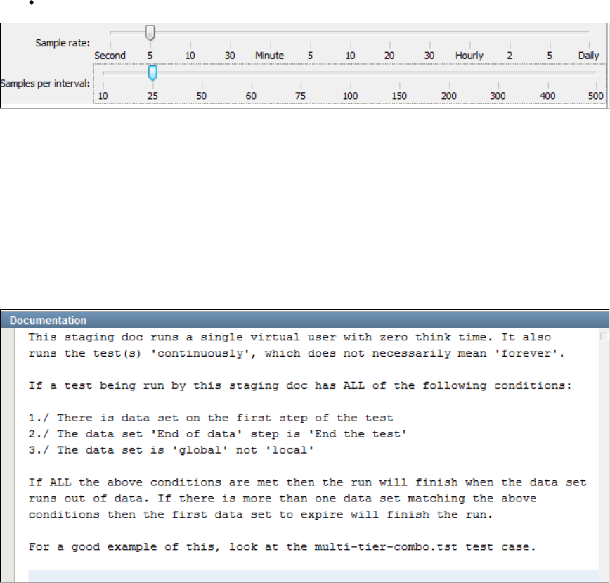
reciprocal of the sampling rate.
Samples per interval: Specifies how many samples are used to create an interval for calculating summary values for the metric.
Taking sample values every minute (Sample rate=1 minute) and averaging every 60 samples (Samples per interval=60) will produce a metric
value every minute and a summary value (average) every hour.
For example, the default is a 1-second sample rate, and 10 samples per interval (making an interval 10 seconds).
The preceding example uses 5 seconds per sample, and 25 samples per interval, producing a metric value every 5 seconds and a summary
value every 125 seconds.
Metric values are stored in XML files or database tables for inclusion in reports (see the previous section on reports).
Staging Document Editor - Documentation Tab
The Documentation tab of the Staging Document Editor lets you enter descriptive information about the staging document.
Staging Document Editor - IP Spoofing Tab
The IP Spoofing tab of the Staging Document Editor lets multiple IP addresses on a network interface to be used when making network requests.
In a performance testing scenario, enabling IP spoofing against a system under test gives the appearance that requests are originating from many
different virtual users. For systems such as web applications, this outcome will often more closely resemble "real-world" behavior.
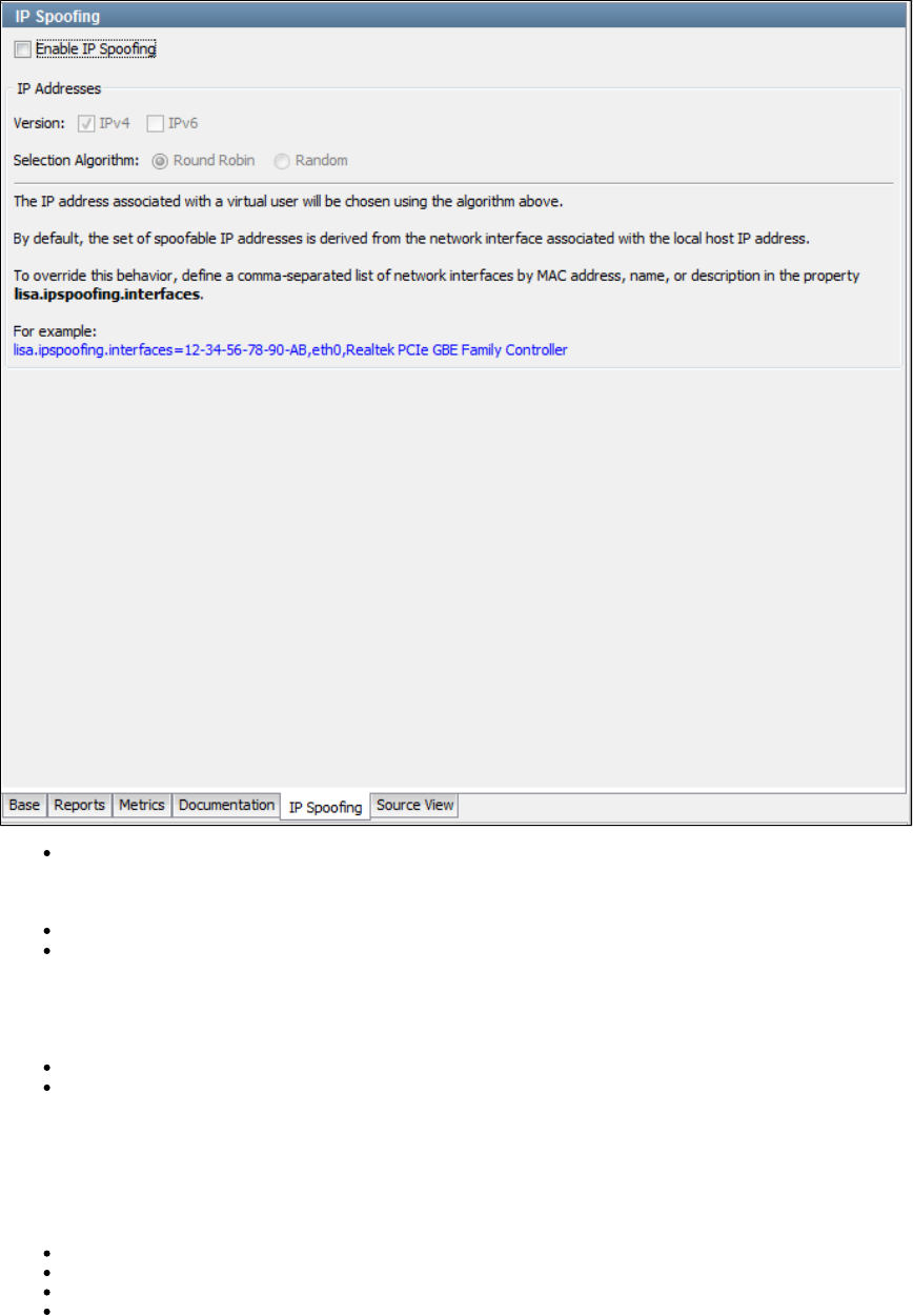
Enable IP Spoofing: If selected, IP addresses will be spoofed for all supported LISA steps in a test case.
Version
IPv4: If selected, IPv4 addresses will be spoofed.
IPv6: If selected, IPv6 addresses will be spoofed.
Either or must be selected.IPv4 IPv6
Selection Algorithm
Round Robin: Spoofed IP addresses will be selected in a round-robin format.
Random: Spoofed IP addresses will be selected in a random format.
Support
Currently, IP spoofing is supported only for HTTP.
You can configure the following steps to use IP spoofing:
HTTP/HTML Request
REST Step
Web Service Execution (XML)
Raw SOAP Request
Configuring IP Addresses in Windows
This section describes how to add IP addresses to a network interface for IP spoofing.
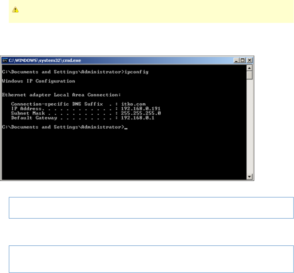
Before adding IP addresses, make sure that you are an Administrator.
On Windows, IP address information can be obtained by using the command-line utility .ipconfig
For example, the following screenshot shows the output of for a server with a single network interface card. It has a single IP address, ipconfig
and is named .192.168.0.191 Local Area Connection
To add a single IP address, 192.168.0.201, the command-line utility can be used:netsh
netsh in ip add address "Local Area Connection" 192.168.0.201 255.255.255.0
If many IP addresses are to be added, can be used in a loop.netsh
For example, the following command will add 9 more IP addresses between 192.168.0.202 and 192.168.0.210:
for /L %i in (202, 1, 210) do netsh in ip add address "Local Area Connection" 192.168.0.%i
255.255.255.0
If these commands are successful, the new IP addresses can be verified by using the command-line utility .ipconfig /all
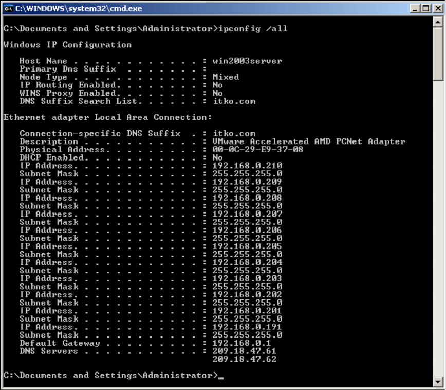
Staging Document Editor - Source View Tab
The Source View tab of the Staging Document Editor shows the XML source of the staging document.
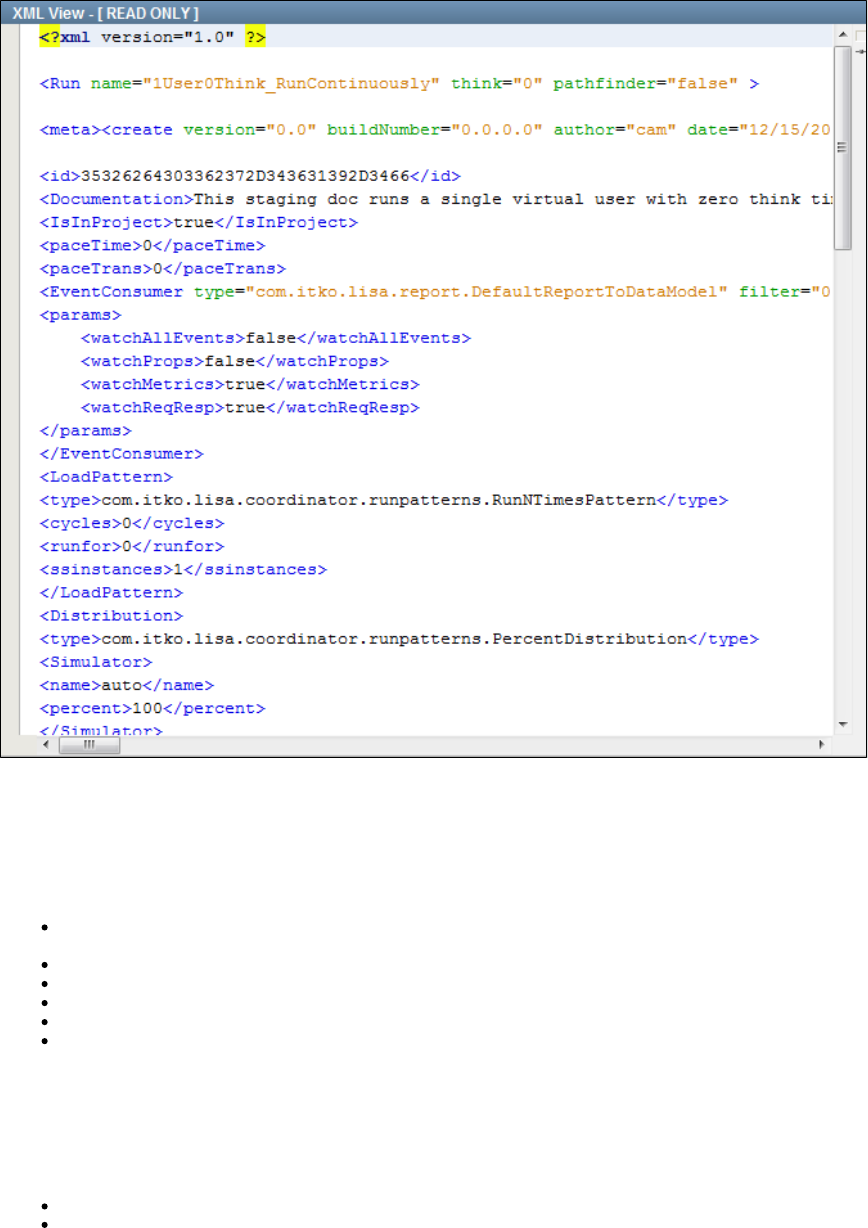
Staging Document Examples
The following staging documents are provided in the StagingDocs folder of the examples project. All of them use the Run N Times load pattern
and the Percent Distribution pattern.
You can use these documents as the starting point of your new staging document and rename it to save it under a different name.
1User0Think_RunContinuously: Runs a single virtual user with zero think time. Runs the test continuously, which does not necessarily
mean forever. LISA Pathfinder is not enabled.
1user1cycle0think: Runs a single virtual user one time with zero think time. LISA Pathfinder is enabled.
ip-spoofing: Lets you test IP spoofing support. LISA Pathfinder is not enabled.
jboss-jmx-metrics-localhost: Runs three concurrent virtual users one time for 440 seconds. LISA Pathfinder is not enabled.
Run1User1Cycle: Runs a single virtual user one time with 100 percent think time. LISA Pathfinder is not enabled.
Run1User1CycleShowAll: Runs a single virtual user one time with 100 percent think time. LISA Pathfinder is not enabled.
Building Audit Documents
An audit document lets you set success criteria for a test case within a suite.
An audit document can track the following:
Events that must occur or must not occur during a test
Whether a test takes too little or too much time to complete
You can specify audit documents in the of the suite document editor. Be sure to select the Record All Events check box in the Base tab Reports
.tab
Audit documents are located in the folder of a project. The file extension is .aud.AuditDocs
When you create a project, the folder contains a default audit document named .AuditDocs DefaultAudit.aud
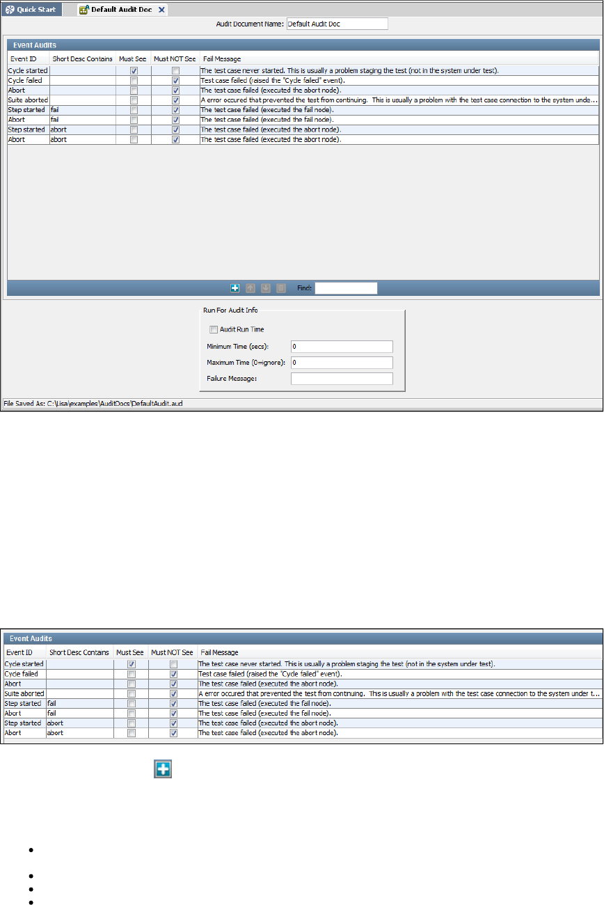
1.
2.
3.
4.
5.
The following image shows the audit document editor. The editor contains an Event Audits panel and a Run for Audit Info panel.
To create an audit document:
From the main menu, select File > New > Test Audit.
Enter the name of the audit document, and click OK.
The audit document editor opens.
If you want to audit events, then configure the parameters in the panel.Event Audits
If you want to audit the execution time, then configure the parameters in the panel.Run for Audit Info
From the main menu, select File > Save.
Event Audits Panel
The Event Audits panel lets you specify events that must occur or must not occur during a test.
The following image shows the event audits for the default audit document.
To add an event, click the Add icon.
In the new row, select the event name from the drop-down list in the Event ID column.
Each row has following parameters:
Short Desc Contains: If you want to filter an event based on the value of the event's short description, then enter the keyword(s) from
the short description in this column.
Must See: Select this check box if the event must occur during the test.
Must NOT See: Select this check box if the event must not occur during the test.
Fail Message: A message to be logged if this audit fails.
Add additional rows for each event that you want to include.
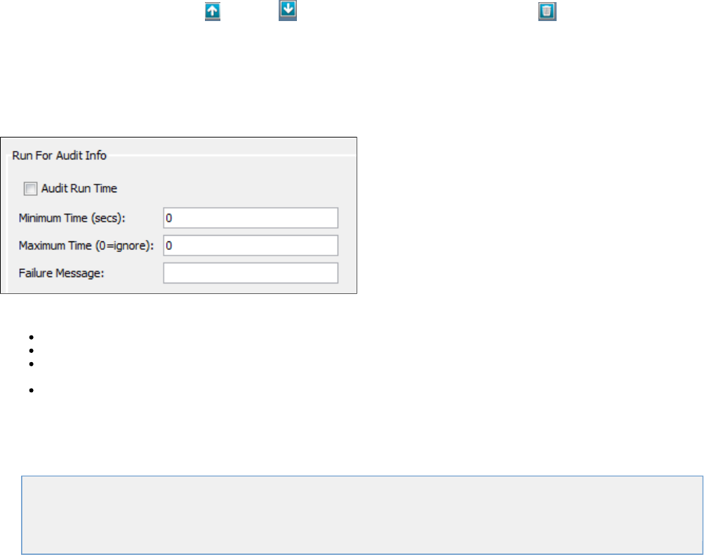
If you try to add event audits that logically conflict with each other, then the editor displays a warning message.
You can rearrange rows by using the Up and Down icons. You can delete rows by using the Delete icon.
Run for Audit Info Panel
The Run for Audit Info panel lets you audit the execution time.
The following image shows the Run for Audit Info panel.
This panel has following parameters:
Audit Run Time: Select this check box to enable the execution time audit.
Minimum Time: The minimum time (in seconds) that the test must run.
Maximum Time: The maximum time (in seconds) that the test can run and still be considered a successful audit. If there is no maximum
time constraint, then enter 0.
Failure Message: A message to be logged if this audit fails.
Understanding Events
An event is a message broadcast from LISA informing any interested parties that an action has occurred.
The following topics are available.
Events Overview
Adding and Viewing Events
Types of Events
Events Overview
An event is a message broadcast from LISA informing any interested parties that an action has occurred. Events are created for every major
action that occurs in a test case.
An event is created every time a step is executed, a property is set, a response time is reported, a result is returned, a test succeeds or fails, and
more. LISA provides you the ability to see every event or to filter out the events that are not of interest.
Events are important when you are monitoring tests or analyzing test results.
You can observe events during an Interactive Test Run (ITR) by clicking the Test Events tab in the ITR. The following image shows the Test
Events tab.
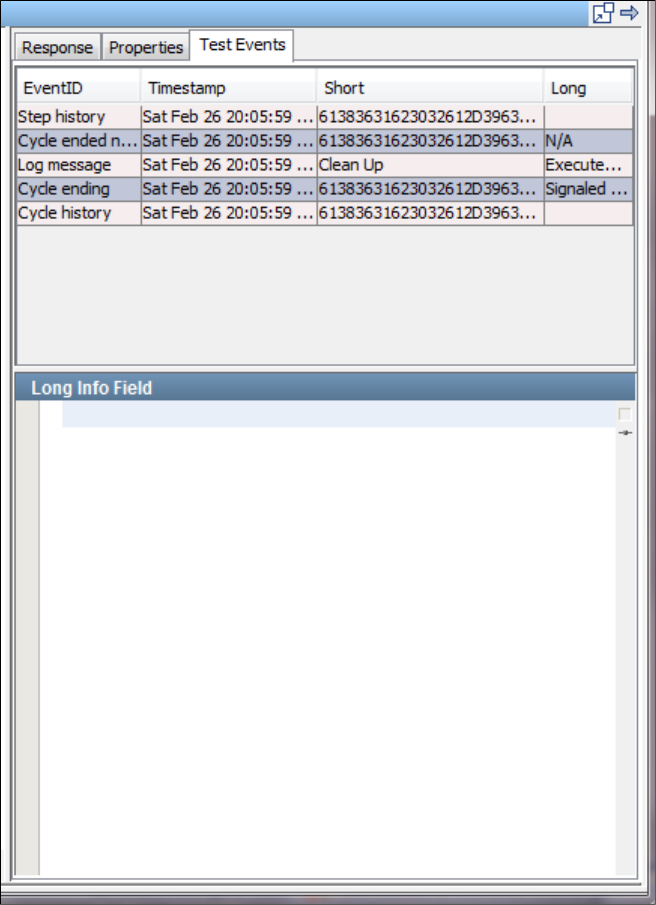
You can observe and filter events in a Quick Test.
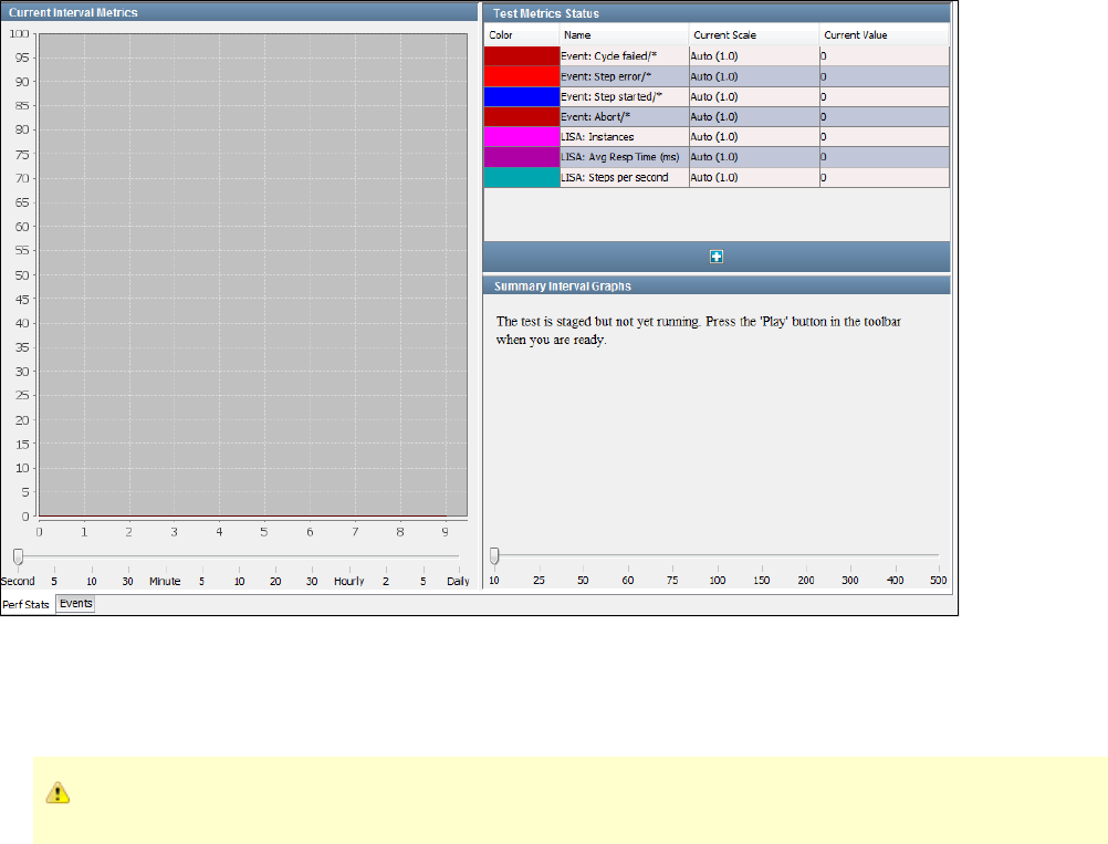
The same can be done while monitoring a staged test or a test suite.
You can select events to be included in reports, and select events to be used as metrics that can be monitored and included in reports.
For more information about reports, see . For more information about metrics, see .Reports Generating Metrics
Internal to LISA, a step can also be referred to as a node, explaining why some events have in the EventID."node"
An event is characterized by an EventID, a short value, and a long value. EventIDs are keywords that indicate the type of event. The short values
and long values contain information about the event. Their contents vary with the type of event.
Adding and Viewing Events
You can add events and .through the ITR through a quick test or staging document
Adding and Viewing Events through the ITR
You can enable some events in the Settings tab of the Interactive Test Run (ITR) utility. Select the Show CALL_RESULT and Show
NODERESPONSE check boxes to view those events.
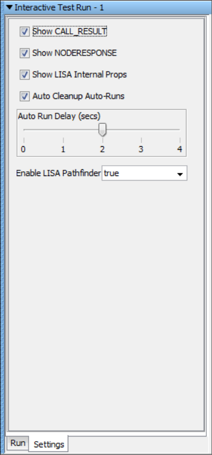
You can view test events in the Interactive Test Run (ITR) by clicking the Test Events tab. The following image shows the Test Events tab.
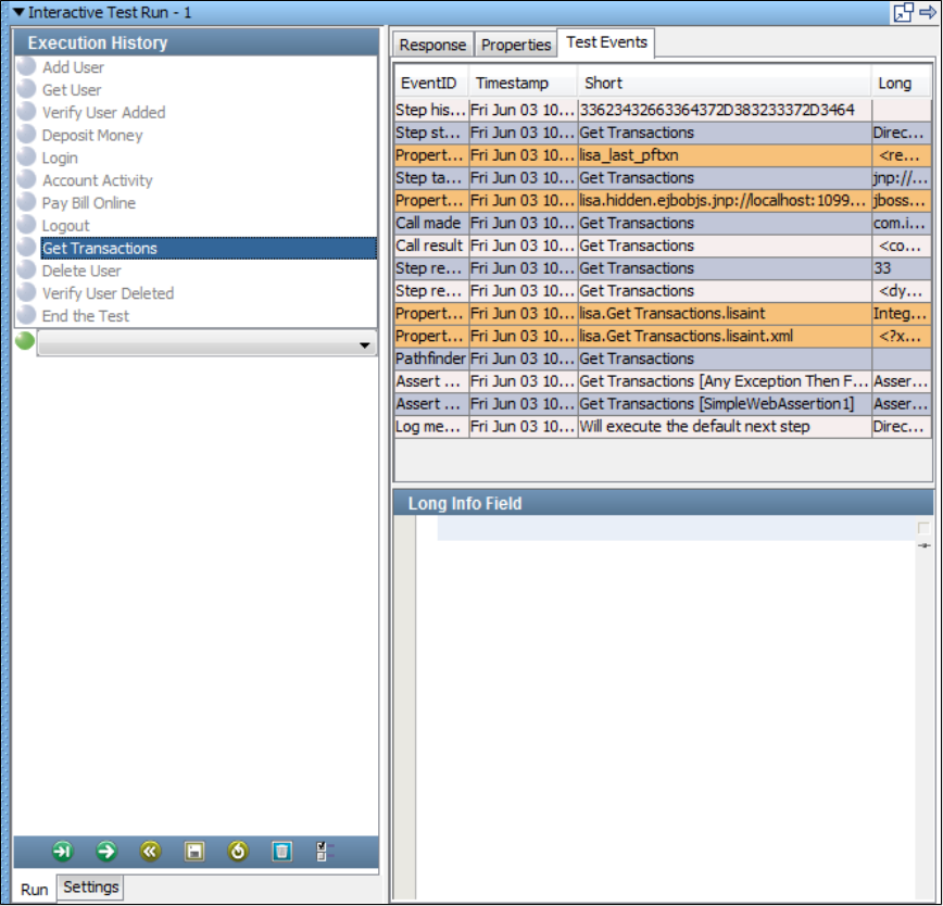
Adding and Viewing Events through a Quick Test/Staging Document
When you start a test case execution through the Start Test option or the Start Suite option, the test will be staged and relevant graphs will appear
in the Perf Stats tab.
To view the test events, click the Events tab.
You can select the Events to Filter Out in the left panel or select from the predefined filter sets.
Select the Auto Refresh check box in the Events tab to refresh the test events list. As the test runs, you will see the events that you designated on
the Events tab.
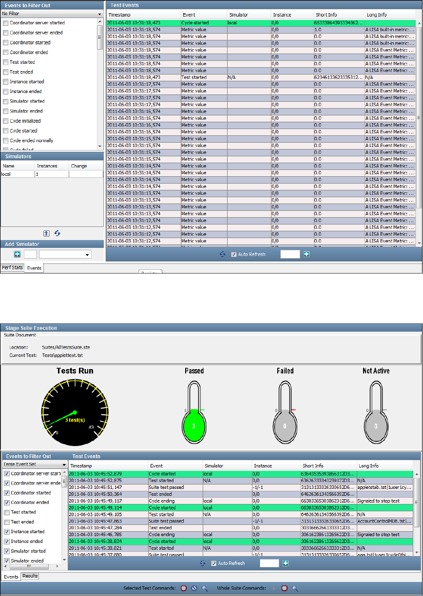
View Events in Test Suites
You can also observe the events when you stage a test suite.
You can select events to be included in reports, and select events to be used as metrics that can be monitored and included in reports.
For more information about reports, see . For more information about metrics, see .Reports Applying Metrics
An event is characterized by an EventID, a short value, and a long value. EventIDs are keywords that indicate the type of event. The short values
and long values contain information about the event. Their contents vary with the type of event.
Internal to LISA, a step can also be referred to as a node, explaining why some events have in the EventID.node
Types of Events
The following table describes the standard events. The table is sorted by event name.
Event Name Old Event Name Description Short Info Long Info
Abort EVENT_ABORT This event ends a test in a "cannot finish"
state. It is a failing type of end event. Event Aborted
Assert
evaluated EVENT_ASSERT_EVALUATED Every non-embedded assert will generate
either this event if it did not fire, or the
EVENT_ASSERT if it did fire. Firing
means it is true and its consequence will
be followed. These events are the asserts
that did not get to execute their
consequence.
Assert
Evaluated
Assertion fired EVENT_ASSERT An assertion on a step "fired". The name of
the assertion The log
message of the
assertion, or a
LISA-generated
message if there
is no log
message set
Call made EVENT_CALL Steps that perform object calls like web
services or EJBs use this event to report
each call that is made on the object.
The name of
the step The call as a
string, for
example, void
setName(
java.lang.String
name[Basic
Checking] )
Call result EVENT_CALLRESULT Steps that perform object calls like web
services or EJBs use this event to report
the response they get from calls.
The name of
the step The call
response as a
string. If the
response is an
object, then an
XML view of the
object is shown.
Coordinator
ended EVENT_REMOVECOORDINATOR A coordinator has been removed. The name of
the
coordinator
server
Coordinator
server ended EVENT_REMOVECOORDSERVER The coordinator server was ended. The name of
the
coordinator
server
Coordinator
server started EVENT_COORDSERVERCREATED The coordinator server was created. The name of
the
coordinator
server

Coordinator
started EVENT_NEWCOORDINATOR A new coordinator was created. The name of
the
coordinator
server
Cycle ended
normally EVENT_NORMALEND Indicates that the test execution
completed in a successful state The name of
the test case
Cycle ending EVENT_STOPTESTSIGNAL The instances have been instructed to
stop testing.
Cycle failed EVENT_TESTFAILED Indicates that the test execution failed.
That there are no exceptions in the test
case, but either logic errors in the test
case or in the system under test caused
the test case not to complete as
expected.
The name of
the test case
Cycle history EVENT_CYCLE_HISTORY Every model that runs will generate one of
these events. It is the final trace of all the
details of its run.
Cycle History
Cycle
initialized EVENT_INIT Indicates that the test has been initialized
(loaded). The name of
the test case
Cycle runtime
error EVENT_TESTRUNERROR An abnormal LISA error occurred. For
example, the coordinator lost its
connection to a simulator while running a
test.
Varies but it is
usually the
name of the
test element
(step, data
set, or filter)
that has the
error
Usually a
message that
explains the
error
Cycle started EVENT_START Indicates that this test instance and cycle
have just started. The name of
the test case
Data set read EVENT_DATA_SET_READ Data sets generate an event that makes it
clear what values are about to be used. Data set read
HTTP
performance EVENT_HTTP_PERFSTATS This event is generated for every HTTP
transaction that LISA executes to capture
the performance statistics.
HTTP
performance
statistics
Info message EVENT_NODEMSG Basic logging data. For example, the
HTTP/HTML request step will send this
message with the step name in the short
field and the URL being sent to the server
in the long field.
Usually the
name of the
step during
which this
message was
generated
Usually a
message that
LISA generated
Instance
ended EVENT_VUSEREND Sent when a simulator instance has
finished. The name of
the simulator
Instance
started EVENT_VUSERSTART Sent when a simulator creates an
instance. The name of
the simulator
Log message EVENT_LOGMSG Basic logging data. Can be turned off,
when filtering events, to minimize
overhead.
The message
sent to the log

Metric alert EVENT_METRICALERT A metric has been collected and is
reporting its value. The short
name of the
metric, for
example,
LISA: Avg
Response
Time
The value of the
metric collected
Metric started EVENT_METRIC_START Metrics that are collected generate
real-time events of their values. Metric Started
Metric value EVENT_METRIC_VALUE Metrics that are collected generate
real-time events of their values. Metric value
Model
definition error EVENT_TESTDEFERROR A test case error was discovered during
execution of the test. For example, the
name is constructed from a property that
does not exist.
Varies but it is
usually the
name of the
test element
(step, data
set, or filter)
that has the
error
Usually a
message that
explains the
error
Pathfinder EVENT_INTEGRATION The system being tested has LISA
integration enabled. This event contains
the LISA integration XML data that was
captured.
The name of
the step The XML
representation
of the LISA
Integration data
captured
Property set EVENT_SETPROP A property was set. The property
key The property
value
Simulator
ended EVENT_SIMEND Sent when a simulator has ended. The name of
the simulator
Simulator
started EVENT_SIMSTARTED Sent when a simulator has started. The name of
the simulator
Step
bandwidth
consumed
EVENT_BANDWIDTH Approximate amount of data sent and
received from the system under test for
the step execution
The name of
the step Actual number
of bytes
read/received
Step error EVENT_TRANSFAILED An error has occurred in the system under
test. For example, there was no response
from a web server. This event is on a
per-step basis. The
EVENT_TESTFAILED refers to the
complete test case.
The name of
the step If available, a
message to help
determine the
cause of the
failure
Step history EVENT_NODE_HISTORY Every node has a history event that fires
of type incom.itko.lisa.test.NodeExecHistory
its long info.
Step History
Step request EVENT_REQUEST Steps that support this event use it to
report the actual request made to the
system under test.
The name of
the step The request
data as a string
Step request
bandwidth EVENT_REQUEST_BANDWIDTH

Step response EVENT_NODERESPONSE Indicates that a transaction has been
completed against the system under test. The name of
the step The response
data as a string
Step response
bandwidth EVENT_RESPONSE_BANDWIDTH
Step response
time EVENT_RESPTIME The amount of time a transaction took to
execute against the system under test. The name of
the step The number of
milliseconds to
execute the step
Step started EVENT_TRANSACTION A step is being executed. Transaction is a
synonym for step. The name of
the step
Step target EVENT_NODE_TARGET Every step has a target, such as the URL
for a web request or the JNDI name of an
EJB.
Step warning EVENT_WARNING A warning was recorded. For example, a
filter took the default value because it
could not find the current value.
Step warning
Subprocess
finished EVENT_SUBPROCESS_ENDED A subprocess has finished executing.
Subprocess
ran EVENT_SUBPROCESS A subprocess (subtest) was started.
Suite aborted EVENT_SUITE_FINISHED When a setup test (defined in a suite
document) has failed, then the suite will
not run the tests defined in the suite. This
event informs you that this has happened.
The name of
the suite
Suite ended EVENT_SUITE_SKIPPED All of the tests running as part of a suite
have finished. The name of
the suite
Suite history EVENT_SUITE_HISTORY Every suite that runs will generate one of
these events. It is the final trace of all the
details of its run.
Suite History
Suite
setup/teardown EVENT_SUITE_SETUPTEARDOWN The suite has a setup or teardown test
defined and that test has just started to
run.
The name of
the suite The name of the
test, path to the
test, and other
information
Suite started EVENT_SUITE_STARTING A suite is starting to run. The name of
the suite
Suite test
failed EVENT_SUITE_TESTFAILED A test running as part of a suite ended in
failure. The name of
the suite
Suite test
passed EVENT_SUITE_TESTPASSED A test running as part of a suite ended
successfully. The name of
the suite
Suite test
staged EVENT_SUITE_TESTSTAGED A test is staged to run as part of a suite. The name of
the suite The name of the
test, path to the
test, and other
information

Test ended EVENT_TESTEND Sent when the coordinator stops the test. The name of
the test case
Test not active EVENT_TEST_NOT_ACTIVE A test in a suite is marked as inactive. Event Test
Not Active
Test started EVENT_TESTSTARTED Sent when the coordinator starts the test. The name of
the test case
VS log
message EVENT_VSE_LOG VSE internal logging VS log
message
VS no
transaction
match
EVENT_VSE_NO_TRANS_MATCH A virtual service did not match a
transaction request to at least one
recorded response.
VS
transaction no
match
VS service
ended EVENT_VSE_SERVICE_STOP A virtual service was stopped. VS service
stopped
VS service
started EVENT_VSE_SERVICE_START A virtual service was started. VS service
started
VS transaction
finished EVENT_VS_TRANSACTION_FINISHED A virtual service finished processing a
transaction request.
VS transaction
match EVENT_VSE_TRANS_MATCH A virtual service matched a transaction
request to at least one recorded
response.
VS
transaction
match
VSE server
reset EVENT_VSE_SERVER_RESET A service reset request was made of a
server. VSE server
resets
VSE server
shutdown EVENT_VSE_SERVER_SHUTDOWN A virtual service environment was asked
to shut down. VSE server
shutdown
VSE server
stop EVENT_VSE_SERVER_STOP A service stop request was made of a
server. VSE server
stops
Generating Metrics
There are a wealth of features related to the generation and capture of data for the purpose of reporting.
Metric collection, our own metric calculation method, is an extensible reporting mechanism, and provides the ability to generate a variety of
reports to a variety of outputs.
Metrics lets you apply quantitative methods and measurements to the performance and functional aspects of your tests, and the system under
test.
The software metric is a measure of some property of a piece of a software, a hardware system, or their specifications. Quantitative methods
using metrics have proved to be very powerful in several areas of computing, and testing is no exception.
Metrics fall into two broad groups:
Gauge: A gauge provides an instantaneous reading of a value, such as response time or CPU utilization.
Counter: A counter provides a continuous count of a property, such as the number of failed tests.
For most metrics, the type of metric, gauge or counter, is already known. When a metric could be used as either, you can specify the type you
want.
Metrics can be added to the following staging documents and test suite documents, and can be generated by test monitors and quick tests.
Information about specifying and generating metrics for each document or test is available in sections about each editor.
Quick Tests: Use to monitor the test.
Staging Documents: Use to include in reports.
Test Suite Documents: Use to include in reports.
Test Monitors: Use to monitor tests.
Types of Metrics
Types of Metrics
LISA Whole Test Metrics
LISA Test Event Metrics
JMX Metrics
SNMP Metrics
TIBCO Hawk Metrics
Windows Perfmon Metrics
UNIX Metrics Via SSH
LISA Whole Test Metrics
Whole Test Metrics, as the name suggests, collect all the basic information about the test case and provide six sub-metrics.
The following sub-metrics are collected. The response time metrics are reported in milliseconds.
Instances (the number of virtual users)
Avg Resp Time
Max Resp Time
Min Resp Time
Last Resp Time
Steps per second
The number of virtual users (Instances), average response times (Avg Resp Time) and Steps Per Second sub-metrics are
added by default to a staging document's metric list.
LISA Test Event Metrics
Test Event Metrics provide metrics based on LISA events. These metrics include both counters and gauges.
Event metrics let you filter events of a given type by including a regular expression to match the short description field of the event.
There are eight sub-metrics in the Test Event Metrics category.
Coordinator server started
Coordinator server ended
Coordinator started
Coordinator ended
Test started
Test ended
Instance started
Instance ended
To add test event metrics
In addition to selecting the metric, you can specify:
Key Expression Match: Enter an expression to say to sample the chosen event only if it has this expression in its short description field.
If you leave this blank, or enter *, then every event of this type will be reported.
Metric is a Counter: If this box is selected, the value counts over time are recorded. If the box is cleared, the absolute value is recorded
(metric is functioning as a gauge).
Click OK to add this metric to the list of metrics.
SNMP Metrics
The metrics use the Simple Network Management Protocol (SNMP) to monitor system performance.SNMP
Setting up SNMP Support
Before you can collect SNMP metrics, you must configure SNMP. For details on setting up SNMP on UNIX and Windows, see Installing and
.Configuring SNMP
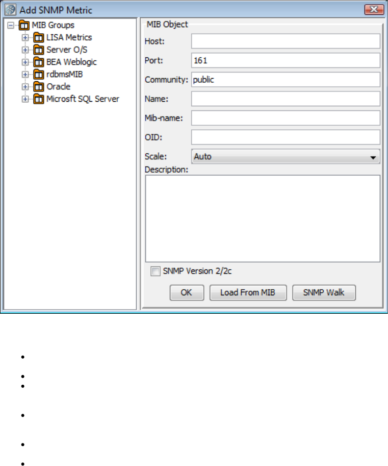
Adding SNMP Metrics
Select from the dialog and click OK. The Add SNMP Metric dialog is displayed.SNMP Metric
The tree displays all the SNMP metrics that come standard with LISA Workstation.MIB Groups
Easy setup for the following is provided by MIBs. A MIB is a predefined database of a set of metrics on a given domain.
Host: Provides system information about a server hosting a coordinator server. Host metrics include for CPUhrProcessorLoad
utilization and for the amount of time since this host was last initialized.hrSystemUptime
Server O/S: Provides information related to the system, like up time, date, number of users, and so forth.
BEA WebLogic: Provides JDBC, JMS, JVM, socket, servlet and web application information about a Server running BEA WebLogic.
BEA WebLogic metrics include for the current amount of free memory in the JVM heap in bytes, and jvmRuntime-HeapFreeCurrent
for the current total number of open sessions in this component.webAppComponentRuntimeOpenSessionsCurrentCount
RDBMS: Provides information about a server running a generic relational database management system. RDBMS metrics include
for the number of physical page reads completed since the RDBMS was last restarted, and rdbmsSrvInfoPageReads for the number of single page writes completed since the RDBMS was last restarted.rdbmsSrvInfoPageWrites
Oracle: Provides information about a server running Oracle. Oracle metrics include for the number of useroraDbSysUserCommits
commits, and for the number of times data has rolled back.oraDbSysUserRollbacks
Microsoft SQL Server: Provides information about a server running Microsoft SQL Server. Microsoft SQL Server metrics include
for the percentage of time that a requested data page was found in the data cache (instead of being readmssqlSrvInfoCacheHitRatio
from disk), and for the number of open user connections.mssqlSrvInfoUserConnections
You can browse through these to select metrics.
When you click the target metric in the left panel, the required parameters for this metric are completed in the form in the right panel.MIB Object
A description of the metric is displayed in the text box. The other information can be ignored or accepted.
You must enter the domain name or IP address of the host computer (Host) where you are collecting the metrics. Click OK to add this metric.
Repeat until you have added all the target SNMP metrics.
To add SNMP metrics that are not in the MIB Group tree, you must manually enter the data (OID) into the form. An OID is the uniqueMIB Object
identifier of a particular metric, using a tree-structured naming scheme. The domain root OID for ITKO is ".1.3.6.1.4.1.12841.1.1", so all SNMP
metrics will start from there.
The button lets you browse the file system for MIBs.Load From MIB
The button lets you browse an SNMP tree.SNMP Walk
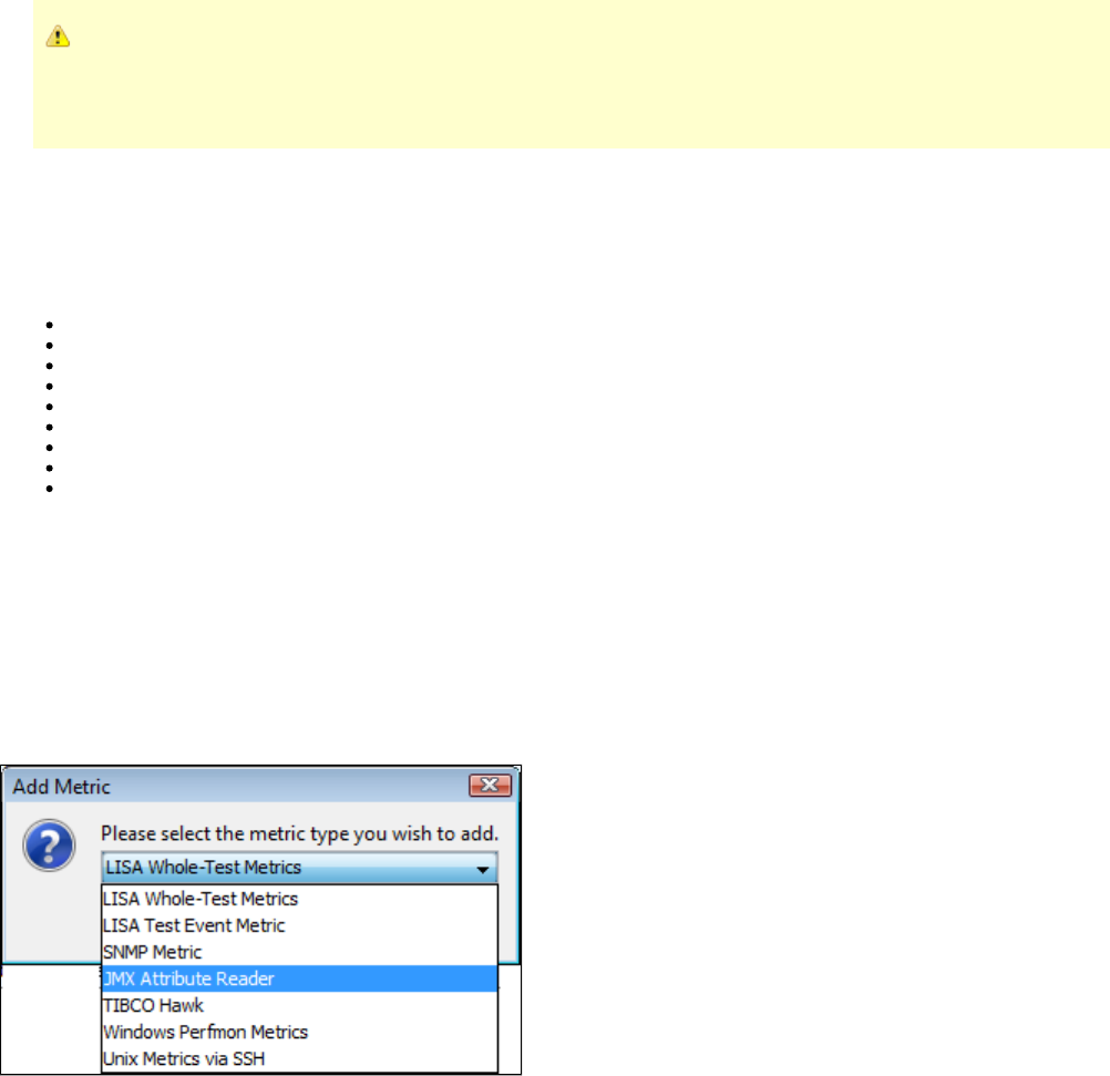
All SNMP MIBs are supported. The set of MIBs displayed in the Add SNMP Metric dialog are only a sample of those supported.
The Add SNMP Metric dialog makes it easier to understand the Object IDs (OIDs) in those MIBs. However, any valid OID
works, not only those displayed in the Add SNMP Metric dialog. A set of all the standard MIBs from IETF and IANA are
provided. Those MIBs are stored in the and directories.LISA_HOME/snmp/ietf LISA_HOME/snmp/iana
JMX Metrics
The JMX metrics uses the Java Management Extension (JMX) API to provide metrics.
JMX connectors are provided for easy set-up:
Any JSR 160 RMI connection
JBoss 3.2-4.0
JSE 5 Connector
Oracle AS (OCJ4)
Tomcat 5.0.28
WebLogic 6.1-8.1
WebLogic 9.x
WebSphere 5.x
iTKO JMX Agents
Each of these requires slightly different connection parameters. The values that you require for your particular server should be available from
your server administrator. There is no agreement on standard metrics, so each provider provides slightly different metrics. To use other JMX
features, you can invoke them as RMI steps.
Only numerical attributes are supported.
Here we will use JBoss as our example.
To add JMX metrics
1. Select from the dialog:JMX Attribute Reader
2. Click OK to display a second dialog, , to configure the JMX agent.Select and Configure JMX Agent
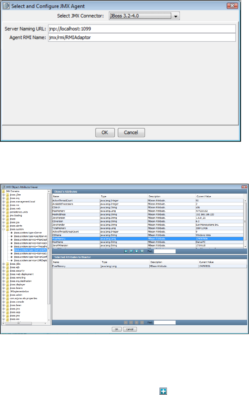
3. Select the target connector, , and enter the connection information and , for your particularJBoss Server Naming URL Agent RMI name
installation.
4. Click OK.
The is now displayed:JMX Object Attribute Viewer
5. On the left is the for JBoss. JMX metrics use an object-attribute model where domain objects are an area published byJMX Domain hierarchy
the particular application server, (for instance "system"), and attributes are name/value pairs within the object.
When you select an object from this tree, the base attributes of that object are also displayed in the tree. After you select a base attribute, the rest
of the attribute name appears in the list in the top right .Object Attribute panel
In the previous example, we selected the domain object to be , the base attribute to be , and the rest of the attributejboss.system ServerInfo
name to be . The attributes for ServerInfo are displayed in the .FreeMemory Object Attribute panel
To select one of these attributes (metrics), select the metric, and click the Add icon. This metric will be added to the list of selected metrics in
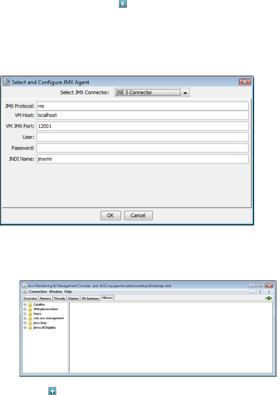
1.
2.
3.
4.
5.
6.
7.
the bottom panel – .Selected Attributes to Monitor panel
To remove an attribute from this panel, click the Delete icon.
Repeat this process until all of your chosen metrics appear in your list (bottom panel).
6. Click OK to return to the main metrics panel.
Notice that the JMX metrics we added are now on our list of metrics.
Depending on the application server, vendor-specific JARs may be required to enable JMX communication with that application server. Visit ITKO
for specific information.Forums
7. Similarly, you can also select the from the JMX Connector list, with the following settings:JSE 5 Connector
8. Click OK to connect to the JMX Agent.
Enabling JMX Metrics for Tomcat
To enable JMX metrics for Tomcat
Modify the file and add You can use the embedded Jakarta-Tomcat packaged with LISA.catalina.bat CATALINA_OPTS.
Connect to Tomcat through JConsole.
Launch LISA, open a staging document, and go to the tab.Metrics
Click the Add icon and select .JMX Attribute Reader
Click OK.
Select .Tomcat 5.0.28
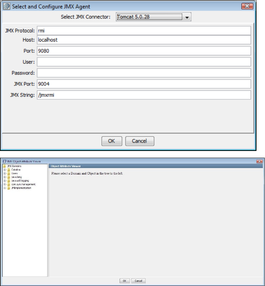
7.
8.
9.
All parameters other than user name and password are pre-populated.
Click OK and connect to the JMX console.
Select a few objects specific to Catalina and add them in the list.
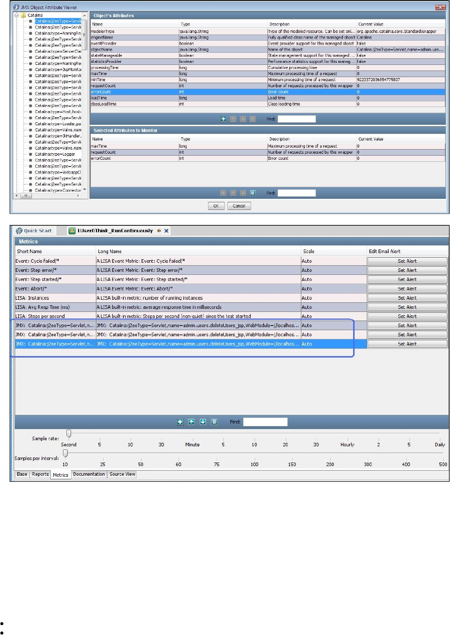
9.
10.
1.
2.
Click OK and these attributes appear in the metrics list.
TIBCO Hawk Metrics
TIBCO Hawk is a tool for monitoring and managing distributed applications and operating systems. Unlike other monitoring solutions, TIBCO
Hawk software uses TIBCO Messaging software for communication and inherits many of its benefits. These benefits include a flexible
architecture, enterprise-wide scalability, and location-transparent product components that are simple to configure.
LISA has out-of-the-box integration with TIBCO Hawk for monitoring distributed applications and operating systems metrics within the context of
testing. TIBCO Hawk provides in-container metrics for TIBCO BusinessWorks process archives. By using TIBCO Hawk, LISA can monitor
metrics of all activities within any TIBCO BusinessWorks process that is deployed. This facilitates peering inside of a process to understand
where bottlenecks are occurring.
Prerequisites:
TIBCO Hawk jar files need to be copied to <LISA_INSTALL_HOME>/lib.
TIBCO Rendezvous and/or TIBCO EMS JAR files, depending on which transport is being used by TIBCO Hawk, need to be copied to
.<LISA_INSTALL_HOME>/lib
Create a staging document.
On the tab of the staging document, click the Add icon and select from the drop-down list.Metrics TIBCO Hawk
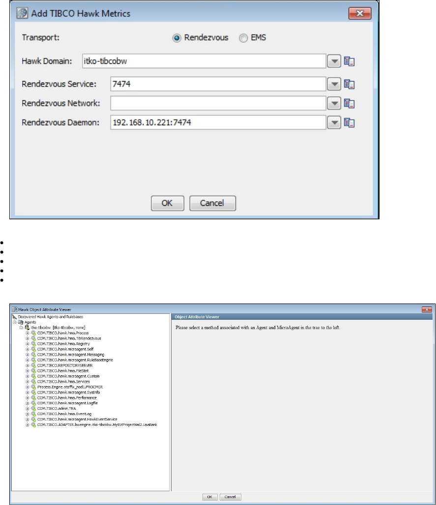
2.
1.
2.
The following parameters are available:
Transport: Select or .Rendezvous EMS
Hawk Domain
Rendezvous Service
Rendezvous Network
Rendezvous Daemon
Click OK to display the Hawk Object Attribute Viewer.
Select the Process Archive and expand beneath it.

2.
3.
4.
5.
GetProcessDefinitions will retrieve the Process Definitions defined in the Process Archive.
Use the Process Definition Name as parameter for .GetActivities
TIBCO Hawk provides a number of metrics for Process Activities.
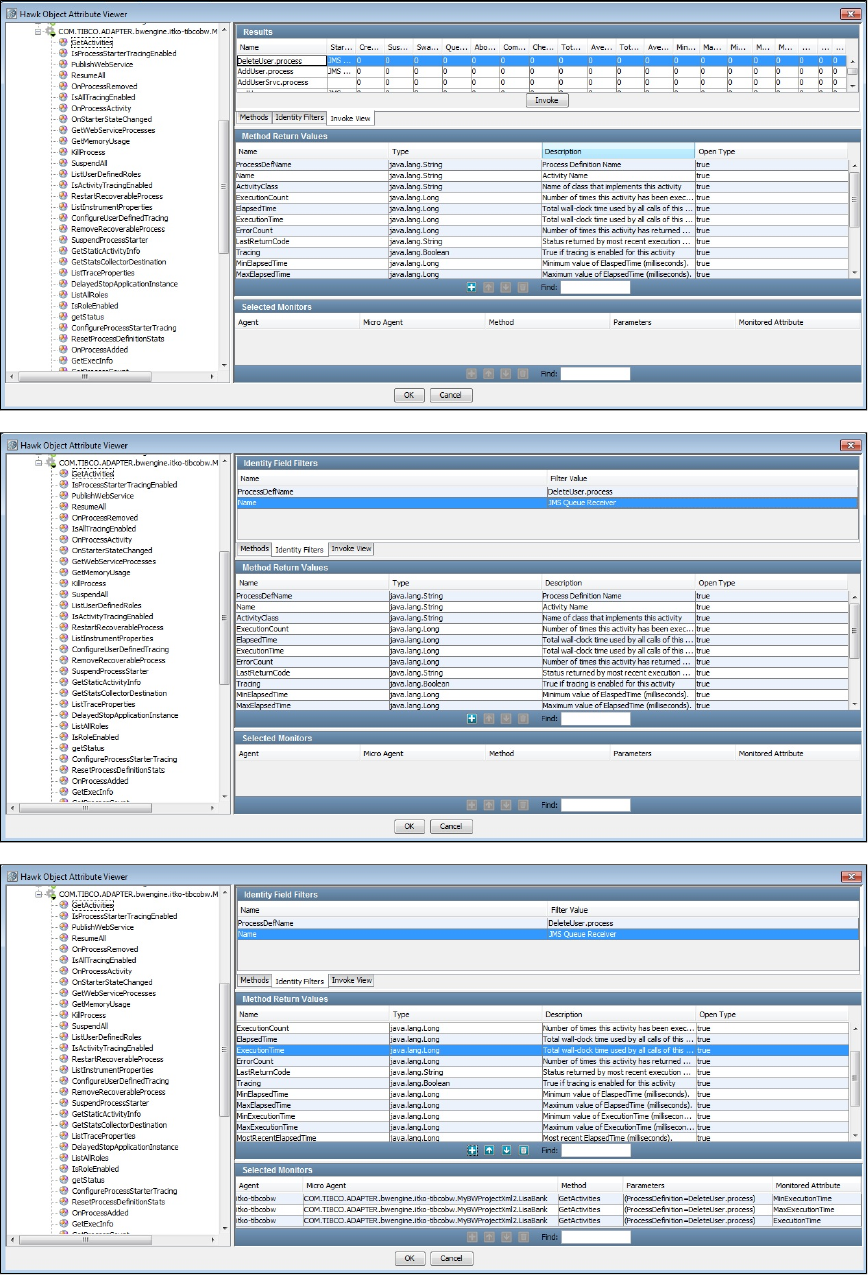
5.
6.
7.
8.
Provide a Filter with the Process Definition Name and the Activity Name.
Select Method Return Values and click OK.
Activity Metrics will now be monitored for test cases staged with this staging document.
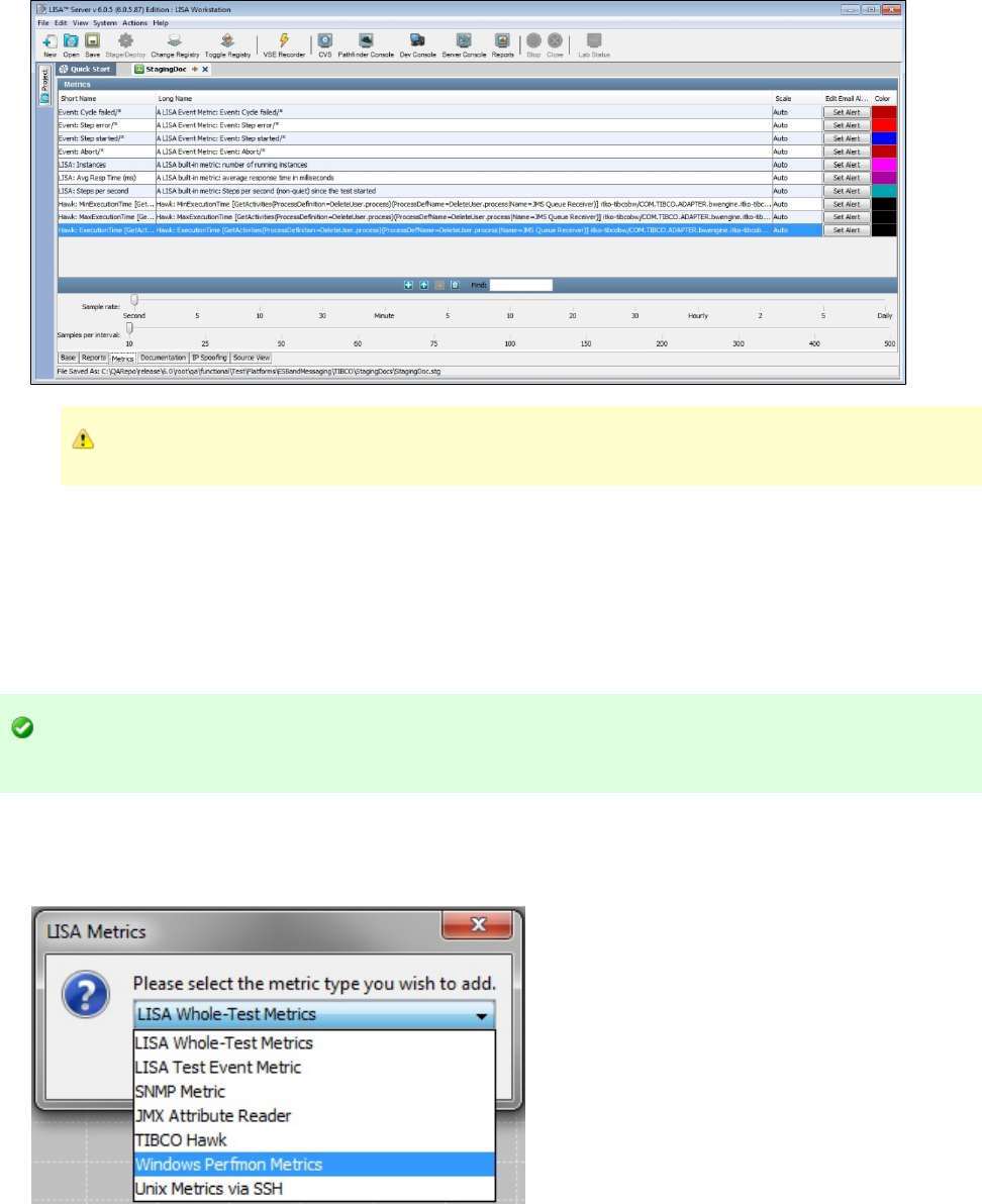
8.
1.
2.
TIBCO Hawk can be also be invoked within a test case, through TIBCO Hawk APIs.
Windows Perfmon Metrics
The Perfmon Metrics use Microsoft Windows Perfmon to provide metrics to monitor system performance on a Windows operating system. These
metrics are similar to the SNMP metrics.
Setting up Perfmon
Before you can collect Perfmon metrics you must configure Perfmon on your Windows computer.
You must have Microsoft .NET framework 2.0 or higher installed and you need to run the file located insetup-wperfmon.bat
the LISA_HOME/bin directory.
For more details on setting up Perfmon, see .Installing Performance Monitor (Perfmon)
To add Perfmon metrics
Select from the LISA Metrics dialog and click OK.Windows Perfmon Metrics
The Windows Perfmon Machine Name dialog is displayed.
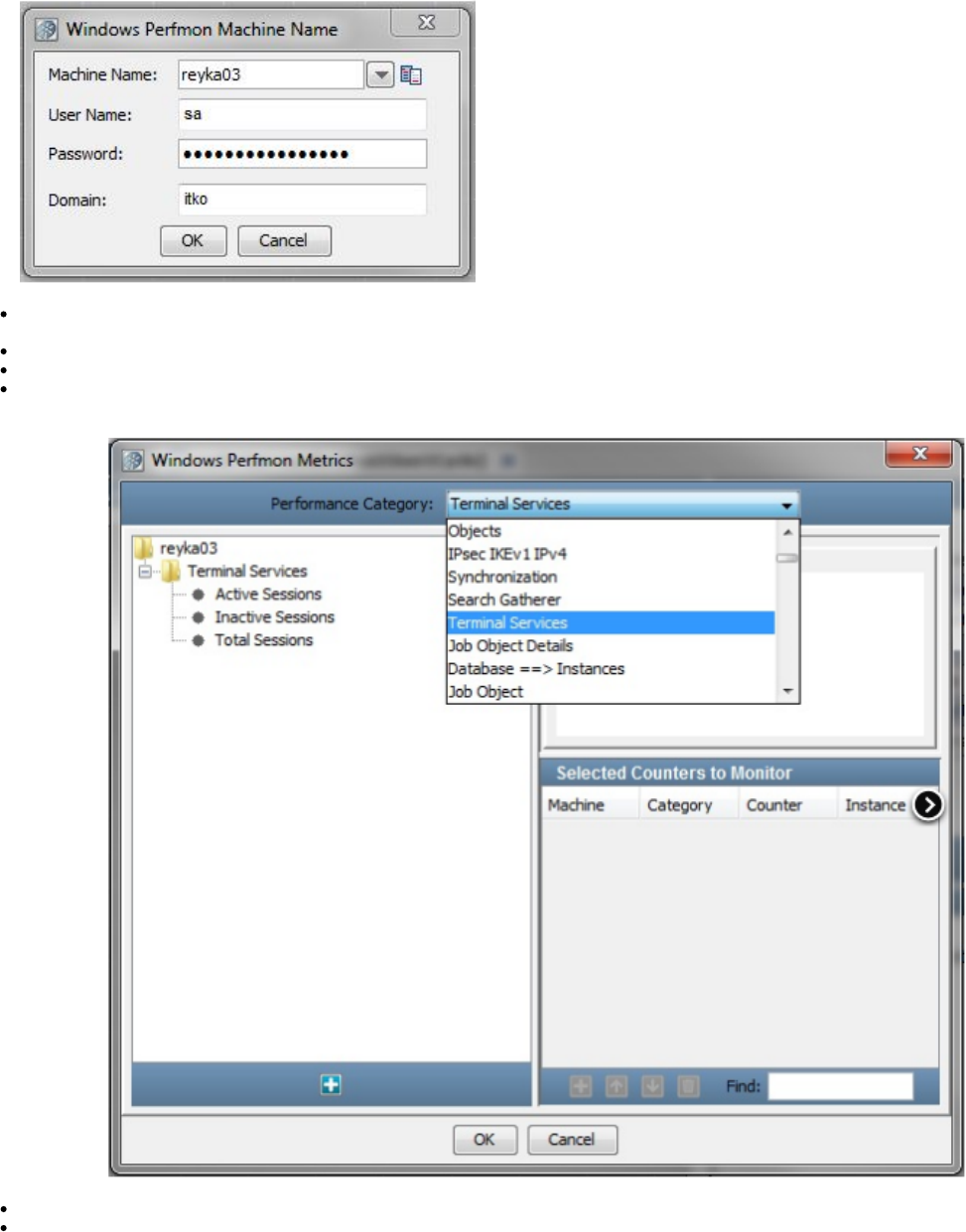
2.
Machine Name: Enter the of your Windows installation. This can be found by right-clicking My Computer, selectingMachine Name
Properties, and going to the Computer Name tab.
User Name: Enter the user name of the remote computer.
Password: Enter the password of the remote computer.
Domain: Enter the domain name. A domain is optional.
3. Click OK to proceed.
4. After you enter valid login credentials, a window appears showing all the available metric types. The Windows Perfmon Metrics screen
is displayed.
5. The Perfmon Metric window has three panels.
The left panel displays the Category.Selected Performance
The top right panel displays the description of the highlighted category in the section.Counter Description
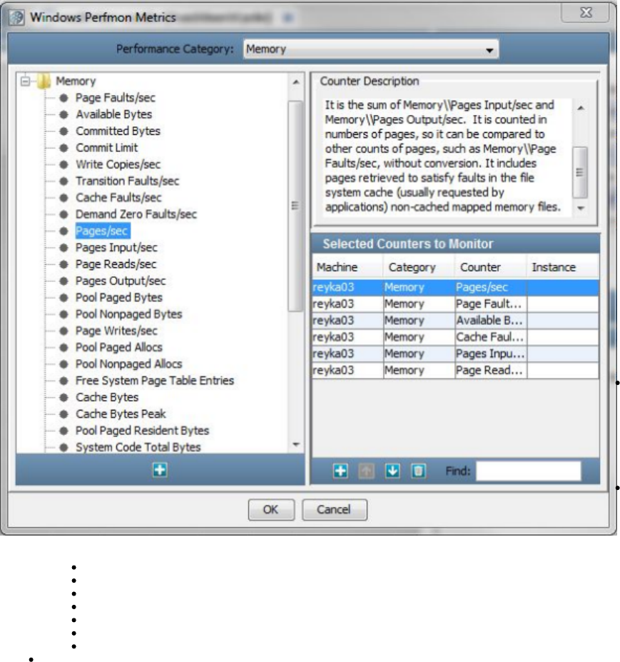
The bottom right
panel lists the metric
that is highlighted in
the left panel.
To select a particular
metric:
Performance
Category: Select a
performance
category from the
pull-down menu.
This lists various categories which can be monitored. To name a few:
.NET CLR Remoting/ LocksandThreads
.NET CLR Data/Networking
Job Objects/Job Object Details
Performance/RSVP Service
Memory/Print Queue
ICMP/Process
Outlook/Logical disk
IP/Server/Cache
6. After you select the category, it will be added to the left panel.
7. Double-click the target metric in the left panel to add it to the table on the right panel.Selected Counters to Monitor
8. Repeat until you have added all the target Perfmon metrics.
9. Click OK.
Example
We have added the following metric:
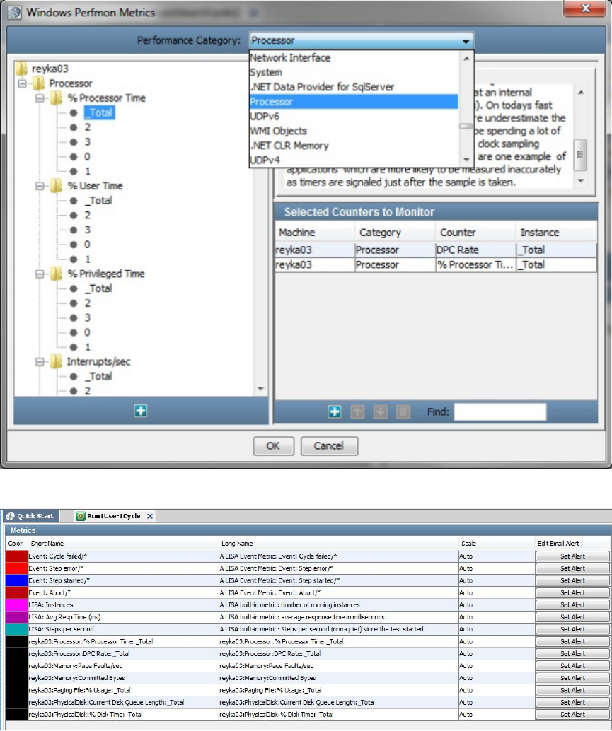
Click OK to add these to the Metric list on the Metric tab of the staging document.
You can also set an email alert for this metric by clicking on the Set Alert button.
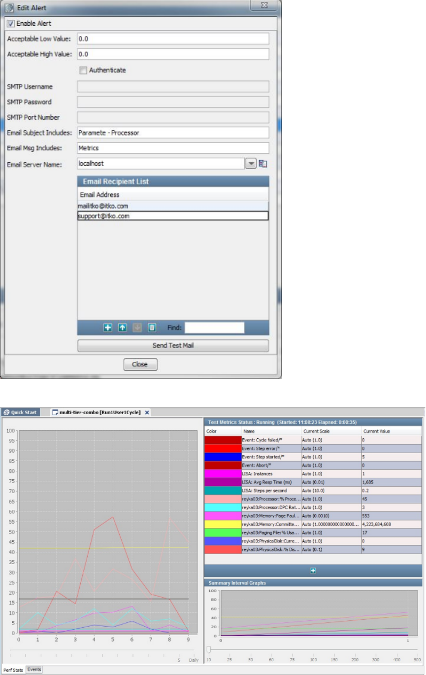
The following graph shows the Perfmon metric being collected while a test is executing.

UNIX Metrics Via SSH
This metric is used to collect command line metrics. This metric will gather inputs like authentication details, host name and the selection of
metrics that need to be collected.
The metric data is stored in an XML file that is located in the directory by default, but you can define a new location byLISA_HOME/umetrics
updating the key in .stats.unix.xml.folder local.properties
Each file in that directory has a unique file name based on operating system.
The XML file is used to feed the information about the command and metrics that needs to be collected on a particular operating system. For
example, to make the command and metrics are known on a Linux operating system, a linux.xml file should be in the LISA_HOME/umetrics
folder.
Following is an example of an OSX command parser for that collects CPU and disk0 metrics.iostat
In the screen, enter the operating system: Linux, OS X, or Solaris.Specify Remote Machine details
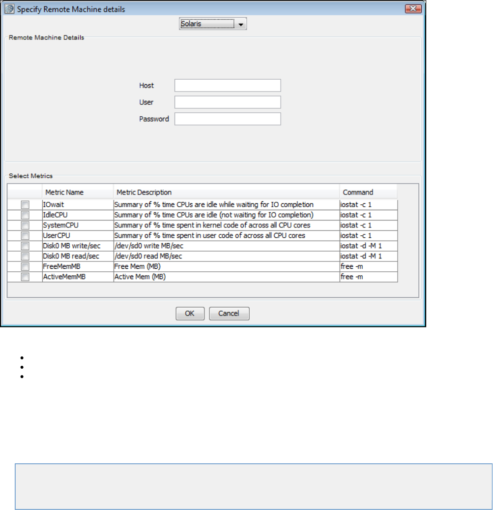
1.
2.
3.
4.
5.
6.
Enter the remote machine details:
Host
User
Password
Each operating system has a slightly different set of metrics from which to choose. Use the check box in the left column to select the metrics you
would like to collect.
Building Test Suites
You can run/stage a combination of test cases together in LISA. The collection of test cases run together are in a form of a test suite.
The following topics are available:
Creating a Test Suite
Test Suite Editor
Creating a Test Suite
You create test suites from within LISA Workstation.
To create a test suite
From the main menu, select File > New > Suite.
The suite document editor appears.
In the , specify basic information about the suite. This information includes the suite name and the suite entries.Base tab
In the , specify the type of report that you want to create at runtime.Reports tab
In the , specify the metrics that you want to record at runtime.Metrics tab
In the , enter descriptive information about the suite.Documentation tab
From the main menu, select File > Save.
Test Suite Editor
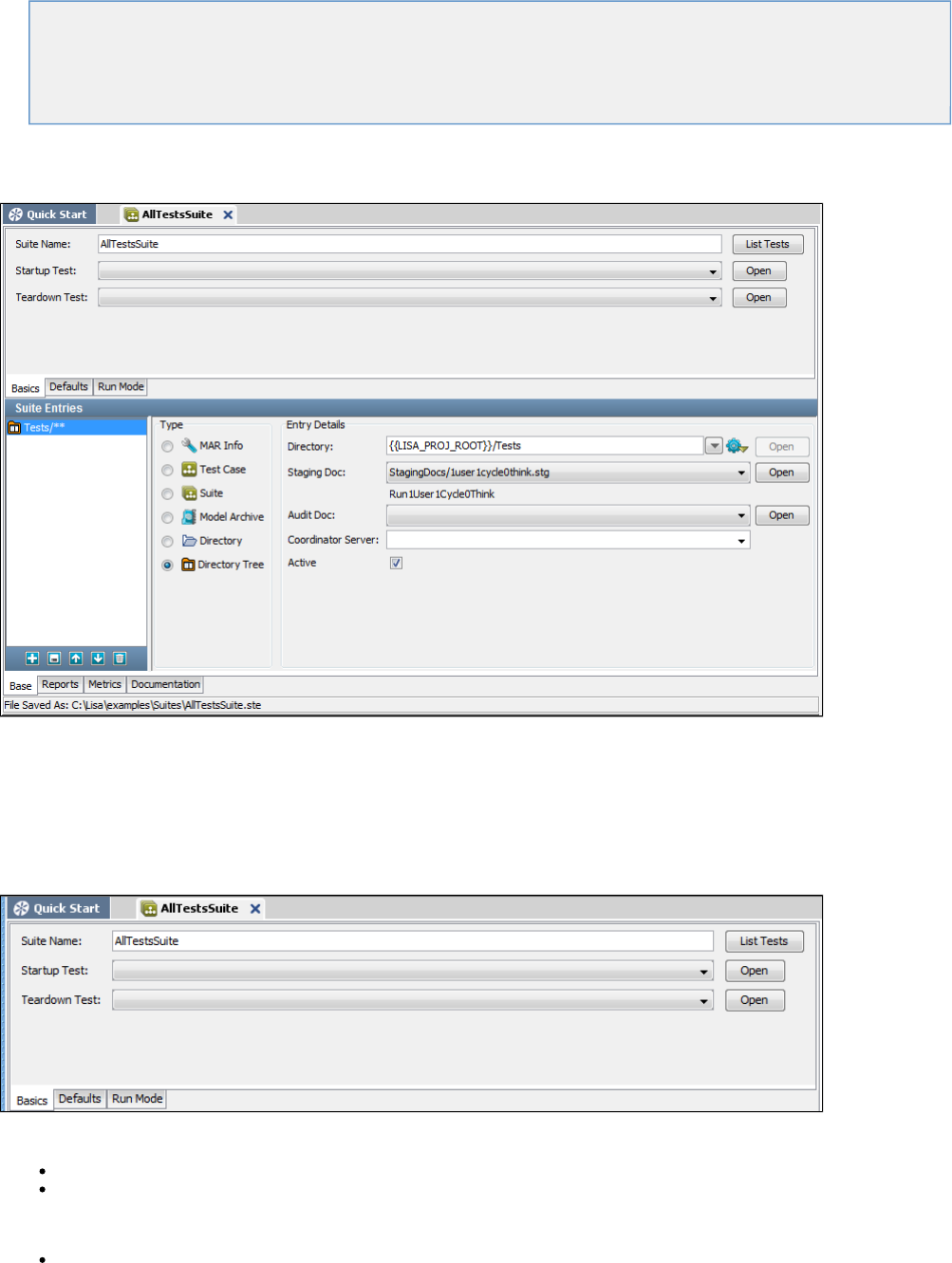
When you create a new test suite, or open an existing test suite, the Test Suite Editor is displayed.
In this section, the following topics are covered:
Test Suite Editor - Base Tab
Test Suite Editor - Reports Tab
Test Suite Editor - Metrics Tab
Test Suite Editor - Documentation Tab
Test Suite Editor - Base Tab
The Base tab of the Suite Document Editor contains basic information about a test suite.
Top Panel
The top panel of the Base tab has basic information about the test suite as a whole.
To configure a suite, you also need to enter parameters in all the sub-tabs.
Basics Tab
This tab has the following parameters:
Suite Name: The name of the suite.
Startup Test/Teardown Test: You can specify a startup test that will run before the suite has begun, and a teardown test that will run
after the suite has completed. Neither the startup test nor the teardown test is included in any test statistics. Events in these tests will
appear in the reports. Test suite testing will not continue if the startup test fails. As of release 6.0.5, you can use a MAR info file as a
startup or teardown test. The primary asset of the MAR info file must be a test case.
List Tests: Displays a dialog window with a list of the tests currently included in your suite. You must save your suite for this list to be
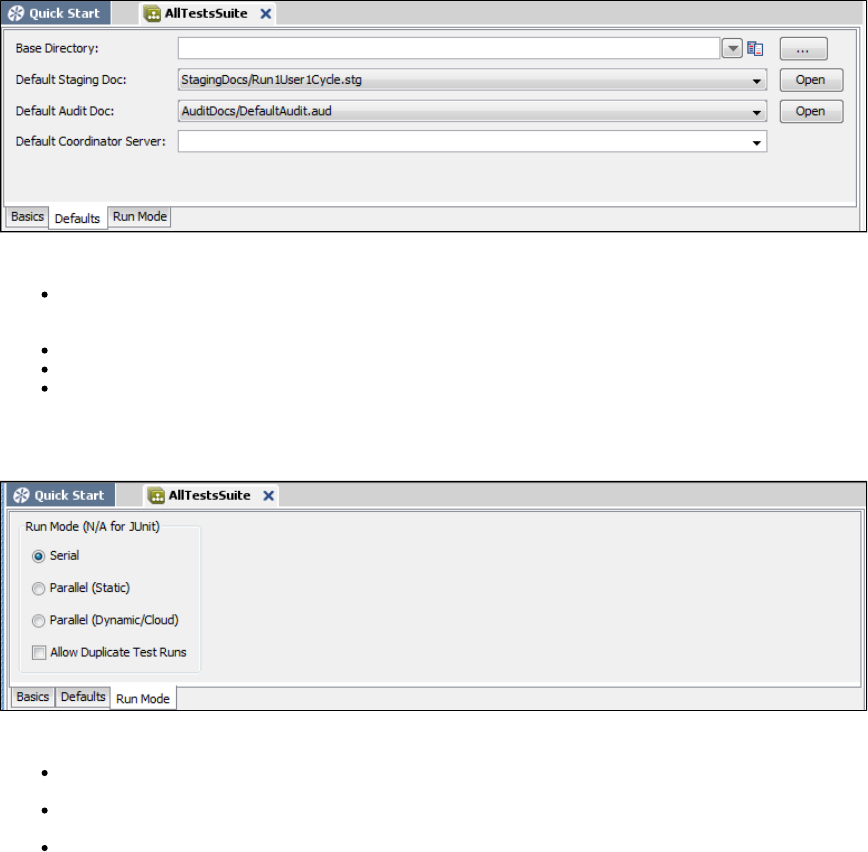
current.
Defaults Tab
This tab has the following parameters:
Base Directory: The name of the directory that will be assumed to be the base directory for any individual test that does not contain a
complete path, or a test cannot be found elsewhere it will look in this directory. If you do not specify a base directory, a default will be
created for you when the suite document is saved.
Default Staging Doc: The staging document to use if one is not specified for an individual test.
Default Audit Doc: The audit document to use if one is not specified for an individual test.
Default Coordinator Server: The coordinator server to use if one is not specified for an individual test. The pull-down menu lists the
available coordinator servers. This parameter is needed only if you are running LISA Server.
Run Mode Tab
This tab has the following parameters:
Serial: Tests will be run one after another in the order they show up in the suite document. This is the setting you would use for functional
and regression testing.
Parallel: Tests will be run at the same time. This is the setting you would use for load and performance testing. You must have enough
virtual users to be able to run all tests concurrently.
Allow Duplicate Test Runs: Lets you choose if you want the same test to run more than once. Duplicate tests can occur in a suite if the
same test appears in an included suite, a directory, or a directory tree.
Bottom Panel
The bottom panel of the Base tab shows the types of documents that can be added in the suite and the associated document details.
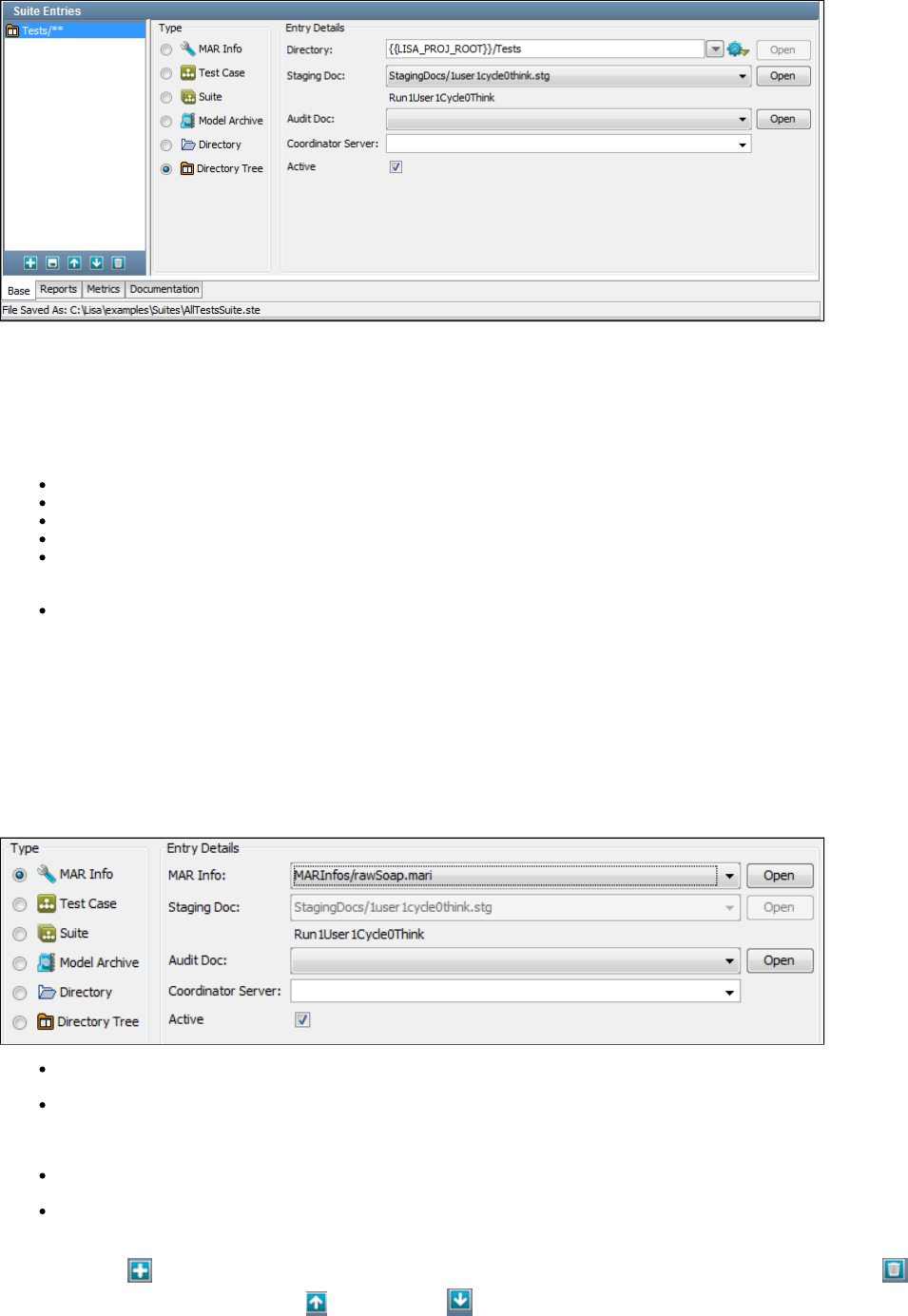
This panel is where you build your suite by adding individual tests, existing suites, and directories and directory trees that contain tests.
A list of the suite entries is displayed in the left panel, after all of the tests have been added and saved to the suite document.
Suite entries are added individually by selecting from the following types. Depending on the selection, the Entry Details area will change.
Type: Select the suite entry type as one of the following:
MAR Info: The name of a Model Archive (MAR) info file.
Test Case: The name of a test case.
Suite: The name of a suite document. All tests will be extracted from this suite and run as individual tests.
Model Archive: The name of a Model Archive (MAR) file.
Directory: The name of a directory that contains tests to be included in the suite. The same staging document, audit document, and
coordinator server will be used for all tests in this directory. If new test cases are added to the directory, they will automatically be
included in this suite.
Directory Tree: The name of a directory that contains tests to be included in the suite. LISA will look in the named directory and
recursively through all sub-directories in the tree. The same staging document, audit document, and coordinator server will be used for all
tests in this directory tree. If new test cases are added to the directory tree, they will automatically be included in this suite.
The Active check box lets you control whether the selected entry will run. For example, you can clear the Active check box for one of the test
cases in a suite.
Adding a Document Type in a Suite
Depending on the document type selected, the fields for entry details change.
As an example, we will add a MAR info document. The entry details for the same have changed from the ones shown for a directory tree.
MAR Info: The MAR info name. Enter the name or select from the pull-down menu or browse to the file or directory. When it is selected,
click Open to open the respective file.
Staging Doc: The name of the staging document for this entry. Enter the name, select from the pull-down menu, or browse to the
document. If you leave this entry blank, the default staging document will be used. After it is selected, click Open to open the staging
document. When you have selected a staging document to use in this suite, the name of the staging document (the same Run Name as
you see on the editor tab when you are editing the document) appears below the Staging Doc field.
Audit Doc: The name of the audit document for this entry. Enter the name, select from the pull-down menu, or browse to the document.
If you leave this entry blank, the default audit document will be used. After it is selected, click Open to open the audit document.
Coordinator Server: The name of the coordinator server to use with this entry. Select from the list of available coordinator servers listed
in the pull-down menu. This parameter is needed only if you are running a LISA Server.
Click the Add icon on the toolbar to add this entry to the list shown in the left panel. You can delete entries by using the Delete icon. You
can re-arrange entries by using the Move Up and Move Down icons.
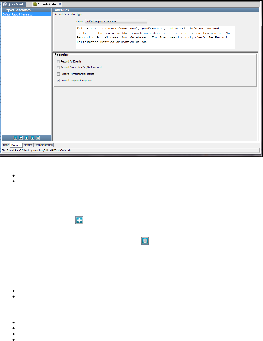
After you have entered all your test entries, save your test suite document.
Test Suite Editor - Reports Tab
The Reports tab of the Test Suite Editor is where you specify the LISA test reports you want to produce, and the events you want to capture at the
test suite level.
Details of the reports available in each report generator, viewing reports, report contents and output options are discussed in detail in .Reports
The metrics to capture for the reports are discussed more fully in .Metrics
The Reports tab contains the following panels:
Report Generators
Attributes
Report Generators
The Report Generators panel has a list of the reports that have been selected.
To add a report, click the Add icon at the bottom of the list panel and select the report type from the Type pull-down menu in the center of the
Reports panel.
To delete a report, select the report in the list and click the Delete icon.
Attributes
The Attributes panel lists the available report types.
The following report types are available:
Default Report Generator
XML Report Generator
Parameters
Record All Events: If selected, will record all events.
Record Properties Set/Referenced: If selected, will record the set or referenced properties.
Record Performance Metrics: If selected, will record the performance metrics. Use this for load testing.
Record Request/Response: If selected, will record the request and response.
Test Suite Editor - Metrics Tab
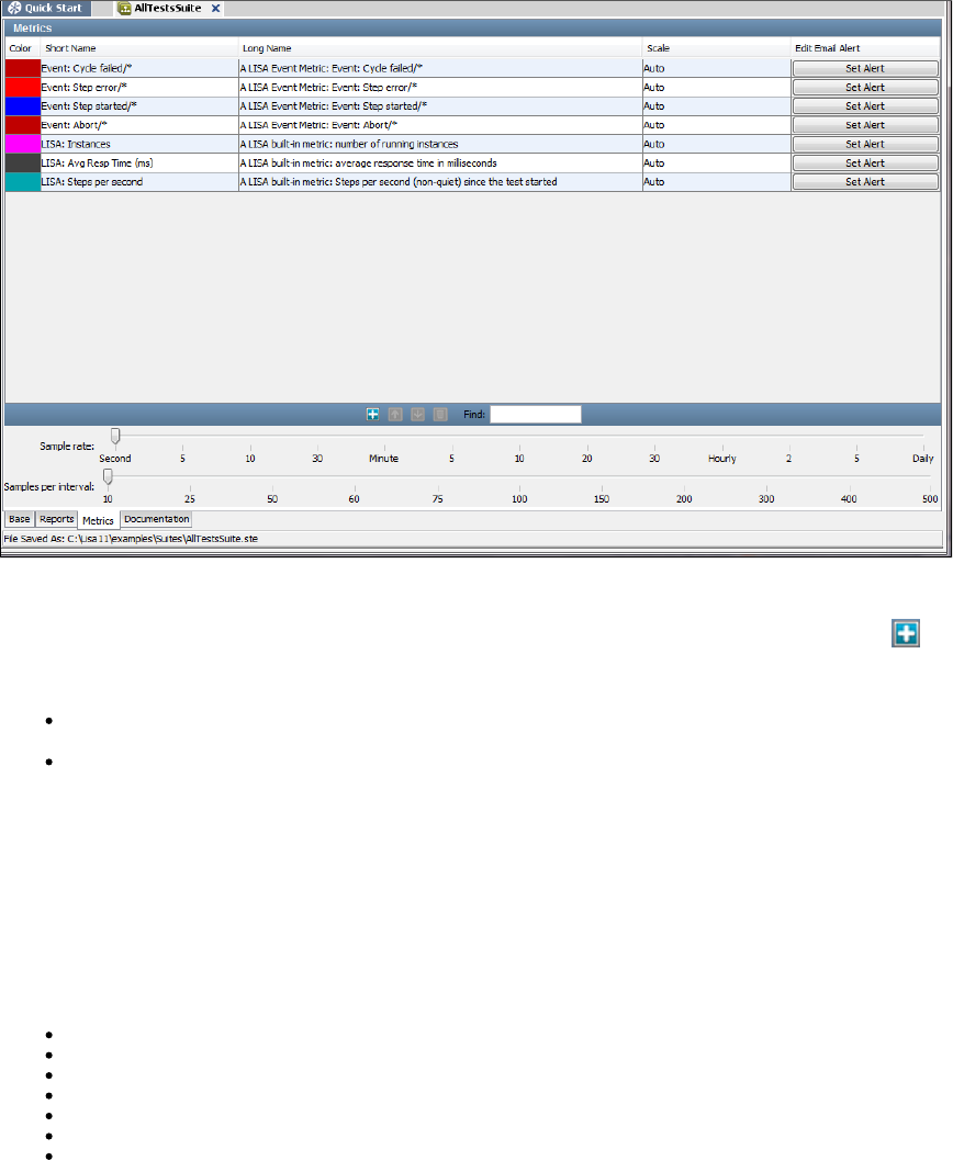
1.
2.
3.
The Metrics tab of the Test Suite Editor is where you select the test metrics you want to record, and set the sampling specifications for the
collection of the metrics.
You can also set an email alert on any metric that you have selected.
The Metrics tab is divided into two sections.
The top panel shows the default metrics that are added to the suite. You can add more metrics by clicking the Add button on the toolbar.
In the bottom panel, two slider bars enable you to set sampling parameters:
Sample rate: Specifies how often to take a sample, that is, record the value of a metric. This parameter is specified as a time period, and
is the reciprocal of the sampling rate.
Samples per interval: Specifies how many samples are used to create an interval for calculating summary values for the metric.
So, taking sample values every minute (Sample Rate Per Interval=1 minute), and averaging every 60 samples (Samples Per Interval=60), will
produce a metric value every minute, and a summary value (average) every hour.
For example, the default is a 1 second Sample Rate, and 10 samples per interval (making an interval 10 seconds).
Metric values are stored in XML files or database tables for inclusion in reports (see ).Reports
Adding Metrics
The following metrics categories are available:
LISA Whole Test Metrics
LISA Test Event Metrics
JMX Metrics
SNMP Metrics
TIBCO Hawk Metrics
Windows Perfmon Metrics
UNIX Metrics Via SSH
To add metrics
Click the Add button on the toolbar. The Add Metric dialog appears.
Select the target metric and click OK.
Repeat the procedure to configure metrics from the other categories.
For descriptions of all the metrics, in all categories, and details on how to configure them for inclusion in your reports, see .Generating Metrics
Setting Email Alerts
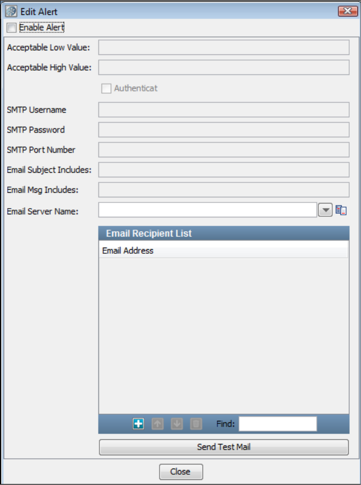
1.
2.
3.
4.
To set an email alert
Click the Set Alert button corresponding to the metric. The Edit Alert dialog appears.
You can set the acceptable limits for the metric (low and high value), and the details to be sent in an email. You must provide the name of
your email server, and a list of email addresses.
You can add and delete email addresses by using the Add and Delete icons at the bottom of the window.
When finished, click Close.
Test Suite Editor - Documentation Tab
The Documentation tab of the Test Suite Editor is where you enter the related documentation.
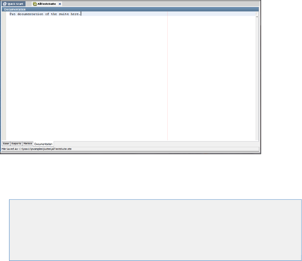
Working with Model Archives (MARs)
The main deployment artifact is a type of file named a Model Archive (MAR).
You can configure MARs from LISA Workstation or by using the Make Mar command-line utility.
In this section, the following topics are covered:
Model Archive (MAR) Overview
Explicit and Implicit MAR Creation
Creating MAR Info Files
Creating Monitor MAR Info Files
Editing MAR Info Files
Building MARs
Deploying to CVS
Make Mar
Model Archive (MAR) Overview
The main deployment artifact is a type of file referred to as a Model Archive (MAR). The file extension is ..mar
MAR files contain a primary asset, all secondary files that are needed to run the primary asset, an info file, and an audit file.
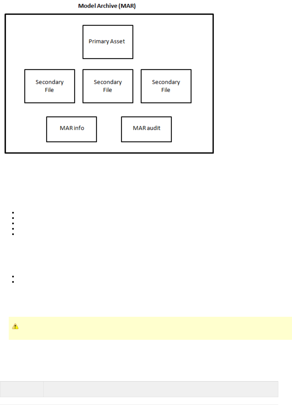
MAR files can also include the contents of the directory, which is used in ..settings LISA Web 2.0
MAR files are created from files in a project. After a MAR file is created, it is independent of the project.
Contents of a MAR
MAR files contain one of the following primary assets:
Test case
Suite
Virtual service
Test case monitor
Suite monitor
MAR files also contain any secondary files that are required by the primary asset.
For example, if the primary asset is a virtual service model, then the MAR file also contains a service image.
In addition, MAR files contain the following files:
MAR info file
MAR audit file
You can specify that a MAR file be . When the MAR file is built, only those project files that are required will be added. However, youoptimized
can also configure an optimized MAR file to include one or more non-required project files.
If a MAR file is not optimized, all the project files will be added.
An archive is typically held in memory. Therefore, the use of optimized archives is highly encouraged.
MAR Info File
MAR info files contain information needed to create a MAR. The file extension is ..marinfo
The information specified in a MAR info file depends on the type of primary asset.
Primary Asset Information Specified
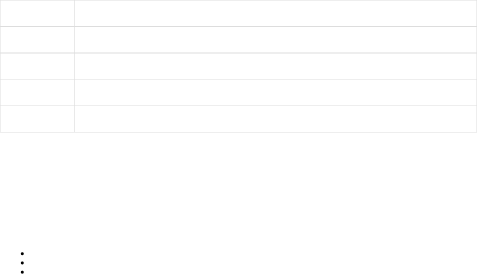
1.
2.
3.
1.
2.
1.
Test case Test case, configuration file, and staging document
Suite Suite and configuration file
Virtual service Virtual service model, configuration file, concurrent capacity, think time scale, and auto restart flag
Test case monitor All the information specified for a test case, plus the service name, notification email, priority, and run schedule
Suite monitor All the information specified for a suite, plus the service name, notification email, priority, and run schedule
MAR info files are located in the folder of a project. However, when you use the stage/deploy related options, a MAR info file is createdMARInfos
but not saved.
The project contains a variety of MAR info files that you can review.examples
MAR Audit File
MAR audit files contain metadata about the creation of a MAR. The file extension is ..maraudit
The following metadata is included in a MAR audit file:
The date and time when the MAR was created
The name of the computer on which the MAR was created
The name of the user that created the MAR
Explicit and Implicit MAR Creation
There are two approaches to creating MARs: explicit and implicit.
To use the web-based dashboards or command-line utilities to deploy assets, you must explicitly create a MAR. An exception is the Test Runner
command-line utility, which you can use to run test cases and suites that are not packaged in a MAR.
If you are staging a test case, staging a suite, deploying a virtual service, deploying a test case as a monitor, or deploying a suite as a monitor
from within LISA Workstation, then you use the implicit approach.
Explicit MAR Creation
In the explicit approach, you perform steps to create a MAR info file, which you then use to build the MAR.
The general steps are as follows:
Identify the primary asset that you want to execute.
Create a MAR info file.
Build the MAR.
Implicit MAR Creation
In the implicit approach, both a MAR info file and a MAR are automatically created.
The general steps are as follows:
Identify the primary asset that you want to execute.
Stage a test case, stage a suite, deploy a virtual service, deploy a test case as a monitor, or deploy a suite as a monitor from within LISA
Workstation or by using Test Runner.
Creating MAR Info Files
You can create a MAR info file from an existing test case, suite, or virtual service.
To create a MAR info file from an existing test case
In the Project panel of LISA Workstation, right-click the test case and select Create MAR Info File.
The Create MAR Info File dialog appears.
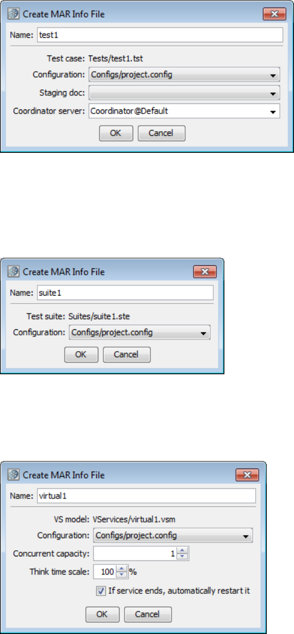
1.
2.
3.
4.
5.
6.
1.
2.
3.
4.
1.
2.
3.
4.
5.
6.
In the Name field, enter a name for the MAR info file.
In the Configuration field, select the configuration file for this test case.
In the Staging doc field, select the staging document for this test case.
In the Coordinator server field, select the coordinator server for this test case (if applicable).
Click OK.
The .mari file is created in the folder of the Project panel.MARInfos
To create a MAR info file from an existing suite
In the Project panel of LISA Workstation, right-click the suite and select Create MAR Info File.
The Create MAR Info File dialog appears.
In the Name field, enter a name for the MAR info file.
In the Configuration field, select the configuration file for this suite.
Click OK.
The .mari file is created in the folder of the Project panel.MARInfos
To create a MAR info file from an existing virtual service
In the Project panel of LISA Workstation, right-click the virtual service and select Create MAR Info File.
The Create MAR Info File dialog appears.
In the Name field, enter a name for the MAR info file.
In the Configuration field, select the configuration file for this virtual service.
In the Concurrent capacity field, enter a number to indicate the load capacity. The default value is 1, but it can be increased to provide
additional capacity. is how many virtual users (instances) can execute with the virtual service model at one time. hereCapacity Capacity
indicates how many threads there are to service requests for this service model.
In the Think time scale field, enter the think time percentage with respect to the recorded think time. To double the think time, use 200. To
halve the think time, use 50. The default value is 100.

6.
7.
1.
2.
3.
4.
5.
6.
7.
The check box keeps the service running even after an emulation session has reached its endIf service ends, automatically restart it
point. Clear the check box, or leave it selected.
Click OK.
The .mari file is created in the folder of the Project panel.MARInfos
Creating Monitor MAR Info Files
You can create a Monitor MAR info file from an existing test case or suite.
For more information on monitors, see .Continuous Validation Service (CVS)
To create a Monitor MAR info file
In the Project panel of LISA Workstation, right-click the test case or suite and select Create Monitor MAR Info File.
The Create Monitor MAR Info File dialog appears.
In the Name field, enter a name for the MAR info file.
In the , specify the monitor information.Monitor Info tab
In the , specify the time schedule information.Schedule tab
(Test Case) In the , specify the test case information.Test Case Info tab
(Suite) In the , specify the suite information.Suite Info tab
Click OK.
The .mari file is created in the folder of the Project panel.MARInfos
Monitor Info Tab
The following image shows the Monitor Info tab of the Create Monitor MAR Info File dialog.
Specify the following information:
Service Name: The name of the service. This name appears in the CVS Dashboard.
Notify Email: The email address of the person for notification.
Priority: Set the priority to High, Medium High, Medium, Medium Low, or Low.
Schedule Tab
The following image shows the Schedule tab of the Create Monitor MAR Info File dialog.
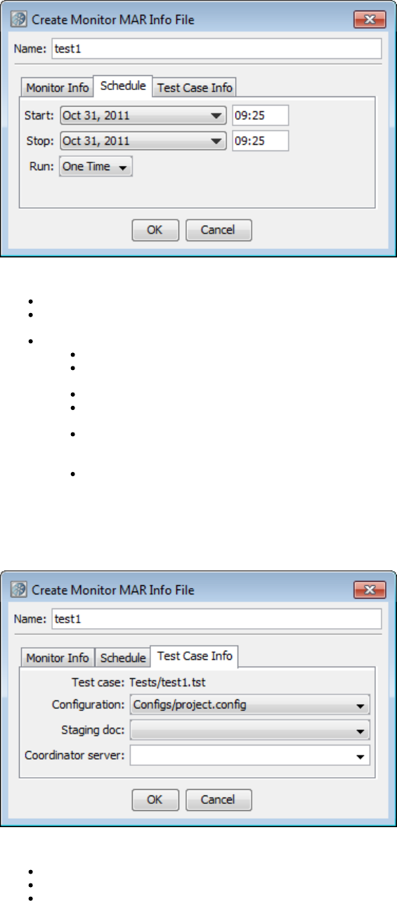
Specify the following information:
Start: The date and time when the monitor will start. For the time value, you must use a 24-hour clock.
Stop: The date and time when the monitor will stop. For the time value, you must use a 24-hour clock. The stop date and time must be
later than the start date and time.
Run: How often the monitor will run. Depending on the selection, additional options may appear.
One Time: The monitor will run once, at the start date and time.
Every: Enter the frequency in minutes. The monitor will run every NN minutes. However, if the previous run has not completed,
CVS will skip the run and try again at the next scheduled time. CVS will not terminate a monitor after it has started.
Daily: The monitor will run once a day, at the time specified in the start time.
Weekly: Select one or more days of the week. The monitor will run once on each selected day, at the time specified in the start
time.
Monthly: Enter one or more days of the month. If you enter multiple days, they must be separated by spaces. For example, you
could enter . If you specify a day that does not occur in a particular month (such as 31), the day is ignored for that month.1 15 30
The monitor will run once on each day, at the time specified in the start time.
CRON: Enter a standard cron specification. Cron is a standard UNIX syntax for specifying time intervals. This approach allows
the most flexibility when specifying a run schedule.
Test Case Info Tab
The following image shows the Test Case Info tab of the Create Monitor MAR Info File dialog.
Specify the following information:
Configuration: The name of the configuration. If this field is blank, the configuration active in the test case is used.
Staging doc: The name of the staging document.
Coordinator Server: The name of the coordinator server.
Suite Info Tab
The following image shows the Suite Info tab of the Create Monitor MAR Info File dialog.
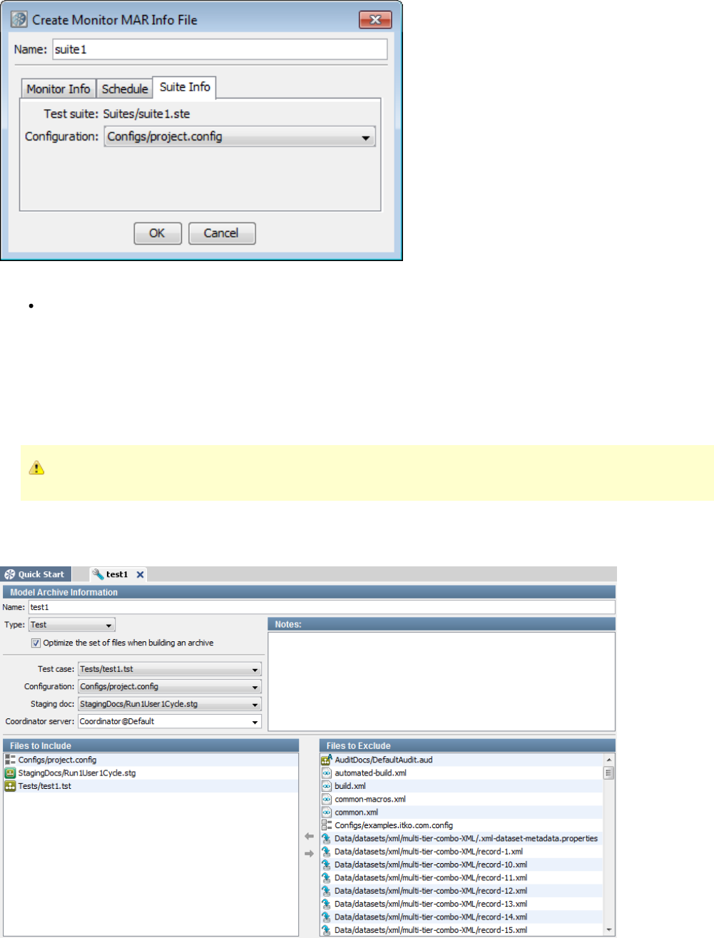
1.
Specify the following information:
Configuration: The name of the configuration.
Editing MAR Info Files
The MAR info editor lets you change the information that was specified during the creation of the MAR info file.
The editor includes an optimize check box. By default, the check box is selected. When the MAR file is built, only those project files that are
required by the primary asset will be added. However, the editor lets you specify that an optimized MAR file include one or more non-required
project files.
An archive is typically held in memory. Therefore, the use of optimized archives is highly encouraged.
If you clear the optimize check box, then all the project files will be added to the MAR file.
The following image shows the MAR info file editor.
To edit MAR info files
1.
2.
3.
4.
5.
6.
1.
2.
3.
1.
2.
In the Project panel of LISA Workstation, double-click the MAR info file.
The editor appears.
The information that you can edit in the upper area depends on the type of MAR info file.
In the Notes area, add any notes about the MAR info file.
By default, the optimize check box is selected. The Files to Include area lists the required project files. The Files to Exclude area lists the
non-required project files. If you want the MAR to include any non-required project files, then move the files to the Files to Include area.
If you want the MAR to include all of the project files, then clear the optimize check box. The Files to Include and Files to Exclude areas
will be disabled.
From the main menu, select File > Save.
Building MARs
After you have created and edited a MAR info file, you can use the file to build a .Model Archive (MAR)
You can save the MAR to a folder that is inside or outside the project directory.
To build a MAR
In the Project panel of LISA Workstation, right-click the MAR info file and select Build Model Archive.
The Build Model Archive dialog appears.
Navigate to the folder where you want to save the MAR.
Click Save.
Deploying to CVS
You can deploy a to CVS.Monitor MAR info file
To deploy to CVS
In the Project panel of LISA Workstation, right-click the .mari file and select Deploy to CVS.
A confirmation message appears.
You can go to the CVS Dashboard and see the newly added monitor.
Make Mar
You can use the Make Mar command-line utility to show the contents of MAR info files (standalone or in an archive) or to create model archive
files from MAR info files.
This utility is located in the directory.LISA_HOME/bin
Options
Each option has a short version and a long version. The short version begins with a single dash. The long version begins with two dashes.
-h, --help
Displays help text.
-s file-name, --show=file-name
Shows the contents of a MAR info file.
If the file name refers to a MAR info file, then it is written out. If the file name refers to an archive, then both the audit and info entries are
written out.
-c, --create
Creates one or more model archives from MAR info files.
Use the --marinfo argument to specify the MAR info file name to build the archive.
Use the --archive argument to specify the name of the archive to create.
If the --source-dir argument is used, then the --marinfo argument is taken as a name pattern to look for in the full directory tree. In this case,
the --target-dir argument must be used to note where to place the created archives. This also implies auto-naming of the created archives.
-m mar-info-name, --marinfo=mar-info-name
Specifies the name of the MAR info file to read (if the --source-dir argument is not used) or the MAR info file name pattern to look for (if the
--source-dir argument is used). In the latter case, if not specified, it will default to ..mari
-s directory, --source-dir=directory
Specifies the directory where the tool will search for MAR info files to make archives from. The full directory tree will be searched for files
that match the pattern specified by the --marinfo argument.
-t output-directory, --target-dir=output-directory
Specifies the directory where archives are to be written.
When this argument is used, the created archives are automatically named based on the MAR info file name with a numeric suffix as
appropriate to help ensure that no files are overwritten.
-a archive-file, --archive=archive-file
Specifies the name of the archive file to create.
When this argument is used, the --marinfo argument must specify a single existing MAR info file and neither --source-dir nor --target-dir are
allowed.
--version
Print the version number.
Examples
The following example shows the contents of a MAR info file.
MakeMar --show=C:\Lisa\examples\MARInfos\AllTestsSuite.mari
The following example creates a model archive named .rawSoap.mar
MakeMar --create --marinfo=C:\Lisa\examples\MARInfos\rawSoap.mari --archive=rawSoap.mar
The following example creates a model archive for every MAR info file in the directory. The destination directory examples\MARInfos
must exist before you run this command.examples\MARs
MakeMar --create --source-dir=examples\MARInfos --target-dir=examples\MARs
Running Test Cases and Suites
You have many options for running test cases:
In LISA Workstation, you can use the to walk through and verify the steps of a test case.Interactive Test Run (ITR) utility
In LISA Workstation, you can with minimal setup.run a test case quickly
In LISA Workstation, you can . This option requires you to specify a configuration, staging document, and coordinatorstage a test case
server. Often, the same test cases are used with different staging documents to perform a variety of different tests. That is, a separate
test case does not have to be written for functional, regression, and load testing. Instead, a different staging document is prepared using
the same test case.
Test Runner is a command-line utility that lets you run tests as a batch process.
LISA Invoke is a REST-like web application that enables you to run test cases and suites with a URL.
In the Server Console, you can .deploy the Model Archive (MAR) for a test case to a lab
You can schedule tests to run at regular time intervals by using the .Continuous Validation Service (CVS)
You can run tests as part of an automatic build process by using .Ant and JUnit
Using the Interactive Test Run (ITR) Utility
The Interactive Test Run (ITR) utility lets you walk through and verify the steps of a test case. Therefore, you can verify that test cases are
running correctly before staging them. The ITR runs the test that is currently in memory, rather than loading a test case document. You can make
changes in real time to alter test properties or the workflow.
For example, you can choose to run a particular test step out of the natural workflow sequence. The real-time changes that you make as the test
is running will be integrated into the test case, and it will continue running without requiring a restart, unless the change was global in nature, like
changing the active configuration. If you execute a step and get an unexpected result, perhaps because you provided a bad parameter, you can
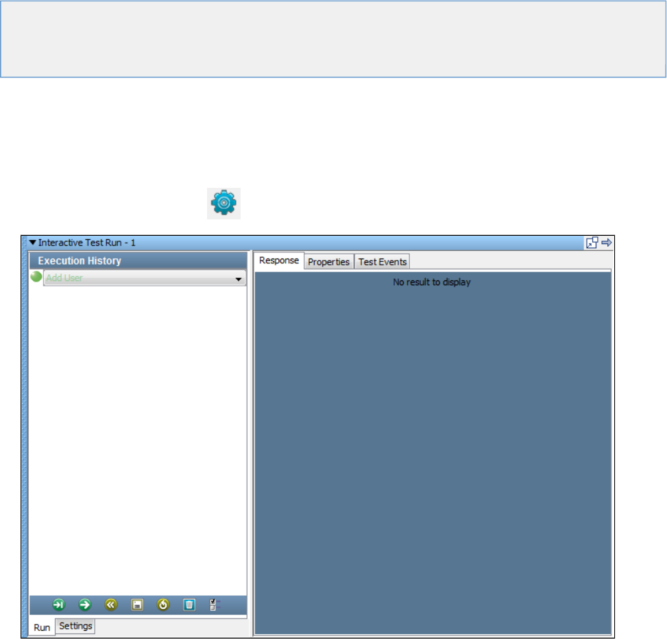
1.
2.
3.
leave the ITR open, edit the offending test step, then go back to the ITR and execute the same step again.
The ITR lets you save the current ITR state, and to load an ITR state that was previously saved. This feature lets you communicate an error, in
context, to another member of your team. You can send the test case and the saved ITR state to provide the exact actions and the results that
you observed.
The following topics are available.
Starting an ITR Run
Examining the Results of an ITR Run
Graphical Text Diff Utility
Starting an ITR Run
The Interactive Test Run (ITR) utility is run from an open test case in LISA Workstation.
To start an ITR run
From the main menu, select Actions > Start Interactive Test Run.
Alternately, you can click the ITR icon on the toolbar. The icon gives you the option of starting a new ITR run or opening a
previous ITR run. The Interactive Test Run window opens.
(Optional) Use the to change one or more settings.Settings tab
Use the to execute all or part of the test case.Run tab
Run Tab
The Run tab shows the steps that have been executed (in gray) and the next step that will be executed (in green).
In the following image, the first two steps (Add User and Get User) have been executed. The third step (Verify User Added) is the next step that
will be executed.
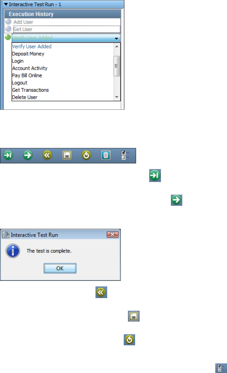
Each step has a pull-down menu that contains all the steps in the test case. You can use this menu to change the next step that will be executed.
Select a step, and it will replace the current next step with the one of your choice. After you change the step, the workflow will continue from the
new step.
You manage the ITR by using the toolbar at the bottom of the Run tab.
To run the next step in the test case, click the Execute Next Step icon . After the step has run, you can in the rightexamine the results
panel. Click the icon again to run the next step listed, or select a different step to run as described previously.
To run all of the steps in the test case, click the Automatically Execute Test icon . While the test is running, the icon will change into a Stop
icon. You can stop the test by clicking the Stop icon.
When the last step has been executed, a dialog indicates that the test is complete.
To start the test again, click the Restart Test icon. This feature is useful if you make a change to your test case and want to execute it from
the beginning.
To save the current ITR state, click the Save ITR State icon . In the dialog, enter the name of the save file. The suffix .itr will be appended to
the name. Subsequent saves will overwrite this file.
To load a saved ITR, click the Load Saved ITR State icon and browse to the .itr file that you want to load. The Saved ITR State will contain
the information displayed in the tabs, thereby capturing all the testing performed. To make use of the Saved State, you must first open the test
case that was used when the original tests were run.
To open the property watch window to add and/or watch properties, click the Add properties to watch icon.
Settings Tab
The Settings tab lets you control various aspects of the ITR.
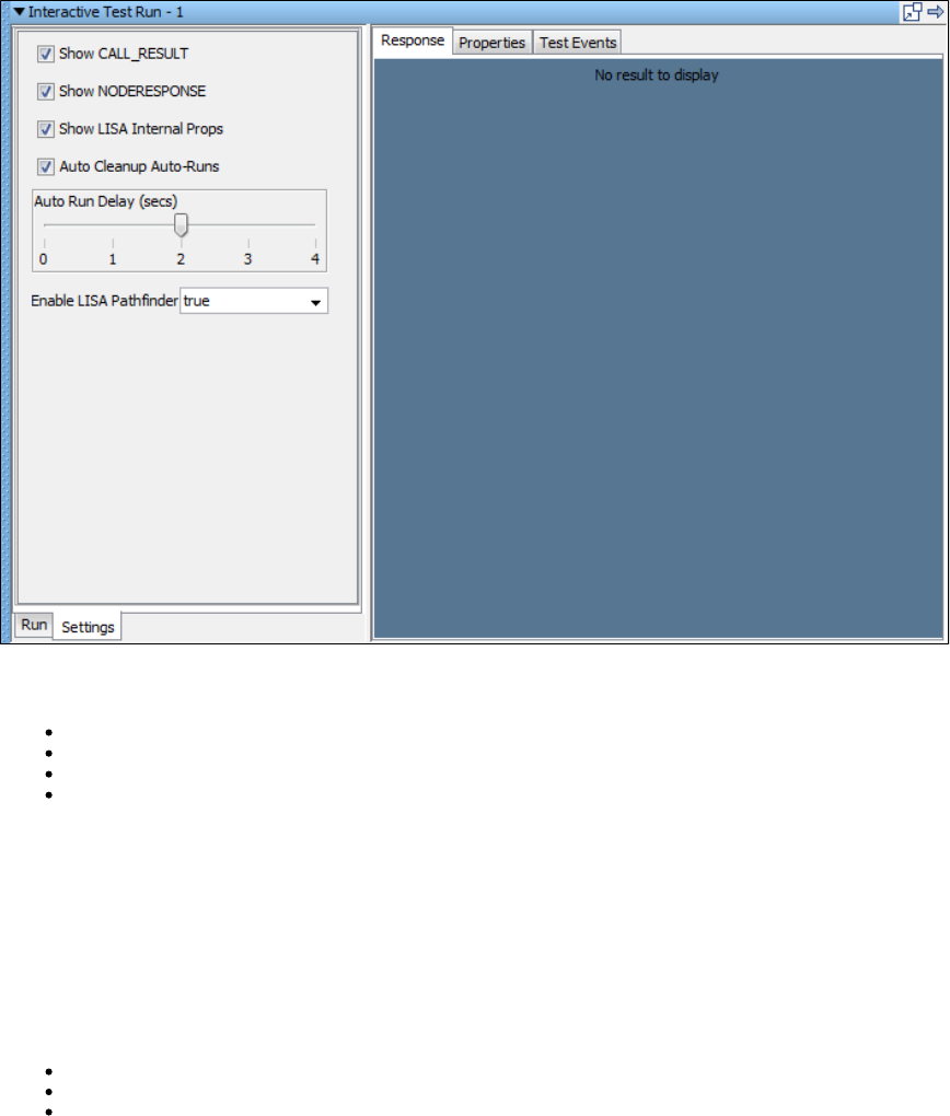
You can filter out events and properties from the results tabs. There are some verbose events that you may not want to see. Likewise, you may
not always want to clutter the property list with LISA internal properties.
Show CALL_RESULT: Include EVENT_CALL_RESULT events in the Test Events list.
Show NODERESPONSE: Include EVENT_NODERESPONSE events in the Test Events list.
Show LISA Internal Props: Include all LISA internal events in the property lists in the Initial State and Post Exec State tabs.
Auto Cleanup Auto-Runs: Clean up the Auto Runs automatically.
In the Automatically Execute Test mode, the ITR pauses between each step execution. The Auto Run Delay (secs) slider lets you change the
pause interval. The ITR does not honor the think time, so this setting lets you add a constant delay between each step execution.
To control whether Pathfinder is enabled, select or clear the Enable LISA Pathfinder check box.
Examining the Results of an ITR Run
You can examine the results of the execution of a particular test step, during the run or between two steps or at the conclusion of the run.
Select the step in the Execution History list. Examine the information in the right panel, which contains the following tabs:
Response Tab
Properties Tab
Test Events Tab
Response Tab
The Response tab displays the step response after executing a step.
The display will use the editor appropriate for the response type. For example, the Add User step in the multi-tier-combo test case invokes the
HTML/XML response.
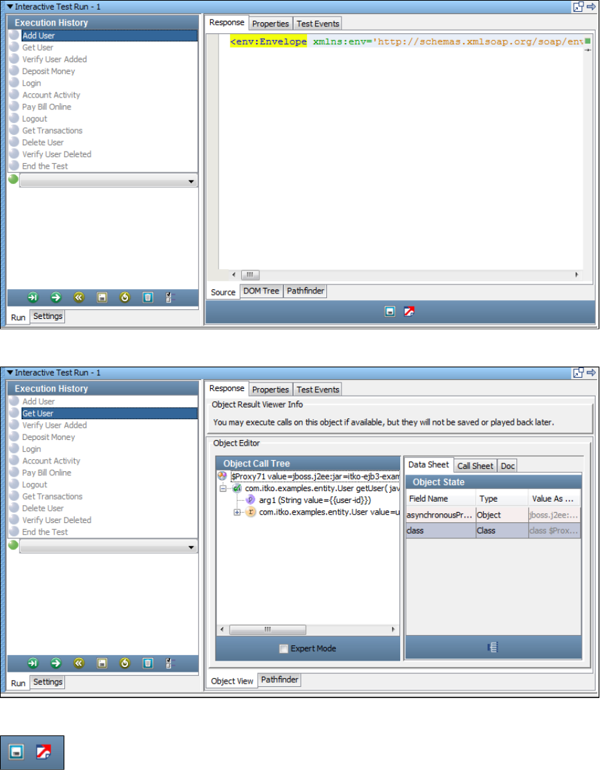
The Get User step in the multi-tier-combo test case invokes an EJB that returns an object that is displayed in the .Complex Object Editor
Some editors include two icons that you can use to save the ITR state and launch an external browser.
Properties Tab
The Properties tab displays the state of the step after execution (Value) and immediately before execution (Previous Value).
To show or hide LISA internal properties, select or clear the Show LISA Internal Props check box in the Settings tab.
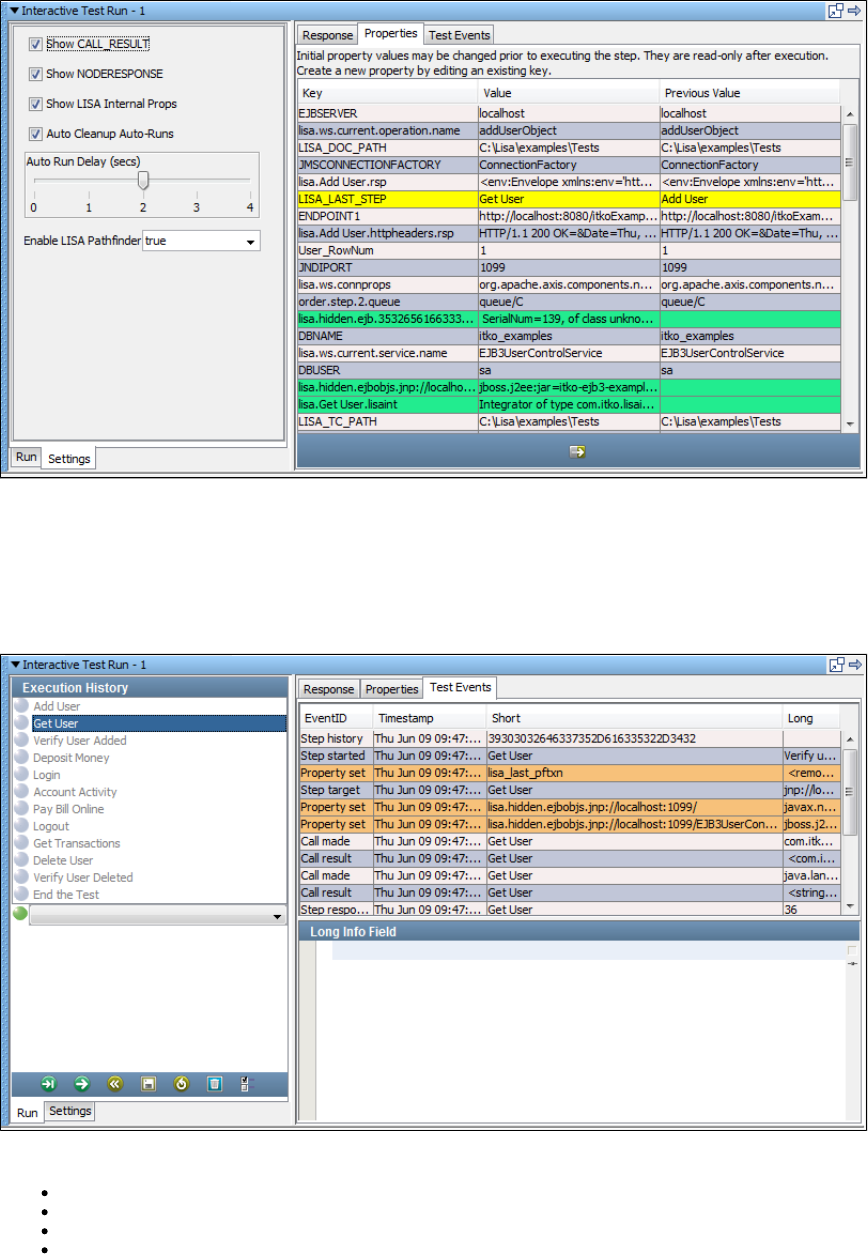
Properties that were newly set by the step are highlighted in green. Properties that were modified in the step are highlighted in yellow.
Test Events Tab
The Test Events tab displays the events that were fired when the step was executed, in the order that the events were fired.
To show or hide the events, select or clear the event check boxes in the Settings tab (Show CALL_RESULT and Show NODE_RESPONSE).
The Test Events tab contains the following columns:
EventID: The ID of the event that fired.
Timestamp: The time the event fired.
Short: The short description of the event.
Long: The long description of the event.
The Long description field can be truncated in the display. To view the full text, click the cell and its full contents will be displayed in the Long Info
Field panel.
You can enter the complete or full description of the event in the Long Info Field.
An event is generated on all assertions that are fired, and are evaluated.
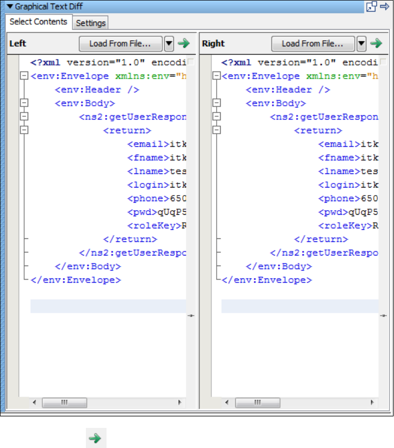
Graphical Text Diff Utility
A graphical XML diff engine and visualizer are available to compare XML files and graphically display their differences.
Starting the Graphical Text Diff Utility
To start the Graphical Text Diff utility from the main menu, select Actions > Graphical Text Diff. From this panel, you can compare the contents of
two XML files.
Click the Compare icon to start the compare.
The following screen appears, which shows the actual comparison. The Diff Viewer tab shows the comparison.
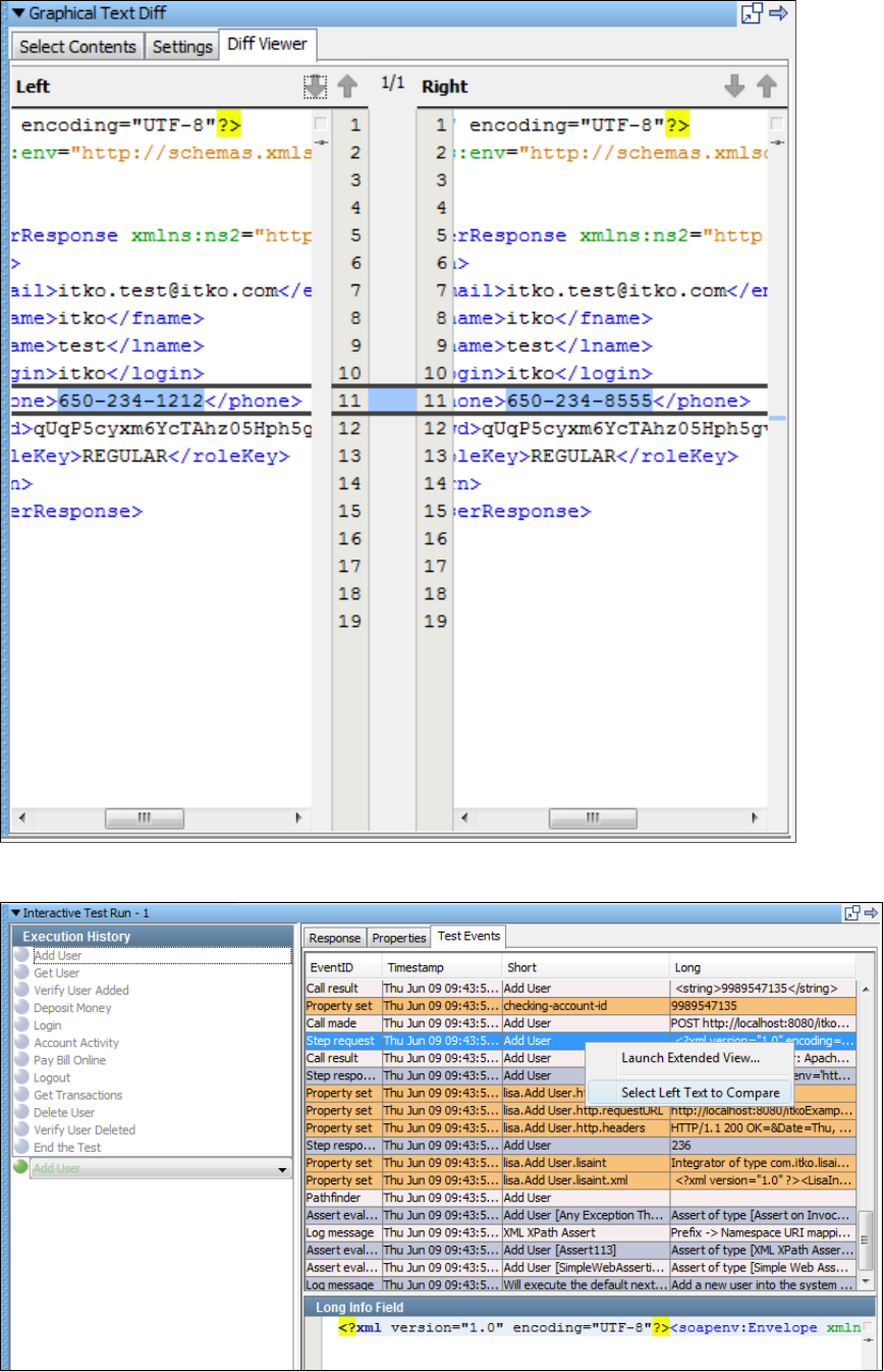
To start the Graphical Text Diff utility from the Interactive Test Run (ITR) utility, select the Test Events tab in the ITR. Right-click a table row and
select Select Left Text to Compare.
Right-click a table row to compare with and select Compare To.
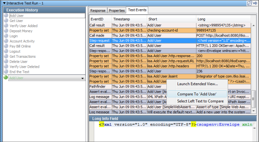
This will open the Graphical Text Diff for comparison.
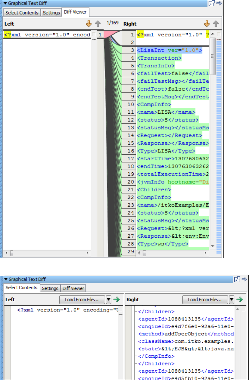
While in the Graphical Text Diff utility, you can also load the contents by selecting a file. Click the Select Contents tab and click Load from File to
load the file.
The results of the diff are then displayed in the global tray panel component.
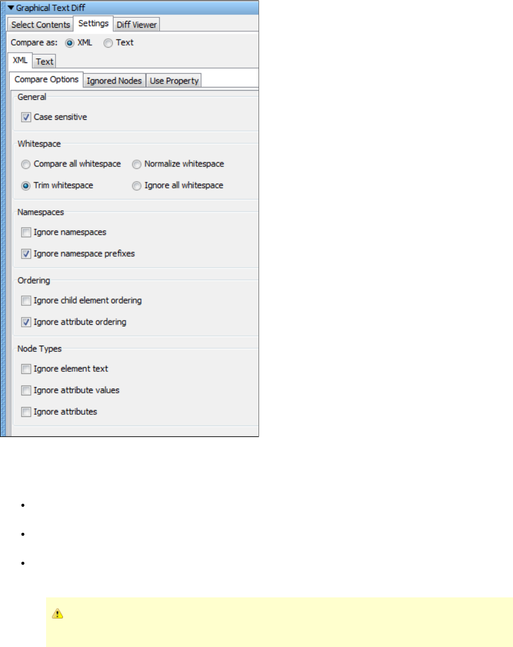
You can also set the compare options in the Settings tab. For more information about the compare options, see Graphical XML Side-by-Side
.Comparison
LISA Properties for the Graphical Text Diff Utility
The following LISA properties are used by the Graphical XML diff feature. These properties can be overridden in or atlocal.properties
runtime.
lisa.graphical.xml.diff.engine.max.differences: This property configures the maximum number of differences that are detected before
the XML diff algorithm stops. The default value is . Set to to compute all differences. When there are many differences, this100 -1
causes the XML diff algorithm to finish faster.
lisa.graphical.xml.diff.report.max.linewidth: This property configures the maximum width of a line of text in the XML diff results report.
The default value is . If the input XML has very long lines of text, this property causes the XML diff results report to consume less80
memory.
lisa.graphical.xml.diff.report.max.numberoflines: This property configures the maximum number of context lines for a difference in the
XML diff results report. The default value is . If the XML being compared has different elements that are very large, this property causes5
the XML diff results report to consume less memory.
In most cases these values do not need to be changed. Changing the default values for these properties may result in
the Graphical XML diff engine using more CPU and/or running out of memory.
Staging Quick Tests
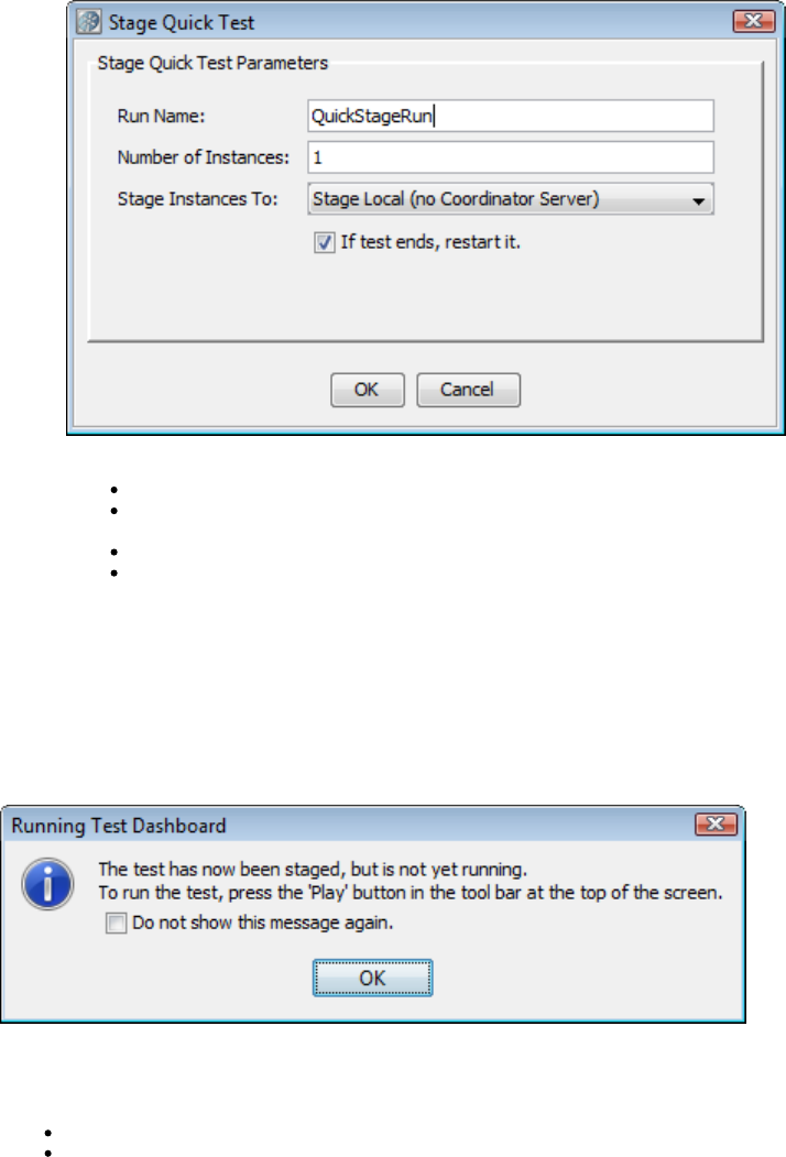
1.
2.
3.
4.
LISA Workstation lets you run a test case quickly with minimal setup. A quick test runs the test that is currently in memory, rather than loading a
test case document, and uses a simple pre-built staging specification with few options. The test has minimal instances so it is easy to stage/run,
but lacks much of the functionality of a test staged with a as in the case of a proper . A quick test letsstaging document test case execution
you select and monitor events and metrics, and view a standard performance report.
To stage a quick test
Open a test case in LISA Workstation.
From the main menu, select Actions > Stage a Quick Test.
The Stage Quick Test dialog appears.
If you have coordinators and simulators attached to a Registry, it will show you the coordinator or simulator servers attached.
Specify the following parameters:
Run Name: The name of the quick test.
Number of Instances: The number of concurrent users (instances) to be used. Your license determines the maximum number
of users that you can specify.
Stage Instances To: The name of the coordinator server where the test will be staged.
If test ends, restart it: Select this check box if you want to run the test continuously until you stop it manually.
Click OK.
The opens.Test Monitor window
Test Monitor Window - Quick Test
When you , the Test Monitor window opens in LISA Workstation. The Test Monitor window for a quick test is similar to the Teststage a quick test
Monitor window for a test case.
At first, the test is staged, but the test has not started running yet. The following image shows the message that is displayed:
At this point you can select the metrics and events that you want to monitor during the test run.
The Test Monitor consists of two tabs:
The displays collected metrics as a function of time. After the test starts, this cannot be changed.Perf Stats Tab
The displays events as they are recorded during the test run.Events Tab
If you run the test case and there are failures in the test, then a third tab labeled is displayed.Failures
You can limit the size of the failure events by adding the property to the file.lisa.coord.failure.list.size local.properties
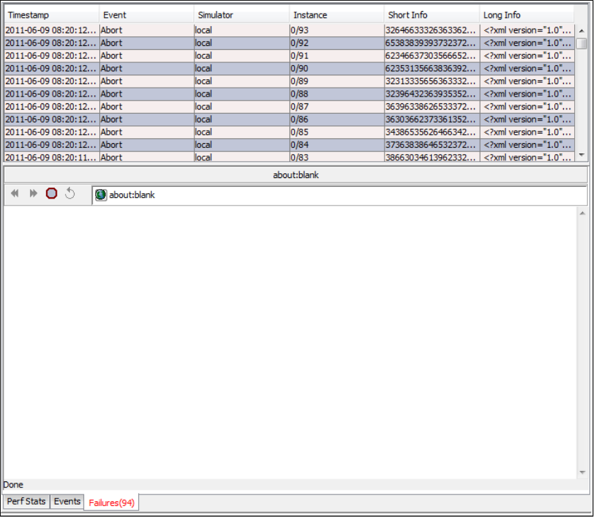
Perf Stats Tab
The tab enables you to add the metrics and events that you want to monitor during the test run.Perf Stats
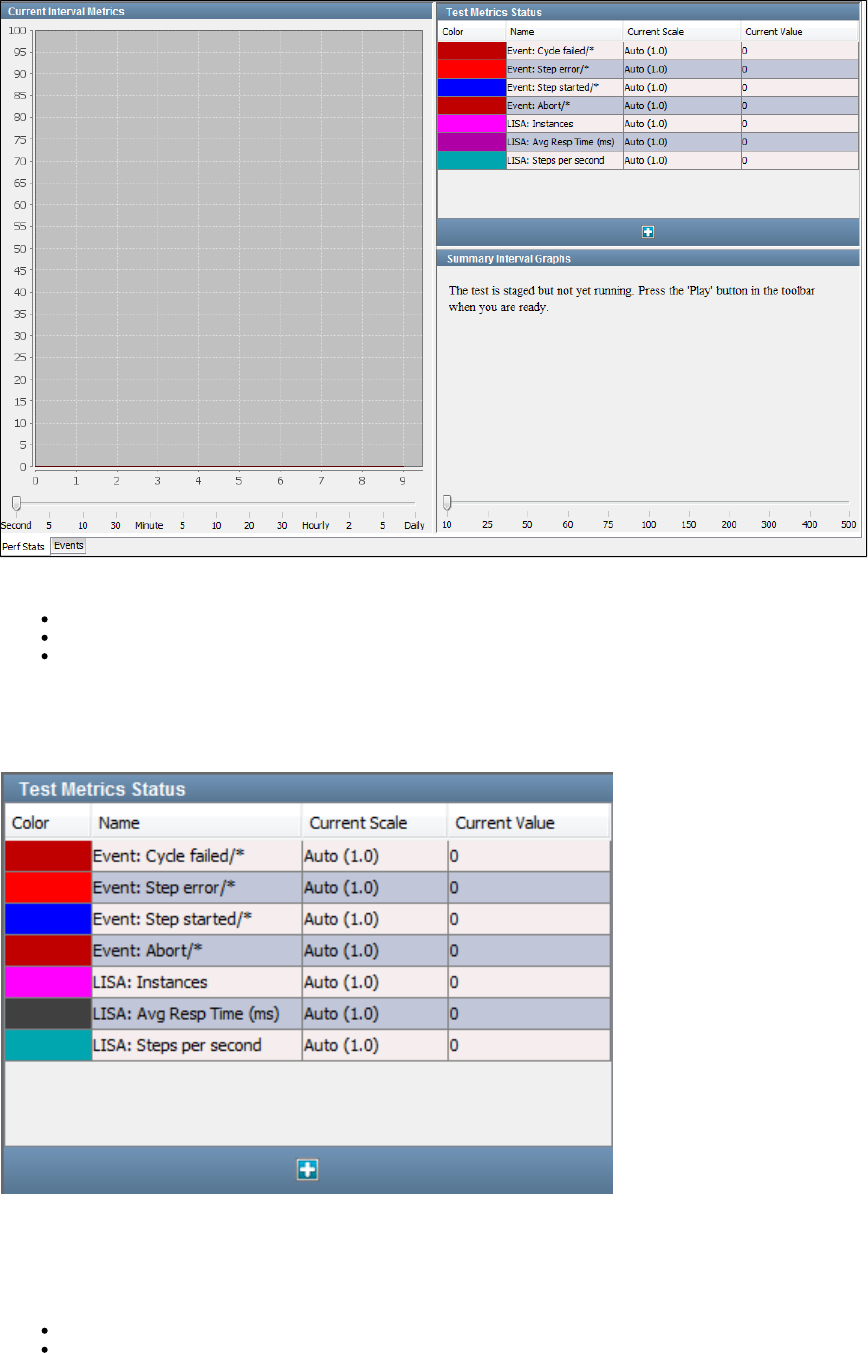
The tab consists of the following panels:Perf Stats
Test Metrics Status
Current Interval Metrics
Summary Interval Graphs
Test Metrics Status
The panel lists the current metrics being monitored.Test Metrics Status
Certain metrics are shown by default. The metrics are color coded to help you distinguish between them.
You can add additional metrics by clicking the Add icon. A pull-down menu displays all the metrics categories that can be added.
The panel contains the following columns:Test Metrics Status
Color: The color coding used on the graphs.
Name: The name of the metric. If the metric has been filtered using its short name, then the short name appears after a slash in the
name field. An asterisk means use just the event name for the metric.
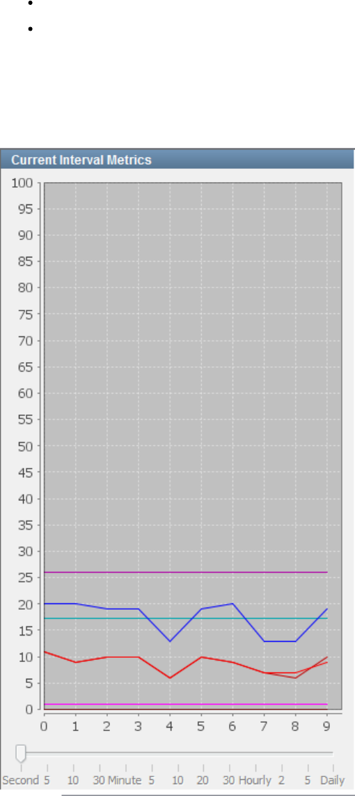
Current Scale: The vertical scale used on the graphs. You can adjust the graph scale for any metric by clicking the scale and selecting a
new value from the drop-down menu.
Current Value: The instantaneous value of the metric.
For detailed information about metrics, see .Generating Metrics
Current Interval Metrics
For each metric in the panel, the panel displays the value at a specified time interval during theTest Metrics Status Current Interval Metrics
run.
To specify the time interval, use the slider at the bottom of the panel. You cannot adjust the value after the run has started.
Summary Interval Graphs
For each metric in the panel, the panel displays the value of each metric averaged over aTest Metrics Status Summary Interval Graphs
specified time interval.
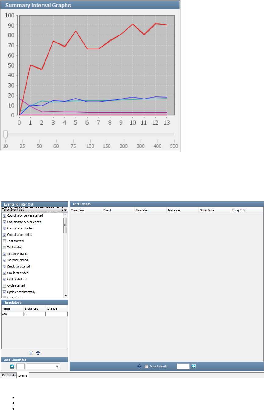
To specify the number of samples per interval, use the slider at the bottom of the panel. You cannot adjust the value after the run has started.
Events Tab
The tab displays the events that are generated during the run.Events
The tab consists of the following panels:Events
Events to Filter Out
Simulators
Test Events
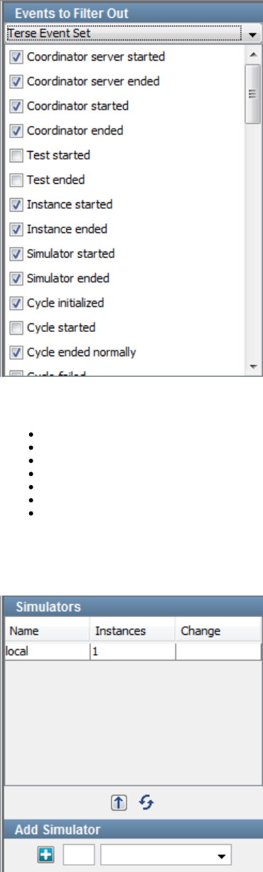
Events to Filter Out
The panel enables you to restrict the events that appear during the run. The panel contains a list of events. If the check boxEvents to Filter Out
for an event is selected, then the event will appear during the run.not
The panel includes a drop-down menu. The options enable you to filter none of the events, include a predefined set of events, or filter all of the
events. The options are:
No Filter
Terse Event Set
Common Event Set
Verbose Event Set
Load Test Set (as of release 6.0.6)
Custom Event Set
Filter All Events
Simulators
The panel shows the status of the Simulators in use.Simulators
Test Events
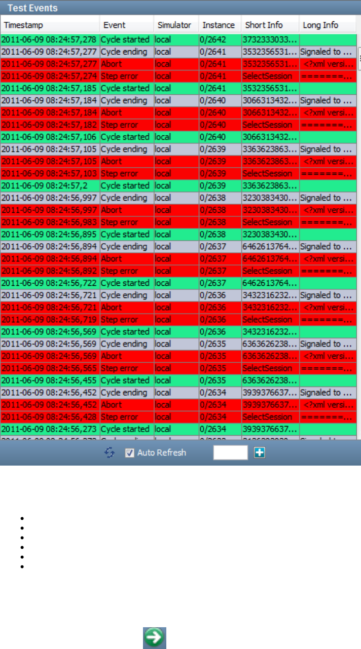
The panel displays the events. The most recent event appears at the top. The oldest event appears at the bottom.Test Events
You can list events in real time by checking the box at the bottom of the panel, or you can refresh the list manually by clicking theAuto Refresh
Refresh icon, with the Auto Refresh box cleared. Only those events that have not been filtered out are displayed.
For each event, the following information is displayed:
Timestamp: The time of the event
Event: The name of the event
Simulator: The name of the Simulator in which the event was generated
Instance: The instance ID and run number (separated by a forward slash)
Short Info: A short piece of information about the event
Long Info: A long piece of information about the event (if available)
Starting and Stopping Quick Tests
With the Test Monitor window open, you can start and stop a quick test by clicking icons on the main toolbar.
To start a quick test, click the icon on the main toolbar.Play
When the quick test starts, the icon changes to a icon.Play Stop
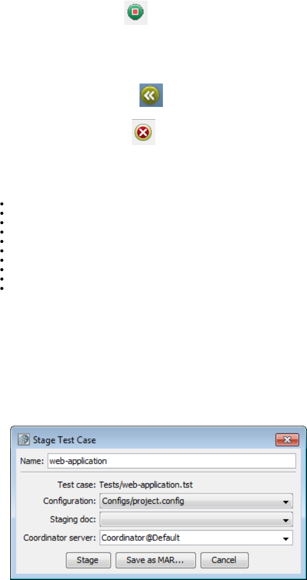
1.
2.
3.
4.
5.
6.
7.
8.
To stop a quick test, click the icon on the main toolbar.Stop
If you click the icon again, you will be asked if you want to kill the test run.Stop
When you stop a test, you are saying "do not start any new instances". When you kill a test, you are saying "stop all running instance as soon as
possible".
To replay a quick test, click the icon on the main toolbar.Replay
To close a quick test, click the icon on the main toolbar.Close
Actions Menu
When you run a test and click the button to actually run it, the following options are added to the Actions menu.Play
Pause Metrics Collection
Un-pause Metrics Collection
Save Recent Metrics to XML Document
Save Recent Metrics to CSV Document
Save Interval Data to CSV Document
Save Interval Data to XML Document
Save Recent Events to CSV Document
Stage This Test
Stop Test
Restart Test (Reloads Documents)
Staging Test Cases
You can run a test case from LISA Workstation by specifying the configuration, staging document, and coordinator server.
The main toolbar in LISA Workstation includes a Lab Status icon. If you stage a test case to a cloud-based lab, the icon indicates when the lab is
being provisioned and then ready.
To stage a test case
Open a test case in LISA Workstation.
From the main menu, choose Actions > Stage Test.
The Stage Test Case dialog appears.
In the Configuration drop-down list, select the . If you leave this field blank, then the default configuration is used.configuration
In the Staging doc drop-down list, select the .staging document
In the Coordinator server drop-down list, select the or (if available) a . Coordinator server namescoordinator server cloud-based lab
include the associated lab. For example, indicates that the Default lab will be used. For cloud-based labs, the labCoordinator@Default
will be started and the test case will be staged to the coordinator in the lab.
Click Stage.
If you selected a coordinator server, the opens. You can now choose the metrics and events that you want toTest Monitor window
monitor, and then start the test case.
If you selected a cloud-based lab, a message indicates that it will take some time to provision the lab and you will be notified when the
process has completed. Click OK. When the Provisioning Complete message appears, click OK. The opens. YouTest Monitor window
can now choose the metrics and events that you want to monitor, and then start the test case.
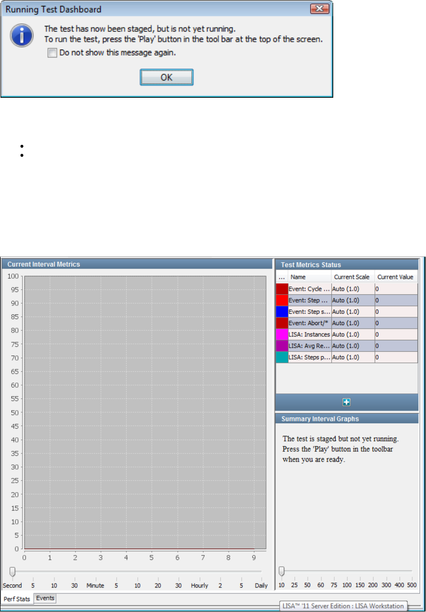
Test Monitor Window - Test Case
When you , the Test Monitor window opens in LISA Workstation. The Test Monitor window for a quick test is similar to the Teststage a test case
Monitor window for a test case.
At first, the test is staged, but the test has not started running yet. The following image shows the message that is displayed:
At this point you can select the metrics and events that you want to monitor during the test run.
The Test Monitor consists of two tabs:
The lets you select metrics, and display them as a function of time.Perf Stats Tab
The lets you select and display events as they occur during the test run.Events Tab
If you run the test case and there are failures in the test, then a third tab labeled is displayed.Failures
You can limit the size of the failure events by adding the property to the file.lisa.coord.failure.list.size local.properties
Perf Stats Tab
The tab enables you to add the metrics and events that you want to monitor during the test run.Perf Stats
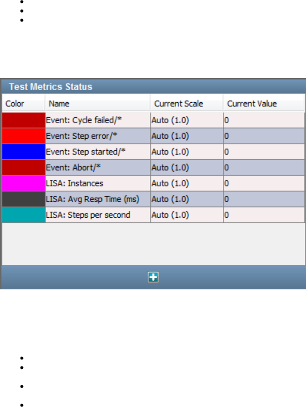
The tab consists of the following panels:Perf Stats
Test Metrics Status
Current Interval Metrics
Summary Interval Graphs
Test Metrics Status
The panel lists the current metrics being monitored.Test Metrics Status
Certain metrics are shown by default. The metrics are color coded to help you distinguish between them.
You can add additional metrics by clicking the icon. A pull-down menu displays all the metrics categories that can be added.Add
The panel contains the following columns:Test Metrics Status
Color: The color coding used on the graphs.
Name: The name of the metric. If the metric has been filtered using its short name, then the short name appears after a slash in the
name field. An asterisk means use just the event name for the metric.
Current Scale: The vertical scale used on the graphs. You can adjust the graph scale for any metric by clicking the scale and selecting a
new value from the drop-down menu.
Current Value: The instantaneous value of the metric.
For detailed information about metrics, see .Generating Metrics
Current Interval Metrics
For each metric in the panel, the panel displays the value at a specified time interval during theTest Metrics Status Current Interval Metrics
run.
To specify the time interval, use the slider at the bottom of the panel. You cannot adjust the value after the run has started.
Summary Interval Graphs
For each metric in the panel, the panel displays the value of each metric averaged over aTest Metrics Status Summary Interval Graphs
specified time interval.
To specify the number of samples per interval, use the slider at the bottom of the panel. You cannot adjust the value after the run has started.
Events Tab
The tab displays the events that are generated during the run.Events
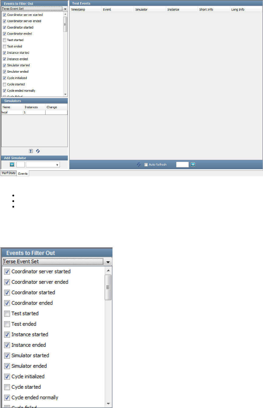
The tab consists of the following panels:Events
Events to Filter Out
Simulators
Test Events
Events to Filter Out
The panel enables you to restrict the events that appear during the run. The panel contains a list of events. If the check boxEvents to Filter Out
for an event is selected, then the event will appear during the run.not
The panel includes a drop-down menu. The options enable you to filter none of the events, include a predefined set of events, or filter all of the
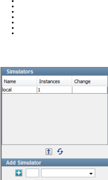
events. The options are:
No Filter
Terse Event Set
Common Event Set
Verbose Event Set
Load Test Set (as of release 6.0.6)
Custom Event Set
Filter All Events
Simulators
The panel shows the status of the simulators in use.Simulators
Test Events
The panel displays the events. The most recent event appears at the top. The oldest event appears at the bottom.Test Events
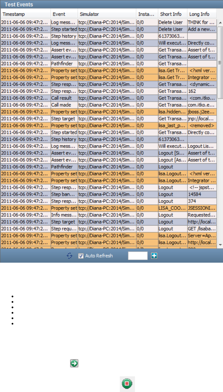
You can list events in real time by checking the box at the bottom of the panel, or you can refresh the list manually by clicking theAuto Refresh
Refresh icon, with the Auto Refresh box cleared. Only those events that have not been filtered out are displayed.
For each event, the following information is displayed:
Timestamp: The time of the event
Event: The name of the event
Simulator: The name of the simulator in which the event was generated
Instance: The instance ID and run number (separated by a forward slash)
Short Info: A short piece of information about the event
Long Info: A long piece of information about the event (if available)
Starting and Stopping Test Cases
With the Test Monitor window open, you can start and stop a test case by clicking icons on the main toolbar.
To start a test case, click the Play icon on the main toolbar:
When the test case starts, the Play icon changes to a Stop icon.
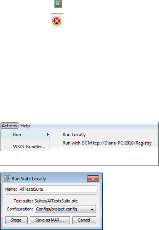
1.
2.
3.
4.
5.
To stop a test case, click the Stop icon on the main toolbar:
If you click the Stop icon again, you will be asked if you want to kill the test run.
When you stop a test, you are saying "do not start any new instances". When you kill a test, you are saying "stop all running instances as soon as
possible."
To replay a test case, click the Replay icon on the main toolbar:
To close a test case, click the Close icon on the main toolbar:
Running Test Suites
A test suite lets you group related test cases and test suites and run them as a single test. A test suite document specifies the contents of the
suite, the reports to generate, and the metrics to collect. These reports and metrics relate to the suite as a whole. Each test within the suite will
still produce its own reports and metrics. Each test still retains the ability to use its own staging document, configuration, and audit document.
Therefore, tests in a suite can be run in a distributed environment.
When a suite is included within a suite, the individual tests in the included suite are extracted from the suite and run as individual tests in the
current suite. The defaults from the included suite and the startup and teardown settings are ignored.
Within LISA Workstation, you can configure and stage the test suite, monitor the tests while they are running, and view the reports at the
conclusion of the test.
To run a test suite
Open the test suite in LISA Workstation.
From the main menu, select Actions > Run. This action opens a menu where you select whether to run locally or to run with a specified
registry.
The Run Suite Locally dialog appears.
Enter the name of the test suite.
Select the configuration from the drop-down list.
Click Stage.
The screen is displayed and the tests start.Stage Suite Execution
Stage Suite Execution
When you click Stage during the process of in LISA Workstation, the Stage Suite Execution tab is displayed and the testsrunning a test suite
start.
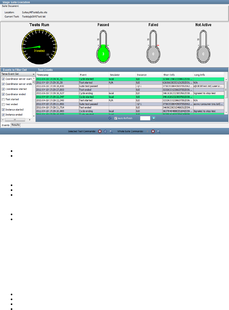
The top panel displays the following information:
The location and name of the test suite document
The name of the current test
The middle panel displays the meter and three thermometers. The meter shows the number of tests completed and theTests Run Tests Run
total number of tests. The thermometers have the following labels: , , and . The colors of the thermometers indicate thatPassed Failed Not Active
you have passed our preselected number of cases. The known behavior when you run more than 50 to 100 test cases in a suite is:
If number of tests passed is greater than 50, then the thermometer is orange.
If number of tests passed is greater than 75, then the thermometer is red.
If number of tests passed is greater than 100, then the thermometer is gray.
The lower panel has the following tabs:
Events Tab: Lists requested events as they occur
Results Tab: Shows the status of each individual test
Stage Suite Execution - Events Tab
The Events tab lists the that you have selected from the panel on the left of the tab.events
Events to Filter Out
The area contains a list of the available events. Each event has a check box. Use this list to select events that you do Events to Filter Out not
want to monitor.
One approach is to manually select the events to filter out. Another approach is to select one of the following event sets from the drop-down menu
and then customize the selections as necessary:
Terse Event Set
Common Event Set
Verbose Event Set
Load Test Set (as of release 6.0.6)
You can clear all the check boxes by selecting No Filter. You can select all the check boxes by selecting Filter All Events.
Test Events
The area lists the events as they occur, with the most recent on the top of the list. You can list events in real time by selecting the Test Events
check box at the bottom of the panel, or you can refresh the list manually by clicking the Refresh icon, with the Auto Refresh Auto Refresh
check box cleared.
For each event, the following information is displayed:
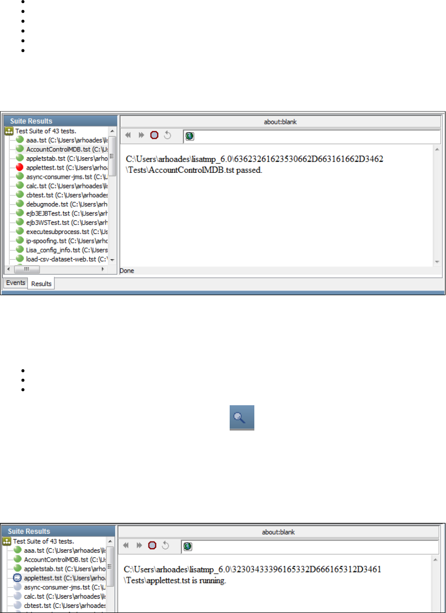
Timestamp: When the event was generated
Event: The name of the event
Simulator: The name of the simulator where the instance is running
Instance: The instance ID and run number (separated by a forward slash)
Short Info: The short information for the event
Long Info: The long information for the event
Stage Suite Execution - Results Tab
The Results tab shows the status of the individual tests in the test suite.
Suite Results
The area displays a list of all the tests in the suite.Suite Results
The tests are shown by the following icons.
The green icon indicates that the test has completed and passed.
The red icon indicates that the test has completed and failed.
The blue icon indicates that the test is still running.
For tests that are still running, you can click the View Test icon at the bottom of the panel to display the test monitor for this test.
For completed tests, you can select the test name to see a status in the text area to the right. This is most useful to see why a given test failed.
Status Window
The status window displays the status of the test selected on the left.
The following test is running:
The following test has failed:
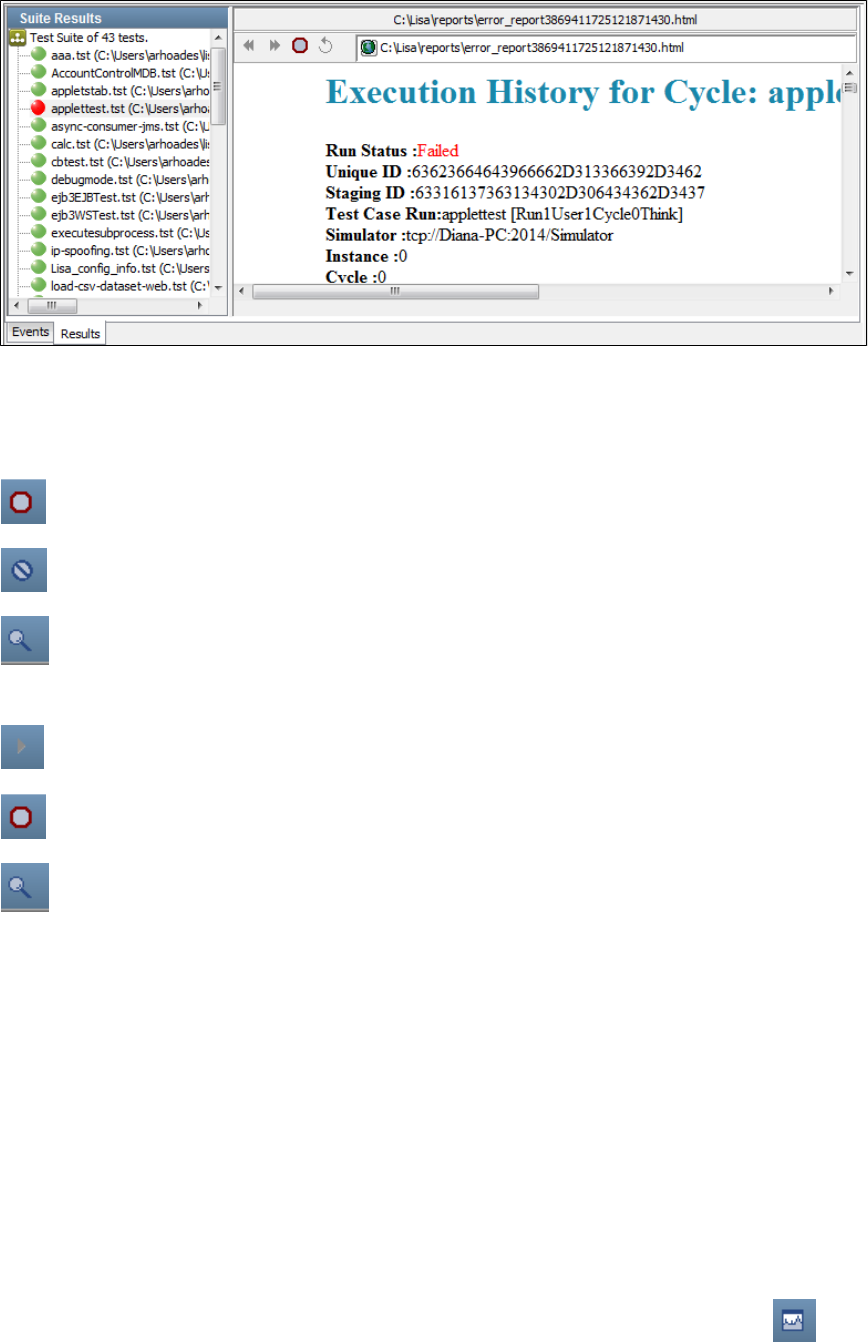
1.
2.
3.
A failed test status shows as much information as is available as to why the test failed.
At the bottom of the Stage Suite Execution panel is a toolbar.
The first set of icons manages individual tests in the suite. To use these icons, first select a test in the Test List section of the Results tab. The
following functions are available for a particular selected test:
: Stops the test after it reaches the next logical end/fail. It does not start a new cycle.Stop Test
: Stops the test immediately after the current step completes.Kill Test
: This tool will work only for currently running tests. This launches the test monitor for the selected test.View Test
The second set of icons manage the test suite itself, or when suite is running:
: Starts/restarts the suite test.Run Suite
: Close the Stage Suite Execution window.Close Suite
: Launches the test monitor for the selected test.View Test
For more information about Test Monitor, see .Using the LISA Registry Monitor
Using the Load Test Optimizer
The Load Test Optimizer appears within the . It lets you run a simple load test on the system under test. A load testLISA Registry Monitor
determines how many users the system under test supports.
In the Load Test Optimizer, the system under test is run continuously while more and more simulated users access it, until a specific target is
reached, usually a predefined average response time.
The Load Test Optimizer helps determine how many users the system under test supports. An optimizer can be set on any LISA metric like
average response time or a metric pulled from an external source (for example, SNMP, JMX, Windows Perfmon). It increases the number of
users at a preset frequency and informs you when a preset metric threshold is achieved. For example, you can configure the optimizer to increase
the number of test instances spawned by the simulator by five every ten seconds until the average response time hits two seconds.
To optimize the test, it must be running.
To configure and start an optimizer
In the LISA Registry Monitor, select a test from the running tests list and click the Optimize Test icon .
The Optimizer panel opens with the name of the staging document listed at the top.
Configure the following parameters:
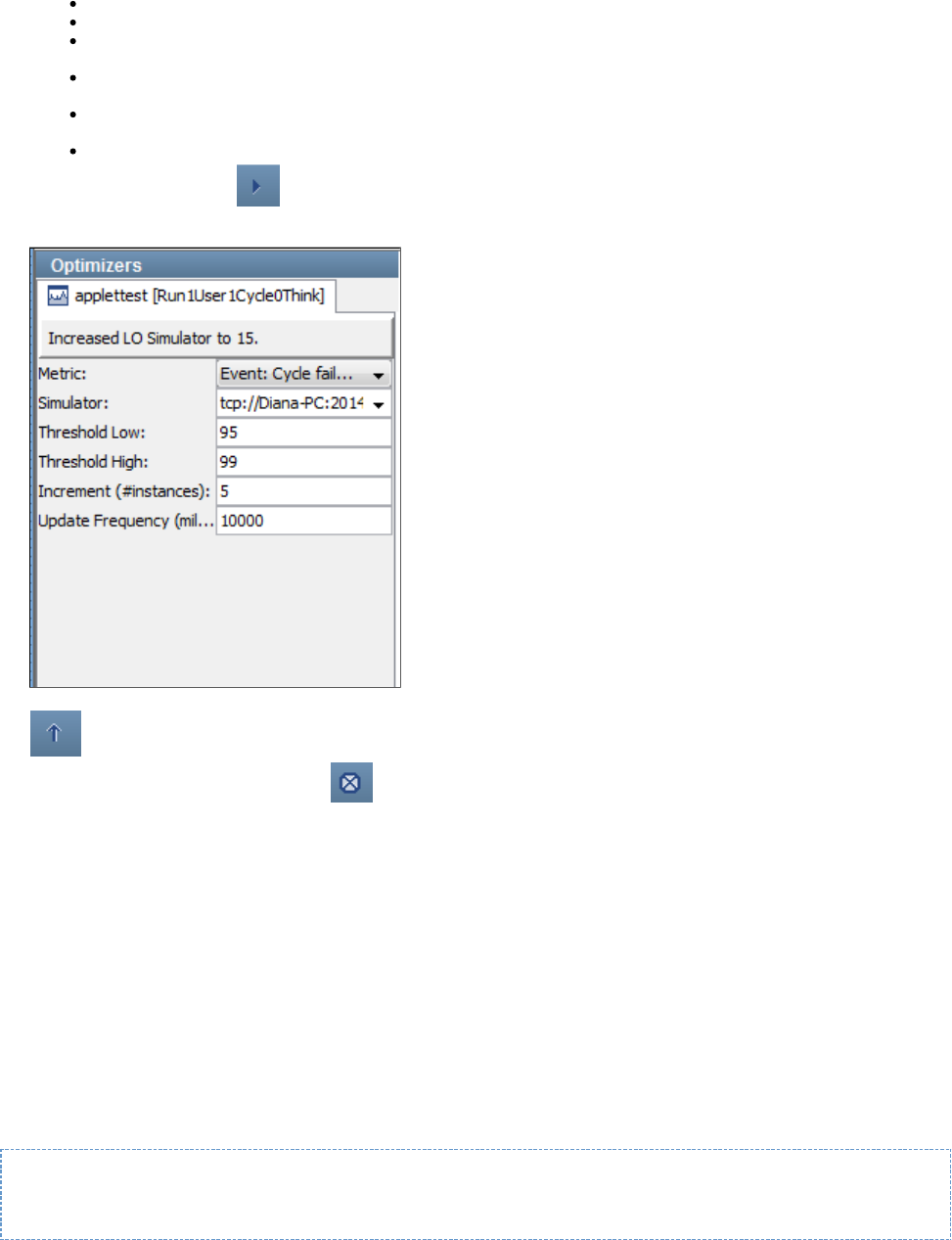
3.
4.
5.
6.
Metric: The metric to use for the optimization. Select from the pull-down list.
Simulator: The simulator used to spawn test instances. Select from the pull-down list.
Threshold Low: The metric value at which the optimizer reports that the system will require more virtual users. Enter a numeric
value.
Threshold High: The metric value at which the optimizer reports that the system cannot support any more virtual users. Enter a
numeric value.
Increment (#instances): The number of additional virtual users to add to the system at the update frequency. Enter a numeric
value.
Update Frequency (millis): the number of milliseconds between increments
Click the Start Optimizer icon .
As the optimizer increases the number of virtual users, it displays the number of virtual users on both the Optimizers section and in the
Instances column of the Tests tab in the LISA Registry Monitor.
As the optimizer executes, you can change the parameters. To update the optimizer with the changed information, click the Update icon
.
To close the optimizer, click the Close icon .
Test Runner
The Test Runner command-line utility is a "headless" version of LISA Workstation with the same functionality but no user interface. That is, it can
be run as a stand-alone application.
Test Runner lets you run tests as batch applications. You give up the opportunity to monitor tests in real time, but you still have the capability to
request reports for later viewing.
On Windows, Test Runner is available in the directory as a Windows executable, .LISA_HOME/bin TestRunner.exe
On UNIX, Test Runner is available as a UNIX executable, , and a UNIX script, .TestRunner TestRunner.sh
This lets you incorporate LISA tests into a continuous build workflow, or use it with JUnit to run standard JUnit tests in Ant or some other build
tool.
Test Runner provides the following options:
TestRunner [-h] [[-r StagingDocument] [-t TestCaseDocument] [-cs CoordinatorServerName]] | [-s
TestSuiteDocument] [-m TestRegistryName] [-a]
As a Java class, you can run it as follows:
java com.itko.lisa.coordinator.TestRunner [-h] [[-r StagingDocument] [-t TestCaseDocument] [-cs
CoordinatorServerName]] | [-s TestSuiteDocument] [-m TestRegistryName] [-a]
To display help information for Test Runner, use the or option.-h --help
TestRunner -h
To display the version number, use the option.--version
As Part of an Automated Build
LISA test cases can be incorporated into an automatic build and test process. LISA provides the additional software required to use Java Ant, and
Java JUnit, and an example Ant build script.
LISA test cases will be run and reported as native JUnit tests.
Test Runner can be used in standard JUnit tests using a custom LISA Java class. For more information, see .Running LISA with Ant and JUnit
Running a Model Archive (MAR) with Test Runner
Running a Test Case with Test Runner
Running a Suite with Test Runner
Other Test Runner Options
Multiple Test Runner Instances
Test Runner Log File
Running a Model Archive (MAR) with Test Runner
To run a with Test Runner, specify the following option:Model Archive (MAR)
-mar or name of the MAR file--mar
Example
The following example runs a MAR file called .test1.mar
TestRunner -mar C:\test1.mar
Running a Test Case with Test Runner
To run a single test case with Test Runner, specify the following options:
-t or name of the test case document--testCase
-r or name of the staging document--stagingDoc
If you want to stage remotely, then also specify the following options:
-cs or name of the Coordinator Server--coordinatorService
-m or name of the LISA Registry--testRegistry
For additional options that you can use, see .Other Test Runner Options
Example
The following example runs the multi-tier-combo test case located in the project.examples
TestRunner -t ../examples/Tests/multi-tier-combo.tst -r ../examples/StagingDocs/Run1User1Cycle.stg
-a

Running a Suite with Test Runner
To run a suite with Test Runner, specify the following option:
-s or name of the suite document--testSuite
No auditing is performed.
If you want to stage remotely, also specify the following option:
-m or name of the LISA Registry--testRegistry
To stage a suite that is within a project and reference project test cases with a property name , you must have a copy of theLISA_PROJ_ROOT
project available somewhere under the folder defined by property on the server side (primarily coordinator and all simulators).lisa.projects.home
This property defaults to , and can be set to any value in local.properties file. A template is available in .LISA_HOME _local.properties
The projects do not have to be siblings under this root. Another important restriction for remote staging project documents is to have a unique
name for all projects. This is the case not only with project suites, but also remotely staging project test cases that refer to other assets (like data
sets) within the project.
For additional options that you can use, see .Other Test Runner Options
Example
The following example runs the AllTestsSuite suite located in the examples project.
TestRunner -s ../examples/Suites/AllTestsSuite.ste
The following example assumes that the registry is running on another computer.
TestRunner -s ../examples/Suites/AllTestsSuite.ste -m somemachine/Registry
Other Test Runner Options
This topic describes additional options that you can use while running a Model Archive (MAR), test case, or suite with Test Runner.
You can use LISA properties when specifying file names. However, in this context only system properties and properties defined in your property
files ( , and ) will work.lisa.properties local.properties site.properties
When the test(s) have been completed, you can view your reports in the standard way using LISA Workstation.
Automatically Starting the Test
The or option automatically starts the test, so you do not need to press Enter after the test has been staged.-a --autoStart
Specifying the Configuration
The or option lets you specify the configuration to use for a test run.-config --configFile
Test Runner does not understand LISA projects, so you must provide the fully qualified path to the configuration file. For example:
-config /path/to/lisa/home/examples/Configs/examples.itko.com.config
Generating an HTML Report
The or option enables you to have Test Runner produce an HTML summary report for a test case. This option is not-html --htmlReport
supported for suites.
The parameter after this option must be a fully qualified filename. For example:
-html /some/directory/MyReport.html
Changing the Update Interval
The or option enables you to change the update interval from the default value of 5 seconds. This interval refers to how often the Test-u --update
Runner writes a status message to the log file.
-u 10
Multiple Test Runner Instances
You can stage multiple instances of Test Runner from a single workstation to a LISA Server.
The following things are required:
You need 512 MB for each instance.
Your license must support launching multiple instances of Test Runner.
Test Runner Log File
Logging output is written to the file. For information about the location of this file, see .trunner.log Log Files
The logging level used is the same as that set in the file.LISA_HOME/logging.properties
To change the logging level, edit the property in the file from:log4j.rootCategory logging.properties
{{log4j.rootCategory=INFO,A1}}
to
{{log4j.rootCategory=DEBUG,A1}}
LISA Invoke
LISA Invoke is a REST-like web application that lets you run test cases and suites with a URL. The response consists of an XML document.
You can invoke synchronously or asynchronously.
You can display the online help by running http:// :1505/lisa-invoke/, where is the computer where the registry is running.hostname hostname
Running Test Cases with LISA Invoke
The syntax for running test cases with LISA Invoke is:
/lisa-invoke/runTest?testCasePath=testCasePath&stagingDocPath=stagingDocPath&[configPath=configPath]&[async=true]&[coordName=csName]
The following table describes the parameters.
Parameter Description
testCasePath The path to the test case that you want to invoke.
stagingDocPath The path to the staging document. If not provided, a default staging document is created.
configPath The path to the configuration. If not provided, the project's project.config file is used.
async If true, then the response includes a callback key. If not provided, the parameter is set to false.
coordName The path to the coordinator. If not provided, the default coordinator name is used.
Running Suites with LISA Invoke
The syntax for running suites with LISA Invoke is:
/lisa-invoke/runSuite?suitePath=[suitePath]&configPath=[configPath]&[async=true|false]
The following table describes the parameters.
Parameter Description
suitePath The path to the suite that you want to invoke.
configPath The path to the configuration.
async If true, then the response includes a callback key. If not provided, the parameter is set to false.
Running Model Archives (MARs) with LISA Invoke
The syntax for running Model Archives (MARs) with LISA Invoke is:
/lisa-invoke/runMar?marOrMariPath=[marOrMariPath]&[async=true|false]
The following table describes the parameters.
Parameter Description
marOrMariPath The path to the MAR or MAR info file that you want to invoke.
async If true, then the response includes a callback key. If not provided, the parameter is set to false.
Invoking the Callback Service
To use the callback service, you must have performed an asynchronous invocation of a test case or suite. The XML response contains the
callback key.
The syntax for invoking the callback service is:
/lisa-invoke/callback?testOrSuitePath=[testOrSuitePath]&callbackKey=[callbackKey]&command=[status|kill|stop]
The following table describes the parameters.
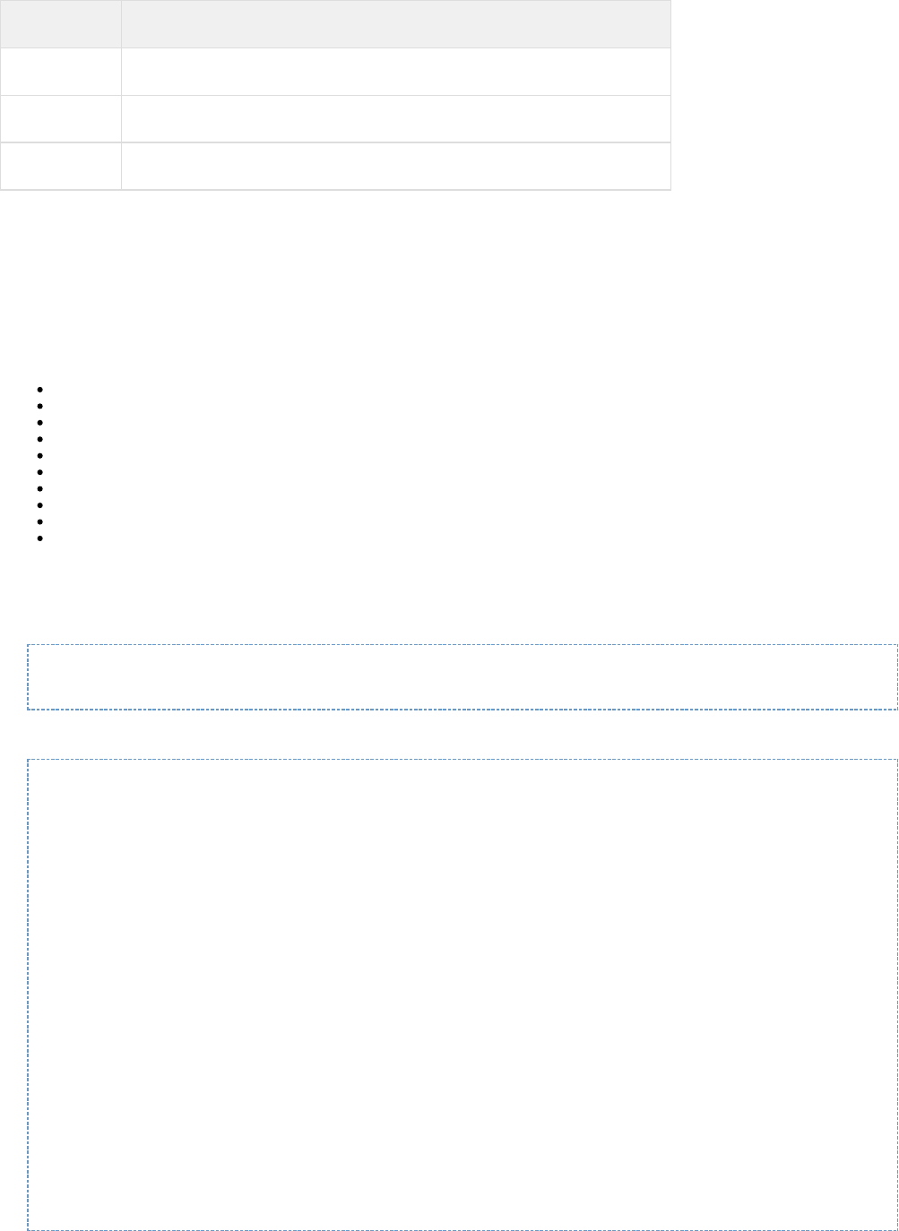
Parameter Description
testOrSuitePath The path to the test case or suite.
callbackKey The callback key that was included in the response to the asynchronous invocation.
command The action that you want to perform: status, kill, or stop.
LISA Invoke Responses
This section describes the elements that can appear in the XML document returned by LISA Invoke.
The method element indicates what type of run was performed.
The status element contains the status of the run: OK or ERROR.
The result element contains one or more of the following child elements:
The status element contains the status of a test case: RUNNING or ENDED.
The reportURL element contains the URL to the report in the Reporting Console.
The runId element contains the unique identifier of the run.
The pass element contains the number of tests that passed.
The fail element contains the number of tests that failed.
The warning element contains the number of tests that had warnings.
The error element contains the number of tests that had errors.
The message element contains information that is specific to the type of run.
The tc element contains the name of a test case included in a suite.
The callbackKey element contains a string that you can use to perform additional actions on the test case or suite.
Example: Synchronous Invocation
The following URL performs a synchronous invocation of the test case in the examples project.AccountControlMDB
http://localhost:1505/lisa-invoke/runTest/?testCasePath=examples/Tests/AccountControlMDB.tst&stagingDocPath=examples/StagingDocs/1user1cycle0think.stg
The following XML response indicates that the test case passed.
<?xml version="1.0" encoding="UTF-8"?>
<invokeResult>
<method name="RunTest">
<params>
<param name="stagingDocPath" value="examples/StagingDocs/1user1cycle0think.stg" />
<param name="coordName" value="Coordinator" />
<param name="configPath" value="" />
<param name="testCasePath" value="examples/Tests/AccountControlMDB.tst" />
<param name="callbackKey" value="64343533653737312D343765312D3439" />
</params>
</method>
<status>OK</status>
<result>
<status>ENDED</status>
<reportUrl><![CDATA[http://localhost:1505/index.html?lisaPortal=reporting/printPreview_functional.html#Idstr=61653261643936342D613636392D3435&curtstr=T]]></reportUrl>
<runId>61653261643936342D613636392D3435</runId>
<pass count="1" />
<fail count="0" />
<warning count="0" />
<error count="0" />
<message>AccountControlMDB,Run1User1Cycle0Think</message>
</result>
</invokeResult>
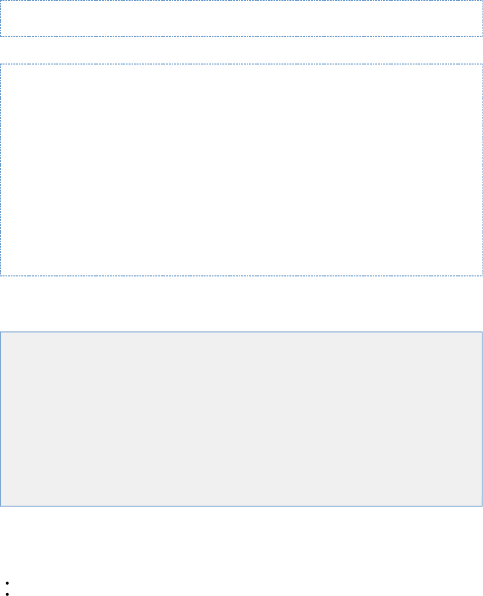
Example: Asynchronous Invocation
The following URL performs an asynchronous invocation of the test case in the examples project.AccountControlMDB
http://localhost:1505/lisa-invoke/runTest/?testCasePath=examples/Tests/AccountControlMDB.tst&stagingDocPath=examples/StagingDocs/1user1cycle0think.stg&async=true
The following XML response shows the callback key in the result element.
<?xml version="1.0" encoding="UTF-8"?>
<invokeResult>
<method name="RunTest">
<params>
<param name="stagingDocPath" value="examples/StagingDocs/1user1cycle0think.stg" />
<param name="coordName" value="" />
<param name="configPath" value="" />
<param name="testCasePath" value="examples/Tests/AccountControlMDB.tst" />
<param name="callbackKey" value="61663038653562382D663566372D3432" />
<param name="async" value="true" />
</params>
</method>
<status>OK</status>
<result>
<callbackKey>61663038653562382D663566372D3432</callbackKey>
<message>The LISA test 'examples/Tests/AccountControlMDB.tst' was launched asynchronously at
Mon Mar 26 16:05:39 PDT 2012.</message>
</result>
</invokeResult>
Cloud DevTest Labs
You can use cloud-based infrastructure to provision development and test environments.
In this section, the following topics are covered:
Labs and Lab Members
Virtual Lab Manager (VLM)
DevTest Cloud Manager (DCM)
Configuring LISA DCM Properties
Configuring ServiceMesh
Configuring vCloud Director
Dynamic Expansion of Test Labs
Listing the Available Labs
Starting a Lab
Deploying a Model Archive (MAR) to a Lab
Viewing the Component Health Summary
Viewing the Component Performance Detail
Creating Heap Dumps and Thread Dumps
Forcing Garbage Collection
Stopping a Lab
Cloud DevTest Lab Videos
Labs and Lab Members
A is a logical container for one or more lab members.lab
A can be a LISA server or a non-LISA server.lab member
The valid types of LISA servers are coordinator, simulator, and Virtual Service Environment.
Examples of non-LISA servers include a database and a web server.
The following diagram shows a lab with two members: a coordinator and a simulator.
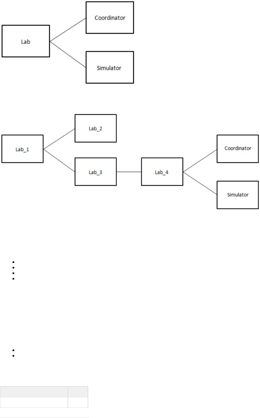
A lab can have one or more child labs.
The following diagram shows the hierarchical nature of labs. Lab_1 is the parent of Lab_2 and Lab_3. Lab_3 is the parent of Lab_4.
The fully qualified name of a child lab uses a forward slash as the separator. For example, the fully qualified name of Lab_4 in the
previous diagram is Lab_1/Lab_3/Lab_4.
A lab named Default is included with LISA. If you start a coordinator, simulator, or Virtual Service Environment without specifying a lab, the
Default lab is used.
A lab member has one of the following statuses:
Uninitialized
Starting
Running
Unknown
If a lab member is a LISA server, then the status proceeds from Uninitialized to Starting to Running.
If a lab member is a non-LISA server, then the status goes directly from Uninitialized to Running.
Virtual Lab Manager (VLM)
The cloud-based environment where the run is known as a Virtual Lab Manager (VLM).labs
The following VLM providers are supported:
ServiceMesh Agility Platform 7.1
VMware vCloud Director 1.0
You can configure LISA to use more than one VLM provider at the same time.
Each VLM provider has a unique prefix. The following table describes the prefixes.
VLM Provider Prefix
ServiceMesh Agility Platform AGL
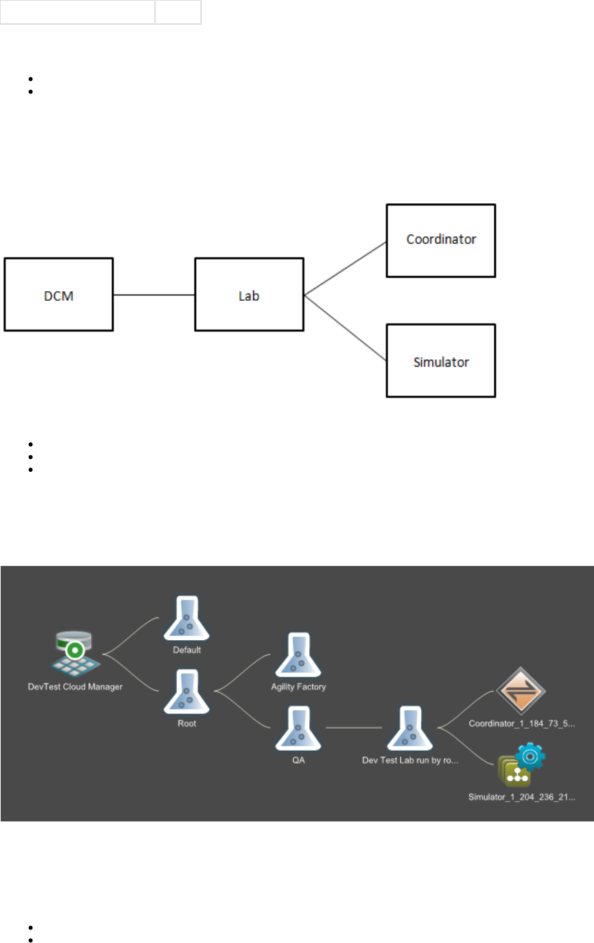
VMware vCloud Director VCD
In LISA Workstation, the prefix and a colon appear at the beginning of a fully qualified lab name to indicate which VLM provider is being used. For
example:
AGL:Root/MyLab
VCD:MyOrganization/MyCatalog/MyLab
The prefixes make it possible for you to use the same lab name in different VLM providers.
DevTest Cloud Manager (DCM)
The DevTest Cloud Manager (DCM) is the LISA component that interacts with the .labs
The responsibilities of the DCM include:
Sending cloud-related properties to a lab
Notifying the Virtual Lab Manager (VLM) provider that a lab should be started
Sending the to a labModel Archive (MAR)
The DCM lets you view, launch, monitor, and shut down labs from the Server Console.
The Server Console displays the DCM as part of the network graph. In the following image, the DCM is interacting with the Default lab and a lab
called Root. The Root lab has two child labs: Agility Factory and QA. The QA lab has a child lab called Dev Test Lab. The fully qualified name of
Dev Test Lab is Root/QA/Dev Test Lab.
Configuring LISA DCM Properties
To enable the provisioning of development and test labs, you must configure properties on the computer where the registry is located.
Some properties are applicable to all Virtual Lab Manager (VLM) providers. Other properties are specific to a VLM provider.
General Properties
ServiceMesh Properties
vCloud Director Properties
Example: Properties for ServiceMesh-Based Configuration
Example: Properties for vCloud Director-Based Configuration
General Properties
This section describes the properties that are applicable to all VLM providers.
You must configure the following property in the file:local.properties
lisa.net.bindToAddress
You must configure the following properties in the file:site.properties
lisa.dcm.labstartup.min
lisa.dcm.lisastartup.min
lisa.dcm.lisashutdown.min
lisa.dcm.lab.factories
lisa.net.timeout.ms
If you want to enable access control (ACL), then you must configure the following property in either the file or the local.properties
file. It does not matter which file you choose.site.properties
lisa.acl.auth.enabled
lisa.net.bindToAddress
The fully qualified domain name or IP address of the computer where the registry is located. The domain name or IP address must be
addressable by any computer that is launched to a network outside of the network in which the registry resides.
Syntax
lisa.net.bindToAddress=<fully-qualified-domain-name-or-IP-address>
lisa.dcm.labstartup.min
The number of minutes that LISA will wait for the VLM provider to start a lab.
Syntax
lisa.dcm.labstartup.min=<integer>
lisa.dcm.lisastartup.min
The number of minutes that LISA will wait after the VLM provider has started a lab for LISA to be properly initialized.
Syntax
lisa.dcm.lisastartup.min=<integer>
lisa.dcm.lisashutdown.min
The number of minutes that LISA will wait after the test execution has completed to shut down a lab.
Syntax
lisa.dcm.lisashutdown.min=<integer>
lisa.dcm.lab.factories
The name of the object that contains cloud support logic for a specific VLM provider. The valid values are
and .com.itko.lisa.cloud.serviceMesh.ServiceMeshCloudSupport com.itko.lisa.cloud.vCloud.vCloudDirectorCloudSupport
You can specify more than one VLM provider. If you do so, then you must separate the values with a semicolon.
Syntax
lisa.dcm.lab.factories=<object-name>[;<object-name>]
lisa.net.timeout.ms
The timeout value (in milliseconds) used by the underlying messaging system. This property is not cloud specific. Modify the value for cloud
integration because certain operations can take longer than the default 30 seconds.
Syntax
lisa.net.timeout.ms=<integer>
lisa.acl.auth.enabled
If you want to enable access control (ACL), then set the value of this property to .true
Syntax
lisa.acl.auth.enabled=<true|false>
ServiceMesh Properties
This section describes the properties that are specific to ServiceMesh Agility Platform.
You must configure the following property in the file:site.properties
lisa.dcm.SERVICEMESH.baseUri
You must also configure the following properties. The location depends on whether ACL is enabled.
lisa.dcm.SERVICEMESH.userId
lisa.dcm.SERVICEMESH.password
If ACL is not enabled, then you must configure the properties in the file.site.properties
If ACL is enabled, then LISA creates the and custom permissions andlisa.dcm.SERVICEMESH.userId lisa.dcm.SERVICEMESH.password
assigns them to each role. You can specify the initial values for these custom permissions by configuring the lisa.dcm.SERVICEMESH.userId
and properties in the file. If you do not specify the initial values, then you must set thelisa.dcm.SERVICEMESH.password site.properties
values from the Server Console. See .Adding, Updating, and Deleting Roles
You can optionally configure the following property in the file:site.properties
lisa.dcm.SERVICEMESH.lab.cache.sec
lisa.dcm.SERVICEMESH.baseUri
The base URL of ServiceMesh Agility Platform's REST interface.
Syntax
lisa.dcm.SERVICEMESH.baseUri=https://<fully-qualified-domain-name>:<ssl-port-number>/agility/api/v1.0
lisa.dcm.SERVICEMESH.userId
A user name that can log in to the ServiceMesh Agility Platform web interface.
Syntax
lisa.dcm.SERVICEMESH.userId=<user-id>
lisa.dcm.SERVICEMESH.password
The password for the user name defined in the property.lisa.dcm.SERVICEMESH.userId
Syntax
lisa.dcm.SERVICEMESH.password=<password>
lisa.dcm.SERVICEMESH.lab.cache.sec
LISA maintains a cache of the ServiceMesh project configuration. This property specifies how often LISA will access ServiceMesh to see whether
the cache needs to be updated (for example, an environment may have been added). The value is in seconds. The default value is 300.
Syntax
lisa.dcm.SERVICEMESH.lab.cache.sec=<integer>
vCloud Director Properties
This section describes the properties that are specific to VMware vCloud Director.
You must configure the following property in the file:site.properties
lisa.dcm.vCLOUD.baseUri
You must also configure the following properties. The location depends on whether ACL is enabled.
lisa.dcm.vCLOUD.userId
lisa.dcm.vCLOUD.password
If ACL is not enabled, then you must configure the properties in the file.site.properties
If ACL is enabled, then LISA creates the and custom permissions and assigns them tolisa.dcm.vCLOUD.userId lisa.dcm.vCLOUD.password
each role. You can specify the initial values for these custom permissions by configuring the and lisa.dcm.vCLOUD.userId
properties in the file. If you do not specify the initial values, then you must set the values from thelisa.dcm.vCLOUD.password site.properties
Server Console. See .Adding, Updating, and Deleting Roles
lisa.dcm.vCLOUD.baseUri
The login URL of the vCloud API.
Syntax
lisa.dcm.vCLOUD.baseUri=<url>
lisa.dcm.vCLOUD.userId
A user name that can log in to vCloud Director. Typically, the format consists of the user name, followed by an ampersand (@), followed by the
organization name.
Syntax

lisa.dcm.vCLOUD.userId=<user-name>@<organization-name>
lisa.dcm.vCLOUD.password
The password for the user name defined in the property.lisa.dcm.vCLOUD.userId
Syntax
lisa.dcm.vCLOUD.password=<password>
Example: Properties for ServiceMesh-Based Configuration
The following example shows a ServiceMesh-based configuration. This example assumes that ACL is not enabled.
This property is located in the file:local.properties
lisa.net.bindToAddress=myserver.example.com
These properties are located in the file:site.properties
lisa.dcm.labstartup.min=6
lisa.dcm.lisastartup.min=4
lisa.dcm.lisashutdown.min=2
lisa.dcm.lab.factories=com.itko.lisa.cloud.serviceMesh.ServiceMeshCloudSupport;
lisa.dcm.SERVICEMESH.baseUri=https://www.example.com:8443/agility/api/v1.0
lisa.dcm.SERVICEMESH.userId=admin
lisa.dcm.SERVICEMESH.password=mypassword
lisa.dcm.SERVICEMESH.lab.cache.sec=360
lisa.net.timeout.ms=60000
Example: Properties for vCloud Director-Based Configuration
The following example shows a vCloud Director-based configuration. This example assumes that ACL is not enabled.
This property is located in the file:local.properties
lisa.net.bindToAddress=myserver.example.com
These properties are located in the file:site.properties
lisa.dcm.labstartup.min=6
lisa.dcm.lisastartup.min=4
lisa.dcm.lisashutdown.min=2
lisa.dcm.lab.factories=com.itko.lisa.cloud.vCloud.vCloudDirectorCloudSupport;
lisa.dcm.vCLOUD.baseUri=https://www.example.com/api/versions
lisa.dcm.vCLOUD.userId=administrator@System
lisa.dcm.vCLOUD.password=mypassword
lisa.net.timeout.ms=60000
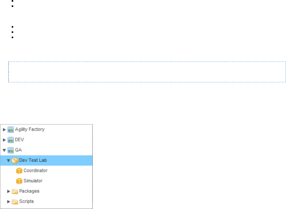
1.
2.
3.
4.
5. a.
b.
6. a.
b.
7. a.
Configuring ServiceMesh
To enable the provisioning of development and test labs with ServiceMesh Agility Platform as the Virtual Lab Manager (VLM) provider, you must
perform configuration steps in ServiceMesh.
This topic uses the following ServiceMesh concepts: environment, image, instance, package, script, stack, and template. Some of these terms
can be mapped to LISA concepts:
An environment in ServiceMesh corresponds to a lab in LISA.
An instance in ServiceMesh corresponds to a lab member in LISA.
Startup scripts must be written for the following LISA server components:
Coordinator
Simulator
Virtual Service Environment
The startup script must include a command that starts the server component in mode. This mode causes the server component toremoteInit
start and then wait until the DevTest Cloud Manager (DCM) sends the required initialization settings. For example:
su -c "nohup lisa/bin/CoordinatorServer -remoteInit" - itko &
If you want the labs to include only a Coordinator and Simulator, then you do not need to write a startup script for the Virtual Service Environment.
If you want the labs to include only a Virtual Service Environment, then you do not need to write startup scripts for the Coordinator and Simulator.
The following image shows an example configuration in ServiceMesh. The Dev Test Lab environment contains a Coordinator template and a
Simulator template.
When a , LISA makes a copy of the corresponding ServiceMesh environment. At any given time, there can be multiple independentlab is started
copies of the same environment.
To configure ServiceMesh
Configure and run a base image supported by ServiceMesh.
Download the installer for LISA Server.
Install LISA Server onto the base image. When the installation is finished, do not configure the license properties or make any changes to
the install.
Create a new stack. Use the base image with LISA installed as the base for the stack. This stack is the "bare metal" image of LISA. Be
sure to note where LISA is installed so that the startup scripts can properly reference the location.
To add a Coordinator, do the following:
Select an environment and create a new virtual machine template. Set the template name to , or ensure that Coordinator
appears as part of the template name. Use the stack that you created as the base for the template. The startupCoordinator
order of the template does not matter to LISA.
In the same project, create a new script that starts the Coordinator in mode. Add the script to a package as a startupremoteInit
script. Add the package to the template that you created in the previous step.
To add a Simulator, do the following:
Select an environment and create a new virtual machine template. Set the template name to , or ensure that Simulator
appears as part of the template name. Use the stack that you created as the base for the template. The startup orderSimulator
of the template does not matter to LISA.
In the same project, create a new script that starts the Simulator in mode. Add the script to a package as a startupremoteInit
script. Add the package to the template that you created in the previous step.
To add a Virtual Service Environment, do the following:
Select an environment and create a new virtual machine template. Set the template name to , or ensure that appearsVSE VSE

7. a.
b.
1.
2.
3.
4.
5.
as part of the template name. Use the stack that you created as the base for the template. The startup order of the template
does not matter to LISA.
In the same project, create a new script that starts the Virtual Service Environment in mode. Add the script to aremoteInit
package as a startup script. Add the package to the template that you created in the previous step.
Configuring vCloud Director
To enable the provisioning of development and test labs with VMware vCloud Director as the Virtual Lab Manager (VLM) provider, you must
perform configuration steps in vCloud Director.
This topic uses the following vCloud Director concepts: catalog, vApp, and vApp template. vApps and vApp templates in vCloud Director
correspond to labs in LISA.
During the configuration procedure, you create virtual machine images for the following LISA server components:
Coordinator
Simulator
Virtual Service Environment
If you want the labs to include only a Coordinator and Simulator, then you do not need to create an image for the Virtual Service Environment.
If you want the labs to include only a Virtual Service Environment, then you do not need to create images for the Coordinator and Simulator.
Each server component must be configured to start in mode. This mode causes the server component to start and then wait until theremoteInit
DevTest Cloud Manager (DCM) sends the required initialization settings.
To configure vCloud Director
Using an application such as VMware Workstation, create a virtual machine image for each server component that you want to include in
a lab. Configure each image to start the server component in mode. The name of a Coordinator must include the term remoteInit
. The name of a Simulator must include the term . The name of a Virtual Service Environment must include theCoordinator Simulator
term . VSE
Log in to the vCloud Director web console as an administrator.
Import each virtual machine image that you created as a vApp template.
Create a vApp from the vApp templates.
Add the vApp to a catalog.
Dynamic Expansion of Test Labs
LISA can determine that more capacity is required to meet the needs of a running test and then automatically expand the lab.
You must use a staging document that has the Dynamic Simulator Scaling with DCM distribution pattern. For more information, see Distribution
.Selection
The following diagram shows an example. In the left portion, the lab initially has one Coordinator and one Simulator. In the right portion, the lab
has one Coordinator and four Simulators after the expansion takes place.
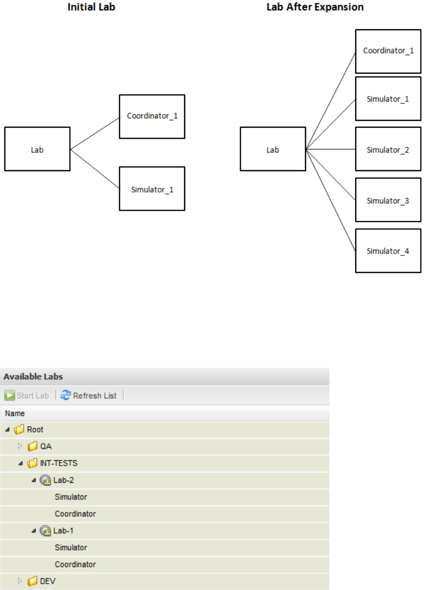
1.
2.
3.
Listing the Available Labs
The Server Console enables you to list the development and test labs that are available in the cloud environment.
The following image shows a list of available labs in the Server Console. The tree structure is expanded to show two child labs.
For instructions on accessing the Server Console, see .Opening the LISA Console
To list the available labs
In the Server Console, display the LISA Network panel.
Expand the DevTest Cloud Manager node.
Click the Available Labs node.
The available labs appear in the right panel. The tree structure is initially collapsed.
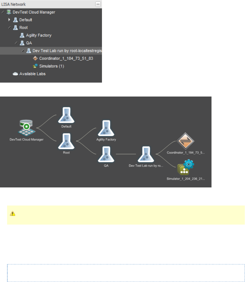
Starting a Lab
When you start a lab, you are actually starting an instance of the lab. A lab can have multiple instances, all of which are independent of each
other.
In the Server Console, the LISA Network panel displays the started lab in a tree structure. The following image shows the LISA Network panel.
The right panel displays the started lab in the . The following image shows the network graph.network graph
The property controls the number of minutes that LISA will wait for the Virtual Lab Manager (VLM) provider to start thelisa.dcm.labstartup.min
lab. For more information, see .Configuring LISA DCM Properties
You do not need to explicitly start the Default lab.
Starting a Lab from the Command Line
You can start a lab by invoking one of the LISA server executables, and specifying a server name and a lab name.
For example, the following command starts a lab named MyLab, which is a child of MyParentLab. The MyLab lab has one lab member: a
coordinator named Dev-Coord.
CoordinatorServer -n Dev-Coord -l MyParentLab/MyLab
Starting a Lab from the Server Console
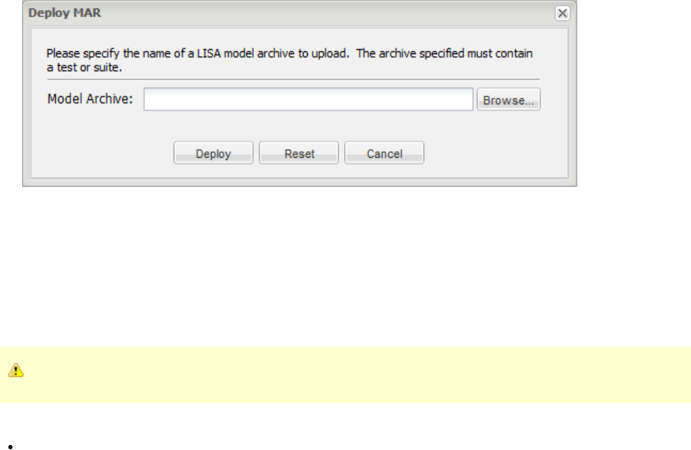
1.
2.
3.
4.
1.
2.
3.
4.
5.
This procedure assumes that you have .listed the available labs
To start a lab from the Server Console
In the list of available labs, select the lab.
Click Start Lab.
Wait for the lab to start.
When the startup sequence is finished, a message indicates that the lab was started.
The LISA Network panel displays the started lab in a tree structure. The right panel displays the started lab in the network graph.
Wait for the lab members to start.
When the startup sequence for a lab member is finished, the member's status changes to Running. In addition, statistics about the lab
member begin appearing in the .Component Health Summary tab
Deploying a Model Archive (MAR) to a Lab
You can deploy the Model Archive (MAR) for a test case or suite to a lab that has been . The lab must include a coordinator and (in moststarted
cases) a simulator.
To deploy a Model Archive (MAR) to a lab
In the LISA Network panel of the Server Console, click the coordinator.
The details window for the coordinator appears in the right panel.
In the right panel, click Deploy MAR.
The Deploy MAR dialog appears.
Click Browse and select the .mar file.
Click Deploy.
A message indicates that the model archive has been successfully deployed. The test case or suite is now running.
Click OK.
Stopping a Lab
You can stop a currently running lab from the Server Console. This action is permanent and cannot be undone.
If the lab is a child lab, the parent labs are not stopped.
You cannot stop the Default lab.
To stop a lab
In the network graph, right-click the lab and select Stop.
When the action is finished, a message indicates that the lab was stopped.
Cloud DevTest Lab Videos
The following videos explore different aspects of using cloud-based infrastructure to provision development and test environments.
Get Runnable Labs
This video shows how to get a list of runnable labs available to be launched. The length of the video is 30 seconds.
Get Runnable Labs
Start a Runnable Lab

1.
2.
3.
This video shows how to start a lab that you can deploy tests to. The length of the video is 1 minute.
Start a Runnable Lab
Stage a Test to Running Lab
This video shows how to take a started lab and initialize a test on the server that was provisioned in the cloud. The length of the video is 1 minute.
Stage a Test to Running Lab
Deploy a Virtual Service to Launched Lab
This video shows how to stage a virtual service to a deployed virtual server. The length of the video is 2 minutes and 30 seconds.
Deploy a Virtual Service to Launched Lab
Stop a Running Lab
This video shows how to shut down a lab. The length of the video is 1 minute.
Stop a Running Lab
Continuous Validation Service (CVS)
The Continuous Validation Service (CVS) lets you schedule tests and test suites to run on a regular basis over an extended time period.
CVS has a dashboard that maintains a list of all scheduled tests (services) and the status of each one. From the CVS Dashboard, you can select
a test and monitor each test run.
A monitor contains a single test or an entire test suite. A service contains one or many monitors within itself.
The tests are managed by a coordinator and run on a simulator. State is maintained in a database on the LISA registry.
You can either choose to run a service or individual monitors within it from the CVS Dashboard.
Prerequisite
CVS runs in a LISA Server environment.
There must be a coordinator server and a simulator server running, registered with a LISA registry.
For details on setting up the LISA Server environment, see the .Installation and Configuration Guide
The following sections are available:
Opening the CVS Dashboard
CVS Dashboard Overview
Deploying a Monitor to CVS
Running a Monitor Immediately
Viewing Test Details
Email Notification Settings
CVS Manager
Opening the CVS Dashboard
You can open the CVS Dashboard from LISA Workstation or from a web browser.
To open the CVS Dashboard from LISA Workstation
From the main menu, select View > CVS Dashboard.
To open the CVS Dashboard from a web browser
Ensure that the is running.registry
Enter in a web browser. If the registry is located on a remote computer, replace with the name or IPhttp://localhost:1505/ localhost
address of the computer.
The LISA Console appears.
Click Continuous Validation Service.
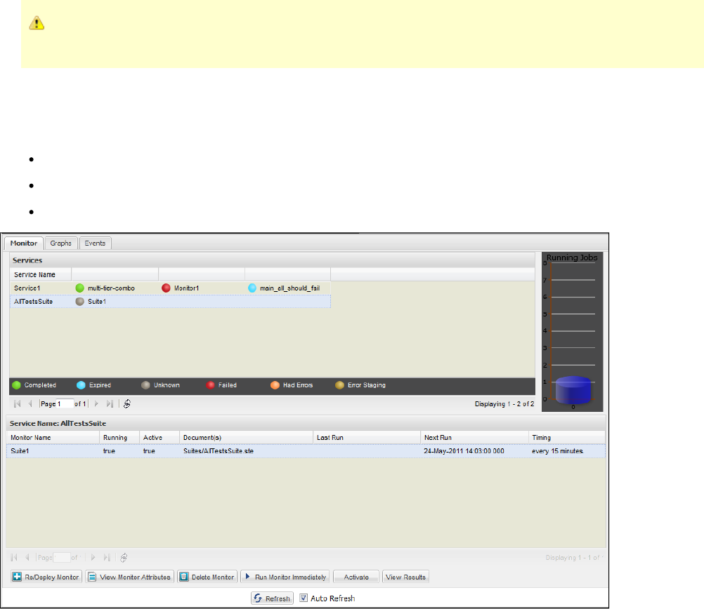
Closing the CVS dashboard or closing LISA Workstation will not interfere with the CVS scheduled tasks. When you reconnect to
the registry, you will see the dashboard with the current data and status information.
CVS Dashboard Overview
The CVS Dashboard has the following tabs:
Monitors: Displays a list of all the monitors (tests/test suites) that are added to the CVS Dashboard. For more information, see Monitor
. Your CVS dashboard will list all the monitors running on an attached LISA Registry, not just the ones initiated by you.Tab
Graphs: Displays the dashboard status graphically. It will also show the percentage of the tests passed or failed. For more information,
see .Graphs Tab
Events: Displays the status events recorded by the monitors. For more information, see .Events Tab
A refresh button, which lets you refresh the list on the dashboard, appears at the bottom of the dashboard.
Monitor Tab
The CVS Dashboard opens in the Monitor tab.
You can add many monitors to run in one or many services. A service contains one or more monitors.
You can schedule to run a service. All monitors in that service are run at the scheduled time. The services are run in the background at scheduled
intervals.
You can either add the monitors in one service (in the following example, ) or add the monitors in different services (in the followingService1
example, and ). All the monitors added in one service (for example, ) are shown added after that service name.Service1 AllTestsSuite Service1
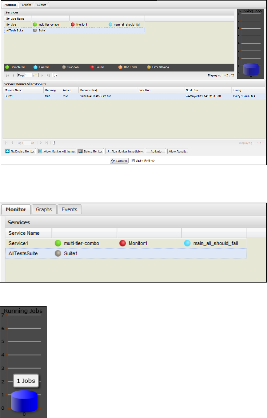
Top Panel
All the tests in a particular service that have run are depicted with a colored ball. The completed tests are shown by a green ball, failed tests are
shown by a red ball, tests that had an error in their staging documents are shown with a yellow ball, and so on. The icons depict the Test Run
Completion, Failure, Error, Staging Doc Error, or Unknown Error. These icons depict the state of the monitor after it has run.
At the right side, the top panel shows a graphical representation of the jobs that are currently running. For example, the following graph shows
only one job currently running.
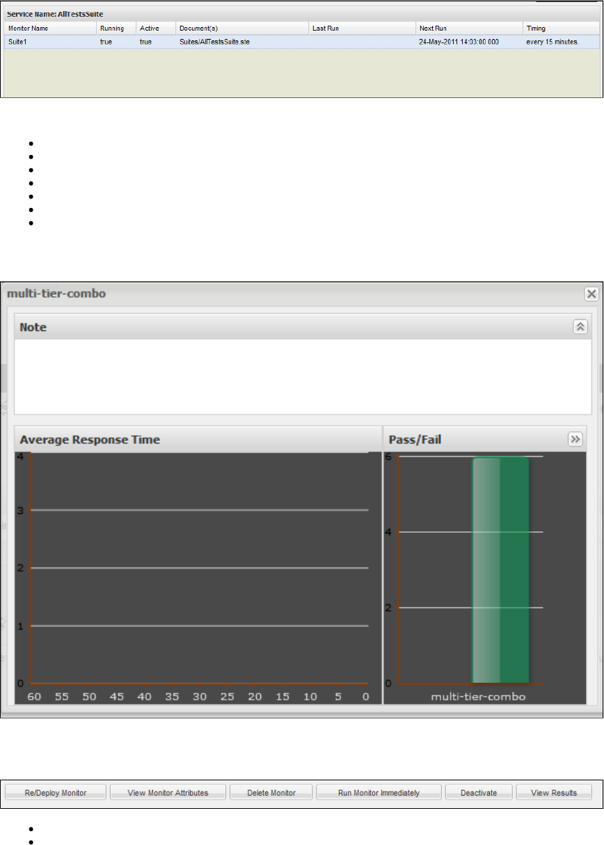
Bottom Panel
The bottom panel displays the status of each monitor run in a service.
The bottom panel shows all the monitors that are running or have finished their last run. The monitors that have finished running completely (are
not scheduled to run again) will not be seen in this list.
The table shows the following information:
Monitor Name: The name given to the monitor
Running: Shows whether this monitor is currently running (True/False)
Active: Shows whether this monitor is currently Active (True/False)
Documents: The names of the documents, such as test case, staging, and suite documents associated with this monitor
Last Run: The last run date and time of this monitor
Next Run: The next scheduled start time of this monitor
Timing: The schedule details for this monitor
You can customize the columns by arranging them in sorted order or showing/hiding of the columns.
Double-click a monitor to see the monitor-related information.
Toolbar
The Toolbar tab includes a toolbar with the following buttons:
Re/Deploy Monitor: Deploy or redeploy a monitor to the Dashboard. See .Deploying a Monitor to CVS
View Monitor Attributes: View monitor-related information
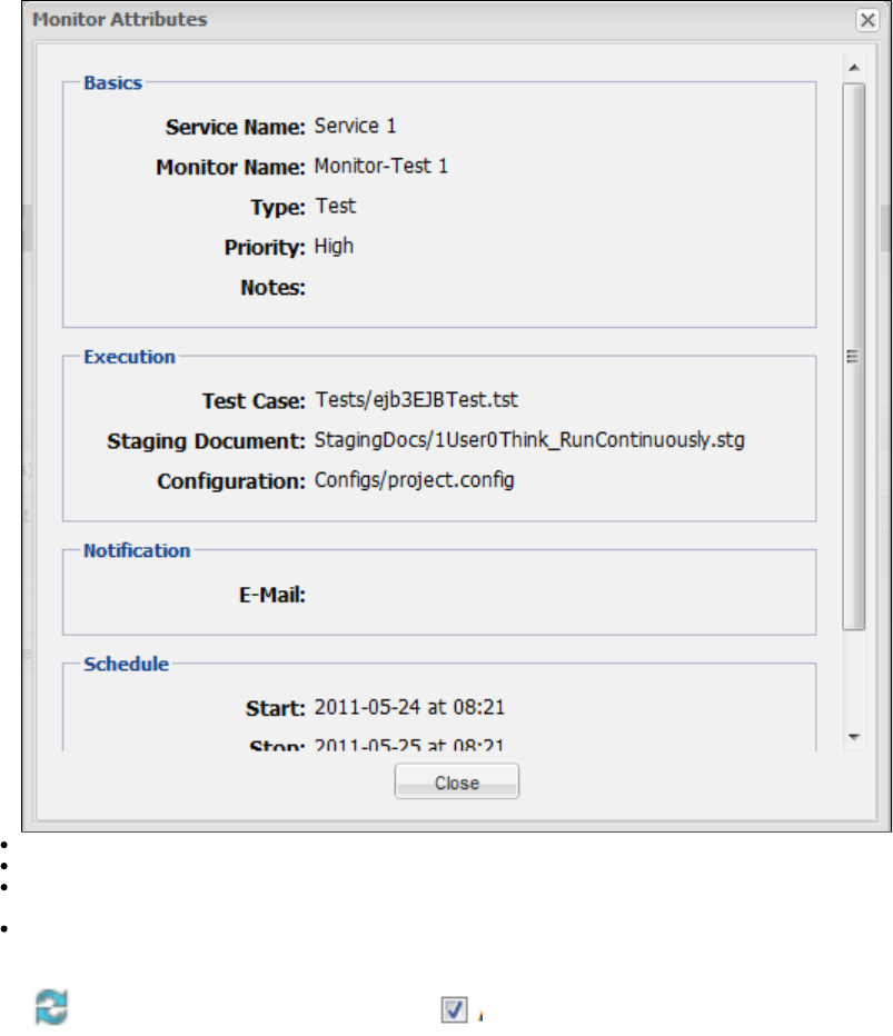
Delete Monitor: Delete a monitor from the Dashboard.
Run Monitor Immediately: Run the monitor immediately.
Deactivate: Click to deactivate the monitor. Deactivate means it remains in the list, but will not run. You can also click this button to
reactivate a previously-deactivated monitor.
View Results: Click to view the results of the run in the Report Viewer.
When you are running the CVS Dashboard directly from LISA Workstation (by selecting to view the Dashboard from LISA), you will see buttons to
the list on the Dashboard and AutoRefresh to auto-refresh the list on the Dashboard after a certain period. When you runRefresh
the CVS Dashboard directly from your browser, these buttons do not appear.
Graphs Tab
The Graphs tab displays the tests in the CVS Dashboard in a graphical format. It gives you a graphical summary of the tests that have passed
and failed.
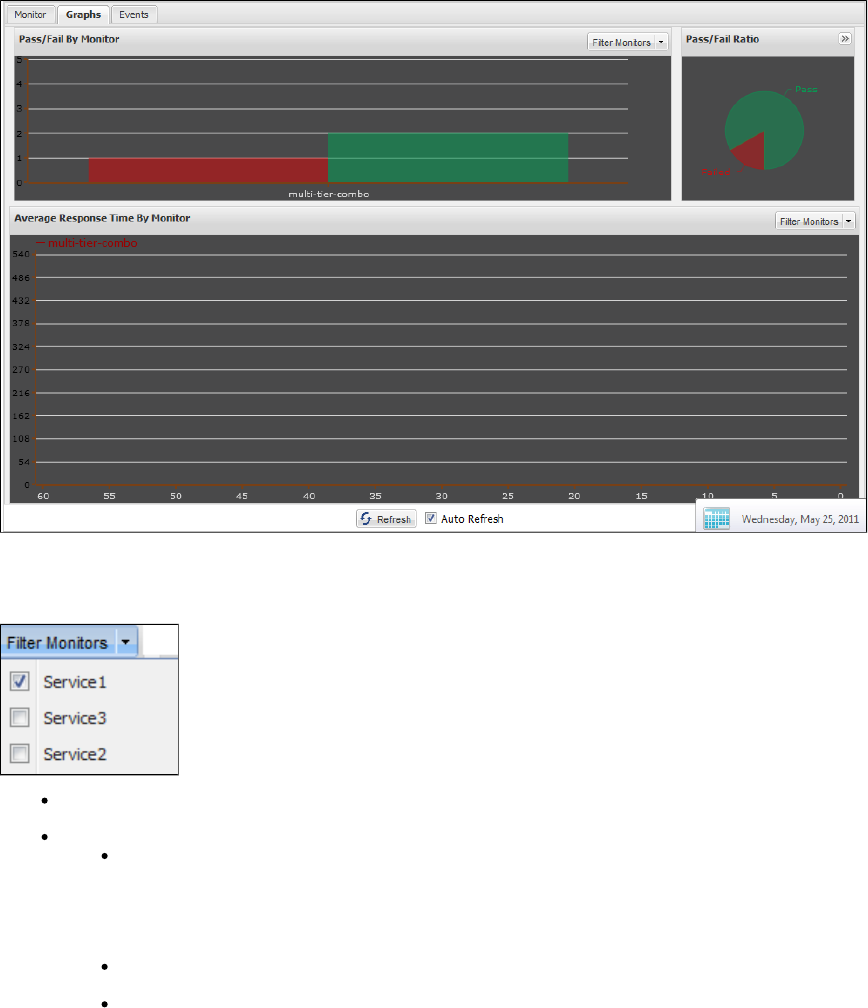
The Graphs tab consists of three graphical displays, which show and track the last 60 minutes of activity.
Filter Monitor: You can filter the monitors for viewing from the Filter Monitor button.
Click the Filter Monitor button to get a list of available monitors.
Select one to view the details regarding that monitor.
Pass/Fail by Monitor: The graph shows stacked histograms of Pass/Fail results for each monitor. MovingPass Fail by Monitor
the cursor over the histogram shows the result in text form.
In the top panel, you can choose to see either all the tests or selective tests/suites by clicking the Filter MonitorPass/Fail By Monitor
button, which lets you select the tests/suites.
Pass/Fail Ratio: The Pass/Fail Ratio graph displays the percentage of total number of passing tests (green), and the total
number of failing tests (red) as a pie chart.
Average Response Time by Monitor: graphs the average response time for eachAverage Response Time by Monitor
monitor over the last 60 minutes of activity. Each monitor is color-coded. Hover over a monitor to show the average response
time in a tooltip.
You can choose to display the test/suite to be seen in the graphical format in the .Pass/Fail By Monitor
Events Tab
The Events tab displays various events corresponding to the stages of the monitor run, like starting of a test run, ending, failing, and so on.
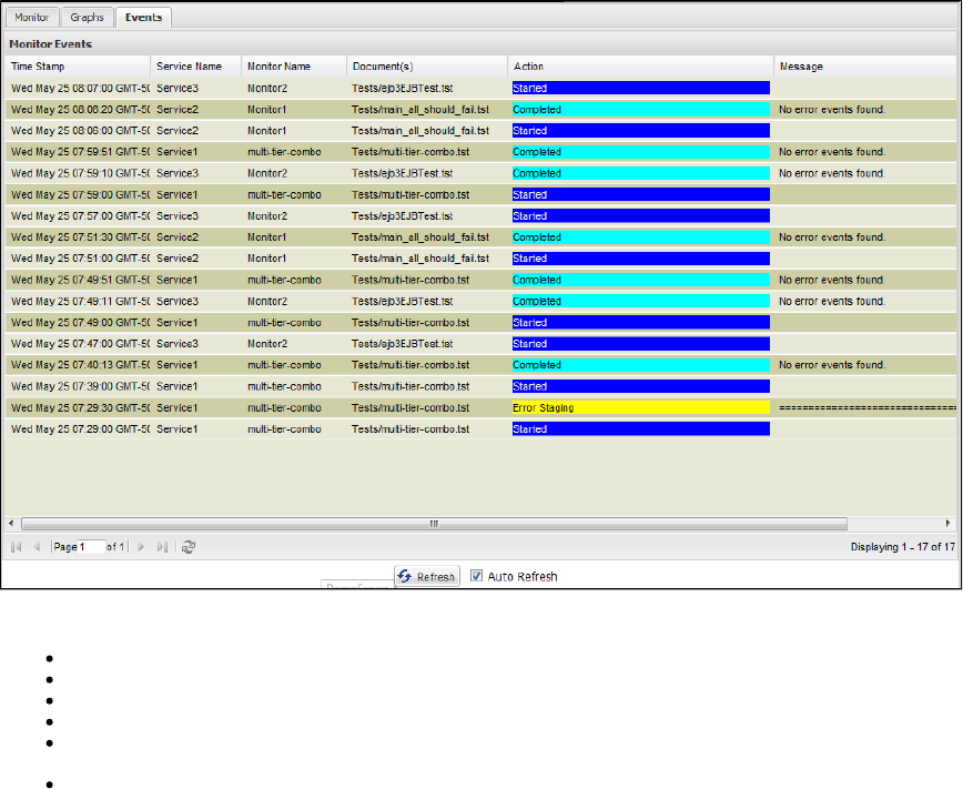
The following information is displayed:
Time Stamp: The time the event occurred.
Service Name: The name of the Service in which the monitor resides.
Monitor Name: The name of the monitor in which the event occurred.
Document(s): A list of the documents associated with the monitor for which the event occurred.
Action: The action reported by the event. Start events are blue, staging error events yellow, completion events green, and failed events
are red.
Message: The message reported by the event. If the text is larger than the message cell, you can right-click the cell to invoke the
extended view window.
You can display the events in real time by checking the Auto Refresh box at the bottom of the panel, or you can refresh the list manually by
clicking the Refresh icon, with the Auto Refresh box cleared.
You can adjust the column sizes so that all columns can display on the screen. If you double-click on a Message field, you can see the full text of
the message.
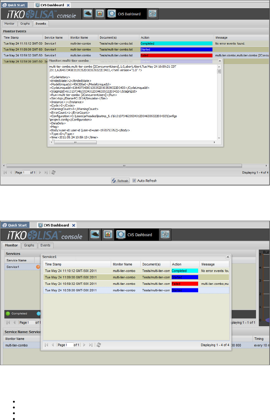
Test Cycle with Errors
At times, the test cycle may fail. The cycle that has errors can be seen in the Actions list in different color. You can double-click any event, to see
the associated messages in an expanded window.
Deploying a Monitor to CVS
You can deploy a monitor to the Continuous Validation Service (CVS) by using any of the following approaches:
Deploying a Monitor through LISA Workstation
Deploying a Monitor through the CVS Dashboard
Deploying a Monitor through the cvsMonitors Directory
Deploying a Monitor through CVS Manager
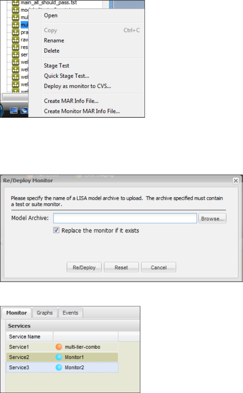
1.
2.
1.
2.
3.
4.
5.
Deploying a Monitor through LISA Workstation
The only prerequisite for this approach is the existence of a test case or suite.
From the Project panel at the left of LISA Workstation, right-click a test case or suite and select Deploy as monitor to CVS.
You will see a collection of tabs to provide monitor information, the same as needed for . See that sectionCreating Monitor MAR Info Files
of the documentation for information, then click Deploy to deploy the monitor.
Deploying a Monitor through the CVS Dashboard
Before you can perform this procedure, a Model Archive for the monitor must have been .created
In the Monitor tab of the CVS Dashboard, click the Re/Deploy Monitor button.
LISA displays the Re/Deploy Monitor window for the new Monitor.
In the area, enter the name of the MAR file.Model Archive
If the MAR has previously been deployed, select or clear the Replace the monitor if it exists check box.
Click Re/Deploy.
The Monitor is added to the CVS Dashboard.

1.
2.
1.
2.
3.
4.
Deploying a Monitor through the cvsMonitors Directory
Before you can perform this procedure, a Model Archive for the monitor must have been .created
Go to the LISA_HOME/cvsMonitors directory.
Add the MAR file to the directory. At a later time, you can update the monitor by placing a new version of the MAR file in the same
directory.
Deploying a Monitor through CVS Manager
For details on the command-line option for deploying a CVS Monitor, see .CVS Manager
Running a Monitor Immediately
When you add the services in the top panel, they will be run automatically in the background at the scheduled time intervals.
If you want to run a particular monitor immediately, you can use the toolbar.
To run a monitor immediately
Deploy the monitor.
When it gets listed in the bottom panel, select it.
Click Run Monitor Immediately to run the monitor immediately. You will not see the monitor run in the bottom panel.
Go to the Events tab of the CVS Dashboard to see the monitor that has run, with a suffix (for example, ).-now Test 3-now
Viewing Test Details
You can view the details of a test run within the CVS Dashboard.
To view test details
Double-click the service to see the service-related details.
Double-click the monitor whose details you want to view in the top panel.
This will open the test-related detail window.
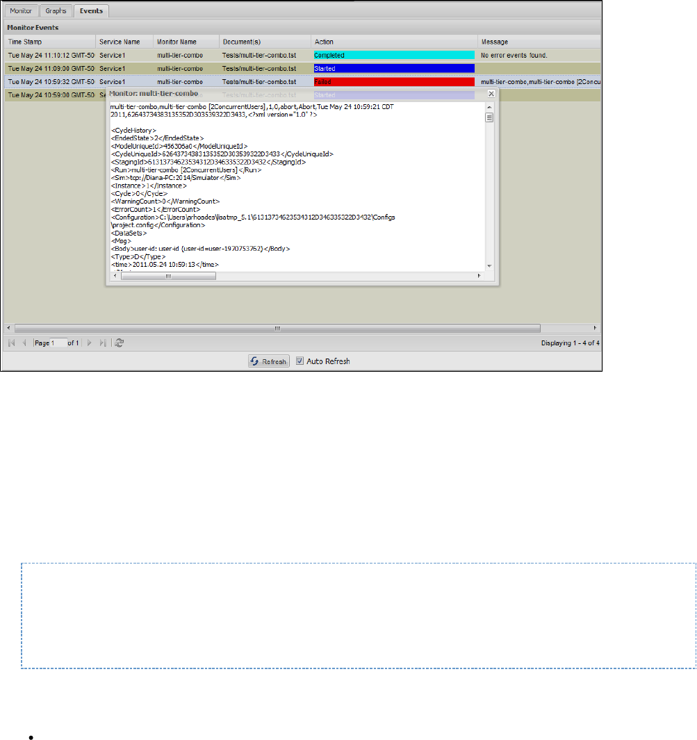
Also, you can display the Events tab in the CVS Dashboard. You can adjust the column sizes so that all columns can display on the screen. If you
double-click on a Message field, you can see the full text of the message.
Any reports generated during scheduled test runs are available and can be seen in the Report Viewer.
Email Notification Settings
Every time you schedule a new test in the CVS utility, you must deploy a monitor in the CVS Dashboard.
Within the monitor window, you can also set an email address, so that you receive an email notification every time the monitor is run within the
specified time period.
To set the email notification, you must update the file.lisa.properties
You also must change the mail server configuration and enter the mail host as shown in the following example.
# If you use performance monitoring alerts, this is the "from" email address of those alerts
# lisa.alert.email.emailAddr=lisa@itko.com
# And this is the email server we will attempt to route emails with (smtp server)
# lisa.alert.email.defHosts=localhost
Remove the # from the first column of the file to uncomment this information in the file.lisa.properties
Restart LISA to set the mail server configuration.
Notification email: Enter the email address for email notification of the test run result.
Every time the test is run, you will receive an email.
CVS Manager
The CVS Manager command-line utility lets you manage the set of monitors deployed to the . The utility is locatedContinuous Validation Service
in the directory.LISA_HOME/bin
This utility has the following format:

CVSManager [-h] [-m registry-spec] [-d archive-file] [-r archive-file] [-l] [-D] [-A] [-e] [x] [-X]
[-s name] [-n name] [-u username] [-p password] [--version]
-h, --help
Displays help text.
-m , --registry=registry-spec registry-spec
Defines the registry to which to connect.
-d , --deploy=archive-file archive-file
Deploys the specified model archive to CVS as a monitor. The monitor defined in the archive must refer to a monitor and service name
combination that does not already exist.
-r , --redeploy=archive-file archive-file
Redeploys the specified model archive to CVS as a monitor. The monitor defined in the archive must refer to a monitor and service name
combination that exists.
-l, --list
Lists the currently deployed monitors with interesting information about each.
-D, --pause
Pauses the scheduled execution of the indicated monitor.
-A, --resume
Resumes the scheduled execution of the indicated monitor.
-e, --execute-now
Causes the indicated monitor to be executed immediately, regardless of its schedule. This action does not affect any scheduled executions
of the monitor.
-x, --remove
Removes a monitor from CVS. Use the service name and monitor name arguments to indicate which monitor to remove.
-X, --remove-all
Removes all monitors from CVS. If a service name is specified, then only monitors defined with that service name are removed.
-s , --service-name=name name
Defines the service name for the monitors to affect.
-n , --monitor-name=name name
Defines the monitor name to affect.
-u , --username=username username
Defines the LISA security user name. If access control (ACL) is enabled, then this option is required.
-p , --password=password password
Defines the LISA security password. If access control (ACL) is enabled, then this option is required.
--version
Print the version number.
Example: Deploy Monitor
This example deploys a monitor to CVS.
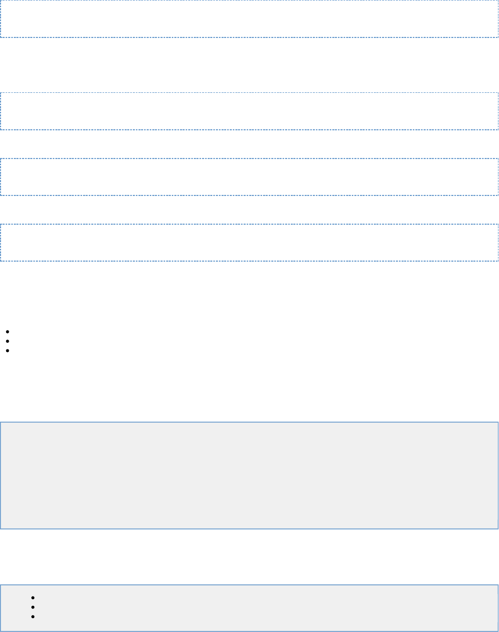
CVSManager -d monitor.mar
Example: Delete Monitor
This example deletes that same monitor (assuming the service and monitor names).
CVSManager -x -s OrderManager -n CheckOrders
This example deletes all monitors in the OrderManager service.
CVSManager -X -s OrderManager
This example deletes all monitors.
CVSManager -X
Reports
There are a wealth of features related to the generation and capture of data for the purpose of reporting results. You determine what data LISA
collects by specifying reporting parameters in one of three areas:
Quick Tests
Staging Documents
Test Suites
You can specify the specific events or metrics you want collected for each test case or test suite you run, resulting in maximum flexibility and
control over the reporting data you collect. You choose between two report generators that store reporting data in either a database or an XML
file. You also determine how long the reporting data should be kept.
After the reports have been generated, they can be viewed and managed at a later date, shared with colleagues, or exported to other locations.
In this section, the following topics are covered:
Report Generator Types
Opening the Reporting Portal
Reporting Portal Layout
Filtering Reports
Viewing Reports
Exporting Reports
Auto Expiring Reports
Changing Reporting Databases
Report Generator Types
You can select the following types of report generators in the Reports tab of the or the .Staging Document Editor Test Suite Editor
Default Report Generator
Load Test Report Generator
XML Report Generator
Default Report Generator
The default report generator captures functional, performance, and metric information and publishes that data to the reporting database
referenced by the registry. The reporting portal uses the reporting database.
For load testing, check the Record Performance Metrics in the Parameters section:
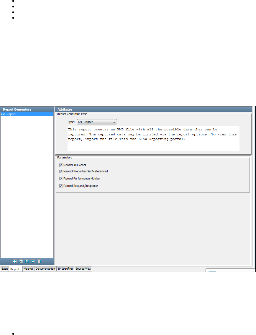
1.
2.
3.
Record All Events: If selected, will record all events.
Record Properties Set/Referenced: If selected, will record the set or referenced properties.
Record Performance Metrics: If selected, will record the performance metrics.
Record Request/Response: If selected, will record the request and response.
Load Test Report Generator
The Load Test report generator is designed for load tests with thousands of virtual users.
This report captures load metrics but not step-level metrics (there would be too much data and the reporting database would slow down the test).
XML Report Generator
This report generator creates an XML file with all the possible data that can be captured. The captured data can be limited by using the report
options in the Test Suite Editor or Staging Document Editor. To view this report, import the file into the LISA Reporting portal.
The data in this table can be used for any custom reporting needs.
After your tests and/or suites are complete, you can view the report data in the reporting console. To export the XML data to a file, see Exporting
.Reports
Opening the Reporting Portal
You can open the Reporting Portal from LISA Workstation or from a web browser.
To open the Reporting Portal from LISA Workstation
From the main menu, select View > Reporting Console.
To open the Reporting Portal from a web browser
Ensure that the is running.registry
Enter in a web browser. If the registry is located on a remote computer, replace with the name or IPhttp://localhost:1505/ localhost
address of the computer.
The LISA Console appears.
Click Reporting Dashboard.
Reporting Portal Layout

The Reporting Portal lets you view all the reports that have run earlier in LISA Workstation. You can configure the reports either through the
staging documents, quick tests, running test cases or test suites.
This section looks at the reports generated by running the multi-tier-combo test case, which is located in the examples directory.
Criteria
In the left panel, you can select the date and time criteria and select the filters for use.
Start date/End date: Select the start/end date by clicking the Calendar icon. By default, the start and end dates will be in the range
of the last hour. Select the start and end time by clicking the 1-12 and AM/PM drop-downs. After entering start and end dates, select the
Apply button to apply your changes.
The Recent button will automatically reset the date and time criteria to find the latest report information available (the last test/suite run)
and the hour previous from it.
Filters: You can create filters of your choice here. Enter the name of the filter and click Save. You can also delete a filter by clicking
Delete. Select Show All Filters to show all filters created by all users, not just ones you have created.
Select from the AND/OR operators for the criteria and click Add or Delete .
Right Panel
The right panel consists of the graphs charted depending on the selected criteria. For more information, see Reports - Graphical View
The Reporting Toolbar is also shown at the top of the right panel.
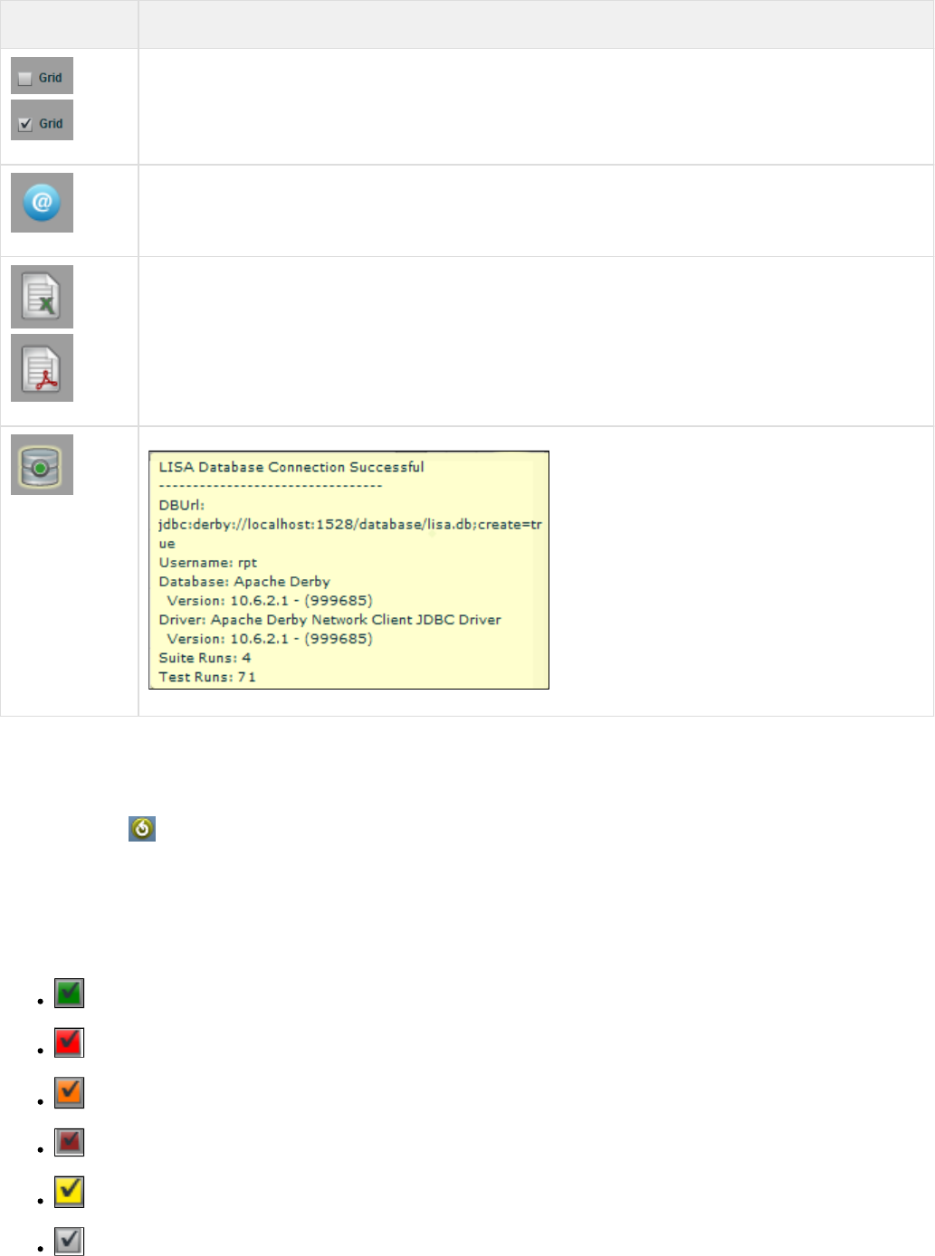
Icon Function
Changes the report view from the default chart view to the grid view, and back. For more information, see Reports - Grid
.View
Copies the URL of the report you are viewing to the operating system clipboard so you can share the report with other
users.
Exports the report data to a PDF file or Excel file to view report details in those formats. For more information, see
.Exporting Reports
Displays information about the reporting database.
You can filter the reports on the results of test cases that have passed or failed. You can also choose to show or hide errors and warnings, and
show or hide test suites or test cases. For more information, see .Filtering Reports
The Zoom slider lets you customize the size of the report display.
The Refresh button will refresh the display. To set an auto-refresh, select the Autorefresh check box and set an interval for auto-refresh.
Filtering Reports
The right panel of the displays the reports.Reporting Portal
You can filter reports by using certain criteria. After you select the criteria, the report viewer will show graphs only for selected criteria.
: Show the test cases/suites that have passedPass
: Show the test cases/suites that have failedFail
: Show the test cases/suites that have abortedAborted
: Show the test cases/suites that have generated errorsErrors
: Show the test cases/suites that have generated warningsWarnings
: Show the test suite resultsSuites
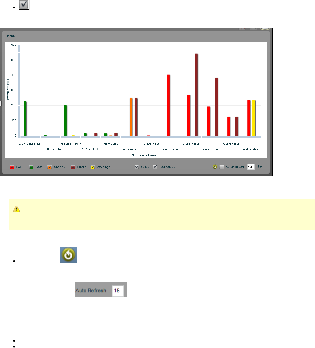
1.
2.
: Show the test case resultsTest Cases
The Reporting Portal will show the reports for all the test cases and test suites that have run and that are currently in its database.
In the previous report, there is no search criteria specified as all are clicked. Therefore, you will see the report for all the test cases and test suites
that have passed, failed, aborted, had errors, and had warnings.
You can combine the criteria with the criteria for more specificity. For example, you could select and result test run Fail Error
and to see only failed test cases or those that completed with some errors.Test Case
To refresh the reports
Click the icon.Refresh
To automatically refresh the reports
Select the icon.AutoRefresh
Enter the number of seconds after which you want the reports to be refreshed.
Viewing Reports
In the Reports viewer, the reports can be viewed in two formats:
Graphical View: This is the default view of the reporting portal. You can see all the reports in the graphical format.
Grid View: You can select the grid view to have the data arranged in a grid format.
Reports - Graphical View
By default, all the reports can be seen as graphs.
Example: Graphical View
The following reports graph contains these test cases: multi-tier-combo.tst, main_all_should_fail.tst, and ejb3WSTest.tst.
Because not all of the filter criteria boxes are checked, we will see the report for only the test cases that have passed, failed, or aborted.
Mousing over a test case will display an information box that shows the test case name, test execution details like the number of pass/fail tests,
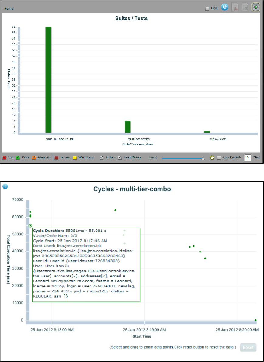
and the date of execution.
Double-clicking a test case in the graph that passed produces a Cycles diagram for the test case.
When you move your mouse over these dots, you see that each dot represents a cycle of the test case, and the details for each cycle are shown:
response time in milliseconds, the cycle/instance number, the date of the cycle, and the data used.
Clicking the Information button at the upper-left of the screen gives you more information about the test case environment.
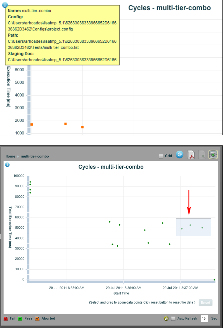
To inspect a subset of cycles more closely, select a group of dots and zoom to see only that subset of cycles.
To return to the complete cycle view, click the Reset button.
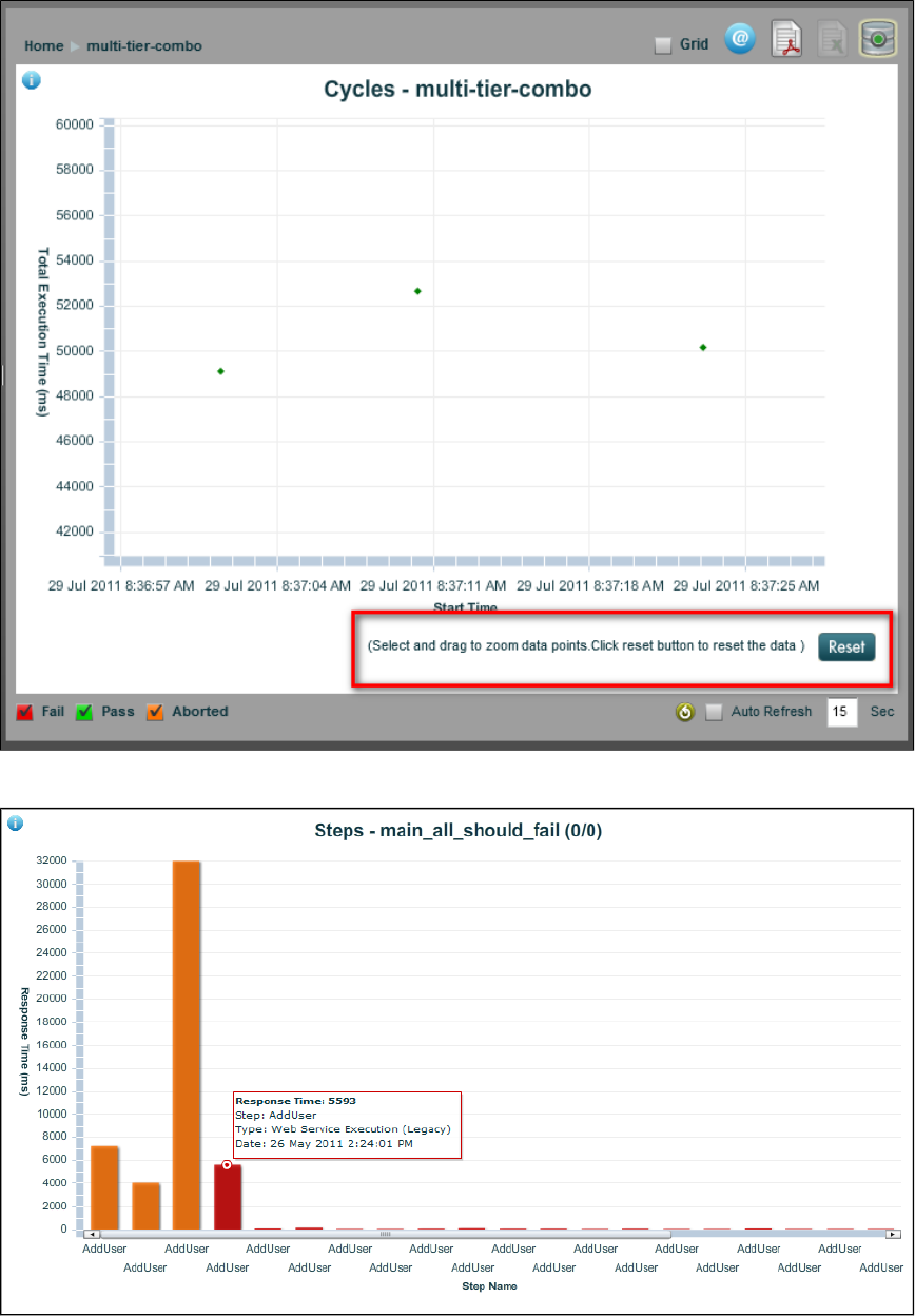
Double-clicking a test case with errors shows a view of each step of the case, with information about response times.
Right-clicking a test case or suite produces a reporting menu.
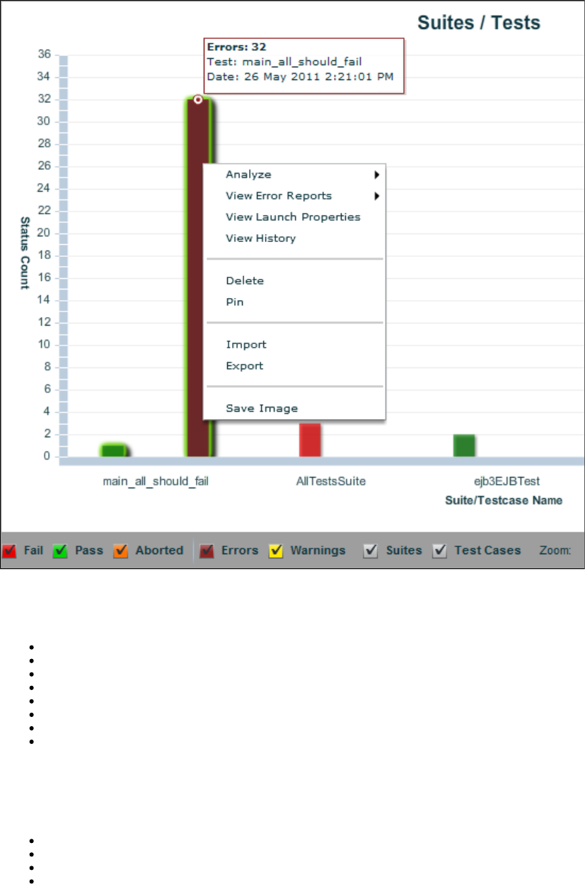
Following are options for the reporting menu. To see examples of these reports, see .Reports - Graphical View - Examples
Analyze
Top Ten Longest Transactions: The ten longest-running transactions in a pie chart
Average Transaction Response: Transaction response time in a line chart
Metrics: A variety of LISA event metrics in a line chart by time
Requests/Second: Number of requests per second in a line chart by time
Performance Summary: Average response time and standard deviation by step in a bar chart
Cycle Performance Summary: Cycle time and cycle execution time in milliseconds in a bar chart
HTTP Details: HTTP traffic details in a grid format by name
HTTP Summary: Cumulative HTTP traffic summary in a line chart
Error reports report errors and warnings from steps that did not complete error-free. To see examples of these reports, see Reports - Graphical
. Reports available are:View - Examples
View Error Reports
Detailed Failures
Detailed Errors
Detailed Warnings
Detailed Aborts
View Launch Properties
View all launch properties with a timestamp, property name and property value in grid form.
View History
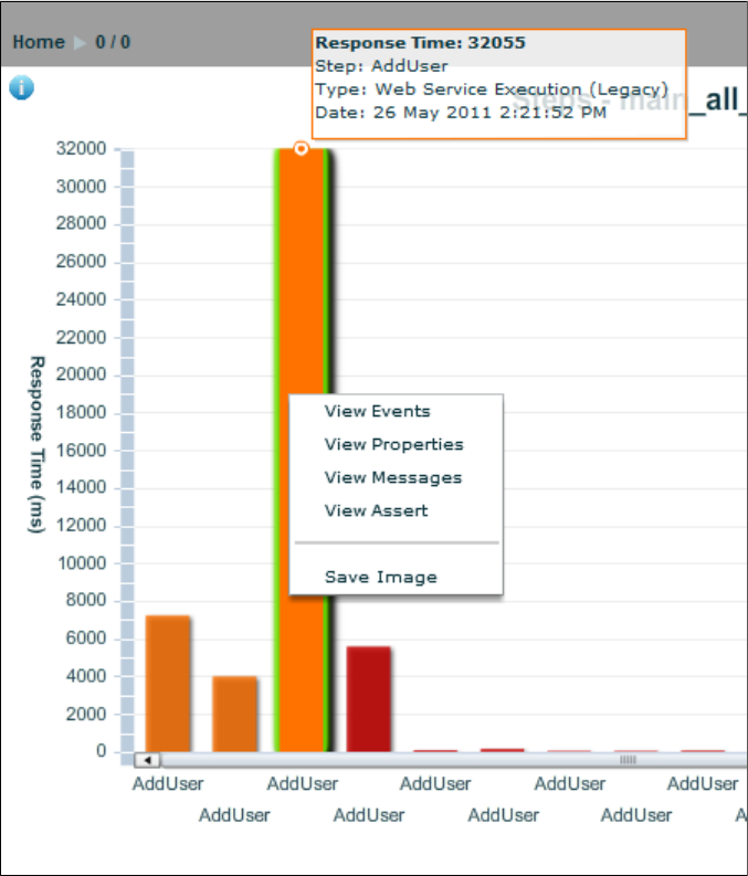
Shrinks the current graph on to the top half of the screen and displays two additional reports: a grid listing of test cases run and their results and a
line chart showing historic execution times. The history report shows information on previous runs of the same test case. For an example of a
history report, see .Reports - Graphical View - Examples
Delete
Deletes that test case or suite from the report
Pin
Keeps the test case or suite from being auto-deleted after 30 days. Any unpinned test older than 30 days will be auto deleted. For more
information, see .Auto Expiring Reports
Import
Imports test case or suite information from an XML file
Export
Exports the test case or suite information to an XML file
Save Image
Saves the graphical image as a .png file
Right-click the step bar for a step menu.
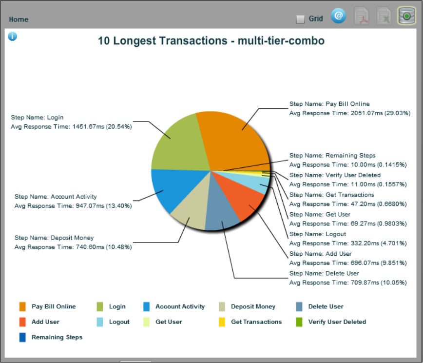
Reports - Graphical View - Examples
Following are examples of report output available when you right-click from a test/suite report.
Analyze Menu
Top Ten Longest Transactions
Average Transaction Response
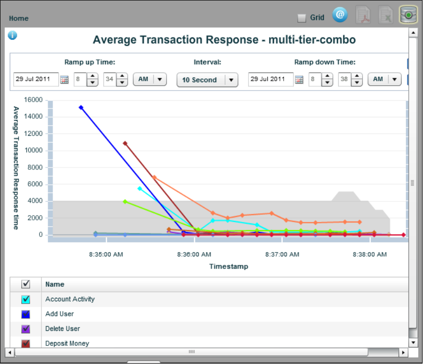
Metrics
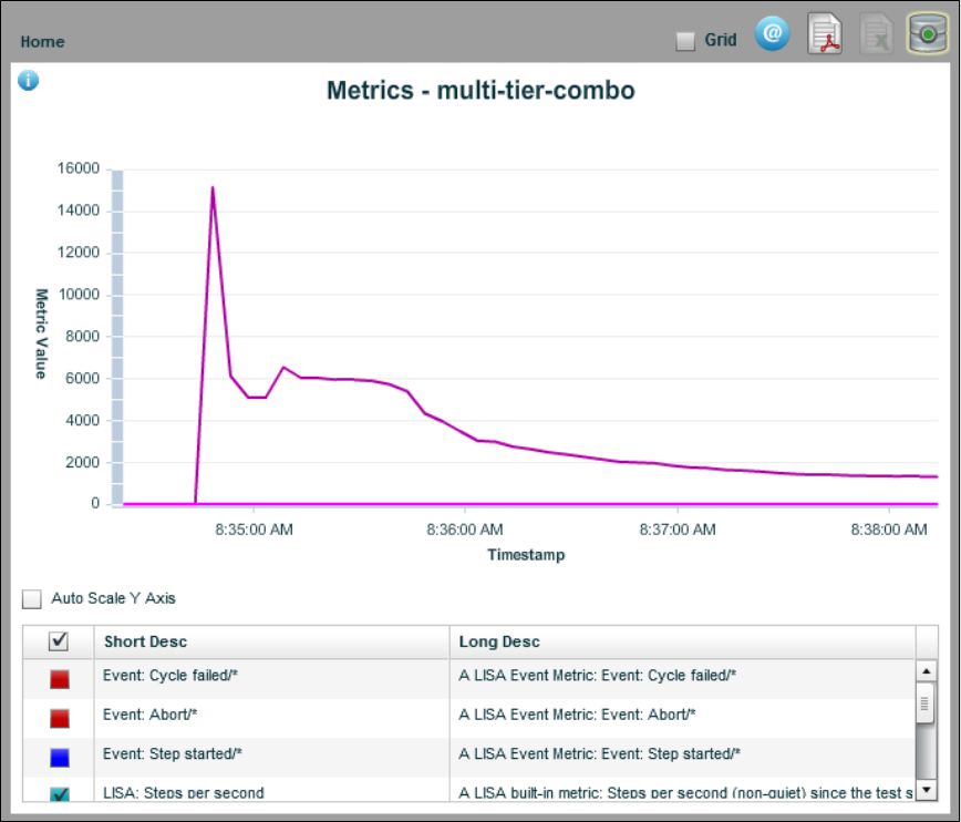
Requests/Second
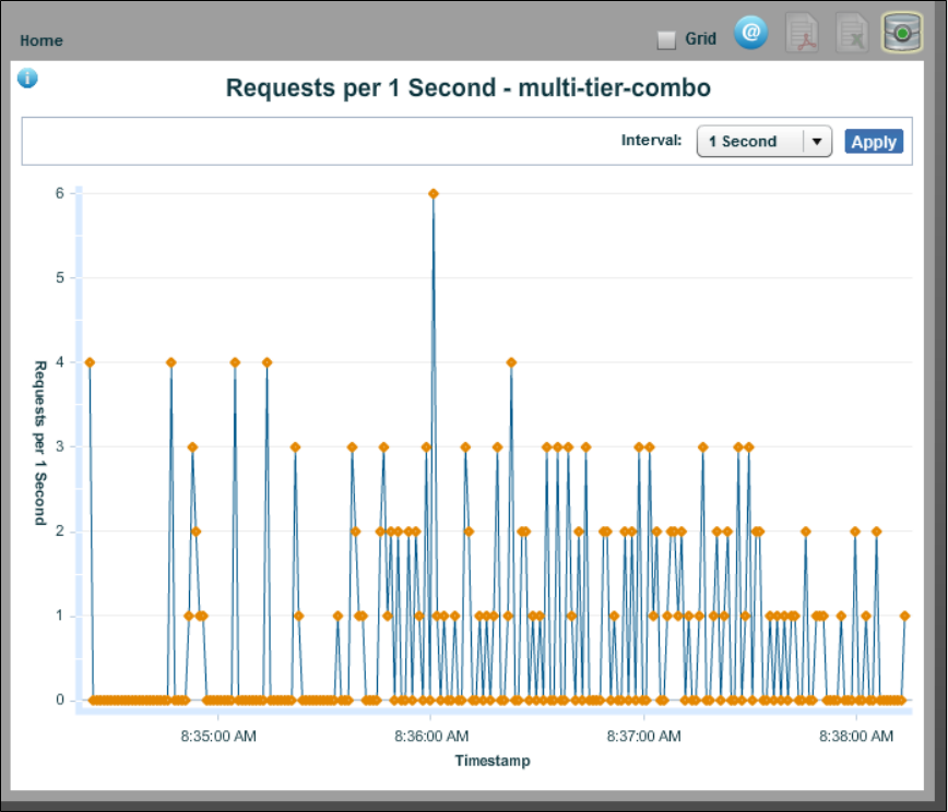
Performance Summary
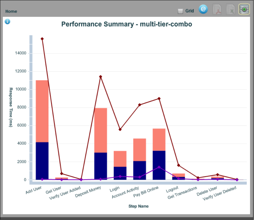
Cycle Performance Summary
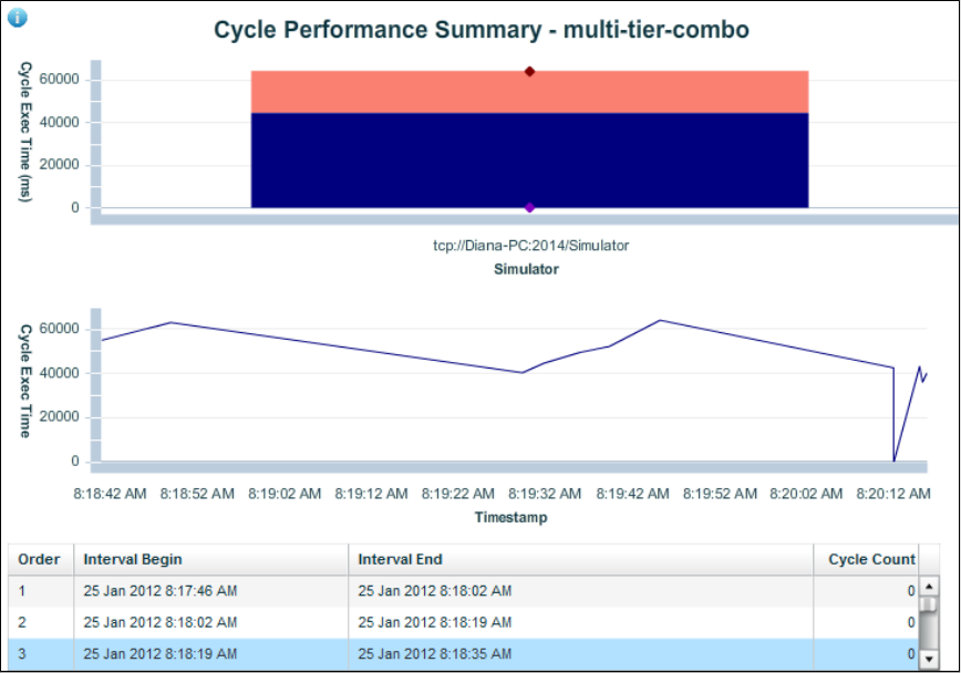
HTTP Details
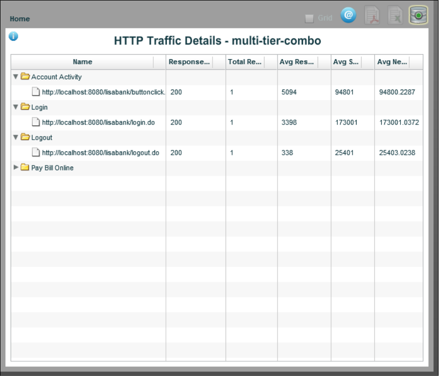
HTTP Summary
To see the Cumulative HTTP Traffic Summary report, the following property must be set in either or : local.properties site.properties
.lisa.commtrans.ctstats=true
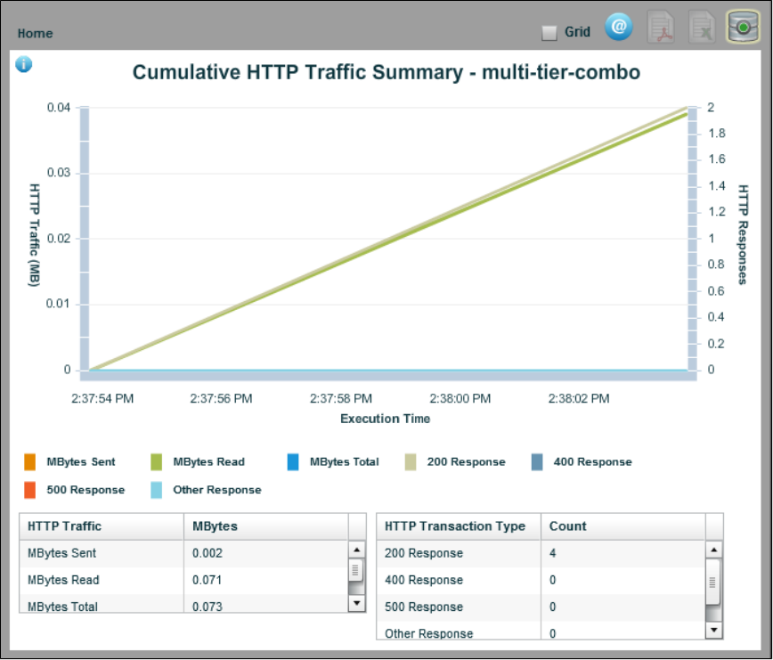
View Error Reports Menu
Error reports report errors and warnings from steps that did not complete error-free. Reports available are:
Detailed Failures
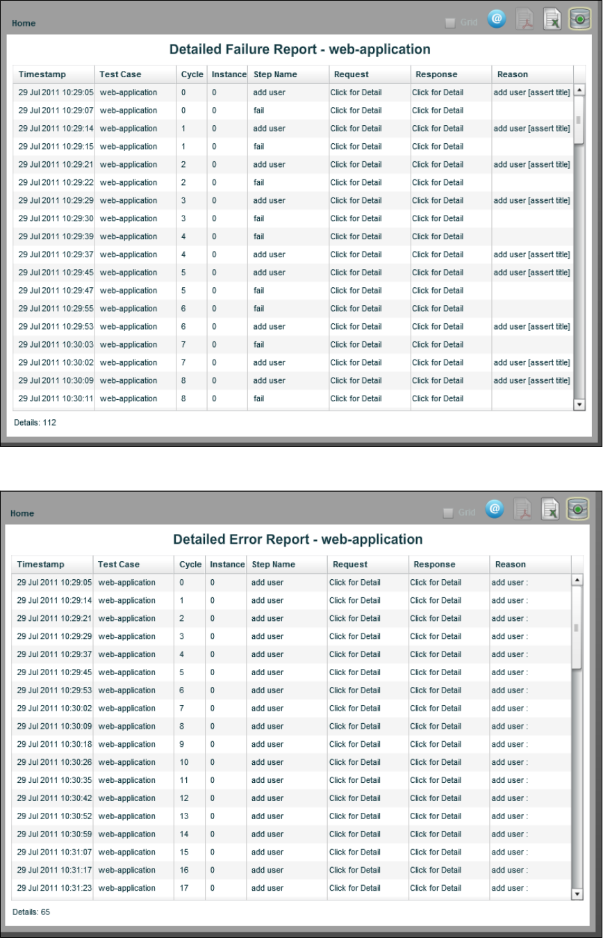
Detailed Errors
Detailed Warnings
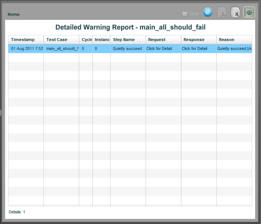
Detailed Aborts
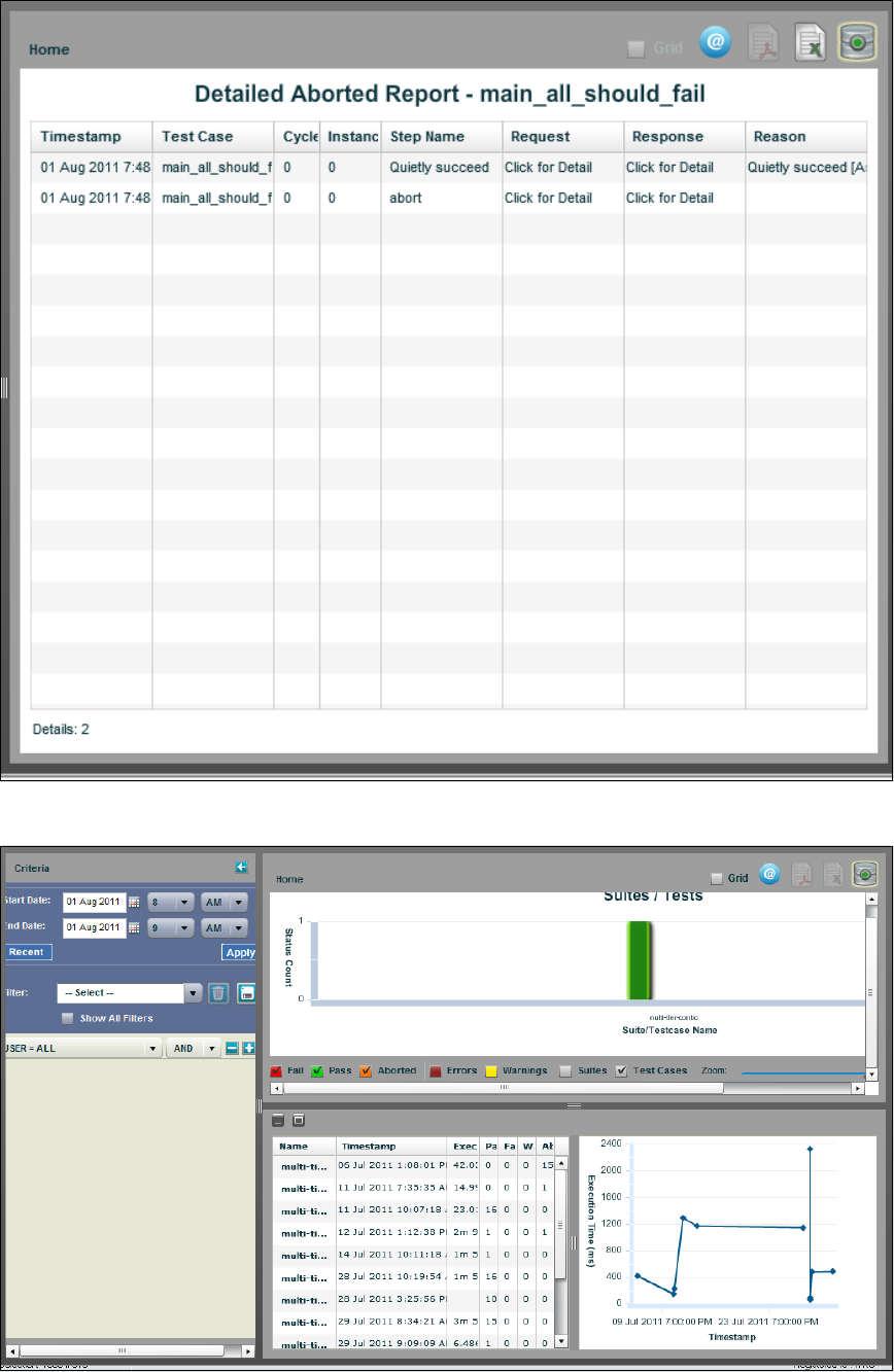
View History
Reports - Grid View

Reports can also display in a grid view. To view the results in a grid, select the Grid icon on the top right corner. The information
available in the grid view is the same as that in the graphs view; the only difference is the display. All report information filters work the same. You
must be in grid view to export reports to Excel.
You can select each of the test cases within the report to find out more details regarding it.
If you click in the , , or columns, you see more detailed information about each of those components ofClick for detail Assert Request Response
the step. In our example, we display the information about the Response on the step.new user
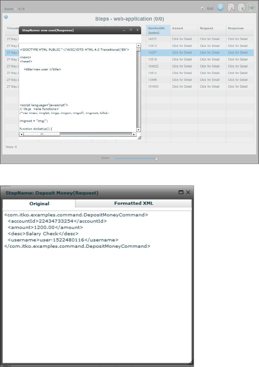
In this view, when you click to view request and response data, for those that are XML, you can select the tab to see formattedFormatted XML
text. For those that are not XML, the Formatted tab shows "Text is not valid XML."
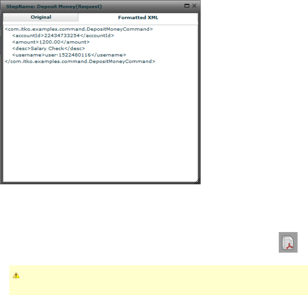
Standard LISA Reports
There are four pre-formatted LISA reports that can be generated and exported to PDF.
Functional Test Report
To produce a functional test report, double-click on a test to see the Cycles report. Select a cycle, then select the Export to PDF icon to
open the report in a PDF format.
The Functional Test Report is produced when the test is run with fewer than three virtual users or fewer than 15 cycles. If the
test is run with more virtual users and/or cycles, the Performance Test Report is produced.
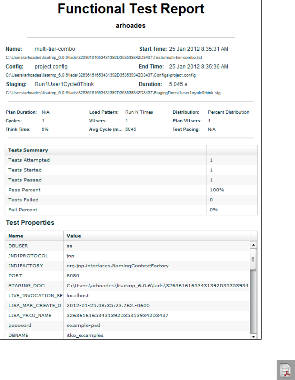
Performance Test Report
To produce a performance test report, double-click on a test to see the Cycles report. Select a cycle, then click the Export to PDF icon to
open the report in a PDF format.
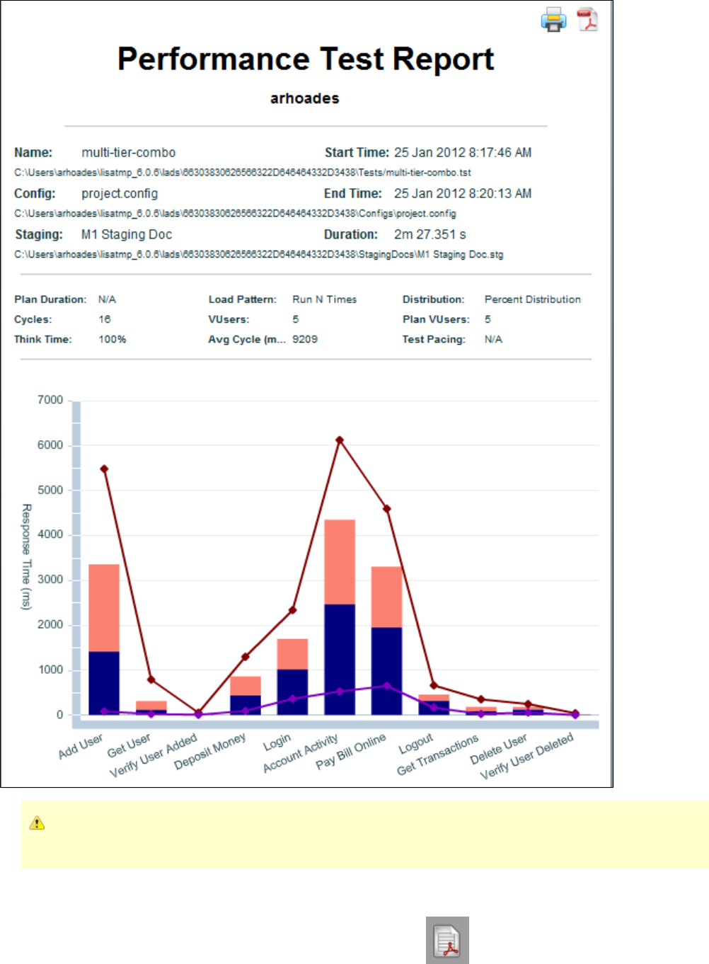
The Performance Test Report is produced when the test is run with more than 3 virtual users or more than 15 cycles. If the test
is run with fewer virtual users and/or cycles, the Functional Test Report is produced.
Suite Summary Report
To produce a suite summary report, open a test suite report. Click the Export to PDF icon to open the suite summary report in a PDF
format.
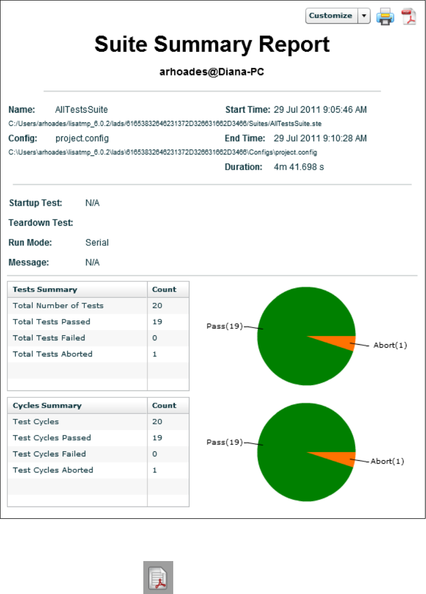
Metrics Report
To produce a Metrics Report, from a test/suite report, right-click on a test or suite and select Analyze > Metrics to display a metrics chart or grid.
From that report, click the Export to PDF icon to open the report in a PDF format.
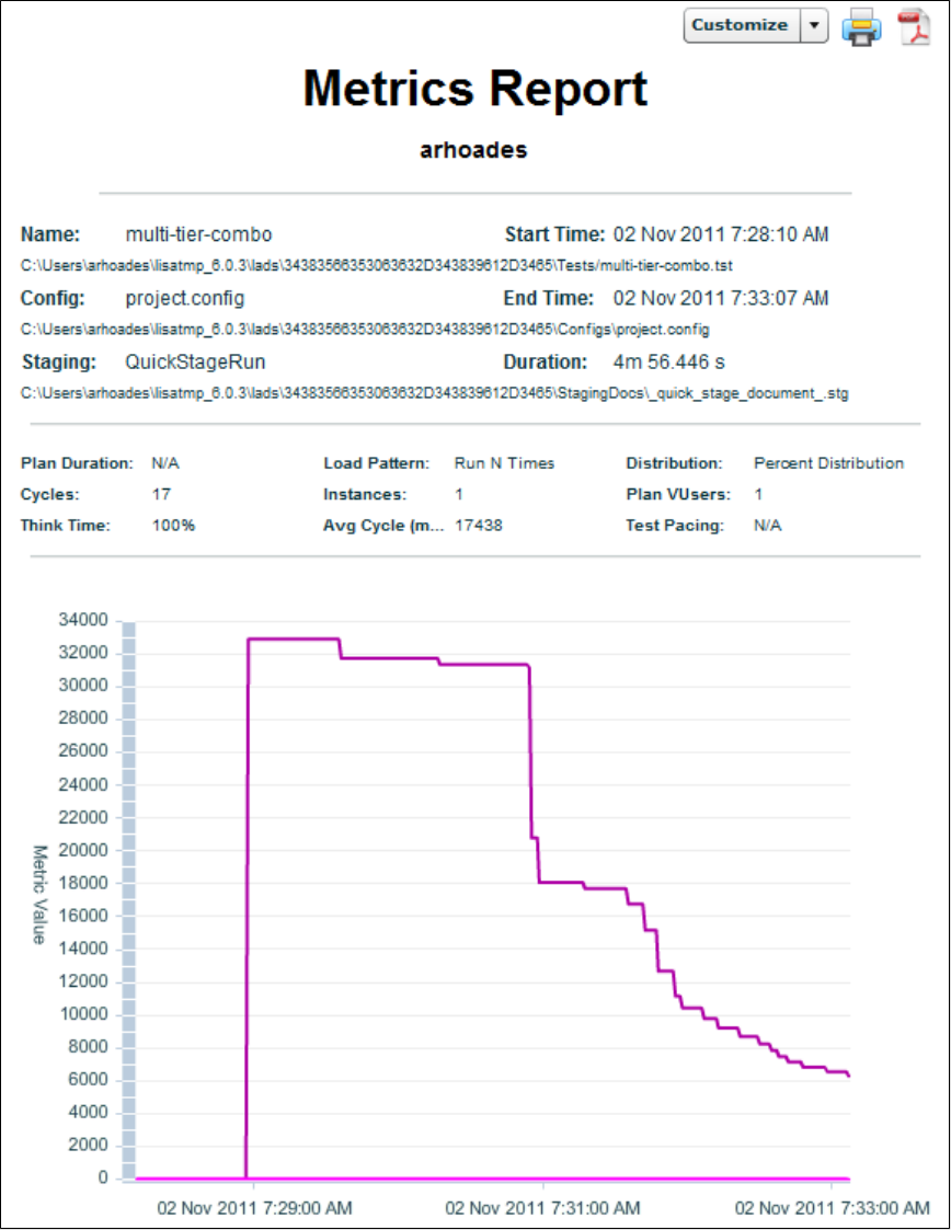
Interpreting Reports
There are some situations where the results of reports are not what you expect, and it may appear that the reporting data is incorrect.
Looping Tests
Loops in test cases can cause unexpected results in the reporting engine.
The LISA workflow engine is designed to flow from the beginning step to the end step, with no loops. One execution of this chain of steps is
considered to be one pass or fail or abort event. Looping is designed to be initiated externally to the test case using a staging document. By using
a staging document to specify 10 virtual users executing a test case once, you will have 10 pass/fail/abort events. When the looping is done within
the test case, a pass/fail/abort will not occur until the end step is reached, therefore creating only a single pass/fail/abort event.
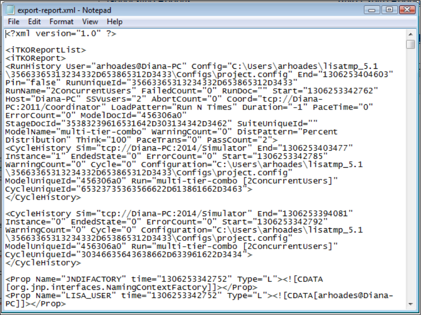
Think Time and Reports
Think time is how long LISA waits to begin the execution of a test step. The purpose of think time is to simulate a real user interacting with any
system. You can set think time in the step editor, in a staging document, or in the Web 2.0 parameters.
In the main reporting panel, we display total execution time, which is the length of time from start to finish of the test. Because this is a duration,
we include think times by design, to show how long it took for the entire test to run. To exclude think times, set your think time amount to 0 in your
staging document or on your test step.
If you are looking for performance numbers, generate a performance report that will give you response times for each step that does not include
think times, which is a more meaningful report for performance tests. Think time is not part of the average step performance time.
For Web 2.0 tests that have think time added to the parameter in the Playback Settings, that time is included in both the totalPlayback Speed
execution time and the response times for each step. The reason there is also a think time in the browser is that when you execute a debugging
session from the browser, LISA think times are not honored because LISA is not driving the playback, the browser is doing it directly, so this gives
you a way to control the test speed from within the browser. The default replay speed is 0x (no think time added). You generally do not need to
set the replay speed to anything other than 0x except for debugging, so this should not be an issue.
Exporting Reports
In the Reports viewer, the reports can be exported in three formats: XML, Microsoft Office Excel, and Adobe Acrobat PDF.
Exporting Report to XML
If your test suite or staging document specified the XML Report, you will be able to export the report data directly to an XML file. To do this,
right-click on the test or suite and select Export. For more information, see . After saving your exported data, you canReports - Graphical View
format or manipulate it as you want.
Exporting your report data to XML lets you move reporting data from one registry to another.
Exporting Report to Excel
You can export all the LISA reports data to an Excel spreadsheet. To export data to Excel file, open the report that you want to export.
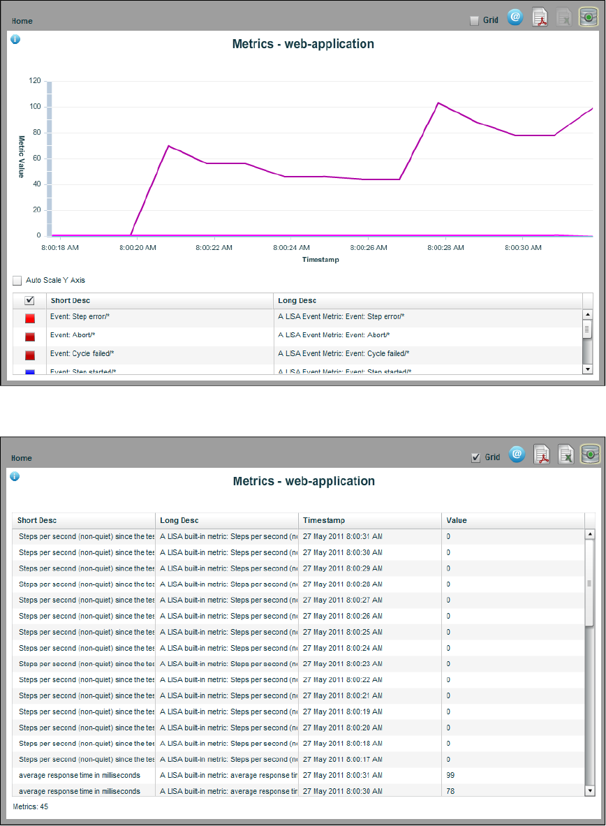
As you can see here, the Export to Excel icon is disabled. To export a report to Excel, it needs to be viewed in grid view. Select the Grid check
box.
Now the Export to Excel icon is enabled. Click it to open the Export to file dialog, where you can specify the name of the Excel file. The reporting
data will be stored in the saved Excel file.
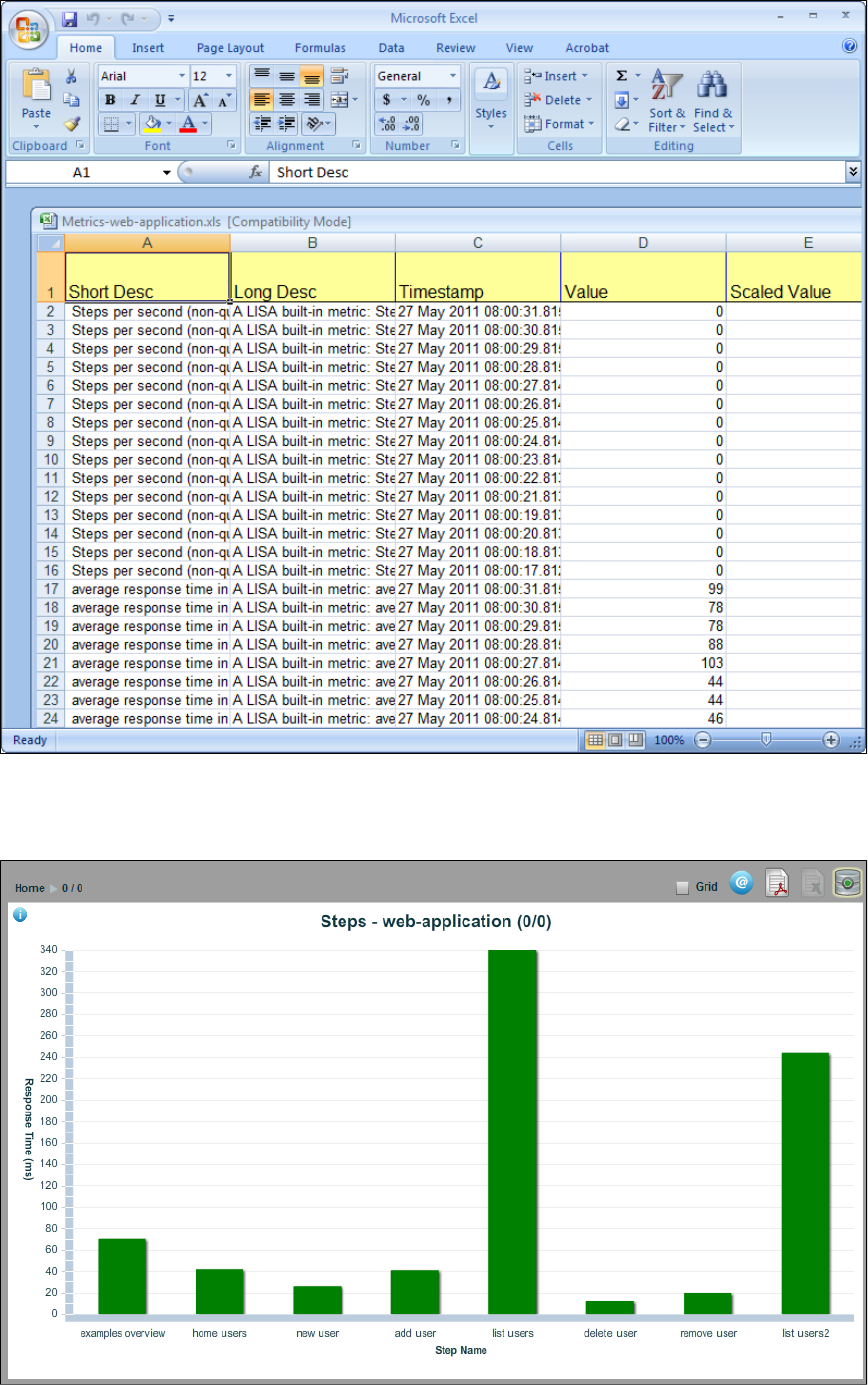
Exporting Reports to PDF
You can also export the report data to PDF. Open the Graphical view of the report.
To export to PDF, click the Export to PDF icon.
The pre-formatted LISA report that is exported is dependent on the location from which you choose the export. The report will be one of four
types, each detailed in .Standard LISA Reports
Changing Reporting Databases
The way you configure LISA to connect to alternate databases has changed in LISA 6.0, which can be seen in or .lisa.properties site.properties
LISA database components are now set by assigning each component to a defined pool configuration like this:
lisadb.reporting.poolName=common
lisadb.vse.poolName=common
lisadb.legacy.poolName=common
lisadb.acl.poolName=common
By default all of the LISA databases share a common Derby database connection pool as defined here
lisadb.pool.common.driverClass=org.apache.derby.jdbc.ClientDriver
lisadb.pool.common.url=jdbc:derby://localhost:1528/database/lisa.db;create=true
lisadb.pool.common.user=rpt
lisadb.pool.common.password=rpt
For example if you want to change the reporting database to connect to Oracle, you first define a new database pool configuration
lisadb.pool.mypool.driverClass=oracle.jdbc.OracleDriver
lisadb.pool.mypool.url=jdbc:oracle:thin:@//myhost:1521/orcl
lisadb.pool.mypool.user=rpt
lisadb.pool.mypool.password=rpt
and then set the reporting component to use that pool.
lisadb.reporting.poolName=mypool
When you enter the Reporting Portal, you can mouse over the database icon on the upper-right corner of the screen to get the details about the
database you are using.
Recorders and Test Generators
There are a variety of methods to record test cases and re-run them.
LISA Test's no-code testing environment allows QA, Development and others to rapidly design and execute functional, unit, regression and load
tests against dynamic websites (RIAs).
The product can be used to test rich browser and web user interfaces, and the many building blocks and data residing below the UI. With LISA, all
the data and implementation layers the team needs to functionally test can be analyzed, invoked and verified to help ensure requirements are
met.
In this section, the following topics are covered:
Recording a Website
Generating a Web Service
Recording a Website
Recording a website with LISA can be done in two ways:
You can use when you want to track the path through the website. Steps are created for each HTTP request.Web Recorder (HTTP Proxy)
You can use ) when you want to capture mouse clicks, mouse movements, keys being typed, and so on, and playWeb Recorder (DOM Events
those events back during test execution.
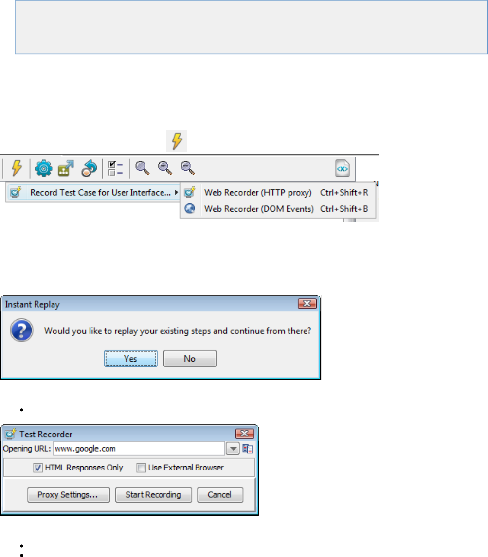
The following sections are available.
Recording a Website via HTTP Proxy
Recording a Website via DOM Events
Recording a Website via HTTP Proxy
LISA Workstation provides a HTTP recorder to test a website test case using a proxy recorder.
This helps track your path through the website and automatically create test steps for each HTTP request that is generated while recording.
To start the recording, click the Begin Recording icon to open the following menu.
Click Record Test Case for User Interface > Web Recorder (HTTP Proxy), or from the main menu, select Actions > Record Test Case for User
Interface > Web Recorder (HTTP Proxy).
This lets you launch the browser that is used to record and play back HTTP tests.
If there is a test case already open in the active tab, it will ask whether you want to replay the tests in the browser.
If there is no test case open in LISA Workstation, the Test Recorder window opens, where you enter the name of the website to record.
Enter the URL for the web page to test.
Select your preferences from the following:
HTML Responses Only: Will capture only the HTML responses.
Use External Browser: Will open an external browser window.
Port Usage
By default the LISA Proxy recorder uses port 8010 for recording.
If you do not want to use this port, you can override the setting in your file with the following property: lisa.properties
.lisa.editor.http.recorderPort=8010
To start the recording, click Start Recording to start the Web recorder, or click Proxy Settings to configure the proxy.
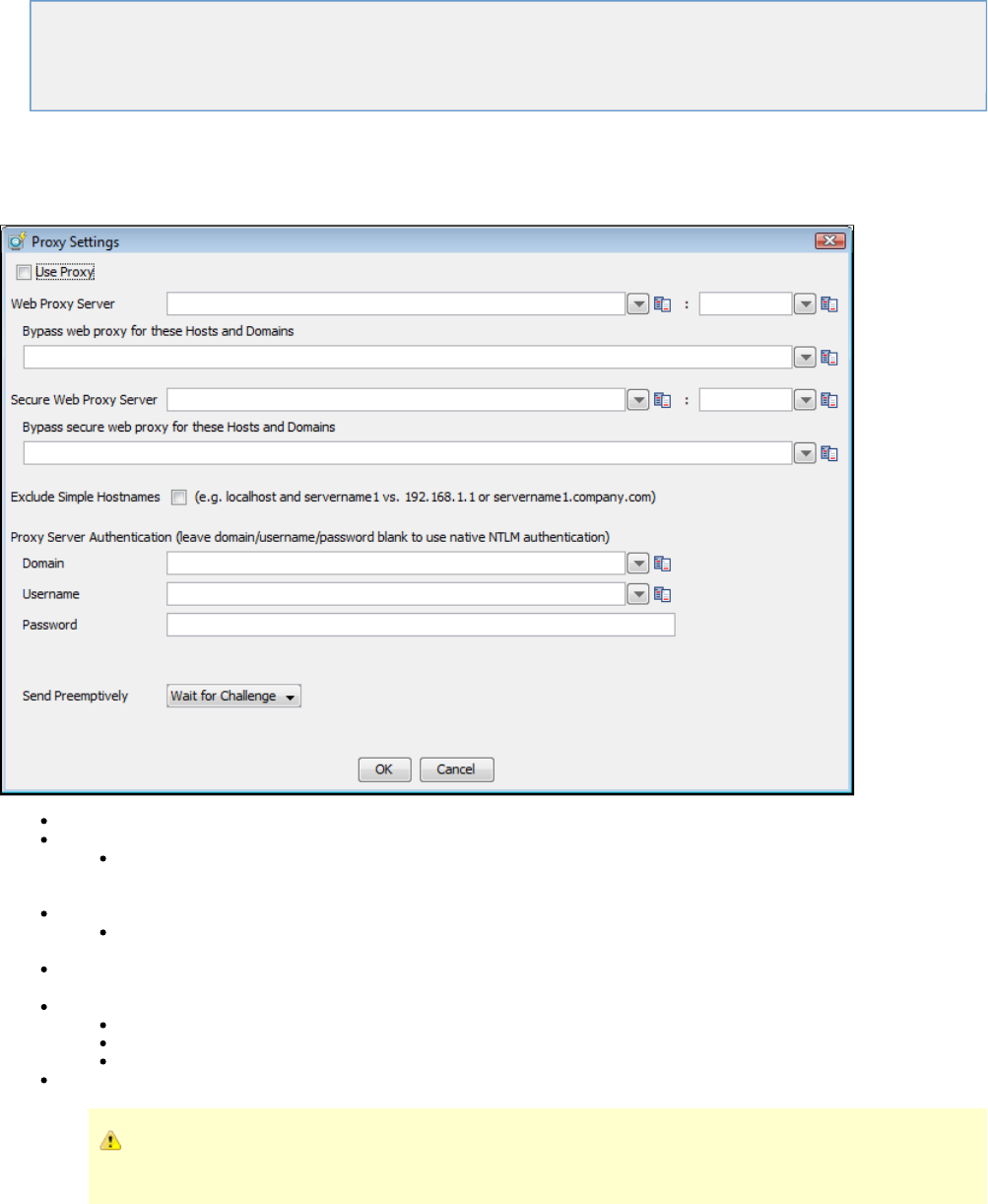
The following topics are available.
Configure Proxy
Start Recording
View Recorded Transactions
View in ITR
Configure Proxy
To set the proxy, click the Proxy Settings button to open the Proxy Setting dialog.
Use Proxy: Check this to use proxy settings. This is useful when you want to enter the proxy settings and use it intermittently.
Web Proxy Server: Enter the proxy server hostname (server IP) and respective port number.
Bypass Web Proxy for these hosts and domains: Enter the host name and domains of those servers for which you want to
bypass proxy. Enter a pipe (|) separated list of hosts to be connected to directly and not through a proxy server. A asterisk * can
be used as a wildcard character for matching; for example, "*.foo.com|localhost".
Secure Web Proxy Server: Enter the secure proxy settings.
Bypass Web Proxy Server for these hosts and domains: Enter the host name and domains for which you need to bypass
proxy.
Exclude simple host names: Check if you want to exclude simple host names (for example, and compared to localhost servername
or .)192.168.1.1 server1.company.com
Proxy server Authentication: Enter authentication details.
Domain: Enter domain name.
User name: Enter user name.
Password: Enter password.
Send Preemtively: Select or Wait for Challenge/Send Basic Send NTLM.
Typically the proxy server will challenge any request when authentication is required. If the proxy server does not send
the challenge, setting this field will force the authentication header to be set with the first request.
Enter the Proxy configuration information in the dialog and click OK to set the proxy settings.
Start Recording
Click Start Recording in the Test Generator to begin recording the test.
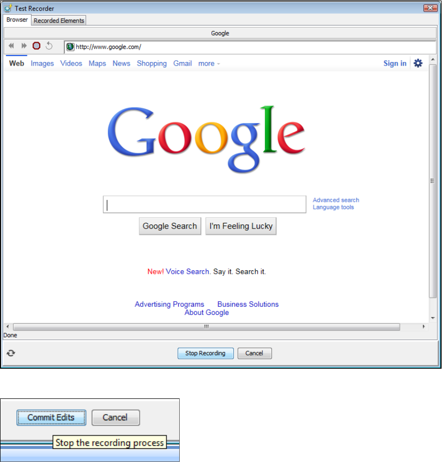
The Test Recorder window opens up and displays the web page URL loaded.
You can test the web page by entering information as a user would.
After you are done, you can stop recording your browser activity by clicking Stop Recording at the bottom of the Test Recorder window. You will
then see the Recorded Elements screen. To complete recording, click the Commit Edits button.
View Recorded Transactions
After you stop recording, all the recorded transactions are shown in the tab.Recorded Elements
All the transactions done are listed in the left panel. The and the are seen in the right tab.Step Details Response
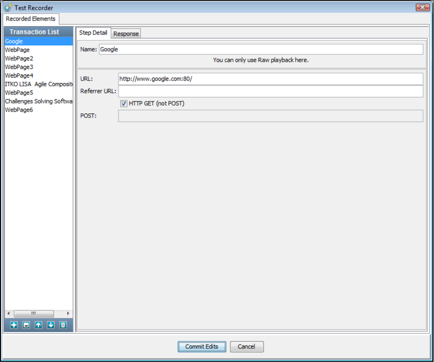
1. Select the tab to see the HTML response recorded.Response
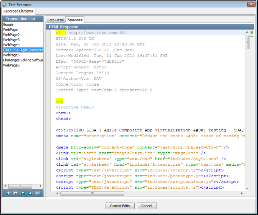
1.
2. Click Commit Edits to commit these transactions in the Test Recorder.
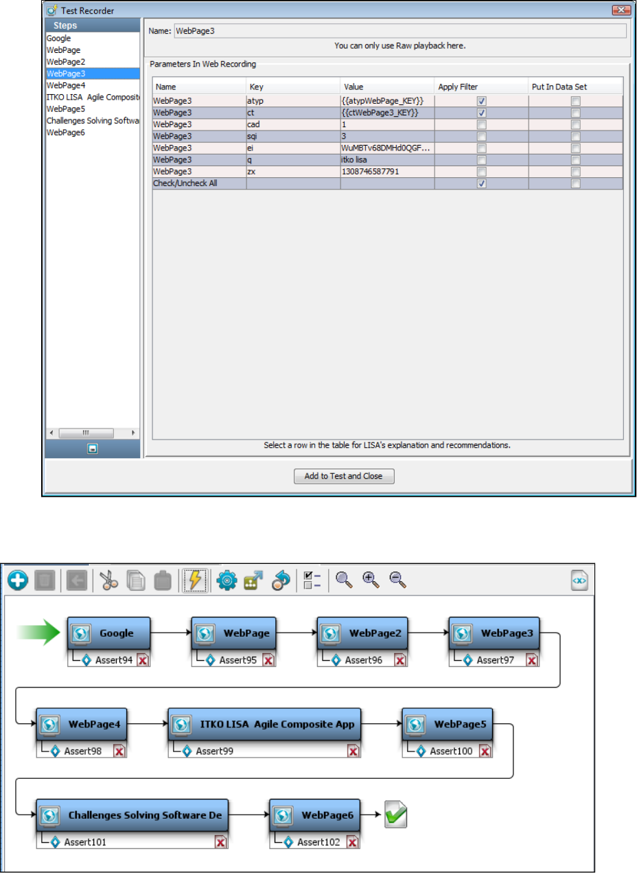
2.
3.
4.
5.
In the enter any parameters required by your test.Parameters In Web Recording
Click Add to Test and Close at the bottom of the Test Recorder window to add transactions as test steps.
A test case is created based on your HTTP requests in the LISA workflow. Each step in the test case represents a recorded HTTP
request.
View in ITR
You can view all these transactions again when you run this test case in the ITR.
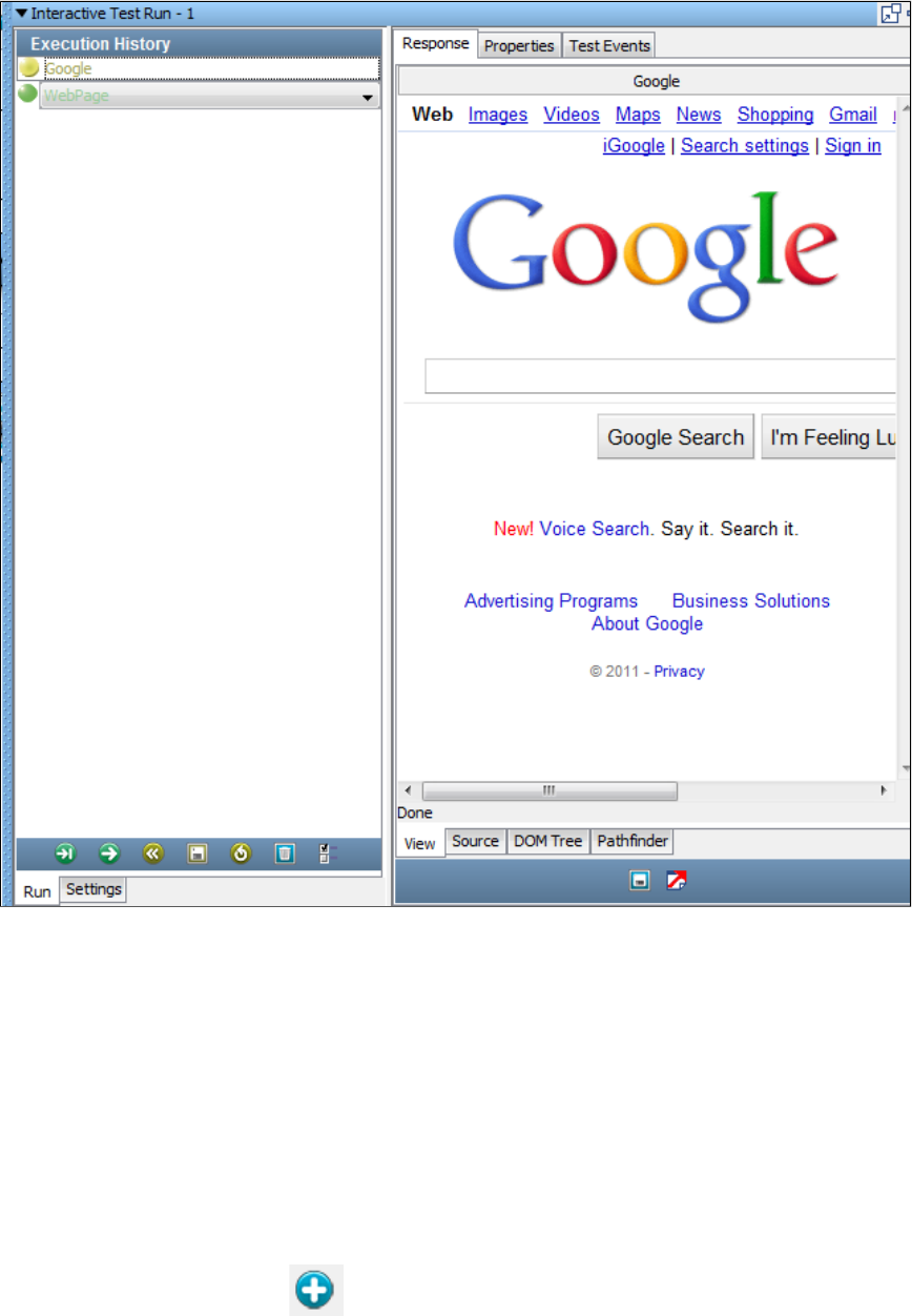
1.
2.
See the and tabs to see more information about the recorded step.View, Source, DOM Tree Pathfinder
Recording a Website via DOM Events
This feature is covered in a separate user guide. See the for additional information.Web 2.0 Guide
Generating a Web Service
You can create a Web Service (XML) test case. For this, you use the Web Service Execution (XML) step to call web service operations in a test
case and test the response and request. These web service operations provide the same functionality as the equivalent method calls in the EJB
used in Tutorial 7. Additional information about the Web Service Execution step is available at .Web Service Execution (XML) Step
Make sure you are running the Demo Server (either the local Demo Server, or the ITKO demo server) to use this step.
Creating the Web Service (XML) Step
To create a Web Service XML step, open LISA Workstation and right-click in the model editor. Click Add Steps or from the test case
toolbar or click the Add Steps icon.
Click Web/Web Services> Web Service Execution (XML), to add the step in the Model editor.
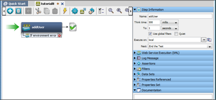
2.
3.
4. A Web Services step is added. Rename the step in the Step Information area.AddUser
Double-click the step to open the editor.Add User Web Service Execution
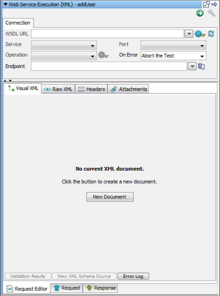
4.
5. Click the New Document button to create a new XML document.
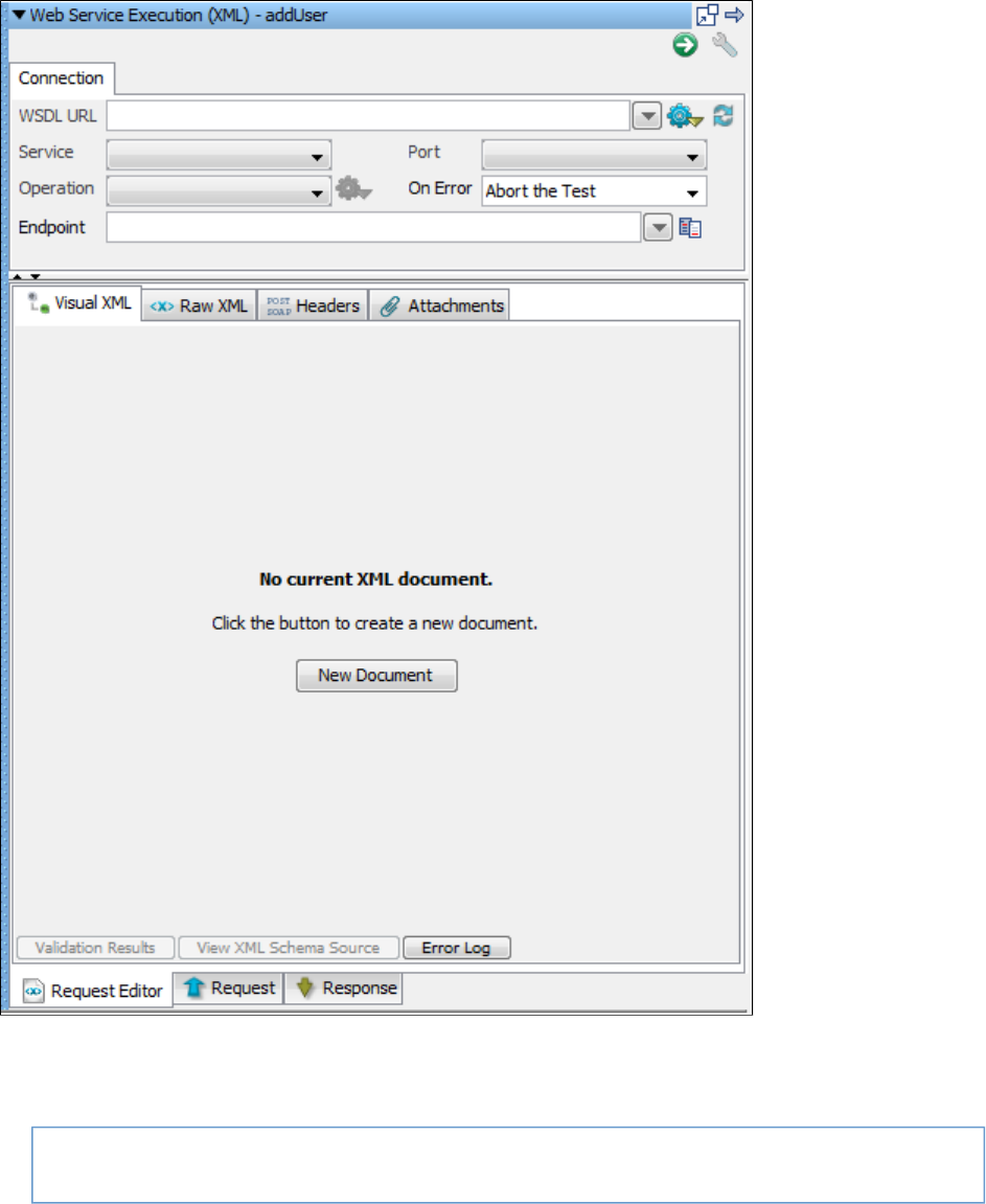
5.
1.
2.
3.
4.
5.
Creating the Web Service Client
In the WSDL field, enter the location of the WSDL.
http://WSSERVER:WSPORT/itko-examples/services/UserControlService?wsdl
In the Service Name field, enter . Do not use spaces within the name of the web service.UserControlServiceService
In the Port field, enter .UserControlServiceService
In the Operation field, select the operation to be tested.
In the On Error field, select the action to be taken on test error: .Abort the Test
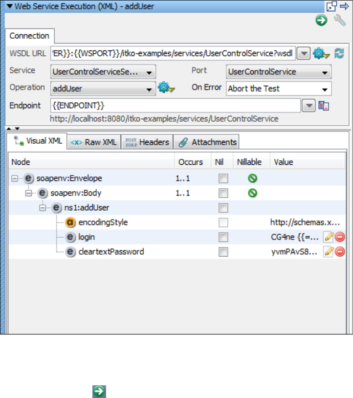
1.
2.
Executing the Test Case
To execute the test case:
Click the Execute button on top right. This will execute the test and show us the Request and Response.
To view the request upon execution, click the Request tab.
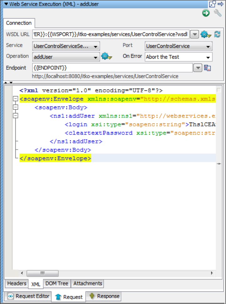
2.
3. To view the response upon execution, click the tab.Response
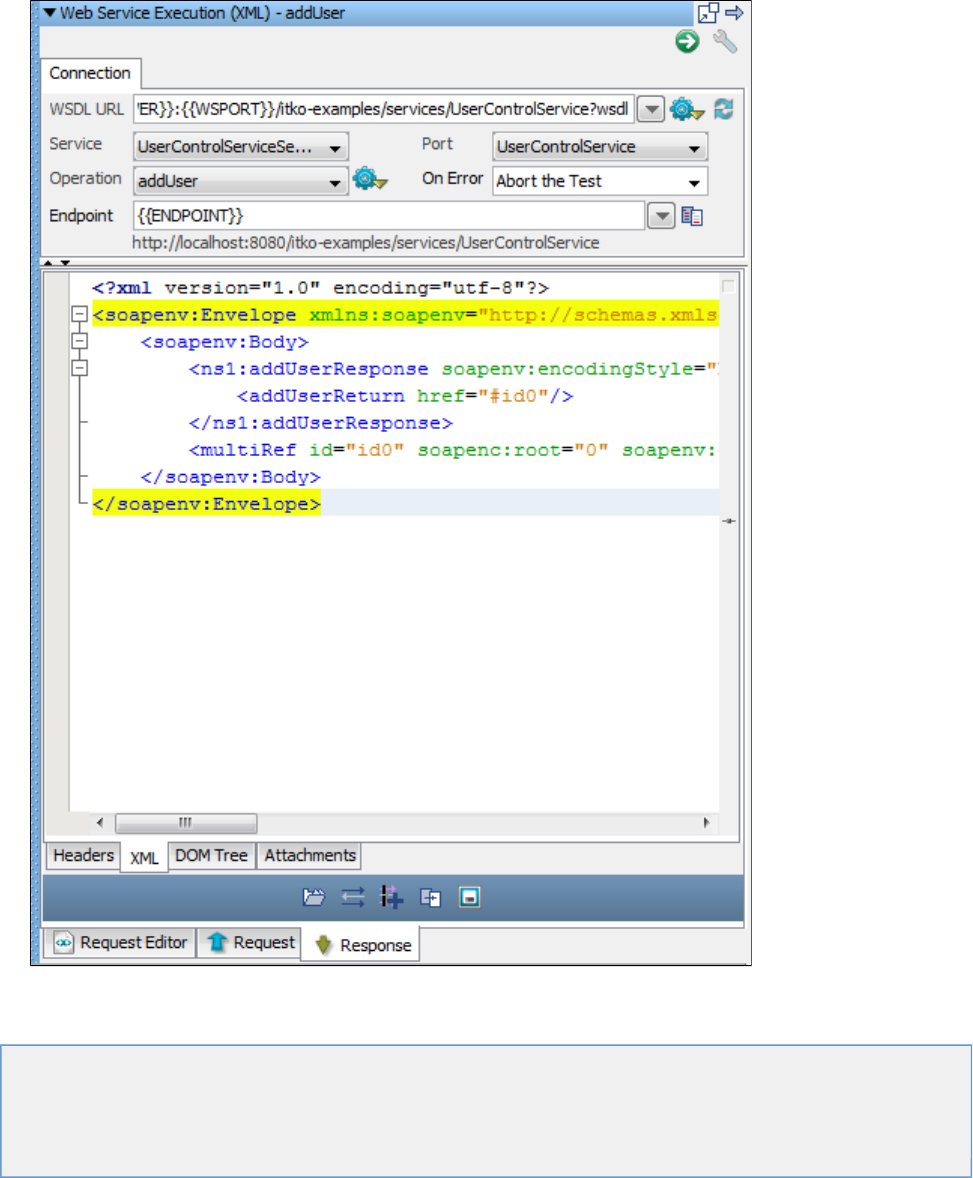
3.
Advanced Features
The following topics are covered:
Using BeanShell in LISA
Running LISA with Ant and JUnit
Class Loader Sandbox Example
In-Container Testing (ICT)
Using BeanShell in LISA
BeanShell ( ) is a free, open-source, lightweight Java scripting language. It is a Java application that uses the Reflectionhttp://www.beanshell.org/
API to execute Java statements and expressions dynamically. By using BeanShell, you avoid the need to compile class files.
BeanShell lets you type standard Java syntax (statements and expressions) on a command line and see the results immediately. A Swing GUI is
also available. BeanShell can also be called from within a Java class; this is how it is used in the product.
BeanShell is used in several places:
To interpret property expressions
As the interpreter framework for the test stepJava Script
As the interpreter framework for the assertionAssert by Script Execution
The following topics are available in this chapter.
Using BeanShell Scripting Language
Using Date Utilities
Using BeanShell Scripting Language
The major difference between BeanShell Java and compiled Java is in the type system. Java is very strongly typed, whereas BeanShell can
loosen the typing in its scripting environment. You can, however, impose strict typing in BeanShell if you want.
BeanShell relaxes typing in a natural way so that you can write BeanShell scripts that look like standard Java method code, while on the other
hand you can write scripts that look more like a traditional scripting language, such as Perl or JavaScript, while still maintaining the framework of
the Java syntax.
If a variable has been typed, then BeanShell will honor and check the type. If a variable is not typed, BeanShell will only signal an error if you
attempt to misuse the actual type of the variable.
The following Java fragments are all valid in BeanShell:
foo = "Foo";
four = (2+2) * 2 / 2.0;
print(foo + " = " + four);
.
.
hash = new Hashtable();
date = new Date();
hash.put("today", date);
.
.
BeanShell lets you declare and then use methods. Arguments and return types can also be loosely typed:
Typed
int addTwoNumbers(int a, int b){
return a + b;
}
Loosely Typed
add (a,b){
return a + b;
}
In the second example, the following would work correctly:
sumI = add (5,7);
sumS = add("LISA " , "Rocks");
sumM = add ("version ", 2);
BeanShell also provides a library of commands that facilitate its use.
A few examples of these commands are:
source(): Read a BeanShell (bsh) script.
run(): Run a bsh script.
exec(): Run a native application.
cd(), , and so on: UNIX-like shell commands.copy()
print(): Print argument as a string.
eval(): Evaluate string argument as code.
For more information, see the BeanShell User Guide at . You can also get BeanShell, the source code, and thehttp://www.beanshell.org/
complete Javadoc at the same place.
Using BeanShell as Standalone
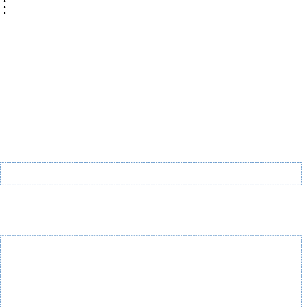
BeanShell is available as a standalone interpreter so you can try it outside of LISA. You can download BeanShell from . It is awww.beanshell.org
single small JAR file named ( is the version number; currently 2.0). Add the JAR file to your classpath.bsh-xx.jar xx
You can use BeanShell in the following configurations:
From a command line: java bsh.Interpreter [script name] [args]
From BeanShell GUI: java bsh.Console
From within a Java class:
Import bsh.Interpreter;
.
.
Interpreter I = new Interpreter();
i.set ("x",5);
i.set("today", new Date());
Date d = (Date)i.get("date");
i.eval("myX = x * 10");
System.out.println(i.get("myX"));
.
Using BeanShell in LISA
The BeanShell interpreter is used in the step and the assertion. Both of these elements alsoJava Script Execution Assert by Script Execution
expose LISA Java objects and the current LISA state (properties). This provides a powerful environment for you to use to add custom
functionality. The exposed Java objects can be used to both interrogate and modify the current state of the test. For example, you can read,
modify, and create LISA properties in your scripts.
As a starting point, become familiar with the class in LISA. Information about TestExec and many other LISA classes can be found inTestExec
the . The SDK includes both a Developer Guide and Javadoc for the LISA classes that you have access to in theseDeveloper's Guide (SDK)
scripts.
LISA also uses BeanShell inside property notation when an equal sign is present. For example:
{{= new Date()}}
This property expression is interpreted using BeanShell.
Using Date Utilities
There are a number of date utility functions as static methods of the class. These functions all return the formatted datecom.itko.util.DateUtils
as a string. You can use these functions in parameter expressions or the JavaScript Execution step.
com.itko.util.DateUtils.formatDate(Date date, String format)
com.itko.util.DateUtils.formatCurrentDate(String format)
com.itko.util.DateUtils.formatCurrentDate(int offsetInSec, String format)
com.itko.util.DateUtils.rfc3339(Date date)
com.itko.util.DateUtils.rfc3339()
com.itko.util.DateUtils.rfc3339(int offsetInSec)
com.itko.util.DateUtils.samlDate(Date date)
com.itko.util.DateUtils.samlDate()
com.itko.util.DateUtils.samlDate(int offsetInSec)
For example, if you have a web service call that takes a formatted date string, and the server is two minutes slow, you can use
=com.itko.util.DateUtils.formatCurrentDate(-120,"yyyy-MM-dd'T'HH:mm:ss.SSSZ")
This will generate the string "2007-11-22T13:30:37.545-0500", the current time minus 120 seconds formatted according to these guidelines.
RFC 3339 is slightly different from what the default Java date formatter will generate. If you need a strict RFC 3339 date you can use the rcf3339
functions:
=com.itko.util.DateUtils.rfc3339()
This will generate the string "2007-11-22T13:30:37.545-05:00".
SAML dates are formatted using the format " ". The samlDate functions are just helpers so you do not need toyyyy-MM-dd'T'HH:mm:ss'Z'
remember that format string when using the formatDate APIs.

For more information, see:
http://download.oracle.com/javase/1.5.0/docs/api/java/text/SimpleDateFormat.html
http://tools.ietf.org/html/rfc3339#section-5.6
Class Loader Sandbox Example
The following Java class is a simple example of a class that cannot be run in multi-threaded or multi-user fashion, because it accesses and
modifies a static variable:
public class NeedsASandbox \{
static \{
System.out.println("This is my static initializer. You will see this many times.");
static String s;
public NeedsASandbox() \{\};
public void setS(String s)\{
this.s = s;
public String getS() \{
return s;
This class must run in a class loader sandbox.
Assume, for example, that you were to run this class within LISA and created a load test of ten users. If you do not use the class loader sandbox,
you would see the System.out.println phrases only one time, and the value of s would be incorrect. This is because all users will be running within
one class loader. This particular class will fail in those circumstances. Presuming that this is the proper function of the application, you will need to
use support for the class loader sandbox to make this work properly.
When you create the Class Loader Sandbox Companion, and LISA stages your ten users, you will actually see the text phrase in the code appear
ten times. LISA will construct ten separate class loaders and instantiate this class ten times; there will be ten separate instances of the class
variable "static string s." This lets your application logic, which is not thread safe, to be run in concurrent user tests.
The Class Loader Sandbox Companion is useful only if the following three conditions are present:
You are testing a POJO with LISA.
The POJO has static members.
You are testing with multiple virtual users.
In-Container Testing (ICT)
In-Container Testing (ICT) using remote proxies in LISA is available in the Enterprise Java Execution and Dynamic Java Execution test nodes.
This feature allows in-container testing of local EJBs and arbitrary Java objects: any objects that are available in the container's classpath for the
application being tested.
RMI and EJB are both supported as remote object protocols.
There are two connection modes used by in-container testing (ICT): EJB and RMI.
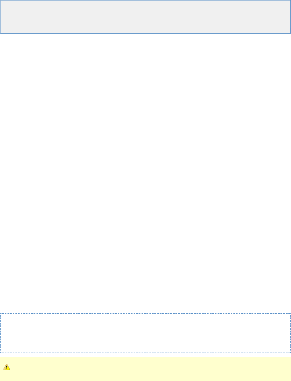
1.
2.
3.
1.
2.
3.
The following topics are available in this chapter.
Access using EJB (J2EE Container Environments)
Access using RMI (Custom Java Server and Application Environments)
Testing your ICT Installation from LISA Workstation
Access using EJB (J2EE Container Environments)
To test in-container objects in a standard J2EE container, a stateful session Enterprise JavaBean (EJB) is used. This EJB is bundled as an
exploded EAR directory named and a standalone jarfile with the LISAlisa-remote-object-manager.ear LISARemoteObjectManagerEJB.jar
installer, in LISA_HOME/incontainer/ejb, where LISA_HOME is the directory where LISA is installed.
This EJB must be deployed with your J2EE application in the J2EE container and be accessible through JNDI using the name "
". Deploying an EJB varies depending on the J2EE container being used, and vendor-provided documentationLISARemoteObjectManagerEJB
may help if there is a problem deploying the ICT EJB.
If your J2EE application uses an isolated classloader, you must incorporate the ICT EJB into your application by modifying the XML deployment
descriptors to include the ICT EJB and its dependencies.
JBoss
Test that you can successfully deploy the exploded ICT EAR in JBoss by copying the directory:
to or other appropriate deployment directory. $LISA/incontainer/ejb/lisa-remote-object-manager.ear $JBOSS/server/default/deploy
JBoss will recognize the new EAR and deploy it without any errors. Check that you can connect to the EJB from LISA Workstation.
After the EAR is successfully deployed, in a standalone configuration, then attempt to integrate the ICT EJB with your J2EE
application. This may be as simple as copying the contents of and including$LISA/incontainer/ejb/lisa-remote-object-manager.ear
them in your existing application EAR. Or create a new EAR that includes your J2EE application combined with these files.
See the application XML deployment descriptor for an idea of how to modify your own application deployment descriptors toapplication.xml
include ICT and its dependencies.
The <module> XML elements are used to indicate the presence of the ICT EJB and Java jarfile dependencies.
WebLogic
The first test on WebLogic is to deploy the exploded ICT EAR in WebLogic, for example, by using the WebLogic Administrator Console
GUI. If your WebLogic Server is in development mode, you can also copy the directory
to your Server's directory and WebLogic will automatically deploy$LISA/incontainer/ejb/lisa-remote-object-manager.ear autodeploy
the EAR. You will observe that the EAR is deployed without any errors.
Check that you can connect to the EJB from LISA Workstation.
After the EAR is successfully deployed in a standalone configuration, attempt to integrate the ICT EJB with your J2EE application. This
may be as simple as copying the contents of and including them in your own$LISA/incontainer/ejb/lisa-remote-object-manager.ear
application EAR. Or create a new EAR that includes your J2EE application combined with these files.
Access using RMI (Custom Java Server and Application Environments)
For custom Java applications, you can modify your application's source code to integrate with ICT. ICT testing can be performed by binding the
remote Server object to the RMI registry. This object will accept connections from LISA Workstation toLISARemoteObjectManagerRMIServer
perform ICT.
For example, the following code can be included in your custom application to bind the ICT remote object Server via RMI:
LISARemoteObjectManagerRMIServer remoteObjectManagerServer = new
LISARemoteObjectManagerRMIServer();Registry registry =
LocateRegistry.createRegistry(port);registry.bind("LISARemoteObjectManager",
remoteObjectManagerServer);
The RMI name " " must be entered exactly as-is for ICT to work correctly.LISARemoteObjectManager
LISA Workstation will attempt to connect to your application via the RMI URL .rmi://<hostname>:<port>/LISARemoteObjectManager
The hostname and port are variables and can be changed in your test application and configured in LISA Workstation.
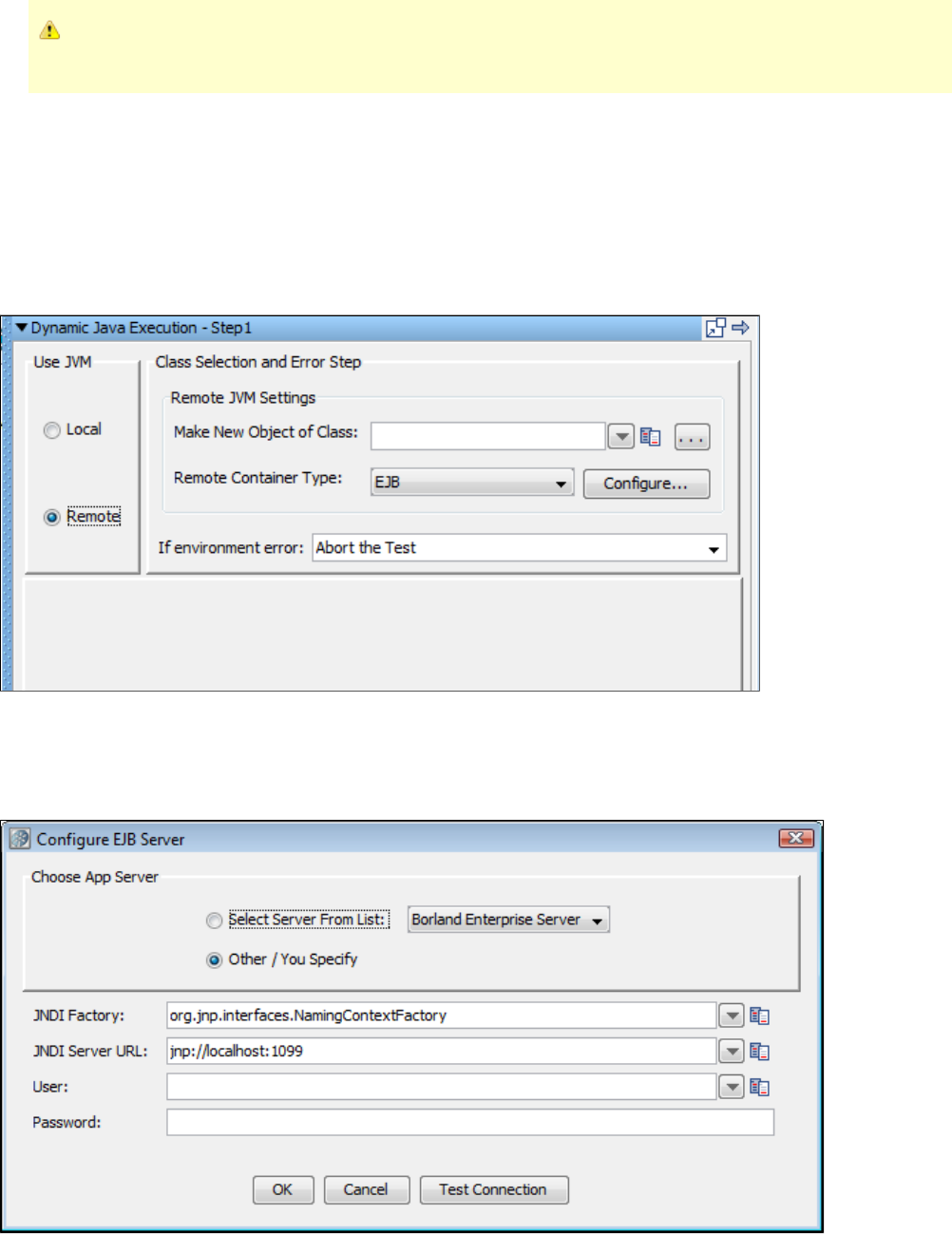
An example Server application can be found in $LISA/incontainer/rmi/example. Using a console window, you can run the example Server by
executing the command "java -jar ExampleServer.jar".
For this command to run successfully, you must be running it from the directory. See sample$LISA/incontainer/rmi/example
source code in the directory.$LISA/incontainer/rmi/example/src
Testing your ICT Installation from LISA Workstation
After the server-side portion of ICT is up and running, you should test that you can connect from LISA Workstation.
To accomplish this, open LISA Workstation and create a new test case named . Inside of this test case, create a new ICT Connection Test
test step.Dynamic Java Execution
In the editor for the new test step, select the option.Remote
Set the drop-down list to your connection protocol, either EJB or RMI.Remote Container Type
Remote Container Type is EJB
If you are using EJB as the connection protocol, click Configure to enter the configuration settings for your protocol.
For example, fill in the Configure EJB Server dialog with host name or IP address and port number of the J2EE container running ICT.
Remote Container Type is RMI
If you are using RMI as the connection protocol, here is an example of the Configure RMI Server dialog that you can use for RMI settings.
After you have successfully tested the connection to the ICT Server, enter in the text field and click java.util.Date Make New Object of Class
to create a new in-container instance of the class.Construct/Load Object java.util.Date
Your installation is complete and you are ready to use ICT.
Dependencies
The ICT Server-side classes depend on the following third-party libraries:
BeanShell 2.0b4 (bsh-2.0b4-lisa-remote-object-manager.jar).
The original jarfile has been modified so that .bsh scripts are removed. These scripts are known to cause problems with
J2EE containers that inspect jarfiles and automatically execute them.
XStream 1.1.2 (xstream-1.1.2.jar)
Log4j 1.2.13 (log4j-1.2.13.jar)
Jakarta Commons Logging 1.0.2 (commons-logging.jar)
These dependencies are intentionally distributed as separate files with LISA ICT jarfiles to make ICT integration easier. Because the application
that you are testing may already include some or all of these libraries in its classpath, adding these dependencies to the classpath may not be
necessary.
Generating DDLs
Setting the following properties in will create DDL's for Reporting and VSE.local.properties
eclipselink.ddl-generation=create-tables
eclipselink.ddl-generation.output-mode=sql-script
eclipselink.target-database=Oracle
For Agent, Pathfinder and CVS, use the following commands for creating DDLs.
java -jar LisaAgent.jar -ddl oracle (generate the Oracle DDL for Pathfinder)
java -jar LisaAgent.jar -ddl mysql (generate the MySQL DDL for Pathfinder)
Appendix A - LISA Property File (lisa.properties)
A property file named is used to store initialization and configuration information.lisa.properties
Property files are stored in the LISA install directory.
You can display the contents of this file within LISA Workstation.
Do not add your custom properties to this file, as ITKO reserves the right to replace this file at any time.
To open the lisa.properties file, from the main menu, choose System > Edit LISA Properties.
Comma-separated list of paths for Javadoc and source code
These paths are used to show you class and parameter documentation. The docpath can take directories and URLs that are base paths to the

Javadoc. Here is an example that includes JDK docs from a website, but websites are not recommended because of delays. lisa.java.docPath=
LISA_HOME/examples/javadoc,[http://java.sun.com/j2se/1.3/docs/api/
lisa.java.docPath=LISA_HOME/examples/javadoc
lisa.java.sourcePath=LISA_HOME/examples/src
This sourcepath can take directories as base paths and JAR /zip files of source.
lisa.axis.compiler.version=1.4
This is lisa.axis.compiler.version 1.4.
System Properties
file.encoding=UTF-8
Encoding for files read and written by LISA.
lisa.supported.jres=1.5,1.6
org.jfree.report.LogLevel=Error
javax.xml.parsers.DocumentBuilderFactory=org.apache.xerces.jaxp.DocumentBuilderFactoryImpl
javax.xml.parsers.SAXParserFactory=org.apache.xerces.jaxp.SAXParserFactoryImpl
javax.xml.transform.TransformerFactory=org.apache.xalan.processor.TransformerFactoryImpl
Server Properties
lisa.net.bindToAddress=192.168.1.1
The IP address that we will listen on. By default, we will listen on all our IP addresses. You can restrict this to a particular IP
address or set it to 127.0.0.1 or localhost to prevent other computers connecting but allowing local connections.
OS X Properties
apple.awt.brushMetalLook=false
apple.awt.brushMetalRounded=false
apple.laf.useScreenMenuBar=true
apple.awt.showGrowBox=true
com.apple.mrj.application.growbox.intrudes=true
com.apple.macos.smallTabs=true
com.apple.mrj.application.apple.menu.about.name=LISA
com.apple.mrj.application.live-resize=true
LISA Update Notifications
lisa.update.every=1
Controls how often LISA checks to see whether a newer version is available to download. To disable checking, set the value to
blank. The other valid values are 0 (check at every startup), 1 (check once per day), 2 (check every two days), and so on.
lisa.update.URL=http://www.itko.com/download/ga/
Basic Defaults
lisa.testcase=test.xml
Default when running a test from the com.itko.lisa.test.TestCase class directly.
lisa.registry=registry.xml
Default when running a test from the com.itko.lisa.test.TestCase class directly.
lisa.runName=Ad-hoc Run
Default when running a test from the com.itko.lisa.test.TestCase class directly.
lisa.registryName=registry
Default name of the registry to attach to, and the default name of the registry when you start it without a name.
lisa.coordName=coordinator

Coordinator Server default name when started without an explicit name AND when the TestRunner needs one and you do not
specify a coordinator server on the command line.
lisa.simulatorName=simulator
Default name of a simulator daemon if you do not provide one on the command line.
lisa.simulatorInstances=256
lisa.vseName=VSE
Virtual environment server default name when started without an explicit name.
lisa.defaultRegistry.pulseInterval=30
Status log interval for registry. The default value is 30 seconds.
lisa.coordinator.pulseInterval=30
Status log interval for coordinator. The default value is 30 seconds.
lisa.simulator.pulseInterval=30
Status log interval for simulator. The default value is 30 seconds.
lisa.vse.pulseInterval=30
Status log interval for VSE. The default value is 30 seconds.
lisa.server.projectmap.refresh.pulseInterval=600
Time interval after which the LISA servers (coordinator and simulator) refresh the map of project names to file paths.
lisa.defaultRegistryConnectionTimeoutSeconds=90
Timeout value in seconds that coordinators and simulators will use when connecting to a LISA Registry. A value of 0 indicates
an infinite timeout; that is, we will wait forever trying to connect.
lisa.regex.helper.tutorial.url=http://download.oracle.com/javase/tutorial/essential/regex/
For the Regex helper window, this is the URL to show for the regular expression tutorial.
lisa.hooks=com.itko.lisa.files.SampleHook
To register hooks with LISA; these are comma-separated.
HTTP Header Keys Properties
These are the default values for header keys in the HTTP support. Remove or change them for all tests to get the benefit of the change, or use
TestNode-specific header directives to change them for a test, or even just the execution of one HTTP transaction.
ice.browser.http.agent=Mozilla/4.0
(compatible; MSIE 6.0; Windows NT 5.0)
lisa.http.header.0.key=Pragma
lisa.http.header.0.value=no-cache
lisa.http.header.1.key=Cache-Control
lisa.http.header.1.value=no-cache
lisa.http.header.0.key=Accept
lisa.http.header.0.value=image/gif, image/x-xbitmap, image/jpeg
lisa.http.header.1.key=Accept-Language
lisa.http.header.1.value=en
lisa.http.header.2.key=Accept-Charset
lisa.http.header.2.value=iso-8859-1,*,utf-8
lisa.http.header.3.key=User-Agent
lisa.http.header.3.value=Mozilla/4.0, MSIE 6.0; Windows NT 5.0
HTTP Field Editor Properties
These are the defaults for fields that show up in the HTTP Field editor. Don't include "Authentication" because it is added by the editor
automatically.
lisa.gui.http.fieldNames=Accept,Accept-Language,User-Agent,Connection
lisa.webrecorder.textMIMEs=html,text,magnus-internal,application/pdf

lisa.webrecorder.notTextMIMEs=css,script
lisa.webrecorder.alwaysIgnore=.gif,.jpg,.jpeg,.css,.js,.ico
lisa.web.ntlm=true
Enables NTLM auth in the Test Runner.
Test Case Execution Parameters
lisa.hotDeploy=/C/Projects/Lisa/custom_classes
This setting tells the ClassLoader built into LISA where to look for custom classes. The default is $LISA_HOME/hotdeploy.
lisa.overloadThreshold=1000
The TestNode attempts to determine if the smulator is thrashing by checking the actual amount of time slept in think time as
opposed to the amount of think time it was supposed to take. This setting is the amount of additional "slip" in think time that is
acceptable before sending a warning TestEvent that the simulator is overloaded. The default of 1000 means that if the
simulator sleeps 1 second more than it was supposed to, (presumably because the computer is CPU starved), then raise the
TestEvent.
lisa.webservices.encode.empty.xmlns=true
Some web service server stacks require empty xmlns strings in the SOAP request (for example, jbossWs). Others, such as
Amazon's, will not work with empty xmlns strings. Change this property to suit the stack you are calling.
lisa.webservices.encode.version=1.1
Set the encoding version to force for client stub generation. The default is 1.1.
TestEvent Handling Customizations
lisa.perfmon.snmp.port=1161
The StatKeeper can load a Perfmon integration class that will wrap or implement a platform-specific monitor, like Windows
Perfmon, JMX, SNMP, and others. LISA comes with a Perfmon DLL class and an SNMP class to support producing our stats
output to either the Windows Performance monitor OR (not both) as an SNMP agent. For more information, see the docs on
SNMP. The usual port for SNMP is 161, but you have to be root for that.
lisa.perfmon.class=com.itko.lisa.stats.snmp.SnmpPerfmon
When we do have something that can pump native OS data into a performance monitor, implement a class that can push LISA
data into that tool and put that class name here.
lisa.perfmon.dll=/c:/Projects/Lisa/PerfmonJNI/LISAPerfmonJNI/Debug/LISAPerfmonJNI.dll
LISA's Windows Perfmon integration to the StatKeeper has a "DLL" setting for the Windows (native) implementation. Put the
full path/file here. You only need this if you are using .PerfmonStatKeeperWindows
Simulators use a separate thread and queue to send TestEvents to the coordinator to cut down on the chattiness of RMI. These are the
thresholds that cause the deamon thread to push events. We take the minimum of the size or the max-wait (if either we take too long or have too
many, we post them).
lisa.eventPoolPoll=250
How often we check the queue size or see if we have overrun our max wait (in milliseconds)
lisa.eventPoolSize=64
The maximum size we let it get before sending
lisa.eventPoolMaxWait=1000
How long we are willing to go with an event being unforwarded
LISA Test Manager/Editor Properties
gui.show.memory.status=false
lisa.screencap.delay.seconds=6
lisa.screencap.dir= /screensLISA_HOME
gui.show.memory.status=false
lisa.screencap.delay.seconds=6
lisa.screencap.dir= /screensLISA_HOME
lisa.screen.cap.prefix=lisa-screencap-
lisa.earsubdir.endingnamepart=-contents
lisa.model.editor.inspector.scale=0.83
This property sets the "scale" (primarily, font size) for things in the model and step inspectors of the main model editor. 1.0 is
12pt, so determine a value for this property by dividing the size you want in points by 12. For example, 11pt is 11/12 = 0.92,
10pt is 10/12 = 0.83 (the default), 14pt is 14/12 = 1.17.
lisa.stats.decimalFormat=###,###.#
Some built-in metrics (steps per second) use a Java DecimalFormat to display floating-point values. If you do not want the
decimal point, make this ###### or choose from a range of displays; see .http://download.oracle.com/javase/6/docs/api/java/text/DecimalFormat.html
lisa.editor.custJavaNodeEditor.classes=com.itko.lisa.files.SampleCustJavaNode
This is the comma-separated list of all custom Java test nodes that you wish to possibly include in your test case.
lisa.editor.combined.report.type=
lisa.tm.hh.on=no
This drives the formatting of messages to the System Messages window.
lisa.gui.log4jfmt=%-5p - %m%n
This drives the formatting of messages to the System Messages window.
lisa.editor.http.recorderPort=8010
The HTTP recorder binds to this port.
lisa.editor.proxy.webProxySupport=on
J2EE server parameters
lisa.prefill.jndiNames=JBOSS=org.jnp.interfaces.NamingContextFactory
Weblogic=weblogic.jndi.WLInitialContextFactory
Websphere=com.ibm.websphere.naming.WsnInitialContextFactory
Borland Enterprise Server=com.inprise.j2ee.jndi.CtxFactory
iPlanet/Sun AS=com.sun.jndi.cosnaming.CNCtxFactory
lisa.prefill.jndiUrlPrefix=JBOSS=jnp://
Weblogic=t3://
Websphere=iiop://
Borland Enterprise Server=iiop://
iPlanet/Sun AS=iiop://
lisa.prefill.jndiDefPort=JBOSS=1099
Weblogic=7001
Websphere=2809
Borland Enterprise Server=1099
iPlanet/Sun AS=1099
lisa.prefill.jndiNeedsClass=JBOSS=false
Weblogic=false
Websphere=true
Borland Enterprise Server=true
iPlanet/Sun AS=true
lisa.prefill.jndiFactories=org.jnp.interfaces.NamingContextFactory
weblogic.jndi.WLInitialContextFactory
com.ibm.websphere.naming.WsnInitialContextFactory
com.webmethods.jms.naming.WmJmsNamingCtxFactory
com.tibco.tibjms.naming.TibjmsInitialContextFactory
com.inprise.j2ee.jndi.CtxFactory
com.sun.jndi.cosnaming.CNCtxFactory
fiorano.jms.runtime.naming.FioranoInitialContextFactory
lisa.prefill.jndiServerURLs=jnp:// :1099&t3:// :7001 SERVER SERVER
iiop:// : SERVER PORT
tibjmsnaming:// :7222&iiop:// : SERVER SERVER PORT
iiop://localhost:9010&wmjmsnaming://Broker #1@ : /JmsAdminTestSERVER PORT
lisa.editor.URLTransEditor.protos=http,https
lisa.editor.URLTransEditor.hosts=
lisa.editor.URLTransEditor.ports=80,443
lisa.editor.URLTransEditor.files=
lisa.prefill.jdbc.names=Oracle
SQL Server
WLS Oracle
JDataStore
Sybase
DB2
MySQL
Derby
lisa.prefill.jdbc.jdbcDrivers=oracle.jdbc.driver.OracleDriver
com.microsoft.sqlserver.jdbc.SQLServerDriver
com.microsoft.jdbc.sqlserver.SQLServerDriver
weblogic.jdbc.oci.Driver
com.borland.datastore.jdbc.DataStoreDriver
com.sybase.jdbc.SybDriver
com.ibm.db2.jcc.DB2Driver
org.gjt.mm.mysql.Driver
org.apache.derby.jdbc.ClientDriver
lisa.prefill.jdbc.jdbcConnectionURLs=jdbc:oracle:thin:@ :1521: SERVER SIDNAME
jdbc:sqlserver:// : ;databasename= SERVER PORT DBNAME
jdbc:microsoft:sqlserver:// : SERVER PORT
jdbc:weblogic:oracle: TNSNAME
jdbc:borland:dslocal: DBNAME
jdbc:sybase:Tds: : / SERVER PORT DBNAME
jdbc:db2:// : / SERVER PORT DBNAME
jdbc:mysql:// : / SERVER PORT DBNAME
jdbc:derby:// : /DBSERVER DBPORT DBNAME
Native Browser Information to Use for Internal Rendering
lisa.internal.browser.on=yes
lisa.internal.browser.win=com.itko.lisa.web.ie.IEUtils
lisa.internal.browser.osx=com.itko.lisa.web.jxbrowser.JxBrowserUtils
lisa.internal.browser.linux=com.itko.lisa.web.jxbrowser.JxBrowserUtils
lisa.internal.browser.sol-sparc=null
lisa.internal.browser.imgs=false
lisa.internal.browser=msie
WR type: mozilla, safari, msie
lisa.internal.browser.swing.heavy=false
lisa.internal.browser.usejsinviews=yes
lisa.example.wsdls=http://localhost:8080/itko-examples/services/UserControlService?wsdl
LISA Test Manager/Monitor Properties
monitor.events.maxrows=500
The maximum number of event rows kept in the Test Manager as a test is run (objects kept is actually twice this number).
lisa.tm.sysmess.size=10240
The system messages window maximum size (memory consumed is twice this value).
LISA Built-in String-generator Patterns
lisa.patterns.stringgenerator.types=&Phone=(DDD)DDD-DDDD, &SSN=DDD-DD-DDDD, &Date=Lll-DD-DDDD, &Zip=D*(5)
JMX Information
lisa.jmx.types=com.itko.lisa.stats.jmx.JSE5Connection
com.itko.lisa.stats.jmx.TomcatConnection
com.itko.lisa.stats.jmx.JBossConnection
com.itko.lisa.stats.jmx.JSR160RMIConnection
com.itko.lisa.stats.jmx.WeblogicConnector
com.itko.lisa.stats.jmx.Weblogic9Connector
com.itko.lisa.stats.jmx.WebsphereSOAPConnection
com.itko.lisa.stats.jmx.ITKOAgentConnection
com.itko.lisa.stats.jmx.OracleASConnector
lisa.jmx.typeprops=com.itko.lisa.stats.jmx.JSE5Connection=LISA_JMX_JSE5
com.itko.lisa.stats.jmx.TomcatConnection=LISA_JMX_TOMCAT5
com.itko.lisa.stats.jmx.JBossConnection=LISA_JMX_JBOSS3240
com.itko.lisa.stats.jmx.JSR160RMIConnection=LISA_JMX_JSR160RMI
com.itko.lisa.stats.jmx.Weblogic9Connector=LISA_JMX_WLS9
com.itko.lisa.stats.jmx.WeblogicConnector=LISA_JMX_WLS6781
com.itko.lisa.stats.jmx.OracleASConnector=LISA_JMX_OC4J
com.itko.lisa.stats.jmx.WebsphereSOAPConnection=LISA_JMX_WASSOAP5X
com.itko.lisa.stats.jmx.ITKOAgentConnection=LISA_JMX_ITKOAGENT
You do not generally need anything for these.
LISA_JMX_JSR160RMI= /lib/mx4j.libLISA_HOME
LISA_JMX_ITKOAGENT= /lib/mx4j.libLISA_HOME
LISA_JMX_JSE5=
If you are running JSE 5, you do not need to change this property. We ship a jboss-client-all that has what you need, assuming
the version is right.
LISA_JMX_JBOSS3240= /lib/mx4j.lib{{path.separator}} /hotDeploy/jbossall-client.jarLISA_HOME LISA_HOME
LISA_JMX_TOMCAT5= /lib/mx4j.lib{{path.separator}} /hotDeploy/mx4j-tools.jarLISA_HOME LISA_HOME
This is for Tomcat.
LISA_JMX_WLS9= /hotDeploy/weblogic.jar{{path.separator}} /hotDeploy/wljmxclient.jarLISA_HOME LISA_HOME
LISA_JMX_WLS6781= /hotDeploy/weblogic.jarLISA_HOME
This needs to change to the location of your weblogic.jar -- no wlclient.jar will not work.
Oracle AS
LISA_JMX_OC4J= /lib/oc4jclient.jar{{path.separator}} /lib/adminclient.jarLISA_HOME LISA_HOME
IBM Websphere
LISA_JMX_WASSOAP5X= /lib/mx4j.libLISA_HOME
It is usually easier to use your IBM/WAS CLASSPATH before you start LISA and leave this blank.
lisa.alert.email.emailAddr=lisa@itko.com
If you use performance monitoring alerts, this is the "from" email address for those alerts.
lisa.alert.email.defHosts=localhost
This is the email server we will attempt to route emails with (smtp server).
lisa.rundoc.builtins
=
com.itko.lisa.files.1user1cycle.stg=Runs the test case once with one simulated user
&com.itko.lisa.files.1user1cycle0think.stg=Runs the test case once with one simulated user and no think time
&com.itko.lisa.files.1user1min.stg=Runs the test case with one simulated user for one minute, restarting the
test as needed
&com.itko.lisa.files.1user5min.stg=Stage the test for 5 minutes, restarting as needed
&com.itko.lisa.files.1usernonstop.stg=Execute this test until manually stopped
&com.itko.lisa.files.5user1min.stg=Execute this test with 5 virtual users for 1 minute
lisa.auditdoc.builtins=com.itko.lisa.files.DefaultAudit.aud
lisa.projects.home=LISA_HOME
This property is used to define all projects home within a server environment.
LISA Test Manager/ITR properties
lisa.tm.itr.max.delay.seconds=5
LISA External Command Shells
test.cmde.win.shell=cmd /c
test.cmde.unix.shell=sh -c
test.cmde.Windows.XP.shell=cmd /c
test.cmde.Windows.Vista.shell=cmd /c
test.cmde.Windows.NT.(unknown).shell=cmd /c
LISA Testing Parameters
lisa.props.blankOnMissing=true
Property to use if you want LISA to replace with an empty string if key is not in state.key
lisa.test.custevents=&101="Custom Event 101"; &102="Custom Event 102"
Custom events: the first allowed event number is 101, so we have registered two as examples here.
lisa.SimpleWebFilter.responseCodeRegEx=[45] d d
lisa.fsss.dateformat=MM/dd/yyyy ahh:mm:ss
Properties for use by StdSchedulerFactory to create a Quartz Scheduler Instance
Configure Main Scheduler Properties
org.quartz.jobStore.class=org.quartz.simpl.RAMJobStore
org.quartz.threadPool.class=org.quartz.simpl.SimpleThreadPool
org.quartz.threadPool.threadCount=5
lisa.meta-refresh.max.delay=5
Platform-specific Parameters in the TM
lisa.tm.exec.unix=xterm -e {0}
lisa.tm.exec.win=cmd /c start {0}
lisa.tm.exec.osx=open -a /Applications/Utilities/Terminal.app {0}
Properties used by Swing Testing Support
lisa.swingtest.client.logging.properties.file=C:/Lisa/swingtestclient-logging.properties
Uncomment to use a custom Log4J logging properties file in SwingTestProgramStarter.
License Settings
laf.request=laf/license.do
laf.default.url=https://license.itko.com
laf.displaysettings=true
Properties used by Web 2.0
lisa.browser.source.port=0
lisa.browser.target.port=0
The ports TM and the LISA browser use to communicate: 0 means choose dynamically.
lisa.browser.launch.timeout=10000
lisa.browser.max.instances=25
Reporting JPA Properties
rpt.eclipselink.ddl-generation=create-tables
rpt.eclipselink.ddl-generation.output-mode=database
rpt.eclipselink.validateschema=false
perfmgr.rvwiz.whatrpt.autoExpire=true
perfmgr.rvwiz.whatrpt.expireTimer=30d
To check for expired reports, set autoExpire = true. Set the expiration period: an integer followed by
(m=month,w=week,d=day,h=hour). The default expiration period is 30d (30 days).
rpt.hibernate.validateschema=false
Validate the report database schema. By default, only the Registry will validate the schema.
lisa.0.registry.local.autoshutdown=true
lisa.8.registry.local.autoshutdown=true
lisa.10.registry.local.autoshutdown=true
The default behavior is to not automatically shut down the local registry if it was started automatically. The exceptions
are LISA Workstation, VSE, and VSE Workstation:
lisa.4.registry.local.autoshutdown=false
lisa.5.registry.local.autoshutdown=false
JUnit and TestRunner should never autoshutdown the registry.
Property used for the Eclipse Connector
lisa.eclipse.connector.port=8546
Property used for example test suites
EXAMPLES_HOME= /examplesLISA_HOME
VSE Properties
lisa.magic.string.min.length=3
Property used to define the minimum length of argument value in a VSE transaction request that is required to consider
that argument for constructing a magic string out of it:
lisa.magic.string.word.boundary.type
=
none: Word boundaries don't matter (the default)
start: Magic string candidates must start on a word boundary
end: Magic string candidates must end on a word boundary
both: Magic string candidates must be found as a whole word (that is, a word boundary on
both ends)
Property used to define how searches in VSE for magic string content relate to word boundaries.
lisa.magic.string.exclusion=Yes, YES, yes, No, NO, no, true, True, TRUE, false, False, FALSE, __NULL
This property lets you exclude certain strings from being eligible for magic stringing.
lisa.magic.string.xml.tags=false
Should text within XML tags be magic stringed?
lisa.vse.server.dir.full.service.name=false
Uncomment this and set it to true if you have a situation where multiple VSE instances are being run on different
computers out of the same install directory.
lisa.vse.response.xml.prettyprint=false
If we record an XML response in VSE should we format the XML in the service image? The default, false, indicates we
will not prettyprint, format, or add line breaks to XML. The XML will be shown as one long string if that is the way it was
received.
lisa.vse.remember.execution.mode=true
Comment this out if you need the VSE to forget across shutdowns the execution modes you set with the VSE dashboard
for virtual services.
lisa.vse.match.event.buffer.size=100
This property controls how many VSE matching related events are buffered. The number of events is per VS model so if
you have two VS models deployed with the default event buffer size of 100, then a total of 200 events will be buffered.
These events are the source for the "Match" tab of the VS model inspection page in the VSE dashboard.
lisa.vse.request.event.set.buffer.size=5
This property controls how many inbound VSE requests for which a full set of LISA events is buffered. The number of
events is per VS model so if ou have 2 VS models deployed with the default request buffer size of 5, then a total of 10
sets of events (grouped by inbound request) will be buffered. These sets of events are the source for the "Events" tab of
theVS model inspection page in the VSE dashboard.
lisa.vse.si.text.editor.order=XMLTextEditor,JSONTextEditor
Change this to affect the order in which registered VSE text response editors are queried when using auto-detect. Only
enough of the "right end" of the class name to make it unique is required. The default text editor is just that; a default,
and so does not need to be listed here.
lisa.tm.def.min.millis=500
lisa.tm.def.max.millis=1000
The default think time for new "regular" steps, in milliseconds:
lisa.tm.sys.min.millis=0
lisa.tm.sys.max.millis=0
The default think time for new "system" steps, in milliseconds. System steps include subprocesses, 'continue', 'continue (quiet), 'fail' and
'end.'
lisa.numFilters.warning=100
lisa.numAsserts.warning=100
There are cases where filters and assertions are dynamically added to test steps and in a load test this could mean many thousands of
asserts/filters. The following two numbers are the threshold before there is a WARN level message generated in the log.
lisa.exception.on.num.exceeded=true
Should we raise a TestDefException (kills the test) if the threshold is exceeded?
LISA Date-checker Properties
These are the set of properties that are used by the LISA VSE date utilities, to determine which date patterns are going to be considered
valid for date sensitivity conversions. Each of the following entries represents a regular expression that will be considered valid as a part of
date, by VSE.
lisa.vse.datechecker.dayregex=
((\[12\]\\d)\|(3\[01\])\|(0?\[1-9\]))
lisa.vse.datechecker.monthnumberregex=
((1\[012\])\|(0 \\d)\|0\[1-9\]\|\[1-9\])
lisa.vse.datechecker.monthalpharegex=
(\\bJAN\\b\|\\bFEB\\b\|\\bMAR\\b\|\\bAPR\\b\|\\bMAY\\b\|\\bJUN\\b\|\\bJUL\\b\|\\bAUG\\b\|\\bSEP\\b\|\\bOCT\\b\|\\bNOV\\b\|\\bDEC \\b)
lisa.vse.datechecker.yearlongregex=
\\d\\d\\d\\d
lisa.vse.datechecker.yearshortregex=
\\d\\d
lisa.vse.datechecker.timeregex=
(\\s?((\[012\]? \\d)\|(2\[0123\]))\:((\[012345\] \\d)\|(60))\:((\[012345\] \\d)\|(60)))
lisa.vse.datechecker.time.hhmmssregex=
((\[012\]? \\d)\|(2\[0123\]))\:((\[012345\] \\d)\|(60))\:((\[012345\] \\
d)\|(60))
lisa.vse.datechecker.time.millisregex=
((\[012\]?\\d)\|(2\[0123\]))\:((\[012345\]\\d)\|(60))\:((\[012345\]\\d)\|(60))\\.(( \\d \\d \\d)\|0)
lisa.vse.datechecker.time.millis.zoneregex
=
((\[012\]?\\d)\|(2\[0123\]))\:((\[012345\] \\d)\|(60))\:((\[012345\] \\
d)\|(60)) \\.((\\d \\d \\d)\|0) \\s(\[A-Za-z\]\[A-Za-z\]\[A-Za-z\])
lisa.vse.datechecker.wstimestampregex=
\\d\\d\\d\\d-((1\[012\])\|(0\\d)\|0\[1-9\]\|\[1-9\])-((\[12\]-\\-d)\|(3\[01\])\|(0?\[1-9\]))T((\[012\]?-\\-d)\|(2\[0123\]))\:((\[012345\]-\\-d)\|(60))\:((\[012345\]-\\-d)\|(60))-\\-.-\\-d-\\-d-\\-d\[-+\]\\d\\d\\d
\\d
lisa.vse.datechecker.ddmmmyyyyregex=
((\[12\]\\d)\|(3\[01\])\|(0?\[1-9\]))(JAN\|FEB\|MAR\|APR\|MAY\|JUN\|JUL\|AUG\|SEP\|OCT\|NOV\|DEC)\\d \\d \\d \\d
lisa.vse.datechecker.mmmddyyyyregex=
(JAN\|FEB\|MAR\|APR\|MAY\|JUN\|JUL\|AUG\|SEP\|OCT\|NOV\|DEC)((\[12\]\\d)\|(3\[01\])\|(0?\[1-9\]))\\d \\d \\d \\d
lisa.vse.datechecker.yyyyddmmmregex=
\\d\\d \\d \\d((\[12\] \\d)\|(3\[01\])\|(0?\[1-9\]))(JAN\|FEB\|MAR\|APR\|MAY\|JUN\|JUL\|AUG\|SEP\|OCT\|NOV\|DEC)
lisa.vse.datechecker.yyyymmmddregex=
\\d\\d\\d\\d(JAN\|FEB\|MAR\|APR\|MAY\|JUN\|JUL\|AUG\|SEP\|OCT\|NOV\|DEC)((\[12\]
\\d)\|(3\[01\])\|(0?\[1-9\]))
lisa.vse.datechecker.ddmmmregex=
((\[12\]\\d)\|(3\[01\])\|(0?\[1-9\]))(JAN\|FEB\|MAR\|APR\|MAY\|JUN\|JUL\|AUG\|SEP\|OCT\|NOV\|DEC)
lisa.vse.datechecker.mmmddregex=
(JAN\|FEB\|MAR\|APR\|MAY\|JUN\|JUL\|AUG\|SEP\|OCT\|NOV\|DEC)((\[12\]\\d)\|(3\[01])|(0?\[1-9\]))
lisa.vse.datechecker.ddmmmyyregex =
((\[12\]\\d)\|(3\[01\])\|(0?\[1-9\]))(JAN\|FEB\|MAR\|APR\|MAY\|JUN\|JUL\|AUG\|SEP\|OCT\|NOV\|DEC)\\d\\d
Each of the following entries represents a valid pattern of a part of date, in VSE.
lisa.vse.datechecker.dayformat=dd
lisa.vse.datechecker.monthnumberformat=MM
lisa.vse.datechecker.monthalphaformat=MMM
lisa.vse.datechecker.yearlongformat=yyyy
lisa.vse.datechecker.yearshortformat=yy
lisa.vse.datechecker.timeformat=HH:mm:ss
lisa.vse.datechecker.time.hhmmssformat=HH:mm:ss
lisa.vse.datechecker.time.millisformat=HH:mm:ss.SSS
lisa.vse.datechecker.time.millis.zoneformat=HH: zmm:ss.SSS
lisa.vse.datechecker.wstimestampformat=yyyy-MM-dd'T'HH:mm:ss.SSSZ
Following are some of the date patterns that cannot be constructed by using a combination for the patterns that involve at least day, month
and year part.
lisa.vse.datechecker.mmmddyyyy.separatorformat=MMM*dd*yyyy
lisa.vse.datechecker.mmddyyyy.separatorformat=MM*dd*yyyy
lisa.vse.datechecker.ddmmmyyyy.separatorformat=dd*MMM*yyyy
lisa.vse.datechecker.ddmmyyyy.separatorformat=dd*MM*yyyy
lisa.vse.datechecker.yyyymmmdd.separatorformat=yyyy*MMM*dd
lisa.vse.datechecker.yyyymmdd.separatorformat=yyyy*MM*dd
lisa.vse.datechecker.ddmmmyyyyformat=ddMMMyyyy
lisa.vse.datechecker.mmmddyyyyformat=MMMddyyyy
lisa.vse.datechecker.yyyyddmmmformat=yyyyddMMM
lisa.vse.datechecker.yyyymmmddformat=yyyyMMMdd
lisa.vse.datechecker.ddmmmyyformat=ddMMMyy
lisa.vse.datechecker.ddmmmformat=ddMMM
lisa.vse.datechecker.mmmddformat=MMMdd
lisa.vse.datechecker.seperators=- /.
This represents the valid separator characters that can be used within the date formats: for example, 10/15/2001 uses '/'
as a separator.
lisa.vse.datechecker.top.priorityorder=lisa.vse.datechecker.wstimestampformat
Priority order decides what order we should use to match the date pattern. The asterisks will be replaced by the
separator characters defined by the "separators" property. For example, MM*dd*yy will generate four date patterns:
"MM-dd-yyyy", "MM dd yyyy", "MM/dd/yyyy", "MM.dd.yyyy".
lisa.vse.datechecker.date.priorityorder=lisa.vse.datechecker.mmmddyyyy.separatorformat&\\\\\\\\\\\\\\\\\\\\\\\\\\\\\\\\\\\\\\\\\\\\\\\\\
lisa.vse.datechecker.mmddyyyy.separatorformat&\\\\\\\\\\\\\\\\\\\\\\\\\\\\\\\\\\\\\\\\\\\\\\\\\
lisa.vse.datechecker.ddmmmyyyy.separatorformat&\\\\\\\\\\\\\\\\\\\\\\\\\\\\\\\\\\\\\\\\\\\\\\\\\
lisa.vse.datechecker.ddmmyyyy.separatorformat&\\\\\\\\\\\\\\\\\\\\\\\\\\\\\\\\\\\\\\\\\\\\\\\\\
lisa.vse.datechecker.yyyymmmdd.separatorformat&\\\\\\\\\\\\\\\\\\\\\\\\\\\\\\\\\\\\\\\\\\\\\\\\\
lisa.vse.datechecker.yyyymmdd.separatorformat&\\\\\\\\\\\\\\\\\\\\\\\\\\\\\\\\\\\\\\\\\\\\\\\\\
lisa.vse.datechecker.mmmddyyyyformat&\\\\\\\\\\\\\\\\\\\\\\\\\\\\\\\\\\\\\\\\\\\\\\\\\
lisa.vse.datechecker.ddmmmyyyyformat&\\\\\\\\\\\\\\\\\\\\\\\\\\\\\\\\\\\\\\\\\\\\\\\\\
lisa.vse.datechecker.yyyyddmmmformat&\\\\\\\\\\\\\\\\\\\\\\\\\\\\\\\\\\\\\\\\\\\\\\\\\
lisa.vse.datechecker.yyyymmmddformat&\\\\\\\\\\\\\\\\\\\\\\\\\\\\\\\\\\\\\\\\\\\\\\\\\
lisa.vse.datechecker.ddmmmyyformat
lisa.vse.datechecker.time.priorityorder = lisa.vse.datechecker.time.millis.zoneformat&
lisa.vse.datechecker.time.millisformat&
lisa.vse.datechecker.time.tenthsformat&
lisa.vse.datechecker.time.hhmmssformat
lisa.vse.datechecker.bottom.priorityorder=lisa.vse.datechecker.mmmddformat&
lisa.vse.datechecker.ddmmmformat
lisa.vse.datechecker.months=JAN,FEB,MAR,APR,MAY,JUN,JUL,AUG,SEP,OCT,NOV,DEC
VSE JMS Messaging - Custom JMS Properties to Ignore
vse.jms.ignore.proplist=JMSX.*,JMS_.*
Some JMS platforms include extra custom properties in the JMS messages they deliver. This can interfere with VSE
creation. contains a list of properties that should be ignored when recording a JMS service withvse.jms.ignore.proplist
the VSE messaging recorder. The format is a comma-delimited list of regular expressions. By default it is excluding
standard JMS extension properties (JMSX.) and JBoss custom bookkeeping properties (JMS_.).
VSE Recorder Conversation Batch Size
lisa.vse.recorder.conversation.batch.size=10
This defines how many conversations we will process before committing them to the database. If you have a few very
large conversations, make this number small. If you have many smaller conversations, make this number large. A batch
size of <= 0 is the same as a batch size of 1.
VSE Service Image Database Settings
eclipselink.ddl-generation=create-tables
eclipselink.ddl-generation.output-mode=database
LISA VSE uses the open source EclipseLink JPA provider. By default we will use our Reports database as the
repository for service images.
Validate the VSE Schema
eclipselink.validateschema=false
By default only the Registry will validate the schema.
isa.eclipselink.query.warn.threshold=100
If EclipseLink has been configured to do query timings (and it will be by default) then this is the maximum time in
milliseconds that a query to the database can take before a WARN level message is raised by the
logger. If you set that logger's threshold to DEBUG you will see timings forcom.itko.lisa.vse.stateful.model.SqlTimer
all SELECT statements issued by EclipseLink. Basically this is the first port of call in debugging any VSE performance
issues - if the database is local and all the indexes have been created then you should not see anything over about 20
ms. But a database on the network that is not under your control and possibly missing indexes could easily take 100ms
or more to return a result and that might make VSE seem slow when in fact it is lightning fast if correctly deployed. In
reality, most service images are small enough or have a working set sufficiently small enough to fit into the VSE entity
cache, so after some time the number of SELECTs issued by VSE should dwindle to zero, provided the VSE has a large
enough heap (the cache maintains soft references by default).
lisa.eclipselink.cache.timeout.ms=10000
By default we cache EclipseLink objects for no longer than 10 seconds. This means that changes made to the service
image database using the service image editor will propagate to a running virtual service model in no longer than 10
seconds and on average 5 seconds, assuming the object is already cached by the VSE.
If the object is not already cached the propagation will be immediate.
Ten seconds is a reasonable trade-off in a development environment where you are making changes to service images.
In a production environment with a heavily loaded VSE server you might consider revising this number upwards to at
least a minute (60000 ms) or even an hour (360000 ms) to reduce the number of SQLs issued and thus increase
performance.
Network Port Properties

The network port properties take the form of .lisa.net. .portAPPID
If you need to change these defaults, override them in the file. Clients make assumptions about what port to connect tosite.properties
their server based on these values.
lisa.net.0.port=2008
LISA Workstation
lisa.net.2.port=2011
Coordinator
lisa.net.3.port=2010
Registry
lisa.net.4.port=2012
JUnit exec
lisa.net.5.port=2005
Test Runner (cmdline)
lisa.net.6.port=2007
Others
lisa.net.8.port=2013
VSE
lisa.net.9.port=2004
VSEManager
lisa.net.11.port=2006
ServiceManager
lisa.net.1.port=2014
Simulator (we start here so it is easier to have many on the same computer)
Pathfinder Properties
lisa.pathfinder.on=true
Database Properties for Pathfinder
For now we will use a separate pooling mechanism. Passwords in LISA property files are encrypted using AES.
lisadb.driver=org.apache.derby.jdbc.ClientDriver
lisadb.url=jdbc:derby://lisa.server.hostname:1528/database/lisa.db;create=true
lisadb.username=rpt
lisadb.password_enc=76f271db3661fd50082e68d4b953fbee
lisa.pathfinder.broker.host=0.0.0.0
lisa.pathfinder.broker.port=2009
pathfinderdb.url=jdbc:derby://lisa.server.hostname:1528/database/pathfinder.db;create=true
lisa.pathfinder.broker.db=lisadb.driver:: :: ::pathfinderdb.url lisadb.username lisadb.password
lisa.webserver.port=1505
Our embedded web server.
lisa.webserver.host=0.0.0.0
Our embedded web server's host. will bind to all local addresses.0.0.0.0
These set the values for all of the portal app launchers from LISA Workstation. Currently the TR host name is used for the Host value so we

get that dynamically. LISA embeds a native browser so if you have stability issues because of this, you can make all the portal apps be
launched externally in your systems browser by setting .lisa.portal.launch.all.external=yes
lisa.portal.launch.all.external=yes
Force the portal to use an external browser.
lisa.portal.url.prefix= ( )http://* http://\*
lisa.portal.root.base.url=/index.html
lisa.portal.cvsdashboard.base.url=/index.html?lisaPortal=cvsdashboard
lisa.portal.pathfinder.console.base.url=/index.html?lisaPortal=pathfinder
lisa.portal.server.console.base.url=/index.html?lisaPortal=serverconsole
lisa.portal.reporting.console.base.url=/index.html?lisaPortal=reporting
lisa.portal.defect.capture.url=/pathfinder/lisa_pathfinder_agent/defectcapture
lisa.portal.save.defect.data.url=/pathfinder/lisa_pathfinder_agent/saveDefectData
lisa.portal.invoke.base.url=/lisa-invoke
lisa.portal.invoke.report.url=/reports
lisa.portal.invoke.server.report.directory=lisa.tmpdirlisa.portal.invoke.report.url
lisa.portal.invoke.test.root=LISA_HOME
Reporting Graph View Properties
rpt.lisa.graph.view.threshhold=100
rpt.lisa.graph.view.infomessage=Results more than maximum threshhold. Modify filter to fetch the details.
rpt.lisa.graph.scatter.view.threshhold=10000
rpt.lisa.graph.scatter.view.infomessage=Results more than maximum threshhold. Modify filter to fetch the details.
Async Reporting Support
lisa.reporting.useAsync=false
If you run load tests and find that the bottleneck in the test cases is writing the events to the reporting database,
consider removing everything except metrics from the report generator. If you still see the reporting engine as the
bottleneck, consider enabling this property; it will use JMS to send the reporting event and background threads in the
simulators and coordinator will write the events to the database asynchronously. This means that your load test will
finish before all the events have been written to the database, so the report will not appear for some time (just how long
will depend on your test cases and how many events they generate). The simulator queue will typically take the longest
to flush; you will get a message at INFO level in the simulator log showing the percentage complete.
This feature is considered as "advanced usage" for now and is disabled by default. Feedback to support@itko.com is
welcome and encouraged.
lisa.reporting.step.max.propsused.buffersize=100
lisa.reporting.step.max.propsset.buffersize=100
These properties control the collection of statistics for a test step during the execution of a test case. The values specify
the maximum number of occurrences that will be recorded for the properties used and properties set. You should not
need to change the default values.
lisa.threadDump.generate=true
lisa.threadDump.interval=30
lisa.threadDump.loggerName=threadDumpLogger
Enable periodic thread dumps. It is a good idea to leave this enabled, it will very efficiently check to see if the
threadDumpLogger is at INFO or below and not do anything if it is set to WARN or higher. LISA properties are only read
once at startup; the file is checked every 10 seconds for changes, so all you need to do is leave thislogging.properties
alone and set the log level of the threadDumpLogger to INFO and wait for at most 30 seconds to get periodic thread
dumps of a running LISA server. These logs are invaluable when debugging performance issues. See the comments in
for more information.logging.properties
These properties are used to control metrics collection in VSE servers. The metrics collected can be viewed in the web-based VSE
dashboard. The values here are the defaults.
lisa.vse.metrics.collect=true
Main property to turn overall metrics collection on (true) or off (false):
lisa.vse.metrics.txn.counts.level=service
This property controls the level at which transaction counts are recorded. Options are none (or false), service (the
default) or request.

1.
2.
lisa.vse.metrics.sample.interval=5m
This property controls how often transaction rate and response times are sampled.
lisa.vse.metrics.delete.cycle=1h
lisa.vse.metrics.delete.age=30d
These properties control how often old metric data is scanned for and deleted, and what is considered old.
lisadb.internal.enabled=true
Indicates whether to start the internal Derby database instance in the registry.
lisadb.internal.host=0.0.0.0
The network interface used by the internal Derby database. The default value 0.0.0.0 indicates that all interfaces are used.
lisadb.internal.port=1528
The port number that the internal Derby database listens on.
Database Properties
The following components interact with a database: reporting, Agent broker, VSE, and ACL. Typically you would point them all to the same
connection pool, but you can define a separate pool for each or mix and match. If you want to define a new pool, just set up properties like
. The underlying pool implementation is the open source c3p0 pool, and the various properties will be passedlisa.db.pool.myPool.url
down. There are many settings to choose from: see .http://www.mchange.com/projects/c3p0/index.html#configuration_properties
lisadb.reporting.poolName=common
lisadb.vse.poolName=common
lisadb.acl.poolName=common
lisadb.broker.poolName=common
lisadb.pool.common.driverClass=org.apache.derby.jdbc.ClientDriver
lisadb.pool.common.url=jdbc:derby://localhost:1528/database/lisa.db;create=true
lisadb.pool.common.user=rpt
lisadb.pool.common.password_enc=76f271db3661fd50082e68d4b953fbee
Set the password by removing the trailing _enc from the property name and adding =MyPlaintextPassword. The password is
automatically encoded at startup.
Extra properties to keep the number of connections to a minimum if we are idle.
lisadb.pool.common.minPoolSize=0
lisadb.pool.common.minPoolSize=0
lisadb.pool.common.maxPoolSize=10
lisadb.pool.common.acquireIncrement=1
lisadb.pool.common.maxIdleTime=45
lisadb.pool.common.idleConnectionTestPeriod=5
Other common database settings: copy and paste the relevant user, password and pool size parameters from the common template.
lisadb.pool.POOLNAME.driverClass=oracle.jdbc.OracleDriver
lisadb.pool.POOLNAME.url=jdbc:oracle:thin:@HOST:1521:SID
lisadb.pool.POOLNAME.driverClass=com.ibm.db2.jcc.DB2Driver
lisadb.pool.POOLNAME.url=jdbc:db2://HOST:50000/DBNAME
lisadb.pool.POOLNAME.driverClass=com.microsoft.sqlserver.jdbc.SQLServerDriver
lisadb.pool.POOLNAME.url=jdbc:sqlserver://durry;databaseName=LISA
lisadb.pool.POOLNAME.driverClass=com.mysql.jdbc.Driver
lisadb.pool.POOLNAME.url=jdbc:mysql://HOST:3306/DBNAME
Appendix B - Custom Property Files (local.properties, site.properties)
There are two other property files that you can use for your custom properties:
local.properties
site.properties
Site properties can be stored at the test server, which automatically pushes the site.properties file to all workstations that connect to it.
Properties files are loaded in the following order:
System properties
2.
3.
4.
1.
2.
3.
lisa.properties
local.properties
site.properties
When LISA Workstation is started, you are prompted to connect to a registry. After the registry is connected, a site.properties is
sent to the LISA Workstation. If you "toggle" the registry and change from Reg1 to Reg2 the site.properties from Reg2 are sent
to LISA Workstation.
To use a custom property file
Go to the LISA_HOME directory.
Copy the _site.properties or _local.properties file and paste it in the same directory.
Change the name of the file that you pasted to site.properties or local.properties.
local.properties
lisaAutoConnect=tcp://somehost/Registry
To automatically load site-wide properties from a LISA Registry, uncomment this and make it the right URL to your LISA Registry.
Usually hostname/lisa.TestRegistry will work. Your properties in this file will override any properties defined at the site level.
License Properties
laf.server.url=https://license.itko.com
laf.domain=iTKO/LISA/YOURCO
laf.username=YOURUSERNAME
laf.password=YOURPASSWORD
VSE Properties
lisa.vse.deploy.dir=
Lets you override the directory where runtime files are managed. Set this to an absolute directory path. If you do not start it with a
drive specification, then it becomes relative to the current directory, which is LISA_HOME. If you are specifying a multi-level directory,
you must specify in this format: C:\\Temp\\myVSE.
In properties files, backslashes MUST be doubled to be recognized.
lisa.vse.si.default.text.editor=
Valid values are the list of VSE SI text editor class names found in typemap.properties assigned to the vseTextBodyEditors name. If
a custom text editor is written and made available through standard SDK methods, then that class name may also be a value for this
property.
The following properties let you have VSE use old-style socket I/O rather than NIO. There are restrictions when using old style socket support.
The ability of VSE to automatically handle being a proxy in front of SSL cannot be supported. The solution is to create a VSM that is in
Live System mode and points to the actual virtual service, with SSL turned on.
The ability of VSE to still handle plain text traffic, even when the listen step has been configured to use SSL cannot be supported. The
solution is to provide two virtual services, one with SSL configured and one not.
Using old style socket support will not scale as well as the default socket support VSE uses.
lisa.vse.tcp.uses.nio=true
Setting this to false will cause both plain and SSL sockets to use old-style I/O.
lisa.vse.plain.tcp.uses.nio=lisa.vse.tcp.uses.nio
This controls plain sockets only.
lisa.vse.ssl.tcp.uses.nio=lisa.vse.tcp.uses.nio
This controls SSL sockets only.
lisa.vse.execution.mode=EFFICIENT
EFFICIENT uses the most efficient path through a VS model.
TRACK records VSE activity at the VS level. (With the improvements to the VSE dashboard in LISA 6, this is less useful).
LIVE routes requests received by a VS model to a live system (somewhat like a passthrough mode),
VALIDATION uses both VSE and the live system to determine a response. Both are recorded as tracking information and feeds the
model healing process. The live response becomes the response of the VS.
DYNAMIC invokes a script or subprocess for every request which must resolve to one of the other 4 modes. This is useful for
tracking only certain requests seen by the VS model.
Web 2.0 Properties
lisa.browser.client.user.single=true
Use a single user.
lisa.browser.share.subprocess.state=true
Share state in subprocess.
Property for All Projects Home within a Server Environment
lisa.projects.home=LISA_HOME
License properties if using an HTTP proxy server
laf.usehttpproxy.server=true
laf.httpproxy.server=my_proxyserver.com
laf.httpproxy.port=3128
If your proxy server requires credentials, leave blank to use native NTLM authentication.
laf.httpproxy.domain=if needed for NTLM
laf.httpproxy.username=if needed
laf.httpproxy.password=if needed
If there is a license error, also optionally send email: hostname,toAddress,fromAddress.
laf.email.alert=mailhost,recipient@mycompany.com,from@mycompany.com
SDK Properties
LISA SDK examples need the following:
asserts=com.mycompany.lisa.AssertFileStartsWith
com.mycompany.lisa.AssertFileStartsWith=com.itko.lisa.editor.DefaultAssertController,com.itko.lisa.editor.DefaultAssertEditor
filters=com.mycompany.lisa.FilterFileFirstLine
com.mycompany.lisa.FilterFileFirstLine=com.itko.lisa.editor.FilterController,com.itko.lisa.editor.DefaultFilterEditor
nodes=com.mycompany.lisa.node.FTPTestNode
com.mycompany.lisa.node.FTPTestNode=com.mycompany.lisa.node.FTPTestNodeController,com.mycompany.lisa.node.FTPTestNodeEditor
Change the default behavior for validating SSL certificates.
ssl.checkexpiry=false
Should it check the validity dates for the certificate?
ssl.checkcrl=false
Should it check the cert revocation list specified in the certificate?
Enable a client cert and password for SSL (used by both HTTP Step and Raw SOAP Step Execution; also used by Web Service Step Execution if
not overridden).
ssl.client.cert.path=a full path to the keystore
ssl.client.cert.pass=password for the keystore (this password will be automatically encrypted when LISA runs)
ssl.client.key.pass=optional password for the key entry if using JKS keystore and key has different password
from keystore (this password will be automatically encrypted when LISA runs)
Override client certificate and password for SSL ( and ) for Web Service Step Executionssl.client.cert.path ssl.client.cert.pass
ws.ssl.client.cert.path=a full path to the keystore
ws.ssl.client.cert.pass=password for the keystore (this password will be automatically encrypted when LISA runs)
ws.ssl.client.key.pass=optional password for the key entry if using JKS keystore and key has different password
from keystore (this password will be automatically encrypted when LISA runs)
HTTP Authorization Properties
These credentials will be automatically encrypted when LISA runs. To reset the values, use the unencrypted property names. If you want to use
native NTLM authorization (Windows only), leave these settings commented out.
lisa.http.domain=<domain name> use this for NTLM
lisa.http.user=<username>
lisa.http.pass=<password>
Preemptively send authorization information rather than waiting for a challenge: valid values are basic, ntlm, or negotiate.
lisa.http.preemptiveAuthenticationType=ntlm
NTLMv2 is used by default but by setting this property to true it can be forced to use NTLMv1 when not using native integrated Windows
authentication.
lisa.http.forceNTLMv1=true
HTTP Proxy Server Properties
lisa.http.webProxy.host=<machine name or ip>
lisa.http.webProxy.nonProxyHosts=<machine name or ip> – you can also use * as a wildcard
lisa.http.webProxy.port=
lisa.http.webProxy.ssl.host=<machine name or ip>
lisa.http.webProxy.ssl.nonProxyHosts=<machine name or ip> – you can also use * as a wildcard
lisa.http.webProxy.ssl.port=Leave blank to use integrated NTLM authentication
lisa.http.webProxy.host.domain=used for NTLM authentication
lisa.http.webProxy.host.account=
lisa.http.webProxy.host.credential=
lisa.http.webProxy.nonProxyHosts.excludeSimple=true
Exclude simple host names from proxy use.
lisa.http.webProxy.preemptiveAuthenticationType=ntlm
Preemptively send authorization information rather than waiting for a challenge: valid values are or .basic ntlm
lisa.http.timeout.connection=15000
HTTP Timeout (in milliseconds) - To extend the timeout to wait indefinitely, set the values to zero.
lisa.http.timeout.socket=180000
HTTP Timeout (in milliseconds) - To extend the timeout to wait indefinitely, set the values to zero.
XML Serialization settings
lisa.toxml.serialize.mode=NOREFERENCES
NOREFERENCES means a simple tree is rendered. Circular references are not allowed. XPATHREFERENCES means XPATH
notation is used for references. Circular references can be used. If there is a circular reference, we will fall back to
XPATHREFERENCES but any serialization before v3.6 that might be re-read will fail and may require setting to a default of
XPATHREFERENCES.
Workstation management
lisa.ui.admin.tr.control=no
lisa.ws.jms.SoapAction.quoted=false
SOAP over JMS with Tibco BusinessWorks/Active Matrix: BW/AM require that the SoapAction header be quoted. It is possible that
in the future, Active Matrix will not require this. If this is the case, uncomment this line.
When LISA serializes a date, time, or dateTime it uses the following formats by default. If you want to change the default formats/timezone you
can do that with these properties or dynamically set them during the test case. You can set the format to one that does not comply with the XML
schema specification, but this is not recommended (except for negative test cases).
lisa.ws.ser.dateFormat=yyyy-MM-dd
lisa.ws.ser.timeFormat=HH: 'mm:ss.SSS'Z
lisa.ws.ser.timeFormat.timeZone=GMT
lisa.ws.ser.dateTimeFormat=yyyy-MM-dd'T'HH: 'mm:ss.SSS'Z
lisa.ws.ser.dateTimeFormat.timeZone=GMT
ws.raw.format=true
As of 4.0.5 LISA can format the SOAP response for RAW Soap Steps. If you want the response formatted, set this LISA property to
true (this can be done dynamically at runtime also).
lisa.ws.endpoint.fullautoprop=false
As of 5.0.11 the entire WS Endpoint URL is automatically converted into a single LISA property. Set this property to if you wantfalse
to revert back to the old behavior of converting the URL to use WSSERVER and WSPORT properties.
stats.unix.xml.folder= /umetricsLISA_HOME
IP Spoofing
lisa.ipspoofing.interfaces=2-34-56-78-90-AB,eth0,Realtek PCIe GBE Family Controller
Interfaces: a comma-separated list of interfaces that will be used for IP spoofing. These can be named using the MAC address (JDK
1.6+), interface name, or interface display name.
lisa.ui.useNativeFileDialog=true
Force the use of a native file dialog.
Quick Start Recent Items Properties
lisa.prefill.recent=10
lisa.quickstart.recent=5
Specify the maximum number of recent items to show in the Open Recent Quick Start tab (no less than 5) and in Prefill Comboboxes
(no less than 10).
lisa-invoke Properties
lisa.portal.invoke.base.url=/lisa-invoke
lisa.portal.invoke.report.url=/reports
lisa.portal.invoke.server.report.directory=lisa.tmpdirlisa.portal.invoke.report.url
lisa.portal.invoke.test.root=d:/lisatests/
Server host name Properties
lisa.net.externalIP=localhost
This must be the external IP address or DNS name for the Registry to be accessible remotely. This is referenced in the relevant
connection properties. If the value is left at "localhost" it will automatically be overridden in the registry server's external IP address
when sent to connecting applications.
LISA Agent and Pathfinder Properties
lisa.pathfinder.on=false
If you are experiencing agent errors and you are not licensed for the LISA agent, consider turning it off here.
IBM WebSphere MQ Properties
The string-value is usually supplied by a data set such as the Unique Code Generator.
lisa.mq.correlation.id=string-value
(runtime value) will set the correlation id for an outgoing MQ message
lisa.mq.correlation.id.bytes=byte[]
(runtime value) will set the correlation id as a byte[] for non-printable values
lisa.mq.message.id=string-value
(runtime value) will set the message id for an outgoing MQ message
lisa.mq.message.id.bytes=byte[]
(runtime value) will set the message id as a byte[] for non printable values
JMS Properties
The string-value is usually supplied by a data set such as the Unique Code Generator.
lisa.jms.correlation.id=string-value
(runtime value) will set the JMSCorrelationID for an outgoing JMS message
lisa.jms.ttl.milliseconds=num-value
(runtime value) will set the time-to-live for an outgoing JMS message
Miscellaneous Properties
lisa.coord.failure.list.size=15
If too many errors are reported in a test, it will cause the coordinator to use up all its available heap space, which will require a restart
of the LISA server. This is bad if multiple tests are running, and one test gets staged and throws nothing but errors. This property
limits the size of the coordinator failure list.
testexec.lite.longMsgLen=1024
To view the full text of long responses, set this property to the length of your longest response. Run your test, capture what you need,
verify that the correct response is indeed being sent back, and then comment out the added line in the local.properties file to revert to
the default length of 1024.
java.rmi.server.hostname=<<IP_ADDRESS_OF_SELECTED_NIC>>
In the local.properties file to force communication through a specific NIC on the machine, add:
lisa.xml.xpath.computeXPath.alwaysUseLocalName=false
This property configures whether the XPath local-name() function is always used during XPath generation. The default value is false,
meaning that local-name() will only be used when necessary. To generate an XPath that will work regardless of the namespace of an
XML node, set the value of this property to true.
lisa.commtrans.ctstats=true
To capture the information needed to populate the Cumulative HTTP Traffic Summary report, you must enter this property into one of
the custom property files.
site.properties
The properties in are sent from the registry to any LISA application or service that connects to it. These properties takesite.properties
precedence over any properties defined locally in . However, these properties do not take precedence over properties definedlisa.properties
locally in or defined on the command line using -D command line option.local.properties
The following components interact with a database: reporting, VSE, ACL and the broker. By default, these components use the common
connection pool. However, you can define a separate pool for each or mix and match. To define a new connection pool, add properties such as
. The underlying pool implementation is the open source c3p0 pool. LISA will pass the various properties down. Forlisadb.pool.newpool.url
information about the c3p0 settings that you can choose from, see .http://www.mchange.com/projects/c3p0/index.html#configuration_properties
These are the default properties used by LISA to connect to the default internal Derby database. To configure LISA to use an external database,
see the appropriate file in the directory.site.properties LISA_HOME/database
lisadb.reporting.poolName=common
lisadb.vse.poolName=common
lisadb.acl.poolName=common
lisadb.broker.poolName=common
lisadb.pool.common.driverClass=org.apache.derby.jdbc.ClientDriver
lisadb.pool.common.url=jdbc:derby://localhost:1528/database/lisa.db;create=true
lisadb.pool.common.user=rpt
lisadb.pool.common.password_enc=76f271db3661fd50082e68d4b953fbee
lisadb.pool.common.minPoolSize=0
lisadb.pool.common.initialPoolSize=0
lisadb.pool.common.maxPoolSize=10
lisadb.pool.common.acquireIncrement=1
lisadb.pool.common.maxIdleTime=45
lisadb.pool.common.idleConnectionTestPeriod=5
lisadb.internal.enabled=true
Controls whether the registry starts an internal Derby database.
lisa.pathfinder.on=true
LISA DCM Settings
lisa.dcm.labstartup.min=6
lisa.dcm.lisastartup.min=4
lisa.dcm.lisashutdown.min=2
lisa.dcm.lab.factories=com.itko.lisa.cloud.serviceMesh.ServiceMeshCloudSupport;com.itko.lisa.cloud.vCloud.vCloudDirectorCloudSupport;;
lisa.dcm.SERVICEMESH.baseUri=<url>
lisa.dcm.SERVICEMESH.userId=<userId>
lisa.dcm.SERVICEMESH.password=<password>
lisa.dcm.SERVICEMESH.lab.cache.sec=<int seconds default 300>
lisa.dcm.vCLOUD.baseUri=<https://<fqdn>/api/versions>
lisa.dcm.vCLOUD.userId=<userId>
lisa.dcm.vCLOUD.password=<password>
lisa.net.timeout.ms=60000
