LISA Virtualize Guide
User Manual:
Open the PDF directly: View PDF ![]() .
.
Page Count: 200 [warning: Documents this large are best viewed by clicking the View PDF Link!]
- LISA Virtualize Guide
- Introduction to Virtualization
- Virtualize Installation and Configuration
- Understanding LISA Virtualize
- Understanding Transactions
- Creating Service Images
- Working with Virtual Service Models
- Creating a Service Image from Scratch
- Creating a Service Image from a WSDL
- Creating a Service Image from Request-Response Pairs
- Creating a Service Image from PCAP
- Creating a Service Image by Recording
- Recording HTTPS Service Images
- Recording IBM WebSphere MQ Service Images
- Recording Standard JMS Service Images
- Recording Java Service Images
- Recording JDBC (Agent based) Service Images
- Recording JDBC (Driver based) Service Images
- Recording TCP Service Images
- Recording WS Service Images
- Recording CICS LINK Service Images
- Recording DRDA Service Images
- Using Data Protocols
- Web Services (SOAP)
- Web Services (SOAP Headers)
- Web Services Bridge
- WS - Security Request
- Request Data Manager
- Request Data Copier
- Auto Hash Transaction Discovery
- Generic XML Payload Parser
- Data Desensitizer
- Copybook Data Protocol
- Delimited Text Data Protocol
- Scriptable Data Protocol
- CICS Request Data Access Data Protocol
- DRDA Data Protocol
- Editing Service Images
- Editing a VSM
- Virtual Service Router Step
- Virtual Service Tracker Step
- Virtual Conversational_Stateless Response Selector Step
- Virtual HTTP_S Listener Step
- Virtual HTTP_S Live Invocation Step
- Virtual HTTP_S Responder Step
- Virtual JDBC Listener Step
- Virtual JDBC Responder Step
- Socket Server Emulator Step
- Messaging Virtualization Marker Step
- Compare Strings for Response Lookup Step
- Compare Strings for Next Step Lookup Step
- Virtual Java Listener Step
- Virtual Java Live Invocation Step
- Virtual Java Responder Step
- Virtual TCP_IP Listener Step
- Virtual TCP_IP Responder Step
- Desensitizing Data
- Doing the Virtualization
- VSE Manager Commands
- Service Manager Commands
- ServiceImageManager Commands
- VirtualServiceEnvironment Commands
1. LISA Virtualize Guide . . . . . . . . . . . . . . . . . . . . . . . . . . . . . . . . . . . . . . . . . . . . . . . . . . . . . . . . . . . . . . . . . . . . . . . . . . . . . . . . . . . . . . . . . 3
1.1 Introduction to Virtualization . . . . . . . . . . . . . . . . . . . . . . . . . . . . . . . . . . . . . . . . . . . . . . . . . . . . . . . . . . . . . . . . . . . . . . . . . . . . . . . 3
1.1.1 Service Virtualization . . . . . . . . . . . . . . . . . . . . . . . . . . . . . . . . . . . . . . . . . . . . . . . . . . . . . . . . . . . . . . . . . . . . . . . . . . . . . . . . 3
1.1.2 High-level Virtualization Steps . . . . . . . . . . . . . . . . . . . . . . . . . . . . . . . . . . . . . . . . . . . . . . . . . . . . . . . . . . . . . . . . . . . . . . . . . 4
1.1.3 Benefits of Virtualization . . . . . . . . . . . . . . . . . . . . . . . . . . . . . . . . . . . . . . . . . . . . . . . . . . . . . . . . . . . . . . . . . . . . . . . . . . . . . 6
1.2 Virtualize Installation and Configuration . . . . . . . . . . . . . . . . . . . . . . . . . . . . . . . . . . . . . . . . . . . . . . . . . . . . . . . . . . . . . . . . . . . . . . 6
1.2.1 System Requirements . . . . . . . . . . . . . . . . . . . . . . . . . . . . . . . . . . . . . . . . . . . . . . . . . . . . . . . . . . . . . . . . . . . . . . . . . . . . . . . 7
1.2.2 Installing LISA Virtualize . . . . . . . . . . . . . . . . . . . . . . . . . . . . . . . . . . . . . . . . . . . . . . . . . . . . . . . . . . . . . . . . . . . . . . . . . . . . . 7
1.2.3 Configuring LISA Virtualize . . . . . . . . . . . . . . . . . . . . . . . . . . . . . . . . . . . . . . . . . . . . . . . . . . . . . . . . . . . . . . . . . . . . . . . . . . . 7
1.2.4 Installing the Database Simulator . . . . . . . . . . . . . . . . . . . . . . . . . . . . . . . . . . . . . . . . . . . . . . . . . . . . . . . . . . . . . . . . . . . . . . 8
1.2.5 Installing a Messaging Simulator . . . . . . . . . . . . . . . . . . . . . . . . . . . . . . . . . . . . . . . . . . . . . . . . . . . . . . . . . . . . . . . . . . . . . . . 9
1.2.6 DDLs for Major DBs . . . . . . . . . . . . . . . . . . . . . . . . . . . . . . . . . . . . . . . . . . . . . . . . . . . . . . . . . . . . . . . . . . . . . . . . . . . . . . . . 10
1.3 Understanding LISA Virtualize . . . . . . . . . . . . . . . . . . . . . . . . . . . . . . . . . . . . . . . . . . . . . . . . . . . . . . . . . . . . . . . . . . . . . . . . . . . . . 14
1.3.1 The LISA Virtualize Process . . . . . . . . . . . . . . . . . . . . . . . . . . . . . . . . . . . . . . . . . . . . . . . . . . . . . . . . . . . . . . . . . . . . . . . . . . 14
1.3.2 LISA Virtualize Concept Diagram . . . . . . . . . . . . . . . . . . . . . . . . . . . . . . . . . . . . . . . . . . . . . . . . . . . . . . . . . . . . . . . . . . . . . . 14
1.3.3 Virtual Service Model (VSM) . . . . . . . . . . . . . . . . . . . . . . . . . . . . . . . . . . . . . . . . . . . . . . . . . . . . . . . . . . . . . . . . . . . . . . . . . . 15
1.3.4 Service Images . . . . . . . . . . . . . . . . . . . . . . . . . . . . . . . . . . . . . . . . . . . . . . . . . . . . . . . . . . . . . . . . . . . . . . . . . . . . . . . . . . . . 15
1.3.5 How Virtualization Works . . . . . . . . . . . . . . . . . . . . . . . . . . . . . . . . . . . . . . . . . . . . . . . . . . . . . . . . . . . . . . . . . . . . . . . . . . . . 16
1.3.6 Magic Strings and Dates . . . . . . . . . . . . . . . . . . . . . . . . . . . . . . . . . . . . . . . . . . . . . . . . . . . . . . . . . . . . . . . . . . . . . . . . . . . . . 17
1.4 Understanding Transactions . . . . . . . . . . . . . . . . . . . . . . . . . . . . . . . . . . . . . . . . . . . . . . . . . . . . . . . . . . . . . . . . . . . . . . . . . . . . . . . 20
1.4.1 Stateless and Conversational Transactions . . . . . . . . . . . . . . . . . . . . . . . . . . . . . . . . . . . . . . . . . . . . . . . . . . . . . . . . . . . . . . 20
1.4.2 Logical Transactions . . . . . . . . . . . . . . . . . . . . . . . . . . . . . . . . . . . . . . . . . . . . . . . . . . . . . . . . . . . . . . . . . . . . . . . . . . . . . . . . 21
1.4.3 Match Tolerance . . . . . . . . . . . . . . . . . . . . . . . . . . . . . . . . . . . . . . . . . . . . . . . . . . . . . . . . . . . . . . . . . . . . . . . . . . . . . . . . . . . 22
1.4.4 Tracking Transactions . . . . . . . . . . . . . . . . . . . . . . . . . . . . . . . . . . . . . . . . . . . . . . . . . . . . . . . . . . . . . . . . . . . . . . . . . . . . . . . 23
1.5 Creating Service Images . . . . . . . . . . . . . . . . . . . . . . . . . . . . . . . . . . . . . . . . . . . . . . . . . . . . . . . . . . . . . . . . . . . . . . . . . . . . . . . . . . 23
1.5.1 Working with Virtual Service Models . . . . . . . . . . . . . . . . . . . . . . . . . . . . . . . . . . . . . . . . . . . . . . . . . . . . . . . . . . . . . . . . . . . . 26
1.5.2 Creating a Service Image from Scratch . . . . . . . . . . . . . . . . . . . . . . . . . . . . . . . . . . . . . . . . . . . . . . . . . . . . . . . . . . . . . . . . . 27
1.5.3 Creating a Service Image from a WSDL . . . . . . . . . . . . . . . . . . . . . . . . . . . . . . . . . . . . . . . . . . . . . . . . . . . . . . . . . . . . . . . . . 28
1.5.4 Creating a Service Image from Request-Response Pairs . . . . . . . . . . . . . . . . . . . . . . . . . . . . . . . . . . . . . . . . . . . . . . . . . . . . 32
1.5.5 Creating a Service Image from PCAP . . . . . . . . . . . . . . . . . . . . . . . . . . . . . . . . . . . . . . . . . . . . . . . . . . . . . . . . . . . . . . . . . . . 37
1.5.6 Creating a Service Image by Recording . . . . . . . . . . . . . . . . . . . . . . . . . . . . . . . . . . . . . . . . . . . . . . . . . . . . . . . . . . . . . . . . . 40
1.5.6.1 Recording HTTPS Service Images . . . . . . . . . . . . . . . . . . . . . . . . . . . . . . . . . . . . . . . . . . . . . . . . . . . . . . . . . . . . . . . . 42
1.5.6.1.1 Virtualizing Two-way SSL Connections . . . . . . . . . . . . . . . . . . . . . . . . . . . . . . . . . . . . . . . . . . . . . . . . . . . . . . . . 50
1.5.6.2 Recording IBM WebSphere MQ Service Images . . . . . . . . . . . . . . . . . . . . . . . . . . . . . . . . . . . . . . . . . . . . . . . . . . . . . 52
1.5.6.3 Recording Standard JMS Service Images . . . . . . . . . . . . . . . . . . . . . . . . . . . . . . . . . . . . . . . . . . . . . . . . . . . . . . . . . . . 68
1.5.6.4 Recording Java Service Images . . . . . . . . . . . . . . . . . . . . . . . . . . . . . . . . . . . . . . . . . . . . . . . . . . . . . . . . . . . . . . . . . . 80
1.5.6.5 Recording JDBC (Agent based) Service Images . . . . . . . . . . . . . . . . . . . . . . . . . . . . . . . . . . . . . . . . . . . . . . . . . . . . . 87
1.5.6.6 Recording JDBC (Driver based) Service Images . . . . . . . . . . . . . . . . . . . . . . . . . . . . . . . . . . . . . . . . . . . . . . . . . . . . . 89
1.5.6.7 Recording TCP Service Images . . . . . . . . . . . . . . . . . . . . . . . . . . . . . . . . . . . . . . . . . . . . . . . . . . . . . . . . . . . . . . . . . . 96
1.5.6.8 Recording WS Service Images . . . . . . . . . . . . . . . . . . . . . . . . . . . . . . . . . . . . . . . . . . . . . . . . . . . . . . . . . . . . . . . . . . . 100
1.5.6.9 Recording CICS LINK Service Images . . . . . . . . . . . . . . . . . . . . . . . . . . . . . . . . . . . . . . . . . . . . . . . . . . . . . . . . . . . . . 100
1.5.6.10 Recording DRDA Service Images . . . . . . . . . . . . . . . . . . . . . . . . . . . . . . . . . . . . . . . . . . . . . . . . . . . . . . . . . . . . . . . . 116
1.5.7 Using Data Protocols . . . . . . . . . . . . . . . . . . . . . . . . . . . . . . . . . . . . . . . . . . . . . . . . . . . . . . . . . . . . . . . . . . . . . . . . . . . . . . . . 116
1.5.7.1 Web Services (SOAP) . . . . . . . . . . . . . . . . . . . . . . . . . . . . . . . . . . . . . . . . . . . . . . . . . . . . . . . . . . . . . . . . . . . . . . . . . . 116
1.5.7.2 Web Services (SOAP Headers) . . . . . . . . . . . . . . . . . . . . . . . . . . . . . . . . . . . . . . . . . . . . . . . . . . . . . . . . . . . . . . . . . . . 116
1.5.7.3 Web Services Bridge . . . . . . . . . . . . . . . . . . . . . . . . . . . . . . . . . . . . . . . . . . . . . . . . . . . . . . . . . . . . . . . . . . . . . . . . . . . 117
1.5.7.4 WS - Security Request . . . . . . . . . . . . . . . . . . . . . . . . . . . . . . . . . . . . . . . . . . . . . . . . . . . . . . . . . . . . . . . . . . . . . . . . . 117
1.5.7.5 Request Data Manager . . . . . . . . . . . . . . . . . . . . . . . . . . . . . . . . . . . . . . . . . . . . . . . . . . . . . . . . . . . . . . . . . . . . . . . . . 122
1.5.7.6 Request Data Copier . . . . . . . . . . . . . . . . . . . . . . . . . . . . . . . . . . . . . . . . . . . . . . . . . . . . . . . . . . . . . . . . . . . . . . . . . . . 126
1.5.7.7 Auto Hash Transaction Discovery . . . . . . . . . . . . . . . . . . . . . . . . . . . . . . . . . . . . . . . . . . . . . . . . . . . . . . . . . . . . . . . . . 126
1.5.7.8 Generic XML Payload Parser . . . . . . . . . . . . . . . . . . . . . . . . . . . . . . . . . . . . . . . . . . . . . . . . . . . . . . . . . . . . . . . . . . . . 126
1.5.7.9 Data Desensitizer . . . . . . . . . . . . . . . . . . . . . . . . . . . . . . . . . . . . . . . . . . . . . . . . . . . . . . . . . . . . . . . . . . . . . . . . . . . . . 132
1.5.7.10 Copybook Data Protocol . . . . . . . . . . . . . . . . . . . . . . . . . . . . . . . . . . . . . . . . . . . . . . . . . . . . . . . . . . . . . . . . . . . . . . . 132
1.5.7.11 Delimited Text Data Protocol . . . . . . . . . . . . . . . . . . . . . . . . . . . . . . . . . . . . . . . . . . . . . . . . . . . . . . . . . . . . . . . . . . . . 139
1.5.7.12 Scriptable Data Protocol . . . . . . . . . . . . . . . . . . . . . . . . . . . . . . . . . . . . . . . . . . . . . . . . . . . . . . . . . . . . . . . . . . . . . . . 142
1.5.7.13 CICS Request Data Access Data Protocol . . . . . . . . . . . . . . . . . . . . . . . . . . . . . . . . . . . . . . . . . . . . . . . . . . . . . . . . . 143
1.5.7.14 DRDA Data Protocol . . . . . . . . . . . . . . . . . . . . . . . . . . . . . . . . . . . . . . . . . . . . . . . . . . . . . . . . . . . . . . . . . . . . . . . . . . 143
1.6 Editing Service Images . . . . . . . . . . . . . . . . . . . . . . . . . . . . . . . . . . . . . . . . . . . . . . . . . . . . . . . . . . . . . . . . . . . . . . . . . . . . . . . . . . . 146
1.6.1 Legacy Service Images . . . . . . . . . . . . . . . . . . . . . . . . . . . . . . . . . . . . . . . . . . . . . . . . . . . . . . . . . . . . . . . . . . . . . . . . . . . . . . 146
1.6.2 Opening the Service Image Editor . . . . . . . . . . . . . . . . . . . . . . . . . . . . . . . . . . . . . . . . . . . . . . . . . . . . . . . . . . . . . . . . . . . . . 146
1.6.3 Service Image Editor Service Image Tab . . . . . . . . . . . . . . . . . . . . . . . . . . . . . . . . . . . . . . . . . . . . . . . . . . . . . . . . . . . . . . . . 146
1.6.4 Service Image Editor Transactions Tab . . . . . . . . . . . . . . . . . . . . . . . . . . . . . . . . . . . . . . . . . . . . . . . . . . . . . . . . . . . . . . . . . 148
1.6.5 Service Image Editor Transactions Tab for Stateless Transactions . . . . . . . . . . . . . . . . . . . . . . . . . . . . . . . . . . . . . . . . . . . . 149
1.6.6 Service Image Editor Transactions Tab for Conversations . . . . . . . . . . . . . . . . . . . . . . . . . . . . . . . . . . . . . . . . . . . . . . . . . . . 155
1.6.7 Conversation Editor . . . . . . . . . . . . . . . . . . . . . . . . . . . . . . . . . . . . . . . . . . . . . . . . . . . . . . . . . . . . . . . . . . . . . . . . . . . . . . . . . 156
1.7 Editing a VSM . . . . . . . . . . . . . . . . . . . . . . . . . . . . . . . . . . . . . . . . . . . . . . . . . . . . . . . . . . . . . . . . . . . . . . . . . . . . . . . . . . . . . . . . . . 164
1.7.1 Virtual Service Router Step . . . . . . . . . . . . . . . . . . . . . . . . . . . . . . . . . . . . . . . . . . . . . . . . . . . . . . . . . . . . . . . . . . . . . . . . . . . 165
1.7.2 Virtual Service Tracker Step . . . . . . . . . . . . . . . . . . . . . . . . . . . . . . . . . . . . . . . . . . . . . . . . . . . . . . . . . . . . . . . . . . . . . . . . . . 165
1.7.3 Virtual Conversational_Stateless Response Selector Step . . . . . . . . . . . . . . . . . . . . . . . . . . . . . . . . . . . . . . . . . . . . . . . . . . . 166
1.7.4 Virtual HTTP_S Listener Step . . . . . . . . . . . . . . . . . . . . . . . . . . . . . . . . . . . . . . . . . . . . . . . . . . . . . . . . . . . . . . . . . . . . . . . . . 166
1.7.5 Virtual HTTP_S Live Invocation Step . . . . . . . . . . . . . . . . . . . . . . . . . . . . . . . . . . . . . . . . . . . . . . . . . . . . . . . . . . . . . . . . . . . 167
1.7.6 Virtual HTTP_S Responder Step . . . . . . . . . . . . . . . . . . . . . . . . . . . . . . . . . . . . . . . . . . . . . . . . . . . . . . . . . . . . . . . . . . . . . . 168
1.7.7 Virtual JDBC Listener Step . . . . . . . . . . . . . . . . . . . . . . . . . . . . . . . . . . . . . . . . . . . . . . . . . . . . . . . . . . . . . . . . . . . . . . . . . . . 168
1.7.8 Virtual JDBC Responder Step . . . . . . . . . . . . . . . . . . . . . . . . . . . . . . . . . . . . . . . . . . . . . . . . . . . . . . . . . . . . . . . . . . . . . . . . . 169
1.7.9 Socket Server Emulator Step . . . . . . . . . . . . . . . . . . . . . . . . . . . . . . . . . . . . . . . . . . . . . . . . . . . . . . . . . . . . . . . . . . . . . . . . . 169
1.7.10 Messaging Virtualization Marker Step . . . . . . . . . . . . . . . . . . . . . . . . . . . . . . . . . . . . . . . . . . . . . . . . . . . . . . . . . . . . . . . . . . 171
1.7.11 Compare Strings for Response Lookup Step . . . . . . . . . . . . . . . . . . . . . . . . . . . . . . . . . . . . . . . . . . . . . . . . . . . . . . . . . . . . 171
1.7.12 Compare Strings for Next Step Lookup Step . . . . . . . . . . . . . . . . . . . . . . . . . . . . . . . . . . . . . . . . . . . . . . . . . . . . . . . . . . . . 171
1.7.13 Virtual Java Listener Step . . . . . . . . . . . . . . . . . . . . . . . . . . . . . . . . . . . . . . . . . . . . . . . . . . . . . . . . . . . . . . . . . . . . . . . . . . . 172
1.7.14 Virtual Java Live Invocation Step . . . . . . . . . . . . . . . . . . . . . . . . . . . . . . . . . . . . . . . . . . . . . . . . . . . . . . . . . . . . . . . . . . . . . 173
1.7.15 Virtual Java Responder Step . . . . . . . . . . . . . . . . . . . . . . . . . . . . . . . . . . . . . . . . . . . . . . . . . . . . . . . . . . . . . . . . . . . . . . . . . 173
1.7.16 Virtual TCP_IP Listener Step . . . . . . . . . . . . . . . . . . . . . . . . . . . . . . . . . . . . . . . . . . . . . . . . . . . . . . . . . . . . . . . . . . . . . . . . 174
1.7.17 Virtual TCP_IP Responder Step . . . . . . . . . . . . . . . . . . . . . . . . . . . . . . . . . . . . . . . . . . . . . . . . . . . . . . . . . . . . . . . . . . . . . . 174
1.8 Desensitizing Data . . . . . . . . . . . . . . . . . . . . . . . . . . . . . . . . . . . . . . . . . . . . . . . . . . . . . . . . . . . . . . . . . . . . . . . . . . . . . . . . . . . . . . 175
1.9 Doing the Virtualization . . . . . . . . . . . . . . . . . . . . . . . . . . . . . . . . . . . . . . . . . . . . . . . . . . . . . . . . . . . . . . . . . . . . . . . . . . . . . . . . . . . 176
1.9.1 Preparing for Virtualization . . . . . . . . . . . . . . . . . . . . . . . . . . . . . . . . . . . . . . . . . . . . . . . . . . . . . . . . . . . . . . . . . . . . . . . . . . . 176
1.9.2 Deploying and Running a Virtual Service . . . . . . . . . . . . . . . . . . . . . . . . . . . . . . . . . . . . . . . . . . . . . . . . . . . . . . . . . . . . . . . . 177
1.9.3 Running Live Requests Against LISA Virtualize . . . . . . . . . . . . . . . . . . . . . . . . . . . . . . . . . . . . . . . . . . . . . . . . . . . . . . . . . . . 178
1.9.4 Session Viewing and Model Healing . . . . . . . . . . . . . . . . . . . . . . . . . . . . . . . . . . . . . . . . . . . . . . . . . . . . . . . . . . . . . . . . . . . . 185
1.9.5 Viewing VSE Metrics . . . . . . . . . . . . . . . . . . . . . . . . . . . . . . . . . . . . . . . . . . . . . . . . . . . . . . . . . . . . . . . . . . . . . . . . . . . . . . . . 187
1.10 VSE Manager Commands . . . . . . . . . . . . . . . . . . . . . . . . . . . . . . . . . . . . . . . . . . . . . . . . . . . . . . . . . . . . . . . . . . . . . . . . . . . . . . . 195
1.11 Service Manager Commands . . . . . . . . . . . . . . . . . . . . . . . . . . . . . . . . . . . . . . . . . . . . . . . . . . . . . . . . . . . . . . . . . . . . . . . . . . . . . 197
1.12 ServiceImageManager Commands . . . . . . . . . . . . . . . . . . . . . . . . . . . . . . . . . . . . . . . . . . . . . . . . . . . . . . . . . . . . . . . . . . . . . . . . . 197
1.13 VirtualServiceEnvironment Commands . . . . . . . . . . . . . . . . . . . . . . . . . . . . . . . . . . . . . . . . . . . . . . . . . . . . . . . . . . . . . . . . . . . . . 199
LISA Virtualize Guide
The LISA Virtualize online documentation consists of the following chapters.
Introduction to Virtualization
Virtualize Installation and Configuration
Understanding LISA Virtualize
Understanding Transactions
Creating Service Images
Editing Service Images
Editing a VSM
Doing the Virtualization
VSE Manager Commands
Service Manager Commands
VirtualServiceEnvironment Commands
Introduction to Virtualization
The word "virtualization" usually refers to hardware virtualization, where the behavior of a physical asset – such as a server or application in a
software emulator – is simulated and the emulator is hosted in a virtual environment. The virtual environment provides the same communication
with the emulated asset as the physical environment.
Virtualization lets you:
Better manage physical assets, which eases change and configuration management
Improve utilization of physical capacity, which better leverages the capacity of the physical assets
Improve agility, which avoids the costly delays caused by waiting for IT to reconfigure or switch servers
LISA Virtualize provides service virtualization. The process is in principle the same as that for hardware virtualization.
The following topics are available.
Service Virtualization
High-level Virtualization Steps
Benefits of Virtualization
Service Virtualization
Service virtualization involves the imaging of software service behavior and the modeling of a virtual service to stand in for the actual service
during development and testing. Service virtualization is complementary to hardware virtualization and addresses its limitations. The word
"virtualization" is meant to refer to service virtualization for the rest of this documentation.
You may not want or be able to stay connected to the server for your quality assurance tasks. LISA Virtualize emulates the behavior of the server.
LISA can virtualize the following transport and data protocols:
Transport protocols (interface protocol)
Web Applications (HTTP, HTTP/S)
Databases (JDBC)
Messaging Platforms (webMethods, TIBCO, WebSphere MQ, Sonic, JCAPS)
Data protocols
Web Services (SOAP)
Web Services Bridge
A data handler that can parse requests
Also, it is possible to add your own transport and data protocols to LISA Virtualize with the .LISA SDK
Because this document concerns the virtualization capabilities within the LISA product suite, the terms "LISA" and "LISA Virtualize" are used
interchangeably.
While you can use LISA as the client to drive the service to be recorded, you will most likely exercise the service for recording with your own client
(for example, a browser or an in-house application).
1.
2.
3.
High-level Virtualization Steps
The high level steps in LISA virtualization are:
Take an image of the service behavior (service image): Record transactions that the server handles.
Construct the virtual service from the behavior (virtual service model or VSM).
Deploy the VSM to Virtual Service Environment (VSE). The VSM then looks at the captured service images to find the appropriate
responses for requests coming in to the VSE.
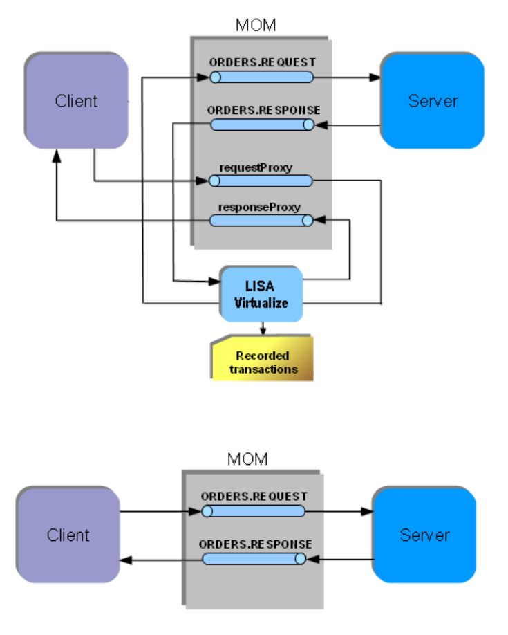
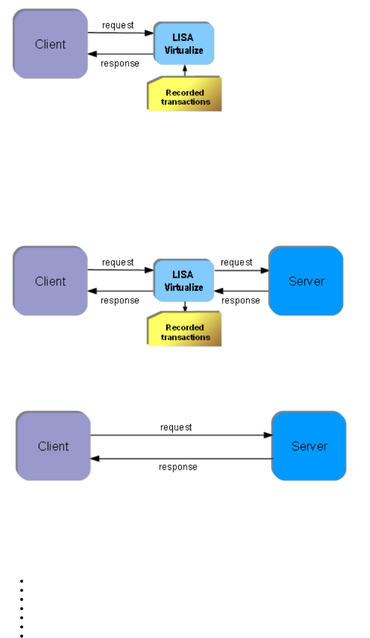
The following images show that at the time of image recording, LISA Virtualize acts as the pass through mechanism between the client and
server. While it passes the requests and responses along, it records the transactions.
Normal Operation
Recording
1.
2.
At the time of virtualization, in the absence of the server, LISA Virtualize responds to the client requests by consulting the recorded transactions.
Virtualization of Messaging Systems
Message Oriented Middleware (MOM), or simply Messaging systems, are services that provide a means to enable asynchronous communication
between two or more software applications. This communication always happens in the form of messages. The messages are posted to message
destinations configured into the MOM.
The two types of message destinations are:
Queues: A publisher can add a message to the queue, and a subscriber pulls messages out of the queue, in a "first in, first out" fashion.
Topics: A publisher can publish a message to a topic, and all subscribers that are subscribed to the topic receive the message.
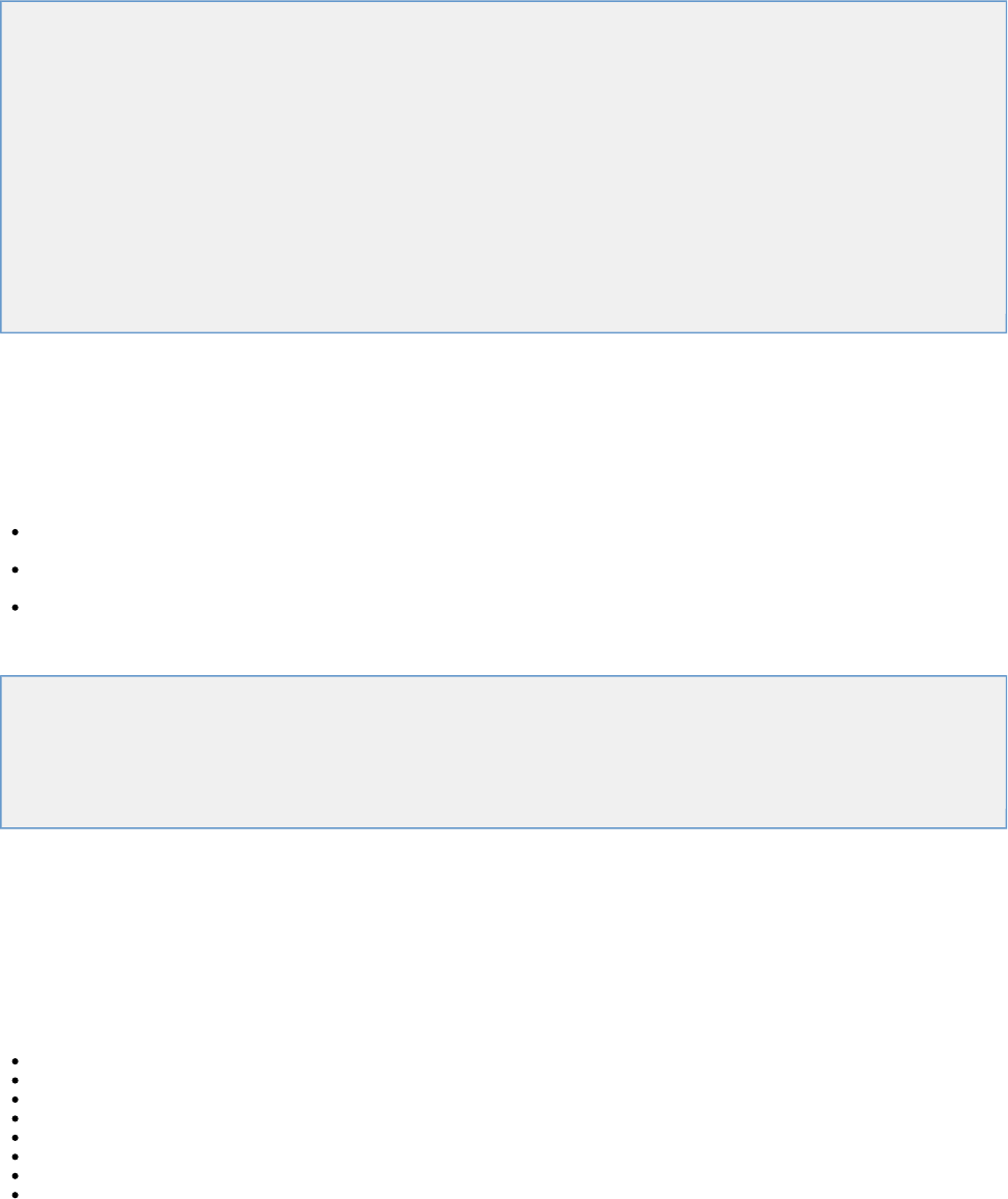
Following is a concept diagram of a simple message-based service. In the scenario shown, the client adds messages to a queue
(ORDERS.REQUEST), which are picked up by the server. The response from the server is in the form of messages added on to another queue
(ORDERS.RESPONSE). They are then picked up by the client.
1.
2.
Some possible variations include:
Use of topics instead of queues
Multiple responses to a single request, which can possibly target different destinations
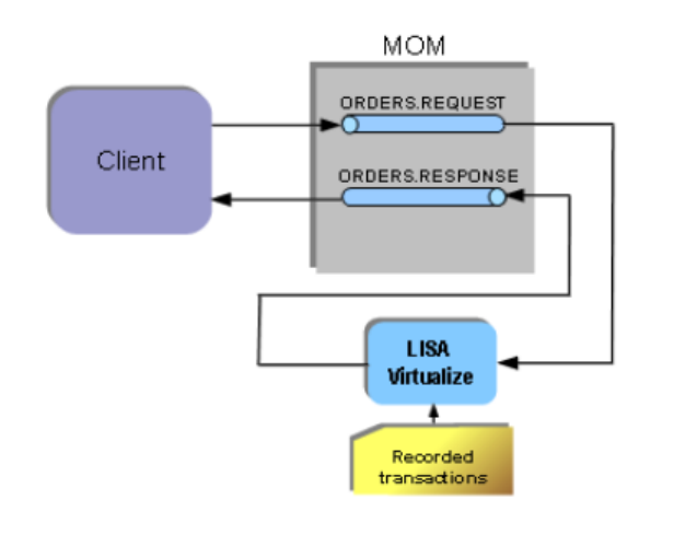
As before, LISA Virtualize aims to virtualize the server. As shown in the following diagram, in the recording mode LISA Virtualize requires extra
proxy destinations (requestProxy and responseProxy queues in the diagram) that are used by the client in place of their counterparts. The server
still listens and posts to the real destinations. LISA Virtualize acts as a pass-through between these proxy and real destinations, in turn recording
the traffic to create the VSM and the service image that it needs for virtualization.
Later, when LISA virtualizes the server, it just works with the real destinations. It does not need the proxy destinations then.
Benefits of Virtualization
The benefits of using LISA Virtualize include:
Providing round-the-clock access to service end points
Removing capacity constraints
Removing contention for shared resources
Providing an alternative to unavailable systems or systems still under development
Controlling complex data scenarios that are inherent during the SDLC
Reducing or eliminating the cost of invoking third-party systems for non-production use
Increasing agility and quality in complex and changing IT environments
Virtualize Installation and Configuration
Virtualize is required for maintaining a Service Oriented Virtualization environment.
1.
2.
3.
As LISA Virtualize is a server level service, it can co-exist with a registry that has a coordinator and simulator attached to it, but the simulator and
coordinator are not mandatory to run VSE.
The following topics are available.
System Requirements
Installing LISA Virtualize
Configuring LISA Virtualize
Installing the Database Simulator
Installing a Messaging Simulator
DDLs for Major DBs
System Requirements
The following system resources for LISA Virtualize are baseline requirements only.
CPU: 2GHz or faster
RAM: 2GB or more
Disk Space: 5GB free space
OS: Recommended: 64 Bit OS. Also supported: Windows 2000, 2003, 2008, Vista, 7, XP, Linux, Solaris, AIX 6.1 (LISA 5.0 and later)
The following resources are recommended for larger scale VSE deployments.
256 Virtual Service Threads per VSE instance
1 Processor Core and 2GB RAM per VSE instance
Example: 1,000,000 transactions per day
1 thread/service to support functional tests ~6 threads/service to support virtualization for L&P Tests
8 cores = 2,048 concurrent virtual service threads
16 GB RAM (for LISA)
For more details on other system requirements, see " ."System Requirements and PrerequisitesLISA Installation and Configuration Guide
Software Directory Structure and Files
The following is the LISA Virtualize directory structure. The directories are located in the LISA root installation folder.
bin: Contains LISA executables, such as TestRegistry.exe, LISAWorkstation.exe, VirtualServiceEnvironment.exe, VSEManager.exe
DemoServer: Contains LISA Demo Server
doc: Contains LISA documentation
examples/vse: Contains examples relating to LISA Virtualize
tmp: Contains LISA VSE's workspace where it temporarily stores conversations and stateless transactions
vseDeploy: Contains deployed VSMs and related data
Installing LISA Virtualize
If you are licensed for LISA Virtualize, the software will be installed when you install LISA Server. For information about installation and
configuration of LISA Server, see the . Installation and Configuration Guide
Configuring LISA Virtualize
Setting up the License
Virtual services are limited to the maximum number of virtual services you own. Each component must have access to the license server or have
a file-based license installed in [LISA_HOME]. In addition, the item in the License Info tab must be set to . virtualService true
You must add your license information for LISA Server to the file.local.properties
You will receive your license information from ITKO Support after purchasing LISA.
To set up a server-based license:
In the root LISA installation folder, make a copy of the file._local.properties
Name the copy .local.properties
Open in a text editor and add the PROJECT_ROOT definition:local.properties
# ==============================================
# Project root definition
3.
4.
5.
1.
2.
3.
# ==============================================
PROJECT_ROOT=C:/TestAssets
In the license properties section, uncomment the properties lines and add your specific licensing information:
# ==============================================
# license properties
# ==============================================
laf.server.url=https://license.itko.com (https://license.itko.com)
laf.domain=iTKO/LISA/YOURCO
laf.username=YOURUSERNAME
laf.password=YOURPASSWORD
Save and close the file.
Viewing Your Number of Licenses
You can view the number of virtual services for which you have licenses in the LISA Runtime Information window.
To view your license information:
From the menu bar, select Help > LISA Runtime Info.
In the License Info tab, locate the property. The number of licenses is shown in the second column.maxvirtualservices
Click Close.
You can install one Test Registry that runs as a server, a number of Virtual Service Environment servers and a number of
LISA Workstations that run as desktop applications, depending on your LISA license.
Proxy for localhost
When LISA acts as the HTTP client for LISA Virtualize, the HTTP traffic from LISA needs to be passed to LISA Virtualize. A common way to do
this is setting LISA Virtualize as the web proxy. However, the use of proxy is disabled by default for simple names like "localhost". To override this
behavior, in the file, uncomment the following LISA property and set its value to false:local.properties
lisa.http.webProxy.nonProxyHosts.excludeSimple=false
Other Settings
You can optionally set some other basic configurations in :local.properties
Rename the VSE Server: Add the following LISA property and change the value where is the name of the VSE Server:VSENAME
lisa.vseName=VSENAME
Connect to another test registry: add the following LISA property and change the values of , and to the server nameSERVER, PORT TRNAME
(or IP address), port number, and name of the new test registry:
lisa.defaultRegistry=rmi://SERVER:PORT/TRNAME
Installing the Database Simulator
Recording the JDBC traffic is done by installing the LISA simulation JDBC driver on the database client, so that it uses that in place of the actual
one.
The driver is packaged in a JAR file named located in the directory. You need to copy this file to be in your lisajdbcsim.jar /libLISA_HOME
database client's classpath. For convenience, it is already copied into the demo server in the directory, to/jboss/server/default/libDEMO_HOME
aid the use of Demo Server as the database client.
The driver class needs to be set to . This needs to be done differently based on the style of JDBC thecom.itko.lisa.vse.jdbc.driver.Driver
database client uses:
DriverManager Style: If the database client uses Java's DriverManager to acquire connections (not likely in an application server), add the
following to the startup command for the database client:
-Djdbc.drivers=com.itko.lisa.vse.jdbc.driver.Driver
If this property is already used, add the LISA driver to the front, separating it from the rest of the driver class names with a colon.
DataSource Style: If the database client uses the DataSource style for connection acquisition (as the Demo Server does), then update its
configuration. In the place where it specifies a data source definition, specify as the JDBC driver to use andcom.itko.lisa.vse.jdbc.driver.Driver
a connection URL.
The driver is packaged in a JAR file named located in the directory. For convenience, it is also copied into the lisajdbcsim.jar /libLISA_HOME
Demo server (for virtualizing it) in the directory./jboss/server/default/libDEMO_HOME
The LISA Simulation JDBC driver needs to know the real driver information to achieve a pass through. It is achieved by modifying the connection
URL. Format the connection URL as:
name=value[ =value...];name
where may be any of the following:name
jdbc:lisasim:driver: The value must be the fully qualified class name of the real JDBC driver to use.
url: The value must be set to the connection URL that the real driver is expecting. (It must be defined as the last property so that it can contain
semi-colons.)
LISA Virtualize does not support Oracle thin driver as a pass through driver, as it does not provide the full JDBC
implementation. If you are using Oracle as a database, use other JDBC drivers for virtualization.
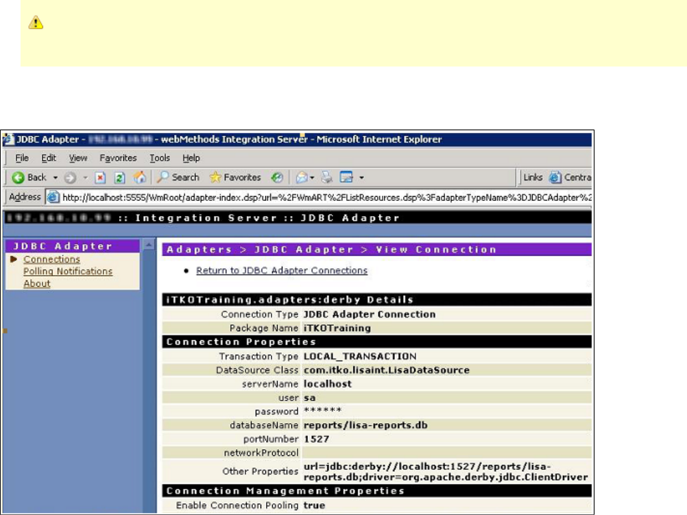
For an example of setting the connection URL, see ./jboss/server/default/deploy/itko-example-ds.xmlDEMO_HOME
For an example of virtualizing the database in a WebMethods environment, see the following screenshot.
If you want to use both the simulation and Pathfinder drivers, make the simulation driver the "outside" driver and specify the Pathfinder class and
URL as the real information described previously. See the file in the folder for anitko-example-ds.xml /jboss/server/default/deployDEMO_HOME
example that defines LISA data source to JBoss for LISA Demo Server.
Other Startup Properties
Regardless of the database client's connection style, you can add these properties to the startup command for the database client to affect the
simulation driver:
lisa.jdbc.sim.require.remote: Valid values for this property are and and the default value is . If set to true the driver blocks untiltrue false false
there is an active connection with a LISA Workstation or VSE Server instance. This is the preferred way to have a database client synchronize
with LISA VSE when you want to record or play back any startup database activity performed by the server.
lisa.jdbc.sim.port: This property must specify a valid IP port. If it is not specified, it defaults to . This is the port the driver listens on for2999
connections from a recorder or a running virtual service model.
Installing a Messaging Simulator
LISA Virtualize can virtualize a messaging-based SOA environment. For this, it needs to connect to the MOM.
There are special steps for connecting to IBM WebSphere MQ server.
It can connect to other messaging systems if they support JMS.
Support for any other messaging system may be created by creating custom steps through the LISA SDK.
To connect to WebSphere MQ server, copy the following JAR files from your WebSphere MQ installation into the folder:LISA_HOME/lib
com.ibm.mq.commonservices.jar
com.ibm.mq.defaultconfig.jar
com.ibm.mq.headers.jar
com.ibm.mq.jar
com.ibm.mq.jmqi.jar
com.ibm.mq.pcf.jar
com.ibm.mqjms.jar
connector.jar
dhbcore.jar
These are found in the folder under your MQ installation. The actual names of the files can differ between different versions ofjava/lib
WebSphere MQ.
In the case of a JMS system, the generic JAR files for connecting to a JMS system already exist - in particular, to the demo server. However, any
additional driver files that may be needed to connect to the messaging system may be needed to be copied into the folder.LISA_HOME/lib
See these sections for more platform-specific information.
TIBCO EMS Messaging
SonicMQ Messaging (JNDI)
IBM WebSphere MQ
DDLs for Major DBs
LISA can generate DDL to a FILE by adding the following three lines to the file:local.properties
eclipselink.ddl-generation=create-tables
eclipselink.ddl-generation.output-mode=sql-script
eclipselink.target-database=Oracle
Start LISA with these three lines and it creates two files - and - that contain the necessary DDL.createDDL.jdbc dropDDL.jdbc
You can generate for a different DBMS by changing the value of "target-database".
This table lists the EclipseLink JPA persistence unit properties that you can define in a file to configure EclipseLinkpersistence.xml
extensions for session, and as the target database and application server.
Property Usage
eclipselink.session-name Specify the name by which the EclipseLink session is stored in the static session manager. Use this option if you need to
access the EclipseLink shared session outside of the context of the JPA or to use a pre-existing EclipseLink session
configured through an EclipseLink file. sessions.xml
Valid values: a valid EclipseLink session name that is unique in a server deployment.
: file<property value="MySession"/> : property importExample persistence.xml Example Map
org.eclipse.persistence.config.PersistenceUnitProperties;propertiesMap.put(PersistenceUnitProperties.SESSION_NAME,
"MySession");
The default value is EclipseLink-generated unique name.
eclipselink.sessions-xml Specify persistence information loaded from the EclipseLink session configuration file ( ). sessions.xml
You can use this option as an alternative to annotations and deployment XML. If you specify this property, EclipseLink
will override all class annotation and the object relational mapping from the , and as andpersistence.xml ORM.xml
other mapping files, if present.
Indicate the session by setting the property.eclipselink.session-name
If you do not specify the value for this property, file will not be used.sessions.xml
Valid values: the resource name of the sessions XML file.
: file<property value="mysession.xml"/> : property importExample persistence.xml Example Map
org.eclipse.persistence.config.PersistenceUnitProperties;propertiesMap.put(PersistenceUnitProperties.SESSIONS_XML, "mysession.xml"); |
eclipselink.session-event-listener Specify a descriptor event listener to be added during bootstrapping.
Valid values: qualified class name for a class that implements the interface. org.eclipse.persistence.sessions.SessionEventListener
: file<property value="mypackage.MyClass.class"/> : property importExample persistence.xml Example Map
org.eclipse.persistence.config.PersistenceUnitProperties;propertiesMap.put(PersistenceUnitProperties.SESSION_EVENT_LISTENER_CLASS,
"mypackage.MyClass.class");
eclipselink.session.include.descriptor.queries Enable or disable the default copying of all named queries from the descriptors to the session. These queries include the ones defined using
EclipseLink API, descriptor amendment methods, and so on.
The following are the valid values:
true – enable the default copying of all named queries from the descriptors to the session.
false – disable the default copying of all named queries from the descriptors to the session. : file<propertyExample persistence.xml
value="false"/> : property importExample Map
org.eclipse.persistence.config.PersistenceUnitProperties;propertiesMap.put(PersistenceUnitProperties.INCLUDE_DESCRIPTOR_QUERIES,
"false");
The default value is .true
eclipselink.target-database Specify the type of database that your JPA application uses.
The following are the valid values for the use in a file and for the :persistence.xml org.eclipse.persistence.config.TargetDatabase
Attunity – configure the persistence provider to use an Attunity database.
Auto – EclipseLink accesses the database and uses the metadata that JDBC provides to determine the target database. Applicable to
JDBC drivers that support this metadata.
Cloudscape – configure the persistence provider to use a Cloudscape database.
Database – configure the persistence provider to use a generic choice if your target database is not listed here and your JDBC driver does
not support the use of metadata that the option requires.Auto
DB2 – configure the persistence provider to use a DB2 database.
DB2Mainframe – configure the persistence provider to use a DB2Mainframe database.
DBase – configure the persistence provider to use a DBase database.
Derby – configure the persistence provider to use a Derby database.
HSQL – configure the persistence provider to use an HSQL database.
Informix – configure the persistence provider to use an Informix database.
JavaDB – configure the persistence provider to use a JavaDB database.
MySQL – configure the persistence provider to use a MySQL database.
Oracle – configure the persistence provider to use an Oracle Database.
PointBase – configure the persistence provider to use a PointBase database.
PostgreSQL – configure the persistence provider to use a PostgreSQL database.
SQLAnywhere – configure the persistence provider to use an SQLAnywhere database.
SQLServer – configure the persistence provider to use an SQLServer database.
Sybase – configure the persistence provider to use a Sybase database.
TimesTen – configure the persistence provider to use a TimesTen database. You can also set the value to the fully qualified classname of a
subclass of the class. org.eclipse.persistence.platform.DatabasePlatform
: file<property value="Oracle"/> : property importExample persistence.xml Example Map
org.eclipse.persistence.config.TargetDatabase;import
org.eclipse.persistence.config.PersistenceUnitProperties;propertiesMap.put(PersistenceUnitProperties.TARGET_DATABASE,
TargetDatabase.Oracle);
The default value is .Auto
eclipselink.target-server Specify the type of application server that your JPA application uses.
The following are the valid values for the use in the file and the :persistence.xml org.eclipse.persistence.config.TargetServer
None – configure the persistence provider to use no application server.
WebLogic – configure the persistence provider to use Oracle WebLogic Server. This server sets this property automatically, so you do not
need to set it, unless it is disabled.
WebLogic_9 – configure the persistence provider to use Oracle WebLogic Server version 9.
WebLogic_10 – configure the persistence provider to use Oracle WebLogic Server version 10.
OC4J – configure the persistence provider to use OC4J.
SunAS9 – configure the persistence provider to use Sun Application Server version 9. This server sets this property automatically, so you do
not need to set it, unless it is disabled.
WebSphere – configure the persistence provider to use WebSphere Application Server.
WebSphere_6_1 – configure the persistence provider to use WebSphere Application Server version 6.1.
JBoss – configure the persistence provider to use JBoss Application Server.
Fully qualified class name of a custom server class that implements org.eclipse.persistence.platform.ServerPlatform
interface.
*Example*: file<property value="OC4J_10_1_3"/> : property importpersistence.xml Example Map
org.eclipse.persistence.config.TargetServer;import
org.eclipse.persistence.config.PersistenceUnitProperties;propertiesMap.put(PersistenceUnitProperties.TARGET_SERVER,
TargetServer.OC4J_10_1_3);
The default value is .None
This table lists the EclipseLink JPA persistence unit properties that you can define in a file to configure schema generation.persistence.xml
EclipseLink JPA Persistence Unit Properties for Schema Generation
Property Usage

eclipselink.ddl-generation Specify what Data Definition Language (DDL) generation action you want for your JPA entities. To specify the DDL generation target, see
. eclipselink.ddl-generation.output-mode
The following are the valid values for the use in a file:persistence.xml
none – EclipseLink does not generate DDL; no schema is generated.
create-tables – EclipseLink will attempt to execute a SQL for each table. If the table already exists, EclipseLinkCREATE TABLE
will follow the default behavior of your specific database and JDBC driver combination (when a SQL is issued forCREATE TABLE
an already existing table). In most cases an exception is thrown and the table created. EclipseLink will then continue with theis not
next statement
drop-and-create-tables – EclipseLink will attempt to all tables, then all tables. If any issues are encountered,DROP CREATE
EclipseLink will follow the default behavior of your specific database and JDBC driver combination, then continue with the next
statement.
The following are the valid values for the :org.eclipse.persistence.config.PersistenceUnitProperties
NONE – see .none
CREATE_ONLY – see .create-tables
DROP_AND_CREATE – see . drop-and-create-tables
If you are using persistence in a Java SE environment and would like to create the DDL files without creating tables, additionally
define a Java system property and set its value to . INTERACT_WITH_DB false
: file<property value="create-tables"/> : property importExample persistence.xml Example Map
org.eclipse.persistence.config.PersistenceUnitProperties;propertiesMap.put(PersistenceUnitProperties.DDL_GENERATION,
PersistenceUnitProperties.CREATE_ONLY);
Default value is or .none PersistenceUnitProperties.NONE
eclipselink.application-location Specify where EclipseLink should write generated DDL files. Files are written if is set to anything othereclipselink.ddl-generation
than . none
Valid values: a file specification to a directory in which you have write access. The file specification may be relative to your current working
directory or absolute. If it does not end in a file separator, EclipseLink will append one valid for your operating system.
: file<property value="C:\ddl\"/> : property importExample persistence.xml Example Map
org.eclipse.persistence.config.PersistenceUnitProperties;propertiesMap.put(PersistenceUnitProperties.APP_LOCATION, "C:\ddl\");
The default value is </tt>"."+File.separator or <tt>PersistenceUnitProperties.DEFAULT_APP_LOCATION
eclipselink.create-ddl-jdbc-file-name Specify the file name of the DDL file that EclipseLink generates containing SQL statements to create tables for JPA entities. This file is
written to the location specified by when is set to eclipselink.application-location eclipselink.ddl-generation
or . create-tables drop-and-create-tables
Valid values: a file name valid for your operating system. Optionally, you may prefix the file name with a file path as long as the
concatenation of + is a valid file specificationeclipselink.application-location eclipselink.create-ddl-jdbc-file-name
for your operating system.
: file<property value="create.sql"/> : property importExample persistence.xml Example Map
org.eclipse.persistence.config.PersistenceUnitProperties;propertiesMap.put(PersistenceUnitProperties.CREATE_JDBC_DDL_FILE,
"create.sql");
The default value is or createDDL.jdbc PersistenceUnitProperties.DEFAULT_CREATE_JDBC_FILE_NAME
eclipselink.drop-ddl-jdbc-file-name Specify the file name of the DDL file that EclipseLink generates containing the SQL statements to drop tables for JPA entities. This file is
written to the location specified by when is set to eclipselink.application-location eclipselink.ddl-generation
. drop-and-create-tables
Valid values: a file name valid for your operating system. Optionally, you may prefix the file name with a file path as long as the
concatenation of + is a valid file specification foreclipselink.application-location eclipselink.drop-ddl-jdbc-file-name
your operating system.
: file<property value="drop.sql"/> : property importExample persistence.xml Example Map
org.eclipse.persistence.config.PersistenceUnitProperties;propertiesMap.put(PersistenceUnitProperties.DROP_JDBC_DDL_FILE, "drop.sql");
The default value is or dropDDL.jdbc PersistenceUnitProperties.DEFAULT_DROP_JDBC_FILE_NAME
1.
2.
3.
4.
5.
6.
7.
8.
eclipselink.ddl-generation.output-mode Use this property to specify the DDL generation target.
The following are the valid values for the use in the file:persistence.xml
both – generate SQL files and execute them on the database.
If is set to , then is writteneclipselink.ddl-generation create-tables eclipselink.create-ddl-jdbc-file-name
to and executed on the database. eclipselink.application-location
If is set to , then both eclipselink.ddl-generation drop-and-create-tables
and are written to eclipselink.create-ddl-jdbc-file-name eclipselink.drop-ddl-jdbc-file-name
and both SQL files are executed on the database.eclipselink.application-location
database – execute SQL on the database only (do not generate SQL files).
sql-script – generate SQL files only (do not execute them on the database).
If is set to , then is writteneclipselink.ddl-generation create-tables eclipselink.create-ddl-jdbc-file-name
to It is not executed on the database. eclipselink.application-location
If is set to , then both eclipselink.ddl-generation drop-and-create-tables
and are written to eclipselink.create-ddl-jdbc-file-name eclipselink.drop-ddl-jdbc-file-name
. Neither is executed on the database. The following are the valid values for the eclipselink.application-location :org.eclipse.persistence.config.PersistenceUnitProperties
DDL_BOTH_GENERATION – see .both
DDL_DATABASE_GENERATION – see .database
DDL_SQL_SCRIPT_GENERATION – see . : file<property value="database"/> :sql-script Example persistence.xml Example
property importMap
org.eclipse.persistence.config.PersistenceUnitProperties;propertiesMap.put(PersistenceUnitProperties.DDL_GENERATION_MODE,
PersistenceUnitProperties.DDL_DATABASE_GENERATION);
The default for Container or Java EE mode is{{database}}
This setting may be overridden by containers with specific EclipseLink support. See your container documentation
for details.Bootstrap or Java SE mode: or both PersistenceUnitProperties.DDL_BOTH_GENERATION
Understanding LISA Virtualize
The following topics are available.
The LISA Virtualize Process
LISA Virtualize Concept Diagram
Virtual Service Model (VSM)
Service Images
How Virtualization Works
Magic Strings and Dates
The LISA Virtualize Process
The general process for working with LISA Virtualize includes these steps:
Create a Virtual Service Model (VSM) in the LISA Workstation.
Launch the Virtual Service Image Recorder.
In the Virtual Service Image Recorder, provide basic information about what needs to be recorded, select the appropriate protocols, and
specify the default navigations. Provide any information required by the selected protocols. Begin the recording.
Exercise the client to cause communication with the server routed through LISA Virtualize. LISA Virtualize records the traffic.
In the Virtual Service Image Recorder, finish the recording.
In LISA Workstation, save the VSM.
In the VSE Console, deploy the VSM, and start the virtual service.
Run live requests against LISA VSE (Virtual Service Environment).
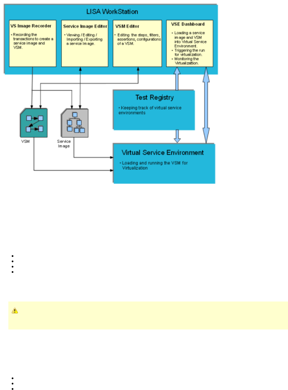
LISA Virtualize Concept Diagram
The following diagram illustrates how the various components in LISA Virtualize are related to each other.
At the time of recording, the Virtual Service Image Recorder is used to record a service image and a VSM. The Service Image Editor and VSM
Editor help in editing and viewing them.
At the time of Virtualization, the VSM and service image are loaded and run on a VSE that runs as a service. The Test Registry service is used to
keep track of one or more Virtual Service Environments running, and LISA Workstation uses it to connect to the VSE. The VSE Dashboard is the
web UI used to monitor and control the various VSMs and service images loaded onto the Virtual Service Environments.
Virtual Service Model (VSM)
A virtual service model can be conceptualized as a series of steps to be executed when a request is received, to create and pass back a
response to the request. It is stored in a file, and must contain at least one VSE step from the step list in.vsm Virtual Service Environment
Workstation to be deployable to a VSE.
After a service image is recorded, the protocol-specific steps are automatically generated in the VSM for all transports supported. Any of the
generated steps can be modified. You can also:
Populate responses from an Excel spreadsheet or by cross referencing a database table and do math on inputs
Add steps of different step types
Manipulate the request and response steps before proceeding
Specify the service image you would like to use from the Response Selection step
At the time of virtualization, a VSM needs to be deployed to the VSE. It defines how behavior patterns get used and queries the service image to
determine how to respond. It knows how to traverse the service image. In general, VSMs are deployable to VSEs only, while test cases can be
staged to coordinators, but not the other way around.
If you have a message-based virtual service and because the same messaging steps are used for both testing and virtualizing,
add the Message Marker step, which lets you deploy to VSE.
Service Images
A service image is a recording of the interaction between the client and server as created by LISA Virtualize and it is referenced in a VSM. After it
is recorded, the service image is used to deliver the appropriate response to the client in the absence of the server.
A service image contains three sets of information:
A list of conversations (requests and responses) recorded as conversation tree.
A list of stateless transactions (requests and responses).
The responses that should be sent when unknown conversational or stateless requests are encountered. (If the recorded service image
is incomplete, an error message appears.)
You can view, edit, or create a service image using the Service Image Editor.
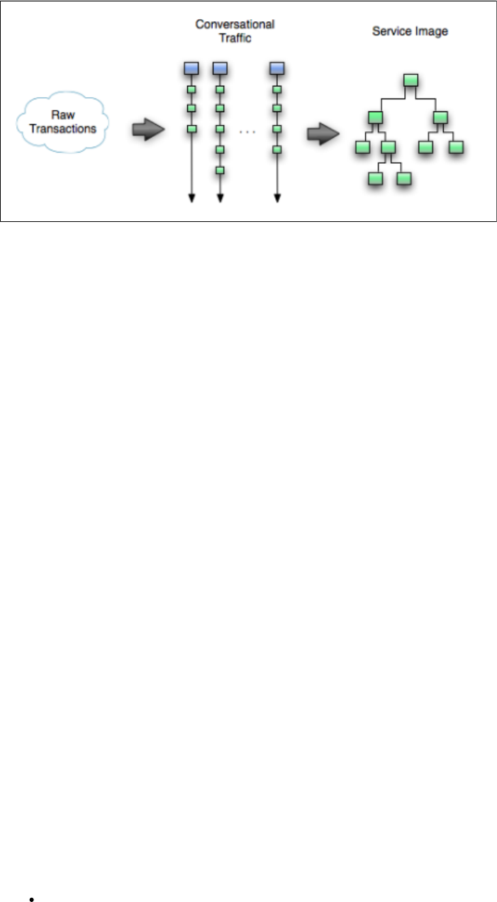
A conversation can be visualized as a series of stateful transactions. However, multiple conversations (from multiple sessions) can be recorded in
the same service image. Similar request structures are merged into a single transaction, thus creating a tree as shown in the following diagram.
As an example, if multiple users log into the system with login() transactions, all these transactions will be merged in a single transaction. But if
one user logs in using login() and another user logs in with an acquireAuthToken(), then these transactions will not be merged.
Importing Transactions
The following XML documents can be imported into a service image being recorded:
Raw Transactions
The XML document represents raw traffic as if coming off the wire, characterized by a root element of <rawTraffic>.
A well-documented example can be found in [LISA_HOME]/examples/vse/raw-traffic.xml.
Conversational Traffic
The XML document represents traffic that has been rearranged into conversations and/or stateless transaction sets. They are organized into
linear lists of transactions, each of which represents a "real" conversation and are characterized by a root element of <traffic>.
A well-documented example can be found in [LISA_HOME]/examples/vse/traffic.xml.
How Virtualization Works
In the absence of a server, LISA Virtualize simulates the behavior of the server for its client. This process is known as the virtualization of server.
It requires loading the service image referenced from a VSM and running it in the VSE dashboard.
When a request is received by the VSE, the request is examined and an attempt is made to match it to an existing conversational state (session)
within the VSE. For example, a cookie ID or some other session identifier can "tie" requests in stateless protocols such as HTTP. The
conversational state is used to determine where in the conversation tree the "current transaction" is, and any other "state" such as a previously
submitted authentication token, the user name, for example, which may not be part of the current request, but used in the subsequent response.
If an existing session cannot be found, the VSE attempts to match the request against the starter transactions of each conversation in the image.
If a match is found, a new session is created and the relevant response is returned. The session is maintained until 20 minutes after it has last
been 'seen' by the VSE. If no conversation starters match, no session is created and the list of stateless transactions is consulted in the order they
are defined. If there is a match, the appropriate response is returned. If there is still no match, the 'unknown request' response is sent.
In the case where we do find a previous session and we are in the midst of a conversation, the next transaction match depends on many factors
including navigation and match tolerances (described in the following section).
If a matching transaction is not found in the conversational and stateless transactions, then the service image is consulted again for the kind of
response that needs to be sent out for an unmatched conversational/stateless request.
Handling Conversational Requests
The navigation tolerance that you can specify for every node in the tree plays an important role in how the VSM handles a conversation request. It
is used to determine where in the conversation tree VSM should search for a transaction that should follow the given transaction.
Navigation Tolerance Levels
Close: The current transaction's children are searched.
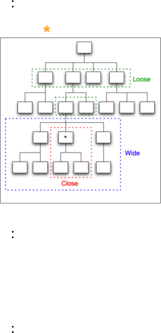
Wide: A close search, including the current transaction plus siblings and "nieces/nephews" of the current transactions.
Loose: A wide search, plus the current transaction's parent and its siblings followed by the children of the starting transaction. If both fail
to find a match, then the starting transactions for all conversations are checked, resulting in searching the full conversation.
The following diagram illustrates how navigation tolerance impacts the transactions to be searched in a conversation tree. The current transaction
is marked with a star .
At the time of recording, the VSE recorder allows for initializing the navigation tolerance on transactions with two separate settings.
Navigation concepts and Defaults
Default navigation: Refers to the default tolerance on all meta transactions that have child meta transactions. Defaults to .Wide
Last: Refers to the default tolerance for meta transactions that are "leaf" transactions without any child meta transactions. Defaults to
.Loose
These can later be changed for each node through the Service Image Editor.
The defaults provide a wider hit on "right" behavior. VSE responds correctly more often in situations when current runtime sessions restart a
conversation without the need to start a new conversation.
Handling Unknown Requests
An unknown request may occur in two situations: when there is an active conversation and when there is not.
In the case where there is no active conversation, a request is identified as unknown if there are no stateless transactions that can satisfy the
request. In this case, the service image's response for unknown stateless requests becomes the reply.
In the case where a request cannot be matched to a follow-on transaction:
If the navigation tolerance is not CLOSE, then the conversation starter transactions are given the chance to satisfy the request.
If the request is still unmatched, and if a stateless transaction can produce a reply, then that is sent out. The current session continues to
remember where it is in its conversational tree.
If that fails, the service image's response for unknown conversational requests becomes the reply.
Magic Strings and Dates
Magic strings and magic dates are central to the dynamic nature of a virtualized service. They enable the virtualized service to return meaningful
results for request parameters that were never recorded.
Magic Strings
During the recording phase, each request is examined for arguments or parameters. For example, a weather forecasting web service call might
include a city name or an airline booking system request might include a flight number. If the flight number is included in the recorded ,response
then it is classified as a "magic" string. If the VSE is in playback mode and a request comes in for a flight number that was never recorded, the
correct flight number is included in the response.
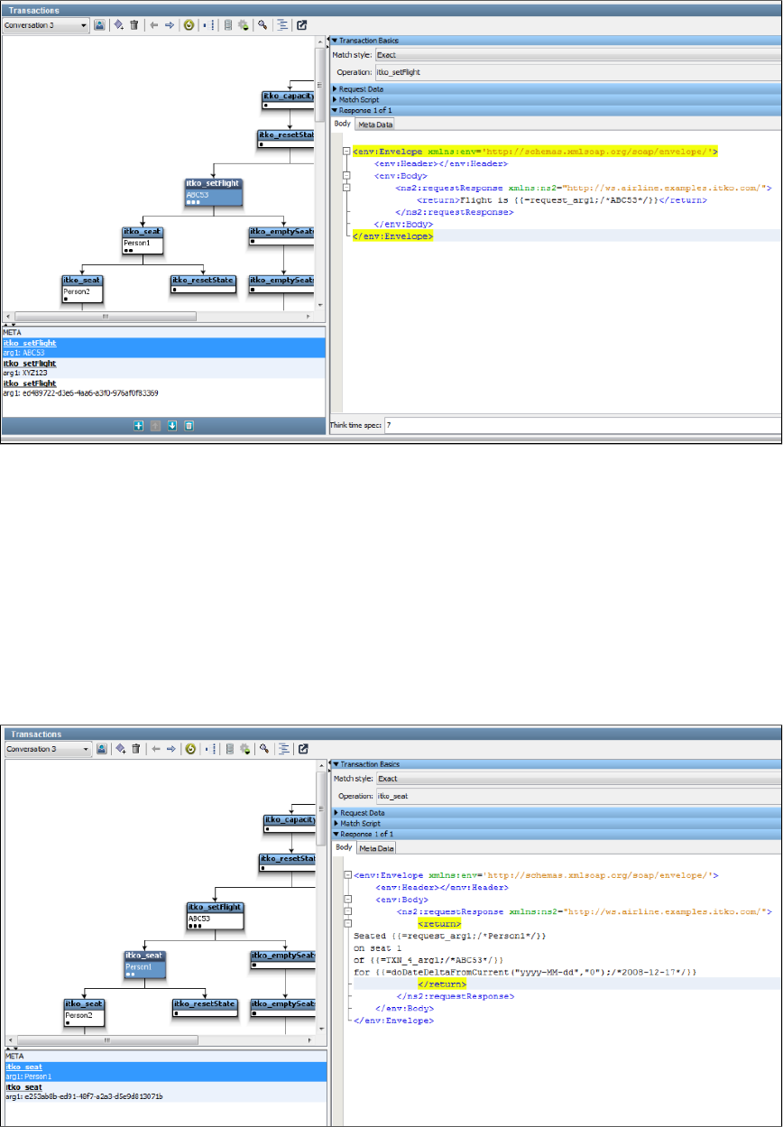
In the previous example, we recorded a request to set some "state" in the conversation, in this case the flight number (ABC53). The recorder
noted that the same string ABC53 was contained in the response, so it converted it to a magic string, which is saved in the service image
database as '=request_arg1;/ /.ABC53
The {{ }} notation is a standard LISA property substitution syntax. The meaning here is "substitute this {{ }} text with the runtime value of the first
argument of the request, and if there is no first argument then use ABC53 as the default".
The practical significance of this is that if some future client requests flight ZZ99, the virtualized service will respond with the correct flight number,
ZZ99.
Magic strings are detected not just in a simple request/response pair. If an argument is ever seen in any subsequent response in a conversation,
it is deemed to be magic and the argument value is stored in the conversation state.
Here is an example, just a little further on in the same conversation. The request operation is "itko_seat" and the single argument is a name, in
this case "Person1". The response contains the name in the request, the previously set flight number and a date (more on dates later).

This is the canonical example of conversational state over a stateless protocol, in this case SOAP over HTTP. It means that if the VSE in
playback mode sees a request to set the flight to ZZ99 and then a request to seat PersonSomeoneElse, then the correct string, "Seated
PersonSomeoneElse on seat 1 of flight ZZ99" will be included in the response, even though those details were never recorded.
The seat number, 1 in this case, is not regarded as a magic string, because it was never seen in the original series of requests that led to this
response. Nor is it "big enough" to be regarded as a magic string: they need to be at least three characters long and optionally have whitespace
on the left, right or both sides of the string. You can adjust the length and whitespace parameters in the configuration file.local.properties
The property notation is extremely powerful and flexible and is not confined to using magic strings. For example, if we changed the '1' in the{{ }}
response in our example to DataSetValue and defined a data set in the virtual service model, that data set would be used to generate the runtime
response value. The dataset might be a random string generator, a counter, a call to a database, a reference to an Excel spreadsheet row,
anything. can execute arbitrary Java code and even generate realistic "everyday" data such as a valid credit card number {{=[:Credit Card:].}}
See .Using BeanShell in LISA
Magic String Exclusions
LISA Virtualize will attempt to identify tokens in requests and responses that are identical (contingent on certain rules), and turn the values in the
response into a "magic string" whose value will vary based on the values in the request.
However, LISA has no way of knowing if those values match by design, or by accident. Experience has shown that this is most common with a
handful of values: Booleans, and the __NULL token used by the Agent / Pathfinder for Java VSE. For instance, consider this request and
response snippet:
Request
<GetUserRequest>
<userId>lisaitko</userId>
<includeDetails>true</includeDetails>
</GetUserRequest>
Response
<GetUserResponse>
<userId>lisaitko</userId>
<isActive>true</isActive>
<isEmailVerified>true</isEmailVerified>
</GetUserResponse>
Clearly, the two "true" values in the response have nothing to do with each other, or with the value in the request. In real world scenarios, the
number of unwanted "magic strings" that are generated is much greater. One way to avoid this is to manually find and replace these magic strings
after the service image was recorded.
An easier way, however, is to use a LISA property, defined in .lisa.properties
lisa.magic.string.exclusion=Yes, YES, yes, No, NO, no, true, True, TRUE, false, False, FALSE, __NULL
This lets you specify values that are not candidates for magic string identification. LISA will not try to correlate these values in the response to
values in the request during recording. The service image can still be manually edited to add magic strings if needed.
Magic Dates
Requests and responses are also scanned at recording time by a powerful date parser. Anything matching a very wide definition of date formats
is recognized and translated into a 'Magic Date'. In the previous example, the magic date is {{
The use of notation is important here.=doDateDeltaFromCurrent("yyyy-MM-dd","0D");/2008-12-17}} {{ }}
At runtime, this is translated as "generate a date of the format yyyy-MM-dd that is 0 days from the current date". In other words, generate today's
date.
If the original recording was taken on 1 February 2009 and the response contained a date 2009-02-10, then the magic date string would be
;/ /. The in the magic string means the VSE will generate a date in the=doDateDeltaFromCurrent("yyyy-MM-dd","10D") 2009-02-10 10D
response 10 days ahead of the current time. Thus if the VSE is in playback mode on 12 June 2010, the response will contain the string
"2010-06-22".
Valid parameters for date deltas are:
D: Days
H: Hours
M: Minutes
S: Seconds
Ms: Milliseconds
There is another variant of magic dates: , as opposed to . The doDateDeltaFromRequest doDateDeltaFromCurrent doDateDeltaFromRequest
variant is used when a date is used as a parameter in the request and a date is seen in the response. For example, an airline reservation system

1.
2.
3.
4.
5.
6.
7.
8.
9.
might accept a seating request for a particular flight on a particular day. If that date is seen in the response, the VSE will correctly substitute the
date in any subsequent responses.
A more sophisticated example is if the flight request generated a response that detailed a flight crossing the international date line: a flight from
Los Angeles to Sydney would arrive two days later than the departure according to the calendar date even though the flight time is around 14
hours. In this example, the response would contain something like If VSE processed a similardoDateDeltaFromRequest("yy-MM-dd", "2D")
request for a flight departing LAX on 19-June-2009, it would include the correct arrival date of 21-June-2009 in the response.
Any valid date/time formats, including the ones that have zones, can be added to for magic date calculations.lisa.properties
Understanding Transactions
A , as it applies to VSE, is a complete unit of work done by a service. This includes both the request sent from the client to the servicetransaction
and the response sent back from the service to the client. With most service protocols, including Web Services, HTTP, and Java, transactions are
done . The request and response are directly related to each other.synchronously
With Web Services and HTTP, the request and response are contained within a single socket connection, and the request is usually followed
directly by the response. With Java, the request and response are contained within a single thread and the request, a method call, is always
followed by the response, the return value.
Messaging is different because it is . The request and response messages do not have to occur in the same socket connection, theasynchronous
same thread, or even in the same day. The client sends a request message and then goes and does something else while waiting for the
response. When the response is sent from the service, the client receives it and , completing thematches it up with the original response
transaction.
In short, a transaction comprises a request and a response. In most cases, a transaction has only one response, such as in the case of an HTTP
responder. However, the messaging protocol can return multiple responses (stored as a list) from a single request.
The following topics are available.
Stateless and Conversational Transactions
Logical Transactions
Match Tolerance
Stateless and Conversational Transactions
Transactions are classified as either or .Stateless Conversational
Stateless Transactions
Stateless transactions include no logical relationships between transactions. For example, HTTP and SOAP are stateless protocols. A stateless
transaction always has a static response, regardless of what calls were made previously.
In a stateless conversation, each service call is independent of the others. For example:
What's the weather like in Dallas, TX? (Operation: weather; arg1-city)
What's the weather like in Atlanta, GA? (Operation: weather; arg1-city)
What will the weather be like in Dallas, TX tomorrow? (Operation: weather; arg1-city; arg2-date)
Conversational/Stateful Transactions
Conversations comprise stateful transactions and consist of the logical transaction that, if matched, starts a unique session and the information
necessary to create and identify that session. A transaction in a conversation always depends on the context created by earlier conversation.
Here is an example of a stateful conversation that involves using an ATM.
Connect to the ATM. (Operation: log on)
What account do you want? (arg1-checking)
What's my balance? (Operation: balance)
Response.
Withdraw an amount of money. (Operation: withdrawal)
How much? (arg2-amount)
What's my balance? (Operation: balance)
Response (different based on the amount withdrawn in the previous request).
End session (Operation: log out)

1.
2.
3.
1.
2.
3.
4.
5.
6.
7.
Conversation Starters
The first transaction in a conversation is known as the conversation starter. When LISA Virtualize gets an incoming request, it will look at the
conversation starters to determine if this transaction means we are starting a new conversation.
All the transactions in a conversation are related to each other. VSE must have a way of determining this relationship. This is typically done by
some kind of special token in the transactions, such as "jsessionid" or a cookie in web transactions, or a custom identifier in message traffic, or
others.
LISA supports the following types of conversations:
Instance-based conversations: The protocol layer is responsible for identifying the unique string based on different instances of the client and
that is used to identify server-side sessions for both recording and playback of the service image.
Token-based conversations: The token is generated by the LISA VSE using a string generation pattern stored with the conversation in the
service image. After the token is generated, it operates the same as an instance-based conversation. Because token-based conversations cannot
be automatically inferred during recording, you will need to use the to specify where tokens are found.VS Image Recorder
Navigation Tolerance
Within a conversation, VSE follows very specific rule to determine how to find the next conversational transaction. There are three sets of rules,
also known as navigation tolerances.
Close The transactions must go straight down the tree. The only candidates for the next conversational transaction are the children of the
current one.
Wide This is the default. This allows navigation to the current transaction's children, the current transaction, the current transaction's
siblings, and the sibling's immediate descendants (or "nephews"). The order of precedence is
Current transaction's children
Immediate children of a sibling
Sibling or current transaction
Loose This is the most permissive navigation tolerance. It first tries the "Close" and "Wide" tolerances, then adds the ability to match the
current transactions parent, any of the parent's siblings ("uncles"), the children of the parent's siblings ("cousins"). If this fails,
navigation is permitted to any transaction in the second or third level of the tree. The order of precedence is
Current transaction's children (close tolerance)
Immediate children of a sibling (wide tolerance)
Sibling, or current transaction (wide tolerance)
The siblings of the parent transaction ("uncles") but not their children (not cousins)
The parent transaction or its siblings (parent or "uncles")
The children of the current conversation's starter transaction (the immediate children of the root of the tree)
The starter transactions for all the SI's conversations
Logical Transactions
A logical transaction appears as a single node in a conversation. It comprises one transaction with one or more specific transactions.meta
When a logical transaction appears in the search for responding to a given request, the meta transaction is consulted to see if this transaction
wants to respond to the given request. If the meta transaction decides to respond to the request, then all the specific transactions are queried if
they want to respond to the request. If none of the specific transactions want to respond to the request, then the response is taken from the meta
transaction.
This logic can be expressed as the following pseudo code:

for each logical transaction \{
if (meta transaction request matches the given request) \{
// This node would handle the request
for each specific transaction in this node \{
if (the specific transaction matches the given request) \{
return the response from the specific transaction
\}
\}
// No specific transaction found for the given request
return the response from the meta transaction
\}
\}
Further, a physical meta transaction carries a list of specific transactions and a list of child meta transactions. The latter allows meta transactions
to be structured into a decision tree.
Match Tolerance
Navigation tolerance tells LISA Virtualize what transactions it can try to match the incoming transaction with. Match tolerance, on the other hand,
defines how VSE decides if a given transaction matches the incoming one. There are three levels of match tolerance.
Operation: This is the loosest match tolerance. It means that the operation name of the incoming transaction must match the name of
the recorded transaction.
Signature: This level of match tolerance means that not only must the operation name match, but the names of the arguments must
match exactly, with no additions or deletions. The order of arguments does not have to be the same.
Exact: In addition to the signature match, the values for each argument must match the values that were recorded, as defined by the
argument match operators.
Argument Match Operators
A match operator is specified for every argument in a request. For an match operation, it controls how the value of the argument in theExact
incoming request is matched against the value of the corresponding argument in the service image.
The following table describes the available match operators.
Anything: Always returns true. The virtual service recorder defaults the comparison to this when it determines that an argument is a
date.
= Equal: Returns true if the values are the same.
!= Not equal: Returns true if the values are different.
< Less than: Returns true if the inbound value is less, before, or earlier than the value from the service image.
<= Less than or equal: Returns true if the inbound value is less, before, or earlier than or equal to the value from the service image.
> Greater than: Returns true if the inbound value is greater, after, or later than the value from the service image.
>= Greater than or equal: Returns true if the inbound value is greater, after, later than or equal to the value from the service image.
Regular Expression: Returns true if the inbound value (as a string) matches the value, as a regular expression, from the service image.
Property Expression: The value in the service image must be in the form of a double-braced script expression, , which returns either .
or . The argument value in the inbound request is ignored unless referenced in the script.true false
If an argument is marked as a date, the values from the requests being compared are first converted to a date before
the comparison is done. This is not done for the Any, Property Expression or Regular Expression comparison types.
META Transactions and Specific Responses
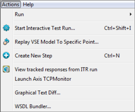
1.
2.
3.
4.
5.
6.
7.
When VSE searches for a conversational match, it only searches what is known as META transactions. A META transaction cannot have a match
tolerance of "Exact" (the default is "Signature"). Each META transaction will have one or more specific responses, which may have any match
tolerance ("Exact" is the default).
If none of the specific responses for a META transaction match, then the response specified for the META transaction will be used.
How the Next Response is Selected
If the incoming request is in a conversation, search for a match based on the navigation tolerance and other rules explained previously.
If nothing is found in the current conversation, look for another conversation (unless navigation tolerance is CLOSE).
If there is a conversational match, and we got a specific response (rather than just a meta match), use that.
Otherwise, look for a specific match in the stateless transactions, and if found, use that one.
If there was no specific match in the stateless list, but we found a meta match in the conversational list, use that meta match.
If there was no conversational match at all, but we did have a meta match in the stateless list, use that.
Fail with "no match found," and send back either the "unknown conversational response" or the "unknown stateless response" specified
in the service image (which could be overriden based on the protocol and handlers used).
Debugging
If you get failures to match, change $LISA_HOME/logging.properties and set log4j.logger.VSE to DEBUG or even TRACE. That will cause VSE to
be extremely verbose to the file, and will tell you exactly what did and did not match.vse_matches.log
Set this to INFO or WARN for production use; do not leave it set to DEBUG or TRACE longer than needed.
Tracking Transactions
In VSE, you can track the transactions done through the ITR facility.
When using a virtual service in the ITR, you need to set the execution mode in the project's configuration file.
In the Actions menu, click .View tracked responses from ITR run
To track transactions of a particular Virtual Service, you must set the execution mode in the active configuration file for the VSM by setting the
property to TRACK.lisa.vse.execution.mode
The tracked transactions get listed in a new window in the LISA editor.
Creating Service Images
Service images are generated using the Virtual Service Image Recorder and pretend to be what you recorded (a manipulated or altered version of
your recorded raw traffic).
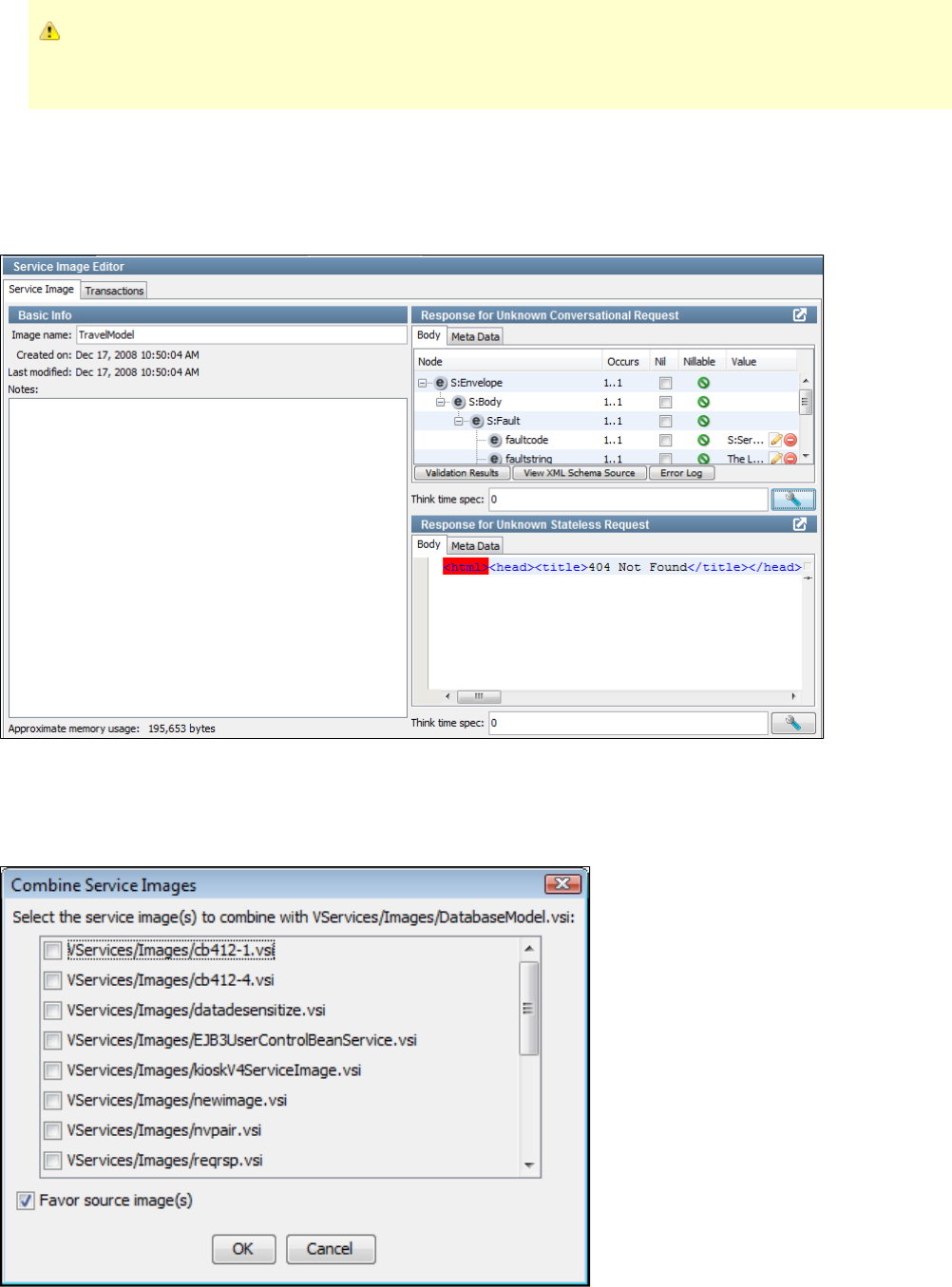
If you have existing service images from releases of LISA Virtualize earlier than LISA 6.0, you need to export those service
images to move them from the database of earlier versions to the file system where they are stored in the current release. See
.Exporting Legacy Service Images
Opening a Service Image
To open an existing Service Image, select the image in the project panel, and double-click, or right-click and select Open. You will see the Service
Image Editor, in which you can view and make changes to existing Service Images. More information about how to use the Service Image Editor
is available in .Editing Service Images
Combining Service Images
Combining service images is useful when you want to add additional functionality to an existing service image. You can combine service images
by right-clicking the service image on the project panel and choosing Combine other service images into this one. You will see a dialog.
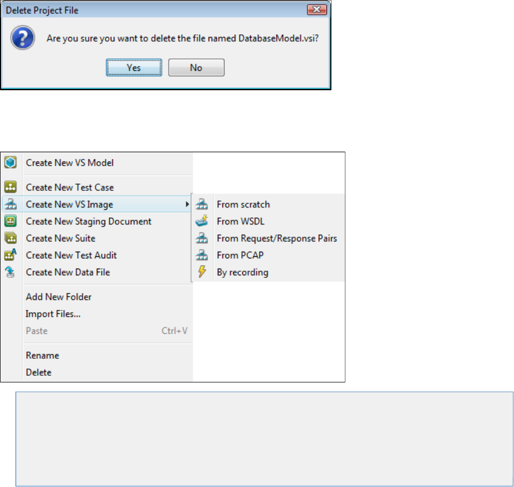
Select one or more service images to combine into the original one, the target. When service images are combined, each stateless transaction (at
the meta level) from each source service image is matched against each one in the target service image. For each one that matches the specific
transactions from the source are matched against the ones in the target. When matches are not found, the source transactions are added to the
target image. When they do match, the transactions must be merged. You have the choice here of having the source data (response bodies, for
example) replace what is in the matching target transaction or of leaving the target data as-is. This choice of how to merge matching transactions
is controlled by the Favor source image(s) check box.
The process for combining conversations is very similar. For each conversation in each source service image, its starter transaction is matched
against each starter in the target's conversations. If no starter matches, then new conversations are created in the target image. If they do match,
then the same process for the stateless list is applied to each meta node in the source conversation tree, adding new transactions and merging
matching transactions as appropriate.
Deleting a Service Image
You can delete service images by right-clicking the service image on the project panel and choosing Delete. You will see the confirmation dialog.
This option lets you permanently remove a service image from LISA Virtualize. It is best practice to think of service images as transient and to
frequently remove unused or outdated service images from LISA.
Creating a Service Image
You can create a new service image by right-clicking the node on the project panel and choosing .VServices > Images Create New VS Image
See the following sections for each menu option.
Creating a Service Image from Scratch
Creating a Service Image from a WSDLCreating a Service Image from Request-Response Pairs
Creating a Service Image from Request-Response Pairs
Creating a Service Image from PCAP
Creating a Service Image by Recording
Importing Raw Traffic
Raw traffic can only be imported through the VSE Service Image recorder. Create a new service image and select Virtual Service Image
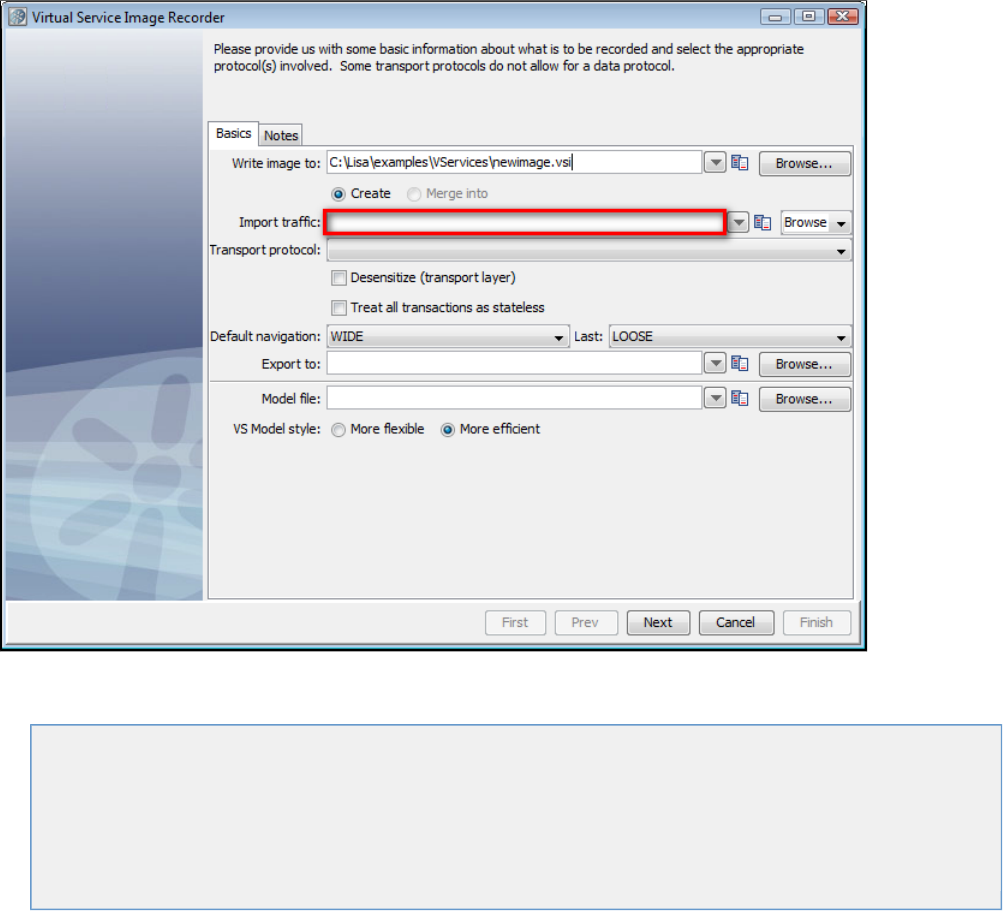
1.
2.
Recorder. Then enter the raw traffic file name or select it using the file browser.
Continue the recording process as normal, by selecting a transport protocol. When you begin the recording process, LISA will import the raw
traffic into a new service image.
The following topics are available.
Working with Virtual Service Models
Creating a Service Image from Scratch
Creating a Service Image from a WSDL
Creating a Service Image from Request-Response PairsCreating a Service Image by Recording
Creating a Service Image by Recording
Using Data Protocols
Working with Virtual Service Models
A Virtual Service Model (VSM) is a specialized type of test case that becomes the end point of a service that has been virtualized. You must
create a VSM to launch the Virtual Service Image Recorder.
Creating a New VSM
You can create a new VSM inside a LISA project.
Open an existing project or create a new project.
The project opens, and the left project panel shows the project folder and its subfolders. Right-click on the subfolder node andVServices
select Create New VS Model. Technically, you can create a VS Model in another folder also, but it is a good practice to create it under
the VServices folder.
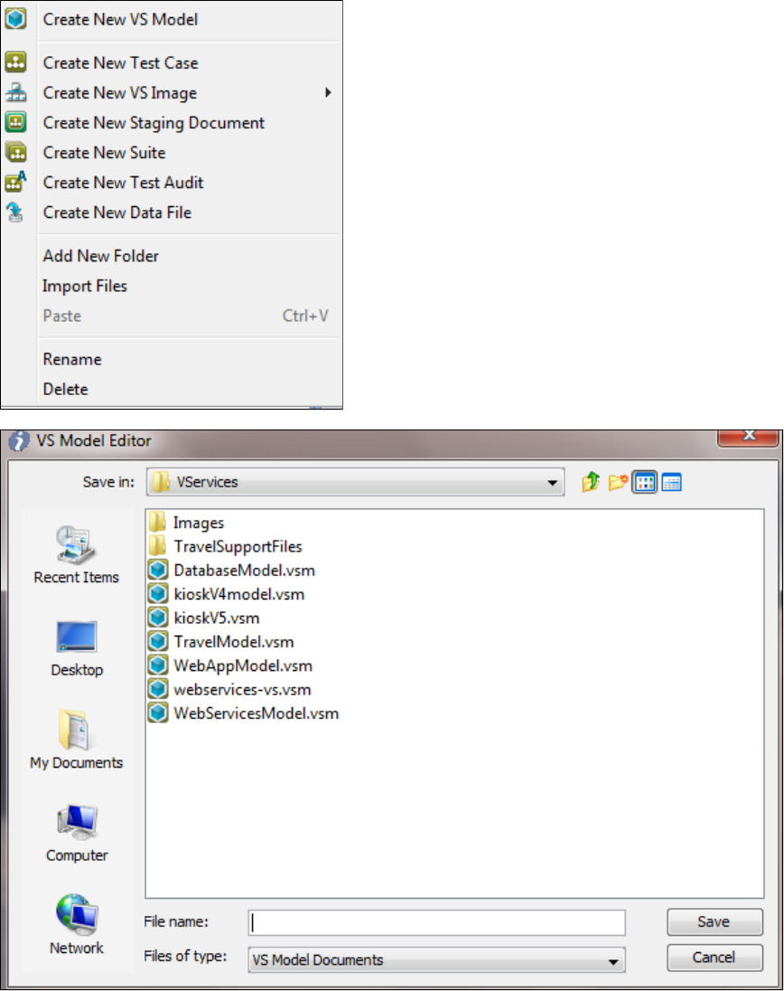
2.
3.
4.
5.
6.
7.
1.
2.
The VS Model Editor window opens.
In the VS Model Editor window, browse to the location for the new VSM.
In the File name field, enter a unique name for the VSM. The extension will be .vsm.
Click Save. The VS Model Wizard opens the new VSM.
When a VSM is open, the Commands menu shows menu items relevant to a VSM.
Opening an Existing VSM
To open an existing VSM inside a project:
From the toolbar, click the button to open the project, or select it from the 'Open Recent' project list on the Quick Start window.Open
From the project panel that opens up on the left side, select the VS model from its folder (usually VServices).
Creating a Service Image from Scratch
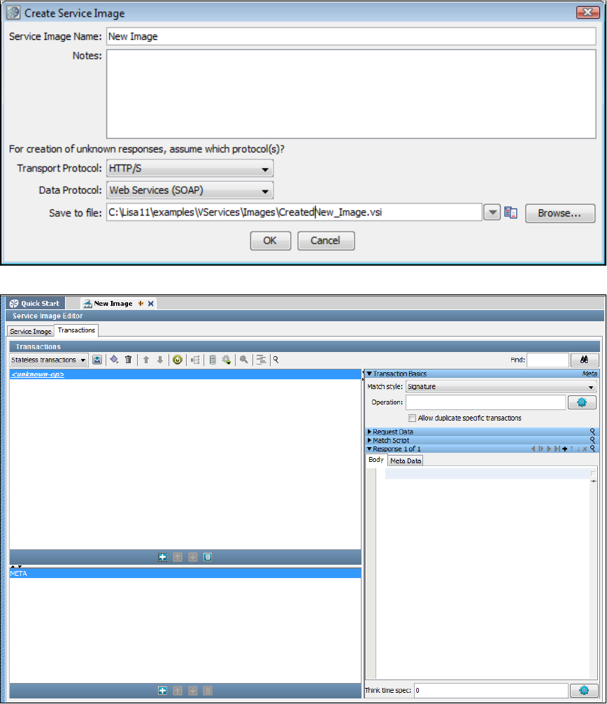
1.
It is possible to create a VS Image from scratch. To do so, right-click on on the project panel and select "Create a New VS Image,"VServices
then "From scratch."
Enter identification and protocol information, and click . You will be taken to the Service Image Editor screen, where you can enter parametersOK
and information about this service image.
Creating a Service Image from a WSDL
A web service can be generated from a WSDL in two ways. You can either use the Quick Start menu or the option.Create New VS Image
Creating a VS Image from a WSDL using the Quick Start Menu
From the Quick Start menu, select . You will see this window.Create an SI from a WSDL
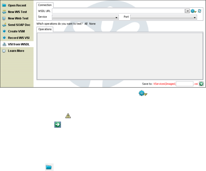
1.
2.
3.
4.
5.
1.
2.
3.
On the Connection tab, enter the name of a WSDL. You can click the Utilities icon to list options to find WSDLs on your system.
After you enter the WSDL name, the and fields are populated. Notice that the associated operations are listed on theService Port
Operations tab. You can select All, None, or use the check boxes to select specific operations to test.
At the bottom of the screen, you can change the name of the service image that will be created. If the service image name that defaults is
already in use, you will see a warning icon.
When you click the green arrow at the bottom of the screen, you will be taken to the Service Image Editor screen, with your service
image displayed.
Creating a VS Image from a WSDL using the optionCreate New VS Image
Right-click the VServices> Images icon on the project panel and select option, then .Create New VS Image From WSDL
Enter a service image name and the name of a VS model file. Defaults are fine for the rest of the fields on this screen.
Clicking the Load from file icon lets you navigate the file system to load parameters from a previously-saved service image into this
recording session.
Click Next.
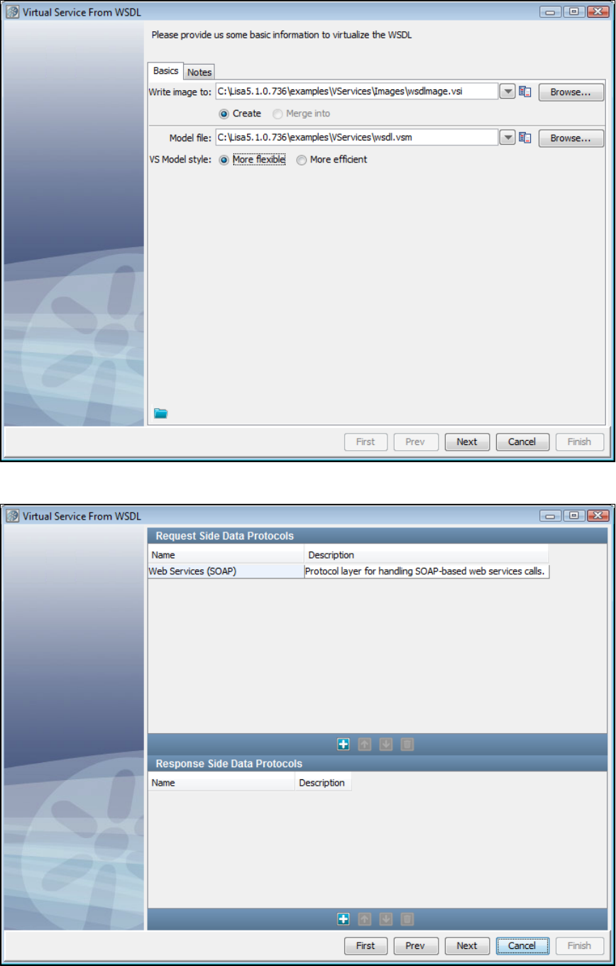
3.
4.
5.
Select Web Services (SOAP) on the next screen. The Request Side Data Protocols list is pre-populated with Web Services (SOAP) data
protocol handler. If you do not select one of the SOAP-style data protocol handlers (Web Service (SOAP), Web Services (SOAP
Headers), or Web Service Bridge), you will be prompted to select one before continuing.
Enter a port number in text box on which the VSE service should listen.Listen on port
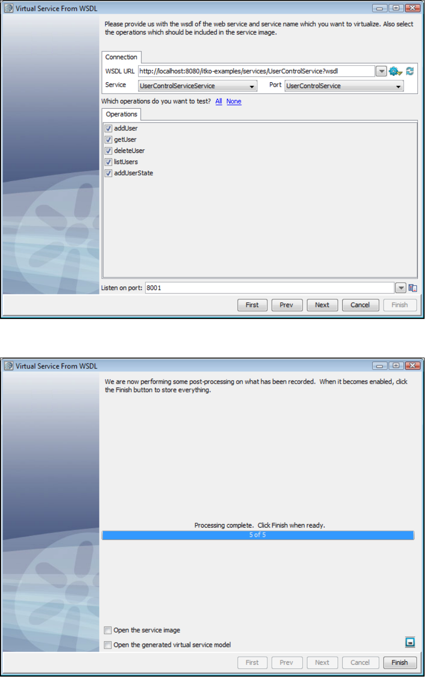
5.
6.
7.
8.
9.
10.
Add the WSDL to be virtualized in the text box. This can be a local file or a URL.WSDL URL
Select the particular service in that WSDL that needs to be selected, in the text box. There is usually only one choice.Service
Select the in that service that should be virtualized. By default, all the operations will be virtualized.operations
Click Next. On the next screen, the service image is generated and the wizard is finished. Click Finish.
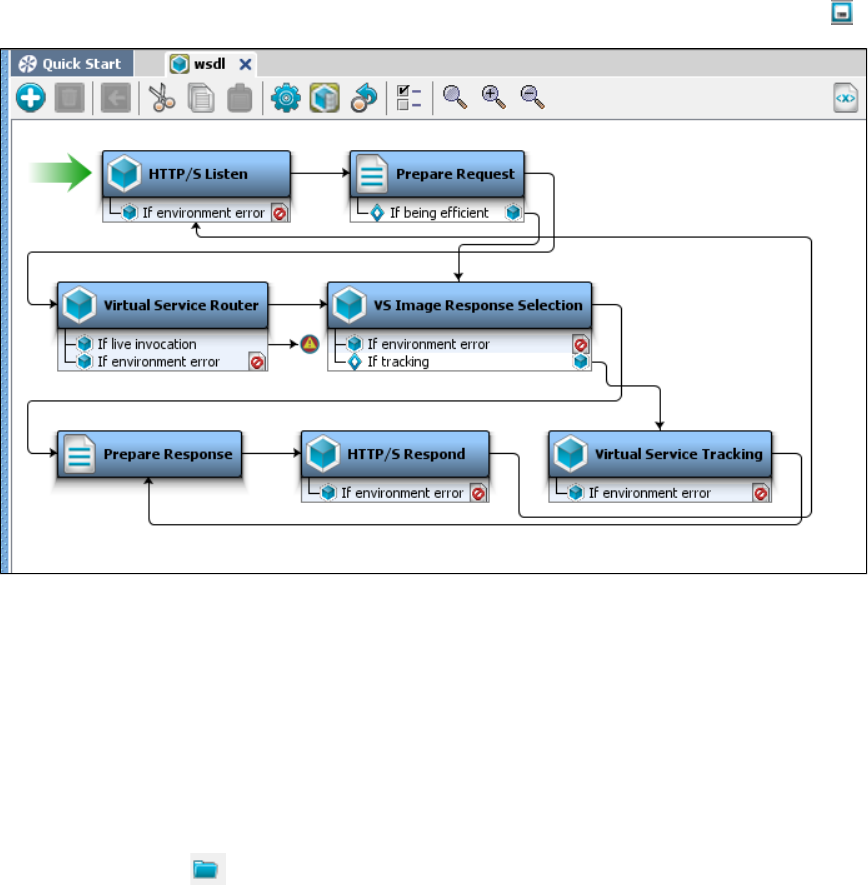
10.
11.
1.
2.
3.
4.
If you want to save the settings on this recording to load into another service image recording, you can click the Save icon.
The blank VSM will now be populated with steps. Save it.
The service image that was generated will be a service. It will return correctly formatted responses, but the values will be defaultstub
values.
The Service Model (VSM) that was saved will be what gets deployed to VSE.
Creating a Service Image from Request-Response Pairs
Creating a Service Image from Request-Response Pairs using the UI
To create a service image from Request/Response pairs
Right-click the icon and select Create New VS Image, then From Request/Response Pairs.VServices> Images
Enter a service image name and the name of a VS model file. Defaults are fine for the rest of the fields on this screen.
Clicking the Load from file icon lets you navigate the file system to load parameters from a previously-saved service image into this
recording session.
Click Next.
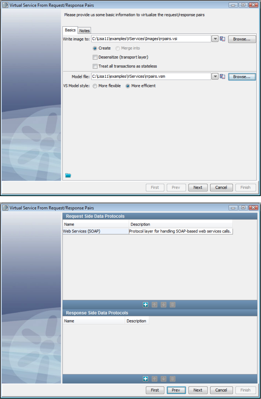
4.
5.
6.
Next, select a data protocol. For this example, we will use Web Services (SOAP).
Browse the file system for the directory that contains your request/response pairs. The request/response pairs should be named with a
unique identifier, then a "-req" on the request side and a "-rsp" on the response side, with a or extension. An example of a.xml .txt
request/response pair of files would be and . LISA Virtualize generates a transactionaddUserObject-req.xml addUserObject-rsp.xml
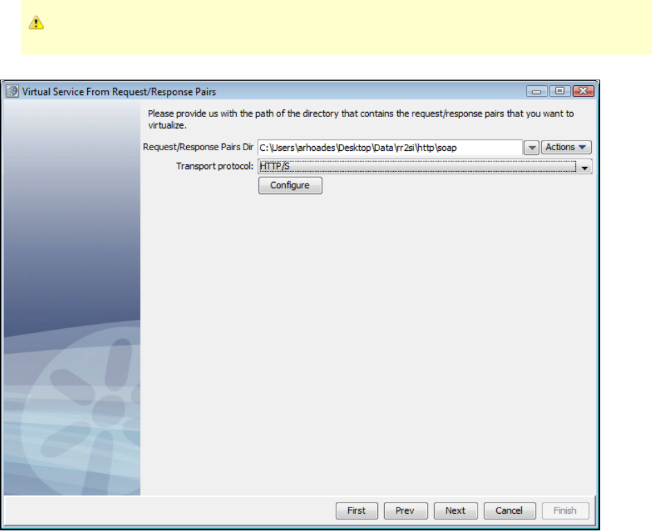
6.
7.
for each request/response pair in the directory you specify.
For HTTP/S, the files must contain the entire SOAP envelope and the headers.
Chose a transport protocol, and click the Configure button.
You will see the appropriate configuration window the for transport protocol you selected on the previous screen. Enter the configuration
information for the request here, then click Finish.
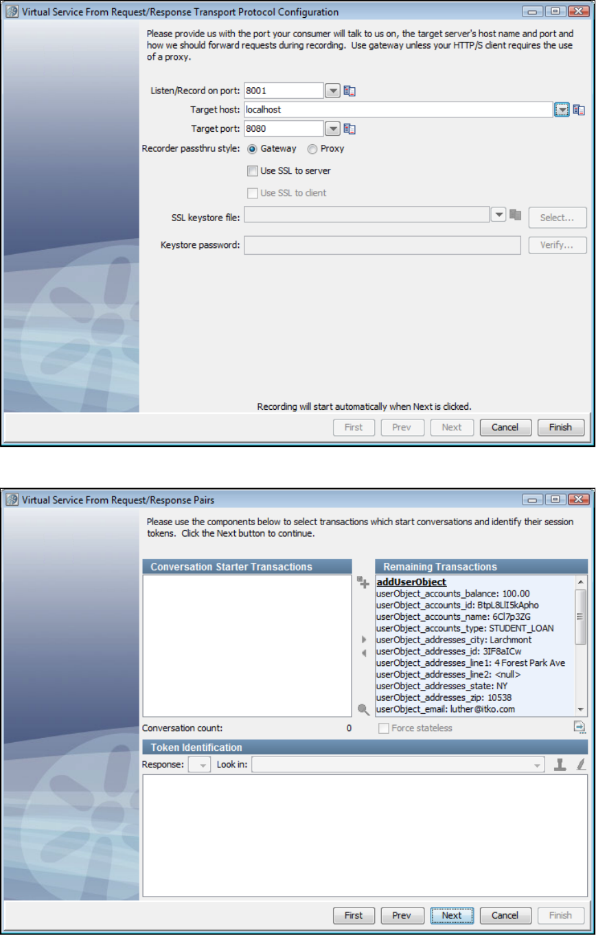
7.
8.
9.
You will return to the window, where you can click again, and the values youVirtual Service from Request/Response Pairs Configure
entered will be persisted. If, however, you select a different protocol, we will present that protocol and you can provide configuration
information for it. Click Next.
Next, you see the virtual service request/response pairs for token identification and conversations. We only support stateless transactions
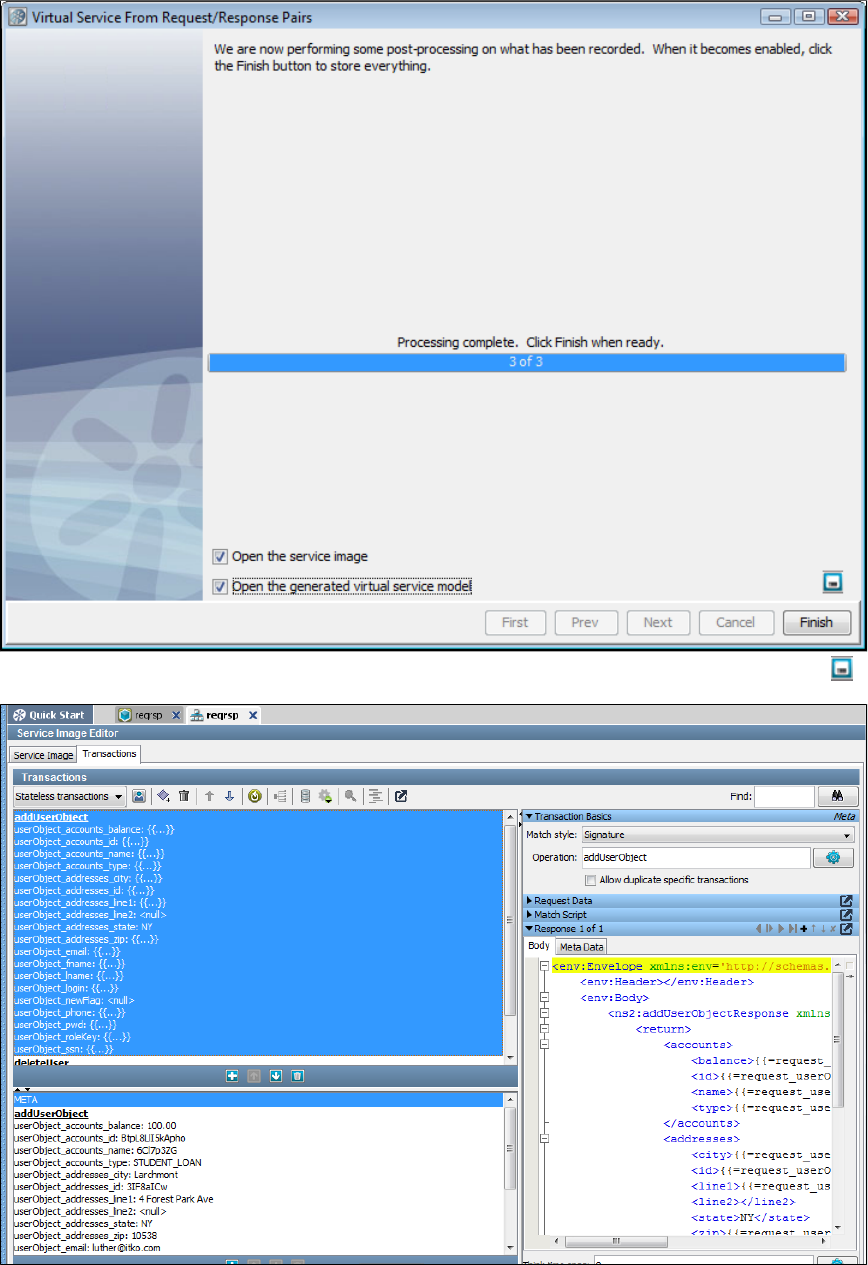
9.
10.
11.
from request/response pairs. Click Next.
If you want to save the settings on this recording to load into another service image recording, you can click the Save icon.
After the processing of the VS image is complete, you can open the service image and the virtual service model.
Creating a Service Image from Request-Response Pairs using the Command Line
As of LISA 6.0.5, you can create a service image from request-response pairs using the ServiceImageManager command line.
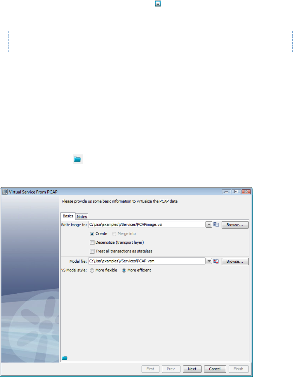
1.
2.
1.
2.
3.
4.
1.
2.
3.
4.
5.
To create a service image from Request/Response pairs using the ServiceImageManager
Create a service image in the UI. After it is created, click the Save icon to save the settings on the recording. The settings will be
saved in a file with a extension..vrs
Navigate to the LISA_HOME\bin directory and enter the following command, where is the path of the .vrs file yourecording-session-file
created previously, and and are the service image and virtual service model files that will be created. vsi-file vsm_file
ServiceImageManager -vrs recording-session-file si-file=vsi-file --vsm_file=vsm-file --record
Creating a Service Image from PCAP
If you are using packet capture software such as Wireshark to create logs of traffic, LISA Virtualize can use those logs to create a virtual service
image.
Prerequisites:
Download the appropriate binary package for your operating system from .http://jnetpcap.com/download
Add the in the binary package to the directory and the jnetpcap native library to . Thejnetpcap.jar LISA_HOME/lib LISA_HOME/bin
native library will be different for different operating systems. For Windows, it is .jnetpcap.dll
At this point, the PCAP functionality is configured.
Restart LISA Workstation, if running, to pick up the new configuration changes.
To create a service image from PCAP (a packet capture file)
Right-click the folder and select "Create New VS Image" option, then "From PCAP."VServices> Images
Enter a service image name and the name of a VS model file. Defaults are fine for the rest of the fields on this screen.
Clicking the Load from file icon will allow you to navigate the file system to load parameters from a previously-saved service image
into this recording session.
Click the Notes tab to add documentation about this virtual service.
Click Next.
5. Click Next on the data protocol window.
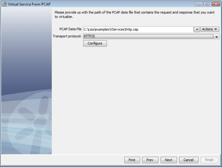
.
6. Enter the name of, or browse the file system to select, the name of the packet capture file to use for input.
7. Select as the Transport Protocol, and click Configure. The Virtual Service from PCAP Transport Protocol Configuration windowHTTP/S
appears next.
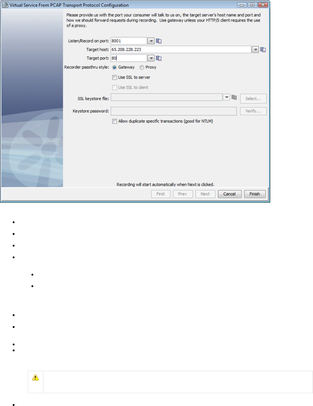
The options are:
Listen/Record on port: Provide the port on which your consumer communicates to LISA. It is typical to choose 8001, but you can
choose another port number.
Target host: Enter the name or IP address of the target host where the server is running. Leave blank if you are going to choose a Proxy
pass through style.
Target port: Enter the target port number listened to by the server. The defaults are 80 (HTTP) and 443 (HTTPS). Leave blank if you are
going to choose a Proxy pass through style.
Recorder passthru style: Indicate how VS Image Recorder will act during recording. The choices are Gateway and Proxy. If you select
Proxy, the contents in Target host and Target port fields are cleared and the fields become disabled. This choice impacts how the client
connects in the recording mode.
If VS Image Recorder would listen in a gateway mode, the client will need to send http requests directly to the recorder and not
to the server. (If the client is a browser, the URL will contain the host and port of the the recorder instead of that of the server.)
If VS Image Recorder would listen in a proxy mode, then the client will need to specify the recorder host and port as the proxy. (If
the client is a browser, then the URL will contain the host and port of the server, but the proxy settings need to be set to route the
request through the recorder.)
Most HTTP clients have a setting for NOT using proxy for localhost. If your VS Image Recorder is running on localhost in proxy
mode, then you will need to disable this setting for the traffic to get correctly passed through the recorder.
Use SSL to server: If checked, sends HTTPS (secured layer) request to the server. If you check but not Use SSL to server Use SSL to
, LISA will present a plain HTTP connection for recording, but will send those requests to the server using HTTPS.client
Use SSL to client: This option is only enabled if has been selected. Check whether we can playback an HTTPSUse SSL to Server
request from client using a custom client keystore. When you specify "Use SSL to client", you are allowed to specify a custom keystore
and a passphrase. If these are entered, LISA will use them rather than the hard-coded defaults.
SSL keystore file: Name of the keystore file.
Keystore password: Password for the keystore file.
For more information on configuring LISA Virtualize in a two-way SSL environment, see Virtualizing Two-way SSL
.Connections
Allow duplicate specific transactions (good for NTLM): Check to allow duplicate specific transactions to be recorded.
8. Click Finish to return to the previous screen.
9. Click Next to begin recording.
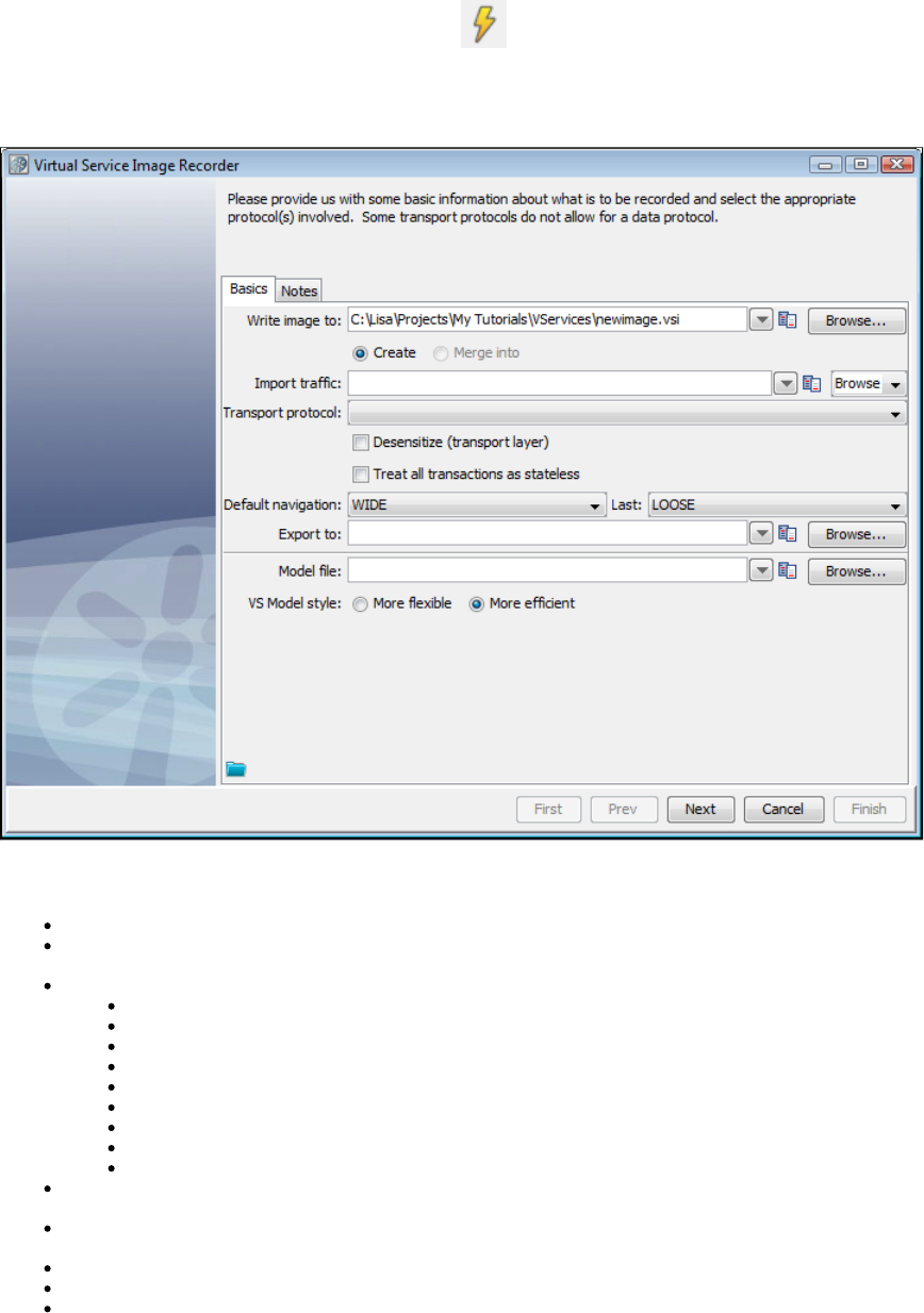
Creating a Service Image by Recording
Service images are generated using the Virtual Service Image Recorder and pretend to be what you recorded (a manipulated or altered version of
your recorded raw traffic).
To begin recording a new VS image, click the VSE Recorder icon on the main toolbar, or right-click the node on your projectVServices
panel and select You will access the Virtual Service Image Recorder. Create a VS Image by Recording.
Virtual Service Image Recorder - Basics Tab
The first window in the VS Image Recorder wizard provides the name, protocol, and navigation options. Enter the information as needed in the
fields depending on the protocol you are using. Subsequent windows are protocol-specific. The Basics tab options are:
Write image to: A unique service image name.
Import traffic: Import a raw or conversational XML traffic file. This field could be blank if no such file exists. If a file is specified, then the
transactions in the referenced XML document are merged into those resulting from the ensuing recording.
Transport protocol: Select one of the following options:
HTTP/S: For virtualizing a web server
IBM MQ : For virtualizing a messaging server connected to IBM WebSphere MQSeries
Standard JMS: For virtualizing a messaging server connected to any middleware that supports JMS API
Java: For virtualizing calls to Java classes
JDBC : For virtualizing a database(Agent based)
JDBC (Driver based): For virtualizing a database
TCP: For virtualizing the transport layer that supports TCP traffic
CICS Link: For virtualizing IBM CICS applications
DRDA: For virtualizing databasesDistributed Relational Database Architecture
Densensitize check box: During the recording, attempt to recognize sensitive data and substitute random values instead. For more
information, see .Desensitizing Data
Treat all transactions as stateless check box: This option is provided for very special cases where you may want to treat all recorded
transactions as stateless. In most cases, you would leave this cleared.
Default navigation: Select the default for all except the last (leaf) transactions. The default is WIDE.navigation tolerance
Last: Select the default for the last (leaf) transactions. The default is LOOSE.navigation tolerance
Export to: Enter the full path of a file where you want the raw traffic logged. If one is specified, every time a transaction is offered to the
recorder (either from the transport protocol during actual recording or from the import process), it is written to this file. A recording session
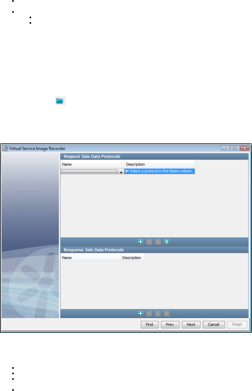
can be captured for later import and can be reused while data protocol details are being refined.
Model file: Enter the full path of your virtual service model file for this service image. The recorder will not automatically generate a VSM
unless a file name has been provided in this field. The model style will have no effect unless a VSM is being requested.
VS Model style: Set this option to indicate whether to generate a VSM including the prepare steps or not. The options are:
More flexible: Default.Includes Prepare steps (leading to a five-step model in case of HTTP/S protocol).
More efficient: Prepare steps are absent (leading to a three-step model in case of HTTP/S protocol).
The available navigation buttons are:
First: Click to return to the first step.
Prev: Click to move to the previous step.
Next: Click to move to the next step.
Cancel: Click to close the wizard without saving.
Finish: Click to complete the recording and save the service image.
Clicking the Load from file icon will let you navigate the file system to load parameters from a previously-saved service image into this
recording session.
Clicking the tab will let you create any documentation for this service image.Notes
Virtual Service Image Recorder - Data Protocols Tab
The second window in the VS Image Recorder wizard lets you enter information about data protocols for the virtual service.
The recorder can use several data protocol handlers. Choosing the appropriate data protocol helps it to analyze the information it records to
correctly distinguish the conversations from one another, and to identify transactions belonging to these conversations. These data protocol
handlers can be chained to be used with each other.
Web Services (SOAP): SOAP data protocol used in web services (written for consumption by a web service client).
Web Services (SOAP Headers): Data protocol to convert SOAP header elements into request arguments.
Web Services Bridge: Data protocol for LISA Travel example. It is very specific to the example and would not be very useful in a general
case. It can therefore be safely ignored.
WS-Security Request: Strips away any security from the SOAP Request before sending it along the Virtualize framework and applies

1.
security to outgoing SOAP responses.
Request Data Manager: Lets you manipulate VSE requests as they are recorded or played back.
Request Data Copier: Lets you copy data from the current inbound request into the current testing context.
Auto Hash Transaction Discovery: Identifies a message by the hash code of the data. The hash code changes with even a slight
change in the data, which effectively makes all requests unique. This is useful in case you will run exactly the same small set of requests
against the service.
Generic XML Payload Parser: Identifies that the requests and responses are XML strings. If this protocol is used, then you can identify
variables out of the XML messages that are used by the recorder.
Data Desensitizer: During the recording, attempts to recognize sensitive data and substitute random values instead. For more
information, see .Desensitizing Data
Copybook Data Protocol: Converts copybook text to XML.
Delimited Text Data Protocol: Converts delimited strings to XML.
Scriptable Data Protocol: Lets you provide scripts on the request side, the response side, or both, to process the request or response.
CICS Request Data Access: TODO
DRDA Data Protocol: Converts binary DRDA payloads to XML during recording to facilitate alignment with native LISA functionality,
readability, dynamic data support. Responses are converted back to their native format on playback.
JDBC does not allow a data protocol.
More details on these data protocols is available at .Using Data Protocols
Using a dynamic data protocol is covered in .Generic XML Payload Parser
Recording by Transport Protocol
More detailed instructions are available for each method of recording VS Images.
Recording HTTPS Service Images
Recording IBM WebSphere MQ Service Images
Recording Standard JMS Service Images
Recording Java Service Images
Recording JDBC (Driver based) Service Images
Recording TCP Service Images
Recording WS Service Images
Recording HTTPS Service Images
If you are using HTTP/S as the transport protocol in the Basics tab of the Virtual Service Image Recorder, complete the wizard steps in
the following example.
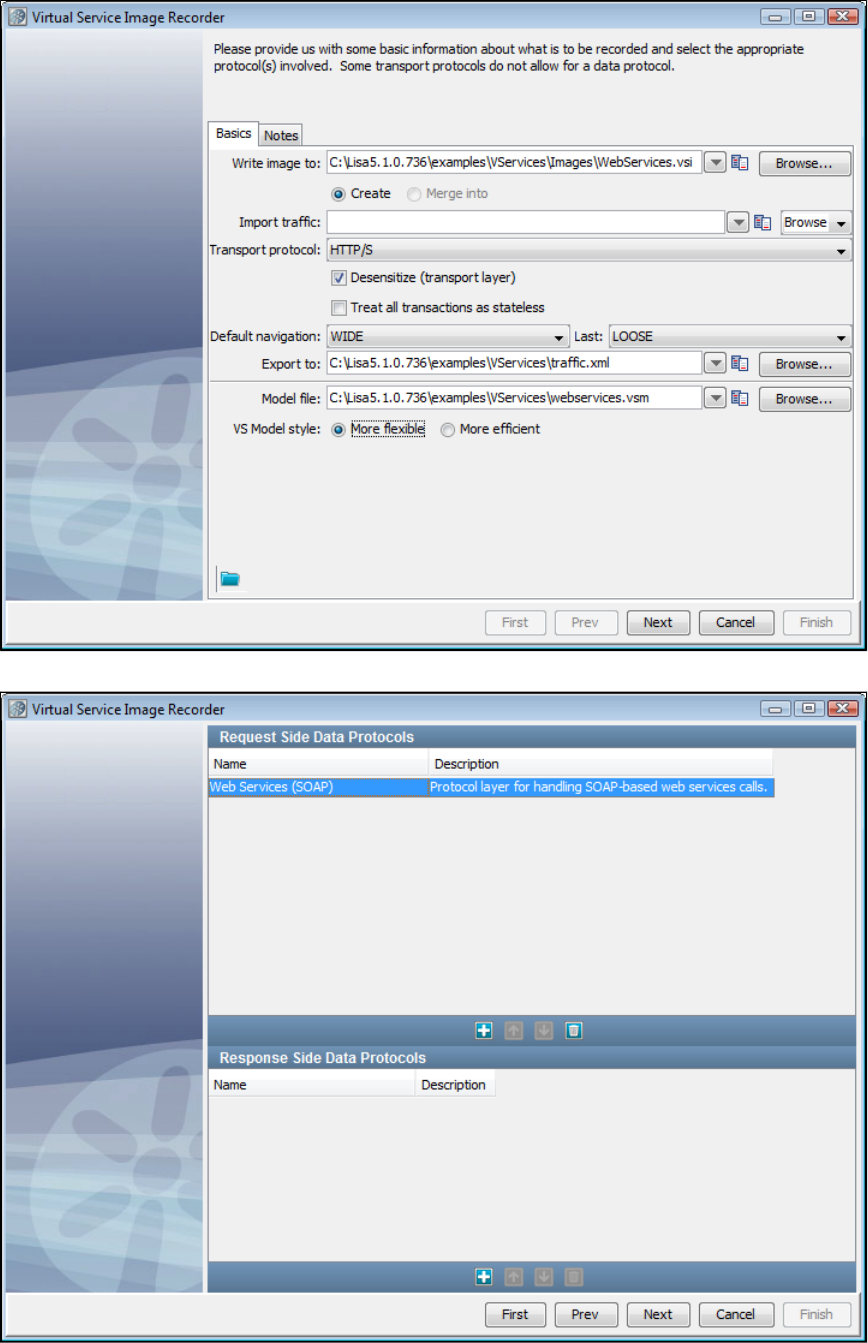
1.
2.
3.
4.
5.
Click Next on the recorder's first screen.
Do not select any value for the data protocol on the recorder's second screen and click Next.
Click Next on the recorder's second screen.
Enter the port and host information for this step.
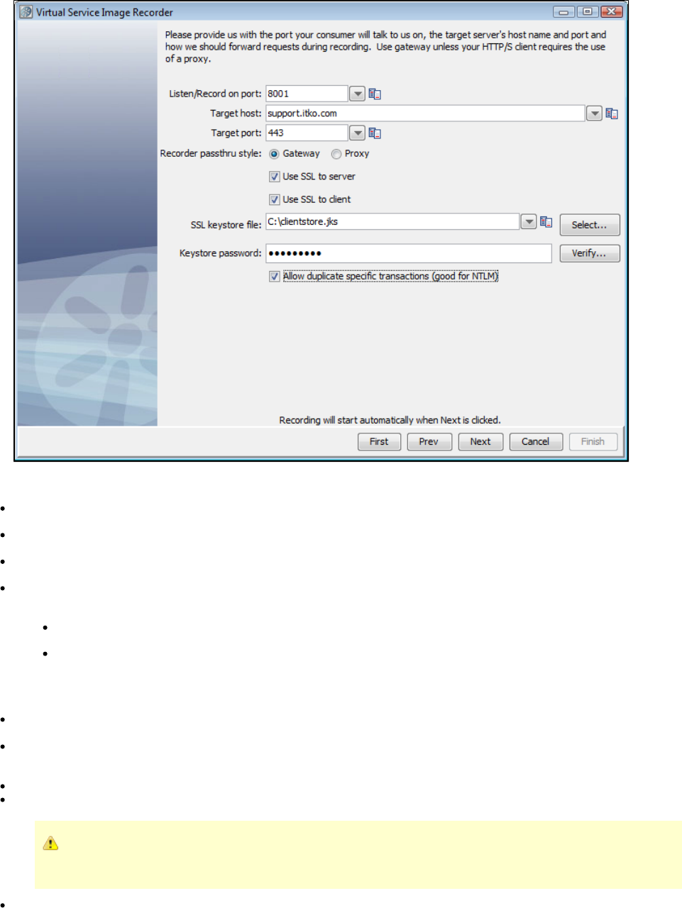
5.
The options are:
Listen/Record on port: Provide the port on which your consumer communicates to LISA. It is typical to select 8001, but you can use
another port number.
Target host: Enter the name or IP address of the target host where the server is running. Leave blank if you are going to select a Proxy
pass through style.
Target port: Enter the target port number listened to by the server. The defaults are 80 (HTTP) and 443 (HTTPS). Leave blank if you are
going to select a Proxy pass through style.
Recorder pass-through style: Indicate how VS Image Recorder will act during recording. The choices are Gateway and Proxy. If you
select Proxy, the contents in Target host and Target port fields are cleared and the fields become disabled. This choice impacts how the
client connects in the recording mode.
If VS Image Recorder would listen in a gateway mode, the client will need to send http requests directly to the recorder and not
to the server. (If the client is a browser, the URL will contain the host and port of the the recorder instead of that of the server.)
If VS Image Recorder would listen in a proxy mode, then the client will need to specify the recorder host and port as the proxy. (If
the client is a browser, then the URL will contain the host and port of the server, but the proxy settings need to be set to route the
request through the recorder.)
Most HTTP clients have a setting for NOT using proxy for localhost. If your VS Image Recorder is running on localhost in proxy
mode, then you will need to disable this setting for the traffic to get correctly passed through the recorder.
Use SSL to server: If selected, sends HTTPS (secured layer) request to the server. If you select but not Use SSL to server Use SSL to
, a plain HTTP connection is presented for recording, but those requests will be sent to the server using HTTPS.client
Use SSL to client: This option is only enabled if has been selected. Check whether we can playback an HTTPSUse SSL to Server
request from client using a custom client keystore. When you specify "Use SSL to client", you are allowed to specify a custom keystore
and a passphrase. If these are entered, they will be used rather than the hard-coded defaults.
SSL keystore file: Name of the keystore file.
Keystore password: Password for the keystore file.
For more information on configuring LISA Virtualize in a two-way SSL environment, see Virtualizing Two-way SSL
.Connections
Allow duplicate specific transactions (good for NTLM): Select to allow duplicate specific transactions to be recorded.
6. The VS Image Recorder starts recording the traffic when you click Next. The screen displays the assigned port and service target.
7. Start recording the traffic now. Use your HTTP client to send the requests to the server routed through the VS Image Recorder.
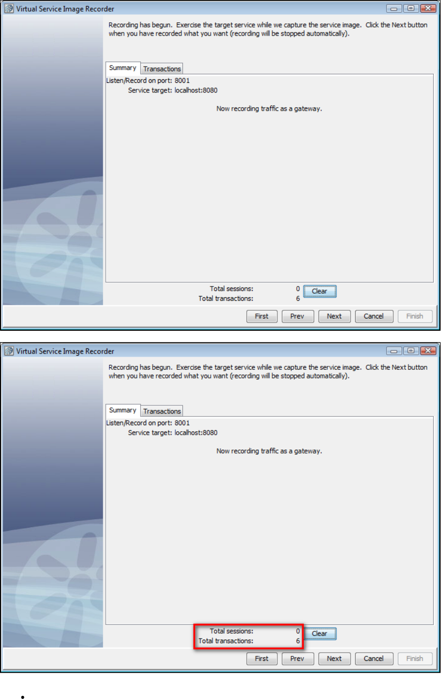
As the VS Image Recorder records transactions, they are reflected in the dynamic display statistics on the lower portion of the screen.8.
The options and dynamic display statistics are:
Total conversations: Indicates the number of conversations recorded.
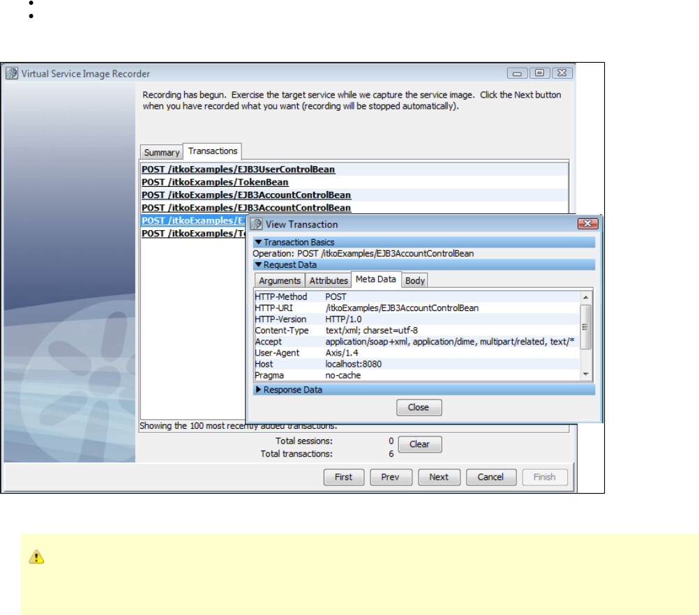
Total transactions: Indicates the number of transactions recorded.
Clear: Click this button to clear out currently recorded transactions.
9. The Transactions tab will display a list of the most recent transactions recorded. On this list of transactions, you can double-click a transaction
and see a dialog showing the content of the transaction.
10. When you have completed the recording, click to move to the next step. If you click Next and no transactions have been recorded, an error
message appears. Click OK to continue recording.
If transactions are not recorded, you may have a port conflict. The client sends transactions to the application instead of the
Virtual Service Recorder. If another service is using that port, either stop that service or change the port setting so there is no
longer a conflict.
11. After you record traffic, click Next.
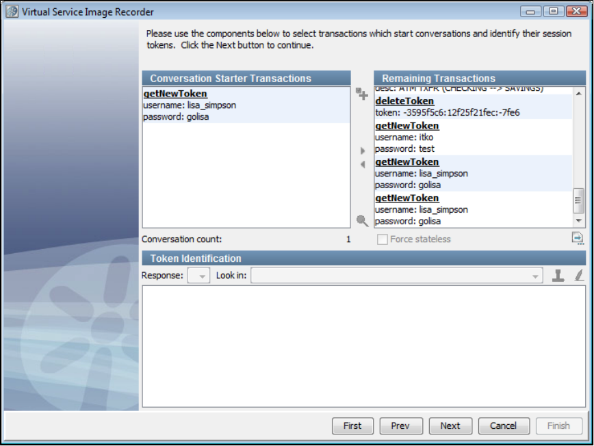
12. If no conversations were detected during the recording process, select transactions that start conversations. For token-based conversations,
you must specify where tokens can be found. Use the area in the VS Image Recorder wizards. Select transactions that startToken Identification
conversations and identify the session tokens. Select the Conversation Starter Transaction listed and click the blue arrow to makegetNewToken
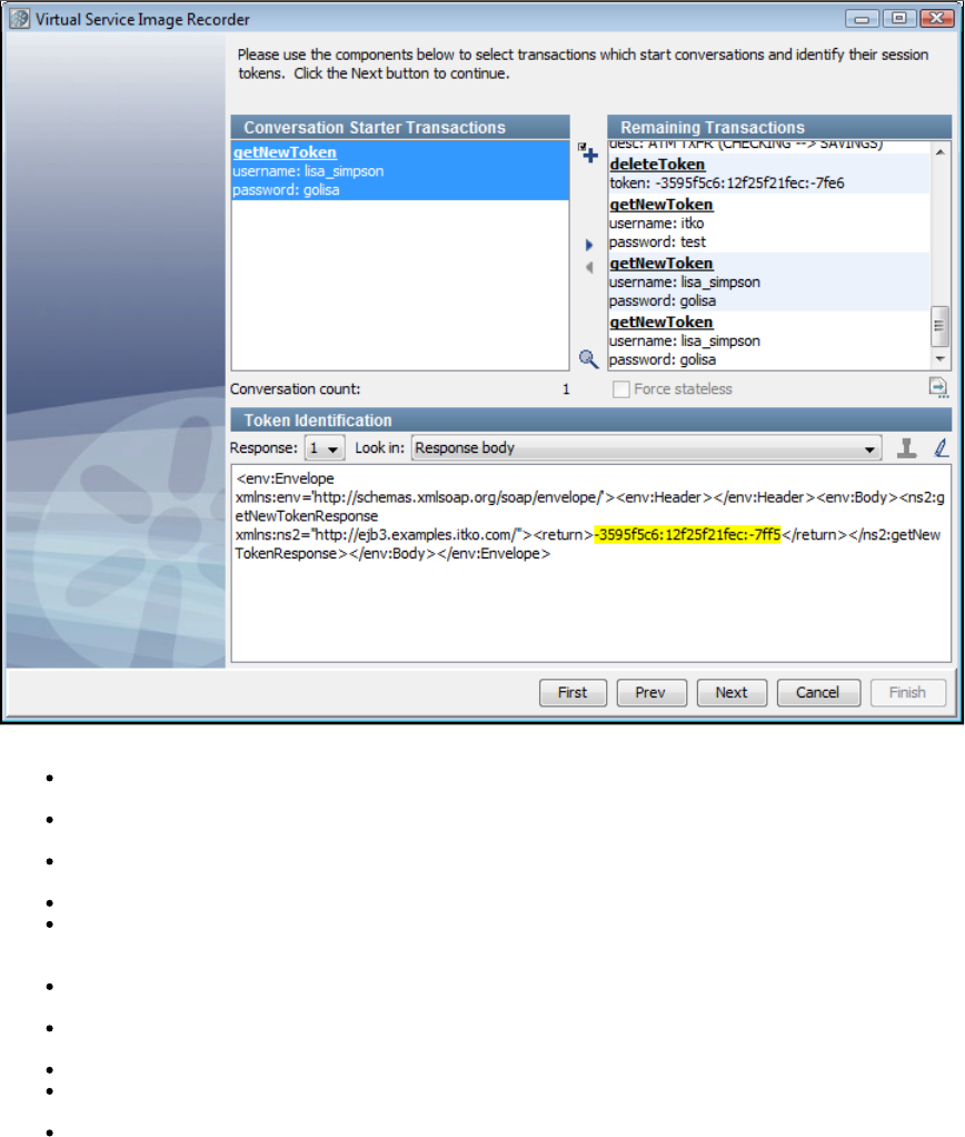
it a conversation starter.
The step components are:
Conversation Starter Transactions: Lists the transactions you have selected as conversation starters. Select a transaction and click the
arrow to move the transaction to the Remaining Transactions list if you do not want it to be a conversation starter.
Remaining Transactions: Lists the recorded transactions. Select a transaction and click the arrow to move the transaction to the
Conversation Starter Transactions list.
Plus icon: Selects all transactions (either Conversation Starters or Remaining) in the list that are like a selected transaction. Use the
appropriate arrow button to move all the selected transactions.
Conversation count: Displays the number of conversations in the recording. As you build conversations, the number is increased.
Force stateless: From the Remaining Transactions list, select any transactions that should stay stateless and select the check box. For
example, you may decide that a transaction that includes an image should stay stateless even though it contains a conversation starter
token.
Stateless Transactions: Click to see a list of all transactions that will remain stateless, assuming the identified conversations on this
panel. You can use the list to verify that you have identified all the conversation starter transactions.
Save: Click to save the raw recorded transactions. Click Browse to navigate to the location in which to save the file. You can import the
raw traffic recording in the Basics tab before beginning a new recording.
Response: For the currently selected transaction, this identifies which of its responses to look in. In general, 1 is the only option.
Look in: Identifies the piece of the response you want to see when looking for conversation tokens. The drop-down list contains an entry
for each of the response's meta data entries plus one for the response's body.
Token Identification area: Based on the selected transaction and response, the content of the selected Look in section of the response
is displayed here.
To mark a piece of the text as a conversation token, select the text and click the red rubber stamp icon. The text is then highlighted in
yellow.
To mark the text as no longer a conversation token, either mark a different piece of the text or click the Erase icon.
After you mark a token, you can use the search icon to find similar transactions and mark their tokens. Click the search icon to open a
dialog where you can select text (such as XML tags) that bound the conversation token, thus specifying the leading and trailing text to
search for.
13. Click Next.
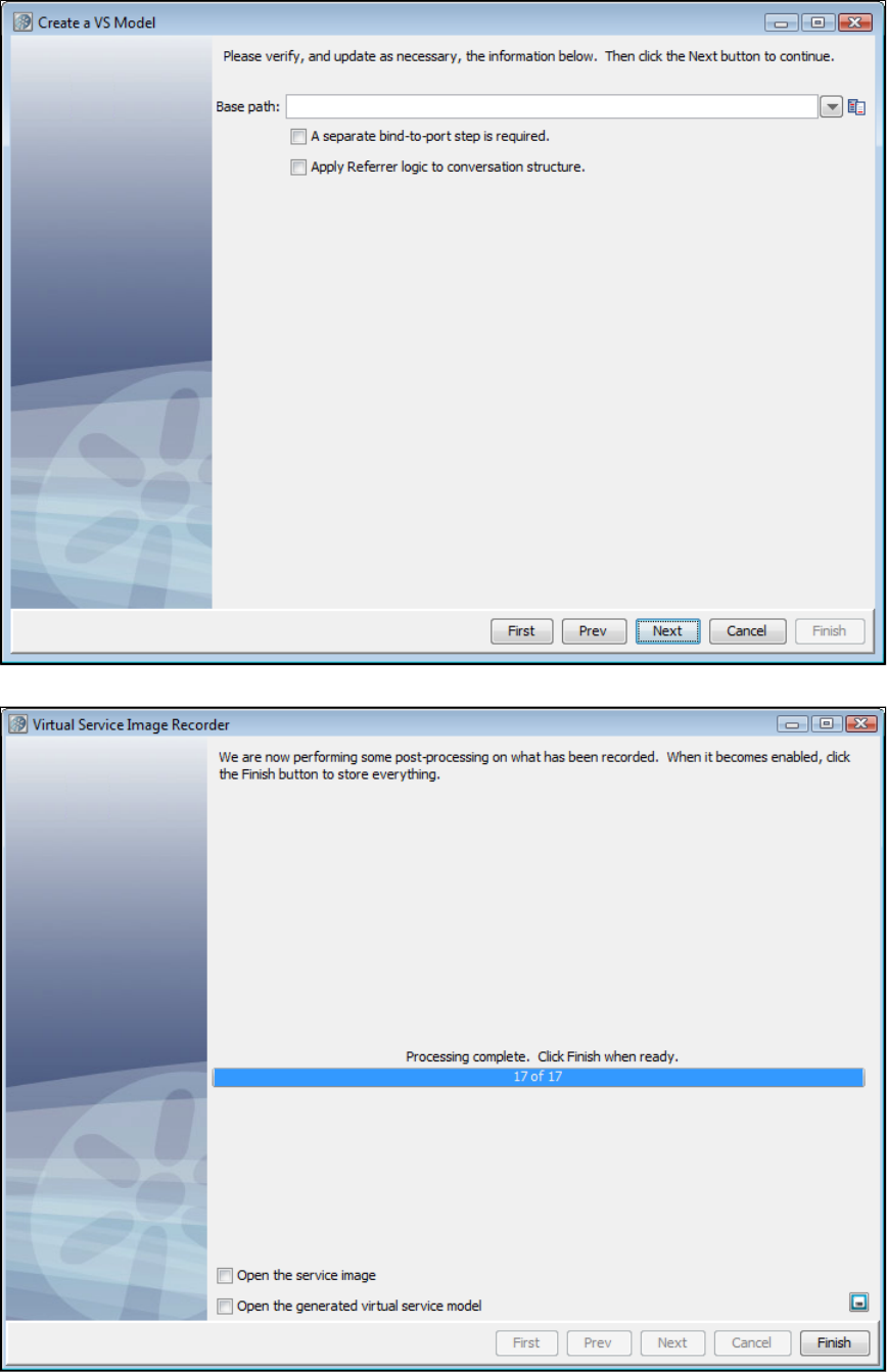
14. After you have identified the conversation starter tokens, verify the base path. Update the base path as needed. If needed, check the box to
require a bind-to-port step before processing requests. Click Next.
15. During post-processing, the VS Image Recorder displays the processing status. As part of the recorder's preparation for writing out the .vsi
file, it verifies request and response bodies to make sure that, if they are marked as text, that they are text. If they are not, the type is switched to
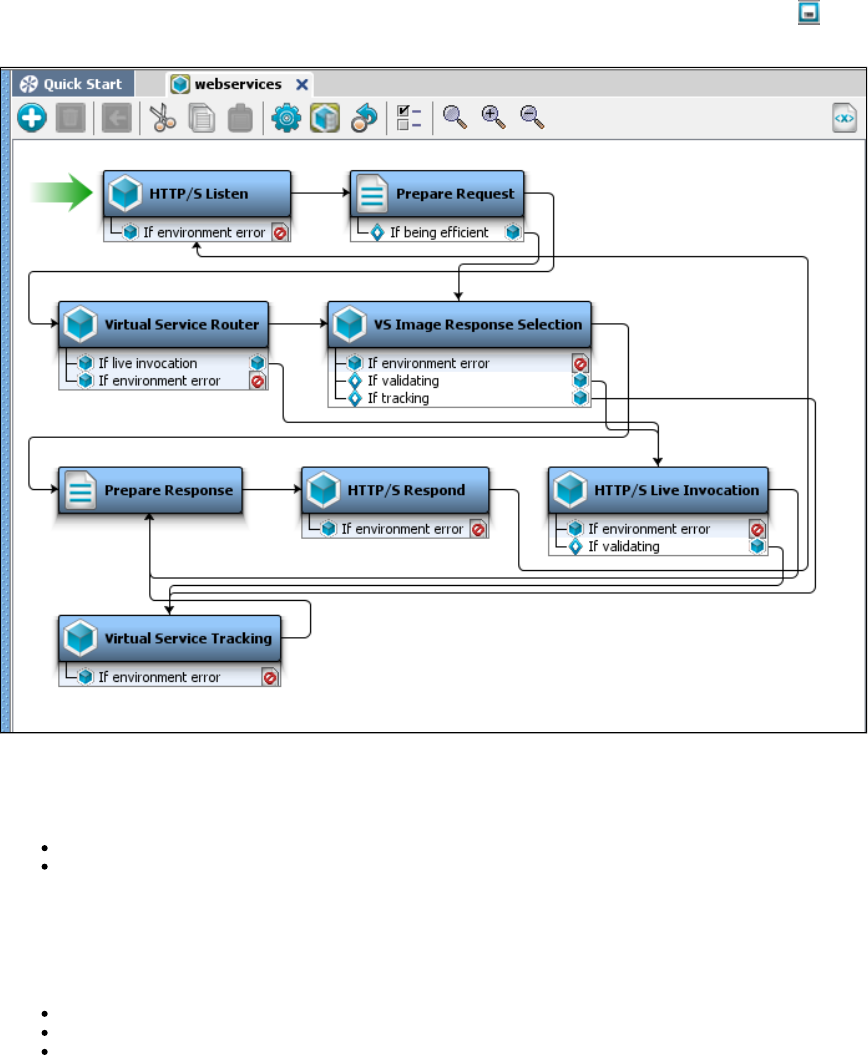
binary.
16. If you want to save the settings on this recording to load into another service image recording, click the Save icon.
17. The recorder completes post-processing the recording. Click Finish to store the image.
18. In LISA Workstation, review and save the .vsm.
Virtualizing Two-way SSL Connections
To be able to virtualize a two-way SSL connection, LISA must have:
both client keystore and server keystore, or
client keystore and LISA keystore (see webreckeys.ks in the LISA home directory). Extract the LISA certificate from the LISA keystore
and add it to the client trust-store. The LISA certificate is a self-signed certificate and not a certificate issued by a CA authority. This
workaround will only work in the cases where client will accept self-signed certificates.
In either case you will end up with two keystores: one client keystore and one server keystore (or LISA keystore).
Configure your SSL properties in the file, which is in the LISA home directory, to use the client keystore as follows:local.properties
ssl.client.cert.path=path to your keystore; for example, c:/mykeystore.jks
ssl.client.cert.pass=your keystore password
ssl.client.key.pass=your certificate password
Start the VSE recorder and tell it to use two-way SSL. If you are using a client and a server keystore, your recorder should look similar to this
screen:
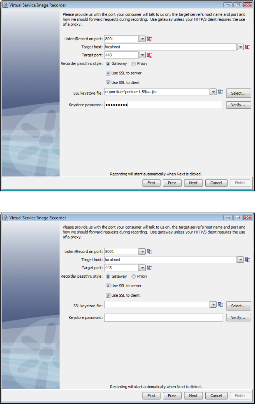
If you are using a LISA keystore instead of the actual server keystore, you will not need to provide the path to it. That keystore will be used by
default and your recorder should be configured similar to this screen:
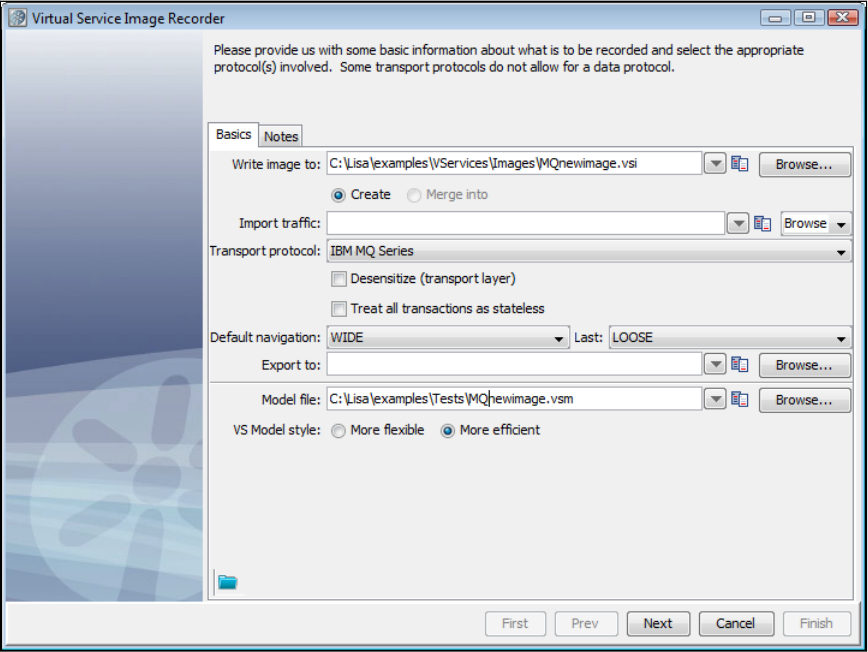
1.
2.
3.
4.
Recording IBM WebSphere MQ Service Images
Information in configuring IBM WebSphere MQ is available in .Installing a Messaging Simulator
If you are using IBM WebSphere MQ as the Transport protocol in the Basics tab in the Virtual Service Image Recorder, complete the
remaining wizard steps as shown in the following example.
Click Next on the recorder's first screen.
Add a Request Data Manager Protocol on the recorder's second screen and click Next. For more information on configuring this protocol,
see .Request Data Manager
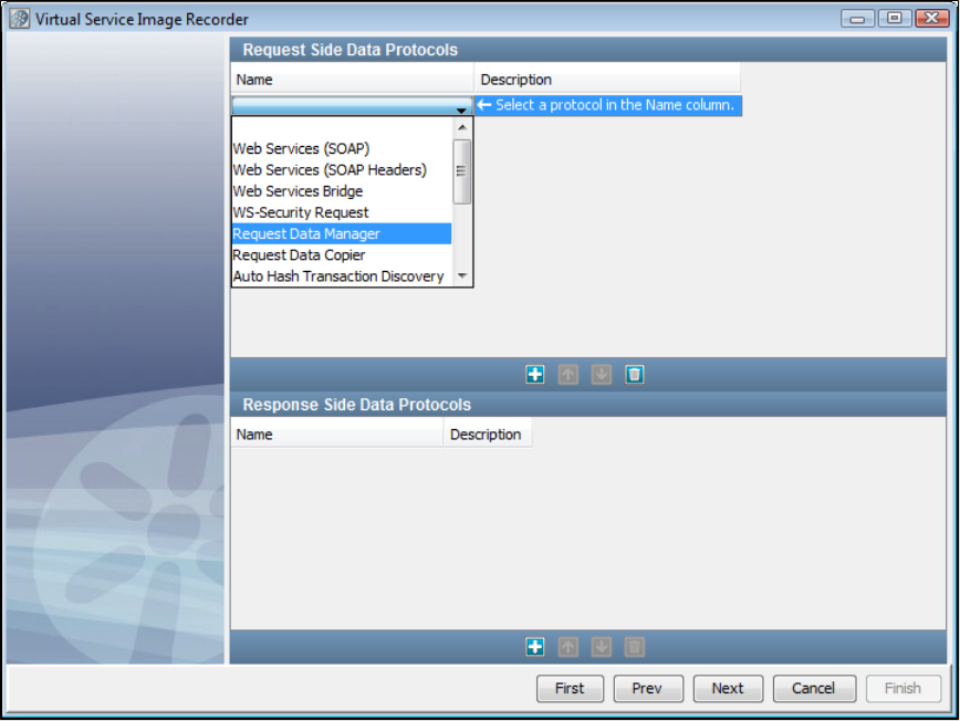
4.
5. This is the recording mode selection step. For now, the only true mode supported is Proxy Mode. With Proxy Mode comes therecording
option to generate the service from the Live queues (the previous default behavior) or generate the service using the Proxy queues.
Proxy Mode
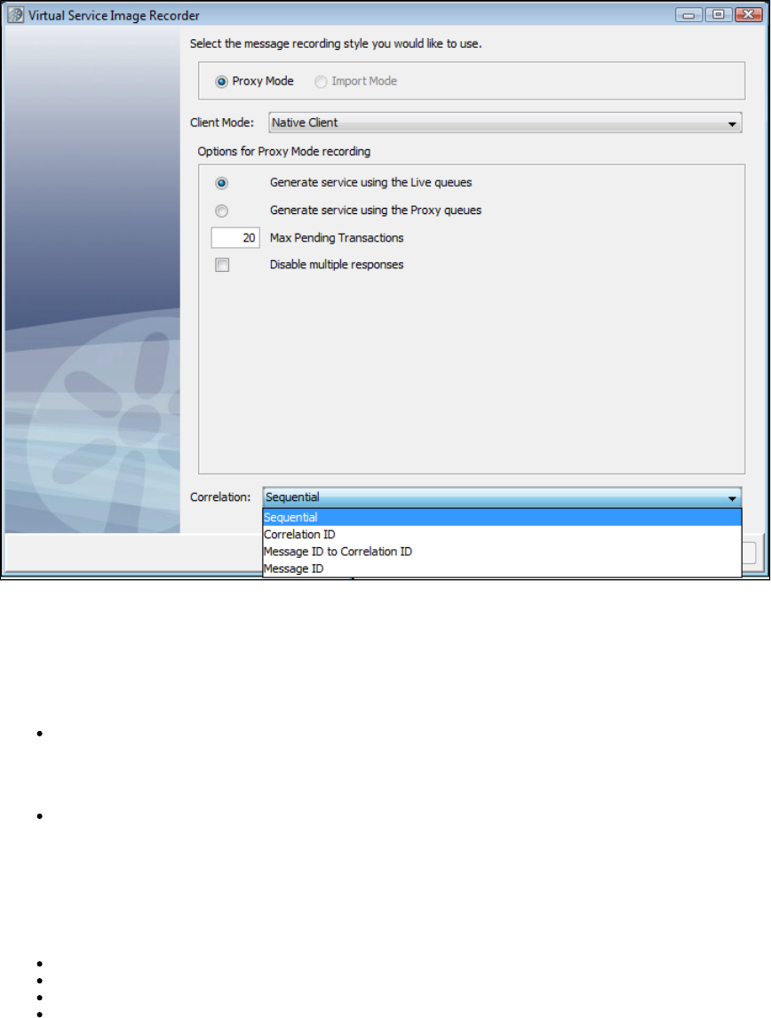
Proxy Mode allows the use of proxy destinations to be set up on the message bus. The client application is configured to put messages on those
proxy destinations and LISA will forward to the real destination after recording them. The same thing happens on the response side, where LISA
is configured to listen on the real response destination and get the message and forward it to the response proxy destination. This mode can
behave differently if temporary destinations are enabled, making the response side basically automated.
When Proxy Mode is selected, the configuration panel has a option button selection for whether to use the Live queues or Proxy queues when
generating the final VSM/SI.
Max Pending Transactions: This is the maximum number of running response listeners on each response queue. These response
listeners will run until as long as a transaction is pending. When the number of pending transactions exceeds this maximum amount the
oldest transaction will be closed automatically. Previously this was available as a system property:
. If you enter 0 in this field, there will be no maximum number.lisa.vse.messaging.maxTransactionBufferSize
Disable Multiple Responses: This determines whether to support multiple responses in each transaction. By default a transaction will
stay pending after the first response, waiting for more responses to come in for the same transaction. When this option is selected the
transaction will be automatically closed after the first response. If there are many transactions coming in very quickly, this can be a
performance boost, especially for MQ.
The field contains the possible correlation schemes for putting together the request and response sides of individual transactions.Correlation
JMS is asynchronous, which means we are receiving the requests and responses separately. This drop-down provides a way for you to tell the
VSE Recorder which request to associate with which response. For the Correlation field, there are four options:
Sequential: Every response is associated with the last request that was received, chronologically.
Correlation ID: The request and the response must have the same Correlation ID.
Message ID to Correlation ID: The request's Message ID must equal the response's Correlation ID.
Message ID: The request and the response have the same Message ID.
Import Mode
If you specify a raw traffic file on the initial recording screen in the Import traffic field, the option is dimmed and the Proxy Mode Import Mode
screen selected.
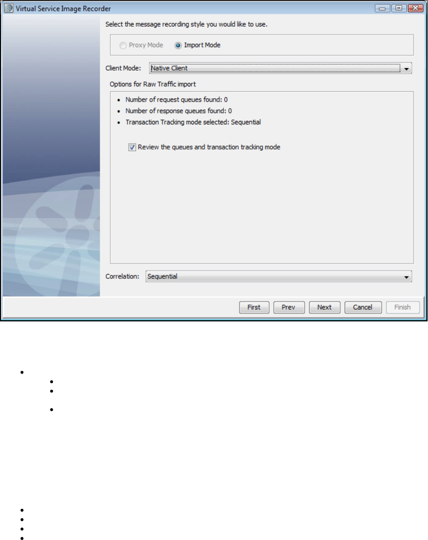
With Import Mode, the extra configuration has some information about what request and response queues were detected in the raw traffic file and
a check box that lets you skip the request and response steps altogether.
For Import mode, a drop-down appears, where you can select:Client Mode
Client Mode: Select from JMS, Native Client or Bindings. Lets you select how you want to interact with the WebSphere MQ server.
Native Client: A pure Java implementation using IBM-specific APIs
JMS: A pure Java implementation based on the JMS specification. We recommend you use the JMS Transport Protocol instead
of MQ if you want this implementation.
Bindings: Requires access to the native libraries from a WebSphere MQ client installation. You must make sure these libraries
are accessible by the LISA application runtime. In most cases, having these available in the PATH environment is good enough.
The check box lets you skip the request and response steps altogether. If the raw traffic fileReview the queues and transaction tracking mode
comes from Pathfinder, this should be cleared by default, because Pathfinder will auto-detect queues and transactions. If the raw traffic file is from
somewhere else, this is selected by default to let you review destination and tracking settings.
The field contains the possible correlation schemes for putting together the request and response sides of individual transactions.Correlation
JMS is asynchronous, which means we are receiving the requests and responses separately. This drop-down provides a way for you to tell the
VSE Recorder which request to associate with which response. For the field, there are four options:Correlation
Sequential: Every response is associated with the last request that was received, chronologically.
Correlation ID: The request and the response must have the same Correlation ID.
Message ID to Correlation ID: The request's Message ID must equal the response's Correlation ID.
Message ID: The request and the response have the same Message ID.
Destination Info Tab
6. Enter your proxy queue and live queue names, and select the queue type from the drop-down. The Create Proxy Queue check box makes it
possible to create a temporary queue on the fly to be used as a proxy queue. Select it if you have not manually created the proxy queue on
WebSphere MQ.
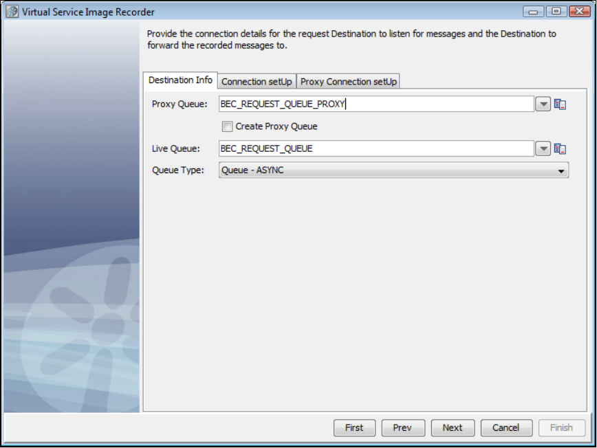
7. Go to the tab and enter the connection parameters useful to connect to the MOM. These connection parameters areConnection setUp
internally saved to save typing the next time.
Connection setUp Tab - Main
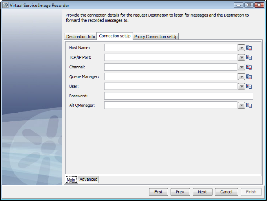
Connection setUp Tab - Advanced - Environment
The tab for WebSphere MQ has an tab with two sub-tabs, and .Connection Setup Main Advanced Environment MQ Exits
The tab lets you add, delete, and specify values for additional MQ environment settings.Environment
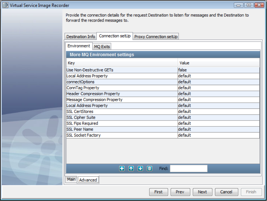
Connection setUp Tab - Advanced - Exits
On the tab, you can point to MQ exits for Security, Send, and Receive.MQ Exits
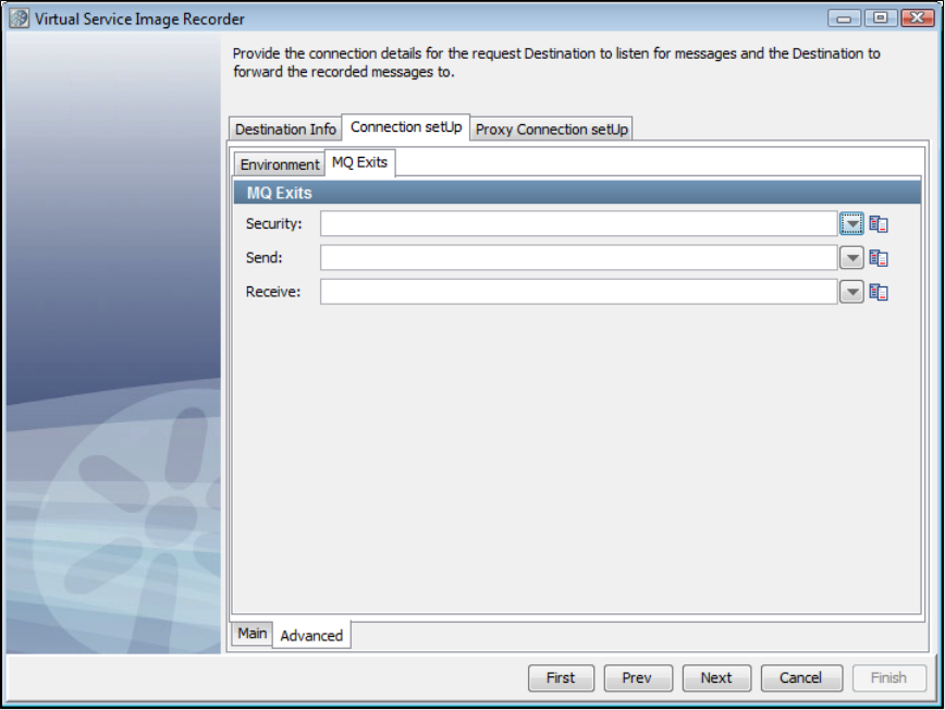
Proxy Connection setUp Tab - Main
The tab is an optional separate set of connection info for when your Proxy Queues are on a different Queue ManagerProxy Connection Setup
from your Live Queues. It has both Main and Advanced tabs.
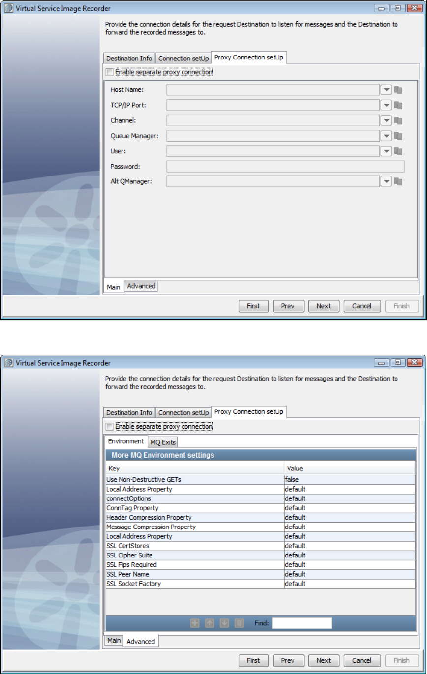
Proxy Connection setUp Tab - Advanced
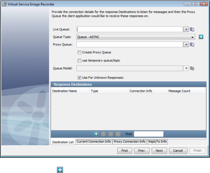
Destination List Tab
On this tab, we set the response and response proxy queues. You may remember that in case of messaging, more than one response is possible
for a given request. Use the Add icon to register a set of response and response proxy queues. Before registering the response queue that
you want to use for unknown requests, select the Use for Unknown Responses check box.
There is a check box on the Response wizard page for temporary destinations. Selecting this will disable the destination name and proxy
destination name text fields and mark the response listener you are adding as a temporary response. The destination name will be blank.
Adding a temporary response destination
A "temporary" destination in messaging is a destination created on demand for a messaging client. This is typically used in request-response
scenarios.
LISA supports using a temporary queues for the responses. In LISA 6.0.1, we only support one concurrent transaction with a temporary queue at
a time.
Current Connection Info Tab - Main
It is possible to go to the tab to verify that the connection info is correct. It is copied from the connection information thatCurrent Connection Info
was given earlier, and you may want to change it only in a very rare case when the response connection information is different.
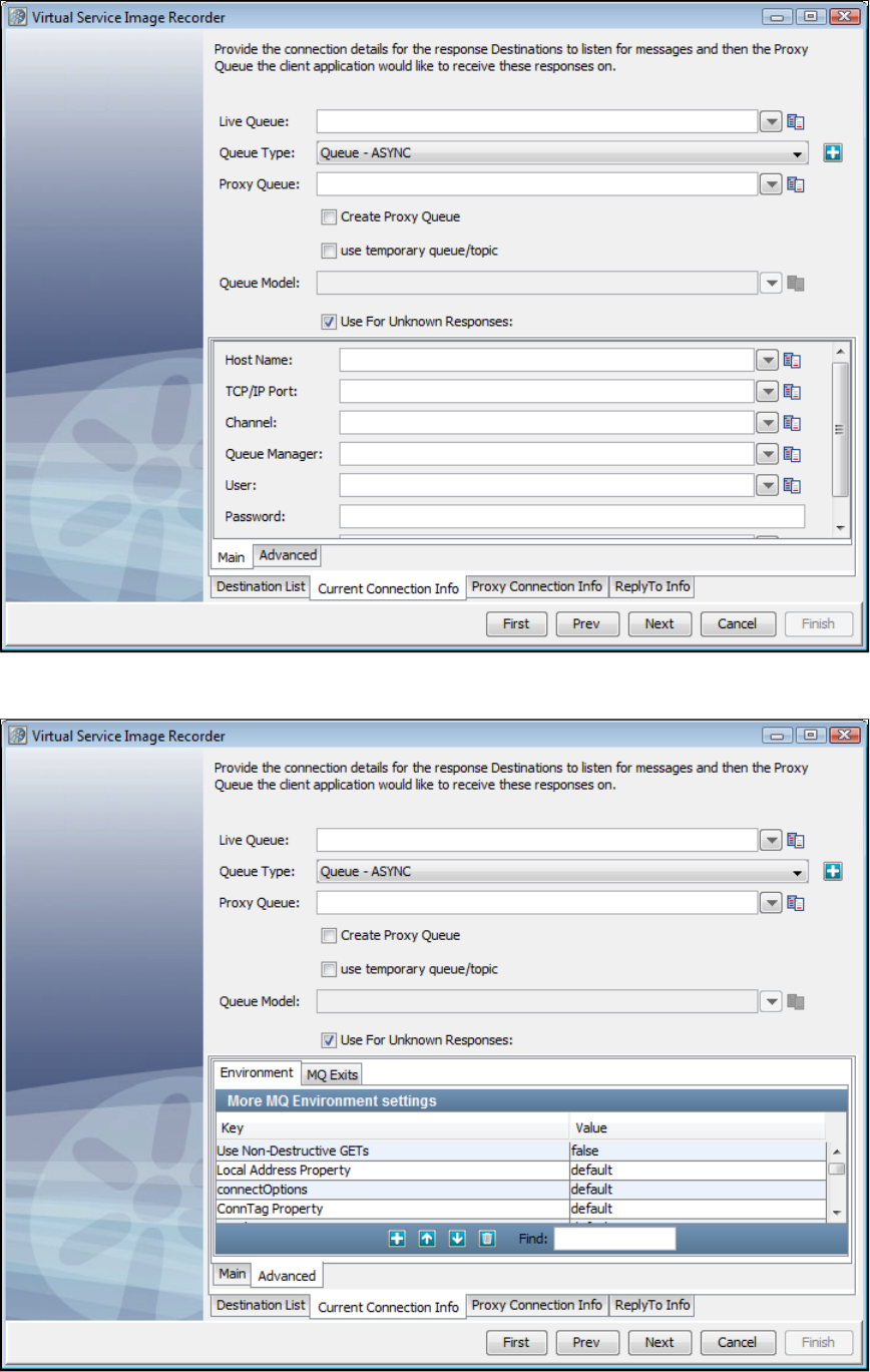
Current Connection Info Tab - Advanced
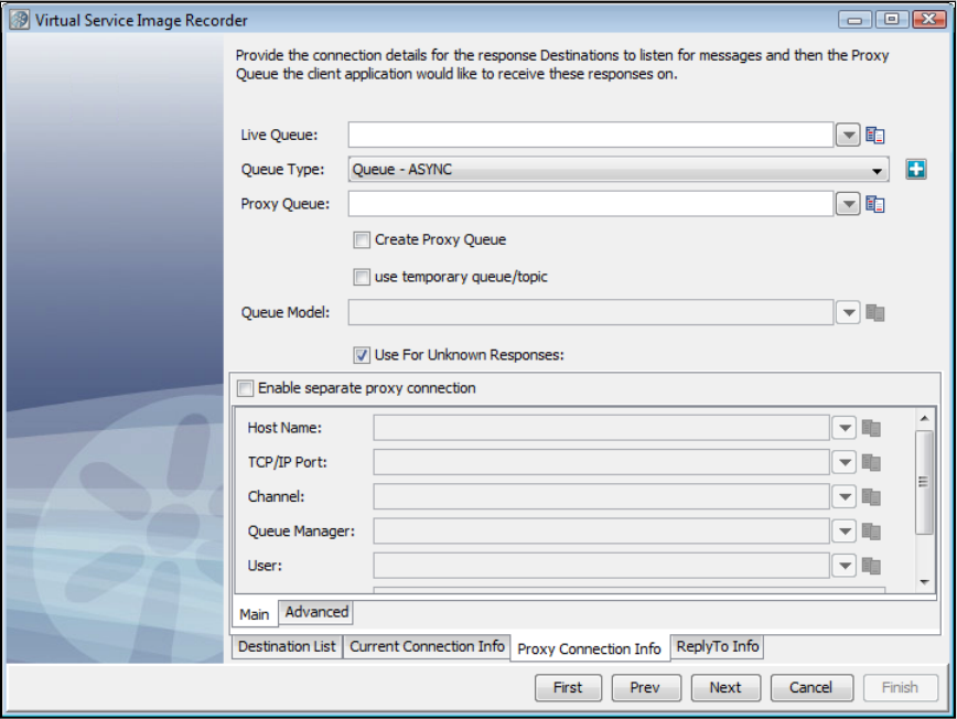
Proxy Connection Info Tab - Main
Proxy Connection Info Tab - Advanced
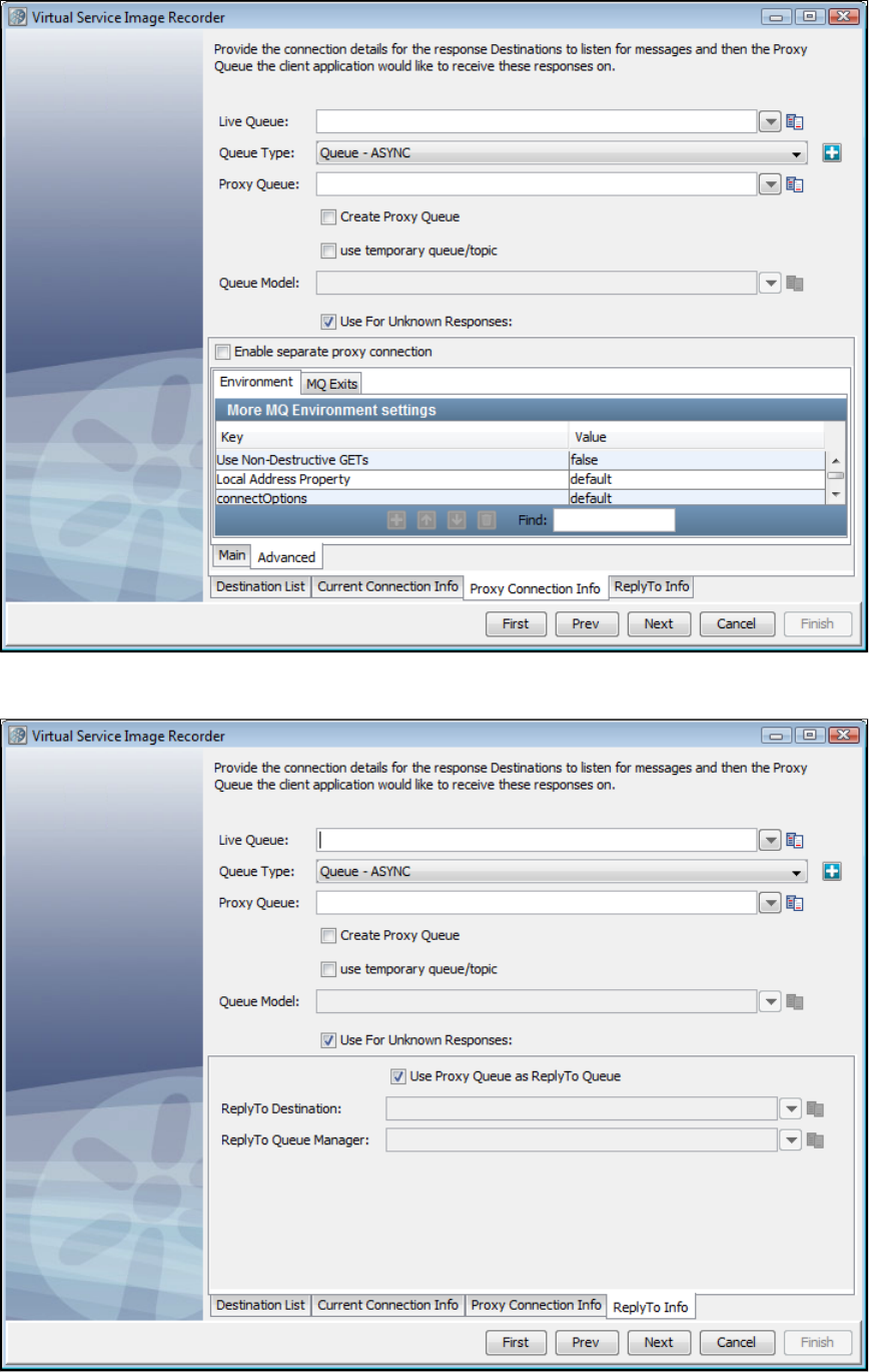
ReplyTo Info Tab
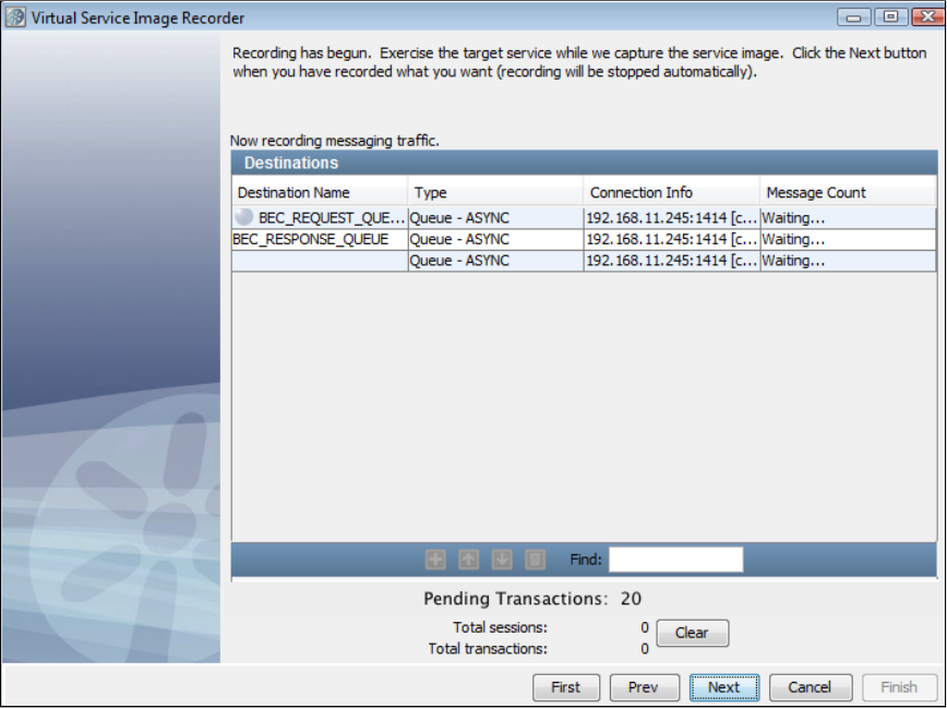
8. Click Next to begin recording. You will see the names of the queues to which LISA Virtualize is listening, and hence the status is Waiting. If you
are connecting to WebSphere MQ and have chosen to create the proxy queues on the fly, at this point those proxy queues would be created.
This is the case with check box selected with response queues. The one without a destination name is the temporaryuse temporary queue
response queue.
This is the case with check box cleared with response queues.use temporary queue
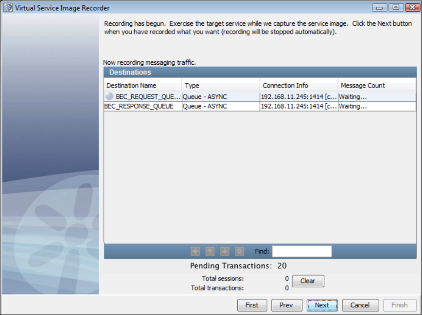
9. Run the client that would add messages to the request proxy queue. LISA Virtualize will copy those messages to the real request queue
(ORDERS.REQUEST as in the screenshots). The server will pick those up from there and send responses to the response queue(s). Again, LISA
Virtualize will pick those up and copy them to the response proxy queue(s), where the client listens to.
10. As the transactions are recorded, you will see the message count increasing and Total sessions and Total transactions count increasing on
the Virtual Service Image Recorder dialog. At the end of recording, all the requests have gone through the same request queue, but about half of
the responses have come back through temporary queues and the other half through the non-temporary response queue. Following is the case of
end of the recording without check box selected.use temporary queue
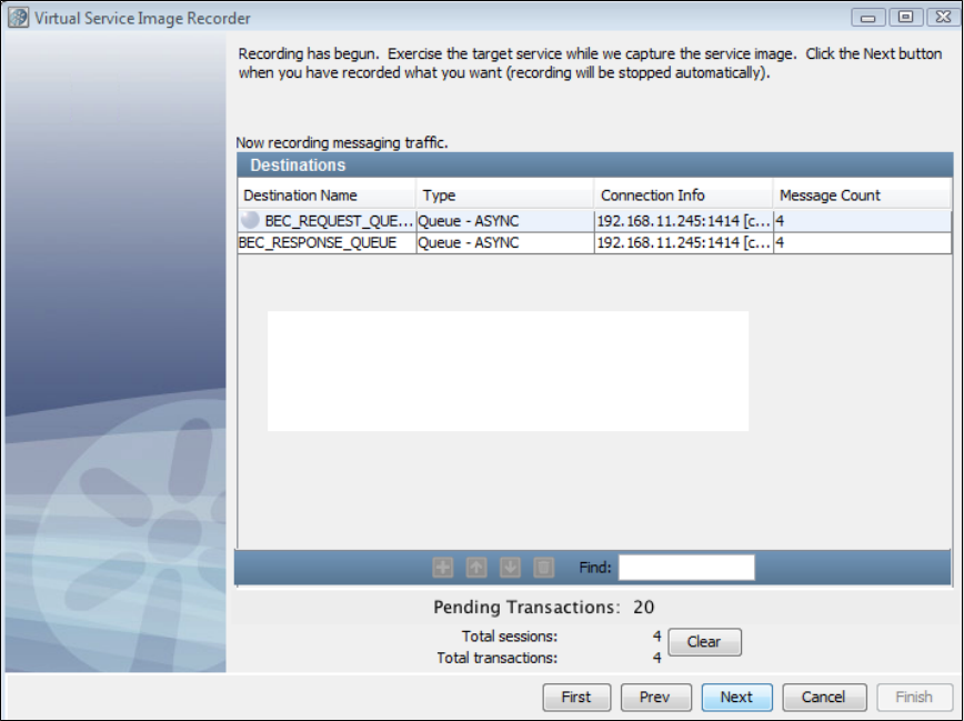
11. When the run is complete, you may see the count of messages on the response queues less by 1. As a single request can have more than
one response, LISA Virtualize would not have yet recognized the last of the transactions to have completed. The messages corresponding to the
last transaction are therefore not counted.
12. Click Next. This serves as a trigger to close the last transaction and do the necessary cleaning. (You would see an intermediate screen if you
were using a dynamic data protocol.) As part of the recorder's preparation for writing out the .vsi file, it verifies request and response bodies to
make sure that, if they are marked as text, that they are text. If they are not, the type is switched to binary.

1.
2.
13. If you want to save the settings on this recording to load into another service image recording, click the Save icon.
14. Click Finish to close this dialog and store the image.
15. Review and save the VSM generated in the main window.
Recording Standard JMS Service Images
Information in configuring Standard JMS is available in .Installing a Messaging Simulator
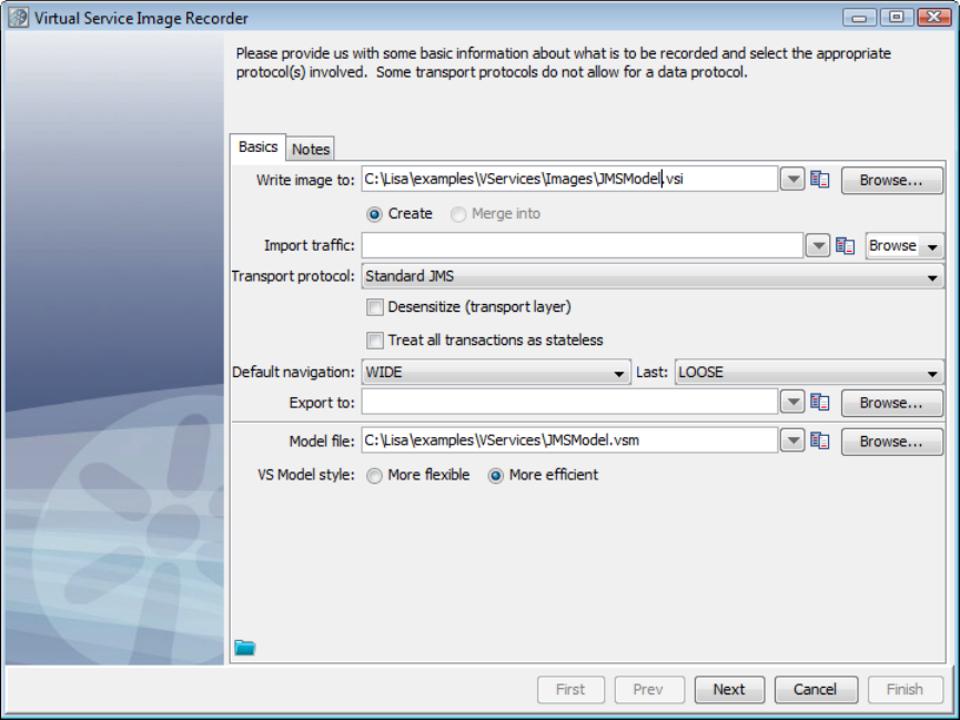
2. If you are using Standard JMS as the transport protocol in the Basics tab in the Virtual Service Image Recorder, complete the remaining
wizard steps as shown in the following example.
3. Click Next on the recorder's first screen.
4. Do not select any value for the data protocol on the recorder's second screen and click Next.
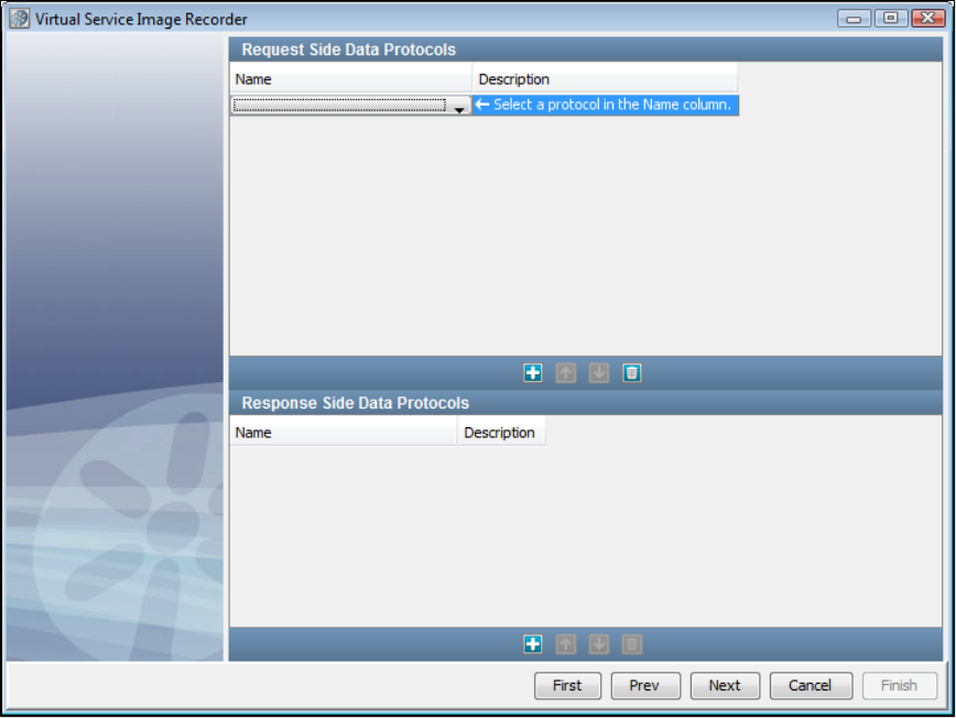
5. This is the recording mode selection step. For now, the only true mode supported is Proxy Mode. With Proxy Mode comes the optionrecording
to generate the service from the Live queues (the previous default behavior) or generate the service using the Proxy queues.
Proxy Mode
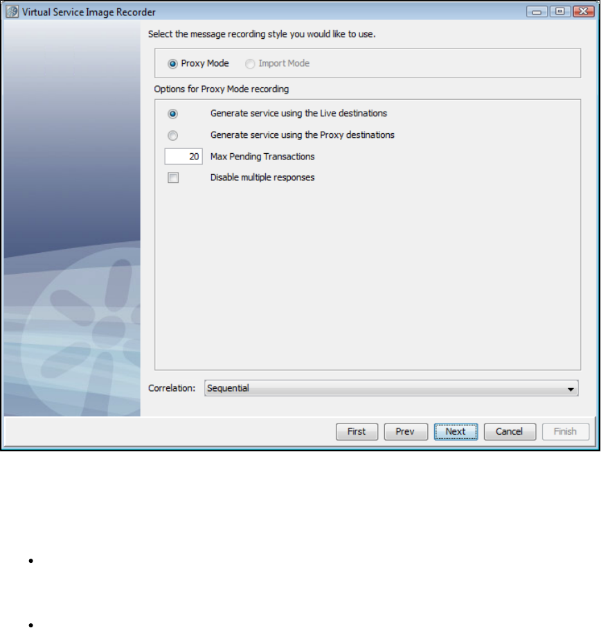
Proxy Mode allows the use of proxy destinations to be set up on the message bus. The client application is configured to put messages on those
proxy destinations and they will be forwarded to the real destination after recording them. The same thing happens on the response side, where
LISA is configured to listen on the real response destination and get the message and forward it to the response proxy destination. This mode can
behave differently if temporary destinations are enabled, making the response side basically automated.
When Proxy Mode is selected, the configuration panel has an option button selection for whether to use the Live queues or Proxy queues when
generating the final VSM/SI.
Max Pending Transactions: This is the maximum number of running response listeners on each response queue. These response
listeners will run until as long as a transaction is pending. When the number of pending transactions exceeds this maximum amount the
oldest transaction will be closed automatically. Previously this was available as a system property:
. If you enter 0 in this field, there will be no maximum number.lisa.vse.messaging.maxTransactionBufferSize
Disable Multiple Responses: This determines whether to support multiple responses in each transaction. By default a transaction will
stay pending after the first response, waiting for more responses to come in for the same transaction. When this option is selected the
transaction will be automatically closed after the first response. If there are a lot of transactions coming in very quickly,this can be a
performance boost, especially for MQ.
Import Mode
If you specify a raw traffic file on the initial recording screen in the Import traffic field, the option is dimmed and the Proxy Mode Import Mode
screen selected.
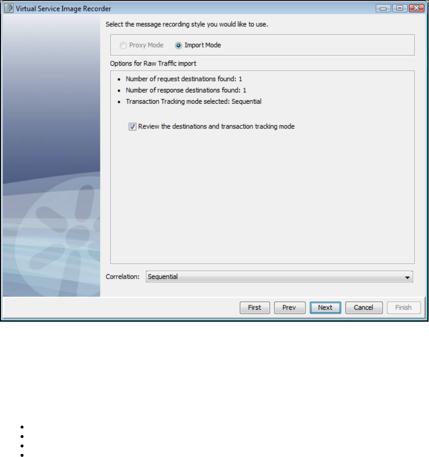
With Import Mode, the extra configuration has some information about what request and response queues were detected in the raw traffic file and
a check box that lets you skip the request and response steps altogether.
The check box lets you skip the request and response steps altogether. If the raw traffic fileReview the queues and transaction tracking mode
comes from Pathfinder, this should be cleared by default, because Pathfinder will auto-detect queues and transactions. If the raw traffic file is from
somewhere else, this is selected by default to let you review destination and tracking settings.
The Correlation field contains the possible correlation schemes for putting together the request and response sides of individual transactions. JMS
is asynchronous, which means we are receive the requests and responses separately. This drop-down provides a way for you to tell the VSE
Recorder which request to associate with which response. For the Correlation field, there are four options:
Sequential: Every response is associated with the last request that was received, chronologically.
Correlation ID: The request and the response must have the same Correlation ID.
Message ID to Correlation ID: The request's Message ID must equal the response's Correlation ID.
Message ID: The request and the response have the same Message ID.
6. Set up the proxy queue and destination queue names. You cannot create a temporary queue dynamically for JMS, so you must create the
proxy queues manually on the MOM server.
7. Click Next.
Destination Info Tab
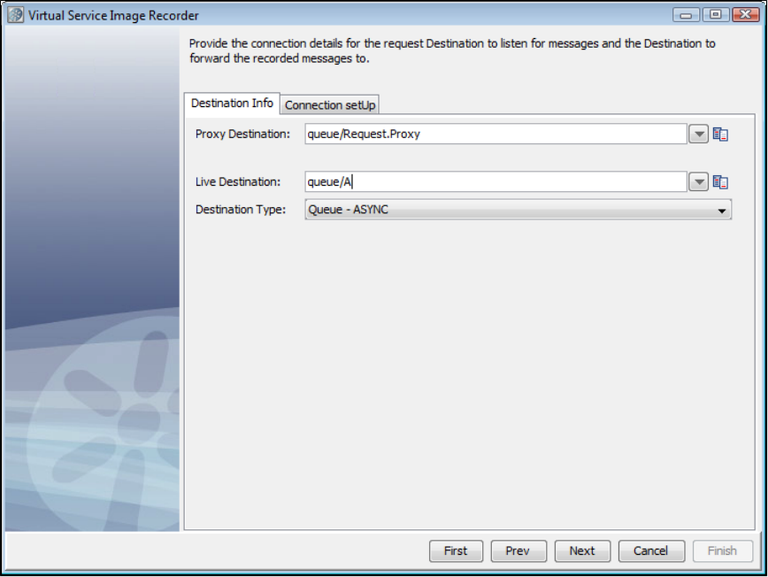
8. Go to the tab and enter the connection parameters useful to connect to the MOM. These connection parameters areConnection setUp
internally saved to save typing the next time.
Connection setUp Tab - Main
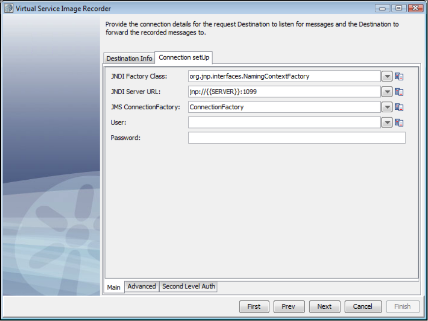
Connection setUp Tab - Advanced
The tab for JMS lets you define custom connection properties for this service image.Connection setUp Advanced
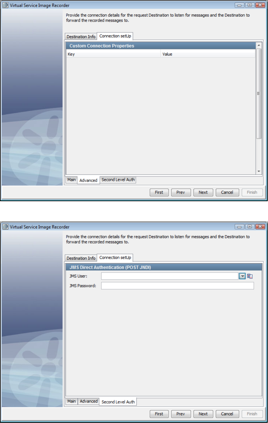
Connection setUp Tab - Second Level Auth
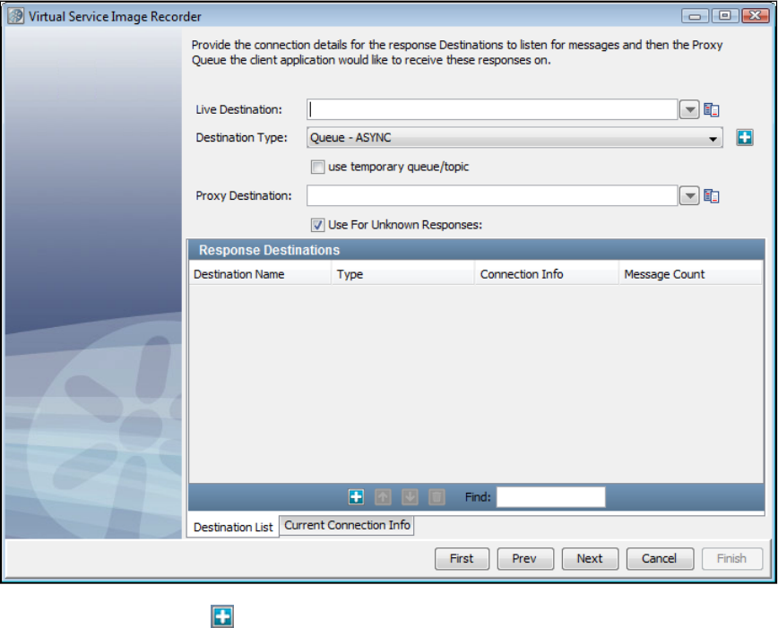
Destination List Tab
On this tab, we set the response and response proxy queues. You may remember that in case of messaging, more than one response is possible
for a given request. Use the Add icon to register a set of response and response proxy queues. Before registering the response queue that
you want to use for unknown requests, select the Use for Unknown Responses check box.
There is a check box on the Response wizard page for temporary destinations. Checking this will disable the destination name and proxy
destination name text fields and mark the response listener you are adding as a temporary response. The destination name will be blank.
Adding a temporary response destination
A "temporary" destination in messaging is a destination created on demand for a messaging client. This is typically used in request-response
scenarios.
You can use a temporary queue for the responses. In LISA 6.0.1, we only support one concurrent transaction with a temporary queue at a time.
Current Connection Info Tab - Main
It is possible to go to the tab to verify that the connection info is correct. It is copied from the connection information thatCurrent Connection Info
was given earlier, and you may want to change it only in a very rare case when the response connection information is different.
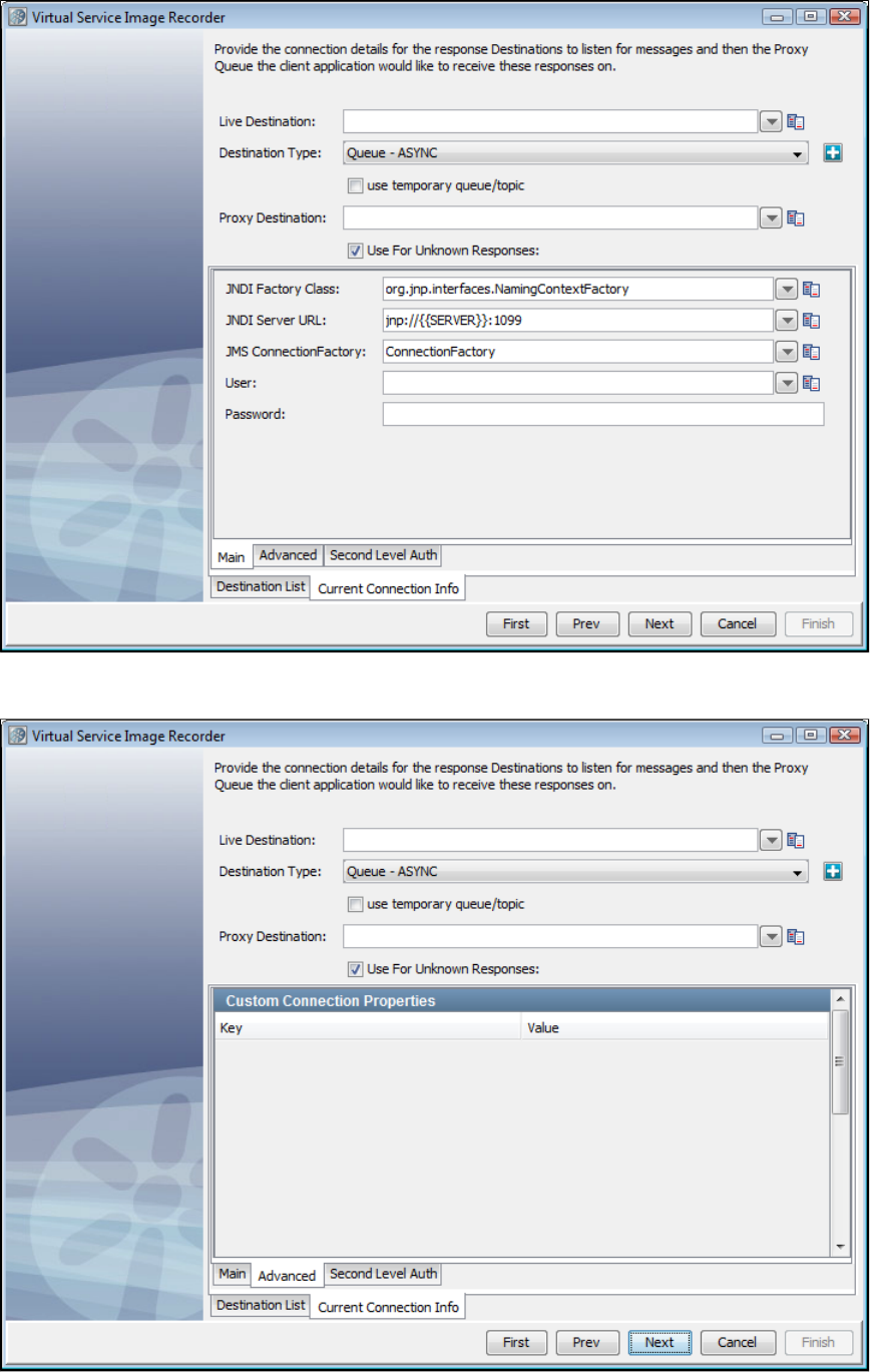
Current Connection Tab - Advanced
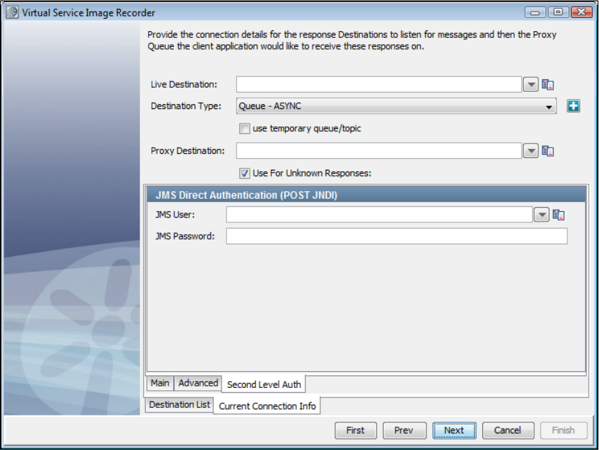
Current Connection Tab - Second Level Auth
9. Click Next to begin recording. You will see the names of the queues to which LISA Virtualize is listening
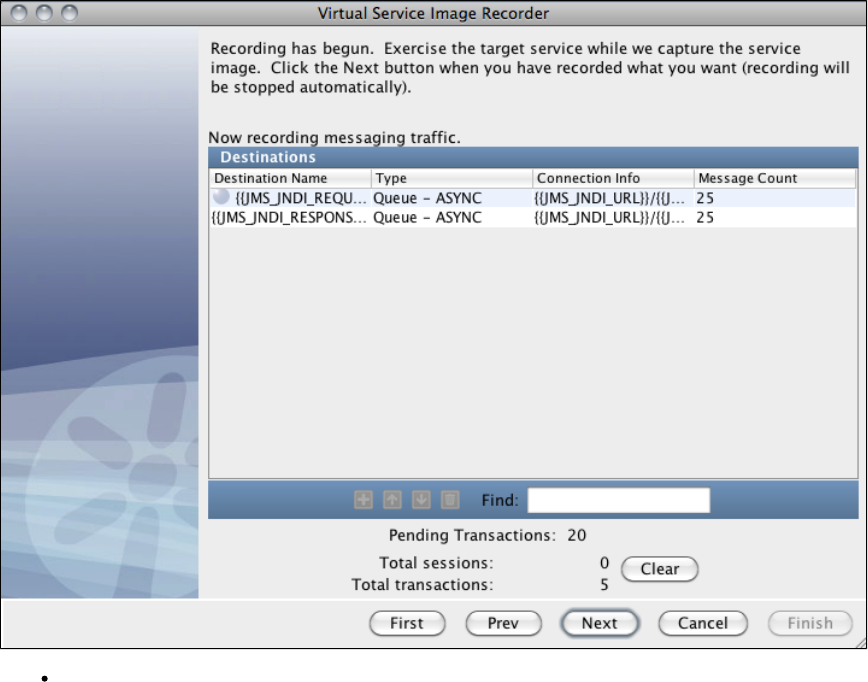
Pending Transactions: This displays the number of transactions being stored in the pending transaction buffer waiting for more
responses. As transactions are closed, either by hitting the maximum pending transaction count or by using the "Disable Multiple
Responses" option, they are moved from the pending transaction buffer to the total transaction buffer.
9. Run the client that would add messages to the request proxy queue. LISA Virtualize will copy those messages to the real request queue. The
server will pick those up from there and send responses to the response queue(s). Again, LISA Virtualize will pick those up and copy them to the
response proxy queue(s), where the client listens to.
As the transactions are recorded, you will see the message count increasing and 'Total sessions' and 'Total transactions' count increasing on the
Virtual Service Image Recorder dialog. At the end of recording, all the requests have gone through the same request queue, but about half of the
responses have come back through temporary queues and the other half through the non-temporary response queue.
When the run is complete, you may see the count of messages on the response queues less by 1. As a single request can have more than one
response, LISA Virtualize would not have yet recognized the last of the transactions to have completed. The messages corresponding to the last
transaction are therefore not counted.
10. Click Next. This serves as a trigger to close the last transaction and do the necessary cleaning. (You would see an intermediate screen if you
were using a dynamic data protocol.)
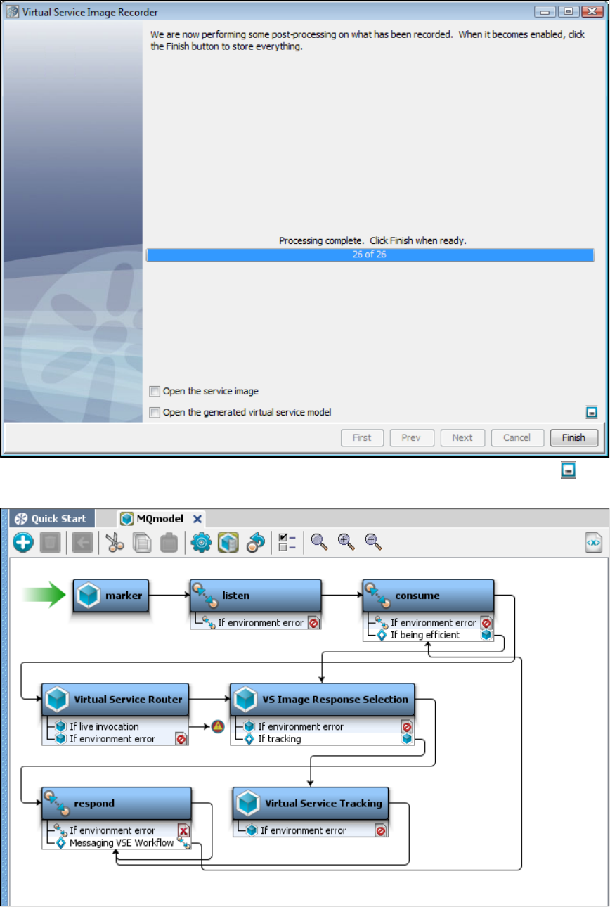
11. If you want to save the settings on this recording to load into another service image recording, click the Save icon.
12. Click Finish to close this dialog and store the image.
13. Review and save the VSM generated in the main window.
Recording Java Service Images
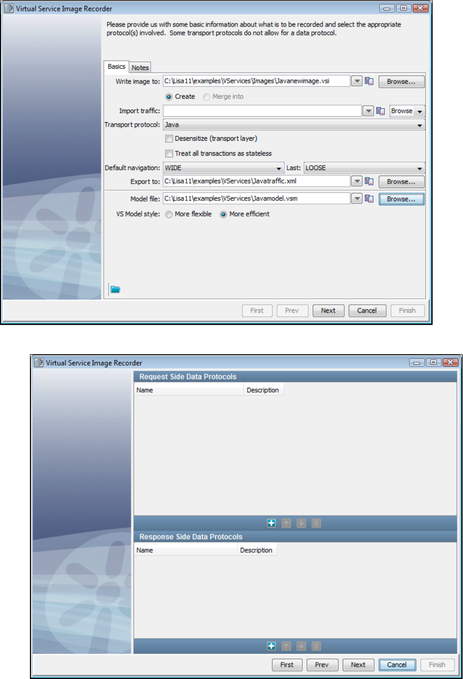
1.
2.
If you are using Java as the transport protocol in the Basics tab in the Virtual Service Image Recorder, complete the remaining wizard steps.
Select Java as the transport protocol and click Next. Do not select any value for the data protocol on the recorder's second screen and
click Next.
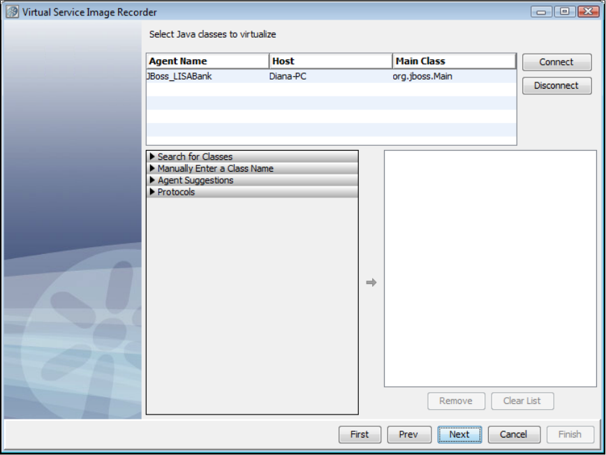
2.
3.
On the next screen, you will see the agent associated with the system under test. Select the agent, then click Connect.
To search for classes, select the Search for Classes arrow and enter a class name. These are entered as fully qualified names (including
package), using regular expressions. To select classes, select the class name on the list and select the right arrow to move the class into
the right pane. Some classes may show up more than once; a class only needs to be selected once for it to be virtualized.
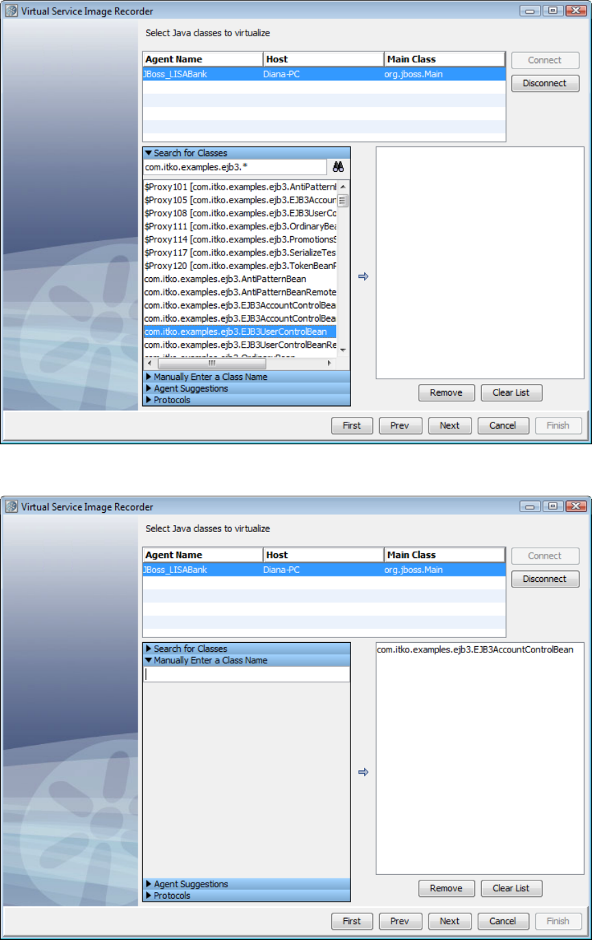
4. To enter a class manually, select the Enter a Class Manually arrow. Enter the name of the class to virtualize, then click the right arrow to move
the class into the right pane.
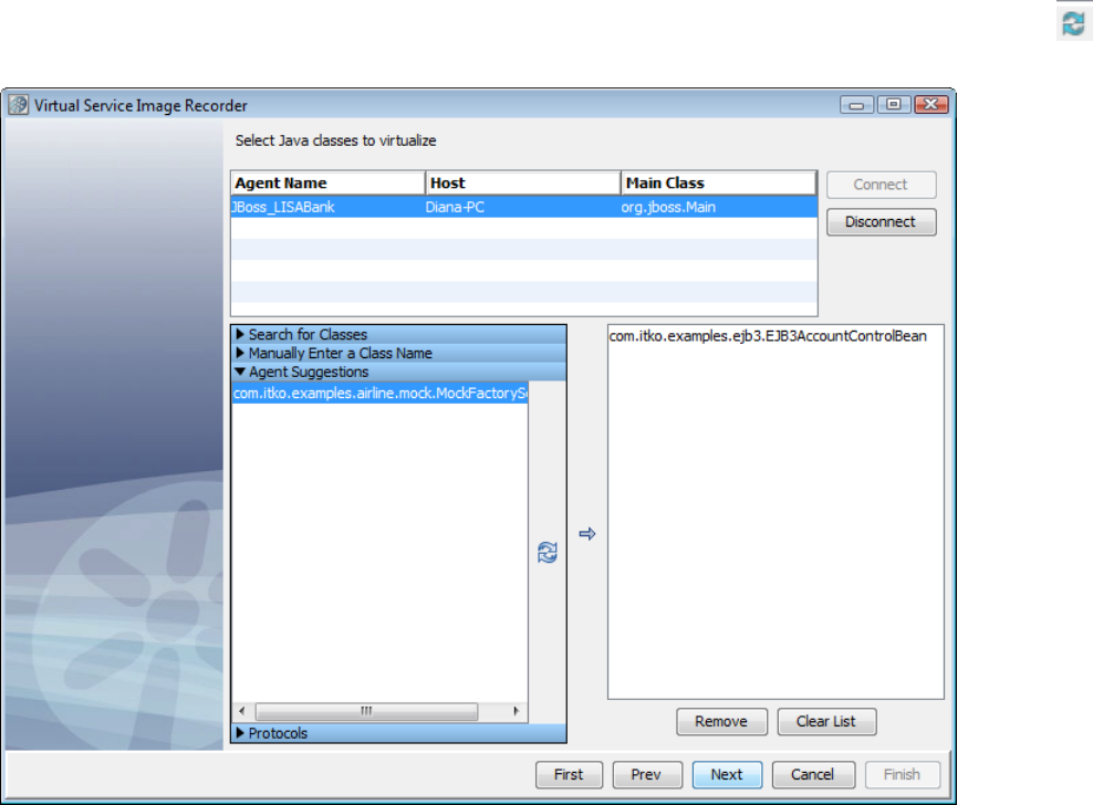
5. To retrieve a list of classes suggested by the LISA agent for virtualization, select the Agent Suggestions arrow and click the Retrieve icon.
Select any classes from the list and click the right arrow to move them into the right pane.
6. To add a protocol to the recording, select the Protocols arrow. From the list of available protocols, select any you want to record and click the
right arrow to move them into the right pane.

7. Shut down the system under test, then click Next, then start the system under test. This will help ensure that LISA Virtualize captures any initial
traffic that happens when the system under test is initialized. Or, if you prefer, click Next to begin recording.
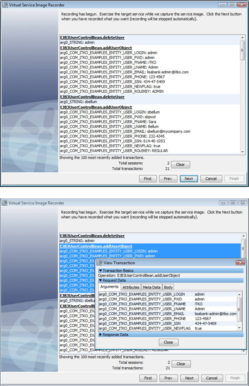
8. You see a list of the most recent transactions displayed on the "now recording" wizard page. On this list of transactions, you can double-click a
transaction and see a dialog showing the content of the transaction.
9. After your recording has completed, click Next. As part of the recorder's preparation for writing out the .vsi file, it verifies request and response
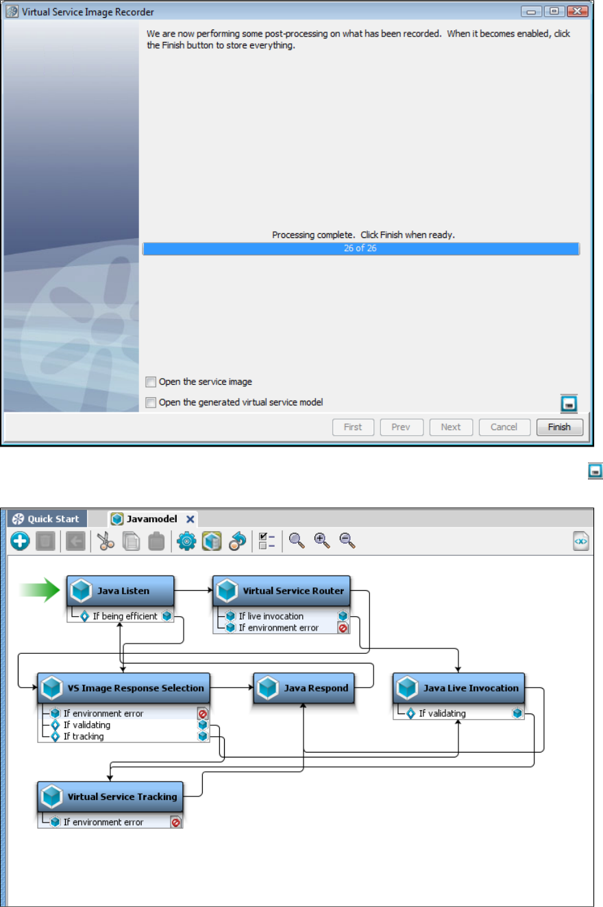
bodies to make sure that, if they are marked as text, that they are text. If they are not, the type is switched to binary.
10. If you want to save the settings on this recording to load into another service image recording, you can click the Save icon.
11. Click Finish to close this dialog and store the image.
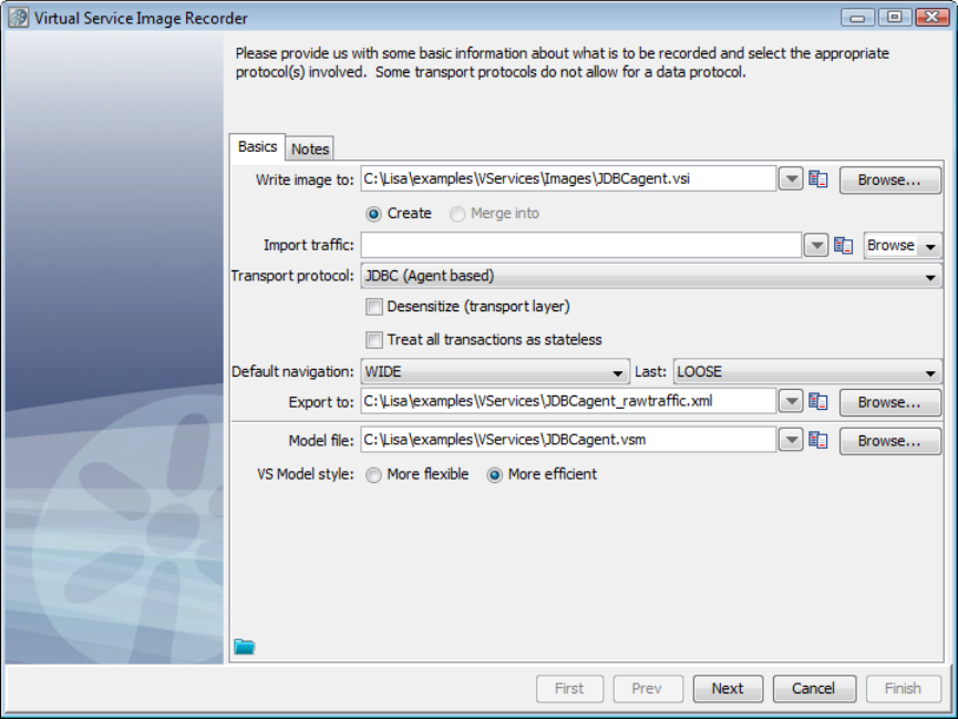
1.
Recording JDBC (Agent based) Service Images
Prerequisites:
This protocol intercepts JDBC calls using the LISA Agent. The LISA Agent is included in a standard LISA installation, and must be installed on the
application making JDBC calls (see ). After the agent is installed and configured, proceed with the following instructions.Installing the Native Agent
To use JDBC (Agent based) as the transport protocol in the Basics tab in the Virtual Service Image Recorder, complete the remaining wizard
steps.
Select JDBC (Agent based) as the transport protocol and click Next. Do not select any value for the data protocol on the recorder's
second screen and click Next
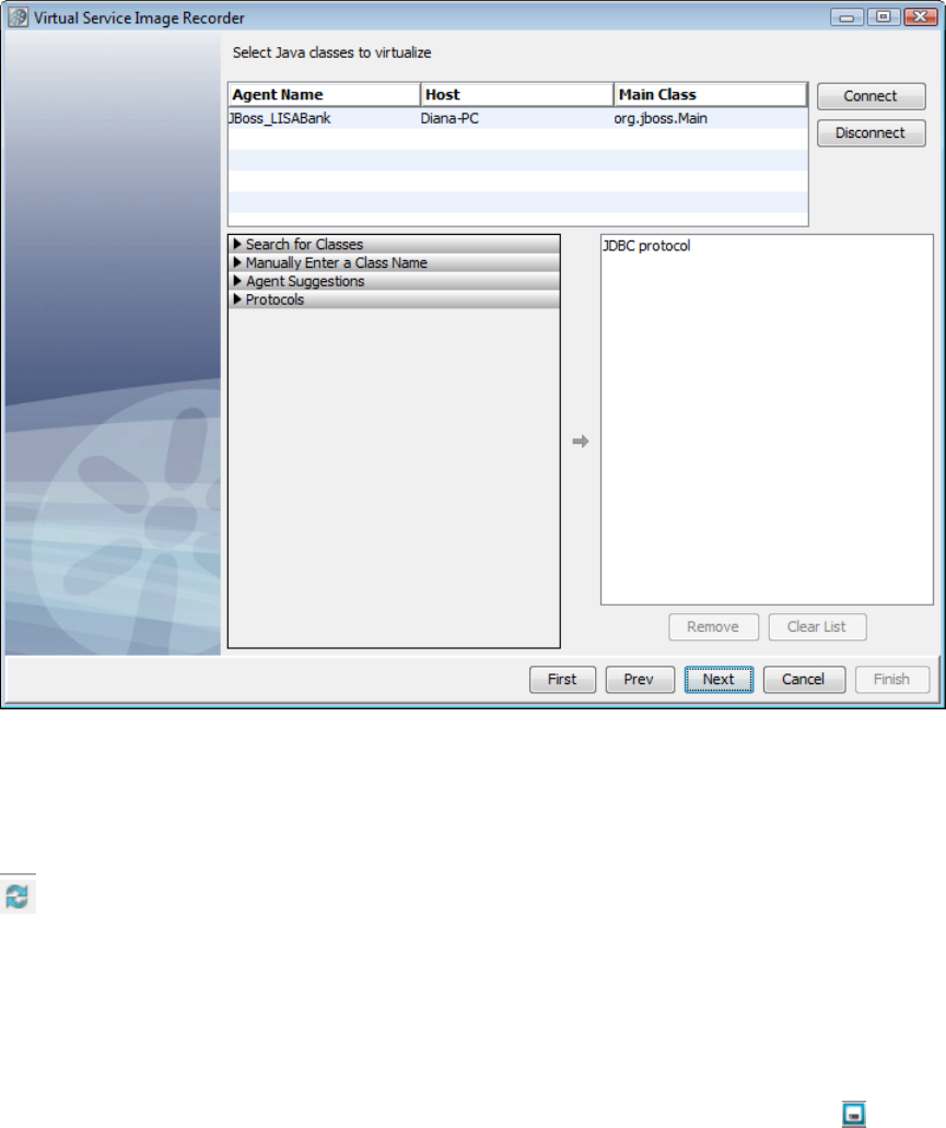
1.
2.
3.
4.
5.
6.
7.
8.
9.
10.
11.
On the next screen, you will see a list of all LISA agents running on the network. Select the agent associated with the system under test,
then select Connect.
To search for classes, select the Search for Classes arrow and enter a class name. These are entered as fully qualified names (including
package), using regular expressions. To select classes, select the class name on the list and select the right arrow to move the class into
the right pane. Some classes may show up more than once; a class only needs to be selected once for it to be virtualized.
To enter a class manually, select the Enter a Class Manually arrow. Enter the name of the class to virtualize, and click the right arrow to
move the class into the right pane.
To retrieve a list of classes suggested by the LISA agent for virtualization, select the Agent Suggestions arrow and click the Retrieve
icon. Select any classes from the list and click the right arrow to move them into the right pane.
To add a protocol to the recording, select the Protocols arrow. From the list of available protocols, select any you want to record and click
the right arrow to move them into the right pane.
Shut down the system under test, then click Next, then start the system under test. This will verify that LISA Virtualize captures any initial
traffic that happens when the system under test is initialized. Or, if you prefer, click Next to begin recording.
You see a list of the most recent transactions displayed on the "now recording" wizard page. On this list of transactions, you can
double-click a transaction and see a dialog showing the content of the transaction.
After your recording has completed, click Next. As part of the recorder's preparation for writing out the .vsi file, it verifies request and
response bodies to make sure that, if they are marked as text, that they are text. If they are not, the type is switched to binary.
If you want to save the settings on this recording to load into another service image recording, click the Save icon.
Click Finish to close this dialog and store the image.
Recording JDBC (Driver based) Service Images
Preparing to Virtualize JDBC
This section gives more detail about how to prepare to use LISA Virtual Service framework to virtualize JDBC-based database traffic. Information
about configuration is also available in . This section documents the various ways that driver-based JDBCInstalling the Database Simulator
virtualization can be combined, and the configuration options supported. It does not include any detail on how to actually implement the
configuration on any given app container.
System-Level Properties
The following properties can be specified either by using system variables (adding a flag to the SUT's start-up, or through some other-Dvar=val
mechanism) or in a properties file named , which has to be on the classpath (probably in the same directory as ).rules.properties lisajdbcsim.jar
If a property exists in both locations, the system property overrides the configuration file.
lisa.jdbc.sim.require.remote: Determines whether the driver should wait on a connection to VSE before processing commands.
Defaults to .false
lisa.jdbc.hijack.drivermanager: Determines whether the driver should attempt to hijack all the database connections from this
application. Defaults to .false
lisa.jdbc.sim.port: Default listen port. Defaults to .2999
lisa.log.level: Default log level; possible values are OFF, FATAL, ERROR, WARN, INFO, DEBUG, DEV. Defaults to .WARN
lisa.log.target: Where the logs should be written to; possible values are stderr, stdout, or any file location. Defaults to .stderr
VSE Driver (standalone)
The VSE driver can be used directly by the system under test, or wrapped in a datasource such as Apache's BasicDataSource. In such cases, the
configuration (other than the username and password) is passed through the URL.
Driver Properties
URL: The actual URL that will be passed to the underlying driver. This must be the last element passed.
State: Initial state for the driver. One of "watch," "record," or "playback."
JdbcSimPort: The port to listen on for connections from VSE. Overrides the system-level property.
Driver: The classname of the real driver to use.
User
Password
Specify the driver's classname as .com.itko.lisa.vse.jdbc.driver.Driver
The URL should be of this format:
jdbc:lisasim:driver=<real driver class>;state=<initial state>;jdbcSimPort=<starting port>;url=<real url>
Everything except the driver and URL is optional.
The "URL" element must come last. Everything following "URL=" will be passed to the underlying driver unchanged. We can
support passing extra information to the underlying driver by embedding it in the real URL.
Example
This URL would be appropriate for a Derby connection:
jdbc:lisasim:driver=org.apache.derby.jdbc.ClientDriver;state=watch;jdbcSimPort=4000;url=jdbc:derby://localhost:1527/sample;create=true
This format tells the VSE driver to use Derby's client driver, to start up in "watch" mode, to use port 4000 to talk to VSE, and to pass the URL
to the real Derby driver.jdbc:derby://localhost:1527/sample;create=true
VSE Datasource Wrapping a Driver
This may be a more typical configuration for app containers than using a VSE driver directly. VSE provides a datasource that wraps a real driver.
Most app containers provide a mechanism for directly specifying properties for the datasource.
Specify the driver's classname as .com.itko.lisa.vse.jdbc.driver.VSEDataSource
Datasource Properties
Driver: Name of the real driver to use (this is the normal configuration).
URL: The real URL to connect with (should not start with .jdbc:lisasim)
User
Password
JdbcSimPort: The port to listen on for connections from VSE. Overrides the system-level property.
CustomProperties: A semicolon-separated list of name=value pairs. These will be parsed and delegated to the wrapped datasource, if
any. If the first character is not alphanumeric, it will be used as the delimiter instead of a semicolon.
VSE Datasource Wrapping a Datasource
This is a very unusual configuration, when an app container does not permit a driver to be instantiated directly via Class.forName(). To use it,
instead of specifying (such as ), specify driver=<classname of real driver> oracle.jdbc.OracleDriver datasource=<classname of real
(such as ).datasource> oracle.jdbc.pool.OracleDataSource
Specify the driver's classname as .com.itko.lisa.vse.jdbc.driver.VSEDataSource
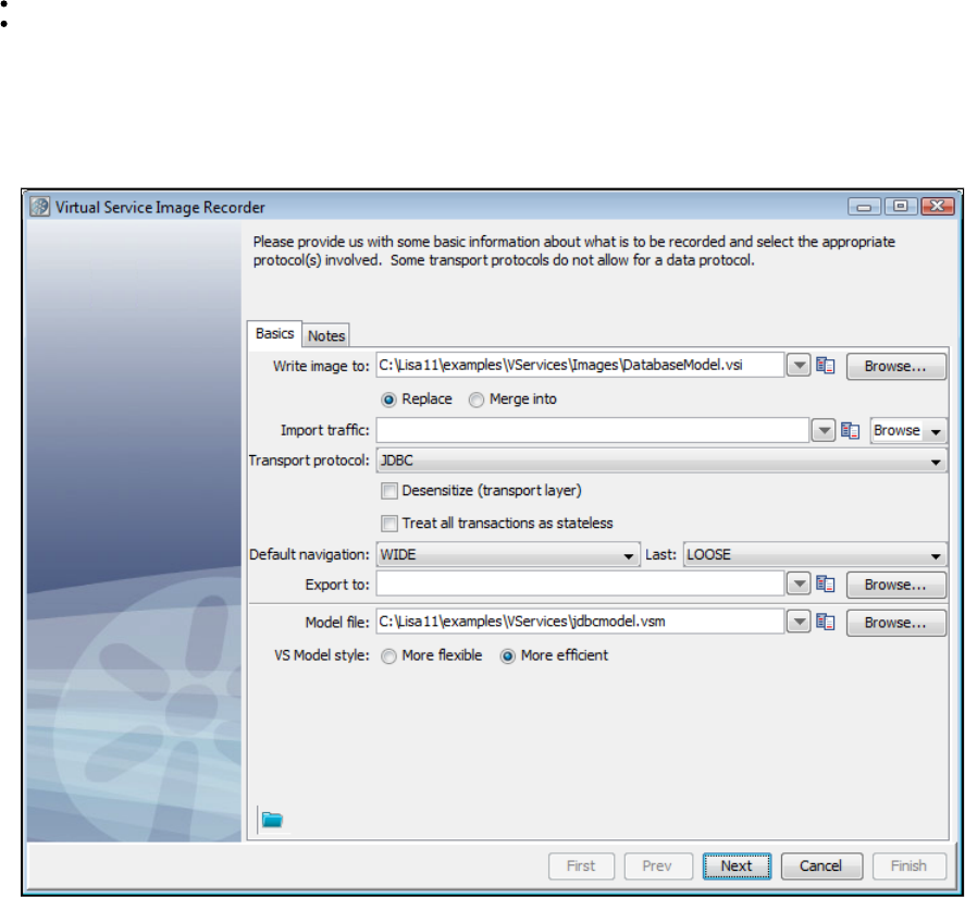
1.
2.
Supporting Multiple Endpoints
If one application has multiple JDBC connections you want to virtualize (or if one appserver has multiple apps with different JDBC connections
you want to virtualize), you need to specify a different for each connection. You can specify this either as a property to the VSEJdbcSimPort
Datasource, or as a parameter on the URL for the driver, as explained previously.
Example
Assume an application uses two JDBC connections, and you want to virtualize both of them. For simplicity, we will assume the application uses
drivers directly.
Specify for each connection, with the appropriate underlying parameters such as driver and URL for each.com.itko.lisa.vse.jdbc.driver.Driver
For the first connection, you could specify and for the second you could use . Your configuration mightjdbcSimPort=3000 jdbcSimPort=3001
look like:
connection1.url=jdbc:lisasim:driver=org.apache.derby.jdbc.ClientDriver;jdbcSimPort=3000;url=jdbc:derby://localhost:1527/sample;create=true
connection2.url=jdbc:lisasim:driver=org.apache.derby.jdbc.ClientDriver;jdbcSimPort=3001;url=jdbc:derby://localhost:1527/sample2;create=true
You would still need to record separately, but you could deploy both services simultaneously, with the ability to start and stop them independently.
Recording JDBC
If you are using JDBC as the Transport protocol in the Basics tab in the Virtual Service Image Recorder, complete the remaining wizard
steps as shown in the following example.
Set up the simulation host and range of ports (default is 2999), as appropriate. JDBC VSE supports multiple endpoints during recording
and playing back. In the recorder and the JDBC listen step editor, there is a table of Driver Host, Base Port and Max Port. When Base
Port and Max Port are different, a unique endpoint is created for each port between, inclusive.
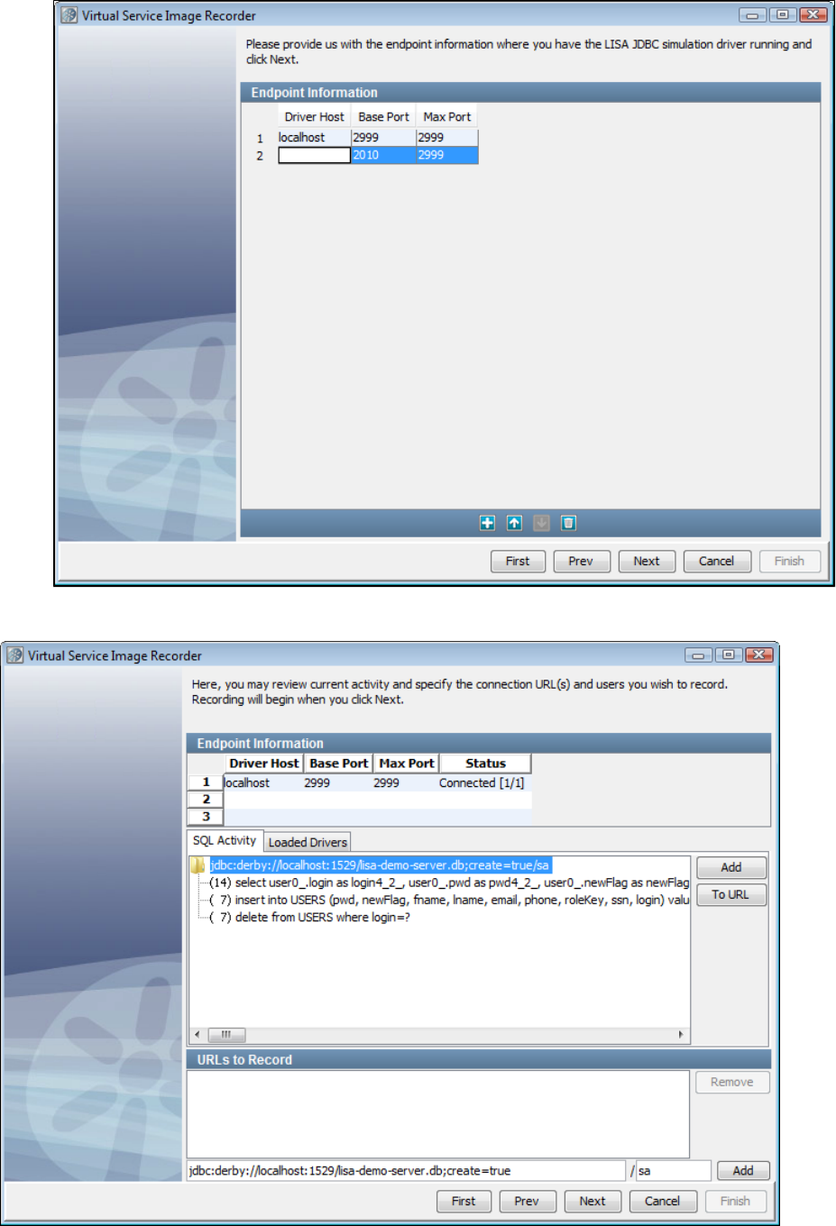
2.
3.
4. Click Next to connect to the JDBC Simulation server. You can stop trying to connect by clicking in the status window.Cancel
Specify connection URLs and users to record.
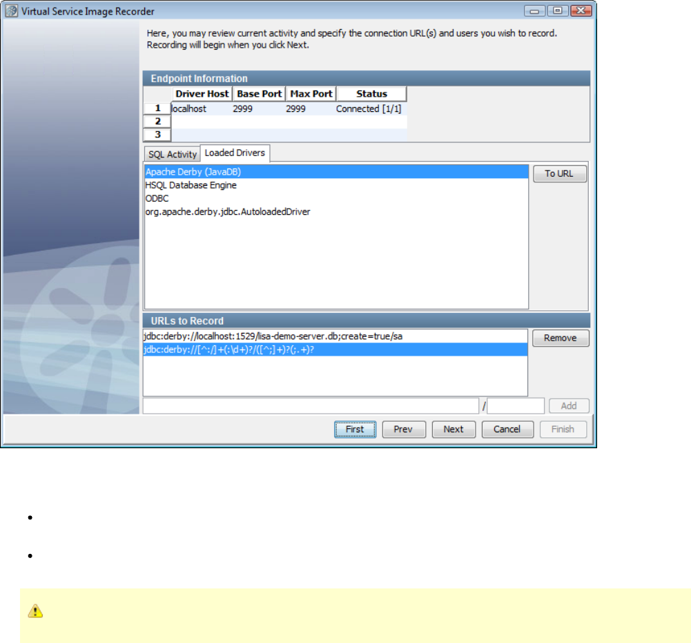
5. The SQL Activity tab shows the 10 most recent statements executed (and how many times) for every unique connection URL/database user
combination. This refreshes every 5 seconds or so. On this tab, select the URLs and users you want to record. Click To URL to place the selected
connection string and user into the URL and user fields at the bottom of the panel. Click Add to put the URL in the URLs to Record list.
6. The Loaded Drivers tab shows the list of all the JDBC drivers installed and registered in the SUT. By selecting a driver and clicking To URL, a
regular expression that matches any connection through that driver is placed in the URL field at the bottom of the panel. Click Add to add that
pattern to the list of URLs to record.
URLs to Record: The URLs added from the SQL Activity list or the URL/User entry fields are displayed. To delete an entry, select it and
click Remove.
User: This is an unnamed area below the URLs to Record field where you can include a database user along with the URL. If you do not
include a database user by leaving this blank, then the recording will be done for all users connecting to the URL.
You must supply a connection URL in the first box and a username in the next box before the Add button is enabled.
The bottom section shows the list of connection URL/database user combinations that are to be recorded. The URL can be a regular expression.
(This list will usually start off empty unless the state attribute is set to RECORD on a simulation connection URL for DataSource style SUTs.)
If a driver is selected in the drivers list, the "To URL" button can be used to copy a generic regular expression that will match connection URLs for
that driver to the URL entry field. If the connection URL (top level) node in the activity tree is selected, the "To URL" button can be used to copy
the URL and user to the URL and user entry fields. Also, the "Add" button to the right of the activity tree can be used to add the connection URL
and user directly to the recording list.
Connection URLs can be either exact or a regular expression that will match connection requests and can be added to the recording list with or
without a database user. The absence of a database user will match any user attempting to connect. If the "Add" button to the right of the
URL/user entry fields is disabled, it is likely the recording list already covers the URL/user combination.
When the recording list contains all the URLs and users to record, clicking Next will display the "recording" wizard page.
7. Click Next.
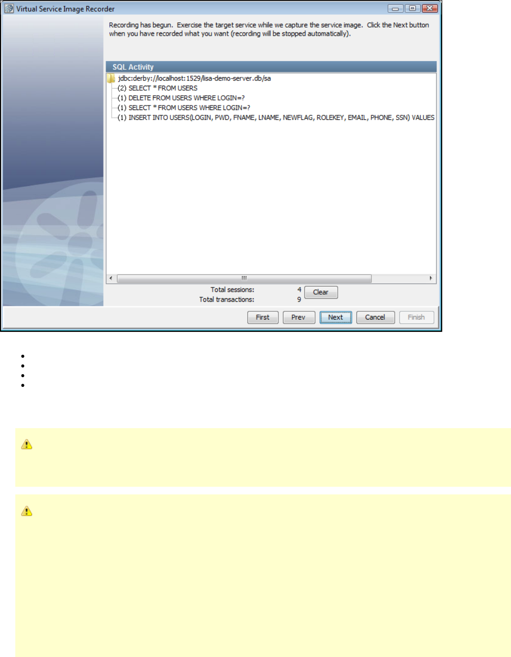
The options and dynamic display statistics are:
Total conversations: Indicates the number of conversations recorded.
Total transactions: Indicates the number of transactions recorded.
Clear: Click to clear out currently recorded transactions.
Next: When you have completed the recording, click to move to the next step. If you click Next and no transactions have been recorded,
an error message will appear. Click OK to continue recording.
8. Record traffic. The number of Total conversations and Total transactions should increase with the number of transactions being recorded.
If transactions are not recorded, you may have a port conflict. The client sends transactions to the application instead of the
Virtual Service Recorder. If another service is using that port, either stop that service or change the port setting so there is no
longer a conflict.
If you have performance issues, it is possible that the target database is responding slowly. Check the
file for debug messages that report the query execution time. user.home/lisatmp/tmanager.log
A sample message is:
2009-07-01 15:35:39,248 [AWT-EventQueue-0] DEBUG com.itko.lisa.vse.stateful.model.SqlTimer - Exec time 72ms : SELECT
TRAFFIC_ID, LAST_MODIFIED, SERVICE_INFO, CREATED_ON, NOTES, UNK_CONV_RESPONSE,
UNK_STLS_RESPONSE FROM SVSE_TRAFFIC
Warning messages of the following kind are generated if the query time is above a threshold:
2009-07-01 15:17:11,161 [AWT-EventQueue-0] WARN com.itko.lisa.vse.stateful.model.SqlTimer - SQL query took a long time
(112 ms) : SELECT TRAFFIC_ID, LAST_MODIFIED, SERVICE_INFO, CREATED_ON, NOTES, UNK_CONV_RESPONSE,
UNK_STLS_RESPONSE FROM SVSE_TRAFFIC
9. When you are finished recording, click Next As part of the recorder's preparation for writing out the .vsi file, it verifies request and response.
bodies to make sure that, if they are marked as text, that they are text. If they are not, the type is switched to binary.
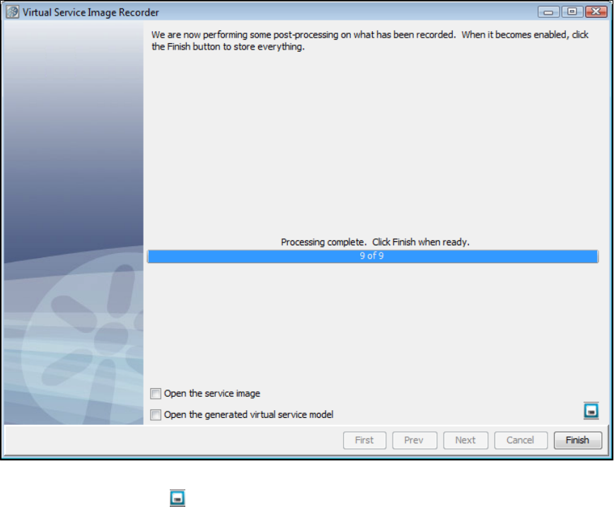
10. The recorder completes post-processing the recording. If you want to save the settings on this recording to load into another service image
recording, you can click the Save icon.
11. Click Finish to store the image.
12. In LISA Workstation, review and save the virtual service model.
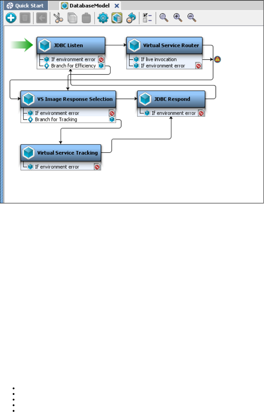
1.
2.
3.
4.
5.
Recording TCP Service Images
The transport protocol lets you virtualize raw TCP/IP traffic between one or more clients, and a server. It is very similar to the HTTP protocol,TCP
and uses much of the same features.
During recording, you configure the TCP protocol just like you would configure HTTP in "Endpoint" mode - you give it a socket to listen on, and as
the target server and destination. The protocol will forward data between the client and server, and "listen in" on that data to create VSE
transactions.
Converting bytes to VSE transactions
Because there is no inherent structure to the TCP data, it can be difficult to know what makes up a complete request or response, and how to
correlate those. It is necessary to select a to identify requests in the incoming data stream. You can also select a request delimiter response
, although this is not strictly required.delimiter
The recorder uses these rules to determine requests and responses, and to correlate those together into transactions:
A request is followed by 0 or 1 responses.
Each response is paired with the latest complete request.
A request is determined to be complete when response data arrives, even if the request delimiter says it is not complete.
A response is determined to be complete when request data arrives, even if the response delimiter (if any) says it is not complete.
When response data is received, if the response delimiter finds a complete response, any extra response data will be discarded.
As an example, consider the following data.
Request 1 - Request 2 - Response A - Partial Request 3 - Response B - Request 4 - Partial Response C - Request 5 - Response D With Trailing
Data
This will be parsed into transactions as follows:
Request 1 with no response
Request 2 with Response A (from rule 2)
Partial Request 3 with Response B (from rule 3)
Request 4 with Partial Response C (from rule 4)
Request 5 with Response D, but with the "trailing data" dropped (from rule 5)
This system will work if the client and server follow a synchronous "request - response" paradigm, and it handles requests with no
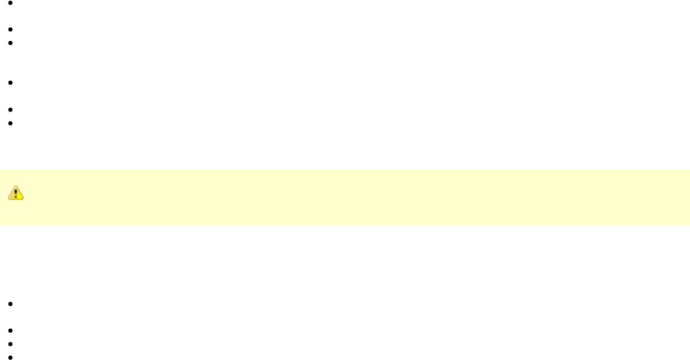
1.
responses. It will not handle asynchronous communication, or one request with multiple responses.
Creating Conversations
Each client's traffic goes into its own conversation.
Out of the Box Delimiters
LISA has the following delimiters:
Records are terminated with line endings: Each request/response is terminated by one or more newline characters - \n, \r, and
Unicode characters 0085, 2028, and 2029. The delimiter itself is not included in the request/response.
Records are of fixed length: Each request/response is a specific number of bytes.
Records are delimited by specific characters: Each request/response is terminated by a specific sequence of characters, such as a
comma. The entire sequence must be matched. The delimiter itself is not included in the request/response. This is analogous to
importing a CSV file.
Records are delimited by a regular expression: Each request/response is terminated by a set of bytes that matches the given regular
expression. The delimiter itself is not included in the request/response.
Records are defined by a regular expression: TODO
DRDA: (request delimiter only) TODO
If the delimiter characters are not included in the request/response (as in most cases), back-to-back sets of delimiters will be ignored.
It is not possible to edit the selected delimiter after the recording is done. You cannot change it in the model editor.
Treat Request/Response as Text
The check boxes Treat Request as Text and Treat Response as Text control how the request and response data is parsed.
Treat Request as Text (selected): The request is set as the body text of the VSE request. The first "word" (up to the first spaceentire
character) is used as the operation name.
Treat Request as Text (not selected): The request body is left as binary. The operation is "OPERATION".
Treat Response as Text (selected): The response body is treated as text, with any embedded nulls (\0) converted to spaces.
Treat Response as Text (not selected): The response body is left as binary.
Why is the Transaction Count Off?
The transaction count will always lag by at least 1. When the TCP protocol finds a complete transaction, it caches that until the next transaction
starts. The reason for this is that the server may intentionally close the socket after responding. If this happens, the TCP protocol will detect it and
set a bit of metadata on the response, "lisa.vse.close_socket_after_response=TRUE". This will cause VSE to close the server side socket after
sending that response during playback.
If you do not use a response delimiter, the transaction count will lag by another transaction because the TCP protocol will not know the response
is finished until a new request starts. So, the total count can be off by two. It will be correct when the recording is finished.
Recording TCP Service Images - Example
If you are using TCP as the Transport protocol in the Basics tab in the Virtual Service Image Recorder, complete the remaining wizard
steps as shown in the following example.
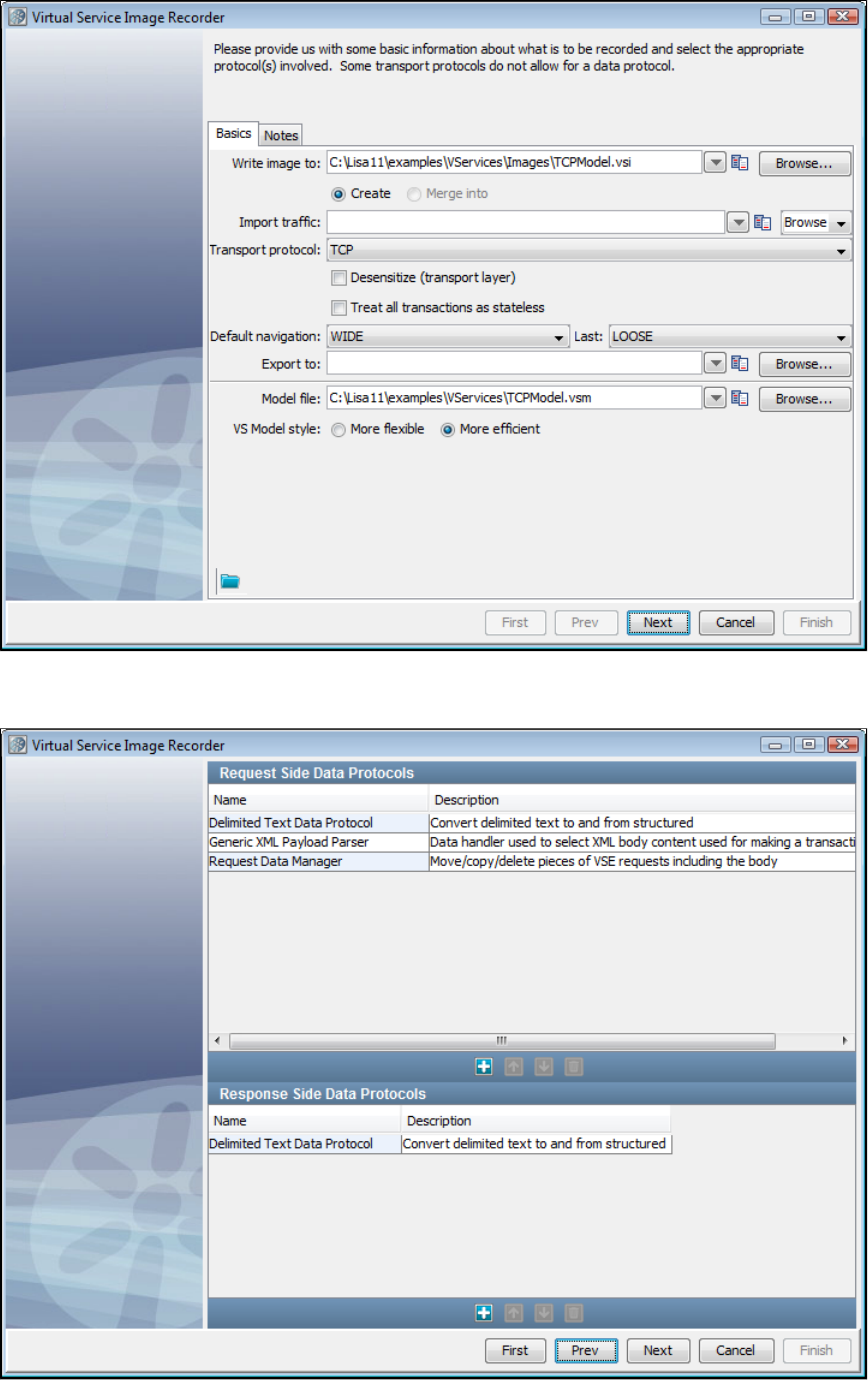
1.
2.
3.
4.
Click Next on the recorder's first screen.
Add three Request Side Data Protocols: Delimited Text Data Protocol, Generic XML Payload Parser, and Request Data Manager. Add a
Generic XML Payload Parser as a Response Side Data Protocol. If you do not select a response protocol, no live invocation step will be
included in the VSM. Click Next to move to the next screen.
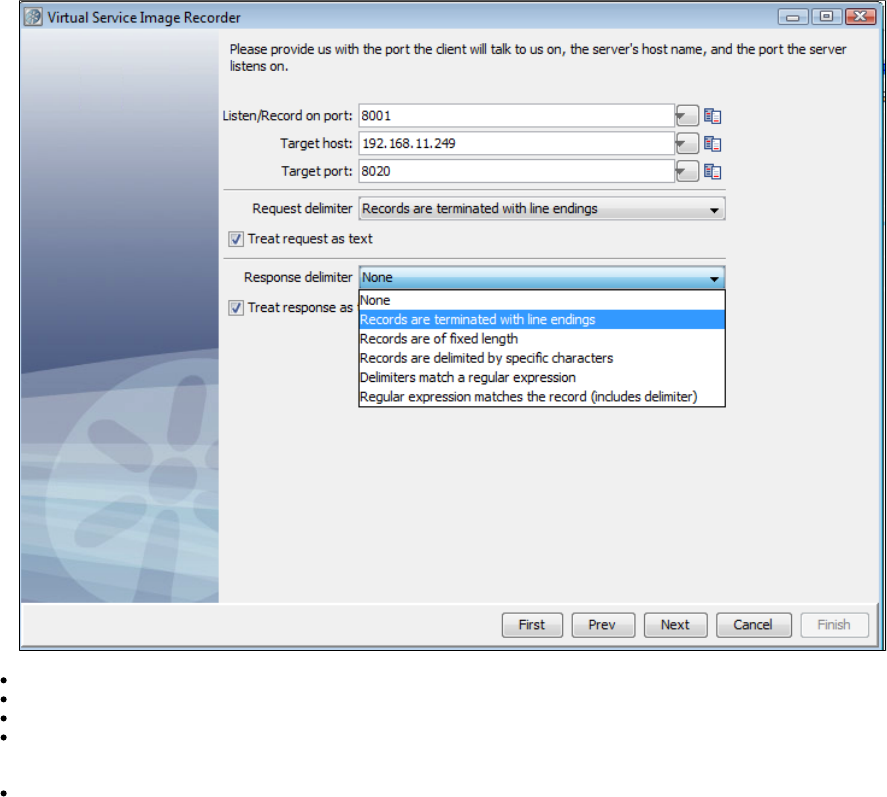
4. The next screen lets you enter information for both the client and the server, and selecting delimiters.
Listen/Record on port: The port on which the client will talk to us.
Target host: The server's host name.
Target port: The port on which the server listens.
Request delimiter and Response delimiter: Select from line endings, fixed length, specific characters, regular expression, or regular
expression matches the record, including the delimiter. The Request delimited can also be DRDA. The Response delimiter can also be
None.
Treat request/response as text: Check to indicate that the request or response should be treated as text.
5. Click Next to begin recording. When you have completed your recording, click Next. As part of the recorder's preparation for writing out the .vsi
file, it verifies request and response bodies to make sure that, if they are marked as text, that they are text. If they are not, the type is switched to
binary.
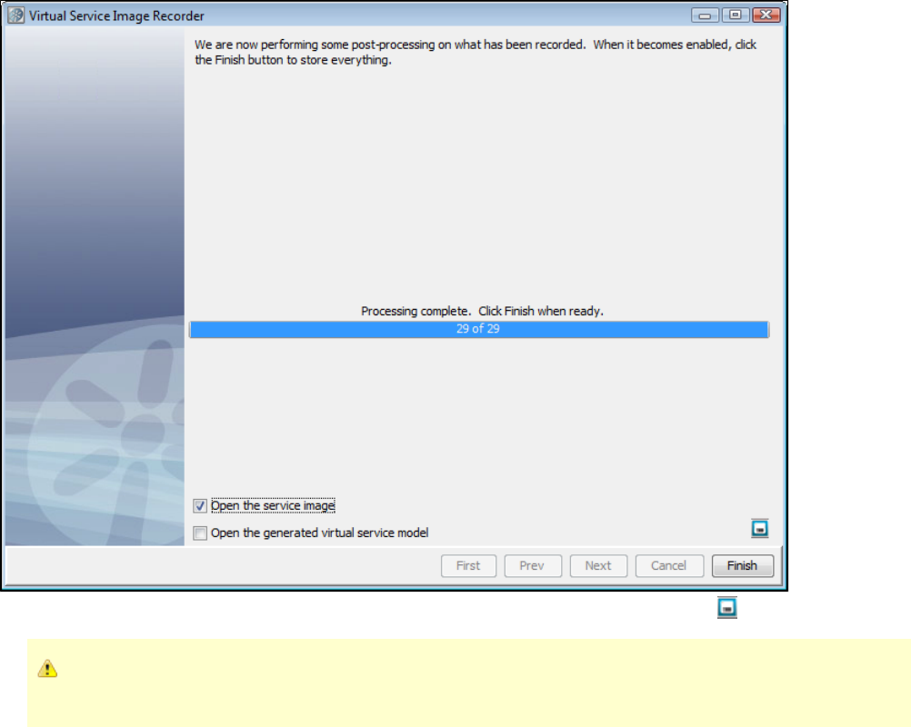
If you want to save the settings on this recording to load into another service image recording, click the Save icon.6.
The TCP/IP protocol supports a live invocation step. To enable this, you must select a response protocol. If you do not select a
response protocol, no live invocation step will be included in the VSM.
Recording WS Service Images
You can record web services service images from the Quick Start window. For details, see .Record WS VSI
Recording CICS LINK Service Images
Recording IBM CICS LINK Service Images Example
The example IBM CICS transaction we will use in our demonstration is named DEM1. It is launched from a 3270 terminal and it drives program
DEMOAPP1. DEMOAPP1 does three CICS links.
The first CICS link is to , which reads the DEMONAME VSAM file to get the account information from the customer.DEMOGETN
The next two links are Distributed Program Links, or DPL links. Both of these programs, and , reside on a separateDEMOGETP DEMOGETB
CICS region, CICSB, with SYSID S650. The first CICS link, to DEMOGETP, has the SYSID coded in the LINK statement, to specifically tell it to
link to SYSID S650. For this reason, is not defined in the PPT of CICSA, so we will need to handle that separately in LISA.DEMOGETP
The second program we link to with a DPL link is , and that has a simple CICS link without the SYSID, because is inDEMOGETB DEMOGETB
the PPT. Both of these CICS programs read their respective VSAM files and return the telephone information and the balance information for the
customer.
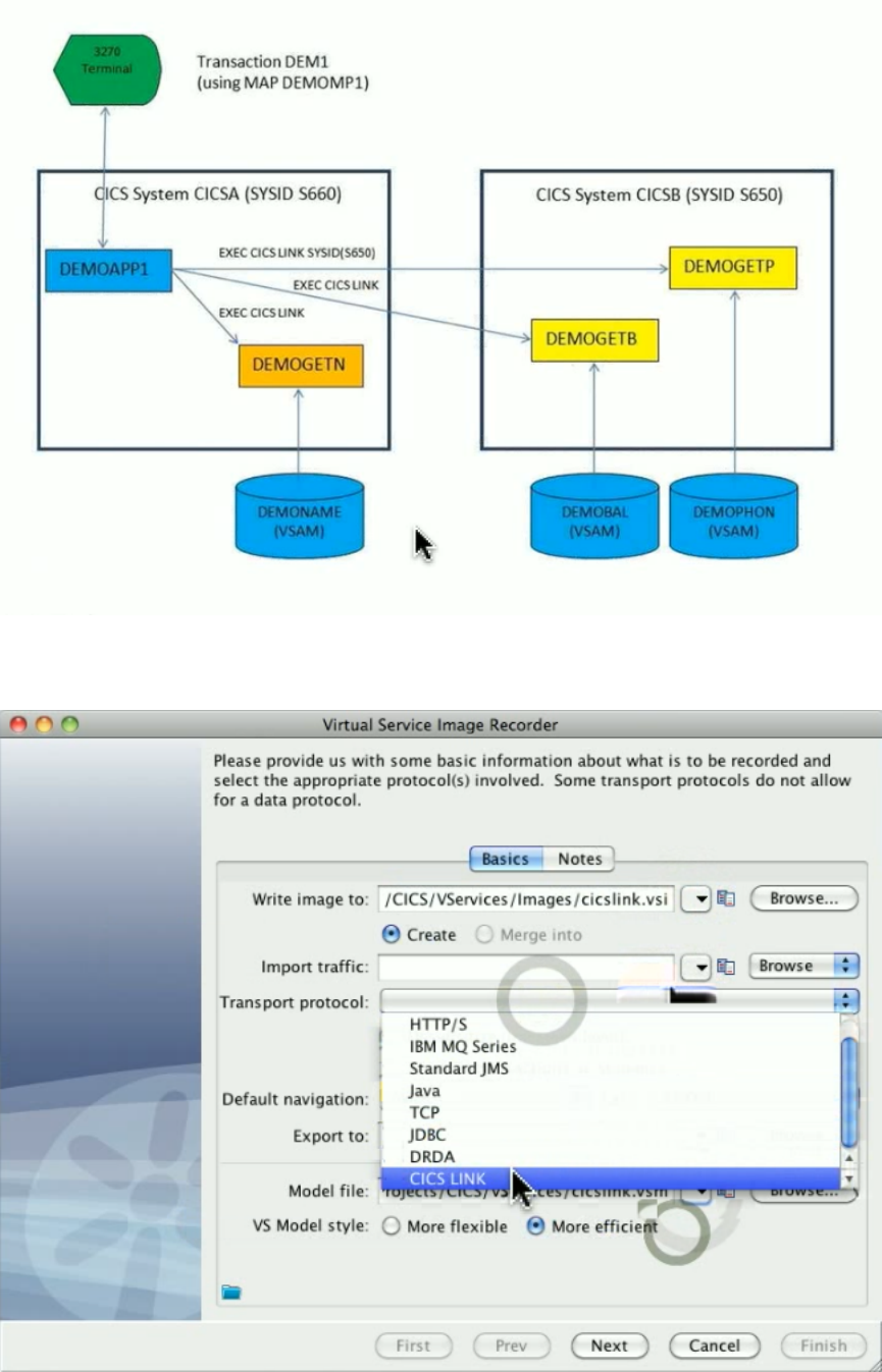
Now that we know what the CICS system that we are going to record looks like, we need to start LISA to actually capture that traffic. In the Virtual
Service Image Recorder, enter the parameters for the file to write the service image to, the file to write the virtual service model to, and select
CICS LINK as the transport protocol. Click Next.
Most programs that talk to each other in the CICS world use copybooks, formatted data structures, to describe the data going back and forth from
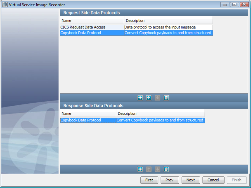
the calling program to the called program and back. So from LISA’s point of view, we will need two data protocol handlers. The first is the new
CICS Request Data Access. This one is used to indicate which of the various types of input styles in the CICS link statement that you are making
use of that you want to capture to virtualize. We will also use our Copybook data protocol. This is a data protocol that will take the copybook data
structure and use that against the incoming data and the response data and convert that into a well-understood XML document, which LISA can
then process. We will need that same XML converter on the response side and the request side.
The next page is for the CICS information. The software talks to a broker, and that broker is what stands in front of the miscellaneous pieces
embedded in CICS from ITKO that let you do this functionality. Enter the IP address where our broker is located. If you click Connect now, all the
known programs will be retrieved. To limit the list of programs to ones that start with DEMO, enter DEMO as a prefix, then click Connect.
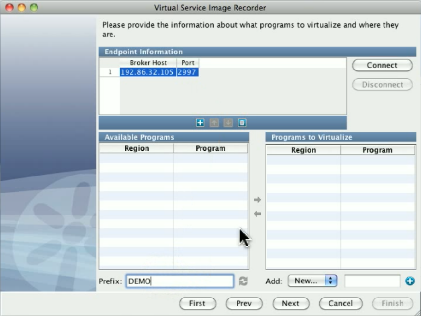
We are now connected and have a list of all programs in this region that begin with DEMO. You can see DEMOGETB and DEMOGETN, so we
will select those and move them over the the list of programs to virtualize.
DEMOGETP is not in the list, because it is not defined in a table, but it is in the same region, so we will add that one manually.
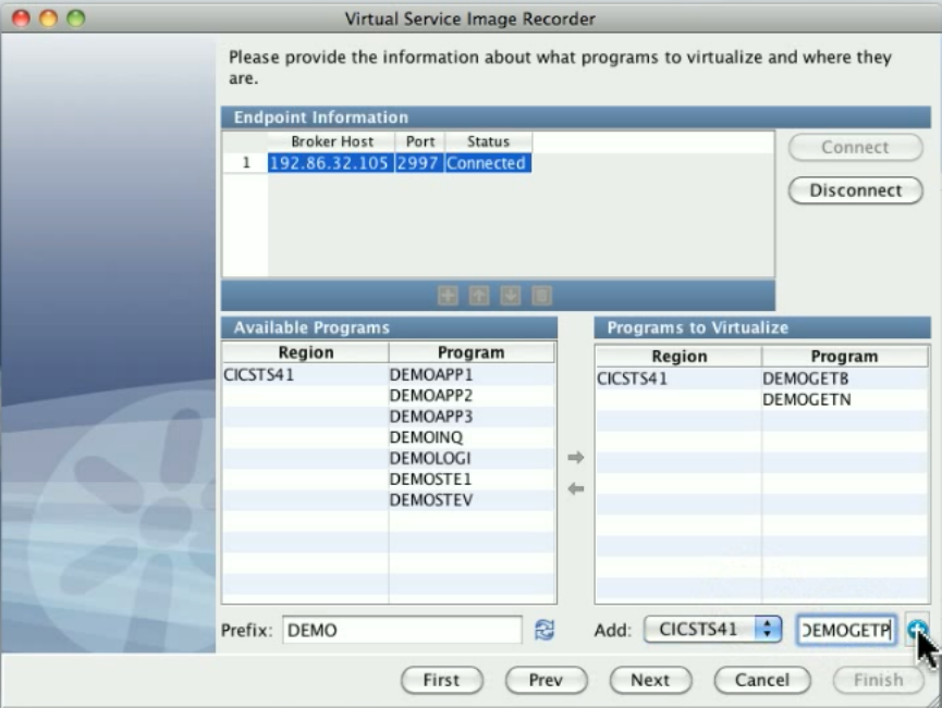
Now, we have everything we need to virtualize.
We are logged on to CICSA and we will press the Clear key, and run transaction DEM1. Press ENTER to read the first record in the file, and you
can see that it calls to read the name and address record. It calls to read the telephone number, and toDEMOGETN DEMOGETP DEMOGETB
read the balance record.
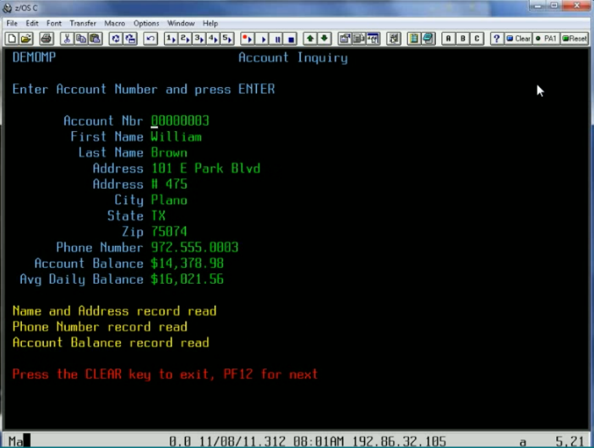
Continue browsing through the file by using PF12 and show the three records, then exit DEM1.
In the VSE recorder, you see the recorded calls; there is one for , one for , and one for . At the bottom ofDEMOGETN DEMOGETP DEMOGETB
the screen, you can see we have 9 transactions total that were captured.
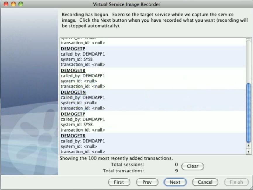
If we double-click on one of these, you can see this is how LISA is already looking at these transactions. We automatically at the CICS transport
layer define the operation for a request as being the program being called, and then we set up three arguments automatically; the program that is
doing the calling, the system id and the transaction id.
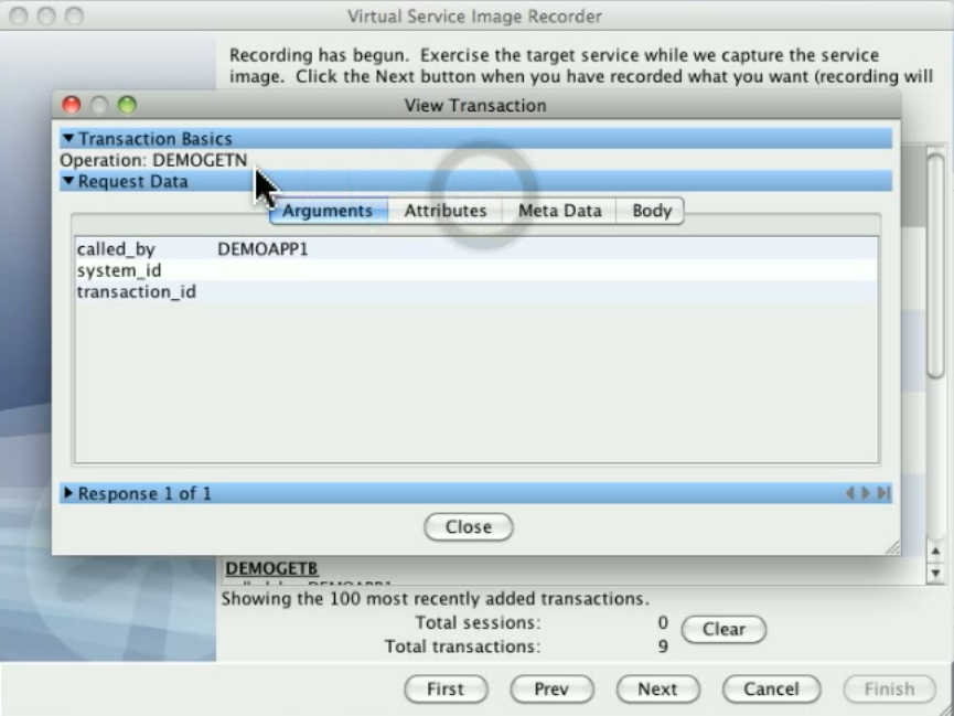
In the meta data, there is some information that is useful for anyone who is really familiar with CICS. Basically we have some control information
to tell us where in our request body the commarea, which is one of the areas that CICS uses to talk between programs, starts. There are control
fields that CICS provides, out of what is named the EXEC INTERFACE BLOCK, or EIB, and we put those all into the meta data for the request.
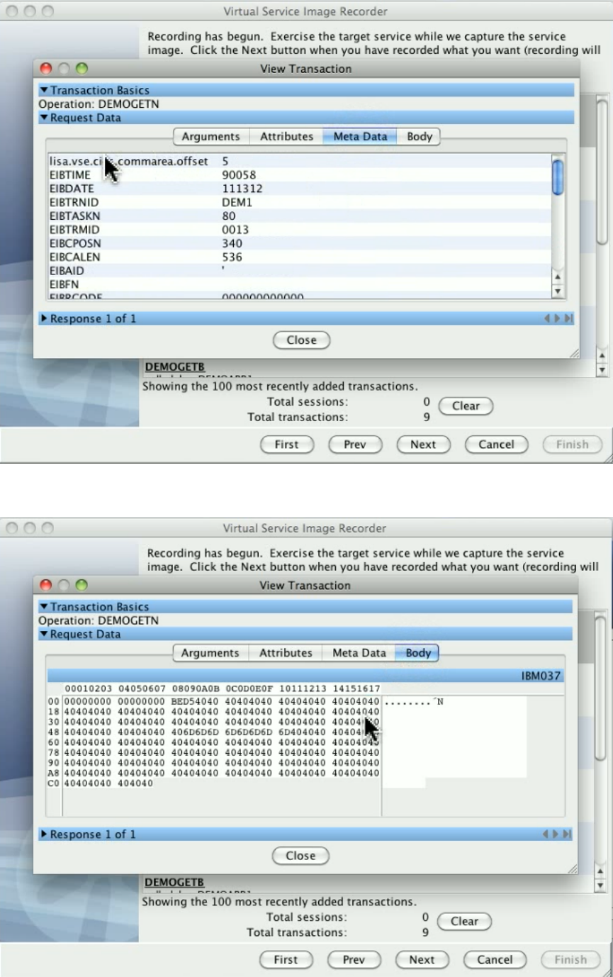
Then on the body, you can see that we have basically the input data. It is somewhat encoded, but again that is what the CICS Request Data
Access data protocol handler is for. This is showing EBCDIC, so that you can see this is being correctly translated within LISA.
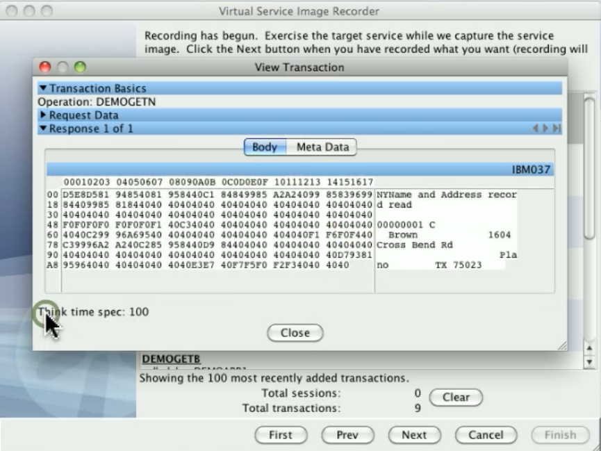
If you look at the response side, you can tell a little bit more clearly this is actually EBCDIC data in the body but we can still read it, so we could
actually later on change it. And on the response side we also have the meta data with all the EIB fields and some encoding information that the
CICS protocol uses to help build the response when it is time to send this back. Click Next to stop recording.
After recording is done we see the page where we can select what kind of input area we want and in the simplest case there is an optional input
message or COMMAREA. Channels are also supported. For this demo, we are using a COMMAREA, so we will add one action that says to
select the COMMAREA.
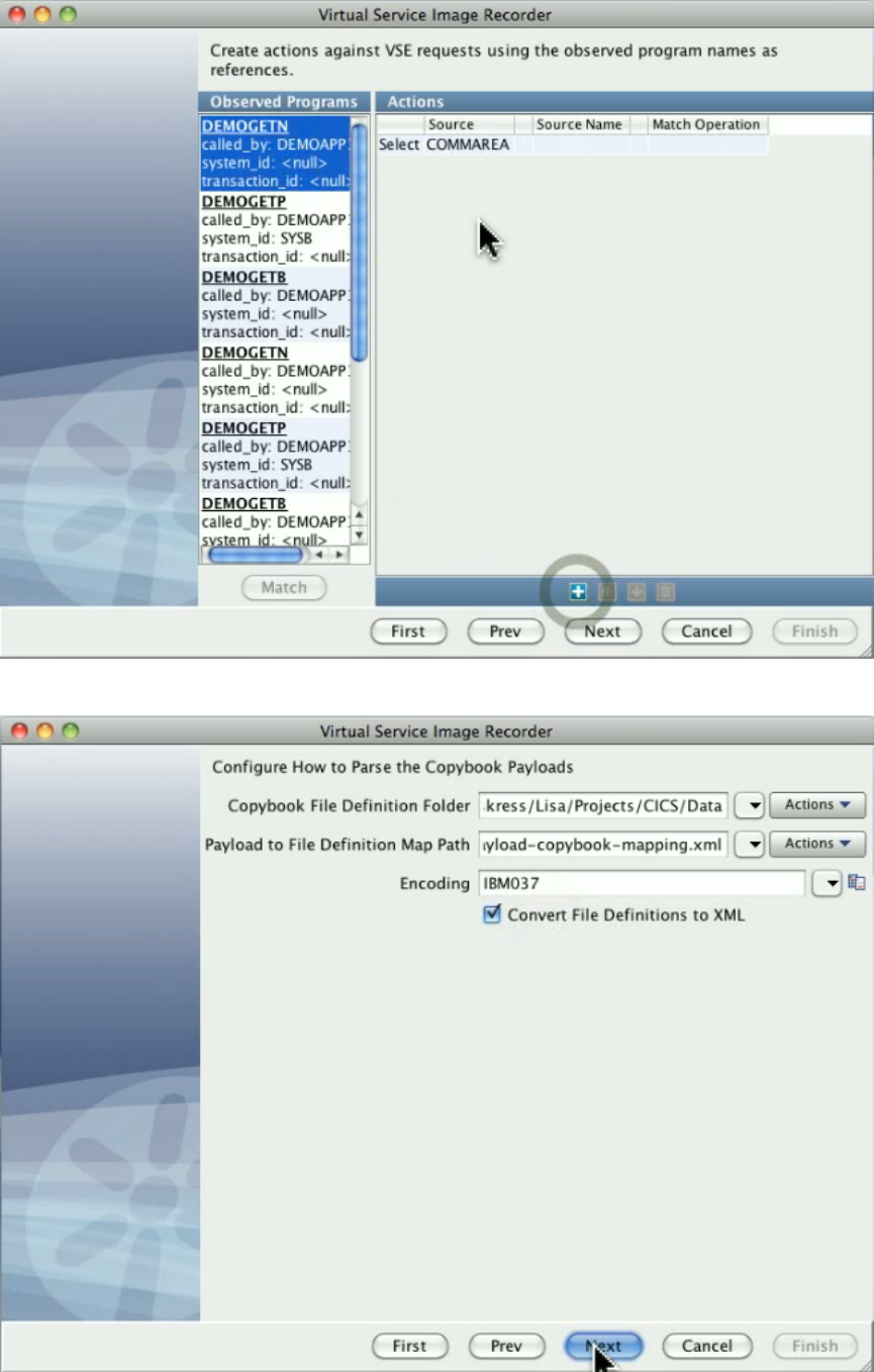
Click Next. Then fill in the information the copybook protocol, which includes the type of encoding that we are using, and click Next.
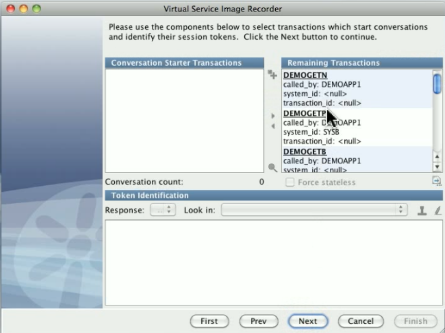
The next screen is where you would typically identify conversation starter transactions. You can see our transactions here.
Double-click on a transaction to see how the data protocols have changed things. The COMMAREA here on the request side has been converted
into an XML document, and the same on the response side.
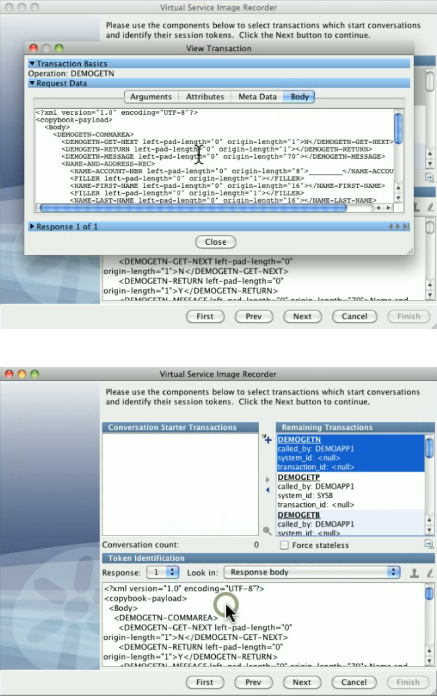
On the request side we could have added the Generic XML Payload Parser data protocol to select even more things and make actual arguments
out of them: whatever is needed to support proper navigation.
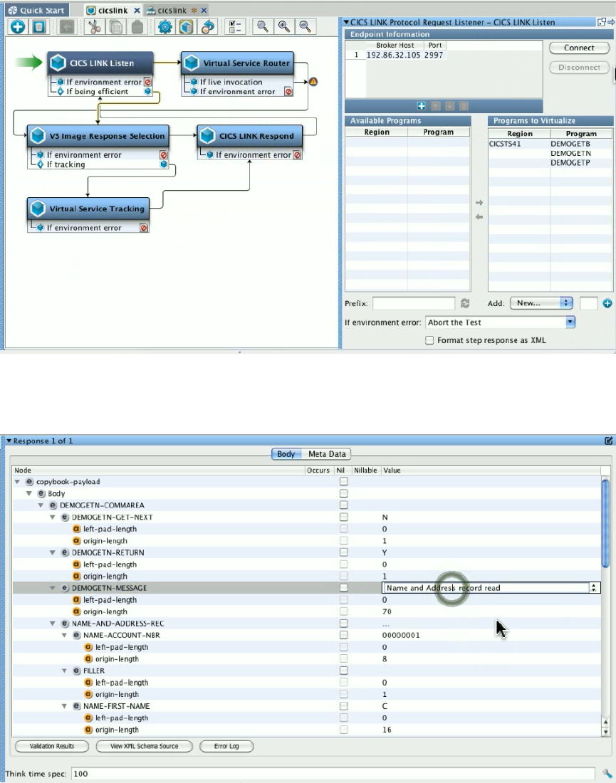
Click Finish to complete the recording. As part of the recorder's preparation for writing out the .vsi file, it verifies request and response bodies to
make sure that, if they are marked as text, that they are text. If they are not, the type is switched to binary.
We have now created a service image and a virtual service model. Open the virtual service model. Notice that it has a listen step and a respond
step, and on the listen step is the information about where the broker lives, what programs to virtualize, and you can change that if you need to.
Open the service image. You can see where we have all stateless transactions, one for , and . BecauseDEMOGETN DEMOGETP DEMOGETB
they have the same argument structure, the repeats of each one all got merged. You can see on the response side we have the XML where we
can set up the data. We will change the field in the response XML, which is the message, where it says "Name and Address recordDEMOGETN
read," to "Name and Address virtualized."
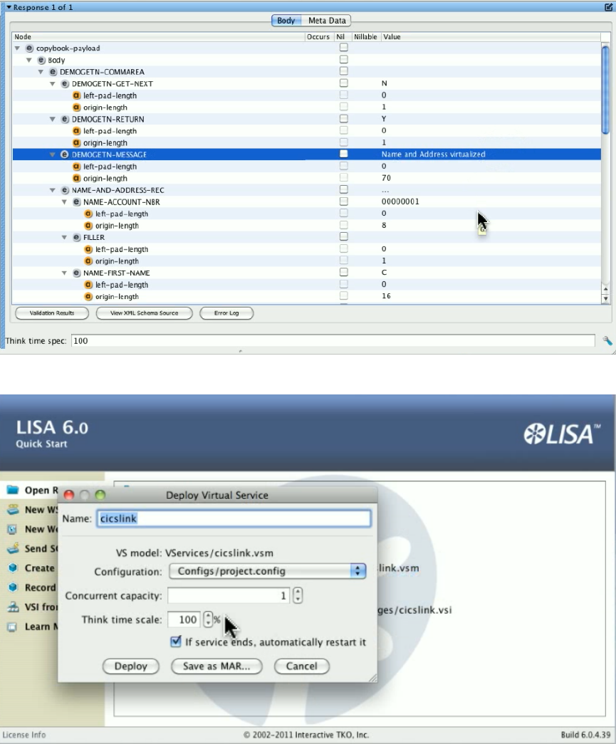
Save the service image. Go to a browser and start LISA Server Console. Deploy the VSM to the dashboard.
Now that we have a virtual service image ready to respond, we will shut down CICSB. We go back to CICSA and run DEM1 again. It reads the
name and address successfully, because that is a local link, but the DPL links, and , fail.The program detects theDEMOGETP DEMOGETB
failure and gives us errors.
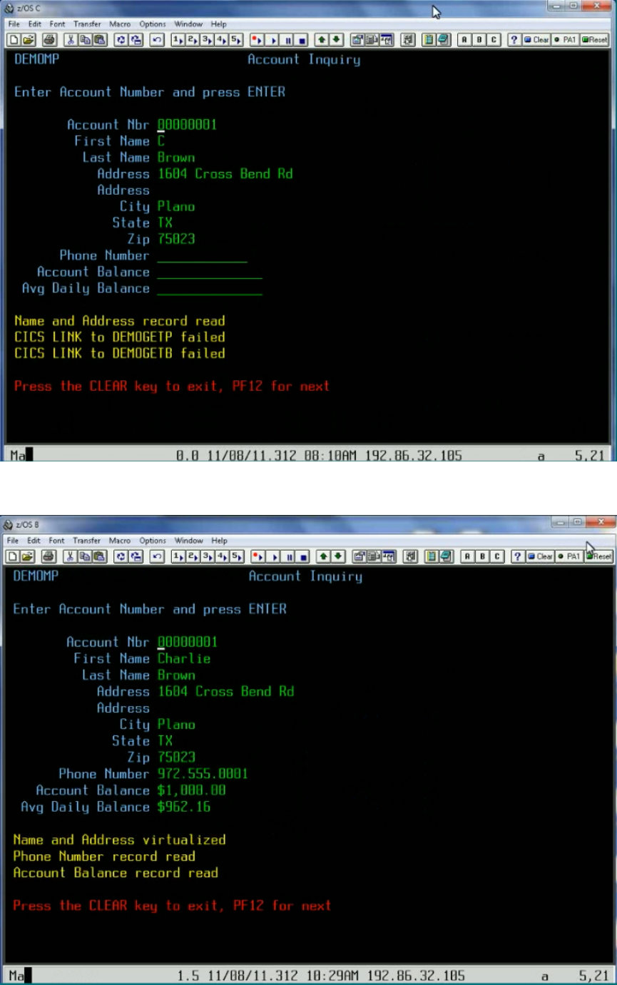
Go back to the VSE dashboard and start the virtual service model and wait until it shows a status of Running, then go to CICS and run program
DEM1 again.

Press Enter to read the first record. The program is successful, even with CICSB down, because the program has been virtualized.
Recording DRDA Service Images
TODO
Using Data Protocols
Data protocol data handlers can be chained to work with each other. For example, on the request side, it is possible to use the Delimited Text
Data Protocol, the Generic XML Payload Parser, and the Request Data Manager all together. Each available data protocol is described in the
following sections.
Web Services (SOAP)
Web Services (SOAP Headers)
Web Services Bridge
WS - Security Request
Request Data Manager
Request Data Copier
Auto Hash Transaction Discovery
Generic XML Payload Parser
Data Desensitizer
Copybook Data Protocol
Delimited Text Data Protocol
Scriptable Data Protocol
CICS Request Data Access Data Protocol
DRDA Data Protocol
Web Services (SOAP)
The Web Services SOAP data protocol handler is used to convert a SOAP document in XML form into a proper operation/arguments type of
request.
For each request presented to the data protocol, an attempt is made to parse the text form of the request's body as an XML document. If the body
is a valid XML document and the top-level element is , then it looks for both and child elements.Envelope Header Body
If the SOAP envelope contains a header element, the data protocol will look for a element in the header and under that, check for an ReplyTo
element. If such an address element is present, its value is set in the current VSE request's meta data list under the name, Address .lisa.vse.reply.to
If the SOAP envelope contains a body element, then the tag name for its first child becomes the operation name for the VSE request. If the
operation cannot be determined for any reason then none of the following will occur for the current request.
If the operation element contains any XML attributes, these are added to the current VSE request's attribute list.
Then the entire tree of XML elements under the operation element is examined. All elements that do not have child elements are added to the
VSE request as arguments. The name of each argument is constructed by using all parent element tags (up to the operation element) to help
ensure uniqueness. If the same name appears more than once, then a numeric suffix is added to both indicate an array style structure and to help
ensure the uniqueness of the specific argument.
Finally, the original XML document (the request body) is copied to a new attribute in the VSE request named .recorded_raw_request
This data protocol handler requires no configuration information and so does not present a page in the recording wizard.
Web Services (SOAP Headers)
The SOAP Headers data protocol handler will turn elements from the header of a SOAP message into arguments for requests in a virtual service
image. It is compatible with any transport protocol that will generate SOAP messages; typically HTTP/S.
To use the SOAP Headers data protocol, generate a VS Image either by recording or from request-response pairs. You will typically use the
HTTP/S transport protocol. Add the SOAP Headers data protocol as a . This data protocol does not require anyRequest Side Data Protocol
extra configuration.
This data protocol can be used with the SOAP data protocol to process both SOAP headers and the SOAP body.
Arguments are named based on the structure of the XML.

Example
<soapenv:Envelope xmlns:soapenv="http://schemas.xmlsoap.org/soap/envelope/">
<soapenv:Header>
<wsse:Security xmlns:wsse="http://docs.oasis-open.org/wss/2004/01/oasis-200401-wss-wssecurity-secext-1.0.xsd">
<wsse:UsernameToken>
<wsse:Username>username</wsse:Username>
<wsse:Password>password</wsse:Password>
</wsse:UsernameToken>
</wsse:Security>
<n1:ServiceControl xmlns:n1="http://examples.itko.com/examples.xsd">
<n1:VersionID>2.0</n1:VersionID>
<n1:Asynchronous>
<n1:ReplyRequiredIndicator>false</n1:ReplyRequiredIndicator>
<n1:PassThroughData>
<n1:Key>InteractionID</n1:Key>
<n1:Value>444831</n1:Value>
</n1:PassThroughData>
</n1:Asynchronous>
</n1:ServiceControl>
</soapenv:Header>
...
This will be parsed into elements named
Security_UsernameToken_Username
Security_UsernameToken_Password
ServiceControl_VersionID
ServiceControl_Asynchronous_ReplyRequiredIndicator
ServiceControl_Asynchronous_PassThroughData_Key
ServiceControl_Asynchronous_PassThroughData_Value
Duplicated elements will be named with _1, _2, and so on, appended to the name.
Web Services Bridge
Data protocol for LISA Travel example. It is very specific to the example and would not be very useful in a general case. It can therefore be safely
ignored.
WS - Security Request
The WS-Security Request data protocol supports SOAP messages that include WS-Security headers. It is designed to strip away any security
from the SOAP Request before sending it along the Virtualize framework and to apply security to outgoing SOAP responses.
When recording a web service with WS-Security headers, add a WS-Security Request (Request Side) Data Protocol (typically before a Web
Service SOAP Data Protocol) and a WS-Security Response (Response Side) Data Protocol.
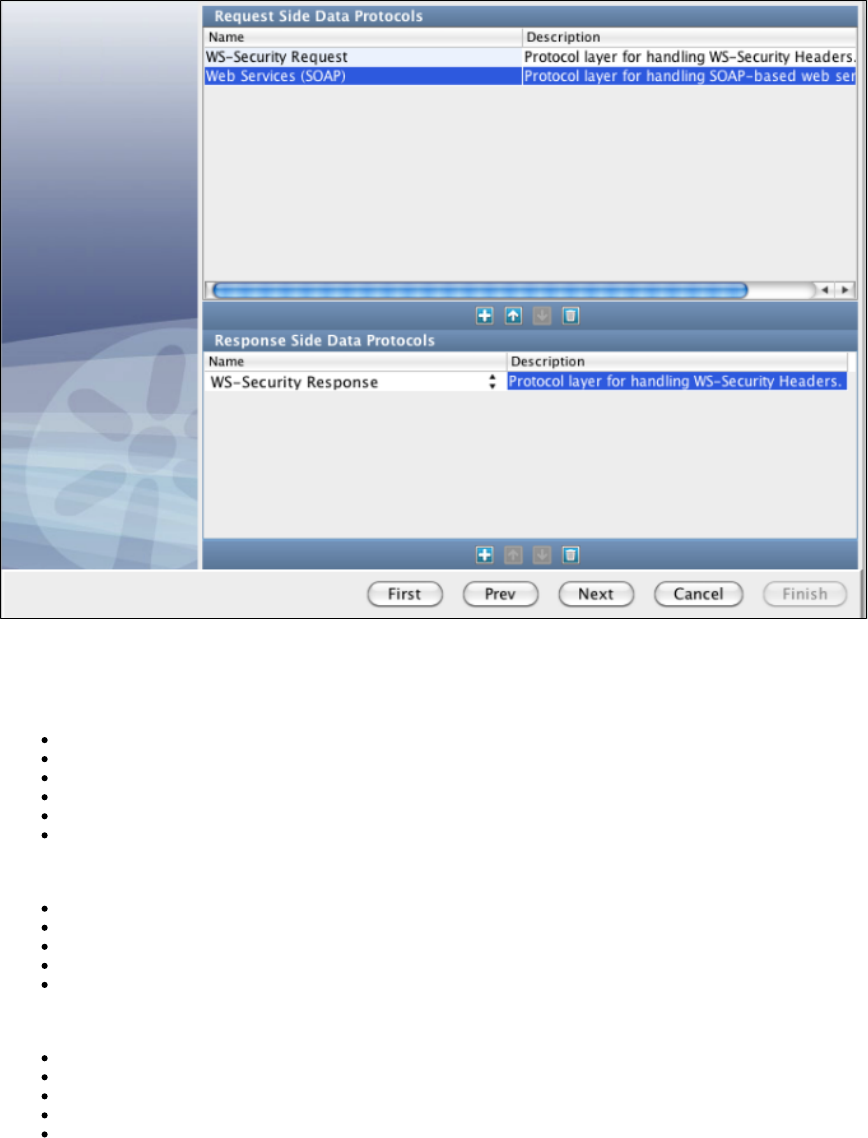
Before recording you will be presented with a set of configuration panels. One is for the WS-Security Request Data Protocol and two are for the
WS-Security Response Data Protocol. For the Request Data Protocol, configure the handler to process a Request message sent by the client. Fill
in the Receive actions used to decode/validate the headers. This configuration is used both for recording and playback.
Options available for Receive (Response) messages are:
Decryption
Signature Verification
SAML Verifier
Username Token Verifier
Timestamp Receipt
Signature Confirmation
Options available for Send (Request) messages are:
Timestamp
Username Token
SAML Token
Signature Token
Encryption
You may want to use encryption, in which case you can enter the following information:
Keystore File: Select from the drop-down or select from the file system the keystore file to use for encryption.
Keystore Type: Select either or Personal Information Exchange (PVKS #12).Java Key Store
Keystore Password: The password for your keystore.
Keystore Alias: Should be an alias for a public key.
Alias Password: Leave blank or enter the same as Keystore Password for PKCS #12 files.
The check box indicates whether to verify compliance with WS-I Basic Security Profile (including usingWS-I BSP Compliant
InclusiveNamespaces and CanonicalizationMethod in SignedInfo).
Click the Verify button to validate your keystore information as entered.
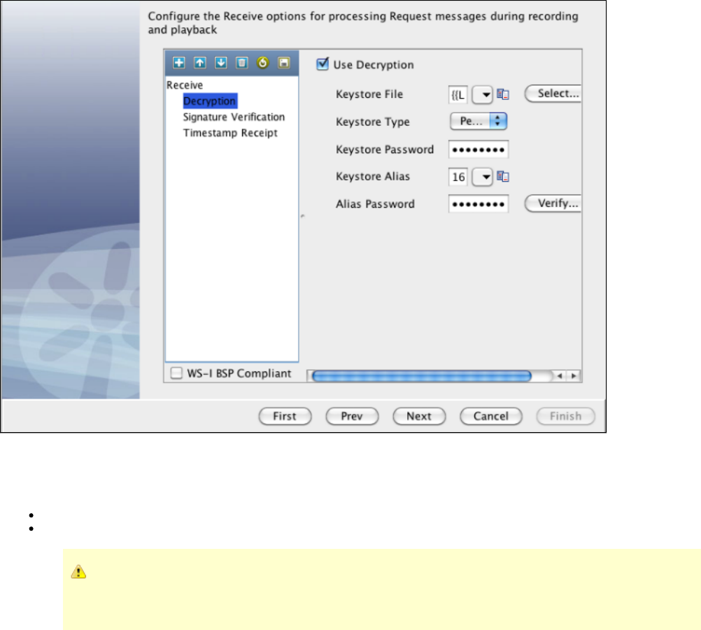
For the Response Data Protocol, configure the handler to both process Response messages sent back from the live service during recording and
Response messages sent back from the VSM. During the recording phase you need to process the Response message as the client would.
Select the check box.Add Timestamp
Time-To-Live (sec): The lifetime of the message in seconds. Enter 0 to not include an Expires element.
Use Millisecond Precision in Timestamp: Express timestamp to milliseconds.
Some Web services, particularly .NET 1.x/2.0 with WSE 2.0, are not compliant with standard timestamp date
formatting, and do not allow milliseconds. For these web services, clear the Use Millisecond Precision in Timestamp
check box.
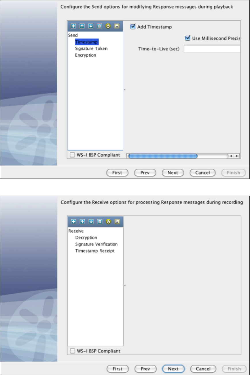
During playback you must process the message as the server would send it (the SOAP message from the VSM will not have any Security
headers and this configuration would apply the Security header).
After recording is complete, a virtual service model is created. In that model, a Data Protocol filter is attached to the HTTP/S Listen step for the
WS-Security Request Data Protocol.
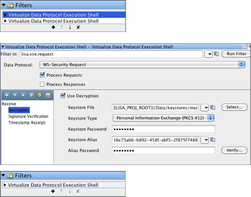
Update any security configuration information for playback (for example, if your WS-Security settings change on the service, you can update them
here as opposed to needing to re-record the virtual service).
In the VSM, a filter is also added for the WS-Security Response Data Protocol onto the HTTP/S Response step.
And like the Request side, any security configuration information for playback can be updated for the response message.
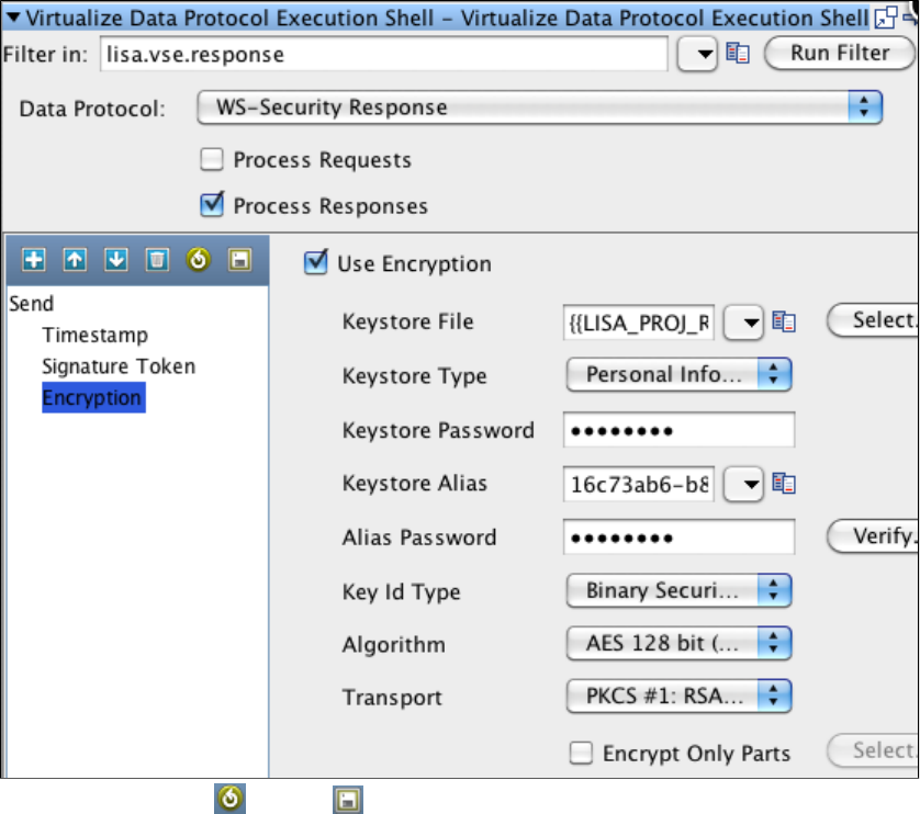
You can also use the Load and Save icons to save your security settings to a file, or to load a saved file containing security settings.
Request Data Manager
On the Data Protocols screen, select Request Data Manager for a data protocol. When your recording is complete, you will see this screen.
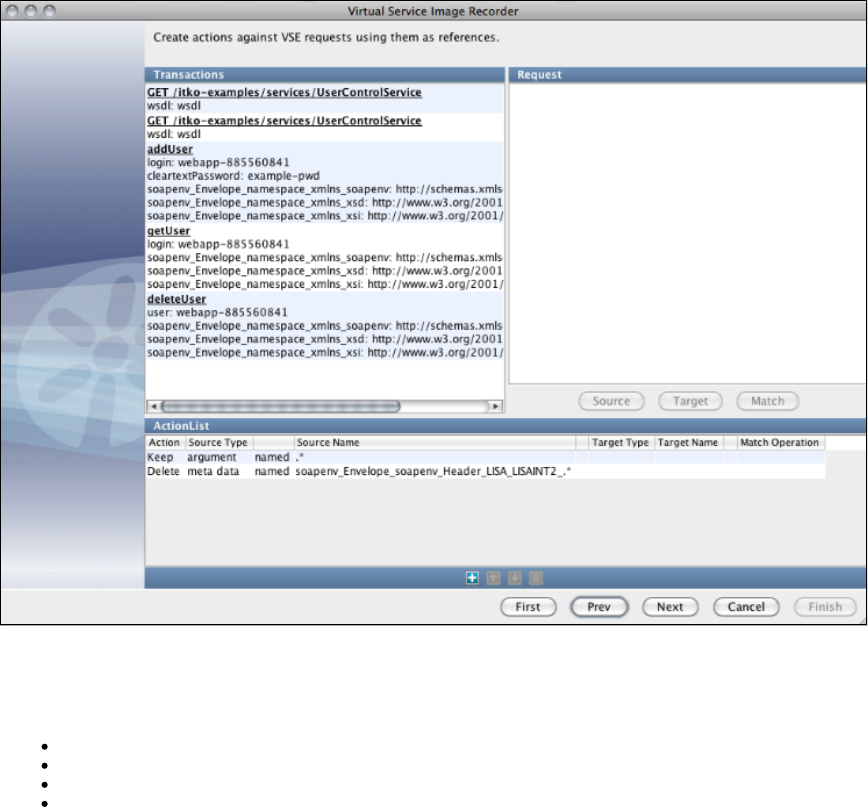
The Request Data Manager protocol lets you do almost anything you want to VSE requests as they are recorded or played back.
Fundamentally, this protocol lets a list of actions to be applied against a request. You select actions to add in the section of theActionList
screen. These actions are:
Copy: You can copy a piece of data in the request to another part of the request.
Move: You can move a piece of data in the request to another part of the request (essentially a copy and a delete of the source data).
Delete: You can delete (or clear) a piece of data from the request.
Keep: You can deliberately keep a piece of data in a request while deleting anything else in that data value's group.
All can be applied to the request operation, any argument, attribute or meta data entry or the request body. So, for example, if you are virtualizing
Java, which ends up with XML documents as arguments, you can use a move or copy action to put the value of an argument into the request
body for processing by other data protocols.
A special note about : this one is most meaningful in relation to arguments, attributes and meta data. If you specifically keep a value fromkeep
one of these three groups, any other value in that group which is not referenced by any action in the data protocol's list will be deleted. So, if you
keep one argument any other arguments will be removed unless they were the target of a move or copy. This is a good way to lose meaningless
arguments.
Each action can also be limited to apply only to requests whose operations match a specified regular expression.
In the recording wizard or the model editor containing a Request Data Manager DPH, add Keep and/or Delete actions and select
argument/attribute/meta data and specify a regular expression to match as the name. You will also need to change the cell that reads "named" to
"matches". When the DPH is run, it will perform the action (keep or delete) on all items in the argument, attribute or meta data list whose name
matches the pattern. Leaving an action's operation matching pattern empty will affect all requests.
From this list of transactions, you can double-click on a transaction and see a dialog showing the content of the transaction.
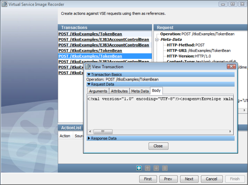
Using the Request Data Manager Data Protocol to set JMS and MQ Message Properties
After recording, use the Request Data Manager screen to add the targeted JMS message properties to the request arguments. The JMS
message properties can be found under the request Meta Data with a ' ' prefix for standard JMS properties, like correlation ID, and a 'msg.
' prefix for custom message properties. To copy a property to the request arguments, select from the drop-down list:msg.props. argument
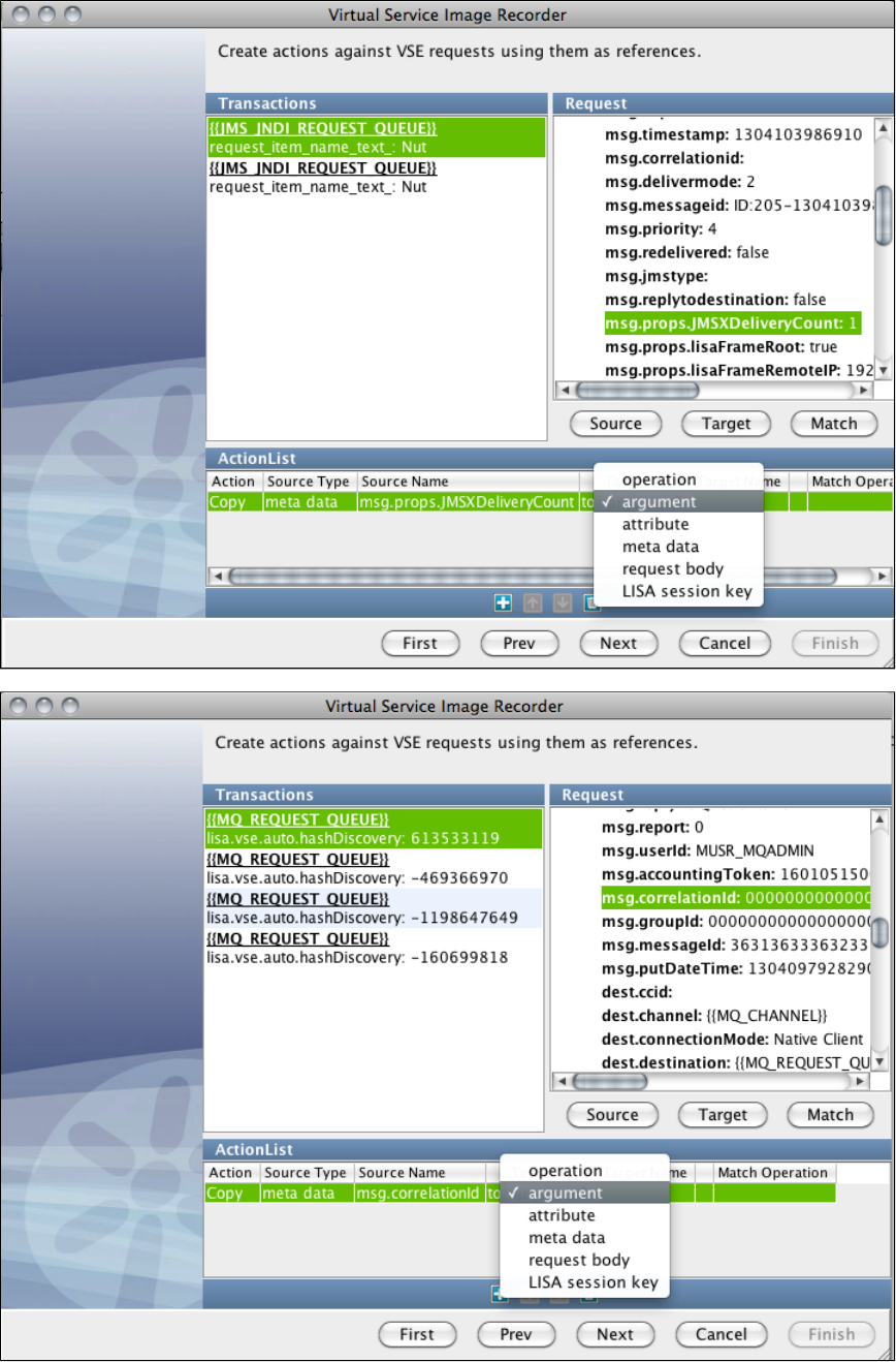
It works the same way for MQ:
To set the stateful session key instead of an argument, select from the drop-down instead: LISA session key
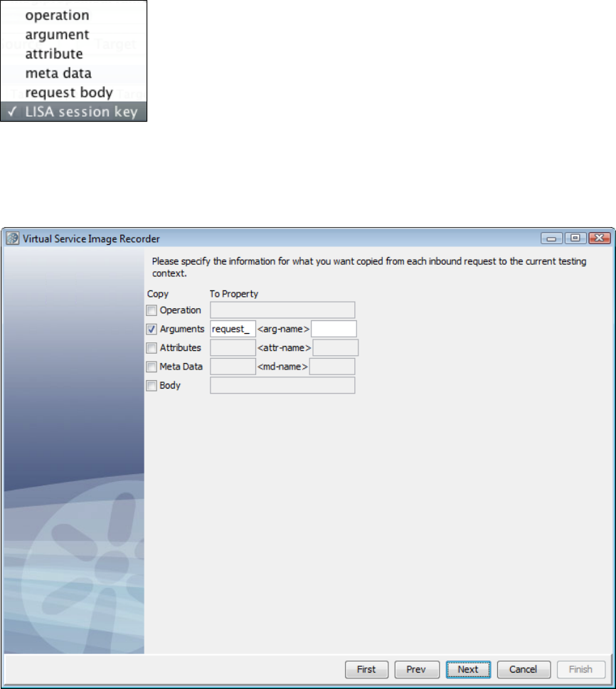
You can use a single Request Data Manager Data Protocol to set any number of arguments and/or the session key at the same time.
Request Data Copier
The Request Data Copierlets you copy data from the current inbound request into the current testing context. This is useful for more easily
examining request information when custom behavior is required before the VSE response lookup step in the VS model flow.
Auto Hash Transaction Discovery
Identifies a message by the hash code of the data. The hash code changes with even a slight change in the data, which effectively makes all
requests unique. This is useful if you will run exactly the same small set of requests against the service.
The Auto Hash Transaction Discovery data protocol has a simple purpose. As it is given requests to handle, the standard Java hash code function
is applied to the text version of the request's body. The resulting hash code value is then added as a new argument in the request named
.lisa.vse.auto.hashDiscovery
This can be helpful, especially in messaging virtualization, for creating a reasonably unique value to use for conversation identification.
This protocol requires no configuration information and so will not present a page in the recording wizard.
Generic XML Payload Parser
The Generic XML Payload Parser identifies that the requests and responses are XML strings. Using this protocol, you can identify variables out of
the XML messages that are used by the recorder.
Identifying Conversations and Transactions
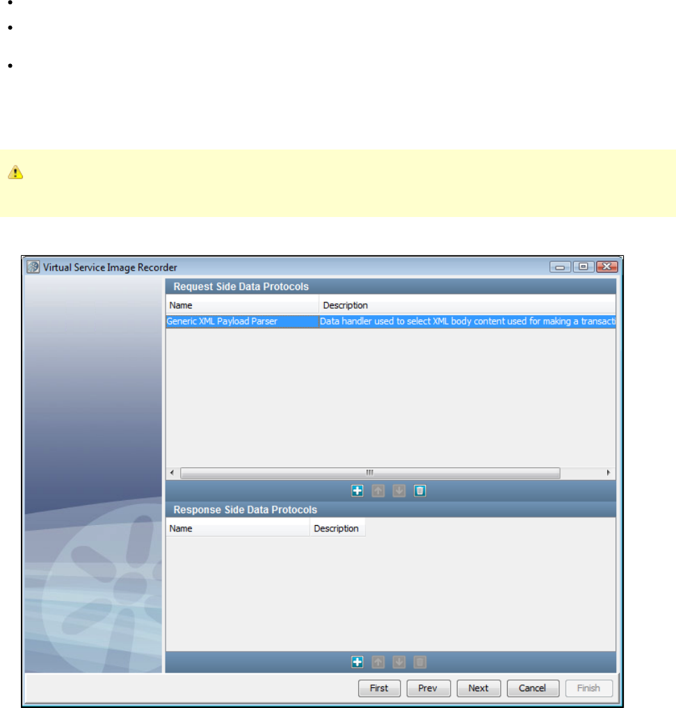
1.
2.
1.
2.
3.
The quality of the recorded service image is directly dependent on how much information LISA Virtualize has to identify the conversations and the
individual transactions in them. In particular, LISA Virtualize needs help in differentiating the transactions from each other:
As part of a conversation: which means identifying some unique id representing a session.
As individual operation: which means identifying some information specific to the semantics of the operation; for example,
distinguishing an "order creation" operation from an "order listing" operation.
LISA Virtualize internally knows many patterns to look for. For example, in case of virtualizing over the HTTP protocol, if the server is a Java
server, it typically sets a cookie containing the value of a special variable named as sessionid, which uniquely identifies the session. LISA
Virtualize can use that to identify different sessions from each other.
However, there are times when LISA Virtualize needs further help. It could be supplied in various forms:
In the HTTP recording, LISA Virtualize gives you the opportunity to identify tokens.
For the JMS protocol, you could identify whether JMS correlation id, custom JMS headers or all JMS headers should be used by LISA
Virtualize for this identification.
LISA Virtualize lets you specify a dynamic data protocol that lets you get meaningful information from the message itself. The following
section describes this technique.
Using the Generic XML Payload Parser is a technique to help LISA Virtualize look at the body of the recorded messages (payload) and extract
meaningful information from them to help identify the transactions. Especially for very opaque protocols like the WebSphere MQ native protocol,
this is the only way to get meaningful conversation information.
If you are using both the Generic XML Payload Parser and the Delimited Text Data Protocol, the Delimited Text Data Protocol
should be added before the Generic XML Payload Parser. Otherwise, the request will never appear as parsed in the recorder.
To use a dynamic data protocol, in the Data Protocols tab of the Virtual Service Image Recorder, select Generic XML Payload Parser, if
the payload is a well-formed XML.
Go through the rest of the steps, up to the cleanup step.
After the cleanup step, the following screen appears:
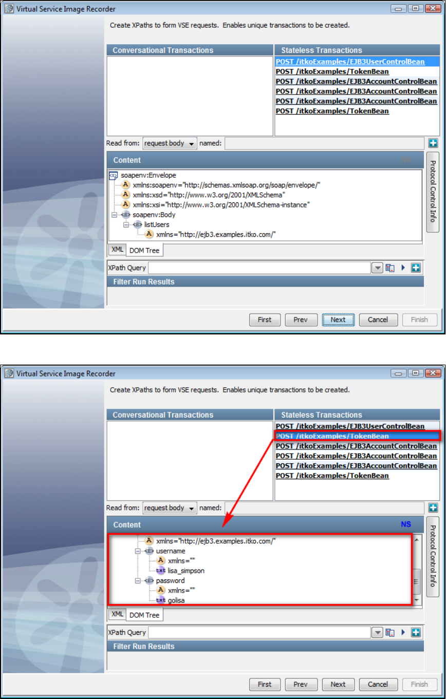
3.
4.
5.
By default, there are no starter transactions identified, which means that LISA does not know which data to look at to identify the
conversations. However, you will see the recorded transactions in the Other Transactions list. Click the first transaction to see the XML
payload.
The XML payload can now be seen under . The XML tab shows the classic XML view. The DOM Tree tab shows it in the treeContent
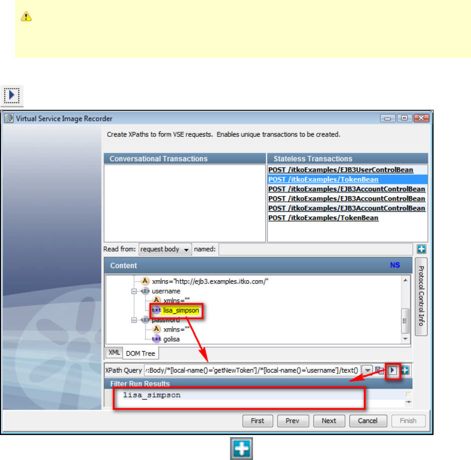
5.
6.
7.
format.
This portion of the screen is similar to the panel that appears when you create an XML XPath filter. As described in
, you can use the property to ignore theXML XPath Filter lisa.xml.xpath.computeXPath.alwaysUseLocalName
namespace.
In the DOM tree, to identify a particular node as a parameter for LISA Virtualize, click on the node. You will see the XPath query
corresponding to the node in the text box against XPath Query. To evaluate the XPath query on the current payload, you can click the
arrow button. The result of the evaluation is shown under the heading .Filter Run Results
To add this particular XPath query to the parameter list, click the plus icon. This will display a menu list where you can choose to
set an operation, an argument, a meta parameter, or the request body. For example, this can be used to select an embedded SOAP
document to the request body so that the WS SOAP protocol could then be used to parse that out.
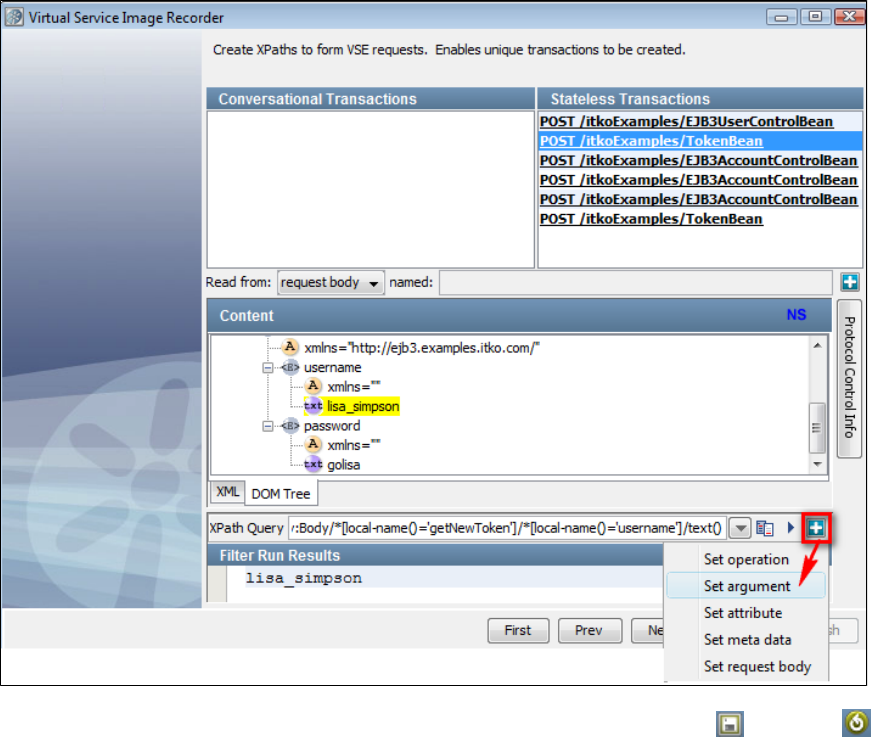
7.
8. When you select Protocol Control Info, see that LISA Virtualize has remembered the XPath string that you identified and has given it an
argument name. You can rename the argument. Also see that from this panel, you can use the Save and Restore buttons to
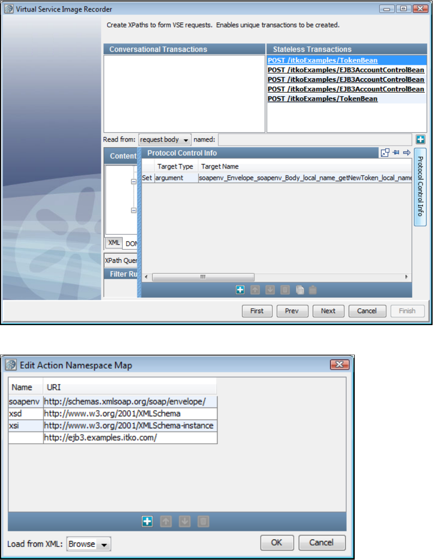
8.
9.
10.
11.
save your list of XPaths to a file, or to load a list of XPaths from a file. By doing this, you can easily copy and paste from one XML
Payload Parser to another.
Likewise, you can pull other variables from this transaction or others. It is not required for all transactions to have the particular argument.
At the time of processing, if a particular argument is not present in the payload then it is ignored.
If you scroll to the right on the panel, you see a column to indicate namespace information.Protocol Control Info NS
Here, you can add or edit namespace definitions, or you can use the Browse button to locate and pull in an XML file from the file system
and use the namespace definitions from that file.
When you are displaying the XML tab, you can double-click on a transaction and see a dialog showing the content of the transaction.
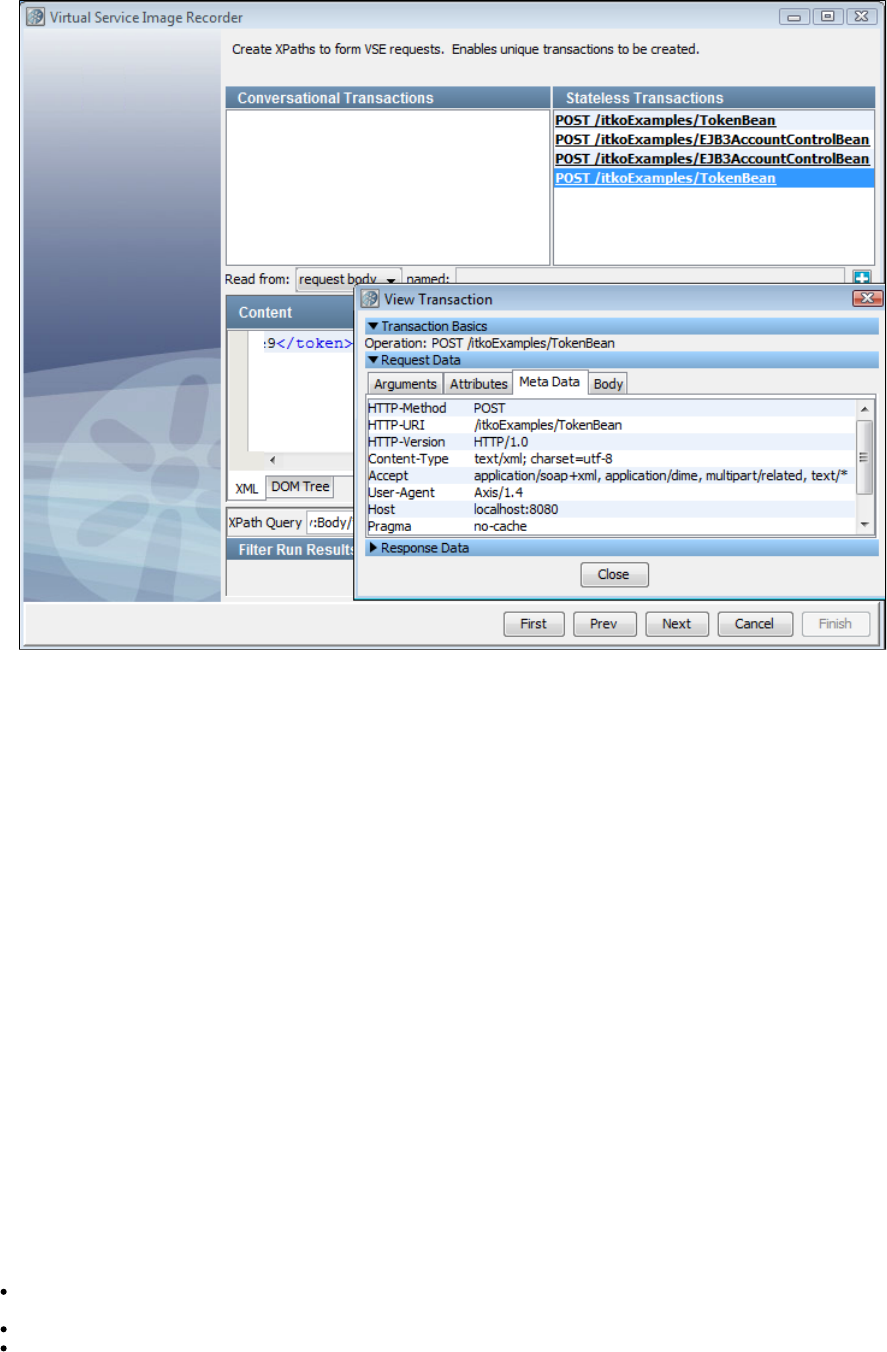
11.
12. Click Next when you are satisfied with your choice of variables. You are then directed to the post-processing screen.
Data Desensitizer
In cases where the transport layer cannot "see" the data to desensitize, VSE provides a data protocol handler. As an example, consider the use of
gzip in SOAP over HTTP or messaging. If VSE is given a gzipped SOAP request (or response), then data desensitization cannot be done at this
level. In that case the recorder can be configured with a data protocol to perform the necessary gunzip operation and with the data desensitization
protocol to handle desensitization after the SOAP body has been converted to plain text.
In general, LISA Virtualize will attempt to desensitize data at the lowest possible level. As such, the Desensitize check box on the first page of the
VSE recording wizard will request that the transport protocol specified attempt to perform desensitization as soon as possible. However, there are
times when the payload for a request is opaque to the transport protocol. Consider HTTP messages in which the payload is compressed, such as
with gzip or FastInfoSet. In this case, the transport protocol cannot apply the desensitization rules. This data protocol is built for such situations.
It is intended to be added to the request and/or response side of a data protocol chain after the protocol which can convert the opaque payload
into something readable and is only intended for recording, not playback. As each request and/or response is presented to the protocol handler,
all desensitization rules as specified in are applied, just as the transport layer does where possible.LISA_HOME/desensitize.xml
This protocol requires no configuration information and so does not present a page in the recording wizard.
Copybook Data Protocol
The Copybook Data Protocol allows VSE to convert copybook payloads to and from XML at runtime in a way that is transparent to the caller.
Being able to display these payloads in XML allows other, standard, VSE mechanisms to provide value. Specifically, the Generic XML Payload
Parser can be used to identify and select request arguments and operations for matching and transaction organization in the service image. Also,
using a standard XML structure allows for magic strings to be processed in the responses so that dynamic data can be created in a more usable
way.
Terms
In order to clarify this documentation, some common terms need to be defined.
Copybook: A hierarchical structure used to define the layout of data. It identifies the field names, their lengths, and their relationships to
each other.
Copybook File Definition: A file in plain text format containing a copybook.
Field: A single element in a copybook. It encapsulates a name for, the length of, and the data type for a single logical piece of data in a
record.
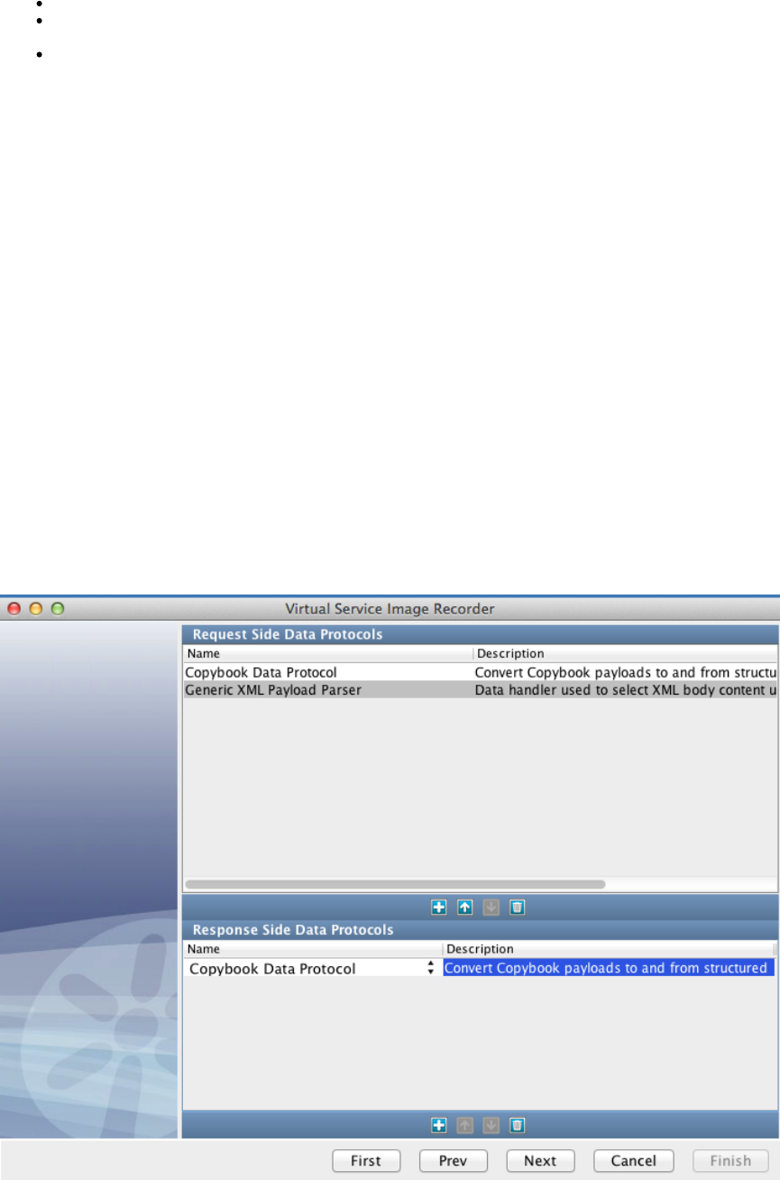
Payload: A collection of one or more records that is seen by VSE in either a single request or a single response.
Payload Mapping File: (also known as "Payload Copybook Mapping" or "Payload to File Definition Map") An XML document describing
how to identify the copybook(s) needed to parse a payload, and providing the basic structure for the resulting XML.
Record: A collection of data with no structural elements in and of itself. It is defined by one or more fields making up a single copybook. A
record may not contain data for every field a copybook defines, but the relationship between records and copybooks is always
one-to-one. That is, a given record is only defined by a single copybook, and a single copybook will define only one record.
Setup
To prepare for creating a copybook virtual service, you will need to gather all of the copybooks that define the records in your payloads. These
need to be placed in a directory within your LISA project. You may include whatever hierarchy you find helpful inside the directory you use.
Typically, you would place the copybook file definition folder somewhere under the Data folder of the project.
Also, you will need to create a payload mapping file. See for more information.the next section
Finally, you will need to prepare your client for recording, gather request/response pairs, capture a PCAP file of the traffic, or use some other
means of gathering the transactions you want to use for your virtual service.
Usage
The Copybook Data Protocol can be used with any of the transport protocols that VSE supports. Commonly, the Copybook Data Protocol Handler
is used with a messaging protocol like JMS or MQ or with the CICS Transport Protocol. There is also a sample copybook application that uses
HTTP available in the Demo Server.
Selection
When selecting the Copybook Data Protocol, there are a few things you will probably want to keep in mind. First, it is very likely that you will want
to use the data protocol handler on both the Request and Response sides. It is technically possible to only use it on one side, but it is not very
common, and single-sided usage will not be covered in detail here. Second, the result of the Copybook Data Protocol is that the Request (or
Response) body has been changed into XML. The Copybook Data Protocol does not automatically add arguments to the Request for
So, in order to do useful things with the Copybook Data Protocol, you will also need to include another data protocol handler on theevery field.
Request side. Most commonly, the second data protocol handler would be the Generic XML Payload Parser; however, any data protocol handler
that does useful things with XML payloads would be fine.
Configuration
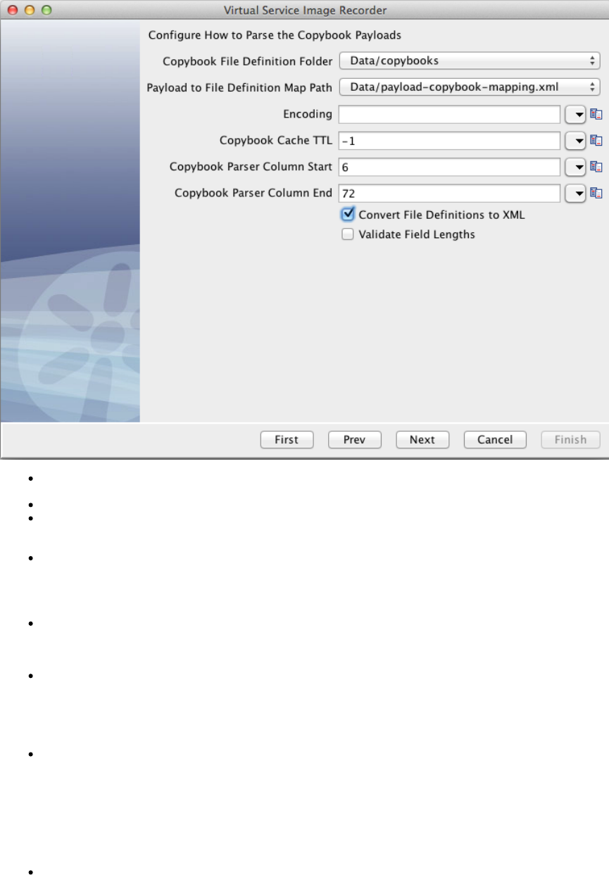
Once you have captured your traffic (or imported from Request/Response pairs, PCAP, or raw traffic files) you will get the following Copybook
DPH configuration screen.
Copybook File Definition Folder: The folder in your project where your copybook file definitions are stored. This becomes the base path
for relative paths in the Payload Mapping File.
Payload to File Definition Map Path: The XML document that will serve as the Payload Mapping File for this virtual service.
Encoding: Specify any valid . If provided, this value will be used in attempting to convert the bytes in the payload into textJava charset
for usage in the output XML. The default is specified by VSE's default charset (UTF-8 by default, and can be configured by setting
in local.properties).lisa.vse.default.charset
Copybook Cache TTL: During runtime, as VSE needs to reference a given copybook, it has to read from the file and potentially convert
it to an XML representation of the copybook. This parameter tells VSE how long it is allowed to keep a cached version of the converted
copybook in memory. Once the TTL is reached, the converted copybook will be removed from the cache and the file will be re-read and
re-converted if it is needed again. A TTL of 0 or a negative number means that caching should be disabled and the files should be read
and parsed every time they are needed. If the TTL is a positive number, it will be used as the timeout, in seconds.
Copybook Parser Column Start: Often copybooks contain line numbers at the beginning of each line. Typically these are 6 digits long,
so the default value of this parameter is 6. This option allows you to specify on which column the parser should start when trying to parse
a copybook file definition. Note that the number is a zero-based index and is clusive. However, if it helps for clarity, you can think of it asin
a "normal" 1-based index that is clusive. That is, if you set this to 6, it will skip the first 6 characters and begin with the 7th.ex
Copybook Parser Column End: Occasionally, copybooks will contain other reference data at the end of each line as well. When that
happens, the parser needs to know on which column to stop. If there is no "extra" data at the end of the lines in the file, this number can
be set to something greater than the length of the longest line in the file. Note that the number is a zero-based index and is clusive.ex
However, if it helps for clarity, you can think of it as a "normal" 1-based index that is clusive. That is, if you set this to 72, it will read thein
72nd character in the line and then stop (without trying to read the 73rd). If this number is greater than the length of a line, the parser will
stop at the end of the line.
Convert File Definitions to XML: Typically, copybook file definitions are text documents that contain copybooks in their traditional
format. However, internally, VSE uses to convert the file definitions to XML documents before trying to use them. If this iscb2xml
checked, it lets VSE know that the files you have provided in your Copybook File Definition Folder are traditional copybook file definitions
and that VSE needs to do the conversion internally. If, however, you have pre-converted your file definitions to XML, you can leave this
checked and VSE will not try to convert the files, but will try to use them as-is. VSE does not currently provide a way for you to saveun-
the internal converted version for future use. Further, VSE is somewhat more permissive in converting file definitions to XML than stock
is. So, if you are able to convert your file definitions with , you may safely provide them as XML and leave thiscb2xml cb2xml
un-checked. However, if you are able to convert with , your file definitions may still work with VSE. In that case, just providenot cb2xml
them as-is to VSE and select this option.
Validate Field Lengths: This option is only used, in VSE, on the Response side. During recording VSE will convert the payload to XML
and then back to bytes to make sure that it is able to convert symmetrically. Also, during playback, VSE converts the XML responses
back to records/payloads before responding to the caller. In both of those operations, VSE is capable of validating that the value in each
field is exactly the length specified in the copybook. However, it is not always desirable to have this check done. For example, if your
record does not contain any data for some fields, VSE will see them as 0 length, whereas the copybook will define that field for some
length greater than 0. If this is selected, in that case, VSE would fail the validation and report it as an error. If you know that your data
does not align correctly with the length defined in your copybooks, you will want to leave this checked. If, however, you want toun-
enforce that each record contains exactly the data it is specified to contain, you may select this option.
This same editor is available on the Data Protocol filters in the VSM (one on the Request side and one on the Response side). If some
configuration needs to be changed after recording, that is the place to do it.
Payload Mapping File
The payload mapping file (also known as payload copybook mapping and payload to copybook file definition map) is an XML document that
describes how incoming payloads can be matched to their corresponding copybook(s) and provides hints on how to structure the resulting XML in
a way that provides clarity to the user.
Sample
A sample mapping file can be found . The sample file contains examples of various configurations as well as lengthy commentsattached here
describing each of the attributes on each node. This sample file will be useful for reference while creating your copybook mapping files.
Structure
The basic structure of the mapping file follows. Note that no attributes or values have been specified for simplicity and clarity. A description of
each of the elements is provided.
Payload Mapping Structure
<payloads>
<payload>
<key></key>
<section>
<copybook></copybook>
...
</section>
...
</payload>
<payload>
...
</payload>
</payloads>
<payloads> : The root XML node for the document. It may not be repeated.
<payload> : This element, in its entirety, is responsible for fully describing a payload that matches it. Once a payload is determined to
match a element in this document, the element will be used to fully describe the incoming payload.<payload> <payload>
<key> : An optional element. Everything that can be specified on this element can also be specified as attributes on the <payload>
element. This is provided as an option to make the XML document more readable.
<section> : A logical grouping of copybooks that define a portion of the payload. There can be more than one , and if there<section>
are, they will be processed in order with no repetition.
<copybook> : A single copybook that may or may not describe a record in the payload. There may be more than one <copybook>
element in a .<section>
<payload>
A sample payload element with all attributes on it and a description of the attributes follows.
Payload Element w/ Attributes
<payload name="TEST" type="request" matchType="all" key="reqKey" value="reqVal" keyStart="3"
keyEnd="6" headerBytes="0" footerBytes="0" saveHeaderFooter="false" definesResponse="false">
...
</payload>
Attribute Required? Description
name Required A unique name to identify the type of request described here. must be unique among the set ofName
payloads of the same type (that is, request or response).

type Required One of: request | response.
matchType Optional One of the following. The default is "payload" if not specified.
argument: Will try to match only the specified argument.
attribute: Will try to match only the specified attribute.
metaData: Will try to match only the specified metaData.
operation: Will try to match on operation name only.
payload: Will try to match on the body of the request.
all: Will try to match in the following order: argument, attribute, metaData, operation, then
payload.
This attribute applies to payload definitions of type "response" in a different way. For example,
Responses do not contain arguments or operation names. If a payload definition of type "response" sets
this attribute to "argument", "attribute" or "operation", it will never match anything (unless the matching
request sets "definesResponse" to "true," which overrides this attribute). If a payload definition of type
"response" sets this attribute to "all," the argument, attribute, and operation phases of matching will be
skipped.
key Required The behavior of this attribute changes depending on the matchType. The permutations are described
below:
If matchType is "operation" or "payload," the value of this attribute is used for matching.
If matchType is "argument," "attribute," "metaData," or "all", the value of this attribute is assumed
to be the key of an argument, attribute, or metaData entry. In the case of "all," the value of this
attribute will NOT be used for matching against the operationName or the payload body (see
"value" below, instead).
value Optional /
Required The behavior of this attribute (and whether it is required or not) changes depending on the matchType.
The permutations are described below:
If the matchType is "operation" or "payload," the value of this attribute is ignored and can be
excluded.
If the matchType is "argument," "attribute," or "metaData," this attribute is assumed to be the
value of an argument, attribute, or metaData entry and is required for matching.
If the matchType is "all," this attribute is required and behaves as described above during the
argument, attribute, and metaData matching phases. During the operation and payload matching
phases, however, the value of attribute is used for matching (as opposed to using the valuethis
of the "key" attribute as would be the case if the matchType had been "operation" or "payload").
keyStart Optional The position where the search for the key should start in the payload (1-based index). The search is
of this value. So, if you specify a keyStart of 1, it will begin searching with the very first byte. Ifinclusive
this is not provided, the entire payload will be searched and keyEnd will be ignored. If this is set to a
number less than 1, it will be treated as if the value was 1. If this is set to a number larger than the length
of the payload, the entire payload will be searched and keyEnd will be ignored. If this value is equal to
keyEnd or greater than keyEnd, the entire payload will be searched. If keyEnd - keyStart is less than the
length of the key, the entire payload will be searched.
keyEnd Optional The position where the search for the key should end in the payload (1-based index). The search is
of this value. So, if you specify a keyEnd of 3, it will search bytes 1 and 2 and no more. If thisexclusive
is not provided, the search starts at keyStart and ends at the end of the payload. If this value is larger
than the length of the payload, the search will end at the end of the payload. If this value is equal to
keyStart or less than keyStart, the entire payload will be searched. If keyEnd - keyStart is less than the
length of the key, the entire payload will be searched.
headerBytes Optional The number of bytes to strip from the beginning of the payload. This defaults to 0 if not provided. If the
attribute is present, the value must be a valid integer.
footerBytes Optional The number of bytes to strip from the end of the payload. This defaults to 0 if not provided. If the attribute
is present, the value must be a valid integer.
saveHeaderFooter Optional If "true" then the header and footer bytes that were stripped will be persisted in the XML version of the
request as hex-encoded strings under the tags "rawHeader" and "rawFooter" respectively.
Default is "false".
definesResponse Optional If "true" then the response for this request will look for a payload element with an identical name but of
type "response". This attribute is ignored when the type is "response".
Default is "false".
The element can optionally be used to replace the key-related attributes. The example <payload> element given previously could,<key>
optionally, be written in the following manner for readability:
Optional Key Element
<payload name="TEST" type="request" headerBytes="0" footerBytes="0" saveHeaderFooter="false"
definesResponse="false">
<key matchType="all" value="reqVal" keyStart="3" keyEnd="6">reqKey</key>
...
</payload>
<section>
A sample section element with all attributes on it and a description of the attributes follows.
Section Element w/ Attributes
...
<section name="Body">
...
</section>
...
Attribute Required? Description
name Required This name will be used as the name of a grouping XML element in the XML output version of the payload. One or
more converted copybook elements will be present beneath it.
<copybook>
A sample copybook element with all attributes on it and a description of the attributes follows.
Copybook Element w/ Attributes
...
<copybook key="cpk" order="1" max="1" name="TESTRECORD"
length-field="SOME-ID">TESTIN.CPY.TXT</copybook>
...
Attribute Required? Description
key Required The unique string in the record to identify the copybook. Technically, this attribute is optional. However, if a key is
not provided, it means in practice that that copybook is the only one that will ever get applied to the payload. It
will be applied over and over until the payload runs out of bytes. If multiple copybook elements have no key, then
the first one will always be used, unless the attribute is specified.max
order Optional A hint as to the order in which the records will be found in the payload. The numbers used are irrelevant, but
"later" records in the payload should use a larger integer. Multiple copybooks may be tagged with the same order
number. This means that those records could be in any order. Once a record has been found with a given order
number, subsequent searches will only search for copybooks with that order number and greater. It is allowed to
include copybooks in a group that will never match against the payload. They will just be ignored. However, there
will be a performance hit as each one has to be checked. If this is not provided, it defaults to 0.

1.
2.
3.
4.
5.
6.
7.
1.
2. a.
b.
c.
d.
max Optional Limits the number of times that a copybook may be applied to the payload. Because a max of 0 does not really
make sense, 0, negative numbers, non-numbers, and non-existent values all mean "no limit".
name Optional Provides an opportunity to override the record name (that is, the root level in the copybook). If this is set, the
generated node in the XML for this copybook will use this name instead of the record name from the copybook
definition. If this is not provided, the default is to look up the record name from the copybook definition and use
that. If this is provided and already set to the record name from the copybook definition, the only effect is on
readability of this file.
length-field Optional Used to determine how to split the payload so that the next record search begins in the correct place. If this
attribute is not present, the processor will attempt to determine the length of the copybook from the definition. If,
for some reason, it is unable to figure out the length, it will assume that the rest of the payload applies to this
copybook, and processing will end after applying this copybook. This field MUST be an unsigned Display
numeric field. If it is not, it will be ignored.
Matching Logic
It may be possible to piece together how the matching logic works based on the descriptions of the XML elements and arguments. However, in
order to provide a clearer picture, this section will explore matching fully.
There are three phases to the matching that happens when VSE receives a payload: Payload, Section, and Copybook.
Payload
When VSE receives a new payload, this is the first phase of matching that happens. This phase is responsible for determining which <payload>
element from the payload mapping file corresponds to the payload VSE received. It will attempt to match a element by processing the<payload>
elements in the payload mapping file in order, from top to bottom. The first match wins. The logic of determining whether a given <payload>
element matches or not is as follows.
If no payload elements match the payload, it will be treated as an "unknown payload," the content will be HEX encoded, and it
will be wrapped in a generic XML structure. Payloads like this will be automatically converted back to bytes, correctly, during
playback if needed.
For Request payloads:
If the type attribute of this element is "request," proceed. Otherwise, this element does not match.
If the matchType is argument, look for a request argument whose key matches the key attribute from this element and whose value
matches the value attribute from this element. If one is found, this payload element matches.
If the matchType is attribute, look for a request attribute whose key matches the key attribute from this element and whose value matches
the value attribute from this element. If one is found, this payload element matches.
If the matchType is metaData, look for a request metaData entry whose key matches the key attribute from this element and whose value
matches the value attribute from this element. If one is found, this payload element matches.
If the matchType is operation, check to see if the request's operation name matches the key attribute from this element. If so, this payload
element matches.
If the matchType is payload, search within the boundary specified by this element's keyStart and keyEnd attributes for the value in the
key attribute. If the key is found within those bounds, the payload element matches.
If the matchType is all, steps 2 through 6 are processed in order, stopping as soon as a match is found. The only variation is that in steps
5 and 6, the "value" attribute is used in place of the "key" attribute.
For Response payloads (during recording):
If the previously seen Request's payload element set the definesResponse attribute to true, immediately return the payload element with
the same name as the request's element, but with a type of "response." If no such element is found, there is no match.
Otherwise (the previously-seen Request's payload element did not specify definesResponse="true")
If the type attribute of this element is "response", proceed. Otherwise, this element does not match.
If the matchType is metaData, look for a response metaData entry whose key matches the key attribute from this element
and whose value matches the value attribute from this element. If one is found, this payload element matches.
If the matchType is payload, search within the boundary specified by this element's keyStart and keyEnd attributes for the value
in the key attribute. If the key is found within those bounds, the payload element matches.
If the matchType is all, do steps (b) and (c) in order, stopping as soon as a match is found. The only variation is that in step (c),
the "value" attribute is used in place of the "key" attribute.
For Response payloads (during playback):
During playback, no matching is done for responses. Instead, during recording, whatever match was determined is saved in the MetaData of the
Response object. Then, during playback, when that Response object is returned, the processor just picks up the value from the Response

1.
2.
3.
4. a.
b.
5.
6.
MetaData, finds the payload element with that name (and type="response") and uses it. If no such element existed, it would be considered an
unrecoverable error.
Section
Once the payload element has been identified, the processor begins looking at each section element in order, from top to bottom. No matching is
done at this level, but once the processor has fully processed a section (that is, none of the copybooks in the section match), it moves on to the
next section and will not revisit previous sections.
Copybook
The final phase of matching is to determine which copybook in this section applies first, second, and so on until all the records in the payload have
been processed. This is, arguably, the most complex matching phase. The process is as follows:
The processor looks at all of the copybook elements in the section and sorts them by the number specified in their order attributes.
The list of copybook elements with the lowest order number is checked first (in the order they are specified in the file). The (remaining)
payload is searched for the value in this copybook element's key attribute and the index where it is found (if at all) is saved.
Once all copybooks in the lowest order list have been checked, if any matched, the one found in the payload is used.earliest
If a copybook match: did
If this copybook has matched this payload previously (an earlier record in the payload), the attribute is checked to see if itmax
may be applied again. If the max has been reached, this is not considered a match and the next matching copybook is used.
If the max has not been reached, this copybook is applied to the payload and the number of bytes specified by the copybook is
consumed (unless there is a length-field attribute on the copybook, in which case, the value of that field in the record is used to
determine how many bytes to consume) and the processor goes back to step 2.
If a copybook did match: the list of copybooks with the next lowest order number is checked using the same rules as steps 2, 3, andnot
4. Note, however, that once the processor has decided that no copybooks in a given order number list match, it will not try to process
that order number list (for this section) again for this payload.
Once all lists have been checked and no matches have been found (or the payload runs out of bytes), the processor moves on to the
next section.
Finalizing
If, after all sections for a payload have been processed, there are bytes left over in the payload, they will be truncated.
Delimited Text Data Protocol
The Delimited Text data protocol converts delimited strings to XML. The data can be defined as one of six formats. This data protocol was
designed to be used with the Generic XML Payload Parser as it converts the payload of these delimited strings into XML documents on both the
request and response side.
Add the Delimited Text data protocol the Generic XML Payload Parser. Otherwise, the request will never appear asbefore
parsed in the recorder.
To demonstrate using the Delimited Text data protocol, we will walk through an example using Name/Value pairs.
After completing the tab of the Virtual Service Recorder, select the Delimited Text Data Protocol on both the request and response sides,Basics
and the Generic XML Payload Parser on the request side.
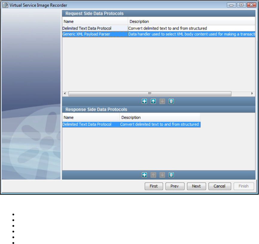
After the recording is complete, specify a Name/Value Token Delimiter and a Name/Value Delimiter on the parser screen. On this screen, you can
select your data type from the list.
Name/Value Pairs: The delimiter between name/value pairs and the delimiter between the name and the value in a name/value pair.
List of Values: The delimiter between values in a list of values.
Fixed Width: The whole number width of a fixed width delimiter.
RegEx Delimited: The regular expression used to tokenize the payload.
Space Delimited: None.
Line Delimited: None.
The field gives you the option to load a field names document, which is a line=delimited document that specifies an orderedField Names Path
list of the names of fields. As a default, the fields will be named , and so on, but to specify names for those XML elementsvalue1, value2, value3
you can do so by using a field names document.
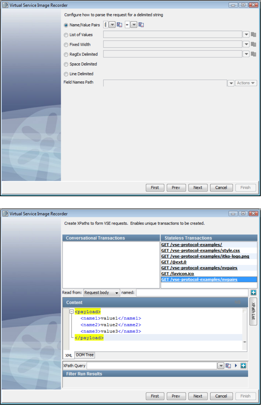
Click and you can see the name/value pairs represented in XML. Here, you can double-click on a transaction to show the contents of thatNext
transaction.
You configure the delimiters for the response side in the same way you did for the request side.
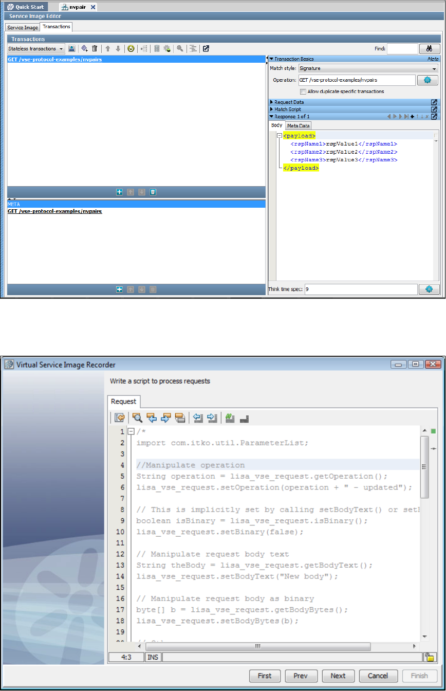
When the processing completes, you can see the virtual service image and the payload converted to XML.
Scriptable Data Protocol
The Scriptable Data Protocol is available for situations where you need a small amount of processing on either the request, the response, or both.
Sample scripts are written in BeanShell. When you specify a Scriptable Data Protocol on the request side, you see the following screen.
Two scripts are available on the response side; one for recording and one for playback. You can use the Response - Recording script to take the
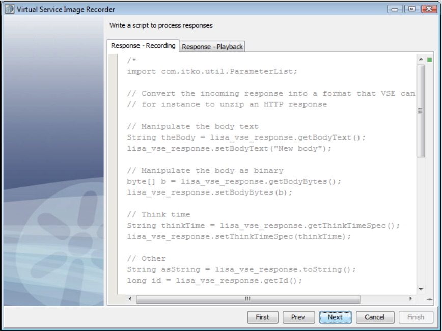
recorded response and change it into a format that VSE can process. Then, after it is processed, you can use the Response - Playback script to
return it to the format that the System Under Test is expecting.
You can add your own BeanShell script to perform any actions you want on the request and/or the response.
CICS Request Data Access Data Protocol
DRDA Data Protocol
The DRDA data protocol converts binary Distributed Relational Database Architecture (DRDA) payloads to XML during recording to facilitate
alignment with native LISA functionality, readability, dynamic data support. Responses are converted back to their native format on playback.
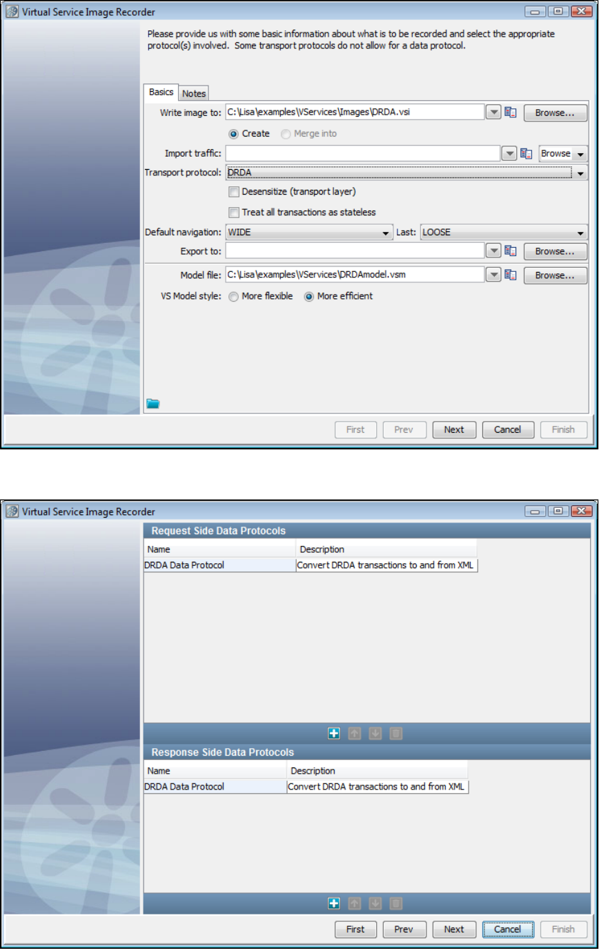
When you select the DRDA data protocol on the Transport Protocol field of the VSI Recorder, the Request and Response side data protocols
fields are automatically populated with the DRDA Data Protocol selections.
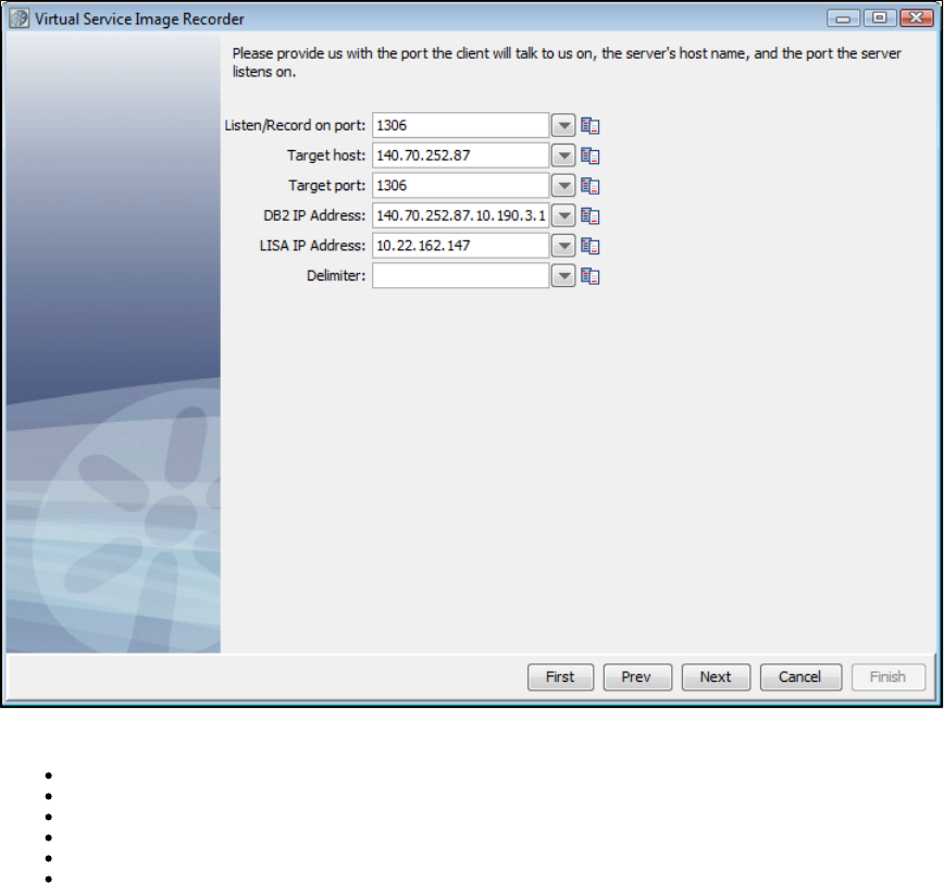
The next screen of the recorder lets you specify communications information.
Enter the communications parameters for the service image:
Listen/Record on port:
Target host:
Target port:
DB2 IP address:
LISA IP address:
Delimiter:
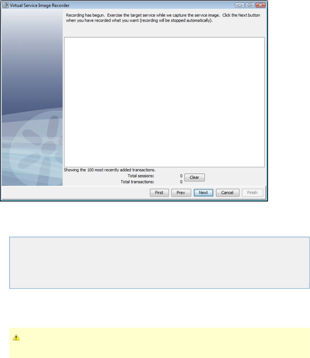
Editing Service Images
This chapter documents how to edit a virtual service image using a Service Image Editor.
The following topics are available.
Legacy Service Images
Opening the Service Image Editor
Service Image Editor Service Image Tab
Service Image Editor Transactions Tab for Stateless Transactions
Service Image Editor Transactions Tab for Conversations
Conversation Editor
Legacy Service Images
Beginning with LISA 6.0, service images are no longer stored in a database. If you need to use LISA 5.0 service images in LISA 6.0, you should
export them using LISA 5.0 and then import them using the Import item on the project tree's context menu in LISA 6.0.
A LISA 5.0 exported service image has an extension of . This exported version 5.x service image can be modified to be a.xml
valid LISA 6.0 service image by changing the extension to .vsi.
Opening the Service Image Editor
From the project panel, double-clicking on a service image from the list will launch the service image editor.Vservices/Images
You can also access the editor from the Response Selection step in the by clicking beside the name of the service image..vsm Open
Service Image Editor Service Image Tab
The following fields are visible on the Service Image Editor Service Image tab:
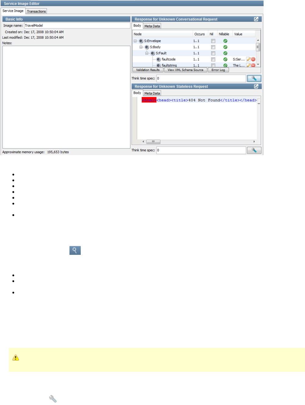
Service Image Editor Service Image Tab Components
Image name: The name of the current service image.
Created on: Date and time when the service image was created.
Last modified: Date and time when the service image was last modified.
Notes: Documentation on the service image.
Approximate memory usage: Estimated memory required for the service image.
Response for Unknown Conversational Request: Details the Body, Meta Data, and think time for a response to an unknown
conversational request in playback.
Response for Unknown Stateless Request: Details the Body, Meta Data, and think time for a response to an unknown stateless
request in playback.
Editing Responses for Unknown Requests
Use the icon to zoom the panels to their largest size. Use the same icon to unzoom back to the original size.magnifying glass
In the panels, complete the fields as needed:Response
Body: Contains the response to be returned for unknown stateless requests during playback.
Response Meta Data Area: In the area, use the toolbar at the bottom to add, move, or delete key-value pairs asResponse Meta Data
needed.
Think time spec: Enter the amount of think time required in milliseconds. The think time is the time that is taken before sending out the
response to a request. The default setting is . If you enter a range, the think time is randomly selected within that range (for example, 0
specifies a random think time between 100 and 1000 milliseconds). You can specify time measurements by adding a suffix to100-1000
the numbers (case does not matter). For example, indicates a random think time between 10 milliseconds and 5 seconds. The10t-5s
valid suffixes are:
---milliseconds t---seconds s---minutes m
---hoursh
A step subtracts its own processing time from the think time to have consistent pacing of test executions.
Customizing the Response Editor
Use the icon to invoke the menu to customize the response editor.wrench
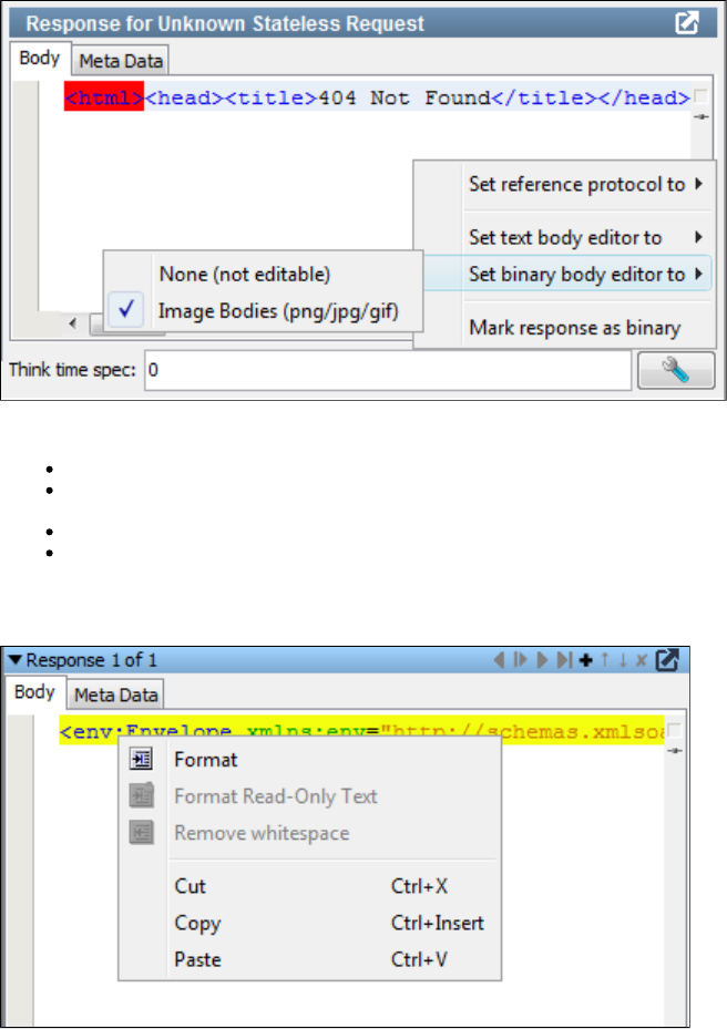
Options on the response editor menu are:
Set reference protocol to: No Specific Protocol or JDBC.
Set text body editor to: Auto-Detect, Default Text Editor, Import/Export Text Editor, Simple Text Editor, Visual JSON/JSONP Editor, or
Visual XML Editor.
Set binary body editor to: None (not editable) or Image Bodies (png/jpg/gif).
Mark response as binary
When the text body editor is set to the Default Text Editor, right-click on the Response Body XML to format or remove whitespace from the
response text.
Service Image Editor Transactions Tab
Access the tab from the Service Image Editor. This tab gives information about both stateless and stateful (conversations)Transactions
transactions, with slightly different components for each. This section describes viewing the general components of the Transactions Tab that are
the same for both types of transactions.
To choose between viewing conversations or stateless transactions, select either by number or from theConversation Stateless Transactions
drop-down list.
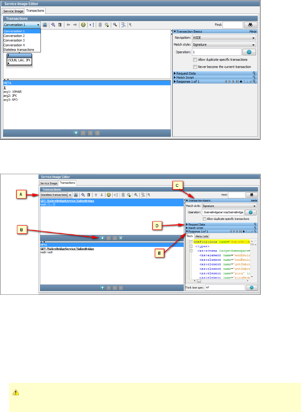
Service Image Editor Transactions Tab for Stateless Transactions
When viewing a stateless transaction, you can see the components shown in the following image.
Transactions Tab Components for Stateless Transactions
A: Use the Stateless Transactions list to view and edit stateless transactions. Use the toolbar at the bottom of the pane to add, move, or delete
stateless transactions.
: One logical transaction (in the stateless transaction list) contains exactly one META transaction and any number of specific transactions. TheB
Transactions list shows these transactions under the logical transaction. Use the toolbar at the bottom of the pane to add, move, or delete
stateless transactions.
: Use the area to view and edit transaction requests and response data for either Specific or Meta transactions, selectedC Transaction Basics
from the Transactions area. You can select a match style for the given transaction here. More information about this follows.
: The panel shows the stateless requests. See following for more information.D Request Data
: The panel shows the response to the stateless requests. See following for more information.E Response
If you add or change several transactions, then click . LISA creates the magicRegenerate Magic Strings and Data Variables
string and date variables for you. Existing magic strings and variables are not modified.
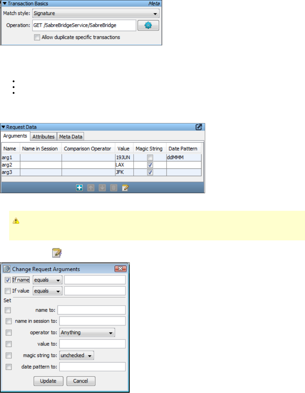
Transaction Basics Editor
Use the Transaction Basics editor to view and edit transaction data for specific or meta transactions. Select a specific transaction or fromMETA
the list.Transactions
The Transaction Basics editor lets you specify:
Match Style: Specify Signature or Operation.
Operation: The operation selected.
Allow duplicate specific transactions: Checking this will let LISA respond more than once to the same call, choosing a different
response.
Request Data Editor
Use the Arguments tab to edit, add, move, or delete meta transaction arguments. For specific transactions, you can only edit aspects of the
arguments.
To sort the arguments by data in a column, double-click the column heading to enable the sort arrows. Click the arrows to
arrange the data in ascending or descending order. Click the arrows again to disable them.
Use the Mass Change icon to perform a mass change of request arguments. When you click this icon, a dialog appears.
You can use this dialog to specify your mass changes, then implement those changes by pressing the Update button.
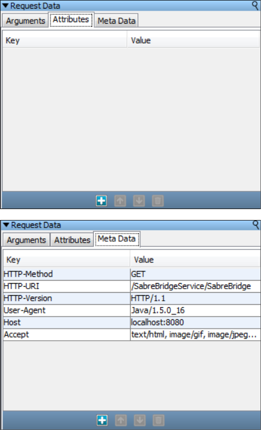
Use the Attributes area to add, edit, move, and delete key-value pairs.
Use the Request Meta Data area to add, edit, move, and delete meta data key-value pairs.
Match Script Editor
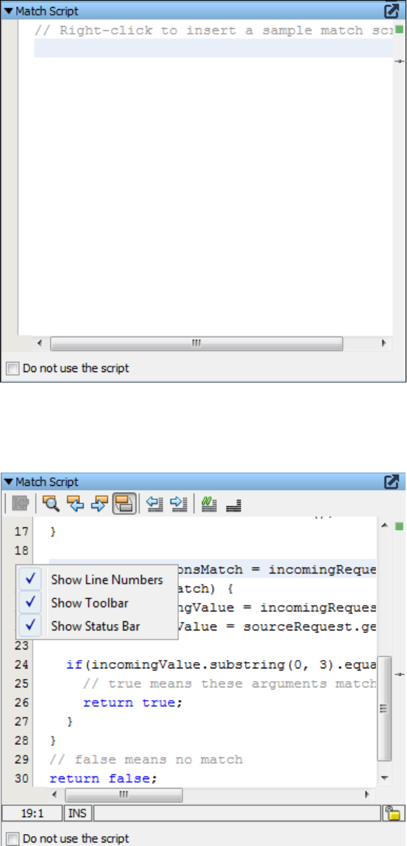
Right-click in the Match Script panel to insert a sample match script for your information. You can also choose to toggle the match script on or off
by using the Do not use the script check box.
Right-click on the left side of the Match Script panel to choose to hide or displayline numbers, the editor toolbar, and the editor status bar. The
image below shows all options displayed.
A match script defines how LISA Virtualize decides if a given transaction matches the incoming one. Unlike Match tolerance, here there is no
need to specify levels of a match tolerance. We just write BeanShell scripts performing certain actions to return the specific match based on the
given condition.
For example:
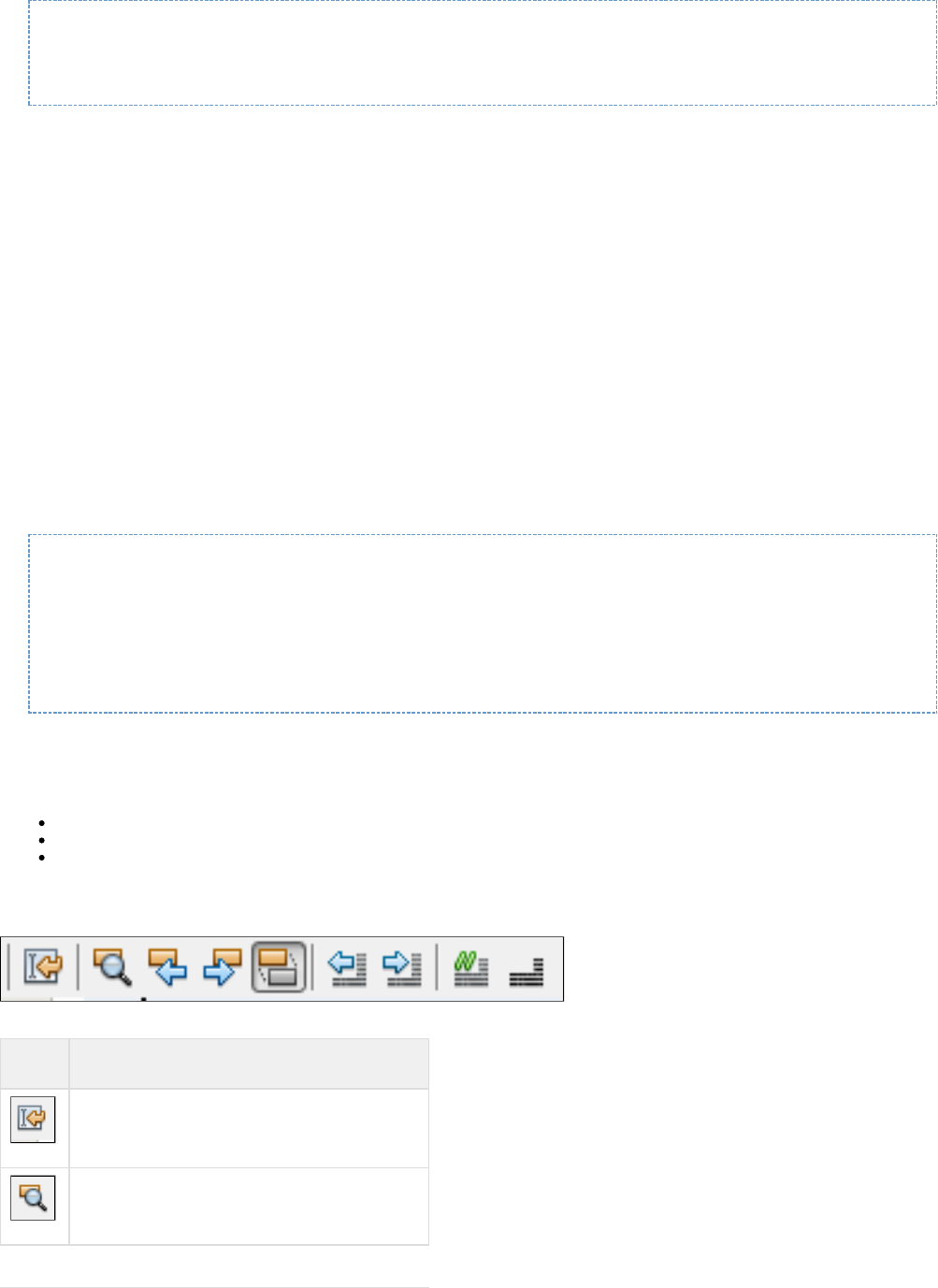
/* always match name=joe */
ParameterList args = incomingRequest.getArguments();
if ("joe".equals(args.get("name"))) return true else return defaultMatcher.matches();
For the match script to work there is no need to specify any match tolerance level, or there is no need to specify any match operator. It just finds
the match based on the condition in the match script.
By default (with no match script) an inbound request is matched against a service image request by comparing operations and/or arguments to
come to a true/false "do they match?" answer. A match script simply replaces this with whatever logic makes sense and must still come to the
true/false "do they match?" answer.
The script does have the ability to make use of the default matching logic if it needs to. To do this, inside the script use the expression,
"defaultMatcher.matches()". This will return a true or false using VSE's default matching logic.
It is similar to a scripted assertion. Basically, it is a regular BeanShell script but with three additional variables preloaded for you (and the usual
properties and variable):testExec
com.itko.lisa.vse.stateful.model.Request sourceRequest //(the recorded request)
com.itko.lisa.vse.stateful.model.Request incomingRequest //(the live request coming in)
com.itko.lisa.VSE.RequestMatcher defaultMatcher //(you can default to this guy if you want)
You must return a Boolean value from the script; true means a match was found.
If there is an error evaluating the script, the VSE deliberately ignores the error and defaults to the regular matching logic. If you don't think your
script is being executed, have a look in the VSE log file.
A good way to add logging/tracing into your match scripts is to embed calls to the VSE matching logger, which produces the messages in the
vse_match.log file. Here is an example:
import com.itko.lisa.VSE;
VSE.info(testExec, "short msg", "a longer message");
VSE.debug(testExec, "", "I got here\!\!");
VSE.error(testExec, "Error\!", "Some unexpected condition");
return defaultMatcher.matches();
If you log messages at INFO, later when the production settings are applied to the logging.properties file, the log level will be WARN and your
messages will show up as a LISA test event (a "Log Message" event).
Tips from :logging.properties
Keep a separate log for VSE transaction match/no-match events: this makes debugging much easier.
Change INFO to WARN or simply comment out the following line for production systems.
In general, INFO will report on every failure to match.
log4j.logger.VSE=INFO, VSEAPP
Match Script Editor Toolbar
The Match Script editor toolbar lets you perform the following functions:
Button Function
Returns you to the last edit that was made
Finds the next occurrence of the highlighted text

Finds previous occurrence
Finds next occurrence
Toggles the highlight search
Shifts the current line to the left four spaces
Shifts the current line to the right four spaces
Inserts comments slashes (//) at the cursor position
Removes the comments slashes (//)
Response Data Editor
Use the Response Data editor to view and edit the response information.
Use the area to edit the expected response for a transaction. Use the toolbar to add, order, delete and chain through responses,Response Body
as described in the . Use the magnifying glass icon to enlarge this panel. Use the wrench icon as described in Match Script Editor Toolbar
.Customizing the Response Editor
You can use the buttons at the bottom of the panel to inspect the Validation Results, if any, view the XML schema source, and see the error log.
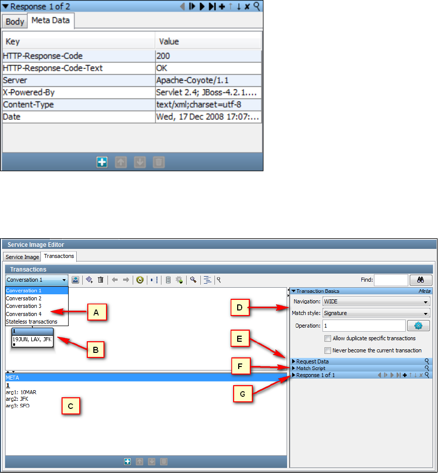
Edit the as needed.Think time spec
Use the area to add, edit, move, and delete key-value pairs.Response Meta Data
Service Image Editor Transactions Tab for Conversations
A stateful transaction (a transaction with conversations) is composed of the following components.
Conversations tab components
A: The list shows all the conversations in the service image. Select a conversation to view and edit. A conversation consists ofConversations
number of logical transactions.
: The displays the logical conversation selected in the Conversation list in either a graph node tree view or a standardBConversation Tree editor
tree view.
: Use the list to view and edit specific transactions or the meta data for transactions inside a selected logical transaction. Use theC Transactions
toolbar at the bottom of the pane to add, move, or delete stateless transactions.
: Use the area to view and edit transaction requests and response data for either or transactions, selectedDTransaction Basics Specific Meta
from the area. The fields are dependent on the selected transport and data protocols. For more information about the TransactionTransactions
Basics area and its tabs, see the .Service Image Editor Transactions Tab for Stateless Transactions
: Use the pane to enter the data for conversational requests during playback.E Transaction Request Data
: Use the to enter and edit a script to return actions based on specified matching conditions.F editorMatch Script
: Use the pane to view and edit the response content, think time, and key-value pairs for the specific or metaG Transaction Response Data
transaction.
Toggle Display Pane
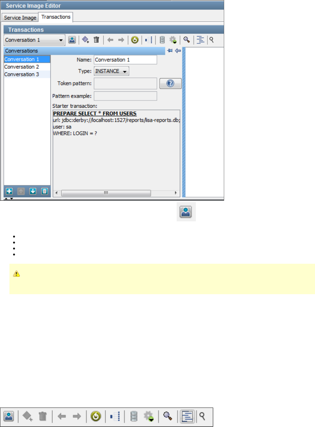
You can see details about a conversation by clicking the Toggle Display button on the Transactions Tab toolbar. From this pane, you
can display and edit the following values.
Type: The type is either or .INSTANCE TOKEN
Token Pattern: Required for token-based conversations. Clicking the question icon will give you examples of string generator patterns. |
Pattern Example: The example for the specified Token Pattern.
Starter Transaction: The starter transaction for the conversation.
If you add or change several transactions, return to the tab to click .Basic Info Regenerate Magic Strings and Data Variables
LISA creates the magic string and date variables for you. Existing magic strings and variables are not modified.
Conversation Editor
Use the Conversation editor to view and edit recorded transactions or create transactions manually. You can view the navigation trees in two
display modes:
Graph View
Tree View
When you switch between views, the selected node remains selected. In both views, you can perform these actions from the editor toolbar,
right-click menus, or the view itself:
The Conversation Editor Toolbar
The Conversation Tree editor toolbar varies slightly, depending on the display.
Graph View Tools
Tree View Tools
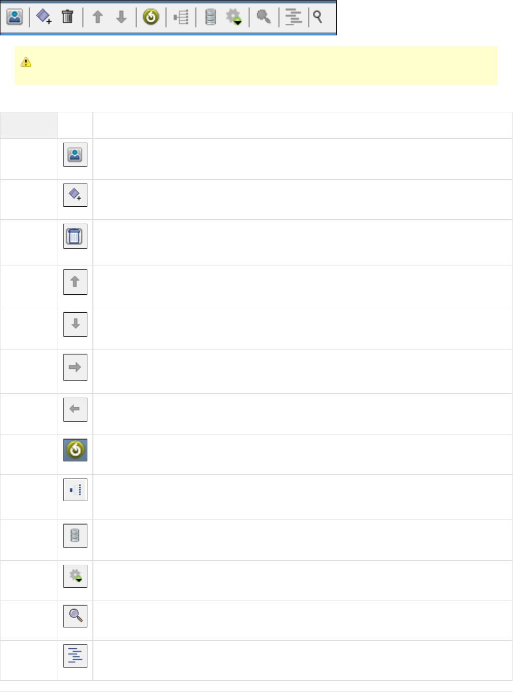
If a tool is dimmed, it cannot be used with the selected transaction.
The Conversation Editor toolbar contains the following components:
Tool Icon Description
Toggle
Display Toggles the display of the panel for managing a list of conversations. You can specify name, type, token pattern,
pattern example or starter transaction.
Create New
Transaction Adds a new transaction.
Delete
Selected
Transaction
Deletes a selected transaction.
Up Arrow Tree View: moves the selected node earlier in the sibling list.
Down
Arrow Tree View: moves the selected node later in the sibling list.
Right Arrow Graph View: moves the selected node earlier in the sibling list.
Left Arrow Graph View: moves the selected node earlier in the sibling list.
Regenerate Regenerates magic strings and date variables for all transactions.
View
Navigation Drops down a menu to select menu navigation highlights for stateful transactions (conversations). You can select
, or No navigation highlight, Highlight on transaction's tolerance, Highlight as if close, Highlight as if wide
Highlight as if loose.
Toggle Toggles the display of transaction id's for debugging.
Match Pulls a match description from the clipboard and highlights the relevant information in the SI.
Zoom Drops down a zoom menu.
Display Toggles the conversation display to a tree display.
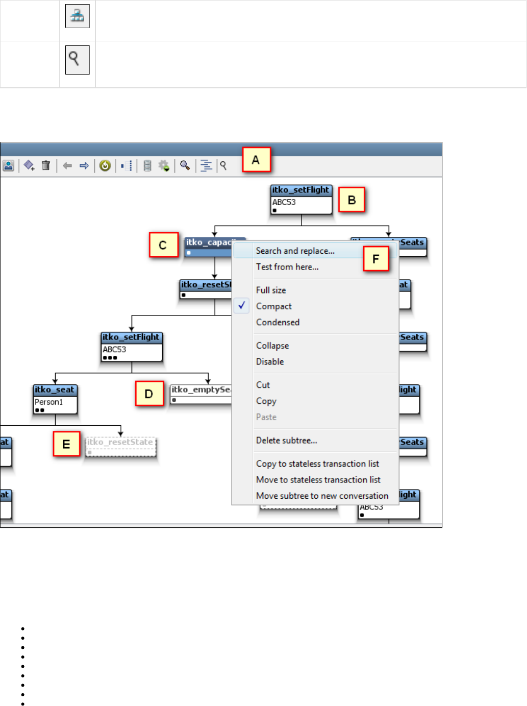
Display Toggles the conversation display to a graph display.
Zoom panel Zooms this panel to its largest size.
Conversation Editor Graph View
In the Conversation Editor, nodes are displayed according to status.
The Conversation Graph Editor components and node themes are described in the following diagram by the image callout letter:
A: Toolbar. For more information, see .Conversation Editor Toolbar
: Standard node appearance.B: Selected node.C: Collapsed node. Any children nodes are not displayed. Expand the node to view any children nodes.D: Disabled node. This node and any children nodes (not displayed) are ignored during runtime.E: Right-click menu. When you right-click a transaction, the menu provides these actions:F
Search and replace...
Test from here...
Full size/Compact/Condensed
Collapse/Disable
Disable/Enable
Cut/Copy/Paste
Delete subtree...
Copy to stateless transaction list
Move to stateless transaction list
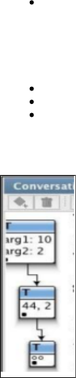
Move subtree to new conversation
Node Display Styles
You can display nodes in three styles:
Full size
Compact (default)
Condensed
In all three styles, the row of black dots at the bottom of each node shows how many specific transactions belong to the node. In the condensed
style, the hollow dots show the number of arguments to the transaction's request. In the following illustration, the first node is displayed full size,
the second is compact and the third one is condensed.
Conversation Editor Tree View
The tree view displays the same information as the graph view in a compact fashion.
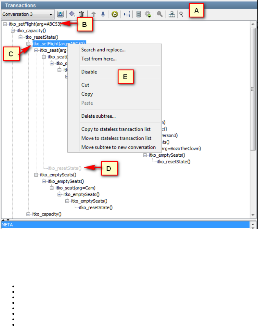
Nodes are displayed according to status. The Conversation Editor components and node themes are described in the following diagram by the
image callout letter:
A: Toolbar. For more information, see .using the Conversation Tree Editor toolbar
: Standard node appearance.B: Selected node.C: Disabled node. This node and any children nodes (not displayed) are ignored during runtime.D: Right-click menu. When you right-click a transaction, the menu provides these actions:E
Search and replace...
Test from here...
Disable/Enable
Cut/Copy/Paste
Delete subtree...
Copy to stateless transaction list
Move to stateless transaction list
Move subtree to new conversation
The Search and Replace Action
From the right-click menu, you can select the Search and Replace action to change values in the conversation or the transaction.
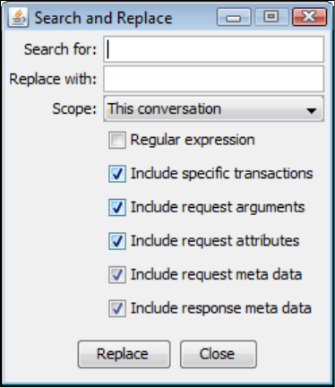
lets you specify whether the search and replace extends to this conversation (the default), this transaction, this transaction and children, orScope
the entire service image. You can also use the check boxes to specify which pieces of the transactions to include.
The Test from Here Action
Use the Conversation Editor to test for an expected response from a selected transaction in both graph and tree views.
To test from a transaction
1. In the Conversation Tree editor, select and right-click a transaction.
2. From the menu, select .Test from here
3. In the Create Test Request window, enter the unique operation name and add argument key-value pairs, as needed.
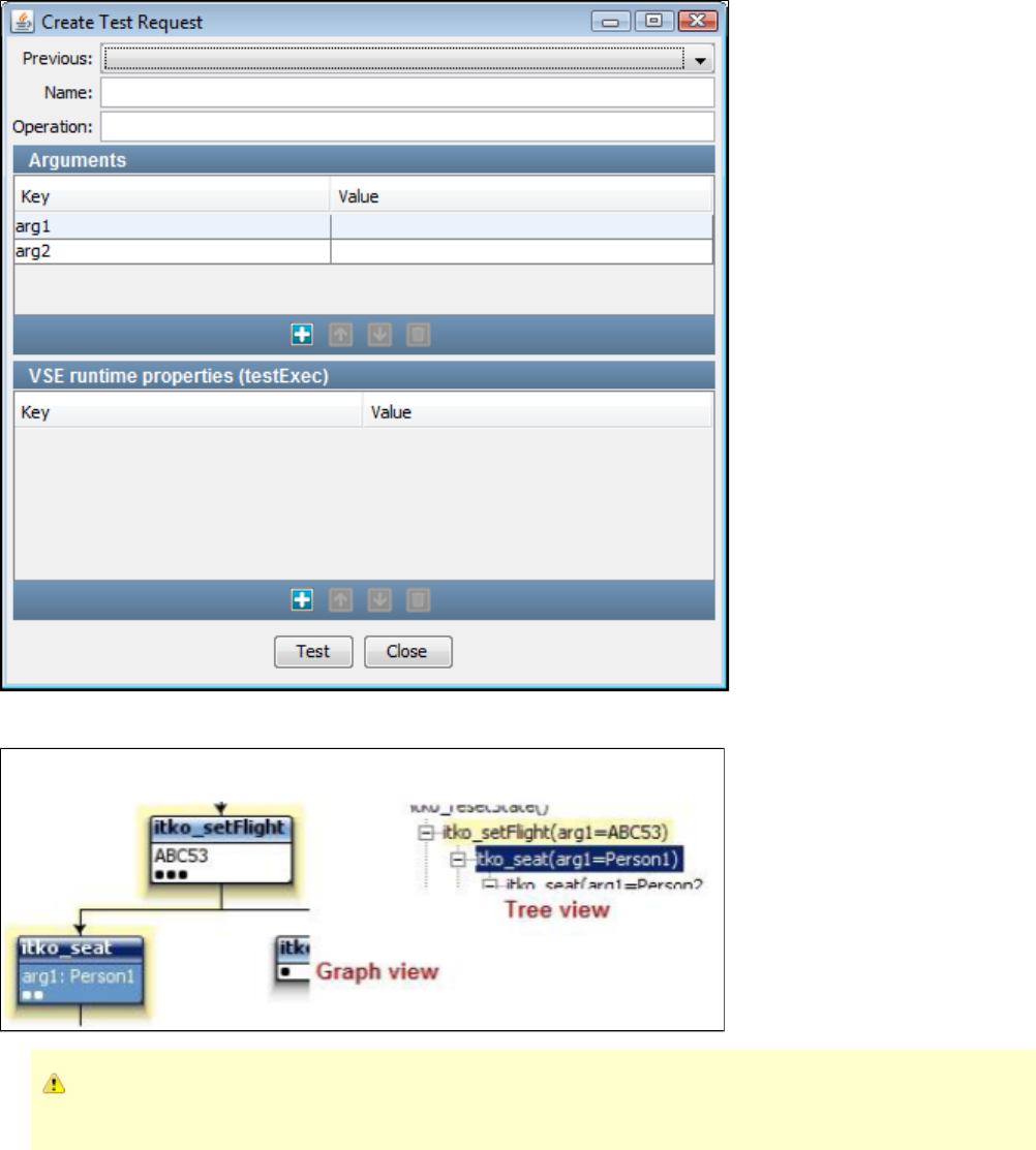
4. Click . The result is displayed in blue with the path in yellow.Test
If the test is not successful, the following error will appear: "No transaction matching the request follows the selected one in this
conversation." Click OK to continue.
5. Click Close to close the window.
Highlighting Navigation Possibilities
Use the Conversation Tree to view navigation possibilities in a conversation based on the selected navigation tolerance. Select a transaction and
click the View Navigation button. The default menu selection is , which means no transactions will be highlighted.No navigation highlight
If you select a transaction and click the option, the transaction and its associated transactions will beHighlight on transaction's tolerance
highlighted according to the selected transaction's defined navigation tolerance, whether Close, Wide, or Loose. The following section describes
expected results for each tolerance level.
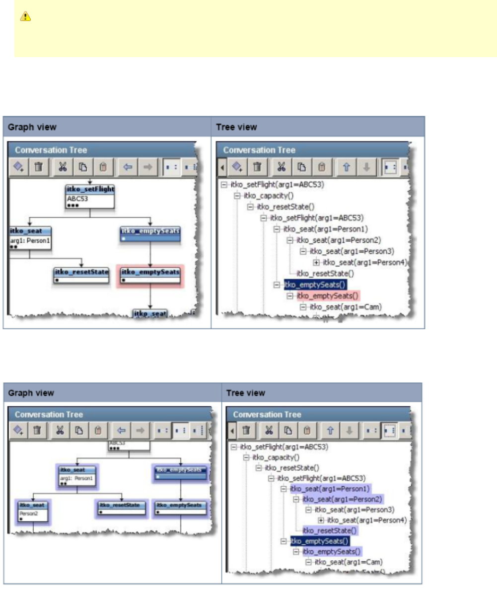
If you use the drop-down on the top right of the editor to change the navigation tolerance for the current transaction, that will
override what is on the menu. To return the highlighting to the "correct" state in this case, you must reselect that navigation
highlighting option.
Viewing Close Navigation
Select a transaction and click the button. The transactions that are searched in the selected transaction's subtree areView Navigation
highlighted in red.
Viewing Wide Navigation
Select a transaction and click the View Navigation button. The transactions that are searched in the selected transaction's subtree and sibling
subtrees are highlighted in blue.
Viewing Loose Navigation
Select a transaction and click the View Navigation button. The transactions that are searched in the selected transaction's subtree, sibling
subtrees, and parent are highlighted in green. A full conversation restart is also possible.
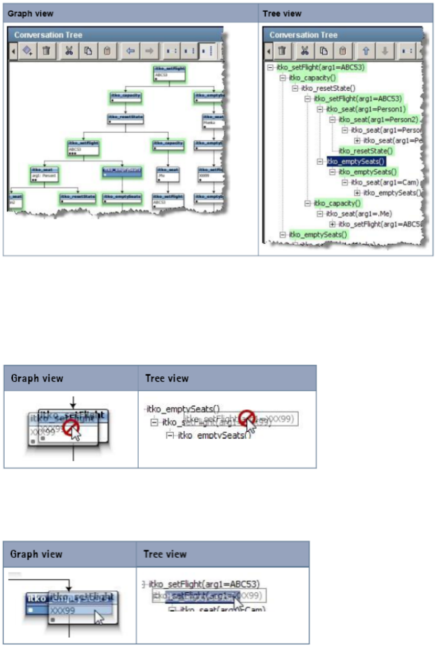
Restructuring a Conversation
In some cases, you may want to restructure a conversation by dragging and dropping a transaction and its subtree, if it has one. You can perform
this action in both the graph and tree views.
To restructure a conversation tree
1. Click a transaction.
As you drag the transaction, it displays the universal symbol for "not possible."
2. Drag the transaction to the transaction that should be the new parent transaction. If it is possible to drop the transaction, then the "not possible"
symbol disappears.
3. Drop the transaction. The transaction and any transactions in its subtree will be moved below the new parent.
Editing a VSM
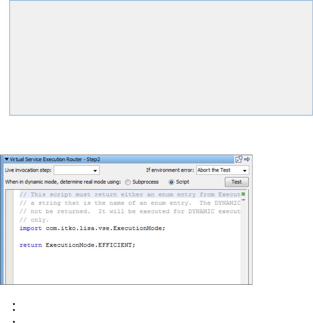
A Virtual Service Image recording creates a Virtual Service Model (VSM) with six steps or eight steps, depending on the option chosen (More
Flexible or More Efficient). There may be situations when you would like to edit the VSM by editing generated steps or adding additional steps to
it.
Also, the recorder cannot be used for message-based services, so for those services, you must create the VSM and service image manually. Feel
free to skip this chapter if you do not need to edit a VSM or create it fresh without a recorder.
A VSM is a specialized LISA test case and therefore editing/creating a VSM is similar to a LISA test case. There are many types of steps that may
be added to a VSM. It is also possible to add a step that does not appear in this menu; however, some of these other step types may make a
VSM undeployable.
Access the menu of step types from the VSM editor by selecting Add a new step, then selecting Virtual Service Environment from the menu
This chapter explains the steps available to use in a Virtual Service Model.
The following topics are available.
Virtual Service Router Step
Virtual Service Tracker Step
Virtual Conversational_Stateless Response Selector Step
Virtual HTTP_S Listener step
Virtual HTTP_S Live Invocation Step
Virtual HTTP_S Responder Step
Virtual JDBC Listener Step
Virtual JDBC Responder Step
Socket Server Emulator Step
Messaging Virtualization Marker Step
Compare Strings for Response Lookup Step
Compare Strings for Next Step Lookup Step
Virtual Java Listener Step
Virtual Java Live Invocation Step
Virtual Java Responder Step
Virtual TCP_IP Listener Step
Virtual TCP_IP Responder Step
Virtual Service Router Step
This step is used to route a request from a VS listen step to the response selector step and/or the protocol-specific live invocation step. The
decision is made based on the current execution mode for the running model.
Enter the data for the fields as described:
Live invocation step: Select the step for live invocation from the list.
If environment error: From the list, select action to take or the step to go to if the test fails because of an environment error. The default
is .Abort the test
When in dynamic mode, determine real mode using: Select or .Subprocess Script
Click the Test button to test your parameters for the step.
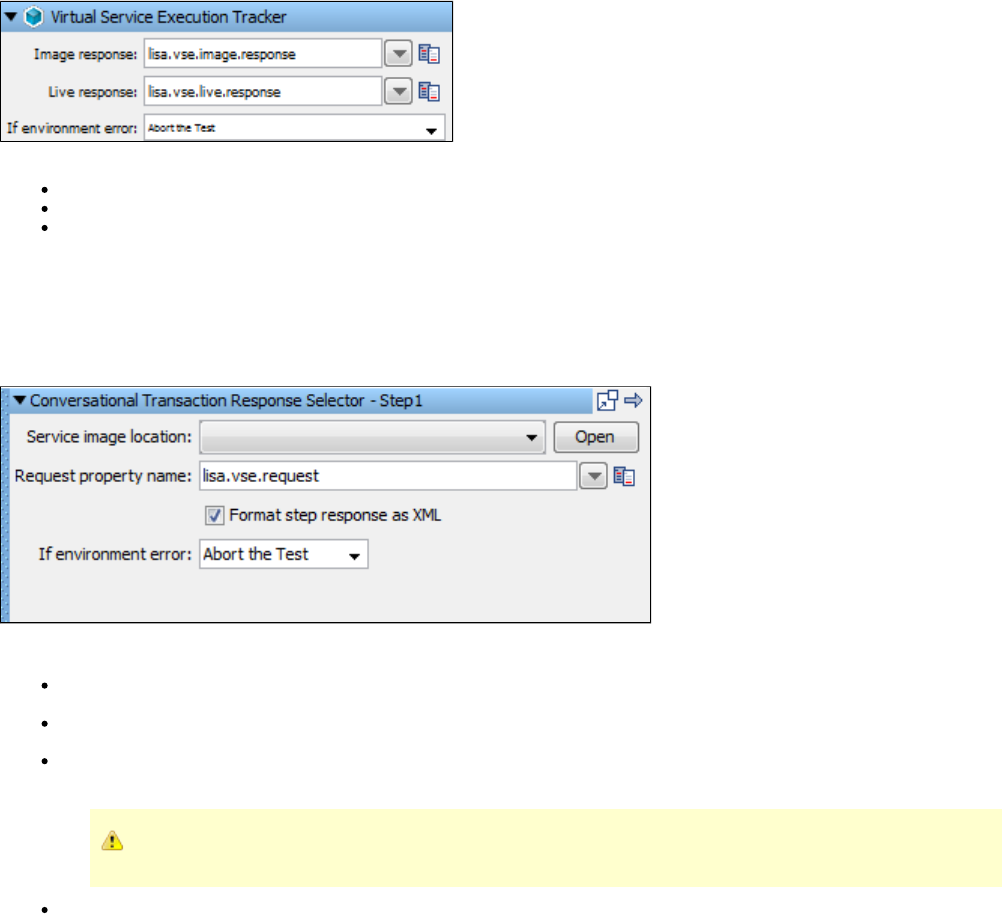
Virtual Service Tracker Step
This step is used to track responses in a running virtual service and, optionally, validate against a live system. This allows for easier service model
debugging and service model "healing".
Enter the data for the fields as described:
Image Response: Select the Image response file.
Live Response: Select the Live response file.
If environment error: Select the step to go to if an environment error occurs. The default is .Abort the test
Virtual Conversational_Stateless Response Selector Step
This step is responsible for deciding on an appropriate virtual response for a given request, and can be seen as the main step in any VSM. It does
that by looking at a service image that is set into it. It is possible that there can be more than one response for a request; therefore, the responses
are always shown as a list. It is typically created by recording and virtualizing some form of service traffic.
Enter the data for the fields as described:
Service Image Location: Select from the drop-down list of service images available to associate with this step. When you have chosen a
service image here, you can view or edit it by clicking the button and it will open in a new tab.Open
Request property name: Set the property name to define the property to look in for the inbound request. This is usually the response of
the previous step.
Format step response as XML: By default the step response is formatted as XML. The VSE framework expects Respond steps to
accept either a response object, a list of response objects, or an XML document that represents either.
If this field is not checked, the step produces a list of response objects, even if the list contains only one response.
If environment error: Select the step to go to if an environment error occurs. The default is .Abort the test
Virtual HTTP_S Listener Step
The Virtual HTTP/S Listener Step step is used to simulate an HTTP server, including SSL support. It listens for incoming HTTP requests and
converts them to a standard virtual request format.
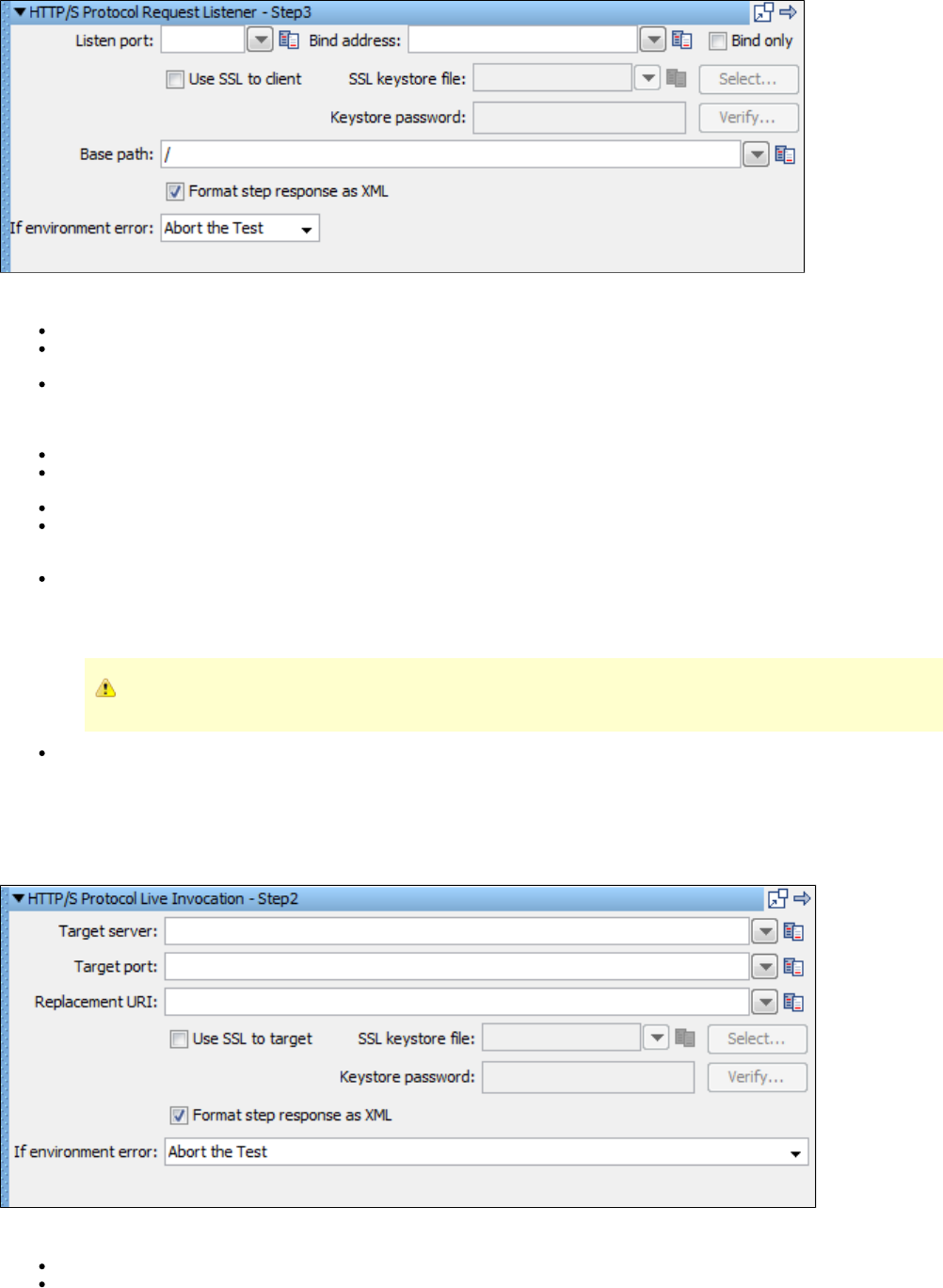
Enter the data for the fields as described:
Listen port: Enter the port on which LISA listens for the HTTP/S traffic.
Bind address: Enter the local IP address on which connections can come in. By default with no bind address specified, the listen step
accepts connections on the specified port regardless of the NIC (or IP address) it comes in on.
Bind only: Select this check box to acquire the network resource and move to the next step. A second Listen step is required that does
not use the option. This option enables the model to listen on a port (requests are queued until a listen step consumes them)Bind only
and perform setup tasks before dropping into the wait/process/respond loop. For example, Step 1 of the model acquires the listening port
(using Bind only) and Step 2 triggers external software that sends requests.
Use SSL to client: Select this check box if you want to simulate a secure HTTP/S website. Then supply the SSL keystore information.
SSL keystore file: Click to browse to your SSL keystore file. The same keystore file must be available to the VSE server toSelect...
which the VS model is deployed.
Keystore password: Enter the keystore password, and click Verify...
Base path: Identify the HTTP requested resource URIs that the listen step is to process. When the request comes in, the list of queue
names is scanned for a name (base path) that starts the URI on the request. The queue name that matches is the one into which the
request is placed and the listen step that is associated with the queue (by base path) processes the request.
Format step response as XML: By default the step response is formatted as XML. The VSE framework expects Respond steps to
accept either a response object, a list of response objects, or an XML document that represents either.
If this field is not selected, the step produces a list of response objects, even if the list contains only one response.
If environment error: Select the step to go to if an environment error occurs. The default is Abort the test.
Virtual HTTP_S Live Invocation Step
This step is used to make a real HTTP call to real server within the context of a virtualized HTTP service. It is typically created by recording and
virtualizing some form of HTTP traffic. It will perform the real request based on the current VSE request in use.
Enter the data for the fields as described:
Target server: Enter the name of the server to which the request is made.
Target port: Enter the name of the port on which the request will be made.
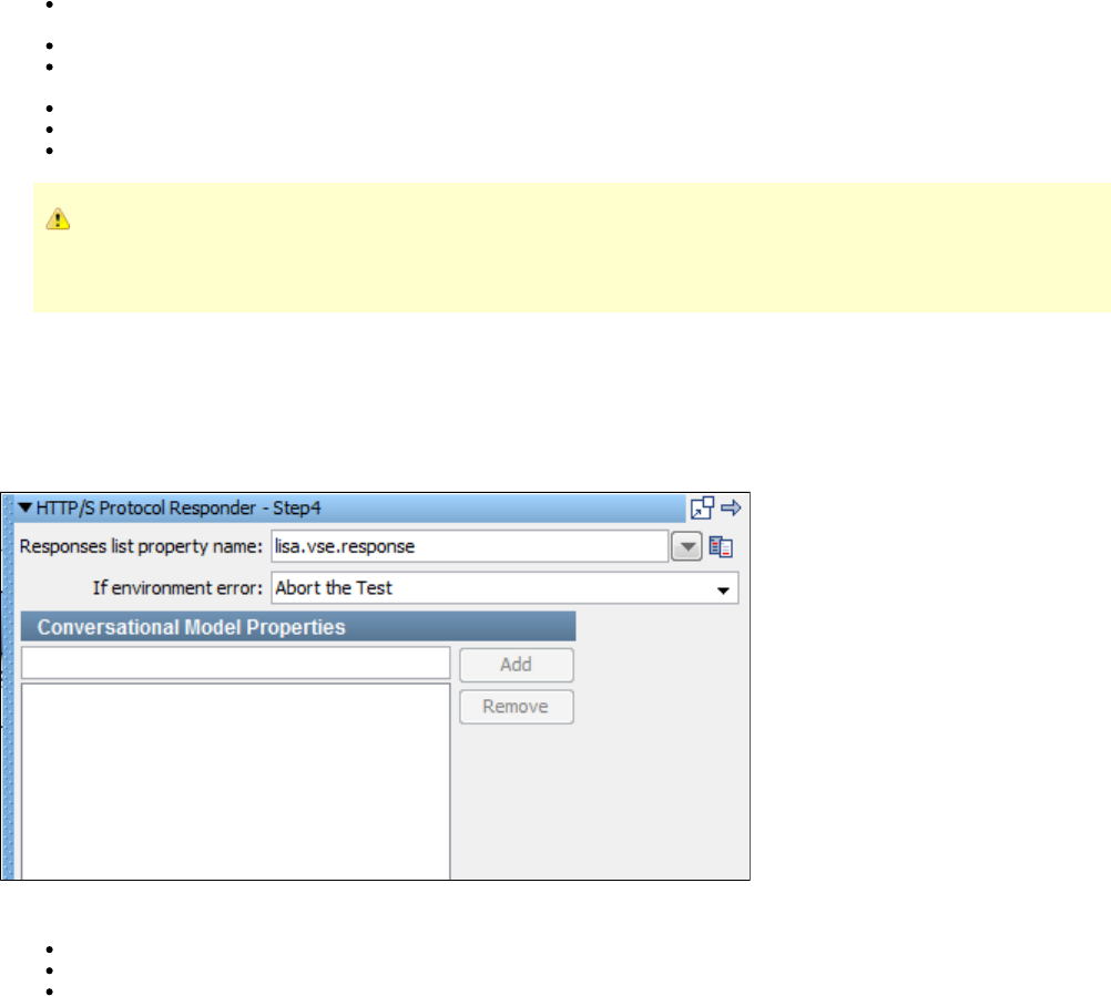
Replacement URI: Enter a new target path field to replace the full URI in a GET/POST request. You can provide the URI as a LISA
property. This field can be blank, in which case the URI from the live request is used.
Use SSL to target: Select this box if you want to simulate a secure HTTPS website. Then supply the SSL keystore information.
SSL keystore file: Click Select to browse to your SSL keystore file. The same keystore file must be available to the VSE server to which
the VS model is deployed.
Keystore password: Enter the keystore password, and click Verify.
Format step response as XML: This field, if selected, formats the response of the step as XML.
If environment error: Select the action to take or the step to go to if an environment error occurs. The default is .Abort the test
The Live Invocation step for virtualized HTTP supports the and lisa.http.timeout.socket lisa.http.timeout.connection
properties to control the client sockets used. There is also a property, , to controllisa.vse.http.live.invocation.max.idle.socket
how long an idle client socket waits before being too old to use. This defaults to two minutes.
Virtual HTTP_S Responder Step
This step is used with the Virtual HTTP/S Listener step to transmit responses to HTTP requests produced by the listener. It takes a virtual
response and uses it as the reply to the corresponding request using the HTTP/S protocol.
You can create this step by recording and virtualizing HTTP traffic.
Enter the data for the fields as described:
Responses list property name: The name of the property to look in for the response to send.
If environment error: Select the step to go to if an environment error occurs. The default is .Abort the test
Conversational Model Properties: Enter a property and click Add. To delete a property, select it from the list and click Remove. The
properties listed here are associated with the current conversation session, which allows their values to be available to downstream
conversational requests.
Virtual JDBC Listener Step
This step is used to control the simulation of JDBC database traffic. It manages the communication with the simulation driver that is embedded in
the database client.
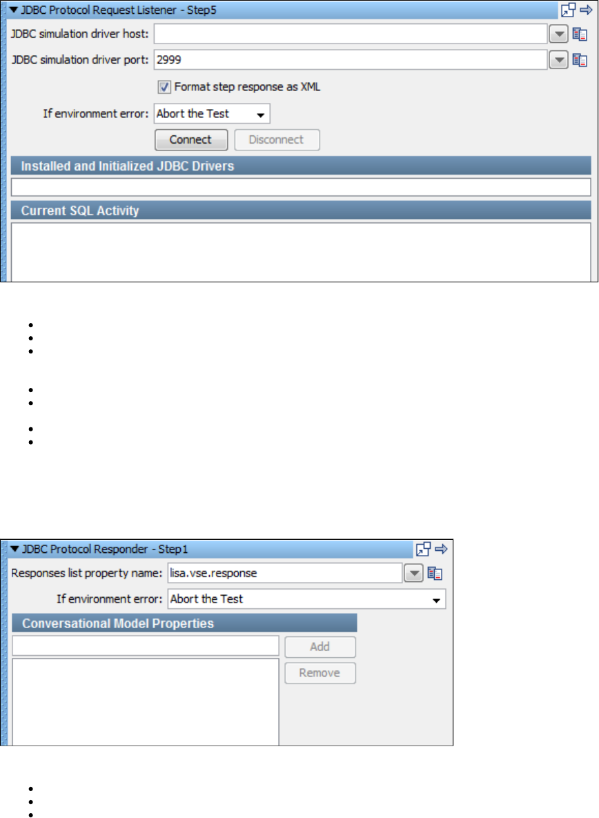
Enter the data for the fields as described:
JDBC simulation driver host: Enter the host name or IP address of the database client where the simulation driver is running.
JDBC simulation driver port: Enter the port number for the JDBC simulation driver. The default is .2999
Format step response as XML: By default the step response is formatted as XML. The VSE framework expects Respond steps to
accept either a response object, a list of response objects, or an XML document that represents either. If this field is cleared, the step
produces a list of response objects, even if the list contains only one response.
If environment error: Select the step to go to if an anvironment error occurs. The default is Abort the test.
Connect/Disconnect: Click Connect to connect to the JDBC simulator. If connected, click Disconnect to end the connection. You can
use this button to validate the connection information.
Installed and Initialized JDBC Drivers: Displays the JDBC drivers installed and initialized in the database client.
Current SQL Activity: Displays the current SQL activity within the database client.
Virtual JDBC Responder Step
This step is used to send the result of a JDBC data call as selected by a conversational response selection step to the simulation driver that is
embedded in the database client.
Enter the data for the fields as described:
Responses list property name: The name of the property to look in for the response to send.
If environment error: Select the step to go to if an environment error occurs. The default is .Abort the test
Conversational Model Properties: Enter a property and click Add. To delete a property, select it from the list and click Remove. The
properties listed here are associated with the current conversation session, which allows their values to be available to downstream
conversational requests.
Socket Server Emulator Step
This step can be used to simulate any text-based (typically HTTP) server socket. It supports listening, responding, and binding. The Socket
Emulator step is very low-level, so if you use this step, it is your responsibility to verify that the block of text that gets sent in the respond step is
fully HTTP compliant.
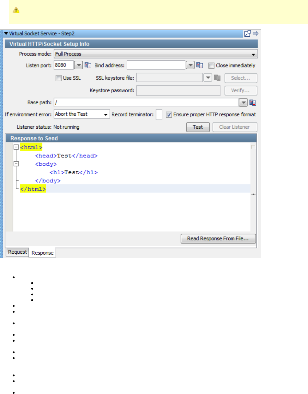
When the Socket Emulator step is used in response mode, the text to go out MUST end up as a valid HTTP response message.
Enter the data for the fields as described:
Process mode: From the list, select the process mode. The valid options are:
Full Process: The default.
Asynchronous setup: Acquires the network resource and moves to the next step.
Listen Only
Respond Only
Listen port: Enter the port on which LISA listens for the HTTP or Socket traffic.
Bind address: Enter the local IP address on which connections can come in. By default with no bind address specified, the listen step
accepts connections on the specified port regardless of the NIC (or IP address) it comes in on.
Close immediately: Check to use design-time testing of this step. This option instructs the step to do the configured work and then
immediately clean up its network resources.
Use SSL: Check this box if you want to simulate a secure HTTPS website. Then supply the SSL keystore information.
SSL keystore file: Click to browse to your SSL keystore file. The same keystore file must be available to the VSE server to whichSelect
the VS model is deployed.
Keystore password: Enter the keystore password, and click .Verify
Base Path: Identify the HTTP requested resource URIs that the listen step is to process. When the request comes in, the list of queue
names is scanned for a name (base path) that starts the URI on the request. The queue name that matches is the one into which the
request is placed and the listen step that is associated with the queue (by base path) processes the request.
If environment error: Select the step to go to if an environment error occurs. The default is .Abort the test
Record terminator: If the socket emulator is to simulate a record-based service, enter the character that marks the end of a record. If
you leave this field blank, either line-oriented records or the HTTP protocol are simulated.
Ensure proper HTTP response format: By default, this option is checked. When in a process mode that sends a response and the
response is to be a valid HTTP response, this option helps ensure that the HTTP headers in the response text are correctly formatted
and, if needed, that the : HTTP response header is present and correct. This check box only verifies that the lineContent-Length
separators are HTTP compliant and that the Content-Length header is present and accurate. However, for even this to totally work, the
message must already be a well formed HTTP message.
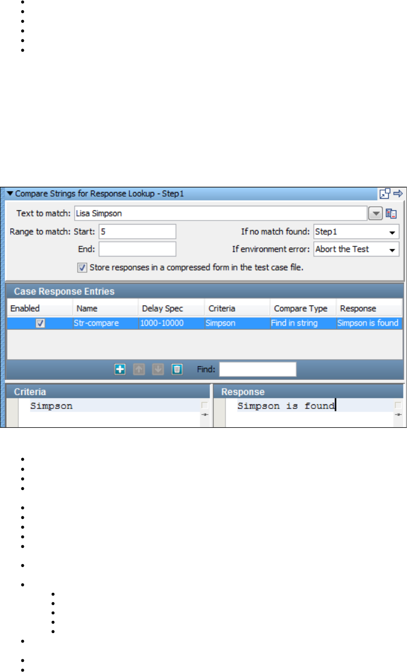
Listener status: Indicates whether the listener is running or not.
Test: Click to test the listener setup.
Clear Listener: Click to stop the test of the step.
Response tab: The Response to Send includes the text for the response.
Read Response From File: Click to browse the file system for a response.
Request tab: Request is used only during design time. It displays the last request the step received.Last/Original
Messaging Virtualization Marker Step
This step is used to designate that a message-based test case is designed for use in the Virtual Service Environment. If the test case is listening
or responding through JMS, add this step to the VS model to verify that it can be deployed to the VSE.
Compare Strings for Response Lookup Step
This step is used to look at an incoming request to a virtual service and determine the appropriate response in a completely stateless fashion,
without referring to any service image. The stateful portions of VSE are not supported. You can match incoming requests using partial text match,
regular expression, among others.
The step components are:
Text to match: Enter the text against which criteria should be matched. This is typically a property reference, such as .LASTRESPONSE
Range to match: Enter the start and end of the range.
If no match found: From the list, select the step to go to if no match is found.
If environment error: From the list, select response or the step to go to if the test fails because of an environment error. Default is Abort
.the test
Store responses in a compressed form...: Selected by default. This option compresses the responses in the test case file.
Case Response Entries: Add, move, and delete entries.
Enabled: Selected by default when you add an entry. Clear to ignore an entry.
Name: Enter a unique name for the case response entry.
Delay Spec: Enter the delay specification range. The default is , which indicates to use a randomly selected delay time1000-10000
between 1000 and 10000 milliseconds. The syntax is the same format as Think Time specifications.
Criteria: This area provides the string to compare against the field. To edit the criteria, in the Text to match Case Response Entries
area select the appropriate row, and then select a different setting from the list.Criteria
Compare Type: Select an option from the list:
Find in string (default)
Regular expression
Starts with
Ends with
Exactly equals
Response: This area provides the response of this step if the entry matches the field. To edit the response, in the Text to match Case
area select the appropriate row, then select a different setting from the list.Response Entries Response
Criteria: Allows for the update of the criteria string for an entry.
Response: Allows for the update of the step response for an entry.
Compare Strings for Next Step Lookup Step
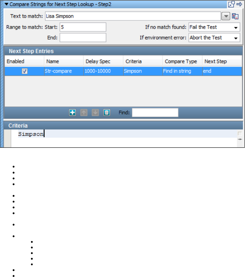
This step is used to look at an incoming request and determine the appropriate next step. You can match incoming requests using partial text
match and regular expression, among others.
Each matching criterion specifies the name of the step to which to transfer if the match succeeds.
The step components are:
Text to match: Enter the text against which criteria should be matched. This is typically a property reference, such as .LASTRESPONSE
Range to match: Enter the start and end of the range.
If no match found: From the list, select the step to go to if no match is found.
If environment error: From the list, select an action to take or the step to go to if the test fails because of an environment error. The
default is .Abort the test
Next Step Entries: Add, move, and delete entries.
Enabled: Selected by default when you add an entry. Clear to ignore an entry.
Name: Enter a unique name for the next step entry.
Delay Spec: Enter the delay specification range. The default is , which indicates to use a randomly selected delay time1000-10000
between 1000 and 10000 milliseconds. The syntax is the same format as Think Time specifications.
Criteria: This area provides the string to compare against the Text to match field. To edit the criteria, in the areaNext Step Entries
select the appropriate row, and then select a different setting from the list.Criteria
Compare Type: Select an option from the list:
Find in string (default)
Regular expression
Starts with
Ends with
Exactly equals
Next Step: From the list, select the step to go to if the match is found.
Criteria: Enables the update of the criteria string for an entry.
Virtual Java Listener Step
The Virtual Java Listener Step is used to handle virtualized JVM calls, such as a call to an EJB or other remote system. It listens for method calls
intercepted by the LISA agent, and converts them to a standard VSE request.
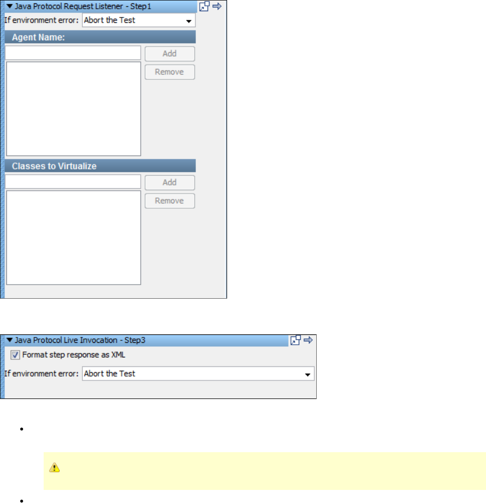
Virtual Java Live Invocation Step
Enter the data for the fields as described:
Format step response as XML: By default the step response is formatted as XML. The VSE framework expects Respond steps to
accept either a response object, a list of response objects, or an XML document that represents either.
If this field is not checked, the step produces a list of response objects, even if the list contains only one response.
If environment error: Select the step to go to if an environment error occurs. The default is Abort the test.
Virtual Java Responder Step
This step is used with the Virtual Java Listener Step to provide responses for virtualized JVM calls.
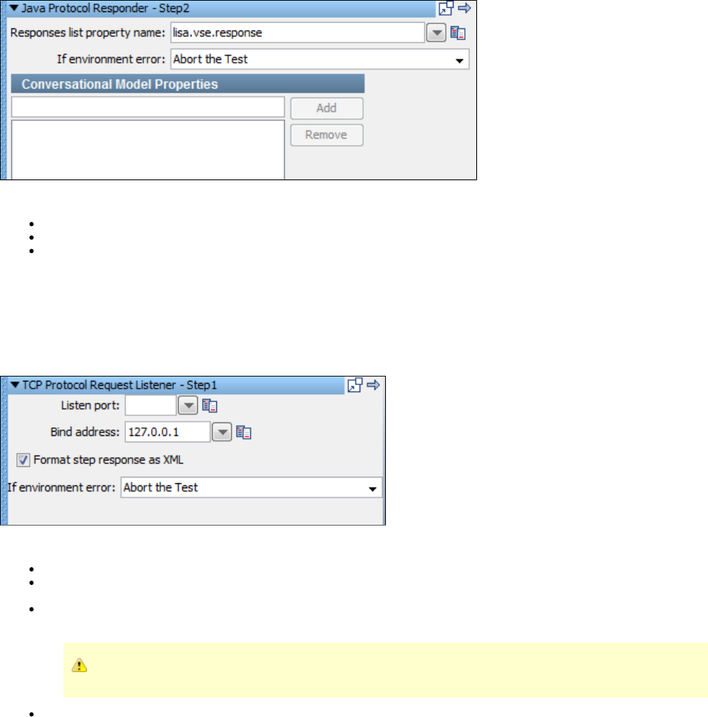
Enter the data for the fields as described:
Responses list property name: The name of the property to look in for the response to send.
If environment error: Select the step to go to if an environment error occurs. The default is .Abort the test
Conversational Model Properties: Enter a property and click Add. To delete a property, select it from the list and click Remove. The
properties listed here are associated with the current conversation session, which allows their values to be available to downstream
conversational requests.
Virtual TCP_IP Listener Step
This step is used to simulate TCP/IP connections to a server application. It listens for incoming TCP/IP traffic and converts it to a standard VSE
request.
Enter the data for the fields as described:
Listen port: Enter the port on which LISA listens for the TCP/IP traffic.
Bind address: Enter the local IP address on which connections can come in. By default with no bind address specified, the listen step
accepts connections on the specified port regardless of the NIC (or IP address) it comes in on.
Format step response as XML: By default the step response is formatted as XML. The VSE framework expects Respond steps to
accept either a response object, a list of response objects, or an XML document that represents either.
If this field is not checked, the step produces a list of response objects, even if the list contains only one response.
If environment error: Select the step to go to if an environment error occurs. The default is Abort the test.
Virtual TCP_IP Responder Step
This step is used to TODO
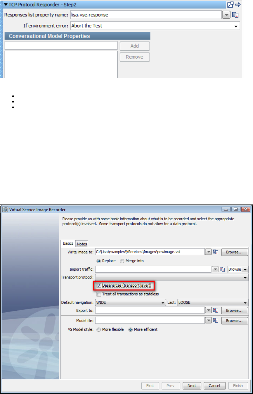
Enter the data for the fields as described:
Responses list property name: The name of the property to look in for the response to send.
If environment error: Select the step to go to if an environment error occurs. The default is .Abort the test
Conversational Model Properties: Enter a property and click Add. To delete a property, select it from the list and click Remove. The
properties listed here are associated with the current conversation session, which allows their values to be available to downstream
conversational requests.
Desensitizing Data
In LISA Virtualize, desensitization means attempting to recognize sensitive data and substituting random, but validly formatted, values for that
data during recording. You use data desensitization when you do not want to use real customer data as your test data.
There are three ways to activate data desensitization in LISA Virtualize: dynamic desensitization, static desensitization, and the Data Desensitizer
Data Protocol.
Dynamic Desensitization
Dynamic desensitization occurs at the transport layer. It is invoked by enabling the check box on the tab of the Virtual Service Recorder.Basics
This desensitization program uses volatile filters that help ensure sensitive information is never written to disk during the recording phase. The
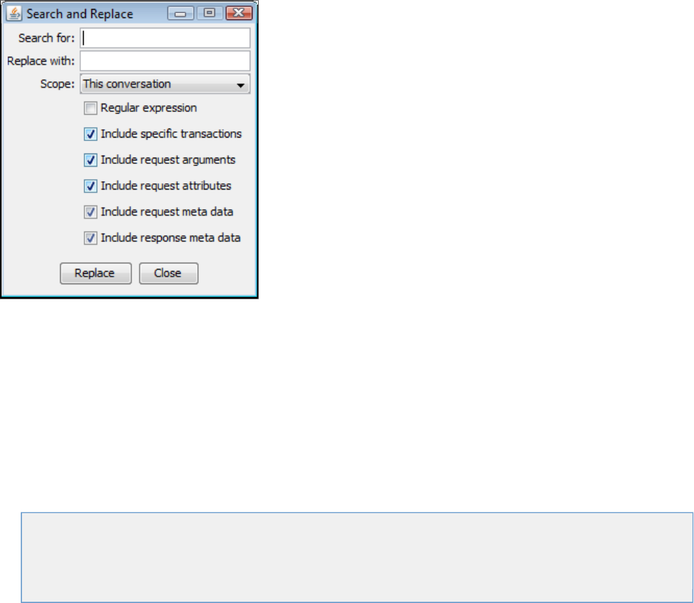
file in the LISA home directory configures data desensitizers to recognize well known patterns such as credit card numbers anddesensitize.xml
telephone numbers and replace the live data with realistic but unusable replacements. It uses REGEX pattern matching to recognize/find sensitive
data. This file is parsed each time the recorder is started.
You can use LISA's built-in TestData string generation patterns as replacement data options. It provides 40,000 rows of test data for you to use,
including replacement data for some common data types: names, addresses, telephone numbers, credit card numbers, Social Security numbers,
and so forth.
You can customize these preset patterns to create your own. We using a regular expression toolkit such as RegexBuddy,highly recommend
which lets you paste in your recorded payload and interactively highlights Regex matches as you fine-tune the Regex.
Matches are processed in the order they exist in the file, so put your more specific matches first.
To avoid painful text escaping issues (especially with Regex) you MUST enclose <regex> and <replacement> child text in a CDATA element.
Static Data Desensitization
Static data desensitization involves manually searching and replacing data in an existing service image. To access the Search and Replace
menu, right-click on a node in the service image and select .Search and Replace
Specify a specific string that will be replaced with another, then indicate the scope of the change. Click and the search/replace functionReplace
will happen for the areas you selected.
Data Desensitizer Data Protocol
There is a Data Desensitizer data protocol handler to allow the application of the desensitization rules in situations where another data protocol is
required to "un-opaque" a request or response body (such as when an HTTP message body is gzipped). For information about this feature, see
.Using Data Protocols
Doing the Virtualization
Virtualization is the process where LISA Virtualize responds to the client in the absence of the server. It uses the VSM and the service image. This
chapter covers the virtualization process.
The following topics are available.
Preparing for Virtualization
Deploying and Running a Virtual Service
Running Live Requests Against LISA Virtualize
Session Viewing and Model Healing
Preparing for Virtualization
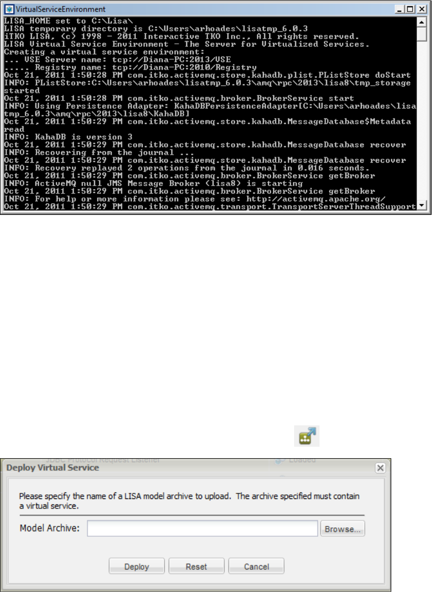
1.
2.
1.
2.
Starting Virtual Service Environment
The Virtual Service Environment (VSE) has to be started for virtualization to run. The VSE needs to register with the LISA registry.
From the Start menu, select Programs > LISA > VirtualServiceEnvironment, which launches a window that creates a Virtual Service
Environment named and connects to the registry instance.lisa.VSEServer
You can minimize the Virtual Service Environment window. Do not close the window. You can use the Windows system service if this
option was chosen during the install process.
You can also start a named virtual service environment from a command prompt by entering [LISA_HOME]\bin\VirtualServiceEnvironment.exe
, where is the name of the VSE and is the name of an existing registry.-n VSEName -m RegistryName VSEName RegistryName
Running Multiple Virtual Service Environments
If you want to run multiple VSE servers on one computer, add command line option while running ,-p port VirtualServiceEnvironment.exe
where is the port number, which will be different for different VSE instances.port
The in your license limits the number of virtual services you can run.maxvirtualservices
Using VSE Manager to Set up the VSE
VSE Manager lets you make changes to your virtual service environments. You can find VSE Manager command information at VSE Manager
.Commands
Deploying and Running a Virtual Service
From the Server Console, click the Deploy a new virtual service to the environment icon. The Deploy Virtual Service window
opens.
In this window, enter the name of a model archive (MAR) to upload. The MAR must contain a virtual service. When you click the Deploy
button, the service will load into the VSE Console and be available to run. Alternatively, you can go to the project panel in LISA
Workstation and right-click a virtual service model (vsm) to see the window.Deploy Virtual Service
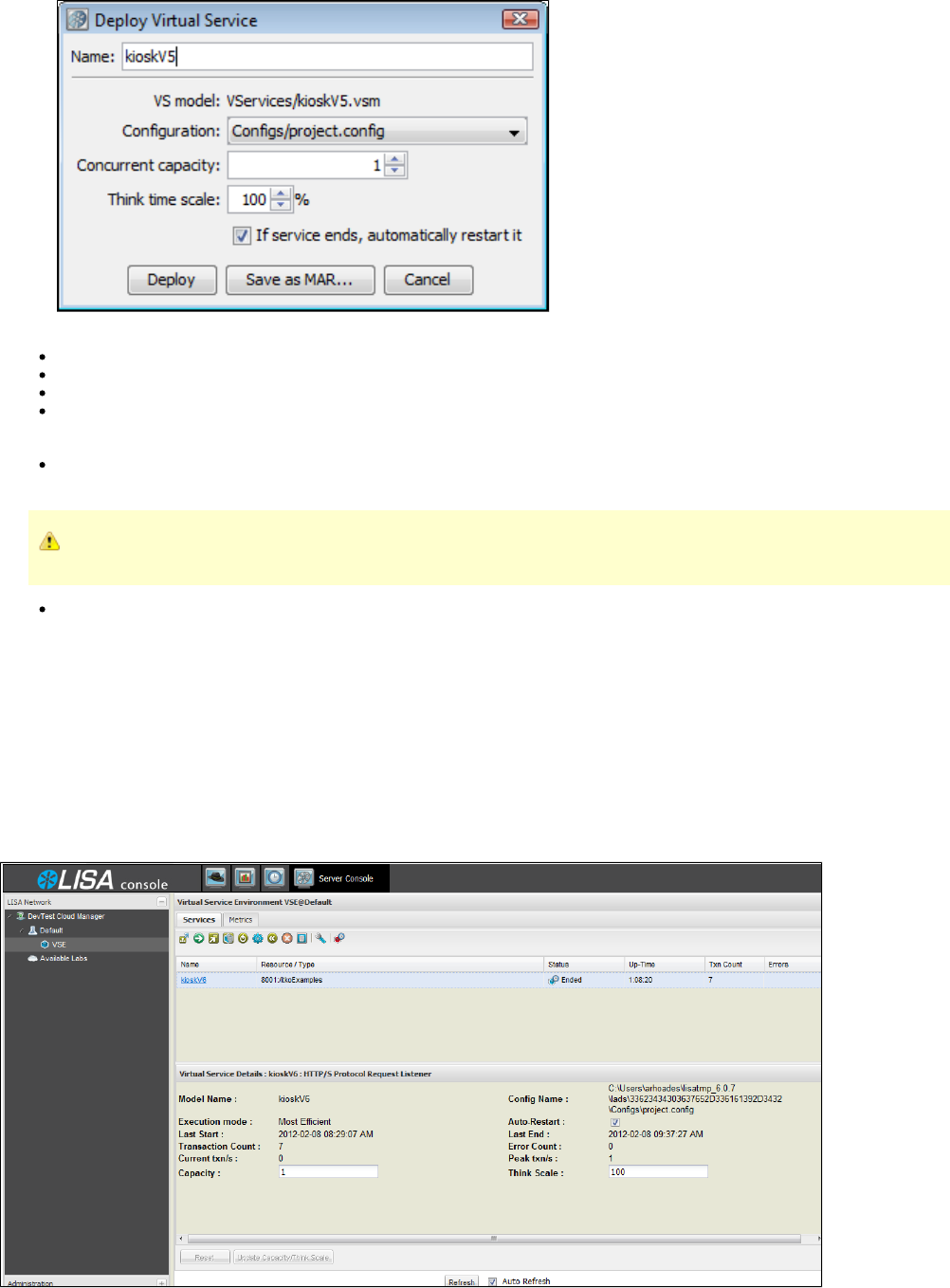
2.
3. Modify the fields as needed:
Name: The name of the virtual service referenced by the vsm you selected is automatically populated in this field.
VS model: The virtual service model you selected.
Configuration: This field is optional, but you can select an alternate configuration file here.
Concurrent capacity: Enter a number to indicate the load capacity. The default is , but it can be increased to provide additional1
capacity. is how many virtual users (instances) can execute with the virtual service model at one time. here indicatesCapacity Capacity
how many threads there are to service requests for this service model.
Think time scale: Enter the think time percentage with respect to the recorded think time. To double the think time, use 200. To halve
the think time, use 50. The default is .100
A step subtracts its own processing time from the think time to have consistent pacing of test executions.
If service ends, automatically restart it: Keeps the service running even after an emulation session has reached its end point. Selected
by default.
Click The virtual service status should be displayed in the VSE Console environment as loaded.Deploy.
Running Live Requests Against LISA Virtualize
After you deploy the virtual service, run live requests against LISA Virtualize. If possible, take down the live service and configure the client to talk
to LISA Virtualize by configuring the gateway/proxy settings.
Accessing the Server Console
From LISA Workstation, click the Server Console button to open the Virtual Service Environment VSE console. From this console, you can
deploy, start, view, stop, redeploy, and remove virtual services.
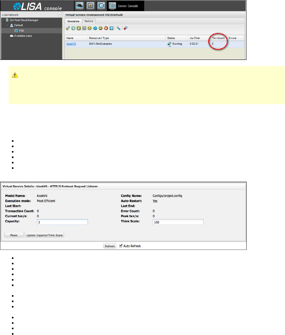
In the VSE Console, verify that the virtual service is deployed ( is Running). Verify that the service received the requests by viewing theStatus
transaction count ( ).Txn count
If transactions are not recorded...
If a deployed VS model is not seeing any transactions, then the client is not configured properly. Reconfigure the client to point
to the virtual model rather than the real system. If another service is using that port, either stop that service or change the port
setting so there is no longer a conflict.
Services Tab
The VSE Console Services Tab displays the following columns. You can sort on any column values either ascending or descending by clicking
the down arrow to the right of the column name. Use this arrow also to select the columns you want to display on this screen.
Name: The name of the virtual service model currently deployed
Type: Indicates the type or protocol of the service
Status: Shows the current state of the virtual service
Up-Time: Indicates how much time has elapsed since the service was started
Txn Count: A count of transactions recorded since service start
Errors: A red dot indicates that errors have occurred while running the service
The panel at the bottom of the screen displays details about the service.Virtual Service Details
Model Name: The name of the virtual service model currently deployed.
Execution Mode: The mode of execution for this virtual service. See .Set the execution mode for the selected virtual service
Last Start: The date and time this service was last started.
Transaction Count: A count of transactions recorded since service start.
Current txn/s: The number of transactions currently executing.
Capacity: How many virtual users (instances) can execute with the virtual service model at one time. Capacity indicates how many
threads there are to service requests for this service model. You can update this field while the service is running.
Resource: The port and file path of the deployed virtual service.
Config Name: The name of the configuration file being used by this service.
Auto-Restart: Whether the auto-restart option was chosen for this service. You can click on this field and toggle its value from to Yes No
or from to while the service is running.No Yes
Last End: The date and time this service was last stopped.
Error Count: The number of errors received.
Peak txn/s: The largest number of transactions run concurrently.
Think Scale: The think time percentage with respect to the recorded think time.
If you click the name of the virtual service in the VSE Console, you can download the backing archive for the virtual service. The system will
prompt you to save the MAR file associated with this virtual service.
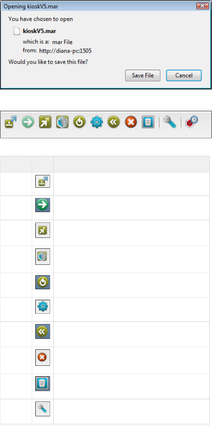
The VSE Console Toolbar
The VSE Console has its own toolbar, which is made up of the following buttons. Each of these buttons is also available by putting your cursor
over a service and right-clicking.
Button Icon Description
Deploy Deploy a new virtual service to the environment
Start Start the selected virtual service
Show Show the inspection view for the selected virtual service
View View session/tracking information for the selected virtual service
Redeploy Redeploy the selected virtual service to the environment
Set Set the execution mode for the selected virtual service
Reset Reset the transaction and error counts for the selected virtual service
Stop Stop the selected virtual service
Remove Remove the selected virtual service from the environment
Configure Configure tracking data cleanup
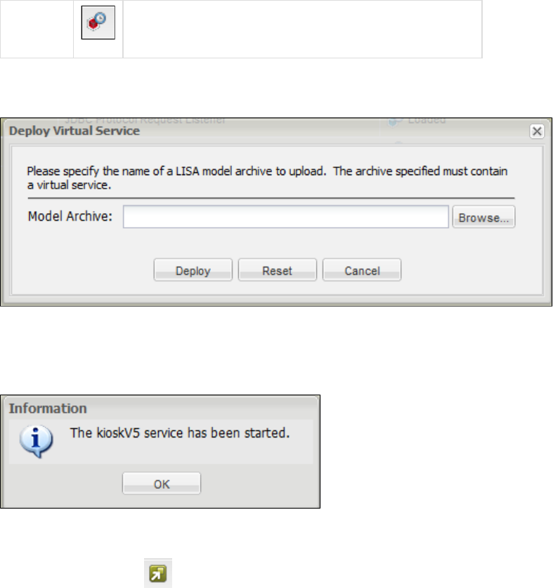
Shut down Shut down the entire virtual service environment
Deploy a new virtual service to the environment
Select this option to deploy a virtual service from a model archive (MAR).
In this window, enter the name of a model archive (MAR) to upload. The MAR must contain a virtual service. When you click the Deploy button,
the service will load into the VSE Console and be available to run.
Start the selected virtual service
This button starts a virtual service that you have selected. You will see the following informational message.
Show the inspection view for the highlighted virtual service
The button opens a tab for an inspector panel specifically tailored for virtual services. This panel has two tabs, Show Inspection View
and .Matching Request Event Details
Matching Tab
On the tab, recent requests processed by the virtual service are listed. When a request is selected, a description is shown of how theMatching
request was (or was not) matched. This is essentially the same information that is recorded in the file. If any events werevse_matches.log
associated with the selected request, they are displayed at the right side of the panel.
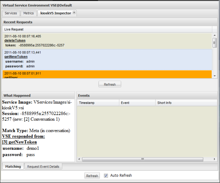
Request Event Details Tab
The tab shows the list of inbound requests that caused the virtual service to error out. When a request is selected, the listRequest Event Details
of VSM steps that were executed is shown, with steps containing error events selected. Select a step to see the events that occurred during
processing for that step (very similar to the ITR).
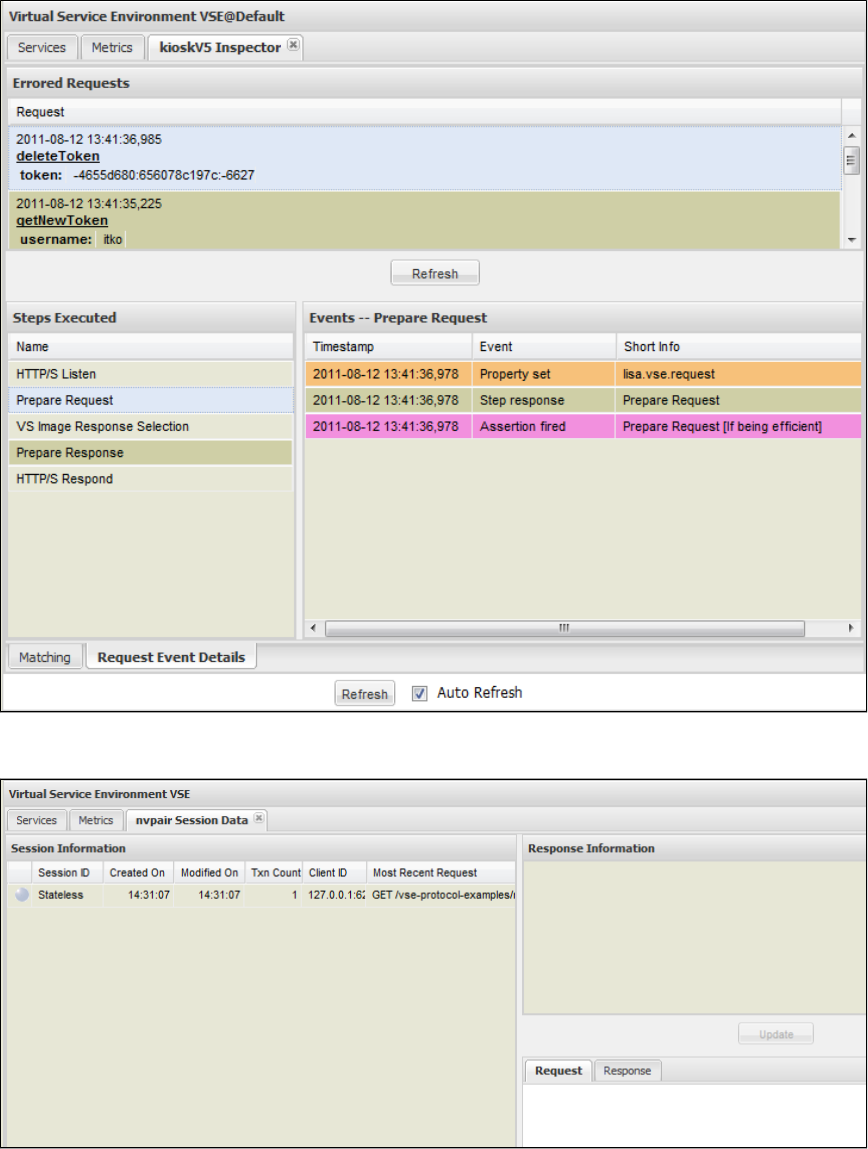
View session/tracking information for the selected virtual service
This option lets you see session tracking information for the virtual service. For more information, see .Session Viewing and Model Healing
Redeploy the selected virtual service to the environment
If you edit the service image or the VSM, save the changes and redeploy the modified service image in the VSE Console by clicking Redeploy.
Set the execution mode for the selected virtual service
This option lets you set one of five execution modes for the virtual service. The number of execution modes available for a virtual service depends
on the assertions on execution mode that exist in that model. For example, if a model does not have an assertion on execution mode for
validating, the Image Validation option will not appear in this window as a selection.
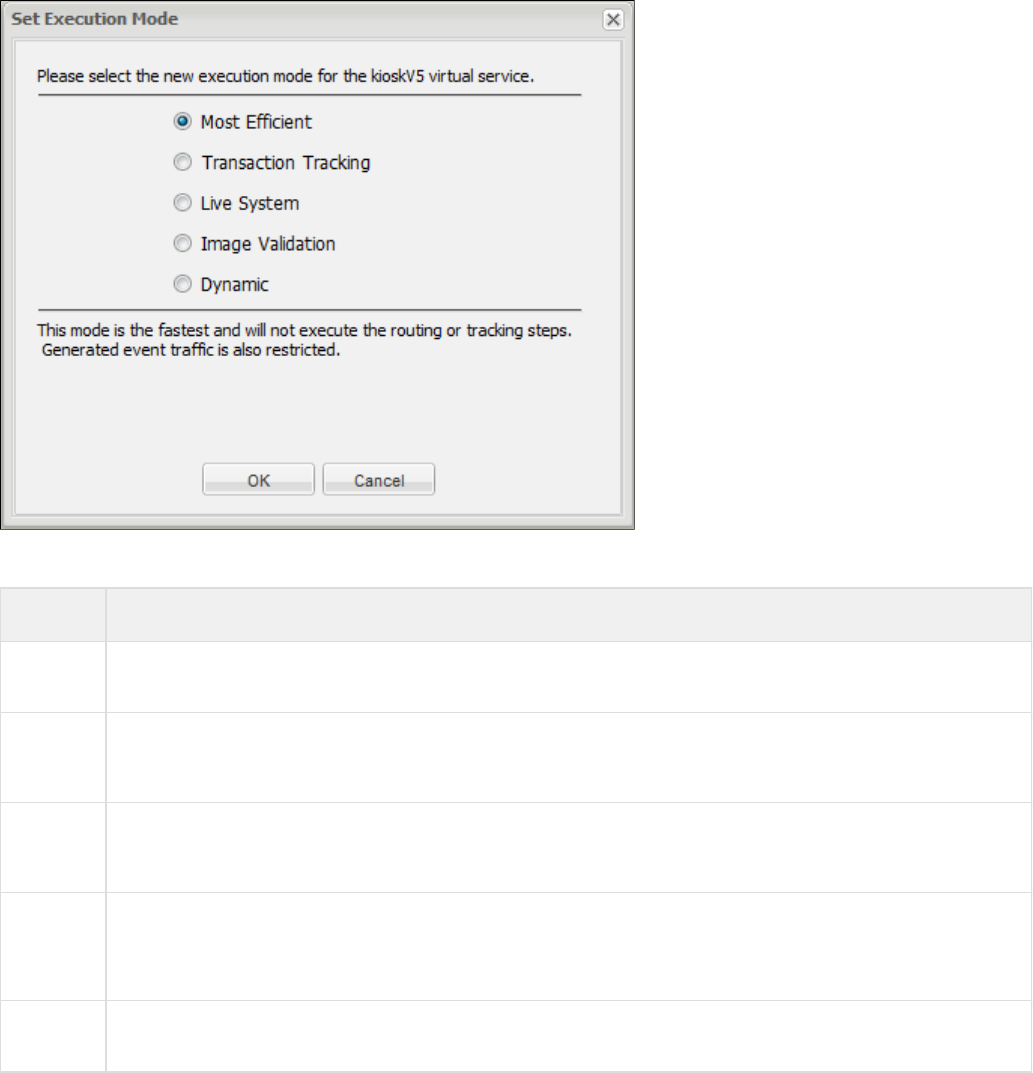
Available execution modes are:
Mode Definition
Most
Efficient The fastest mode; it does not execute the routing or tracking steps. It also restricts generated event tracking.
Transaction
Tracking This model fires more events than Most Efficient and remembers transaction flow through sessions. This transactional
information is used to help determine why a particular response was chosen for a given request. This will not perform as well as
Most Efficient.
Live
System This mode will use the Live Invocation step of the model to determine a response to the current request. Instead of using the
Virtual Service's response, it accesses the live service to get the response. The target system of the live invocation will control
performance. This mode is also known as pass through, and is only available for Web Services.
Image
Validation This mode uses both the VSE and the live system to derive a response to the current request. The responses are compared
and appropriate history remembered. It allows a live comparison between the responses provided by VSE and a corresponding
live system and, where differences exist, patch or heal the VSE service image to keep in sync with the live system. This mode
is also known as live healing mode. It is the least efficient of all the modes, and is only available for Web Services.
Dynamic This mode enables the model to determine on a per-request basis which of the other modes to use. Performance is, therefore,
unpredictable. This mode is only available for Web Services.
Reset the transaction and error counts for the selected virtual service
This option makes both the transaction count and error count zero for the selected virtual service.
Stop the selected virtual service
Click this button to stop the selected virtual service. You will get a confirmation message before the service stops.
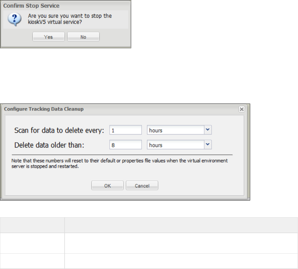
Remove the selected virtual service from the environment
Click this button to remove the selected virtual service from the console display. You will get a confirmation message before the service is
removed.
Configure tracking data cleanup
Clicking this button will open a Configure Tracking Data Cleanup window:
You can enter values here that will remain in effect until the service is stopped and restarted, at which time the values will reset according to their
defaults or the values set in a properties file.
Value Description
Scan for data to delete
every Amount of time, in milliseconds/seconds/minutes/hours/days/weeks, to scan for tracking data that can be
deleted
Delete data older than Age of data, in milliseconds/seconds/minutes/hours/days/weeks, to delete
Shut down the entire virtual service environment
Click this button to shut down the complete VSE environment. If you reply affirmatively to the shutdown confirmation message, your Virtual
Service Environment that you started from the command line will be shut down and the corresponding window will be closed.
Session Viewing and Model Healing
This feature lets a LISA Virtualize user actually see what is going on with current (or recent) sessions on a VSE server and to track down why the
particular response for a given request was given. It also enables a live comparison between the responses provided by VSE and a
corresponding live system and, where differences exist, patch or heal the VSE service image to keep in sync with the live system. The latter
activity is referred as model healing.
Session Viewing is only available for virtual services that are run with an Execution Mode of Transaction Tracking or Image Validation. Model
Healing is only available for virtual services that are run in Image Validation mode.
Viewing/Healing Panel
Session viewing and model healing are accomplished using a panel that is accessible from either the VSE dashboard or while editing a virtual
service model.
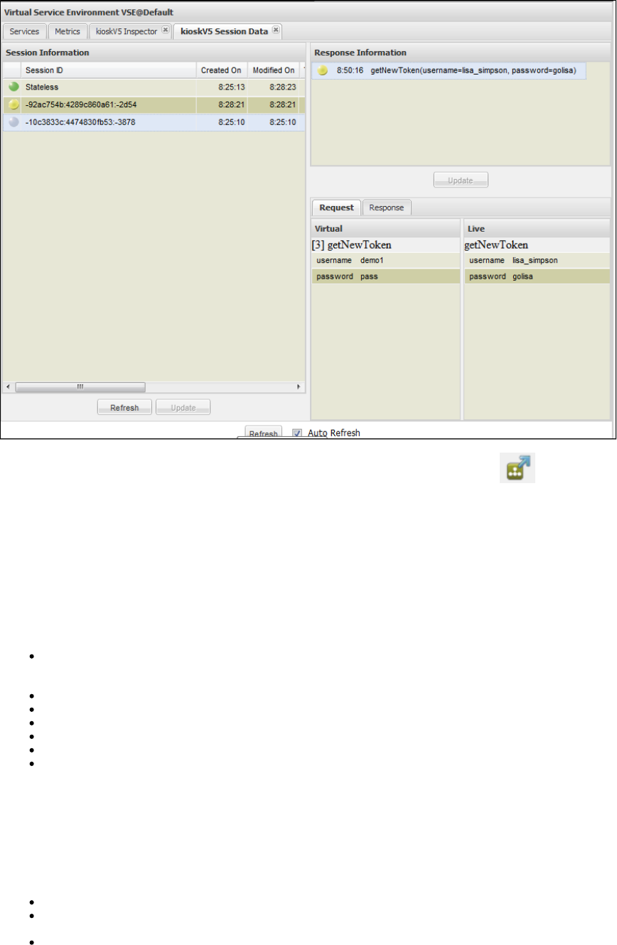
From the VSE Console Services tab, select a service and click the icon to view the session tracking forSession/Tracking Information
selected virtual service.
When you click the icon, the session panel opens and shows the recorded session and transactions. If a deployed virtual service does not have
any recorded transactions, the session panel opens without any session information.
The session panel is divided into two panes: Session Information and Response Information.
Session Information
This pane lists all the sessions for the selected virtual service in tabular format. You can click the arrow at the right of each column heading to
select to reorder the table or to select or clear the columns that are shown.
Session Status: A gray ball indicates a session recorded in Transaction Tracking mode, or a session that has been healed using model
healing. A red ball indicates a session recorded in Image Validation mode that is a candidate for healing. A green ball indicates a session
recorded in Image Validation mode where the live and VSE responses match.
Session ID: The unique Id for each session.
Created On: Timestamp of first transaction in that particular session.
Modified On: Timestamp of most recent transaction.
Txn Count: Number of transaction in that the session.
Client ID: Protocol-specific; for HTTP, the endpoint of the client that submitted the transaction.
Most Recent Request: The most recent request that came through on that session.
Response Information
The Response Information pane shows the list of transactions for the selected session. When you put your cursor over the colored ball in the first
column of this pane, a tooltip indicates the match for that transaction. If you click on any specific transaction, on the bottom of the pane you will
find the request and response tab that compares request/response between the VSE system and the live system.
In the Response Information pane, transactions are represented using green, yellow and red balls.
Green ball: Signature match on meta transaction.
Yellow ball: Signature match on meta transaction; the image navigation is successful, but the response body differs between VSE and
the live system.
Red ball: Conversational transaction diverged between the live system and VSE image.
The buttons are used to update the service image with live session/stateless transaction. This process is referred to as model healing. AUpdate
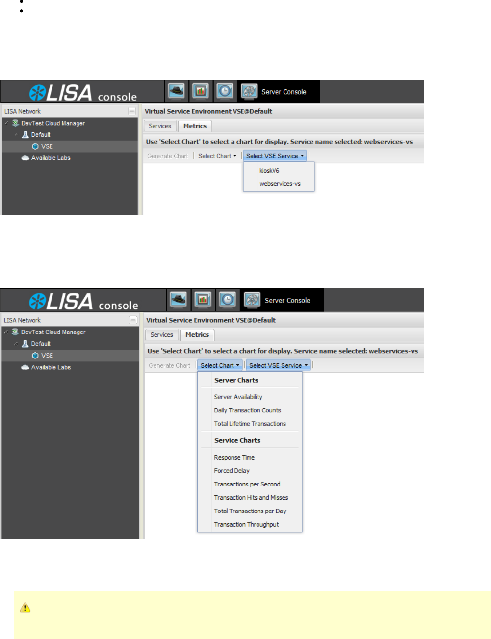
1.
2.
3.
4.
session marked with a red colored ball indicates a disparity between the VSE image and live system. You use model healing to remove the
disparity for the VSM to work correctly. When you click on the button, the session marked with a red ball will change to a gray ball, as this is now
tracked.
The Response Information button updates the service image for the selected transaction.Update
The Session Information button lets you select multiple sessions displayed in the Service Information pane and update them allUpdate
at once.
Viewing VSE Metrics
Selecting the Metrics tab from the LISA Console gives you the following metrics window.
To view VSE metrics for a service
Click Select VSE Service to show a list of all active services.
Select the service you want to display. The service you selected will be displayed.
Click Select Chart to see the available charts for the selected service.
After you have selected a chart, click Generate Chart to see the chart.
Server Chart Metrics
Server chart metrics are metrics that apply to all activity on this virtual server, or VSE.
If you select a server chart, the panel header will indicate that the selected virtual service will not be used for this chart, as these
charts apply to the entire server, not just the selected service.
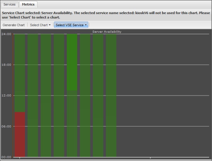
Server Availability
Daily Transaction Counts
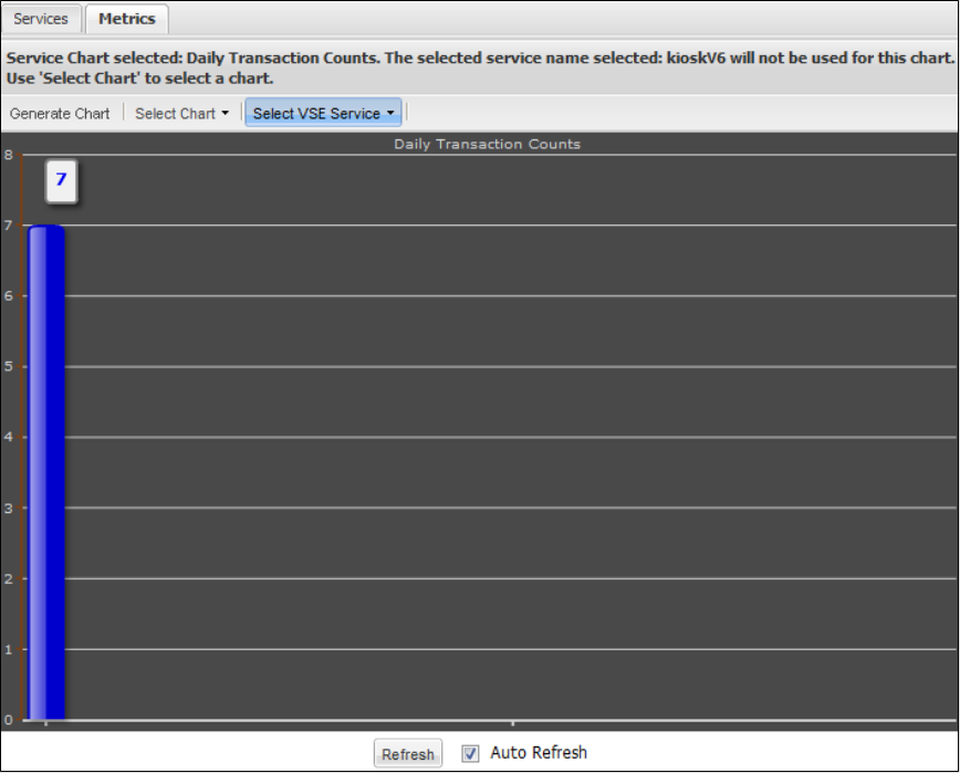
Total Lifetime Transactions
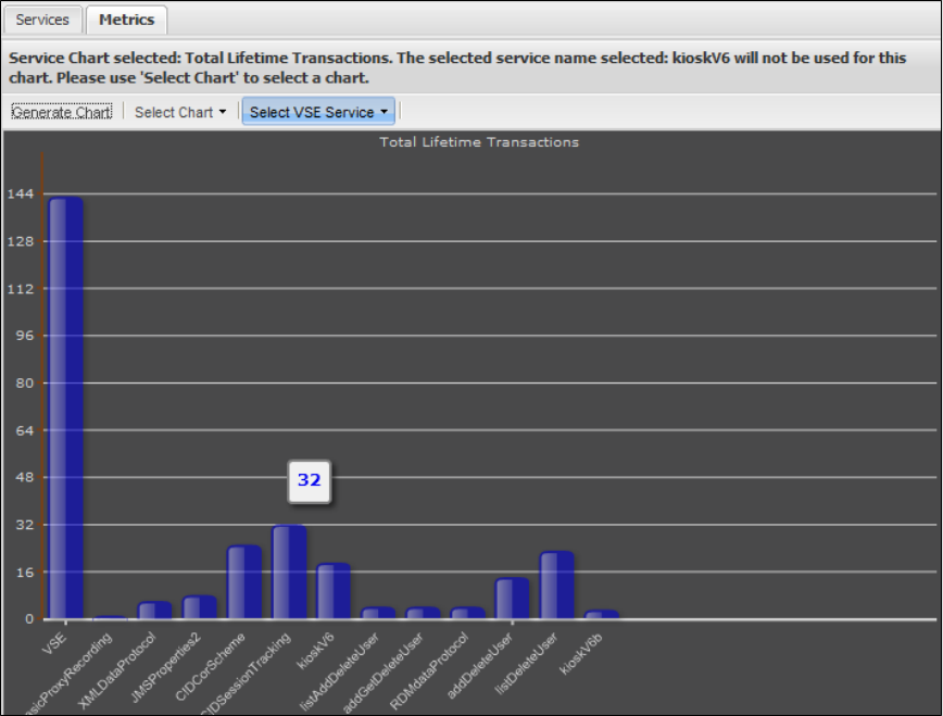
Service Chart Metrics
Service chart metrics are metrics that are applicable to each virtual service. On the right pane, there is a list of virtual services that have been
deployed in this environment. You can select one of them, then select a chart from the list.
Response Time
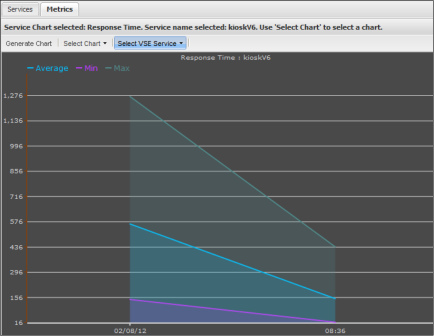
Forced Delay
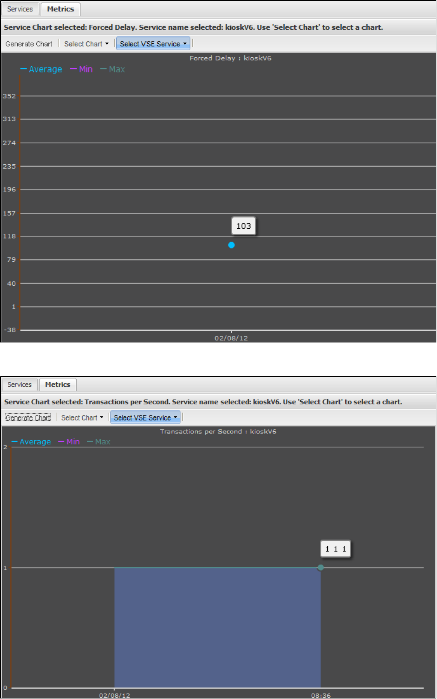
Transactions Per Second
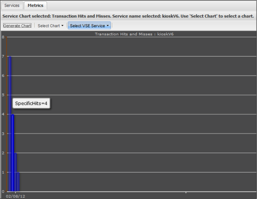
Transaction Hits and Misses
Total Transactions per Day
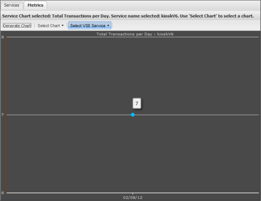
Transaction Throughput
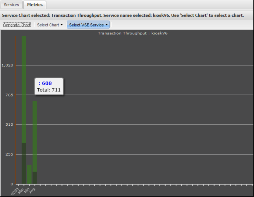
VSE Manager Commands
This command line tool can be used for managing virtual service environments. It is recommended that you use the newer, more functional
command line tool for LISA 6.0 implementations. For information about the new tool, see .Service Manager Commands
VSE Manager is included as a tool under the bin/ directory in LISA Server.
For example, the command to deploy a VSE service looks like this:
LISA_HOME/bin/VSEManager.exe --deploy "service name" --model "LISA_PROJ_ROOT/VServices/service.vsm" --config "
LISA_PROJ_ROOT/Configs/project.config"
And the command to undeploy that VSE service:
LISA_HOME/bin/VSEManager.exe --remove "service name"
Run VSE Manager by itself on the command line to get a complete listing of the available options.
JavaScript
In some installations VSE Manager may not be available as a tool under bin/. The same outcome can be achieved by using a JavaScript step:
Deploying a VSE Service
arguments = new String[] {
"--deploy",
"service name",
"--model",
" /VServices/service.vsm",LISA_PROJ_ROOT
"--config",
" /Configs/project.config"LISA_PROJ_ROOT
};
com.itko.lisa.coordinator.VSEManager.main(arguments);
Recalling a Deployed VSE Service
arguments = new String[] {
"--remove",
"service name"
};
com.itko.lisa.coordinator.VSEManager.main(arguments);
Syntax:
VSEManager options command [ ... command]
where "options" may be one or more of the following:
--registry <name>
Used to set the name of the LISA Registry to work through
--vse <name>
Used to set the name of the virtual service environment to work with
--username <name>
Used to set the id of the user to authenticate with when ACL is in use
--password <name>
Used to set the password for the user to authenticate with when ACL is in use
and where "command" may be one or more of the following:
--status [ <vs-name> | all ]
Used to print out the status of one or all virtual services in the
current environment
--deploy <archive-file>
Used to deploy a new virtual service to the current environment. The
must have a virtual service model as its primary asset.archive file
--redeploy <archive-file>
Used to redeploy an existing virtual service to the current environment
-- capacity <capacity>] [--thinkscale <scale>]update <vs-name>
[--auto-restart [on|off]
Used to update the capacity, think scale, auto-restart setting, or any combination thereof for the named
virtual service.
--remove <vs-name>
Used to remove the named virtual service from the current environment.
--start <vs-name>
Used to start the named virtual service in the current environment.
--set-exec-mode <vs-name> --mode <exec-mode>
Used to set the execution mode for the named virtual service in the
current environment. must be one of the following: .exec-mode DYNAMIC, VALIDATION, LIVE, TRACK, or EFFICIENT
--stop <vs-name>
Used to stop the named virtual service in the current environment.
--stopvse
Used to stop the current virtual service environment.
--help
Displays this text.
--version
Print the version number.
Service Manager Commands
This command line tool is used for monitoring, resetting, and stopping LISA services. The commands apply to any LISA Registry, Simulator,
Coordinator, and the VSE server. The Service Manager is included as a tool under the bin/ directory in LISA Server.
For detailed information, see .Service Manager
ServiceImageManager Commands
LISA Virtualize has a command line tool that can be used to either import transactions (raw or session) into a new orServiceImageManager
existing service image or to combine two or more service images together. The is located in the LISA_HOME\binServiceImageManager
directory.
Recording can be controlled in one of three ways: interactive, timed, or disconnected. For all three styles, the "--vrs=" and "--si-file=" arguments
are required. Optionally, for the interactive and disconnected styles, " go" can be specified to skip waiting for a start signal and begin recording--
immediately. This argument can be specified for timed recordings but has the same effect if (and requires that) the "--start" argument is not
specified.
The interactive style is used when only the "--record" argument is specified. When the recorder is ready, it will wait for Enter to be pressed on the
console before actually beginning the recording process, and then wait for Enter again to stop it.
The timed style is used when the "--record" and "--stop=" (and, optionally, the "--start=") arguments are specified.
The disconnected style is used when the "--record" and "--port=" arguments are specified. This sets up a listener that the "--signal" argument will
use to pass control signals to the recorder.
After a recorder has been initiated with the disconnected style, this tool, in a separate process, can be used to control it by sending start and stop
signals over the port. This requires specifying only the "--signal=" and "--port=" arguments.
To import, specify the raw or session traffic transaction file to import after the argument. Use the transport, request, and response data--import
protocols and navigation tolerances to control how the import takes place. To use the "–vrs=" argument with the protocol or tolerance arguments,
you must specify it before the others, as the "–vrs=" argument will reset things to their initial state. Use the argument to specify the name--si-file
of the file containing the service image to import into. You must specify at least these arguments:
--import=, , and either or --si-file= --vrs= --transport=
and can additionally specify these arguments:
--request-data=, , , or --response-data= --non-leaf= --leaf=,
To combine, specify the target service image after the argument. The file name defined by "--combine=" is the target VSI and other--combine
files listed are the sources. Use the argument to control how like transactions are combined and list the file names of the source images to--favor
combine into the target image. You must specify at least this argument:
--combine=
and can additionally specify this argument:
--favor=
Source files for the combine operation are simply listed.
Any arguments whose values contain spaces (such as the names of protocols) must be enclosed in quotes. For example,
"--import=my file.xml"
-i"my file.xml"
The supported arguments are:
Short Command Long Command Description
-h --help Displays help text.
-d --record Records transactions into a service image file.

-v
recording-session-file --vrs=recording-session-file Specifies the recording session file that contains all the configuration information for the
recording or import operation.
-G --go Specifies that for interactive or disconnected styles, the wait for a start signal will be
bypassed.
-S time-spec --start=time-spec Indicates that the recorder should start recording after the specified amount of time.
-E time-spec --stop=time-spec Indicates that the recorder should stop recording after the specified amount of time.
This amount is relative to the time at which the recorder started recording, and is
specified in milliseconds.
-P port-number --port=port-number Specifies the port to be used for recorder control. When used with "--record," it notes
the port the recorder should listen on for control. When used with "-signal=," it notes the
port the start/stop signal should be sent to.
-g start|stop --signal=start|stop Specifies the signal to send to a recorder in a different process. This requires the
"--port=" argument also.
-i raw/traffic-file --import=raw/traffic-file Imports the specified raw or session traffic XML document into a service image file.
-t protocol --transport=protocol Specifies the transport protocol to use during an import operation. Valid protocols are:
HTTP/S IBM MQ Series
Standard JMS
Java
TCP
JDBC
DRDA
-r protocol --request-data=protocol Specifies the request-side data protocol to use during an import operation. Valid
protocols are: Web Services (SOAP) Web Services (SOAP Headers)
Web Services Bridge WS-Security Request
Request Data Manager
Request Data Copier
Auto Hash Transaction Discovery
Generic XML Payload Parser
Data Desensitizer
Copybook Data Protocol
Delimited Text Data Protocol
Scriptable Data Protocol
CICS Request Data Access
DRDA Data Protocol
-R protocol --response-data=protocol Specifies the response-side data protocol to use during an import operation. Valid
protocols are: WS-Security Response
Data Desensitizer
Copybook Data Protocol
Delimited Text Data Protocol
Scriptable Data Protocol
DRDA Data Protocol
-n tolerance --non-leaf=tolerance Specifies the default navigation tolerance to assume for any non-leaf conversation
nodes created. It must be one of CLOSE, WIDE, or LOOSE. If this is not specified, it
defaults to WIDE.

-l tolerance --leaf=tolerance Specifies the default navigation tolerance to assume for any leaf conversation nodes
created. It must be one of CLOSE, WIDE, or LOOSE. If this is not specified, it defaults
to LOOSE.
-o config --config=config-file In Recording mode, specifies a configuration file to use.
-s vsi-file --si-file=vsi-file Specifies the name of the service image file to import transactions into. If this file does
not already exist, it will be created. Otherwise, the imported transactions will be merged
into the existing service image.
-m vsm_file
--vsm_file=vsm-file Specifies the name of the virtual service model file to create during a recording.
-c target-vsi-file --combine=target-vsi-file Combine one or more service image files into the named service image file. Unless the
"favor" argument is specified, the source service images will be favored.
-f source ¦ target --favor=source ¦ target Specifies how to combine like transactions when combining service images. Specifying
"source" will cause like transactions (and other data) to update the target side from the
source side. Specifying "target" will cause like transactions (and other data) to leave the
target side unchanged.
Not applicable --version Print the version number.
VirtualServiceEnvironment Commands
The VirtualServiceEnvironment executable is located in the [LISA_HOME]\bin directory and is used to manage the LISA Virtualize application.
Syntax:
The default VSE name is the value of the system property lisa.vseName.
VirtualServiceEnvironment [ arguments ]
where "arguments" may be one or more of the following:
--help, -h
Displays help text.
--name=name, -n
Defines the service name for the environment server. The default is the system property . The default for the property is lisa.vseName
VSEServer.
--registry=registry-spec, -m
The registry to connect to. For example, .tcp://localhost:2010/registry1
--labName=lab-name, -l
Specifies the name of the lab to use. The default is .Default
--force, -f
Forces this server into the LISA registry, replacing any object already registered by the environment's service name.
--standalone, -s
Causes a LISA registry to be started in the same process as the VSE server. No effort is made to check if one already exists; it is just
started. If the "-m" parameter is specified, it is pass on (as "-n" to the started registry. When using a VSE server in standalone mode it is
important to note that the registry will be listening on the VSE port (2013 by default) rather than the default registry port of 2010.
--port=port-number, -P
Specifies the service port that the VSE will publish to. It is the same as specifying the port as part of the "–name" argument.

As of LISA 6.0.4, the --username and --password options are obsolete.
--username=username, -u
The LISA security user name.
--password=password, -p
The LISA security password.
--version
Print the version number.
