LNW80 Microcomputer Operations Manual 1982 LNW Research
User Manual: manual pdf -FilePursuit
Open the PDF directly: View PDF ![]() .
.
Page Count: 125 [warning: Documents this large are best viewed by clicking the View PDF Link!]
By
Ciarán McManus
First Edition - October, 1982
All rights reserved. Reproduction or use, without express
permission is prohibited. While every effort was taken in the
preparation of this book, the publisher assumes no liability
for errors or omissions. Neither is any liability assumed for
damages resulting from the use of the information contained
herein.
Copyright © 1982, LNW RESEARCH CORP.
TABLE OF CONTENTS
SECTION 0: INTRODUCTION TO THE LNW80 OWNERS' MANUAL ...... 5
* Documentation * What is a Computer?
* I/0 Devices * CPU * Memory * Computer Languages
* What is an Operating System? * Utility Programs
* Application Programs
SECTION 1: UNPACKING THE HARDWARE ....................... 13
SECTION 2: DESCRIPTION OF THE LNW80 ..................... 14
* General Description * Keyboard
* Changing Key Definition * Z80A Microprocessor
* ROM * RAM * Parallel Printer Interface
* Cassette Interface * RS232C Interface
* Floppy Disk Controller * I/0 Panel
SECTION 3: VIDEO DISPLAY ................................ 22
* Introduction * Monitors for the LNW80
* Connecting a Monitor * Connecting an RGB Monitor
* Using the Monitor With BASIC
SECTION 4: CASSETTE INTERFACE ........................... 27
* Hooking up a Cassette Recorder
* Using a Cassette Recorder * Transfer Speed
* Saving a BASIC Program
Page 1 of 31
LNW80 Microcomputer Operations Manual
12/4/03
http://www.xs4all.nl/~fjkraan/comp/LNW/mom/mom_1.html

* Loading a BASIC Program * So, it Won’t Load
* Verifying a Load
* Loading a Machine-language Program
* Lower-case with Cassette Based System
* Complete Lower-case Program
SECTION 5: DISK INTERFACE ............................... 33
* Introduction
* What Kind of Disk Drives You Should Use
* Configuring 5-1/4" 6 8" Drives
* Connecting a 5-1/4" Drive * Connecting 8" Drives
* Disk Drive Set-up 6 the 5/8 Switch
* Other Considerations * Disk Descriptions
* Disk Care
SECTION 6: POWER ON ..................................... 41
* Connecting AC Power
* Power-up 6 Reset for Non-Disk Owners
* Power-up a Reset for Disk Owners
* Disk Power-up Malfunctions
* Monochrome Monitor Adjustments
* NTSC Monitor Adjustment * Monochrome Operation
* Color Operation
* RGB Monitor Adjustment a Operation * Power Off
* Memory Test * High Speed / Low Speed Test
* Graphics Test
SECTION 7: LNW80 GRAPHICS ............................... 47
* Introduction * Graphics Modes * Mode 0 * Mode 1
* Mode 2 * Mode 3 * Machine-language Overview
* Mode 0 Addressing * Mode 1 Addressing
* Mode 2 Addressing * Mode 3 Addressing
SECTION 8: LINE PRINTER INTERFACE ....................... 70
* Line Printer Types
* Outputting to the Printer Using BASIC
* Page Length * Line Count
* Printer Availability * Adjusting Printer Controls
SECTION 9: RS232C INTERFACING ........................... 74
* History of Serial Data Communication
* RS232C Standard * RS232C Operation
* Connecting Equipment to the RS232C
* The Baud * Transmission Techniques
* Transmitting and Receiving
* Setting Transmit and Receive Rates
* Setting Parity * Setting Word Length
* Setting Stop Bits * Getting the Most From RS232C
* Modem
SECTION 10: MEMORY UTILIZATION .......................... 90
* A Look at Memory in a Non-disk System
* A Look at Memory in a Disk System
* High Memory Protection
SECTION ll: CHOOSING AND USING A DISK OPERATING SYSTEM .. 92
* Introduction * Important Aspects of o DOS
* Brief History of TRS80 Model I Operating Systems
* Looking at the Various DOSes
Page 2 of 31
LNW80 Microcomputer Operations Manual
12/4/03
http://www.xs4all.nl/~fjkraan/comp/LNW/mom/mom_1.html

* Top Five DOSes * TRSDOS 2.3 * DOSPLUS 3.4
* NEWDOS80 2.0 * LDOS 5.0/5.1 * MULTIDOS
SECTION 12: COMPATIBILITY FEATURES OF THE LNW80 ......... 106
* DOSPLUS 3.4 CONVERT Command
* LNWBASIC 6 TRS EXTENDED COLOR BASIC
SECTION 13: LNW80 DETAILED DESCRIPTION & SPECIFICATIONS . 111
* General * CPU * Memory * Keyboard
* MICROSOFT BASIC Interpreter * Other Features
* Video Display Specifications
* Floppy Disk Interface * Printer Interface
* Cassette Interface * RS232C Interface
* Terminal Emulation Capability
* Expansion Port * Real-time Clock
* LNWBASIC
SECTION 14: SHOOTING TROUBLE ............................ 120
* Symptoms, Causes, Cures * Outside Interference
APPENDIX A: A BUYER’S GUIDE TO MONITORS ................. 122
* Introduction * Monochrome Monitors
* Recommended List of Monochrome Monitors
* NSTC Video Color Monitors
* RGB Color Monitors
APPENDIX B: DISK DRIVE TUTORIAL ......,....,............. 125
* The History of the TRS-80 Disk
* Termination Resistors
* Drive Selection & Pulled Pin Cables
* Double-sided Disk Drives
* Double-density Catches On
* Configuring 5-1/4" Disk Drives * Eight-inch Drives
* Configuring 8" Disk Drives
APPENDIX C: MODE 1 DRAWING PROGRAM ...................... 139
APPENDIX D: VIDEO DISPLAY DIAGRAM ....................... 142
APPENDIX E: GLOSSARY .................................... 145
INDEX: .................................................. 157
USER'S RESPONSE SHEET ................................... 167
SECTION 0: INTRODUCTION TO THE LNW80 OWNER MANUAL
Congratulations! You have purchased one of the finest
personal and small business computers available - the LNW80.
The LNW80 is software and hardware compatible with the TRS80
Model I computer. This means that one of the largest and most
mature libraries of software will run on the LNW80 without
modification. It also means that a huge selection of hardware
accessories, such as disk drives, printers, printers, modems,
video monitors, data acquisition equipment and much more will
plug right in and run. But the LNW80 is more than just a TRS80
work-alike. The LNW features high resolution graphics,
color, the interfaces for RS232, 5" and 8" single and
double-density floppy disk drives, printer and cassette. The
Page 3 of 31
LNW80 Microcomputer Operations Manual
12/4/03
http://www.xs4all.nl/~fjkraan/comp/LNW/mom/mom_1.html

LNW80 comes complete with 12K ROM, 48K RAM and a 74-key
keyboard with numeric entry pad. The LNW80 also comes complete
with the DOSPLUS 3.4 Disk Operating System (TRSDOS
compatible), Advanced Disk Basic (LNWBASIC) and complete
documentation. It is housed in a sleek steel case with a
cooling fan for increased reliability.
This owner manual was written to make your first experience
with the LNW80 a pleasant one. It also provides the link
between your computer and the following other documentation:
1. Level 2 BASIC Manual
Level 2 BASIC is the microsoft BASIC-88 interpreter written
for the LNW80. It is the BASIC which is compatible with the
TRS-80 Model I LEVEL 2 computer. This BASIC is "BUILT IN" to
the LNW80 and is permanently stored an ROM.
2. DOSPLUS 3.4 Disk Operating System Manual
DOSPLUS 3.4 is a DOS (Disk Operating System) which is
compatible with TRSDOS (Model I). It is authored by
Microsystem Software Inc.
3. LNWBASIC Advanced Disk BASIC Manual
LNWBASIC (written by Nodular Software Associates) is an
extension to the Disk BASIC Interpreter supplied in DOSPLUS
3.4, or to NEWDOS80 version 2.0, LDOS 5.1 and TRSDOS 2.3. This
is the part that has graphics, color, programmable key
functions and some other advanced features.
4. LNW80 Technical Reference Manual
This ls the Service manual for the LNW80. This manual is
intended for those technically- inclined individuals. Theory of
operations, logic diagrams, trouble-shooting tips, test
programs, parts lists, disaasembly and re-assembly
instructions are provided.
If you are a first-time computer owner -- sit back, relax
and read the following section before proceeding to tear the
wrapping off your LNW80 computer. If you have owned a TRS-80
or another personal computer (or if you just cannot wait to
get your hands on your LNW80) proceed to section 1, entitled
"Unpacking the Hardware".
What is a Computer?
Twenty years ago, the word "COMPUTER" meant an
air-conditioned room full of electronics costing millions of
dollars. Today the word "computer" can mean anything from a 10
million dollar mainframe computer to the "chip" inside the
electronics of your microwave oven. A computer is a machine
which can automatically do arithmetic and make logical
decisions.
Input Output (I/0) Devices
The computer can also make data available to and from us
via input and output, devices. A KEYBOARD (typewriter style
keys) is an INPUT device because it allows us to type
information into the computer. This information can then be
used by the computer to tell it what you want it to do, or it
Page 4 of 31
LNW80 Microcomputer Operations Manual
12/4/03
http://www.xs4all.nl/~fjkraan/comp/LNW/mom/mom_1.html

could be data for calculations or even a typed letter. An
OUTPUT device is one that allows the computer to make
information available to us. A video display is an output
device because it allows the computer to "write" to us via the
display screen. This display is fast and can be written over
and over again, It has a disadvantage that there is no
permanent "record" of this information. Once it "ROLLS" off
the screen (SCROLLS), it is lost. A printer is also an output
device. It "writes" on paper the information that the computer
would like to communicate to us in a more permanent manner.
Central Processing Unit (CPU)
To make a computer useful, we must have input devices,
output devices, and we must perform computations (arithmetic
and logical decisions). The device which performs the
computation is called the "CENTRAL PROCESSING UNIT" or CPU.
The CPU in the LNW80 is the Z80A MICROPROCESSOR. It is the
world's most popular 8-bit microprocessor (small processor)
and can do thousands of computations in one second. In order
for the CPU to do computations, the CPU must be told what it
should do in a step-by-step fashion. Each step is an addition,
subtraction, logical operation, or input/output operation.
These step-by-step operations are called "instructions," or to
be more exact, MACHINE LEVEL INSTRUCTIONS.
Memory
These instructions are stored in main computer storage
before being executed. The main computer storage is called
MEMORY. Memory as analogous to 65536 mailboxes in a row on a
very long street. Each mailbox has an address marked on it
from 0 to 65535. Each mailbox may look different on the
outside, but can only hold the same amount of materia1 inside.
Each location of a mailbox as called a "memory location," or
"memory ADDRESS". For an 8-bit CPU, each address can contain a
number from 0 to 255. This corresponds to 2 to the eighth
power or 2exp(8) or 2x2x2x2x2x2x2x2=256. The reason that there
are 65536 memory locations as due to the memory addressing
capability of the Z80 microprocessor. Most of the eight-bit
microprocessors have this home addressing capability. Smaller
CPU's (4-bit) address fewer locations, and larger CPU's
(minicomputers and some 16-bit. CPU’s) can address much larger
memories (sometimes millions of locations). The advantage of
larger memories is the ability to have much larger programs.
Since memory is not cheap, this does cost money. There are
techniques of storing large programs in modules so that only a
few modules need to be in main computer storage at any time,
thus allowing larger programs to run in a smaller address
space. This as called memory management, or as it is more
commonly referred to an the microcomputer world - OVERLAYS.
OVERLAYS are just come of the programming techniques made easy
by LNWBASIC, and DISK BASIC.
In the LNW80, memory takes two different forms. There is
ROM (Read Only Memory) which as a "hard wired" memory that
cannot be changed, and there is RAM (Random Access Memory -
also called Read/Write Memory), which can be changed, but will
disappear when power is removed from the computer.
Instructions, when executed as a group to perform a desired
function are called PROGRAMS.
Computer Languages
Just as people developed a variety of languages to
communicate with each other, so there would become a variety
Page 5 of 31
LNW80 Microcomputer Operations Manual
12/4/03
http://www.xs4all.nl/~fjkraan/comp/LNW/mom/mom_1.html

of languages to communicate with computers. COMPUTER LANGUAGES
are machine level programs that make communication between us
and computer easier. Hundreds of computer languages have been
developed, and with time, even dialects of languages
developed. Cobol, Snobol, Algol, Fortran 4, Fortran 77, BASIC,
Tiny BASIC, Extended BASIC, Level 2 BASIC, Disk BASIC and
Advanced Disk BASIC are dialects of some fundamental computer
languages. These languages are called HIGH-LEVEL LANGUAGES. By
high-level we mean that a single high-level language
instruction is translated into multiple machine-level
instructions. This reduces the amount of time required to tell
the computer what to do - which simplifies programming. This
translation can occur during the time that the program is
being run (RUN-TIME), or the translation can be done in
advance, with the final translated version of the program
(COMPILED OBJECT CODE) stored for later execution.
A run-time translator is known as an INTERPRETER. One of
the advantages of an interpreted high-level language is the
reduced memory requirement for storing and executing the
program. Since the high-level language is in memory during the
execution, the program also can take advantage of the error
recovery facilities of the high-level language. This makes
interpretive languages qenerally easier to program and easier
to get the "bugs" out of the program (DEBUG) to make it
operational. All the levels of BASIC supplied with the LNW80
are interpretive.
A translator that does the translating in advance of
execution is commonly referred to as a COMPILER. A compiler
has the advantage of execution speed since it has all the
instructions, translated in advance and can directly execute
the translated instructions.
Assembly-Language
Assembly-language was the first of the computer languages
developed. It allows symbolic notation to represent
machine-language instructions. This makes for an easier way of
programming machine level instructions. This is sometimes
confusing to first-time computer owners, since much literature
is written using the terms MACHINE-LANGUAGE and ASSEMBLY-
LANGUAGE interchangably. The program that compiles the
assembly-language program is called an ASSEMBLER. For more
details concerning assembly-level programming, we recommend
the following book, available from Radio Shack:
TRS80 Assembly-Language Programming
by William Barden Jr.
BASIC
The most popular language used on the LNW80 computer is
BASIC. BASIC (Beginner's All-purpose Symbolic Instruction
Code) was developed at Dartmouth College in 1965. It has since
become the most widely used language of microcomputers and
small business computer systems. Both interpretive and
compiled forms of BASIC are commonly used. The LNW80 is
supplied with four levels of interpretive BASIC:
1. Level II BASIC (FOOTNOTE - if you are wondering what
happened to level 1, it is a small, very limited BASIC that
was originally sold on the TRS80 Model I and Model III)
occupies 12K (12 X 1024) bytes of memory, and is permanently
stored in ROM. It has full line editing features, string
variables, multiple dimension arrays, 14-digit accuracy, low
Page 6 of 31
LNW80 Microcomputer Operations Manual
12/4/03
http://www.xs4all.nl/~fjkraan/comp/LNW/mom/mom_1.html

resolution graphics, cassette I/0, Video I/0, Printer I/0,
scientific functions, string-handling operations, etc.
2. DOSPLUS 3.4 TINY DISK BASIC - This is supplied on the
DOSPLUS 3.4 diskette and provides an extension to the above
BASIC. It adds floppy disk file handling, advanced keyboard
I/0, in-string search command, programmer-defined BASIC
instructions, and loading, saving, killing, merging BASIC
programs to and from the floppy disk drive.
3. DOSPLUS 3.4 EXTENDED DISK BASIC - This BASIC adds to the
above BASIC the following features:
1. Execute DOS commands from BASIC
2. Advanced editing features
3. Program line renumbering
4. BASIC array sort verb
5. Controlled screen input routine
4. LNWBASIC Advanced Disk BASIC - This adds even more
commands to the above BASIC and is supplied on a 35-track
single-density data disk. It can be used with either Extended
Disk BASIC or Tiny Disk BASIC. It adds up to 40 new commands
to BASIC. It has a "creator" mode which allows the programmer
to create the BASIC he wants by selecting from a menu of new
commands which include:
1. High resolution graphics and color commands
2. Programmable keyboard features
3. Programming shorthand notation
4. Machine Language "CALL" command
5. Sound command
6. RS232 communications from BASIC
7. Printer Spooler
8. Execute string as BASIC statement
9. Block and blinking cursor
10. Do/Until Construct and Much more...
BASIC Compilers
There is quite a variety of BASIC Compilers available for
the LNW80 computer. The biggest disadvantage of most of these
compilers is the lack of compatibilty with their interpretive
counterparts. The Compiler BASIC available from Radio Shack is
not compatible at all. The Microsoft BASIC Compiler (for the
R/S Model I) is almost completely compatible with the DOSPLUS
3.4 Tiny Disk BASIC (including disk I/0), but it does have its
limitations and cannot take advantage of some of the advanced
features of DOSPLUS 3.4 Advanced Disk BASIC or LNWBASIC. There
are other compilers that vary in price and features end can be
found advertised in the computer magazines or available from
your local computer dealer.
Other Languages
One of the reasons for the many computer languages is that
the high-level language programmers have different needs as to
the high-level instructions they would prefer to use. For
example, scientific applications require fast data
computation, scientific accuracy, easy formula evaluation and
special scientific functions (trigonometry functions, etc.)
FORTRAN (FORmula TRANslation) provides this by having
instructions which can do these types of functions easily.
Fortran is not a good language for business since it does not
have some of the high-level instructions for manipulating
Page 7 of 31
LNW80 Microcomputer Operations Manual
12/4/03
http://www.xs4all.nl/~fjkraan/comp/LNW/mom/mom_1.html

business data. Cobol (COmmon Business Oriented Language) was
developed for this purpose. Both Fortran and Cobol are
compiler languages. FORTRAN, COBOL and ASSEMBLER are available
for the LNW80 from a variety of sources including RADIO SHACK.
Some of the other languages that run on the LNW80 are PASCAL,
FORTH, "C" and many others,
What is an Operating System?
The Level II BASIC ROM in the LNW80 computer has a CASSETTE
OPERATING SYSTEM built in. This means that it provides a
method for loading, storing, and executing BASIC programs to
and from cassette and the loading and executing of machine
level programs from cassette. It also provides the overhead
functions, such as communicating with the keyboard and the
video display. In addition, it provides a method of loading in
from disk, the DISK OPERATING SYSTEM (DOS). This loading of
the DOS from the disk drive is called the BOOTSTRAP LOADER.
This is commonly referred to as "booting the disk." When the
disk is "booted," the first 256 memory locations on the disk
drive are loaded into main memory and executed. These first
256 locations are called the BOOT SECTOR. This 256-byte
program then loads the rest of the operating system from the
disk into main memory where it can be executed.
The disk operating system supplied with the LNW80 is
DOSPLUS 3.4. This is a very powerful, yet easy-to-use system
that provides the following functions:
1. Keeps track of programs and data (sometimes referred to
as FILES) stored on the disk. A DIRECTORY of programs and data
is kept. DOSPLUS allocates space on the disk for programs and
data, and the DIR command allows the operator to view the
contents of the disk at any time.
2. Provides a set of functions that the operator can use
to manipulate the programs and data on the disk and other
useful tasks. This set of commands is called the LIBRARY of
disk commands. The LIB command will display all available
functions. Here are a few examples of these functions:
COPY - Allows the transfer of a program or data from one
diskette to another.
AUTO - Automatically execute an application program when
the disk is "booted."
DIR - Display the contents of a selected disk.
CLOCK - Display the time of day on the screen.
RENAME - Change the name of a file.
KILL - Delete a file from the disk.
BUILD - Create a file that is a series of DOS commands or
programs to be linked together to run automatically.
3. Provides some specialized utility programs such as:
BACKUP - Duplicate the entire contents of one disk onto
another disk.
FORMAT - Initialize a blank diskette in such a way that
it has a directory of disk space and contains fields designed
for storing information.
DEBUG - Display and manipulate the contents of memory and
display the contents of the internal Z80A CPU registers. Debug
also provides the abilty to set stopping points to assist in
getting a machine level program to work.
DISKZAP - Display, modify or verify the contents of the
diskette itself.
SPOOL - Store what would nomally print on the printer in
Page 8 of 31
LNW80 Microcomputer Operations Manual
12/4/03
http://www.xs4all.nl/~fjkraan/comp/LNW/mom/mom_1.html

main memory and print as a background function (the printer is
usually very slow) while the operator is running another
program.
DO - Execute a BUILD file. A build file is a series of
DOS commands or programs which can be linked together (using
the BUILD command) to operate automatically. In the larger
computers this program control language is called a Job
Control Language (JCL) and is used to link programs together
to increase the efficiency of running a computer.
4. Provides the following BASIC interpreters:
TBASIC - The TRSDOS 2.3 compatible BASIC
BASIC - The Extended Disk BASIC
For more details concerning the above features of DOSPLUS
3.4, refer to the manual entitled:
USER MANUAL Ver A.x
for
DOSPLUS 3.4
DISK OPERATING SYSTEM
Utility Programs
These are generally (but not necessarily) written in
machine-language and provide some useful function for
programmers. An example of a utility program available from
your dealer is CHARM. This program allows the you to create
new character sets for use in BASIC programs. As mentioned
earlier, there are many utility programs supplied with DOSPLUS
3.4.
Application Programs
An application program is a program which is written in
machine-language or a high-level language that performs some
specialized application. Games, accounting and financial
programs, word processing and text editing programs, and
specialized industrial or business programs are all examples
of application programs. The entire manuscript of this manual
was prepared using the ELECTRIC PENCIL program. The ELECTRIC
PENCIL is a word processing and text editing program available
from your local dealer.
SECTION 1: UNPACKING THE HARDWARE
Now that the LNW80 Computer is in your possession, let's
get it out of the box and have a look at it. Decide where you
are going to put the computer before unpacking. Avoid the
temptation of setting it up on the floor, where the wayward
foot is a very plausible source of destruction! Clear a space
on a convenient table or desk that is near a power plug. You
should also have a power strip or plug bar for the various
pieces of equipment that will need 110V AC power.
The LNW80 is packed within a special protective foam
cushion. Fold back the packing, lift out your LNW80 Computer
and set it on the desk or table top.
After you have removed the computer, you will notice that
there is a package of printed material on the bottom of the
carton. This package contains your warranty information. Read
it carefully; fill out the warranty card and then mail it as
Page 9 of 31
LNW80 Microcomputer Operations Manual
12/4/03
http://www.xs4all.nl/~fjkraan/comp/LNW/mom/mom_1.html

soon as possible.
This packing list contains the equipment list. To ensure
that you have everything, check the list now. If you do not
have all of the equipment listed, notify your dealer
immediately.
Now that your LNW80 Computer has been unleashed from its
package, let’s sit back for a minute and describe the LNW80 in
a little more detail.
Note: Keep all packing materials. In the event that you have
to transport your computer, the packing material will help to
ensure safe passage.
SECTION 2: A DESCRIPTION OF THE LNW80 COMPUTER
The LNW80 computer comes to you with keyboard encased in a
steel housing. At first sight the most conspicuous features
are the 62-key keyboard and the 12-key numeric pad. Above the
numeric pad is the POWER-ON light. The input/output (I/0)
panel (for connecting peripheral equipment) is situated at the
rear of the housing. The following is a list outlining the
main features of the LNW80 Computer:
* 74-key keyboard (including a 12-key numeric pad)
for inputting data and programs.
* Z80A microprocessor with a 4Mhz clock.
* 12K Read Only Memory (ROM) containing the Microsoft
BASIC Language interpreter.
* 48K Random Access Memory (RAM) to store your programs
and data.
* Real time clock.
* Parallel Printer interface.
* Cassette interface.
* RS232C communications interface.
* Single and double-density floppy disk controllers
with 5-1/4 and 8 inch drive zero switch.
* 24 by 80 character screen capability.
* High resolution graphics in color and b/w.
* Upper and lower case character sets.
* 4MHz or 1.77MHz processor speeds.
* Cassette I/0 at either 500 or 1000 baud.
* Three video output jacks.
* Heavy duty power supply.
* All gold-plated edge card connectors.
All of these components are housed in a single steel case
and are powered by a single power cord.
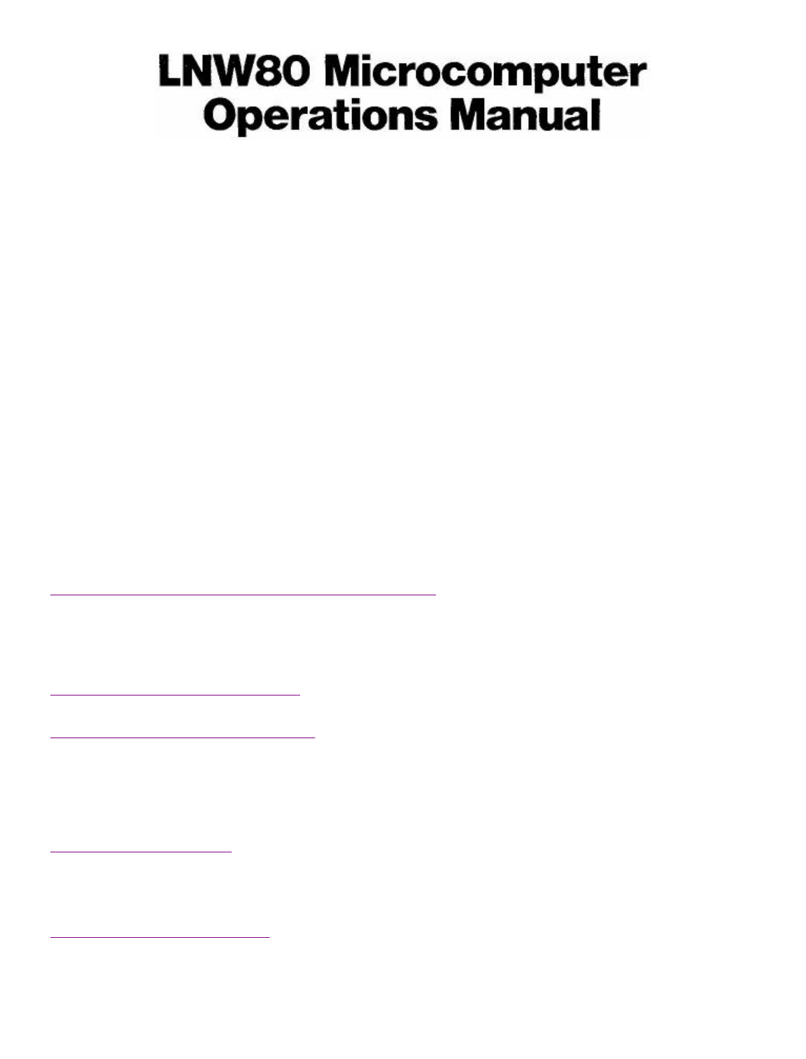
Figure 2.0 - 3/4 Front view of the computer.
Page 10 of 31
LNW80 Microcomputer Operations Manual
12/4/03
http://www.xs4all.nl/~fjkraan/comp/LNW/mom/mom_1.html
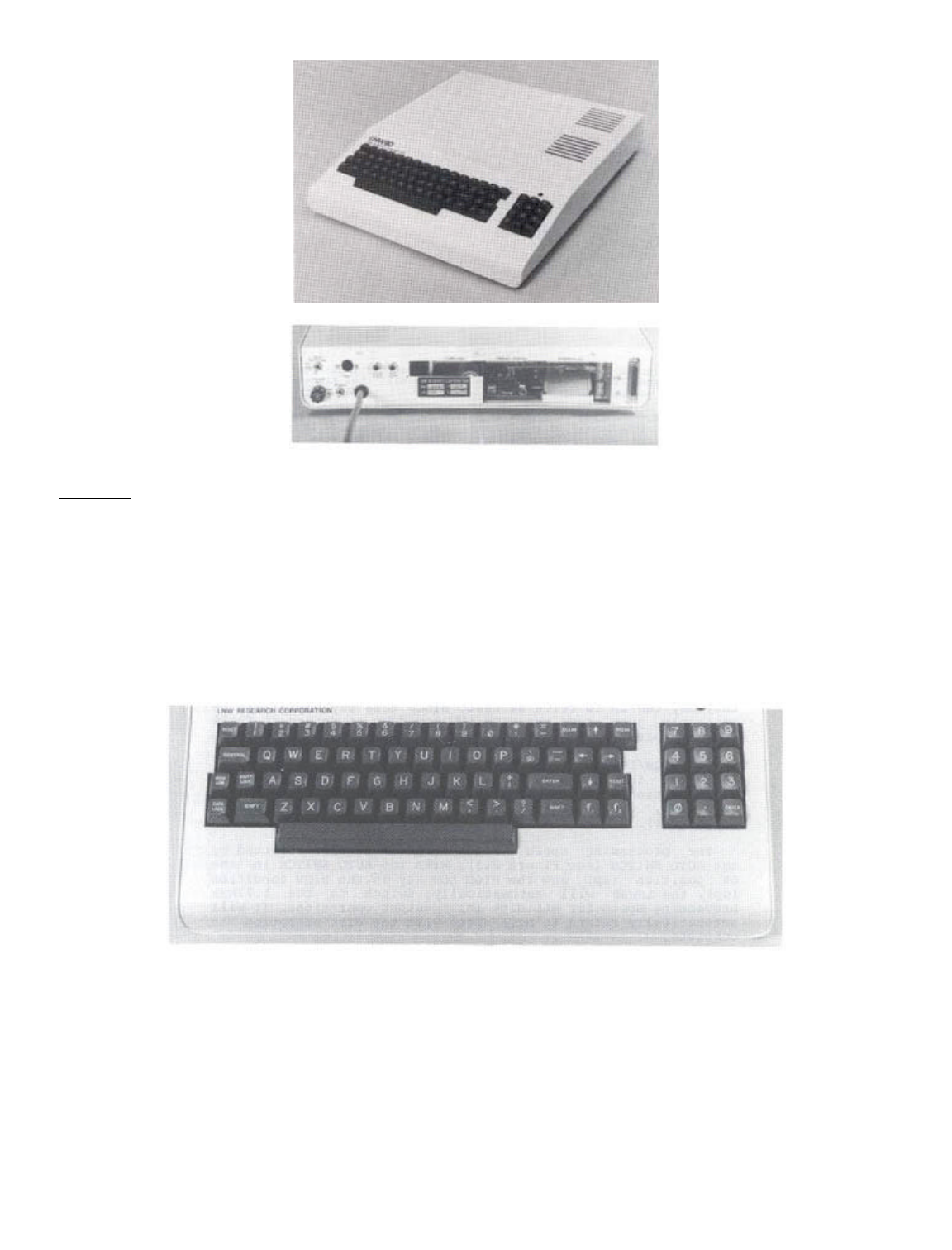
Figure 2.1 - 3/4 Rear view.
Keyboard
The LNW80 keyboard is pictured in Figure 2.2. The keyboard
allows you to interact with the computer. You enter data,
programs and control characters by typing on the computer
keyboard. The main section of the keyboard is similar to that
of a typewriter, with some extra keys which relate strictly to
computer functions.
To the right of the keyboard is a numeric pad to facilitate
data entry in accounting or mathematical applications.
Figure 2.2 - Photo of LNW80 Keyboard
RESET - There are two reset keys, one on each side of the main
part of the key board. The RESET keys are used to reset the
computer AFTER it has been initially turned on.
If you don’t have disks, reset the system by holding down
the BREAK key and then pressing both RESET keys
simultaneously. If you have disks, reset the system by
pressing both RESET keys.
ENTER - When you type or enter data into the computer, you
must press the ENTER key to signal the computer that you are
Page 11 of 31
LNW80 Microcomputer Operations Manual
12/4/03
http://www.xs4all.nl/~fjkraan/comp/LNW/mom/mom_1.html

finished with your input. The computer will then process the
data you have entered.
BREAK - This key generates an escape code which is used by the
BASIC interpreter to stop execution of a program. It is also
used in word processing applications and in some system
programs, e.g., DISKZAP, which comes with the DOSPLUS disk
operating system. BREAK will not usually return control to you
when the system 'hangs.' For example, if you try to CLOAD a
program from cassette and it’s not set up correctly, the
system hangs. It will now ignore your incessant pounding on
the BREAK key until you either hook-up the cassette recorder
correctly or RESET the system.
CONTROL - This key is used to generate special codes when used
with another key. It is especially useful in data
communications and word processing.
HIGH/LOW - Ordinarily the LNW80 Computer runs at a clock speed
of 4MHz (4 million cycles per second). Certain input/output
(I/0) situations may require a slower processing cycle, in
which case, this key may be pressed to give a clock speed of
1.77MHz.
The 4MHz speed is over twice the speed of the TRS80 Model
I. When programs written for the Model I are run on the LNW80,
they may run up to twice as fast. Since this may not always be
desirable, just press the HIGH/LOW key down to return to TRS80
model I speed.
The HIGH/LOW key also serves to select the data transfer
rate for the cassette interface. When the H/L key is in the
HIGH position, data as SAVERS or LOADed at 1000 baud. With the
key down, data transfer is at 500 baud (TRS80 model I
compatible).
The processing speed of the computer is also affected by
the AUTO SWITCH (see Figure 2.3) . With the AUTO SWITCH in the
ON position (up) and the HIGH LOW key in the HIGH condition
(up), the LNW80 will automatically switch to the 1.77MHz
processing speed for ALL disk input/output operations. It will
automatically return to HIGH speed when the disk operation is
complete.
This allows programs written on TRSDOS 2.1 & 2.3 (as well
as NEWDOS 2.1 and operating systems listed in Section 11,
Table 11.0 which have a NO in the '4MHz OK' column) to operate
at the high CPU speed except for disk I/0. If these operating
systems are run at 4MHz during disk I/0, a "DISK ERROR"
message will be displayed.
Note: NEWDOS80 2.0 will run at 1.77MHz all the time if the
AUTO SWITCH is ON (up).
RIGHT ARROW - Tab key. Tabs 8 spaces to the right.
LEFT ARROW - Backspace one position and delete.
CLEAR - Clears screen, homes cursor, switches to 64 characters
per line.
Fl and F2 - The Fl key generates a down arrow. The F2
generates a right arrow. Disk operators use key to
effect same; otherwise, Fl generates an elongated colon (|)
which can be used to make lines down the page, and the F2 key
generates the Yen character
Page 12 of 31
LNW80 Microcomputer Operations Manual
12/4/03
http://www.xs4all.nl/~fjkraan/comp/LNW/mom/mom_1.html

These characters may by used for normal input or as special
program keys in applications programs since they generate
normal ASCII characters. These ASCII codes are:
Down arrow 92 Right arrow 94
Elongated colon 124 Yen character 126
Since these keys are not present in the TRS80 Model I, they
can be reprogrammed using LNWBASIC while still maintaining the
normal functions of all the standard keys. (See DEFKEY in the
LNWBASIC Manual).
CAPS LOCK - This key provides you with a means of locking all
the alphabetic keys into upper case. Fl, F2, "0" and the
underscore key (to the left of the down arrow) are also
affected. Fl generates a down arrow, F2 generatee a right
arrow, "0" generates "0" and the underscore key generates an
underscore when the CAPS LOCK is down.
The CAPS LOCK is only sensed by programs which use it
during the program LOAD. For example, when DOSPLUS is first
booted, the switch is sensed. If the CAPS LOCK is down, all
alphabetic characters will appear as upper case characters,
regardless of the SHIFT key operation. The same applies to
application programs such as Visicalc, where it is useful if
you only want to make your entries in upper case. The CAPS
LOCK is similarly sensed in Electric Pencil, ST80 and many
other application programs.
Note: Set the CAPS LOCK just prior to loading your program.
Changing the setting while the program is running will give
rise to unintelligible displays and may cause data loss.
The SHIFT Key:
As with a typewriter, the SHIFT key is used to print the
upper symbol on dual-symbol keys. The SHIFT key is, in fact,
used in a number of combinations as listed below in DOSPLUS,
BASIC (all kinds), Electric Pencil and most application
programs:
KEY FUNCTION
<SHIFT><right Switches to 32 charaters/line
arrow>
<SHIFT><left Backspace to beginning of line & erase
arrow>
<SHIFT><@> Stalls program execution, e.g., a
listing. Hit any key to continue
<SHIFT> 0 Toggle between: (a) capitals only,
or (b) capitals and lower case on
the A - Z keys. In mode (b), switch
from upper to lower, or vice versa
Page 13 of 31
LNW80 Microcomputer Operations Manual
12/4/03
http://www.xs4all.nl/~fjkraan/comp/LNW/mom/mom_1.html

using . Available to
disk operators only.
Changing key definition
Using the LNWBASIC command DEFKEY, you may redefine any 10
keys as strings of ASCII character codes of length 1 or more.
You may also use the Quickey option in LNWBASIC to enter
entire commands by just pressing one key. See the LNWBASIC
manual for more details.
Z80A Microprocessor
Often called the Central Processing Unit (CPU), this is the
focal point of all events taking place within the computer.
All the calculations and logical operations are carried out
here and then routed or addressed for storage, video display,
printing, etc. Sometimes the CPU is referred to as the
"brains" of the computer.
The microprocessor has two operating speeds. The higher
operating speed is 4MHz. A lower operating speed is obtained
at the flick of a switch, as explained in the HIGH-LOW notes
above.
The Z80A belongs to the 8080 family of microprocessors. It
has 158 machine-language instructions (including all 78 8080
instructions) and 16 internal registers, It is capable of
processing approximately 400,000 instructions per second.
ROM
ROM stands for Read Only Memory. The ROM memory is
preprogrammed. There is 12K of ROM in your LNW80 Computer. The
"K" unit refers to 1024 single units of storage. These units
are known as "bytes." The ROM contains the MICROSOFT BASIC and
other information required by the CPU. As the name implies,
information may only be read from ROM. You cannot write or
store information in ROM.
RAM
RAM refers to Random Access Memory. A more accurate name
would be Read/Write Memory. As this latter name suggests, RAM
can be either written to or read from. It is true that RAM is
accessed randomly, but so is ROM. However, unlike ROM, RAM
loses the information stored in it when the power to the
computer is turned off. The contents of RAM can also be
changed at any time, whereas those of ROM cannot be changed.
You can address a total of 65K of memory address space in
the LNW80 computer. Of this, 48K is available for programming
use; 16K x 6 bits is used for graphics, and the remaining 1K
is tied up for video use.
Parallel Printer Interface
The parallel printer interface allows you to attach any
Centronics-compatible parallel printer and get a "hard copy"
of your programs and other files. It is invaluable if you
intend to use your computer for word processing, invoicing or
other applications where the printed word is a must.
Cassette Interface
If you do not intend to use disk drives, the need will
Page 14 of 31
LNW80 Microcomputer Operations Manual
12/4/03
http://www.xs4all.nl/~fjkraan/comp/LNW/mom/mom_1.html

arise for you to store your programs for later recall. You
will also find that many programs (even programs for disk) are
distributed on cassettes. A cassette player can be attached to
your LNW80 computer that will allow you to read and write
programs and data to cassette tape. The LNW80 allows you to
output data to tape at either 1000 or 500 baud (bits per
second).
The baud rate is controlled by the HIGH/LOW speed switch.
In the HIGH position, the tape is recorded at 1000 baud; and
in the LOW position, it is recorded at 500 baud.
Standard TRS-80 Model I cassette tapes are recorded at 500
baud.
RS232C Communications Interface
This interface will allow you to communicate via a modem
and telephone with any other computer similarly equipped. It
also serves as a serial printer interface. The RS232C port may
be configured to the various settings required by serial
devices by setting switches located on the rear panel (see
Figure 2.3) or by software.
Expansion Port
The expansion interface is located on the I/0 panel at
rear. This interface allows you to connect such devices as
speech and music synthesizers to your LNW80 computer. For more
details see section 13 and the LNW80 Technical Reference
manual.
Single- & Double-Density Floppy Disk Controller
Your LNW80 Computer has a single/double-density disk
controller that will support 5-1/4 and 8 inch, dual or single
headed, floppy disk drives. 5-1/4 and 8 inch drives may be
hooked up in any order on the disk drive cable.
When applied to storage on disks, density refers to the
amount of information that, can be stored on a storage medium.
Specifically, in the case of floppy disks, it refers to the
number of bits per track. Double-density offers 80% more
capacity and twice the data transfer rate of single-density.
Single-density is retained for compatibility reasons.
To take advantage of this increased potential for storage,
a microcomputer must have, as part of the hardware, a
double-density floppy disk controller (as does the LNW80).
Also, the disk operating system (DOS) used in a disk drive
system must take advantage of this hardware.
The big advantage of double-density storage is that it
helps to reduce costs by minimizing the number of disk drives
required.
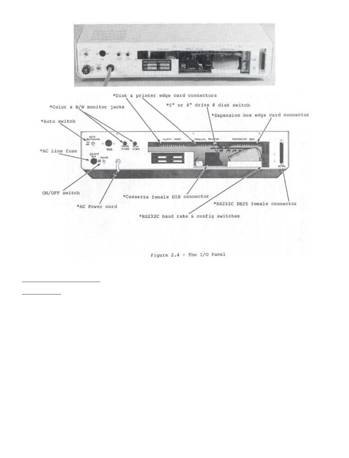
The Input/Output Panel
At the opposite end of the computer from the keyboard is
the input/output (I/0) panel. It is to this panel that all of
the peripheral devices are connected. And, as a picture is
worth a thousand words, see Figure 2.3.
Figure 2.3 The I/0 Panel
Page 15 of 31
LNW80 Microcomputer Operations Manual
12/4/03
http://www.xs4all.nl/~fjkraan/comp/LNW/mom/mom_1.html
SECTION 3: VIDEO DISPLAY
Introduction
You will require a video display unit (VDU or monitor) to
operate your LNW80 Computer (The video display is sometimes
called a CRT or Cathode Ray Tube). Your selection of VDU will
no doubt depend on what you want from your computer.
If color graphics is your bag, then a color monitor of some
sort is required. An ordinary color TV (NTSC) will suffice,
but there are some limitations when using a TV set as a
monitor. The resolution of a TV set is not sufficient for the
display of text unless the display is set for a screen width
of 32 characters. Also, you will need to attach an R/F
modulator between your LNW80 and the TV set. TV sets aren’t
very good monitors, and because of the low resolution,
graphics displays are rather fuzzy.
An NSTC color monitor, with composite video input, will
provide good color graphics and text an 32 characters per line
mode.
An RGB (Red Green Blue) color monitor will provide
excellent resolution for graphics and text.
Page 16 of 31
LNW80 Microcomputer Operations Manual
12/4/03
http://www.xs4all.nl/~fjkraan/comp/LNW/mom/mom_1.html
See Appendix A, "A Buyer's Guide to Monitors".
Connecting a Monitor
Set the monitor on top of the computer and locate the three
monitor jacks on the I/0 panel at rear (see Figure 3.1).
Notice there are separate jacks for B/W, color TV with RF
modulator or color monitor, and RGB monitors. Attach your
monitor with the appropriate cable. The B/W and color TV
cables are standard computer-to-monitor connector cables.
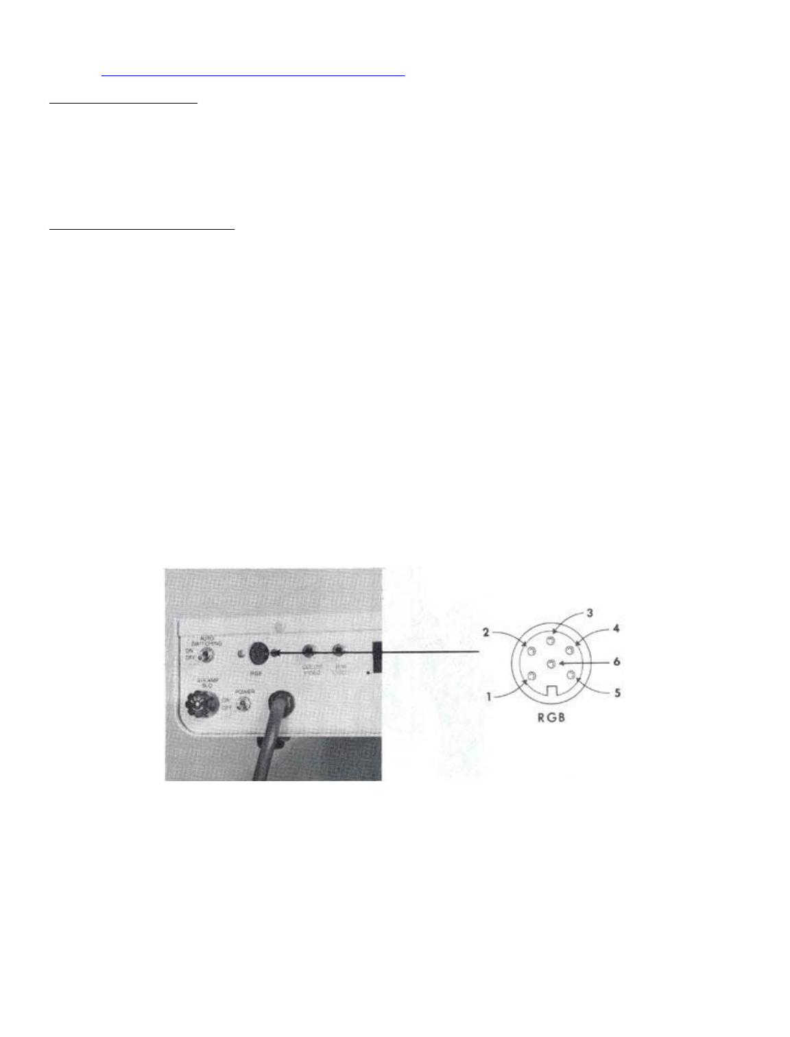
Connecting an RGB Monitor
The RGB monitor has a separate gun for each of the three
colors red, green and blue. Each gun requires a distinct
signal, and hence, the computer-to-monitor cable is a little
more sophisticated. You will notice that the RGB jack is a
six-pin DIN type female connector. A mating connector for this
jack is provided; however, you will have to provide the cable
and connector for the RGB monitor. Below are the pin
specifications for the monitor and RGB connectors:
LNW80 RGB Connector Signal Monitor Connector
Pin 1 Vertical Sync Pin 8
Pin 2 Blue Pin 4
Pin 3 Green Pin 3
Pin 4 Red Pin 2
Pin 5 Horizontal Sync Pin 7
Pin 6 Ground Pin 5,6
The RGB interface is shown below with pin numbering.
Figure 3.1 - LNW80 RGB Monitor Jack
Figure 3.2 - LNW80 Video Display
Page 17 of 31
LNW80 Microcomputer Operations Manual
12/4/03
http://www.xs4all.nl/~fjkraan/comp/LNW/mom/mom_1.html
Note: For "First Time Through The Manual" People . . .
If this is your first time reading through the manual,
please move on to the next section at this point. When you
have made your way through Section 6, entitled "Power On," the
rest of this section will make more sense.
Using the Monitor with BASIC
Cursor
After performing an operation, BASIC announces its return
to the immediate mode as follows:
READY
>_
( ">" = PROMPT, "_" = CURSOR )
The cursor may be moved along the line by the space bar or
the right arrow, which tabs eight spaces to the right.
Scrolling
When the cursor is positioned on the bottom line of the
display and ,you depress the ENTER key, another line is added
to the display. At the same time, all the lines currently
displayed move upwards, and the line at the top is erased.
Page 18 of 31
LNW80 Microcomputer Operations Manual
12/4/03
http://www.xs4all.nl/~fjkraan/comp/LNW/mom/mom_1.html

Inverse Video
Inverse video can be generated by the following program.
You may have to brighten the screen to observe the effect.
(Results can vary with different monitor types).
10 A=INP (254)
20 A=A OR 1
30 OUT 254,A
Inverse video is only good for black and white. It is not
defined for color.
Text Characters
The BASIC program below displays the text characters
together with their ASCII codes that are available from the
character generator.
10 '......TEXT GENERATOR
15 CLS: X=0
20 FOR K=32 TO 127
30 PRINT @ (X),Z; CHR$(Z)
40 LET X=X+8
50 NEXT Z
You may alter the text and graphics characters by using the
CHARM program, which is available from your dealer.
Graphics Characters
The low-resolution graphics characters available from the
character generator and their accompanying ASCII codes are
displayed by this next program.
10 ’.....GRAPHICS GENERATOR
20 CLS: X=0: Y=0
30 FOR Z=128 TO 191
40 PRINT @ (X),Z; CHR$(Z)
50 LET X=X+8: LET Y=Y+1
60 IF Y/8=INT(Y/8) THEN X=X+64
70 NEXT
80 GOTO 80
to exit program.
You can display any of the characters yourself by typing:
PRINT CHR$(nnn)
... where nnn is a whole number from 128 to 191 inclusive.
Character Size
32 Characters per Line:
The 32 characters per line mode can be effected from the
keyboard by using the combination. Return
to 64 c.p.l. by CLEARing the screen.
80 Characters per line:
This feature is only available to Disk Operating Systems
(DOS) owners. The program to generate this display, called a
"driver," is loaded from disk after booting up the system.
These drivers are available from your dealer. Before trying to
Page 19 of 31
LNW80 Microcomputer Operations Manual
12/4/03
http://www.xs4all.nl/~fjkraan/comp/LNW/mom/mom_1.html
load the drivers, read Section 5 concerning the disk
interface.
Drivers are available to generate both an 80xl6 and an
80x24 display. These drivers have limitations, however, in
that they cannot be used (to date) in word processing
applications.
40 Characters per line:
Depending on which 80x24 driver is in use (or up), using
introduces the 40x24 display mode.
Programmable Character Font
With the use of CHARM (available from your computer
dealer) the LNW80 can have user programmable character sets.
The user can program foreign language, scientific and even
special graphics symbols, and then save them to disk. CHARM
features three display formats: 80 x 24 80 x 16 and 64 x 16.
CHARM also features standard video as well as inverse video on
a character by character basis.
SECTION 4: CASSETTE INTERFACE
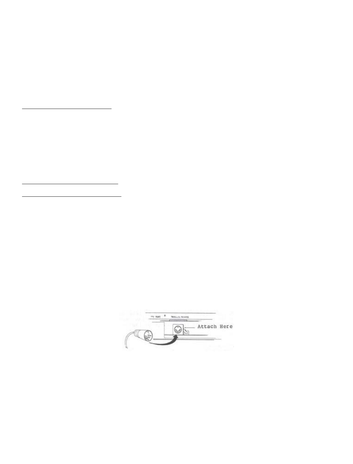
Hooking up a Cassette Recorder
Any good quality cassette tape unit may be attached to the
LNW80 Computer with a cassette cable (Figure 4.0). The
cassette cable is available from your local Radio Shack store
(Radio Shack Catalog No. 26-1207).
A cassette player is not required for immediate operation.
However, if you have one available and intend to store
programs and data on tape, now would be an appropriate time to
attach it to the computer.
The cable has a DIN plug at one end and three color-coded
miniature phone plugs at the other. The DIN plug is attached
to the cassette jack on the I/0 panel (Figure 4.0). The DIN
plug may be attached to the computer only one way, so there is
no danger of plugging it in backwards.
Figure 4.0 - Cassette Cable Attachment
The phone plugs are connected to the cassette player by
color code as follows:
GREY - connects to the AUXillary input
SMALL GREY - connects MIC REMote control
BLACK - connects to the EAR phone input
The AUX line carries information from the computer to the
cassette tape.
The EAR line carries information in the other direction,
from the cassette to the computer.
Page 20 of 31
LNW80 Microcomputer Operations Manual
12/4/03
http://www.xs4all.nl/~fjkraan/comp/LNW/mom/mom_1.html

The MIC REM line carries a signal from the computer which
controls the motor in the cassette player.
Using a Cassette Recorder
A cassette player provides a handy, low-cost method of
loading and storing programs. If this is your first computer,
experiment to get familiar with cassette player operation
before storing any close-to-your-heart programs. Before
playing with the cassette recorder, it would be a good idea to
clean the tape heads and the rubber pinch roller with
isopropyl alcohol. An alcohol swab after every few hours of
use, will keep the heads and roller clean. So called "cleaning
tapes" are not recommended, as their abrasive action may
damage the heads. Cheap tapes are not recommended.
Transfer Speed
Programs and data can be transferred to and from the tape
surface at two different transfer speeds. The faster transfer
rate is 1000 bits per second (baud), and the slower rate is
500 baud. By using the key, you switch to fast or
slow, respectively.
The faster transfer rate (1000 baud) allows you to save and
load programs twice as fast as the slower rate, and in
addition it saves tape. The faster rate is also more sensitive
to tape noise while loading. For this reason, the tape should
be well erased (see below) before SAVEing programs or data to
it. Always note at which speed a program was saved, as
programs saved at one speed cannot be loaded at the other
speed.
SAVEing a BASIC Program
Begin with a blank tape. To blank a tape, run a commercial
tape eraser slowly over the surface of the cassette a few
times. Alternatively, you may put a shorting plug in the AUX
input, insert the cassette and place the recorder in record
mode.
1) Mount the cassette in the recorder and run it
forward a little to clear the non-magnetic strip
at the ends of the tape. Note position of tape
counter and transfer speed.
2) Put recorder in record mode.
3) Type:
CSAVE"N"
where N is a one-character name of the program.
LOADing a BASIC Program
1) Mount cassette and set recorder in play mode just
a little before start of the program on tape. Set
the transfer speed and adjust volume control to
mid-range.
2) Enter:
Page 21 of 31
LNW80 Microcomputer Operations Manual
12/4/03
http://www.xs4all.nl/~fjkraan/comp/LNW/mom/mom_1.html

CLOAD"N"
where N is the name of the program. If no program
name is specified, the first program or file
encountered will be LOADed.
When the program begins LOADing, an asterisk will appear in
the upper-right corner of the screen. This means that it has
found the synchronization pattern that leads the file on tape.
So far, so good! Next the file name is read and compared with
the requested filename. If the names match, the file will be
LOADed. WhiIe the file is being loaded, a second asterisk will
appear to the right of the first. If the LOAD is successful,
this second asterisk blinks.
If the file names do not match, the first asterisk remains
on display while the next synchronization pattern is searched
for.
So It Won't Load
If the second asterisk doesn't appear after a short time,
or appears and fails to blink, the program is not LOADing
correctly.
Go through the list below. The solution will most likely
lie within the bounds of steps 1 through 3.
1) Check that all electrical connections are secure.
2) Check that the transfer speed is correct.
3) Starting with the lowest volume setting, proceed a
half-step at a time for each LOAD attempt.
4) If there is a tone control, adjust it.
5) Demagnetize the head of the recorder.
6) REWIND and FAST FORWARD the tape a few times
to remove any tape surface debris.
7) If you have just turned on the computer, let it
warm up for a few minutes before attempting
another LOAD.
8) Unplug the earphone jack and play the tape to
check where the program begins and to make sure
you have a program.
9) Try another cassette recorder.
Verifying a LOAD or SAVE
When a SAVE is complete, the computer responds with
READY
>_
To ensure that no errors have occurred during the transfer
of data, rewind the tape and ENTER
CLOAD? "N"
Page 22 of 31
LNW80 Microcomputer Operations Manual
12/4/03
http://www.xs4all.nl/~fjkraan/comp/LNW/mom/mom_1.html

This will compare the version of the program loaded into
the computer with the program on tape. If all went well, the
computer replies with
READY
>_
In the event of an incorrect read, the response will be
BAD
SAVE the program again and repeat the procedure.
In the case of LOADing, rewind the tape after the LOAD and
proceed as above.
If the program continues to misbehave during the SAVEing or
LOADing procedure, take a break before you drive yourself
crazy! On your return, take a look at the cassette recorder.
Examine the rubber pinch roller. If it's smooth and shiney, it
may not be gripping the tape properly, with tape slip
resulting. Clean it with isopropyl alcohol and then rough it
up lightly with a strip of emery paper.
If the program loads but fails to run, and upon scrutiny
reveals erroneous characters here, there and yonder, then you
have probably CSAVEd your progran on a tape that wasn’t fully
blanked.
Loading a Machine Language Program
As with the BASIC program, mount the cassette in the
recorder and rewind to the correct position. Then enter the
command
SYSTEM
The computer responds with
*?
to which you add the program name
*? PROGRAM
Press the PLAY button on the recorder. As the program
loads, an asterisk will appear on the top right hand corner of
the screen, followed by a second blinking asterisk immediately
to its right. When the program has loaded, the prompt
reappears ...
*?
You are presented with three options at this point:
(i) respond with to return to BASIC
(ii) you may load a second program
(iii) respond with
*? / ENTRY ADDRESS
if you want to execute the program at a specific
location in memory, or,
*? /
if the entry address is specified by the program.
Page 23 of 31
LNW80 Microcomputer Operations Manual
12/4/03
http://www.xs4all.nl/~fjkraan/comp/LNW/mom/mom_1.html

Lower Case With a Cassette Based LNW80 Computer
The LNW80 computer has the hardware necessary to implement
lower case characters. Since hardware does not function
without software, the following program is included. Note that
this program is not necessary when the LNW80 is used with
cassette or disk versions of word processors such as ELECTRIC
PENCIL since they contain their own display drivers that
support lower case. This program is also not necessary when
the LNW80 is used with disk drives and one of the following
operating systems:
1) DOSPLUS
2) NEWDOS80
3) MULTIDOS
4) LDOS
5) VTOS
6) Any other operating
system or program that
supports lower case.
Complete Lower Case Program
This program allows the full implementation of the lower
case in BASIC. It has only one known peculiarity, - the "@"
key will display as the monetary pound symbol in the unshifted
position. Before typing in the program, type in a short
program and verify that it can be saved to cassette. Once this
is done, begin typing in the program. Check carefully for
typing errors. Once you have the program typed in, save the
program out to cassette at least twice. Then perform a
cassette verify with the CLOAD? command, Make sure that your
recorder is correctly set to playback before attempting this.
Once the program has been entered and saved to cassette, you
may now attempt to use it. This is done by setting the memory
size to 65375 on power up and then loading the program off
cassette. List the program to verify a good load and then type
RUN. The program will then ask the operator if both upper and
lower case is desired. Unless you respond with N the
program will assume that you want both upper and lower case
characters.
LOWER CASE PROGRAM
10 REM SET MEMORY SIZE AT 65375
20 FOR X=-160 TO -1:READ I: POKE X,I:NEXTX
30 POKE 16414,96:POKE16415,255:POKE16422,167:POKE16423,255
40 INPUT"WOULD YOU LIKE UPPER AND LOWER CASE (N=NO)";A$
50 IF A$="N"THENPOKE16409,0ELSEPOKE16409,1
60 DATA 245,58,24,64,254,01,32,6,121,197,205,59,0,193,58,25
70 DATA 64,254,1,40,4,241,195,88,4,241,221,110,3,221,102,4
80 DATA 218,154,4,221,126,5,183,40,1,119,121,254,128,210,166,4
90 DATA 254,32,218,6,5,254,64,218,125,4,254,96,48,5,246,32
100 DATA 195,125,4,230,159,195,125,4,58,25,64,254,1,32,20,121
110 DATA 254,65,56,14,254,122,48,l0,254,91,56,4,254,32,56,2
120 DATA 238,32,79,58,26,64,254,1,194,141,5,l21,254,13,40,5
130 DATA 254,l0,194,141,5,l7,0,32,27,122,179,32,251,62,13,50
140 DATA 232,55,17,00,32,27,122,179,32,251,62,10,50,232,55
150 DATA 17,0,48,27,122,179,32,254,l4,13,201,0,0,0,0,0,0
SECTION 5: DISK INTERFACE
Introduction
Page 24 of 31
LNW80 Microcomputer Operations Manual
12/4/03
http://www.xs4all.nl/~fjkraan/comp/LNW/mom/mom_1.html

A disk drive system has the great advantage over tape in
that it permits greater dexterity in handling masses of
information. Large amounts of information can be stored or
accessed quickly, reliably and with a minimum of fuss.
Programs and files can be loaded from disk about 250 times
faster than from tape. Files can be manipulated with relative
ease and can be designed to suit a particular application.
In a disk operating system (DOS), the operating system for
the computer resides on disk. A DOS is more powerful than the
ROM operating system. It affords flexibility as regards data
storage and makes available problem-solving programs
(debugging software) to observe data at almost any memory
location within the system.
The LNW80 allows you to attach up to four disk drive units
to the disk interface. These may be 5 1/4 inch or 8 inch
drives, a combination of both, or even hard disk drives. Dual
headed drives (two read/write heads) may also be used, but in
this case, only 3 drives are allowed. Disks may be formatted
in single-or double-density.
As an introduction to disk drives and their development,
you might want to read through Appendix B before reading this
section.
What kind of Disk Drives should you use?
The LNW80 will work with virtually any type of disk drive
(once configured for the LNW) and any floppy disk. Armed with
this knowledge, you may be tempted to use the cheapest disk
drives you can find. However, these may prove to be quite a
frustation, so with your long term mental health in mind, we
make the following suggestions:
1). Use double-density rated disk drives.
Single-density drives may work, but the proper
operation in double-density cannot be guaranteed for
the life of the drive (See list of compatible
drives in appendix).
2). Clean and align your drives according to
manufacturer specifications.
Configuring 5-1/4" & 8" Disk Drives for the LNW80
Disk drives and cables which are configured to run on the
TRS-80 Model I are fully compatible with the LNW80. Any eight
inch drive which is Shugart compatible should run on the
LNW80. If you are about to purchase drives and are unfamiliar
with the concept of drive configuration, Appendix B should set
you straight.
Proper configuration for drives and cables should be
provided by your computer dealer.
Connecting a 5 1/4" Disk Drive
Disk drives are connected to the computer's disk interface
with a ribbon cable. 5-1/4" drives require a 34-wire cable
with a card edge connector at each end. The drive cover must
be removed to connect the ribbon cable. It is a good idea to
fit the drive with an extender cable so that connection and
removal are made easier.
Table 5.0 - Pin specifications for the 34-pin 5-1/4"
Page 25 of 31
LNW80 Microcomputer Operations Manual
12/4/03
http://www.xs4all.nl/~fjkraan/comp/LNW/mom/mom_1.html
drive bus. The unlisted pins are used as
grounds.
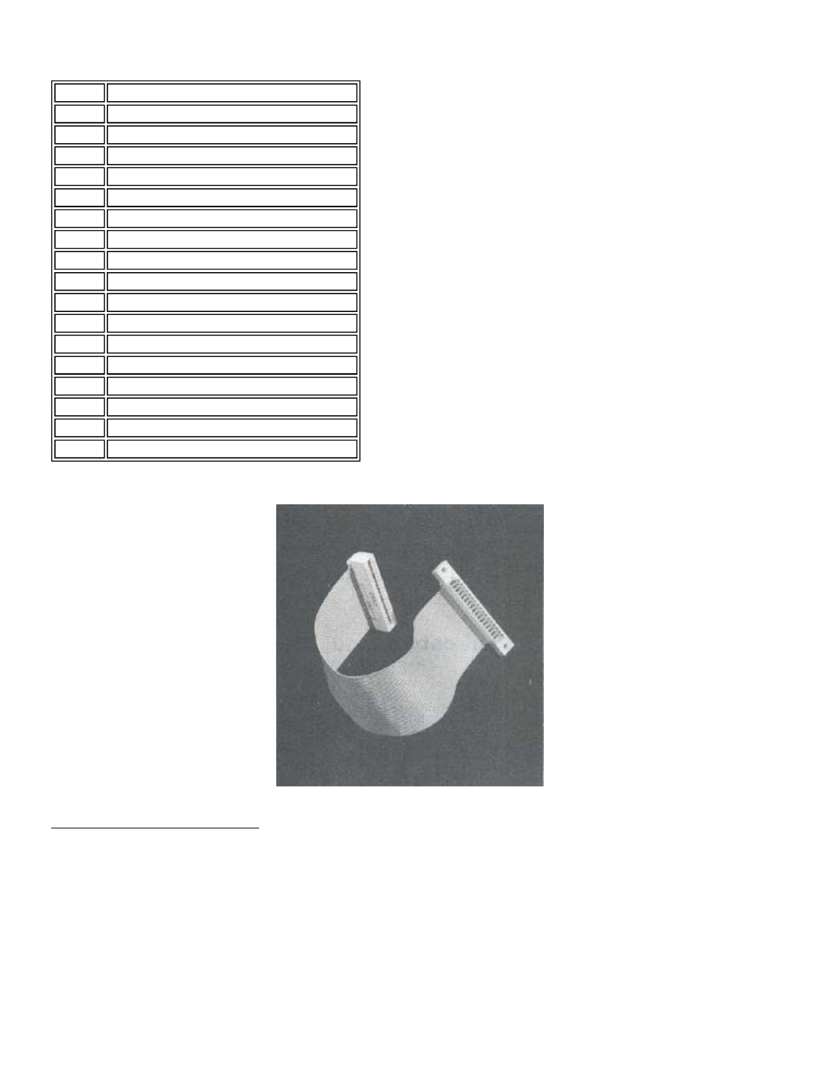
Figure 5.0 - Extender Cable
Connecting an 8" Disk Drive
Eight-inch drives require 50 - wire ribbon cables for
operation, You will notice that the disk interface on the
computer is made for a 34-wire cable (17 connections on each
side). A 50-to-34 adapter board is available from LNW (stock#
1096) to connect the 8" drive to the 34-wire cable. One end of
this board plugs into the 8" drive cable-connector (50-pin),
the other into the 5-1/4" drive cable-connector (34-pin) as
shown in Figure 5.1. If the connector on the 34-pin cable has
pins pulled, you may only connect one 8" drive per adapter.
Otherwise, the drive select process will not be able to "see"
any 8" drive after the first one it encounters. If the cable
is not of the pulled pin type, then you may connect a few 8"
Pin # Description
2 Not Used
4 Not Used
6 Not Used
8 Index
10 Drive Select 1
12 Drive Select 2
14 Drive Select 3
16 Motor On
18 Direction Select
20 Step
22 Write Data
24 Write Gate
26 Track 0
28 Write Protect (Active Low)
30 Read Data
32 Side Select (Dual Sided Drives)
34 Not Used
Page 26 of 31
LNW80 Microcomputer Operations Manual
12/4/03
http://www.xs4all.nl/~fjkraan/comp/LNW/mom/mom_1.html

drives to the 34-pin cable using just one adapter. Figures 5.2
and 5.3 outline the rights and wrongs of the matter.
Figure 5.1 - 34 to 50 Pin Adapter
Figure 5.2 - Pulled pin cable and 8" drive
Figure 5.3 - No pins pulled cable and 8" drive hook-up.
Table 5.1 - Pin Specifications for the 50-pin 8-inch Drive Bus
Pin # Description
2Ground or Lower Write
4Not Used / Reserved
6Not Used
Page 27 of 31
LNW80 Microcomputer Operations Manual
12/4/03
http://www.xs4all.nl/~fjkraan/comp/LNW/mom/mom_1.html
In the RARE event that you haVe an 8" disk drive which
requires the "write current" line on the disk drive to be
driven when using double-density above track 43, the adapter
requires a small modification. A jumper cable (LNW stock#
1097) must be soldered between TG43 on the adapter board to
pin 2 of the 50-pin bus. Test out your drives first, and if
you're having trouble above track 43 in double-density, get
out the soldering iron!
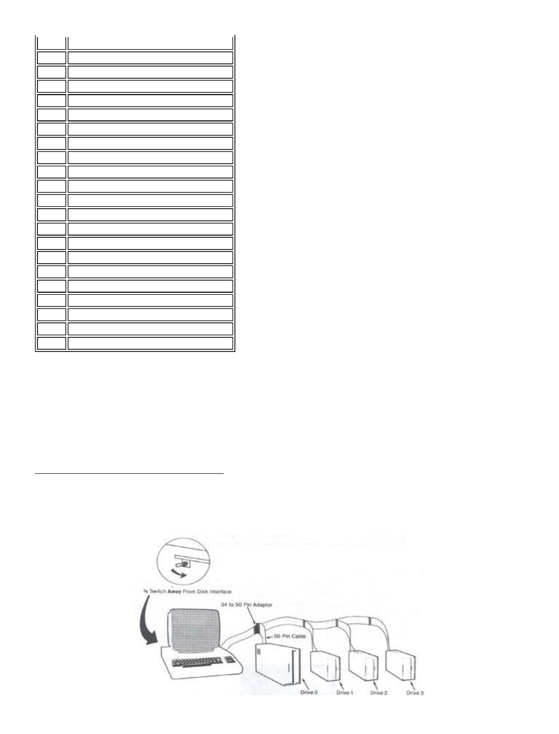
Disk Drive Set-up and the 5/8 Switch
The layout for a typical disk drive system is shown in
Figure 5.4.
Figure 5.4 - Typical Disk Drive System Showing
Mixed Drive Setup & 5/8 Switch
8Not Used
10 Two Sided (Not Used)
l2 Disk Change (Not Used)
14 Side Select (Dual-sided drives)
16 Activity / In Use
18 Head Load (Not Used)
20 Index
22 Ready (Not Used)
24 Not Used
26 Drive Select 1
28 Drive Select 2
30 Drive Select 3
32 Drive Select 4
34 Direction Select
36 Step
38 Write Data
40 Write Gate
42 Track 0
44 Write Protect (Active High)
46 Read Data
48 Not Used
50 Not Used
Page 28 of 31
LNW80 Microcomputer Operations Manual
12/4/03
http://www.xs4all.nl/~fjkraan/comp/LNW/mom/mom_1.html
5-1/4" or 8" disk drives may be used together in a mixed
set-up, although you must make the computer aware of the size
of drive zero (whether it is 5-1/4 inch or 8 inch). You do
this by way of the 5/8 Switch, This is located in o recessed
position above the cassette jack on the I/0 panel. The
information relevant to this switch is shown in Table 5.2.
Table 5.2 - Drive 0 and the 5/8 Switch
Disk Description
The names "disk" and "diskette" have become
interchangeable. Formerly, "disk" was reserved to describe the
large rigid disks associated with bigger computers, and
"diskette" was used to describe the smaller flexible or
"floppy" disks of microcomputers.
Refer to Figure 5.5 for a graphic description of the disk.
Figure 5.5
1) Protective cover - should not be opened.
2) Read/write opening. It is through this aperture
that data is read from and written to the disk.
3) Write protect notch. In the case of 5 1/4 inch
disks, covering the notch with an opaque label
protects the disk from being written to
accidentally. The reverse is true in the case of
Drive 0 Type 5/8 Switch
5-1/4 Inch Towards Floppy Port
8 Inch Away from Floppy Port
Page 29 of 31
LNW80 Microcomputer Operations Manual
12/4/03
http://www.xs4all.nl/~fjkraan/comp/LNW/mom/mom_1.html
8 inch disks - no label gives write protect
status.
4) Timing aperture. The disk also has a small hole
in it. When the disk is rotating, each time the
hole is aligned with the timing aperture, a beam of
light passes through. This triggers an electronic
signal, letting the computer know that the disk has
made one revolution.
5) Disk label. Use only a felt-tipped pen when writing
on the label. Ballpoints and lead pencils may leave
impressions on the disk.
6) Disk envelope. Inner lining helps to keep the disk
clean.
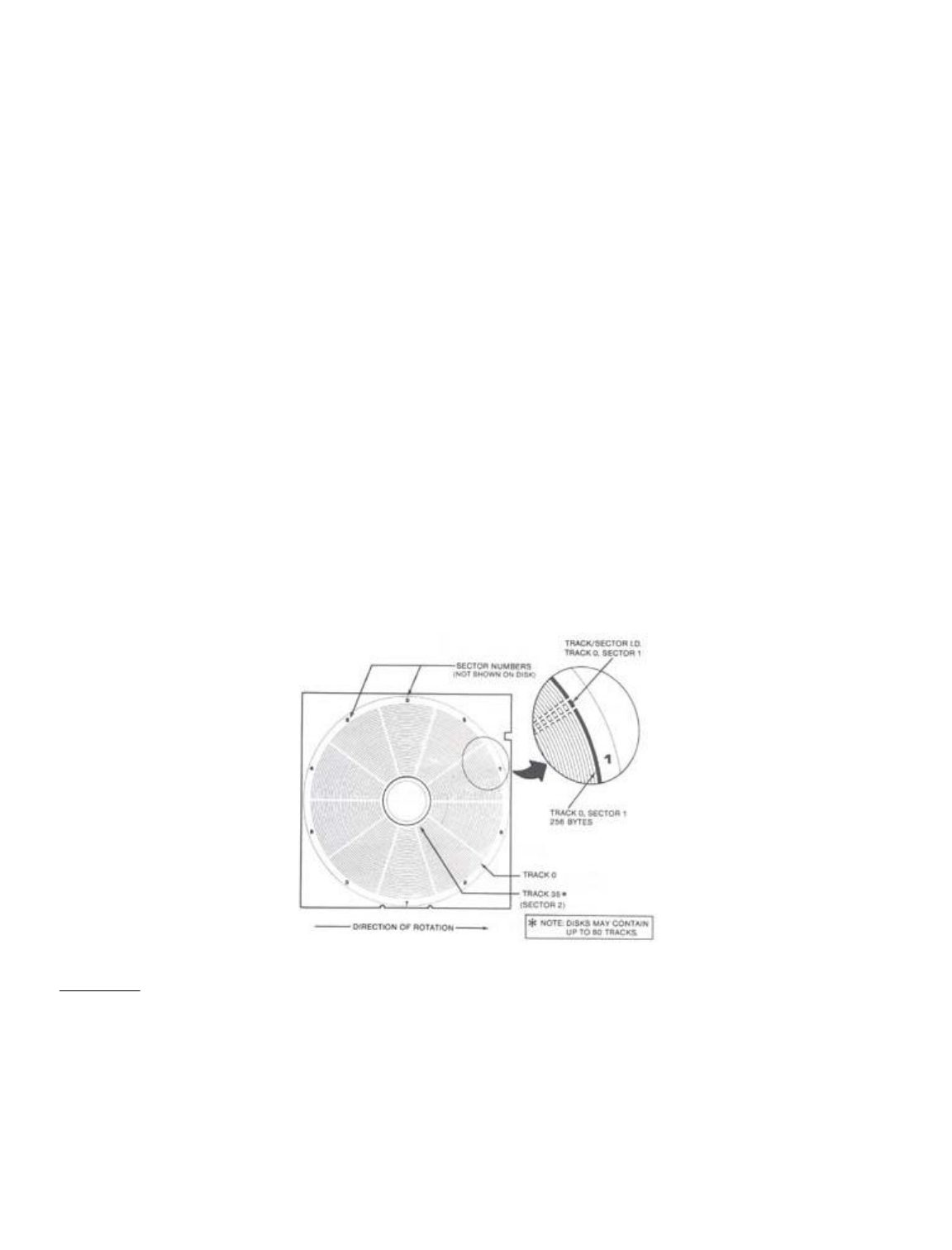
Floppy disks are made of a thin plastic material which is
coated on one or both sides with a thin, uniform layer of
metal oxide. Data is stored on the disk on concentric tracks,
which are arranged on the disk by the read/write head of the
disk drive. This process is called formatting, and is carried
out under control of the disk operating system (DOS).
The number of tracks is optional, but is usually 35, 40, 77
or 80. The tracks are numbered from the outer edge inwards.
Each track is divided into sectors. The number of sectors per
track depends on the DOS used to format the disk and whether
single or double-density is involved. Most TRSDOS-like DOSes
use 10 sectors per track in single-density and 18 sectors per
track in double-density, Figure 5.6 clarifies this
information.
Figure 5.6 - Sketch of disk, tracks a sector.
Disk Care
- Keep disks away from magnetic fields. Many
domestic appliances have transformers which
are capable of generating a magnetic field
strong enough to erose all or part of a disk.
Refrigerators, telephones a TV's are among these.
- Avoid touching disk surface. Keep the disk in its
envelope when not in the drive.
- Remove disks from drives before turning drives or
Page 30 of 31
LNW80 Microcomputer Operations Manual
12/4/03
http://www.xs4all.nl/~fjkraan/comp/LNW/mom/mom_1.html

computer on or off.
- In dry climates guard against static. Ground
yourself by touching something metallic before
handling disks.
- Store disks standing on edge (not flat).
- Store in a clean, dust-free environment between
50 and 125 degrees Fahrenheit (10 - 50 degrees C).
Avoid leaving disks in the sunlight.
Next page | TOC
Page 31 of 31
LNW80 Microcomputer Operations Manual
12/4/03
http://www.xs4all.nl/~fjkraan/comp/LNW/mom/mom_1.html

SECTION 6: POWER ON
Connecting AC Power
As you prepare to hook up to the main power supply, ensure
that the computer and all peripherals are switched OFF.
Locate the power cord exiting from the rear of the computer
and plug it inta a 110V AC outlet. All peripherals attached to
the computer must also be supplied with AC power
independently.
Turn on the monitor and let it warm up for a minute or
two,
Power Up & Reset for Non-Disk Owners
Press the BREAK key and switch the computer on. After a
moment's hesitation, the computer will respond with the
following prompt:
MEMORY SIZE?
MEMORY SIZE? _
(If this is not displayed clearly or if the monitor is not
in a cooperative mood, see the relevant sub-sections below on
monitor adjustment).
We may ignore the MEMORY SIZE? question for the moment (see
SECTION 10) and simply press the ENTER key.
The computer in its turn replies with,
READY
>_
To restart the system in ROM once the power is on, press
the BREAK key first and then the two RESET keys
simultaneously.
Power Up and Reset for Disk Owners
- Switch on drive(s).
- Switch on computer.
- Wait until drives stop running.
- Insert the system disk in drive 0, with the label
facing the arm of the door (see Figure 6.0).
- Close the drive door gently. The door will not
close if the disk is not fully inserted.
- Press both RESET keys simultaneously. The computer
responds with the system logo.
Page 1 of 24
LNW80 Microcomputer Operations Manual
12/4/03
http://www.xs4all.nl/~fjkraan/comp/LNW/mom/mom_2.html

Figure 6.0
You should now make a backup copy of your system disk
before proceeding any further. This is most important. It is
not beyond the realms of possibility to destroy the
information on disk at this initial phase of investigation and
experimentation.
The BACKUP utility is described on page 80 of the DOSPLUS
manual.
Disk Power Up Malfunctions
If the drives fail to stop running after switching the
computer on or the system fails to boot, check the following:
- Are the drive cables connected correctly and
securely at both the computer and drive outlets?
Note that the drive connection is "backwards"
relative to TRS80 Model I, with cable up vs. down.
- Is the disk in drive 0 a system disk?
- Is the drive running smoothly? If not, the disk is
not securely mounted on the drive spindle.
Re-insert the disk.
To RESET the disk operating system (to "boot" the system),
hit the two RESET keys simultaneously.
Monochrome Monitor Adjustment
1. BRIGHTNESS - turn fully clockwise.
2. CONTRAST - turn fully clockwise.
If the display is not stable (ie. rolls vertically,
horizontally or tears diagonally) make the following two
adjustments. If the display is stable, then skip this section
and go on to final adjustments.
3. HORIZONTAL HOLD - adjust for a picture that does not "tear"
diagonally and is stable horizontally. It may still have
vertical roll at this point.
4. VERTICAL HOLD - adjust for a picture that does not roll
vertically and does not have any multiple or overlayed
images.
Make the following final adjustments:
5. BRIGHTNESS - turn counterclockwise till the background scan
lines are just no longer visible (but the letters should still
be brightly displayed.
6. CONTRAST - turn counterclockwise for the sharpest, roundest
characters with a bright, easy-to-read display. The individual
dots that make the letters should be visible, and the black
space between the letters Z and E at the top and bottom of the
letters should be seen. The following drawing illustrates
this:
Figure 6.1 - High and normal contrast drawings
Page 2 of 24
LNW80 Microcomputer Operations Manual
12/4/03
http://www.xs4all.nl/~fjkraan/comp/LNW/mom/mom_2.html

GOOD CONTRAST CONTRAST TOO HIGH
If you cannot achieve crisp characters with the following
adjustments, then either - adjust the SIGNAL ADJUSTMENT (if
any) to reduce the amplitude of the video OR install a series
resistor in line (10 - 33 ohm) with the "hot side" of the
video cable.
If you intend to use the LNW80 computer in the inverse
video display mode, then you will have to repeat the above
adjustments while in the inverse display mode. Most monitors
will probably not be properly adjusted for both inverse and
normal display modes with the same settings. When you turn on
the inverse display mode, don't, be suprised to see the screen
go blank. When adjusting for BOTH display modes simply adjust
to your own preference.
NTSC Color Monitor Adjustment
An NTSC color monitor has some of the same adjustments as
your home television: BRIGHTNESS (may be called BACKGROUND),
CONTRAST, COLOR, TINT, VERTICAL H0LD, HORIZONTAL HOLD and
SHARPNESS (sometimes called FOCUS). The first step of
alignment is to perform the same adjustments, as with a
monochrome monitor (the procedure is listed in the previous
section). Some of the controls found in a monochrome monitor
(i.e., horizontal and vertical sync) may, or may not be
present in your color monitor. If the control cannot be found,
then it should be assumed that the control is automatically
set internally and needs no adjustment. Check the owner's
manual for more details concerning your monitor.
Monochrome Operation
The NTSC color monitor cannot display the 64-column text
screen with clarity. With some monitors it may be possible to
read the characters in this mode, but it will require the
optimum setting of the above-mentioned controls and a very
high quality set with a +6MHz luminance bandwidth. It may also
require that the NTSC color monitor be connected to the B/W
video output since the bandwidth is higher through that
display channel, and the color setting on the set should be
turned completely off.
Color Operation
In order to align your monitor for color operation, you
must first display the color bar pattern generated by the
program listed below. IF THE NTSC MONITOR IS YOUR ONLY
MONITOR, THEN YOU MUST PERFORM THE MONOCHROME DISPLAY
ADJUSTMENTS MENTIONED IN THE PREVIOUS SECTION TO MAKE THE
DISPLAY READABLE WHILE TYPING IN THE PROGRAM THAT IS LISTED
BELOW. This program is written using LNWBASIC and is easy to
type in. It does require that the programmer has a working
knowledge of DOSPLUS 3.4 and LNWBASIC. These details can be
found elsewhere in this manual and in the LNWBASIC USER MANUAL
or the DOSPLUS 3.4 USER MANUAL.
1 'LNWBASIC Color Bar Test Program
10 MODE2
20 PCLS
30 FLS(191)
40 FOR X=0 TO 7
50 COLORX
60 Xi=16*X:Y1=0:X2=(16*X+14):Y2=191
70 LINE Xl,YlgX2,Y2,SET,BF
80 NEXTX
Page 3 of 24
LNW80 Microcomputer Operations Manual
12/4/03
http://www.xs4all.nl/~fjkraan/comp/LNW/mom/mom_2.html

90 END
Once you have typed in the program, save it for future use
by typing:
SAVE"COLOR/BAS"
This program should generate 8 color bars in the following
order:
White Green Yellow Red Magenta Blue Blue-green Black.
Once the color bar program has been run, make the following
adjustments:
1. BRIGHTNESS (May be Called BACKGROUND) - adjust such that 7
color bars (may appear as 7 grey areas) appear, but the BLACK
bar (eighth bar) at the right of the screen is completely
black.
2. CONTRAST - adjust so that the bars have adequate range of
intensity. The BLACK bar should be black, and the WHITE bar
should be a bright white. The thin black borders between the
color bars should have the sharpest edges attainable.
3. COLOR - adjust so that the colors (may not be the correct
colors yet) are bright and clean, but not saturated so much
that there is color "bleeding" and distortion in the black
borders between the color bars.
4. TINT - adjust the tint so that the colors displayed on the
screen match the 8 color bars and suit your individual
preference. From left to right:
white green yellow red magenta blue blue-green black
5. SHARPNESS - Between the color bars are thin, two-pixel
borders of black. Adjust the sharpness or focus such that the
sharpest edges are obtained.
RGB Monitor Adjustment and Operation
The RGB monitor generally requires no more adjustments than
a monochrome monitor:
l. Perform the MONOCHROME MONITOR ADJUSTMENTS
2. Type in the COLOR BAR program listed in the previous
section and run it using LNWBASIC.
Power Off
When turning off your computer, allow at least 15 seconds
before turning it on again. This time allows any power that
may not have drained away in the electrical circuitry to do
so,
Memory Test
Although your LNW80 has been thoroughly tested at our
manufacturing plant, we include this memory test in case you
ever need to use it in the years ahead.
10 REM Memory Test for LNW80
20 REM This is a simple test of computer memory.
30 REM Each memory location is tested by using the
40 REM the GOSUB instruction. It should run
Page 4 of 24
LNW80 Microcomputer Operations Manual
12/4/03
http://www.xs4all.nl/~fjkraan/comp/LNW/mom/mom_2.html

50 REM continously until it reaches location 100
60 REM or so. Total memory is printed on the top
65 REM left hand corner of the screen.
70 CLS
80 PRINT CHR$(23)
85 PRINT @ 0,MEM
90 PRINT @ 470,MEM
100 IF MEM < 100 THEN STOP ELSE GOSUB 90
Now type:
RUN
means that you press the ENTER key after typing RUN.
The program should run continuously until location 100 or
so is encountered.
High Speed / Low Speed Test
We can make convenient use of this program to do another
test. As was indicated earlier, the LNW80's microprocessor
operates at two clock speeds: 4MHz and 1.77MHz. By timing the
program with the key in the up position (HIGH) and
down position (LOW), the following approximate results should
be obtained:
HIGH 119 seconds
LOW 222 seconds
You may wonder why the result for the faster clock speed is
not twice that of the slower. The reason it isn't is that the
CPU works at a faster clock speed than the Level II ROMs are
capable of. As a result, the CPU must slow slightly (using
"wait states") so that the ROMs can keep up.
Graphics Test
Running the program below will fill the display with the
standard text and low-resolution graphics characters available
from the character generator.
10 REM Mode 0 text and graphics test.
20 LET Y=0
30 FQR X=15360 TO 16363
40 IF Y>192 LET Y=0
50 POKE X,Y
60 LET Y=Y+1
70 NEXT X
80 GOTO 80
To exit from this program, you must press the key.
Line 80 in the program puts the program into an infinite loop
so as not to disrupt the display on the screen.
SECTION 7: LNW80 GRAPHICS
Introduction
The color graphics capabilities of the LNW80 make up one of
the computer's real highlights. You now have a machine which
not only allows good data manipulation, but also has high
resolution graphics. The LNW80 comes to you with LNWBASIC, a
tailor made BASIC, designed to extract the maximum potential
from the machine in terms of color and black and white
Page 5 of 24
LNW80 Microcomputer Operations Manual
12/4/03
http://www.xs4all.nl/~fjkraan/comp/LNW/mom/mom_2.html

graphics.
This section introduces you to the machine's graphics
capabilities and lays the foundation for your adventures into
LNWBASIC. The second half of this section was written for the
benefit of machine-language programmers. It is not vital
reading for the novice.
Note: As LNWBASIC is only supplied on disk, a subsection is
included for non-disk owners on how to generate both black 6
white and color graphics.
Graphics Modes
The LNW80 has four different graphics modes:
Mode 0 Low Resolution (LORES) graphics mixed
with text. Control of 128 x 48
picture elements (pixels).
Mode l High Resolution (HIRES) graphics
mixed with LORES graphics and text.
Control of 480 x 192 pixels.
Mode 2 LORES Color, with control of
128 x 192 pixels. There are 8 colores
available in this mode.
Mode 3 HIRES Color. Control of 480 x 192
pixels. The screen may be mapped in
color blocks of 128 x 16 pixels.
There are 8 colors available in this
mode.
Note that the picture element (pixel) size depends on the
graphics mode in operation.
Mode 0 - Low Resolution Graphics a Text
In this mode you have 128 (64x2) points of reference across
the screen and 48 (16x3) points down the screen.
Mode 0 is the normal operating mode. The mode 0 screen is
laid out as shown on the video display worksheet in Appendix
D. Turning your attention to this for a moment, you will see
that there are 64 character positions across the screen,
numbered from 0 to 63. There are 16 lines of 64 characters
each, ending up at character position 1023 on the lower
right-hand corner. You will notice also that each character
which is outlined in dark ink is subdivided into 6 smaller
units. These smaller units are called graphics cells. Neither
character positions nor graphic cells are physical areas on
the screen, but rather areas of the screen that the computer
has chosen.
Figure 7.0 - character position and Graphics cell
Page 6 of 24
LNW80 Microcomputer Operations Manual
12/4/03
http://www.xs4all.nl/~fjkraan/comp/LNW/mom/mom_2.html
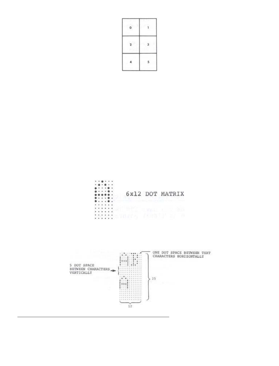
The mode 0 graphics cell corresponds to the mode 0 pixel.
The term graphics cell is retained here, as it is often used
to describe the size of pixel which is controllable using SET
and RESET in BASIC.
To see the size of one mode zero pixel, use the following
BASIC statement:
CLS : PRINTS 480, CHR$(129)
or
CLS : SET (64,21)
A text character appears as a 5 x 7 matrix within the
sounds of the 12 x 6 dot matrix that makes up a character
position.
Figure 7.1 - 12 x 6 dot matrix of character posn
with 5 x 7 text character imposed on
it.
The 5 x 7 format allows a one dot space between characters
and a 5 dot space between lines.
Figure 7.2 - Interspacing of text characters
Mode 1 - High Resolution Graphics & LORES Graphics a Text.
In this mode, you may reference 480 dots across the screen
and 192 down the screen, giving you the highest resolution
possible on the LNW80. The normal screen width of 64
characters is extended to 80 character positions in this mode.
These additional 16 character positions give you an extra 96
Page 7 of 24
LNW80 Microcomputer Operations Manual
12/4/03
http://www.xs4all.nl/~fjkraan/comp/LNW/mom/mom_2.html

(16x6) pixels per line. This mode allows you to turn on or off
the smallest dots which we saw in the mode 0 character
position.
This mode can be entered in LNWBASIC by simply typing,
MODE 1
The pixel size in this mode can be seen by RUNning the
following LNWBASIC program:
l ' LNWBASIC program to light up mode 1 pixel
10 MODE 1: CLS: PCLS
20 PSET 240,96
30 CIRCLE 240,96,40
40 GOTO 40
Press the BREAK key to exit the program.
A drawing program is included in Appendix C to illustrate
some of the possibilities in this mode.
Mode 2 - Low Resolution Color
This color mode is the highest resolution mode possible for
NTSC composite video. The resolution in this mode offers you
128 pixels across the screen and 192 pixels down the screen.
To give you an idea of the size of pixel we're talking about,
the following figure shows the relationship between the mode 0
character position and the mode 2 pixel.
Figure 7.3 - Mode 0 character position with mode
2 pixel outlined.
As you can see, four vertically-stacked mode 2 pixels are
equivalent to a mode zero graphics cell.
To enter this mode in LNWBASIC, use the mode command,
MODE 2
The mode 2 pixel can be displayed on the screen using this
LNWBASIC program. Press BREAK to exit the program.
1 ' LNWBASIC program to display mode 2 pixel
10 MODE 2 : PCLS 2 : CLS
20 COLOR 5 : FLS REM FLS 'WHITES' MODE 0 SCREEN TO DISPLAY COLOR
30 PSET 63,97
40 CIRCLE 63,97,15
50 GOTO 50
To get the most of the computer's color capabilities in
this mode, examine the COLOR, FLS and PCLS commands in the
LNWBASIC manual.
Mode 3 Graphics - High Resolution Color
This high resolution graphics display mode allows the high
resolution graphics monochrome (MODE1) information to be
displayed on an RGB color monitor. This high resolution
information is displayed with limited color control. This
means that while the number of individually controllable color
dots that can be displayed is 480H (horizontal) by 192V
(vertical), the colors that they can be set to are limited to
Page 8 of 24
LNW80 Microcomputer Operations Manual
12/4/03
http://www.xs4all.nl/~fjkraan/comp/LNW/mom/mom_2.html

128H by 16V color fields. These color fields have a
relationship to. the high resolution position such that one
color field controls the color of 36 high resolution pixels
(dots). Color information is provided by the MODE0 text memory
(memory from 3C00H to 3FFFH). The data stored in a given
character position will determine the color of the high
resolution graphics at that position. To better understand
this, we will run the following program in LNWBASIC:
10 MODEl:PCLS:CLS' set to high res and clear all screens
20 LINE 0,3,383,3,SET ' draw high res line
30 MODE3 ? note the line above can be drawn in mode 3 also
40 FORC=0T07 ' step through all the colors
50 FOR I=0 TO 3'PUT EACH COLOR FIELD FOUR TIMES
60 AD=&H3C00+C*4+I? COLOR FIELD ADDRESS
70 POKEAD,C*9 'must use poke to output
80 NEXT I
90 NEXTC
100 GOTO 100 'wait forever and do not disturb screen
When this program is run with a monochrome monitor
installed, a high res (MODE1) LINE is drawn across the top of
the screen, followed by characters overlapping the line on the
screen. If we install an RGB monitor to the LNW80 now, we
would see that the various characters cause the line to change
colors. This overlapping of characters with high resolution
graphics is how MODE3 graphics works. You might have noticed
that after the color bars there was a blank space (color
black) and then the rest of the line is displayed as
alternating violet and white dots. Each of these dots
represents the width of the smallest unit of color field which
is one-half of a character position. This example used an
entire character position as a color field with four
consecutive color fields set to the same color. If we wanted
to use the maximum color resolution, we could change the
program to the following:
10 MODE1:PCLS:CLS? set to high res and clear all screens
20 LINE 0,7,479,11,SET,BF ' draw a high res line
30 MODE3 ? note the line above can be drawn in mode 3 also
40 FOR I=0 TO 15
50 FORC=0T07 ' step through all the colors
60 IF(C AND l)=0THEN90ELSE70 'is the pixel even or odd?
70 AD=INT(C/2)+I*4:D=PEEK(6H3C00+AD)?ODD find address and get
data
80 D=DAND&H38:D=DORC:POKE(6H3C00+AD),D:GOT0110 'mask upr 3
bits, output
90 AD=INT(C/2)+I*4:D=PEEK(aH3C00+AD)'EVEN find address, get
data
100 D=DAND7:D=DOR(C*8):POKEfaH3C00+AD),D'mask, or data,
output
110 NEXTC
120 NEXTI
130 FOR Z=1T01000:NEXTZ
140 LINE 0,0,479,11,SET,BF
150 GOTO 150
This program draws a high res bar that extends beyond 383,
and you should have noticed on the monochrome monitor that the
characters that appear above the high res bar change the color
of the bar on the RGB color monitor. Note that characters do
not appear above the bar beyond character position 64 or high
res position 383. Run the program again and watch the
extension region while the inner region is writing the color
Page 9 of 24
LNW80 Microcomputer Operations Manual
12/4/03
http://www.xs4all.nl/~fjkraan/comp/LNW/mom/mom_2.html

fields. You will see that while colors are written to the
inner region there is a duplication into the outer region. Due
to the design of the hardware, the color information for any
horizontal position past 383 is taken from color information
from the same vertical position but from an assortment of
horizontal positions (with values less than 383). This means
that. if you use high resolution graphics beyond 383, you
cannot be guaranteed the color unless all the color fields for
pixels less than 383 are set to the same color.
Mode 3 With LNWBASIC
The initial release of LNWBASIC does not totally support
MODE3 graphics. The mode command will set the LNW80 to the
correct setting, but lines drawn in MODE3 are the same as
lines drawn in MODEl with no color information provided. Later
versions of LNWBASIC (if you registered with MODULAR SOFTWARE
ASSOCIATES, you will be notified when this new version is
ready) will fully support MODE3. In order to use the high
resolution capability at this time, special subroutines must
be written to write the color fields to match the high res
graphics of LNWBASIC. The following programs provide
rudimentary routines to fill fields and do limited line
drawings in MODE3.
1 'THIS PROGRAM CONTAINS 3 MODULES. THE FIRST STARTING AT
LINE
10 WILL DRAW A SINGLE LINE FROM 0,0 TO 383,191 AND THEN USE
A COLOR FIELD TO MAKE THE LINE A GIVEN COLOR
2 ?THE SECOND MODULE (AT LINE 200) IS A DEMONSTRATION OF THE
WAY LINES CAN BE DRAWN AND MADE TO HAVE A SPECIFIED COLOR
USING MODE 3. THE ACTUAL SUBROUTINE TO DRAW THE LINE IS
LOCATED AT LINE 1000
3 ?THE THIRD MODULE IS A DEMONSTRATION OF THE ABILITY TO
CREATE BLOCKS OF COLORS. IT STARTS AT LINE 300. THE ACTUAL
ROUTINE TO CREATE BLOCKS IS FOUND AT LINE 1000. NOTE THAT
THIS THIRD MODULE DOES REQUIRE MODULE 2.
4 'IF ALL THIS SEEMS TERRIBLY CLUMSY- IT IS. THE FIRST
RELEASE
OF LNWBASIC DID NOT HAVE ANY MENTION OF MODE3 LATER
RELEASES OF LNWBASIC WILL ALLOW THE USER THE ABILITY TO
DRAW LINES' BOXES' CIRCLES' ETC IN MODE3
5 ?NOTE THAT THE PROGRAM TO DRAW LINES IS TERRIBLY
INACCURATE
10 INPUT"COLOR";C
20 INPUT"X";X:INPUT"Y";Y
30 CLS
40 PCLS
50 MODE3
60 LINE 0,0,383,191,SET
70 MODE3
80 FLS(191)
90 POKE (&H3C00+Y*64+X),C*9
100 FOR X=1 TO 64
110 Y=INT(X/4)
120 POKE (6H3C00+Y*64+X),C*9
130 NEXTX
140 GOTO 140
200 'THIS DEMONSTRATES DRAWING A MODE 3 LINE
210 FOR P=1 TO 10
220 GOSUB 510
230 GOSUB 1040
240 NEXTP
250 GOTO 250
300 'THIS DEMONSTRATES DRAWING BLOCKS OF COLORS IN MODE3
Page 10 of 24
LNW80 Microcomputer Operations Manual
12/4/03
http://www.xs4all.nl/~fjkraan/comp/LNW/mom/mom_2.html

310 FOR P=1 TO 10
320 GOSUB 510
330 GOSUB 2000
340 NEXTP
350 GOT0350
510 Xl=RND(383):X2=RND(383):Yl=RND(191):Y2=RND(191):C=RND(7)
515 RETURN
1000 REM THE FOLLOWING ROUTINE DRAWS A LINE OF A SPECIFIED
COLOR IN MODE3
1010 INPUT"DESIRED COLOR";C
1020 INPUT"Xl,Yl";Xl,Yl
1030 INPUT"X2,Y2";X2,Y2
1040 MODE1
1050 CLS:PCLS:LINE Xl,Yl,X2,Y2,SET
1055 GOSUB 1060
1056 GOTO 1075
1060
Xl=INT(X1/6+.5):X2=INT(X2/6+.5):Yl=INT(Yl/12+.5):Y2=INT(Y2/12
+.5)
1070 IF
Xl>63THENX1=63ELSE:IFX2>63THENX2=63ELSE:IFYl>15THENY1=15ELSE:
IFY2>15THENY2=15
1072 RETURN
1075 IF100*Xl+Yl>100*X2+Y2 THEN T=Xl:Xl=X2:X2=T:T=Yl:Yl=Y2:
Y2=T
1080 IF Xl=X2THENGOT01090ELSEGOT01100
1090 MODE3:FORY=YlTO Y2:POKESH3C00+Y"64+Xl,C*9:NEXTY:GOT01210
1100 M=(Y2-Yl)/(X2-Xl)
1110 B=Yl-M*Xl
1120 MODE3
1125 IFM>0
THENIFM<=1THEN1130ELSE1300
ELSEIFM>=-1THEN1130ELSE1350
1130 FORX=X1TOX2-1
1140 Y=INT((M*X+B)+.5)
1145 GOSUB1150
1146 NEXTX:RETURN
1150 Z=&H3C00+Y*64+X:IFZ<&H3C00ORZ>6tH3FFFTHENGOT01210
1160 POKE Z,C*9
1165 IF(X-2)>=0THENPOKE(&H3C00+Y*64+X-l),C*9 ELSEGOT01170
1170 IF(X-l)>0THEN POKE(&H3C00+Y*64+X-1),C*9 ELSEGOT01180
1180 IF(X+1)<65THENPOKE(&H3C00+Y*64+X+l),C*9 ELSEGOT01190
1190 IF(X+2)<64THENPOKE(&H3C00+Y*64+X+2),C*9 ELSE GOT01200
1200 RETURN
1210 RETURN
1220 Xl=0:Y1=0:X2=63:Y2=15
1230 MODE1
1240 LINE 0,0,377,179,SET
1250 MODE3
1260 GOTO 1100
1300 FORY=Y1TOY2'SLOPE BETWEEN -1 AND 1
1310 X=INT((Y-B)/M+.5)
1320 GOSUB 1150
1330 NEXTY
1340 RETURN
1350 T=Y1:Yl=Y2:Y2=T? SLOPE BETWEEN -1 AND -INFINITY
1360 GOT01300
2000 IFXl=X2THEN1050ELSEIFYl=Y2THENGOT01050
2010 LINE Xl,Y1,X2,Y2,SET,B
2020 M0DE3
2030 GOSUB 1060
2040 IFY1<Y2THEN2060
2050 T=Y1:Yl=Y2:Y2=T
2060 IFXl<X2THEN2080
2070 T=X2:X2=X1:X1=T
Page 11 of 24
LNW80 Microcomputer Operations Manual
12/4/03
http://www.xs4all.nl/~fjkraan/comp/LNW/mom/mom_2.html

2080 IFY1=0THENY1=1ELSE:IFX1=0THENX1=1
2090
FORY=Y1-1T0Y2:FORX=X1-1TOX2:POKE&H3C00+Y*64+X,C*9:NEXTX:NEXTY
2100 RETURN
High Resolution Graphics for Non-Disk Owners
The program listed below sets up tables in memory which
hold information on the coordinates of points to be SET, RESET
or POINTed. (The machine-language program encoded in the DATA
statements is listed at the end of this section).
0 REM This program POKES 2 tables into memory. The first one
1 REM generates 2 bytes for each horizontal coordinate (X).
2 REM This two byte pair consists of (a) the character
3 REM position (0-79) and (b) the one of six pattern
4 REM selecting the pixel within the character position.
5 REM The second table gives the vertical coordinate. It
6 REM consists of 192 locations each of which holds the
7 REM row (D4-7) and the line (D0-3).The tables start at
8 REM 30000.
10 X=30000
20 FOR Y=0 TO 79
30 GOSUB 100
40 NEXT Y
50 X=31024
55 FOR L=0 TO 15
60 FOR R=0 TO 11
65 N=(16*R)+L
70 POKE X,N
75 X=X+1
80 NEXT R
85 NEXT L
90 GOTO 171
100 N=l
101 FOR Z=0 TO 5
120 POKE X,Y
130 X=X+1
140 POKE X,N
150 X=X+1
155 N=N*2
160 NEXT Z
165 RETURN
166 REM This routine POKES the machine-language USR program
168 REM (encoded in the DATA statements) into RAM from
167 REM location 79F0H (31216) to 7A90H (31376)
169 REM (31376).
171 FOR X=31216 TO 31376
172 READ Y
173 POKE K,Y
174 NEXT X
175 REM The POKE command at line 200 gives the entry point of
177 REM the one USR call. The low order byte must be changed
179 REM to point to one of the other routines if desired:
185 REM To select SET,RESET,POINT use the following values:
187 REM SET - POKE 16526,240:POKE 16527,121
189 REM RESET - POKE 16526,243:POKE 16527,121
191 REM POINT - POKE 16526,246:POKE 16527,I21
182 REM Remember that these address locations are decimal.
193 REM Once you have POKEd these values out, you need only
195 REM POKE the LOW ORDER BYTE to change to a different
197 REM routine (e.g. POKE 16526,246 gives POINT).
199 REM
200 POKE 16526,240:POKE 16527,121 ' SET Routine
210 CLS ?Clears LORES screen
Page 12 of 24
LNW80 Microcomputer Operations Manual
12/4/03
http://www.xs4all.nl/~fjkraan/comp/LNW/mom/mom_2.html

220 OUT 254,2 'Turns HIRES (Mode 1) on
230 FOR X=0 TO 479 'Bumps through all X
240 FOR Y=0 TO 191 'Bumps through all Y
250 POKE 31257,Y ?POKES Y value to 31257 (in USR)
260 A=USR(X) 'X is passed to USR routine
270 NEXT Y
280 NEXT X
290 END
300 DATA 195,67,122,195,88,122,195,113,122,205,127,10
310 DATA 1,48,117,4lg9,126,254,64,242,35,122,205,19,122
320 DATA 203,60,203,29,203,60,203,29,201,35,70,33,48,121
330 DATA 17,0,0,25,102,111,203,37,203,37,201,205,19,122
340 DATA 203,37,203,37,203,4,203,4,203,60,203,29,203,60
350 DATA 203,29,203,60,203,29,203,60,203,29,124,198,48
360 DATA 103,20l,205,249,121,219,254,246,8,211,254,126
370 DATA l76,ll9,219,254,230,247,211,254,195,154,10,205
380 DATA 249,121,219,254,246,8,211,254,120,238,255,71
390 DATA 126,160,119,219,254,230,247,211,254,195,154,10
400 DATA 205,249,121,219,254,246,8,211,254,126,160,194,133
410 DATA 122,33,0,0,195,l36,l22,33,1,0,219,254,230,247
420 DATA 211,254,195,154,10
Color Graphics for Non-Disk Owners
The following listing demonstrates how to generate colors
on the LNW80 without using LNWBASIC.
10 REM COLOR BAR TEST PROGRAM
20 REM CASSETTE (16K) VERSION
30 REM This test should generate the following colors:
35 REM White Green Yellow Red Magenta Blue Blue-Green Black
36 CLS:PRINTCHR$(23)
40 PRINT "LNW RESEARCH COLOR BAR TEST"
45 REM Delay before starting test
50 FOR Z=0 TO 1000
60 NEXT Z
70 OUT 254,4
72 FOR X=15360 TO 16383
74 POKE X,255
76 NEXT X
80 FOR X=32512 TO 32533
90 READ D
100 POKE X,D
110 NEXT X
120 POKE 16526,0:POKE 16527,127
125 FOR X=0 TO 12288
130 FOR Y=0 TO 7
135 FOR Z=0 TO 7
150 POKE 32522,Y*9
180 A=USR(X)
190 LET X=X+1
200 NEXT Z
210 NEXT Y
220 LET X=X-1
230 NEXT X
240 END
270 DATA 205,127,l0,219,254,246,8,211,254,54,0,0,110,38,0
280 DATA 230,247,211,254,195,154,10
GRAPHICS FOR MACHINE-LANGUAGE PROGRAMMERS
Machine-Language Overview
Page 13 of 24
LNW80 Microcomputer Operations Manual
12/4/03
http://www.xs4all.nl/~fjkraan/comp/LNW/mom/mom_2.html
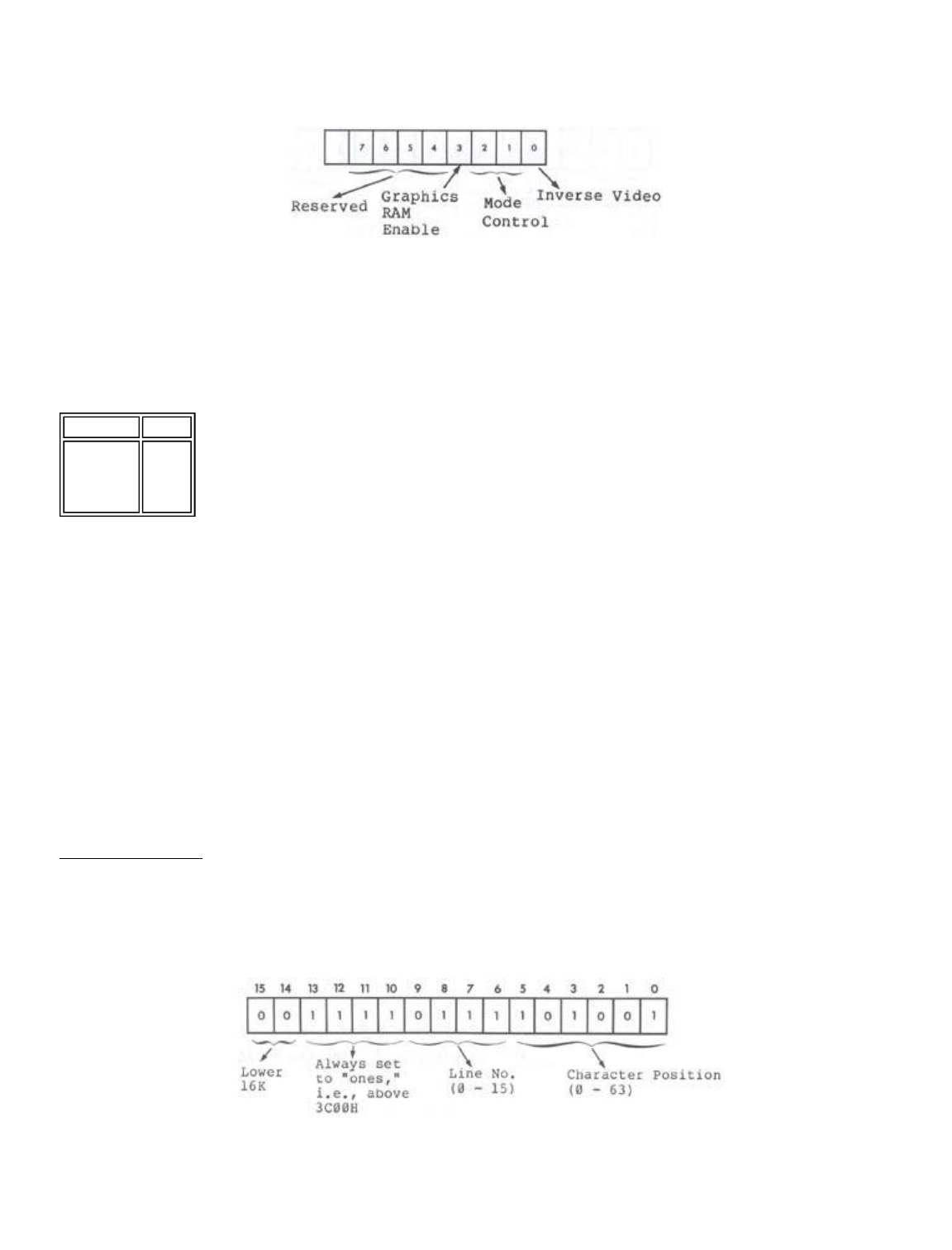
The four different graphics modes are selected by I/0 port
254 (FE Hex). The definition of port 254 is shown
schematically in Figure 7.4.
Figure 7.4 - 8 bit address of port 254 showing
bit definition.
Data bit 0 controls inverse video operation in modes 0 and
1 only. Data bits 1 and 2 together give mode control, as can
be seen from Table 7.1.
Table 7.1 - Mode Control Using Port 254
Data bit 3 controls graphics RAM enable. Data bits 4 to 7
are reserved and should not be used.
When modifying port 254, first read the port and then
change only the bits that you want to change. As an example,
consider the following LNWBASIC program (any level of BASIC
will do) which sets data bit 0 of port 254, thus changing over
to inverse video.
1 ?PROGRAM TO SET DATA BIT 0 OF PORT 254
10 A=IMP(254)
20 A=1 OR A
30 OUT 254,A
To return to normal white on black, substitute 0 for 1 in line
20.
Mode 0 Adressing
Video display memory for this mode runs from 15360 (3C00
Hex) to 16383 (3FFF HEX) . A two-byte address is used to point
to a location in video RAM. The relationship between the
memory location and the visibly displayed character is defined
by the following address chart:
Figure 7.5 - Mode 0 addressing as in p. 64 of
original LNW manual.
The least significant (rightmost) 6 bits, bits 0 to 5, of the
D2 D1 Mode
0 0
0 1
1 0
1 1
0
1
2
3
Page 14 of 24
LNW80 Microcomputer Operations Manual
12/4/03
http://www.xs4all.nl/~fjkraan/comp/LNW/mom/mom_2.html

address specify the character position. With all 6 bits on for
example, character position 63 would be specified. Bits 6 to 9
inclusive store the binary code for the line (0 - 15) on which
the character posit.3.on is found.
Take, for example, address 3C97. Filling the address chart
we get:
Figure 7.6 - Mode 0 address chart with 3C97
displayed.
This translates to line 2, character position 23, as shown
in Figure 7.7.
Figure 7.7 - Screen with character 23, line 3
highlighted.
We have seen how screen positions are addressed and how
both graphics characters and text characters are constituted.
But how does the computer know whether a graphics character or
a text character is to be displayed? The answer is encoded in
the data byte to be displayed. When data bit 7 of the data
byte is on, bits 0 to 5 select all possible combinations of
graphics characters. With data bit 7 off, bits 0 to 5 are
together interpreted as an ASCII text code. See figure 7.8.
Figure 7.8 - Data byte, 8 bits, bit 7 on/off -
graphics/text respectfully. Bit 6
not used, bits 0 to 5 store code.
Note that graphics RAM is not used in this mode.
Accessing Graphics RAM
Graphics modes I, 2 and 3 make use of graphics RAM. The
graphics RAM, running from address 0 to 3FFF (hex), is located
in the lower 16K of LNW80 address space. This is also where
the the Level II ROMs, keyboard, mode 0 video RAM, and
miscellaneous I/0 is mapped.
Page 15 of 24
LNW80 Microcomputer Operations Manual
12/4/03
http://www.xs4all.nl/~fjkraan/comp/LNW/mom/mom_2.html
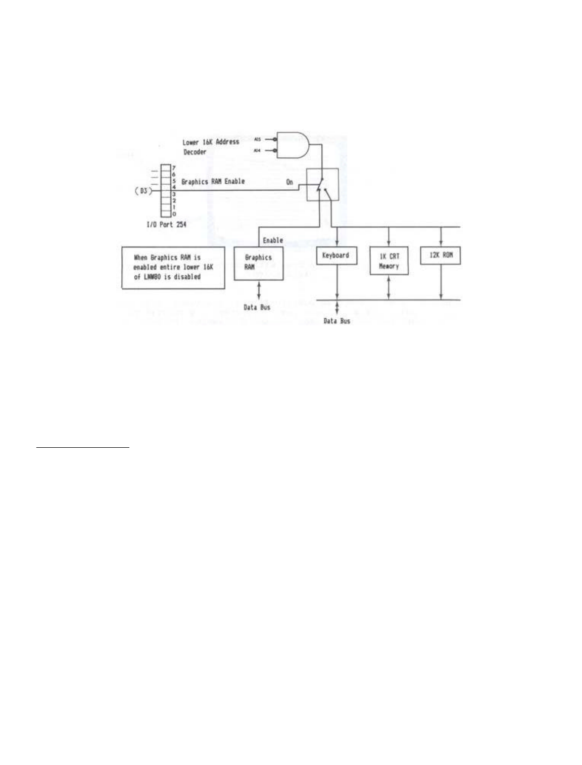
I/0 port 254, data bit 3 (D3), selects which block of
memory is enabled in the lower 16K. With D3 on (1), the
graphics memory is enabled. With D3 off (0), the keyboard,
video RAM, 12K ROM and anything else which might be mapped in
the lower 16K of address space are enabled. Figure 7.9
illustrates this bank switching operation.
Figure 7.9 - Memory bank switching diagram
Since the Level II ROMs are also disabled when D3 is on,
using the out command in BASIC to turn this bit on will cause
a system "crash." This is because the computer will be
operating out of graphics RAM instead of ROM. The implication
of this is that D3 can only be accessed by a machine-language
program (or USR call from BASIC). Note that while the graphics
RAM is enabled, the lower 16K is inaccessible.
Mode 1 Addressing
The high resolution graphics RAM is located between 0 and
3FFF (hex). The 16K x 6 bits of graphics memory allows
individual control of 480 x 192 dots. The addressing is not
simple X,Y addressing, but is optimized for rapid character
generation, In this scheme of things, the video memory map is
broken into two fegiona: an inner region comprised of 384 x
192 dots, and an extension region comprised of 96 x 192 dots.
Figure 7.10 shows this screen breakdown.
Page 16 of 24
LNW80 Microcomputer Operations Manual
12/4/03
http://www.xs4all.nl/~fjkraan/comp/LNW/mom/mom_2.html
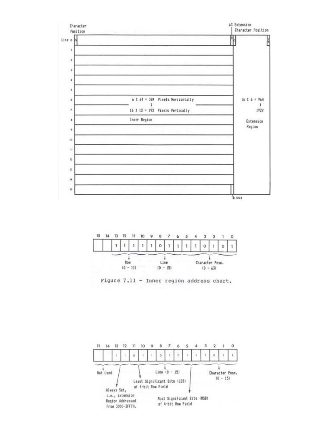
Figure 7.10 - Screen inner and extension regions.
The 384 x 192 inner region runs from address 0 to 2FFF
(hex). The address chart for the inner region is as follows:
Figure 7.11 - Inner region address chart.
The 96 x 192 extension region is addressed from 3000 to
3FFF (hex). The address chart for the inner region is given
below. In this case, the row field has been divided in two:
bits 10 and 11 holding the two least significant bits (LSB),
and bits 4 and 5 holding the two most significant bits (MSB).
This was done for hardware implementation reasons only.
Page 17 of 24
LNW80 Microcomputer Operations Manual
12/4/03
http://www.xs4all.nl/~fjkraan/comp/LNW/mom/mom_2.html
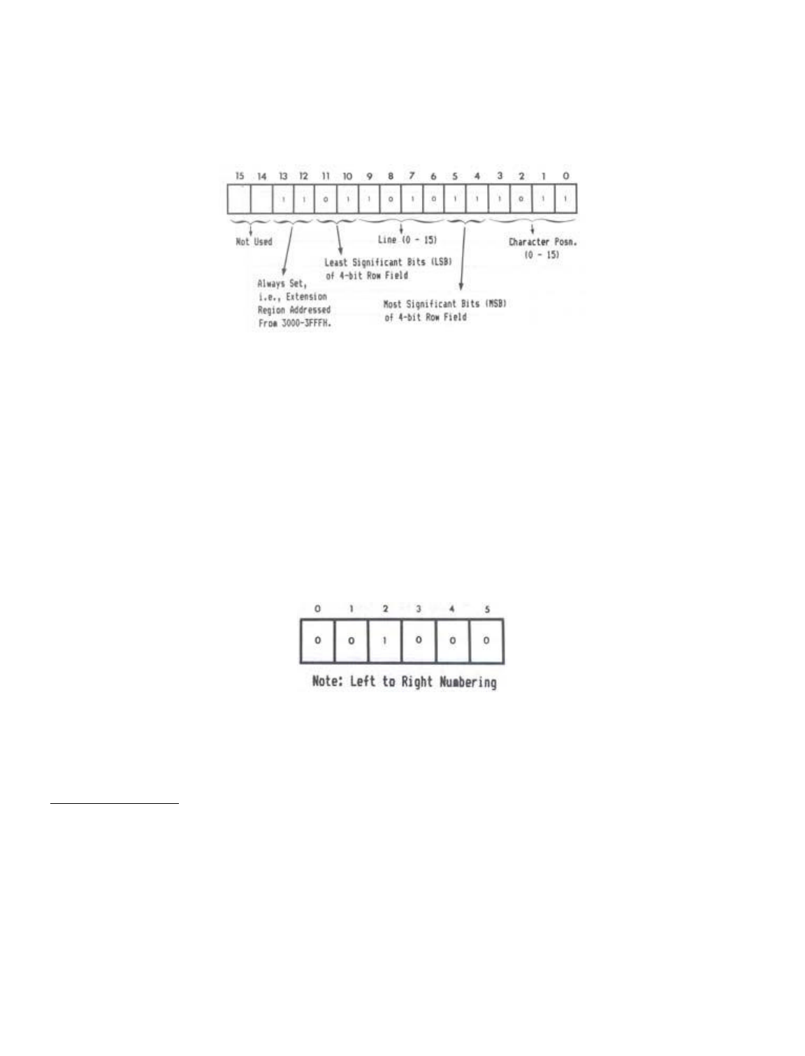
Figure 7.12 - Extension region addressing.
We said that the addressing was not simple X,Y addressing.
So what does that mean? An example will help to illustrate the
situation.
Take address 2000H. Going to the address chart and filling
in 2000H, we get:
Figure 7.13 - Address chart with 2000H, and
character position, line & row,
marked.
This takes us to row 8 of line 0, character position 0.
This is a bit unexpected, as we have been used to the idea of
starting at the top left hand corner of the screen and then
addressing all points down the screen, in a contiguous
fashion. If we start with address 0 and sequentially move
through to address 2FFF, examining the positions pointed to on
the screen by each address, we will see that row 0 of all
character positions is addressed first, then row 1 of all
character positions, then row 2... and so on. The same holds
for the extension region. (Try a few examples).
The information telling us which pixels are on in a
particular row, comes from the 6 bit-datum byte located in
graphics RAM:
Figure 7.14 - Graphics Data Byte in LSB (0-2)
and MSB (3-5) Format
Each bit in the byte corresponds to one of the pixels in
the row, pointed to by the address we just deciphered.
Mode 2 Addressing
The mode 2 pixel differs from the mode l pixel in that it
is 3 times larger, being composed of 3 horizontal dots, The
loss of resolution is compensated for by way of color
information for each pixel. Mode 2 addressing is similar to
mode 1 inner region addressing (see Fig. 7.15). In this case
however, the data byte holds information for two adjacent
color pixels, each half of the byte containing three bits
specifying one of 8 colors.
Page 18 of 24
LNW80 Microcomputer Operations Manual
12/4/03
http://www.xs4all.nl/~fjkraan/comp/LNW/mom/mom_2.html
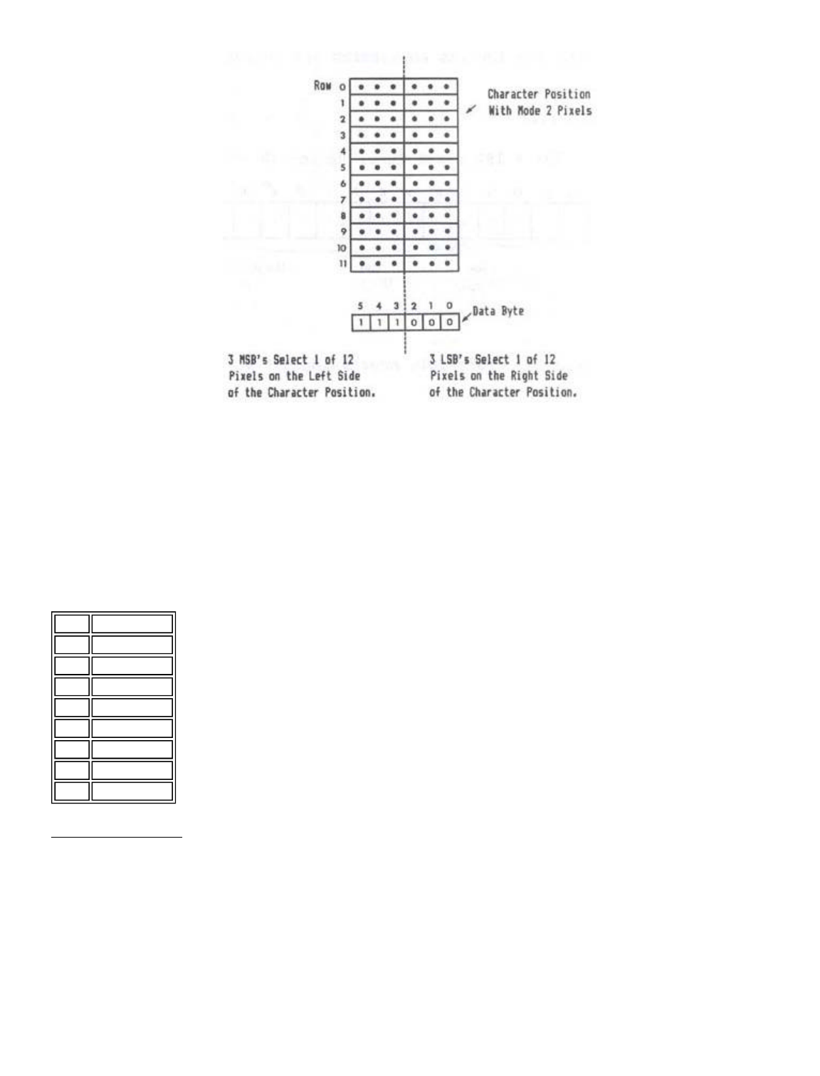
Figure 7.15- Mode 0 character position w/mode 2
pixel outlined, and data byte
underneath.
Bits 3, 4 and 5 contain color information for the pixels on
the left hand aide of the character position. Bits 0, 1 and 2
contain color information for the right-hand side of the
character position. The codes for the 8 colors available are
as follows:
Table 7.2 - Color coding for mode 2 pixels.
Mode 3 Addressing
A simple relationship exists between the high resolution
video and the mode 3 color fields. This relationship is due to
the fact that the low res text memory and the high res memory
share the same addressing in the hardware. The inner region
addressing and the low res addressing are compared below:
Figure 7.16
Data Color
000 White
001 Green
010 Yellow
011 Red
100 Magenta
101 Blue
110 Blue/Green
111 Black
Page 19 of 24
LNW80 Microcomputer Operations Manual
12/4/03
http://www.xs4all.nl/~fjkraan/comp/LNW/mom/mom_2.html
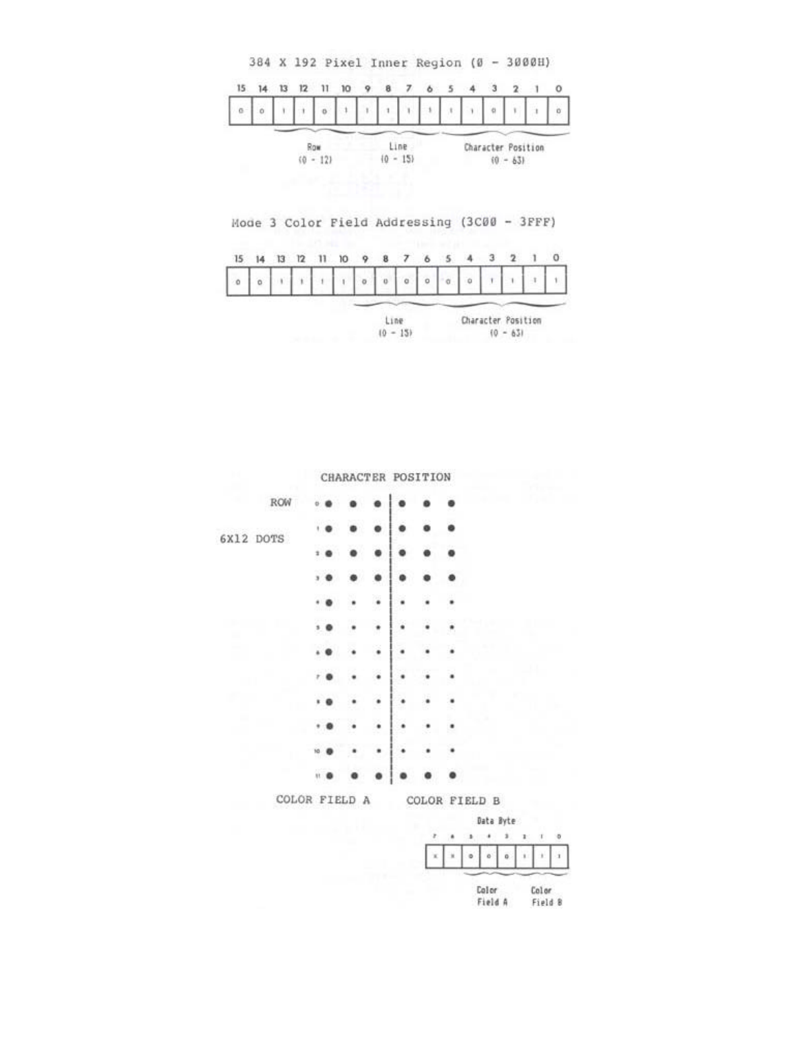
It should be noted that the character position of the MODE3
color field addressing is divided into two color fields. When
a byte is written to 3C00H to 3FFFH, two color fields are set
as illustrated below:
Figure 7.17 Mode 3 Character Position With Color Fields
WITH COLORS DEFINED AS:
Page 20 of 24
LNW80 Microcomputer Operations Manual
12/4/03
http://www.xs4all.nl/~fjkraan/comp/LNW/mom/mom_2.html

5 4 3 or
2 1 0
----------
0 0 0 0 white
0 0 1 1 green
0 1 0 2 yellow
0 1 1 3 red
1 0 0 4 magenta
1 0 1 5 blue
1 1 0 6 blue-green
1 1 1 7 black
The second LNWBASIC program in this section illustrates how
MODE 3 graphics is done from BASIC. Once this is clearly
understood, machine-language use should be simple. When using
MODE 3 to draw lines, circles, etc., setting the correct color
field can be easily done at the same time that the
machine-language routine is outputting to the high res screen.
If the high res address has been computed or looked-up via
some form of address computation table, this address needs
only to have the most significant 6 bits masked and set as
follows:
A15=0
A14=0
A13=1
A12=1
All=1
A10=1
The only additional consideration is which color field is to
be written at that character position? Is it color field A or
B? The software that writes the high res information must have
some method of knowing which high res data bit was the one
that was being written to. If the data bit(s) of the high res
memory was 0, 1 or 2 (the leftmost 3 dots on the screen) then
the color field to be written to is color field A. If the data
bit(s) of high res are 3, 4 or 5 (the right three bits) then
the appropriate color field is B. In order to write only the
desired color field, the program must first read the entire
byte (both color fields) with masking and ORing to put the
3-bit color information in the right place without disturbing
the other color field. Refer to the LNWBASIC program in the
above section for the conceptual details.
Remember that when the high res video memory is enabled via
port 254 data bit 3, the low res video memory 3C00 to 3FFFH is
not accessible. This means that before writing the color field
you must turn off the graphics enable as follows:
IN A,(0FEH) ; INPUT FROM 254
AND 0F7H ; TURN OFF GRAPHICS RAM
OUT (0FEH),A ; OUTPUT TO 254
Then the graphics mode must again be turned on before
writing more graphics.
Machine-language Routine to SET, RESET, POINT
The following is the machine-language listing to SET, RESET
or POINT a video RAM location. This is the listing for the
machine-language that was encoded in the DATA statements in
the program listed under the subsection entitled "Graphics for
Non-Disk Owners."
Page 21 of 24
LNW80 Microcomputer Operations Manual
12/4/03
http://www.xs4all.nl/~fjkraan/comp/LNW/mom/mom_2.html

79F0 00100 ORG 79F0H
79F0 C3437A 00101 SET JP SETR ;SET ROUTINE ENTRY
79F3 C3587A 00102 RESET JP RESR ;RESET ENTRY
79F6 C3717A 00103 POINT JP POIR ;POINT ROUTINE
79F9 CD7F0A 00110 ADCAL CALL INPX GET X POSITION IN
HL PAIR
79FC 013075 00120 LD BC,7530H ;START OF
HORIZONTAL
TBL
79FF 29 00125 ADD HL,HL ;DOUBLE HL IN TABLE
7A00 09 00130 ADD HL,BC ;POINT TO
CHARACTER POS. IN TBL
7A01 7E 00140 LD A,(HL) ;INPUT CHARACTER
POSITION
7A02 FE40 00150 CP 64 ;IS > THAN CHAR 64
(IN EXTENSION)
7A04 F2237A 00160 JP P,EXTEND ;YES USE
EXT. ALGORlTHM
7A07 CD137A 00170 CALL VERT ;GET
ROW.LINE,CHARACTER
ADJUSTED
7A0A CB3C 00180 SRL H ;SHIFT LSB OF H
INTO
CARRY
7A0C CB1D 00190 RR L ;GET LSB OF H INTO
MSB OF L REG
7A0E CB3C 00200 SRL H ;SHFT LSB OF H INTO
MSB OF L
7A10 CB1D 00210 RR L ;ONCE AGAIN
7A12 C9 00220 RET ;NOW HL HAS ADDRESS
OF GRAPHICS
7A13 23 00240 VERT INC HL ;THlS PUTS ROW.LINE
INTO H AND
00245 ;PUTS CHARACTER
POSITION SHIFTED
00247 ;LEFT TWO BITS INTO
L WITH THE
00249 ;TWO LSB SET TO
ZERO
7A14 46 00250 LD B,(HL) ;NOW B REG HAS ONE
OF SIX PATERN
7A15 213079 00260 LD HL,7930H ;START OF VERTICAL
LOOKUP TABLE
7A18 110000 00265 LD DE,0H ;POKE DATA HERE
7A1B 19 00270 ADD HL,DE ;POINT TO VALUE IN
TABLE
7A1C 66 00280 LD H,(HL) ;PUT ROW.LINE INTO
H
7AlD 6F 00290 LD L,A ;COPY CHARACTER
POSITION TO L
7A1E CB25 00300 SLA L ;SHIFT LEFT ONE
PLACE
7A20 CB25 00310 SLA L ;NOW L HAS LEFT
JUSTIFIED CHAR
7A22 C9 00320 RET
7A23 CD137A 00330 EXTEND CALL VERT ;GET VERT IN H,CHAR
IN L,DAT IN B
7A26 CB25 00340 SLA L ;ROTATE 2 MSB OF
ROW
AND
7A28 CB25 00350 SLA L ;PUT THEM IN THE 2
LSB OF H
7A2A CB04 00360 RLC H
7A2C CB04 00370 RLC H
7A2E CB3C 00375 SBL H ;NOW SHIFT HL RIGHT
Page 22 of 24
LNW80 Microcomputer Operations Manual
12/4/03
http://www.xs4all.nl/~fjkraan/comp/LNW/mom/mom_2.html

4 PLACES
7A30 CB1D 00380 RR L
7A32 CB3C 00398 SRL H
7A34 CB1D 00400 RR L
7A36 CB3C 00410 SRL H
7A38 CB1D 00420 RR L
7A3A CB3C 00430 SRL H
7A3C CB10 00440 RR L ;HL OK NOW
7A3R 7C 00445 LD A,H
7A3F C630 00447 ADD A,30H ;MAKE ADDRESS
ABOVE ROW 11
7A41 67 00449 LD H,A
7A42 C9 00460 RET
7A43 CDF979 00478 SETR CALL ADCAL
7A46 DBFE 00480 IN A,(0FEH) ;INPUT FROM 254
7A48 F688 08498 OR 8 ;TURN ON
GRAPHICS
RAM ENABLE BIT
7A4A D3PE 00500 OUT (0FEH),A ;OUTPUT TO 254
7A4C 7E 00510 LD A,(HL) OLD DATA IN A
REG
7A4D BS 80520 OR B ;SET BIT
7A4E 77 00530 LD (HL),A ;WRITE DATA BACK
OUT
7A4F DBFE 00540 IN A,(0FEH) ;INPU AGAIN
7A51 E6F7 00550 AND 0F7H ;TURN OF
GRAPHICS
RAM
7A53 D3FE 00560 OUT (0FEH),A ;OUTPUT PORT 254
7A55 C39A0A 00570 JP RETURN
7A58 CDF979 00580 RKSR CALL ADCAL
7A58 DBFE 00590 IN A,(0FEH) ;INPUT PORT 254
7A5D F608 00600 OR 8 ;SET GRAPHICS
RAM
ENABLE BIT
7A5F D3FE 00610 OUT (0FEH),A ;OUTPUT TO PORT
254
7A61 78 00620 LD A,B
7A62 EEFF 00630 XOR 0FFH ;COMPLEMENT A
7A64 47 00640 LD B,A
7A65 7E 00650 LD A,(HL)
7A66 A0 00660 AND B
7A67 77 00670 LD (HL),A ;WRITE DATA BACK
OUT
7A68 DBFZ 00688 IN A,(0FEH) ;INPUT AGAIN
7A6A EGF7 00690 AND 0F7H ;TURN OFF
GRAPHICS RAM
7A6C D3FE 00700 OUT (0FEH) ,A
7A6E C39A0A 00710 JP RETURN
7A71 CDF979 00720 POIR CALL ADCAL
7A74 DBPR 00730 IN A,(0FEH)
7A76 F608 08748 OR 8
7A78 D3FE 00750 OUT (0FEH),A
7A7A 7E 00760 LD A,(HL) ;GET SIX BITS OF
DATA
7A7B A0 00770 AND 8 ;MASK ALL BUT
SELECTED BIT
7A7C C2857A 00780 JP NZ,SETHL ;MAKE L=l IF NOT
ZERO
7A7F 210000 00790 LD HL,0H ;MAKE BL PAIR 0
7A82 C3887A 00800 JP QUIT ;EXIT
7A85 210100 00810 SETHL LD HL,1H ;SET HL=00018
7A88 DBFE 00812 QUIT IN A,(0FEH) ;INPUT PORT
7A8A E6F7 00814 AND 0F7H ;TURN OFF
GRAPHICS RAM
Page 23 of 24
LNW80 Microcomputer Operations Manual
12/4/03
http://www.xs4all.nl/~fjkraan/comp/LNW/mom/mom_2.html

BIT
7A8C D3FE 00816 OUT (0FEH),A ;0UTPUT TO PORT
254
7A8E C39A0A 00820 JP RETURN
0A9A 00838 RETURN EQU 0A9AH
0A7P 00840 INPX EQU 0A7FH ;THIS PUTS
VARIABLE INTO
HL
0000 00850 END
00000 TOTAL ERRORS
Next page | TOC
Page 24 of 24
LNW80 Microcomputer Operations Manual
12/4/03
http://www.xs4all.nl/~fjkraan/comp/LNW/mom/mom_2.html
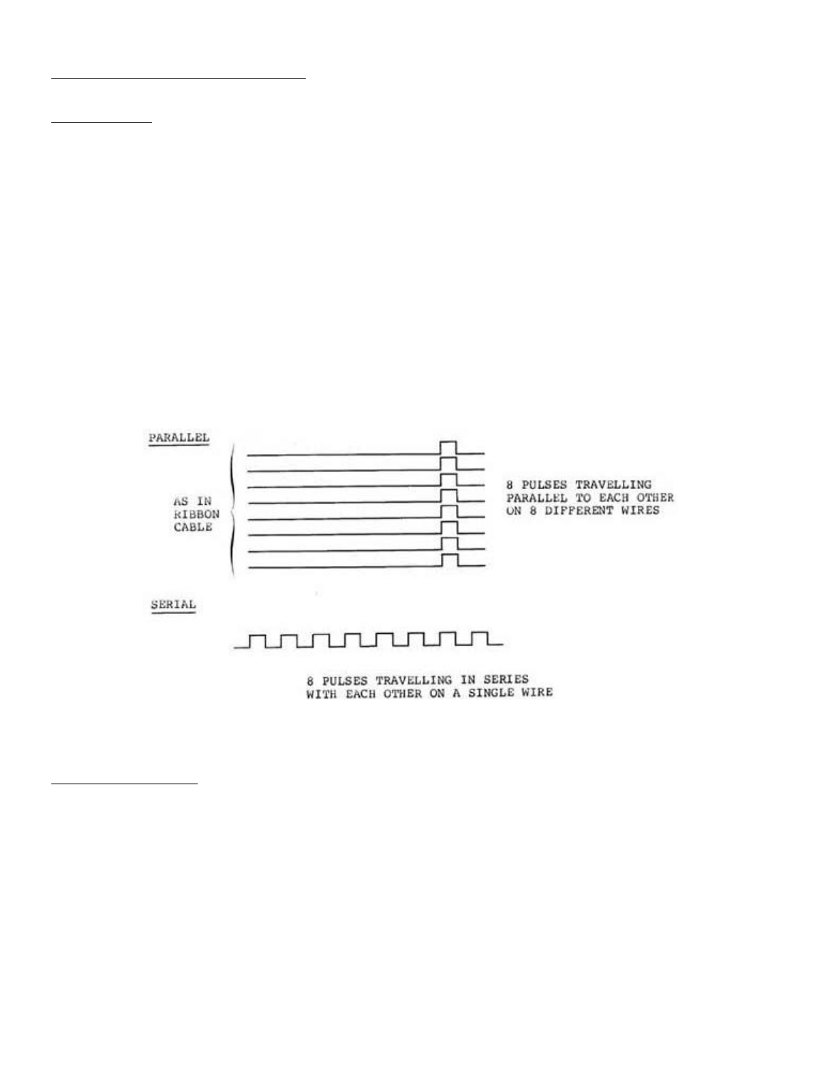
SECTION 8: LINE PRINTER INTERFACE
Line Printers
There are two types of line printer:
1. Serial line printer
2. Parallel line printer
You can connect either type to the LNW80 Computer. The
physical connections for each differ from one another, as they
carry data differently.
A serial line printer handles a byte of information by
receiving the basic elements of information (the bits) in
serial fashion, i.e., one after another, or bit-by-bit, like
eight cars following any behind the other on a single-lane
road. On reception of eight bits the printer reconstructs the
appropriate character.
Parallel printers, on the other hand, receive information
byte-by-byte. At any one time, at least 8 bits are travelling
parallel to one another along the ribbon cable, much like 8
cars abreast on an 8-lane freeway.
Figure 8.0 - Parallel and Serial Data Flow
Serial Line Printer
Serial line printers must be connected to the RS-232 serial
communications interface. A DB25 socket is required to make
this connection. The transmitting rate must be set on the TX
switch to the right of the interface. You will also, in all
probability, have to modify the the printer line so that it
can interface with the RS-232 interface. Because connection of
a serial printer requires some knowledge of RS-232 operation,
details on tne "how tos" of serial printer connection are
found in Section 9.
If you are currently on the hunt for a printer, do yourself
a favor and make it a parallel one.
Note: In order that the LPRINT and LLIST commands of BASIC
work properly, a special program must be used. This program is
Page 1 of 32
LNW80 Microcomputer Operations Manual
12/4/03
http://www.xs4all.nl/~fjkraan/comp/LNW/mom/mom_3.html

resident in DOSPLUS 3.4 as part of the forms command. For
serial printers which require handshaking, this can be
configured the RS232 command in DOSPLUS 3.4. LNWBASIC allows a
serial printer (no handshaking) with the RSOUT command. For
cassette based systems or other DOSes, a serial printer driver
program is supplied at the end of Section 9.
Parallel Line Printer
The LNW80 8-bit parallel printer interface is CENTRONICS
compatible. Parallel line printers are hooked up to the line
printer interface via a card edge connector and a ribbon
cable.
Outputting to the Printer using BASIC
There are two BASIC commands which output material to the
printer:
LLIST LPRINT
These correspond to the commands:
LIST PRINT
which display material on the video display. The PRINT @
command does not have a line printer equivalent. Also, not all
line printers are able to display the ASCII coded graphics
characters 128 through 151. Some line printers may have their
own graphics characters.
Page Length
The page length may be controlled from the keyboard. Memory
location 16424 stores the number of lines per page plus one.
The value stored at this location can be examined by using:
PRINT PEEK (16424)
The reply is:
67
The page length being ll inches and the printing rate being
set at 66 lines per inch for most printers, the number of
lines per page is 66. Some line printers, however, require that
this value be adjusted (see adjusting printer controls) .
Line Count
The line count plus 1 is stored at the adjacent memory
location, address 16425. This value can be retrieved as before
by using:
PRINT PEEK (16425)
the reply at boot up being 0. This value should be initialized
to 1 or more.
Printer Availability
The next location we PEEK at is memory address 14312. This
contains a code depicting printer status.
Table 8.0 - Line Printer Status
Page 2 of 32
LNW80 Microcomputer Operations Manual
12/4/03
http://www.xs4all.nl/~fjkraan/comp/LNW/mom/mom_3.html

The 4 most significant bits (MSB) at byte 14312 are used to
code printer status. Each of these bits represents a
particular aspect of printer status. For example, when bit 6
is on (set) it means the printer is out of paper. When it's
off, it means the printer has paper. The 4 least significant
bits (LSB), which are not used, are always set. The codes
above are a result of a combination of the various conditions.
(For a detailed account of printer status coding and Microsoft
BASIC coding in general, see "Microsoft BASIC Decoded" by
James Farvour, available through your IJG dealer).
Adjusting Printer Controls
The value at any RAM address in the computer can be changed
using the POKE verb in BASIC. A good idea is to initialize the
line count and page length at the beginning of every program
in which there is line printer output. At this point, printer
status can also be ascertained.
l0 REM Program code to alter page-length and
20 REM line-count and to check line printer status.
30 POKE 16424,nnn ' Number of lines per page.
40 POKE 16425,nnn ' Line-count
50 A = PEEK(143l2)
55 B = A AND 240
60 IF B <> 48 THEN PRINT " PRINTER NOT READY"
SECTION 9: RS232C INTERFACING
This section is a bit long, so you might want to grab a cup
of tea, coffee or whatever before launching into it.
The RS-232-C interface was mentioned fleetingly in Section
3 in connection with serial printers. How come we had all of
this to-do about an RS-232-C when all we wanted was to hook-up
a serial printer? Parallel printers, being good little
printers, provided no problem at all!
Serial devices handle digital data in serial form; whereas,
the computer handles data in parallel form. The circuitry
associated with the RS-232-C asynchronous serial
communications interface, to give it its full name, performs
the change over from parallel form to serial form and
vice-versa.
Note: A program is required that supports the RS-232-C. See
page 85.
History of Serial Data Communication
Not long after Babbage introduced his "Analytical Machine"
in 1822, Andre Ampere toyed with various concepts for
communicating information over electrical wires. In the
1830's, Samuel Morse took Ampere's idea and went on to develop
the telegraph using a code he developed, - Morse Code. This
CODE EXPLANATION
16 Cable connection upside down
48 Hooked up and on-line
128 Hooked up, not on-line
192 Printer out of paper
240 Printer not available
Page 3 of 32
LNW80 Microcomputer Operations Manual
12/4/03
http://www.xs4all.nl/~fjkraan/comp/LNW/mom/mom_3.html
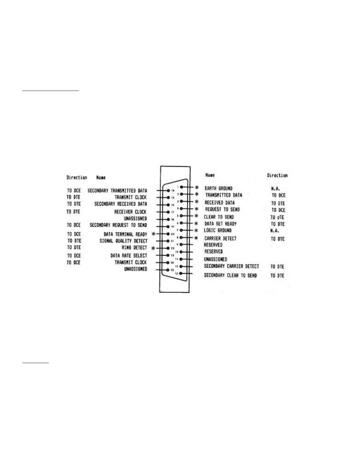
was the first step in communication over wires, using
electrical signals to encode human symbols.
From that time to the development of computers, coding
information over single wires in serial fashion, gave rise to
various standards. As a result, when it came to interfacing
computers with the serial communications network, which is now
the phone system, computer manufacturers had to develop their
own standard: the RS-232.
RS-232-C Standard
The "C" in RS-232-C refers to the particular version of the
standard. The LNW80'S RS-232-C interface conforms to the
Electronic Industries Association (EIA) standard RS-232-C.
However, different computers employing the RS-232-C standard
often interpret it differently. As a result, various makes of
computer claiming RS-232-C compatibility will not necessarily
communicate or "talk" with each other without some adjustment.
Figure 9.0 shows the pin specifications on the 25-pin
connector, as defined by the RS-232-C standard.
Only pins marked with an asterisk are connected in the LNW80.
Figure 9.0 - RS-232-C pin connector as defined
by EIA.
Some equipment which is attached to computers only uses
pins 2, 3 (data lines) and pin 7 (ground), while other
equipment may use the unassigned and reserved pins while still
going under the label 'RS-232-C Standard’.
The Baud
The BAUD, like many of the terms in RS232 jargon, has a bit
of history behind it. Named after Baudot, a pioneer in
telegraphic communications, the baud was the unit of
transmision speed for serial data communication. It
represented the number of half-dot cycles transmitted
continuously in one second (which is in fact the modulation
rate). We can think of the modulation rate as being the rate
at which a carrier wave is adjusted to accomodate data
transmission,
In the present-day scheme of things, when the data
Page 4 of 32
LNW80 Microcomputer Operations Manual
12/4/03
http://www.xs4all.nl/~fjkraan/comp/LNW/mom/mom_3.html
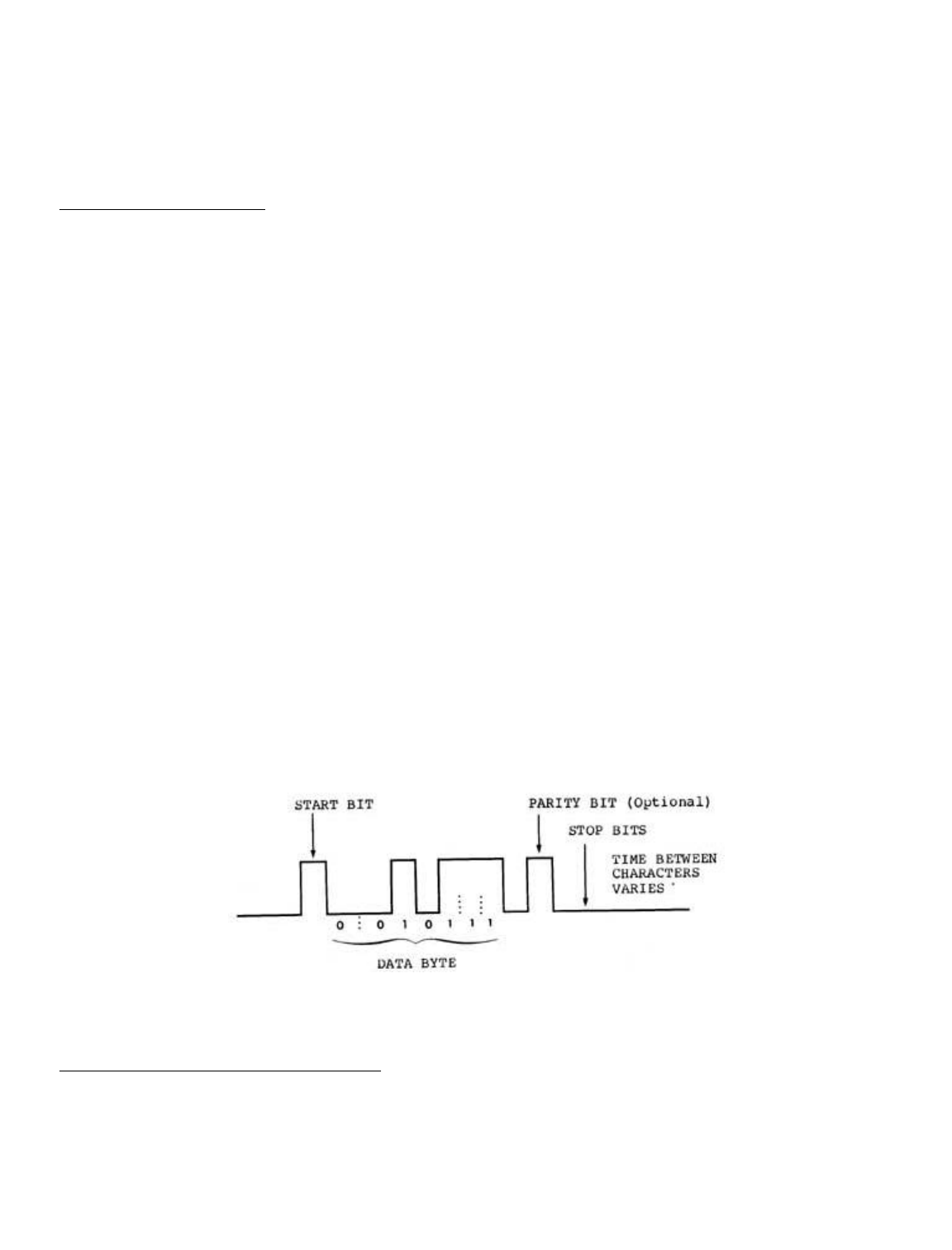
signalling rate (measured in bits per second) is equal to the
modulation rate (expressed as baud), then the number of bits
transmitted per second is equal to the baud rate. (Long
sentence, that!). In our situation of asynchronous data
transmission, the baud rate is equal to the bit rate when one
stop bit is used.
Transmission Techniques
Inter-computer communication over a distance is almost
always achieved using serial data transmission, as the
communications,network is already there (the phone system).
As we have seen, data in the form of characters is encoded
in bits. The character length is optional here and can be
either 5, 6, 7 or 8 bits. This is to allow for various word
lengths that have arisen as standard over the years.
Each bit is transmitted as an electrical pulse along the
transmission line. The pulses are of a definite time
duration.
At the other end of the line, the receiver must somehow be
in synchronization with the pulses it receives. It must be
able to recognize when a bit starts and how long it lasts, and
when a character starts and ends. There are two modes of
operation to achieve synchronization between receiver and
transmitter:
- asynchronous operation
- synchronous operation
The LNW80 uses the asynchronous method, as do most
microcomputers.
With asynchronous communication, characters can be dumped
on to the transmission line raggle-taggle fashion, i.e., the
timing of character placement on the line is not important. In
allowing this, however, the receiver demands that each
character must be transmitted at a fixed rate and must be
framed with a start-bit and stop-bit(s).
Figure 9.1 - asynchronous transmission showing
character with start and stop bits.
Connecting Equipment to the RS-232-C
When connecting equipment to the RS-232-C interface, we
must take into account whether it is:
Data Terminal Equipment (DTE), or
Data Communications Equipment (DCE).
Page 5 of 32
LNW80 Microcomputer Operations Manual
12/4/03
http://www.xs4all.nl/~fjkraan/comp/LNW/mom/mom_3.html
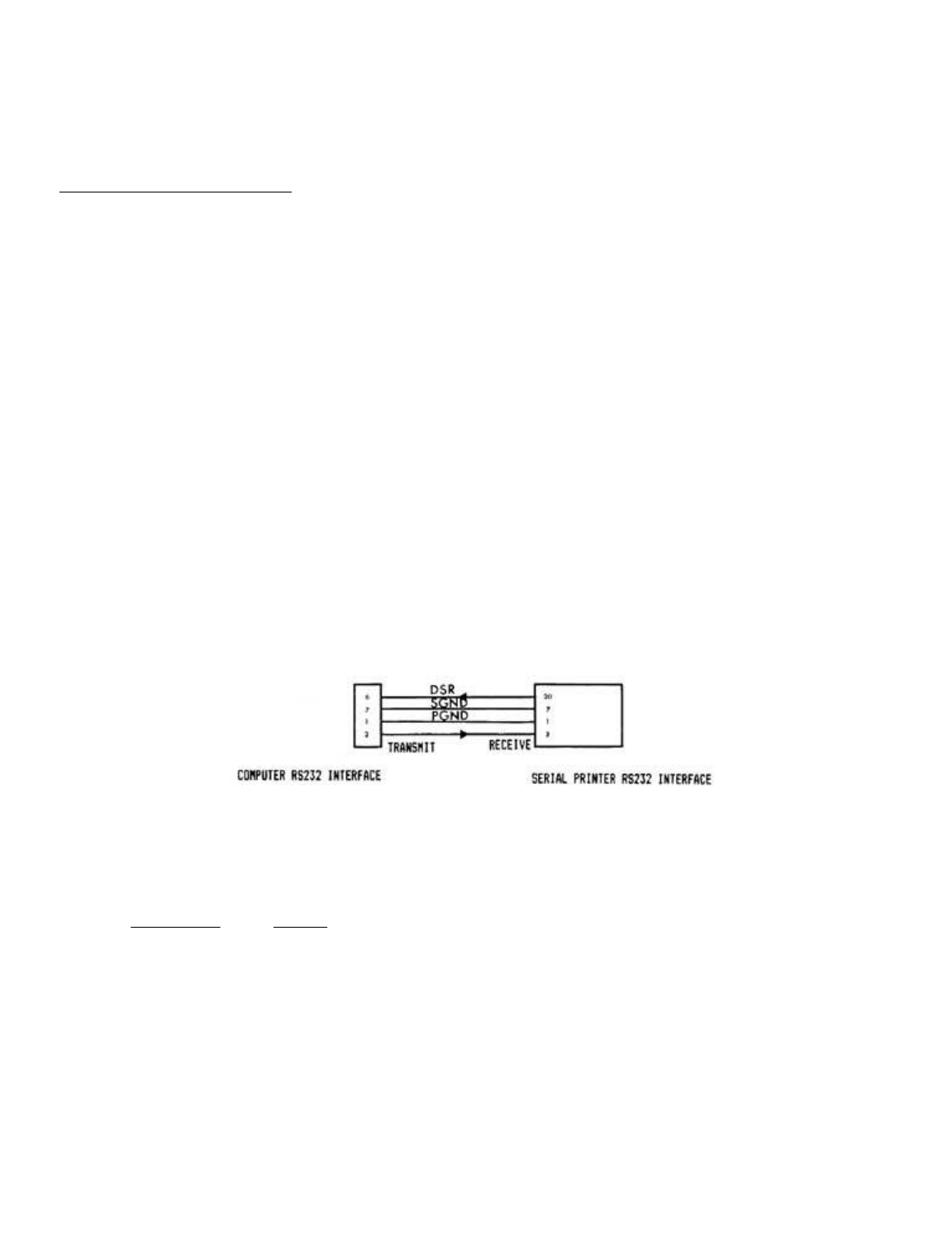
DTE includes serial printers, teletypes and Decwriters. DCE
refers to modems.
As is, the LNW80’s RS-232-C interface is configured to
interact with DCE.
Serial Printer a the RS232
Serial printers and teletypes (DTE) have the same signals
on the RS232 cable as the LNW80. This is because Teletypes
were designed to interface directly with modems (as is the
LNW80) to act as a remote terminals. This means that there
will be conflicts on the RS232 lines since the printer's
outputs are the same as the computer’s. Fortunately not all of
the RS232 signals are required when connecting to a serial
printer. Usually only the Transmit Data (TD) for the computer
is tied to the Receive Data (RD) of the printer along with the
chassis and signal ground (see table 9.0).
Some printers also require the use of handshaking lines.
Handshaking is the printers way of telling the computer that
it's buffers are full, and to hold off until it has printed
their contents. The computer must then wait until the printer
is ready to recieve data again. This signal should be received
on DSR (pin 6) and may be output by the serial printer on
either DTR (pin 20) or a separate RS232 handshaking signal.
For handshaking to operate properly, the handshaking signals
should be "ON" (+12V) when ready to receive more data, and
"OFF" (-12V) when busy. Check with the operations manual of
your printer if in doubt.
The following drawing illustates the lines connected. Some
serial printers require that CTS (pin 5) or DSR (pin 6) of the
printer be tied to either +12V or -12V for proper operation.
The operating manual for the printer should provide the
details.
Figure 9.2 - Serial printer interfacing with the
computer.
Table 9.0 - Specifications for the LNW80's RS-232-C Interface
Pin Number Signal
1 PGND (protective ground)
2 TD (transmit data)
3 RD (receive data)
4 RTS (request to send)
5 CTS (clear to send)
6 DSR (data set ready)
7 SGND (signal ground)
8 CD (carrier detect)
20 DTR (data terminal ready)
22 RI (ring indicator)
TD -- Serial data is output to external device.
RD -- Serial data is received from external device.
RTS - Outputs a request to the external device to allow the
computer to transmit serial data.
Page 6 of 32
LNW80 Microcomputer Operations Manual
12/4/03
http://www.xs4all.nl/~fjkraan/comp/LNW/mom/mom_3.html
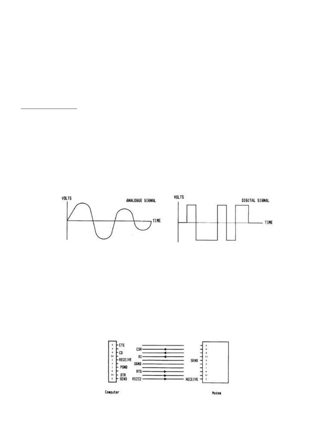
CTS - Inputs a response from an external device to a RTS
saying that the external device is ready to receive serial
data.
DSR - Input to the computer saying that the receiving device
(at the other end of the telephone) is ready to receive from
the computer. In the case of a modem, this signal acknowledges
that it is not in test, talk or dial mode.
CD -- Input to the computer saying that the modem has sensed a
carrier signal over the telephone.
DTR - Output by the computer to tell the external device that
the computer is ready to transmit or receive serial data.
RI -- Input to the computer indicating that the modem has
received a ringing tone at the other end of the telephone.
Connecting a Modem
This device allows information to be transmitted from one
computer to another over the telephone lines. Telephone lines,
however, were designed, not for transmitting data, but with
the human voice in mind. The result is a system designed to
reproduce an analog signal representing the fluctuations of
the human voice in the frequency range 300 to 3400 Hertz
(cycles per second). Analog signals vary continuously with
time, rising and falling between high and low values. Digital
signals, on the other hand, have either a constant high value
or a constant low value at any one instant, changing from one
value to the other over a negligible period of time.
Figure 9.3 - Analogue and Digital Signals
The modem forges the gap between the two worlds. The word
modem is an acronym for MOdulator/DEModulator, indicating the
two functions a modem performs. When serial digital data from
the computer presents itself to the modem for transmission
over the telephone lines, it is first coded as an analog
signal, and then "applied" to a carrier wave resident in the
telephone network. This "applying" is called modulation.
A modulated signal arriving at the computer must be
demodulated. That is, the analog information imposed on the
carrier wave must be stripped off and converted into serial
digital information.
Figure 9.4 - Modem Interfacing With the Computer
Page 7 of 32
LNW80 Microcomputer Operations Manual
12/4/03
http://www.xs4all.nl/~fjkraan/comp/LNW/mom/mom_3.html
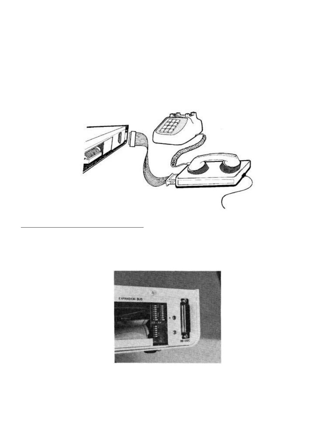
Acoustic modems convert transmission data received into
audible tones which are fed to the computer via the earpiece
of the phone.
When data is going in the other direction, from the
computer to the transmission line, the modem converts data
into audible tones which are fed to the transmission line via
the phone mouthpiece.
A modem is DCE and, as a result, interfaces directly with
the RS-232-C serial communications interface. (Pin 2 on the
modem receives data, and pin 3 transmits). A cable with a male
DB25 plug is required to make this connection.
Figure 9.5 - Hooking Up a Modem
Switch Settings on the RS232C Interface
Located on the I/0 panel, next to the RS232 DB25 connector,
are 3 sets of small DIP switches, as shown in figure 9.6.
These switches are used to set the BAUD RATE and the UART (see
RS232 Operation 6 Programing) configuration settings (parity,
word length and number of stop bits).
Figure 9.6 - Close up of RS232C dip switches.
The two BAUD RATE switches select the actual baud clocks (for
both receive and transmit) to the UART. The baud rate is not
software selectable on the LNW80 as it was on the TRS80 Model
I. Almost all TRS80 Model I software can still be used even if
it thinks it can set the baud rate under software control.
Page 8 of 32
LNW80 Microcomputer Operations Manual
12/4/03
http://www.xs4all.nl/~fjkraan/comp/LNW/mom/mom_3.html

Only applications where the baud rates MUST be controlled by
the application program will the LNW80 not be compatible with
the TRS80 Model I . Some programs will attempt to display or
otherwise indicate the current baud rate setting under software
control. This is not possible on the LNW80 and this
information should be ignored.
The configuration switches for parity, word length, and
number of stop bits do not actually set these values directly
in the UART. These switches simply are present to allow the
application program to read back what they have been set to.
Since many existing TRS80 model 1 RS232 programs require that
these switches are present, it is also included on the LNW80.
These switches can be read by inputting from port E9H. For
more information on these configuration switches refer to the
section on programming the RS232 interface.
Transmitting and Receiving
The programmer has a number of things to consider before
communicating via the RS-232-C interface:
- Transmit and receive rates
- Parity
- Word length
- Start and stop bits
Setting Transmit and Receive Rates
For most applications the Transmit (TX) and Receive (RX)
switches (located next to the RS232 interface) will be both
set at the same value. Only one switch on the TX and one
switch on the RX should be on at any one time.
Table 9.1 - Setting Tx and Rx Rates
TX & RX Switch Baud rate
1 9600
2 2400
3 4800
4 1200
5 150
6 110
7 600
8 300
Setting Parity
When data is transmitted, errors often occur due to
electrical interference, or "noise," on the line. This may
result in an extra bit being included in a character, for
example. To provide a check on this, a parity bit is appended
to the word making the total number of "ones" in the word odd
or even, depending on whether you have chosen odd or even
parity for transmission.
The configuration switches on the I/0 panel are used to set
parity.
Table 9.2 - Setting Parity With the Configuration Switches
Parity Con Switch Position
Page 9 of 32
LNW80 Microcomputer Operations Manual
12/4/03
http://www.xs4all.nl/~fjkraan/comp/LNW/mom/mom_3.html

Inhibit 1 Off
2 Off
Even 1 On
2 Off
Odd 1 On
2 On
Setting Word Length
A word (character) length of 5, 6, 7 or 8 bits may be used.
The reason for the various word lengths (just when we had
gotten used to 8 bits to a character) is that older machines
have different word lengths. For example, teletypes use a
5-bit word length.
Table 9.3 - Setting Word Length
Word Length Con Switch Position
5 4 On
5 On
6 4 Off
5 On
7 4 On
5 Off
8 4 Off
5 Off
Setting Stop Bits
You may select 1 or 2 stop bits. When using a 5-bit word
length, the configuration corresponding to 2 bits is, in
actual fact, 1.5 atop bits. You may well wonder how a half-bit
is arrived at. A hali-bit is represented by a time pulse half
that of full bit.
Table 9.4 - Setting Stop Bits
Stop Bits Con Switch Position
1 3 On
2 3 Off
Note: Configuration switch 6 is not used for anything.
RS-232-C Operation
The circuitry associated with the RS-232-C has as its
centerpiece a small dedicated processor, - the UART (Universal
Asynchronous Transmitter/Receiver). It is dedicated in the
sense that it has nothing else to do except to look after the
RS-232-C's goings on.
It is within the UART that the parallel data structure of
the computer is interfaced with the serial data structure of
the communications channel. The transmitter section of the
UART takes a parallel byte from the CPU bus (information
route) and converts it to a serial word with start, stop and
parity bits. The receiver section accepts a serial word from a
serial device complete with its adornment of stop, start and
parity bits, checks its validity, and then reconstitutes a
parallel byte.
Programming the RS232C Interface
Page 10 of 32
LNW80 Microcomputer Operations Manual
12/4/03
http://www.xs4all.nl/~fjkraan/comp/LNW/mom/mom_3.html

In order for the UART to function to receive and transmit
serial data, a program within the LNW80 must communicate with
the UART writing commands, configuration information, and data
to its internal registers and reacting status and data back.
Here is a list of the requirements for programming the UART:
1. MASTER RESET
After power has been applied to the UART, it must be reset
before attempting to program any of the internal registers.
This can be done by outputting anything to port location E8
(hex). Here is an example of the assembly language source
code.
OUT (0E8H),A ;OUTPUT ANYTHING
2. CONFIGURATION OF UART
The UART will transmit and receive at the baud rate that is
provided by the switch settings but it must be told how it is
to transmit the serial data. Should there be PARITY? If so,
should it be EVEN PARITY or ODD PARITY? Should 5,6,7 or 8 bits
of data be transmitted? Should the STOP BITS be set at 1 or 2?
This information is programmed into the UART by certain bits
set or not set in the UART CONTROL REGISTER. This register is
addressed at port location EAH. The upper 5 bits of this
location determine the setting of this configuration while the
lower 3 bits are also used to set some of the handshaking
output lines.
The relationship between these switches and the UART
CONTROL REGISTER is such that by manually setting the
switches, your program can simply read the switches, mask the
lower 3 bits and then output that value to the UART CONTROL
REGISTER at EAH. This feature is provided for the purpose of
remaining compatible with programs written for the TRS80 Model
1 that read the switches and do not allow the user to select
this configuration under software control. Since both DOSPLUS
3.4 and LNWBASIC allow programming of the configuration AND it
is done in the BASIC programs provided at the end of this
section it is not recommended that new programs be written
that depend on these switches. Here is an example of how the
UART CONTROL REGISTER is set:
LD A,(CONFIG) ;load value from memory
OUT (EAH),A ; actually output to UART
CONFIG DEFB ; here is where the BASIC
; program put the
; configuration settings.
The example programs are provided at the end of this section
to illustrate how the configuration settings are selected from
a basic program.
Or if you are using the configuration switches...
IN A,(0E9H) ; INPUT FROM CONFIGURATION
SWITCHES
AND 0F8H ; MASK OFF LOWER 3 BITS
OR 05H ; SET THE LOWER 3 BITS AS DESIRED
FOR HANDSHAKING (BRK,DTR,RTS)
OUT (0EAH),A ; OUTPUT TO UART
Page 11 of 32
LNW80 Microcomputer Operations Manual
12/4/03
http://www.xs4all.nl/~fjkraan/comp/LNW/mom/mom_3.html

3. TRANSMIT AND RECEIVE DATA
In order for the UART to transmit data, data must output
to the UART TRANSMIT REGISTER (EBH). Data can be input from
the UART RECEIVE REGISTER (EBH). Status concerning data
received, data transmitted, and errors can be read back on the
UART STATUS REGISTER (EAH). The status bits are defined in
figure 2 above. For more details in programming the UART,
refer to the LNW80 TECHNICAL REFERENCE MANUAL and the data
sheets on the TR1602B.
4. MODEM STATUS REGISTER
When communicating over voice grade telephone lines and
using a modem, various modem status conditions can be read
back. CTS, DSR, CD, RI can all be input at port location E8H.
See page 40 of the LNW80 Technical Reference Manual for the
bits associated with these status signals.
The assembly listing of the serial terminal program which
follows illustrates how the RS232 interface and the UART are
programmed.
;
; Assembly-language Listing of Terminal Program
;
0033 00010 DSP EQU 338
002B 00020 KBD EQU 2BH
FF70 00100 ORG 0FF70H
FF70 3E1C 00110 START LD A,1CH ;HOME CURSOR
FF72 CD3300 00120 CALL DSP
FF75 3E1F 00130 LD A,lFH ;CLEAR SCREEN
FF77 CD3300 00140 CALL DSP
FF7A 3E0E 00150 LD A,0EH ;TURN ON CURSOR
FF7C CD3300 00160 CALL DSP
FF7F D3E8 00170 IUART OUT (MR),A ;RESET UART WITH
ANYTHING
FF81 DBE9 00180 IN A,(CONFIG) ;GET TERM
CONFIG
JUMPERS
FF83 E6F8 00190 AND 0FSH ;MASK LOWER 3 BITS
FF85 F605 00200 OR 5H ;SET BRK, RESET,
DTR, SET RTS
FF87 D3EA 00210 OUT (CTRL),A;PUT IN CONTROL
REG
FF89 DBEA 00220 RSRD IN A;(CTRL)
FFSB CB7F 00230 BIT 07H,A ;IS RECEIVE DATA
AVAILABLE
FFSD 2817 00240 JR Z,SEROUT
FFSF DBEB 00250 IN A;(DATA) ;GET DATA
FF91 B7 00260 OR A
FF92 2812 00270 JR Z;SEROUT ;IF NO INPUT LOOK
TO OUT
FF94 E67F 00280 AND 7FH ;STRIP PARITY
FF96 FE60 00290 CP 60H
FF98 FA9DFF 00300 JP M,AAT
FF9B E65F 00310 AND 5FH ;LOWER TO UPPER
CASE
FF9D FE0A 00320 AAT CP 0AH
FF9F 28E8 00330 JR Z,RSRD
FFA1 CD3300 00340 CALL DSP ;DISPLAY
CHARACTER
FFA4 18E3 00350 JR RSRD
FFA6 CD2B00 00360 SEROUT CALL KBD ;INPUT FROM
KEYBOARD?
Page 12 of 32
LNW80 Microcomputer Operations Manual
12/4/03
http://www.xs4all.nl/~fjkraan/comp/LNW/mom/mom_3.html

FFA9 B7 00370 OR A
FFAA 28DD 00380 JR Z,RSRD ;IF NOTHING THEN
BACK TO INPUT
FFAC FE05 00390 CP 5H
FFAE F2B9FF 00400 JP P,NOSPCH ;NOT A SPECIAL
CHARACTER
FFB1 21CSFF 00410 LD HL,SPCHTB-1 ;SPECIAL
CHARACTER
TABLE
FFB4 4F 00420 LD C,A
FFB5 0600 00430 LD B,0H
FFB7 09 00440 ADD HL,BC ;HL POINTS TO
SPEC. CHARACTER
FFB8 7E 00450 LD A,(HL) ;GET SPECIAL
CHARACTER CODE
FFB9 FE1A 00460 NOSPCH CP 1AH
FFBB 28CC 00470 JR Z,RSRD ;IS SHIFT DOWN
ARROW? IGNORE
FFBD 4F 00480 RSWR LD C,A ;SAVE DATA
FFBE DBEA 00490 IN A,(CTRL) ;GET UART STATUS
FFC0 CB77 00500 BIT 06H,A ;IS TRANSMIT
REGISTER EMPTY
FFC2 28F9 00510 JR Z,RSWR ;IF NOT LOOP
FFC4 79 00520 LD A,C ;PUT CHAR IN A
FFC5 D3EB 00530 OUT (DATA),A gOUTPUT CHAR
FFC7 18C0 00540 JR RSRD ;BACK TO INPUT
ROUTINE
FFC9 03 00550 SPCHTB DEFB 03H
; DEFAULT: EOT-CNT "A"
FFCA 1B 00560 DEFB 1BH
;DEFAULT:ESC-CNT"B"
FFCB 7C 00570 DEFB 7CH ;DEFAULT:VERT BAR
-CNT"C"
FFCC 7F 00580 DEFB 7FH
;DEFAULT:DEL-CNT"D"
00E8 00720 MR EQU 00E8H
00E9 00730 CONFIG EQU 00E9H
00EA 00740 CTRL EQU 00EAH
00KB 00750 DATA EQU 00EBH
FF70 00770 END START 00000 TOTAL ERRORS
Getting the Most From the RS-232-C
The RS-232-C may well be one of the most important features
on your LNW80. It allows you to communicate with your local
community college computer (educational budget permitting), or
work computer, your LNW80 acting as a terminal. Thus you can
interact with large computer systems from your home.
The ramifications of this kind of setup could have dramatic
effects on society in the not so distant future. Ponder for a
moment if you will, on the work habits of people in
metropolitan areas. Every morning large numbers of citizens
from the suburbs pile into their automobiles and drive towards
downtown. Once there, they assume positions at desks where
they write on paper and pass information, one to the other,
again on paper.
Adding up the cost of this kind of modus operandi, a number
of inefficiences come rushing to mind. Think of the time spent
commuting and the cost of this on both pocket and environment.
The astronomical cost of harboring thousands of people in one
big building also springs to the fore. If only we could
communicate, perform more direct accounting and commit
information to store without all of this paper!
Page 13 of 32
LNW80 Microcomputer Operations Manual
12/4/03
http://www.xs4all.nl/~fjkraan/comp/LNW/mom/mom_3.html

Let's be glib here. Instead of spending the tons of money
(literally) on office construction and maintenance, why not
give all of the employees a microcomputer and modem (I have
just the system in mind!) and the resources for a small bureau
at home. The employees could log on every morning to a central
computer and find out what was wanted of them today. They
could submit work to the computer, which would spout out the
facts to the company president and his aides. The considerable
savings on gasoline could be used to improve the
communications network.
This rather loosely strung together train of thought hints
at the real possibilities the RS-232-C communications unit
could present.
BASIC RS232C Serial Printer & Terminal Programs
The following program can be used as a terminal program,
which allows your computer to communicate with other computers
via a modem.
10 REM SERIAL CRT TERMINAL PROGRAM
20 REM
30 REM This program allows the use of the LNW80 computer
40 REM system as a CRT terminal. This program may also be
50 REM used for testing the serial interface by connecting
60 REM pins 2 & 3 of the RS232C DB25 connector together.
65 REM BE SURE TO SET HIGH MEMORY TO 65390
70 FOR X=-144 TO -52
80 READ D
90 POKE X,D
100 NEXT X
110 POKE 16526,112 '070H
120 POKE 16527,255 '0FFH
130 A=USR(N)
200 DATA 62,28,205,51,0,62,31,205,51,0,62,14,205,51,0,211
210 DATA 232,219,233,230,248,246,5,211,234,219,234,203,127
220 DATA 40,23,219,235,183,40,18,230,127,254,96,250,157,255
230 DATA 230,95,254,10,40,232,205,51,0,24,227,205,43,0,183
240 DATA 40,221,254,5,242,285,255,33,200,255,79,6,0,9,126
250 DATA 254,26,40,204,79,219,234,203,119,40,249,121,2ll
260 DATA 235,24,192,3,27,124,127
Serial Printer Program
10 REM BASIC SERIAL PRINTER PROGRAM
30 REM This program allows the use of a serial printer
40 REM with the LNW80. This program is left in memory
50 REM unaltered by BASIC and user programs. The program
60 REM is executed during each LPRINT and LLIST statement
70 REM Handshaking is supported as the software reads the
71 REM the printer busy (DSR) before outputting a
72 REM character. If your printer does not support
73 REM handshaking, change line number 340 to:
74 REM 340 DATA 219,232,203,119,0,0,219,234
75 REM BE SURE TO SET HIGH MEMORY TO 65278 BEFORE
76 REM entering BASIC.
77 REM
78 REM
80 CLS:PRINTCHR$(23):PRINT"LNW RESEARCH CORP.":PRINT"BASIC
SERIAL PRINTER PROGRAM"
90 FOR X=-256 TO -207
100 READ D
110 POKE X,D
120 NEXT X
Page 14 of 32
LNW80 Microcomputer Operations Manual
12/4/03
http://www.xs4all.nl/~fjkraan/comp/LNW/mom/mom_3.html

130 A$="E":P=128:L=0:WL=1:SB=7:B=32
140 'INITALLY SET FOR 1 START BIT, SEVEN BITS DATA, EVEN
PARITY,ONE STOP BIT
150 POKE 16421,2:POKE 16422,0:POKE 16423,255 'POKE NEW DCB
160 FORZX=1T0600:NEXTZX:CLS:PRINT"CONFIGURATION MENU":
PRINT: PRINT"RS232 CONFIGURATION SETTINGS"
170 PRINT"1) PAR1TY (E-EVEN)g(O-ODD),(D-DISABLED) ";A$
180 PRINT"2) STOP BITS ";WL
190 PRINT"3) WORD LENGTH ";SB
200 PRINT"4) RUN TERMINAL PROGRAM":PRINT"SELECT FUNCTION"
210 Z$ =INKEY$:IFZ$=""THENGOT0210ELSEIFZ$="1"THENGOT0220ELSE
IFZ$=" 2" THENGOT0270ELSEIFZ$="3"THENGOT0240ELSEIFZ$="4"
THEN GOT0290ELSE GOT0210
220 P=0:INPUT"PARITY EVEN (E), ODD (0), OR DISABLED (D)";
A$:IFA$="E" THENP=POR128ELSEIFA$="0"THENP=PAND127ELSE
IFA$="D"THENP=POR8 ELSEGOT0220
230 GOTO 160
240 INPUT"WORD LENGTH (5,6,7,8)";SB:IF SB<5THEN240ELSE
IFSB>8THEN240
250 IFSB=5THENB=0ELSEIFSB=6THENB=64ELSEIFSB=7THENB=32ELSE
IFSB=STH ENB=96
260 GOT0160
270 INPUT"STOP BITS (1 OR
2)";WL:IFWL>2THENGOT0270ELSEIFWL
SECTION 10: MEMORY UTILIZATION
A Look at Memory in a Non-Disk System
The computer is now operating out of ROM using the Level II
BASIC language.
On power up we have 64K of memory address space in the
machine. 12K of this is Read Only Memory (ROM), which we
cannot use to hold programs or data. In addition, the computer
takes up just over 2K bytes of memory space which it uses to
operate the keyboard, the video, I/0 routines and other
computer "housekeeping" functions. Almost 2K is not used for
anything.
So, of the 64K of memory space that we started out with,
the computer has earmarked 16K for its own purposes. This
leaves us, the programmers, with 48K or thereabouts. See
figure 10.0 for a schematic presentation of memory
allocation.
Figure 10.0 - Simple Rectangular Memory Block Diagram.
Page 15 of 32
LNW80 Microcomputer Operations Manual
12/4/03
http://www.xs4all.nl/~fjkraan/comp/LNW/mom/mom_3.html
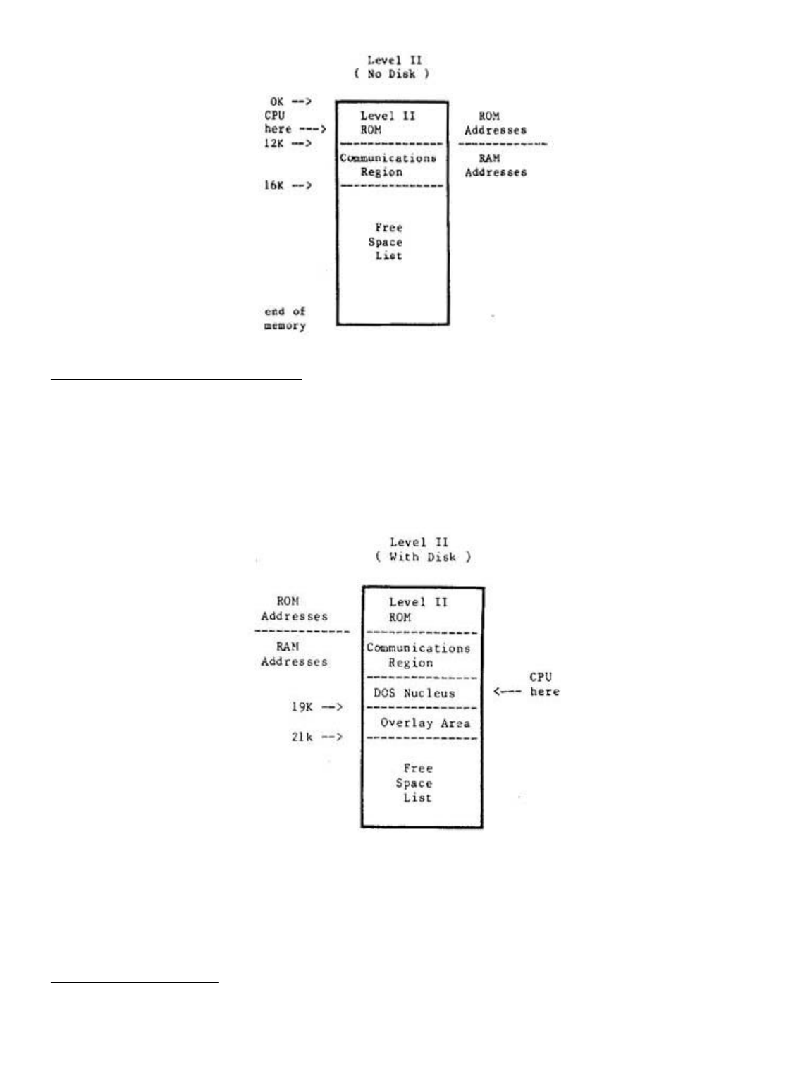
A Look at Memory in a Disk System
With system start-up from disk, the DOSPLUS disk operating
system is loaded from disk into RAM. The system doesn't just
load into memory at any old position. No, the DOS loads in at
the 16K mark in memory and extends for 5K to 21K. The memory
up to 16K is the same as that in a non-disk system. In fact
the DOS enhances the ROM based system ay acting in cooperation
with it. Figure 10.1 is a schematic drawing of memory
allocation in a disk system.
Figure 10.1 - Memory block diagram for a disk
system. (Before BASIC is called).
A disk operating system takes up more memory than the ROM
based system. However, the availability of a large amount of
quickly accessible storage on disk, more than compensates for
the extra 5K of memory we have sacrificed.
High Memory Protection
The BASIC interpreter uses as much memory as you will allow
Page 16 of 32
LNW80 Microcomputer Operations Manual
12/4/03
http://www.xs4all.nl/~fjkraan/comp/LNW/mom/mom_3.html

it. In a ROM based system, BASIC uses a variable amount of
space beyond the 16K region, where it stores tables and
variables. In the case of a disk system, these tables and
variables are stored just beyond the 26K region. In both
cases, BASIC also stores information way up there in high
memory (in the 40K+ region).
You may put a ceiling on BASIC's use of memory by replying
to the MEMORY SIZE? question on power up or reset. By replying
with say 32768, you will keep BASIC out of memory locations
above 32K. This is important if you want to use
assembly-language programs.
For a memory map showing how Level II BASIC uses memory,
see Appendix D of the Radio Shack Level Il manual. This is not
vital information if you are a beginner, but it is important
if you are an assembly-language enthusiast.
SECTION ll: CHOOSING AND USING A DISK OPERATING SYSTEM
Introduction
The LNW80 supports a wide number of disk operating systems
(DOS). A full list is supplied in Table 11.0. This versatility
towards software will be welcome news to those programmers who
want to continue using the same software that wooed them
towards microcomputers in the first place. However, the first
time owner may find the choice of DOSes a bit bewildering, and
for this reason we include DOSPLUS 3.4 in the LNW80 package.
We think this is a well-documented and easy to use DOS.
Knowing full well that the first operating system that you
come to know generates a feeling not unlike that towards your
first car, this section includes detailed instructions on how
to set up a disk system for a number of DOSes.
But first, as a backdrop (hey, this is southern
Californian) to all of this technical mumbo jumbo, let’s take
a vague look at microcomputer operating systems and their
background. (For a detailed description of a disk operating
system, see the introduction to this manual).
Important Aspects of a DOS
From a programmer’s point of view, a DOS should be
transparent and fast. Transparent means that it should perform
the various data manipulations in such a way that the
programmer is hardly aware of what's going on. When the DOS
needs to look up system tables, or bring another system module
from disk into RAM (overlaying), we, the programmers, want it
to do so without bothering us as we slave away at the
keyboard. We would also like to have some data recovery
facilities, in the event that the DOS tells us it can’t read a
disk sector. Ideally, the DOS should do all of this using a
minimum of valuable RAM.
A very important aspect of any operating system is its
documentation. If the documentation is not very clear, and you
can't find out how to use the system, or you find yourself
encountering difficulties which are not explained, then the
system ends up being of little use and a real pain in the
byte.
A Brief History of the TRS80 Model I Operating Systems
Page 17 of 32
LNW80 Microcomputer Operations Manual
12/4/03
http://www.xs4all.nl/~fjkraan/comp/LNW/mom/mom_3.html

Since the introduction in 1978 of tba TRS80 Model I
microcomputer and its disk operating system, TRSDOS, a wide
variety of operating systems have been developed to operate on
the TRS80 Model I. These systems were developed, for the most
part, to improve upon a poor TRSDOS 2.1. One of the operating
systems to emerge was NEWDOS. This operating system was
written because its owners, Apparat Inc., needed a DOS for
their own internal use that actually worked. Before long,
others heard that a DOS really did exist that worked and
Apparat became a DOS company.
Meanwhile, the original author of the Radio Shack TRSDOS
2.1, Randy Cook, began improving on what he had written and
created what would be known as VTOS 3.0. He marketed the DOS
under the company name of Virtual Technology Inc. Apparat
continued to improve the NEWDOS and released NEWDOS 2.1,
NEWDOS+, and NEWDOS80 1.0. VTOS 3.0 evolved to VTOS 4.0 as
more features were added.
At about the same time, a young programmer in Florida had
written a DOS for both single-density and for the new
double-density adaptor from Percom Data Co. This DOS became
widely known as DOSPLUS 3.2 and 3.2D, and was marketed by a
company known as Microsystems Software. This DOS evolved to
3.3D, which became the standard DOS supplied with the
LNDOUBLER. At about the same time, other DOS systems were
springing up almost from nowhere. The DOS WAR had just begun.
Radio Shack did not sit still during the DOS WAR. They
improved upon TRSDOS and finally developed a DOS which both
worked and offered some usable features, - TRSDOS 2.3.
VTOS was sold to Lobo Drives fox use on their LX80
interface, and with a major effort in both programming and
documentation, LDOS 5.0 and 5.1 emerged. LDOS was a powerful
"device independent" system with the features of VTOS, but
without the bugs. LDOS uses the same syntax as TRSDOS, but has
many additional features and capabilities. With the LDOS PATCH
(available from your LNW dealer), diskettes that were written
using the LX80 interface under LDOS (5-1/4" and 8" double or
single-sided, single or double-density) can be read or written
to with an LNW80 or LNDOUBLER 5/8 (with a speed-up kit) and
the appropriate disk drives under LDOS 5.0 or 5.1.
With the emergence of the standard of double-density,
Apparat released NEWDOS80 version 2.0. This DOS was by far the
most powerful and flexible system ever developed. It would
interface not only 5-1/4" disk drives but, with the use of the
LNDOUBLER 5/8, would interface both single and double-density
(double-density required a speed-up kit on the TRS80 Mod I)
8-inch floppy disk drives, The only drawback of this
outstanding system was the complexity of operation and the
differences in syntax between TRSDOS 2.3 and NEWDOS.
Microsystems Software had also developed a new DOS with the 8
inch and hard drive features, as well as adding many other
powerful functions. This was to be called DOSPLUS 3.4.
DOSPLUS 3.4 has become the standard DOS supplied with both
the LNW80 and the LNDOUBLER 5/8 double-density adaptor. This
DOS has the great advantage of simplicity. It matches TRSDOS
syntax, has clear and concise documentation, and thus, is a
good DOS for the first-time owner.
Looking at the Various Disk Operating Systems
Page 18 of 32
LNW80 Microcomputer Operations Manual
12/4/03
http://www.xs4all.nl/~fjkraan/comp/LNW/mom/mom_3.html
There are two important points to note at this juncture:
NOTE 1
Some of the operating systems that will operate on the
TRS80 will not support the 4MHz CPU speed of the LNW80. Some
of the operating systems may operate at the 4HMz speed with
special configuration of the operating system. Others will
operate at the high speed, but will not properly boot (reset)
at the high speed. For these reasons, we recommend that the
HIGH/LOW speed switch on the keyboard be set to LOW (down)
before booting a previously untested DOS. Table 11.0 lists the
known compatible systems.
NOTE 2
The double-density disks created on the following DOSes are
not necessarily read/write compatible with each other. Of all
the DOSes listed, only MULTIDOS has the ability to read the
formats of the other operating systems (note that MULTIDOS
will not read double-sided or 8 inch formats). Single-density
disks created using any of the operating systems listed in
Table 11.0 are, for the most part, fully interchangeable.
Table 11.0 - LNW80 Compatible DOSes
S = system disk, D = data disk,
SD = single-density, DD = double-density
DUAL = dual-sided drive support
1 = Double Zapii from Software Etc. required
2 = LDOSPATCH from LNW Research required
The Top Five Operating Systems
TRSDOS 2.3
DOSPLUS 3.4
NEWDOS80 U 2.0
LDOS 5.0 AND 5.1
MULTIDOS
TRSDOS 2.3
While probably the most popular of all the DOSes, TRSDOS is
OPERATING
SYSTEM NAME
4MHZ
OK
5-1/4"
SD
DISK DRIVE SUPPORT
5-1/4" | 8" | 8"
DD | SD | DD
DUAL
DOSPLUS 3.2S NO S,D YES
DOSPLUS 3.2D NO D S YES
DOSPLUS 3.4 YES D S,D D S,D YES
DBLDOS NO D S,D YES
EZ-DOS YES S,D S,D S,D S,D YES
LDOS 5.0 YES S,D S,D(2) S,D(2) D(2) YES
LDOS 5.1 YES S,D S,D S,D(2) D(2) YES
MULTIDOS YES S,D S,D
NEWDOS 2.1 NO S,D
MEWDOS+ NO S,D
NEWDOS80 1.0 NO S,D S,D(l) YES
NEWDOS80 2.0 YES S,D S,D S,D S,D YES
OS-80 NO S,D S,D YES
TRSDOS 2.3 NO S,D
ULTRADOS NO S,D
VTOS 4.0 NO S,D S,D(1) YES
Page 19 of 32
LNW80 Microcomputer Operations Manual
12/4/03
http://www.xs4all.nl/~fjkraan/comp/LNW/mom/mom_3.html

the simplest, will only operate with single-density, 5-1/4"
35-track floppy drives and has a limited BASIC as well as a
limited set of library commands. The TRSDOS manual is by far
the finest piece of documention written on any of these
operating systems and is available at Radio Shack stores
around the world:
TRSDOS & DISK BASIC Reference Manual
For the TRS80 TRSDOS 2.3
Disk BASIC Version 2.2
LNWBASIC is fully compatible with the DISK BASIC in TRSDOS
2.3.
DOSPLUS 3.4
DOSPLUS 3.4 is a powerful, easy-to-use system that is well
documented and is fully TRSDOS compatible. DOSPLUS 3.4 was
supplied on either a
5-1/4 inch 35 track double-density system disk, OR
An 8 inch double-density 77 track system disk
with your LNW80 computer. In order to make a back-up copy,
simply use the BACKUP command while referring to the first six
pages of the DOSPLUS 3.4 USER manual.
Eight-inch Data Disks
In order to tell the operating system that you have
installed an eight-inch drive on your system, DOSPLUS 3.4
requires that you use the CONFIG command. The following
example assumes that an eight-inch drive is installed at
position 3.
1. For Eight-inch Single-sided type:
CONFIG :3 (SIZE=8,SIDES=1)
For Eight-inch Double-sided type:
CONFIG :3 (SIZE=8,SIDES=2)
2. Next type:
CONFIG (SAVE)
The CONFIG command can also be used to set the LNW80
computer to inverse video on power up. This is done by typing
CONFIG :0 (MODE=1)
and then typing
CONFIG (SAVE)
To restore to standard video on power up, type:
CONFIG :0 (MODE=0)
and then:
CONFIG (SAVE)
For more details on the CONFIG command, refer to page 32 of
the DOSPLUS 3.4 USER MANUAL.
Page 20 of 32
LNW80 Microcomputer Operations Manual
12/4/03
http://www.xs4all.nl/~fjkraan/comp/LNW/mom/mom_3.html

DOSPLUS 3.4 and LNWBASIC
LNWBASIC is 100% compatible with DOSPLUS 3.4. In order to
bring a program written in LNWBASIC to execute automatically,
create a DO file using the BUILD command. For example, say we
wanted to automatically power up and run a demonstration
program called DEMO/LNW. First we would create a DO file like
this:
BUILD DEMO:0
After the system asks you to type in commands of 64
characters or less:
LNWBASIC
RUN "DEMO/LNW"
Using the AUTO library command, now make the DO file
execute on BOOT or power up:
AUTO DO DEMO
Now the demo program will run automatically when your
DOSPLUS disk with LNWBASIC is booted.
NEWDOS80 VERSION 2.0
BEFORE ATTEMPTING TO USE THIS OPERATING SYSTEM,
READ THIS SECTION CAREFULLY!
This operating system is by far the most powerful of the
operating systems that will run on the LNW80 computer. It has
so many options and features that it can leave many owners
lost attempting to sift through the huge manual. The manual,
like the operating system, is not intended for the first-time
computer owner, and if you can read faithfully through the
second page, you are instructed to spend a couple of hours
reading through the manual before even touching the diskette.
It is the first 50 pages in the manual that provide the key to
the operation of the DOS, and we recommend that you slowly
read through these first two sections before even attempting
to use the DOS.
NEWDOS80 System Configuration
When using NEWDOS80 V2 at the high CPU speed (HIGH/LOW UP
and AUTO SWITCHING DOWN) the SYSTEM option BJ must be set to
3. In order to set this, boot a copy of the MASTER system disk
(not write protected) with the HIGH/LOW switch set to the low
position. Type:
SYSTEM,0,BJ=3
Now RESET your computer again before proceeding. You may
now use this system disk (or copies made from it) with the
HIGH/LOW switch set to the high position (mandatory for 8 inch
drives).
Disk Drives and NEWDOS80 Version 2.0
NB: Proper 8 inch operation requires that ZAPS up to and
including 047 must be applied to the NEWDOS80 system disk. If
you are in doubt, contact Apparat Inc. or your computer
dealer. LNW Research cannot distribute this zap information.
Page 21 of 32
LNW80 Microcomputer Operations Manual
12/4/03
http://www.xs4all.nl/~fjkraan/comp/LNW/mom/mom_3.html

Also, since proper electrical configuration of your drives
must be assured BEFORE proceed, you must have operated your
drives under DOSPLUS 3.4 before attempting to use any other
operating system.
NEWDOS80 2.0 allows the programmer a tremendous degree of
flexibility in choosing the type of disk drive to be used with
the system. Disks can be set as single-density,
double-density, any number of tracks, 5-1/4 and 8 eight-inch,
single or double-sided. Configuring the operating system such
that it knows what type of drives you have connected to your
LNW80 is accomplished with the PDRIVE library command. This is
a more complex form of the CONFIG command in DOSPLUS. Section
2.37, on pages 2 - 33 of the NEWBOS80 manual, details just how
to use this command. You will notice that LNW has its own
interface setting TI=E. This means that although your system
will boot with the TI=A setting, as set on the diskette
supplied from Apparat, in order to use double-density or 8
inch disk drives, the TI=E flag must be set for ALL of the
drives (all 10 of them) REGARDLESS of whether or not you have
a drive at that position. Double-density, single-density, 5
inch, 8 inch, single-sided, dual-sided system disks can be
made by correctly setting the PDRIVE specification and using
the correct form of the COPY command. To simplify things a
bit, the following sections will illustrate just how to make
some of the most common forms of SYSTEM as well as DATA
disks.
Backing Up
Before proceeding, lets make sure that we have made a
"back-up" of our one and only copy of the NEWDOS80 V 2 SYSTEM
DISK. How to make a backup is found on pages 1 - 4. Since
there is no BACKUP command, the COPY command is used:
for SINGLE drive system configuration
COPY,0,0,,FMT,USD
for MULTIPLE drive configuration
COPY,0,l,,FMT,USD
Now, using the backup copy of the operating system, a
double-density system disk can be made.
Making a NEWDOS80 2.0 Double Density 5-1/4" System Disk
The NEWDOS80 VERSION 2.0 system disk comes in
single-density format and requires that a DOUBLE-DENSITY
SYSTEM DISK be created using the procedure which follows. Read
the section in the NEWDOS80 2.0 manual on PDRIVE specification
(pages 2 – 33) before proceeding, and do not attempt to create
a double-density system disk without reading the following
instructions. Going to double-density is not as simple as just
changing the pdrive specifications for your single-density
diskette. A NEW diskette must be created!
Instructions
l. Insert the backup NEWDOS80 system disk into drive 0
and put the master system disk away.
2. After each of the following commands in STEP 3,the
system will respond by listing the PDRIVE specifications for
Page 22 of 32
LNW80 Microcomputer Operations Manual
12/4/03
http://www.xs4all.nl/~fjkraan/comp/LNW/mom/mom_3.html

all drives and also print an error message. Wait for the
NEWDOS80 READY prompt and then type in the next command. Do
not reset the computer until instructed to. Resetting the
computer with an error in the PDRIVE specifications will
result in the destruction of your system diskette.
3. Type in the following commands and then return
:
PDRIVE 0,0,TI=E,TC=40
PDRIVE 0,l,TI=EK,TD=E,TC=39,SPT=18
PDRIVE 0,2=0
PDRIVE 0,3=0
PDRIVE 0,4=0
PDRIVE 0,5=0
PDRIVE 0,6=0
PDRIVE 0,7=0
PDRIVE 0,8=0
PDRIVE 0,9=0,A
The error message should disappear after the last entry is
made. If it does not, redo the entire procedure, exercising
more care this time. Once this process is complete, the DOUBLE
DENSITY system disk can be generated.
Multiple Drive Systems
1. Insert a blank diskette in drive 1
2. Type COPY 0 1,,CBF
Type "Y" to FORMAT prompt
and "Y" to the SYSTEM 0 prompt.
Enter return
to the DESTINATION DRIVE prompt.
3. When the copy is done, type DIR :1
You should be able to verify that there are considerably
more granules (grans) free on the new double-density disk than
on the single-density system disk in drive 0.
4. Remove the system disk from drive 0 and replace it
with the newly created double-density system disk from drive
1. Press RESET and now the double-density disk should boot.
Type:
PDRIVE 0
Notice that the pdrive specifications for both drive 1 and
drive 0 are the same (double-density).
Single Drive Systems
With the system disk in drive 0 type:
COPY,0,0,,FMT,USD,CBF,DPDN=l
The system will instruct you when to remove the source disk
and insert the destination (blank) disk. Follow as instructed,
remembering that your original diskette is the source and the
blank diskette is the destination diskette. Usa great care not
to become confused as to which disk is which since you will
have to do this several times.
When the copy is complete, replace the system disk in drive
0 with the destination diskette and reset the system. Type DIR
. More grans should be available on this newly created
disk.
Page 23 of 32
LNW80 Microcomputer Operations Manual
12/4/03
http://www.xs4all.nl/~fjkraan/comp/LNW/mom/mom_3.html

Special Note
NEWDOS80 2.0 does not have automatic density recognition as
does DOSPLUS 3.3D, 3.4 and the zaps from CIRCLE J. This means
that if you would like to look at the directory or copy files
to and from or execute a file from a single-density diskette,
you cannot do it without first changing the PDRIVE
specifications on your NEWDOS80 2.0 drive 0 disk. Automatic
density recognition for NEWDOS80 2.0 is available from TAS
(The Alternate Source, 704 North Pennsylvania Ave., Lansing,
MI., 48906 (517) 482-TAS0) under the product name of DDSD/CMD.
Without this program, switching PDRIVE specifications manually
can be done by typing:
PDRIVE 0,1=3,A
This assumes that drive 1 is the drive that the
single-density disk will be inserted into. To change back to
double-density on drive 1, simply type:
PDRIVE 0,1=0,A
This sets (or equates) the pdrive specifications for drive
1 to be the same as drive 0 (double-density).
Other Types of Drives
NEWDOS80 supports any type of disk drive from single-sided,
single-density five inch to dual-sided eight-inch
double-density. Even system disks can be made on any drive
type. This flexibility offers potential problems for the
uninitiated owner. The following should help clear up some
possible points of confusion:
Double-sided Disk Drives
Going to dual-sided disk drives is similar to upgrading to
double-density. A NEW diskette must be created using the
correct PDRIVE spec.
Eight-inch Disk Drives
For proper double-density operation, the HIGH/LOW key on
the keyboard must be UP and the AUTO SWITCHING control on the
I/0 panel. By setting the PDRIVE specs as listed below,
eight-inch system or data disks can be made.
Making an Eight-inch System Disk with NEWDSO80
An eight-inch single or double-sided, single or
double-density system disk can be created from the NEWDOS80
system disk created above (with NO write-protect tab). The
following example assumes that an eight-inch drive is on drive
2 and a five-inch drive is on drive 0.
1. Depending on which type of disk you want to create type
one of the following:
For
Single-density, 77 Track, Single-sided Eight-inch type:
PDRIVE,0,2,TI=EH,TD=B,TC=77,SPT=l7,TSR=3,GPL=3,DDSL=17,DDGA=6
For
Single-density, 77 Track, Double-sided Eight-inch type:
Page 24 of 32
LNW80 Microcomputer Operations Manual
12/4/03
http://www.xs4all.nl/~fjkraan/comp/LNW/mom/mom_3.html

PDRIVE,0,2,TI=EH,TD=D,TC=77,SPT=34,TSR=3,GPL=3,DDSL=17,DDGA=6
For
Double-density, 77 Track, Single-sided Eight-inch type:
PDRIVE,0,2,TI=EHK,TD=F,TC=76,SPT=30,TSR=3,GPL=3,DDSL=17,DDGA=4
For
Double-density, 77 Track, Double-sided Eight-inch type:
PDRIVE,0,2,TI=EHK,TD=H,TC=76,SPT=60,TSR=3,GPL=3,DDSL=17,DDGA=4
2. The complete PDRIVE table should have been displayed. If
an error was indicated, then either you do not have the proper
PDRIVE settings OR you do not have ZAPS up to and including
047 installed on your system disk.
3. RESET the computer.
4. Install a blank 8 inch disk in drive 2 and type:
COPY,0,2,,CBF,NDMW,FMT
5. Once the format and copy are complete, this new
eight-inch disk drive can be booted by:
a. Changing the drive select such that an eight-inch
drive is set for drive 0.
b. Change the position of the 5/8 switch on the
LNDOUBLER 5/8 circuit board inside the LNW80 such that it is
set to the 8 position. This means the switch lever faces AWAY
from the floppy disk connector.
c. Reset the computer (make sure that the computer has
had power applied for at least 10 seconds).
77 or 80 Track 5-1/4 Inch Drives and NEWDOS80
If you have ONLY this type of drive, a special system disk
must be obtained from Apparat since the standard 35 track
diskette cannot be used as a system disk on reset.
List of the Most Common NEWDOS80 PDRIVE Specifications
System Disks
SIZE DENSITY TRACKS SIDES TI TD TC SPT TSR GPL DDSL DDGA
5 SINGLE 35 1 E A 35 10 3 2 17 2
5 SINGLE 35 2 E C 35 20 3 2 17 2
5 SINGLE 40 1 E A 40 10 3 2 17 2
5 SINGLE 40 2 E C 40 20 3 2 17 2
5 SINGLE 80 1 E A 80 10 3 2 35 2
5 SINGLE 80 2 E C 80 20 3 2 35 2
5 DOUBLE 35 1 EK E 34 18 3 2 17 2
5 DOUBLE 35 2 EK G 34 36 3 2 17 2
5 DOUBLE 40 1 EK E 39 18 3 2 17 2
5 DOUBLE 40 2 EK G 39 36 3 2 17 2
5 DOUBLE 80 1 EK E 79 18 3 2 35 4
5 DOUBLE 80 2 EK G 79 36 3 2 35 4
8 SINGLE 77 1 EH B 77 17 3 3 17 6
8 SINGLE 77 2 EH D 77 34 3 3 17 6
8 DOUBLE 77 1 EHK F 76 30 3 3 17 4
Page 25 of 32
LNW80 Microcomputer Operations Manual
12/4/03
http://www.xs4all.nl/~fjkraan/comp/LNW/mom/mom_3.html

8 DOUBLE 77 2 EHK H 76 60 3 3 17 4
Data Disks
When using diskettes simply for storing data, the following
formats will increase slightly your storage space over the
above system disk capacity. If possible, stay with the above
formats and STANDARDIZE on the formats that you use such that
you do not forget which PDRIVE spec is used on which diskette.
This will reduce frustration later when reviewing old
diskettes. Use the FORMAT command in NEWDOS80 with the correct
PDRIVE specification to properly initialize data diskettes
(even when using the above formats).
SIZE DENSITY TRACKS SIDES TI TD TC SPT TSR GPL DDSL DDGA
5 SINGLE 35 1 E A 35 10 3 2 17 2
5 SINGLE 35 2 E C 35 20 3 2 17 2
5 SINGLE 40 1 E A 40 10 3 2 17 2
5 SINGLE 40 2 E C 40 20 3 2 17 2
5 SINGLE 80 1 E A 80 10 3 2 35 2
5 SINGLE 80 2 E C 80 20 3 2 35 2
5 DOUBLE 35 1 E E 35 18 3 2 17 2
5 DOUBLE 35 2 E G 35 36 3 2 17 2
5 DOUBLE 40 1 E E 40 18 3 2 17 2
5 DOUBLE 40 2 E G 40 36 3 2 17 2
5 DOUBLE 80 1 E E 80 18 3 2 35 2
5 DOUBLE 80 2 E G 80 36 3 2 35 25
8 SINGLE 77 1 EH B 77 17 3 3 17 6
8 SINGLE 77 2 EH D 77 34 3 3 17 6
8 DOUBLE 77 1 EH F 77 30 3 3 17 4
8 DOUBLE 77 2 EH H 77 60 3 3 17 4
LNWBASIC and NEWDOS80 2.0
LNWBASIC is fully compatible with NEWDOS80 2.0. In order to
run LNWBASIC, simply type: LNWBASIC. To chain automatic
execution of programs written in LNWBASIC, the programmer can
either chain together the commands in a DO file (like DOSPLUS
3.4) using the CHAINBLD/BAS program or a simple one-line
command can be used to bring up the program:
LNWBASIC RUN"DEMO/LNW"
LDOS 5.0 AND 5.1
Before attempting to use this DOS, please read this section
carefully!
NOTE: LDOS WILL NOT BOOT AT THE HIGH CPU SPEED
OF THE LNW80 COMPUTER ALWAYS MAKE SURE THAT THE
HIGH/LOW SWITCH IS DEPRESSED PRIOR TO RESETTING
THE SYSTEM
LDOS is a powerful and well-documented operating system for
the LNW80. It is a good system for the first-time owner since
it uses the same syntax as TRSDOS 2.3 yet offers quite a few
additional features. As supplied from Logical Systems Inc.,
LDOS will operate with 5 inch single or double-density, single
or double-sided disk drives. LDOS is supplied on two
single-density, single-sided diskettes. These diskettes should
be backed up according to the instructions supplied in the
owner manual's introductory section BEFORE using LDOS.
Disregard the constant mention of the LX80 interface when it
is referenced in their manual. This interface can only be used
Page 26 of 32
LNW80 Microcomputer Operations Manual
12/4/03
http://www.xs4all.nl/~fjkraan/comp/LNW/mom/mom_3.html

with the TRS80 Model I. A program called LDOSPATCH is
available from your dealer. This program allows the LNW80
computer and LDOS to operate with 5 or 8 inch disk drives in
single or double-density and single and double-sided operation
fully compatible with the LX80 interface. LDOSPATCH also
provides AUTO DENSITY recognition such that either single or
double-density diskettes can be read with the density set
automatically by the operating system.
Setting the LDOS System
The SYSTEM library command allows the programmer to
configure many parameters in LDOS. The system FAST command
does allows the LNW80 to operate (except on reset) at the high
CPU speed. It unfortunately has one bad side effect, - it
turns on inverse video. This can be eliminated by outputting
OUT 254,0 during BASIC.
LNWBASIC and LDOS
The resident DISK BASIC on LDOS is called LBASIC. Its name
on the diskette creates an incompatibility with LNWBASIC. In
order to use LNWBASIC with LDOS, LBASIC must be renamed in the
directory. Type in the statement below exactly as shown.
RENAME LBASIC/CMD.RS0LT0FF TO BASIC/CMD
Note: The character between the S and L and again between
the T and F is a ZERO and not "O".
The mechanism for bringing up a program written in LNWBASIC
to automatically run (CHAIN or AUTO) DOES NOT WORK in LDOS.
THIS DOES NOT MEAN THAT LNWBASIC WILL NOT WORK IN LDOS, IT
MEANS THAT AUTOMATIC EXECUTION OF A BASIC PROGRAM WRITTEN IN
LNWBASIC CANNOT BE DONE.
Using Eight-inch and Double-density
For proper double-density operation on EIGHT INCH drives
the HIGH/LOW key on the keyboard must be UP and the AUTO
SWITCHING control on the I/0 panel should be down.
Important Note:
Since proper electrical configuration of your drives must
be assured BEFORE proceed, you must have operated your drives
under DOSPLUS 3.4 before attempting to use any other operating
system.
LDOSPATCH provides the necessary routines to allow LDOS to
support all the common disk drive types. To use LDOSPATCH,
simply copy the program called LPATCH/CMD from the LDOSPATCH
diskette to your working LDOS system disk using the copy
command. When you have it copied, your drive settings can then
be configured by typing:
LNW (N0,N1,N2,N3)
Where N0 indicates the drive size for the drive at location
0 (5 or 8), Nl indicates either 5 or 8 at drive position 1,
etc. For example, if you had five inch drives at 0 and 1 and
eight-inch drives at 2 and 3 you would enter the following:
Page 27 of 32
LNW80 Microcomputer Operations Manual
12/4/03
http://www.xs4all.nl/~fjkraan/comp/LNW/mom/mom_3.html

LNW (5,5,8,8)
Remember that for 8 inch double-density operation, the
HIGH/LOW switch must be high and the AUTO SWITCH must be set
low. Refer to the instructions supplied with LDOSPATCH for
more information concerning its use.
Limitations of LDOS
Eight-inch SYSTEM disks cannot be made using the BACKUP
utility in LDOS from a 5 inch master. A single-density 8"
system disk is available (referred to as OMIKRON format) from
Logical Systems Inc. for those that only have eight-inch disk
drives. ONLY single-density system disks are available for 8
and 5 inch systems.
MULTIDOS MULTIDOS
MULTIDOS is so named because of a unique feature of
supporting the different double-density disk formats that are
used by NEWDOS80, DOSPLUS, DOUBLEDOS, LDOS and others.
MULTIDOS also features a very powerful disk basic called
SUPERBASIC. MULTIDOS is quite simple to use and is very much
like TRSDOS 2.3 in syntax.
MULTIDOS is also compatible with LNWBASIC, and a chained DO
file can be used (as with DOSPLUS) to automatically bring a
BASIC application program up and running.
SECTION 12: COMPATIBILITY FEATURES OF THE LNW80
Introduction
It has been more the rule than the exception that new
microcomputers which introduce new hardware also introduce a
whole new software system. This has led to a great
diversification of hardware and software in the growth of the
microcomputer. Enter the exception! The LNW80 stands at a new
juncture in computer development. While providing new hardware
features which allow greater disk drive support ( 5-1/4" or 8"
single or double-headed drives operating under single or
double-density), and color high resolution graphics, the LNW80
remains faithful to proven software. Rather than starting out
on a new evolutionary limb, the LNW80 stands along side that
software which has had a precocious development since the
birth of the TRS80 Model I. Supporting ALL software ever
conceived for the Model I, the LNW80 will also accept Model II
and Model III file use with the aid of the CONVERT utility in
DOSPLUS 3.4, which is supplied with the documentation.
LNWBASIC is upward compatible with all of the disk BASICs
which evolved under the TRS80 Model I umbrella. Model II BASIC
files may be transferred across to the LNW80 using a variation
of the CONVERT command. LNWBASIC retains close similarity to
TRS COLOR BASIC.
LNWBASIC goes on to offer you many more functions, such as
changing key function (DEFKEY), conditional loops (DO UNTIL),
locating strings in files (LOG.), saving graphics memory to
disk (PSAVE) and many others.
DOSPLUS 3.4 CONVERT Command
DOSPLUS allows the conversion of both the TRS80 Model II (8
Page 28 of 32
LNW80 Microcomputer Operations Manual
12/4/03
http://www.xs4all.nl/~fjkraan/comp/LNW/mom/mom_3.html

inch double-density) AND Model III (5-1/4 inch double-density)
disks to DOSPLUS on the LNW80 (any drive type and any
density).
Converting TRS80 Model III Disks to DOSPLUS
DOSPLUS 3.4 allows the conversion of files that were
created on the Model III with TRSDOS Versions l.l, 1.2 or 1.3.
In order to copy files across to a DOSPLUS formatted diskette,
type:
CONVERT FILENAME :S :D (V13)
where S is the source drive number, D is the destination drive
number and (V13) is an optional flag to indicate that the
source disk is a Version 1.3 format (not necessary if 1.1 or
1.2). Filename is a wild card mask that allows you to select
either a file name, extension or part of a file name, or if no
file name is entered, the entire disk will be converted. Note
that not all TRS80 Model III programs are fully compatible
with the LNW80 computer. For more details, refer to page 84 of
your DOSPLUS 3.4 user manual.
Eight Inch Drives
For proper double-density operation, the HIGH/LOW key on
the keyboard must be UP and the AUTO SWITCHING control on the
I/0 panel should be down.
Eight-inch System Disks
DOSPLUS 3.4 is also available on an 8 inch double-density
SYSTEM DISK. On this disk is a program called CONV2/CMD. This
program allows the conversion of programs from Radio Shack
Model II disks to DOSPLUS on the LNW80. BASIC programs must be
stored in ASCII format to be converted properly. NOTE THAT
THERE ARE SOME DIFFERENCES BETWEEN MODEL2 BASIC and the
LNWBASIC. Other ASCII files, such as SCRIPSIT files (not the
program) can also be transferred using this program. The
program can be used in two ways:
1. Convert entire disk by typing:
CONV2 :S :D
where S is the number of the source disk drive and D is the
number of the destination disk drive.
2. Convert one program at a time by typing:
CONV2 FILESPEC:S :D
where FILESPEC is the name of the file or program to be
converted, S is the source drive and D is the number of the
destination drive.
CONV2/CM3 is also available on a 35 track single-density
data disk. Contact your LNW dealer for additional details.
Color Mapping - TRS80 Black/White Games in Color
While MAP/BAS may be used as a color "etch-a-sketch" type
program, one of the uses to which this program may also be put
is to take to take graphics games written for the TRS80 Model
I and convert them to color. This is done in a 3-step
Page 29 of 32
LNW80 Microcomputer Operations Manual
12/4/03
http://www.xs4all.nl/~fjkraan/comp/LNW/mom/mom_3.html

process.
1. Load in the TRS80 game with the color monitor connected.
While running the program, mark the different areas of the
screen that you would like to see appear as different colors
with a grease pencil or erasable felt tip marker.
2. Run the MAP/BAS program from LNWBASIC. Move the cursor
to the left top edge of the rectangular region to be set and
mark that point using selection 1. Then move the cursor to the
bottom rightmost point of the rectangular color region and
mark that using selection 2. Now, using selection 3, set the
region to your desired color. Continue to map all the color
regions that you desire. Now save the final mapped screen to
disk using the name of your game as a guide (i.e. ANDROID/GRF
for the ANDROID/NIM game).
3. Now create a BLD file which:
a. Loads LNWBASIC
b. PLOAD" your file"
c. Sets the LNW80 to NODE2
d. Exits LNWBASIC and loads and executes the
machine-language game OR
a. Runs your BASIC game.
For the game called GAME/CMD and our color file named
GAME/GRF, here is how the BLD file would appear:
LNWBASIC
PLOAD"GAME/GRF"
MODE2
EXIT
GAME/CMD
In this manner your old TRS80 games will automatically load
and run in beautiful living color!
MAP/BAS Program Listing
10 CLEAR1000
20 CLS:PRINT"WELCOME TO THE COLOR MAP AND DRAW PROGRAM":PRINT
30 PRINT"0. CURSOR IS THE TINY FLASHING DOT (UPPER LEFT OF
SCREEN)":PRINT"1, TYPE FROM MAP SCREEN TO ENTER SYSTEM
MENU
40 PRINT"2. USE ARROWS TO DIRECT CURSOR
50 PRINT"3' DEPRESS THE HIGH/LOW SWITCH TO SLOW MOVEMENTS WHEN
DESIRED
60 PRINT"4. EACH TIME THE SYSTEM MENU IS ENTERED, THE DRAW
FUNCTION
70 PRINT" (SELECTION 8) IS TURNED OFF'
80 PRINT"5. LIFT FINGERS COMPLETELY OFF ARROWS TO CHANGE
DIRECTION"
90 PRINT"6 THE SCREEN IS CLEARED EACH TIME THE PROGRAM IS
RUN"
100 PRINT"7. YOU MUST USE A COLOR MONITORED WITH THIS PROGRAM"
110 PRINT:PRINT
120 INPUT"TO BEGIN THE PROGRAM DEPRESS ";X$
130 CLS
140 FLS(191)
150 PCLS
160 MODE2
170 COLOR7
180 X=0:Y=0:X1=0:Y1=0
Page 30 of 32
LNW80 Microcomputer Operations Manual
12/4/03
http://www.xs4all.nl/~fjkraan/comp/LNW/mom/mom_3.html

190 Cl=POINT(Xl,Yl):IFM8=1THENCl=C
200 PSETXl,Yl:A$=INKEY$:IFA$=""THEN210ELSE230
210 I=I+1:IFI=5THENGOT0220ELSEGOT0200
220 I=0:COLOR0:PSETX1,Y1:COLOR7:GOT0200
230 IF A$=CHRS(10)THEN660 ELSE 240
240 IFA$=CHR$(91)THEN690
250 IFA$=CHR$(08)THEN720
260 IFA$=CHR$(09)THEN750
270 IFA$="
"ORA$=CHR$(13)THENGOT0290
280 GOTO 200
290 MODE0:CLS:C0=0:MS=0
300 PRINT"X,Y COORDINATES OF CURRENT CURSOR POSITION ARE
";X;",";Y
310 PRINT"X1,Y1 IS MARKED AS ";21;","'Z2
320 PRINT"X2,Y2 IS MARKED AS" 23;",0;24
330 PRINT"COLOR IS SET TO ";C
340 PRINT:PRINT"SELECT ONE OF THE FOLLOWING
FUNCTIONS:0:PRINT"1. MARK CURRENT CURSOR POSITION AS X1,Y1"
350 PRINT"2. MARK CURRENT CURSOR POSITION AS X2,Y2"
360 PRINT"3. SET COLOR VALUE AND MAP COLOR FIELD"
370 PRINT"4. SET CURSOR POINT TO NEW POSITIONS
380 PRINT"5 SET ENTIRE SCREEN TO A COLOR"
390 PRINT"6. LOAD SCREEN FROM DISK"
400 PRINT"7. SAVE SCREEN TO DISKS
410 PRINT"8. DRAW SCREEN FROM CURRENT CURSOR POSITION USING
CURRENT COLOR"
420 PRINT" TO RETURN TO MAP SCREEN"
430 A$=INKEY$:IFA$=""THEN430
440 IF A$="1"THENGOT0540
450 IF A$="2"THENGOT0550
460 IF A$="3"THENGOT0560
470 IF A$="4"THENGoT0570
480 IF A$="5"TBENGOT0640
490 IFA$="6"THENGOT0630
500 IFA$="7"THENGOT0600
510 IF A$="8"THENGOT0650
520 IFA$=CHR$(13)THENGOT0590
530 GOTO 430
540 21=X:22=Y:FLS:MODE2:COLOR7:GOT0200
550 Z3=X:Z4=Y:GOT0290
560
INPUT"COLOR";C:COLORC:MODE2:LINEZ1,Z2,Z3,Z4,SET,BF:GOT0580
570 INPUT"X COORDINATE";X:INPUT"Y
COORDINATE";Y:GOSUB780:FLS:GOT0200
580 FLS:MODE2:COLOR7!GOT0190
590 FLS:MODE2:COLOR7:GOT0200
600 INPUT"FILE NAME TO SAVE TO";F1$:MODE2
610 COLORCl:PSETXl,Yl
620 PSAVE F1$:GOT0290
630 INPUT"FILE NAME TO LOAD";F1$:PLOAD F1$:MODE2:FLS:GOT0190
640 INPUT"BACKGROUND COLOR (0- SET TO
WHITE)";C3:MODE2:PCLS(C3):FLS:GOT0190
650 M8=1:INPUT"WRITE COLOR";C0:NODE2:FLS:GOTO200
660 Y=Y+1:IFY=192THENY=0'MOVE Y UP ONE
670 GOSUB 780 ’ CLEAR SCREEN AND WRITE NEW SCREEN
680 GOSUB S0 0: IFA=1THENGOT0660ELSEGOT0200
690 Y=Y-1:IFY=-1THENY=191
700 GOSUB 780 '
710 GOSUB800:IFA=1THENGOT0690ELSEGOT0200
720 X=X-1:IFX=-1THENX=127
730 GOSUB 780
740 GOSUB800:IFA=lTHENGOT0720ELSEGOT0200
750 X=X+1:IFX=128THENX=0
760 GOSUB 780
Page 31 of 32
LNW80 Microcomputer Operations Manual
12/4/03
http://www.xs4all.nl/~fjkraan/comp/LNW/mom/mom_3.html
770 GOSUB800:IFA=1THENGOT0750ELSEGOT0200
780
MODE2:COLORCl:PSETXl,Yl:COLORH:Cl=POINT(X,Y):PSETX,Y:Xl=X:Y1=
Y:COLOR7:PSETX,Y:IFM8=0THENRETURNELSECl=C0
790 RETURN
800 A=PEEK(&H38FF):IFA=0THENRETURNELSEA=1
810 A=1:RETURN
LNWBASIC and TRS EXTENDED COLOR BASIC
Because of the hardware differences between the TRS COLOR
computer and the LNW80, there are some differences between
LNWBASIC and TRS EXTENDED COLOR BASIC. However, the
similarities between the two remains most striking.
Below is a table showing the similarity between the
graphics commands,
Table 12.0 - Similarity Between LNWBASIC & TRS
EXTENDED COLOR BASIC Graphics.
Next page | TOC
Command LNW80 Color Computer
Circle
Color
Draw
Fill Screen
Line
Resolution
Clear
memory,set
color
Point
Set, reset
point
CIRCLE X,Y,XR(,YR)(,SA)
COLOR C
DRAW + numerous
options
FLS X
LINE Xl,Y1,X2,Y2,SET
(,B)
MODE X
PCLS X
POINT(X,Y)
PSET X,Y
PRESET X,Y
CIRCLE (X,Y),R,HW,l,SP
EP
COLOR Cl,C2
DRAW + numerous
options
SCREEN
LINE (Xl,Yl)-(X2,Y2)
PSET(,B)
PMODE X,Y
PCLS X graphics
POINT (X,Y)
SET(X,Y(,C))
PRESET (X,Y)
Page 32 of 32
LNW80 Microcomputer Operations Manual
12/4/03
http://www.xs4all.nl/~fjkraan/comp/LNW/mom/mom_3.html

SECTION 13: LNW80 DETAILED DESCRIPTION AND SPECIFICATIONS
General
The LNW80 base unit measures 16.5"W x 3.5"H x 22"D and
weighs 26 lbs. The base unit contains the CPU, Memory,
Keyboard, Video and peripheral controllers, power supply and
cooling fan. All peripherals and accessories connect to the
LNW80 via connectors on the rear panel. The optional color or
monochrome monitor fits easily on the large surface of the
LNW80 .
The LNW80 is available in TWO different models:
#105000 LNW80 120 VAC 60Hz
NTSC VIDEO (525 LINES USA/JAPAN)
#105001 LNW80 as listed above with optional RGB
interface installed.
CENTRAL PROCESSING UNIT (CPU)
Processor: Z80A
Features: 158 instructions (with all 78 of the 8080
CPU instructions)
Clock Speed: 4MHz
ROM Wait States: 1 (250ns)
RAM Wait States: NONE
MEMORY
User RAM: 48K Bytes
Graphics RAM: 16K X 6 Bits
Video RAM: 1K Bytes
ROM: 12K Bytes MICROSOFT BASIC-80 (Level 2
compatible)
KEYBOARD
73 KEY expanded professional typewriter style keyboard
including:
1. 11 key numeric pad
2. Control key
3. Shift lock and caps lock keys
4. Localized cursor control keys (arrows)
5. Cassette speed switch (500/1000 baud)
6. Underline key
7. Contains all the TRS-80 Model I keys plus more
The keyboard also includes two RESET (RST) Keys which, when
depressed together, cause a system master reset.
MICROSOFT BASIC-80 Interpreter
BASIC Functions:
ABS ASC ATN
CDBL CHRIS CINT
COS CSGN ERL
ERR EXP FIX
FRE FRE($) INKEY$
INP INT LEFTY
LEN LOG MEN
MID$ PEEK POINT
POS RIGHT$ RND
Page 1 of 37
LNW80 Microcomputer Operations Manual
12/4/03
http://www.xs4all.nl/~fjkraan/comp/LNW/mom/mom_4.html

FGN SIN SQR
STR$ STRING$ TAN
USR VAL VARPTR
BASIC Statements:
AUTO CLEAR CLOAD
CLOAD? CLS CONT
CSAVE DATA DEFDBL
DEFINT DEFSGN DEFSTR
DELETE DIM EDIT
END ERROR FOR..TO..STEP/NEXT
GOSUB GOTO IF...THEN...ELSE
INPUT LET LIST
LLIST LPRINT LPRINTTAB
LPRINTUSING NEW ONERROR GOTO
ON..GOSUB ON..GOTO OUT
POKE PRINT PRINT0
PRINTS PRINTTAB PRINTUSING
RANDOM READ REM
RESET RESTORE RESUME
RETURN RUN SET
STOP SYSTEM TROFF
TRON
OTHER FEATURES
Auto Line Numbering
Full Editing Features
Keyboard Rollover
16 Digits Accuracy
Unlimit Array Dimensions
255 Character String Length
Upward Compatible with Disk BASIC
100% TRS80 Model I Level 2 Compatible
VIDEO DISPLAY SPECIFICATIONS
Text Modes:
l. 64 Characters per line, 16 lines.
2. 32 Characters per line, 16 lines.
Each character is a 5x8 matrix in a 6xl2 rectangle. The
hardware character generator supports both upper and lower
case (with descenders) for a total of 96 characters and
symbols.
Graphics Display Modes
Table 13.1 - Graphics display mode details
GRAPHICS MODES GRAPHICS RESOLUTION
TEXT MODE 1 TEXT MODE 2 COMMENTS
"0" LOW RES 128X48 64X48 +TEXT
1" HIGH RES BSM 128X48+ 64X48 +TEXT
480X192 240X192 +TEXT
"2" LOW RES COLOR 12SX192 (8) 64X192(8) +TEXT NOTEl
"3" HI RES COLOR 48SX192 pixels 240X192 pixels
color defined by: 128X16 (8) 64X16 (8)
Page 2 of 37
LNW80 Microcomputer Operations Manual
12/4/03
http://www.xs4all.nl/~fjkraan/comp/LNW/mom/mom_4.html

NOTEl: If text is displayed in text mode l and graphics mode 2
then the display will exceed the bandwidth of NTSC video. An
RGB monitor will display this mode accurately, however.
Software Character Generation
Besides using the capabilities of mode 1 and mode 3 for
graphics alone, these modes can be used to extend the TEXT
DISPLAY modes. With the special character generation software
supplied with the LNW80, the following additional text modes
are usable both at the operating system level and from BASICS
STANDARD TEXT MODE GRAPHICS TEXT NODE
l. 64 characters, 16 lines 80 characters, 16 lines OR
88 characters, 24 lines
2. 32 characters, 16 lines 40 characters, 16 lines OR
40 characters, 24 lines
In this software, each character is a 5x8 matrix in a 6xl2
rectangle (16 lines) or a 5x8 matrix in a 6x8 rectangle (24
lines).
VIDEO DISPLAY OUTPUTS
Table 13.2 - Video display output specifications
Standard:
OUTPUT SPECIFICATIONS
1 . B&W VIDEO IMPEDANCE: 75 OHM
SIGNAL : 1.8V p-p (+/-.25V)
SYNC : NEGATIVE
2. LOW RES COLOR OUTPUT IMPEDANCE: 75 OHM
SIGNAL : 1.5V p-p (+/-.35V)
SYNC : NEGATIVE
CHROMA : 3.579 MHz (NTSC)
Optional
OUTPUT SPECIFICATIONS
3. HIGH RES COLOR IMPEDANCE: 330 OHM
(RGB) SIGNAL : TTL OPEN COLLECTOR
SIGNAL POLARITY
RED, GREEN, BLUE POSITIVE
HORIZONTAL SYNC POSITIVE
VERTICAL SYNC POSITIVE
The following chart defines the display content of the
three display outputs under the four display modes.
DISPLAY MODE # B&W VIDEO LOW RES COLOR HIGH RES COLOR
MODE 0 X X X
MODE 1 X X X
NODE 2 X X
MODE 3 X
Page 3 of 37
LNW80 Microcomputer Operations Manual
12/4/03
http://www.xs4all.nl/~fjkraan/comp/LNW/mom/mom_4.html

Recommended Monitor Types
The following chart details the recommended video
peripherals which can be connected to the LNW80.
Table 13.3 - Video Peripheral Types
OUTPUT DEVICE COMMENTS
B&W VIDEO
l. MONOCHROME MONITOR >10MHz bandwidth
2 VIDEO COLOR MONITOR 32 & 40 CHARS/LINE ONLY
3. TELEVISION SET 32 & 40 CHARS/LINE ONLY
With user supplied
RF modulator
LOWRES COLOR
1. VIDEO COLOR MONITOR 32 6 40 CHARS/LINE TEXT
128X192 COLOR OK,NO TEXT
2. COLOR TELEVISION 32 & 40 CHARS/LINE TEXT
With user supplied 128X192 LIMITED CLARITY
RF modulator
3. MONOCHROME MONITOR USE ON B&W VIDEO OUTPUT
RGB COLOR 1. LOW RES RGB MONITOR GOOD CLARITY IN LOW RES
<320 lines horiz. FAIR CLARITY IN HIGH RES
resolution
2. MEDIUM RES RGB EXCELLENT DISPLAY IN ALL
MONITOR DISPLAY MODES
FLOPPY DISK DRIVE INTERFACE
Drive Types: 5-1/4" and 8" SHUGART compatible
Number of Drives: 4 Single-sided or 3 dual-sided drives
Interface: 34 Contact 5-1/4" floppy drive compatible
Optional 34 to 50 conductor cable adaptor
required to connect 8" disk drives.
Drive Density: Single or Double
Data Separation: Analog Phase Locked Loop
Maximum Storage: 3,550,000 Bytes on 3 dual-sided 8" drives
Other Features
5-1/4" and 8" drives in any mix.
Single and double-density in any mix.
35, 40, 77, 80 track drive support
5-1/4" or 8" system disk (drive 0).
Precision Write Precompensation.
Double-Density Storage Capacity:
Five Inch Drives (formatted storage per drive).
161,280 bytes -35 track ss
322,560 bytes -35 track ds
184,320 bytes -40 track ss
368,640 bytes -40 track ds
368,640 bytes -80 track ss
737,280 bytes -80 track ds
Eight Inch Drives (formatted storage per drive).
Page 4 of 37
LNW80 Microcomputer Operations Manual
12/4/03
http://www.xs4all.nl/~fjkraan/comp/LNW/mom/mom_4.html

591,360 bytes -77 track ss
1,182,720 bytes -77 track ds
PRINTER INTERFACE
Type: Industry Standard Centronics 8-bit parallel
100% TRS-80 compatible
NOTE: The RS232C serial communication interface can be
configured for operation with printers which require a serial
RS232 port. Routing the printer output from most application
software requires that a program (listing supplied in the
LNW80 computer documentation) be resident (usually high
memory) in memory. Software which uses its own printer driver
software may not function with this arrangement.
CASSETTE INTERFACE
Format: Amplitude Nodulated.
TRS-80 Model I and III (500 baud only)
compatible.
Data Rate: Baud Rate CPU Speed
500 1.77MHz
1000 4.00MHz
Recorder Type: Inexpensive Battery or Line-Powered Portable.
RS232-C ASYNCHRONOUS SERIAL INTERFACE
Type: Full Duplex.
Handshaking: Fully supported under software control.
Baud Rates: Switch selectable at the following rates:
110, 155, 300, 600, 1200, 2400, 4800, 9600
Parity: Even, odd, or disabled (sofware selectable)
Word Length: 5, 6, 7, 8 BITS (software selectable).
Stop Bits: 1, 1.5, 2 (software selectable),
Connector: FEMALE DB25, mounted on the rear panel.
Config: Factory configured to connect to Data
Communication Equipment (DCE, e.g., modems).
Proper cable wiring will allow connection of
Data Terminal Equipment (DTE, e.g., serial
printers and other LNW80 computers).
TERMINAL EMULATION CAPABILTY
A large amount of dumb and intelligent terminal software is
available to run on the LNW80. A listing of a dumb terminal
program is supplied in the LNW80 documentation.
EXPANSION PORT
This 40-pin CPU bus has all the ADDRESS, DATA, and control
lines to expand the capabilities of the LNW80. This bus is
electrically equivalent to the SCREEN PRINTER" bus on the
TRS-80 Model I. Here are just some of the products which
connect to the EXPANSION BUS and are available from
independent hardware suppliers:
* Exatron Stringy Floppy
* Eprom add-on memory/ programmers
* Corvus Hard Disk/ Constellation
* TCHRON-Battery-powered clock calender
* Data aquisition equipment
* Industrial controllers
Page 5 of 37
LNW80 Microcomputer Operations Manual
12/4/03
http://www.xs4all.nl/~fjkraan/comp/LNW/mom/mom_4.html

* Speech synthesizers
* Voice recognition equipment
* Orchestra85-stereo,multi-voice,music synthesizer
PLUS ANY ACCESSORY designed to connect to the TRS-80
Model I screen printer port.
REAL TIME CLOCK
Type: Interrupt "heartbeat" type
Frequency: 40 HZ
NOTE: The real time clock feature is not available on the
cassette only systems without one of the following programs:
1. Microsoft Level 3 BASIC
2. Radio Shack Real Time Clock Cassette program
WE RESERVE THE RIGHT TO CHANGE SPECIFICATIONS WITHOUT NOTICE
LNWBASIC (C) MODULAR SOFTWARE ASSOCIATES
AN ADVANCED DISK BASIC FOR THE LNW80
Specifications
LNWBASIC provides an EXTENSION to the DISK BASIC in
DOSPLUS, NEWDOS80 2.0, or TRS-DOS 2.3 to add high resolution
graphics, color, special keyboard functions, sound, RS232
communications and advanced programming commands. LNWBASIC
features a CREATOR which allows the user to select from the
more than 40 new commands to make a custom-tailored BASIC
interpreter. Syntactically similar to the R/S Color Computer
Extended Color Basic, LNWBASIC offers such commands as DRAW,
LINE, COLOR, CIRCLE, MODE and SOUND. The following is a brief
list of the commands:
BLINK - Switch blinking cursor on/off
CALL - Execute a machine-language subroutine
CIRCLE - Draw circle with parameters
COLOR - Set color for mode 2 graphics (color)
CONV - Convert input to hex, decimal, or ASCII
DEFKEY - Modify 10 user-definable keys
DISKEY - Display the current set of defined keys
DLOAD - Load an object code file from disk
DO/UNTIL - Do/Until construct
DRAW - Draw lines with Turtle Graphics, rotation and
scale parameters
DRUN - Exit LNWBASIC and execute disk object program
EXIT - Exit LNWBASIC to DOS
FLS - Fill the text screen with ASCII character
Page 6 of 37
LNW80 Microcomputer Operations Manual
12/4/03
http://www.xs4all.nl/~fjkraan/comp/LNW/mom/mom_4.html

GSUB - GOSUB or
GTO - GOTO or
HIMEM - Change MEMORY SIZE? from BASIC
#"label" - Make this line referenced by a label rather than
line number
LCASE - Toggle CAPS LOCK on and off
LINE - Set or reset line, box, or box with fill
LOADKEY - Load a user-definable key definition file from disk
LOC. - Locate a string or BASIC token(s)
MODE - Set the graphics display mode
NTROFF/ON- Turn NEW TRACE UTILITY off/on
PCLS - Fill the graphics screen with a specific value
PLOAD - Load the graphics screen from a disk file
PON/POFF - Route video to the printer also
POINT - Test graphics point/return color
PSAVE - Save the graphics memory to a specified disk file
PSET - Set a point (with color parameter if in mode 2)
PRESET - Reset a point (in color will be set to white)
QUICKEY - Turn on/off key to enter shorthand BASIC
keywords
REPEAT - Turn on/off repeating key functions
REST - ’RESTORE' to a specified data line
RS232 - Set RS232 initialization
RSIN - Input from the RS232C device or from the keyboard
RSOUT - Route the printer output to the RS232 port
SAVEKEY - Output the current user-definable key list to a
specified disk file
SOUND - Output tone to the cassette port with frequency,
duration, and waveform
SPOOLON - Direct the printer output to a specified disk file
SPOOLOFF - Turn off spooling
XSTR$() - Execute a string as a BASIC statement(s)
SECTION 14: SHOOTING TROUBLE
Every now and then (usually Monday mornings) the computer
will not behave as desired. We are faced with the sudden
Page 7 of 37
LNW80 Microcomputer Operations Manual
12/4/03
http://www.xs4all.nl/~fjkraan/comp/LNW/mom/mom_4.html

realization that the noble computer has its own defects, just
like any other manufactured contraption.
The majority of problems arise at electrical or data path
connections. If we stop for a minute and focus our thoughts on
what actually happens at electrical junctions, we might get a
better appreciation as to why good connections are important.
There are the electrons travelling merrily along the surface
of the wires, when suddenly they encounter a break (as in the
case of a socket). If the the two sockets are only loosely
interconnected, and as a result only making contact at a few
points, then you have a situation similar to that at the exit
points of a crowded building during a fire. The pile up of
electrons causes heat generation. This melee results in
distortion of data signals, and voltage fluctuations on power
lines. The moral: Look after your connections.
Below is a list of symptoms, causes and cures.
Symptom. Cause. Cure.
No video Bad connections Check all
response. or monitor. connections and
switches. Are you
using the correct
monitor jack?
Adjust brightness
& contrast.
Screen full BREAK not depressed Depress BREAK &
of gibberish during power up, or both RESET keys.
after ROM CAPS LOCK pressed. For disk system,
reset. depress both RESET
keys only.
Cassette Various. See "So It Won't
program will Load," page 29.
not load.
Computer Programming error. Uarious
"hangs." improper use of
POKE, calling a
peripheral which is
not connected or
somehow damaged.
Loose electrical or
peripheral contact.
Disk system Is drive zero 5/8 See page 37.
won’t boot switch set correctly?
Are drives connected
correctly?
Outside Interference
AC power supplies vary slightly in their output during peak
usage periods. This rarely presents a problem, and most people
never become aware of it. As a precaution, the LNW80 contains
a line filter to smooth out any fluctuations. In some areas,
voltage fluctuations may be large (noticeable in sudden
dimming of lights, for example). Local heavy electrical
industry, home-grown power source or faulty electrical
equipment on the same circuit as the computer can present
problems.
Voltage fluctuations outside of your control can be
resolved by fitting a line filter designed for microcomputers.
Page 8 of 37
LNW80 Microcomputer Operations Manual
12/4/03
http://www.xs4all.nl/~fjkraan/comp/LNW/mom/mom_4.html

In extreme cases, an alternate power supply may be the only
answer.
APPENDIX A: A BUYER’S GUIDE TO MONITORS
The LNW80 interfaces with three different types of video
monitors:
1. Monochrome (commonly called Black and White)
or Green Phosphor Monitor
2. NTSC Composite Color Monitor
(a TV set with an RF modulator may be used)
3. RGB TTL TYPE direct drive monitor
Ask your dealer to recommend the monitor that he feels will
best suit your needs. Remember that only the Monochrome and
the RGB monitors will deliver a sharp 80-column text display
and crisp, high resolution graphics.
Monitors come in a variety of prices and levels of quality,
and since you cannot tell how well it will work before you
hook it up, we suggest you ask your dealer for his
recommendation. Here is a list of monitors known to interface
properly with the LNW80 computer. We have included only 12"
monochrome and 13" color monitor tube sizes. Other sizes are
available, but we recommend these sizes for optimum viewing.
To see if other monitors not listed here will work properly,
refer to the complete LNW80 and the monitor’s specifications,
or ask your dealer for his recommendations. This is by no
means an all inclusive list. We regret that we cannot test and
approve all the monitors that will work properly with the
LNW80 due to the vast number of monitors available.
Monochrome Monitors
There is an abundance of low cost monochrome monitors that
will work with the LNW80. There are two basic types of
monochrome monitors - (1)STANDARD and (2) GREEN PHOSPHOR. The
green phosphor type monitor displays the characters in green
and is easy to read for extended periods of time. Whichever
monitor type you choose, be sure to select a monitor that can
use the 1.8VP-P video signal output by the LNW80 through a low
cost RCA type phono jack. The TRS80 Model I monitor will not
work with the LNW80 because it requires a special connection
with +5V DC power, and it cannot handle the 80-column display
width. In addition, it lacks the overall bandwidth and clarity
to display the high resolution graphics.
There are some brands of monitors which may not function
properly with the LNW80 computer without reducing the signal
level driving the monitor. These monitors are too sensitive to
the video signal and will display characters in such a manner
as to make them appear "block-like" or smeared. These monitors
can have their input signal reduced by installing a resistor
in series with the "hot side" of the cable. The value of this
resistor should be somewhere in the neighborhood of 33 to 75
ohms. The following monitors may or may not require this
modification:
NEC JB1201M
HEATH/ZENITH ZVM 121
AMDEK VIDEO 300-G
Page 9 of 37
LNW80 Microcomputer Operations Manual
12/4/03
http://www.xs4all.nl/~fjkraan/comp/LNW/mom/mom_4.html

Recommended List of Monochrome Monitors
The following two monitors are known to function ideally
with the LNW80. The AMDEK monitor has a strange connector and
an "RCA PHONO JACK to UHF" cable must be purchased from your
dealer. The BMC monitor uses a simple, low-cost "RCA to RCA"
cable just like the HI-FI cables on your stereo system. The
AMDEK 100G and the BMC monitors are both GREEN PHOSPHOR types.
Of the two monitors, the BMC has the highest quality display.
Table A.0 - Green Phosphor Monitors for the LNW80
MANUFACTURER/MODEL# BANDWIDTH COLOR/STYLING COMMENTS
ANDEK VIDEO 100/100G 12MHz WHITE/GRAY LOW COST
BMC KG12/BN12A 18MHZ TAN/GRAY HIGH Quality
NTSC Composite Video Color Monitors
As with the monochrome monitors, there is a wide choice of
monitors to choose from. All the following monitors use a
standard "RCA to RCA" cable (HI-FI type) to connect to the
computer. A color television with an RF modulator will not
achieve the resolution of these monitors:
AMDEK COLOR 1
ZENITH 13" COLOR MONITOR (HEATHKIT)
BNC BM1400CLU
SANYO 13" COLOR
NEC 12" JC1201 M(A) COLOR
RGB Color Monitors
Due to the wide differences in the electrical requirements
of the many RGB monitors that are on the market, it is
important that you check with the LNW80 specifications or your
dealer before purchasing an RGB monitor. There are two basic
resolution levels in RGB monitors - high and low. The high
resolution RGB monitors allow for a very crisp, clear display
in both graphics and text for up to 80 characters/line and 24
lines. These monitors use a picture tube that has tiny round
dots that make up the picture (one dot/color).
The selection of RGB monitors for the LNW80 is more limited
than the other monitor types. The monitors that will work on
the LNW80 computer without modification to either the monitor
or the computer (they may require modification to the
connecting cable) are:
AMDEK COLOR 2
AMDEK COLOR 3
HITACHI CM1472
There are firms modifying other monitors for use on the IBM
PC, and these may be compatible with the LNW80. If the monitor
has been modified to accept positive TTL data, positive TTL
horizontal sync, positive TTL vertical sync and the monitor
has internal pull up resistors for termination on the RGB
input lines, then it should be compatible with the LNW80. For
more details on the RGB interface in the LNW80, refer to the
LNW80 Technical Reference Manual or contact your LNW Research
dealer.
Page 10 of 37
LNW80 Microcomputer Operations Manual
12/4/03
http://www.xs4all.nl/~fjkraan/comp/LNW/mom/mom_4.html

The monitors that WILL NOT WORK without modification to
either the computer or the monitor are:
NEC 1202DH RGB
TECO RGB
No details are available for connection to these monitor
types, and therefore, we do not recommended using these
monitors.
APPENDIX B: DISK DRIVE TUTORIAL
The LNW80 computer can interface with a wide variety of
flexible disk drives. Connecting disk drives to your LNW80
computer, when the drives are properly configured, is as easy
as plugging the drivers) cable into the rear of the computer.
Disk drives and cables which are configured to run on a TRS80
Model I are fully compatible with the LNW80. Up to 4
single-sided drives and 3 dual-sided drives can be attached to
the LNW80. Proper configuration for drives and cables should
be provided by your computer dealer.
In the event that the computer retailer cannot provide this
configuration or you have drives that are not configured
properly or there is some aspect of the configuration that you
do not understand, this section is written for you.
The History of the TRS80 Disk
When Tandy introduced their minidisk drive for the TRS80
Model I, they developed some unique conventions. The 34-pin
SHUGART (Shugart Associates was the first to set the standard
in flexible disk drives) compatible minifloppy (5-1/4")
interface was already the standard in the industry. The 50-pin
Shugart-compatible 8 inch drive interface had been developed
years earlier and was adopted by most of the disk drive
manufacturers. The way Shugart-compatible disk systems work is
that the operator can daisy-chain (parallel) up to four disk
drives on the same cable. While the disk interface circuits
can only talk to one drive at a time, there is a mechanism for
selecting which of the four drives the interface is talking
to. This mechanism of selection is done by providing four
unique signals (would be known as select lines, - DS1 to DS4)
that would be on the cable. Each drive would be selected by
only one of these signals, Since no two would be on at one
time, each drive could be told when the disk interface wanted
to talk to that drive. The other non-selected drives would
then act as though they were not even on the cable. Tandy then
only had to develop a system of SELECTING the four disk drives
from the expansion interface to the minifloppy through the
34-pin cable. Drive selection was accomplished on the disk
drive itself through a DIP shunt or DIP switch that could be
set by the operator. Most of the original disk drives had only
3 drive-select positions, DSl-DS3.
Termination Resistors
Since the data to and from the disk drive was high-speed
information and it had to travel a long distance along the
cable, TERMINATION was required of the last drive along the
cable, Termination resistors varied from drive to drive.
Termination is a process by which a transmitted signal is
Page 11 of 37
LNW80 Microcomputer Operations Manual
12/4/03
http://www.xs4all.nl/~fjkraan/comp/LNW/mom/mom_4.html
absorbed so as not to allow any reflection of the signal on
the line. Some drives had permanently wired resistors and a
DIP shunt to select whether the drive would be terminating or
not. Other drives had termination resistor packs mounted in a
DIP package (mounted in a socket) that could be removed if the
drive was not to be the terminating drive.
Termination, cabling and drive selects were just some of
the problems that had to be overcome in developing a system of
connecting disk drives to the TRS80.
Drive Selection & Pulled-Pin Drive Cables
Tandy wanted to select up to 4 drives, To do this, the
customer was required to open up his drives and change the
settings as new drives were added to the system. This was
impractical. A mechanism was developed that would use the
cable to perform the task of assigning the drive numbers based
on their position along the cable. The mechanism would become
known as "pulled pins". Here is how it works:
Each drive is made the same. Pins 10, 12, 14 on the edge
card of the drive are tied together. Since the fourth drive
select did not exist on the EARLY GENERATION drives, the disk
drive is modified to connect pin 32 of the edge card to the
drive select lines on the edge card at pins 10, 12, and 14.
The disk drive cable is a 34-pin ribbon-cable assembly with
termination-type edge card plugs at the head (where the
computer connects) of the cable and at each of the 4 drive
positions along the cable. Each connector along the cable has
a different set of pins pulled, such that only one of the 4
drive select pins is installed at each location.
Table B.0 - Drive Selection by Pulled Pins
Tandy sells the FIRST drive with the cable and the
termination installed. The second, third and fourth drives do
not have the termination installed. They sell the first drive
as a different part from the rest. The following chart
illustrates the drive select lines on the cable and the
drive:
Table B.l - Drive Select Lines on Cable 6 Drive
(* = Early Generation Drives
** = Later Generation Drives)
Drive Pins Pulled Drive Select Line
0 12, 14, 32 10
1 10, 14, 32 12
2 10, 12, 32 14
3 10, 12, 14 32
Disk
Drive
Drive
Select
Disk Drive
Pinout
Interface
Pinout
0 DS1 10 10
1 DS2 12 12
2 DS3 14 14
3 * N/A N/A 32
Page 12 of 37
LNW80 Microcomputer Operations Manual
12/4/03
http://www.xs4all.nl/~fjkraan/comp/LNW/mom/mom_4.html

If it is so simple, why are we spending so much time
talking about it? Because before too long, Tandy wasn't the
only company selling disk drives for the Model I. There were
VISTA, MTI, PERCOM, AEROCOMP and many others trying to sell
drives a little less expensive. These firms do not actually
build the disk drive mechanism and electronics themselves
(neither did Tandy at the time). They simply purchase the disk
drive from manufacturers such as TANDON, MPI, SHUGART, TEAC,
QUME, PERTEC and others and supply the disk drive installed
with a power supply in a metal enclosure. This made life
difficult since these firms supplied little, if any
documentation, to assist the first-time computer owner. This
mail-order business grew rapidly since the lower prices
attracted many.
The powerpack on the back of the Radio Shack supplied
TRS-80 disk drive allowed the case to be designed to allow the
cable to be connected from outside the drive. When the user
adds a new drive to his system, he simply plugs the cable into
the rear of the drive. The other manufacturers, in their
effort to save a few dollars, have designed drive cases with
the power supply inside the case, thus making it too deep for
the disk drive's edge card to be accessible from the outside
of the drive. So what happens next? Extender cables must be
used to allow the edge card to be extended to the rear of the
case, making it accessible without opening the drive's case.
Are our problems now solved? No, they just began...
Double-Sided Disk Drives: Two Heads Are Better than One
Double-sided disk drives meant another problem for the disk
drive business. Pin 32 of the Radio Shack interface and the
LNW SYSTEM EXPANSION was used for the fourth drive select, and
the disk drive manufacturers (of these new dual-sided drives)
used that pin for the side select control. This did mean that
through a bit of luck double-sided disk drives could be easily
configured for operation by using the fourth drive select as
the side select. But it did not happen that easily.
When double-sided drives were introduced, no operating
system would support double-sided operation. The disk drive
manufacturers did not modify the drives when they sold them,
but instead provided difficult instructions for the user to
modify the drive himself, This modification used the drive
selects to select a different side of the same drive. It was
messy, very difficult to do, and it never caught on. When
double-sided operation was finally accepted by the operating
system companies (NEWDOS80 and DOSPLUS) there were differences
in opinion on how it would be implemented. Dosplus 3.3 treats
each side of a double-sided disk as a separate volume with its
own directory, On Dosplus 3.4, this would be changed and
double-sided operation would allow each dual-sided diskette to
represent one volume with only one directory. Newdos80 V2.0
and LDOS 5.0 and 5.1 have a similar structure.
Double-Density Catches On
Double-density operation became popular with the PERCOM
DOUBLER. LNW Research released the LNDoubler soon after. After
that, a wide variety of doublers appeared. Even Tandy has
introduced a doubler. Eight-inch drives became popular with
3 ** DS4 6 N/A
Page 13 of 37
LNW80 Microcomputer Operations Manual
12/4/03
http://www.xs4all.nl/~fjkraan/comp/LNW/mom/mom_4.html
the OMIKRON CP/M adaptor and eight-inch adaptor board. When
the LNDoubler 5/8 was announced, eight-inch support for
double-density had already been developed by Microsystems
(DOSPLUS 3.4) and by Apparat (NEWDOS80 VERSION 2).
Double-density also provided its own problems. Shugart SA400
drives (early Tandy drives) would only access 35 tracks, and
the drive heads did not have adequate resolution for
double-density operation. The OLD Shugart SA800,801 8-inch
disk drives (newer 800, 801's work perfectly) also did not
have the resolution for double-density operation. The newer
Shugart drives, and almost all other drives, can handle
double-density operation with no problem.
Number of tracks, head-stepping rate, and bead-load delay
have also been drive parameters that have caused some
interfacing problems between operating systems and disk
drives. Drives should be configured such that when the motor
comes on, the heads load regardless of the drive select. Be
sure to set the stepping rate (programmable in DOSPLUS and
NEWDOS80) to the appropriate setting. These operating systems
are initially set at 40ms (milliseconds) and should work with
any disk drive as initially configured.
Configuring 5-1/4 Inch Drives
The pulled-pin cable will work adequately with four
single-sided drives, but fails to function with the dual-sided
drives, since pin 32 (side select) is only available to the
last drive on the cable. A pulled-pin cable may be "fixed" by
removing the keys in the cable-connectors (small piece of
plastic that prevents the connector from being plugged in
backwards) and turning the cable around. The pulled pins will
then become unused ground lines, and all the drive selects
will be available on each connector. This means that the
drives themselves must be designed to accomodate the drive
selection on the drive and not on the cable. Older drives did
not have four drive-select positions, but this is not
important since we are using up to 3 dual-sided drives.
Table B.2 shows the pin specifications for the 34-pin drive
bus.
The following describes the configuration shunt settings
for the most popular minifloppy disk drives. Double-sided
Pin # Description
2
4
6
8
10
12
14
16
18
20
22
24
26
28
30
32
34
Not Used
Not Used
Not Used
Index
Drive Select 1
Drive Select 2
Drive Select 3
Motor On
Direction Select
Step
Write Data
Write Gate
Track 0
Write Protect (Active Low)
Read Data
Side Select (Dual Sided Drives)
Not Used
Page 14 of 37
LNW80 Microcomputer Operations Manual
12/4/03
http://www.xs4all.nl/~fjkraan/comp/LNW/mom/mom_4.html

drives already use pin 32 for the side select.
MPI Disk Drives
This description follows for these models only:
51, 52, 91 and 92
Shunt Description No Pins Pulled Pins Pulled
1 Head load on select Open
2 Drive select 1 On if drive 0 On
3 Drive select 2 On if drive 1 On
4 Drive select 3 On if drive 2 On
5 Mux Open Open
6 Drive select 4 On if drive 3 On
Note: If drive 4 is selected, a jumper must be installed
between pin 32 and pin 6 of the edge card. For double-sided
operation, do not use more than three drives total.
Tandon Disk Drives
Models TM100-1,TM100-2,TM100-3 and TM100-4
Shunt Pins at 1E
Shunt Description Correct Setting
1 Head load on select Open
2 Drive select 1 On if drive 0
3 Drive select 2 On if drive 1
4 Drive select 3 On if drive 2
5 Drive select 4 On if drive 3
6 MUX Open
7 Not used
8 HM On
Note: If drive 4 is selected, a jumper must be installed
between pin 32 and pin 6 of the edge card. For double-sided
operation, do not use more than three drives total.
Siemens/Wangco Model 82
Shunt Description Correct Setting
1 Head load on select Open
2 Drive select 1 On if drive 0
3 Drive select 2 On if drive 1
4 Drive select 3 On if drive 2
5 Mux Open
6 Not used
7 Head load, motor on On
Note: If configuring for drive number 4, a wire must
connected between pin 32 of the edge card and pin 1 of IC 1D.
All the rest of the drive selects should be off.
Teac Model FD50 Series
Switch Description No Pins Pulled Pins Pulled
HS Head load on select Open
DSO Drive select 0 On if drive 0 On
DSl Drive select 1 On if drive 1 On
DS2 Drive select 2 On if drive 2 On
Page 15 of 37
LNW80 Microcomputer Operations Manual
12/4/03
http://www.xs4all.nl/~fjkraan/comp/LNW/mom/mom_4.html

MX MUX Open Open
DS3 Drive select 3 On if drive 3 On
HM Head load on motor On On
Note: If configuring for drive number 4, a jumper must be
installed between pin 32 and pin 6 of the edge card. For
double-sided operation, do not use more than three drives
total.
Other 5-1/4 Inch Drives
If you have a drive that is not listed above, refer to the
user manual for that disk drive. Most drives are similar to
one of the above types.
Eight-inch Drives
Eight-inch disk drives have a 50-pin edge card to interface
to a 50-pin cable instead of the 34-pin cable used on the
5-1/4" drives. It is then necessary to use some type of
cable-adaptor between a 34-pin cable connected to the rear of
the LNW80 and a 50-pin disk drive cable for the 8" drives.
This 34-to-50 pin cable-adaptor is available from your
computer retailer under the LNW part number 1096, and it has
two gold contact edge cards which mate the 34-pin cable and
the 50-pin cable. The 34-pin cable must not be of the
pulled-pin type since missing pins will not allow drive select
lines to pass to the 8" drive 50-pin cable. Here is a drawing
to illustrate a typical multidrive setup with both 5-1/4" and
8" disk drives. Note that an 8" disk drive may be the system
disk (drive select 0) if the 5/8 SWITCH inside the LNW80 is
positioned to the 8" side. (See Figure 5.4 - 5/8 switch in
action).
Configuring 8-inch Drives
The LNW80 is designed to interface with 8" disk drives
without the drives themselves requiring modification. As with
5-1/4" disk drives, drive select shunts or switches on the
drives themselves, as well as termination resistors must be
properly configured. Note that termination resistor packs are
still only required on one of the disk drives. A properly
configured disk drive and cable requires only the simple
connection between the 34-pin cable, the cable-adaptor and the
50-pin 8" drive cable, Proper configuration for drives and
cables should be provided by your computer dealer. In the
event that the computer retailer cannot provide this
configuration or you have drives that are not configured
properly or there is some aspect of the configuration that you
do not understand, this section is written for you.
Eight-inch Disk Drive Specifications
Eight-inch disk drives are different from five-inch drives
in many ways. As mentioned earlier, the interface between the
drive and the controller is a 50-pin bus. The pin
specifications for the 50-pin bus are given below.
Table B.3 - Pin Specifications for the 50-pin 8-inch
Drive Bus
Pin # Description
2
4
Ground or Lower Write
Not Used / Reserved
Page 16 of 37
LNW80 Microcomputer Operations Manual
12/4/03
http://www.xs4all.nl/~fjkraan/comp/LNW/mom/mom_4.html
Note: In the eight-inch drive manuals, - "NOT USED" may be
referred to as alternate I/0 or reserved.
If the drive that you would like to use has a cable
interface that differs radically from the above, then it is
possible that you do not have a Shugart-compatible disk drive.
If that's the case, then it will not properly interface with
the LNW80. The following drives are the ONLY drives that have
been used extensively with the LNW80 computer and the DOSPLUS
3.4 operating systems
Table B.4 - 8 Inch Drives Tested With LNW80 & DOSPLUS 3.4.
Eight-inch drives also provide more configuration options.
Luckily, most of the manufacturers have retained the Shugart
notation for the most part. The proper configuration for the
drives is such that the drives have not been modified in any
manner, and the jumper (or trace) options are installed just
as the drive is delivered from the factory.
Some 8-inch drives that are sold through many mail-order
disk drive firms, are specially configured for other
computers, and may not operate on the LNW80 as configured.
Make sure that the drive that you purchase is configured just
as it came from the factory OR CONFIGURED SPECIFICALLY FOR THE
LNW80 COMPUTER. The proper configuration for the drives listed
in Table B.5 is detailed below.
Shugart SA800/801:
There is a bit of confusion between the Shugart SA800 and
6
8
10
12
14
16
18
20
22
24
26
28
30
32
34
36
38
40
42
44
46
48
50
Not Used
Not Used
Two Sided (Not Used)
Disk Change (Not Used)
Side Select (Dual-sided drives)
Activity / In Use
Head Load (Not Used)
Index
Ready (Not Used)
Not Used
Drive Select 1
Drive Select 2
Drive Select 3
Drive Select 4
Direction Select
Step
Write Data
Write Gate
Track 0
Write Protect (Active High)
Read Data
Not Used
Not Used
MANUFACTURER MODEL NUMBER SIDES
Shugart
Shugart
Qume
Tandon
Tandon
SA800/801
SA850/851
DATA TRACK 8
TM848-1
TM848-2
Single
Dual
Dual
Single
Dual
Page 17 of 37
LNW80 Microcomputer Operations Manual
12/4/03
http://www.xs4all.nl/~fjkraan/comp/LNW/mom/mom_4.html
SA801. The correct drive is the SA800. An SA801 can be easily
converted to an SA800 by moving the shorting plug on the
drive’s PCB from the 801 position to the 800 position. The
summary of the correct option settings is listed below:
Table B.5 - Correct Option Settings for Shugart
SA80 0/80 I.
NOTE: The above options are selected via pins or circuit
trace. CLOSED means that either a Berg pin-shorting-plug or a
circuit trace is making continuity. OPEN means that a
shorting-pin is not present or that the circuit etch is
broken. For more information, refer to the SA800/801 diskette
storage drive OEM manual.
Qume Data Track 8
The Data Track 8 (DT-8) is a Shugart-compatible, dual-sided
disk drive that is compatible with the LNW80 computer. It has
virtually the same option settings and factory configuration
as the Shugart SA850. It should require no modification other
than the setting of the drive selects and the proper
termination, The termination resistors consist of two (2)
dual-inline IC type packages mounted in sockets on the disk
drive's PCB. They should only be installed in the last drive
on the cable. Remember that only one set of termination
resistors is required for both 5" and 8" drives. A 16-pin dip
shunt is provided for the seven most commonly used trace cut
options. These options include:
Trace
Designator Description Correct
Setting
T3,T4,T5,T6
T1
T2
DS1
DS2
Ds3
DS4
RR
RI
R,I,S
HL
DS
WP
NP
8,16,32
D
2,4,6,8,10,
12,14,16,18
D1,D2,D4,DDS
A,B,X
C
Z
Y
DC
Termination for mux inputs
For last drive on cable
Termination for drive select
Spare termination
Drive select 1 - drive 1
- others
Drive select 2 - drive 2
- others
Drive select 3 - drive 3
- others
Drive select 4 - drive 4
- others
Radial ready
Radial index 6 sector
Ready, Index, Sector alternate
Stepper power from head load
Stepper power from drive
select
Enable write protect feature
Disable write protect
8,16,32 Sectors (801 only)
Alternate input-in use
Nine alternate I/0 pins
Drive select decode option
Radial head load
Alternate input-head load
In use from drive select
In use from head load
Alternate output-disk change
Open
Closed
Closed
Open
Closed
Open
Closed
Open
Closed
Open
Closed
Open
Closed
Closed
Closed
Closed
Open
Closed
Open
Don't care
Open
Open
Open
Closed
Open
Closed
Open
Open
Page 18 of 37
LNW80 Microcomputer Operations Manual
12/4/03
http://www.xs4all.nl/~fjkraan/comp/LNW/mom/mom_4.html
Table B.6 - Qume Data Track 8 Option Settings
This shunt should be installed with no positions broken.
OTHER OPTION SETTINGS
Table B.7 - Other Option Settings for 8 Inch Drives.
NOTE: The above options are selected via pins or circuit
trace. CLOSED means that either a Berg pin-shorting-plug or a
circuit trace is making continuity. OPEN means that a
shorting-pin is not present or that the circuit etch is
broken. For more information refer to the Qume Memory Products
Data Trak 8 Maintenance Manual.
Tandon 848-1 and 848-2
These drives are the single (-1) and dual-sided (-2) disk
drives that occupy one-half the space of a standard 8-inch
drive. These drives also feature DC-only operation. These
drives do not have a head-load solenoid as a standard feature
Trace
Designator Description Correct
Setting
R
I
HL
A
B
X
Z
READY IN THE MUX MODE
INDEX IN THE MUX NODE
STEPPER POWER FROM HEAD LOAD
DRIVE SELECT ACTIVE
DRIVE SELECT ACTIVE
HEAD LOAD ACTIVE ON DRIVE SLCT
IN USE FROM DRIVE SELECT
CLOSED
CLOSED
CLOSED
CLOSED
CLOSED
CLOSED
CLOSED
TRACE
DESIGNATOR DESCRIPTION CORRECT SETTING
DS1 DRIVE SELECT 1 FOR DRIVE l: CLOSED
OTHERS: OPEN
DS2 DRIVE SELECT 2 FOR DRIVE 2: CLOSED
OTHERS: OPEN
DS3 DRIVE SELECT 3 FOR DRIVE 3: CLOSED
OTHERS: OPEN
DS4 DRIVE SELECT 4 FOR DRIVE 4: CLOSED
OTHERS: OPEN
RR RADIAL READY CLOSED
RI RADIAL INDEX AND SECTOR CLOSED
R,I READY, INDEX ALTERNATE CLOSED
HL STEPPER POWER FROM HEAD LOAD CLOSED
DS STEPPER POWER FROM DRIVE SELECT OPEN
WP ENABLE WRITE PROTECT FEATURE CLOSED
NP DISABLE WRITE PROTECT OPEN
D ALTERNATE INPUT-IN USE OPEN
6,8,l0,12,
16,18,24 SEVEN ALTERNATE I/0 PINS OPEN
Dl,D2,D4,DDS DRIVE SELECT DECODE OPTION OPEN
A,B,X RADIAL HEAD LOAD CLOSED
C ALTERNATE INPUT-HEAD LOAD OPEN
Z IN USE FROM DRIVE SELECT CLOSED
Y IN USE FROM HEAD LOAD OPEN
2S ALTERNATE OUTPUT DISK 2 SENSE OPEN
DL DOOR LOCK LATCH OPEN
Bl-B4 TWO, DOUBLE SIDED DRIVE SELECT OPEN
S2 HEAD SELECT FROM SIDE SELECT CLOSED
Sl,S3 CONFIGURATION FOR HEAD SELECT OPEN
Page 19 of 37
LNW80 Microcomputer Operations Manual
12/4/03
http://www.xs4all.nl/~fjkraan/comp/LNW/mom/mom_4.html
(the heads are loaded all the time). WE RECOMMEND, for the
sake of media and head wear, that the spindle motor should be
configured to be turned on and off by the MOTOR ON line on the
output of the LNW80 disk controller. This modification
procedure is detailed in the next section. The TM848 is fully
Shugart-compatible, with the following exceptions:
Table B.8 - TM848 Exceptions to Shugart Compatibility
The factory options are configured via a DIP shunt at U3,
pins and circuit traces. The factory settings require no
changes with the exception of drive selects and the removal of
the termination resistor DIP pack from all the drives except
the last drive on the cable. Table B.9 is a summary of the
factory selected options.
Table B.9 - TM848 Factory Selected Options
This shunt should be installed with no positions broken
Other Options
Table B.10 - Other Options for the Tandon 848-1
and 848-2 Drives.
Configuring the TM848 for MOTOR-ON Controlled Operation
PIN # DESCRIPTION COMMENTS
6
18
MOTOR OFF
NOT USED
WILL BE MODIFIED TO BE MOTOR ON
IS HEAD LOAD ON OTHER DRIVES
Trace
Settings
Description
Correct
Settings
R READY IN THE MUX MODE CLOSED
I INDEX IN THE MUX MODE CLOSED
HL STEPPER POWER FROM HEAD LOAD CLOSED
A DRIVE SELECT ACTIVE CLOSED
B DRIVE SELECT ACTIVE CLOSED
X HEAD LOAD ACTIVE ON DRIVE SLCT CLOSED
Z IN USE FROM DRIVE SELECT CLOSED
TRACE
DESIGNATOR DESCRIPTION CORRECT SETTING
DS1 DRIVE SELECT 1 FOR DRIVE 1: CLOSED
OTHERS: OPEN
DS2 DRIVE SELECT 2 FOR DRIVE 2: CLOSED
OTHERS: OPEN
DS3 DRIVE SELECT 3 FOR DR1VE 3: CLOSED
OTHERS: OPEN
DS4 DRIVE SELECT 4 FOR DRIVE 4: CLOSED
OTHERS: OPEN
RR RADIAL READY CLOSED
RI RADIAL INDEX AND SECTOR CLOSED
R,I READY, INDEX ALTERNATE CLOSED
DS STEPPER POWER FROM DRIVE SELECT OPEN
WP ENABLE WRITE PROTECT FEATURE CLOSED
NP DISABLE WRITE PROTECT OPEN
DC ALTERNATE DISK CHANGE OPEN
D ALTERNATE INPUT-IN USE OPEN
Z IN USE FROM DRIVE SELECT CLOSED
2S ALTERNATE OUTPUT DISK 2 SENSE OPEN
DL DOOR LOCK LATCH (OPTIONAL) OPEN
Bl-B4 TWO, DOUBLE SIDED DRIVE SELECT OPEN
S2 HEAD SELECT FROM SIDE SELECT CLOSED
Sl,S3 CONFIGURATION FOR HEAD SELECT OPEN
Y (OPTIONAL) IN USE FROM HEAD LOAD OPEN
HL (OPTIONAL) STEPPER POWER FROM HEAD LOAD CLOSED
MC1 MOTOR ON CONTROL FROM PIN 4 CLOSED
Page 20 of 37
LNW80 Microcomputer Operations Manual
12/4/03
http://www.xs4all.nl/~fjkraan/comp/LNW/mom/mom_4.html
If the TM848 that you are using does not have the HEAD LOAD
SOLENOID OPTION OR it is desired that the TM848 motor control
operates like a minifloppy (for noise or media wear
considerations), the following procedure can be performed to
configure the drive to operate in this manner:
1. Modify the Disk Drive:
Install a jumper from Pin 6 of the drive’s 50-pin edge card
(a pad is provided at MC2) to U35-10 (available at one side of
jumper strap M2). This can be accomplished using a 30 AWG wire
of sufficient length soldered properly and mechanically
secured with some type of glue or tape to keep it close to the
surface of the PCB. Refer to the silkscreen on the circuit
board and, if possible, the schematic diagrams (Tandon Dwg. #
210092-00) and the technical documentation on the drive.
2. Install a Jumper on the 34 to 50 Cable Adapter
The motor-on control (from the 5-1/4" 34-pin cable) should
then be routed to Pin 6 of the 50-pin 8" disk drive bus so
that the motor-on control will drive the 8" disk drive(s).
This can be accomplished by installing a jumper (soldering a
small wire) across the pads that are conveniently provided on
the 34-to-50 pin adaptor-cable LNW STK# 1096. To find these
unmarked pads, simply trace Pin 6 of the 50-pin side to a
"dead end" pad. Another pad is located nearby and should be
connected to Pin 16 of the 34 pin 5-1/4" side of the adaptor
board.
Other Considerations.
Now that the 8" drives act similar in nature to the 5-1/4"
drives, there is a small problem with the DOSPLUS 3.4
operating system. DOSPLUS does not wait for the drive to come
up to speed on the 8" disk drives (since this burdens the
performance of the other type of drives). In order to use
DOSPLUS, a patch is required to allow the disk drive adequate
time for the drive to come up to speed. Here it is:
5-1/4 or 8 Inch System Disk
Using the DISKZAP utility program in DOSPLUS, modify the
following two bytes ON A BACKUP OF YOUR DOSPLUS MASTER
DISKETTE:
Track: F
Sector: 3
Table B.11 - Zaps to 5-1/4 or 8 Inch System Disk
APPENDIX C: DRAWING PROGRAM FOR LNWBASIC MODE 1
10 '...DRAWING PROGRAM - This program allows you to draw
20 '...lines and circles on the screen
30 CLEAR200:CLS:PCLS:MODE 1
40 GSUB #"MENU"
60 DRAW"B,M240,96" ' Start at centre of screen
Bytes Was Should Be
CF
D0
20
09
00
00
Page 21 of 37
LNW80 Microcomputer Operations Manual
12/4/03
http://www.xs4all.nl/~fjkraan/comp/LNW/mom/mom_4.html

90 CLS:PCLS
100 IN$="UDLREFGHBZCSO"
120 A=PEEK(SH4099)IFA=0THEN120
140 A$=CHRS(A)
160 AX=INSTR(IN$gA$)
180 ON AX GOSUB
500,500,500,500,500,500,500,500,600,700,800,900,950
190 GOT0100 '...Erroneus entry disregarded
499 '...Main draw section
500 B$=A$
520 DO
540 DRAWAS+"1"
560 A=PEEK(kH4099):A$=CHR$(A)
580 UNTIL (A$
900 INPUT"Name of graphics screen to be saved ";S$
910 PSAVE S$: CLS: RETURN
950 INPUT"Name of graphics screen to be loaded ";O$
960 PLOAD O$: CLS: RETURN
1000 4"MENU"
1010 PRINT @0,STRING$(64,131)
1020 PRINT @85,"DRAWING PROGRAM MENU"
1030 PRINT @128,STRING$(64,131)
1040 PRINT @259,"By pressing any of the keys U,D,L,R,E,F,G or
H, you may draw lines as indiated in the diagram"
1050 DRAW"B,N100,120"
1060 DRAW"N,U20,N,D20,N,L20,N,R20,N,E20,N,F20,N,G20,N,H20"
1070
PRINT@460,"H";:PRINT@464,"U";:PRINT@469,"E";:PRINT@651,"L";:P
RINT@662("R";
1080 PRINT0780,"G";:PRINT@784,"D";:PRINT@789,"F";
1090 PRINT@480,"Z = Zero (erase) last line ";:RINT@544,"B =
Move to new start point";
1100 PRINT@800,"Press space-bar to halt a line";
1110 PRINT@608,"C = Draw circle";
1120 PRINT@896,"S = Save graphics screen";: PRINT@928,"0 =
Load graphics screen";
1130 A=PEEK(&H4099): IF A=0 THEN 1130 ELSE RETURN
APPENDIX D
Video Display Worksheet
Video Display Worksheet
Page 22 of 37
LNW80 Microcomputer Operations Manual
12/4/03
http://www.xs4all.nl/~fjkraan/comp/LNW/mom/mom_4.html

APPENDIX E
GLOSSARY
access
The operation of seeking, reading or writing data on a storage
unit (in this case, the diskette).
access time
The time that elapses between any instruction being given to
access some data and that data becoming available for use.
address
An identification (number, name, or label) for a location in
which data is stored.
algorithm
A computational procedure.
alphanumeric (characters)
A generic term for numeric digits and alphabetic characters.
alphanumeric string
A group of characters which may include digits, alphabetic
characters, punctuation characters and special characters, and
may include spaces. (Note: a space is a ’character' to the
computer, as it must generate a code for spaces as well as
symbols.)
ASCII
Abbreviation for American Standard Code for Information
Interchange. Pronounced: ’ass-key'. Usually refers to a
standard method of encoding letter, numeral, symbol and
special function characters, as used by the computer
industry.
assembly language
A machine-oriented language for programming mnemonics and
machine readable code from the mnemonics.
base
Quantity of characters for use in each of the digital
positions of a numbering system.
base 2
The 'binary’ numbering system consisting of more than one
symbol, representing a sum, in which the individual quantity
Page 23 of 37
LNW80 Microcomputer Operations Manual
12/4/03
http://www.xs4all.nl/~fjkraan/comp/LNW/mom/mom_4.html

represented by each figure is based on a multiple of 2.
base 10
The 'decimal' numbering system HMD consisting of more than one
symbol, representing a sum, in which the individual quantity
represented by each symbol is based on a multiple of 10.
base 16
The 'hexadecimal’ numbering s stem HMD consisting or more than
one symbol representing sum, in which the individual
quantity represented by eac symbol is based on a multiple of
16.
binary
See ’base 2'
bit
a. single 'binary’ digit whose value is 'zero' or 'one'.
Boolean
This word isn't really bere (for you folks who paid attention
to the general information section). A form of algebra applied
to binary numbers which is similar in form to ordinary
algebra. It is especially useful for logical analysis of
binary numbers as used in computers.
'BOOT' -- BOOTSTRAP
A machine language program file that is put onto every
diskette by the 'FORMAT' routine. This routing is invoked when
reset or power-on occurs. It automatically loads the necessary
programs (SYS0/SYS) to cause the computer to respond to the
DOS commands; i.e., the machine is 'BOOTSTRAPPED' or ’BOOTED'
into operation,
buffer
A small area of memory used for the temporary storage of data
to be processed.
buffer track
A track on a diskette used for the temporary storage of data
or program material during a recovery process.
bug
A Software fault that results in the malfunction of a program.
May also refer to hardware malfunctions.
byte
Eight ’bits'. A 'byte' may represent any numerical value
between '0' and '255'.
command file
A file consisting of a list of commands, to be executed in
sequence.
contiguous
Adjacent or adjoining.
control code
In programming, instructions which determine conditional jumps
are often referred to as control instructions and the time
sequence of execution of instructions is called the flow of
control.
CRC error
Cyclic Redundancy Check. A means of checking for errors by
using redundant information used primarily to check disk I/0
Page 24 of 37
LNW80 Microcomputer Operations Manual
12/4/03
http://www.xs4all.nl/~fjkraan/comp/LNW/mom/mom_4.html

while verifying
data base
A collection of interrelated data stored together with
controlled redundancy to serve one or more applications. The
data are stored so that they are independent of programs which
use the data. A common and controlled approach is used in
adding new data and in modifying and retrieving existing data
within a data base. A system is said to contain a collection
of data-based information if they are disjoint in structure.
data-base management system
The collection of software required for using a data base.
data element
Synonymous with ’data item' or 'field’
data type
The form in which data is stored; i.e., integer, single
precision, double precision, ’alphanumeric' character strings
or 'strings'.
DEC
Initials for Directory Entry Code.
decimal
See 'base 10'.
direct access
Retrieval or storage of data by a reference to its location on
a disk, rather than relative to the previously retrieved or
stored data.
DIRECT STATEMENT (IN FILE)
A program statement that exists in the disk file that is not
assigned a line number.
DIRECTORY
A table giving the relationships between items of data.
Sometimes a table or an index giving the addresses of data.
displacement
A specified number of sectors, at the top or beginning of the
file, in which the 'bookkeeping’ and file parameters are
stored for later use by various program modules.
distributed free space
Space left empty at intervals in a data lay out to permit the
possible insertion of new data.
double precision
A positive or negative numeric value, 16 digits in length, not
including a decimal point (Example: 99999999999999.99).
DUMP
To transfer all or part of the contents of one section of
computer memory or disk into another section, or to some other
computer device.
embedded pointers
Pointers in the data records rather than in a directory.
entity
Something about which data is recorded.
Page 25 of 37
LNW80 Microcomputer Operations Manual
12/4/03
http://www.xs4all.nl/~fjkraan/comp/LNW/mom/mom_4.html

EOF
Initials for 'end of file’. It is common practice to say that
the EOF is record number nn or that the EOF is byte 15 of
sector 12. Hence, it is a convenient term to use in describing
the location of the last record or last byte in a file.
extent
A contiguous area of data storage.
file
A collection of related records treated as a unit; The word
file is used in the general sense to mean any collection of
informational items similar to one another in purpose, form
and content.
file parameters
The data that describes or defines the structure of the file.
FILESPEC
A file specification and may include the 'file name', the 'the
file name extension', 'password', and 'disk drive'
specification.
field
See ’data item’.
file area
The physical location of the file, on the disk, or in memory.
header record
A record containing common, constant or identifying
information for a group of records which follow.
hexadecimal
See 'base 16’
index
A table used to determine the location of a record.
indirect addressing
Any method of specifying or locating a storage location,
whereby, the key (of itself or through calculation) does not
represent an address. For example, locating an address through
indices,
INSTRING
Refers to the capability of locating a substring of characters
that may exist in another character string. An example would
be: Substring = 'THE' String = 'NOW IS THE TIME'. An INSTRING
routine would locate the substring and return its starting
position within that string. In this example, it would return
a value of eight.
integer
A natural or whole number with no decimal point..
inverted file
A file structure which permits fast spontaneous searching for
previous unspecified information. Independent lists or indices
are maintained in records' keys which are accessible according
to the values of specific fields.
inverted list
A list organized by a secondary key HMD not a primary key.
IPL
Page 26 of 37
LNW80 Microcomputer Operations Manual
12/4/03
http://www.xs4all.nl/~fjkraan/comp/LNW/mom/mom_4.html

Initials for Initialize Program Loader; a program usually
executed upon pressing of the 'RESET’ button.
key
A data item used to identify or locate a record or other data
grouping.
label
A set of symbols used to identify or describe an item, record,
message or file. Occasionally, it may be the same as the
address in storage.
least significant byte
The significant byte contributing the smallest quantity to the
value of a numeral.
list
An ordered set of data items. A 'chain'.
load module
A program developed for loading into storage and being
executed when control is passed to the program.
logical
An adjective describing the form of data organization,
hardware or system that is perceived by an application
program, programmer, or user; it may be different than the
real (physical) form.
logical data-base description
A schema. A description of the overall data-base structure, as
perceived for the users, which is employed by the data base
management software.
logical file
A file as perceived by an application program; it may be in a
completely different form from that in which it is stored on
the storage units.
logical operator
A mathematical symbol that represents a mathematical process
to be performed on an associated operand. Such operators are
’AND’, 'OR’, 'NOT’, ’AND NOT’ and ’OR NOT'.
logical record
A record or data item as perceived by an application program;
it may be in a completely different form from that in which it
is stored on the storage units.
LSB
See least significant byte.
machine-language
See assembly language.
maintenance of a file
(1) The addition, deletion, changing or updating of records in
the database.
(2) Periodic reorganization of a file to better accommodate
items that have been added.
monitor
A program that may supervise the operation of another program
for operation or debugging or other purposes.
Page 27 of 37
LNW80 Microcomputer Operations Manual
12/4/03
http://www.xs4all.nl/~fjkraan/comp/LNW/mom/mom_4.html

most significant byte
The significant byte contributinq the greatest quantity to the
value of a numeral.
MSB
See most significant byte.
multiple-key retrieval
Retrieval which requires searches of data based on the values
of several key fields (some or all of which are secondary
keys).
nibble
The four right most or left most binary digits of a byte.
null
An absence of information as contrasted with zero or blank for
the presence of no information.
on-line
An on-line system is one in which the input data enter the
computer directly from their point of origin, and/or output
data are transmitted directly to where they are used. The
intermediate stages such as writing tape, loading disks or
off-line printing are avoided.
on-line storage
Storage devices and especially the storage media which they
contain under the direct control of a computing system, not
off-line or in a volume library.
operating system
Software which enables a computer to supervise its own
operations, automatically calling in programs, routines,
language and data as needed for continuous throughput of
different types of jobs.
parity
Parity relates to the maintenance of a sameness of level or
count, i.e., keeping the same number of binary ones in a
computer word to thus be able to perform a check based on an
even or odd number for all words under examination.
physical
An adjective, contrasted with logical, which refers to the
form in which data or systems exist in reality. data is often
converted by software from the form in which it is physically
stored to a form in which a user or programmer perceives it.
physical data base
A data base in the form in which it is stored on the storage
media, including pointers or other means of interconnecting
it. Multiple logical data bases may be derived from one or
more physical data bases.
physical record
A collection of bits that are physically recorded on the
storage medium and which are read or written by one machine
input/output instruction.
pointer
The address or a record (or other data groupings) contained in
another record so that a program may access the former record
when it has retrieved the latter record. The address can be
absolute, relative, symbolic, hence, the pointer is referred
to as absolute, relative, or symbolic.
Page 28 of 37
LNW80 Microcomputer Operations Manual
12/4/03
http://www.xs4all.nl/~fjkraan/comp/LNW/mom/mom_4.html

primary entry
The main entry made to the directory.
random access
To obtain data directly from any storage location regardless
of its position, with respect to the previously referenced
information. Also called 'direct access'.
random access storage
A storage technique in which the time required to obtain
information is independent of the location of the information
most recently obtained.
read
To accept or copy information or data from input devices or a
memory register; i.e., to read out, to read in.
record
A group of related fields of information treated as a unit by
an application program.
relational operator
A mathematical symbol that represents a mathematical process
to perform a comparison describing the relationship between
two values (e.g. < less than . . . .> greater than .
equal . . . and combinations thereof).
search
To examine a,series of items for any that have a desired
property or properties.
secondary index
An index composed of secondary keys rather than primary keys.
sector
The smallest addressable portion of storage on a diskette.
seek
To position the access mechanism of a direct-access storage
device at a specified location.
sequential access
Access in which records must be read serially or sequentially
one after the other; i.e., ASCII files, tape.
single precision
A positive or negative numerical value of 6 digits in length,
not including a decimal point (Example: 99999.9).
sort
To arrange a file or data in a sequence by a specified key
(may be alphabetic or numeric and in descending or ascending
order).
source code
The text from which executable code is derived.
system file
A program used by the operating system to manage the executing
program and/or the computer's resources.
sub-strings
See INSTRING
Page 29 of 37
LNW80 Microcomputer Operations Manual
12/4/03
http://www.xs4all.nl/~fjkraan/comp/LNW/mom/mom_4.html

table
A collection of data suitable for quick reference, each item
being uniquely identified either by a label or its relative
position.
tally
To add or subtract a digit from a quantity.
token
A one byte code representing a larger word consisting of 2 or
more characters.
track
The circular recording surface transcribed by a read/write
head on the disk.
transaction
An input record applied to an established file. The input
record describes some "event" that will either cause a new
file record to be generated, an existing record to be changed
or an existing record to be deleted.
transparent
Complexities that are hidden from the programmers or users
(made transparent to them) by the software.
vector
A line representing the properties of magnitude and direction.
Since such a 'line' can be described in mathematical terms, a
mathematical description (expressed in numbers, of course) of
a given 'direction' and ’magnitude' is referred to as a
'vector'.
verify
To check a data transfer or transcription.
working storage
A portion of storage, usually computer main memory, reserved
for the temporary results of operations.
write
To record information on a storage device.
zap
To change a byte or bytes of data in memory on on diskette by
using a software utility program.
INDEX
INDEX
* = Discussion
# = Proqram listing
-A-
AC Power 41
Adapter Board, 34 to 50 pin #35,138
Aerocomp 127
Alternate Source 100
Ampere, Andre 74
Analogue Signal 79
Analytical Machine 74
Android/Nim 108
Apparat Inc. 93,128
AUX Input 27,28
ASCII 18,107
Page 30 of 37
LNW80 Microcomputer Operations Manual
12/4/03
http://www.xs4all.nl/~fjkraan/comp/LNW/mom/mom_4.html

Assembler 8
Assembly Language *8
Asynchronous Transmission #76
AUTO (various DOSes) 11,96
Auto Switch 16,97,101,104,107
-B-
Babbage, Charles 74
BACKUP 11
Basic *8
- interpreter 91
Baud 19,28,*75
- rate switches 80-81
Baudot 75
Boot sector 10
Bootstrap loader 10
BREAK (key) 16
BUILD (Dosplus 3.4) 11,96
-C-
CAPS LOCK *17
Carrier Wave 79
Cassette Interface 9,*27
- specifications 116
Cassette Recorder 27,28
Cathode Ray Tube 22
Central Processing Unit *6,18
- specifications 111
Centronics 71
CHAINBLD/BAS 103
Character
- size 26
- position 48,58
CHARM 12,25,26
CLOAD 29
CLEAR 17
Clock ll
Color
- test program 44
- field 66
- mapping 107
Community College 87
Compatibility 106
Computer *6
Computer Languagea *7
CONFIG (Dosplus 3.4) 96,97
Configuration Switches 81,82,83,84
CONTROL key 16
CONVERT (Dosplus 3.4) 106
CONV2 (Dosplus 3.4) 107
COPY (Newdos80) 11,98,99,101
CRAVE (Basic) 29
Cup (tea or coffee?) 74
Cursor 24
-D-
Data Communications Equipment 77,80
Data Terminal Equipment 77
DB25 socket 71,80
Debug ll
DEFKEY 18
Digital Signal 79
Page 31 of 37
LNW80 Microcomputer Operations Manual
12/4/03
http://www.xs4all.nl/~fjkraan/comp/LNW/mom/mom_4.html

DIN Plug 27
Dip Switches 80
DIR 11
Directory 10
Disk Basic 5
Disk
- care 40
- description 38
- eight inch 95,97
- system 102
Disk Controller *20 Disk Drives *33-38
- configuring 5 1/4" 128
- configuring 8" 131-138
- connecting 5 1/4" 34
- connecting 8" 35
- double sided 127
- MPI 129
- Qume 134
- selection 126
- Shugart 128,133-134
- Siemens/Wangco 130
- Tandon 130,136
- Teac 130
- tutorial 125
Disk Interface *33
specifications 115
Disk Operating System 5,*10-ll,33,91,*82-105
Diskzap 11,16,138
DO 11,103
Documentation 92
DOSPLUS (various versions)
5,9,17,32,71,84,9l,92,93,94, 95-96,97,104,106,128,138
- and LNWbasic 96
- system disk 138
Double density 20,93,95,98-99,128
-E-
EAR Input 27,28
Earphone Jack 30
Electric Pencil 12,17,32
Electronic Industries Association 74
Electrons 120
ENTER 15
Environment 87
Expansion Port 20
Extender Cable 34,035
-F-
Farvour, James 72
Files 10
Five/Eight Switch *37-38,102
F1,F2 keys 17
FORMAT (various DOSes) ll
-G-
Graphics *47-69
- cell 48
- characters 25
- machine language 57
- modes 47
- mode 0 *47.58
Page 32 of 37
LNW80 Microcomputer Operations Manual
12/4/03
http://www.xs4all.nl/~fjkraan/comp/LNW/mom/mom_4.html

- mode 1 *48,60
- mode 2 *50,63
- mode 3 *50-54,64
- mode control 57
RAM, accessing 59
- test 46
-H-
Half-bit 83
Handshaking 77
High Memory 87
- protection 91
High/Low Switch *16,19,28,94,97,101,103,104,107
- test 46
Housekeeping 90
-I-
Input/Output devices *6
Input/Output panel *20,#21,80,101
Interpreter 8
Inverse video *25,57
-K-
Keyboard 6,*15
- specifications 111
KILL (various DOSes) 11.
-L-
Left Arrow 17
Level 2 5,90,91
Ldos (various versions) 5,32,93,95,*103-105,128
- and LNWbasic 104
LDOSPATCH 104,105
Library 10
Line Count 72
Line Printer
- adjusting printer controls 73
- availability 72
- interface 70,71
- parallel 70,71
- serial 70,*77,87
- specifications for interface 116
LLIST 71
LNWBasic 5,9,17,84,95,96,106,107
- specifications 117
LNDoubler 5/8 93,102,128
Logical Systems Inc 103,105
Lower Case Program 32
LPATCH/CMD 105
LPRINT 71
LX80 Interface 93,103,104
-M-
MAP/BAS (LNWBasic) 107-110
Memory *7
- bank switching 60
- size? 41,91
- specifications 111
- ,text 64
- test 45
Page 33 of 37
LNW80 Microcomputer Operations Manual
12/4/03
http://www.xs4all.nl/~fjkraan/comp/LNW/mom/mom_4.html

utilization 90
MIC Input 27,28
Microsoft 18,72
- Basic interpreter specifications 112
Modem *78-80
- status register 85
Modulation 79
Monitor 22,23, *122-124
- adjustment 42
- monochrome *122-123
- NSTC Composite Video Color *123
- RGB (Red Green Blue) *123-124
Morse, Samuel 74
Multidos 32,93,95, *105
-N-
Newdos (various versions) 5,16,32,92,93,94,95,*97-103
- and disk drive setup 99-103
- and LNWbasic 103
Noise 82
NTSC 22
color 44
-0-
Object code 8
Omikron 105,128
Operating system *10-11
OS-Dos 94
Outside Interference . 121
Overlays 7,92
-P-
Page Length 71
Parallel Printer 19
- see also Line Printer
Parity 81,82,84
PDRIVE (Newdos80) 97-102
PEEK (Basic) 72
Percom Data Co. 93,127
Per tec 127
Pixel 47
POINT (Basic) 66
Power Supply 121
Power Up *41
- Malfunctions 42
Power Off 45
Prompt 24
Pulled Pin Drive Cables 126
-Q-
Quickey (LNWBasic) 17
-R-
Radio Frequency modulator 22
Radio Shack 27,91,93
Random Access Memory *19,91
Read Only Memory *18,90
Real Time Clock 117
Receiving (RS232) 81
Red Green Blue 22,023
- monitor 45,50-52
RESET key 15,66
Page 34 of 37
LNW80 Microcomputer Operations Manual
12/4/03
http://www.xs4all.nl/~fjkraan/comp/LNW/mom/mom_4.html

RGB (see Red Green Blue)
Right Arrow 17
ROM (see Read Only Memory)
Rubber Pinch Roller 28,30
Run-Time 7
RS232 5,19,*74-89
- & Serial printer 77
- specifications 116
-S-
Screen #61
- inner 6 extension 62
Scrolling *24
Scrolls 6
Sector 39
Serial Printer (see Line Printer)
Serial Terminal Program (see Terminal Program)
SHIFT key *17
Shooting Trouble 120
Shugart 125,127
Spool 11
Start Bits 81
Stop Bits 81,83
Superbasic 105
Synchronization Pattern 29
SYSTEM (Newdos80) 97
-T-
Tape 27,28
Tape Noise 28
Teletypes 82
Terminal Emulation Capability 116
Terminal Program
- assembly language 85
- BASIC 87
Termination 125,131,134
Text Characters *25
Tone Control 30
Tracks 39
Transfer Speed 28,30
Transmitting (RS232) 81
Trouble Shooting see Shooting Trouble
Trsdos (various versions) 5,16,92,93,94,95,103
TRS80
- Model I 17,80,81,92,94,107,*125
- Model lI 106,107
- Model III 106,107
- Extended Color Basic 110
TV 22
-U-
UART (see Universal Asynchronous Transmitter Receiver)
Ultrados 94
Universal Asynchronous Transmitter Receiver 80,81,*83-84
- control register 84
- receive register 85
- status register 85
Utility programs 11
-V-
Page 35 of 37
LNW80 Microcomputer Operations Manual
12/4/03
http://www.xs4all.nl/~fjkraan/comp/LNW/mom/mom_4.html

Video display 6,*22
- specifications 113
- output specifications 114
Visicalc 17
Voltage Fluctuations 121
Vtos 32,93,94
-W-
Wait States 46
Word Length 81,82
-Y-
Yen 17
-Z-
Z80A Microprocessor 6,*18,111
Page 36 of 37
LNW80 Microcomputer Operations Manual
12/4/03
http://www.xs4all.nl/~fjkraan/comp/LNW/mom/mom_4.html

USER'S RESPONSE SHEET
manual Title: The LNW80 Owner's Manual
Manual Date: October, 1982 Date of This Letter:
User's Name: Telephone ( )
Company: Office/Dept.:
Street Address:
City/State/Zip Code:
Please list any discrepancy found in this manual by page,
paragraph, figure or table number in the following space.
If there are any other suggestions that you wish to make,
feel free to include them. Thank you.
manual Location Comment/Suggestion
-
FOLD ON TWO LINES (LOCATED ON REVERSE SIDE), STAPLE AND MAIL
FOLD
PLACE POSTAGE
HERE
LNW RESEARCH CORP. 2620 WALNUT AVE.
TUSTIN, CA. 92680
ATT: PUBLICATIONS DEPT.
FOLD
TOC
Page 37 of 37
LNW80 Microcomputer Operations Manual
12/4/03
http://www.xs4all.nl/~fjkraan/comp/LNW/mom/mom_4.html
