LTspice Getting Started Guide
User Manual:
Open the PDF directly: View PDF ![]() .
.
Page Count: 53
- SwitcherCAD III/LTspice Getting Started Guide
- Benefits of Using SwitcherCAD III/LTspice
- How Do You Get SwitcherCAD III/LTspice
- Getting Started
- Getting Started using SwitcherCAD III/LTspice
- Demo Circuits on linear.com
- Demo Circuit
- Getting Started using SwitcherCAD III/LTspice
- Pre-Drafted Test Fixture (JIG)
- Start with a New Schematic
- Add a Macromodel & Opening Test Fixture
- Getting Started using SwitcherCAD III/LTspice
- Draft a Design Using the Schematic Editor
- Start with a New Schematic
- Add a Linear Technology Macromodel
- Getting the Latest Datasheet
- Adding Circuit Elements
- Adding Sources, Loads & Additional Circuit Elements
- Highlights of Additional Circuit Elements
- Drawing Lines and Labeling Nodes
- Editing Circuit Elements
- Editing Circuit Elements Attributes
- Use Labels to Specify Units in Circuit Elements Attributes
- Circuit Elements Database
- Editing Voltage Sources and Loads
- Summary of Schematic Editor Toolbar
- Run and Probe a Circuit
- Simulation Commands
- Editing Simulation Commands
- Running a Circuit
- Probing a Circuit & Waveform Viewer
- Probing a Demo Circuit and Test Fixture
- Voltage Differences Across Nodes
- Plot Planes
- Zooming In and Out in the Waveform Viewer
- Measuring VRipple, IRipple and Time (Frequency)
- Average/RMS Current or Voltage Calculations
- Instantaneous & Average Power Dissipation
- Generating a BOM and Efficiency Report
- Bill of Materials (BOM)
- Computing Efficiency of SMPS Circuits
- Viewing Efficiency Report
- Simulate a Transient Response in a SMPS
- Use a Pulsed Function as a Transient Response Load
- Configuring Load as a Pulse Function
- Simulate a Transformer
- Simulating a Transformer
- Additional Information and Support
- Reminder to Periodically Sync Release
- Built-in Help System
- Emailing Comments and Signing up for Linear Insider
- Customer Support
- Independent LTspice Users’ Group

Copyright © 2008 Linear Technology. All rights reserved.
SwitcherCAD III/LTspice
Getting Started Guide

© 2008 Linear Technology
2
Benefits of Using SwitcherCAD III/LTspice
Stable SPICE circuit simulation with
Unlimited number of nodes
Schematic/symbol editor
Waveform viewer
Library of passive devices
Fast simulation of switching mode power supplies (SMPS)
Steady state detection
Turn on transient
Step response
Efficiency / power computations
Advanced analysis and simulation options
Not covered in this presentation
Over 1100 macromodels of
Linear Technology products
500+ SMPS
LTspice is also a great
schematic capture
Outperforms pay-for options


Copyright © 2008 Linear Technology. All rights reserved.
Getting Started

© 2008 Linear Technology
5
Getting Started using SwitcherCAD III/LTspice
Use one of the 100s of demo circuits available on linear.com
Reviewed by Linear Technology’s Factory Applications Group
Use a pre-drafted test fixture (JIG)
Provides a good starting point
Use the schematic editor to create your own design
LTspice contains macromodels for most LTC power devices

© 2008 Linear Technology
6
Demo Circuits on linear.com
Download LTspice
Download Demo Circuit
Go to http://www.linear.com
Enter root part number in the search
box (e.g. 3411)
Select Simulate Tab
Follow the instructions provided
If you do not find a demo circuit of
interest, use a pre-drafted test
fixture – covered next
Complete list of demo circuits available
at www.linear.com/democircuits

© 2008 Linear Technology
7
Demo Circuit
9Designed and Reviewed by Factory Apps Group
What if I cannot find
a demo circuit?
To run a demo circuit jump
to the Run and Probe a
Circuit in LTspice section
It remains the customer's responsibility to verify proper and reliable operation in the
actual application
Printed circuit board layout may significantly affect circuit performance or reliability

© 2008 Linear Technology
8
Getting Started using SwitcherCAD III/LTspice
Use one of the 100s of demo circuits available on linear.com
Reviewed by Linear Technology’s Factory Applications Group
Use a pre-drafted test fixture (JIG)
Provides a good starting point
Use the schematic editor to create your own design
LTspice contains macromodels for most LTC power devices

© 2008 Linear Technology
9
Pre-Drafted Test Fixture (JIG)
Used for testing models during development
Provides a draft starting point
Not reviewed by Linear Technology’s factory applications team
It remains the customer's responsibility to verify proper and reliable operation in the
actual application
Printed circuit board layout may significantly affect circuit performance or reliability
© 2008 Linear Technology
10
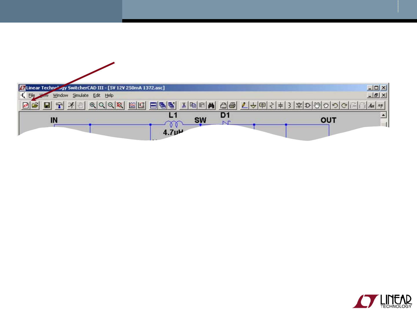
New Schematic
Start with a New Schematic
Left click on the New Schematic symbol in the Schematic Editor Toolbar

© 2008 Linear Technology
11
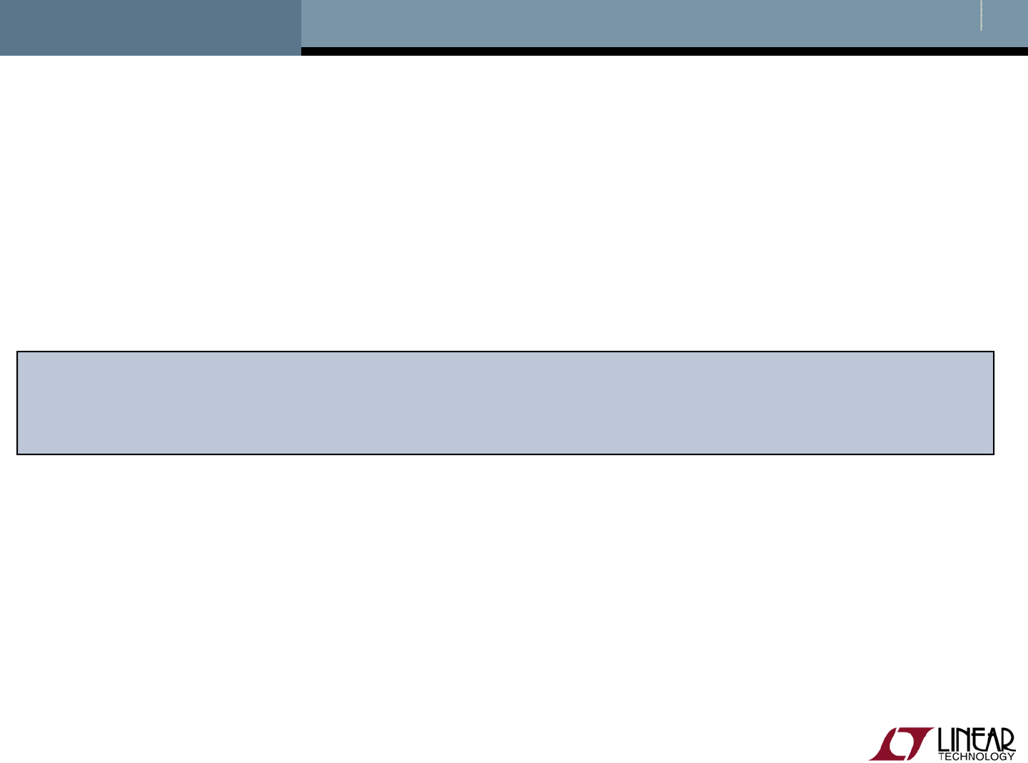
Add a Macromodel & Opening Test Fixture
Add Component
Left click on the Component symbol in
the Schematic Editor Toolbar
Enter “root” part to search for the model
(e.g. 3411)
Left click on Open this macromodel’s
test fixture
To run a test fixture, jump to the Run and
Probe a Circuit in LTspice section
© 2008 Linear Technology
12
Getting Started using SwitcherCAD III/LTspice
Use one of the 100s of demo circuits available on linear.com
Reviewed by Linear Technology’s Factory Applications Group
Use a pre-drafted test fixture (JIG)
Provides a good starting point
Use the schematic editor to create your own design
LTspice contains macromodels for most LTC power devices

Copyright © 2008 Linear Technology. All rights reserved.
Draft a Design Using the
Schematic Editor

© 2008 Linear Technology
14
New Schematic
Start with a New Schematic
Left click on the New Schematic symbol in the Schematic Editor Toolbar
LTspice is also a great
schematic capture
© 2008 Linear Technology
15
Add a Linear Technology Macromodel
Add Component
Left click on the Component symbol in the Schematic Editor Toolbar
Enter “root” part to search for the model (e.g. 3411)
Left click on OK

© 2008 Linear Technology
16
Getting the Latest Datasheet
Use the macromodel’s shortcuts to download the Datasheet
as a reference for your design
Hold Ctrl key and right click (Ctrl – right click) over the LT
macromodel’s symbol
Left click on Go to Linear website for datasheet on the dialog
box that appears
You can also open the macromodel's test fixture as a draft starting point

© 2008 Linear Technology
17
Adding Circuit Elements
To cancel or quit a component type,
click the right mouse button
Rotate
Mirror
Place Diode
Place Inductor
Place Capacitor
Place Resistor
Left click on the desired component in the Schematic Editor Toolbar
Left click on Rotate or Mirror to adjust orientation
Alternate you can also use Ctrl – R and Ctrl – M key shortcuts
Move the mouse to the position you want to place it
Left click to place it

© 2008 Linear Technology
18
Adding Sources, Loads & Additional Circuit Elements
Additional Circuit Elements
Like Sources and Loads
Left click on the Component symbol in
the Schematic Editor Toolbar
Search directory structure for desired
circuit element (e.g. load and voltage)
Left click on OK
Move the mouse to the position you
want to place it
Left click to place it

© 2008 Linear Technology
19
Highlights of Additional Circuit Elements
Left click on the Component symbol in the Schematic Editor Toolbar for a
directory of additional circuit elements:
Arbitrary behavioral source
Voltage dependent voltage
Current dependent current
Voltage dependent current
Current dependent voltage
Independent current source
JFET transistor
Mutual inductance
MOSFET transistor
Lossy transmission line
Bipolar transistor
Voltage controlled switch
Lossless transmission line
Uniform RC-line
Independent voltage source
Current controlled switch
Subcircuit
MESFET transistor
…many more

© 2008 Linear Technology
20
Drawing Lines and Labeling Nodes
Lines
Left click on the Draw Wire in the Schematic Editor Toolbar
Left click a blue box (terminal)
Define the line’s path with a left click over intermediate points
Left click on another blue box (terminal)
Draw Wire
Place Ground
Label Node
Do not forget to place a
ground in your design, it is
required for simulation!
© 2008 Linear Technology
21
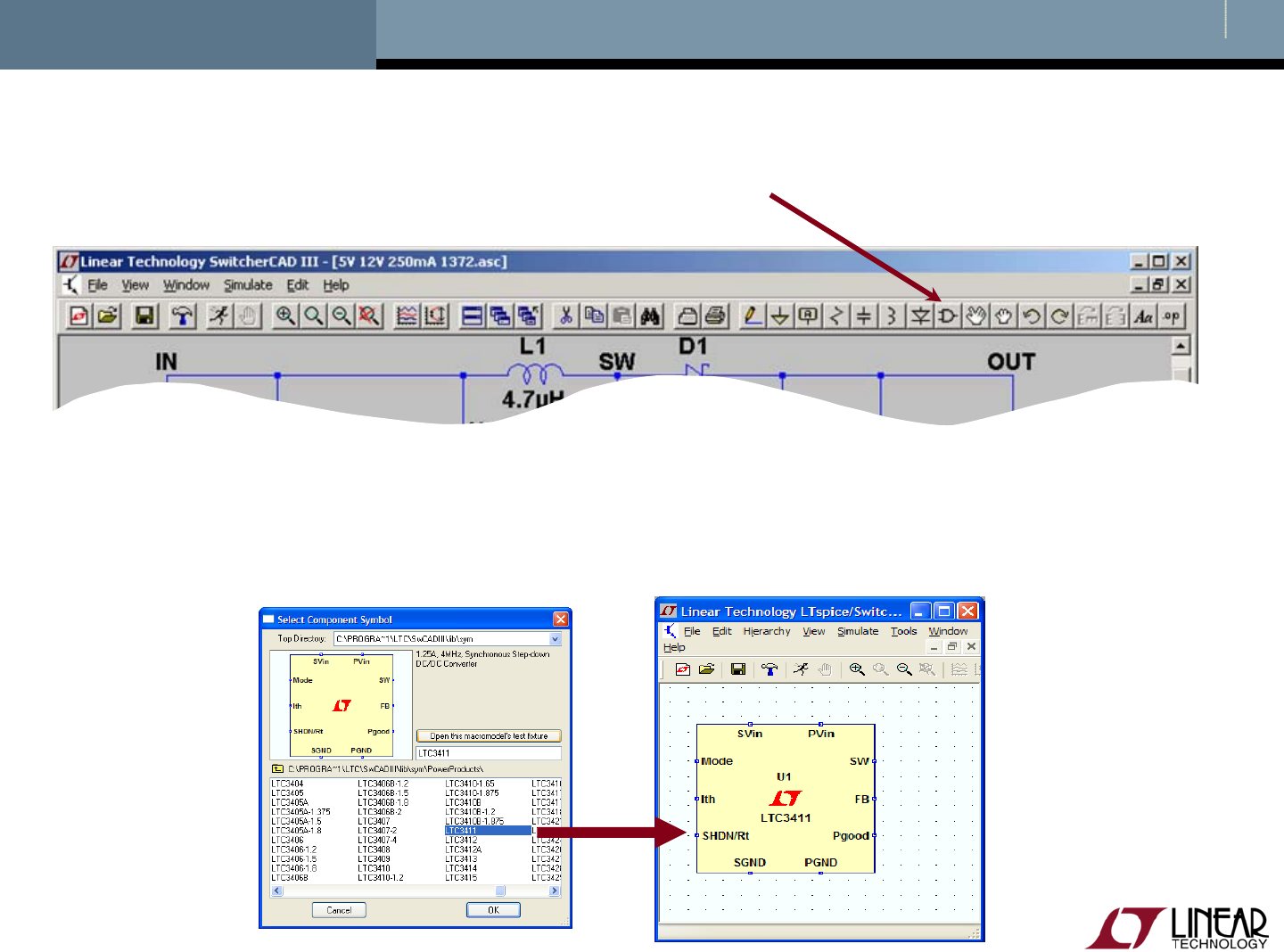
Editing Circuit Elements
To organize your layout, use the Drag option to move circuit
elements around and to adjust lines between terminals
Move
Drag
Undo
Redo
Delete
Duplicate
Left click on the desired editing option
Left click on the circuit element

© 2008 Linear Technology
22
Editing Circuit Elements Attributes
Right click on the component symbol to modify attributes
Right click on the text next to the component to edit the
visible attribute and label
Pointer will turn into a text caret
© 2008 Linear Technology
23
Use Labels to Specify Units in Circuit Elements Attributes
K = k = kilo = 103
MEG = meg = 106
G = g = giga = 109
T = t = terra = 1012
M = m = milli = 10-3
U = u = micro = 10-6
N = n = nano = 10-9
P = p = pico = 10-12
F = f = femto = 10-15
Hints
Use MEG to specify 106, not M
Enter 1for 1 Farad, not 1F
© 2008 Linear Technology
24
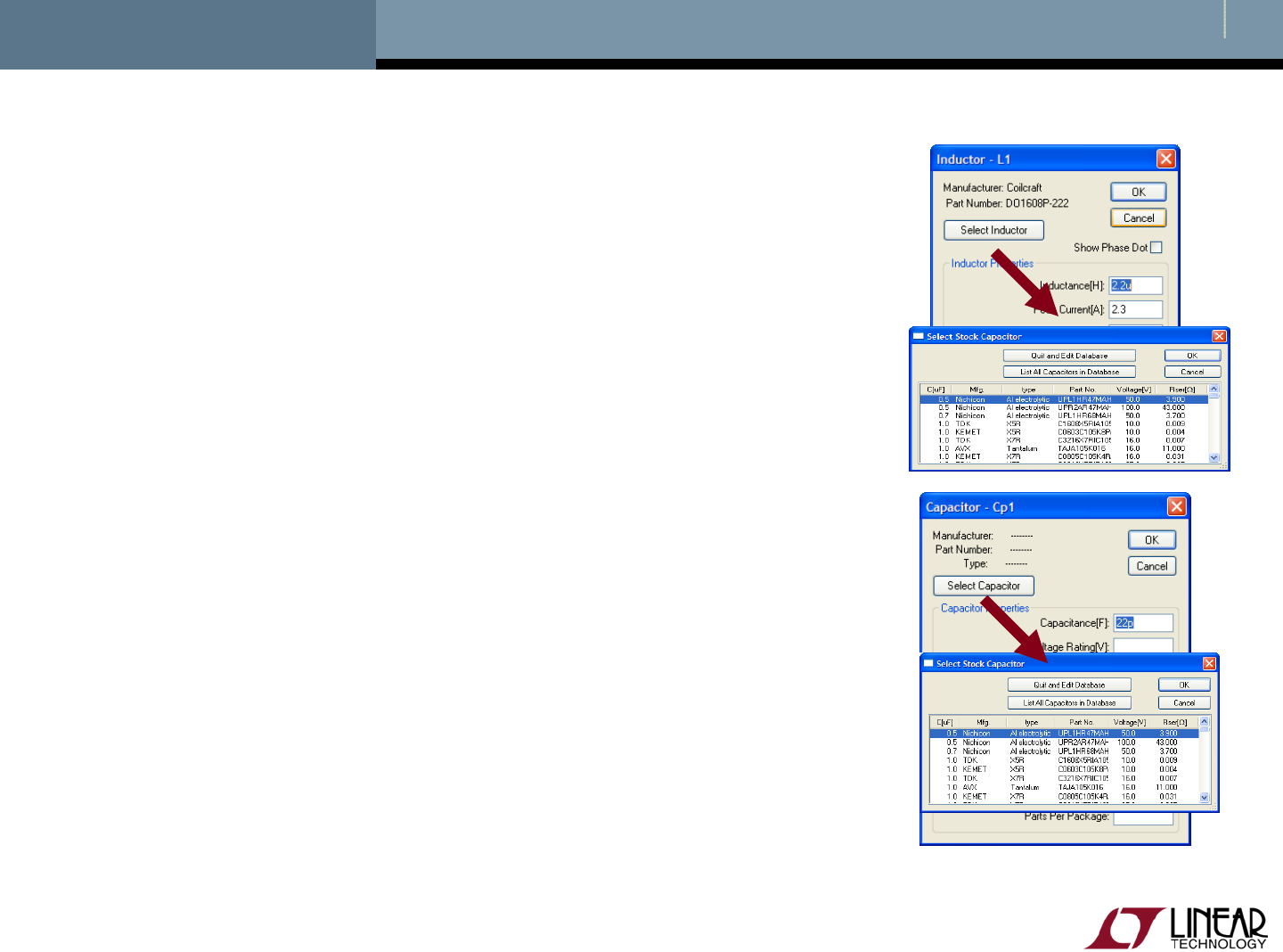
Circuit Elements Database
Some components have an available database of
manufacturers’ attributes
Resistors, capacitors, inductors, diodes,
Bipolar transistors, MOSFET transistors, JFET
transistors
Independent voltage and current sources
To configure a component to a manufacture’s
attributes
Right click on the component symbol
Left click on Select… or Pick New…
Left click on a selected device
Left click on OK
© 2008 Linear Technology
25
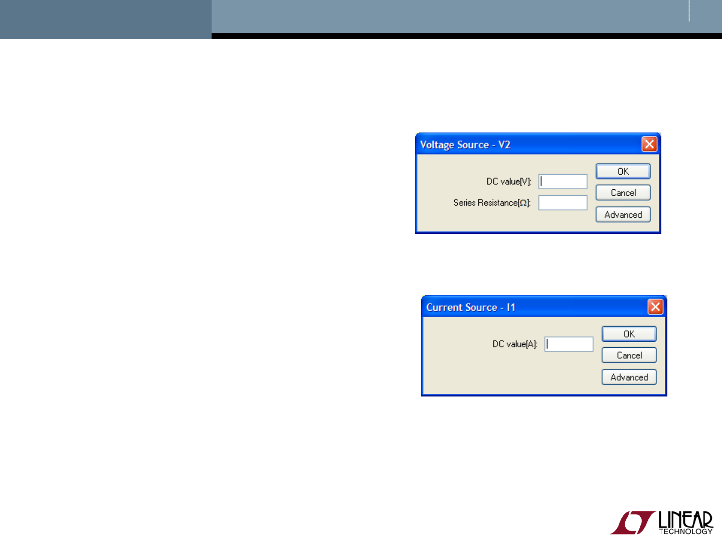
Editing Voltage Sources and Loads
Voltage Source
Right click the voltage
symbol
Enter DC voltage value and
(optional) Series Resistance
Left click on OK
Load (current)
Right click on the load
symbol
Enter DC current value
Left click on OK
© 2008 Linear Technology
26
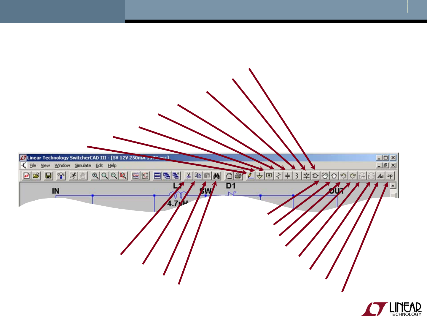
Summary of Schematic Editor Toolbar
Place Circuit Element
Place Diode
Place Inductor
Place Capacitor
Place Resistor
Label Node
Place Ground
Draw Wire
Move
Drag
Undo
Redo
Rotate
Mirror
Place Comment
Place SPICE directive
Delete
Duplicate
Paste b/t Schematics Find
Copyright © 2008 Linear Technology. All rights reserved.
Run and Probe a Circuit

© 2008 Linear Technology
28
Simulation Commands
To run a simulation, specify the type of analysis to be
performed
There are six different types of analyses:
Transient analysis
Small signal AC
DC sweep
Noise
DC transfer function
DC operating point
Simulation commands are placed on the schematic as text
Called dot commands
More information on simulation and dot
commands are available in
SwitcherCAD III/LTspice User Guide
© 2008 Linear Technology
29
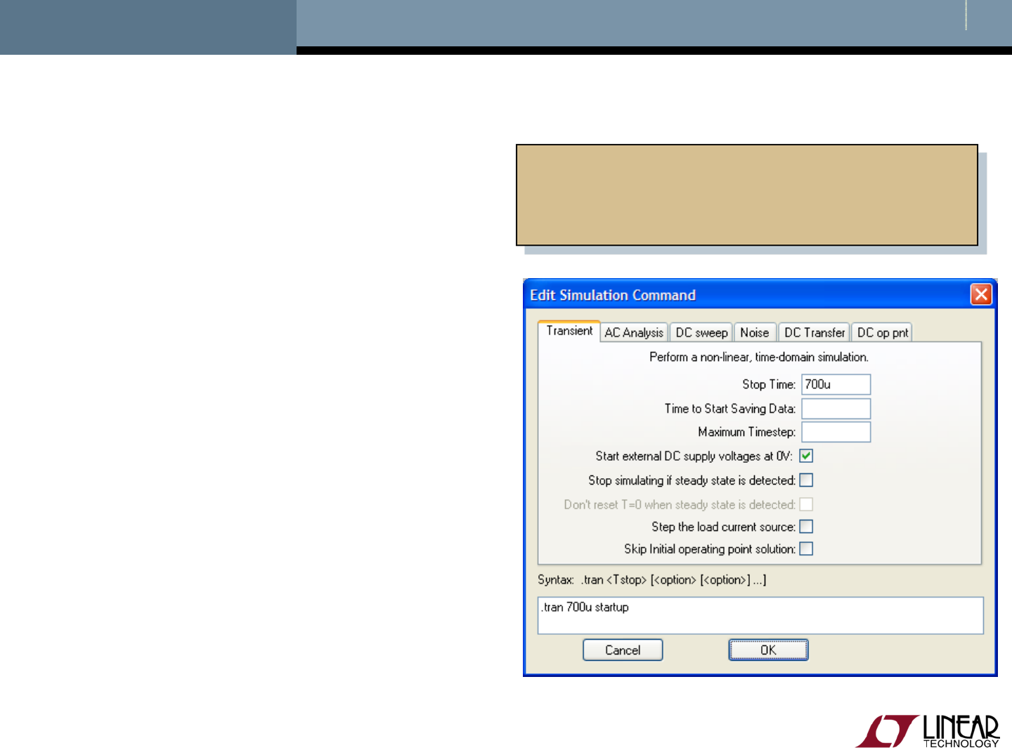
Editing Simulation Commands
Left click on Simulation menu
Left click on Edit Simulation Cmd
As a starting point in a simulation
Left click on Transient tab
Enter a Stop Time
You may need to adjust this
again later
Select OK
Demo Circuits and Test Fixtures
have predefined Simulations
Commands
© 2008 Linear Technology
30
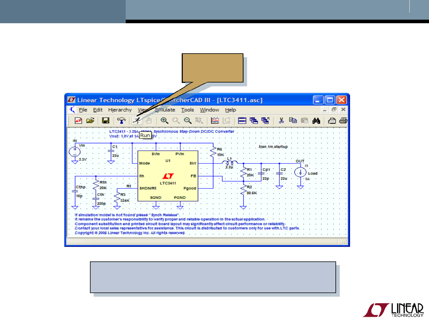
Running a Circuit
Run
If model is not found please Sync Release
under Help menu to update LTspice
© 2008 Linear Technology
31
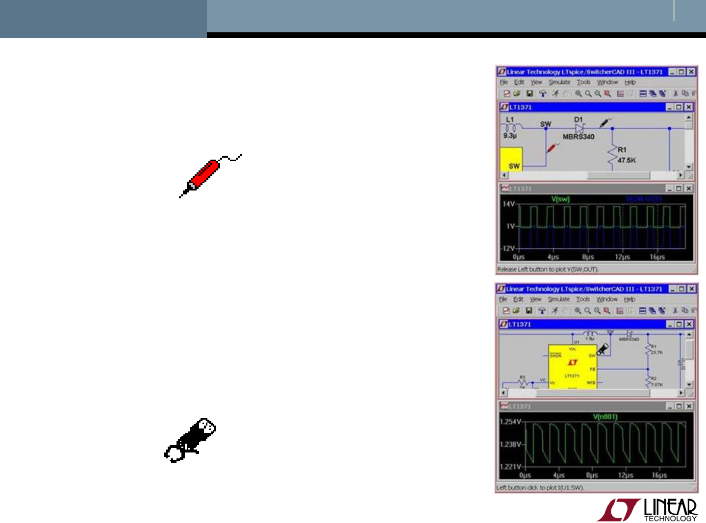
Current probe cursor
Probing a Circuit & Waveform Viewer
Left click on any wire to plot the voltage
on the waveform viewer
Left click on the body of the component
to plot the current on the waveform
viewer
Convention of positive current is in
the direction into the pin
Voltage probe cursor

© 2008 Linear Technology
32
Probing a Demo Circuit and Test Fixture
Demo Circuits and Test Fixtures have INs and OUTs clearly
labeled to help you quickly select them
To view the waveform left click on IN and OUT
Left Click
Here for
Output
Waveform
Left Click
Here for
Input
Waveform

© 2008 Linear Technology
33
Voltage Differences Across Nodes
Left click and hold on one
node and drag the mouse
to another node
Red voltage probe at the first
node
Black probe on the second
Differential voltages are
displayed in the waveform
viewer

© 2008 Linear Technology
34
Plot Planes
Multiple plot panes can be displayed on one window to allow better
separation between traces permitting different traces to be
independently autoscaled
Right click in the waveform pane
Select Add Plot Pane
Left click and hold to drag a label to a new plot pane

© 2008 Linear Technology
35
Zooming In and Out in the Waveform Viewer
To zoom in
Left click and hold as you
drag a box about the region
you wish to zoom in then
release
To zoom out
Right click and select Zoom
to Fit or Zoom Back
Zoom In
Pan
Zoom Out
Autoscale
© 2008 Linear Technology
36
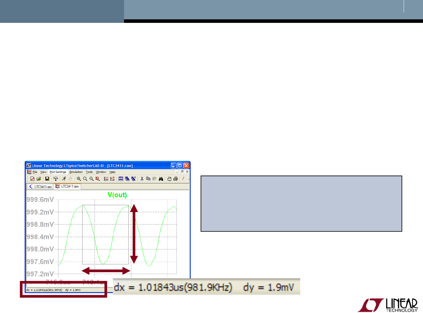
Measuring VRipple, IRipple and Time (Frequency)
Drag a box about the region you wish to measure (peak to peak
over a period)
Left click and hold to drag a box over the portion of interest
View the lower left hand side of the screen
To avoid resizing, shrink your box before you let go of the left mouse
click or use the Undo command in the Edit menu
To view SMPS voltage ripple you will
need to zoom into a narrow section
since waveform is initially
compressed to full range

© 2008 Linear Technology
37
Average/RMS Current or Voltage Calculations
Hold down Ctrl and left click on the I or V trace label in the
waveform viewer
© 2008 Linear Technology
38
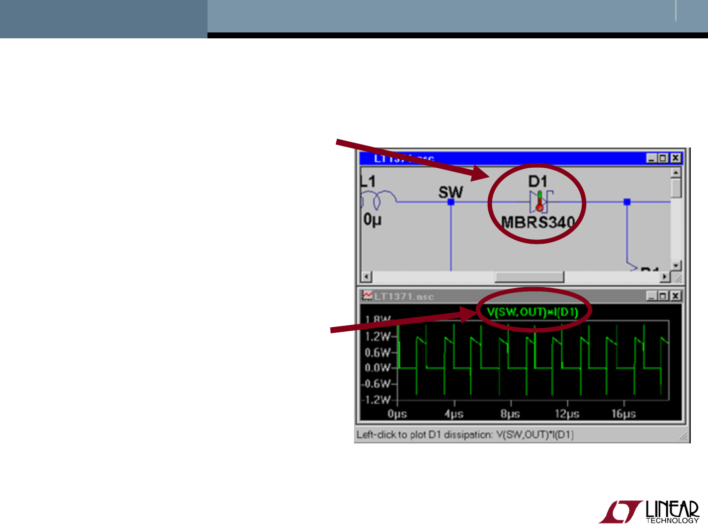
Instantaneous & Average Power Dissipation
Instantaneous Power Dissipation
Hold down the ALT key and
left click on the symbol of the
component
Pointer will change to a
thermometer
Plotted in units of Watts
Average Power Dissipation
Hold down the Ctrl key and
left click on the trace label
power dissipation waveform

Copyright © 2008 Linear Technology. All rights reserved.
Generating a BOM and
Efficiency Report
© 2008 Linear Technology
40
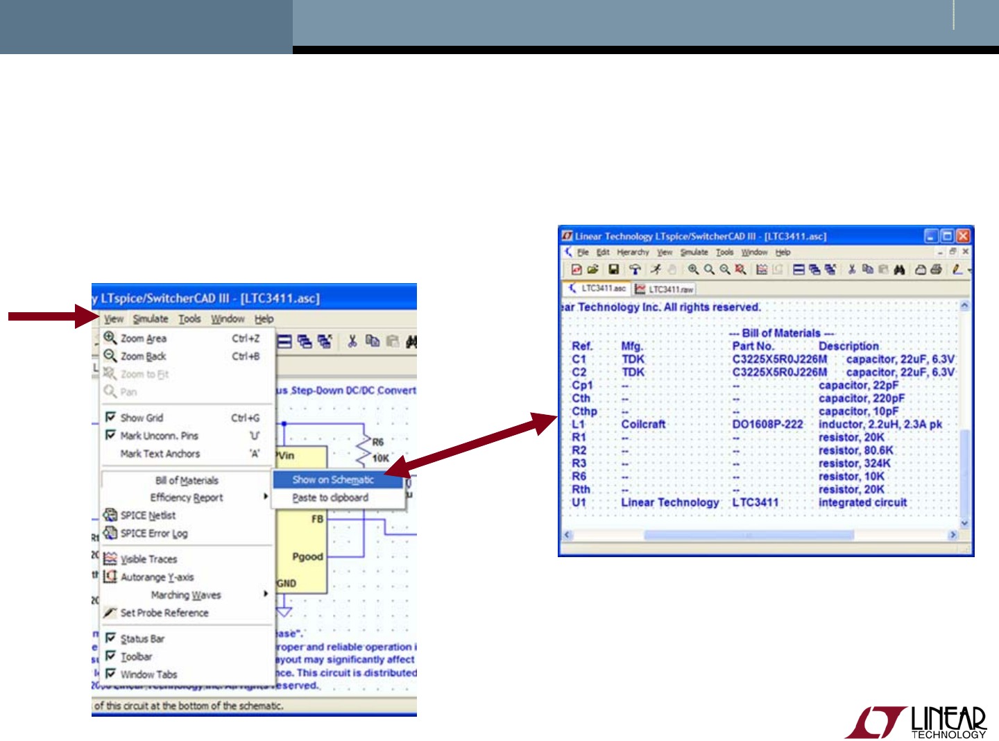
Bill of Materials (BOM)
Left click on View menu
Left click on Bill of Materials

© 2008 Linear Technology
41
Computing Efficiency of SMPS Circuits
Left click on Simulate menu
Left click on Edit Simulation Cmd
Left click on Stop simulating if steady state is detected
Automatically detect the steady state by checking the internal
state of the macromodels
Rerun simulation Automatic detection of steady state
may not work – steady state detection
may be too strict or lenient
© 2008 Linear Technology
42
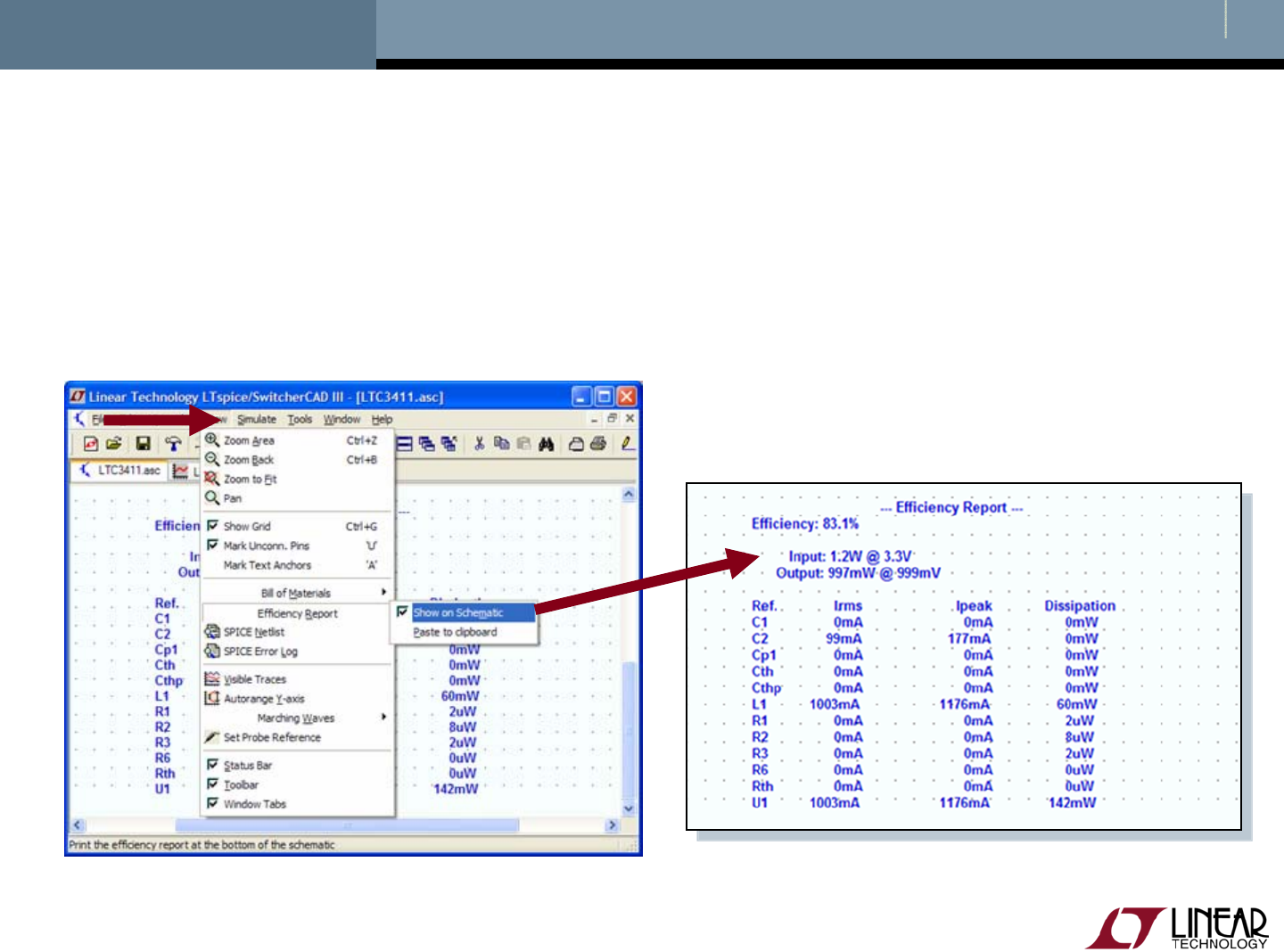
Viewing Efficiency Report
Left click on Simulate menu
Left click on Efficiency Report

Copyright © 2008 Linear Technology. All rights reserved.
Simulate a Transient Response
in a SMPS
Advanced Topic
© 2008 Linear Technology
44
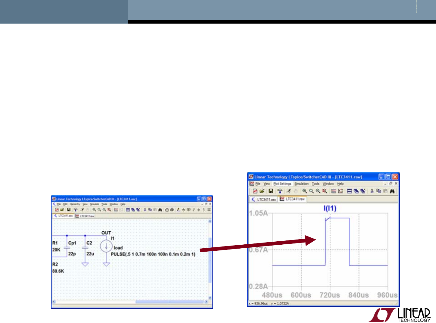
Use a Pulsed Function as a Transient Response Load
Insert a current source load
Left click on the Component symbol in the Schematic Editor Toolbar
Select load (or load2) circuit element and configure as pulsed
Left click on OK
Configure load as a pulsed function (covered next)
Steps current from initial to pulsed value and back
Run and review results
© 2008 Linear Technology
45
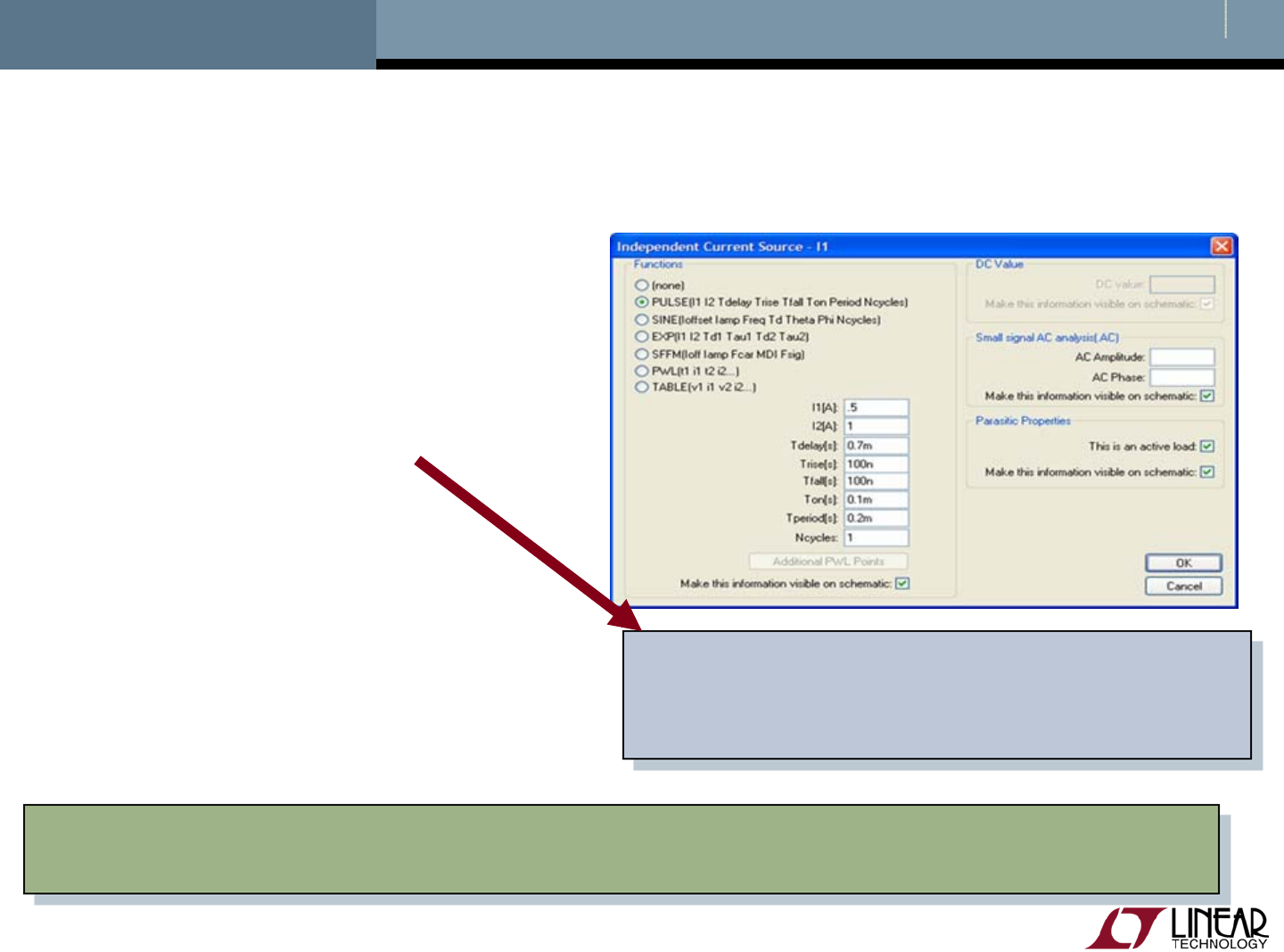
Configuring Load as a Pulse Function
Right click on the load (or load2) component
Select Pulse
Modify the Attributes
I1 = Initial value
I2 = Pulsed Value
Tdelay = Delay
Tr = Rise time
Tf = Fall time
Ton = On time
Tperiod = Period
Ncycles = Number of cycles
Omit for free running
Tdelay needs to be adequate so that
the device is in steady state and out
of startup before the load step occurs
You may need to un-click Stop simulating if steady state is detected
and specify an end time in Edit Simulation Cmd under the Simulate menu

Copyright © 2008 Linear Technology. All rights reserved.
Simulate a Transformer
Advanced Topic
© 2008 Linear Technology
47
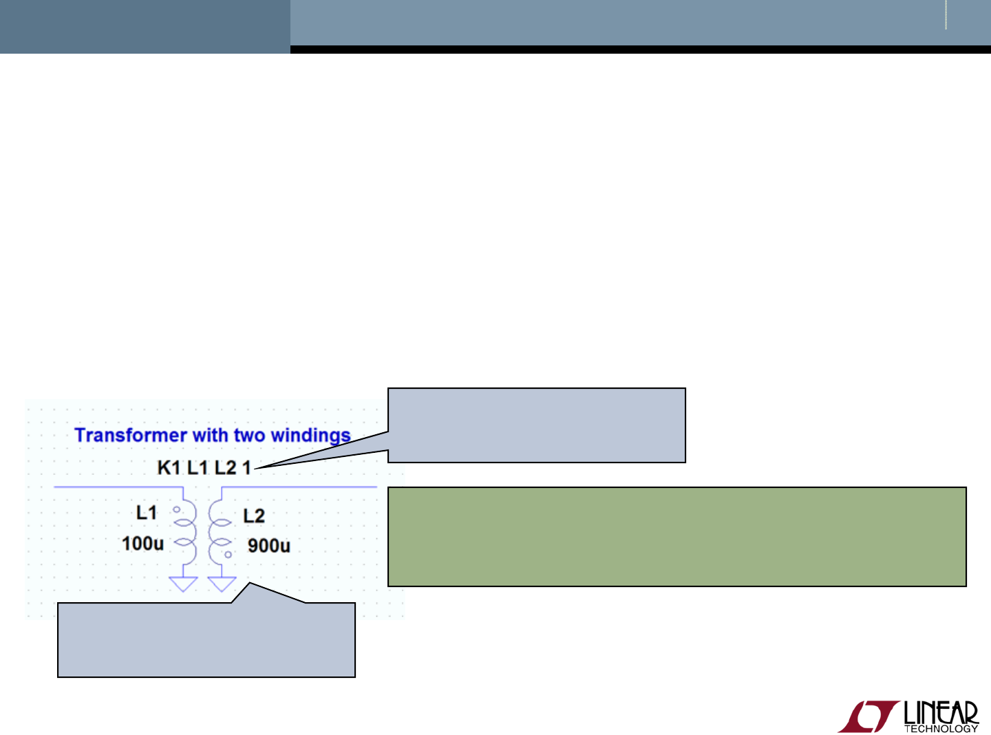
Simulating a Transformer
Draw each winding of the transformer as an individual inductor
Couple inductors with a mutual inductance statement
Add a SPICE directive of the form K1 L1 L2 L3 ... 1 to the schematic
Left Click on Edit then SPICE Directive
Inductors in a mutual inductance will be drawn with a phasing dot
Start initially with a mutual coupling coefficient equal to 1
K statement coupling
the windings
1:3 turns ration gives
a 1:9 inductance ratio Note: winding inductance ratio is
the square of the turns ratio
For more information check out LTC1871
demo circuit and page 23-24 of September
2006 LT Magazine at www.linear.com

Copyright © 2008 Linear Technology. All rights reserved.
Additional Information and
Support
© 2008 Linear Technology
49
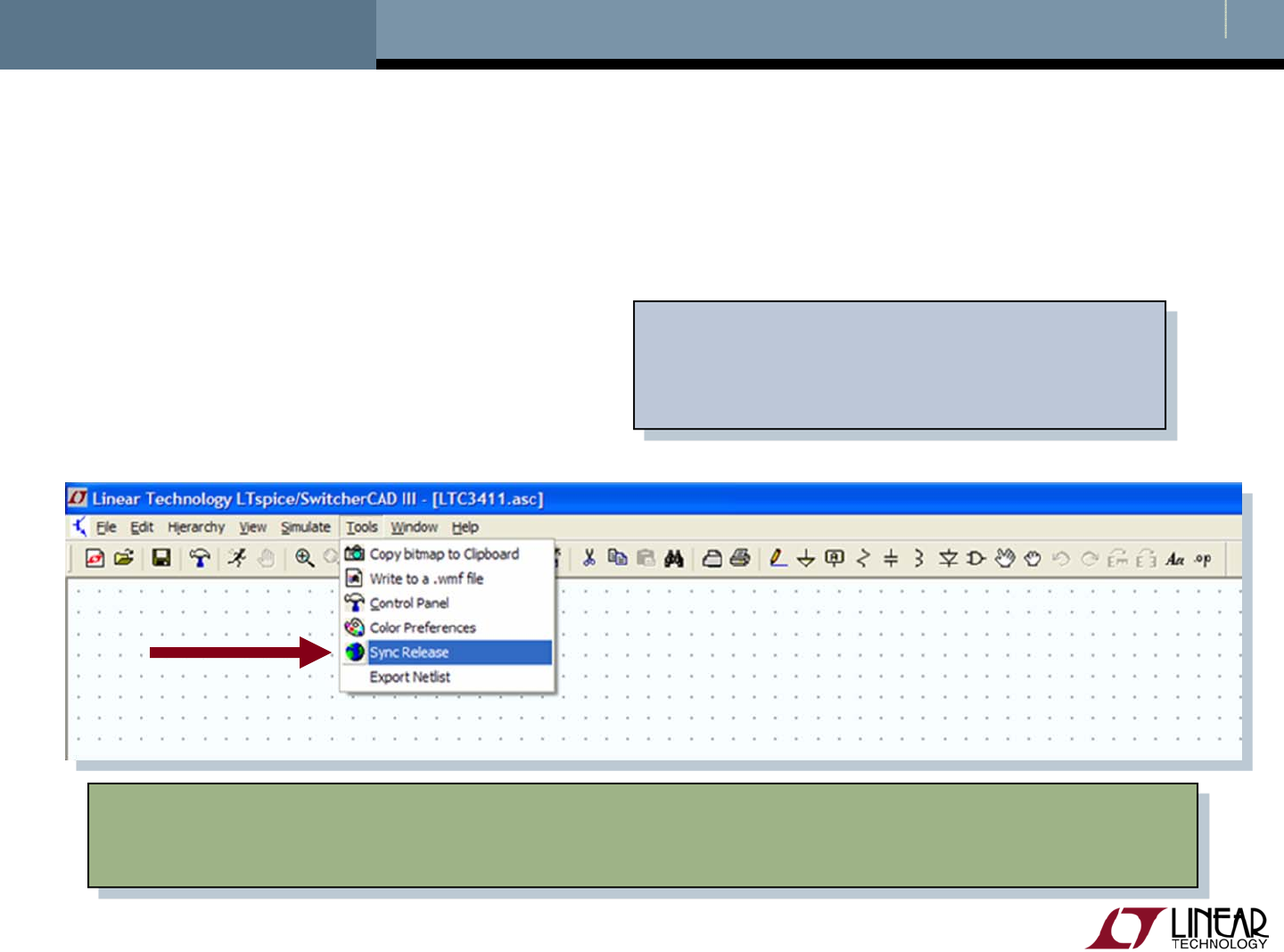
Reminder to Periodically Sync Release
Update your release of LTspice to get the latest
Software updates
Models and examples Sign up for Linear Insider via
MyLinear (www.linear.com) for
email news and updates
List of changes are available in the changelog.txt that is located in
your LTspice root directory (C:\Program Files\LTC\SwCADIII)

© 2008 Linear Technology
51
Emailing Comments and Signing up for Linear Insider

© 2008 Linear Technology
52
Customer Support
Linear Technology customers can obtain support by
Calling your local field applications engineer
http://www.linear.com/contact/
Calling +1 (408) 432 – 1900 for factory application support
Additional support (not related to Linear Technology circuits
or models support)
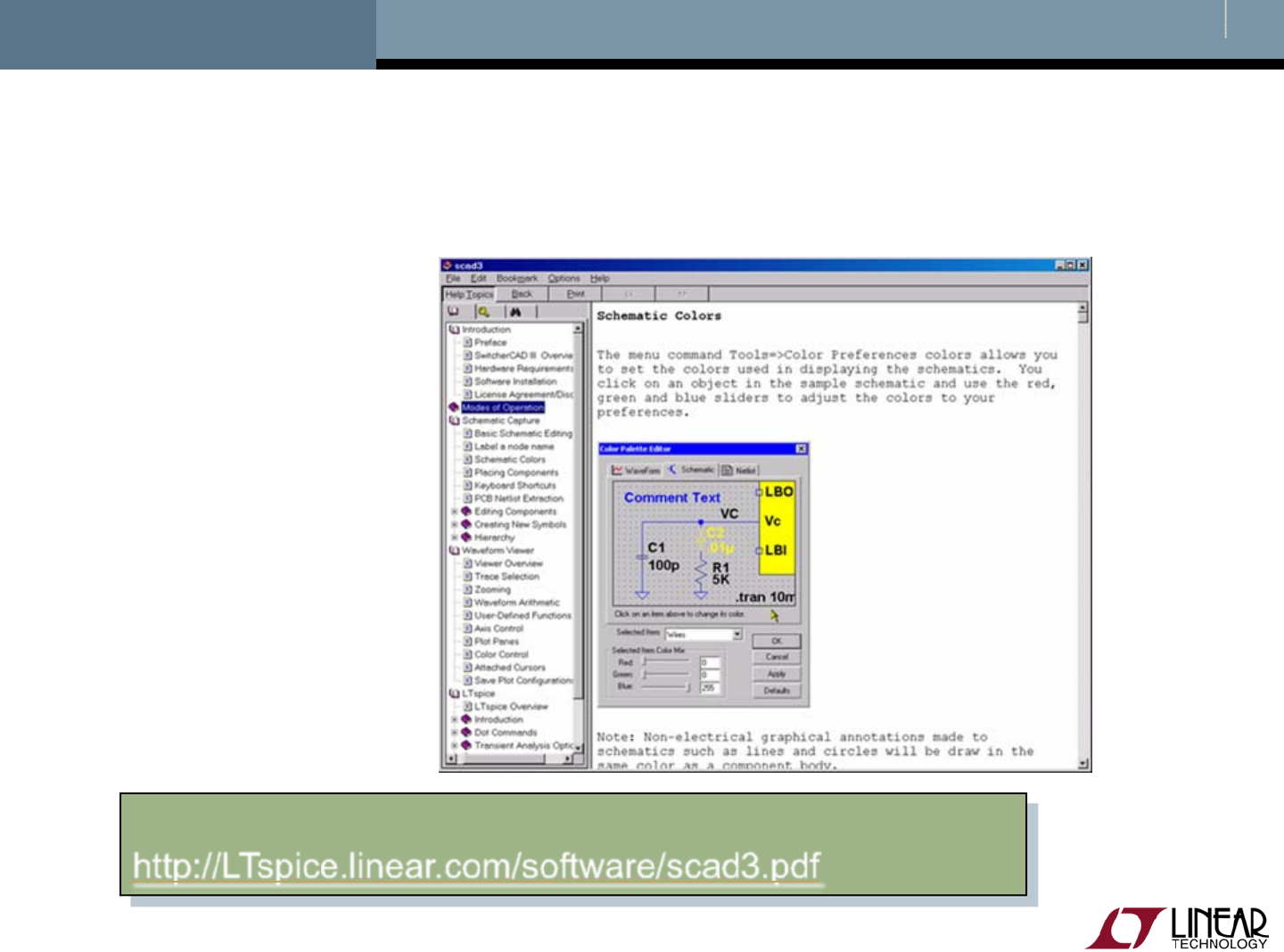
Built-in help topics & User Manual
Independent LTspice users’ group (search messages)
Simulation with the supplied models is fully supported
All bug reports are appreciated and will be resolved
© 2008 Linear Technology
53
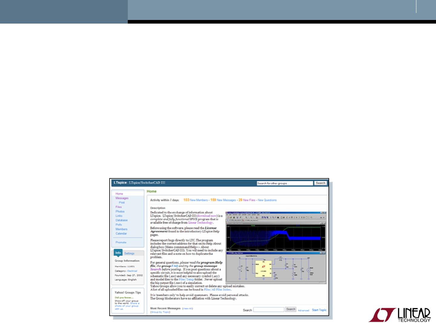
Independent LTspice Users’ Group
The group has a section of files and messages with
additional tutorials, libraries, and examples
http://groups.yahoo.com/group/LTspice/
Join LTspice Users’ Group
Email LTspice-subscribe@yahoogroups.com
Subject=Subscribe
