Lab Gruppen Lake LM44
User Manual: LabGruppen Lake LM44
Open the PDF directly: View PDF ![]() .
.
Page Count: 71
Operation Manual
Lake® LM Series
Digital Audio Processors
Rev 1.3.5
Item: OM-LM
Operation Manual

Important Safety Instructions
i
Lake LM Series Operation Manual Rev 1.3.5
1. Important Safety Instructions
Before using the device, be sure to carefully read the Safety Instructions. Keep this document with the device at all times.
1.1 Important Safety Instructions
1. Read these instructions.
2. Keep these instructions.
3. Heed all warnings.
4. Follow all instructions.
5. Do not use this apparatus near water.
6. Clean only with a dry cloth.
7. Do not block any ventilation openings. Install in accordance
with the manufacturer’s instructions.
8. Do not install near any heat sources such as radiators, heat
registers, stoves, or other apparatus (including ampliers)
that produce heat.
9. Do not defeat the safety purpose of the polarized or
grounding-type plug. A polarized plug has two blades with
one wider than the other. A grounding-type plug has two
blades and a third grounding prong. The wide blade or
the third prong is provided for your safety. If the provided
plug does not t into your outlet, consult an electrician for
replacement of the obsolete outlet.
10. Protect the power cord from being walked on or pinched,
particularly at plugs, convenience receptacles, and the point
where they exit from the apparatus.
11. Only use attachments/accessories specied by the
manufacturer.
12. Use only with a cart, stand, tripod, bracket, or table specied
by the manufacturer, or sold with the apparatus. When a
cart is used, use caution when moving the cart/apparatus
combination to avoid injury from tip-over.
13. Unplug this apparatus during lightning storms or when
unused for long periods of time.
14. Refer all servicing to qualied service personnel. Servicing
is required when the apparatus has been damaged in any
way, such as power-supply cord or plug is damaged, liquid
has been spilled or objects have fallen into the apparatus, the
apparatus has been exposed to rain or moisture, does not
operate normally, or has been dropped.
15. Use the mains plug to disconnect the apparatus from the
mains.
16. WARNING: To reduce the risk of re of electric shock, do not
expose this apparatus to rain or moisture.
17. Do not expose this equipment to dripping or splashing and
ensure that no objects lled with liquids, such as vases, are
placed on the equipment.
18. The mains plug of the power supply cord shall remain readily
operable.
19. Do not connect the unit’s output to any other voltage source,
such as battery, mains source, or power supply, regardless
of whether the unit is turned on or off.
20. Do not remove the top (or bottom) cover. Removal of the
cover will expose hazardous voltages. There are no user
serviceable parts inside and removal may void the warranty.
21. An experienced user shall always supervise this professional
audio equipment, especially if inexperienced adults or
minors are using the equipment.
22. The US National Differences clause 16.3 requires that
network cables must be ame rated VW-1.
To prevent electric shock do not remove top or bottom covers.
No user serviceable parts inside, refer servicing to qualied
service personnel.
À prévenir le choc électrique n’enlevez pas les couvercles. Il n’y a
pas des parties serviceable à l’intérieur, tous reparations doit etre
faire par personnel qualié seulment.
To completely disconnect this equipment from the AC mains,
disconnect the power supply cord plug from the AC receptacle.
The mains plug of the power supply cord shall remain readily
operable.
Pour démonter complètement l’équipement de l’alimentation
générale, démonter le câble d’alimentation de son réceptacle. La
prise d’alimentation restera aisément fonctionnelle.
1.2 Standards
This equipment conforms to the require-
ments of the EMC Directive 2004/108/EC
and the requirements of the Low Voltage
Directive 2006/95/EC.
Standards applied: EMC Emission
EN55103-1, E3
EMC Immunity EN55103-2, E3, with S/N
below 1% at normal operation level.
Electrical Safety EN60065, Class I
This equipment is tested and listed accord-
ing to the U.S. safety standard ANSI/ UL
60065 and Canadian safety standard CSA
C22.2 NO. 60065. Intertek made the tests
and they are a Nationally Recognized Test-
ing Laboratory (NRTL).
1.3 Explanation of Graphical Symbols
The lightning bolt triangle is used to alert the user to
the presence of un-insulated “dangerous voltages”
within the unit’s chassis that may be of sufcient
magnitude to constitute a risk of electric shock to
humans.
The exclamation point triangle is used to alert the
user to presence of important operating and service
instructions in the literature accompanying the
product.
ii
Important Safety Instructions
Lake LM Series Operation Manual Rev 1.3.5
1.4 WARNING
To reduce risk of re or electric shock, do not expose this apparatus to rain or moisture.
Pour réduire les risques de blessure ou le choc électrique, n’exposez pas l’appareil à la pluie ou à l’humidité.
Do not expose this system/apparatus to dripping or splashing and ensure that no objects lled with liquids, such
as vases, are placed on the apparatus.
L’appareil ne doit pas être exposé à des egouttements d’eau ou des éclaboussures et de plus qu’aucun objet
rempli de liquide tel que des vases ne doit pas être placé sur l’appareil.
This apparatus must be connected to a mains socket outlet with a protective earthing connection.
Cet appareil doi t être raccordé á une prise de courant qui est branchée à la terre.
The mains plug is used as a disconnect device and shall remain readily operable.
Lorsque la prise du réseau d’alimentation est utilisés comme dispositif de déconnexion, ce dispositif doit
demeuré aisément accessible.
1.5 CAUTION
To reduce the risk of re or electric shock, do not remove screws. No user-serviceable parts inside.
Refer servicing to qualied service personnel.
Pour réduire le risque d’incendie ou de choc électrique, ne pas retirer les vis. Aucune pièce réparable par
l’utilisateur. Coner l’entretien àpersonnel qualié.
1.6 FCC Compliance Notice (Radio Interference)
A sample of this product has been tested and complies with the limits for the European Electro Magnetic
Compatibility (EMC) directive. This equipment has also been tested and found to comply with the limits for a
Class A digital device, pursuant to Part 15 of the FCC Rules. These limits are designed to provide reasonable
protection against harmful interference from electrical equipment. This product uses radio frequency energy
and if not used or installed in accordance with these operating instructions, may cause interference to other
equipment, such as radio receivers.
This Class A digital apparatus complies with Canadian ICES-003.
Cet appareil numérique de la classe A est conforme à la norme NMB-003 du Canada.
However, there is no guarantee that interference will not occur in a particular installation. If this equipment
does cause harmful interference to radio or television reception, which can be determined by turning the
equipment on and off, the user is encouraged to try to correct the interference by one or more of the
following measures:
▸Reorient or relocate the antenna.
▸Increase the separation between the equipment and receiver.

Important Safety Instructions
iii
Lake LM Series Operation Manual Rev 1.3.5
▸Connect the equipment to an outlet on a circuit different from that to which the receiver is connected.
▸Check if the affected unit complies with the EMC limits for immunity, (CE-labeled). If not, address the
problem with the manufacturer or supplier. All electrical products sold in the EC must be approved for
immunity against electromagnetic elds, high voltage ashes, and radio interference.
▸Consult the dealer or an experienced radio/TV technician for help.
1.7 User Responsibility
1.7.1 Mains Connection Grounding
Your apparatus must be connected to a grounded socket outlet.
1.7.2 Maintenance
For safe and reliable operation, the dust lter on the right-hand side air intake should be removed and
cleaned regularly to ensure maximum airow through the device.
If the dust lter is not maintained there will be safety risks; for example, high internal temperatures
could ignite the dust and start a re. There is also a risk that the unit will malfunction since it is dependent
on constant airow from right to left. If the dust lter is not clean and the unit malfunctions, any resulting
problems will not be covered by the warranty.

iv
Lake LM Series Operation Manual Rev 1.3.5
Table of Contents
1. Important Safety Instructions ................................................................................................................i
1.1 Important Safety Instructions ............................................................................................................... i
1.2 Standards .............................................................................................................................................. i
1.3 Explanation of Graphical Symbols ......................................................................................................... i
1.4 WARNING ............................................................................................................................................ ii
1.5 CAUTION ............................................................................................................................................. ii
1.6 FCC Compliance Notice (Radio Interference) ....................................................................................... ii
1.7 User Responsibility ..............................................................................................................................iii
2. Welcome ...................................................................................................................................................1
2.1 Introduction .........................................................................................................................................1
2.2 Main Features ......................................................................................................................................1
2.3 Additional Documentation .................................................................................................................... 2
3. Installation ................................................................................................................................................3
3.1 Unpacking ............................................................................................................................................3
3.2 Mounting .............................................................................................................................................. 3
3.3 Cooling .................................................................................................................................................3
3.4 Operating Voltage ................................................................................................................................4
3.5 Grounding .............................................................................................................................................4
4. Product Overview .................................................................................................................................... 5
4.1 Front Panel Overview ...........................................................................................................................5
4.2 Back Panel Overview ...........................................................................................................................8
5. Signal Flow and Lake Processing ........................................................................................................ 11
5.1 Signal Flow ........................................................................................................................................ 11
5.2 Level Adjustments & Mute Points ..................................................................................................... 12
5.3 Lake Processing and Control .............................................................................................................. 13
5.4 Modules and Frames ........................................................................................................................ 13
5.5 Loudspeaker Processor (Contour Mode) Overview ........................................................................... 14
5.6 System Equalizer (Mesa Mode) Overview ......................................................................................... 14
5.7 Switching between Contour and Mesa Mode ................................................................................... 15
5.8 Files and Presets ................................................................................................................................ 15
6. Front Panel Interface .............................................................................................................................16
6.1 O ver view ............................................................................................................................................ 16
6.2 Front Panel Key Lock .......................................................................................................................... 17
6.3 Power Button .................................................................................................................................. 17
6.4 Meter Button ...................................................................................................................................... 18
6.5 Menu Button ...................................................................................................................................... 18
6.6 Exit Button ........................................................................................................................................ 18
6.7 Dynamic Buttons, Controls and LEDs ................................................................................................ 18

v
Lake LM Series Operation Manual Rev 1.3.5
6.8 Module I/O Mute Buttons and LED Meters .......................................................................................21
6.9 Meter Mode .......................................................................................................................................23
6.10 Menu Mode .......................................................................................................................................25
7. Back Panel Interface ..............................................................................................................................42
7.1 Analog Inputs and Outputs ................................................................................................................42
7.2 AES3 Digital I/O ................................................................................................................................44
7.3 RJ45 etherCON Network Connections ..............................................................................................45
7.4 GPIO Connection ............................................................................................................................... 47
7.5 Universal Power Supply Connection .................................................................................................48
8. Appendix ................................................................................................................................................. 49
8.1 Faults and Warnings Overview ..........................................................................................................49
8.2 Maintenance ......................................................................................................................................50
8.3 Factory Default Settings.....................................................................................................................50
8.4 Glossary of Terms, Acronyms and Abbreviations ..............................................................................51
9. Application Guide ..................................................................................................................................54
9.1 Gain Structure ....................................................................................................................................54
9.2 Gain / Level Optimization ...................................................................................................................55
9.3 Digital Audio Connections ..................................................................................................................55
9.4 Digital Clock Conguration .................................................................................................................57
9.5 Signal Processing Latency .................................................................................................................59
10. Technical Specications .......................................................................................................................61
11. Warranty and Support ..........................................................................................................................62
11.1 General .............................................................................................................................................. 62
11.2 International Warranties .....................................................................................................................62
11.3 Technical Assistance and Service ......................................................................................................62
11.4 Trademarks .........................................................................................................................................63

Welcome
1
Lake LM Series Operation Manual Rev 1.3.5
2. Welcome
2.1 Introduction
Thank you for choosing the Lake LM Series of Digital Audio Processors. We are condent that you will be
pleased with the performance, unique features, conguration exibility, reliability, and long-term durability
offered by this product.
For fast installation and use of this product, your welcome package includes a printed copy of the LM Series
Quick Start & Field Reference Guide which contains the information required to safely install the product and
place it in service. Control and editing features are accessible via the front panel interface or via the included
Lake Controller software.
It is recommended that the Quick Start & Field Reference Guide and all product documentation on the
included CD-ROM / USB key is reviewed to ensure familiarity with the various conguration and control
options.
Thank you again for placing your condence in Lake products.
2.2 Main Features
The LM Series incorporates a number of sophisticated technologies to ensure the best possible perfor-
mance and many years of reliable operation. The following section summarizes the benets of each feature;
additional information is available in the reference manuals.
2.2.1 Lake Processing and Controller
LM Series devices integrate seamlessly into the Lake Processing environment and are accessible via the
Lake Controller software. Processing modules offer precise settings for gain, delay, crossover settings,
equalization and limiting. Lake processing features incorporated in each module include Raised Cosine
Equalization™, linear phase crossovers, and LimiterMax™ loudspeaker protection. The Super Module feature
allows hardware processing modules in two or more separate devices to function as a single module in the
Lake Controller software. Please refer to the Lake Controller Operation Manual for further information.
2.2.2 Analyzer Plug-In
Lake Controller software provides integration with third-party real-time analyzers, providing simultaneous
measurement display and EQ adjustment via the Lake Controller. Approved analyzers include Rational
Acoustics Smaart 7, SysTune from AMFG, and WaveCapture Live‐Capture Light or Live-Capture Pro; ad-
ditional third-party analyzers may be approved in the future.
Please refer to the Lake Controller Operation Manual for further information regarding the Analyzer plug-in
and associated functionality.

2
Welcome
Lake LM Series Operation Manual Rev 1.3.5
2.2.3 Dante™ Audio Network
LM Series devices include Dante digital audio networking as standard. Utilizing the latest advances in
Ethernet technology, Dante offers simplied system conguration and extremely low latency while deliver-
ing very high quality uncompressed digital audio across the Lake network. The Zen™ automatic conguration
feature enables plug-and-play setup without third-party DHCP or DNS servers. Dante is compatible with
high-bandwidth networks, allowing large numbers of audio channels to be distributed alongside control and
analyzer data.
2.3 Additional Documentation
This document, the Lake LM Series Operation Manual, serves as the primary reference source for detailed
information on the installation and operation of LM Series devices. It also provides detailed information on
set-up and conguration using the front-panel interface.
If you intend to use the device as part of a networked system, or access features via the Lake Controller,
please refer to the various supporting documents which can be located via these methods:
▸Start > Programs > Lake Controller > Documentation (after installing Lake Controller software)
▸On the included installer CD-ROM / USB key, or via the downloaded software installer
▸Online at: http://labgruppen.com/products/documentation/

Installation
3
Lake LM Series Operation Manual Rev 1.3.5
3. Installation
3.1 Unpacking
Carefully open the shipping carton and check for any damage to the device or the supplied accessories.
Every Lake product is tested and inspected before leaving the factory and should arrive in perfect condition.
If any damage is discovered, please notify the shipping company immediately. Only the consignee may
initiate a claim with the carrier or their insurers for damage incurred during shipping. Save the carton and
packing materials for the carrier’s inspection.
In addition to the Lake LM Series device, the shipping carton include the following items:
▸Lake LM Series Quick Start & Field Reference Guide
▸AC mains lead (IEC power cable) with locking connector
▸AES break-out cable (8-in, 8-out)
▸Ethernet Cable
▸Software Installer and Documentation CD-ROM or USB key
Please keep the original carton and associated packaging to facilitate shipping of the device should the need
arise.
3.2 Mounting
Airow for cooling the device is from side to side (right-side intake to left-side fan). Please ensure there is
sufcient space on each side of the unit to allow airow; the space provided by standard rack-rails should
be sufcient. This device has no top or bottom vents and therefore may be stacked directly on top of each
other.
Sufcient space should be available at the front of the rack to accommodate the handles, and at the rear to
accommodate connectors and cables; allowance must be made for cable or loom bends within a rack.
3.3 Cooling
The Lake LM Series devices use a forced-air cooling system, with airow from right to left. The dust lter
on the air intake (right-side) should be regularly cleaned, especially after exposure to dusty environments, to
ensure the maximum possible airow through the unit.
This device is designed to operate in situations where the ambient temperature is below 55oC (131oF).
Automatic actions and warnings occur at following temperature thresholds:
▸At 40oC (104oF) or less, the fan is OFF
4
Installation
Lake LM Series Operation Manual Rev 1.3.5
▸At more than 40oC (104oF) the fan is ON
▸At 55oC (131oF) a temperature warning is indicated on the front panel as ‘TEMP WARNING’ and in the
Controller Event Log as ‘Temp warning: DSP area’.
▸At 70oC (158oF) the device has exceeded the maximum normal operating temperature. This fault is
indicated on the front panel as ‘OVERTEMP’ and in the Controller Event Log as ‘Temp fault: DSP area’.
The Processor will NOT mute or shut down when the
temperature reaches or exceeds 70 oC (158 oF), however,
sustained performance at this temperature cannot be
guaranteed.
3.4 Operating Voltage
The label above the IEC connector indicates the AC mains voltage range for which the device is approved.
LM Series devices utilize a universal power supply, and will operate within the range 70-265V~50-60Hz :
25W. If the plug on the IEC cable provided is not appropriate for your country, a locally-sourced IEC cable
with the appropriate molded plug should be used. A locking IEC cable is not necessary in order to power
the device, although is essential if locking functionality is required. Once a suitable AC power supply is
connected, the device can be turned on using the front panel power button. When the device is turned on,
the power button LED changes from red (Standby) to green (Active).
3.5 Grounding
Analog inputs and outputs feature Iso-Float™ ground isolation, a technology which combines the benets of
transformer-coupled isolation with the advantages of clean, direct-coupled inputs and outputs.
The audio converters are galvanically isolated, and not connected to mains ground. High-speed transformers
and opto-isolators create a barrier between the device and the outside electrical environment.
The Iso-Float feature is activated by default, but may
be disabled via the Lake Controller software, or via
the front panel menu.
Use correctly-shielded balanced audio input connections to minimise hum and interference. Please refer to
section 7.1.5 for further information.
NEVER disconnect the earth (ground) pin on the mains cable (AC power cord).
Product Overview
5
Lake LM Series Operation Manual Rev 1.3.5
4. Product Overview
This chapter provides an overview of key features and functionality. For further information please see
chapters 5 to 9 of this Operation Manual.
4.1 Front Panel Overview
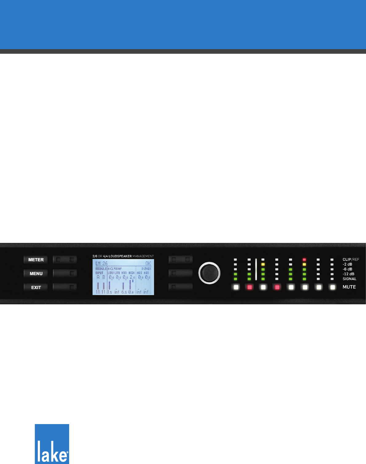
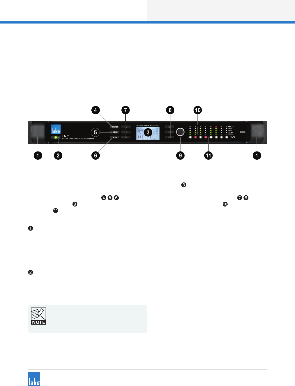
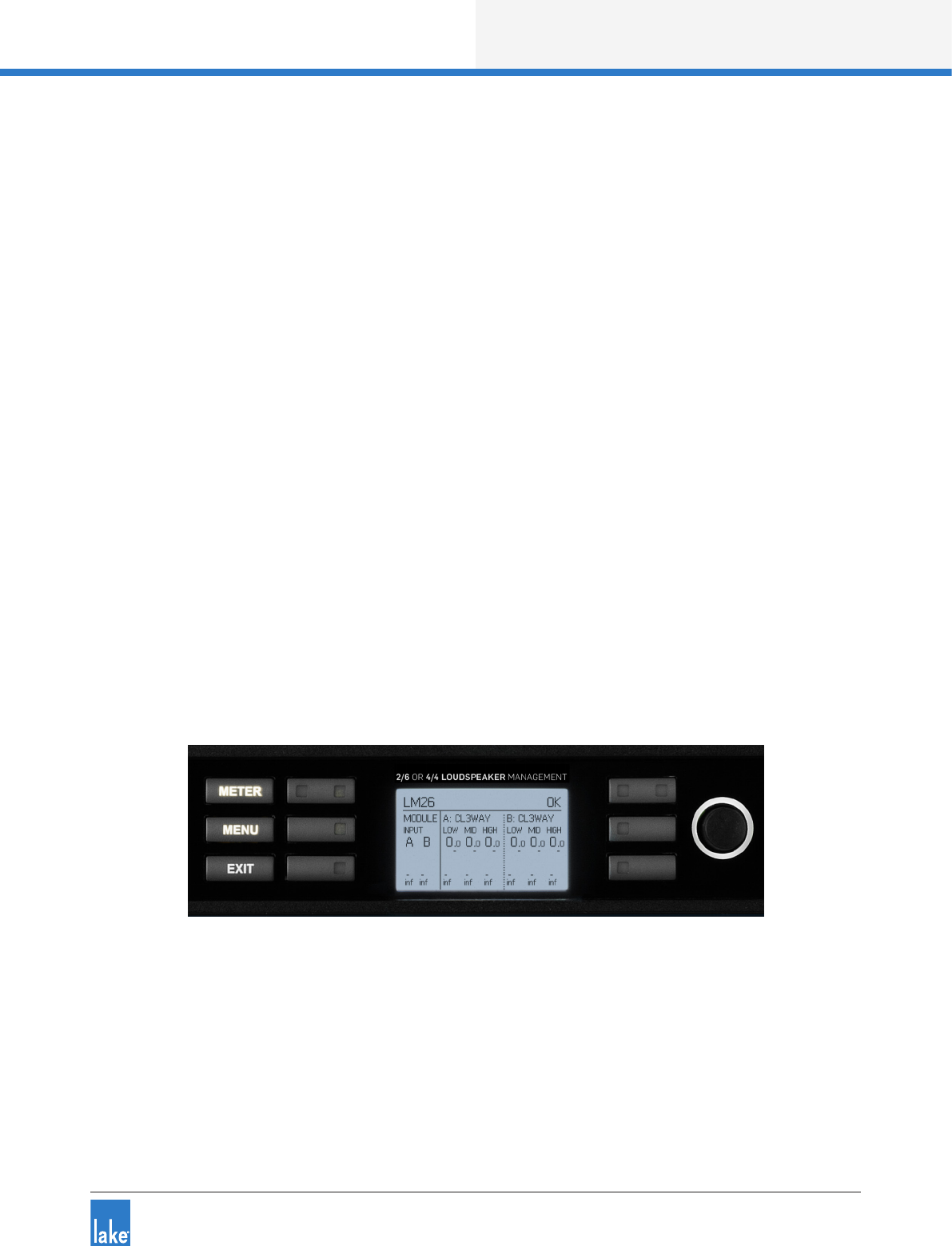
Figure 4-1: LM Series Front Panel Overview
The front panel controls are clustered around a daylight readable LCD , allowing adjustment and monitor-
ing of the majority parameters and meters. The two clusters of controls on either side of the LCD include
three dedicated function buttons , six dynamic function buttons with embedded LEDs and a
rotary data encoder . To the right of these controls is a dynamic illuminated I/O divider along with input
and output mute buttons and level meters.
Handles
Two sturdy cast aluminium handles are integrated into the front panel. The handles should be used when
carrying the device, and when tting into or removing from a rack. Ensure that any door or removable rack
front cover has sufcient depth to clear the handles.
Standby
LM Series devices are powered on and placed into standby mode using the left-most button, or via the
Lake Controller. Standby mode is not equivalent to turning the device off at the mains power.
All audio in and out of the processor is muted when
in Standby mode. Network communication remains
active to allow the device to be turned on via the
Lake Controller.

6
Product Overview
Lake LM Series Operation Manual Rev 1.3.5
Display
The display illuminates when the device is on. The LCD, function buttons, and the rotary encoder provide
real-time control and monitoring of most parameters. The LEDs embedded in the function buttons indicate
available menu options, provide conrmation of Controller communication, and indicate various faults and
warnings.
The brightness and contrast of the display and front panel LEDs can be adjusted via the front panel menu.
Please refer to chapter 6 for further details.
Meter
The METER button scrolls through various meter views including the default Home View, Input Meters View
(Mesa Mode only) and I/O Status View. Pressing METER from Menu Mode returns the screen to Meter
Mode with the Home View displayed. Please refer to section for further details.
Menu
After pressing the MENU button, the LCD will display the top level menu. In Menu Mode the dynamic func-
tion buttons enable access to various information and functionality. Please refer to section 6.5 for further
details.
Exit
The EXIT button is used primarily while navigating the menu system in Menu Mode; pressing EXIT will
return the menu up one level. In Meter Mode, pressing EXIT returns the metering display to the default
Home View.
Dynamic Function Buttons with LEDs (Left of LCD)
The function of these buttons change according to the currently selected view or menu.
The left LED in the top button illuminates white to indicate the Frame is selected in the Lake Controller, or
ashes white to indicate communication from the Lake Controller. If this button is pressed while in Home
View, and with the Lake Controller on the Home page or the Modules Menu, the associated Module/s of the
selected frame will be highlighted in the Controller (Module A in Contour Mode, or Modules A&B in Mesa
Mode).
The three LEDs on the right side of each button illuminate white when an associated option is available on
the LCD screen.
Please refer to chapter 6 for further details.

Product Overview
7
Lake LM Series Operation Manual Rev 1.3.5
Dynamic Function Buttons with LEDs (Right of LCD)
The function of these buttons change according to the currently selected view or menu.
The right bi-color LED in the top button illuminates red or yellow to indicate faults or warnings. If this button
is pressed while in Home View, and with the Lake Controller on the Home page or the Modules Menu, the
associated Module/s of the selected frame will be highlighted in the Controller (Module B in Contour Mode,
or Modules C&D in Mesa Mode).
The three LEDs on the left side of each button illuminate white when an associated option is available on
the LCD screen.
Please refer to chapter 6 for further details.
Rotary Encoder
The rotary encoder is used to modify various parameters (e.g. input level) via the menu. When a menu item
is selected that permits adjustment of parameter values, the ring around the rotary encoder illuminates. In
Home View the encoder can be used to scroll through the Meter Views.
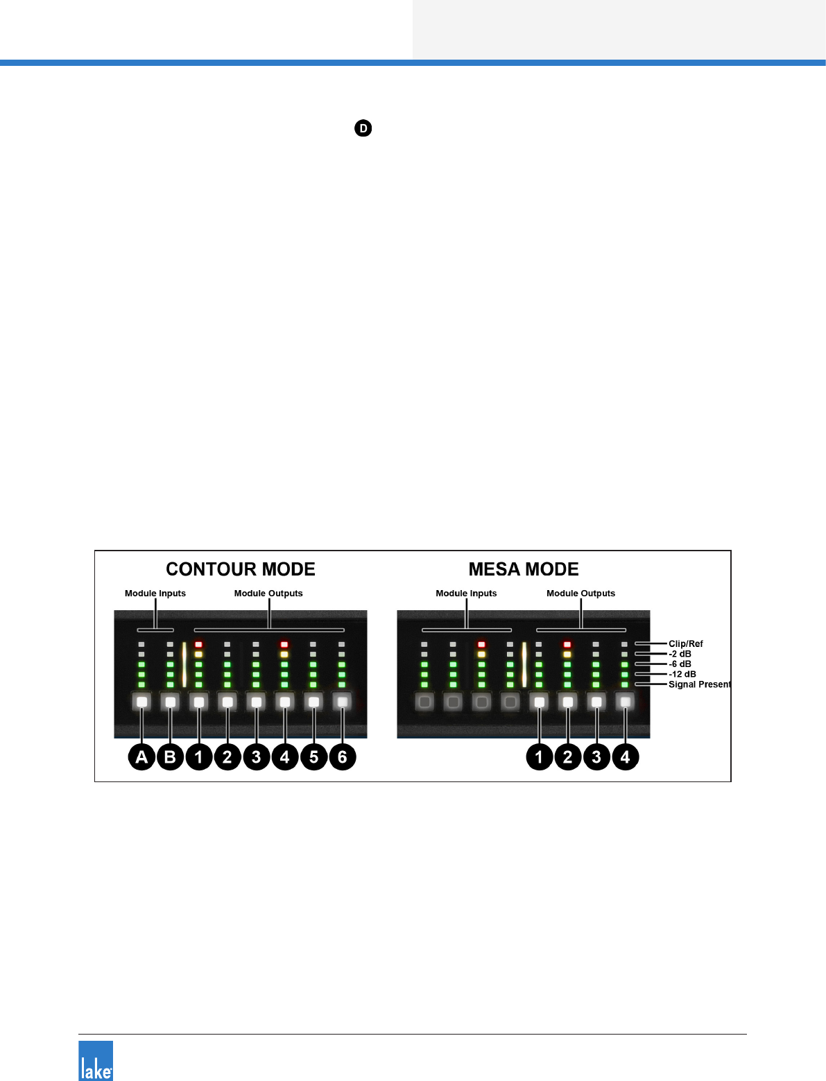
Dynamic Illuminated I/O Divider
The dynamic illuminated divider moves position to indicate the split between inputs and outputs for meter-
ing and mute purposes in the two different modes of conguration. Contour Mode provides two Module
inputs, and six Module outputs; Mesa Mode provides four Module inputs and four Module outputs.
The LED meters and mute buttons to the left of the illuminated divider relate to the Module inputs; the LED
meters and mute buttons to the right of the divider relate to the Module outputs.
The I/O divider is not illuminated in I/O Status View as all eight LED meters and associated mute buttons are
used for Input Router signal and mute functionality.
Module Input / Output Mute Buttons and LED Meters
Independent mute buttons and LED meters are provided for the Module inputs and outputs. The number of
inputs and outputs varies depedning on processor and module conguration. Refer to the description above
regarding the Dynamic Illuminated I/O Divider.
The LED meters for each channel are split into ve segments: The bottom three segments (green) indicate
signal; the 4th segment (yellow) indicates signal 2 dB below clipping; and the 5th segment (red) indicates
signal clipping.
The embedded LED in each mute button conrms whether the associated Module input/s or output/s are
muted (red), unmuted (white), associated input router is muted (pink), or unused (not illuminated).
Please refer to section 6.8 for further information.

8
Product Overview
Lake LM Series Operation Manual Rev 1.3.5
4.2 Back Panel Overview
Figure 4-2: LM 26 Back Panel Layout
Figure 4-3: LM 44 Back Panel Layout
Analog Outputs
Analog outputs are provided via standard XLR3M connections. The outputs are electronically balanced
and feature Lake Iso-Float circuitry; it is not recommended to use unbalanced connections. The output
impedance is 50 ohms, providing a maximum output level of +21 dBu. Please refer to section 7.1 for further
information.
Analog Inputs
Analog inputs are provided via standard XLR3F latching connectors. The inputs are electronically balanced
and feature Lake Iso-Float circuitry; it is not recommended to use unbalanced connections. The impedance
is 20 kohms (balanced), and the inputs can accept a maximum input level of +26 dBu. Please refer to section
7.1 for further information.
AES3 I/O
AES inputs and outputs are provided via a 25-pin DB25 connector. Inputs can be received on AES1 (Ch.1,2)
and AES2 (Ch.3,4) for all LM Series devices; the LM 44 also allows input from AES3 (Ch.5,6) and AES4
(Ch.7,8).
Outputs are via AES1 (Ch.1,2), AES2 (Ch.3,4), AES3 (Ch.5,6) and AES4 (Ch.7,8). Please refer to section 7.2
for further information.
Product Overview
9
Lake LM Series Operation Manual Rev 1.3.5
The sample rates available for AES3 inputs and outputs are 44.1, 48, 88.2, 96, 176.4, 192 kHz; input and
output sample rates can be congured to lock to different sample rates.
Primary Network Connector
The primary Neutrik RJ45 etherCON® connection provides integration into an Ethernet control network
which may include other Lake Processors and the Lake Controller software. Network connection permits full
control of all functions along with real-time metering from a remote position. This device supports the Dante
audio networking protocol, which allows transmission of multichannel, high-denition digital audio over the
same Ethernet connection.
Use the primary connector when using a star network topology, consisting of individual Cat-5e connections
between the devices and an Ethernet switch. Alternatively this connection can be used to daisy chain
directly to another Lake Processor. The daisy chain topology should not be used with Dante.
For a technical reference of the Ethernet Port, please refer to section 7.3 . Additional information is also
available in the Lake Network Conguration Guide.
The Ethernet ports automatically switch to operate at Ethernet data
rates of 100 Mbps or 1000 Mbps, and allow straight or crossed
network cables. Two LEDs above each port indicate valid network
connection (LINK) and network activity (ACT).
Secondary Connector
The secondary network connector can be used to daisy-chain multiple LM & PLM Series devices. Alterna-
tively, a Dante dual-network topology can be created by connecting all secondary network connectors to a
separate Ethernet switch, ensuring full redundancy in the event of a network component failure.
Additional processor conguration is required for a
dual redundant network setup. See the Lake
Controller Operation Manual for further details.
For a technical reference of the Ethernet Port, please refer to section 7.3 . Additional information is also
available in the Lake Network Conguration Guide.
When connecting multiple devices to an Ethernet
network, care must be taken NOT to create a closed
loop which causes network malfunction.

10
Product Overview
Lake LM Series Operation Manual Rev 1.3.5
GPIO Connector
A 9-pin GPIO (General Purpose Input Output) connection is provided to enable integration with external
systems such as alarm/re systems, providing basic control of power state, mute along with fault notica-
tion to an external monitoring system. Please refer to sections 6.10.4.4 and 7.4 for further details.
Mains Power Connector
A universal power supply capable of accepting 70-265 V ~ 50-60 Hz : 25 W is built into LM Series devices.
The IEC power cable provided includes a locking feature via a pin on the bottom of the connector; the
connector can accept standard or locking IEC power cables.
The power supply must be connected to AC mains using a power cable with a correctly wired plug for the
country of operation.
Signal Flow and Lake Processing
11
Lake LM Series Operation Manual Rev 1.3.5
5. Signal Flow and Lake Processing
5.1 Signal Flow
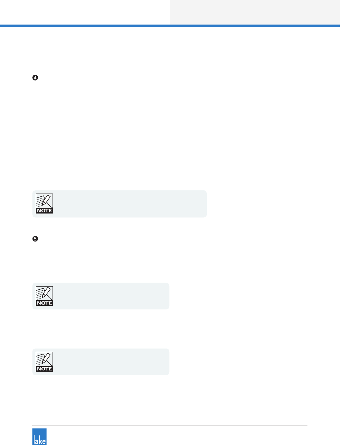
The gures below depict the audio signal ow for LM Series devices congured in both Contour and Mesa
modes. It is worth noting that this sophisticated device provides up to ve points in the signal chain where
the signal level can be adjusted, muted or disconnected (depending on whether congured in Contour or
Mesa Mode as described below). The blue sections represent Frame data, and the red sections represent
Module data - please refer to the Lake Controller Operation Manual for further information.
Important information regarding correct setting of the gain structure can be found in section 9.1.
Figure 5-1: LM Series Signal Flow (Contour Mode)
12
Signal Flow and Lake Processing
Lake LM Series Operation Manual Rev 1.3.5
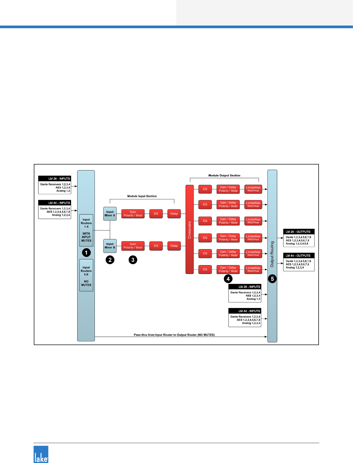
Figure 5-2: LM Series Signal Flow (Mesa Mode)
Please refer to section 6.10.4.2 for information on changing the Frame conguration between Contour and
Mesa Modes.
5.2 Level Adjustments & Mute Points
The numbers below correspond the points identied inFigure 5-1 and Figure 5-2.
Input Router Stage - Input selection and MUTE
Input Mixer Stage - Router ON/OFF connection to mixer and gain settings
Module Input Stage - Mute (N/A for LM Series Mesa Mode) and gain settings
Module Output Stage - Mute and gain settings
Output Router Stage - Output ON/OFF routing connections
In Contour Mode, a Module can be connected to Input Routers 1-4 providing all ve stages of mute/connec-
tivity functionality via the front panel interface or the Lake Controller; Input Routers 5-8 allow stage 1 input
selection only (MUTE unavailable), along with stage 5 output ON/OFF routing connections (i.e. pass-thru).

Signal Flow and Lake Processing
13
Lake LM Series Operation Manual Rev 1.3.5
In Mesa Mode, a Module can be connected to any of the eight input routers, providing four stages of mute/
connectivity (stage 1,2,4 & 5).
If the required audio signal is not passing correctly,
verify the connection, mute and gain settings at all
ve stages.
5.3 Lake Processing and Control
As outlined in section 2.2.1, this device integrates seamlessly into the Lake Processing environment,
providing all features, functionality and connectivity associated with all Lake Processors. The internal Lake
Processing includes programmable crossovers, EQ, dynamics and other functions, and can be fully con-
trolled via the supplied Lake Controller software. Additionally, many functions can be controlled or accessed
directly via the front panel.
The Lake Controller Operation Manual and Lake Network Conguration Guide are supplied on the accom-
panying CD-ROM or USB key and additional documentation is available from the Start Menu after software
installation.
Visit http://lakeprocessing.com to download the latest software, rmware and documentation for your
devices.
5.4 Modules and Frames
5.4.1 Overview
A Frame represents one physical Lake Processor (e.g. LM 26 or LM 44). In Contour Mode, a maximum
of two Modules are contained within each Frame; these are referred to as Module A and Module B. The
number of Modules shown in a given Frame is also dependent upon the signal processing conguration of
that Frame. In Mesa Mode each Frame contains four Modules labelled A, B, C & D.
In Contour Mode, each Module can be congured as a Classic Crossover (Bessel, Butterworth, Linkwitz-
Riley), as a Linear Phase Crossover, or as multiple full bandwidth Auxiliary Outputs. The default conguration
for the LM 26 is 2 x Classic 3-Way Modules, providing a total of six Module outputs. The default congura-
tion for an LM 44 is four Mesa EQ Modules, providing a total of four Module outputs.
Please refer to the Lake Controller Operation Manual for further information.

14
Signal Flow and Lake Processing
Lake LM Series Operation Manual Rev 1.3.5
5.4.2 Super Modules
Super Modules allow control of multiple Modules of the same type, distributed across multiple Frames, as
a single entity within the Lake Controller software. A change made in the Super Module is replicated across
all assigned Modules, resulting in improved efciency in system conguration and a reduction of on-screen
icons within the Lake Controller software.
The key benet of this feature is the ability to connect and control crossovers, levels and EQ across multiple
hardware devices simultaneously from the Lake Controller. For example, one device may be driving sub and
low-frequency speakers, while another device controls mid-range and hi-frequency drivers. Using a single
adjustment the crossover points between the two devices can be changed simultaneously.
Please refer to the Lake Controller Operation Manual for further information regarding Super Modules.
5.5 Loudspeaker Processor (Contour Mode) Overview
In Contour Mode, LM Series devices may be congured with up to two processing Modules containing a
total of up to six processing Module outputs as shown in Figure 5-1 on page 11. Each set of processing
elements is referred to as a Module and can be congured as crossovers, full-bandwidth auxiliary outputs,
or a combination of the two. The relationship between inputs and outputs is dened via the Lake Controller
or via the front panel I/O CONFIG Menu.
The Lake Processing system provides two distinct categories of crossovers:
▸Innite Impulse Response lters (IIR) such as the classic Bessel, Butterworth or Linkwitz-Riley types;
these are available with slopes ranging from 6 dB/octave to 48 dB/octave.
▸Finite Impulse Response lters (FIR) providing zero phase shift with steep transition slopes at the
crossover frequencies. These are also referred to as Linear Phase Crossovers.
Further details on crossovers and module types is available in the Lake Controller Operation Manual.
5.6 System Equalizer (Mesa Mode) Overview
In Mesa Mode, an LM Series device provides four processing Modules with independant EQ, HPF/
LPF, Gain, Polarity, Delay and Limiters. The relationship between inputs and outputs is dened via the
Lake Controller or via the front panel I/O Input Cong Menu.
Please refer to the Lake Controller Operation Manual for addiitonal information on Mesa Mode and associ-
ated I/O routing.

Signal Flow and Lake Processing
15
Lake LM Series Operation Manual Rev 1.3.5
5.7 Switching between Contour and Mesa Mode
When switching between Contour and Mesa Modes, all current Frame conguration data is lost (Presets
are retained) and the device is completely recongured into the selected Mode. Ensure you have stored any
existing frame conguration data before conguring into a different mode.
The device conguration may be changed either via the Front Panel MENU > FRAME > FRAME RST (refer
to section 6.10.4.2) or via the Lake Controller MODULES > I/O CONFIG > FRAME CONFIG menu (refer to
the Lake Controller Operation Manual).
5.8 Files and Presets
The Lake system provides various methods for storing and recalling Module, Frame, or system-wide data.
An overview is provided below; for further information please refer to the Lake Controller Operation Manual.
5.8.1 Module, System and Sub-System Conguration Files
Module, System and Sub-System Conguration les are stored on the Lake Controller PC, and data is
passed across the network when recalling or storing these type of les.
▸A Module le is the smallest set of data that can be stored and recalled; it contains crossover, gain,
delay, and limiter information for an individual loudspeaker (i.e. the data shown in red in the signal ow
diagrams in section 5.1). A Module le may be recalled into other Lake devices. It is not possible to
store a Module File directly on the hardware device.
▸A System or Sub-System Conguration File contains a set of Module le information in addition to
Frame related information such Group data and I/O conguration (i.e. the data shown in blue in the
signal ow diagrams in section 5.1).
5.8.2 Frame and System Presets
The entire processor conguration can be stored as a Frame Preset on this hardware device. Presets can
be recalled via the front panel (refer to section 6.10.6) or via the Lake Controller software or Preset Manager
utility; presets can be stored using the Lake Controller software or Preset Manager utility.
A maximum of 100 Frame Presets can be stored on this device. The data within a Frame Preset includes the
congurations of all Modules in the Frame, including levels, crossover, EQ, input mixer, routing, and all other
parameters. As Frame Presets are stored in the hardware device, recall is available without using a PC.
Using the System Presets function in the Lake Controller, entire system congurations can be stored and
recalled across a network of LM & PLM Series devices. This enables fast retrieval and switching of entire
system congurations as minimal data is being sent between the Controller and Processors.
16
Front Panel Interface
Lake LM Series Operation Manual Rev 1.3.5
6. Front Panel Interface
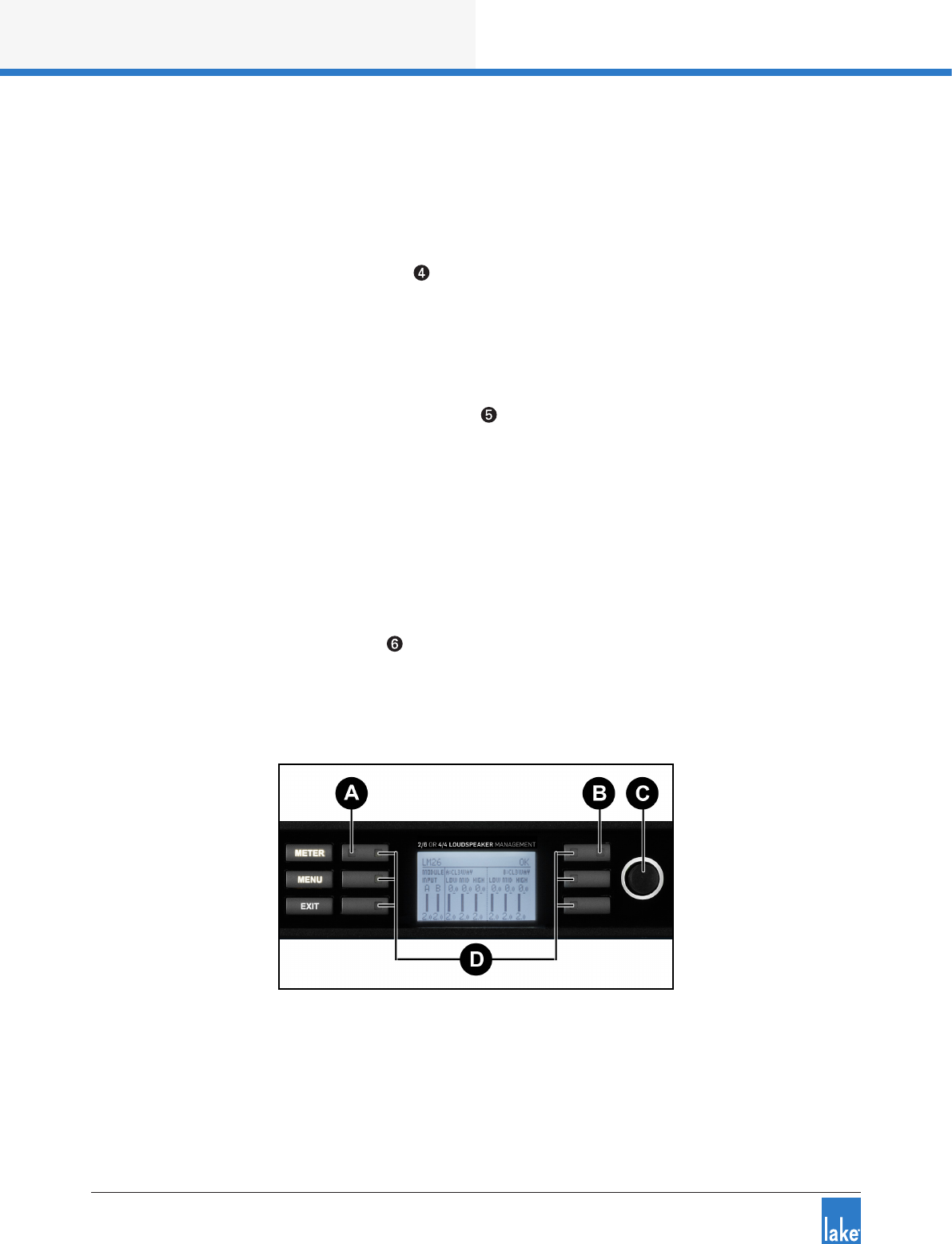
An overview of the front panel interface is provided in section 4.1. This chapter describes each cluster of
controls as shown in Figure 6-1.
Figure 6-1: Front Panel Interface
6.1 Overview
The front panel interface is framed by two sturdy cast aluminium handles . The majority of functions
on LM Series devices can be operated and monitored via the following controls and display features: On/
standby button , front-panel LCD display screen , function buttons , rotary encoder , a
dynamic illuminated I/O divider and the dedicated Module input output mute buttons and LED meters .
The front panel has two basic modes: Meter Mode and Menu Mode.
▸Meter Mode provides the following views: Home View (default), Input Meters View (Mesa Mode only)
and I/O Status View. To navigate through these views, press the METER button. Please refer to section
6.8 for further information on Meter Mode.
▸Menu Mode provides various menus for viewing and editing parameters and is selected by pressing the
MENU button. Select the required submenu by pressing the associated button. Please refer to section
6.10 for further information on Menu Mode.
6.1.1 Warning, Fault and Mute Indications
Fault or warning conditions are indicated via the LEDs embedded in the dynamic function buttons; a simulta-
neous description is shown adjacent to the button, on the LCD.
Further information on faults and warnings is provided in section 6.7.2 and section 8.1.
Front Panel Interface
17
Lake LM Series Operation Manual Rev 1.3.5
6.1. 2 Selecting a Module in the Lake Controller software via the device
It is sometimes useful to identify which Module icon/s in the Lake Controller software are associated with a
particular hardware Frame. To highlight the module in the Lake Controller software:
1. Ensure Meter Mode is selected
2. Press the button adjacent to the Module description on the LCD
If the Frame is online, but the Module is not in the work area, the selected Module will be centred on the
Module scroll bar (assuming the Modules Menu is selected in the Lake Controller).
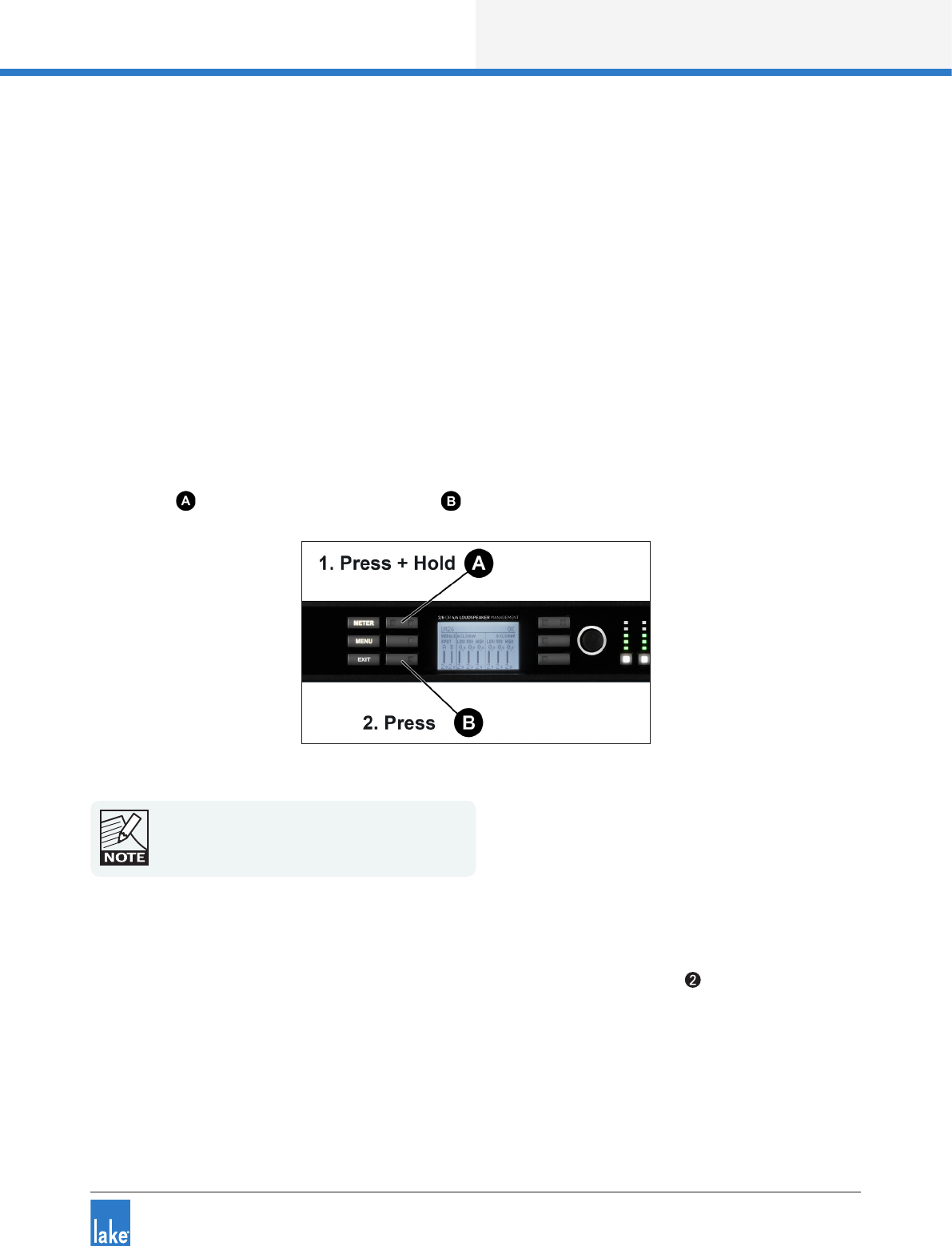
6.2 Front Panel Key Lock
It is possible to lock the front panel buttons for security purposes. When this function is active, all front
panel controls are disabled and all adjustment must be made via the network. To lock controls, press and
hold button then simultaneously press button as shown in Figure 6-2; repeat this process to unlock.
Figure 6-2: Locking / Unlocking Front Panel Controls
A key icon will appear at the top of the display when
the Front Panel is locked.
6.3 Power Button
The unit is powered on by pressing the left-most button on the front panel, labelled in Figure 6-1. It has
a bi-color power symbol which illuminates red when connected to the AC mains and the unit is in standby
mode. It turns green when the button is pressed to turn the processor on. A subsequent press of this
button returns the unit to standby mode.
18
Front Panel Interface
Lake LM Series Operation Manual Rev 1.3.5
6.4 Meter Button
The front panel display has two main operating modes, Meter Mode (default) and Menu Mode. In normal
operation, the display will be in Meter Mode.
The following views are available in Meter Mode: Home View (default), Input View (Mesa Mode only) and
I/O Status View. Pressing the METER button scrolls through these views. Pressing the METER button
when in Menu Mode will return the system to Meter Mode, with the Home View displayed. Please refer to
section 6.9 for further information.
6.5 Menu Button
Menu Mode is selected by pressing the MENU button . The screen displays the top level menu with
various submenu options. Press the button adjacent to the required submenu to select it.
Pressing the MENU button while in Menu Mode will display the previous menu level.
Menu Mode is used for processor conguration, or for editing a parameter. Please refer to section 6.10 for
further details.
6.6 Exit Button
In Menu Mode, pressing the EXIT button returns back one menu level. In Meter Mode, pressing EXIT
returns the display to the Home View.
6.7 Dynamic Buttons, Controls and LEDs
Figure 6-3: LCD with Dynamic Buttons, Controls and LEDs
Front Panel Interface
19
Lake LM Series Operation Manual Rev 1.3.5
6.7.1 Communication LED
This bright white LED signies selection in the Lake Controller, or Controller communication providing visual
conrmation of:
1. Network communication between the Lake Controller and the Lake Processor (Flashing LED).
2. Selection of the Lake Processor in the Lake Controller software (Steady LED).
The Communication LED can be dimmed via the
front panel by selecting Frame menu, and then Front
- Dimming.
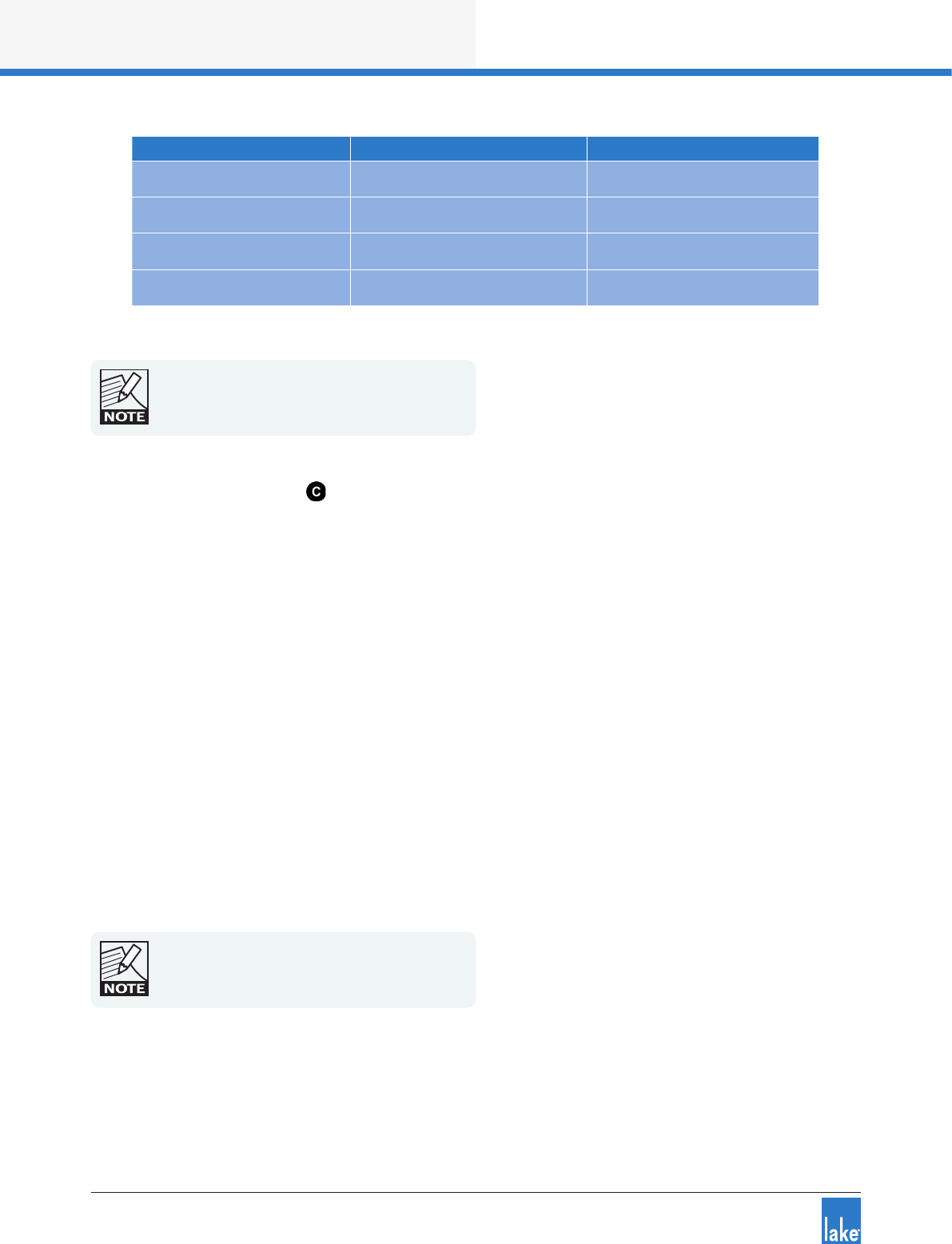
6.7.2 Faults and Warnings LED
This LED turns red to indicate a fault or mute state and turns yellow to indicate a warning. Additional clari-
cation of the fault or warning is displayed in the LCD. All mute, fault and warning states displayed on the
front panel are summarized in section 8.1.
Additional faults and warnings are reported in the Event Log of the Lake Controller only. All faults and
warnings recorded in the Event Log are listed in section 8.1 along with scenarios that may have arisen to
cause them.
Device Fault / Mute Description LCD Warning Text Event Log Warning Text
LM 44 Only A/D PSU Fault PSU FAULT Frame Fault: PSU
All LM Series Protective Mute State PROTECTIVE MUTE Protective mute via GPIO
All LM Series Overtemperature OVERTEMP Temp Fault: DSP area
All LM Series No Input Source Available NO INPUT No Input Source
All LM Series Analog Input Fault ANALOG IN FAULT Frame Fault: Analog input
All LM Series Fan Alarm FAN FAULT Frame Fault: Fan error
All LM Series Input Router Mute INPUT RTR MUTE Input Router x mute
Table 6-1: Faults (RED FAULT / WARNING LED)
20
Front Panel Interface
Lake LM Series Operation Manual Rev 1.3.5
Warning Description LCD Warning Text Event Log Warning Text
Digital Clock Slipping CLOCK SLIPPING AES/Dante input clock slipping
Temperature Warning TEMP WARNING Temp Warning: DSP area
Controller Ofine CTRL OFFLINE n/a
Device Name Conict NAME CONFLICT Dante device name conict
Table 6-2: Warnings (YELLOW FAULT / WARNING LED)
Module Input/Output mute status is indicated by the
dedicated mute button LEDs. Clipping is indicated
by the associated red meter segment. Please refer
to section 6.8 for further details.
6.7.3 Rotary Encoder
The rotary encoder is used to adjust parameters in conjunction with the selection made via the dynamic
function buttons and LCD menus. The ring around the rotary encoder illuminates when a selected parameter
is available for adjustment.
Turn the encoder clockwise to increase the selected parameter, or counter-clockwise to decrease the value.
Parameters with only two states (e.g. ON, OFF) are toggled by turning clockwise or counter-clockwise.
Some parameters enable simultaneous adjustment of a combination of input and output channels.
To select which channels are adjusted:
1. Press the associated soft button/s to select the parameter/s for editing.
A selected parameter is indicated by inverse text and background color.
2. Use the rotary encoder to change the value.
It is possible to select multiple parameters for simultaneous editing even if the values are different on each
channel. Turning the rotary encoder will adjust each parameter by the same increment. When in Meter
Mode, the rotary encoder allows the user to change between the available meter views.
Some menus permit parameters to be adjusted
across multiple channels simultaneously by default.
Front Panel Interface
21
Lake LM Series Operation Manual Rev 1.3.5
6.7.4 Dynamic Function Buttons
The buttons surrounding the display are unlabeled because their functions change according to the currently
selected menu or display.
In Menu Mode these buttons are used to navigate the menu structure. A white LED illuminates on each
button when a valid menu option is available.
6.8 Module I/O Mute Buttons and LED Meters
LM Series devices provide mute functions at several points in the audio signal path. Please refer to section
5.1 for mute locations and descriptions. Three types of mute are available from the front panel:
1. Input Router Mutes
2. Module Input Mutes
3. Module Output Mutes
In Home View (default), Module Input and Output Mutes are controlled via the dedicated mute buttons
underneath each channel’s ve-segment LED meter as shown in Figure 6-4.
Figure 6-4: Dedicated Module Input and Output Mutes - Home View
In Figure 6-4, the buttons labelled A & B provide Module input muting; the buttons labelled 1-6 provide
Module output muting.
The embedded LED in each mute button conrms whether the associated Module input/s or output/s are
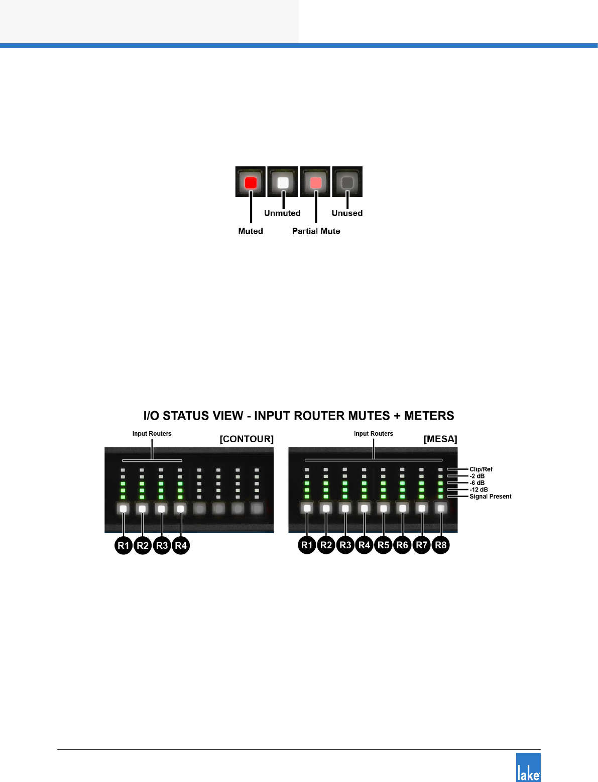
muted (red), unmuted (white), associated input router is muted (pink), or unused (not illuminated) as shown
in Figure 6-5.
22
Front Panel Interface
Lake LM Series Operation Manual Rev 1.3.5
A pink LED indicates a partial mute caused by a mute on an Input Router used by the associated Input
Mixer. If all Input Routers used by an Input Mixer are muted the LED turns red to indicate a full mute; this
type of mute cannot be unmuted from Home View. Input router mutes are accessed via the I/O Status View
as described below, or via the Lake Controller Levels screen as described in the Lake Controller Operation
Manual.
Figure 6-5: Mute Button LED Colours and States
In I/O Status View (accessed via the METER button as described in section 6.9.3) the front panel mute
buttons and meters change to show Input Router mutes and Input Router metering; the dynamic I/O divider
line is not present and the buttons and meters change to represent the input router mute status and associ-
ated metering.
The number of Input Routers varies depending on the whether the frame is congured as Contour or Mesa
as shown in Figure 6-6; the number and location of the Input Router channels is identied by the labels
R1-R8.
Figure 6-6: I/O Status View - Input Router Mutes and Meters
The Input Router Mutes can also be viewed and changed via buttons adjacent to each label the front panel
I/O Status view.
6.8.1 Module Input and Output Mutes
In Home View, dedicated mute buttons are provided for the Module inputs and Module outputs. To mute
or unmute a module input or output, tap the corresponding button. The button illuminates as described in
section 6.8 and shown in Figure 6-5.
Front Panel Interface
23
Lake LM Series Operation Manual Rev 1.3.5
Module input mutes are only available in Contour Mode; Module input mutes are not applicable in Mesa
Mode. The quantity and position of the output mute buttons changes as shown in Figure 6-4 depending on
whether the device is congured in Contour Mode (six outputs) or Mesa Mode (four outputs).
Please refer to the Lake Controller Operation Manual for details of Module mute controls via the software.
6.8.2 Clip Indication
The dedicated 5-segment metering LEDs (Figure 6-4 ) display Module input and output clip or pre-clip
conditions. Additionally, the faults and warnings LED described in section 6.7.2 provides clip warnings for
input mutes, or GPIO protective mutes, along with conrmation text on the LCD screen.
Clipping is monitored at the following positions in the signal chain:
▸Analog Inputs: If the input signal exceeds either +12 dBu or +26 dBu (according to analog sensitivity
setting), a clip indication will be given. This does not apply if digital inputs are selected.
▸Module Inputs: If the signal level at this point exceeds +25 dBu, a clip indication will be given.
▸Module Outputs: If the signal level at this point exceeds +21 dBu, a clip indication will be given.
6.9 Meter Mode
6.9.1 Home View (Contour Mode)
The default view when powering on an LM Series device device congured in Contour Mode is the Meter
Mode > Home View as shown in Figure 6-7.
Figure 6-7: Meter Mode > Home View
Home View (Contour Mode) provides a summary of Module I/O gain level and limiter gain reduction, along
with frame, module and channel labeling information.
24
Front Panel Interface
Lake LM Series Operation Manual Rev 1.3.5
6.9.2 Home View (Mesa Mode)
The default view when powering on an LM Series device congured in Mesa Mode is Meter Mode > Home
View as shown in .
Figure 6-8: Meter Mode > Home View (Mesa - Module Outputs)
Home View (Mesa Mode) provides a summary of Module output gain level and limiter gain reduction, along
with frame, module and channel labeling information.
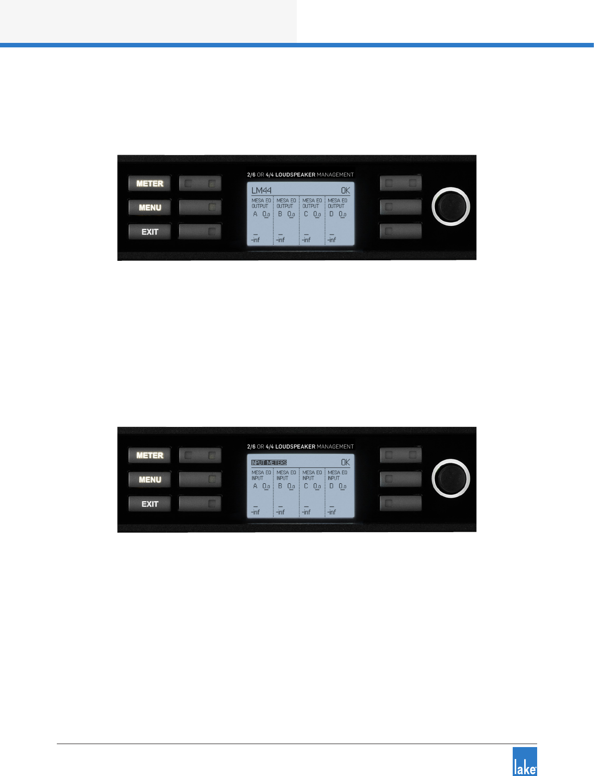
Input Meters (Mesa Mode)
Pressing the METER button from Home View in Mesa Mode will display the Input Meters View similar to
that shown in Figure 6-9. This view is not available in Contour Mode as Contour Mode Home View includes
both input and output metering information.
Figure 6-9: Meter Mode > Input Meters (Mesa Only)
6.9.3 I/O Status View
Pressing the METER button from Home View (once in Contour Mode, twice in Mesa Mode) results in the
I/O Status View being displayed, similar to that shown in Figure 6-10. There are two pages to this screen;
press the meter button again to display page two. Page one displays the selected input status and metering
information for input routers 1-4, page two displays input routers 5-8.
In I/O Status View, the front panel mute button and metering LED’s change to represent the Input Router
mute status an metering levels as described in 6.8.

Front Panel Interface
25
Lake LM Series Operation Manual Rev 1.3.5
Figure 6-10: Meter Mode > I/O Status View
This section displays the screen title (left) and frame fault or warning description (right)
This section displays conrmation of the following settings:
Master - Dante Clock Master (no icon = Dante Slave or Dante Disabled)
AES - AES3 Input Terminated (no icon = Unterminated)
I NP. - Analog Inputs Iso-Float Grounded (no icon = Floating)
O UTP. - Analog Outputs Iso-Float Grounded (no icon = Floating)
- Dante Slave Only (no icon = device may be used as Dante Clock Master)
REDUNDANT - Dual Redundancy networking enabled
The main section of the I/O Status View displays status and metering information for four of the eight
input routers. The information displayed for each input includes the currently selected input source type,
input router gain level meter (displayed as a horizontal bar and numeric dB, and also shown on the main
front panel LED meters), input mute status, analog headroom, digital sample rate, digital clock selection and
digital clock locking status.
If an Input Router is muted, the top-right LED is illuminated red as shown in Figure 6-10, and the frame fault
text in section A of the screen will display INPUT MUTE. The fault and warning LED illuminates red or yellow
in all Meter and Menu Views as described in section 6.7.2 and section 8.1.
These buttons allow muting/unmuting of the associated device input router. Conrmation of each input
router’s mute status is displayed on the LCD next to the associated button as shown for input 2 in Figure
6-10. To view inputs 5-8 (I/O Status 2) press the METER button, or turn the rotary encoder clockwise.
The faults and warnings LED is accompanied by text on the top-right side of the LCD. The LED illumi-
nates red if any input is muted, or if another fault condition occurs; it illuminates yellow if a warning condition
arises. Please refer to section 6.7.2 for further details.
26
Front Panel Interface
Lake LM Series Operation Manual Rev 1.3.5
6.10 Menu Mode
6.10.1 Overview
The majority of functions can be accessed via Menu Mode on the front panel. These functions include
the adjustment of gain, delay, limiters, input and output routing, and the ability to recall Frame Presets.
Menu Mode can be accessed at any time by pressing the MENU button.
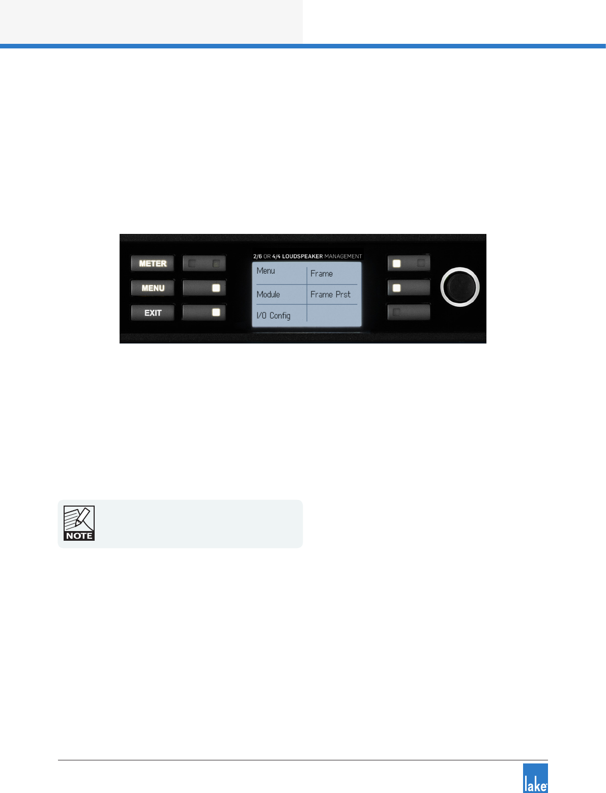
After pressing the MENU button, various submenu options are displayed as shown in Figure 6-11.
Figure 6-11: Menu Mode > Main Menu
Press the illuminated button adjacent to the required option to display an associated submenu. When
parameter level is reached, individual parameters may be selected for adjustment by pressing the adjacent
button. The selected parameter value/s are highlighted, and are adjustable using the rotary encoder.
A parameter may be adjusted simultaneously across multiple channels by selecting all values to be adjusted;
any current value offsets are retained. Some parameters default to multiple selection, with all inputs or
outputs adjusted simultaneously. Changes are effected in real-time and a stored without further conrma-
tion. Pressing EXIT returns to the previous menu level, automatically retaining any parameter changes.
All parameters are also editable via the Lake
Controller unless specied otherwise.
6.10.1.1 Parameters with Individual Values and Group Totals
The following parameters display two values:
▸MODULE > GAIN
▸MODULE > DELAY
▸MODULE > LIMITERS > MAXRMS LEVEL
▸MODULE > LIMITERS > MAXPEAK LEVEL

Front Panel Interface
27
Lake LM Series Operation Manual Rev 1.3.5
The Module parameter can be adjusted using the rotary encoder. The Group total (shown in brackets) is only
adjustable using the Groups function in the Lake Controller.
The Group total is the sum of the individual Module value plus any values for this parameter on all Groups to
which the Module is assigned. Please refer to the Lake Controller Operation Manual for further information
on Groups.
6.10.1. 2 Menu Structure Overview
From the Main Menu, the following submenus are available, as shown in Figure 6-11 and described in the
following sections.
▸MODULE (See section 6.10.2)
▸Mixer Gain
▸Gain
▸Delay
▸Polarity
▸Limiters
▸INPUT CONFIGURATION (See section 6.10.3)
▸Input Router
▸AES Termination
▸Iso-Float
▸Output Router
▸FRAME (See section 6.10.4)
▸Frame Information
▸Frame Reset
▸Latency Match
▸GPIO Conguration
▸Front Panel
▸FRAME PRESETS (See section 6.10.6)
▸Preset Recall
For simplicity, the following sections refer to the
buttons by their associated name on the LCD
screen. E.g. ‘Press GAIN’ equates to ‘Press the
button adjacent to the Gain label on the LCD’.
28
Front Panel Interface
Lake LM Series Operation Manual Rev 1.3.5
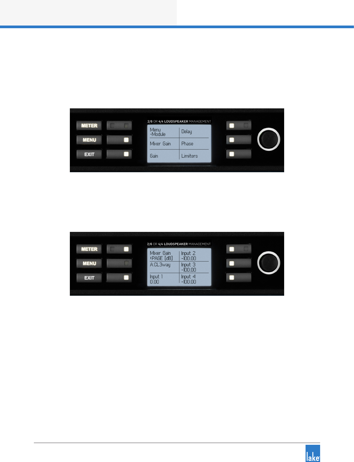
6.10. 2 Module Submenu
MENU > MODULE
After selecting the Module Menu, the screen shown in Figure 6-12 is displayed. Press the illuminated button
adjacent to the required option to view or edit the associated parameters.
Figure 6-12: Module Submenu
6.10.2 .1 Mixer Gain
MENU > MODULE > MIXER GAIN
Figure 6-13: Module Input Mixer Gain Edit Screen
The top left button labeled PAGE toggles between the input mixer gain settings for each Module in the
Frame. Press any other illuminated button to select a parameter for editing then use the rotary encoder to
make adjustments. Multiple parameters may be selected and adjusted together.
6.10.2.2 Gain
MENU > MODULE > GAIN
For frames where both Modules have four output channels or less, a detailed parameter screen as shown
in Figure 6-14 is displayed. Where Module A has ve output channels or more, the combined summary edit
screen shown in Figure 6-15 is the only screen available.
Front Panel Interface
29
Lake LM Series Operation Manual Rev 1.3.5
Figure 6-14: Single Module Gain Edit Screen
Pressing the top left PAGE button scrolls between the following three views for modules with four output
channels or less:
1. Module A Input and Output Gain Settings (with Group totals)
2. Module B Input and Output Gain Settings (with Group totals)
3. Module A & B Combined Summary (without Group totals)
Pressing any other illuminated button on any of these three screens allows direct editing of the Module
parameter using the rotary encoder.
Figure 6-15: Module A+B Combined Gain Summary Edit Screen
On the combined module summary screen, use the NAV button to navigate through the channels, and the
SEL button to select a parameter for editing. Selected parameters are highlighted using inverse video on the
value. The navigation cursor is identied by a bounding box around the abbreviated channel label. Multiple
gain values may be adjusted in 0.1 dB increments subject to dened level limits.
6.10.2 .3 Delay
MENU > MODULE > DELAY
Module Delay adjustment follows the same logic as Module Gain. Please refer to section 6.10.2.2 for further
information. Multiple delay values may be adjusted simultaneously in 0.1 ms increments, subject to dened
level limits.

30
Front Panel Interface
Lake LM Series Operation Manual Rev 1.3.5
The audio signal may be delayed (typically for reasons of driver or delay subsystem alignment) at either
the Module inputs or on individual outputs. Delay added at the inputs affects all outputs equally, and will
be generally be introduced to time-align arrays of loudspeakers at different locations. Delaying individual
outputs may be desirable to time-align drivers in the same cabinet or array.
6.10.2 .4 Phase (Polarity)
MENU > MODULE > PHASE
Module Phase adjustment follows the same logic as Module Gain. Please refer to the section 6.10.2.2 for
further information. Phase may be changed on one input or output at a time.
Audio phase reversal is available at the inputs to Module A and Module B, and also individually on the
six output channels. The LCD displays ‘Positive’ for normal operation, and ‘Negative’ when the phase is
inverted.
6.10.2 .5 Limiters
MENU > MODULE > LIMITERS
LimiterMax parameters can be adjusted via this submenu. By default, simultaneous adjustment of most
limiter parameters across all output channels is selected, although channels may be adjusted individually if
required. Attack and Release times must be adjusted individually per channel.
MaxPeak Level (MaxPeakLvl)
This sets the maximum peak signal level at the Module outputs. It is adjustable from -30 dBu to +30 dBu
in 0.1 dB increments, subject to user-dened level limits. The Group total is displayed (in brackets) for each
channel.
MaxRMS Level (MaxRMSLvl)
This sets the maximum RMS signal level at the Module outputs. It is adjustable from -30 dBu to +30 dBu
in 0.1 dB increments, subject to user-dened level limits. The Group total is displayed (in brackets) for each
channel.
MaxRMS Corner (MaxRMSCor)
A soft-knee or hard-knee corner may be applied to the RMS Limiter. A soft-knee corner gently increases
limiting as the signal approaches the threshold; a hard-knee corner applies full limiting to any signal exceed-
ing the threshold by any amount, but none to signals below the threshold.
Front Panel Interface
31
Lake LM Series Operation Manual Rev 1.3.5
The Corner parameter is adjustable in 0.1 dB increments, subject to dened level limits. This gure repre-
sents the level below the limiter threshold at which compression commences; the larger this negative value,
the softer the knee. A setting of 0 dB implies a hard-knee characteristic.
LimiterMax provides peak and RMS limiting
features, referred to as MaxPeak and MaxRMS
respectively. Full details regarding LimiterMax can
be found in the Lake Controller Operation Manual.
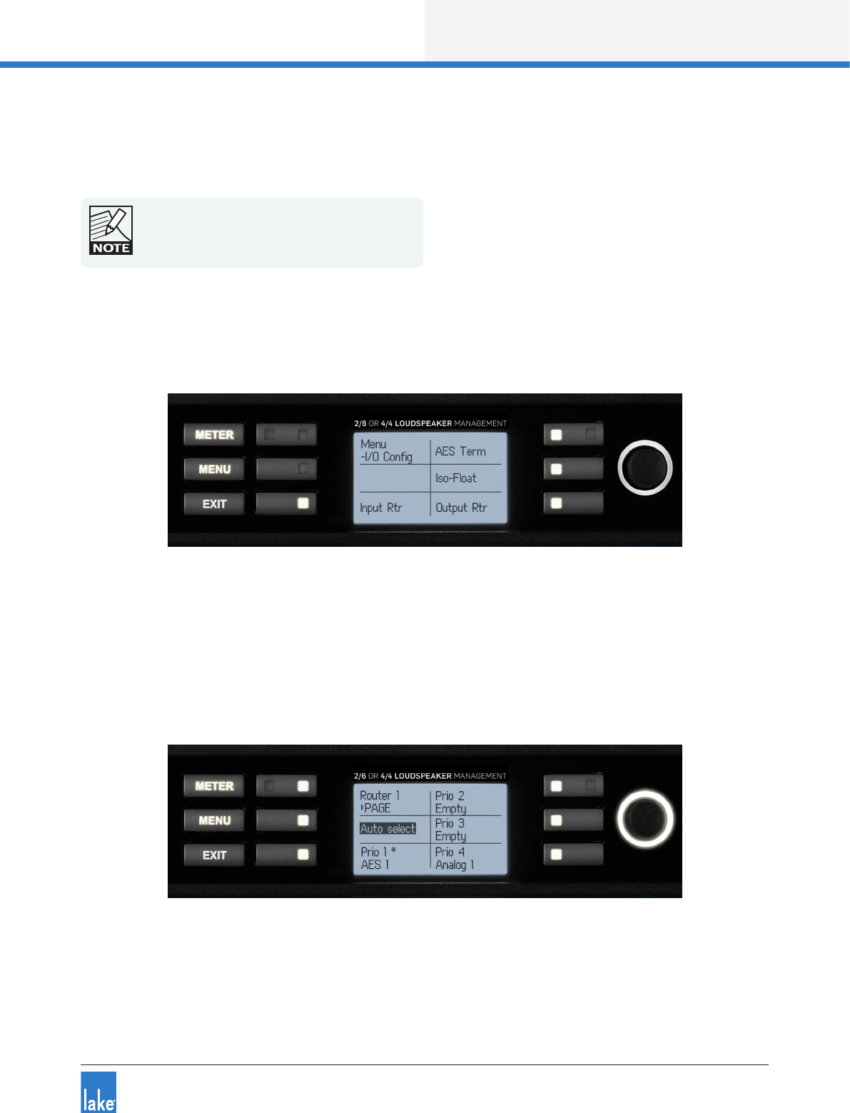
6.10.3 I/O Cong Submenu
MENU > I/O CONFIG
Figure 6-16: I/O Cong Submenu
This menu provides conguration options for input and output routing, along with settings for AES Termina-
tion and Iso-Float as described in the following sections.
6.10.3.1 Input Router
MENU > I/O CONFIG > INPUT RTR
Figure 6-17: Input Router 1
The signal ow diagrams in chapter 5 highlight that there are eight Input Routers available on LM Series
devices.

32
Front Panel Interface
Lake LM Series Operation Manual Rev 1.3.5
In Contour Mode, the signal from the rst four Input Routers can be routed to the Module Input Mixers;
in Mesa Mode, the signal from all eight Input Routers can be routed to the Module Input Mixers. In both
conguration modes, the signal from all eight Input Routers can be passed directly to any output.
Each router has four priority levels allowing any input to be placed in a sequence providing automatic input
signal fail over. AES3 and Dante inputs have priority over analog inputs.
Only one analog input is allowed in each router, and
the analog input must be at the lowest priority level
in relation to any other inputs.
Two modes of input selection are available, Auto Select and Forced Selection. The selected setting is also
visible from the I/O STATUS screen on the front panel, and via the Lake Controller.
In Auto Select mode, Priority 1 is checked for a valid input signal; if no signal is found, Priority 2 is checked,
and so on until a valid signal is located; this process occurs if the currently selected input fails. In Forced
Selection mode, one of the four priorities is xed regardless of whether a valid signal is present.
With a router selected on the front panel, press the middle button on the left of the LCD to activate this
parameter for editing; the text will be highlighted as shown in Figure 6-17. Use the illuminated rotary encoder
to scroll through the following options:
▸Auto Select (default)
▸Force Priority 1
▸Force Priority 2
▸Force Priority 3
▸Force Priority 4
Assignment of Input Priority
Factory default settings assign AES3 to Priority 1 and Analog to Priority 4, with Priority 2 and 3 empty.
To change these settings via the front panel, select Priority slot number to be changed and use the rotary
encoder to scroll through the available options. Due to the signal hierarchy it is not possible to assign an
analog source to a higher priority than a digital source. Dante inputs are not selectable from the front panel;
their assignment must be made via the Lake Controller software.
Analog Input Sensitivity and Digital Gain Offset
While viewing the Input Router screen as shown in Figure 6-17, press PAGE to reveal existing input sensitiv-
ity for analog inputs, or digital gain offset for digital inputs. This is equivalent to the DISPLAY DETAILS
option in the Lake Controller. Adjust a parameter by pressing the associated button, and then use the rotary
encoder to change the value.
Front Panel Interface
33
Lake LM Series Operation Manual Rev 1.3.5
The maximum input level accepted by the analog input pre-ampliers without clipping may be set to 12 dBu
or 26 dBu. Digital gain offset may be applied to AES3 digital input signals in 0.1 dB increments from -100 dB
to +15 dB.
6.10.3. 2 AES3 Input Termination
MENU > I/O CONFIG > AES TERM
Figure 6-18: AES Termination Edit Screen
To adjust the AES3 Input Termination, select AES TERM from the I/O CONFIG menu then use the rotary
encoder to toggle the value. A setting of ‘Terminated’ is also displayed on the I/O STATUS screen.
For fault-free operation when using AES3 digital audio as an input source, inputs must be correctly termi-
nated with the characteristic impedance of 110 ohm. The Input Termination setting is determined by the
method used to distribute the AES3 signals.
The processor at the end of a distribution line should be set to TERMINATED; all other processors should
be set to UNTERMINATED. If an AES3 distribution amplier (DA) is being used to distribute the digital audio
signals, with one DA output per processor, then all terminations should be on. However, if the AES3 is
daisy-chained, only terminate the last processor in the chain.
6.10.3.3 Iso-Float
MENU > I/O CONFIG > ISO-FLOAT
Figure 6-19: Iso-Float Menu
34
Front Panel Interface
Lake LM Series Operation Manual Rev 1.3.5
To change the Iso-Float setting, press the Inputs or Outputs button, then adjust the value using the rotary
encoder. The current settings are also displayed on the front panel I/O STATUS screen.
The analog inputs utilize Iso-Float transformerless electronic balancing circuitry. This provides electrical isola-
tion from an analog source comparable to that achieved with transformer-based designs. However, pin 1 of
the XLR input connector may be connected to ground within the device if desired. This option is selected by
using the rotary encoder to toggle between FLOATING and GROUNDED.
It may be necessary to change this setting to resolve ground loop problems when using analog inputs.
6.10.3.4 Output Router
MENU > I/O CONFIG > OUTPUT RTR
Figure 6-20: Output Router Conguration Screen
The LM Series device provides comprehensive output routing via the front panel interface. The number of
channels available for the audio source and destination varies depending on whether the device has been
congured in Contour or Mesa mode.
Figure 6-20 shows the functions available along with numbers to identify the various features described
below.
Press this button to toggle through the available audio sources
Press this button to move the cursor upwards
Press this button to move the cursor downwards
This section of the screen displays the selected audio source
This section of the screen displays the selected output destination type
This section of the screen displays the channels for the selected audio source
Front Panel Interface
35
Lake LM Series Operation Manual Rev 1.3.5
This section of the screen displays the output routing conguration
Press this button to scroll through the available output destination types
Press this button to move the cursor to the left
Press this button to move the cursor to the right
Use the rotary encoder to toggle the selected routing point ON or OFF
Use the above function keys to navigate to the required audio source and output destination, then move the
cursor to a routing point and adjust using the rotary encoder.
▸‘X’ identies a connected routing point
▸‘O’ identies a currently unused and available routing point
▸‘-’ identies that routing is unavailable for this routing point, normally because another audio channel is
already routed to the output.
All three states are shown in inverse video when they are selected by the cursor.
6.10.4 Frame Submenu
MENU > FRAME
Figure 6-21: Frame Menu
The Frame Menu provides information and options relating to the device as a physical unit. It is referred to
as a Frame for consistency with Lake Controller terminology.
6.10.4.1 Frame Info
MENU > FRAME > FRAME INFO
Frame Info provides information about the device settings and conguration. All data in this front panel
menu is read-only; some parameters are xed, some can be changed only via the Lake Controller software.

36
Front Panel Interface
Lake LM Series Operation Manual Rev 1.3.5
Frame Label
The Frame Label as dened in the Lake Controller is displayed in this menu. It is also displayed at the
top-left of the screen in Meter Mode, Home View.
Serial Number (Serial No.)
The printed serial number on the back panel of the device is also electronically embedded in the hardware,
and therefore cannot be removed or altered if stolen.
Network
Pressing the NETWORK button displays a further screen containing network conguration information.
All parameters are view-only on the front panel and are either not editable, or can only be adjusted via the
Lake Controller.
A summary at the top right of the screen conrms whether a valid connection is present for both Ethernet
ports, and whether the Lake Controller is online.
▸IP*: Displays the Internet Protocol address for the selected unit and can only be changed via the Lake
Controller software. *Reads ‘Auto IP’ for Auto - Zero Conf, ‘DHCP IP’ for Auto - DHCP, and ‘Fixed IP’
when a xed IP address is used. Please refer to the Lake Controller Operation Manual for details.
▸IP Mask: Displays the IP address subnet mask for the selected unit and can only be changed via the
Lake Controller software. Please refer to the Lake Controller Operation Manual for further details.
▸MAC: Displays the unique Media Access Control Ethernet address for the processor. This value cannot
be changed.
▸F.ID: Displays the Frame ID, a unique Lake product identier that cannot be changed.
The Dual Redundancy network status is only shown
in the I/O Status View as described in section 6.9.3.
6.10.4.2 Frame Reset and Conguration
MENU > FRAME > FRAME RST
Use this option to display a further menu with options to reset all parameters back to their original factory
default values, or to recongure the Frame in a different mode (i.e. Contour or Mesa). See section 8.3 for a
full list of the default factory reset parameter values.
Three types of reset are provided: Factory Reset, Contour Reset and Mesa Reset.
Front Panel Interface
37
Lake LM Series Operation Manual Rev 1.3.5
Factory Reset
A Factory Reset will reset all settings and parameters to the original factory-dened default values. This
includes the deletion of any Frame Presets stored within the device, and the relevant Frame conguration
for the device (LM 26 = Contour; LM 44 = Mesa). It also resets the IP Address and all network related
settings including the Dual Redundancy setting; a hard power cycle is required to complete this reset.
Contour Reset
A Contour Reset will congure the Frame in Contour Loudspeaker Processor Mode (2-in, 6-out) and will
reset all settings and parameters to the original factory-dened default values for that conguration. Frame
Preset information and IP / Network conguration will be unaffected. A power cycle is not required to
complete this type of reset.
Mesa Reset
A Mesa Reset will congure the Frame in Mesa System Processor Mode (4-in, 4-out) and will reset all
settings and parameters to the original factory-dened default values for that conguration. Frame Preset
information and IP / Network conguration will be unaffected. A power cycle is not required to complete this
type of reset.
6.10.4.3 Latency Match
To turn Latency Match on or off, select the parameter using the adjacent button then change the status
using the rotary encoder.
When Latency Match is ON the LM Series device adds delay to match the overall processing delay of legacy
Lake Contour Pro 26 and Mesa Quad EQ products. Please refer to the Lake Controller Operation Manual for
further information.
6.10.4.4 GPIO
MENU > FRAME > GPIO
Figure 6-22: GPIO Menu
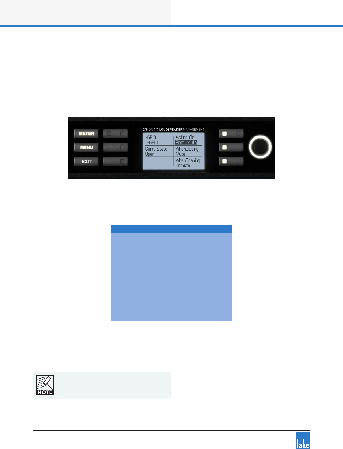
38
Front Panel Interface
Lake LM Series Operation Manual Rev 1.3.5
Four general purpose input/output conguration settings are available; two conguration options for inputs,
and two for outputs.
GPI Conguration
To adjust GPI 1 or GPI 2, press the associated button to display a screen similar to that shown in Figure
6-23.
Figure 6-23: GPI Conguration
Table 6-3 lists the options available for General Purpose Input (GPI). These options can be set independently
for a transition from closed > open and from open > closed.
Acting on Transition Option
Protective Mute State
1. No Action
2. Toggle State
3. Mute
4. Unmute
Standby State
1. No Action
2. Toggle State
3. Standby
4. Turn On
Preset Recall
1. No Action
2. Recall #99
3. Recall #100
No Action -
Table 6-3: GPI Options
A change to the ‘Acting on’ setting takes effect the next time the transition occurs. For example, changing a
GPI closed to open transition when the selected GPI is currently open is not executed until the next transi-
tion to open.
A change in GPI open/closed state occurring when
the device is disconnected from power will be
acknowledged and executed when power is
reconnected.
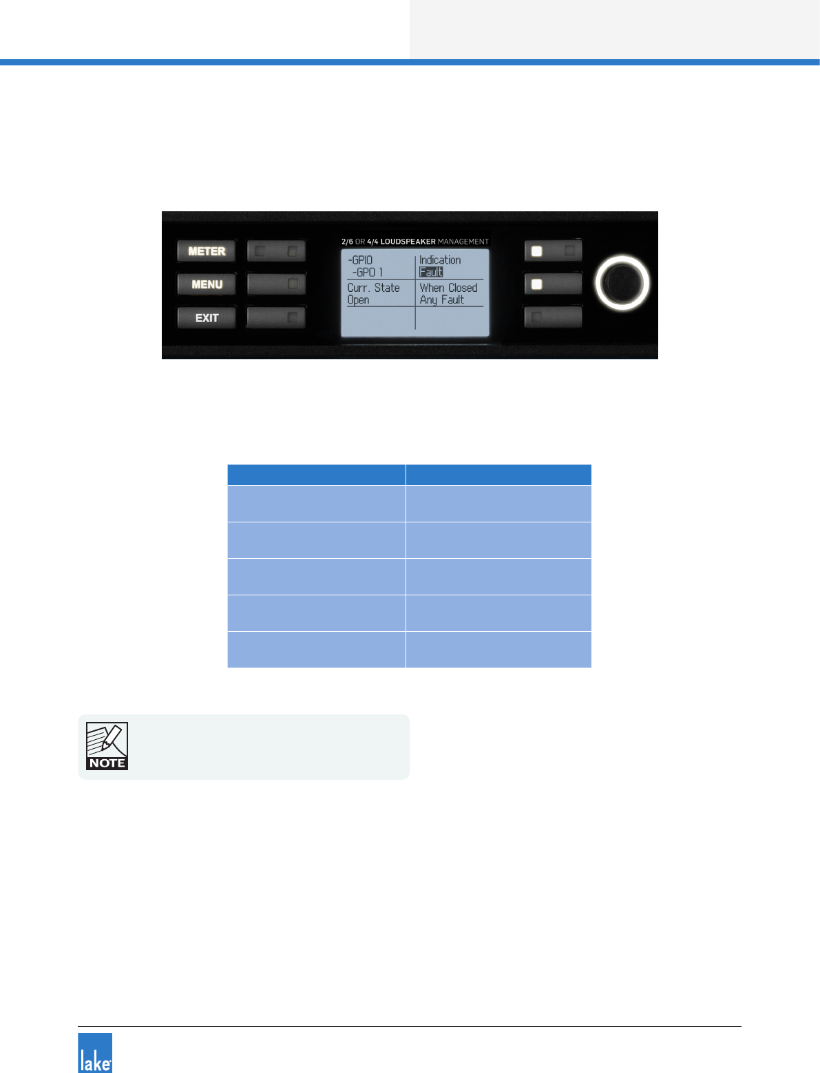
Front Panel Interface
39
Lake LM Series Operation Manual Rev 1.3.5
GPO Conguration
To adjust GPO 1 or GPO 2, press the associated button to display a screen similar to that shown in Figure
6-24
Figure 6-24: GPO Conguration
Table 6-4 lists the options available for General Purpose Output (GPO).
Acting on State when Closed
Protective Mute State 1. Muted
2. Unmuted
Standby State 1. Standby
2. On
Fault 1. No Fault
2. Any Fault
Ready 1. Ready
2. Not Ready
No Indication -
Table 6-4: GPO Options
Factory Reset and Soft Reset clear the protective
mute state.
Two input options (GPI) and two output options (GPO) may be set at any one time. The default GPIO con-
guration is shown in Table 6-5. The current state (open/closed) is reported for all GPIO settings on the front
panel and in the Lake Controller software.
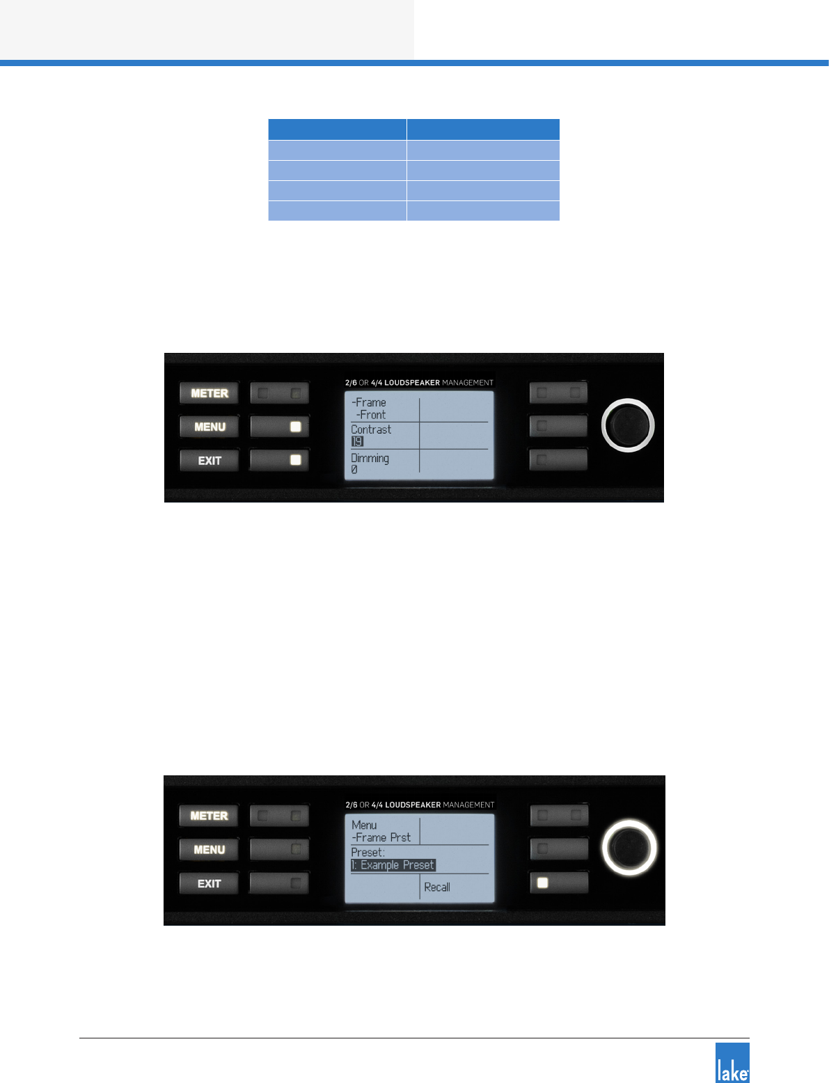
40
Front Panel Interface
Lake LM Series Operation Manual Rev 1.3.5
GPIO # Default Option
GPI 1 No Action
GPI 2 No Action
GPO 1 Standby State
GPO 2 Fault
Table 6-5: Default GPIO Conguration
6.10.5 Front Panel Display Controls
MENU > FRAME > FRONT
Figure 6-25: Front Panel Display Controls Menu
Contrast
To adjust the front panel LCD contrast, select this option then use the rotary encoder to change the value.
Dimming
To adjust the front panel LCD & LED brightness, select this option then use the rotary encoder to change
the value.
6.10.6 Frame Preset Menu
MENU > FRAME PRST
Figure 6-26: Frame Preset Menu

Front Panel Interface
41
Lake LM Series Operation Manual Rev 1.3.5
To recall an existing Frame Preset, use the rotary encoder to select the required Preset then press the
RECALL button to overwrite the current conguration.
Frame Presets must initially be created in the Lake
Controller, and stored as a Preset using the Lake
Controller or the LM Series Preset Manager.
Up to 100 Frame Presets can be stored in the device. The data within a Frame Preset includes the congura-
tion of all Modules in the Frame including levels, crossovers, EQ, input mixer, and output routing.
As Frame Presets are stored within the device, complete processor congurations can be recalled without
connecting the device to a PC.
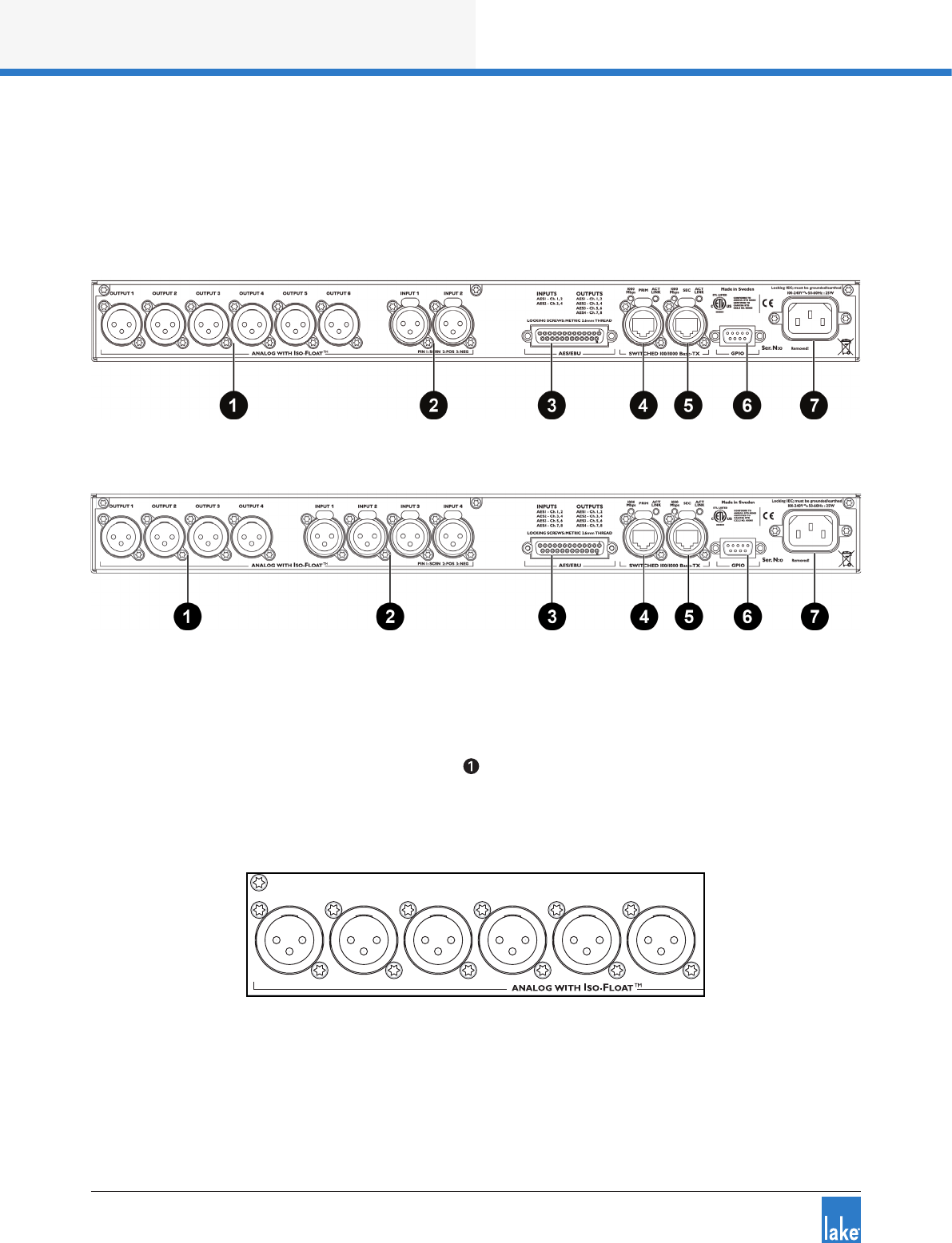
42
Back Panel Interface
Lake LM Series Operation Manual Rev 1.3.5
7. Back Panel Interface
An overview of the back panel interface is provided in section 4.2. This chapter describes each cluster of
connections as shown in Figure 7-1.
Figure 7-1: Back Panel Interface (LM 26)
Figure 7-2: Back Panel Interface (LM 44)
7.1 Analog Inputs and Outputs
7.1.1 Analog Output XLR Connections
Six (LM 26) or four (LM 44) electronically-balanced analog outputs are provided via standard XLR3M connec-
tions.
AES/EBU GPIO
SWITCHED 100/1000 Base-T
INPUT 1
OUTPUT 1OUTPUT 2OUTPUT 3OUTPUT 4OUTPUT 5OUTPUT 6
INPUT 2LINKPRIMACT
Ser. N:o
SEC LINKACT
Figure 7-3: Analog Output XLR Connections (LM 26)
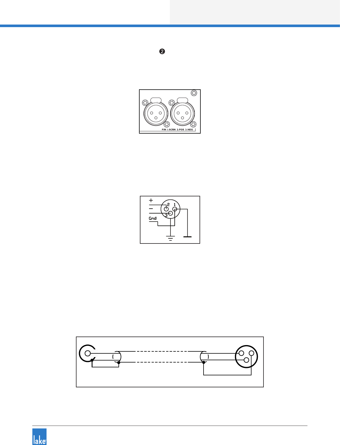
Back Panel Interface
43
Lake LM Series Operation Manual Rev 1.3.5
7.1. 2 Analog Input XLR Connections
Two (LM 26) or four (LM 44) electronically-balanced analog inputs are provided via latching XLR3F connec-
tions.
AES/EBU GPIO
SWITCHED 100/1000 Base-T
INPUT 1
OUTPUT 1OUTPUT 2OUTPUT 3OUTPUT 4OUTPUT 5OUTPUT 6
INPUT 2
LINKPRIMACT
Ser. N:o
SEC LINKACT
Figure 7-4: Analog Input XLR Connections (LM 26)
7.1.3 Analog XLR Wiring and Pin Out
All XLR connections are wired to IEC268 as shown in Figure 7-5.
Figure 7-5: IEC268 XLR Wiring and Pin Out
Pin 1: Ground / Shield
Pin 2: Hot (+)
Pin 3: Cold (-)
7.1.4 Unbalanced Operation
Balanced connections are recommended where possible. However, if it is necessary to drive the device
from equipment with an unbalanced output, wire the inputs as shown in Figure 7-6.
12
3
COLD
HOT
SCRN
COLD
HOT
SCRN
Unbalanced Output
(Typically phono)
Balanced Input
(XLR)
Figure 7-6: Balanced to Unbalanced Analog Wiring and Pin Out
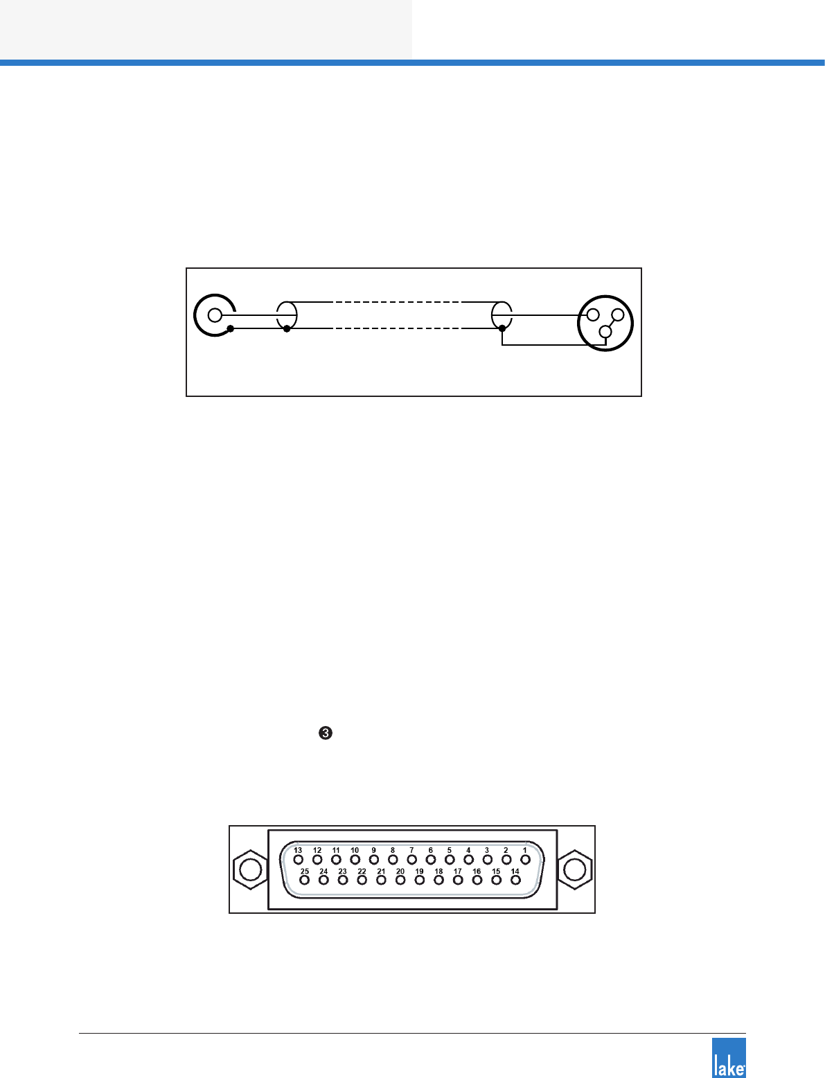
44
Back Panel Interface
Lake LM Series Operation Manual Rev 1.3.5
The method shown in Figure 7-6 uses twin-and-screen (balanced) cable and standard XLR pin connections
at the LM Series device end, with the cold wire and the cable screen connected to the signal ground of the
equipment at the source end.
This usually provides better noise and hum rejection than the more common method of joining pins 1 and
3 together in the XLR. However, if only a single-core (unbalanced) cable is available, the method shown in
Figure 7-7 may be used.
12
3
HOT
SCRN
HOT
SCRN
Unbalanced Output
(Typically phono)
Balanced Input
(XLR)
Figure 7-7: Unbalanced Analog Wiring and Pin Out
7.1.5 Iso-Float Electronic Balancing
The analog input and output electronic balancing circuits use the Lake Iso-Float system.
The Iso-Float technology combines the benets of transformer-coupled isolation with the advantages of
clean, direct-coupled inputs and outputs. The audio converters are galvanically isolated, and not connected
to the main ground. High-quality transformers and opto-isolators create a barrier between the device and
possible grounding aberrations from the outside electrical environment.
Iso-Float settings are adjustable via the front panel menu or the Lake Controller software.
7.2 AES3 Digital I/O
7. 2.1 AES3 DB25 Connector
A DB25 connector following the Yamaha pin-out standard is provided for AES3 connectivity on the LM
Series device.
Figure 7-8: AES3 DB25 Connector and Pinout Reference

Back Panel Interface
45
Lake LM Series Operation Manual Rev 1.3.5
This single DB25 connection provides four channels of AES3 input and eight channels of AES3 output as
shown in Figure 7-5 on page 43 below. A detailed wiring reference is provided in Figure 7-9.
AES3 Inputs AES3 Outputs
AES1: Ch. 1 & 2 AES1: Ch. 1 & 2
AES2: Ch. 3 & 4 AES2: Ch. 3 & 4
AES3: Ch. 5 & 6* AES3: Ch. 5 & 6
AES4: Ch. 7 & 8* AES4: Ch. 7 & 8
*LM 44 Only
Table 7-1: DB25 Input and Outputs
Figure 7-9 below provides a wiring reference for the DB25 connector.
Ch. Ground Hot Cold
1/2 IN 10 114
3/4 IN 11 215
5/6 IN 12 316
7/8 IN 13 417
1/2 OUT 22 518
3/4 OUT 23 619
5/6 OUT 24 720
7/8 OUT 25 821
Figure 7-9: DB25 Wiring Reference
Figure 7-5 on page 43 shows the only possible method of wiring; there is no equivalent of an unbalanced
connection in the digital domain.
7.3 RJ45 etherCON Network Connections
Two RJ45 etherCON style network connections are provided as shown in Figure 7-10.
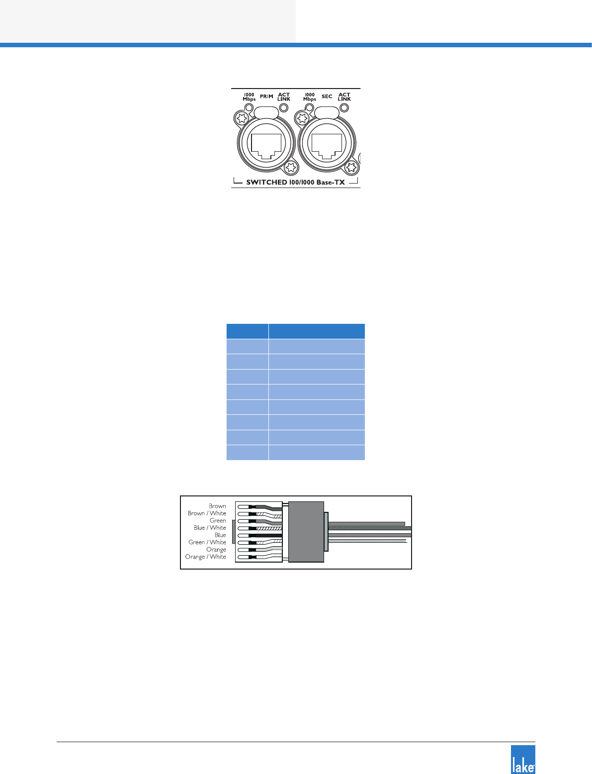
46
Back Panel Interface
Lake LM Series Operation Manual Rev 1.3.5
Figure 7-10: etherCON Network Connectors
The switched 100/100 Base-T network connections auto-sense whether standard or crossover Cat-5e
cables are in use. The green ACT LED illuminates (ashes) to show network activity, and when a 100 Mbps
connection is present; the orange LED illuminates (static) to indicate a 1000 Mbps connection.
Pre-made cables with moulded RJ45 plugs are recommended. If it is necessary to make up custom Cat-5e
network cables, use pinout described in Table 7-2.
Pin No. Color
1Brown
2 Brown + White
3Green
4Blue + White
5Blue
6 Green + White
7Orange
8 Orange + White
Table 7-2: RJ45 Wiring & Pin Out Description
Figure 7-11: RJ45 Wiring and Pin Out Diagram
When the device is connected to an active network, the yellow LINK LED illuminates above the connector in
use. Data activity on the network is indicated by illumination of the green ACT LED. It is normal for the ACT
LED to icker either sporadically or continuously.
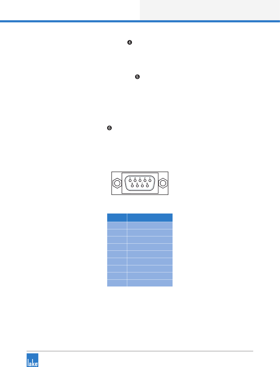
Back Panel Interface
47
Lake LM Series Operation Manual Rev 1.3.5
7.3.1 Primary Network Connection
The Primary Network connection is used for Lake Controller connectivity and Dante digital audio. Please
refer to section 4.2 for additional information.
7.3. 2 Secondary Network Connection
The Secondary Network connection may be used for a redundant Dante digital audio network. Please refer
to section 4.2 for additional information.
7.4 GPIO Connection
7.4.1 9-Pin GPIO Connector
A General Purpose Input/Output (GPIO) connection is provided, allowing interface to external devices such
as re alarm systems for emergency muting, processor power control, or preset recall. The GPO function
allows fault and state monitoring via external systems. Figure 7-12 in conjunction with Table 7-3 describes
the pinout conguration for the GPIO connector.
Figure 7-12: 9-Pin GPIO Connector and Pinout Reference
Pin No. Description
1GPI 1a
2GPI 1b
3 GPI 2a
4 GPI 2b
5Chassis Ground
6GPO 1a
7GPO 1b
8 GPO 2a
9 GPO 2b
Table 7-3: GPIO Pinout Wiring Reference
GPIO conguration is available via the front panel interface or via the Lake Controller software. Please refer
to section 6.10.4.4 of this manual for additional information on adjustment via the front panel, and refer to
the Lake Controller Operation Manual for information on adjusting via software interface.

48
Back Panel Interface
Lake LM Series Operation Manual Rev 1.3.5
7.5 Universal Power Supply Connection
7.5.1 IEC Power Connector
A universal power supply capable of accepting 70-265 V ~ 50-60 Hz : 25 W is built into the device. The IEC
power cable provided includes a locking feature via a pin on the bottom of the connector; the connector can
accept standard or locking IEC power cables.
The power supply must be connected to AC mains using an IEC power cable with a correctly wired and
molded plug for the country of operation.

Appendix
49
Lake LM Series Operation Manual Rev 1.3.5
8. Appendix
8.1 Faults and Warnings Overview
Fault or warning conditions are indicated by the LED shown in Figure 6-3 on page 18. As the LED indi-
cates several types of faults or warnings, a brief textual description of the fault or warning is provided on the
LCD display. Section on page 34 details the fault and warning indications that appear on the front panel.
Table 8-1 lists the events that may have triggered each fault or warning condition.
LCD Tex t Event Log Text Type Description / Troubleshooting
ANALOG IN
FAULT
Frame Fault:
Analog Input Fault There is a problem with the analog input; verify signal and connec-
tions.
NO INPUT No Input Source Fault No input signal can be identied for any valid unmuted input router.
Connect an input source, or verify input signals and connections.
OVERTEMP Temp Fault:
DSP area Fault
The temperature has reached a critical 70oC (158oF). Turn the unit
off or take steps to cool the unit immediately; continued operation
cannot be guaranteed.
PSU FAULT Frame Fault:
PSU Fault
This fault is relevant only to the LM44 device.
There is a problem with the power supply for the A/D convertors;
analog inputs will not be available. Send the device for service.
CLOCK
SLIPPING
AES Clock
Slipping Warning
The selected digital clock and digital input combination is not
aligned. Verify digital input conguration to ensure all clock settings
match.
CTRL OFFLINE -Warning The device is no longer able to communicate with the Lake Control-
ler. Check network connectivity.
NAME
CONFLICT
Dante device
name conict Warning There are multiple devices with identical Dante device names;
change the device name to ensure unique.
TEMP
WARNING
Temp Warning:
DSP area Warning
The temperature has reached 55oC (131oF). Monitor the tempera-
ture and take additional steps to reduce temperature if it continues
to increase.
- Frame Ofine Warning The Lake Controller is no longer able to communicate with the
device. Check network connectivity.
-Sound Source
Changed Warning The input source has been changed either manually or by automatic
input priority detection.
IN RTR MUTE Input Router X
Mute Mute An input router is muted; all Modules and outputs sourced from
this input router will be affected.
-Module Input
Mute Mute A Module Input has been muted. The mute is identied via the
associated Module Input mute button on the front panel.
-Module Output
Mute Mute A Module Output has been muted. The mute is identied via the
associated Module Output mute button on the front panel.
PROTECTIVE
MUTE
Protective mute
via GPIO Event A processor mute state has been triggered via GPIO. Change this
setting using the external control device.
Table 8-1: Warning, Fault and Mute Indications (alphabetical by LCD Text / Event Log Text)

50
Appendix
Lake LM Series Operation Manual Rev 1.3.5
8.2 Maintenance
During normal operation this devices provides trouble-free service. If the LCD or front panel display requires
cleaning, use a soft cloth only; do not use solvent cleaners. The dust lter on the right-hand side air intake
should occasionally be removed and cleaned to ensure maximum airow through the device.
Disconnect the unit from mains power prior to removing dust the lter, and ensure the dust lter is
replace prior to turning the unit back on.
Do not use sharp or metal objects to remove the dust lter, and be careful that the implement used to
remove the lter does not enter the device.
In extreme cases it may be necessary to clean the inside of the device. This procedure should only be
carried out by qualied service personnel. This may be necessary if the device has had prolonged operation
in an extreme environment such as one where cracked oil smoke machines are in use. If the device is used
in extreme conditions, it is recommended to have it serviced every three years as a preventative measure.
8.3 Factory Default Settings
8.3.1 Module Defaults
Module Type: 2 x Classic 3-Way (LM 26) or 4 x Mesa EQ (LM 44)
Mod Input Mute: On (LM 26) - N/A (LM 44)
Mod Output Mutes: Off (LM 26) - On (LM 44)
Gain: 0 dB (unity)
Delay: 0 ms
Polarity: Positive (In phase)
MaxRMS: 20 dB
MaxPeak: 21 dB
Input & Output EQ: Flat
8.3.2 Input and Router Defaults
Autoselect: On
Input sensitivity: +26 dBu
Dante: Disabled
AES3: Terminated
Iso-Float: Enabled
8. 3. 2.1 Router Defaults (LM 26)
Router 1: Priority 1 = Dante (Ch.1), Priority 2 = Empty, Priority 3 = AES (Ch.1), Priority 4 = Analog 1
Router 2: Priority 1 = Dante (Ch.2), Priority 2 = Empty, Priority 3 = AES (Ch.2), Priority 4 = Analog 2
Router 3: Priority 1 = Dante (Ch.3), Priority 2 = Empty, Priority 3 = AES (Ch.3), Priority 4 = Empty
Router 4: Priority 1 = Dante (Ch.4), Priority 2 = Empty, Priority 3 = AES (Ch.4), Priority 4 = Empty

Appendix
51
Lake LM Series Operation Manual Rev 1.3.5
Router 5: Empty
Router 6: Empty
Router 7: Empty
Router 8: Empty
8.3.2.2 Router Defaults (LM 44)
Router 1: Priority 1 = Dante (Ch.1), Priority 2 = Empty, Priority 3 = AES1 (Ch.1), Priority 4 = Analog 1
Router 2: Priority 1 = Dante (Ch.2), Priority 2 = Empty, Priority 3 = AES1 (Ch.2), Priority 4 = Analog 2
Router 3: Priority 1 = Dante (Ch.3), Priority 2 = Empty, Priority 3 = AES2 (Ch.3), Priority 4 = Analog 3
Router 4: Priority 1 = Dante (Ch.4), Priority 2 = Empty, Priority 3 = AES2 (Ch.4), Priority 4 = Analog 4
Router 5: Priority 1 = Empty, Priority 2 = Empty, Priority 3 = AES3 (Ch.5), Priority 4 = Empty
Router 6: Priority 1 = Empty, Priority 2 = Empty, Priority 3 = AES3 (Ch.6), Priority 4 = Empty
Router 7: Priority 1 = Empty, Priority 2 = Empty, Priority 3 = AES4 (Ch.7), Priority 4 = Empty
Router 8: Priority 1 = Empty, Priority 2 = Empty, Priority 3 = AES4 (Ch.8), Priority 4 = Empty
8.3.3 Other Device Defaults
Dual Redundancy: Disabled
Dante Slave Only: Disabled
GPIO: No Action / No Indication
IP Conguration: Auto Zero Conf. (Auto IP)
8.4 Glossary of Terms, Acronyms and Abbreviations
The explanations given in Table 8-2 below are based on the specic use of each term in this manual. The
denitions are not intended to be exhaustive and many of these terms have wider meanings.
Term Description
100/1000 Base-T 100/1000 Base-T is IT industry-speak for different standards of Ethernet network. This term incorporates 100 Base-TX, which operates
at 100 Mbps, and 1000 Base-T which operates at 1000 Mbps (1 Gbps).
Access Point See Wireless Access Point.
Auto-Sensing The Ethernet ports automatically determine the base speed of the network they are connected to (10 Base-T or 100 Base-T) and
congure themselves appropriately. This is termed auto-sensing.
Auto-Uplink The Ethernet ports can operate with either straight or crossed network cables. This ability to connect correctly with either type is
termed auto-uplinking.
Auxiliary Output Some of the congurations possible in the Lake processing system Modules result in a single audio processing channel being created in
addition to a crossover. This is termed an Auxiliary output.
Backbone Large Ethernet networks are often implemented with a very high speed “trunk” part of the network topology feeding main switches,
which in turn support smaller, lower-speed local networks. The term backbone is used to describe such a trunk.
Bandwidth The bandwidth of a signal channel or interconnection is the range of frequencies it is able to handle. The term can be applied to both
audio channels and Ethernet networks.
Cat-5e/Cat-6, etc.
Designations of industry-standard cables suitable for Ethernet networks using four twisted pairs of conductors. Often referred to as UTP
cable (Unscreened Twisted Pair). Cat-5 has generally been replaced by Cat-5e (e = ‘enhanced’). Either Cat-5e or Cat-6 cable are suitable
for networking Lake and Lab.gruppen devices.
Chain An Ethernet network comprising several devices interconnected using the Secondary connectors to daisy-chain the units together is an
example of a network with a chain topology.
Clock
Digital audio is produced by sampling analog audio at a known, xed rate, controlled by some form of master clock. Problems can occur
when interconnecting two pieces of digital audio equipment if their internal master clocks are not synchronized. Various techniques may
be employed to ensure that this is the case.

52
Appendix
Lake LM Series Operation Manual Rev 1.3.5
Term Description
Contour Terminology given to a Frame or Module that denotes it is congured as a Loudspeaker Processor, normaly featuring crossovers and
multiple outputs fed from the same input.
Crossed Network Cable
An Ethernet cable in which four of the eight conductors (pins 1, 2, 5 & 6) are not wired pin-to-pin. Such a cable is required in conventional
IT networks to connect two PCs together without using a hub or switch. The auto-uplink feature of the Ethernet ports allows crossed
cables to be used if wished. See also Straight network cable.
Dante
A new-generation audio data protocol developed by Audinate® Pty Ltd, allowing multichannel high-resolution digital audio plus control
data to be transmitted via standard IT-industry networks using TCP/IP data packets. The Lake processing system integrated within the
LM Series device includes a dual-redundant Dante network interface, providing digital audio inputs and outputs via Ethernet.
dBu dBu’s are usually used instead of voltages to describe signal levels in audio systems. A signal level of 0 dBu may be taken as 0,775 Vrms.
Delay Up to two seconds of delay may be added to the input and/or output channels to time-align loudspeaker arrays.
Digital Gain Offset Digital gain offset is effectively a ‘ne’ gain adjustment performed in the digital domain, which can be applied to digital input signals to
optimize the signal to the gain structure.
Distribution Amplier
A distribution amplier (usually abbreviated to DA) is an audio buffer stage – usually with zero gain – with one input and several outputs.
Mono, stereo and AES3 digital versions can be obtained. Use of a DA to feed a signal to several destinations ensures correct impedance
matching and isolation between source and destinations.
Dual-Network Topology
A network topology consisting of two (usually) identical networks, one connecting to the Primary Ethernet ports and the other to the
Secondary ports. Although more complex to implement, the advantage of using a dual-network system is one of greatly improved
reliability as one complete network remains operational if the other should fail.
Dynamic Function
Buttons
The six buttons around the front panel display are termed dynamic function buttons because their function varies depending upon which
display page is currently on-screen.
Electronic Balancing
In the analog domain, balanced inputs and outputs may be provided on audio equipment either by the use of transformers (traditional,
very good, but heavy and expensive) or via electronic balancing circuits (nearly as good, without full electrical isolation, but a great deal
cheaper).
Event Log The details of any fault or warning conditions which arise in the device during operation are recorded in a data le created by the Lake
Controller software called the Event Log.
Fault A Fault in the device occurs when one of the operating parameters exceeds pre-determined safety levels, or when a condition is
detected that otherwise seriously affects the performance. Some fault conditions may result in one or all of the channels being muted.
FIR Filter Finite Impuse Response Filter. An alternative design of crossover lter realisable in the digital domain, providing linear phase
characteristics. FIR ltering is provided in all Lake devices.
Floating
An analog balanced input or output is said to be oating when full electrical isolation exists between that input or output and the equip-
ment connected to it. Transformer-coupled inputs and outputs are inherently oating. Electronically balanced inputs and outputs can
never be truly oating, though better designs – such as that found in LM Series devices - do mimic the characteristics of transformer-
coupled designs to a high degree.
Frame Lake terminology for a physical unit containing a Lake processing system (i.e. a single LM or PLM Series device, or legacy Lake
Processor).
Frame ID An electronic identication ‘label’ which can be given to each Frame in an amplication system. Naming Frames in a large system is
desirable as it simplies identication in the Lake Controller.
Frame Preset Frame Presets are a class of Presets within the Lake processing system. Up to 100 can be stored in the hardware device, and each holds
the complete conguration of all Modules and the Modules’ internal settings.
Gigabit Ethernet Describes the speed of Ethernet data transfer for devices that transmit Ethernet frames at a rate of a gigabit per second, as dened by
the IEEE 802.3-2008 standard.
GPIO The General Purpose Input/Output (GPIO) port on a LM Series device allows two-way communication with external devices for certain
functions.
Hub A type of network interface device with multiple Ethernet ports. Data arriving at any port is sent to all others. Hubs have been largely
replaced by Switches.
Input Level
The amplitude of an audio signal at the point where it is applied to the input of the device, or at the input of an intermediate stage within
it. An analog input signal level will be expressed in dBu’s, while a digital input signal level in dBfS (dBs below digital clip level; fS =
full-scale)
Input Router
The Input Router allows automatic or manual selection of any device input to be allocated to a Module Input or directly to any output.
The Input Router is effectively an intelligent digital patch bay & automated switch that can seamlessly failover to up to four levels of
inputs in the event of digital signal loss. The output from the router is the input signal from a valid input with the highest priority.
IP Address
Every item of equipment connected to an Ethernet network has a unique address called the IP address, so that data gets to the correct
place. IP addresses are written as four groups of three decimal numbers between 0 and 255. In a system consisting of Lake Processors
and a Lake Controller they are assigned and detected automatically.
IP Subnet Mask IP subnet masks are required in all IP networks. The subnet is determined by the size and type of network being used. For small
networks (less than 254 addresses) a subnet mask of 255.255.255.0 can be used. (A Class C network).
Iso-Float Iso-Float is Lake’s proprietary method of electronic balancing, which provides a particularly high level of isolation and immunity from
ground loops.
Lake Controller
The Lake Controller is the software application used to control LM and PLM Series devices and legacy Lake processors. This software
application provides additional functionality and allows various grouping functions for simultaneous control of multiple Lake Processing-
enabled devices.
Latency The small but nite delay incurred by audio signals when they are transformed into the digital domain, processed digitally and then
converted back into analog signals. In the Lake system, latency is assured to be constant.

Appendix
53
Lake LM Series Operation Manual Rev 1.3.5
Term Description
Legacy Lake Device This term refers to older Lake audio equipment which may form part of an audio system (i.e. Lake Contour Pro 26, Lake Mesa Quad EQ
and the Dolby Lake Processor). The Lake Controller has the capability to control all Lake legacy products.
LimiterMax LimiterMax is the name given to Lake’s proprietary package of dynamics control which forms part of the Lake Processing system.
Line Driver An analog audio amplier, usually with zero gain, having very low output impedance and high drive capability. They are used for transmit-
ting balanced analog audio over very long cables.
Linear Phase Crossover See FIR Filters
MAC Address In addition to an IP address, every device on an Ethernet network has a MAC address. This address is xed at the time of manufacture,
and is effectively the permanent identier of the physical unit. MAC stands for Media Access Control
MaxPeak Lake’s LimiterMax provides independent dynamics control over signal peaks (MaxPeak) and the average signal level (MaxRMS).
MaxRMS See MaxPeak.
Mesa or Mesa EQ Terminology given to a Frame or Module that denotes it is congured as a System EQ Processor, providing HPF/LPF, EQ & Levels
functionality (no crossovers). Often congured with a single input to single output routing.
Mesa EQ Filter The name given to the unique Lake EQ lter with a variable width at top and variable slopes on each side of the lter.
Module
Module is the term used in the Lake Controller to describe the virtual set of signal processing that routes an audio input to the various
frequency-weighted outputs of a crossover. The processing system within the device allows for two Modules, each of which may be
assigned a range of crossover congurations, input sources, etc.
Module Preset A class of Preset within the Lake processing system. A Module Preset (Module le) contains all the conguration data and settings for
one Module, and is saved in the Lake Controller software, not in the hardware device.
Ofine A device on an Ethernet network which is not communicating with the rest of the network either due to a fault or intentionally is said to
be ofine.
Online A device on an Ethernet network which is fully operational and communicating with the rest of the network is said to be online.
Parallel Two or more e.g. inputs which are wired together so that all inputs are connected to the same source are said to be paralleled. Signal
levels will be reduced if too many inputs are paralleled; in the case of AES3, this may result in a complete loss of audio.
Parameter Any control function which can be adjusted by the user to one of several different values is termed a parameter. For example, input level,
gain, delay, and limiter threshold are all parameters.
Pass-Through Cable See Straight network cable.
Ping
Ping is a term coined by the IT industry to the procedure of sending a command over a network to a particular Ethernet device asking it
to conrm its identity and possibly reply with additional information. Thus an Lake device on the network can be pinged from the Lake
Controller; on receipt of the ‘ping’, the hi-intensity white LED on the front panel illuminates. Reverse pinging is also possible, whereby
the ping is instigated from Lake hardware device and a visual identication of the processor registers in the Lake Controller software.
Preset A complete frame conguration that is stored in the device hardware.
Primary Ethernet Port The Primary Ethernet port on the is the means of connecting the device to a network. See also Secondary Ethernet Port.
PSU Abbreviation of Power Supply Unit. The PSU in any item of electronic equipment converts the AC mains into a set of internal DC voltages
which run the electronic assemblies themselves.
RJ45 RJ45 connections are the industry-standard connectors for Ethernet ports.
Router As far as networks of the type discussed in this manual are concerned, see Switch. For a description of the term Input Router used on
Lake devices, see Input Router.
Secondary Ethernet
Port
The Secondary Ethernet port can be used either as a daisy-chain output, repeating the network connection at the Primary port, or for the
connection of a separate second network for full redundancy.
Star Topology A network topology which uses a network switch to connect to individual Lake devices. Each device connects to one port on the switch
with its own cable, thus the network looks like a star when drawn as a diagram with the switch at the centre.
Straight Network Cable A Cat-5/6 network cable with full pin-to-pin connections is called a straight network cable. Lake devices can connect to a network using
either straight or crossed network cables.
Subsystem
It is possible when working with large networked systems to store selected components of the system into a Subsystem. This is useful
if working on a tour that encompasses both large and mid-sized venues. The same core Lake Controller data can then be used for a
reduced number of Lake devices.
Super Module A Super Module is a virtual construct that can be realized within the Lake Controller, allowing a set of Modules in different Frames to be
treated as a single Module.
Switch (Ethernet)
An Ethernet switch allows several Ethernet devices to be connected to a network using a star topology. More intelligent than the earlier
hubs which they now largely replace, they route packets of data only to the units for which they are intended, and also perform other
system housekeeping and control functions.
System Preset A class of Preset within the Lake Processing system, System Presets allow Module or Frame congurations and settings to be stored for
the entire network of LM and PLM Series devices and legacy Lake processors.
Tablet PC A compact PC which uses a touchscreen instead of keyboard and mouse. The Lake Controller has been optimized for use on Tablet PCs.
Termination AES3 digital audio interconnections must be correctly terminated for reliable operation. The 110 ohm terminations must be set ‘on’ at the
beginning and end of a set of daisy-chained digital audio equipment, and ‘off’ at any intermediate ones.
Topology A mathematical word for “arrangement” or “conguration”. The topology of a network is a means of visualizing the overall conguration
of the network.

54
Appendix
Lake LM Series Operation Manual Rev 1.3.5
Term Description
Universal Power Supply A power supply that operates in all countries, without the need for manual adjustment, as long as the voltage falls within the specied
range for the device.
Vrms The RMS voltage of a signal. See RMS.
Wireless Access Point A device used to connect a computer to an Ethernet network without cables; a radio transmitter/receiver for data.
Wireless Network An Ethernet network where some or all cabled connections are replaced by wireless links.
Table 8-2: Glossary of Terms, Acronyms and Abbreviations

66
Application Guide
Lake LM Series Operation Manual Rev 1.3.5
9. Application Guide
This chapter describes the practical application and use of LM Series devices.
9.1 Gain Structure
The LM Series architecture provides gain adjustments at various points in the signal path and therefore, vari-
ous places for muting and level adjustment. Each mute or gain adjustment point serves a different purpose.
The signal ow diagrams in chapter 5 provides a useful reference for the signal path. The following sections
describe the various adjustment points, all of which are available via the Lake Controller software.
9.1.1 Input Headroom (Analog Inputs Only)
This parameter should be set relevant to the output level of the analog audio source (e.g. mixing console).
This setting does not affect the other gain stages, or the overall noise oor; it allows control of the appropri-
ate headroom at the input stage only.
To adjust, navigate to I/O CONFIG > INPUT CONFIGURATION in the Lake Controller. Please refer to the
Lake Controller Operation Manual for further details.
9.1. 2 Input Mixer
Input Mixer gains can remain at 0.00 dB for most congurations; if only one input channel is used per
Module, the other can be set to -INF.
To adjust, navigate to I/O CONFIG and tap the Input Mixer blocks for the Module in the Lake Controller.
Please refer to the Lake Controller Operation Manual for further details.
9.1. 3 Module Input Gain
Input Gain is used to adjust the level between different speaker cabinets in the system. This gain can remain
at 0.00 dB unless a lower level is required for the cabinet/s driven by this Module.
To adjust, navigate to MODULES > EQ/LEVELS > LEVELS in the Lake Controller. Please refer to the
Lake Controller Operation Manual for further details.
9.1.4 Module Output Gain
Factory and User Gain are provided for each Module output. These two stages provide a level of security
and control for the system designer (Factory) and a further level of adjustment for the user (User), both of
which combine to balance the level between frequency bands in a multi-way crossover (Contour congura-
tion) or the Module output level (Mesa conguration).

Application Guide
67
Lake LM Series Operation Manual Rev 1.3.5
1. Factory Gain is set by the system designer and can be hidden within the Module le. The Factory
Gain parameter is only accessible when the Module is unlocked and the Lake Controller is in
Designer Mode. Adjust via MODULES > LEVELS > METER OPTIONS > ADJUST FACTORY.
2. User Gain is editable by a user unless the system designer has locked away the parameter; adjust
via MODULES > LEVELS.
Generally, output gain values are congured within a Module / loudspeaker preset le and should not need
to be adjusted further.
9.2 Gain / Level Optimization
9. 2 .1 Maximize Volume Capability
To maximize the volume capability of the device, ensure there is sufcient headroom in the signal path to
avoid clipping before the limiters engage. It must be possible to achieve enough gain through the device to
engage the limiters and realize a high average SPL. As an optimal setting, allow for a headroom of 10 dB or
more for all channels; the simplest way to accomplish this is to increase the Module input gain.
9.2.2 Minimize Noise
To help provide the best volume to noise ratio, use an AES or Dante digital input signal wherever possible. If
using analog inputs, ensure that unused or unnecessarily high headroom is not introduced at the input to the
device. If full or high average power is not required, the Module input gain may be reduced.
9.3 Digital Audio Connections
Whenever possible, it is preferable to connect a digital rather that analog input signal to the device. This is
particularly relevant if the source signal is already in the digital domain, such as the source from a digital
mixing console or digital distribution system. The primary cause of signal distortion and signal delay (latency)
is the digital-to-analog and analog-to-digital conversion process. Therefore, using digital inputs normally
provides higher quality audio with lower latency.
Two types of digital audio inputs are available: Dante networked multi-channel digital audio, and 2-channel
digital audio via the AES3. Dante-based system congurations and interconnections are explained in a
separate document, the Lake Network Conguration Guide.
The information in this section is supplied for users unfamiliar with AES3. Users already familiar with AES3
will nd that the device conforms to established conventions.

68
Application Guide
Lake LM Series Operation Manual Rev 1.3.5
9.3.1 AES3 Digital Audio
The original AES/EBU digital audio interface standard was developed by the Audio Engineering Society in
conjunction with the European Broadcast Union. Originally published in 1985, it was revised in 1992 and
2003, and in its current iteration it is properly designated the AES3 standard.
AES3 is a serial transmission format for linearly represented (uncompressed) digital audio data. It describes
a method for carrying two channels of periodically sampled and uniformly quantized audio signals on a single
twisted-pair cable.
The data format allows for auxiliary data which can be used for information on signal characteristics as
well as the sampled audio data. The physical interconnection, as dened by IEC 60958 Type I, species
three-conductor 110-ohm twisted pair cabling terminated by an XLR connector. Please refer to section 7.2
for wiring details.
AES3 provides for multiple sampling rates and resolutions of up to 24 bits; this device accepts sample rates
from 44.1 to 192 kHz.
9.3.2 System Latency and Delay Compensation
All types of digital audio processing inherently involves a small processing delay referred to as latency. If the
processing chain does not involve analog-to-digital or digital-to-analog conversion, the amount of latency is
usually very small and often may be disregarded.
However, in complex systems involving multiple digital audio components and connections, enough delay
may be generated to cause audio phasing problems. Therefore, the lowest latency is always preferred, and
it is always important to consider system latency delays when calculating and adjusting overall delay for
time-aligning multiple loudspeaker systems.
9.3.3 External Signal Distribution Hardware
9.3.3.1 Distribution Ampliers
Dedicated distribution ampliers for AES3 signals are available from several manufacturers. The most com-
mon format is one input and six outputs. Digital distribution ampliers are designed to refresh or reconstruct
the signal as well making up for line losses.
One type of distribution amplier is a simple repeater, which restores the waveform shape and brings the
signal amplitude back up the required level. Some distribution ampliers also offer a re-clocking feature,
which also re-times the signal to prevent signal degradation from clocking errors known as jitter.
Distribution ampliers that offer re-clocking often make the feature optional as using re-clocking can intro-
duce small additional amounts of latency, so should not be used unless necessary.
Application Guide
69
Lake LM Series Operation Manual Rev 1.3.5
9.3.3.2 Passive splitters
In some limited applications, a single AES3 input may be split into two signals using a simple passive
splitter. Splitters provide a convenient and low cost solution when only one additional signal is required, and
in situations where cable lengths are short. Attenuation is minimal, but there is no refreshing of the signal.
9.3.4 Additional Reference Material
Complete technical information on the AES/EBU (AES3) standard can be downloaded from the AES web
site at http://www.aes.org/publications/standards/.
9.4 Digital Clock Conguration
9.4.1 Digital Clock Overview
In order to provide a exible and robust audio processing system, the device is equipped with a congurable
digital clocking system. There are two separate digital clocks which can generate various independent
internal sample rates, or can sync to an incoming AES3 signal. Figure 9-1 shows the various sample rates
and options available.
Figure 9-1: Digital Clocking System

70
Application Guide
Lake LM Series Operation Manual Rev 1.3.5
In Figure 9-1, each circled C represents a choice point. A choice point is a user‐interface control that can
be congured using the Lake Controller software. Please refer to the Lake Controller Operation Manual for
further information.
Figure 9-1 indicates internally generated clocks with
base-rate multiples of 44.1 kHz or 48 kHz. This
should not be confused with the internal DSP
sample rate of 96 kHz.
Both the Primary and Sample Rate Converter (SRC) clocks can either generate their own internal clock
signal, or synchronize to an incoming AES3 signal. An incoming AES3 signal can be locked using automatic
clock detection or manual clock selection.
The Primary and SRC clocks produce multiple audio clocks derived from a base sample rate. The Primary
Clock’s base rate is 48 kHz, which also derives the 96 and 192 kHz clocks. The SRC Clock’s base rate can
be either 44.1 or 48 kHz. If the SRC Clock’s base rate is 44.1 kHz, then 88.2 and 176.4 kHz clocks are also
derived; if the SRC Clock’s base rate is 48 kHz, then 96 and 192 kHz clocks are also derived.
In most typical applications, SRC Clock will be set at a base rate of 44.1 kHz. A base rate of 48 kHz is
provided to allow for both synchronous (via Primary Clock) and asynchronous (via SRC Clock) I/O.
All clocks derived from the Primary and SRC clocks are available to drive the AES3 audio outputs. The
desired sample rate can be selected independently for each AES3 output pair, as shown on the right side of
Figure 9-1.
For example, you could congure AES1, AES2, and AES3 to provide 96 kHz AES3 outputs to drive digital
ampliers in the sound system, and congure AES4 to provide a 44.1 kHz audio recording output for media
or broadcast purposes.
9.4.2 Clock Source Priorities
There are two options for clock source conguration: Manual Conguration or Automatic Detection.
For Manual Conguration, the selected internal or external clock source remains xed regardless of whether
a compatible clock signal is preset.
For Automatic Detection, the most appropriate clock matching the selected base-rate is automatically
selected according to the following priorities.
1. AES1 (Input 1+2)
2. AES2 (Input 3+4)
3. AES3 (Input 5+6) - LM 44 Only
4. AES4 (Input 7+8) - LM 44 Only
5. Internal Clock
Application Guide
71
Lake LM Series Operation Manual Rev 1.3.5
When using automatic detection, the AES3 digital input is monitored and will switch the clock source back
and forth depending on the availability of an AES3 signal.
Please refer to the Lake Controller Operation Manual for additional information.
9.4.3 Dante Clock Conguration
Dante uses its own digital clocking technology across the Ethernet network to ensure that all Dante devices
are synchronized. As part of this logic, an order of priority is dened to identify which device becomes the
Dante Master. A Dante-capable device set as Preferred Clock Master is chosen as the highest priority,
followed by a device with a valid AES3 signal, then an internally generated clock.
Dante only operates at 48 kHz or 96 kHz, and therefore only uses the Primary Digital Clock to lock the
sample rate for the Dante Master. The Primary Clock on all Dante Slaves will be overridden by the Dante
Clock. If an additional digital input signal is required on a device that is already a Dante slave, this secondary
digital input must be locked using the SRC clock.
The front panel I/O Status View indicates if that device is selected as Dante Clock Master. Conrmation of
Dante Master / Slave status is also displayed in the Lake Controller. The Dante Preferred Master setting can
be set from the Lake Controller I/O Conguration screen, or via the Dante Controller.
For further information on Digital Clock conguration
and the Lake Controller user interface, please refer
to the Lake Controller Operation Manual.
9.5 Signal Processing Latency
The information in Table 9-1 lists the total latency for common input-output congurations when the audio
passes through the Module processing. Table 9-2 on page 72 shows the latency when congured as
pass-thru (no Module processing).
Input
Conguration
Output
Conguration
LM 26
Total Latency (ms)
LM 44
Total Latency (ms)
Analog Analog 1.039 1.049
Analog 48 kHz sync 1.18 5 1.18 5
Analog 96 kHz sync 0.971 0.971
48 kHz sync Analog 1.208 1.219
48 kHz sync 48 kHz sync 1.358 1.358
96 kHz sync Analog 0.951 0.962
96 kHz sync 96 kHz sync 0.871 0.871
Table 9-1: Latency for Common I/O Congurations (via Module)

72
Application Guide
Lake LM Series Operation Manual Rev 1.3.5
Input
Conguration
Output
Conguration
LM 26
Total Latency (ms)
LM 44
Total Latency (ms)
Analog Analog 0.226 0236
Analog 48 kHz sync 0.373 0.373
Analog 96 kHz sync 0.15 8 0.15 8
48 kHz sync Analog 0.395 0.406
48 kHz sync 48 kHz sync 0.545 0.545
96 kHz sync Analog 0.138 0.15 0
96 kHz sync 96 kHz sync 0.059 0.059
Table 9-2: Latency for Common I/O Congurations (Pass-thru)

Technical Specications
73
Lake LM Series Operation Manual Rev 1.3.5
10. Technical Specications
Model LM 26 LM 44
Module confi guration 2 Contour Modules or 4 Mesa Modules
Processing channels 6 in Contour mode, 4 in Mesa mode
Input routers 8 input routers with 4 priorities in each, seamless failover to lower priorities
Module input mixer 4 ch. for Contour, 8 ch. for Mesa-modules. Mix any ratio between all input routers.
Input processing Raised Cosine Mesa and Ideal Graphic input equalizers
Output processing Linear phase or Classic crossovers, Parametric EQ, shelving and all-pass filters
Features Delay, mute, phase, gain etc.
Limiters LimiterMax with Peak and RMS limiter, MaxRMSRelease and MaxPeakLevel, Configurable MaxRMSLevel,
MaxRMSCorner, MaxRMSAttack
SuperModule compatible Yes
Audio performance
Conversion resolution 24 bit
Internal sample rate 96 kHz
Internal data path 32 bit floating point
Product propagation delay Best case (AES synchronous 96 kHz to AES Best case (AES synchronous 96 kHz to AES
synchronous 96 kHz via module) 0.871 ms synchronous 96 kHz via module) 0.871 ms
An alo g (A nal og in to An alog ou t via mod ule) 1.039 ms
Analog (Analog in to Analog out via module) 1.049 ms
Pass thru (Analog in to AES synchronous 96 kHz Pass thru (Analog in to AES synchronous
bypassing module) 0.158 ms 96 kHz bypassing module) 0.158 ms
Maximum available user delay 2 seconds
Analog
Inputs and Outputs 2 inputs, 6 outputs 4 inputs, 4 outputs
Frequency Response, analog-to-digital +/-0.1 dB, 20 Hz to 20 kHz
Frequency Response, digital-to-analog +/-0.1 dB, 20 Hz to 20 kHz
THD+Noise, Inputs 0.00024% typical at 1 kHz
THD+Noise, Outputs 0.00037% typical at 1 kHz
Dynamic Range, Inputs 116 dB
Dynamic Range, Outputs 115 dB
Input impedance 20 kOhm balanced, 10 kOhm unbalanced
Output impedance 50 ohm
Maximum input level +26 dBu
Input Sensitivity - settings for digital full-scale +12 dBu, +26 dBu
Maximum Output level +21 dBu
Crosstalk, inputs -98 dB, 20 Hz to 20 kHz
Crosstalk, outputs -98 dB, 20 Hz to 20 kHz
Common Mode Rejection Ratio (CMRR) >70 dB, 20 Hz to 20 kHz
AES3/EBU (sample rate converters available as desired)
Inputs and Outputs 4 inputs, 8 outputs 8 inputs, 8 outputs
Supported sample rates (I/O individually selectable)
Supported resolutions Up to 24-bit
THD+Noise 0.00002 % at 96 kHz, 0.00006 % at 44.1 kHz sample rate
Dynamic range Base48 -140 dBFS, Base44 -125 dBFS
Clocking
Clock selection Manual or automatic according to priority scheme
Oscillator type / synchronization High quality VCXO clock can provide Dante master clock or slave. Automatic synchronization with Dante network.
Base48 2 (Primary and SRC)
Base44 1 (SRC)
Clock accuracy < ± 7 ppm
Dante (audio network)
Inputs and Outputs 4 inputs, 8 outputs
Supported sample rates 48, 96 kHz
Support redundant paths Yes, Glitch-free Dual Redundant Dante using two Ethernet networks.
Device latency 0.25 ms, 0.5 ms, 1.0 ms, 2.0 ms, 5 ms
GPIO
Inputs 2 General Purpose Inputs (GPI) supporting external contact
Outputs 2 General Purpose Outputs (GPO) with internal contact closure
Software confi gurable input control Standby state, Mute state, Dual Preset recall
Software confi gurable output indication Standby state, Mute state, Faults, Ready
Device presets
Frame presets 100
Power requirements
Nominal voltage 100-240 VAC
Operating voltage 70 -265 VAC
Power consumption 30 W maximum
Front panel interface
Display Daylight readable monochrome (128 x 64)
Meters LED for signal level and clip indicators per channel
Mute access Dedicated Mute button and LED indication per processing channel
Menu Intuitive and powerful user interface with soft keys
Status indication LED Fault and Warning indication and detailed description on display
Parameter adjustment Single/multiple parameter edits with rotary encoder
Back Panel Interface
Analog Inputs and Outputs 2 + 6 XLR 4 + 4 XLR
AES Inputs and Outputs DB-25, with selectable termination
Ethernet Auto 100/1000, Auto uplink, 2 x Neutrik etherCON RJ45 connectors
GPIO DB-9
Power Detachable locking 3-pin IEC
Control and monitoring interface Via Ethernet for Lake Controller software, or DLM (the 3rd party protocol)
Dimensions (W/H/D) 483 mm (19"), 44 mm (1 U), 290 mm (11.5")
Weight 5 kg (11 lbs)
Finish Black painted steel chassis with cast alumimum handles
Approvals CE, ANSI/UL 60065 (ETL), CSA C22.2 NO. 60065, FCC
Warranty 3 years, components and factory workmanship; see full warranty statement
Specifications subject to change without notice
2 + 6 XLR
4 + 4 XLR
4 inputs, 8 outputs
8 inputs, 8 outputs
LM Series: Specifications

74
Warranty and Support
Lake LM Series Operation Manual Rev 1.3.5
11. Warranty and Support
11.1 General
This product is manufactured by Lake, and it is warranted to be free from any defects caused by compo-
nents or factory workmanship, under normal use and service, for a period of three (3) years from date of
purchase from an authorized Lake dealer.
If the product fails to perform as specied during the warranty period, Lake will undertake to repair, or at its
option, replace this product at no charge to its owner, provided the unit is returned undamaged, shipping
prepaid, to an authorized service facility or to the factory.
This warranty shall be null and void if the product is subjected to: repair work or alteration by a person
other than those authorized by us; mechanical damage including shipping accidents; war, civil insurrection,
misuse, abuse, operation with incorrect AC voltage; incorrect connections or accessories; operation with
faulty associated equipment; or exposure to inclement weather conditions. Damage due to normal wear and
tear is not covered by the warranty. Units on which the serial number has been removed or defaced will not
be eligible for warranty service.
Lake shall not be responsible for any incidental or consequential damages. Lake’s responsibility is limited
to the product itself. Lake takes no responsibility for any loss due to cancellation of any events, or rent of
replacement equipment or costs due to a third party’s or customer’s loss of prot, or any other indirect cost
or losses however incurred.
Lake reserves the right to make changes or improvements in design or manufacturing without assuming any
obligation to change or improve products previously manufactured.
This warranty is exclusive, and no other warranty is expressed or implied. This warranty does not affect the
customer’s statutory rights.
11.2 International Warranties
Please contact your supplier or distributor for this information, as rights and disclaimers may vary from
country to country.
11.3 Technical Assistance and Service
11. 3.1 International Service
If your Lake product requires repair, contact your Lake dealer or distributor, visit http://labgruppen.com/sup-
port/nd_service_centre/ or contact Lake by fax or email to obtain details for the nearest authorized service
centre.

Warranty and Support
75
Lake LM Series Operation Manual Rev 1.3.5
11.3.2 Factory Service
In the event a Lake product requires factory service, you may contact Lake’s service department for return
instructions and a Return Authorization number.
Please note for product return:
1. Use the original packing.
2. Include a copy of the sales receipt, your name, return address, phone and fax number, email address
and description of the defect.
3. Mark the Return Authorization number on the outside of the packing.
4. Ship the product prepaid to:
Lake
Faktorvägen 1
SE-434 37 Kungsbacka
SWEDEN
Phone: +46 300 56 28 00
Fax: +46 300 56 28 99
service@lakeprocessing.com
www.lakeprocessing.com
11.4 Trademarks
Lake is a national and/or international registered trademark of Lab.gruppen AB. LM, PLM, Loudspeaker
Management and Powered Loudspeaker Management are trademarks of Lab.gruppen AB.
Dolby is a registered trademark of Dolby Laboratories. Raised Cosine Equalization, LimiterMax and Iso-Float
are trademarks of Dolby Laboratories. Audinate is a registered trademark of Audinate Pty Ltd. Dante and Zen
are trademarks of Audinate Pty Ltd.
All other trademarks remain the property of their respective owners.
Copyright © 2013 Lab.gruppen AB. All rights reserved.

