LightObject LaserSoft Manual Laser Soft
User Manual:
Open the PDF directly: View PDF ![]() .
.
Page Count: 54

LightObject
Laser Engraving and Cutting Software
Instruction
For
Operation
In case that the actual operation mode and functional setting, etc. don’t conform to the instruction due to the
software upgrading, the software shall prevail.

Laser Engraving and Cutting Software-Instruction for Operation
1
Contents
Chapter I General..................................................................................................................................... 4
1.1 Introduction on Laser Engraving and Cutting System ....................................................................... 4
1.2 Support Plug-in ........................................................................................................................... 4
1.3 File Formats Supported ................................................................................................................ 4
1.4 Operating System Requirements .................................................................................................... 4
Chapter II Installation of Software ............................................................................................................. 5
2.1 Installing Driver .......................................................................................................................... 5
2.2 Installing LightObject Software ..................................................................................................... 6
Chapter III Basic Operation of Software ..................................................................................................... 8
3.1 LightObject Sofware Main Interface .............................................................................................. 8
3.2 File Menu ................................................................................................................................... 9
3.2.1 New ................................................................................................................................. 9
3.2.2 Open/Import...................................................................................................................... 9
3.2.3 Export .............................................................................................................................. 9
3.2.4 Save ................................................................................................................................10
3.2.5 Save As ...........................................................................................................................10
3.2.6 Print ................................................................................................................................10
3.3 Edit Menu .................................................................................................................................10
3.3.1 Undo ...............................................................................................................................10
3.3.2 Redo ...............................................................................................................................10
3.3.3 Cut..................................................................................................................................10
3.3.4 Copy ...............................................................................................................................10
3.3.5 Paste ...............................................................................................................................10
3.3.6 Delete..............................................................................................................................10
3.3.7 Select ..............................................................................................................................10
3.3.8 Reverse Selection.............................................................................................................. 11
3.3.9 Group .............................................................................................................................. 11
3.3.10 Ungroup......................................................................................................................... 11
3.3.11 All Groups Cancel ...........................................................................................................12
3.3.12 Rotate ............................................................................................................................12
3.3.13 Alignment ......................................................................................................................12
3.3.14 Move .............................................................................................................................12
3.3.15 Select the same graph ......................................................................................................12
3.3.16 Select inside graph ..........................................................................................................13
3.3.17 Select outside graph.........................................................................................................13
3.3.18 Select unclosed graph ......................................................................................................13
3.4 Draw Menu................................................................................................................................13
3.4.1 Select ..............................................................................................................................13
3.4.2 Node Edit ........................................................................................................................13
3.4.3 Line ................................................................................................................................14
3.4.4 Polyline ...........................................................................................................................14
3.4.5 Rectangle.........................................................................................................................14
3.4.6 Ellipse .............................................................................................................................14
3.4.7 Bezier Curve ....................................................................................................................15

Laser Engraving and Cutting Software-Instruction for Operation
2
3.4.8 Text.................................................................................................................................15
3.4.9 Camera ............................................................................................................................15
3.4.10 LGP Design....................................................................................................................16
3.5 Operation Menu .........................................................................................................................18
3.5.1 Array Copy ......................................................................................................................18
3.5.2 Shrink & Expand ..............................................................................................................18
3.5.3 Curve Smoothing ..............................................................................................................19
3.5.4 Node Optimization ............................................................................................................19
3.5.5 Small Circle Filling ...........................................................................................................20
3.5.6 Dashed Conversion ...........................................................................................................20
3.5.7 Approximate Circle Conversion ..........................................................................................21
3.5.8 DST Contour Line.............................................................................................................21
3.5.9 Delete Overlap Line ..........................................................................................................22
3.5.10 Combine Joined Lines .....................................................................................................22
3.5.11 Set Lead Line .................................................................................................................22
3.5.12 Covert Graph into Image ..................................................................................................23
3.5.13 Image Negtive ................................................................................................................24
3.5.14 Image Dither ..................................................................................................................24
3.5.15 Create Image Block .........................................................................................................25
3.5.16 Create Image Contour ......................................................................................................25
3.6 Tool menu .................................................................................................................................26
3.6.1 Simulate ..........................................................................................................................26
3.6.2 Automatic sorting..............................................................................................................26
3.6.3 Manual sorting .................................................................................................................27
3.6.4 Adjust the direction of starting point (idle line minimum) .......................................................28
3.6.5 Adjust the direction of starting point (gap compensation) .......................................................29
3.6.6 Move...............................................................................................................................29
3.6.7 Zoom ..............................................................................................................................29
3.6.8 Zoom the selected graphics ................................................................................................29
3.6.9 Zoom all graphics .............................................................................................................29
3.6.10 Page Display ..................................................................................................................29
3.6.11 Data detection .................................................................................................................30
3.6.12 Measure .........................................................................................................................30
3.7 Setting menu ..............................................................................................................................31
3.7.1 System setting ..................................................................................................................31
3.7.2 Virtual display (double head intermotion).............................................................................38
3.7.3 Import parameters .............................................................................................................39
3.7.4 Export parametes ..............................................................................................................39
3.7.5 Restore default parameters .................................................................................................40
3.7.6 Plugin manager.................................................................................................................40
3.8 Layer parameters ........................................................................................................................41
3.9 Machine control .........................................................................................................................45
Chapter 4 CorelDraw / AutoCAD / Adobe Illustrator Plugin .........................................................................47
4.1 Supported CorelDraw Versions.....................................................................................................47
4.2 Supported AutoCAD Versions ......................................................................................................47
4.3 Supported Adobe Illustrator Versions ............................................................................................47

Laser Engraving and Cutting Software-Instruction for Operation
3
4.4 Operating system support ............................................................................................................47
4.5 Manually load “PH_LaserCut” toolbar ..........................................................................................47
4.6 Display the hidden “PH_LaserCut”toolbar .....................................................................................48
4.7 Import DST/DSB file ..................................................................................................................48
4.8 Transfer from CorelDraw to Lasersoft ...........................................................................................48
Chapter 5 FAQ Answering .......................................................................................................................49
5.1 USB is unable to connect .............................................................................................................49
5.2 When start processing, machine is immovable or moves in a mess way or part of the graphs is under no
processing.......................................................................................................................................49
5.3 The faceplate gives a prompt of [buffer distance insufficiency] .........................................................49
5.4 When loading documents, it gives a prompt of [The current document data is empty] ..........................49
5.5 The processed graph is the mirror image of actual graph ..................................................................49
5.6 Unreadable AI documents ............................................................................................................49
5.7 How to choose mainboard type when saving off-line file .................................................................50
5.8 Machine is locked (only apply to the encrypted machine) ................................................................51
Chapter 6 Shortcuts .................................................................................................................................51
Laser Engraving and Cutting Software-Instruction for Operation
4
Chapter I General
1.1 Introduction on Laser Engraving and Cutting System
The system is composed of the control main board, control panel and supporting software. The instruction
introduces how to use the software to complete the laser machining task.
1.2 Support Plug-in
Drawing Software
Operating Systems
Software Name
Version
WinXP
Win7(32)
Win7(64)
Win8(64)
CorelDraw
12
√
√
√
?
X4
√
√
√
?
X5
√
√
√
?
X6
√
√
√
√
X7
√
√
√
√
AutoCAD
2004
√
√
√
?
2010
√
√
√
?
2012
X
√
√
?
2013
X
√
√
√
2014
X
√
√
√
2015
X
√
√
√
Adobe
Illustrator
CS5
√
√
√
√
CS6
√
√
√
√
CC 2014
X
√
√
√
Note: "√" indicates support, "X" indicates nonsupport and "?" indicates no test.
1.3 File Formats Supported
(1) Vector Format: DXF, AI, PLT, DST and DSB, etc.
(2) Bitmap Format: BMP, JPG, GIF, PNG and MNG, etc.
(3) Project File: PWJ
1.4 Operating System Requirements
(1) Operating System of Windows XP or above.
(2) The internal memory of over 1gb is recommended.
Laser Engraving and Cutting Software-Instruction for Operation
5
Chapter II Installing LightObject Software
2.1 Installing Driver
Please note that when first installing the software onto your computer, be sure to install the driver first as it is
necessary to establish the connection between your computer and the laser controller. Once you have installed the
driver, then you can begin installing LaserSoft. Follow the step by step instructions below.
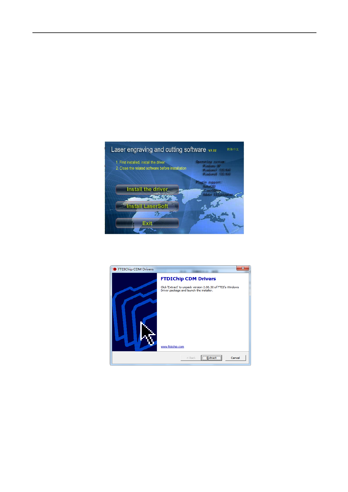
(1) Double-click the setup.exe under the installation directory, and the following dialog box will appear:
(2) Click [Install the driver] and the following dialog box will appear:
(3) Click [Extract] and the following dialog will appear:
Laser Engraving and Cutting Software-Instruction for Operation
6
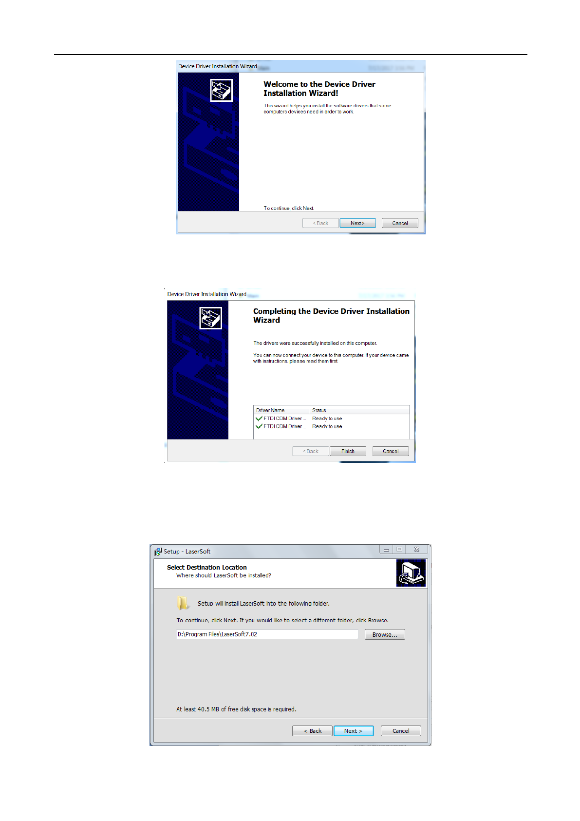
(4) Click [Next Step] and the following dialog box will appear:
(5) Click [Finish].
2.2 Installing LightObject Software
(1) Click [Install LaserSoft] and the following dialog box will appear:
Laser Engraving and Cutting Software-Instruction for Operation
7
(2) Click [Next >] after selecting the installation path, and the following dialog box will appear:
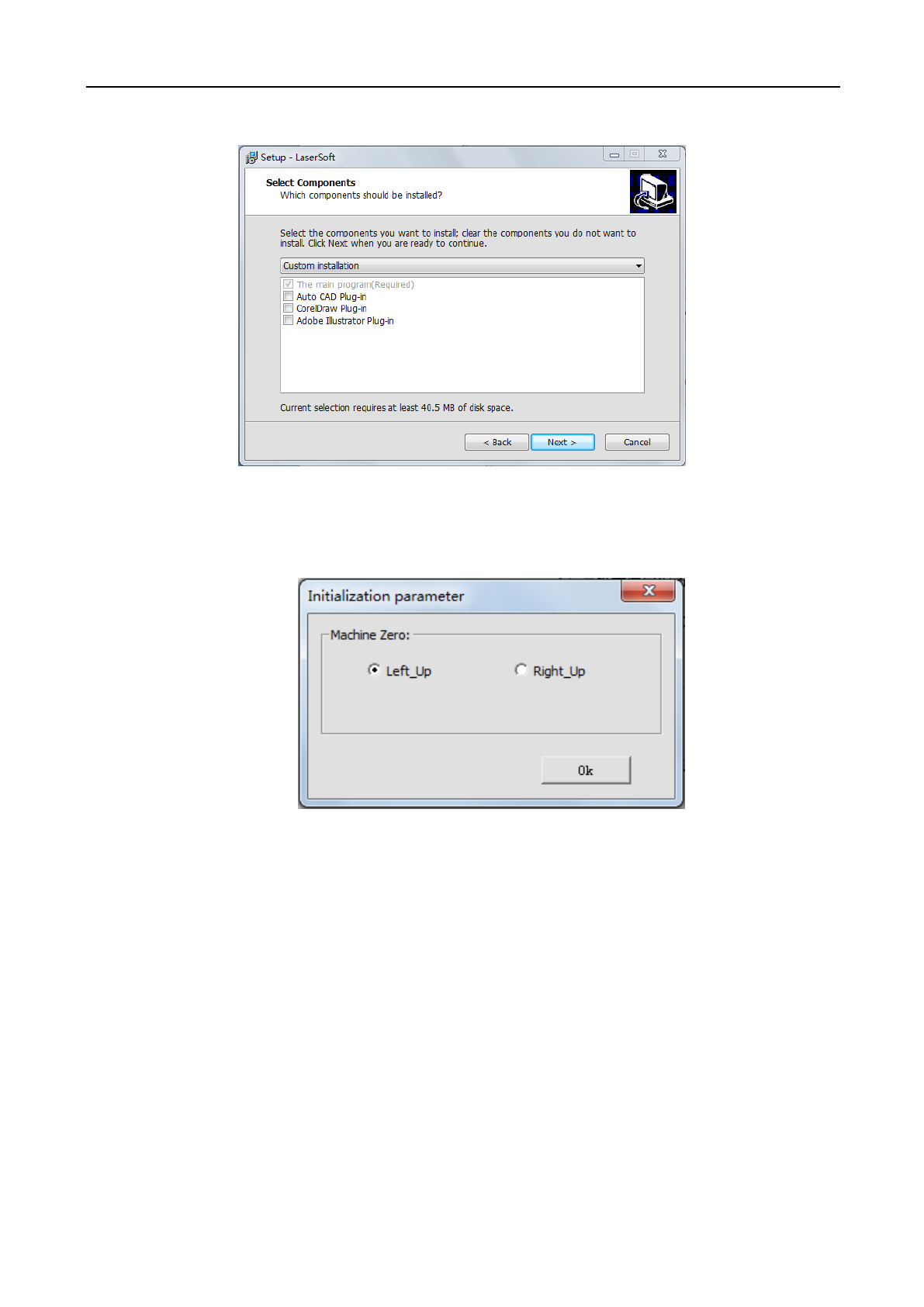
(3) Click [Next >] after selecting the plug-ins that you wish to install, and the following dialog box will
appear. Select the position of original point of machine and click [OK] to enter the dialog box of software
initialization.
Laser Engraving and Cutting Software-Instruction for Operation
8
Chapter III Basic Operation of Software
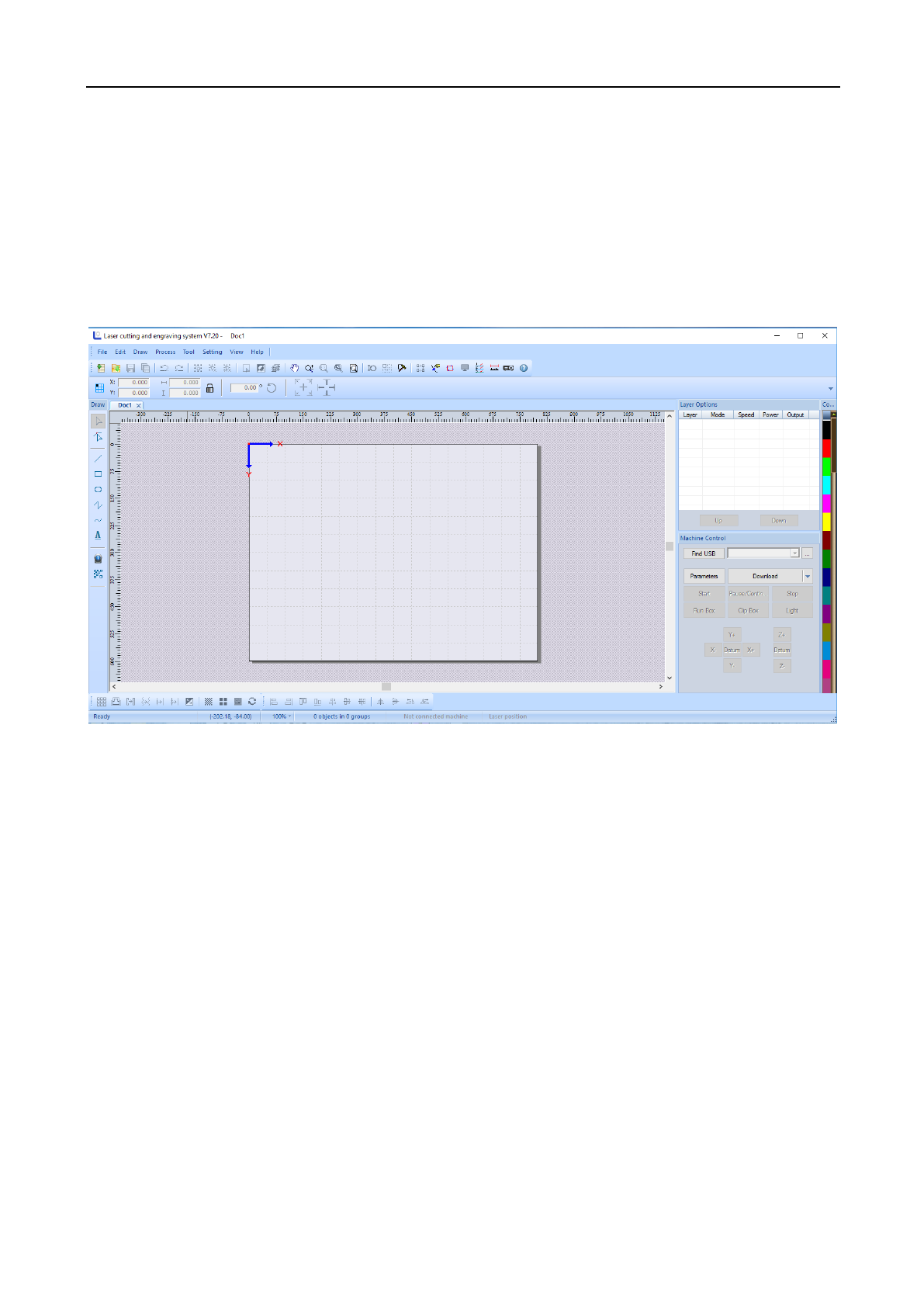
3.1 LightObject Software Main Interface
After starting the software, you will see the main interface of LaserSoft. Getting familiar and understanding this
main interface will be the base for operating and sending files to the laser machining.
Menu Bar: Menu Bar includes 8 sub-menus: File, Edit, Draw, Process, Tool, Setting, View and Help.
Toolbar: These command buttons are located right below the menu bar. These buttons include new file, open file,
file save, undo / redo, combination of selected graphics, ungroup, cancel all combinations, select all, invert
selection, select layers, moving tool, zooming tool, zooming of selected objects, page display, set lead line, virtual
array, system setting, auto sorting, manual sorting, display cutting path, project simulation, graph check, distance
measurement and help.
Object Bar: Allows selecting object during operation and relevant properties during using tool. It can control the
change of object by setting relevant properties in property bar.
Drawing Toolbar: the drawing menu includes the selection tools, node editing tool, tools for drawing a straight
line, rectangle, oval, polyline, bezier curve, and adding text.
Operating Tool Column: these tools include array copy, draw-in and external expansion, closed figure, curve
smoothing, node optimization, delete overlap line, combine joined line, image inverse, image hanging net, set up
image block, set up image contour, left alignment, right alignment, upper alignment, lower alignment, horizontal
center, vertical center, center alignment, horizontal flip, vertical overturn, turning left at 90 degrees and turning
right at 90 degrees.
Laser Engraving and Cutting Software-Instruction for Operation
9
Layer Tool Column: Modifies the color of object to be selected and allows setting adjustments like speed and
power for each color.
Layer Attribute Column: Displays the settings on each layer selected. Able to change options from engraving to
cut, speed of each layer, and power of each layer.
Equipment Control Column: Uses the control panel to complete several tasks of laser machining, including the
setting of communication mode, graph loading and operation to machine, etc.
3.2 File Menu
3.2.1 New
Click the [File]/[New] in the menu column, or click the new icon on system tool column, or press
Ctrl+N to create new machining file.
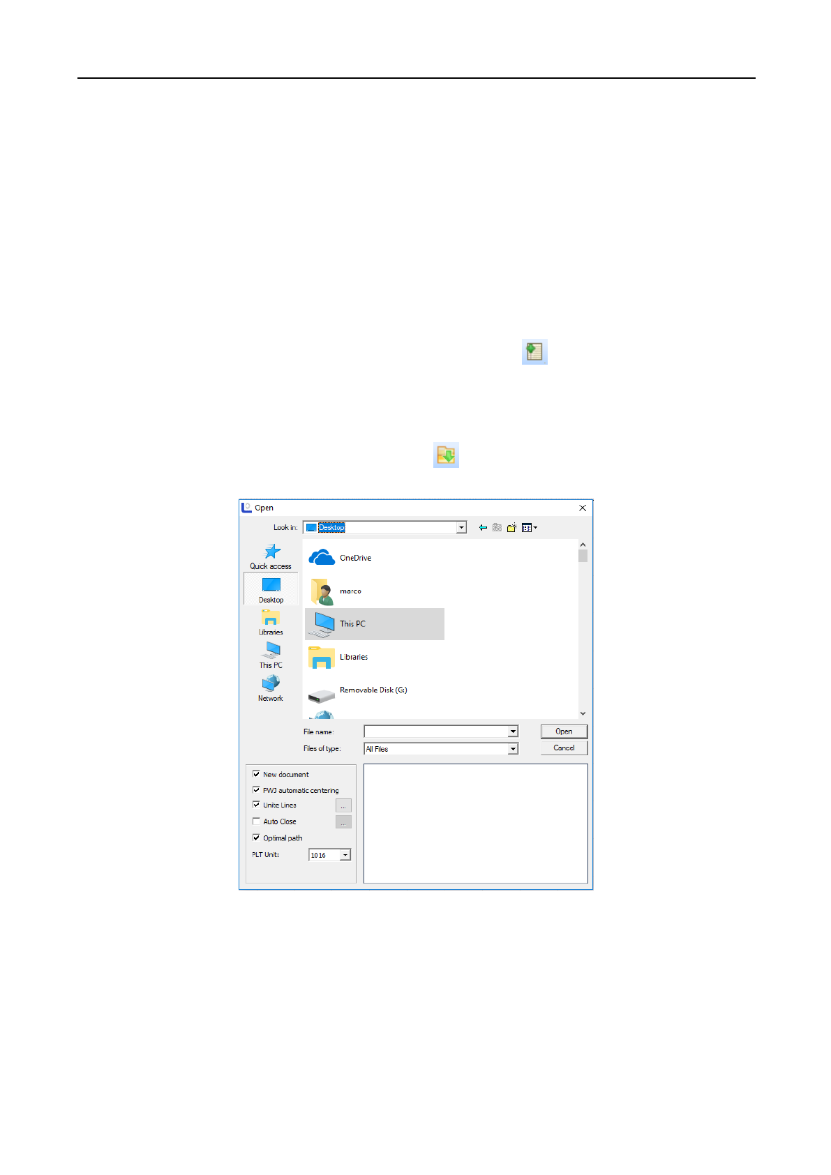
3.2.2 Open/Import
(1) Click [File]/[Open] in the menu column, or click on system tool column, or press Ctrl+O, and the
following dialog box will appear:
(2) Select the file to be opened and then click [Open].
3.2.3 Export
Click [File]/[Export] in the menu column or press Ctrl+E, and then the dialog box of lead-out will appear.
Input the file name, and then click the button [Save] to lead out the graph in the software into the file in the format
of PLT.

Laser Engraving and Cutting Software-Instruction for Operation
10
3.2.4 Save
Click [File]/[Save] in the menu, or click in the system tool column to open the icon, or press Ctrl+S,
fill in the save name, select the save controls, and click save to save the file in the format of PWJ. If the file
opened currently is not in the format of PWJ, the function “Save As” will be auto-called.
3.2.5 Save As
(1) Click [File]/[Save As] in the menu column, or press Ctrl+Shift+S, and the following dialog box will
appear:
(2) Input the file name in the file name editing box, and then click [Save].
3.2.6 Print
(1) Click [File]/[Print] in the menu column, or press Ctrl+P, and the following dialog box will appear:
3.3 Edit Menu
3.3.1 Undo
Click [Edit]/[Undo], or click the icon in the system tool column, or press Ctrl+Z to return to the state
of previous edit.
3.3.2 Redo
Click [Edit] /[Redo], or click the icon in the system tool column, or press Ctrl+Y to recover to the
state at previous step.
3.3.3 Cut
Select the graph to be cut and click [Edit]/[Cut] or press Ctrl+X.
3.3.4 Copy
Select the graph to be copied and click [Edit]/[Copy] or press Ctrl+C.
3.3.5 Paste
Select the graph copied/cut and click [Edit]/[Paste] or press Ctrl+V.
3.3.6 Delete
Select the graph to be deleted and click [Edit]/[Delete] or press the Delete button.
3.3.7 Select
Click the [Drawing]/[Select] in the menu column, or click on the edit tool column to shift to the state
of “select”. At this state, you may select the object. The following is five methods to select objects.
◆ Click [Edit]/[Select All] in the menu, or click in the edit tool column, or press Ctrl+A to select all
objects.
◆ Click to select single object by mouse, and other objects are in non-selected state.
Laser Engraving and Cutting Software-Instruction for Operation
11
◆ Box the objects (internal selection/cross selection)
Internal selection: Press the mouse and drag it (X from big to small), and the object in the box will be
completely selected.
Cross selection: Press the mouse and drag it (X from small to big), select the box in the box completely and
all objects in contact with it will be selected.
◆ Add selected object/ subtract selected object
Add: Press Ctrl/Shift and click the unselected object, and such object becomes selected state and other
objects in selected state are still in selected state.
Subtract: Press Ctrl/Shift and click the selected object, and such object becomes unselected state.
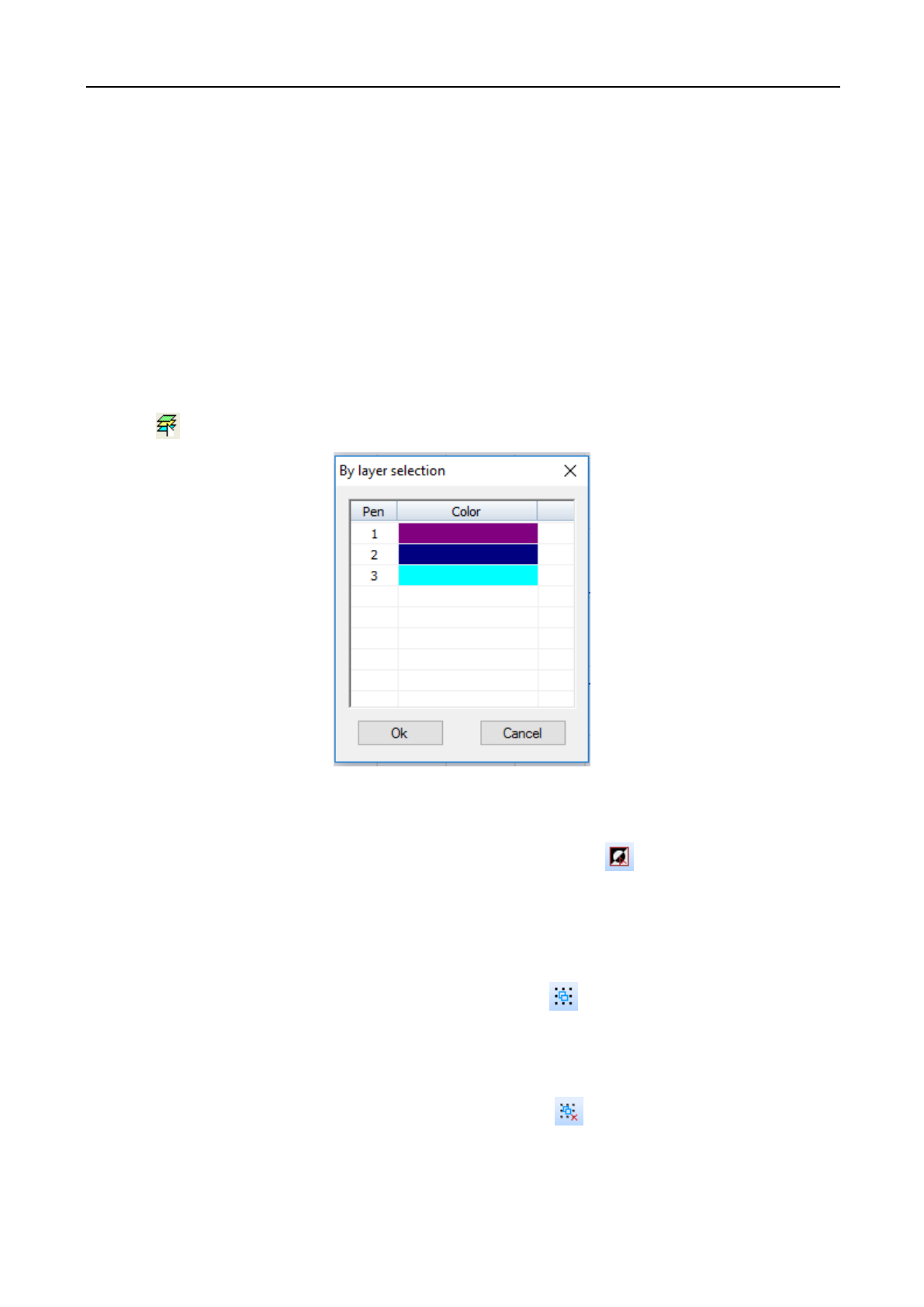
◆ Select object as per layer color
Click in the system operation column, and the following dialog box will appear:
Select the color of object to be selected, and then click [OK] and all objects in such color layer will be selected.
3.3.8 Reverse Selection
Click [Edit]/[Reverse Selection] in the menu column, or click the icon in the system tool column, or
press Ctrl+Shift+I, and the selected object becomes unselected state and unselected objects become the selected
state.
3.3.9 Group
Click [Edit]/[Group] in the menu column, or click the icon on the system tool column, or press
Ctrl+G to group several selected graphs.
3.3.10 Ungroup
Click [Edit]/[Ungroup] in the menu column, or click column in the system tool column, or press
Ctrl+U to ungroup the selected several grouped graphs currently.
Laser Engraving and Cutting Software-Instruction for Operation
12
3.3.11 All Groups Cancel
Click [Edit]/[Cancel All Groups] in the menu column, or click the icon in the system tool column, or
press Ctrl+Shift+U to ungroup all selected grouped graphs.
3.3.12 Rotate
The shortcut button is as shown in the figure:
(1) Rotate left at 90 degrees Select the graph to be rotated and click [Edit]/[Rotate]/[Rotate Left at 90 o]
(2) Rotate right at 90 degrees Select the graph to be rotated and click [Edit]/[Rotate]/[Rotate Right at 90 o]
(3) Rotate vertically Select the graph to be rotated and click [Edit]/[Rotate]/[Rotate Vertically].
(4) Rotate Horizontally Select the graph to be rotated and click [Edit]/[Rotate]/[Rotate Horizontally].
3.3.13 Alignment
The shortcut button is as shown in the figure:
(1) Left alignment Select the graph to be aligned, and click [Edit]/[Align]/[Left Alignment].
(2) Right alignment Select the graph to be aligned, and click [Edit]/[Align]/[Right Alignment].
(3) Top alignment Select the graph to be aligned, and click [Edit]/[Align]/[Top Alignment].
(4) Bottom alignment Select the graph to be aligned, and click [Edit]/[Align]/[Bottom Alignment].
(5) Central alignment Select the graph to be aligned, and click [Edit]/[Align]/[Central Alignment].
(6) Horizontal center Select the graph to be aligned, and click [Edit]/[Align]/[Horizontal Center].
(7) Vertical center Select the graph to be aligned, and click [Edit]/[Align]/[Vertical Center].
3.3.14 Move
(1) Move shall be with reference to the breadth rectangle, to top left corner, top right corner, lower right
corner, lower left corner, central point, left, upside, right and lower side. The shortcut button is located in the
object attribute column as shown in the figure below.
(2) Fine adjusting Move tiny distance up and down or left and right. The shortcut button is located in the
object attribute column as shown in the figure below.
3.3.15 Select the same graph
Click the [Edit]/ [Select style] / [Select the same graph] in the menu column, and the following dialog box
will appear. Input the parameter and click the button [OK].
Laser Engraving and Cutting Software-Instruction for Operation
13
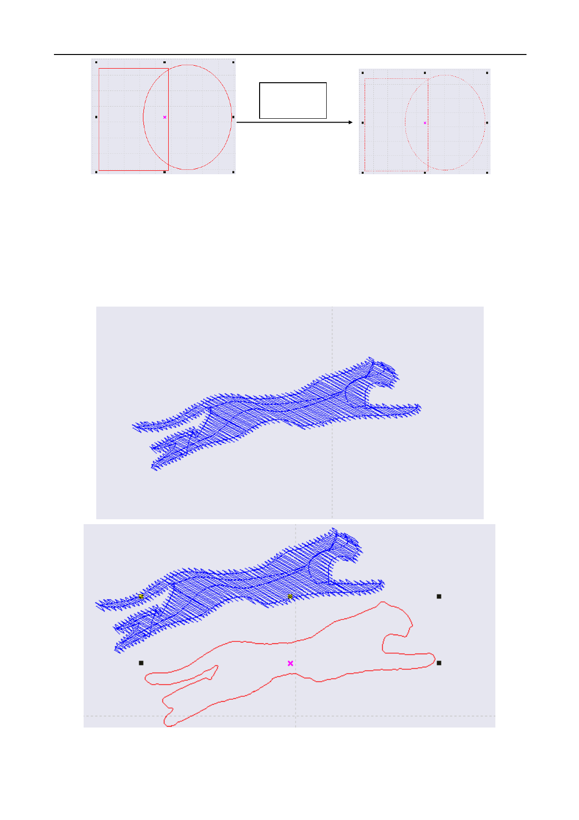
3.3.16 Select inside graph
Select the border of the object (graph) and click [Edit]/ [Select style] /[Select inside graph], And all internal
objects within the border will be selected as shown in the figure below:
3.3.17 Select outside graph
Select several graphs, and click [Edit]/ [Select style] /[Select outside graph] in the menu column, and the
most outer object will be selected.
3.3.18 Select unclosed graph
Select several graphs and click the [Edit]/ [Select style] /[Select unclosed graph], And the non-closed graph
will be selected.
3.4 Draw Menu
3.4.1 Select
Click [Draw]/[Select] in the menu column or click in the drawing tool column to select the graph or
part of the graph to move, delete or change layer, etc. of the selected part.
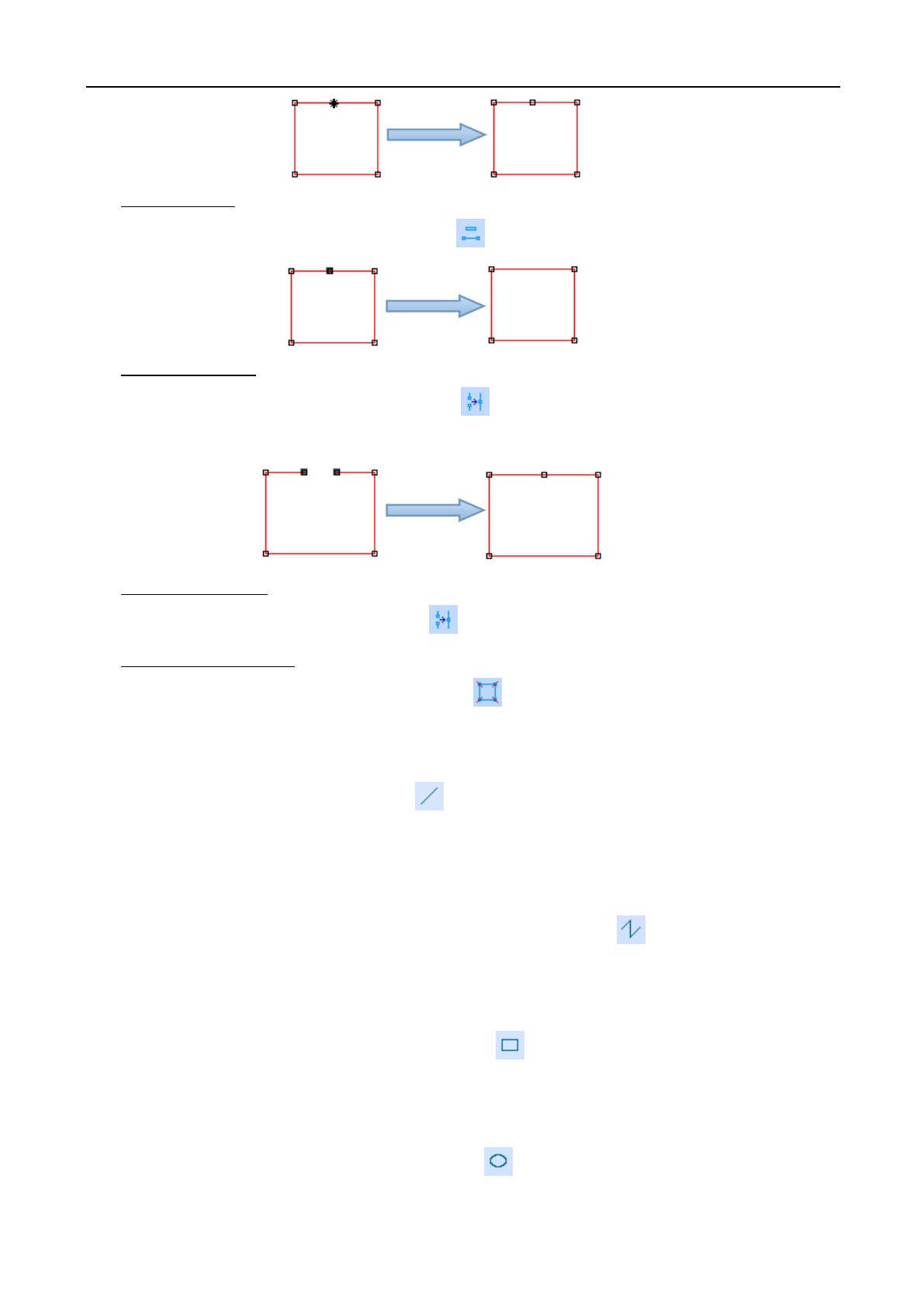
3.4.2 Node Edit
Click [Draw]/[Node Edit], or click in the edit tool column to enter the node edit mode.
◆ Add Node
Select a point on the selected object and then click in the object tool column to add such selected point
as the object node.
After select inside
graph
After select outside
graph
Laser Engraving and Cutting Software-Instruction for Operation
14
◆ Delete Node
Select a node on the selected object and then click in the object tool column to delete such node.
◆ Connect Node
Use the mouse to select two nodes, and then click in the object operation column to connect such two
nodes.
◆ Disconnect Node
Use the mouse to select a node, and then click in the object operation column to disconnect such node.
◆ Disconnect all nodes
Use the mouse to select two nodes, and then click in the object operation column to disconnect all
nodes.
3.4.3 Line
Click [Draw]/[ Line] in the menu, or click in the edit tool column. Drag the mouse on the screen to
draw any straight line. Press “Ctrl” and drag the mouse at the same time to draw the horizontal line.
3.4.4 Polyline
Click [Draw]/[Polyline] In the menu column, or click the edit tool column . Drag the mouse on the
screen and click the mouse to draw any line.
3.4.5 Rectangle
Click [Draw]/[Rectangle] In the menu column, or click in the edit tool column. Drag the mouse on the
screen to draw a rectangle of any size. Press “Ctrl” and drag the mouse at the same time to draw a square.
3.4.6 Ellipse
Click [Draw]/[Ellipse] In the menu column, or click in the edit tool column. Drag the mouse on the
screen to draw an oval of any size. Press “Ctrl” and drag the mouse at the same time to draw a perfect circle
Laser Engraving and Cutting Software-Instruction for Operation
15
3.4.7 Bezier Curve
Click [Draw]/[Bezier Curve] in the menu column, or click in the edit tool column. Drag the mouse on
the screen and click the mouse to draw the Bezier curve.
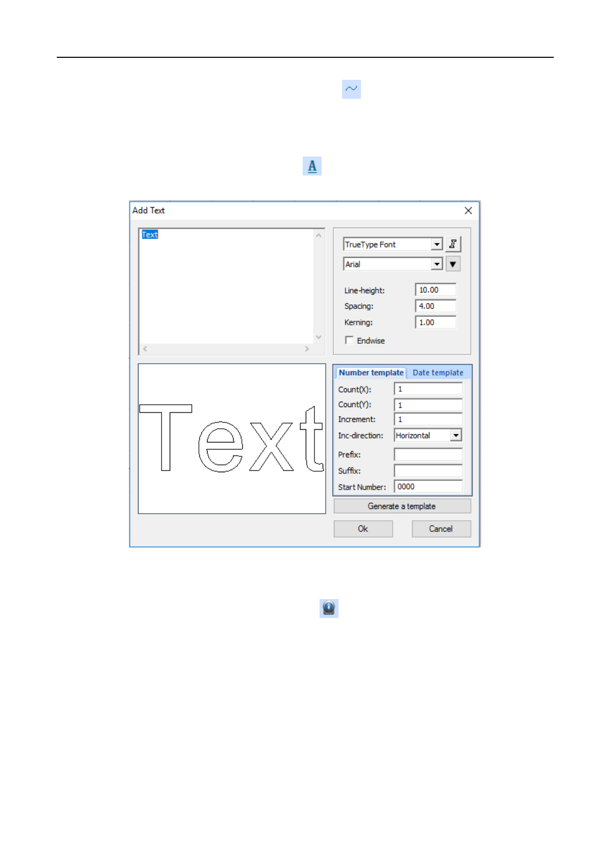
3.4.8 Text
Click [Draw]/[Text] in the menu column, or click in the edit tool column. Double click the mouse left
on the screen, and the following dialog box will appear:
Select the Font, input or select the font size, and then input the text. Then, click [OK].
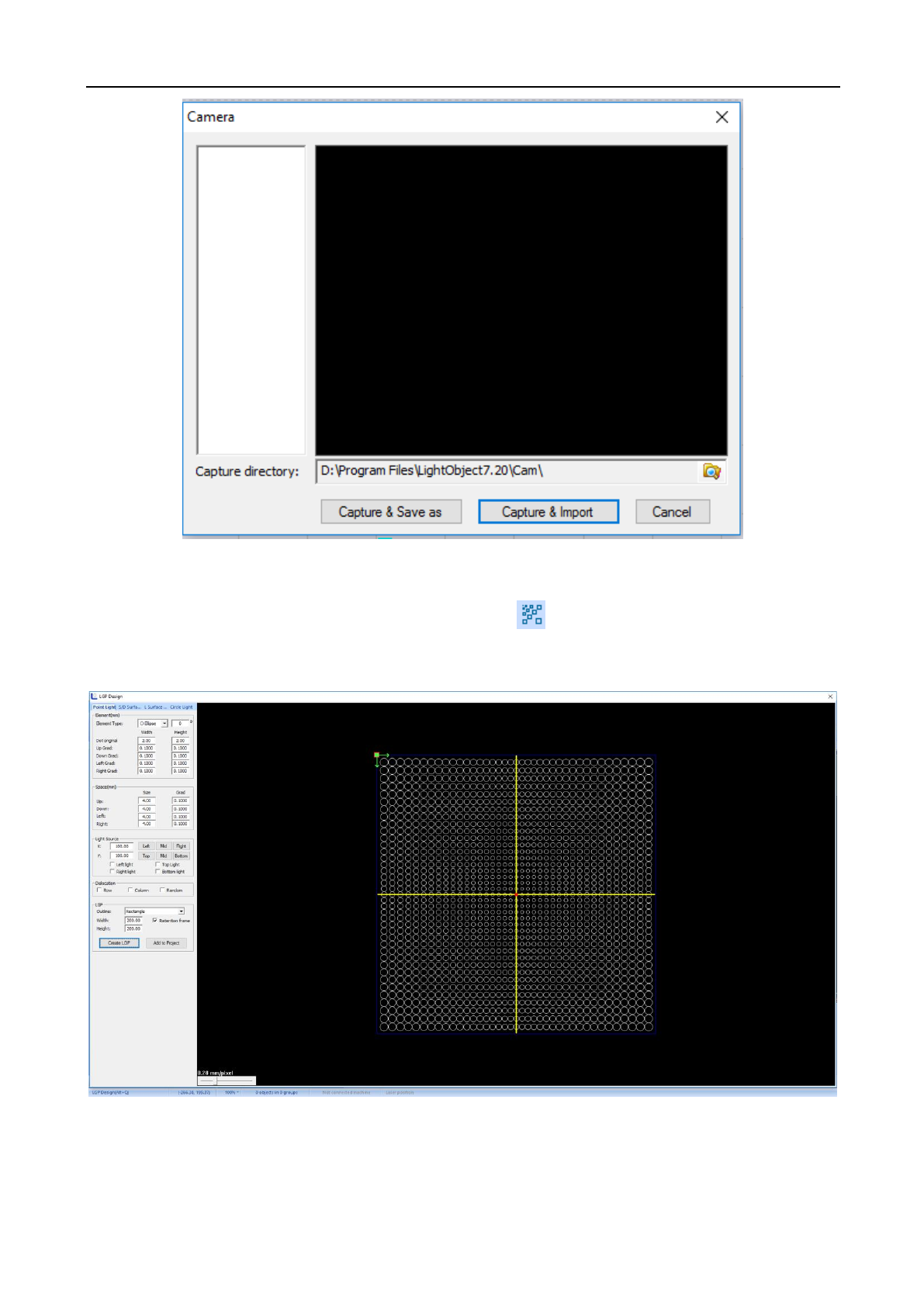
3.4.9 Camera
Click [Draw]/[Camera] in the menu column, or click in the edit tool column. Double click the mouse
left on the screen, and the following dialog box will appear:
Laser Engraving and Cutting Software-Instruction for Operation
16
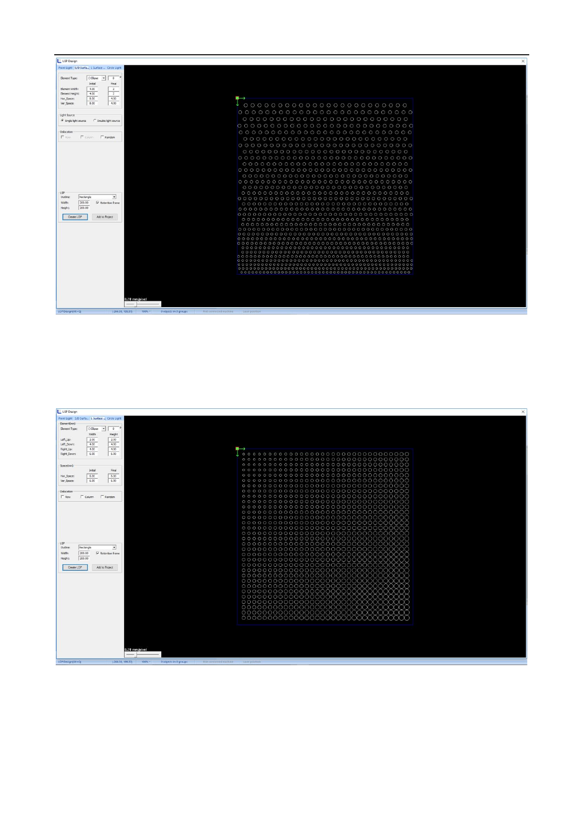
3.4.10 LGP Design
Click [Draw]/[LGP Design] in the menu column, or click in the edit tool column, and the light guide
plate design window will pop up.
◆ Point Light Source
◆Single/Double-Faced Light Source
Laser Engraving and Cutting Software-Instruction for Operation
17
◆ L Area Light Source
◆ Center Light Source
Laser Engraving and Cutting Software-Instruction for Operation
18
3.5 Operation Menu
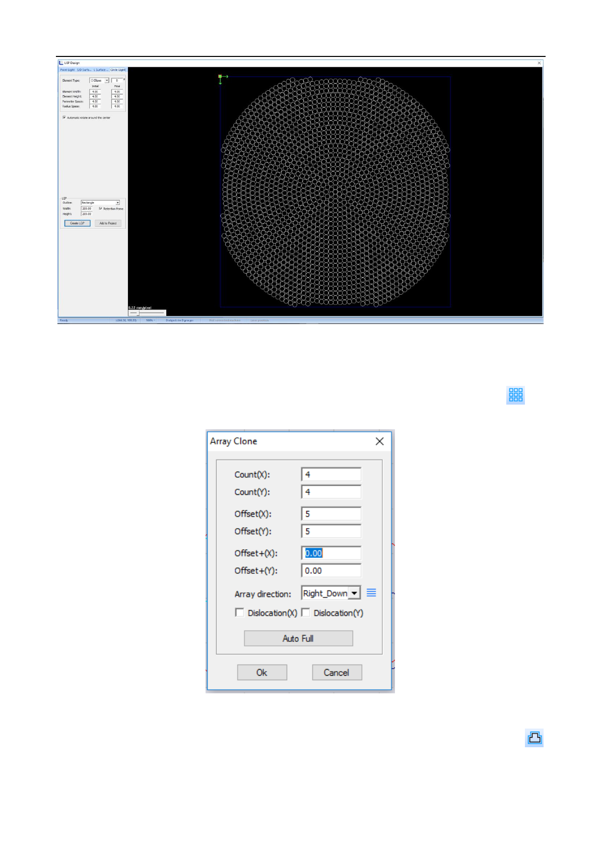
3.5.1 Array Copy
Select the object to be treated, and then click [Process]/[Array Copy] in the menu column, or click in
the operation tool column, and the array copy window will pop up. Click “OK” after inputting the parameters
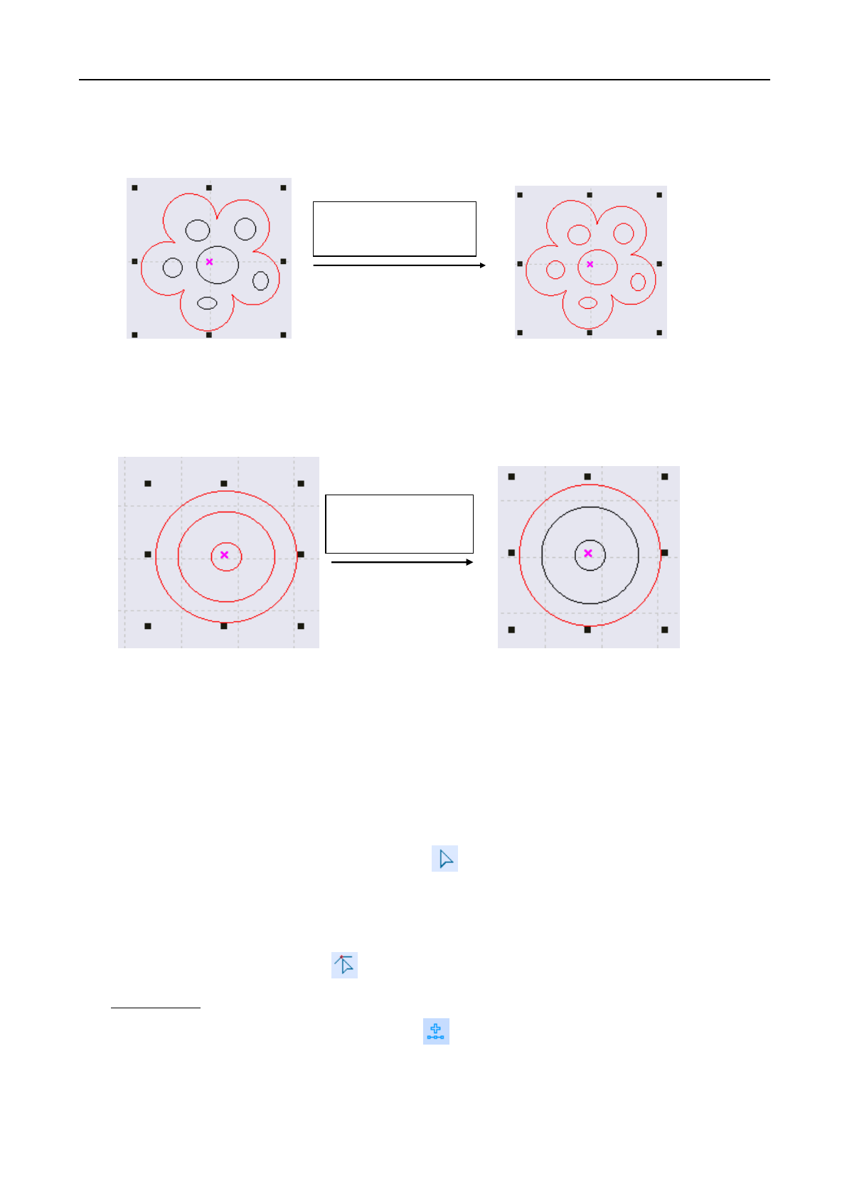
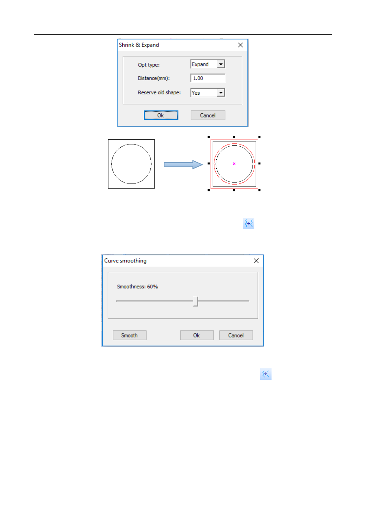
3.5.2 Shrink & Expand
Select the object to be treated, and then click [Process]/[Shrink & Expand] in the menu order, or click
in the operation tool column, and the following dialog box will appear. Input the parameter and click [OK].
Laser Engraving and Cutting Software-Instruction for Operation
19
3.5.3 Curve Smoothing
Click [Process]/[Curve Smoothing] in the menu column or click the icon in the operation tool column,
and the adjusting window of curve smoothing will appear. The larger the smoothing degree is, the graph is
smoother and the corresponding graph is more distorted.
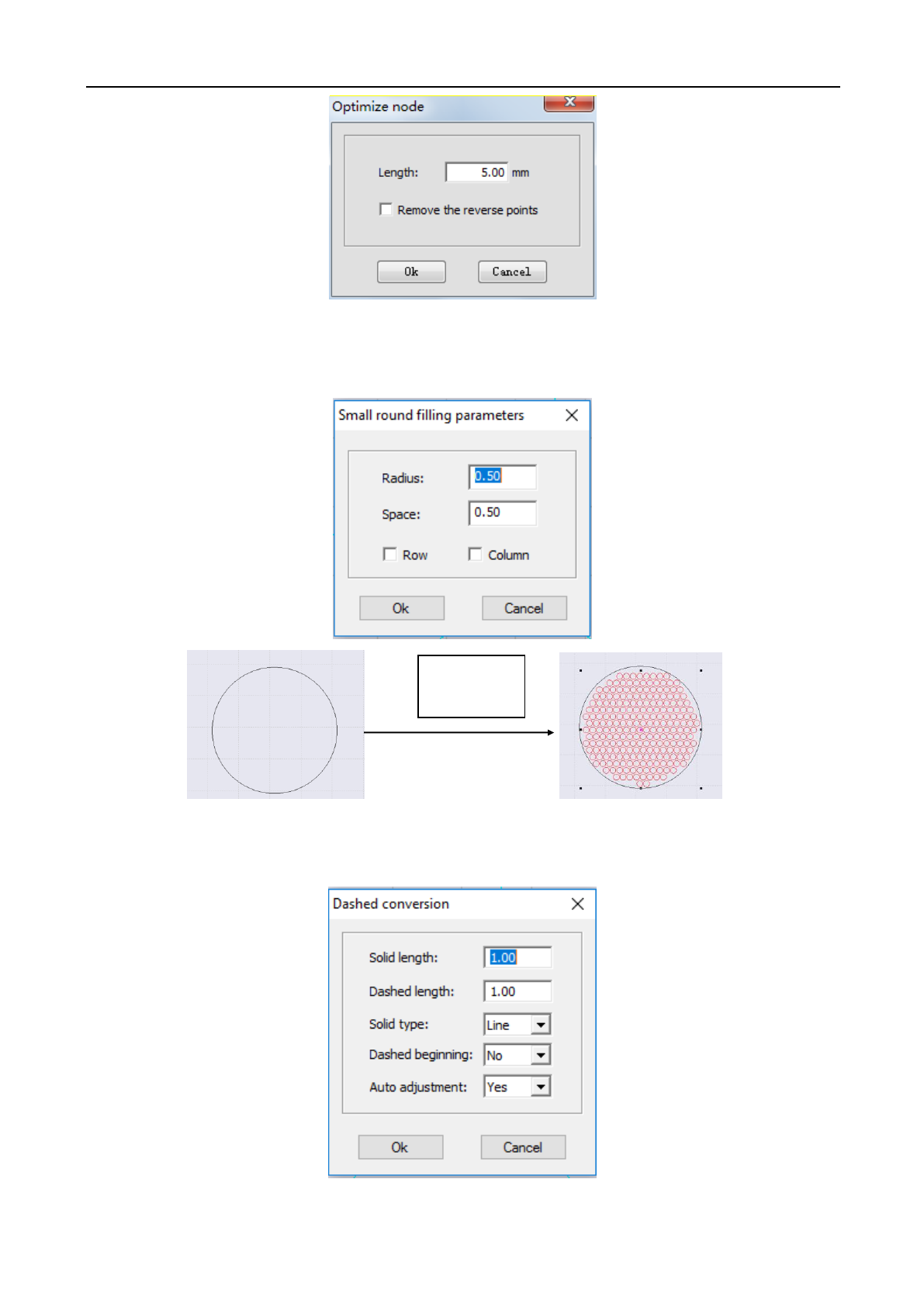
3.5.4 Node Optimization
Click [Process]/[Node Optimization] in the menu column or click the icon in the operation tool
column, and the node optimization window will pop up. Input the parameter and click [OK]. The larger the
optimization degree is, the graph is smoother and the corresponding graph is more distorted. (This feature may or
may not be available)
Laser Engraving and Cutting Software-Instruction for Operation
20
3.5.5 Small Circle Filling
Select the graph to be filled (it must be closed graph), click [Process]/[Advance]/[Small Round Filling], fill
in the parameter of small circle filling and click “OK”.
3.5.6 Dashed Conversion
Select the graph and click [Process] /[Advance]/[ Dashed Conversion], as shown in the figure below:
As shown in the figure below, fill in the data as per your own need:
Small Circle
Filling
Laser Engraving and Cutting Software-Instruction for Operation
21
3.5.7 Approximate Circle Conversion
Composite the graph of approximate circle into circle to make the cutting smoother. Select the graph, and
click [Process]/[Advance]/ [Approximate Circle Conversion].
3.5.8 DST Contour Line
Select the graph and click [Process]/[Advance]/[DST contour line]
Dotted Line
Conversion
Laser Engraving and Cutting Software-Instruction for Operation
22
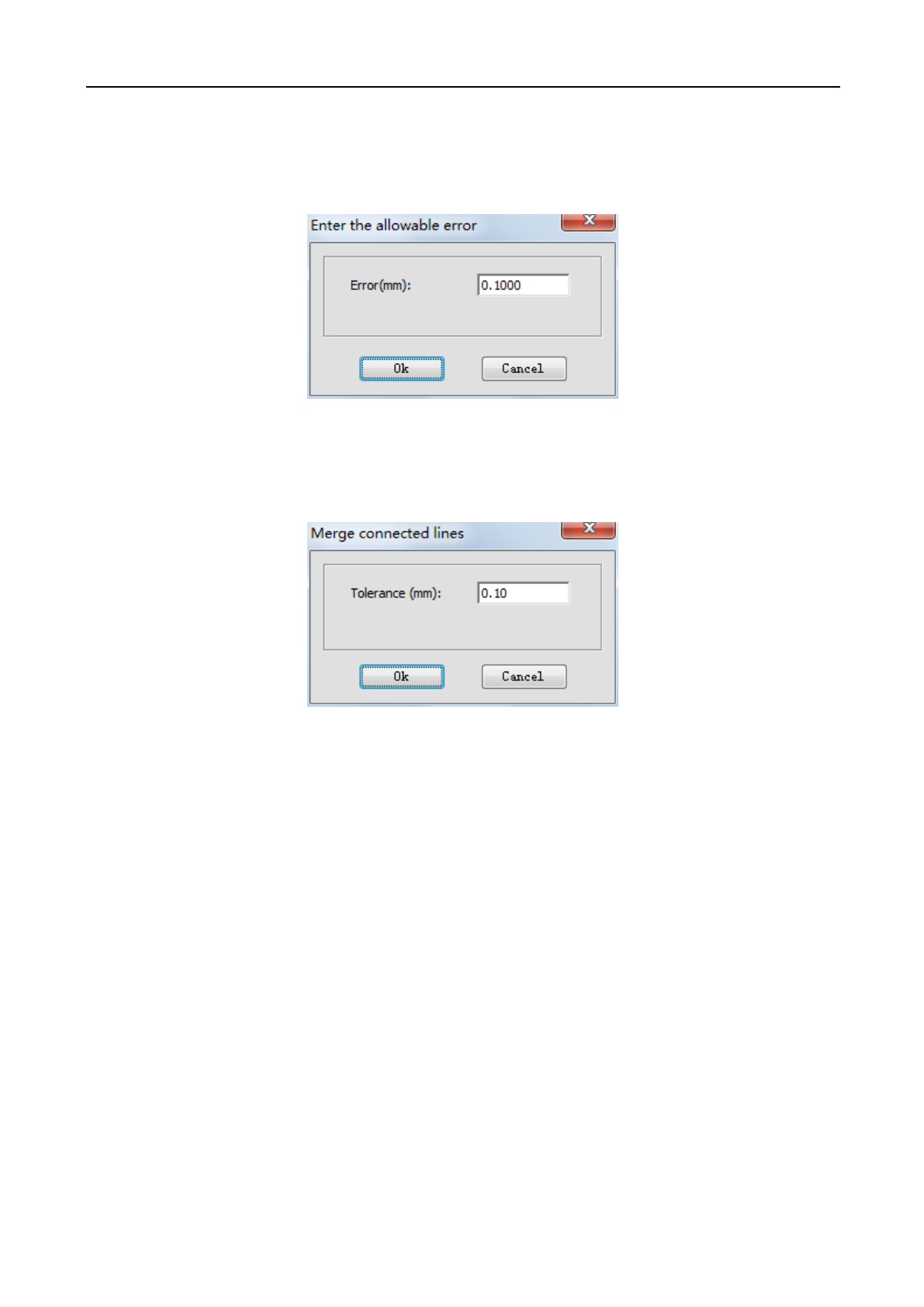
3.5.9 Delete Overlap Line
When the overlap ratio of two straight lines is good, the overlap line can be deleted and the overlapping deviation
shall not be set too large generally, for fear that delete by mistake is caused. Click the [Process]/[Delete Overlap
Line] in the menu column, the following dialog box will appear. Input the allowed deviation and click [OK].
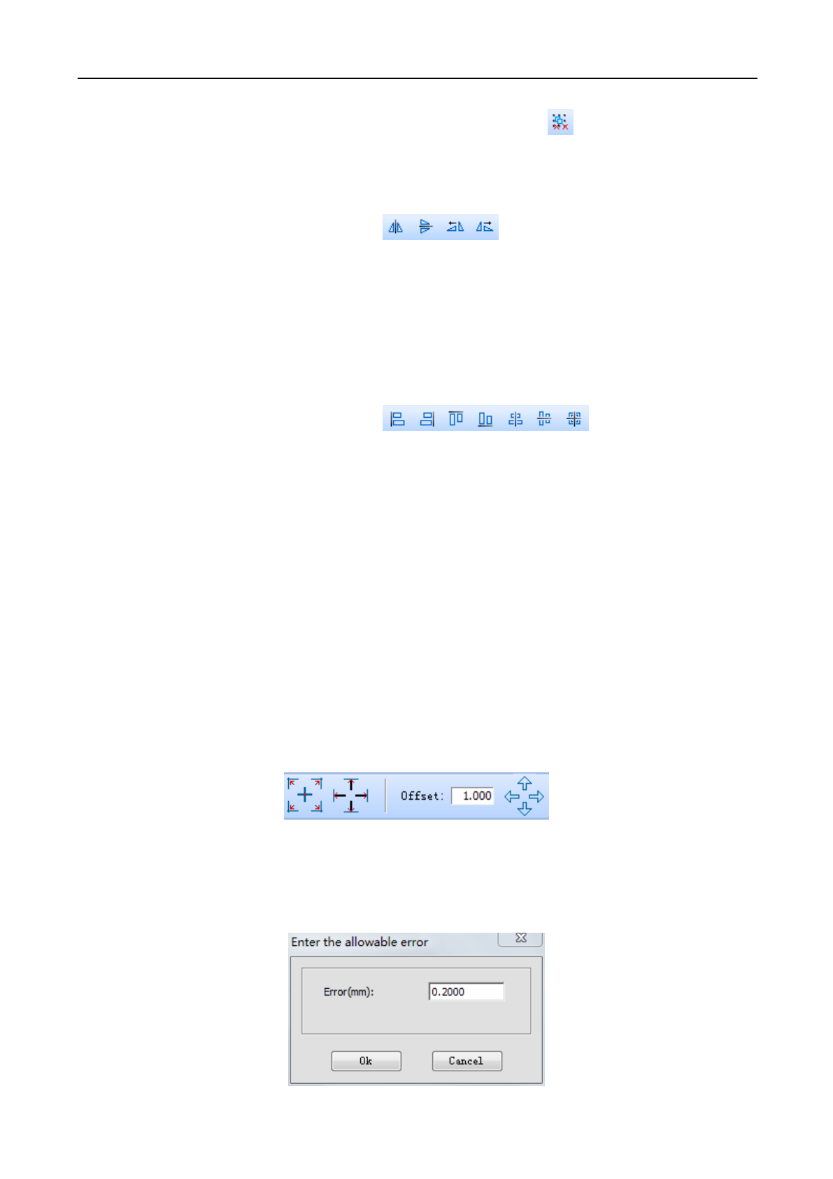
3.5.10 Combine Joined Lines
Combine multiple line segments joined into a line segment. Click [Operation]/[Combine Joined Lines] in
the menu column, and the following dialog box will appear. Input the allowed error and click [OK].
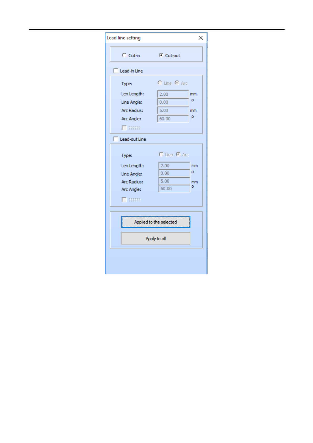
3.5.11 Set Lead Line
The lead line function refers to leading out of the open knife and close knife in cutting some articles with
high accuracy. Click [Process]/[Set Lead Line] in the menu column, the following window will appear at the
left/right side of main window. Input the corresponding parameter, and click [Apply into Selected Graph] or
[Apply into All Graphs].
Laser Engraving and Cutting Software-Instruction for Operation
23
[Lead-in line]: Lead in a line segment/arc from the cutting start point.
[Lead-out line]: Lead out a line segment/arc from the cutting end point.
[Concave cut]: When the lead line is in the graph and multi-layer is connected, the concave and convex will be
shifted automatically with the outermost layer as the benchmark.
[Convex cut]: When the lead line is outside the graph and multi-layer is connected, the concave and convex will
be shifted automatically with the outermost layer as the benchmark.
After the lead line is generated, you may use the mouse to edit in the main window.
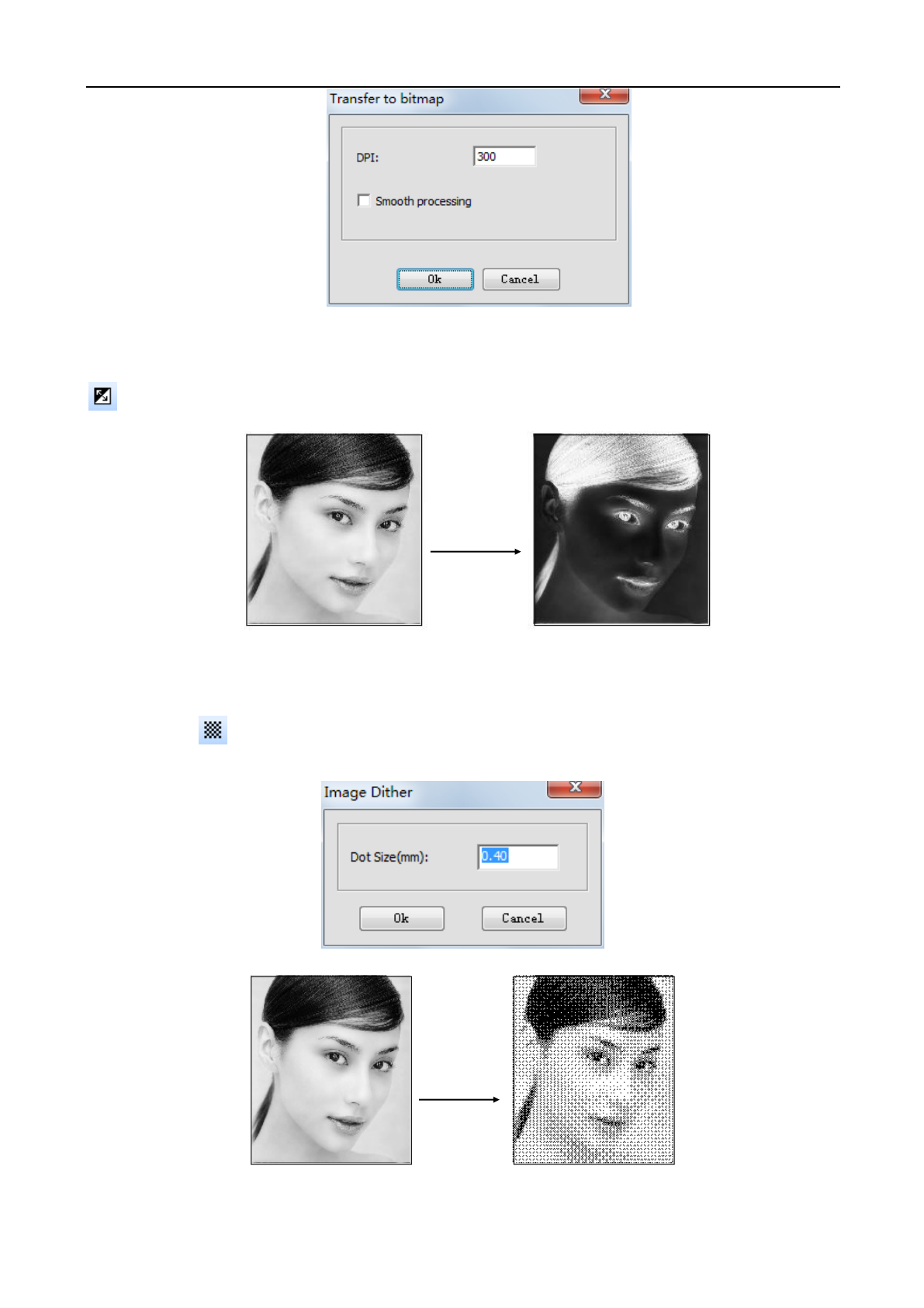
3.5.12 Covert Graph into Image
Select the graph to be converted, click [Process]/[Convert Graph into Image] and the following window
will pop up. Input the parameters and click [OK].
Laser Engraving and Cutting Software-Instruction for Operation
24
3.5.13 Image Negative
Select the bitmap object to be treated with inverse and click [Process]/[Image Negative] in the menu or click
in the operation tool column.
3.5.14 Image Dither
Select the bitmap object to be treated with hanging net, click the [Process]/[Image Dither] in the menu
column or click in the operation tool column, and the following dialog box will appear. Input [Dot Size] and
click [OK].
Image Negative
Image
Dither
Laser Engraving and Cutting Software-Instruction for Operation
25
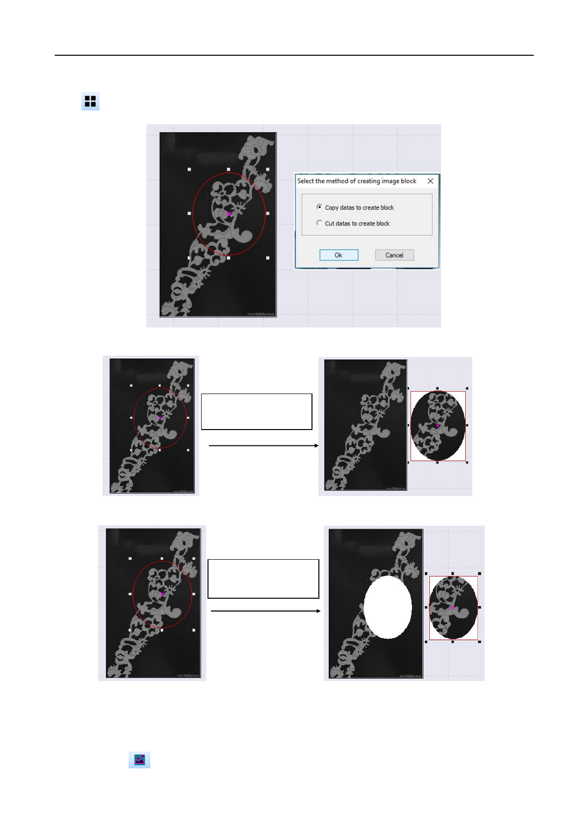
3.5.15 Create Image Block
Select a closed graph object (on image) and click [Process]/[Create Image Block] in the menu column or
click in operation tool column, as shown in the figure below:
Select copy or cut as per your own need and click the button “OK”, as shown in the figure below:
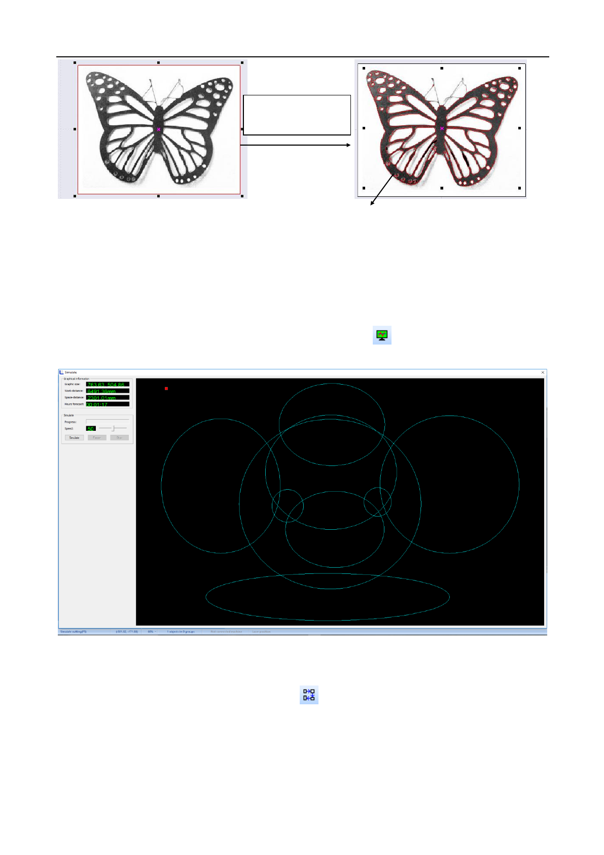
3.5.16 Create Image Contour
To create an image outline, select the image, and click [Process]/[Create Image Contour] in the menu column
or click the icon in the operation tool column, as shown in the figure below:
Copy the date to
generate bitmap block
Cut the data to
generate bitmap block
Laser Engraving and Cutting Software-Instruction for Operation
26
3.6 Tool menu
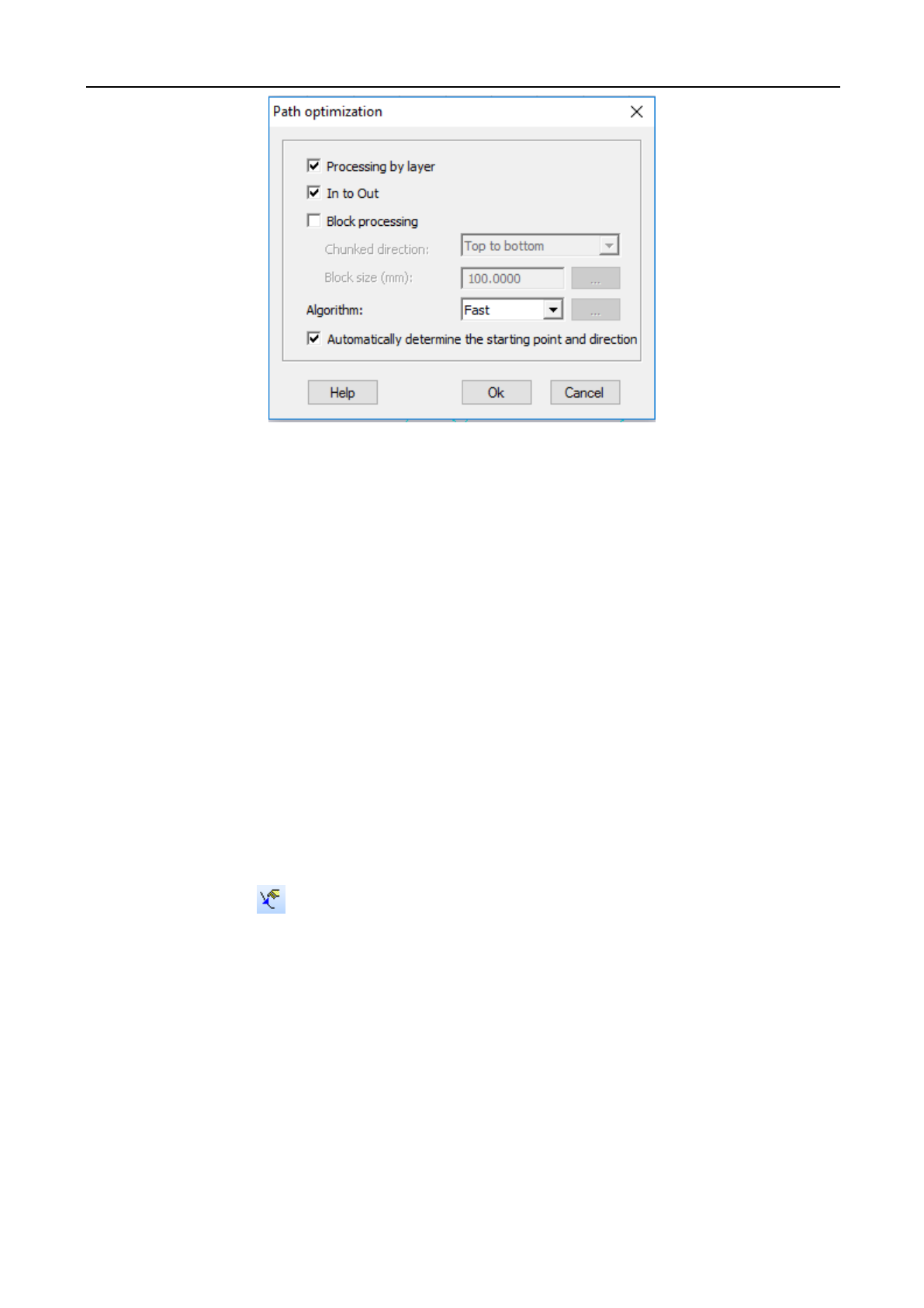
3.6.1 Simulate
Simulation is to simulate the graphics processing operation. By simulation loading, simulation data like in
actual processing can be obtained, such as processing time, processing path and distance.
Click on menu bar [Tool] / [Simulate] or click on system toolbar icon or press F5, and a popup simulation
window appears.
3.6.2 Automatic sorting
It is used to automatically arrange the processing sequence of all objects in current document. Click on menu
bar [Tool/Automatic sorting] or click on system toolbar . As shown in the figure below:
Create image contour
Laser Engraving and Cutting Software-Instruction for Operation
27
● Select [Processing by layer]: when laser cutting, process the graphics of some color first, then process the
graphics of other color.
● Select [In to out]: When laser cutting, process the graphics inside first, then process the graphics outside.
● Select [Automatically Determine the starting Point and direction]: When arrange the graphics,
automatically determine the starting point and direction of graphics cutting.
● Select [Block processing] the graphics will be arranged in given [split field direction] according to [Size of
Block] , respectively including from top to bottom, from bottom to top, from left to right, from right to left. [Process
in Blocks] is commonly used to arrange regular array of graphics, several options at this time [Size of Block] is set
as the height of single graphics in array; [Block processing] can also be used to arrange the graphics with a large
amount of data.
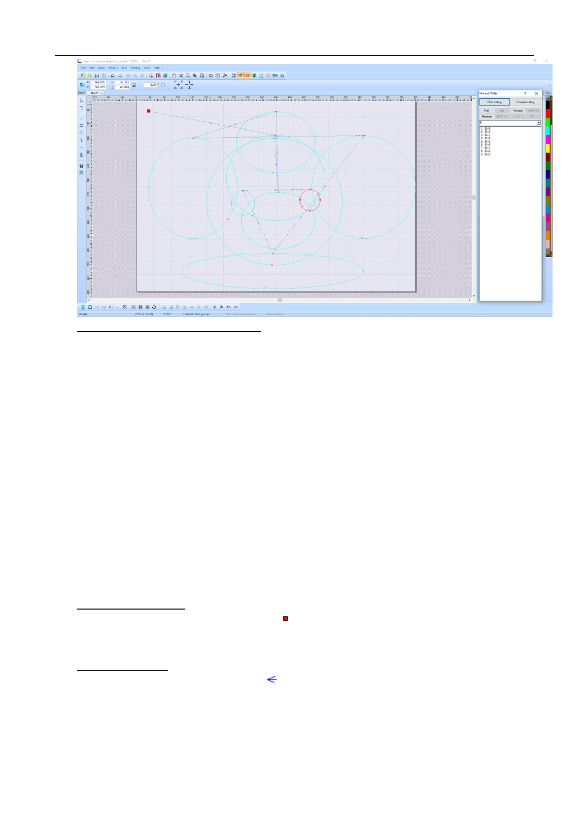
3.6.3 Manual sorting
Users can use [Manual sorting] to custom set the order that the project is done. This allows the user to be able
to choose which piece to start with and which piece to end with. Click on menu command [Tool]/ [Manual sorting]
or click on system toolbar . As shown in the figure below:
Laser Engraving and Cutting Software-Instruction for Operation
28
◆ Change cutting serial number of object
(1) Single Graphics Operation: Select one graphics, then this graphics can be moved to the [First],
[Forward], [Back], [Last].
(2) Multiple Graphics Operation: Select multiple graphics, then these graphics can be [Connected],
[Inverted], [Automatic] sequenced.
(3) List Graphics Operation: Select one graphics in the list and drag to another row, then its processing
sequence will be changed.
(4) Sequencing by Click: Click on [Sequencing by Click], then click the graphics in view area according to
the processing sequence; first click, first process. It is easy to operate.
(5) Sequencing by Row: Click on [Sequencing by Row], then click the mouse and row in the view area. The
graphics first rowed will be processed first. During operation, the mouse can be released. Press again to
continue, also the selected graphics can be canceled by the right mouse button.
◆ Cutting starting point
The cutting starting point of object is shown as “ ”. Click on the object path can change the cutting starting
point of the object.
◆ Cutting direction
The cutting direction of object is shown as “ ”. The direction of the arrow indicates the cutting direction.
Click on [Inverted] can make the cutting direction contrary to the original.
3.6.4 Adjust the direction of starting point (idle line minimum)
Without changing the processing order of the graphics, taking the idle line between two graphics minimum as
the principle, automatically change the starting point and direction of each graphics.
Laser Engraving and Cutting Software-Instruction for Operation
29
3.6.5 Adjust the direction of starting point (gap compensation)
Without changing the processing order of the graphics, taking the idle line between two graphics with a close to
45 degree angle to the horizontal line as the principle, automatically change the starting point and direction of each
graphics.
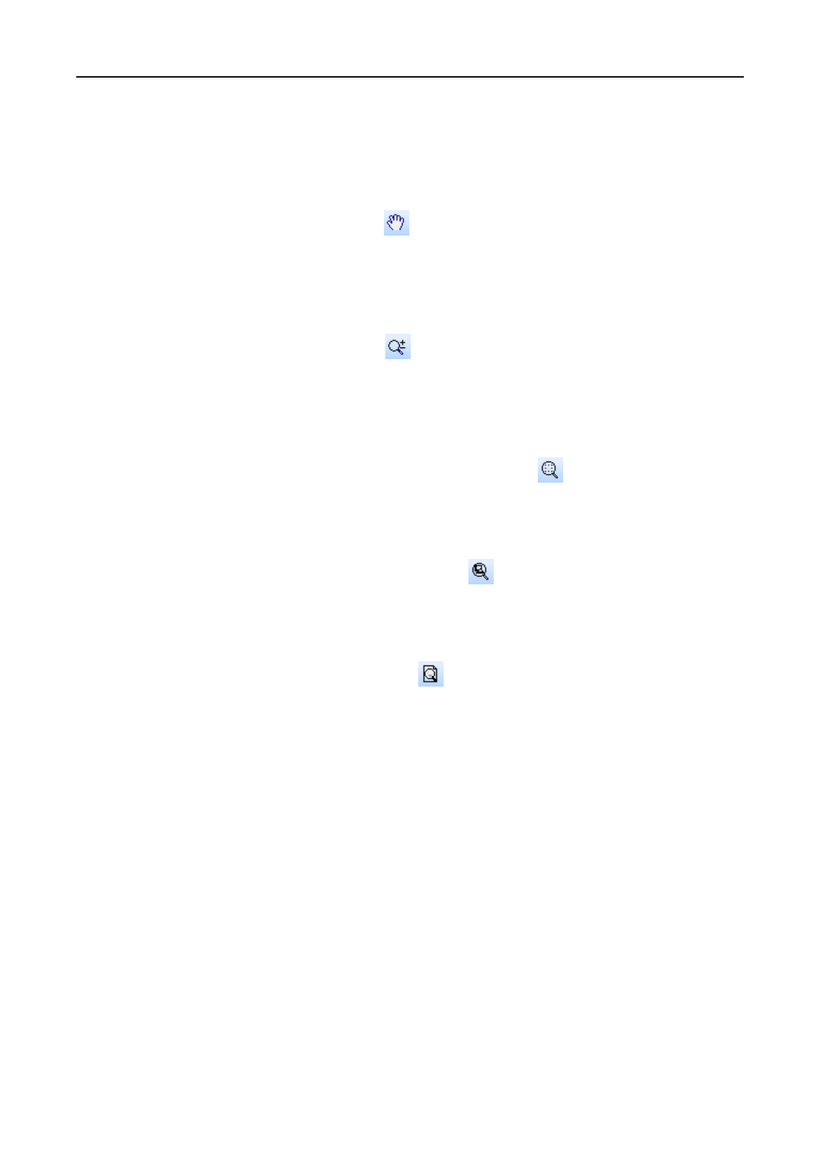
3.6.6 Move
Click on menu bar [Tool] / [Move] or click icon on system toolbar, or press the right mouse button, move
and display current view.
3.6.7 Zoom
Click on menu bar [Tool] / [Zoom] or click icon on system toolbar, then click on the graphics by the left
mouse button, it will be zoomed in; while click on the graphics by the right mouse button, it will be zoomed out.
3.6.8 Zoom the selected graphics
Click on menu bar [Tool] / [Zoom the Selected Graphics] or click icon on system toolbar, the selected
graphics will be zoomed in.
3.6.9 Zoom all graphics
Click on menu bar [Tool] / [Zoom all Graphics] or click icon on system toolbar, all objects can be fully
displayed.
3.6.10 Page Display
Click on menu bar [Tool] / [Page Display] or click icon on system toolbar, page in the graphics can be fully
displayed.
Laser Engraving and Cutting Software-Instruction for Operation
30
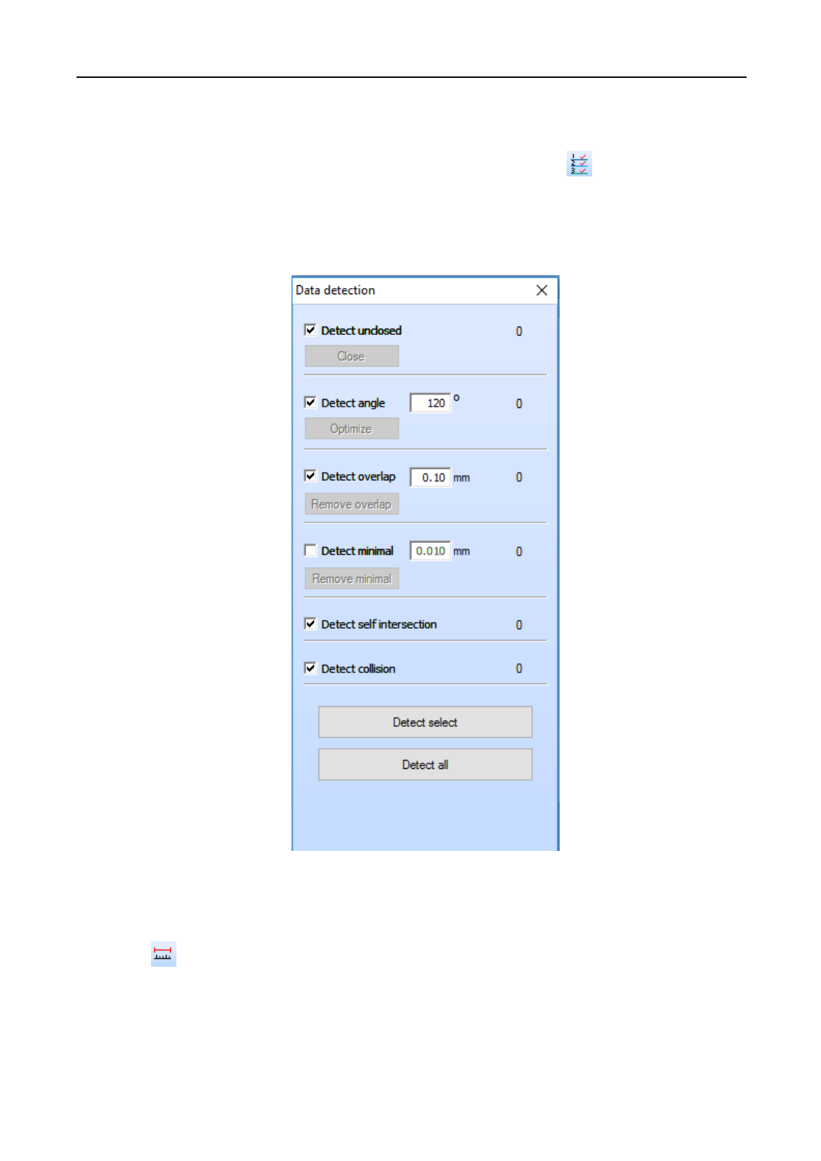
3.6.11 Data detection
Data detection can detect the graphics overlapping, intersection, self-intersection, sharp corner and
minimal graphics. Click on menu bar [Tool] / [Data Detection], or click the icon on system toolbar, popup
data detection window (as shown below), select the object to be detected, click on [Detect the Selected Graphics]
or [Detect all Graphics], the detected graphics will be selected, and in the following picture the number of detected
graphics will be displayed.
3.6.12 Measure
Distance measurement can measure the distance between any two points. Click on menu bar [Tool] / [Measure]
or click icon on system toolbar, enter into distance measurement mode.
Laser Engraving and Cutting Software-Instruction for Operation
31
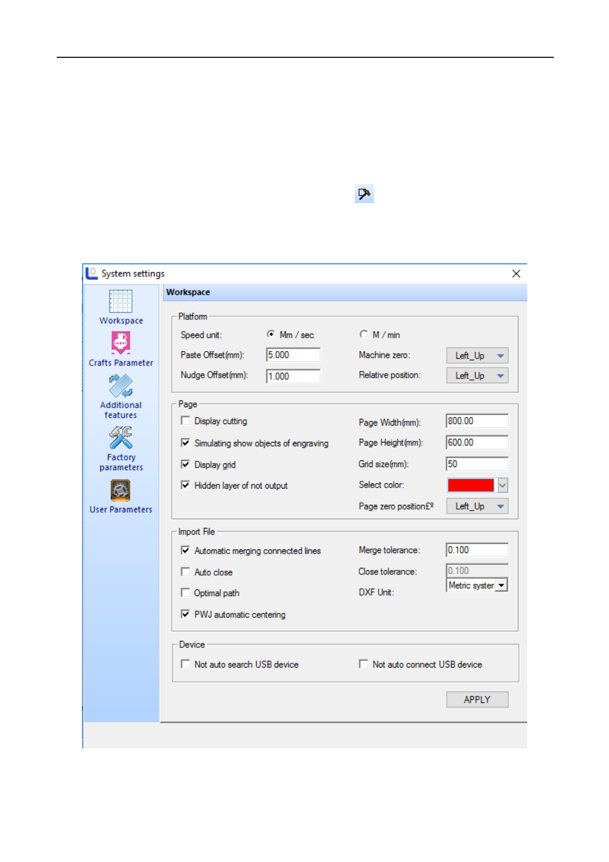
3.7 Setting menu
3.7.1 System setting
Click on menu bar [Setting] / [System setting] or click icon on system toolbar, popup system setting
window.
◆Workspace
(1) Platform parameters
[Speed Units]: All speeds involved in the software, unit types used in the software.
Laser Engraving and Cutting Software-Instruction for Operation
32
[Nudge Offset]: Fill in the size according to the requirements.
[Paste Offset]: Fill in the size according to the requirements.
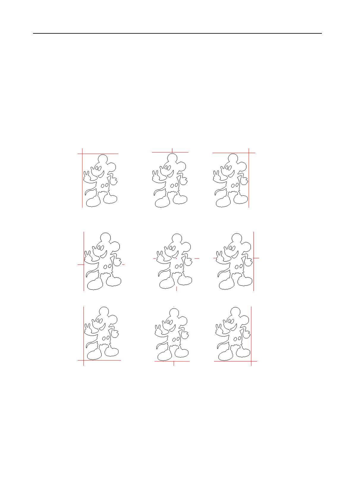
[Machine Zero]: The zero position of current machine, make sure that it is consistent with the actual machine
zero point. Otherwise the graphics processed may be reversed left and right or up and down. (pay attention to this)
[Relative Position]: The position of laser head relative to the processing graphics; it is recommended that this
parameter is consistent with the machine zero setting. The following is the position of the laser head relative to the
graphics at different setting values (the intersection of the two red lines is the position of the laser head):
(2) Working page
[Display Cutting Path]: Whether to display the cutting path of graphics in the view.
[Simulating show Engraving Graphics]: Whether to display the engraving graphics in the way of filling in
the view.
[Display Grid]: Whether to display the grid in the view.
[Grid Size]: The distance between the grid lines.
Laser head is at
“right middle”
Laser head is at
“left middle”
Laser head is in
the “center”
Laser head is at
“lower middle”
Laser head is at
“lower right”
Laser head is at
“upper left”
Laser head is at
“middle up”
Laser head is at
“upper right”
Laser head is at
“lower left”
Laser Engraving and Cutting Software-Instruction for Operation
33
[Hide Layers of Not Output]: Whether to hide the layers not output.
[Page Width]: The width of working page.
[Page Height]: The height of working page.
[Select Color ]: Select the display color of the object.
(3) Import file
[Auto Merge connected Lines]: When import the graphics file, whether to merge link lines.
[Merge Tolerance]: Only when distance between link lines smaller than this value, they can be merged.
[Auto Close]: When import the graphics file, whether to merge the unclosed graphics.
[Close Tolerance]: Only when the distance between starting point and ending point of the unclosed graphics
smaller than this value, it will be closed.
[Optimal path]: When import the graphics file, whether to optimize the graphics.
[DXF Unit]: If DXF file without specified unit, set the unit here.
[PWJ Automatically Centering]: When open PWJ file, whether to make it centered.
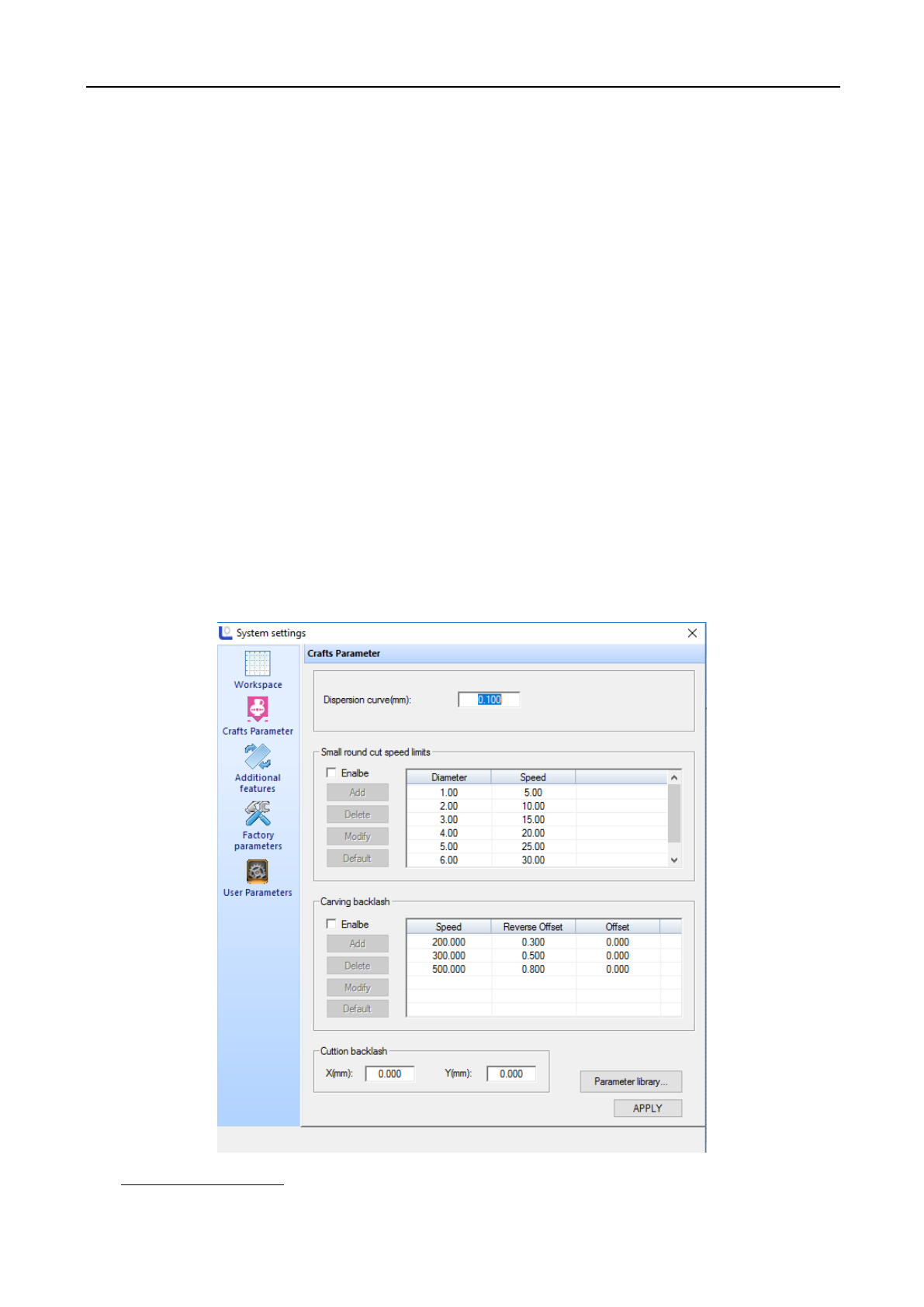
◆ Technological parameter
(1) Curve discrete length
Laser Engraving and Cutting Software-Instruction for Operation
34
The smaller this value, the higher the accuracy of graphics, but computation speed is more slow, and it may affect the
processing speed. Generally to cut organic glass, choose smaller values; for other kind of cutting, please use the default
value of 0.1.
(2) Small circle cutting speed limit
During processing, the system will automatically identify whether the processing object is a small circle and will
adjust the speed limit. Then according to the diameter of the circle, use the set limit speed to process the circle. If the
parameter configuration is appropriate, it will greatly improve the cutting quality of small circle. You can click [Add] ,
[Delete] , [Modify] to set this parameter.
(3) Carving reverse gap
When laser curve graphics two-ways, due to mechanical return gap, it may cause uneven edge of graphics after
scanning. So the reverse gap is added to modify. There is specific reverse clearance under specific speed. Generally, the
greater the speed, the bigger the reverse clearance is. Reverse gap value can be positive or negative.
(4) Cutting reverse gap
Adjust the overall location offset of the cutting graphics.
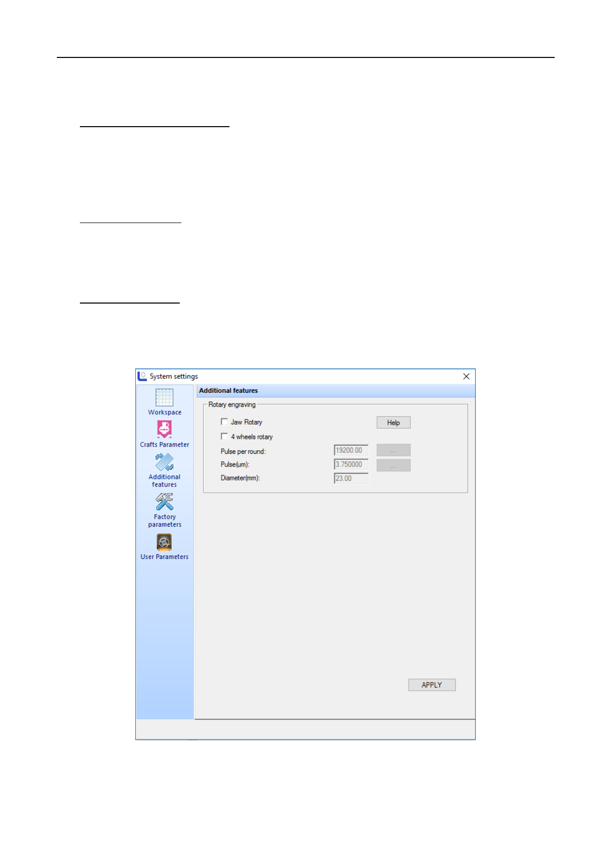
◆Additional function
[Jaw Rotary]: After select fixture rotation carve, Y axis is the axis for rotation; parameters can be adjusted
according to "rotating pulse equivalent", "pulse count of a circle”, "current diameter" .
Laser Engraving and Cutting Software-Instruction for Operation
35
[Four-Wheel Rotary]: "rotating pulse equivalent" and "pulse count of a circle" are effective.
[Pulse (Um)]: When sending a pulse to the motor, the absolute traveling distance of corresponding rotating axis
(unit: um).
[Pulse per round]: The number of pulses required for one revolution of the workpiece. Pulse count of a circle= fine
fraction of motor driver*drive ratio
[Diameter (mm)]: Measures the diameter of the workpiece.
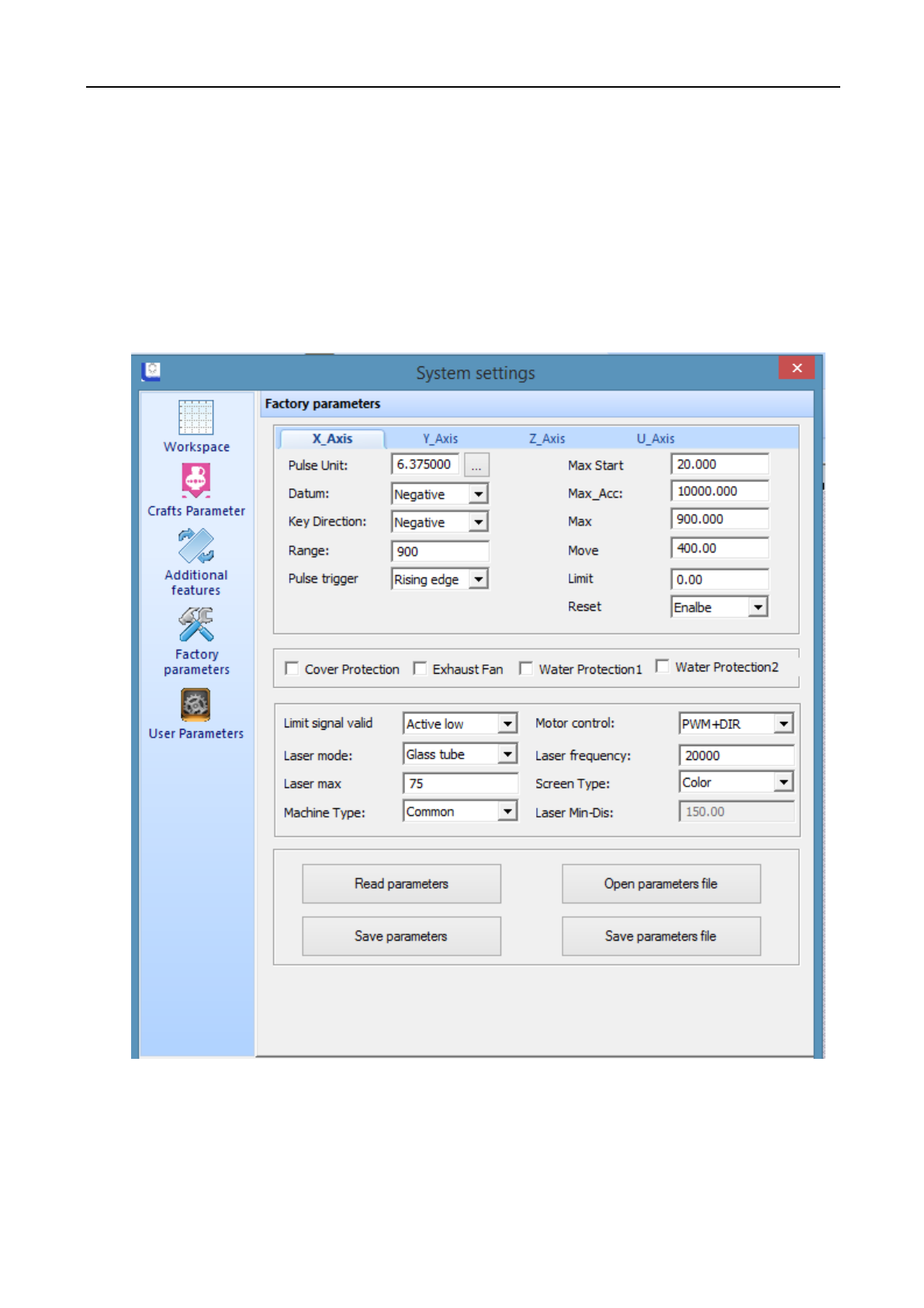
◆Manufacturer parameters
Manufacturer parameters include the parameters of machine properties, about the safety performance and machine
configuration. They are set up by the manufacturer before they leave the factory, users without permission to modify these
parameters. Manufacturer parameters are saved in mainboard. When reinstall, the software parameters will not be lost.
Under this parameter page, two methods can modify parameters:
◆ Click on [Read Parameters], then manually modify the parameters. And then click on [Save parameters].

Laser Engraving and Cutting Software-Instruction for Operation
36
◆ Click on [Open Parameter File], then click [Save Parameters File]. This method will set all parameters at
one time. You can click on to save the manufacturer parameters on current mainboard to parameter file.
Introduction of main parameters:
[Pulse Unit]: When send a pulse to the motor, the absolute traveling distance of corresponding motion axis (unit:
mm). If the pulse equivalent set is not correct, the size of the processed graphics will be different from the actual size.
[Datum]: It indicates the moving direction of motion axis. X limit on the left, direction of X original point is positive;
X limit on the right, direction of X original point is negative. Y limit on the up (inside), direction of Y original point is
negative; Y limit on the below (outside), direction of Y original point is positive.
[Key Direction]: It indicates the moving direction of panel keypad or software keypad which controls the motion.
When the direction of X keypad is positive, the keypad direction is consistent with actual direction; When the direction of
X keypad is negative, the keypad direction is opposite with actual direction; other axis is similar.
[Range]: Actual workbench size of the machine.
[Max Start Speed]: the start speed of the motor, generally set between 5~20.
[Max Acc]: The maximum acceleration that the motor and machine can withstand. At working, the motor will at less
than or equal to the maximum acceleration speed.
[Max Speed]: The maximum speed that the motor and machine can withstand. When working, the motor will be at
less than or equal to the maximum speed.
[Laser Mode]: Includes three modes, such as glass tube radio-frequency tube CO2 (without pre-combustion),
radio-frequency tube CO2 (with pre-combustion)
[Laser Frequency]: Typically set the laser frequency of glass tube between 10000 ~ 20000.
[Laser Max Power]: Typically set as 98, but will vary from different wattage tubes.
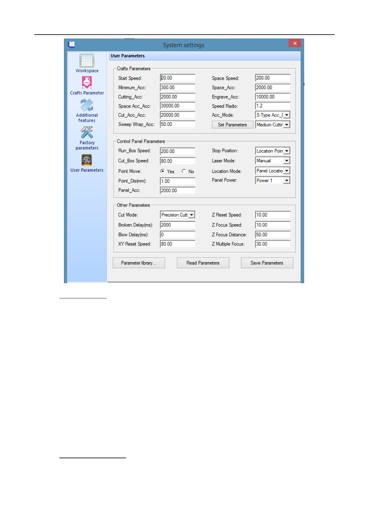
◆ User parameters
Laser Engraving and Cutting Software-Instruction for Operation
37
(1) Crafts parameters
[Space Speed]: During processing, it is the fast running speed of laser head when no laser sending out.
[Space Acc]: During processing, it is the maximum running acceleration of laser head when no laser sending out.
[Space Acc_Acc]: It is the change frequency of idle acceleration. The greater this parameter is, the faster the idle
acceleration and the greater the corresponding vibration is. Normally, the value is between 10000~60000.
[Start Speed]: Initial speed of axis motion.
[Min Acc]: The minimum acceleration of axis motion during process.
[Cut Acc]: Maximum acceleration of laser head motion when laser processing.
[Cut Acc_Acc]: It is the change frequency of cutting acceleration. The greater this parameter is, the faster the idle
acceleration, and the greater the corresponding vibration is. Normally, the value is between 5000~50000.
[Sweep_Acc]: When laser engraving, the maximum acceleration of laser head motion. Normally is set greater than
8000.
(2) Control panel parameters
[Run box Speed]: When no laser sending out, the moving speed along the frame of the processing graphics, it is
mainly used to locate.
Laser Engraving and Cutting Software-Instruction for Operation
38
[Cut box Speed]: When laser sending out, the moving speed along the frame of the processing graphics, it is
mainly used to locate.
[Location Mode]: The location mode includes software location and keypad location.
[Stop Position]: It is divided into machine original point and location point.
[Laser Mode]: Includes manual and automatic options. (manual refers to run according to the power and speed set
on the panel, automatic refers to run according to the power and speed set in the software).
[Point Move]: The system default is no, and it can be changed according to the requirement.
[Panel Power]: Select corresponding output power according to personal requirement. This system includes:
Power and Power 2.
(3) Other parameters
[Cutting Mode]: Includes “precision cutting” and “fast cutting”. For higher quality of cutting, select “precision
cutting”; for lower quality of cutting, select “fast cutting”. “Faster cutting” is more efficient than “precision cutting”.
[Power-off Delay]: When the machine shuts off unexpectedly, the graphics be continued after restart occurs.
Setting the [power-off delay] can make the outage connected, generally set about 1000ms.
[Reset Speed]: The speed of machine back to the origin point. For larger breadth, this parameter can be
appropriately increased.
[Blowing Delay]: When using the blowing function, there will be some delay after cutting and then close the
blowing function
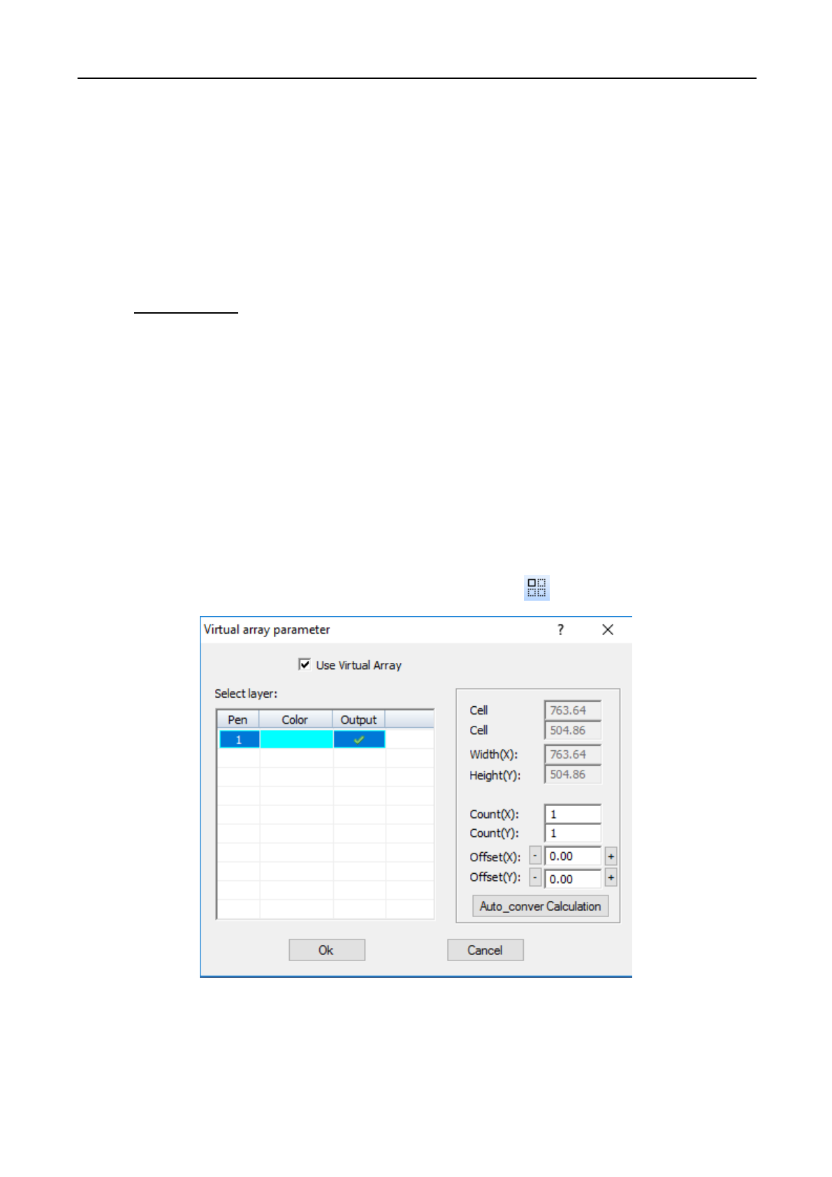
3.7.2 Virtual display (double head inter-motion)
Click menu command [Setting] / [Virtual Array], or click system toolbar , following dialogue box appears:
[Cell width (X)]: Original size of processing data.
[Cell height (Y)]: Original size of processing data.
[Count]: Row number or column number of data to be output.
Laser Engraving and Cutting Software-Instruction for Operation
39
[Offset]: Distance between each row or each column.
[Width]: Width of all data after array.
[Height]: Height of all data after array.
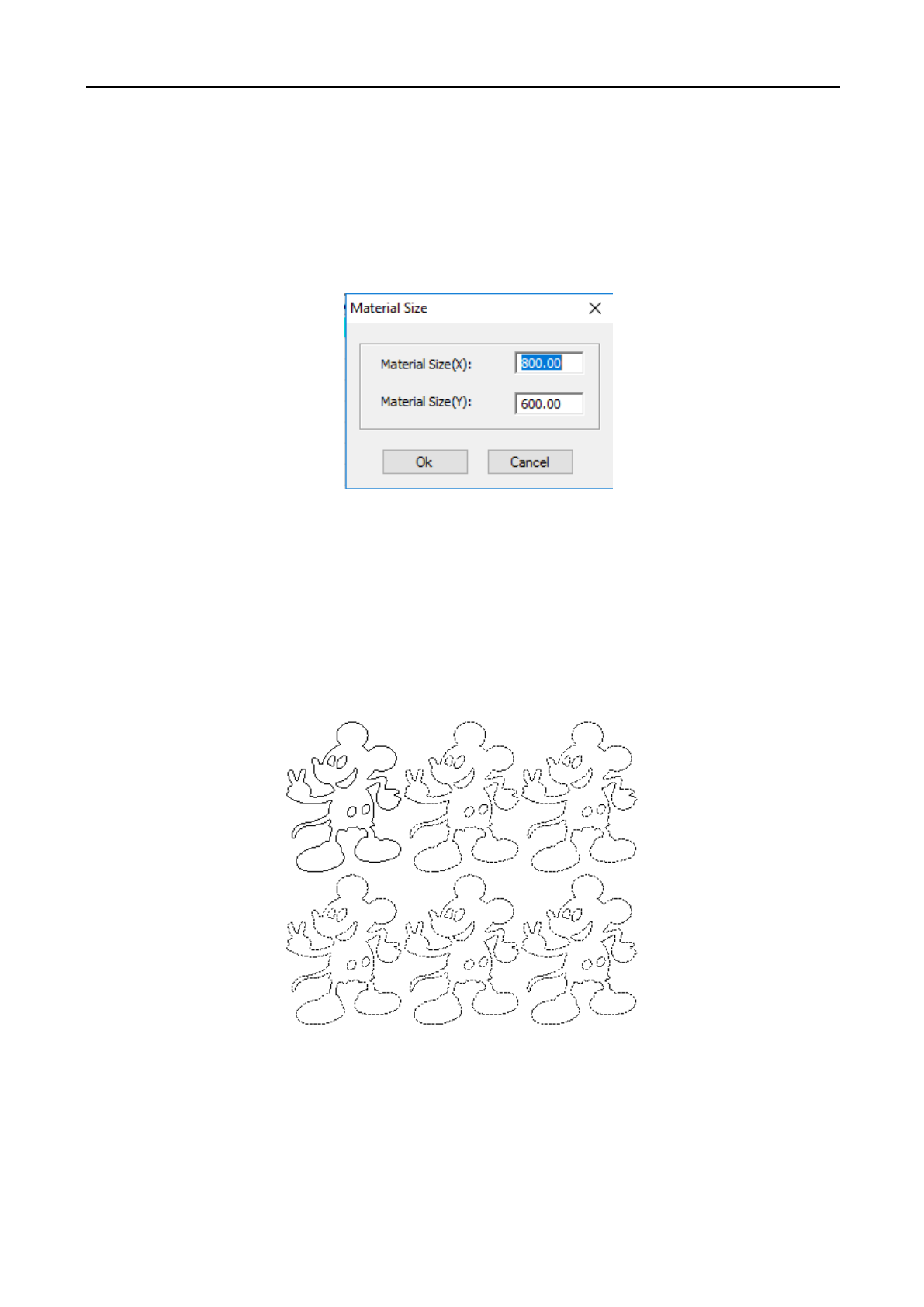
Auto Conversion Calculation: according to the set interval, automatically calculate the row number and column
number needed to cover all the work breadth. Click [Auto Conversion Calculation] button, following dialogue box
appears:
[Material size (X)]: The length of the material to be processed (default value is the length of the workbench).
[Material size (Y)]: The width of the material to be processed (default value is the width of the workbench).
The system will automatically calculate the numbers needed to cover the processing material according to the set
material size.
Array parameter setup example is illustrated below:
3.7.3 Import Parameters
Click on menu bar [Setting] / [Import Parameters], select to import the graphics parameters which already
saved in the computer.
3.7.4 Export Parameters
Laser Engraving and Cutting Software-Instruction for Operation
40
Click on menu bar [Setting] / [Export Parameters], export the graphics parameters and save on corresponding
location in the computer.
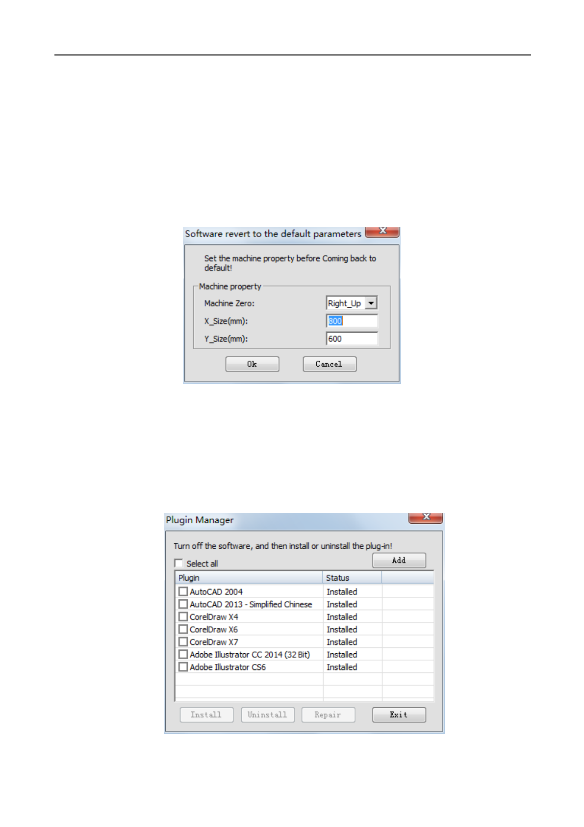
3.7.5 Restore Default Parameters
If there are problems with the machine as several machine settings of the software has been changed into
inappropriate values, or there are problems with software operation and laser output, then it may be good to restore
to default parameters. When restoring the software parameters to default values, all parameters of the software will
be restored to default appropriate values; however, they may not be the ideal values for your specific machine.
To restore software parameters to default values: click on menus command [Setting] / [Restore Default
Parameters], following dialogue box appears:
Correctly select [Machine Zero], set [X_Size] and [Y_Size], then click on [Ok] .
Note: Make sure to correctly set [Machine Zero], [X_Size] and [Y_Size], otherwise the processed graphics may be
inconsistent with the actual (inconsistent in size, graphics image).
3.7.6 Plugin Manager
Detect whether the local installation drawing software (AutoCAD / CorelDraw / Adobe Illustrator) with
plugins installed. To install/uninstall plugins, click on menu bar [Setting]/[Plugin Manager], the following pop-up
window appears.
Check the plugin to be installed, click [Install] / [Uninstall] to install/uninstall the corresponding plugin.
Laser Engraving and Cutting Software-Instruction for Operation
41
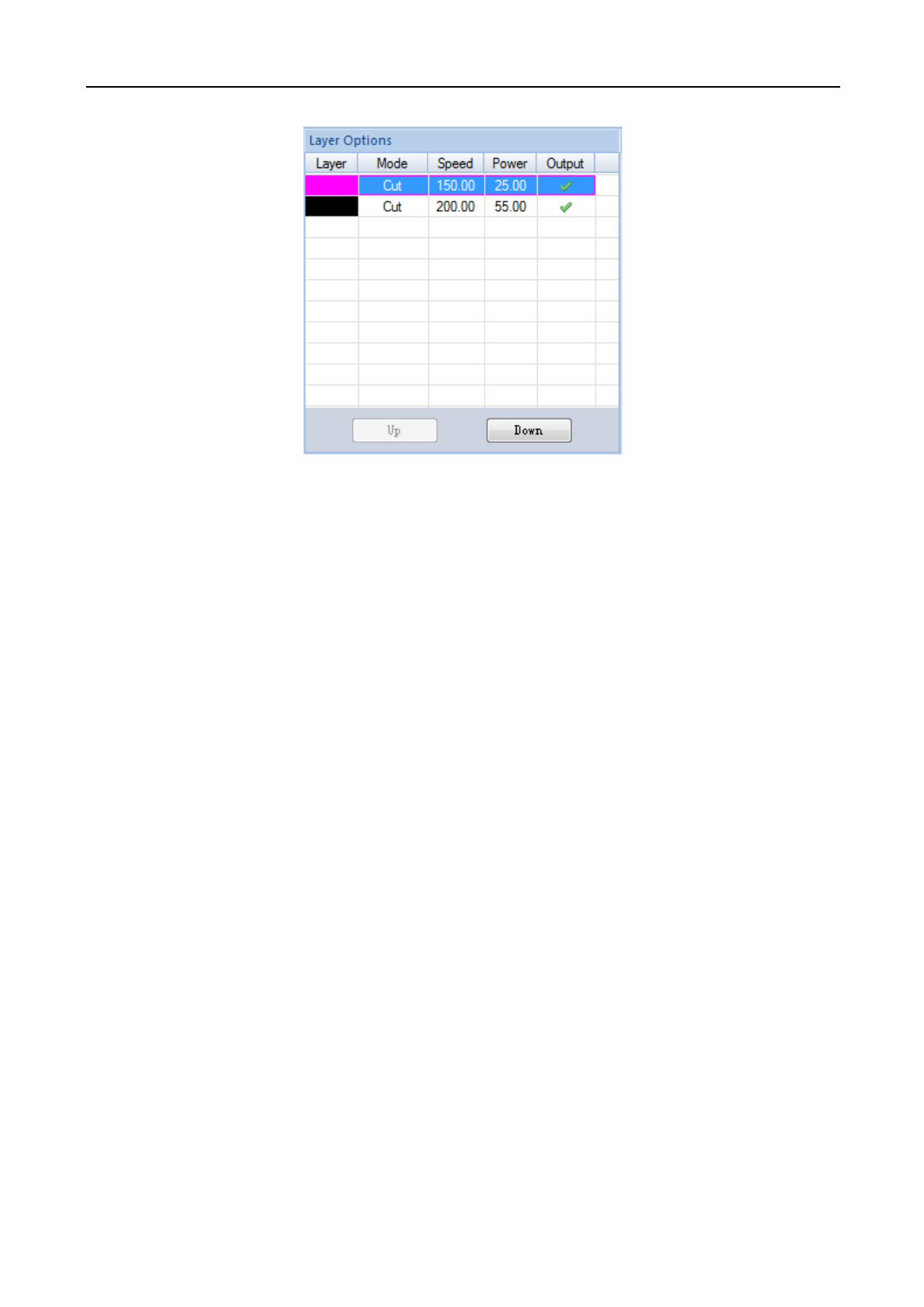
3.8 Layer parameters
Layer parameters display the processing related parameters, whether to output, the layer order.
◆ Click the last column [Output] of each layer, to determine whether or not the layer will be processed. Only the
ones selected with a checkmark will be processed.
◆ Select layer, click [Up] / [Down], the order of each layer can be adjusted.
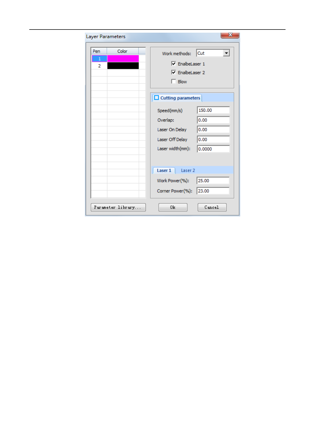
◆ Double click the layer to enter the layer parameter settings shown below.
There will be several work method options that users can choose between:
(1) Laser cutting
Laser Engraving and Cutting Software-Instruction for Operation
42
Select “Cut” in [Work Methods], display cutting parameters, as the figure above.
[Speed]: The maximum speed of laser head when cutting.
[Overlap]: Sometimes due to mechanical error, the closed graphics may not be cut down. This parameter will
help solve the problem. This parameter should not be too large. It is recommended that the adjustment of
mechanical assembly precision to solve the problem.
[Laser On Delay]: laser output time before cutting.
[Laser Off Delay]: laser output time after cutting.
[Laser Width]: according to this value, graphics automatically shrink inward or outward expand.
[Work Power]: adjusts the maximum power of the laser when processing the layer (in percentage).
[Corner Power]: the power value at the lowest speed. (By adjusting the above two parameters, it ensures that
the turn during processing with same effect will cut thoroughly.
Laser Engraving and Cutting Software-Instruction for Operation
43
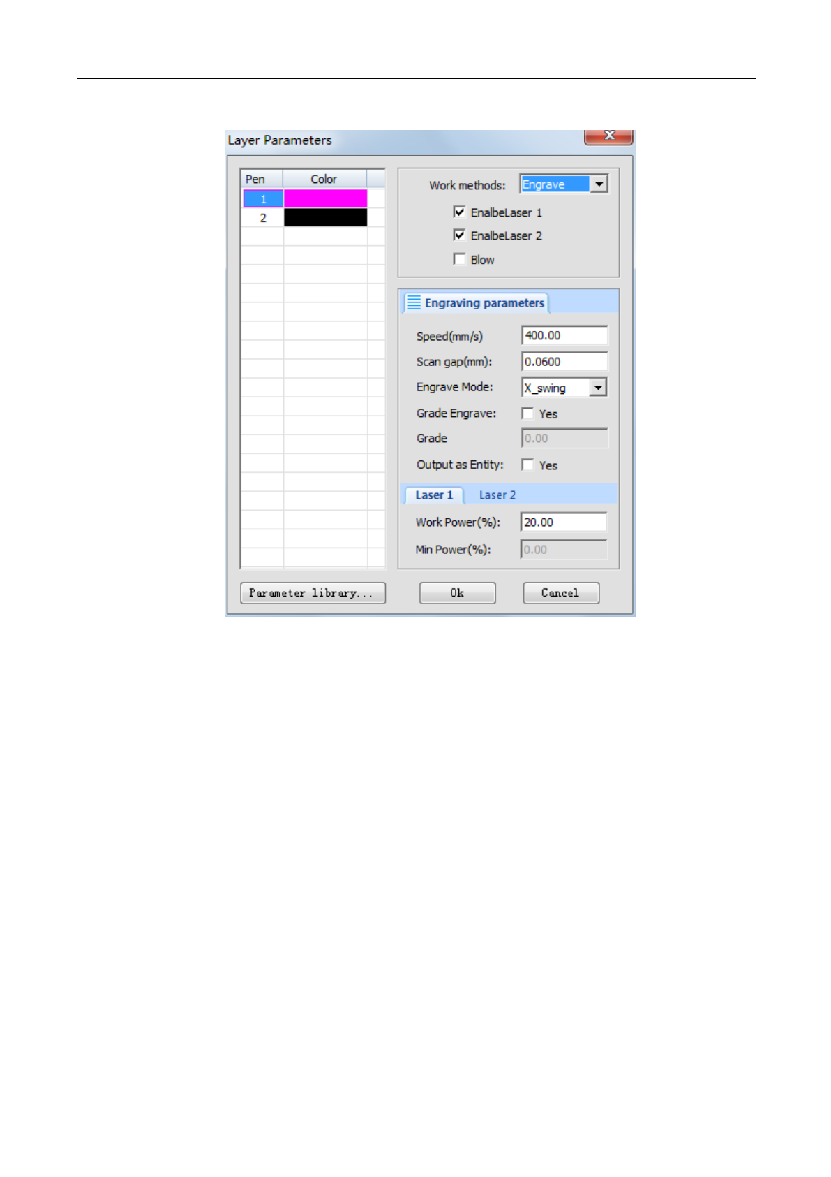
(2) Laser engraving
Select “Engrave” in [Work Methods], display engraving parameters, as the figure above.
[Speed]: The scanning speed when engraving.
[Scan gap]: The gap between scanning line.
[Engrave Mode]: Allows the option to adjust which way the laser head moves when engraving the project. This
includes "horizontal two-way", "horizontal one-way" and "vertical two-way", "vertical one-way".
Horizontal two-way: Laser outputs the laser scanning graphics in a horizontal direction back and forth.
Horizontal one-way: Laser outputs the laser scanning graphics in a horizontal direction back and forth, but only
when it scans to one direction. For example, when the laser head engraves an image from left to right, there will be a laser
output in that direction, but when it returns back from the right side of the image to the left, there will not be any output .
Vertical two-way: Laser outputs the laser scanning graphics in a vertical direction back and forth.
Vertical one-way: Laser outputs the laser scanning graphics in a vertical direction up and down, but only when it
scans to one direction. For example, when the laser head engraves an image from top to bottom, there will be a laser
output in that direction, but when it returns back from the bottom of the image to the top, there will not be any output.
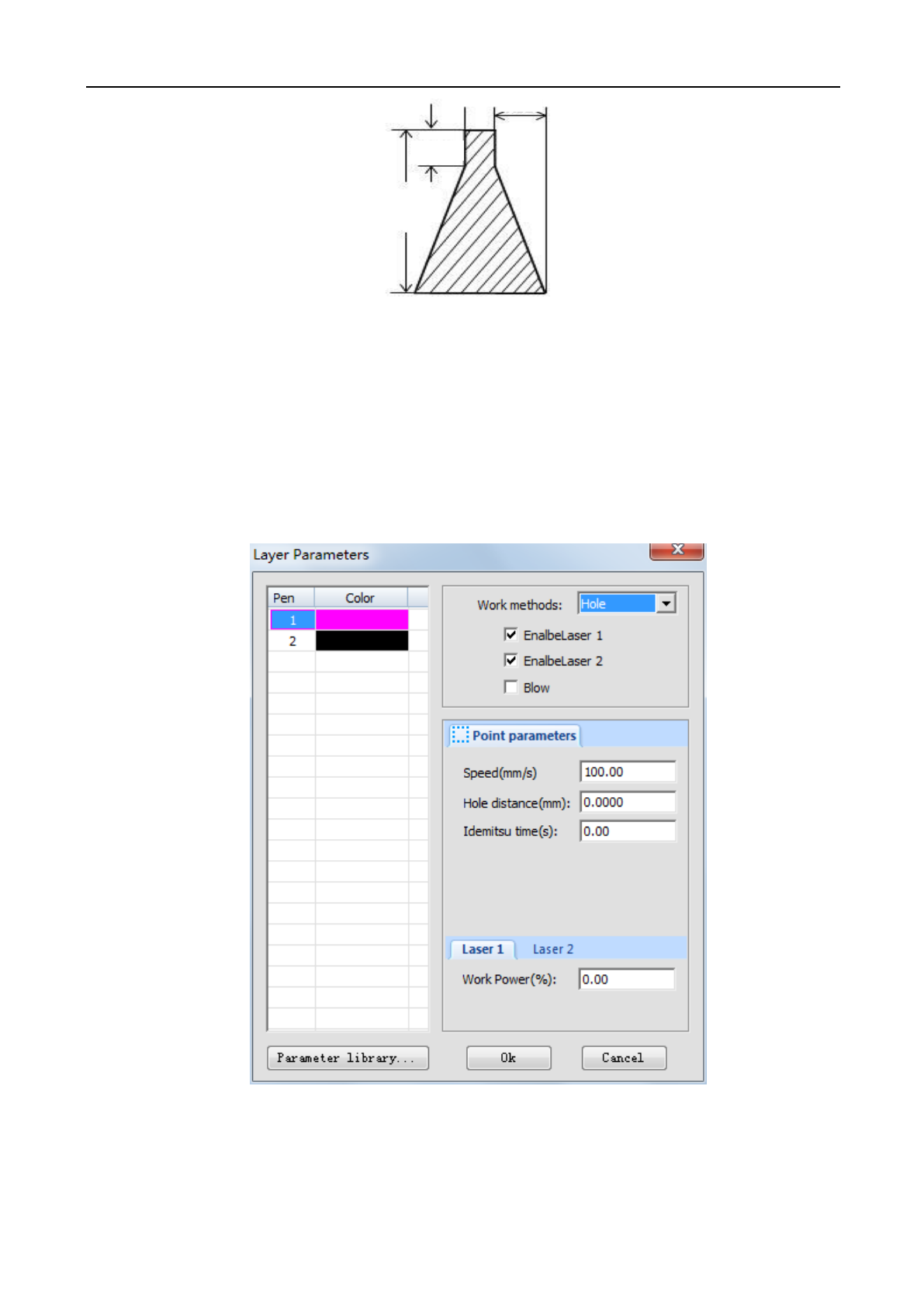
[Grade Engrave]: Select “yes”, [Slope Length] and [Minimum Power] effective. slope engraving schematic
figure:
Laser Engraving and Cutting Software-Instruction for Operation
44
[Grade Length]: “Slope degree” in the schematic figure.
[Output as Entity]: During engraving scanning, whether take the edge of graphics as the starting and ending
points, otherwise take the frame of graphics as the starting and ending points.
[Work Power]: The power of the laser when processing the layer (in percentage).
[Min Power]: The minimum value of laser power when adjusting slope engraving. This value determines the top
depth of the slope.
(3) Laser hole
Select “Hole” in [Work Methods] to display drilling parameters, as the figure above.
[Speed]: Moving speed of laser head.
[Hole Distance]: The diameter/distance of the hole.
[Idemitsu time]: When drilling, the pause time of laser head.
Laser Engraving and Cutting Software-Instruction for Operation
45
[Work Power]: The laser power when processing this layer (in percentage).
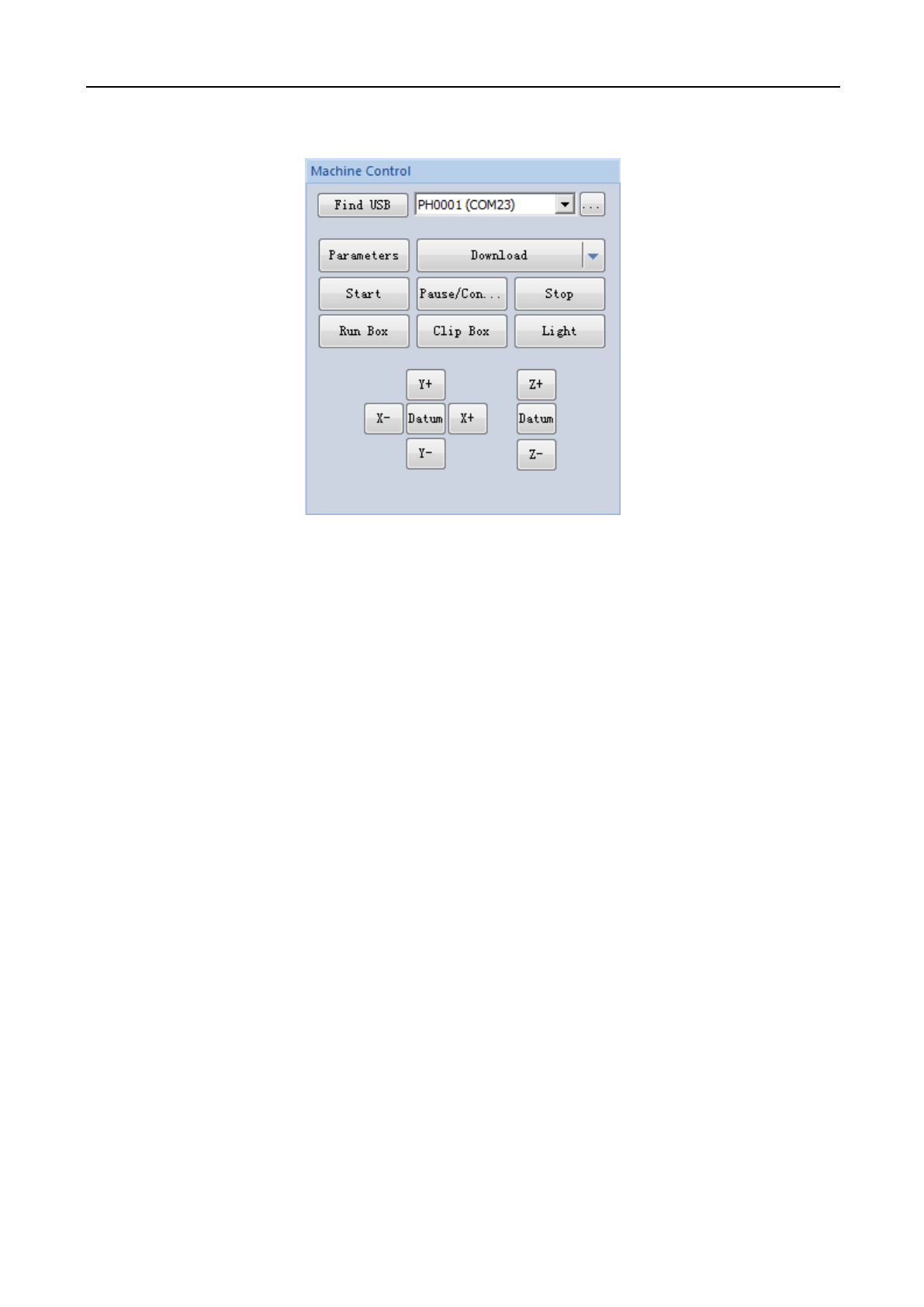
3.9 Machine control
[Start]: Begins the project that is downloaded and sent to the laser machine controller through the software
program.
[Pause/Continue]: If machine is in the process of cutting/engraving, click [Pause/Continue] to pause the current
operation. To continue the operation after pausing, press [Pause/Continue].
[Stop]: Stops all processes on the laser machine.
[Run Box]: The laser head will form a rectangle according to the size of processing data, mainly used to determine
the position for processing workpiece.
[Clip Box]: Cut the processed workpiece from material.
[Light]: Press [laser output] button to send out a laser pulse; by releasing the laser output button, the laser will shut
down.
[Datum]: “original point” is “reset”. When clicking this button, the laser head (or axis Z) will slowly move the
machine to its original point. When it touches the machine’s limit switches, it will quickly move to the positioning location.
This function can eliminate the accumulated error, generally must be conducted before processing.
[X-] [X+] [Y-] [Y+] [Z-] [Z+]: Controls on the software that moves the laser head (or axis Z). When it is
“jog“ , click once and the laser head will move once. The moving distance is normally set on “jog distance”; when it is
not “jog”, press the above direction buttons and the head will move; to stop movement, release the button.
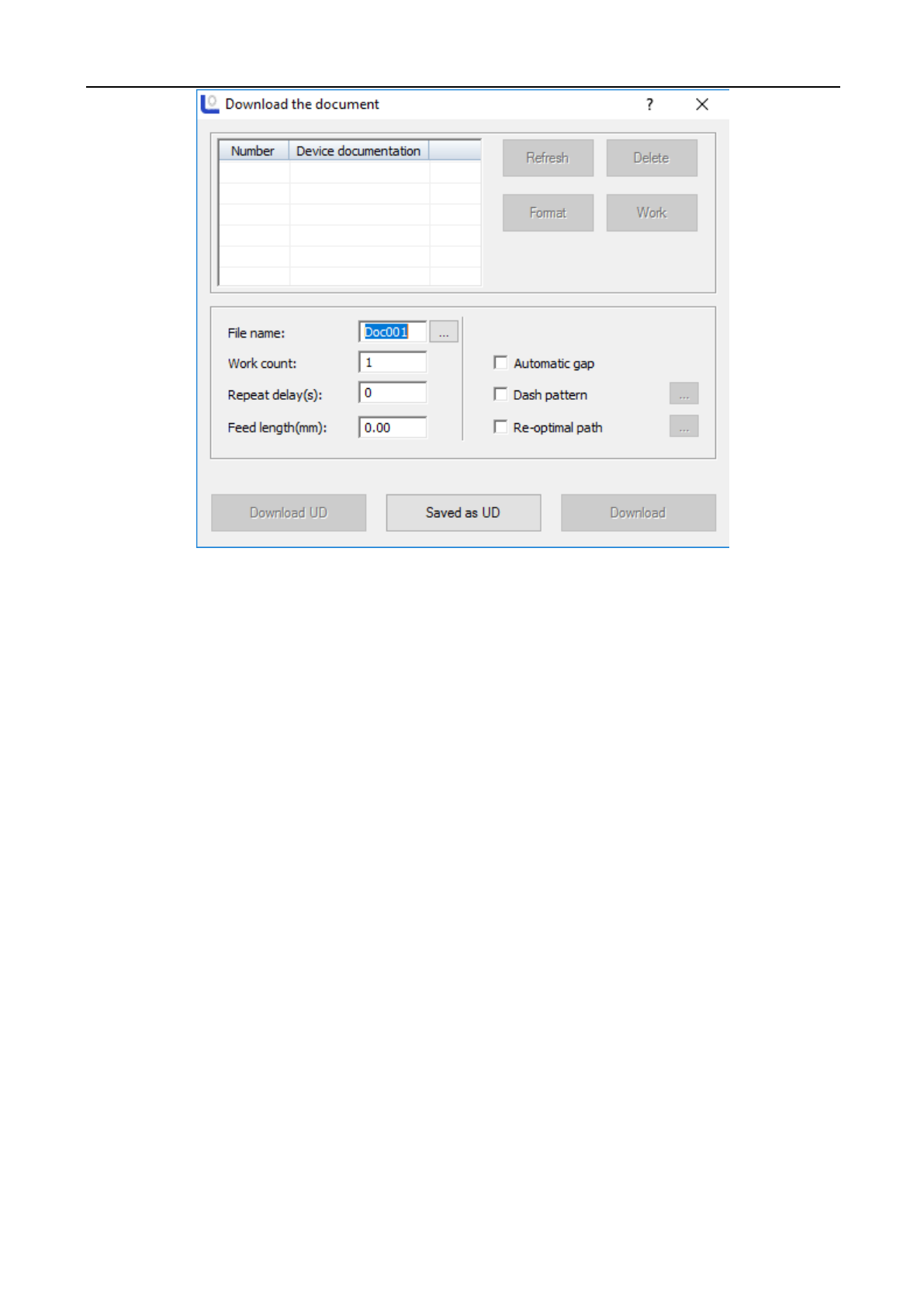
[Download]: Click on [Download] button, and the following dialogue below will appear:
Laser Engraving and Cutting Software-Instruction for Operation
46
[File name]: The name of the file load to mainboard.
[Work count]: The processing timers of loaded file. When start processing, the system can automatically repeat the
processing of this file data.
[Repeat delay]: Processing for many times, delay time after each processing.
[Feed length]: the distance of feeding axis (Z axis) after each processing.
[Download]: Through USB connection/ethernet cable, this will load the document in current software to the laser
controller. The controller will use the file name of the set document of the file and save. To save the graphics data to file
system of mainboard. After load, press the “file” button on “control panel” which will match with the system. After that,
you may find that the last file in file system.
[Save as UD]: Offline file (extension name of ud/uo) saved to computer, and then copies to U disk. It can be loaded
to mainboard through U disk interface.
[Download UD]: Loads the offline file stored (ud file) to mainboard.
[Refresh]: namely query all files stored in the mainboard. Click [Refresh], file list of equipment document will show
all filenames of all files stored in the mainboard.
[Work]: Select a file in the file list, click on [Work] button, can start the processing of this file.
[Delete]: Select a file in the file list, click on [Delete] button to delete the selected file from mainboard.
[Format]: Formatting motherboard memory. All files stored in mainboard will be lost.
Laser Engraving and Cutting Software-Instruction for Operation
47
Chapter 4 CorelDraw / AutoCAD / Adobe
Illustrator Plugin
4.1 CorelDraw Versions Supported
CorelDraw12 / CorelDraw13 / CorelDrawX4 / CorelDrawX5/ CorelDrawX6、CorelDrawX7
4.2 Supported CorelDraw Versions
AutoCAD 2004, AutoCAD 2008, AutoCAD 2010, AutoCAD 2012, AutoCAD 2013, AutoCAD 2014,
AutoCAD 2015
4.3 Supported Adobe Illustrator Versions
Adobe Illustrator CS5, Adobe Illustrator CS6, Adobe Illustrator CC2014
4.4 Operating system support
Windows XP, Windows 7 (32/64), Windows 8 (32/64)
4.5 Manually load “PH_LaserCut”toolbar
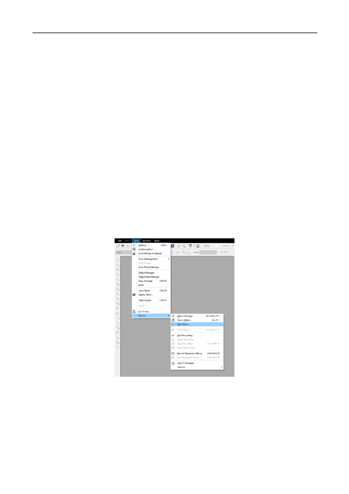
After installing the CorelDraw / AutoCAD/ Adobe Illustrator Plugin, start up the software. Using
CorelDrawX4 as an example.
(1) Click on [Tools] / [Macro] / [Run Macro], shown as the figure below:
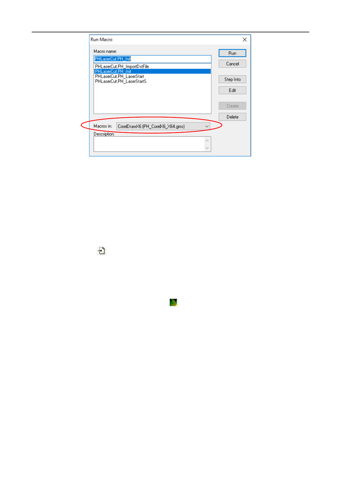
(2) In the pop up window, for the [Macro Position] select “Global Macros (PH_CorelEx.gms)”. Then in
[Macro Name] select “PHLaserCut.PH_Init”.
Laser Engraving and Cutting Software-Instruction for Operation
48
(3) Click on [Run] button, the CorelDraw main interface will add “PH_LaserCut” toolbar.
(4) In CorelDraw, already manually load “PH_LaserCut” toolbar, later restart CorelDraw, “PH_LaserCut”,
toolbar will appear.
4.6 Display the hidden “PH_LaserCut”toolbar
During use of CorelDraw, users may close “PH_LaserCut”toolbar, so you may need to display the hidden
toolbar. Hover over onto the toolbar and right click area and then click on [PH_LaserCut] .
4.7 Import DST/DSB file
Click on import button on “PH_LaserCut” toolbar, following dialogue box appear:
Select the DST/DSB file to loaded, then click on [Open] button.
4.8 Transfer from your software to the LightObject Software
Compile the graphics in your software and click on button on the “PH_LaserCut” toolbar, directly transfer
to a universal version, and the graphics compiled in CorelDraw will also be shown in view of universal version.

Laser Engraving and Cutting Software-Instruction for Operation
49
Chapter 5 FAQ Answering
5.1 USB is unable to connect
USB serial port connection failure may be due to these reasons:
1. No connection by computer to USB plug-in and pull-out, and its reason may be due to
:
(1). Machine is off. (Machine should be turned on to establish connection)
(2). Computer USB outlet is not working. Try a different USB outlet or try on a different computer.
(3). USB cable may be broken, try another cable with the same plugs.
2. After USB plugin, the forward solution right of computer desktop notes “unknown device”, which may
result from:
(1). USB plugged in the incorrectly. (There are two USB interface on the laser machine, one for flash
drive and one for USB cable) Plug in the square shaped plug into the controller and the USB side into the
computer.
(2). Use of invalid USB cable. Find the correct cable to connect to your machine.
3. Corresponding serial port shows "?"/"!" in the computer device manager after USB plugin, which is due to
incorrect driver installation, and reinstallation of driver will do.
4. If in notes it says “serial port is occupied!” then the possible reasons may be:
(1). Operating system is occupying this port, so re-plug in USB;
(2). Mainboard serial port module or USB interface fault, which requires manufacturer overhaul;
5. Other faults, and it shall be delivered to the manufacturer for overhaul.
Special Instruction:
USB cable communication is suitable for short distance communication. The USB cable should not be longer
than 10m.
5.2 When starting a process, the machine is immovable or moves in an unfamiliar way where
parts of the graphs is under no processing
◆ Check the graphic data, and those exceeding the breadth shall not be incised.
◆ Check the setting of “relative graph location”.
5.3 The faceplate gives a prompt of [buffer distance insufficiency]
◆ Check the setting of engraving accelerated speed which is normally set at 8,000 or more.
◆ Keep the graph outline border away from machine breadth boundary.
5.4 When loading documents, it gives a prompt of [The current document data is empty]
◆ Check the engraving output graph for sealing.
◆ Check all layers for output choice and make sure that there is at least one “Yes” for it to transfer.
5.5 The processed graph is the mirror image of actual graph
Check the setting of “machine dead center position”.
5.6 Unreadable AI documents
AI documents are normally generated by CorelDraw or Adobe Illustrator, and when save AI using adobe
Illustrator:
1. Do not use compressed format or PDF format.
Laser Engraving and Cutting Software-Instruction for Operation
50
2. As for text, first create a profile of test (if it is a plug-in call, it needs no processing, and the plugin will
automatically process)
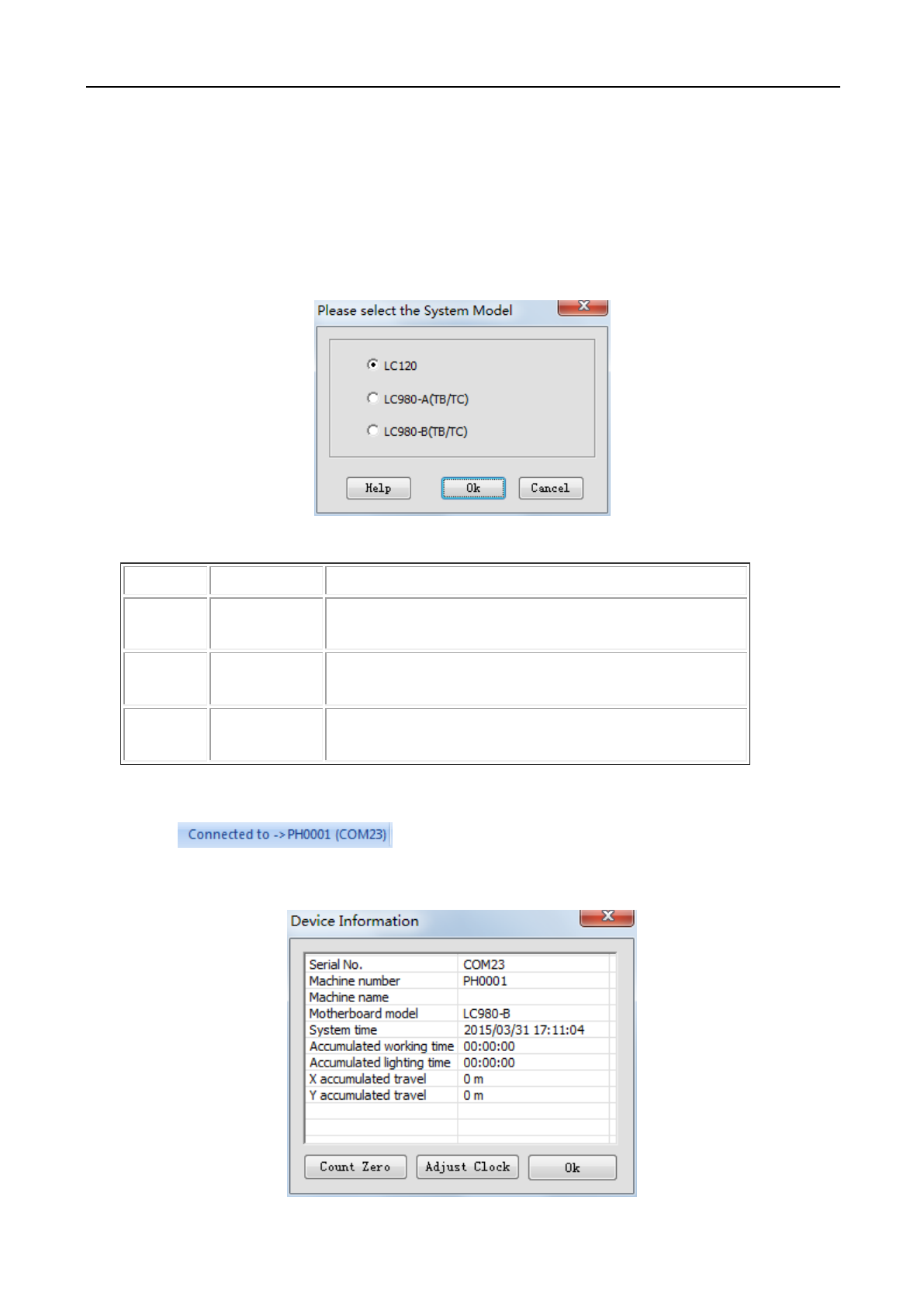
5.7 How to choose mainboard type when saving off-line file
It needs to choose system type when saving off-line files, as shown below. Choosing the wrong one may lead
to nonfunctional machine.
In normal condition, the mainboard type can be judged by faceplate.
Mainboard
Faceplate
Description
LC120
Black-and-white
screen
15 buttons on faceplate (no number key), no touch-control
LC980-A
Large colorized
screen
33 buttons on faceplate (with number keys), touch-control
LC980-B
Small colorized
screen
15 buttons on faceplate (no number key), touch-control
If not know the machine type clearly, check it according to the following steps:
Step 1: open the software on the computer to be connected and properly connect the machine;
Step 2: click in status bar, and prompt machine info windows as shown
below, where the machine type is described in the red box position.
Laser Engraving and Cutting Software-Instruction for Operation
51
5.8 Machine is locked (only apply to the encrypted machine)
(1) Advance hint for due date
For encrypted machine, it shall popup the hint upon software started three days prior to the due date.
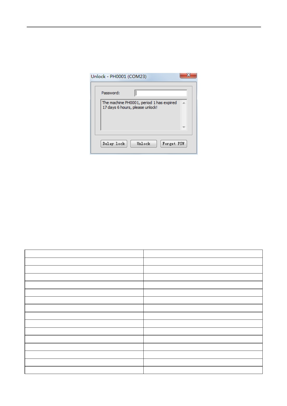
(2) Unlock
If it is about to reach or reaches the date due, click [Help]/ [Unlock] menu, input unlock password in
the popup window shown below, and click [Unlock] button.
(3) Forget password
If machine supplier forgot password, click [Forget password] button, input file name in the popup
window, save LPW file and send it to the supplier. Machine supplier shall parse the above-sent file and give
back the password, re-input the password and click [Unlock] button.
Chapter 6 Shortcuts
Shortcut Key
Function Description
F1
Display help file
F2
Enter zoom display mode
F3
Enter translation display mode
F4
Enter zoom-all-image display mode
F5
Enter simulation window
F7
Enter manual sorting mode
F8
Display/hide recent files
F9
Enter system setting window
Shift+F2
Enter zoom-selected-image display mode
Shift+F4
Display as per page size
Alt+S
Enter selection mode
Alt+N
Enter node edit mode
Alt+L
Enter draw-line mode
Alt+P
Enter draw-polyline mode

Laser Engraving and Cutting Software-Instruction for Operation
52
Alt+R
Enter draw-rectangle mode
Alt+E
Enter draw-ellipse mode
Alt+B
Enter draw-Bezier-curve mode
Alt+T
Enter draw-text mode
Alt+C
Open camera
Alt+Q
Enter LGP design window
Alt+G
Enter mesh generation window
Shift+A
Array copy
Shift+C
Closed figure
Shift+D
Delete overlapping line
Shift+L
Generate lead line
Shift+I
Image counter-color
Shift+N
Image network
Ctrl+C
Copy
Ctrl+V
Paste
Ctrl+X
Cut
Ctrl+Y
Redo
Ctrl+Z
Restore
Ctrl+U
Ungroup
Ctrl+G
Group
Ctrl+Shift+U
Ungroup all
Ctrl+N
New document
Ctrl+O(I)
Open project file, lay in graphic file
Ctrl+E
Export Plt file
Ctrl+S
Save
Ctrl+Shift+S
Save-as
Ctrl+1
Shift to bottom left corner of page
Ctrl+3
Shift to bottom right corner of page
Ctrl+5
Shift to page corner
Ctrl+7
Shift to bottom left corner of page
Ctrl+9
Shift to upper-right corner of page
Ctrl+→
Right justify
Ctrl+←
Left justify
Ctrl+↑
Up justify
Ctrl+↓
Down justify
→
Right shift
←
Left shift
↑
Up shift
↓
Down shift

Laser Engraving and Cutting Software-Instruction for Operation
53
Delete
Delete
