MSP432P401R LaunchPad™ Development Kit (MSP‑EXP432P401R) (Rev. B) Launch Pad Users Guide
User's%20Guide%20-%20slau597b
User Manual:
Open the PDF directly: View PDF ![]() .
.
Page Count: 52
- MSP432P401R LaunchPad™ Development Kit (MSP‑EXP432P401R)
- 1 Getting Started
- 2 Hardware
- 3 Software Examples
- 3.1 Out-of-Box Software Example
- 3.2 CC3100BOOST MQTT-Twitter LED Control Example
- 3.3 BOOSTXL-K350QVG-S1 Graphics Library Example
- 3.4 430BOOST-SHARP96 Graphics Library Example
- 3.5 BOOSTXL-BATPAKMKII_FuelGauge_MSP432P401R
- 3.6 BOOSTXL-SENSORS_SensorGUI_MSP432P401R
- 3.7 BOOSTXL-SENSORS_TI-RTOS_SensorGUI_MSP432P401R
- 4 Resources
- 5 FAQ
- 6 Schematics
- Revision History
- Important Notice
1
SLAU597B–March 2015–Revised July 2016
Submit Documentation Feedback Copyright © 2015–2016, Texas Instruments Incorporated
MSP432P401R LaunchPad™ Development Kit (MSP
‑
EXP432P401R)
LaunchPad, MSP432, BoosterPack, Code Composer Studio, EnergyTrace, MSP430, SimpleLink, E2E are trademarks of Texas Instruments.
ARM, Cortex, Keil, µVision are registered trademarks of ARM Ltd.
IAR Embedded Workbench is a trademark of IAR Systems.
All other trademarks are the property of their respective owners.
User's Guide
SLAU597B–March 2015–Revised July 2016
MSP432P401R LaunchPad™ Development Kit
(MSP
‑‑
EXP432P401R)
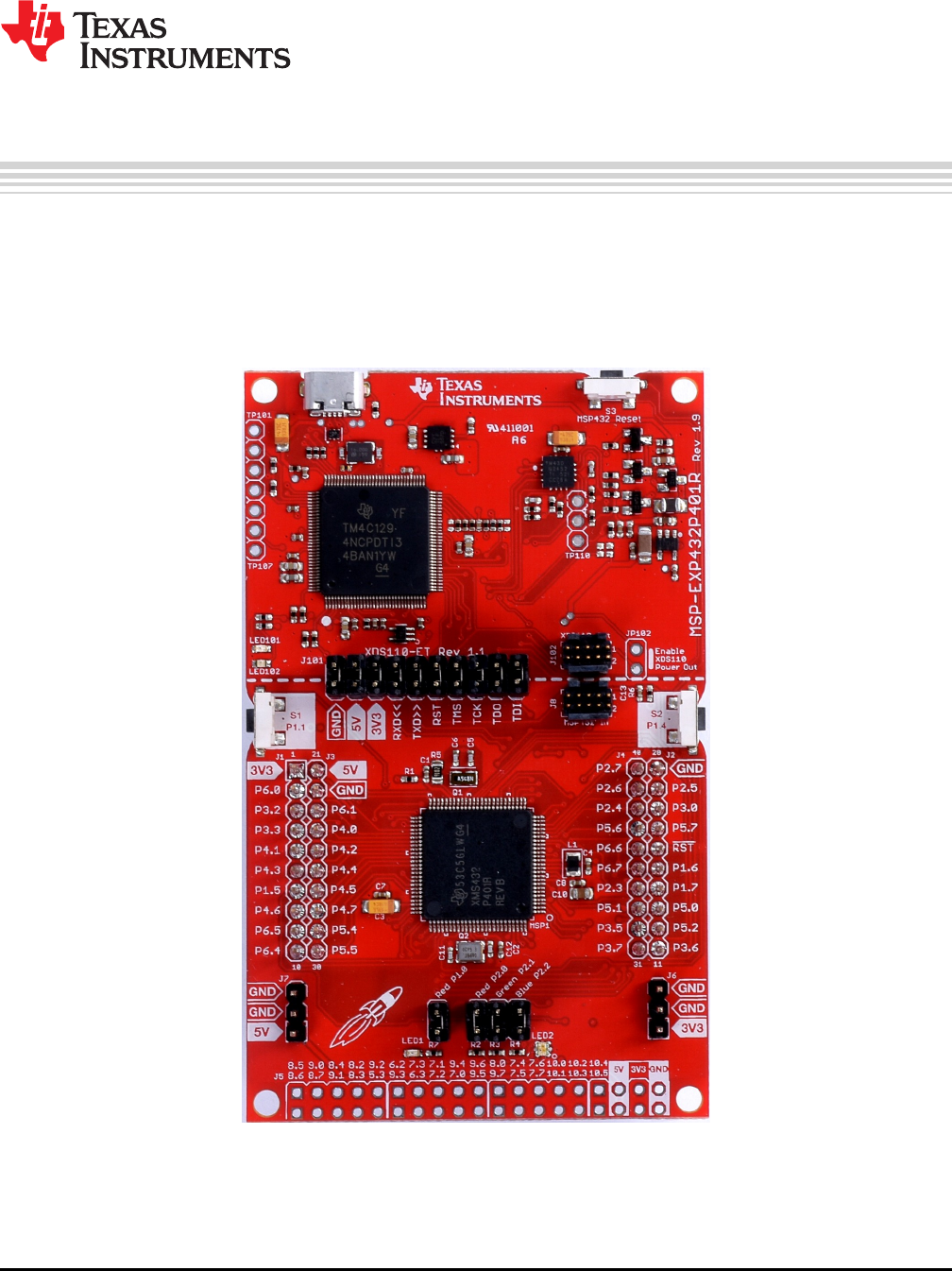
The MSP‑EXP432P401R LaunchPad™ development kit is an easy-to-use evaluation module for the
MSP432P401R microcontroller. It contains everything needed to start developing on the MSP432™ Low-
Power + Performance ARM®32-bit Cortex®-M4F microcontroller (MCU), including onboard debug probe
for programming, debugging, and energy measurements. The MSP432P401R device supports low-power
applications requiring increased CPU speed, memory, analog, and 32-bit performance.
Figure 1. MSP‑‑EXP432P401R LaunchPad™ Development Kit

www.ti.com
2SLAU597B–March 2015–Revised July 2016
Submit Documentation Feedback
Copyright © 2015–2016, Texas Instruments Incorporated
MSP432P401R LaunchPad™ Development Kit (MSP
‑
EXP432P401R)
Contents
1 Getting Started ............................................................................................................... 3
2 Hardware...................................................................................................................... 5
3 Software Examples ........................................................................................................ 19
4 Resources................................................................................................................... 37
5 FAQ .......................................................................................................................... 40
6 Schematics.................................................................................................................. 45
List of Figures
1 MSP‑EXP432P401R LaunchPad™ Development Kit .................................................................. 1
2 MSP-EXP432P401R Overview ............................................................................................ 5
3 Block Diagram................................................................................................................ 5
4 MSP432P401RIPZ Pinout .................................................................................................. 6
5 XDS110-ET Debug Probe .................................................................................................. 7
6 XDS110-ET Isolation Block................................................................................................. 8
7 Application Backchannel UART in Device Manager .................................................................... 9
8 EnergyTrace™ Technology Preferences ............................................................................... 11
9 EnergyTrace™ Windows.................................................................................................. 12
10 MSP‑EXP432P401R Power Block Diagram ............................................................................ 13
11 LaunchPad™ Development Kit to BoosterPack™ Plug-in Module Connector Pinout ............................ 16
12 Differences Between Rev 1.0 (Black) and Rev 2.0 (Red) ............................................................ 18
13 BSL Update Utility in TI Resource Explorer ............................................................................ 19
14 Out-of-Box GUI Running Locally ......................................................................................... 20
15 Out-of-Box GUI Running From TI Cloud Tools......................................................................... 21
16 Backend Block Diagram of CC3100BOOST MQTT-Twitter LED Control Demo................................... 23
17 Importing and Converting an Image With MSP Image Reformer .................................................... 25
18 Hardware Setup and Connections ....................................................................................... 26
19 Determine COM Port Number Using Device Manager on Windows ................................................ 27
20 Example Serial Terminal Configuration ................................................................................. 27
21 Snapshot of Serial Terminal Connected to Running Fuel Gauge Demo ........................................... 28
22 Setting up COM Port Configuration for the LaunchPad™ Development Kit ....................................... 29
23 Programming Sensor Software With the GUI .......................................................................... 30
24 Sensor GUI Layout......................................................................................................... 30
25 GUI Sensor Tile ............................................................................................................ 32
26 GUI Integrated EnergyTrace™ Measurements ........................................................................ 33
27 Board Movement Window................................................................................................. 33
28 Translation Along the X Axis.............................................................................................. 33
29 Translation Along the Y Axis.............................................................................................. 34
30 Translation Along the Z Axis.............................................................................................. 34
31 Rotation Around the X Axis ............................................................................................... 34
32 Rotation Around the Y Axis ............................................................................................... 35
33 Rotation Around the Z Axis ............................................................................................... 35
34 No Movement............................................................................................................... 35
35 Light Sensing in the Gesture Recognition Window.................................................................... 36
36 Using TI Resource Explorer to Browse MSP‑EXP432P401R in MSPWare........................................ 39
37 SWD Mode Settings ....................................................................................................... 40
38 Target Configurations...................................................................................................... 41
39 Launch Selected Configuration........................................................................................... 41
40 Show All Cores ............................................................................................................. 42

www.ti.com
Getting Started
3
SLAU597B–March 2015–Revised July 2016
Submit Documentation Feedback Copyright © 2015–2016, Texas Instruments Incorporated
MSP432P401R LaunchPad™ Development Kit (MSP
‑
EXP432P401R)
41 Connect Target ............................................................................................................. 43
42 MSP432_Factory_Reset Script........................................................................................... 43
43 Schematics (1 of 6) ........................................................................................................ 45
44 Schematics (2 of 6) ........................................................................................................ 46
45 Schematics (3 of 6) ........................................................................................................ 47
46 Schematics (4 of 6) ........................................................................................................ 48
47 Schematics (5 of 6) ........................................................................................................ 49
48 Schematics (6 of 6) ........................................................................................................ 50
List of Tables
1 Isolation Block Connections................................................................................................ 7
2 Default Clock Operation................................................................................................... 14
3 Hardware Change Log .................................................................................................... 17
4 Software Examples ........................................................................................................ 19
5 IDE Minimum Requirements for MSP‑EXP432P401R ................................................................ 20
6 Source File and Folders................................................................................................... 22
7 Source File and Folders................................................................................................... 26
8 Source File and Folders................................................................................................... 29
9 Source Files and Folders.................................................................................................. 36
10 How MSP Device Documentation is Organized........................................................................ 39
1 Getting Started
1.1 Introduction
The MSP‑EXP432P401R LaunchPad development kit is an easy-to-use evaluation module for the
MSP432P401R microcontroller. It contains everything needed to start developing on the MSP432 Low-
Power + Performance ARM 32-bit Cortex-M4F microcontroller (MCU), including onboard debug probe for
programming, debugging, and energy measurements. The MSP432P401R device supports low-power
applications that require increased CPU speed, memory, analog, and 32-bit performance.
Rapid prototyping is simplified by access to the 40-pin headers and a wide variety of BoosterPack™ plug-
in modules that enable technologies such as wireless connectivity, graphical displays, environmental
sensing, and many more. Free software development tools are also available such as TI's Eclipse-based
Code Composer Studio™ (CCS) IDE, IAR Embedded Workbench™ IDE, and Keil®µVision®IDE. Code
Composer (CCS) supports EnergyTrace™ technology when paired with the MSP432P401R LaunchPad
development kit. More information about the LaunchPad development kit, the supported BoosterPack
plug-in modules, and the available resources can be found at TI's LaunchPad portal. To get started
quickly, and find available resources in MSPWare, visit the TI Cloud Development Environment.
1.2 Key Features
• Low-power ARM Cortex-M4F MSP432P401R
• 40-pin LaunchPad development kit standard that leverages the BoosterPack plug-in module ecosystem
• XDS110-ET, an open-source onboard debug probe featuring EnergyTrace+ technology and application
UART
• Two buttons and two LEDs for user interaction
• Backchannel UART through USB to PC

Getting Started
www.ti.com
4SLAU597B–March 2015–Revised July 2016
Submit Documentation Feedback
Copyright © 2015–2016, Texas Instruments Incorporated
MSP432P401R LaunchPad™ Development Kit (MSP
‑
EXP432P401R)
1.3 What's Included
1.3.1 Kit Contents
• One MSP‑EXP432P401R LaunchPad development kit
• One Micro USB cable
• One Quick Start Guide
1.3.2 Software Examples (Section 3)
• Out-of-Box Software Example
• CC3100BOOST MQTT-Twitter LED Control Example
• BOOSTXL-K350QVG-S1 Graphics Library Example
• 430BOOST-SHARP96 Graphics Library Example
• BOOSTXL-BATPAKMKII Fuel Gauge Example
• BOOSTXL-SENSORS Sensor GUI Example
• BOOSTXL-SENSORS Sensor GUI with TI-RTOS Example
1.4 First Steps: Out-of-Box Experience
An easy way to get familiar with the EVM is by using its preprogrammed out-of-box code. It demonstrates
some key features of the LaunchPad development kit from a user level, showing how to use the
pushbutton switches together with onboard LEDs and basic serial communication with a computer.
A more detailed explanation of the out-of-box demo can be found in Section 3.
1.5 Next Steps: Looking Into the Provided Code
It is now time to start exploring more features of the EVM!
www.ti.com/beginMSP432launchpad
To get started, you will need an integrated development environment (IDE) to explore and start editing the
code examples. Refer to Section 4 for more information on IDEs and where to download them.
Continuing in the footsteps of the widely successful MSP430™ 16-bit ultra-low-power microcontroller
platform, Texas Instruments expands its MSP product line with the MSP432 microcontroller platform. If
you are used to developing with MSP430 devices, see MSP432 Platform Porting to help start your
MSP432 application with ease.
The out-of-box source code and more code examples can be downloaded from the MSP-EXP432P401R
tool folder. Find what code examples are available and more details about each example in Section 3. All
code is licensed under BSD, and TI encourages reuse and modifications to fit specific needs.
Target Device
MSP432P401R
Crystal
48 MHz
Micro‐B
USB
EnergyTrace+
Current
Measure HW
LDO
5 V, 3.3 V
ESD
Protection
Power
Switch
Debug
MCU
LED
Red, Green
Power, UART, JTAG to Target
User Interface
Buttons and LEDs
40‐pin LaunchPad
standard headers
{EnergyTrace Technology
Real-time power consumption
readings and state updates from the
MSP432P401R MCU viewable
through the EnergyTrace GUI
40-pin BoosterPack
plug-in module connector
(J1–J4) {
Button/Switch
S2
User LEDs
LED1 and LED2
Button/Switch
S1
Fanout of Unused Pins
- Access to unused pins on the
MSP432P401R device
- Support for bread-board connection
MSP432P401R Microcontroller
MSP1
{
Jumper Isolation Block
- J101
- Power
- GND, 5V, and 3V3
- Back-channel UART to the PC
- RXD, TXD
- JTAG
- RST, TMS, TCK, TDO, TDI
XDS110 onboard debug probe
Enables debugging and programming
as well as communication to the PC.
The XDS110 can also provide power
to the target MCU.
Reset
MSP432P401R Reset
www.ti.com
Hardware
5
SLAU597B–March 2015–Revised July 2016
Submit Documentation Feedback Copyright © 2015–2016, Texas Instruments Incorporated
MSP432P401R LaunchPad™ Development Kit (MSP
‑
EXP432P401R)
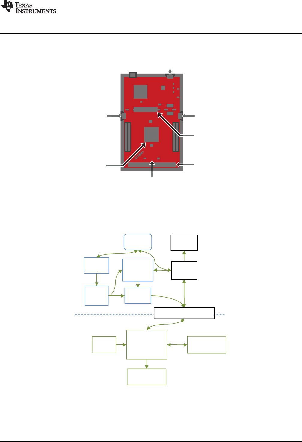
2 Hardware
Figure 2 shows an overview of the EVM hardware.
Figure 2. MSP-EXP432P401R Overview
2.1 Block Diagram
Figure 3 shows the block diagram.
Figure 3. Block Diagram
1P10.1/UCB3CLK
2P10.2/UCB3SIMO/UCB3SDA
3P10.3/UCB3SOMI/UCB3SCL
4P1.0/UCA0STE
5P1.1/UCA0CLK
6P1.2/UCA0RXD/UCA0SOMI
7P1.3/UCA0TXD/UCA0SIMO
8P1.4/UCB0STE
9P1.5/UCB0CLK
10P1.6/UCB0SIMO/UCB0SDA
11P1.7/UCB0SOMI/UCB0SCL
12VCORE
13DVCC1
14VSW
15DVSS1
16P2.0/PM_UCA1STE
17P2.1/PM_UCA1CLK
18P2.2/PM_UCA1RXD/PM_UCA1SOMI
19P2.3/PM_UCA1TXD/PM_UCA1SIMO
20P2.4/PM_TA0.1
21P2.5/PM_TA0.2
22P2.6/PM_TA0.3
23P2.7/PM_TA0.4
24P10.4/TA3.0/C0.7
25P10.5/TA3.1/C0.6
26
P7.4/PM_TA1.4/C0.5
27
P7.5/PM_TA1.3/C0.4
28
P7.6/PM_TA1.2/C0.3
29
P7.7/PM_TA1.1/C0.2
30
P8.0/UCB3STE/TA1.0/C0.1
31
P8.1/UCB3CLK/TA2.0/C0.0
32
P3.0/PM_UCA2STE
33
P3.1/PM_UCA2CLK
34
P3.2/PM_UCA2RXD/PM_UCA2SOMI
35
P3.3/PM_UCA2TXD/PM_UCA2SIMO
36
P3.4/PM_UCB2STE
37
P3.5/PM_UCB2CLK
38
P3.6/PM_UCB2SIMO/PM_UCB2SDA
39
P3.7/PM_UCB2SOMI/PM_UCB2SCL
40
AVSS3
41
PJ.0/LFXIN
42
PJ.1/LFXOUT
43
AVSS1
44
DCOR
45
AVCC1
46
P8.2/TA3.2/A23
47
P8.3/TA3CLK/A22
48
P8.4/A21
49
P8.5/A20
50
P8.6/A19
51 P8.7/A18
52 P9.0/A17
53 P9.1/A16
54 P6.0/A15
55 P6.1/A14
56 P4.0/A13
57 P4.1/A12
58 P4.2/ACLK/TA2CLK/A11
59 P4.3/MCLK/RTCCLK/A10
60 P4.4/HSMCLK/SVMHOUT/A9
61 P4.5/A8
62 P4.6/A7
63 P4.7/A6
64 P5.0/A5
65 P5.1/A4
66 P5.2/A3
67 P5.3/A2
68 P5.4/A1
69 P5.5/A0
70 P5.6/TA2.1/VREF+/VeREF+/C1.7
71 P5.7/TA2.2/VREF-/VeREF-/C1.6
72 DVSS2
73 DVCC2
74 P9.2/TA3.3
75 P9.3/TA3.4
76
P6.2/UCB1STE/C1.5
77
P6.3/UCB1CLK/C1.4
78
P6.4/UCB1SIMO/UCB1SDA/C1.3
79
P6.5/UCB1SOMI/UCB1SCL/C1.2
80
P6.6/TA2.3/UCB3SIMO/UCB3SDA/C1.1
81
P6.7/TA2.4/UCB3SOMI/UCB3SCL/C1.0
82
DVSS3
83
RSTn/NMI
84
AVSS2
85
PJ.2/HFXOUT
86
PJ.3/HFXIN
87
AVCC2
88
P7.0/PM_SMCLK/PM_DMAE0
89
P7.1/PM_C0OUT/PM_TA0CLK
90
P7.2/PM_C1OUT/PM_TA1CLK
91
P7.3/PM_TA0.0
92
PJ.4/TDI
93
PJ.5/TDO/SWO
94
SWDIOTMS
95
SWCLKTCK
96
P9.4/UCA3STE
97
P9.5/UCA3CLK
98
P9.6/UCA3RXD/UCA3SOMI
99
P9.7/UCA3TXD/UCA3SIMO
100
P10.0/UCB3STE
Hardware
www.ti.com
6SLAU597B–March 2015–Revised July 2016
Submit Documentation Feedback
Copyright © 2015–2016, Texas Instruments Incorporated
MSP432P401R LaunchPad™ Development Kit (MSP
‑
EXP432P401R)
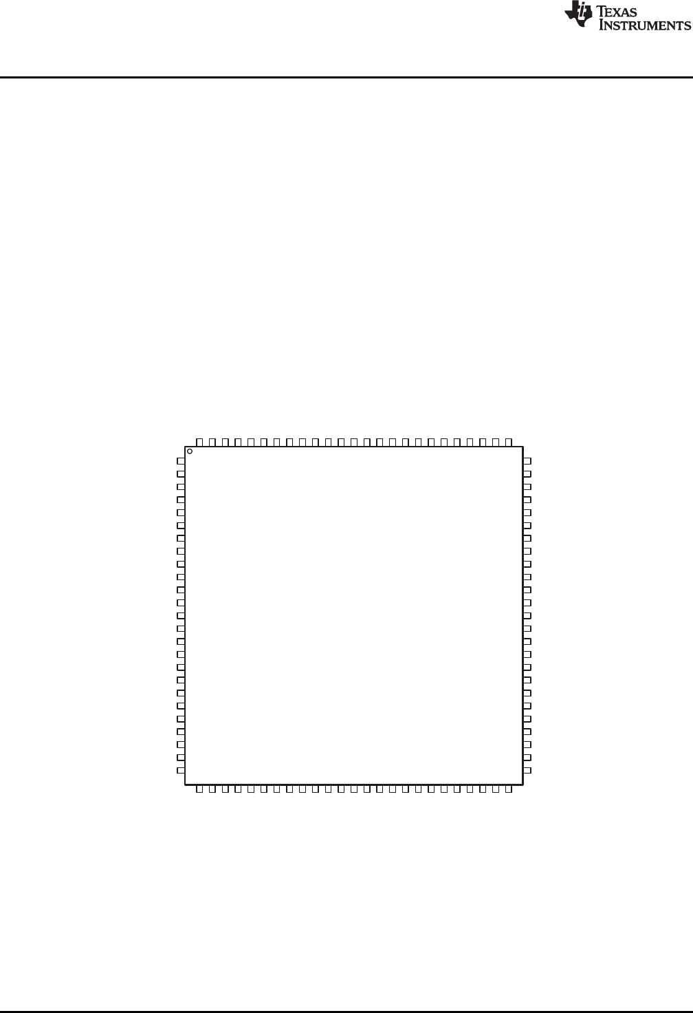
2.2 MSP432P401R
The MSP432P401R is the first MSP432 family device featuring low-power performance with an ARM
Cortex-M4F core. Device features include:
• Low-power ARM Cortex-M4F MSP432P401R
• Up to 48-MHz system clock
• 256KB flash memory, 64KB SRAM, and 32KB ROM with MSPWare libraries
• Four 16-bit timers with capture/compare/PWM, two 32-bit timers, and RTC
• Up to eight serial communication channels (I2C, SPI, UART, and IrDA)
• Analog: 14-bit SAR ADC, capacitive touch, comparator
• Digital: AES256, CRC, uDMA
Figure 4. MSP432P401RIPZ Pinout

www.ti.com
Hardware
7
SLAU597B–March 2015–Revised July 2016
Submit Documentation Feedback Copyright © 2015–2016, Texas Instruments Incorporated
MSP432P401R LaunchPad™ Development Kit (MSP
‑
EXP432P401R)
2.3 XDS110-ET Onboard Debug Probe
To keep development easy and cost effective, TI's LaunchPad development kits integrate an onboard
debug probe, which eliminates the need for expensive programmers. The MSP‑EXP432P401R has the
XDS110-ET debug probe, which is a simple low-cost debug probe that supports nearly all TI ARM device
derivatives.
Figure 5. XDS110-ET Debug Probe
The XDS110-ET hardware can be found in the schematics in Section 6 and in the MSP‑EXP432P401R
Hardware Design Files.
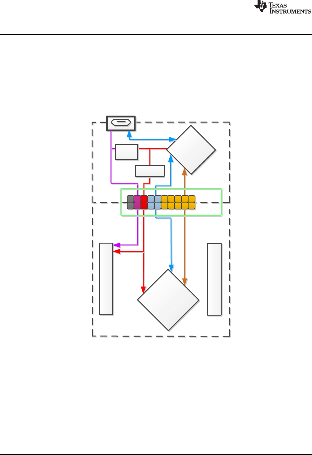
2.3.1 XDS110-ET Isolation Block J101
The J101 isolation block is composed of J101 jumpers shown in Table 1. The J101 isolation block allows
the user to connect or disconnect signals that cross from the XDS110-ET domain into the MSP432P401R
target domain. This crossing is shown by the silkscreen dotted line across the LaunchPad development kit
through J101. No other signals cross the domain, so the XDS110-ET can be completely decoupled from
the MSP432P401R target side. This includes XDS110-ET power and GND signals, UART, and JTAG
signals.
Table 1 lists the signals that are controlled at the isolation block.
Table 1. Isolation Block Connections
Signal Description
GND GND power connection between XDS110 and MSP432 target GND planes. The GND jumper is
populated to connect the separate GND planes. This connection is required for proper operation with
3V3, 5V, UART, and JTAG.
5V 5-V power rail, VBUS from USB
3V3 3.3-V power rail, derived from VBUS by an LDO in the XDS110-ET domain
RXD << Backchannel UART: The target MCU receives data through this signal. The arrows indicate the direction
of the signal.
TXD >> Backchannel UART: The target MCU sends data through this signal. The arrows indicate the direction of
the signal.
RST MCU RST signal (active low)
TCK_SWCLK Serial wire clock input (SWCLK) / JTAG clock input (TCK)
TMS_SWDIO Serial wire data input/output (SWDIO) / JTAG test mode select (TMS)
TDO_SWO Serial wire trace output (SWO) / JTAG trace output (TWO) (Also PJ.5)
TDI JTAG test data input (Also PJ.4)
XDS110-ET
Debug Probe
MCU
J101
Isolation
Block
JTAG and SWD
Application UART
3.3V Power
5V Power
MSP432P401R
Target MCU
XDS110-ETMSP432 Target
USB Connector
in out
LDO
BoosterPack Header
BoosterPack Header
USB
EnergyTrace
eUSCI_A0
Hardware
www.ti.com
8SLAU597B–March 2015–Revised July 2016
Submit Documentation Feedback
Copyright © 2015–2016, Texas Instruments Incorporated
MSP432P401R LaunchPad™ Development Kit (MSP
‑
EXP432P401R)
Reasons to open these connections:
• To remove any and all influence from the XDS110-ET debug probe for high accuracy target power
measurements
• To control 3-V and 5-V power flow between the XDS110-ET and target domains
• To expose the target MCU pins for other use than onboard debugging and application UART
communication
• To expose the UART interface of the XDS110-ET so that it can be used for devices other than the
onboard MCU.
Figure 6. XDS110-ET Isolation Block
2.3.2 Application (or "Backchannel") UART
The XDS110-ET provides a "backchannel" UART-over-USB connection with the host, which can be very
useful during debugging and for easy communication with a PC.
The backchannel UART allows communication with the USB host that is not part of the target application's
main functionality. This is very useful during development, and also provides a communication channel to
the PC host side. This can be used to create GUIs and other programs on the PC that communicate with
the LaunchPad development kit.
The pathway of the backchannel UART is shown in Figure 7. The backchannel UART eUSCI_A0 is
independent of the UART on the 40-pin BoosterPack plug-in module connector eUSCI_A2.

www.ti.com
Hardware
9
SLAU597B–March 2015–Revised July 2016
Submit Documentation Feedback Copyright © 2015–2016, Texas Instruments Incorporated
MSP432P401R LaunchPad™ Development Kit (MSP
‑
EXP432P401R)
On the host side, a virtual COM port for the application backchannel UART is generated when the
LaunchPad development kit enumerates on the host. You can use any PC application that interfaces with
COM ports, including terminal applications like Hyperterminal or Docklight, to open this port and
communicate with the target application. You need to identify the COM port for the backchannel. On
Windows PCs, Device Manager can assist.
Figure 7. Application Backchannel UART in Device Manager
The backchannel UART is the XDS110 Class Application/User UART port. In this case, Figure 7 shows
COM156, but this port can vary from one host PC to the next. After you identify the correct COM port,
configure it in your host application according to its documentation. You can then open the port and begin
communication to it from the host.
The XDS110-ET has a configurable baud rate; therefore, it is important that the PC application configures
the baud rate to be the same as what is configured on the eUSCI_A0 backchannel UART.

Hardware
www.ti.com
10 SLAU597B–March 2015–Revised July 2016
Submit Documentation Feedback
Copyright © 2015–2016, Texas Instruments Incorporated
MSP432P401R LaunchPad™ Development Kit (MSP
‑
EXP432P401R)
2.3.3 Using an External Debug Probe Instead of the Onboard XDS110-ET
Many users have a specific external debug probe that they prefer to use, and may wish to bypass the
XDS110-ET debug probe to program the MSP432 target MCU. This is enabled by jumpers on isolation
block J101, and the connector J8. Using an external debug probe is simple, and full JTAG access is
provided through J8.
1. Remove jumpers on the JTAG signals on the J101 isolation block, including RST, TMS, TCK, TDO,
and TDI.
2. Plug any ARM debug probe into J8.
(a) J8 follows the ARM Cortex Debug Connector standard outlined in Cortex-M Debug Connectors.
3. Plug USB power into the LaunchPad development kit, or power it externally.
(a) Ensure that the jumpers across 3V3 and GND are connected if using USB power.
(b) External debug probes do not provide power, the VCC pin is a power sense pin.
(c) More details on powering the LaunchPad development kit can be found in Section 2.4.
2.3.4 Using the XDS110-ET Debug Probe With a Different Target
The XDS110-ET debug probe on the LaunchPad can interface to most ARM Cortex-M devices, not just
the onboard target MSP432P410R device. This functionality is enabled by the J102 10-pin Cortex-M JTAG
connector. The 10-pin cable can be purchased from DigiKey Electronics (sold separately from the
LaunchPad development kit).
Header J102 follows the Cortex-M ARM standard; however, pin 1 is not a voltage sense pin. The XDS110-
ET outputs only 3.3-V JTAG signals. If another voltage level is needed, the user must provide level
shifters to translate the JTAG signal voltages. Additionally, 3.3 V of output power can be sourced from the
XDS110-ET when jumper JP102 is connected. This allows the XDS110-ET to power the external target at
3.3 V through pin 1. By default JP102 is not populated as it does not explicitly follow the standard.
1. Remove jumpers on the JTAG signals on the J101 isolation block, including RST, TMS, TCK, TDO,
and TDI.
2. Plug the 10-pin cable into J102, and connect to an external target a. J102 follows the ARM Cortex
Debug Connector standard outlined in Cortex-M Debug Connectors.
3. Plug USB power into the LaunchPad, or power it externally
(a) JTAG levels are 3.3 V ONLY.
(b) 3.3-V power can be sourced through J102 by shorting the JP102 jumper.
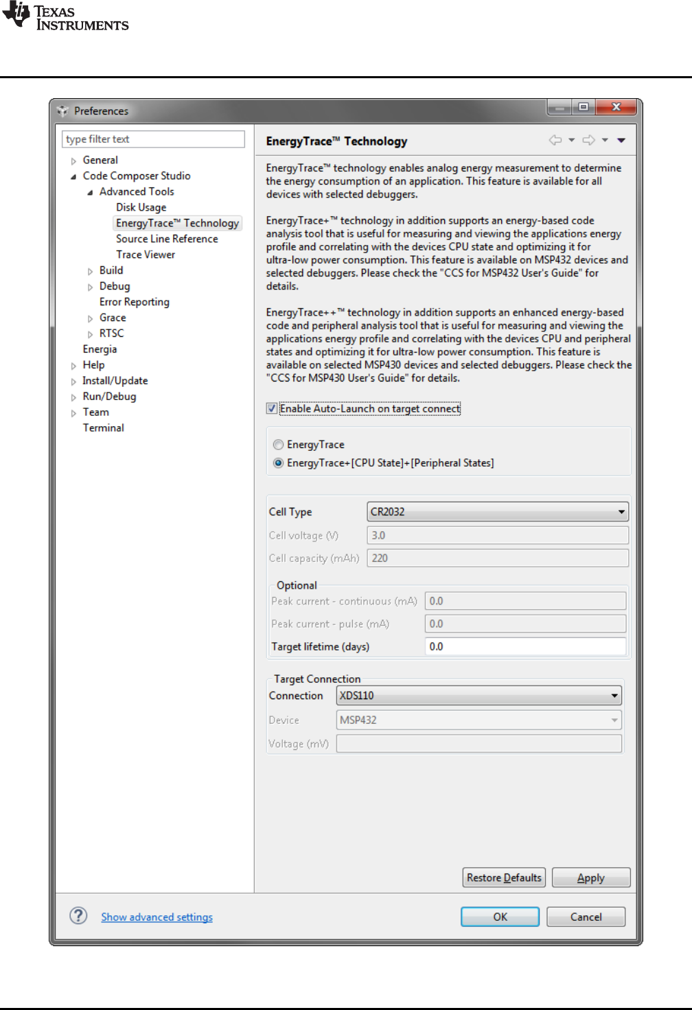
2.3.5 EnergyTrace+ Technology
EnergyTrace™ technology is an energy-based code analysis tool that measures and displays the
application's energy profile and helps to optimize it for ultra-low power consumption.
MSP432 devices with built-in EnergyTrace+[CPU State] (or in short EnergyTrace+) technology allow real-
time monitoring of internal device states while user program code executes.
EnergyTrace+ technology is supported on the LaunchPad development kit MSP432P401R device +
XDS110-ET debug probe. EnergyTrace technology is available as part of TI's Code Composer Studio IDE.
During application debug, additional windows are available for EnergyTrace technology.
To enable EnergyTrace technology, go to:
• Window > Preferences > Code Composer Studio > Advanced Tools > EnergyTrace™ Technology
• Check the Enable Auto-Launch on target connect box

Hardware
www.ti.com
12 SLAU597B–March 2015–Revised July 2016
Submit Documentation Feedback
Copyright © 2015–2016, Texas Instruments Incorporated
MSP432P401R LaunchPad™ Development Kit (MSP
‑
EXP432P401R)
Starting a debug session will now open EnergyTrace technology windows. These windows show energy,
power, profile, and states to give the user a full view of the energy profile of their application.
Figure 9. EnergyTrace™ Windows
This data allows the user to see exactly where and how energy is consumed in their application.
Optimizations for energy can be quickly made for the lowest power application possible.
On the LaunchPad development kit, EnergyTrace technology measures the current that enters the target
side of the LaunchPad development kit. This includes all BoosterPack plug-in modules plugged in, and
anything else connected to the 3V3 power rail. For more information about powering the LaunchPad
development kit, see Section 2.4.
For more information about EnergyTrace technology, see http://www.ti.com/tool/energytrace.
For more details and questions about setting up and using EnergyTrace technology with the
MSP432P401R, see the Code Composer Studio 6 User's Guide for MSP432.
www.ti.com
Hardware
13
SLAU597B–March 2015–Revised July 2016
Submit Documentation Feedback Copyright © 2015–2016, Texas Instruments Incorporated
MSP432P401R LaunchPad™ Development Kit (MSP
‑
EXP432P401R)
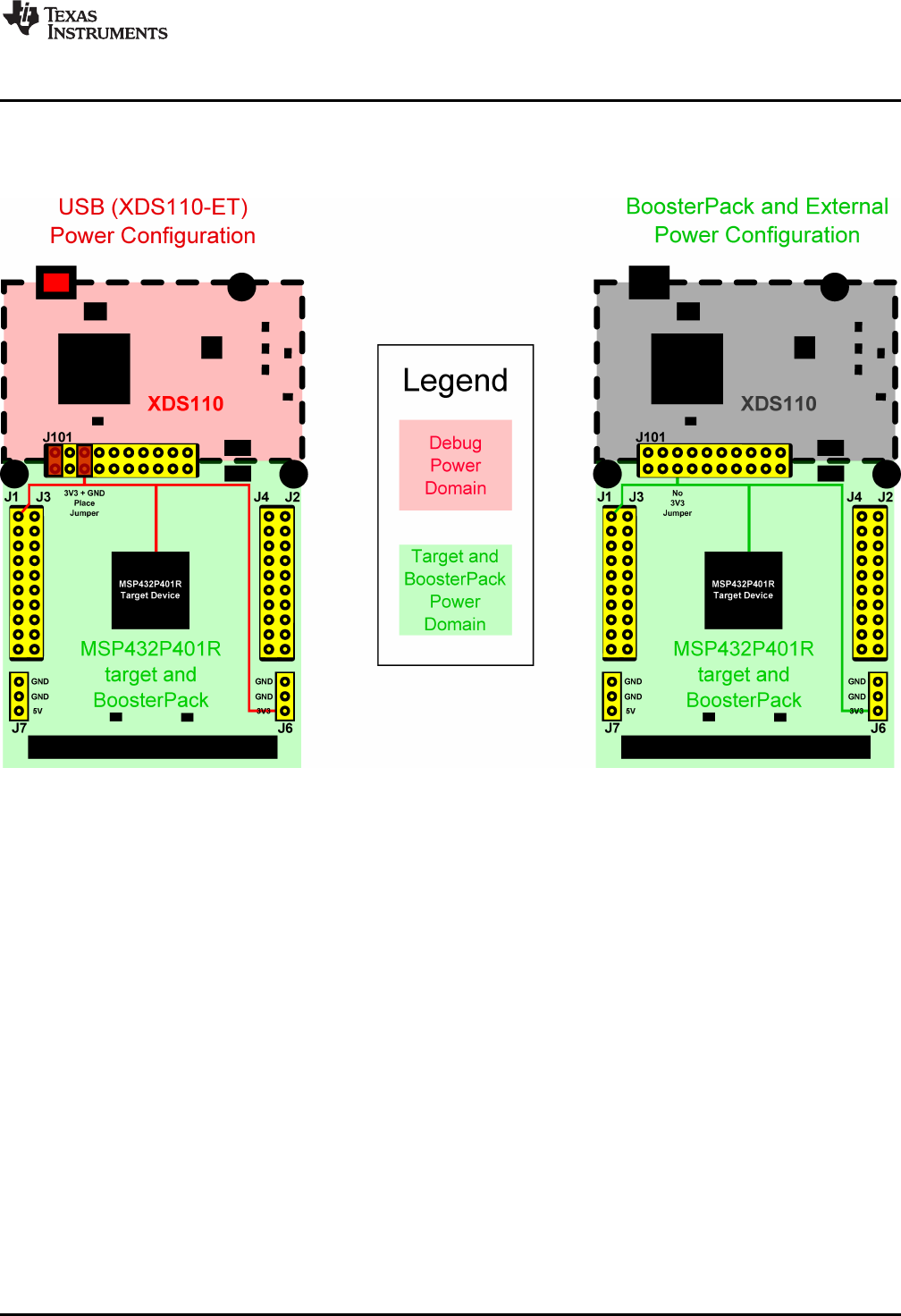
2.4 Power
The board was designed to accommodate various powering methods, including through the onboard
XDS110-ET and from an external source or BoosterPack plug-in module.
Figure 10. MSP‑‑EXP432P401R Power Block Diagram
2.4.1 XDS110-ET USB Power
The most common power-supply scenario is from USB through the XDS110-ET debug probe. This
provides 5-V power from the USB and also regulates this power rail to 3.3 V for XDS110-ET operation and
3.3 V to the target side of the LaunchPad development kit. Power from the XDS110-ET is controlled by
the isolation block 3V3 jumper, ensure this jumper is connected for power to be provided to the target
MCU side.
Under normal operation, the LDO on the XDS110-ET can supply up to 500 mA of current to the target side
including any BoosterPack plug-in modules plugged in. However, when debugging and using the
EnergyTrace technology tool, this current is limited to 75 mA total. Be aware of this current limitation when
using EnergyTrace technology.
2.4.2 BoosterPack Plug-in Module and External Power Supply
Header J6 is present on the board to supply external power directly. It is important to comply with the
device voltage operation specifications when supplying external power. The MSP432P401R has an
operating range of 1.62 V to 3.7 V. More information can be found in the MSP432P401xx Mixed-Signal
Microcontroller data sheet.
Hardware
www.ti.com
14 SLAU597B–March 2015–Revised July 2016
Submit Documentation Feedback
Copyright © 2015–2016, Texas Instruments Incorporated
MSP432P401R LaunchPad™ Development Kit (MSP
‑
EXP432P401R)
2.5 Measure MSP432 Current Draw
To measure the current draw of the MSP432P401R, use the 3V3 jumper on the jumper isolation block.
The current measured includes the target device and any current drawn through the BoosterPack plug-in
module headers.
To measure ultra-low power, follow these steps:
1. Remove the 3V3 jumper in the isolation block, and attach an ammeter across this jumper.
2. Consider the effect that the backchannel UART and any circuitry attached to the MSP432P401R may
have on current draw. Disconnect these at the isolation block if possible, or at least consider their
current sinking and sourcing capability in the final measurement.
3. Make sure there are no floating input I/Os. These cause unnecessary extra current draw. Every I/O
should either be driven out or, if it is an input, should be pulled or driven to a high or low level.
4. Begin target execution.
5. Measure the current. Keep in mind that if the current levels are fluctuating, it may be difficult to get a
stable measurement. It is easier to measure quiescent states.
For a better look at the power consumed in the application, use EnergyTrace+ Technology. EnergyTrace+
Technology allows the user to see energy consumed as the application progresses. More details about
EnergyTrace+ Technology can be found in Section 2.3.5.
2.6 Clocking
The MSP‑EXP432P401R provides external clocks in addition to the internal clocks in the device.
• Q1: 32-kHz crystal (LFXTCLK)
• Q2: 48-MHz crystal (HFXTCLK)
The 32-kHz crystal allows for lower LPM3 sleep currents, and higher precision clock source than the
default internal 32 kHz REFOCLK. Therefore, the presence of the crystal allows the full range of low-
power modes to be used.
The 48-MHz crystal allows the device to run at its maximum operating speed for MCLK and HSMCLK.
The MSP432P401R device has several internal clocks that can be sourced from many clock sources.
Most peripherals on the device can select which of the internal clocks to use to operate at the desired
speed.
The internal clocks in the device default to the configuration listed in Table 2.
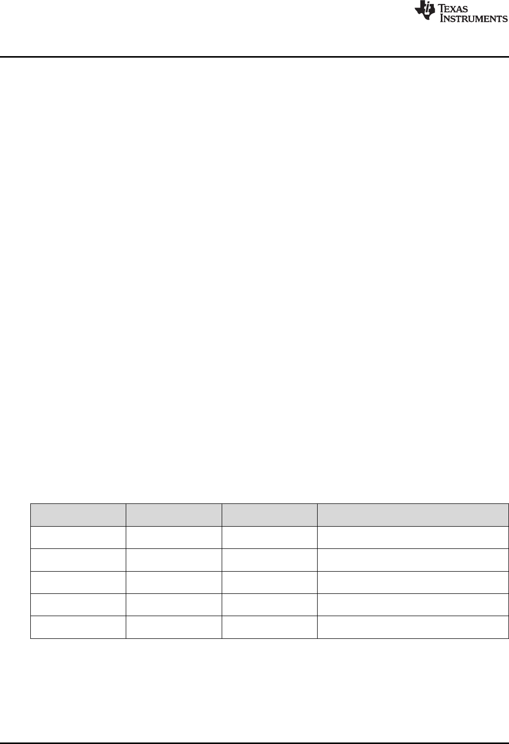
Table 2. Default Clock Operation
Clock Default Clock Source Default Clock
Frequency Description
MCLK DCO 3 MHz Master Clock
Sources CPU and peripherals
HSMCLK DCO 3 MHz Subsystem Master Clock
Sources peripherals
SMCLK DCO 3 MHz Low-speed subsystem master clock
Sources peripherals
ACLK LFXT (or REFO if no
crystal present) 32.768 kHz Auxiliary clock
Sources peripherals
BCLK LFXT(or REFO if no
crystal present) 32.768 kHz Low-speed backup domain clock
Sources LPM peripherals
For more information about configuring internal clocks and using the external oscillators, see the
MSP432P4xx Family Technical Reference Manual.

www.ti.com
Hardware
15
SLAU597B–March 2015–Revised July 2016
Submit Documentation Feedback Copyright © 2015–2016, Texas Instruments Incorporated
MSP432P401R LaunchPad™ Development Kit (MSP
‑
EXP432P401R)
2.7 BoosterPack Plug-in Module Pinout
The MSP‑EXP432P401R LaunchPad development kit adheres to the 40-pin LaunchPad development kit
pinout standard. A standard was created to aid compatibility between LaunchPad development kit and
BoosterPack plug-in module tools across the TI ecosystem.
The 40-pin standard is compatible with the 20-pin standard that is used by other LaunchPad development
kits like the MSP‑EXP430FR4133. This allows some subset of functionality of 40-pin BoosterPack plug-in
modules to be used with 20-pin LaunchPad development kits.
While most BoosterPack plug-in modules are compliant with the standard, some are not. The
MSP‑EXP432P401R LaunchPad development kit is compatible with all 20-pin and 40-pin BoosterPack
plug-in modules that are compliant with the standard. If the reseller or owner of the BoosterPack plug-in
module does not explicitly indicate compatibility with the MSP‑EXP432P401R LaunchPad development kit,
compare the schematic of the candidate BoosterPack plug-in module with the LaunchPad development kit
to ensure compatibility. Keep in mind that sometimes conflicts can be resolved by changing the
MSP432P401R device pin function configuration in software. More information about compatibility can
also be found at http://www.ti.com/launchpad.
Figure 11 shows the 40-pin pinout of the MSP‑EXP432P401R LaunchPad development kit.
Note that software configuration of the pin functions plays a role in compatibility. The MSP‑EXP432P401R
LaunchPad development kit side of the dashed line in Figure 11 shows all of the functions for which the
MSP432P401R device's pins can be configured. This can also be seen in the MSP432P401R data sheet.
The BoosterPack plug-in module side of the dashed line shows the standard. The MSP432P401R function
whose color matches the BoosterPack plug-in module function shows the specific software-configurable
function by which the MSP‑EXP432P401R LaunchPad development kit adheres to the standard.

Hardware
www.ti.com
16 SLAU597B–March 2015–Revised July 2016
Submit Documentation Feedback
Copyright © 2015–2016, Texas Instruments Incorporated
MSP432P401R LaunchPad™ Development Kit (MSP
‑
EXP432P401R)
Figure 11. LaunchPad™ Development Kit to BoosterPack™ Plug-in Module Connector Pinout
2.8 Design Files
2.8.1 Hardware Design Files
Schematics can be found in Section 6. All design files including schematics, layout, bill of materials
(BOM), Gerber files, and documentation are available in the MSP‑EXP432P401R Hardware Design Files.
Do you have an older version of the LaunchPad development kit? The differences in the hardware are
outlined in Section 2.9. The hardware design files for older versions of the LaunchPad are available at the
link above – navigate to previous release versions according to Table 3.
www.ti.com
Hardware
17
SLAU597B–March 2015–Revised July 2016
Submit Documentation Feedback Copyright © 2015–2016, Texas Instruments Incorporated
MSP432P401R LaunchPad™ Development Kit (MSP
‑
EXP432P401R)
2.8.2 Software Examples
All design files including TI-TXT object-code firmware images, software example projects, and
documentation are available in the MSP‑EXP432P401R Software Examples.
Do you have an older version of the LaunchPad development kit? The differences in the hardware are
outlined in Section 2.9. In addition to the hardware being different, the device revision also changes with
the LaunchPad development kit revisions. Because of this, you must download a software package that
matches your exact hardware. The software example files for older versions of the LaunchPad
development kit are available at the link above – navigate to previous release versions according to
Table 3.
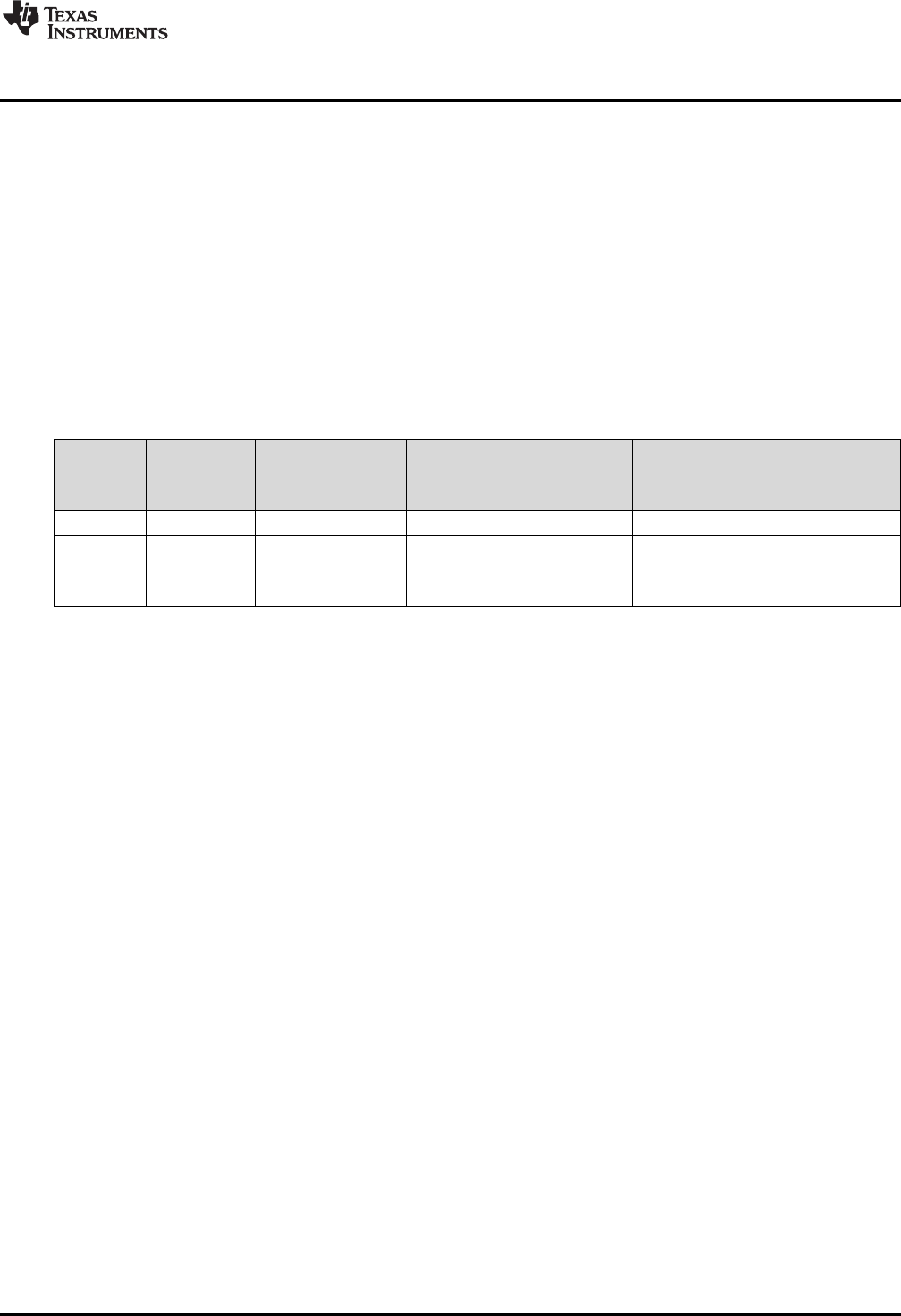
2.9 Hardware Change Log
Table 3 lists the hardware revisions.
Table 3. Hardware Change Log
PCB
Revision Date Description MSP432P401R Device Revision
MSP-EXP432P401R Hardware and
Software Download Version (for
downloading zip packages online
only)
Rev 1.0 March 2015 Initial Release XMS432P401R Rev B 2_00_00_03
Rev 2.0 June 2016 RTM Silicon Release
XMS432P401R Rev C or
MSP432P401R Rev C
(check device markings to
determine your version)
3_00_00_03
2.9.1 MSP-EXP432P401R Rev 1.0 (Black) LaunchPad Development Kit
As shown in Table 3, this was the initially released LaunchPad development kit, with XMS432P401R Rev
B silicon. Connecting any debugger to the old version of the MSP432 MCU will generate a warning telling
the user to update their silicon. TI will continue to support this board for the foreseeable future. However,
upgrading to the latest LaunchPad development kit gets you all the silicon upgrades and the final
production version of Driver Library in ROM.
2.9.2 MSP-EXP432P401R Rev 2.0 (Red) LaunchPad Development Kit
As shown in Table 3, this is the updated LaunchPad development kit for the silicon RTM, with
XMS432P401R Rev C or MSP432P401R Rev C silicon. In addition to the latest silicon, several updates
were made to the LaunchPad development kit hardware to enhance the user experience.
2.9.2.1 MSP-EXP432P401R Updates
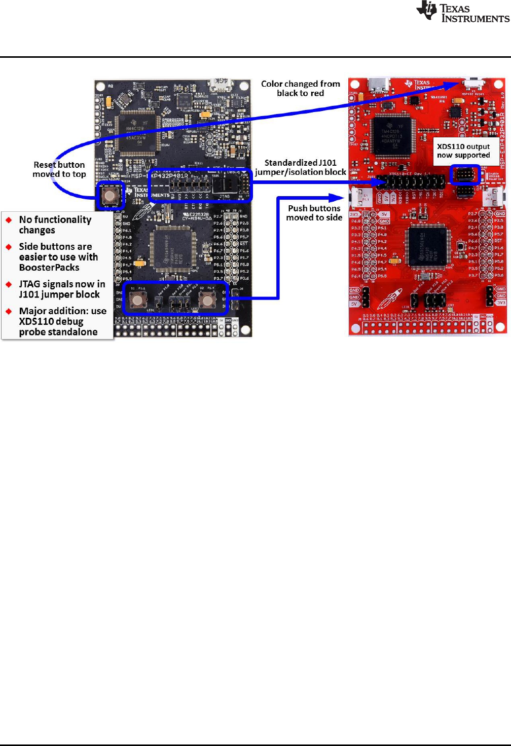
From the perspective of the board, all of the changes are aesthetic or make the kit easier to use (see
Figure 12). For example, moving the user buttons to the side of the board makes them easier to reach
when you have a BoosterPack plug-in module plugged into the top of the LaunchPad development kit.
The button placement has changed, but the physical button connections are the same. The biggest
change comes from the addition of an extra 10-pin ARM JTAG connector. This connector lets you use the
LaunchPad development kit as a stand-alone XDS110 debug probe.
Hardware
www.ti.com
18 SLAU597B–March 2015–Revised July 2016
Submit Documentation Feedback
Copyright © 2015–2016, Texas Instruments Incorporated
MSP432P401R LaunchPad™ Development Kit (MSP
‑
EXP432P401R)
Figure 12. Differences Between Rev 1.0 (Black) and Rev 2.0 (Red)
2.9.2.2 MSP432P401R Device Revision Differences
The primary MSP432P401R silicon differences are the differences between Rev. B and Rev. C devices.
For details of the differences, see Moving From Evaluation to Production With MSP432P401x MCUs.
The first shipments of Rev 2.0 (Red) LaunchPad development kit have XMS432P401R Rev C.
preproduction silicon before the final production version of MSP432P401R Rev C. silicon is released.
Which device is on a particular LaunchPad development kit can be determined by looking at the markings
on the MSP432P401R device. The XMS version have a marking of "XMS" instead of "MSP". For details
on the differences between the preproduction and production silicon, see XMS432P401x Rev. C
Preproduction Advisories.
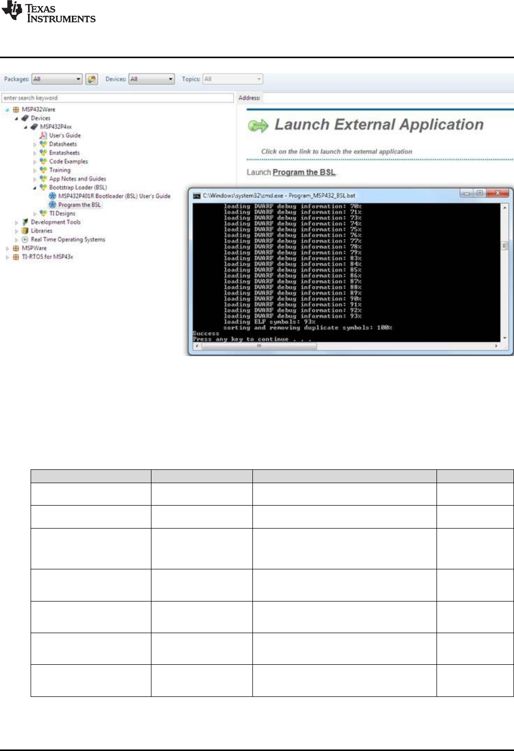
To work around Advisory 1 in the document above, and as a general way to update to the latest device
BSL, TI provides a utility to download the latest BSL. This utility is available inside of TI Resource Explorer
(see Figure 13). Alternatively, the BSL can be updated by running Program_MSP432_BSL.bat in the
source files for MSP432P401R BSL update.
www.ti.com
Software Examples
19
SLAU597B–March 2015–Revised July 2016
Submit Documentation Feedback Copyright © 2015–2016, Texas Instruments Incorporated
MSP432P401R LaunchPad™ Development Kit (MSP
‑
EXP432P401R)
Figure 13. BSL Update Utility in TI Resource Explorer
3 Software Examples
There are four software examples included with the MSP‑EXP432P401R LaunchPad development kit (see
Table 4), which can be found in the MSP‑EXP432P401R Software Examples.
Table 4. Software Examples
Demo Name BoosterPack Required Description More Details
Out-of-Box Software Example N/A The out-of-box demo programmed on the
LaunchPad development kit from the factory. Section 3.1
CC3100BOOST MQTT-Twitter
LED Control Example CC3100BOOST An IoT application demonstrating controlling an
RGB LED using Twitter through Wi-Fi Section 3.2
BOOSTXL-K350QVG-S1
Graphics Library Example BOOSTXL-K350SVG-S1
A simple example showing how to use MSP
Graphics Library (grlib) to display graphics
primitives and images and implement
touchscreen functionality
Section 3.3
430BOOST-SHARP96
Graphics Library Example 430BOOST-SHARP96 A simple example showing how to use MSP
Graphics Library (grlib) to display graphics
primitives and images Section 3.4
BOOSTXL-
BATPAKMKII_FuelGauge_
MSP432P401R BOOSTXL-BATPAKMKII Demonstrates how to initialize bq27441-G1 fuel
gauge configurations and how to control and
read data registers Section 3.5
BOOSTXL-
SENSORS_SensorGUI_
MSP432P401R BOOSTXL-SENSORS Demonstrates how to sample data from the five
onboard digital sensors and communicate that
over UART in a JSON payload Section 3.6
BOOSTXL-SENSORS_TI-
RTOS_SensorGUI_
MSP432P401R BOOSTXL-SENSORS Demonstrates how to sample data from the five
onboard digital sensors and communicate that
over UART in a JSON payload using TI-RTOS Section 3.7
Software Examples
www.ti.com
20 SLAU597B–March 2015–Revised July 2016
Submit Documentation Feedback
Copyright © 2015–2016, Texas Instruments Incorporated
MSP432P401R LaunchPad™ Development Kit (MSP
‑
EXP432P401R)
To use any of the software examples with the LaunchPad development kit, you must have an integrated
development environment (IDE) that supports the MSP432P401R device (see Table 5).
Table 5. IDE Minimum Requirements for MSP‑‑EXP432P401R
Code Composer Studio™ IDE IAR Embedded Workbench® IDE Keil™ µVision® IDE
CCS v6.1 or later IAR Embedded Workbench for ARM 7.10 or later Keil µVision MDK-ARM v5 or later
For more details on how to get started quickly and where to download the latest CCS, IAR, and Keil IDEs,
see Section 4.
3.1 Out-of-Box Software Example
This section describes the functionality and structure of the out-of-box software that is preloaded on the
EVM. The source code can be found in the MSP‑EXP432P401R Software Examples download, or more
easily accessible through MSPWare (see Section 4.3).
The out-of-box software extends a basic blink LED example to allow users to control the blink rate and
color of an RGB LED on the MSP432 LaunchPad development kit.
3.1.1 Operation
Upon powering up the out-of-box demo, the RGB LED2 blinks red at 1 Hz. Switch S1 can be tapped
repeatedly at a constant rate to set the blink frequency of LED2. Switch S2 cycles LED2 through four
different color settings: Red, Green, Blue, and random RGB color. Each color setting retains its own blink
frequency.
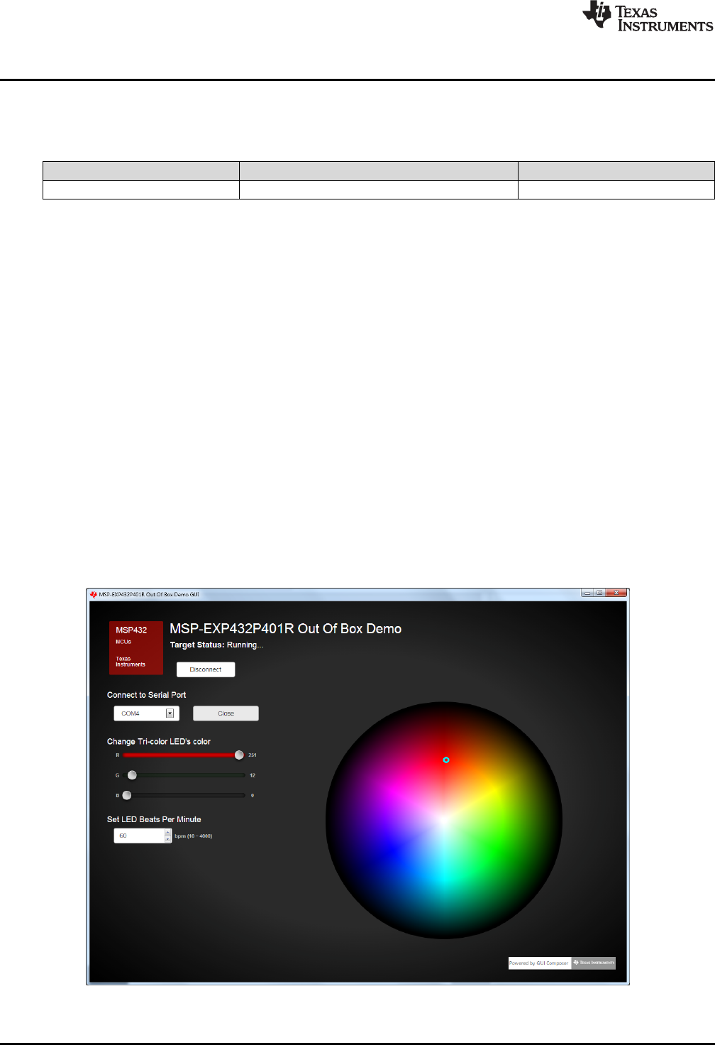
A PC GUI accompanies the out-of-box demo to allow user to set the color and blink rate of the RGB LED.
If not already, connect the LaunchPad development kit using the included USB cable to a computer. The
out-of-box GUI can be opened from within CCS using the TI Resource Explorer: MSPWare >
Development Tools > MSP‑EXP432P401R > Examples > Out of Box Experience GUI. A copy can also be
found in the MSP‑EXP432P401R Software Examples.
Figure 14. Out-of-Box GUI Running Locally
www.ti.com
Software Examples
21
SLAU597B–March 2015–Revised July 2016
Submit Documentation Feedback Copyright © 2015–2016, Texas Instruments Incorporated
MSP432P401R LaunchPad™ Development Kit (MSP
‑
EXP432P401R)
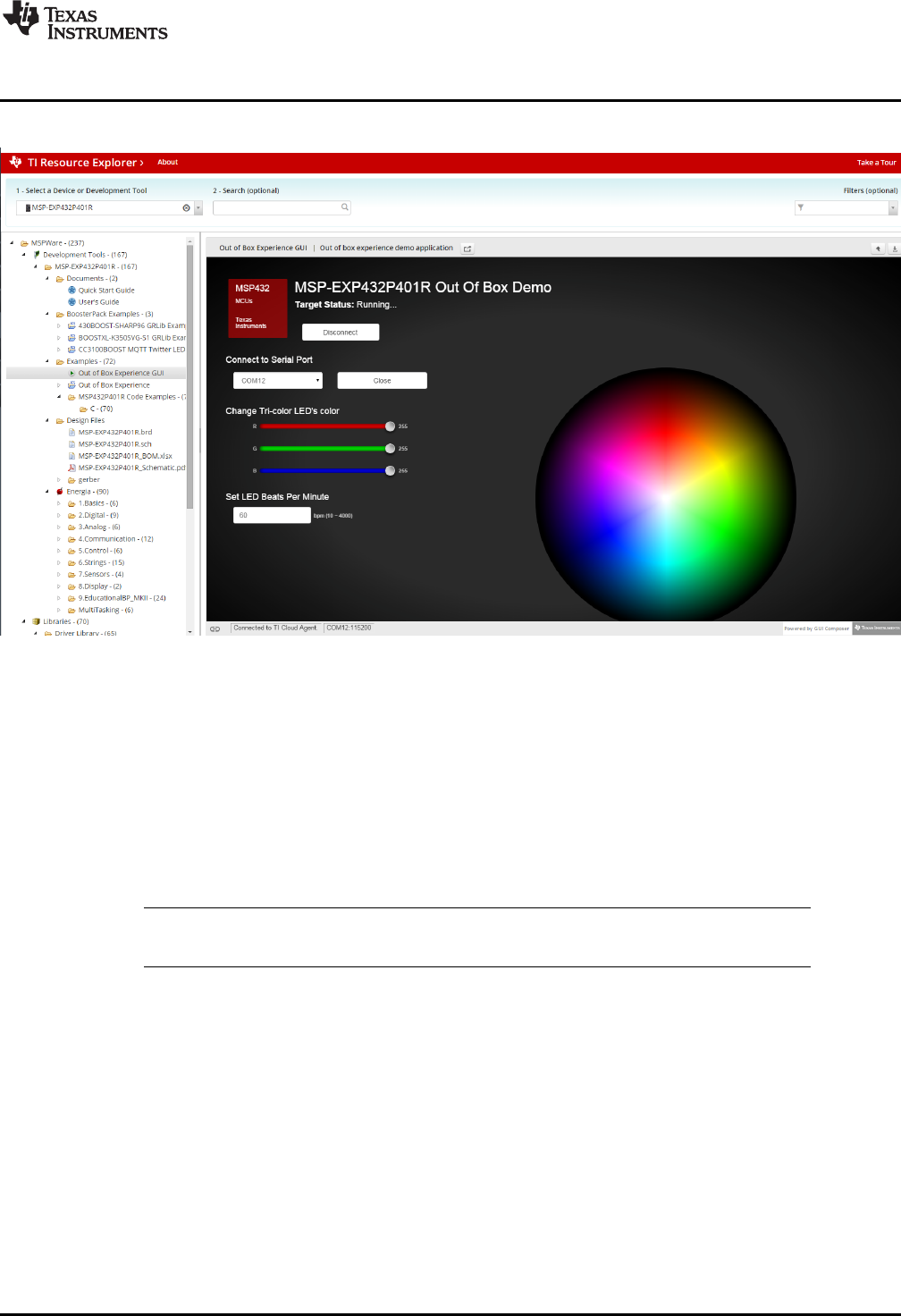
The GUI can also run directly from the TI Cloud Tools (see Section 4.1.1).
Figure 15. Out-of-Box GUI Running From TI Cloud Tools
Click on the Connect button to connect to the LaunchPad development kit then open the serial COM port.
Once the connection has been established and the GUI indicates, "Target Status: Running…," you can
use the color wheel or the Red, Green, and Blue color sliders to set the color of the LaunchPad
development kit RGB LED. Changing the LED Beats Per Minute input box sets the RGB LED blink rate.
3.2 CC3100BOOST MQTT-Twitter LED Control Example
This section describes the functionality and structure of the CC3100BOOST MQTT-Twitter LED Control
demo that is included in the MSP‑EXP432P401R Software Examples download, or more easily accessible
through MSPWare (see Section 4.3).
NOTE: This CC3100BOOST MQTT-Twitter LED Control demo requires the CC3100BOOST
BoosterPack plug-in module to function properly.
This demo uses the MQTT connectivity protocol to realize a simple Internet-of-Things application that
allows user to control MSP432 LaunchPad development kit RGB LED wirelessly using Twitter tweets.
Software Examples
www.ti.com
22 SLAU597B–March 2015–Revised July 2016
Submit Documentation Feedback
Copyright © 2015–2016, Texas Instruments Incorporated
MSP432P401R LaunchPad™ Development Kit (MSP
‑
EXP432P401R)
3.2.1 Source File Structure
The project is split into multiple files (see Table 6). This makes it easier to navigate and reuse parts of it
for other projects.
Table 6. Source File and Folders
Name Description
main.c The demo's main function, shared ISRs, and so on
sl_common.h Common SimpleLink™ technology definitions
Driver: board Board specific driver including basic initializations
Driver: cli_uart Command line interface for backchannel UART communication
Driver: spi_cc3100 MSP432 SPI driver to interface CC3100
Driver: uart_cc3100 MSP432 UART driver to interface CC3100
Library: mqtt MQTT protocol library
Library: simplelink Simplelink library containing Wi-Fi APIs
Library: driverlib Device driver library (MSP432DRIVERLIB)
3.2.2 Running the Demo
In order to connect the CC3100BOOST to a wireless access point, start by modifying SSID_NAME and
PASSKEY in the #define section of main.c with your wireless access point's information. You may also
need to change SEC_TYPE depending on your access point's setting.
Next, using TI Cloud tools or offline IDEs, build and download the project to the MSP432 LaunchPad
development kit. If not already, plug the CC3100BOOST BoosterPack plug-in module onto the LaunchPad
development kit, and connect the LaunchPad development kit to your computer. The CC3100 should
automatically try to connect to the access point with the provided credentials. The LaunchPad
development kit outputs status messages through its Application/User UART COM port, which can be
viewed by opening it using terminal applications (see Section 2.3.2).
Once the CC3100 has established internet connection and successfully subscribed to the public MQTT
broker server, the LaunchPad development kit RGB LED is ready to be controlled with Twitter. Any public
tweets in the following format will change the RGB LED color on all MSP‑EXP432P401R LaunchPad
development kit running this demo:
RGB(red_value, green_value, blue_value) #MSP432LaunchPad
The color parameters can be integers ranging from 0 to 255.
Pressing the left push button S1 on the LaunchPad development kit publishes a 32-bit unique ID from the
LaunchPad development kit to the MQTT broker, which then gets tweeted by the twitter account,
@MSPLaunchPad. You may then use this 32-bit Unique ID in your tweet message to control the RGB
LED on the specific LaunchPad development kit and CC3100BOOST combination tied to that unique ID:
<32-bit unique ID> RGB(red_value, green_value, blue_value) #MSP432LaunchPad
www.ti.com
Software Examples
23
SLAU597B–March 2015–Revised July 2016
Submit Documentation Feedback Copyright © 2015–2016, Texas Instruments Incorporated
MSP432P401R LaunchPad™ Development Kit (MSP
‑
EXP432P401R)
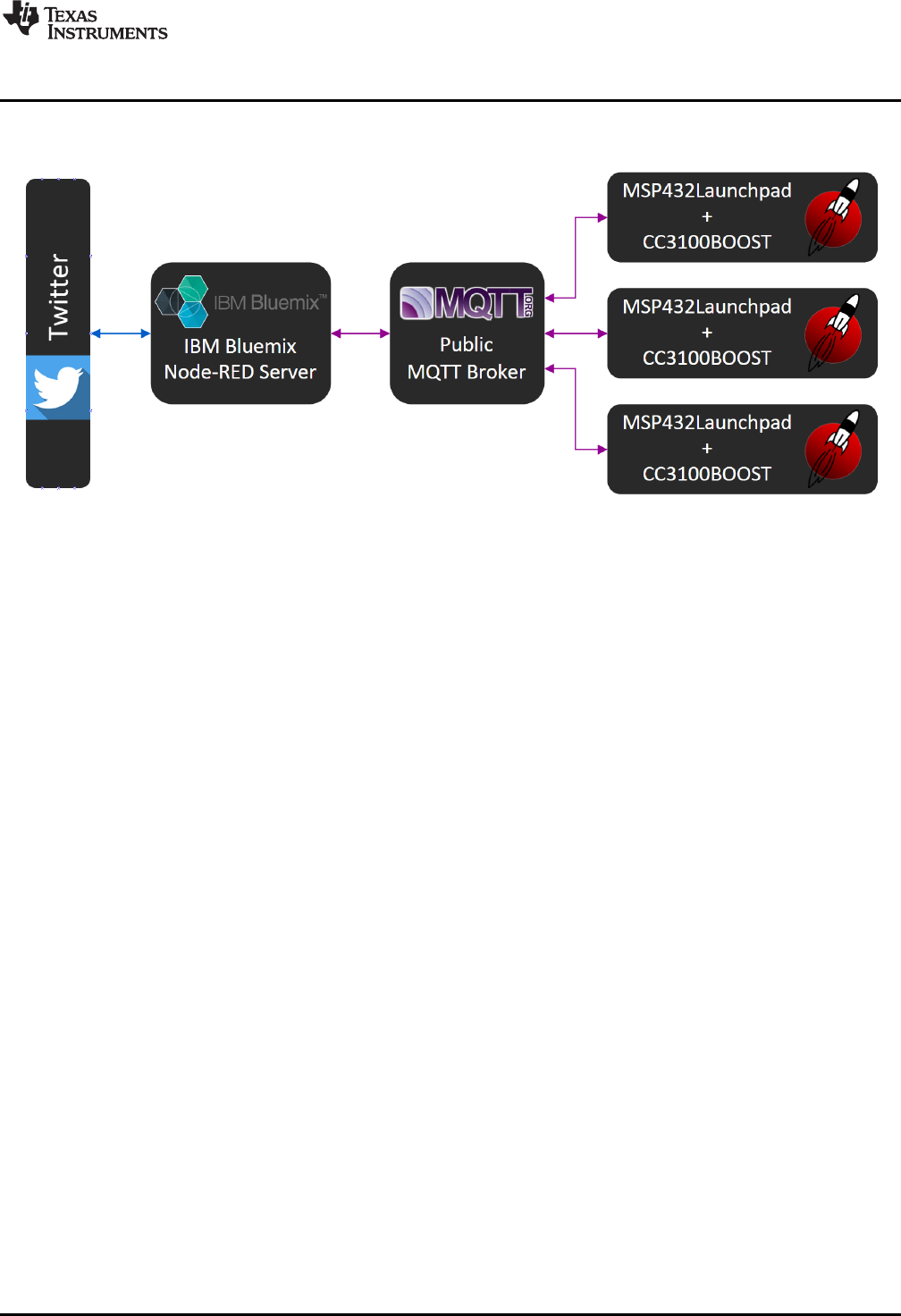
3.2.3 Overview of Backend Servers
Figure 16. Backend Block Diagram of CC3100BOOST MQTT-Twitter LED Control Demo
As shown in the above Figure 16, inputs from either the MSP432 LaunchPad development kit or Twitter
travel through a couple of intermediary servers before reaching the output on the opposite end. Instead of
interacting with Twitter server directly through the more resource intensive HTTP, the MSP432 LaunchPad
development kit communicates with the cloud solely through MQTT protocol. MQTT is a publish-subscribe
messaging protocol designed for lightweight M2M communications. Multiple clients sends message to one
another through a server known as a broker, and each client can publish messages to different topics and
subscribe to multiple topics. While a dedicated MQTT broker can be setup for an application, this demo
uses one of the several MQTT brokers that are freely available to the public,
http://iot.eclipse.org/sandbox.html.
Every LaunchPad development kit running the CC3100BOOST MQTT-Twitter LED Control demo
subscribes to the MQTT topic, "/msp/cc3100/demo". This is why any RGB data published to this topic will
change the LED color on all LaunchPad development kits running this demo. However, each LaunchPad
development kit also subscribes to an "<uniqueID>" topic that can be used to control LaunchPad
development kits individually.
A cloud server is also setup/maintained by the MSP Team using the IBM Bluemix cloud platform service.
This server runs a couple of Node-RED applications that interface with Twitter directly through HTTP.
After processing public tweets containing #MSP432LaunchPad, the Node-RED server also act as a MQTT
client, publishing color information to either the "/msp/cc3100/demo" or "<uniqueID>" topic, which then
gets received on subscribed LaunchPad development kits. Conversely, unique id data published by the
LaunchPad development kits to the "/msp/cc3100/demo/fromLP" topic gets received by the Node-RED
server, which then tweets a time stamped message on the Twitter account @MSPLaunchPad.
Check out IBM Bluemix to see how you can also build your own cloud application.
3.2.4 Developing With CC3100BOOST BoosterPack Plug-in Module
A SimpleLink Wi-Fi CC3100 Software Development Kit (SDK) can be downloaded at
http://www.ti.com/tool/cc3100sdk. It contains drivers, many sample applications for Wi-Fi features and
internet, and documentation needed to use the CC3100 Internet-on-a-chip™ solution.
The CC3100BOOST MQTT-Twitter LED Control Demo was developed on CC3100SDK_1.0.0. Service
pack update may be required on the CC3100BOOST with newer SDK release. Refer to the CC3100
SimpleLink Wi-Fi and IoT Solution Getting Started Guide for more information.

Software Examples
www.ti.com
24 SLAU597B–March 2015–Revised July 2016
Submit Documentation Feedback
Copyright © 2015–2016, Texas Instruments Incorporated
MSP432P401R LaunchPad™ Development Kit (MSP
‑
EXP432P401R)
3.3 BOOSTXL-K350QVG-S1 Graphics Library Example
This software is available in the MSP‑EXP432P401R Software Examples, or more easily accessible
through MSPWare (see Section 4.3).
The demo shows how to use the MSP Graphics Library http://www.ti.com/tool/msp-grlib or "grlib," in a
project with the Kentec display. This demo shows the user how to enable the touch screen, create
buttons, and use graphics primitives including colors and images.
The program begins by calibrating the touch screen. There is a routine that detects the four corner
coordinates to determine if an eligible rectangle boundary is formed. If the calibration was incorrect, a
message will display on the screen indicating the calibration failed. When successful, the calibration
provides a reference for all button presses throughout the rest of the program.
The next step is to select the mode of the program- display primitives or images. Each mode simply cycles
through without user interaction to show off features of the display. In the graphics primitives mode, the
following primitives are shown:
• Pixels
• Lines
• Circles
• Rectangles
• Text
The application is heavily commented to ensure it is very clear how to use the grlib APIs. The above
primitives are shown as well as the underlying concepts of grlib including background and foreground
colors, context, fonts, opacity, and more.
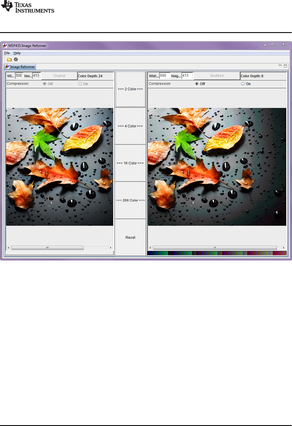
The images mode shows the drawing of a few different images both compressed and uncompressed.
Image compression can have a big impact to drawing speeds for simple images. To draw images with the
MSP Graphics Library, they must first be converted into the right file format. These files can be generated
by the Image Reformer tool that comes packaged with grlib. Launch this tool from the grlib folder or direct
from TI Resource Explorer.
• File Path: <grlib root>\utils\image-reformer\imagereformer.exe
• TI Resource Explorer > MSPWare > Libraries > Graphics Library > MSP430 Image Reformer
The Image Reformer tool allows you to import images and output into grlib specific files to add to your
grlib project. Image Reformer does not manipulate any images (such as color modifications, rotation, or
cropping), any image manipulation must be done before importing into the Image Reformer tool. More
information about MSP grlib and the Image Reformer tool can be found in Design Considerations When
Using the MSP430 Graphics Library.
www.ti.com
Software Examples
25
SLAU597B–March 2015–Revised July 2016
Submit Documentation Feedback Copyright © 2015–2016, Texas Instruments Incorporated
MSP432P401R LaunchPad™ Development Kit (MSP
‑
EXP432P401R)
Figure 17. Importing and Converting an Image With MSP Image Reformer
3.4 430BOOST-SHARP96 Graphics Library Example
This software example is similar to the BOOSTXL-K350QVG-S1 Graphics library example. It shows how
to use the MSP Graphics Library http://www.ti.com/tool/msp-grlib or "grlib," in a project with the Sharp
96×96 display. The Sharp 96×96 display BoosterPack plug-in module does not support touch or color, it is
a simple monochrome LCD. It is a great LCD for ultra-low power display applications and has a unique
mirrored pixel display.
This demo cycles screens without user interaction to show simple graphics primitives.
• Pixels
• Lines
• Circles
• Rectangles
• Text
• Images
This demo introduces the functions to configure grlib such as initialization, color inversion, and using
foreground and background colors properly.
Software Examples
www.ti.com
26 SLAU597B–March 2015–Revised July 2016
Submit Documentation Feedback
Copyright © 2015–2016, Texas Instruments Incorporated
MSP432P401R LaunchPad™ Development Kit (MSP
‑
EXP432P401R)
3.5 BOOSTXL-BATPAKMKII_FuelGauge_MSP432P401R
This section describes the functionality and structure of the BOOSTXL-
BATPAKMKII_FuelGauge_MSP432P401R demo that is included in the MSP-EXP432P401R Software
Examples download, or more easily accessible through MSPWare (see Section 4.3).
3.5.1 Source File Structure
The project is split into multiple files (see Table 7). This makes it easier to navigate and reuse parts of it
for other projects.
Table 7. Source File and Folders
Name Description
Library: driverlib Device driver library (MSP432DRIVERLIB)
startup_msp432p401r.c MSP432™ MCU family interrupt vector table for CGT
HAL_BQ27441.c Driver for communicating with the bq27441-G1 fuel gauge
HAL_I2C.c Board specific support driver for I2C communication
HAL_UART.c Board specific driver for UART communication through Application/User UART
main.c The main function of the demo, global variables, and more
3.5.2 Running the Fuel Gauge Example
After the compiling/loading the BOOSTXL-BATPAKMKII_FuelGauge_MSP432P401R project or
downloading the pre-built firmware binary onto the MSP-EXP432P401R LaunchPad development kit,
included in the MSP-EXP432P401R Software Examples, follow the steps below to run the demo firmware.
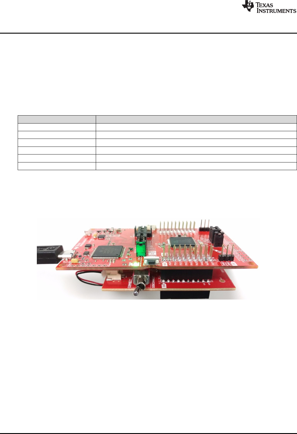
Figure 18. Hardware Setup and Connections
1. Attach the BOOSTXL-BATPAKMKII Battery BoosterPack plug-in module to the LaunchPad
development kit.
2. Flip the switch to the "ON" position on the side of the BOOSTXL-BATPAKMKII Battery BoosterPack
plug-in module.
3. Connect the MSP-EXP432P401R LaunchPad development kit to a computer via micro-USB cable.
4. Launch a serial terminal application and connect to the COM port for "XDS110 Class Application/User
UART" at 115200 baud rate (see Figure 19 and Figure 20).
www.ti.com
Software Examples
27
SLAU597B–March 2015–Revised July 2016
Submit Documentation Feedback Copyright © 2015–2016, Texas Instruments Incorporated
MSP432P401R LaunchPad™ Development Kit (MSP
‑
EXP432P401R)
Figure 19. Determine COM Port Number Using Device Manager on Windows
Figure 20. Example Serial Terminal Configuration
5. Press the reset button on the MSP-EXP432P401R LaunchPad development kit.
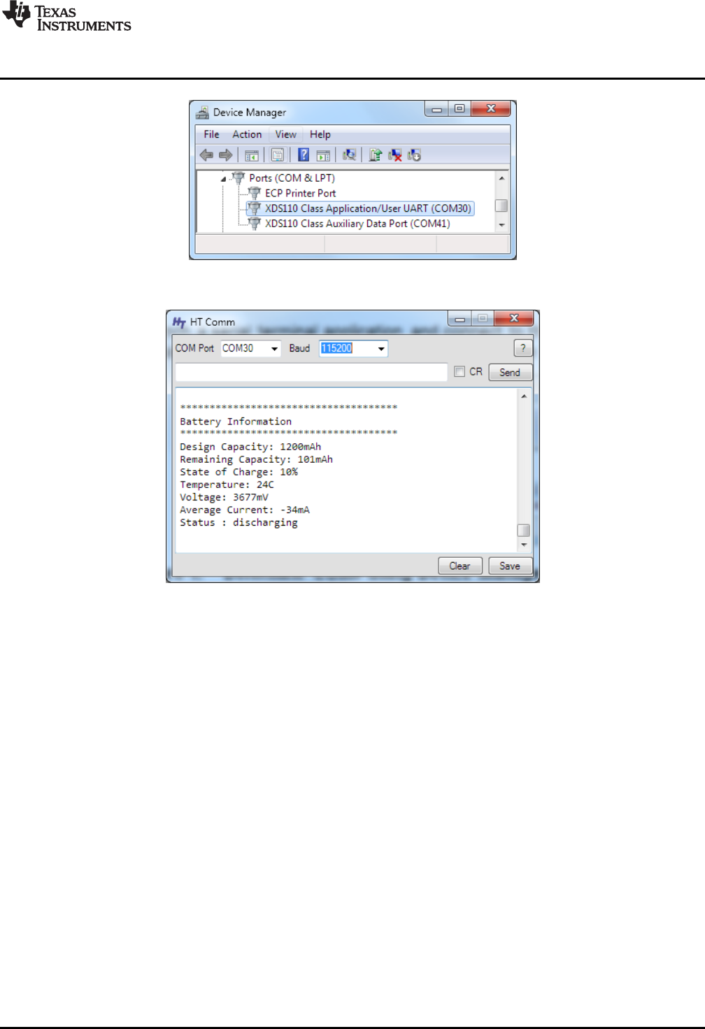
6. Observe serial data displaying Fuel Gauge configuration and Battery Information.

Software Examples
www.ti.com
28 SLAU597B–March 2015–Revised July 2016
Submit Documentation Feedback
Copyright © 2015–2016, Texas Instruments Incorporated
MSP432P401R LaunchPad™ Development Kit (MSP
‑
EXP432P401R)
Figure 21. Snapshot of Serial Terminal Connected to Running Fuel Gauge Demo
3.5.3 Firmware Overview
Refer to Quick Start Guide for bq27441-G1 and bq27441-G1 Technical Reference Manual for detailed
description of the Battery Fuel Gauge usage.
The demo program begins by initializing a number of configuration parameters in the bq27441-G1 to
match the target battery. Four important parameters are Design Capacity, Design Energy, Terminate
Voltage, and Taper Rate. Values are determined based on the target battery properties and bq27441-G1
documentations.
Next, the host MSP432P401R MCU clears the BIE (Batter Insert Enable) bit in the fuel gauge operation
configuration register. When BIE is cleared, the battery detection will rely on the host to issue a
BAT_INSERT subcommand to indicate battery presence, bypassing the J6 BIN jumper on the BOOSTXL-
BATPAKMKII BoosterPack plug-in module that the fuel gauge relies on for battery detection by default
when BIE is set (J6 shorted = Battery Inserted; J6 open = Battery Removed). This is done to ensure the
demo application works regardless if J6 is connected or not.
In end user applications, a switch or the host MCU would more likely be used control the BIN state of the
fuel gauge depending on battery connection. However, this is not implemented on the BoosterPack plug-in
module and a jumper is used to manually toggle between battery insertion and removal.
Once the bq27441-G1 has been configured properly, the main loop repeatedly reads back
DESIGN_CAPACITY, REMAINING_CAPACITY, STATE_OF_CHARGE, TEMPERATURE, VOLTAGE,
and AVERAGE_CURRENT from the fuel gauge. Results are formatted and transmitted through
Application/User UART.
3.6 BOOSTXL-SENSORS_SensorGUI_MSP432P401R
This section describes the functionality and structure of the BOOSTXL-
SENSORS_SensorGUI_MSP432P401R demo that is included in the MSP-EXP432P401R Software
Examples download, or more easily accessible through MSPWare (see Section 4.3).
www.ti.com
Software Examples
29
SLAU597B–March 2015–Revised July 2016
Submit Documentation Feedback Copyright © 2015–2016, Texas Instruments Incorporated
MSP432P401R LaunchPad™ Development Kit (MSP
‑
EXP432P401R)
3.6.1 Source File Structure
The project is split into multiple files (see Table 8). This makes it easier to navigate and reuse parts of it
for other projects.
Table 8. Source File and Folders
Name Description
msp432_startup_ccs.c MSP432™ MCU family interrupt vector table for CGT
Library: driverlib Device driver library (MSP432DRIVERLIB)
src/bme280.c Driver for communicating with the environmental sensor
src/bme280_support.c Support driver for communicating with the environmental sensor
src/bmi160.c Driver for communicating with the IMU and magnetometer sensors
src/bmi160_support.c Support driver for communicating with the IMU and magnetometer sensors
src/demo_sysctl.c Delay function for MSP432 MCU
src/i2c_driver.c Driver for I2C communication with the sensors
src/main.c The demo's main function, interrupt service routines, global variables, etc
src/opt3001.c Driver for communicating with the ambient light sensor
src/tmp007.c Driver for communicating with the infrared temperature sensor
src/uart_driver.c Driver for UART communication with the PC GUI
3.6.2 Working With the GUI
The Sensor GUI allows for quick visualizations of the sensors data and testing of applications.
3.6.2.1 Getting Started
1. Download the BOOSTXL-SENSORS_GUI+ET.zip, and extract its contents.
2. Launch BOOSTXL-SENSORS_GUI+ET.
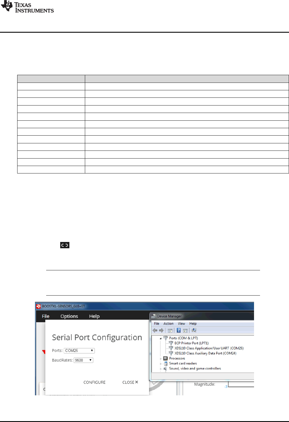
3. Plug in your MSP432P401R LaunchPad development kit with Sensors BoosterPack into a USB port.
And click the icon in the lower left corner of the GUI.
• If needed, go to "Options" and select the proper COM Port for the Application UART and the baud
rate as 115200 (see Figure 22).
NOTE: For Windows, you can find the port number by opening Device Manager and looking for
"XDS110 Class Application/User UART" under "Ports (COM & LPT)". It will be listed as
COMnn, where nn is the number of the port.
Figure 22. Setting up COM Port Configuration for the LaunchPad™ Development Kit
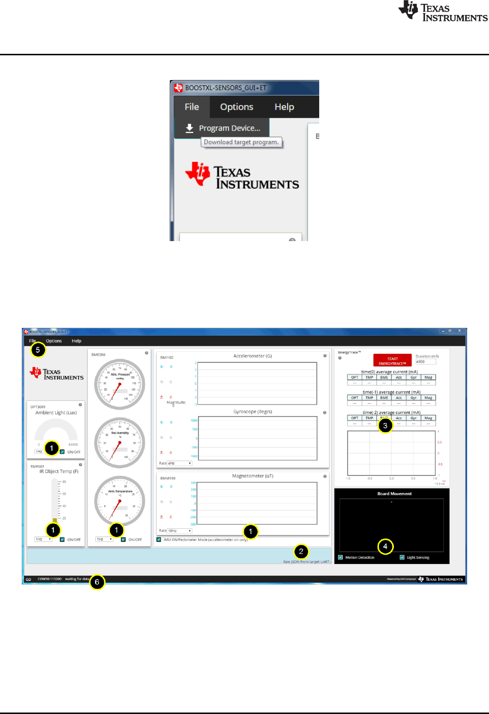
4. Click "File" and click "Program Device". The Firmware should download to the LaunchPad
Software Examples
www.ti.com
30 SLAU597B–March 2015–Revised July 2016
Submit Documentation Feedback
Copyright © 2015–2016, Texas Instruments Incorporated
MSP432P401R LaunchPad™ Development Kit (MSP
‑
EXP432P401R)
development kit (see Figure 23).
Figure 23. Programming Sensor Software With the GUI
5. You should now be seeing live sensor data from the LaunchPad + BoosterPack.
3.6.2.2 Understanding the GUI
Figure 24 shows the layout of the sensor GUI.
Figure 24. Sensor GUI Layout
www.ti.com
Software Examples
31
SLAU597B–March 2015–Revised July 2016
Submit Documentation Feedback Copyright © 2015–2016, Texas Instruments Incorporated
MSP432P401R LaunchPad™ Development Kit (MSP
‑
EXP432P401R)
(1) JSON = JavaScript Object Notation. This is the data format in which the information is sent. For more information, go to www.json.org.
The GUI contains six main elements:
1. Four sensor tiles
2. A serial monitor
3. The EnergyTrace™ software section
4. The board movement detection window
5. A menu bar
6. A status bar
The Serial Monitor lets you see the JSON (1) that is being reported back by the MCU.
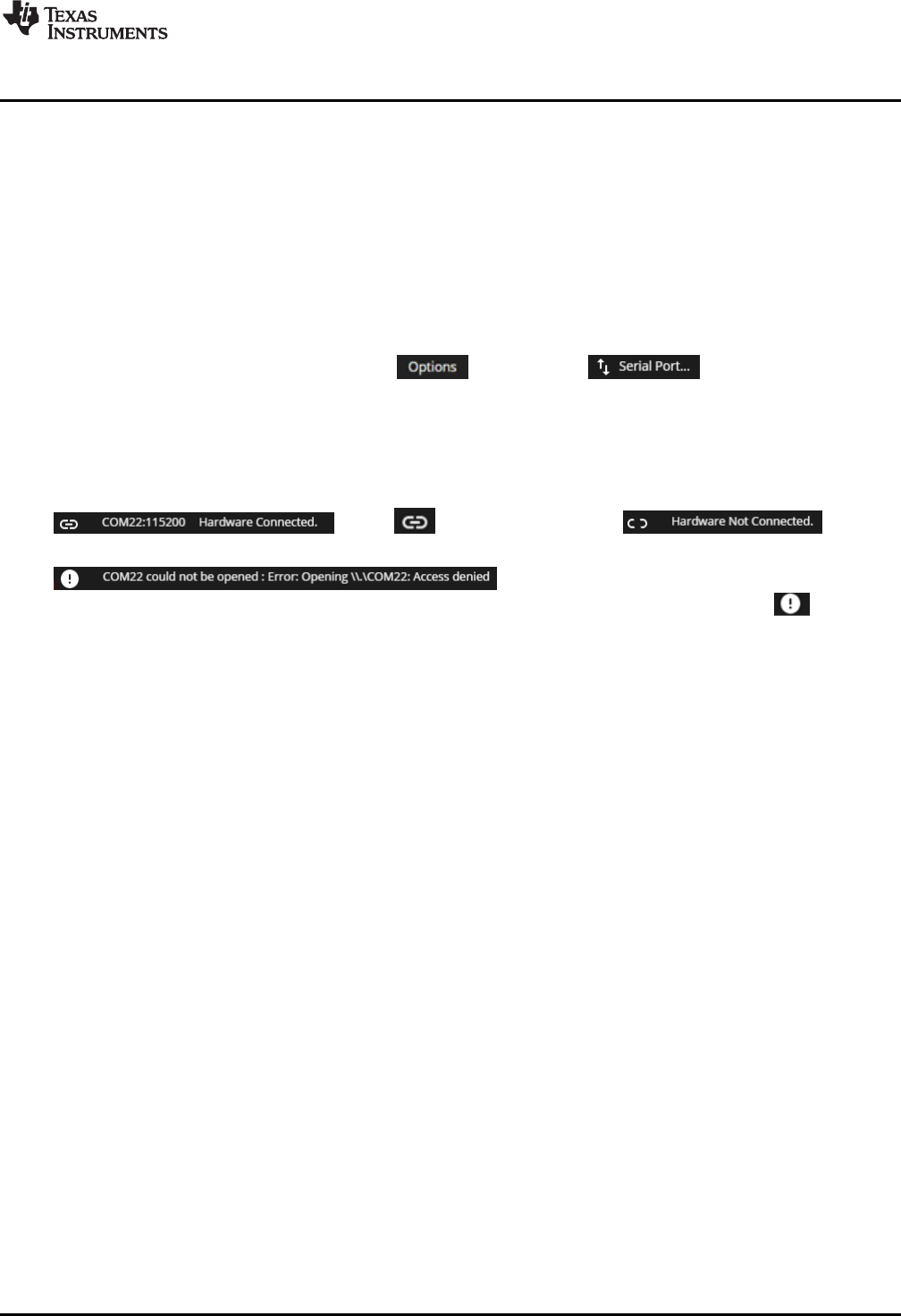
The menu bar serves two functions:
• To change the serial port settings, click and then click . In the dialog, select a
port number and the baud rate, which should be 115200. To apply the settings, click "Configure".
• To program the GUI firmware to the MSP432 MCU LaunchPad development kit, click "File" and then
click "Program Device…".
The status bar indicates if the LaunchPad is connected to the PC, the port that is used, and the baud rate.
The following example indicates a connection to COM22 at 115000 baud:
. Click to disconnect the GUI:
The following example indicates a busy port on COM22:
. To connect the LaunchPad development kit to
this COM port, close any programs that are using that port, disconnect the GUI by clicking ,
disconnect and reconnect (or restart) the LaunchPad development kit, and reconnect the GUI.
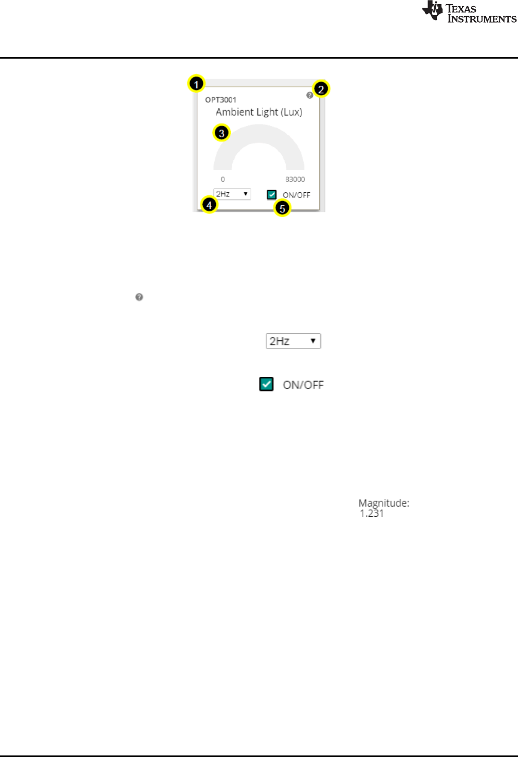
3.6.2.3 Sensor Tiles
Four sensor tiles are available in the Sensor GUI for the BOOSTXL-SENSORS BoosterPack plug-in
module (see Figure 25). Each tile represents the data output for a sensor or set of integrated sensors. The
following is a brief description of each sensor tile:
The OPT3001 Ambient Light Sensor tile responds to ambient light, and displays the brightness of the
light in lux. Casting a shadow over this sensor causes the reading to decrease, and shining a light on the
sensor cause the reading to increase.
The TMP007 IR Temperature Sensor tile responds to infrared energy emitted by objects in its field of
view, displaying this in degrees Celsius. Holding a warm or cold object over the sensor causes a
response, even over short distances.
The BME280 Ambient Temperature, Relative Humidity, and Atmospheric Pressure Sensor tile
responds to atmospheric pressure in millimeters of mercury (which can be stimulated using a pressure
chamber or by lightly pressing on the sensor), relative humidity as a percentage, and ambient temperature
in degrees Celsius (both of which can be stimulated by breathing on the sensor).
The IMU tile is made up of two subtiles:
• The BMI160 Accelerometer and Gyroscope tile responds to acceleration in g (which can be
stimulated by changing the orientation of the board with respect to Earth's gravity, by shaking, or by
changing speed along an axis) and rotation in degrees per second (which can be stimulated by rotating
the board about its axes).
• The BMM150 Magnetometer tile responds to magnetic field in microtesla. This sensor can be
stimulated by changing the sensor orientation with respect to Earth's geomagnetic field or by passing a
magnet over it.
Software Examples
www.ti.com
32 SLAU597B–March 2015–Revised July 2016
Submit Documentation Feedback
Copyright © 2015–2016, Texas Instruments Incorporated
MSP432P401R LaunchPad™ Development Kit (MSP
‑
EXP432P401R)
Figure 25. GUI Sensor Tile
The sensor tiles all share a common set of features. With a special case being the IMU (which consists of
the BMM150 and BMI160).
1. The sensor part number
2. A hint button. Click for an animated demonstration on how to stimulate the sensors. Click again to
hide the hint.
3. A graphical and numerical read out of the sensor values.
4. A sample rate selection drop-down menu. Click to select another frequency. This is the
frequency at which the sensor is checked, which also affects the rate at which the MCU wakes from
LPM0.
5. A button to toggle the sensor on and off. Click to toggle the sensor on or off. The
current draw of each sensor's "ON" and "OFF" states can be seen in the table described in
Section 3.6.2.4, or in the EnergyTrace software hint.
The IMU tile is different from the other tiles in the following ways:
• It is made up of two parts, the BMI160 and the BMM150, each in its own box.
• Each box consists of graphs and numerical data, which are color coded to correspond to one another.
• Each part has its own sample rate selector.
• It has a hint button for each type of sensor; the accelerometer, gyroscope, and magnetometer.
The accelerometer has a display for the acceleration vector magnitude.
The ON/OFF toggle button puts the BMM150 into hibernate and the BMI160 into pedometer mode, and
only the accelerometer remains active.
www.ti.com
Software Examples
33
SLAU597B–March 2015–Revised July 2016
Submit Documentation Feedback Copyright © 2015–2016, Texas Instruments Incorporated
MSP432P401R LaunchPad™ Development Kit (MSP
‑
EXP432P401R)
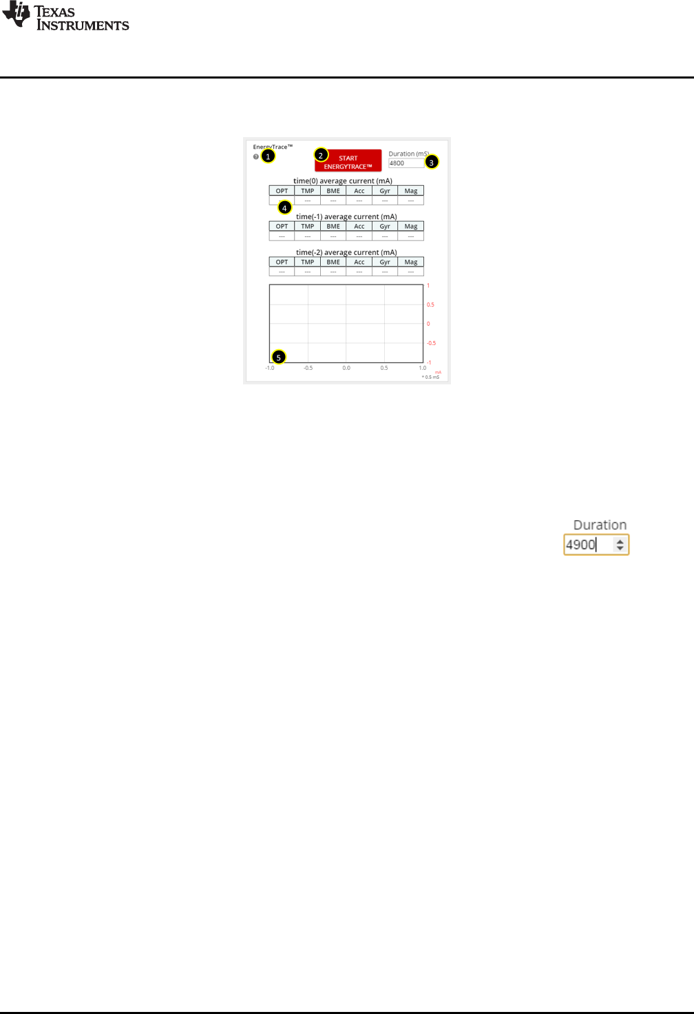
3.6.2.4 EnergyTrace Software Function
Figure 26 shows the interface to EnergyTrace functions.
Figure 26. GUI Integrated EnergyTrace™ Measurements
This section provides monitoring of system current using TI's EnergyTrace technology. It consists of:
1. A hint button. Explains EnergyTrace software measurements and displays a table of expected sensor
currents.
2. A start button. Press this to shift any previous data down to the next time frame, clear the graph, and
begin the next measurement for the selected duration.
3. An input box. To set the duration in milliseconds, click the arrows or type a value:
4. The past three sensor settings and current measurements, with the most recent on top.
5. A graph showing the actual current draw over time. The X-axis corresponds to 0.5-ms ticks, the Y-axis
to the current in milliamps. Each peak is a good indicator of when the MCU is in active mode, and the
valleys indicate when the MCU is in LPM0.
This implementation is an abbreviated form of EnergyTrace software. The full version can track power
consumption, power mode, and more. EnergyTrace software can be used on any application through
Code Composer Studio™ IDE v6 or IAR Embedded Workbench™ IDE. For more information, visit
http://www.ti.com/tool/energytrace
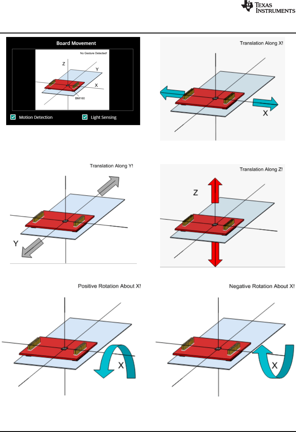
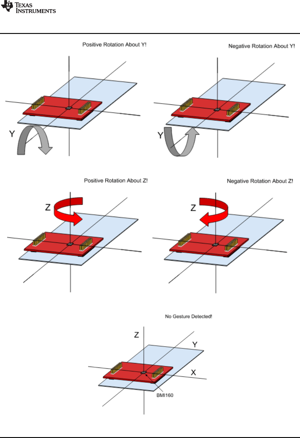
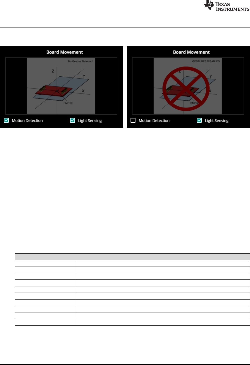
3.6.2.5 Board Movement Window
Figure 27 shows the board movement section. When the "motion detection" toggle box is checked, it
responds to 10 motions (see Figure 28 through Figure 34):
• Translation along the X, Y, or Z axis
• Positive or negative rotation around the X, Y, or Z axis
• No movement
Software Examples
www.ti.com
34 SLAU597B–March 2015–Revised July 2016
Submit Documentation Feedback
Copyright © 2015–2016, Texas Instruments Incorporated
MSP432P401R LaunchPad™ Development Kit (MSP
‑
EXP432P401R)
Figure 27. Board Movement Window Figure 28. Translation Along the X Axis
Figure 29. Translation Along the Y Axis Figure 30. Translation Along the Z Axis
Figure 31. Rotation Around the X Axis
www.ti.com
Software Examples
35
SLAU597B–March 2015–Revised July 2016
Submit Documentation Feedback Copyright © 2015–2016, Texas Instruments Incorporated
MSP432P401R LaunchPad™ Development Kit (MSP
‑
EXP432P401R)
Figure 32. Rotation Around the Y Axis
Figure 33. Rotation Around the Z Axis
Figure 34. No Movement
Software Examples
www.ti.com
36 SLAU597B–March 2015–Revised July 2016
Submit Documentation Feedback
Copyright © 2015–2016, Texas Instruments Incorporated
MSP432P401R LaunchPad™ Development Kit (MSP
‑
EXP432P401R)
With both the OPT3001 tile on and the Light Sensing toggle box checked, the image darkens, whether or
not gesture recognition is enabled (see Figure 35).
Figure 35. Light Sensing in the Gesture Recognition Window
Board movement data is updated whenever the BMI160 is sampled; that is, it follows the same frequency
as the BMI160 drop-down selection box. If motion detection is not enabled, no related calculations are
done on the microcontroller and hence no update occurs.
Similarly, light sensing data is updated whenever the OPT3001 is sampled.
3.7 BOOSTXL-SENSORS_TI-RTOS_SensorGUI_MSP432P401R
This section describes the functionality structure of the BOOSTXL-
SENSORS_TI_RTOS_SensorGUI_MSP432P401R demo that is included in the MSP-EXP432P401R
Software Examples download, or more easily accessible through MSPWare (see Section 4.3).
This example requires TI-RTOS MSP43x version 2_16_01_14 to be installed in CCS.
More information on the use of TI-RTOS can be found within the TI-RTOS User’s Guide.
3.7.1 Source File Structure
Table 9 lists the source files and folders.
Table 9. Source Files and Folders
Name Description
OS: TI-RTOS Real-Time Operating System using TI-RTOS Kernel
Library: driverlib Device driver library (MSP432DRIVERLIB)
bme280.c Driver for communicating with the environmental sensor
bme280_support.c Support driver for communicating with the environmental sensor
bmi160.c Driver for communicating with the IMU and magnetometer sensors
bmi160_support.c Support driver for communicating with the IMU and magnetometer sensors
MSP_EXP432P401R.c Driver for setting up board specific items (for example, I2C and UART)
main.c The demo’s main function, tasks, semaphores, global variables, and others
opt3001.c Driver for communicating with the ambient light sensor
tmp007.c Driver for communicating with the infrared temperature sensor

www.ti.com
Resources
37
SLAU597B–March 2015–Revised July 2016
Submit Documentation Feedback Copyright © 2015–2016, Texas Instruments Incorporated
MSP432P401R LaunchPad™ Development Kit (MSP
‑
EXP432P401R)
3.7.2 Working With the GUI
Collaboration with the Sensor GUI is identical to Section 3.6.2, except for programming the device directly
from the GUI. The .out file located within the GUI is specific to the BOOSTXL-
SENSORS_SensorGUI_MSP432P401R example project. To download the program, you must use a
separate IDE, such as CCS or IAR, and the BOOSTXL-SENSORS_TI_RTOS_SensorGUI_MSP432P401R
source code found within MSP-EXP432P401R Software Examples.
4 Resources
4.1 Integrated Development Environments
Although the source files can be viewed with any text editor, more can be done with the projects if they're
opened with a development environment like Code Composer Studio™ (CCS), Keil™ µVision®, IAR
Embedded Workbench®, or Energia.
4.1.1 TI Cloud Development Tools
TI's Cloud-based software development tools provide instant access to MSPWare content and a web-
based IDE.
4.1.1.1 TI Resource Explorer Cloud
TI Resource Explorer Cloud provides a web interface for browsing examples, libraries and documentation
found in MSPWare without having to download files to your local drive.
Go check out TI Resource Explorer Cloud now at dev.ti.com.
4.1.1.2 Code Composer Studio™ Cloud
Code Composer Studio Cloud is a web-based IDE that allows code edit, compile and download to devices
right from your web browser. It also integrates seamlessly with TI Resource Explorer Cloud with the ability
to import projects directly on the cloud.
A full comparison between CCS Cloud and CCS Desktop is available here.
See Code Composer Studio Cloud now at dev.ti.com.
4.1.2 Code Composer Studio™ IDE
Code Composer Studio Desktop is a professional integrated development environment that supports TI's
Microcontroller and Embedded Processors portfolio. Code Composer Studio comprises a suite of tools
used to develop and debug embedded applications. It includes an optimizing C/C++ compiler, source code
editor, project build environment, debugger, profiler, and many other features.
Note: MSP432 LaunchPad development kit requires CCS Version 6.1.0 or later. Refer to the Code
Composer Studio 6.1 for MSP432 User’s Guide for detailed instructions of using the IDE with MSP432.
Learn more about CCS and download it at http://www.ti.com/tool/ccstudio.
4.1.3 Keil®µVision®
The µVision IDE is an embedded project development environment included in Keil's Microcontroller
Development Kit Version 5, that provides an source code editor, project manager, and make utility tool.
µVision supports all the Keil tools including C/C++ Compiler, Macro Assembler, Linker, Library Manager,
and Object-HEX Converter.
Note: MSP432 LaunchPad development kit requires µVision IDE/MDK Version 5 or later. Refer to the
ARM Keil MDK 5 IDE for MSP432 User's Guide for detailed instructions of using the IDE with MSP432.
Learn more about Keil µVision and download it at http://www.keil.com/arm/mdk.asp.

Resources
www.ti.com
38 SLAU597B–March 2015–Revised July 2016
Submit Documentation Feedback
Copyright © 2015–2016, Texas Instruments Incorporated
MSP432P401R LaunchPad™ Development Kit (MSP
‑
EXP432P401R)
4.1.4 IAR Embedded Workbench®for ARM
IAR Embedded Workbench for ARM is another very powerful integrated development environment that
allows you to develop and manage complete embedded application projects. It integrates the IAR C/C++
Compiler, IAR Assembler, IAR ILINK Linker, editor, project manager, command line build utility, and IAR
C-SPY Debugger.
NOTE: The MSP432 LaunchPad development kit requires the IAR Embedded Workbench for ARM
IDE Version 7.10 or later. Refer to the IAR Embedded Workbench for ARM 7.40.2 for
MSP432 User's Guide for detailed instructions of using the IDE with MSP432.
Learn more about IAR Embedded Workbench and download it at https://www.iar.com/iar-embedded-
workbench/arm.
4.1.5 Energia
Energia is a simple open-source community-driven code editor that is based on the Wiring and Arduino
framework. Energia provides unmatched ease of use through very-high-level APIs that can be used
across hardware platforms. Energia is a light-weight IDE that does not have the full feature set of CCS,
Keil, or IAR. However, Energia is great for anyone who wants to get started very quickly or who does not
have significant coding experience.
Learn more about Energia and download it at www.energia.nu.
4.2 LaunchPad Development Kit Websites
More information about the LaunchPad development kit, supported BoosterPack plug-in modules, and
available resources can be found at:
•MSP‑EXP432P401R tool folder: Resources specific to this particular LaunchPad development kit
•TI's LaunchPad portal: Information about all LaunchPad development kits from TI
4.3 MSPWare and TI Resource Explorer
TI Resource Explorer is a tool integrated into CCS that allows you to browse through available design
resources. TI Resource Explorer will help you quickly find what you need inside packages including
MSPWare, ControlSuite, TivaWare and more. TI Resource Explorer is well organized to find everything
that you need quickly, and you can import software projects into your workspace in one click!
TI Resource Explorer Cloud is one of the TI Cloud Development tools, and is tightly integrated with CCS
Cloud. See Section 4.1.1 for more information.
MSPWare is a collection of code examples, software libraries, data sheets, and other design resources for
all MSP devices delivered in a convenient package – essentially everything developers need to become
MSP experts!
In addition to providing a complete collection of existing MSP design resources, MSPWare also includes a
high-level API called MSP Driver Library. This library makes it easy to program MSP hardware. More
information can be found at http://www.ti.com/tool/mspware.

www.ti.com
Resources
39
SLAU597B–March 2015–Revised July 2016
Submit Documentation Feedback Copyright © 2015–2016, Texas Instruments Incorporated
MSP432P401R LaunchPad™ Development Kit (MSP
‑
EXP432P401R)
Figure 36. Using TI Resource Explorer to Browse MSP‑‑EXP432P401R in MSPWare
Inside TI Resource Explorer, these examples and many more can be found and easily imported into CCS
with one click.
4.4 MSP432P401R
4.4.1 Device Documentation
At some point, you will probably want more information about the MSP432P401R device. For every MSP
device, the documentation is organized as shown in Table 10.
Table 10. How MSP Device Documentation is Organized
Document For MSP432P401R Description
Device family
user's guide MSP432P4xx Family Technical Reference Manual Architectural information about the device,
including all modules and peripherals such as
clocks, timers, ADC, and so on.
Device-specific
data sheet MSP432P401xx Mixed-Signal Microcontroller data sheet Device-specific information and all parametric
information for this device
4.4.2 MSP432P401R Code Examples
This is a set of very simple MSP432P401xx code examples that demonstrate how to use the entire set of
MSP432 peripherals: serial communication, ADC14, Timer_A, Timer_B, and so on. These examples show
both the direct register access and driver library methods.
Every MSP derivative has a set of these code examples. When starting a new project or adding a new
peripheral, these examples serve as a great starting point.
4.4.3 MSP432 Application Notes and TI Designs
There are many application notes that can be found at www.ti.com/msp432, as well as TI Designs with
practical design examples and topics.
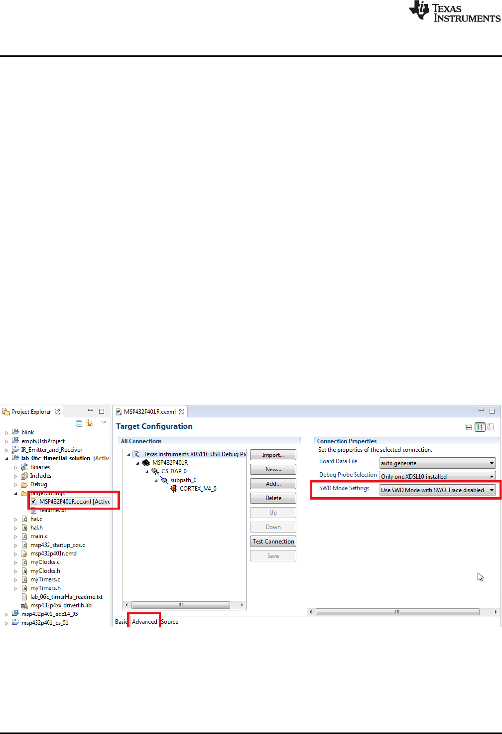
Resources
www.ti.com
40 SLAU597B–March 2015–Revised July 2016
Submit Documentation Feedback
Copyright © 2015–2016, Texas Instruments Incorporated
MSP432P401R LaunchPad™ Development Kit (MSP
‑
EXP432P401R)
4.5 Community Resources
4.5.1 TI E2E™ Community
Search the E2E forums at e2e.ti.com. If you cannot find your answer, post your question to the
community!
4.5.2 Community at Large
Many online communities focus on the LaunchPad development kit; for example, http://www.43oh.com.
You can find additional tools, resources, and support from these communities.
5 FAQ
Q: I can't program my LaunchPad development kit; the IDE can't connect to target. What's wrong?
A: Check the following:
• Are the JTAG jumpers on J101 populated (GND, RST, TMS, TCK, TDO, TDI)
• Check for power to the target
– Are the 3V3 and GND jumpers on J101 populated and USB cable plugged in?
– If using an external debug probe, is USB power provided as shown above? Otherwise is external
power provided to the target?
• Check the debug probe settings: change to Serial Wire Debug (SWD) without SWO
– Under targetconfigs, double-click the *.ccxml file
– Click the Advanced tab at the bottom
– Click on Texas Instruments XDS110 USB Debug Probe
– Under Connection Properties, change SWD Mode Settings to Use SWD Mode with SWO Trace
Disabled
Figure 37. SWD Mode Settings
– When the settings of Port J (PJSEL0 and PJSEL1 bits) are changed, full JTAG access is prevented
on these pins. Changing to use SWD allows access through the dedicated debug pins only.
• If even this cannot connect, reset the device to factory settings
– Click View →Target Configurations. CCS shows the target configuration.
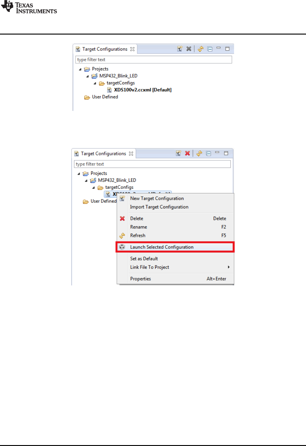
www.ti.com
FAQ
41
SLAU597B–March 2015–Revised July 2016
Submit Documentation Feedback Copyright © 2015–2016, Texas Instruments Incorporated
MSP432P401R LaunchPad™ Development Kit (MSP
‑
EXP432P401R)
Figure 38. Target Configurations
If using the onboard debug probe, XDS110-ET is shown.
– Right click Launch Selected Configuration.
Figure 39. Launch Selected Configuration
– The debug probe now connects to the device (which is still possible) but does not try to halt the
CPU, write to registers, or even download code (which would not be possible). The Debug view that
is spawned shows the CPU core but marks it as disconnected.
– Right click Show all cores.

FAQ
www.ti.com
42 SLAU597B–March 2015–Revised July 2016
Submit Documentation Feedback
Copyright © 2015–2016, Texas Instruments Incorporated
MSP432P401R LaunchPad™ Development Kit (MSP
‑
EXP432P401R)
Figure 40. Show All Cores
The MSP432 Debug Access Port, or DAP, is shown under Non Debuggable Devices.
– Right click Connect Target
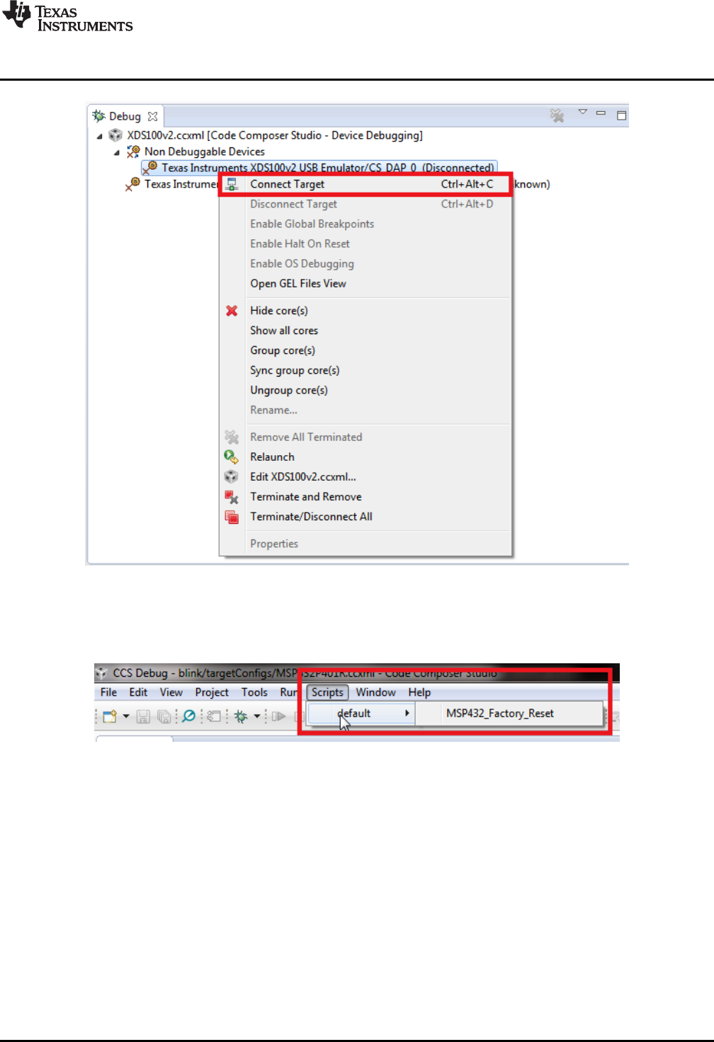
www.ti.com
FAQ
43
SLAU597B–March 2015–Revised July 2016
Submit Documentation Feedback Copyright © 2015–2016, Texas Instruments Incorporated
MSP432P401R LaunchPad™ Development Kit (MSP
‑
EXP432P401R)
Figure 41. Connect Target
Now run a script to return the device back to factory settings:
Scripts > default > MSP432_Factory_Reset
Figure 42. MSP432_Factory_Reset Script
• These instructions are generally the same for all IDEs, but the exact steps may vary slightly by IDE.
See the following MSP432 IDE user's guides for additional details:
–Code Composer Studio 6 for MSP432 User's Guide
–Keil µVision IDE Version 5 for MSP432 User's Guide
–IAR Embedded Workbench for ARM 7.10 for MSP432 User's Guide
Q: How do I use the LaunchPad development kit and my Segger J-Link to debug the target externally? It
won't connect to the onboard connector.
A: The Segger J-Link is the only major ARM debug probe that does not come with an adapter for the 10-
pin small-pitch ARM connector. The adapter cable is found here and can be purchased from Digi-Key.

FAQ
www.ti.com
44 SLAU597B–March 2015–Revised July 2016
Submit Documentation Feedback
Copyright © 2015–2016, Texas Instruments Incorporated
MSP432P401R LaunchPad™ Development Kit (MSP
‑
EXP432P401R)
Q: Problems plugging the MSP432 LaunchPad development kit into a USB3.0 port.
A: It has been observed that when the MSP432 LaunchPad development kit is connected to USB3.0 ports
provided by a certain combination of USB3.0 host controller hardware and associated device drivers that
the IDE is unable to establish a debug session with the LaunchPad development kit, resulting in an error
message like "CS_DAP_0: Error connecting to the target: (Error -260 @ 0x0) An attempt to connect to the
XDS110 failed." in the case of Code Composer Studio IDE. In this case the CCS-provided low-level
command line utility ‘xdsdfu' will also not be able to establish a connection with the LaunchPad
development kit.
Specifically, this issue was observed on PCs running Windows 7 that show the "Renesas Electronics USB
3.0 Host Controller" and the associated "Renesas Electronics USB 3.0 Root Hub" in the device manager.
After updating the associated Windows USB drivers to more recent versions obtained from the hardware
vendor the issue went away. There might be other USB3.0 hardware and device driver combinations that
will lead to the same issue. If you think you might be affected try contacting your PC vendor or try locating
and installing more recent versions of the USB3.0 device drivers. Alternatively, connect the LaunchPad
development kit to an USB2.0 port on your PC if one is available.
Q: I can't get the backchannel UART to connect. What's wrong?
A: Check the following:
• Do the baud rate in the host's terminal application and the eUSCI settings match?
• Are the appropriate jumpers in place on the isolation jumper block?
• Probe on RXD and send data from the host. If you do not see data, it might be a problem on the host
side.
• Probe on TXD while sending data from the MSP432. If you do not see data, it might be a configuration
problem with the eUSCI module.
• Consider the use of the hardware flow control lines (especially for higher baud rates).
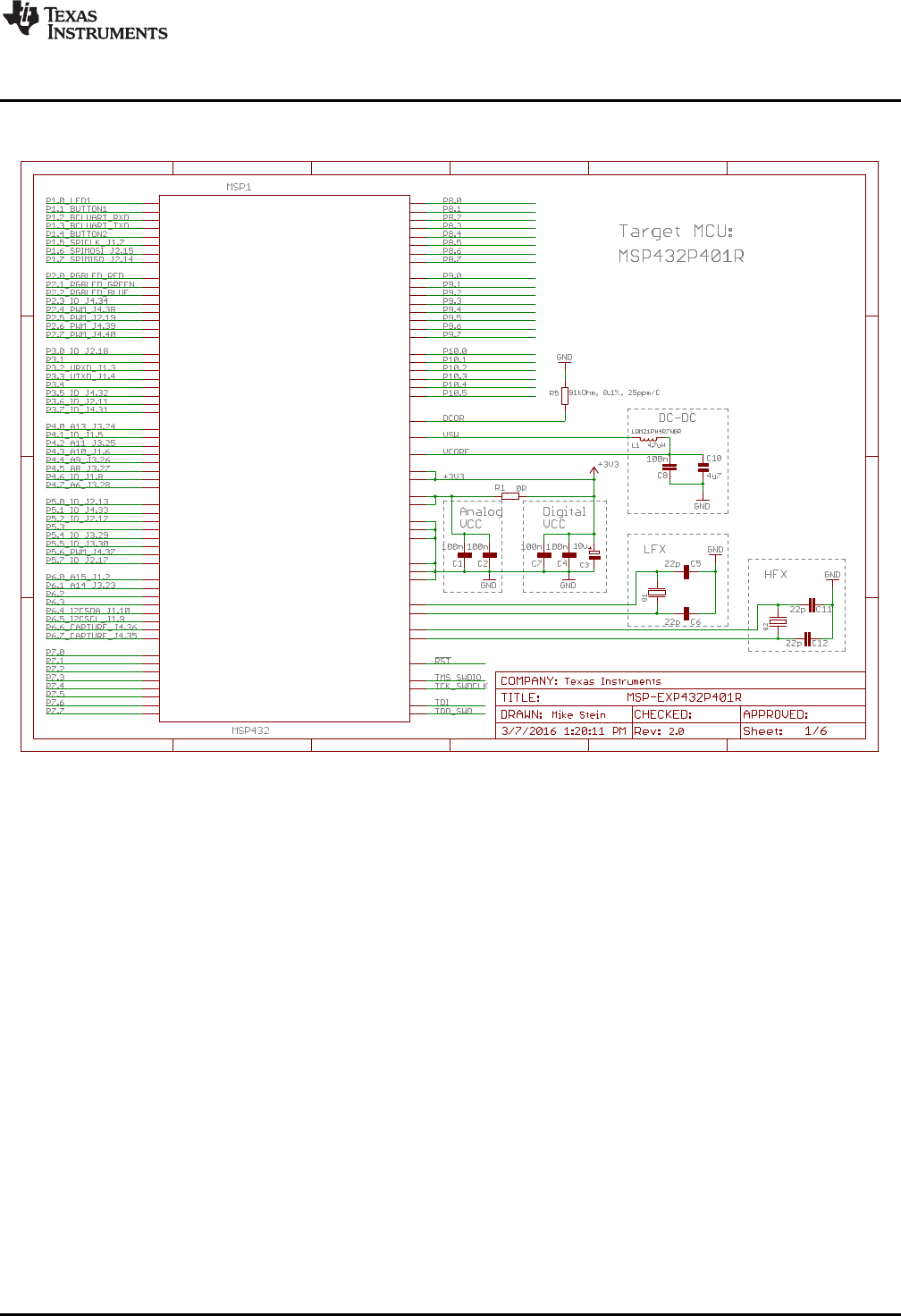
P10.1/UCB3CLK 1
P10.2/UCB3SIMO/UCB3SDA 2
P1.0/UCA0STE
4
P1.1/UCA0CLK
5
P1.2/UCA0RXD/UCA0SOMI
6
P1.3/UCA0TXD/UCA0SIMO
7
P1.4/UCB0STE
8
P1.5/UCB0CLK
9
P1.6/UCB0SIMO/UCB0SDA
10
P1.7/UCB0SOMI/UCB0SCL
11
P2.0/PM_UCA1STE
16
P2.1/PM_UCA1CLK
17
P2.2/PM_UCA1RXD/PM_UCA1SOMI
18
P2.3/PM_UCA1TXD/PM_UCA1SIMO
19
P2.4/PM_TA0.1
20
P2.5/PM_TA0.2
21
P2.6/PM_TA0.3
22
P2.7/PM_TA0.4
23
P3.0/PM_UCA2STE
32
P3.1/PM_UCA2CLK
33
P3.2/PM_UCA2RXD/PM_UCA2SOMI
34
P3.3/PM_UCA2TXD/PM_UCA2SIMO
35
P3.4/PM_UCB2STE
36
P3.5/PM_UCB2CLK
37
P3.6/PM_UCB2SIMO/PM_UCB2SDA
38
P3.7/PM_UCB2SOMI/PM_UCB2SCL
39
P4.0/A13
56
P4.1/A12
57
P4.2/ACLK/TA2CLK/A11
58
P4.3/MCLK/RTCCLK/A10
59
P4.4/HSMCLK/SVMHOUT/A9
60
P4.5/A8
61
P4.6/A7
62
P4.7/A6
63
P5.0/A5
64
P5.1/A4
65
P5.2/A3
66
P5.3/A2
67
P5.4/A1
68
P5.5/A0
69
P5.6/TA2.1/VREF+/VEREF+/C1.7
70
P5.7/TA2.2/VREF-/VEREF-/C1.6
71
P6.0/A15
54
P6.1/A14
55
P6.2/UCB1STE/C1.5
76
P6.3/UCB1CLK/C1.4
77
P6.4/UCB1SIMO/UCB1SDA/C1.3
78
P6.5/UCB1SOMI/UCB1SCL/C1.2
79
P6.6/TA2.3/UCB3SIMO/UCB3SDA/C1.1
80
P6.7/TA2.4/UCB3SOMI/UCB3SCL/C1.0
81
P10.3UCB3SOMI/UCB3SCL 3
P9.7/UCA3TXD/UCA3SIMO 99
P9.6/UCA3RXD/UCA3SOMI 98
P9.5/UCA3CLK 97
P9.4/UCA3STE 96
P9.3/TA3.4 75
P9.2/TA3.3 74
P9.1/A16 53
P9.0/A17 52
P8.7/A18 51
P8.6/A19 50
P8.5/A20 49
P8.4/A21 48
P8.3/TA3CLK/A22 47
P8.2/TA3.2/A23 46
P8.1/UCB3CLK/TA2.0/C0.0 31
P8.0/UCB3STE/TA1.0/C0.1 30
P7.0/PM_SMCLK/PM_DMAE0
88
P7.1/PM_C0OUT/PM_TA0CLK
89
P7.2/PM_C1OUT/PM_TA1CLK
90
P7.3/PM_TA0.0
91
P7.4/PM_TA1.4/C0.5
26
P7.5/PM_TA1.3/C0.4
27
P7.6/PM_TA1.2/C0.3
28
P7.7/PM_TA1.1/C0.2
29
DVSS3 82
SWDIOTMS 94
PJ.5/TDO/SWO 93
PJ.4/TDI/ADC14CLK 92
PJ.3/HFXIN 86
PJ.2/HFXOUT 85
PJ.1/LFXOUT 42
PJ.0/LFXIN 41
SWCLKTCK 95
AVSS3 40
RSTN/NMI 83
DCOR 44
DVSS2 72
DVSS1 15
AVSS2 84
AVSS1 43
AVCC2 87
AVCC1 45
DVCC2 73
DVCC1 13
VCORE 12
VSW 14
P10.5/TA3.1/C0.6 25
P10.4/TA3.0/C0.7 24
P10.0/UCB3STE 100
1 2
1 3
A
B
C
D
1 2 3 4 5 6
A
B
C
D
1 2 3 4 5 6
Copyright © 2016, Texas Instruments Incorporated
www.ti.com
Schematics
45
SLAU597B–March 2015–Revised July 2016
Submit Documentation Feedback Copyright © 2015–2016, Texas Instruments Incorporated
MSP432P401R LaunchPad™ Development Kit (MSP
‑
EXP432P401R)
6 Schematics
Figure 43. Schematics (1 of 6)
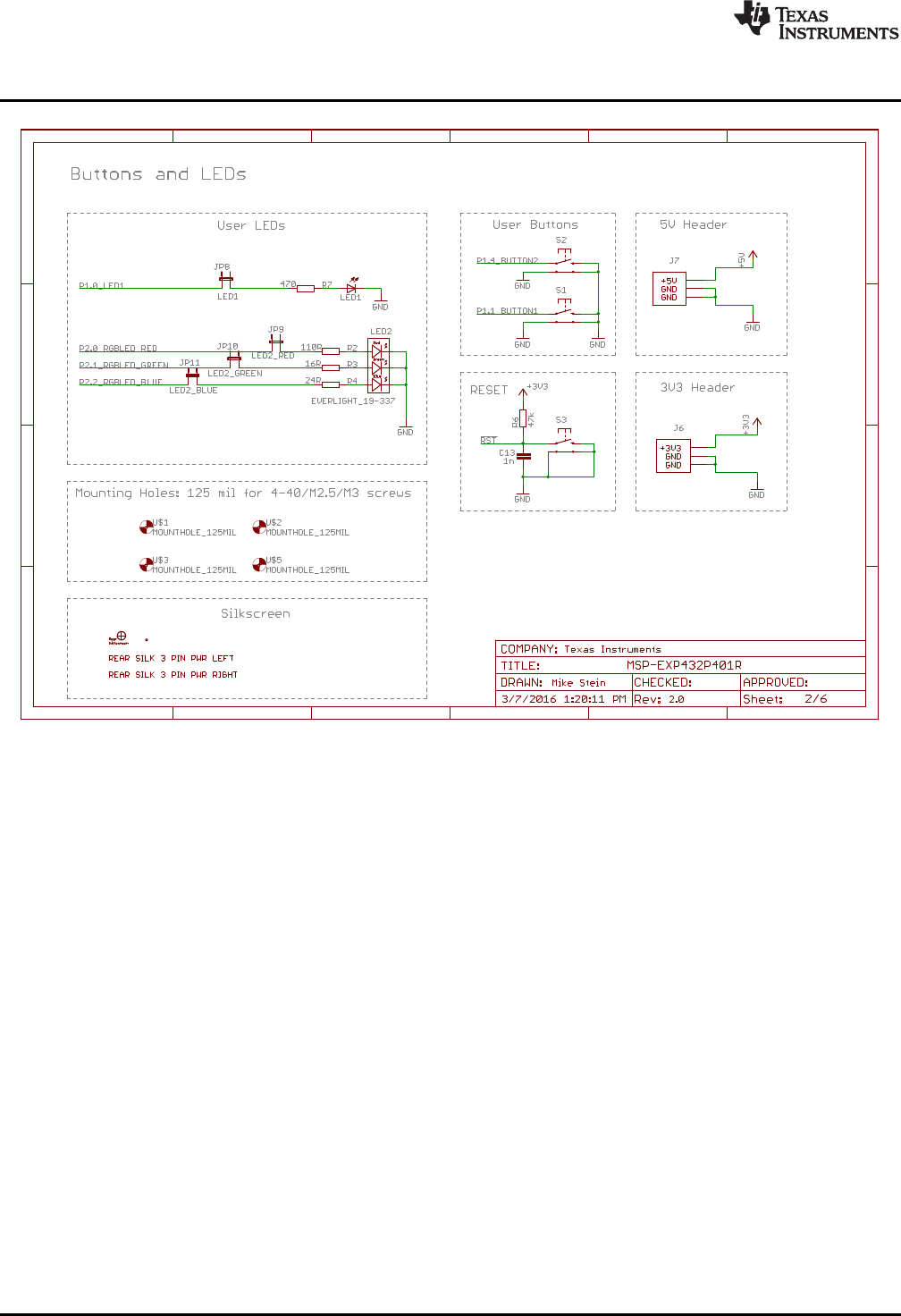
1
2
1
2
1
2
1
2
1
2
3
1
2
3
S1 S2
G2G1
S1 S2
G2G1
S1 S2
G2G1
A
B
C
D
1 2 3 4 5 6
A
B
C
D
1 2 3 4 5 6
Copyright © 2016, Texas Instruments Incorporated
Schematics
www.ti.com
46 SLAU597B–March 2015–Revised July 2016
Submit Documentation Feedback
Copyright © 2015–2016, Texas Instruments Incorporated
MSP432P401R LaunchPad™ Development Kit (MSP
‑
EXP432P401R)
Figure 44. Schematics (2 of 6)

1
1
3
3
5
5
7
7
9
9
11
11
13
13
15
15
17
17
19
19
21
21
23
23
25
25
27
27
29
29
31
31
33
33
35
35
37
37 38 38
36 36
34 34
32 32
30 30
28 28
26 26
24 24
22 22
20 20
18 18
16 16
14 14
12 12
10 10
88
66
44
22
14 13
12 11
10 9
8 7
6 5
4 3
2 1
20 19
18 17
16 15
1
2
1 2
3 4
5 6
7 8
9 10
1 2
3 4
5 6
7 8
9 10
A
B
C
D
1 2 3 4 5 6
A
B
C
D
1 2 3 4 5 6
Copyright © 2016, Texas Instruments Incorporated
www.ti.com
Schematics
47
SLAU597B–March 2015–Revised July 2016
Submit Documentation Feedback Copyright © 2015–2016, Texas Instruments Incorporated
MSP432P401R LaunchPad™ Development Kit (MSP
‑
EXP432P401R)
Figure 45. Schematics (3 of 6)
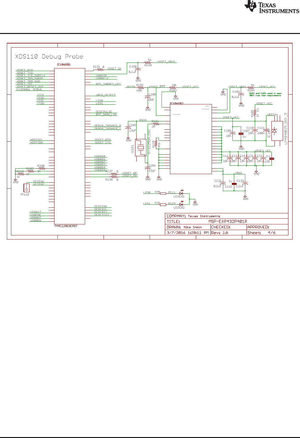
PA0
P$33
PA1
P$34
PA2
P$35
PA3
P$36
PA4
P$37
PA5
P$38
PA6
P$40
PA7
P$41
PB0 P$95
PB1 P$96
PB2 P$91
PB3 P$92
PB4 P$121
PB5 P$120
PC0
P$100
PC1
P$99
PC2
P$98
PC3
P$97
PC4
P$25
PC5
P$24
PC6
P$23
PC7
P$22
PD0 P$1
PD1 P$2
PD2 P$3
PD3 P$4
PD4 P$125
PD5 P$126
PD6 P$127
PD7 P$128
PE0
P$15
PE1
P$14
PE2
P$13
PE3
P$12
PE4
P$123
PE5
P$124
PF0 P$42
PF1 P$43
PF2 P$44
PF3 P$45
PF4 P$46
PG0
P$49
PG1
P$50 PH0 P$29
PH1 P$30
PH2 P$31
PH3 P$32
PJ0
P$116
PJ1
P$117
PK0
P$18
PK1
P$19
PK2
P$20
PK3
P$21
PK4
P$63
PK5
P$62
PK6
P$61
PK7
P$60
PL0 P$81
PL1 P$82
PL2 P$83
PL3 P$84
PL4 P$85
PL5 P$86
PL6 P$94
PL7 P$93
PM0
P$78
PM1
P$77
PM2
P$76
PM3
P$75
PM4
P$74
PM5
P$73
PM6
P$72
PM7
P$71
PN0 P$107
PN1 P$108
PN2 P$109
PN3 P$110
PN4 P$111
PN5 P$112
PP0
P$118
PP1
P$119
PP2
P$103
PP3
P$104
PP4
P$105
PP5
P$106
PQ0 P$5
PQ1 P$6
PQ2 P$11
PQ3 P$27
PQ4 P$102
HIB P$65
RESET
P$70
WAKE P$64
EN0RXIN
P$53
EN0RXIP
P$54
EN0TXON
P$56
EN0TXOP
P$57
GND
P$17
GND
P$48
GND
P$55
GND
P$58
GND
P$80
GND
P$114
GNDA
P$10
OSC0
P$88
OSC1
P$89
RBIAS
P$59
VBAT P$68
VDD P$7
VDD P$16
VDD P$26
VDD P$28
VDD P$39
VDD P$47
VDD P$51
VDD P$52
VDD P$69
VDD P$79
VDD P$90
VDD P$101
VDD P$113
VDD P$122
VDDA P$8
VDDC P$87
VDDC P$115
VREFA+ P$9
XOSC0
P$66
XOSC1
P$67
OSC0
1NC 2
OSC1 3
NC2
4
1
A
1
NC_2
2
C3
NC_3 4
NC 5
A
B
C
D
1 2 3 4 5 6
A
B
C
D
1 2 3 4 5 6
Copyright © 2016, Texas Instruments Incorporated
Schematics
www.ti.com
48 SLAU597B–March 2015–Revised July 2016
Submit Documentation Feedback
Copyright © 2015–2016, Texas Instruments Incorporated
MSP432P401R LaunchPad™ Development Kit (MSP
‑
EXP432P401R)
Figure 46. Schematics (4 of 6)
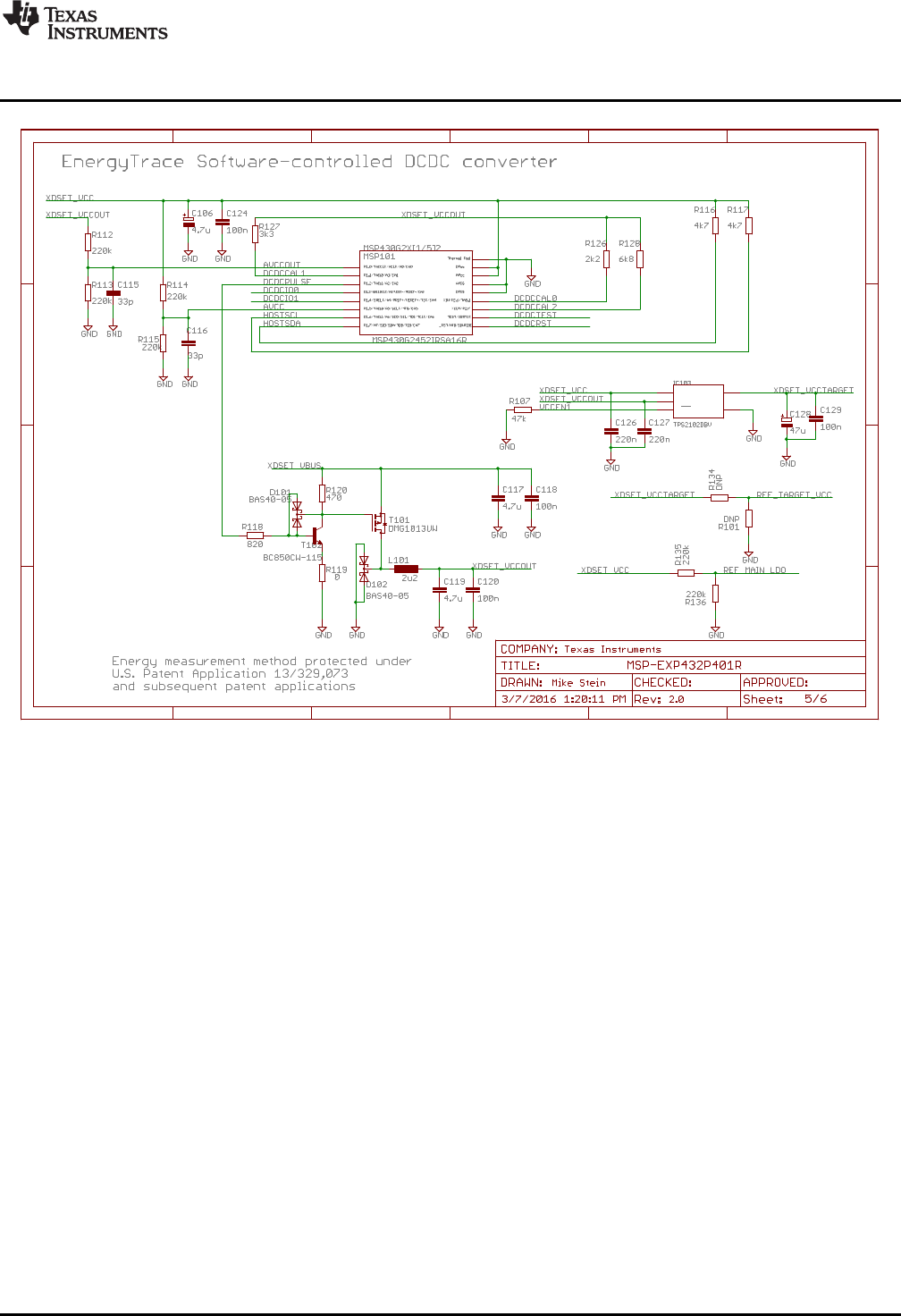
1
2
3
4
5
6
7 10
11
12
13
14
15
16
8 9
TP
EN
1GND 2
IN2
3OUT 4
IN1
5
A
B
C
D
1 2 3 4 5 6
A
B
C
D
1 2 3 4 5 6
Copyright © 2016, Texas Instruments Incorporated
www.ti.com
Schematics
49
SLAU597B–March 2015–Revised July 2016
Submit Documentation Feedback Copyright © 2015–2016, Texas Instruments Incorporated
MSP432P401R LaunchPad™ Development Kit (MSP
‑
EXP432P401R)
Figure 47. Schematics (5 of 6)
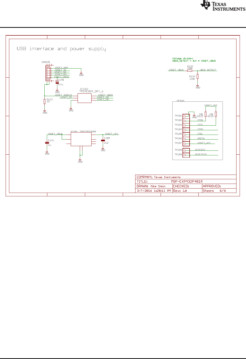
1
1
1
1
1
1
1
1
OUT 1
NC0 2
NR
3
GND
4
EN
5
NC1 6
NC2 7
IN
8
PAD
9
IO1
1
IO2
2
GND
3IO3 4
IO4 5
VCC 6
1
D+
D-
GND
ID
VBUS
A
B
C
D
1 2 3 4 5 6
A
B
C
D
1 2 3 4 5 6
Copyright © 2016, Texas Instruments Incorporated
Schematics
www.ti.com
50 SLAU597B–March 2015–Revised July 2016
Submit Documentation Feedback
Copyright © 2015–2016, Texas Instruments Incorporated
MSP432P401R LaunchPad™ Development Kit (MSP
‑
EXP432P401R)
Figure 48. Schematics (6 of 6)

www.ti.com
Revision History
51
SLAU597B–March 2015–Revised July 2016
Submit Documentation Feedback Copyright © 2015–2016, Texas Instruments Incorporated
Revision History
Revision History
NOTE: Page numbers for previous revisions may differ from page numbers in the current version.
Changes from July 21, 2015 to July 12, 2016 .................................................................................................................. Page
• Changed Figure 1,MSP
‑
EXP432P401R LaunchPad™ Development Kit......................................................... 1
• Added last three list items in Section 1.3.2,Software Examples ................................................................... 4
• Changed Figure 5,XDS110-ET Debug Probe ........................................................................................ 7
• Changed first paragraph in Section 2.3.1,XDS110-ET Isolation Block J101 ..................................................... 7
• In Table 1,Isolation Block Connections: removed Isolation Type column, removed RTS and CTS rows, removed notes,
added GND row ........................................................................................................................... 7
• Changed Figure 6,XDS110-ET Isolation Block....................................................................................... 8
• Removed the sentence that started "The provided UART supports hardware flow control..." from the first paragraph of
Section 2.3.2,Application (or "Backchannel") UART................................................................................. 8
• Removed the paragraph that started "The XDS110-ET also supports hardware flow control..." in Section 2.3.2,Application
(or "Backchannel") UART ................................................................................................................ 9
• Changed the first paragraph and all steps in Section 2.3.3,Using an External Debug Probe Instead of the Onboard
XDS110-ET............................................................................................................................... 10
• Updated all contents of Section 2.3.4,Using the XDS110-ET Emulator With a Different Target............................. 10
• Changed Figure 10,MSP
‑
EXP432P401R Power Block Diagram................................................................. 13
• Changed Figure 11,LaunchPad™ Development Kit to BoosterPack™ Plug-in Module Connector Pinout ................. 16
• Added the paragraph that starts "Do you have an older version..." in Section 2.8.1,Hardware Design Files .............. 16
• Added the paragraph that starts "Do you have an older version..." in Section 2.8.2,Software Examples .................. 17
• Added row for "Rev 2.0" and added two columns on right to Table 3,Hardware Change Log ............................... 17
• Added Section 2.9.1,MSP-EXP432P401R Rev 1.0 (Black) LaunchPad Development Kit.................................... 17
• Added Section 2.9.2,MSP-EXP432P401R Rev 2.0 (Red) LaunchPad Development Kit...................................... 17
• Added the last three rows to Table 4,Software Examples......................................................................... 19
• Added Section 3.5,BOOSTXL-BATPAKMKII Fuel Gauge Example ............................................................. 26
• Added Section 3.6,BOOSTXL-SENSORS Sensor GUI Example ................................................................ 28
• Added Section 3.7,BOOSTXL-SENSORS Sensor GUI With TI-RTOS Example............................................... 36
• Changed Figure 36,Using TI Resource Explorer to Browse MSP
‑
EXP432P401R in MSPWare............................. 39
• Changed the first two list items in the answer to the FAQ that starts "I can't program my LaunchPad development kit..." in
Section 5,FAQ........................................................................................................................... 40
• Removed the FAQ that started "Q: Why doesn't the back-channel UART ..."................................................... 43
• Changed all figures in Section 6,Schematics ....................................................................................... 45

IMPORTANT NOTICE
Texas Instruments Incorporated and its subsidiaries (TI) reserve the right to make corrections, enhancements, improvements and other
changes to its semiconductor products and services per JESD46, latest issue, and to discontinue any product or service per JESD48, latest
issue. Buyers should obtain the latest relevant information before placing orders and should verify that such information is current and
complete. All semiconductor products (also referred to herein as “components”) are sold subject to TI’s terms and conditions of sale
supplied at the time of order acknowledgment.
TI warrants performance of its components to the specifications applicable at the time of sale, in accordance with the warranty in TI’s terms
and conditions of sale of semiconductor products. Testing and other quality control techniques are used to the extent TI deems necessary
to support this warranty. Except where mandated by applicable law, testing of all parameters of each component is not necessarily
performed.
TI assumes no liability for applications assistance or the design of Buyers’ products. Buyers are responsible for their products and
applications using TI components. To minimize the risks associated with Buyers’ products and applications, Buyers should provide
adequate design and operating safeguards.
TI does not warrant or represent that any license, either express or implied, is granted under any patent right, copyright, mask work right, or
other intellectual property right relating to any combination, machine, or process in which TI components or services are used. Information
published by TI regarding third-party products or services does not constitute a license to use such products or services or a warranty or
endorsement thereof. Use of such information may require a license from a third party under the patents or other intellectual property of the
third party, or a license from TI under the patents or other intellectual property of TI.
Reproduction of significant portions of TI information in TI data books or data sheets is permissible only if reproduction is without alteration
and is accompanied by all associated warranties, conditions, limitations, and notices. TI is not responsible or liable for such altered
documentation. Information of third parties may be subject to additional restrictions.
Resale of TI components or services with statements different from or beyond the parameters stated by TI for that component or service
voids all express and any implied warranties for the associated TI component or service and is an unfair and deceptive business practice.
TI is not responsible or liable for any such statements.
Buyer acknowledges and agrees that it is solely responsible for compliance with all legal, regulatory and safety-related requirements
concerning its products, and any use of TI components in its applications, notwithstanding any applications-related information or support
that may be provided by TI. Buyer represents and agrees that it has all the necessary expertise to create and implement safeguards which
anticipate dangerous consequences of failures, monitor failures and their consequences, lessen the likelihood of failures that might cause
harm and take appropriate remedial actions. Buyer will fully indemnify TI and its representatives against any damages arising out of the use
of any TI components in safety-critical applications.
In some cases, TI components may be promoted specifically to facilitate safety-related applications. With such components, TI’s goal is to
help enable customers to design and create their own end-product solutions that meet applicable functional safety standards and
requirements. Nonetheless, such components are subject to these terms.
No TI components are authorized for use in FDA Class III (or similar life-critical medical equipment) unless authorized officers of the parties
have executed a special agreement specifically governing such use.
Only those TI components which TI has specifically designated as military grade or “enhanced plastic” are designed and intended for use in
military/aerospace applications or environments. Buyer acknowledges and agrees that any military or aerospace use of TI components
which have not been so designated is solely at the Buyer's risk, and that Buyer is solely responsible for compliance with all legal and
regulatory requirements in connection with such use.
TI has specifically designated certain components as meeting ISO/TS16949 requirements, mainly for automotive use. In any case of use of
non-designated products, TI will not be responsible for any failure to meet ISO/TS16949.
Products Applications
Audio www.ti.com/audio Automotive and Transportation www.ti.com/automotive
Amplifiers amplifier.ti.com Communications and Telecom www.ti.com/communications
Data Converters dataconverter.ti.com Computers and Peripherals www.ti.com/computers
DLP® Products www.dlp.com Consumer Electronics www.ti.com/consumer-apps
DSP dsp.ti.com Energy and Lighting www.ti.com/energy
Clocks and Timers www.ti.com/clocks Industrial www.ti.com/industrial
Interface interface.ti.com Medical www.ti.com/medical
Logic logic.ti.com Security www.ti.com/security
Power Mgmt power.ti.com Space, Avionics and Defense www.ti.com/space-avionics-defense
Microcontrollers microcontroller.ti.com Video and Imaging www.ti.com/video
RFID www.ti-rfid.com
OMAP Applications Processors www.ti.com/omap TI E2E Community e2e.ti.com
Wireless Connectivity www.ti.com/wirelessconnectivity
Mailing Address: Texas Instruments, Post Office Box 655303, Dallas, Texas 75265
Copyright © 2016, Texas Instruments Incorporated
