Stellaris® LM4F120 LaunchPad Evaluation Board User's Manual Launch Pad Users
LaunchPadUsersManual
LaunchPadUsersManual
LaunchPadUsersManual
User Manual:
Open the PDF directly: View PDF ![]() .
.
Page Count: 26
- Stellaris® LM4F120 LaunchPad Evaluation Board
- Table of Contents
- List of Figures
- List of Tables
- Board Overview
- Hardware Description
- Software Development
- Schematics
- Component Locations
- Bill of Materials (BOM)
- References

EK-LM4F120XL-UM-01 Copyright © 2012 Texas Instruments
SMPU289
User’s Manual
Stellaris® LM4F120 LaunchPad Evaluation
Board

2August 29, 2012
Copyright
Copyright © 2012 Texas Instruments, Inc. All rights reserved. Stellaris and StellarisWare are registered trademarks of Texas Instruments. ARM and
Thumb are registered trademarks, and Cortex is a trademark of ARM Limited. Other names and brands may be claimed as the property of others.
Texas Instruments
108 Wild Basin, Suite 350
Austin, TX 78746
http://www.ti.com/stellaris

August 29, 2012 3
Table of Contents
Chapter 1: Board Overview.............................................................................................................................. 6
Kit Contents ........................................................................................................................................................ 7
Using the Stellaris® LaunchPad......................................................................................................................... 7
Features.............................................................................................................................................................. 7
BoosterPacks...................................................................................................................................................... 8
Specifications...................................................................................................................................................... 8
Chapter 2: Hardware Description.................................................................................................................... 9
Functional Description ...................................................................................................................................... 10
(Microcontroller, USB, Expansion, Buttons, and LED (Schematic on page 18)............................................ 10
Power Management (Schematic on page 19)............................................................................................... 13
Stellaris In-Circuit Debug Interface (ICDI) (Schematic on page 20) ............................................................. 14
Chapter 3: Software Development ................................................................................................................ 15
Software Description......................................................................................................................................... 15
Source Code..................................................................................................................................................... 15
Tool Options ..................................................................................................................................................... 15
Programming the Stellaris LaunchPad Evaluation Board................................................................................. 15
Appendix A: Schematics................................................................................................................................ 17
Appendix B: Component Locations..............................................................................................................21
Appendix C: Bill of Materials (BOM) ............................................................................................................. 23
Appendix D: References ................................................................................................................................ 25

Stellaris® LM4F120 LaunchPad XL User’s Manual
4August 29, 2012
List of Figures
Figure 1-1. Stellaris® LM4F120 LaunchPad Evaluation Board .........................................................................6
Figure 2-1. Stellaris® LaunchPad Evaluation Board Block Diagram ................................................................. 9
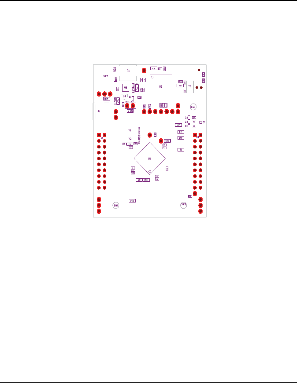
Figure B-1. Stellaris® LaunchPad Component Locations (Top View) ............................................................. 21
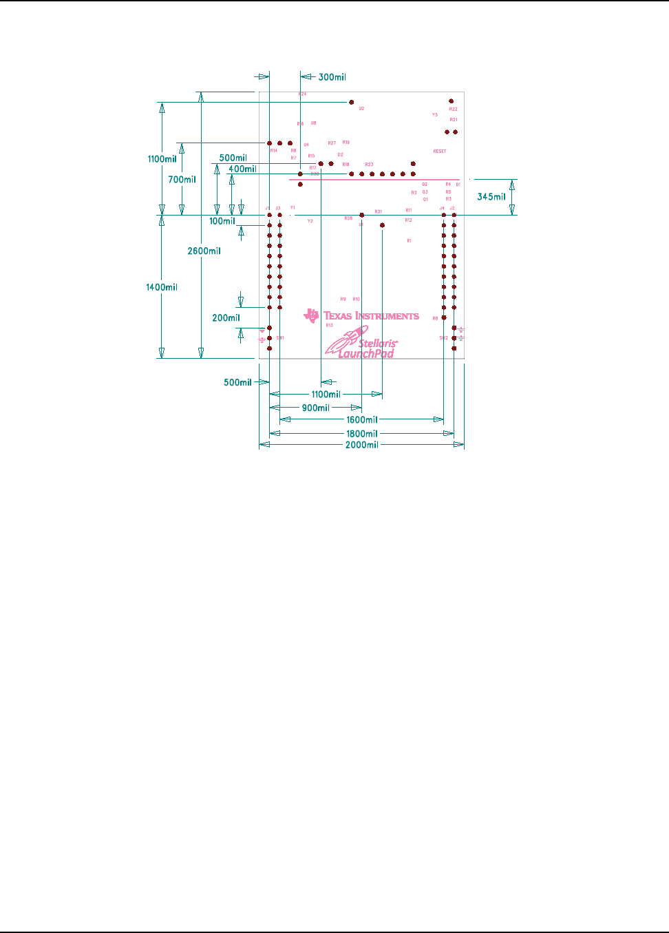
Figure B-2. Stellaris® LaunchPad Dimensions)............................................................................................... 22

August 29, 2012 5
List of Tables
Table 1-1. EK-LM4F120XL Specifications........................................................................................................ 8
Table 2-1. USB Device Signals ...................................................................................................................... 10
Table 2-2. User Switches and RGB LED Signals........................................................................................... 10
Table 2-3. J1 Connector................................................................................................................................. 11
Table 2-4. J2 Connector................................................................................................................................. 11
Table 2-5. J3 Connector................................................................................................................................. 12
Table 2-6. J4 Connector................................................................................................................................. 12
Table 2-7. Stellaris® In-Circuit Debug Interface (ICDI) Signals...................................................................... 14
Table 2-8. Virtual COM Port Signals .............................................................................................................. 14
Table C-1. EK-LM4F120 Bill of Materials........................................................................................................ 23
August 29, 2012 6
Board Overview
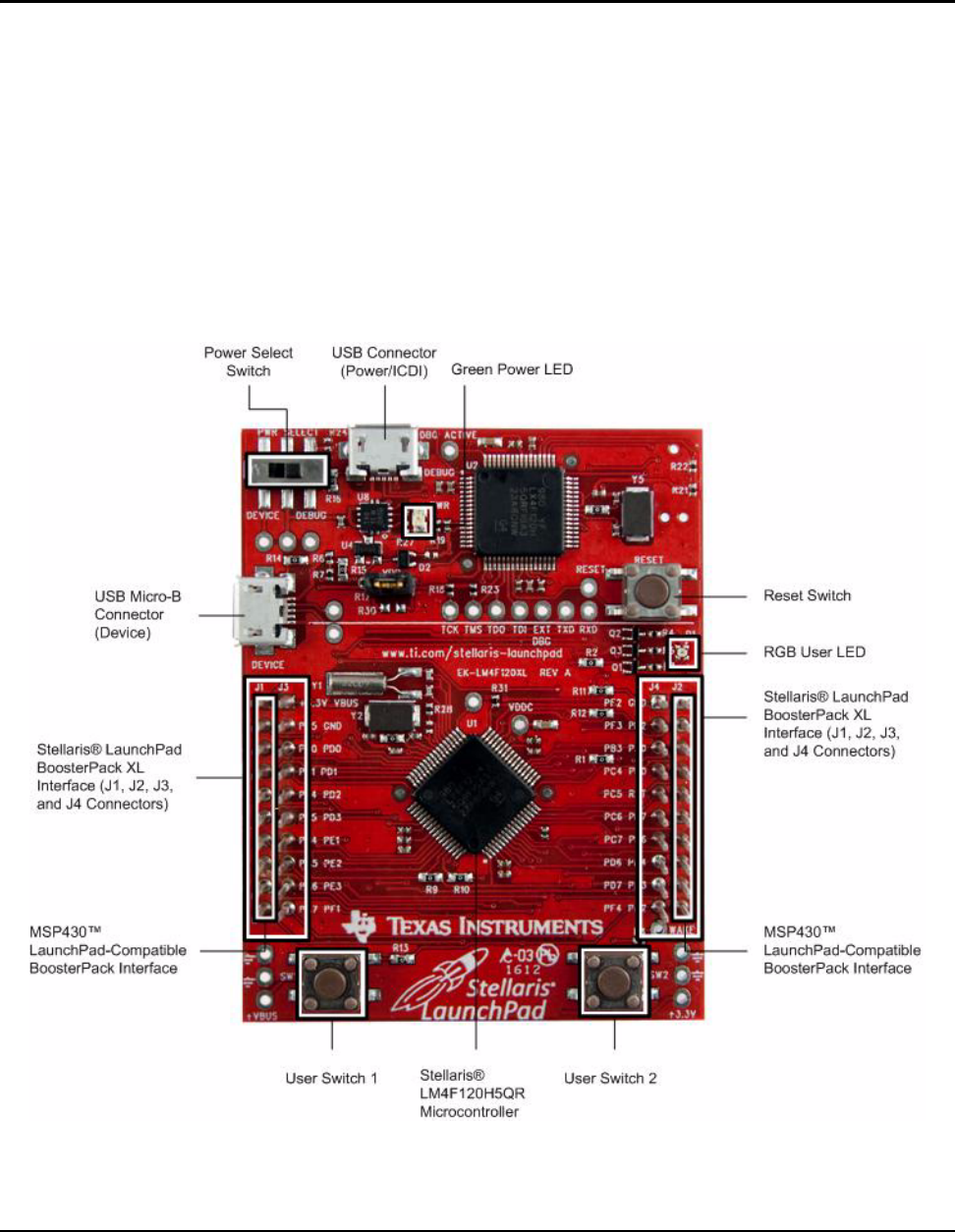
The Stellaris® LM4F120 LaunchPad Evaluation Board (EK-LM4F120XL) is a low-cost evaluation
platform for ARM® Cortex™-M4F-based microcontrollers. The Stellaris® LaunchPad’s design
highlights the LM4F120H5QR microcontroller's USB 2.0 Device interface and Hibernation module.
The Stellaris® LaunchPad also features programmable user buttons and an RGB LED for custom
applications. The stackable headers of the Stellaris® LM4F120 LaunchPad BoosterPack XL
Interface demonstrate how easy it is to expand the functionality of the Stellaris® LaunchPad when
interfacing to other peripherals with Stellaris® BoosterPacks and MSP430™ BoosterPacks.
Figure 1-1 shows a photo of the Stellaris® LaunchPad.
Figure 1-1. Stellaris® LM4F120 LaunchPad Evaluation Board
CHAPTER 1

Board Overview
August 29, 2012 7
Kit Contents
The Stellaris® LM4F120 LaunchPad Evaluation Kit comes with the following:
Stellaris® LaunchPad Evaluation Board (EK-LM4F120XL)
On-board Stellaris® In-Circuit Debug Interface (ICDI)
USB Micro-B plug to USB-A plug cable
README First document
Using the Stellaris® LaunchPad
The recommended steps for using the Stellaris® LM4F120 LaunchPad Evaluation Kit are:
1. Follow the README First document included in the kit. The README First document will
help get the Stellaris® LaunchPad up and running in minutes. See the
www.ti.com/stellaris-launchpad web site for additional information to get started.
2. Experiment with LaunchPad BoosterPacks. Stellaris® BoosterPacks and compatible
MSP430™ BoosterPacks can be found at the www.ti.com/stellaris-launchpad web site.
3. Take your first step toward developing an application with Project 0 using your
preferred ARM tool-chain and the Stellaris Peripheral Driver Library. Software
applications are loaded using the on-board Stellaris® In-Circuit Debug Interface (ICDI). See
Chapter 3, “Software Development” on page 20, for the programming procedure. The
StellarisWare Peripheral Driver Library Software Reference Manual contains specific
information on software structure and function. For more information on Project 0, go to the
www.ti.com/stellaris-launchpad/project0 web site.
4. Customize and integrate the hardware to suit an end application. This user's manual is an
important reference for understanding circuit operation and completing hardware modification.
Features
The Stellaris® LaunchPad includes the following features:
Stellaris® LM4F120H5QR microcontroller
USB Micro-B connector for USB Device
RGB user LED
2 user switches (application/wake)
Available I/O brought out to headers on a 0.1" grid
On-board Stellaris® In-Circuit Debug Interface (ICDI)
Switch-selectable power sources
–ICDI
–USB Device
Reset switch
Preloaded RGB quickstart application
Supported by StellarisWare® software including the USB library and the peripheral driver
library
Stellaris® LM4F120 LaunchPad User’s Manual
8August 29, 2012
Stellaris® LM4F120 LaunchPad BoosterPack XL Interface which features stackable headers
to expand the capabilities of the Stellaris® LaunchPad development platform
–For a complete list of available BoosterPacks that can be used with the Stellaris®
LaunchPad, see the www.ti.com/stellaris-launchpad web site.
BoosterPacks
Stellaris® LaunchPad provides an easy and inexpensive way to develop applications with the
Stellaris® LM4F120H5QR microcontroller. Stellaris® BoosterPacks and MSP430™ BoosterPacks
expand the available peripherals and potential applications of the Stellaris® LaunchPad.
BoosterPacks can be used with the Stellaris® LaunchPad or just use the on-board
LM4F120H5QR microcontroller as its processor. See“(Microcontroller, USB, Expansion, Buttons,
and LED (Schematic on page 18)” on page 10 in Chapter 2 for more information.
Build your own BoosterPack and take advantage of Texas Instruments’ web site to help promote it!
From sharing a new idea or project, to designing, manufacturing, and selling your own
BoosterPack kit, TI offers a variety of avenues for you to reach potential customers with your
solutions.
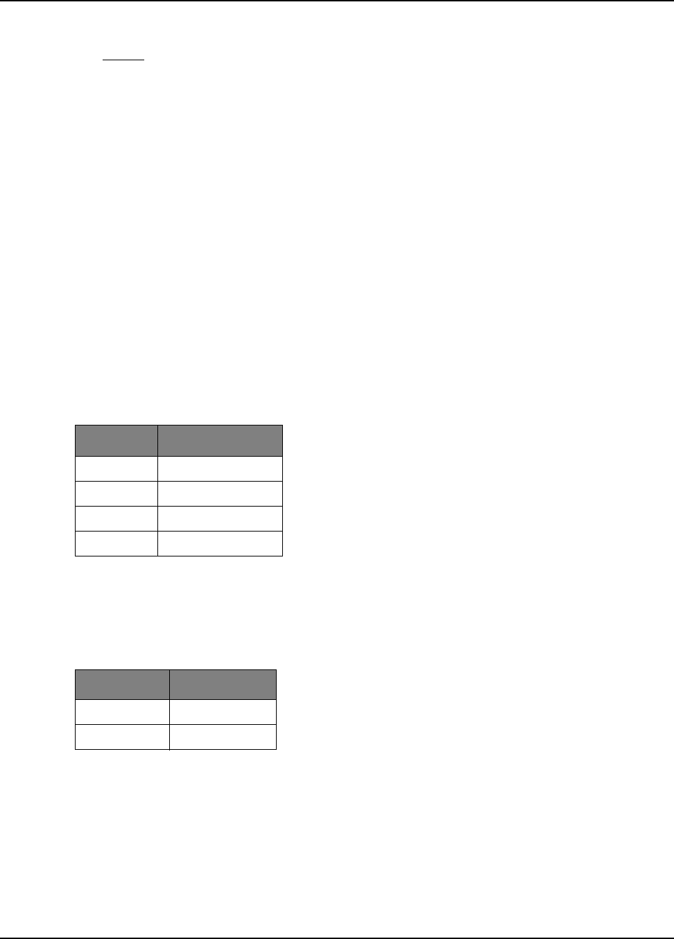
Specifications
Table 1-1 shows the specifications for the Stellaris® LaunchPad.
Table 1-1. EK-LM4F120XL Specifications
Parameter Value
Board supply voltage 4.75–5.25 VDC from one of the following sources:
Debugger (ICDI) USB Micro-B cable (connected to a PC)
USB Device Micro-B cable (connected to a PC)
Dimensions 2.0" x 2.25" x 0.425" (L x W x H)
Break-out power output 3.3 VDC (300 mA max)
5.0 VDC (depends on 3.3 VDC usage, 23 mA - 323 mA)
RoHS status Compliant
August 29, 2012 9
Hardware Description
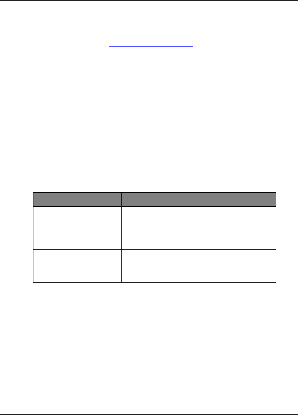
The Stellaris® LaunchPad includes a Stellaris LM4F120H5QR microcontroller and an integrated
Stellaris® In-Circuit Debug Interface (ICDI) as well as a range of useful peripheral features (see
the block diagram in Figure 2-1). This chapter describes how these peripherals operate and
interface to the microcontroller.
Figure 2-1. Stellaris® LaunchPad Evaluation Board Block Diagram
LM4F120H5QR
Stellaris ICDI
USB Debug
Connector
USB Device
Connector
Power Select
Switch
User
Switches
GPIO
GPIO
GPIO
GPIO
USB
Stellaris®
LaunchPad-Specific
BoosterPack XL
Expansion Headers
MSP430™
LaunchPad-Compatible
Expansion Headers
Device
JTAG/SWD
Power
Management
RGB LED
Debug Breakout Pads
I/O
I/O
Breakout Pads
HIB WAKE
VDD
UART0
ICDI
CHAPTER 2
Stellaris® LM4F120 LaunchPad User’s Manual
10 August 29, 2012
Functional Description
(Microcontroller, USB, Expansion, Buttons, and LED (Schematic on
page 18)
Microcontroller
The Stellaris LM4F120H5QR is a 32-bit ARM® Cortex™-M4F-based microcontroller with 256-KB
Flash memory, 32-KB SRAM, 80-MHz operation, USB Device, Hibernation module, and a wide
range of other peripherals. See the LM4F120H5QR microcontroller data sheet (order number
DS-LM4F120H5QR) for complete device details.
Most of the microcontroller signals are routed to 0.1" pitch headers. An internal multiplexer allows
different peripheral functions to be assigned to each of these GPIO pads. When adding external
circuitry, consider the additional load on the evaluation board’s power rails.
The LM4F120H5QR microcontroller is factory-programmed with a quickstart demo program. The
quickstart program resides in on-chip Flash memory and runs each time power is applied, unless
the quickstart application has been replaced with a user program.
USB Device
The Stellaris® LaunchPad includes a USB Micro-B connector to allow for USB 2.0 Device
operation. The signals shown in Table 2-1 are used for USB Device.
When connected as a USB Device, the evaluation board can be powered from either the Stellaris®
ICDI or the USB Device connectors. The user can select the power source by moving the POWER
SELECT switch (SW3) to the Device position. See the Power Management schematic on page 19
User Switches and RGB User LED
The Stellaris® LaunchPad comes with an RGB LED. This LED is used in the preloaded RGB
quickstart application and can be configured for use in custom applications.
Two user buttons are included on the board. The user buttons are both used in the preloaded
quickstart application to adjust the light spectrum of the RGB LED as well as go into and out of
hibernation. The user buttons can be used for other purposes in the user’s custom application.
The evaluation board also has a green power LED.
Table 2-2 shows how these features are connected to the pins on the microcontroller.
Table 2-1. USB Device Signals
GPIO Pin Pin Function USB Device
PD4 USB0DM D-
PD5 USB0DP D+
Table 2-2. User Switches and RGB LED Signals
GPIO Pin Pin Function Feature
PF4 GPIO SW1
PF0 GPIO SW2
Hardware Description
August 29, 2012 11
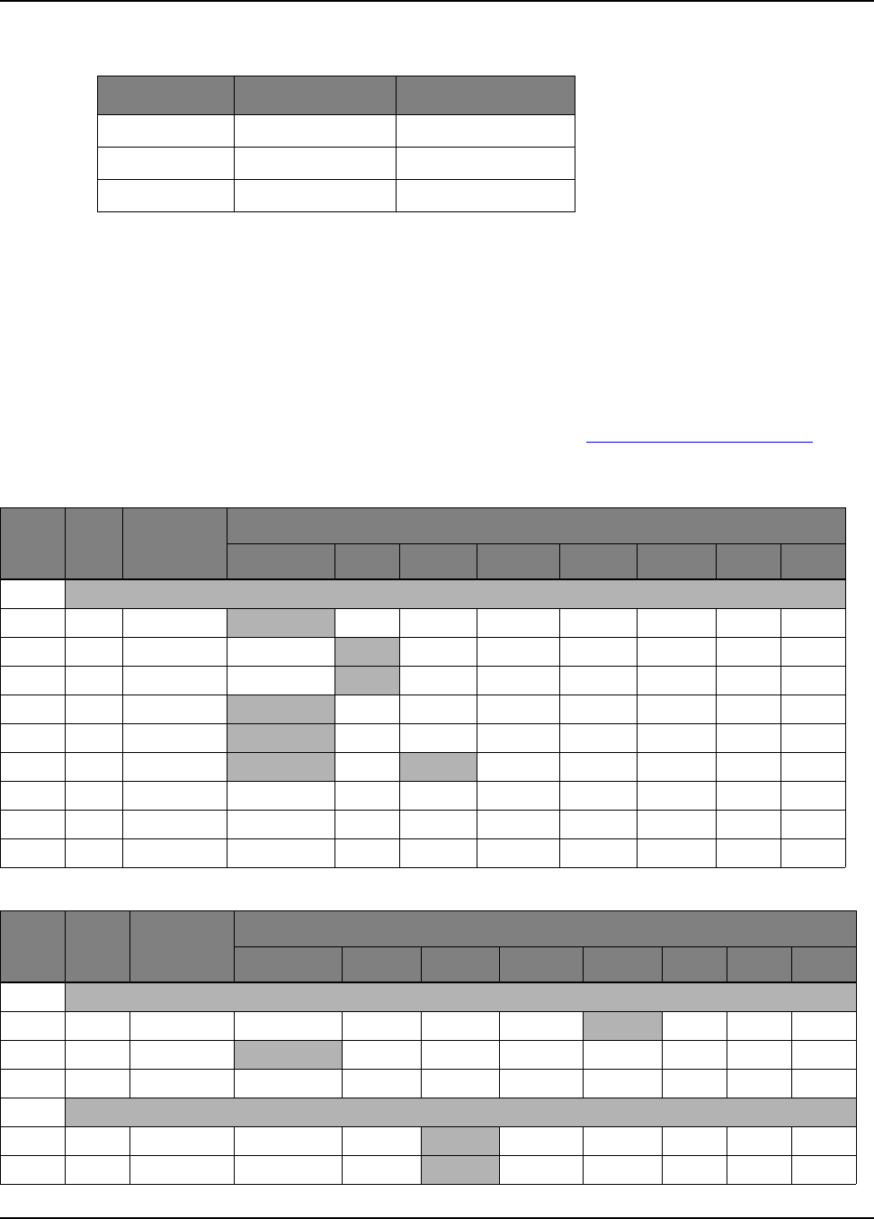
Headers and BoosterPacks
The two double rows of stackable headers are mapped to most of the GPIO pins of the
LM4F120H5QR microcontroller. These rows are labeled as connectors J1, J2, J3, and J4.
Connectors J3 and J4 are located 0.1 inches inside of the J1 and J2 connectors. All 40 header
pins of the J1, J2, J3, and J4 connectors make up the Stellaris® LM4F120 LaunchPad
BoosterPack XL Interface. Table 2-3, Table 2-4, Table 2-5, and Table 2-6 show how these header
pins are connected to the microcontroller pins and which GPIO functions can be selected.
NOTE: To configure the device peripherals easily and intuitively using a graphical user interface
(GUI), see the Stellaris® LM4F Pinmux Utility found at www.ti.com/tool/lm4f_pinmux. This
easy-to-use interface makes setting up alternate functions for GPIOs simple and error-free.
PF1 GPIO RGB LED (red)
PF2 GPIO RGB LED (blue)
PF3 GPIO RGB LED (green)
Table 2-3. J1 Connector
J1 Pin GPIO Stellaris Pin GPIOPCTL Register Setting
GPIOAMSEL 1 2 3 7 8 9 14
1.01 3.3 V
1.02 PB5 57 AIN11 - SSI2Fss - T1CCP1 CAN0Tx - -
1.03 PB0 45 - U1Rx - - T2CCP0 - - -
1.04 PB1 46 - U1Tx - - T2CCP1 - - -
1.05 PE4 59 AIN9 U5Rx - I2C2SCL - CAN0Rx - -
1.06 PE5 60 AIN8 U5Tx - I2C2SDA - CAN0Tx - -
1.07 PB4 58 AIN10 - SSI2Clk - T1CCP0 CAN0Rx - -
1.08 PA5 22 - - SSI0Tx - - - - -
1.09 PA6 23 - - - I2C1SCL - - - -
1.10 PA7 24 - - - I2C1SDA - - - -
Table 2-4. J2 Connector
J2 Pin GPIO Stellaris Pin GPIOPCTL Register Setting
GPIOAMSEL 1 2 3 7 8 9 14
2.01 GND
2.02 PB2 47 - - - I2C0SCL T3CCP0---
2.03 PE0 9 AIN3 U7Rx - - - - - -
2.04 PF0 28 - U1RTS SSI1Rx CAN0Rx T0CCP0 NMI C0o -
2.05 RESET
2.06aPB7 4 - - SSI2Tx - T0CCP1 - - -
2.07bPB6 1 - - SSI2Rx - T0CCP0 - - -
Table 2-2. User Switches and RGB LED Signals (Continued)
GPIO Pin Pin Function Feature
Stellaris® LM4F120 LaunchPad User’s Manual
12 August 29, 2012
2.08 PA4 21 - - SSI0Rx - - - - -
2.09 PA3 20 - - SSI0Fss - - - - -
2.10 PA2 19 - - SSI0Clk - - - - -
a. J2.06 (PB7) is also connected via 0-Ω resistor to J3.04 (PD1).
b. J2.07 (PB6) is also connected via 0-Ω resistor to J3.03 (PD0).
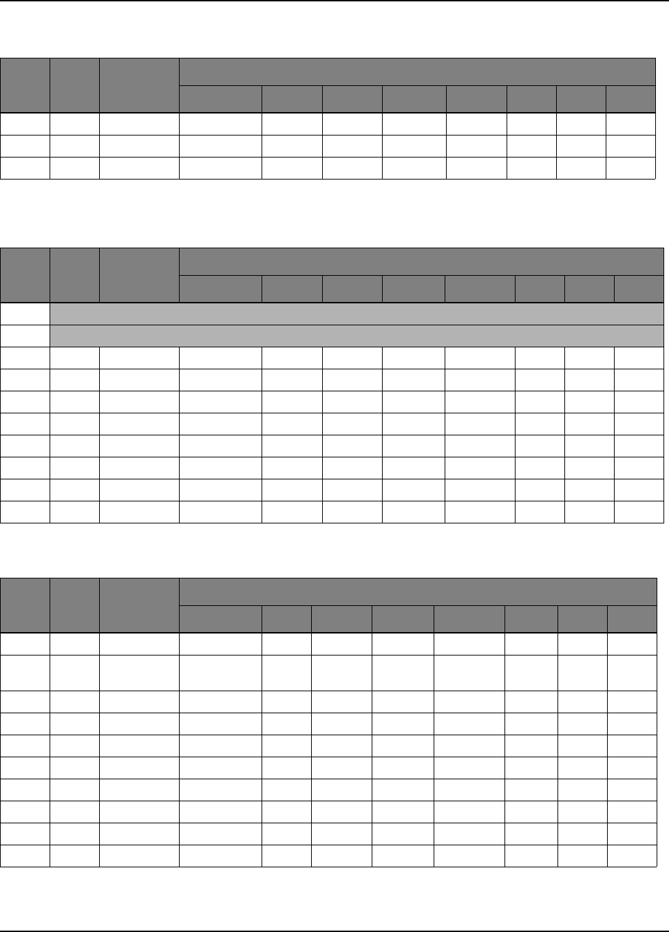
Table 2-5. J3 Connector
J3 Pin GPIO Stellaris Pin GPIOPCTL Register Setting
GPIOAMSEL 1 2 3 7 8 9 14
3.01 5.0V
3.02 GND
3.03 PD0 61 AIN7 SSI3Clk SSI1Clk I2C3SCL WT2CCP0 - - -
3.04 PD1 62 AIN6 SSI3Fss SSI1Fss I2C3SDA WT2CCP1 - - -
3.05 PD2 63 AIN5 SSI3Rx SSI1Rx - WT3CCP0 - - -
3.06 PD3 64 AIN4 SSI3Tx SSI1Tx - WT3CCP1 - - -
3.07 PE1 8 AIN2 U7Tx - - - - - -
3.08 PE2 7 AIN1 - - - - - - -
3.09 PE3 6 AIN0 - - - - - - -
3.10aPF1 29 - U1CTS SSI1Tx - T0CCP1 - C1o TRD1
a. Not recommended for BoosterPack use. This signal tied to on-board function via 0-Ω resistor.
Table 2-6. J4 Connector
J4 Pin GPIO Stellaris Pin GPIOPCTL Register Setting
GPIOAMSEL 1 2 3 7 8 9 14
4.01aPF2 30 - - SSI1Clk - T1CCP0 - - TRD0
4.02aPF3 31 - - SSI1Fss CAN0Tx T1CCP1 - - TRCL
K
4.03 PB3 48 - - - I2C0SDA T3CCP1 - - -
4.04 PC4 16 C1- U4Rx U1Rx - WT0CCP0 U1RTS - -
4.05 PC5 15 C1+ U4Tx U1Tx - WT0CCP1 U1CTS - -
4.06 PC6 14 C0+ U3Rx - - WT1CCP0 - - -
4.07 PC7 13 C0- U3Tx - - WT1CCP1 - - -
4.08 PD6 53 - U2Rx - - WT5CCP0 - - -
4.09 PD7 10 - U2Tx - - WT5CCP1 NMI - -
4.10aPF4 5 - - - - T2CCP0 - - -
a. Not recommended for BoosterPack use. This signal tied to on-board function via 0-Ω resistor.
Table 2-4. J2 Connector (Continued)
J2 Pin GPIO Stellaris Pin GPIOPCTL Register Setting
GPIOAMSEL 1 2 3 7 8 9 14

Hardware Description
August 29, 2012 13
Connectors J1 and J2 of the Stellaris® LM4F120 LaunchPad BoosterPack XL Interface provide
compatibility with MSP430™ LaunchPad BoosterPacks. Highlighted functions in Table 2-3, "J1
Connector" on page 11 and Table 2-4, "J2 Connector" on page 11 indicate configuration for
compatibility with the MSP430 LaunchPad.
A complete list of Stellaris® BoosterPacks and Stellaris LaunchPad-compatible MSP430
BoosterPacks is available at www.ti.com/stellaris-launchpad.
Power Management (Schematic on page 19)
Power Supplies
The Stellaris® LaunchPad can be powered from one of two power sources:
On-board Stellaris® In-Circuit Debug Interface (ICDI) USB cable (Debug, Default)
USB Device cable (Device)
The POWER SELECT switch (SW3) is used to select one of the two power sources. Select only
one source at a time.
Hibernate
The Stellaris® LaunchPad provides an external 32.768 kHz crystal (Y1) as the clock source for the
LM4F120H5QR’s Hibernation module clock source. The current draw while in Hibernate mode can
be measured by making some minor adjustments to the Stellaris® LaunchPad. This is explained in
more detail later in this section.
The conditions that can generate a wake signal to the Hibernate module on the Stellaris®
LaunchPad are waking on a Real-time Clock (RTC) match and/or waking on assertion of the WAKE
pin.1 The second user switch (SW2) is connected to the WAKE pin on the microcontroller. The
WAKE pin, as well as the VDD and HIB pins, are easily accessible through breakout pads on the
Stellaris® LaunchPad. See Appendix A, “Schematics” on page 22 for details.
There is no external battery source on the Stellaris® LaunchPad Hibernation module, which
means the VDD3ON power control mechanism should be used. This mechanism uses internal
switches to remove power from the Cortex-M4F processor as well as to most analog and digital
functions while retaining I/O pin power.
To measure the Hibernation mode current or the Run mode current, the VDD jumper that connects
the 3.3 V pin and the MCU_PWR pin must be removed. See Appendix A, “Schematics” on
page 17 for details on these pins and component locations. An ammeter should then be placed
between the 3.3 V pin and the MCU_PWR pin to measure IDD (or IHIB_VDD3ON). The
LM4F120H5QR microcontroller uses VDD as its power source during VDD3ON Hibernation mode,
so IDD is the Hibernation mode (VDD3ON mode) current. This measurement can also be taken
during Run mode, which measures IDD the microcontroller running current.
Clocking
The Stellaris® LaunchPad uses a 16.0-MHz crystal (Y2) to complete the LM4F120H5QR
microcontroller's main internal clock circuit. An internal PLL, configured in software, multiples this
clock to higher frequencies for core and peripheral timing.
The Hibernation module is clocked from an external 32.768 kHz crystal (Y1).
1. If the board does not turn on when you connect it to a power source, the microcontroller might be in Hibernate mode (depending
on the programmed application). You must satisfy one of the programmed wake conditions and connect the power to bring the
microcontroller out of Hibernate mode and turn on the board.
Stellaris® LM4F120 LaunchPad User’s Manual
14 August 29, 2012
Reset
The RESET signal into the LM4F120H5QR microcontroller connects to the RESET switch and to
the Stellaris® ICDI circuit for a debugger-controlled reset.
External reset is asserted (active low) under any of three conditions:
Power-on reset (filtered by an R-C network)
RESET switch held down
By the Stellaris® ICDI circuit when instructed by the debugger (this capability is optional, and
may not be supported by all debuggers)
Stellaris In-Circuit Debug Interface (ICDI) (Schematic on page 20)
Stellaris® In-Circuit Debug Interface (ICDI)
The Stellaris® LaunchPad evaluation board comes with an on-board Stellaris® In-Circuit Debug
Interface (ICDI). The Stellaris® ICDI allows for the programming and debug of the LM4F120H5QR
using LM Flash Programmer and/or any of the supported tool chains. Both JTAG and Serial Wire
Debug (SWD) are supported.
Table 2-7 shows the pins used for JTAG and SWD. These signals are also mapped out to easily
accessible breakout pads and headers on the board.
Virtual COM Port
When plugged in to a PC, the device enumerates as a debugger and a virtual COM port. Table 2-8
shows the connections for the COM port to the pins on the microcontroller.
Table 2-7. Stellaris® In-Circuit Debug Interface (ICDI) Signals
GPIO Pin Pin Function
PC0 TCK/SWCLK
PC1 TMS/SWDIO
PC2 TDI
PC3 TDO/SWO
Table 2-8. Virtual COM Port Signals
GPIO Pin Pin Function
PA0 U0RX
PA1 U0TX

August 29, 2012 15
Software Development
This chapter provides general information on software development as well as instructions for
Flash memory programming.
Software Description
The StellarisWare® software provided with the Stellaris® LaunchPad provides access to all of the
peripheral devices supplied in the design. The Stellaris® Peripheral Driver Library is used to
operate the on-chip peripherals as part of StellarisWare®.
StellarisWare® includes a set of example applications that use the StellarisWare® Peripheral
Driver Library. These applications demonstrate the capabilities of the LM4F120H5QR
microcontroller, as well as provide a starting point for the development of the final application for
use on the Stellaris® LaunchPad evaluation board.
Source Code
The complete source code including the source code installation instructions are provided at
www.ti.com/stellaris-launchpad. The source code and binary files are installed in the DriverLib
tree.
Tool Options
The source code installation includes directories containing projects and/or makefiles for the
following tool-chains:
Keil ARM RealView® Microcontroller Development System
IAR Embedded Workbench for ARM
Sourcery CodeBench
Texas Instruments' Code Composer Studio™ IDE
Download evaluation versions of these tools from www.ti.com/stellaris. Due to code size
restrictions, the evaluation tools may not build all example programs. A full license is necessary to
re-build or debug all examples.
Instructions on installing and using each of the evaluation tools can be found in the Quickstart
guides (for example, Quickstart-Keil, Quickstart-IAR) which are available for download from the
evaluation kit section of our web site at www.ti.com/stellaris.
For detailed information on using the tools, see the documentation included in the tool chain
installation or visit the web site of the tools supplier.
Programming the Stellaris LaunchPad Evaluation Board
The Stellaris® LaunchPad software package includes pre-built binaries for each of the example
applications. If you installed StellarisWare® to the default installation path of C:\StellarisWare, you
can find the example applications in “C:\StellarisWare\boards\ek-lm4f120xl”. The on-board
Stellaris ICDI is used with the Stellaris LM Flash Programmer tool to program applications on the
Stellaris® LaunchPad.
CHAPTER 3

Stellaris® LM4F120 LaunchPad User’s Manual
16 August 29, 2012
Follow these steps to program example applications into the Stellaris® LaunchPad evaluation
board using the Stellaris® ICDI:
1. Install LM Flash Programmer on a Windows PC.
2. Switch the POWER SELECT switch to the right for Debug mode.
3. Connect the USB-A cable plug to an available port on the PC and the Micro-B plug to the
'Debug' USB port on the board.
4. Verify that the POWER LED D4 on the board is lit.
5. Run LM Flash Programmer.
6. In the Configuration tab, use the Quick Set control to select the EK-LM4F120XL evaluation
board.
7. Move to the Program tab and click the Browse button. Navigate to the example applications
directory (the default location is “C:\StellarisWare\boards\ek-lm4f120xl\”).
8. Each example application has its own directory. Navigate to the example directory that you
want to load and then into the directory which contains the binary (*.bin) files. Select the binary
file and click Open.
9. Set the “Erase Method” to “Erase Necessary Pages,” check the “Verify After Program” box,
and check “Reset MCU After Program”.
10. Click the Program button to start the Erase, Download, and Verify process.
Program execution starts once the Verify process is complete.

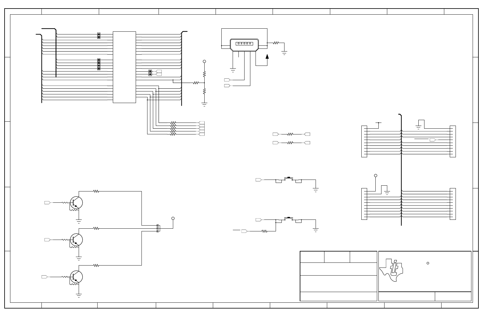
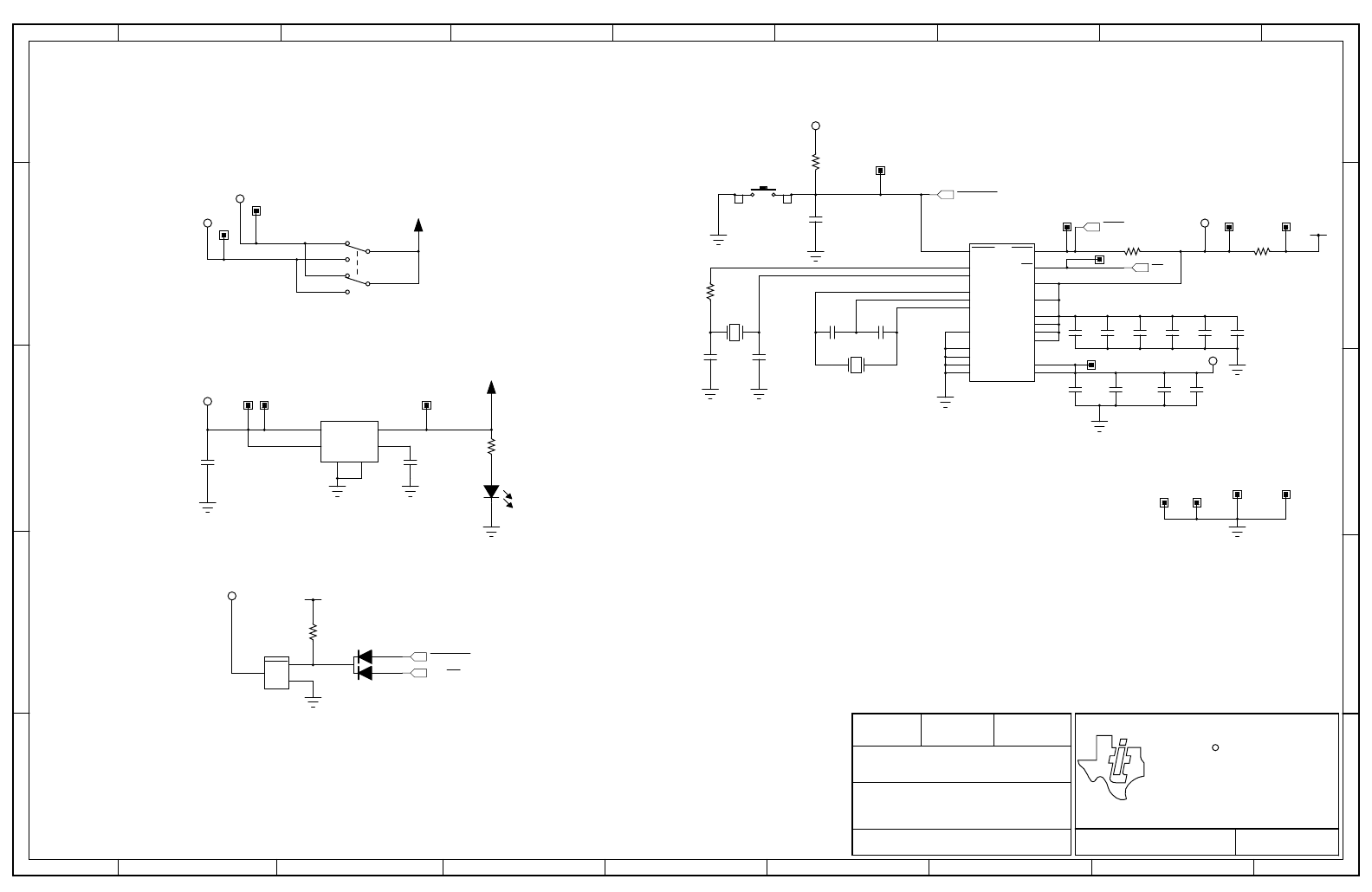
Microcontroller, USB, Expansion, Buttons and LED
Stellaris Launchpad
EK-LM4F120XL
0.1DGT STELLARIS MICROCONTROLLERS
www.ti.com/stellaris
AUSTIN TX, 78746
108 WILD BASIN ROAD, SUITE 350
TEXAS INSTRUMENTS
8/23/2012
EK-LM4F120XL Rev A.sch OF13
SHEETPART NO.
DATEREVISIONDESIGNER
FILENAME
DESCRIPTION
PROJECT
R
J1 and J2 provide compatability with
Booster Packs designed for MSP430 Launchpad
Used for VBUS detection when
configured as a self-powered USB Device J3 and J4 sit 100 mils inside J1 and J2 to provide
extended functions specific to this board.
See the board user manual for complete table of pin mux functions
1VB
2D-
3D+
4ID
5G
68
97
J9
CON-USB-MICROB
1
2
3
4
5
6
7
8
9
10
J1
CON_110_100
1
2
3
4
5
6
7
8
9
10
J2
CON_110_100
SW1
SW2
R6
10k
R7
1M
R8
330
1
2
3
4
5
6
7
8
9
10
J3
CON_110_100
1
2
3
4
5
6
7
8
9
10
J4
CON_110_100
1
PB6 4
PB7
5
PF4
6PE3
7PE2
8PE1
9PE0
10
PD7
13 PC7
14 PC6
15 PC5
16 PC4
17 PA0
18 PA1
19 PA2
20 PA3
21 PA4
22 PA5
23 PA6
24 PA7
28
PF0 29
PF1 30
PF2 31
PF3
43
PD4 44
PD5
45
PB0 46
PB1 47
PB2 48
PB3
49 PC3
50 PC2
51 PC1
52 PC0
53
PD6
58
PB4 57
PB5
59 PE4
60 PE5
61
PD0 62
PD1 63
PD2 64
PD3
U1-A
LM4F120
1
A
2R
3G
4B
D1
RGB_LED_0404_COMA
R9
0
R10
0
R1
0R2
0R11
0R12
0R13
0
R14
0
R15
0
R4
330
B
E
C
Q2
DTC114EET1G
R3
330
B
E
C
Q1
DTC114EET1G
R5
330
B
E
C
Q3
DTC114EET1G
USB_DM
USB_DP
DEBUG/VCOM
GPIO
GPIO
PA2
PA3
PA4
PA5
PA6
PA7
PB0
PB1
PB2
PB3
PB4
PB5
PB6
PB7
PC4
PC5
PC6
PC7
PD0
PD1
PD2
PD3
PD6
PD7
PE0
PE1
PE2
PE3
PE4
PE5
PA0/U0RX_VCP_TXD
PA1/U0TX_VCP_RXD
DEBUG_PC0/TCK/SWCLK
DEBUG_PC1/TMS/SWDIO
DEBUG_PC2/TDI
DEBUG_PC3/TDO/SWO
USB_DM
USB_DP
USR_SW2
USR_SW1
GPIO
PB0
PB1
PB4 PB7
PB6
+3.3V
USR_SW2
USR_SW1
+USB_VBUS
+USB_VBUS
WAKE
PB6
PB7 TARGETRST
PF4
PF3
PF2
PF1
PF0
PF4
PD7
+VBUS
PF2
PF3
PB2
+VBUS
LED_B
PB5
PE4
PE5
PA6 PA2
PA3
PA4
PF0
PE0
PF1
PB3
PC4
PC5
PC6
PC7
PD6
PA5
PA7
PD0
PD1
PD2
PD3
PE1
PE2
PE3
PD0
PD1
LED_G
LED_R
LED_R
LED_B
LED_G
Microcontroller, USB, Expansion, Buttons, and
LED
Power Management
Stellaris Launchpad
EK-LM4F120XL
0.1DGT STELLARIS MICROCONTROLLERS
www.ti.com/stellaris
AUSTIN TX, 78746
108 WILD BASIN ROAD, SUITE 350
TEXAS INSTRUMENTS
8/23/2012
EK-LM4F120XL Rev A.sch OF23
SHEETPART NO.
DATEREVISIONDESIGNER
FILENAME
DESCRIPTION
PROJECT
R
+3.3V 400mA Regulator
Power Select
RESET H24 and H25 installed as a single 1x2
header on 100 mil center with jumper
8IN
5EN
1
OUT
3
NR
4
GND
9
PAD
U8
TPS73633DRB
C18
0.01uF
D4
Green
R27
330
C3
0.01uF
C4
0.1uF
C5
0.01uF
C6
0.1uF
C8
0.01uF
C10
0.1uF C11
0.1uF
R31
1M
H1
C31
10pF C32
10pF
Y2
16MHz
C29
24pF
C28
24pF
R28
10k
RESET
C13
0.1uF
OMIT
H2
C22
2.2uF
H17
H18
H19
H20
H21
2
VDDA
3GNDA
11
VDD
12 GND
25
VDDC
26
VDD
27 GND
32
WAKE
33
HIB
34 XOSC0
35 GNDX
36 XOSC1
37
VBAT
38 RESET
39 GND
40 OSC0
41 OSC1
42
VDD 54
VDD
55 GND 56
VDDC
U1-B
LM4F120
Y1
32.768Khz
12
3
45
6
SW3
H22H23
R26
0
R30
0
OMIT
H11 H12
H10H13
H24 H25
1
A
2
A
3
K
D2
R17
10k
1
GND
2
RESET
3VDD
U4
TLV803
C7
1.0uF
C12
1.0uF
C14
1.0uF
+3.3V
+VBUS
WAKE
TARGETRST
+USB_VBUS
+ICDI_VBUS
+VBUS
+MCU_VDDC
+MCU_PWR
+3.3V
HIB
TARGETRST
ICDI_RST
+3.3V
+VBUS
+MCU_PWR
Power Management
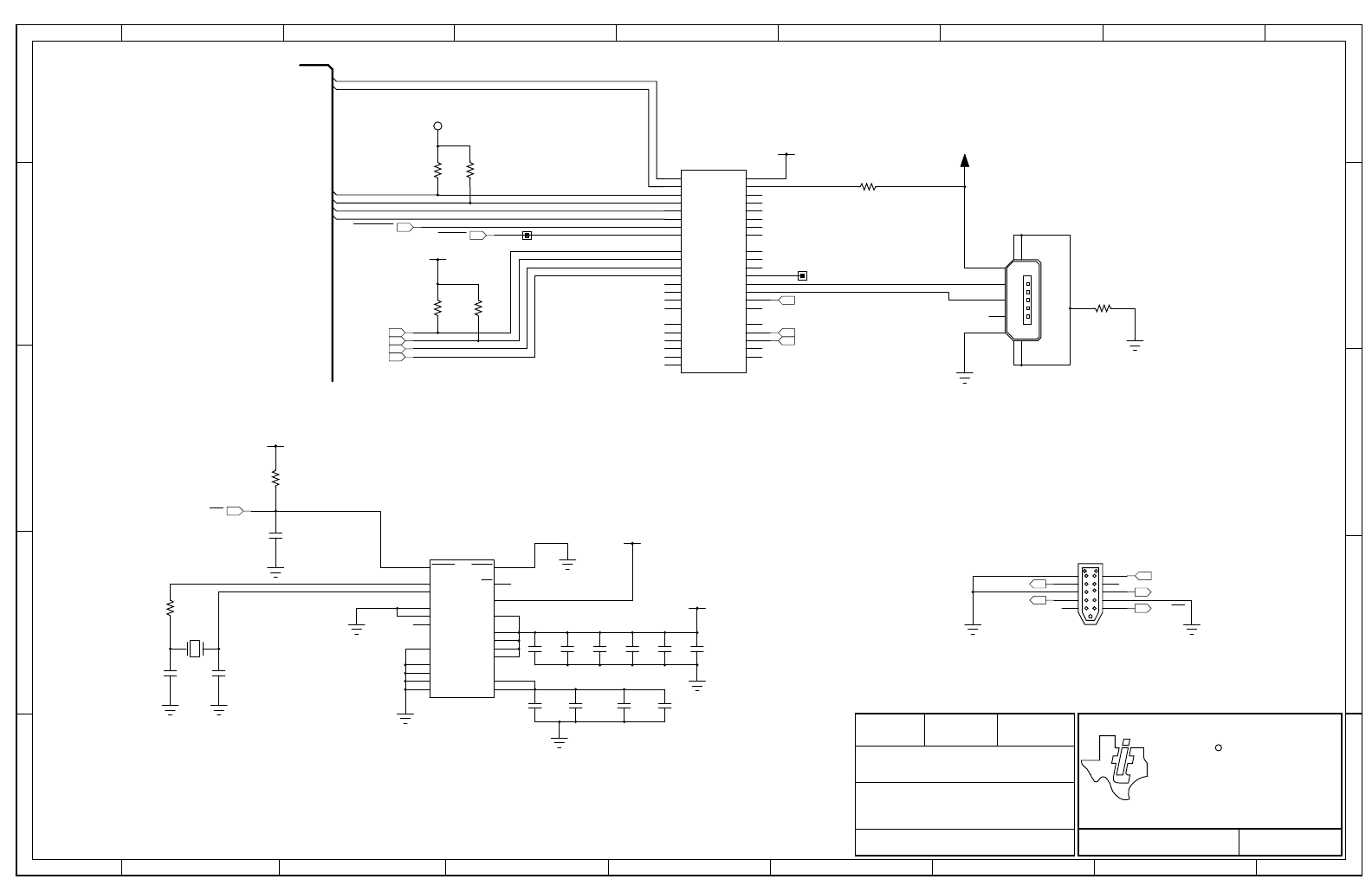
SStellaris In Circuit Debug Interface
Stellaris Launchpad
EK-LM4F120XL
0.1 8/23/2012DGT STELLARIS MICROCONTROLLERS
www.ti.com/stellaris
AUSTIN TX, 78746
108 WILD BASIN ROAD, SUITE 350
TEXAS INSTRUMENTS
EK-LM4F120XL Rev A.sch OF33
SHEETPART NO.
DATEREVISIONDESIGNER
FILENAME
DESCRIPTION
PROJECT
R
ICDI JTAG
Stellaris In-Circuit Debug Interface (ICDI)
5
4
3
2
1
6
7
8
9
10
J5
TC2050-IDC-NL
C15
0.01uF
C17
0.1uF
C19
0.01uF
C20
0.1uF
C21
0.01uF
C23
0.1uF C24
0.1uF
C25
10pF C26
10pF
Y5
16MHz
R19
10k
C34
0.1uF
OMIT
R21
10k R22
10k
C9
2.2uF
R18
10k R23
10k
H14
1VB
2D-
3D+
4ID
5G
68
97
J11
CON-USB-MICROB
R24
330
H15
1
PB6 4
PB7
5
PF4
6PE3
7PE2
8PE1
9PE0
10
PD7
13 PC7
14 PC6
15 PC5
16 PC4
17 PA0
18 PA1
19 PA2
20 PA3
21 PA4
22 PA5
23 PA6
24 PA7
28
PF0 29
PF1 30
PF2 31
PF3
43
PD4 44
PD5
45
PB0 46
PB1 47
PB2 48
PB3
49 PC3
50 PC2
51 PC1
52 PC0
53
PD6
58
PB4 57
PB5
59 PE4
60 PE5
61
PD0 62
PD1 63
PD2 64
PD3
U2-A
LM4F120
2
VDDA
3GNDA
11
VDD
12 GND
25
VDDC
26
VDD
27 GND
32
WAKE
33
HIB
34 XOSC0
35 GNDX
36 XOSC1
37
VBAT
38 RESET
39 GND
40 OSC0
41 OSC1
42
VDD 54
VDD
55 GND 56
VDDC
U2-B
LM4F120
R16
0
C1
1.0uF
C2
1.0uF
R20
0
ICDI_TMS
ICDI_TCK ICDI_TDO
ICDI_TDI
ICDI_RST
+3.3V
+3.3V
+3.3V
ICDI_TCK
ICDI_TMS
ICDI_TDI
ICDI_TDO
ICDI_RST
+3.3V
DEBUG/VCOM
PA1/U0TX_VCP_RXD
PA0/U0RX_VCP_TXD
DEBUG_PC0/TCK/SWCLK
DEBUG_PC1/TMS/SWDIO
DEBUG_PC3/TDO/SWO
DEBUG_PC2/TDI
TARGETRST EXTDBG
DEBUG_PC3/TDO/SWO
DEBUG_PC1/TMS/SWDIO
DEBUG_PC0/TCK/SWCLK
+3.3V +ICDI_VBUS
+MCU_PWR
Stellaris In-Circuit Debug Interface (ICDI)
Stellaris® LM4F120 LaunchPad User’s Manual
22 August 29, 2012
Figure B-2. Stellaris® LaunchPad Dimensions)
NOTE: Units are in mil (one thousandth of an inch):
1 mil = 0.001 inch

August 29, 2012 23
Bill of Materials (BOM)
Table C-1 shows the Bill of Materials for the EK-LM4F120XL evaluation board.
Table C-1. EK-LM4F120 Bill of Materials
Item Ref Qty Description Mfg Part Number
1 C1-2 C7 C12 C14 5 Capacitor, 0402, X5R, 10V, Low ESR Johanson
Dielectrics Inc
100R07X105KV4T
2 C25-26 C31-32 4 Capacitor, 10pF, 50V, 5%, NPO/COG,
0402
Murata GRM1555C1H100JZ0
1D
3 C28-29 2 Capacitor, 24pF, 50V, 5%, NPO/COG,
0402
TDK C1005C0G1H240J
4 C3 C5 C8 C15
C18-19 C21
7 Capacitor, 0.01uF 25V, 10% 0402
X7R
Taiyo Yuden TMK105B7103KV-F
5 C4 C6 C10-11 C17
C20 C23-24
8 Capacitor, 0.1uF 16V, 10% 0402 X7R Taiyo Yuden EMK105B7104KV-F
6 C9 C22 2 Capacitor, 2.2uF, 16V, 10%, 0603,
X5R
Murata GRM188R61C225KE1
5D
7 D1 1 LED, Tri-Color RGB, 0404 SMD
Common Anode
Everlight 18-038/RSGHBHC1-S
02/2T
8 D2 1 DIODE, Dual Schottky, SC70, BAS70
Common Cathode
Diodes Inc BAS70W-05-7-F
9 D4 1 LED, Green 565nm, Clear 0805 SMD Lite-On LTST-C171GKT
Lite-On LTST-C171GKT
10 H24 1 Header, 1x2, 0.100, T-Hole, Vertical
Unshrouded, 0.220 Mate
3M 961102-6404-AR
FCI 68001-102HLF
11 H25 1 Jumper, 0.100, Gold, Black, Closed Sullins SPC02SYAN
12 J1 J4 2 Header, 2x10, T-Hole Vertical
unshrouded stacking
Samtec SSW-110-23-S-D
13 J9 J11 2 USB Connectors MICRO B RECEPT
RA SMT BTTM MNT
Hirose ZX62-B-5PA
14 Q1-3 3 NPN SC70 pre-biased Diodes Inc DTC114EET1G
15 R1-2 R9-16 R20
R26
12 Resistor, 0 OHM 1/10W 0603 SMD Panasonic ERJ-3GEY0R00V
16 R3-5 R8 R27 5 Resistor, 330 ohm, 1/10W, 5%, 0402 Yageo RC0402FR-07330RL
APPENDIX C

Stellaris® LM4F120 LaunchPad User’s Manual
24 August 29, 2012
17 R6 R17-19 R21-23
R28
8 Resistor, 10k ohm, 1/10W, 5%, 0402
Thick Film
Yageo RC0402FR-0710KL
18 R7 R31 2 Resistor, 1M Ohm 1/10W, 5%, 0402 Rohm MCR01MRTF1004
19 RESET SW1 SW2 3 Switch, Tact 6mm SMT, 160gf Omron B3S-1000
20 SW3 1 Switch, DPDT, SMT 300 mA*2 @ 6V C&K
Components
JS202011SCQN
21 U1 U2 2 Stellaris MCU LM4F120H5QRFIGA3 Texas
Instruments
LM4F120H5QRFIG
22 U4 1 IC, Single Voltage Supervisor, 5V,
DBV
Texas
Instruments
TLV803MDBZR
23 U8 1 Regualtor, 3.3V, 400mA, LDO Texas
Instruments
TPS73633DRBT
24 Y1 1 Crystal, 32.768KHz Radial Can Abracon AB26TRB-32.768KHZ-
T
25 Y2 Y5 2 Crystal, 16.00MHz 5.0x3.2mm SMT NDK NX5032GA-16.000000
MHZ
Abracon ABM3-16.000MHZ-B2-
T
PCB Do Not Populate List (Shown for information only)
26 C31 C34 2 Capacitor, 0.1uF 16V, 10% 0402 X7R Taiyo Yuden EMK105B7104KV-F
27 R24 1 Resistor, 330 ohm, 1/10W, 5%, 0402 Yageo RC0402FR-07330RL
28 R30 1 Resistor, 0 OHM 1/10W 0603 SMD Panasonic ERJ-3GEY0R00V
Table C-1. EK-LM4F120 Bill of Materials (Continued)
Item Ref Qty Description Mfg Part Number

August 29, 2012 25
References
In addition to this document, the following references are included on the Stellaris LM4F120H5QR
Evaluation Kit CD and are also available for download at www.ti.com.
Stellaris LM4F120H5QR Microcontroller Data Sheet, publication DS-LM4F120H5QR
StellarisWare Driver Library
StellarisWare Driver Library User’s Manual, publication SW-DRL-UG
Additional references include:
Low-Dropout Regulator with Reverse Current Protection Data Sheet (TPS73633DRB)
Voltage Supervisor Data Sheet (TLV803)
Information on development tool being used:
RealView MDK web site, www.keil.com/arm/rvmdkkit.asp
IAR Embedded Workbench web site, www.iar.com
Sourcery CodeBench development tools web site,
www.codesourcery.com/gnu_toolchains/arm
Texas Instruments’ Code Composer Studio™ IDE web site, www.ti.com/ccs
APPENDIX D

IMPORTANT NOTICE
Texas Instruments Incorporated and its subsidiaries (TI) reserve the right to make corrections, enhancements, improvements and other
changes to its semiconductor products and services per JESD46C and to discontinue any product or service per JESD48B. Buyers should
obtain the latest relevant information before placing orders and should verify that such information is current and complete. All
semiconductor products (also referred to herein as “components”) are sold subject to TI’s terms and conditions of sale supplied at the time
of order acknowledgment.
TI warrants performance of its components to the specifications applicable at the time of sale, in accordance with the warranty in TI’s terms
and conditions of sale of semiconductor products. Testing and other quality control techniques are used to the extent TI deems necessary
to support this warranty. Except where mandated by applicable law, testing of all parameters of each component is not necessarily
performed.
TI assumes no liability for applications assistance or the design of Buyers’ products. Buyers are responsible for their products and
applications using TI components. To minimize the risks associated with Buyers’ products and applications, Buyers should provide
adequate design and operating safeguards.
TI does not warrant or represent that any license, either express or implied, is granted under any patent right, copyright, mask work right, or
other intellectual property right relating to any combination, machine, or process in which TI components or services are used. Information
published by TI regarding third-party products or services does not constitute a license to use such products or services or a warranty or
endorsement thereof. Use of such information may require a license from a third party under the patents or other intellectual property of the
third party, or a license from TI under the patents or other intellectual property of TI.
Reproduction of significant portions of TI information in TI data books or data sheets is permissible only if reproduction is without alteration
and is accompanied by all associated warranties, conditions, limitations, and notices. TI is not responsible or liable for such altered
documentation. Information of third parties may be subject to additional restrictions.
Resale of TI components or services with statements different from or beyond the parameters stated by TI for that component or service
voids all express and any implied warranties for the associated TI component or service and is an unfair and deceptive business practice.
TI is not responsible or liable for any such statements.
Buyer acknowledges and agrees that it is solely responsible for compliance with all legal, regulatory and safety-related requirements
concerning its products, and any use of TI components in its applications, notwithstanding any applications-related information or support
that may be provided by TI. Buyer represents and agrees that it has all the necessary expertise to create and implement safeguards which
anticipate dangerous consequences of failures, monitor failures and their consequences, lessen the likelihood of failures that might cause
harm and take appropriate remedial actions. Buyer will fully indemnify TI and its representatives against any damages arising out of the use
of any TI components in safety-critical applications.
In some cases, TI components may be promoted specifically to facilitate safety-related applications. With such components, TI’s goal is to
help enable customers to design and create their own end-product solutions that meet applicable functional safety standards and
requirements. Nonetheless, such components are subject to these terms.
No TI components are authorized for use in FDA Class III (or similar life-critical medical equipment) unless authorized officers of the parties
have executed a special agreement specifically governing such use.
Only those TI components which TI has specifically designated as military grade or “enhanced plastic” are designed and intended for use in
military/aerospace applications or environments. Buyer acknowledges and agrees that any military or aerospace use of TI components
which have not been so designated is solely at the Buyer's risk, and that Buyer is solely responsible for compliance with all legal and
regulatory requirements in connection with such use.
TI has specifically designated certain components which meet ISO/TS16949 requirements, mainly for automotive use. Components which
have not been so designated are neither designed nor intended for automotive use; and TI will not be responsible for any failure of such
components to meet such requirements.
Products Applications
Audio www.ti.com/audio Automotive and Transportation www.ti.com/automotive
Amplifiers amplifier.ti.com Communications and Telecom www.ti.com/communications
Data Converters dataconverter.ti.com Computers and Peripherals www.ti.com/computers
DLP® Products www.dlp.com Consumer Electronics www.ti.com/consumer-apps
DSP dsp.ti.com Energy and Lighting www.ti.com/energy
Clocks and Timers www.ti.com/clocks Industrial www.ti.com/industrial
Interface interface.ti.com Medical www.ti.com/medical
Logic logic.ti.com Security www.ti.com/security
Power Mgmt power.ti.com Space, Avionics and Defense www.ti.com/space-avionics-defense
Microcontrollers microcontroller.ti.com Video and Imaging www.ti.com/video
RFID www.ti-rfid.com
OMAP Mobile Processors www.ti.com/omap TI E2E Community e2e.ti.com
Wireless Connectivity www.ti.com/wirelessconnectivity
Mailing Address: Texas Instruments, Post Office Box 655303, Dallas, Texas 75265
Copyright © 2012, Texas Instruments Incorporated
