P23 Lincoln Shield Arc SA200 Welder Parts
User Manual: Lincoln-Shield-Arc-SA200-Welder-Parts- Continental Engines
Open the PDF directly: View PDF ![]() .
.
Page Count: 24
NUMBERS IN THE TABLE BELOW INDICATE
WHICH COLUMN TO USE IN EACH PARTS LIST
FOR EACH INDIVIDUAL CODE NUMBER
7-22-82
Shield-Arc
®
SA-200-F162 & F163
Model Index
P-23-A P-23-A
PARTS LIST
NUMBER
CODE
NUMBER
P-23-C
P-23-D
P-23-E
P-23-F
P-23-H
P-23-J
P-23-K
P-23-L
P-23-M
P-25-L
P-25-M
P-71-G
PARTS
LIST
TITLES
RETURN TO MAIN INDEX
DO NOT attempt to use this Parts List for a machine if its
code number is not listed. Contact the Service Department
for any code numbers not listed. (Only those suffixes which
require distinction from the basic codes are shown.)
MISCELLANEOUS
ASSEMBLY
CONTROL PANEL
ENGINE COOLING
SYSTEM
ENGINE FUEL
SYSTEM
ENGINE ELECTRICAL
SYSTEM
ENGINE BLOCK &
EXTERIOR PARTS
CRANKSHAFT AND
PISTON ASSEMBLY
CAMSHAFT, VALVES
AND OIL PUMP
WELDING GENERATOR
AND COUPLING
GENERATOR
BRUSHHOLDER
EXCITER
BRUSHHOLDER
IDLER
3417 211121 111116
3418 SM 211111 111116
3554 211121 112116
3555 SM 211111 112116
4113 SMM 1 3 1 1 1 1 1 1 2 1 1 6
4149 121121 112116
4150 SM 121111 112116
4744 121122 113116
4745 SM 121112 113116
4815 121121 112116
4816 SM 121131 112116
4843 SMM 131131 112116
4998 121121 112116
4999 SM 121131 112116
5065 SMM 131131 112116
5107 121122 113116
5108 SM 121132 113116
5141 SMM 131132 113116
5336 121122 113116
5337 SM 121132 113116
5376 SMM 131132 113116
5495 121121 or 2114116
5496 SM 121132 114116
5500 SMM 131132 114116
5537 M 131121 or 2114116
5568 SM 121131 114116
5604 121151 114116
5642 121121 114116
5660 SMM 131132 114116
5696 SMM 121151 114116
5840 121122 214116
5841 SM 121152 214116
5957 SM 141151 114116
6072 141122 214116
6073 SM 141152 214116
6132 SMM 141152 214116
6339 141122 214116
6339A 141322 214116
6340 SM 1 4 1 1 5 2 2 1 4 1 1 6
6340A SM 1 4 1 3 5 2 2 1 4 1 1 6
6345 SMM 1 4 1 1 5 2 2 1 4 1 1 6
6345A SMM 1 4 1 3 5 2 2 1 4 1 1 6
6552 M 1 4 1 3 2 2 2 1 4 1 1 6
6632 1 4 1 3 2 2 2 1 4 1 1 6
6633 SM 1 4 1 3 5 2 2 1 4 1 1 6
6634 SMM 1 4 1 3 5 2 2 1 4 1 1 6
6779 SM 1 4 1 3 5 2 2 1 4 1 1 6
6791 1 4 1 3 2 2 2 1 4 1 1 6
6791-M 1 4 1 3 2 2 2 1 4 1 1 6
6792 SM 1 4 1 3 5 2 2 1 4 1 1 6
6934 SM 1 4 1 3 6 2 2 1 4 1 1 6
6934-M SMM 1 4 1 3 6 2 2 1 4 1 1 6
7044 1 4 1 3 2 2 2 1 4 1 1 6
7074 SM 1 4 1 3 6 2 2 1 5 1 1 6
7074-M SMM 1 4 1 3 6 2 2 1 5 1 1 6
7078 1 4 1 3 2 2 2 1 5 1 1 6
7167 1 4 1 3 2 3 2 1 5 1 1 6
7168 SM 1 4 1 3 6 3 2 1 5 1 1 6
7168-M SMM 1 4 1 3 6 3 2 1 5 1 1 6
7213 1 4 1 3 2 3 2 1 5 1 1 6
7214 SM 1 4 1 3 7 3 2 1 5 1 1 6
7214-M SMM 1 4 1 3 7 3 2 1 5 1 1 6
7214-NC SMNC 1 4 1 3 7 3 2 1 5 1 1 6
7242 SM 1 4 1 3 7 3 2 1 5 1 1 6
For Codes ABOVE 7242, see P-111.
NUMBERS IN THE TABLE BELOW INDICATE
WHICH COLUMN TO USE IN EACH PARTS LIST
FOR EACH INDIVIDUAL CODE NUMBER
P-23-A.1P-23-A.1
PARTS LIST
NUMBER
CODE
NUMBER
P-23-C
P-23-D
P-23-E
P-23-F
P-23-H
P-23-J
P-23-K
P-23-L
P-23-M
P-25-L
P-25-M
P-71-G
PARTS
LIST
TITLES
RETURN TO MAIN INDEX
DO NOT attempt to use this Parts List for a machine if its
code number is not listed. Contact the Service Department
for any code numbers not listed. (Only those suffixes which
require distinction from the basic codes are shown,
MISCELLANEOUS
ASSEMBLY
CONTROL PANEL
ENGINE COOLING
SYSTEM
ENGINE FUEL
SYSTEM
ENGINE ELECTRICAL
SYSTEM
ENGINE BLOCK &
EXTERIOR PARTS
CRANKSHAFT AND
PISTON ASSEMBLY
CAMSHAFT, VALVES
AND OIL PUMP
WELDING GENERATOR
AND COUPLING
GENERATOR
BRUSHHOLDER
EXCITER
BRUSHHOLDER
IDLER
Winding Specifications and Diagrams . . . . . . . . . . . . . . . . . . . . . . . . . . . . . . . . . . . . . . . . . . . . . . . . . P-23-B
Operating Manual . . . . . . . . . . . . . . . . . . . . . . . . . . . . . . . . . . . . . . . . . . . . . . . . . . . . . . . . . . . . . . . . IM208 #
03-09-2005

07-19-2001
P-23-B P-23-B
WINDING SPECIFICATIONS AND DIAGRAMS
Only those suffixes requiring distinction from the basic codes are shown
GENERATOR GENERATOR GENERATOR SET OF 4 EXCITER FIELD EXCITER INTERNAL
SHUNT FIELD COIL SERIES FIELD COIL ARMATURE COIL INTERPOLE FIELD COIL
COIL SET
ARMATURE COIL WIRING DIAGRAM
3417 FJW5-Z FJW115-N FJW27.6E
ø
S5050
ø
L8707
M4047-1/24.26B
M8791
3418 FJW5-Z FJW115-N FJW27.6E
ø
S5050
ø
L8707
M4047-1/24.26B
M8791
3554 FJW5-Z FJW115-N FJW27.6E
ø
S5050
ø
L8707
M4047-1/24.26B
M8791
3555 FJW5-Z FJW115-N FJW27.6E
ø
S5050
ø
L8707
M4047-1/24.26B
M8791
4113 FJW5-Z FJW115-N FJW27.6E
ø
S5050
ø
L8707
M4047-1/24.26B
M8791
4149 FJW5-Z FJW115-N FJW27.6E
ø
S5050
ø
L8707
M4047-1/24.26B
M8791
4150 FJW5-Z FJW115-N FJW27.6E
ø
S5050
ø
L8707
M4047-1/24.26B
M8791
4744 FJW5-Z FJW115-N FJW27.6E
ø
S5050
ø
L8707
M4047-1/24.26B
M8791
4745 FJW5-Z FJW115-N FJW27.6E
ø
S5050
ø
L8707
M4047-1/24.26B
M8791
4815 FJW5-Z FJW115-N FJW27.6E
ø
S5050
ø
L8707
M4047-1/24.26B
M8791
4816 FJW5-Z FJW115-N FJW27.6E
ø
S5050
ø
L8707
M4047-1/24.26B
M8791
4843 FJW5-Z FJW115-N FJW27.6E
ø
S5050
ø
L8707
M4047-1/24.26B
M8791
4998 FJW5-Z FJW115-N FJW27.6E
ø
S12261-2A L8707
M4047-1/24.26B
M8791
4999 FJW5-Z FJW115-N FJW27.6E
ø
S12261-2A L8707
M4047-1/24.26B
M8791
5065 FJW5-Z FJW115-N FJW27.6E
ø
S12261-2A L8707
M4047-1/24.26B
M8791
5107 FJW5-Z FJW115-N FJW27.6E
ø
S12261-2A L8707
M4047-1/24.26B
M8791
5108 FJW5-Z FJW115-N FJW27.6E
ø
S12261-2A L8707
M4047-1/24.26B
M8791
5141 FJW5-Z FJW115-N FJW27.6E
ø
S12261-2A L8707
M4047-1/24.26B
M8791
5336 FJW5-Z FJW115-N FJW27.6E
ø
S12261-2A L8707
M4047-1/24.26B
M8791
5337 FJW5-Z FJW115-N FJW27.6E
ø
S12261-2A L8707
M4047-1/24.26B
M8791
5376 FJW5-Z FJW115-N FJW27.6E
ø
S12261-2A L8707
M4047-1/24.26B
M8791
5495 FJW5-Z FJW115-N FJW27.6E
ø
S12261-2A L8707
M4047-1/24.26B
M8791
5496 FJW5-Z FJW115-N FJW27.6E
ø
S12261-2A L8707
M4047-1/24.26B
M8791
5500 FJW5-Z FJW115-N FJW27.6E
ø
S12261-2A L8707
M4047-1/24.26B
M8791
5537 FJW5-Z FJW115-N FJW27.6E
ø
S12261-2A L8707
M4047-1/24.26B
M8791
5568 FJW5-Z FJW115-N FJW27.6E
ø
S12261-2A L8707
M4047-1/24.26B
M8791
5604 FJW5-Z FJW115-N FJW27.6E
ø
S12261-2A L8707
M4047-1/24.26B
M8791
5642 FJW5-Z FJW115-N FJW27.6E
ø
S12261-2A L8707
M4047-1/24.26B
M8791
5660 FJW5-Z FJW115-N FJW27.6E
ø
S12261-2A L8707
M4047-1/24.26B
M8791
5696 FJW5-Z FJW115-N FJW27.6E
ø
S12261-2A L8707
M4047-1/24.26B
M8791
5840 FJW5-Z FJW115-N FJW27.6E
ø
S12261-2A L8707
M4047-1/24.26B
M8791
5841 FJW5-Z FJW115-N FJW27.6E
ø
S12261-2A L8707
M4047-1/24.26B
M8791
5957 FJW5-Z FJW115-N FJW27.6E
ø
S12261-2A L8707
M4047-1/24.26B
M8791
6072 FJW5-Z FJW115-N FJW27.6E
ø
S12261-2A L8707
M4047-1/24.26B
M8791
6073 FJW5-Z FJW115-N FJW27.6E
ø
S12261-2A L8707
M4047-1/24.26B
M8791
6132 FJW5-Z FJW115-N FJW27.6E
ø
S12261-2A L8707
M4047-1/24.26B
M8791
6339 FJW5-Z FJW115-N FJW27.6E
ø
S12261-2A L8707
M4047-1/24.26B
M8791
6339A FJW5-Z FJW115-N FJW27.6E
ø
S12261-2A L8707
M4047-1/24.26B
M8791
6340 FJW5-Z FJW115-N FJW27.6E
ø
S12261-2A L8707
M4047-1/24.26B
M8791
6340A FJW5-Z FJW115-N FJW27.6E
ø
S12261-2A L8707
M4047-1/24.26B
M8791
6345 FJW5-Z FJW115-N FJW27.6E
ø
S12261-2A L8707
M4047-1/24.26B
M8791
6345A FJW5-Z FJW115-N FJW27.6E
ø
S12261-2A L8707
M4047-1/24.26B
M8791
6552 FJW5-Z FJW115-N FJW27.6E
ø
S12261-2A L8707
M4047-1/24.26B
M8791
6632 FJW5-Z FJW115-N FJW27.6E
ø
S12261-2A L8707
M4047-1/24.26B
M8791
6633 FJW5-Z FJW115-N FJW27.6E
ø
S12261-2A L8707
M4047-1/24.26B
M8791
6634 FJW5-Z FJW115-N FJW27.6E
ø
S12261-2A L8707
M4047-1/24.26B
M8791
6779 FJW5-Z FJW115-N FJW27.6E
ø
S12261-2A L8707
M4047-1/24.26B
M8791
6791 FJW5-Z FJW115-N FJW27.6E
ø
S12261-2A L8707
M4047-1/24.26B
M8791
6791M FJW5-Z FJW115-N FJW27.6E
ø
S12261-2A L8707
M4047-1/24.26B
M8791
6792 FJW5-Z FJW115-N FJW27.6E
ø
S12261-2A L8707
M4047-1/24.26B
M8791
6934 FJW5-Z FJW115-N FJW27.6E
ø
S12261-2A L8707
M4047-1/24.26B
M8791
6934M FJW5-Z FJW115-N FJW27.6E
ø
S12261-2A L8707
M4047-1/24.26B
M8791
7044 FJW5-Z FJW115-N FJW27.6E
ø
S12261-2A L8707
M4047-1/24.26B
M8791
7074 FJW5-AJ FJW115-T FJW27.6E
ø
S12261-15A (2) ø& -16A ø (2)
L8707
M4047-1/24.26B
M8791
7074M FJW5-AJ FJW115-T FJW27.6E
ø
S12261-15A (2) ø& -16A ø (2)
L8707
M4047-1/24.26B
M8791
7078 FJW5-AJ FJW115-T FJW27.6E
ø
S12261-15A (2) ø& -16A ø (2
)
L8707
M4047-1/24.26B
M8791
7167 FJW5-AJ FJW115-T FJW27.6E
ø
S12261-15A (2) ø& -16A ø (2)
L8707
M4047-1/24.26B
M8791
7168 FJW5-AJ FJW115-T FJW27.6E
ø
S12261-15A (2) ø& -16A ø (2)
L8707
M4047-1/24.26B
M8791
7168M FJW5-AJ FJW115-T FJW27.6E
ø
S12261-15A (2) ø& -16A ø (2)
L8707
M4047-1/24.26B
M8791
7213 FJW5-AJ FJW115-T FJW27.6E
ø
S12261-15A (2) ø& -16A ø (2)
L8707
M4047-1/24.26B
M8791
7214 FJW5-AJ FJW115-T FJW27.6E
ø
S12261-15A (2) ø& -16A ø (2)
L8707
M4047-1/24.26B
M8791
7214M FJW5-AJ FJW115-T FJW27.6E
ø
S12261-15A (2) ø& -16A ø (2)
L8707
M4047-1/24.26B
M8791
7214NC FJW5-AJ FJW115-T FJW27.6E
ø
S12261-15A (2) ø& -16A ø (2)
L8707
M4047-1/24.26B
M8791
7242 FJW5-AJ FJW115-T FJW27.6E
ø
S12261-15A (2) ø& -16A ø (2)
L8707
M4047-1/24.26B
M8791
CODE NO.
Index of Sub Assemblies Index of Sub Assemblies Index of Sub Assemblies Index of Sub Assemblies
øThis part is obsolete and no longer available.

1 Radiator Shell and Screen Assembly L3403
ø
1XX
7 Hex Head Bolt - Front Roof Mounting 5/16-18 x 1-1/4 2 X X
Hug Nut - Front Roof Mounting T9187 2 X X
Plain Washer - Front Roof Mounting S9262-121 2 X X
10 Thread Cutting Screw - Mounts Radiator Shell
and Rear Panel S9225-8 6 or 9 X X
11 Roof L3384 1 X X
13 Clamp - Crank T10474
ø
1XX
14 Round Head Screw - Clamp Mounting 1/4-20 x 5/8 2 X X
Hex Nut - Clamp Mounting 1/4-20 2 X X
Lockwasher E106A-2 2 X X
15 Washer S9262-63 1 X X
16 Base Assembly L3385
ø
1XX
17 Hex Head Bolt - Rear Roof Support to Base 3/8-16 x 1 4 X X
Hex Nut - Rear Roof Support to Base 3/8-16 4 X X
Lockwasher - Rear Roof Support to Base E106A-4 4 X X
18 Door L6659-A 2 X X
19 Hex Head Bolt - Rear Roof Mounting 5/16-18 x 1-1/4 2 X X
Hug Nut - Rear Roof Mounting T9187 2 X X
20
Rear Roof Mounting Angle
S13593 2 X X
22 Door Hook S10656-1 2 X X
23 Door Hook S10656-2 2 X X
Thread Cutting Screw - Door Hook Mounting S8025-70 8 X X
Washer - Door Hook Mounting T10878 4 X X
24 Lower Control Panel L3387 1 X X
(Not Used on Codes Above 5900)
27 Hex Head Bolt - Shell to Radiator 5/16-18 x 1-1/2 2 X X
Washer - Shell to Radiator S9262-120 2 X X
Hex Nut - Shell to Radiator 5/16-18 2 X X
28 Plain Washer - Shell to Radiator S9262-121 2 X X
28 Lockwasher - Shell to Radiator E106A-3 2 X X
29 Radiator Shroud Assembly Includes: M8858 1 X X
29
Radiator Shroud Assembly Includes: (Codes Above 6000)
M8858-3 1 X •
30 Sems Screw - Shroud to Shell T10082-16 4 X X
31 Washer - Shroud to Shell S9262-23 4 X X
32 Lockwasher - Shroud to Shell E106A-2 4 X X
33 Hex Nut - Shroud to Shell 1/4-20 4 X X
66 Door Decal T11030 2 X X
67 Base Panel (Below Code 4700) S10403
ø
1XX
67 Base Panel (Above Code 4700) S15639-1 1 X •
68 Hex Head Screw - Panel Mounting 1/4-20 x 1/2 2 X X
Lockwasher - Panel Mounting E106A-2 2 X X
Lincoln Decal S11893-4 2 X X
07-18-2001
Use only the parts marked “X” in the column under the
heading number called for in the model index page.
ITEM DESCRIPTION PART NO. QTY. 123456789
SA-200-F162 & F163
P-23-C.1 P-23-C.1
# Indicates a Change This Printing
Index of Sub Assemblies Index of Sub Assemblies Index of Sub Assemblies Index of Sub Assemblies
Sub Assembly Illustration Sub Assembly Illustration Sub Assembly Illustration Sub Assembly Illustration
øThis part is obsolete and no longer available.
#
#


1 Radiator Shell and Screen Assembly L3403
ø
1XX
1 Control Panel and Gas Tank Rail M9085-3 1 • • X •
1 Control Panel and Gas Tank Rail M9085-1
ø
1•X••
1 Control Panel and Gas Tank Rail M9085-2
ø
1X•••
1 Control Panel Assembly, Includes:
Front Panel G1217 1 • • • X
Gas Tank Rail (Left From Control Panel End) M10996-B 1 • • • X
Gas Tank Rail (Right From Control Panel End) M10996-A 1 • • • X
2 Rheostat M5090-C 1 X X X X
5 Instruction Decal T10829 1 X X X X
6 Receptacle S14824 1 X X X X
Round Head Screw, Lead to Rheostat #8-32 x 1/2 2 X X X X
Lockwasher, Lead to Rheostat E106A-2 4 X X X X
Hex Nut, Lead to Rheostat #8-32 4 X X X X
17 Nameplate ( Code: 5957 and Above ) M10926
ø
1XXXX
17 Nameplate ( Code: 5841 and Below ) M8803 1 X X X X
18 Self Tapping Screw S8025-12 6 X X X X
19 Rheostat Handle S16664-4 1 X X X X
22 Insulator T10089 1 X • • •
23
Output Stud Assembly, (Code 3555 and Below) Includes:
24 Through 31 Except 30 T8061 2 X • • •
24 Stud T6931-2 1 X • • •
25 Insulating Tube T4122 1 X • • •
26 Insulating Washer S10773-9 1 X • • •
27 Flat Washer S9262-1 2 X • • •
28 Lockwasher E106A-5 1 X • • •
29 Hex Jam Nut 1/2-13 2 X • • •
30 Connection Strap T8141 1 X • • •
31 Weld Nut T3960 1 X • • •
32 Selector Switch M11013 1 X X X X
33 Selector Switch Handle S16664-6 1 X X X X
Output Stud Assembly, (Code 4113 and Above), Includes:
37 Through 44 S11125-1 2 • X X X
37 Insulator S10958-3 1 • X X X
38 Stud S11111 1 • X X X
39 Insulating Washer T11195 1 • X X X
40 Flat Washer S9262-1 1 • X X X
41 Lockwasher E106A-5 1 • X X X
42 Hex Jam Nut 1/2 x 13 1 • X X X
43 Brass Nut T10114 1 • X X X
44 Weld Nut T3960 1 • X X X
45 Volt-ammeter (Optional) S4934-1 1 • • X X
46 Shunt Assembly S6602-2
ø
1••XX
07-13-2006
Use only the parts marked “X” in the column under the
heading number called for in the model index page.
ITEM DESCRIPTION PART NO. QTY. 123456789
P-23-D.1P-23-D.1
# Indicates a Change This Printing
Index of Sub Assemblies Index of Sub Assemblies Index of Sub Assemblies Index of Sub Assemblies
Sub Assembly Illustration Sub Assembly Illustration Sub Assembly Illustration Sub Assembly Illustration
øThis part is obsolete and no longer available.
#
#


1 Radiator Cap S9970 1 X
* 2 Radiator G1087 1 X
Hex Nut 1/2-13 2 X
Washer S9262-5 2 X
Lock Washer E106A-5 2 X
Rubber Washers (Mount to Frame) T10355-3 2 X
3 Radiator Hose - Upper S9788 1 X
4 Cylinder Water Outlet Elbow * 1 X
5 Nut - Cylinder Water Outlet Elbow to Head T10940-1 2 X
6 Lockwasher - Cylinder Water Outlet Elbow to Head E106A-11 2 X
7 Nipple - Thermostat Bypass T10113 2 X
8 Hose Clamp - Thermostat Bypass T13777-3
ø
2X
9 Hose - Thermostat Bypass T9950 1 X
10 Stud - Cylinder Water Outlet Elbow to Head * 2 X
Gasket - Cylinder Water Outlet Elbow * 1 X
11 Thermostat * 1 X
Decal * 1 X
12 Thermostat Adapter Ring S9250-342
ø
1X
13 Water Pump * 1 X
Water Pump Repair Kit * 1 X
14 Gasket * 1 X
Copper Washer * 1 X
Screw & Lock Washer, WP - Upper Left & Lower Center
*2X
Screw & Washer, WP - Upper Right * 1 X
Screw, WP - Upper Center * 1 X
19 Hex Head Screw 5/16-18 x 3/4 4 X
20 Lock Washer E106A-3 4 X
21 Fan Blade Assembly L2649 1 X
22 Fan Belt - No Starter S8075 1 X
22 Fan Belt - With Starter and Generator S8074 1 X
22
Fan Belt - With Starter and Alternator (Below Code 7250)
T13274 1 X
22
Fan Belt - With Starter and Alternator (Above Code 7250)
T13536 1 X
23 Radiator Hose Clamp S10888-8 4 X
24 Radiator Hose - Lower M7999 1 X
* These parts are not normally stocked by Lincoln.
For fastest service on these parts order from your
area Continental parts distributor using the part
description and engine nameplate data.
11-26-2001
Use only the parts marked “X” in the column under the
heading number called for in the model index page.
ITEM DESCRIPTION PART NO. QTY. 123456789
P-23-E.1 P-23-E.1
# Indicates a Change This Printing
Index of Sub Assemblies Index of Sub Assemblies Index of Sub Assemblies Index of Sub Assemblies
Sub Assembly Illustration Sub Assembly Illustration Sub Assembly Illustration Sub Assembly Illustration
#
øThis part is obsolete and no longer available.
#
#
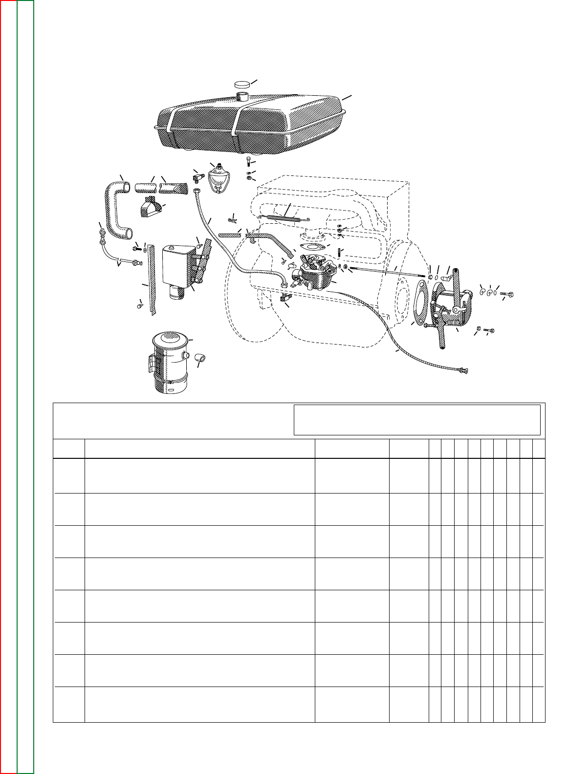
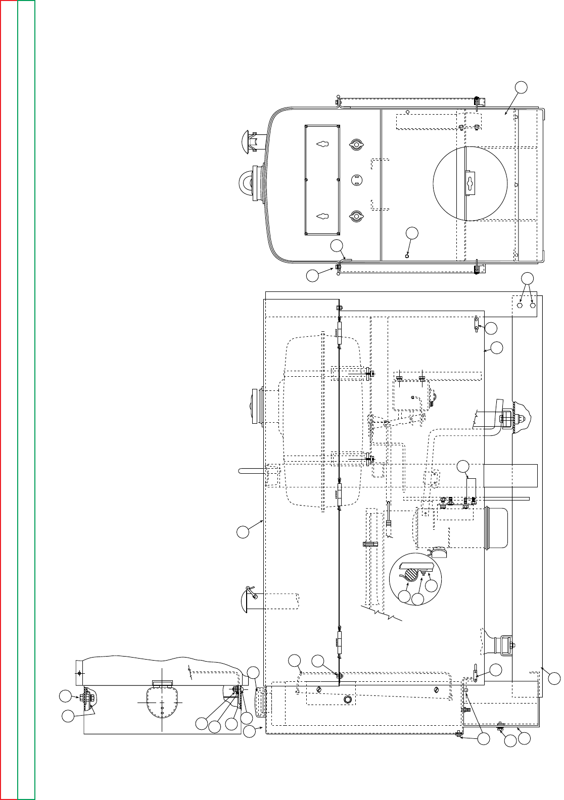
ENGINE FUEL SYSTEM
9-5-2001
P-23-FP-23-F
32
27
26 33
28
2930
31
16
7
6
35
23 24
22
40
4544
46
42
43 39
17
18
47
19
21
20 53
2
1
41
4
13
14
12
22A
3736
34 3637 38
9
811
10
Index of Sub Assemblies Index of Sub Assemblies Index of Sub Assemblies Index of Sub Assemblies
Part Numbers Part Numbers Part Numbers Part Numbers
1 Fuel Tank L3398-3 1 X X X
Filler Neck Gasket S10437-A 1 X X X
2 Filler Cap S10149 1 X X X
3 Fuel Strainer, Includes: S6185 1 X X X
Bowl S6185-1 1 X X X
Screen S6185-2 1 X X X
Gasket S6185-3 1 X X X
4 Fuel Line, Includes: S8099-10 1 X X X
Fitting T10954-1 2 X X X
Fuel Line Clip T11076
ø
2XXX
5 Fitting - Fuel Line to Strainer T10953 1 X X X
6 Elbow - Fuel Line to Carburetor T11012 1 X X X
7 Carburetor S17423-1
ø
1X•X
S9790 Carburetor Repair Kit S9790-1
ø
1X•X
7 Carburetor (SAF-300 - F162 &F163) S12875 1 •X•
8 Gasket - Marvel Schebler Only S9233 1 X X X
8 Gasket - Facet Only S9233-1 3 X X X
9 Stud - Carburetor Mounting - Marvel Schebler Only T9954 2 X X X
9 Stud - Carburetor Mounting - Facet Only T9954-1 2 X X X
10 Nut - Carburetor Mounting 5/16-18 2 X X X
11 Lock Washer - Carburetor Mounting E106A-3 2 X X X
12 Square Head Bolt - Gas Tank Mounting 3/8-16 x 1-1/4 4 X X •
12 Hex Head Bolt - Gas Tank Mounting 3/8-16 x 1-3/4 4 ••X
Use only the parts marked “X” in the column under the
heading number called for in the model index page.
ITEM DESCRIPTION PART NO. QTY. 123456789
# Indicates a Change This Printing
øThis part is obsolete and no longer available.
#

13 Clamp Nut - Gas Tank Mounting T10384 4 X X •
13 Lock Nut - Gas Tank Mounting T9187-2 4 • • X
14 Lock Washer - Gas Tank Mounting E106A-4 4 X X •
14 Flat Washer - Gas Tank Mounting S9262-56 8 • • X
Rubber Washer - Mounts Between Gas Tank Foot and Rail
T11135-14 4 • • X
Rubber Washer - Mounts Under Gas Tank Rail T11135-15 4 • • X
16 Choke Control S7525-1 1 X X X
17 Air Filter Assembly, Includes: L3406 1 X • X
17
Air Filter Assembly, Includes: (SAF-300 - F162 & F163)
No Longer Available
1•X •
Oil Cup Assembly L3406-3 1 X • X
Mounting Plate - Air Filter M8837 1 X • X
18 Hose - Air Filter to Carburetor S10817 1 X • X
18 Hose - Air Filter to Carburetor S12951 1 • X •
Hose Clamp S10888-8 2 X • X
Hose Clamp S10888-12 2 • X •
19 Hose - Heater Tube to Air Filter S8688 1 X • X
19 Hose - Heater Tube to Air Filter M7798 1 • X •
20 Heater Tube S8626
ø
1X•X
20 Heater Tube S12950
ø
1•X•
21 Clamp - Heater Tube to Manifold T9486 1 X • X
21 Clamp - Heater Tube to Manifold S9454-1
ø
1•X•
22 Throttle Rod S10774-1
ø
1XXX
22 Throttle Rod (Above Code 7050 on SA-200 Only) S10774-4
ø
1••X
22A Throttle Rod Spring T9284 1 X X X
23 Pivot Pin - Throttle Rod to Carburetor T9751-2 1 X X X
24 Spring Clip - Throttle Rod to Carburetor T9744 1 X X X
26 Governor Assembly M9130 1 X • X
26 Governor Assembly (SAF-300 - F162 & F163) M10564 1 • X •
27 Screw - Top Mounting 3/8-16 x 3-1/4 1 X X X
28 Washer, Copper Asbestos S9262-106 1 X X X
29 Cover Plate S9240 1 X X X
30 Gasket (Cover Plate) S9235 1 X X X
31 Gasket (Governor) S9234 1 X X X
32 Hex Head Screw 3/8-16 x 1-1/8 1 X X X
33 Lock Washer E106A-4 1 X X X
34 Governor Rod S13621-1 1 X X X
35 Ball Joint (Carburetor End) S10623-2 1 X X X
36 Hex Nut 1/4-28 2 X X X
37 Lock Washer E106A-2 2 X X X
38 Ball Joint (Governor End) S10623-1 1 X X X
39 R-57 Idler L3006-F
ø
1X•X
39 R-57 Idler (SAF-300 - F162- & F163) L3006-B 1 • X •
R-57 Idler Separate Parts See P-71-G
40 Pivot Pin - Idler to Throttle Rod T9751-1 1 X X X
41 Spring Clip - Idler to Throttle Rod T9744 1 X X X
42 Idler Mounting Bracket S10908 1 X X X
42
Idler Mounting Bracket (Above Code 7050 on SA-200 Only)
S14518
ø
1••X
43 Thread Cutting Screw - Idler Bracket to Frame S9225-26 2 X X X
44 Hex Head Cap Screw 1/4-20 x 1/2 2 X X X
45 Lock Washer E106A-2 2 X X X
46 Air Line - Idler to Manifold S8099-8 1 X X •
46 Air Line - Idler to Manifold
S8099-12 Note 1
1••X
47 Connector - Air Line to Manifold T9114 1 X X •
47 Check Valve T12942 Note 1 1 • • X
Note 1: Used on Codes 6339A, 6340A, 6345A and
on all codes above 6400.
10-04-2002
Use only the parts marked “X” in the column under the
heading number called for in the model index page.
ITEM DESCRIPTION PART NO. QTY. 123456789
P-23-F.1 P-23-F.1
# Indicates a Change This Printing
Index of Sub Assemblies Index of Sub Assemblies Index of Sub Assemblies Index of Sub Assemblies
Sub Assembly Illustration Sub Assembly Illustration Sub Assembly Illustration Sub Assembly Illustration
øThis part is obsolete and no longer available.
#
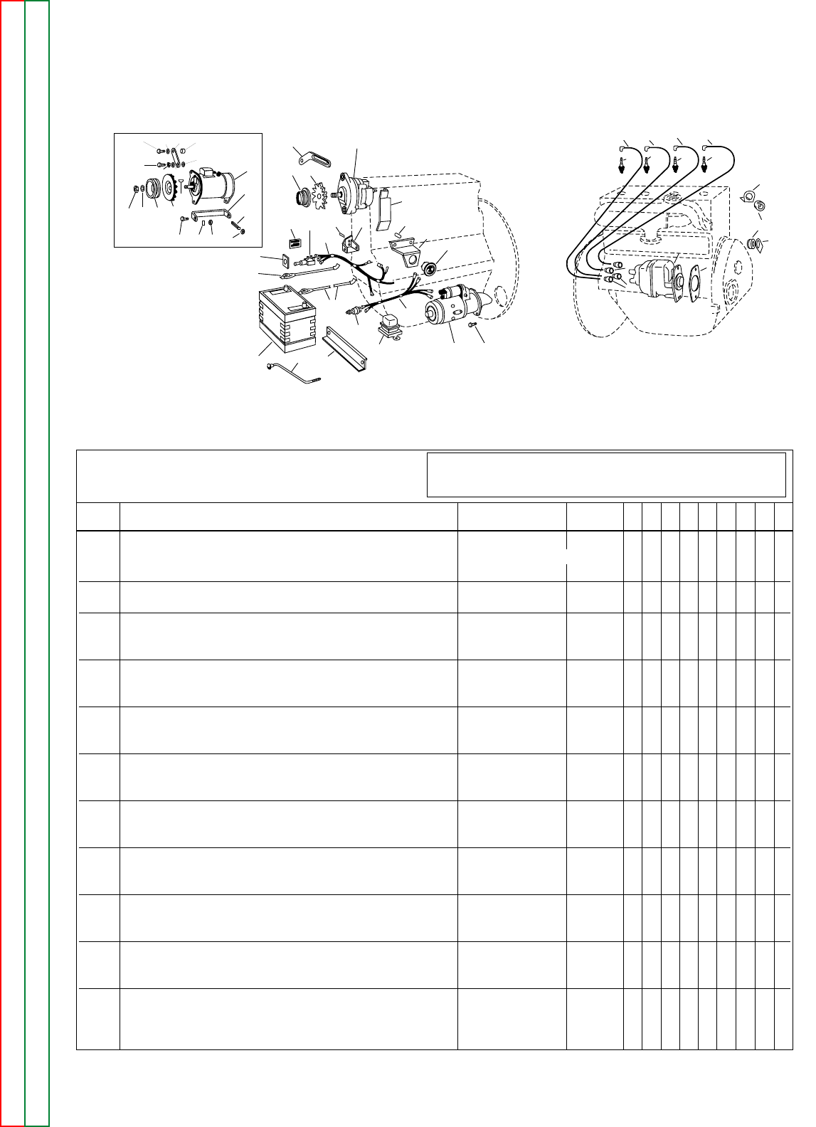
ENGINE ELECTRICAL SYSTEM
12-19-2001
P-23-HP-23-H
49
50 50 50 50
53
51
52
38
37
45
45
2
1
28
60
29
36
35
43
70
63
68
64
62
69
67
67 27 26
66
42
42A
16
141312
10
21 22 23
24
18 19 17 20
986715
11
5
32
31 33A
48 47 46
Index of Sub Assemblies Index of Sub Assemblies Index of Sub Assemblies Index of Sub Assemblies
Part Numbers Part Numbers Part Numbers Part Numbers
RIGHT SIDELEFT SIDE
Machines above code 4800
equipped with 12 volt systems
Use only the parts marked “X” in the column under the
heading number called for in the model index page.
ITEM DESCRIPTION PART NO. QTY. 123456789
# Indicates a Change This Printing
1Starting Motor (6 Volt)
Order from Delco #1109460
Starter Spacer (6 Volt Only) S8073
ø
1
1Starting Motor (12 Volt) L4334 1 • • X X X X X
2Hex Head Screw (Starter Mounting)
7/16-14 x 1-1/2
2X••••••
2Hex Head Screw (Starter Mounting) T8833-1 2 • • X X X X X
3Lock Washer (Starter Mounting) E106A-8 2 X • X X X X X
Starter Hole Cover S8076
ø
1•X•••••
Generator Assembly, Includes: (6 Volt) L3308-1 1 X • • • • • •
Generator Assembly, Includes: (12 Volt) M12103
ø
1••XXX • •
5Generator L3308 1 X • • • • • •
5Generator L3923 1 • • X X X • •
6Generator Pulley T14191-1 1 X • X X X • •
7Generator Pulley Fan M8529 1 X • X X X • •
8Lock Washer (Generator Pulley) S9311-36
ø
1X••••••
9Nut (Generator Pulley) S9311-37 1 X • • • • • •
10 Woodruff Key (Generator Pulley) 1/8 x 5/8 1 X • • • • • •
11 Bracket S10249 1 X • X X X • •
12 Hex Head Screw (Generator to Bracket) 5/16-18 x 1 2 X • X X X • •
13 Lock Washer (Generator to Bracket) E106A-3 2 X • X X X • •
14 Hex Nut (Generator to Bracket) 5/16-18 2 X • X X X • •
15 Stud (Generator Bracket to Engine Block) T9087 2 X • X X X • •
16 Hex Nut (Generator Bracket to Engine Block) 3/8-16 2 X • X X X • •
17 Adjusting Strap S8533 1 X • X X X • •
18 Hex Head Screw (Adjusting Strap to Engine)
3/8-16 x 1-1/2
1X•XXX • •
19 Lock Washer (Adjusting Strap to Engine) E106A-4 1 X • X X X • •
20 Spacer (Adjusting Strap to Generator) S10731-3
ø
1X•XXX • •
21 Hex Head Screw (Adjusting Strap to Generator)
5/16-18 x 7/8
1X•XXX • •
22 Lock Washer (Adjusting Strap to Generator) E106A-3 1 X • X X X • •
23 Plain Washer (Adjusting Strap to Generator) S9262-30 1 X • X X X • •
24 Plain Washer (Adjusting Strap to Generator) S9262-4 1 X • X X X • •
øThis part is obsolete and no longer available.
#

Ammeter Panel Assembly, Includes: M7010
ø
1X•X••••
Ammeter Panel Assembly, Includes: M7010-3
ø
1•••XX ••
Ammeter Panel Assembly, Includes: M12040 1 •••••X•
Ammeter Panel Assembly, Includes: M12506 1 ••••••X
26 Ammeter S7514-4 1 X •XXXXX
27 Ammeter Panel M6955 1 X •XXXXX
29 Starter Switch S13145 1 X •X••••
29 Starter Switch S13146-1 1 •••XXXX
31 Battery M6962-2 1 X ••••••
31 Battery M9399-1 1 X •XXXXX
32 Battery Strap S8069 1 X ••••••
32 Battery Bracket S12128 1 ••XXXXX
33 Carriage Bolt and Nut (Battery Mounting) 1/4-20 x 8 2 X ••••••
33 Carriage Bolt and Nut (Battery Mounting) T11888 2 ••XXXXX
34 Lockwasher (Battery Mounting) E106A-2 2 X •XXXXX
35 Ground Lead (+) S8070 1 X •XXX ••
35 Ground Lead (–) S8070-28 1 •••••X•
35 Ground Lead (–) S14922 1 ••••••X
36 Battery Lead (–) S13147 1 X •XXX ••
36 Battery Lead (+) S13147-1 1 •••••XX
37 Magneto L2677
ø
1XXX•XXX
37 Magneto (SAF-300 Only) M10591
ø
1•X•X•XX
38 Magneto Gasket S9234 1 X X X X X X X
39 Hex Head Cap Screw 3/8-16 x 1-1/2 1 X X X •XXX
39 Hex Head Cap Screw (SAF-300 Only) T9087 1 •X•X•XX
40 Lockwasher E106A-4 1 X X X •XXX
40 Lockwasher (SAF-300 Only) T9695-6 1 •X•X•XX
41 Washer S9262-2 1 X X X X X X X
42 Switch - Ignition S8020 1 X X X X X ••
42 Switch - Ignition (Above Code 7200 Only) T10616 1 •X••••X
42 Switch - Ignition S14090 1 •••••X•
43 Plate - Switch T9061 1 X X X X X ••
43 Plate - Switch (Above Code 7200 Only) T10589 1 •X••••X
43 Plate - Switch T9061-1 1 •••••X•
45 Nipple T8627 4 X X X X X X X
46 Ignition Wire #1 Cylinder S7518-5 1 X X X •XXX
46 Ignition Wire #1 Cylinder (SAF-300 Only) S7518-7 1 •••X•XX
47 Ignition Wire #2 Cylinder S7518-7 1 X X X X X X X
48 Ignition Wire #3 Cylinder S7518-14 1 X X X •XXX
48 Ignition Wire #3 Cylinder (SAF-300 Only) S7518-8 1 •••X•XX
49 Ignition Wire #4 Cylinder S7518-11 1 X X X •XXX
49 Ignition Wire #4 Cylinder (SAF-300 Only) S7518-14 1 •••X•XX
50 Spark Plug S8159 4 X X X X X X X
51 Grommet * 3 X X X X X X X
52 Bracket (Wire Support) * 2 X X X X X X X
53 Bracket (Wire Support) * 1 X X X X X X X
60 Voltage Regulator M11567 1 •••••XX
Alternator Assembly, Includes: L4722-3
ø
1•••••XX
62 Alternator L4715
ø
1•••••XX
63 Pulley S16133-3
ø
1•••••XX
64 Fan S16133-4
ø
1•••••XX
66 Mounting Bracket S14426 1 •••••XX
67
Stud - Mount Alternator Bracket and Ammeter Panel
T9087 2 •••••XX
68 Adjusting Strap M11566 1 •••••XX
69 Alternator Fan Guard M12067 1 •••••XX
70 Caution Decal S14108-1
ø
1•••••XX
NOTE: Items 1 Through 36 and 60 Through 70 Used with Self Starter Only.
* These parts are not normally stocked by Lincoln. For fastest service on these parts, order from your
area Continental parts distributor using the part description and engine nameplate date.
9-5-2001
Use only the parts marked “X” in the column under the
heading number called for in the model index page.
ITEM DESCRIPTION PART NO. QTY. 123456789
P-23-H.1 P-23-H.1
# Indicates a Change This Printing
Index of Sub Assemblies Index of Sub Assemblies Index of Sub Assemblies Index of Sub Assemblies
Sub Assembly Illustration Sub Assembly Illustration Sub Assembly Illustration Sub Assembly Illustration
øThis part is obsolete and no longer available.
#
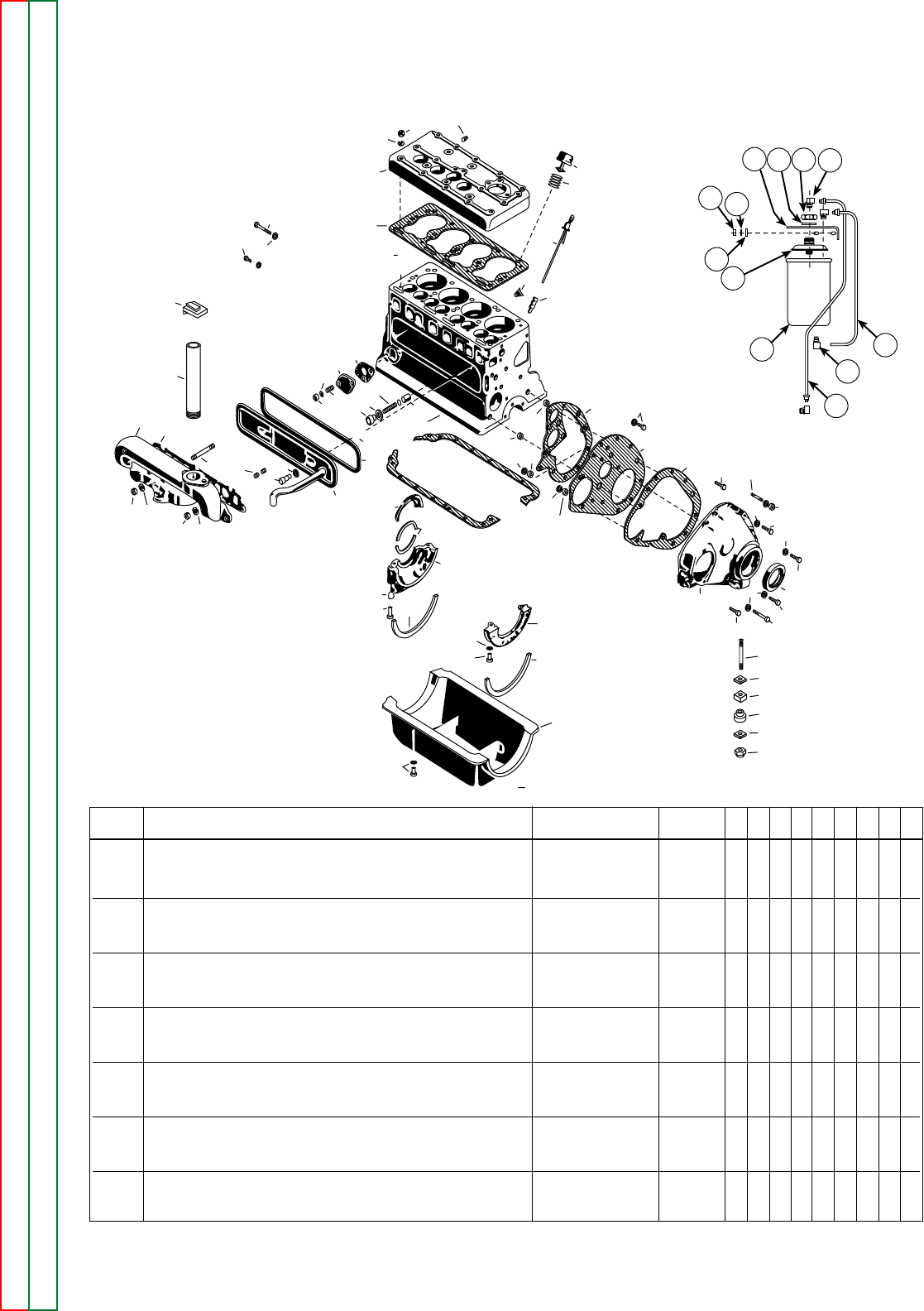
P-23-JP-23-J
Index of Sub Assemblies Index of Sub Assemblies Index of Sub Assemblies Index of Sub Assemblies
Part Numbers Part Numbers Part Numbers Part Numbers
ENGINE BLOCK AND EXTERNAL PARTS
7-22-82
97
96 95
83
84
8587 88
8669
70
71
63
72
73
74
75
78
81
68
6766
62
80
77 79
77 76
60
59 58
61
57
55 56
53
94
91
93
92
91
90
42
41
49
50
31
51
52
62 54 40
39
30 37 48
47
46 45
46
44
38
46
43
29
34
28
36
35
32
33
17
65
16
14
24
27
24
18
101
11
815
22
21
23
25
98
99100
13
12
7
10 96
###
6
Pipe Plug Temperature Gauge Hole in Cylinder Head
*1
7 Cylinder Head * 1
8 Cylinder Head Gasket * 1
9 Cylinder Head Nut * 15
10 Washer - Cylinder Head Nut * 15
11 Stud - Cylinder Head to Block * 15
12 Oil Filler Cap Assembly * 1
13 Oil Filler Tube S8612-2 1
14 Drain Cock * 1
15 Oil Gauge Rod * 1
16 Oil Rod Support * 1
17 Block * 1
18 Oil Filter S12634-1 or -2 1 •XX
18 Oil Filter (old Style) See Note 1 1 X ••
20 Stud - Oil Filter to Cylinder Head * 2
21 Lockwasher - Oil Filter to Cylinder Head E106A-3 2 •XX
22 Washer - Oil Filter to Cylinder Head S9262-121 2 •XX
23 Hex Nut - Oil Filter to Cylinder Head 5/16 - 18 2 •XX
ITEM DESCRIPTION PART NO. QTY. 123456789
#

24 Oil Line, Inlet
T12185-2
1•X•
Oil Line, Inlet
T13452-1
1•X
24 Oil Line, Outlet T12186 1 • X •
Oil Line, Outlet T13453 1 • X
25 Elbow, Oil Line T9116 2 or 3 • X X
27 Tee Fitting T12184 1 • X X
Front End Plate Assembly Includes: * 1
28 Gasket - Front End Plage * 1
29 Front End Plate * 1
30 Gasket, Gear Cover * 1
31 Gear Cover * 1
32 Ring Dowel, Front Plate * 1
33 Ring Dowel, Gear Cover * 1
34 Screw and Lockwasher Assembly * 1
35 Nut - Gear Cover to End Plate * 1
36 Lockwasher - Gear Cover to End Plate * 1
37 Screw, Gear Cover to End Plate * 1
38 Oil Seal, Crankshaft * 1
39 Nut - Gear Cover Dowel Screw * 1
40 Lockwasher - Gear Cover Dowel Screw * 1
41 Gear Cover Dowel Screw * 1
42 Hex Head Screw - Gear Cover to Filler Block * 1
43 Hex Head Screw - Gear Cover to Filler Block * 3
44 Hex Head Screw - Gear Cover to Block * 1
45
Hex Head Screw - Gear Cover to Block (At Ring Dowel)
*1
46 Lockwasher - Gear Cover Mounting Screws * 8
47 Hex Nut - Gear Cover to Stud * 2
48 Stud - Gear Cover to Block (Upper Holes) * 1
49 Cork - Oil Pan to Front Filler Block * 1
50 Front Filler Block * 1
51 Lockwasher - Front Filler Block to Engine * 2
52
Hex Head Screw - Front Filler Block to Engine Block
*2
Oil Pan Assembly Includes: * 1
53 Oil Pan * 1
54
Oil Pan Gasket (Not Included in Oil Pan Assembly)
*1
55 Gasket - Oil Pan Drain Plug * 1
56 Oil Pan Drain Plug * 1
57 Screw and Lockwasher Assembly - Oil Pan to Block * 14
58 Cork - Oil Pan to Rear Filler Block * 1
59 Hex Head Screw - Rear Filler Block to Engine Block * 2
60 Lockwasher - Rear Filler Block to Engine Block * 2
61 Rear Filler Block * 1
Rear Bearing Oil Guard Assembly Includes: * 1
62 Seal - Rear Filler Block * 2
63 Rear Bearing Oil Guard * 1
64 Felt - Rear Bearing Oil Guard * 1
65 Oil Pressure Relief Valve * 1
66 Washer - Oil Pressure Relief Spring Adjusting * As Req'd
67 Oil Pressure Relief Valve Spring * 1
68 Gasket - Oil Pressure Relief Valve * 1
69 Plug - Oil Pressure Relief Valve * 1
70 Stud - Valve Chamber Cover * 2
71 Gasket - Valve Chamber Cover * 1
72 Valve Chamber Cover * 1
73 Gasket - Valve Chamber Cover Nut * 2
74 Hex Nut - Valve Chamber Cover * 2
75 Stud - Manifold to Block * 6
76 Washer - Manifold to Block - End and Center Studs * 3
77 Hex Nut - Manifold to Block * 7
07-25-2005
Use only the parts marked “X” in the column under the
heading number called for in the model index page.
ITEM DESCRIPTION PART NO. QTY. 123456789
P-23-J.1.a P-23-J.1.a
# Indicates a Change This Printing
Index of Sub Assemblies Index of Sub Assemblies Index of Sub Assemblies Index of Sub Assemblies
Sub Assembly Illustration Sub Assembly Illustration Sub Assembly Illustration Sub Assembly Illustration
78 Stud - Manifold to Block (Center Hole) * 1
79 Washer - Manifold to Block * 4
80 Manifold * 1
81 Manifold Gasket * 1
82 Exhaust Pipe (Without Muffler) T11176-1 1 X X X
83 Rain Cap S9563-2 1 X X X
Optional Muffler Kit, Includes: K203 1 • • X
Muffler M12620 1 • • X
Exhaust Pipe
T11176-5
ø
1••X
Pipe Nipple S8612-8 1 • • X
Rain Cap S9563-2 1 • • X
84 Nut - Fuel Pump Hole in Block * 2
85 Lockwasher - Fuel Pump Hole in Block * 2
86 Stud - Fuel Pump Hole in Block * 2
87 Cover - Fuel Pump Hole in Block * 1
88 Gasket - Fuel Pump Hole in Block * 1
89 Oil Pressure Gauge S8163 1 X X X
90 Stud - Front Engine Mounting T8911 1 X X X
91 Washer - Front Engine Mounting T9054 2 X X X
92 Engine Mount - Front Engine Mounting T8823 2 X X X
93 Rubber Washer T11135-1 1 X X X
94 Huglock Nut Front Engine Mounting T9187-3 1 X X X
95
Lockwasher - Engine Rear End Plate to Engine
T9695-4 5 X X X
96
Dowel Screw - Engine Rear End Plate to Engine
T8833-2 2 X X X
97
Screw - Engine Rear End Plate to Engine
T8833-1 3 X X X
98 Hex Jam Nut 3/4-16 1 • X X
99 Lockwasher
T9695-12
1•XX
100 Filter Bracket M10369 1 • X •
100 Filter Bracket M12375 1 • • X
101 Filter Adapter (Base) S12635 1 • X X
102
Tee Adapter Used on Electric Start Only
T13555 1 • • X
103 Oil Pressure Switch Above Code 7200 S14446 1 • • X
*These parts are not normally stocked by Lincoln.
For fastest service on these parts, order from
your area Continental parts distributor using the
part description and engine nameplate data.
Note 1
Filter cartridge models no longer stocked by
Lincoln. To replace with lower cost expendable
type oil filter, order Kit S12642.
07-25-2005
Use only the parts marked “X” in the column under the
heading number called for in the model index page.
ITEM DESCRIPTION PART NO. QTY. 123456789
P-23-J.1.bP-23-J.1.b
# Indicates a Change This Printing
Index of Sub Assemblies Index of Sub Assemblies Index of Sub Assemblies Index of Sub Assemblies
Sub Assembly Illustration Sub Assembly Illustration Sub Assembly Illustration Sub Assembly Illustration
øThis part is obsolete and no longer available.

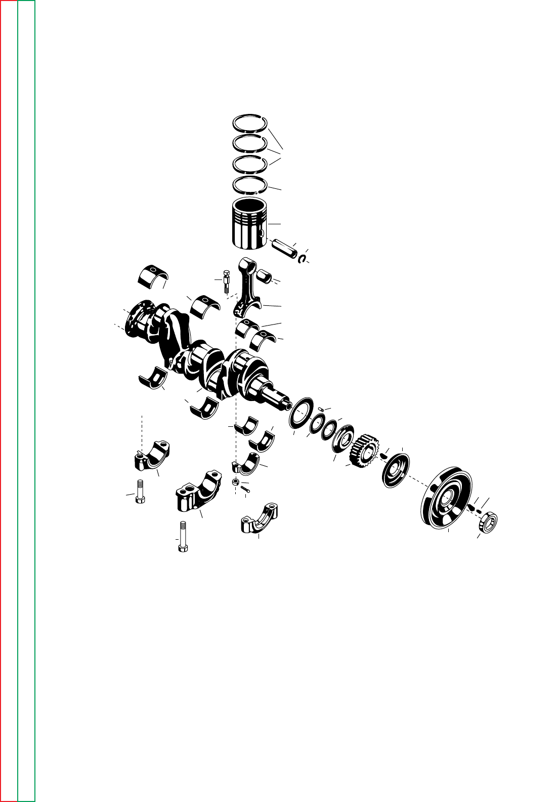
P-23-KP-23-K
Index of Sub Assemblies Index of Sub Assemblies Index of Sub Assemblies Index of Sub Assemblies
Part Numbers Part Numbers Part Numbers Part Numbers
CRANKSHAFT AND PISTON ASSEMBLY
3-15-82
27
26
28
29 30
32
33
31
18
18
35
31
34
36
21
24
19
5
3
3
47
89
1
35
20
20
16
16
6
17
15
811
12
10
NOTE: Engine Spec. is located
on Engine Nameplate
Crankshaft Assembly - Includes: * 1
1 Crankshaft * 1
2 Crankshaft Thrust Shim (.002) * 8
3 Crankshaft Thrust Shim (.008) * 8
4 Crankshaft Thrust Plate * 1
5 Thrust Washer * 2
6
Pin-Crankshaft Thrust Washer to Crankcase
*3
7 Crankshaft Gear * 1
8 Key - Crankshaft Gear to Crankshaft * 1
9 Oil Thrower * 1
10 Pulley * 1
11 Cork - Fan Drive Pulley Keyway Plug * 1
12 Spacer Collar - Crank Starting Jaw * 1
13 Starting Jaw S9022 1 X •
13 Starting Jaw S13280 1 • X
14 Crank S7430 1 X X
15 Bearing Cap - Front Main * 1
16
Bearing Assembly - Front Main (One Assembly is 2 Halves)
*1
17 Bearing Cap - Center Main * 1
18
Bearing Assembly - Center Main (One Assembly is 2 Halves)
*1
19 Bearing Cap - Rear Main * 1
20
Bearing Assembly - Rear Main (One Assembly is 2 Halves)
*1
21
Place Bolt - Front and Rear Main Bearing Cap Mounting
*4
24 Place Bolt - Center Main Bearing Cap Mounting * 2
26 Piston * 4
27 Piston Ring - Taper Face (Top 3 Rings) * 12
28 Piston Ring - Oil Control (Bottom Ring) * 4
29 Piston Pin * 4
30 Piston Pin Retaining Ring * 8
Connecting Rod and Cap Assembly - (#1 and #3 Cyl) Includes:
*2
Connecting Rod and Cap Assembly - (All 4 Cyl) Includes:
*4
31 Rod and Cap * 2
32 Piston Pin Bushing * 2 or 4
33 Connecting Rod Bolt * 4 or 8
34 Connecting Rod Bolt Nut * 4 or 8
35
Connecting Rod Bearing - (One Bearing is One Half)
*4
Connecting Rod and Cap Assembly - #2 and #4 cyl) Includes:
*2
31 Rod and Cap * 2
32 Piston Pin Bushing * 2
33 Connecting Rod Bolt * 4
34 Connecting Rod Bolt Nut * 4
35
Connecting Rod Bearing - (One Bearing is One Half)
*4
36 Cotter Pin - Connecting Rod Bolts * 8
* These parts are not normally stocked by Lincoln. For fastest
service on these parts order from your area Continental parts
distributor using the part description and engine nameplate data.
3-15-82
Use only the parts marked “X” in the column under the
heading number called for in the model index page.
ITEM DESCRIPTION PART NO. QTY. 123456789
P-23-K.a P-23-K.a
# Indicates a Change This Printing
Index of Sub Assemblies Index of Sub Assemblies Index of Sub Assemblies Index of Sub Assemblies
Sub Assembly Illustration Sub Assembly Illustration Sub Assembly Illustration Sub Assembly Illustration
#
#
#
#
#
#
#
#
#
#
#
#
#
#
#
#
#
#
#
#
#
#
#
#
#
#
#
P-23-LP-23-L
Index of Sub Assemblies Index of Sub Assemblies Index of Sub Assemblies Index of Sub Assemblies
Part Numbers Part Numbers Part Numbers Part Numbers
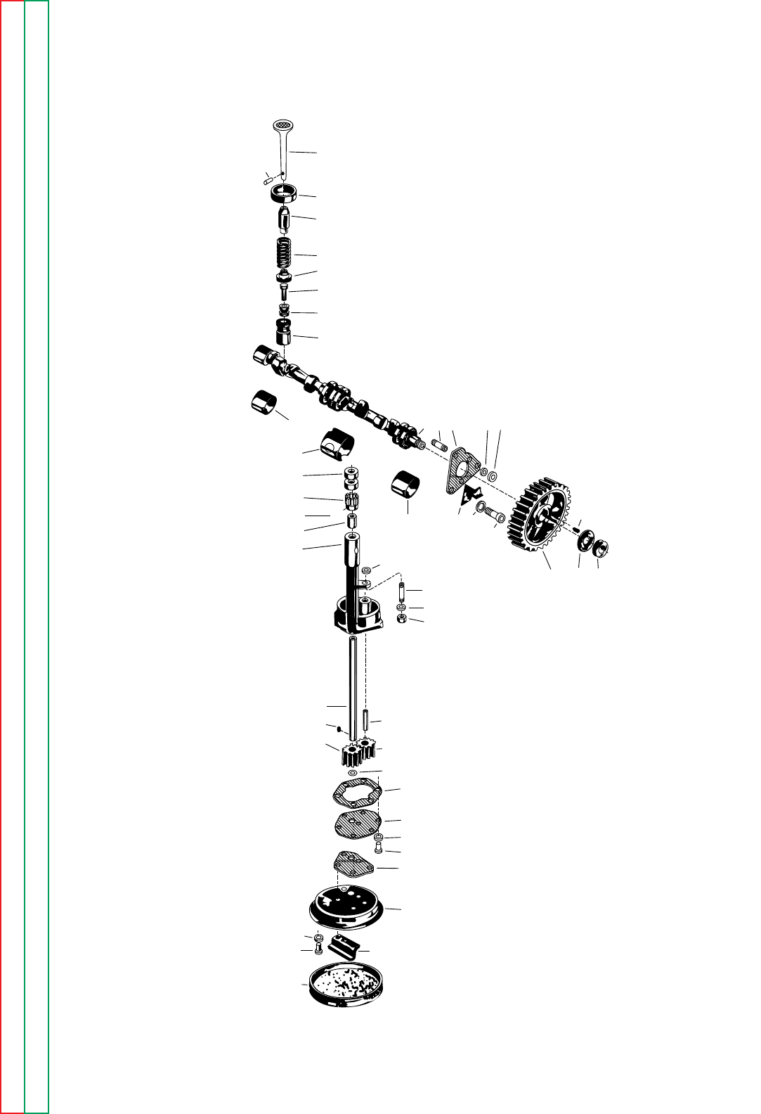
CAMSHAFT AND VALVE ASSEMBLY
3-15-82
24
23
22
21
20
19
18
17
16
15
14
47
132 45
10
8
76
13
25
26
28
27 46
43
44
45
911 12
29
30
31
33
32
34
35
36
40
41
37
38
40
3941
42
NOTE: Engine Spec. is located
on Engine Nameplate
1 Camshaft * 1
2 Camshaft Thrust Plate * 2
3 Stud - Camshaft Thrust Plate to Block * 2
4 Lockwasher - Camshaft Thrust Plate to Block * 2
5 Hex Nut - Camshaft Thrust Plate to Block * 2
6 Timing Gear Oiler Plate * 1
7 Lockwasher - Oiler Plate and Thrust Plate to Block * 1
8
Hex Head Bolt - Oiler Plate and Thrust Plate to Block
*1
9 Camshaft Gear * 1
10 Key - Camshaft Gear to Camshaft * 1
11 Washer - To Lock Nut on Camshaft * 1
12 Hex Nut - Camshaft Gear to Camshaft * 1
13 Bushing - Camshaft Front * 1
14 Bushing - Camshaft Center * 1
15 Bushing - Camshaft Rear * 1
Valve Tappet Assembly - Includes: * 8
16 Valve Tappet * 8
17 Valve Tappet Locknut * 8
18 Valve Tappet Screw * 8
19 Valve Spring Seat * 8
20 Valve Spring * 8
21 Valve Stem Guide * 8
22 Exhaust Valve Seat Insert * 4
23 Valve Spring Lock * 8
24 Intake Valve * 4
24 Exhaust Valve * 4
Oil Pump Assembly - Includes: * 1
25 Drive Gear - Oil Pump * 1
26 Pin - Oil Pump Drive Gear to Shaft * 1
27 Body Assembly - Includes: * 1
28 Bushing * 1
29 Shaft * 1
30 Key * 1
31 Gear - Oil Pump Driver * 1
32 Gear - Oil Pump Driver * 1
33 Stud - Oil Pump Idler Gear * 1
34 Snap Ring - Oil Pump Drive Shaft * 1
35 Gasket - Oil Pump Cover * 1
36 Cover - Oil Pump * 1
37 Gasket - Strainer Screen * 1
38 Strainer Frame * 1
39 Strainer Spacer * 1
41 Hex Head Screw and Lockwasher * 6
42 Oil Strainer Screen * 1
43
Stud - Oil Pump Body to Center Main Bearing Cap
*1
44
Lockwasher - Oil Pump Body to Center Main Bearing Cap
*1
45
Hex Nut - Oil Pump Body to Center Main Bearing Cap
*1
46 Washer - Oil Pump Spacer * 1
47 Oil Pump Drive Shaft Sleeve * 1
* These parts are not normally stocked by Lincoln. For fastest service on these parts,
order from your area Continental parts distributor using the part description and
engine nameplate data.
3-15-82
ITEM DESCRIPTION PART NO. QTY. 123456789
P-23-L.a P-23-L.a
# Indicates a Change This Printing
Index of Sub Assemblies Index of Sub Assemblies Index of Sub Assemblies Index of Sub Assemblies
Sub Assembly Illustration Sub Assembly Illustration Sub Assembly Illustration Sub Assembly Illustration
P-23-MP-23-M
Index of Sub Assemblies Index of Sub Assemblies Index of Sub Assemblies Index of Sub Assemblies
Part Numbers Part Numbers Part Numbers Part Numbers
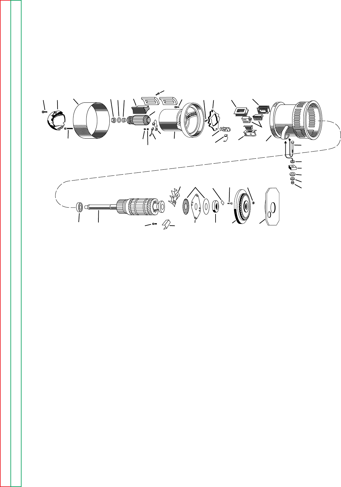
WELDING GENERATOR AND COUPLING
1-27-97
16A 16 17 1011 9 6
7
8
17A 12B
12C12A
12
6A
5
5A 14A 14 3A 3B
13
13A 3C
2
124
23
21
22
23
25
26e20A20B19A
19 20 26 27
18C
18D
4
15
18

1 Welder Frame M8804 1 X • • • • • •
1 Welder Frame M8881
ø
1•XXX•••
1 Welder Frame (Below Code 7250) M12099-1 1 • • • • X • •
1 Welder Frame (Between Code 7250 & 9800) L9074-2 1 • • • • X X •
1 Welder Frame (Between Code 9800 & 9900) L8714
ø
1 ••••••X
1 Welder Frame (Above Code 9900) L8986 1 • • • • • • X
2 Main Pole Lamination Assembly S10745-6 4 X X X X • • X
2 Main Pole Lamination Assembly S10745-12 4 • • • • X X •
3 Main Pole Shunt Field Coil
See Winding Specs
1 XXXXXXX
3 Main Pole Series Field Coil
See Winding Specs
2 XXXXXXX
Interpole Coil and Pole (Set of 4), Includes: S12261-2 1 X X X X • • •
Interpole Coil and Pole (Set of 2-3 & 6 O'Clock) S12261-16
ø
1••••XX•
Interpole Coil and Pole (Set of 2-3 & 6 O'Clock) S12261-24 1 • • • • • • X
Interpole Coil and Pole (Set of 2-9 & 12 O'Clock) S18891 1 • • • • X X •
Interpole Coil and Pole (Set of 2-9 & 12 O'Clock) S12261-23 1 • • • • • • X
2 Interpole Pole Piece S12260-2 4 X X X X • • X
2 Interpole Pole Piece S12260-6 4 • • • • X X •
3 Interpole Coil (Set of 4) S12261-2A 1 X X X X • • •
3 Interpole Coil (Set of 2-3 & 6 O'Clock) S12261-16A
ø
1••••XX•
3 Interpole Coil (Set of 2-3 & 6 O'Clock) S12261-24A
ø
1 ••••••X
3 Interpole Coil (Set of 2-8 & 12 O'Clock) S12261-15A 1 • • • • X X •
3 Interpole Coil (Set of 2-9 & 12 O'Clock) S12261-23A 1 • • • • • • X
4 Welder Armature M7014-1
ø
1 XX•••••
4 Welder Armature
Order Kit M12107
ø
1 ••X••••
4 Welder Armature M7014-11 1 • • • X X X X
Armature Coil Spec.
See Winding Specs
XXXXXXX
5 Welder Bracket and Exciter Frame
Includes: Baffle M8797 1 X X X X • • X
5 Welder Bracket and Exciter Frame, incudes Baffle M12101-1 1 • • • • X X •
Hex Head Screw - Bracket to Welder Frame T8833-2 4 X X X X X X X
6 Exciter Main Pole Lamination Assembly M8774-1 2 X X X X X X X
Hex Head Screw - Exciter Main Pole Lamination
Assembly to Exciter Frame 5/16-18 x 1-1/4 4 X X X X X X X
7 Exciter Main Pole Field Coil
See Winding Specs
1 XXXXXXX
8 Exciter Armature
M4047-1/24.26B
1 XXXXXXX
9 Exciter Armature Sleeve Collar - For Centering
Armature on Shaft T5345 1 X X X X X X X
10 Exciter Lock Nut T6225-1 1 X X X X X X X
11 Exciter Lock Nut Locking Washer T7090-1 1 X X X X X X X
12
Exciter Brushholder Assembly, Includes: (Below Code 7700)
S6531-A 2 X X X X X • •
12
Exciter Brushholder Assembly, Includes: (Above Code 7700)
S15963-A 2 • • • • X X X
Exciter Brushholder Parts See P-25-M
12A Exciter Brush (Below Code 7700) T6968 2 X X X X X • •
12A Exciter Brush (Above Code 7700) T7554 2 • • • • X X X
12B Screw - Brushholder to Frame S9225-17 4 X X X X X X X
12C Washer - Brushholder to Frame S9262-23 4 X X X X X X X
13 Brushholder Assembly M6964-2A 4 X X X X X X X
Brushholder Parts See P-25-L
13A Brush T2687 8 X X X X X X X
14 Rocker M1961 1 X X • • • • •
14 Rocker M9857 1 • • X X X X X
14A Hex Head Cap Screw T8833-22 1 X X X X X X X
15 Ball Bearing M9300-19 1 X X • • • • •
15 Ball Bearing M9300-38 1 • • X X X X X
Bearing Shoulder Ring S18541 1 • • • • • X X
Pipe Plug - Mounts in Bearing Housing S10780-4 1 X X X X X • X
Lead Block - Mounts on Rear Ring of Welder Frame S10783 1 X X X X X X X
Drive Screw - For Mounting Lead Block S8025-7 2 X X X X X X X
16 Exciter End Cover L2594 1 X X X X X X X
16 Exciter End Cover (Code 10072) L6129-1 1 • • X • • • •
16A Screw - To Mount Exciter Cover S9225-8 2 X X X X X X X
17 Bracket Cover L3391-1 1 X X X X • • X
11-21-2006
Use only the parts marked “X” in the column under the
heading number called for in the model index page.
ITEM DESCRIPTION PART NO. QTY. 123456789
P-23-M.1 P-23-M.1
# Indicates a Change This Printing
Index of Sub Assemblies Index of Sub Assemblies Index of Sub Assemblies Index of Sub Assemblies
Sub Assembly Illustration Sub Assembly Illustration Sub Assembly Illustration Sub Assembly Illustration
øThis part is obsolete and no longer available.
#

17 Bracket Cover L3391-46 1 ••••XX•
Round Head Bolt 1/4-20 x 1-3/4 2 X X X X X X X
Square Nut 1/4-20 2 X X X X X X X
18 Blower Segment (Sold in Set of 4 only) M14361 1 X X •XXXX
18C Blower Paddle (Code 4744 & 4745) S12008
ø
8••X••••
18C Blower Paddle (Codes Above 5100) S12480 8 ••X••••
18D Lock Screw T11762-2 8 ••X••••
19 Coupling Disc M6730 1 X X •XXXX
19A Coupling Disc Backing Plate S8042 2 X X •XXXX
20 Coupling Ring (Engine Side) S14232 1 X X •XXXX
20 Coupling Ring (Armature Side) S14233 1 X X •XXXX
20A Bolt - Disc to Hub T8833-2 8 X X •XXXX
20B Bolt Locking Clip - Disc to Hub T9049-A 4 X X •XXXX
Bolt - Disc to Flywheel T8833-44 8 X X •XXXX
Lock Washer E106A-8 8 X X X X X X X
21 Welder Foot Upper Cushion T8823 2 X X X X X X X
22 Welder Foot Lower Cushion T8822 2 X X X X X X X
23 Washer S9262-1 4 X X X X X X X
24 Hex Head Bolt 1/2-13 x 3 2 X X X X X X X
25 Huglock Nut T9187-4 2 X X X X X X X
26 Flywheel - Includes Ring Gear M7671 1 X X •X•••
26 Flywheel - Includes Ring Gear M7671-2 1 ••X••••
26
Flywheel - Includes Ring Gear (Between Code 5550 & 7250)
M7671-4
ø
1•••XX ••
26
Flywheel - Includes Ring Gear (Between Code 7250 & 7600)
M14343-3 1 ••••X••
26 Flywheel - Includes Ring Gear (Above Code 7600) M14343-1 1 ••••XXX
26 Flywheel - Includes Ring Gear (Above Code 9900) M14343-7 1 ••••••X
26B Nut - Flywheel to Crankshaft T10018 6 X X X X X X •
Lock Washer - Flywheel to Crankshaft T9695-5 6 X X X X X X X
27 Engine Adapter Plate Assembly, Includes: S9352-2 1 X ••••••
Engine Adapter Plate L3389 1 X ••••••
Timing Pin T10088 1 X ••••••
27
Engine Adapter Plate Assembly, Includes: (Codes 3500-4800)
S9352-3 1 •X•••••
Engine Adapter Plate L3456-A 1 •X•••••
Timing Pin T10088 1 •X•••••
27
Engine Adapter Plate Assembly, Includes: (Codes 4800-6000
except 5840 and 5841) S9352-4 1 •XXX•••
Engine Adapter Plate L3456-B 1 •XXX•••
Timing Pin T10088 1 •XXX•••
27
Engine Adapter Plate Assembly, Includes: (Codes 5840, 5841,
and 6000 to 7250) S9352-6 1 •••XX ••
Engine Adapter Plate L3456-C
ø
1•••XX ••
Timing Pin T10088 1 •••XX ••
27 Engine Adapter Plate (Code 7250 to 8900) G1261-1C 1 ••••X••
27 Engine Adapter Plate (Between Code 8900 & 9900) G1261-1D
ø
1••••XXX
27 Engine Adapter Plate (Above Code 9900) G2543 1 ••••••X
Dowel Ring (Above Code 7250) T12598 2 ••••XXX
Hex Head Cap Screw - Welder to Engine Adapter Plate
T8833-1 4 X ••••••
Lock Washer - Welder to Engine Adapter Plate E106A-8 4 X ••••••
Hex Head Cap Screw - Welder to Engine Adapter Plate
3/8-16 x 1
As Req'd
•XXXXXX
Lock Washer - Welder to Engine Adapter Plate E106A-4
As Req'd
•XXXXXX
07-18-2001
Use only the parts marked “X” in the column under the
heading number called for in the model index page.
ITEM DESCRIPTION PART NO. QTY. 123456789
SA 200 F162 & F163
P-23-M.2P-23-M.2
# Indicates a Change This Printing
Index of Sub Assemblies Index of Sub Assemblies Index of Sub Assemblies Index of Sub Assemblies
Sub Assembly Illustration Sub Assembly Illustration Sub Assembly Illustration Sub Assembly Illustration
#
øThis part is obsolete and no longer available.
