Single Pendulum User Manual Linear Inverted And Gantry
Linear%20Inverted%20Pendulum%20and%20Pendulum%20Gantry%20-%20User%20Manual
Linear%20Inverted%20Pendulum%20and%20Pendulum%20Gantry%20-%20User%20Manual
User Manual:
Open the PDF directly: View PDF ![]() .
.
Page Count: 11
CAPTIVATE. MOTIVATE. GRADUATE.
Solutions for teaching and research. Made in Canada.
CAPTIVATE. MOTIVATE. GRADUATE.
Solutions for teaching and research. Made in Canada.
Nine linear motion plants for teaching fundamental and advanced controls concepts
USER MANUAL
IP02 Linear Inverted Pendulum and
IP02 Linear Pendulum Gantry Experiments
Set Up and Configuration

c
⃝2012 Quanser Inc., All rights reserved.
Quanser Inc.
119 Spy Court
Markham, Ontario
L3R 5H6
Canada
info@quanser.com
Phone: 1-905-940-3575
Fax: 1-905-940-3576
Printed in Markham, Ontario.
For more information on the solutions Quanser Inc. offers, please visit the web site at:
http://www.quanser.com
This document and the software described in it are provided subject to a license agreement. Neither the software nor this document may be
used or copied except as specified under the terms of that license agreement. All rights are reserved and no part may be reproduced, stored in
a retrieval system or transmitted in any form or by any means, electronic, mechanical, photocopying, recording, or otherwise, without the prior
written permission of Quanser Inc.
SIP AND SPG User Manual 2

1 PRESENTATION
1.1 Description
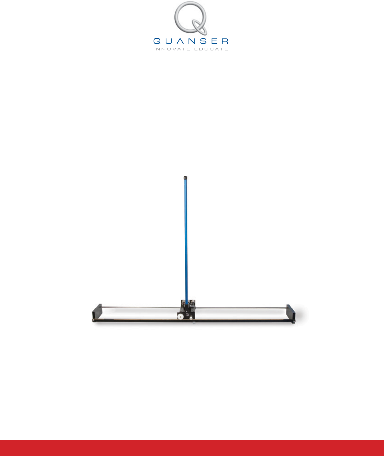
The IP02 linear pendulum system can be configured in both a conventional single pendulum gantry (SPG), and
single inverted pendulum (SIP) configuration as shown in Figure 1.1. Both systems consists of a single rod mounted
on a linear cart whose axis of rotation is perpendicular to the direction of motion of the cart. The pendulums come
in two different lengths: a 0.30 m (12'') ''medium'' pendulum, and a 0.61 m (24'') ''long'' pendulum.
(a) SIP Medium Pendulum (b) SPG Medium Pendulum
Figure 1.1: Quanser Single Pendulum
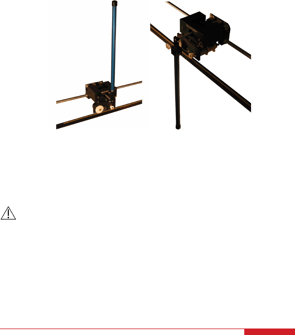
The IP02 is a solid aluminum cart. It is driven by a rack and pinion mechanism using a 6-Volt DC motor, ensuring
consistent and continuous traction. Such cart slides along a stainless steel shaft using linear bearings. The cart
position is measured using a sensor coupled to the rack via an additional pinion. The pendulum is instrumented
using a quadrature incremental encoder. The pendulum is mounted in front of the cart to enable 360 degree free
rotation. Please review [1] for a complete description of the IP02 system.
Caution: This equipment is designed to be used for educational and research purposes and is not
intended for use by the general public. The user is responsible to ensure that the equipment
will be used by technically qualified personnel only.
SIP AND SPG User Manual 4
2 PENDULUM COMPONENTS
The SIP and SPG components are identified in Section 2.1.
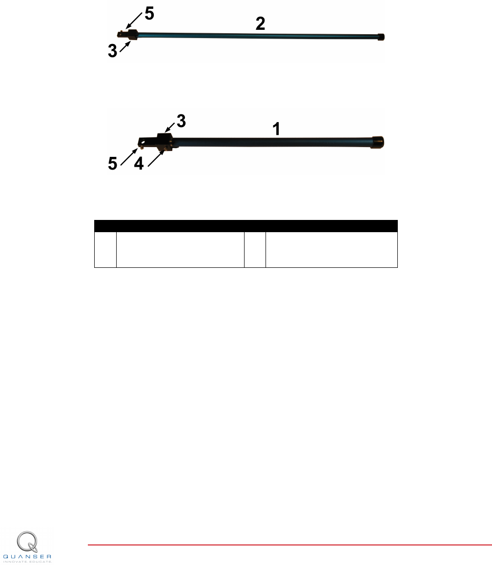
2.1 SIP Component Nomenclature
The components listed in Table 2.1 below are labeled in Figure 2.1 and Figure 2.2. Both the SIP and SPG modules
are comprised of two primary components: a medium pendulum (30.5 cm), and a long pendulum (61 cm).
Figure 2.1: Long pendulum
Figure 2.2: Medium pendulum
ID Component ID Component
1 Medium length pendulum 4 Pendulum set screw (3/32'')
2 Long length pendulum 5 Axis set screw (3/32'')
3 Pendulum socket (T-fitting)
Table 2.1: SIP and SPG Components
SIP AND SPG User Manual v 1.0

3 PENDULUM SPECIFICATIONS
Table 3.1 lists and characterizes the main parameters associated with the SIP and SPG. Some of these are used in
the mathematical model.
Symbol Description Value
Mpl Long Pendulum Mass (with T-fitting) 0.230 kg
Mpm Medium Pendulum Mass (with T-fitting) 0.127 kg
Lpl Long Pendulum Full Length (from Pivot to
Tip)
0.6413 m
Lpm Medium Pendulum Full Length (from Pivot
to Tip)
0.3365 m
lpl Long Pendulum Length from Pivot to Cen-
ter Of Gravity
0.3302 m
lpm Medium Pendulum Length from Pivot to
Center Of Gravity
0.1778 m
Ipl Long Pendulum Moment of Inertia, about
its Center Of Gravity
7.88 ×10⁻³kg.m2
Ipm Medium Pendulum Moment of Inertia,
about its Center Of Gravity
1.20 ×10⁻³kg.m2
BpViscous Damping Coefficient, as seen at
the Pendulum Axis
0.0024 N.m.s/rad
g Gravitational Constant on Earth 9.81 m/s2
Table 3.1: SIP and SPG Specifications
SIP AND SPG User Manual 6
4 SIP AND SPG SETUP
As discussed in Section 4.1, the Single Inverted Pendulum, and Single Pendulum Gantry modules require a specific
workspace to avoid injury to the system or user. See Section 4.2 for instructions on how to assemble the Single
Inverted Pendulum system.
Caution: If the equipment is used in a manner not specified by the manufacturer, the protection provided by
the equipment may be impaired.
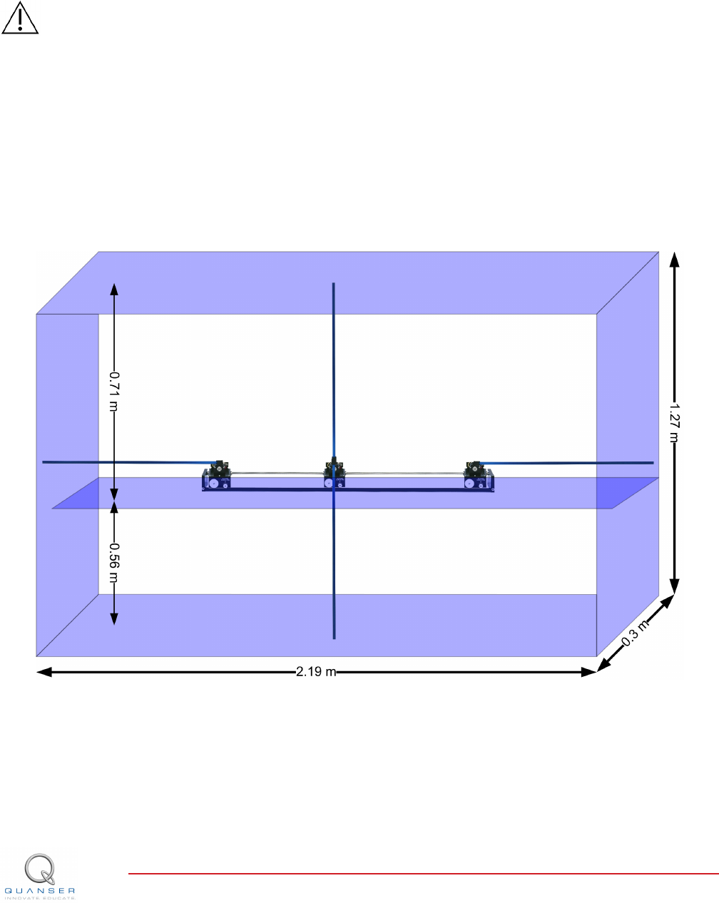
4.1 Workspace
When creating a workspace for the pendulum modules, it is important to keep in mind that the single pendulum is
mounted in front of that cart in such a way that it can operate freely over a 360-degree range. Therefore, you should
ensure that the pendulum does not collide with any objects while it swings/rotates. Note that the pendulum will swing
even while the cart is at one of the extremities of the track! In such a configuration (i.e. when the pendulum rod
goes from the inverted to the gantry position and vice-versa), the systems require an overall space of 2.19 m long
by 1.27 m high (0.56 m below table and 0.71 m above) by 0.3 m deep. The clearance needed to avoid collisions is
characteirized in Figure 4.1.
Figure 4.1: Pendulum Workspace
SIP AND SPG User Manual v 1.0
4.2 Assembly
4.2.1 Default SIP and SPG Configuration
The setup procedure for the default SIP configuration, is as follows:
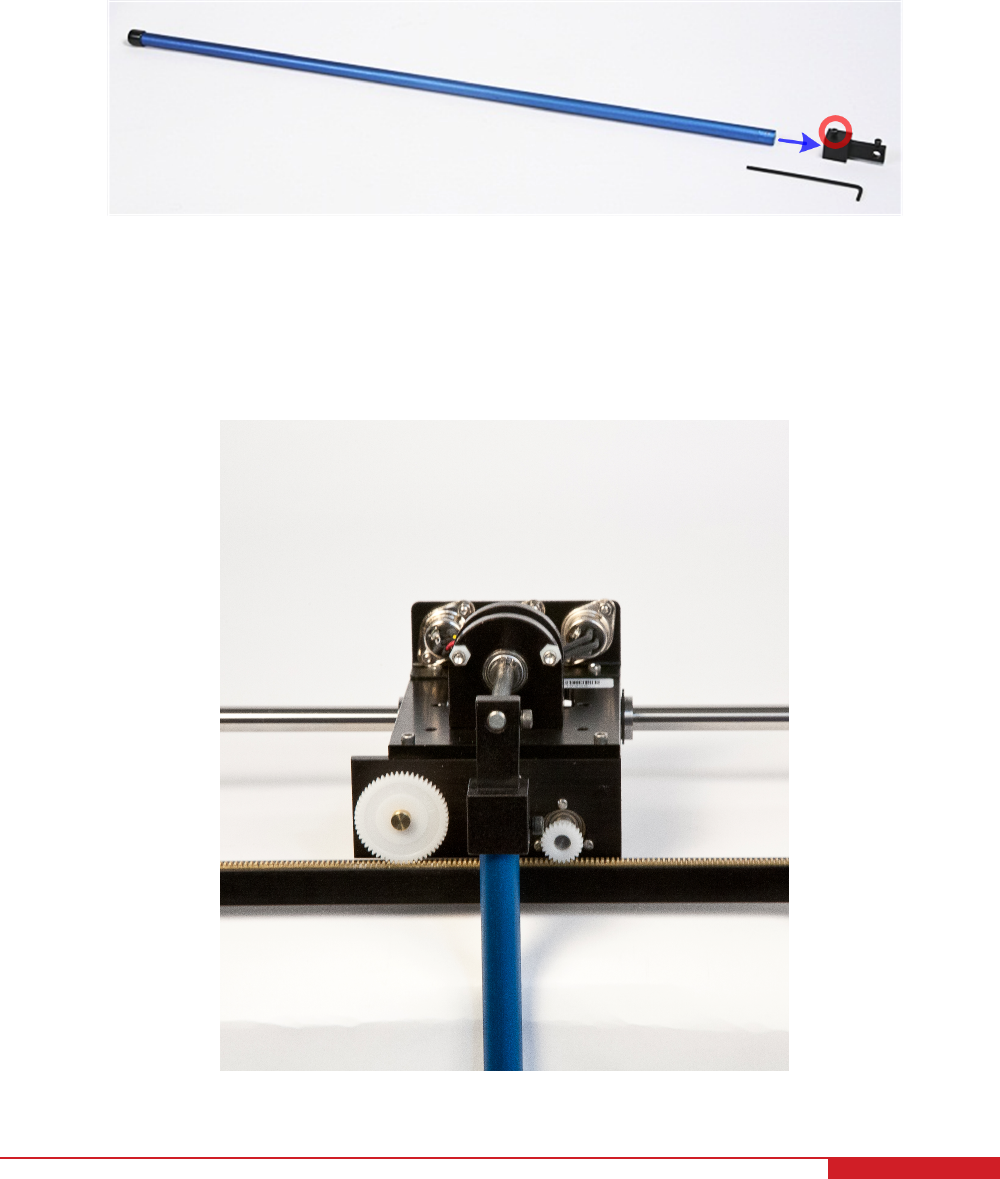
1. Insert the long pendulum rod inside its T-fitting (i.e. component #3), as shown in Figure 4.2. Ensure that it sits
properly. Tighten the pendulum set screw #4, as required.
Figure 4.2: Insert the long pendulum rod inside its T-fitting
2. If you are setting up the SPG configuration, place the addional mass on top of the IP02 cart before proceeding.
3. On the IP02, attach the single pendulum, pointing downwards, at the tip of the IP02 cart's pendulum axis, as
shown in Figure 4.3. Tighten set screw #5 as necessary. As a remark, it is reminded that in this configuration,
the pendulum is free to rotate over a 360-degree range in front of the cart.
Figure 4.3: Attach the pendulum pointing downwards
SIP AND SPG User Manual 8

4. We highly recommend that you can clamp the track down to the table using its end plates.
5. Wire up the IP02 cart as per dictated in the IP02 User Manual [1], where the Quanser's standard wiring con-
ventions are fully described. No further electrical cabling is required in setting up the pendulum, as all the
connections are done at the IP02 level.
Note: The SPG default configuration is the same as the SIP default configuration, but with the additional mass
placed on top of the IP02 base unit cart.
4.2.2 Other Configurations
Four other configurations using the medium and long pendulums are possible, outlined as follows:
1. An IP02 cart without its additional weight and in front of which the medium pendulum is attached, pointing
downwards.
2. An IP02 cart with its additional weight and in front of which the medium pendulum is attached, pointing down-
wards.
3. An IP02 cart without its additional weight and on top of which the long pendulum is mounted, pointing upwards.
In order to install the pendulum in this configuration, slide the T-fitting (i.e. component #3) all the way back
on the IP02 cart pendulum axis, so that the pendulum sits on top of the cart in the ''inverted'' position. In this
configuration, the angular range of motion of the inverted pendulum is mechanically constrained by two plastic
washers to ±32º from the upright position. This setup is very similar to that of with the IP01.
4. An IP02 cart without its additional weight and on top of which the medium pendulum is mounted, pointing
upwards.
SIP AND SPG User Manual v 1.0

REFERENCES
[1] Quanser Inc. IP02 User Manual, 2009.
SIP AND SPG User Manual 10
CAPTIVATE. MOTIVATE. GRADUATE.
Solutions for teaching and research. Made in Canada.
INFO@QUANSER.COM +1-905-940-3575 QUANSER.COM CAPTIVATE. MOTIVATE. GRADUATE.
Solutions for teaching and research. Made in Canada.
INFO@QUANSER.COM +1-905-940-3575 QUANSER.COM
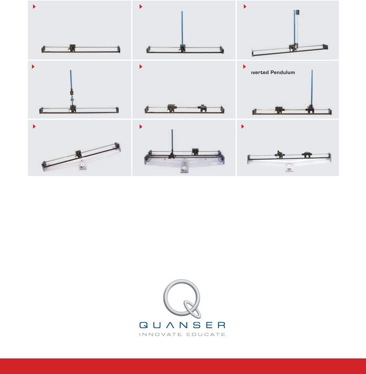
Nine linear motion plants for teaching fundamental and advanced controls concepts
Linear PendulumIP02 Base Unit
Linear Flexible Joint Linear Flexible Joint with
Inverted Pendulum
Double Inverted Pendulum
Seesaw Pendulum
Seesaw
Linear Flexible Inverted Pendulum
Inverted Pendulum
Quanser’s linear collection allows you to create experiments of varying complexity – from basic to advanced. With nine
plants to choose from, students can be exposed to a wide range of topics relating to mechanical and aerospace
engineering. For more information please contact info@quanser.com
©2012 Quanser Inc. All rights reserved.
Linear Flexible Joint on Seesaw
