IP02 User Manual Linear Servo Base Unit
Linear%20Servo%20Base%20Unit%20-%20User%20Manual
User Manual:
Open the PDF directly: View PDF ![]() .
.
Page Count: 18
CAPTIVATE. MOTIVATE. GRADUATE.
Solutions for teaching and research. Made in Canada.
CAPTIVATE. MOTIVATE. GRADUATE.
Solutions for teaching and research. Made in Canada.
USER MANUAL
IP02 Base Unit Experiment
Set Up and Configuration
Nine linear motion plants for teaching fundamental and advanced controls concepts

© 2012 Quanser Inc., All rights reserved.
Quanser Inc.
119 Spy Court
Markham, Ontario
L3R 5H6
Canada
info@quanser.com
Phone: 1-905-940-3575
Fax: 1-905-940-3576
Printed in Markham, Ontario.
For more information on the solutions Quanser Inc. offers, please visit the web site at:
http://www.quanser.com
This document and the software described in it are provided subject to a license agreement. Neither the software nor this document may be
used or copied except as specified under the terms of that license agreement. All rights are reserved and no part may be reproduced, stored in
a retrieval system or transmitted in any form or by any means, electronic, mechanical, photocopying, recording, or otherwise, without the prior
written permission of Quanser Inc.
Waste Electrical and Electronic Equipment (WEEE)
This symbol indicates that waste products must be disposed of separately from municipal household waste, according to Directive
2002/96/EC of the European Parliament and the Council on waste electrical and electronic equipment (WEEE). All products at the
end of their life cycle must be sent to a WEEE collection and recycling center. Proper WEEE disposal reduces the environmental
impact and the risk to human health due to potentially hazardous substances used in such equipment. Your cooperation in proper
WEEE disposal will contribute to the effective usage of natural resources. For information about the available collection and
recycling scheme in a particular country, go to ni.com/citizenship/weee.
电子信息产品污染控制管理办法 (中国 RoHS)
中国客户 Naonal Instruments 符合中国电子信息产品中限制使用某些有害物质命令 (RoHS)
。
关于Naonal Instruments 中国 RoHS合规性信息,请登录 ni.com/environment/rohs_china
(For informaon about China RoHS compliance, go to ni.com/environment/rohs_china)
This product meets the essential requirements of applicable European Directives as follows:
• 2006/95/EC; Low-Voltage Directive (safety)
• 2004/108/EC; Electromagnetic Compatibility Directive (EMC)
IP02 User Manual 2

CONTENTS
1 Presentation 4
1.1 Description 4
1.2 Linear Modules and Experiment Overview 4
2 IP02 Components 6
2.1 IP02 Component Nomenclature 6
2.2 Component Description 6
3 IP02 Specifications 8
4 Wiring Procedure 10
4.1 Cable Nomenclature 10
4.2 Typical Connections 11
5 Testing and
Troubleshooting 13
5.1 Motor 13
5.2 Encoder 13
6 Technical Support 14
7 Maintenance 15
7.1 Reducing IP02 Pinion Wear 15
7.2 Replacing the IP02 Pinions 15
IP02 User Manual v 1.0
1 PRESENTATION
1.1 Description
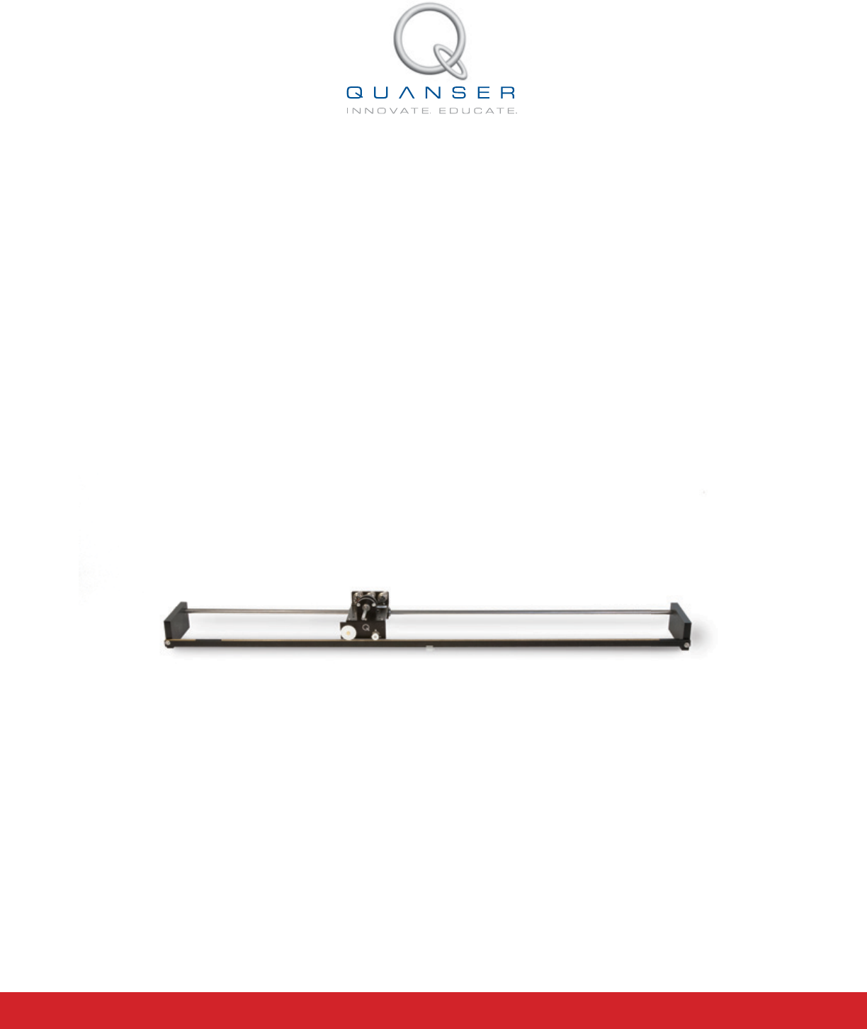
The IP02 is a fundamental module for the linear motion experiments. It consists of a precisely machined solid
aluminum cart driven by a high quality DC motor equipped with a planetary gearbox. The cart slides along a stainless
steel shaft using linear bearings. The cart is driven via a rack and pinion mechanism as opposed to belts or wheels,
in order to eliminate slippage, belt stretching and other undesirable effects. This ensures consistent and continuous
traction.
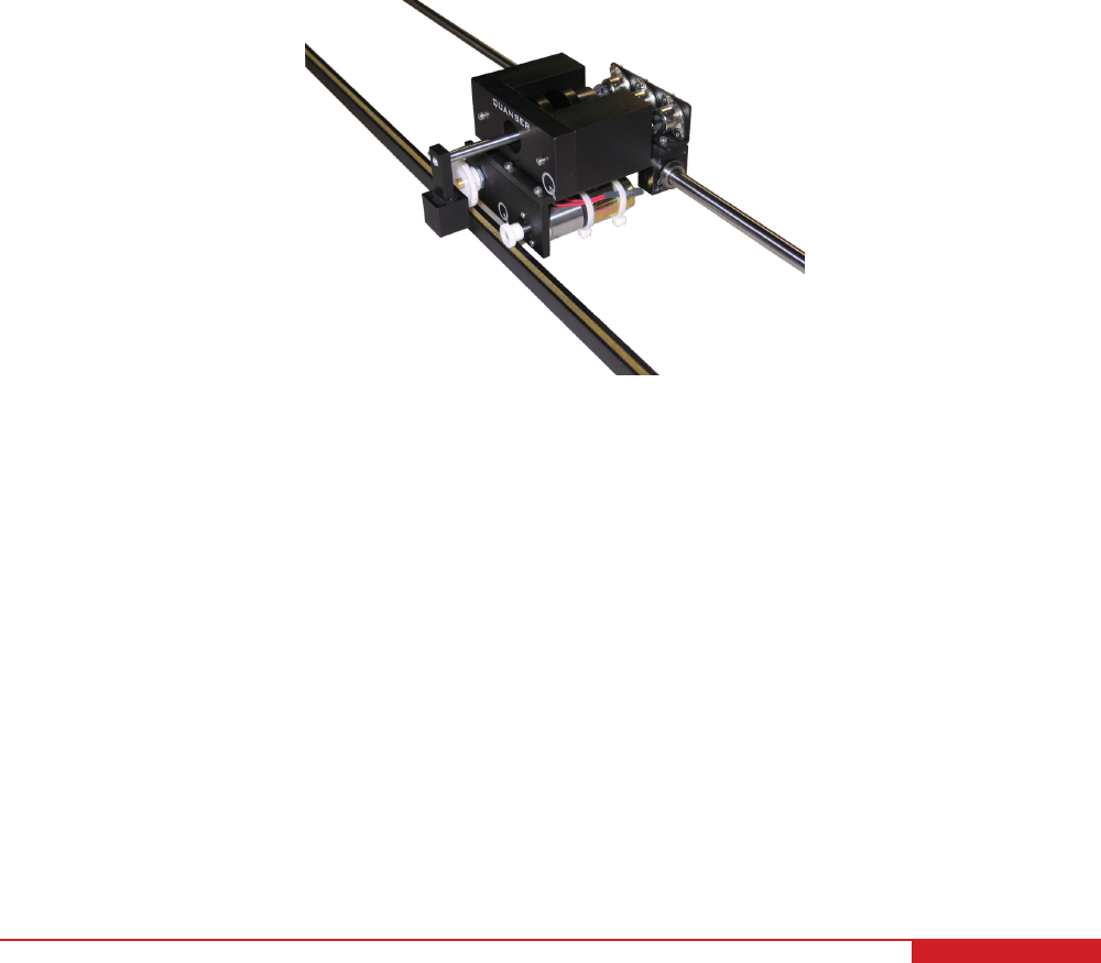
A typical IP02 is depicted in Figure 1.1. The IP02 pendulum can suspend in front of the cart to perform self-erecting
and gantry experiments. The IP02 cart position is sensed using a quadrature incremental encoder whose shaft
meshes with the track via an additional pinion. The IP02 is also equipped with a rotary joint to which a free-swinging
rod can be attached and suspended in front of the cart. This rod functions, in subsequent experiments, as an
''inverted pendulum'', but more precisely as a self-erecting inverted pendulum as well as a regular inverted pendulum.
The angle of the rod inclination about the vertical axis is also measured using a quadrature incremental encoder
and is therefore unlimited and continuous over the entire range of motion. The pendulum in itself is a module and
can be mounted on or remove from the cart. Furthermore, in order to run the self-erecting experiment, the supplied
extra mass needs to be attached to the cart, so that the swinging inertia of the pendulum does not lift the cart off the
track.
Figure 1.1: Quanser IP02 system
Caution: This equipment is designed to be used for educational and research purposes and is not
intended for use by the general public. The user is responsible to ensure that the equipment will be used by
technically qualified personnel only.
1.2 Linear Modules and Experiment Overview
The IP02 linear plant can be used stand-alone for several experiments, but it also serves as a base component for
several add-on modules. Table 1.1 below lists these modules and the corresponding experiments that are supplied
with them. Thus a new plant is obtained by adding a module which presents new modeling and control challenges.
IP02 User Manual 4

System Experiment Description
IP02 IP02 QUARC Integration Describes how to use the IP02 plant
IP02 Modeling Derive the dynamic model of the IP02 from first-
principles.
IP02 Position Control Regulate position of the IP02 using PID.
IP02 Speed Control Control the speed of the IP02 using a lead and lag
compensator.
Single Pendulum
Gantry
Anti-swing Control Design of a control system to track a desired cart
linear position while minimizing the swing of the sus-
pended pendulum.
Single Inverted
Pendulum
Inverted Pendulum Control Model the system and then design a controller that
balances the pendulum while the linear cart is track-
ing a reference position
Self-Erecting
Single Inverted
Pendulum
Self-Erecting Single Inverted
Pendulum Control
Design a swing-up controller and a balance com-
pensator to swing-up the pendulum from the resting
downward position to the upright vertical position.
Single Linear Flexi-
ble Joint
Joint Deflection and Resonance
Control
Model the system and design a control system to
manipulate the position of a spring driven cart.
Seesaw Seesaw Balance Control Model the system and then design a controller that
balances the seesaw using a sliding mass.
Seesaw with Sin-
gle Linear Flexible
Joint
Seesaw with Single Linear Flex-
ible Joint Control
Design of a control system to balance a seesaw us-
ing a spring driven cart.
Seesaw and In-
verted Pendlulum
Seesaw with Inverted Pendulum
Control
Design of a control system to balance an inverted
pendulum on top of a seesaw.
Single Linear Flex-
ible Joint with In-
verted Pendulum
Single Linear Flexible Joint with
Inverted Pendulum Control
Design of a control system to balance a pendulum
on a spring driven cart.
Flexible Inverted
Pendulum
Flexible Inverted Pendulum
Control
Design of a control system to balance a flexible in-
verted pendulum.
Double Inverted
Pendulum
Double Inverted Pendlulum
Control
Model the system and design a control system to
balance a double inverted pendulum on a linear mo-
tion cart.
Table 1.1: IP02-based Experiments
IP02 User Manual v 1.0

2 IP02 COMPONENTS
The IP02 components are identified in Section 2.1. Some of the those components are then described in Section
2.2.
2.1 IP02 Component Nomenclature
The IP02 components listed in Table 2.1 below are labeled in figures Figure 3.1a, Figure 3.1c, Figure 3.1b, Figure
3.1d, and Figure 3.1e.
ID Component ID Component
1 IP02 Cart 11 IP02 Pendulum Encoder Connector
2 Stainless Steel Shaft 12 Motor Connector
3 Rack 13 DC Motor
4 Cart Position Pinion 14 Planetary Gearbox
5 Cart Motor Pinion 15 Linear Bearing
6 Cart Motor Pinion Shaft 16 Pendulum Socket
7 Pendulum Axis 17 IP02 Weight
8 IP02 Cart Encoder 18 Rack End Plate
9 IP02 Pendulum Encoder 19 Rack Set Screw: (7/64)''
10 IP02 Cart Encoder Connector 20 Track Discontinuity
Table 2.1: IP02 Components
2.2 Component Description
2.2.1 DC Motor
The IP02 utilizes a Faulhaber Coreless DC Motor (2338S006), as shown in Figure 3.1b and Figure 3.1c (component
# 13). This model is a high-efficiency low- inductance motor resulting in a much faster response than a conventional
DC motor. The complete specification sheet of the motor is included in [2].
Caution: High-frequency signal applied to a motor will eventually damage the gearbox motor and the motor
brushes. The most likely source for high frequency noise is derivative feedback. If the derivative gain is set too high,
a noisy voltage will be fed into the motor. To protect your motor, you should always band limit your signal (especially
derivative feedback) to a value of 50 Hz.
Caution: Input ±15 V, 3 A peak, 1 A continuous.
Caution: Exposed moving parts.
2.2.2 Planetary Gearbox
The IP02 DC motor is coupled to a Faulhaber Planetary Gearhead Series 23/1, as shown in Figure 3.1b and Figure
3.1c (component # 14). Its reduction ratio is 3.71:1. The complete specification sheet of the planetary gearbox is
included in [3].
IP02 User Manual 6
2.2.3 Encoders
On the IP02, both cart and pendulum positions are measured with two optical encoders, represented in Figure 3.1a
by components # 8 and 9, respectively. The encoder measuring the IP02 cart linear position does so through a
rack-pinion system. Both encoders are typically identical. The encoder model used in the IP02 is a US Digital S1
single-ended optical shaft encoder. It offers a high resolution of 4096 counts per revolution (i.e. 1024 lines per
revolution with two channels in quadrature). The complete specification sheet of the S1 optical shaft encoder is
included in [1]. Remark that incremental encoders measure the relative angle of the shaft.
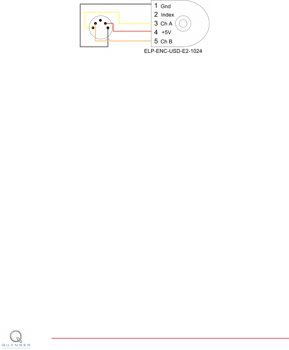
Figure 2.1: IP02 encoder wiring
The position signal generated by the encoder can be directly connected to the data-acquisition device using a
standard 5-pin DIN cable. The internal wiring of the encoder and the 5-pin DIN connectors on the IP02, components
#10 and #11, is illustrated in Figure 2.1.
Caution: Make sure you connect the encoder directly to your data-acquistion device and not to the power
amplifier.
IP02 User Manual v 1.0

3 IP02 SPECIFICATIONS
Table 3.1 lists and characterizes the main parameters associated with the IP02. Some of these are used in the
mathematical model.
Symbol Description Value Variation
Vnom Motor nominal input voltage 6.0 V
RmMotor armature resistance 2.6 Ω±12%
LmMotor armature inductance 0.18 mH
ktMotor current-torque constant 7.68 ×10⁻³N m/A ±12%
kmMotor back-emf constant 7.68 ×10⁻³V/(rad/s) ±12%
ηmMotor efficiency 0.69 ±5%
Jm,rotor Rotor moment of inertia 3.90 ×10⁻⁷kg ·m2±10%
KgPlanetary gearbox gear ratio 3.71
ηgPlanetary geabox efficiency 0.90 ±10%
McMass of cart 0.38 kg
MwMass of cart weight 0.37 kg
Beq,c Equivalent viscous damping coefficient
(Cart)
4.3 N m s/rad
Beq,c Equivalent viscous damping coefficient
(Cart and Weight)
5.4 N m s/rad
LtTrack length 0.990 m
TcCart travel 0.814 m
PrRack pitch 1.664 ×10⁻³m/tooth
rmp Motor pinion radius 6.35 ×10⁻³m
Nmp Motor pinion number of teeth 24
rpp Position pinion radius 0.01483 m
Npp Position pinion number of teeth 56
Kec Cart encoder resolution 2.275 ×10⁻⁵
Kep Pendulum encoder resolution 0.0015 rad/count
fmax Maximum input voltage frequency 50 Hz
Imax Maximum input current 1 A
ωmax Maximum motor speed 628.3 rad/s
Table 3.1: IP02 Specifications
IP02 User Manual 8
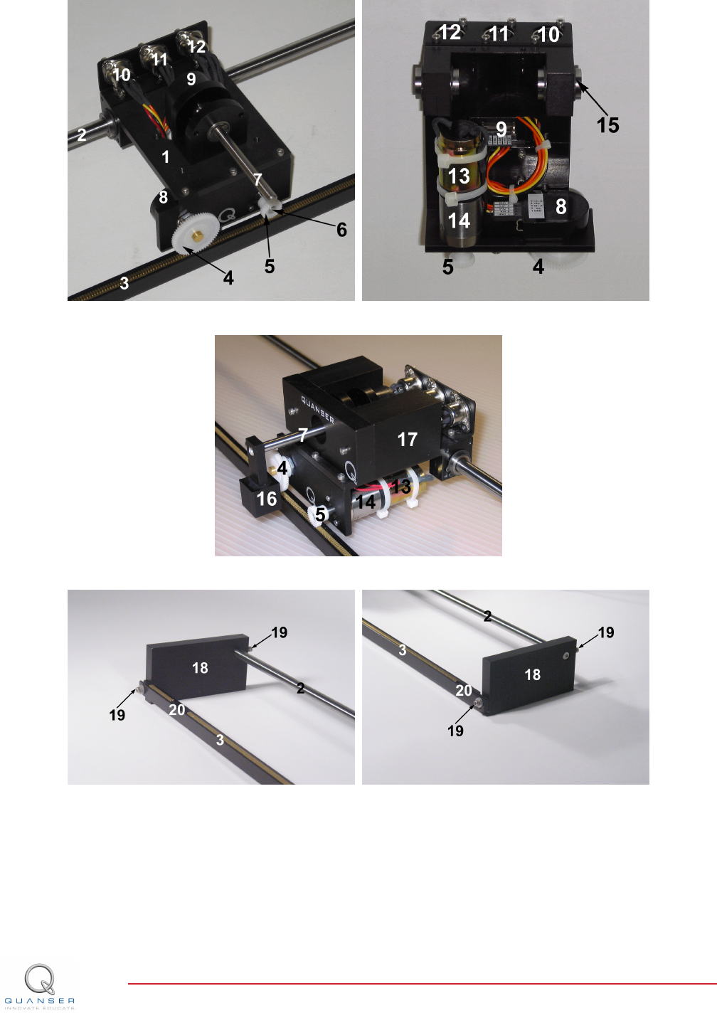
(a) Top view (b) Bottom view
(c) Front view
(d) Rack left end (e) Rack right end
Figure 3.1: IP02 components
IP02 User Manual v 1.0
4 WIRING PROCEDURE
The following is a listing of the hardware components used in this experiment:
1. Power Amplifier: Quanser VoltPAQ-X1, or equivalent.
2. Data Acquisition Board: Quanser Q1-cRIO, Q2-USB, Q8-USB, QPID/QPIDe, NI DAQ, or equivalent.
See the corresponding documentation for more information on these components. The cables supplied with the
IP02 are described in Section Section 4.1 and the procedure to connect the above components is given in Section
4.2.
Caution: When using the Quanser VoltPAQ-X1 power amplifier, make sure you set the Gain to 1!
Caution: If the equipment is used in a manner not specified by the manufacturer, the protection provided by the
equipment may be impaired.
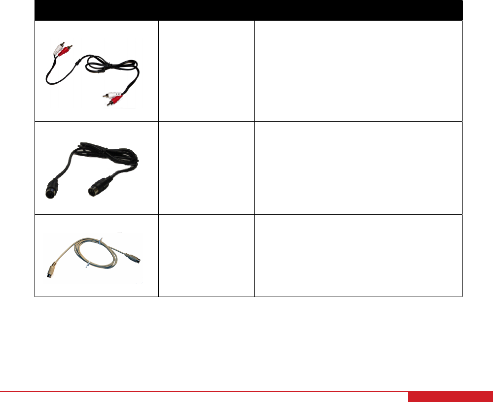
4.1 Cable Nomenclature
The cables used to connect the Quanser IP02 system with a power amplifier and data-acquisition device is shown
in Table 4.1. Depending on your configuration, not all these cables are necessary.
Cable Type Description
(a) RCA Cable
2xRCA to 2xRCA This cable connects an analog output of the
data acquisition terminal board to the power
module for proper power amplification.
(b) Motor Cable
4-pin-DIN to 6-pin-
DIN
This cable connects the output of the power
module, after amplification, to the DC motor.
(c) Encoder Cable
5-pin-stereo-DIN to
5-pin-stereo-DIN
This cable carries the encoder signals be-
tween an encoder connector and the data
acquisition board (to the encoder counter).
Namely, these signals are: +5 VDC power
supply, ground, channel A, and channel B
Table 4.1: Cables used to connect IP02 to amplifier and DAQ device
IP02 User Manual 10
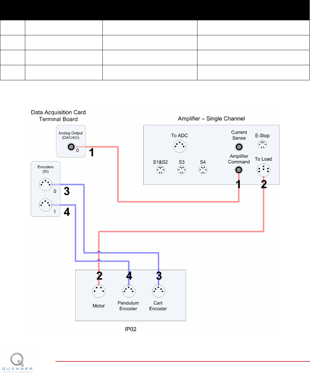
4.2 Typical Connections
This section describes the typical connections used to connect the IP02 plant to a data-acquisition board and a power
amplifier. The connections are described in detail in the procedure below, summarized in Table 4.2, and pictured in
Figure 4.1.
Note: The wiring diagram shown in Figure 4.1 is using a generic data aquisition device. The same connections
can be applied for any data-acquisition system that has at least 1x analog output, and 2x encoder inputs.
Cable
#
From To Signal
1 Terminal Board: Analog
Output #0
Amplifier Amplifier Command
connector
Control signal to the amplifier.
2 Amplifier: To Load con-
nector
IP02 Motor connector Power leads to the IP02 dc motor.
3 Terminal Board: Encoder
Input #0
IP02 Cart Encoder connector Cart encoder position measurement.
4 Terminal Board: Encoder
Input #1
IP02 Pendulum Encoder con-
nector
Pendulum encoder angle measure-
ment.
Table 4.2: IP02 Wiring
Figure 4.1: Connecting the IP02 to a Single-Channel Amplifier and Two-Channel DAQ
IP02 User Manual v 1.0

Follow these steps to connect the IP02 system:
1. Make sure that your data-acquisition device is installed and is operational. For example, if using the Quanser
Q2-USB see Reference [5].
2. Make sure everything is powered off before making any of these connections. This includes turning off your
PC and the amplifier.
3. Connect one end of the 2xRCA to 2xRCA cable from the Analog Output Channel #0 on the terminal board
to the Amplifier Command connector on the amplifier, i.e. use both white or both red RCA connectors. See
cable #1 shown in Figure 4.1. This carries the attenuated motor voltage control signal, Vm/Ka, where Kais
the amplifier gain.
4. Connect the 4-pin-stereo-DIN to 6-pin-stereo-DIN that is labeled from To Load on the amplifier to the Mo-
torconnector on the IP02. See connection #2 shown in Figure 4.1. The cable transmits the amplified voltage
that is applied to the SRV02 motor and is denoted Vm.
5. Connect the 5-pin-stereo-DIN to 5-pin-stereo-DIN cable from the Cart Encoder connector on the IP02 panel
to Encoder Input # 0 on the terminal board, as depicted by connection #3 in Figure 4.1. This carries the cart
position measurement.
6. Connect the 5-pin-stereo-DIN to 5-pin-stereo-DIN cable from the Pendulum Encoder connector on the IP02
panel to Encoder Input # 1 on the terminal board, as depicted by connection #4 in Figure 4.1. This carries the
pendulum angle measurement.
Caution: Any encoder should be directly connected to the data-acquisition terminal board (or equivalent)
using a standard 5-pin DIN cable. DO NOT connect the encoder cable to the amplifier!
IP02 User Manual 12

5 TESTING AND
TROUBLESHOOTING
This section describes some functional tests to determine if your IP02 is operating normally. It is assumed that the
IP02 is connected as described in the Section 4, above. To carry out these tests, it is preferable if the user can
use a software such as QUARCror LabVIEWrto read sensor measurements and feed voltages to the motor. See
Reference [4] to learn how to interface the IP02 with QUARC. Alternatively, these tests can be performed with a
signal generator and an oscilloscope.
5.1 Motor
5.1.1 Testing
Ensure the IP02 motor is operating correctly by going through this procedure:
1. Apply a small voltage to analog output channel #0 of the terminal board using, for example, the QUARC
software.
2. The cart should move to the right when facing the IP02 (facing the motor pinions with the cables connected to
the back).
5.1.2 Troubleshooting
If the motor is not responding to a voltage signal, go through these steps:
• Verify that the power amplifier is functional. For example when using the Quanser VoltPAQ device, is the green
LED lit?
• Check that the data-acquisition board is functional, e.g. ensure it is properly connected, that the fuse is not
burnt.
• Make sure the voltage is actually reaching the motor terminals (use a voltmeter or oscilloscope).
• If the motor terminals are receiving the signal and the motor is still not turning, your motor might be damaged
and will need to be repaired. Please see Section 6 for information on contacting Quanser for technical support.
5.2 Encoder
5.2.1 Testing
Follow this procedure to test the IP02 encoders:
1. Measure Encoder Input Channel #0 using, for instance, the QUARC software.
2. Move the IP02 cart towards the right side of the track. This movement should results in a positive change in
the cart position encoder counts at a rate of +4096 counts per revolution.
3. Similarly, rotating the IP02 free-falling pendulum (or pendulum socket) counter-clockwise, when facing the cart,
should result in a positive change in the pendulum encoder counts at a rate of +4096 counts per rotation.
IP02 User Manual v 1.0

Note: Some data acquisition systems do not measure in quadrature and, in this case, one-quarter of the
expected counts are received. In addition, some data acquisition systems measure in quadrature but increment
the count by 0.25 (as opposed to having an integer number of counts). Make sure the details of the data-
acquisition system being used is known. The counters on the Quanser DAQ boards measure in quadrature
and therefore a total of four times the number of encoder lines per rotation, e.g. a 1024-line encoder results in
4096 integer counts for every full rotation.
5.2.2 Troubleshooting
If the encoder is not measuring properly, go through this procedure:
• Check that the data-acquisition board is functional, e.g. ensure it is properly connected, that the fuse is not
burnt.
• Check that both the A and B channels from the encoder are properly generated and fed to the data-acquisition
device. Using an oscilloscope, there should be two square waves, signals A and B, with a phase shift of 90
degrees. If this is not observed then the encoder may be damaged and need to be replaced. Please see
Section 6 for information on contacting Quanser for technical support.
6 TECHNICAL SUPPORT
To obtain support from Quanser, go to http://www.quanser.com/ and click on the Tech Support link. Fill in the form
with all the requested software and hardware information as well as a description of the problem encountered. Also,
make sure your e-mail address and telephone number are included. Submit the form and a technical support person
will contact you.
IP02 User Manual 14
7 MAINTENANCE
7.1 Reducing IP02 Pinion Wear
The motor and encoder pinions will wear gradually over time as a result of regular use. If the motor pinion is wearing
or becoming damaged prematurely, consult the following checklist to improve the lifetime of the pinions:
1. Ensure that the track is firmly clamped to a flat surface. The following procedure should be followed when
clamping the track to a table:
(a) Loosen the track set screws located at either end of the track (Component #19 in Figure 3.1d and Figure
3.1e).
(b) Clamp one side of the track to the tabletop.
(c) Tighten the track set screw furthest away from the clamp.
(d) With the track flat and balanced, tighten the track set screw closest to the clamp.
Note: If necessary, two clamps can be used on either side of the track to ensure that the track remains straight
and does not move when is use.
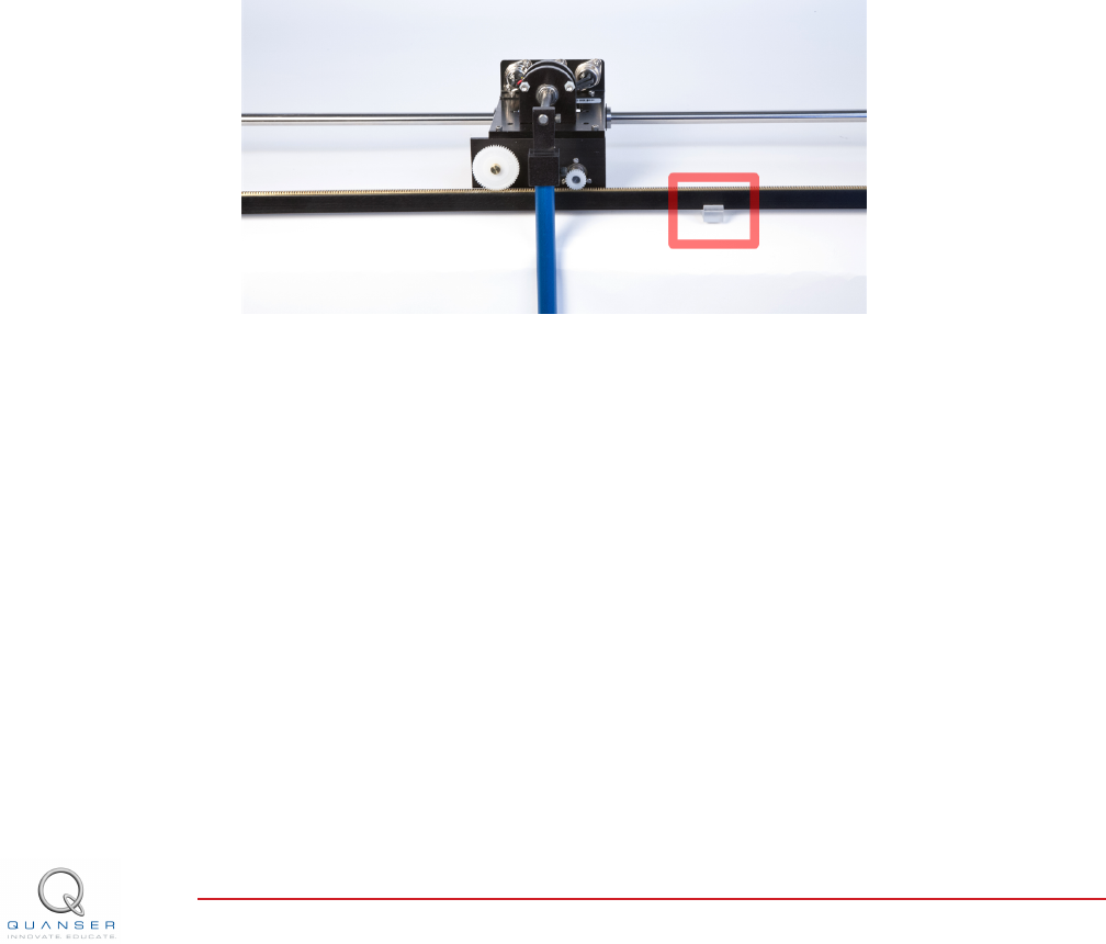
2. Check that the track support, shown in Figure 7.1, is located in the centre of the track
Figure 7.1: IP02 track support
3. Check that the pinions for both the endoder and the motor are aligned in the centre of the rack.
7.2 Replacing the IP02 Pinions
The IP02 comes with several replacement motor and encoder pinions. If you require additional units, contact your
local distributor for information on purchasing replacement component kits for the IP02.
Motor Pinion
To replace the motor pinion, slide the damaged pinion off of the motor shaft. You can also use a screwdriver to gain
additional leverage, but be careful not to damage the IP02 cart while removing the pinion. We recommend using a
Track-Brad-Staple Puller (McMaster-Carr #5865A11) with some additional padding to prevent damage to the cart,
as shown in Figure 7.2.
IP02 User Manual v 1.0

Figure 7.2: Pinion removal tool
Encoder Pinion
The encoder pinion can be removed by loosening the set screw located on the pinion, and sliding the pinion off the
encoder shaft by hand.
Note: Make sure to adjust the motor and encoder pinions to ensure that they are located in the centre of the rack.
This will prevent uneven wear on the pinions.
IP02 User Manual 16

REFERENCES
[1] US Digital. E2 Optical Kit Encoder, 2007.
[2] Faulhaber. DC-Micromotors Series 2338, 2002.
[3] Faulhaber. Planetary Gearhead Series 23/1, 2002.
[4] Quanser Inc. IP02 QUARC Integration, 2008.
[5] Quanser Inc. Q2-USB Data-Acquisition System User's Guide, 2010.
IP02 User Manual v 1.0
CAPTIVATE. MOTIVATE. GRADUATE.
Solutions for teaching and research. Made in Canada.
INFO@QUANSER.COM +1-905-940-3575 QUANSER.COM CAPTIVATE. MOTIVATE. GRADUATE.
Solutions for teaching and research. Made in Canada.
INFO@QUANSER.COM +1-905-940-3575 QUANSER.COM
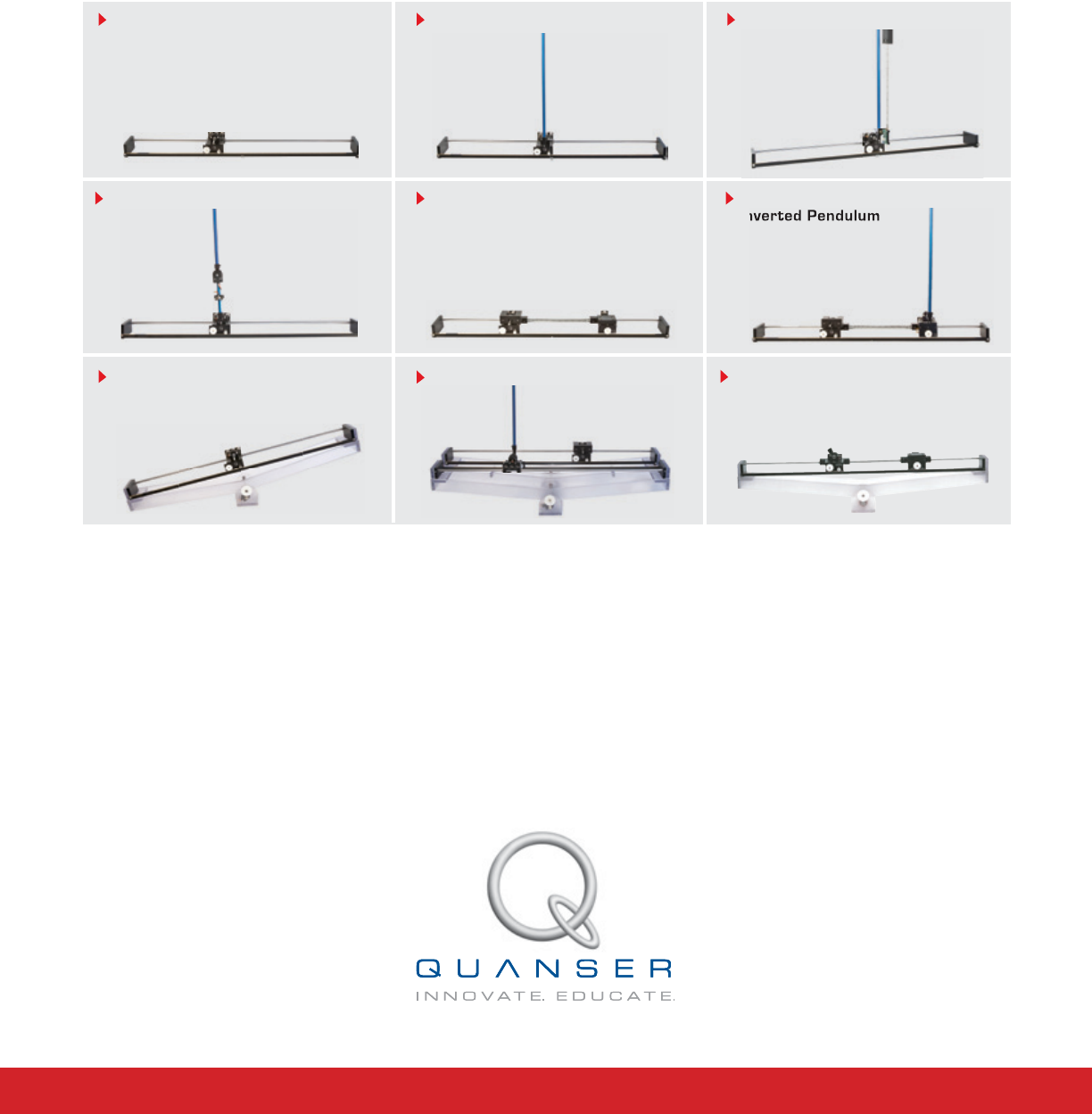
Nine linear motion plants for teaching fundamental and advanced controls concepts
Linear Flexible Joint Linear Flexible Joint with
Inverted Pendulum
Seesaw Pendulum
Seesaw
Inverted Pendulum
Linear PendulumIP02 Base Unit Linear Flexible Inverted Pendulum
Linear Double Inverted Pendulum
Quanser’s linear collection allows you to create experiments of varying complexity – from basic to advanced. With nine
plants to choose from, students can be exposed to a wide range of topics relating to mechanical and aerospace
engineering. For more information please contact info@quanser.com
©2012 Quanser Inc. All rights reserved.
Linear Flexible Joint on Seesaw
