Linear Servo Base With Pendulum Quick Start Guide (MATLAB)
Linear%20Servo%20Base%20with%20Pendulum-Quick%20Start%20Guide%20(MATLAB)
Linear%20Servo%20Base%20with%20Pendulum-Quick%20Start%20Guide%20(MATLAB)
User Manual:
Open the PDF directly: View PDF ![]() .
.
Page Count: 4
Quick Start Guide: Linear Servo Base Unit and Pendulum
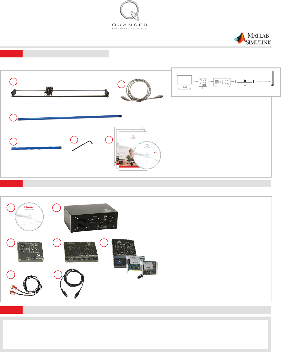
Check Components and Details
STEP 1
Make sure your Linear Servo Base Unit and Pendulum module includes the following components:
1. Linear Servo Base Unit
2. Set of two 5-pin DIN to 5-pin DIN encoder cables
3. Long (0.6m) pendulum
4. Medium (0.34m) pendulum
5. 7/64’ Allen key
6. Quanser Workstations Resources DVD*
(includes controllers; digital versions of User
Manuals, Quick Start Guide and courseware;
and other les)
*DVD supplied with the QUARC Real-Time Rapid
Control Prototyping Software, see Step 2
2
1. QUARC Real-Time Rapid Control Prototyping
Software Installation DVD
2. Power Amplier (VoltPAQ-X1 pictured)
3. One of the following data acquisition devices:
a. Quanser Q2-USB, or
b. Q8-USB, or
c. NI PCI/PCIe with Terminal Board
4. RCA to RCA cable
5. 4-pin DIN to 6-pin DIN motor cable
U
s
e
Q
U
A
R
C
R
e
a
l
-
T
i
m
e
R
a
p
i
d
C
o
n
t
r
o
l
P
r
o
t
o
t
y
p
i
n
g
S
o
f
t
w
a
r
e
t
o
c
o
n
t
r
o
l
o
v
e
r
8
0
Q
u
a
n
s
e
r
e
x
p
e
r
i
m
e
n
t
s
.
C
o
n
t
a
c
t
i
n
f
o
@
q
u
a
n
s
e
r
.
c
o
m
f
o
r
i
n
f
o
r
m
a
t
i
o
n
.
SOFTWARE INSTALLATION DVD
REAL-TIME RAPID CONTROL
PROTOTYPING SOFTWARE v2.3
R2011a, b and R2012a, b
For MATLAB®/Simulink®
For installation procedure please
refer to the Installation Guide on this DVD.
For assistance, contact tech@quanser.com
©
2
0
1
3
Q
u
a
n
s
e
r
I
n
c
.
A
l
l
r
i
g
h
t
s
r
e
s
e
r
v
e
d
.
w
w
w
.
q
u
a
n
s
e
r
.
c
o
m
U
s
e
Q
U
A
R
C
R
e
a
l
-
T
i
m
e
R
a
p
i
d
C
o
n
t
r
o
l
P
r
o
t
o
t
y
p
i
n
g
S
o
f
t
w
a
r
e
t
o
c
o
n
t
r
o
l
o
v
e
r
8
0
Q
u
a
n
s
e
r
e
x
p
e
r
i
m
e
n
t
s
.
C
o
n
t
a
c
t
i
n
f
o
@
q
u
a
n
s
e
r
.
c
o
m
f
o
r
i
n
f
o
r
m
a
t
i
o
n
.
RESOURCES DVD
TO SET UP QUANSER WORKSTATIONS
On this DVD:
•Quick start Guides
• Pre-designed Controllers
• User Manuals
• Instructor and Student Workbooks
or Laboratory Guides
For use with
©
2
0
1
3
Q
u
a
n
s
e
r
I
n
c
.
A
l
l
r
i
g
h
t
s
r
e
s
e
r
v
e
d
.
w
w
w
.
q
u
a
n
s
e
r
.
c
o
m
45
3c
Note: These components must be purchased separately.
12
3a 3b
Additional Components Required for Set Up
STEP 2
To complete the Linear Servo Base Unit and Pendulum set up, you will also need the following:
A. Make sure you have all required software, as listed in the QUARC Compatibility Table document located in the QUARC DVD folder.
B. See the QUARC Installation Manual for details on how to install the software.
C. Make sure you test the system using the Sine and Scope demo. You can access this by typing qc_show_demos in the Matlab prompt.
Install and Test QUARC
STEP 3
Servo Base Unit
Optional
Computer AmplifierDAQ Module
1
3
45 6
CAPTIVATE. MOTIVATE. GRADUATE. CAPTIVATE. MOTIVATE. GRADUATE.
USER MANUAL
IP02 Base Unit Experiment
Set Up and Configuration
Quanser educational solutions
are powered by:
STUDENT WORKBOOK
IP02 Base Unit Experiment for LabVIEW™ Users
Standardized for ABET* Evaluation Criteria
Developed by:
Jacob Apkarian, Ph.D., Quanser
Hervé Lacheray, M.A.SC., Quanser
Peter Martin, M.A.SC., Quanser
Quanser educational solutions
are powered by:
Course material
complies with:
CAPTIVATE. MOTIVATE. GRADUATE.
* ABET Inc., is the recognized accreditor for college and university programs in applied science, computing, engineering, and technology. Among the most respected accreditation
organizations in the U.S., ABET has provided leadership and quality assurance in higher education for over 75 years.
INSTRUCTOR WORKBOOK
IP02 Base Unit Experiment for LabVIEW™ Users
Standardized for ABET* Evaluation Criteria
Developed by:
Jacob Apkarian, Ph.D., Quanser
Hervé Lacheray, M.A.SC., Quanser
Peter Martin, M.A.SC., Quanser
Quanser educational solutions
are powered by:
Course material
complies with:
CAPTIVATE. MOTIVATE. GRADUATE.
* ABET Inc., is the recognized accreditor for college and university programs in applied science, computing, engineering, and technology. Among the most respected accreditation
organizations in the U.S., ABET has provided leadership and quality assurance in higher education for over 75 years.
U
s
e
Q
U
A
R
C
R
e
a
l
-
T
i
m
e
R
a
p
i
d
C
o
n
t
r
o
l
P
r
o
t
o
t
y
p
i
n
g
S
o
f
t
w
a
r
e
t
o
c
o
n
t
r
o
l
o
v
e
r
8
0
Q
u
a
n
s
e
r
e
x
p
e
r
i
m
e
n
t
s
.
C
o
n
t
a
c
t
i
n
f
o
@
q
u
a
n
s
e
r
.
c
o
m
f
o
r
i
n
f
o
r
m
a
t
i
o
n
.
SOFTWARE INSTALLATION DVD
REAL-TIME RAPID CONTROL
PROTOTYPING SOFTWARE v2.3
R2011a, b and R2012a, b
For MATLAB®/Simulink®
For installation procedure please
refer to the Installation Guide on this DVD.
For assistance, contact tech@quanser.com
©
2
0
1
3
Q
u
a
n
s
e
r
I
n
c
.
A
l
l
r
i
g
h
t
s
r
e
s
e
r
v
e
d
.
w
w
w
.
q
u
a
n
s
e
r
.
c
o
m
U
s
e
Q
U
A
R
C
R
e
a
l
-
T
i
m
e
R
a
p
i
d
C
o
n
t
r
o
l
P
r
o
t
o
t
y
p
i
n
g
S
o
f
t
w
a
r
e
t
o
c
o
n
t
r
o
l
o
v
e
r
8
0
Q
u
a
n
s
e
r
e
x
p
e
r
i
m
e
n
t
s
.
C
o
n
t
a
c
t
i
n
f
o
@
q
u
a
n
s
e
r
.
c
o
m
f
o
r
i
n
f
o
r
m
a
t
i
o
n
.
RESOURCES DVD
TO SET UP QUANSER WORKSTATIONS
On this DVD:
•Quick start Guides
• Pre-designed Controllers
• User Manuals
• Instructor and Student Workbooks
or Laboratory Guides
For use with
©
2
0
1
3
Q
u
a
n
s
e
r
I
n
c
.
A
l
l
r
i
g
h
t
s
r
e
s
e
r
v
e
d
.
w
w
w
.
q
u
a
n
s
e
r
.
c
o
m
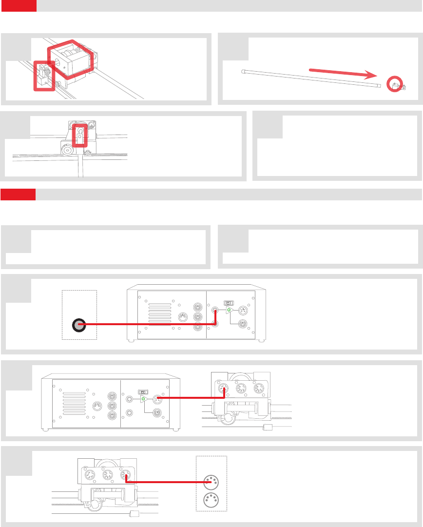
Set Up the Hardware
Wiring
STEP 4
STEP 5
To set up your Linear Servo Base Unit and Pendulum, please read the following instructions carefully. For full details, see the Linear
Servo Base Unit and Pendulum User Manual (enclosed with shipment).
B
D
Remove the T-tting and
additional weight from
the top of the Linear
Servo Base Unit cart,
if installed.
EUsing the 5-pin DIN to 5-pin DIN encoder
cable, connect the Encoder Channel #0
(EI #0) on the data acquisition (DAQ) device
to the Cart Encoder connector (CART ENC)
on the Linear Base Unit Cart.
Linear Servo Base Unit
Linear Servo Base Unit
MOTOR PEN ENC CART ENC
MOTOR PEN ENC CART ENC
Using the RCA to RCA cable,
connect Analog Output
Channel #0 (AO #0) on the
data acquisition (DAQ) device
to the Amplier Command
socket on the amplier.
Using the 4-pin DIN to 6-pin
DIN motor motor cable, con-
nect the To Load socket on
the amplier to the Motor
socket on the Linear Servo
Base Unit.
C
D
Analog Sensor
Inputs
S1&S2
Amplifier
Command
Current
Sense (1V=1A)
To Load
E-Stop
Amplifier Gain
1X 3X
To ADC
S3
S4
Analog Sensor
Inputs
S1&S2
Amplifier
Command
Current
Sense (1V=1A)
To Load
E-Stop
Amplifier Gain
1X 3X
To ADC
S3
S4
Amplier
Amplier
Analog
Output
(AO)
0
Data Acquisition Device
Encoders
(EI)
0
1
Data Acquisition Device
T-tting
Insert the long pendulum rod inside its T-tting.
Ensure that it sits properly. Tighten set screw as
required.
T-tting
Long Pendulum
Linear Servo Base Unit
Attach the pendulum, pointing
downwards, at the end of the
Linear Servo Base Unit cart’s
pendulum axis. Tighten the
T-tting set screw as required.
Ensure that he track is located at the
edge of a table so that the pendulum
is free to rotate 360-degrees in front of the cart.
It is recommended to clamp down the Linear
Servo Base Unit to the table (clamp not included).
The connections shown below are illustrated using a generic data acquisition (DAQ) device and a VoltPAQ-X1 amplier (you may have a
dierent DAQ or amplier). For detailed instructions, see the Linear Servo Base Unit and Pendulum User Manual (enclosed with shipment).
Before proceeding, set up and test your Linear Servo
Base Unit. For detailed instructions, see the Linear
Servo Base Unit Quick Start Guide or User Manual.
Make sure everything is powered OFF before
making any connections. This includes turning
o your PC and the amplier.
AB
C
A
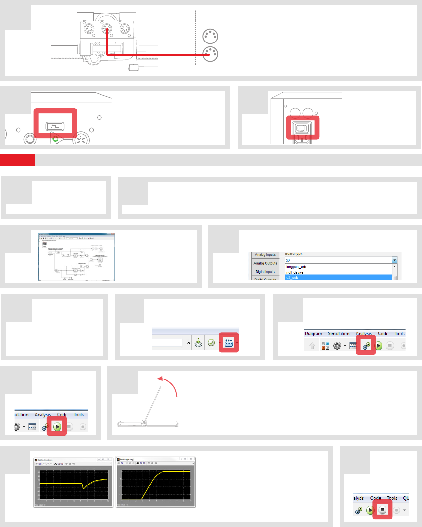
Testing the Linear Servo Base Unit and Pendulum
STEP 6
Make sure your
PC and amplier
are powered ON.
On the Resources DVD (supplied with the QUARC and Servo Base Unit package),
locate the Quick Start Folder: Linear\Linear Servo Base Unit\Quick Start.
Copy the Quick Start folder to your local hard drive.
AB
Analog Sensor
Inputs
S1&S2
Amplifier
Command
Current
Sense (1V=1A)
To Load
E-Stop
Amplifier Gain
1X 3X
To ADC
S3
S4
Attention VoltPAQ-X1 Users:
Make sure you set the GAIN on
the VoltPAQ-X1 to 1 when using
any Linear Servo Base Unit
experiment.
Turn ON the
power switch on
the VoltPAQ-X1. It
is located on the
rear of the device.
G H
100 VAC - 132 VAC or
200 VAC - 240 VAC
47Hz - 63Hz
F
U
S
E
F
U
S
E
F
U
S
E
F
U
S
E
Follow the procedure below to test your Linear Servo Base Unit and Pendulum module.
FG
H
Once the model code has been
compiled, click on the Connect
To Target button.
Click on the Run
button to start
the QUARC real-
time model.
Click on the Build Model button
on the Simulink model toolbar.
Scope view of the VI Front Panel
K
JThe pendulum should balance, and
the scopes should look similar to those
shown here. Once the pendulum is
balanced, try to disturb it as little as
possible. If the pendulum is unable to
balance, consult the Troubleshooting
section at the end of this guide.
Click on the
Simulink
Stop button to stop
the running model.
D
E
I
Double-click on the HIL Initialize block and choose the
board that is installed on your system (e.g. Q2-USB).
Open the Simulink
model le (.mdl)
found under the
Quick Start folder
on your hard drive.
FUsing the 5-pin DIN to 5-pin DIN encoder ca-
ble, connect the Pendulum Encoder socket
on the Linear Servo Base Unit panel to
the Encoder Channel #1 (EI #1) socket on
the data acquisition (DAQ) device.
Linear Servo Base Unit
MOTOR PEN ENC CART ENC
Data Acquisition Device
Encoders
(EI)
0
1
C
Slowly raise the pendulum to the upright position. When the pendulum
is close to vertical, the controller will activate and attempt to balance
the pendulum. Immediately release the pendulum when you feel the
balance controller engage. If there is a problem, immediately stop the
controller by clicking on the STOP button (see Step K). Do not attempt
to lower the pendulum manually once the controller has engaged!
Check that the
pendulum is resting
perfectly vertically with the
tip towards the ground.

Review the following recommendations before contacting Quanser’s technical support engineers.
TROUBLESHOOTING
1. Make sure the cables are rmly connected.
2. Check the connection outlined in Step 5 in this guide.
Getting an error
when trying to
build or run the
Quick Start Simu-
link model (.mdl)
A. Type ver in the Matlab Command Window and verify that QUARC is on the list. If not, then
go through the QUARC Quick Installation Guide to install QUARC. If it is listed, run mex -setup
as described in the the QUARC Installation Guide.
B. If the “… specic kernel level driver for the specied card could not be found” error is
prompted when you attempt to run, then you may not have selected the correct data
acquisition (DAQ) device in the HIL Initialize block or the DAQ device has not been installed
properly (refer to the DAQ device User Manual).
The Motor is
not responding.
A. Review connection Steps 5C tand 5D.
B. Ensure the power amplier is powered on and operational, i.e., when using VoltPAQ-X1,
verify that the green LED is lit.
C. Verify that the data acquisition (DAQ) device is functional. Go through the DAQ User Manual
for troubleshooting guidelines.
D. Ensure the voltage is actually reaching the motor terminals. See the Linear Servo Base Unit
and Pendulum User Manual for details.
The Encoder(s) is
(are) not reading.
A. Review connection in Steps 5E and 5F.
B. Verify that the data acquisition (DAQ) device is functional. Go through the DAQ User Manual
for troubleshooting guidelines.
©2013 Quanser Inc. All rights reserved. MATLAB® and Simulink® are registered trademarks of The MathWorks, Inc. V.1 5.3.2013
LEARN MORE To find out about the full range of Quanser Control modules,
visit www.quanser.com
LEARN MORE To find out about the full range of Quanser control experiments,
visit www.quanser.com
Expand the Linear Servo Base Unit to the following popular experiments using Quanser Linear control add-on modules.
For further assistance from a Quanser engineer, contact us at
tech@quanser.com or call +1-905-940-3575.
STILL NEED HELP?
Flexible Inver ted PendulumLinear Flexible Joint
Linear Pendulum Seesaw Pendulum
