Linear Structures Workflow Guide
User Manual:
Open the PDF directly: View PDF ![]() .
.
Page Count: 54
Linear Structures Workflow Guide
Autodesk
Global Consulting Delivery

Autodesk
Linear Structures Workflow Guide
Global Consulting Delivery
Page 1 of 53
© 2019 Autodesk
Version No: 2.0
The information in this document is to be considered Confidential to Autodesk, Inc., and cannot be reproduced or
redistributed without the prior written consent except internally for purposes of review and consideration of this document.
Executive Summary
This document is the guide to using the Autodesk Model Authoring process for Linear Structures which includes
the Dynamo CivilConnection and CivilPython technology packages as workflow enablers.
We define a linear structure as being any object either defined by a relationship with an alignment/profile or
discretely placed at a location that can be defined by a positional relationship with the alignment/profile for a road
or railway. Typically, these are tunnels and bridges, but could also be foundations for a gantry or a retaining wall
for waterways or pipelines.
Implementing this workflow facilitates efficient model information exchange for Linear Structures designs. The
benefits of this workflows are:
• Reduced time to manage design updates, avoiding manual rework and reducing the resources needed.
• Improved collaboration, connecting the models in real-time.
• Improved coordination, reducing the risks of out-of-date models and increasing model accuracy.
• Gaining advantage on the market modelling complex geometry and systems that are very difficult or
impossible to do with the interactive tools out-of-the-box.
• Achieving a higher return on the investment, using the appropriate tools in an organized workflow.
This document covers the roles involved in the Linear Structures workflow, their responsibilities in the process and
how they should collaborate and communicate.
The technology section provides a guide on how to prepare the tools, setup the design and manage model updates.
The CivilConnection package is the technology that enables an efficient model authoring process for Linear
Structures using Civil 3D and Revit.
CivilPython is a command for Civil 3D that allows to run Python scripts for Civil 3D. The scripts can access the
product .NET framework providing the flexibility of a scripting environment but without the overhead of compiling
the code.
In the last section of the document there is a list of the nodes contained in the current version of the CivilConnection
package with a brief description of their functionality.

Autodesk
Linear Structures Workflow Guide
Global Consulting Delivery
Page 2 of 53
© 2019 Autodesk
Version No: 2.0
The information in this document is to be considered Confidential to Autodesk, Inc., and cannot be reproduced or
redistributed without the prior written consent except internally for purposes of review and consideration of this document.
Contents
Executive Summary .............................................................................................................................................. 1
1 Introduction .................................................................................................................................................... 4
2 People ............................................................................................................................................................. 5
2.1 Roles and Responsibilities ......................................................................................................................... 5
2.2 Collaboration .............................................................................................................................................. 6
2.3 Communication .......................................................................................................................................... 7
3 Process ........................................................................................................................................................... 8
3.1 Tasks Description .................................................................................................................................... 10
3.2 BIM Uses ................................................................................................................................................. 19
4 Technology ................................................................................................................................................... 21
4.1 IT Requirements ...................................................................................................................................... 21
4.2 CivilConnection ........................................................................................................................................ 26
4.3 CivilPython ............................................................................................................................................... 44
CivilConnection Snippets ................................................................................................................................... 47
CivilConnection Nodes Quick Reference .......................................................................................................... 51
Document Control ............................................................................................................................................... 52
List of figures
Figure 1: Collaboration map example on a tunnel linear asset ............................................................................... 9
Figure 2: Volume definitions along an asset as illustrated in Figure 11 PAS 1192-2:2013 ................................... 10
Figure 3: Linear Assets Collaboration Map Template ........................................................................................... 11
Figure 4: Define and use a Unique Reference System file for Shared Coordinates in Revit ................................. 14
Figure 5: Define the target category for the IfcBuildingElementProxy class in the IFC ......................................... 15
Figure 6: Setup and Update an IFC link ................................................................................................................ 16
Figure 7: Publishing Shared Site to a Revit link instance ...................................................................................... 16
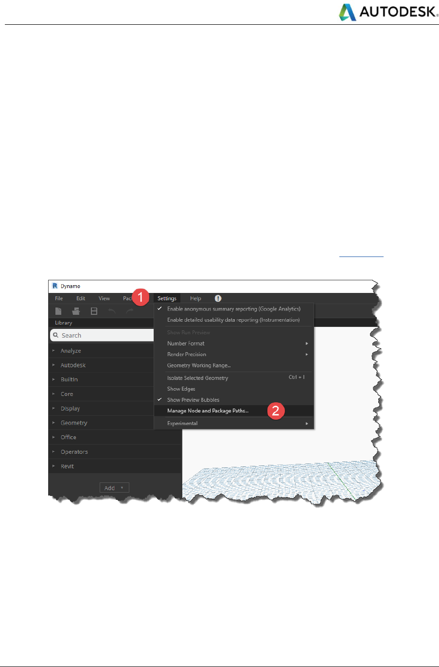
Figure 8: Manage Node and Package Paths ........................................................................................................ 27
Figure 9: Add new package paths to Dynamo settings ......................................................................................... 28
Figure 10: Civil 3D Workspace .............................................................................................................................. 28
Figure 11: Civil 3D Coordinate System ................................................................................................................. 29
Figure 12: Set Revit length units ........................................................................................................................... 29
Figure 13: CivilConnection in the Dynamo library ................................................................................................. 30
Figure 14: Access the Geometry Working Range in Dynamo ............................................................................... 31
Figure 15: Set the working range to Medium ........................................................................................................ 31
Figure 16: Point Codes in the Subassembly Composer ........................................................................................ 32
Figure 17: Civil 3D 2017 Property Sets on 3D Solids ............................................................................................ 33
Figure 18: IFC Import Settings .............................................................................................................................. 34
Figure 19: Example spreadsheet containing MEP Family selection and location parameters .............................. 39
Figure 20: Value error via Revit User Interface ..................................................................................................... 41
Figure 21: Change values via Dynamo ................................................................................................................. 42

Autodesk
Linear Structures Workflow Guide
Global Consulting Delivery
Page 3 of 53
© 2019 Autodesk
Version No: 2.0
The information in this document is to be considered Confidential to Autodesk, Inc., and cannot be reproduced or
redistributed without the prior written consent except internally for purposes of review and consideration of this document.
Figure 22: Conflict loading the CivilConnection 2018 in Revit 2017 ...................................................................... 43
Figure 23: The CivilConnection 2018 cannot connect to Civil 3D 2017 ................................................................. 43
Figure 24: Correct settings for the shortcut target ................................................................................................. 44
Figure 25: Excerpt of the script dumping Civil 3D Property Sets to a CSV file ...................................................... 45
Figure 26: Excerpt of the script populating Civil 3D Property Sets on objects reading from a CSV file ................. 46
Figure 27: CivilApplication ..................................................................................................................................... 47
Figure 28: GetDocuments ..................................................................................................................................... 48
Figure 29: GetCorridors ........................................................................................................................................ 48
Figure 30: GetCodes ............................................................................................................................................. 49
Figure 31: GetFeaturelinesByCode ....................................................................................................................... 50
List of tables
Table 1: Linear Structures Model Authoring RACI Matrix ........................................................................................ 5
Table 2: Revit 2017 IT Requirements .................................................................................................................... 21
Table 3: Revit 2018 IT Requirements .................................................................................................................... 22
Table 4: Revit 2019 IT Requirements .................................................................................................................... 22
Table 5: Revit 2020 IT Requirements .................................................................................................................... 23
Table 6: Civil 3D 2017 IT Requirements ............................................................................................................... 24
Table 7: Civil 3D 2018 IT Requirements ............................................................................................................... 24
Table 8: Civil 3D 2019 IT Requirements ............................................................................................................... 25
Table 9: Civil 3D 2020 IT Requirements ............................................................................................................... 25
Table 10: CivilConnection Shared Parameters ..................................................................................................... 35

Autodesk
Linear Structures Workflow Guide
Global Consulting Delivery
Page 4 of 53
© 2019 Autodesk
Version No: 2.0
The information in this document is to be considered Confidential to Autodesk, Inc., and cannot be reproduced or
redistributed without the prior written consent except internally for purposes of review and consideration of this document.
1 Introduction
The outcome of the Linear Structures BIM workflow is to establish a common language across multiple disciplines
involved in the design of linear assets, such as roads, tunnels and railways. This enables collaboration and
coordination of both the geometric and information models, reducing the effort needed to manage model changes.
The basic components of this common language are:
• Linear Coordinate Systems, which are used in linear infrastructures to describe the assets in space
using a set of linear coordinates (station, offset and elevation) rather than the more common X, Y, Z
coordinates in the Cartesian space.
• Lean Workflows, for which the ownership of model elements is explicitly defined so that there is no
duplication of work among disciplines. The modelling strategy uses the right tools for the right purpose to
maximize efficiency and reduce waste to a minimum. In this context, “waste” is the need for remodeling
something that has been other in a different platform with the connected risks of misinterpretation,
discrepancy and omissions.
• Interoperability, where the information contained in the different models is accessible to the other
disciplines and model authoring platforms. The models are correlated through a set of dynamic
relationships based on information rather than data. The PAS 1192-2: 2013 defines information as the
representation of data in a formal manner suitable for communication, interpretation or processing by
human beings or computer applications. The same norm defines data as information stored but not yet
interpreted or analyzed (for example a digital file).
The proposed solution is structured using the typical factors of successful technology implementation:
• People
• Process
• Technology
CivilConnection is a package for Dynamo for Revit that connects Revit and Civil 3D. The package enables
prototyping and interoperability between the two modeling environments.
CivilPython is a command for Civil 3D that allows to run Python scripts for Civil 3D. The scripts can access the
product .NET framework providing the flexibility of a scripting environment but without the overhead of compiling
the code.
Autodesk Consulting has developed these technology packages to support the Linear Structures Model Authoring
workflow.
Autodesk
Linear Structures Workflow Guide
Global Consulting Delivery
Page 5 of 53
© 2019 Autodesk
Version No: 2.0
The information in this document is to be considered Confidential to Autodesk, Inc., and cannot be reproduced or
redistributed without the prior written consent except internally for purposes of review and consideration of this document.
2 People
In using this framework of people, process, and technology, it is acknowledged that no matter how good technology
is and the processes that it may automate, without people engaged with the technology, understanding the daily
data requirements and adopting the process, the technology will not function.
Increasingly, national codes define the roles and responsibilities among design partnerships for authoring, sharing,
and validating the quality of information modeling received. But as new tools such as Dynamo appear, RACI
matrices need more tasks.
Despite the complexity that this seems to add, the solution simplifies collaboration by automating information format
conversion between applications that consume diverse data and facilitates communication amongst the design
parties by making that data transfer transparent.
2.1 Roles and Responsibilities
Role names in this document follow PAS1192-2:2013 guidance (link
1
). The table below extends “Table 2 –
Information exchange activities” in PAS1192, where section 7.5.1.6 says:
For successful information management exchange the following activities listed in Table 2
shall be undertaken at all stages of a project.
The roles involved in this process are the same as those defined in a task team for each discipline involved. The
responsibilities concerning the ownership and hierarchy of the model elements are defined on a project basis in
the BIM Execution Plan. The roles can be aspects of a person’s job. A role may be performed by more than one
person and a single person may act in more than one role. This is left to the project team’s discretion but should
be agreed at the outset.
Once the matrix of Model Element Authors has been defined for a linear structure type, the roles involved should
collaborate among disciplines to define the common references and interface protocols throughout the project
lifecycle.
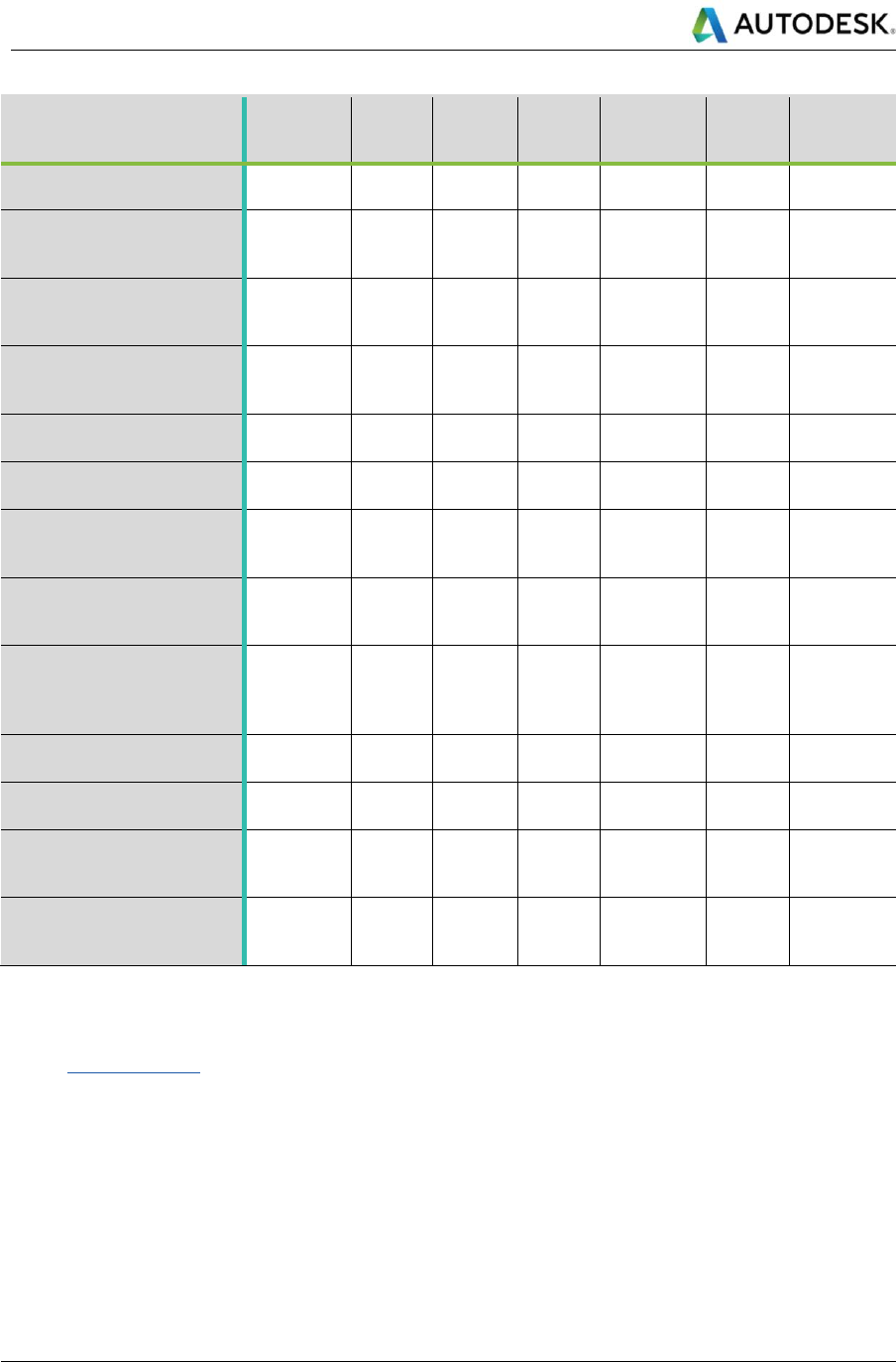
The following RACI matrix defines the different degrees of involvement of the typical roles in a task team.
• Responsible (R)
• Accountable (A)
• Consulted (C)
• Informed (I)
For more info on defining RACI and the model see http://racichart.org/the-raci-model/
Table 1: Linear Structures Model Authoring RACI Matrix
Activities
Project
Information
Manager
Project
Delivery
Manager
Lead
Designer
Task
Team
Manager
Task
Information
Manager
Interface
Manager
Information
Originator
Define model elements
ownership
A
I
R
C
I
C
C
Select technology systems
to author the model
elements
R
I
A
C
C
I
C
1
http://bim-level2.org/en/standards/ Accessed June 2018
Autodesk
Linear Structures Workflow Guide
Global Consulting Delivery
Page 6 of 53
© 2019 Autodesk
Version No: 2.0
The information in this document is to be considered Confidential to Autodesk, Inc., and cannot be reproduced or
redistributed without the prior written consent except internally for purposes of review and consideration of this document.
Activities
Project
Information
Manager
Project
Delivery
Manager
Lead
Designer
Task
Team
Manager
Task
Information
Manager
Interface
Manager
Information
Originator
Define point codes naming
convention
R
I
A
C
C
C
C
Define BIM Uses
requirements to implement
in the project
R
I
A
C
C
C
I
Define Model Authoring
strategy for the task-based
Civil 3D models
C
I
A
R
C
C
C
Set up dynamic
relationships between
inputs and Civil 3D models
C
I
I
A
C
C
R
Assign information via
property sets (*)
C
I
I
C
A
C
R
Set up Revit model Shared
Coordinates
A
I
I
C
C
I
R
Link IFC in Revit and
publish Shared
Coordinates (*)
C
I
I
A
C
C
R
Set up task-based dynamic
relationships between Civil
3D and Revit via Dynamo
C
I
I
A
C
C
R
Add or Subtract solids to
the corridor geometries for
coordination and detailing
(*)
C
I
I
A
C
R
C
Create Revit families of
continuous elements
C
I
I
A
C
C
R
Detail modelling of
continuous elements
I
I
I
A
C
R
C
Manage model
coordination and update
inputs
C
I
I
A
C
R
C
Prepare the models for
issue and enable other BIM
Uses
A
I
I
R
C
C
C
The tasks with a (*) may depend on the information requirements for the project.
See the tasks description in this document.
2.2 Collaboration
The information exchange is possible only if there is a collaboration framework in place. Design data should be
easily accessible to all the teams via a common data environment with a clear understanding of who may use the
data and for what purpose.
Collaboration is crucial for BIM because it reduces the risk of inconsistencies and mistakes. According to PAS
1192-2:2013 the definition of Level 2 BIM will continue to evolve around the core principle of the shared use of
individually authored models in a common data environment. The scope of Level 2 BIM workflows is the production
of coordinated design and construction information. The information models are usually exchanged in some form

Autodesk
Linear Structures Workflow Guide
Global Consulting Delivery
Page 7 of 53
© 2019 Autodesk
Version No: 2.0
The information in this document is to be considered Confidential to Autodesk, Inc., and cannot be reproduced or
redistributed without the prior written consent except internally for purposes of review and consideration of this document.
of data on a periodic base, for example federated models are exchanged for spatial coordination and review,
drawing sheets are issued for information as well as specifications for systems, elements and materials, etc. This
means the information contained in the models is captured in some format to support this exchange outside the
model authoring environments. Data must then be reinterpreted by the stakeholders to check the design content
and coordination. The interpretation is not effortless, it can cause mistakes and omissions and ultimately fail to
produce coordinated information models. The quality of the coordination of the information models in a collaborative
environment over time depends on the skills of the individuals and the effectiveness of the communication of design
changes. This can be achieved if there is clarity around the information structure and if the data interpretation is
simplified or even automated. In principle, the more frequently the information is exchanged the better coordinated
the discipline models will be. In practice, because of the coordination workflow limitations and because of the lack
of automated interpretation of the data, a change of a small entity in one discipline has the same impact of a change
of much more significance when updating models. To limit the costs of modeling, coordination exchanges are
restricted to the minimum necessary, but this does not really address the real problem which is, managing the
model updates efficiently.
One of the main goals of the Linear Structures workflow is to improve and simplify the collaboration process by:
• Reducing the effort of interpreting data: Defining a common language for Linear Structures across
disciplines, giving a common understanding of linear coordinate systems defined by stations, offset and
elevation. Involving all disciplines in the creation of the necessary tools to enable an efficient modeling
process (I.e. point codes naming convention per discipline on Civil 3D subassemblies).
• Managing model updates efficiently: Defining dynamic relationships to control model elements. Using
Dynamo to establish these logical relationships and capture the results in Revit and Civil 3D.
The information contained in the different model authoring environments becomes consistent and relevant. The
model elements are clearly assigned reducing the risk of inconsistencies. Thanks to the dynamic relationships the
model elements are connect to the information model that is driving them hierarchically.
2.3 Communication
Design teams should be able to communicate design changes and resolutions to coordinate model conflicts.
Effective communication can significantly improve the coordination process. Raising the awareness of the current
status of the design in a team should become a best practice in an agile, multi-disciplinary design environment.
Identifying all the changes that occurred between two coordination meetings is not always an easy task.
The communication among task teams starts at the very beginning of the design and continues through the work
stages. Disciplines should bring their requirements to define the necessary dynamic relationships to enable efficient
model management. For example, a naming convention for point codes, and therefore corridor feature lines, can
simplify the interpretation of the design data. It’s most beneficial to identify the key linear references across teams.
The Linear Structures workflow is based on the principle of data-transparency: all the task teams can have access
to the latest information models of other disciplines. The latest information can be used to update their own design
models or to communicate design intentions more effectively (e.g. the MEP engineer can place Placeholder solids
for openings in a concrete wall for the structural engineer to review).
In this workflow, there is less needing to request the latest information in a useable, published format from the other
disciplines. Nevertheless, a proactive approach to communication it is still the best option.

Autodesk
Linear Structures Workflow Guide
Global Consulting Delivery
Page 8 of 53
© 2019 Autodesk
Version No: 2.0
The information in this document is to be considered Confidential to Autodesk, Inc., and cannot be reproduced or
redistributed without the prior written consent except internally for purposes of review and consideration of this document.
3 Process
This process describes how to connect information models between Civil 3D and Revit, managing design updates
based on linear coordinate systems, using Dynamo to automate the workflow and maintain the dynamic
relationships between the model authoring environments.
Implementing this workflow facilitates efficient model information exchange for Linear Structures designs. The
benefits of this workflow are:
• Reduced time to manage design updates, avoiding manual rework and reducing the resources needed.
• Improved collaboration, connecting the models in real-time
• Improved coordination, reducing the risks of out-of-date models and increasing model accuracy.
• Gaining advantage on the market modelling complex geometry and systems that are very difficult or
impossible to do with the interactive tools out-of-the-box.
• Achieving a higher return on the investment, using the appropriate tools in an organized framework.
There are many possible entry points for this process, the common milestone is, as a minimum, a Civil 3D model
containing at least a corridor or an alignment with vertical profiles. The main goal is to enable a mechanism that
allows Civil 3D to update the model almost in real time. This is achieved by setting up the data shortcut in Civil 3D
and leveraging dynamic input updates (e.g. LandXML for alignments, surface and linear targets, etc.).
The next step is to define the dynamic relationships in the linear coordinate systems that describe the asset, in
other words to define the volumes along the asset.
In Civil 3D, this is done using the assemblies (the parametric components that define a linear asset cross-section),
the regions (the segments along the linear asset in which a given cross-section is applied to) and the targets (the
entity and constraints that enable the control of the linear asset overall geometry, e.g. surfaces, alignments, vertical
profiles, feature lines, and polylines). Each assembly is assigned to a region in the asset. Where this division occurs
is part of the modeling strategy that should be determined by design process, work breakdown and enabling
downstream BIM uses. Assemblies are positioned and maintained by Civil 3D according to the frequency settings
in a corridor.
Each assembly carries the information of the subassemblies, these are in turn defined by a set of points with a
code associated. The sequence of points with the same codes along the asset is used to create a string in the
space that is uniquely identified as a feature line. Every two points in a subassembly define a link, the links are
used to generate surfaces along the corridor. Each closed loop of links in a subassembly defines a shape that is
used to generate solids along the corridor.
Feature lines define the linear coordinate systems that can be used to build dynamic relationships with other objects
maintained via CivilConnection and Dynamo.
These relationships can be stored in Revit using shared parameters, stored on Civil 3D objects or serialized in an
spreadsheet, XML or similar.
When a change to the configuration of the linear coordinate systems is introduced, the design will update
recalculating the values of the dynamic relationships and updating the model in Civil 3D and Revit via Dynamo
CivilConnection.
Autodesk
Linear Structures Workflow Guide
Global Consulting Delivery
Page 9 of 53
© 2019 Autodesk
Version No: 2.0
The information in this document is to be considered Confidential to Autodesk, Inc., and cannot be reproduced or
redistributed without the prior written consent except internally for purposes of review and consideration of this document.
Figure 1: Collaboration map example on a tunnel linear asset
Structure
Transportation Architecture
MEP
Hydraulic
Geology
Survey
Outside
Tunnel
Inside
Tunnel
Inside
Tunnel
Outside
Tunnel
1
23
4
Civil 3D
Revit
• Electrical
• Piping
• Ventilation
• Shafts
• Drainage
• Fire Escape
• Utility Rooms
• Landscaping
• Plants
• Alignment
• Profiles
• Roadway
• Earthworks
• Tunnel
• Barriers
• Fire Resistance
• Lining System
Dynamo
CivilConnection
CivilPython
Autodesk
Linear Structures Workflow Guide
Global Consulting Delivery
Page 10 of 53
© 2019 Autodesk
Version No: 2.0
The information in this document is to be considered Confidential to Autodesk, Inc., and cannot be reproduced or
redistributed without the prior written consent except internally for purposes of review and consideration of this document.
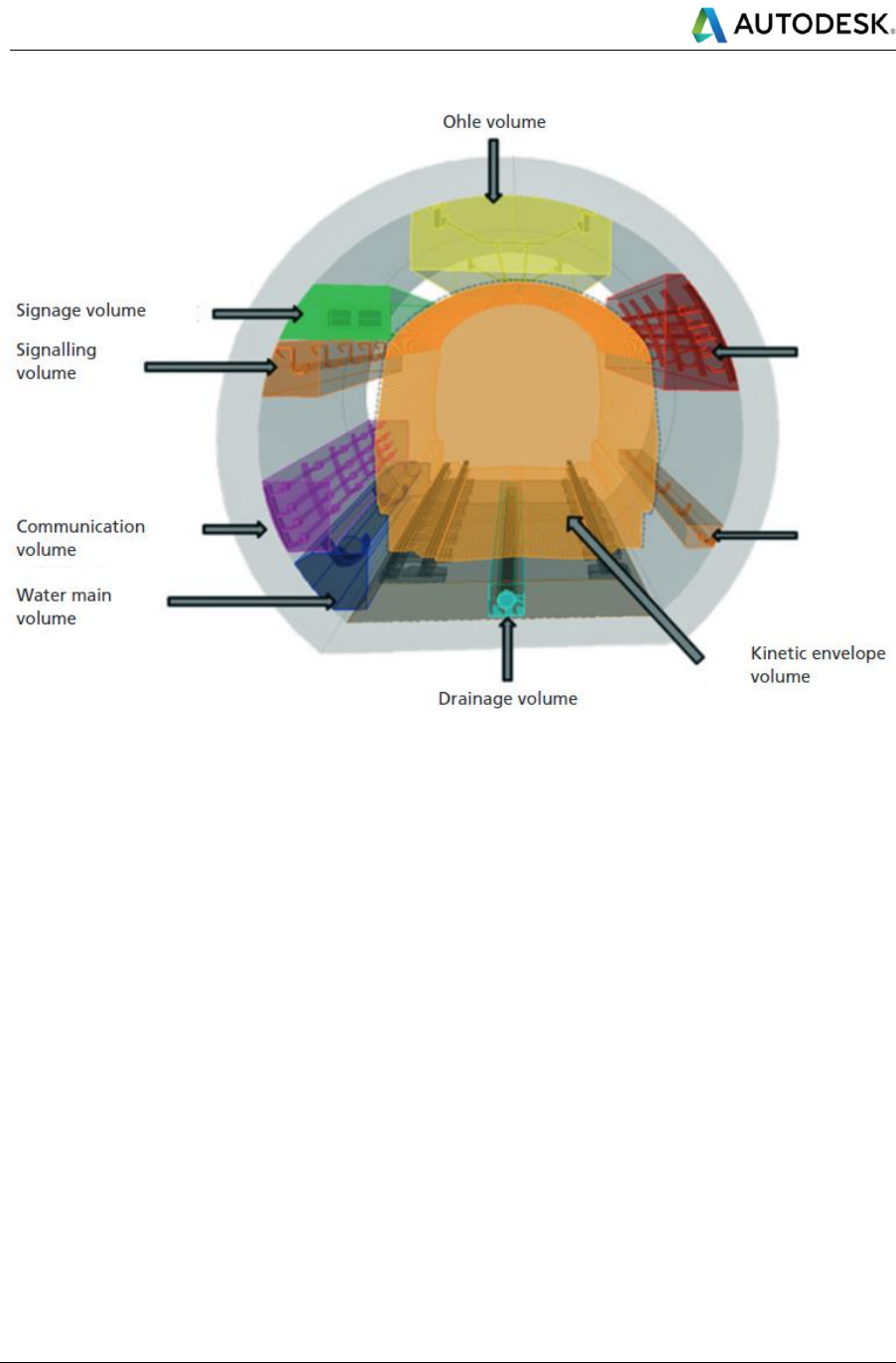
Figure 2: Volume definitions along an asset as illustrated in Figure 11 PAS 1192-2:2013
3.1 Tasks Description
This section describes the key tasks in Table 1, Linear Structures Model Authoring RACI Matrix.
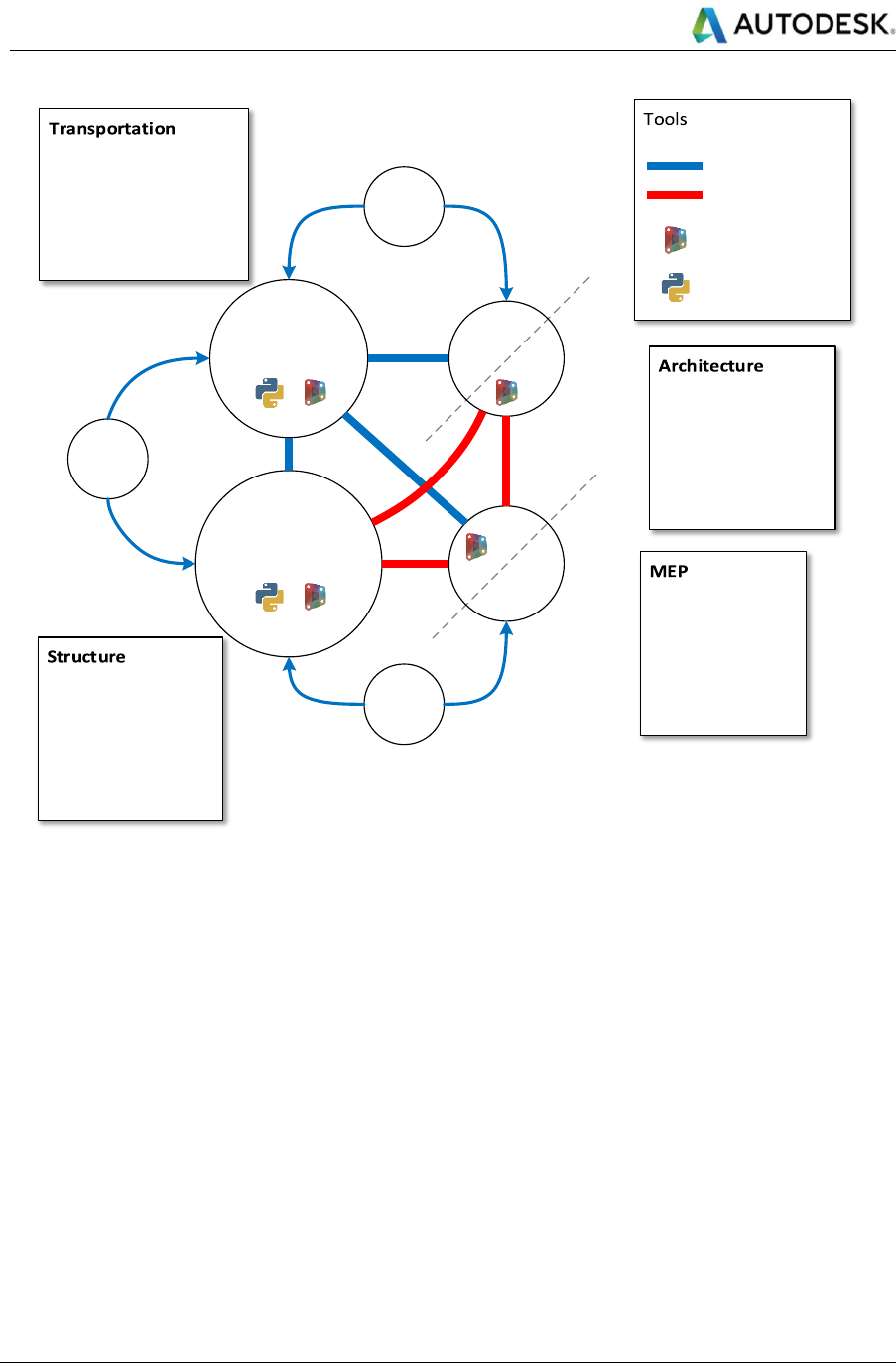
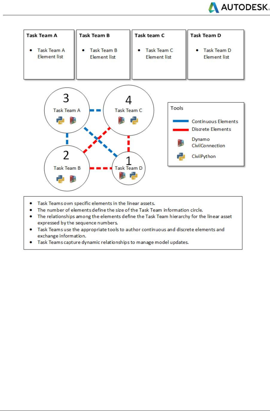
Define model elements ownership
At the beginning of a project, the task teams (i.e. discipline teams) list the real elements that needs to be defined
for a given linear asset. In doing so, the elements are grouped by task team ownership to avoid data redundancy.
The teams also underline the dependencies relationships between objects: this defines the elements and teams’
hierarchy and will be used to guide the information exchange and capturing the dynamic relationships to drive the
model elements. The result of this task is captured in the collaboration map: the number of elements and
information pertaining a task team defines the size of the team circle, but the hierarchy is derived from the object
relationships within the same disciplines and towards other disciplines.
Autodesk
Linear Structures Workflow Guide
Global Consulting Delivery
Page 11 of 53
© 2019 Autodesk
Version No: 2.0
The information in this document is to be considered Confidential to Autodesk, Inc., and cannot be reproduced or
redistributed without the prior written consent except internally for purposes of review and consideration of this document.
Figure 3: Linear Assets Collaboration Map Template
Select technology systems to author the model elements
Depending on the nature of the objects (continuous vs. discrete, linear vs. point) the project teams select the best
model authoring tools to model them. In general, Civil 3D is used to define the continuous/linear objects and
references (i.e. alignment and corridor feature lines) whilst Revit is used for discrete objects. Dynamo is used to
capture the intelligence that defines the objects relationships, create objects that would be otherwise difficult to
manage with Revit or Civil 3D only (i.e. openings along a tunnel wall, equipment along a feature line).
Define point codes naming convention
Point codes are used by Civil 3D to generate corridor feature lines. Without corridor feature lines, the Linear
Structures workflow is limited to the corridor baselines and there is not enough information to mimic the Revit
hosting capabilities. In a subassembly, there are potentially many point codes and each assembly can be
composed by several subassemblies. In turn, each region in a corridor can have as many feature lines and each
baseline can have multiple regions. Furthermore, a corridor can have multiple baselines, so the number of feature
lines and associated point codes can be difficult to manage. Without a clear, consistent and effective naming
convention for the point codes becomes difficult communicating the design intent and leverage the automation

Autodesk
Linear Structures Workflow Guide
Global Consulting Delivery
Page 12 of 53
© 2019 Autodesk
Version No: 2.0
The information in this document is to be considered Confidential to Autodesk, Inc., and cannot be reproduced or
redistributed without the prior written consent except internally for purposes of review and consideration of this document.
across multiple disciplines. A good naming convention defines a clear syntax and style, here are some
recommendations:
• Using underscores to separate words.
• Start a word with an upper case.
• Do not use abbreviations if not agreed in the BIM Execution Plan.
• Describe the object following a granularity principle (i.e. Assembly_element_subelement_vertical
location_horizontal location).
For example:
• Tunnel_ Wall1_Base_External
• Bridge_Deck_Top_Left
Whenever possible it is recommended to use the same Civil 3D Subassembly point code to represent a continuous
edge in the model across multiple regions. Point codes enable the Linear Structures workflow for all disciplines and
the naming convention should be part of the BIM Execution Plan.
Note that in CivilConnection a feature line is defined on a Civil 3D Corridor as opposed to a Land Feature Line that
is instead defined without the need for a corridor. A Feature Line in CivilConnection is always defined per baseline
region as opposed to an Auto Corridor Feature Lines in Civil 3D that can be joined across multiple baseline regions.
Define BIM Use requirements to implement in the project
Each BIM Use can affect the standard methods and procedures used to author the models. The requirements that
are necessary to enable the BIM Uses should be captured in the BIM Execution Plan and be mandatory for the
project team and the supply chain. The Project Information Manager is responsible for the definition of such
requirements as they impact on all disciplines, on the organization of the models and associated data.
Define Model Authoring strategy for the task-based Civil 3D models
The model is organised to maximise performance and enable the project BIM Uses. This has a direct impact on
how the disciplines are collaborating and coordinating the information models in the Linear Structures workflow.
The strategy adopted to build the Civil 3D models should be defined in the BIM Execution Plan. The point codes
discussion above is a part of this strategy, but work breakdown and model breakdown plans need to be developed
in order to maintain optimal performance of the model, the workflow and the team. This will include where to divide
corridors and regions, responsibilities for areas of the model and how dynamic links between model elements will
be built in order that when changes are made, the impact is obvious.
Model breakdown across linear project sites should be carefully considered and communicated into the Revit
shared coordinate system process as outlined below.
Set up dynamic relationships between inputs and Civil 3D models
Civil 3D offers a set of tools to facilitate the creation and management of the models so that they are dynamically
linked to the inputs. Adopting offset alignments, targets, extracting corridor feature lines, enable a safe workflow in
Civil 3D throughout the duration of the design cycle because ensure the models to be up-to-date with the latest
input regardless the complexity or the discipline. The inputs for a Civil 3D corridor can be LandXML or GENIO files,
2D DWGs, and even other Civil 3D corridor models. The crucial aspect is to identify the best methodology to update
the Civil 3D corridor definitions when a change in the inputs should occur. The recommendation is to use an
approach that raises the awareness with the user that a change happened and that provides an easy way to trigger
the necessary updates is the user wish to do so.
One of the methodologies that is present natively in Civil 3D regards the data shortcuts.

Autodesk
Linear Structures Workflow Guide
Global Consulting Delivery
Page 13 of 53
© 2019 Autodesk
Version No: 2.0
The information in this document is to be considered Confidential to Autodesk, Inc., and cannot be reproduced or
redistributed without the prior written consent except internally for purposes of review and consideration of this document.
This feature enables an effective collaboration across several Civil 3D models improving the performance and
preserving the dynamic links with the inputs. Data short cuts should be defined in the BIM Execution Plan.
Since Civil 3D 2017 the objects suitable for shared references via data short cuts are surfaces, alignments and
associated profiles and corridors. See further references on Data Shortcuts.
Assign information via property sets
A property set is a collection of parameters that can be applied to an instance of an AutoCAD object. The definition
of the property set contains also the type of objects it is applicable to. Setting the Civil 3D system variable
AECPSDAUTOATTACH to 1 it is possible to assign the property sets automatically to all the objects of the same
type. See further references for property sets.
Since Civil 3D 2017 it is possible to expand and maintain the property sets on corridor solids at the moment of their
extraction. The information contained in the property sets contributes to fulfil the EIRs and AIRs. It is important not
to lose the information attached throughout the process regardless of the authoring platform.
Civil 3D exposes the property sets via the STYLEMANAGER command and they can be transferred between
projects via the Design Centre. Property sets are customizable, and they support different kinds of value types,
texts, numbers and even enumerations or lists. The values can be dynamically calculated using formulae or reading
other properties from the objects.
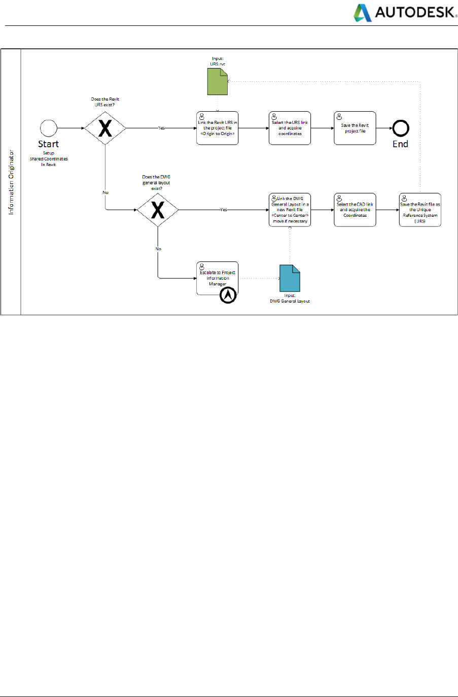
Set up Revit model Shared Coordinates
Revit is used in each discipline to model or capture the discrete elements in a linear asset. The Revit model must
acquire the coordinates so that the local origin is close to the location of the linear asset in the World Coordinate
System used in Civil 3D. This impacts how precisely the geometry of the corridor solids will be when using the IFC
export workflow, the closer the better. There are several ways to setup the shared coordinates system in a Revit
model. Autodesk recommend definition of a Unique Reference System (URS) file that is used across multiple
disciplines. Due to the Linear Structures typical project geographical extents, it is entirely possible that every asset
in the project will need to have its own URS file or at least its own shared site. The following diagram shows how
to create and use a URS file to acquire the shared coordinates from. The Project Information Manager is
responsible for the creation and maintenance of the URS files at a project level. In the Task Team, the Information
Originator is responsible for using the correct URS file for each model. The coordinates used for each asset should
be stored in the BIM Execution Plan. See further references on shared coordinates.
Autodesk
Linear Structures Workflow Guide
Global Consulting Delivery
Page 14 of 53
© 2019 Autodesk
Version No: 2.0
The information in this document is to be considered Confidential to Autodesk, Inc., and cannot be reproduced or
redistributed without the prior written consent except internally for purposes of review and consideration of this document.
Figure 4: Define and use a Unique Reference System file for Shared Coordinates in Revit
Autodesk
Linear Structures Workflow Guide
Global Consulting Delivery
Page 15 of 53
© 2019 Autodesk
Version No: 2.0
The information in this document is to be considered Confidential to Autodesk, Inc., and cannot be reproduced or
redistributed without the prior written consent except internally for purposes of review and consideration of this document.
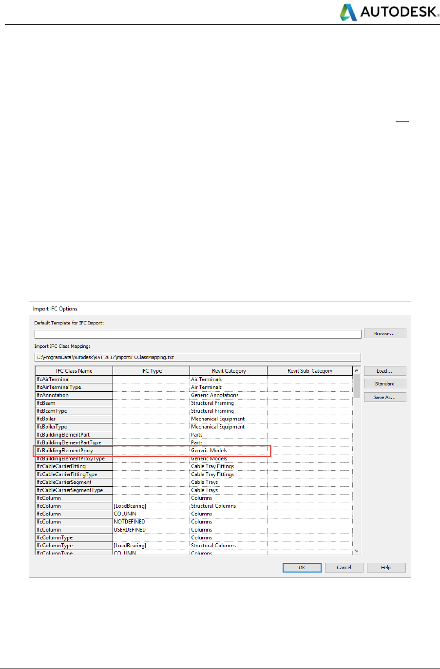
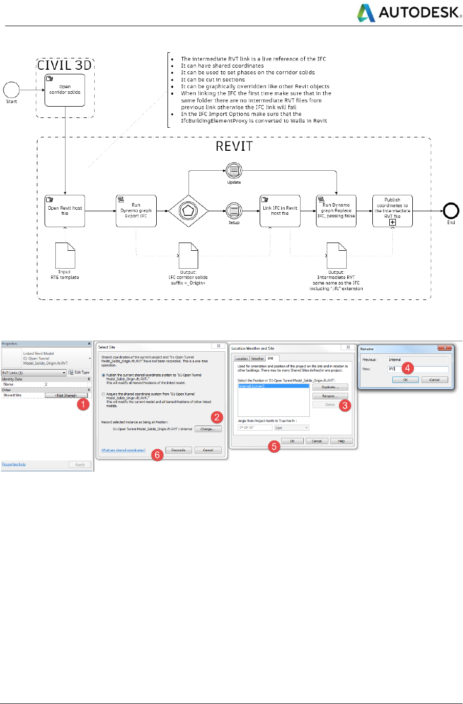
Link IFC in Revit and publish Shared Coordinates (*)
The fastest way to provide the geometry scope and information from Civil 3D and Revit is to use the IFC export of
the Civil 3D corridor solids.
This option is recommended for frequent updates and information exchange. The fast exchange comes with a price
of a tessellated geometry based on the IFC2x3 format that does not support Advanced BRep objects (link).
Even if smooth surfaces were supported, the corridor solids in Civil 3D are defined as unions of profiles rather than
lofts of more than two profiles, therefore they would appear in Revit as segmented at best. For a loft, smooth
transition representation of the corridor solids the reader should refer to the workflow that creates Revit families of
continuous elements. The IFC workflow could still be useful in particularly complex situations such as intersections.
Following some key considerations to enable the IFC export of corridor solids from Civil 3D with CivilConnection.
The corridor solids must be extracted to a clean DWG file to process exclusively the data important for the Linear
Structures workflow. The corridor solids will provide a context to enable other disciplines’ design or to embed linear
modifiers to increase the level of detail in the model. Using IFC allows to retain the geometry and the information
attached to the solids via property sets. The IFC is linked in Revit and converted to unmodifiable Revit objects that
can be used to continue with the design. To export the IFC in the local coordinate system defined in the Revit
model it is necessary to use the CivilConnection package in Dynamo. The following diagrams show the steps to
prepare, setup and updated the IFC link in this workflow.
Figure 5: Define the target category for the IfcBuildingElementProxy class in the IFC
Autodesk
Linear Structures Workflow Guide
Global Consulting Delivery
Page 16 of 53
© 2019 Autodesk
Version No: 2.0
The information in this document is to be considered Confidential to Autodesk, Inc., and cannot be reproduced or
redistributed without the prior written consent except internally for purposes of review and consideration of this document.
Figure 6: Setup and Update an IFC link
Figure 7: Publishing Shared Site to a Revit link instance
Set up dynamic relationships between Civil 3D and Revit via Dynamo
The Information Originator defines the dynamic relationships between the objects in Dynamo and uses the
CivilConnection to process the information contained in the Civil 3D corridors. Dynamo graph development should
be made referring to modelling techniques like use user stories, SIPOC diagrams or task workflows using UML or
BPMN or similar. In this way, it is possible to capture at a high level the functionality and the inputs necessary to
drive the creation of the model elements and provide guidance for their development. The automation requirements
should be captured and clarified with their rationale. Each should have test and fit criteria defined to guide the
development. The requirements must be prioritized and captured in the graph documentation.
Known issues and limitations should also be captured so that users are aware of situations where the graph can
produce unwanted results. This can serve as a starting point for future developments.
When the graph is defined and the logic for an asset in a project is captured it can stay, there is no need to change
it. Dynamo graphs used in previous projects for similar assets can be deployed in new projects. Dynamo graphs

Autodesk
Linear Structures Workflow Guide
Global Consulting Delivery
Page 17 of 53
© 2019 Autodesk
Version No: 2.0
The information in this document is to be considered Confidential to Autodesk, Inc., and cannot be reproduced or
redistributed without the prior written consent except internally for purposes of review and consideration of this document.
should be optimized to be used via Dynamo Player, a tool available since in Revit 2018.1 that creates a very
simplified interface for the Dynamo graphs inputs and hides the actual complexity with the graph. The set of graphs
is displayed in alphabetical order and this can be used to provide a naming convention that takes care of the
sequence in which each graph should be executed in the project. The users that are not familiar with Dynamo and
the detail of the implementation of each graph can still access the benefits of the automation.
The Revit elements created with CivilConnection will contain a set of shared parameters to enable the common
language around linear structures. For example, an object will carry references such as the corridor name or the
featureline code. These parameters are necessary to enable the update phase of the linear structures’ workflow.
CivilConnection makes sure to capture the GUID of objects created in the Revit model in an XML file to ensure that
the update process is safe and efficient when the Civil input model changes. Only the objects with the shared
parameters for the linear coordinates system compiled are safe to be updated. This enables also a very simple
mechanism to keep track of the changes to a model as the XML stored the name of the project, the user and the
date. The XML file is saved with the Revit model and it is named in the same way. The XML file is structured for
different kinds of objects: single point (i.e. most of the equipment), linear (i.e. pipes, ducts, cable trays, structural
framing, walls, etc.) or multipoint (i.e. adaptive components or floors). CivilConnection creates a new XML
automatically before the user executes the update workflow.
Add or Subtract solids to the corridor geometries for coordination and detailing (*)
CivilConnection enables the creation of discrete elements that would be difficult to model and maintain with Civil
3D only. These objects can be:
• Dynamo geometry environment and then imported in a Civil 3D document (“one-off").
• Revit elements linked into a Civil 3D document (“live link”).
CivilConnection logic is used to create, for example, walls that don’t exactly follow the corridor alignment (i.e. at
the interface between two regions with a different type of applied assembly in a corridor), or to add non-continuous
solids such as retaining walls counterforts.
The same approach can be used to create openings in the corridor solids to improve the coordination, truncate the
corridor for a skewed bridge or to improve the level of detail on the models.
When linking elements, if something changes in the Revit model this will be reflected in the Civil 3D model. If any
of those elements are projected on sections or profiles, the projections will be updated too.
The information can flow from Revit into Civil 3D and remain coordinated over time, this makes Civil 3D an ideal
environment for drawing production in the Linear Structures workflow as it natively provides support for longitudinal
profiles.
Create Revit families of continuous elements
In the design process a time will come when the design of the disciplines with more importance on the hierarchy of
the collaboration map can be considered fixed. The project team can consider the opportunity to further the
modelling and detailing of the continuous elements directly in Revit via CivilConnection. This approach is not
recommended until the drawing production is needed as it can be quite slow compared to the IFC workflow.
The information originator must specify the starting and ending stations for each baseline region as well as the key
stations along the corridor where the continuous elements change suddenly width or height (e.g. recesses,
widening, etc.). For this task it is possible to define a sample line group along the alignment that is used only with
this intent. The goal is to establish pairs of stations along a given baseline region for which is safe to loft multiple
cross-section profiles together without altering the design intent nor the precision of the model.

Autodesk
Linear Structures Workflow Guide
Global Consulting Delivery
Page 18 of 53
© 2019 Autodesk
Version No: 2.0
The information in this document is to be considered Confidential to Autodesk, Inc., and cannot be reproduced or
redistributed without the prior written consent except internally for purposes of review and consideration of this document.
CivilConnection will access the applied subassembly shapes or links in a baseline region of the corridor, extract
the geometry information and use it to create a Revit family with a free form element for each shape in the
subassembly. It is also possible to use a similar approach with geometry for the cross-section profiles that either is
generated in Dynamo or coming from Revit elements (e.g. adaptive components).
This approach comes with several pros:
• The representation of the continuous elements is smooth and not tessellated nor segmented.
• The outcome is a set of Revit families whose geometry can be altered in the Family Editor and adjusted
to accommodate construction detailing.
• The objects can have type, subcategories, materials.
• The objects are updated by CivilConnection, the Element Ids of the instances are preserved, only the
definition of the families is updated.
• The objects can be modified using parts.
• The objects can be used to host free form rebar.
There are also cons to take into consideration:
• The process of creation and update of these families can take quite some time compared to the IFC
workflow.
• Any manual modifications to the families will be lost in case of an update.
• The logic used to create the openings in the IFC workflow needs to be adjusted to target the Revit families
instead.
Detailed modelling of continuous elements
The linear modifiers (e.g. the openings along a tunnel, or skew angles for a bridge deck) have to be transferred
from the IFC workflow and adjusted to target the Revit families as opposed to the DWG solids in Civil 3D. The logic
used to create the tools used in the Boolean operations does not change. It is also possible use alternative detailing
techniques that involve the UI tools available in Revit:
• Edit the family geometry in the family editor with Boolean operations.
• Using parts in the project environment.
• Join and cut geometries with other family instances.
It is also possible to leverage the free form rebar modelling tools that have been introduced and continuously
improved since Revit 2018 onwards (e.g. Free Form Rebar surface based and rebar following a path since Revit
2019.2).
Manage model coordination and update inputs
The multidisciplinary coordination is simplified by adjusting and updating model elements with high accuracy using
an analytical/logical process to modify the linear coordinate systems values. The models update to reflect the
changes in the input discipline design. The effort required to update the models is reduced as the intelligence and
relationships used to drive the model definition is captured in the Dynamo graphs and the outcomes are stored in
the model authoring environments. Is also possible to update the geometries of the discrete Revit elements in Civil
3D as solids and used them in section views or profiles as projections. If the Revit elements should change, the
tools in CivilConnection and CivilPython will update the definitions of the solids in Civil 3D so that the documentation
views in will be updated with the latest discrete elements, preserving for example tags and labels.
Prepare the models for issue and enable other BIM Uses
The design data is authored in the ideal platforms for the type of elements required by the design. The information
is preserved and updated without data duplication or redundancy across platforms. The coordinated information

Autodesk
Linear Structures Workflow Guide
Global Consulting Delivery
Page 19 of 53
© 2019 Autodesk
Version No: 2.0
The information in this document is to be considered Confidential to Autodesk, Inc., and cannot be reproduced or
redistributed without the prior written consent except internally for purposes of review and consideration of this document.
models can be used to perform the BIM Uses defined in the BIM Execution Plan. The models and documentation
can be shared with the rest of the team for the authorised usage.
3.2 BIM Uses
Using IFC to connect Civil 3D to Revit introduces property sets and values on the objects that remain visible in
Revit. These properties define the linear coordinate system as a common language between the two authoring
platforms.
BIM Uses enabled by this data structure do not stop to Model Authoring: new workflows become possible and
existing workflows become better coordinated requiring less management efforts. Four example BIM uses are
described below but many others are possible by extension or adaptation of the workflow described in this
document.
Drawing production
The shape code assigned in a Civil 3D subassembly can be found as a parameter inside Revit objects after linking
an IFC. This can be used to create view filters in Revit. The view filter creation can be automated in Dynamo and
made available to all the Revit based projects using Transfer Project Standards. Using view filters, the visual
representation of the objects in the structural model can be customized to suit different documentation purposes.
Revit objects can be related to phases in a project and this has an impact on drawing production too. In this
workflow, the corridor objects in Civil 3D become Revit components after linking the IFC and can be associated to
the project phases. For Architecture and MEP disciplines, the plan views rely on Revit linked files, for the length of
the linear structure: it is rarely possible to find a unique horizontal level that encompasses all the objects at the
same time.
In Revit, there are two options to solve this issue: scope boxes or plan regions, neither are very user friendly and
can be difficult to maintain in case of design changes. One easy solution is to implement view filters to turn off slabs
in tunnels and use linked views to show specific levels in the Revit links (i.e. linked utility rooms along a tunnel).
The safest option is still to produce drawings in Civil 3D linking the discrete Revit elements and taking advantage
of the fact that Revit does not support the creation of longitudinal profiles.
3D Coordination
Identifying clashes means to compare models and testing for objects that either occupy the same space or that are
too close to each other. A classification system helps in organizing the clashes and prioritize the resolution actions.
In Linear Structures, using the World Coordinate System is sufficient to identify a clash in space but it is not ideal
in terms of resolution and Design Review because the model is built using a linear coordinate system. This
introduces unnecessary efforts to translate from one system to the other. In the proposed solution, the objects and
clashes can be grouped based on their station, offset and elevation values. The clash results can be related directly
to a portion of the linear structure giving more insights on the clash priorities and restraints to identify the resolution
actions to mitigate the clashes.
In Navisworks it is possible to create search sets using these values and the classification system to organize
Linear Structures models.
The resolution actions can be reflected in the modifications of the station, offset and elevation parameters of the
objects, Dynamo will update the location of the objects accordingly to the new parameter values against the Civil
3D corridor input.
Quantity Take-Off

Autodesk
Linear Structures Workflow Guide
Global Consulting Delivery
Page 20 of 53
© 2019 Autodesk
Version No: 2.0
The information in this document is to be considered Confidential to Autodesk, Inc., and cannot be reproduced or
redistributed without the prior written consent except internally for purposes of review and consideration of this document.
In buildings, the quantity take-offs are usually referenced to the levels and grid systems, in Linear Structures the
same concept is applied through chainage and cross-sections, to enable this organization, model elements must
contain information on station, offset and elevation.
4D Modelling
To associate a model object to an activity in the task’s hierarchy in a Gantt, a relationship based on a WBS code
is defined. In Linear Structures, the 4D Modelling is once more related to the linear coordinates.
In previous modelling this information was not available on Revit objects. With the proposed workflow, this
information can be used to create the assignment rules in Navisworks to enable, for example, the simulation of
construction fronts of a tunnel or segments of a bridge.
Typically, 4D Modelling for Linear Structures is documented through a space-time diagram: activities are at the
intersection of a specific chainage (column) at a specific time (row). This workflow is enabling a 3D visual
representation of this diagram.
Asset Management
The assets, the utility rooms, the signage, etc. along a Linear Structure are identified using the chainage. It is logical
that the model elements, regardless the platform, must comply with this Asset Information Requirement (AIR) since
the beginning of the project to keep track during the design phase, during the construction and procurement and
later for operation and maintenance.
Autodesk
Linear Structures Workflow Guide
Global Consulting Delivery
Page 21 of 53
© 2019 Autodesk
Version No: 2.0
The information in this document is to be considered Confidential to Autodesk, Inc., and cannot be reproduced or
redistributed without the prior written consent except internally for purposes of review and consideration of this document.
4 Technology
The CivilConnection is compatible with Civil 3D 2017-20, Revit 2017-20 and Dynamo 1.3-2.1.
The 2019 release has been developed specifically against Dynamo 2.0, The 2020 release has been developed
specifically against Dynamo 2.1.
CivilConnection is a package for Dynamo for Revit and needs to be installed locally on a machine or on a shared
network. In case of a network deployment, each Dynamo application on each machine needs configuration to look
for the CivilConnection package.
CivilPython is a set of commands for Civil 3D and needs to be installed locally on a machine. CivilPython leverages
the IronPython engine that comes with Dynamo for Revit, therefore Civil 3D and Revit must be installed on the
same machine. CivilPython contains commands that enable some workflows that are useful for CivilConnection,
therefore CivilPython needs to be installed and approved to use the full range of features present in
CivilConnection.
4.1 IT Requirements
Revit
Table 2: Revit 2017 IT Requirements
Autodesk Revit 2017
Requirements
Operating System
• Microsoft® Windows® 7 SP1 64-bit: Enterprise, Ultimate, Professional, or Home
Premium
• Microsoft® Windows® 8.1 64-bit: Enterprise, Pro, or Windows 8.1
• Microsoft® Windows® 10 64-bit: Enterprise, or Pro
CPU Type
Multi-Core Intel® Xeon®, or i-Series processor or AMD® equivalent with SSE2
technology. Highest affordable CPU speed rating recommended.
Autodesk® Revit® software products will use multiple cores for many tasks, using up
to 16 cores for near-photorealistic rendering operations.
Memory
16 GB RAM
• Usually sufficient for a typical editing session for a single model up to
approximately 700 MB on disk. This estimate is based on internal testing and
customer reports. Individual models will vary in their use of computer resources
and performance characteristics.
• Models created in previous versions of Revit software products may require
more available memory for the one-time upgrade process.
Video Display
1,920 x 1,200 or higher with true color
DPI Display Setting: 150% or less
Video Adapter
DirectX® 11 capable graphics card with Shader Model 5 as recommended by
Autodesk.
Disk Space
• 5 GB free disk space
• 10,000+ RPM (for Point Cloud interactions) or Solid State Drive
Media
Download or installation from DVD9 or USB key
Pointing Device
MS-Mouse or 3Dconnexion® compliant device
Autodesk
Linear Structures Workflow Guide
Global Consulting Delivery
Page 22 of 53
© 2019 Autodesk
Version No: 2.0
The information in this document is to be considered Confidential to Autodesk, Inc., and cannot be reproduced or
redistributed without the prior written consent except internally for purposes of review and consideration of this document.
Autodesk Revit 2017
Requirements
Browser
Microsoft® Internet Explorer® 7.0 (or later)
Connectivity
Internet connection for license registration and prerequisite component download
References
System Requirements for Autodesk Revit 2017 Products
Table 3: Revit 2018 IT Requirements
Autodesk Revit 2018
Requirements
Operating System
• Microsoft® Windows® 7 SP1 64-bit: Enterprise, Ultimate, Professional, or Home
Premium
• Microsoft® Windows® 8.1 64-bit: Enterprise, Pro, or Windows 8.1
• Microsoft® Windows® 10 64-bit:Enterprise, or Pro
CPU Type
Multi-Core Intel® Xeon®, or i-Series processor or AMD® equivalent with SSE2
technology. Highest affordable CPU speed rating recommended.
Autodesk® Revit® software products will use multiple cores for many tasks, using up
to 16 cores for near-photorealistic rendering operations.
Memory
16 GB RAM
• Usually sufficient for a typical editing session for a single model up to
approximately 700 MB on disk. This estimate is based on internal testing and
customer reports. Individual models will vary in their use of computer resources
and performance characteristics.
• Models created in previous versions of Revit software products may require
more available memory for the one-time upgrade process.
Video Display
Ultra-High Definition Monitor
Video Adapter
DirectX 11 capable graphics card with Shader Model 5.
A list of certified cards can be found on the Autodesk Certified Hardware page
Disk Space
• 5 GB free disk space
• 10,000+ RPM (for Point Cloud interactions) or Solid State Drive
Media
Download or installation from DVD9 or USB key
Pointing Device
MS-Mouse or 3Dconnexion® compliant device
Browser
Microsoft® Internet Explorer® 7.0 (or later)
Connectivity
Internet connection for license registration and prerequisite component download
References
System Requirements for Autodesk Revit 2018 Products
Table 4: Revit 2019 IT Requirements
Autodesk Revit 2019
Requirements
Operating System
• Microsoft® Windows® 7 SP1 64-bit: Enterprise, Ultimate, Professional, or Home
Premium
• Microsoft® Windows® 8.1 64-bit: Enterprise, Pro, or Windows 8.1
• Microsoft Windows 10 Anniversary Update 64-bit (version 1607 or higher):
Enterprise, or Pro

Autodesk
Linear Structures Workflow Guide
Global Consulting Delivery
Page 23 of 53
© 2019 Autodesk
Version No: 2.0
The information in this document is to be considered Confidential to Autodesk, Inc., and cannot be reproduced or
redistributed without the prior written consent except internally for purposes of review and consideration of this document.
Autodesk Revit 2019
Requirements
CPU Type
Multi-Core Intel® Xeon®, or i-Series processor or AMD® equivalent with SSE2
technology. Highest affordable CPU speed rating recommended.
Autodesk® Revit® software products will use multiple cores for many tasks, using up
to 16 cores for near-photorealistic rendering operations.
Memory
16 GB RAM
• Usually sufficient for a typical editing session for a single model up to
approximately 700 MB on disk. This estimate is based on internal testing and
customer reports. Individual models will vary in their use of computer resources
and performance characteristics.
• Models created in previous versions of Revit software products may require
more available memory for the one-time upgrade process.
Video Display
Resolutions
Minimum:
1920 x 1200 with true color
Maximum:
Ultra-High (4k) Definition Monitor
Video Adapter
DirectX 11 capable graphics card with Shader Model 5.
A list of certified cards can be found on the Autodesk Certified Hardware page
Disk Space
• 5 GB free disk space
• 10,000+ RPM (for Point Cloud interactions) or Solid State Drive
Media
Download or installation from DVD9 or USB key
Pointing Device
MS-Mouse or 3Dconnexion® compliant device
Browser
Microsoft® Internet Explorer® 7.0 (or later)
Connectivity
Internet connection for license registration and prerequisite component download
References
System Requirements for Autodesk Revit 2019 Products
Table 5: Revit 2020 IT Requirements
Autodesk Revit 2020
Requirements
Operating System
Microsoft® Windows® 10 64-bit
• Windows 10 Enterprise
• Windows 10 Pro
CPU Type
Multi-Core Intel Xeon, or i-Series processor or AMD equivalent with SSE2
technology. Highest affordable CPU speed rating recommended.
Autodesk Revit software products will use multiple cores for many tasks.
Memory
32 GB RAM
• Usually sufficient for a typical editing session for a single model up to
approximately 700 MB on disk. This estimate is based on internal testing and
customer reports. Individual models will vary in their use of computer resources
and performance characteristics.
• Models created in previous versions of Revit software products may require
more available memory for the one-time upgrade process.
Autodesk
Linear Structures Workflow Guide
Global Consulting Delivery
Page 24 of 53
© 2019 Autodesk
Version No: 2.0
The information in this document is to be considered Confidential to Autodesk, Inc., and cannot be reproduced or
redistributed without the prior written consent except internally for purposes of review and consideration of this document.
Autodesk Revit 2020
Requirements
Video Display
Resolutions
Minimum:
1920 x 1200 with true color
Maximum:
Ultra-High (4k) Definition Monitor
Video Adapter
DirectX 11 capable graphics card with Shader Model 5.
Disk Space
• 30 GB free disk space
• 10,000+ RPM (for Point Cloud interactions) or Solid State Drive
Media
Download or installation from DVD9 or USB key
Pointing Device
MS-Mouse or 3Dconnexion® compliant device
Browser
Microsoft® Internet Explorer® 10.0 or higher
Connectivity
Internet connection for license registration and prerequisite component download
References
System Requirements for Autodesk Revit 2020 Products
Civil 3D
Table 6: Civil 3D 2017 IT Requirements
Autodesk Civil 3D 2017
Requirements
Operating System
• Microsoft® Windows® 10
• Microsoft Windows 8.1 with Update KB2919355
• Microsoft Windows 7 SP1
CPU Type
1 gigahertz (GHz) or faster 64-bit (x64) processor
Memory
8 GB or greater
Display Resolution
1600x1050 or higher with True Color.
125% Desktop Scaling (120 DPI) or less recommended.
Display Card
1600x1050 or greater True Color video display adapter; 128 MB VRAM or greater;
Pixel Shader 3.0 or greater; Direct3D®-capable workstation class graphics card.
Disk Space
16.0 GB
Browser
Windows Internet Explorer® 9.0 (or later)
Pointing Device
MS-Mouse compliant
Media (DVD)
Download and installation from DVD
Multiple Processors
Supported by the application
.NET Framework
.NET Framework Version 4.6
References
System Requirements Civil 3D 2017
Table 7: Civil 3D 2018 IT Requirements
Autodesk Civil 3D 2018
Requirements
Operating System
• Microsoft® Windows® 10
• Microsoft Windows 8.1 with Update KB2919355
• Microsoft Windows 7 SP1
CPU Type
1 gigahertz (GHz) or faster 64-bit (x64) processor
Memory
8 GB or greater
Autodesk
Linear Structures Workflow Guide
Global Consulting Delivery
Page 25 of 53
© 2019 Autodesk
Version No: 2.0
The information in this document is to be considered Confidential to Autodesk, Inc., and cannot be reproduced or
redistributed without the prior written consent except internally for purposes of review and consideration of this document.
Autodesk Civil 3D 2018
Requirements
Display Resolution
1920 x 1080 with True Color
Display Card
1920 x 1080 or greater True Color video display adapter; 128 MB VRAM or greater;
Pixel Shader 3.0 or greater; Direct3D®-capable workstation class graphics card.
Disk Space
16.0 GB
Browser
Windows Internet Explorer® 11 (or later)
Pointing Device
MS-Mouse compliant
Media (DVD)
Download and installation from DVD
Multiple Processors
Supported by the application
.NET Framework
.NET Framework Version 4.6
References
System Requirements Civil 3D 2018
Table 8: Civil 3D 2019 IT Requirements
Autodesk Civil 3D 2019
Requirements
Operating System
• Microsoft® Windows® 10 Anniversary Update (version 1607 or higher)
• Microsoft Windows 8.1 with Update KB2919355
• Microsoft Windows 7 SP1
Processor
Minimum: 2.5–2.9 GHz or faster processor
Recommended: 3+ GHz or faster processor
Memory
16 GB or more
Display Resolution
Conventional Displays:
1360 x 768 with True Color, and 125% Desktop Scaling (120 DPI) or less
recommended
High Resolution & 4K Displays:
Resolutions up to 3840 x 2160 with True Color (Windows 10 64-bit and capable
display card)
Display Card
1920 x 1080 or greater True Color video display adapter; 128 MB VRAM or greater;
Pixel Shader 3.0 or greater; Direct3D®-capable workstation class graphics card.
Disk Space
16.0 GB
Browser
Minimum: Internet Explorer® 11 or later
Recommended: Google™ Chrome
Pointing Device
MS-Mouse compliant
File Format Changes
AutoCAD .DWG format – R2018
Civil 3D Object format – R2018.2 ¹
¹ New vertical curve profile entities (fixed vertical curve by high or low point) are not
supported in Civil 3D 2018.
.NET Framework
.NET Framework Version 4.7
References
System Requirements Civil 3D 2019
Table 9: Civil 3D 2020 IT Requirements
Autodesk Civil 3D 2020
Requirements
Operating System
• Microsoft® Windows® 7 SP1 with Update KB4019990 (64-bit only)
• Microsoft Windows 8.1 with Update KB2919355 (64-bit only)
Autodesk
Linear Structures Workflow Guide
Global Consulting Delivery
Page 26 of 53
© 2019 Autodesk
Version No: 2.0
The information in this document is to be considered Confidential to Autodesk, Inc., and cannot be reproduced or
redistributed without the prior written consent except internally for purposes of review and consideration of this document.
Autodesk Civil 3D 2020
Requirements
• Microsoft® Windows® 10 (64-bit only) (version 1803 or higher)
Processor
Minimum: 2.5–2.9 GHz or faster processor
Recommended: 3+ GHz or faster processor
Memory
16 GB or more
Display Resolution
Conventional Displays:
1920 x 1080 with True Color
High Resolution & 4K Displays:
Resolutions up to 3840 x 2160 supported on Windows 10, 64 bit systems (with
capable display card)
Display Card
1920 x 1080 or greater True Color video display adapter; 128 MB VRAM or greater;
Pixel Shader 3.0 or greater; Direct3D®-capable workstation class graphics card.
Disk Space
16.0 GB
Browser
Google Chrome (for AutoCAD web app)
Pointing Device
MS-Mouse compliant
File Format Changes
AutoCAD .DWG format – R2018
Civil 3D Object format – R2018.2 ¹
¹ New vertical curve profile entities (fixed vertical curve by high or low point) are not
supported in Civil 3D 2018.
.NET Framework
.NET Framework Version 4.7
References
System Requirements Civil 3D 2020
Dynamo
See Revit requirements.
4.2 CivilConnection
4.2.1 Usage
The CivilConnection package for Dynamo and the CivilPython for Civil 3D are licensed under Apache License,
Version 2.0
You may not use this file except in compliance with the License. You may obtain a copy of the License at
http://www.apache.org/licenses/LICENSE-2.0
Unless required by applicable law or agreed to in writing, software distributed under the License is distributed on
an "AS IS" BASIS, WITHOUT WARRANTIES OR CONDITIONS OF ANY KIND, either express or implied. See the
License for the specific language governing permissions and limitations under the License.
The project repository is https://github.com/Autodesk/civilconnection
Autodesk
Linear Structures Workflow Guide
Global Consulting Delivery
Page 27 of 53
© 2019 Autodesk
Version No: 2.0
The information in this document is to be considered Confidential to Autodesk, Inc., and cannot be reproduced or
redistributed without the prior written consent except internally for purposes of review and consideration of this document.
4.2.2 Installation
Copy the folder contained in the Zip file to the default location for Dynamo Revit packages or alternatively to a
custom location on the hard drive or on a shared network path. For a custom location, the path must also be added
in the Dynamo settings. For deployment, the Dynamo Settings XML can be copied on all machines to read form
the same location for the Dynamo packages.
The XML is located in the AppData folder, for Dynamo 1.3:
%APPDATA%\Dynamo\Dynamo Revit\1.3\DynamoSettings.xml
For Dynamo 2.0:
%APPDATA%\Dynamo\Dynamo Revit\2.0\DynamoSettings.xml
In the <CustomPackageFolders> </CustomPackageFolders> node add a <string> </string> node with an inner text
equal to the path to the folder that contains the packages.
Note: After installing CivilConnection in Dynamo for Revit it is necessary to install CivilPython, run it at least once
so that the user authorizes the loading of the necessary assemblies in Civil 3D. See the CivilPython section of this
document for further details.
Figure 8: Manage Node and Package Paths
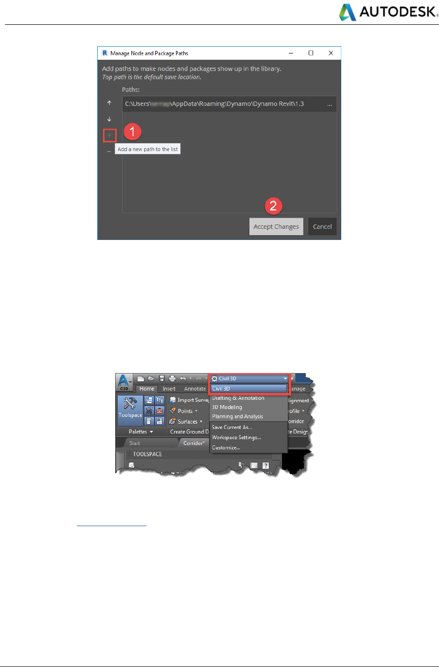
Autodesk
Linear Structures Workflow Guide
Global Consulting Delivery
Page 28 of 53
© 2019 Autodesk
Version No: 2.0
The information in this document is to be considered Confidential to Autodesk, Inc., and cannot be reproduced or
redistributed without the prior written consent except internally for purposes of review and consideration of this document.
Figure 9: Add new package paths to Dynamo settings
4.2.3 Preparation
This section illustrates some technical features to adopt when using CivilConnection.
Civil 3D
Make sure that Civil 3D is running and at least a document is open. The Workspace must be set to “Civil 3D”. Make
sure to align the drawing units between Civil 3D and Revit (metric or imperial). Make sure that Civil 3D has a single
viewport configuration.
Figure 10: Civil 3D Workspace
In Civil 3D, it is possible to setup the coordinate system to ensure a good interoperability with other software such
as InfraWorks. See further references.
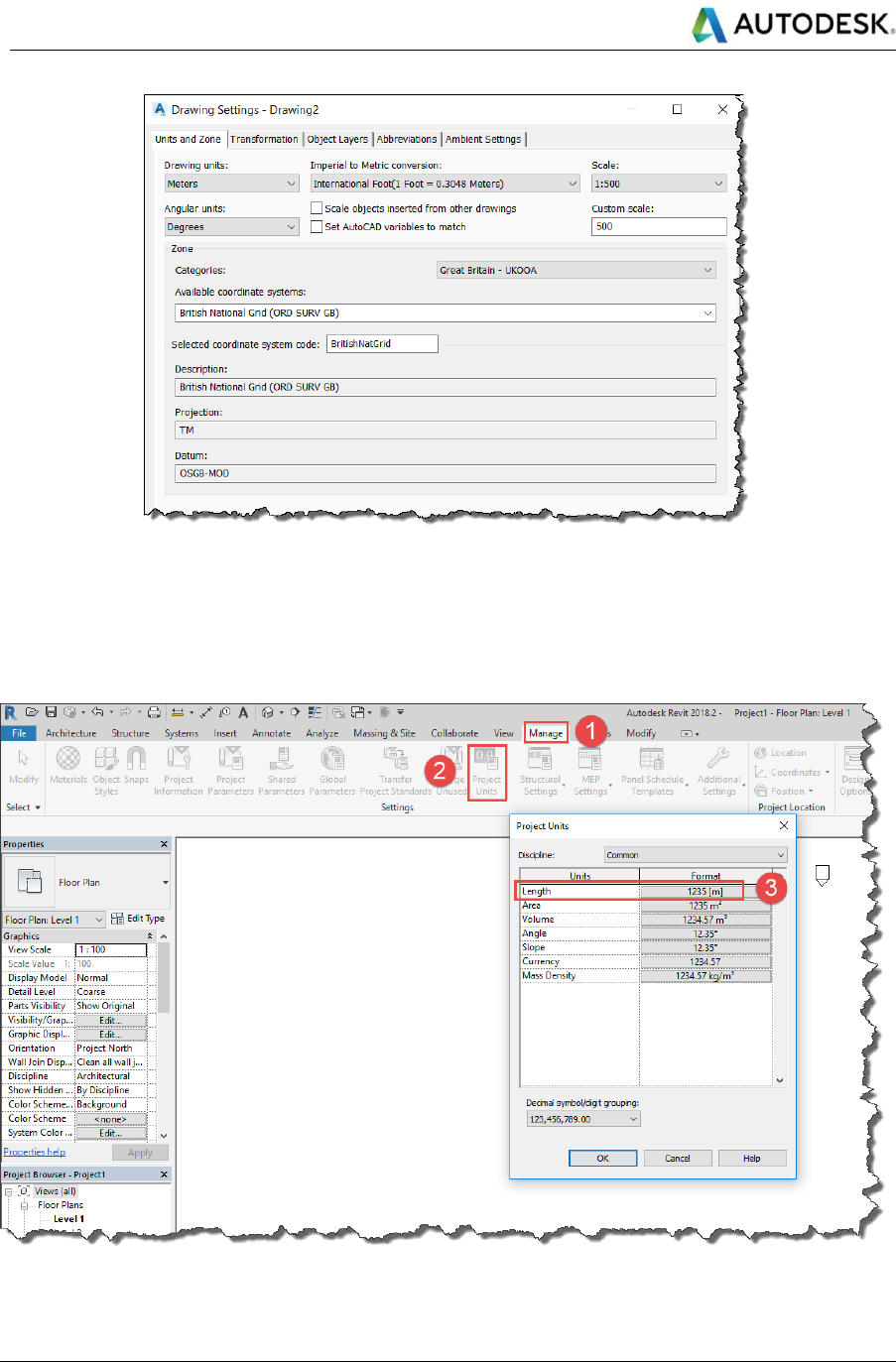
Autodesk
Linear Structures Workflow Guide
Global Consulting Delivery
Page 29 of 53
© 2019 Autodesk
Version No: 2.0
The information in this document is to be considered Confidential to Autodesk, Inc., and cannot be reproduced or
redistributed without the prior written consent except internally for purposes of review and consideration of this document.
Figure 11: Civil 3D Coordinate System
Revit
The Dynamo environment will adopt the same units as the Revit document that hosts the Dynamo session. The
CivilApplication node automatically sets the Revit project length units to those in use in the active document in Civil
3D. The user can restore the length units’ settings when using graphs that do not contain CivilConnection nodes.
Figure 12: Set Revit length units
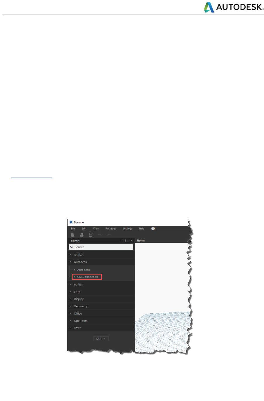
Autodesk
Linear Structures Workflow Guide
Global Consulting Delivery
Page 30 of 53
© 2019 Autodesk
Version No: 2.0
The information in this document is to be considered Confidential to Autodesk, Inc., and cannot be reproduced or
redistributed without the prior written consent except internally for purposes of review and consideration of this document.
Make sure that the Revit document shares coordinates with a Civil 3D document so that the linear asset satisfies
the 20-mile limitation from the start-up position of the project base point.
The recommendation is to create a circle in Civil 3D, centred around the linear asset, if necessary round the
coordinates of the circle centre point via the Properties palette (make sure the World Coordinate System is active).
Select the circle and call the write block command (WBLOCK) to create an empty DWG that contains only the
circle in the same coordinates.
Select the path on the file system where to save the new DWG, keep the units to meters and discard the Map 3D
data.
Once in Revit, activate a plan view and hide all categories (model, annotation) and leave only the Site > Project
Base Point sub-category visible.
Link the newly created DWG in the current view by “Center to Center”.
Acquire the coordinates from the linked DWG.
At the end the Project Base Point reports the same coordinates as the circle in Civil 3D, the Revit file is setup
correctly.
See further references.
Dynamo
Verify that the CivilConnection package is correctly loaded in Dynamo. The AutodeskYYYY shelf will appear in the
library and this will contain the CivilConnection nodes. Ignore the Autodesk shelf that appears immediately above
CivilConnection.
Figure 13: CivilConnection in the Dynamo library
Set the geometry working range to Medium and ignore the warnings associated to these settings during execution.
Changing the settings to other options (i.e. Large or Extra-Large) affects the accuracy in the geometry objects.
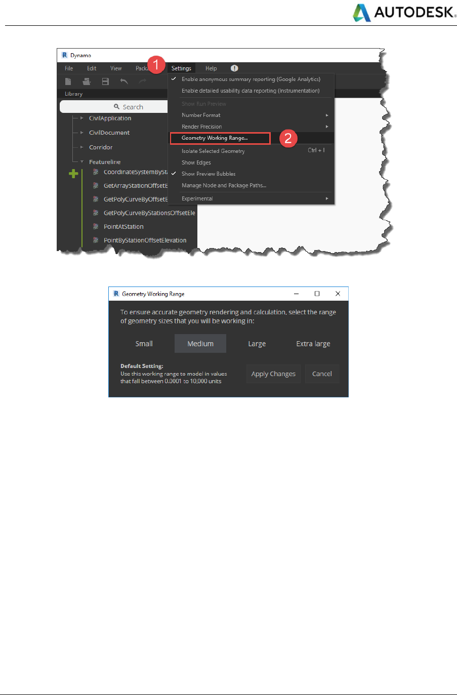
Autodesk
Linear Structures Workflow Guide
Global Consulting Delivery
Page 31 of 53
© 2019 Autodesk
Version No: 2.0
The information in this document is to be considered Confidential to Autodesk, Inc., and cannot be reproduced or
redistributed without the prior written consent except internally for purposes of review and consideration of this document.
Figure 14: Access the Geometry Working Range in Dynamo
Figure 15: Set the working range to Medium
Note: In Dynamo 2.0 the menu item under Settings has been renamed to Geometry Scaling, but it accesses the
very same Geometry Working Range dialog to select from.
4.2.4 Design Setup
This section illustrates some key features to implement when initializing the design workflow.
Civil 3D
Point Codes
At the beginning of the process each discipline should be aware of the naming convention in place for the point
codes. It is crucial to define the point codes to enable the identification of the key feature lines in a corridor. They
specify the linear coordinate systems necessary to drive the dynamic relationships and manage model updates of
Revit items. The best practice is to define the point codes as input parameters on the subassembly so that it is
possible to apply different naming conventions reusing the same subassemblies in different projects.
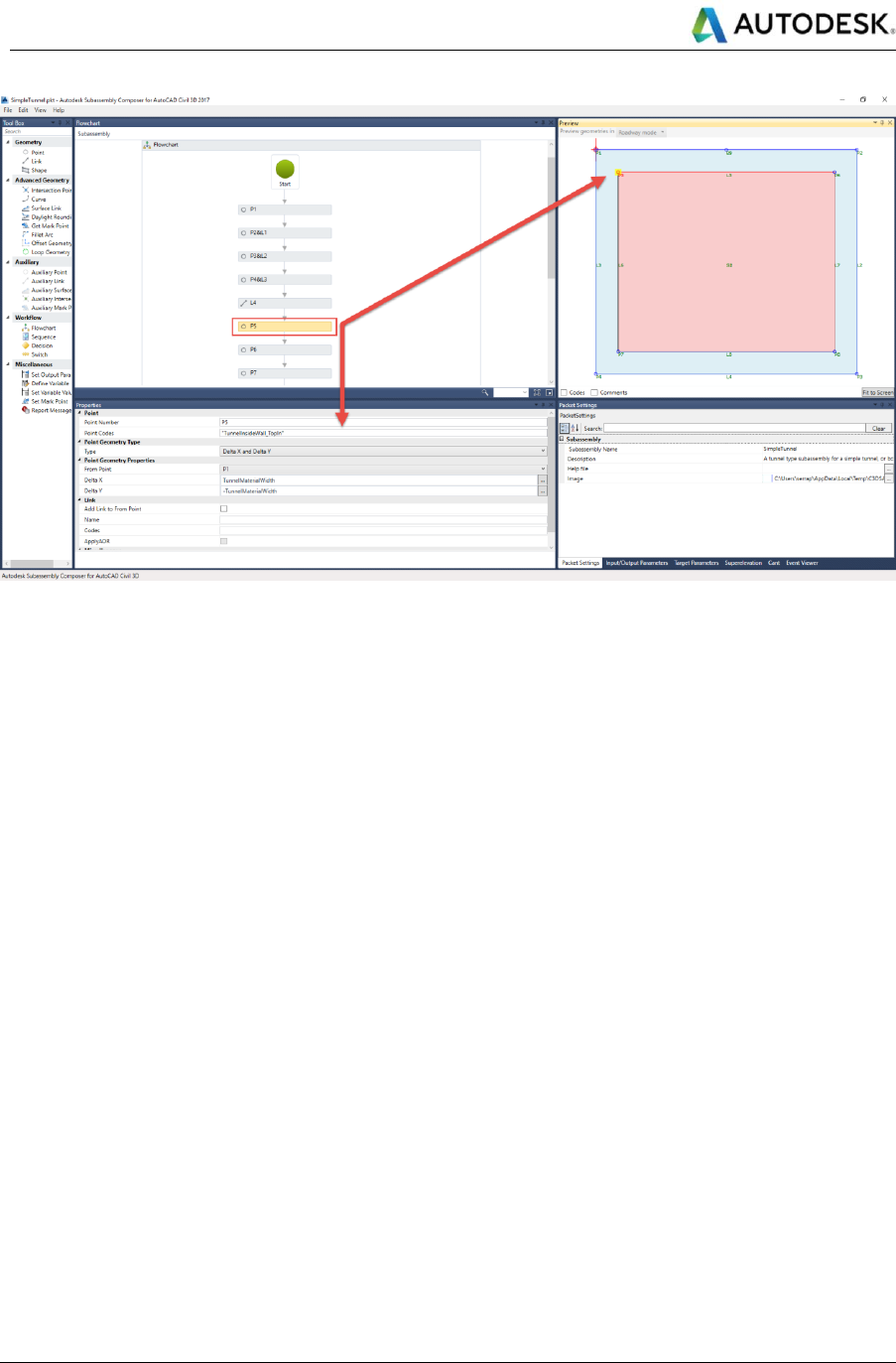
Autodesk
Linear Structures Workflow Guide
Global Consulting Delivery
Page 32 of 53
© 2019 Autodesk
Version No: 2.0
The information in this document is to be considered Confidential to Autodesk, Inc., and cannot be reproduced or
redistributed without the prior written consent except internally for purposes of review and consideration of this document.
Figure 16: Point Codes in the Subassembly Composer
Property Sets
To produce coordinated information models, it is necessary to manage information and maintain it on the objects
describing a linear asset. Information is a requirement of the BIM Execution Plan to fulfil the Employer Information
Requirements and the Asset Information Requirements. Civil 3D 2017 has introduced a set of dynamically-
maintained property sets on the solids extracted from a corridor. Property sets are safely passed from Civil 3D to
Navisworks and they are also stored when exporting the model to IFC. This is also true for user-defined property
sets. Combined, these features make it possible to migrate geometry and information from Civil 3D to other
platforms, enabling a good level of interoperability. For further references on property sets refer to the CivilPython
section of this document.
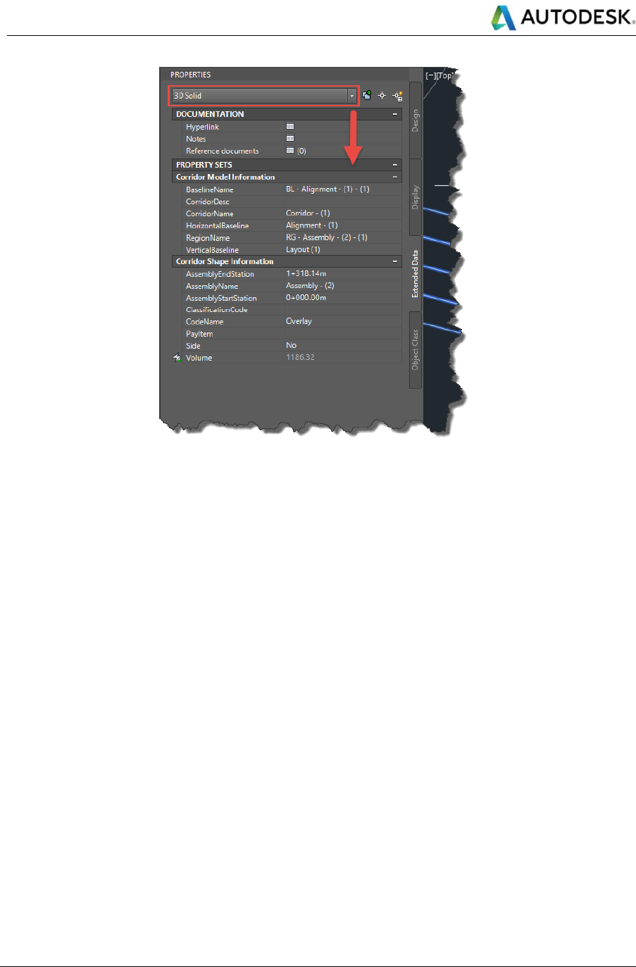
Autodesk
Linear Structures Workflow Guide
Global Consulting Delivery
Page 33 of 53
© 2019 Autodesk
Version No: 2.0
The information in this document is to be considered Confidential to Autodesk, Inc., and cannot be reproduced or
redistributed without the prior written consent except internally for purposes of review and consideration of this document.
Figure 17: Civil 3D 2017 Property Sets on 3D Solids
IFC
Industry Foundation Classes (IFC) is a non-proprietary data exchange format for BIM workflows. It contains
geometry and information for communicating design intent, in a relatively simple way, among disciplines and model
authoring platforms. In this workflow, IFCs are used to provide an immediate representation of the Civil 3D corridors
in Revit for coordination and collaboration only. At the time of the writing, the IFC 4.1 format supports only the
IfcAlignment class, all other civil objects are not included yet. Civil 3D 2017 supports only the IFC 2x3 format: this
means that the solid elements in a Civil 3D corridor model are classified as IfcBuildingElementProxy. For this
workflow, only the corridor solids are considered. The user must extract the solids from the corridor, assign the
necessary property sets and, via the WBLOCK command, create a separate DWG file containing only the selected
solids. The name of the new file must not change through the design cycle to enable the model updates across
Civil 3D and Revit (i.e. <DocumentName>_Solids.dwg).
Load the solids file in Civil 3D, open Revit and load the model with the shared coordinates setup. Use the
CivilConnection RevitUtils.ExportIFC node to create an IFC file in the same folder of the Revit model named as the
solid DWG file with a “_Origin” suffix (i.e. <DocumentName>_Solids_Origin.ifc). The Revit file must be saved with
the name before attempting to export the IFC.
Linear object modifiers
Civil 3D is the tool used to define the linear coordinate systems and the continuous / linear objects (e.g.
carriageway, deck, and retaining walls). Conversely Revit is used to create and manage the discrete objects (e.g.
abutments, girders, columns, foundation slabs, equipment, and piping systems). In this workflow Dynamo is used
as a prototyping environment to create the geometry components that will drive the Revit elements and to introduce
the modifiers to the Civil 3D linear objects. For example, Dynamo can be used to create the skew angles of a bridge
deck or to create the recesses and openings for the equipment along a tunnel or to add the counterforts in a
retaining wall.
These modifiers can be added to the Civil 3D model and maintained dynamically using Revit and Dynamo via
CivilConnection. It is possible to store the results of a geometry calculation in Revit using a DirectShape node from
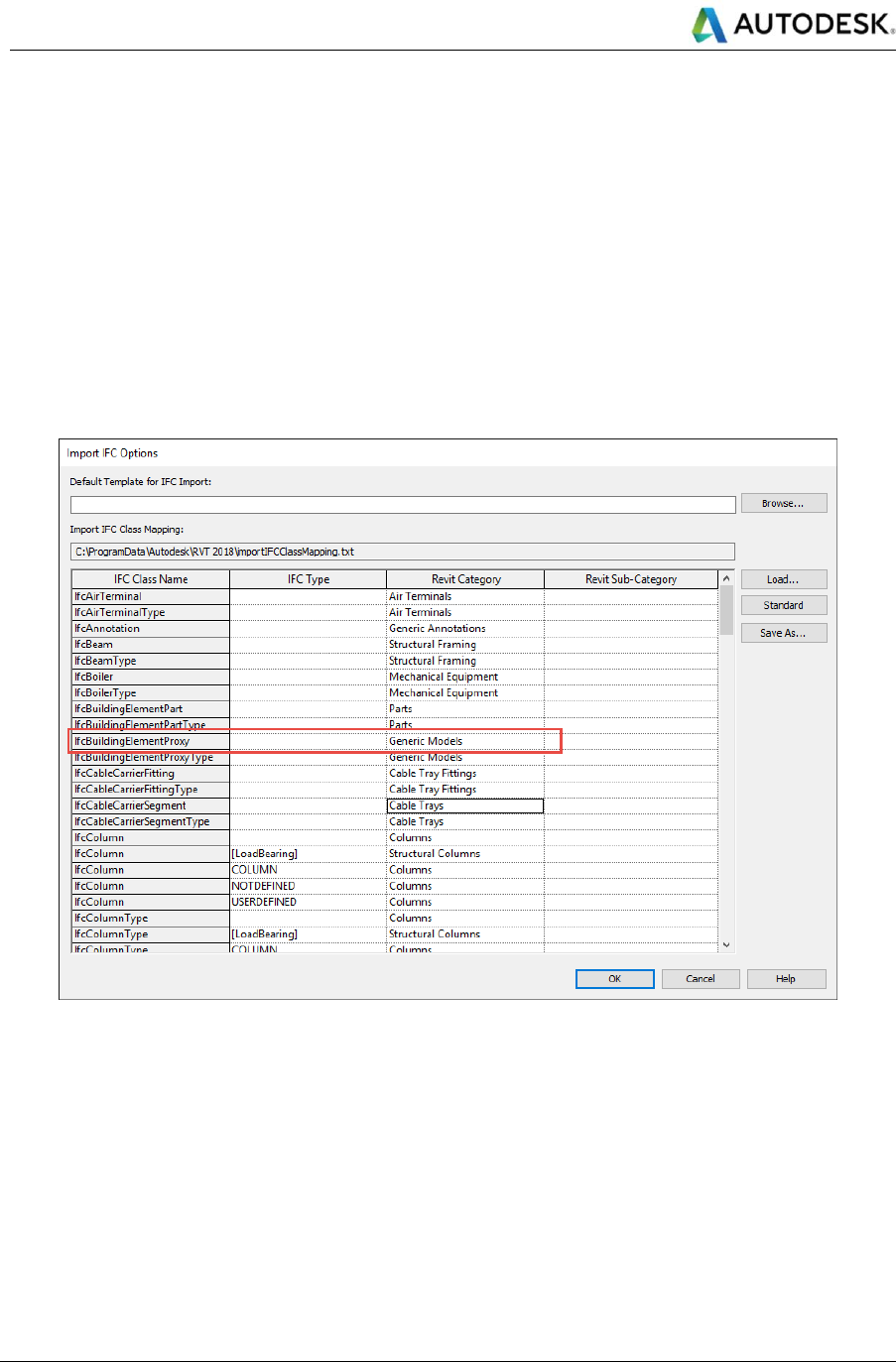
Autodesk
Linear Structures Workflow Guide
Global Consulting Delivery
Page 34 of 53
© 2019 Autodesk
Version No: 2.0
The information in this document is to be considered Confidential to Autodesk, Inc., and cannot be reproduced or
redistributed without the prior written consent except internally for purposes of review and consideration of this document.
the Revit shelf. This element representation can be linked to the Civil 3D model and, using the entity handle, it is
possible to assign the property from the Revit object to the Civil 3D object without losing information nor user
intervention.
If the modifiers are solids they can be added to the Civil 3D model or they can be used to cut the existing solids in
the Civil 3D model preserving the individual elements. In the second option, the layer that contains the solids will
be frozen by default. This is a design choice so that the end user is invited to verify the outcome of the automation
and validate what solids can be used to update the IFC.
Revit
IFC Import Settings
Before Linking the IFC in Revit, set up the IFC Import Settings for the IfcBuildingElementProxy class. Assigning it
to Generic Models is usually fine.
Figure 18: IFC Import Settings
IFC Shared Coordinates
Linked IFC cannot have shared coordinates in Revit, so the below workflow is used as a workaround to force Revit
to link the IFC file required for this Linear Structures workflow with the defined shared coordinates.
It is possible to link directly the intermediate Revit file that Revit automatically produces by linking the IFC in the
Revit host model. This file can acquire the shared coordinates from the host model just like any other Revit linked
model. Reopening the Revit host file will reload the latest version of the IFC link.
The intermediate Revit file is saved in the same folder as the IFC file and it is named after the input IFC file,
including the “.ifc” extension with a “.RVT” (capital letters) extension , for example:
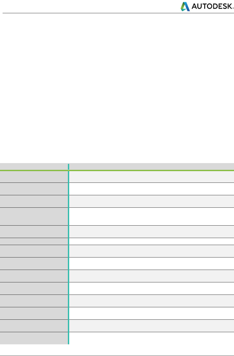
Autodesk
Linear Structures Workflow Guide
Global Consulting Delivery
Page 35 of 53
© 2019 Autodesk
Version No: 2.0
The information in this document is to be considered Confidential to Autodesk, Inc., and cannot be reproduced or
redistributed without the prior written consent except internally for purposes of review and consideration of this document.
<DocumentName>_Solids_Origin.ifc.RVT
The name of the IFC file must remain the same for the entire design cycle. This updates the intermediate Revit file
linked in the host Revit model. Linking a new version of the IFC file in Revit (it must be a different Revit document,
even a new, blank document will do) will override the intermediate Revit link. Reopening the host model will load
the latest Revit link.
Shared Parameters
CivilConnection generates a list of shared parameters that is assigned to all Revit categories. These parameters
are the minimum necessary to manage a Revit element in relationship to a linear coordinate system in Civil 3D.
The GUIDs of these shared parameters are hard coded in CivilConnection, so they can be safely used to create
schedules and tags across multiple projects and they will stay the same during the update cycles.
These parameters are compiled automatically by CivilConnection when the elements are controlled by Dynamo. If
the Revit elements are created manually it is necessary to assign a corridor feature line to them (i.e. a linear
coordinate system) from the Civil 3D model to enable the update capabilities of CivilConnection.
If these shared parameters are not present it is necessary to create at least an object via CivilConnection. The
shared parameters are bound to the Revit categories and they might differ depending on the nature of the objects
(single point, linear, multiple placement points or sketch based, etc.).
Table 10: CivilConnection Shared Parameters
Parameter
Description
ADSK_Corridor
The name of the corridor in the Civil 3D document that was used to extract the
feature line.
ADSK_BaselineIndex
An integer that represents the position of the baseline that contains the feature
line in the corridor structure in Civil 3D.
ADSK_RegionIndex
An integer that represents the position of the baseline region that contains the
feature line in the corridor structure in Civil 3D, read-only.
ADSK_RegionRelative
A length value that represents difference between the station along the
alignment used to describe the Revit element and the starting station of the
baseline region, read-only.
ADSK_RegionNormalized
A numeric value that normalizes the Region Relative against the difference
between baseline region ending and starting stations, read-only.
ADSK_Code
The Point code that identifies the feature line.
ADSK_Side
The side of the first point of the feature line geometry with respect to the
baseline. If the offset is less than zero the side is Left, otherwise Right.
ADSK_X
A length value that defines the World Coordinate System X coordinate of the
Revit element location, read-only.
ADSK_Y
A length value that defines the World Coordinate System Y coordinate of the
Revit element location, read-only.
ADSK_Z
A length value that defines the World Coordinate System Z coordinate of the
Revit element location, read-only.
ADSK_Station
The length measured along the alignment that defines the baseline for the Revit
element location.
ADSK_Offset
The distance between the Revit element location and a point on the feature line
at the same station measured on the local XY plane.
ADSK_Elevation
The distance between the Revit element location and a point on the feature line
at the same station measured on the local XZ plane.
ADSK_AngleZ
The rotation angle between the Revit element orientation and the feature line
horizontal direction at the same station with reference to the local Z Axis.
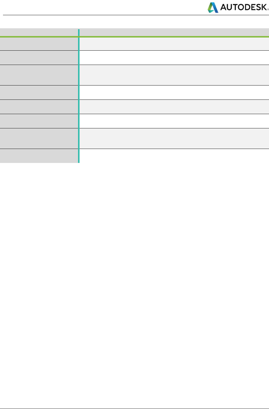
Autodesk
Linear Structures Workflow Guide
Global Consulting Delivery
Page 36 of 53
© 2019 Autodesk
Version No: 2.0
The information in this document is to be considered Confidential to Autodesk, Inc., and cannot be reproduced or
redistributed without the prior written consent except internally for purposes of review and consideration of this document.
Parameter
Description
ADSK_Update
Yes/No parameter that will include or not the Revit element from the update
process. Default is Yes.
ADSK_Delete
Yes/No parameter that will delete the Revit element during the next update
process. Default is No.
ADSK_Multipoint
A parameter that captures the JSON representation of the parameters
necessary to describe more complex objects such as adaptive components or
floors.
ADSK_EndStation
The length measured along the alignment that defines the baseline of the end
point of the Revit element location curve.
ADSK_EndOffset
The distance between the end point of the Revit element location curve and a
point on the feature line at the same station measured on the local XY plane.
ADSK_EndElevation
The distance between the end point of the Revit element location curve and a
point on the feature line at the same station measured on the local XZ plane.
ADSK_EndRegionRelative
A length value that represents difference between the station along the
alignment used to describe the end point of the Revit element location curve
and the starting station of the baseline region, read-only.
ADSK_EndRegionNormalized
A numeric value that normalizes the End Region Relative against the difference
between baseline region ending and starting stations, read-only.
The IFC workflow also generates shared parameters that are describing the IFC properties of the elements as well
as the Property Sets attached to the Civil 3D objects. Using CivilPython it is possible to extract the values of the
property sets form Civil 3D objects and populate the same shared parameters on the Revit families that replace
the IFC link for the continuous elements in Revit.
Create Revit elements
The RevitUtils.CreateFamilyInstance node creates single point family instances along a feature line at given station
with local offset, elevation and rotation values. The objects are created in Revit and the shared parameters
compiled by CivilConnection.
Multipoint objects
Objects in Revit are not only single point or curved based, they can be sketched based (e.g. floors) or have multiple
control points (e.g. adaptive components). Revit needs, in principle, ten parameters to define a point in space with
reference to a corridor feature line, having all those parameters for any extra point describing an object would not
be practical in Revit. In CivilConnection it is possible to create Multipoint objects that are made of a
ShapePointArray which in turn is an ordered list of ShapePoints. A ShapePoint embeds the necessary parameters
and each one of them occupies a defined position in the sequence that makes up the Multipoint. These values are
serialized to a JSON string and stored in the ADSK_Multipoint parameter. In principle a Multipoint could even be
defined by ShapePoint objects referencing feature lines in different corridors (e.g. useful to create cross passages
in tunnels). A Multipoint can be used to create an adaptive component that has the same amount of control points.
Another application is for floor with a slope.
In Dynamo for Revit the only methods exposed to create floors create planar floors but when in linear structures
projects it much more frequent that floors are following a slope by design. In the Revit API it is possible to modify
the secondary elements of a floor, but the resulting element may have inaccuracies in the thickness depending on
the type properties. If in the structure of the Revit floor there are no layer set to variable, the thickness value will be
used to create a vertical offset of the top surface of the floor rather than recalculating the bottom surface.
CivilConnection implements a method in the Revit API that returns a floor by sketch with a slope arrow. The slope
is calculated as the best-fit plane for all the points contained in the Multipoint.
If the points share all the same elevation, the sloped floor will return a standard floor by sketch with no slope.

Autodesk
Linear Structures Workflow Guide
Global Consulting Delivery
Page 37 of 53
© 2019 Autodesk
Version No: 2.0
The information in this document is to be considered Confidential to Autodesk, Inc., and cannot be reproduced or
redistributed without the prior written consent except internally for purposes of review and consideration of this document.
MEP curves and fittings
In CivilConnection there are utilities to support the creation of Revit MEP curves: pipes, ducts, conduits and cable
trays. These elements follow the same principles of other objects created via CivilConnection and their relationship
with a feature line is captured in the shared parameters. The user needs to select the object types and the system
type where supported (pipes and ducts), and for each pipe segment a Dynamo curve in relationship to the feature
line used as a linear reference. The MEP curve will use the start and end points of the Dynamo curve and will
create the corresponding Revit object.
The size of the Revit object must be set after the creation, this can be achieved via Dynamo for Revit setting the
size parameter value by name and choosing the appropriate value from the sizes associated with the object type.
When two or more MEP curves (e.g. pipes) are concurrent they can be joined in Revit to for what is called a system.
The systems are used in Revit for organizing the design and support calculations. In the UI this is possible adding
elements called fittings that use the connectors on the MEP curves to provide continuity. Depending on the
geometry configuration the fittings will adapt, the available combinations are for two, three or four concurrent MEP
curves. These complex geometry calculations are managed by Revit that is accessing the connectors in the objects
involved in this process. A connector carries the information of the location, orientation and size of the face of the
MEP element it belongs to.
The two connectors configurations are:
• Elbow: when the centre lines of the MEP curves meet in one point and form an angle greater or equal to
5°.
• Transition: when the sizes of the connectors have different values.
• Union: when the centre lines of the MEP curves are parallel (not necessarily collinear).
The three connectors configurations are called Tees, the four connectors configurations are called crosses.
Tees and crosses are used when two main MEP curves intersect, and the creation of the fittings results into splitting
the main MEP curves respectively into three or four objects.
There are also connections along the length of a MEP curve (called tap) that do not split the main curve.
CivilConnection provides tools for the two connectors configuration, the connection type is determined
automatically by the geometry of the curves involved. Should the creation of the fittings fail, CivilConnection
attempts to connect the MEP curves directly between each other. This is possible via API but it is not allowed in
the Revit UI. The system that results even without fittings supports calculations and allows to have continuity
between elements with very small angles between curves which are very common in a linear structures context.
CivilConnection populates the parameters of the MEP curves with relation to the linear reference (e.g. starting and
ending station of a pipe). During the update, CivilConnection attempts to preserve the continuity of the system so
that, for example, the user can modify the offset value of one end of a pipe and the other pipes preceding and
following will also adapt their geometry to accommodate the modification without breaking the system.
Assign Featureline
Revit models can be created manually using the standard UI tools or even using Dynamo for Revit nodes. If these
objects need to later take part to the update of the model depending on the Civil 3D input changes the need to be
assigned to a feature line. The RevitUtils.AssignFeatureline node calculates the values of the shared parameters
that CivilConnection uses to update the location and orientation of Revit elements. This can be also used to assign
a different feature line to a Revit element that was created via CivilConnection nodes.

Autodesk
Linear Structures Workflow Guide
Global Consulting Delivery
Page 38 of 53
© 2019 Autodesk
Version No: 2.0
The information in this document is to be considered Confidential to Autodesk, Inc., and cannot be reproduced or
redistributed without the prior written consent except internally for purposes of review and consideration of this document.
XML Object Files
To update the location of the objects using CivilConnection it is necessary to rely on the values of the shared
parameters on the Revit elements. The RevitUtils.ExportXML node saves an XML file with the Revit model that
contains references to the objects that have the necessary shared parameters compiled to enable the update
process. This is a necessary safety measure to avoid failures during the update cycle.
CivilConnection automatically generates the XML file before attempting the update of the model with
RevitUtils.UpdatedObjects node.
Revit Links
The CivilConnection offers the possibility to place and manage Revit Link Instances as if they were family instances.
The insertion point used to place and rotate the Revit Links is the project base point of the origin. In the first release
of CivilConnection for Revit 2017 it was not possible to assign shared parameters to Revit link instances. For this
reason, the name of the instances is used to store the necessary information to manage links location updates.
It is also possible to create the Named Sites directly in the Revit Link document so that it is possible to reconcile
the location of a Revit Link Instance from the host file.
Dynamo
Dynamic Relationships
The intelligence to read information from the Civil 3D model, drive Revit components and create linear modifiers
resides in Dynamo files (DYN). Dynamo natively provides the ability to update Revit elements if there is a one-to-
one relationship between a Revit model and a Dynamo file. The results of the automation are captured in the DYN
file and they are used to update the Revit model if the input changes. The visual programming environment is ideal
to understand the relationships among objects and their hierarchy within a linear structure. It is worth noting that
the update mechanism is triggered only when the graph is used within the full Dynamo UI and it instead it is not
available via Dynamo Player. In CivilConnection the update workflow is explicit and intentional, therefore it can be
triggered even with Dynamo Player to take advantage of the simplified user experience.
The CivilConnection package extends these capabilities starting from a Civil 3D corridor input and enables the
roundtrip of information across the model authoring platforms.
Depending on the Linear Structures the dynamic relationships needed to define the linear asset can vary, the basic
principles though remain the same (linear coordinate systems, lean workflows and interoperability of information).
CivilConnection can send commands to the command line in Civil 3D and executing CivilPython it is even possible
to dynamically update Civil 3D elements.
XLSX Location File
Using the linear structures workflow, the approach to modelling MEP for a linear structure can change significantly.
The effect is to ‘host’ the equipment in the linear coordinate space controlled by Dynamo.
To simplify the scripting logic for modellers it is possible to take the parametric relationships of the equipment to
the structure to a spreadsheet and enable, for example, the definition and placement of the equipment and MEP
components starting from an Excel input. The spreadsheet can be read by the Dynamo graph and the information
used to place or update the elements in the models.
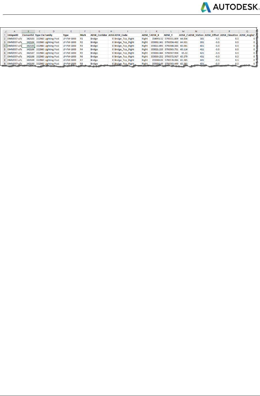
Autodesk
Linear Structures Workflow Guide
Global Consulting Delivery
Page 39 of 53
© 2019 Autodesk
Version No: 2.0
The information in this document is to be considered Confidential to Autodesk, Inc., and cannot be reproduced or
redistributed without the prior written consent except internally for purposes of review and consideration of this document.
Figure 19: Example spreadsheet containing MEP Family selection and location parameters
4.2.5 Model Updates
In this workflow, the model authoring outcomes are captured in Civil 3D and Revit while Dynamo retains the
intelligence that provides the means to update the models if the inputs change. When the design setup has been
executed properly and the references are preserved (same names for the IFC file, same names for the corridors
and the point codes used, etc.), the model content will update.
Another example of model update use is on model adjustments to resolve conflicts. The user can manually specify
the values of the shared parameters on a Revit element and let CivilConnection recalculate the position and
orientation of the object. This implies that the values input does not depend on the frequency of the stations in the
Civil 3D corridor. In fact, the values are passed to Civil 3D that recalculates the location and orientation dynamically
and update the location and the parameters of the Revit elements.
4.2.6 CivilConnection Known Issues
Geometry working range warnings
Dynamo 1.3 introduced the concept of working range geometry (in Dynamo 2.0 it is called geometry scaling). This
was intended to provide the Dynamo session with an adequate level of precision in representing numbers. Design
Script, the language that executes the Dynamo graphs at runtime, allows only for 14 digits numbers, so the resulting
precision of the decimal digits varies with the number of digits used for the integer part. Therefore, quite often,
dealing with world coordinates for linear structures projects, produces geometry working range warnings. In
general, it has been noticed that for metric projects the best representation is obtained setting the geometry working
range to Medium.
Using Large or Extra Large affects the geometry objects definition, for example the poly curves returned for the
feature lines are not continuous and the coordinate systems result scaled.
Null feature lines
When a corridor model returns null feature lines, regardless the code provided, it might indicate that the geometry
underlying the feature lines in Civil 3D failed to be generated in Dynamo. This is frequently due to a vertical profile
that does not cover the entire range of stations for a corridor region. Even if the feature lines are visible in Civil 3D
this does not mean that they are good enough to be used in the Linear Structures workflow.
This issue is clearly visible from the poly curve that represents a baseline: the range of stations where the profile
is not defined remain at elevation 0, just like the alignment.
Excessive station frequency
The station frequency defined in the corridor affects how feature lines will be tessellated. The higher the frequency
the more points there will be to process at detriment of the CivilConnection performance. It is up to the designer to
define the optimal frequency for the automatically managed corridor stations and when to add extra stations
manually to ensure the proper design intent. For a corridor that defines the structure in a metric system, a frequency
of 20m along tangents, with 5m along the curves and spirals with a mid-ordinate of 0.1m that takes into account
both curvature and increment produce, in general, a fairly precise representation with manageable feature lines in
CivilConnection. Higher frequencies are not recommended.

Autodesk
Linear Structures Workflow Guide
Global Consulting Delivery
Page 40 of 53
© 2019 Autodesk
Version No: 2.0
The information in this document is to be considered Confidential to Autodesk, Inc., and cannot be reproduced or
redistributed without the prior written consent except internally for purposes of review and consideration of this document.
The above values might change for different situations and the user should find the ideal values on a project basis.
The frequency becomes excessive when the CivilConnection performance is not acceptable (it takes too long to
elaborate) or in the worst cases, when the feature lines return null values. This is determined by the geometry
working range and some specific combination of stations for the regions in a corridor. For example, an alignment
built out of a best fit through points could be made of very short entities like line and arcs, Civil 3D will automatically
add a station at the beginning and at the end of each entity and it will add one in the middle along curves. If the
stations are too close to one another causes the extraction of feature lines to fail.
A possible resolution is to lower the frequency, rebuild the corridor and try to extract the feature lines again. If the
problem persists it might be worth to change the stations for a region: if it is possible to “stretch” a little the
extensions of a region this will force the CivilConnection to rebuild the poly curves underlying the feature lines. If
the problem persists it might depend on the alignment used to generate the corridor. In that case it might be worth
to consider using a 3D tessellated feature line or remove some of the arcs from the alignment definition. This
reduces the number of stations automatically added to the corridor and should improve the chances to extract the
feature lines from it.
As a last resort, the feature lines in CivilConnection can be created using the Corridor.GetFeaturelines node.
This method uses a temporary LandXML file to extract the coordinates of the points in a feature line. This approach
can be very slow as the LandXML might contain surfaces and other extraneous objects, furthermore being a “last
resort” method is not intended to produce an accurate representation of the feature lines of the corridor. For
example, if the subassembly used was set to “centred”, the resulting objects will have a side value of None and
only one feature line per region is returned.
Execution time
Dynamo supports three running modes: Automatic, Manual and Periodic. Remember to execute the graph in
Manual mode especially for expensive calculations, for example placing Revit objects or updating model elements.
The execution time is directly proportional to the length of the corridor and the station frequency.
Point code naming convention
The Linear Structures workflow is based on corridor feature lines.
These feature lines are defined via the point codes on the subassemblies, the point codes should be clear and
avoid confusion throughout the design cycle across the multidisciplinary team.
It is important to define a syntax for the point codes and make sure it is applied to all subassemblies. The
recommendation is to not hardcode the point code in the subassemblies but rather used input parameters that
could be overwritten from the corridor model. This method allows to be more flexible during the model authoring
process and align the point codes naming convention to suit both Civil 3D and CivilConnection. The point code
naming convention should be defined in the BIM Execution Plan.
Non-unique point codes
Civil 3D automatically attempts to build the feature lines in a corridor connecting the same point codes along the
corridor and across multiple regions. Although this is tolerated from a pure Civil 3D perspective, it has to be avoided
in the Linear Structures workflow. The reason is that the point codes applied to multiple points in the assemblies
can produce crossing feature lines and this is undesirable because it can generate confusion and unexpected
results. The feature lines are continuous linear reference systems and having them crossing each other without
control defeats their purpose in the workflow. Corridor feature lines can be used as targets across multiple models
(i.e. the edges of the carriageway from the road corridor can drive the width of the deck corridor), for this reason it
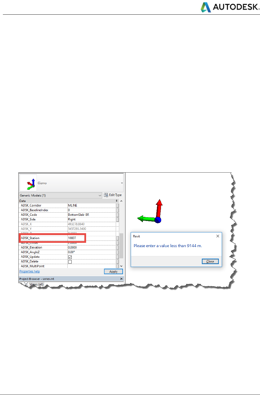
Autodesk
Linear Structures Workflow Guide
Global Consulting Delivery
Page 41 of 53
© 2019 Autodesk
Version No: 2.0
The information in this document is to be considered Confidential to Autodesk, Inc., and cannot be reproduced or
redistributed without the prior written consent except internally for purposes of review and consideration of this document.
is important to avoid malformed feature lines, or potential confusion. Using separate baselines in conjunction with
coordinated assemblies in the same corridor can reduce this risk.
Overlapping feature lines
When subassemblies share points with the same point code assigned, overlapping feature lines are generated in
the corridor and therefore in CivilConnection. Using parameters instead of hardcoding the point codes into the
subassemblies allows the end user to decide which subassemblies in the assembly bear the point code information.
In principle, it should be possible to assign unique codes to all the necessary points and maintain continuity across
regions or apply different naming conventions in different projects reusing the same subassemblies. Ultimately
overlapping feature lines impact negatively on the performance as they are computed more than once and because
they can generate confusion. Corridor feature lines can be used as targets across multiple models (i.e. the edges
of the carriageway from the road corridor can drive the width of the deck corridor), for this reason it is important to
avoid malformed feature lines, or potential confusion. Using separate baselines in conjunction with coordinated
assemblies in the same corridor can reduce this risk.
Data values limitations
Revit has a limitation on the input via user interface for lengths (9144m or 30000 feet) and often stations values
are greater than this. The Revit user interface prevents edit and entry of these values, but it is still possible to edit
them via the API or via Dynamo.
Figure 20: Value error via Revit User Interface
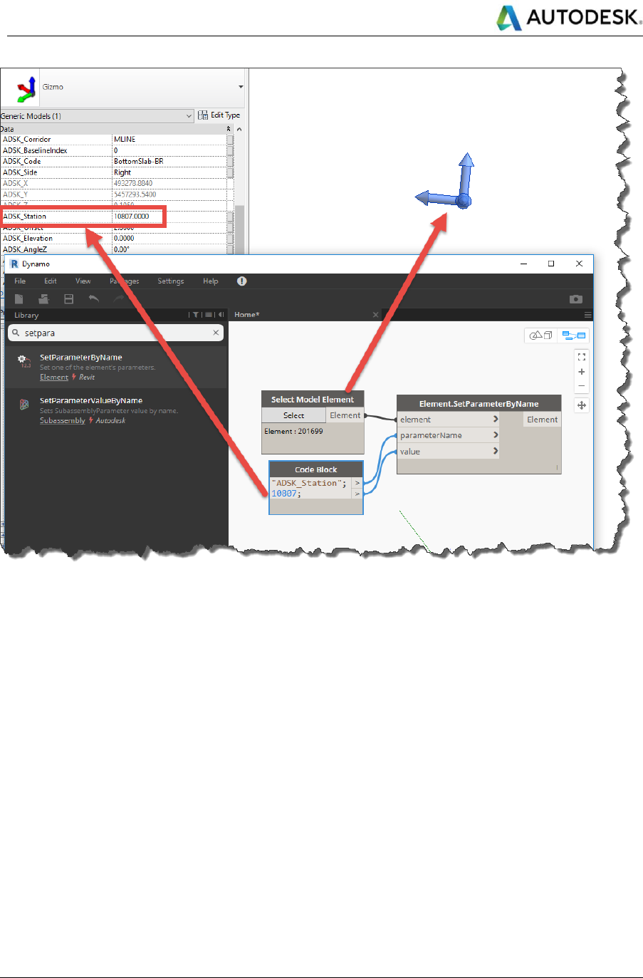
Autodesk
Linear Structures Workflow Guide
Global Consulting Delivery
Page 42 of 53
© 2019 Autodesk
Version No: 2.0
The information in this document is to be considered Confidential to Autodesk, Inc., and cannot be reproduced or
redistributed without the prior written consent except internally for purposes of review and consideration of this document.
Figure 21: Change values via Dynamo
Conflicting versions
The CivilConnection package comes in two different versions, one for Civil 3D 2017 and one for Civil 3D 2018.
If they are both installed on a machine this will cause a conflict when working from Revit 2017 like the one shown
in the picture below.
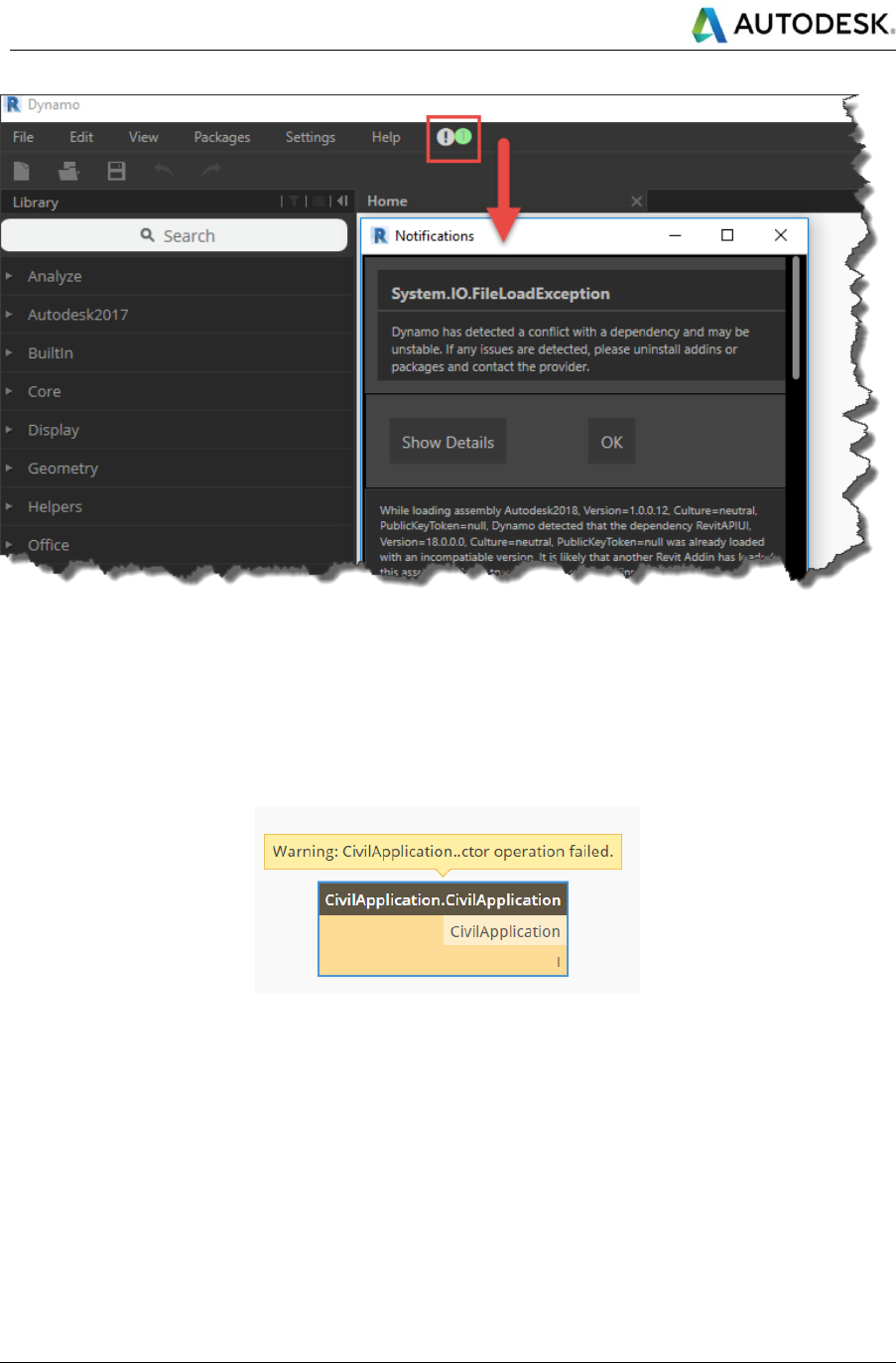
Autodesk
Linear Structures Workflow Guide
Global Consulting Delivery
Page 43 of 53
© 2019 Autodesk
Version No: 2.0
The information in this document is to be considered Confidential to Autodesk, Inc., and cannot be reproduced or
redistributed without the prior written consent except internally for purposes of review and consideration of this document.
Figure 22: Conflict loading the CivilConnection 2018 in Revit 2017
When launching Revit 2018 this exception will not be raised. In both cases though, only the CivilConnection 2017
will be loaded in Dynamo (under the Autodesk2017 shelf), so the CivilConnection 2017 will work only with Civil
3D 2017.
When attempting to use CivilConnection 2017 with Civil 3D 2018 a warning will be raised like the one shown in
the picture below.
Figure 23: The CivilConnection 2018 cannot connect to Civil 3D 2017
A similar warning will be raised when attempting to use the CivilConnection 2017 with Civil 3D 2018.
To use with Civil 3D 2018, CivilConnection 2018 must be used and the CivilConnection 2017 version must be
disabled (for example uninstalling the package).
The Dynamo graphs (DYN files) developed using both versions remain compatible.
When launching Civil 3D from a shortcut that is not properly configured can cause the same warning message.
Make sure that the shortcut target settings are forcing to start the Civil 3D product rather than the generic AutoCAD.
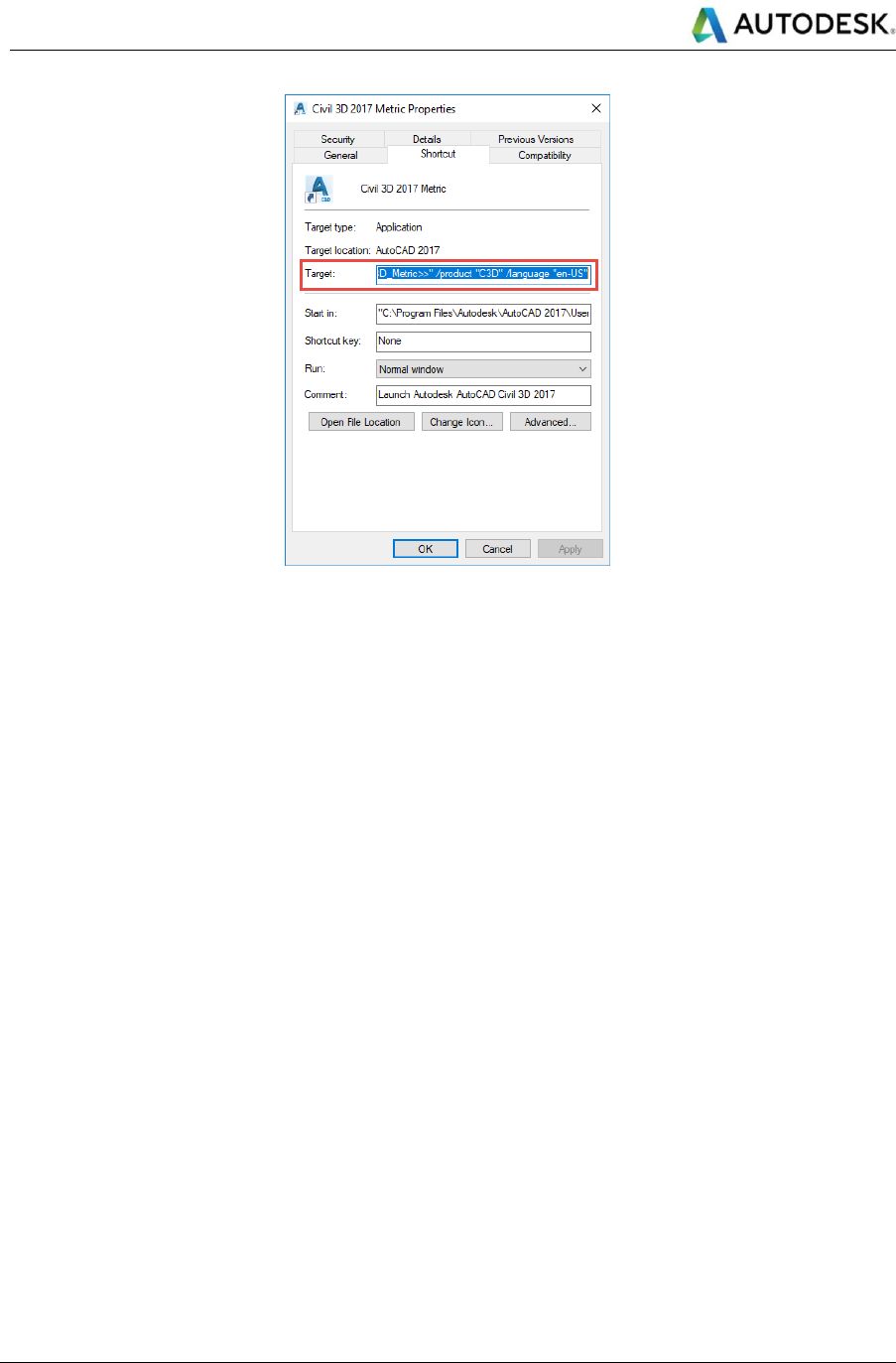
Autodesk
Linear Structures Workflow Guide
Global Consulting Delivery
Page 44 of 53
© 2019 Autodesk
Version No: 2.0
The information in this document is to be considered Confidential to Autodesk, Inc., and cannot be reproduced or
redistributed without the prior written consent except internally for purposes of review and consideration of this document.
Figure 24: Correct settings for the shortcut target
4.3 CivilPython
This is a command that executes Python scripts in the Civil 3D application. It is based on the same IronPython 2.7
that is present in Dynamo for Revit. The scripts can access the .NET API in Civil 3D and take advantage of the full
range automation framework. Python scripts must have a “.py” extension and can be developed with any text editor.
Changes to the code can be made on the fly, simplifying the prototyping process. In case of failures and during
debugging, a message will show the user the line in the code that requires attention.
Calling “Python” at the command line will activate the user interface of the command that will guide the user in
selecting the script to execute.
Calling a “-Python” at the command line, with a dash in front, will prompt the user for the path to the script to execute
in the command line.
With the last option it is possible to call any Python scripts directly from Dynamo via the CivilConnection node
CivilDocument.SendCommand, providing the document in Civil 3D and the file path to the Python script to execute.
Data can be processed in Dynamo and then passed as an argument for the Python script via command line in Civil
3D, for example as a JSON string that gets deserialized in the script, or again it can be dumped to a CSV file then
read in the script using the default Python libraries. It is up to the script owner to decide how to consume which
data, with which structure, and in which format.
4.3.1 Example use - Manage Property Sets via CivilPython
With CivilPython it is possible to write a script that accesses the objects in the Civil 3D model and gets or sets their
Property Set values.
In the examples below, the Python script called DumpPropertySets.py searches for the Property Sets names and
extracts their definition data to a CSV file. This can be used to build a schema in Excel to insert data on the objects.
The Python script called ReadCSVPropertySet.py reads a CSV file instead, selects the Civil 3D objects via their
handles and updates the Property Sets values.
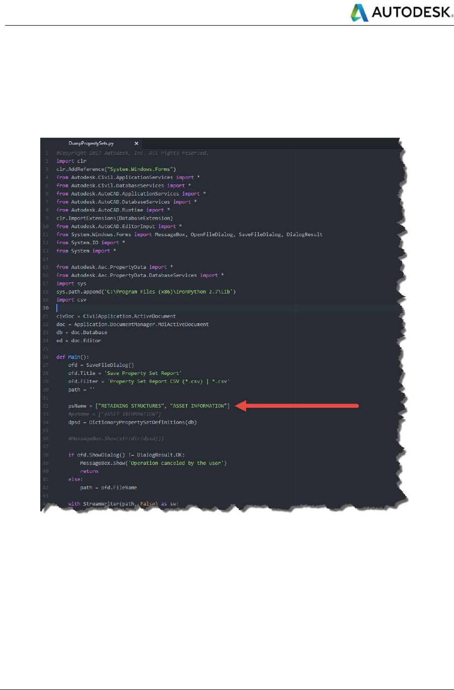
Autodesk
Linear Structures Workflow Guide
Global Consulting Delivery
Page 45 of 53
© 2019 Autodesk
Version No: 2.0
The information in this document is to be considered Confidential to Autodesk, Inc., and cannot be reproduced or
redistributed without the prior written consent except internally for purposes of review and consideration of this document.
In both cases the end-user that does not have Python or API skills can still benefit from these scripts as they only
have to select the scripts using a standard dialog and let CivilPython take care of the rest.
If an exception is raised, then the script owner must take action and resolve it or indicate a solution to the end-user.
For example, if the names of the property sets cannot be found, they must be added to the Civil 3D model first.
A good script should always handle the exceptions and inform the user of the possible causes and resolutions.
Figure 25: Excerpt of the script dumping Civil 3D Property Sets to a CSV file
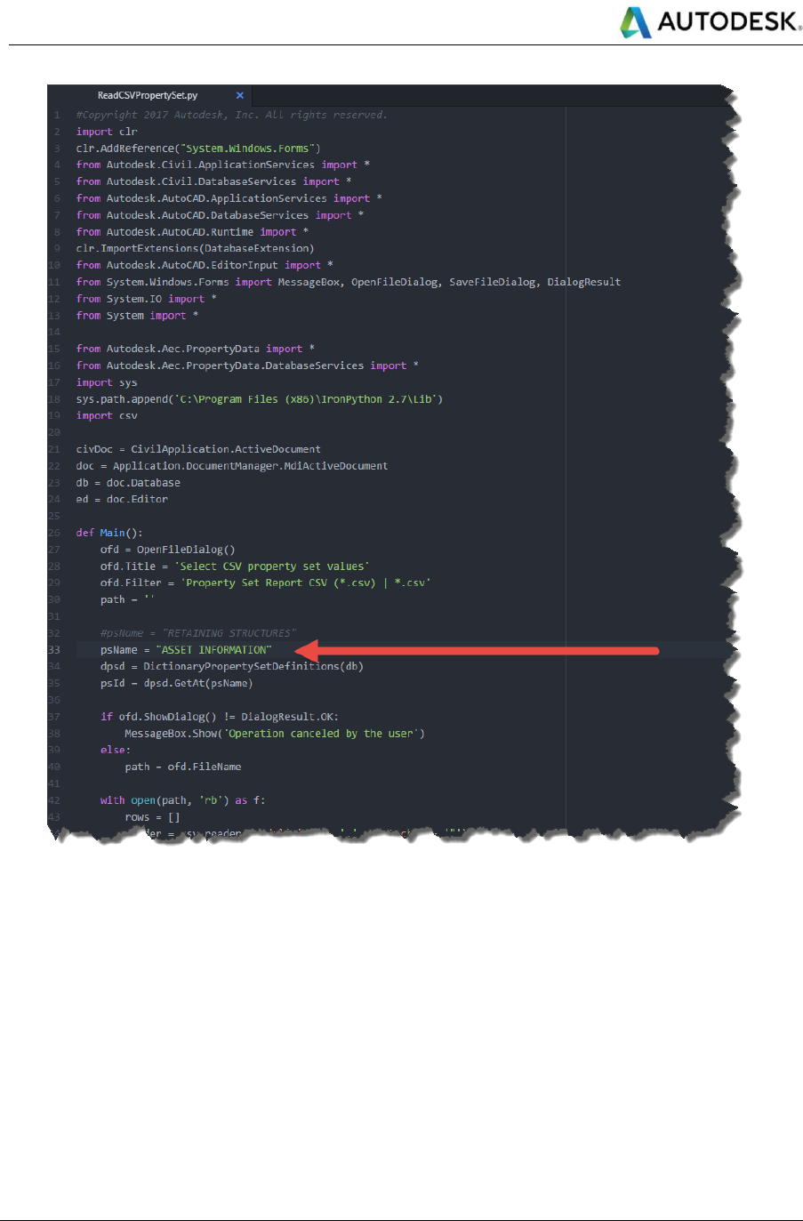
Autodesk
Linear Structures Workflow Guide
Global Consulting Delivery
Page 46 of 53
© 2019 Autodesk
Version No: 2.0
The information in this document is to be considered Confidential to Autodesk, Inc., and cannot be reproduced or
redistributed without the prior written consent except internally for purposes of review and consideration of this document.
Figure 26: Excerpt of the script populating Civil 3D Property Sets on objects reading from a CSV file
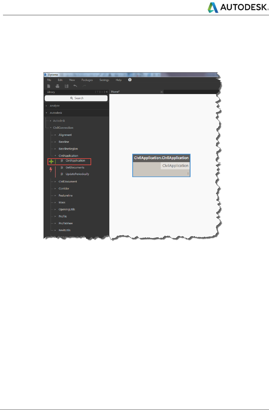
Autodesk
Linear Structures Workflow Guide
Global Consulting Delivery
Page 47 of 53
© 2019 Autodesk
Version No: 2.0
The information in this document is to be considered Confidential to Autodesk, Inc., and cannot be reproduced or
redistributed without the prior written consent except internally for purposes of review and consideration of this document.
CivilConnection Snippets
This section gives a list of the common node configurations available with the CivilConnection package. The list is
far from being exhaustive and its sole purpose is to demonstrate how to combine the most frequently used nodes
to access the information from a Civil 3D model.
Figure 27: CivilApplication
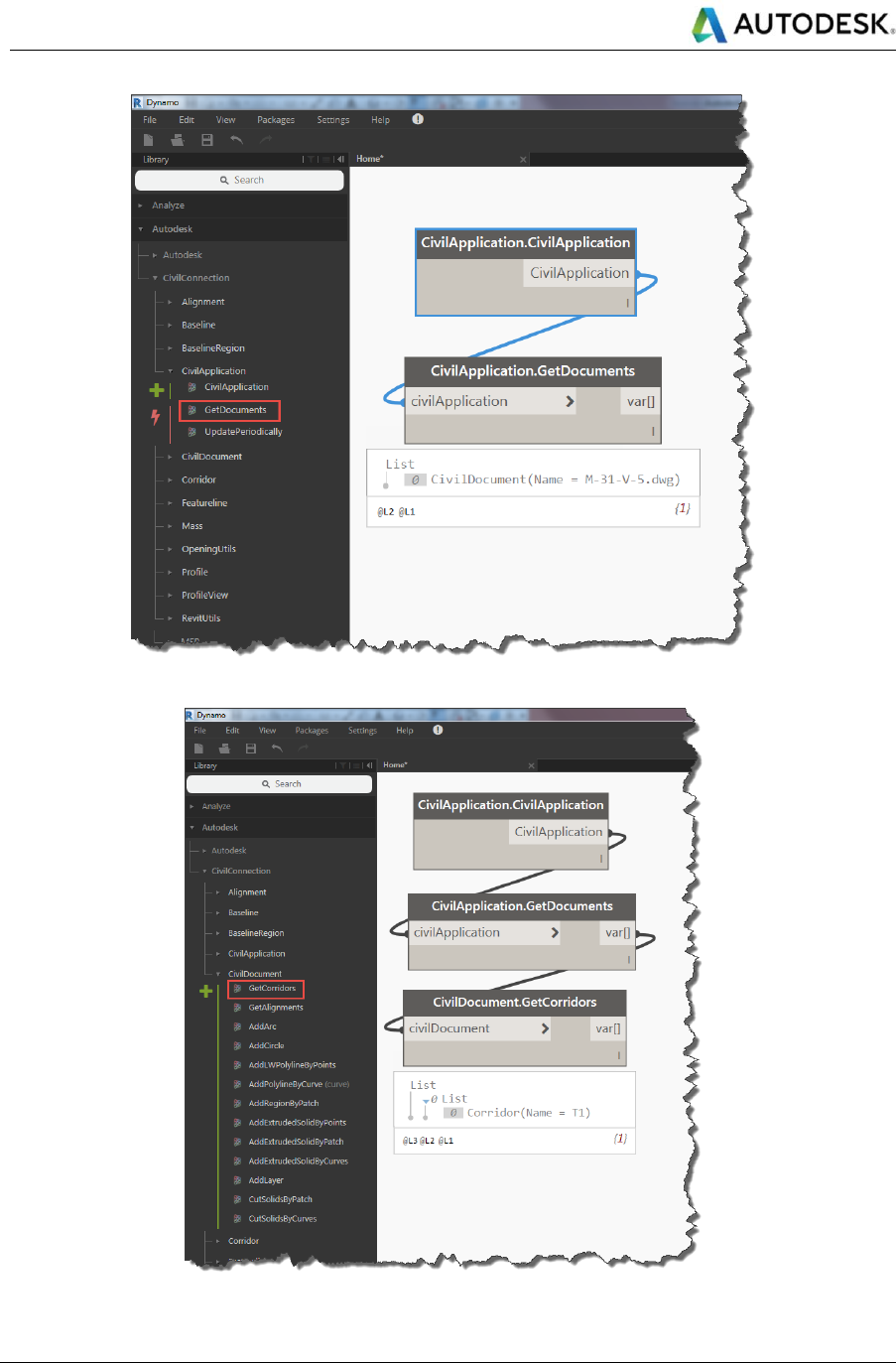
Autodesk
Linear Structures Workflow Guide
Global Consulting Delivery
Page 48 of 53
© 2019 Autodesk
Version No: 2.0
The information in this document is to be considered Confidential to Autodesk, Inc., and cannot be reproduced or
redistributed without the prior written consent except internally for purposes of review and consideration of this document.
Figure 28: GetDocuments
Figure 29: GetCorridors
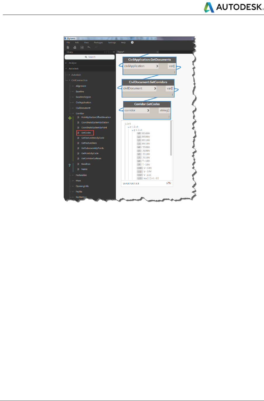
Autodesk
Linear Structures Workflow Guide
Global Consulting Delivery
Page 49 of 53
© 2019 Autodesk
Version No: 2.0
The information in this document is to be considered Confidential to Autodesk, Inc., and cannot be reproduced or
redistributed without the prior written consent except internally for purposes of review and consideration of this document.
Figure 30: GetCodes
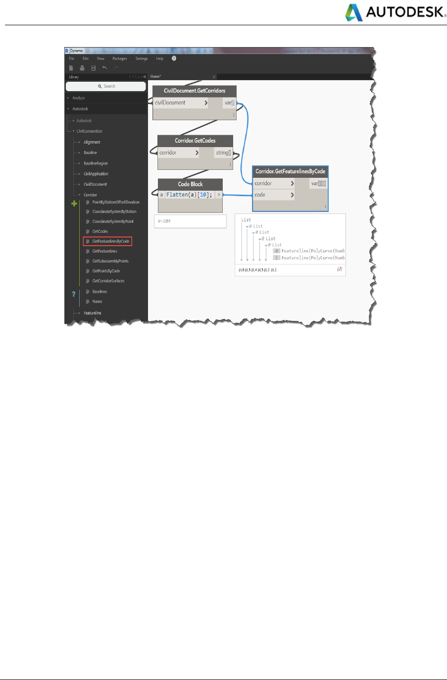
Autodesk
Linear Structures Workflow Guide
Global Consulting Delivery
Page 50 of 53
© 2019 Autodesk
Version No: 2.0
The information in this document is to be considered Confidential to Autodesk, Inc., and cannot be reproduced or
redistributed without the prior written consent except internally for purposes of review and consideration of this document.
Figure 31: GetFeaturelinesByCode

Autodesk
Linear Structures Workflow Guide
Global Consulting Delivery
Page 51 of 53
© 2019 Autodesk
Version No: 2.0
The information in this document is to be considered Confidential to Autodesk, Inc., and cannot be reproduced or
redistributed without the prior written consent except internally for purposes of review and consideration of this document.
CivilConnection Nodes Quick Reference
UNDER REVIEW
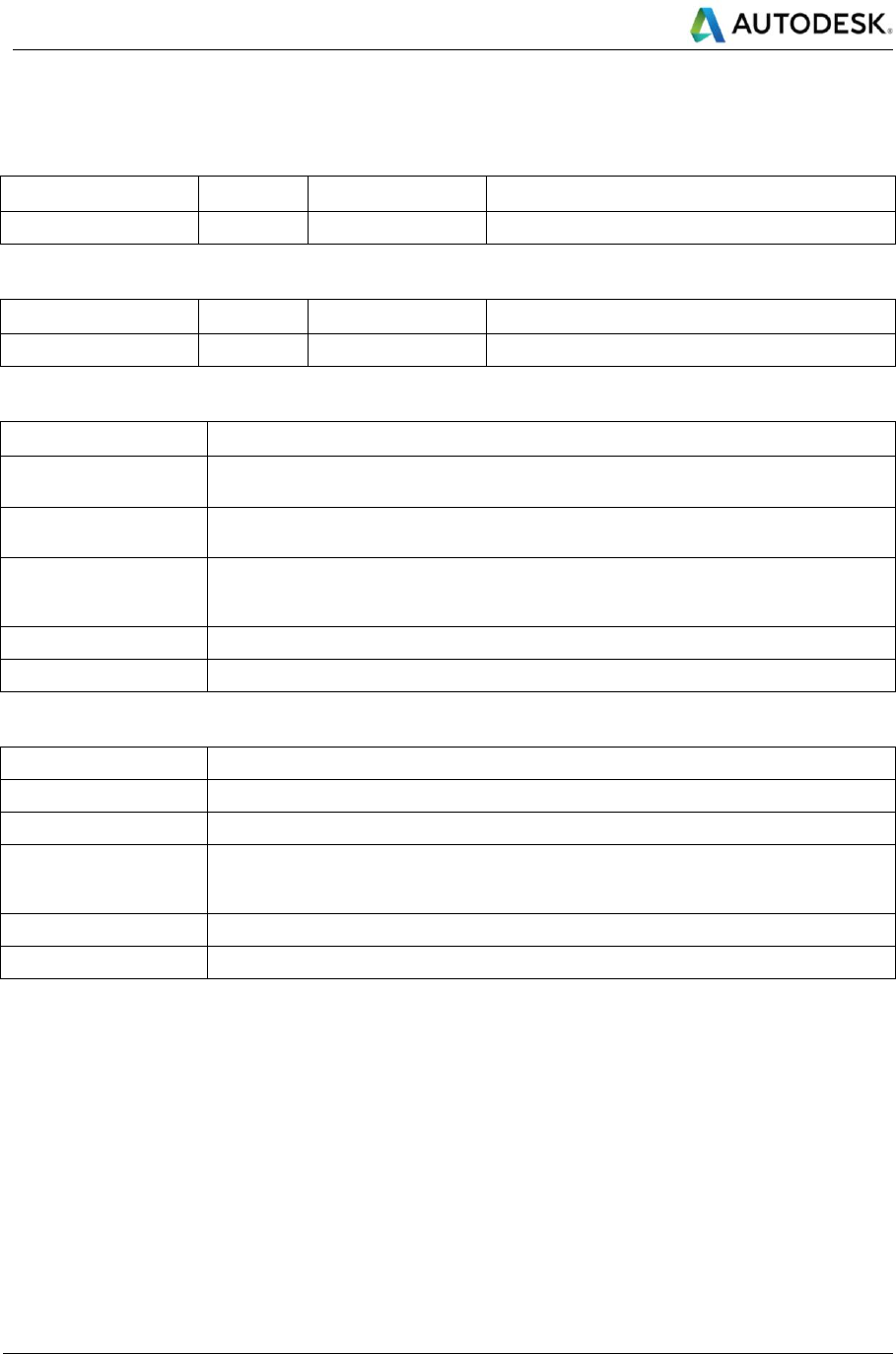
Autodesk
Linear Structures Workflow Guide
Global Consulting Delivery
Page 52 of 53
© 2019 Autodesk
Version No: 2.0
The information in this document is to be considered Confidential to Autodesk, Inc., and cannot be reproduced or
redistributed without the prior written consent except internally for purposes of review and consideration of this document.
Document Control
Change history
Date
Version
Author
Description
6-May-19
1.0
PS
Update
Approval history
Date
Version
Approver
Comments
Click here to enter a date.
Abbreviations
Term
Description
IFC
Industry Foundation Classes format file. Open format defined by BuildingSmart International to
communicate BIM data.
XML
eXtensible Markup Language code in human readable format used to define and describe the
format of data
Dynamo Graph or script
Dynamo is a graphical or visual programming language and prototyping environment within the
Revit product. The graph (or script (synonymous)) defines a procedure for creating an output of
some kind. It is saved in a .dyn file.
EIRs / AIRs
Employer Information Requirements / Asset Information Requirements
Terminology
Term
Description
CivilConnection
Custom Dynamo Package integrating Civil 3D and Revit data and workflows
BIM Use
Definition of the suitability and purpose of creation of a model in a BIM system or framework.
Shared Coordinates
Revit terminology for defining the real-world coordinate space relationship to the current model
being defined. Coordinate space needs to be shared across all models that will be linked to form
the overall project

Autodesk and the Autodesk logo are registered trademarks of Autodesk, Inc., and/or its subsidiaries and/or affiliates in the USA
and/or other countries. All other brand names, product names, or trademarks belong to their respective holders. Autodesk
reserves the right to alter product and service offerings, and specifications and pricing at any time without notice, and is not
responsible for typographical or graphical errors that may appear in this document.
© 2019 Autodesk, Inc. All rights reserved.
Blank End Page
