LinkIt 7697 HDK V10 User's Guide Link It Users
LinkIt_7697_HDK_Users_Guide
LinkIt_7697_HDK_Users_Guide
LinkIt_7697_HDK_Users_Guide
User Manual:
Open the PDF directly: View PDF ![]() .
.
Page Count: 14

LinkIt 7697 HDK v10 User's Guide
Version: 1.0
Release date: 5 May 2017
© 2015 - 2017 MediaTek Inc.
This document contains information that is proprietary to MediaTek Inc. (“MediaTek”) and/or its licensor(s). MediaTek cannot grant you
permission for any material that is owned by third parties. You may only use or reproduce this document if you have agreed to and been
bound by the applicable license agreement with MediaTek (“License Agreement”) and been granted explicit permission within the License
Agreement (“Permitted User”). If you are not a Permitted User, please cease any access or use of this document immediately. Any
unauthorized use, reproduction or disclosure of this document in whole or in part is strictly prohibited. THIS DOCUMENT IS PROVIDED ON AN
“AS-IS” BASIS ONLY. MEDIATEK EXPRESSLY DISCLAIMS ANY AND ALL WARRANTIES OF ANY KIND AND SHALL IN NO EVENT BE LIABLE FOR ANY
CLAIMS RELATING TO OR ARISING OUT OF THIS DOCUMENT OR ANY USE OR INABILITY TO USE THEREOF. Specifications contained herein are
subject to change without notice.

LinkIt 7697 HDK v10 User's Guide
© 2015 - 2017 MediaTek Inc.
Page 1
This document contains information that is proprietary to MediaTek Inc. (“MediaTek”) and/or its licensor(s).
Any unauthorized use, reproduction or disclosure of this document in whole or in part is strictly prohibited.
Document Revision History
Revision Date Description
1.0 5 May 2017 Initial release
LinkIt 7697 HDK v10 User's Guide
© 2015 - 2017 MediaTek Inc.
Page 2
This document contains information that is proprietary to MediaTek Inc. (“MediaTek”) and/or its licensor(s).
Any unauthorized use, reproduction or disclosure of this document in whole or in part is strictly prohibited.
Table of Contents
Introduction ........................................................................................................................................... 5
Overview ............................................................................................................................................. 5
Get Started with the HDK ...................................................................................................................... 6
2.1. Board configuration ............................................................................................................................ 6
2.2. Installing the driver for Windows ....................................................................................................... 7
2.3. Updating the flash .............................................................................................................................. 8
Hardware Features ............................................................................................................................... 10
Schematics ............................................................................................................................................ 11
Pin-Out Diagram ................................................................................................................................... 13

LinkIt 7697 HDK v10 User's Guide
© 2015 - 2017 MediaTek Inc.
Page 3
This document contains information that is proprietary to MediaTek Inc. (“MediaTek”) and/or its licensor(s).
Any unauthorized use, reproduction or disclosure of this document in whole or in part is strictly prohibited.
Lists of Tables and Figures
Table 1. Comparison between Flash tool and mt76x7-uploader ............................................................................ 8
Figure 1. LinkIt 7697 HDK v1.0 ................................................................................................................................ 5
Figure 2. Front view of the HDK (created in Fritzing) .............................................................................................. 6
Figure 3. Communication between PC and the HDK............................................................................................... 7
Figure 4. The COM port allocation for LinkIt 7697 HDK .......................................................................................... 8
LinkIt 7697 HDK v10 User's Guide
© 2015 - 2017 MediaTek Inc.
Page 5
This document contains information that is proprietary to MediaTek Inc. (“MediaTek”) and/or its licensor(s).
Any unauthorized use, reproduction or disclosure of this document in whole or in part is strictly prohibited.
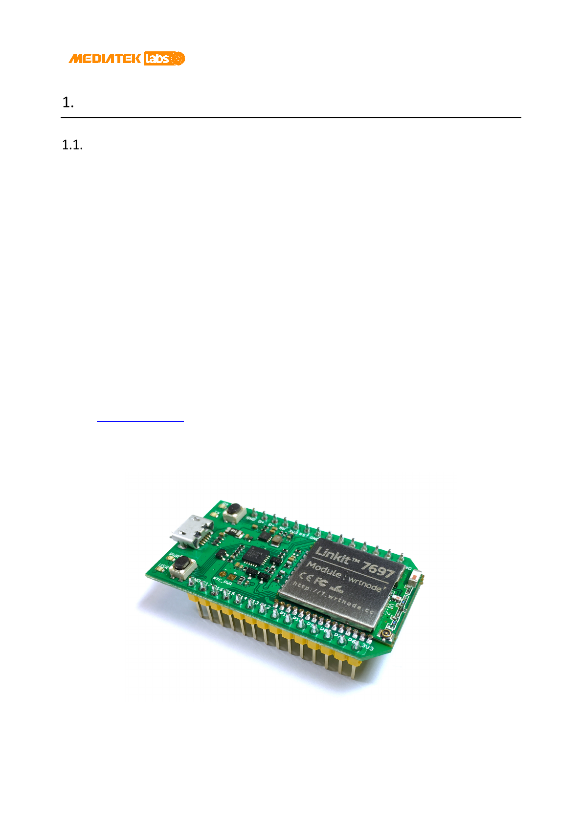
Introduction
Overview
MediaTek LinkIt™ 7697 hardware development kit (HDK) is part of LinkIt development platform for RTOS and is
based on a highly integrated MediaTek MT7697 SOC with an application processor, a low power 1x1 11n single-
band Wi-Fi subsystem, a Bluetooth Low Energy subsystem and a Power Management Unit. The application
processor subsystem contains ARM Cortex-M4 with floating point unit microprocessor.
The HDK supports peripherals, including UART, I2C, SPI, I2S, PWM, IrDA and auxiliary ADC. It also includes an
embedded SRAM/ROM. The Wi-Fi subsystem contains 802.11b/g/n radio, baseband and MAC that are designed to
meet both the low power and high throughput application requirements. It runs on a 32-bit RISC CPU that could
fully offload the application processor. The Bluetooth Low Energy subsystem contains the Bluetooth radio,
baseband and link controller and uses the same 32-bit RISC CPU for the Bluetooth protocols. The LinkIt 7697 HDK is
shown in Figure 1.
The main features of this HDK are:
• Breadboard compatible form factor. Developers can use breadboards to connect peripherals with this
HDK conveniently to build their applications.
• Auxiliary LED and buttons to reset the board and to program a user-defined functionality.
• An on-board USB-to-UART conversion chip to access logs and conveniently update the firmware.
• Serial Wire Debug (SWD) interface.
• mt76x7-uploader tool, enables the HDK to switch between flash normal mode and recovery mode
automatically without user intervention.
• Developers can program the board with the native LinkIt SDK using GCC, IAR embedded workbench, or
Keil µVision IDE. Development with Arduino IDE is also supported.
Figure 1. LinkIt 7697 HDK v1.0
LinkIt 7697 HDK v10 User's Guide
© 2015 - 2017 MediaTek Inc.
Page 6
This document contains information that is proprietary to MediaTek Inc. (“MediaTek”) and/or its licensor(s).
Any unauthorized use, reproduction or disclosure of this document in whole or in part is strictly prohibited.
Get Started with the HDK
This section covers the HDK configuration, driver installation and the update flow for the flash storage.
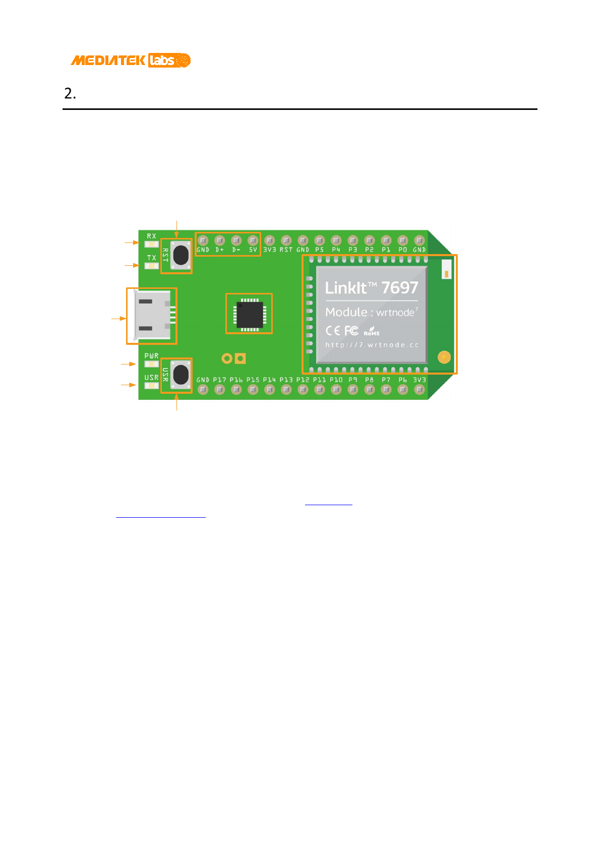
2.1. Board configuration
The interfaces and modules are shown in Figure 2.
USB pin
header
Reset
Micro-
USB
connector
Power LED
USR LED
User configurable
button
CP2102N wrtnode7 module
UART RX LED
UART TX LED
Figure 2. Front view of the HDK (created in Fritzing)
• wrtnode7 Wi-Fi and Bluetooth LE module: It equips the MT7697 Wi-Fi / BLE SOC and is ready to use with
an on-board antenna and an I-PEX connector. Moreover, a 4MB flash is also included in this module.
• CP2102N: A USB-to-UART bridge chipset made by Silicon Labs. It’s used during flash update process with
the mt76x7-uploader tool and to switch between the flash normal mode and the flash recovery mode,
automatically.
• Micro-USB connector: Serves as a 5V power source to the HDK. Connect the HDK to a computer that has
the CP2102N driver installed, to get UART messages (from UART0 on MT7697) using a terminal program.
• RX / TX LEDs: LEDs used to indicate the transmission states of the UART port (UART0).
• PWR LED: This LED will light on while connecting to a power source.
• USR LED: An LED used for user-defined behavior. It’s controlled by P7 pin (GPIO36).
• RST button: Resets the chipset and is connected to the RST pin. While it’s pressed, it will be linked to the
GND.
• USR button: A button used for user-defined behavior. It’s connected to P6 pin (GPIO37). When it’s
pressed, it will be linked to the 3V3 source.
• USB pin header: It provides the same functionality as the micro-USB connector but in the form of pin
headers.
• MT7697 bootstrap pins: All MT7697 bootstrap pins except GPIO37 (used for Flash Access Mode control)
are hidden from this HDK and not accessible through breakout headers. The Flash Access Mode has to two
LinkIt 7697 HDK v10 User's Guide
© 2015 - 2017 MediaTek Inc.
Page 7
This document contains information that is proprietary to MediaTek Inc. (“MediaTek”) and/or its licensor(s).
Any unauthorized use, reproduction or disclosure of this document in whole or in part is strictly prohibited.
configurations; normal mode and recovery mode. To set the HDK to Flash Recovery mode, use the USR
button to pull up GPIO37. For more details, see section 2.3, “Updating the flash”. Note, that since GPIO37
is in the breakout header, if there is an external component connected to P6 (where GPIO37 is), the
voltage level of that component might affect the boot-up sequence. Ensure P6 is clear or pulled low when
the system powers on.
• If there is no 5V power source, this HDK can also work with 3.3V by simply connecting the 3V3 pin to a
3.3V power source.
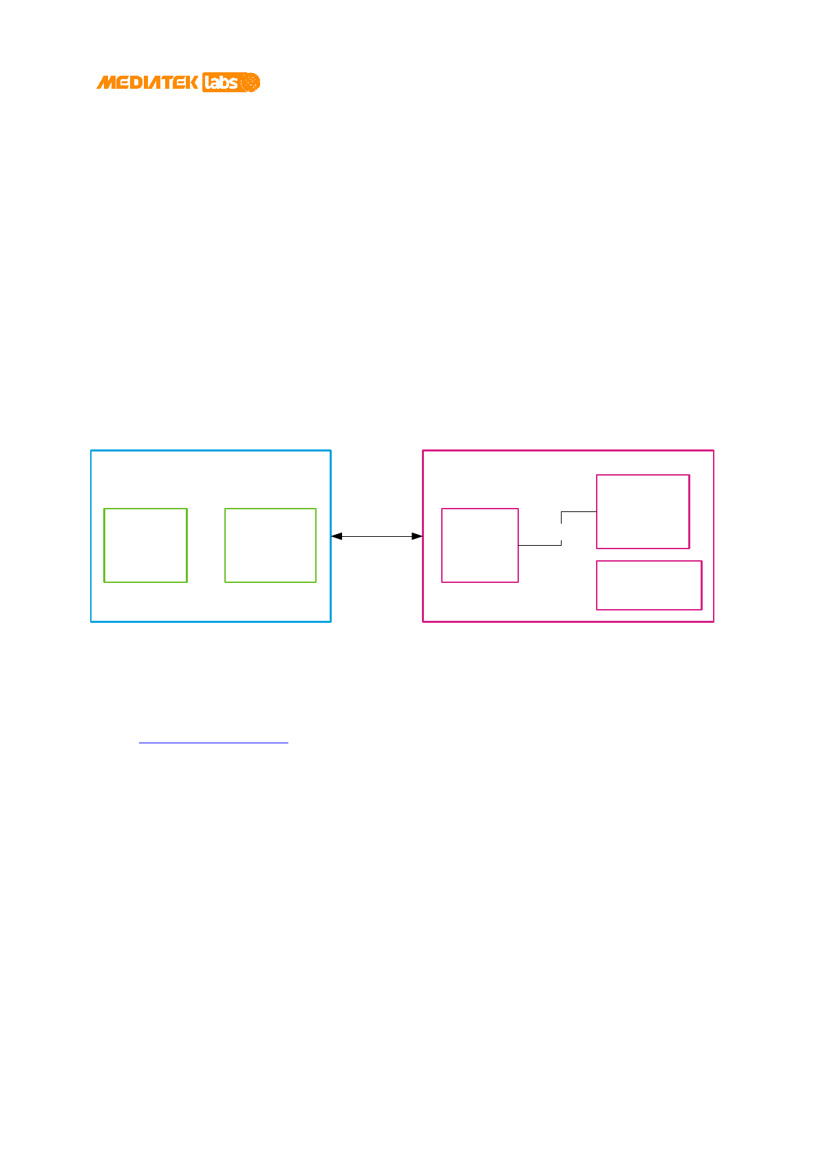
2.2. Installing the driver for Windows
LinkIt 7697 HDK connects to your computer through the COM port interface. The COM port interface is provided
by the on-board CP2102N USB-to-UART bridge chipset, which then connects to the UART0 port of the MT7697
chipset. The UART0 port can be used to program the flash memory attached to the MT7697 chipset. It can also be
used as a communication channel for your application through terminal emulator program of your choice.
The block diagram for the communication is shown in
Figure 3:
Arduino IDE CP2102N
Driver
PC
Micro-USB
Connector
CP2102N
Flash Memory
MT7697 SOC
LinkIt 7697 HDK
UART0
Figure 3. Communication between PC and the HDK
Since the board relies on CP2102N to provide the COM port functionality, you'll need to install a driver so that your
computer can recognize it. And because the board uses the default USB VID and PID of the CP2102N, it’s required
to install the official CP2102N driver from the vendor's website.
After choosing the Download VCP option according to your operating system version and finishing the driver
installation, use a micro-USB cable to connect the board to your computer. The onboard PWR LED should light up.
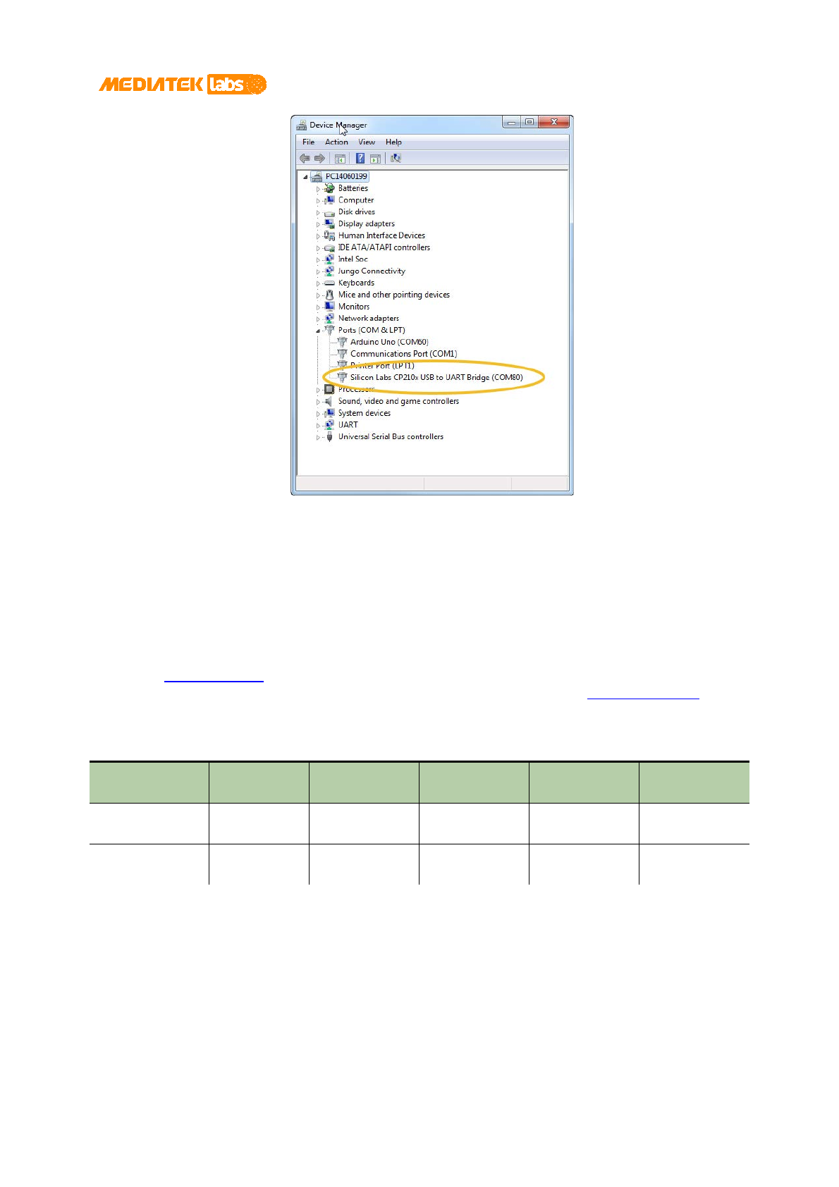
Follow the steps below to confirm the driver is properly installed:
• Open Device Manager from the control panel.
• In the Ports (COM & LPT) section, an item named Silicon Labs CP210x USB to UART Bridge
(COMnnn) should appear. The port number can be different on each computer. This is the COM port
you'll be using to program and interact with the LinkIt 7697 HDK (see Figure 4).
LinkIt 7697 HDK v10 User's Guide
© 2015 - 2017 MediaTek Inc.
Page 8
This document contains information that is proprietary to MediaTek Inc. (“MediaTek”) and/or its licensor(s).
Any unauthorized use, reproduction or disclosure of this document in whole or in part is strictly prohibited.
Figure 4. The COM port allocation for LinkIt 7697 HDK
2.3. Updating the flash
There are two tools provided for programming the flash storage:
1) The Flash tool inside the LinkIt SDK. It’s a Windows execution program providing the functionality to
program and format the flash storage, see section 2.2.4.1, “Using the Flash Tool” of the LinkIt for RTOS
development platform get started guide, for more details about using the Flash tool.
2) The mt76x7-uploader on MediaTek Labs’ GitHub page. It’s a Python script providing cross-platform
implementation for the flash storage. For its usage guide, refer to the readme on the project page.
Select the tool based on your development requirements (see Table 1).
Table 1. Comparison between Flash tool and mt76x7-uploader
One thing to be noted is that when using the Flash tool, switch the board into the Flash Recovery mode for the tool
to operate properly.
To switch the board into the Flash recovery mode:
1) Connect the board to a power source.
2) Press and hold the USR button.
Supported OS Recovery mode
switching
Flash contents
read-back
Format the
flash storage
Where to get
Flash Tool Windows Manual Supported Supported LinkIt SDK
package
mt76x7-uploader Windows,
Linux, macOS
Automatic N/A N/A MediaTek Labs’
GitHub page

LinkIt 7697 HDK v10 User's Guide
© 2015 - 2017 MediaTek Inc.
Page 9
This document contains information that is proprietary to MediaTek Inc. (“MediaTek”) and/or its licensor(s).
Any unauthorized use, reproduction or disclosure of this document in whole or in part is strictly prohibited.
3) Click (press and release) the RST button.
4) Wait for 1 second and then release the USR button.
After step 4, the board will go into the Flash Recovery mode and you can then use the Flash tool or the QA tool
with it.
If you choose the mt76x7-uploader to update the flash, the tool itself will handle the flash mode switch
automatically without user intervention.

LinkIt 7697 HDK v10 User's Guide
© 2015 - 2017 MediaTek Inc.
Page 10
This document contains information that is proprietary to MediaTek Inc. (“MediaTek”) and/or its licensor(s).
Any unauthorized use, reproduction or disclosure of this document in whole or in part is strictly prohibited.
Hardware Features
This section lists the LinkIt 7697 HDK features. For more detailed specification of MT7697, please refer to the
MT7697 datasheet.
• 192MHz ARM Cortex-M4 CPU with FPU support.
• 352KB RAM.
• 4MB Flash storage.
• 802.11 b/g/n 2.4GHz Wi-Fi.
• Bluetooth Low Energy support.
• On-board chip antenna.
• I-PEX connector provided.
• CP2102N USB-to-UART convertor.
• Passed FCC / CE certifications.
• Support two operational power voltages: 5V and 3.3V.
• Pin headers for 5V / 3.3V / GND / Reset / GPIO (18) / PWM (18) / UART (2 sets) / IR (1 set) / EINT (4) / I2S
(1 set) / I2C (1 set) / SPI (1 set) / ADC (4) and USB UART (1 set).
• Two buttons are provided. The RST button (connected to the RST pin) and the USR button (connected to
the P6/GPIO37).
• Four LEDs are provided. One is for the power indicator and one is for the user-defined behavior
(controlled by P7/GPIO36). The other two are used for indicating the TX / RX status of UART0.
• Breadboard compatible form factor for the pin pitch (2.54mm).
LinkIt 7697 HDK v10 User's Guide
© 2015 - 2017 MediaTek Inc.
Page 11
This document contains information that is proprietary to MediaTek Inc. (“MediaTek”) and/or its licensor(s).
Any unauthorized use, reproduction or disclosure of this document in whole or in part is strictly prohibited.
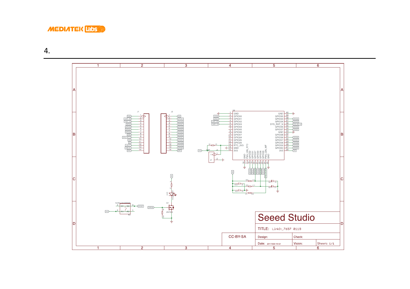
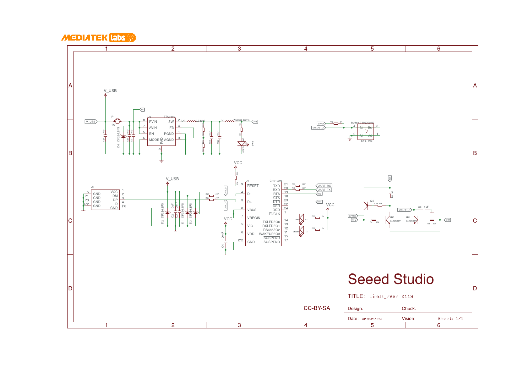
Schematics
LinkIt 7697 HDK v10 User's Guide
© 2015 - 2017 MediaTek Inc.
Page 12
This document contains information that is proprietary to MediaTek Inc. (“MediaTek”) and/or its licensor(s).
Any unauthorized use, reproduction or disclosure of this document in whole or in part is strictly prohibited.
LinkIt 7697 HDK v10 User's Guide
© 2015 - 2017 MediaTek Inc.
Page 13
This document contains information that is proprietary to MediaTek Inc. (“MediaTek”) and/or its licensor(s).
Any unauthorized use, reproduction or disclosure of this document in whole or in part is strictly prohibited.
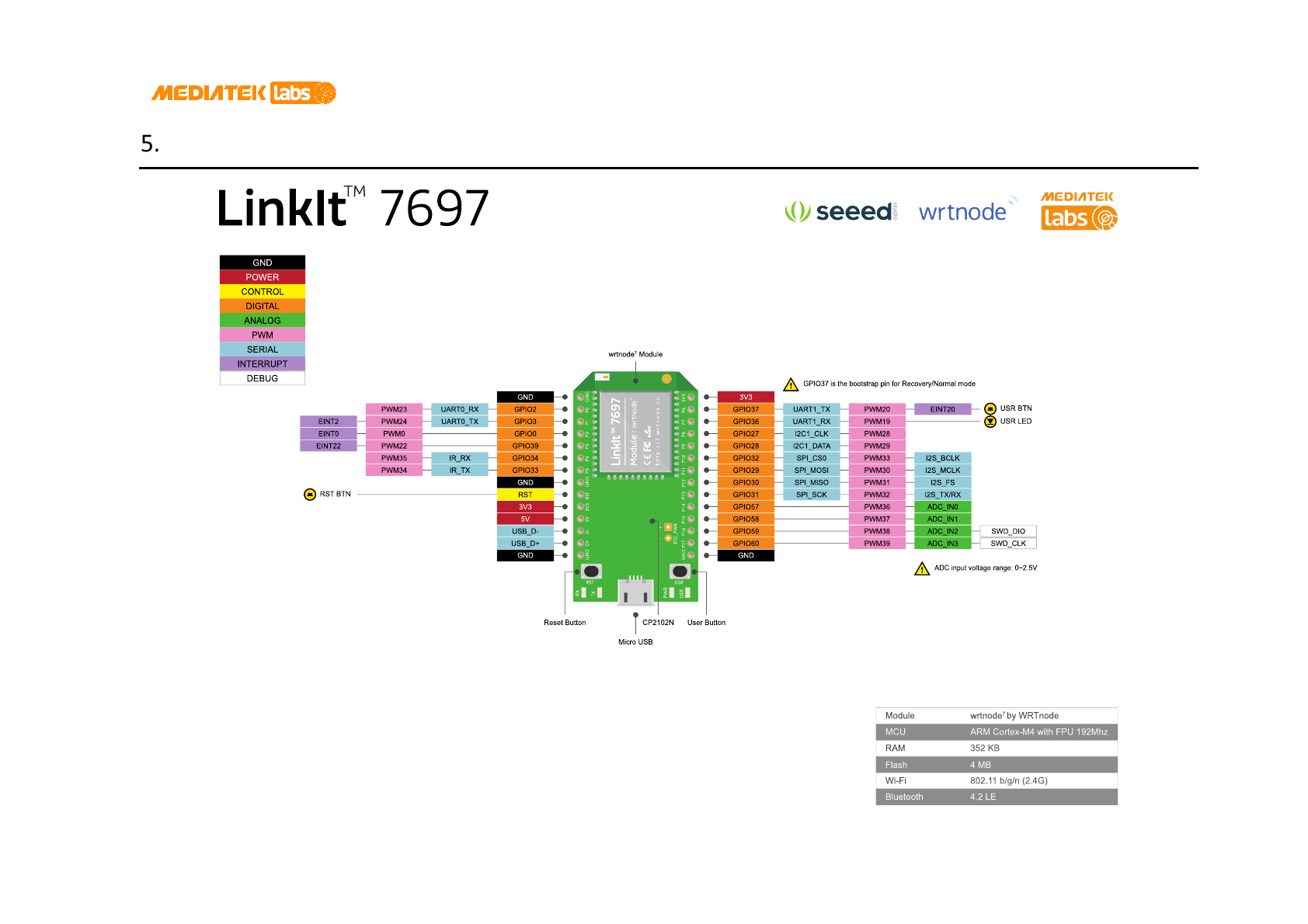
Pin-Out Diagram
