Lino_062208 Lino
Lino Lino
User Manual: Lino
Open the PDF directly: View PDF ![]() .
.
Page Count: 14

Xitron Part Number Doc-1012-0608
Plug-in Manual
Linotype
Version 7.2.1.1
June 23, 2008

6/23/2008 Xitron Plug-in Manual
Page 1
Overview
Xitron’s Navigator PostScript RIP and Raster Blaster TIFF
Catcher rely on software modules called plug-ins to
communicate with imaging systems. In many cases they work
in tandem with an interface card, while in others it is simply a
conversion to a bitmap file in a compatible format.
When interface cards are involved, these plug-ins act as device
drivers and control most actions of the output devices. Some of
these actions include checking device status, device setup, and
advancing and cutting material. In addition, the plug-in relays
all the physical characteristics of an engine such as supported
resolutions and imageable area.
During the launch sequence, both Navigator and Raster Blaster
scan a specific directory for plug-ins. The software loads each
plug-in it finds, and then queries them for a description of the
capabilities of the supported devices. In this manner the plug-in
configures the RIP to output a bitmap to these devices.
Each plug-in controls a particular family of recorders and is
able to understand most messages and errors communicated by
the output device. Plug-ins for use with Windows-based
platforms consist of three software modules. The first module
is the core plug-in written specifically for a particular device.
This DLL is 32-bit code and runs under Windows NT,
Windows 2000 Server, Windows 2000 Professional, Windows
2003 Server and Windows XP. The second module is a kernel
mode device driver. This module communicates with the

6/23/2008 Xitron Plug-in Manual
Page 2
Xitron interface boards and moves the bitmap data from the
PC to the output device's interface. The third module is a
“helper” DLL that translates calls from the plug-in to the
Windows device driver.
When a page is sent to an output device for imaging, the
Xitron software loads the correct plug-in and begins a series of
steps prior to output. The plug-in first initializes the engine and
checks that it is ready. After receiving the proper signal, the
plug-in will begin reading bitmap data from the platform's hard
drive into a “printer buffer.” Once the printer buffer is full, the
plug-in will start communicating the data to the output device.
As the output device consumes the data, the plug-in relays this
information to the software, which then refills the buffer. This
continues until all of the data has been communicated to the
output device. The plug-in tells the software the job is
complete and waits for an indicator that the recorder has
finished. This process is repeated for each page being output.
Raster Blaster
Plug-ins used by Xitron's Raster Blaster have the same
functionality as those for the Navigator RIP and the same
options are available for configuration. Therefore, unless
otherwise specified, the information in this manual will apply
to both products. See the Raster Blaster Reference Manual for
specific configuration information.

6/23/2008 Xitron Plug-in Manual
Page 3
Configuring Devices
Xitron distributes a separate plug-in for each recorder family.
This plug-in, in conjunction with firmware on specific Xitron
interfaces (PCI, PCI-X, USB), has the capability to drive most
of the devices in each recorder family. Users may install more
than one plug-in within a single RIP. In addition, it is possible
to configure more than one engine type within a single plug-in.
Xitron pre-configures most plug-ins to display all output
devices currently supported. To view these devices, click the
Device Manager icon shown in Figure 1.
Figure 1: Device Manager Icon
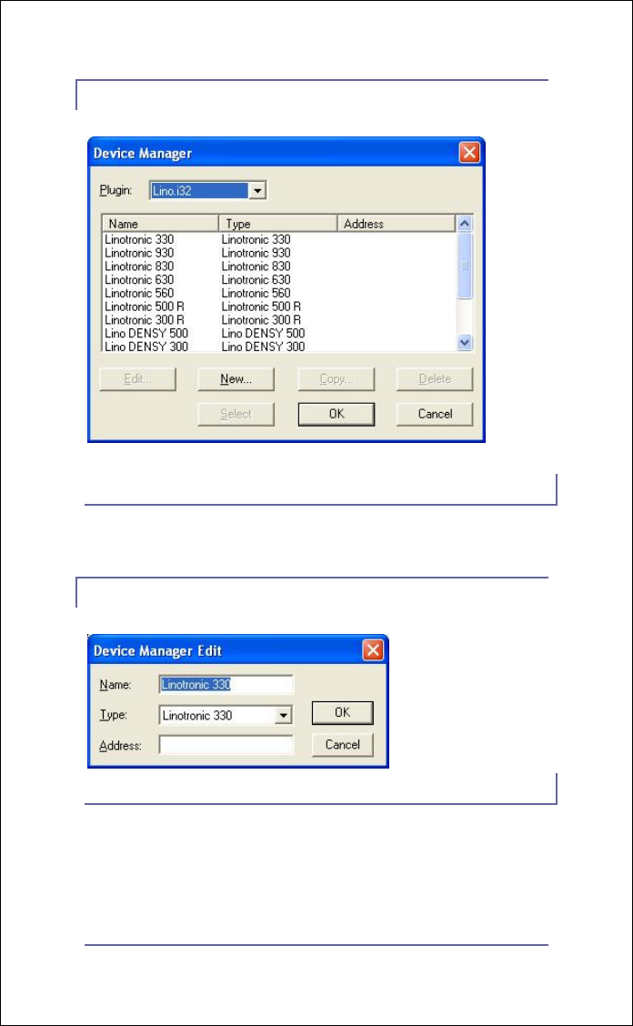
The Device Manager dialog box shown in Figure 2 will display.
If the dialog displays the user’s output device in the scrollable
list, no further editing is necessary. The names of the available
output devices will appear in the Output Device pull-down
menu of the Page Set-up dialog box. However, in the rare
circumstance that another device name is necessary; the user
has the option of customizing the name field.
With the Device manager dialog window open, click New or
select an existing device and click Edit.
6/23/2008 Xitron Plug-in Manual
Page 4
Figure 2: Device manager Dialog
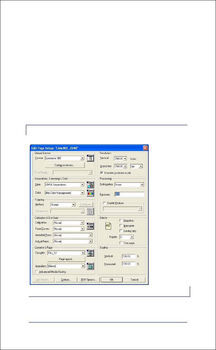
Figure 3: Device Manager Edit
A dialog box similar to the one shown in Figure 3 will display.
Enter a name for the device. This name will display in the
Device pull-down menu as a selection in the Page Setup dialog.
6/23/2008 Xitron Plug-in Manual
Page 5
For example, if two Linotronic 330 imagesetters are being
driven by the same plug-in and differentiation between the two
is important, edit this field to reflect Lino1 and Lino 2.
The name can be any string of up to 32 characters. Select the
specific recorder from the pull-down menu labeled Type.
Ignore the address field, as it is not used. After making the
selections, click OK to make the device available in the Page
Setup menu as seen in Figure 4.
Figure 4: page Setup

6/23/2008 Xitron Plug-in Manual
Page 6
Linotronic Specific Settings
Xitron’s Linotronic plug-in supports the following recorders:
• *200p, *200SQ, *230, 300D, 500D, 300, 330, 500,
530, 560
• 630 (See additional document, “DLDBuild”)
• 830, 930
Based on the device selected in the pull-down menu of the
Page Setup, various capabilities regarding resolution, density
settings, page orientations and film dimensions will
automatically populate the available menu options. For
example, choosing Linotronic 330 provides 10 resolution
options between 423 dpi and 3387 dpi, which match the
programming of the recorder. Selecting Linotronic 630 yields
only three resolutions, which match the capability of that
model.
Choose the appropriate resolution, exposure, and page
orientation from the main window of Page Setup as shown in
Figure 4. Click the button labeled Configure device… to
change settings that are more specific to the output device such
as punch positioning.
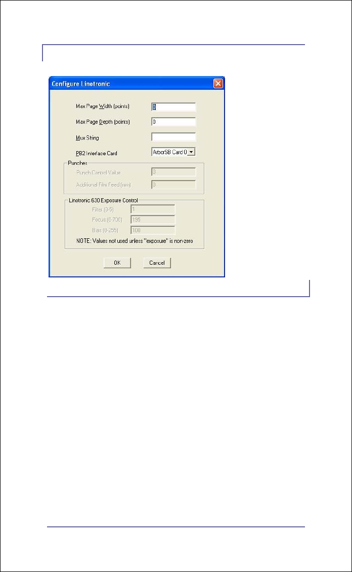
Some configuration options will be grayed out and non-
editable. This occurs when the device chosen does not offer
that particular functionality. An example can be seen in Figure
5, which shows the Configure Device window as it pertains to
the L330. In this example only a few of the options are
selectable by the operator.
6/23/2008 Xitron Plug-in Manual
Page 7
Figure 5: L330 Configure Device
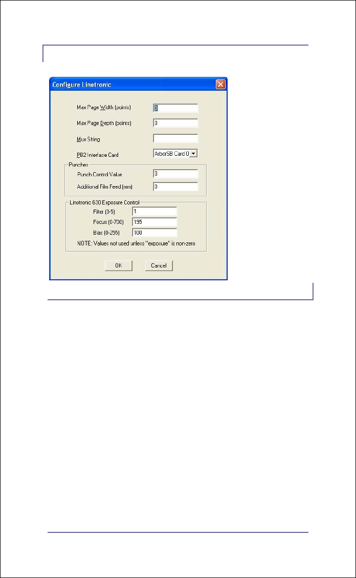
However, the L630 dialog shown in Figure 6 allows operator
entry for all variables. Explanations for each of the entries can
be found below Figure 6.
6/23/2008 Xitron Plug-in Manual
Page 8
Figure 6: L630 Configure Device
• Max Page Depth: Use this value to set the
maximum length of an imaged job. This feature is
helpful if a film device is imaging plate material and
the plate must be a consistent length. Setting this
value to 0 disables the feature. If this value is set to 0
on a drum or cut sheet type imager, images will be
clipped at the maximum length allowed by the plug-
in. Non-zero values will cause the plug-in to allow
images of the set value. Enter values in points.
• Mux String: This is used in an environment with a
multiplexer, which can scan for a connection to one
or more output devices.

6/23/2008 Xitron Plug-in Manual
Page 9
• PB2 Interface Card: If more than one interface
(ArborSB) card is in the PC, select the appropriate
interface here. The default for this box is blank,
signifying that the first configured card will be used. If
the USB interface is being used, one PCI card and one
USB may be configured for output to two systems. To
configure a plug-in to output to the USB interface,
select “Sedona” in the drop down menu.
• Punch Control Value (Linotronic 630 ONLY):
This option allows the user to enable and disable
punches on the Linotronic 630. Normally, a value of
7 will enable the punch and a value of 0 will disable
the punch. In order to determine the values specific to
the attached imager, input jobs from an existing
Linotronic RIP first with the punches ON and then
with the punches OFF. Examine the image placement
after each exposure to determine the correct value.
• Additional Film Feed (mm) (Linotronic 630
ONLY): This value is added to the normal film feed
(width of the job) after exposure to make sure the
punched holes are flushed off the drum.
• Linotronic 630 Exposure Control: This group of
3 settings supplements the exposure setting on the
Page Setup dialog, providing all necessary laser
control of the Linotronic 630 recorder. Please refer
to the Linotronic 630 documentation for more
information.
o Filter: This setting selects which filter to
engage at this resolution.
o Focus: This setting selects the focus lens
position.

6/23/2008 Xitron Plug-in Manual
Page 10
o Bias: This setting sets the current supplied
to the laser when in the “off” state (dark). It
is sometimes referred to as “Bias light
current” on Linotronic equipment and
software.
Connecting the Interface
The Xitron interface for Linotronic recorders uses the LI2 and
LI5 ports on the back of the recorder. For almost all
installations, both the LI2 and LI5 ports are connected. (For
exceptions see LI2-Only under Additional Set-Up.) One
Xitron cable (020-0423-020) attaches to the 50-pin mini-SCSI
connector of the Xitron PCI card or USB interface, and the LI2
port on the back of the recorder. Command and status
information to control the recorder is carried on the LI5
interface via the second Xitron cable (020-0422-010), which
attaches to the 9-pin D-shell type connector on the card (or
USB Interface Box), and the LI5 port (25-pin D-shell) on the
back of the recorder.
Additional Set-up
After attaching the LI2 and LI5 cables between the Xitron
interface and the imager, use the Linotronic front panel to
select the LI5 interface. An indication that the imager is in LI5
mode is an “L” in the upper left corner of the Linotronic front

6/23/2008 Xitron Plug-in Manual
Page 11
panel LCD. At this point, the system should be ready for initial
testing.
The LI2-Only device type is provided for Linotronic machines
that do not have an LI5 interface. Since the setting of all imager
parameters like resolution and density is handled through LI5,
the LI2-Only device type will not take advantage of all the
Xitron plug-in features. LI2 mode will allow proper imaging
only if the RIP and recorder parameters match.
Set the Linotronic for Panel interface and place it in imaging
mode by pressing the Start button on the front panel. When
the Linotronic is in imaging mode, a reverse P will appear on
the left side of the imager’s LCD. To feed and cut the film,
press the Stop button (shift-stop) on the front panel, followed
by the Cut button. Always take the Linotronic out of imaging
mode before shutting down the Navigator RIP.
The error message “LI5 OVRRUN” will occasionally appear
on the Linotronic console during imaging. This is normal. In
order to receive up-to-date status and error information from
the imaging engine, it is necessary to poll the engine
periodically while it is imaging. At certain points during the
startup of the imaging process, the engine will stop responding
momentarily to perform time-critical adjustments. These LI5
OVRRUN messages occur during those periods. The Xitron
software will timeout and retry the status request two seconds
later without any indication that the overrun has occurred.
The Linotronic recorder has some features that may interfere
with the operation of Xitron software. Specifically, a group of

6/23/2008 Xitron Plug-in Manual
Page 12
settings in the front panel control the width of the imageable
area and provide a hardware setting for the left margin. These
options are available under the key labeled “X/Y” on the
recorder’s front panel. Make sure that the setting labeled “X-
Measure” correctly reflects the width of the imager: 12-inch
for the 300 series and 18-inch for the 500 series. Make sure
“X-LeftMargin” is set to 0. This will enable the recorder’s
maximum imaging area and allow margins and image width to
be controlled from the Xitron plug-in.
Plug-in Messages
From the time a plug-in is loaded for the purpose of setting up
and outputting to one of its devices, it begins to send messages
to the software’s Monitor window. These messages are
typically informational but can convey warnings and report
errors from the engine. There is a user-changeable setting
called “debug level” that controls the verbosity of these
messages. This can range from 0 (almost no messages) to 4
(very high message traffic). This is described in the Xitron Tech
Note CreatingLogfile.pdf.
Examples of informational messages are:
• PostScript job name
• Commands being sent to the PCI card to set up the
engine
• Output start and stop time
Examples of warning messages are:
• A job being clipped to fit a recorder width

6/23/2008 Xitron Plug-in Manual
Page 13
• Data being left at the end of the job.
• Certain settings in the .ini file overriding defaults
When the plug-in encounters an error from the output device,
it will generate an appropriate error message. The short form
of this message will appear in the Throughput Controller. The
long form will appear in Navigator’s Monitor window. If the
error encountered is easily remedied, i.e. an empty cassette,
then the plug-in will continue to periodically test the engine
until the error has been cleared. During this time the user may
disable output by checking the “Disable output” check box in
the Throughput Controller and dragging the page to either the
Active or Held queue. If the error is serious, the plug-in will
automatically request that the software disable output and the
page will be placed back in the Active Queue automatically.
