Lycoming General Operations Article
User Manual: Lycoming-General-Operations-Article
Open the PDF directly: View PDF ![]() .
.
Page Count: 28

Lycoming Flyer
Lycoming has been pleased and impressed by the number of requests for copies of the “Key Reprints”
— pleased by your many favorable comments concerning it, and impressed by the thirst for knowledge
by operators of General Aviation aircraft engines.
In the event a reader perceives a conflict between the content of these articles and the content of the
current manuals, service bulletins or service instructions, the latter items govern, but the reader should
contact Lycoming Service and bring such a conflict to our attention. The service bulletins and parts of the
manuals are FAA approved; these articles are not.
Some of the articles published are based on information contained in Service Bulletins, Service
Instruction, and Service Letters. In addition, other articles are taken from actual field test data car-
ried on by Lycoming personnel. Furthermore, the Lycoming factory is a central collecting agency
on its aircraft engines in the field. Experiences and information from all over the world provide
feedback that is recorded and analyzed. We share this information with our readers in the Flyer
and Key Reprints.
During the preparation process of each article and as each subsequent re-issue updating of information
is part of the procedure. After articles are written, each one is carefully screened and checked by man-
agement, engineering and service personnel to ensure accuracy before being released for publication.
The Flyer does not have an established publishing date for each issue. The latest issue is Number .
The original concept of the Flyer has not changed since the first issue was published in 9. Approximately
8% of the prepared text deals with technical information related to Lycoming engines, and the remaining
% covers general newsworthy items. Distribution of the Flyer is made to owners and operators of
Lycoming powered aircraft, authorized distributors and others who write us and request that we place
them on our mailing list, with all costs of printing and mailing absorbed by Lycoming. It is the intention
of Lycoming to continue to make available service, maintenance and operational data in the Flyer and
Key Reprints to assist the owner and operator in improving their engine’s performance and reliability.
G E N E R A L
Lycoming Flyer

8 L y c o m i n g F l y e r
If you are not sure of the meaning of such terms as normally
aspirated, turbocharged, supercharged or direct-drive
engines, then perhaps you’ll want to read our simplified defini-
tion of them.
The Normally Aspirated Engine is one that is not turbocharged
or supercharged. If the airplane has a manifold pressure gauge,
at full takeoff power at sea level on a standard day, it would indi-
cate an MP reading of approximately 29" of Hg. Takeoff power
at 5,000 ft. density altitude airport would read about 24" MP.
The normally aspirated engine uses atmospheric pressure and is
thereby altitude limited.
Direct-Drive Engines are those piston-powered engines where
the propeller is bolted on the end of the crankshaft, and the prop
turns at the same speed as the crankshaft.
Geared Engines are usually the higher powered, more com-
plex engines using a reduction gear on the nose of the aircraft,
and with the prop attached to it. As a result, the prop will turn
somewhat slower than the crankshaft, resulting in a lower prop
noise level. When the engine is geared, we precede the engine
designation with a “G.” Thus a geared, opposed (O) normally
aspirated Lycoming engine with a 480-cubic inch displacement
of the cylinders would be designated a GO-480 model.
Turbocharged Engines as manufactured by Lycoming simply
consist of a turbocharger unit with a small turbine wheel attached
by a common shaft to a compressor wheel, and utilizes the engine
exhaust gas by directing it over the turbine wheel to drive the
compressor. The horsepower loss in operating the turbocharger is
negligible. Turbocharging can provide greater utility to the piston
engine by providing sea-level horsepower, in some models, as high
as 20,000 feet; or it can be used to add horsepower to the engine
particularly for takeoffs. The faster the engine runs, the more air
the turbocharger can pack into the cylinder to compensate for the
thin air of altitude, or to increase the horsepower. Although this
definition is somewhat oversimplified, it is a basic definition of
turbocharging of General Aviation power plants.
Where turbocharging is used with a fuel-injected, opposed
Lycoming engine with a 540 cubic inch displacement,
we designate it as a TIO-540 model. “T” represents the
turbocharging.
Supercharged Engines as manufactured by Lycoming uses a
compressor wheel to pack air into the cylinders; but the com-
pressor is driven by the crankshaft through an intricate gearing
system, which takes considerable horsepower from the engine to
operate. In comparison with a turbocharged engine, it is a medium
altitude power plant.
Although supercharged engines could be built by Lycoming,
new aircraft designs during the past 20 or more years have used
turbocharging instead of supercharging because of the advantages
that turbocharging offers.
A supercharged, geared, opposed, fuel-injected Lycoming
engine with cylinders of 540-cubic inch displacement is desig-
nated an IGSO-540 model. “S” represents supercharging.
All publications may be ordered through authorized Lycoming
distributors, or direct from Lycoming. If ordered by mail direct
from Lycoming, payment in the form of check or money order
must be submitted with the request as outlined in the latest revi-
sion of Lycoming Service Letter No. 114. Fax or telephone orders
will be accepted if payment is made with a credit card: American
Express, Visa and MasterCard are accepted.
The available maintenance publications for Lycoming engines
and accessories consist of the following:
OPERATOR’S MANUAL
The Operator’s Manual contains information of use to pilots and
maintenance personnel. It contains engine specifications, inspec-
tion procedures, operational information, and is used in conjunc-
tion with the Pilots Operating Handbook for the aircraft.
OVERHAUL MANUALS
The Overhaul Manual is a guide for major repair of the engine. It
contains complete disassembly, inspection, repair, reassembly and
test procedures for the various Lycoming reciprocating engines.
When used in conjunction with the applicable parts catalog and
service bulletins, service instructions and service letters, this
manual provides an authoritative text for complete overhaul of
the engine. Overhaul Manuals for current Lycoming engines are
published in loose-leaf format so that revisions may be easily
inserted.
PARTS CATALOGS
Lycoming Parts Catalogs are illustrated to permit iden-
tification of parts. A referenced numerical index is also
included.
SERVICE BULLETINS, INSTRUCTIONS, LETTERS
These publications are issued as required. Service Bulletins are
mandatory, and require some modification or inspection to be
accomplished on the engine within a specified time. Service
Instructions cover a variety of subjects; such as repair processes,
modification procedures, inspection procedures and overhaul
methods. Service Letters are of an informative nature, usually
pertaining to service policy or vendor products.
SPECIAL SERVICE PUBLICATIONS
These publications are concerned with topics of general
interest or subjects that are too lengthy for inclusion in maintenance
manuals.
ENGINE SPECIFICATIONS AND INSTALLATION
DRAWINGS
These materials are needed by those who are planning to install
a particular engine model in their aircraft.

Lycoming Flyer 9
OWNER ADVISORY
This notification may be sent without charge to applicable
aircraft owners listed in the FAA database when a mandatory
Service Bulletin is issued and it appears that it may affect the
engine in your aircraft.
NOTE — In this publication, all references to maintenance
publications are to the most recent revision.
As an engine builds operating hours and approaches TBO,
which may be either the manufacturer’s recommended oper-
ating hours, or a calendar year limit before overhaul, the ques-
tion arises concerning the decision to either continue flying,
or top overhaul, major overhaul or exchange engines. Here is a
quick-reference checklist to help make such a decision, followed
by a brief explanation of the nine points.
I. Oil consumption — any unusual increase?
II. Engine history and calendar age.
III. How has the engine been operated?
IV. Pilot’s opinion of the engine.
V. Maintenance — what kind has the engine received?
VI. What does the oil filter tell?
VII. What has been the trend in compression checks?
VIII. What do the spark plugs show?
IX. Refer to the engine manufacturer’s service letter for engine
life and recommended overhaul periods.
Along with the above quick-reference checklist, as an engine
manufacturer we would like to share our experience with inter-
ested operators by discussing the nine points:
I. OIL CONSUMPTION
The operator and maintenance people should know what has been the
general history of oil consumption during the life of an engine.
A possible danger signal concerning engine health is a definite
increase in oil consumption during the recent 25 to 50 hours of
flight time. The oil screens and filter should be carefully observed
for signs of metal. Maintenance should also take a good differ-
ential compression check at this time. They should also look in
the cylinders with a gooseneck light or a borescope to detect any
unusual conditions in the combustion chamber.
If you haven’t looked at your air filter lately, it would be a good
idea to carefully inspect it for wear and proper fit. This is all the
more important when operating in dusty areas, and definitely
could be a cause of increased oil consumption.
II. ENGINE HISTORY AND CALENDAR AGE
If a power plant has been basically healthy throughout its life, this
would be a favorable factor in continuing to operate it as the engine
approached high time. Alternately, if it has required frequent
repairs, the engine may not achieve its expected normal life. The
engine logbook should contain this accumulative record.
Another important aspect of an engine’s history would be its
calendar age. Engine flight time and calendar age are equally
important to the operator. We have observed that engines infre-
quently flown do tend to age or deteriorate more quickly than
those flown on a regular basis. Therefore, Lycoming recommends
both an operating-hour limit and a calendar-year limit between
overhauls. Service Instruction 1009 gives these recommenda-
tions, but other items in this checklist will help to determine if an
overhaul or engine exchange is needed before the engine reaches
these recommended limits.
III. OPERATION
The basic question here would be how the engine has been oper-
ated the majority of its life. Some engines operating continuously
at high power, or in dusty conditions, could have a reduced life.
Likewise, if the pilot hasn’t followed the manufacturer’s recom-
mendations on operation, it may cause engine problems and
reduce the expected life. This becomes a more critical influence
on a decision in single engine aircraft, and also for single or twin
engine planes flown frequently at night or in IFR conditions.
IV. PILOT’S OPINION OF THE ENGINE
The pilot’s opinion of the power plant, based on experience
operating it, is another important point in our checklist.
The pilot’s opinion and confidence in the engine is based on
whether it has been a dependable power plant. If the pilot lacks
confidence in an engine as it approaches the manufacturer’s
recommended limits, this could be a weighty factor in the deci-
sion to continue flying or to overhaul it. The pilot should consult
with his maintenance personnel concerning their evaluation of
the condition of the power plant.
V. MAINTENANCE
Good maintenance should aid in achieving maximum engine life;
alternately, poor maintenance tends to reduce the expected life.
We notice among those power plants coming back to the factory
to be rebuilt or for an overhaul, that the smaller engines in general
have had less care and attention, and in a number of instances have
been run until something goes wrong. The higher powered engines
have generally had better maintenance and show evidence that
the operators do not wait until something goes wrong, but tend
to observe the manufacturer’s recommended operating hour or
calendar limits to overhaul. The engine logbook should properly
reflect the kind of maintenance provided the engine or engines.
The technician who regularly cares for an engine will usually have
an opinion about its health.

0 L y c o m i n g F l y e r
VI. WHAT DOES THE OIL FILTER TELL?
Clean oil has consistently been an important factor in aiding
and extending engine life. A good full-flow oil filter has been
a most desirable application here. When the filter is exchanged,
ask the mechanic to open it and carefully examine for any for-
eign elements, just as is accomplished at oil change when the
engine oil screen is also examined for the same purpose. Just
as the spark plugs tell a story about what is going on in the
engine, so the engine oil screen and the external oil filter tell
a story about the health of an engine. Whether the engine is
equipped with an oil filter or just a screen, oil changes should
have been accomplished in accordance with the manufacturer’s
recommendations. These oil changes should have been recorded
in the engine logbook.
If oil is analyzed, it should be done at each oil change in order
to establish a baseline. Analysis is a tool which only gives useful
information when a dramatic departure from the established norm
occurs. (See “Spectrometric Oil Analysis” later in this section.)
VII. COMPRESSION CHECKS
What has been the trend in compression in at least the last two
differential compression checks? The differential compression
check is the more reliable type and should be taken on a warm
engine. If the differential check reveals 25% loss or more, then
trouble may be developing.
Some operators are confused by the compression check and
its application. A compression test should be made any-
time faulty compression is suspected, anytime the pilot
observes a loss of power in flight, when high oil consumption is
experienced, or when soft spots are noticed while hand pulling
the prop.
Many maintenance technicians do a compression check at each
oil change, and it is also considered part of the 100-hour engine
inspection and the annual inspection. Most experienced mechanics
feel that the differential compression check is best used to chart
a trend over a period of flight hours. A gradual deterioration of
charted compression taken during maintenance checks would be
a sound basis for further investigation.
VIII. SPARK PLUGS
The spark plugs when removed and carefully observed, tell the
skilled mechanic what has been happening in the cylinders during
flight, and can be a helpful factor in deciding what to do with a
high-time engine:
1. Copper run out and/or lead fouling means excessive heat.
2. Black carbon and lead bromide may indicate low temperatures,
the type of fuel being used, and possibly excessive richness of
fuel metering at idle.
3. Oil fouled plugs may indicate that piston rings are failing to
seat, or excessive wear is taking place.
4. The normal color of a spark plug deposit is generally
brownish gray.
5. I n h ig h compre ssion a nd supe rcha rged engi ne s,
a cracked spark plug porcelain will cause or has been caused
by preignition.
IX. ENGINE MANUFACTURER’S RECOMMENDED
OVERHAUL LIFE
Service Instruction 1009 is the Lycoming published recom-
mendation for operating hour and calendar year limits until
engine overhaul as they apply to each specific engine model.
The amount of total operating time on an engine will be a basic
factor in any decision to either continue flying, change, top or
major overhaul the power plant. Operators should be reminded,
however, that the hours of service life shown in the service
instruction are recommendations for engines as manufactured
and delivered from the factory. These hours can normally be
expected, provided recommended operation, periodic inspections,
frequent flights and engine maintenance have been exercised in
accordance with respective engine operator’s manuals.
If an operator chooses to operate an engine beyond the recom-
mended limits, there are factors to consider. The cost of overhaul
is likely to be greater as engine parts continue to wear, and the
potential for failure may also increase.
Operators who have top overhauled their engine at some point in
the engine life invariably want to know if this extends the life of
the engine. This is an important question. The chances are that
if the operator applies the checklist we have been discussing and
comes up with favorable answers to these questions about his
engine, he can probably get the hours desired — with only a few
exceptions. But a top overhaul does not increase the official life
or TBO of the engine.
We are surprised from time to time to have owners tell us they top
overhauled their engine at some point less than the major overhaul
life for no reason other than somebody said it was a good idea.
Unless the manufacturer recommends it, or there is a problem
requiring a top overhaul, this is a needless cost. If the engine is
healthy and running satisfactorily, then leave it alone!
One other point deserves attention here; there is no substitute
or cheap route to safety in the proper maintenance or correct
overhaul of an engine.
CONCLUSION:
Apply all of these basic nine points concerning your engine
or engines and then make a decision whether to top over-
haul, major overhaul, exchange engines or continue flying.
QUESTION: I hear the term “Shower of Sparks” relative
to ignition systems. What does this term mean to pilots?
ANSWER: It means that while the engine is cranking during
a start, a prolonged series of sparks is jumping the spark plug
gap as compared to one single spark. This results in improved
cold-weather starting.
Lycoming Flyer
QUESTION: During starts with the shower of sparks ignition
system, I get some pretty severe kickbacks. Why?
ANSWER: The common cause here is that the retard breaker
doesn’t close, resulting in a start attempt on the advance points.
A simple check is to run the engine at about 700 RPM and for a
fraction of a second, hold the starter switch to the start position.
The tachometer will indicate an immediate drop in RPM if the
retard points are operating. There will be no drop in RPM with a
malfunctioning retard breaker.
CAUTION — This check noT recommended on our
direcT-drive engines using auTomoTive-Type sTarTers.
QUESTION: At what RPM should I check my mags?
ANSWER: Where the airplane manual says. For example,
checking at a lower than indicated RPM may give a higher than
normal mag drop.
QUESTION: Is the actual mag drop in RPM very important?
ANSWER: No. We are more concerned that the mag drop is
less than 50 RPM between the two mags and smooth, rather
than whether it’s 50-75 or 150. Again, it should be within the
limits as indicated in the manual.
QUESTION: I noticed some of your engines show practically
no mag drop. Is this normal?
ANSWER: Yes, but give it a little more time, and I think
you’ll note some mag drop. However, if in doubt about any
mag drop, be suspicious of a hot mag. Reduce engine RPM
to idle, and turn switch to off and see if engine dies out. If it
keeps running, beware of hot mag. It’s sad but true that we
will still have people getting hurt due to hot mags.
QUESTION: Can I save the engine any by using less than
takeoff power?
ANSWER: Indeed not. In fact, harm to the engine can be
caused by using less than takeoff power.
A condensed version of several articles.
TIME BETWEEN OVERHAUL (TBO)
Lycoming publishes, and updates from time to time as needed,
Service Instruction 1009. This document sets forth factory recom-
mendations for time between overhaul (TBO). Aircraft owners
often have questions concerning TBO, and the need for engine
overhaul or replacement. This condensed article will answer many
of those questions.
Published in Service Instruction 1009 is a table listing recom-
mended operating-hour limits for all Lycoming engine models.
Some owners are inclined to think that the number of hours
listed is some magic number that an engine is certain to obtain,
but after which it will immediately fail to operate. Actually,
the recommended number is not magic at all. It is the average
number of operating hours a particular model is expected to
achieve, but there are many qualifying factors.
The recommended operating hours (TBO) for Lycoming
aircraft engines only applies to those engines that incorporate
genuine Lycoming parts. Reliability and average service life also
cannot be predicted when an engine has undergone any modi-
fication not approved by Lycoming. Other factors affecting the
operating life of an engine are operating conditions, frequency
of operation and the manner in which the engine is operated
and maintained.
OPERATING CONDITIONS
Engines installed in aircraft that are used to apply chemicals (crop
dusting) may be affected by those chemicals and therefore are
subject to shorter than normal recommended TBOs. Operation
in dusty conditions, or in an atmosphere of salt air near the ocean
are examples of conditions that may have a detrimental affect on
engine condition, and on the capability of reaching the recom-
mended TBO.
OPERATING TECHNIQUE
Pilot technique is another factor affecting engine life. Following
manufacturer recommendations could be categorized as good
operation. On the other hand, complete disregard for these rec-
ommendations could conceivably cause engine destruction in as
little as 100 hours. Although this would be extreme and unusual,
pilots who regularly climb at steep angles, make abrupt throttle
changes, improperly lean the engine in climb, exceed maximum
specified manifold pressure and/or RPM, chop throttles abruptly
and let down rapidly causing rapid contraction of metals that have
been up to operating temperatures are using techniques that may
shorten TBO.
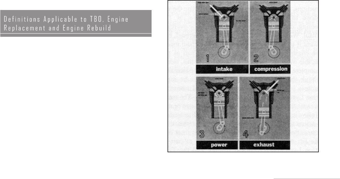
THE FOUR-STROKE CYCLE

L y c o m i n g F l y e r
GOOD VS. IRREGULAR MAINTENANCE
Regular maintenance, performed by qualified personnel using
factory-recommended inspection procedures and intervals, will
contribute to engine performance and the capability of reaching the
manufacturer recommended TBO hours. Stretching inspection or
oil change intervals may create the illusion of saving money, but is
really false economy. Regular oil changes and scheduled mainte-
nance play an important role in achieving recommended TBO.
FREQUENCY OF FLIGHT
Frequency of flight also plays an important part in the operating
history of an engine. Engines flown only occasionally and with
extended periods between oil changes are subject to corrosion
because of acids that build up in the oil and attack internal
metallic parts of the engine. Only regular oil changes can elimi-
nate these acids.
Moisture that enters through the breather or exhaust system can
cause rusting of cylinders and other steel parts. Rings may take
a set and stick in the groove. Condensation in the magnetos may
cause shorting of the breaker points. Flying as often as possible to
bring the engine temperatures up to their normal operating levels
will help to eliminate moisture. A ground run of the engine only
is not considered satisfactory. Frequent flights are needed.
The number of hours that need to be flown each month, and
the length of time between flights cannot be specified for every
aircraft and engine. Variables such as geographic location and
local temperature and humidity must be considered. Inactivity
and time will cause hardening of gaskets, seals and hoses. Long
periods between flights can be expected to cause excessive wear
during engine start due to loss of the protective oil film on bearing
surfaces during the long periods of inactivity. Regardless of the
operating hours, those engines that have not reached the recom-
mended number of operating hours for TBO in a 12-year period
must be overhauled or replaced during that twelfth year.
DECISION TIME
The timing of engine overhaul or replacement is sometimes the
result of government regulations. Anytime regulations are not
a factor, the engine owner must make the decision to overhaul
or replace the engine based on knowledge of the engine and the
conditions under which it has been operated. This decision may
come before the engine has reached the recommended number of
operating hours, or in some cases, after that number of operating
hours has been achieved.
TBO recommendations apply to the engine, and in some cases,
engine accessories and propellers. There is the possibility that
certain components such as magnetos, ignition harness, gover-
nors and other engine-driven accessories may require overhaul
or replacement prior to engine overhaul. This decision, too, is to
be made by the party responsible for maintaining the engine, or
by the accessory manufacturer.
NEW ENGINE
A new engine is a product manufactured by Lycoming
containing all new parts and accessories, and meeting all
production test specifications, quality control tests and regu-
lations necessary to hold and maintain a “production certifi-
cate” issued by the FAA. When this engine has met each of
these criteria and is shipped to an airframe manufacturer, it
will be subject to further testing during flight test of the aircraft
for its certification acceptance. When the ultimate purchaser
receives the aircraft, it may have also been subjected to ferry
time. However, all flight testing and ferry time will be logged.
The user then receives the engine with the full Lycoming new
engine warranty, accompanied by an Engine Logbook.
REBUILT ENGINE
To the aircraft engine purchaser, the “rebuilt” engine, as provided
by Lycoming, offers the opportunity to obtain many of the ben-
efits of a new engine, but at a price savings.
A Lycoming factory-rebuilt engine is defined as an aircraft engine
originally designed and manufactured by Lycoming that has been
disassembled, cleaned, inspected, repaired as necessary, reas-
sembled, and tested to the same tolerances and limits as a new
item, using either new parts or used parts that either conform to
new part tolerances and limits or to approved oversized or under-
sized dimensions. Tolerances and limits established and published
by Lycoming, and approved rework procedures, are used during
the rebuilding of the engine so that the engine is brought back to
zero time. It is important to note that the Lycoming factory is the
only agency authorized by the FAA to return a Lycoming engine
to ZERO time. Such engines retain their original serial number,
but the letter “R” is added preceding the letter “L” on the data
plate which designates rebuilt by Lycoming.
Thus, a factory-rebuilt engine that has been returned to zero time,
by Lycoming’s definition, has all the foregoing, plus the fact that
it is done by Lycoming at its factory, by factory personnel with
manufacturing and engineering expertise. This factory-rebuilt
engine must also meet the same production test specifications
used for a new engine. With each Lycoming factory-rebuilt
engine, an Engine Logbook is furnished with Lycoming Form
No. 489 included on the inside of the first page. Additionally, each
engine released through the rebuilding system is accompanied by
a maintenance release that refers to the factory order to which all
work was performed.
OVERHAULED ENGINE
Overhaul is a term which certainly means different things
to different people. When the aircraft owner has run a
factory-new engine to TBO, and then paid for an overhaul,
that owner usually has expectations of running the engine
until the manufacturer’s recommended TBO has again been
achieved. These expectations may or may not be realistic
depending on what the overhauler puts into the overhaul. There
is no specific definition of the term overhaul in the Code of
Federal Regulations for Aeronautics and Space (FAR). FAR
Part 43 states the following about Maintenance, Rebuilding
and Alteration.
a. Each person maintaining or altering, or performing
preventive maintenance, shall use methods, techniques
and practices acceptable to the Administrator. The tools,
equipment and test apparatus necessary to assure com-

Lycoming Flyer
pletion of the work shall be in accordance with accepted
industry practices. If special equipment or test apparatus
is recommended by the manufacturer involved, equipment
acceptable to the Administrator must be used.
b. Each person maintaining or altering, or performing preven-
tive maintenance, shall do that work in such a manner and use
materials of such quality, that the condition of the aircraft,
airframe, aircraft engine, propeller or appliance worked on
will be at least equal to its original or properly altered condi-
tions (with regard to aerodynamic function, structural strength,
resistance to vibration and deterioration, and other qualities
affecting airworthiness).
The Lycoming overhaul manuals, as supplemented by appro-
priate service bulletins, service instructions, and service let-
ters, clearly stipulate the work to be done to accomplish an
overhaul. We at Lycoming do not distinguish between major
overhaul and overhaul. We prefer to use the one word,
overhaul, because we want it to be as broad as possible.
Overhaul means the entire engine must be considered part by part
as per the applicable overhaul manuals. To accomplish this, there
must be complete teardown so that all parts can be examined. In
overhaul, there are certain parts that must be replaced, regardless
of condition as per the overhaul manuals, and Lycoming Service
Bulletin No. 240. The remaining parts must then be examined as
required by one or more of the following: (1) visual examination
for discrepancy, (2) non-destructive testing or other mechanical
examination, and (3) dimensional checking. At this point, parts
must conform to the fits and limits specifications listed as part of
the Lycoming Overhaul Manual, and the Table of Limits.
By means of overhaul manuals for the various engine models,
Lycoming makes available all maintenance data and informa-
tion necessary to maintain, repair or overhaul engines that
are in service. In addition, Service Bulletin 240 lists the parts
that are recommended for replacement at overhaul. Service
Instruction No. 1009 lists the recommended overhaul periods
for the various engine models. However, the FAA has no spe-
cific requirements that the repair agency must comply with the
Lycoming manual, or with the applicable service bulletins and
instructions. The final decision on the type of maintenance or
repair accomplished is left to the mechanic doing the work.
When the mechanic signs for the overhaul of an aircraft engine,
the signature certifies that the work performed using methods,
techniques and practices acceptable to the FAA Administrator.
While the factory-remanufactured engine goes back to zero
time, previous time on an overhauled engine is carried forward
in the engine logbook.
In addition to manufacturing and rebuilding aircraft
engines, Lycoming also overhauls engines at the Lycoming fac-
tory. These overhauled engines exceed industry standards for
quality through the use of genuine Lycoming parts and full fac-
tory support. Although these engines do not become zero-time
as when rebuilt, a policy of extensive parts replacement ensures
a quality product which has a parts and labor warranty against
defects in material and workmanship.
Customers may choose either a “custom overhaul” or an
“exchange overhaul.” Both of these overhauls provide expert
workmanship and replacement of all the parts recommended
for replacement in Service Bulletin 240.
The exchange overhaul has the advantage of very short aircraft
down time. A freshly overhauled exchange engine can be shipped
to the aircraft owner’s airport for installation, and the old engine
core can be returned to Lycoming after it has been removed and
replaced.
The owner who orders a custom overhaul gets his or her own
engine back after overhaul. The disadvantage is the time required
to remove the engine, ship it for overhaul, have the overhaul
completed and then have the freshly overhauled engine returned
and reinstalled in the aircraft. To some owners, getting their own
engine back is worth the wait.
TOP OVERHAUL VS. MAJOR OVERHAUL
The industry originated the terms top overhaul and major over-
haul years ago to identify and make a distinction between the
degrees of work done on an engine. Lycoming defines a top over-
haul as the repair or overhaul of those parts on the outside of the
crankcase without completely disassembling the entire engine. It
includes the removal of the cylinders and deglazing the cylinder
walls, inspection of the pistons, valve operating mechanism, valve
guides and replacing piston rings. A major overhaul consists of
the complete disassembly of an engine, its repair, reassembly
and testing to assure proper operation. Nevertheless, whether the
work accomplished is a top or major overhaul, Federal Aviation
Regulations require that it meet regulations, which were quoted
at the very beginning of this discussion of overhaul.
OVERHAUL — A SUMMARY
To summarize, all engine overhauls are not the same.
The Lycoming factory-overhauled engine is a QUALITY
product which assures long-term reliability to meet your
expectations. An overhauled engine carries forward all pre-
vious time in the engine logbook; a factory-rebuilt engine
goes back to zero time. The cheapest overhaul may not be the
best. There should be no compromise with safety. Lycoming
provides overhaul manuals and related service publications
to aid operators in the field to accomplish a top overhaul,
or the more complete major overhaul; but the overhauling
agency must comply with the performance rules set forth in
Section 43 of the Federal Aviation Regulations. Lycoming
can supply either a custom or an exchange engine overhaul.
Much is heard these days about the use of oil analysis as a tool
for helping to determine engine condition. However, the vast
majority of the general aviation public do not understand how
this tool is to be used. We will attempt here to set forth a brief
summary of the subject.
Oil analysis is not new, but it came late to general aviation as a
maintenance tool. The object is to examine oil samples from an

L y c o m i n g F l y e r
engine, and break down the sample in parts per million in order
to determine the internal health of the engine. This is based on
the fact that all lubricated engine parts wear and deposit a certain
amount of metallic particles in the oil. The number of particles
per million of each metal determines the wear pattern for the
particular engine being analyzed. It is of the utmost importance
to understand that the result of the analysis is only pertinent to
the engine being analyzed, although accumulation of data on
any specific engine series is a basis for establishing standards for
that series of engine.
The fact that is important is a sharp rise above normal of the
amount of a particular metal in the oil. It is imperative then to
build a case history of each engine, wherein a sharp rise in any
one metal will indicate abnormal engine wear. The analysis can
also tell you whether the oil contains other liquid contaminants
such as gasoline or water. Gasoline contamination of the oil can
result from blow-by from the combustion chamber caused by poor
combustion, bad timing, improper fuel mixture, worn rings and
the like. Water contamination is usually restricted to condensed
vapor, but this vapor combines with the fuel combustion products
to form harmful metal-attacking acids. Based on this contami-
nation in the oil, the analysis will be able to pinpoint improper
mixture, poor maintenance, etc.
Lycoming Service Letter No. L171, entitled “General Aspects of
Spectrometric Oil Analysis,” provides a guide for the use of oil analysis
in measuring engine health. The information is in general terms since the
health of each engine must be determined on its own merits.
Differences in manufacturing processes may cause a variation
in analysis results for different engine models. The amount of
tin plating, copper plating, nitriding, etc., performed during
manufacture has a definite relationship to the oil analysis
reports. It is not uncommon, for example, to see what seems
to be high copper content early in the life of an engine, only
to have this content continually decrease as the engine accu-
mulates time, and then disappear altogether. Poor air filter
maintenance, running the aircraft on the ground with carbu-
retor/ alternate air on, and holes in the air intake system are all
factors which will allow an engine to ingest dirt and foreign
matter. The result of this will show up as high iron (cylinder bar-
rels) and chrome (piston rings) content at the next oil analysis.
Neither time nor space permits us here to list all of the variables
involved (indeed we do not profess to know them all) but it should
be obvious to everyone that a continuing history of each engine is
the only criteria by which its health can be determined.
Remember that several samples taken at the regular oil change
intervals must be analyzed to determine the normal characteristics
of an engine, and also remember that the first few samples on
factory fresh engines will read high as new parts are wearing in
and conforming to each other.
Excessively heavy wear of internal engine parts will show up as
traces in parts per million during analysis long before detrimental
flaking or scoring takes place, and almost always before any
outward indication of trouble. This initial departure from normal
is not usually any reason to tear the engine down. An investiga-
tion and timely and appropriate corrective action (replacing the
air filter, perhaps) by the operator will usually result in trace
elements returning to normal at the next oil change. If long
TBOs are to be achieved, it is most important that clean air be
provided to the engines.
Basically and briefly, that is the oil analysis story. It is a good
tool if properly used. Like any other tool, it is only one of many
things that must be used to determine engine health.
A Flyer reader wrote to express interest in a Lycoming IO-360
engine. He went on to say that the engine would be used in an
aircraft capable or unlimited aerobatics. A statement like this
indicates a need for explanation of the differences between the
standard Lycoming engine and the aerobatic Lycoming engine.
Aerobatic flight with a non-aerobatic engine could result in
engine stoppage from either fuel or oil starvation.
It should first be explained that unlimited aerobatic flight
implies that the aircraft may be flown in any altitude with no
limitations. Although an aircraft may have excellent aerobatic
capability, every aircraft and engine does have limitations which
must not be exceeded.
Any engine which employs a float-type carburetor for fuel
metering is immediately eliminated from use in a fully aero-
batic aircraft. Inverted flight for more than a few seconds would
cause the carburetor to stop metering fuel and the engine to stop
running. While carbureted engines are used in some aircraft with
limited aerobatic capability, only positive G maneuvers and very
brief periods of inverted flight are possible.
To operate correctly, an engine must have fuel which is properly
metered in proportion to the air entering the engine induction
system. The fuel injector measures air flow and meters fuel to
the inlet ports of each cylinder. Unlike the carburetor, a fuel
injector is not affected by unusual aircraft attitudes. Therefore,
all Lycoming engines that are designed for aerobatic flight are
equipped with a fuel injector.
Delivery of metered fuel to the combustion chamber is not the
only challenge addressed in designing an aerobatic aircraft
engine. It is also necessary to provide lubricating oil to many
points in an operating engine regardless of the aircraft attitude.
Two different methods have been used to provide oil for aerobatic
engines manufactured by Lycoming.
The flat, opposed cylinder aerobatic engines first offered by
Lycoming were designated AIO-320 or AIO-360. These engines
were the dry sump type with appropriate oil inlet and outlet con-
nections as well as two crankcase breather connections. Necessary
lines and an external oil tank with a revolving pickup capable of
reaching oil in almost any aircraft attitude were then supplied by the
aircraft manufacturer. This type of installation provided aerobatic
capability, but it was complicated enough to be very expensive. A
simpler, more universally usable system was needed.
Most Lycoming engines are termed “wet sump” engines because
oil is stored internally in a sump at the bottom of the crankcase.
When the engine is inverted, the oil will be in the top of the crank-
Lycoming Flyer
case rather than in the oil sump. To maintain a continuous flow
of oil during inverted flight, an oil pickup line must be provided
near the top of the engine as well as in the oil sump. Lycoming
aerobatic engines carrying an AEIO designation use inverted oil
system hardware to adapt oil pickup lines at the top and bottom
of the wet sump engine.
This inverted oil system comprises two major components: the
oil valve and the oil separator. Several other items of hardware
adapt the system to the Lycoming engine so that oil is available
to the oil pump in either the upright or inverted position. These
hardware items include a standpipe in the sump which acts as the
engine breather during inverted flight, a special adapter or plug at
the oil sump suction screen, and other hoses and fittings.
In addition to the inverted oil system, Lycoming makes other
engine modifications to adapt standard engine models to aerobatic
use. Some models of the AEIO-540 engine have a baffle added in
the oil sump to eliminate oil loss through the oil separator. Also
the flow of oil to the oil pickup in the accessory case is limited in
the inverted position. To improve this oil flow, holes are machined
in the upper rear wall of the crankcase.
With these changes completed, the engine is capable of inverted
flight in addition to normal upright flight. Because the oil
pickup points are at the top and bottom of the engine, knife-
edge flight or flight at very high up or down pitch angles have
some limitations; these limitations do not prevent engines from
being used in aircraft which perform all the maneuvers required
for international aerobatic competition. Engines built with the
inverted oil system and incorporating the other modifications
discussed earlier are certified by the FAA as aerobatic engines.
Aerobatic engines subjected to the exceedingly stressful
maneuvers developed in recent years are also limited by pos-
sible damage to the crankshaft flange. Lycoming Service
Bulletin No. 465 requires periodic inspections of all crankshafts
installed in aircraft that are used for aerobatics.
The me a n i ng s o f t he le t t e r s a nd nu m b er s i n t h e
Lycoming engine designation are fully explained elsewhere in
this publication, but the AE part of the AEIO indicates “aer-
obatic engine.” Lycoming is currently producing AEIO-320,
AEIO-360, AEIO-540 and AEIO-580 aerobatic engines which
range from 150 to 320 horsepower. One of these models should
be installed in a general aviation aircraft which is designed for
aerobatic flight.
Condensed from two articles on this subject
Many Lycoming engines designated as low compression
engines were originally certified to use Grade 80 aviation
gasoline. The fuel was rated at 80 octane when the engine was
leaned for cruise, and at 87 octane when it was set at rich for
takeoff and climb. This aviation gasoline contained one-half
milliliter of lead per gallon. Owners of aircraft that use engines
certified to use Grade 80 fuel occasionally have questions
about the use of higher leaded fuels.
During the mid-1970s, announcement of a single-grade aviation
fuel for all reciprocating aircraft engines created a furor which
gradually faded away as pilots and mechanics became more
knowledgeable of the actual effects of using the new fuel, Grade
100LL. Grade 100LL has two milliliters of lead per gallon and
is rated at 100 octane when the engine is leaned for cruise, and at
130 octane when the mixture is set at rich. The fuel is designated
as “low lead” because the previous fuel with a 100/130 octane
rating contained twice as much lead, four milliliters per gallon.
For all practical purposes, Grade 80 fuel with one-half milliliter
of lead has been phased out and is no longer available. Use of
Grade 100LL fuel in engines certified for 80 octane fuel can
result in increased engine deposits in both the combustion
chamber and the engine oil. It may require increased spark plug
maintenance and more frequent oil changes. The frequency of
spark plug maintenance and oil drain periods will be governed
by the type of operation. Operation at full-rich mixture requires
more frequent maintenance periods; therefore, it is important to
use approved mixture-leaning procedures.
To reduce or keep engine deposits at a minimum when using
the leaded fuel available today, it is essential that the fol-
lowing four conditions of operation and maintenance are
applied. These procedures are taken directly from Service Letter
No. L185.
A. GENERAL RULES
1. Never lean the mixture from full rich during take-off, climb or
high-performance cruise operation unless the Pilot’s Operating
Handbook advises otherwise. However, during takeoff from
high-elevation airports or during climb at higher altitudes,
roughness or reduction of power may occur at full-rich mixture.
In such a case, the mixture may be adjusted only enough to
obtain smooth engine operation. Careful observation of tempera-
ture instruments should be practiced.
2. Operate the engine at maximum power mixture for
performance cruise powers and at best economy mixture
for economy cruise power; unless otherwise specified in the
Pilot’s Operating Handbook.
3. Always return the mixture to full rich before increasing
power settings.
4. During let-down and reduced-power flight operations, it may
be necessary to manually lean or leave mixture setting at cruise
position prior to landing. During the landing sequence, the
mixture control should then be placed in the full-rich position,
unless landing at high-elevation fields where operation at a lean
setting may be necessary.
5. Methods for manually setting maximum power or best
economy mixture.
a. Engine Tachometer — Airspeed Indicator Method:
The tachometer and/or the airspeed indicator may be
used to locate, approximately, maximum power and best
economy-mixture ranges. When a fixed-pitch propeller is

L y c o m i n g F l y e r
used, either or both instruments are useful indicators. When
the airplane uses a constant speed propeller, the airspeed
indicator is useful. Regardless of the propeller type, set
the controls for the desired cruise power as shown in the
Pilot’s Operating Handbook. Gradually lean the mixture from
full rich until either the tachometer or the airspeed indicator
are reading peaks. At peak indication the engine is operating
in the maximum power range.
b. For Cruise Power: Where best economy operation is allowed
by the manufacturer, the mixture is first leaned from full rich
to maximum power, then leaning is slowly continued until
engine operation becomes rough or until engine power is
rapidly diminishing as noted by an undesirable decrease in
airspeed. When either condition occurs, enrich the mixture
sufficiently to obtain an evenly firing engine or to regain
most of the lost airspeed or engine RPM. Some slight engine
power and airspeed must be sacrificed to gain a best economy
mixture setting.
c. Exhaust Gas Temperature Method (EGT): Refer to the
article on this subject in the Operations section of this book.
Recommended fuel management — manual leaning will not only
result in less engine deposits and reduced maintenance cost, but
will provide more economical operation and fuel savings.
B. ENGINE GROUND OPERATION
The engine ground operation greatly influences formation of
lead salt deposits on spark plugs and exhaust valve stems. Proper
operation of the engine on the ground (warm-up, landing, taxi
and engine shut-down) can greatly reduce the deposition rate and
deposit formation which cause spark plug fouling and exhaust
valve sticking.
1. Proper adjustment of the idle speed (600 to 650 RPM) fuel
mixture, and maintenance of the induction air system will ensure
smooth engine operation and eliminate excessively rich fuel/air
mixtures at idle speeds. This will minimize the separation of the
nonvolatile components of the high-leaded aviation fuels greatly
retarding the deposition rate.
2. The engine should be operated at engine speeds between
1000 and 1200 RPM after starting and during the initial warm-
up period. Avoid prolonged closed-throttle idle engine speed
operation (when possible). At engine speeds from 1000 to 1200
RPM, the spark plug core temperatures are hot enough to activate
the lead scavenging agents contained in the fuel which retards
the formation of the lead salt deposits on the spark plugs and
exhaust valve stems. Avoid rapid engine speed changes after start-
up, and use only the power settings required to taxi.
3. Rapid engine cooldown from low-power altitude changes, low-
power landing approach and/or engine shut-down too soon after
landing or ground runs should be avoided.
4. Prior to the engine shut-down, the engine speed should be
maintained between 1000 and 1200 RPM until the operating
temperatures have stabilized. At this time, the engine speed
should be increased to approximately 1800 RPM for 15 to 20
seconds, then reduced to 1000 to 1200 RPM and shut down
immediately using the mixture control.
C. LUBRICATION RECOMMENDATIONS
Many of the engine deposits formed by combustion, regardless of
the lead content of fuel used, are in suspension within the engine
oil and are not removed by a full-flow filter. When sufficient
amounts of these contaminants in the oil reach high temperature
areas of the engine, they can be baked out, resulting in possible
malfunctions such as in exhaust valve guides, causing sticking
valves. The recommended periods of 50-hour interval oil change
and filter replacement for all engines using full-flow filtration
system and 25-hour intervals for oil change and screen cleaning
for pressure screen systems must be followed. If valve sticking is
noted, all guides should be reamed using the procedures stated
in latest editions of Service Instruction No. 1116 and/or Service
Instruction No. 1425, and the time between oil and filter changes
should be reduced.
D. SPARK PLUGS
The fuel management techniques outlined previously will aid
in minimizing spark plug fouling. Engine operation, spark plug
selection and spark plug maintenance are all factors that help to
keep engines operating smoothly with leaded fuels.
If the magneto check before or after flight reveals any rough-
ness caused by a fouled spark plug, open the throttle slowly and
smoothly to cruise RPM, and lean the mixture as far as possible
(yet with a smooth engine). After several seconds leaned, return
to the proper mixture position for takeoff and recheck the mag-
neto. If two such attempts do not clear the fouled plug, then return
to the line and report the problem to maintenance.
Spark plugs should be rotated from top to bottom on a 50-hour
basis, and serviced on a 100-hour basis. If excessive spark plug
lead fouling occurs, the selection of a hotter plug from the
approved list in Service Instruction No. 1042 may be necessary.
However, depending on the type of lead deposit formed, a colder
plug from the approved list may better resolve the problem.
Depending on the lead content of the fuel and the type of opera-
tion, more frequent cleaning of the spark plugs may be neces-
sary. Where the majority of operation is at low power, such as
patrol, a hotter plug would be advantageous. If the majority of
operation is at high cruise power, a colder plug is recommended.
Spark plug fouling is not limited to engines that were certified
for 80-octane aviation fuel, but which are using the higher leaded
100-octane gasoline. Therefore, the techniques recommended
herein for operation and maintenance apply to all Lycoming
piston engines, but with emphasis on the 80-octane engine
using 100-octane fuel.
E. SUMMARY
When Grade 80 aviation gasoline was first phased out, the
highly leaded Grade 100 green fuel was the only alternative
for some operators. During that period of time, in the middle
1970s, exhaust valve erosion was a concern for the operators of
low-compression engines. There are two reasons why this should
not cause concern today. First, Grade 100LL does not cause this
problem, and second, the materials used in Lycoming exhaust
valves are highly resistant to erosion.
Lycoming Flyer
In addition, Grade 100LL has proved to be a satisfactory fuel for
all Lycoming reciprocating aircraft engines. The higher octane
level does not change engine operating temperatures, and engine
deposits on the spark plugs and in the oil can be managed by using
the techniques outlined in previous paragraphs.
With the increase in recent years of the number of fuel injec-
tors on our engines, there have been a number of complaints
about a mysterious occasional engine “miss” in flight. We have
been able to verify that the majority of these complaints on
fuel-injected power plants are from contamination in the
fuel — principally water. We have been telling operators for many
years that fuel injectors and their systems are more vulnerable
to contamination than are carburetors. Since water and other
contaminants collect on the bottom of the airplane fuel tank, it
also makes good sense not to make a practice of running a fuel
tank dry.
Careful draining of fuel sumps for water will help alleviate the
“miss” problem. A sufficient amount of fuel must be drained
to ensure getting the water. Experience indicates that draining
should be accomplished before refueling, because fuel servicing
mixes the water and fuel, and the water may not have settled
to the bottom of the tank until the airplane is airborne. Learn
to identify suspended water droplets in the fuel which causes
the fuel to have a cloudy appearance; or the clear separation of
water from the colored fuel after the water has settled to the
bottom of the fuel tank.
The Flyer articles reprinted here provide product
information. Informed pilots and mechanics contribute
to safe flying
Lycoming does not permit the use of any fuel other than those
specified in our latest edition of Service Instruction No. 1070.
Although Supplemental Type Certificates (STC) now make the
use of automotive fuel, which meets minimum specified stan-
dards, legal for use in some aircraft, reciprocating engine manu-
facturers and most major oil companies do not approve. While
it is true that octane levels appear adequate, these organizations
are of the opinion that the varying quality control standards
applicable to automobile gasoline produce undue risk when it
is used in aircraft. Several specific reasons are given for the
non-approval of automobile fuel:
1. Its use reduces safety. Although an operator may find that
the engine runs well on a specific grade of auto fuel, there is no
assurance that fuel from the same tank will be of the same quality
when purchased the next time. Risk is increased.
2. Its use can void warranty, or result in cancellation of the
owner’s insurance.
3. The storage characteristics of automotive fuel are less desir-
able in comparison with the good storage characteristics of avia-
tion gasoline. After several months, stored automotive fuel may
suffer loss of octane rating, and tends to deteriorate into hard
starting, along with forming gum deposits that cause sticking
exhaust and intake valves, and fuel metering problems, resulting
in rough running engines. The turnover of automotive fuel is so
fast that long-lasting storage characteristics are not required.
4. The additives in automotive fuels are chemically different
from those designed for aviation, and contain auxiliary scav-
engers which are very corrosive, and under continued use
can lead to exhaust valve failures. They also cause rust and
corrosion in the internal parts of the engine. The allowable
additives for aviation gasoline are rigidly tested and controlled.
There is no uniform control of additives in automotive gasoline.
Many different additives are used, depending on the fuel manu-
facturer. For example, one fuel company adds a detergent to clean
carburetors. This additive creates a significant increase in the
affinity of the gasoline for water which can cause fuel filter icing
problems in flight if outside temperatures are cold enough.
5. Automotive fuels have higher vapor pressures than aviation
fuel. This can lead to vapor lock during flight because the fuel
companies advise that automotive fuels can have double the
vapor lock pressures of aviation gasoline, depending on the sea-
sons of the year and the location because of climatic conditions.
In addition, automotive fuel also increases the possibility of
vapor lock on the ground with a warm engine on a hot day.
6. Although the fuel octane numbers shown on the pump of auto-
motive and aircraft gasolines may be similar, the actual octane
ratings are not comparable due to the different methods used to
rate the two types of fuels. Furthermore, aviation gasolines have
a lean and rich rating, i.e., 100/130, whereas motor gas is not
tested for a rich rating.
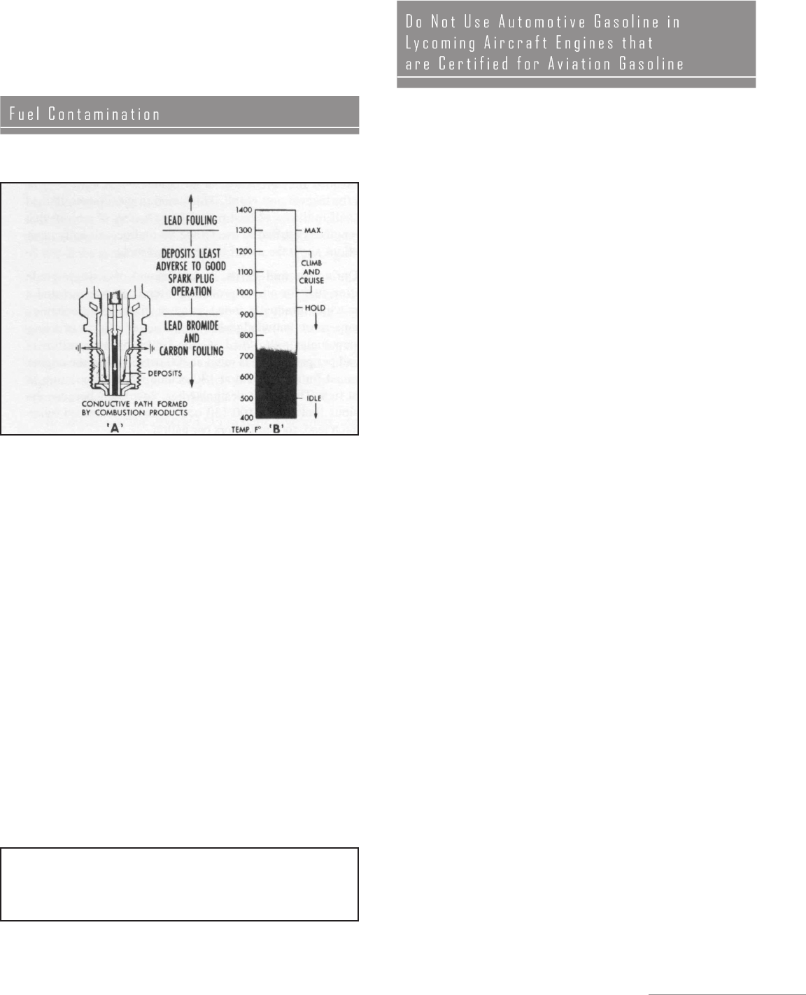
COMBUSTION DEPOSIT FOULING FUNDAMENTALS

8 L y c o m i n g F l y e r
7. Automotive fuel used in an aircraft engine may lead to destruc-
tive detonation or preignition and potential engine failure at high
power conditions.
8. Please review the Mo-Gas fuel requirements in your state or
destination.
SUMMARY:
Auto fuel is now being used as a substitute for Grade 80 aviation
gasoline under STCs issued by the FAA. Most major oil com-
panies and engine manufacturers continue to recommend that
aircraft piston engines be operated only on aviation gasoline.
Deterioration of engine and fuel system parts have been reported
in aircraft using auto fuel. Operators should consider the added risk
of using auto fuel in aircraft. Remember — a pilot can’t pull over
to the side of the road when fuel creates a problem with the engine.
The advent of the lightweight turbocharger has been called the
shot of adrenaline which the piston engine needed to remain the
prime method of powering general aviation-type aircraft. Although
in some respects this may be an overstatement, it does have much
merit, and it is the lightweight turbocharger that has enabled
general aviation aircraft to operate above adverse weather in the
smooth air of the higher altitudes, and to realize that increased true
air speed is not possible with normally aspirated engines. So this
is the “why” of turbocharging, and since it is possible that there
is a turbocharged Lycoming engine in your present or future, we
are going to review the very basics of turbocharging and bring the
reader up to the present “state of the art” of it.
The aircraft engine, as any reciprocating engine, is a heat engine
which derives its power from the burning of a mixture of air
and fuel, which has been mixed in the proper proportions by a
fuel-metering device. The amount of power the engine develops
will be directly proportional to the total mass of air pumped
through the engine, providing the fuel/air ratio is kept constant.
This can be varied in a normally aspirated (unturbocharged)
engine by changing the throttle setting and/or changing the RPM.
Let us go over that again. Changing the throttle will vary the mani-
fold pressure available to the cylinder during the intake stroke.
As a result, the cylinder will develop a given amount of power
on each power stroke. So if we increase manifold pressure to the
cylinder, we will in turn receive more power from the engine.
Now if we keep the manifold pressure constant, but increase the
number of power strokes by increasing the RPM, we will also
receive more power from the engine. We see that changing either
the throttle setting (manifold pressure) or the number of power
strokes per minute (RPM), will result in varying the total air mass
flow through the engine and will determine the horsepower the
engine will develop. So in essence, a reciprocating engine is also
an air pump, and if the fuel/air ratio is kept constant, the power
developed will vary directly with the mass of air consumed.
We are limited in the speed at which we can operate the engine
because of engine and prop mechanical limitations. So the only
other way to change the mass flow is to increase the manifold
pressure. We all know, however, that as we ascend in altitude, the
air becomes less dense which reduces the mass flow through the
engine with the result of a power loss that is proportional to the
reduced-mass air flow through the engine. You have noted that
in climb with a normally aspirated engine, it is necessary to keep
opening the throttle if you are to keep the air speed and the rate
of climb constant. So we see that if there were a way we could
put the engine into a container so it could be kept at sea level
conditions, we could maintain the same performance regardless
of ambient conditions and altitude.
A long time ago, a smart engineer who was thinking along these
same lines reasoned that if he built an air pump into the engine that
could pump the less dense air at altitude up to the same pressure
he had at sea level, he would be able to maintain sea level horse-
power. So he designed a centrifugal air compressor and placed it
between the fuel-metering system and the intake pipes. The pump
consisted of an impeller, diffuser and collector. The impeller was
driven at about 12 times crankshaft speed, and this high rota-
tional speed imparted a large velocity of energy to the air passing
through. Now as the fuel/air charge leaves the impeller, it goes to
the diffuser where vanes smooth out the air flow while allowing
the mixture to slow down so that the velocity pressure acquired
from the rapid rotational speed of the impeller is transformed
into static pressure. This air mass is then stored momentarily and
equalized in the collector and is then drawn into the cylinders. Our
engineer now has his air pump, but how is he to drive it? Well,
he could drive it from the accessory gear train or from the rear
of the crankshaft, but both of these methods robbed the engine
of horsepower it could deliver to the propeller. Although super-
chargers for many years have been driven mechanically off the
crankshaft, our engineer realized he had not reached the ultimate
in the “state of the art” of supercharging, so he began looking for
another means of driving his air pump.
Our hypothetical engineer realized that the largest percent of
energy released by burning the fuel/air mixture was going out
of the exhaust pipe in the form of heat. Realizing if he could in
some way harness this wasted energy to drive his air pump, the
horsepower normally robbed from the engine to drive the impeller
could be used by the propeller.
We have all seen a windmill turning in the breeze, so our engineer
rightfully reasoned if he put a turbine wheel in the exhaust stream,
he could take the hot exhaust gas under pressure and expand
it as it passed through the wheel to extract energy. He took an
impeller, connected it by a common shaft to the turbine, and he
had a means of driving his air pump by energy which was for-
merly going to waste. Supercharging by means of using exhaust
gases to drive the air pump is called turbocharging. Now our
engineer had progressed to the point where he required a means
of controlling his turbocharger. As he climbed in altitude the
pump must constantly put out a higher pressure ratio in order to
maintain sea level conditions. He reasoned that if he can dump
the exhaust gas at sea level through a butterfly valve in a leg off
the exhaust pipe and ahead of the turbine wheel, he will be able
to control the amount of energy being used to drive the turbine
and thus control the speed of the compressor.

Lycoming Flyer 9
The butterfly valve (wastegate) can be positioned by means of
mechanical linkage, but the disadvantage in this system is that
the engine can be overboosted, causing detonation and severe
engine damage if someone “forgets” and leaves the wastegate
in the closed position. So our engineer was looking for an auto-
matic means for control which would eliminate someone putting
“Murphy’s Law” into practice. (Murphy’s Law states that if
something can be done incorrectly, someone is bound to do it.)
So he came up with an automatic system that sensed compressor
discharge pressure and positioned the wastegate to maintain the
correct manifold pressure.
The system contains a controller, which senses the compressor
discharge pressure and regulates engine oil pressure used as the
muscle for the actuator on the wastegate. When the controller calls
for more compressor discharge pressure, it closes the oil bleed line
from the wastegate so the wastegate actuator sees higher engine
oil pressure and thus closes the butterfly. When the compressor
discharge pressure comes up to the desired control pressure, the
controller will bleed oil from the wastegate to maintain the cor-
rect butterfly position, which in turn will maintain the correct
compressor discharge pressure. Now the system is complete and
automatic and except in cases of poor or abrupt throttle manage-
ment, it does not overboost.
The automatic control system just described is basic, but it is
the basis for most control systems used on Lycoming engines.
In another article, we will also talk about the changes required
in an engine to make it suitable for turbocharging, and the dif-
ference between an engine designed for turbocharging and the
one that has just had a turbocharger added. We will also discuss
turbocharging to increase power at sea level instead of only using
it to maintain sea level pressure at altitude. (See “The Pilot and
Turbocharging” in the Operation section.)
Although Lycoming publication SSP-885-2 covers the latest
information concerning full-flow oil filters for our engines, we
feel it is also important to emphasize and explain key aspects of
the publication to help people in the field. SSP-885-2 is concerned
with full-flow oil filters in our direct-drive engines, but does
include one exception, the geared TIGO-541 which powers the
Piper Pressurized Navajo.
Operators and mechanics must carefully read SSP-885-2
before handling the various types of Lycoming-approved filters.
Special note should be made of the differences of installing the
canister-type vs. spin-on filters. The canister-type is installed
with the housing not turned, but with an attaching bolt through
the center of the housing, torqued to 20-25 foot pounds.
The spin-on filter calls for a different installation in that the
filter housing itself is turned to a torque of 18-20 foot pounds.
Never exceed the maximum torque limit. Maintenance people in
the field using both types of filters must be very careful during
installation of this part.
SSP-885-2 data includes the full-flow spin-on filter which is
installed as optional equipment on all direct-drive Lycoming
aircraft engines. Advantages of the spin-on filter include a resin
impregnated paper that constitutes the filter element, which is
heat-cured, acid resistant and capable of removing contaminants
that would be injurious to the engine. The spin-on was designed
to save weight and also shorten maintenance time, and is avail-
able in long and short sizes. There is no need to replace elements,
O-rings, and various nuts and bolts and washers, or to clean the
filtering units.
All models of Lycoming direct-drive engines can be converted
to use the Lycoming-approved full-flow filter element or
full-flow spin-on oil filter; however, before installing, check
the distance between the firewall and the mounting pad on the
accessory housing. Do not over-torque the filter at installation.
After installation of the full-flow filter, always ground run the
engine before flight and get oil temperature into the bottom of the
green arc on the gage. After a good runup, shut engine down, and
inspect the filter area for oil leaks. Also check engine oil level;
addition of the filter assembly will require adding approximately
one quart of oil.
Champion and Airwolf both offer a “can opener” service tool for
the aviation mechanic. The tool easily cuts open the filter without
contaminating it, so the element can be examined for any signs
of metal chips indicating engine deterioration.
Before discarding, the filter elements should be examined
by unfolding the pleated element and examining the mate-
rial trapped for evidence of internal engine damage. In new or
newly overhauled engines, some small particles of metallic
shaving might be found; these are generally caused during manu-
facture and should not be cause for alarm. However, positive
evidence of internal engine damage found in the filter element
justifies further examination to determine the cause.
To examine the cartridge-type filter element, remove the outer per-
forated paper cover, and using a sharp knife, cut through the folds
of the element at both ends close to the metal caps. For examination
of the spin-on filter, Champion Tool CT-470 or Airwolf AFC-470
must be used to cut the top of the can.
Clean engine oil is essential to long engine life. Consequently,
the quest for better ways to keep the lubricating oil free from
contaminants is endless.
Although knowledge of detonation and preignition may be “old
hat” to the old timers in aviation, lots of people in our industry
are still somewhat confused over the difference between the
two, and what causes either of them.
DETONATION
There is a limit to the amount of compression and the degree of
temperature rise that can be tolerated within an engine cylinder
and still permit normal combustion. When this limit is exceeded,
detonation can take place. Piston engines are vulnerable to

0 L y c o m i n g F l y e r
D e t o n a t i o n a n d P r e i g n i -
t i o n
detonation at high power output because combustion temperature
and pressure are, of course, higher than they are at low or medium
powers. Leaning the mixture at high power can cause it.
Unless detonation is heavy, there is no cockpit evidence of its
presence. Light to medium detonation may not cause noticeable
roughness, observable cylinder head or oil temperature increase,
or loss of power. However, when an engine has experienced
detonation, we see evidence of it at teardown as indicated by
dished piston heads, collapsed valve heads, broken ring lands
or eroded portions of valves, pistons and cylinder heads. Severe
detonation can cause a rough-running engine and high cylinder
head temperature.
PREIGNITION
Preignition, as the name implies, means that combustion takes
place within the cylinder before the timed spark jumps across
the spark plug terminals. This condition can often be traced to
excessive combustion deposits or other deposits (such as lead)
which cause local hot spots. Detonation often leads to preigni-
tion. However, preignition may also be caused by high power
operation at excessively leaned mixtures. Preignition is usually
indicated in the cockpit by engine roughness, backfiring, and
by a sudden increase in cylinder head temperature. It may also
be caused by a cracked valve or piston, or a broken spark plug
insulator which creates a hot point and serves as a glow spot.
Specifically, preignition is a condition similar to early timing of
the spark. Preignition is a serious condition in the combustion
chamber and will cause burnt pistons and tuliped intake valves.
The best temporary in-flight methods for correcting preignition
and detonation are to reduce the cylinder temperature by retarding
the throttle, enriching the mixture, opening cowl flaps if avail-
able, or a combination of all of these.
Lycoming Engineering, in their continuing effort to improve our
engines, developed a better method of manufacturing hardened
alloy steel cylinder barrels a number of years ago by means
of a method known as nitriding. Simply described, the addition
of nitrogen to the surface of an alloy steel produced a hard, wear-
resistant surface. Commercially, the introduction of nitrogen into
the surface layers of alloy steel is brought about by subjecting
the practically finished parts to an atmosphere of ammonia gas.
The process requires special heat treating furnaces which are
air tight and capable of holding the parts at a high temperature.
At this heat level (975oF), the ammonia gas flowing into the
furnace is broken down into its elements of hydrogen and
nitrogen, and this is the source of the nitrogen which penetrates
the surfaces of the steel. In order to produce a satisfactory
nitrided surface, the process must be operated for an extended
period of time, generally from 25 to 80 hours. Along with
cylinder barrels, Lycoming nitrides all its crankshafts and
some gears.
The nitriding process applied to cylinder barrels has been thor-
oughly service tested in military as well as commercial service.
After having been FAA type tested, we began production of
engines using nitrided cylinders in 1960. The service record of
these cylinders has been excellent. In fact, our management was
so impressed with the favorable service record of the nitrided
cylinder that they changed from chrome to nitrided cylinders
in all our higher powered turbocharged and supercharged
engines. Some favorable characteristics of nitrided barrels are
as follows:
1. Reduced cylinder wall wear - the harder a surface the more
difficult to wear down.
2. Natural choked barrels provide improved piston ring life due to
a resulting straight cylinder wall when engine is hot or operating,
and a better job of sealing.
3. Nitriding permits use of chrome plated piston rings, which are
more wear resistant and quite compatible with hardened steel.
4. Nitriding provides a hardened surface with an increased
fatigue strength.
5. It also has the ability to resist softening when excessively heated
during engine operation.
These worthwhile features in the power plants have meant even
longer operating life than standard steel barrels, and they mean
dependability and economy.
Now chrome plated cylinders cannot be obtained from the factory,
but the identification specification for them has been an orange
band around the cylinder base, or the equivalent color on the
edges of the top cylinder head fins between the two valve push
rod shroud tubes. The color coding for the nitrided cylinders is
azure blue and will appear in either of the two locations indicated
above. The band around the cylinder base is used when cylinders
are painted black as a separate operation prior to engine assembly.
The color coding on the top edges of the cylinder head fins has
been used on engines painted all gray after assembly.
From the service standpoint on nitrided cylinders, there
are three methods of handling an engine at overhaul.
1. The barrels can simply be reworked and returned to
service if they are not beyond service limits.
2. The barrel can be reground and then chrome plated, but
the factory has achieved better results with nitriding and
uses method three.
3. The old cylinder may be discarded and replaced with
a new one as in the Lycoming factory overhaul and
rebuild programs.
CHROME VS. NITRIDING
Either method provides a satisfactory hard-wearing surface, but
application of the chrome plate is a critical operation. Engines
with chrome or nitride-hardened barrels have a good wear charac-
teristic, and are more rugged than standard steel barrels. In spite
of hardened barrels, a good, properly maintained air filter is still
a must. Pistons are moving up and down at a rate of more than
two thousand times per minute, and when dirt or any abrasive
is introduced into the combustion chambers, it causes a lapping
process which rapidly wears metal away. No engine can digest
dirt and give a satisfactory service life.

Lycoming Flyer
We aren’t attempting to make mechanics out of pilots by writing
about compression ratio in aircraft engines, but we desire to help
both groups by providing a simplified description as it relates to
our engines.
In order to gain a reasonable amount of work from an internal
combustion engine, we must compress the fuel/air mixture during
each power stroke. The fuel/air charge in the cylinder can be com-
pared to a coil spring in that the more it is compressed, (within
limits), the more work it is potentially capable of doing.
Engineering tells us that the compression ratio of an engine is a
comparison of the volume of space in a cylinder when the piston
is at the bottom of the stroke to the volume of space when the
piston is at the top of the stroke. For example, if there are 140
cubic inches of space in the cylinder when the piston is at the
bottom and 20 cubic inches of space when the piston is at the top
of the stroke, the compression ratio would be 140 to 20 or usually
represented at 7:1.
Although we can create a more efficient engine by increasing the
compression ratio, there are limits and a compromise is needed.
If the pressure is too high, premature ignition will occur and
produce overheating. Compression ratio is a controlling factor
in the maximum horsepower developed by an engine, but it is
limited by present-day fuel grades and the high engine speeds
and manifold pressures required for takeoff.
Our normally aspirated engines are generally categorized as
either low-compression or high-compression power plants. In
surveying the complete range of all Lycoming engine models,
we note that compression ratios vary all the way from a low
6.5:1 to a high of 10:1. Engineering has generally established the
low-compression group as those with a compression ratio of 6.5:1
to 7.9:1; and the high-compression group from 8:1 and higher.
All Lycoming engines in the high-compression category
require a minimum of Grade 100LL (blue) or 100/130 (green)
octane, FAA-approved aviation fuel, and nothing less. With
high-compression engines we must stress the importance of
the manufacturer’s recommendations as outlined in the Engine
Operator’s Manual or in the Pilot’s Operating Handbook. These
engines require not only the correct fuel, but the proper oil, pre-
cise timing and a good air filter. All are very important in order
to protect this high-performance power plant.
By F. F. Rohm, Chief Qualification Engineer (Ret.)
James Watt, Scottish physicist, had an engine problem even
in 1769. Although steam engines had been invented before he
was born, they were crude, inefficient machines and only a few
were in use. So he had, after much experimental work, developed
a relatively efficient condensing steam engine, the forerunner of
the present-day type.
Being a good businessman, Watt tried to sell his engine
to coal mine operators who were then using draft horses to supply
power to drive the pumps which kept the mines free of water.
But the mine owners had sales resistance! They insisted
on knowing exactly how many horses each engine would
replace, or, in other words, the horsepower of the engine. How
much work would his steam engine do? This, then, was James
Watt’s problem.
Although simple machines such as sailing vessels, windmills and
waterwheels had been used for centuries, Watt realized that for
the most part, the majority of work in the world had been done
by man and his domesticated animals. Work was measured and
paid for by the day, from “sun to sun.” With the advent of reli-
able clocks, work was then accounted and paid for by the hour.
Evaluating work by this time method, it was assumed that all men
and animals could and did perform the same amount of work.
This was far from being true.
Watt realized that in order to have his steam engine used
by the coal mine operators, he would have to answer their
questions — “how much work will it do, and how many men and
horses will it replace?” Since the “power” of one horse was a gen-
erally known and a constant quantity, he would have to determine
the “power” of his engine in order to compare it with the horses
which it was to replace. His problem then was to define “power.”
Power did not mean force. The mine owners cared nothing about
the force Watt’s engine might exert. They wanted to know how
fast the engine would pump water out of the mine; in other words,
how fast will the engine do the work? Simply, that was the defini-
tion of “power.”
The methodical physicist experimenting with draft horses used
to operate mine pumps found that, on an average, a horse pulling
with a force equal to a weight of 150 pounds walked 2-½ miles
LOW COMPRESSION HIGH COMPRESSION
This interesting article was written for us by Fred Rohm,
who was our Chief Qualification Engineer when he retired.
Fred had a career of 44 years in the industry, with a ma-
jority of those years spent at Lycoming. Most of his career
at Lycoming was as Chief Experimental Engineer, which
establishes his qualifications to author this kind of article.
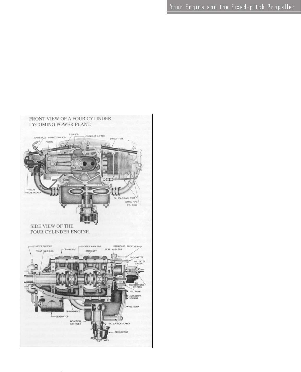
L y c o m i n g F l y e r
per hour. Since work is force exerted through a given distance,
it is measured in terms of feet pounds. Thus, on an average, one
horse could do work at the rate of 33,000 feet pounds per minute
or 550 feet pounds per second.
Watt’s definition for one horsepower, which has now become
universal, was, therefore, the doing of work at the rate of 33,000
feet pounds per minute. Today, all conventional power producing
units are rated on this basis.
The 250-horsepower engine in the modern light plane is capable
of doing work at the same rate as that of 250 average horses. From
an interested engineer’s point of view, it is capable of moving
137,500 pounds of weight one foot in one second. Yet, what a dif-
ference there is in its size and weight (approximately 400 pounds)
when compared to the horses it replaces!
The effect the propeller has on engine operation and on aircraft
performance is quite significant. Based on questions which have
been asked by aircraft owners and from experience, there are
several areas of propeller-related information which may be
of interest.
Aircraft equipped with a fixed-pitch propeller will usually have
static RPM (full throttle with aircraft standing still) limitations
and full power in-flight RPM limitations spelled out in the Pilot’s
Operating Handbook. If static RPM is below the minimum speci-
fied, the engine could be low in power. However, experience has
shown that this is not always true. Faulty induction air systems
and/or faulty exhaust systems have been shown to contribute to
indications of low power. A propeller which is ever so slightly
less than perfect may cause the static RPM to be outside the des-
ignated full throttle static RPM zone. In addition to these other
factors, it is not unusual to find a tachometer which is inaccurate.
If an incorrect static RPM reading is observed during the engine
check, any one or all of these components could be at fault.
The tachometer may be the easiest to check as there are hand-held
devices that quickly give an RPM reading that will verify the
accuracy of the standard aircraft instrument. Knowing the accu-
racy limits of the aircraft tachometer may eliminate the need for
further examination of the engine and propeller, or it may confirm
the need for further troubleshooting. In any case, consider each
component of the system before blaming low-static RPM reading
on one of them.
Another aspect of operation with a fixed-pitch propeller came in
the form of a question from a Lycoming engine owner. He indi-
cated that the propeller provided by the airframe manufacturer
had been exchanged for a cruise propeller. (This exchange should
only be done with FAA approval.) With the new cruise propeller in
use, an increase in fuel usage was soon apparent. Operating costs
increased, and an explanation was requested.
It is well known that the amount of horsepower taken from an
engine will have a direct relationship to the amount of fuel used.
Therefore, it can be deduced that use of the cruise propeller
increased the horsepower requirement. This deduction deserves
some additional explanation.
As an example, the standard propeller supplied with an aircraft
may allow the engine to develop 180 horsepower at 2700 RPM at
full throttle, in flight at sea level, with a standard temperature. The
Lycoming O-360-A Series normally aspirated engine illustrates
this example.
Next, let us assume that this same engine/propeller com-
bination is operated at 75% power with a “best economy”
fuel/air mixture setting. Again, assume sea level and stan-
dard temperature to simplify and standardize the discussion.
75% power will require about 2450 RPM with a brake-spe-
cific fuel consumption of .435 pounds per brake horsepower
hour. Also, 75% of the 180 rated horsepower is equal to
135 horsepower. Fuel usage at this power and mixture set-
ting will be 58.7 pounds per hour or 9.8 gallons per hour.
CUTAWAY OF A FOUR CYLINDER POWER PLAN

Lycoming Flyer
The mathematics to arrive at this fuel usage are simple:
180 HP X 75% of power = 135 HP
135 HP X .435 BSFC = 58.7 lbs. of fuel
58.7 lbs. of fuel 6 lbs. per gal. = 9.8 gal. per hour
Having made some assessments about what can happen with a
standard propeller, now we will try to see what happens when
a cruise propeller is installed in place of the original. The first
thing we must know about the cruise propeller is that it has more
pitch than the standard propeller. This means it will take a bigger
“bite” of air than the original propeller with each revolution. This
bigger bite of air will have an effect on aircraft performance and
on how the engine may be operated.
Taking a bigger bite of air increases the resistance to the turning
propeller. Perhaps it may be easiest to imagine what happens
by considering your hand when held in the airstream outside
a moving automobile with the palm forward as compared to
having the side of the hand forward. Because of this increased
resistance, the static RPM will be lower than with the original
propeller. The same thing will be true when full throttle, in-
flight RPM, is compared to that of the standard propeller at a
similar altitude and temperature. This will reduce takeoff per-
formance of any aircraft. Using the earlier example, the engine
was rated at 180 horsepower at full throttle and 2700 RPM.
Now, in spite of applying full throttle, the increased resistance
reduces the maximum attainable RPM to something less than
2700. As a result of not developing the rated 2700 RPM, the
engine also will not develop the power for which it was rated.
Since maximum power is less than full rated, aircraft perfor-
mance will suffer. This should be considered before a fixed-
pitch propeller is chosen or exchanged for a different model.
At this point, we must return to the original question. Why
does the engine require more fuel with the cruise propeller?
It is an accepted fact that the cruise propeller is more efficient
for cruise operation, so it would not be unusual to follow this
line of thinking. Seventy-five percent of rated power, using
the original propeller at sea level and standard temperature,
required a throttle setting to achieve 2450 RPM. Therefore,
without more thoughtful consideration, it seems logical that
the cruise propeller might also be set for 2450 RPM when
75% power is desired. Of course, there is an increase in per-
formance, but this can be attributed to the more efficient
cruise propeller. Next comes the realization that the improved
cruise performance isn’t all efficiency. Instead of 9.8 gallons
of fuel, the engine is now using a greater amount of fuel per
hour. For purposes of this illustration, let us assume that the
number is 11 GPH. By reversing the mathematics used earlier,
it is possible to estimate the horsepower and percentage of
power actually being used as a result of operating the cruise
prop at 2450 RPM with a best economy fuel/air mixture.
11 GPH X 6 lbs. per gallon = 66 pounds
66 pounds .435 BSFC = 151.7 horsepower
151.7 HP 180 rated HP = 84.3% of power
Assuming a fuel usage of 11 gallons per hour for this problem
provides a reasonably realistic example of the change that a
different fixed-pitch propeller might create. It also illustrates
the need for pilots to change their habits when a propeller is
changed. In addition to the change of habits, the discussion
shows a real need to reevaluate the takeoff, climb and cruise
performance of an aircraft if the fixed-pitch propeller is
changed for a different model.
Another very important point concerns leaning. Remember that
Lycoming recommends leaning to best economy only at 75% of
rated horsepower or less. It is very possible that leaning to rough-
ness or to peak on the EGT gage could cause serious damage if the
engine is actually producing more than 75% of rated horsepower
as shown in this illustration.
With this information as background, it is easy to see that set-
ting a desired power with a fixed-pitch propeller can only be
accomplished if the pilot has a chart that applies to the specific
aircraft/engine/propeller combination. Although the power chart
for a new aircraft may come from data obtained by test flying
with a calibrated torque meter, a fairly accurate chart can be
derived for any fixed-pitch propeller and engine combination.
Briefly, this is done by finding the maximum available RPM
at any particular altitude and applying data from the propeller
load curve.
To conclude, the purpose of this article is to make readers more
aware of some operational aspects of the fixed-pitch propeller.
Usually, it is only necessary to accept the material provided
by the airframe manufacturer and to use the engine/propeller
as directed. If a propeller change is made, or on those rare
occasions when we question the power available to the pro-
peller, the material presented here could prove to be helpful.
From time to time, a field-service report states that an engine has
damage. After further examination of the engine, this damage
may be classified as “induced damage.” To clarify what is meant
by this term, induced engine damage is a failure or unsatisfactory
condition which results from operational or maintenance practices
employed after the engine is placed in service. Although there are
a variety of conditions which may fall into the induced damage
category, this article will discuss two particular types of failure
and the circumstances which can induce them.
Examination of an engine that is reported to have low compres-
sion, loss of power, erratic operation, metal contamination or
even complete engine stoppage may result in a determination
that pistons are burned or valves stretched. (Stretched valves are
sometimes said to be tuliped.) These two types of damage can
be initiated in a number of ways, but the chain of events is often
the same; detonation is followed by preignition and the engine
damage has begun. To prevent burned pistons and tuliped (or
stretched) valves, action must be taken to eliminate the possibility
of detonation and preignition.

L y c o m i n g F l y e r
Detonation is a phenomenon which can occur in any internal
combustion engine. The possibility of detonation cannot
be completely eliminated. By definition, detonation is a vio-
lent explosion. When used with reference to a spark igni-
tion internal combustion engine like the Lycoming aircraft
piston engines, detonation indicates abnormal combustion.
Essentially, detonation is an uncontrolled explosion of the
unburned gases in the engine combustion chamber. Some
engines are more susceptible to detonation than others. For
example, turbocharged engines are more susceptible than similar
non-turbocharged models and engines with higher compression
ratios are more likely to exhibit detonation than engines with
lower compression ratios.
Detonation may occur in an aircraft engine as a result of main-
taining a manifold pressure that is too high for the specific
engine speed and mixture setting being used. The engine power
(i.e., speed and manifold pressure) and mixture settings recom-
mended in the Pilot’s Operating Handbook (POH) for a par-
ticular aircraft model have been determined by a detonation
survey. These surveys use special instrumentation to detect
and record detonation as it occurs. Based on these surveys, the
detonation-limiting conditions are defined. Data from the sur-
veys indicate that detonation occurs in varying degrees; it is
sometimes possible to operate an engine for relatively long
periods in the first minor phase of detonation without inducing
damage. Lycoming does not recommend or condone engine
operation which even approaches conditions which might cause
detonation. The laboratory quality equipment used for the
detonation survey is not practical for use in an aircraft engaged
in normal flight operations. Without this equipment, the pilot
may not know that detonation is occurring, and it is impossible to
establish the fine line between the first phase of minor detonation
and the detonation magnitude which induces preignition and/or
engine damage. For this reason, it is imperative that power and
mixture recommendations of the POH be carefully observed.
Preignition is a circumstance that causes destructive engine
damage and will be examined here briefly. Most Lycoming
engines are designed for ignition of the fuel/air mixture at
20 crankshaft angle degrees (CAD) before the piston reaches
top dead center during the compression stroke. Some engine
models specify ignition at 18, 23, or 25 CAD before top dead
center. If ignition of the fuel/air mixture occurs before the
scheduled point in the operational sequence of events, preigni-
tion exists and the compression stroke continues as the burning
fuel/air mixture is trying to expand. This subjects the combus-
tion chamber and pistons to temperatures and pressures far in
excess of those experienced during normal combustion. These
excessive temperatures and pressures cause damage to pistons
and valves. In some cases, both burned pistons and stretched
valves will be found in an engine which has been subjected
to preignition.
Considering the millions of hours f lown each year in
piston-powered aircraft, engine damage from detonation and
preignition is quite rare. The infrequency of this happening
means little if your engine is the one affected. Therefore, it seems
appropriate to look more closely at some of the factors which lead
to detonation and preignition.
The possibility of overboost is a characteristic of all super-
charged and turbocharged engines. Generally, overboost
means the application of manifold pressure which exceeds the
limit specified by the manufacturer. Early versions of the
manually controlled turbocharger allowed quite a few pilots to
inadvertently induce damage by overboost. With this system, the
turbocharger wastegate was normally left full open for
takeoff; full throttle would produce 28 to 30" of manifold pres-
sure. After takeoff at full throttle, gradual closing of the
wastegate would slowly increase turbocharger speed and mani-
fold pressure to maintain climb power to cruise altitude or
to the critical altitude of the engine. The system worked fine until
the wastegate was inadvertently left in the closed position. If the pilot
then applied full throttle for takeoff or a go-round, it could produce
60" or more of manifold pressure and failure of the engine.
More recent turbocharger installations usually include a pres-
sure relief valve and/or an automatic wastegate control which
helps to avoid the possibility of overboost. Even with these pro-
tective devices, it is still possible to overboost by rapid throttle
operation and/or inattention to limiting manifold pressures
at low engine speeds.
Automatic controllers may not be capable of preventing over-
boost if full throttle operation is attempted before engine oil
is warmed up sufficiently. Lycoming Service Bulletin 369F
addresses the problem of overboost and recommends, depending
on the severity and duration of the overboost, a log-book entry,
engine inspection or complete engine overhaul including replace-
ment of the crankshaft.
As stated earlier, ignition of the fuel/air mixture must take
place at precisely the right time. A spark plug which has been
dropped, or damaged in some other way, may induce preigni-
tion by causing a “hot spot” in the combustion chamber which
self-ignites the fuel/air mixture. This could also occur from
use of unapproved spark plugs. Flight with defective magnetos
or flight in excess of certified aircraft limits may allow
cross-firing within the magneto, improperly sequenced ignition
of the fuel/air mixture and engine damage. Proper magneto
engine timing is also an important factor. The timing is affected
by wear and therefore should be checked and reset at specified
intervals. Regular, meticulous spark plug and magneto mainte-
nance will help to avoid preignition and possible engine damage
from these sources.
Although overboost and incorrect ignition timing are causes
of induced engine damage, this damage can often be attrib-
uted to fuel and the fuel/air mixture. The first problem related
to fuel is simply having improper fuel in the aircraft tanks.
A piston-powered aircraft refueled with jet fuel would have a fuel
blend with greatly reduced octane level. A piston engine should
not be started when even small amounts of jet fuel have been
added to aviation gasoline because engine contamination and
detonation are likely; attempted flight under these conditions will
certainly result in destructive detonation and preignition. The use
of 80 octane aviation fuel in an engine certified for 100 octane
aviation fuel will produce similar results.
The lubricating oil may be a source of octane reducing fuel con-
tamination. Excessively worn piston rings may allow enough oil into

Lycoming Flyer
In some cases, it is possible to repair the engine by removing the
metal contamination from the engine and oil system, including
the oil cooler, and by replacing all damaged parts, but often it
is necessary to replace the entire engine. If an engine is to be
repaired, it must be remembered that repairing the damage is not
enough; the cause of the malfunction which induced detonation
and preignition must also be found and corrected. Did a magneto
malfunction produce ignition outside the normal firing sequence?
Were manufacturer-approved spark plugs installed in the engine?
Did a cracked spark plug induce preignition? Was an approved
fuel used, and if so, is there evidence of fuel contamination?
Whatever the malfunction, it must be corrected along with the
damage or the same problem could reoccur.
To conclude, induced damage in the form of tuliped valves and
burned pistons can usually be avoided by understanding the
sequence of events which lead to this form of engine damage.
Careful attention to detail is required of pilots and maintenance
personnel. Compared to the expense of repairing or replacing a
damaged engine, it is worth the time and effort necessary to avoid
induced engine damage.
We often tend to believe what we know, everyone knows. While
participating in a flight instructor refresher recently, a young lady
from Maine provided a reminder that this is often not the case.
This lady and her husband fly in Maine throughout the year.
During the winter, they and their aircraft are frequently exposed
to extremely cold temperatures. During the past winter, they had
an unfortunate experience. The end of the engine breather tube
froze over, a pressure buildup occurred in the crankcase, and the
crankshaft nose seal ruptured. The oil leak that resulted covered
the aircraft with oil from nose to tail. Fortunately, a safe landing
was made before all oil was lost.
As she related her story, another flight instructor quickly indi-
cated that he had also experienced the same problem several years
earlier. The safe landings in both cases are good news. The bad
news is the expense incurred to repair the engine.
An incident like this is preventable, and for that reason, it is
important that we repeat ourselves from time to time. We should
not assume that everyone knows about the “whistle slot” or
other methods of ensuring adequate crankcase venting.
First, the cause of this incident. Moisture is expelled from the
engine crankcase through the breather tube which often extends
through the bottom of the engine cowling into the airstream.
Under very cold conditions, this moisture may freeze and continue
a buildup of ice until the tube is completely blocked.
It is normal practice for the airframe manufacturer to provide
some means of preventing freeze-up of the crankcase breather
tube. The breather tube may be insulated, it may be designed so
the end is located in a hot area, it may be equipped with an electric
heater, or it may incorporate a hole, notch or slot which is often
the combustion chamber to dilute the fuel/air mixture. The dilution
will reduce the octane rating of the fuel and can lead to detonation
and engine damage. While this scenario is not entirely typical of
the engine that uses large amounts of oil because of worn or broken
piston rings, it is possible for this situation to occur.
Even the use of 100 octane fuel in an engine in good mechanical
condition does not eliminate all the possibilities of induced
engine damage. Most engines operated at takeoff power or at
a power setting in the high cruise range need a relatively rich
fuel/air mixture to help cool the engine and reduce possibilities
of detonation. Since lean fuel/air mixtures and high power set-
tings promote detonation, it is recommended that Lycoming
engines not be leaned at power settings which produce more than
75% of rated engine power unless this operation is approved in
the POH. The pilot, by simply leaning the mixture excessively at
power settings above the cruise ranges, may be responsible for
inducing the detonation and preignition which leads to tuliped
valves and burned pistons.
And finally, a small amount of dirt in the fuel system may
be responsible for clogging a fuel injector nozzle or nozzles.
A partially clogged fuel injection nozzle will reduce fuel
flow to that cylinder and will cause a lean fuel/air mixture.
A nozzle which is partially clogged in an aircraft that has a pressure
operated fuel flow indicator will cause that indicator to display
a higher than normal fuel flow. Leaning in an attempt to correct
the high indicated fuel flow will result in an even leaner mixture
in the affected cylinder. Again, it is possible that a burned piston
or tuliped valve will be the final result.
Understanding and avoiding those factors which lead to in-
duced engine damage is certainly preferable to the discovery
of tuliped valves or burned pistons in your engine. This
entire discussion is aimed at promoting an understanding which
will allow pilots and maintenance personnel to direct their efforts
to those elements which will reduce the possibility of induced engine
damage. Observing the refueling of the aircraft and checking
the fuel system for indications of contamination are
tasks expected of the pilot. Meticulous management of power
and fuel/air mixture as recommended by the POH is also a pilot
activity which will reduce the possibility of induced damage.
Maintenance personnel play an equally important role.
Troubleshooting a fuel-injected engine for rough idle may lead to
the cleaning or changing of partially clogged fuel injector nozzles.
Damage could result if the engine were operated at takeoff or
climb power with reduced fuel flow to one or more cylinders. A
close check of magneto timing and magneto condition at regular
inspection intervals will help to ensure the continued satisfactory
operation of any engine.
There are some “after-the-damage” factors that maintenance
personnel should consider. Suppose that a power loss has
been reported. A compression check reveals low compression;
a stretched or tuliped valve may be found. This is an indica-
tion that the engine has experienced detonation and preignition.
A borescope examination should be conducted to see if a piston
has been burned. A burned piston often results in damage to cyl-
inder walls and piston skirts; it also may contaminate the engine
with metal particles. There is no healing process for this damage.

L y c o m i n g F l y e r
called a “whistle slot.” The operator of any aircraft should know
which method is used for preventing freezing of the breather
tube, and should ensure that the configuration is maintained as
specified by the airframe manufacturer.
Because of its simplicity, the “whistle slot” is often used.
Although the end of the tube may extend into the air stream, a
notch or hole in the tube is located in a warm area near the engine
where freezing is extremely unlikely. When a breather tube with
whistle slot is changed, the new tube must be of the same design.
Replacing a slotted tube with a non-slotted tube could result in an
incident like the one described by the lady from Maine.
The Flyer may have carried information on this subject in the
past, but the reminder from someone who had an unfortunate
incident prompted this story. Preventing possible freezing of the
crankcase breather tube by use of a whistle slot or other means is
an important little detail which all of our readers should be aware
of. Many may benefit from the knowledge.
If you are told that a cylinder head on your engine should be
welded because of a crack, think long and hard about the step
you are about to take. The argument is that it is less expensive to
recondition a cylinder head than to buy a new one. This is true
when the only consideration is getting your aircraft back in the
air as cheaply as possible. For the long run, welding the aluminum
parts of an aircraft engine to repair cracks may not be a permanent
solution, and may cause you many headaches.
The recommendation to replace rather than weld is based on
years of experience and thousands of examinations in the
Lycoming Metallurgical Laboratory. Based on this experience,
the vast knowledge of the individuals who work in this Met Lab
should not be ignored. The brief explanation that follows will
attempt to relate some of this experience and to explain why
welding is not generally recommended.
Starting with two very basic but critical items in the welding
process, we look at the material to be welded and the welder.
The material is an aluminum alloy, and it takes more than just a
very good welder to successfully weld aluminum. The experience
in qualifying welders at the factory shows is that only the most
outstanding can pass the annual FAA qualifying examination for
Aircraft Certified Welder. Even a good welder may leave tungsten
in the weld. This causes it to be unsatisfactory.
Even an expert welder with complete knowledge of the aluminum
alloy material cannot assure a satisfactory weld in a cracked
engine part. There are many inherent pitfalls over which the
welder has no control. Cylinder heads are made of aluminum
alloy. Cracks sometimes occur inside the dome area. The metal-
lurgists consider repair by welding to be absolutely foolish, and
their experience provides them with good reasons. The surface
area in the dome is affected by a thermochemical attack — to put
it simply, corrosion. This corrosion is a form of oxidation that will
not fuse properly during welding. It is not practical to remove all
of the corrosion, because this would entail remachining the entire
interior surface which would change the designed compression
ratio of the engine. Those who attempt to weld this area make
an effort to clean the crack thoroughly. Unfortunately, this is of
little help because the area adjacent to the cleaned-out crack will
still be affected by thermochemical attack. Because this corrosion
will not allow the weld to fuse completely, new cracks are almost
certain to occur.
Thermochemical attack is not something we can see. To the
novice, a welded crack in a cylinder head may look great. It
may not even be possible to identify the weld. But when the
part is dissected by a metallurgist for examination under a
high-powered microscope, the weld, the poor fusion and cracks
around the weld are immediately identified.
Based on this explanation, readers should now understand why
Lycoming does not recommend the welding of cracks in cylinder
heads. These cracks usually occur as the result of fatigue over
long hours of use, and the odds of achieving long-term satis-
faction by welding are extremely remote. If you are buying an
aircraft, watch out for the engine with reconditioned cylinders
that have been repaired by welding, and if you own an engine
which has experienced cracks, remember that you probably are
wasting money by having those cracks welded. Experience has
shown that replacement of these parts is likely to be most eco-
nomical and is likely to cause fewer headaches over the long run.
After certifying hundreds of flat, opposed cylinder aircraft
engines, and after building more than three hundred thousand
engines for general aviation, Lycoming engineers have learned
what it takes to produce properly balanced engines. Many engines
have been tested over the years and a great deal of data is available
to support the building of engines to factory specifications. To
put it simply, the subject of engine balance is well understood by
Lycoming and is a major consideration in the design and manu-
facturer of all Lycoming-Certified engines.
These statements are contrary to what has been implied by several
advertisements and magazine articles. Some reports in several
industry publications say your Lycoming-Certified engine would
be much better if you would just take the time and spend the
money to have it “custom balanced”. The implication is that the
manufacturer knows nothing about the importance of balancing.
This is absolutely false. Lycoming-Certified engines are very
carefully balanced to the degree that is necessary. They are not
balanced to a point of absolute perfection because they run at
relatively low speeds (compared to some automobile engines) and
therefore do not require the degree of balancing being advocated
by shops that deal in this specialty.
To justify this excessive emphasis on balancing, the automobile
racing engine is often cited as another place where balancing

Lycoming Flyer
is important. This is like comparing apples to oranges; the two
types of engines are not the same. A typical Lycoming direct drive
engine is red-lined at 2700 or 2800 RPM while an auto racing
engine may operate at more than three times this speed.
In order to delve into the subject a little deeper, several ques-
tions were directed to the Senior Analytical Engineer at
Lycoming. His responses may help those who have doubts about
the quality of engine balancing done at the factory.
Several Lycoming engine components are dynamically bal-
anced. For non-engineers, that means that the proper balance is
determined while the part is in motion; it is spinning as it would
be during operation. These parts are the starter ring gear sup-
ports and the crankshaft. In addition, dynamic counterweights
are statically balanced to control the location of the very critical
center of gravity.
Balance also includes the control of weight for a number of
moving engine components. Items such as piston pins, piston
plugs, and piston rings are 100% machined to close tolerances
that provide consistent weights. These are three types of piston
plug, and although they are interchangeable, each type must be
used as a set because of their weight differences. The weight of
dynamic counterweights is also carefully controlled.
A second aspect of engine balancing is accomplished by
matching some engine parts by weight. Pistons and con-
necting rods are in this category. Both of these parts are
organized in matched sets, by weight, before installation in a
Lycoming engine. Should it be necessary to replace one of these
matched parts during the service life of the engine, there
is a system to keep the balance within specified tolerances.
(See “Notes on Replacing Rods or Pistons” in the Maintenance
Section of this book.)
Perhaps the engineering answer to other questions may be enlight-
ening – or to the non-engineers, confusing. The point is, Lycoming
engineers are well aware of what is needed to make a Lycoming-
Certified engine safe and reliable for the long TBO times that are
recommended for these engines. Thousands of hours of engine
testing followed by days and weeks of data analysis provide the
basis for the Lycoming engine design.
The engineering answer as to why there is a need for matching
and balancing of engine parts is this: “As a matter of sound design
practice, matching and balancing components will load crank-
shaft bearings in a predictable manner and reduce the reaction
loads at the engine mounts.” Just as we suspected – right!
Since those engineers did such a good job on that last question,
another was ventured, “Is there any danger or problem with
additional balancing by non-factory activities?” Those of us who
are pilots will understand some of the response, but it will take
those who speak the language of engineering to comprehend
the rest. Here it is: “There are occasions when dynamic balance
of the prop/engine combination can provide reduced first order
vibration, but additional internal balancing of Lycoming pro-
duction engines is not required nor recommended. The rotating
and reciprocating masses of the six and eight cylinder opposed
engines are inherently balanced. The rotating masses of the four
cylinder opposed design are balanced. The rotating masses of
the four cylinder opposed design are balanced. The reciprocating
masses of the four-cylinder engine are not balanced as a vibratory
inertia moment at second order exists in the plane of cylinder
center lines. Matching the weights of components closer will
not reduce the second order moment. A redesign incorporating
counter rotating layshafts rotating at twice engine speed could
be implemented.
“Additional internal balancing contributes little to engine
smoothness, and it may even be harmful when material is
removed from highly stressed parts of the engine.”
To summarize, these are the points we have attempted to com-
municate by providing information about the balancing of
Lycoming-Certified engines. First, Lycoming engineers have
acquired vast amounts of data though years of engine testing.
This knowledge is used to insure that Lycoming Certified
engines are carefully balanced during manufacture. It is also
used to formulate a system which allows satisfactory engine bal-
ance to be maintained when weight matched parts are replaced
during the operational life of the engine. The engine balancing
done by Lycoming is part of an organized system which is
intended to provide a high-quality product.
The second point is that additional internal custom balancing,
by removing material from highly stressed parts is not recom-
mended by Lycoming. Lycoming does currently offer additional
custom balancing for Non-Certified/Experimental Engines, sold
through Thunderbolt Engines (Factory Custom-Build Shop),
but this is accomplished via another method. Due to the sheer
number of parts available at the factory, Lycoming is able to
satisfy customers’ close to exact balancing demands by weighing
and matching parts.
From time to time, there is a question about the advantages of a
fuel injection system over a carburetor. That is probably the wrong
way to approach the matter when there is a choice to be made.
Each of these methods of fuel metering has its own unique set of
characteristics. It may be helpful to consider the advantages or
disadvantages of each system.
First, consider why we need a carburetor or fuel injector as a
part of any engine. Both devices provide a means of delivering a
metered amount of fuel to be mixed with a measured volume of
air. This is necessary because combustion can only occur when
the air/fuel mixture falls within a given range. The extreme
outside limits of this range are approximately 20:1 at the lean end
and 8:1 on the rich end. For practical purposes, the operational
air/fuel mixture range for most air-cooled Lycoming engines will
fall between 16:1 at lean and 10:1 when operating at full rich.
Obviously, both the fuel injector and the carburetor are capable
of metering within these limits.
The float type carburetor is a device which mixes fuel with air
and has been used for many years. It has the advantage of being
8 L y c o m i n g F l y e r
relatively simple. There are no diaphragm or springs — in gen-
eral, very few moving parts. Installation on the engine is simple.
All of this adds up to the significant advantage of being the least
costly method of fuel metering. One additional item should also
be considered. The fuel lines to a carburetor are large enough that
there is little chance of them becoming clogged by the very tiny
particles of foreign matter that may be found in the fuel.
Along with these advantages, the disadvantage frequently
attributed to the carburetor is its inherent capability for
developing ice in the vicinity of the throttle plate. For the pilot
who understands and recognizes carburetor icing, this disadvan-
tage is easily managed since all certified aircraft are required
to have a carburetor air-heating system which will prevent or
eliminate icing.
Since the fuel injector is more complex and expensive than
a carburetor, why should it be considered? Because the fuel
injector has its own set of advantages which in some cases are
worth the additional cost.
First, the fuel injector causes air and fuel to be mixed at the
cylinder intake port. Therefore, the refrigeration-type icing that
occurs in a carburetor venturi when fuel vaporizes in moist air
cannot happen when a fuel injector is used for fuel metering.
Many pilots consider this to be a significant advantage.
The primary characteristic of the fuel injector is improved fuel
distribution to each cylinder. This feature reduces the possibility
of one cylinder operating at a very lean air/fuel mixture while
another may be operating near the rich end of the mixture scale.
The improved distribution allows leaning that results in slightly
lower overall fuel consumption. This is of particular value in the
higher horsepower engines where saving a small percentage of the
fuel being burned may result in a significant dollar savings.
Finally, the fuel injector will meter fuel regardless of aircraft
attitude while a float-type carburetor can only operate in an
upright position. This advantage, of operating in any attitude,
makes the fuel injector an ideal fuel-metering device for the
engine that is designed for aerobatics.
Questions that frequently are asked of Lycoming sales per-
sonnel, engineers and technical representatives indicate that
among aircraft owners and aviation writers there is a myth
regarding Lycoming piston engines. Many of these individ-
uals assume each Lycoming engine in a series to be essentially
the same. For example, some believe that all 360-cubic inch
displacement engines are inherently the same except for dif-
ferences in fuel metering or turbocharging. The idea that these
engines are the same is false. A few specific examples may help
to put this myth to rest.
Lycoming builds O-320 engines that produce 150 HP or 160 HP.
The 150 HP O-320-E series engines operate at a compression ratio
of 7.0:1. The O-320-D series has high-compression pistons which
raise the compression ratio to 8.5:1, and increase rated output to
160 HP. Those who believe that the pistons are the only difference
in these engines will be disappointed if they plan to upgrade their
O-320-E to the higher horsepower by simply changing pistons.
Many models in the O-320-E series were designed for economy.
Thousands of these low-compression engines were built with plain
steel cylinder barrels instead of the nitrided barrels used in the
O-320-D series engines. They also had two narrow bearings
instead of one long front main bearing. The engines were certi-
fied at 150 HP and were not intended to withstand the additional
stress of higher horsepower.
Because of the similarity in designation, it would be easy to
believe that the O-360-AlA and the IO-360-A1A are the same
engine except that the first engine has a carburetor and the
second a fuel injection system. Here are some features of each
engine for comparison. The O-360-AlA has a bottom-mounted
updraft carburetor, parallel valves, 8.5:1 compression ratio
and produces 180 HP. The IO-360-AlA features a horizontal
front-mounted fuel injector, angle valves, 8.7:1 compression
ratio, and is rated at 200 HP. The IO-360-A1A incorpo-
rates additional design items which are not included in the
O-360: piston cooling nozzles, stronger crankshaft, tongue and
groove connecting rods with stretch bolts, tuned intake system
and rotator type intake valves. There are actually few similarities
except for the 360-cubic inch displacement.
There have been suggestions that by putting 10:1 compres-
sion ratio pistons in an IO-360 engine, it could be the same
as the HIO-360-D1A. These are some characteristics of the
HIO-360-D1A helicopter engine that can be compared with
the data on the IO-360 listed in the previous paragraph. To
start, the HIO has conical rather than dynafocal mounts. The
main bearing is a thick-wall bearing instead of the thin-wall,
high-crush bearing used in the IO-360. Other differences include:
crankshaft designed for small crankpins, high-speed camshaft,
rear-mounted RSA7AA1 fuel injector, large intake valves and
torsional vibration damper magneto drives.
Finally, both the Navajo engines and the turbocharged
Lycoming used in the Mooney TLS are equipped with dif-
ferential and density controllers that automatically set the
maximum allowable horsepower when the throttle is advanced
fully for takeoff. Some believe that the TIO-540-AF1A
which powers the Mooney TLS is simply a derated Navajo
engine. This conclusion could hardly be more inaccurate. The
most obvious difference, even to the complete novice can be seen
by looking at the rocker box covers. The TIO-540-AF1A is rated
at 270 HP and has parallel valve-down exhaust cylinders. The
Navajo series has three engines at 310 HP, 325 HP and 350 HP.
All have cylinders designed with up exhaust and angle valves.
Other differences respectively in the 270 HP AF1A and the
Navajo series engines are: small main bearing instead of large
main bearing, 8.0:1 compression ratio rather than 7.3:1, inter-
cooled and non-intercooled, pressurized Slick magnetos versus
Bendix/TCM magnetos and an RSA5AD1 fuel injector in place
of the RSA10AD1 injector. There are some other differences, but
those comparisons listed should convince even the most skeptical
that these engines are vastly different.

Lycoming Flyer 9
Comparing various parts and accessories used in engine models
which some individuals have considered to be much the same,
illustrates the differences. Although some Lycoming models
are closely related, this cannot be assumed. A review of the
engineering parts list for each engine model by a knowledgeable
individual is the only sure way of establishing similarities and
differences. Those who may have been taken in by the myth that
all Lycoming engines of a particular displacement are very much
the same are now armed with a better knowledge.
There are many who look for an aircraft engine on the open
market. While there is nothing wrong with this approach to
acquiring a needed power plant, it sometimes results in an
unfortunate choice. Perhaps a little information on the possible
pitfalls may help to reduce the number of bad choices.
Individuals working on home-built aircraft may be particularly
susceptible to this type of error. At Lycoming, there have been
many calls from people who grabbed an engine that seemed to
be an exceptionally good deal — only to find that this “engine of
their dreams” would not fit into the aircraft they are building.
Consider the circumstances which lead to these problems. The
person looking for an engine is usually building an aircraft from
his own plans or from a kit supplied by a kit manufacturer.
As the airframe begins to take shape, obtaining a suitable engine
may be reason for some concern and anxiety. When a Lycoming
0-320, 0-360 or other engine with appropriate horsepower rating
is found, there is a temptation to buy now and ask questions later.
This could be a serious mistake.
The article “Low-time Engine May Not Mean Quality and
Value” that appears next in this booklet explains that old engines
with low time are frequently affected by internal rust and corro-
sion. Any engine that is not used frequently should be preserved.
The condition of the engine is just one of the items to be consid-
ered when acquiring a power plant in the resale market.
Other mistakes often involve the engine model. Unfortunately,
there are those who believe that all Lycoming 0-320 engine
models are alike, and that all Lycoming O-360 engine models
are also very similar. The Lycoming-certified aircraft engine
list shows 58 O-320 models and 51 0-360 models. While these
engines may be similar in many respects, it is the differences that
are likely to cause installation problems. These differences should
be well understood before an engine is purchased.
What are the differences that may cause installation problems?
The engine-mounts should be considered. Older engine models
were built with conical mounts that make installation somewhat
easier, but which do not dampen engine vibration as well. With
very few exceptions, engines certified during the l970s and 1980s
have dynafocal mounts.
Although the type of engine mount is not likely to be a
serious problem, the shape of the sump, the location of the
carburetor or an engine-mounted oil filter may result in airframe
interference which makes installation of a particular engine
model difficult or impossible. Some aircraft, for example, do not
have enough space between the engine and the fire-wall for an
engine-mounted oil filter. In the case of an engine with a
single-unit dual magneto, there is nothing that can be done since
the filter is a required part of the engine design. All Lycoming
engines with two individual magnetos can be configured to
operate without an oil filter. Should an oil filter and the space
needed to remove it be the only problem in adapting this type of
engine to an airframe, the filter and adapter can be removed and
an oil pressure screen housing can be installed instead. Should this
step be necessary, the recommended oil change interval is reduced
to 25 hours. A second option would involve removing the filter
from its standard location and mounting it remotely.
Engine to firewall is not the only area where space may be limited.
The sump is often tailored in size and shape to meet the require-
ments for a particular airframe. For that reason, the home-builder
may find that some engine models will not fit the plane being built
because of interference. As if this were not enough to be con-
cerned about, the carburetor or fuel injector location must also be
considered. These fuel-metering devices are frequently mounted
under the engine in an updraft configuration, but there are also
front- and rear-mounted configurations. Some engine models are
equipped with horizontal carburetors. All of these variations in
model, may have an effect on engine/airframe fit.
Another error in choice which occurs all too frequently is the
purchase of an engine originally designed for a high-wing aircraft
when the builder has a low-wing design under construction. The
low wing needs a fuel pump, but the high wing usually delivers
fuel to the carburetor by gravity. In most cases, a fuel pump cannot
be added to the engine because the drive mechanism was not built
in during engine manufacture, and the accessory housing was not
machined to allow mounting of a fuel pump.
As a result of contacts with individuals who have made engine
purchases for their aircraft, we know that the variations in
engine configuration outlined in this article have resulted in
problems. The purpose of bringing these issues to the atten-
tion of Flyer and Key Reprints readers is to help them avoid
making the same mistakes others have made. If a particular
engine model has been recommended by a kit manufacturer, it
is best to search out that model. Although similar, other engine
models may not meet your needs.
Choosing the right engine is often a difficult decision that
ultimately could affect the success of the home-built aircraft.
Finding a used engine is tricky and, as we have already cov-
ered, the builder has to keep a lot of factors in mind such as size
and configuration.
Lycoming recognizes that home-built aircraft builders are
mechanically inclined and technically trained and are always
striving for more options and new technologies. Therefore,
Lycoming has recently launched several new product lines that
offer builders the “Power of Choice.”
Lycoming works very hard with Experimental Aircraft
Manufacturers to ensure that they have power plants for their
customers. Lycoming currently offers fully assembled Certified
0 L y c o m i n g F l y e r
and Non-Certified Engines through most if not all Experimental
OEMs. Since these manufacturers designed the aircraft, they are
well equipped to handle your powerplant questions and needs.
Lycoming has recently launched Thunderbolt Engines. This is
where technology and passion meet. Only the most premium
engines carry the Thunderbolt Engine Medallion. These engines
will be custom-built to your specifications from horsepower to
engine color and everything in between at Lycoming’s perfor-
mance-proven facility in Williamsport, PA. It’s one-of-a-kind
pairing of Lycoming reliability and cutting-edge technology for
the kind of power and status only the most passionate ever attain.
Please contact Thunderbolt Engines at 570-327-7115 to exercise
your “Power of Choice.”
Lycoming has also launched an impressive lineup of engine kits
that are available through an exclusive network of internation-
ally recognized shops. These engines will be assembled from
100% Lycoming parts and tested before delivery. Through this
exclusive network, Lycoming’s Kit Engine product line delivers
the power plant solutions that experimental aircraft builders have
been asking for.
For more facts on the power of making the right choice, please
visit us at www.lycoming.textron.com.
Reading the “Aircraft for Sale” advertisements can be interesting
and misleading. As aviation-oriented people, we are conditioned
to look for certain bits of information which we believe will
allow us to evaluate the product offered for sale. In the case of
airplanes, this information can generally be segregated into three
categories — airframe, avionics and engine. For purposes of this
article, you are on your own with respect to airframe and avionics.
There does seem to be information on engines which cannot be
emphasized too strongly.
Engine information is usually provided as hours of operation
since new or from some major maintenance event. For example,
700 TTSN would indicate that this aircraft and engine have
been flown for 700 hours since new from the factory. Other,
but not all, engine-related abbreviations include SMOH (hours
since major overhaul, SPOH (hours since prop overhaul), STOH
(hours since top overhaul) and SFRM (hours since factory
remanufacture). Assuming that the recommended TBO of the
engine being considered is 1800 or 2000 hours, it would appear
that hours of use in the 400- to 800-hour range would automati-
cally make this engine a very valuable commodity. Unfortunately
this is not always true, and therefore an advertisement like those
discussed earlier may state numbers and facts which are abso-
lutely correct, but still misleading.
Consider a situation which occurred recently. A Lycoming
IO-360 engine with less than 700 hours since new was reported to
be using oil at the rate of two-thirds quart per hour and losing oil
pressure during flight. On closer examination, it was determined
that deterioration and wear had caused metal contamination
throughout the engine. An engine overhaul was necessary, and
it included replacement of items such as the camshaft, oil pump
gears and pistons. Why should an engine with less than 700 hours
since new be in this sad state?
It should be apparent that the number of hours the engine has
operated is only part of the story. We need to know all the facts
if we are to understand what may have happened to this normally
reliable engine, and also if we are to determine the value of a
low-time engine in a preowned airplane.
The engine with metal contamination and less than 700
hours of operation had been installed brand new from the
factory — more than 12 years before. The engine logbook
shows that during the first 10 years of service, this engine had
averaged less than four hours of flight time each month. Chances
are excellent that there were some months when the engine was
not flown at all.
Lycoming Service Instruction No. 1009 states that the rec-
ommended TBO is based on the use of genuine Lycoming
parts, average experience in operation and continuous service.
Continuous service assumes that the aircraft will not be out of
service for any extended period of time. If an engine is to be out
of service for longer than 30 days, it should be preserved as speci-
fied in Lycoming Service Letter No. L180. Service Instruction
No. 1009 also states that because of the variations in operation
and maintenance, there can be no assurance that an individual
operator will achieve the recommended TBO.
The point of this discussion is simple. A low-time engine may
not add value to an aircraft, and the buyer should be aware of all
factors which may affect the condition and value of the engine. An
engine which is not flown frequently is subject to deterioration as
a result inactivity. When the engine does not achieve flight oper-
ating temperatures on a regular basis, the moisture and acids that
form as a result of combustion and condensation are not vaporized
and eliminated through the exhaust and crankcase breather. As
moisture and acids collect in the engine, they contribute to the
formation of rust on the cylinder walls, camshaft and tappets.
As the engine is run after rust has formed, the rust becomes a
very fine abrasive causing internal engine wear, particularly to
the camshaft and tappets. As these components wear, they make
more metal which attacks the softer metals in the engine. Piston
pin plugs are examples of parts that may wear rapidly when rust
becomes an abrasive inside the engine. This wear could eventu-
ally lead to failure.
The infrequently flown engine is just one example of a low-
time engine not meeting the expectations of a buyer or new
owner. The term zero SMOH is always enticing since it indicates
the engine has been overhauled, has zero hours since over-
haul and now may be expected to fly happily on through a full
manufacturer-recommended TBO. This will happen in some
cases, but in others, there will not be a chance of this happening.
It depends on the quality of the overhaul.
Lycoming Service Bulletin No. 240 recommends parts to be
replaced at overhaul regardless of the apparent condition of the
old parts. The number of these new parts used in the engine at

Lycoming Flyer
overhaul will probably determine the possibilities of achieving
a full TBO. Consider that most overhaulers install reconditioned
cylinders on the engines they overhaul. These cylinders are not
traceable. There is no requirement to maintain a record of their
previous history. They may have only 2000 hours of operation,
but they could just as easily have 5000, 7000 or more hours of
operation. Those cylinders may have been cracked and repaired
by welding — a procedure that Lycoming metallurgists do not
recommend because the strength of a repaired cylinder head
may be significantly less than that of a new head. There is no
requirement to let a prospective engine buyer know if cylinders
have been welded, and this cannot be determined even by close
examination. The possibility of finding a reconditioned cylinder
with cracks after a few hundred hours of operation is very real.
Should this happen, it will be a costly experience.
The lesson to be learned here is a very old one — “Buyer
Beware.” Whether you are looking at those “Aircraft for Sale”
advertisements or looking for a replacement engine for an aircraft
you already own, consider carefully what you are about to buy.
What do you really know about the engine other than the low-time
number? How much validity does that number really have? What
questions can you ask which may help you ensure this engine will
meet your expectations?
Perhaps simply rereading the paragraphs you have just read may
help you to formulate questions you want answered before taking
the plunge. In the case of a low-time engine with a history of
infrequent flight, borescope examination of the cylinders and
an inspection of cam and tappet surfaces by a competent and
knowledgeable A & P mechanic would be a very wise move.
Always remember that low numbers in the hours of operation
records do not guarantee reaching TBO with many long hours of
trouble-free operation. The buyer must investigate every detail
of engine history as closely as possible, and be satisfied that the
product does have the value which the low hours of operation
number suggests.
Like ducts in a heating system, the baffles and seals of an
engine compartment form a channel that’s designed to trans-
port air from one location to another along a prescribed route.
In this case, the “duct” funnels ram air through the engine
compartment and back out into the slipstream, cooling down
heat-sensitive components in the process. Faulty or improperly
performing baffles and seals, like a leaky duct, are inefficient
and apt to cause damage to your assets.
“Both are critical to cooling your engine,” says aviation col-
umnist and former Shell Oil chemist, Ben Visser. Common
engine problems related to faulty baffles and seals include
abnormally high cylinder head temperatures, sticking valves
and spark plug overheating.
To understand the importance of the function of baffles and
seals, Visser says you first have to grasp the physical process
of how an air-cooled engine is cooled. He explains that when
an aircraft is flying, air enters the cowling and is slowed in the
plenum formed by the cowling, engine, baffles and seals. The
effect creates a static, or higher pressure area, above the engine.
Since gasses move from high pressure to low pressure, the air
then flows down through the cylinders and across the oil cooler
to the low-pressure areas below and behind the engine. The air
exits the cowling through cowl flaps or other flaring openings,
carrying away excess heat.
If the baffles are broken or misshapen, Visser says the deformity
can reduce the volume of air passing some or all of the cylinders,
meaning less than expected cooling for the cylinders or for the
oil cooler. Seals can create similar problems. Visser says if the
seals are not in good condition or are not properly adjusted, air
can “bleed up” and reduce the static pressure, slowing the flow
of cooling air and increasing engine temperatures.
Higher engine temperatures can foreshadow trouble to
come. Lycoming says that if cooling air is not “adequately
contained and directed, hot spots which promote a lead or carbon
buildup” on the valve guides can occur, potentially leading
to valve sticking problems during startup. Paul McBride, aka
“Mr. Lycoming,” says a stuck valve most of the time ends up
bending a push rod and causing an oil leak, but can also cause a
large reduction in engine power and very expensive damage to
the crankcase. McBride, now an aviation columnist and lecturer,
retired from Lycoming after a four-decade career.
Other problems with insufficient cooling include overheating
the spark plug barrels, a problem that deteriorates ignition leads
and boosts temperatures in the insulator tip high enough to cause
preignition and piston distress. Lycoming points out that adequate
air flow is particularly important during hot weather in order
to provide proper cooling of the oil cooler; oil that runs too hot
breaks down and causes more friction inside the engine.
Visser recommends having the baffles checked any time the
engine is being serviced or before a new engine is installed. The
seals, he says, should be checked during periodic inspections.
While the first step in diagnosing abnormal engine temperatures
in normal operations is making sure the temperature gauge is
providing accurate readings — a problem that mechanics say
accounts for most of the high temperature complaints — Visser
says the next step is to check all the seals for fit and condition. “If
the seals aren’t soft and pliable, replace them,” he says.
One way to observe how well the seals are performing their
stop-gap function is to remove the cowling and look at the
residues left where the cowling and seals rub together. Visser
says having one continuous line of smudge means the seal is
doing its job. If there are breaks in the line — which might show
up as unmarked area where the air was rushing through the
gap — that could mean leaks and lower static pressure above the
engine. Visser also recommends inspecting cowl flaps or flaring
openings at the rear of the cowling for excessive leakage, indi-
cated by discoloration.
If high cylinder head temperatures continue to be problem-
atic, Lycoming suggests having the ignition and fuel systems
inspected for problems.

L y c o m i n g F l y e r
NOTES

Lycoming Flyer
NOTES

L y c o m i n g F l y e r
NOTES
