COVER M240 Machine Gun Manual TM 9 1005 313 10
User Manual: manual pdf -FilePursuit
Open the PDF directly: View PDF ![]() .
.
Page Count: 260 [warning: Documents this large are best viewed by clicking the View PDF Link!]
- TABLE OF CONTENTS
- WARNING
- CHAPTERS
- WP
- INDEX
- PAGES
- PAGE 0001 00-1
- PAGE 0001 00-4
- PAGE 0002 00-1
- PAGE 0003 00-1
- PAGE 0004 00-1
- PAGE 0005 00-1
- PAGE 0006 00-1
- PAGE 0007 00-1
- PAGE 0008 00-1
- PAGE 0009 00-1
- PAGE 0010 00-1
- PAGE 0011 00-1
- PAGE 0012 00-1
- PAGE 0013 00-1
- PAGE 0014 00-1
- PAGE 0015 00-1
- PAGE 0016 00-1
- PAGE 0017 00-1
- PAGE 0018 00-1
- PAGE 0019 00-1
- PAGE 0019 00-2
- PAGE 0019 00-4
- PAGE 0019 00-6
- PAGE 0019 00-9
- PAGE 0019 00-10
- PAGE 0019 00-13
- PAGE 0019 00-14
- PAGE 0019 00-15
- PAGE 0019 00-17
- PAGE 0020 00-1
- PAGE 0021 00-1
- PAGE 0022 00-1
- PAGE 0023 00-1
- PAGE 0024 00-1
- PAGE 0025 00-1
- PAGE 0026 00-1
- PAGE 0027 00-1
- PAGE 0028 00-1
- PAGE 0029 00-1
- PAGE 0030 00-1
- PAGE 0031 00-1
- PAGE 0032 00-1
- PAGE 0033 00-1
- PAGE 0034 00-1
- PAGE 0035 00-1
- PAGE 0036 00-1
- PAGE 0037 00-1
- PAGE 0038 00-1
- PAGE 0039 00-1
- PAGE 0040 00-1

ARMY TM 9-1005-313-10
AIR FORCE T.O. 11W2-6-5-1
MARINE CORPS TM 08670A/09712A-10/1B
NAVY SW360-AH-OPI-010
Supersedes copy dated 19 July 1996
OPERATOR'S MANUAL FOR
MACHINE GUN, 7.62MM, M240 (1005-01-025-8095);
M240B (1005-01-412-3129); M240C (1005-01-085-4758)
M240D (1005-01-418-6995); M240E1 (1005-01-252-4288)
M240G (1005-01-359-2714); M240N (1005-01-493-1666)
DISTRIBUTION STATEMENT C: Distribution authorized to U.S. Government
agencies and their contractors. This publication is required for administration
and operational purposes, as determined 9 Jan 1989. Other request for this
document shall be referred to: Tank-automotive and Armaments Command,
1 Rock Island Arsenal, Rock Island, IL 61299-7630.
HEADQUARTERS, DEPARTMENTS OF THE ARMY,
AIR FORCE, MARINE CORPS AND NAVY
NOVEMBER 2002

WARNING SUMMARY
Observe all the warnings in this manual. They can save your life.
Be sure to clear weapon before disassembling, cleaning, inspecting, transporting,
or storing.
Ensure that assigned/spare barrels have been headspaced and tagged to your
receiver. Rotate usage of the barrels.
Do not interchange barrel assembly or bolt assembly from one machine gun to
another without being headspaced/gaged. Doing so may result in injury to, or
death of, personnel.
Never reload a runaway weapon until it is repaired. Be sure weapon is cleared
before removing it from vehicle/tripod mount.
Before firing, make sure the barrel is locked tightly in the receiver. If the barrel is
not locked, threads in receiver could be damaged or cause personal injury.
A hot barrel can burn you. If the barrel is hot, use your heat resistant mitten.
a

WARNING SUMMARY (cont)
Using gasoline, kerosene, hydraulic oil, benzene, bensol, high-pressure water,
steam, or air for cleaning is prohibited.
If nothing is ejected and you have a hot gun (200 rounds fired within a 2 minute
period), do NOT open the cover. Place safety to “S” safe, keep weapon pointed
down range, and remain away from the weapon for 15 minutes. After 15
minutes, clear your weapon (WP 0010 00).
The climate temperature in different regions will make a difference as to what
constitutes a hot gun. A hot, sunny day can cause a cook-off within 50 rounds,
weapon and ammunition in the sun.
If runaway occurs, always keep machine gun pointed down range.
Always keep weapon pointed down range.
Appropriate eye protection is recommended when cleaning your weapon and/or
its parts.
Use care when removing excess carbon, carbon may chip off and fly into eyes.
b

Cleaning solvent is FLAMMABLE and TOXIC and must be kept away from open
flames and used in a well-ventilated area. Use of rubber gloves is necessary to
protect the skin when washing machine gun parts.
The canvas cover above the driver and passenger seats should always be in
place when firing.
Firing on the move is not permitted from the M998 HMMWV (Cargo/Troop
Carrier).
Ground personnel should not be within 10 meters of any vehicle when firing.
All personnel within 20 meters of a weapon firing, shall wear approved single
hearing protection devices during training exercises.
This is the only ammunition authorized for use in your machine gun. If it is not
shown, it is not authorized.
Ammunition which fails to fire will be disposed of by authorized procedures.
Stay clear of muzzle. Do not allow round to hit any hard surface or it may fire.
Dispose of live round(s) in accordance with local procedures.
c

WARNING SUMMARY (cont)
First aid
For further information on first aid, see FM 21-11.
d

LIST OF EFFECTIVE PAGES
NOTE: The portion affected by this revision are indicated by a vertical line in the
outer margin of the page.
Dates of issue for original and change pages are:
Original 0 15 Nov 2002
Page thru Page Change
No. Page thru Page Change
No.
a-d 0 0010 00-1 thru –4 0
A-B 0 0011 00-1 thru –2 0
i-viii 0 0012 00-1 thru -2 0
0001 00-1 thru -6 0 0013 00-1 thru –2 0
0002 00-1 thru –2 0 0014 00-1 thru –2 0
0003 00-1 thru –2 0 0015 00-1 thru –2 0
0004 00-1 thru –2 0 0016 00-1 thru –4 0
0005 00-1 thru –2 0 0017 00-1 thru –2 0
0006 00-1 thru –2 0 0018 00-1 thru –2 0
0007 00-1 thru –14 0 0019 00-1 thru –18 0
0008 00-1 thru –2 0 0020 00-1 thru –14 0
0009 00-1 thru –4 0 0021 00-1 thru –6 0
A

LIST OF EFFECTIVE PAGES (cont)
List of Effective Pages (cont)
Page thru Page Change
No. Page thru Page Change
No.
0022 00-1 thru –26 0 0038 00-1 thru –6 0
0023 00-1 thru –6 0 0039 00-1 thru -6 0
0024 00-1 thru -2 0 0040 00-1 thru -6 0
0025 00-1 thru –4 0 Cover 0
0026 00-1 thru –6 0
0027 00-1 thru –2 0
0028 00-1 thru –4 0
0029 00-1 thru -4 0
0030 00-1 thru –4 0
0031 00-1 thru –2 0
0032 00-1 thru –6 0
0033 00-1 thru –2 0
0034 00-1 thru –18 0
0035 00-1 thru –2 0
0036 00-1 thru -4 0
0037 00-1 thru –16 0
B

ARMY TM 9-10050313-10
AIR FORCE T.O. 11W2-6-5-1
MARINE CORPS TM 08670A/09712A-10/1B
NAVY SW360-AH-OMI-010
TECHNICAL MANUAL
ARMY NO. 9-1005-313-10
AIR FORCE NO. 11W2-6-5-1
MARINE CORPS NO. 08670A-10/2B
NAVY NO. SW360-AH-OMI-010
HEADQUARTERS
DEPARTMENTS OF THE ARMY
AIR FORCE, MARINE CORPS,
AND NAVY
Washington, D.C., 15 November 2002
Operator's Manual
MACHINE GUN, 7.62MM, M240 (1005-01-025-8095)
MACHINE GUN, 7.62MM, M240B (1005-01-412-3129)
MACHINE GUN, 7.62MM, M240C (1005-01-085-4758)
MACHINE GUN, 7.62MM, M240D (1005-01-418-6995)
MACHINE GUN, 7.62MM, M240E1 (1005-01-252-4288)
MACHINE GUN, 7.62MM, M240G (1005-01-359-2714)
MACHINE GUN, 7.62MM, M240N (1005-01-493-1666)
* This manual supersedes TM 9-1005-313-10, dated 19 July 1996, with all
changes, and Marine Corps TM 08670B-10/1A, Supplement 1, dated 29 July
1994.
i

REPORTING ERRORS AND RECOMMENDING IMPROVEMENTS
You can help improve this manual. If you find any mistakes or if you know of any
way to improve the procedures, please let us know. Submit your DA Form 2028
(Recommended Changes to Equipment Technical Publications), through the
Internet, on the Army Electronic Product Support (AEPS) website. The internet
address is http://aeps.ria.army.mil. If you need a password, scroll down and click
on “ACCESS REQUEST FORM”. The DA 2028 form is located in the ONLINE
FORMS PROCESSING section of the AEPS. Fill out the form and click on
SUBMIT. Using this form on the AEPS will enable us to respond quicker to your
comments and better manage to DA Form 2028 program. You may also mail,
fax, or E-mail your letter or DA Form 2028 direct to: AMSTA-LC-CI/TECH PUBS,
TACOM-RI, 1 Rock Island Arsenal, Rock Island, IL 61299-7630. The email
address is TACOM-TECH-PUBS@ria.army.mil. The fax number is DSN 793-
0726 or commercial (309) 782-0726. Marine Corps users submit NAVMC Form
10772 via Marine Corps Publications website at: http://pubs.ala.usmc.mil . Air
Force requests for this document shall be referred to WR-ALC/LKC, Robins AFB,
GA 31098-1640. Navy users submit Recommended Changes to Publications to
Commander, Naval Surface Warfare Center, Crane Division, Code 4081, Crane,
IN 47522-5001. A reply will be furnished to you.
ii

DISTRIBUTION STATEMENT C: Distribution authorized to U.S. Government
Agencies and their contractors. This publication is required for administration and
operational purposes, as determined 9 Jan 1989. Other requests for this
document shall be referred to Tank-automotive and Armaments Command,
ATTN: AMSTA-LC-CIP-WT, 1 Rock Island Arsenal, Rock Island, IL 61299-7630.
iii

This page intentionally left blank.
iv

TABLE OF CONTENTS
Page
WARNING SUMMARY.......................................................................a
LIST OF EFFECTIVE PAGES ...........................................................A
HOW TO USE THIS MANUAL...........................................................vii
CHAPTER 1 GENERAL INFORMATION, DESCRIPTION, AND
THEORY OF OPERATION
General Information........................................................................WP 0001 00-1
Scope................................................................................................WP 0001 00-4
Maintenance Forms, Records and Reports ................................WP 0002 00-1
Reporting Equipment Improvement Recommendations...........WP 0003 00-1
Corrosion Prevention and Control................................................WP 0004 00-1
Destruction of Material to Prevent Enemy Use..........................WP 0005 00-1
Preparation for Storage and Shipment........................................WP 0006 00-1
Equipment Description and Data..................................................WP 0007 00-1
v

TABLE OF CONTENTS (cont)
Page
CHAPTER 2 OPERATING INSTRUCTIONS
Technical Principles of Operation.................................................WP 0008 00-1
Operation Under Usual Conditions ..............................................WP 0009 00-1
Loading........................................................................................WP 0009 00-1
Clearing.......................................................................................WP 0010 00-1
Bipod Operation (M240B/M240G)).........................................WP 0011 00-1
Definitions ...................................................................................WP 0012 00-1
Immediate Action.......................................................................WP 0013 00-1
Remedial Action.........................................................................WP 0014 00-1
Runaway Machine Gun ............................................................WP 0015 00-1
Stuck Cartridge Case or Live Round......................................WP 0016 00-1
Ruptured Cartridge Case..........................................................WP 0017 00-1
Operation Under Unusual Conditions ...............................................WP 0018 00-1
CHAPTER 3 TROUBLESHOOTING PROCEDURES
General........................................................................................WP 0019 00-1
Fails to fire on initial burst.........................................................WP 0019 00-2
Failure to feed............................................................................WP 0019 00-4
Weapon stops firing...................................................................WP 0019 00-6
vi

Page
CHAPTER 3 TROUBLESHOOTING PROCEDURES (cont)
Sluggish operation.....................................................................WP 0019 00-9
Fails to chamber........................................................................WP 0019 00-10
Fails to fire ..................................................................................WP 0019 00-13
Failure to extract ........................................................................WP 0019 00-14
Failure to eject............................................................................WP 0019 00-15
Failure to cock or runaway gun...............................................WP 0019 00-17
CHAPTER 4 MAINTENANCE PROCEDURES
Preventive Maintenance Checks and Services..........................WP 0020 00-1
Field Strip.........................................................................................WP 0021 00-1
Cleaning, Inspection, and Repair.................................................WP 0022 00-1
Reassembly.....................................................................................WP 0023 00-1
Safety/Function Check...................................................................WP 0024 00-1
Lubrication Instructions ..................................................................WP 0025 00-1
Adjustment of Sights.......................................................................WP 0026 00-1
Associated Equipment....................................................................WP 0027 00-1
Mounting T&E Mechanism and
Pintle Assembly to Tripod (M122A1) ......................................WP 0028 00-1
Mounting Weapon on M122A1 Tripod Assembly......................WP 0029 00-1
vii

TABLE OF CONTENTS
CHAPTER 4 MAINTENANCE PROCEDURES (cont)
Mounting T&E Mechanism and
Flexible Mount Assembly to Tripod.........................................WP 0030 00-1
Mounting Weapon on Flexible Mount Assembly on Tripod......WP 0031 00-1
Mounting Weapon on M6 Pedestal Mount and
M197 Machine Gun Mount.......................................................WP 0032 00-1
Attachment of Ammunition Adapter Assembly (M240B) ..........WP 0033 00-1
M24 Blank Firing Adapter and
M21 Blank Firing Attachment...................................................WP 0034 00-1
Emergency Ergess Package (M240D Only) ..................................WP 0035 00-1
CHAPTER 5 AMMUNITION .........................................................WP 0036 00-1
CHAPTER 6 SUPPORTING INFORMATION
References .......................................................................................WP 0037 00-1
Components of End Item and Basic Issue Items Lists.............WP 0038 00-1
Additional Authorized List and Additional Equipment List........WP 0039 00-1
Expendable/Durable Supplies and Materials List......................WP 0040 00-1
viii

HOW TO USE THIS MANUAL
In order to use this manual, there are several things you need to know.
1) All references in the manual are to work packages or to another
manual.
2) Procedures apply to all models unless otherwise specified.
This manual is organized to help you quickly find the information you need.
1) Table of Contents: List in order all chapters and work package
references.
2) Component of End Item (COEI): List of items that are part of the end
item, but are shipped separately. It is not an authorization to
requisition replacements.
3) Basic Issue Items (BII): List of minimum essential items required when
weapon is in operation, and to perform emergency repairs. This
manual is you authorization to request/replace BII.
ix/x blank

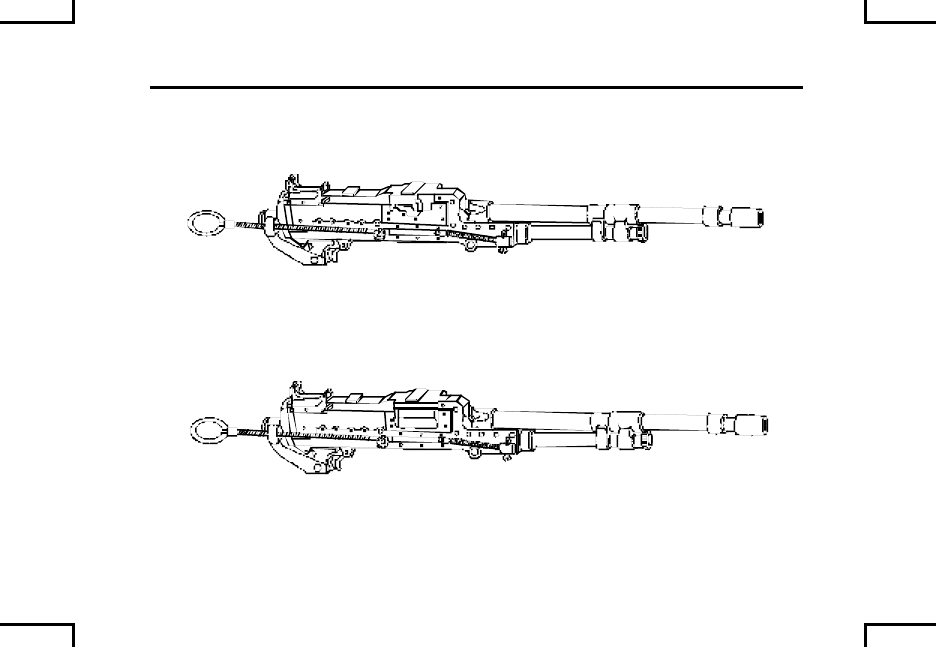
GENERAL INFORMATION (cont) 0001 00
2AN0003
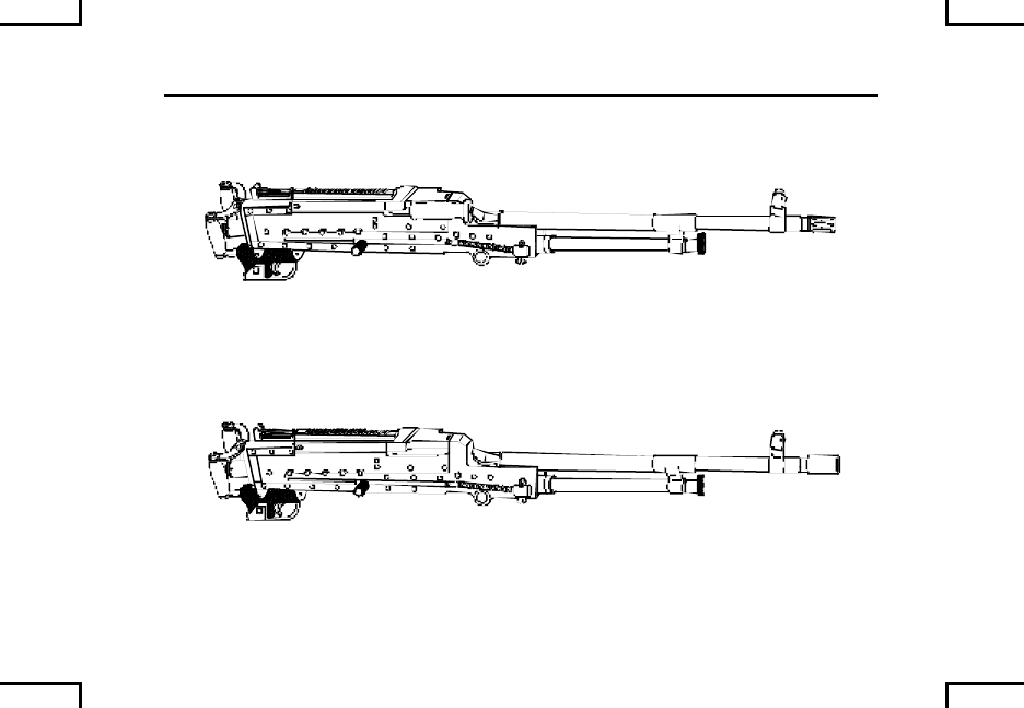
M240D
2AN0004
M240E1
0001 00-2
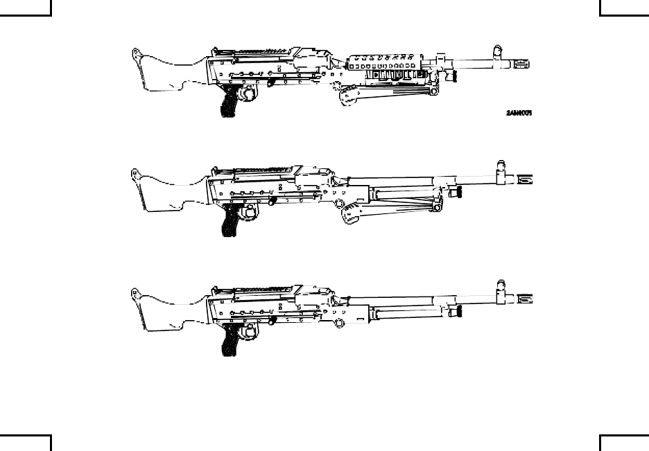
M240B
2AN0006
M240G
2AN0007
M240N
0001 00-3

GENERAL INFORMATION (cont) 0001 00
SCOPE
Type of Manual: Operator’s Manual.
Model Number and Equipment Name:
M240, 7.62mm, Machine Gun
M240B, 7.62mm, Machine Gun
M240C, 7.62mm, Machine Gun
M240D, 7.62mm, Machine Gun
M240E1, 7.62mm, Machine Gun
M240G, 7.62mm, Machine Gun
M240N, 7.62mm, Machine Gun
Purpose of Equipment:
M240/M240C – Designed as coaxial machine gun for tanks and 7.62mm fire power on light
armored vehicles.
M240B/M240G – Designed as a tripod mounted or bipod supported machine gun for use by
ground forces. The bipod is integrated into the receiver assembly of the weapon.
0001 00-4

M240E1 - Designed with front and rear sights, uses 7.62mm ammunition, and
spade grip trigger device and is pintle mounted on light armored vehicles.
M240D - Designed with front and rear sights, uses 7.62mm ammunition, and
spade grip trigger and is mounted in helicopter applications.
M240N– Designed with front and rear sights, and configured for mounting on
water craft.
0001 00-5/6 blank

MAINTENANCE FORMS, RECORDS, AND REPORTS 0002 00
Department of the Army forms and procedures used for equipment maintenance
will be those prescribed by DA PAM 738-750, The Army Maintenance
Management System (TAMMS).
Marine Corps users refer to TM 4700-15/1, Ground Equipment Record
Procedures.
0002 00-1/2 blank

REPORTING EQUIPMENT IMPROVEMENT
RECOMMENDATIONS (EIR) 0003 00
If your machine gun needs improvement, let us know. Send us an EIR. You, the
user, are the only one who can tell use what you don’t like about your equipment.
Let us know why you don’t like the design or performance. Put it on an SF 368
(Product Quality Deficiency Report). Mail to the address specified in DA PAM
738-750, Functional users Manual for the Army Maintenance Management
System (TAMMS), or as specified by the acquiring activity. We will send you a
reply.
Army users submit an SF 368 (QDR) and mail to: Commander, U.S. Army
Armament Research Development and Engineering Center, ATTN: AMSTA-AR-
QAW-A, 1 Rock Island Arsenal, Rock Island, IL 61299-7630.
Marine Corps users submit QDR’s or SF 368 in accordance with MCO 4855.10 to:
Commanding General, Marine Corps Logistics Base (Code 808), Albany, GA
31704-5000.
Navy users submit Quality Deficiency Report to Commander, Naval Surface
Warfare Center, Crane Division, Code 4081, Crane, IN 47522-5001.
We’ll send you a reply.
0003 00-1/2 blank

CORROSION PREVENTION AND CONTROL 0004 00
Corrosion Prevention and Control (CPC) of Army materiel is a continuing concern.
It is important that any corrosion problems with this item be reported so that the
problem can be corrected and improvements can be made to prevent the problem
in the future.
While corrosion is typically associated with rusting of metals, it can also include
deterioration of other materials, such as rubber and plastic. Unusual cracking,
softening, swelling, or breaking of these materials may be a corrosion problem.
If a corrosion problem is identified, it can be reported using SF 368, Product
Quality Deficiency Report. Use key words such as “corrosion”, rust”,
deterioration”, or cracking” will ensure that the information is identified as a CPC
problem.
The form should be submitted to the address specified in DA PAM 738-750,
Functional Users Manual for the Army Maintenance Management System
(TAMMS).
0004 00-1

CORROSION PREVENTION AND CONTROL (cont) 0004 00
Marine Corps users: The prevention of corrosion on any equipment is important
and is critically important for safe functioning of your machine gun. Corrosion
prevention is carried out in accordance with TM 3080-12 (Corrosion Prevention
and Control for Marine Corps Equipment). If a recurrent corrosion problem is
identified, it should be reported on SF 368 (Product Quality Deficiency Report) in
accordance with guidance contained in MCO 4855.10 (Product Quality Deficiency
Report).
Navy users submit Product Quality Deficiency Report or Material Deficiency
Report (MDR) to Commander, Naval Surface Warfare Center, Crane Division,
Code 4081, Crane, IN 47522-5001.
0004 00-2

DESTRUCTION OF ARMY MATERIEL
TO PREVENT ENEMY USE 0005 00
Procedures and materials used for the destruction of the machine gun to prevent
enemy use will be found in TM 750-244-7.
Marine Corps users render the M240 inoperable by smashing, schattering, and
concealing disassembled pieces.
0005 00-1/2 blank


EQUIPMENT DESCRIPTION AND DATA 0007 00
EQUIPMENT CHARACTERISTICS, CAPABILITIES, AND FEATURES
Equipment Characteristics:
M240/M240C – Designed as coaxial machine gun for tanks and 7.62mm fire
power on light armored vehicles.
M240B/M240G – Designed as a tripod mounted or bipod supported machine gun
for use by ground forces. The bipod is integrated into the receiver assembly of
the weapon.
M240E1 - Designed with front and rear sights, uses 7.62mm ammunition, and
spade grip trigger device and is pintle mounted on light armored vehicles.
M240D - Designed with front and rear sights, uses 7.62mm ammunition, and
spade grip trigger and is mounted in helicopter applications.
M240N– Designed with front and rear sights, and configured for mounting on
water craft.
0007 00-1

EQUIPMENT DESCRIPTION AND DATA (cont) 0007 00
EQUIPMENT CHARACTERISTICS, CAPABILITIES, AND FEATURES (cont)
Capabilities and Features:
The M240 Series Machine Gun is gas -operated and fires from the open bolt
position. The 7.62mm is the authorized round for the machine gun (WP 0035
00).
The M240B has a buttstock and hydraulic buffer assembly and can be mounted
on the M122A1 tripod (refer to TM 9-1005-245-13&P).
The M240G has a buttstock and buffer assembly and can be mounted on the
M122 tripod with a flexible mount (refer to TM 9-1005-245-13&P) (Marine Corps
only).
0007 00-2

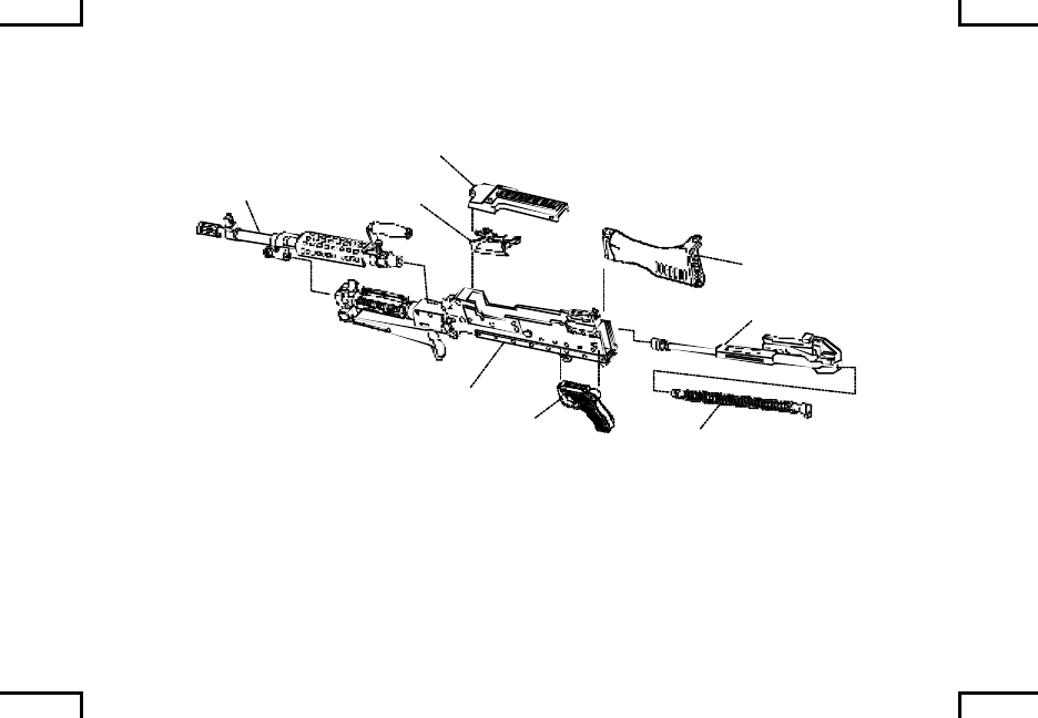
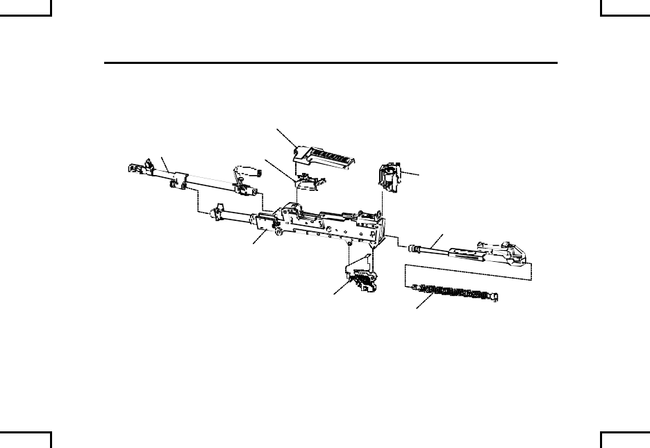
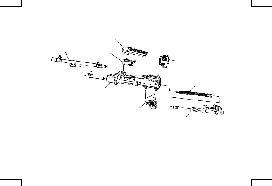
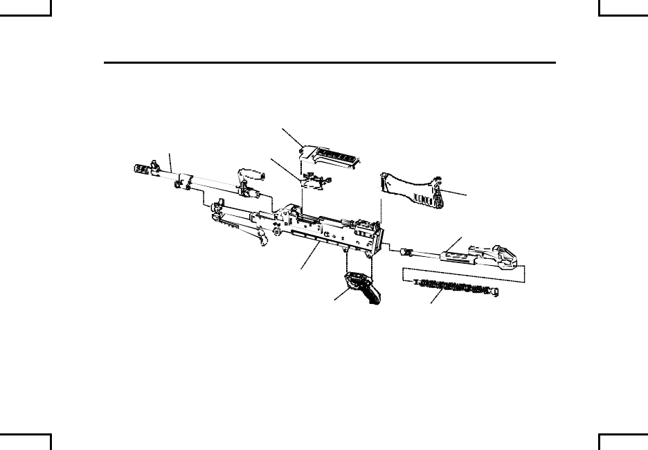
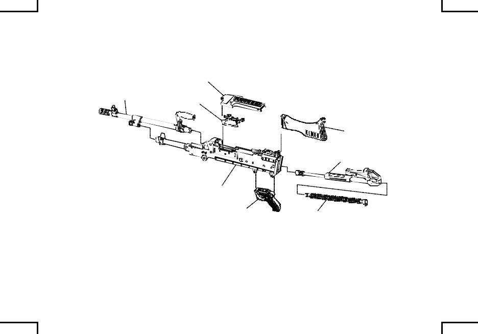
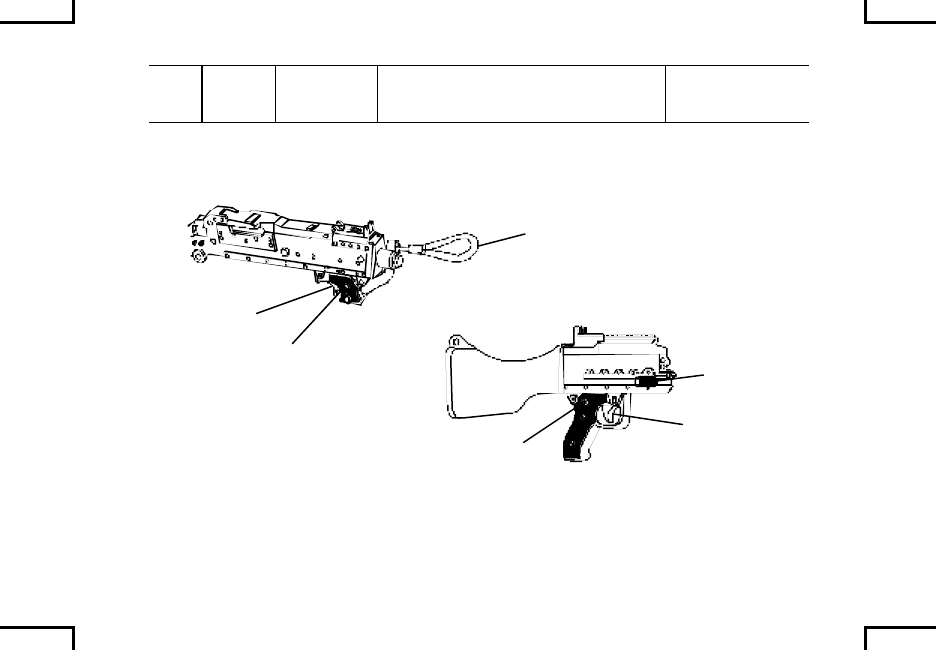
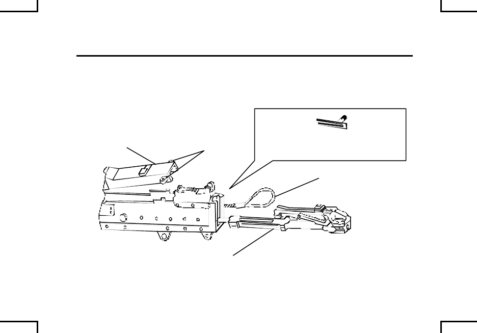
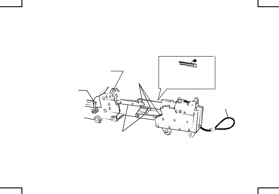
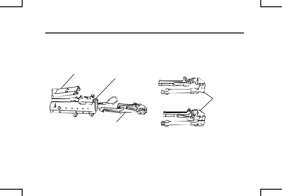
LOCATION AND DESCRIPTION OF MAJOR COMPONENTS
Barrel Assembly (A) – Houses cartridge for firing and directs projectile.
Buffer Assembly/Buffer and Spade Grip Assembly/Buttstock and Buffer
Assembly (B) – Absorbs recoil for bolt and operating rod assembly at the end of
recoil movement.
Driving Spring Rod Assembly (C) - Provides energy for returning bolt and
operating rod assembly to firing position.
Bolt and Operating Rod Assembly (D) – Provides feeding, striping,
chambering, firing, extraction, and ejection of cartridges using the projectile
propelling gases for power.
Trigger Housing Assembly (E) – Controls the firing of the machine gun.
Cover Assembly (F) - Feeds linked belt, positions and holds cartridges in
position for stripping, feeding and chambering. Cover has integral sight mounting
rail for current/future accessories (all models except M240/M240C).
Feed Tray (G) – Serves as a guide for positioning cartridges to assist in
chambering.
0007 00-3
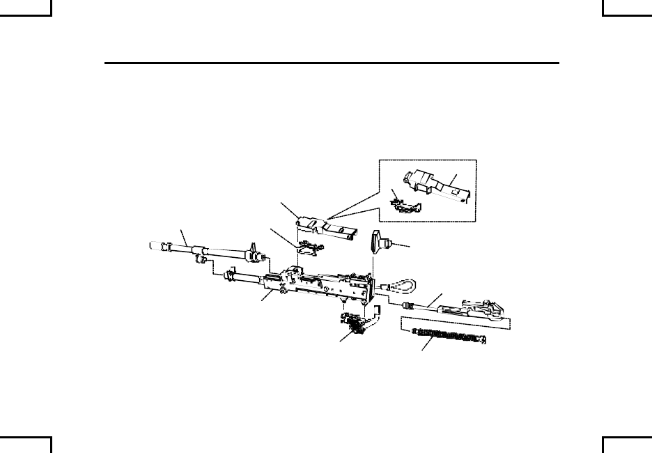
EQUIPMENT DESCRIPTION AND DATA (cont) 0007 00
LOCATION AND DESCRIPTION OF MAJOR COMPONENTS (cont)
Receiver Assembly (H) – Serves as a support of all major components. The
receiver houses action of weapon, and controls functioning of weapon through a
series of cam ways. Receiver has a forward integral mounting rail for
current/future accessories (M240B only).
M240C
A
B
C
D
E
F
G
H
2AN0008
F
G
M240/M240C
0007 00-4
2AN0009
A
B
C
D
E
F
G
H
M240B
0007 00-5
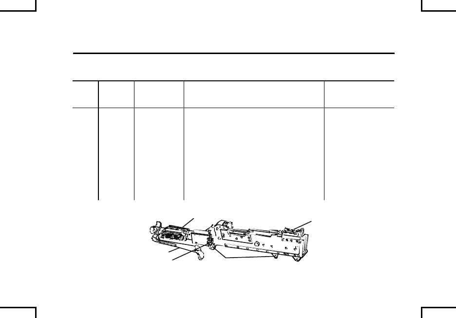
EQUIPMENT DESCRIPTION AND DATA (cont) 0007 00
LOCATION AND DESCRIPTION OF MAJOR COMPONENTS (cont)
A
C
D
F
G
H
B
E
2AN0010
M240D
0007 00-6
A
B
C
D
E
F
G
H
2AN0011
M240E1
0007 00-7
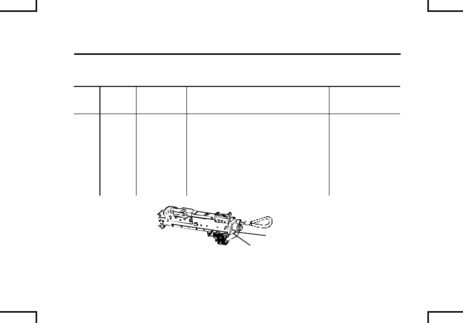
EQUIPMENT DESCRIPTION AND DATA (cont) 0007 00
LOCATION AND DESCRIPTION OF MAJOR COMPONENTS (cont)
A
B
C
D
E
F
G
2AN0012
H
M240G
0007 00-8
A
B
C
D
E
F
G
2AN0013
H
M240N
0007 00-9

EQUIPMENT DESCRIPTION AND DATA (cont) 0007 00
DIFFERENCES BETWEEN MODELS
M240
M240B
M240C
M240D M240E1
M240G M240N
Feeds from right X
Feeds from left X X X X X X
Cover Assy:
PN 11826165
PN 11826038
PN 12977101
X
X
X
X
X
X
X
Receiver Assy:
PN 11826192
PN 12597044
PN 12976834
PN 12997566
PN 12999179
PN 12977104
X
X
X
X
X
X
X
0007 00-10

M240
M240B
M240C
M240D M240E1
M240G M240N
Barrel Assy:
PN 11825985
PN 12597035
PN 12976817
PN 12976818
X
X
X
X
X
X
X
Trigger Assy:
PN 11826230
PN 12597070
PN 12977118
PN 12976869
X
X
X
X
X
X
X
Buffer Assy
PN 11826211
X
X
Buffer and
Spade Grip
Assy:
PN 12597057
X
X
Buttstock and
Buffer Assy:
PN 12976851
X
0007 00-11

EQUIPMENT DESCRIPTION AND DATA (cont) 0007 00
DIFFERENCES BETWEEN MODELS (cont)
M240
M240B
M240C
M240D M240E1
M240G M240N
Buttstock and
Buffer Assy
(Hydraulic):
PN 12988986
X
X
Charger Cable
PN 11826145
X
X
Cocking Handle
Assy:
PN 12597045
PN 12976835
PN 12977105
X
X
X
X
X
Procedures are written for the M240 machine gun but apply to all seven models,
except where noted.
Do not mix and match parts for one model configuration to another model.
0007 00-12

EQUIPMENT DATA
Weight.............10.34 Kg (22.2 lbs) (M240/M240C); 12.29 Kg (27.1 lbs) (M240B);
10.39 Kg (22.9 lbs) (M240D); 11.66 Kg (25.7 lbs) (M240E1);
11.7 Kg (25.8 lbs) (M240G); 10.93 Kg (24.1 lbs) (M240N)
Rate of Fire ....You get the sustained and rapid rates through practice.
Cyclic...............650 to 950 RDS/M – Weapon is not intended to fire at 950 RDS/M.
This will cause accelerated wear/damage to the barrel and rest of
weapon.
600 to 650 RDS/M – M240B/M240N with hydraulic buffer.
Sustained........100 RDS/M (4-5 seconds between burst) – Change barrel every
10 minutes.
Rapid...............200 RDS/M (2-3 seconds between burst) – Change barrel every 2
minutes.
NOTE
Barrel change intervals also apply when firing blank ammunition.
0007 00-13

EQUIPMENT DESCRIPTION AND DATA (cont) 0007 00
EQUIPMENT DATA (cont)
Range:
Maximum.....................................3,725 meters
Maximum
effective (point)...........................800 meters with M122A1 Tripod (M240B)
(M122 Tripod with Flex Mount Assembly
(M240G) (Marine Corps only)).
Maximum
Effective (area)...........................1,800 meters with M122A1 Tripod (M240B)
(M122 Tripod with Flex Mount Assembly
(M240G) (Marine Corps only)).
Tracer burnout............................Approximately 900 meters.
0007 00-14


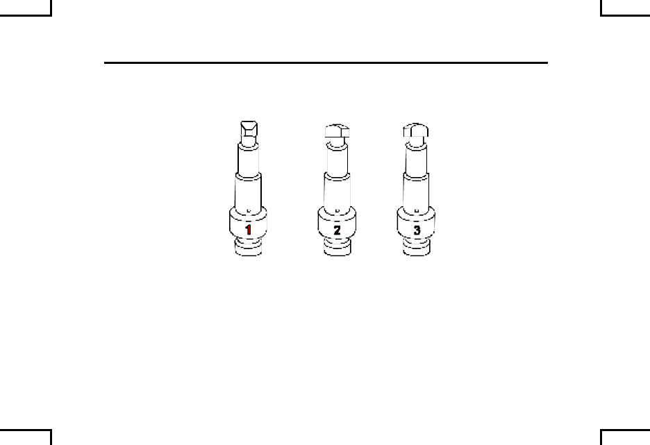
TECHNICAL PRINCIPLES OF OPERATION 0008 00
FACTS ABOUT YOUR MACHINE GUN
The barrel is air-cooled and has an established headspace allowing quick
changes for cooling and maintenance when required. The rate of fire is
controlled by 3 regulator settings (setting #1 is preferred). Settings #2 and #3 are
used when carbon build-up, cold weather, or dusty conditions reduce the firing
rate. Bolt design permits the cover to be opened or closed, regardless of the bolt
position, without damage.
NOTE
This design is intended to maintain a consistent rate of fire
under adverse conditions and is not to increase the rate of fire.
Gas inlet setting #1 is the preferred setting for normal
conditions. If gas regulator plug has been set to setting #2 or
#3 to increase firing rate, take corrective action to return to
primary setting #1 as soon as possible.
Gas regulator may need to be changed to setting #2 for firing
blank ammunition. After cleaning, return to Setting #1 for
firing of standard ammunition.
0008 00-1
TECHNICAL PRINCIPLES OF OPERATION 0008 00
FACTS ABOUT YOUR MACHINE GUN
2AN0014
Setting #1 = 650 RDS/M approx. (600 RD/S – M240B/M240N with hydraulic buffer)
Setting #2 = 750 RDS/M approx. (625 RD/S – M240B/M240N with hydraulic buffer)
Setting #3 = 950 RDS/M approx. (650 RD/S – M240B/M240N with hydraulic buffer)
0008 00-2
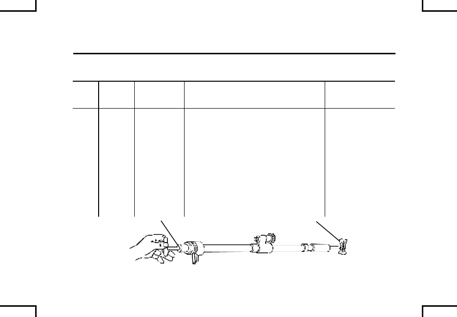
OPERATION UNDER USUAL CONDITIONS –
LOADING 0009 00
S
2AN0015
ALL MODELS EXCEPT
M240/M240C
WARNING
Under no circumstances should the safety be engaged with the
bolt in the forward position.
Place safety to “F” fire.
Pull charger cable (or cocking handle assembly) to rear, and ensure bolt locks to
rear. Release charger cable (or return cocking handle assembly) to fully forward
and locked position.
0009 00-1
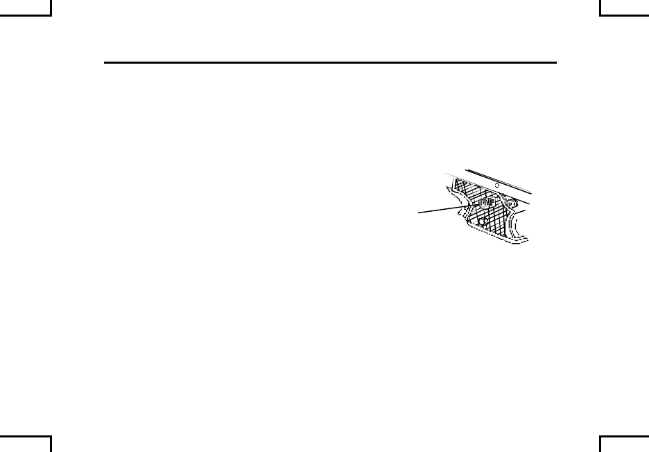
OPERATION UNDER USUAL CONDITIONS –
LOADING (cont) 0009 00
2AN0016
FEED TRAY
Place safety to “S” safe.
Push in latches to open cover assembly. Remove any ammunition if present.
Raise feed tray. Look into chamber, make sure no round is chambered and area is
free of obstructions. Lower feed tray.
Place safety to “F” fire.
Pull and hold charger cable (or cocking handle assembly) to rear, squeeze trigger
and ease bolt forward to close and lock.
0009 00-2
ALL MODELS
EXCEPT M240C M240C
2AN0017
NOTE
Position open side of links down.
Place link belt in feed tray with first round positioned against cartridge stop.
CAUTION
Make sure round does not move away from cartridge stop during
closing and latching of cover.
Close cover assembly. Make sure it locks shut. (Air Force users, this is HALF-
LOAD and is an authorized carry/transportation configuration of the M240B and
it’s ammo.)
0009 00-3

OPERATION UNDER USUAL CONDITIONS –
LOADING (cont) 0009 00
Pull charger cable (or cocking handle assembly) to rear, and ensure bolt locks to
rear. Release charger cable (or return cocking handle assembly) to fully forward
and locked position.
If weapon is not to be fired immediately, place safety to “S” safe. Place safety to
“F” fire immediately prior to firing. (Air Force users, this is FULL-LOAD/
COMBAT LOAD configuration.)
NOTE
Proper trigger control is pulling the trigger fully to the rear and
then releasing completely. Squeezing the trigger can cause
accelerated wear on the trigger tripping lever, sear and
operating rod, leading to a run-away gun.
0009 00-4
OPERATION UNDER USUAL CONDITIONS –
CLEARING 0010 00
ALL MODELS
EXCEPT M240C 2AN0018
COVER
LATCH
M240C
COVER
LATCH
AMMO
BELT
Push in latches to open cover assembly.
Remove ammunition belt.
0010 00-2
OPERATION UNDER USUAL CONDITIONS –
CLEARING (cont) 0010 00
2AN0019
FEED TRAY
CHAMBER
Raise feed tray. Look into chamber to make sure it is empty. If a round is still in
the chamber, refer to ruptured/stuck cartridge case or live round procedures
(WP 0016 00 and WP 0017 00).
Lower feed tray.
0010 00-3
OPERATION UNDER USUAL CONDITIONS –
CLEARING (cont) 0010 00
S
2AN0015
ALL MODELS EXCEPT
M240/M240C
Place safety to “F” fire.
Pull and hold charger cable (or cocking handle assembly) to rear, pull trigger and
ease bolt forward to close and lock.
Close cover assembly. Make sure it locks shut.
NOTE
Be sure bolt is forward with safety in “F” fire when gun is not in use.
0010 00-4

OPERATION UNDER USUAL CONDITIONS –
OPERATION OF BIPOD 0011 00
BIPOD RETAINING
LATCH
BIPOD LEGS
2AN0021
To operate the weapon from the bipod (M240B/M240G):
Depress the bipod retaining latch, while holding the bipod legs together to
disengage them from the receiver
Rotate the bipod legs down and release them so they lock in the vertical position.
0011 00-1
OPERATION UNDER USUAL CONDITIONS –
OPERATION OF BIPOD (cont) 0011 00
BIPOD RETAINING
LATCH
BIPOD LEGS
2AN0021
To return the bipod to locked upright position:
Hold the bipod legs together to disengage them from the locked vertical position.
Rotate legs rearward, depress the bipod latch and engage the bipod leg hooks
into the slots of receiver. Release the bipod retaining latch to its original position,
locking the legs into position.
0011 00-2

OPERATION UNDER USUAL CONDITIONS –
DEFINITIONS 0012 00
STOPPAGE – Any interruption in the cycle of operation of the gun.
IMMEDIATE ACTION – Prompt actions taken by the crew to overcome a
stoppage.
REMEDIAL ACTION - Action taken to identify stoppage, if immediate action fails.
COOK-OFF – This is a peacetime classification only. The gun will be classed as
a hot or cold gun in the interest of safety.
CLASSIFICATION OF HOT GUN
• More than 200 rounds fired within a 2 minute period.
• A long continuous burst or repeated firing of the weapon even though
you do not reach 200 rounds.
• Less than 15 minutes have lapsed with out a round being fired from a hot
gun.
• If the vehicle Commander for any reason determines the weapon is hot.
0012 00-1/2 blank

OPERATION UNDER USUAL CONDITIONS –
IMMEDIATE ACTION 0013 00
WARNING
If nothing is ejected and you have a hot gun (200 rounds fired
within a 2 minute period), do NOT open the cover. Place safety
to “S” safe, keep weapon pointed down range, and remain
away from the weapon for 15 minutes. After 15 minutes, clear
your weapon (WP 0010 00).
The climate temperature in different regions will make a
difference as to what constitutes a hot gun. A hot, sunny day
can cause a cook-off within 50 rounds, weapon and
ammunition in the sun.
0013 00-1

OPERATION UNDER USUAL CONDITIONS –
IMMEDIATE ACTION (cont) 0013 00
Charge the weapon.
Attempt to fire.
If the gun does not fire, pull charger cable (or cocking handle assembly) rearward
to lock bolt assembly back (return cocking handle assembly to forward locked
position), place safety on “S” safe, then:
• If Hot Gun – Keep weapon pointed down range for 15 minutes, then
perform remedial action.
• If Cold Gun – Perform remedial action.
0013 00-2

OPERATION UNDER USUAL CONDITIONS –
RUNAWAY MACHINE GUN 0015 00
WARNING
Always keep weapon pointed down range.
Never reload a runaway weapon until it is repaired. Be sure
weapon is cleared (WP 0010 00) before removing it from
vehicle/tripod mount.
If runaway occurs (weapon won’t stop firing), take any of the 3 actions below to
stop the runaway. Then notify unit maintenance.
Let weapon fire if near end of link belt.
ALL MODELS EXCEPT
M240/M240C
2AN0022
LINK
BELT
S
SAFETY
0015 00-1
OPERATION UNDER USUAL CONDITIONS –
RUNAWAY MACHINE GUN (cont) 0015 00
Break link belt (grasp link belt and twist it firmly).
Grab charger cable (or cocking handle assembly), pull all the way back and hold.
Place safety to “S” safe and remove ammunition belt.
ALL MODELS EXCEPT
M240/M240C
2AN0022
LINK
BELT
S
SAFETY
0015 00-2
OPERATION UNDER USUAL CONDITIONS –
STUCK CARTRIDGE CASE OR LIVE ROUND 0016 00
WARNING
Stay clear of muzzle. Do not allow round to hit any hard surface
or it may fire. Dispose of live round(s) in accordance with local
procedures.
If weapon fired but didn’t extract, you have a stuck cartridge case. If weapon did
not fire and didn’t extract, you have a stuck live round.
Charge the weapon, and place safety on “S” safe.
ALL MODELS EXCEPT
M240/M240C
2AN0022
LINK
BELT
S
SAFETY
0016 00-1
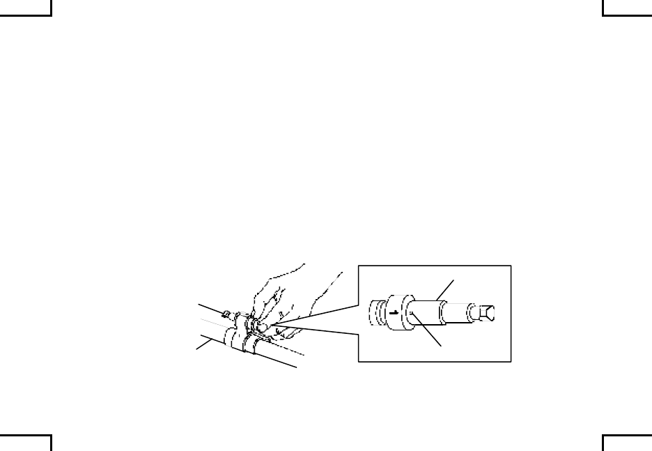
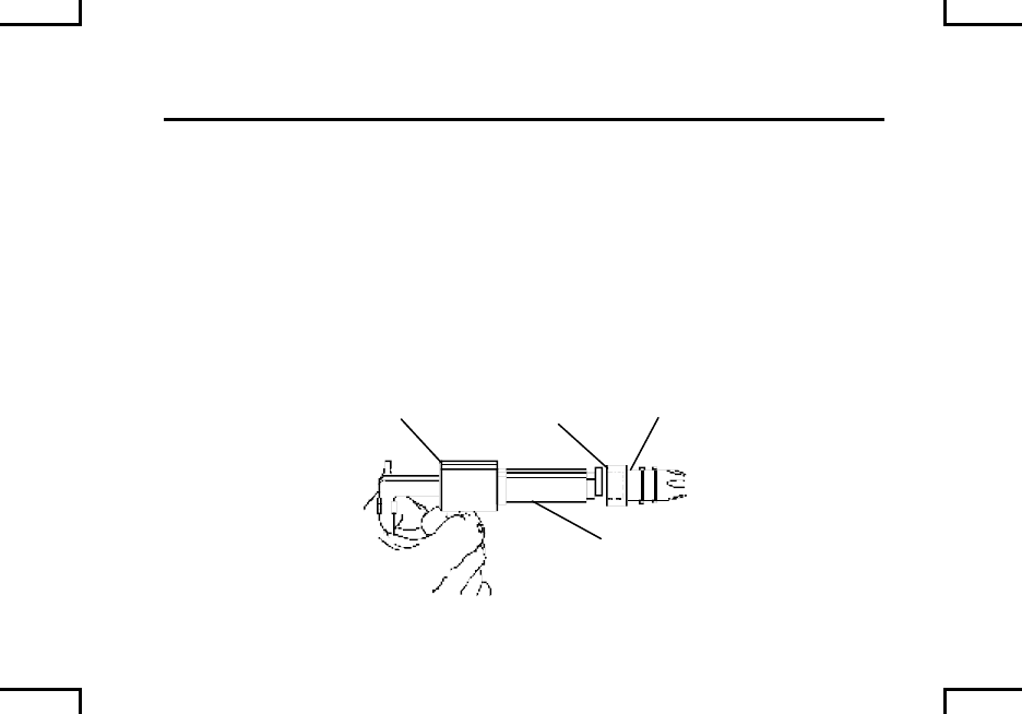
OPERATION UNDER USUAL CONDITIONS –
STUCK CARTRIDGE CASE OR LIVE ROUND (cont) 0016 00
Push cocking handle assembly to forward locked position (all models except
M240/M240C).
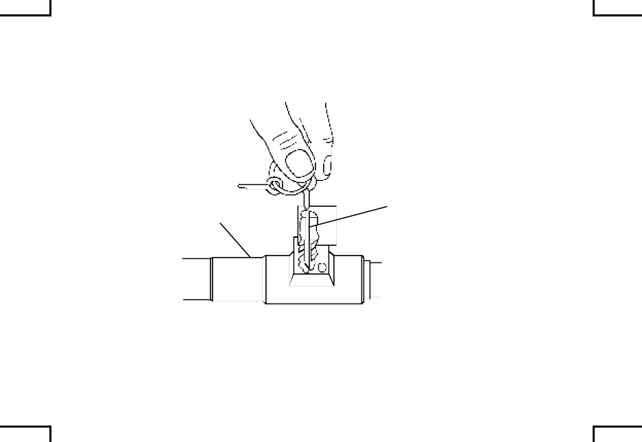
Wait until barrel is cool; remove barrel (WP 0021 00). Remove cartridge case
from chamber of barrel, or pry rim (if case is tight).
RIM
BARREL
BARREL
CARTRIDGE
CASE
2AN0023
0016 00-2
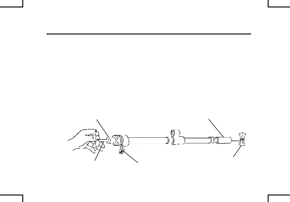
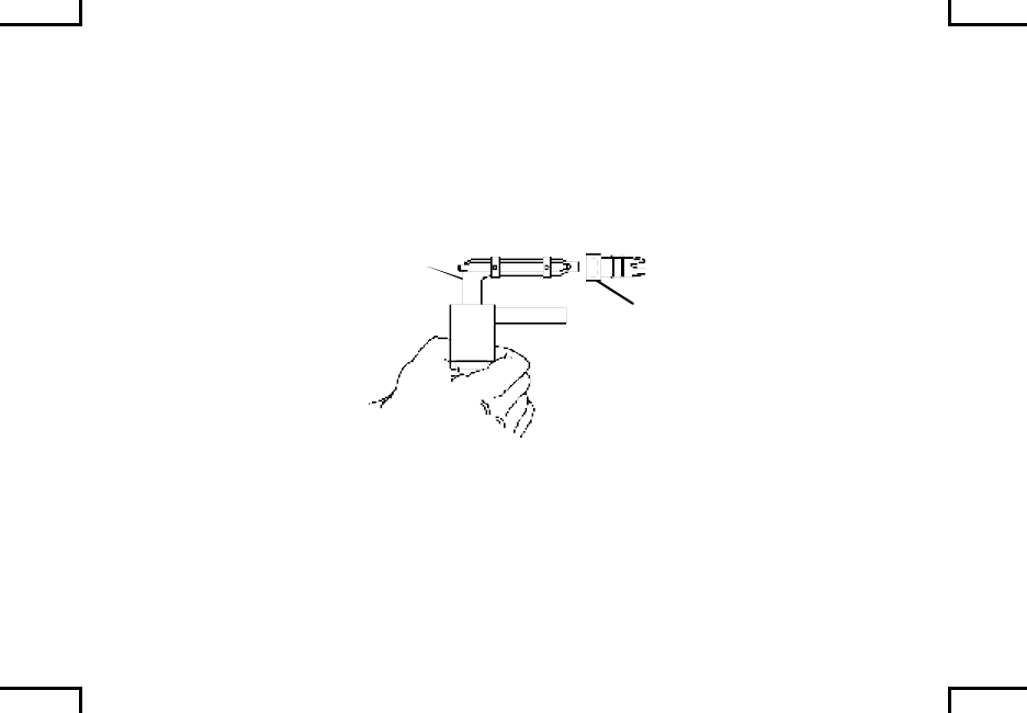
ALTERNATIVE MEATHOD
Remove swab holder section from cleaning rod and insert cleaning rod through
muzzle end of barrel, gently tap out cartridge.
STUCK
CARTRIDGE
CASE
CLEANING
ROD
2AN0024
Push end of cleaning rod against stuck case. Push cleaning rod to remove case
with weapon in mounted position.
CLEANING
ROD
STUCK
CARTRIDGE
CASE
BARREL
2AN0025
0016 00-3/4 blank

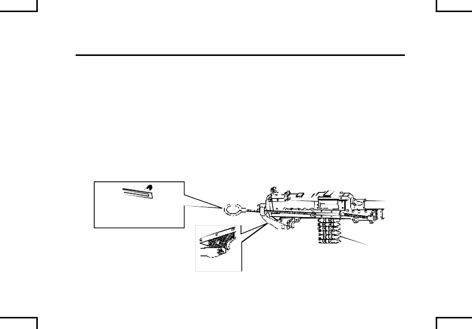
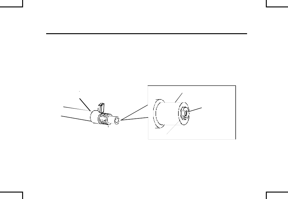
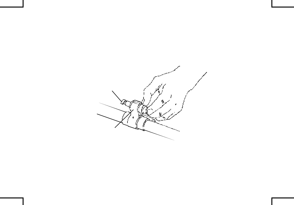
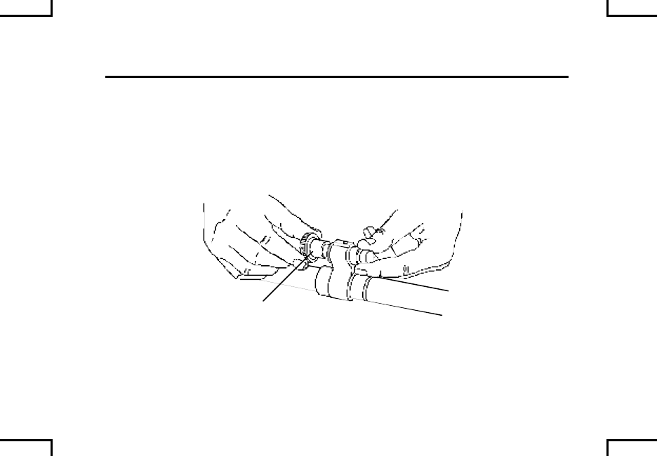
OPERATION UNDER USUAL CONDITIONS –
RUPTURED CARTRIDGE CASE 0017 00
WARNING
Stay clear of muzzle. Do not allow round to hit any hard surface
or it may fire. Dispose of live round(s) in accordance with local
procedures.
Charge the weapon, and place safety on “S” safe.
Push cocking handle assembly to forward locked position (all models except
M240/M240C).
Wait until barrel is cool; remove barrel (WP 0021 00).
0017 00-1
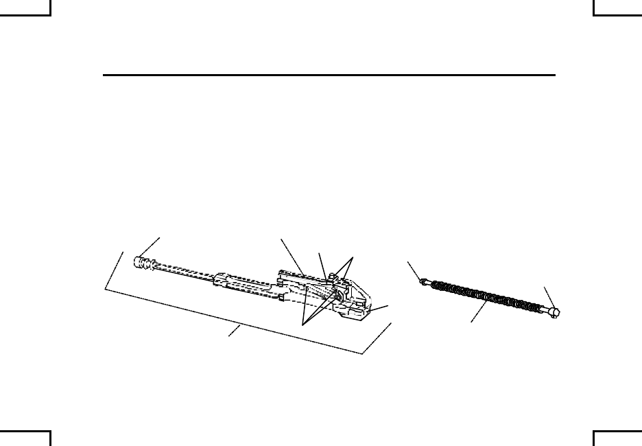
OPERATION UNDER USUAL CONDITIONS –
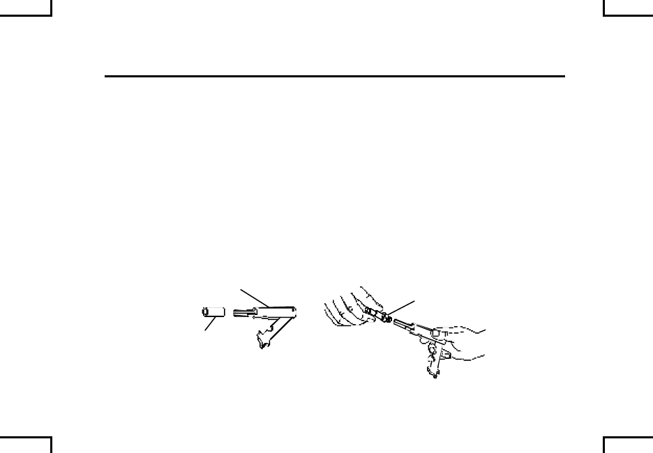
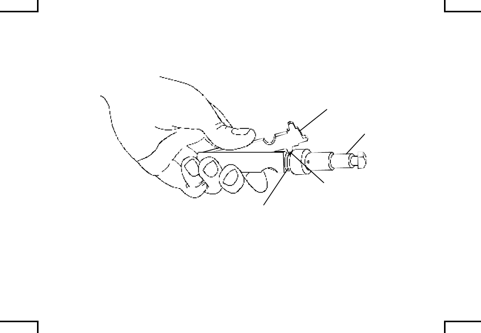
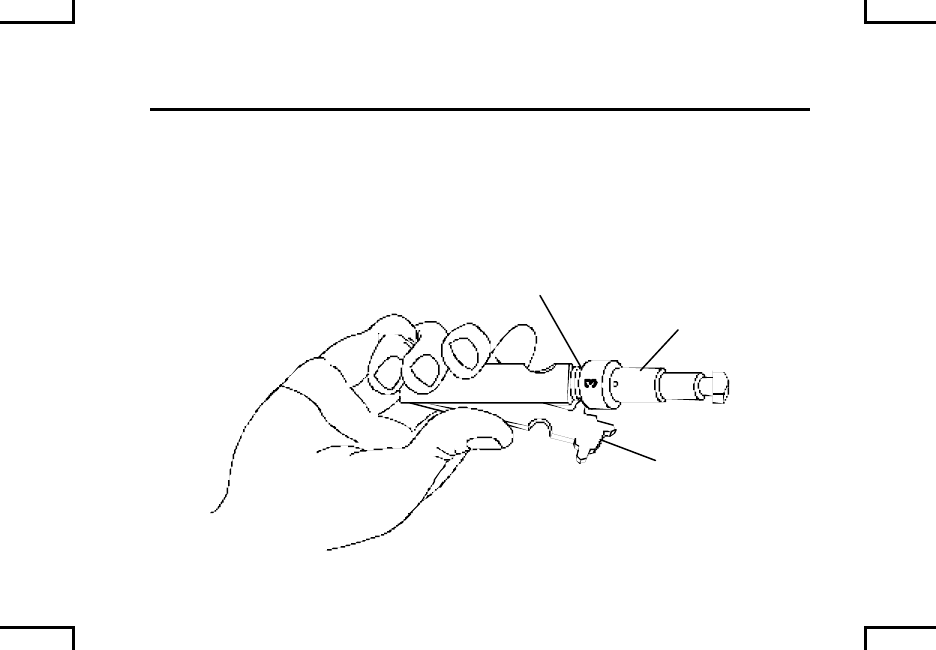
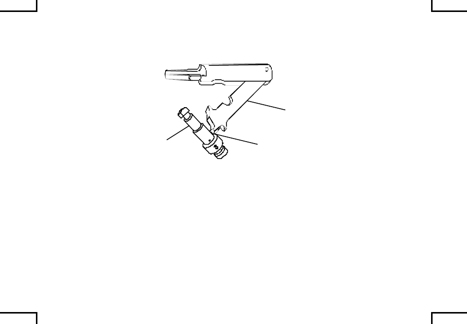
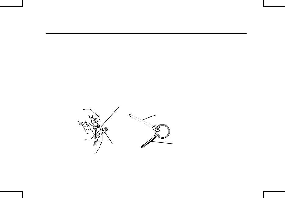
RUPTURED CARTRIDGE CASE (cont) 001700
NOTE
In the event a live round is fed into a ruptured case, remove live
round first (WP 0016 00), then remove ruptured cartridge case.
Push threaded end of extractor post through ruptured case. Pull on handle to
remove case.
2AN0026
RUPTURED
CARTRIDGE
CASE
BARREL EXTRACTOR
0017 00-2

OPERATION UNDER UNUSUAL CONDITIONS – 0018 00
Under unusual conditions, clean and lubricate weapon more often.
HOT, DUSTY, AND SANDY AREAS. Clean often. Wipe oil from exposed
surfaces with clean wiping rag (item 7, WP 0040 00). Cover weapon as much as
possible to keep dust and sand out of parts.
HOT, WET CLIMATE. Inspect often. Dry, clean, and lubricate lightly as
necessary.
EXTREMELY COLD CLIMATE. Keep free of moisture. Lightly oil with LAW
(item 4, WP 0040 00).
AFTER EXPOSURE TO WATER. Disassemble, clean, oil and reassemble as
soon as possible. Make sure it’s dry.
NUCLEAR, BIOLOGICAL, AND CHEMICAL (NBC) ESCONTAMINATION.
Decontamination procedures can be found in FM-3-5.
NOTE
Refer to WP 0025 00 for lubrication instructions.
0018 00-1/2 blank


TROUBLESHOOTING PROCEDURES 0019 00
GENERAL
This table lists the common malfunctions that you may find during the operation
or maintenance of the machine gun or its components. You should perform the
tests/inspections and corrective actions in the order listed.
This manual cannot list all the malfunctions that may occur, nor all tests or
inspections and corrective actions. If a malfunction is not listed or is not
corrected by listed corrective actions, notify unit maintenance.
NOTE
Troubleshooting procedures are written for one machine gun
but apply to all models.
0019 00-1
TROUBLESHOOTING PROCEDURES (cont) 0019 00
Table 1. Troubleshooting Procedures
SYMPTOM
Fails to fire on initial burst.
MALFUNCTION
Weapon not properly charged.
CORRECTIVE ACTION
Charge the weapon.
Safety is still in “S” safe position.
CORRECTIVE ACTION
Move safety to “F” fire.
SAFETY
2AN0027
0019 00-2

TROUBLESHOOTING PROCEDURES (cont) 0019 00
Table 1. Troubleshooting Procedures (cont).
SYMPTOM
Failure to feed.
MALFUNCTION
Improper lubrication.
CORRECTIVE ACTION
Lube as required (WP 0025 00).
Ammunition or links are defective.
CORRECTIVE ACTION
Remove defective ammunition/links. Install new ammunition/links.
Obstruction in receiver.
CORRECTIVE ACTION
Remove obstruction.
0019 00-4
TROUBLESHOOTING PROCEDURES (cont) 0019 00
Table 1. Troubleshooting Procedures (cont).
SYMPTOM (cont)
Failure to feed.
MALFUNCTION
Cover assembly is damaged, or has weak, worn or missing parts.
CORRECTIVE ACTION
Notify unit maintenance.
SYMPTOM
Weapon stops firing.
MALFUNCTION
Round in chamber is defective.
CORRECTIVE ACTION
Eject round.
RIM
BARREL
CARTRIDGE
CASE
2AN0029
0019 00-6

TROUBLESHOOTING PROCEDURES (cont) 0019 00
Table 1. Troubleshooting Procedures (cont).
SYMPTOM (cont)
Weapon stops firing.
MALFUNCTION (cont)
Unfired round with dented primer.
CORRECTIVE ACTION
Eject round. Notify unit maintenance.
Feed mechanism is sticking.
CORRECTIVE ACTION
Clean (WP 0022 00) and lubricate (WP 0025 00) feed mechanism. If
problem still exist, notify unit maintenance.
Short recoil.
CORRECTIVE ACTION
Clean (WP 0022 00) and lubricate (WP 0025 00) bolt and operating
rod assembly. If problem still exist, notify unit maintenance.
0019 00-8

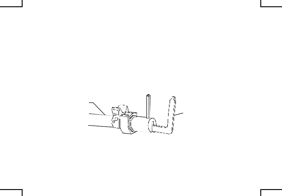
TROUBLESHOOTING PROCEDURES (cont) 0019 00
Table 1. Troubleshooting Procedures (cont).
SYMPTOM
Failure to chamber.
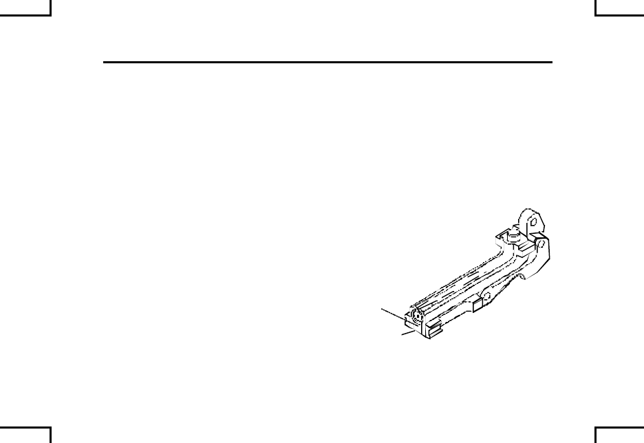
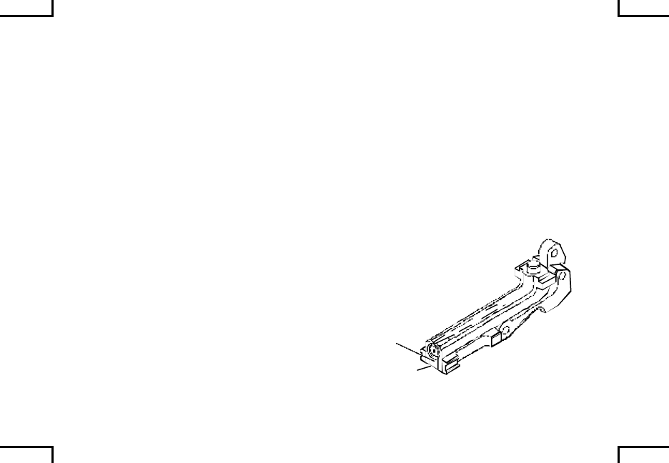
MALFUNCTION
Stuck or ruptured cartridge case.
CORRECTIVE ACTION
Remove cartridge (WP 0016 00/WP 0017 00).
CARTRIDGE
CASE
2AN0031
Ammunition is dirty.
CORRECTIVE ACTION
Wipe ammunition off with a clean, dry rag (item 7, WP 0040 00).
0019 00-10
MALFUNCTION (cont)
Carbon build-up in receiver.
CORRECTIVE ACTION
Clean receiver as necessary (WP 0022 00).
Round is damaged.
CORRECTIVE ACTION
Remove round and recharge weapon.
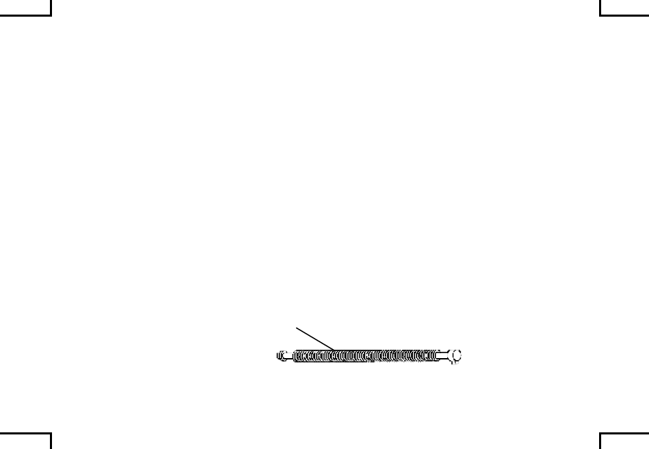
Driving spring is damaged or weak.
CORRECTIVE ACTION
If two or more strands broken on the same coil, or three of more
strands are broken in any location, notify unit maintenance.
DRIVING SPRING
2AN0032
0019 00-11
TROUBLESHOOTING PROCEDURES (cont) 0019 00
Table 1. Troubleshooting Procedures (cont).
SYMPTOM (cont)
Failure to chamber.
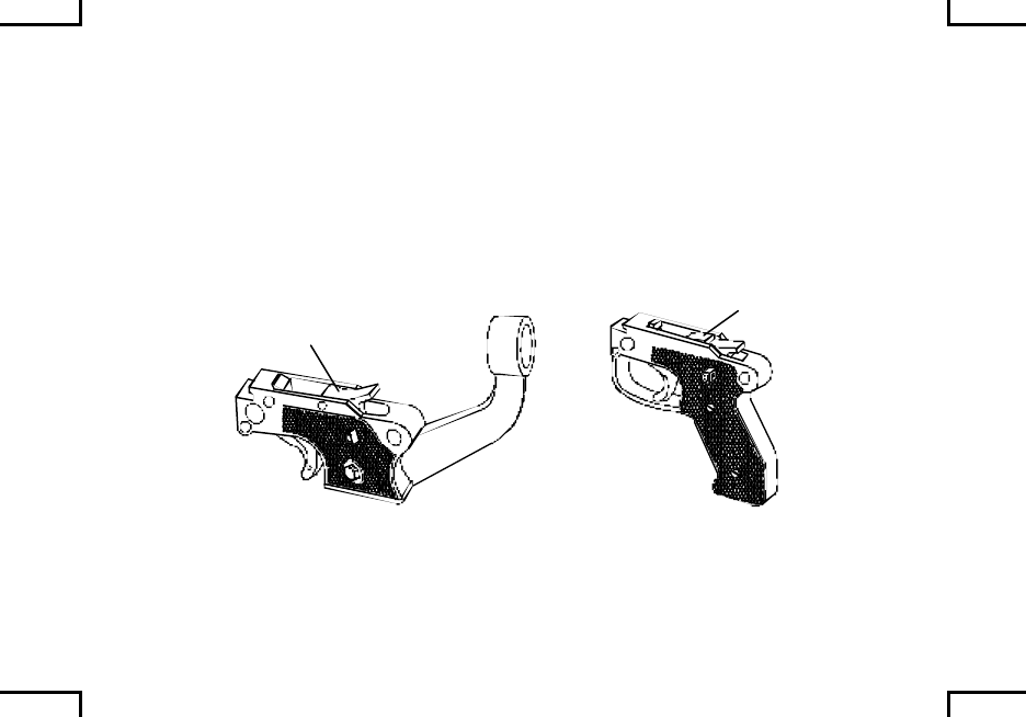
MALFUNCTION (cont)
Gas plug regulator is damaged.
CORRECTIVE ACTION
Notify unit maintenance.
Dirt in chamber.
CORRECTIVE ACTION
Clean chamber (WP 0022 00).
CHAMBER GAS PLUG
REGULATOR
2AN0033
0019 00-12
SYMPTOM
Failure to fire.
MALFUNCTION
Ammunition is faulty.
CORRECTIVE ACTION
Replace ammunition.
Broken or damaged firing pin.
CORRECTIVE ACTION
Notify unit maintenance.
Driving spring is damaged or weak.
CORRECTIVE ACTION
If two or more strands broken on the same coil, or three of more
strands are broken in any location, notify unit maintenance.
DRIVING SPRING
2AN0032
0019 00-13
MALFUNCTION (cont)
Dirty chamber or ammunition.
CORRECTIVE ACTION
Clean chamber (WP 0022 00), wipe ammunition off with clean, dry
rag (item 7, WP 0040 00).
SYMPTOM
Failure to eject.
MALFUNCTION
Short recoil.
CORRECTIVE ACTION
Notify unit maintenance.
Damaged extractor/spring.
CORRECTIVE ACTION
Notify unit maintenance.
EXTRACTOR
SPRING
2AN0034
0019 00-15

TROUBLESHOOTING PROCEDURES (cont) 0019 00
Table 1. Troubleshooting Procedures (cont).
SYMPTOM (cont)
Failure to eject.
MALFUNCTION (cont)
Spent case bag is full.
CORRECTIVE ACTION
Empty bag.
0019 00-16

TROUBLESHOOTING PROCEDURES (cont) 0019 00
Table 1. Troubleshooting Procedures (cont).
SYMPTOM (cont)
Failure to cock or runaway gun.
MALFUNCTION (cont)
Operating rod sear notch is worn.
CORRECTIVE ACTION
Notify unit maintenance.
Sear is stuck in housing.
CORRECTIVE ACTION
Notify unit maintenance.
Short recoil.
CORRECTIVE ACTION
Notify unit maintenance.
0019 00-18


PREVENTIVE MAINTENANCE CHECKS
AND SERVICES 0020 00
Always keep in mind the WARNINGS and CAUTIONS before and during
operation. Be sure to perform your after (A) PMCS.
Perform BEFORE PMCS if:
• You are the assigned operator and the machine gun has been stored
and not used for a period of 90 days.
• You have been issued the machine gun for the first time.
BEFORE (B)- Checks and services performed prior to the equipment leaving its
containment area or performing its intended mission.
DURING (D) – Checks begin when the equipment is being used in its intended
mission.
AFTER (A) – Checks and services begin when the equipment is taken out of its
mission mode or returned to its containment area.
0020 00-1

PREVENTIVE MAINTENANCE CHECKS
AND SERVICES (cont) 0020 00
Your PMCS table lists inspections and care required to keep your machine gun in
good operating condition.
The interval column tells you when and the procedure column tells you how to do
a certain check or service. The equipment condition listed in “NOT FULLY
MISSION CAPABABLE IF” column indicates problems which must be corrected
before you can operate the machine gun. The terms “ready/available” and
“mission capable” refer to the same status: equipment is on hand and is able to
perform its combat missions (see DA PAM 738-750).
If your machine gun does not perform as required, refer to Troubleshooting (WP
0019 00) for possible malfunctions and corrective actions. Report malfunctions
on proper DA Form 2404 or refer to DA PAM 738-750.
0020 00-2

Table 1. Preventive Maintenance Checks and Services
Item
No. Interval
Item to be
Checked/
Serviced
Procedure Not Fully Mission
Capable If:
WARNING
Be sure to clear weapon before disassembling, clearing,
inspecting, transporting, or storing.
Do not interchange barrel assembly or bolt assembly from one
machine gun to another without being headspaced/gaged.
Doing so may result in injury to, or death of, personnel.
Ensure that assigned/spare barrels have been headspaced and
tagged to your receiver. Rotate usage of the barrels as
specified in WP 0007 00.
NOTE
Barrel changes are required with all types of authorized
ammunition, to include blanks.
0020 00-3
PREVENTIVE MAINTENANCE CHECKS
AND SERVICES (cont) 0020 00
Table 1. Preventive Maintenance Checks and Services (cont)
Item
No. Interval
Item to be
Checked/
Serviced
Procedure Not Fully Mission
Capable If:
1 B Barrel
Assembly Remove barrel (WP 0021 00) and
check bore and chamber. Using
cleaning rod and swab (item 8, WP
0039 00), remove oil, foreign
material, or obstructions. Install and
lock barrel securely in receiver (WP
0023 00). (Spare barrel must also be
checked and cleaned before use.)
Inspect heat shield for cracks
(M240B).
Obstruction in
barrel cannot be
removed or
barrel will not
lock securely in
receiver (WP
0023 00). Heat
shield missing or
broken so as to
allow contact
with metal
(M240B only).
CHAMBER
2AN0036
SWAB
0020 00-4
Item
No. Interval
Item to be
Checked/
Serviced
Procedure Not Fully Mission
Capable If:
2 B Buffer
Assembly Make sure back plate latch is locked. Latch will not
hold buffer
assembly in
receiver.
NOTE
Ensure spring pin is in place.
BACK PLATE
LATCH
SPRING PIN
2AN0037
0020 00-5
PREVENTIVE MAINTENANCE CHECKS
AND SERVICES (cont) 0020 00
Table 1. Preventive Maintenance Checks and Services (cont)
Item
No. Interval
Item to be
Checked/
Serviced
Procedure Not Fully Mission
Capable If:
NOTE
Do not apply lubricants to composition/rubber components.
3 B Buttstock
and Buffer
Assembly
(M240B/
M240G/
M240N)
Make sure back plate latch is locked.
Externally inspect the buttstock for
cracks. The buttstock may be
cleaned with a brush and soapy
water, rinsed, and wiped dry with a
clean rag.
Latch will not
hold buttstock
assembly in
receiver.
Buttstock is
cracked.
LATCH
BUTTSTOCK AND
BUFFER ASSEMBLY
2AN0038
0020 00-6
Item
No. Interval
Item to be
Checked/
Serviced
Procedure Not Fully
Mission capable
if:
3 B Cover
Assembly Squeeze cover latches and raise
cover. Let go of latches and close
cover. Make sure latches hold cover
shut. Inspect accessory mounting
rail for nicks and burrs (all models
except M240/M240C).
Latches fail to
hold cover shut.
Accessory rail
will not accept
optional sighting
devices (all
models except
M240/M240C).
COVER
LATCH
2AN0039
0020 00-7

PREVENTIVE MAINTENANCE CHECKS
AND SERVICES (cont) 0020 00
Table 1. Preventive Maintenance Checks and Services (cont)
Item
No. Interval
Item to be
Checked/
Serviced
Procedure Not Fully Mission
Capable If:
NOTE
The charger cable is on the M240/M240C models only. All other models
have a cocking handle assembly.
Weapon should not be on “S” safe without bolt assembly locked fully to
the rear.
4 B Charger
Cable,
Safety,
and Bolt
Assembly
Pull charger cable/cocking handle
assembly to the rear (return and lock
in forward position), make sure bolt
assembly moves freely without
binding and locks to the rear. Place
safety to “S” safe and pull trigger.
Bolt assembly should not move
forward. Place safety to “F” fire.
Keep hold of charger cable and pull
trigger. Let bolt assembly return to
forward position slowly.
0020 00-8
Item
No. Interval
Item to be
Checked/
Serviced
Procedure Not Fully Mission
Capable If:
TRIGGEER
COCKING
HANDLE
SAFETY
CHARGER
CABLE
TRIGGER
SAFETY
2AN0040
0020 00-9
PREVENTIVE MAINTENANCE CHECKS
AND SERVICES (cont) 0020 00
Table 1. Preventive Maintenance Checks and Services (cont)
Item
No. Interval
Item to be
Checked/
Serviced
Procedure Not Fully Mission
Capable If:
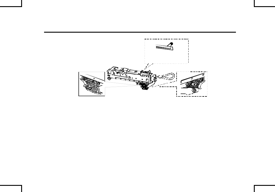
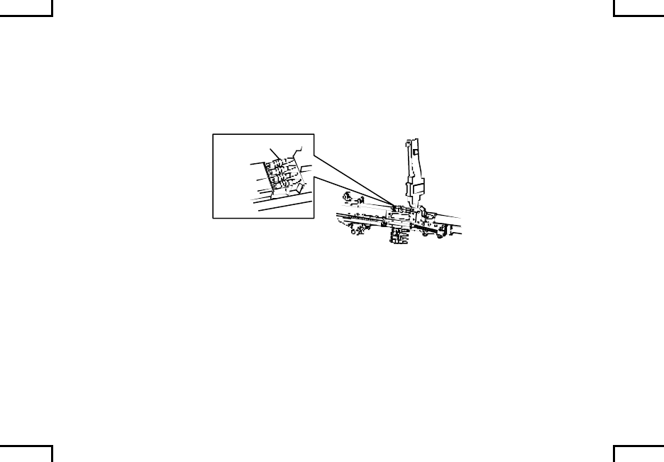
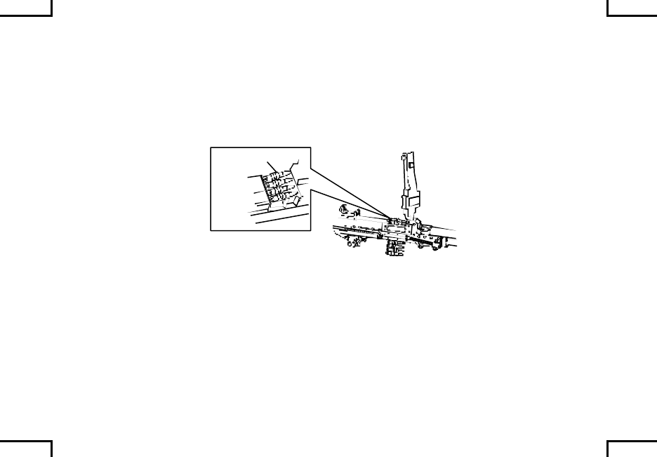
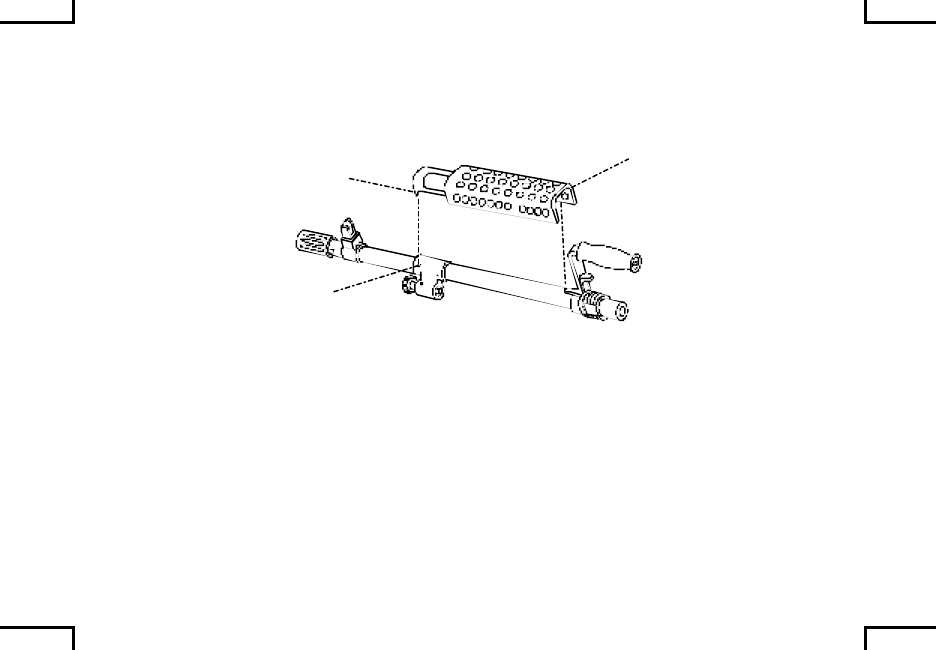
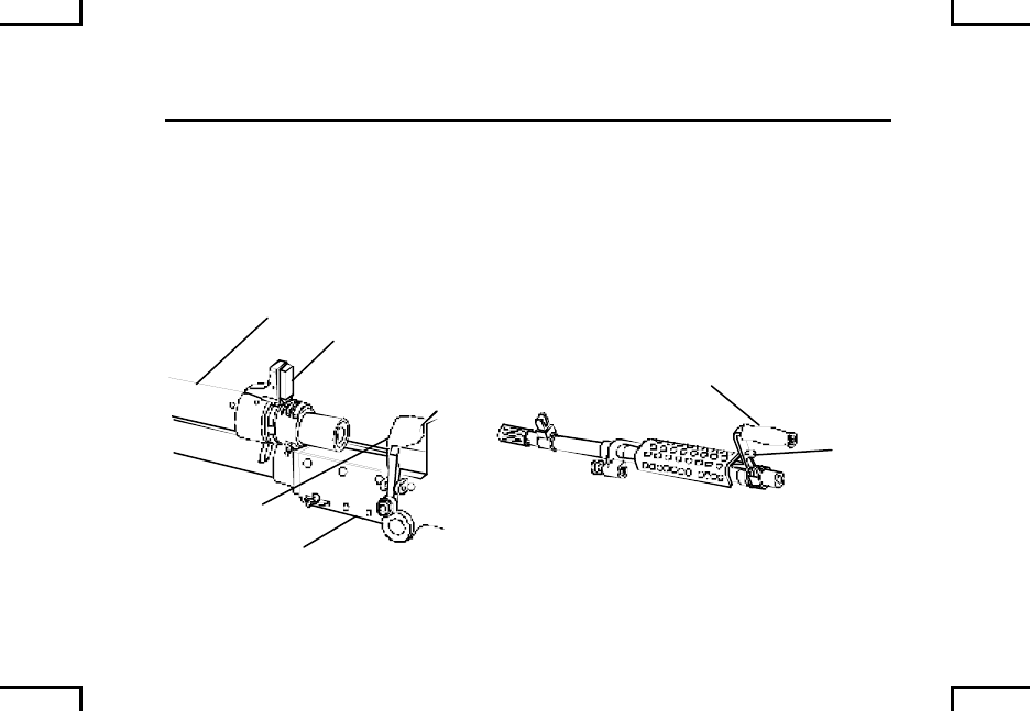
5 B/A Receiver
Assembly
(models as
specif ied)
Inspect mounting points (2).
Check barrel locking latch (3) for
spring tension and locking action (all
models). Externally inspect the
appearance and operation of the
bipod (1) (M240B/M240G). Check
the rear sight (4), the slide assembly
catches, and that the elevation
markings are readable (all models
except M240/M240C).
Any parts are
broken, missing,
or damaged to
the extent it
could cause gun
to malfunction.
132
4
2AN0041
5
0020 00-10
Item
No. Interval
Item to be
Checked/
Serviced
Procedure Not Fully Mission
Capable If:
Check forward rail assembly (5) for
nicks and burrs; movement on
receiver.
Rails will nor
accept optional
devices; rail
assembly moves
on receiver.
NOTE
If gas regulator has to be set to setting #2 or #3 to increase firing rate,
take corrective action and return weapon to primary setting #1 (WP 0008
00).
6 D Machine
Gun (firing
cycle)
Note machine gun firing rate. If firing
cycle slows down, clean and oil
machine gun. Notify unit
maintenance as soon as possible if
machine gun does not function
properly.
If rate of fire can
not be increased
by cleaning; or
changing gas
plug setting (#2
or #3) during
firing, notify unit
maintenance.
0020 00-11
PREVENTIVE MAINTENANCE CHECKS
AND SERVICES (cont) 0020 00
Table 1. Preventive Maintenance Checks and Services (cont)
Item
No. Interval
Item to be
Checked/
Serviced
Procedure Not Fully Mission
Capable If:
7 D Buffer
Assembly/
Buffer and
Spade
Grip
Assembly/
Buttstock
and Buffer
Assembly
If plug becomes loose on buffer
assembly (M240/M240C/M240D/
M240E1) or the buttstock appears
loose (M240B/M240G/M240N),
machine gun needs to be returned to
unit maintenance to ensure proper
assembly.
Plug is loose on
buffer; or
buttstock
appears loose.
BACK PLATE
LATCH
SPRING PIN
2AN0037
0020 00-12
Item
No. Interval
Item to be
Checked/
Serviced
Procedure Not Fully Mission
Capable If:
WARNING
Be sure to clear weapon before disassembling, clearing, inspecting, transporting,
or storing.
8 A Barrel
Assemb-
lies
Check chamber and bore for
obstructions.
Remove heat shield to allow cleaning
and lubrication of barrel assembly
(M240B only) (WP 0021 00).
BARREL
2AN0042
CHAMBER
9 A Machine
Gun (all
models)
Disassemble, clean, inspect,
lubricate, and reassemble machine
gun (WP 0021 00 through WP 0023
00).
Any part is
broken, missing,
or damaged to
the extent that it
could cause gun
to malfunction.
0020 00-13/14 blank
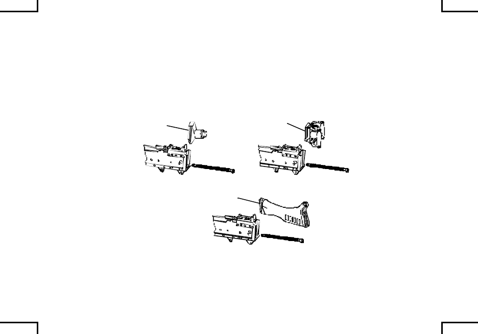
MAINTENANCE PROCEDURES –
FIELD STRIPPING 0021 00
Clear your machine gun. (WP 0010 00)*.
Depress barrel locking latch and hold.
Turn barrel release/carrying handle to upright position.
Remove barrel. Push forward and lift out barrel.
BARREL
RELEASE
BARREL
LOCKING
LATCH BARREL
RELEASE
CARRYING
HANDLE
2AN0043
_______
*To change barrels follow these four steps.
0021 00-1
MAINTENANCE PROCEDURES –
FIELD STRIPPING (cont) 0021 00
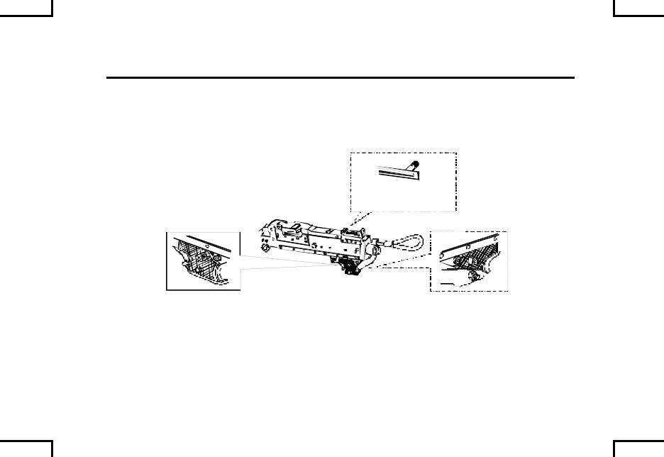
M240B: Remove heat shield assembly from barrel. Lift rear of heat shield
assembly off barrel then pry front tabs out of holes on gas hole bushing.
HEATSHIELD
2AN0044
Depress spring and remove spring pin. (This can usually be done without tools).
SPRING PIN
SPRING
2AN0045
TRIGGER
HOUSING
ASSEMBLY
Pull trigger housing down and back. Pull charge cable through cable guide
(M240/M240C).
0021 00-2
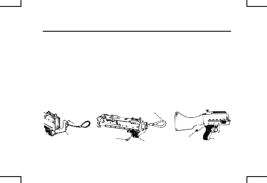
Depress back plate latch and lift buffer/buttstock and buffer assembly/buffer and
spade grip assembly straight up.
Depress driving spring in; up; and out.
M240/M240C
BUFFER
M240D/M240E1
BUFFER AND
SPADE GRIP
ASSEMBLY
M240B (HYDRAULIC BUFFER)/
M240G/M240N
BUTTSTOCK AND
BUFFER ASSEMBLY
2AN0046
0021 00-3
MAINTENANCE PROCEDURES –
FIELD STRIPPING (cont) 0021 00
Depress cover latches and raise cover assembly. Pull cocking handle assembly,
or charging handle assembly (M240/M240C) back; then pull bolt and operating
rod assembly out.
BOLT AND
OPERATING ROD
ASSEMBLY
COVER
ASSEMBLY
CABLE
ASSEMBLY
COCKING HANDLE ASSEMBLY
(ALL MODELS EXCEPT M240/M240C)
COVER
LATCH
2NA0047
0021 00-4
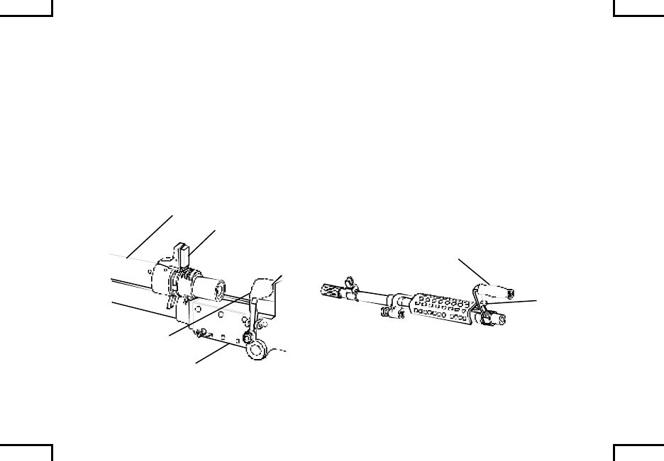
Close cover. Push out spring pin as far as possible with the back or buffer. Then
remove pin with fingers. Depress cover latches, lift upward and remove cover
assembly. Remove feed tray.
M240 M240C
ALL MODELS
EXCEPT M240/M240C
COVER
ASSEMBLY
SPRING
PIN SPRING
PIN
SPRING
PIN
FEED
TRAY
FEED
TRAY
FEED
TRAY
2NA0048
0021 00-5
MAINTENANCE PROCEDURES –
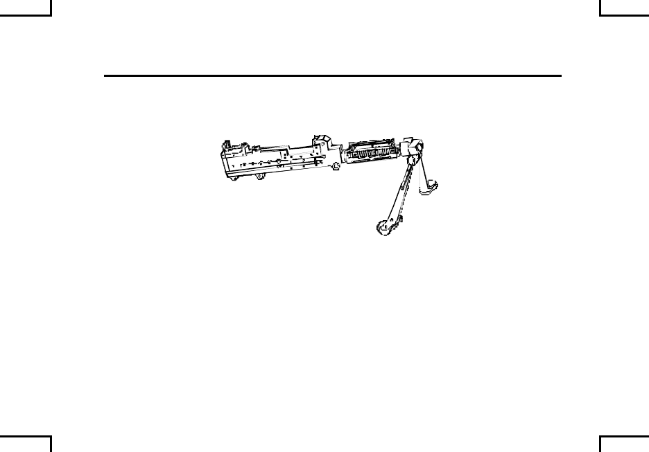
FIELD STRIPPING (cont) 0021 00
M240B/M240G: Extend bipod legs to down and locked position.
2NA0049
END OF WORK PACKAGE
0021 00-6

MAINTENANCE PROCEDURES –
CLEANING INSPECTION, AND REPAIR 0022 00
WARNING
Be sure to clear weapon before disassembling, cleaning,
inspecting, transporting, or storing
Using gasoline, kerosene, hydraulic oil, benzene, bensol, high-
pressure water, steam, or air for cleaning is prohibited.
CAUTION
Do not use abrasives to clean the bore, piston, gas cylinder, or
gas regulator plug.
Do not submerge the buffer in any liquid. Wipe with clean
wiping rag only.
Do not allow cleaning solvents to come in contact with the
rubber handle of the charger cable (M240/M240C).
Do not apply lubricants to composite/rubber components.
0022 00-1
MAINTENANCE PROCEDURES –
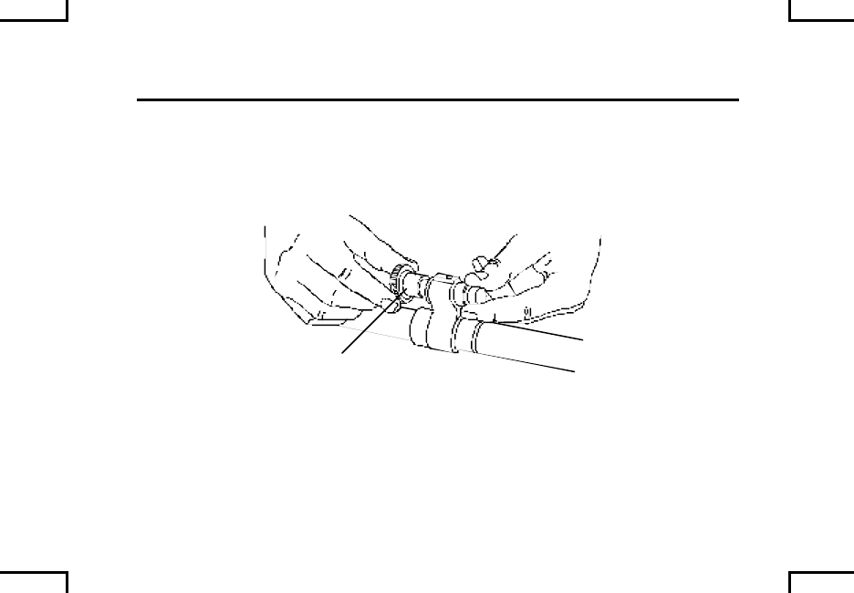
CLEANING INSPECTION, AND REPAIR (cont) 0022 00
BARREL ASSEMBLY
Press in and rotate collar counterclockwise until it releases, then pull it out.
COLLAR
2AN0050
0022 00-2
NOTE
If the plug cannot be removed by hand from the gas regulator,
send the gun to unit maintenance for removal.
Pull gas regulator plug from gas hole bushing.
PLUG
GAS
BUSHING
2AN0051
0022 00-3
MAINTENANCE PROCEDURES –
CLEANING INSPECTION, AND REPAIR (cont) 0022 00
BARREL ASSEMBLY (cont)
USING SCRAPER TO REMOVE CARBON
WARNING
Use care when removing excess carbon, carbon may chip off
and fly into eyes.
Remove cover from scraper.
Insert scraper into center hole of gas regulator plug. Twist scraper clockwise to
remove carbon from center hole until scraper is fully seated against gas regulator
plug.
2AN0052
COVER
SCRAPER PLUG
0022 00-4
Fold scraper and press point into groove. Turn gas regulator plug clockwise to
remove carbon from groove on gas regulator plug.
3
2AN0053
SCRAPER
PLUG
GROOVE
POINT
0022 00-5
MAINTENANCE PROCEDURES –
CLEANING INSPECTION, AND REPAIR (cont) 0022 00
BARREL ASSEMBLY (cont)
USING SCRAPER TO REMOVE CARBON (cont)
Pivot scraper blade 180O to opposite side and place groove tip of scraper into
groove of gas regulator plug and turn clockwise to remove carbon from groove
on plug.
2AN0054
SCRAPER
PLUG
GROOVE
0022 00-6
With tip of scraper, scrape carbon from surface of gas regulator plug.
SCRAPER
PLUG
TIP
2AN0055
0022 00-7
MAINTENANCE PROCEDURES –
CLEANING INSPECTION, AND REPAIR (cont) 0022 00
BARREL ASSEMBLY (cont)
USING REAMER TO REMOVE CARBON
NOTE
When using reamers, apply hand pressure only.
Insert small reamer into each gas inlet hole of gas regulator plug and twist back
and forth to remove the carbon.
2AN0056
SMALL REAMER
LARGE REAMER
PLUG
SMALL REAMER
0022 00-8
Insert large reamer through hole in gas port bushing into gas port hole in barrel;
twist back and forth until reamer enters bore of barrel to remove carbon.
2AN0057
LARGE REAMER
BARREL
0022 00-9
MAINTENANCE PROCEDURES –
CLEANING INSPECTION, AND REPAIR (cont) 0022 00
BARREL ASSEMBLY (cont)
Remove dirt and corrosion from bore using cleaning rod and swab (item 8, WP
0040 00), dampened with CLP (item 1, WP 0040 00). Remove dirt and corrosion
from other parts using wiping rag, (item 7, WP 0040 00) dampened with CLP
(item 1, WP 0040 00) or RBC (item 3, WP 0040 00). Lightly lubricate with CLP
(item 1, WP 0040 00), LAW (item 4, WP 0040 00), LSA (item 6, WP 0040 00), or
LSA-T (item 5, WP 0040 00 (Marine Corp only)).
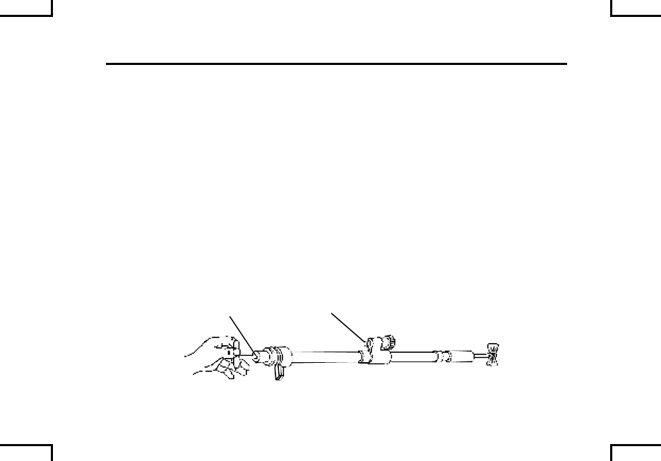
Inspect for cracks, dents, burrs, or other damage on flash hider/suppresser,
barrel adapter, carrying handle, barrel release and front sight.
BARREL RELEASE
BARREL; ADAPTER
CLEANING ROD
FLASH HIDER/
SUPPRESSOR
SWAB
2AN0058
0022 00-10
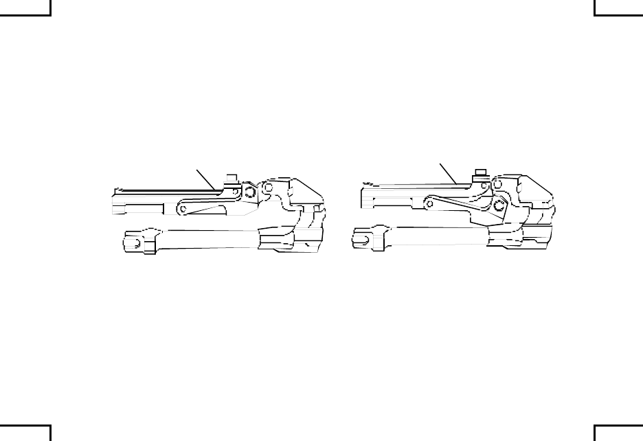
NOTE
Primary setting for gas plug is setting #1 (refer to WP 0008 00).
This design is intended to maintain a consistent rate of fire
under adverse conditions and is not to increase the rate of fire.
Gas inlet setting #1 is the preferred setting for normal
conditions. If gas regulator plug has been set to setting #2 or #3
to increase firing rate, take corrective action and return to
primary setting #1 (WP 0008 00).
Gas regulator may need to be changed to setting #2 for firing
blank ammunition. After cleaning, return to setting #1 for firing
of standard ammunition.
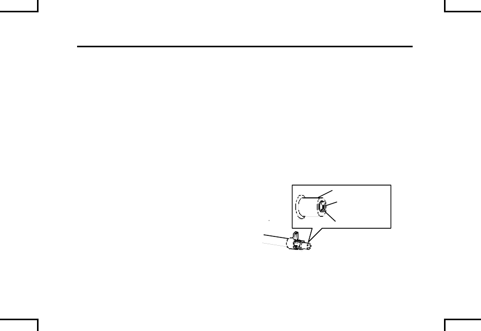
Place gas regulator plug with gas inlet setting #1 hole facing the barrel.
2AN0059
BARREL
PLUG
NUMBER 1
PLUG
0022 00-11
MAINTENANCE PROCEDURES –
CLEANING INSPECTION, AND REPAIR (cont) 0022 00
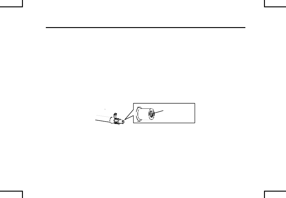
BARREL ASSEMBLY (cont)
Install collar on gas regulator plug. Rotate collar until it slips onto gas regulator
plug. Press in and rotate to lock in place (pull collar to be sure it is in the locked
position).
COLLAR
2AN0050
0022 00-12
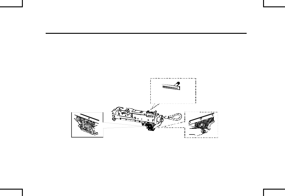
M240B: Install heat shield on barrel. Make sure front tabs snap into hole on gas
hole bushing, then push down onto barrel.
FRONT TABS HEAT SHIELD
ASSEMBLY
GAS BUSHING
HOLE
2AN0060
0022 00-13
MAINTENANCE PROCEDURES –
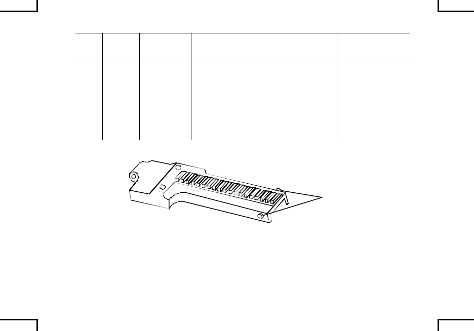
CLEANING INSPECTION, AND REPAIR (cont) 0022 00
COVER ASSEMBLY
CAUTION
Do not use brushes when cleaning cover assembly, use clean
rag only.
Check cover assembly for smooth operation, spring tension, bent, or missing
parts, or excessive wear.
Check accessory mounting rail (if present) for nicks or burrs, which will prevent
proper attachment of optional sighting devices.
O
O
O
O
O
O
O
O
2NA0061
O - LIGHTLY LUBE MOVING PARTS
0022 00-14
Check for bends, cracks, and free movement of cocking handle assembly or
charger cable assembly (M240/M240C), and excessively worn, burred, or
chipped rails. Check barrel locking latch and cover detent for proper spring
tension.
COCKING HANDLE
ALL MODELS EXCEPT
M240/M240C
CHARGER
CABLE
BARREL
LOCKING LATCH
COVER
DETENT
RAILS
RAILS
2AN0062
0022 00-15
MAINTENANCE PROCEDURES –
CLEANING INSPECTION, AND REPAIR (cont) 0022 00
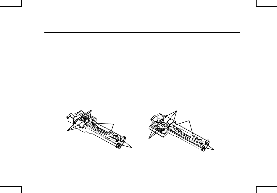
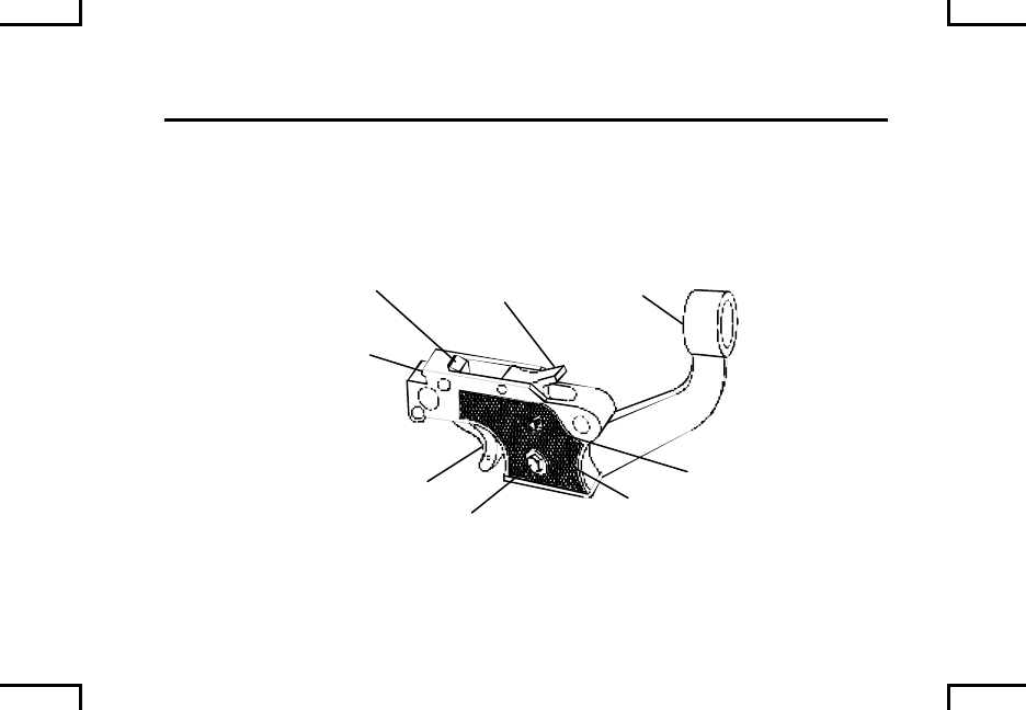
TRIGGER ASSEMBLY
M240/M240C: Check for broken grips, bent cable guide, loose nut and bolt, and
chipped or cracked trigger housing holding lug.
HOLDING
LUD
TRIPPING
LEVER SEAR
TRIGGER
NUT AND
BOLT
GRIP
SAFETY
CABLE
GUIDE
2AN0063
0022 00-16
M240D/M240E1: Check for broken grips, and chipped or cracked trigger housing
holding lug. Check for bent, cracked or broken trigger actuating assembly,
butterfly trigger or actuating arm. Check for loose or missing nut, bolt and
screws.
TRIPPING
LEVER
HOLDING
LUG
SEAR
TRIGGER
ACTUATING
ASSEMBLY
NUT AND
BOLT
GRIP
SAFETY ACTUATOR
ARM
GRIP
SCREW
SCREW
BUTTERFLY
TRIGGER
2AN0064
0022 00-17
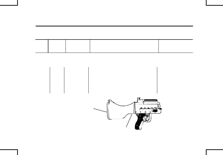
MAINTENANCE PROCEDURES –
CLEANING INSPECTION, AND REPAIR (cont) 0022 00
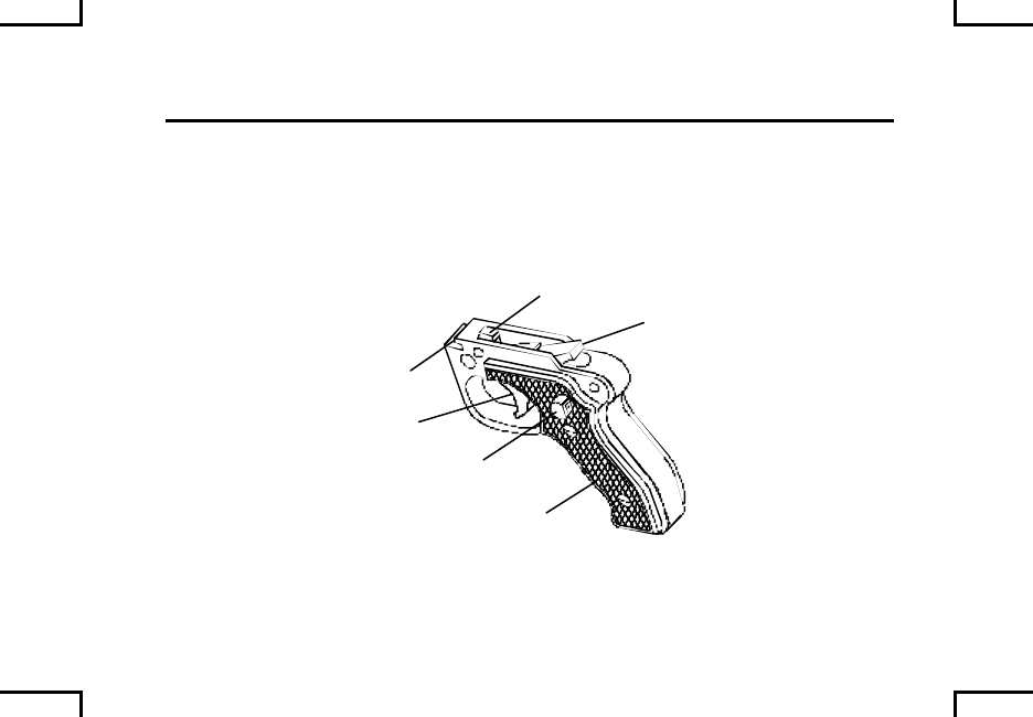
TRIGGER ASSEMBLY
M240B/M240G/M240N: Check for broken grips, and chipped or cracked trigger
housing lug. Ensure trigger guard does not interfere with full operation of trigger.
SAFETY
(FIRE POSITION)
TRIGGER
TRIPPING LEVER
SEAR
2AN0065
GRIP
HOUSING
LUG
0022 00-18

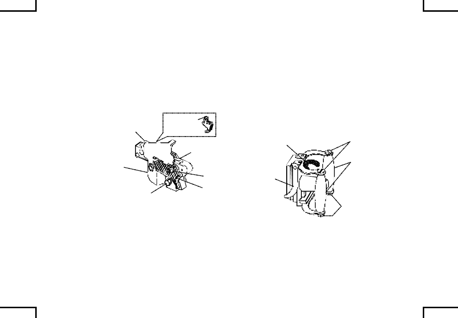
Check tripping lever and sear for burrs, cracks, and wear.
Notify unit maintenance if problems exist.
NOTE
To place safety to “S” safe, the sear must be up.
Check cocking action by pushing back on tripping lever (sear will raise). Pull
trigger (sear will lower).
Check safety functions. When safety in placed to “S” safe, pull trigger (sear will
not lower). When safety is placed to “F” fire, pull trigger (sear will lower).
Lightly lubricate tripping lever and sear surfaces.
0022 00-19
MAINTENANCE PROCEDURES –
CLEANING INSPECTION, AND REPAIR (cont) 0022 00
OPERATING ROD
USING COMBINATION TOOL TO CLEAN CARBON FROM PISTOL HEAD
CAVITY
CAUTION
Do not use abrasives to clean the operating rod piston.
Be sure tool bottom is securely against face of piston.
Insert combination tool into bottom of cavity of piston end of operating rod.
Squeeze handles firm ly and twist combination tool clockwise to remove carbon.
FACE OF
PISTON
COMBINATION
TOOL
TOOL
BOTTOM
OPERATING
ROD
2AN0066
0022 00-20
Insert screwdriver end of combination tool into cavity of piston end of operating
rod to remove carbon residue in bottom of cavity.
Clean all other areas of operating rod, firing pin, and spring pin, with wiping rig
(item 7, WP 0040 00) dampened with CLP (item 4, WP 0040 00). Lightly
lubricate after cleaning.
COMBINATION
TOOL OPERATING
ROD
2AN0067
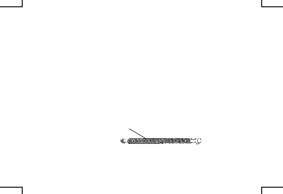
Check bolt and operating rod assembly for burrs, cracks, broken pins, or frozen
roller. Push down on roller to make sure it will retract. Check driving spring for
broken strands. If two or more strands are broken on the same coil or three or
more strands in any location, notify unit maintenance.
0022 00-21
MAINTENANCE PROCEDURES –
CLEANING INSPECTION, AND REPAIR (cont) 0022 00
OPERATING ROD (cont)
USING COMBINATION TOOL TO CLEAN CARBON FROM PISTON HEAD
CAVITY (cont)
NOTE
Do not lubricate face of bolt. Do not lubricate piston.
O – Lightly lubricate driving spring. Lightly lubricate bolt and operating rod
assembly moving parts, polished areas, firing pin, and roller.
FIRING
PIN OO
O
O
PISTON
BOLT AND OPERATING
ROD ASSEMBLY
O
O
DRIVING
SPRING
2AN0068
0022 00-22
RECEIVER
USING COMBINATION TOOL TO CLEAN GAS CYLINDER END OF
RECEIVER BODY
CAUTION
Do not use an abrasive to clean gas cylinder end of receiver.
Insert combination tool with handle upward carefully into the forward end of the
gas cylinder of the receiver body.
GAS
CYLINDER COMBINATION
TOOL
2AN0069
0022 00-23
MAINTENANCE PROCEDURES –
CLEANING INSPECTION, AND REPAIR (cont) 0022 00
RECEIVER (cont)
USING COMBINATION TOOL TO CLEAN GAS CYLINDER END OF
RECEIVER BODY (cont)
CAUTION
If combination tool is not properly seated, it could cause damage
to smaller diameter of gas cylinder.
Be sure the combination tool shoulder is fully inserted and seated against the
forward end of gas cylinder in receiver body.
GAS
CYLINDER COMBINATION
TOOL
2AN0069
0022 00-24
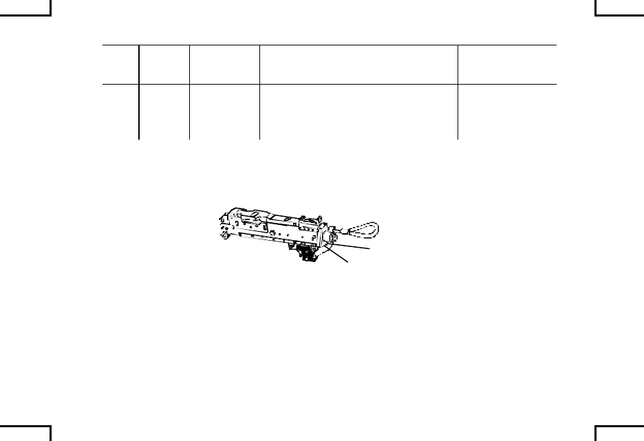
MAINTENANCE PROCEDURES –
CLEANING INSPECTION, AND REPAIR (cont) 0022 00
RECEIVER (cont)
With wiping rag (item 7, WP 0039 00) dampened with CLP (item 1, WP 0040 00)
or RBC (item 3, WP 0040 00), remove dirt and corrosion from area under front
access cover of receiver and all other parts and areas.
Ensure proper operation of ejection port cover (M240B/M240N) and bipod latch
(M240B/M240G).
BIPOD LATCH
ACCESS COVER EJECTION
PORT COVER 2AN0071
END OF WORK PACKAGE
0022 00-26
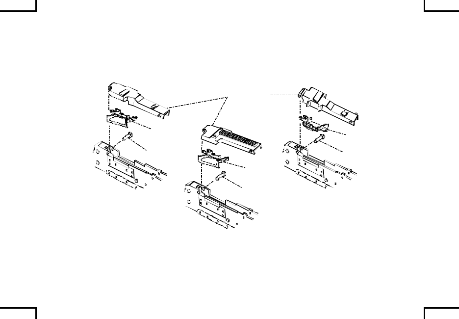
MAINTENANCE PROCEDURES –
REASSEMBLY 0023 00
Position feed tray and cover assembly on receiver; push cover assembly forward;
close cover and insert spring pin.
NOTE
Insert spring pin from right side.
M240 M240C
ALL MODELS
EXCEPT M240/M240C
COVER
ASSEMBLY
SPRING
PIN SPRING
PIN
SPRING
PIN
FEED
TRAY
FEED
TRAY
FEED
TRAY
2NA0048
0023 00-1
MAINTENANCE PROCEDURES –
REASSEMBLY (cont) 0023 00
Open top cover assembly. Set bolt and operating rod assembly on top of rails
(inside receiver). Extend bolt to unlocked position; push the assembly all the way
into the receiver. Close cover assembly and lock.
BOLT AND OPERATING
ROD ASSEMBLY
COVER
ASSEMBLY
UNLOCKED
LOCKED
RECEIVER
BOLT
ASSEMBLY
2AN0072
Insert driving spring into operating rod assembly. Push it in fully and lower it to
seat the stud in hole of receiver.
0023 00-2
NOTE
Be sure operating rod assembly is properly seated in receiver
before operating weapon. Top of buffer/buffer and spade
grip/buttstock should be flush with top of receiver.
Install buffer assembly/buffer or spade grip assembly/buttstock and buffer
assembly and make sure it latches.
M240/M240C
BUFFER
M240D/M240E1
BUFFER AND
SPADE GRIP
ASSEMBLY
M240B (HYDRAULIC BUFFER)/
M240G/M240N
BUTTSTOCK AND
BUFFER ASSEMBLY
2AN0046
0023 00-3
MAINTENANCE PROCEDURES –
REASSEMBLY (cont) 0023 00
NOTE
Charger cable is on the M240/M240C models only.
Pin can be inserted from either side. For M240B/M240G/
M240N insert from right side only.
Place safety in fire position; position front of housing assembly into place
and pivot into position.
Slide charger cable (M240/M240C) through cable guide and position trigger
housing assembly into place. Insert spring pin.
CABLE
GUIDE SPRING
PIN
SPRING
PIN TRIGGER
HOUSING
TRIGGER
HOUSING
CABLE
2AN0073
0023 00-4
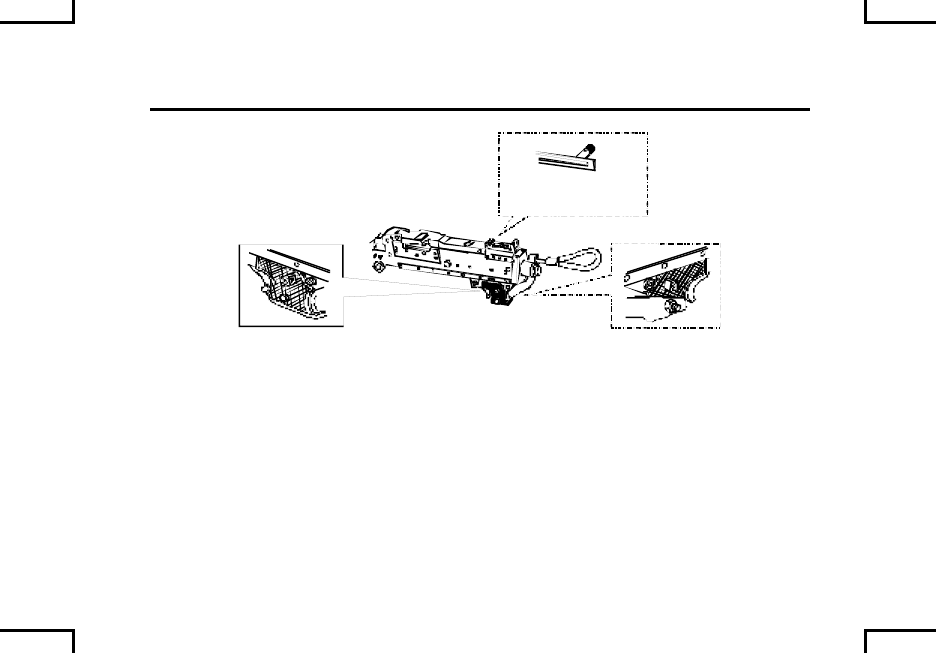
WARNING
Before firing, make sure the barrel is locked tightly in receiver.
If the barrel is not locked tight, threads in receiver could be
damaged or cause personal injury.
NOTE
Barrel must be in upright position when installing barrel.
Insert barrel fully into socket and push barrel release/barrel carrying handle
clockwise as far as it will go.
RECEIVER
SOCKET
BARREL RELEASE
BARREL
BARREL
RELEASE
CARRYING
HANDLE
2AN0074
0023 00-5
MAINTENANCE PROCEDURES –
REASSEMBLY (cont) 0023 00
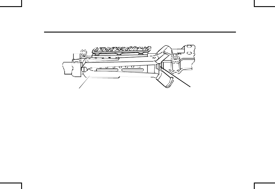
Release barrel release/barrel carrying handle and return to upright position.
Push barrel release/barrel carrying handle clockwise while counting the clicks
(fewer than 2 or more than 7 clicks indicate defective parts) to lock. If barrel
binds in socket or if barrel release/barrel carrying handle will not rotate when
pushed, do not pound on barrel release/barrel carrying handle. Take machine
gun to unit maintenance.
RECEIVER
SOCKET
BARREL RELEASE
BARREL
BARREL
RELEASE
CARRYING
HANDLE
2AN0074
END OF WORK PACKAGE
0023 00-6
MAINTENANCE PROCEDURES –
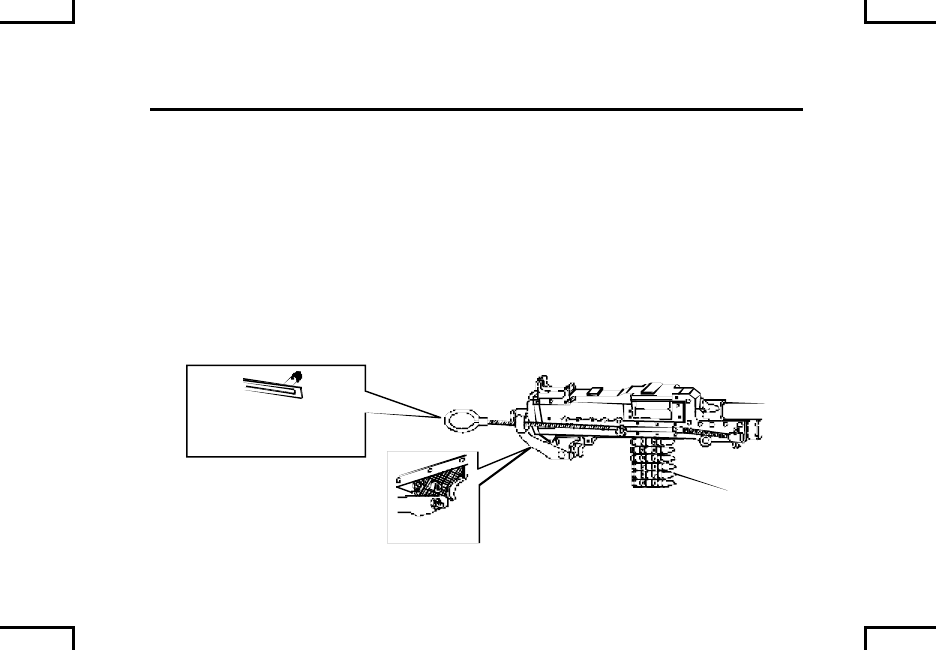
SAFETY/FUNCTION CHECK 0024 00
Place safety to “F” fire. Pull cocking handle (charger cable (M240/MM240C)) to
rear to lock bolt back. Return cocking handle to forward, locked position.
Place safety to “S” safe position, depress trigger, nothing should happen.
S
2AN0015
ALL MODELS EXCEPT
M240/M240C
0024 00-1
MAINTENANCE PROCEDURES –
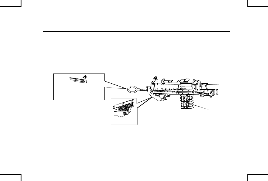
SAFETY/FUNCTION CHECK 0024 00
Place safety to “F” fire. Hold cocking handle assembly (charger cable (M240/
MM240C)) to rear, depress trigger, and ease bolt forward to close and lock.
S
2AN0015
ALL MODELS EXCEPT
M240/M240C
END OF WORK PACKAGE
0024 00-2

LUBRICATION 0025 00
Under all but the coldest artic conditions, LSA (item 6, WP 0040 00), CLP (item
1, WP 0040 00), or LSA-T (item 5, WP 0040 00)(Marine Corps only), are the
lubricants to use on your machine gun. Remember to remove excessive oil from
the bore before firing.
NOTE
Lubrication instructions are mandatory. Do not mix lubricants on
the same weapon. The weapon must be thoroughly cleaned
during change from one lubricant to another. Cleaning solvent
(available to unit maintenance) is recommended for cleaning
during change from one lubricant to another. Only lubricants
and cleaners specified in this manual are authorized for use on
this weapon.
0025 00-1
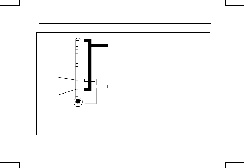
LUBRICATION (cont) 0025 00
+10OF
(-12OC)
-10OF
(-23O
C)
2AN0075
CLP –Cleaner, lubricant and preservative
(item 1, WP 0040 00).
LSA – Weapons lubricating oil, semi-fluid
(item 6, WP 0040 00).
LSA-T – Weapons lubricating oil, semi-
fluid, with Teflon (item 5, WP 0040 00).
Between 10OF (-12OC) and –10OF (-23OC)
use CLP, LSA or LAW. Below –10OF
(-23OC) use only LAW.
LAW – Weapons lubricating oil, artic
(item 4, WP 0040 00).
Lightly lube – A film of oil barely visible to
the eye.
0025 00-2
WARNING
Be sure to clear your weapon before disassembling, cleaning,
inspecting, transporting or storing.
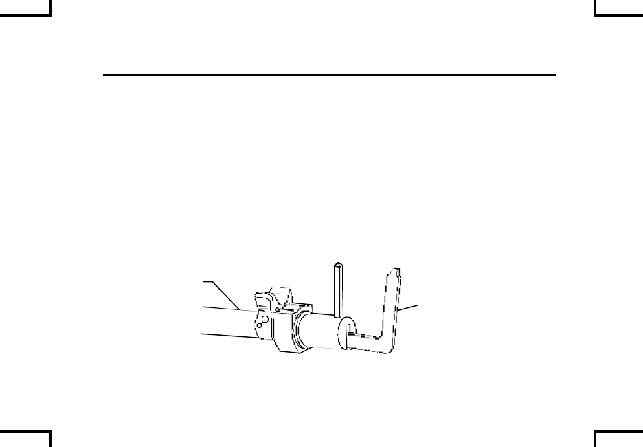
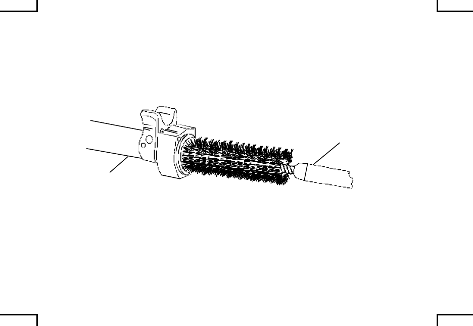
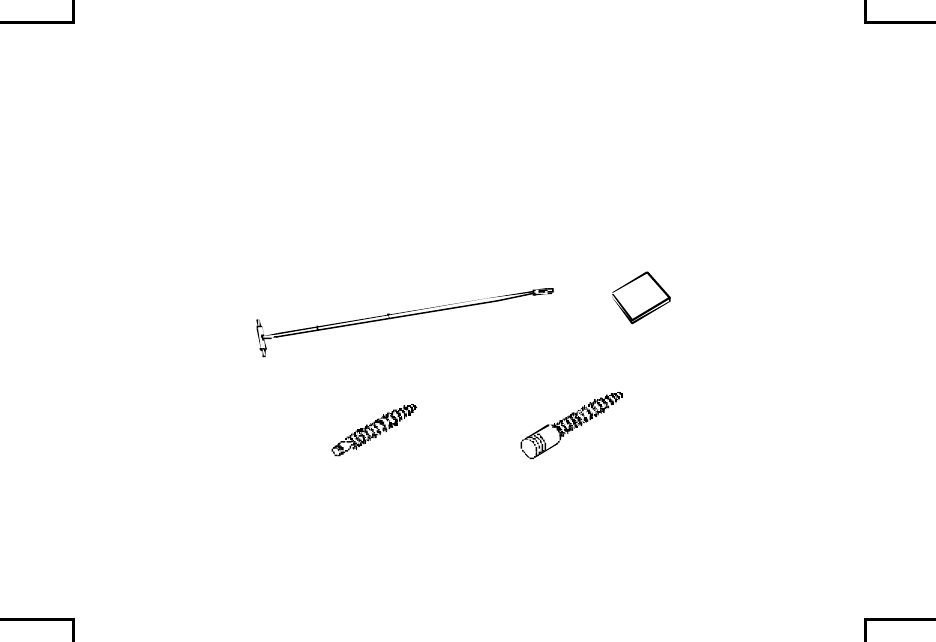
After firing, field strip your machine gun (WP 0021 00). Clean bore and chamber
with cleaning rod, chamber brush, bore brush, and swab (item 8, WP 0040 00)
soaked with RBC (item 3, WP 0040 00) or CLP (item 1, WP 0040 00) until a
clean swab can be run through the bore without getting dirty.
CLEANING ROD SWAB
BORE BRUSH CHAMBER BRUSH
2AN0076
0025 00-3

LUBRICATION (cont) 0025 00
Clean powder-fouled parts, except the buffer, with a wiping rag (item 7, WP 0040
00) dampened with RBC (item 3, WP 0040 00) or CLP (item 1, WP 0040 00).
Wipe dry and lube as required. Inspect and run a lightly oiled swab (item 8, WP
0040 00) through the bore and chamber (WP 0022 00).
If your machine gun isn’t used, it still needs complete cleaning and lubing at least
every 90 days. (Unusual conditions could shorten this interval.)
0025 00-4

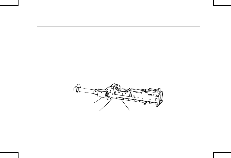
ADJUSTMENT OF SIGHTS 0026 00
GENERAL
NOTE
Perform this adjustment procedure only if barrel assembly/front
sight assembly has been replaced or if there is a new operator.
Proper trigger control is pulling the trigger all the way to the way
to the rear and then releasing completely. Squeezing the trigger
can cause accelerated wear on the trigger tripping lever, sear,
and operating rod leading to a run-away gun.
Check for the following prior to making adjustments:
• Cleanliness of barrel front sight.
• Cleanliness of contact surfaces of the barrel adapter, barrel, and
receiver.
• Rigidity and good condition of the slides and rear sight base.
• Correct assembly of flash hider/suppressor.
• Correct assembly of barrel to receiver.
0026 00-1

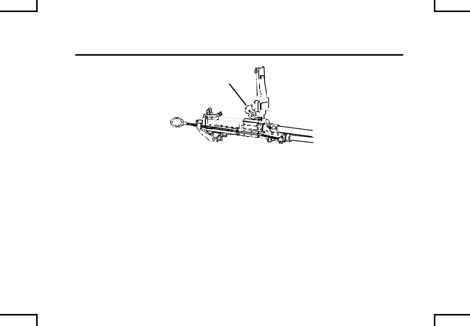
ADJUSTMENT OF SIGHTS (cont) 0026 00
ADJUSTMENT OF SIGHT FOR ELEVATION
Lift the front sight retaining strap to the vertical position using the front sight
adjustment tool.
Rotate the front sight blade one or more half turns using the front sight
adjustment tool.
• At a range of 10 meters, one-half turn of the front sight blade will move
the strike of the round by approximately 0.5 cm (1/5 inch). One full turn
will move the strike of the rounds by approximately 1.0 cm
(approximately 3/8 inch).
• If the center of the shot group is above the point of aim, raise the front
sight blade by turning it counter-clockwise.
• If the center of the shot group is below the point of aim, lower the front
sight blade by turning it clockwise.
0026 00-2
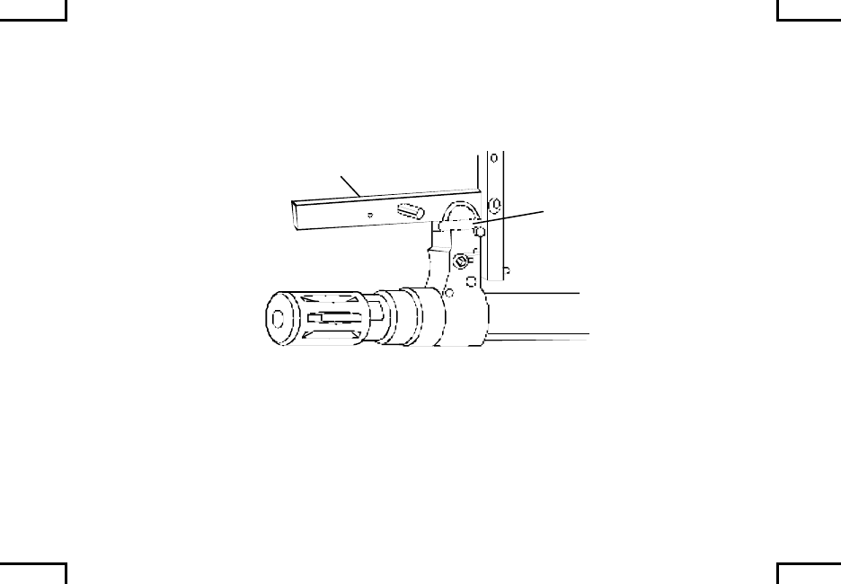
2
1
2AN0077
0026 00-3
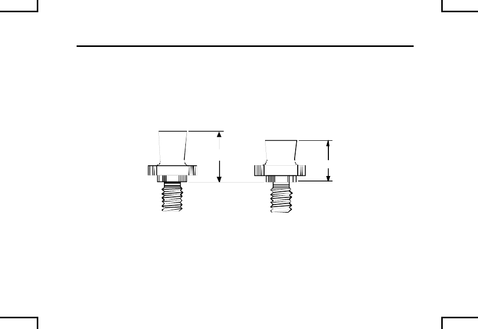
ADJUSTMENT OF SIGHTS (cont) 0026 00
ADJUSTMENT OF SIGHT FOR ELEVATION (cont)
NOTE
There are two types of front sight blades. The number 1 blade
is 9.8 mm tall; the number 2 blade is 11.18 mm tall.
9.8
11.8
21
2AN0078
If the required correction cannot be obtained with the installed front sight blade,
you may need to install the other blade.
0026 00-4

• The maximum unscrewed position of either blade is where the base of
the blade is flush with the front sight protector surface. If the center of
the shot group is still above the point of aim with the number 1 blade
unscrewed to the maximum position, remove it and install a number 2
blade. Start with the number 2 blade at a flush position, two full turns
(clockwise) should approximate the same position as the number 1
blade.
• If the center of the shot group is still below the point of aim with the
number 2 blade screwed all the way in (clockwise), remove it and install
a number 1 blade. Starting with the number 1 blade screwed clockwise,
two full turns (counter-clockwise) should approximate the same position
as the number 2 blade.
• If the center of the shot group cannot be brought to the point of aim after
trying both sight blades, the spare barrel (BII) should be used and a new
barrel assembly acquired. If neither barrel assembly can be adjusted,
the weapon should be coded and turned in through normal channels.
0026 00-5

ADJUSTMENT OF SIGHTS (cont) 0026 00
ADJUSTMENT OF SIGHT FOR WINDAGE
Move the front sight protector to the right or left according to the correction that is
needed.
• At a range of 10 meters, one complete rotation (360O) of the adjusting
screws will move the center of the shot group 0.8 cm (approximately 1/3
inch).
• If the center of the shot group is to the left of the point of aim, move the
front sight protector to the left. To move the front sight protector to the
left, first unscrew the screw on the left side (looking from the rear of the
weapon) of the sight protector more than the number of turns needed
for the sight correction. Then screw in the right side of the front sight
protector the desires number of turns. Finally screw in the left side of
the sight protector fully home.
• If the center of the shot group is to the right of the point of aim, move the
front sight protector to the right. To move the front sight protector to the
right, first turn the hex adjusting screw on the right counter-clockwise to
loosen it the desired amount. Then turn the hex adjusting screw on the
left side clockwise the same number of turns to tighten.
0026 00-6
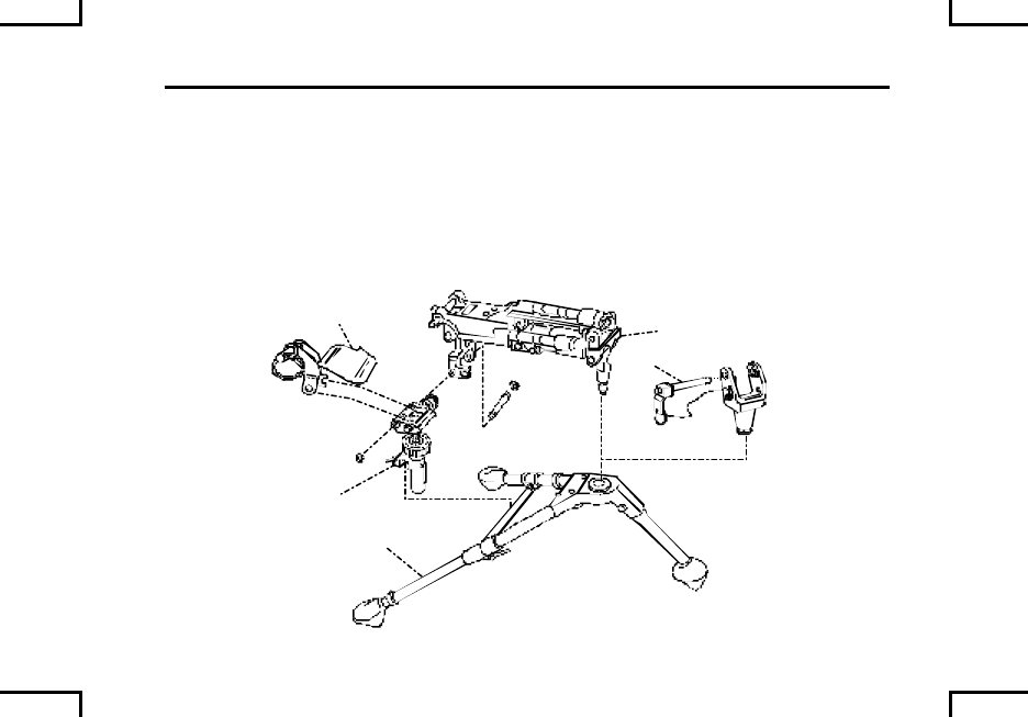
ASSOCIATED EQUIPMENT (M240B/M240G) 0027 00
A – Tripod Leg Assembly.
B – Traversing and Elevating (T&E) Mechanism.
C – Flexible Mount Assembly (M240G only). Houses T&E adapter bracket and
pintle. Absorbs recoil of weapon, improving accuracy.
D – Pintle Mount (M240B).
E - Fork Assembly (M240B).
E
D
C
B
A
2AN0079
0027 00-1/2 blank
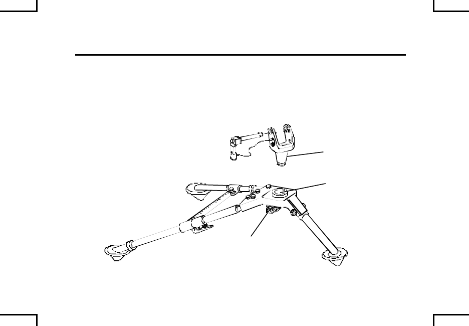
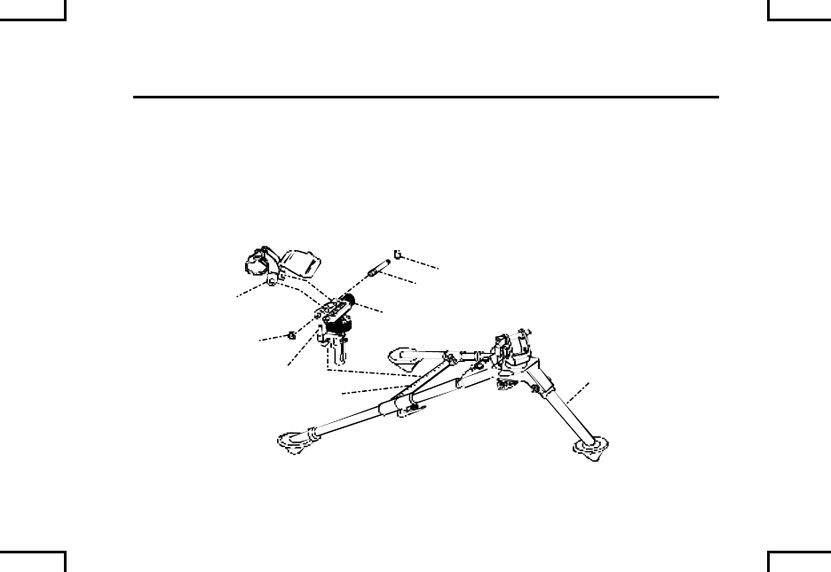
MOUNTING T&E MECHANISM AND
PINTLE ASSEMBLY TO TRIPOD (M122A1) 0028 00
NOTE
Deflector on fork assembly should deflect to the right.
If not already assembled, align holes in fork assembly (4) with holes in T&E (5).
Insert pin (6) through fork assembly and T&E and secure with “C” clamps (7).
2AN0081
45
6
7
7
8
2
9
0028 00-2

Place T&E assembly (5) (with the fork assembly attached) onto the traverse bar
(8) of tripod leg assembly (2). Lock T&E mechanism into place by turning lock
lever (9) clockwise.
NOTE
For maintenance and repair of the M122A1 tripod, refer to TM 9-1005-
245-13&P.
END OF WORK PACKAGE
0028 00-3/4 blank
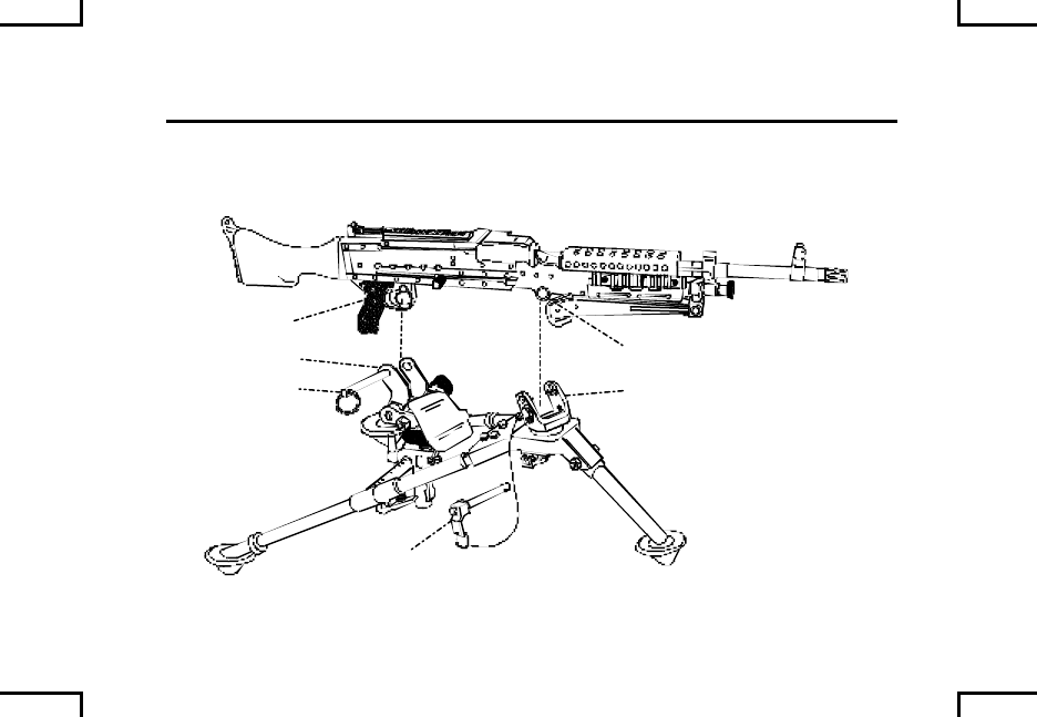
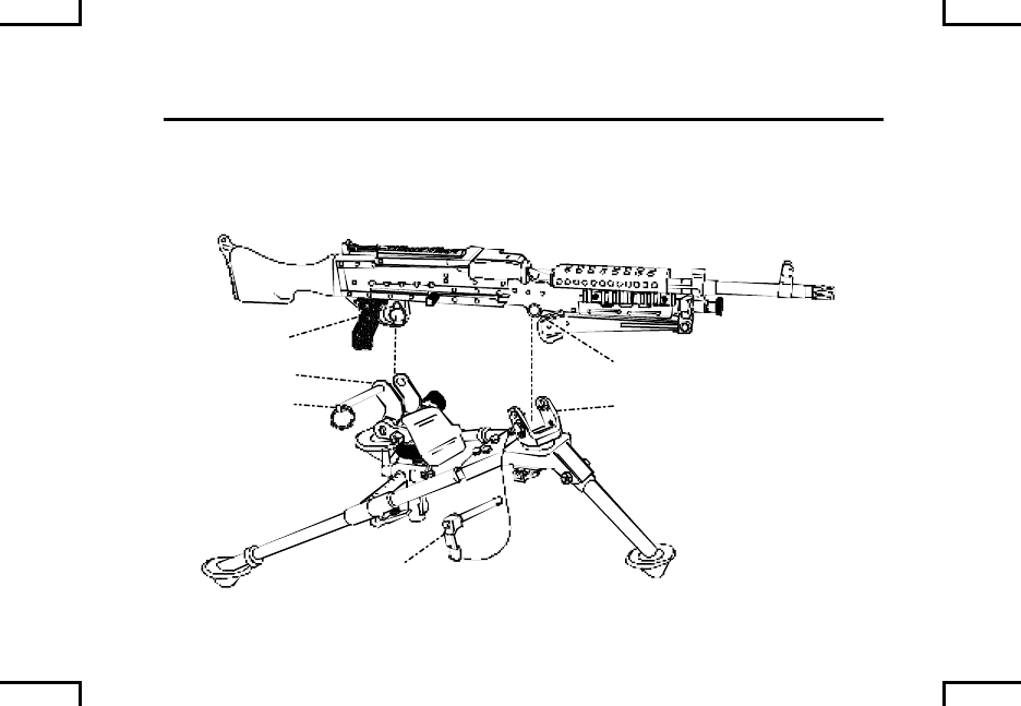
MOUNTING WEAPON ON
M122A1 TRIPOD ASSEMBLY 0029 00
Tilt muzzle down slightly and insert the weapons front receiver bushing (1) into
the slots in the pintle assembly (2). Insert quick release pin (3) through pintle (2)
and front receiver bushing (1).
2AN0082
5
4
6
1
2
3
0029 00-2

Lower the rear of the weapon into the fork assembly (4). Align the mounting hole
(5) in trigger housing with hole in fork assembly (4).
Insert spring pin (6) through the holes in trigger assembly and fork, insuring
weapon is securely attached.
END OF WORK PACKAGE
0029 00-3/4 blank
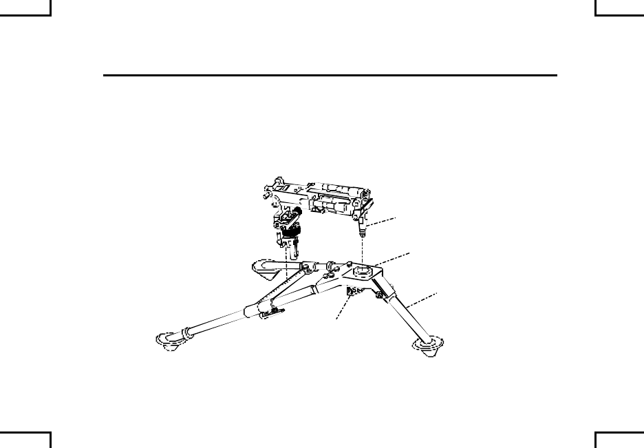
MOUNTING T&E MECHANISM AND
FLEXIBLE MOUNT ASSEMBLY TO M122 TRIPOD 0030 00
Place the pintle (1) of the flexible mount assembly into the sleeve bushing (2) on
the tripod leg assembly (3).
Release the pintle lock (4) on tripod leg assembly to secure the flexible mount
assembly to the tripod leg assembly (3).
1
2
3
4
2AN0084
0030 00-1
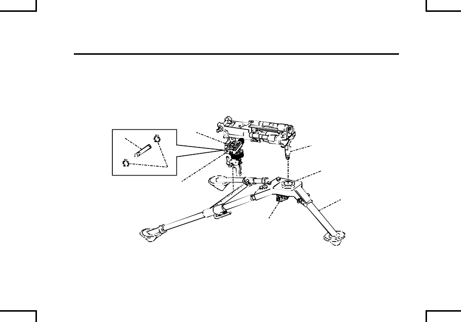
MOUNTING T&E MECHANISM AND
FLEXIBLE MOUNT ASSEMBLY TO M122 TRIPOD 0030 00
If not already assembled, align holes in flexible mount T&E cradle bracket (5)
with holes in T&E (6). Insert pin (7) through cradle bracket and T&E and secure
with “C” clamps (8).
1
2
3
4
2AN0085
5
6
7
8
0030 00-2
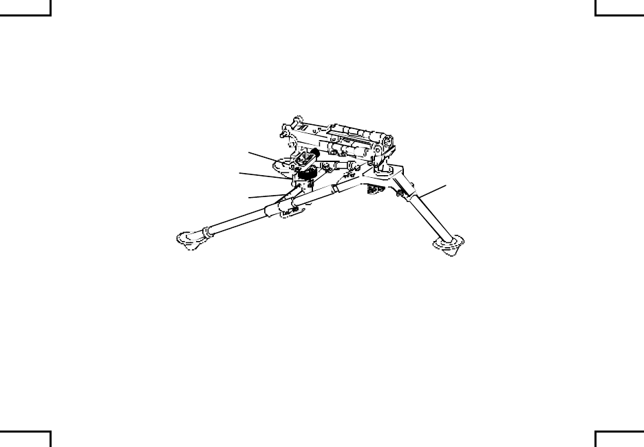
Place T&E assembly (9) (with the flex mount assembly attached) onto the
traverse bar (10) of tripod leg assembly (3). Lock T&E mechanism into place by
turning lock lever (11) clockwise.
2AN0086
3
11
9
10
NOTE
For maintenance and repair of M122 tripod, T&E, and flexible mount
assembly, refer to TM 9-1005-245-13&P.
END OF WORK PACKAGE
0030 00-3/4 blank
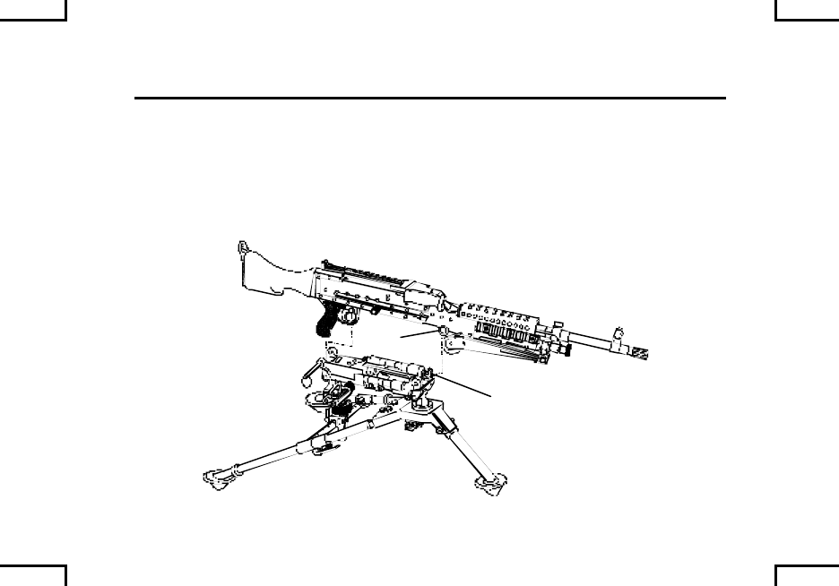
MOUNTING WEAPON ON FLEXIBLE MOUNT
ASSEMBLY AND M122 TRIPOD 0031 00
Position weapon over tripod assembly with flexible mount and T&E mechanism
installed.
Tilt muzzle down slightly and insert the weapons front receiver bushing (1) into
the front cradle slot of the flexible mount assembly (2). Pull the weapon to the
rear to fully seat the receiver bushings in the cradle.
2AN0087
1
2
0031 00-1
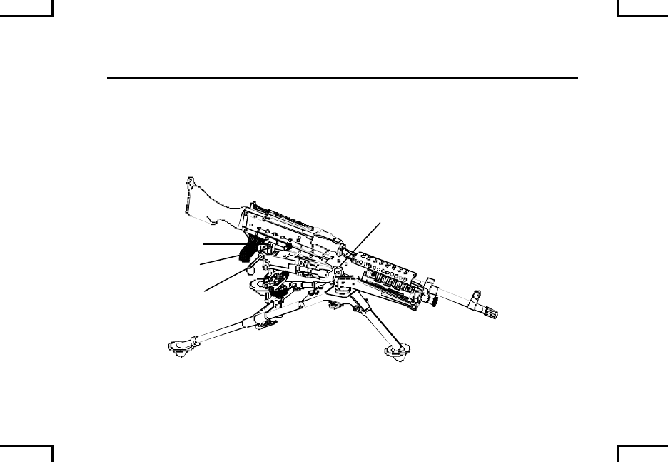
MOUNTING WEAPON ON FLEXIBLE MOUNT
ASSEMBLY AND M122 TRIPOD 0031 00
Lower the rear of the weapon onto the flexible mount assembly (2). Align the
mounting hole (3) in trigger housing with hole in the flexible mount (4).
Insert spring pin (5) through the hole in the flexible mount and receiver assembly.
Ensure weapon is securely attached to the flex mount.
2AN0088
5
4
3
2
END OF WORK PACKAGE
0031 00-2

MOUNTING WEAPON ON M6 PEDESTAL MOUNT
AND M197 MACHINE GUN MOUNT 0032 00
The weapon can be mounted on a M998 High Mobility Multipurpose Wheeled
Vehicle (HMMWV) (Cargo/Troop Carrier).
WARNING
Firing on-the-move is not permitted from the M998.
The canvas cover above the driver and passenger seats should
always be in place when firing.
Ground personnel should not be within 10 meters of the vehicle
when firing.
0032 00-1
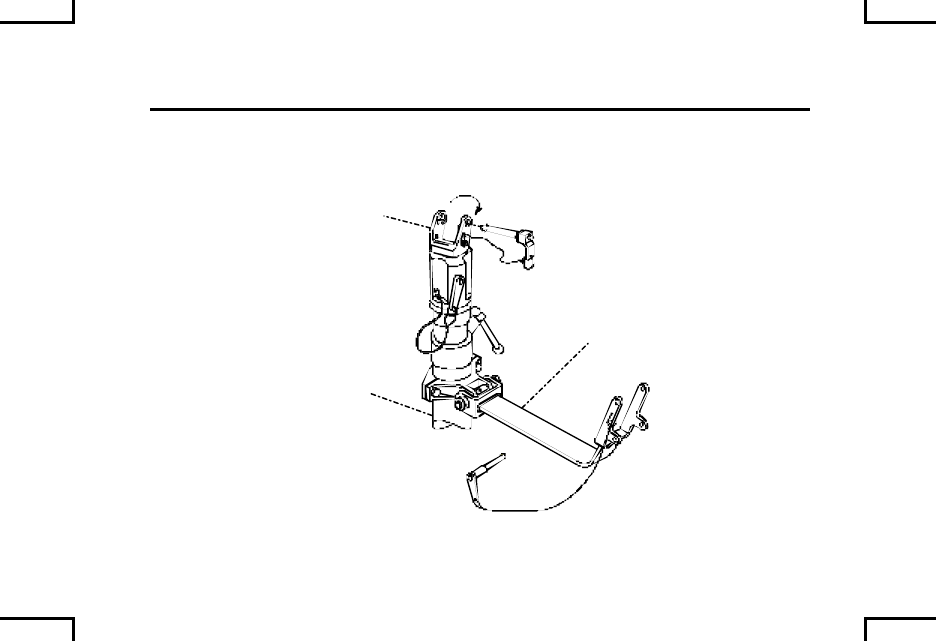
MOUNTING WEAPON ON M6 PEDESTAL MOUNT
AND M197 MACHINE GUN MOUNT (cont) 0032 00
Assure clevis of pintle assembly slants to rear.
PINTLE
M6 PEDESTAL
M197 MOUNT
2AN0089
0032 00-2
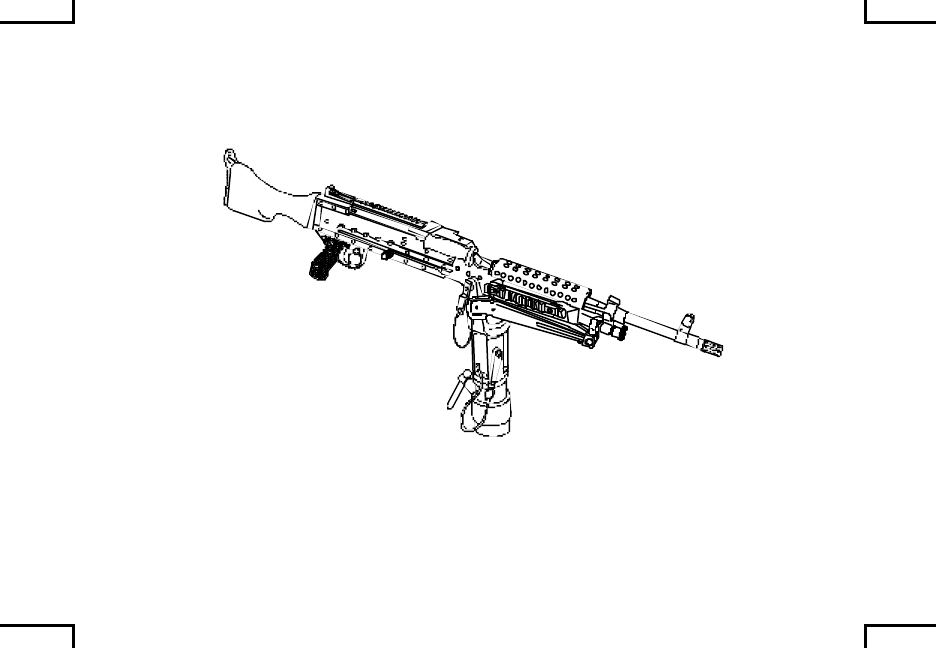
Place weapon in pintle, aligning the front receiver bushing with the holes in the
pintle and secure with quick release pin.
2AN0090
0032 00-3
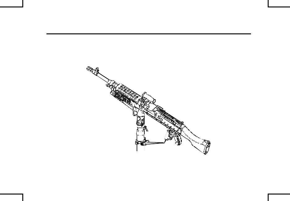
MOUNTING WEAPON ON M6 PEDESTAL MOUNT
AND M197 MACHINE GUN MOUNT (cont) 0032 00
Align the mounting hole in the trigger housing with the holes in the fork of the
mount and secure with quick release pin.
2AN0091
0032 00-4
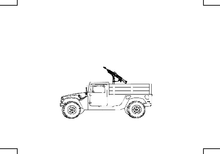
CAUTION
When the weapon is not in use it should be removed from the
pedestal or secured by the travel lock.
NOTE
For mounting instructions of M6 Pedestal and M197 Mounts in
M998 HMMWV’s refer to TM 9-1005-245-13&P.
For maintenance and repair of M6 Pedestal and M197 Mounts,
refer to TM 9-1005-245-13&P.
2AN0092
END OF WORK PACKAGE
0032 00-5/6 blank
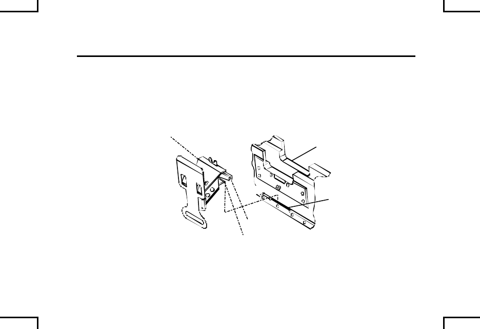
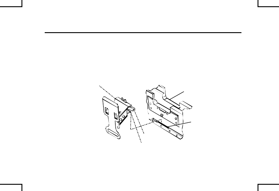
ATTACHMENT OF
AMMUNITION ADAPTER ASSEMBLY (M240B) (cont) 0033 00
Depress lever on the adapter assembly.
Push the adapter toward the receiver until it is against the receiver.
Release lever to allow the adapter assembly to secure itself onto the button on
the receiver.
LIP
LEVER
ADAPTER
ASSEMBLY
SLOT
RECEIVER
2AN0093
END OF WORK PACKAGE
0033 00-2
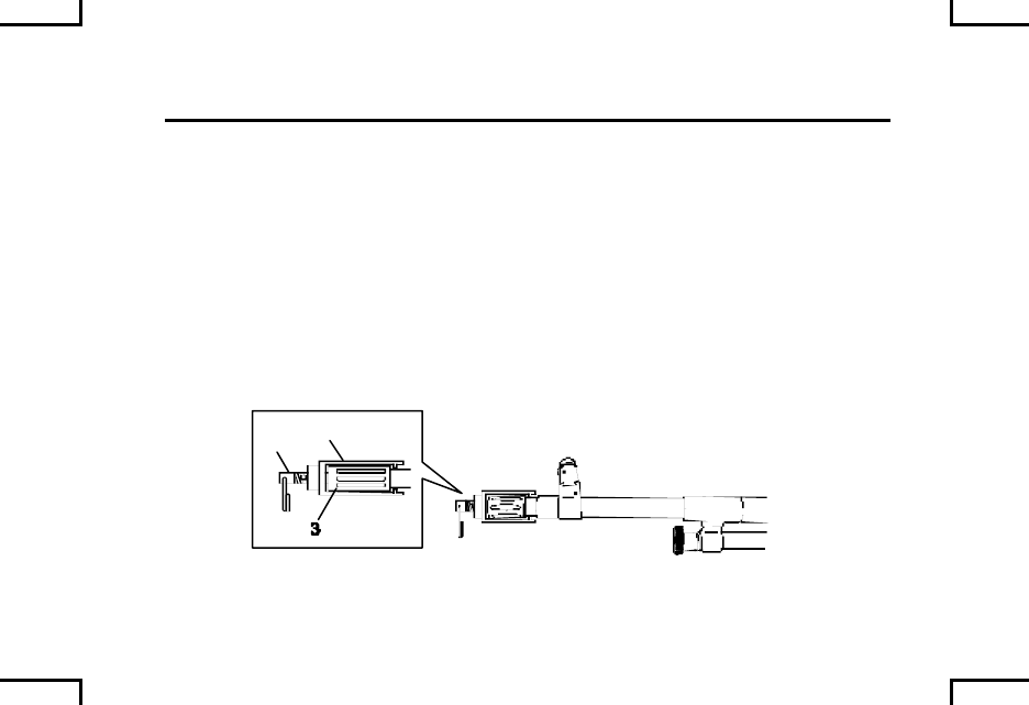
M24 BLANK FIRING ADAPTER (M240B/M240D/M240G/M240N)
AND M21 BLANK FIRING ATTACHMENT (M240/M240C/M240E1) 0034 00
M24 BLANK FIRING ADAPTER
NOTE
Each weapon requires two M24 BFA’s (primary and spare barrel).
ATTACHMENT
Unscrew shaft (1) until it slides all the way to the rear. Install chamber device (2)
over the flash suppressor (3).
Slide shaft (1) into throat of flash suppressor. Engage threads on shaft into body
of chamber device (2); turn clockwise until hand tight.
12
2AN0094
0034 00-1

M24 BLANK FIRING ADAPTER (M240B/M240D/M240G/M240N)
AND M21 BLANK FIRING ATTACHMENT (M240/M240C/M240E1) 0034 00
M24 BLANK FIRING ADAPTER (cont)
REMOVAL
NOTE
Allow barrels to cool until they can be held with bare hands prior
to removing the chamber device from the barrel.
Hold barrel and rotate chamber body (2) approximately 180O to break any carbon
seal between the shaft (1) and the suppressor (3).
Unscrew shaft (1) until threads disengage. Rem ove chamber device from flash
suppressor (3).
12
2AN0094
0034 00-2

M21 BLANK FIRING ATTACHMENT
The following restrictions must be observed to avoid hazardous concentrations of
gases caused while firing the M240 machine gun with the M21 BFA. A blank-fire
mission is limited to 200 rounds fired at a rate of 100 rounds per minute or less in
a 25-round bursts with gas regulator on weapon set at position number 1. Below
are vehicle operating mode/mission restriction requirements.
Table 1. Operating Mode Firing Restrictions
Vehicle System
Engine On
Heater Off
Hatches Open
Blower On
Engine Off
Heater Off
Hatches Open
Blower On
Engine On
Heater On
Hatches Closed
Blower On
M2/M3 BFVS None 7 times/24 hours 14 times/24 hours
LAV 25 (Coax) None 7 times/24 hours 14 times/24 hours
M1 Series Tank
(Coax) None 34 times/24 hours 48 times/24 hours
Effective use of the M21 BFA/M240 machine gun system is greatly dependant on
adherence to the installation instructions and mission scenario limits in the
instructions.
0034 00-3
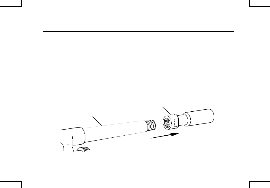
M24 BLANK FIRING ADAPTER (M240B/M240G/M240N)
AND M21 BLANK FIRING ATTACHMENT (M240/M240C/M240E1) 0034 00
ATTACHMENT OF CHAMBER AND DISCRIMINATOR ASSEMBLY
(M2/M3 BFV/M1 SERIES TANK/LAV 25 SERIES (USMC))
CAUTION
Take care not to damage threads on end of barrel. Barrel must
completely cooled before removing flash hider or attaching BFA.
Using 23mm box/open end combination wrench, remove flash hider from barrel
of weapon. Store flash hider in ordnance spare parts bag and place in oddment
tray in vehicle. Be sure to tag flash hider so it will remain with the barrel.
BARREL
FLASH HIDER
2AN0105
0034 00-4
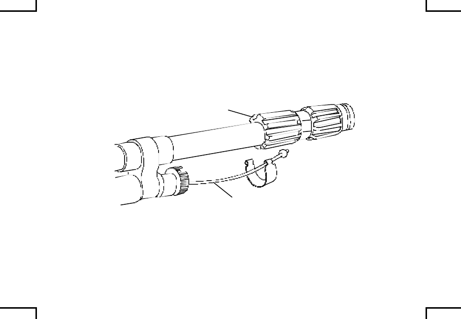
Remove wire rope assembly from chamber.
Screw chamber onto end of barrel and tighten with box/open-end wrench.
Reattach wire rope assembly onto chamber
2AN0106
WIRE ROPE
CHAMBER
0034 00-5
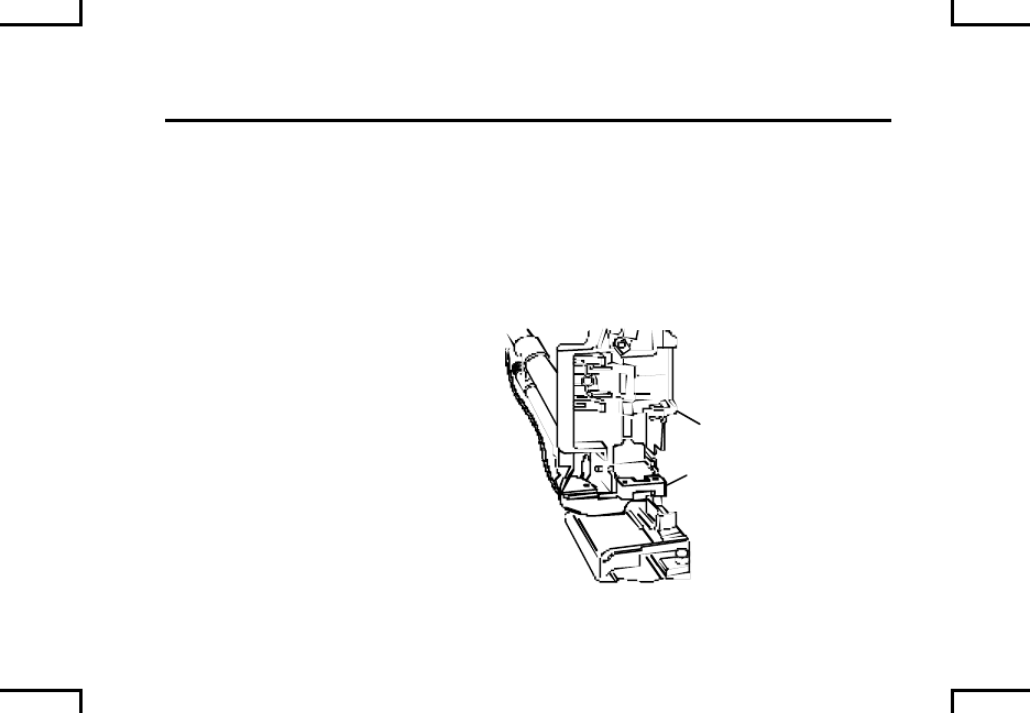
M24 BLANK FIRING ADAPTER (M240B/M240G/M240N)
AND M21 BLANK FIRING ATTACHMENT (M240/M240C/M240E1) 0034 00
ATTACHMENT OF CHAMBER AND DISCRIMINATOR ASSEMBLY
(M2/M3 BFV/M1 SERIES TANK/LAV 25 SERIES (USMC))
WARNING
Discriminator must be in place in feed tray of machine gun when
M21 BFA is in use to prevent live ammo from entering the barrel
chamber.
Open cover on receiver and
place discriminator in feed tray
with slot in discriminator over
front lip of tray.
Closing the cover will retain the
discriminator in place.
2AN0107
DISCRIMINATOR
COVER
0034 00-6

INSTALLATION OF WEAPON ONTO VEHICLE
Install M240C machine gun into BFV mount per TM 9-2350-252-10.
Install M240 machine gun onto exterior mount (M1 Tank) per TM 9-2350-255-10,
or into LAV 25 per TM 08594A-10/2 (USMC only).
Install M240E1 machine gun onto LAV 25 exterior mount per TM 08594A-10/2
(USMC only).
0034 00-7
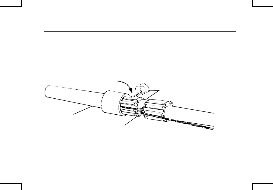
M24 BLANK FIRING ADAPTER (M240B/M240D/M240G/M240N)
AND M21 BLANK FIRING ATTACHMENT (M240/M240C/M240E1) 0034 00
INSTALLATION OF COUPLER ASSEMBLY AND EXTENSION ASSEMBLY
ON M240 (M1 TANK COAX ONLY)
Place coupler assembly over the chamber and clip coupler assembly clamp to
hold in place.
2AN0108
COUPLER
ASSEMBLY CHAMBER
CLAMP
0034 00-8
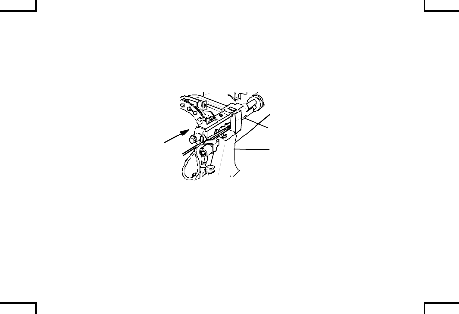
NOTE
If BFA/coupler assembly catches in smoke box, shake gun
slightly as you slide it forward.
Install M240 machine gun onto coax mount of M1 Series tank.
COAX
MOUNT
M240 MG
2AN0109
On outside of turret, loosen clamp on extension assembly so that the inside
diameter of the extension assembly will clear the outside diameter of the coax
mantlet. Do not remove clamp from extension assembly.
0034 00-9
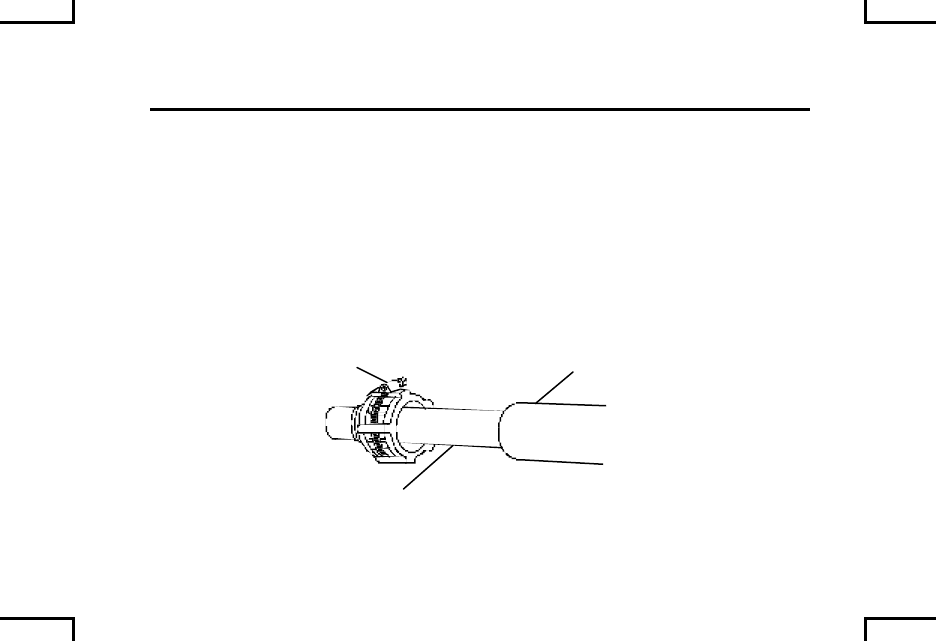
M24 BLANK FIRING ADAPTER (M240B/M240D/M240G/M240N)
AND M21 BLANK FIRING ATTACHMENT (M240/M240C/M240E1) 0034 00
INSTALLATION OF COUPLER ASSEMBLY AND EXTENSION ASSEMBLY
ON M240 (M1 TANK COAX ONLY) (cont)
Slide extension assembly into coax mantlet until extension is over end of coax
mantlet and bottomed. If resistance is encountered during installation, shake
extension assembly slightly while sliding into coax mantlet. Fully seat extension
assembly in place over the coax mantlet.
With clamp positioned over slots in extension assembly, tighten until strap is
snug against the mantlet.
CLAMP
EXTENSION
ASSEMBLY
COAX
MANTLET
2AN0110
0034 00-10

REMOVAL OF WEAPON FROM VEHICLE
Remove M240C machine gun from BFV mount per TM 9-2350-252-10.
Remove M240 machine gun from exterior mount (M1 Tank) per TM 9-2350-255-
10, or into LAV 25 per TM 08594A-10/2 (USMC only).
Remove M240E1 machine gun from LAV 25 exterior mount per TM 08594A-10/2
(USMC only).
0034 00-11
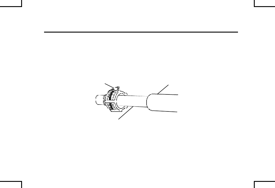
M24 BLANK FIRING ADAPTER (M240B/M240D/M240G/M240N)
AND M21 BLANK FIRING ATTACHMENT (M240/M240C/M240E1) 0034 00
REMOVAL OF COUPLER ASSEMBLY AND EXTENSION ASSEMBLY ON
M240 (M1 TANK COAX ONLY)
Loosen clamp. Slide extension assembly out of coax mantlet. Tighten clamp on
extension assembly.
CLAMP
EXTENSION
ASSEMBLY
COAX
MANTLET
2AN0110
0034 00-12
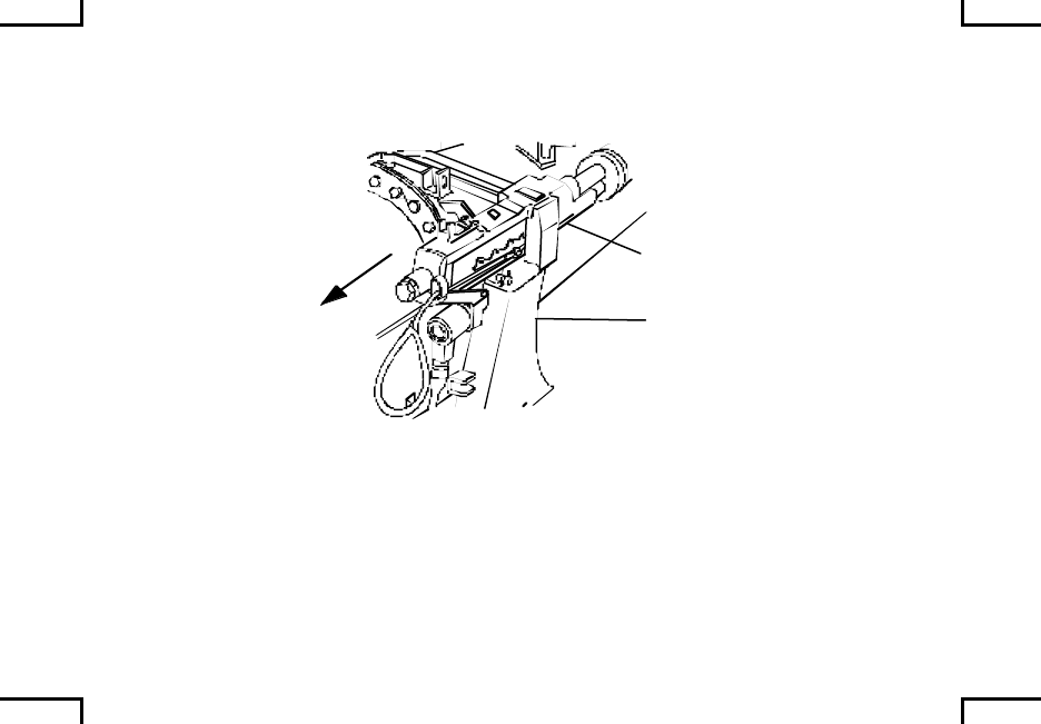
Remove M240 from coax mount per TM 9-2350-255-10.
COAX
MOUNT
M240 MG
2AN0111
0034 00-13
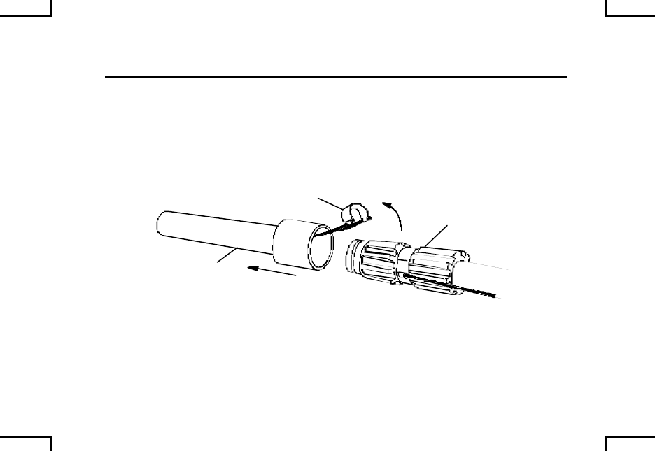
M24 BLANK FIRING ADAPTER (M240B/M240D/M240G/M240N)
AND M21 BLANK FIRING ATTACHMENT (M240/M240C/M240E1) 0034 00
REMOVAL OF COUPLER ASSEMBLY AND EXTENSION ASSEMBLY ON
M240 (M1 TANK COAX ONLY)
Unclip coupler assembly from chamber and remove (M1 Series Tank only).
COUPLER
ASSEMBLY
CLAMP
CHAMBER
2AN0112
0034 00-14
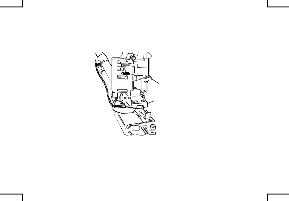
REMOVAL OF DISCRIMINATOR ASSEMBLY
Open cover of machine gun and remove discriminator assembly.
2AN0107
DISCRIMINATOR
COVER
0034 00-15
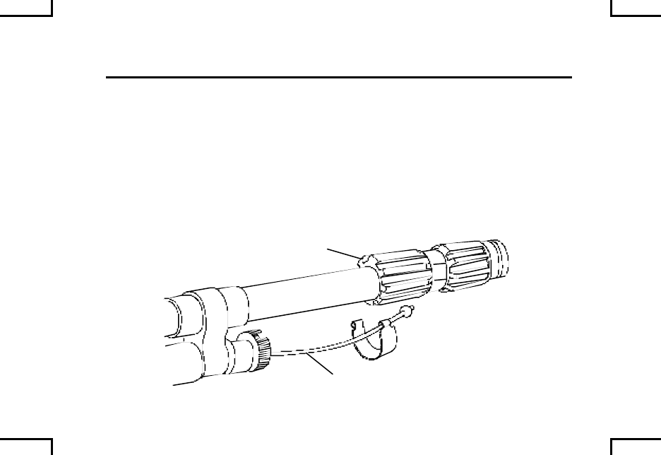
M24 BLANK FIRING ADAPTER (M240B/M240D/M240G/M240N)
AND M21 BLANK FIRING ATTACHMENT (M240/M240C/M240E1) 0034 00
REMOVAL OF DISCRIMINATOR ASSEMBLY (cont)
CAUTION
Do not remove chamber form machine gun barrel until both
items are cooled.
Take care not to damage threads on end of barrel.
Remove wire rope assembly from chamber.
2AN0106
WIRE ROPE
CHAMBER
0034 00-16
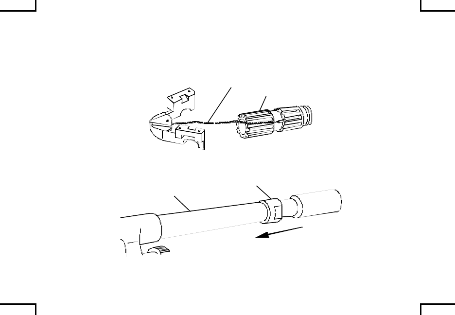
Loosen chamber with box/open-end combination wrench and unscrew from
barrel of weapon.
Replace wire rope assembly on chamber.
LEFT FEED
2AN0113
CHAMBER
WIRE ROPE
Replace flash hider on machine gun barrel.
BARREL FLASH HIDER
2AN0114
0034 00-17/18 blank
EMERGENCY EGRESS PACKAGE (M240D ONLY) 0035 00
The Emergency Egress Package is to be used only on the M240D. The package
consists of the following components:
• Buffer and Buttstock Assembly (1), P/N 12976851
• Trigger Assembly (2), P/N 12976869
• Bipod Assembly (3), P/N 12976883
12
3
2AN0115
0035 00-1

EMERGENCY EGRESS PACKAGE (M240D ONLY) (cont) 0035 00
WARNING
Be sure to clear your weapon before disassembling, clearing,
inspecting, transporting, or storing.
Clear your machine gun (WP 0010 00).
Depress backplate latch and lift buffer and spade grip assembly straight up.
Install buffer and buttstock assembly; make sure it locks in place.
Depress spring on trigger housing pin and remove pin/trigger housing assembly.
Place safety of infantry trigger housing assembly to “F” fire position. Position
front of housing assembly into place and pivot into position; install trigger housing
pin from right to left.
Attach the bipod lag assembly to the receiver by aligning the gaps in the bipod
head with the flanges on the receiver. Swivel the bipod assembly so it s in the
upright position. Drive the retaining pin into the cut-out in the bipod head.
END OF WORK PACKAGE
0035 00-2

AMMUNITION 0036 00
WARNING
This is the only ammunition authorized for use in your machine
gun. If it is not shown, it is not authorized.
Ammunition that fails to fire will be disposed of by authorized
procedures.
BLACK
RED ORANGE
NATO 7.62 AMMO
4-1 COMBAT MIX
M80 M62 M172 M82
IMPROVED
BLANK
DUMMYTRACERBALL
ARMOR
PIERCING
M61/M993
2AN0095
0036 00-1

AMMUNITION (cont) 0036 00
Protect ammunition from mud, sand, and water. If the ammunition gets wet or
dirty, wipe it off at once with a clean, dry, rag (item 7, WP 0040 00). Wipe off
light corrosion as soon as it is discovered. Turn in heavily corroded cartridges.
Do not expose ammunition to the direct rays of the sun. If the powder is hot,
excessive pressure may develop when the weapon is fired.
Do not oil or grease ammunition. Dust and other abrasives that collect on greasy
ammunition may cause damage to the operating parts of the machine gun.
Moreover, oiled cartridges produce excessive chamber pressure.
Do not fire dented cartridges, cartridges with loose bullets, or otherwise defective
rounds.
END OF WORK PACKAGE
0036 00-2


REFERENCES 0037 00
This work package lists all forms, field manuals, and miscellaneous publications
referenced in the manual.
ARMY REGULATIONS
AR 190-11.............................Physical Security of Arms, Ammunition and
Explosives
DEPARTMENT OF THE ARMY PAMPLETS
DA PAM 783-750.................The Army Maintenance Management System (TAMMS)
FIELD MANUALS
FM 21-11...............................First Aid for Soldiers
FM 3-5....................................NBC Decontamination
0037 00-1

REFERENCES (cont) 0037 00
FORMS
DA Form 2402......................Equipment inspection and Maintenance Worksheet
DA Form 2028......................Recommended Changes to Publications and Blank
Forms
SF 368 ...................................Product Quality Deficiency Report
TECHNICAL MANUALS
TM 9-1005-245-13&P..........Operator’s, Unit, and Direct Support Maintenance
Manual with Repair Parts and Special Tools List for
Machine Gun Mounts and Combinations for
Tactical/Armored Vehicles and Ground Mounting
TM 9-2350-252-10 ...............Operator’s Manual for Fighting Vehicle, Infantry,
Bradley
TM 9-2350-255-10 ...............Operator’s Manual for Operator Controls, PMCS, and
Operation Under Usual Conditions
TM 08594A-10/2...................Operator’s Manual for LAV-25
0037 00-2

TM 9-4933-273-12&P..........Operator’s and Unit Maintenance Manual (Including
RPSTL) for Boresighting Equipment, Weapon Small
Arms, M30
TM 9-4933-273-12&P..........Operator’s, Unit and Direct Support Maintenance
Manual (Including RPSTL) for Machine Guns Mounts
and Combinations fro Tactical/Armored Vehicles and
Ground Mounting
TM 750-244-7.......................Procedures for Destruction of Equipment in Federal
Supply Classification 1000, 1005, 1010, 1020, 1030,
1055, 1090, and 1095 to Prevent Enemy Use
MARINE CORPS PUBLICATIONS AND FORMS
TM 4700.15/1........................Equipment Report Procedures
MCO 4855.10 .......................Quality deficiency Report Manual
NAVMC Form 10722 ...........Recommended Changes to Publications
0037 00-3

REFERENCES (cont) 0037 00
RELATED PUBLICATIONS
CTA 8-100.............................Army Medical Department Expendable/Durable Items
CTA 50-970...........................Expendable/Durable Items (Except Medical, Class V,
Repair Parts, and heraldic Items)
END OF WORK PACKAGE
0037 00-4

COMPONENTS OF THE END ITEM
AND BASIC ISSUE ITEMS 0038 00
This work package lists components of the end item and basic issue items for the
machine gun to help you inventory items required for safe and effective operation.
The Components of the End Item (COEI) and Basic Issue Items (BII) lists are
divided into the following:
Components of the End Item (COEI): This is for informational purposes only and
is not authority to requisition replacements. These items are part of the end item
but are removed and separately packaged for transportation or shipment. As part
of the end item, these items must be with the end item whenever it is issued or
transferred between property accounts. Illustrations are furnished to assist you in
identifying the items.
These are the minimum essential items required to place the machine gun in
operation, to operate it, and to perform emergency repairs. Although shipped
separately packaged, BII must be with the machine gun during operation and
whenever it is transferred between property accounts. The illustrations will assist
you with hard to identify items. This manual is your authority to request/
requisition replacement BII, based on TOE/MTOE authorization of the end item.
0038 00-1

COMPONENTS OF THE END ITEM
AND BASIC ISSUE ITEMS (cont) 0038 00
EXPLANATION OF COLUMNS. The following provide an explanation of columns
found in the tabular listings:
Column (1) – Illus. Number, gives you the number of the item illustrated.
Column (2) – National Stock Number, the stock number of the item to be used for
requisitioning purposes.
Column (3) – Description and Usable On Code, identifies the Federal item name
(in capital letters) followed by a minimum description when needed. The last line
below the description is the CAGEC (in parenthesis) and the part number. If the
item you need is not the same for different models of the equipment, a Usable On
Code will appear on the right side of the description column on the same line as
the part number. These codes are identified
CODE USED ON CODE USED ON CODE USED ON
G69 M240 BC2 M240D BJ8 M240N
BB2 M240B AG8 M240E1
L04 M240C BC6 M240G
0038 00-2
Column (4) – U/M, indicates how the item is issued for the National Stock
Number shown in column (2).
Column (5) – Qty Rqd, indicates the quantity required.
Table 1. Components of End Item
(1)
ILLUS
NUMBER
(2)
NATIONAL STOCK
NUMBER
(3)
DESCRIPTION
CAGEC AND PART NUMBER
USABLE
ON CODE
(4)
U/M
(5)
QTY
RQD
1 1005-01-431-8324 ADAPTER, AMMUNITION
(19200) 12976909 BB2 EA 1
2AN0096
1
0038 00-3
COMPONENTS OF THE END ITEM
AND BASIC ISSUE ITEMS (cont) 0038 00
Table 1. Components of End Item (cont)
(1)
ILLUS
NUMBER
(2)
NATIONAL STOCK
NUMBER
(3)
DESCRIPTION
CAGEC AND PART NUMBER
USABLE
ON CODE
(4)
U/M
(5)
QTY
RQD
2 1005-01-439-6899 SLING W/HOOK
ASSEMBLY
(19200) 12976938
BB2 EA 1
2
2AN0097
0038 00-4
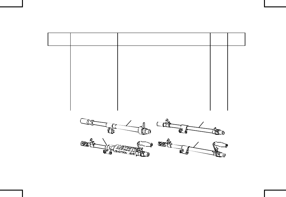
Table 2. Basic Issue Items
(1)
ILLUS
NUMBER
(2)
NATIONAL STOCK
NUMBER
(3)
DESCRIPTION
CAGEC AND PART NUMBER
USABLE
ON CODE
(4)
U/M
(5)
QTY
RQD
1 1005-01-044-1026 BARREL ASSEMBLY
(19200) 11825985 G69,
L04 EA 1
2 1005-01-251-9701 BARREL ASSEMBLY
(19200) 12597035 AG8 EA 1
3 BARREL ASSEMBLY
(19200) 12976817 BB2 EA 1
4 1005-01-408-5897 BARREL ASSEMBLY
(19200) 12976818 BC2,
BC6,
BJ8
EA 1
1
3
2
4
2AN0098
0038 00-5

COMPONENTS OF THE END ITEM
AND BASIC ISSUE ITEMS (cont) 0038 00
Table 2. Basic Issue Items (cont)
(1)
ILLUS
NUMBER
(2)
NATIONAL STOCK
NUMBER
(3)
DESCRIPTION
CAGEC AND PART NUMBER
USABLE
ON CODE
(4)
U/M
(5)
QTY
RQD
5 1005-01-033-3925 BRUSH, CLEANING, GAS
CYLINDER
(19200) 11826118
BC6,
BJ8 EA 1
6 1005-00-556-4174 BRUSH, CLEANING,
SMALL ARMS BORE
(10001) 5564174
BC6,
BJ8 EA 2
7 1005-00-690-3115 BRUSH, CLEANING,
SMALL ARMS CHAMBER
(19205) 7790452
BC6,
BJ8 EA 1
8 1005-00-350-4100 BRUSH, CLEANING,
SMALL ARMS RECEIVER
(19200) 8448466
BC2,
BJ8 EA 1
0038 00-6
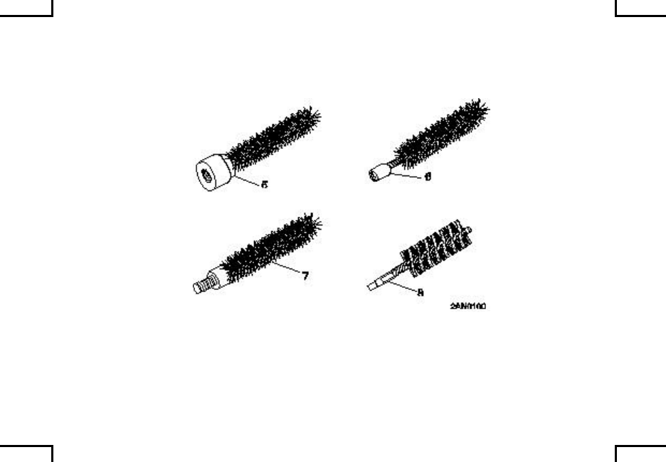
0038 00-7

COMPONENTS OF THE END ITEM
AND BASIC ISSUE ITEMS (cont) 0038 00
Table 2. Basic Issue Items (cont)
(1)
ILLUS
NUMBER
(2)
NATIONAL STOCK
NUMBER
(3)
DESCRIPTION
CAGEC AND PART NUMBER
USABLE
ON CODE
(4)
U/M
(5)
QTY
RQD
9 8465-01-408-5431 CASE, CARRYING,
MACHINE GUN
(0EUP8) SSC/BMG/M240G
BC6 EA 1
10 1005-01-408-5422 CASE , CARRYING,
SPARE BARREL
(0EUP8) SSC/BBB/M240G
BC6 EA 1
11 1005-00-550-6573 CASE, SMALL SRMS
CLEANING ROD
(19204) 5506573
G69,
L04 EA 1
12 1005-01-038-6025 CASE SPARE BARREL
(19200) 11826275 G69,
L04,
AG8
EA 1
13 1005-01-442-8626 CASE, SPARE BARREL
(19200) 12977109 BC2,
BJ8 EA 1
14 1005-01-470-3006 CASE, SPARE BARREL
(19200) 12991853 BB2 EA 1
0038 00-8
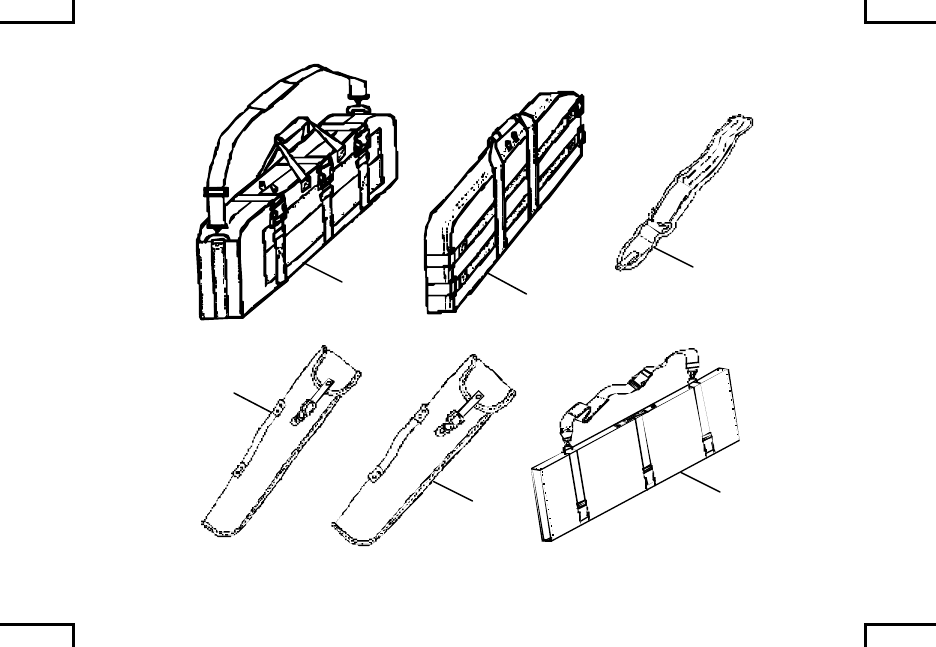
910
11
12
13 14
2AN0101
0038 00-9

COMPONENTS OF THE END ITEM
AND BASIC ISSUE ITEMS (cont) 0038 00
Table 2. Basic Issue Items (cont)
(1)
ILLUS
NUMBER
(2)
NATIONAL STOCK
NUMBER
(3)
DESCRIPTION
CAGEC AND PART NUMBER
USABLE
ON CODE
(4)
U/M
(5)
QTY
RQD
15 4933-01-033-1510 EXTRACTOR, RUPTURED
CARTRIDG CASE
(19200) 11826264
EA 1
16 5340-01-265-2683 HANDLE ASSEMBLY,
CLEANING ROD
(19204) 12900436
BC6,
BJ8,
G69,
L04
EA 1
17 8415-01-092-0039 MITTEN, HEAT
PROTECTIVE M5337
(81349) MIL-M-11199
AG8,
BJ8,
G69,
L04
EA 1
18 5143-00-329-4306 POUCH, MECHANICS
TOOL
(80049) 50J8016
BJ8 EA 5
0038 00-10
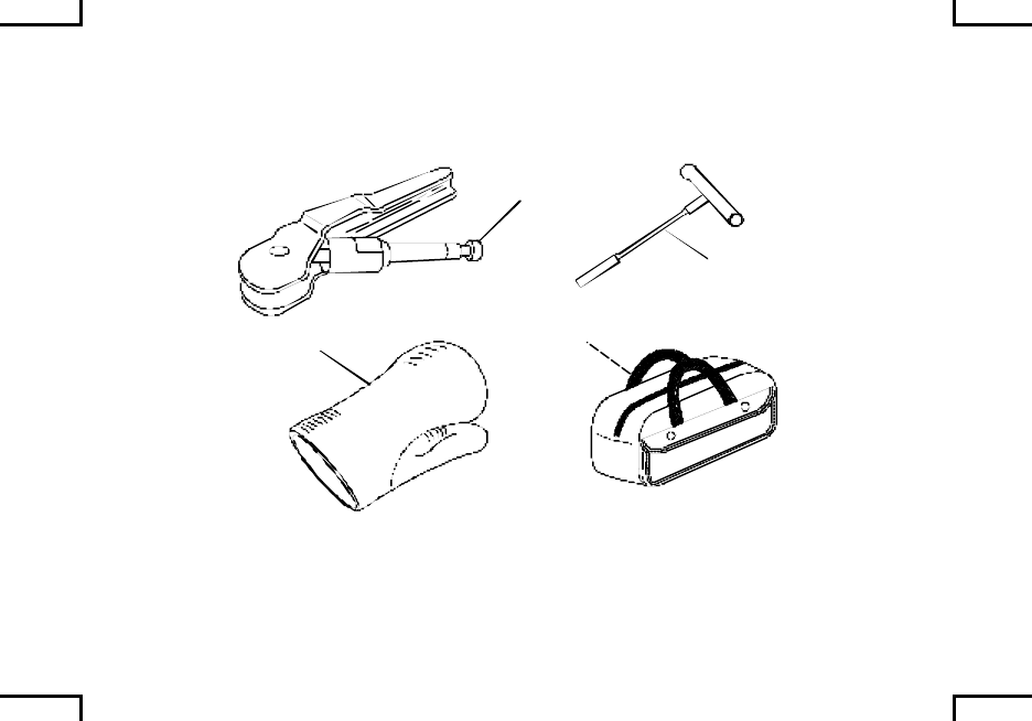
15
16
17
2AN0102
18
0038 00-11

COMPONENTS OF THE END ITEM
AND BASIC ISSUE ITEMS (cont) 0038 00
Table 2. Basic Issue Items (cont)
(1)
ILLUS
NUMBER
(2)
NATIONAL STOCK
NUMBER
(3)
DESCRIPTION
CAGEC AND PART NUMBER
USABLE
ON CODE
(4)
U/M
(5)
QTY
RQD
19 4933-01-047-3394 REAMER
(19200) 11826036 BC6,
BJ8 EA 1
20 1005-00-726-6109 ROD, SECTION,
CLEANING, SMALL ARMS
(19205) 7266109
BC6,
BJ8,
G69,
L04
EA 1
21 4933-01-033-1504 SCRAPER, COMBINAT-
ION REGULATOR
(19200) 11826005
BC6,
BJ8 EA 1
22 1005-01-448-2614 SHIELD ASSEMBLY,
PROTECTIVE
(0EUP8) BB-M240G-HS
BC6 EA 1
23 1005-00-312-7177 SLING ASSEMBLY (W/O
HOOKS)
(19200) 12002983
BC6 EA 1
0038 00-12
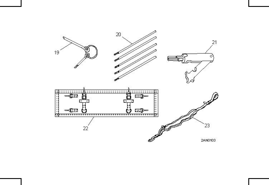
0038 00-13

COMPONENTS OF THE END ITEM
AND BASIC ISSUE ITEMS (cont) 0038 00
Table 2. Basic Issue Items (cont)
(1)
ILLUS
NUMBER
(2)
NATIONAL STOCK
NUMBER
(3)
DESCRIPTION
CAGEC AND PART NUMBER
USABLE
ON CODE
(4)
U/M
(5)
QTY
RQD
24 1005-00-726-6110 SWAB HOLDER SECTION
(19200) 7266110 BC6,
BJ8,
G69,
L04
EA 1
25 1005-01-411-9003 SWIVEL, HOOK, SLING,
CARRYING
(3S679) 3602004460
BC6 EA 2
26 1005-01-458-7004 TOOL, FRONT SIGHT
ADJUSTMENT TOOL
(19200) 12012086
BJ8 EA 1
27 4933-01-033-1503 TOOL, COMBINATION,
SCRAPER AND
EXTRACTOR
(19200) 11826059
BC6,
BJ8 EA 1
28 TM 9-1005-313-10 EA 1
0038 00-14
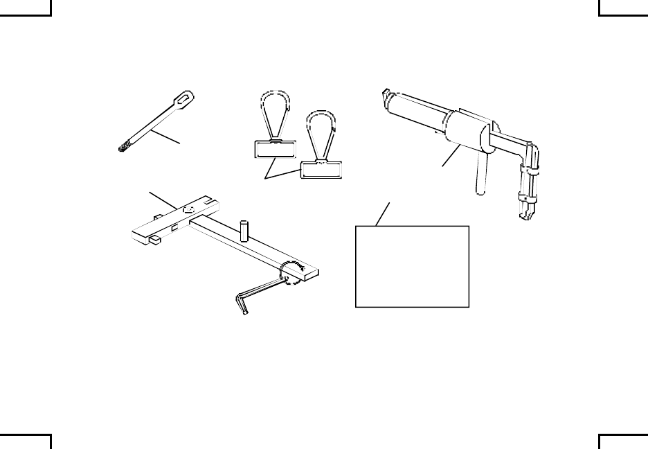
ARMY TM 9-1005-313-10
AIR FORCE T.O. 11W2-6-5-1
MARING CORPS TM 008670A-10/2A
NAVY SW360-AH-OPI-010
Supercedes copy dated 19 July 1996`
OPERATOR'S MANUAL FOR
MACHINE GUN, 7.62, M240 (1005-01-025-08095);
M240B (1005-01-412-3129); M240C (1005-01-085-4758);
M240D (1005-01-418-6995); M240E1 (1005-01-252-4288);
M240G (1005-01-359-2714) M240N (1005-01-493-1666)
DISTRIBUTION STATEMENT C: Distribution authorized to U.S. Government
agencies and their contractors. This publication is required for administration
and operational purposes, as determined 9 Jan 1989. Other request for this
document shall be reffered to: Tank-automotive and Armaments Command,
1 Rock Island Arsenal, Rock island, IL 61299-7630.
HEADQUARTERS, DEPARTMENTS OF THE ARMY,
AIR FORCE, AMRINE CORPS AND NAVY
JUNE 2002
24
25 26
28
27
2AN0104
0038 00-15/16 blank

ADDITIONAL AUTHORIZATION LIST AND
ASSOCIATED EQUIPMENT LIST 0039 00
This work package lists additional items you are authorized for the support of the
machine gun.
This list identifies items that do not have to accompany the machine gun and that
do not have to be turned in with it. These items are all authorized to you by CTA,
MOTE, TDA, or JTA.
EXPLANATION OF COLUMNS. National stock numbers, descriptions, and
quantities are provided to help you identify and request the additional items you
require to support the equipment. The items are listed in alphabetical sequence
by item name under the type document (i.e., CTA, MTOE, TDA, or JTA) which
authorizes the item(s) to you.
0039 00-1

ADDITIONAL AUTHORIZATION LIST AND
ASSOCIATED EQUIPMENT LIST (cont) 0039 00
Table 1. Additional Authorization List
(1)
NATIONAL STOCK
NUMBER
(1)
DESCRIPTION
CAGEC AND PART NUMBER
USABLE
ON CODE
(3)
U/M
(4)
QTY
RQD
CTA AUTHORIZED ITEMS
1005-01-148-7437 BLANK FIRING ATTACHMENT, M21
(19200) 11833471 AG8,
G69,
L04
EA 1
1005-01-480-0289 BLANK FIRING ATTACHMENT, M24
(19200) 12993733 BB2,
BC2,
BC6,
BJ8
EA 2
1005-01-033-3925 BRUSH, CLEANING, GAS
CYLINDER
(19200) 11826118
EA 1
1005-00-556-4174 BRUSH, CLEANING, SMALL ARMS
BORE
(10001) 5584174
EA 2
1005-00-690-3115 BRUSH, CLEANING, SMALL ARMS
CHAMBER
(19205) 7790452
EA 1
0039 00-2

(1)
NATIONAL STOCK
NUMBER
(1)
DESCRIPTION
CAGEC AND PART NUMBER
USABLE
ON CODE
(3)
U/M
(4)
QTY
RQD
1005-00-350-4100 BRUSH, CLEANING, SMALL ARMS
RECEIVER
(19204) 8448466
BB2 EA 1
1005-00-550-6573 CASE, SMALL ARMS CLEANING
ROD
(19304) 5506573
EA 1
5340-01-265-2683 HANDLE ASSEMBLY, CLEANING
ROD
(19204) 12900436
EA 1
8415-01-092-0039 MITTEN, HEAT PROTECTIVE
M5337
(81349) MIL-M-11199
BB2,
BC6 EA 1
4933-01-047-3394 REAMER, CLEANING
(19200) 11826036 EA 1
1005-00-726-6109 ROD SECTION, CLEANING, SMALL
ARMS
(19205) 7266109
EA 5
0039 00-3

ADDITIONAL AUTHORIZATION LIST AND
ASSOCIATED EQUIPMENT LIST (cont) 0039 00
Table 1. Additional Authorization List
(1)
NATIONAL STOCK
NUMBER
(1)
DESCRIPTION
CAGEC AND PART NUMBER
USABLE
ON CODE
(3)
U/M
(4)
QTY
RQD
4933-01-033-1504 SCRAPER, COMBINATION
REGULATOR
(19200) 11826005
EA 1
1005-00-726-6110 SWAB HOLDER SECTION, SMALL
ARMS CLEANING
(19204) 7266110
EA 1
4933-01-033-1503 TOOL, COMBINATION SCRAPER
AND EXTRACTOR
(19200) 11826059
EA 1
0039 00-4

Table 2. Associated Equipment List
(1)
NATIONAL STOCK
NUMBER
(1)
DESCRIPTION
CAGEC AND PART NUMBER
USABLE
ON CODE
(3)
U/M
(4)
QTY
RQD
CTA AUTHORIZED ITEMS
1005-01-413-4098 MOUNT, MACHINE GUN, M197
(19200) 12956264 BB2,
BC6 EA 1
1005-01-411-6341 MOUNT, PEDESTAL, MACHINE
GUN, M6
(19200) 12596270
BB2,
BC6 EA 1
1095-01-466-2065 RACK, STORAGE, SMALL ARMS
(19200) 12991083 BB2,
BC6 EA 1 per 9
weapons
MTOE AUTHORIZED ITEMS
1005-00-710-5599 MOUNT, TRIPOD, MACHINE GUN,
M122
(19200) 7790723
BC6 EA 1
1005-01-433-1617 MOUNT, TRIPOD, MACHINE GUN,
M122A1
(19200) 12976949
BB2 EA 1
0039 00-5
Table 2. Associated Equipment List (cont)
(1)
NATIONAL STOCK
NUMBER
(1)
DESCRIPTION
CAGEC AND PART NUMBER
USABLE
ON CODE
(3)
U/M
(4)
QTY
RQD
MTOE AUTHORIZED ITEMS (cont)
1005-01-411-6340 FLEXIBLE MOUNT ASSEMBLY
(19200) 12976940 BC6 EA 1
END OF WORK PACKAGE
0039 00-6

EXPENDABLE/DURABLE SUPPLIES
AND MATERIALS LIST 0040 00
This work package lists expendable/durable supplies and materials you need to
operate and maintain the machine gun. This is for informational purposes only
and is not authority to requisition the listed items. These items are authorized to
you by CTA 50-970, Expendable/Durable Items (Except Medical, Class V, Repair
Parts, and Heraldic items); or CTA 8-100, Army Medical Department Expendable/
Durable Items.
EXPLANATION OF COLUMNS.
Column (1) – Item Number. This number is assigned to the entry in the listing and
is referenced in the narrative instructions to identify the material (e.g., “Use
cleaner, lubricant and preservative (item 1, WP 0000 00)”).
Column (2) – Level. This column identifies the lowest level of maintenance that
requires the listed item.
C – Operator/Crew
Column (3) –National Stock Number. This is the National Stock Number assigned
to the item; use it to requisition the item.
0040 00-1

EXPENDABLE/DURABLE SUPPLIES
AND MATERIALS LIST (cont) 0040 00
Column (4) – Description. Indicates the Federal item name and, if required, a
description to identify the item. The last line for each item indicates the
Contractor and Government Entity Code (CAGEC) in parentheses followed by
the part number.
Column (5) - Unit of Measure (U/M). Indicates the measure used in performing
the actual maintenance function. This measure is expressed by a two-character
alphabetical abbreviation (e.g., EA, IN, PR). The unit of measure differs from the
unit of issue, requisition the lowest unit of issue that will satisfy your requirements.
0040 00-2

Table 1. Expendable/Durable Supplies List
(1)
ITEM
NO.
(2)
LEVEL
(3)
NATIONAL STOCK
NUMBER
(4)
DESCRIPTION
(5)
U/M
1 C
9150-01-102-1473
9150-01-079-6124
CLEANER, LUBRICANT AND
PRESERVATIVE, grade 2, (CLP)
(81349) MIL-PRF-63460
½ oz bottle
4 oz bottle
EA
EA
2 C
9920-00-292-9946
CLEANER, TOBACCO, PIPE
(92849) DILLS
1 pkg (32 per pkg)
(Marine Corps only)
EA
3 C
6850-00-224-6656
6850-00-224-6657
CLEANING COMPOUND,
SOLVENT: rifle bore cleaner (RBC)
(81349) MIL-PRF-372
2 oz can
6 oz can
EA
EA
4 C
9150-00-664-0038
LUBRICATING OIL, WEAPONS
(LAW)
(81349) MIL-PRF-14107
4 oz
EA
0040 00-3

EXPENDABLE/DURABLE SUPPLIES
AND MATERIALS LIST (cont) 0040 00
Table 1. Expendable/Durable Supplies List (cont)
(1)
ITEM
NO.
(2)
LEVEL
(3)
NATIONAL STOCK
NUMBER
(4)
DESCRIPTION
(5)
U/M
5 C
9150-00-949-0323
LUBRICATING OIL, WEAPONS
semi-fluid w/Teflon (LSA-T)
(81349) MIL-L-46150
8 oz bottle
(Marine Corps only)
EA
6 C
9150-00-889-3522
LUBRICATING OIL, WEAPONS
Semi-fluid (LSA)
(19204) MIL-L-46000
4 oz bottle
EA
7 C
7920-00-205-1711
WIPING RAG: cotton
(58536) A-A-531
50 lb bdl
LB
0040 00-4

(1)
ITEM
NO.
(2)
LEVEL
(3)
NATIONAL STOCK
NUMBER
(4)
DESCRIPTION
(5)
U/M
8 C
1005-00-288-3565
SWAB, SMALL ARMS CLEANING:
cotton
(19204) 5019316
1pkg (1000 per pkg)
EA
9 C
6920-00-078-5126
TARGET, BASIC MACHINE GUN
QUALIFICATION/10 METER
QUALIFICATION TARGET
(19204) 8426940
1box (200 per box )
(Marine Corps only)
BX
0040 00-5/6 blank

ALPHABETICAL INDEX 0041 00
WP/Page
A
Additional Authorized List and Additional Equipment List.............WP 0039 00-1
Adjustment of Sights............................................................................WP 0026 00-1
Ammunition ...........................................................................................WP 0036 00-1
Ammunition Adapter Assembly, Attachment of (M240B) ..............WP 0033 00-1
Associated Equipment.........................................................................WP 0027 00-1
C
Cleaning, Inspection, and Repair......................................................WP 0022 00-1
Components of End Item and Basic Issue Items Lists ..................WP 0038 00-1
Corrosion Prevention and Control.....................................................WP 0004 00-1
D
Destruction of Material to Prevent Enemy Use...............................WP 0005 00-1
E
Equipment Description and Data.......................................................WP 0007 00-1
Expendable/Durable Supplies and Materials List...........................WP 0040 00-1
0041 00-1

ALPHABETICAL INDEX (cont) 0041 00
WP/Page
F
Field Strip..............................................................................................WP 0021 00-1
H
How to Use This Manual.....................................................................vii
L
List of Effective Pages.........................................................................A
Lubrication Instructions .......................................................................WP 0025 00-1
M
M24 Blank Firing Adapter and
M21 Blank Firing Attachment........................................................WP 0034 00-1
Maintenance Forms, Records and Reports .....................................WP 0002 00-1
Mounting T&E Mechanism and
Pintle Assembly to Tripod (M122A1) ...........................................WP 0028 00-1
Mounting T&E Mechanism and
Flexible Mount Assembly to Tripod..............................................WP 0030 00-1
0041 00-2

M(cont)
Mounting Weapon on Flexible Mount Assembly on Tripod...........WP 0031 00-1
Mounting Weapon on M122A1 Tripod Assembly...........................WP 0029 00-1
Mounting Weapon on M6 Pedestal Mount and
M197 Machine Gun Mount............................................................WP 0032 00-1
O
Operation Under Usual Conditions ...................................................WP 0009 00-1
Bipod Operation (M240B/M240G)) ..............................................WP 0011 00-1
Clearing............................................................................................WP 0010 00-1
Definitions.........................................................................................WP 0012 00-1
Immediate Action ............................................................................WP 0013 00-1
Loading.............................................................................................WP 0009 00-1
Remedial Action..............................................................................WP 0014 00-1
Runaway Machine Gun..................................................................WP 0015 00-1
Ruptured Cartridge Case...............................................................WP 0017 00-1
Stuck Cartridge Case or Live Round ...........................................WP 0016 00-1
Operation Under Unusual Conditions ...............................................WP 0018 00-1
P
Preparation for Storage and Shipment.............................................WP 0006 00-1
Preventive Maintenance Checks and Services...............................WP 0020 00-1
0041 00-3

ALPHABETICAL INDEX (cont) 0041 00
WP/Page
R
References ............................................................................................WP 0037 00-1
Reporting Equipment Improvement Recommendations................WP 0003 00-1
S
Safety/Function Check........................................................................WP 0024 00-1
T
Technical Principles of Operation......................................................WP 0008 00-1
Troubleshooting Procedures:
Fails to chamber..............................................................................WP 0019 00-10
Fails to fire........................................................................................WP 0019 00-13
Fails to fire on initial burst..............................................................WP 0019 00-2
Failure to cock or runaway gun.....................................................WP 0019 00-17
Failure to eject.................................................................................WP 0019 00-15
Failure to extract..............................................................................WP 0019 00-14
Failure to feed..................................................................................WP 0019 00-4
Sluggish operation ..........................................................................WP 0019 00-9
Weapon stops firing........................................................................WP 0019 00-6
0041 00-4

ALPHABETICAL INDEX (cont) 0041 00
WP/Page
W
Warning Summary...............................................................................a
0041 00-5/6 blank
By Order of the Secretary of the Army, Air Force and Commandant of the Marine Corps.
Official:
JOEL B HUDSON ERIC K. SHINSEKI
Administrative Assistant to the General, United States Army
Secretary of the Army Chief of Staff
0215502
D.R. BLOOMER MICHAEL E. RYAN
Colonel, USMC General United States Air Force
Director, Program Support Chief of Staff
Marine Corps Systems Command
JERRY GASKILL
Small Arms Program Manager
Naval Sea Systems Command
DISTRIBUTION:
To be distributed in accordance with original distribution number (IDN) 400559,
requirements for TM 9-1005-313-10.


PIN: 033934-000
