SM9E 1C11U2(MA) MA
User Manual: MA
Open the PDF directly: View PDF ![]() .
.
Page Count: 51
- QUICK REFERENCE INDEX
- Table of Contents
- SERVICE INFORMATION
- PRECAUTIONS
- PREPARATION
- GENERAL MAINTENANCE
- PERIODIC MAINTENANCE
- RECOMMENDED FLUIDS AND LUBRICANTS
- ENGINE MAINTENANCE (HR16DE)
- ENGINE MAINTENANCE (MR18DE)
- CHASSIS AND BODY MAINTENANCE
- SERVICE INFORMATION

MA-1
MAINTENANCE
C
D
E
F
G
H
I
J
K
M
SECTION MA A
B
MA
N
O
P
CONTENTS
MAINTENANCE
SERVICE INFORMATION ............................ 3
PRECAUTIONS ................................................... 3
Precaution for Supplemental Restraint System
(SRS) "AIR BAG" and "SEAT BELT PRE-TEN-
SIONER" ...................................................................3
Precaution Necessary for Steering Wheel Rota-
tion After Battery Disconnect .....................................3
PREPARATION ................................................... 5
Special Service Tool .................................................5
Commercial Service Tool ..........................................5
GENERAL MAINTENANCE ................................ 6
Explanation of General Maintenance ........................6
General Maintenance ................................................6
PERIODIC MAINTENANCE ................................ 9
Introduction of Periodic Maintenance ........................9
Schedule 1 ................................................................9
Schedule 2 ..............................................................11
RECOMMENDED FLUIDS AND LUBRI-
CANTS ................................................................14
Fluids and Lubricants .............................................. 14
SAE Viscosity Number ............................................14
Anti-freeze Coolant Mixture Ratio ...........................15
ENGINE MAINTENANCE (HR16DE) .................16
DRIVE BELT .............................................................. 16
DRIVE BELT : Checking .........................................16
DRIVE BELT : Tension Adjustment ........................16
ENGINE COOLANT ...................................................17
ENGINE COOLANT : Inspection .............................17
ENGINE COOLANT : Changing Engine Coolant ....17
FUEL LINES ..............................................................19
FUEL LINES : Checking Fuel Line .......................... 19
AIR CLEANER FILTER .............................................19
AIR CLEANER FILTER : Removal and Installation
....20
ENGINE OIL ...............................................................20
ENGINE OIL : Inspection .........................................20
ENGINE OIL : Draining ............................................22
ENGINE OIL : Refilling ............................................22
OIL FILTER ................................................................22
OIL FILTER : Removal and Installation ...................23
SPARK PLUG (HR16DE) ..........................................23
SPARK PLUG (HR16DE) : Exploded View .............24
SPARK PLUG (HR16DE) : Removal and Installa-
tion ...........................................................................24
EVAP VAPOR LINES ................................................25
EVAP VAPOR LINES : Checking EVAP Vapor
Line ..........................................................................25
ENGINE MAINTENANCE (MR18DE) ...............26
DRIVE BELT ..............................................................26
DRIVE BELT : Component ......................................26
DRIVE BELT : Checking Drive Belts .......................26
DRIVE BELT : Tension Adjustment .........................26
ENGINE COOLANT ...................................................26
ENGINE COOLANT : Inspection .............................26
ENGINE COOLANT : Changing Engine Coolant ....27
FUEL LINES ...............................................................29
FUEL LINES : Checking Fuel Line ..........................29
AIR CLEANER FILTER .............................................29
AIR CLEANER FILTER : Component ......................29
AIR CLEANER FILTER : Changing Air Cleaner
Filter .........................................................................30
ENGINE OIL ...............................................................30
ENGINE OIL : Inspection .........................................30
ENGINE OIL : Changing Engine Oil ........................32
OIL FILTER ................................................................33
Revision: October 2008
2009 Versa

MA-2
OIL FILTER : Removal and Installation .................. 33
SPARK PLUG ........................................................... 34
SPARK PLUG : Component ................................... 34
SPARK PLUG : Removal and Installation .............. 35
EVAP VAPOR LINES ................................................ 36
EVAP VAPOR LINES : Checking EVAP Vapor
Line ......................................................................... 36
CHASSIS AND BODY MAINTENANCE ............ 37
IN-CABIN MICROFILTER ......................................... 37
IN-CABIN MICROFILTER : Removal and Installa-
tion .......................................................................... 37
EXHAUST SYSTEM .................................................. 37
EXHAUST SYSTEM : Checking Exhaust System ... 37
CVT FLUID ................................................................ 37
CVT FLUID : Checking CVT Fluid (RE0F08A) ....... 38
CVT FLUID : Changing CVT Fluid (RE0F08A) ....... 39
CVT FLUID : Checking CVT Fluid (RE0F08B) ....... 39
CVT FLUID : Changing CVT Fluid (RE0F08B) ....... 40
CLUTCH FLUID ........................................................ 41
CLUTCH FLUID : Air Bleeding Procedure .............. 41
M/T OIL ...................................................................... 42
M/T OIL : Draining (RS5F91R) ............................... 42
M/T OIL : Refilling (RS5F91R) ................................ 43
M/T OIL : Inspection (RS5F91R) ............................ 43
M/T OIL : Changing M/T Oil (RS6F94R) ................. 43
M/T OIL : Checking M/T Oil (RS6F94R) ................. 44
A/T FLUID ................................................................. 44
A/T FLUID : Checking A/T Fluid ............................. 44
A/T FLUID : Changing A/T Fluid ............................. 45
WHEELS .................................................................... 45
WHEELS : Balancing Wheels ................................. 45
WHEELS : Rotation ................................................ 46
BRAKE FLUID LEVEL AND LEAKS ........................ 46
BRAKE FLUID LEVEL AND LEAKS : On Board In-
spection ................................................................... 46
BRAKE FLUID LEVEL AND LEAKS : Drain and
Refill ........................................................................ 46
BRAKE LINES AND CABLES .................................. 47
BRAKE LINES AND CABLES : Checking Brake
Line and Cables ...................................................... 47
DISC BRAKE ............................................................. 47
DISC BRAKE : On Board Inspection ...................... 47
DRUM BRAKE .......................................................... 47
DRUM BRAKE : Inspection ..................................... 47
AXLE AND SUSPENSION PARTS ........................... 48
AXLE AND SUSPENSION PARTS : Axle and
Suspension Parts .................................................... 48
DRIVE SHAFT ........................................................... 49
DRIVE SHAFT : Drive Shaft ................................... 49
LOCKS, HINGES AND HOOD LATCH ..................... 49
LOCKS, HINGES AND HOOD LATCH : Lubricat-
ing Locks, Hinges and Hood Latch ......................... 50
SEAT BELT, BUCKLES, RETRACTORS, AN-
CHORS AND ADJUSTERS ...................................... 50
SEAT BELT, BUCKLES, RETRACTORS, AN-
CHORS AND ADJUSTERS : Checking Seat
Belts, Buckles, Retractors, Anchors and Adjusters
... 50
Revision: October 2008
2009 Versa

PRECAUTIONS
MA-3
< SERVICE INFORMATION >
C
D
E
F
G
H
I
J
K
M
A
B
MA
N
O
P
SERVICE INFORMATION
PRECAUTIONS
Precaution for Supplemental Restraint System (SRS) "AIR BAG" and "SEAT BELT
PRE-TENSIONER" INFOID:0000000004803408
The Supplemental Restraint System such as “AIR BAG” and “SEAT BELT PRE-TENSIONER”, used along
with a front seat belt, helps to reduce the risk or severity of injury to the driver and front passenger for certain
types of collision. This system includes seat belt switch inputs and dual stage front air bag modules. The SRS
system uses the seat belt switches to determine the front air bag deployment, and may only deploy one front
air bag, depending on the severity of a collision and whether the front occupants are belted or unbelted.
Information necessary to service the system safely is included in the SRS and SB section of this Service Man-
ual.
WARNING:
• To avoid rendering the SRS inoperative, which could increase the risk of personal injury or death in
the event of a collision which would result in air bag inflation, all maintenance must be performed by
an authorized NISSAN/INFINITI dealer.
• Improper maintenance, including incorrect removal and installation of the SRS can lead to personal
injury caused by unintentional activation of the system. For removal of Spiral Cable and Air Bag
Module, see the SRS section.
• Do not use electrical test equipment on any circuit related to the SRS unless instructed to in this
Service Manual. SRS wiring harnesses can be identified by yellow and/or orange harnesses or har-
ness connectors.
PRECAUTIONS WHEN USING POWER TOOLS (AIR OR ELECTRIC) AND HAMMERS
WARNING:
• When working near the Airbag Diagnosis Sensor Unit or other Airbag System sensors with the Igni-
tion ON or engine running, DO NOT use air or electric power tools or strike near the sensor(s) with a
hammer. Heavy vibration could activate the sensor(s) and deploy the air bag(s), possibly causing
serious injury.
• When using air or electric power tools or hammers, always switch the Ignition OFF, disconnect the
battery, and wait at least 3 minutes before performing any service.
Precaution Necessary for Steering Wheel Rotation After Battery Disconnect
INFOID:0000000004803409
NOTE:
• This Procedure is applied only to models with Intelligent Key system and NATS (NISSAN ANTI-THEFT SYS-
TEM).
• Remove and install all control units after disconnecting both battery cables with the ignition knob in the
″LOCK″ position.
• Always use CONSULT-III to perform self-diagnosis as a part of each function inspection after finishing work.
If DTC is detected, perform trouble diagnosis according to self-diagnostic results.
For models equipped with the Intelligent Key system and NATS, an electrically controlled steering lock mech-
anism is adopted on the key cylinder.
For this reason, if the battery is disconnected or if the battery is discharged, the steering wheel will lock and
steering wheel rotation will become impossible.
If steering wheel rotation is required when battery power is interrupted, follow the procedure below before
starting the repair operation.
OPERATION PROCEDURE
1. Connect both battery cables.
NOTE:
Supply power using jumper cables if battery is discharged.
2. Use the Intelligent Key or mechanical key to turn the ignition switch to the ″ACC″ position. At this time, the
steering lock will be released.
3. Disconnect both battery cables. The steering lock will remain released and the steering wheel can be
rotated.
4. Perform the necessary repair operation.
Revision: October 2008
2009 Versa

MA-4
< SERVICE INFORMATION >
PRECAUTIONS
5. When the repair work is completed, return the ignition switch to the ″LOCK″ position before connecting
the battery cables. (At this time, the steering lock mechanism will engage.)
6. Perform a self-diagnosis check of all control units using CONSULT-III.
Revision: October 2008
2009 Versa
PREPARATION
MA-5
< SERVICE INFORMATION >
C
D
E
F
G
H
I
J
K
M
A
B
MA
N
O
P
PREPARATION
Special Service Tool INFOID:0000000004305180
The actual shapes of Kent-Moore tools may differ from those of special service tools illustrated here.
Commercial Service Tool INFOID:0000000004305181
Tool number
(Kent-Moore No.)
Tool name
Description
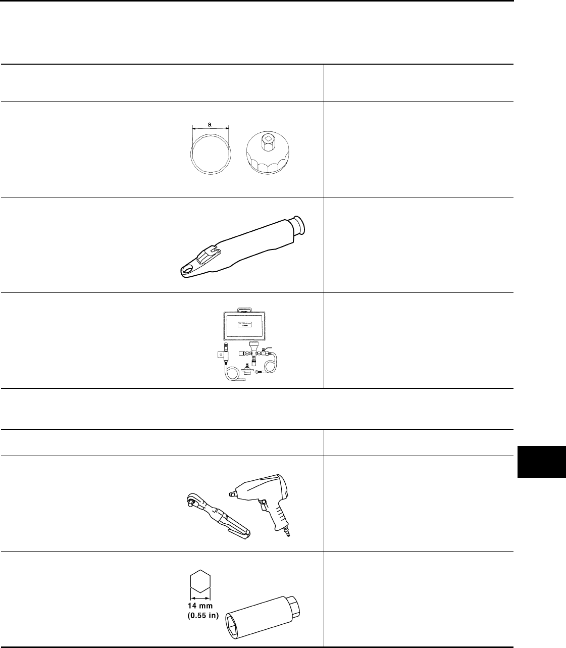
KV10115801
(J-38956)
Oil filter wrench
Removing and installing oil filter
a: 64.3 mm (2.531 in)
KV991J0010
(J-23688)
Engine coolant refractometer
Checking concentration of ethylene glycol in
engine coolant
KV991J0070
(J-45695)
Coolant Refill Tool
Refilling engine cooling system
S-NT375
WBIA0539E
LMA053
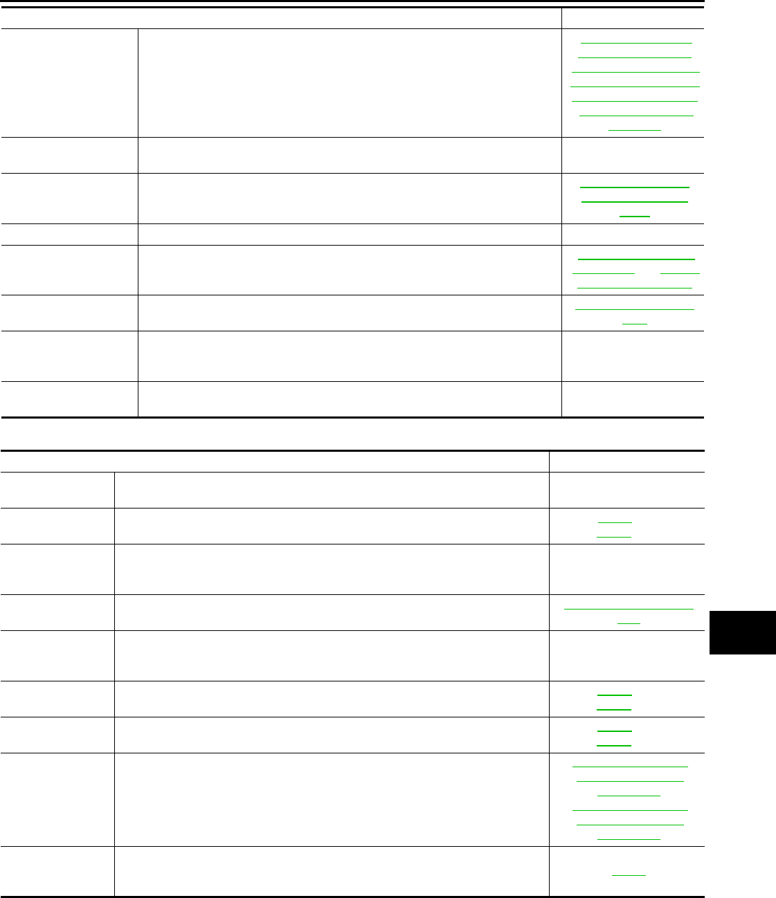
(Kent-Moore No.)
Tool name
Description
Power tool Loosening bolts and nuts
Spark plug wrench Removing and installing spark plug
PBIC0190E
PBIC2982E
Revision: October 2008
2009 Versa

MA-6
< SERVICE INFORMATION >
GENERAL MAINTENANCE
GENERAL MAINTENANCE
Explanation of General Maintenance INFOID:0000000004305182
General Maintenance INFOID:0000000004305183
General maintenance includes those items which should be checked during the normal day-to-day operation
of the vehicle. They are essential if the vehicle is to continue operating properly. The owners can perform
checks and inspections themselves or they can have their NISSAN dealers do them.
OUTSIDE THE VEHICLE
The maintenance items listed here should be performed from time to time, unless otherwise specified.
INSIDE THE VEHICLE
The maintenance items listed here should be checked on a regular basis, such as when performing periodic maintenance, cleaning the vehicle,
etc.
Item Reference page
Tires Check the pressure with a gauge often and always prior to long distance trips.
Adjust the pressure in all tires, including the spare, to the specified pressure.
Check carefully for damage, cuts or excessive wear.
WT-27, "Tire"
Wheel nuts When checking the tires, make sure no nuts are missing, and check for any loose
nuts. Tighten if necessary. WT-7, "Rotation"
Windshield Clean the windshield on a regular basis. Check the windshield at least every six
months for cracks or other damage. Repair as necessary. —
Tire rotation Tires should be rotated every 12,000 km (7,500 miles). WT-7, "Rotation"
Tire Pressure Monitor-
ing System (TPMS)
transmitter compo-
nents
Replace the TPMS transmitter grommet seal, valve core and cap when the tires
are replaced due to wear or age. WT-8
Wheel alignment and
balance
If the vehicle pulls to either side while driving on a straight and level road, or if
you detect uneven or abnormal tire wear, there may be a need for wheel align-
ment. If the steering wheel or seat vibrates at normal highway speeds, wheel bal-
ancing may be needed.
FSU-7, "Wheel Align-
ment Inspection" and
WT-7, "Balancing
Wheels"
Windshield wiper
blades Check for cracks or wear if they do not wipe properly. —
Doors and engine
hood
Check that all doors and the engine hood operate smoothly as well as the trunk
lid and back hatch. Also make sure that all latches lock securely. Lubricate if nec-
essary. Make sure that the secondary latch keeps the hood from opening when
the primary latch is released.
When driving in areas using road salt or other corrosive materials, check lubrica-
tion frequently.
MA-50, "LOCKS, HING-
ES AND HOOD LATCH :
Lubricating Locks, Hing-
es and Hood Latch"
Lamps Make sure that the headlamps, stop lamps, tail lamps, turn signal lamps, and oth-
er lamps are all operating properly and installed securely. Also check headlamp
aim. Clean the headlamps on a regular basis.
—
Item Reference page
Warning lamps and
chimes Make sure that all warning lamps and chimes are operating properly. —
Windshield wiper and
washer
Check that the wipers and washer operate properly and that the wipers do not
streak. —
Windshield defroster Check that the air comes out of the defroster outlets properly and in sufficient
quantity when operating the heater or air conditioning. —
Steering wheel Check that it has the specified play. Be sure to check for changes in the steering
condition, such as excessive play, hard steering or strange noises.
Free play: Less than 35 mm (1.38 in)
—
Seats Check seat position controls such as seat adjusters, seat back recliner, etc. to
make sure they operate smoothly and that all latches lock securely in every po-
sition. Check that the head restraints move up and down smoothly and that the
locks (if equipped) hold securely in all latched positions. Check that the latches
lock securely for folding-down rear seat backs.
—
Revision: October 2008
2009 Versa
GENERAL MAINTENANCE
MA-7
< SERVICE INFORMATION >
C
D
E
F
G
H
I
J
K
M
A
B
MA
N
O
P
UNDER THE HOOD AND VEHICLE
The maintenance items listed here should be checked periodically (e.g. each time you check the engine oil or refuel).
Seat belts
Check that all parts of the seat belt system (e.g. buckles, anchors, adjusters and
retractors) operate properly and smoothly and are installed securely. Check the
belt webbing for cuts, fraying, wear or damage.
MA-50, "SEAT BELT,
BUCKLES, RETRAC-
TORS, ANCHORS AND
ADJUSTERS : Checking
Seat Belts, Buckles, Re-
tractors, Anchors and
Adjusters"
Accelerator pedal Check the pedal for smooth operation and make sure the pedal does not catch
or require uneven effort. Keep the floor mats away from the pedal. —
Clutch pedal
Make sure the pedal operates smoothly and check that it has the proper free play.
CL-5, "On-vehicle In-
spection and Adjust-
ment"
Brakes Check that the brake does not pull the vehicle to one side when applied. —
Brake pedal and
booster
Check the pedal for smooth operation and make sure it has the proper distance
under it when depressed fully. Check the brake booster function. Be sure to keep
floor mats away from the pedal.
BR-6, "Inspection and
Adjustment" and BR-20,
"On Board Inspection"
Parking brake Check that the lever has the proper travel and make sure that the vehicle is held
securely on a fairly steep hill when only the parking brake is applied.
PB-5, "On-Vehicle Ser-
vice"
Automatic transaxle
“Park” mechanism
Check that the lock release button on the selector lever operates properly and
smoothly. On a fairly steep hill check that the vehicle is held securely with the se-
lector lever in the “P” position without applying any brakes.
—
CVT P (Park) position
mechanism
On a fairly steep hill check that the vehicle is held securely with the selector lever
in the “P” position without applying any brakes. —
Item Reference page
Item Reference page
Windshield wash-
er fluid Check that there is adequate fluid in the tank. —
Engine coolant
level Check the coolant level when the engine is cold. CO-11 (HR)
CO-35 (MR)
A/C condenser,
radiator and hos-
es
Check the front of the condenser and radiator and clean off any dirt, insects, leaves,
etc., that may have accumulated. Make sure the radiator hoses have no cracks, de-
formation, deterioration or loose connections.
—
Brake and clutch
fluid levels
Make sure that the brake and clutch fluid levels are between the “MAX” and “MIN”
lines on the reservoirs.
BR-9, "On Board Inspec-
tion"
Battery Check the fluid level in each cell. It should be between the “MAX” and “MIN” lines.
Vehicles operated in high temperatures or under severe conditions require frequent
checks of the battery fluid level.
—
Engine drive belts Make sure that no belt is frayed, worn, cracked or oily. MA-16 (HR)
MA-26 (MR)
Engine oil level Check the level on the dipstick after parking the vehicle on a level spot and turning
off the engine.
MA-20 (HR)
MA-30 (MR)
Automatic tran-
saxle fluid level
Check the level on the dipstick after putting the selector lever in “P” with the engine
idling.
MA-38, "CVT FLUID :
Checking CVT Fluid
(RE0F08A)"
MA-39, "CVT FLUID :
Checking CVT Fluid
(RE0F08B)"
Exhaust system Make sure there are no loose supports, cracks or holes. If the sound of the exhaust
seems unusual or there is a smell of exhaust fumes, immediately locate the trouble
and correct it.
MA-37
Revision: October 2008
2009 Versa

MA-8
< SERVICE INFORMATION >
GENERAL MAINTENANCE
Underbody The underbody is frequently exposed to corrosive substances such as those used
on icy roads or to control dust. It is very important to remove these substances, oth-
erwise rust will form on the floor pan, frame, fuel lines and around the exhaust sys-
tem. At the end of winter, the underbody should be thoroughly flushed with plain
water, being careful to clean those areas where mud and dirt can easily accumu-
late.
—
Fluid leaks Check under the vehicle for fuel, oil, water or other fluid leaks after the vehicle has
been parked for a while. Water dripping from the air conditioner after use is normal.
If you should notice any leaks or gasoline fumes are evident, check for the cause
and correct it immediately.
—
Item Reference page
Revision: October 2008
2009 Versa
PERIODIC MAINTENANCE
MA-9
< SERVICE INFORMATION >
C
D
E
F
G
H
I
J
K
M
A
B
MA
N
O
P
PERIODIC MAINTENANCE
Introduction of Periodic Maintenance INFOID:0000000004305184
Two different maintenance schedules are provided, and should be used, depending upon the conditions in
which the vehicle is mainly operated. After 60,000 miles (96,000 km) or 48 months, continue the periodic
maintenance at the same mileage/time intervals.
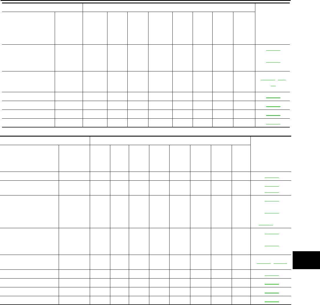
Schedule 1 INFOID:0000000004305185
Emission Control System Maintenance
Abbreviations: R = Replace. I = Inspect. Correct or replace if necessary. [ ]: At the mileage intervals only
Schedule 1
Follow Periodic Maintenance Schedule 1 if your driving habits frequently includes
one or more of the following driving conditions:
• Repeated short trips of less than 5 miles (8 km).
• Repeated short trips of less than 10 miles (16 km) with outside temperatures re-
maining below freezing.
• Operating in hot weather in stop-and-go “rush hour” traffic.
• Extensive idling and/or low speed driving for long distances, such as police, taxi
or door-to-door delivery use.
• Driving in dusty conditions.
• Driving on rough, muddy, or salt spread roads.
• Towing a trailer, using a camper or a car-top carrier.
Emission Control Sys-
tem Maintenance MA-9
Chassis and Body
Maintenance
MA-9
Schedule 2
Follow Periodic Maintenance Schedule 2 if none of the driving conditions shown
in Schedule 1 apply to your driving habits.
Emission Control Sys-
tem Maintenance MA-11
Chassis and Body
Maintenance MA-11
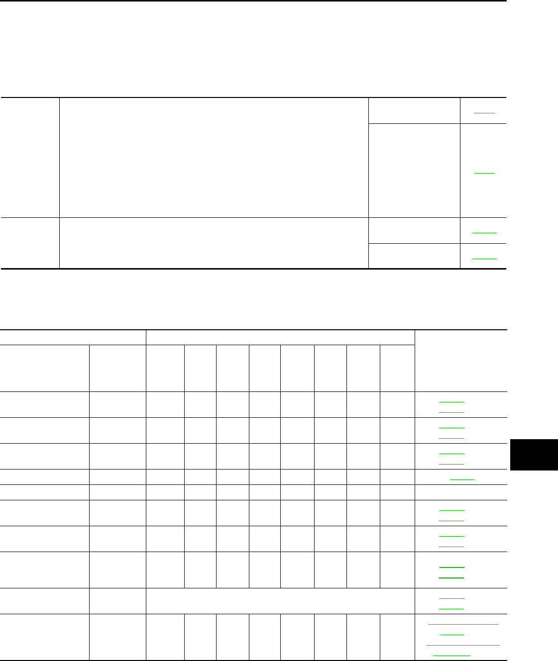
MAINTENANCE OPERATION MAINTENANCE INTERVAL
Reference Section -
Page or - Content Title
Perform at number of
miles, kilometers or
months, whichever
comes first.
Miles x 1,000
(km x 1,000)
Months
3.75
(6)
3
7.5
(12)
6
11.25
(18)
9
15
(24)
12
18.75
(30)
15
22.5
(36)
18
26.25
(42)
21
30
(48)
24
Drive belt NOTE (1) MA-16 (HR)
MA-26 (MR)
Air cleaner filter NOTE (2) [R] MA-20 (HR)
MA-29 (MR)
EVAP vapor lines I* MA-25 (HR)
MA-36 (MR)
Fuel lines I* MA-29
Fuel filter NOTE (3) —
Engine coolant NOTE (4) MA-17 (HR)
MA-26 (MR)
Engine oil R R R R R R R R MA-20 (HR)
MA-30 (MR)
Engine oil filter (Use
genuine oil filter or
equivalent)
RRRRRRRR MA-23 (HR)
MA-33 (MR)
Spark plugs (Iridium-
tipped type) Replace every 105,000 miles (169,000 km) MA-24 (HR)
MA-34 (MR)
Intake and exhaust
valve clearance* NOTE (5)
EM-119, "Cylinder
Head" (HR)
EM-227, "Standard
and Limit" (MR)
Revision: October 2008
2009 Versa
MA-10
< SERVICE INFORMATION >
PERIODIC MAINTENANCE
Abbreviations: R = Replace. I = Inspect. Correct or replace if necessary. [ ]: At the mileage intervals only
(1) After 60,000 miles (96,000 km) or 48 months, inspect every 15,000 miles (24,000 km) or 12 months. Replace the drive belts if found
damaged.
(2) If operating mainly in dusty conditions, more frequent maintenance may be required.
(3) Maintenance-free item. For service procedures, go to the FL section.
(4) After 60,000 miles (96,000 km) or 48 months, replace every 30,000 miles (48,000 km) or 24 months.
(5) Periodic maintenance is not required. However, if valve noise increases, inspect valve clearance.
* Maintenance items and intervals with “*” are recommended by NISSAN for reliable vehicle operation. The owner need not perform
such maintenance in order to maintain the emission warranty or manufacturer recall liability. Other maintenance items and intervals are
required.
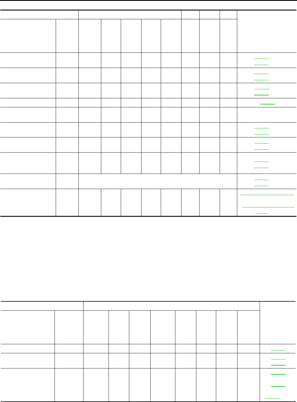
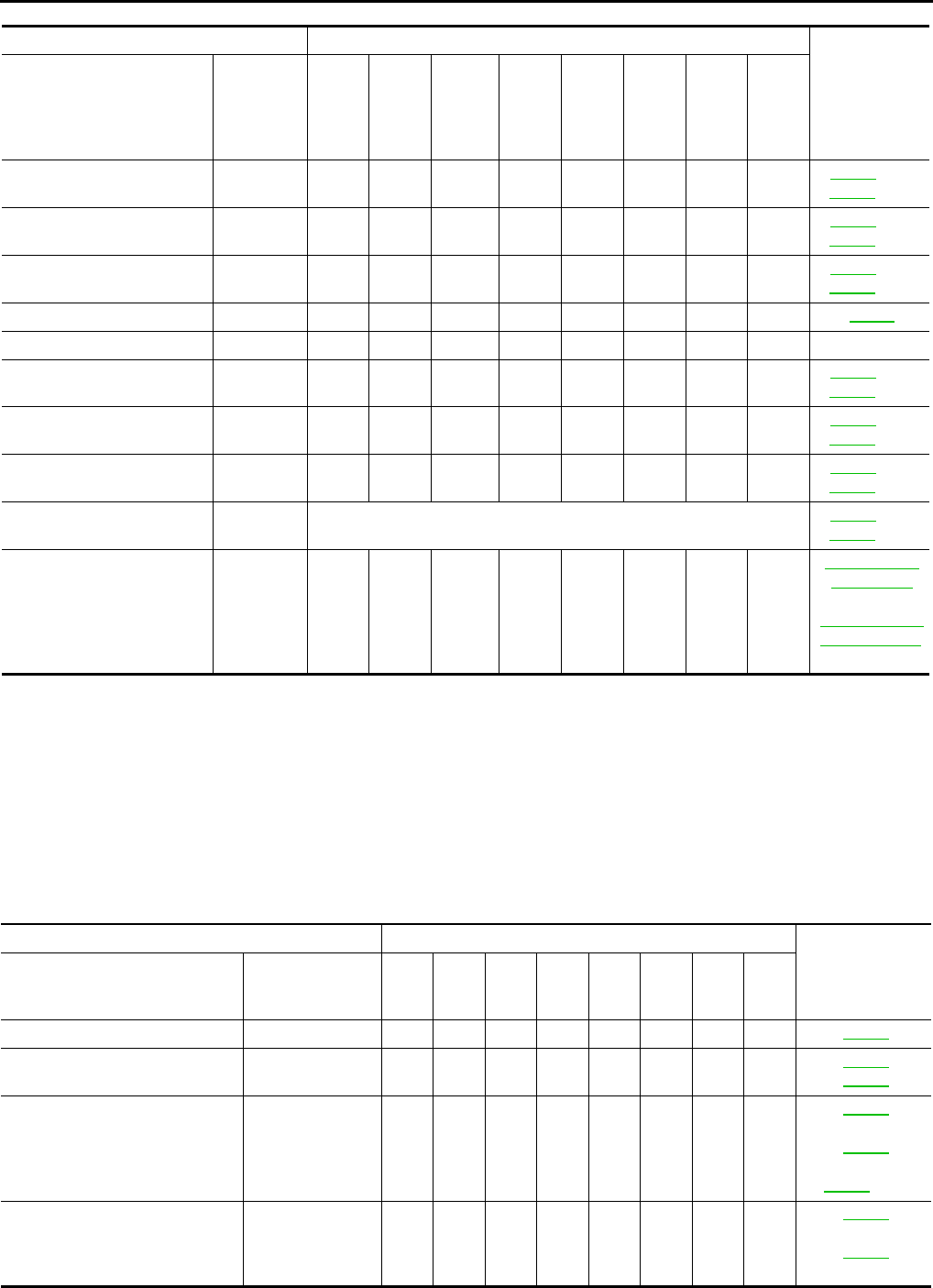
Chassis and Body Maintenance
Abbreviations: R = Replace. I = Inspect. Correct or replace if necessary. L = Lubricate.
MAINTENANCE OPERATION MAINTENANCE INTERVAL
Reference Section -
Page or - Content Title
Perform at number of
miles, kilometers or
months, whichever
comes first.
Miles x
1,000
(km x
1,000)
Months
33.75
(54)
27
37.5
(60)
30
41.25
(66)
33
45
(72)
36
48.75
(78)
39
52.5
(84)
42
56.25
(90)
45
60
(96)
48
Drive belt NOTE
(1) I* MA-16 (HR)
MA-26 (MR)
Air cleaner filter NOTE
(2) [R] MA-20 (HR)
MA-29 (MR)
EVAP vapor lines I* MA-25 (HR)
MA-36 (MR)
Fuel lines I* MA-29
Fuel filter NOTE
(3) —
Engine coolant NOTE
(4) R* MA-17 (HR)
MA-26 (MR)
Engine oil R R R R R R R R MA-20 (HR)
MA-30 (MR)
Engine oil filter (Use
genuine oil filter or
equivalent)
R R R R RRRR MA-23 (HR)
MA-33 (MR)
Spark plugs (Iridium-
tipped type) Replace every 105,000 miles (169,000 km) MA-24 (HR)
MA-34 (MR)
Intake and exhaust
valve clearance*
NOTE
(5)
EM-119, "Cylinder Head"
(HR)
EM-227, "Standard and
Limit" (MR)
MAINTENANCE OPERATION MAINTENANCE INTERVAL
Reference
Section -
Page or -
Content Title
Perform at number of
miles, kilometers or
months, whichever
comes first.
Miles x
1,000
(km x
1,000)
Months
3.75
(6)
3
7.5
(12)
6
11.25
(18)
9
15
(24)
12
18.75
(30)
15
22.5
(36)
18
26.25
(42)
21
30
(48)
24
Brake lines & cables I I MA-47
Brake pads, rotors,
drums & linings IIII
MA-47
MA-47
Manual transaxle oil or
automatic transaxle
fluid
NOTE (1) I I
MA-43
(RS5F91R)
MA-44
(RS6F94R)
MA-44 (A/T)
Revision: October 2008
2009 Versa
PERIODIC MAINTENANCE
MA-11
< SERVICE INFORMATION >
C
D
E
F
G
H
I
J
K
M
A
B
MA
N
O
P
Abbreviations: R = Replace. I = Inspect. Correct or replace if necessary. L = Lubricate.
(1) If towing a trailer, using a camper or a car-top carrier, or driving on rough or muddy roads, change (not just inspect) oil (exc. LSD) at
every 30,000 miles (48,000 km) or 24 months, and change LSD gear oil every 15,000 miles (24,000 km) or 12 months.
(2) If towing a trailer, using a camper or a car-top carrier, or driving on rough or muddy roads, inspect CVT fluid deterioration with CON-
SULT-III every 60,000 miles (96,000 km), then change CVT fluid NS-2 if necessary. If CONSULT-III is not available, change (not just
inspect) CVT fluid NS-2 every 60,000 miles (96,000 km). Using transmission fluid other than Genuine NISSAN CVT Fluid NS-2 will
damage the CVT, which is not covered by the NISSAN new vehicle limited warranty.
(3) Refer to “Tire rotation” under the “GENERAL MAINTENANCE” heading earlier in this section.
Schedule 2 INFOID:0000000004305186
Emission Control System Maintenance
CVT fluid NOTE (2) I I
MA-38
(RE0F08A)
MA-39
(RE0F08B)
Steering gear & link-
age, axle & suspen-
sion parts
IIII
MA-48, PS-
12
Tire rotation NOTE (3) MA-46
Front drive shaft boots I I I I MA-49
Exhaust system I I I I MA-37
In-cabin microfilter R R MA-37
MAINTENANCE OPERATION MAINTENANCE INTERVAL
Reference
Section -
Page or -
Content Title
Perform at number of
miles, kilometers or
months, whichever
comes first.
Miles x
1,000
(km x
1,000)
Months
3.75
(6)
3
7.5
(12)
6
11.25
(18)
9
15
(24)
12
18.75
(30)
15
22.5
(36)
18
26.25
(42)
21
30
(48)
24
MAINTENANCE OPERATION MAINTENANCE INTERVAL
Reference Sec-
tion - Page or -
Content Title
Perform at number of
miles, kilometers or
months, whichever
comes first.
Miles x
1,000
(km x 1,000)
Months
33.75
(54)
27
37.5
(60)
30
41.25
(66)
33
45
(72)
36
48.75
(78)
39
52.5
(84)
42
56.25
(90)
45
60
(96)
48
Brake lines & cables I I MA-47
Brake pads, rotors,
drums & linings II I I
MA-47
MA-47
Manual transaxle oil or
automatic transaxle fluid NOTE (1) I I
MA-43
(RS5F91R)
MA-44
(RS6F94R)
MA-44 (A/T)
CVT fluid NOTE (2) I I
MA-38
(RE0F08A)
MA-39
(RE0F08B)
Steering gear & linkage,
axle & suspension parts II I IMA-48, PS-12
Tire rotation NOTE (3) MA-46
Front drive shaft boots I I I I MA-49
Exhaust system I I I I MA-37
In-cabin microfilter R R MA-37
Revision: October 2008
2009 Versa
MA-12
< SERVICE INFORMATION >
PERIODIC MAINTENANCE
Abbreviations: R = Replace. I = Inspect. Correct or replace if necessary. [ ]: At the mileage intervals only
(1) After 60,000 miles (96,000 km) or 48 months, inspect every 15,000 miles (24,000 km) or 12 months. Replace the drive belt if found
damaged or if the auto belt tensioner reading reaches the maximum limit.
(2) Maintenance-free item.
(3) After 60,000 miles (96,000 km) or 48 months, replace every 30,000 miles (48,000 km) or 24 months.
(4) Periodic maintenance is not required. However, if valve noise increases, inspect valve clearance.
Maintenance items and intervals with “*” are recommended by NISSAN for reliable vehicle operation. The owner need not perform such
maintenance in order to maintain the emission warranty or manufacturer recall liability. Other maintenance items and intervals are
required.
Chassis and Body Maintenance
Abbreviations: R = Replace. I = Inspect. Correct or replace if necessary. L = Lubricate.
MAINTENANCE OPERATION MAINTENANCE INTERVAL Reference
Section - Page
or - Content Ti-
tle
Perform at number of miles,
kilometers or months, which-
ever comes first.
Miles x
1,000
(km x
1,000)
Months
7.5
(12)
6
15
(24)
12
22.5
(36)
18
30
(48)
24
37.5
(60)
30
45
(72)
36
52.5
(84)
42
60
(96)
48
Drive belt NOTE (1) I* MA-16 (HR)
MA-26 (MR)
Air cleaner filter [R] [R] MA-20 (HR)
MA-29 (MR)
EVAP vapor lines I* I* MA-25 (HR)
MA-36 (MR)
Fuel lines I* I* MA-29
Fuel filter NOTE (2) —
Engine coolant NOTE (3) R* MA-17 (HR)
MA-26 (MR)
Engine oil RR R RRRRR
MA-20 (HR)
MA-30 (MR)
Engine oil filter (Use genuine
oil filter or equivalent.) RR R RRRRR
MA-23 (HR)
MA-33 (MR)
Spark plugs (Iridium-tipped
type) Replace every 105,000 miles (169,000 km) MA-24 (HR)
MA-34 (MR)
Intake and exhaust valve
clearance* NOTE (4)
EM-119, "Cyl-
inder Head"
(HR)
EM-227, "Stan-
dard and Limit"
(MR)
MAINTENANCE OPERATION MAINTENANCE INTERVAL Reference Sec-
tion - Page or -
Content Title
Perform at number of miles, kilo-
meters or months, whichever
comes first.
Miles x 1,000
(km x 1,000)
Months
7.5
(12)
6
15
(24)
12
22.5
(36)
18
30
(48)
24
37.5
(60)
30
45
(72)
36
52.5
(84)
42
60
(96)
48
Brake lines & cables IIIIMA-47
Brake pads, rotors, drums & lin-
ings IIII
MA-47
MA-47
Manual transaxle oil or automatic
transaxle fluid IIII
MA-43
(RS5F91R)
MA-44
(RS6F94R)
MA-44 (A/T)
CVT fluid NOTE (1) IIII
MA-38
(RE0F08A)
MA-39
(RE0F08B)
Revision: October 2008
2009 Versa
PERIODIC MAINTENANCE
MA-13
< SERVICE INFORMATION >
C
D
E
F
G
H
I
J
K
M
A
B
MA
N
O
P
(1) Using transmission fluid other than Genuine NISSAN CVT Fluid NS-2 will damage the CVT, which is not covered by the
NISSAN new vehicle limited warranty.
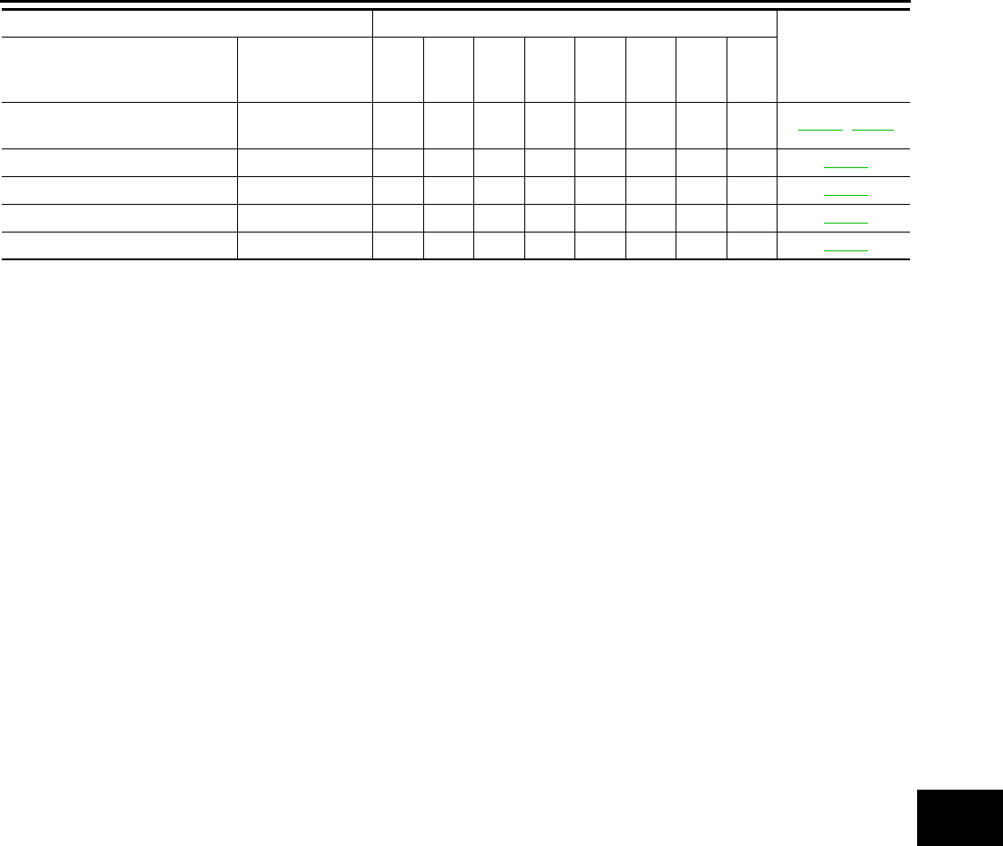
(2) Refer to “Tire rotation” under the “GENERAL MAINTENANCE” heading earlier in this section.
Steering gear & linkage, axle &
suspension parts IIMA-48, PS-12
Tire rotation NOTE (2) MA-46
Front drive shaft boots I I I I MA-49
Exhaust system I I MA-37
In-cabin microfilter R R R R MA-37
MAINTENANCE OPERATION MAINTENANCE INTERVAL Reference Sec-
tion - Page or -
Content Title
Perform at number of miles, kilo-
meters or months, whichever
comes first.
Miles x 1,000
(km x 1,000)
Months
7.5
(12)
6
15
(24)
12
22.5
(36)
18
30
(48)
24
37.5
(60)
30
45
(72)
36
52.5
(84)
42
60
(96)
48
Revision: October 2008
2009 Versa
MA-14
< SERVICE INFORMATION >
RECOMMENDED FLUIDS AND LUBRICANTS
RECOMMENDED FLUIDS AND LUBRICANTS
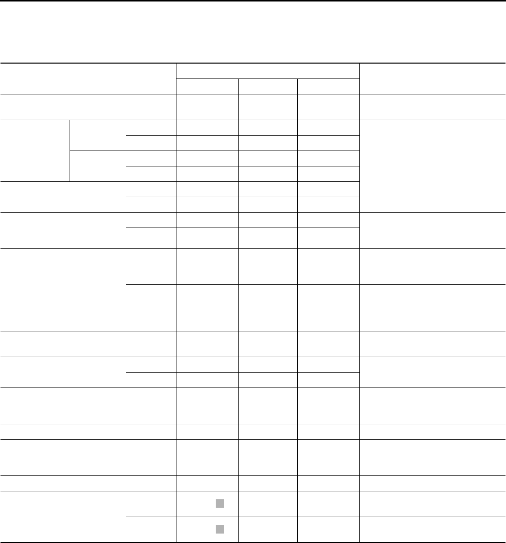
Fluids and Lubricants INFOID:0000000004305187
*1: For further details, see “Engine Oil Recommendation”.
*2: If genuine NISSAN gear oil is not available, API GL-4, Viscosity SAE 75W-80 may be used as a temporary replacement. However
use Genuine NISSAN gear oil as soon as it is possible.
*3: Using transaxle fluid other than Genuine NISSAN CVT Fluid NS-2 will damage the CVT, which is not covered by the NISSAN
new vehicle limited warranty.
*4: Available in mainland U.S.A. through a NISSAN dealer.
*5: For further details, see “Air conditioner specification label”.
SAE Viscosity Number INFOID:0000000004305188
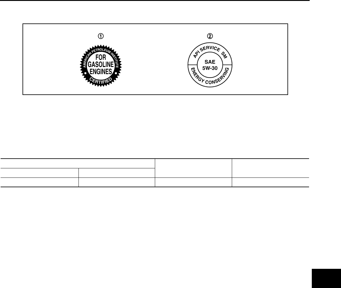
NISSAN recommends the use of an energy conserving oil in order to improve fuel economy.
Select only engine oils that meet the American Petroleum Institute (API) certification and International Lubrica-
tion Standardization and Approval Committee (ILSAC) certification and SAE viscosity standard. These oils
Description Capacity (Approximate) Recommended Fluids/Lubricants
Liter US measure Imp measure
Fuel 50.0 13 1/4 gal 11 gal Unleaded gasoline with an octane
rating of at least 87 AKI (RON 91)
Engine oil
Drain and refil
With oil filter
change
HR16DE 3.0 3 1/8 qt 2 5/8 qt
• Engine oil with API Certification
Mark *1
• Viscosity SAE 5W-30
MR18DE 4.1 4 3/8 qt 3 5/8 qt
Without oil
filter change
HR16DE 2.8 3 qt 2 1/2 qt
MR18DE 3.9 4 1/8 qt 3 3/8 qt
Dry engine (engine overhaul) HR16DE 3.5 3 3/4 qt 3 1/8 qt
MR18DE 4.9 5 1/8 qt 4 3/8 qt
Cooling system
(with reservoir at max level)
HR16DE 6.3 6 5/8 qt 5 1/2 qt Genuine NISSAN Long Life Anti-
freeze Coolant or equivalent
MR18DE 6.8 7 1/4 qt 6 qt
Manual transaxle fluid (MTF)
5MT 2.6 5 1/2 pt 4 5/8 pt
Genuine NISSAN Manual Transmis-
sion Fluid (MTF) HQ Multi 75W-85 or
API GL-4, Viscosity SAE 75W-85
6MT 2.0 4 1/4 pt 3 1/2 pt
Genuine NISSAN gear oil (XT4447
M+) 75W-80, Genuine NISSAN gear
oil (ETL8997B) 75W-80, or equiva-
lent *2
Automatic transaxle fluid (ATF) 7.9 8 3/8 qt 7 qt Genuine NISSAN Matic D ATF or
equivalent (if available)
CVT fluid RE0F08A 8.3 8 3/4 qt 7 1/4 qt Genuine NISSAN CVT Fluid NS-2 *3
RE0F08B 7.4 7 7/8 qt 6 1/2 qt
Brake and clutch fluid — — —
Genuine NISSAN Super Heavy Duty
Brake Fluid*4 or equivalent DOT 3
(US FMVSS No. 116)
Multi-purpose grease — — — NLGI No. 2 (Lithium soap base)
Windshield washer fluid 4.5 4 3/4 qt 4 qt
Genuine NISSAN Windshield Wash-
er Concentrate Cleaner & Anti-
Freeze or equivalent
Air conditioning system refrigerant 0.45 ± 0.05 kg 0.99 ± 0.11 lb 0.99 ± 0.11 lb HFC-134a (R-134a) *5
Air conditioning system oil
Type 1 120 m 4.1 fl oz 4.2 fl oz NISSAN A/C System Lubricant Type
R or equivalent *5
Type 2 100 m 3.4 fl oz 3.5 fl oz NISSAN A/C System Lubricant Type
S or equivalent *5
Revision: October 2008
2009 Versa
RECOMMENDED FLUIDS AND LUBRICANTS
MA-15
< SERVICE INFORMATION >
C
D
E
F
G
H
I
J
K
M
A
B
MA
N
O
P
have the API certification mark on the front of the container. Oils which do not have the specified quality label
should not be used as they could cause engine damage.
Anti-freeze Coolant Mixture Ratio INFOID:0000000004305189
The engine cooling system is filled at the factory with a high-quality, long life, year-round, anti-freeze coolant
solution. The anti-freeze solution contains rust and corrosion inhibitors. Therefore, additional cooling system
additives are not necessary.
CAUTION:
• When adding or replacing coolant, be sure to use only a Genuine NISSAN Long Life Anti-Freeze
coolant or equivalent with the proper mixture ratio.
• The use of other types of coolant solutions may damage the engine cooling system.
SAIA1514E
1. API certification mark 2. API service symbol
For outside temperatures down to: Genuine NISSAN Anti-freeze
Coolant or equivalent
Demineralized water or distilled
water
°C°F
-35 -30 50% 50%
Revision: October 2008
2009 Versa
MA-16
< SERVICE INFORMATION >
ENGINE MAINTENANCE (HR16DE)
ENGINE MAINTENANCE (HR16DE)
DRIVE BELT
DRIVE BELT : Checking INFOID:0000000004806005
• Inspection should be done only when engine is cold or over 30
minutes after the engine is stopped.
• Visually check belts for wear, damage, and cracks on inside and
edges.
• Turn crankshaft pulley two time clockwise, and make sure tension on all pulleys is equal before doing the
test.
• When measuring deflection, apply 98 N (10 kg, 22 lb) at the ( ) marked point.
• Measure the belt tension and frequency with acoustic tension gauge at the ( ) marked point.
CAUTION:
• When the tension and frequency are measured, the acoustic tension gauge should be used.
• When checking immediately after installation, first adjust it to the specified value. Then, after turning
crankshaft two turns or more, re-adjust to the specified value to avoid variation in deflection
between pulleys.
DRIVE BELT : Tension Adjustment INFOID:0000000004806006
CAUTION:
• When belt is replaced with new one, adjust belt tension to the value for “New belt”, because new belt
will not fully seat in the pulley groove.
• When tension of the belt being used exceeds “Limit”, adjust it to the value for “After adjusted”.
• When installing a belt, make sure it is correctly engaged with the pulley groove.
• Never allow oil or engine coolant to get on the belt.
• Never twist or bend the belt strongly.
1. Loosen the idler pulley lock nut (A) from the tightening position
with the specified torque by 45 degrees.
CAUTION:
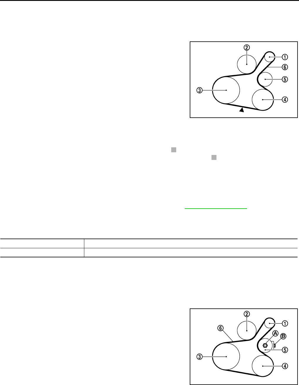
1 : Generator
2: Water pump
3 : Crankshaft pulley
4: A/C compressor (with A/C models)
: Idler pulley (without A/C models)
5 : Idler pulley
6: Drive belt
Belt Deflection / Belt Tension and Frequency : Refer to EM-116, "Drive Belts".
PBIC3642E
Location Location of adjuster and tightening method
Drive belt Adjusting bolt on idler pulley
1 : Generator
2: Water pump
3 : Crankshaft pulley
4: A/C compressor (with A/C models)
: Idler pulley (without A/C models)
5 : Idler pulley
6 : Drive belt
A : Idler pulley lock nut
B : Adjusting bolt
PBIC3643E
Revision: October 2008
2009 Versa
ENGINE MAINTENANCE (HR16DE)
MA-17
< SERVICE INFORMATION >
C
D
E
F
G
H
I
J
K
M
A
B
MA
N
O
P
• When the lock nut is loosened excessively, the idler pulley tilts and the correct tension adjust-
ment cannot be performed. Never loosen it excessively (more than 45 degrees).
• Put a matching mark on the lock nut, and check turning angle with a protractor. Never visually
check the tightening angle.
2. Adjust the belt tension by turning the adjusting bolt.
CAUTION:
• When checking immediately after installation, first adjust it to the specified value. Then, after
turning crankshaft two turns or more, re-adjust to the specified value to avoid variation in deflec-
tion between pulleys.
• When the tension adjustment is performed, the lock nut should be in the condition at step“2”. If
the tension adjustment is performed when the lock nut is loosened more than the standard, the
idler pulley tilts and the correct tension adjustment cannot be performed.
3. Tighten the idler pulley lock nut.
ENGINE COOLANT
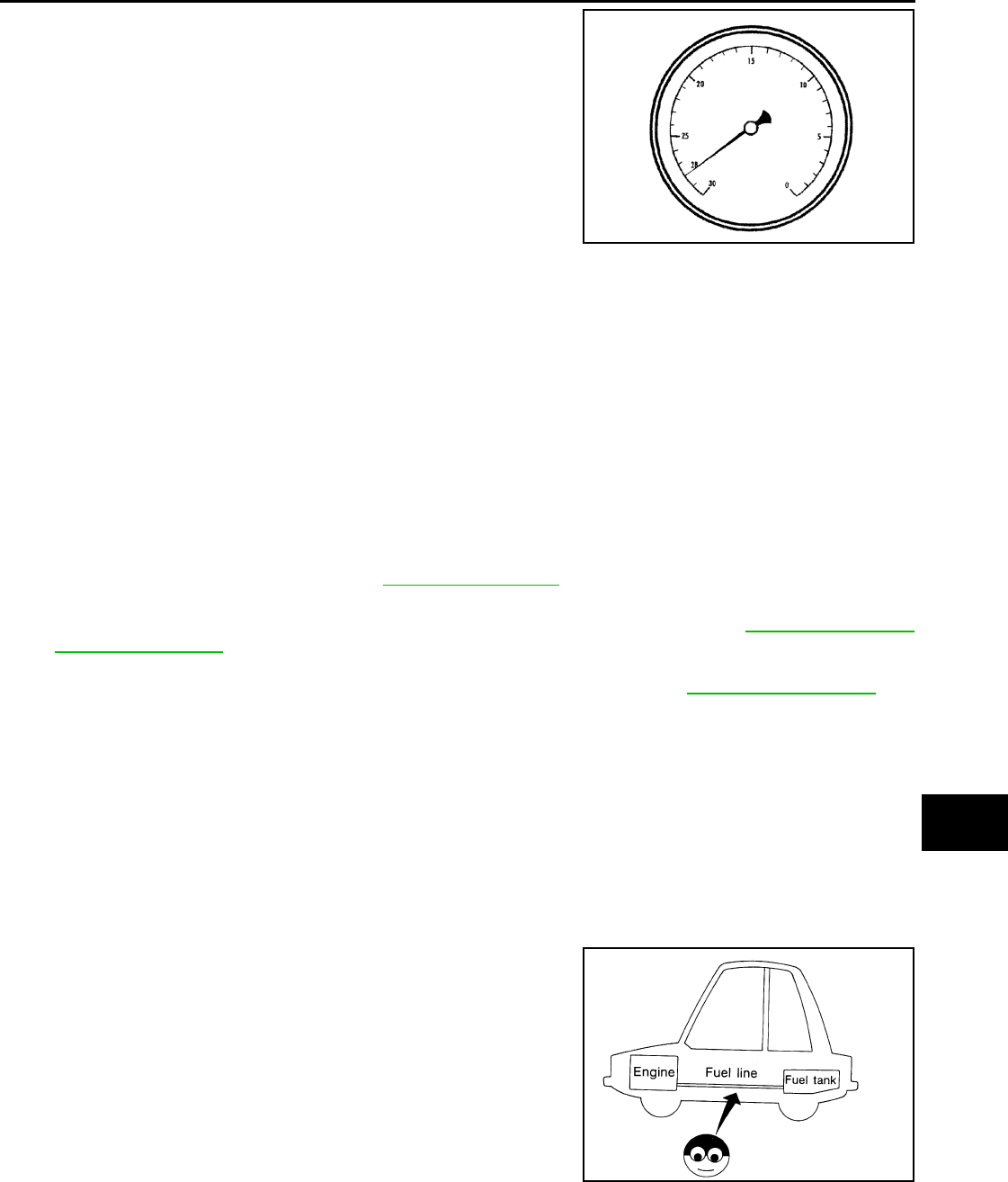
ENGINE COOLANT : Inspection INFOID:0000000004806014
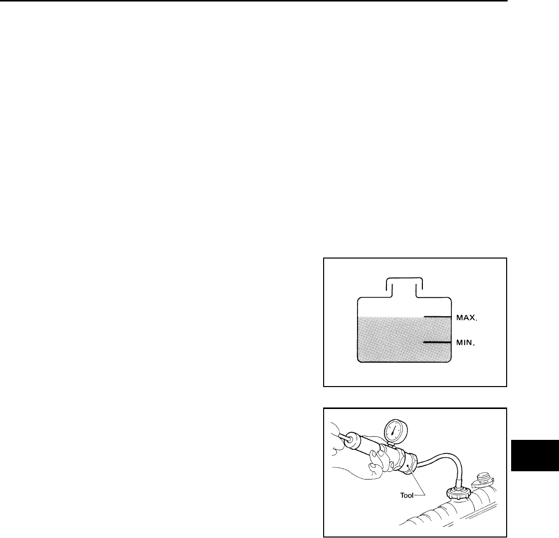
LEVEL CHECK
• Check if the reservoir tank engine coolant level is within the “MIN”
to “MAX” range when engine is cool.
• Adjust the engine coolant level as necessary.
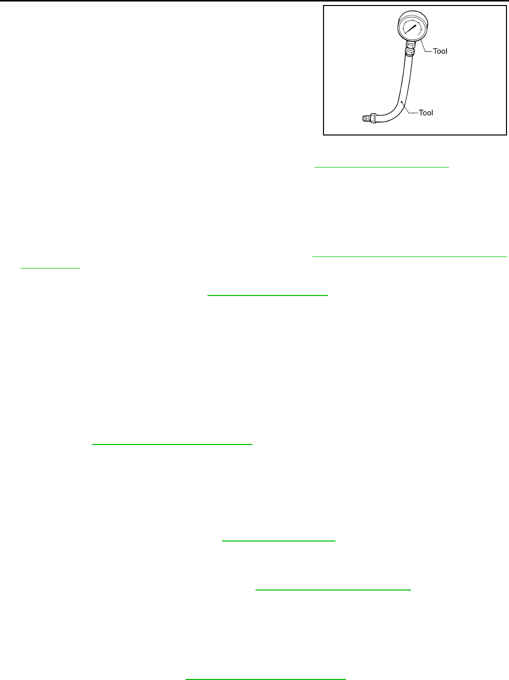
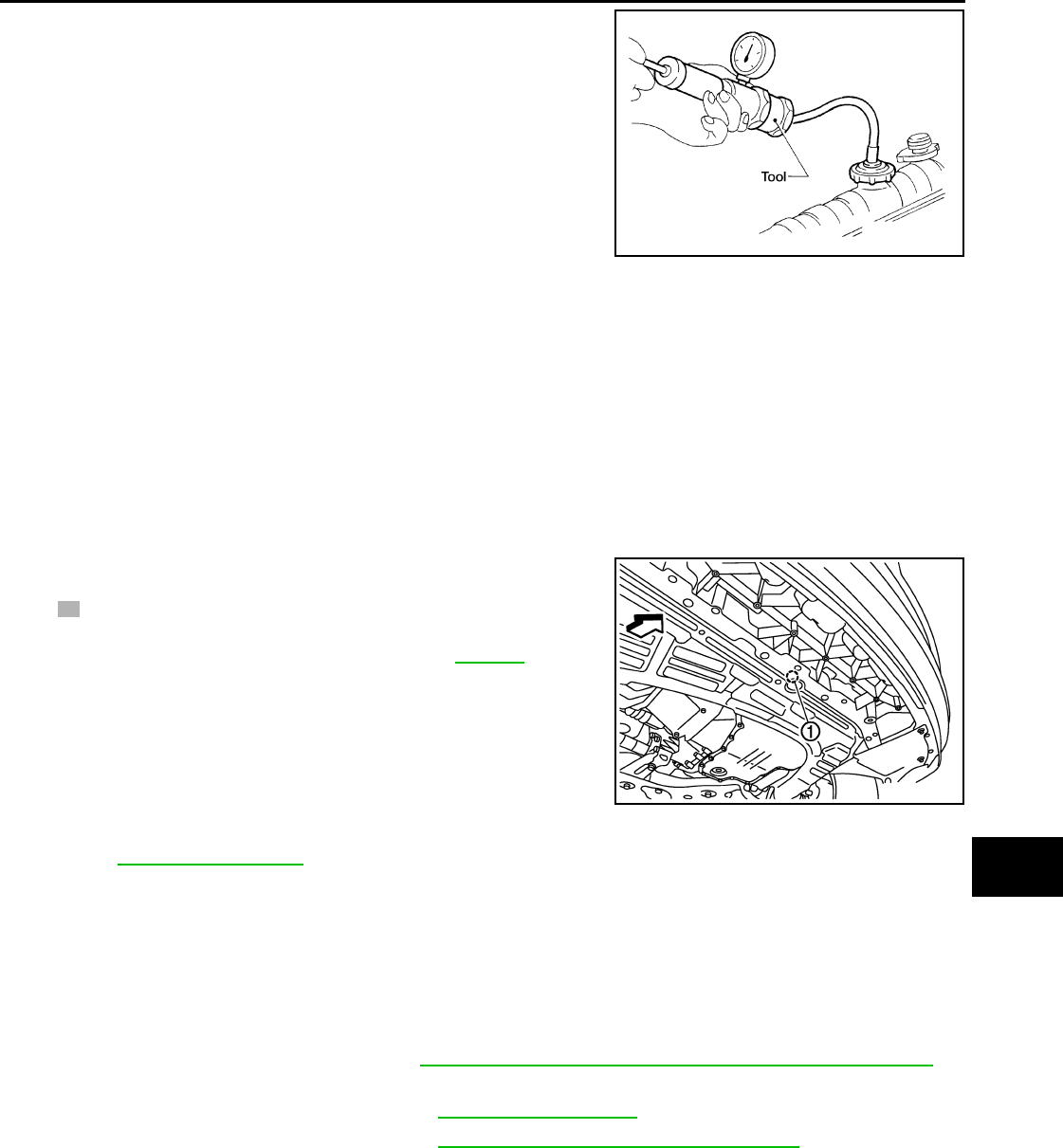
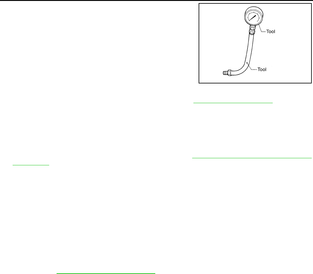
CHECKING COOLING SYSTEM FOR LEAKS
To check for leaks, apply pressure to the cooling system using suit-
able tool and Tool.
WARNING:
Never remove the radiator cap when the engine is hot. Serious
burns could occur from high pressure coolant escaping from
the radiator.
CAUTION:
Higher pressure than specified may cause radiator damage.
ENGINE COOLANT : Changing Engine Coolant INFOID:0000000004806015
WARNING:
• To avoid being scalded, do not change engine coolant when engine is hot.
• Wrap a thick cloth around radiator cap and carefully remove the cap. First, turn the cap a quarter of a
turn to release built-up pressure. Then turn the cap all the way.
CAUTION:
• Do not spill engine coolant on drive belt.
DRAINING ENGINE COOLANT
Idler pulley lock nut : 34.8 N·m (3.5 kg-m, 26 ft-lb)
SMA412B
Tool number : EG17650301 (J-33984-A)
Testing pressure : 157 kPa (1.6 kg/cm2, 23 psi)
WBIA0568E
Revision: October 2008
2009 Versa
MA-18
< SERVICE INFORMATION >
ENGINE MAINTENANCE (HR16DE)
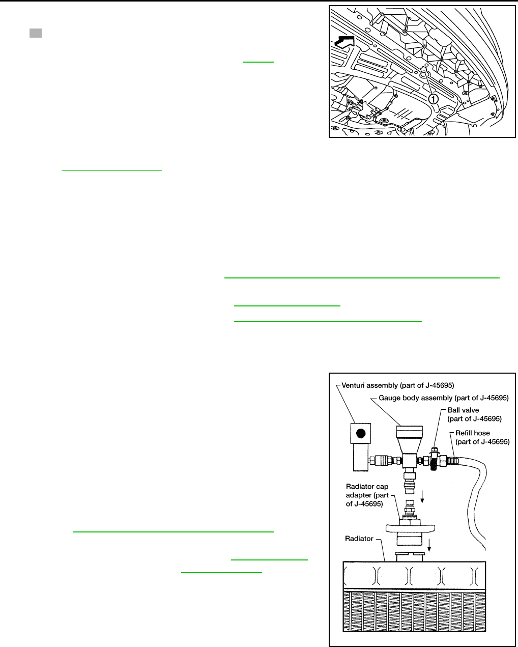
1. Open radiator drain plug (1) at the bottom of radiator, and then
remove radiator cap.
• Front
When draining all of engine coolant in the system, open
water drain plug on cylinder block. Refer to EM-96.
CAUTION:
• Perform this step when engine is cold.
• Do not spill engine coolant on drive belt.
2. Remove reservoir tank as necessary, and drain engine coolant and clean reservoir tank before installing.
Refer to CO-16, "Component".
3. Check drained engine coolant for contaminants such as rust, corrosion or discoloration.
If contaminated, flush the engine cooling system.
REFILLING ENGINE COOLANT
1. Install the radiator drain plug. Install the reservoir tank and cylinder block drain plug, if removed for a total
system drain or for engine removal or repair.
•The radiator must be completely empty of coolant and water.
•Apply sealant to the threads of the cylinder block drain plugs. Use Genuine High Performance
Thread Sealant or equivalent. Refer to GI-42, "Recommended Chemical Product and Sealant".
2. If disconnected, reattach the upper radiator hose at the engine side.
3. Set the vehicle heater controls to the full HOT and heater ON position. Turn the vehicle ignition ON with
the engine OFF as necessary to activate the heater mode.
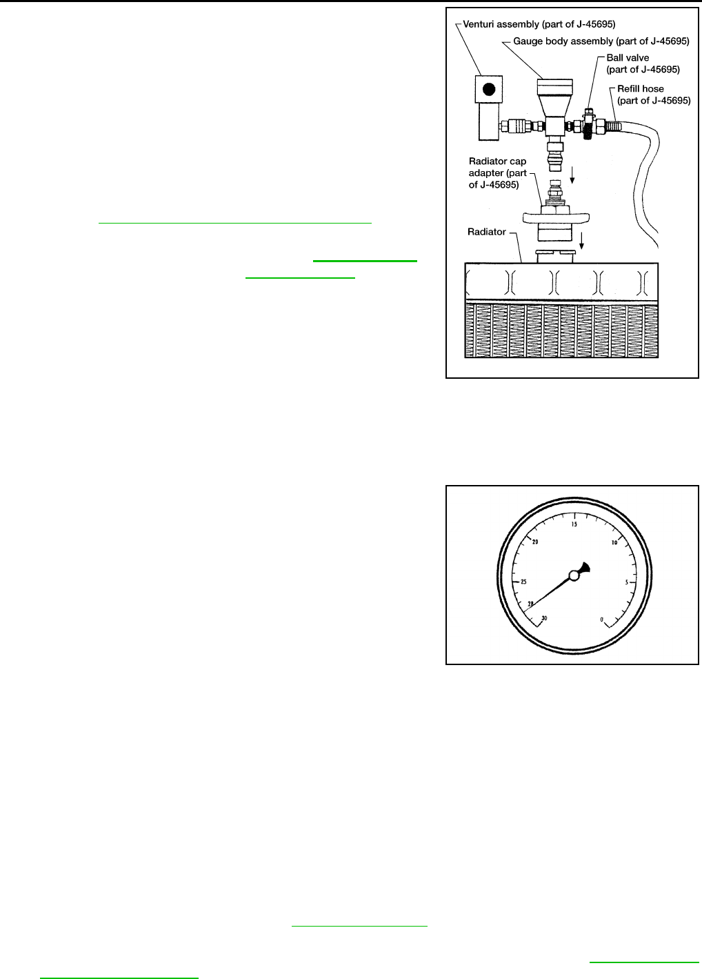
4. Install the Tool by installing the radiator cap adapter onto the
radiator neck opening. Then attach the gauge body assembly
with the refill tube and the venturi assembly to the radiator cap
adapter.
5. Insert the refill hose into the coolant mixture container that is
placed at floor level. Make sure the ball valve is in the closed
position.
•Use Genuine NISSAN Long Life Anti-freeze coolant or
equivalent, mixed with distilled water or demineralized
water.
Refer to MA-15, "Anti-freeze Coolant Mixture Ratio".
6. Install an air hose to the venturi assembly, the air pressure must
be within specification.
CAUTION:
The compressed air supply must be equipped with an air dryer.
7. The vacuum gauge will begin to rise and there will be an audible hissing noise. During this process open
the ball valve on the refill hose slightly. Coolant will be visible rising in the refill hose. Once the refill hose is
full of coolant, close the ball valve. This will purge any air trapped in the refill hose.
PBIC3799E
Radiator drain plug : Refer to CO-16, "Component".
Cylinder block drain plug : Refer to EM-96, "Disassembly and Assembly".
Tool number : KV991J0070 (J-45695)
Engine coolant capacity
(with reservoir tank)
: Refer to MA-14, "Fluids
and Lubricants".
Compressed air
supply pressure : 5.7 - 8.5 kPa (5.6 - 8.4 kg/cm2,
80 - 120 psi) LLIA0058E
Revision: October 2008
2009 Versa
ENGINE MAINTENANCE (HR16DE)
MA-19
< SERVICE INFORMATION >
C
D
E
F
G
H
I
J
K
M
A
B
MA
N
O
P
8. Continue to draw the vacuum until the gauge reaches 28 inches
of vacuum. The gauge may not reach 28 inches in high altitude
locations, use the vacuum specifications based on the altitude
above sea level.
9. When the vacuum gauge has reached the specified amount, disconnect the air hose and wait 20 seconds
to see if the system loses any vacuum. If the vacuum level drops, perform any necessary repairs to the
system and repeat steps 6 - 8 to bring the vacuum to the specified amount. Recheck for any leaks.
10. Place the coolant container (with the refill hose inserted) at the same level as the top of the radiator. Then
open the ball valve on the refill hose so the coolant will be drawn up to fill the cooling system. The cooling
system is full when the vacuum gauge reads zero.
CAUTION:
Do not allow the coolant container to get too low when filling, to avoid air from being drawn into
the cooling system.
11. Remove the Tool from the radiator neck opening.
12. Fill the cooling system reservoir tank to the specified level and install the radiator cap. Run the engine to
warm up the cooling system and top up the system as necessary.
FLUSHING COOLING SYSTEM
1. Install reservoir tank if removed. Refer to CO-16, "Component".
2. Install radiator drain plug.
•If water drain plug on cylinder block is removed, close and tighten it. Refer to EM-96, "Disassem-
bly and Assembly".
CAUTION:
Be sure to clean radiator drain plug and install with new O-ring. Refer to CO-16, "Component".
3. Fill radiator and reservoir tank with water and reinstall radiator cap.
4. Run engine and warm it up to normal operating temperature.
5. Rev engine two or three times under no-load.
6. Stop engine and wait until it cools down.
7. Drain water from the cooling system.
8. Repeat steps 1 through 7 until clear water begins to drain from radiator.
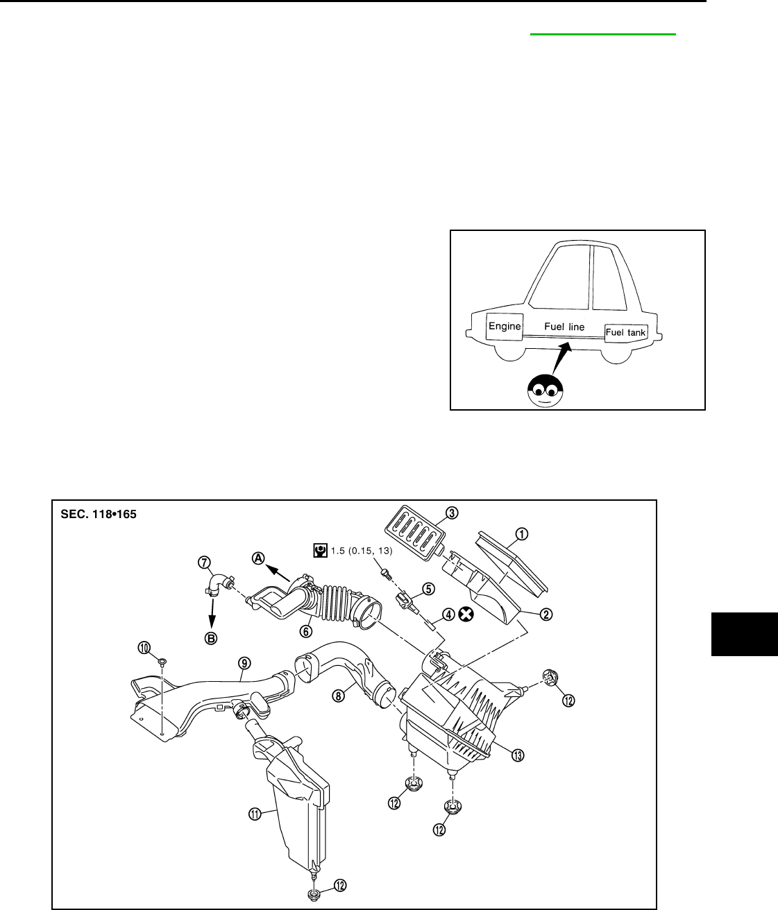
FUEL LINES
FUEL LINES : Checking Fuel Line INFOID:0000000004803414
Inspect fuel lines, fuel filler cap and fuel tank for improper attach-
ment, leaks, cracks, damage, loose connections, chafing or deterio-
ration.
If necessary, repair or replace damaged parts.
AIR CLEANER FILTER
Altitude above sea level Vacuum gauge reading
0 - 100 m (328 ft) : 28 inches of vacuum
300 m (984 ft) : 27 inches of vacuum
500 m (1,641 ft) : 26 inches of vacuum
1,000 m (3,281 ft) : 24 - 25 inches of vacuum LLIA0057E
SMA803A
Revision: October 2008
2009 Versa
MA-20
< SERVICE INFORMATION >
ENGINE MAINTENANCE (HR16DE)
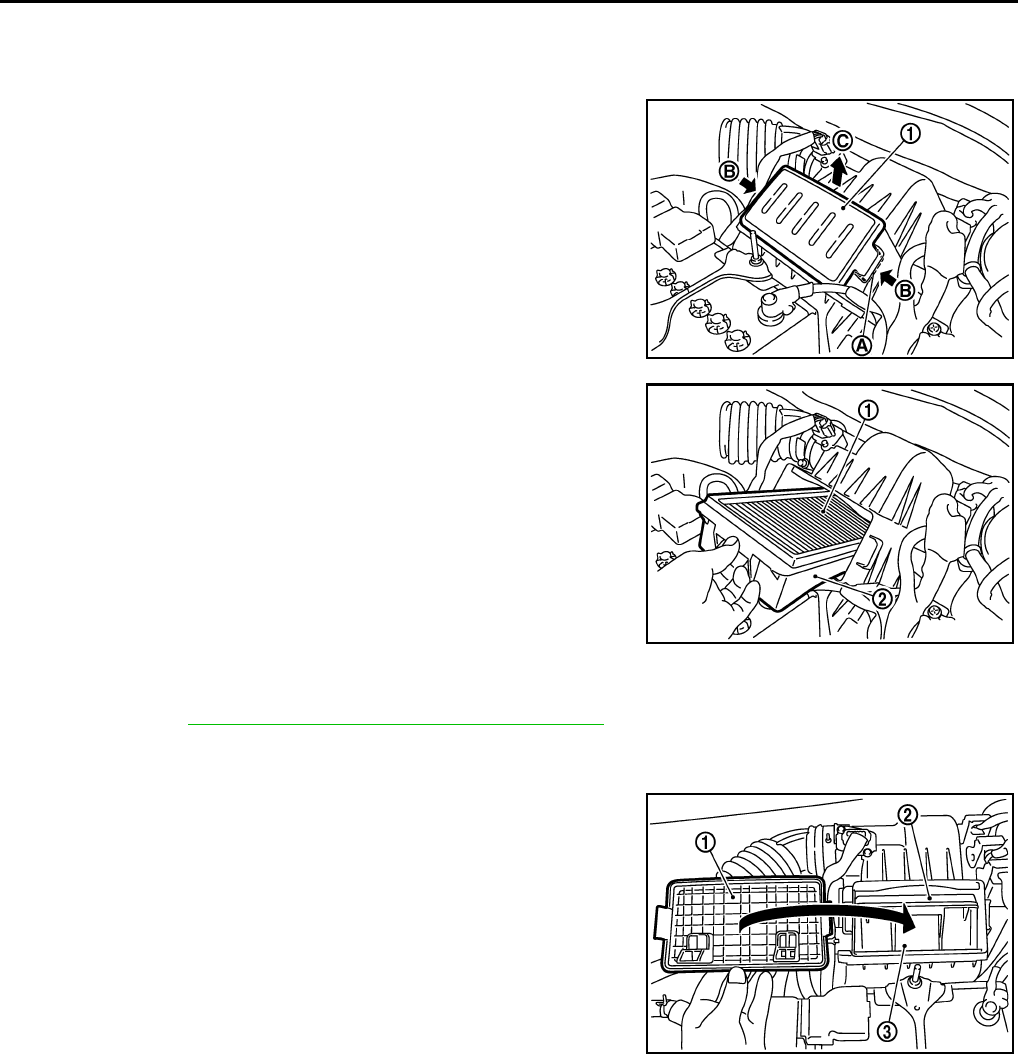
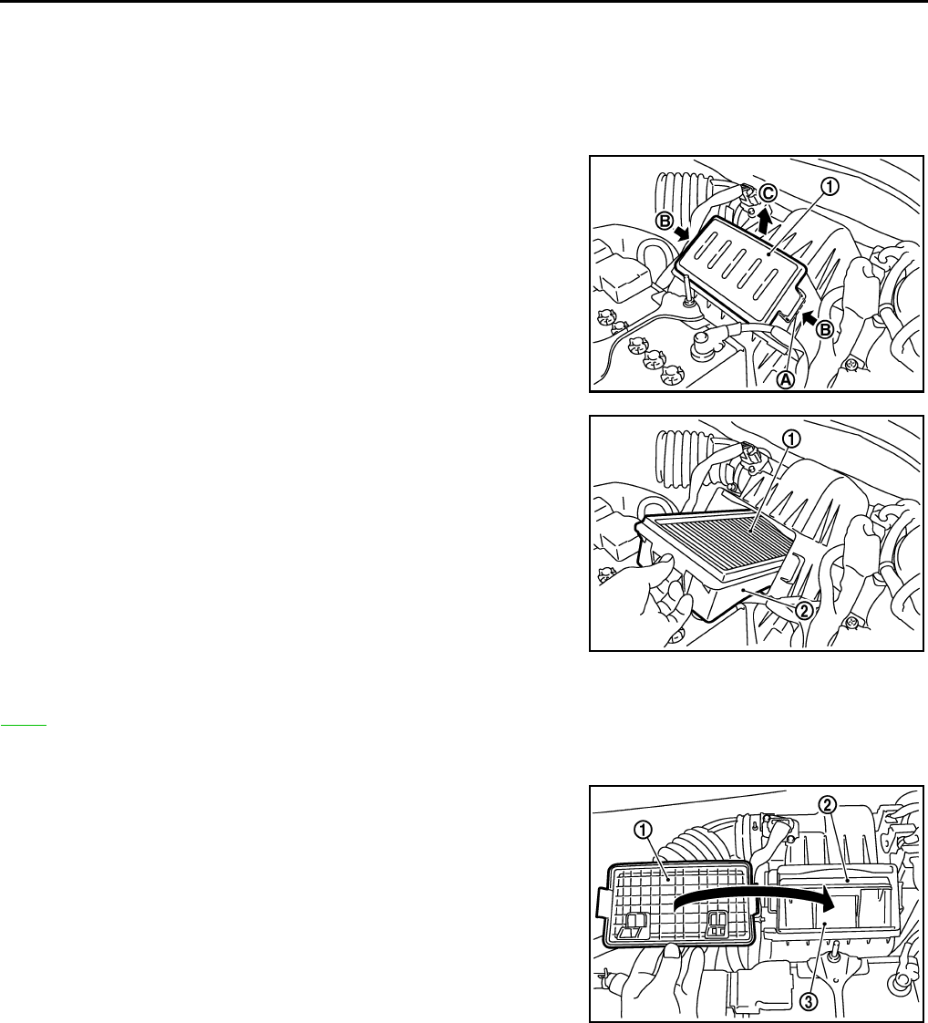
AIR CLEANER FILTER : Removal and Installation INFOID:0000000004806007
REMOVAL
1. Push the tabs (A) of both ends of the air cleaner cover (1) into
the inside (B).
2. Pull up the air cleaner cover (1) and remove it (C).
3. Remove air cleaner filter (1) and holder (2) assembly from the
air cleaner case.
4. Remove the air cleaner filter (1) from the holder (2).
INSPECTION AFTER REMOVAL
It is necessary to replace the air cleaner filter at the recommended intervals, more often under dusty driving
conditions. Refer to MA-9, "Introduction of Periodic Maintenance".
INSTALLATION
Installation is in the reverse order of removal.
• Install the air cleaner cover (1) in the direction shown.
• Air cleaner filter (2)
• Holder (3)
ENGINE OIL
ENGINE OIL : Inspection INFOID:0000000004806010
ENGINE OIL LEVEL
NOTE:
Park vehicle on a level surface, wait 10 minutes and check the engine oil level.
1. Pull out oil level gauge and wipe it clean.
PBIC3557J
PBIC3558J
PBIC3559J
Revision: October 2008
2009 Versa
ENGINE MAINTENANCE (HR16DE)
MA-21
< SERVICE INFORMATION >
C
D
E
F
G
H
I
J
K
M
A
B
MA
N
O
P
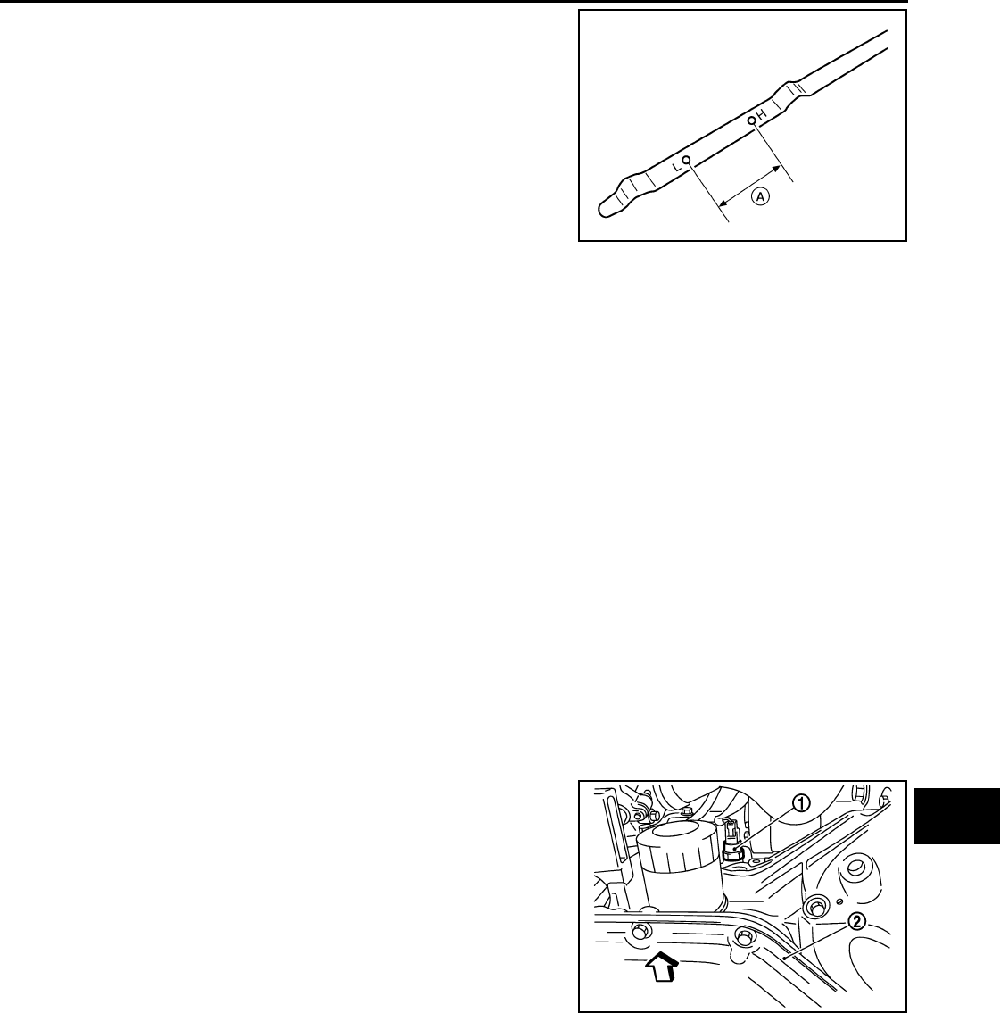
2. Insert oil level gauge and make sure the engine oil level is within
the range (A) shown.
3. If it is out of range, adjust it.
ENGINE OIL APPEARANCE
• Check engine oil for white milky or excessive contamination.
• If engine oil becomes white, it is highly probable that it is contaminated with engine coolant. Repair or
replace damaged parts.
ENGINE OIL LEAKAGE
Check for engine oil leakage around the following areas:
• Oil pan (upper and lower)
• Oil pan drain plug
• Oil pressure switch
• Oil filter
• Intake valve timing control solenoid valve
• Front cover
• Mating surface between cylinder head and camshaft bracket
• Mating surface between cylinder block and cylinder head
• Mating surface between cylinder head and rocker cover
• Crankshaft oil seals (front and rear)
• Oil filter (for intake valve timing control)
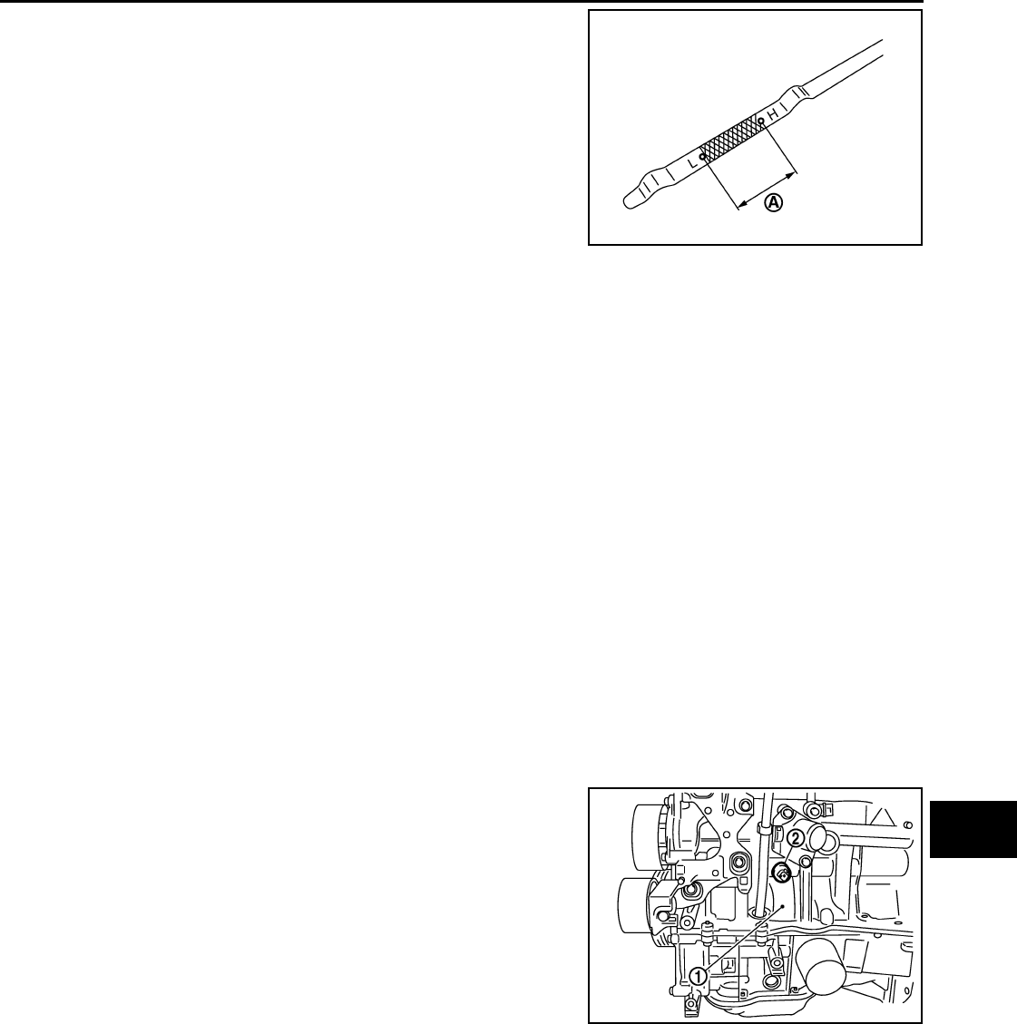
OIL PRESSURE CHECK
WARNING:
• Be careful not to burn yourself, as engine oil may be hot.
• For engine oil pressure check the transaxle should be in “ Park position” (A/T models) or “Neutral
position” (M/T models), and apply the parking brake securely.
1. Check engine oil level.
2. Disconnect harness connector at oil pressure switch (2), and
remove oil pressure switch (2) from the cylinder block (1) using
suitable tool.
CAUTION:
Never drop or shock oil pressure switch.
JPBIA0554ZZ
PBIC3817E
Revision: October 2008
2009 Versa
MA-22
< SERVICE INFORMATION >
ENGINE MAINTENANCE (HR16DE)
3. Install oil pressure gauge and hose.
4. Start engine and warm it up to normal operating temperature.
5. Check oil pressure with engine running under no-load. Refer to LU-10, "Engine Oil Pressure".
If difference is extreme, check oil passage and oil pump for oil leaks.
NOTE:
When engine oil temperature is low, engine oil pressure becomes high.
6. After the inspections, install oil pressure switch as follows:
a. Remove old liquid gasket adhering to oil pressure switch and engine.
b. Apply liquid gasket and tighten oil pressure switch to specification.
Use Genuine Silicone RTV Sealant or equivalent. Refer to GI-42, "Recommended Chemical Product
and Sealant".
c. Check engine oil level.
d. After warming up engine, make sure there are no leaks of engine oil with running engine.
ENGINE OIL : Draining INFOID:0000000004806011
WARNING:
• Be careful not to burn yourself, as engine oil may be hot.
• Prolonged and repeated contact with used engine oil may cause skin cancer. Try to avoid direct skin
contact with used engine oil. If skin contact is made, wash thoroughly with soap or hand cleaner as
soon as possible.
1. Warm up the engine, park vehicle on a level surface and check for engine oil leakage from engine compo-
nents. Refer to MA-20, "ENGINE OIL : Inspection".
2. Stop the engine and wait for 10 minutes.
3. Loosen oil filler cap.
4. Remove drain plug and then drain engine oil.
ENGINE OIL : Refilling INFOID:0000000004806012
1. Install drain plug with new washer. Refer to EM-39, "Exploded View".
CAUTION:
Be sure to clean drain plug and install with new washer.
2. Refill with new engine oil.
Engine oil specification and viscosity: Refer to MA-14, "Fluids and Lubricants".
CAUTION:
• The refill capacity depends on the engine oil temperature and drain time. Use these specifica-
tions for reference only.
• Always use oil level gauge to determine the proper amount of engine oil in the engine.
3. Warm up engine and check area around drain plug and oil filter for engine oil leakage.
4. Stop engine and wait for 10 minutes.
5. Check the engine oil level. Refer to MA-20, "ENGINE OIL : Inspection".
OIL FILTER
Tool number : ST25051001 (J-25695-1)
: ST25052000 (J-25695-2)
WBIA0571E
Oil pressure switch : Refer to EM-95, "Exploded View".
Revision: October 2008
2009 Versa
ENGINE MAINTENANCE (HR16DE)
MA-23
< SERVICE INFORMATION >
C
D
E
F
G
H
I
J
K
M
A
B
MA
N
O
P
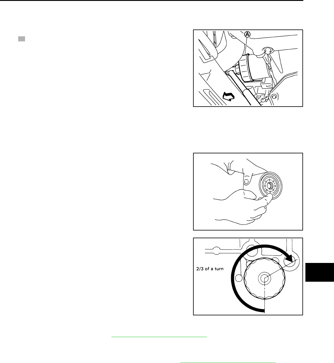
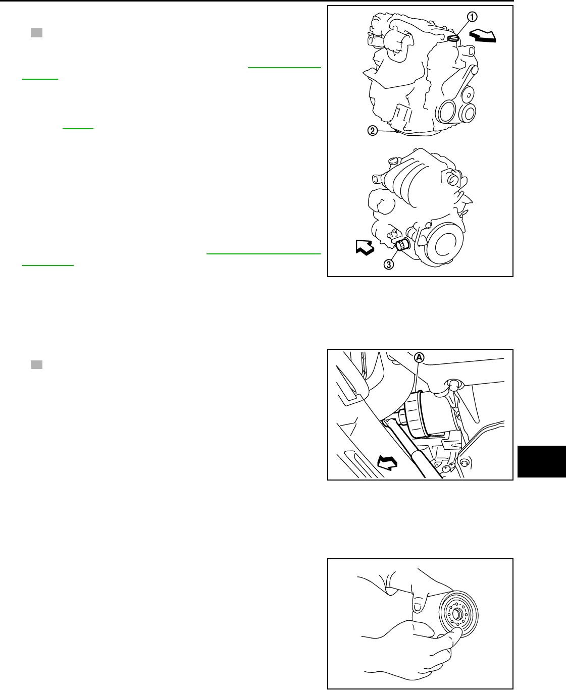
OIL FILTER : Removal and Installation INFOID:0000000004806013
REMOVAL
1. Remove oil filter using Tool (A).
• : Front
WARNING:
• Be careful not to get burned when engine and engine oil
may be hot.
CAUTION:
• Oil filter is provided with relief valve. Use Genuine
NISSAN Oil Filter or equivalent.
• When removing, prepare a shop cloth to absorb any
engine oil leakage or spillage.
• Do not spill engine oil on drive belt.
• Completely wipe off any engine oil that spills on engine and vehicle.
INSTALLATION
1. Remove foreign materials adhering to the oil filter installation surface.
2. Apply new engine oil to the oil seal contact surface of new oil fil-
ter.
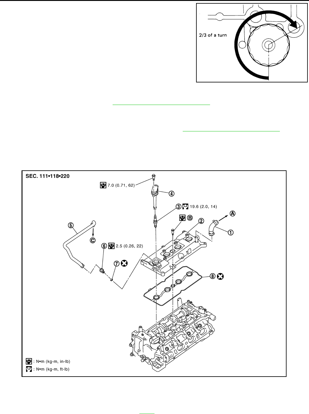
3. Screw oil filter manually until it touches the installation surface,
then tighten it by 2/3 turn. Or tighten to specification.
INSPECTION AFTER INSTALLATION
1. Check the engine oil level. Refer to MA-20, "ENGINE OIL : Inspection".
2. Start engine, and make sure there are no leaks of engine oil.
3. Stop engine and wait for 10 minutes.
4. Check the engine oil level and adjust as necessary. Refer to MA-20, "ENGINE OIL : Inspection".
SPARK PLUG (HR16DE)
Tool number : KV10115801 (J-38956)
PBIC3818E
SMA010
Oil filter: : 17.7 N·m (1.8 kg-m, 13 ft-lb)
SMA229B
Revision: October 2008
2009 Versa
MA-24
< SERVICE INFORMATION >
ENGINE MAINTENANCE (HR16DE)
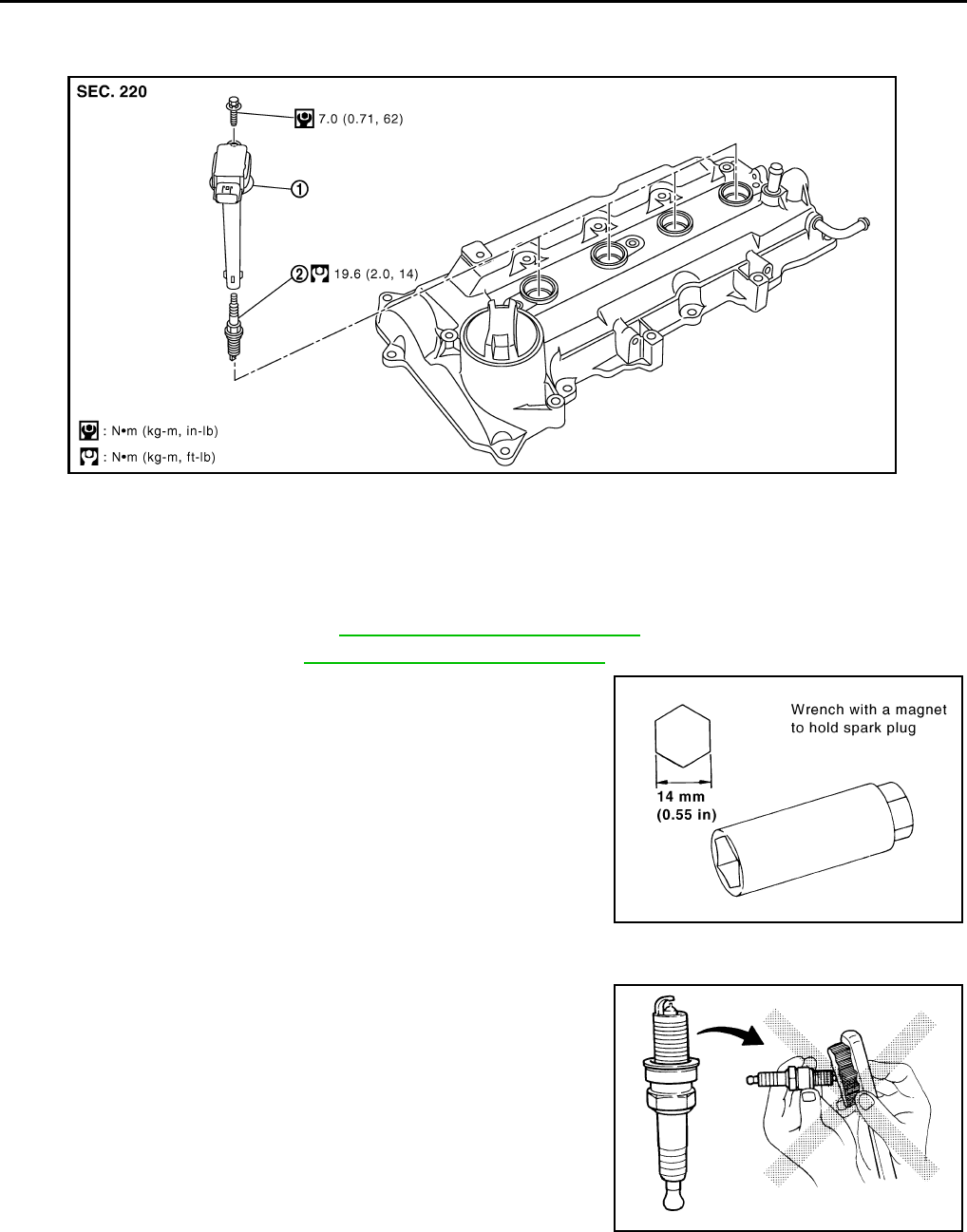
SPARK PLUG (HR16DE) : Exploded View INFOID:0000000004806008
SPARK PLUG (HR16DE) : Removal and Installation INFOID:0000000004806009
REMOVAL
1. Remove intake manifold. Refer to EM-28, "Removal and Installation".
2. Remove ignition coil. Refer to EM-46, "Removal and Installation".
3. Remove spark plug with a suitable tool.
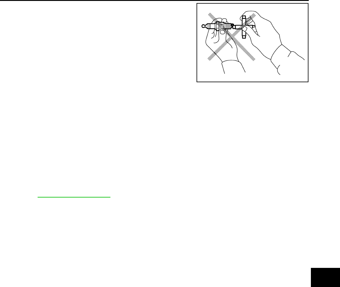
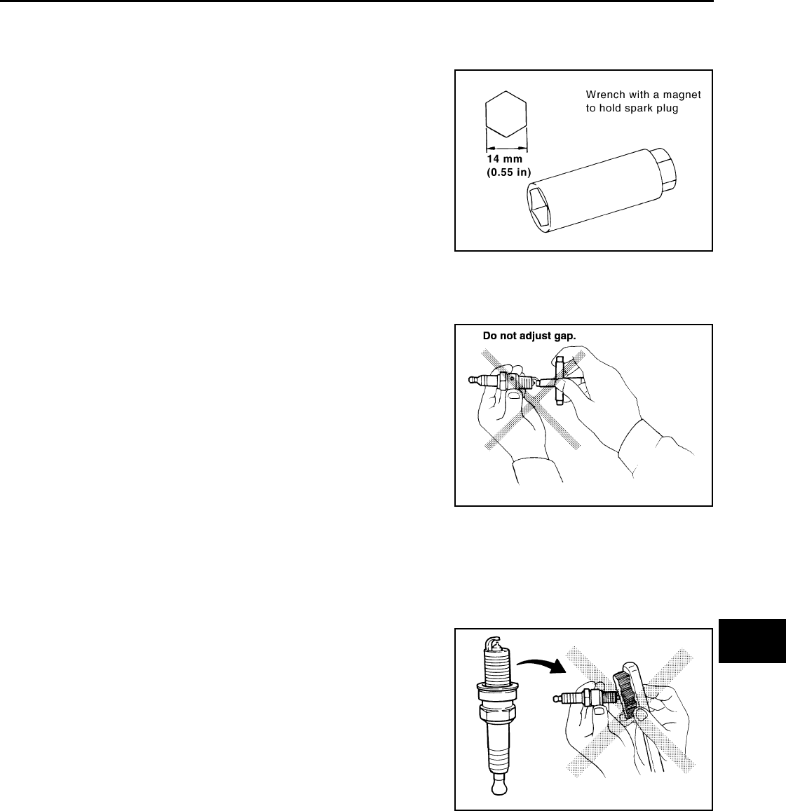
INSPECTION AFTER REMOVAL
CAUTION:
• Never drop or shock spark plug.
• Never use a wire brush for cleaning.
• If plug tip is covered with carbon, spark plug cleaner may be
used.
1. Ignition coil 2. Spark plug
PBIC3662E
PBIC3871E
Cleaner air
pressure: Less than 588 kPa (6 kg/cm2, 85 psi)
Cleaning time: Less than 20 seconds
SMA773C
Revision: October 2008
2009 Versa
ENGINE MAINTENANCE (HR16DE)
MA-25
< SERVICE INFORMATION >
C
D
E
F
G
H
I
J
K
M
A
B
MA
N
O
P
•Checking and adjusting plug gap is not required between
change intervals.
INSTALLATION
Installation is in the reverse order of removal.
EVAP VAPOR LINES
EVAP VAPOR LINES : Checking EVAP Vapor Line INFOID:0000000004803420
1. Visually inspect EVAP vapor lines for improper attachment and for cracks, damage, loose connections,
chafing and deterioration.
2. Inspect fuel tank filler cap vacuum relief valve for clogging, sticking, etc.
Refer to EC-74, "System Diagram".
JPBIA0031ZZ
Make : Denso
Part number : FXE20HE-11
Gap (nominal) : 1.1 mm (0.043 in)
Revision: October 2008
2009 Versa
MA-26
< SERVICE INFORMATION >
ENGINE MAINTENANCE (MR18DE)
ENGINE MAINTENANCE (MR18DE)
DRIVE BELT
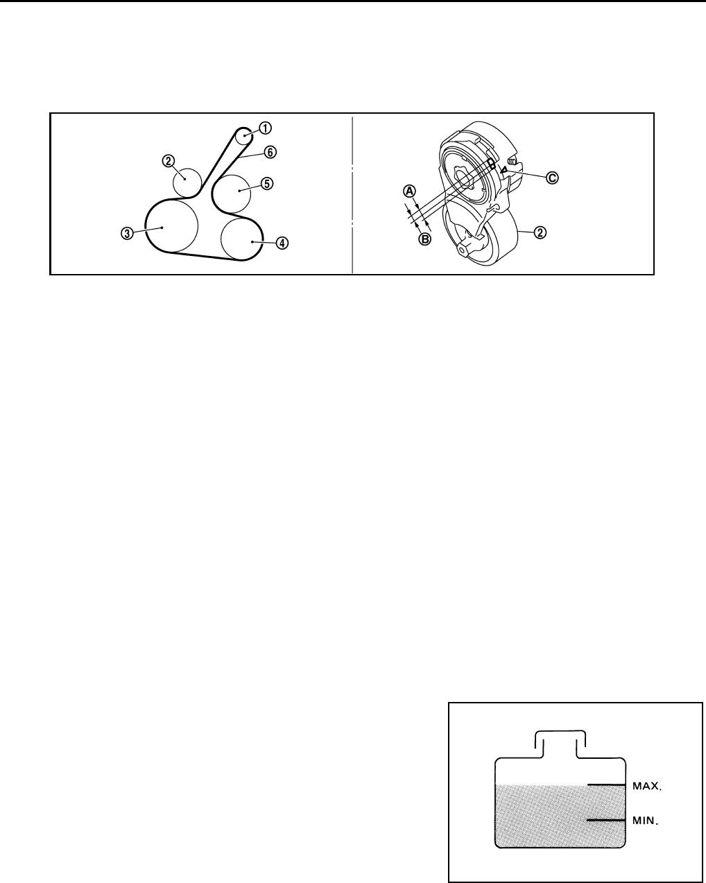
DRIVE BELT : Component INFOID:0000000004683270
DRIVE BELT : Checking Drive Belts INFOID:0000000004683271
WARNING:
Be sure to perform this step when the engine is stopped.
• Make sure that the indicator (notch on fixed side) of drive belt auto-tensioner is within the possible use range
(A).
NOTE:
• Check the drive belt auto-tensioner indication when the engine is cold.
• When new drive belt is installed, the indicator (notch on fixed side) should be within the range (B).
• Visually check entire drive belt for wear, damage or cracks.
• If the indicator (notch on fixed side) is out of the possible use range or belt is damaged, replace drive belt.
DRIVE BELT : Tension Adjustment INFOID:0000000004683272
Belt tension is not necessary, as it is automatically adjusted by drive belt auto-tensioner.
ENGINE COOLANT
ENGINE COOLANT : Inspection INFOID:0000000004683273
LEVEL CHECK
• Check if the reservoir tank engine coolant level is within the “MIN”
to “MAX” range when engine is cool.
• Adjust the engine coolant level as necessary.
CHECKING COOLING SYSTEM FOR LEAKS
1. Generator 2. Drive belt auto–tensioner 3. Crankshaft pulley
4. A/C compressor (models with A/C)
Idler pulley (models without A/C) 5. Water pump 6. Drive belt
A. Possible use range B. Range when new drive belt is installed C. Indicator
PBIC3137J
SMA412B
Revision: October 2008
2009 Versa
ENGINE MAINTENANCE (MR18DE)
MA-27
< SERVICE INFORMATION >
C
D
E
F
G
H
I
J
K
M
A
B
MA
N
O
P
To check for leaks, apply pressure to the cooling system using suit-
able tool and Tool.
WARNING:
Never remove the radiator cap when the engine is hot. Serious
burns could occur from high pressure coolant escaping from
the radiator.
CAUTION:
Higher pressure than specified may cause radiator damage.
ENGINE COOLANT : Changing Engine Coolant INFOID:0000000004683274
WARNING:
• To avoid being scalded, do not change engine coolant when engine is hot.
• Wrap a thick cloth around radiator cap and carefully remove the cap. First, turn the cap a quarter of a
turn to release built-up pressure. Then turn the cap all the way.
CAUTION:
• Do not spill engine coolant on drive belt.
DRAINING ENGINE COOLANT
1. Open radiator drain plug (1) at the bottom of radiator, and then
remove radiator cap.
• Front
When draining all of engine coolant in the system, open
water drain plug on cylinder block. Refer to EM-200.
CAUTION:
• Perform this step when engine is cold.
• Do not spill engine coolant on drive belt.
2. Remove reservoir tank as necessary, and drain engine coolant and clean reservoir tank before installing.
Refer to CO-38, "Component".
3. Check drained engine coolant for contaminants such as rust, corrosion or discoloration.
If contaminated, flush the engine cooling system.
REFILLING ENGINE COOLANT
1. Install the radiator drain plug. Install the reservoir tank and cylinder block drain plug, if removed for a total
system drain or for engine removal or repair.
•The radiator must be completely empty of coolant and water.
•Apply sealant to the threads of the cylinder block drain plugs. Use Genuine High Performance
Thread Sealant or equivalent. Refer to GI-42, "Recommended Chemical Product and Sealant".
2. If disconnected, reattach the upper radiator hose at the engine side.
3. Set the vehicle heater controls to the full HOT and heater ON position. Turn the vehicle ignition ON with
the engine OFF as necessary to activate the heater mode.
Tool number : EG17650301 (J-33984-A)
Testing pressure : 157 kPa (1.6 kg/cm2, 23 psi)
WBIA0568E
PBIC3799E
Radiator drain plug : Refer to CO-38, "Component".
Cylinder block drain plug : Refer to EM-200, "Disassembly and Assembly".
Revision: October 2008
2009 Versa
MA-28
< SERVICE INFORMATION >
ENGINE MAINTENANCE (MR18DE)
4. Install the Tool by installing the radiator cap adapter onto the
radiator neck opening. Then attach the gauge body assembly
with the refill tube and the venturi assembly to the radiator cap
adapter.
5. Insert the refill hose into the coolant mixture container that is
placed at floor level. Make sure the ball valve is in the closed
position.
•Use Genuine NISSAN Long Life Anti-freeze coolant or
equivalent, mixed with distilled water or demineralized
water.
Refer to MA-15, "Anti-freeze Coolant Mixture Ratio".
6. Install an air hose to the venturi assembly, the air pressure must
be within specification.
CAUTION:
The compressed air supply must be equipped with an air dryer.
7. The vacuum gauge will begin to rise and there will be an audible hissing noise. During this process open
the ball valve on the refill hose slightly. Coolant will be visible rising in the refill hose. Once the refill hose is
full of coolant, close the ball valve. This will purge any air trapped in the refill hose.
8. Continue to draw the vacuum until the gauge reaches 28 inches
of vacuum. The gauge may not reach 28 inches in high altitude
locations, use the vacuum specifications based on the altitude
above sea level.
9. When the vacuum gauge has reached the specified amount, disconnect the air hose and wait 20 seconds
to see if the system loses any vacuum. If the vacuum level drops, perform any necessary repairs to the
system and repeat steps 6 - 8 to bring the vacuum to the specified amount. Recheck for any leaks.
10. Place the coolant container (with the refill hose inserted) at the same level as the top of the radiator. Then
open the ball valve on the refill hose so the coolant will be drawn up to fill the cooling system. The cooling
system is full when the vacuum gauge reads zero.
CAUTION:
Do not allow the coolant container to get too low when filling, to avoid air from being drawn into
the cooling system.
11. Remove the Tool from the radiator neck opening.
12. Fill the cooling system reservoir tank to the specified level and install the radiator cap. Run the engine to
warm up the cooling system and top up the system as necessary.
FLUSHING COOLING SYSTEM
1. Install reservoir tank if removed. Refer to CO-38, "Component".
2. Install radiator drain plug.
•If water drain plug on cylinder block is removed, close and tighten it. Refer to EM-200, "Disas-
sembly and Assembly".
Tool number : KV991J0070 (J-45695)
Engine coolant capacity
(with reservoir tank)
: Refer to MA-14, "Fluids
and Lubricants".
Compressed air
supply pressure : 5.7 - 8.5 kPa (5.6 - 8.4 kg/cm2,
80 - 120 psi) LLIA0058E
Altitude above sea level Vacuum gauge reading
0 - 100 m (328 ft) : 28 inches of vacuum
300 m (984 ft) : 27 inches of vacuum
500 m (1,641 ft) : 26 inches of vacuum
1,000 m (3,281 ft) : 24 - 25 inches of vacuum LLIA0057E
Revision: October 2008
2009 Versa
ENGINE MAINTENANCE (MR18DE)
MA-29
< SERVICE INFORMATION >
C
D
E
F
G
H
I
J
K
M
A
B
MA
N
O
P
CAUTION:
Be sure to clean radiator drain plug and install with new O-ring. Refer to CO-38, "Component".
3. Fill radiator and reservoir tank with water and reinstall radiator cap.
4. Run engine and warm it up to normal operating temperature.
5. Rev engine two or three times under no-load.
6. Stop engine and wait until it cools down.
7. Drain water from the cooling system.
8. Repeat steps 1 through 7 until clear water begins to drain from radiator.
FUEL LINES
FUEL LINES : Checking Fuel Line INFOID:0000000004683691
Inspect fuel lines, fuel filler cap and fuel tank for improper attach-
ment, leaks, cracks, damage, loose connections, chafing or deterio-
ration.
If necessary, repair or replace damaged parts.
AIR CLEANER FILTER
AIR CLEANER FILTER : Component INFOID:0000000004683692
SMA803A
1. Air cleaner filter 2. Holder 3. Air cleaner cover
4. Seal 5. Mass air flow sensor 6. Air duct
7. PCV hose 8. Air duct (Inlet) 9. Air duct (Front)
WBIA0770E
Revision: October 2008
2009 Versa
MA-30
< SERVICE INFORMATION >
ENGINE MAINTENANCE (MR18DE)
AIR CLEANER FILTER : Changing Air Cleaner Filter INFOID:0000000004685431
REMOVAL
1. Push the tabs (A) of both ends of the air cleaner cover (1) into
the inside (B).
2. Pull up the air cleaner cover forward (C) and remove it.
3. Remove the air cleaner filter (1) and holder (2) assembly from
the air cleaner case.
4. Remove the air cleaner filter (1) from the holder (2).
INSPECTION AFTER REMOVAL
It is necessary to replace it at the recommended intervals, more often under dusty driving conditions. Refer to
MA-9.
INSTALLATION
Installation is in the reverse order of removal.
• Install the air cleaner cover (1) in the direction shown.
• Air cleaner filter (2)
• Holder (3)
ENGINE OIL
ENGINE OIL : Inspection INFOID:0000000004683694
ENGINE OIL LEVEL
NOTE:
Park vehicle on a level surface, wait 10 minutes and check the engine oil level.
1. Pull out oil level gauge and wipe it clean.
10. Clip 11. Resonator 12. Grommet
13. Air cleaner case A. To electric throttle control actuator B. To rocker cover
PBIC3557J
PBIC3558J
PBIC3559J
Revision: October 2008
2009 Versa
ENGINE MAINTENANCE (MR18DE)
MA-31
< SERVICE INFORMATION >
C
D
E
F
G
H
I
J
K
M
A
B
MA
N
O
P
2. Insert oil level gauge and make sure the engine oil level is within
the range (A) as shown.
3. If it is out of range, adjust it.
ENGINE OIL APPEARANCE
• Check engine oil for white milky or excessive contamination.
• If engine oil becomes white, it is highly probable that it is contaminated with engine coolant. Repair or
replace damaged parts.
ENGINE OIL LEAKAGE
Check for engine oil leakage around the following areas:
• Oil pan (upper and lower)
• Oil pan drain plug
• Oil pressure switch
• Oil filter
• Intake valve timing control solenoid valve
• Front cover
• Mating surface between cylinder block and cylinder head
• Mating surface between cylinder head and rocker cover
• Crankshaft oil seals (front and rear)
• Oil filter (for intake valve timing control)
OIL PRESSURE CHECK
WARNING:
• Be careful not to burn yourself, as engine oil may be hot.
• For engine oil pressure check the transaxle should be in “ Park position” (A/T models) and (CVT
models) or “Neutral position” (M/T models), and apply the parking brake securely.
1. Check engine oil level.
2. Remove undercover using power tool.
3. Disconnect harness connector at oil pressure switch (1), and
remove oil pressure switch using a suitable tool.
• Oil pan (lower) (2)
•⇐ Front
CAUTION:
Do not drop or shock oil pressure switch.
WBIA0776E
PBIC3310E
Revision: October 2008
2009 Versa
MA-32
< SERVICE INFORMATION >
ENGINE MAINTENANCE (MR18DE)
4. Install oil pressure gauge and hose.
5. Start engine and warm it up to normal operating temperature.
6. Check oil pressure with engine running under no-load. Refer to LU-22, "Standard and Limit".
If difference is extreme, check oil passage and oil pump for oil leaks.
NOTE:
When engine oil temperature is low, engine oil pressure becomes high.
7. After the inspections, install oil pressure switch as follows:
a. Remove old liquid gasket adhering to oil pressure switch and engine.
b. Apply liquid gasket and tighten oil pressure switch to specification.
Use Genuine Silicone RTV Sealant or equivalent. Refer to GI-42, "Recommended Chemical Product
and Sealant".
c. Check engine oil level.
d. After warming up engine, make sure there are no leaks of engine oil with running engine.
ENGINE OIL : Changing Engine Oil INFOID:0000000004683695
WARNING:
• Be careful not to burn yourself, as engine oil may be hot.
• Prolonged and repeated contact with used engine oil may cause skin cancer. Try to avoid direct skin
contact with used engine oil. If skin contact is made, wash thoroughly with soap or hand cleaner as
soon as possible.
1. Warm up the engine, park vehicle on a level surface and check for engine oil leakage from engine compo-
nents. Refer to MA-30, "ENGINE OIL : Inspection".
2. Stop the engine and wait for 10 minutes.
Tool number : ST25051001 (J-25695-1)
: ST25052000 (J-25695-2)
WBIA0571E
Oil pressure switch : 14.7 N·m (1.5 kg-m, 11 ft-lb)
Revision: October 2008
2009 Versa
ENGINE MAINTENANCE (MR18DE)
MA-33
< SERVICE INFORMATION >
C
D
E
F
G
H
I
J
K
M
A
B
MA
N
O
P
3. Loosen oil filler cap (1) and then remove drain plug (2).
• Oil filter (3)
• : Engine front
4. Drain engine oil.
5. Install drain plug (2) with new washer. Refer to EM-147, "Com-
ponent".
CAUTION:
Be sure to clean drain plug (2) and install with new washer.
6. Refill with new engine oil.
Refer to MA-14.
CAUTION:
• The refill capacity depends on the engine oil temperature
and drain time. Use these specifications for reference
only.
• Always use oil level gauge to determine the proper
amount of engine oil in the engine.
7. Warm up engine and check area around drain plug (2) and oil fil-
ter (3) for engine oil leakage.
8. Stop engine and wait for 10 minutes.
9. Check the engine oil level. Refer to MA-30, "ENGINE OIL :
Inspection".
OIL FILTER
OIL FILTER : Removal and Installation INFOID:0000000004683696
REMOVAL
1. Remove oil filter using Tool (A).
• : Front
WARNING:
• Be careful not to get burned when engine and engine oil
may be hot.
CAUTION:
• Oil filter is provided with relief valve. Use Genuine
NISSAN Oil Filter or equivalent.
• When removing, prepare a shop cloth to absorb any
engine oil leakage or spillage.
• Do not spill engine oil on drive belt.
• Completely wipe off any engine oil that spills on engine and vehicle.
INSTALLATION
1. Remove foreign materials adhering to the oil filter installation surface.
2. Apply new engine oil to the oil seal contact surface of new oil fil-
ter.
PBIC3915E
Tool number : KV10115801 (J-38956)
PBIC3818E
SMA010
Revision: October 2008
2009 Versa
MA-34
< SERVICE INFORMATION >
ENGINE MAINTENANCE (MR18DE)
3. Screw oil filter manually until it touches the installation surface,
then tighten it by 2/3 turn. Or tighten to specification.
INSPECTION AFTER INSTALLATION
1. Check the engine oil level. Refer to MA-30, "ENGINE OIL : Inspection".
2. Start engine, and make sure there are no leaks of engine oil.
3. Stop engine and wait for 10 minutes.
4. Check the engine oil level and adjust as necessary. Refer to MA-30, "ENGINE OIL : Inspection".
SPARK PLUG
SPARK PLUG : Component INFOID:0000000004683697
Oil filter: : 17.7 N·m (1.8 kg-m, 13 ft-lb)
SMA229B
1. PCV hose 2. Rocker cover 3. Spark plug
4. Ignition coil 5. PCV hose 6. PCV valve
7. O-ring 8. Gasket
A. To air duct B. Refer to MA-35. C. To intake manifold
PBIC3536J
Revision: October 2008
2009 Versa
ENGINE MAINTENANCE (MR18DE)
MA-35
< SERVICE INFORMATION >
C
D
E
F
G
H
I
J
K
M
A
B
MA
N
O
P
SPARK PLUG : Removal and Installation INFOID:0000000004683698
REMOVAL
1. Remove spark plug using suitable tool.
CAUTION:
Never drop or shock it.
INSPECTION AFTER REMOVAL
CAUTION:
• Never drop or shock spark plug.
• Checking and adjusting spark plug gap is not required
between change intervals.
• If spark plug tip is covered with carbon, a spark plug cleaner may be used.
• Never use wire brush for cleaning spark plug.
INSTALLATION
1. Install rocker cover gasket to rocker cover.
PBIC3871E
SMA806CA
Cleaner air pressure : Less than 588 kPa (5.88 bar, 6 kg/cm2, 85 psi)
Cleaning time : Less than 20 seconds
SMA773C
Revision: October 2008
2009 Versa
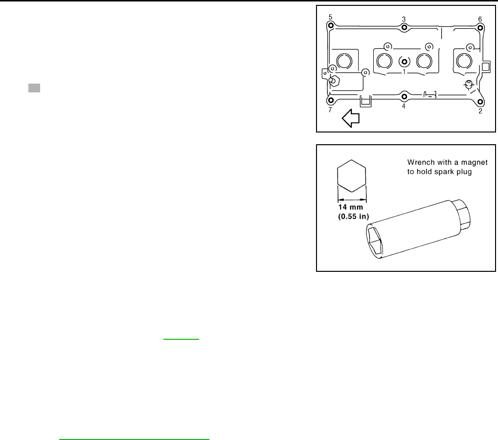
MA-36
< SERVICE INFORMATION >
ENGINE MAINTENANCE (MR18DE)
2. Install rocker cover.
• Tighten bolts in two steps separately in numerical order as
shown.
• Engine front
CAUTION:
Check if rocker cover gasket is not dropped from the instal-
lation groove of rocker cover.
3. Install spark plug using suitable tool.
CAUTION:
Never drop or shock it.
4. Install ignition coil.
CAUTION:
• Handle it carefully and avoid impacts.
• Never disassemble.
5. Install intake manifold. Refer to EM-141.
EVAP VAPOR LINES
EVAP VAPOR LINES : Checking EVAP Vapor Line INFOID:0000000004305200
1. Visually inspect EVAP vapor lines for improper attachment and for cracks, damage, loose connections,
chafing and deterioration.
2. Inspect fuel tank filler cap vacuum relief valve for clogging, sticking, etc.
Refer to EC-529, "Component Inspection".
1st step : 1.96 N·m (0.20 kg-m, 17 in-lb)
2nd step : 8.33 N·m (0.85 kg-m, 73 in-lb)
PBIC3151J
Make : DENSO
Part number : FXE20HR11
Gap (nominal) : 1.1 mm (0.043 in)
PBIC3871E
Revision: October 2008
2009 Versa
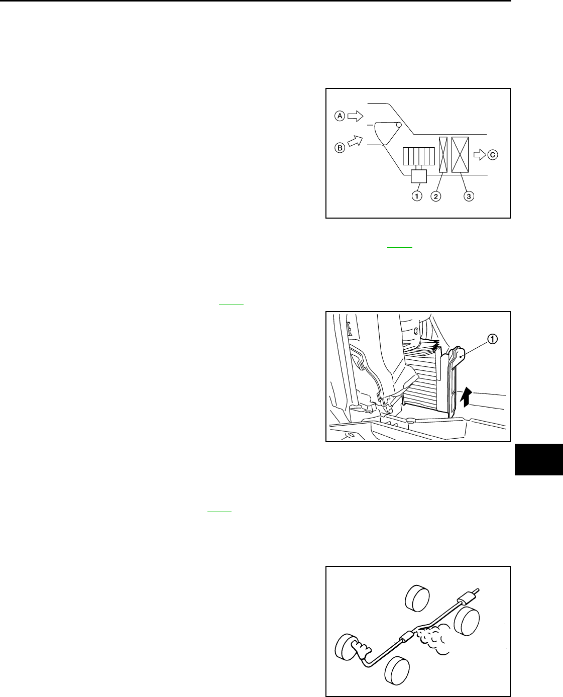
CHASSIS AND BODY MAINTENANCE
MA-37
< SERVICE INFORMATION >
C
D
E
F
G
H
I
J
K
M
A
B
MA
N
O
P
CHASSIS AND BODY MAINTENANCE
IN-CABIN MICROFILTER
IN-CABIN MICROFILTER : Removal and Installation INFOID:0000000004683699
FUNCTION
The fresh air (A) and the recirculated air (B) drawn inside the pas-
senger compartment by the blower fan (1) is kept clean (C) on either
mode by the air conditioner filter (2), located before the evaporator
(3), in the A/C unit assembly.
REPLACEMENT TIMING
Replace the air conditioner filter according to the maintenance schedules. Refer to MA-9.
NOTE:
The air conditioner filter caution label is located inside the glove box door.
REPLACEMENT PROCEDURES
1. Remove the glove box assembly. Refer to IP-11.
2. Compress the air conditioner filter (1) downward while sliding it
to the RH side of the vehicle to release the upper pawl.
3. Move the bottom of air conditioner filter (1) upward as shown to
release the bottom tab, then remove it.
4. Replace the air conditioner filter with new one and install the new filter in the A/C unit assembly.
CAUTION:
Make sure that the air conditioner filter lower tab is fully seated, and that the air conditioner upper
pawl is locked into place securing the new filter into the A/C unit assembly.
5. Install the glove box assembly. Refer to IP-11.
EXHAUST SYSTEM
EXHAUST SYSTEM : Checking Exhaust System INFOID:0000000004683700
Check exhaust pipes, muffler and mounting for improper attachment,
leaks, cracks, damage or deterioration.
• If necessary, repair or replace damaged parts.
CVT FLUID
WJIA2253E
SJIA0652E
SMA211A
Revision: October 2008
2009 Versa
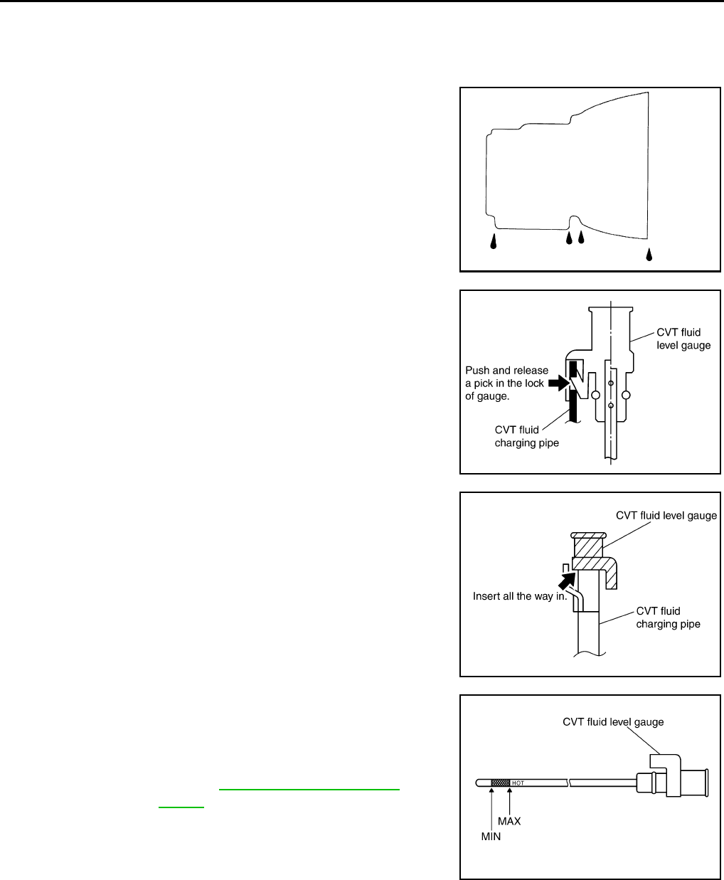
MA-38
< SERVICE INFORMATION >
CHASSIS AND BODY MAINTENANCE
CVT FLUID : Checking CVT Fluid (RE0F08A) INFOID:0000000004803426
FLUID LEVEL CHECK
Fluid level should be checked with the fluid warmed up to 50° to 80°C (122° to 176°F).
1. Check for fluid leakage.
2. With the engine warmed up, drive the vehicle to warm up the
CVT fluid. When ambient temperature is 20°C (68°F), it takes
about 10 minutes for the CVT fluid to warm up to 50° to 80°C
(122° to 176°F).
3. Park the vehicle on a level surface and set the parking brake.
4. With engine at idle, while depressing brake pedal, move the
selector lever throughout the entire shift range and return it to
the “P” position.
5. Press the tab on the CVT fluid level gauge to release the lock
and pull out the CVT fluid level gauge from the CVT fluid charg-
ing pipe.
6. Wipe fluid off the CVT fluid level gauge. Then rotate the CVT
fluid level gauge 180° and re-insert it into the CVT charging pipe
as far as it will go.
CAUTION:
Always use lint free paper towels to wipe fluid off the CVT
fluid level gauge.
7. Remove the CVT fluid level gauge and check that the fluid level
is within the specified range as shown. If the fluid level is at or
below the low side of the range, add the necessary specified
NISSAN CVT fluid through the CVT charging pipe.
CAUTION:
• Only use specified NISSAN CVT fluid.
• Do not overfill the CVT.
8. Install the CVT fluid level gauge to the CVT fluid charging pipe until it locks.
CAUTION:
When CVT fluid level gauge is installed into the CVT fluid charging pipe, make sure that the CVT
fluid level gauge is securely locked in place.
FLUID CONDITION CHECK
SMA146B
SCIA1933E
SCIA1931E
Fluid grade: Refer to MA-14, "Fluids and Lubri-
cants".
SCIA1932E
Revision: October 2008
2009 Versa
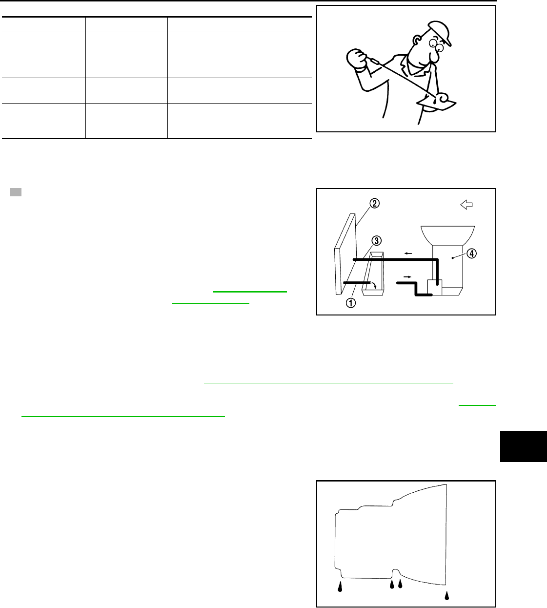
CHASSIS AND BODY MAINTENANCE
MA-39
< SERVICE INFORMATION >
C
D
E
F
G
H
I
J
K
M
A
B
MA
N
O
P
CVT FLUID : Changing CVT Fluid (RE0F08A) INFOID:0000000004803427
1. Warm up CVT fluid by driving the vehicle for 10 minutes.
• : Vehicle front
• Radiator (2)
• CVT fluid cooler hose [inlet side (3)]
• Transaxle assembly (4)
2. Drain CVT fluid from CVT fluid cooler hose [outlet side (1)] and
refill with new specified NISSAN CVT fluid in the CVT fluid
charging pipe with the engine running at idle speed.
CAUTION:
Only use the specified NISSAN CVT fluid.
3. Refill until new CVT fluid comes out from CVT fluid cooler hose [outlet side (1)].
NOTE:
About 30 to 50% extra fluid will be required for this procedure.
4. Check fluid level and condition. Refer to MA-38, "CVT FLUID : Checking CVT Fluid (RE0F08A)".
CAUTION:
Delete CVT fluid deterioration date with CONSULT-III after changing CVT fluid. Refer to CVT-51,
"CONSULT-III Function (TRANSMISSION)".
CVT FLUID : Checking CVT Fluid (RE0F08B) INFOID:0000000004803428
FLUID LEVEL CHECK
Fluid level should be checked with the fluid warmed up to 50° to 80°C (122° to 176°F).
1. Check for fluid leakage.
2. With the engine warmed up, drive the vehicle to warm up the
CVT fluid. When ambient temperature is 20°C (68°F), it takes
about 10 minutes for the CVT fluid to warm up to 50° to 80°C
(122° to 176°F).
3. Park the vehicle on a level surface and set the parking brake.
4. With engine at idle, while depressing brake pedal, move the
selector lever throughout the entire shift range and return it to
the “P” position.
Fluid status Conceivable cause Required operation
Varnished (viscous
varnish state)
Clutch, brake
scorched
Replace the CVT fluid and check the
CVT main unit and the vehicle for
malfunctions (wire harness, cooler
pipes, etc.)
Milky white or cloudy Water in the fluid Replace the CVT fluid and check for
places where water is getting in.
Large amount of
metal powder mixed
in fluid
Unusual wear of
sliding parts within
CVT
Replace the CVT fluid and check for
improper operation of the CVT.
ATA0022D
Fluid capacity and grade: Refer to MA-14, "Fluids
and Lubricants".
SCIA6088E
SMA146B
Revision: October 2008
2009 Versa
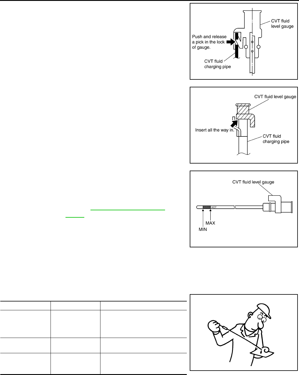
MA-40
< SERVICE INFORMATION >
CHASSIS AND BODY MAINTENANCE
5. Press the tab on the CVT fluid level gauge to release the lock
and pull out the CVT fluid level gauge from the CVT fluid charg-
ing pipe.
6. Wipe fluid off the CVT fluid level gauge. Then rotate the CVT
fluid level gauge 180° and re-insert it into the CVT charging pipe
as far as it will go.
CAUTION:
Always use lint free paper towels to wipe fluid off the CVT
fluid level gauge.
7. Remove the CVT fluid level gauge and check that the fluid level
is within the specified range as shown. If the fluid level is at or
below the low side of the range, add the necessary specified
NISSAN CVT fluid through the CVT charging pipe.
CAUTION:
• Only use specified NISSAN CVT fluid.
• Do not overfill the CVT.
8. Install the CVT fluid level gauge to the CVT fluid charging pipe until it locks.
CAUTION:
When CVT fluid level gauge is installed into the CVT fluid charging pipe, make sure that the CVT
fluid level gauge is securely locked in place.
FLUID CONDITION CHECK
CVT FLUID : Changing CVT Fluid (RE0F08B) INFOID:0000000004803429
1. Warm up CVT fluid by driving the vehicle for 10 minutes.
SCIA1933E
SCIA1931E
Fluid grade: Refer to MA-14, "Fluids and Lubri-
cants".
SCIA1932E
Fluid status Conceivable cause Required operation
Varnished (viscous
varnish state)
Clutch, brake
scorched
Replace the CVT fluid and check the
CVT main unit and the vehicle for
malfunctions (wire harness, cooler
pipes, etc.)
Milky white or cloudy Water in the fluid Replace the CVT fluid and check for
places where water is getting in.
Large amount of
metal powder mixed
in fluid
Unusual wear of
sliding parts within
CVT
Replace the CVT fluid and check for
improper operation of the CVT.
ATA0022D
Revision: October 2008
2009 Versa
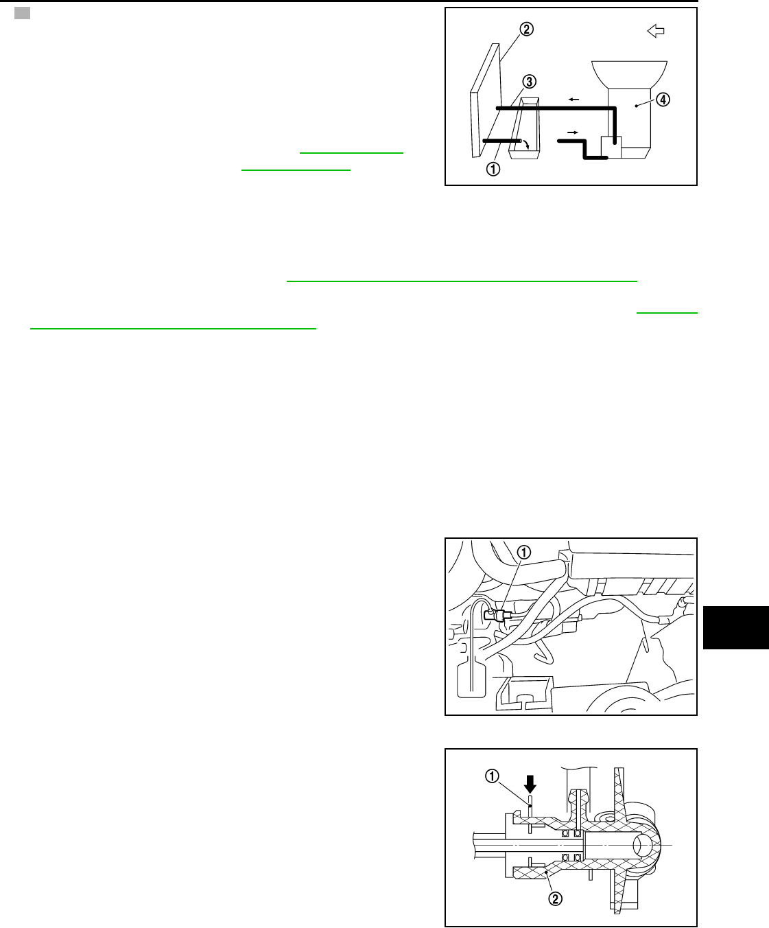
CHASSIS AND BODY MAINTENANCE
MA-41
< SERVICE INFORMATION >
C
D
E
F
G
H
I
J
K
M
A
B
MA
N
O
P
• : Vehicle front
• Radiator (2)
• CVT fluid cooler hose [inlet side (3)]
• Transaxle assembly (4)
2. Drain CVT fluid from CVT fluid cooler hose [outlet side (1)] and
refill with new specified NISSAN CVT fluid in the CVT fluid
charging pipe with the engine running at idle speed.
CAUTION:
Only use the specified NISSAN CVT fluid.
3. Refill until new CVT fluid comes out from CVT fluid cooler hose [outlet side (1)].
NOTE:
About 30 to 50% extra fluid will be required for this procedure.
4. Check fluid level and condition. Refer to MA-39, "CVT FLUID : Checking CVT Fluid (RE0F08B)".
CAUTION:
Delete CVT fluid deterioration date with CONSULT-III after changing CVT fluid. Refer to CVT-230,
"CONSULT-III Function (TRANSMISSION)".
CLUTCH FLUID
CLUTCH FLUID : Air Bleeding Procedure INFOID:0000000004683730
CAUTION:
Do not spill clutch fluid onto painted surfaces. If it spills, wipe up immediately and wash the affected
area with water.
NOTE:
• Do not use a vacuum assist or any other type of power bleeder on this system. Use of a vacuum assist or
power bleeder will not purge all the air from the system.
• Carefully monitor fluid level in reservoir tank during bleeding operation.
1. Fill master cylinder reservoir tank with new clutch fluid.
2. Connect a transparent vinyl tube and container to the bleeding
connector (1) on the CSC.
3. Depress and release the clutch pedal slowly and fully 15 times
at an interval of two to three seconds and release the clutch
pedal.
4. Push in the lock pin (1) of the bleeding connector (2), and maintain the position.
• RS5F91R transaxle models
CAUTION:
Hold the lock pin in to prevent the bleeding connector from
separating when fluid pressure is applied.
Fluid capacity and grade: Refer to MA-14, "Fluids
and Lubricants".
SCIA6088E
PCIB1494E
PCIB1495E
Revision: October 2008
2009 Versa
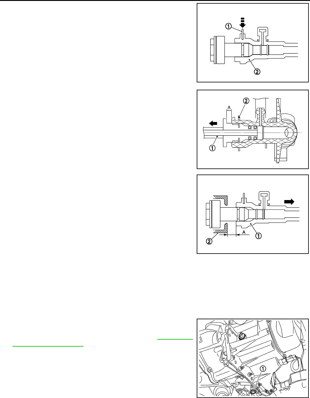
MA-42
< SERVICE INFORMATION >
CHASSIS AND BODY MAINTENANCE
• RS6F94R transaxle models
CAUTION:
Hold the lock pin in to prevent the bleeding connector from
separating when fluid pressure is applied.
5. Slide the clutch tube (1) in the direction of the arrow as shown to
the dimension (A). (For RS5F91R transaxle models)
2: bleeding connector
6. Slide bleeding connector (1) in the direction of the arrow as
shown to the dimension (A). (For RS6F94R transaxle models)
2: clutch housing
7. Depress the clutch pedal soon and hold it, and then bleed air
from the piping. wait for 5 seconds.
CAUTION:
Hold the clutch pedal down to prevent air from getting back
into the clutch system.
8. Return the clutch tube and lock pin to their original positions.
9. Release clutch pedal and wait for 5 seconds.
10. Repeat steps 3 to 8 until no bubbles are observed in the clutch fluid.
M/T OIL
M/T OIL : Draining (RS5F91R) INFOID:0000000004803421
1. Start engine and let it run to warm up transaxle.
2. Stop engine. Remove drain plug (1) and drain oil.
3. Set a new gasket on drain plug (1) and install it to transaxle and
tighten drain plug to the specified torque. Refer to MT-17, "Dis-
assembly and Assembly".
CAUTION:
Do not reuse gasket.
JPDIB0041ZZ
Dimension (A) : 5 mm (0.20 in)
PCIB1496E
Dimension (A) : 10 mm (0.39 in)
JPDIB0042ZZ
PCIB1504E
Revision: October 2008
2009 Versa
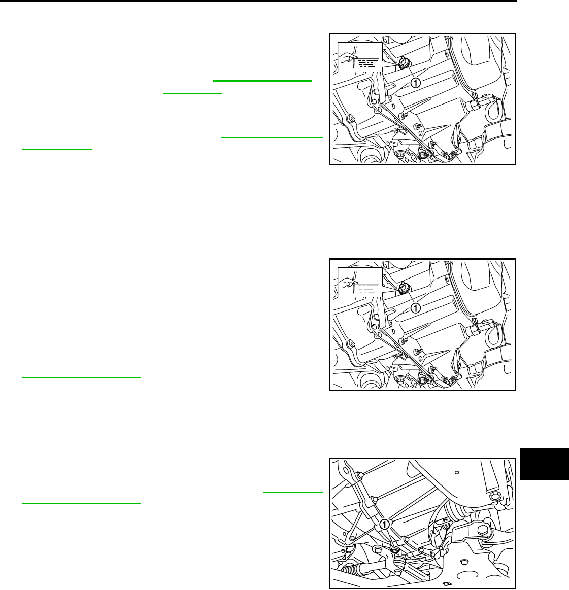
CHASSIS AND BODY MAINTENANCE
MA-43
< SERVICE INFORMATION >
C
D
E
F
G
H
I
J
K
M
A
B
MA
N
O
P
M/T OIL : Refilling (RS5F91R) INFOID:0000000004803422
1. Remove filler plug (1). Fill with new oil until oil level reaches the
specified limit near filler plug hole as shown.
2. After refilling oil, check oil level.
3. Set a new gasket on filler plug (1), then install it to transaxle and
tighten to the specified torque. Refer to MT-17, "Disassembly
and Assembly".
CAUTION:
Do not reuse gasket.
M/T OIL : Inspection (RS5F91R) INFOID:0000000004803423
LEAKAGE
Make sure that oil is not leaking from transaxle or around it.
LEVEL
1. Remove filler plug (1) and check oil level at filler plug hole as
shown.
CAUTION:
Do not start engine while checking oil level.
2. Set a new gasket on filler plug (1) and install it to the transaxle
case.
CAUTION:
Do not reuse gasket.
3. Tighten filler plug to the specified torque. Refer to MT-17, "Dis-
assembly and Assembly".
M/T OIL : Changing M/T Oil (RS6F94R) INFOID:0000000004803424
DRAINING
1. Start engine and let it run to warm up transaxle.
2. Stop engine. Remove drain plug (1) and drain oil.
3. Install a new gasket onto drain plug (1) and install it into tran-
saxle. Tighten drain plug to specification. Refer to MT-59, "Dis-
assembly and Assembly".
CAUTION:
Do not reuse gasket.
FILLING
Oil grade and capacity : Refer to MA-14, "Fluids and
Lubricants".
SCIA7119E
SCIA7119E
SCIA7622E
Revision: October 2008
2009 Versa
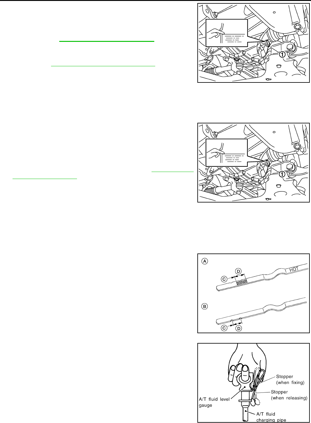
MA-44
< SERVICE INFORMATION >
CHASSIS AND BODY MAINTENANCE
1. Remove filler plug (1). Fill with new oil until oil level reaches the
specified limit at filler plug hole as shown.
2. After refilling oil, check oil level. Install a new gasket on filler plug
(1), then install it into transaxle. Tighten filler plug to specifica-
tion. Refer to MT-59, "Disassembly and Assembly".
CAUTION:
Do not reuse gasket.
M/T OIL : Checking M/T Oil (RS6F94R) INFOID:0000000004803425
OIL LEAKAGE AND OIL LEVEL
1. Make sure that oil is not leaking from transaxle or around it.
2. Remove filler plug (1) and check oil level at filler plug hole as
shown.
CAUTION:
Do not start engine while checking oil level.
3.
Install a new gasket onto filler plug (1) and install it into tran-
saxle. Tighten filler plug to specification. Refer to MT-59, "Disas-
sembly and Assembly".
CAUTION:
Do not reuse gasket.
A/T FLUID
A/T FLUID : Checking A/T Fluid INFOID:0000000004803430
1. Warm up engine.
2. Check for A/T fluid leakage.
3. Before driving, A/T fluid level can be checked at A/T fluid tem-
peratures of 30° to 50°C (86° to 122°F) using the “COLD” range
on A/T fluid level gauge.
• A : Front side
• B : Reverse side
• C : Add
• D : OK
a. Park vehicle on level surface and set parking brake.
b. Start engine and move selector lever through each gear posi-
tion. Leave selector lever in “P” position.
c. Check A/T fluid level with engine idling.
d. Remove A/T fluid level gauge and wipe clean with lint-free cloth.
CAUTION:
When wiping the A/T fluid level gauge, always use lint-free
cloth.
e. Re-insert A/T fluid level gauge into A/T fluid charging pipe as far
as it will go.
CAUTION:
Firmly fix the A/T fluid level gauge to the A/T fluid charging
pipe using the stopper attached.
f. Remove A/T fluid level gauge and note reading. If reading is at
low side of range, add A/T fluid to the A/T fluid charging pipe.
CAUTION:
Oil grade and capacity
: Refer to MA-14, "Fluids and Lubricants"
SCIA7623E
SCIA7623E
AWDIA0660G
B
SMA051D
Revision: October 2008
2009 Versa
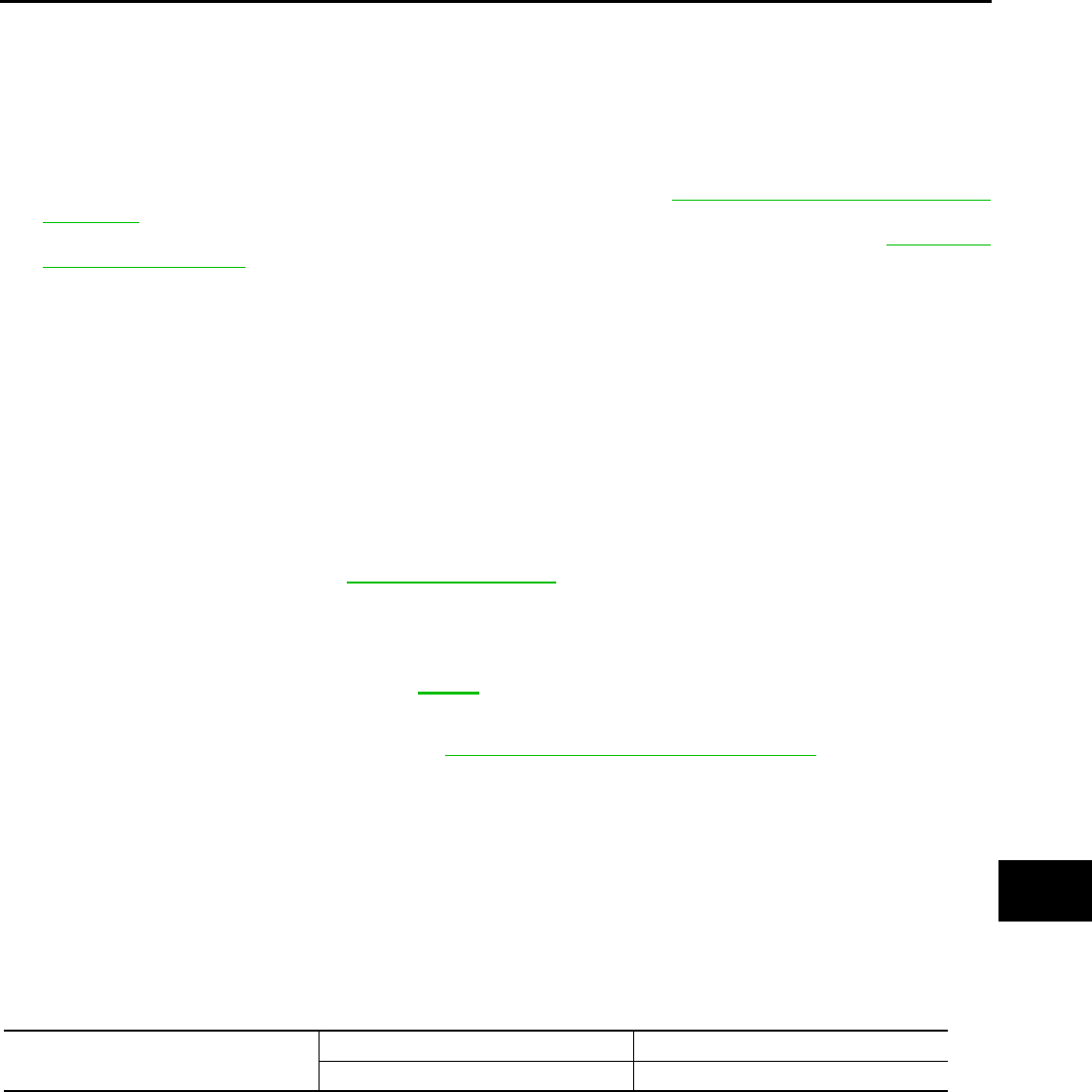
CHASSIS AND BODY MAINTENANCE
MA-45
< SERVICE INFORMATION >
C
D
E
F
G
H
I
J
K
M
A
B
MA
N
O
P
Do not overfill.
4. Drive vehicle for approximately 5 minutes.
5. Re-check A/T fluid level at A/T fluid temperatures of 50° to 80°C (122° to 176°F) using “HOT” range on A/
T fluid level gauge.
CAUTION:
• When wiping the A/T fluid level gauge, always use lint-free cloth.
• Firmly fix the A/T fluid level gauge to the A/T fluid charging pipe using the stopper attached.
6. Check A/T fluid condition and make any necessary repairs. Refer to AT-51, "Inspections Before Trouble
Diagnosis". If the A/T fluid contains frictional material (clutches, bands, etc.), or if the A/T is repaired, over-
hauled, or replaced, inspect and clean the A/T fluid cooler mounted in the radiator. Refer to AT-18, "A/T
Fluid Cooler Cleaning".
7. Install the removed A/T fluid level gauge into the A/T fluid charging pipe.
CAUTION:
Firmly fix the A/T fluid level gauge to the A/T fluid charging pipe using the stopper attached.
A/T FLUID : Changing A/T Fluid INFOID:0000000004803431
1. Warm up A/T fluid.
2. Stop engine.
3. Drain A/T fluid by removing the drain plug. Reinstall the drain plug to the specified torque.
CAUTION:
Do not reuse drain plug gasket.
4. Refill the transaxle with new specified A/T fluid through the A/T fluid charging pipe. Always refill the tran-
saxle with the same volume of A/T fluid that was drained out.
5. Run engine at idle speed for 5 minutes.
6. Check A/T fluid level and condition. Refer to MA-44, "A/T FLUID : Checking A/T Fluid".
WHEELS
WHEELS : Balancing Wheels INFOID:0000000004683837
Adjust wheel balance using road wheel center.
CAUTION:
• Be careful not to scratch the road wheel during removal.
• Use clip-on type wheel balance weights only.
Wheel balance (Maximum allowable unbalance):
Drain plug: Refer to AT-236, "Component".
Fluid grade and capacity: Refer to MA-14.
Maximum allowable unbalance Dynamic (At rim flange) Less than 5 g (0.18 oz) (one side)
Static (At rim flange) Less than 10 g (0.35 oz)
Revision: October 2008
2009 Versa
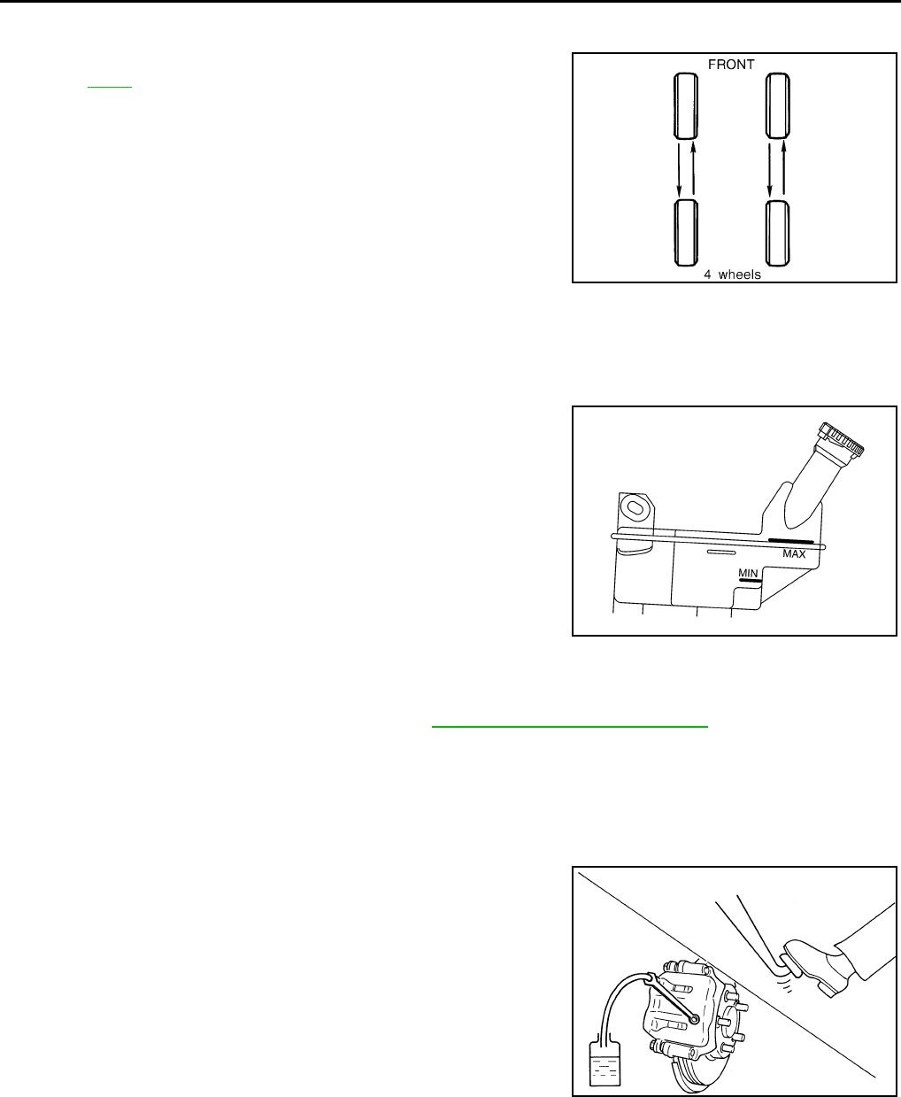
MA-46
< SERVICE INFORMATION >
CHASSIS AND BODY MAINTENANCE
WHEELS : Rotation INFOID:0000000004683838
• Follow the maintenance schedule for tire rotation service intervals.
Refer to MA-9.
• Do not include the T-type spare tire when rotating tires.
CAUTION:
• When installing wheels, tighten them diagonally by dividing
the work two to three times in order to prevent the wheels
from developing any distortion.
• Be careful not to tighten wheel nut at torque exceeding the
specification to prevent damage of disc rotor.
BRAKE FLUID LEVEL AND LEAKS
BRAKE FLUID LEVEL AND LEAKS : On Board Inspection INFOID:0000000004683839
CHECKING BRAKE FLUID LEVEL
• Make sure the fluid level in the reservoir tank is within the standard
(between MAX and MIN lines).
• Visually check around the reservoir tank for fluid leaks.
• If fluid level is excessively low, check brake system for fluid leaks.
• Release parking brake lever and see if brake warning lamp goes
off. If not, check brake system for fluid leaks.
BRAKE FLUID LEVEL AND LEAKS : Drain and Refill INFOID:0000000004683840
CAUTION:
• Refill using recommended brake fluid. Refer to MA-14, "Fluids and Lubricants".
• Never reuse drained brake fluid.
• Be careful not to splash brake fluid on painted areas; it may cause paint damage. If brake fluid is
splashed on painted areas, immediately wipe them with cloth and wash it away with water.
• Before working, disconnect connectors of ABS actuator and electric unit (control unit) or battery
negative terminal.
1. Connect a vinyl tube to bleed valve.
2. Depress the brake pedal, loosen the bleed valve, and gradually
remove the brake fluid.
Wheel nut : 113 N·m (12 kg-m, 83 ft-lb) SMA829C
SFIA3067E
WFIA0512E
Revision: October 2008
2009 Versa
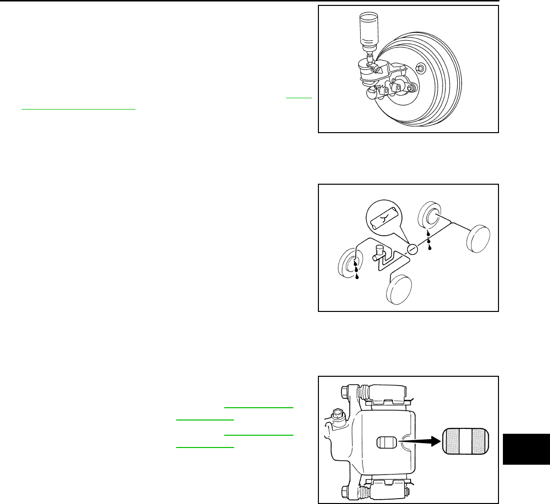
CHASSIS AND BODY MAINTENANCE
MA-47
< SERVICE INFORMATION >
C
D
E
F
G
H
I
J
K
M
A
B
MA
N
O
P
3. Clean inside of reservoir tank, and refill with new brake fluid.
4. Loosen bleed valve, depress brake pedal slowly to full stroke
and then release it. Repeat the procedure every 2 or 3 seconds
until the new brake fluid comes out, then close the bleed valve
while depressing the brake pedal. Repeat the same procedure
for each wheel.
5. Bleed the air from the brake hydraulic system. Refer to BR-9,
"Bleeding Brake System" .
BRAKE LINES AND CABLES
BRAKE LINES AND CABLES : Checking Brake Line and Cables INFOID:0000000004305214
• Check brake fluid lines and parking brake cables for improper
attachment, leaks, chafing, abrasions, deterioration, etc.
DISC BRAKE
DISC BRAKE : On Board Inspection INFOID:0000000004683841
PAD WEAR INSPECTION
• Check pad thickness from check hole on cylinder body.
DRUM BRAKE
DRUM BRAKE : Inspection INFOID:0000000004683843
INSPECTION
Lining Thickness Inspection
WFIA0513E
SBR389C
Standard thickness : Refer to BR-40, "Front
Disc Brake".
Repair limit thickness : Refer to BR-40, "Front
Disc Brake".
BRA0010D
Revision: October 2008
2009 Versa
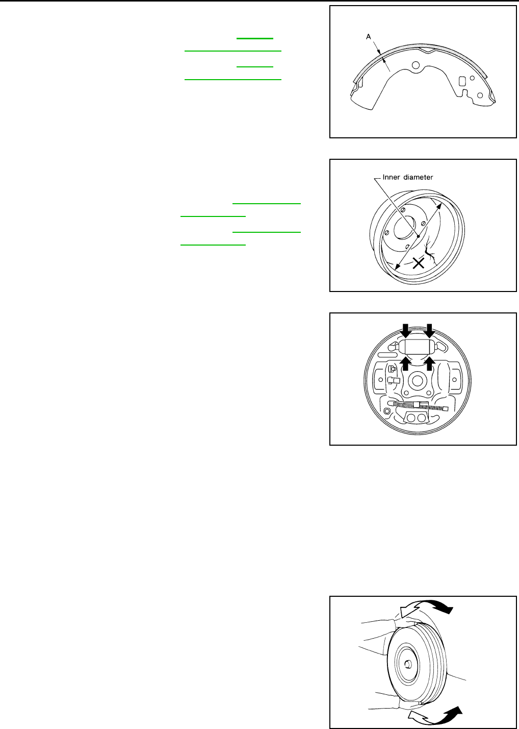
MA-48
< SERVICE INFORMATION >
CHASSIS AND BODY MAINTENANCE
Check lining thickness.
Drum Inner Diameter Inspection
Check inner diameter of brake drum.
Measurement area: lining contact surface (center)
Wheel Cylinder Leakage Inspection
• Check wheel cylinder for brake fluid leakage.
• Check for wear, damage, and looseness. If any non-standard con-
dition is found, replace it.
Other Inspections
Check the following:
• Inside of the drum for excessive wear, damage, and cracks.
• Lining for excessive wear, damage, and peeling.
• Shoe sliding surface for excessive wear and damage.
• Return spring for sagging.
• Check back plate for damage, cracks, and deformation. Replace back plate as necessary.
Replace applicable part as necessary.
AXLE AND SUSPENSION PARTS
AXLE AND SUSPENSION PARTS : Axle and Suspension Parts INFOID:0000000004305217
Check front and rear axle and suspension parts for excessive play,
cracks, wear or other damage.
• Shake each wheel to check for excessive play.
• Check wheel bearings for smooth operation.
• Check axle and suspension nuts and bolts for looseness.
• Check strut (shock absorber) for oil leakage or other damage.
• Check suspension ball joint for grease leakage and ball joint dust
cover for cracks or other damage.
Standard thickness (A) : Refer to BR-40,
"Rear Drum Brake"
Repair limit thickness (A) : Refer to BR-40,
"Rear Drum Brake"
SBR021A
Standard inner diameter : Refer to BR-40, "Rear
Drum Brake"
Repair limit inner diameter : Refer to BR-40, "Rear
Drum Brake"
SBR022A
WFIA0528E
SMA525A
Revision: October 2008
2009 Versa
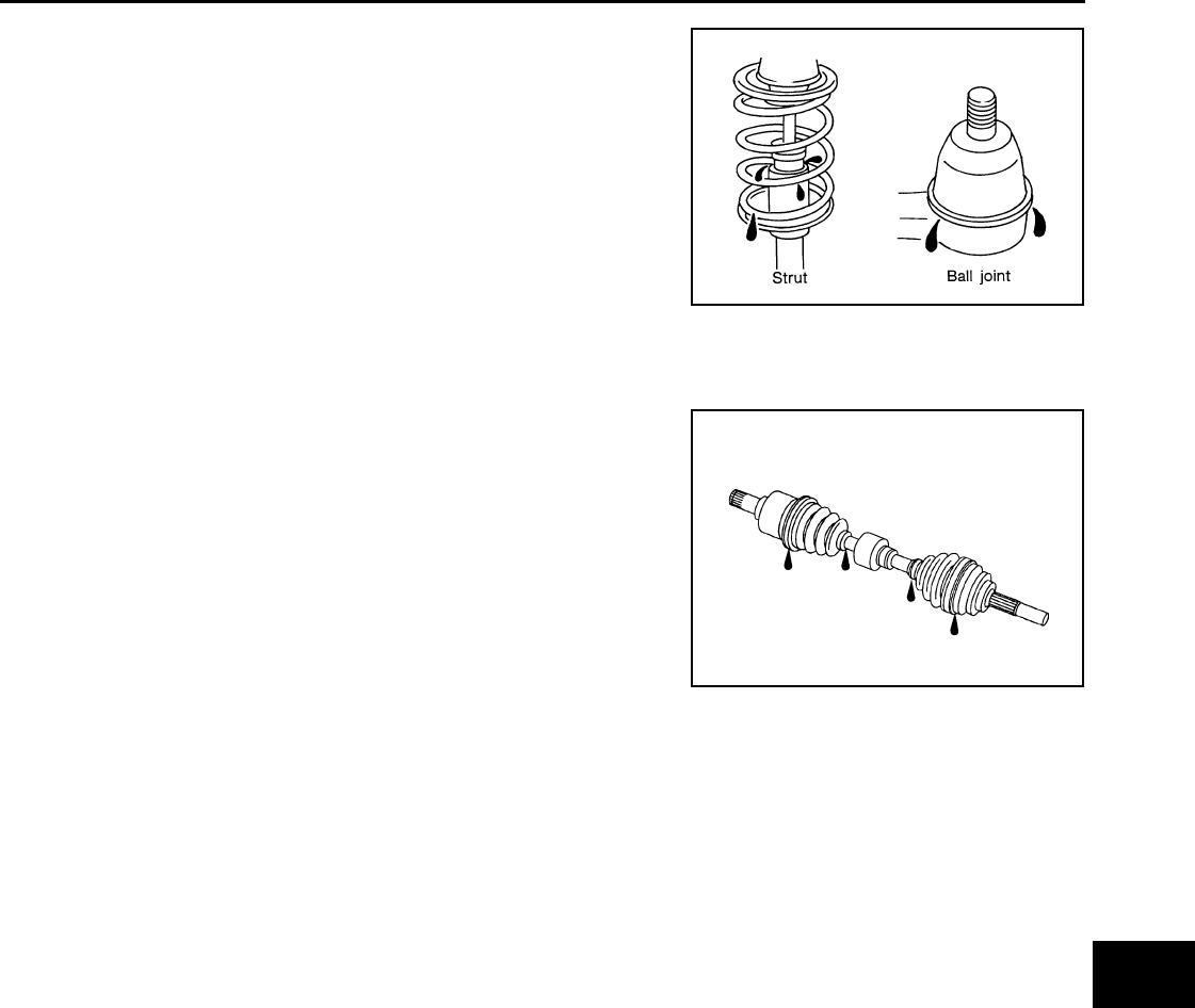
CHASSIS AND BODY MAINTENANCE
MA-49
< SERVICE INFORMATION >
C
D
E
F
G
H
I
J
K
M
A
B
MA
N
O
P
DRIVE SHAFT
DRIVE SHAFT : Drive Shaft INFOID:0000000004305218
Check boot and drive shaft for cracks, wear, damage and grease
leakage.
LOCKS, HINGES AND HOOD LATCH
SFA392B
SDIA1190J
Revision: October 2008
2009 Versa
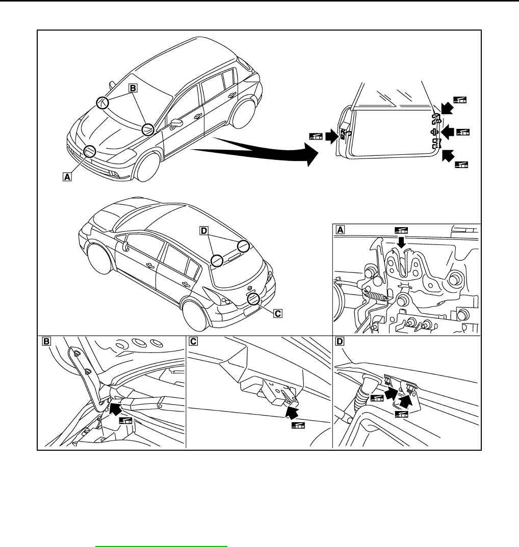
MA-50
< SERVICE INFORMATION >
CHASSIS AND BODY MAINTENANCE
LOCKS, HINGES AND HOOD LATCH : Lubricating Locks, Hinges and Hood Latch
INFOID:0000000004305219
SEAT BELT, BUCKLES, RETRACTORS, ANCHORS AND ADJUSTERS
SEAT BELT, BUCKLES, RETRACTORS, ANCHORS AND ADJUSTERS : Checking
Seat Belts, Buckles, Retractors, Anchors and Adjusters INFOID:0000000004305220
Check the seat belt buckles, webbing, retractors, anchors and adjusters. Replace any seat belt assembly as
necessary. Refer to SB-8, "Seat Belt Inspection" .
• Check the seat belt anchors for loose bolts, damage, or excessive wear.
• Check the seat belt webbing for any damage, cuts, fraying, or excessive wear.
• Check the retractor for smooth operation.
• Check the function of the buckles by inserting the seat belt tongue and checking for proper engagement of
the buckle and press the button on the buckle to check for proper release of the seat belt tongue.
CAUTION:
• After any collision, inspect all seat belt assemblies, including retractors and other attached compo-
nents, such as the guide rail set. NISSAN recommends replacing all seat belt assemblies in use dur-
ing a collision, unless they are not damaged and are inspected to confirm they are operating
properly after a minor collision.
Also inspect all seat belt assemblies that are not in use during a collision, and replace any compo-
nents if damaged or not operating properly. The seat belt pre-tensioner should be replaced even if
the seat belts are not in use during a frontal collision where the driver and passenger air bags have
been deployed.
PIIB7546E
Revision: October 2008
2009 Versa

CHASSIS AND BODY MAINTENANCE
MA-51
< SERVICE INFORMATION >
C
D
E
F
G
H
I
J
K
M
A
B
MA
N
O
P
• If any component of the seat belt assembly is suspected of being damaged or not operating prop-
erly, do not repair the component. Replace the components as an assembly.
• If the seat belt webbing is cut, frayed, or damaged then replace the seat belt assembly.
• Never lubricate the seat belt buckle or tongue.
• When replacing any seat belt assembly always use a Genuine NISSAN seat belt assembly.
Revision: October 2008
2009 Versa
