MC200 Installation And Setting Instructions Issue 3.1 (Issue 3.1) (Jan 2012)
User Manual: MC200 Instructions (Issue 3.1) (Jan 2012)
Open the PDF directly: View PDF ![]() .
.
Page Count: 18
MC200 Installation and Setting Instructions Issue 3.1 January 2012
Installation and Setting
Instructions
MC200
Contents
Section Page
1 Description 1
2 Specifications 1
3 Dimensions 2
4 Installation 2
5 Electrical Connections 2
6 Keypad Layout 3
7 User Controls 4
8 Engineer Controls 7
9 Temperature Sensors 9
10 Outputs 10
11 Handover 10
12 Short List of Parts 10
13 Terminal Layout 10
14. Connections to Powrmatic Heaters 11
1
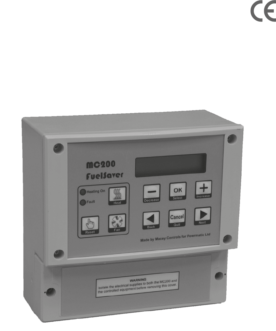
1. General Description
The MC200 is a high specification heating controller designed specifically to meet the demands of modern fuel efficient
heating equipment and the latest energy saving and environmental guidelines.
Optimum start technology is available that will continually monitor the heating systems previous performance to determine the
optimum time to turn the heating on to raise the space temperature to the required level for when occupancy begins. Optimum
stop can also be selected which can save energy at the end of the heating period.
The control uses a simple menu based structure for entering User settings.
The MC200 is protected by 2 levels of password. The User password may be set to restrict access to certain User controls. The
second password is for use by commissioning and servicing engineers and allows access to parameters normally used only in
the initial setting of the controller, a fault log and system reset facility.
The user keypad allows easy selection of the heating and fan only modes, the override functions and fault reset. These may
also be locked in various combinations to allow different levels of user accessibility.
The MC200 can give a readout of the hours the burner has operated, to help accessing servicing intervals and after being
programmed with the correct data, can also give an indication of the running costs of the heating appliance. In addition a
forward service date can be programmed. When the due date is reached a notification will be shown which alternates with the
normal display. This notification can only be removed by a Service Engineer.
The MC200 can be used to directly control both Hi/Lo and Modulating burners, the latter by an internally generated 0-10V
signal.
2. Specifications
General
Electricity supply 230V 50Hz Fused at 6A.
Internal Fuses F1 20mm 6.3A 230V.(HRC), F2 20mm 500mA 230V. (Non replaceable)
Display 2 line 5mm L.C.D.
Day set point range 10 - 30°C.
Night set point range 1 - 15°C.
Temperature accuracy 0.5 °C.
Overall switching differential Adjustable 0.5 - 10.0°C for Hi/Lo burner types.
Sensing Element Internal or remotely mounted up to 100m from control.
Switching contacts ratings 12A. 230V.ac. (resistive). All Volt Free
Modulating Control 0-10V dc
Heating ON Indicator Red L.E.D.when the heater is a single-stage burner, Green when the burner is a
Hi-Low type, and Yellow when the burner is a Modulating type.
Fault (Lockout) Indicator Orange L.E.D.
Protection Rating IP20
Software version 3.0
Clock
- The unit date range is from 01/01/2001 to 31/12/2099
- Leap years are recognised
- BST begins on the last Sunday in March and ends on the last Sunday in October. The time changes at 01:00 GMT.
- The clock may gain or lose up to 10 minutes in a year.
Time Switch
- 14 timers are provided in the software, and each can be assigned to any single day of the week, or to day groupings such as
weekdays or weekends. This allows greatest flexibility in operating the heating whenever required.
- It is possible to schedule timers so that one starts before another has finished. The heating will be on while any timer is
requiring Heat On, and the heating will turn off only when all timers have reached Heat Off. The requested temperature will
be set by the most recent timer to switch On. When an overlapping timer switches Off, the requested temperature will be set
by the remaining timer(s).
- No timer can be programmed to run past midnight, because it is assigned to a day of the week. If timed heating is required
across midnight, it must be provided by two timers, one ending at 23:59 and the other starting at 00:00. At midnight, all manual
over-rides and extensions are cleared.
Optimum Start
- The MC200 achieves Optimum start by keeping a moving record of how many minutes it takes to increase the temperature
per degree in each 3° band of temperature from 5°C to 20°C. The current overnight temperature is referenced and the MC200
can estimate how many minutes are required to bring the temperature to the required level. When Optimum Start is enabled the
switch-on time for the heater is then advanced accordingly to achieve the required temperature by the Heat On time i.e. the
warmer the night time temperature the closer the switch on time will be to the Heat On time
Optimum Stop
- The MC200 keeps a note of how many minutes are taken for the temperature to drop the number of degrees entered against
this parameter when the heating period ends. When Optimum Stop is enabled, the MC200 switches off the heating that
number of minutes early.
4 Installation
IMPORTANT
The MC200 and sensor MUST NOT be sited in areas of high electromagnetic fields, i.e. distribution boards, transformers or
heavy duty supply cables.
MC200
Location
Siting of the MC200 is important in that it must be fitted where the temperature will be generally representative of the area to
be heated. It should be installed 1.7m above floor level and away from draughty areas or areas subjected to direct heat from
sunlight, radiators etc. (Unless a remote sensor is being used). It should also be in a position easily accessible for
programming and operation.
Fixing
The MC200 will accept cable entry from the back and base. A sub base is available, as an optional extra, to allow cable entry
from the top or side.
Remove the two screws from the terminal cover and remove. Check that the unit fits in the intended mounting position. Using
the template on the packaging box mark the location of the three fixing holes. Secure the top fixing leaving approximately
5mm protruding. Hang the MC200 on the top fixing screw, line up the bottom fixing holes and secure using two screws.
Remote Sensor (optional)
Location
The sensor should be sited no further than 100m from the main unit. Siting of the sensor is important in that it must be fitted
where the temperature will be generally representative of the area to be heated. It should be installed 1.7m above floor level
and away from draughty areas or areas subjected to direct heat from sunlight, radiators etc.
Fixing
Remove cover and offer the sensor up to the intended mounting position and mark two fixing holes. Fix sensor base plate to
the wall.
5 Electrical Connections
IMPORTANT
Wiring external to the MC200 must be installed in accordance with I.E.E. Regulations together with any local regulations
which may apply. Wiring should be completed in conduit, entry for which is provided in the bottom of the unit. See external
wiring diagram Mains supply and control circuit wiring should be completed in cables not less than 0.5mm² and fan circuit in
not less than 1.5mm². The connection to the mains electrical supply can be taken from the appliance or a separate ‘local’
supply, but in both cases a local isolator must be fitted adjacent to the MC200. Should more than one appliance be controlled
from one MC200 an interfacing relay box MUST BE USED with the MC200 driving the relay coils.
WARNING - SENSOR WIRING
Sensor cable must be screened two core and a minimum of 0.6mm² if solid and 7 x 0.2mm² if multistrand. The screen must be
grounded only at the MC200. Wiring for the temperature sensor MUST BE RUN SEPARATELY and apart from ALL other
wiring. Failure to regard this instruction may cause the MC200 to malfunction and may render it faulty. Under no
circumstances must voltage be applied to the sensor connections - see Section 9 regarding alternative sensor inputs.
Burner Reset
Note: The reset terminal is internally connected to NEUTRAL when the reset button is pressed.
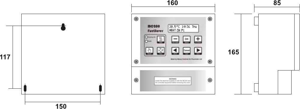
3 Dimensions
2
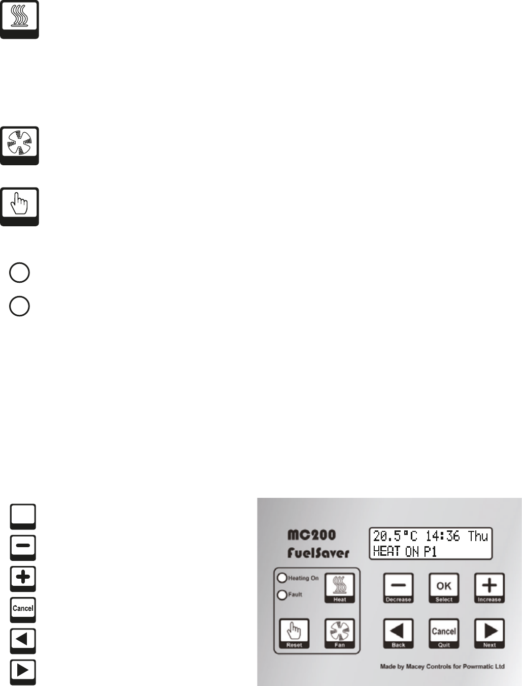
6 Keypad Layout
6.1 User keypad (3 Buttons) 7 User Controls
7.1 Direct Control
If configured during the commissioning stage the User has the following direct control of the heater without using the menu.
- If the Fault LED is on because the heater is at lockout, the user can reset the heater by pressing the Reset button.
- The user can switch on or off heating by pressing the Heat button.
- The user can start or cancel extension time by pressing the Heat button longer than 3 seconds.
- The user can run the fan without heating, by pressing the Fan button.
7.2 User Settings
7.2.1 General
The second line of the display shows what keypad buttons are active.
After changing settings press OK to save the new setting. To return to the normal display press Cancel or do not touch any
keys for 15 or more seconds.
Keys , , – and + will auto-repeat if held down longer than approximately half a second. The + key will automatically wrap
round from the maximum value to the minimum value and the – key will wrap the other way.
7.2.2 Description of User Settings
Temperature
This shows the temperature set by the currently active programme, and it is the target temperature for thermostatic control.
The user can increase or decrease the value to adjust comfort. This will not alter the set temperature associated with the
programme, but it will temporarily alter the target temperature for thermostatic control.
The effect of altering the temperature lasts until the current programme expires or until another programme changes the set
temperature requirement.
Note: the range of adjustment permitted may be limited during commissioning. Temperature adjustment can be disabled by a
setting within the user menu.
Clock Set
Sets the current date and the time of day. The correct date allows the MC200 to know the day of the week, allows for
automatic BST-GMT changeovers, carries out the holiday shutdown function and permits overrride password entry.
Programme Settings
The MC200 has 14 programmes, each of which can be assigned to any day of the week. Each programme can be given an ON
time, an OFF time and a set temperature. The user may organize the programmes in any way that suits. The simplest would be
one programme on in the morning, off at the end of the afternoon, active Monday to Friday.
If two or more programmes are active at the same time, for instance one is on all day and another is on between 11:00 and
13:00, then the set temperature of the second programme will apply between 11:00 and 13:00, and the set temperature of the
first programme will apply during the rest of the working day. Programme times increment in 5 minute steps.
Extension time (if set) applies when all programmes have reached the end of their set period for that day.
Optimum start applies at the beginning of the first programme to switch on and optimum stop applies at the end of the last
programme to switch off.
Holiday date
A future date can be set so that the heating will not operate on that date, and remains “OFF” for a consecutive number of days
from that date. The date includes the year number, ensuring that the holiday shutdown date is not automatically repeated the
following year.
During the holiday period the heater will only operate if the temperature falls below the frost temperature and if frost
temperature operation is selected “ON” in the engineer menu. The night temperature setting is ignored during holidays. During
the holiday period, manual operation of the fan or heater is permitted. Any manual operation still on at midnight will be
automatically cancelled.
Run Mode
The MC200 has three Run modes: WINTER, SUMMER and OFF.
Winter - the heating operates when any programme is in a “Heat On” period. The heating also operates to maintain the Night
Temperature if this has been set. The heating also operates when the temperature drops below the frost temperature.
Note: Summer/Winter mode has no connection with the clock change from GMT to BST.
Summer - the fan operates to circulate air when switched on manually. With certain types of heater or certain types of
installation, Fan-only operation may not be appropriate and the fan control circuit should not be used.
In SUMMER the heating never operates unless the temperature drops below the frost temperature. During
commissioning the frost temperature operation will be set to be on or off. If the frost setting is off, the heater will
not operate under frost conditions in any User mode.
Off - the heater never operates unless the temperature drops below the frost temperature (see above).
User Button Permissions
This menu option facilitates the user to enable or disable the following controls separately if it is required to restrict
unauthorized access to user controls. Note: User permissions are only effective when User access to the menu is protected by a
password.
Reset - Allows operation of the reset button
Change temperature - Allows temporary adjustment of the current set temperature
Heat Override - Allows switching ON/OFF and extension of Heat ON time
Fan override - Allows switching ON/OFF of the fan
Set Password
The user may enter a 4-digit password here. Once set, the password must be given before selected user controls may be
accessed or changed. “Set password” cannot be entered unless the password has been given.
As delivered, the MC200 has no User password restrictions, the user password being set to 0000. Entering a password of 0000
will remove all restrictions.
Extension time
A user can extend the heating to operate beyond the switch-off time of the last programme of the day, in 30minute increments,
by pressing the Heat button. This menu option allows a maximum extension period to be set, in units of 30minutes. If set to 0
minutes, extension is not permitted. Factory default setting: 1hour. Maximum setting 3hours.
Cost Log
This option shows the total hours run and the total cost of running since the log was last cleared. The display will show the
date when it was last cleared. For this option to function it is necessary to enter the fuel cost and heater rating (see Engineer
Menu for the latter). The cost log should be cleared whenever the heater type is changed.
For Hi/Lo heaters, there are two heater power entries and the MC200 will calculate the run cost according to the level of heat
requested. In the case of modulating control heaters, the cost is an estimate based on half the full heater power.
Password
Once a password has been set, the password must be entered at this menu option to allow access to selected user controls.
Once entered the password gives access to the User menu functions for 60 minutes. To re-apply the restrictions before the end
of the 60 minute period, select the ‘Enter password’ option and press OK without entering any digits. The display will show
‘Password CLOSED’.
Service Date
When the MC200 is installed the Commissioning Engineer may have entered a date for when the heating equipment requires
servicing. When this date is reached the MC200 fault indicator will be illuminated and the display will alternate between the
normal display and "Service due, call engineer". The Service Engineer can clear this display by entering a new service date
when the heating equipment has been serviced.
3
6.4 Programming keypad (6 Buttons)
6.2 Indicators
6.3 Display
The display normally shows
- the current air temperature as measured by the sensor, or the average temperature if two sensors are fitted.
- the time of day using 24-hr notation. The colon flashes once per second to confirm that the clock is running.
- the day of the week. Programmes are associated with individual days of the week or day-groups such as weekday or
weekend.
- the current setting of the heater: ON or OFF, as determined by the internal programmes (the display will say ON even if
the MC200 is not currently calling for heat because the thermostat is satisfied) or
- for High/Low and Modulating burners an indication of the heat demand: HEAT HI or HEAT LO for Hi-Low burners, or a
simple bar-graph display for modulating control heaters where 1 bar is low fire and 10 bars is high fire.
- Pn where n represents the active programme number.
Heating On - Is illuminated when the MC200 is calling for heat (It does not confirm that the heating is actually
working). It shows Red when the heater is a single-stage burner, Green when the heater is a Hi-Low type, and
Yellow when the heater has a Modulating burner.
Fault - Is illuminated when the burner control is at lockout or when a service call is due (if this has been set) or
when there is a sensor fault.
Select Button - Press to accept changes.
Select
OK
Back Button - Press to enter User Menu, go
back to previous screen.
Back
Reset Button - Press to reset the burner controls from lockout, (when this facility is available on the heater).
Reset
Heat Button - (Note: this facility may be limited or disabled by the User).
If heating is ON (via programme)
- pressing the Heat button for less than 2 seconds overrides the programme to OFF. Any extension time that has
been set is cancelled.
- pressing the heat button for more than 3 seconds determines that heat will remain on for an extension time after
the programmed off time. The extension timer will increase in 30 minute steps, up to the maximum allowed
period, and then revert to 0 minutes. Release the button when the required extension period is showing.
If heating is OFF (via override)
- pressing the Heat button removes override and reverts to the current programme.
If heating is OFF (via programme)
- pressing the Heat button for less than 2 seconds brings on heating for 30 minutes.
- pressing the heat button for more than 3 seconds will increase the on time in 30 minute steps, up to the maximum
allowed period, and then revert to 0 minutes. Release the button when the required heating period is showing.
Heat
Cancel Button - Press to exit without saving
change values.
Quit
Decrease Button - Press to decrease values.
Decrease
Increase Button - Press to increase values.
Increase
Fan Button -
In WINTER mode and OFF mode, the Fan button has no control over the air heater fan.
In SUMMER mode, the Fan button switches on the fan for air circulation, and another press switches it off. If the
fan is left on, it will be automatically switched off at midnight. If the fan is running because the heating is on and
the fan is in Auto or Const mode, the Fan button cannot switch it off.
If the fan is in On mode, it always runs, in WINTER, SUMMER and OFF. The Fan button cannot switch it off.
Fan
Next Button - Press to to enter User Menu,
go forward to next screen.
Next
7 User Controls
7.1 Direct Control
If configured during the commissioning stage the User has the following direct control of the heater without using the menu.
- If the Fault LED is on because the heater is at lockout, the user can reset the heater by pressing the Reset button.
- The user can switch on or off heating by pressing the Heat button.
- The user can start or cancel extension time by pressing the Heat button longer than 3 seconds.
- The user can run the fan without heating, by pressing the Fan button.
7.2 User Settings
7.2.1 General
The second line of the display shows what keypad buttons are active.
After changing settings press OK to save the new setting. To return to the normal display press Cancel or do not touch any
keys for 15 or more seconds.
Keys , , – and + will auto-repeat if held down longer than approximately half a second. The + key will automatically wrap
round from the maximum value to the minimum value and the – key will wrap the other way.
7.2.2 Description of User Settings
Temperature
This shows the temperature set by the currently active programme, and it is the target temperature for thermostatic control.
The user can increase or decrease the value to adjust comfort. This will not alter the set temperature associated with the
programme, but it will temporarily alter the target temperature for thermostatic control.
The effect of altering the temperature lasts until the current programme expires or until another programme changes the set
temperature requirement.
Note: the range of adjustment permitted may be limited during commissioning. Temperature adjustment can be disabled by a
setting within the user menu.
Clock Set
Sets the current date and the time of day. The correct date allows the MC200 to know the day of the week, allows for
automatic BST-GMT changeovers, carries out the holiday shutdown function and permits overrride password entry.
Programme Settings
The MC200 has 14 programmes, each of which can be assigned to any day of the week. Each programme can be given an ON
time, an OFF time and a set temperature. The user may organize the programmes in any way that suits. The simplest would be
one programme on in the morning, off at the end of the afternoon, active Monday to Friday.
If two or more programmes are active at the same time, for instance one is on all day and another is on between 11:00 and
13:00, then the set temperature of the second programme will apply between 11:00 and 13:00, and the set temperature of the
first programme will apply during the rest of the working day. Programme times increment in 5 minute steps.
Extension time (if set) applies when all programmes have reached the end of their set period for that day.
Optimum start applies at the beginning of the first programme to switch on and optimum stop applies at the end of the last
programme to switch off.
Holiday date
A future date can be set so that the heating will not operate on that date, and remains “OFF” for a consecutive number of days
from that date. The date includes the year number, ensuring that the holiday shutdown date is not automatically repeated the
following year.
During the holiday period the heater will only operate if the temperature falls below the frost temperature and if frost
temperature operation is selected “ON” in the engineer menu. The night temperature setting is ignored during holidays. During
the holiday period, manual operation of the fan or heater is permitted. Any manual operation still on at midnight will be
automatically cancelled.
Run Mode
The MC200 has three Run modes: WINTER, SUMMER and OFF.
Winter - the heating operates when any programme is in a “Heat On” period. The heating also operates to maintain the Night
Temperature if this has been set. The heating also operates when the temperature drops below the frost temperature.
Note: Summer/Winter mode has no connection with the clock change from GMT to BST.
Summer - the fan operates to circulate air when switched on manually. With certain types of heater or certain types of
installation, Fan-only operation may not be appropriate and the fan control circuit should not be used.
In SUMMER the heating never operates unless the temperature drops below the frost temperature. During
commissioning the frost temperature operation will be set to be on or off. If the frost setting is off, the heater will
not operate under frost conditions in any User mode.
Off - the heater never operates unless the temperature drops below the frost temperature (see above).
User Button Permissions
This menu option facilitates the user to enable or disable the following controls separately if it is required to restrict
unauthorized access to user controls. Note: User permissions are only effective when User access to the menu is protected by a
password.
Reset - Allows operation of the reset button
Change temperature - Allows temporary adjustment of the current set temperature
Heat Override - Allows switching ON/OFF and extension of Heat ON time
Fan override - Allows switching ON/OFF of the fan
Set Password
The user may enter a 4-digit password here. Once set, the password must be given before selected user controls may be
accessed or changed. “Set password” cannot be entered unless the password has been given.
As delivered, the MC200 has no User password restrictions, the user password being set to 0000. Entering a password of 0000
will remove all restrictions.
Extension time
A user can extend the heating to operate beyond the switch-off time of the last programme of the day, in 30minute increments,
by pressing the Heat button. This menu option allows a maximum extension period to be set, in units of 30minutes. If set to 0
minutes, extension is not permitted. Factory default setting: 1hour. Maximum setting 3hours.
Cost Log
This option shows the total hours run and the total cost of running since the log was last cleared. The display will show the
date when it was last cleared. For this option to function it is necessary to enter the fuel cost and heater rating (see Engineer
Menu for the latter). The cost log should be cleared whenever the heater type is changed.
For Hi/Lo heaters, there are two heater power entries and the MC200 will calculate the run cost according to the level of heat
requested. In the case of modulating control heaters, the cost is an estimate based on half the full heater power.
Password
Once a password has been set, the password must be entered at this menu option to allow access to selected user controls.
Once entered the password gives access to the User menu functions for 60 minutes. To re-apply the restrictions before the end
of the 60 minute period, select the ‘Enter password’ option and press OK without entering any digits. The display will show
‘Password CLOSED’.
Service Date
When the MC200 is installed the Commissioning Engineer may have entered a date for when the heating equipment requires
servicing. When this date is reached the MC200 fault indicator will be illuminated and the display will alternate between the
normal display and "Service due, call engineer". The Service Engineer can clear this display by entering a new service date
when the heating equipment has been serviced.
4
7 User Controls
7.1 Direct Control
If configured during the commissioning stage the User has the following direct control of the heater without using the menu.
- If the Fault LED is on because the heater is at lockout, the user can reset the heater by pressing the Reset button.
- The user can switch on or off heating by pressing the Heat button.
- The user can start or cancel extension time by pressing the Heat button longer than 3 seconds.
- The user can run the fan without heating, by pressing the Fan button.
7.2 User Settings
7.2.1 General
The second line of the display shows what keypad buttons are active.
After changing settings press OK to save the new setting. To return to the normal display press Cancel or do not touch any
keys for 15 or more seconds.
Keys , , – and + will auto-repeat if held down longer than approximately half a second. The + key will automatically wrap
round from the maximum value to the minimum value and the – key will wrap the other way.
7.2.2 Description of User Settings
Temperature
This shows the temperature set by the currently active programme, and it is the target temperature for thermostatic control.
The user can increase or decrease the value to adjust comfort. This will not alter the set temperature associated with the
programme, but it will temporarily alter the target temperature for thermostatic control.
The effect of altering the temperature lasts until the current programme expires or until another programme changes the set
temperature requirement.
Note: the range of adjustment permitted may be limited during commissioning. Temperature adjustment can be disabled by a
setting within the user menu.
Clock Set
Sets the current date and the time of day. The correct date allows the MC200 to know the day of the week, allows for
automatic BST-GMT changeovers, carries out the holiday shutdown function and permits overrride password entry.
Programme Settings
The MC200 has 14 programmes, each of which can be assigned to any day of the week. Each programme can be given an ON
time, an OFF time and a set temperature. The user may organize the programmes in any way that suits. The simplest would be
one programme on in the morning, off at the end of the afternoon, active Monday to Friday.
If two or more programmes are active at the same time, for instance one is on all day and another is on between 11:00 and
13:00, then the set temperature of the second programme will apply between 11:00 and 13:00, and the set temperature of the
first programme will apply during the rest of the working day. Programme times increment in 5 minute steps.
Extension time (if set) applies when all programmes have reached the end of their set period for that day.
Optimum start applies at the beginning of the first programme to switch on and optimum stop applies at the end of the last
programme to switch off.
Holiday date
A future date can be set so that the heating will not operate on that date, and remains “OFF” for a consecutive number of days
from that date. The date includes the year number, ensuring that the holiday shutdown date is not automatically repeated the
following year.
During the holiday period the heater will only operate if the temperature falls below the frost temperature and if frost
temperature operation is selected “ON” in the engineer menu. The night temperature setting is ignored during holidays. During
the holiday period, manual operation of the fan or heater is permitted. Any manual operation still on at midnight will be
automatically cancelled.
Run Mode
The MC200 has three Run modes: WINTER, SUMMER and OFF.
Winter - the heating operates when any programme is in a “Heat On” period. The heating also operates to maintain the Night
Temperature if this has been set. The heating also operates when the temperature drops below the frost temperature.
Note: Summer/Winter mode has no connection with the clock change from GMT to BST.
Summer - the fan operates to circulate air when switched on manually. With certain types of heater or certain types of
installation, Fan-only operation may not be appropriate and the fan control circuit should not be used.
In SUMMER the heating never operates unless the temperature drops below the frost temperature. During
commissioning the frost temperature operation will be set to be on or off. If the frost setting is off, the heater will
not operate under frost conditions in any User mode.
Off - the heater never operates unless the temperature drops below the frost temperature (see above).
User Button Permissions
This menu option facilitates the user to enable or disable the following controls separately if it is required to restrict
unauthorized access to user controls. Note: User permissions are only effective when User access to the menu is protected by a
password.
Reset - Allows operation of the reset button
Change temperature - Allows temporary adjustment of the current set temperature
Heat Override - Allows switching ON/OFF and extension of Heat ON time
Fan override - Allows switching ON/OFF of the fan
Set Password
The user may enter a 4-digit password here. Once set, the password must be given before selected user controls may be
accessed or changed. “Set password” cannot be entered unless the password has been given.
As delivered, the MC200 has no User password restrictions, the user password being set to 0000. Entering a password of 0000
will remove all restrictions.
Extension time
A user can extend the heating to operate beyond the switch-off time of the last programme of the day, in 30minute increments,
by pressing the Heat button. This menu option allows a maximum extension period to be set, in units of 30minutes. If set to 0
minutes, extension is not permitted. Factory default setting: 1hour. Maximum setting 3hours.
Cost Log
This option shows the total hours run and the total cost of running since the log was last cleared. The display will show the
date when it was last cleared. For this option to function it is necessary to enter the fuel cost and heater rating (see Engineer
Menu for the latter). The cost log should be cleared whenever the heater type is changed.
For Hi/Lo heaters, there are two heater power entries and the MC200 will calculate the run cost according to the level of heat
requested. In the case of modulating control heaters, the cost is an estimate based on half the full heater power.
Password
Once a password has been set, the password must be entered at this menu option to allow access to selected user controls.
Once entered the password gives access to the User menu functions for 60 minutes. To re-apply the restrictions before the end
of the 60 minute period, select the ‘Enter password’ option and press OK without entering any digits. The display will show
‘Password CLOSED’.
Service Date
When the MC200 is installed the Commissioning Engineer may have entered a date for when the heating equipment requires
servicing. When this date is reached the MC200 fault indicator will be illuminated and the display will alternate between the
normal display and "Service due, call engineer". The Service Engineer can clear this display by entering a new service date
when the heating equipment has been serviced.
5
7 User Controls
7.1 Direct Control
If configured during the commissioning stage the User has the following direct control of the heater without using the menu.
- If the Fault LED is on because the heater is at lockout, the user can reset the heater by pressing the Reset button.
- The user can switch on or off heating by pressing the Heat button.
- The user can start or cancel extension time by pressing the Heat button longer than 3 seconds.
- The user can run the fan without heating, by pressing the Fan button.
7.2 User Settings
7.2.1 General
The second line of the display shows what keypad buttons are active.
After changing settings press OK to save the new setting. To return to the normal display press Cancel or do not touch any
keys for 15 or more seconds.
Keys , , – and + will auto-repeat if held down longer than approximately half a second. The + key will automatically wrap
round from the maximum value to the minimum value and the – key will wrap the other way.
7.2.2 Description of User Settings
Temperature
This shows the temperature set by the currently active programme, and it is the target temperature for thermostatic control.
The user can increase or decrease the value to adjust comfort. This will not alter the set temperature associated with the
programme, but it will temporarily alter the target temperature for thermostatic control.
The effect of altering the temperature lasts until the current programme expires or until another programme changes the set
temperature requirement.
Note: the range of adjustment permitted may be limited during commissioning. Temperature adjustment can be disabled by a
setting within the user menu.
Clock Set
Sets the current date and the time of day. The correct date allows the MC200 to know the day of the week, allows for
automatic BST-GMT changeovers, carries out the holiday shutdown function and permits overrride password entry.
Programme Settings
The MC200 has 14 programmes, each of which can be assigned to any day of the week. Each programme can be given an ON
time, an OFF time and a set temperature. The user may organize the programmes in any way that suits. The simplest would be
one programme on in the morning, off at the end of the afternoon, active Monday to Friday.
If two or more programmes are active at the same time, for instance one is on all day and another is on between 11:00 and
13:00, then the set temperature of the second programme will apply between 11:00 and 13:00, and the set temperature of the
first programme will apply during the rest of the working day. Programme times increment in 5 minute steps.
Extension time (if set) applies when all programmes have reached the end of their set period for that day.
Optimum start applies at the beginning of the first programme to switch on and optimum stop applies at the end of the last
programme to switch off.
Holiday date
A future date can be set so that the heating will not operate on that date, and remains “OFF” for a consecutive number of days
from that date. The date includes the year number, ensuring that the holiday shutdown date is not automatically repeated the
following year.
During the holiday period the heater will only operate if the temperature falls below the frost temperature and if frost
temperature operation is selected “ON” in the engineer menu. The night temperature setting is ignored during holidays. During
the holiday period, manual operation of the fan or heater is permitted. Any manual operation still on at midnight will be
automatically cancelled.
Run Mode
The MC200 has three Run modes: WINTER, SUMMER and OFF.
Winter - the heating operates when any programme is in a “Heat On” period. The heating also operates to maintain the Night
Temperature if this has been set. The heating also operates when the temperature drops below the frost temperature.
Note: Summer/Winter mode has no connection with the clock change from GMT to BST.
Summer - the fan operates to circulate air when switched on manually. With certain types of heater or certain types of
installation, Fan-only operation may not be appropriate and the fan control circuit should not be used.
In SUMMER the heating never operates unless the temperature drops below the frost temperature. During
commissioning the frost temperature operation will be set to be on or off. If the frost setting is off, the heater will
not operate under frost conditions in any User mode.
Off - the heater never operates unless the temperature drops below the frost temperature (see above).
User Button Permissions
This menu option facilitates the user to enable or disable the following controls separately if it is required to restrict
unauthorized access to user controls. Note: User permissions are only effective when User access to the menu is protected by a
password.
Reset - Allows operation of the reset button
Change temperature - Allows temporary adjustment of the current set temperature
Heat Override - Allows switching ON/OFF and extension of Heat ON time
Fan override - Allows switching ON/OFF of the fan
Set Password
The user may enter a 4-digit password here. Once set, the password must be given before selected user controls may be
accessed or changed. “Set password” cannot be entered unless the password has been given.
As delivered, the MC200 has no User password restrictions, the user password being set to 0000. Entering a password of 0000
will remove all restrictions.
Extension time
A user can extend the heating to operate beyond the switch-off time of the last programme of the day, in 30minute increments,
by pressing the Heat button. This menu option allows a maximum extension period to be set, in units of 30minutes. If set to 0
minutes, extension is not permitted. Factory default setting: 1hour. Maximum setting 3hours.
Cost Log
This option shows the total hours run and the total cost of running since the log was last cleared. The display will show the
date when it was last cleared. For this option to function it is necessary to enter the fuel cost and heater rating (see Engineer
Menu for the latter). The cost log should be cleared whenever the heater type is changed.
For Hi/Lo heaters, there are two heater power entries and the MC200 will calculate the run cost according to the level of heat
requested. In the case of modulating control heaters, the cost is an estimate based on half the full heater power.
Password
Once a password has been set, the password must be entered at this menu option to allow access to selected user controls.
Once entered the password gives access to the User menu functions for 60 minutes. To re-apply the restrictions before the end
of the 60 minute period, select the ‘Enter password’ option and press OK without entering any digits. The display will show
‘Password CLOSED’.
Service Date
When the MC200 is installed the Commissioning Engineer may have entered a date for when the heating equipment requires
servicing. When this date is reached the MC200 fault indicator will be illuminated and the display will alternate between the
normal display and "Service due, call engineer". The Service Engineer can clear this display by entering a new service date
when the heating equipment has been serviced.
6
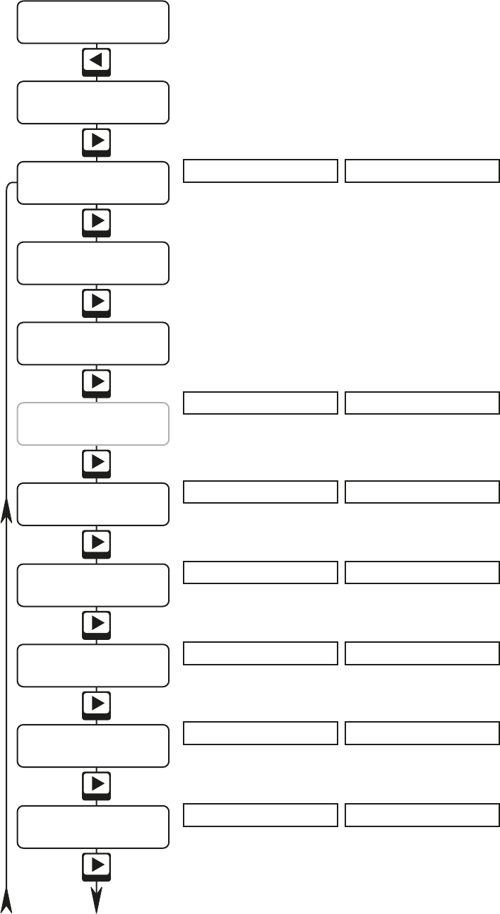
19.0°C 11:06 Tue
HEAT ON P1
Temperature 20.0
< - + >
Clock set
< OK >
Prog settings
< OK >
Holiday Date
< OK >
Run Mode: WINTER
< - + >
Permissions
< OK >
Date: 25/05/2011
< >
Next
Next
Next
Next
Next
Next
Next
Next
Next
Next
Next
Next
SetPassword ****
< - + >
Extend time 1.00
< - + >
Cost Log
< OK >
Password ****
< - + >
Press - or + to decrease or increase day temperature set point (17°C to 23°C Adjustment may be disabled or limited by other
unit settings). Press OK to save change, Cancel to exit without saving
Normal display. (Winter mode with ON/OFF burner shown). Displays, depending on operating mode and burner type,
temperature at sensor, time, day, programme status, whether heating and/or fan are ON or OFF, level of burner modulation.
Press OK to alter date or time. Press or to select gure to change, gure will pulse. Change by pressing - or +. Press to
go to next gure. Pressing after seconds will allow changes to be discarded (Cancel) or saved (OK).
Press OK to set/alter programmes. Press - or + to select programme number (1 to 14). Press OK. Press - or + to set Heat On time.
Press to move to next digits and then to Heat O time. Press to move to Temperature setting. Press - and + to set
temperature. Press to move to day setting. Change by pressing - or +. Pressing again will allow changes to that
programme be saved (OK) or discarded (Cancel). Start screen for this section reappears, press Cancel to nish or repeat above
sequence for further programmes.
Press OK to set/alter Holiday Date. Press - or + to set start date. Press to go to next gure. Press after setting year to set
number of days. Press - or + to set number of days. Pressing again will allow changes to Holiday Date to be discarded (Cancel) or
saved (OK).
Press OK to set/alter Permissions. Set each permission using - or +. Press to go to the next permission. Pressing after the
nal permission (Fan Control) will allow changes to Permissions be discarded (Cancel) or saved (OK) .
Press OK to access Cost Log. Screen shows date log started. Press to view log hours and then log cost. Pressing again will
give the option of clearing the log. Note: Clearing the log resets the start date to the current date.
Press - or + to increase/decrease extension time. Discard (Cancel) or save (OK) change.
The rst * will be pulsing. Press - or + to enter the rst password number. Press to go to the next digit and repeat until a 4
digit password is entered. Press OK and the screen will show [ SetPassword SET ].
The rst * will be pulsing. Press - or + to enter the rst password number. Press to go to the next digit and repeat until the 4
digit password is entered. Press OK and the screen will show VALID or FAIL. If FAIL displays check password and repeat entry
sequence. The User password, if set, must be entered for access to User functions.
Press - or + to toggle through modes. Discard (Cancel) or save (OK) changes.
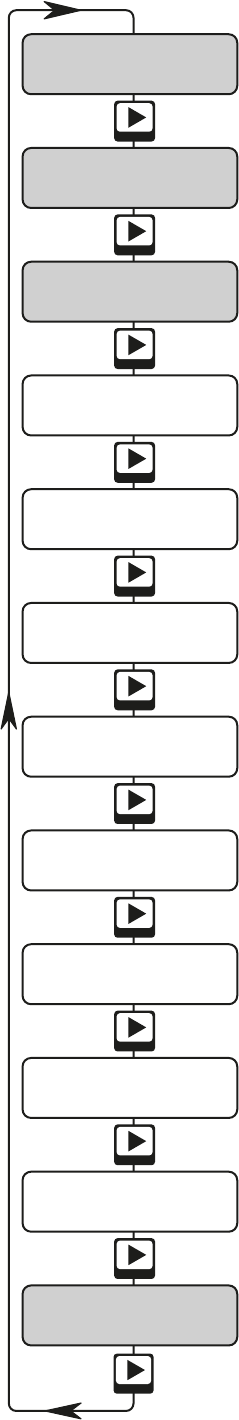
7.3 User Operation flow chart
Use or to navigate through menu. Pressing Cancel (Quit) at any of the displays shown below will return you to the normal
display. Bottom line of display shows which keys can be used in menu programming modes. Displays shown shaded are the
only ones visible when the MC200 is password protected.
8 Engineer Controls
The engineer menu is enabled by entering the engineer pass-code at the Password menu option.
In order to ensure that the engineer code and the user code are always distinct, the engineer code is a 3-digit number and one
asterisk and is factory set as 535*
Once the engineer code has been correctly entered no user or engineer codes will be required for a period of 1 hour. This will
then allow an engineer to move between all screens / modes without having to keep re-entering a code.
Once the engineer pass-code has been entered, an additional menu option becomes visible, leading to the engineer’s sub-menu.
Many of the Engineer settings are determined by the installed equipment however others will be to the end users preferences. The
latter should be left at default settings if there is no end user when the control is being commissioned.
8.1 Engineer Settings
If the engineer code is entered the “Engineer” menus will be added to menu list available. Press OK to enter the engineer sub-menu
and > or < to move through the options. At any point, press Cancel to exit from the engineer sub-menu back to the User menu. If
the Users menu is password protected the Engineer code permits access to both the Engineer menu and the User menu.
Burner type (On/Off, High-Low, Modulating)
Defines the type of controlled burner.
Burner High Rating (kW)
Defines the high ( and Low) heat input ( in kW) of the controlled burner for cost calculations.
Test Burners
Facilitates direct testing of the controlled burner(s) irrespective of current control settings, times etc.
High-Low differential (°C)
Sets the temperature difference between the Hi and Lo stages of Hi/Lo burners
Note: This menu item only appears when Hi/Lo burner type has been selected.
Modulation offset (°C)
Sets the temperature at which the 0-10V signal will be 10V and the burner will be at High Fire.
Note: This menu item only appears when Modulating burner type has been selected.
Auto reset (On/Off)
Sets whether the control will complete an automatic reset of lockout, If lockout signal is not removed by a manual reset the MC200
will initiate an automatic reset 30 minutes after the lockout signal and then once every 24hrs.
Reset Time (1 sceond, 3 seconds, 5 seconds)
Sets how long the lockout reset terminal is connected to neutral when the reset button is pressed.
Sensor 2 Function (Not Used, Remote, Heat Off, Heat On)
Sets the function of sensor 2 input
Trim Temperature (°C)
A temperature offset can be entered here to adjust the displayed temperature to agree with the sensor temperature. Range of
adjustment -5°C to +5°C
Set User Temperature minimum (°C)
Sets the minimum temperature that the User can select. Default 15°C, can reduce to 10°C.
Set User Temperature maximum (°C)
Sets the maximum temperature that the User can select. Default 25°C, can increase to 30°C.
Temp Adjust (°C)
Sets °C that User can temporarily adjust the current set point up or down.
Constant Fan (Off/Auto/Const/On)
Sets the mode of Fan operation between Auto, Const, ON or OFF.
Frost/Setback (On/Off)
Sets frost protection/night setback to active or inactive.
Setback Temperature (°C)
Sets the frost protection/night setback temperatue value.
Optimum Start (On/Off)
Sets whether Optimum Start is active
Optimum Stop (°C)
Sets the Optimum Stop temperature
Service Date
Allows a service date to be set
Lockout Log
Displays the most recent lockout time and date
Clear Lockout Log
If lockout log is not cleared newer events will over-write older ones.
Restore Defaults
Resets all parameters to factory default settings.
9. Temperature Sensors
Options are Default internal sensor Terminals Sen1 & Com
Remote sensor Terminals Sen1 & Com
Internal + Remote Terminals Sen1, Com & In2
Remote + Remote Terminals Sen1, Com & In2
The remote sensor may be either ‘room’ or ‘duct’ type.
The second ‘sensor’ input (Terminals Com & In2) can also accept a volt free switch input i.e. a volt free switch is connected
across Terminals Com & In2 to facilitate additional functions as below
Sensor terminal options are (It is assumed that Sensor 1 is always fitted)
1) In2: Not used The sensor 2 terminals are ignored
2) In2: Remote A temperature sensor is connected
3) In2: Heat off A switch is fitted. When it closes, heating goes off
4) In2: Heat on A switch is fitted. When it closes, heating goes on
7
Heating will be overridden by the switch closure during programmed heating times. Heating control returns to normal when the
switch opens, or when the programmed control period ends.
The switched control does not occur while heating is turned on due to manual override in non-programmed times, and does not
occur during the manually-selected extension time at the end of a programmed control period.
If heating has been manually overridden to be off during a programmed heating period, the switched control cannot bring on the
heating.
The fourth option (Heat on) means that heat will be turned fully on by the switch. For high-low burners, the high and low relays
will be on, and for modulating burners, the control output will be 10v.
Cost logging operates as usual. During these switch control periods the burn time is recorded at the maximum rate.
If the sensor goes open-circuit (if either of the sensors goes open-circuit where two are fitted), the Fault LED will flash. The LCD
display will show “sensor failed”.
NOTE: The earlier MC100 sensor cannot be used with the MC200 and the MC200 sensor cannot be used with the MC100.
10. Outputs
10.1 Single burner
When configured for a single burner heater, the Low heat relay (Terminals Heat In Lo and Heat Out Lo) operates when the
sensor temperature is below the set temperature.
10.2 Two-stage
When configured for a two-stage burner heater, the Low heat relay (Terminals Heat In Lo and Heat Out Lo) operates when the
sensor temperature is below the set temperature i.e. as ON/OFF. The High heat relay (Terminals Heat In Hi and Heat Out Hi)
operates when the sensor temperature is more than a given number of degrees below the set temperature as set in the Hi/Lo
differential parameter to switch from low fire to high fire
The Low Level relay also remains operated while the High heat relay is operated.
10.3 Modulating
The 0-10Vdc output stays at zero and the Low heat relay (Terminals Heat In Lo and Heat Out Lo) will remain de-energized
while the sensor temperature is at or above the set temperature. Below the set temperature, the Low heat relay (Terminals Heat
In Lo and Heat Out Lo) will operate and the modulating output voltage (Terminals 0-10v+ and 0-10v-) increases, reaching 10v
when the sensor temperature falls to the threshold set i.e 0V at low fire, 10V at High Fire.
11. Handover
Demonstrate the setting up and operation of the control to the end user. Leave the User Instructions with the end user.
12. Short List of Parts
Item Powrmatic Part #
Complete unit MC200
PCB alone 143070033
Internal sensor bead 143070034
Remote sensor (air temperature) 143070031
Black bulb sensor (radiant temperature) 143070032
Duct Sensor 143070035
8 Engineer Controls
The engineer menu is enabled by entering the engineer pass-code at the Password menu option.
In order to ensure that the engineer code and the user code are always distinct, the engineer code is a 3-digit number and one
asterisk and is factory set as 535*
Once the engineer code has been correctly entered no user or engineer codes will be required for a period of 1 hour. This will
then allow an engineer to move between all screens / modes without having to keep re-entering a code.
Once the engineer pass-code has been entered, an additional menu option becomes visible, leading to the engineer’s sub-menu.
Many of the Engineer settings are determined by the installed equipment however others will be to the end users preferences. The
latter should be left at default settings if there is no end user when the control is being commissioned.
8.1 Engineer Settings
If the engineer code is entered the “Engineer” menus will be added to menu list available. Press OK to enter the engineer sub-menu
and > or < to move through the options. At any point, press Cancel to exit from the engineer sub-menu back to the User menu. If
the Users menu is password protected the Engineer code permits access to both the Engineer menu and the User menu.
Burner type (On/Off, High-Low, Modulating)
Defines the type of controlled burner.
Burner High Rating (kW)
Defines the high ( and Low) heat input ( in kW) of the controlled burner for cost calculations.
Test Burners
Facilitates direct testing of the controlled burner(s) irrespective of current control settings, times etc.
High-Low differential (°C)
Sets the temperature difference between the Hi and Lo stages of Hi/Lo burners
Note: This menu item only appears when Hi/Lo burner type has been selected.
Modulation offset (°C)
Sets the temperature at which the 0-10V signal will be 10V and the burner will be at High Fire.
Note: This menu item only appears when Modulating burner type has been selected.
Auto reset (On/Off)
Sets whether the control will complete an automatic reset of lockout, If lockout signal is not removed by a manual reset the MC200
will initiate an automatic reset 30 minutes after the lockout signal and then once every 24hrs.
Reset Time (1 sceond, 3 seconds, 5 seconds)
Sets how long the lockout reset terminal is connected to neutral when the reset button is pressed.
Sensor 2 Function (Not Used, Remote, Heat Off, Heat On)
Sets the function of sensor 2 input
Trim Temperature (°C)
A temperature offset can be entered here to adjust the displayed temperature to agree with the sensor temperature. Range of
adjustment -5°C to +5°C
Set User Temperature minimum (°C)
Sets the minimum temperature that the User can select. Default 15°C, can reduce to 10°C.
Set User Temperature maximum (°C)
Sets the maximum temperature that the User can select. Default 25°C, can increase to 30°C.
Temp Adjust (°C)
Sets °C that User can temporarily adjust the current set point up or down.
Constant Fan (Off/Auto/Const/On)
Sets the mode of Fan operation between Auto, Const, ON or OFF.
Frost/Setback (On/Off)
Sets frost protection/night setback to active or inactive.
Setback Temperature (°C)
Sets the frost protection/night setback temperatue value.
Optimum Start (On/Off)
Sets whether Optimum Start is active
Optimum Stop (°C)
Sets the Optimum Stop temperature
Service Date
Allows a service date to be set
Lockout Log
Displays the most recent lockout time and date
Clear Lockout Log
If lockout log is not cleared newer events will over-write older ones.
Restore Defaults
Resets all parameters to factory default settings.
9. Temperature Sensors
Options are Default internal sensor Terminals Sen1 & Com
Remote sensor Terminals Sen1 & Com
Internal + Remote Terminals Sen1, Com & In2
Remote + Remote Terminals Sen1, Com & In2
The remote sensor may be either ‘room’ or ‘duct’ type.
The second ‘sensor’ input (Terminals Com & In2) can also accept a volt free switch input i.e. a volt free switch is connected
across Terminals Com & In2 to facilitate additional functions as below
Sensor terminal options are (It is assumed that Sensor 1 is always fitted)
1) In2: Not used The sensor 2 terminals are ignored
2) In2: Remote A temperature sensor is connected
3) In2: Heat off A switch is fitted. When it closes, heating goes off
4) In2: Heat on A switch is fitted. When it closes, heating goes on
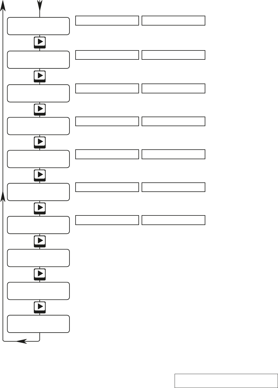
8.1 Engineer Settings Menu flow chart
At the normal display screen press Back to access the Password screen
Engineer menu
< OK >
Burner: On-Off
< - + >
Burner Test
< OK >
Mod Offset 6.0°C
< - + >
Auto Reset OFF
< - + >
BurnerHi 0120 kW
< - + >
Next
Password ****
< - + >
Back
Next
Next
Next
Next
Next
Press OK to test the burner. Pressing - or + will toggle between modes. Available modes are determined by the type of
burner entered. For modulating burners the 0-10V out put can be changed in 1V steps. Press Cancel to exit.
Press OK to access Engineers menu.
The rst digit will be pulsing. Press - or + to set this digit to agree with rst digit of burner maximum input rating (in kW).
Press to go to the next digit and repeat until input rating is entered. Press OK. If the burner type has been set to
High-Low pressing and the next screen will allow entry of the burner minimum input rating.
Press - or + to toggle through modes. Discard (Cancel) or save (OK) changes.
Default Setting: On - O Set to:
Only present if a modulating burner is selected. Press - or + to decrease or increase the value. Discard (Cancel) or save (OK)
changes.
Default Setting: On - O Set to:
Press - or + to toggle through modes (ON, OFF). Discard (Cancel) or save (OK) changes.
Default Setting: OFF Set to:
The rst * will be pulsing. Press - or + to enter 5. Press to go to the next digit and repeat until 535* is entered. Press OK and the
screen will show VALID . Press Back. Note: If - or + is pressed when the last * is pulsing it is not possible to enter *. Press OK (the display
will show Password FAIL), press Cancel and then Back to restart the entry process.
8
Reset time 1 sec
< - + >
Snsr2: Not used
< - + >
Next
Next
Next
Trim temp +0.0°C
< - + >
Press - or + to toggle through available times (1, 3, 5secs). Discard (Cancel) or save (OK) changes.
Default Setting: 1 Set to:
Press - or + to toggle through available options (Not used, Remote, Heat o, Heat on). Discard (Cancel) or save (OK) changes.
Default Setting: Not used Set to:
Press - or + to decrease or increase the value (-5 to +5°C). Discard (Cancel) or save (OK) changes.
Default Setting: +0.0 Set to:
Next
User TempMin 10.0
< - + > Press - or + to decrease or increase the value (10 to 20°C). Discard (Cancel) or save (OK) changes.
Default Setting: 15.0 Set to:
Heating will be overridden by the switch closure during programmed heating times. Heating control returns to normal when the
switch opens, or when the programmed control period ends.
The switched control does not occur while heating is turned on due to manual override in non-programmed times, and does not
occur during the manually-selected extension time at the end of a programmed control period.
If heating has been manually overridden to be off during a programmed heating period, the switched control cannot bring on the
heating.
The fourth option (Heat on) means that heat will be turned fully on by the switch. For high-low burners, the high and low relays
will be on, and for modulating burners, the control output will be 10v.
Cost logging operates as usual. During these switch control periods the burn time is recorded at the maximum rate.
If the sensor goes open-circuit (if either of the sensors goes open-circuit where two are fitted), the Fault LED will flash. The LCD
display will show “sensor failed”.
NOTE: The earlier MC100 sensor cannot be used with the MC200 and the MC200 sensor cannot be used with the MC100.
10. Outputs
10.1 Single burner
When configured for a single burner heater, the Low heat relay (Terminals Heat In Lo and Heat Out Lo) operates when the
sensor temperature is below the set temperature.
10.2 Two-stage
When configured for a two-stage burner heater, the Low heat relay (Terminals Heat In Lo and Heat Out Lo) operates when the
sensor temperature is below the set temperature i.e. as ON/OFF. The High heat relay (Terminals Heat In Hi and Heat Out Hi)
operates when the sensor temperature is more than a given number of degrees below the set temperature as set in the Hi/Lo
differential parameter to switch from low fire to high fire
The Low Level relay also remains operated while the High heat relay is operated.
10.3 Modulating
The 0-10Vdc output stays at zero and the Low heat relay (Terminals Heat In Lo and Heat Out Lo) will remain de-energized
while the sensor temperature is at or above the set temperature. Below the set temperature, the Low heat relay (Terminals Heat
In Lo and Heat Out Lo) will operate and the modulating output voltage (Terminals 0-10v+ and 0-10v-) increases, reaching 10v
when the sensor temperature falls to the threshold set i.e 0V at low fire, 10V at High Fire.
11. Handover
Demonstrate the setting up and operation of the control to the end user. Leave the User Instructions with the end user.
12. Short List of Parts
Item Powrmatic Part #
Complete unit MC200
PCB alone 143070033
Internal sensor bead 143070034
Remote sensor (air temperature) 143070031
Black bulb sensor (radiant temperature) 143070032
Duct Sensor 143070035
8 Engineer Controls
The engineer menu is enabled by entering the engineer pass-code at the Password menu option.
In order to ensure that the engineer code and the user code are always distinct, the engineer code is a 3-digit number and one
asterisk and is factory set as 535*
Once the engineer code has been correctly entered no user or engineer codes will be required for a period of 1 hour. This will
then allow an engineer to move between all screens / modes without having to keep re-entering a code.
Once the engineer pass-code has been entered, an additional menu option becomes visible, leading to the engineer’s sub-menu.
Many of the Engineer settings are determined by the installed equipment however others will be to the end users preferences. The
latter should be left at default settings if there is no end user when the control is being commissioned.
8.1 Engineer Settings
If the engineer code is entered the “Engineer” menus will be added to menu list available. Press OK to enter the engineer sub-menu
and > or < to move through the options. At any point, press Cancel to exit from the engineer sub-menu back to the User menu. If
the Users menu is password protected the Engineer code permits access to both the Engineer menu and the User menu.
Burner type (On/Off, High-Low, Modulating)
Defines the type of controlled burner.
Burner High Rating (kW)
Defines the high ( and Low) heat input ( in kW) of the controlled burner for cost calculations.
Test Burners
Facilitates direct testing of the controlled burner(s) irrespective of current control settings, times etc.
High-Low differential (°C)
Sets the temperature difference between the Hi and Lo stages of Hi/Lo burners
Note: This menu item only appears when Hi/Lo burner type has been selected.
Modulation offset (°C)
Sets the temperature at which the 0-10V signal will be 10V and the burner will be at High Fire.
Note: This menu item only appears when Modulating burner type has been selected.
Auto reset (On/Off)
Sets whether the control will complete an automatic reset of lockout, If lockout signal is not removed by a manual reset the MC200
will initiate an automatic reset 30 minutes after the lockout signal and then once every 24hrs.
Reset Time (1 sceond, 3 seconds, 5 seconds)
Sets how long the lockout reset terminal is connected to neutral when the reset button is pressed.
Sensor 2 Function (Not Used, Remote, Heat Off, Heat On)
Sets the function of sensor 2 input
Trim Temperature (°C)
A temperature offset can be entered here to adjust the displayed temperature to agree with the sensor temperature. Range of
adjustment -5°C to +5°C
Set User Temperature minimum (°C)
Sets the minimum temperature that the User can select. Default 15°C, can reduce to 10°C.
Set User Temperature maximum (°C)
Sets the maximum temperature that the User can select. Default 25°C, can increase to 30°C.
Temp Adjust (°C)
Sets °C that User can temporarily adjust the current set point up or down.
Constant Fan (Off/Auto/Const/On)
Sets the mode of Fan operation between Auto, Const, ON or OFF.
Frost/Setback (On/Off)
Sets frost protection/night setback to active or inactive.
Setback Temperature (°C)
Sets the frost protection/night setback temperatue value.
Optimum Start (On/Off)
Sets whether Optimum Start is active
Optimum Stop (°C)
Sets the Optimum Stop temperature
Service Date
Allows a service date to be set
Lockout Log
Displays the most recent lockout time and date
Clear Lockout Log
If lockout log is not cleared newer events will over-write older ones.
Restore Defaults
Resets all parameters to factory default settings.
9. Temperature Sensors
Options are Default internal sensor Terminals Sen1 & Com
Remote sensor Terminals Sen1 & Com
Internal + Remote Terminals Sen1, Com & In2
Remote + Remote Terminals Sen1, Com & In2
The remote sensor may be either ‘room’ or ‘duct’ type.
The second ‘sensor’ input (Terminals Com & In2) can also accept a volt free switch input i.e. a volt free switch is connected
across Terminals Com & In2 to facilitate additional functions as below
Sensor terminal options are (It is assumed that Sensor 1 is always fitted)
1) In2: Not used The sensor 2 terminals are ignored
2) In2: Remote A temperature sensor is connected
3) In2: Heat off A switch is fitted. When it closes, heating goes off
4) In2: Heat on A switch is fitted. When it closes, heating goes on
9
Next
User TempMax 20.0
< - + > Press - or + to decrease or increase the value (20 to 30°C). Discard (Cancel) or save (OK) changes.
Default Setting: 25.0 Set to:
ConstFan: Auto
< - + >
Frost/setback OFF
< - + >
OptimumStart OFF
< OK >
Opt Stop 3.0°C
< - + >
Service date
< OK >
Lockout Log
< OK >
Restore Defaults
< OK >
SetbackTemp 5.0
< - + >
Next
Next
Next
Next
Next
Next
Next
Press OK to enter a service date. Pressing - or + will decrease or increase the pulsing digits. Press or to select gure to
change, gure will pulse. Discard (Cancel) or save (OK) changes.
Warning: This action is immediate and cannot be reversed. Press OK to restore defaults.
Press OK to view lock out log. Press or to clear log. Press OK or Cancel as required.
Press - or + to toggle through modes (Auto, Const, On, O). Discard (Cancel) or save (OK) changes.
Default Setting: OFF Set to:
Press - or + to toggle through modes (OFF, ON). Discard (Cancel) or save (OK) changes.
Default Setting: OFF Set to:
Press - or + to decrease or increase the value (1°C to 15°C). Discard (Cancel) or save (OK) changes.
Default Setting: 5.0 Set to:
Press - or + to toggle through modes (OFF, ON). Discard (Cancel) or save (OK) changes.
Default Setting: OFF Set to:
Press - or + to decrease or increase the value (0.5°C to 6.0°C). Discard (Cancel) or save (OK) changes.
Default Setting: 0.0 Set to:
Next
Temp Adjust 3.0
< - + > Press - or + to decrease or increase the value (0.5 to 6°C). Discard (Cancel) or save (OK) changes.
Default Setting: 3.0 Set to:
Heating will be overridden by the switch closure during programmed heating times. Heating control returns to normal when the
switch opens, or when the programmed control period ends.
The switched control does not occur while heating is turned on due to manual override in non-programmed times, and does not
occur during the manually-selected extension time at the end of a programmed control period.
If heating has been manually overridden to be off during a programmed heating period, the switched control cannot bring on the
heating.
The fourth option (Heat on) means that heat will be turned fully on by the switch. For high-low burners, the high and low relays
will be on, and for modulating burners, the control output will be 10v.
Cost logging operates as usual. During these switch control periods the burn time is recorded at the maximum rate.
If the sensor goes open-circuit (if either of the sensors goes open-circuit where two are fitted), the Fault LED will flash. The LCD
display will show “sensor failed”.
NOTE: The earlier MC100 sensor cannot be used with the MC200 and the MC200 sensor cannot be used with the MC100.
10. Outputs
10.1 Single burner
When configured for a single burner heater, the Low heat relay (Terminals Heat In Lo and Heat Out Lo) operates when the
sensor temperature is below the set temperature.
10.2 Two-stage
When configured for a two-stage burner heater, the Low heat relay (Terminals Heat In Lo and Heat Out Lo) operates when the
sensor temperature is below the set temperature i.e. as ON/OFF. The High heat relay (Terminals Heat In Hi and Heat Out Hi)
operates when the sensor temperature is more than a given number of degrees below the set temperature as set in the Hi/Lo
differential parameter to switch from low fire to high fire
The Low Level relay also remains operated while the High heat relay is operated.
10.3 Modulating
The 0-10Vdc output stays at zero and the Low heat relay (Terminals Heat In Lo and Heat Out Lo) will remain de-energized
while the sensor temperature is at or above the set temperature. Below the set temperature, the Low heat relay (Terminals Heat
In Lo and Heat Out Lo) will operate and the modulating output voltage (Terminals 0-10v+ and 0-10v-) increases, reaching 10v
when the sensor temperature falls to the threshold set i.e 0V at low fire, 10V at High Fire.
11. Handover
Demonstrate the setting up and operation of the control to the end user. Leave the User Instructions with the end user.
12. Short List of Parts
Item Powrmatic Part #
Complete unit MC200
PCB alone 143070033
Internal sensor bead 143070034
Remote sensor (air temperature) 143070031
Black bulb sensor (radiant temperature) 143070032
Duct Sensor 143070035
Temperatures returned by the two sensors
are averaged by the MC200.
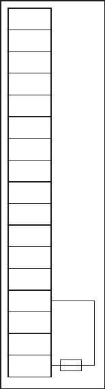
13. Terminal Layout
8 Engineer Controls
The engineer menu is enabled by entering the engineer pass-code at the Password menu option.
In order to ensure that the engineer code and the user code are always distinct, the engineer code is a 3-digit number and one
asterisk and is factory set as 535*
Once the engineer code has been correctly entered no user or engineer codes will be required for a period of 1 hour. This will
then allow an engineer to move between all screens / modes without having to keep re-entering a code.
Once the engineer pass-code has been entered, an additional menu option becomes visible, leading to the engineer’s sub-menu.
Many of the Engineer settings are determined by the installed equipment however others will be to the end users preferences. The
latter should be left at default settings if there is no end user when the control is being commissioned.
8.1 Engineer Settings
If the engineer code is entered the “Engineer” menus will be added to menu list available. Press OK to enter the engineer sub-menu
and > or < to move through the options. At any point, press Cancel to exit from the engineer sub-menu back to the User menu. If
the Users menu is password protected the Engineer code permits access to both the Engineer menu and the User menu.
Burner type (On/Off, High-Low, Modulating)
Defines the type of controlled burner.
Burner High Rating (kW)
Defines the high ( and Low) heat input ( in kW) of the controlled burner for cost calculations.
Test Burners
Facilitates direct testing of the controlled burner(s) irrespective of current control settings, times etc.
High-Low differential (°C)
Sets the temperature difference between the Hi and Lo stages of Hi/Lo burners
Note: This menu item only appears when Hi/Lo burner type has been selected.
Modulation offset (°C)
Sets the temperature at which the 0-10V signal will be 10V and the burner will be at High Fire.
Note: This menu item only appears when Modulating burner type has been selected.
Auto reset (On/Off)
Sets whether the control will complete an automatic reset of lockout, If lockout signal is not removed by a manual reset the MC200
will initiate an automatic reset 30 minutes after the lockout signal and then once every 24hrs.
Reset Time (1 sceond, 3 seconds, 5 seconds)
Sets how long the lockout reset terminal is connected to neutral when the reset button is pressed.
Sensor 2 Function (Not Used, Remote, Heat Off, Heat On)
Sets the function of sensor 2 input
Trim Temperature (°C)
A temperature offset can be entered here to adjust the displayed temperature to agree with the sensor temperature. Range of
adjustment -5°C to +5°C
Set User Temperature minimum (°C)
Sets the minimum temperature that the User can select. Default 15°C, can reduce to 10°C.
Set User Temperature maximum (°C)
Sets the maximum temperature that the User can select. Default 25°C, can increase to 30°C.
Temp Adjust (°C)
Sets °C that User can temporarily adjust the current set point up or down.
Constant Fan (Off/Auto/Const/On)
Sets the mode of Fan operation between Auto, Const, ON or OFF.
Frost/Setback (On/Off)
Sets frost protection/night setback to active or inactive.
Setback Temperature (°C)
Sets the frost protection/night setback temperatue value.
Optimum Start (On/Off)
Sets whether Optimum Start is active
Optimum Stop (°C)
Sets the Optimum Stop temperature
Service Date
Allows a service date to be set
Lockout Log
Displays the most recent lockout time and date
Clear Lockout Log
If lockout log is not cleared newer events will over-write older ones.
Restore Defaults
Resets all parameters to factory default settings.
9. Temperature Sensors
Options are Default internal sensor Terminals Sen1 & Com
Remote sensor Terminals Sen1 & Com
Internal + Remote Terminals Sen1, Com & In2
Remote + Remote Terminals Sen1, Com & In2
The remote sensor may be either ‘room’ or ‘duct’ type.
The second ‘sensor’ input (Terminals Com & In2) can also accept a volt free switch input i.e. a volt free switch is connected
across Terminals Com & In2 to facilitate additional functions as below
Sensor terminal options are (It is assumed that Sensor 1 is always fitted)
1) In2: Not used The sensor 2 terminals are ignored
2) In2: Remote A temperature sensor is connected
3) In2: Heat off A switch is fitted. When it closes, heating goes off
4) In2: Heat on A switch is fitted. When it closes, heating goes on
10
Terminal Type Function
Sen1 Input (no voltage1) Connection for prime sensor (not polarity sensitive)
COM Input (no voltage1) Common connection for sensors and/or auxillary switch
IN 2 Input (no voltage1) Connection for 2nd sensor (averaging) or for auxillary switch
0-10V + Output Positive rail of 0-10V modulating control votage
0-10V - Output Negative rail of 0-10V modulating control votage
Reset Output Internally connected to NEUTRAL when reset button pressed.
Lockout Input (230V~) Receives Lockout signal from burner controls
Heat Hi In Input (Volt free2) Heat Hi relay contact
Heat Hi Out Output (Volt free2) Heat Hi relay contact
Heat Lo In Input (Volt free2) Heat Lo relay contact
Heat Lo Out Output (Volt free2) Heat Lo relay contact
Fan In Input (Volt free2) Fan relay contact
Fan Out Output (Volt free2) Fan relay contact
L Out Output (230V~) As required (Derived from L terminal via internal 6.3A HRC fuse)
N Input Electrical Supply
L Input (230V~) Electrical Supply
E Earth Electrical Supply
Notes:
1 - Voltage must not be applied to the sensor terminals. If a switch is fitted across COM and IN 2 it must be volt free.
2 - If an output voltage is required (230V, 24V, 10V etc) the appropriate voltage must be applied to the corresponding
input terminal.
Heating will be overridden by the switch closure during programmed heating times. Heating control returns to normal when the
switch opens, or when the programmed control period ends.
The switched control does not occur while heating is turned on due to manual override in non-programmed times, and does not
occur during the manually-selected extension time at the end of a programmed control period.
If heating has been manually overridden to be off during a programmed heating period, the switched control cannot bring on the
heating.
The fourth option (Heat on) means that heat will be turned fully on by the switch. For high-low burners, the high and low relays
will be on, and for modulating burners, the control output will be 10v.
Cost logging operates as usual. During these switch control periods the burn time is recorded at the maximum rate.
If the sensor goes open-circuit (if either of the sensors goes open-circuit where two are fitted), the Fault LED will flash. The LCD
display will show “sensor failed”.
NOTE: The earlier MC100 sensor cannot be used with the MC200 and the MC200 sensor cannot be used with the MC100.
10. Outputs
10.1 Single burner
When configured for a single burner heater, the Low heat relay (Terminals Heat In Lo and Heat Out Lo) operates when the
sensor temperature is below the set temperature.
10.2 Two-stage
When configured for a two-stage burner heater, the Low heat relay (Terminals Heat In Lo and Heat Out Lo) operates when the
sensor temperature is below the set temperature i.e. as ON/OFF. The High heat relay (Terminals Heat In Hi and Heat Out Hi)
operates when the sensor temperature is more than a given number of degrees below the set temperature as set in the Hi/Lo
differential parameter to switch from low fire to high fire
The Low Level relay also remains operated while the High heat relay is operated.
10.3 Modulating
The 0-10Vdc output stays at zero and the Low heat relay (Terminals Heat In Lo and Heat Out Lo) will remain de-energized
while the sensor temperature is at or above the set temperature. Below the set temperature, the Low heat relay (Terminals Heat
In Lo and Heat Out Lo) will operate and the modulating output voltage (Terminals 0-10v+ and 0-10v-) increases, reaching 10v
when the sensor temperature falls to the threshold set i.e 0V at low fire, 10V at High Fire.
11. Handover
Demonstrate the setting up and operation of the control to the end user. Leave the User Instructions with the end user.
12. Short List of Parts
Item Powrmatic Part #
Complete unit MC200
PCB alone 143070033
Internal sensor bead 143070034
Remote sensor (air temperature) 143070031
Black bulb sensor (radiant temperature) 143070032
Duct Sensor 143070035
MC200
Fuelsaver
SEN 1
COM
IN 2
0-10v +
0-10v -
Reset
Lockout
Heat Hi
In
Heat Hi
Out
Heat Lo
In
Heat Lo
Out
Fan In
Fan Out
L Out
N
E
L
6.3A
HRC
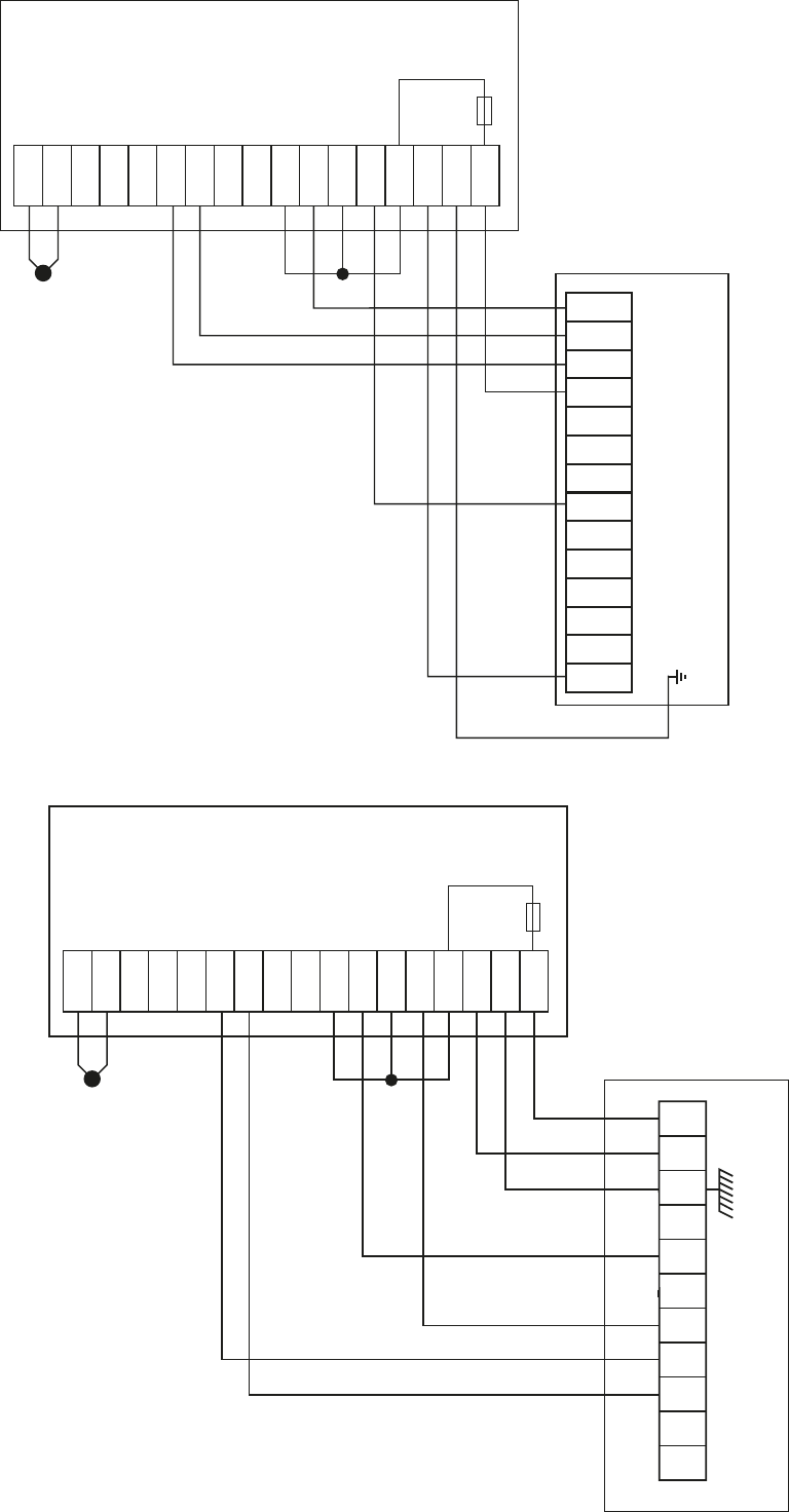
11
SEN 1
COM
IN 2
0-10v +
0-10v -
Reset
Lockout
Heat Hi
In
Heat Hi
Out
Heat Lo
In
Heat Lo
Out
Fan In
Fan Out
L Out
N
E
L
MC200 CONTROLLING
STANDARD NV / VP / DHM SL
fitted with Pactrol Control
N
N CAP
N MAIN
FAN
N
N
L MAIN
FAN
L MAIN
FAN
L
L
L
L
R/S
L/O
HEAT
MC200 Fuelsaver
14. Connections to Powrmatic Heaters
6.3A
HRC
SEN 1
COM
IN 2
0-10v +
0-10v -
Reset
Lockout
Heat Hi
In
Heat Hi
Out
Heat Lo
In
Heat Lo
Out
Fan In
Fan Out
L Out
N
E
L
MC200 CONTROLLING
STANDARD NV / VP / DHM SL
fitted with Brahma Control
MC200 Fuelsaver
6.3A
HRC
NV HEATER
1
L
N
18
17
E
2
8
9
13
14
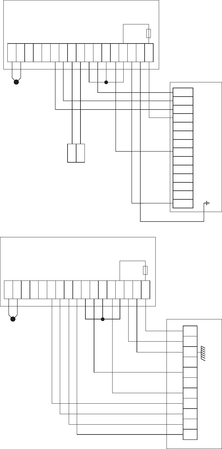
12
SEN 1
COM
IN 2
0-10v +
0-10v -
Reset
Lockout
Heat Hi
In
Heat Hi
Out
Heat Lo
In
Heat Lo
Out
Fan In
Fan Out
L Out
N
E
L
MC200 CONTROLLING
HI/LO NV / VP / DHM SL
fitted with Pactrol Control
HL
HL
MC200 Fuelsaver
N
N CAP
N MAIN
FAN
N
N
L MAIN
FAN
L MAIN
FAN
L
L
L
L
R/S
L/O
HEAT
6.3A
HRC
SEN 1
COM
IN 2
0-10v +
0-10v -
Reset
Lockout
Heat Hi
In
Heat Hi
Out
Heat Lo
In
Heat Lo
Out
Fan In
Fan Out
L Out
N
E
L
MC200 CONTROLLING
Hi/Lo NV / VP / DHM SL
fitted with Brahma Control
MC200 Fuelsaver
6.3A
HRC
NV HEATER
1
L
N
18
17
E
2
8
9
13
14
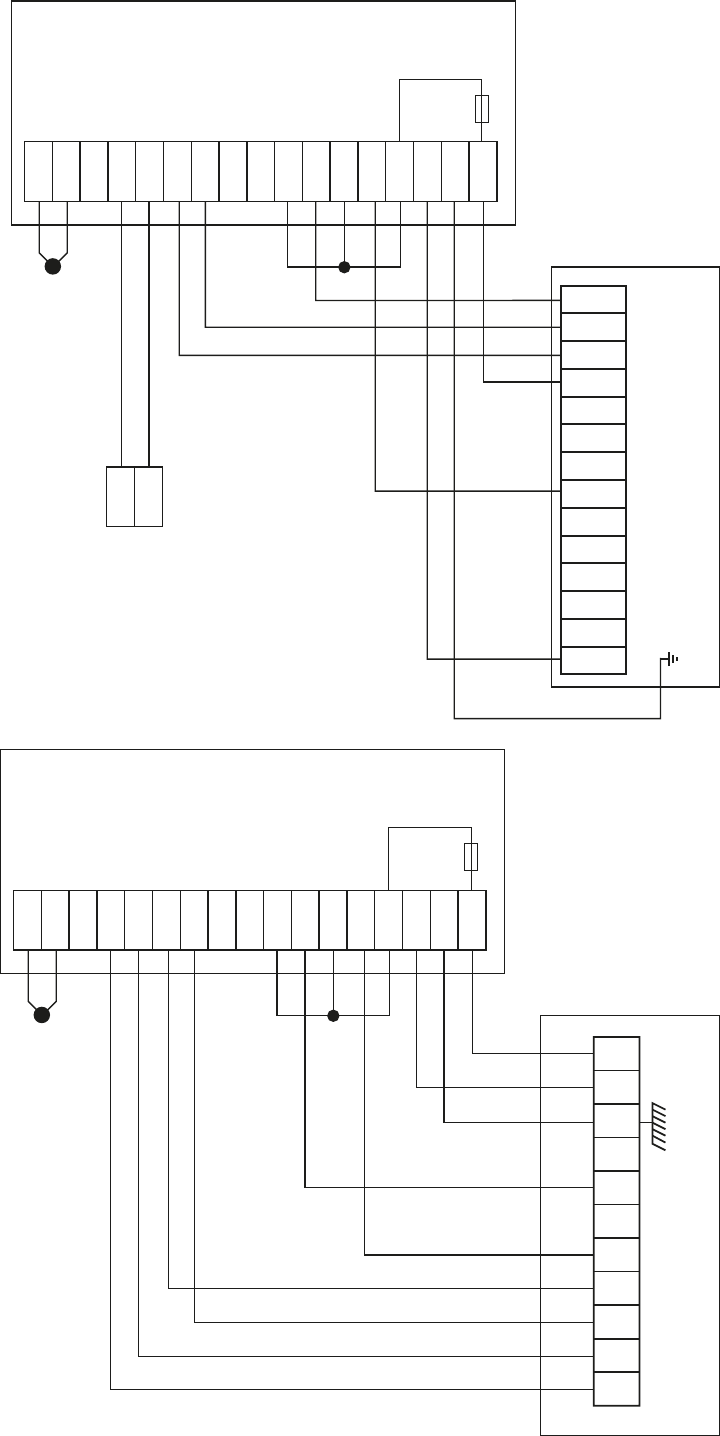
13
SEN 1
COM
IN 2
0-10v +
0-10v -
Reset
Lockout
Heat Hi
In
Heat Hi
Out
Heat Lo
In
Heat Lo
Out
Fan In
Fan Out
L Out
N
E
L
MC200 CONTROLLING
MODULATING NV / VP / DHM SL
fitted with Pactrol Control
1
2
MC200 Fuelsaver
N
N CAP
N MAIN
FAN
N
N
L MAIN
FAN
L MAIN
FAN
L
L
L
L
R/S
L/O
HEAT
6.3A
HRC
SEN 1
COM
IN 2
0-10v +
0-10v -
Reset
Lockout
Heat Hi
In
Heat Hi
Out
Heat Lo
In
Heat Lo
Out
Fan In
Fan Out
L Out
N
E
L
MC200 CONTROLLING
MODULATING NV / VP / DHM SL
fitted with Brahma Control
MC200 Fuelsaver
6.3A
HRC
NV HEATER
1
L
N
18
17
E
2
8
9
13
14
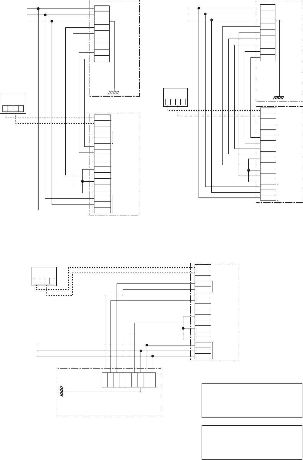
14
NEUTRAL
LIVE
EARTH
NVx HEATER (ON/OFF)
1
L
N
E
2
3
4
5
6
Remote Sensor
(optional)
T1 3 T2 1
MC200 FUEL SAVER
N
RESET
IN 2
COM
SEN 1
0-10V+
0-10V-
Lockout
Fan In
Heat Hi In
Heat Hi Out
Heat Lo In
Heat Lo Out
E
L
Fan Out
L Out
SUPPLY IN Mod Out
1
2
3
4
5
6
7
8
9
11
12
14
17
16
15
13
10
NVx HEATER (Hi/Lo)
Remote Sensor
(optional)
T1 3 T2 1
MC200 FUEL SAVER
N
RESET
IN 2
COM
SEN 1
0-10V+
0-10V-
Lockout
Fan In
Heat Hi In
Heat Hi Out
Heat Lo In
Heat Lo Out
E
L
Fan Out
L Out
SUPPLY IN Mod Out
1
2
3
4
5
6
7
8
9
11
12
14
17
16
15
13
10
NEUTRAL
LIVE
EARTH
Note: The NVx Heater and MC200
may be fed by separate electrical
supplies providing both supplies are
the same phase.
Warning: If external controls are
not isolated 230V may be present at
heater terminals even when the
heater is isolated.
MC200 FUEL SAVER
N
RESET
IN 2
COM
SEN 1
0-10V+
0-10V-
Lockout
Fan In
Heat Hi In
Heat Hi Out
Heat Lo In
Heat Lo Out
E
L
Fan Out
L Out
SUPPLY IN Mod Out
1
2
3
4
5
6
7
8
9
11
12
14
17
16
15
13
10
Remote Sensor
(optional)
T1 3 T2 1
NEUTRAL
LIVE
EARTH
NVx HEATER (Modulating)
1
L
N
E
2
3
4
5
6
1
L
N
E
2
3
4
5
6
MC200 CONTROLLING
On/Off NVx
MC200 CONTROLLING
Hi/Lo NVx
MC200 CONTROLLING
Modulating NVx
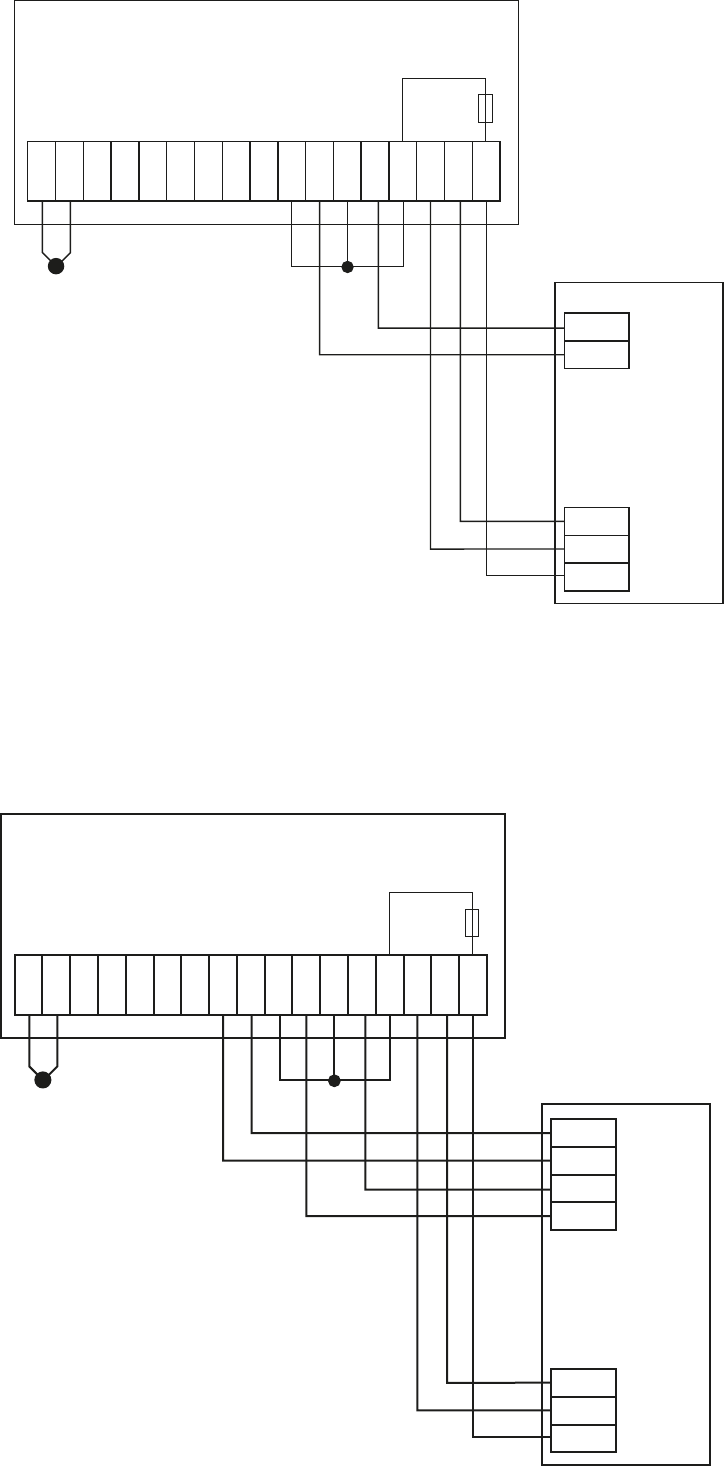
15
SEN 1
COM
IN 2
0-10v +
0-10v -
Reset
Lockout
Heat Hi
In
Heat Hi
Out
Heat Lo
In
Heat Lo
Out
Fan In
Fan Out
L Out
N
E
L
MC200 CONTROLLING
STANDARD CABINET HEATER
12 7 8
3
MC200 fuelsaver
6.3A
HRC
SEN 1
COM
IN 2
0-10v +
0-10v -
Reset
Lockout
Heat Hi
In
Heat Hi
Out
Heat Lo
In
Heat Lo
Out
Fan In
Fan Out
L Out
N
E
L
MC200 CONTROLLING
HI/LO CABINET HEATER
12 7 8
3 9 10
MC200 fuelsaver
6.3A
HRC
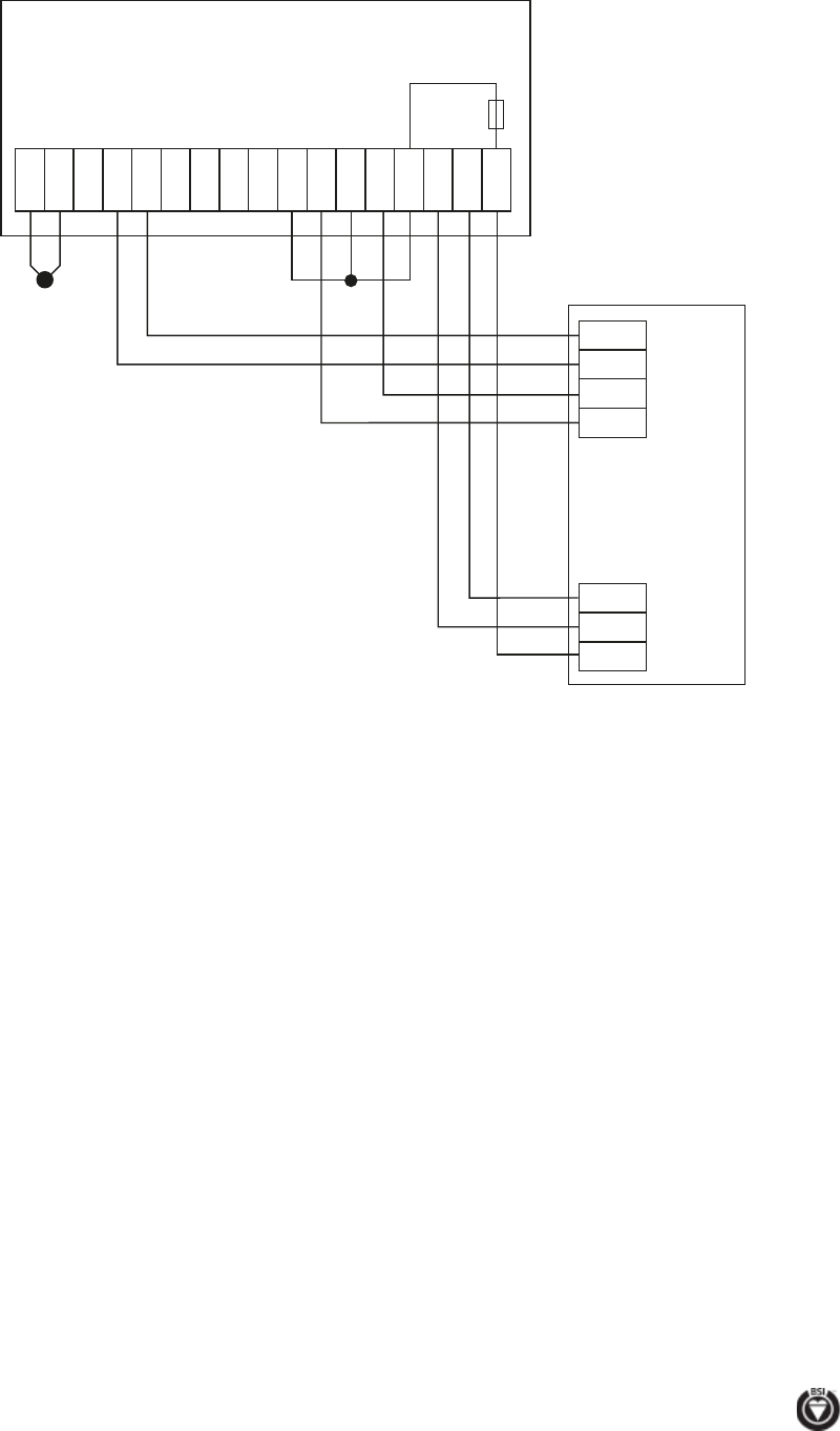
Every effort is made to ensure accuracy at time of going to press. However as part of our policy of continual product improvement, we reserve the right to alter specifications without prior notice.
HEATING DIVISION
Hort Bridge
Ilminster, Somerset TA19 9PS
Tel: 01460 53535 Fax: 01460 52341
BSI Registered Firm
FM 414
Ind. & Comm. Air Heaters;
Air Moving Equipment;
Flues & Chimneys; Natural
Smoke & Heat Ventilators;
Powered Supply & Extract
Fans & Systems. ISO 9001
SEN 1
COM
IN 2
0-10v +
0-10v -
Reset
Lockout
Heat Hi
In
Heat Hi
Out
Heat Lo
In
Heat Lo
Out
Fan In
Fan Out
L Out
N
E
L
MC200 CONTROLLING
MODULATING CABINET HEATER
12 7 8
3 9 10
MC200 fuelsaver
6.3A
HRC
