MCA8000D User Manual B1
User Manual:
Open the PDF directly: View PDF ![]() .
.
Page Count: 15
Products for
Your
Imagination
AMPTEK, Inc. 14 DeAngelo Drive, Bedford, MA 01730-2204 USA
+1 781 275-2242 Fax: +1 781 275-3470 www.amptek.com sales@amptek.com
MCA8000D User Manual
1 Introduction .......................................................................................................................................... 2
1.1 MCA8000D Description ................................................................................................................. 2
1.2 MCA8000D vs MCA8000A ............................................................................................................. 3
1.3 DP5 Family .................................................................................................................................... 3
1.4 Options and Variations ................................................................................................................. 4
2 Specifications ........................................................................................................................................ 5
2.1 Spectroscopic Performance .......................................................................................................... 5
2.2 Processing, physical, and power ................................................................................................... 5
3 Mechanical Interface ............................................................................................................................ 7
3.1 Dimensions .................................................................................................................................... 7
3.2 Connectors .................................................................................................................................... 7
4 Electrical Interface ................................................................................................................................ 8
4.1 Communications Interface ............................................................................................................ 8
4.2 Input signal interface .................................................................................................................... 8
4.3 GATE Interface .............................................................................................................................. 9
4.4 Power Interface ............................................................................................................................. 9
5 Design .................................................................................................................................................... 9
5.1 Block diagram ................................................................................................................................ 9
5.2 Peak detect modes ........................................................................................................................ 9
5.3 Thresholds ................................................................................................................................... 10
5.4 Livetime ....................................................................................................................................... 10
6 DPPMCA Software Interface ............................................................................................................... 11
7 Application Advice .............................................................................................................................. 12
7.1 MCA800D in Radiation Detection ............................................................................................... 12
7.2 MCA8000D in Particle Counting .................................................................................................. 13
7.3 Grounding and measurement errors .......................................................................................... 13
7.4 Calibration ................................................................................................................................... 14
Products for
Your
Imagination
2
1 Introduction
1.1 MCA8000D Description
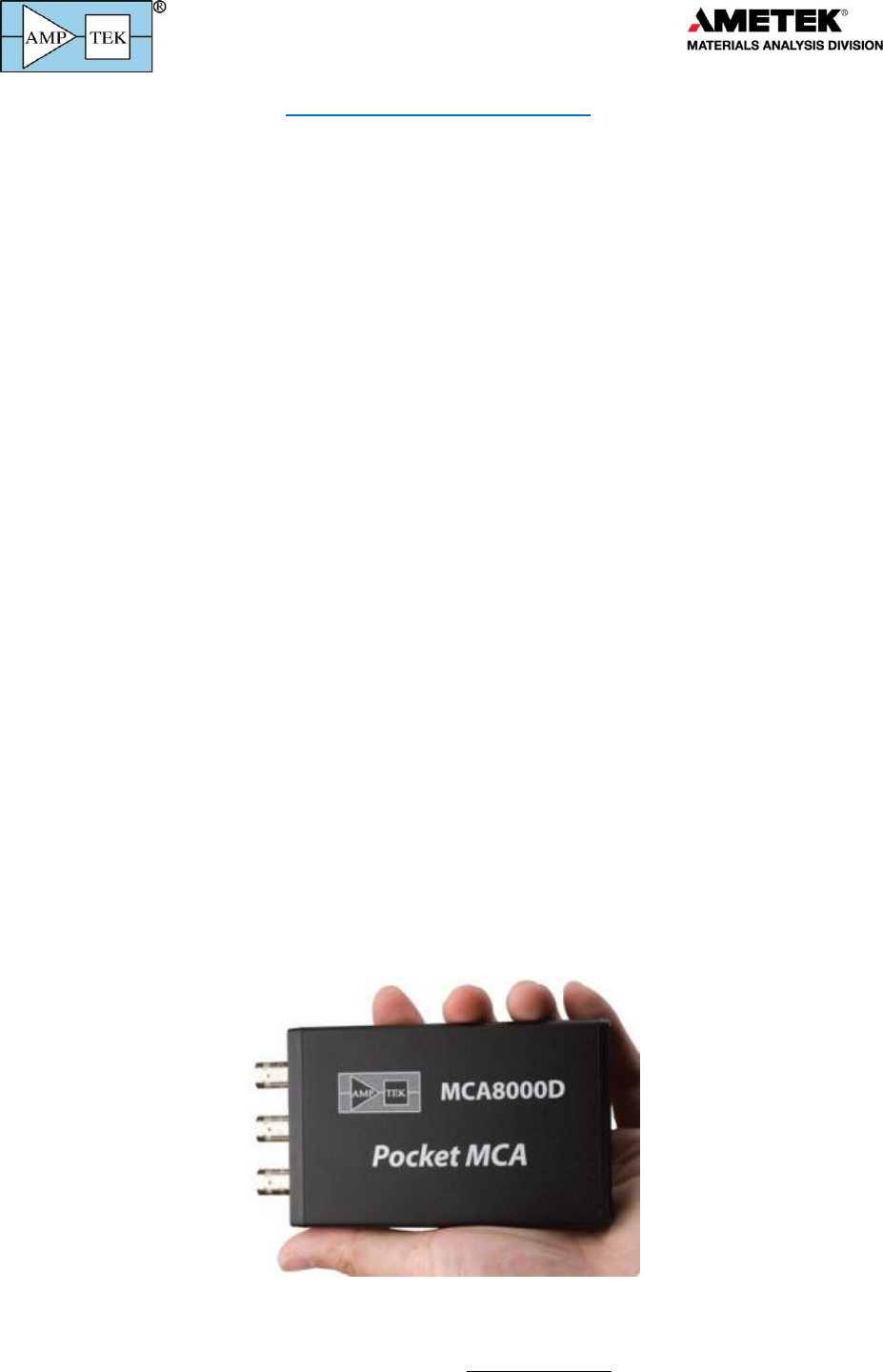
The MCA8000D is a modern, high performance multichannel analyzer (MCA). It is a replacement
for Amptek’s MCA8000A. The MCA8000A has provided very high performance for spectroscopic
applications for 15+ years but its architecture was designed around computer interfaces and hardware
now obsolete. Amptek has designed the MCA8000D to use modern, digital signal processing technology
and to use modern, high speed USB and Ethernet interfaces.
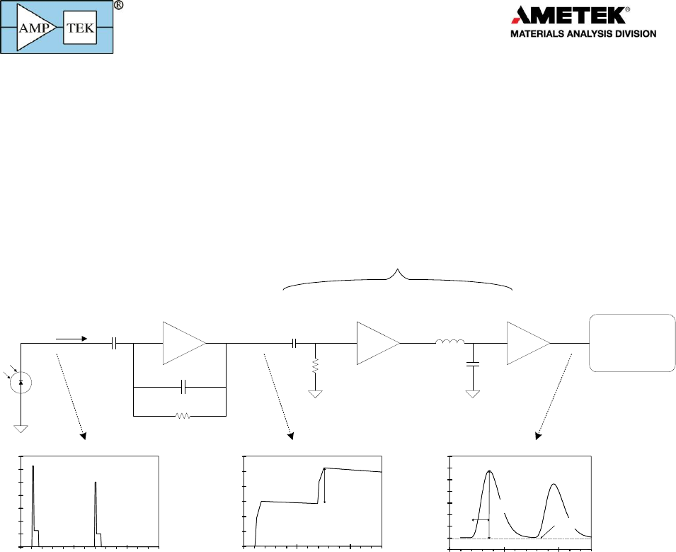
An MCA is one component in a complete instrumentation system. In most applications, a sensor
produces as its signal a series of current pulses. Signal processing electronics produce “shaped” pulses,
where the peak voltage is proportional to the deposited energy, size of the particle, or another quantity
of interest. The MCA outputs the pulse height spectrum, a histogram of the pulse heights.
The MCA detects the peak voltage of each shaped pulse and obtains the digital value; this digital
value is proportional to the peak voltage. At 10 bits, for example, there are 1024 digital values (a.k.a.
channels), so for a gain of 1V full scale, a 0.5V input pulse is in channel 512. Each time a pulse peaks in a
given channel, the MCA increments a counter for the corresponding channel. This array of integer
counter values is the pulse height spectrum which is the primary output of the MCA. This is sent to a
display or to spectrum processing software. Along with the histogram, the MCA outputs the
measurement time, a dead time correction, and total counts.
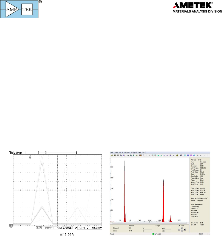
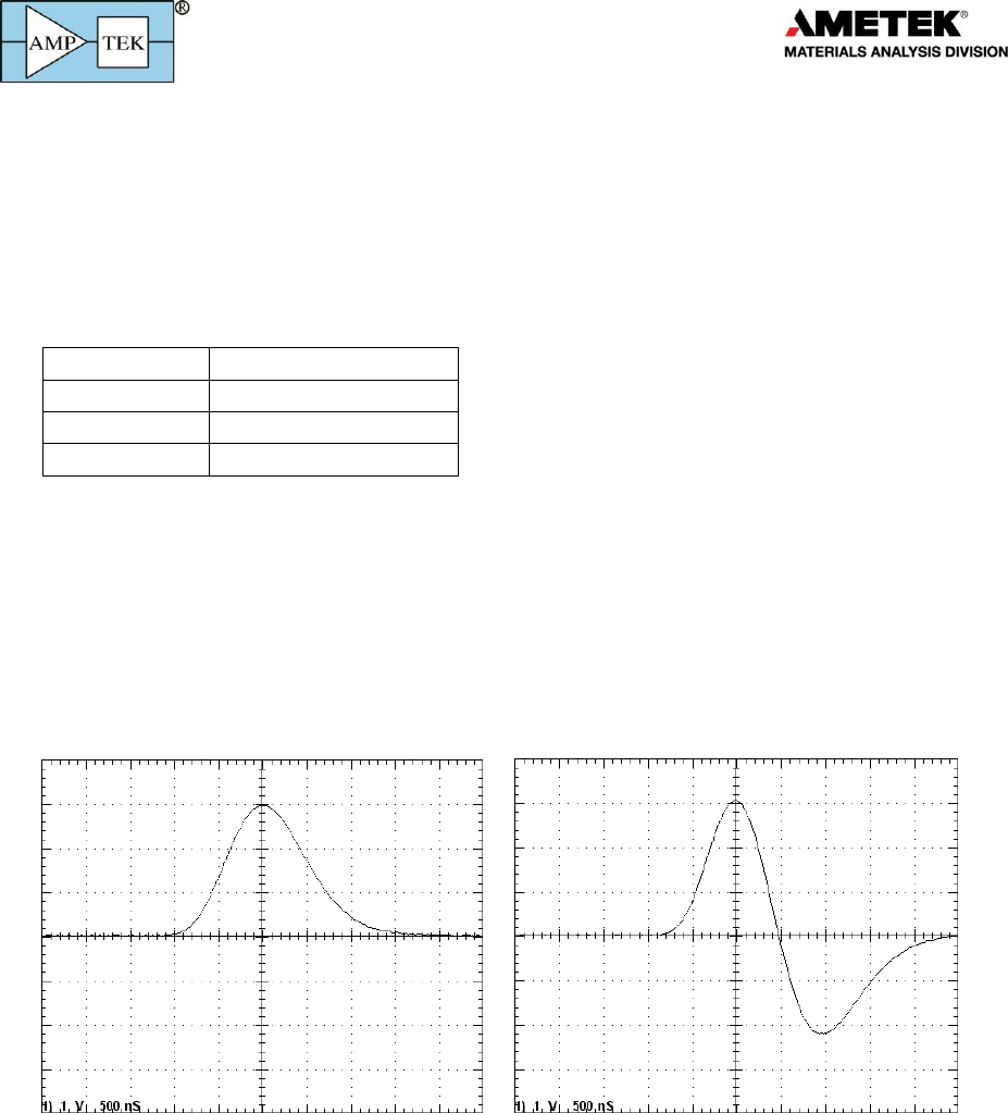
A typical MCA input, a series of shaped pulses, is shown on the left while the MCA output, the pulse height
spectrum, is shown on the right.
Figure 1 shows sample pulses, as seen on an oscilloscope (left), and the corresponding pulse height
spectrum (right). For Fig. 1, two different sources were use, a 55Fe source emitting 5.9 and 6.5 keV X-
rays and a 109Cd source emitting 22.1 and 25.0 keV X-rays. Each X-ray produces a pulse with height
proportional to its energy. The different pulse heights seen on the scope trace correspond to these
energies, as do the peaks in the pulse height spectrum on the right. In this application, the pulse heights
correspond to energy deposited in a radiation detector. In other applications, the pulse height may
correspond to the size of a dust particle, to the time between two events, or to other physical
quantities. The role of the MCA is to output the pulse height spectrum and the count rates.
Note that the MCA8000D discards overrange events – over 1V for the 1V scale, or over 10V for the
10V scale. The input can safely handle larger events.
Products for
Your
Imagination
3
MCA or DPP?
In many modern sensor systems using digital technology, the pulse shaping function is combined
with the MCA. The preamplifier signal is digitized, the pulse shaping is done digitally, and the already
digital peak is found by the MCA portion of the signal processor. Such a device is properly called a
“digital pulse processor” or DPP. Many people (incorrectly) refer to a digital processor which does both
the shaping and MCA function as an MCA. The MCA8000D does no digital shaping. It requires analog
pulse shaping circuitry to produce its input; it only carries out the functions of digitizing the peak and
acquiring the histogram. Amptek, Inc. makes a whole family of digital signal processors which combine
the shaping and MCA functions, designed for a range of products and applications (the DP5, PX5, DP5G,
TB-5, PX5-HPGe, and others). If you need a full digital signal processor rather than just the MCA
function, please contact Sales@amptek.com.
1.2 MCA8000D vs MCA8000A
There are a few important differences between the MCA8000D and the MCA8000A
o The MCA8000A only supported an RS232 interface (and required the handshaking signals to be
present). Most modern computers do not contain RS232 hardware; most RS232 to USB
adapters do not work with the MCA8000A and it does not work with Win7. The MCA8000D
supports RS232, USB, and Ethernet, making it compatible with modern computers.
o The MCA8000A used an analog peak hold and the MCA8000D uses a digital peak hold. The most
important consequence, for the user, is that the MCA8000A could support a pulse with a 250 ns
time to peak while the MCA8000D requires at least a 500 ns time to peak (Gaussian) for best
performance.
o The MCA8000A drew 200 mW (it could run for a day from two AA batteries) while the
MCA8000D draws 2 W. It can be powered from USB, unlike the MCA8000A.
o The MCA8000A interfaced to Amptek's ADMCA software while the MCA8000D interfaces to
Amptek's DPPMCA software. These look similar to the user but are different programs. If a
customer wrote custom software, this will need to be revised using a new SDK.
o The physical size and mass of the MCA8000D are about half that of the MCA8000A.
1.3 DP5 Family
Amptek has a family of products built around its core DP5 digital pulse processing technology,
designed for pulse height spectroscopy. It was originally designed for the detection of ionizing radiation,
principally X-ray and gamma-ray spectroscopy. A generic system, illustrated below, includes (a) a
sensor, a.k.a. detector, (b) a charge sensitive preamplifier, (c) analog prefilter circuitry, (d) an ADC, (e) an
FPGA which implements pulse shaping and multichannel analysis, (f) a communications interface, (g)
power supplies, (h) data acquisition and control software, and (i) analysis software.
Detector and
Preamplifier Analog
Prefilter ADC Slow
Channel
Peak Detect
Histogram Logic
Counters
Pulse
Selection
C and
Interface
Auxiliary
Signals
Computer
Oscilloscope or
external logic
Digital Processor (DPP)
Fast
Channel
Digital Pulse Shaping

Products for
Your
Imagination
4
The core DP5 technology shared by all the systems includes the ADC, the FPGA, the communication
interface, and the data acquisition and control software. All products in the DP5 product family include
nearly the same digital signal processing algorithms, the same communication interfaces (both the
primary serial interfaces and the auxiliary I/O), and use the same data acquisition and control software.
The DPPMCA software package is a complete, compiled data acquisition and control software package
used across the family; Amptek also offers an SDK for custom software solutions.
The products in the DP5 family differ in the sensor for which they are designed, which leads to
changes in the analog prefilter, power supplies, and form factor. They also differ in their completeness:
some of Amptek’s products are “complete”, with elements (a) through (i), while others offer only a
portion of the functionality for the user to integrate into a complete system.
1.4 Options and Variations
The MCA8000D is available in two different configurations: the standard configuration is optimized
for nuclear spectroscopy, while the “Option PA” configuration is optimized for particle size and counting
applications. These applications are discussed further in the applications notes (section 6).
In terms of hardware the only difference is that the nuclear configuration (standard) has 1 k input
impedance while option PA units have 100 k input impedance. In addition, option PA units are
calibrated, in terms of the voltage input, using a NIST traceable calibration. The “absolute peak mode”,
selectable in software, is more common for particle applications.
Option PA
The Option PA package has been developed to facilitate the use of the MCA8000D for particle
counting in airborne1 (Size Calibration) and liquid suspended (Number Calibration) particle applications.
The unit is calibrated and certified traceable to the National Institute of Standards and Technology
(NIST).
The Option PA package is capable of detecting pulses from 5 mV to 10 V. The MCA8000D is typically
connected to the output of a particle sensor. It detects and displays a spectrum of pulse heights allowing
the user to determine if a given particle size is producing the correct voltage. The software included with
the MCA provides information on the peak center (centroid and mean calculation) making it easy to
determine if the peak is in the correct position. The MCA is internally calibrated to convert the MCA
channel scale to a mV scale. This calibration is loaded automatically in the DPPMCA application, making
it unnecessary to load calibration files manually.
o Pulse detection from 5 mV to 10 V
o 2 Voltage scales: 0-1 V and 0-10 V
o 100 k input impedance
o NIST Traceable calibration
o Certificate of calibration
o Absolute peak or separate peak detection modes (absolute mode typical for PA)
1Sommer, H.T. “IMPLEMENTING PARTICLE COUNTER CALIBRATION PER ISO 11171-1999.”; TEAM Service,
Inc., P.O. Box 220, Merlin, OR 97532, (541)476-4744, HolgerTSo@aol.com; Copyright Society of
Automotive Engineers

Products for
Your
Imagination
5
2 Specifications
2.1 Spectroscopic Performance
This is dependent upon the detector and the shaping amplifier. The MCA8000D does not affect the
spectroscopic performance.
2.2 Processing, physical, and power
The processing specifications of the MCA8000D are quite different from those of the other
members of the DP5 family, due to its fundamentally different function in a spectroscopy system.
General Characteristics
Pulse-Height Digitizer
High speed 100 MHz, 14 bit ADC with digital pulse height measurement
Input Ranges
0 to 1 V or 0 to 10 V (software selectable) (over-range events are discarded)
Number of Channels
256, 512, 1k, 2k, 4k, or 8k (software selectable)
Minimum input risetime
≥500 ns to meet specifications
Dead Time per pulse
10 ns plus pulse shaping time
Peak Detection Modes
Separate peaks (V1): Standard to nuclear instrumentation MCAs.
Absolute Peak Above Threshold (V2): Typically used in airborne particle sizing
analyzers, in environmental air monitoring systems and in aerosol research.
Acquisition Modes
MCA and MCS (multichannel scaling) down to 10 ms/channel
Differential Nonlinearity
<±0.6% from 5 mV to full scale
Integral Nonlinearity
<±0.02% over full scale
Gain Stability
±10 ppm/°C (typical)
Zero drift
±10 ppm/°C (typical)
Low Level Discriminator
Software selectable threshold, in increments of one channel.
Counts per Channel
Maximum = 16.7 x 10⁶ counts (3 bytes)
Real and Live Timers
Data acquisition real or live time preset. Maximum preset time 4,294,967.29
seconds (10mS precision), or 999,999.999 seconds (1mS precision). Shorter
accumulation times can be achieved by gating the input signal with Gate 1 or Gate 2
Real and Live Time
4,294,967.295 s (0.001 s precision)
Acquisition Time
1,677,721.599 s (0.001 s precision)
Preset Counts
4,294,967,295 (232-1) in channel or ROI
Interface
RS232: 115.2 or 57.6 Kbaud.
USB: Standard 2.0 full speed (12 Mbps).
Ethernet: Standard 10base-T (UDP).
Operating Temperature
-20 °C to +60 °C
TUV Certification
Certificate #: CU 72131640 01
Tested to: UL 61010-1:2012
CAN/CSA-C22.2 NO. 61010-1-12

Products for
Your
Imagination
6
Exterior Controls and Indicators
Status Light
Steady red light: power is ON and no data acquisition in progress
Flashing red light: data acquisition in progress. [Same as amber light on Ethernet
connector.]
Power
Operating Power
2W
Input Power
+5 V at 0.4 A
Input Power Range
+4 V to +5.5 V (0.5 to 0.4 A typical)
Input Power Sources
USB power or AC/DC adapter (supplied)
Connections
Input
The analog input accepts positive unipolar or bipolar semigaussian type pulses of
shaping time constants ≥200 ns or peaking time ≥500 ns
The dynamic range is 0 to +1 V or 0 to +10 V, software selectable.
Minimum pulse height is 5 mV.
Input impedance is 1 kΩ or 100 kΩ (options at purchase).
The input has overload protection up to ±20 V.
The DC level of the input signal must be zero.
Gates
The MCA8000D has two logic gates:
GATE1 is used to synchronize acquisition with external hardware.
GATE2 is used for pileup rejection.
Each gate can be commanded to ACTIVE HIGH, ACTIVE LOW, or DISABLED. When set
to ACTIVE HIGH, if the input is high, then pulse heights are recorded and the live
time clock runs. The active state of each GATE input is evaluated at the time the
peak of the input analog pulse is detected.
Interface (I/O)
USB: Standard USB Mini-B jack.
Ethernet: Standard RJ45 Ethernet jack.
RS232: Standard 2.5 mm stereo audio jack.
Power Plug mates with 3.5 mm x 1.3 mm x 9.5 mm female barrel, center positive,
plug connector.
Mechanicals
Weight
<165 g
Dimensions
5 x 2.8 x 0.8 in (125 x 71 x 20 mm)
Products for
Your
Imagination
7
3 Mechanical Interface
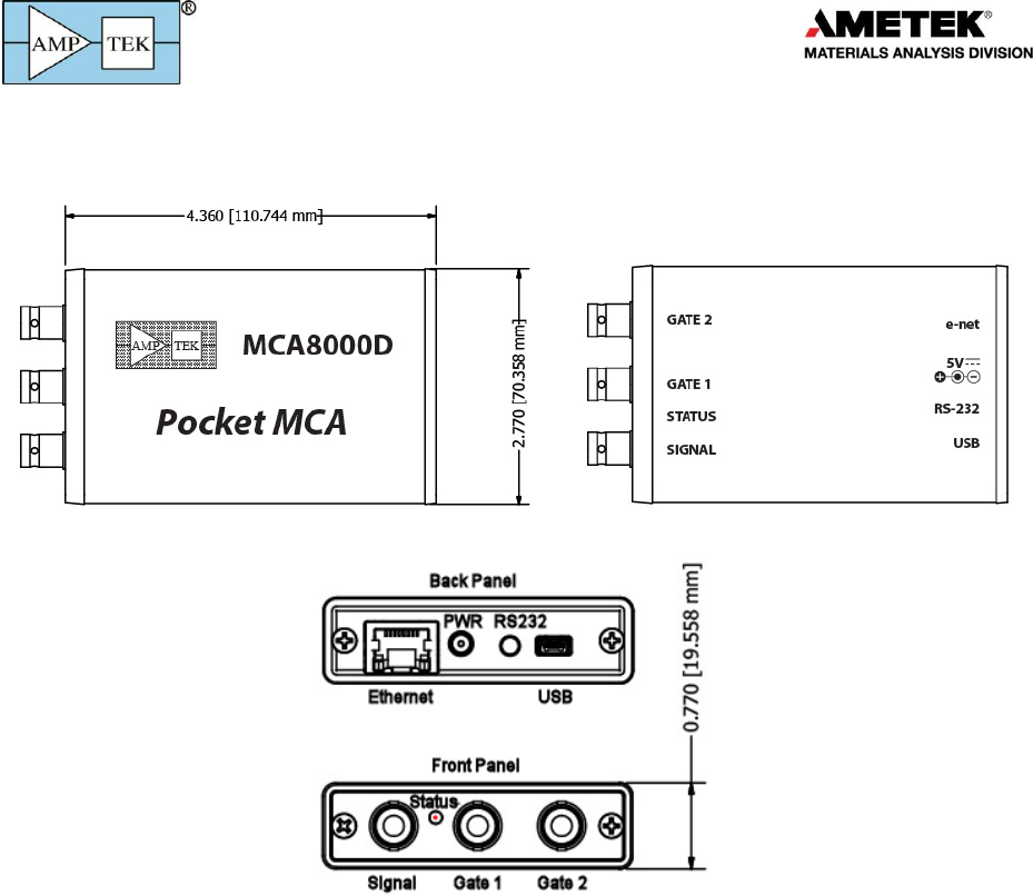
3.1 Dimensions
3.2 Connectors
Input
Standard BNC Coax
Gate 1, Gate 2
Standard BNC Coax
Power
Power jack: 3.5 mm x 1.3 mm x 9.5 mm female barrel, center positive.
Mating plug: Kobiconn #171-PA35135-E (or equiv.)
Products for
Your
Imagination
8
Ethernet (J2)
Standard Ethernet connector (RJ-45)
USB
Standard USB ‘mini-B’ jack. MCA8000D can be powered from the USB bus.
RS-232
Standard 2.5 mm stereo audio jack.
Contact
Signal
Tip
TXD (from MCA8000D)
Ring
RXD (to MCA8000D)
Sleeve
GND
4 Electrical Interface
4.1 Communications Interface
Common to DP5 family and described in the DP5 family manual.
4.2 Input signal interface
Signal type: Shaped pulse. Typical examples shown below.
Oscilloscope traces illustrating typical pulses input to the MCA8000D.
Input polarity: Must be positive: the MCA8000D finds the peak of the positive going signal.
Pulse risetime: Must be >500 ns for full accuracy and resolution. Shorter risetimes will be measured
but the accuracy or pulse height resolution may be compromised.
Input ranges: The MCA8000D supports two allowable input ranges, 0 to +1V and 0 to +10V,
selectable by software command. As discussed below, when the 10V range is selected, a precision
10:1 divider brings the signal into the 0 to +1V range of the ADC. The minimum pulse height that can
be detected is 5 mV.
Products for
Your
Imagination
9
4.3 GATE Interface
The input is 5V-tolerant and the thresholds are compatible with TTL and 3.3V CMOS
4.4 Power Interface
Absolute Maximum Power Supply Voltage +6.0 VDC
Absolute Minimum Power Supply Voltage +4.0 VDC
Input power outside this range will damage MCA8000D components.
5 Design
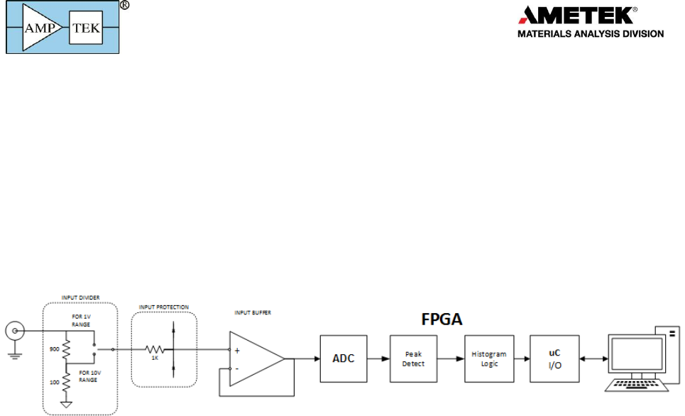
5.1 Block diagram
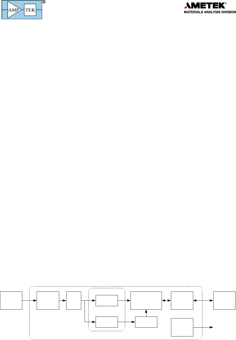
A block diagram of the MCA8000D is shown above. It includes (a) an analog prefilter, (b) a 100
MHz, 16 bit ADC, (c) an FPGA, (c) a microprocessor and I/O components, and (d) power supplies (not
shown).
The analog prefilter consists of (a) a switchable attenuator, (b) input protection circuitry, and (c) a
unity gain buffer. The ADC has a range corresponding to 1 volt full scale. To handle a 10V input, the
signal is sent to a precision divider. This resistance of this divider is typically 1 kohm for nuclear
measurements (shown above) and 100 kohm for particle analyzers (Option PA).
The two resistance values are available because the analog circuitry of most particle analyzers is
designed to drive a high impedance; if the impedance is too low, then the series resistance of the
analyzer attenuates the signal and degrades accuracy. Many shaping amplifiers for nuclear applications
are specified for lower impedance. But Amptek can supply a 100 kohm unit for nuclear applications or a
1 kohm unit for particle analyzers. Contact Amptek for details. The buffer keeps the impedance of the
rest of the circuit from loading the input, which is important for accuracy and linearity
The FPGA implements the peak detect function and then bins the data into the histogram memory.
The peak detect includes a low pass filter to minimize the effects of timing jitter (the pulse is not
synchronous with the clock). Sliding scale linearization is used to assure the required linearity. The logic
tracks the rising edge of the pulse to a peak and then requires the value to fall by a threshold which can
be configured via software.
The FPGA stores the pulse height spectrum as a histogram in its memory, along with counter
values. This is periodically read by the microcontroller, which then formats the data into the
appropriate packets and transmits them over the selected interface. The microcontroller also accepts
commands from the attached computer to configure the hardware. The microcontroller is only used for
serial interface; all acquisition, counting, and timing are carried out in the FPGA.
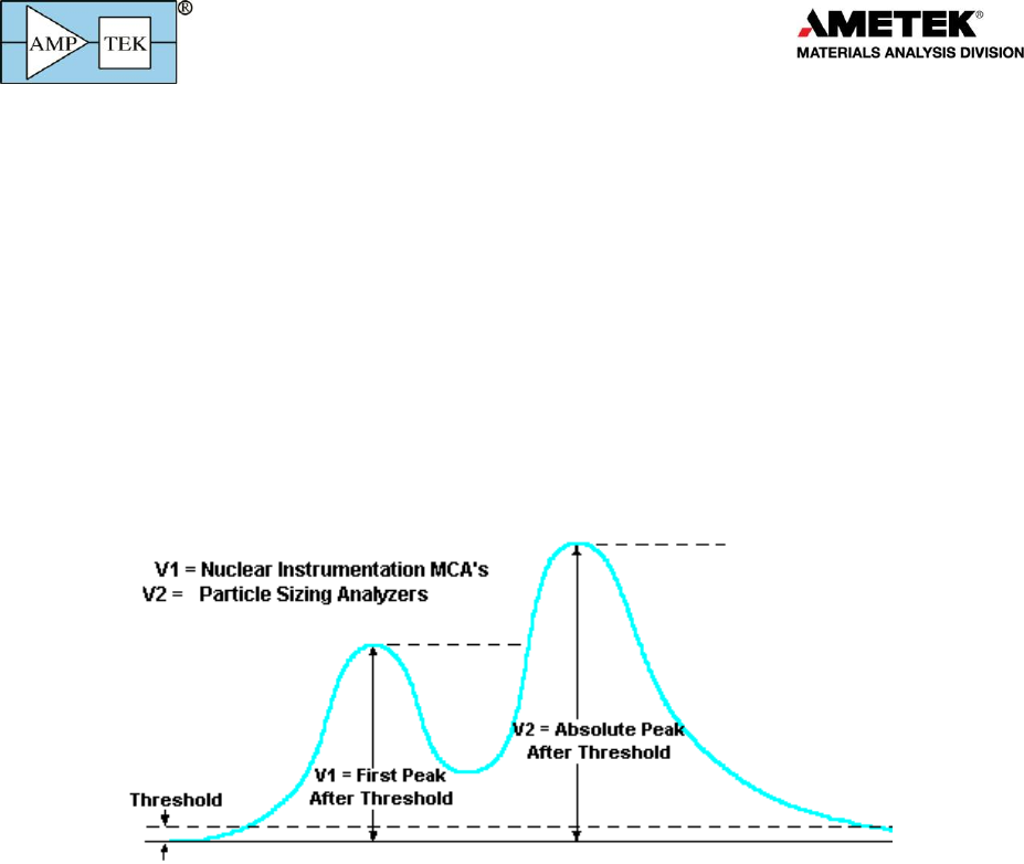
5.2 Peak detect modes
The MCA8000D supports two different peak detect modes, selectable by software command:
Products for
Your
Imagination
10
o In Mode 1, the MCA8000D tracks the signal when it passes a threshold (the “slow threshold”, set
in software) up to the first peak and then detects that a peak has occurred when the input has
fallen by a certain value (also the “slow threshold”). If a second peak occurs before the signal
has fallen back to threshold, then this second peak is also detected and recorded in the
spectrum. Each of the separate peaks are recorded, unless vetoed by a pile-up reject logic signal
into a GATE. Mode 1 is common in nuclear instruments, where the two peaks occur due to
discrete radiation interactions occurring closely in time and both may be valid. Note that a pile-
up rejection circuit external to the MCA can be used to gate off such pulses (discussed below).
o In Mode 2, the MCA8000D tracks the signal when it passes the slow threshold. If it detects that
a peak has occurred, but then the signal rises to a second (or third or fourth or …) peak before
returning to threshold, it is the largest peak which is output from the peak detector. The largest
value between slow threshold crossings is the output. Mode 2 is common in particle sizing
analyzers, where the shape of the particle can cause the light curve to exhibit multiple peaks but
the largest peak is the quantity of interest.
Figure 3. Illustration of the two peak detection modes available.
5.3 Thresholds
The MCA8000D includes a threshold parameter which can be set in software. Its primary function
is in the peak detect logic: the pulse height must be greater than the threshold, then the pulse must fall
below its peak by the threshold before the system recognizes that a peak occurred. Usually, the MCA
will only record pulses above this threshold but, with some bipolar pulses, it is possible to have below
threshold pulses recorded. The MCA8000D also include a separate parameter, the LLD (low level
discriminator). This functions purely as a lower threshold, only recording pulse heights which exceed
the LLD.
5.4 Livetime
In the MCA8000D, there is a livetime clock. This clock is stopped whenever (a) the input is over the
slow threshold or (b) GATE1 or GATE2 disables acquisition.
Products for
Your
Imagination
11
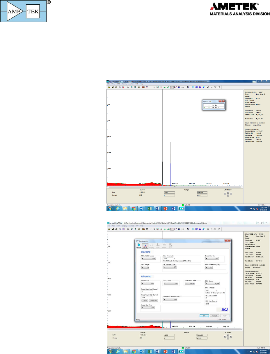
6 DPPMCA Software Interface
The MCA8000D uses the same DPPMCA software, with the same FW6 communication protocol, as
the other members of the product family. It’s the same basic software interface, but because the
MCA8000D has a much more limited set of configuration options (only those related to the MCA rather
than to signal processing and power supplies), the interface looks slightly different. The DPPMCA Help
File remains accurate but the accessible parameters are much more limited.
When connected to and acquiring
data from the MCA8000D, the main
screen (shown to the right, top) is
almost unchanged. The only difference
is that, in the “Info Pan” on the right,
DPPMCA does not show the gain,
peaking time, HV, detector
temperature, or the other parameters
shown with the digital processors. In
addition, it shows the live time and real
time, rather than accumulation time,
because the MCA8000D uses different
clocks, as discussed elsewhere in this
manual.
When configuring the MCA8000D,
(shown to the right, bottom) only the
MCA tab is available, because none of
the parameters listed on the other
pages are present in the MCA8000D.
These parameters all have their usual
meanings, as discussed in the DPPMCA
help file and in this user manual.
o To use an external gate, connect
the logic signal to GATE1, then set
the “Gate Control” to HIGH or LOW
(depending on the signal polarity).
o To use pileup rejection, connect the
logic signal to GATE2, then set
“PUR” to HIGH or LOW (depending
on the signal polarity).
The digital oscilloscope still
functions but the only valid trigger
signal is PEAKH (the other triggers are
generated by DPP logic in Amptek’s
other products).
Products for
Your
Imagination
12
7 Application Advice
7.1 MCA800D in Radiation Detection
The figure below illustrates a typical spectrometer used in detecting ionizing radiation – X-rays,
gamma-rays, alpha particles, etc. When ionizing radiation interacts in the detector, charge is liberated.
The total amount of charge is proportional to the energy deposited. The ratio depends on the detector
but in many applications, the total charge may only be a few thousand electron-ion pairs. The signal
current is input to a charge sensitive preamplifier, which produces a voltage pulse where the step, V is
proportional to the charge in the input pulse and hence to the energy.
The step from the preamplifier is usually very small and is superimposed on a baseline which is
much larger, varies with time, and has wideband noise present. The preamplifier output thus goes to a
shaping amplifier which filters the noise, stabilizes the baseline, and provides enough gain for accurate
measurement. The MCA does two things: (1) it digitizes the voltage of the peak of the shaped pulses
and (2) from the many pulses it produces a pulse height spectrum. This is a histogram.
In most radiation detection systems, the quantity of interest is the system conversion gain in
eV/channel. This depends on many factors: detector material, preamp conversion gain, shaping
amplifier gain, and a pulse peaking factor related to the shaping network. In most radiation detection
applications, one sets up the complete system and then uses monoenergetic radiation sources to
calibrate the system conversion gain. There are many excellent calibration sources, e.g. characteristic X-
ray lines and gamma-ray lines. These are constant and do not depend on any external conditions The
absolute calibration of the MCA, in volts/channel, is not needed for most radiation detection
applications because the system gain depends on so many factors and excellent, traceable calibration
sources are readily available.
Because radioactive decays are random processes, they occur at random times. Among other
things, because the pulse shaping electronics give a finite time to process each pulse (a dead time per
pulse), two pulses can overlap or pile-up. They will be input to the circuit as a single pulse. The
MCA8000D includes a dead time clock to estimate the true, incoming rate from the number of
measured pulses and the total time the system was dead. This is discussed in more detail below. The
MCA8000D also includes a Gate input which can be used to stop acquisition for piled up pulses. The
Detector
-
CF
G
Charge Sensitive
Preamplifier
isig(t)
diff
High Pass Filter Voltage Gain
Pulse Shaping
Amplifier
int
Low Pass Filter
RF
MultiChannel
Analyzer (MCA)
Current
Time
Voltage
Time
V
Voltage
Time
Vpeak
Baseline
p
Products for
Your
Imagination
13
shaping amplifier or other circuitry preceding the MCA8000D must be used to generate the Gate signal.
The MCA8000D cannot detect pile-up but it can reject pulses when external circuitry signals.
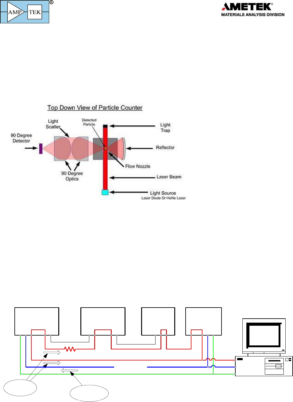
7.2 MCA8000D in Particle Counting
The figure below (from Wikipedia) illustrates a typical particle counter system. A light shines on
region through which dust passes. When a dust particle passes in front of the light source, light reflects
into the detector, producing a current pulse. The current profile may have a very erratic shape
depending on the shape of the particle. By measuring the distribution of peak values, one determines
the distribution of particle sizes.
The manufacturer will provide a calibration value: a 0.1V output pulse corresponds to a given
particle size. An MCA then measures the distribution and number of these pulses. Note that the
particle analyzer requires the MCA’s calibration, in volts per channel, to be known. This is unlike the
nuclear system where the characteristics of ionizing radiation can be used for very accurate calibrations.
The MCA8000D for particle analyzers, Option PA, includes a NIST certified voltage calibration. In the
calibrated MCA8000D, channel 512 corresponds to 0.5 (5) volts in the 0-1 (0-10) voltage range. Amptek
guarantees the calibration to +/- 1% but it is usually much better.
7.3 Grounding and measurement errors
Grounding is very important for accurate, small signal measurements. Customers have reported
errors which arise from return currents when powering the unit via USB. The drawing below illustrates
the problem.
MCA8000D Shaping Amp Preamp
Computer
X-ray
source
USB Power
USB Communications
Signal Signal
Ground
Supply
0.4 A DC
Zgnd
Power
Return

Products for
Your
Imagination
14
The problem arises because “ground” has two distinct roles in most circuits. The ground
connection is usually both a signal reference and a power return path. If there is significant current in
the power return, then the impedance of the ground leads to voltage differential which causes errors if
the same ground path is used as the signal reference.
In the sketch above, the red trace illustrates the ground connection in a common arrangement.
The preamp signal passes to the shaping amp and its output to the MCA8000D. There is a ground
connection between them, so the preamp output voltage is referenced to ground and the shaping amp
output is referenced to ground.
In this sketch, the 0.4A of USB power must return to the computer. There are two parallel paths,
the ground in the USB cable but also the signal ground. The 0.4A current will be divided between the
two paths and this current, across the resistance in the ground path between the amplifier and the
MCA8000D will cause an error. Even 50 m of resistance in the cables will lead to a 20 mV error.
The best solution is to separate the signal ground from the power return path. In this particular
case, using the MCA8000D’s AC/DC power supply accomplishes this. The AC/DC supply is not grounded,
so the return current is entirely contained in the power supply wire. The separation between signal
reference and power return is usually recommended and will help with measurement accuracy.
7.4 Calibration
General Information
Calibration of the MCA8000D is simple yet is the source of much confusion for novice users, so will
be discussed in some detail. To calibrate the MCA, whatever the application, one needs to inject into
the MCA a set of pulses of known, discrete amplitudes. A spectrum is then acquired and these discrete
amplitudes appear as discrete peaks in the spectrum. The centroid of each peak is measured, often
using the DPPMCA software. A calibration dialog in DPPMCA lets one enter the measured centroids (in
channels) and the corresponding known amplitudes (in volts, keV, electrons, nanoseconds, or whatever
unit is appropriate). The software then implements a correlation using these (amplitude, channel) pairs.
The MCA8000D hardware is linear to within 0.6% full scale but many sensors are not linear, so the
software permits either linear or quadratic regressions. The DPPMCA software uses the values entered
into the calibration dialog to show the scale of the horizontal axis in its display. The use of the
calibration dialog is discussed in more detail in the DPPMCA Help File but, at its core, it implements a
regression on a set of measured (amplitude, channel) pairs.
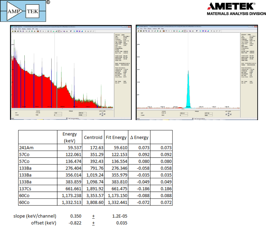
Nuclear Instruments
In a nuclear instrument, one typically measures the spectrum from a sample with at least two peaks
of known energies. The energy of the incident particles is correlated with the measured centroids; this
calibrates not only the MCA but the entire signal processing chain (detector, preamp, shaping amp, etc).
Because the characteristic energies of X-rays and gamma-rays are physical constants, there is no need
for NIST traceable calibrations: one is calibrating the system to constants. But one does need a
spectrum with peaks of known energies. The plot below shows the spectrum measured from an HPGe
gamma-ray detector and shows a zoomed in photopeak; the software computes the centroid channel of
this peak. The table below that shows a set of calibration values, (energy, channel) pairs, and the result
of a linear regression. Note that channel zero is not zero energy; this is typical, since real amplifiers have
nonzero offset.
Products for
Your
Imagination
15
Particle Analyzers
For a particle analyzer, Amptek provides a NIST traceable calibration. We use a DC voltage source
and a special calibration mode to trigger the ADC on each of two DC voltage levels. This produced the
centroid channel for each of the two voltages.
At Amptek, we program into each MCA8000D (Option PA) the two (voltage, channel centroid) pairs.
Amptek’s DPPMCA software reads these two pairs and does a linear regression to obtain the
mV/channel and mV offset; these are used in the display of the horizontal axis. Amptek guarantees the
accuracy of this Option PA calibration to within +/-1% and the offset to be within 0.02 mV (0.2 mV) for
the 1 (10V) range. A customer can do a calibration check (using a calibrated pulser and recording
centroids) or can acquire additional calibration points using the calibration dialog in DPPMCA.
