MCP Deployment Guide
User Manual:
Open the PDF directly: View PDF ![]() .
.
Page Count: 339 [warning: Documents this large are best viewed by clicking the View PDF Link!]
- Copyright notice
- Preface
- Introduction
- Plan the deployment
- Prepare for the deployment
- Deploy MCP DriveTrain
- Prerequisites for MCP DriveTrain deployment
- Deploy the APT node
- Deploy the Salt Master node
- Verify the Salt infrastructure
- Enable the management of the APT node through the Salt Master node
- Configure MAAS for bare metal provisioning
- Provision physical nodes using MAAS
- Deploy physical servers
- Deploy VCP
- Deploy CI/CD
- Deploy an MCP cluster using DriveTrain
- Deploy an OpenStack environment
- Deploy a multi-site OpenStack environment
- Deploy a Kubernetes cluster
- Deploy StackLight LMA with the DevOps Portal
- View credentials details used in Jenkins pipelines
- View the deployment details
- Deploy an MCP cluster manually
- Deploy an OpenStack environment manually
- Prepare VMs to install OpenStack
- Enable TLS support
- Encrypt internal API HTTP transport with TLS
- Enable TLS for RabbitMQ and MySQL back ends
- Enable TLS for client-server communications
- Enable libvirt control channel and live migration over TLS
- Enable TLS encryption between the OpenStack compute nodes and VNC clients
- Configure OpenStack APIs to use X.509 certificates for MySQL
- Configure OpenStack APIs to use X.509 certificates for RabbitMQ
- Install support services
- Install OpenStack services
- Deploy a Ceph cluster manually
- Deploy Xtrabackup for MySQL
- Post-deployment procedures
- Troubleshoot
- Deploy a Kubernetes cluster manually
- Prerequisites
- Salt formulas used in the Kubernetes cluster deployment
- Add swap configuration to a Kubernetes deployment model
- Define interfaces
- Deploy a Kubernetes cluster
- Enable Virtlet
- Enable the role-based access control (RBAC)
- Enable the MetalLB support
- Enable the NGINX Ingress controller
- Enable an external Ceph RBD storage
- Deploy OpenContrail manually
- Deploy compute nodes
- Deploy the DevOps Portal manually
- Deploy StackLight LMA components
- Finalize the deployment
- Deploy an OpenStack environment manually
- Deployment customizations guidelines
- Generate configuration drives manually
- Add custom commissioning scripts
- Configure PXE booting over UEFI
- Add a custom disk layout per node in the MCP model
- Enable NTP authentication
- Enable a watchdog
- Enable the Linux Audit system
- Configure a company name for the SSH and interactive logon disclaimer
- Set custom Transmit Queue Length
- Advanced configuration
MCP Deployment Guide
version q3-18

Copyright notice
2019 Mirantis, Inc. All rights reserved.
This product is protected by U.S. and international copyright and intellectual property laws. No
part of this publication may be reproduced in any written, electronic, recording, or photocopying
form without written permission of Mirantis, Inc.
Mirantis, Inc. reserves the right to modify the content of this document at any time without prior
notice. Functionality described in the document may not be available at the moment. The
document contains the latest information at the time of publication.
Mirantis, Inc. and the Mirantis Logo are trademarks of Mirantis, Inc. and/or its affiliates in the
United States an other countries. Third party trademarks, service marks, and names mentioned
in this document are the properties of their respective owners.
Mirantis Cloud Platform Deployment Guide
©2019, Mirantis Inc. Page 2

Preface
This documentation provides information on how to use Mirantis products to deploy cloud
environments. The information is for reference purposes and is subject to change.
Intended audience
This documentation is intended for deployment engineers, system administrators, and
developers; it assumes that the reader is already familiar with network and cloud concepts.
Documentation history
The following table lists the released revisions of this documentation.
Revision date Description
November 26, 2018 Q3`18 GA
Mirantis Cloud Platform Deployment Guide
©2019, Mirantis Inc. Page 3

Introduction
MCP enables you to deploy and manage cloud platforms and their dependencies. These include
OpenStack and Kubernetes based clusters.
The deployment can be performed automatically through MCP DriveTrain or using the manual
deployment procedures.
The MCP DriveTrain deployment approach is based on the bootstrap automation of the Salt
Master node that contains MAAS hardware nodes provisioner as well as on the automation of an
MCP cluster deployment using the Jenkins pipelines. This approach significantly reduces your
time and eliminates possible human errors.
The manual deployment approach provides the ability to deploy all the components of the cloud
solution in a very granular fashion.
The guide also covers the deployment procedures for additional MCP components including
OpenContrail, Ceph, StackLight, NFV features.
Seealso
Minimum hardware requirements
Mirantis Cloud Platform Deployment Guide
©2019, Mirantis Inc. Page 4

Plan the deployment
The configuration of your MCP installation depends on the individual requirements that should
be met by the cloud environments.
The detailed plan of any MCP deployment is determined on a per-cloud basis.
Seealso
•Plan an OpenStack environment
•Plan a Kubernetes cluster
Mirantis Cloud Platform Deployment Guide
©2019, Mirantis Inc. Page 5

Prepare for the deployment
Create a project repository
An MCP cluster deployment configuration is stored in a Git repository created on a per-customer
basis. This section instructs you on how to manually create and prepare your project repository
for an MCP deployment.
Before you start this procedure, create a Git repository in your version control system, such as
GitHub.
To create a project repository manually:
1. Log in to any computer.
2. Create an empty directory and change to that directory.
3. Initialize your project repository:
git init
Example of system response:
Initialized empty Git repository in /Users/crh/Dev/mcpdoc/.git/
4. Add your repository to the directory you have created:
git remote add origin <YOUR-GIT-REPO-URL>
5. Create the following directories for your deployment metadata model:
mkdir -p classes/cluster
mkdir nodes
6. Add the Reclass variable to your bash profile:
vim ~/.bash_profile
Example:
export RECLASS_REPO=<PATH_TO_YOUR_DEV_DIRECTORY>
7. Log out and log back in.
8. Verify that your ~/.bash_profile is sourced:
echo $RECLASS_REPO
The command returns the content of the ~/.bash_profile file.
Mirantis Cloud Platform Deployment Guide
©2019, Mirantis Inc. Page 6

9. Add the Mirantis Reclass module to your repository as a submodule:
git submodule add https://github.com/Mirantis/reclass-system-salt-model ./classes/system/
System response:
Cloning into ‘<PATH_TO_YOUR_DEV_DIRECTORY>/classes/system’...
remote: Counting objects: 8923, done.
remote: Compressing objects: 100% (214/214), done.
remote: Total 8923 (delta 126), reused 229 (delta 82), pack-reused 8613
Receiving objects: 100% (8923/8923), 1.15 MiB | 826.00 KiB/s, done.
Resolving deltas: 100% (4482/4482), done.
Checking connectivity... done.
10. Update the submodule:
git submodule sync
git submodule update --init --recursive --remote
11. Add your changes to a new commit:
git add -A
12. Commit your changes:
git commit
13. Add your commit message.
Example of system response:
[master (root-commit) 9466ada] Initial Commit
2 files changed, 4 insertions(+)
create mode 100644 .gitmodules
create mode 160000 classes/system
14. Push your changes:
git push
15. Proceed to Create a deployment metadata model.
Mirantis Cloud Platform Deployment Guide
©2019, Mirantis Inc. Page 7

Create local mirrors
During an MCP deployment or MCP cluster update, you can make use of local mirrors.
By default, MCP deploys local mirrors with packages in a Docker container on the DriveTrain
nodes with GlusterFS volumes. MCP creates and manages mirrors with the help of Aptly, which
runs in the container named aptly in the Docker Swarm mode cluster on the DriveTrain nodes,
or cid0x in terms of Reclass model.
MCP provides a prebuilt mirror image that you can customize depending on the needs of your
MCP deployment, as well as the flexibility to manually create local mirrors. Specifically, the
usage of the prebuilt mirror image is essential in the case of an offline MCP deployment
scenario.
Mirantis Cloud Platform Deployment Guide
©2019, Mirantis Inc. Page 8

Get the prebuilt mirror image
The prebuilt mirror image contains the Debian package mirror (Aptly), Docker images mirror
(Registry), Python packages mirror (PyPi), Git repositories mirror, and mirror of Mirantis Ubuntu
VM cloud images.
To get the prebuilt mirror image:
1. On http://images.mirantis.com, download the latest version of the prebuilt mirror VM in the
mcp-offline-image-<MCP_version>.qcow2 format.
2. If required, customize the VM contents as described in Customize the prebuilt mirror image.
3. Proceed to Deploy MCP DriveTrain.
Seealso
MCP Release Notes: Release artifacts section in the related MCP release documentation
Mirantis Cloud Platform Deployment Guide
©2019, Mirantis Inc. Page 9

Customize the prebuilt mirror image
You can easily customize mirrored Aptly, Docker, and Git repositories by configuring contents of
the mirror VM defined in the cicd/aptly.yml file of the Reclass model.
After you perform the customization, apply the changes to the Reclass model as described in
Update mirror image.
To customize the Aptly repositories mirrors
You can either customize the already existing mirrors content or specify any custom mirror
required by your MCP deployment:
• To customize existing mirror sources:
The sources for existing mirrors can be configured to use different upstream.
Each Aptly mirror specification includes parameters that define their source on the system
level of the Reclass model as well distribution, components, key URL, and GPG keys. To
customize a mirror content, redefine these parameters as required.
An example of the apt.mirantis.com mirror specification:
_param:
apt_mk_version: stable
mirror_mirantis_openstack_xenial_extra_source: http://apt.mirantis.com/xenial/
mirror_mirantis_openstack_xenial_extra_distribution: ${_param:apt_mk_version}
mirror_mirantis_openstack_xenial_extra_components: extra
mirror_mirantis_openstack_xenial_extra_key_url: "http://apt.mirantis.com/public.gpg"
mirror_mirantis_openstack_xenial_extra_gpgkeys:
- A76882D3
aptly:
server:
mirror:
mirantis_openstack_xenial_extra:
source: ${_param:mirror_mirantis_openstack_xenial_extra_source}
distribution: ${_param:mirror_mirantis_openstack_xenial_extra_distribution}
components: ${_param:mirror_mirantis_openstack_xenial_extra_components}
architectures: amd64
key_url: ${_param:mirror_mirantis_openstack_xenial_extra_key_url}
gpgkeys: ${_param:mirror_mirantis_openstack_xenial_extra_gpgkeys}
publisher:
component: extra
distributions:
- ubuntu-xenial/${_param:apt_mk_version}
Note
You can find all mirrors and their parameters that can be overriden in the
aptly/server/mirror section of the Reclass System Model
Mirantis Cloud Platform Deployment Guide
©2019, Mirantis Inc. Page 10

•To add new mirrors, extend the aptly:server:mirror part of the model using the structure as
shown in the example above
Note
The aptly:server:mirror:<REPO_NAME>:publisher parameter specifies how the
custom repository will be published.
The example of a custom mirror specification:
aptly:
server:
mirror:
my_custom_repo_main:
source: http://my-custom-repo.com
distribution: custom-dist
components: main
architectures: amd64
key_url: http://my-custom-repo.com/public.gpg
gpgkeys:
- AAAA0000
publisher:
component: custom-component
distributions:
- custom-dist/stable
To customize the Docker images mirrors
The Docker repositories are defined as an image list that includes a registry and name for each
Docker image. Customize the list depending on the needs of your MCP deployment:
• Specify a different Docker registry for the existing image to be pulled from
• Add a new Docker image
Example of customization:
docker:
client:
registry:
target_registry: apt:5000
image:
- registry: ""
name: registry:2
- registry: osixia
name: openldap:1.1.8
- registry: tcpcloud
name: aptly-public:latest
Mirantis Cloud Platform Deployment Guide
©2019, Mirantis Inc. Page 11

Note
The target_registry parameter specifies which registry the images will be pushed into.
To customize the Git repositories mirrors:
The Git repositories are defined as a repository list that includes a name and URL for each Git
repository. Customize the list depending on the needs of your MCP deployment.
Example of customization:
git:
server:
directory: /srv/git/
repos:
- name: gerritlib
url: https://github.com/openstack-infra/gerritlib.git
- name: jeepyb
url: https://github.com/openstack-infra/jeepyb.git
Seealso
Update mirror image
Mirantis Cloud Platform Deployment Guide
©2019, Mirantis Inc. Page 12

Create local mirrors manually
If you prefer to manually create local mirrors for your MCP deployment, check the MCP Release
Notes: Release artifacts section in the related MCP release documentation for the list of mirrors
required for the MCP deployment.
To manually create a local mirror:
1. Log in to the Salt Master node.
2. Identify where the container with the aptly service is running in the Docker Swarm cluster.
salt -C 'I@docker:swarm:role:master' cmd.run 'docker service ps aptly|head -n3'
3. Log in to the node where the container with the aptly service is running.
4. Open the console in the container with the aptly service:
docker exec -it <CONTAINER_ID> bash
5. In the console, import the public key that will be used to fetch the repository.
Note
The public keys are typically available in the root directory of the repository and are
called Release.key or Release.gpg. Also, you can download the public key from the
key server keys.gnupg.net.
gpg --no-default-keyring --keyring trustedkeys.gpg --keyserver keys.gnupg.net \
--recv-keys <PUB_KEY_ID>
For example, for the apt.mirantis.com repository:
gpg --no-default-keyring --keyring trustedkeys.gpg --keyserver keys.gnupg.net \
--recv-keys 24008509A76882D3
6. Create a local mirror for the specified repository:
Note
You can find the list of repositories in the Repository planning section of the MCP
Reference Architecture guide.
aptly mirror create <LOCAL_MIRROR_NAME> <REMOTE_REPOSITORY> <DISTRIBUTION>
Mirantis Cloud Platform Deployment Guide
©2019, Mirantis Inc. Page 13

For example, for the http://apt.mirantis.com/xenial repository:
aptly mirror create local.apt.mirantis.xenial http://apt.mirantis.com/xenial stable
7. Update a local mirror:
aptly mirror update <LOCAL_MIRROR_NAME>
For example, for the local.apt.mirantis.xenial local mirror:
aptly mirror update local.apt.mirantis.xenial
8. Verify that the local mirror has been created:
aptly mirror show <LOCAL_MIRROR_NAME>
For example, for the local.apt.mirantis.xenial local mirror:
aptly mirror show local.apt.mirantis.xenial
Example of system response:
Name: local.apt.mirantis.xenial
Status: In Update (PID 9167)
Archive Root URL: http://apt.mirantis.com/xenial/
Distribution: stable
Components: extra, mitaka, newton, oc31, oc311, oc32, oc323, oc40, oc666, ocata,
salt, salt-latest
Architectures: amd64
Download Sources: no
Download .udebs: no
Last update: never
Information from release file:
Architectures: amd64
Codename: stable
Components: extra mitaka newton oc31 oc311 oc32 oc323 oc40 oc666 ocata salt
salt-latest
Date: Mon, 28 Aug 2017 14:12:39 UTC
Description: Generated by aptly
Label: xenial stable
Origin: xenial stable
Suite: stable
Mirantis Cloud Platform Deployment Guide
©2019, Mirantis Inc. Page 14

9. In the Model Designer web UI, set the local_repositories parameter to True to enable using
of local mirrors.
10. Add the local_repo_url parameter manually to classes/cluster/<cluster_name>/init.yml after
model generation.
Seealso
•Repository planning
•GitLab Repository Mirroring
•The aptly mirror
Mirantis Cloud Platform Deployment Guide
©2019, Mirantis Inc. Page 15

Create a deployment metadata model
In a Reclass metadata infrastructural model, the data is stored as a set of several layers of
objects, where objects of a higher layer are combined with objects of a lower layer, that allows
for as flexible configuration as required.
The MCP metadata model has the following levels:
•Service level includes metadata fragments for individual services that are stored in Salt
formulas and can be reused in multiple contexts.
•System level includes sets of services combined in a such way that the installation of these
services results in a ready-to-use system.
•Cluster level is a set of models that combine already created system objects into different
solutions. The cluster module settings override any settings of service and system levels
and are specific for each deployment.
The model layers are firmly isolated from each other. They can be aggregated on a south-north
direction using service interface agreements for objects on the same level. Such approach
allows reusing of the already created objects both on service and system levels.
Mirantis provides the following methods to create a deployment metadata model:
Mirantis Cloud Platform Deployment Guide
©2019, Mirantis Inc. Page 16

Create a deployment metadata model using the Model Designer UI
This section describes how to generate the cluster level metadata model for your MCP cluster
deployment using the Model Designer UI. The tool used to generate the model is Cookiecutter, a
command-line utility that creates projects from templates.
Note
The Model Designer web UI is only available within Mirantis. The Mirantis deployment
engineers can access the Model Designer web UI using their Mirantis corporate username
and password.
Alternatively, you can generate the deployment model manually as described in Create a
deployment metadata model manually.
The workflow of a model creation includes the following stages:
1. Defining the model through the Model Designer web UI.
2. Tracking the execution of the model creation pipeline in the Jenkins web UI if required.
3. Obtaining the generated model to your email address or getting it published to the project
repository directly.
Note
If you prefer publishing to the project repository, verify that the dedicated repository
is configured correctly and Jenkins can access it. See Create a project repository for
details.
As a result, you get a generated deployment model and can customize it to fit specific
use-cases. Otherwise, you can proceed with the base infrastructure deployment.
Mirantis Cloud Platform Deployment Guide
©2019, Mirantis Inc. Page 17

Define the deployment model
This section instructs you on how to define the cluster level metadata model through the web UI
using Cookiecutter. Eventually, you will obtain a generic deployment configuration that can be
overriden afterwards.
Note
The Model Designer web UI is only available within Mirantis. The Mirantis deployment
engineers can access the Model Designer web UI using their Mirantis corporate username
and password.
Alterantivetly you can generate the deployment model manually as described in Create a
deployment metadata model manually.
Note
Currently, Cookiecutter can generate models with basic configurations. You may need to
manually customize your model after generation to meet specific requirements of your
deployment, for example, four interfaces bonding.
To define the deployment model:
1. Log in to the web UI.
2. Go to Integration dashboard > Models > Model Designer.
3. Click Create Model. The Create Model page opens.
4. Configure your model by selecting a corresponding tab and editing as required:
1. Configure General deployment parameters. Click Next.
2. Configure Infrastructure related parameters. Click Next.
3. Configure Product related parameters. Click Next.
5. Verify the model on the Output summary tab. Edit if required.
6. Click Confirm to trigger the Generate„reclass„cluster separated-products-auto Jenkins
pipeline. If required, you can track the success of the pipeline execution in the Jenkins web
UI.
If you selected the Send to e-mail address publication option on the General parameters tab,
you will receive the generated model to the e-mail address you specified in the Publication
options > Email address field on the Infrastructure parameters tab. Otherwise, the model will
automatically be pushed to your project repository.
Mirantis Cloud Platform Deployment Guide
©2019, Mirantis Inc. Page 18


General deployment parameters
The tables in this section outline the general configuration parameters that you can define for
your deployment model through the Model Designer web UI. Consult the Define the deployment
model section for the complete procedure.
The General deployment parameters wizard includes the following sections:
•Basic deployment parameters cover basic deployment parameters
•Services deployment parameters define the platform you need to generate the model for
•Networking deployment parameters cover the generic networking setup for a dedicated
management interface and two interfaces for the workload. The two interfaces for the
workload are in bond and have tagged sub-interfaces for the Control plane (Control
network/VLAN) and Data plane (Tenant network/VLAN) traffic. The PXE interface is not
managed and is leaved to default DHCP from installation. Setups for the NFV scenarios are
not covered and require manual configuration.
Basic deployment parameters
Parameter Default JSON output Description
Cluster name cluster_name:„deployment_name The name of the cluster that will be
used as cluster/<cluster_name>/ in
the project directory structure
Cluster domain cluster_domain:„deploy-name.local The name of the domain that will be
used as part of the cluster FQDN
Public host public_host:„${_param:openstack_proxy_address}The name or IP address of the
public endpoint for the deployment
Reclass
repository
reclass_repository:„https://github.com/Mirantis/mk-lab-salt-model.gitThe URL to your project Git
repository containing your models
Cookiecutter
template URL
cookiecutter_template_url:„git@github.com:Mirantis/mk2x-cookiecutter-reclass-model.gitThe URL to the Cookiecutter
template repository
Cookiecutter
template branch
cookiecutter_template_branch:„masterThe branch of the Cookiecutter
template repository to use, master
by default. Use
refs/tags/<mcp_version> to
generate the model that
corresponds to a specific MCP
release version. For example,
2017.12. Other possible values
include stable and testing.
Shared Reclass
URL
shared_reclass_url:„ssh://mcp-jenkins@gerrit.mcp.mirantis.net:29418/salt-models/reclass-system.gitThe URL to the shared system
model to be used as a Git
submodule for the MCP cluster
Mirantis Cloud Platform Deployment Guide
©2019, Mirantis Inc. Page 20

MCP version mcp_version:„stable Version of MCP to use, stable by
default. Enter the release version
number, for example, 2017.12.
Other possible values are: nightly,
testing. For nightly, use
cookiecutter_template_branch:„master.
Cookiecutter
template
credentials
cookiecutter_template_credentials:„gerritCredentials to Gerrit to fetch the
Cookiecutter templates repository.
The parameter is used by Jenkins
Deployment
type
deployment_type:„physical The supported deployment types
include:
•Physical for the OpenStack
platform
•Physical and Heat for the
Kubernetes platform
Publication
method
publication_method:„email The method to obtain the template.
Available options include:
• Send to the e-mail address
• Commit to repository
Services deployment parameters
Parameter Default JSON output Description
Platform • platform:„openstack_enabled
• platform:„kubernetes_enabled
The platform to generate the model
for:
•The OpenStack platform
supports OpenContrail,
StackLight LMA, Ceph, CI/CD,
and OSS sub-clusters
enablement. If the
OpenContrail is not enabled,
the model will define OVS as a
network engine.
•The Kubernetes platform
supports StackLight LMA and
CI/CD sub-clusters enablement,
OpenContrail networking, and
presupposes Calico networking.
To use the default Calico
plugin, uncheck the
OpenContrail enabled check
box.
Mirantis Cloud Platform Deployment Guide
©2019, Mirantis Inc. Page 21

StackLight
enabled
stacklight_enabled:„'True' Enables a StackLight LMA
sub-cluster.
Gainsight
service enabled
gainsight_service_enabled:„'False' Enables support for the
Salesforce/Gainsight service
Ceph enabled ceph_enabled:„'True' Enables a Ceph sub-cluster.
CI/CD enabled cicd_enabled:„'True' Enables a CI/CD sub-cluster.
OSS enabled oss_enabled:„'True' Enables an OSS sub-cluster.
Benchmark node
enabled
bmk_enabled:„'False' Enables a benchmark node. False,
by default.
Barbican
enabled
barbican_enabled:„'False' Enables the Barbican service
Back end for
Barbican
barbican_backend:„dogtag The back end for Barbican
Networking deployment parameters
Parameter Default JSON output Description
DNS Server 01 dns_server01:„8.8.8.8 The IP address of the dns01 server
DNS Server 02 dns_server02:„1.1.1.1 The IP address of the dns02 server
Deploy network
subnet
deploy_network_subnet:„10.0.0.0/24 The IP address of the deploy
network with the network mask
Deploy network
gateway
deploy_network_gateway:„10.0.0.1 The IP gateway address of the
deploy network
Control network
subnet
control_network_subnet:„10.0.1.0/24 The IP address of the control
network with the network mask
Tenant network
subnet
tenant_network_subnet:„10.0.2.0/24 The IP address of the tenant
network with the network mask
Tenant network
gateway
tenant_network_gateway:„10.0.2.1 The IP gateway address of the
tenant network
Control VLAN control_vlan:„'10' The Control plane VLAN ID
Tenant VLAN tenant_vlan:„'20' The Data plane VLAN ID
Mirantis Cloud Platform Deployment Guide
©2019, Mirantis Inc. Page 22

Infrastructure related parameters
The tables in this section outline the infrastructure configuration parameters you can define for
your deployment model through the Model Designer web UI. Consult the Define the deployment
model section for the complete procedure.
The Infrastructure deployment parameters wizard includes the following sections:
•Salt Master
•Ubuntu MAAS
•Publication options
•Kubernetes Storage
•Kubernetes Networking
•OpenStack cluster sizes
•OpenStack or Kuberbetes networking
•Ceph
•CI/CD
•Alertmanager email notifications
•OSS
•Repositories
•Nova
Salt Master
Parameter Default JSON output Description
Salt Master
address
salt_master_address:„10.0.1.15 The IP address of the Salt Master
node on the control network
Salt Master
management
address
salt_master_management_address:„10.0.1.15The IP address of the Salt Master
node on the management network
Salt Master
hostname
salt_master_hostname:„cfg01 The hostname of the Salt Master
node
Ubuntu MAAS
Parameter Default JSON output Description
MAAS hostname maas_hostname:„cfg01 The hostname of the MAAS virtual
server
MAAS deploy
address
maas_deploy_address:„10.0.0.15 The IP address of the MAAS control
on the deploy network
Mirantis Cloud Platform Deployment Guide
©2019, Mirantis Inc. Page 23

MAAS fabric
name
deploy_fabric The MAAS fabric name for the
deploy network
MAAS deploy
network name
deploy_network The MAAS deploy network name
MAAS deploy
range start
10.0.0.20 The first IP address of the deploy
network range
MAAS deploy
range end
10.0.0.230 The last IP address of the deploy
network range
Publication options
Parameter Default JSON output Description
Email address email_address:„<your-email> The email address where the
generated Reclass model will be
sent to
Kubernetes Storage
Parameter Default JSON output Description
Kubernetes rbd
enabled
False Enables a connection to an existing
external Ceph RADOS Block Device
(RBD) storage. Requires additional
parameters to be configured in the
Product parameters section. For
details, see: Product related
parameters.
Kubernetes Networking
Parameter Default JSON output Description
Kubernetes
metallb enabled
False Enables the MetalLB add-on that
provides a network load balancer
for bare metal Kubernetes clusters
using standard routing protocols.
For the deployment details, see:
Enable the MetalLB support.
Kubernetes
ingressnginx
enabled
False Enables the NGINX Ingress
controller for Kubernetes. For the
deployment details, see: Enable the
NGINX Ingress controller.
OpenStack cluster sizes
Parameter Default JSON output Description
Mirantis Cloud Platform Deployment Guide
©2019, Mirantis Inc. Page 24

OpenStack
cluster sizes
openstack_cluster_size:„compact A predefined number of compute
nodes for an OpenStack cluster.
Available options include: few for a
minimal cloud, up„to„50 for a
compact cloud, up„to„100 for a
small cloud, up„to„200 for a medium
cloud, up„to„500 for a large cloud.
OpenStack or Kuberbetes networking
Parameter Default JSON output Description
OpenStack
network engine
openstack_network_engine:„opencontrailAvailable options include
opencontrail and ovs.
NFV feature generation is
experimental. The OpenStack Nova
compute NFV req enabled
parameter is for enabling
Hugepages and CPU pinning
without DPDK.
Kubernetes
network engine
kubernetes_network_engine:„opencontrailAvailable options include calico and
opencontrail. This parameter is set
automatically. If you uncheck the
OpenContrail enabled field in the
General parameters section, the
default Calico plugin is set as the
Kubernetes networking.
Ceph
Parameter Default JSON output Description
Ceph version luminous The Ceph version
Ceph OSD back
end
bluestore The OSD back-end type
CI/CD
Parameter Default JSON output Description
OpenLDAP
enabled
openldap_enabled:„'True' Enables OpenLDAP authentication
Keycloak service
enabled
keycloak_enabled:„'False' Enables the Keycloak service
Alertmanager email notifications
Mirantis Cloud Platform Deployment Guide
©2019, Mirantis Inc. Page 25

Parameter Default JSON output Description
Alertmanager
email
notifications
enabled
alertmanager_notification_email_enabled:„'False'Enables email notifications using
the Alertmanager service
Alertmanager
notification
email from
alertmanager_notification_email_from:„john.doe@example.orgAlertmanager email notifications
sender
Alertmanager
notification
email to
alertmanager_notification_email_to:„jane.doe@example.orgAlertmanager email notifications
receiver
Alertmanager
email
notifications
SMTP host
alertmanager_notification_email_hostname:„127.0.0.1The address of the SMTP host for
alerts notifications
Alertmanager
email
notifications
SMTP port
alertmanager_notification_email_port:„587The address of the SMTP port for
alerts notifications
Alertmanager
email
notifications
with TLS
alertmanager_notification_email_require_tls:„'True'Enable using of the SMTP server
under TLS (for alerts notifications)
Alertmanager
notification
email password
alertmanager_notification_email_password:„passwordThe sender-mail password for alerts
notifications
OSS
Parameter Default JSON output Description
OSS CIS enabled cis_enabled:„'True' Enables the Cloud Intelligence
Service
OSS Security
Audit enabled
oss_security_audit_enabled:„'True' Enables the Security Audit service
OSS Cleanup
Service enabled
oss_cleanup_service_enabled:„'True' Enables the Cleanup Service
OSS SFDC
support enabled
oss_sfdc_support_enabled:„'True'` Enables synchronization of your
SalesForce account with OSS
Repositories
Parameter Default JSON output Description
Mirantis Cloud Platform Deployment Guide
©2019, Mirantis Inc. Page 26

Local
repositories
local_repositories:„'False' If true, changes repositories URLs to
local mirrors. The local_repo_url
parameter should be added
manually after model generation.
Nova
Parameter Default JSON output Description
Nova VNC TLS
enabled
nova_vnc_tls_enabled:„'False' If True, enables the TLS encryption
for communications between the
OpenStack compute nodes and VNC
clients.
Mirantis Cloud Platform Deployment Guide
©2019, Mirantis Inc. Page 27

Product related parameters
The tables in this section outline the product configuration parameters including infrastructure,
CI/CD, OpenContrail, OpenStack, Kubernetes, Stacklight LMA, and Ceph hosts details. You can
configure your product infrastructure for the deployment model through the Model Designer
web UI. Consult the Define the deployment model section for the complete procedure.
The Product deployment parameters wizard includes the following sections:
•Infrastructure product parameters
•CI/CD product parameters
•OSS parameters
•OpenContrail service parameters
•OpenStack product parameters
•Kubernetes product parameters
•StackLight LMA product parameters
•Ceph product parameters
Infrastructure product parameters
Section Default JSON output Description
Infra kvm01
hostname
infra_kvm01_hostname:„kvm01 The hostname of the first
KVM node
Infra kvm01
control address
infra_kvm01_control_address:„10.0.1.241 The IP address of the first
KVM node on the control
network
Infra kvm01
deploy address
infra_kvm01_deploy_address:„10.0.0.241 The IP address of the first
KVM node on the
management network
Infra kvm02
hostname
infra_kvm02_hostname:„kvm02 The hostname of the second
KVM node
Infra kvm02
control address
infra_kvm02_control_address:„10.0.1.242 The IP address of the second
KVM node on the control
network
Infra kvm02
deploy address
infra_kvm02_deploy_address:„10.0.0.242 The IP address of the second
KVM node on the
management network
Infra kvm03
hostname
infra_kvm03_hostname:„kvm03 The hostname of the third
KVM node
Infra kvm03
control address
infra_kvm03_control_address:„10.0.1.243 The IP address of the third
KVM node on the control
network
Mirantis Cloud Platform Deployment Guide
©2019, Mirantis Inc. Page 28

Infra kvm03
deploy address
infra_kvm03_deploy_address:„10.0.0.243 The IP address of the third
KVM node on the
management network
Infra KVM VIP
address
infra_kvm_vip_address:„10.0.1.240 The virtual IP address of the
KVM cluster
Infra deploy NIC infra_deploy_nic:„eth0 The NIC used for PXE of the
KVM hosts
Infra primary first
NIC
infra_primary_first_nic:„eth1 The first NIC in the KVM bond
Infra primary
second NIC
infra_primary_second_nic:„eth2 The second NIC in the KVM
bond
Infra bond mode infra_bond_mode:„active-backup The bonding mode for the
KVM nodes. Available options
include:
• active-backup
• balance-xor
• broadcast
• 802.3ad
• balance-ltb
• balance-alb
To decide which bonding
mode best suits the needs of
your deployment, you can
consult the official Linux
bonding documentation.
OpenStack
compute count
openstack_compute_count:„'100' The number of compute
nodes to be generated. The
naming convention for
compute nodes is cmp000 -
cmp${openstack_compute_count}.
If the value is 100, for
example, the host names for
the compute nodes expected
by Salt include cmp000,
cmp001, ..., cmp100.
CI/CD product parameters
Section Default JSON output Description
CI/CD control
node01 address
cicd_control_node01_address:„10.0.1.91 The IP address of the first
CI/CD control node
Mirantis Cloud Platform Deployment Guide
©2019, Mirantis Inc. Page 29

CI/CD control
node01 hostname
cicd_control_node01_hostname:„cid01 The hostname of the first
CI/CD control node
CI/CD control
node02 address
cicd_control_node02_address:„10.0.1.92 The IP address of the second
CI/CD control nod
CI/CD control
node02 hostname
cicd_control_node02_hostname:„cid02 The hostname of the second
CI/CD control node
CI/CD control
node03 address
cicd_control_node03_address:„10.0.1.93 The IP address of the third
CI/CD control node
CI/CD control
node03 hostname
cicd_control_node03_hostname:„cid03 The hostname of the third
CI/CD control node
CI/CD control VIP
address
cicd_control_vip_address:„10.0.1.90 The virtual IP address of the
CI/CD control cluster
CI/CD control VIP
hostname
cicd_control_vip_hostname:„cid The hostname of the CI/CD
control cluster
OSS parameters
Section Default JSON output Description
OSS address oss_address:„${_param:stacklight_monitor_address}VIP address of the OSS
cluster
OSS node01
address
oss_node01_addres:„${_param:stacklight_monitor01_address}The IP address of the first
OSS node
OSS node02
address
oss_node02_addres:„${_param:stacklight_monitor02_address}The IP address of the second
OSS node
OSS node03
address
oss_node03_addres:„${_param:stacklight_monitor03_address}The IP address of the third
OSS node
OSS OpenStack
auth URL
oss_openstack_auth_url:„http://172.17.16.190:5000/v3OpenStack auth URL for OSS
tools
OSS OpenStack
username
oss_openstack_username:„admin Username for access to
OpenStack
OSS OpenStack
password
oss_openstack_password:„nova Password for access to
OpenStack
OSS OpenStack
project
oss_openstack_project:„admin OpenStack project name
OSS OpenStack
domain ID
oss_openstack_domain_id:„default OpenStack domain ID
OSS OpenStack
SSL verify
oss_openstack_ssl_verify:„'False' OpenStack SSL verification
mechanism
OSS OpenStack
certificate
oss_openstack_cert:„'' OpenStack plain CA
certificate
Mirantis Cloud Platform Deployment Guide
©2019, Mirantis Inc. Page 30

OSS OpenStack
credentials path
oss_openstack_credentials_path:„/srv/volumes/rundeck/storageOpenStack credentials path
OSS OpenStack
endpoint type
oss_openstack_endpoint_type:„public Interface type of OpenStack
endpoint for service
connections
OSS Rundeck
external
datasource
enabled
oss_rundeck_external_datasource_enabled:„FalseEnabled external datasource
(PostgreSQL) for Rundeck
OSS Rundeck
forward iframe
rundeck_forward_iframe:„False Forward iframe of Rundeck
through proxy
OSS Rundeck
iframe host
rundeck_iframe_host:„${_param:openstack_proxy_address}IP address for Rundeck
configuration for proxy
OSS Rundeck
iframe port
rundeck_iframe_port:„${_param:haproxy_rundeck_exposed_port}Port for Rundeck through
proxy
OSS Rundeck
iframe ssl
rundeck_iframe_ssl:„False Secure Rundeck iframe with
SSL
OSS webhook from oss_webhook_from:„TEXT Required. Notification email
sender.
OSS webhook
recipients
oss_webhook_recipients:„TEXT Required. Notification email
recipients.
OSS Pushkin SMTP
host
oss_pushkin_smtp_host:„127.0.0.1 The address of SMTP host for
alerts notifications
OSS Pushkin SMTP
port
oss_pushkin_smtp_port:„587 The address of SMTP port for
alerts notifications
OSS notification
SMTP with TLS
oss_pushkin_smtp_use_tls:„'True' Enable using of the SMTP
server under TLS (for alert
notifications)
OSS Pushkin email
sender password
oss_pushkin_email_sender_password:„passwordThe sender-mail password for
alerts notifications
SFDC auth URL N/A Authentication URL for the
Salesforce service. For
example,
sfdc_auth_url:„https://login.salesforce.com/services/oauth2/token
SFDC username N/A Username for logging in to
the Salesforce service. For
example,
sfdc_username:„user@example.net
SFDC password N/A Password for logging in to the
Salesforce service. For
example,
sfdc_password:„secret
Mirantis Cloud Platform Deployment Guide
©2019, Mirantis Inc. Page 31

SFDC consumer
key
N/A Consumer Key in Salesforce
required for Open
Authorization (OAuth). For
example,
sfdc_consumer_key:„example_consumer_key
SFDC consumer
secret
N/A Consumer Secret from
Salesforce required for
OAuth. For example,
sfdc_consumer_secret:„example_consumer_secret
SFDC organization
ID
N/A Salesforce Organization ID in
Salesforce required for
OAuth. For example,
sfdc_organization_id:„example_organization_id.
SFDC environment
ID
sfdc_environment_id:„0 The cloud ID in Salesforce
SFDC Sandbox
enabled
sfdc_sandbox_enabled:„True Sandbox environments are
isolated from production
Salesforce clouds. Enable
sandbox to use it for testing
and evaluation purposes.
Verify that you specify the
correct sandbox-url value in
the sfdc_auth_url parameter.
Otherwise, set the parameter
to False.
OSS CIS username oss_cis_username:„${_param:oss_openstack_username}CIS username
OSS CIS password oss_cis_password:„${_param:oss_openstack_password}CIS password
OSS CIS
OpenStack auth
URL
oss_cis_os_auth_url:„${_param:oss_openstack_auth_url}CIS OpenStack authentication
URL
OSS CIS
OpenStack
endpoint type
oss_cis_endpoint_type:„${_param:oss_openstack_endpoint_type}CIS OpenStack endpoint type
OSS CIS project oss_cis_project:„${_param:oss_openstack_project}CIS OpenStack project
OSS CIS domain ID oss_cis_domain_id:„${_param:oss_openstack_domain_id}CIS OpenStack domain ID
OSS CIS certificate oss_cis_cacert:„${_param:oss_openstack_cert}OSS CIS certificate
OSS CIS jobs
repository
oss_cis_jobs_repository:„https://github.com/Mirantis/rundeck-cis-jobs.gitCIS jobs repository
OSS CIS jobs
repository branch
oss_cis_jobs_repository_branch:„master CIS jobs repository branch
OSS Security Audit
username
oss_security_audit_username:„${_param:oss_openstack_username}Security audit service
username
Mirantis Cloud Platform Deployment Guide
©2019, Mirantis Inc. Page 32

OSS Security Audit
password
oss_security_audit_password:„${_param:oss_openstack_password}Security Audit service
password
OSS Security Audit
auth URL
name:„oss_security_audit_os_auth_url:„${_param:oss_openstack_auth_url}Security Audit service
authentication URL
OSS Security Audit
project
oss_security_audit_project:„${_param:oss_openstack_project}Security Audit project name
OSS Security Audit
user domain ID
oss_security_audit_user_domain_id:„${_param:oss_openstack_domain_id}Security Audit user domain ID
OSS Security Audit
project domain ID
oss_security_audit_project_domain_id:„${_param:oss_openstack_domain_id}Security Audit project domain
ID
OSS Security Audit
OpenStack
credentials path
oss_security_audit_os_credentials_path:„${_param:oss_openstack_credentials_path}Path to credentials for
OpenStack cloud for the
Security Audit service
OSS Cleanup
service Openstack
credentials path
oss_cleanup_service_os_credentials_path:„${_param:oss_openstack_credentials_path}Path to credentials for
OpenStack cloud for the
Cleanup service
OSS Cleanup
service username
oss_cleanup_username:„${_param:oss_openstack_username}Cleanup service username
OSS Cleanup
service password
oss_cleanup_password:„${_param:oss_openstack_password}Cleanup service password
OSS Cleanup
service auth URL
oss_cleanup_service_os_auth_url:„${_param:oss_openstack_auth_url}Cleanup service
authentication URL
OSS Cleanup
service project
oss_cleanup_project:„${_param:oss_openstack_project}Cleanup service project name
OSS Cleanup
service project
domain ID
oss_cleanup_project_domain_id:„${_param:oss_openstack_domain_id}Cleanup service project
domain ID
OpenContrail service parameters
Section Default JSON output Description
OpenContrail
analytics address
opencontrail_analytics_address:„10.0.1.30 The virtual IP address of the
OpenContrail analytics
cluster
OpenContrail
analytics
hostname
opencontrail_analytics_hostname:„nal The hostname of the
OpenContrail analytics
cluster
OpenContrail
analytics node01
address
opencontrail_analytics_node01_address:„10.0.1.31The virtual IP address of the
first OpenContrail analytics
node on the control network
Mirantis Cloud Platform Deployment Guide
©2019, Mirantis Inc. Page 33

OpenContrail
analytics node01
hostname
opencontrail_analytics_node01_hostname:„nal01The hostname of the first
OpenContrail analytics node
on the control network
OpenContrail
analytics node02
address
opencontrail_analytics_node02_address:„10.0.1.32The virtual IP address of the
second OpenContrail
analytics node on the control
network
OpenContrail
analytics node02
hostname
opencontrail_analytics_node02_hostname:„nal02The hostname of the second
OpenContrail analytics node
on the control network
OpenContrail
analytics node03
address
opencontrail_analytics_node03_address:„10.0.1.33The virtual IP address of the
third OpenContrail analytics
node on the control network
OpenContrail
analytics node03
hostname
opencontrail_analytics_node03_hostname:„nal03The hostname of the second
OpenContrail analytics node
on the control network
OpenContrail
control address
opencontrail_control_address:„10.0.1.20 The virtual IP address of the
OpenContrail control cluster
OpenContrail
control hostname
opencontrail_control_hostname:„ntw The hostname of the
OpenContrail control cluster
OpenContrail
control node01
address
opencontrail_control_node01_address:„10.0.1.21The virtual IP address of the
first OpenContrail control
node on the control network
OpenContrail
control node01
hostname
opencontrail_control_node01_hostname:„ntw01The hostname of the first
OpenContrail control node on
the control network
OpenContrail
control node02
address
opencontrail_control_node02_address:„10.0.1.22The virtual IP address of the
second OpenContrail control
node on the control network
OpenContrail
control node02
hostname
opencontrail_control_node02_hostname:„ntw02The hostname of the second
OpenContrail control node on
the control network
OpenContrail
control node03
address
opencontrail_control_node03_address:„10.0.1.23The virtual IP address of the
third OpenContrail control
node on the control network
OpenContrail
control node03
hostname
opencontrail_control_node03_hostname:„ntw03The hostname of the third
OpenContrail control node on
the control network
OpenContrail
router01 address
opencontrail_router01_address:„10.0.1.100The IP address of the first
OpenContrail gateway router
for BGP
Mirantis Cloud Platform Deployment Guide
©2019, Mirantis Inc. Page 34

OpenContrail
router01
hostname
opencontrail_router01_hostname:„rtr01 The hostname of the first
OpenContrail gateway router
for BGP
OpenContrail
router02 address
opencontrail_router02_address:„10.0.1.101The IP address of the second
OpenContrail gateway router
for BGP
OpenContrail
router02
hostname
opencontrail_router02_hostname:„rtr02 The hostname of the second
OpenContrail gateway router
for BGP
OpenStack product parameters
Section Default JSON output Description
Compute primary
first NIC
compute_primary_first_nic:„eth1 The first NIC in the
OpenStack compute bond
Compute primary
second NIC
compute_primary_second_nic:„eth2 The second NIC in the
OpenStack compute bond
Compute bond
mode
compute_bond_mode:„active-backup The bond mode for the
compute nodes
OpenStack
compute rack01
hostname
openstack_compute_rack01_hostname:„cmpThe compute hostname
prefix
OpenStack
compute rack01
single subnet
openstack_compute_rack01_single_subnet:„10.0.0.1The Control plane network
prefix for compute nodes
OpenStack
compute rack01
tenant subnet
openstack_compute_rack01_tenant_subnet:„10.0.2The data plane netwrok
prefix for compute nodes
OpenStack control
address
openstack_control_address:„10.0.1.10 The virtual IP address of the
control cluster on the control
network
OpenStack control
hostname
openstack_control_hostname:„ctl The hostname of the VIP
control cluster
OpenStack control
node01 address
openstack_control_node01_address:„10.0.1.11The IP address of the first
control node on the control
network
OpenStack control
node01 hostname
openstack_control_node01_hostname:„ctl01The hostname of the first
control node
OpenStack control
node02 address
openstack_control_node02_address:„10.0.1.12The IP address of the second
control node on the control
network
Mirantis Cloud Platform Deployment Guide
©2019, Mirantis Inc. Page 35

OpenStack control
node02 hostname
openstack_control_node02_hostname:„ctl02The hostname of the second
control node
OpenStack control
node03 address
openstack_control_node03_address:„10.0.1.13The IP address of the third
control node on the control
network
OpenStack control
node03 hostname
openstack_control_node03_hostname:„ctl03The hostname of the third
control node
OpenStack
database address
openstack_database_address:„10.0.1.50 The virtual IP address of the
database cluster on the
control network
OpenStack
database
hostname
openstack_database_hostname:„dbs The hostname of the VIP
database cluster
OpenStack
database node01
address
openstack_database_node01_address:„10.0.1.51The IP address of the first
database node on the control
network
OpenStack
database node01
hostname
openstack_database_node01_hostname:„dbs01The hostname of the first
database node
OpenStack
database node02
address
openstack_database_node02_address:„10.0.1.52The IP address of the second
database node on the control
network
OpenStack
database node02
hostname
openstack_database_node02_hostname:„dbs02The hostname of the second
database node
OpenStack
database node03
address
openstack_database_node03_address:„10.0.1.53The IP address of the third
database node on the control
network
OpenStack
database node03
hostname
openstack_database_node03_hostname:„dbs03The hostname of the third
database node
OpenStack
message queue
address
openstack_message_queue_address:„10.0.1.40The vitrual IP address of the
message queue cluster on
the control network
OpenStack
message queue
hostname
openstack_message_queue_hostname:„msgThe hostname of the VIP
message queue cluster
OpenStack
message queue
node01 address
openstack_message_queue_node01_address:„10.0.1.41The IP address of the first
message queue node on the
control network
Mirantis Cloud Platform Deployment Guide
©2019, Mirantis Inc. Page 36

OpenStack
message queue
node01 hostname
openstack_message_queue_node01_hostname:„msg01The hostname of the first
message queue node
OpenStack
message queue
node02 address
openstack_message_queue_node02_address:„10.0.1.42The IP address of the second
message queue node on the
control network
OpenStack
message queue
node02 hostname
openstack_message_queue_node02_hostname:„msg02The hostname of the second
message queue node
OpenStack
message queue
node03 address
openstack_message_queue_node03_address:„10.0.1.43The IP address of the third
message wueue node on the
control network
OpenStack
message queue
node03 hostname
openstack_message_queue_node03_hostname:„msg03The hostname of the third
message queue node
OpenStack
benchmark
node01 address
openstack_benchmark_node01_address:„10.0.1.95The IP address of a
benchmark node on the
control network
OpenStack
benchmark
node01 hostname
openstack_benchmark_node01_hostname:„bmk01The hostname of a
becnhmark node
Openstack octavia
enabled
False Enable the Octavia Load
Balancing-as-a-Service for
OpenStack. Requires OVS
OpenStack to be enabled as
a networking engine in
Infrastructure related
parameters.
OpenStack proxy
address
openstack_proxy_address:„10.0.1.80 The virtual IP address of a
proxy cluster on the control
network
OpenStack proxy
hostname
openstack_proxy_hostname:„prx The hostname of the VIP
proxy cluster
OpenStack proxy
node01 address
openstack_proxy_node01_address:„10.0.1.81The IP address of the first
proxy node on the control
network
OpenStack proxy
node01 hostname
openstack_proxy_node01_hostname:„prx01The hostname of the first
proxy node
OpenStack proxy
node02 address
openstack_proxy_node02_address:„10.0.1.82The IP address of the second
proxy node on the control
network
OpenStack proxy
node02 hostname
openstack_proxy_node02_hostname:„prx02The hostname of the second
proxy node
Mirantis Cloud Platform Deployment Guide
©2019, Mirantis Inc. Page 37

OpenStack version openstack_version:„pike The version of OpenStack to
be deployed
Manila enabled False Enable the Manila OpenStack
Shared File Systems service
Manila share
backend
LVM Enable the LVM Manila share
back end
Manila lvm volume
name
manila-volume The Manila LVM volume
name
Manila lvm devices /dev/sdb,/dev/sdc The comma-separated paths
to the Manila LVM devices
Tenant Telemetry
enabled
false Enable Tenant Telemetry
based on Ceilometer, Aodh,
Panko, and Gnocchi. Disabled
by default. If enabled, you
can choose the Gnocchi
aggregation storage type for
metrics: ceph, file, or redis
storage drivers.
Tenant Telemetry does not
support integration with
StackLight LMA.
Gnocchi
aggregation
storage
gnocchi_aggregation_storage:„file Storage for aggregated
metrics
Designate enabled designate_enabled:„'False' Enables OpenStack DNSaaS
based on Designate
Designate back
end
designate_backend:„powerdns The DNS back end for
Designate
OpenStack internal
protocol
openstack_internal_protocol:„http The protocol on internal
OpenStack endpoints
Kubernetes product parameters
Section Default JSON output Description
Calico cni image artifactory.mirantis.com/docker-prod-local/mirantis/projectcalico/calico/cni:latestThe Calico image with CNI
binaries
Calico enable nat calico_enable_nat:„'True' If selected, NAT will be
enabled for Calico
Calico image artifactory.mirantis.com/docker-prod-local/mirantis/projectcalico/calico/node:latestThe Calico image
Calico netmask 16 The netmask of the Calico
network
Mirantis Cloud Platform Deployment Guide
©2019, Mirantis Inc. Page 38

Calico network 192.168.0.0 The network that is used for
the Kubernetes containers
Calicoctl image artifactory.mirantis.com/docker-prod-local/mirantis/projectcalico/calico/ctl:latestThe image with the calicoctl
command
etcd SSL etcd_ssl:„'True' If selected, the SSL for etcd
will be enabled
Hyperkube image artifactory.mirantis.com/docker-prod-local/mirantis/kubernetes/hyperkube-amd64:v1.4.6-6The Kubernetes image
Kubernetes virtlet
enabled
False Optional. Virtlet enables
Kubernetes to run virtual
machines. For the
enablement details, see
Enable Virtlet. Virtlet with
OpenContrail is available as
technical preview. Use such
configuration for testing and
evaluation purposes only.
Kubernetes
containerd
enabled
False Optional. Enables the
containerd runtime to
execute containers and
manage container images on
a node instead of Docker.
Available as technical
preview only.
Kubernetes
externaldns
enabled
False If selected, ExternalDNS will
be deployed. For details, see:
Deploy ExternalDNS for
Kubernetes.
Kubernetes rbd
monitors
10.0.1.66:6789,10.0.1.67:6789,10.0.1.68:6789A comma-separated list of
the Ceph RADOS Block
Device (RBD) monitors in a
Ceph cluster that will be
connected to Kubernetes.
This parameter becomes
available if you select the
Kubernetes rbd enabled
option in the Infrastructure
parameters section.
Kubernetes rbd
pool
kubernetes A pool in a Ceph cluster that
will be connected to
Kubernetes. This parameter
becomes available if you
select the Kubernetes rbd
enabled option in the
Infrastructure parameters
section.
Mirantis Cloud Platform Deployment Guide
©2019, Mirantis Inc. Page 39

Kubernetes rbd
user id
kubernetes A Ceph RBD user ID of a
Ceph cluster that will be
connected to Kubernetes.
This parameter becomes
available if you select the
Kubernetes rbd enabled
option in the Infrastructure
parameters section.
Kubernetes rbd
user key
kubernetes_key A Ceph RBD user key of a
Ceph cluster that will be
connected to Kubernetes.
This parameter becomes
available if you select the
Kubernetes rbd enabled
option in the Infrastructure
parameters section.
Kubernetes
compute node01
hostname
cmp01 The hostname of the first
Kubernetes compute node
Kubernetes
compute node01
deploy address
10.0.0.101 The IP address of the first
Kubernetes compute node
Kubernetes
compute node01
single address
10.0.1.101 The IP address of the first
Kubernetes compute node on
the Control plane
Kubernetes
compute node01
tenant address
10.0.2.101 The tenant IP address of the
first Kubernetes compute
node
Kubernetes
compute node02
hostname
cmp02 The hostname of the second
Kubernetes compute node
Kubernetes
compute node02
deploy address
10.0.0.102 The IP address of the second
Kubernetes compute node on
the deploy network
Kubernetes
compute node02
single address
10.0.1.102 The IP address of the second
Kubernetes compute node on
the control plane
Kubernetes control
address
10.0.1.10 The Keepalived VIP of the
Kubernetes control nodes
Kubernetes control
node01 address
10.0.1.11 The IP address of the first
Kubernetes controller node
Kubernetes control
node01 deploy
address
10.0.0.11 The IP address of the first
Kubernetes control node on
the deploy network
Mirantis Cloud Platform Deployment Guide
©2019, Mirantis Inc. Page 40

Kubernetes control
node01 hostname
ctl01 The hostname of the first
Kubernetes controller node
Kubernetes control
node01 tenant
address
10.0.2.11 The tenant IP address of the
first Kubernetes controller
node
Kubernetes control
node02 address
10.0.1.12 The IP address of the second
Kubernetes controller node
Kubernetes control
node02 deploy
address
10.0.0.12 The IP address of the second
Kubernetes control node on
the deploy network
Kubernetes control
node02 hostname
ctl02 The hostname of the second
Kubernetes controller node
Kubernetes control
node02 tenant
address
10.0.2.12 The tenant IP address of the
second Kubernetes controller
node
Kubernetes control
node03 address
10.0.1.13 The IP address of the third
Kubernetes controller node
Kubernetes control
node03 tenant
address
10.0.2.13 The tenant IP address of the
third Kubernetes controller
node
Kubernetes control
node03 deploy
address
10.0.0.13 The IP address of the third
Kubernetes control node on
the deploy network
Kubernetes control
node03 hostname
ctl03 The hostname of the third
Kubernetes controller node
OpenContrail
public ip range
10.151.0.0/16 The public floating IP pool for
OpenContrail
Opencontrail
private ip range
10.150.0.0/16 The range of private
OpenContrail IPs used for
pods
Kubernetes
keepalived vip
interface
ens4 The Kubernetes interface
used for the Keepalived VIP
StackLight LMA product parameters
Section Default JSON output Description
StackLight LMA log
address
stacklight_log_address:„10.167.4.60 The virtual IP address of the
StackLight LMA logging
cluster
Mirantis Cloud Platform Deployment Guide
©2019, Mirantis Inc. Page 41

StackLight LMA log
hostname
stacklight_log_hostname:„log The hostname of the
StackLight LMA logging
cluster
StackLight LMA log
node01 address
stacklight_log_node01_address:„10.167.4.61The IP address of the first
StackLight LMA logging node
StackLight LMA log
node01 hostname
stacklight_log_node01_hostname:„log01 The hostname of the first
StackLight LMA logging node
StackLight LMA log
node02 address
stacklight_log_node02_address:„10.167.4.62The IP address of the second
StackLight LMA logging node
StackLight LMA log
node02 hostname
stacklight_log_node02_hostname:„log02 The hostname of the second
StackLight LMA logging node
StackLight LMA log
node03 address
stacklight_log_node03_address:„10.167.4.63The IP address of the third
StackLight LMA logging node
StackLight LMA log
node03 hostname
stacklight_log_node03_hostname:„log03 The hostname of the third
StackLight LMA logging node
StackLight LMA
monitor address
stacklight_monitor_address:„10.167.4.70 The virtual IP address of the
StackLight LMA monitoring
cluster
StackLight LMA
monitor hostname
stacklight_monitor_hostname:„mon The hostname of the
StackLight LMA monitoring
cluster
StackLight LMA
monitor node01
address
stacklight_monitor_node01_address:„10.167.4.71The IP address of the first
StackLight LMA monitoring
node
StackLight LMA
monitor node01
hostname
stacklight_monitor_node01_hostname:„mon01The hostname of the first
StackLight LMA monitoring
node
StackLight LMA
monitor node02
address
stacklight_monitor_node02_address:„10.167.4.72The IP address of the second
StackLight LMA monitoring
node
StackLight LMA
monitor node02
hostname
stacklight_monitor_node02_hostname:„mon02The hostname of the second
StackLight LMA monitoring
node
StackLight LMA
monitor node03
address
stacklight_monitor_node03_address:„10.167.4.73The IP address of the third
StackLight LMA monitoring
node
StackLight LMA
monitor node03
hostname
stacklight_monitor_node03_hostname:„mon03The hostname of the third
StackLight LMA monitoring
node
StackLight LMA
telemetry address
stacklight_telemetry_address:„10.167.4.85 The virtual IP address of a
StackLight LMA telemetry
cluster
Mirantis Cloud Platform Deployment Guide
©2019, Mirantis Inc. Page 42

StackLight LMA
telemetry
hostname
stacklight_telemetry_hostname:„mtr The hostname of a StackLight
LMA telemetry cluster
StackLight LMA
telemetry node01
address
stacklight_telemetry_node01_address:„10.167.4.86The IP address of the first
StackLight LMA telemetry
node
StackLight LMA
telemetry node01
hostname
stacklight_telemetry_node01_hostname:„mtr01The hostname of the first
StackLight LMA telemetry
node
StackLight LMA
telemetry node02
address
stacklight_telemetry_node02_address:„10.167.4.87The IP address of the second
StackLight LMA telemetry
node
StackLight LMA
telemetry node02
hostname
stacklight_telemetry_node02_hostname:„mtr02The hostname of the second
StackLight LMA telemetry
node
StackLight LMA
telemetry node03
address
stacklight_telemetry_node03_address:„10.167.4.88The IP address of the third
StackLight LMA telemetry
node
StackLight LMA
telemetry node03
hostname
stacklight_telemetry_node03_hostname:„mtr03The hostname of the third
StackLight LMA telemetry
node
Long-term storage
type
stacklight_long_term_storage_type:„prometheusThe type of the long-term
storage
OSS webhook
login ID
oss_webhook_login_id:„13 The webhook login ID for
alerts notifications
OSS webhook app
ID
oss_webhook_app_id:„24 The webhook application ID
for alerts notifications
Gainsight account
ID
N/A The customer account ID in
Salesforce
Gainsight
application
organization ID
N/A Mirantis organization ID in
Salesforce
Gainsight access
key
N/A The access key for the
Salesforce Gainsight service
Gainsight CSV
upload URL
N/A The URL to Gainsight API
Gainsight
environment ID
N/A The customer environment ID
in Salesforce
Gainsight job ID N/A The job ID for the Salesforce
Gainsight service
Mirantis Cloud Platform Deployment Guide
©2019, Mirantis Inc. Page 43

Gainsight login N/A The login for the Salesforce
Gainsight service
Ceph product parameters
Section Default JSON output Description
Ceph RGW
address
ceph_rgw_address:„172.16.47.75 The IP address of the Ceph
RGW storage cluster
Ceph RGW
hostname
ceph_rgw_hostname:„rgw The hostname of the Ceph
RGW storage cluster
Ceph MON node01
address
ceph_mon_node01_address:„172.16.47.66 The IP address of the first
Ceph MON storage node
Ceph MON node01
hostname
ceph_mon_node01_hostname:„cmn01 The hostname of the first
Ceph MON storage node
Ceph MON node02
address
ceph_mon_node02_address:„172.16.47.67 The IP address of the second
Ceph MON storage node
Ceph MON node02
hostname
ceph_mon_node02_hostname:„cmn02 The hostname of the second
Ceph MON storage node
Ceph MON node03
address
ceph_mon_node03_address:„172.16.47.68 The IP address of the third
Ceph MON storage node
Ceph MON node03
hostname
ceph_mon_node03_hostname:„cmn03 The hostname of the third
Ceph MON storage node
Ceph RGW node01
address
ceph_rgw_node01_address:„172.16.47.76 The IP address of the first
Ceph RGW node
Ceph RGW node01
hostname
ceph_rgw_node01_hostname:„rgw01 The hostname of the first
Ceph RGW storage node
Ceph RGW node02
address
ceph_rgw_node02_address:„172.16.47.77 The IP address of the second
Ceph RGW storage node
Ceph RGW node02
hostname
ceph_rgw_node02_hostname:„rgw02 The hostname of the second
Ceph RGW storage node
Ceph RGW node03
address
ceph_rgw_node03_address:„172.16.47.78 The IP address of the third
Ceph RGW storage node
Ceph RGW node03
hostname
ceph_rgw_node03_hostname:„rgw03 The hostname of the third
Ceph RGW storage node
Ceph OSD count ceph_osd_count:„10 The number of OSDs
Ceph OSD rack01
hostname
ceph_osd_rack01_hostname:„osd The OSD rack01 hostname
Ceph OSD rack01
single subnet
ceph_osd_rack01_single_subnet:„172.16.47The control plane network
prefix for Ceph OSDs
Mirantis Cloud Platform Deployment Guide
©2019, Mirantis Inc. Page 44

Ceph OSD rack01
back-end subnet
ceph_osd_rack01_backend_subnet:„172.16.48The deploy network prefix for
Ceph OSDs
Ceph public
network
ceph_public_network:„172.16.47.0/24 The IP address of Ceph public
network with the network
mask
Ceph cluster
network
ceph_cluster_network:„172.16.48.70/24 The IP address of Ceph
cluster network with the
network mask
Ceph OSD block
DB size
ceph_osd_block_db_size:„20 The Ceph OSD block DB size
in GB
Ceph OSD data
disks
ceph_osd_data_disks:„/dev/vdd,/dev/vde The list of OSD data disks
Ceph OSD journal
or block DB disks
ceph_osd_journal_or_block_db_disks:„/dev/vdb,/dev/vdcThe list of journal or block
disks
Mirantis Cloud Platform Deployment Guide
©2019, Mirantis Inc. Page 45

Publish the deployment model to a project repository
If you selected the option to receive the generated deployment model to your email address
and customized it as required, you need to apply the model to the project repository.
To publish the metadata model, push the changes to the project Git repository:
git add *
git commit –m "Initial commit"
git pull -r
git push --set-upstream origin master
Seealso
Deployment automation
Mirantis Cloud Platform Deployment Guide
©2019, Mirantis Inc. Page 46

Create a deployment metadata model manually
You can create a deployment metadata model manually by populating the Cookiecutter
template with the required information and generating the model.
For simplicity, perform all the procedures described in this section on the same machine and in
the same directory where you have configured your Git repository.
Before performing this task, you need to have a networking design prepared for your
environment, as well as understand traffic flow in OpenStack. For more information, see MCP
Reference Architecture.
For the purpose of example, the following network configuration is used:
Example of network design with OpenContrail
Network IP range Gateway VLAN
Management
network
172.17.17.192/26 172.17.17.193 130
Control network 172.17.18.0/26 N/A 131
Data network 172.17.18.128/26 172.17.18.129 133
Proxy network 172.17.18.64/26 172.17.18.65 132
Tenant network 172.17.18.192/26 172.17.18.193 134
Salt Master 172.17.18.5/26 172.17.17.197/26 N/A
This„Cookiecutter„template is used as an example throughout this section.
Mirantis Cloud Platform Deployment Guide
©2019, Mirantis Inc. Page 47

Define the Salt Master node
When you deploy your first MCP cluster, you need to define your Salt Master node.
For the purpose of this example, the following bash profile variables are used:
export RECLASS_REPO="/Users/crh/MCP-DEV/mcpdoc"
export ENV_NAME="mcpdoc"
export ENV_DOMAIN="mirantis.local"
export SALT_MASTER_NAME="cfg01"
Note
Mirantis highly recommends to populate ~/.bash_profile with the parameters of your
environment to protect your configuration in the event of reboots.
Define the Salt Master node:
1. Log in to the computer on which you configured the Git repository.
2. Using the variables from your bash profile, create a
$SALT_MASTER_NAME.$ENV_DOMAIN.yml file in the nodes/ directory with the Salt Master
node definition:
classes:
- cluster.$ENV_NAME.infra.config
parameters:
_param:
linux_system_codename: xenial
reclass_data_revision: master
linux:
system:
name: $SALT_MASTER_NAME
domain: $ENV_DOMAIN
3. Add the changes to a new commit:
git add -A
4. Commit your changes:
git commit -m "your_message"
5. Push your changes:
git push
Mirantis Cloud Platform Deployment Guide
©2019, Mirantis Inc. Page 48

Download the Cookiecutter templates
Use the Cookiecutter templates to generate infrastructure models for your future MCP cluster
deployments. Cookiecutter is a command-line utility that creates projects from cookiecutters,
that are project templates.
The MCP template repository contains a number of infrastructure models for CI/CD,
infrastructure nodes, Kubernetes, OpenContrail, StackLight LMA, and OpenStack.
Note
To access the template repository, you need to have the corresponding privileges.
Contact Mirantis Support for further details.
To download the Cookiecutter templates:
1. Install the latest Cookiecutter:
pip install cookiecutter
2. Clone the template repository to your working directory:
git clone https://github.com/Mirantis/mk2x-cookiecutter-reclass-model.git
3. Create a symbolic link:
mkdir $RECLASS_REPO/.cookiecutters
ln -sv $RECLASS_REPO/mk2x-cookiecutter-reclass-model/cluster_product/*
$RECLASS_REPO/.cookiecutters/
Now, you can generate the required metadata model for your MCP cluster deployment.
Seealso
Generate an OpenStack environment metadata model
Mirantis Cloud Platform Deployment Guide
©2019, Mirantis Inc. Page 49

Generate an OpenStack environment metadata model
This section describes how to generate the OpenStack environment model using the
cluster_product Cookiecutter template. You need to modify the cookiecutter.json files in the
following directories under the .cookiecutter directory:
• cicd - cluster name, IP address for the CI/CD control nodes.
•infra - cluster name, cluster domain name, URL to the Git repository for the cluster,
networking information, such as netmasks, gateway, and so on for the infrastructure nodes.
•opencontrail - cluster name, IP adresses and host names for the OpenContrail nodes, as
well as router information. An important parameter that you need to set is the interface
mask opencontrail_compute_iface_mask.
•openstack - cluster name, IP addresses, host names, and interface names for different
OpenStack nodes, as well as bonding type according to your network design. You must also
update the cluster name parameter to be identical in all files. For
gateway_primary_first_nic, gateway_primary_second_nic, compute_primary_first_nic,
compute_primary_second_nic, specify virtual interface addresses.
• stacklight - cluster name, IP addresses and host names for StackLight LMA nodes.
To generate a metadata model for your OpenStack environment:
1. Log in to the compute on which you configured your Cookiecutter templates.
2. Generate the metadata model:
1. Create symbolic links for all cookiecutter directories:
for i in `ls .cookiecutters`; do ln -sf \
.cookiecutters/$i/cookiecutter.json cookiecutter.$i.json; done
2. Configure infrastructure specifications in all cookiecutter.json files. See: Deployment
parameters.
3. Generate or regenerate the environment metadata model:
for i in cicd infra openstack opencontrail stacklight; \
do cookiecutter .cookiecutters/$i --output-dir ./classes/cluster \
--no-input -f; done
The command creates directories and files on your machine. Example:
Mirantis Cloud Platform Deployment Guide
©2019, Mirantis Inc. Page 50
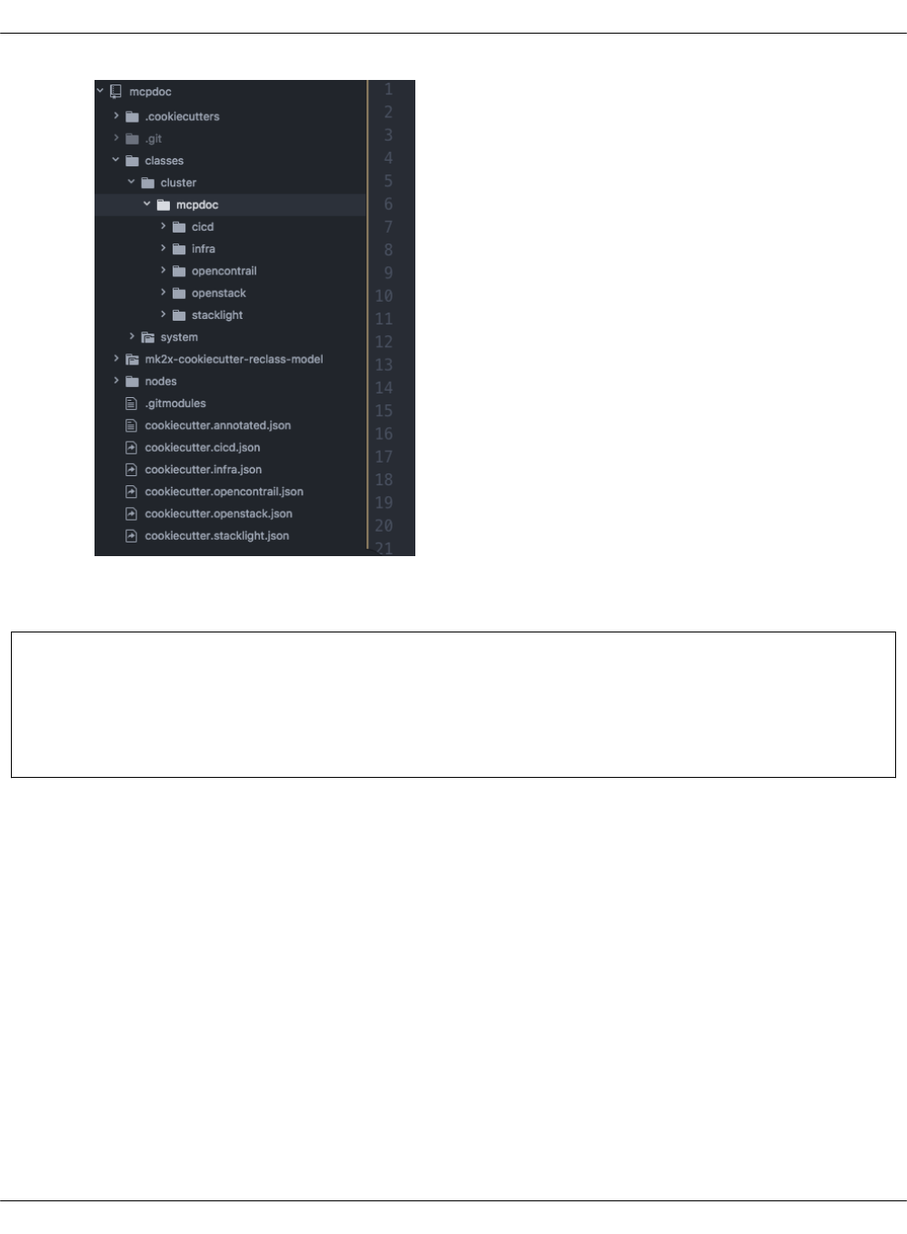

Deployment parameters
This section lists all parameters that can be modified for generated environments.
Example deployment parameters
Parameter Default value Description
cluster_name deployment_name Name of the cluster, used as
cluster/<ENV_NAME>/ in a directory structure
cluster_domain deploy-name.local Domain name part of FQDN of cluster in the
cluster
public_host public-name Name or IP of public endpoint of the
deployment
reclass_repository https://github.com/Mirantis/mk-lab-salt-model.gitURL to reclass metadata repository
control_network_netmask255.255.255.0 IP mask of control network
control_network_gateway10.167.4.1 IP gateway address of control network
dns_server01 8.8.8.8 IP address of dns01 server
dns_server02 1.1.1.1 IP address of dns02 server
salt_master_ip 10.167.4.90 IP address of Salt Master on control network
salt_master_management_ip10.167.5.90 IP address of Salt Master on management
network
salt_master_hostname cfg01 Hostname of Salt Master
kvm_vip_ip 10.167.4.240 VIP address of KVM cluster
kvm01_control_ip 10.167.4.241 IP address of a KVM node01 on control
network
kvm02_control_ip 10.167.4.242 IP address of a KVM node02 on control
network
kvm03_control_ip 10.167.4.243 IP address of a KVM node03 on control
network
kvm01_deploy_ip 10.167.5.241 IP address of KVM node01 on management
network
kvm02_deploy_ip 10.167.5.242 IP address of KVM node02 on management
network
kvm03_deploy_ip 10.167.5.243 IP address of KVM node03 on management
network
kvm01_name kvm01 Hostname of a KVM node01
kvm02_name kvm02 Hostname of a KVM node02
kvm03_name kvm03 Hostname of a KVM node03
Mirantis Cloud Platform Deployment Guide
©2019, Mirantis Inc. Page 52

openstack_proxy_address10.167.4.80 VIP address of proxy cluster on control
network
openstack_proxy_node01_address10.167.4.81 IP address of a proxy node01 on control
network
openstack_proxy_node02_address10.167.4.82 IP address of a proxy node02 on control
network
openstack_proxy_hostnameprx Hostname of VIP proxy cluster
openstack_proxy_node01_hostnameprx01 Hostname of a proxy node01
openstack_proxy_node02_hostnameprx02 Hostname of a proxy node02
openstack_control_address10.167.4.10 VIP address of control cluster on control
network
openstack_control_node01_address10.167.4.11 IP address of a control node01 on control
network
openstack_control_node02_address10.167.4.12 IP address of a control node02 on control
network
openstack_control_node03_address10.167.4.13 IP address of a control node03 on control
network
openstack_control_hostnamectl Hostname of VIP control cluster
openstack_control_node01_hostnamectl01 Hostname of a control node01
openstack_control_node02_hostnamectl02 Hostname of a control node02
openstack_control_node03_hostnamectl03 Hostname of a control node03
openstack_database_address10.167.4.50 VIP address of database cluster on control
network
openstack_database_node01_address10.167.4.51 IP address of a database node01 on control
network
openstack_database_node02_address10.167.4.52 IP address of a database node02 on control
network
openstack_database_node03_address10.167.4.53 IP address of a database node03 on control
network
openstack_database_hostnamedbs Hostname of VIP database cluster
openstack_database_node01_hostnamedbs01 Hostname of a database node01
openstack_database_node02_hostnamedbs02 Hostname of a database node02
openstack_database_node03_hostnamedbs03 Hostname of a database node03
openstack_message_queue_address10.167.4.40 VIP address of message queue cluster on
control network
openstack_message_queue_node01_address10.167.4.41 IP address of a message queue node01 on
control network
Mirantis Cloud Platform Deployment Guide
©2019, Mirantis Inc. Page 53

openstack_message_queue_node02_address10.167.4.42 IP address of a message queue node02 on
control network
openstack_message_queue_node03_address10.167.4.43 IP address of a message queue node03 on
control network
openstack_message_queue_hostnamemsg Hostname of VIP message queue cluster
openstack_message_queue_node01_hostnamemsg01 Hostname of a message queue node01
openstack_message_queue_node02_hostnamemsg02 Hostname of a message queue node02
openstack_message_queue_node03_hostnamemsg03 Hostname of a message queue node03
openstack_gateway_node01_address10.167.4.224 IP address of gateway node01
openstack_gateway_node02_address10.167.4.225 IP address of gateway node02
openstack_gateway_node01_tenant_address192.168.50.6 IP tenant address of gateway node01
openstack_gateway_node02_tenant_address192.168.50.7 IP tenant address of gateway node02
openstack_gateway_node01_hostnamegtw01 Hostname of gateway node01
openstack_gateway_node02_hostnamegtw02 Hostname of gateway node02
stacklight_log_address 10.167.4.60 VIP address of StackLight LMA logging cluster
stacklight_log_node01_address10.167.4.61 IP address of StackLight LMA logging node01
stacklight_log_node02_address10.167.4.62 IP address of StackLight LMA logging node02
stacklight_log_node03_address10.167.4.63 IP address of StackLight LMA logging node03
stacklight_log_hostnamelog Hostname of StackLight LMA logging cluster
stacklight_log_node01_hostnamelog01 Hostname of StackLight LMA logging node01
stacklight_log_node02_hostnamelog02 Hostname of StackLight LMA logging node02
stacklight_log_node03_hostnamelog03 Hostname of StackLight LMA logging node03
stacklight_monitor_address10.167.4.70 VIP address of StackLight LMA monitoring
cluster
stacklight_monitor_node01_address10.167.4.71 IP address of StackLight LMA monitoring
node01
stacklight_monitor_node02_address10.167.4.72 IP address of StackLight LMA monitoring
node02
stacklight_monitor_node03_address10.167.4.73 IP address of StackLight LMA monitoring
node03
stacklight_monitor_hostnamemon Hostname of StackLight LMA monitoring
cluster
stacklight_monitor_node01_hostnamemon01 Hostname of StackLight LMA monitoring
node01
stacklight_monitor_node02_hostnamemon02 Hostname of StackLight LMA monitoring
node02
Mirantis Cloud Platform Deployment Guide
©2019, Mirantis Inc. Page 54

stacklight_monitor_node03_hostnamemon03 Hostname of StackLight LMA monitoring
node03
stacklight_telemetry_address10.167.4.85 VIP address of StackLight LMA telemetry
cluster
stacklight_telemetry_node01_address10.167.4.86 IP address of StackLight LMA telemetry
node01
stacklight_telemetry_node02_address10.167.4.87 IP address of StackLight LMA telemetry
node02
stacklight_telemetry_node03_address10.167.4.88 IP address of StackLight LMA telemetry
node03
stacklight_telemetry_hostnamemtr hostname of StackLight LMA telemetry
cluster
stacklight_telemetry_node01_hostnamemtr01 Hostname of StackLight LMA telemetry
node01
stacklight_telemetry_node02_hostnamemtr02 Hostname of StackLight LMA telemetry
node02
stacklight_telemetry_node03_hostnamemtr03 Hostname of StackLight LMA telemetry
node03
openstack_compute_node01_single_address10.167.2.101 IP address of a compute node01 on a
dataplane network
openstack_compute_node02_single_address10.167.2.102 IP address of a compute node02 on a
dataplane network
openstack_compute_node03_single_address10.167.2.103 IP address of a compute node03 on a
dataplane network
openstack_compute_node01_control_address10.167.4.101 IP address of a compute node01 on a control
network
openstack_compute_node02_control_address10.167.4.102 IP address of a compute node02 on a control
network
openstack_compute_node03_control_address10.167.4.103 IP address of a compute node03 on a control
network
openstack_compute_node01_tenant_address10.167.6.101 IP tenant address of a compute node01
openstack_compute_node02_tenant_address10.167.6.102 IP tenant address of a compute node02
openstack_compute_node03_tenant_address10.167.6.103 IP tenant address of a compute node03
openstack_compute_node01_hostnamecmp001 Hostname of a compute node01
openstack_compute_node02_hostnamecmp002 Hostname of a compute node02
openstack_compute_node03_hostnamecmp003 Hostname of a compute node03
openstack_compute_node04_hostnamecmp004 Hostname of a compute node04
openstack_compute_node05_hostnamecmp005 Hostname of a compute node05
Mirantis Cloud Platform Deployment Guide
©2019, Mirantis Inc. Page 55

ceph_rgw_address 172.16.47.75 The IP address of the Ceph RGW storage
cluster
ceph_rgw_hostname rgw The hostname of the Ceph RGW storage
cluster
ceph_mon_node01_address172.16.47.66 The IP address of the first Ceph MON storage
node
ceph_mon_node02_address172.16.47.67 The IP address of the second Ceph MON
storage node
ceph_mon_node03_address172.16.47.68 The IP address of the third Ceph MON storage
node
ceph_mon_node01_hostnamecmn01 The hostname of the first Ceph MON storage
node
ceph_mon_node02_hostnamecmn02 The hostname of the second Ceph MON
storage node
ceph_mon_node03_hostnamecmn03 The hostname of the third Ceph MON storage
node
ceph_rgw_node01_address172.16.47.76 The IP address of the first Ceph RGW storage
node
ceph_rgw_node02_address172.16.47.77 The IP address of the second Ceph RGW
storage node
ceph_rgw_node03_address172.16.47.78 The IP address of the third Ceph RGW storage
node
ceph_rgw_node01_hostnamergw01 The hostname of the first Ceph RGW storage
node
ceph_rgw_node02_hostnamergw02 The hostname of the second Ceph RGW
storage node
ceph_rgw_node03_hostnamergw03 The hostname of the third Ceph RGW storage
node
ceph_osd_count 10 The number of OSDs
ceph_osd_rack01_hostnameosd The OSD rack01 hostname
ceph_osd_rack01_single_subnet172.16.47 The control plane network prefix for Ceph
OSDs
ceph_osd_rack01_backend_subnet172.16.48 The deploy network prefix for Ceph OSDs
ceph_public_network 172.16.47.0/24 The IP address of Ceph public network with
the network mask
ceph_cluster_network 172.16.48.70/24 The IP address of Ceph cluster network with
the network mask
ceph_osd_block_db_size20 The Ceph OSD block DB size in GB
ceph_osd_data_disks /dev/vdd,/dev/vde The list of OSD data disks
Mirantis Cloud Platform Deployment Guide
©2019, Mirantis Inc. Page 56

ceph_osd_journal_or_block_db_disks/dev/vdb,/dev/vdc The list of journal or block disks
Mirantis Cloud Platform Deployment Guide
©2019, Mirantis Inc. Page 57

Deploy MCP DriveTrain
To reduce the deployment time and eliminate possible human errors, Mirantis recommends that
you use the semi-automated approach to the MCP DriveTrain deployment as described in this
section.
Caution!
The execution of the CLI commands used in the MCP Deployment Guide requires root
privileges. Therefore, unless explicitly stated otherwise, run the commands as a root user
or use sudo.
The deployment of MCP DriveTrain bases on the bootstrap automation of the Salt Master node.
On a Reclass model creation, you receive the configuration drives by the email that you
specified during the deployment model generation.
Depending on the deployment type, you receive the following configuration drives:
•For an online and offline deployment, the configuration drive for the cfg01 VM that is used
in cloud-init to set up a virtual machine with Salt Master, MAAS provisioner, Jenkins server,
and local Git server installed on it.
•For an offline deployment, the configuration drive for the APT VM that is used in cloud-init
to set up a virtual machine with all required repositories mirrors.
The high-level workflow of the MCP DriveTrain deployment
# Description
1 Manually deploy and configure the Foundation node.
2 Create the deployment model using the Model Designer web UI.
3 Obtain the pre-built ISO configuration drive(s) with the Reclass deployment metadata
model to you email. If required, customize and regenerate the configuration drives.
4 Bootstrap the APT node. Optional, for an offline deployment only.
5 Bootstrap the Salt Master node that contains MAAS provisioner.
6 Deploy the remaining bare metal servers through MAAS provisioner.
7 Deploy MCP CI/CD using Jenkins.
Mirantis Cloud Platform Deployment Guide
©2019, Mirantis Inc. Page 58

Prerequisites for MCP DriveTrain deployment
Before you proceed with the actual deployment, verify that you have performed the following
steps:
1. Deploy the Foundation physical node using one of the initial versions of Ubuntu Xenial, for
example, 16.04.1.
Use any standalone hardware node where you can run a KVM-based day01 virtual machine
with an access to the deploy/control network. The Foundation node will host the Salt Master
node and MAAS provisioner.
2. Depending on your case, proceed with one of the following options:
• If you do not have a deployment metadata model:
1. Create a model using the Model Designer UI as described in Create a deployment
metadata model using the Model Designer UI.
Note
For an offline deployment, select the Offline deployment and Local
repositories options under the Repositories section on the Infrastructure
parameters tab.
2. Customize the obtained configuration drives as described in Generate
configuration drives manually. For example, enable custom user access.
•If you use an already existing model that does not have configuration drives, or you
want to generate updated configuration drives, proceed with Generate configuration
drives manually.
3. Configure bridges on the Foundation node:
• br-mgm for the management network
• br-ctl for the control network
„
1. Log in to the Foundation node through IPMI.
Note
If the IPMI network is not reachable from the management or control network,
add the br-ipmi bridge for the IPMI network or any other network that is routed
to the IPMI network.
2. Create PXE bridges to provision network on the foundation node:
Mirantis Cloud Platform Deployment Guide
©2019, Mirantis Inc. Page 59

brctl addbr br-mgm
brctl addbr br-ctl
3. Add the bridges definition for br-mgm and br-ctl to /etc/network/interfaces. Use
definitions from your deployment metadata model.
Example:
auto br-mgm
iface br-mgm inet static
address 172.17.17.200
netmask 255.255.255.192
bridge_ports bond0
4. Restart networking from the IPMI console to bring the bonds up.
5. Verify that the foundation node bridges are up by checking the output of the ip a show
command:
ip a show br-ctl
Example of system response:
8: br-ctl: <BROADCAST,MULTICAST,UP,LOWER_UP> mtu 1500 qdisc noqueue state UP group default qlen 1000
link/ether 00:1b:21:93:c7:c8 brd ff:ff:ff:ff:ff:ff
inet 172.17.45.241/24 brd 172.17.45.255 scope global br-ctl
valid_lft forever preferred_lft forever
inet6 fe80::21b:21ff:fe93:c7c8/64 scope link
valid_lft forever preferred_lft forever
4. Depending on your case, proceed with one of the following options:
•If you perform the offline deployment or online deployment with local mirrors, proceed
to Deploy the APT node.
• If you perform an online deployment, proceed to Deploy the Salt Master node.
Mirantis Cloud Platform Deployment Guide
©2019, Mirantis Inc. Page 60

Deploy the APT node
MCP enables you to deploy the whole MCP cluster without access to the Internet. On creating
the metadata model, along with the configuration drive for the cfg01 VM, you will obtain a
preconfigured QCOW2 image that will contain packages, Docker images, operating system
images, Git repositories, and other software required specifically for the offline deployment.
This section describes how to deploy the apt01 VM using the prebuilt configuration drive.
Warning
Perform the procedure below only in case of an offline deployment or when using a local
mirror from the prebuilt image.
To deploy the APT node:
1. Log in to the Foundation node.
Note
Root privileges are required for following steps. Execute the commands as a root
user or use sudo.
2. In the /var/lib/libvirt/images/ directory, create an apt01/ subdirectory where the offline
mirror image will be stored:
Note
You can create and use a different subdirectory in /var/lib/libvirt/images/. If that is the
case, verify that you specify the correct directory for the VM_*DISK variables
described in next steps.
mkdir -p /var/lib/libvirt/images/apt01/
3. Download the latest version of the prebuilt
http://images.mirantis.com/mcp-offline-image-<BUILD-ID>.qcow2 image for the apt node
from http://images.mirantis.com.
4. Save the image on the Foundation node as /var/lib/libvirt/images/apt01/system.qcow2.
5. Copy the configuration ISO drive for the APT VM provided with the metadata model for the
offline image to, for example, /var/lib/libvirt/images/apt01/.
Mirantis Cloud Platform Deployment Guide
©2019, Mirantis Inc. Page 61

Note
If you are using an already existing model that does not have configuration drives, or
you want to generate updated configuration drives, proceed with Generate
configuration drives manually.
cp /path/to/prepared-drive/apt01-config.iso /var/lib/libvirt/images/apt01/apt01-config.iso
Mirantis Cloud Platform Deployment Guide
©2019, Mirantis Inc. Page 62

6. Select from the following options to deploy the APT node:
1. Download the shell script from GitHub:
export MCP_VERSION="master"
https://raw.githubusercontent.com/Mirantis/mcp-common-scripts/${MCP_VERSION}/predefine-vm/define-vm.sh
2. Make the script executable, export the required variables:
chmod +x define-vm.sh
export VM_NAME="apt01.<CLUSTER_DOMAIN>"
export VM_SOURCE_DISK="/var/lib/libvirt/images/apt01/system.qcow2"
export VM_CONFIG_DISK="/var/lib/libvirt/images/apt01/apt01-config.iso"
The CLUSTER_DOMAIN value is the cluster domain name used for the model. See Basic
deployment parameters for details.
Note
You may add other optional variables that have default values and change them
depending on your deployment configuration. These variables include:
• VM_MGM_BRIDGE_NAME="br-mgm"
• VM_CTL_BRIDGE_NAME="br-ctl"
• VM_MEM_KB="8388608"
• VM_CPUS="4"
„
The br-mgm and br-ctl values are the names of the Linux bridges. See
Prerequisites for MCP DriveTrain deployment for details. Custom names can be
passed to a VM definition using the VM_MGM_BRIDGE_NAME and
VM_CTL_BRIDGE_NAME variables accordingly.
3. Run the shell script:
./define-vm.sh
7. Start the apt01 VM:
virsh start apt01.<CLUSTER_DOMAIN>
Mirantis Cloud Platform Deployment Guide
©2019, Mirantis Inc. Page 63

Deploy the Salt Master node
The Salt Master node acts as a central control point for the clients that are called Salt minion
nodes. The minions, in their turn, connect back to the Salt Master node.
This section describes how to set up a virtual machine with Salt Master, MAAS provisioner,
Jenkins server, and local Git server. The procedure is applicable to both online and offline MCP
deployments.
To deploy the Salt Master node:
1. Log in to the Foundation node.
Note
Root privileges are required for following steps. Execute the commands as a root
user or use sudo.
2. In case of an offline deployment, replace the content of the /etc/apt/sources.list file with the
following lines:
deb [arch=amd64] http://<local_mirror_url>/ubuntu xenial-security main universe restricted
deb [arch=amd64] http://<local_mirror_url>/ubuntu xenial-updates main universe restricted
deb [arch=amd64] http://<local_mirror_url>/ubuntu xenial main universe restricted
3. Create a directory for the VM system disk:
Note
You can create and use a different subdirectory in /var/lib/libvirt/images/. If that is the
case, verify that you specify the correct directory for the VM_*DISK variables
described in next steps.
mkdir -p /var/lib/libvirt/images/cfg01/
4. Download the day01 image for the cfg01 node:
wget http://images.mirantis.com/cfg01-day01-<BUILD_ID>.qcow2 -O \
/var/lib/libvirt/images/cfg01/system.qcow2
Substitute <BUILD_ID> with the required MCP Build ID, for example, 2018.11.0.
5. Copy the configuration ISO drive for the cfg01 VM provided with the metadata model for the
offline image to, for example, /var/lib/libvirt/images/cfg01/cfg01-config.iso.
Mirantis Cloud Platform Deployment Guide
©2019, Mirantis Inc. Page 64

Note
If you are using an already existing model that does not have configuration drives, or
you want to generate updated configuration drives, proceed with Generate
configuration drives manually.
cp /path/to/prepared-drive/cfg01-config.iso /var/lib/libvirt/images/cfg01/cfg01-config.iso
Mirantis Cloud Platform Deployment Guide
©2019, Mirantis Inc. Page 65

6. Create the Salt Master VM domain definition using the example script:
1. Download the shell script from GitHub:
export MCP_VERSION="master"
wget https://raw.githubusercontent.com/Mirantis/mcp-common-scripts/${MCP_VERSION}/predefine-vm/define-vm.sh
2. Make the script executable and export the required variables:
chmod 0755 define-vm.sh
export VM_NAME="cfg01.[CLUSTER_DOMAIN]"
export VM_SOURCE_DISK="/var/lib/libvirt/images/cfg01/system.qcow2"
export VM_CONFIG_DISK="/var/lib/libvirt/images/cfg01/cfg01-config.iso"
The CLUSTER_DOMAIN value is the cluster domain name used for the model. See Basic
deployment parameters for details.
Note
You may add other optional variables that have default values and change them
depending on your deployment configuration. These variables include:
• VM_MGM_BRIDGE_NAME="br-mgm"
• VM_CTL_BRIDGE_NAME="br-ctl"
• VM_MEM_KB="8388608"
• VM_CPUS="4"
„
The br-mgm and br-ctl values are the names of the Linux bridges. See
Prerequisites for MCP DriveTrain deployment for details. Custom names can be
passed to a VM definition using the VM_MGM_BRIDGE_NAME and
VM_CTL_BRIDGE_NAME variables accordingly.
3. Run the shell script:
./define-vm.sh
7. Start the Salt Master node VM:
virsh start cfg01.[CLUSTER_DOMAIN]
8. Log in to the Salt Master virsh console with the user name and password that you created
in step 4 of the Generate configuration drives manually procedure:
virsh console cfg01.[CLUSTER_DOMAIN]
Mirantis Cloud Platform Deployment Guide
©2019, Mirantis Inc. Page 66

9. If you use local repositories, verify that mk-pipelines are present in /home/repo/mk and
pipeline-library is present in /home/repo/mcp-ci after cloud-init finishes. If not, fix the
connection to local repositories and run the /var/lib/cloud/instance/scripts/part-001 script.
10. Verify that the following states are successfully applied during the execution of cloud-init:
salt-call state.sls linux.system,linux,openssh,salt
salt-call state.sls maas.cluster,maas.region,reclass
Otherwise, fix the pillar and re-apply the above states.
11. In case of using kvm01 as the Foundation node, perform the following steps on it:
1. Depending on the deployment type, proceed with one of the options below:
•For an online deployment, add the following deb repository to
/etc/apt/sources.list.d/mcp_saltstack.list:
deb [arch=amd64] https://mirror.mirantis.com/<MCP_VERSION>/saltstack-2017.7/xenial/ xenial main
•For an offline deployment or local mirrors case, in
/etc/apt/sources.list.d/mcp_saltstack.list, add the following deb repository:
deb [arch=amd64] http://<local_mirror_url>/<MCP_VERSION>/saltstack-2017.7/xenial/ xenial main
2. Install the salt-minion package.
3. Modify /etc/salt/minion.d/minion.conf:
id: <kvm01_FQDN>
master: <Salt_Master_IP_or_FQDN>
4. Restart the salt-minion service:
service salt-minion restart
5. Check the output of salt-key command on the Salt Master node to verify that the
minion ID of kvm01 is present.
Mirantis Cloud Platform Deployment Guide
©2019, Mirantis Inc. Page 67

Verify the Salt infrastructure
Before you proceed with the deployment, validate the Reclass model and node pillars.
To verify the Salt infrastructure:
1. Log in to the Salt Master node.
2. Verify the Salt Master pillars:
reclass -n cfg01.<cluster_domain>
The cluster_domain value is the cluster domain name that you created while preparing your
deployment metadata model. See Basic deployment parameters for details.
3. Verify that the Salt version for the Salt minions is the same as for the Salt Master node, that
is currently 2017.7:
salt-call --version
salt '*' test.version
Mirantis Cloud Platform Deployment Guide
©2019, Mirantis Inc. Page 68

Enable the management of the APT node through the
Salt Master node
In compliance with the security best practices, MCP enables you to connect your offline mirror
APT VM to the Salt Master node and manage it as any infrastructure VM on your MCP
deployment.
Generally, the procedure consists of the following steps:
1. In the existing cluster model, configure the pillars required to manage the offline mirror VM.
2. For the MCP releases below the 2018.8.0 Build ID, enable the Salt minion on the existing
offline mirror VM.
Note
This section is only applicable for the offline deployments where all repositories are stored
on a specific VM deployed using the MCP apt01 offline image, which is included in the
MCP release artifacts.
Mirantis Cloud Platform Deployment Guide
©2019, Mirantis Inc. Page 69

Enable the APT node management in the Reclass model
This section instructs you on how to configure your existing cluster model to enable the
management of the offline mirror VM through the Salt Master node.
To configure the APT node management in the Reclass model:
1. Log in to the Salt Master node.
2. Open the cluster level of your Reclass model.
3. In infra/config/nodes.yml, add the following pillars:
parameters:
reclass:
storage:
node:
aptly_server_node01:
name: ${_param:aptly_server_hostname}01
domain: ${_param:cluster_domain}
classes:
- cluster.${_param:cluster_name}.cicd.aptly
- cluster.${_param:cluster_name}.infra
params:
salt_master_host: ${_param:reclass_config_master}
linux_system_codename: xenial
single_address: ${_param:aptly_server_control_address}
deploy_address: ${_param:aptly_server_deploy_address}
4. If the offline mirror VM is in the full offline mode and does not have the cicd/aptly path,
create the cicd/aptly.yml file with the following contents:
classes:
- system.linux.system.repo_local.mcp.apt_mirantis.docker_legacy
- system.linux.system.repo.mcp.apt_mirantis.ubuntu
- system.linux.system.repo.mcp.apt_mirantis.saltstack
- system.linux.system.repo_local.mcp.extra
parameters:
linux:
network:
interface:
ens3: ${_param:linux_deploy_interface}
5. Add the following pillars to infra/init.yml or verify that they are present in the model:
parameters:
linux:
network:
host:
apt:
address: ${_param:aptly_server_deploy_address}
Mirantis Cloud Platform Deployment Guide
©2019, Mirantis Inc. Page 70

names:
- ${_param:aptly_server_hostname}
- ${_param:aptly_server_hostname}.${_param:cluster_domain}
6. Check out your inventory to be able to resolve any inconsistencies in your model:
reclass-salt --top
7. Use the system response of the reclass-salt --top command to define the missing variables
and specify proper environment-specific values if any.
8. Generate the storage Reclass definitions for your offline image node:
salt-call state.sls reclass.storage -l debug
9. Synchronize pillars and check out the inventory once again:
salt '*' saltutil.refresh_pillar
reclass-salt --top
If your MCP version is Build ID 2018.8.0 or later, your offline mirror node should now be
manageable through the Salt Master node. Otherwise, proceed to Enable the Salt minion on an
existing APT node.
Mirantis Cloud Platform Deployment Guide
©2019, Mirantis Inc. Page 71

Enable the Salt minion on an existing APT node
For the deployments managed by the MCP 2018.8.0 Build ID or later, you should not manually
enable the Salt minion on the offline image VM as it is configured automaticaly on boot during
the APT VM provisioning.
Though, if your want to enable the management of the offline image VM through the Salt Master
node on an existing deployment managed by the MCP version below the 2018.8.0 Build ID, you
need to perform the procedure included in this section.
To enable the Salt minion on an existing offline mirror node:
1. Connect to the serial console of your offline image VM, which is included in the pre-built
offline APT QCOW image:
virsh console $(virsh list --all --name | grep ^apt01) --force
Log in with the user name and password that you created in step 4 of the Generate
configuration drives manually procedure.
Example of system response:
Connected to domain apt01.example.local
Escape character is ^]
2. Press Enter to drop into the root shell.
3. Configure the Salt minion and start it:
echo "" > /etc/salt/minion
echo "master: <IP_address>" > /etc/salt/minion.d/minion.conf
echo "id: <apt01.example.local>" >> /etc/salt/minion.d/minion.conf
service salt-minion stop
rm -f /etc/salt/pki/minion/*
service salt-minion start
4. Quit the serial console by sending the Ctrl + ] combination.
5. Log in to the Salt Master node.
6. Verify that you have the offline mirror VM Salt minion connected to your Salt Master node:
salt-key -L | grep apt
The system response should include your offline mirror VM. For example:
apt01.example.local
7. Verify that you can access the Salt minion from the Salt Master node:
salt apt01\* test.ping
Mirantis Cloud Platform Deployment Guide
©2019, Mirantis Inc. Page 72

8. Verify the Salt states mapped to the offline mirror VM:
salt apt01\* state.show_top
Now, you can manage your offline mirror APT VM from the Salt Master node.
Mirantis Cloud Platform Deployment Guide
©2019, Mirantis Inc. Page 73

Configure MAAS for bare metal provisioning
Before you proceed with provisioning of the remaining bare metal nodes, configure MAAS as
described below.
To configure MAAS for bare metal provisioning:
1. Log in to the MAAS web UI through http://<infra_config_deploy_address>:5240/MAAS with
the following credentials:
• Username: mirantis
• Password: r00tme
2. Go to the Subnets tab.
3. Select the fabric that is under the deploy network.
4. In the VLANs on this fabric area, click the VLAN under the VLAN column where the deploy
network subnet is.
5. In the Take action drop-down menu, select Provide DHCP.
6. Adjust the IP range as required.
Note
The number of IP addresses should not be less than the number of the planned VCP
nodes.
7. Click Provide DHCP to submit.
8. If you use local package mirrors:
Note
The following steps are required only to specify the local Ubuntu package repositories
that are secured by a custom GPG key and used mainly for the offline mirror images
prior the MCP version 2017.12.
1. Go to Settings > Package repositories.
2. Click Actions > Edit on the Ubuntu archive repository.
3. Specify the GPG key of the repository in the Key field. The key can be obtained from
the aptly_gpg_public_key parameter in the cluster level Reclass model.
4. Click Save.
Mirantis Cloud Platform Deployment Guide
©2019, Mirantis Inc. Page 74

Provision physical nodes using MAAS
Physical nodes host the Virtualized Control Plane (VCP) of your Mirantis Cloud Platform
deployment.
This section describes how to provision the physical nodes using the MAAS service that you
have deployed on the Foundation node while deploying the Salt Master node.
The servers that you must deploy include at least:
• For OpenStack:
• kvm02 and kvm03 infrastructure nodes
• cmp0 compute node
• For Kubernetes:
• kvm02 and kvm03 infrastructure nodes
• ctl01, ctl02, ctl03 controller nodes
• cmp01 and cmp02 compute nodes
You can provision physical nodes automatically or manually:
•An automated provisioning requires you to define IPMI and MAC addresses in your Reclass
model. After you enforce all servers, the Salt Master node commissions and provisions them
automatically.
• A manual provisioning enables commissioning nodes through the MAAS web UI.
Before you proceed with the physical nodes provisioning, you may want to customize the
commissioning script, for example, to set custom NIC names. For details, see: Add custom
commissioning scripts.
Warning
Before you proceed with the physical nodes provisioning, verify that BIOS settings enable
PXE booting from NICs on each physical server.
Mirantis Cloud Platform Deployment Guide
©2019, Mirantis Inc. Page 75

Automatically commission and provision the physical nodes
This section describes how to define physical nodes in a Reclass model to automatically
commission and then provision the nodes through Salt.
Automatically commission the physical nodes
You must define all IPMI credentials in your Reclass model to access physical servers for
automated commissioning. Once you define the nodes, Salt enforces them into MAAS and starts
commissioning.
To automatically commission physical nodes:
1. Define all physical nodes under classes/cluster/<cluster>/infra/maas.yml using the
following structure.
For example, to define the kvm02 node:
maas:
region:
machines:
kvm02:
interface:
mac: 00:25:90:eb:92:4a
power_parameters:
power_address: kvm02.ipmi.net
power_password: password
power_type: ipmi
power_user: ipmi_user
Note
To get MAC addresses from IPMI, you can use the ipmi tool. Usage example for
Supermicro:
ipmitool -U ipmi_user-P passowrd -H kvm02.ipmi.net raw 0x30 0x21 1| tail -c 18
2. (Optional) Define the IP address on the first (PXE) interface. By default, it is assigned
automatically and can be used as is.
For example, to define the kvm02 node:
maas:
region:
machines:
kvm02:
interface:
Mirantis Cloud Platform Deployment Guide
©2019, Mirantis Inc. Page 76

mac: 00:25:90:eb:92:4a
mode: "static"
ip: "2.2.3.15"
subnet: "subnet1"
gateway: "2.2.3.2"
3. (Optional) Define a custom disk layout or partitioning per server in MAAS. For more
information and examples on how to define it in the model, see: Add a custom disk layout
per node in the MCP model.
4. (Optional) Modify the commissioning process as required. For more information and
examples, see: Add custom commissioning scripts.
5. Once you have defined all physical servers in your Reclass model, enforce the nodes:
Caution!
For an offline deployment, remove the deb-src repositories from commissioning before
enforcing the nodes, since these repositories are not present on the reduced offline apt
image node. To remove these repositories, you can enforce MAAS to rebuild sources.list.
For example:
export PROFILE="mirantis"
export API_KEY=$(cat /var/lib/maas/.maas_credentials)
maas login ${PROFILE} http://localhost:5240/MAAS/api/2.0/ ${API_KEY}
REPO_ID=$(maas $PROFILE package-repositories read | jq '.[]| select(.name=="main_archive") | .id ')
maas $PROFILE package-repository update ${REPO_ID} disabled_components=multiverse
maas $PROFILE package-repository update ${REPO_ID} "disabled_pockets=backports"
The default PROFILE variable is mirantis. You can find your deployment-specific value for
this parameter in parameters:maas:region:admin:username of your Reclass model.
For details on building a custom list of repositories, see: MAAS GitHub project.
salt-call maas.process_machines
All nodes are automatically commissioned.
6. Verify the status of servers either through the MAAS web UI or using the salt call command:
salt-call maas.machines_status
The successfully commissioned servers appear in the ready status.
7. Enforce the interfaces configuration defined in the model for servers:
salt-call state.sls maas.machines.assign_ip
Mirantis Cloud Platform Deployment Guide
©2019, Mirantis Inc. Page 77

8. To protect any static IP assignment defined, for example, in the model, configure a
reserved IP range in MAAS on the management subnet.
9. (Optional) Enforce the disk custom configuration defined in the model for servers:
salt-call state.sls maas.machines.storage
10. Verify that all servers have correct NIC names and configurations.
11. Proceed to Provision the automatically commissioned physical nodes.
Mirantis Cloud Platform Deployment Guide
©2019, Mirantis Inc. Page 78

Provision the automatically commissioned physical nodes
Once you successfully commission your physical nodes, you can start the provisioning.
To provision the automatically commissioned physical nodes through MAAS:
1. Log in to the Salt Master node.
2. Run the following command:
salt-call maas.deploy_machines
3. Check the status of the nodes:
salt-call maas.machines_status
local:
----------
machines:
- hostname:kvm02,system_id:anc6a4,status:Deploying
summary:
----------
Deploying:
1
4. When all servers have been provisioned, perform the verification of the servers` automatic
registration by running the salt-key command on the Salt Master node. All nodes should be
registered. For example:
salt-key
Accepted Keys:
cfg01.bud.mirantis.net
cmp001.bud.mirantis.net
cmp002.bud.mirantis.net
kvm02.bud.mirantis.net
kvm03.bud.mirantis.net
Mirantis Cloud Platform Deployment Guide
©2019, Mirantis Inc. Page 79

Manually commission and provision the physical nodes
This section describes how to discover, commission, and provision the physical nodes using the
MAAS web UI.
Manually discover and commission the physical nodes
You can discover and commission your physical nodes manually using the MAAS web UI.
To discover and commission physical nodes manually:
1. Power on a physical node.
2. In the MAAS UI, verify that the server has been discovered.
3. On the Nodes tab, rename the discovered host accordingly. Click Save after each renaming.
4. In the Settings tab, configure the Commissioning release and the Default Minimum Kernel
Version to Ubuntu 16.04 TLS 'Xenial Xerus' and Xenial (hwe-16.04), respectively.
Note
The above step ensures that the NIC naming convention uses the predictable
schemas, for example, enp130s0f0 rather than eth0.
5. In the Deploy area, configure the Default operating system used for deployment and
Default OS release used for deployment to Ubuntu and Ubuntu 16.04 LTS 'Xenial Xerus',
respectively.
6. Leave the remaining parameters as defaults.
7. (Optional) Modify the commissioning process as required. For more information and
examples, see: Add custom commissioning scripts.
8. Commission the node:
1. From the Take Action drop-down list, select Commission.
2. Define a storage schema for each node.
3. On the Nodes tab, click the required node link from the list.
4. Scroll down to the Available disks and partitions section.
5. Select two SSDs using check marks in the left column.
6. Click the radio button to make one of the disks the boot target.
7. Click Create RAID to create an MD raid1 volume.
8. In RAID type, select RAID„1.
9. In File system, select ext4.
10. Set / as Mount point.
11. Click Create RAID.
Mirantis Cloud Platform Deployment Guide
©2019, Mirantis Inc. Page 80


Manually provision the physical nodes
Start the manual provisioning of the physical nodes with the control plane kvm02 and kvm03
physical nodes, and then proceed with the compute cmp01 node deployment.
To manually provision the physical nodes through MAAS:
1. Verify that the boot order in the physical nodes' BIOS is set in the following order:
1. PXE
2. The physical disk that was chosen as the boot target in the Maas UI.
2. Log in to the MAAS web UI.
3. Click on a node.
4. Click the Take Action drop-down menu and select Deploy.
5. In the Choose your image area, verify that Ubuntu„16.04„LTS„'Xenial„Xerus' with the
Xenial(hwe-16.04) kernel is selected.
6. Click Go to deploy the node.
7. Repeat the above steps for each node.
Now, your physical nodes are provisioned and you can proceed with configuring and deploying
an MCP cluster on them.
Seealso
•Configure PXE booting over UEFI
Mirantis Cloud Platform Deployment Guide
©2019, Mirantis Inc. Page 82

Deploy physical servers
This section describes how to deploy physical servers intended for an OpenStack-based MCP
cluster. If you plan to deploy a Kubernetes-based MCP cluster, proceed with steps 1-2 of the
Kubernetes Prerequisites procedure.
To deploy physical servers:
1. Log in to the Salt Master node.
2. Verify that the cfg01 key has been added to Salt and your host FQDN is shown properly in
the Accepted„Keys field in the output of the following command:
salt-key
3. Verify that all pillars and Salt data are refreshed:
salt "*" saltutil.refresh_pillar
salt "*" saltutil.sync_all
4. Verify that the Reclass model is configured correctly. The following command output should
show top states for all nodes:
python -m reclass.cli --inventory
5. To verify that the rebooting of the nodes, which will be performed further, is successful,
create the trigger file:
salt -C 'I@salt:control or I@nova:compute or I@neutron:gateway or I@ceph:osd' \
cmd.run "touch /run/is_rebooted"
6. To prepare physical nodes for VCP deployment, apply the basic Salt states for setting up
network interfaces and SSH access. Nodes will be rebooted.
Warning
If you use kvm01 as a Foundation node, the execution of the commands below will
also reboot the Salt Master node.
Caution!
All hardware nodes must be rebooted after executing the commands below. If the
nodes do not reboot for a long time, execute the below commands again or reboot
the nodes manually.
Mirantis Cloud Platform Deployment Guide
©2019, Mirantis Inc. Page 83

Verify that you have a possibility to log in to nodes through IPMI in case of
emergency.
1. For KVM nodes:
salt --async -C 'I@salt:control' cmd.run 'salt-call state.sls \
linux.system.repo,linux.system.user,openssh,linux.network;reboot'
2. For compute nodes:
salt --async -C 'I@nova:compute' pkg.install bridge-utils,vlan
salt --async -C 'I@nova:compute' cmd.run 'salt-call state.sls \
linux.system.repo,linux.system.user,openssh,linux.network;reboot'
3. For gateway nodes, execute the following command only for the deployments with OVS
setup with physical gateway nodes:
salt --async -C 'I@neutron:gateway' cmd.run 'salt-call state.sls \
linux.system.repo,linux.system.user,openssh,linux.network;reboot'
The targeted KVM, compute, and gateway nodes will stop responding after a couple of
minutes. Wait until all of the nodes reboot.
7. Verify that the targeted nodes are up and running:
salt -C 'I@salt:control or I@nova:compute or I@neutron:gateway or I@ceph:osd' \
test.ping
8. Check the previously created trigger file to verify that the targeted nodes are actually
rebooted:
salt -C 'I@salt:control or I@nova:compute or I@neutron:gateway' \
cmd.run 'if [ -f "/run/is_rebooted" ];then echo "Has not been rebooted!";else echo "Rebooted";fi'
All nodes should be in the Rebooted state.
9. Verify that the hardware nodes have the required network configuration. For example,
verify the output of the ip a command:
salt -C 'I@salt:control or I@nova:compute or I@neutron:gateway or I@ceph:osd' \
cmd.run "ip a"
Mirantis Cloud Platform Deployment Guide
©2019, Mirantis Inc. Page 84

Deploy VCP
The virtualized control plane (VCP) is hosted by KVM nodes deployed by MAAS. Depending on
the cluster type, the VCP runs Kubernetes or OpenStack services, database (MySQL), message
queue (RabbitMQ), Contrail, and support services, such as monitoring, log aggregation, and a
time-series metric database. VMs can be added to or removed from the VCP allowing for easy
scaling of your MCP cluster.
After the KVM nodes are deployed, Salt is used to configure Linux networking, appropriate
repositories, host name, and so on by running the linux Salt state against these nodes. The
libvirt packages configuration, in its turn, is managed by running the libvirt Salt state.
Mirantis Cloud Platform Deployment Guide
©2019, Mirantis Inc. Page 85

Prepare KVM nodes to run the VCP nodes
To prepare physical nodes to run the VCP nodes:
1. On the Salt Master node, prepare the node operating system by running the Salt linux
state:
salt-call state.sls linux -l info
Warning
Some formulas may not correctly deploy on the first run of this command. This could
be due to a race condition in running the deployment of nodes and services in
parallel while some services are dependent on others. Repeat the command
execution. If an immediate subsequent run of the command fails again, reboot the
affected physical node and re-run the command.
2. Prepare physical nodes operating system to run the controller node:
1. Verify the salt-common and salt-minion versions
2. If necessary, Install the correct versions of salt-common and salt-minion.
3. Proceed to Create and provision the control plane VMs.
Mirantis Cloud Platform Deployment Guide
©2019, Mirantis Inc. Page 86

Verify the salt-common and salt-minion versions
To verify the version deployed with the state:
1. Log in to the physical node console.
2. To verify the salt-common version, run:
apt-cache policy salt-common
3. To verify the salt-minion version, run:
apt-cache policy salt-minion
The output for the commands above must show the 2017.7 version. If you have different
versions installed, proceed with Install the correct versions of salt-common and salt-minion.
Mirantis Cloud Platform Deployment Guide
©2019, Mirantis Inc. Page 87

Install the correct versions of salt-common and salt-minion
This section describes the workaround for salt.virt to properly inject minion.conf.
To manually install the required version of salt-common and salt-minion:
1. Log in to the physical node console
2. Change the version to 2017.7 in /etc/apt/sources.list.d/salt.list:
deb [arch=amd64] http://repo.saltstack.com/apt/ubuntu/16.04/amd64/2017.7/dists/ xenial main
3. Sync the packages index files:
apt-get update
4. Verify the versions:
apt-cache policy salt-common
apt-cache policy salt-minion
5. If the wrong versions are installed, remove them:
apt-get remove salt-minion
apt-get remove salt-common
6. Install the required versions of salt-common and salt-minion:
apt-get install salt-common=2017.7
apt-get install salt-minion=2017.7
7. Restart the salt-minion service to ensure connectivity with the Salt Master node:
service salt-minion stop && service salt-minion start
8. Verify that the required version is installed:
apt-cache policy salt-common
apt-cache policy salt-minion
9. Repeat the procedure on each physical node.
Mirantis Cloud Platform Deployment Guide
©2019, Mirantis Inc. Page 88

Create and provision the control plane VMs
The control plane VMs are created on each node by running the salt state. This state leverages
the salt„virt module along with some customizations defined in a Mirantis formula called
salt-formula-salt. Similarly to how MAAS manages bare metal, the salt„virt module creates VMs
based on profiles that are defined in the metadata and mounts the virtual disk to add the
appropriate parameters to the minion configuration file.
After the salt state successfully runs against a KVM node where metadata specifies the VMs
placement, these VMs will be started and automatically added to the Salt Master node.
To create control plane VMs:
1. Log in to the KVM nodes that do not host the Salt Master node. The correct physical node
names used in the installation described in this guide to perform the next step are kvm02
and kvm03.
Warning
Otherwise, on running the command in the step below, you will delete the cfg Salt
Master.
2. Verify whether virtual machines are not yet present:
virsh list --name --all | grep -Ev '^(mas|cfg|apt)' | xargs -n 1 virsh destroy
virsh list --name --all | grep -Ev '^(mas|cfg|apt)' | xargs -n 1 virsh undefine
3. Log in to the Salt Master node console.
4. Verify that the Salt Minion nodes are synchronized by running the following command on
the Salt Master node:
salt '*' saltutil.sync_all
5. Perform the initial Salt configuration:
salt 'kvm*' state.sls salt.minion
Mirantis Cloud Platform Deployment Guide
©2019, Mirantis Inc. Page 89

6. Set up the network interfaces and the SSH access:
salt -C 'I@salt:control' cmd.run 'salt-call state.sls \
linux.system.user,openssh,linux.network;reboot'
Warning
This will also reboot the Salt Master node because it is running on top of kvm01.
7. Log in back to the Salt Master node console.
8. Run the libvirt state:
salt 'kvm*' state.sls libvirt
9. For the OpenStack-based MCP clusters, add
system.salt.control.cluster.openstack_gateway_single to infra/kvm.yml to enable a gateway
VM for your OpenStack environment. Skip this step for the Kubernetes-based MCP clusters.
10. Run salt.control to create virtual machines. This command also inserts minion.conf files
from KVM hosts:
salt 'kvm*' state.sls salt.control
11. Verify that all your Salt Minion nodes are registered on the Salt Master node. This may take
a few minutes.
salt-key
Example of system response:
mon03.bud.mirantis.net
msg01.bud.mirantis.net
msg02.bud.mirantis.net
msg03.bud.mirantis.net
mtr01.bud.mirantis.net
mtr02.bud.mirantis.net
mtr03.bud.mirantis.net
nal01.bud.mirantis.net
nal02.bud.mirantis.net
nal03.bud.mirantis.net
ntw01.bud.mirantis.net
ntw02.bud.mirantis.net
ntw03.bud.mirantis.net
prx01.bud.mirantis.net
Mirantis Cloud Platform Deployment Guide
©2019, Mirantis Inc. Page 90

prx02.bud.mirantis.net
...
Mirantis Cloud Platform Deployment Guide
©2019, Mirantis Inc. Page 91

Deploy CI/CD
The automated deployment of the MCP components is performed through CI/CD that is a part of
MCP DriveTrain along with SaltStack and Reclass. CI/CD, in its turn, includes Jenkins, Gerrit, and
MCP Registry components. This section explains how to deploy a CI/CD infrastructure.
For a description of MCP CI/CD components, see: MCP Reference Architecture: MCP CI/CD
components
To deploy CI/CD automatically:
1. Deploy a customer-specific CI/CD using Jenkins as part of, for example, an OpenStack cloud
environment deployment:
1. Log in to the Jenkins web UI available at salt_master_management_address:8081 with
the following credentials:
• Username: admin
• Password: r00tme
2. Use the Deploy - OpenStack pipeline to deploy cicd cluster nodes as described in
Deploy an OpenStack environment. Start with Step 7 in case of the online deployment
and with Step 8 in case of the offline deployment.
2. Once the cloud environment is deployed, verify that the cicd cluster is up and running.
3. Disable the Jenkins service on the Salt Master node and start using Jenkins on cicd nodes.
Seealso
•Enable a watchdog
Mirantis Cloud Platform Deployment Guide
©2019, Mirantis Inc. Page 92

Deploy an MCP cluster using DriveTrain
After you have installed the MCP CI/CD infrastructure as descibed in Deploy CI/CD, you can
reach the Jenkins web UI through the Jenkins master IP address. This section contains
procedures explaining how to deploy OpenStack environments and Kubernetes clusters using
CI/CD pipelines.
Note
For production environments, CI/CD should be deployed on a per-customer basis.
For testing purposes, you can use the central Jenkins lab that is available for Mirantis
employees only. To be able to configure and execute Jenkins pipelines using the lab, you
need to log in to the Jenkins web UI with your Launchpad credentials.
Mirantis Cloud Platform Deployment Guide
©2019, Mirantis Inc. Page 93

Deploy an OpenStack environment
This section explains how to configure and launch the OpenStack environment deployment
pipeline. This job is run by Jenkins through the Salt API on the functioning Salt Master node and
deployed hardware servers to set up your MCP OpenStack environment.
Run this Jenkins pipeline after you configure the basic infrastructure as described in Deploy MCP
DriveTrain. Also, verify that you have successfully applied the linux and salt states to all
physical and virtual nodes for them not to be disconnected during network and Salt Minion
setup.
Note
For production environments, CI/CD should be deployed on a per-customer basis.
For testing purposes, you can use the central Jenkins lab that is available for Mirantis
employees only. To be able to configure and execute Jenkins pipelines using the lab, you
need to log in to the Jenkins web UI with your Launchpad credentials.
To automatically deploy an OpenStack environment:
1. Log in to the Salt Master node.
2. For the OpenContrail 4.0 setup, add the following parameters to the
<cluster_name>/opencontrail/init.yml file of your Reclass model:
parameters:
_param:
opencontrail_version: 4.0
linux_repo_contrail_component: oc40
Note
OpenContrail 3.2 is not supported.
3. Set up network interfaces and the SSH access on all compute nodes:
salt -C 'I@nova:compute' cmd.run 'salt-call state.sls \
linux.system.user,openssh,linux.network;reboot'
4. If you run OVS, run the same command on physical gateway nodes as well:
salt -C 'I@neutron:gateway' cmd.run 'salt-call state.sls \
linux.system.user,openssh,linux.network;reboot'
Mirantis Cloud Platform Deployment Guide
©2019, Mirantis Inc. Page 94

5. Verify that all nodes are ready for deployment:
salt '*' state.sls linux,ntp,openssh,salt.minion
Caution!
If any of these states fails, fix the issue provided in the output and re-apply the state
before you proceed to the next step. Otherwise, the Jenkins pipeline will fail.
6. In a web browser, open http://<ip„address>:8081 to access the Jenkins web UI.
Note
The IP address is defined in the classes/cluster/<cluster_name>/cicd/init.yml file of
the Reclass model under the cicd_control_address parameter variable.
7. Log in to the Jenkins web UI as admin.
Note
The password for the admin user is defined in the
classes/cluster/<cluster_name>/cicd/control/init.yml file of the Reclass model under
the openldap_admin_password parameter variable.
8. In the global view, verify that the git-mirror-downstream-mk-pipelines and
git-mirror-downstream-pipeline-library pipelines have successfully mirrored all content.
9. Find the Deploy - OpenStack job in the global view.
10. Select the Build with Parameters option from the drop-down menu of the Deploy -
OpenStack job.
11. Specify the following parameters:
Deploy - OpenStack environment parameters
Parameter Description and values
ASK_ON_ERROR If checked, Jenkins will ask either to stop a pipeline or continue
execution in case of Salt state fails on any task
Mirantis Cloud Platform Deployment Guide
©2019, Mirantis Inc. Page 95

STACK_INSTALL Specifies the components you need to install. The available
values include:
• core
• kvm
• cicd
• openstack
• ovs or contrail depending on the network plugin.
• ceph
• stacklight
• oss
Note
For the details regarding StackLight LMA
(stacklight) with the DevOps Portal (oss)
deployment, see Deploy StackLight LMA with the
DevOps Portal.
SALT_MASTER_CREDENTIALSSpecifies credentials to Salt API stored in Jenkins, included by
default. See View credentials details used in Jenkins pipelines
for details.
SALT_MASTER_URL Specifies the reachable IP address of the Salt Master node and
port on which Salt API listens. For example,
http://172.18.170.28:6969
To find out on which port Salt API listens:
1. Log in to the Salt Master node.
2. Search for the port in the /etc/salt/master.d/_api.conf file.
3. Verify that the Salt Master node is listening on that port:
netstat -tunelp | grep <PORT>
STACK_TYPE Specifies the environment type. Use physical for a bare metal
deployment
12. Click Build.
Mirantis Cloud Platform Deployment Guide
©2019, Mirantis Inc. Page 96


Deploy a multi-site OpenStack environment
MCP DriveTrain enables you to deploy several OpenStack environments at the same time.
Note
For production environments, CI/CD should be deployed on a per-customer basis.
For testing purposes, you can use the central Jenkins lab that is available for Mirantis
employees only. To be able to configure and execute Jenkins pipelines using the lab, you
need to log in to the Jenkins web UI with your Launchpad credentials.
To deploy a multi-site OpenStack environment, repeat the Deploy an OpenStack environment
procedure as many times as you need specifying different values for the SALT_MASTER_URL
parameter.
Seealso
View the deployment details
Mirantis Cloud Platform Deployment Guide
©2019, Mirantis Inc. Page 98

Deploy a Kubernetes cluster
The MCP Containers as a Service architecture enables you to easily deploy a Kubernetes cluster
on bare metal with Calico or OpenContrail plugins set for Kubernetes networking.
This section explains how to configure and launch the Kubernetes cluster deployment pipeline
using DriveTrain.
Caution!
OpenContrail 3.2 for Kubernetes is not supported. For production environments, use
OpenContrail 4.0. For the list of OpenContrail limitations for Kubernetes, see:
OpenContrail limitations.
You can enable an external Ceph RBD storage in your Kubernetes cluster as required. For new
deployments, enable the corresponding parameters while creating your deployment metadata
model as described in Create a deployment metadata model using the Model Designer UI. For
existing deployments, follow the Enable an external Ceph RBD storage procedure.
You can also deploy ExternalDNS to set up a DNS management server in order to control DNS
records dynamically through Kubernetes resources and make Kubernetes resources
discoverable through public DNS servers.
Depending on your cluster configuration, proceed with one of the sections listed below.
Note
For production environments, CI/CD should be deployed on a per-customer basis.
For testing purposes, you can use the central Jenkins lab that is available for Mirantis
employees only. To be able to configure and execute Jenkins pipelines using the lab, you
need to log in to the Jenkins web UI with your Launchpad credentials.
Mirantis Cloud Platform Deployment Guide
©2019, Mirantis Inc. Page 99

Prerequisites
Before you proceed with an automated deployment of a Kubernetes cluster, follow the steps
below:
1. If you have swap enabled on the ctl and cmp nodes, modify your Kubernetes deployment
model as described in Add swap configuration to a Kubernetes deployment model.
2. For the OpenContrail 4.0 setup, add the following parameters to the
<cluster_name>/opencontrail/init.yml file of your deployment model:
parameters:
_param:
opencontrail_version: 4.0
linux_repo_contrail_component: oc40
Caution!
OpenContrail 3.2 for Kubernetes is not supported. For production MCP Kubernetes
deployments, use OpenContrail 4.0.
3. Deploy DriveTrain as described in Deploy MCP DriveTrain.
Now, proceed to deploying Kubernetes as described in Deploy a Kubernetes cluster on bare
metal.
Mirantis Cloud Platform Deployment Guide
©2019, Mirantis Inc. Page 100

Deploy a Kubernetes cluster on bare metal
This section provides the steps to deploy a Kubernetes cluster on bare metal nodes configured
using MAAS with Calico or OpenContrail as a Kubernetes networking plugin.
Caution!
OpenContrail 3.2 for Kubernetes is not supported. For production MCP Kubernetes
deployments, use OpenContrail 4.0.
To automatically deploy a Kubernetes cluster on bare metal nodes:
1. Verify that you have completed the steps described in Prerequisites.
2. Log in to the Jenkins web UI as Administrator.
Note
The password for the Administrator is defined in the
classes/cluster/<CLUSTER_NAME>/cicd/control/init.yml file of the Reclass model
under the openldap_admin_password parameter variable.
3. Depending on your use case, find the k8s_ha_calico heat or k8s_ha_contrail heat pipeline
job in the global view.
4. Select the Build with Parameters option from the drop-down menu of the selected job.
5. Configure the deployment by setting the following parameters as required:
Deployment parameters
Parameter Defualt value Description
ASK_ON_ERRORFalse If True, Jenkins will stop on any failure and ask
either you want to cancel the pipeline or
proceed with the execution ignoring the error.
SALT_MASTER_CREDENTIALS<YOUR_SALT_MASTER_CREDENTIALS_ID>The Jenkins ID of credentials for logging in to
the Salt API. For example, salt-credentials. See
View credentials details used in Jenkins
pipelines for details.
SALT_MASTER_URL<YOUR_SALT_MASTER_URL> The URL to access the Salt Master node.
Mirantis Cloud Platform Deployment Guide
©2019, Mirantis Inc. Page 101

STACK_INSTALL
•core,k8s,calico for a
deployment with Calico
•core,k8s,contrail for a
deployment with
OpenContrail
Components to install.
STACK_TESTEmpty The names of the cluster components to test.
By default, nothing is tested.
STACK_TYPEphysical The type of the cluster.
6. Click Build to launch the pipeline.
7. Click Full stage view to track the deployment process.
The following table contains the stages details for the deployment with Calico or
OpenContrail as a Kubernetes networking plugin:
The deploy pipeline workflow
# Title Details
1 Create infrastructure Creates a base infrastructure using MAAS.
2 Install core infrastructure 1. Prepares and validates the Salt Master node and Salt
Minion nodes. For example, refreshes pillars and
synchronizes custom modules.
2. Applies the linux,openssh,salt.minion,ntp states to
all nodes.
3 Install Kubernetes
infrastructure 1. Reads the control plane load-balancer address and
applies it to the model.
2. Generates the Kubernetes certificates.
3. Installs the Kubernetes support packages that
include Keepalived, HAProxy, Docker, and etcd.
4 Install the Kubernetes
control plane and
networking plugins
• For the Calico deployments:
1. Installs Calico.
2. Sets up etcd.
3. Installs the control plane nodes.
• For the OpenContrail deployments:
1. Installs the OpenContrail infrastructure.
2. Configures OpenContrail to be used by
Kubernetes.
3. Installs the control plane nodes.
Mirantis Cloud Platform Deployment Guide
©2019, Mirantis Inc. Page 102


Deploy ExternalDNS for Kubernetes
ExternalDNS deployed on Mirantis Cloud Platform (MCP) allows you to set up a DNS
management server for Kubernetes starting with version 1.7. ExternalDNS enables you to
control DNS records dynamically through Kubernetes resources and make Kubernetes resources
discoverable through public DNS servers. ExternalDNS synchronizes exposed Kubernetes
Services and Ingresses with DNS cloud providers, such as Designate, AWS Route 53, Google
CloudDNS, and CoreDNS.
ExternalDNS retrieves a list of resources from the Kubernetes API to determine the desired list
of DNS records. It synchronizes the DNS service according to the current Kubernetes status.
ExternalDNS can use the following DNS back-end providers:
•AWS Route 53 is a highly available and scalable cloud DNS web service. Amazon Route 53
is fully compliant with IPv6.
•Google CloudDNS is a highly available, scalable, cost-effective, and programmable DNS
service running on the same infrastructure as Google.
•OpenStack Designate can use different DNS servers including Bind9 and PowerDNS that are
supported by MCP.
•CoreDNS is the next generation of SkyDNS that can use etcd to accept updates to DNS
entries. It functions as an on-premises open-source alternative to cloud DNS services
(DNSaaS). You can deploy CoreDNS with ExternalDNS if you do not have an active DNS
back-end provider yet.
This section describes how to configure and set up ExternalDNS on a new or existing MCP
Kubernetes-based cluster.
Mirantis Cloud Platform Deployment Guide
©2019, Mirantis Inc. Page 104

Prepare a DNS back end for ExternalDNS
Depending on your DNS back-end provider, prepare your back end and the metadata model of
your MCP cluster before setting up ExternalDNS. If you do not have an active DNS back-end
provider yet, you can use CoreDNS that functions as an on-premises open-source alternative to
cloud DNS services.
To prepare a DNS back end
Choose from the following options depending on your DNS back end:
• For AWS Route 53:
1. Log in to your AWS Route 53 console.
2. Navigate to the AWS Services page.
3. In the search field, type "Route 53" to find the corresponding service page.
4. On the Route 53 page, find the DNS management icon and click Get started now.
5. On the DNS management page, click Create hosted zone.
6. On the right side of the Create hosted zone window:
1. Add <your_mcp_domain.>.local name.
2. Choose the Public Hosted Zone type.
3. Click Create.
You will be redirected to the previous page with two records of NS and SOA type. Keep
the link of this page for verification after the ExernalDNS deployment.
7. Click Back to Hosted zones.
8. Locate and copy the Hosted Zone ID in the corresponding column of your recently
created hosted zone.
9. Add this ID to the following template:
{
"Version": "2012-10-17",
"Statement": [
{
"Effect": "Allow",
"Action": [
"route53:ChangeResourceRecordSets",
"route53:ListResourceRecordSets",
"route53:GetHostedZone
],
"Resource": [
"arn:aws:route53:::hostedzone/<YOUR_ZONE_ID>"
]
},
{
"Effect" : "Allow",
"Action" : [
"route53:GetChange"
],
"Resource" : [
"arn:aws:route53:::change/*"
Mirantis Cloud Platform Deployment Guide
©2019, Mirantis Inc. Page 105

]
},
{
"Effect" : "Allow",
"Action" " [
"route53:ListHostedZones"
],
"Resource" : [
"*"
]
}
]
}
10. Navigate to Services > IAM > Customer Managed Policies.
11. Click Create Policy > Create your own policy.
12. Fill in the required fields:
• Policy Name field: externaldns
• Policy Document field: use the JSON template provided in step 9
13. Click Validate Policy.
14. Click Create Policy. You will be redirected to the policy view page.
15. Navigate to Users.
16. Click Add user:
1. Add a user name: extenaldns.
2. Select the Programmatic access check box.
3. Click Next: Permissions.
4. Select the Attach existing policy directly option.
5. Choose the Customer managed policy type in the Filter drop-down menu.
6. Select the externaldns check box.
7. Click Next: Review.
8. Click Create user.
9. Copy the Access key ID and Secret access key.
„
• For Google CloudDNS:
1. Log in to your Google Cloud Platform web console.
2. Navigate to IAM & Admin > Service accounts > Create service account.
3. In the Create service account window, configure your new ExernalDNS service
account:
1. Add a service account name.
Mirantis Cloud Platform Deployment Guide
©2019, Mirantis Inc. Page 106

2. Assign the DNS Administrator role to the account.
3. Select the Furnish a new private key check box and the JSON key type radio
button.
The private key is automatically saved on your computer.
4. Navigate to NETWORKING > Network services > Cloud DNS.
5. Click CREATE ZONE to create a DNS zone that will be managed by ExternalDNS.
6. In the Create a DNS zone window, fill in the following fields:
• Zone name
•DNS name that must contain your MCP domain address in the
<your_mcp_domain>.local format.
7. Click Create.
You will be redirected to the Zone details page with two DNS names of the NS and SOA
type. Keep this page for verification after the ExernalDNS deployment.
„
• For Designate:
1. Log in to the Horizon web UI of your OpenStack environment with Designate.
2. Create a project with the required admin role as well as generate the access
credentials for the project.
3. Create a hosted DNS zone in this project.
„
• For CoreDNS, proceed to Configure cluster model for ExternalDNS.
Now, proceed to Configure cluster model for ExternalDNS.
Mirantis Cloud Platform Deployment Guide
©2019, Mirantis Inc. Page 107

Configure cluster model for ExternalDNS
After you prepare your DNS back end as described in Prepare a DNS back end for ExternalDNS,
prepare your cluster model as described below.
To configure the cluster model:
1. Choose from the following options:
• If you are performing the initial deployment of your MCP Kubernetes cluster:
1. Use the ModelDesigner UI to create the Kubernetes cluster model. For details, see:
Create a deployment metadata model using the Model Designer UI.
2. While creating the model, select the Kubernetes externaldns enabled check box in
the Kubernetes product parameters section.
•If you are making changes to an existing MCP Kubernetes cluster, proceed to the next
step.
2. Open your Git project repository.
3. In classes/cluster/<cluster_name>/kubernetes/control.yml:
1. If you are performing the initial deployment of your MCP Kubernetes cluster, configure
the provider parameter in the snippet below depending on your DNS provider:
coredns|aws|google|designate. If you are making changes to an existing cluster, add
and configure the snippet below. For example:
parameters:
kubernetes:
common:
addons:
externaldns:
enabled: True
namespace: kube-system
image: mirantis/external-dns:latest
domain: domain
provider: coredns
2. Set up the pillar data for your DNS provider to configure it as an add-on. Use the
credentials generated while preparing your DNS provider.
• For Designate:
parameters:
kubernetes:
common:
addons:
externaldns:
externaldns:
enabled: True
domain: company.mydomain
provider: designate
designate_os_options:
Mirantis Cloud Platform Deployment Guide
©2019, Mirantis Inc. Page 108

OS_AUTH_URL: https://keystone_auth_endpoint:5000
OS_PROJECT_DOMAIN_NAME: default
OS_USER_DOMAIN_NAME: default
OS_PROJECT_NAME: admin
OS_USERNAME: admin
OS_PASSWORD: password
OS_REGION_NAME: RegionOne
• For AWS Route 53:
parameters:
kubernetes:
common:
addons:
externaldns:
externaldns:
enabled: True
domain: company.mydomain
provider: aws
aws_options:
AWS_ACCESS_KEY_ID: XXXXXXXXXXXXXXXXXXXX
AWS_SECRET_ACCESS_KEY: XXXXXXXXXXXXXXXXXXXXXXXXXXXXXXXXXXXXXXXX
• For Google CloudDNS:
parameters:
kubernetes:
common:
addons:
externaldns:
externaldns:
enabled: True
domain: company.mydomain
provider: google
google_options:
key: ''
project: default-123
Note
You can export the credentials from the Google console and process them
using the cat key.json | tr -d 'n' command.
• For CoreDNS:
parameters:
kubernetes:
Mirantis Cloud Platform Deployment Guide
©2019, Mirantis Inc. Page 109

common:
addons:
coredns:
enabled: True
namespace: kube-system
image: coredns/coredns:latest
etcd:
operator_image: quay.io/coreos/etcd-operator:v0.5.2
version: 3.1.8
base_image: quay.io/coreos/etcd
4. Commit and push the changes to the project Git repository.
5. Log in to the Salt Master node.
6. Update your Salt formulas and the system level of your repository:
1. Change the directory to /srv/salt/reclass.
2. Run the git pull origin master command.
3. Run the salt-call state.sls salt.master command.
4. Run the salt-call state.sls reclass command.
Now, proceed to Deploy ExternalDNS.
Mirantis Cloud Platform Deployment Guide
©2019, Mirantis Inc. Page 110

Deploy ExternalDNS
Before you deploy ExternalDNS, complete the steps described in Configure cluster model for
ExternalDNS.
To deploy ExternalDNS
Choose from the following options:
•If you are performing the initial deployment of your MCP Kubernetes cluster, deploy a
Kubernetes cluster as described in Deploy a Kubernetes cluster on bare metal. The
ExternalDNS will be deployed automatically by the MCP DriveTrain pipeline job during the
Kubernetes cluster deployment.
• If you are making changes to an existing MCP Kubernetes cluster, apply the following state:
salt --hard-crash --state-output=mixed --state-verbose=False -C \
'I@kubernetes:master' state.sls kubernetes.master.kube-addons
Once the state is applied, the kube-addons.sh script applies the Kubernetes resources and
they will shortly appear in the Kubernetes resources list.
Mirantis Cloud Platform Deployment Guide
©2019, Mirantis Inc. Page 111


Verify ExternalDNS with Designate back end after deployment
After you complete the steps described in Deploy ExternalDNS, verify that ExternalDNS is
successfully deployed with Designate back end using the procedure below.
To verify ExternalDNS with Designate back end:
1. Log in to any Kubernetes Master node.
2. Source the openrc file of your OpenStack environment:
source keystonerc
Note
If you use Keystone v3, use the source keystonercv3 command instead.
3. Open the Designate shell using the designate command.
4. Create a domain:
domain-create --name nginx.<your_mcp_domain>.local. --email <your_email>
Example of system response:
+-------------+---------------------------------------+
| Field | Value |
+-------------+---------------------------------------+
| description | None |
| created_at | 2017-10-13T16:23:26.533547 |
| updated_at | None |
| email | designate@example.org |
| ttl | 3600 |
| serial | 1423844606 |
| id | ae59d62b-d655-49a0-ab4b-ea536d845a32 |
| name | nginx.virtual-mcp11-k8s-calico.local. |
+-------------+---------------------------------------+
5. Verify that the domain was successfully created. Use the id parameter value from the
output of the command described in the previous step. Keep this value for further
verification steps.
For example:
record-list ae59d62b-d655-49a0-ab4b-ea536d845a32
Example of system response:
Mirantis Cloud Platform Deployment Guide
©2019, Mirantis Inc. Page 113

+----+------+---------------------------------------+------------------------+
|id | type | name | data |
+----+------+---------------------------------------+------------------------+
|... | NS | nginx.virtual-mcp11-k8s-calico.local. | dns01.bud.mirantis.net.|
+----+------+---------------------------------------+------------------------+
6. Start my-nginx:
kubectl run my-nginx --image=nginx --port=80
Example of system response:
deployment "my-nginx" created
7. Expose my-nginx:
kubectl expose deployment my-nginx --port=80 --type=ClusterIP
Example of system response:
service "my-nginx" exposed
8. Annotate my-nginx:
kubectl annotate service my-nginx \
"external-dns.alpha.kubernetes.io/hostname=nginx.<your_domain>.local."
Example of system response:
service "my-nginx" annotated
9. Verify that the domain was associated with the IP inside a Designate record by running the
record-list [id] command. Use the id parameter value from the output of the command
described in step 4. For example:
record-list ae59d62b-d655-49a0-ab4b-ea536d845a32
Example of system response:
+-----+------+--------------------------------------+---------------------------------------------------------+
| id | type | name | data |
+-----+------+--------------------------------------+---------------------------------------------------------+
| ... | NS | nginx.virtual-mcp11-k8s-calico.local.| dns01.bud.mirantis.net. |
+-----+------+--------------------------------------+---------------------------------------------------------+
Mirantis Cloud Platform Deployment Guide
©2019, Mirantis Inc. Page 114

| ... | A | nginx.virtual-mcp11-k8s-calico.local.| 10.254.70.16 |
+-----+------+--------------------------------------+---------------------------------------------------------+
| ... | TXT | nginx.virtual-mcp11-k8s-calico.local.| "heritage=external-dns,external-dns/owner=my-identifier"|
+-----+------+--------------------------------------+---------------------------------------------------------+
Mirantis Cloud Platform Deployment Guide
©2019, Mirantis Inc. Page 115

Verify ExternalDNS with CoreDNS back end after deployment
After you complete the steps described in Deploy ExternalDNS, verify that ExternalDNS is
successfully deployed with CoreDNS back end using the procedure below.
To verify ExternalDNS with CoreDNS back end:
1. Log in to any Kubernetes Master node.
2. Start my-nginx:
kubectl run my-nginx --image=nginx --port=80
Example of system response:
deployment "my-nginx" created
3. Expose my-nginx:
kubectl expose deployment my-nginx --port=80 --type=ClusterIP
Example of system response:
service "my-nginx" exposed
4. Annotate my-nginx:
kubectl annotate service my-nginx \
"external-dns.alpha.kubernetes.io/hostname=nginx.<your_domain>.local."
Example of system response:
service "my-nginx" annotated
5. Get the IP of DNS service:
kubectl get svc coredns -n kube-system | awk '{print $2}' | tail -1
Example of system response:
10.254.203.8
6. Choose from the following options:
•If your Kubernetes networking is Calico, run the following command from any
Kubernetes Master node.
Mirantis Cloud Platform Deployment Guide
©2019, Mirantis Inc. Page 116

•If your Kubernetes networking is OpenContrail, run the following command from any
Kubernetes pod.
nslookup nginx.<your_domain>.local. <coredns_ip>
Example of system response:
Server: 10.254.203.8 Address: 10.254.203.8#53
Name: test.my_domain.local Address: 10.254.42.128
Mirantis Cloud Platform Deployment Guide
©2019, Mirantis Inc. Page 117

Verify ExternalDNS with Google CloudDNS back end after deployment
After you complete the steps described in Deploy ExternalDNS, verify that ExternalDNS is
successfully deployed with Google CloudDNS back end using the procedure below.
To verify ExternalDNS with Google CloudDNS back end:
1. Log in to any Kubernetes Master node.
2. Start my-nginx:
kubectl run my-nginx --image=nginx --port=80
Example of system response:
deployment "my-nginx" created
3. Expose my-nginx:
kubectl expose deployment my-nginx --port=80 --type=ClusterIP
Example of system response:
service "my-nginx" exposed
4. Annotate my-nginx:
kubectl annotate service my-nginx \
"external-dns.alpha.kubernetes.io/hostname=nginx.<your_domain>.local."
Example of system response:
service "my-nginx" annotated
5. Log in to your Google Cloud Platform web console.
6. Navigate to the Cloud DNS > Zone details page.
7. Verify that your DNS zone now has two more records of the A and TXT type. Both records
must point to nginx.<your_domain>.local.
Mirantis Cloud Platform Deployment Guide
©2019, Mirantis Inc. Page 118

Verify ExternalDNS with AWS Route 53 back end after deployment
After you complete the steps described in Deploy ExternalDNS, verify that ExternalDNS is
successfully deployed with AWS Route 53 back end using the procedure below.
To verify ExternalDNS with AWS Route 53 back end:
1. Log in to any Kubernetes Master node.
2. Start my-nginx:
kubectl run my-nginx --image=nginx --port=80
Example of system response:
deployment "my-nginx" created
3. Expose my-nginx:
kubectl expose deployment my-nginx --port=80 --type=ClusterIP
Example of system response:
service "my-nginx" exposed
4. Annotate my-nginx:
kubectl annotate service my-nginx \
"external-dns.alpha.kubernetes.io/hostname=nginx.<your_domain>.local."
Example of system response:
service "my-nginx" annotated
5. Log in to your AWS Route 53 console.
6. Navigate to the Services > Route 53 > Hosted zones > YOUR_ZONE_NAME page.
7. Verify that your DNS zone now has two more records of the A and TXT type. Both records
must point to nginx.<your_domain>.local.
Seealso
MCP Operations Guide: Kubernetes operations
Mirantis Cloud Platform Deployment Guide
©2019, Mirantis Inc. Page 119

Deploy StackLight LMA with the DevOps Portal
This section explains how to deploy StackLight LMA with the DevOps Portal (OSS) using Jenkins.
Before you proceed with the deployment, verify that your cluster level model contains
configuration to deploy StackLight LMA as well as OSS. More specifically, check whether you
enabled StackLight LMA and OSS as described in Services deployment parameters, and
specified all the required parameters for these MCP components as described in StackLight LMA
product parameters and OSS parameters.
Note
For production environments, CI/CD should be deployed on a per-customer basis.
For testing purposes, you can use the central Jenkins lab that is available for Mirantis
employees only. To be able to configure and execute Jenkins pipelines using the lab, you
need to log in to the Jenkins web UI with your Launchpad credentials.
To deploy StackLight LMA with the DevOps Portal:
1. In a web browser, open http://<ip_address>:8081 to access the Jenkins web UI.
Note
The IP address is defined in the classes/cluster/<cluster_name>/cicd/init.yml file of
the Reclass model under the cicd_control_address parameter variable.
2. Log in to the Jenkins web UI as admin.
Note
The password for the admin user is defined in the
classes/cluster/<cluster_name>/cicd/control/init.yml file of the Reclass model under
the openldap_admin_password parameter variable.
3. Find the Deploy - OpenStack job in the global view.
4. Select the Build with Parameters option from the drop-down menu of the Deploy -
OpenStack job.
5. For the STACK_INSTALL parameter, specify the stacklight and oss values.
Mirantis Cloud Platform Deployment Guide
©2019, Mirantis Inc. Page 120

Warning
If you enabled Stacklight LMA and OSS in the Reclass model, you should specify both
stacklight and oss to deploy them together. Otherwise, the Runbooks Automation
service (Rundeck) will not start due to Salt and Rundeck behavior.
Note
For the details regarding other parameters for this pipeline, see Deploy - OpenStack
environment parameters.
6. Click Build.
7. Once the cluster is deployed, you can access the DevOps Portal at the the IP address
specified in the stacklight_monitor_address parameter on port 8800.
Seealso
•Deploy an OpenStack environment
•View the deployment details
Mirantis Cloud Platform Deployment Guide
©2019, Mirantis Inc. Page 121

View credentials details used in Jenkins pipelines
MCP uses the Jenkins Credentials Plugin that enables users to store credentials in Jenkins
globally. Each Jenkins pipeline can operate only the credential ID defined in the pipeline's
parameters and does not share any security data.
To view the detailed information about all available credentials in the Jenkins UI:
1. Log in to your Jenkins master located at http://<jenkins_master_ip_address>:8081.
Note
The Jenkins master IP address is defined in the
classes/cluster/<cluster_name>/cicd/init.yml file of the Reclass model under the
cicd_control_address parameter variable.
2. Navigate to the Credentials page from the left navigation menu.
All credentials listed on the Credentials page are defined in the Reclass model. For
example, on the system level in the ../../system/jenkins/client/credential/gerrit.yml file.
Examples of users definitions in the Reclass model:
• With the RSA key definition:
jenkins:
client:
credential:
gerrit:
username: ${_param:gerrit_admin_user}
key: ${_param:gerrit_admin_private_key}
• With the open password:
jenkins:
client:
credential:
salt:
username: salt
password: ${_param:salt_api_password}
Mirantis Cloud Platform Deployment Guide
©2019, Mirantis Inc. Page 122

View the deployment details
Once you have enforced a pipeline in CI/CD, you can monitor the progress of its execution on
the job progress bar that appears on your screen. Moreover, Jenkins enables you to analyze the
details of the deployments process.
To view the deployment details:
1. Log in to the Jenkins web UI.
2. Under Build History on the left, click the number of the build you are interested in.
3. Go to Console Output from the navigation menu to view the the deployment progress.
4. When the deployment succeeds, verify the deployment result in Horizon.
Note
The IP address for Horizon is defined in the
classes/cluster/<name>/openstack/init.yml file of the Reclass model under the
openstack_proxy_address parameter variable.
To troubleshoot an OpenStack deployment:
1. Log in to the Jenkins web UI.
2. Under Build History on the left, click the number of the build you are interested in.
3. Verify Full log to determine the cause of the error.
4. Rerun the deployment with the failed component only. For example, if StackLight LMA fails,
run the deployment with only StackLight selected for deployment. Use steps 6-10 of the
Deploy an OpenStack environment instruction.
Mirantis Cloud Platform Deployment Guide
©2019, Mirantis Inc. Page 123

Deploy an MCP cluster manually
This section explains how to manually configure and install the software required for your MCP
cluster. For an easier deployment process, use the automated DriveTrain deployment procedure
described in Deploy an MCP cluster using DriveTrain.
Note
The modifications to the metadata deployment model described in this section provide
only component-specific parameters and presuppose the networking-specific parameters
related to each OpenStack component, since the networking model may differ depending
on a per-customer basis.
Deploy an OpenStack environment manually
This section explains how to manually configure and install software required by your MCP
OpenStack environment, such as support services, OpenStack services, and others.
Prepare VMs to install OpenStack
This section instructs you on how to prepare the virtual machines for the OpenStack services
installation.
To prepare VMs for a manual installation of an OpenStack environment:
1. Log in to the Salt Master node.
2. Verify that the Salt Minion nodes are synchronized:
salt '*' saltutil.sync_all
3. Configure basic operating system settings on all nodes:
salt '*' state.sls salt.minion,linux,ntp,openssh
Enable TLS support
To assure the confidentiality and integrity of network traffic inside your OpenStack deployment,
you should use cryptographic protective measures, such as the Transport Layer Security (TLS)
protocol.
By default, only the traffic that is transmitted over public networks is encrypted. If you have
specific security requirements, you may want to configure internal communications to connect
through encrypted channels. This section explains how to enable the TLS support for your MCP
cluster.
Mirantis Cloud Platform Deployment Guide
©2019, Mirantis Inc. Page 124

Note
The procedures included in this section apply to new MCP OpenStack deployments only,
unless specified otherwise.
Encrypt internal API HTTP transport with TLS
This section explains how to encrypt the internal OpenStack API HTTP with TLS.
Note
The procedures included in this section apply to new MCP OpenStack deployments only,
unless specified otherwise.
To encrypt the internal API HTTP transport with TLS:
1. Verify that the Keystone, Nova Placement, Cinder, Barbican, Gnocchi, Panko, and Manila API
services, whose formulas support using Web Server Gateway Interface (WSGI) templates
from Apache, are running under Apache by adding the following classes to your deployment
model:
• In openstack/control.yml:
classes:
...
- system.apache.server.site.barbican
- system.apache.server.site.cinder
- system.apache.server.site.gnocchi
- system.apache.server.site.manila
- system.apache.server.site.nova-placement
- system.apache.server.site.panko
• In openstack/telemetry.yml:
classes:
...
- system.apache.server.site.gnocchi
- system.apache.server.site.panko
2. Add SSL configuration for each WSGI template by specifying the following parameters:
• In openstack/control.yml:
parameters:
_param:
...
Mirantis Cloud Platform Deployment Guide
©2019, Mirantis Inc. Page 125

apache_proxy_ssl:
enabled: true
engine: salt
authority: "${_param:salt_minion_ca_authority}"
key_file: "/etc/ssl/private/internal_proxy.key"
cert_file: "/etc/ssl/certs/internal_proxy.crt"
chain_file: "/etc/ssl/certs/internal_proxy-with-chain.crt"
apache_cinder_ssl: ${_param:apache_proxy_ssl}
apache_keystone_ssl: ${_param:apache_proxy_ssl}
apache_barbican_ssl: ${_param:apache_proxy_ssl}
apache_manila_ssl: ${_param:apache_proxy_ssl}
apache_nova_placement: ${_param:apache_proxy_ssl}
• In openstack/telemetry.yml:
parameters:
_param:
...
apache_gnocchi_api_address: ${_param:single_address}
apache_panko_api_address: ${_param:single_address}
apache_gnocchi_ssl: ${_param:nginx_proxy_ssl}
apache_panko_ssl: ${_param:nginx_proxy_ssl}
3. For services that are still running under Eventlet, configure TLS termination proxy. Such
services include Nova, Neutron, Ironic, Glance, Heat, Aodh, and Designate.
Depending on your use case, configure proxy on top of either Apache or NGINX by defining
the following classes and parameters:
• In openstack/control.yml:
• To configure proxy on Apache:
classes:
...
- system.apache.server.proxy.openstack.designate
- system.apache.server.proxy.openstack.glance
- system.apache.server.proxy.openstack.heat
- system.apache.server.proxy.openstack.ironic
- system.apache.server.proxy.openstack.neutron
- system.apache.server.proxy.openstack.nova
parameters:
_param:
...
# Configure proxy to redirect request to locahost:
apache_proxy_openstack_api_address: ${_param:cluster_local_host}
apache_proxy_openstack_designate_host: 127.0.0.1
apache_proxy_openstack_glance_host: 127.0.0.1
Mirantis Cloud Platform Deployment Guide
©2019, Mirantis Inc. Page 126

apache_proxy_openstack_heat_host: 127.0.0.1
apache_proxy_openstack_ironic_host: 127.0.0.1
apache_proxy_openstack_neutron_host: 127.0.0.1
apache_proxy_openstack_nova_host: 127.0.0.1
• To configure proxy on NGINX:
classes:
...
- system.nginx.server.single
- system.nginx.server.proxy.openstack_api
- system.nginx.server.proxy.openstack.designate
- system.nginx.server.proxy.openstack.ironic
- system.nginx.server.proxy.openstack.placement
# Delete proxy sites that are running under Apache:
_param:
...
nginx:
server:
site:
nginx_proxy_openstack_api_keystone:
enabled: false
nginx_proxy_openstack_api_keystone_private:
enabled: false
...
# Configure proxy to redirect request to locahost
_param:
...
nginx_proxy_openstack_api_address: ${_param:cluster_local_address}
nginx_proxy_openstack_cinder_host: 127.0.0.1
nginx_proxy_openstack_designate_host: 127.0.0.1
nginx_proxy_openstack_glance_host: 127.0.0.1
nginx_proxy_openstack_heat_host: 127.0.0.1
nginx_proxy_openstack_ironic_host: 127.0.0.1
nginx_proxy_openstack_neutron_host: 127.0.0.1
nginx_proxy_openstack_nova_host: 127.0.0.1
# Add nginx SSL settings:
_param:
...
nginx_proxy_ssl:
enabled: true
engine: salt
authority: "${_param:salt_minion_ca_authority}"
key_file: "/etc/ssl/private/internal_proxy.key"
Mirantis Cloud Platform Deployment Guide
©2019, Mirantis Inc. Page 127

cert_file: "/etc/ssl/certs/internal_proxy.crt"
chain_file: "/etc/ssl/certs/internal_proxy-with-chain.crt"
• In openstack/telemetry.yml:
classes:
...
- system.nginx.server.proxy.openstack_aodh
...
parameters:
_param:
...
nginx_proxy_openstack_aodh_host: 127.0.0.1
4. Edit the openstack/init.yml file:
1. Add the following parameters to the cluster model:
parameters:
_param:
...
cluster_public_protocol: https
cluster_internal_protocol: https
aodh_service_protocol: ${_param:cluster_internal_protocol}
barbican_service_protocol: ${_param:cluster_internal_protocol}
cinder_service_protocol: ${_param:cluster_internal_protocol}
designate_service_protocol: ${_param:cluster_internal_protocol}
glance_service_protocol: ${_param:cluster_internal_protocol}
gnocchi_service_protocol: ${_param:cluster_internal_protocol}
heat_service_protocol: ${_param:cluster_internal_protocol}
ironic_service_protocol: ${_param:cluster_internal_protocol}
keystone_service_protocol: ${_param:cluster_internal_protocol}
manila_service_protocol: ${_param:cluster_internal_protocol}
neutron_service_protocol: ${_param:cluster_internal_protocol}
nova_service_protocol: ${_param:cluster_internal_protocol}
panko_service_protocol: ${_param:cluster_internal_protocol}
2. Depending on your use case, define the following parameters for the OpenStack
services to verify that the services running behind TLS proxy are binded to the
localhost:
• In openstack/control.yml:
OpenStack
service Required configuration
Mirantis Cloud Platform Deployment Guide
©2019, Mirantis Inc. Page 128

Barbican bind:
address: 127.0.0.1
identity:
protocol: https
Cinder identity:
protocol: https
osapi:
host: 127.0.0.1
glance:
protocol: https
Designate identity:
protocol: https
bind:
api:
address: 127.0.0.1
Glance bind:
address: 127.0.0.1
identity:
protocol: https
registry:
protocol: https
Heat bind:
api:
address: 127.0.0.1
api_cfn:
address: 127.0.0.1
api_cloudwatch:
address: 127.0.0.1
identity:
protocol: https
Horizon identity:
encryption: ssl
Ironic ironic:
bind:
api:
address: 127.0.0.1
Mirantis Cloud Platform Deployment Guide
©2019, Mirantis Inc. Page 129

Neutron bind:
address: 127.0.0.1
identity:
protocol: https
Nova controller:
bind:
private_address: 127.0.0.1
identity:
protocol: https
network:
protocol: https
glance:
protocol: https
metadata:
bind:
address: ${_param:nova_service_host}
Panko panko:
server:
bind:
host: 127.0.0.1
• In openstack/telemetry.yml:
parameters:
_param:
...
aodh
server:
bind:
host: 127.0.0.1
identity:
protocol: http
gnocchi:
server:
identity:
protocol: http
panko:
server:
identity:
protocol: https
5. Apply the model changes to your deployment:
Mirantis Cloud Platform Deployment Guide
©2019, Mirantis Inc. Page 130

salt -C 'I@haproxy' state.apply haproxy
salt -C 'I@apache' state.apply apache
salt 'ctl0*' state.apply kesytone,nova,neutron,heat,glance,cinder,designate,manila,ironic
salt 'mdb0*' state.apply aodh,ceilometer,panko,gnocchi
Enable TLS for RabbitMQ and MySQL back ends
Using TLS protects the communications within your cloud environment from tampering and
eavesdropping. This section explains how to configure the OpenStack databases back ends to
require TLS.
Caution!
TLS for MySQL is supported starting from the Pike OpenStack release.
Note
The procedures included in this section apply to new MCP OpenStack deployments only,
unless specified otherwise.
To encrypt RabbitMQ and MySQL communications:
1. Add the following classes to the cluster model of the nodes where the server is located:
• For the RabbitMQ server:
classes:
### Enable tls, contains paths to certs/keys
- service.rabbitmq.server.ssl
### Definition of cert/key
- system.salt.minion.cert.rabbitmq_server
• For the MySQL server (Galera cluster):
classes:
### Enable tls, contains paths to certs/keys
- service.galera.ssl
### Definition of cert/key
- system.salt.minion.cert.mysql.server
2. Verify that each node trusts the CA certificates that come from the Salt Master node:
Mirantis Cloud Platform Deployment Guide
©2019, Mirantis Inc. Page 131

_param:
salt_minion_ca_host: cfg01.${_param:cluster_domain}
salt:
minion:
trusted_ca_minions:
- cfg01.${_param:cluster_domain}
3. Deploy RabbitMQ and MySQL as described in Install support services.
4. Apply the changes by executing the salt.minion state:
salt -I salt:minion:enabled state.apply salt.minion
Seealso
•Database transport security in the OpenStack Security Guide
•Messaging security in the OpenStack Security Guide
Enable TLS for client-server communications
This section explains how to encrypt the communication paths between the OpenStack services
and the message queue service (RabbitMQ) as well as the MySQL database.
Note
The procedures included in this section apply to new MCP OpenStack deployments only,
unless specified otherwise.
To enable TLS for client-server communications:
1. For each of the OpenStack services, enable the TLS protocol usage for messaging and
database communications by changing the cluster model as shown in the examples below:
• For a controller node:
• The database server configuration example:
classes:
- system.salt.minion.cert.mysql.server
- service.galera.ssl
parameters:
barbican:
server:
database:
Mirantis Cloud Platform Deployment Guide
©2019, Mirantis Inc. Page 132

ssl:
enabled: True
heat:
server:
database:
ssl:
enabled: True
designate:
server:
database:
ssl:
enabled: True
glance:
server:
database:
ssl:
enabled: True
neutron:
server:
database:
ssl:
enabled: True
nova:
controller:
database:
ssl:
enabled: True
cinder:
controller:
database:
ssl:
enabled: True
volume:
database:
ssl:
enabled: True
keystone:
server:
database:
ssl:
enabled: True
• The messaging server configuration example:
classes:
- service.rabbitmq.server.ssl
- system.salt.minion.cert.rabbitmq_server
Mirantis Cloud Platform Deployment Guide
©2019, Mirantis Inc. Page 133

parameters:
designate:
server:
message_queue:
port: 5671
ssl:
enabled: True
barbican:
server:
message_queue:
port: 5671
ssl:
enabled: True
heat:
server:
message_queue:
port: 5671
ssl:
enabled: True
glance:
server:
message_queue:
port: 5671
ssl:
enabled: True
neutron:
server:
message_queue:
port: 5671
ssl:
enabled: True
nova:
controller:
message_queue:
port: 5671
ssl:
enabled: True
cinder:
controller:
message_queue:
Mirantis Cloud Platform Deployment Guide
©2019, Mirantis Inc. Page 134

port: 5671
ssl:
enabled: True
volume:
message_queue:
port: 5671
ssl:
enabled: True
keystone:
server:
message_queue:
port: 5671
ssl:
enabled: True
• For a compute node, the messaging server configuration example:
parameters:
neutron:
compute:
message_queue:
port: 5671
ssl:
enabled: True
nova:
compute:
message_queue:
port: 5671
ssl:
enabled: True
• For a gateway node, the messaging configuration example:
parameters:
neutron:
gateway:
message_queue:
port: 5671
ssl:
enabled: True
2. Refresh the pillar data to synchronize the model update at all nodes:
salt '*' saltutil.refresh_pillar
salt '*' saltutil.sync_all
3. Proceed to Install OpenStack services.
Mirantis Cloud Platform Deployment Guide
©2019, Mirantis Inc. Page 135

Enable libvirt control channel and live migration over TLS
This section explains how to enable TLS encryption for libvirt. By protecting libvirt with TLS, you
prevent your cloud workloads from security compromise. The attacker without an appropriate
TLS certificate will not be able to connect to libvirtd and affect its operation. Even if the user
does not define custom certificates in their Reclass configuration, the certificates are created
automatically.
Note
The procedures included in this section apply to new MCP OpenStack deployments only,
unless specified otherwise.
To enable libvirt control channel and live migration over TLS:
1. Log in to the Salt Master node.
2. Select from the following options:
•To use dynamically generated pillars from the Salt minion with the automatically
generated certificates, add the following class in the
classes/cluster/cluster_name/openstack/compute/init.yml of your Recalss model:
classes:
...
- system.nova.compute.libvirt.ssl
• To install the pre-created certificates, define them as follows in the pillar:
nova:
compute:
libvirt:
tls:
enabled: True
key: certificate_content
cert: certificate_content
cacert: certificate_content
client:
key: certificate_content
cert: certificate_content
3. Apply the changes by running the nova state for all compute nodes:
salt 'cmp*' state.apply nova
Enable TLS encryption between the OpenStack compute nodes and VNC clients
The Virtual Network Computing (VNC) provides a remote console or remote desktop access to
guest virtual machines through either the OpenStack dashboard or the command-line interface.
Mirantis Cloud Platform Deployment Guide
©2019, Mirantis Inc. Page 136

The OpenStack Compute service users can access their instances using the VNC clients through
the VNC proxy. MCP enables you to encrypt the communication between the VNC clients and
OpenStack сompute nodes with TLS.
Note
The procedures included in this section apply to new MCP OpenStack deployments only,
unless specified otherwise.
To enable TLS encryption for VNC:
1. Open your Reclass model Git repository on the cluster level.
Mirantis Cloud Platform Deployment Guide
©2019, Mirantis Inc. Page 137

2. Enable the TLS encryption of communications between the OpenStack compute nodes and
VNC proxy:
Note
The data encryption over TLS between the OpenStack compute nodes and VNC proxy
is supported starting with the OpenStack Pike release.
1. In openstack/compute/init.yml, enable the TLS encryption on the OpenStack compute
nodes:
- system.nova.compute.libvirt.ssl.vnc
parameters:
_param:
...
nova_vncproxy_url: https://${_param:cluster_public_host}:6080
2. In openstack/control.yml, enable the TLS encryption on the VNC proxy:
- system.nova.control.novncproxy.tls
parameters:
_param:
...
nova_vncproxy_url: https://${_param:cluster_public_host}:6080
3. In openstack/proxy.yml, define the HTTPS protocol for the nginx_proxy_novnc site:
nginx:
server:
site:
nginx_proxy_novnc:
proxy:
protocol: https
3. Enable the TLS encryption of communications between VNC proxy and VNC clients in
openstack/control.yml:
Note
The data encryption over TLS between VNC proxy and VNC clients is supported
starting with the OpenStack Queens release.
Mirantis Cloud Platform Deployment Guide
©2019, Mirantis Inc. Page 138

nova:
controller:
novncproxy:
tls:
enabled: True
4. Apply the changes:
salt 'cmp*' state.apply nova
salt 'ctl*' state.apply nova
salt 'prx*' state.apply nginx
Configure OpenStack APIs to use X.509 certificates for MySQL
MCP enables you to enhance the security of your OpenStack cloud by requiring X.509
certificates for authentication. Configuring OpenStack APIs to use X.509 certificates for
communicating with the MySQL database provides greater identity assurance of OpenStack
clients making the connection to the database and ensures that the communications are
encrypted.
When configuring X.509 for your MCP cloud, you enable the TLS support for the communications
between MySQL and the OpenStack services.
The OpenStack services that support X.509 certificates include: Aodh, Barbican, Cinder,
Designate, Glance, Gnocchi, Heat, Ironic, Keystone, Manila Neutron, Nova, and Panko.
Note
The procedures included in this section apply to new MCP OpenStack deployments only,
unless specified otherwise.
To enable the X.509 and SSL support:
1. Configure the X.509 support on the Galera side:
1. Include the following class to cluster_name/openstack/database.yml of your
deployment model:
system.galera.server.database.x509.<openstack_service_name>
2. Apply the changes by running the galera state:
Note
On an existing environment, the already existing database users and their
privileges will not be replaced automatically. If you want to replace the existing
users, you need to remove them manually before applying the galera state.
Mirantis Cloud Platform Deployment Guide
©2019, Mirantis Inc. Page 139

salt -C 'I@galera:master' state.sls galera
2. Configure the X.509 support on the service side:
1. Configure all OpenStack APIs that support X.509 to use X.509 certificates by setting
openstack_mysql_x509_enabled:„True on the cluster level of your deployment model:
parameters:
_param:
openstack_mysql_x509_enabled: True
2. Define the certificates:
1. Generate certificates automatically using Salt:
salt '*' state.sls salt.minion
2. Optional. Define pre-created certificates for particular services in pillars as
described in the table below.
Note
The table illustrates how to define pre-created certificates through paths.
Though, you can include a certificate content to a pillar instead. For example,
for the Aodh, use the following structure:
aodh:
server:
database:
x509:
cacert: (certificate content)
cert: (certificate content)
key: (certificate content)
OpenStack
service
Define custom certificates in
pillar Apply the change
Aodh aodh:
server:
database:
x509:
ca_cert: <path/to/cert/file>
cert_file: <path/to/cert/file>
key_file: <path/to/cert/file>
salt -C 'I@aodh:server' state.sls aodh
Mirantis Cloud Platform Deployment Guide
©2019, Mirantis Inc. Page 140

Barbican barbican:
server:
database:
x509:
ca_cert: <path/to/cert/file>
cert_file: <path/to/cert/file>
key_file: <path/to/cert/file>
salt -C 'I@barbican:server' state.sls barbican.server
Cinder cinder:
controller:
database:
x509:
ca_cert: <path/to/cert/file>
cert_file: <path/to/cert/file>
key_file: <path/to/cert/file>
volume:
database:
x509:
ca_cert: <path/to/cert/file>
cert_file: <path/to/cert/file>
key_file: <path/to/cert/file>
salt -C 'I@cinder:controller' state.sls cinder
Designatedesignate:
server:
database:
x509:
ca_cert: <path/to/cert/file>
cert_file: <path/to/cert/file>
key_file: <path/to/cert/file>
salt -C 'I@designate:server' state.sls designate
Glance glance:
server:
database:
x509:
ca_cert: <path/to/cert/file>
cert_file: <path/to/cert/file>
key_file: <path/to/cert/file>
salt -C 'I@glance:server' state.sls glance.server
Gnocchi gnocchi:
common:
database:
x509:
ca_cert: <path/to/cert/file>
cert_file: <path/to/cert/file>
key_file: <path/to/cert/file>
salt -C 'I@gnocchi:server' state.sls gnocchi.server
Mirantis Cloud Platform Deployment Guide
©2019, Mirantis Inc. Page 141

Heat heat:
server:
database:
x509:
ca_cert: <path/to/cert/file>
cert_file: <path/to/cert/file>
key_file: <path/to/cert/file>
salt -C 'I@heat:server' state.sls heat
Ironic ironic:
api:
database:
x509:
ca_cert: <path/to/cert/file>
cert_file: <path/to/cert/file>
key_file: <path/to/cert/file>
conductor:
database:
x509:
ca_cert: <path/to/cert/file>
cert_file: <path/to/cert/file>
key_file: <path/to/cert/file>
salt -C 'I@ironic:api' state.sls ironic.api
salt -C 'I@ironic:conductor' state.sls ironic.conductor
Keystone keystone:
server:
database:
x509:
ca_cert: <path/to/cert/file>
cert_file: <path/to/cert/file>
key_file: <path/to/cert/file>
salt -C 'I@keystone:server' state.sls keystone.server
Manila manila:
common:
database:
x509:
ca_cert: <path/to/cert/file>
cert_file: <path/to/cert/file>
key_file: <path/to/cert/file>
salt -C 'I@manila:common' state.sls manila
Neutron neutron:
server:
database:
x509:
ca_cert: <path/to/cert/file>
cert_file: <path/to/cert/file>
key_file: <path/to/cert/file>
salt -C 'I@neutron:server' state.sls neutron.server
Mirantis Cloud Platform Deployment Guide
©2019, Mirantis Inc. Page 142

Nova nova:
controller:
database:
x509:
ca_cert: <path/to/cert/file>
cert_file: <path/to/cert/file>
key_file: <path/to/cert/file>
salt -C 'I@nova:controller' state.sls nova.controller
Panko panko:
server:
database:
x509:
ca_cert: <path/to/cert/file>
cert_file: <path/to/cert/file>
key_file: <path/to/cert/file>
salt -C 'I@panko:server' state.sls panko
3. To verify that a particular client is able to authorize with X.509, verify the output of the
mysql --user-name=<component_name> on any controller node. For example:
mysql --user-name=nova --host=10.11.0.50 --password=<password> --silent \
--ssl-ca=/etc/nova/ssl/mysql/ca-cert.pem \
--ssl-cert=/etc/nova/ssl/mysql/client-cert.pem \
--ssl-key=/etc/nova/ssl/mysql/client-key.pem
Configure OpenStack APIs to use X.509 certificates for RabbitMQ
MCP enables you to enhance the security of your OpenStack environment by requiring X.509
certificates for authentication. Configuring the OpenStack services to use X.509 certificates for
communicating with the RabbitMQ server provides greater identity assurance of OpenStack
clients making the connection to message_queue and ensures that the communications are
encrypted.
When configuring X.509 for your MCP cloud, you enable the TLS support for the communications
between RabbitMQ and the OpenStack services.
The OpenStack services that support X.509 certificates for communicating with the RabbitMQ
server include Aodh, Barbican, Cinder, Designate, Glance, Heat, Ironic, Keystone, Manila,
Neutron, and Nova.
Note
The procedures included in this section apply to new MCP OpenStack deployments only,
unless specified otherwise.
To enable the X.509 and SSL support for communications between the OpenStack services and
RabbitMQ:
1. Configure the X.509 support on the RabbitMQ server side:
Mirantis Cloud Platform Deployment Guide
©2019, Mirantis Inc. Page 143

1. Include the following class to <cluster_name>/openstack/message_queue.yml of your
deployment model:
- system.rabbitmq.server.ssl
2. Refresh the pillars:
salt -C 'I@rabbitmq:server' saltutil.refresh_pillar
3. Verify the pillars:
Note
X.509 remains disabled until you enable it on the cluster level as described
further in this procedure.
salt -C 'I@rabbitmq:server' pillar.get rabbitmq:server:x509
2. Configure the X.509 support on the service side:
1. Configure all OpenStack services that support X.509 to use X.509 certificates for
RabbitMQ by setting the following parameters on the cluster level of your deployment
model in <cluster_name>/openstack/init.yml:
parameters:
_param:
rabbitmq_ssl_enabled: True
openstack_rabbitmq_x509_enabled: True
openstack_rabbitmq_port: 5671
2. Refresh the pillars:
salt '*' saltutil.refresh_pillar
3. Verify that the pillars for the OpenStack services are updated. For example, for the
Nova controller:
salt -C 'I@nova:controller' pillar.get nova:controller:message_queue:x509
Example of system response:
ctl03.example-cookiecutter-model.local:
----------
ca_file:
/etc/nova/ssl/rabbitmq/ca-cert.pem
cert_file:
Mirantis Cloud Platform Deployment Guide
©2019, Mirantis Inc. Page 144

/etc/nova/ssl/rabbitmq/client-cert.pem
enabled:
True
key_file:
/etc/nova/ssl/rabbitmq/client-key.pem
ctl02.example-cookiecutter-model.local:
----------
ca_file:
/etc/nova/ssl/rabbitmq/ca-cert.pem
cert_file:
/etc/nova/ssl/rabbitmq/client-cert.pem
enabled:
True
key_file:
/etc/nova/ssl/rabbitmq/client-key.pem
ctl01.example-cookiecutter-model.local:
----------
ca_file:
/etc/nova/ssl/rabbitmq/ca-cert.pem
cert_file:
/etc/nova/ssl/rabbitmq/client-cert.pem
enabled:
True
key_file:
/etc/nova/ssl/rabbitmq/client-key.pem
3. Generate certificates automatically using Salt:
1. For the OpenStack services:
salt '*' state.sls salt.minion
2. For the RabbitMQ server:
salt -C 'I@rabbitmq:server' state.sls salt.minion.cert
4. Verify that the RabbitmMQ cluster is healthy:
salt -C 'I@rabbitmq:server' cmd.run 'rabbitmqctl cluster_status'
5. Apply the changes on the server side:
salt -C 'I@rabbitmq:server' state.sls rabbitmq
6. Apply the changes for the OpenStack services by running the appropriate service states
listed in the Apply the change column of the Definition of custom X.509 certificates for
RabbitMQ table in the next step.
Mirantis Cloud Platform Deployment Guide
©2019, Mirantis Inc. Page 145

7. Optional. Define pre-created certificates for particular services in pillars as described in the
table below.
Note
The table illustrates how to define pre-created certificates through paths. Though, you
can include a certificate content to a pillar instead. For example, for the Aodh, use the
following structure:
aodh:
server:
message_queue:
x509:
cacert: <certificate_content>
cert: <certificate_content>
key: <certificate_content>
Definition of custom X.509 certificates for RabbitMQ
OpenStack
service
Define custom certificates in
pillar Apply the change
Aodh aodh:
server:
message_queue:
x509:
ca_cert: <path/to/cert/file>
cert_file: <path/to/cert/file>
key_file: <path/to/cert/file>
salt -C 'I@aodh:server' state.sls aodh
Barbican barbican:
server:
message_queue:
x509:
ca_cert: <path/to/cert/file>
cert_file: <path/to/cert/file>
key_file: <path/to/cert/file>
salt -C 'I@barbican:server' state.sls barbican.server
Mirantis Cloud Platform Deployment Guide
©2019, Mirantis Inc. Page 146

Cinder cinder:
controller:
message_queue:
x509:
ca_cert: <path/to/cert/file>
cert_file: <path/to/cert/file>
key_file: <path/to/cert/file>
volume:
message_queue:
x509:
ca_cert: <path/to/cert/file>
cert_file: <path/to/cert/file>
key_file: <path/to/cert/file>
salt -C 'I@cinder:controller or I@cinder:volume' state.sls cinder
Designate designate:
server:
message_queue:
x509:
ca_cert: <path/to/cert/file>
cert_file: <path/to/cert/file>
key_file: <path/to/cert/file>
salt -C 'I@designate:server' state.sls designate
Glance glance:
server:
message_queue:
x509:
ca_cert: <path/to/cert/file>
cert_file: <path/to/cert/file>
key_file: <path/to/cert/file>
salt -C 'I@glance:server' state.sls glance.server
Heat heat:
server:
message_queue:
x509:
ca_cert: <path/to/cert/file>
cert_file: <path/to/cert/file>
key_file: <path/to/cert/file>
salt -C 'I@heat:server' state.sls heat
Mirantis Cloud Platform Deployment Guide
©2019, Mirantis Inc. Page 147

Ironic ironic:
api:
message_queue:
x509:
ca_cert: <path/to/cert/file>
cert_file: <path/to/cert/file>
key_file: <path/to/cert/file>
conductor:
message_queue:
x509:
ca_cert: <path/to/cert/file>
cert_file: <path/to/cert/file>
key_file: <path/to/cert/file>
salt -C 'I@ironic:api' state.sls ironic.api
salt -C 'I@ironic:conductor' state.sls ironic.conductor
Keystone keystone:
server:
message_queue:
x509:
ca_cert: <path/to/cert/file>
cert_file: <path/to/cert/file>
key_file: <path/to/cert/file>
salt -C 'I@keystone:server' state.sls keystone.server
Manila manila:
common:
message_queue:
x509:
ca_cert: <path/to/cert/file>
cert_file: <path/to/cert/file>
key_file: <path/to/cert/file
salt -C 'I@manila:common' state.sls manila
Neutron neutron:
server:
message_queue:
x509:
ca_cert: <path/to/cert/file>
cert_file: <path/to/cert/file>
key_file: <path/to/cert/file>
neutron:
gateway:
message_queue:
x509:
ca_cert: <path/to/cert/file>
cert_file: <path/to/cert/file>
key_file: <path/to/cert/file>
salt -C 'I@neutron:server or I@neutron:gateway or I@neutron:compute' state.sls neutron
Mirantis Cloud Platform Deployment Guide
©2019, Mirantis Inc. Page 148

Nova nova:
controller:
message_queue:
x509:
ca_cert: <path/to/cert/file>
cert_file: <path/to/cert/file>
key_file: <path/to/cert/file>
nova:
compute:
message_queue:
x509:
ca_cert: <path/to/cert/file>
cert_file: <path/to/cert/file>
key_file: <path/to/cert/file>
salt -C 'I@nova:controller or I@nova:compute' state.sls nova
8. To verify that a particular client can authorize to RabbitMQ with an X.509 certificate, verify
the output of the rabbitmqctl list_connections command on any RabbitMQ node. For
example:
salt msg01* cmd.run 'rabbitmqctl list_connections peer_host peer_port peer_cert_subject ssl'
Install support services
Your installation should include a number of support services such as RabbitMQ for messaging;
HAProxy for load balancing, proxying, and HA; GlusterFS for storage; and others. This section
provides the procedures to install the services and verify they are up and running.
Warning
The HAProxy state should not be deployed prior to Galera. Otherwise, the Galera
deployment will fail because of the ports/IP are not available due to HAProxy is already
listening on them attempting to bind to 0.0.0.0.
Therefore, verify that your deployment workflow is correct:
1. Keepalived
2. Galera
3. HAProxy
Deploy Keepalived
Keepalived is a framework that provides high availability and load balancing to Linux systems.
Keepalived provides a virtual IP address that network clients use as a main entry point to access
the CI/CD services distributed between nodes. Therefore, in MCP, Keepalived is used in HA
Mirantis Cloud Platform Deployment Guide
©2019, Mirantis Inc. Page 149

(multiple-node warm-standby) configuration to keep track of services availability and manage
failovers.
Warning
The HAProxy state should not be deployed prior to Galera. Otherwise, the Galera
deployment will fail because of the ports/IP are not available due to HAProxy is already
listening on them attempting to bind to 0.0.0.0.
Therefore, verify that your deployment workflow is correct:
1. Keepalived
2. Galera
3. HAProxy
To deploy Keepalived:
salt -C 'I@keepalived:cluster' state.sls keepalived -b 1
To verify the VIP address:
1. Determine the VIP address for the current environment:
salt -C 'I@keepalived:cluster' pillar.get keepalived:cluster:instance:VIP:address
Example of system output:
ctl03.mk22-lab-basic.local:
172.16.10.254
ctl02.mk22-lab-basic.local:
172.16.10.254
ctl01.mk22-lab-basic.local:
172.16.10.254
Note
You can also find the Keepalived VIP address in the following files of the Reclass
model:
•/usr/share/salt-formulas/reclass/service/keepalived/cluster/single.yml, parameter
keepalived.cluster.instance.VIP.address
•/srv/salt/reclass/classes/cluster/<ENV_NAME>/openstack/control.yml, parameter
cluster_vip_address
Mirantis Cloud Platform Deployment Guide
©2019, Mirantis Inc. Page 150

2. Verify if the obtained VIP address is assigned to any network interface on one of the
controller nodes:
salt -C 'I@keepalived:cluster' cmd.run "ip a | grep <ENV_VIP_ADDRESS>"
Note
Remember that multiple clusters are defined. Therefore, verify that all of them are up and
running.
Deploy NTP
The Network Time Protocol (NTP) is used to properly synchronize services among your
OpenStack nodes.
To deploy NTP:
salt '*' state.sls ntp
Seealso
Enable NTP authentication
Deploy GlusterFS
GlusterFS is a highly-scalable distributed network file system that enables you to create a
reliable and redundant data storage. GlusterFS keeps all important data for Database,
Artifactory, and Gerrit in shared storage on separate volumes that makes MCP CI infrastructure
fully tolerant to failovers.
To deploy GlusterFS:
salt -C 'I@glusterfs:server' state.sls glusterfs.server.service
salt -C 'I@glusterfs:server' state.sls glusterfs.server.setup -b 1
To verify GlusterFS:
salt -C 'I@glusterfs:server' cmd.run "gluster peer status; gluster volume status" -b 1
Deploy RabbitMQ
RabbitMQ is an intermediary for messaging. It provides a platform to send and receive
messages for applications and a safe place for messages to live until they are received. All
Mirantis Cloud Platform Deployment Guide
©2019, Mirantis Inc. Page 151

OpenStack services depend on RabbitMQ message queues to communicate and distribute the
workload across workers.
To deploy RabbitMQ:
1. Log in to the Salt Master node.
2. Apply the rabbitmq state:
salt -C 'I@rabbitmq:server' state.sls rabbitmq
3. Verify the RabbitMQ status:
salt -C 'I@rabbitmq:server' cmd.run "rabbitmqctl cluster_status"
Deploy Galera (MySQL)
Galera cluster is a synchronous multi-master database cluster based on the MySQL storage
engine. Galera is an HA service that provides scalability and high system uptime.
Warning
The HAProxy state should not be deployed prior to Galera. Otherwise, the Galera
deployment will fail because of the ports/IP are not available due to HAProxy is already
listening on them attempting to bind to 0.0.0.0.
Therefore, verify that your deployment workflow is correct:
1. Keepalived
2. Galera
3. HAProxy
To deploy Galera:
1. Log in to the Salt Master node.
2. Apply the galera state:
salt -C 'I@galera:master' state.sls galera
salt -C 'I@galera:slave' state.sls galera -b 1
3. Verify that Galera is up and running:
salt -C 'I@galera:master' mysql.status | grep -A1 wsrep_cluster_size
salt -C 'I@galera:slave' mysql.status | grep -A1 wsrep_cluster_size
Deploy HAProxy
Mirantis Cloud Platform Deployment Guide
©2019, Mirantis Inc. Page 152

HAProxy is a software that provides load balancing for network connections while Keepalived is
used for configuring the IP address of the VIP.
Warning
The HAProxy state should not be deployed prior to Galera. Otherwise, the Galera
deployment will fail because of the ports/IP are not available due to HAProxy is already
listening on them attempting to bind to 0.0.0.0.
Therefore, verify that your deployment workflow is correct:
1. Keepalived
2. Galera
3. HAProxy
To deploy HAProxy:
salt -C 'I@haproxy:proxy' state.sls haproxy
salt -C 'I@haproxy:proxy' service.status haproxy
salt -I 'haproxy:proxy' service.restart rsyslog
Deploy Memcached
Memcached is used for caching data for different OpenStack services such as Keystone, for
example.
To deploy Memcached:
salt -C 'I@memcached:server' state.sls memcached
Deploy a DNS back end for Designate
Berkely Internet Name Domain (BIND9) and PowerDNS are the two underlying Domain Name
system (DNS) servers that Designate supports out of the box. You can use either new or existing
DNS server as a back end for Designate.
Deploy BIND9 for Designate
Berkely Internet Name Domain (BIND9) server can be used by Designate as its underlying back
end. This section describes how to configure an existing or deploy a new BIND9 server for
Designate.
Configure an existing BIND9 server for Designate
If you already have a running BIND9 server, you can configure and use it for the Designate
deployment.
The example configuration below has three predeployed BIND9 servers.
Mirantis Cloud Platform Deployment Guide
©2019, Mirantis Inc. Page 153

To configure an existing BIND9 server for Designate:
1. Open your BIND9 server UI.
2. Verify that the BIND9 configuration files contain rdnc.key for Designate.
The following text is an example of /etc/bind/named.conf.local on the managed BIND9
server with the IPs allowed for Designate and rdnc.key:
key "designate" {
algorithm hmac-sha512;
secret "4pc+X4PDqb2q+5o72dISm72LM1Ds9X2EYZjqg+nmsS7F/C8H+z0fLLBunoitw==";
};
controls {
inet 10.0.0.3 port 953
allow {
172.16.10.101;
172.16.10.102;
172.16.10.103;
}
keys {
designate;
};
};
3. Open classes/cluster/cluster_name/openstack in your Git project repository.
4. In init.yml, add the following parameters:
bind9_node01_address: 10.0.0.1
bind9_node02_address: 10.0.0.2
bind9_node03_address: 10.0.0.3
mysql_designate_password: password
keystone_designate_password: password
designate_service_host: ${_param:openstack_control_address}
designate_bind9_rndc_algorithm: hmac-sha512
designate_bind9_rndc_key: >
4pc+X4PDqb2q+5o72dISm72LM1Ds9X2EYZjqg+nmsS7F/C8H+z0fLLBunoitw==
designate_domain_id: 5186883b-91fb-4891-bd49-e6769234a8fc
designate_pool_ns_records:
- hostname: 'ns1.example.org.'
priority: 10
designate_pool_nameservers:
- host: ${_param:bind9_node01_address}
port: 53
- host: ${_param:bind9_node02_address}
port: 53
- host: ${_param:bind9_node03_address}
port: 53
designate_pool_target_type: bind9
designate_pool_target_masters:
Mirantis Cloud Platform Deployment Guide
©2019, Mirantis Inc. Page 154

- host: ${_param:openstack_control_node01_address}
port: 5354
- host: ${_param:openstack_control_node02_address}
port: 5354
- host: ${_param:openstack_control_node03_address}
port: 5354
designate_pool_target_options:
host: ${_param:bind9_node01_address}
port: 53
rndc_host: ${_param:bind9_node01_address}
rndc_port: 953
rndc_key_file: /etc/designate/rndc.key
designate_version: ${_param:openstack_version}
5. In control.yml, modify the parameters section. Add targets according to the number of
BIND9 severs that will be managed, three in our case.
Example:
designate:
server:
backend:
bind9:
rndc_key: ${_param:designate_bind9_rndc_key}
rndc_algorithm: ${_param:designate_bind9_rndc_algorithm}
pools:
default:
description: 'test pool'
targets:
default:
description: 'test target1'
default1:
type: ${_param:designate_pool_target_type}
description: 'test target2'
masters: ${_param:designate_pool_target_masters}
options:
host: ${_param:bind9_node02_address}
port: 53
rndc_host: ${_param:bind9_node02_address}
rndc_port: 953
rndc_key_file: /etc/designate/rndc.key
default2:
type: ${_param:designate_pool_target_type}
description: 'test target3'
masters: ${_param:designate_pool_target_masters}
options:
host: ${_param:bind9_node03_address}
port: 53
rndc_host: ${_param:bind9_node03_address}
Mirantis Cloud Platform Deployment Guide
©2019, Mirantis Inc. Page 155

rndc_port: 953
rndc_key_file: /etc/designate/rndc.key
6. Add your changes to a new commit.
7. Commit and push the changes.
Once done, proceed to deploy Designate as described in Deploy Designate.
Prepare a deployment model for a new BIND9 server
Before you deploy a BIND9 server as a back end for Designate, prepare your cluster deployment
model as described below.
The example provided in this section describes the configuration of the deployment model with
two BIND9 servers deployed on separate VMs of the infrastructure nodes.
To prepare a deployment model for a new BIND9 server:
1. Open the classes/cluster/cluster_name/openstack directory in your Git project repository.
2. Create a dns.yml file with the following parameters:
classes:
- system.linux.system.repo.mcp.extra
- system.linux.system.repo.mcp.apt_mirantis.ubuntu
- system.linux.system.repo.mcp.apt_mirantis.saltstack
- system.bind.server.single
- cluster.cluster_name.infra
parameters:
linux:
network:
interface:
ens3: ${_param:linux_single_interface}
bind:
server:
key:
designate:
secret: "${_param:designate_bind9_rndc_key}"
algorithm: "${_param:designate_bind9_rndc_algorithm}"
allow_new_zones: true
query: true
control:
mgmt:
enabled: true
bind:
address: ${_param:single_address}
port: 953
allow:
- ${_param:openstack_control_node01_address}
- ${_param:openstack_control_node02_address}
- ${_param:openstack_control_node03_address}
Mirantis Cloud Platform Deployment Guide
©2019, Mirantis Inc. Page 156

- ${_param:single_address}
- 127.0.0.1
keys:
- designate
client:
enabled: true
option:
default:
server: 127.0.0.1
port: 953
key: designate
key:
designate:
secret: "${_param:designate_bind9_rndc_key}"
algorithm: "${_param:designate_bind9_rndc_algorithm}"
Note
In the parameters above, substitute cluster_name with the appropriate value.
3. In control.yml, modify the parameters section as follows. Add targets according to the
number of the BIND9 servers that will be managed.
designate:
server:
backend:
bind9:
rndc_key: ${_param:designate_bind9_rndc_key}
rndc_algorithm: ${_param:designate_bind9_rndc_algorithm}
pools:
default:
description: 'test pool'
targets:
default:
description: 'test target1'
default1:
type: ${_param:designate_pool_target_type}
description: 'test target2'
masters: ${_param:designate_pool_target_masters}
options:
host: ${_param:openstack_dns_node02_address}
port: 53
rndc_host: ${_param:openstack_dns_node02_address}
rndc_port: 953
rndc_key_file: /etc/designate/rndc.key
Mirantis Cloud Platform Deployment Guide
©2019, Mirantis Inc. Page 157

Note
In the example above, the first target that contains default parameters is defined in
openstack/init.yml. The second target is defined explicitly. You can add more targets
in this section as required.
4. In init.yml, modify the parameters section.
Example:
openstack_dns_node01_hostname: dns01
openstack_dns_node02_hostname: dns02
openstack_dns_node01_deploy_address: 10.0.0.8
openstack_dns_node02_deploy_address: 10.0.0.9
openstack_dns_node01_address: 10.0.0.1
openstack_dns_node02_address: 10.0.0.2
mysql_designate_password: password
keystone_designate_password: password
designate_service_host: ${_param:openstack_control_address}
designate_bind9_rndc_key: >
4pc+X4PDqb2q+5o72dISm72LM1Ds9X2EYZjqg+nmsS7F/C8H+z0fLLBunoitw==
designate_bind9_rndc_algorithm: hmac-sha512
designate_domain_id: 5186883b-91fb-4891-bd49-e6769234a8fc
designate_pool_ns_records:
- hostname: 'ns1.example.org.'
priority: 10
designate_pool_nameservers:
- host: ${_param:openstack_dns_node01_address}
port: 53
- host: ${_param:openstack_dns_node02_address}
port: 53
designate_pool_target_type: bind9
designate_pool_target_masters:
- host: ${_param:openstack_control_node01_address}
port: 5354
- host: ${_param:openstack_control_node02_address}
port: 5354
- host: ${_param:openstack_control_node03_address}
port: 5354
designate_pool_target_options:
host: ${_param:openstack_dns_node01_address}
port: 53
rndc_host: ${_param:openstack_dns_node01_address}
rndc_port: 953
rndc_key_file: /etc/designate/rndc.key
designate_version: ${_param:openstack_version}
linux:
Mirantis Cloud Platform Deployment Guide
©2019, Mirantis Inc. Page 158

network:
host:
dns01:
address: ${_param:openstack_dns_node01_address}
names:
- ${_param:openstack_dns_node01_hostname}
- ${_param:openstack_dns_node01_hostname}.${_param:cluster_domain}
dns02:
address: ${_param:openstack_dns_node02_address}
names:
- ${_param:openstack_dns_node02_hostname}
- ${_param:openstack_dns_node02_hostname}.${_param:cluster_domain}
5. In classes/cluster/cluster_name/infra/kvm.yml, add the following class:
classes:
- system.salt.control.cluster.openstack_dns_cluster
6. In classes/cluster/cluster_name/infra/config.yml, modify the classes and parameters
sections.
Example:
• In the classes section:
classes:
- system.reclass.storage.system.openstack_dns_cluster
• In the parameters section, add the DNS VMs.
reclass:
storage:
node:
openstack_dns_node01:
params:
linux_system_codename: xenial
deploy_address: ${_param:openstack_database_node03_deploy_address}
openstack_dns_node01:
params:
linux_system_codename: xenial
deploy_address: ${_param:openstack_dns_node01_deploy_address}
openstack_dns_node02:
params:
linux_system_codename: xenial
deploy_address: ${_param:openstack_dns_node02_deploy_address}
openstack_message_queue_node01:
params:
linux_system_codename: xenial
Mirantis Cloud Platform Deployment Guide
©2019, Mirantis Inc. Page 159

7. Commit and push the changes.
Once done, proceed to deploy the BIND9 server service as described in Deploy a new BIND9
server for Designate.
Deploy a new BIND9 server for Designate
After you configure the Reclass model for a BIND9 server as the back end for Designate,
proceed to deploying the BIND9 server service as described below.
To deploy a BIND9 server service:
1. Log in to the Salt Master node.
2. Configure basic operating system settings on the DNS nodes:
salt -C ‘I@bind:server’ state.sls linux,ntp,openssh
3. Apply the following state:
salt -C ‘I@bind:server’ state.sls bind
Once done, proceed to deploy Designate as described in Deploy Designate.
Deploy PowerDNS for Designate
PowerDNS server can be used by Designate as its underlying back end. This section describes
how to configure an existing or deploy a new PowerDNS server for Designate.
The default PowerDNS configuration for Designate uses the Designate worker role. If you need
live synchronization of DNS zones between Designate and PowerDNS servers, you can configure
Designate with the pool_manager role. The Designate Pool Manager keeps records consistent
across the Designate database and the PowerDNS servers. For example, if a record was
removed from the PowerDNS server due to a hard disk failure, this record will be automatically
restored from the Designate database.
Configure an existing PowerDNS server for Designate
If you already have a running PowerDNS server, you can configure and use it for the Designate
deployment.
The example configuration below has three predeployed PowerDNS servers.
To configure an existing PowerDNS server for Designate:
1. Open your PowerDNS server UI.
2. In etc/powerdns/pdns.conf, modify the following parameters:
•allow-axfr-ips - must list the IPs of the Designate nodes, which will be located on the
OpenStack API nodes
•api-key - must coincide with the designate_pdns_api_key parameter for Designate in
the Reclass model
• webserver - must have the value yes
Mirantis Cloud Platform Deployment Guide
©2019, Mirantis Inc. Page 160

•webserver-port - must coincide with the powerdns_webserver_port parameter for
Designate in the Reclass model
• api - must have the value yes to enable management through API
•disable-axfr - must have the value no to enable the axfr zone updates from the
Designate nodes
Example:
allow-axfr-ips=172.16.10.101,172.16.10.102,172.16.10.103,127.0.0.1
allow-recursion=127.0.0.1
api-key=VxK9cMlFL5Ae
api=yes
config-dir=/etc/powerdns
daemon=yes
default-soa-name=a.very.best.power.dns.server
disable-axfr=no
guardian=yes
include-dir=/etc/powerdns/pdns.d
launch=
local-address=10.0.0.1
local-port=53
master=no
setgid=pdns
setuid=pdns
slave=yes
soa-minimum-ttl=3600
socket-dir=/var/run
version-string=powerdns
webserver=yes
webserver-address=10.0.0.1
webserver-password=gJ6n3gVaYP8eS
webserver-port=8081
3. Open the classes/cluster/cluster_name/openstack directory in your Git project repository.
4. In init.yml, add the following parameters:
powerdns_node01_address: 10.0.0.1
powerdns_node02_address: 10.0.0.2
powerdns_node03_address: 10.0.0.3
powerdns_webserver_password: gJ6n3gVaYP8eS
powerdns_webserver_port: 8081
mysql_designate_password: password
keystone_designate_password: password
designate_service_host: ${_param:openstack_control_address}
designate_domain_id: 5186883b-91fb-4891-bd49-e6769234a8fc
designate_pdns_api_key: VxK9cMlFL5Ae
designate_pdns_api_endpoint: >
"http://${_param:powerdns_node01_address}:${_param:powerdns_webserver_port}"
Mirantis Cloud Platform Deployment Guide
©2019, Mirantis Inc. Page 161

designate_pool_ns_records:
- hostname: 'ns1.example.org.'
priority: 10
designate_pool_nameservers:
- host: ${_param:powerdns_node01_address}
port: 53
- host: ${_param:powerdns_node02_address}
port: 53
- host: ${_param:powerdns_node03_address}
port: 53
designate_pool_target_type: pdns4
designate_pool_target_masters:
- host: ${_param:openstack_control_node01_address}
port: 5354
- host: ${_param:openstack_control_node02_address}
port: 5354
- host: ${_param:openstack_control_node03_address}
port: 5354
designate_pool_target_options:
host: ${_param:powerdns_node01_address}
port: 53
api_token: ${_param:designate_pdns_api_key}
api_endpoint: ${_param:designate_pdns_api_endpoint}
designate_version: ${_param:openstack_version}
5. In control.yml, modify the parameters section. Add targets according to the number of
PowerDNS severs that will be managed, three in our case.
Example:
designate:
server:
backend:
pdns4:
api_token: ${_param:designate_pdns_api_key}
api_endpoint: ${_param:designate_pdns_api_endpoint}
pools:
default:
description: 'test pool'
targets:
default:
description: 'test target1'
default1:
type: ${_param:designate_pool_target_type}
description: 'test target2'
masters: ${_param:designate_pool_target_masters}
options:
host: ${_param:powerdns_node02_address}
port: 53
Mirantis Cloud Platform Deployment Guide
©2019, Mirantis Inc. Page 162

api_endpoint: >
"http://${_param:${_param:powerdns_node02_address}}:
${_param:powerdns_webserver_port}"
api_token: ${_param:designate_pdns_api_key}
default2:
type: ${_param:designate_pool_target_type}
description: 'test target3'
masters: ${_param:designate_pool_target_masters}
options:
host: ${_param:powerdns_node03_address}
port: 53
api_endpoint: >
"http://${_param:powerdns_node03_address}:
${_param:powerdns_webserver_port}"
api_token: ${_param:designate_pdns_api_key}
Once done, proceed to deploy Designate as described in Deploy Designate.
Prepare a deployment model for a new PowerDNS server with the worker role
Before you deploy a PowerDNS server as a back end for Designate, prepare your deployment
model with the default Designate worker role as described below.
If you need live synchronization of DNS zones between Designate and PowerDNS servers,
configure Designate with the pool_manager role as described in Prepare a deployment model for
a new PowerDNS server with the pool_manager role.
The examples provided in this section describe the configuration of the deployment model with
two PowerDNS servers deployed on separate VMs of the infrastructure nodes.
To prepare a deployment model for a new PowerDNS server:
1. Open the classes/cluster/cluster_name/openstack directory of your Git project repository.
2. Create a dns.yml file with the following parameters:
classes:
- system.powerdns.server.single
- cluster.cluster_name.infra
parameters:
linux:
network:
interface:
ens3: ${_param:linux_single_interface}
host:
dns01:
address: ${_param:openstack_dns_node01_address}
names:
- dns01
- dns01.${_param:cluster_domain}
dns02:
Mirantis Cloud Platform Deployment Guide
©2019, Mirantis Inc. Page 163

address: ${_param:openstack_dns_node02_address}
names:
- dns02
- dns02.${_param:cluster_domain}
powerdns:
server:
enabled: true
bind:
address: ${_param:single_address}
port: 53
backend:
engine: sqlite
dbname: pdns.sqlite3
dbpath: /var/lib/powerdns
api:
enabled: true
key: ${_param:designate_pdns_api_key}
webserver:
enabled: true
address: ${_param:single_address}
port: ${_param:powerdns_webserver_port}
password: ${_param:powerdns_webserver_password}
axfr_ips:
- ${_param:openstack_control_node01_address}
- ${_param:openstack_control_node02_address}
- ${_param:openstack_control_node03_address}
- 127.0.0.1
Note
If you want to use the MySQL back end instead of the default SQLite one, modify the
backend section parameters accordingly and configure your metadata model as
described in Enable the MySQL back end for PowerDNS.
3. In init.yml, define the following parameters:
Example:
openstack_dns_node01_address: 10.0.0.1
openstack_dns_node02_address: 10.0.0.2
powerdns_webserver_password: gJ6n3gVaYP8eS
powerdns_webserver_port: 8081
mysql_designate_password: password
keystone_designate_password: password
designate_service_host: ${_param:openstack_control_address}
designate_domain_id: 5186883b-91fb-4891-bd49-e6769234a8fc
designate_pdns_api_key: VxK9cMlFL5Ae
Mirantis Cloud Platform Deployment Guide
©2019, Mirantis Inc. Page 164

designate_pdns_api_endpoint: >
"http://${_param:openstack_dns_node01_address}:${_param:powerdns_webserver_port}"
designate_pool_ns_records:
- hostname: 'ns1.example.org.'
priority: 10
designate_pool_nameservers:
- host: ${_param:openstack_dns_node01_address}
port: 53
- host: ${_param:openstack_dns_node02_address}
port: 53
designate_pool_target_type: pdns4
designate_pool_target_masters:
- host: ${_param:openstack_control_node01_address}
port: 5354
- host: ${_param:openstack_control_node02_address}
port: 5354
- host: ${_param:openstack_control_node03_address}
port: 5354
designate_pool_target_options:
host: ${_param:openstack_dns_node01_address}
port: 53
api_token: ${_param:designate_pdns_api_key}
api_endpoint: ${_param:designate_pdns_api_endpoint}
designate_version: ${_param:openstack_version}
designate_worker_enabled: true
4. In control.yml, define the following parameters in the parameters section:
Example:
designate:
worker:
enabled: ${_param:designate_worker_enabled}
server:
backend:
pdns4:
api_token: ${_param:designate_pdns_api_key}
api_endpoint: ${_param:designate_pdns_api_endpoint}
pools:
default:
description: 'test pool'
targets:
default:
description: 'test target1'
default1:
type: ${_param:designate_pool_target_type}
description: 'test target2'
masters: ${_param:designate_pool_target_masters}
options:
host: ${_param:openstack_dns_node02_address}
Mirantis Cloud Platform Deployment Guide
©2019, Mirantis Inc. Page 165

port: 53
api_endpoint: >
"http://${_param:openstack_dns_node02_address}:
${_param:powerdns_webserver_port}"
api_token: ${_param:designate_pdns_api_key}
5. In classes/cluster/cluster_name/infra/kvm.yml, modify the classes and parameters sections.
Example:
• In the classes section:
classes:
- system.salt.control.cluster.openstack_dns_cluster
•In the parameters section, add the DNS parameters for VMs with the required location
of DNS VMs on kvm nodes and the planned resource usage for them.
salt:
control:
openstack.dns:
cpu: 2
ram: 2048
disk_profile: small
net_profile: default
cluster:
internal:
node:
dns01:
provider: kvm01.${_param:cluster_domain}
dns02:
provider: kvm02.${_param:cluster_domain}
6. In classes/cluster/cluster_name/infra/config.yml, modify the classes and parameters
sections.
Example:
• In the classes section:
classes:
- system.reclass.storage.system.openstack_dns_cluster
• In the parameters section, add the DNS VMs. For example:
reclass:
storage:
node:
openstack_dns_node01:
params:
Mirantis Cloud Platform Deployment Guide
©2019, Mirantis Inc. Page 166

linux_system_codename: xenial
openstack_dns_node02:
params:
linux_system_codename: xenial
7. Commit and push the changes.
Once done, proceed to deploy the PowerDNS server service as described in Deploy a new
PowerDNS server for Designate.
Prepare a deployment model for a new PowerDNS server with the pool_manager role
If you need live synchronization of DNS zones between Designate and PowerDNS servers, you
can configure Designate with the pool_manager role as described below. The Designate Pool
Manager keeps records consistent across the Designate database and the PowerDNS servers.
For example, if a record was removed from the PowerDNS server due to a hard disk failure, this
record will be automatically restored from the Designate database.
To configure a PowerDNS server with the default Designate worker role, see Prepare a
deployment model for a new PowerDNS server with the worker role.
The examples provided in this section describe the configuration of the deployment model with
two PowerDNS servers deployed on separate VMs of the infrastructure nodes.
To prepare a model for a new PowerDNS server with the pool_manager role:
1. Open the classes/cluster/cluster_name/openstack directory of your Git project repository.
2. Create a dns.yml file with the following parameters:
classes:
- system.powerdns.server.single
- cluster.cluster_name.infra
parameters:
linux:
network:
interface:
ens3: ${_param:linux_single_interface}
host:
dns01:
address: ${_param:openstack_dns_node01_address}
names:
- dns01
- dns01.${_param:cluster_domain}
dns02:
address: ${_param:openstack_dns_node02_address}
names:
- dns02
- dns02.${_param:cluster_domain}
powerdns:
server:
enabled: true
Mirantis Cloud Platform Deployment Guide
©2019, Mirantis Inc. Page 167

bind:
address: ${_param:single_address}
port: 53
backend:
engine: sqlite
dbname: pdns.sqlite3
dbpath: /var/lib/powerdns
api:
enabled: true
key: ${_param:designate_pdns_api_key}
overwrite_supermasters: ${_param:powerdns_supermasters}
supermasters:
${_param:powerdns_supermasters}
webserver:
enabled: true
address: ${_param:single_address}
port: ${_param:powerdns_webserver_port}
password: ${_param:powerdns_webserver_password}
axfr_ips:
- ${_param:openstack_control_node01_address}
- ${_param:openstack_control_node02_address}
- ${_param:openstack_control_node03_address}
- 127.0.0.1
Note
If you want to use the MySQL back end instead of the default SQLite one, modify the
backend section parameters accordingly and configure your metadata model as
described in Enable the MySQL back end for PowerDNS.
3. In init.yml, define the following parameters:
Example:
openstack_dns_node01_address: 10.0.0.1
openstack_dns_node02_address: 10.0.0.2
powerdns_axfr_ips:
- ${_param:openstack_control_node01_address}
- ${_param:openstack_control_node02_address}
- ${_param:openstack_control_node03_address}
- 127.0.0.1
powerdns_supermasters:
- ip: ${_param:openstack_control_node01_address}
nameserver: ns1.example.org
account: master
- ip: ${_param:openstack_control_node02_address}
Mirantis Cloud Platform Deployment Guide
©2019, Mirantis Inc. Page 168

nameserver: ns2.example.org
account: master
- ip: ${_param:openstack_control_node03_address}
nameserver: ns3.example.org
account: master
powerdns_overwrite_supermasters: True
powerdns_webserver_password: gJ6n3gVaYP8eS
powerdns_webserver_port: 8081
mysql_designate_password: password
keystone_designate_password: password
designate_service_host: ${_param:openstack_control_address}
designate_domain_id: 5186883b-91fb-4891-bd49-e6769234a8fc
designate_mdns_address: 0.0.0.0
designate_mdns_port: 53
designate_pdns_api_key: VxK9cMlFL5Ae
designate_pdns_api_endpoint: >
"http://${_param:openstack_dns_node01_address}:${_param:powerdns_webserver_port}"
designate_pool_manager_enabled: True
designate_pool_manager_periodic_sync_interval: '120'
designate_pool_ns_records:
- hostname: 'ns1.example.org.'
priority: 10
- hostname: 'ns2.example.org.'
priority: 20
- hostname: 'ns3.example.org.'
priority: 30
designate_pool_nameservers:
- host: ${_param:openstack_dns_node01_address}
port: 53
- host: ${_param:openstack_dns_node02_address}
port: 53
designate_pool_target_type: pdns4
designate_pool_target_masters:
- host: ${_param:openstack_control_node01_address}
port: ${_param:designate_mdns_port}
- host: ${_param:openstack_control_node02_address}
port: ${_param:designate_mdns_port}
- host: ${_param:openstack_control_node03_address}
port: ${_param:designate_mdns_port}
designate_pool_target_options:
host: ${_param:openstack_dns_node01_address}
port: 53
api_token: ${_param:designate_pdns_api_key}
api_endpoint: ${_param:designate_pdns_api_endpoint}
designate_version: ${_param:openstack_version}
4. In control.yml, define the following parameters in the parameters section:
Example:
Mirantis Cloud Platform Deployment Guide
©2019, Mirantis Inc. Page 169

designate:
pool_manager:
enabled: ${_param:designate_pool_manager_enabled}
periodic_sync_interval: ${_param:designate_pool_manager_periodic_sync_interval}
server:
backend:
pdns4:
api_token: ${_param:designate_pdns_api_key}
api_endpoint: ${_param:designate_pdns_api_endpoint}
mdns:
address: ${_param:designate_mdns_address}
port: ${_param:designate_mdns_port}
pools:
default:
description: 'test pool'
targets:
default:
description: 'test target1'
default1:
type: ${_param:designate_pool_target_type}
description: 'test target2'
masters: ${_param:designate_pool_target_masters}
options:
host: ${_param:openstack_dns_node02_address}
port: 53
api_endpoint: >
"http://${_param:openstack_dns_node02_address}:
${_param:powerdns_webserver_port}"
api_token: ${_param:designate_pdns_api_key}
5. In classes/cluster/cluster_name/infra/kvm.yml, modify the classes and parameters sections.
Example:
• In the classes section:
classes:
- system.salt.control.cluster.openstack_dns_cluster
•In the parameters section, add the DNS parameters for VMs with the required location
of DNS VMs on the kvm nodes and the planned resource usage for them.
salt:
control:
openstack.dns:
cpu: 2
ram: 2048
disk_profile: small
net_profile: default
cluster:
Mirantis Cloud Platform Deployment Guide
©2019, Mirantis Inc. Page 170

internal:
node:
dns01:
provider: kvm01.${_param:cluster_domain}
dns02:
provider: kvm02.${_param:cluster_domain}
6. In classes/cluster/cluster_name/infra/config.yml, modify the classes and parameters
sections.
Example:
• In the classes section:
classes:
- system.reclass.storage.system.openstack_dns_cluster
• In the parameters section, add the DNS VMs. For example:
reclass:
storage:
node:
openstack_dns_node01:
params:
linux_system_codename: xenial
openstack_dns_node02:
params:
linux_system_codename: xenial
7. Commit and push the changes.
Once done, proceed to deploy the PowerDNS server service as described in Deploy a new
PowerDNS server for Designate.
Enable the MySQL back end for PowerDNS
You can use PowerDNS with the MySQL back end instead of the default SQLite one if required.
Warning
If you use PowerDNS in the slave mode, you must run MySQL with a storage engine that
supports transactions, for example, InnoDB that is the default storage engine for MySQL
in MCP.
Using a non-transaction storage engine may negatively affect your database after some
actions, such as failures in an incoming zone transfer.
For more information, see: PowerDNS documentation.
Mirantis Cloud Platform Deployment Guide
©2019, Mirantis Inc. Page 171

Note
While following the procedure below, replace ${node} with a short name of the required
node where applicable.
To enable the MySQL back end for PowerDNS:
1. Open your Reclass model Git repository.
2. Modify nodes/_generated/${full_host_name}.yml, where ${full_host_name} is the FQDN of
the particular node. Add the following classes and parameters:
classes:
...
- cluster.<cluster_name>
- system.powerdns.server.single
...
parameters:
...
powerdns:
...
server:
...
backend:
engine: mysql
host: ${_param:cluster_vip_address}
port: 3306
dbname: ${_param:mysql_powerdns_db_name}
user: ${_param:mysql_powerdns_db_name}
password: ${_param:mysql_powerdns_password}
Substitute <cluster_name> with the appropriate value.
Warning
Do not override the cluster_vip_address parameter.
3. Create a classes/system/galera/server/database/powerdns_${node}.yml file and add the
databases to use with the MySQL back end:
parameters:
mysql:
server:
database:
powerdns_${node}:
Mirantis Cloud Platform Deployment Guide
©2019, Mirantis Inc. Page 172

encoding: utf8
users:
- name: ${_param:mysql_powerdns_user_name_${node}}
password: ${_param:mysql_powerdns_user_password_${node}}
host: '%'
rights: all
- name: ${_param:mysql_powerdns_user_name_${node}}
password: ${_param:mysql_powerdns_user_password_${node}}
host: ${_param:cluster_local_address}
rights: all
4. Add the following class to classes/cluster/<cluster_name>/openstack/control.yml:
classes:
...
- system.galera.server.database.powerdns_${node}
5. Add the MySQL parameters for Galera to
classes/cluster/<cluster_name>/openstack/init.yml. For example:
parameters:
_param:
...
mysql_powerdns_db_name_${node}: powerdns_${node}
mysql_powerdns_user_name_${node}: pdns_slave_${node}
mysql_powerdns_user_password_${node}: ni1iX1wuf]ongiVu
6. Log in to the Salt Master node.
7. Refresh pillar information:
salt '*' saltutil.refresh_pillar
8. Apply the Galera states:
salt -C 'I@galera:master' state.sls galera
9. Proceed to deploying PowerDNS as described in Deploy a new PowerDNS server for
Designate.
10. Optional. After you deploy PowerDNS:
•If you use MySQL InnoDB, add foreign key constraints to the tables. For details, see:
PowerDNS documentation.
•If you use MySQL replication, to support the NATIVE domains, set binlog_format to
MIXED or ROW to prevent differences in data between replicated servers. For details,
see: MySQL documentation.
Deploy a new PowerDNS server for Designate
Mirantis Cloud Platform Deployment Guide
©2019, Mirantis Inc. Page 173

After you configure the Reclass model for PowerDNS server as a back end for Designate,
proceed to deploying the PowerDNS server service as described below.
To deploy a PowerDNS server service:
1. Log in to the Salt Master node.
2. Configure basic operating system settings on the DNS nodes:
salt -C ‘I@powerdns:server’ state.sls linux,ntp,openssh
3. Apply the following state:
salt -C ‘I@powerdns:server’ state.sls powerdns
Once done, you can proceed to deploy Designate as described in Deploy Designate.
Seealso
•Deploy Designate
•BIND9 documentation
•PowerDNS documentation
•Plan the Domain Name System
Install OpenStack services
Many of the OpenStack service states make changes to the databases upon deployment. To
ensure proper deployment and to prevent multiple simultaneous attempts to make these
changes, deploy a service states on a single node of the environment first. Then, you can deploy
the remaining nodes of this environment.
Keystone must be deployed before other services. Following the order of installation is
important, because many of the services have dependencies of the others being in place.
Deploy Keystone
To deploy Keystone:
1. Log in to the Salt Master node.
2. Set up the Keystone service:
salt -C 'I@keystone:server and *01*' state.sls keystone.server
salt -C 'I@keystone:server' state.sls keystone.server
3. Populate keystone services/tenants/admins:
Mirantis Cloud Platform Deployment Guide
©2019, Mirantis Inc. Page 174

salt -C 'I@keystone:client' state.sls keystone.client
salt -C 'I@keystone:server' cmd.run ". /root/keystonerc; openstack service list"
Note
By default, the latest MCP deployments use rsync for fernet and credential keys rotation.
To configure rsync on the environments that use GlusterFS as a default rotation driver
and credential keys rotation driver, see MCP Operations Guide: Migrate from GlusterFS to
rsync for fernet and credential keys rotation.
Deploy Glance
The OpenStack Image service (Glance) provides a REST API for storing and managing virtual
machine images and snapshots.
To deploy Glance:
1. Install Glance and verify that GlusterFS clusters exist:
salt -C 'I@glance:server and *01*' state.sls glance.server
salt -C 'I@glance:server' state.sls glance.server
salt -C 'I@glance:client' state.sls glance.client
salt -C 'I@glusterfs:client' state.sls glusterfs.client
2. Update Fernet tokens before doing request on the Keystone server. Otherwise, you will get
the following error: No„encryption„keys„found;
run„keystone-manage„fernet_setup„to„bootstrap„one:
salt -C 'I@keystone:server' state.sls keystone.server
salt -C 'I@keystone:server' cmd.run ". /root/keystonerc; glance image-list"
Deploy Nova
To deploy the Nova:
1. Install Nova:
salt -C 'I@nova:controller and *01*' state.sls nova.controller
salt -C 'I@nova:controller' state.sls nova.controller
salt -C 'I@keystone:server' cmd.run ". /root/keystonercv3; nova --debug service-list"
salt -C 'I@keystone:server' cmd.run ". /root/keystonercv3; nova --debug list"
salt -C 'I@nova:client' state.sls nova.client
2. On one of the controller nodes, verify that the Nova services are enabled and running:
root@cfg01:~# ssh ctl01 "source keystonerc; nova service-list"
Mirantis Cloud Platform Deployment Guide
©2019, Mirantis Inc. Page 175

Deploy Cinder
To deploy Cinder:
1. Install Cinder:
salt -C 'I@cinder:controller and *01*' state.sls cinder
salt -C 'I@cinder:controller' state.sls cinder
2. On one of the controller nodes, verify that the Cinder service is enabled and running:
salt -C 'I@keystone:server' cmd.run ". /root/keystonerc; cinder list"
Deploy Neutron
To install Neutron:
salt -C 'I@neutron:server and *01*' state.sls neutron.server
salt -C 'I@neutron:server' state.sls neutron.server
salt -C 'I@neutron:gateway' state.sls neutron
salt -C 'I@keystone:server' cmd.run ". /root/keystonerc; neutron agent-list"
Note
For installations with the OpenContrail setup, see Deploy OpenContrail manually.
Seealso
MCP Operations Guide: Configure Neutron OVS
Deploy Horizon
To install Horizon:
salt -C 'I@horizon:server' state.sls horizon
salt -C 'I@nginx:server' state.sls nginx
Deploy Heat
To deploy Heat:
1. Apply the following states:
Mirantis Cloud Platform Deployment Guide
©2019, Mirantis Inc. Page 176

salt -C 'I@heat:server and *01*' state.sls heat
salt -C 'I@heat:server' state.sls heat
2. On one of the controller nodes, verify that the Heat service is enabled and running:
salt -C 'I@keystone:server' cmd.run ". /root/keystonerc; heat list"
Deploy Tenant Telemetry
Tenant Telemetry collects metrics about the OpenStack resources and provides this data
through the APIs. This section describes how to deploy the Tenant Telemetry, which uses its own
back ends, such as Gnocchi and Panko, on a new or existing MCP cluster.
Caution!
The deployment of Tenant Telemetry based on Ceilometer, Aodh, Panko, and Gnocchi is
supported starting from the Pike OpenStack release and does not support integration with
StackLight LMA. However, you can add the Gnocchi data source to Grafana to view the
Tenant Telemetry data.
Note
If you select Ceph as an aggregation metrics storage, a Ceph health warning
1„pools„have„many„more„objects„per„pg„than„average may appear due to Telemetry
writing a number of small files to Ceph. The possible solutions are as follows:
•Increase the amount of PGs per pool. This option is suitable only if concurrent access
is required together with request low latency.
•Suppress the warning by modifying mon„pg„warn„max„object„skew depending on the
number of objects. For details, see Ceph documentation.
Deploy Tenant Telemetry on a new cluster
Caution!
The deployment of Tenant Telemetry based on Ceilometer, Aodh, Panko, and Gnocchi is
supported starting from the Pike OpenStack release and does not support integration with
StackLight LMA. However, you can add the Gnocchi data source to Grafana to view the
Tenant Telemetry data.
Mirantis Cloud Platform Deployment Guide
©2019, Mirantis Inc. Page 177

Follow the procedure below to deploy Tenant Telemetry that uses its own back ends, such as
Gnocchi and Panko.
To deploy Tenant Telemetry on a new cluster:
1. Log in to the Salt Master node.
2. Set up the aggregation metrics storage for Gnocchi:
•For Ceph, verify that you have deployed Ceph as described in Deploy a Ceph cluster
manually and run the following commands:
salt -C "I@ceph:osd or I@ceph:osd or I@ceph:radosgw" saltutil.refresh_pillar
salt -C "I@ceph:mon:keyring:mon or I@ceph:common:keyring:admin" state.sls ceph.mon
salt -C "I@ceph:mon:keyring:mon or I@ceph:common:keyring:admin" mine.update
salt -C "I@ceph:mon" state.sls 'ceph.mon'
salt -C "I@ceph:setup" state.sls ceph.setup
salt -C "I@ceph:osd or I@ceph:osd or I@ceph:radosgw" state.sls ceph.setup.keyring
• For the file back end based on GlusterFS, run the following commands:
salt -C "I@glusterfs:server" saltutil.refresh_pillar
salt -C "I@glusterfs:server" state.sls glusterfs.server.service
salt -C "I@glusterfs:server:role:primary" state.sls glusterfs.server.setup
salt -C "I@glusterfs:server" state.sls glusterfs
salt -C "I@glusterfs:client" saltutil.refresh_pillar
salt -C "I@glusterfs:client" state.sls glusterfs.client
3. Create users and databases for Panko and Gnocchi:
salt-call state.sls reclass.storage
salt -C 'I@salt:control' state.sls salt.control
salt -C 'I@keystone:client' state.sls keystone.client
salt -C 'I@keystone:server state.sls linux.system.package
salt -C 'I@galera:master' state.sls galera
salt -C 'I@galera:slave' state.sls galera
salt prx\* state.sls nginx
4. Provision the mdb nodes:
1. Apply basic states:
salt mdb\* saltutil.refresh_pillar
salt mdb\* saltutil.sync_all
salt mdb\* state.sls linux.system
salt mdb\* state.sls linux,ntp,openssh,salt.minion
salt mdb\* system.reboot --async
2. Deploy basic services on mdb nodes:
Mirantis Cloud Platform Deployment Guide
©2019, Mirantis Inc. Page 178

salt mdb01\* state.sls keepalived
salt mdb\* state.sls keepalived
salt mdb\* state.sls haproxy
salt mdb\* state.sls memcached
salt mdb\* state.sls nginx
salt mdb\* state.sls apache
3. Install packages:
• For Ceph:
salt mdb\* state.sls ceph.common,ceph.setup.keyring
• For GlusterFS:
salt mdb\* state.sls glusterfs
5. Update the cluster nodes:
salt '*' saltutil.refresh_pillar
salt '*' state.sls linux.network.host
6. To use the Redis cluster as coordination back end and storage for Gnocchi, deploy Redis
master:
salt -C 'I@redis:cluster:role:master' state.sls redis
7. Deploy Redis on all servers:
salt -C 'I@redis:server' state.sls redis
8. Deploy Gnocchi:
salt -C 'I@gnocchi:server and *01*' state.sls gnocchi.server
salt -C 'I@gnocchi:server' state.sls gnocchi.server
9. Deploy Panko:
salt -C 'I@panko:server and *01*' state.sls panko
salt -C 'I@panko:server' state.sls panko
10. Deploy Ceilometer:
salt -C 'I@ceilometer:server and *01*' state.sls ceilometer
salt -C 'I@ceilometer:server' state.sls ceilometer
salt -C 'I@ceilometer:agent' state.sls ceilometer -b 1
Mirantis Cloud Platform Deployment Guide
©2019, Mirantis Inc. Page 179

11. Deploy Aodh:
salt -C 'I@aodh:server and *01*' state.sls aodh
salt -C 'I@aodh:server' state.sls aodh
Deploy Tenant Telemetry on an existing cluster
Caution!
The deployment of Tenant Telemetry based on Ceilometer, Aodh, Panko, and Gnocchi is
supported starting from the Pike OpenStack release and does not support integration with
StackLight LMA. However, you can add the Gnocchi data source to Grafana to view the
Tenant Telemetry data.
If you have already deployed an MCP cluster with OpenStack Pike, StackLight LMA, and Ceph
(optionally), you can add the Tenant Telemetry as required.
Prepare the cluster deployment model
Before you deploy Tenant Telemetry on an existing MCP cluster, prepare your cluster
deployment model by making the corresponding changes in your Git project repository.
To prepare the deployment model:
1. Open your Git project repository.
2. Set up the aggregation metrics storage for Gnocchi:
• For the Ceph back end, define the Ceph users and pools:
1. In the classes/cluster/<cluster_name>/ceph/setup.yml file, add the pools:
parameters:
ceph:
setup:
pool:
telemetry_pool:
pg_num: 512
pgp_num: 512
type: replicated
application: rgw
# crush_rule: sata
dev-telemetry:
pg_num: 512
pgp_num: 512
type: replicated
application: rgw
# crush_rule: sata
Mirantis Cloud Platform Deployment Guide
©2019, Mirantis Inc. Page 180

2. In the classes/cluster/<cluster_name>/ceph/init.yml file, specify the Telemetry
user names and keyrings:
parameters:
_param:
dev_gnocchi_storage_user: gnocchi_user
dev_gnocchi_storage_client_key: "secret_key"
Note
To generate the keyring, run the salt -C 'I@ceph:mon and *01*' cmd.run
'ceph-authtool --gen-print-key' command from the Salt Master node.
3. In the classes/cluster/<cluster_name>/ceph/common.yml file, define the
Telemetry user permissions:
parameters:
ceph:
common:
keyring:
gnocchi:
name: ${_param:gnocchi_storage_user}
caps:
mon: "allow r"
osd: "allow rwx pool=telemetry_pool"
dev-gnocchi:
name: ${_param:dev_gnocchi_storage_user}
key: ${_param:dev_gnocchi_storage_client_key}
caps:
mon: "allow r"
osd: "allow rwx pool=dev-telemetry"
•For the file back end with GlusterFS, define the GlusterFS volume in the
classes/cluster/<cluster_name>/infra/glusterfs.yml file:
classes:
- system.glusterfs.server.volume.gnocchi
Note
Mirantis recommends creating a separate LVM for the Gnocchi GlusterFS
volume. The LVM must contain a file system with a large number of inodes.
Four million of inodes allow keeping the metrics of 1000 Gnocchi resources with
a medium Gnocchi archive policy for two days maximum.
Mirantis Cloud Platform Deployment Guide
©2019, Mirantis Inc. Page 181

3. In the classes/cluster/<cluster_name>/infra/config.yml file, add the Telemetry node
definitions:
classes:
- system.reclass.storage.system.openstack_telemetry_cluster
parameters:
salt:
reclass:
storage:
node:
openstack_telemetry_node01:
params:
linux_system_codename: xenial
deploy_address: ${_param:openstack_telemetry_node01_deploy_address}
storage_address: ${_param:openstack_telemetry_node01_storage_address}
redis_cluster_role: 'master'
ceilometer_create_gnocchi_resources: true
openstack_telemetry_node02:
params:
linux_system_codename: xenial
deploy_address: ${_param:openstack_telemetry_node02_deploy_address}
storage_address: ${_param:openstack_telemetry_node02_storage_address}
redis_cluster_role: 'slave'
openstack_telemetry_node03:
params:
linux_system_codename: xenial
deploy_address: ${_param:openstack_telemetry_node03_deploy_address}
storage_address: ${_param:openstack_telemetry_node03_storage_address}
redis_cluster_role: 'slave'
4. In the classes/cluster/<cluster_name>/infra/kvm.yml file, add the Telemetry VM definition:
classes:
- system.salt.control.cluster.openstack_telemetry_cluster
parameters:
salt:
control:
size:
openstack.telemetry:
cpu: 4
ram: 8192
disk_profile: large
net_profile: mdb
cluster:
internal:
node:
mdb01:
Mirantis Cloud Platform Deployment Guide
©2019, Mirantis Inc. Page 182

name: ${_param:openstack_telemetry_node01_hostname}
provider: ${_param:infra_kvm_node01_hostname}.${_param:cluster_domain}
image: ${_param:salt_control_xenial_image}
size: openstack.telemetry
rng:
backend: /dev/urandom
mdb02:
name: ${_param:openstack_telemetry_node02_hostname}
provider: ${_param:infra_kvm_node02_hostname}.${_param:cluster_domain}
image: ${_param:salt_control_xenial_image}
size: openstack.telemetry
rng:
backend: /dev/urandom
mdb03:
name: ${_param:openstack_telemetry_node03_hostname}
provider: ${_param:infra_kvm_node03_hostname}.${_param:cluster_domain}
image: ${_param:salt_control_xenial_image}
size: openstack.telemetry
rng:
backend: /dev/urandom
virt:
nic:
##Telemetry
mdb:
eth2:
bridge: br-mgm
eth1:
bridge: br-ctl
eth0:
bridge: br-storage
5. Define the Panko and Gnocchi secrets:
1. In the classes/cluster/<cluster_name>/infra/secrets.yml file, add passwords for
Gnocchi and Panko services:
parameters:
_param:
mysql_gnocchi_password: <GNOCCHI_MYSQL_PASSWORD>
mysql_panko_password: <PANKO_MYSQL_PASSWORD>
keystone_gnocchi_password: <GNOCCHI_KEYSTONE_PASSWORD>
keystone_panko_password: <PANKO_KEYSTONE_PASSWORD>
2. Optional. If you have configured Ceph as the aggregation metrics storage for Gnocchi,
specify the following parameters in the
classes/cluster/<cluster_name>/openstack/init.yml file:
gnocchi_storage_user: gnocchi_storage_user_name
gnocchi_storage_pool: telemetry_storage_pool
Mirantis Cloud Platform Deployment Guide
©2019, Mirantis Inc. Page 183

Note
Use dev-telemetry for Gnocchi storage pool and devgnocchi for Gnocchi storage
user.
6. In the classes/cluster/<cluster_name>/openstack/init.yml file, define the global parameters
and linux:network:host:
parameters:
_param:
telemetry_public_host: ${_param:openstack_telemetry_address}
ceilometer_service_host: ${_param:openstack_telemetry_address}
aodh_service_host: ${_param:openstack_control_address}
aodh_service_host: ${_param:openstack_telemetry_address}
panko_version: ${_param:openstack_version}
gnocchi_version: 4.0
gnocchi_service_host: ${_param:openstack_telemetry_address}
gnocchi_public_host: ${_param:telemetry_public_host}
aodh_public_host: ${_param:telemetry_public_host}
ceilometer_public_host: ${_param:telemetry_public_host}
panko_public_host: ${_param:telemetry_public_host}
panko_service_host: ${_param:openstack_telemetry_address}
mysql_gnocchi_password: ${_param:mysql_gnocchi_password_generated}
mysql_panko_password: ${_param:mysql_panko_password_generated}
keystone_gnocchi_password: ${_param:keystone_gnocchi_password_generated}
keystone_panko_password: ${_param:keystone_panko_password_generated}
# openstack telemetry
openstack_telemetry_address: 172.30.121.65
openstack_telemetry_node01_deploy_address: 10.160.252.66
openstack_telemetry_node02_deploy_address: 10.160.252.67
openstack_telemetry_node03_deploy_address: 10.160.252.68
openstack_telemetry_node01_address: 172.30.121.66
openstack_telemetry_node02_address: 172.30.121.67
openstack_telemetry_node03_address: 172.30.121.68
openstack_telemetry_node01_storage_address: 10.160.196.66
openstack_telemetry_node02_storage_address: 10.160.196.67
openstack_telemetry_node03_storage_address: 10.160.196.68
openstack_telemetry_hostname: mdb
openstack_telemetry_node01_hostname: mdb01
openstack_telemetry_node02_hostname: mdb02
openstack_telemetry_node03_hostname: mdb03
linux:
network:
host:
Mirantis Cloud Platform Deployment Guide
©2019, Mirantis Inc. Page 184

mdb:
address: ${_param:openstack_telemetry_address}
names:
- ${_param:openstack_telemetry_hostname}
- ${_param:openstack_telemetry_hostname}.${_param:cluster_domain}
mdb01:
address: ${_param:openstack_telemetry_node01_address}
names:
- ${_param:openstack_telemetry_node01_hostname}
- ${_param:openstack_telemetry_node01_hostname}.${_param:cluster_domain}
mdb02:
address: ${_param:openstack_telemetry_node02_address}
names:
- ${_param:openstack_telemetry_node02_hostname}
- ${_param:openstack_telemetry_node02_hostname}.${_param:cluster_domain}
mdb03:
address: ${_param:openstack_telemetry_node03_address}
names:
- ${_param:openstack_telemetry_node03_hostname}
- ${_param:openstack_telemetry_node03_hostname}.${_param:cluster_domain}
7. Add endpoints:
1. In the classes/cluster/<cluster_name>/openstack/control_init.yml file, add the Panko
and Gnocchi endpoints:
classes:
- system.keystone.client.service.panko
- system.keystone.client.service.gnocchi
2. In the classes/cluster/<cluster_name>/openstack/proxy.yml file, add the Aodh public
endpoint:
classes:
- system.nginx.server.proxy.openstack.aodh
8. In the classes/cluster/<cluster_name>/openstack/database.yml file, add classes for the
Panko and Gnocchi databases:
classes:
- system.galera.server.database.panko
- system.galera.server.database.gnocchi
9. Change the configuration of the OpenStack controller nodes:
1. In the classes/cluster/<cluster_name>/openstack/control.yml file, remove Heka,
Ceilometer, and Aodh. Optionally, add the Panko client package to test the OpenStack
event CLI command. Additionally, verify that the file includes the ceilometer.client
classes.
Mirantis Cloud Platform Deployment Guide
©2019, Mirantis Inc. Page 185

classes:
#- system.ceilometer.server.backend.influxdb
#- system.heka.ceilometer_collector.single
#- system.aodh.server.cluster
#- system.ceilometer.server.cluster
- system.keystone.server.notification.messagingv2
- system.glance.control.notification.messagingv2
- system.nova.control.notification.messagingv2
- system.neutron.control.notification.messagingv2
- system.ceilometer.client.nova_control
- system.cinder.control.notification.messagingv2
- system.cinder.volume.notification.messagingv2
- system.heat.server.notification.messagingv2
parameters:
linux:
system:
package:
python-pankoclient:
2. In the classes/cluster/<cluster_name>/openstack/control_init.yml file, add the following
classes:
classes:
- system.gnocchi.client
- system.gnocchi.client.v1.archive_policy.default
3. In the classes/cluster/<cluster_name>/stacklight/telemetry.yml file, remove InfluxDB
from the mdb* node definition:
classes:
#- system.haproxy.proxy.listen.stacklight.influxdb_relay
#- system.influxdb.relay.cluster
#- system.influxdb.server.single
#- system.influxdb.database.ceilometer
10. Change the configuration of compute nodes:
1. Open the classes/cluster/<cluster_name>/openstack/compute.yml file for editing.
2. Verify that ceilometer.client and ceilometer.agent classes are present on the compute
nodes:
classes:
- system.ceilometer.agent.telemetry.cluster
- system.ceilometer.agent.polling.default
- system.nova.compute.notification.messagingv2
3. Set the following parameters:
Mirantis Cloud Platform Deployment Guide
©2019, Mirantis Inc. Page 186

parameters:
ceilometer:
agent:
message_queue:
port: ${_param:rabbitmq_port}
ssl:
enabled: ${_param:rabbitmq_ssl_enabled}
identity:
protocol: https
11. In the classes/cluster/<cluster_name>/openstack/networking/telemetry.yml file, define the
networking schema for the mdb VMs:
# Networking template for Telemetry nodes
parameters:
linux:
network:
interface:
ens2: ${_param:linux_deploy_interface}
ens3: ${_param:linux_single_interface}
ens4:
enabled: true
type: eth
mtu: 9000
proto: static
address: ${_param:storage_address}
netmask: 255.255.252.0
12. Define the Telemetry node YAML file:
1. Open the classes/cluster/<cluster_name>/openstack/telemetry.yml file for editing.
2. Specify the classes and parameters depending on the aggregation metrics storage:
• For Ceph, specify:
classes:
- cluster.<cluster_name>.ceph.common
parameters:
gnocchi:
common:
storage:
driver: ceph
ceph_pool: ${_param:gnocchi_storage_pool}
ceph_username: ${_param:gnocchi_storage_user}
• For the file back end with GlusterFS, specify:
classes:
- system.linux.system.repo.mcp.apt_mirantis.glusterfs
Mirantis Cloud Platform Deployment Guide
©2019, Mirantis Inc. Page 187

- system.glusterfs.client.cluster
- system.glusterfs.client.volume.gnocchi
parameters:
_param:
gnocchi_glusterfs_service_host: ${_param:glusterfs_service_host}
3. Specify the following classes and parameters:
classes:
- system.linux.system.repo.mcp.extra
- system.linux.system.repo.mcp.apt_mirantis.openstack
- system.linux.system.repo.mcp.apt_mirantis.ubuntu
- system.linux.system.repo.mcp.apt_mirantis.saltstack_2016_3
- system.keepalived.cluster.instance.openstack_telemetry_vip
- system.memcached.server.single
- system.apache.server.single
- system.apache.server.site.gnocchi
- system.apache.server.site.panko
- service.redis.server.single
- system.nginx.server.single
- system.nginx.server.proxy.openstack.aodh
- system.gnocchi.server.cluster
- system.gnocchi.common.storage.incoming.redis
- system.gnocchi.common.coordination.redis
- system.ceilometer.server.telemetry.cluster
- system.ceilometer.server.coordination.redis
- system.aodh.server.cluster
- system.aodh.server.coordination.redis
- system.panko.server.cluster
- system.ceilometer.server.backend.gnocchi
- system.ceph.common.cluster
- cluster.<cluster_name>.infra
- cluster.<cluster_name>.openstack.networking.telemetry
parameters:
_param:
cluster_vip_address: ${_param:openstack_telemetry_address}
keepalived_vip_interface: ens3
keepalived_vip_address: ${_param:cluster_vip_address}
keepalived_vip_password: secret_password
cluster_local_address: ${_param:single_address}
cluster_node01_hostname: ${_param:openstack_telemetry_node01_hostname}
cluster_node01_address: ${_param:openstack_telemetry_node01_address}
cluster_node02_hostname: ${_param:openstack_telemetry_node02_hostname}
cluster_node02_address: ${_param:openstack_telemetry_node02_address}
cluster_node03_hostname: ${_param:openstack_telemetry_node03_hostname}
cluster_node03_address: ${_param:openstack_telemetry_node03_address}
cluster_internal_protocol: https
redis_sentinel_node01_address: ${_param:openstack_telemetry_node01_address}
redis_sentinel_node02_address: ${_param:openstack_telemetry_node02_address}
redis_sentinel_node03_address: ${_param:openstack_telemetry_node03_address}
openstack_telemetry_redis_url: redis://${_param:redis_sentinel_node01_address}:26379?sentinel=master_1&sentinel_fallback=${_param:redis_sentinel_node02_address}:26379&sentinel_fallback=${_param:redis_sentinel_node03_address}:26379
gnocchi_coordination_url: ${_param:openstack_telemetry_redis_url}
gnocchi_storage_incoming_redis_url: ${_param:openstack_telemetry_redis_url}
nginx_proxy_openstack_api_host: ${_param:openstack_telemetry_address}
nginx_proxy_openstack_api_address: ${_param:single_address}
nginx_proxy_openstack_ceilometer_host: 127.0.0.1
nginx_proxy_openstack_aodh_host: 127.0.0.1
nginx_proxy_ssl:
enabled: true
engine: salt
authority: "${_param:salt_minion_ca_authority}"
key_file: "/etc/ssl/private/internal_proxy.key"
cert_file: "/etc/ssl/certs/internal_proxy.crt"
chain_file: "/etc/ssl/certs/internal_proxy-with-chain.crt"
apache_gnocchi_api_address: ${_param:single_address}
apache_panko_api_address: ${_param:single_address}
apache_gnocchi_ssl: ${_param:nginx_proxy_ssl}
apache_panko_ssl: ${_param:nginx_proxy_ssl}
salt:
minion:
cert:
internal_proxy:
host: ${_param:salt_minion_ca_host}
authority: ${_param:salt_minion_ca_authority}
common_name: internal_proxy
signing_policy: cert_open
alternative_names: IP:127.0.0.1,IP:${_param:cluster_local_address},IP:${_param:openstack_proxy_address},IP:${_param:openstack_telemetry_address},DNS:${linux:system:name},DNS:${linux:network:fqdn},DNS:${_param:single_address},DNS:${_param:openstack_telemetry_address},DNS:${_param:openstack_proxy_address}
key_file: "/etc/ssl/private/internal_proxy.key"
cert_file: "/etc/ssl/certs/internal_proxy.crt"
all_file: "/etc/ssl/certs/internal_proxy-with-chain.crt"
redis:
server:
version: 3.0
bind:
address: ${_param:single_address}
cluster:
enabled: True
mode: sentinel
role: ${_param:redis_cluster_role}
quorum: 2
master:
host: ${_param:cluster_node01_address}
port: 6379
sentinel:
address: ${_param:single_address}
apache:
server:
modules:
- wsgi
gnocchi:
common:
database:
host: ${_param:openstack_database_address}
ssl:
enabled: true
server:
identity:
protocol: ${_param:cluster_internal_protocol}
pkgs:
# TODO: move python-memcache installation to formula
- gnocchi-api
- gnocchi-metricd
- python-memcache
panko:
server:
identity:
protocol: ${_param:cluster_internal_protocol}
database:
ssl:
enabled: true
aodh:
server:
bind:
host: 127.0.0.1
coordination_backend:
url: ${_param:openstack_telemetry_redis_url}
identity:
protocol: ${_param:cluster_internal_protocol}
host: ${_param:openstack_control_address}
database:
ssl:
enabled: true
message_queue:
port: 5671
ssl:
enabled: true
ceilometer:
server:
bind:
host: 127.0.0.1
coordination_backend:
url: ${_param:openstack_telemetry_redis_url}
identity:
protocol: ${_param:cluster_internal_protocol}
host: ${_param:openstack_control_address}
message_queue:
port: 5672
ssl:
enabled: true
haproxy:
proxy:
listen:
panko_api:
type: ~
gnocchi_api:
type: ~
aodh-api:
type: ~
Once done, proceed to Deploy Tenant Telemetry.
Mirantis Cloud Platform Deployment Guide
©2019, Mirantis Inc. Page 188

Deploy Tenant Telemetry
Once you have performed the steps described in Prepare the cluster deployment model, deploy
Tenant Telemetry on an existing MCP cluster as described below.
To deploy Tenant Telemetry on an existing MCP cluster:
1. Log in to the Salt Master node.
2. Depending on the type of the aggregation metrics storage, choose from the following
options:
• For Ceph, deploy the newly created users and pools:
salt -C "I@ceph:osd or I@ceph:osd or I@ceph:radosgw" saltutil.refresh_pillar
salt -C "I@ceph:mon:keyring:mon or I@ceph:common:keyring:admin" state.sls ceph.mon
salt -C "I@ceph:mon:keyring:mon or I@ceph:common:keyring:admin" mine.update
salt -C "I@ceph:mon" state.sls 'ceph.mon'
salt -C "I@ceph:setup" state.sls ceph.setup
salt -C "I@ceph:osd or I@ceph:osd or I@ceph:radosgw" state.sls ceph.setup.keyring
• For the file back end with GlusterFS, deploy the Gnocchi GlusterFS configuration:
salt -C "I@glusterfs:server" saltutil.refresh_pillar
salt -C "I@glusterfs:server" state.sls glusterfs
3. Run the following commands to generate definitions under
/srv/salt/reclass/nodes/_generated:
salt-call saltutil.refresh_pillar
salt-call state.sls reclass.storage
4. Verify that the following files were created:
ls -1 /srv/salt/reclass/nodes/_generated | grep mdb
mdb01.domain.name
mdb02.domain.name
mdb03.domain.name
5. Create the mdb VMs:
salt -C 'I@salt:control' saltutil.refresh_pillar
salt -C 'I@salt:control' state.sls salt.control
6. Verify that the mdb nodes were successfully registered on the Salt Master node:
salt-key -L | grep mdb
mdb01.domain.name
mdb02.domain.name
mdb03.domain.name
Mirantis Cloud Platform Deployment Guide
©2019, Mirantis Inc. Page 189

7. Create endpoints:
1. Create additional endpoints for Panko and Gnocchi and update the existing Ceilometer
and Aodh endpoints, if any:
salt -C 'I@keystone:client' saltutil.refresh_pillar
salt -C 'I@keystone:client' state.sls keystone.client
2. Verify the created endpoints:
salt -C 'I@keystone:client' cmd.run '. /root/keystonercv3 ; openstack endpoint list --service ceilometer'
salt -C 'I@keystone:client' cmd.run '. /root/keystonercv3 ; openstack endpoint list --service aodh'
salt -C 'I@keystone:client' cmd.run '. /root/keystonercv3 ; openstack endpoint list --service panko'
salt -C 'I@keystone:client' cmd.run '. /root/keystonercv3 ; openstack endpoint list --service gnocchi'
3. Optional. Install the Panko client if you have defined it in the cluster model:
salt -C 'I@keystone:server' saltutil.refresh_pillar
salt -C 'I@keystone:server' state.sls linux.system.package
8. Create databases:
1. Create databases for Panko and Gnocchi:
salt -C 'I@galera:master or I@galera:slave' saltutil.refresh_pillar
salt -C 'I@galera:master' state.sls galera
salt -C 'I@galera:slave' state.sls galera
2. Verify that the databases were successfully created:
salt -C 'I@galera:master' cmd.run 'mysql --defaults-extra-file=/etc/mysql/debian.cnf -e "show databases;"'
salt -C 'I@galera:master' cmd.run 'mysql --defaults-extra-file=/etc/mysql/debian.cnf -e "select User from mysql.user;"'
9. Update the NGINX configuration on the prx nodes:
salt prx\* saltutil.refresh_pillar
salt prx\* state.sls nginx
10. Disable the Ceilometer and Aodh services deployed on the ctl nodes:
for service in aodh-evaluator aodh-listener aodh-notifier \
ceilometer-agent-central ceilometer-agent-notification \
ceilometer_collector
do
salt ctl\* service.stop $service
salt ctl\* service.disable $service
done
11. Provision the mdb nodes:
1. Apply the basic states for the mdb nodes:
Mirantis Cloud Platform Deployment Guide
©2019, Mirantis Inc. Page 190

salt mdb\* saltutil.refresh_pillar
salt mdb\* saltutil.sync_all
salt mdb\* state.sls linux.system
salt mdb\* state.sls linux,ntp,openssh,salt.minion
salt mdb\* system.reboot --async
2. Install basic services on the mdb nodes:
salt mdb01\* state.sls keepalived
salt mdb\* state.sls keepalived
salt mdb\* state.sls haproxy
salt mdb\* state.sls memcached
salt mdb\* state.sls nginx
salt mdb\* state.sls apache
3. Install packages depending on the aggregation metrics storage:
• For Ceph:
salt mdb\* state.sls ceph.common,ceph.setup.keyring
• For the file back end with GlusterFS:
salt mdb\* state.sls glusterfs
4. Install the Redis, Gnocchi, Panko, Ceilometer, and Aodh services on mdb nodes:
salt -C 'I@redis:cluster:role:master' state.sls redis
salt -C 'I@redis:server' state.sls redis
salt -C 'I@gnocchi:server' state.sls gnocchi -b 1
salt -C 'I@gnocchi:client' state.sls gnocchi.client -b 1
salt -C 'I@panko:server' state.sls panko -b 1
salt -C 'I@ceilometer:server' state.sls ceilometer -b 1
salt -C 'I@aodh:server' state.sls aodh -b 1
5. Update the cluster nodes:
1. Verify that the mdb nodes were added to /etc/hosts on every node:
salt '*' saltutil.refresh_pillar
salt '*' state.sls linux.network.host
2. For Ceph, run:
salt -C 'I@ceph:common and not mon*' state.sls ceph.setup.keyring
6. Verify that the Ceilometer agent is deployed and up to date:
Mirantis Cloud Platform Deployment Guide
©2019, Mirantis Inc. Page 191

salt -C 'I@ceilometer:agent' state.sls ceilometer
7. Update the StackLight LMA configuration:
salt mdb\* state.sls telegraf
salt mdb\* state.sls fluentd
salt '*' state.sls salt.minion.grains
salt '*' saltutil.refresh_modules
salt '*' mine.update
salt -C 'I@docker:swarm and I@prometheus:server' state.sls prometheus
salt -C 'I@sphinx:server' state.sls sphinx
12. Verify Tenant Telemetry:
Note
Metrics will be collected for the newly created resources. Therefore, launch an
instance or create a volume before executing the commands below.
1. Verify that metrics are available:
salt ctl01\* cmd.run '. /root/keystonercv3 ; openstack metric list --limit 50'
2. If you have installed the Panko client on the ctl nodes, verify that events are available:
salt ctl01\* cmd.run '. /root/keystonercv3 ; openstack event list --limit 20'
3. Verify that the Aodh endpoint is available:
salt ctl01\* cmd.run '. /root/keystonercv3 ; openstack --debug alarm list'
The output will not contain any alarm because no alarm was created yet.
4. For Ceph, verify that metrics are saved to the Ceph pool (telemtry_pool for the cloud):
salt cmn01\* cmd.run 'rados df'
Seealso
•MCP Reference Architecture: Tenant Telemetry
•MCP Operations Guide: Enable the Gnocchi archive policies in Tenant Telemetry
•MCP Operations Guide: Add the Gnocchi data source to Grafana
Mirantis Cloud Platform Deployment Guide
©2019, Mirantis Inc. Page 192

Deploy Designate
Designate supports underlying DNS servers, such as BIND9 and PowerDNS. You can use either a
new or an existing DNS server as a back end for Designate. By default, Designate is deployed on
three OpenStack API VMs of the VCP nodes.
Prepare a deployment model for the Designate deployment
Before you deploy Designate with a new or existing BIND9 or PowerDNS server as a back end,
prepare your cluster deployment model by making corresponding changes in your Git project
repository.
To prepare a deployment model for the Designate deployment:
1. Verify that you have configured and deployed a DNS server as a back end for Designate as
described in Deploy a DNS back end for Designate.
2. Open the classes/cluster/<cluster_name>/openstack/ directory in your Git project
repository.
3. In control_init.yml, add the following parameter in the classes section:
classes:
- system.keystone.client.service.designate
4. In control.yml, add the following parameter in the classes section:
classes:
- system.designate.server.cluster
5. In database.yml, add the following parameter in the classes section:
classes:
- system.galera.server.database.designate
6. Add your changes to a new commit.
7. Commit and push the changes.
Once done, proceed to Install Designate.
Install Designate
This section describes how to install Designate on a new or existing MCP cluster.
Before you proceed to installing Designate:
1. Configure and deploy a DNS back end for Designate as described in Deploy a DNS back end
for Designate.
2. Prepare your cluster model for the Designate deployment as described in Prepare a
deployment model for the Designate deployment.
To install Designate on a new MCP cluster:
1. Log in to the Salt Master node.
Mirantis Cloud Platform Deployment Guide
©2019, Mirantis Inc. Page 193

2. Apply the following states:
salt -C 'I@designate:server and *01*' state.sls designate.server
salt -C 'I@designate:server' state.sls designate
To install Designate on an already deployed MCP cluster:
1. Log in to the Salt Master node.
2. Refresh Salt pillars:
salt '*' saltutil.refresh_pillar
3. Create databases for Designate by applying the mysql state:
salt -C 'I@galera:master' state.sls galera
4. Create the HAProxy configuration for Designate:
salt -C 'I@haproxy:proxy' state.sls haproxy
5. Create endpoints for Designate in Keystone:
salt -C 'I@keystone:client' state.sls keystone.client
6. Apply the designate states:
salt -C 'I@designate:server and *01*' state.sls designate.server
salt -C 'I@designate:server' state.sls designate
7. Verify that the Designate services are up and running:
salt -C 'I@designate:server' cmd.run ". /root/keystonercv3; openstack dns service list"
Example of the system response extract:
ctl02.virtual-mcp-ocata-ovs.local:
+-------------------+---------+-------------+-------+------+-------------+
| id |hostname |service_name |status |stats |capabilities |
+-------------------+---------+-------------+-------+------+-------------+
| 72df3c63-ed26-... | ctl03 | worker | UP | - | - |
| c3d425bb-131f-... | ctl03 | central | UP | - | - |
| 1af4c4ef-57fb-... | ctl03 | producer | UP | - | - |
| 75ac49bc-112c-... | ctl03 | api | UP | - | - |
| ee0f24cd-0d7a-... | ctl03 | mdns | UP | - | - |
| 680902ef-380a-... | ctl02 | worker | UP | - | - |
| f09dca51-c4ab-... | ctl02 | producer | UP | - | - |
| 26e09523-0140-... | ctl01 | producer | UP | - | - |
Mirantis Cloud Platform Deployment Guide
©2019, Mirantis Inc. Page 194

| 18ae9e1f-7248-... | ctl01 | worker | UP | - | - |
| e96dffc1-dab2-... | ctl01 | central | UP | - | - |
| 3859f1e7-24c0-... | ctl01 | api | UP | - | - |
| 18ee47a4-8e38-... | ctl01 | mdns | UP | - | - |
| 4c807478-f545-... | ctl02 | api | UP | - | - |
| b66305e3-a75f-... | ctl02 | central | UP | - | - |
| 3c0d2310-d852-... | ctl02 | mdns | UP | - | - |
+-------------------+---------+-------------+-------+------+-------------+
Seealso
Designate operations
Seealso
•Deploy a DNS back end for Designate
•Plan the Domain Name System
•Designate operations
Deploy Barbican
MCP enables you to integrate LBaaSv2 Barbican to OpenContrail. Barbican is an OpenStack
service that provides a REST API for secured storage as well as for provisioning and managing of
secrets such as passwords, encryption keys, and X.509 certificates.
Barbican requires a back end to store secret data in its database. If you have an existing Dogtag
back end, deploy and configure Barbican with it as described in Deploy Barbican with the
Dogtag back end. Otherwise, deploy a new Dogtag back end as described in Deploy Dogtag. For
testing purposes, you can use the simple_crypto back end.
Deploy Dogtag
Dogtag is one of the Barbican plugins that represents a back end for storing symmetric keys, for
example, for volume encryption, as well as passwords, and X.509 certificates.
To deploy the Dogtag back end for Barbican:
1. Open the classes/cluster/<cluster_name>/ directory of your Git project repository.
2. In openstack/control.yml, add the Dogtag class and specify the required parameters. For
example:
classes:
- system.dogtag.server.cluster
Mirantis Cloud Platform Deployment Guide
©2019, Mirantis Inc. Page 195

...
parameters:
_param:
dogtag_master_host: ${_param:openstack_control_node01_hostname}.${_param:cluster_domain}
haproxy_dogtag_bind_port: 8444
cluster_dogtag_port: 8443
# Dogtag listens on 8443 but there is no way to bind it to a
# Specific IP, as in this setup Dogtag is installed on ctl nodes
# Change port on haproxy side to avoid binding conflict.
haproxy_dogtag_bind_port: 8444
cluster_dogtag_port: 8443
dogtag_master_host: ctl01.${linux:system:domain}
dogtag_pki_admin_password: workshop
dogtag_pki_client_database_password: workshop
dogtag_pki_client_pkcs12_password: workshop
dogtag_pki_ds_password: workshop
dogtag_pki_token_password: workshop
dogtag_pki_security_domain_password: workshop
dogtag_pki_clone_pkcs12_password: workshop
dogtag:
server:
ldap_hostname: ${linux:network:fqdn}
ldap_dn_password: workshop
ldap_admin_password: workshop
export_pem_file_path: /etc/dogtag/kra_admin_cert.pem
3. Modify classes/cluster/os-ha-ovs/infra/config.yml:
1. Add the -„salt.master.formula.pkg.dogtag class to the classes section.
2. Specify the dogtag_cluster_role:„master parameter in the openstack_control_node01
section, and the dogtag_cluster_role:„slave parameter in the openstack_control_node02
and openstack_control_node03 sections.
For example:
classes:
- salt.master.formula.pkg.dogtag
...
node:
openstack_control_node01:
classes:
- service.galera.master.cluster
- service.dogtag.server.cluster.master
params:
mysql_cluster_role: master
linux_system_codename: xenial
dogtag_cluster_role: master
openstack_control_node02:
classes:
- service.galera.slave.cluster
- service.dogtag.server.cluster.slave
params:
Mirantis Cloud Platform Deployment Guide
©2019, Mirantis Inc. Page 196

mysql_cluster_role: slave
linux_system_codename: xenial
dogtag_cluster_role: slave
openstack_control_node03:
classes:
- service.galera.slave.cluster
- service.dogtag.server.cluster.slave
params:
mysql_cluster_role: slave
linux_system_codename: xenial
dogtag_cluster_role: slave
4. Commit and push the changes to the project Git repository.
5. Log in to the Salt Master node.
6. Update your Salt formulas at the system level:
1. Change the directory to /srv/salt/reclass.
2. Run the git pull origin master command.
3. Run the salt-call state.sls salt.master command.
7. Apply the following states:
salt -C 'I@salt:master' state.sls salt,reclass
salt -C 'I@dogtag:server and *01*' state.sls dogtag.server
salt -C 'I@dogtag:server' state.sls dogtag.server
salt -C 'I@haproxy:proxy' state.sls haproxy
8. Proceed to Deploy Barbican with the Dogtag back end.
Note
If the dogtag:export_pem_file_path variable is defined, the system imports
kra„admin„certificate to the defined .pem file and to the Salt Mine dogtag_admin_cert
variable. After that, Barbican and other components can use kra„admin„certificate.
Seealso
Dogtag OpenStack documentation
Deploy Barbican with the Dogtag back end
You can deploy and configure Barbican to work with the private Key Recovery Agent (KRA)
Dogtag back end.
Mirantis Cloud Platform Deployment Guide
©2019, Mirantis Inc. Page 197

Before you proceed with the deployment, make sure that you have a running Dogtag back end.
If you do not have a Dogtag back end yet, deploy it as described in Deploy Dogtag.
To deploy Barbican with the Dogtag back end:
1. Open the classes/cluster/<cluster_name>/ directory of your Git project repository.
2. In infra/config.yml, add the following class:
classes:
- system.keystone.client.service.barbican
3. In openstack/control.yml, modify the classes and parameters sections:
classes:
- system.apache.server.site.barbican
- system.galera.server.database.barbican
- system.barbican.server.cluster
- service.barbican.server.plugin.dogtag
...
parameters:
_param:
apache_barbican_api_address: ${_param:cluster_local_address}
apache_barbican_api_host: ${_param:single_address}
apache_barbican_ssl: ${_param:nginx_proxy_ssl}
barbican_dogtag_nss_password: workshop
barbican_dogtag_host: ${_param:cluster_vip_address}
...
barbican:
server:
enabled: true
dogtag_admin_cert:
engine: mine
minion: ${_param:dogtag_master_host}
ks_notifications_enable: True
store:
software:
store_plugin: dogtag_crypto
global_default: True
plugin:
dogtag:
port: ${_param:haproxy_dogtag_bind_port}
nova:
controller:
barbican:
enabled: ${_param:barbican_integration_enabled}
cinder:
controller:
barbican:
enabled: ${_param:barbican_integration_enabled}
Mirantis Cloud Platform Deployment Guide
©2019, Mirantis Inc. Page 198

glance:
server:
barbican:
enabled: ${_param:barbican_integration_enabled}
4. In openstack/init.yml, modify the parameters section. For example:
parameters:
_param:
...
barbican_service_protocol: ${_param:cluster_internal_protocol}
barbican_service_host: ${_param:openstack_control_address}
barbican_version: ${_param:openstack_version}
mysql_barbican_password: workshop
keystone_barbican_password: workshop
barbican_dogtag_host: "dogtag.example.com"
barbican_dogtag_nss_password: workshop
barbican_integration_enabled: true
5. In openstack/proxy.yml, add the following class:
classes:
- system.nginx.server.proxy.openstack.barbican
6. Optional. Enable image verification:
1. In openstack/compute/init.yml, add the following parameters:
parameters:
_param:
nova:
compute:
barbican:
enabled: ${_param:barbican_integration_enabled}
2. In openstack/control.yml, add the following parameters:
parameters:
_param:
nova:
controller:
barbican:
enabled: ${_param:barbican_integration_enabled}
Mirantis Cloud Platform Deployment Guide
©2019, Mirantis Inc. Page 199

Note
This configuration changes the requirement to the Glance image upload procedure.
All glance images will have to be updated with signature information. For details, see:
OpenStack Nova and OpenStack Glance documentation.
7. Optional. In openstack/control.yml, enable volume encryption supported by the key
manager:
parameters:
_param:
cinder:
volume:
barbican:
enabled: ${_param:barbican_integration_enabled}
8. Optional. In init.yml, add the following parameters if you plan to use a self-signed certificate
managed by Salt:
parameters:
_param:
salt:
minion:
trusted_ca_minions:
- cfg01
9. Distribute the Dogtag KRA certificate from the Dogtag node to the Barbican nodes. Choose
from the following options (engines):
•Define the KRA admin certificate manually in pillar by editing the
infra/openstack/control.yml file:
barbican:
server:
dogtag_admin_cert:
engine: manual
key: |
<key_data>
•Receive the Dogtag certificate from Salt Mine. The Dogtag formula sends the KRA
certificate to the dogtag_admin_cert Mine function. Add the following to
infra/openstack/control.yml:
barbican:
server:
dogtag_admin_cert:
Mirantis Cloud Platform Deployment Guide
©2019, Mirantis Inc. Page 200

engine: mine
minion: <dogtag_minion_node_name>
•If some additional steps were applied to install the KRA certificate and these steps are
out of scope of the Barbican formula, the formula has the noop engine to perform no
operations. If the noop engine is defined in infra/openstack/control.yml, the Barbican
formula does nothing to install the KRA admin certificate.
barbican:
server:
dogtag_admin_cert:
engine: noop
In this case, manually populate the Dogtag KRA certificate in
/etc/barbican/kra_admin_cert.pem on the Barbican nodes.
10. Commit and push the changes to the project Git repository.
11. Log in to the Salt Master node.
12. Update your Salt formulas at the system level:
1. Change the directory to /srv/salt/reclass.
2. Run the git pull origin master command.
3. Run the salt-call state.sls salt.master command.
13. If you enabled the usage of a self-signed certificate managed by Salt, apply the following
state:
salt -C 'I@salt:minion' state.apply salt.minion
14. Apply the following states:
salt -C 'I@keystone:client' state.sls keystone.client
salt -C 'I@galera:master' state.sls galera.server
salt -C 'I@galera:slave' state.apply galera
salt -C 'I@nginx:server' state.sls nginx
salt -C 'I@barbican:server and *01*' state.sls barbican.server
salt -C 'I@barbican:server' state.sls barbican.server
salt -C 'I@barbican:client' state.sls barbican.client
15. If you enabled image verification by Nova, apply the following states:
salt -C 'I@nova:controller' state.sls nova -b 1
salt -C 'I@nova:compute' state.sls nova
16. If you enabled volume encryption supported by the key manager, apply the following state:
salt -C 'I@cinder:controller' state.sls cinder -b 1
Mirantis Cloud Platform Deployment Guide
©2019, Mirantis Inc. Page 201

17. If you have async workers enabled, restart the Barbican worker service:
salt -C 'I@barbican:server' service.restart barbican-worker
18. Restart the Barbican API server:
salt -C 'I@barbican:server' service.restart apache2
19. Verify that Barbican works correctly. For example:
openstack secret store --name mysecret --payload j4=]d21
Deploy Barbican with the simple_crypto back end
Warning
The deployment of Barbican with the simple_crypto back end described in this section is
intended for testing and evaluation purposes only. For production deployments, use the
Dogtag back end. For details, see: Deploy Dogtag.
You can configure and deploy Barbican with the simple_crypto back end.
To deploy Barbican with the simple_crypto back end:
1. Open the classes/cluster/<cluster_name>/ directory of your Git project repository.
2. In openstack/database_init.yml, add the following class:
classes:
- system.mysql.client.database.barbican
3. In openstack/control_init.yml, add the following class:
classes:
- system.keystone.client.service.barbican
4. In infra/openstack/control.yml, modify the parameters section. For example:
classes:
- system.apache.server.site.barbican
- system.barbican.server.cluster
- service.barbican.server.plugin.simple_crypto
parameters:
_param:
barbican:
Mirantis Cloud Platform Deployment Guide
©2019, Mirantis Inc. Page 202

server:
store:
software:
crypto_plugin: simple_crypto
store_plugin: store_crypto
global_default: True
5. In infra/secret.yml, modify the parameters section. For example:
parameters:
_param:
barbican_version: ${_param:openstack_version}
barbican_service_host: ${_param:openstack_control_address}
mysql_barbican_password: password123
keystone_barbican_password: password123
barbican_simple_crypto_kek: "base64 encoded 32 bytes as secret key"
6. In openstack/proxy.yml, add the following class:
classes:
- system.nginx.server.proxy.openstack.barbican
Mirantis Cloud Platform Deployment Guide
©2019, Mirantis Inc. Page 203

7. Optional. Enable image verification:
1. In openstack/compute/init.yml, add the following parameters:
parameters:
_param:
nova:
compute:
barbican:
enabled: ${_param:barbican_integration_enabled}
2. In openstack/control.yml, add the following parameters:
parameters:
_param:
nova:
controller:
barbican:
enabled: ${_param:barbican_integration_enabled}
Note
This configuration changes the requirement for the Glance image upload procedure.
All glance images will have to be updated with signature information. For details, see:
OpenStack Nova and OpenStack Glance documentation.
8. Optional. In openstack/control.yml, enable volume encryption supported by the key
manager:
parameters:
_param:
cinder:
volume:
barbican:
enabled: ${_param:barbican_integration_enabled}
9. Optional. In init.yml, add the following parameters if you plan to use a self-signed certificate
managed by Salt:
parameters:
_param:
salt:
minion:
trusted_ca_minions:
- cfg01
Mirantis Cloud Platform Deployment Guide
©2019, Mirantis Inc. Page 204

10. Commit and push the changes to the project Git repository.
11. Log in to the Salt Master node.
12. Update your Salt formulas at the system level:
1. Change the directory to /srv/salt/reclass.
2. Run the git pull origin master command.
3. Run the salt-call state.sls salt.master command.
13. If you enabled the usage of a self-signed certificate managed by Salt, apply the following
state:
salt -C 'I@salt:minion' state.apply salt.minion
14. If you enabled image verification by Nova, apply the following states:
salt -C 'I@nova:controller' state.sls nova -b 1
salt -C 'I@nova:compute' state.sls nova
15. If you enabled volume encryption supported by the key manager, apply the following state:
salt -C 'I@cinder:controller' state.sls cinder -b 1
16. Apply the following states:
salt -C 'I@keystone:client' state.apply keystone.client
salt -C 'I@galera:master' state.apply galera.server
salt -C 'I@galera:slave' state.apply galera
salt -C 'I@nginx:server' state.apply nginx
salt -C 'I@haproxy:proxy' state.apply haproxy.proxy
salt -C 'I@barbican:server and *01*' state.sls barbican.server
salt -C 'I@barbican:server' state.sls barbican.server
salt -C 'I@barbican:client' state.sls barbican.client
Seealso
•Integrate Barbican to OpenContrail LBaaSv2
•Barbican OpenStack documentation
Deploy Ironic
While virtualization provides outstanding benefits in server management, cost efficiency, and
resource consolidation, some cloud environments with particularly high I/O rate may require
physical servers as opposed to virtual.
Mirantis Cloud Platform Deployment Guide
©2019, Mirantis Inc. Page 205

MCP supports bare-metal provisioning for OpenStack environments using the OpenStack Bare
Metal service (Ironic). Ironic enables system administrators to provision physical machines in
the same fashion as they provision virtual machines.
Note
This feature is available as technical preview. Use such configuration for testing and
evaluation purposes only.
By default, MCP does not deploy Ironic, therefore, to use this functionality, you need to make
changes to your Reclass model manually prior to deploying an OpenStack environment.
Limitations
When you plan on using the OpenStack Bare Metal provisioning service (Ironic), consider the
following limitations:
Specific hardware limitations
When choosing hardware (switch) to be used by Ironic, consider hardware limitations of a
specific vendor. For example, for the limitations of the Cumulus Supermicro SSE-X3648S/R
switch used as an example in this guide, see Prepare a physical switch for TSN.
Only iSCSI deploy drivers are enabled
Ironic is deployed with only iSCSI deploy drivers enabled which may pose performance
limitations for deploying multiple nodes concurrently. You can enable agent-based Ironic
drivers manually after deployment if the deployed cloud has a working Swift-compatible
object-store service with support for temporary URLs, with Glance configured to use the
object store service to store images. For more information on how to configure Glance for
temporary URLs, see OpenStack documentation.
Modify the deployment model
To use the OpenStack Bare Metal service, you need to modify your Reclass model before
deploying a new OpenStack environment. You can also deploy the OpenStack Bare Metal
service in the existing OpenStack environment by updating the Salt states.
Note
This feature is available as technical preview. Use such configuration for testing and
evaluation purposes only.
As bare-metal configurations vary, this section provides examples of deployment model
modifications. You may need to tailor them for your specific use case. The examples describe:
• OpenStack Bare Metal API service running on the OpenStack Controller node
•A single-node Bare Metal service for ironic-conductor and other services per the baremetal
role residing on the bmt01 node
Mirantis Cloud Platform Deployment Guide
©2019, Mirantis Inc. Page 206

To modify the deployment model:
1. Create a deployment model as described in Create a deployment metadata model using
the Model Designer UI.
2. In the top Reclass ./init.yml file, add:
parameters:
_param:
openstack_baremetal_node01_address: 172.16.10.110
openstack_baremetal_address: 192.168.90.10
openstack_baremetal_node01_baremetal_address: 192.168.90.11
openstack_baremetal_neutron_subnet_cidr: 192.168.90.0/24
openstack_baremetal_neutron_subnet_allocation_start: 192.168.90.100
openstack_baremetal_neutron_subnet_allocation_end: 192.168.90.150
openstack_baremetal_node01_hostname: bmt01
Note
The openstack_baremetal_neutron_subnet_ parameters must match your baremetal
network settings. The baremetal nodes must connected to the network before the
deployment. During the deployment, MCP automatically registers this network in the
OpenStack Networking service.
3. Modify the ./infra/config.yml:
classes:
- system.salt.master.formula.pkg.baremetal
- system.keystone.client.service.ironic
- system.reclass.storage.system.openstack_baremetal_single
parameters:
reclass:
storage:
class_mapping:
expression: <<node_hostname>>__startswith__bmt
node_class:
value_template:
- cluster.<<node_cluster>>.openstack.baremetal
cluster_param:
openstack_baremetal_node01_address:
value_template: <<node_control_ip>>
node:
openstack_baremetal_node01:
params:
single_baremetal_address: ${_param:openstack_baremetal_node01_baremetal_address}
Mirantis Cloud Platform Deployment Guide
©2019, Mirantis Inc. Page 207

keepalived_openstack_baremetal_vip_priority: 100
ironic_api_type: 'deploy'
tenant_address: 10.1.0.110
external_address: 10.16.0.110
4. Modify the OpenStack nodes:
• ./openstack/init.yml:
parameters:
_param:
ironic_version: ${_param:openstack_version}
ironic_api_type: 'public'
ironic_service_host: ${_param:cluster_vip_address}
cluster_baremetal_local_address: ${_param:cluster_local_address}
mysql_ironic_password: workshop
keystone_ironic_password: workshop
linux:
network:
host:
bmt01:
address: ${_param:openstack_baremetal_node01_address}
names:
- bmt01
- bmt01.${_param:cluster_domain}
• ./openstack/control.yml:
classes:
- system.haproxy.proxy.listen.openstack.ironic
- system.galera.server.database.ironic
- service.ironic.client
- system.ironic.api.cluster
- cluster.virtual-mcp11-ovs-ironic
• ./openstack/baremetal.yml:
classes:
- system.linux.system.repo.mcp.openstack
- system.linux.system.repo.mcp.extra
- system.linux.system.repo.saltstack.xenial
- system.keepalived.cluster.instance.openstack_baremetal_vip
- system.haproxy.proxy.listen.openstack.ironic_deploy
- system.ironic.api.cluster # deploy only api (heartbeat and lookup
endpoints are open)
- system.ironic.conductor.cluster
- system.ironic.tftpd_hpa
- system.nova.compute_ironic.cluster
- system.apache.server.single
Mirantis Cloud Platform Deployment Guide
©2019, Mirantis Inc. Page 208

- system.apache.server.site.ironic
- system.keystone.client.core
- system.neutron.client.service.ironic
- cluster.virtual-mcp11-ovs-ironic
parameters:
_param:
primary_interface: ens4
baremetal_interface: ens5
linux_system_codename: xenial
interface_mtu: 1450
cluster_vip_address: ${_param:openstack_control_address}
cluster_baremetal_vip_address: ${_param:single_baremetal_address}
cluster_baremetal_local_address: ${_param:single_baremetal_address}
linux_system_codename: xenial
linux:
network:
concat_iface_files:
- src: '/etc/network/interfaces.d/50-cloud-init.cfg'
dst: '/etc/network/interfaces'
bridge: openvswitch
interface:
dhcp_int:
enabled: true
name: ens3
proto: dhcp
type: eth
mtu: ${_param:interface_mtu}
primary_interface:
enabled: true
name: ${_param:primary_interface}
proto: static
address: ${_param:single_address}
netmask: 255.255.255.0
mtu: ${_param:interface_mtu}
type: eth
baremetal_interface:
enabled: true
name: ${_param:baremetal_interface}
mtu: ${_param:interface_mtu}
proto: static
address: ${_param:cluster_baremetal_local_address}
netmask: 255.255.255.0
type: eth
mtu: ${_param:interface_mtu}
5. Proceed to Install the Bare Metal service components.
Install the Bare Metal service components
Mirantis Cloud Platform Deployment Guide
©2019, Mirantis Inc. Page 209

After you have configured the deployment model as described in Modify the deployment model,
install the Bare Metal service components, including Ironic API, Ironic Conductor, Ironic Client,
and others. Use the procedure below for both new or existing clusters.
Note
This feature is available as technical preview. Use such configuration for testing and
evaluation purposes only.
To install the Bare Metal service components:
1. Install Ironic API:
salt -C 'I@ironic:api and *01*' state.sls ironic.api
salt -C 'I@ironic:api' state.sls ironic.api
2. Install Ironic Conductor:
salt -C 'I@ironic:conductor' state.sls ironic.conductor
3. Install Ironic Client:
salt -C 'I@ironic:client' state.sls ironic.client
4. Install software required by Ironic, such as Apache and TFTP server:
salt -C 'I@ironic:conductor' state.sls apache
salt -C 'I@tftpd_hpa:server' state.sls tftpd_hpa
5. Install nova-compute with ironic virt-driver:
salt -C 'I@nova:compute' state.sls nova.compute
salt -C 'I@nova:compute' cmd.run 'systemctl restart nova-compute'
6. Log in to an OpenStack Controller node.
7. Verify that the Ironic services are enabled and running:
salt -C 'I@ironic:client' cmd.run 'source keystonerc; ironic driver-list'
Deploy Manila
Manila, also known as the OpenStack Shared File Systems service, provides coordinated access
to shared or distributed file systems that a compute instance can consume.
Modify the deployment model
Mirantis Cloud Platform Deployment Guide
©2019, Mirantis Inc. Page 210

You can enable Manila while generating you deployment metadata model using the Model
Designer UI before deploying a new OpenStack environment. You can also deploy Manila on an
existing OpenStack environment.
The manila-share service may use different back ends. This section provides examples of
deployment model modifications for the LVM back end. You may need to tailor these examples
depending on the needs of your deployment. Basically, the examples provided in this section
describe the following configuration:
• The OpenStack Manila API and Scheduler services run on the OpenStack share nodes.
•The manila-share service and other services per share role may reside on the share or cmp
nodes depending on the back end type. The default LVM-based shares reside on the cmp
nodes.
To modify the deployment model:
1. While generating a deployment metadata model for your new MCP cluster as described in
Create a deployment metadata model using the Model Designer UI, select Manila enabled
and modify its parameters as required in the Product parameters section of the Model
Designer UI.
2. If you have already generated a deployment metadata model without the Manila service or
to enable this feature on an existing MCP cluster:
1. Open your Reclass model Git project repository on the cluster level.
2. Modify the ./infra/config.yml file:
classes:
...
- system.reclass.storage.system.openstack_share_multi
- system.salt.master.formula.pkg.manila
3. Modify the ./infra/secrets.yml file:
parameters:
_param:
...
keystone_manila_password_generated: some_password
mysql_manila_password_generated: some_password
manila_keepalived_vip_password_generated: some_password
4. Modify the ./openstack/compute/init.yml file:
classes:
...
- system.manila.share
- system.manila.share.backend.lvm
parameters:
_param:
...
Mirantis Cloud Platform Deployment Guide
©2019, Mirantis Inc. Page 211

manila_lvm_volume_name: <lvm_volume_name>
manila_lvm_devices: <list_of_lvm_devices>
5. Modify the ./openstack/control_init.yml file:
classes:
...
- system.keystone.client.service.manila
- system.keystone.client.service.manila2
- system.manila.client
parameters:
_param:
...
manila_share_type_default_extra_specs:
driver_handles_share_servers: False
snapshot_support: True
create_share_from_snapshot_support : True
mount_snapshot_support : True
revert_to_snapshot_support : True
6. Modify the ./openstack/database.yml file:
classes:
...
- system.galera.server.database.manila
7. Modify the ./openstack/init.yml file:
parameters:
_param:
...
manila_service_host: ${_param:openstack_share_address}
keystone_manila_password: ${_param:keystone_manila_password_generated}
mysql_manila_password: ${_param:mysql_manila_password_generated}
openstack_share_address: <share_address>
openstack_share_node01_address: <share_node01_address>
openstack_share_node02_address: <share_node02_address>
openstack_share_node03_address: <share_node03_address>
openstack_share_node01_share_address: ${_param:openstack_share_node01_address}
openstack_share_node02_share_address: ${_param:openstack_share_node02_address}
openstack_share_node03_share_address: ${_param:openstack_share_node03_address}
openstack_share_node01_deploy_address: <share_node01_deploy_address>
openstack_share_node02_deploy_address: <share_node02_deploy_address>
openstack_share_node03_deploy_address: <share_node03_deploy_address>
openstack_share_hostname: <share_hostname>
openstack_share_node01_hostname: <share_node01_hostname>
openstack_share_node02_hostname: <share_node02_hostname>
openstack_share_node03_hostname: <share_node03_hostname>
Mirantis Cloud Platform Deployment Guide
©2019, Mirantis Inc. Page 212

linux:
network:
host:
...
share01:
address: ${_param:openstack_share_node01_address}
names:
- ${_param:openstack_share_node01_hostname}
- ${_param:openstack_share_node01_hostname}.${_param:cluster_domain}
share02:
address: ${_param:openstack_share_node02_address}
names:
- ${_param:openstack_share_node02_hostname}
- ${_param:openstack_share_node02_hostname}.${_param:cluster_domain}
share03:
address: ${_param:openstack_share_node03_address}
names:
- ${_param:openstack_share_node03_hostname}
- ${_param:openstack_share_node03_hostname}.${_param:cluster_domain}
8. Modify the ./openstack/proxy.yml file:
classes:
...
- system.nginx.server.proxy.openstack.manila
9. Modify the ./openstack/share.yml file:
classes:
...
- system.linux.system.repo.mcp.extra
- system.linux.system.repo.mcp.apt_mirantis.openstack
- system.apache.server.single
- system.manila.control.cluster
- system.keepalived.cluster.instance.openstack_manila_vip
parameters:
_param:
...
manila_cluster_vip_address: ${_param:openstack_control_address}
cluster_vip_address: ${_param:openstack_share_address}
cluster_local_address: ${_param:single_address}
cluster_node01_hostname: ${_param:openstack_share_node01_hostname}
cluster_node01_address: ${_param:openstack_share_node01_address}
cluster_node02_hostname: ${_param:openstack_share_node02_hostname}
cluster_node02_address: ${_param:openstack_share_node02_address}
cluster_node03_hostname: ${_param:openstack_share_node03_hostname}
cluster_node03_address: ${_param:openstack_share_node03_address}
keepalived_vip_interface: ens3
keepalived_vip_address: ${_param:cluster_vip_address}
Mirantis Cloud Platform Deployment Guide
©2019, Mirantis Inc. Page 213

keepalived_vip_password: ${_param:manila_keepalived_vip_password_generated}
apache_manila_api_address: ${_param:cluster_local_address}
manila:
common:
default_share_type: default
3. Proceed to Install the Manila components.
Install the Manila components
After you have configured the deployment model as described in Modify the deployment model,
install the Manila components that include the manila-api, manila-scheduler, manila-share,
manila-data, and other services.
To install the Manila components:
1. Log in to the Salt Master node.
2. Refresh your Reclass storage data:
salt-call state.sls reclass.storage
3. Install manila-api:
salt -C 'I@manila:api and *01*' state.sls manila.api
salt -C 'I@manila:api' state.sls manila.api
4. Install manila-scheduler:
salt -C 'I@manila:scheduler' state.sls manila.scheduler
5. Install manila-share:
salt -C 'I@manila:share' state.sls manila.share
6. Install manila-data:
salt -C 'I@manila:data' state.sls manila.data
7. Install the Manila client:
salt -C 'I@manila:client' state.sls manila.client
8. Log in to any OpenStack controller node.
9. Verify that the Manila services are enabled and running:
salt 'cfg01*' cmd.run 'source keystonercv3; manila list'
salt 'cfg01*' cmd.run 'source keystonercv3; manila service-list'
Mirantis Cloud Platform Deployment Guide
©2019, Mirantis Inc. Page 214

Deploy a Ceph cluster manually
Ceph is a storage back end for cloud environments. This section guides you through the manual
deployment of a Ceph cluster.
Warning
Converged storage is not supported.
Note
Prior to deploying a Ceph cluster:
1. Verify that you have selected Ceph enabled while generating a deployment model as
described in Define the deployment model.
2. If you require Tenant Telemetry, verify that you have set the
gnocchi_aggregation_storage option to Ceph while generating the deployment
model.
3. Verify that OpenStack services, such as Cinder, Glance, and Nova are up and
running.
4. Verify and, if required, adjust the Ceph setup for disks in the
classes/cluster/<CLUSTER_NAME>/ceph/osd.yml file.
To deploy a Ceph cluster:
1. Log in to the Salt Master node.
2. Update modules and states on all Minions:
salt '*' saltutil.sync_all
3. Run basic states on all Ceph nodes:
salt "*" state.sls linux,openssh,salt,ntp,rsyslog
4. Generate admin and mon keyrings:
salt -C 'I@ceph:mon:keyring:mon or I@ceph:common:keyring:admin' state.sls ceph.mon
salt -C 'I@ceph:mon' saltutil.sync_grains
salt -C 'I@ceph:mon:keyring:mon or I@ceph:common:keyring:admin' mine.update
5. Deploy Ceph mon nodes:
• If your Ceph version is older than Luminous:
Mirantis Cloud Platform Deployment Guide
©2019, Mirantis Inc. Page 215

salt -C 'I@ceph:mon' state.sls ceph.mon
• If your Ceph version is Luminous or newer:
salt -C 'I@ceph:mon' state.sls ceph.mon
salt -C 'I@ceph:mgr' state.sls ceph.mgr
6. (Optional) To modify the Ceph CRUSH map:
1. Uncomment the example pillar in the
classes/cluster/<CLUSTER_NAME>/ceph/setup.yml file and modify it as required.
2. Verify the ceph_crush_parent parameters in the
classes/cluster/<CLUSTER_NAME>/infra.config.yml file and modify them if required.
3. If you have modified the ceph_crush_parent parameters, also update the grains:
salt -C 'I@salt:master' state.sls reclass.storage
salt '*' saltutil.refresh_pillar
salt -C 'I@ceph:common' state.sls salt.minion.grains
salt -C 'I@ceph:common' mine.flush
salt -C 'I@ceph:common' mine.update
7. Deploy Ceph osd nodes:
salt -C 'I@ceph:osd' state.sls ceph.osd
salt -C 'I@ceph:osd' saltutil.sync_grains
salt -C 'I@ceph:osd' state.sls ceph.osd.custom
salt -C 'I@ceph:osd' saltutil.sync_grains
salt -C 'I@ceph:osd' mine.update
salt -C 'I@ceph:setup' state.sls ceph.setup
8. Deploy RADOS Gateway:
salt -C 'I@ceph:radosgw' saltutil.sync_grains
salt -C 'I@ceph:radosgw' state.sls ceph.radosgw
9. Set up the Keystone service and endpoints for Swift or S3:
salt -C 'I@keystone:client' state.sls keystone.client
10. Connect Ceph to your MCP cluster:
salt -C 'I@ceph:common and I@glance:server' state.sls ceph.common,ceph.setup.keyring,glance
salt -C 'I@ceph:common and I@glance:server' service.restart glance-api
salt -C 'I@ceph:common and I@glance:server' service.restart glance-glare
salt -C 'I@ceph:common and I@glance:server' service.restart glance-registry
salt -C 'I@ceph:common and I@cinder:controller' state.sls ceph.common,ceph.setup.keyring,cinder
salt -C 'I@ceph:common and I@nova:compute' state.sls ceph.common,ceph.setup.keyring
Mirantis Cloud Platform Deployment Guide
©2019, Mirantis Inc. Page 216

salt -C 'I@ceph:common and I@nova:compute' saltutil.sync_grains
salt -C 'I@ceph:common and I@nova:compute' state.sls nova
11. If you have deployed Tenant Telemetry, connect Gnocchi to Ceph:
salt -C 'I@ceph:common and I@gnocchi:server' state.sls ceph.common,ceph.setup.keyring
salt -C 'I@ceph:common and I@gnocchi:server' saltutil.sync_grains
salt -C 'I@ceph:common and I@gnocchi:server:role:primary' state.sls gnocchi.server
salt -C 'I@ceph:common and I@gnocchi:server' state.sls gnocchi.server
12. (Optional) If you have modified the CRUSH map as described in the step 6:
1. View the CRUSH map generated in the /etc/ceph/crushmap file and modify it as
required. Before applying the CRUSH map, verify that the settings are correct.
2. Apply the following state:
salt -C 'I@ceph:setup:crush' state.sls ceph.setup.crush
3. Once the CRUSH map is set up correctly, add the following snippet to the
classes/cluster/<CLUSTER_NAME>/ceph/osd.yml file to make the settings persist even
after a Ceph OSD reboots:
ceph:
osd:
crush_update: false
4. Apply the following state:
salt -C 'I@ceph:osd' state.sls ceph.osd
Once done, if your Ceph version is Luminous or newer, you can access the Ceph dashboard
through http://<active_mgr_node_IP>:7000/. Run ceph -s on a cmn node to obtain the active
mgr node.
Deploy Xtrabackup for MySQL
MCP uses the Xtrabackup utility to back up MySQL databases.
To deploy Xtrabackup for MySQL:
1. Apply the xtrabackup server state:
salt -C 'I@xtrabackup:server' state.sls xtrabackup
2. Apply the xtrabackup client state:
salt -C 'I@xtrabackup:client' state.sls openssh.client,xtrabackup
Mirantis Cloud Platform Deployment Guide
©2019, Mirantis Inc. Page 217

Post-deployment procedures
After your OpenStack environment deployment has been successfully completed, perform a
number of steps to verify all the components are working and your OpenStack installation is
stable and performs correctly at scale.
Run non-destructive Rally tests
Rally is a benchmarking tool that enables you to test the performance and stability of your
OpenStack environment at scale.
The Tempest and Rally tests are integrated into the MCP CI/CD pipeline and can be managed
through the DriveTrain web UI.
For debugging purposes, you can manually start Rally tests from the deployed Benchmark Rally
Server (bmk01) with the installed Rally benchmark service or run the appropriate Docker
container.
To manually run a Rally test on a deployed environment:
1. Validate the input parameters of the Rally scenarios in the task_arguments.yaml file.
2. Create the Cirros image:
Note
If you need to run Glance scenarios with an image that is stored locally, download it from
https://download.cirros-cloud.net/0.3.5/cirros-0.3.5-i386-disk.img:
wget https://download.cirros-cloud.net/0.3.5/cirros-0.3.5-i386-disk.img
openstack image create --disk-format qcow2 --container-format bare --public --file ./cirros-0.3.5-i386-disk.img cirros
3. Run the Rally scenarios:
rally task start <name_of_file_with_scenarios> --task-args-file task_arguments.yaml
or
rally task start combined_scenario.yaml --task-args-file task_arguments.yaml
Troubleshoot
This section provides solutions to the issues that may occur while installing Mirantis Cloud
Platform.
Troubleshooting of an MCP installation usually requires the salt command usage. The following
options may be helpful if you run into an error:
Mirantis Cloud Platform Deployment Guide
©2019, Mirantis Inc. Page 218

• -l LOG_LEVEL, --log-level=LOG_LEVEL
Console logging log level. One of all, garbage, trace, debug, info, warning, error, or quiet.
Default is warning
• --state-output=STATE_OUTPUT
Override the configured STATE_OUTPUT value for minion output. One of full, terse, mixed,
changes, or filter. Default is full.
To synchronize all of the dynamic modules from the file server for a specific environment, use
the saltutil.sync_all module. For example:
salt '*' saltutil.sync_all
Troubleshooting the server provisioning
This section includes the workarounds for the following issues:
Virtual machine node stops responding
If one of the control plane VM nodes stops responding, you may need to redeploy it.
Workaround:
1. From the physical node where the target VM is located, get a list of the VM domain IDs and
VM names:
virsh list
2. Destroy the target VM (ungraceful powering off of the VM):
virsh destroy DOMAIN_ID
3. Undefine the VM (removes the VM configuration from KVM):
virsh undefine VM_NAME
4. Verify that your physical KVM node has the correct salt-common and salt-minion version:
apt-cache policy salt-common
apt-cache policy salt-minion
Note
If the salt-common and salt-minion versions are not 2015.8, proceed with Install the
correct versions of salt-common and salt-minion.
Mirantis Cloud Platform Deployment Guide
©2019, Mirantis Inc. Page 219

5. Redeploy the VM from the physical node meant to host the VM:
salt-call state.sls salt.control
6. Verify the newly deployed VM is listed in the Salt keys:
salt-key
7. Deploy the Salt states to the node:
salt 'OST_NAME*' state.sls linux,ntp,openssh,salt
8. Deploy service states to the node:
salt 'HOST_NAME*' state.sls keepalived,haproxy,SPECIFIC_SERVICES
Note
You may need to log in to the node itself and run the states locally for higher success
rates.
Troubleshoot Ceph
This section includes workarounds for the Ceph-related issues that may occur during the
deployment of a Ceph cluster.
Troubleshoot an encrypted Ceph OSD
During the deployment of a Ceph cluster, an encrypted OSD may fail to be prepared or
activated and thus fail to join the Ceph cluster. In such case, remove all the disk partitions as
described below.
Workaround:
1. From the Ceph OSD node where the failed encrypted OSD disk resides, erase its partition
table:
dd if=/dev/zero of=/dev/<<ADD>> bs=512 count=1 conv=notrunc
2. Reboot the server:
reboot
3. Run the following command twice to create a partition table for the disk and to remove the
disk data:
Mirantis Cloud Platform Deployment Guide
©2019, Mirantis Inc. Page 220

ceph-disk zap /dev/<<ADD>>;
4. Remove all disk signatures using wipefs:
wipefs --all --force /dev/<<ADD>>*;
Mirantis Cloud Platform Deployment Guide
©2019, Mirantis Inc. Page 221
Deploy a Kubernetes cluster manually
Kubernetes is the system for containerized applications automated deployment, scaling, and
management. This section guides you through the manual deployment of a Kubernetes cluster
on bare metal with Calico or OpenContrail plugins set for Kubernetes networking. For an easier
deployment process, use the automated DriveTrain deployment procedure described in Deploy
a Kubernetes cluster.
Caution!
OpenContrail 3.2 for Kubernetes is not supported. For production MCP Kubernetes
deployments, use OpenContrail 4.0.
Note
For the list of OpenContrail limitations for Kubernetes, see: OpenContrail limitations.
Prerequisites
The following are the prerequisite steps for a manual MCP Kubernetes deployment:
1. Prepare six nodes:
• 1 x configuration node - a host for the Salt Master node. Can be a virtual machine.
•3 x Kubernetes Master nodes (ctl) - hosts for the Kubernetes control plane components
and etcd.
•2 x Kubernetes Nodes (cmp) - hosts for the Kubernetes pods, groups of containers that
are deployed together on the same host.
2. For an easier deployment and testing, the following usage of three NICs is recommended:
•1 x NIC as a PXE/DHCP/Salt network (PXE and DHCP is are third-party services in a data
center, unmanaged by SaltStack)
• 2 x NICs as bond active-passive or active-active with two 10 Gbit slave interfaces
3. Create a project repository.
4. Create a deployment metadata model.
5. Optional. Add additional options to the deployment model as required:
•Enable Virtlet
•Enable the role-based access control (RBAC)
•Enable the MetalLB support
•Enable an external Ceph RBD storage
Mirantis Cloud Platform Deployment Guide
©2019, Mirantis Inc. Page 222

6. For the OpenContrail 4.0 setup, add the following parameters to the
<cluster_name>/opencontrail/init.yml file of your deployment model:
parameters:
_param:
opencontrail_version: 4.0
linux_repo_contrail_component: oc40
Caution!
OpenContrail 3.2 for Kubernetes is not supported. For production MCP Kubernetes
deployments, use OpenContrail 4.0.
7. If you have swap enabled on the ctl and cmp nodes, modify the deployment model as
described in Add swap configuration to a Kubernetes deployment model.
8. Define interfaces.
9. Deploy the Salt Master node.
Now, proceed to Deploy a Kubernetes cluster.
Salt formulas used in the Kubernetes cluster deployment
MCP Kubernetes cluster standard deployment uses the following Salt formulas to deploy and
configure a Kubernetes cluster:
salt-formula-kubernetes
Handles Kubernetes hyperkube binaries, CNI plugins, Calico manifests
salt-formula-etcd
Provisions etcd clusters
salt-formula-docker
Installs and configures the Docker daemon
salt-formula-bird
Customizes BIRD templates used by Calico to provide advanced networking scenarios for
route distribution through BGP
Add swap configuration to a Kubernetes deployment model
If you have swap enabled on the ctl and cmp nodes, configure your Kubernetes model to make
kubelet work correctly with swapping.
To add swap configuration to a Kubernetes deployment model:
1. Open your Git project repository.
2. In classes/cluster/<cluster-name>/kubernetes/control.yml, add the following snippet:
Mirantis Cloud Platform Deployment Guide
©2019, Mirantis Inc. Page 223

...
parameters:
kubernetes:
master:
kubelet:
fail_on_swap: False
3. In classes/cluster/<cluster-name>/kubernetes/compute.yml, add the following snippet:
...
parameters:
kubernetes:
pool:
kubelet:
fail_on_swap: False
Now, proceed with further MCP Kubernetes cluster configuration as required.
Define interfaces
Since Cookiecutter is simply a tool to generate projects from templates, it cannot handle all
networking use-cases. Your cluster may include a single interface, two interfaces in bond, bond
and management interfaces, and so on.
This section explains how to handle 3 interfaces configuration:
• eth0 interface for pxe
• eth1 and eth2 as bond0 slave interfaces
To configure network interfaces:
1. Open your MCP Git project repository.
2. Open the {{„cookiecutter.cluster_name„}}/kubernetes/init.yml file for editing.
3. Add the following example definition to this file:
parameters:
…
_param:
deploy_nic: eth0
primary_first_nic: eth1
primary_second_nic: eth2
linux:
...
network:
...
interface:
deploy_nic:
name: ${_param:deploy_nic}
enabled: true
Mirantis Cloud Platform Deployment Guide
©2019, Mirantis Inc. Page 224

type: eth
proto: static
address: ${_param:deploy_address}
netmask: 255.255.255.0
primary_first_nic:
name: ${_param:primary_first_nic}
enabled: true
type: slave
master: bond0
mtu: 9000
pre_up_cmds:
- /sbin/ethtool --offload eth6 rx off tx off tso off gro off
primary_second_nic:
name: ${_param:primary_second_nic}
type: slave
master: bond0
mtu: 9000
pre_up_cmds:
- /sbin/ethtool --offload eth7 rx off tx off tso off gro off
bond0:
enabled: true
proto: static
type: bond
use_interfaces:
- ${_param:primary_first_nic}
- ${_param:primary_second_nic}
slaves: ${_param:primary_first_nic} ${_param:primary_second_nic}
mode: active-backup
mtu: 9000
address: ${_param:single_address}
netmask: 255.255.255.0
name_servers:
- {{ cookiecutter.dns_server01 }}
- {{ cookiecutter.dns_server02 }}
Deploy a Kubernetes cluster
After you complete the prerequisite steps described in Prerequisites, deploy your MCP
Kubernetes cluster manually using the procedure below.
To deploy the Kubernetes cluster:
1. Log in to the Salt Master node.
2. Update modules and states on all Minions:
salt '*' saltutil.sync_all
3. If you use autoregistration for the compute nodes, register all discovered compute nodes.
Run the following command on every compute node:
Mirantis Cloud Platform Deployment Guide
©2019, Mirantis Inc. Page 225

salt-call event.send "reclass/minion/classify" \
"{\"node_master_ip\": \"<config_host>\", \
\"node_os\": \"<os_codename>\", \
\"node_deploy_ip\": \"<node_deploy_network_ip>\", \
\"node_deploy_iface\": \"<node_deploy_network_iface>\", \
\"node_control_ip\": \"<node_control_network_ip>\", \
\"node_control_iface\": \"<node_control_network_iface>\", \
\"node_sriov_ip\": \"<node_sriov_ip>\", \
\"node_sriov_iface\": \"<node_sriov_iface>\", \
\"node_tenant_ip\": \"<node_tenant_network_ip>\", \
\"node_tenant_iface\": \"<node_tenant_network_iface>\", \
\"node_external_ip\": \"<node_external_network_ip>\", \
\"node_external_iface\": \"<node_external_network_iface>\", \
\"node_baremetal_ip\": \"<node_baremetal_network_ip>\", \
\"node_baremetal_iface\": \"<node_baremetal_network_iface>\", \
\"node_domain\": \"<node_domain>\", \
\"node_cluster\": \"<cluster_name>\", \
\"node_hostname\": \"<node_hostname>\"}"
Modify the parameters passed with the command above as required. The table below
provides the description of the parameters required for a compute node registration.
Parameter Description
config_host IP of the Salt Master node
os_codename Operating system code name. Check the system response
of lsb_release -c for it
node_deploy_network_ip Minion deploy network IP address
node_deploy_network_iface Minion deploy network interface
node_control_network_ip Minion control network IP address
node_control_network_iface Minion control network interface
node_sriov_ip Minion SR-IOV IP address
node_sriov_iface Minion SR-IOV interface
node_tenant_network_ip Minion tenant network IP address
node_tenant_network_iface Minion tenant network interface
node_external_network_ip Minion external network IP address
node_external_network_ifaceMinion external network interface
node_baremetal_network_ip Minion baremetal network IP address
node_baremetal_network_ifaceMinion baremetal network interface
node_domain Domain of a minion. Check the system response of
hostname -d for it
Mirantis Cloud Platform Deployment Guide
©2019, Mirantis Inc. Page 226

cluster_name Value of the cluster_name variable specified in the Reclass
model. See Basic deployment parameters for details
node_hostname Short hostname without a domain part. Check the system
response of hostname -s for it
4. Log in to the Salt Master node.
5. Perform Linux system configuration to synchronize repositories and execute outstanding
system maintenance tasks:
salt -C 'I@docker:host' state.sls linux.system
6. Install the Kubernetes control plane:
1. Bootstrap the Kubernetes Master nodes:
salt -C 'I@kubernetes:master' state.sls linux
salt -C 'I@kubernetes:master' state.sls salt.minion
salt -C 'I@kubernetes:master' state.sls openssh,ntp
salt -C 'I@docker:host' state.sls docker.host
2. Create and distribute SSL certificates for services using the salt state and install etcd
with the SSL support:
salt -C 'I@kubernetes:master' state.sls salt.minion.cert,etcd.server.service
salt -C 'I@etcd:server' cmd.run '. /var/lib/etcd/configenv && etcdctl cluster-health'
3. Install Keepalived:
salt -C 'I@keepalived:cluster' state.sls keepalived -b 1
4. Install HAProxy:
salt -C 'I@haproxy:proxy' state.sls haproxy
salt -C 'I@haproxy:proxy' service.status haproxy
5. Install Kubernetes:
• For the OpenContrail-based clusters:
salt -C 'I@kubernetes:master' state.sls kubernetes.pool
• For the Calico-based clusters:
salt -C 'I@kubernetes:master' state.sls kubernetes.master.kube-addons
salt -C 'I@kubernetes:master' state.sls kubernetes.pool
6. For the Calico setup:
1. Verify the Calico nodes status:
Mirantis Cloud Platform Deployment Guide
©2019, Mirantis Inc. Page 227

salt -C 'I@kubernetes:pool' cmd.run "calicoctl node status"
2. Set up NAT for Calico:
salt -C 'I@kubernetes:master' state.sls etcd.server.setup
7. Apply the following state to simplify namespaces creation:
• For the OpenContrail-based clusters:
salt -C 'I@kubernetes:master and *01*' state.sls kubernetes.master \
exclude=kubernetes.master.setup,kubernetes.master.kube-addons
• For the Calico-based clusters:
salt -C 'I@kubernetes:master and *01*' state.sls kubernetes.master \
exclude=kubernetes.master.setup
8. Apply the following state:
• For the OpenContrail-based clusters:
salt -C 'I@kubernetes:master' state.sls kubernetes \
exclude=kubernetes.master.setup,kubernetes.master.kube-addons
• For the Calico-based clusters:
salt -C 'I@kubernetes:master' state.sls kubernetes exclude=kubernetes.master.setup
9. Run the Kubernetes Master nodes setup:
salt -C 'I@kubernetes:master' state.sls kubernetes.master.setup
10. Restart kubelet:
salt -C 'I@kubernetes:master' service.restart kubelet
7. For the OpenContrail setup, deploy OpenContrail 4.0 as described in Deploy OpenContrail
4.0 for Kubernetes.
Caution!
OpenContrail 3.2 for Kubernetes is not supported.
Mirantis Cloud Platform Deployment Guide
©2019, Mirantis Inc. Page 228

8. Log in to any Kubernetes Master node and verify that all nodes have been registered
successfully:
kubectl get nodes
9. Deploy the Kubernetes Nodes:
1. Log in to the Salt Master node.
2. Bootstrap all compute nodes:
salt -C 'I@kubernetes:pool and not I@kubernetes:master' state.sls linux
salt -C 'I@kubernetes:pool and not I@kubernetes:master' state.sls salt.minion
salt -C 'I@kubernetes:pool and not I@kubernetes:master' state.sls openssh,ntp
3. Create and distribute SSL certificates for services and install etcd with the SSL support:
salt -C 'I@kubernetes:pool and not I@kubernetes:master' state.sls salt.minion.cert,etcd.server.service
salt -C 'I@etcd:server' cmd.run '. /var/lib/etcd/configenv && etcdctl cluster-health'
4. Install Docker:
salt -C 'I@docker:host' state.sls docker.host
5. Install Kubernetes:
salt -C 'I@kubernetes:pool and not I@kubernetes:master' state.sls kubernetes.pool
6. Restart kubelet:
• For the OpenContrail-based clusters:
salt -C 'I@kubernetes:master' state.sls kubernetes.master.kube-addons
salt -C 'I@kubernetes:pool and not I@kubernetes:master' service.restart kubelet
• For the Calico-based clusters:
salt -C 'I@kubernetes:pool and not I@kubernetes:master' service.restart kubelet
After you deploy Kubernetes, deploy StackLight LMA to your cluster as described in Deploy
StackLight LMA components.
Enable Virtlet
You can enable Kubernetes to run virtual machines using Virtlet. Virtlet enables you to run
unmodified QEMU/KVM virtual machines that do not include an additional Docker layer as in
similar solutions in Kubernetes.
Virtlet requires the --feature-gates=MountPropagation=true feature gate to be enabled in the
Kubernetes API server and on all kubelet instances. This feature is enabled by default in MCP.
Using this feature, Virtlet can create or delete network namespaces assigned to VM pods.
Mirantis Cloud Platform Deployment Guide
©2019, Mirantis Inc. Page 229

Caution!
Virtlet with OpenContrail is available as technical preview. Use such configuration for
testing and evaluation purposes only.
Deploy Virtlet
You can deploy Virtlet on either new or existing MCP cluster using the procedure below. By
default, Virtlet is deployed on all Kubernetes Nodes (cmp).
To deploy Virtlet on a new MCP cluster:
1. When generating a deployment metadata model using the ModelDesigner UI, select the
Virtlet enabled check box in the Kubernetes Product parameters section.
2. Open your Git project repository.
3. In classes/cluster/<cluster-name>/kubernetes/compute.yml, modify the
kubernetes:common:addons:virtlet: parameters as required to define the Virtlet namespace
and image path as well as the number of compute nodes on which you want to enable
Virtlet. For example:
parameters:
kubernetes:
common:
addons:
virtlet:
enabled: true
namespace: kube-system
image: mirantis/virtlet:latest
4. If your networking system is OpenContrail, add the following snippet to
classes/cluster/<cluster-name>/opencontrail/compute.yml:
kubernetes:
pool:
network:
hash: 77169cdadb80a5e33e9d9fe093ed0d99
Proceed with further MCP cluster configuration. Virtlet will be automatically deployed during the
Kubernetes cluster deployment.
To deploy Virtlet on an existing MCP cluster:
1. Open your Git project repository.
2. In classes/cluster/<cluster-name>/kubernetes/compute.yml, add the following snippet:
Mirantis Cloud Platform Deployment Guide
©2019, Mirantis Inc. Page 230

parameters:
kubernetes:
common:
addons:
virtlet:
enabled: true
namespace: kube-system
image: mirantis/virtlet:latest
Modify the kubernetes:common:addons:virtlet: parameters as required to define the Virtlet
namespace and image path as well as the number of compute nodes on which you want to
enable Virtlet.
3. If your networking system is OpenContrail, add the following snippet to
classes/cluster/<cluster-name>/opencontrail/compute.yml:
kubernetes:
pool:
network:
hash: 77169cdadb80a5e33e9d9fe093ed0d99
4. Commit and push the changes to the project Git repository.
5. Log in to the Salt Master node.
6. Update your Salt formulas and the system level of your repository:
1. Change the directory to /srv/salt/reclass.
2. Run the git pull origin master command.
3. Run the salt-call state.sls salt.master command.
4. Run the salt-call state.sls reclass command.
7. Apply the following states:
salt -C 'I@kubernetes:master' state.sls kubernetes.master.kube-addons
salt -C 'I@kubernetes:pool' state.sls kubernetes.pool
salt -C 'I@kubernetes:master' state.sls kubernetes.master.setup
Seealso
Verify Virtlet after deployment
Verify Virtlet after deployment
After you enable Virtlet as described in Deploy Virtlet, proceed with the verification procedure
described in this section.
Mirantis Cloud Platform Deployment Guide
©2019, Mirantis Inc. Page 231

To verify Virtlet after deployment:
1. Verify a basic pod startup:
1. Start a sample VM:
kubectl create -f https://raw.githubusercontent.com/Mirantis/virtlet/v1.1.2/examples/cirros-vm.yaml
kubectl get pods --all-namespaces -o wide -w
2. Connect to the VM console:
kubectl attach -it cirros-vm
If you do not see a command prompt, press Enter.
Example of system response:
login as 'cirros' user. default password: 'gosubsgo'. use 'sudo' for root.
cirros-vm login: cirros
Password:
$
To quit the console, use the ^] key combination.
2. Verify SSH access to the VM pod:
1. Download the vmssh.sh script with the test SSH key:
wget https://raw.githubusercontent.com/Mirantis/virtlet/v1.1.2/examples/{vmssh.sh,vmkey}
chmod +x vmssh.sh
chmod 600 vmkey
Note
The vmssh.sh script requires kubectl to access a cluster.
2. Access the VM pod using the vmssh.sh script:
./vmssh.sh cirros@cirros-vm
3. Verify whether the VM can access the Kubernetes cluster services:
1. Verify the DNS resolution of the cluster services:
Mirantis Cloud Platform Deployment Guide
©2019, Mirantis Inc. Page 232

nslookup kubernetes.default.svc.cluster.local
2. Verify the service connectivity:
curl -k https://kubernetes.default.svc.cluster.local
Note
The above command will raise an authentication error. Ignore this error.
3. Verify Internet access from the VM. For example:
curl -k https://google.com
ping -c 1 8.8.8.8
Enable the role-based access control (RBAC)
Enabling the role-based access control (RBAC) allows you to dynamically configure and control
access rights to a cluster resources for users and services.
To enable RBAC on a new MCP cluster:
1. Generate a deployment metadata model for your new MCP Kubernetes deployment as
described in Create a deployment metadata model using the Model Designer UI.
2. Open your Git project repository.
3. In classes/cluster/<cluster-name/kubernetes/control.yml, define the following parameters:
parameters:
...
kubernetes:
master:
auth:
mode: Node,RBAC
Proceed with further MCP cluster configuration. RBAC will be enabled during the Kubernetes
cluster deployment.
Seealso
MCP Operations Guide: Use RBAC
Mirantis Cloud Platform Deployment Guide
©2019, Mirantis Inc. Page 233

Enable the MetalLB support
MetalLB is a Kubernetes add-on that provides a network load balancer for bare metal
Kubernetes clusters using standard routing protocols. It provides external IP addresses to the
workloads services, for example, NGINX, from the pool of addresses defined in the MetalLB
configuration.
To enable MetalLB support on a bare metal Kubernetes cluster:
1. While generating a deployment metadata model for your new MCP Kubernetes cluster as
described in Create a deployment metadata model using the Model Designer UI, select the
Kubernetes metallb enabled option in the Infrastructure parameters section of the Model
Designer UI.
2. If you have already generated a deployment metadata model without the MetalLB
parameter or to enable this feature on an existing Kubernetes cluster:
1. Open your Reclass model Git project repository on the cluster level.
2. In /kubernetes/control.yml, add the MetalLB parameters. For example:
parameters:
kubernetes:
common:
addons:
...
metallb:
enabled: true
addresses:
- 172.16.10.150-172.16.10.180
- 172.16.10.192/26
For the addresses parameter, define the required pool of IP addresses.
3. Select from the following options:
•If you are performing an initial deployment of your cluster, proceed with further
configuration as required. MetalLB will be installed during your Kubernetes cluster
deployment.
• If you are making changes to an existing cluster:
1. Log in to the Salt Master node.
2. Refresh your Reclass storage data:
salt-call state.sls reclass.storage
3. Apply the kube-addons state:
salt -C 'I@kubernetes:master' state.sls kubernetes.master.kube-addons
To verify MetalLB after deployment:
Mirantis Cloud Platform Deployment Guide
©2019, Mirantis Inc. Page 234

1. Log in to any Kubernetes Master node.
2. Verify that the MetalLB pods are created:
kubectl get pods --namespace metallb-system
Example of system response:
NAME READY STATUS RESTARTS AGE
controller-79876bc7cc-8z2bh 1/1 Running 0 20h
speaker-ckn49 1/1 Running 0 21h
speaker-dr65f 1/1 Running 0 21h
3. Create two NGINX pods that listen on port 80:
kubectl run my-nginx --image=nginx --replicas=2 --port=80
4. Expose the NGINX pods to the Internet:
kubectl expose deployment my-nginx --port=80 --type=LoadBalancer
5. Verify that NGINX obtained an EXTERNAL-IP address from the pool of addresses defined in
the MetalLB configuration.
kubectl get svc
Example of system response:
NAME TYPE CLUSTER-IP EXTERNAL-IP PORT(S) AGE
kubernetes ClusterIP 10.254.0.1 <none> 443/TCP 23h
my-nginx LoadBalancer 10.254.96.233 172.16.10.150 80:31983/TCP 7m
Seealso
•MCP Reference Architecture: MetalLB support
•Enable the NGINX Ingress controller
Enable the NGINX Ingress controller
The NGINX Ingress controller provides load balancing, SSL termination, and name-based virtual
hosting. You can enable the NGINX Ingress controller if you use MetalLB in your MCP
Kubernetes-based cluster.
To enable the NGINX Ingress controller on a Kubernetes cluster:
Mirantis Cloud Platform Deployment Guide
©2019, Mirantis Inc. Page 235

1. While generating a deployment metadata model for your new MCP Kubernetes cluster as
described in Create a deployment metadata model using the Model Designer UI, select the
following options in the Infrastructure parameters section of the Model Designer UI:
• Kubernetes ingressnginx enabled
• Kubernetes metallb enabled as the Kubernetes network engine
2. If you have already generated a deployment metadata model without the NGINX Ingress
controller parameter or to enable this feature on an existing Kubernetes cluster:
1. Enable MetalLB as described in Enable the MetalLB support.
2. Open your Reclass model Git project repository on the cluster level.
3. In /kubernetes/control.yml, enable the NGINX Ingress controller:
parameters:
kubernetes:
common:
addons:
...
ingress-nginx:
enabled: true
Note
If required, you can change the default number of replicas for the NGINX Ingress
controller by adding the kubernetes_ingressnginx_controller_replicas parameter
to /kubernetes/control.yml. The default value is 1.
3. Select from the following options:
•If you are performing an initial deployment of your cluster, proceed with further
configuration as required. The NGINX Ingress controller will be installed during your
Kubernetes cluster deployment.
• If you are making changes to an existing cluster:
1. Log in to the Salt Master node.
2. Refresh your Reclass storage data:
salt-call state.sls reclass.storage
3. Apply the kube-addons state:
salt -C 'I@kubernetes:master' state.sls kubernetes.master.kube-addons
Enable an external Ceph RBD storage
Mirantis Cloud Platform Deployment Guide
©2019, Mirantis Inc. Page 236

You can connect your Kubernetes cluster to an existing external Ceph RADOS Block Device
(RBD) storage by enabling the corresponding feature in your new or existing Kubernetes cluster.
To enable an external Ceph RBD storage on a Kubernetes cluster:
1. While generating a deployment metadata model for your new MCP Kubernetes cluster as
described in Create a deployment metadata model using the Model Designer UI, select the
Kubernetes rbd enabled option in the Infrastructure parameters section and define the
Kubernetes RBD parameters in the Product parameters section of the Model Designer UI.
2. If you have already generated a deployment metadata model without the Ceph RBD
storage parameters or to enable this feature on an existing Kubernetes cluster:
1. Open your Reclass model Git project repository on the cluster level.
2. In /kubernetes/control.yml, add the Ceph RBD cluster parameters. For example:
parameters:
...
kubernetes:
common:
addons:
storageclass:
rbd:
enabled: True
default: True
provisioner: rbd
name: rbd
user_id: kubernetes
user_key: AQAOoo5bGqtPExAABGSPtThpt5s+iq97KAE+WQ==
monitors: cmn01:6789,cmn02:6789,cmn03:6789
pool: kubernetes
fstype: ext4
3. Choose from the following options:
•On a new Kubernetes cluster, proceed to further cluster configuration. The external
Ceph RBD storage will be enabled during the Kubernetes cluster deployment. For the
deployment details, see: Deploy a Kubernetes cluster.
• On an existing Kubernetes cluster:
1. Log in to the Salt Master node.
2. Update your Salt formulas and the system level of your repository:
1. Change the directory to /srv/salt/reclass.
2. Run the following commands:
git pull origin master
salt-call state.sls salt.master
salt-call state.sls reclass
3. Apply the following state:
Mirantis Cloud Platform Deployment Guide
©2019, Mirantis Inc. Page 237
salt -C 'I@kubernetes:master' state.sls kubernetes.master.kube-addons
Deploy OpenContrail manually
OpenContrail is a component of MCP that provides overlay networking built on top of physical
IP-based underlay network for cloud environments. OpenContrail provides more flexibility in
terms of network hardware used in cloud environments comparing to other enterprise-class
networking solutions.
Deploy OpenContrail
This section instructs you on how to manually deploy OpenContrail 4.0 on your Mirantis Cloud
Platform (MCP) cluster.
Caution!
New deployments with OpenContrail 3.2 are not supported.
Deploy OpenContrail 4.0 for OpenStack
This section provides instructions on how to manually deploy OpenContrail 4.0 on your
OpenStack-based MCP cluster.
To deploy OpenContrail 4.0 on an OpenStack-based MCP cluster:
1. Log in to the Salt Master node.
2. Run the following basic states to prepare the OpenContrail nodes:
salt -C 'ntw* or nal*' saltutil.refresh_pillar
salt -C 'I@opencontrail:database' saltutil.sync_all
salt -C 'I@opencontrail:database' state.sls salt.minion,linux,ntp,openssh
3. Deploy and configure Keepalived and HAProxy:
salt -C 'I@opencontrail:database' state.sls keepalived,haproxy
4. Deploy and configure Docker:
salt -C 'I@opencontrail:database' state.sls docker.host
5. Create configuration files for OpenContrail:
salt -C 'I@opencontrail:database' state.sls opencontrail exclude=opencontrail.client
6. Start the OpenContrail Docker containers:
Mirantis Cloud Platform Deployment Guide
©2019, Mirantis Inc. Page 238

salt -C 'I@opencontrail:database' state.sls docker.client
7. Verify the status of the OpenContrail service:
salt -C 'I@opencontrail:database' cmd.run 'doctrail all contrail-status'
In the output, the services status should be active„or„backup.
Note
It may take some time for all services to finish initializing.
8. Configure the OpenContrail resources:
salt -C 'I@opencontrail:client and not I@opencontrail:compute' state.sls opencontrail.client
9. Apply the following states to deploy the OpenContrail vRouters:
salt -C 'cmp*' saltutil.refresh_pillar
salt -C 'I@opencontrail:compute' saltutil.sync_all
salt -C 'I@opencontrail:compute' state.highstate exclude=opencontrail.client
salt -C 'I@opencontrail:compute' cmd.run 'reboot'
salt -C 'I@opencontrail:compute' state.sls opencontrail.client
Deploy OpenContrail 4.0 for Kubernetes
This section provides instructions on how to manually deploy OpenContrail 4.0 as an add-on on
your Kubernetes-based MCP cluster.
To deploy OpenContrail 4.0 on a Kubernetes-based MCP cluster:
1. Log in to the Salt Master node.
2. Run the following basic states to prepare the OpenContrail nodes:
salt -C 'ctl*' saltutil.refresh_pillar
salt -C 'I@opencontrail:control' saltutil.sync_all
salt -C 'I@opencontrail:control' state.sls salt.minion,linux,ntp,openssh
3. Create configuration files for OpenContrail:
salt -C 'I@opencontrail:control' state.sls opencontrail exclude=opencontrail.client
4. Apply the following states to configure OpenContrail as an add-on for Kubernetes:
Mirantis Cloud Platform Deployment Guide
©2019, Mirantis Inc. Page 239

salt -C 'I@kubernetes:pool and not I@kubernetes:master' state.sls kubernetes.pool
salt -C 'I@kubernetes:master' state.sls kubernetes.master.kube-addons
5. Verify the status of the OpenContrail service:
salt -C 'I@opencontrail:database' cmd.run 'doctrail all contrail-status'
In the output, the services status should be active„or„backup.
Note
It may take some time for all services to finish initializing.
6. Set up the OpenContrail resources:
salt -C 'I@opencontrail:database:id:1' state.sls opencontrail.client
7. Apply the following states to deploy the OpenContrail vRouters:
salt -C 'cmp*' saltutil.refresh_pillar
salt -C 'I@opencontrail:compute' saltutil.sync_all
salt -C 'I@opencontrail:compute' state.highstate exclude=opencontrail.client
salt -C 'I@opencontrail:compute' cmd.run 'reboot'
salt -C 'I@opencontrail:compute' state.sls opencontrail.client
8. Proceed to the step 14 of the Deploy a Kubernetes cluster procedure.
Seealso
OpenContrail limitations
Integrate Barbican to OpenContrail LBaaSv2
The Transport Layer Security (TLS) termination on OpenContrail HAProxy load balancer requires
Barbican. Barbican is a REST API that is used for secured storage as well as for provisioning and
managing of secrets such as passwords, encryption keys, and X.509 certificates.
To connect to the Barbican API, OpenContrail requires configuring the authentication in
/etc/contrail/contrail-lbaas-auth.conf and the Barbican client library package
python-barbicanclient installed on compute nodes.
To install the Barbican client library:
1. Deploy Barbican.
Mirantis Cloud Platform Deployment Guide
©2019, Mirantis Inc. Page 240

2. Open your Git project repository.
3. Include the following class to classes/cluster/<cluster_name>/openstack/compute/init.yml:
- service.barbican.client.cluster
4. Commit and push the changes to the project Git repository.
5. Log in to the Salt Master node.
6. Update your Salt formulas at the system level:
1. Change the directory to /srv/salt/reclass.
2. Run the git pull origin master command.
3. Run the salt-call state.sls salt.master command.
7. Apply the following state:
salt -C 'I@barbican:client' state.apply barbican
To configure OpenContrail for the Barbican authentication:
1. Open the classes/cluster/<cluster_name>/ directory of your Git project repository.
2. In openstack/compute.yml, include the following class:
- service.opencontrail.compute.lbaas.barbican
3. In openstack/init.yml, edit the following parameters:
opencontrail_barbican_user: admin
opencontrail_barbican_password: ${_param:keystone_admin_password}
opencontrail_barbican_tenant: admin
4. Commit and push the changes to the project Git repository.
5. Log in to the Salt Master node.
6. Update your Salt formulas at the system level:
1. Change the directory to /srv/salt/reclass.
2. Run the git pull origin master command.
3. Run the salt-call state.sls salt.master command.
7. Log in to the Salt Master node.
8. Apply the following state:
salt -C 'I@opencontrail:compute' state.apply opencontrail
Mirantis Cloud Platform Deployment Guide
©2019, Mirantis Inc. Page 241

Seealso
Use HTTPS termination in OpenContrail load balancer
Enable TSN support
While deploying your MCP cluster with OpenContrail, you can connect the OpenContrail virtual
network to a bare metal server through a top-of-rack (ToR) switch. Using this feature on large
deployments enhances the performance of the tenant-to-tenant networking and simplifies
communication with the virtual instances that run on the OpenContrail cluster.
A basic ToR services node (TSN) of the OpenContrail cluster consists of two physical servers that
host the ToR Service node and ToR agents. TSN is the multicast controller of the ToR switches.
The modification of the MCP DriveTrain pipeline is not required since deployment of a TSN is the
same as deploying a compute node. You only have to modify the TARGET_SERVERS field when
enabling TSN on an existing MCP cluster. The configuration of TSN and the ToR agent is part of
the OpenContrail compute role along with Keepalived and HAProxy.
Add a ToR services node to MCP
This section describes how to add one top-of-rack (ToR) services node (TSN) with one ToR agent
to manage one ToR switch for the OpenContrail cluster in MCP.
Before you proceed with the procedure:
•If you are performing the initial deployment of your MCP cluster, verify that you have
created the deployment metadata model as described in Create a deployment metadata
model.
• If you are making changes to an existing MCP cluster:
1. Verify that two physical servers dedicated for TSN are provisioned by MAAS as
described in Provision physical nodes using MAAS.
2. Verify that these two nodes are ready for deployment:
salt 'tor*' state.sls linux,ntp,openssh,salt.minion
Caution!
If any of these states fail, fix the issue provided in the output and re-apply the
state before you proceed to the below procedure.
To add a TSN to an MCP cluster:
1. Open your Git project repository.
Mirantis Cloud Platform Deployment Guide
©2019, Mirantis Inc. Page 242

2. In classes/cluster/<cluster_name>/infra/config.yml, include the following class:
- reclass.storage.system.opencontrail_tor_cluster
3. In classes/cluster/<cluster_name>/opencontrail/init.yml, add the TSN IP addresses and ToR
VIP address. For example:
opencontrail_tor01_node01_address: 172.16.174.61
opencontrail_tor01_node02_address: 172.16.174.62
opencontrail_tor01_vip_address: 172.16.174.60
opencontrail_tor01_node01_tenant_address: 172.16.175.61
opencontrail_tor01_node02_tenant_address: 172.16.175.62
4. In classes/cluster/<cluster_name>/opencontrail/, create a tor01.yml file with the following
content:
classes:
- system.haproxy.proxy.listen.opencontrail.tor
- system.salt.minion.cert.opencontrail.tor
- system.opencontrail.tor.cluster
- system.opencontrail.client.resource.tor.yml
- cluster.deployment_name.opencontrail.compute
parameters:
_param:
keepalived_vip_interface: bond0.${_param:control_vlan}
keepalived_vip_virtual_router_id: 61
contrail_client_virtual_router_type: tor-service-node
cluster_node01_address: ${_param:opencontrail_tor01_node01_address}
cluster_node02_address: ${_param:opencontrail_tor01_node02_address}
cluster_vip_address: ${_param:opencontrail_tor01_vip_address}
deploy_nic: one1
primary_first_nic: ten1
primary_second_nic: ten2
5. Commit and push the changes to the project Git repository.
6. Select from the following options:
•If you are performing the initial deployment of your MCP cluster, proceed with the
further cluster configuration as required.
•If you are making changes to an existing MCP cluster, re-run the Salt configuration on
the Salt Master node to apply changes:
1. Log in to the Salt Master node.
Mirantis Cloud Platform Deployment Guide
©2019, Mirantis Inc. Page 243

2. Update your Salt formulas and the system level of your repository:
1. Change the directory to /srv/salt/reclass.
2. Run the git pull origin master command.
3. Run the salt-call state.sls salt.master command.
4. Run the salt-call state.sls reclass command.
3. In the Jenkins web UI, find and open the Deploy - OpenStack Compute node
pipeline.
4. Open the Build with Parameters section.
5. Specify the following parameters:
Parameter Description and values
SALT_MASTER_CREDENTIALSCredentials to the Salt API.
SALT_MASTER_URL A full Salt API address. For example,
https://10.10.10.1:8000.
TARGET_SERVERS Add I@opencontrail:compute:tor or target the global
name of your TSN node, for example tor*.
6. Click Deploy. To view the deployment process, see View the deployment details.
7. Configure a physical switch dedicated for TSN as described in Prepare a physical switch for
TSN.
Seealso
Add second ToR agent to an existing TSN
Add second ToR agent to an existing TSN
After you enable TSN for OpenContrail as described in Add a ToR services node to MCP, you
should have TSN running one ToR agent tor01 with ID 0 managed by default. You can also add
another ToR agent to an existing TSN.
To add a ToR agent to an existing TSN:
1. Open your Git project repository.
2. In classes/cluster/<cluster_name>/opencontrail/, add the following snippet to the tor01.yml
file:
parameters:
opencontrail:
compute:
tor:
agent:
Mirantis Cloud Platform Deployment Guide
©2019, Mirantis Inc. Page 244

tor02:
id: 1
address: ${_param:single_address}
port: 6634
ssl:
enabled: True
haproxy:
proxy:
listen:
contrail_tor02:
type: contrail-tor
service_name: contrail
binds:
- address: ${_param:cluster_vip_address}
port: 6633
servers:
- name: tor01
host: ${_param:cluster_node01_address}
port: 6634
params: check
- name: tor02
host: ${_param:cluster_node02_address}
port: 6634
params: check backup
3. Commit and push the changes to the project Git repository.
4. Log in to the Salt Master node.
5. Update your Salt formulas at the system level:
1. Change the directory to /srv/salt/reclass.
2. Run the git pull origin master command.
3. Run the salt-call state.sls salt.master command.
6. Apply the following states:
salt '*' saltutil.refresh_pillar
salt -C 'I@opencontrail:compute:tor' state.sls haproxy,opencontrail
Now, you have two ToR agents tor01 with IDs 0 and 1 on the TSN of your OpenContrail cluster.
Prepare a physical switch for TSN
After adding the top-of-rack (ToR) services node (TSN) as described in Add a ToR services node
to MCP, you must prepare a physical switch for TSN depending on your needs. This section
describes how to configure the Cumulus Supermicro SSE-X3648S/R switch as an example.
The Cumulus Supermicro SSE-X3648S/R switch has the following limitations:
Mirantis Cloud Platform Deployment Guide
©2019, Mirantis Inc. Page 245

•VXLAN is supported only on switches in the Cumulus Linux hardware compatibility list using
the Broadcom Tomahawk, Trident II+, and Trident II chipsets, as well as the Mellanox
Spectrum chipset.
•VXLAN encapsulation over layer 3 sub-interfaces, for example, swp3.111, is not supported.
Therefore, configure VXLAN uplinks only as layer 3 interfaces without any sub-interfaces.
•The VXLAN tunnel endpoints cannot share a common subnet. Therefore, configure at least
one layer 3 hop between the VXLAN source and destination.
Note
For details about the Cumulus limitations, see the official Cumulus documentation.
To prepare the Cumulus switch for TSN:
1. Log in to the Cumulus node.
2. Add openvswitch-vtep to autostart:
sudo sed -i.bak s/START=no/START=yes/g /etc/default/openvswitch-vtep
systemctl enable openvswitch-vtep
3. Configure the Open vSwitch Database (OVSDB) in one of the following modes:
• Plain Transmission Control Protocol (PTCP) mode:
1. Verify that ovsdb listens on TCP by updating
/usr/share/openvswitch/scripts/ovs-ctl-vtep. For example:
set "$@" --remote=ptcp:6633:$LOCALIP)
2. Configure tunnel_ips and management_ips:
sudo vtep-ctl set Physical_switch <switch_name> tunnel_ips=<tunnel_ip>
sudo vtep-ctl set Physical_switch <switch_name> management_ips=<management_ip>
• Secure Sockets Layer (SSL) mode:
1. Log in to the TSN node.
2. Copy the certificates to the Cumulus node:
scp /etc/contrail/ssl/certs/tor.key IP:<Cumulus_IP> $PRIVATE_KEY_PATH
scp /etc/contrail/ssl/certs/tor.crt IP:<Cumulus_IP> $CERTIFICATE_PATH
scp /etc/contrail/ssl/certs/ca.crt IP:<Cumulus_IP> $BOOTSTRAP_CA_CERT_PATH
3. Log in to the Cumulus node.
4. Configure OVSDB to use generated certificates by updating
/usr/share/openvswitch/scripts/ovs-ctl-vtep:
Mirantis Cloud Platform Deployment Guide
©2019, Mirantis Inc. Page 246

set "$@" --private-key=$PRIVATE_KEY_PATH
set "$@" --certificate=$CERTIFICATE_PATH
set "$@" --bootstrap-ca-cert=$BOOTSTRAP_CA_CERT_PATH
5. Define the OVSDB controller for the ToR switch. For example:
sudo vtep-ctl set-manager ssl:192.168.100.17:6632
Seealso
VXLAN Layer 2 Gateway and OVSDB configuration example in the official Juniper
documentation
Verify TSN after deployment
Once you enable TSN support as described in Enable TSN support, verify that all services are up
and running.
To verify TSN after deployment:
1. Log in to any OpenStack controller ctl node.
2. Verify that the Ironic bare metal nodes are in the available state:
ironic node-list
Example of system response extract:
+----------------+-------+-------------+-----------+------------------+
|UUID |Name |Instance UUID|Power State|Provisioning State|
+----------------+-------+-------------+-----------+------------------+
|653309c7-a9f3...|cz7788 | None | power off | available |
+----------------+-------+-------------+-----------+------------------+
|7541cb97-8427...|cz7396 | None | power off | available |
+----------------+-------+-------------+-----------+------------------+
|0f09bef9-baed...|cz7787 | None | power off | available |
+----------------+-------+-------------+-----------+------------------+
|4fa42ff7-21d8...|cz7789 | None | power off | available |
+----------------+-------+-------------+-----------+------------------+
3. Verify the bare metal nodes settings using the ironic node-show <node_name> command.
For example:
ironic --ironic-api-version latest node-show cz7789
Mirantis Cloud Platform Deployment Guide
©2019, Mirantis Inc. Page 247

The nodes must be registered with the neutron network_interface to pass the connection
information to Neutron.
Mirantis Cloud Platform Deployment Guide
©2019, Mirantis Inc. Page 248

4. Verify the connection information of the nodes that is stored in the local_link_connection
field. For example:
ironic --ironic-api-version latest node-port-list cz7789
Example of system response:
+-------------------------------------+------------------+
|UUID |Address |
+-------------------------------------+------------------+
|0c187be9-86b0-4527-89-15-0baf24c5d263|0c:c4:7a:6a:fb:1e |
+-------------------------------------+------------------+
ironic --ironic-api-version latest node-port-show 0c187be9-86b0-4527-89-15-0baf24c5d263
Example of system response:
+---------------------------+--------------------------------------+
|Property |Value |
+---------------------------+--------------------------------------+
|address |0c:c4:7a:6a:fb:1e |
+---------------------------+--------------------------------------+
|created_at |2018-01-07T08:55:32+00:00 |
+---------------------------+--------------------------------------+
|extra |{} |
+---------------------------+--------------------------------------+
|internal_info |{} |
+---------------------------+--------------------------------------+
|local_link_connection |{u'switch_info': u'cz-eth1303-3', |
| |u'port_id': u'swp5', u'switch_id': |
| |u'00:00:00:00:00:00'} |
+---------------------------+--------------------------------------+
|node_uuid |4fa42ff7-21d8-49db-bcdf-090939fc4859 |
+---------------------------+--------------------------------------+
|portgroup_uuid |None |
+---------------------------+--------------------------------------+
|pxe_enabled |True |
+---------------------------+--------------------------------------+
|updated_at |2018-01-08T09:47:55+00:00 |
+---------------------------+--------------------------------------+
|uuid |0c187be9-86b0-4527-89-15-0baf24c5d263 |
+---------------------------+--------------------------------------+
5. Log in to the Cumulus switch node.
Mirantis Cloud Platform Deployment Guide
©2019, Mirantis Inc. Page 249

6. Identify physical switches available on the node:
vtep-ctl list-ps
Example of system response:
cz-eth1303-3
7. Verify the port bindings of the switch. Use the port_id value displayed in the
local_link_connection field. For example, swp5:
vtep-ctl list-bindings cz-eth1303-3 swp5
The output displays no switch ports bound to the Contrail network.
8. Log in to any OpenStack controller ctl node.
9. Display the Nova VMs spawned in the network:
nova list
Example of system response extract:
+---------------------+------+------+----------+-----------+--------------------+
|ID |Name |Status|Task State|Power State|Networks |
+---------------------+------+------+----------+-----------+--------------------+
|49074df4-4d4b-47a3...|demovm|ACTIVE| - |Running |demo-test=10.11.12.3|
+---------------------+------+------+----------+-----------+--------------------+
10. Provision two new bare metal servers in the same network where the Nova VMs are
spawned. For example:
nova boot --image ubuntu16-server.qcow2 --key-name demo --nic \
net-name=demo-test --flavor bm_flavor --min-count 2 demo-BM-test
Use the nova list command to verify the provisioning status.
11. Provision the remaining bare metal servers in a different network. For example, in
demo-test2:
Mirantis Cloud Platform Deployment Guide
©2019, Mirantis Inc. Page 250

nova boot --image ubuntu16-server.qcow2 --key-name demo --nic \
net-name=demo-test2 --flavor bm_flavor --min-count 2 demo-BM-test2
12. Log in to the Cumulus switch node.
13. Verify that the corresponding ports are bound to the tenant network used by Ironic for
provisioning. For example:
vtep-ctl list-bindings cz-eth1303-3 swp5
Example of system response:
0000 Contrail-2b141da7-db89-49a5-9120-fb5228980761
for i in {2..5}; do echo "swp$i $(vtep-ctl list-bindings cz-eth1303-3 swp$i)"; done
Example of system response:
swp2 0000 Contrail-2b141da7-db89-49a5-9120-fb5228980761
swp3 0000 Contrail-2b141da7-db89-49a5-9120-fb5228980761
swp4 0000 Contrail-2b141da7-db89-49a5-9120-fb5228980761
swp5 0000 Contrail-2b141da7-db89-49a5-9120-fb5228980761
14. Log in to any OpenStack controller ctl node.
15. Verify that the instances that you have created are placed on the Ironic bare metal nodes:
ironic node-list
Example of system response extract:
+----------------+------+----------------+-----------+------------------+
|UUID |Name |Instance UUID |Power State|Provisioning State|
+----------------+------+----------------+-----------+------------------+
|653309c7-a9f3...|cz7788|bd82aa9b-c034...|power on |active |
+----------------+------+----------------+-----------+------------------+
|7541cb97-8427...|cz7396|f51bf0b7-7bbd...|power on |deploying |
+----------------+------+----------------+-----------+------------------+
|0f09bef9-baed...|cz7787|806ae56b-64e1...|power on |deploying |
Mirantis Cloud Platform Deployment Guide
©2019, Mirantis Inc. Page 251

+----------------+------+----------------+-----------+------------------+
|4fa42ff7-21d8...|cz7789|e60dae5f-5a2c...|power on |active |
+----------------+------+----------------+-----------+------------------+
Wait until the Provisioning„state of the bare metal machines is active.
16. Log in to the Cumulus switch node.
17. Verify that the nodes ports are connected to the tenant network. For example:
for i in {2..5}; do echo "swp$i $(vtep-ctl list-bindings cz-eth1303-3 swp$i)"; done
Example of system response:
swp2 0000 Contrail-2b141da7-db89-49a5-9120-fb5228980761
swp3 0000 Contrail-22de534e-9ab3-4fe6-bb41-71accd56c47e
swp4 0000 Contrail-a85c8ab2-84ef-418b-aa1b-0d45a626afff
swp5 0000 Contrail-4c951bcf-ac90-54ff-1048-cd56c85a6265
18. Verify that the bare metal machines are reachable from compute nodes and the
OpenContrail vRouter. For example:
1. Log in to any bare metal machine.
2. Run the following command:
ip route
Example of system response:
default via 10.11.12.1 dev eno1
10.11.12.0/24 dev eno1 proto kernel scope link src 10.11.12.4
3. Run the following command:
ping 10.11.12.3
ping 10.11.12.2
Mirantis Cloud Platform Deployment Guide
©2019, Mirantis Inc. Page 252

Seealso
MCP Operations Guide: Ironic operations
Seealso
•OpenContrail SDN Lab testing in Mirantis blog
•Using ToR Switches and OVSDB in Juniper documentation
Seealso
•OpenContrail limitations
•Troubleshoot OpenContrail for OpenStack
•OpenContrail operations
•Integrate Barbican to OpenContrail LBaaSv2
•Plan OpenContrail networking
Deploy compute nodes
Provisioning and deploying of OpenStack or Kubernetes compute nodes (cmpX, cmp0X) is
relatively straightforward and should be performed after the bare-metal provisioning through
MAAS is done. You can run all states at once. Though, this has to be done multiple times with a
reboot involved for changes to network configuration to take effect. The ordering of
dependencies is not yet orchestrated.
To deploy a compute node:
1. Log in to the Salt Master node.
2. Verify that the new machines have connectivity with the Salt Master node:
salt 'cmp*' test.ping
3. Run the reclass.storage state to refresh the deployed pillar data:
salt 'cfg*' state.sls reclass.storage
4. Apply the Salt data sync and base states for Linux, NTP, OpenSSH, and Salt on the target
nodes:
Mirantis Cloud Platform Deployment Guide
©2019, Mirantis Inc. Page 253

salt 'cmp*' saltutil.sync_all
salt 'cmp*' saltutil.refresh_pillar
salt 'cmp*' state.sls linux,ntp,openssh,salt
Note
Refreshing the pillar data must be done every time you run the reclass state on the
cfg node.
5. Apply all states for the target nodes:
salt 'cmp*' state.apply
Note
You may need to apply the states multiple times to get a successful deployment. If
after two runs you still have errors, reboot the target nodes and apply the states
again.
Note
You may have an error stating that iptables is down. Ignore this error.
6. Reboot the target nodes.
After you deploy compute nodes, deploy StackLight LMA to your MCP cluster as described in
Deploy StackLight LMA components.
Deploy the DevOps Portal manually
The DevOps Portal collects a comprehensive set of data about the cloud, offers visualization
dashboards, and enables the operator to interact with a variety of tools.
Note
The DevOps Portal is currently supported for OpenStack environments only.
Mirantis Cloud Platform Deployment Guide
©2019, Mirantis Inc. Page 254

This section instructs you on how to manually deploy the DevOps Portal with the Operations
Support System (OSS) services available. Eventually, you will be able to access the DevOps
Portal at the VIP address of the deployment on port 8800 with the following services installed:
• Push Notification service
• Runbook Automation service
• Security Audit service
• Cleanup service
• PostgreSQL database management system
• Elasticsearch back end
•Gerrit and Jenkins as part of the CI/CD deployment, will be available from the DevOps Portal
web UI
• OpenLDAP and aptly as part of the CI/CD deployment
Caution!
Before you can deploy the DevOps Portal, you must complete the steps described in
Deploy CI/CD.
MCP enables you to configure the OSS services metadata in a Reclass model using Cookiecutter.
Therefore, if you are performing the initial deployment of your MCP environment, you should
have already configured your deployment model with the OSS parameters during the Create a
deployment metadata model using the Model Designer UI stage considering the dependencies
described in MCP Reference Architecture: Dependencies between services. If so, skip the
procedure described in Configure services in the Reclass model and proceed to Deploy OSS
services manually.
Configure services in the Reclass model
If the Reclass model of your deployment does not include metadata for OSS services, you must
define it in the Reclass model before proceeding with the deployment of the DevOps portal.
Note
Before proceeding, consider the dependencies described in MCP Reference Architecture:
Dependencies between services.
To configure OSS services in the Reclass model:
1. In the init.yml file in the
/srv/salt/reclass/classes/cluster/${_param:cluster_name}/cicd/control/ directory, define the
required classes.
Mirantis Cloud Platform Deployment Guide
©2019, Mirantis Inc. Page 255

The following code snippet contains all services currently available. To configure your
deployment for a specific use case, comment out the services that are not required:
classes:
# GlusterFS
- system.glusterfs.server.volume.devops_portal
- system.glusterfs.server.volume.elasticsearch
- system.glusterfs.server.volume.mongodb
- system.glusterfs.server.volume.postgresql
- system.glusterfs.server.volume.pushkin
- system.glusterfs.server.volume.rundeck
- system.glusterfs.server.volume.security_monkey
- system.glusterfs.client.volume.devops_portal
- system.glusterfs.client.volume.elasticsearch
- system.glusterfs.client.volume.mongodb
- system.glusterfs.client.volume.postgresql
- system.glusterfs.client.volume.pushkin
- system.glusterfs.client.volume.rundeck
- system.glusterfs.client.volume.security_monkey
# Docker services
- system.docker.swarm.stack.devops_portal
- system.docker.swarm.stack.elasticsearch
- system.docker.swarm.stack.janitor_monkey
- system.docker.swarm.stack.postgresql
- system.docker.swarm.stack.pushkin
- system.docker.swarm.stack.rundeck
- system.docker.swarm.stack.security_monkey
# Docker networks
- system.docker.swarm.network.runbook
# HAProxy
- system.haproxy.proxy.listen.oss.devops_portal
- system.haproxy.proxy.listen.oss.elasticsearch
- system.haproxy.proxy.listen.oss.janitor_monkey
- system.haproxy.proxy.listen.oss.mongodb
- system.haproxy.proxy.listen.oss.postgresql
- system.haproxy.proxy.listen.oss.pushkin
- system.haproxy.proxy.listen.oss.rundeck
- system.haproxy.proxy.listen.oss.security_monkey
# OSS tooling
- system.devops_portal.service.elasticsearch
- system.devops_portal.service.gerrit
- system.devops_portal.service.janitor_monkey
- system.devops_portal.service.jenkins
- system.devops_portal.service.pushkin
Mirantis Cloud Platform Deployment Guide
©2019, Mirantis Inc. Page 256

- system.devops_portal.service.rundeck
- system.devops_portal.service.security_monkey
# Rundeck
- system.rundeck.client.runbook
2. In the init.yml file in the
/srv/salt/reclass/classes/cluster/${_param:cluster_name}/cicd/control/ directory, define the
required parameters:
• For the Runbook Automation service, define:
parameters:
_param:
rundeck_runbook_public_key: <SSH_PUBLIC_KEY>
rundeck_runbook_private_key: |
<SSH_PRIVATE_KEY>
• For the Security Audit service, define:
parameters:
_param:
security_monkey_openstack:
username: <USERNAME>
password: <PASSWORD>
auth_url: <KEYSTONE_AUTH_ENDPOINT>
The configuration for the Security Audit service above will use the Administrator
account to access OpenStack with the admin tenant. To configure the Security Audit
service deployment for a specific tenant, define the security_monkey_openstack
parameter as follows:
parameters:
_param:
security_monkey_openstack:
os_account_id: <OS_ACCOUNT_ID>
os_account_name: <OS_ACCOUNT_NAME>
username: <USERNAME>
password: <PASSWORD>
auth_url: <KEYSTONE_AUTH_ENDPOINT>
project_domain_name: <PROJ_DOMAIN_NAME>
project_name: <PROJ_NAME>
user_domain_name: <USER_DOMAIN_NAME>
Mirantis Cloud Platform Deployment Guide
©2019, Mirantis Inc. Page 257

Warning
The project_name:„<PROJ_NAME> parameter specifies a project for the Keystone
authentication in the Security Audit service. Therefore, the service will not listen
by projects, but synchronize issues from all projects in the current environment
with the DevOps Portal using the specified project to authenticate.
• For the Janitor service, define:
parameters:
_param:
janitor_monkey_openstack:
username: <USERNAME>
password: <PASSWORD>
auth_url: <KEYSTONE_AUTH_ENDPOINT>
The configuration for the Janitor service above will use the Administrator account to
access OpenStack with the admin tenant. To configure the Security Audit service
deployment for a specific tenant, define the janitor_monkey_openstack parameter as
follows:
parameters:
_param:
janitor_monkey_openstack:
username: <USERNAME>
password: <PASSWORD>
auth_url: <KEYSTONE_AUTH_ENDPOINT>
project_domain_name: <PROJ_DOMAIN_NAME>
project_name: <PROJ_NAME>
3. In the master.yml file in the
/srv/salt/reclass/classes/cluster/${_param:cluster_name}/cicd/control/ directory, configure
classes and parameters as required:
• Define classes for the DevOps Portal and services as required:
classes:
# DevOps Portal
- service.devops_portal.config
# Elasticsearch
- system.elasticsearch.client
- system.elasticsearch.client.index.pushkin
- system.elasticsearch.client.index.janitor_monkey
# PostgreSQL
Mirantis Cloud Platform Deployment Guide
©2019, Mirantis Inc. Page 258

- system.postgresql.client.pushkin
- system.postgresql.client.rundeck
- system.postgresql.client.security_monkey
# Runbook Automation
- system.rundeck.server.docker
- system.rundeck.client
• Define parameters for the Runbooks Automation service, if required:
parameters:
_param:
rundeck_db_user: ${_param:rundeck_postgresql_username}
rundeck_db_password: ${_param:rundeck_postgresql_password}
rundeck_db_host: ${_param:cluster_vip_address}
rundeck_postgresql_host: ${_param:cluster_vip_address}
rundeck_postgresql_port: ${_param:haproxy_postgresql_bind_port}
4. Push all changes of the model to the dedicated project repository.
5. Verify that the metadata of the Salt Master node contains all the required parameters:
reclass --nodeinfo=$SALT_MASTER_FQDN.$ENV_DOMAIN
salt '*' saltutil.refresh_pillar
salt '*' saltutil.sync_all
salt '$SALT_MASTER_FQDN.$ENV_DOMAIN' pillar.get devops_portal
For example, for the ci01 node on the cicd-lab-dev.local domain run:
reclass --nodeinfo=ci01.cicd-lab-dev.local
salt '*' saltutil.refresh_pillar
salt '*' saltutil.sync_all
salt 'ci01.cicd-lab-dev.local' pillar.get devops_portal
Deploy OSS services manually
Before you proceed with the services installation, verify that you have updated the Reclass
model accordingly as described in Configure services in the Reclass model.
To deploy the DevOps portal:
1. Log in to the Salt Master node.
2. Refresh Salt pillars and synchronize Salt modules on all Salt Minion nodes:
salt '*' saltutil.refresh_pillar
salt '*' saltutil.sync_all
3. Set up GlusterFS:
Mirantis Cloud Platform Deployment Guide
©2019, Mirantis Inc. Page 259

salt -b 1 -C 'I@glusterfs:server' state.sls glusterfs.server
Note
The -b option specifies the explicit number of the Salt Minion nodes to apply the state
at once to. Therefore, you will get a more stable configuration during the
establishment of peers between the services.
4. Mount the GlusterFS volume on Docker Swarm nodes:
salt -C 'I@glusterfs:client' state.sls glusterfs.client
5. Verify that the volume is mounted on Docker Swarm nodes:
salt '*' cmd.run 'systemctl -a|grep "GlusterFS File System"|grep -v mounted'
6. Configure HAProxy and Keepalived for the load balancing of incoming traffic:
salt -C "I@haproxy:proxy" state.sls haproxy,keepalived
7. Set up Docker Swarm:
salt -C 'I@docker:host' state.sls docker.host
salt -C 'I@docker:swarm:role:master' state.sls docker.swarm
salt -C 'I@docker:swarm:role:master' state.sls salt
salt -C 'I@docker:swarm:role:master' mine.flush
salt -C 'I@docker:swarm:role:master' mine.update
salt -C 'I@docker:swarm' state.sls docker.swarm
salt -C 'I@docker:swarm:role:master' cmd.run 'docker node ls'
8. Configure the OSS services:
salt -C 'I@devops_portal:config' state.sls devops_portal.config
salt -C 'I@rundeck:server' state.sls rundeck.server
Note
In addition to setting up the server side for the Runbook Automation service, the
rundeck.server state configures users and API tokens.
9. Prepare aptly before deployment:
Mirantis Cloud Platform Deployment Guide
©2019, Mirantis Inc. Page 260

salt -C 'I@aptly:publisher' saltutil.refresh_pillar
salt -C 'I@aptly:publisher' state.sls aptly.publisher
10. Apply the docker.client state:
salt -C 'I@docker:swarm:role:master' state.sls docker.client
11. Prepare Jenkins for the deployment:
salt -C 'I@docker:swarm' cmd.run 'mkdir -p /var/lib/jenkins'
12. Identify the IP address on which HAProxy listens for stats:
HAPROXY_STATS_IP=$(salt -C 'I@docker:swarm:role:master' \
--out=newline_values_only \
pillar.fetch haproxy:proxy:listen:stats:binds:address)
Caution!
You will use the HAPROXY_STATS_IP variable to verify that the Docker-based service
you are going to deploy is up in stats of the HAProxy service.
13. Verify that aptly is UP in stats of the HAProxy service:
curl -s "http://${HAPROXY_STATS_IP}:9600/haproxy?stats;csv" | grep aptly
14. Deploy aptly:
salt -C 'I@aptly:server' state.sls aptly
15. Verify that OpenLDAP is UP in stats of the HAProxy service:
curl -s "http://${HAPROXY_STATS_IP}:9600/haproxy?stats;csv" | grep openldap
16. Deploy OpenLDAP:
salt -C 'I@openldap:client' state.sls openldap
17. Verify that Gerrit is UP in stats of the HAProxy service:
curl -s "http://${HAPROXY_STATS_IP}:9600/haproxy?stats;csv" | grep gerrit
Mirantis Cloud Platform Deployment Guide
©2019, Mirantis Inc. Page 261

18. Deploy Gerrit:
salt -C 'I@gerrit:client' state.sls gerrit
Note
The execution of the command above may hang for some time. If it happens,
re-apply the state after its termination.
19. Verify that Jenkins is UP in stats of the HAProxy service:
curl -s "http://${HAPROXY_STATS_IP}:9600/haproxy?stats;csv" | grep jenkins
20. Deploy Jenkins:
salt -C 'I@jenkins:client' state.sls jenkins
Note
The execution of the command above may hang for some time. If it happens,
re-apply the state after its termination.
21. Verify that the process of bootstrapping of the PostgreSQL container has been finalized:
docker service logs postgresql_db | grep "ready to accept"
22. Verify that PostgreSQL is UP in stats of the HAProxy service:
curl -s "http://${HAPROXY_STATS_IP}:9600/haproxy?stats;csv" | grep postgresql
23. Initialize OSS services databases by setting up the PostgreSQL client:
salt -C 'I@postgresql:client' state.sls postgresql.client
The postgresql.client state application will return errors due to cross-dependencies between
the docker.stack and postgresql.client states. To configure integration between Push
Notification and Security Audit services:
1. Verify that Push Notification service is UP in stats of the HAProxy service:
Mirantis Cloud Platform Deployment Guide
©2019, Mirantis Inc. Page 262

curl -s "http://${HAPROXY_STATS_IP}:9600/haproxy?stats;csv" | grep pushkin
2. Re-apply the postgresql.client state:
salt -C 'I@postgresql:client' state.sls postgresql.client
24. Verify that Runbook Automation is UP in stats of the HAProxy service:
curl -s "http://${HAPROXY_STATS_IP}:9600/haproxy?stats;csv" | grep rundeck
25. Deploy Runbook Automation:
salt -C 'I@rundeck:client' state.sls rundeck.client
26. Verify that Elasticksearch is UP in stats of the HAProxy service:
curl -s "http://${HAPROXY_STATS_IP}:9600/haproxy?stats;csv" | grep elasticsearch
27. Deploy the Elasticsearch back end:
salt -C 'I@elasticsearch:client' state.sls elasticsearch.client
Due to index creation, you may need to re-apply the state above.
28. If required, generate documentation and set up proxy to access it. The generated content
will reflect the current configuration of the deployed environment:
salt -C 'I@sphinx:server' state.sls 'sphinx'
# Execute 'salt-run' on salt-master
salt-run state.orchestrate sphinx.orch.generate_doc || echo "Command execution failed"
salt -C 'I@nginx:server' state.sls 'nginx'
Build a custom image of the DevOps Portal
For testing purposes, you may need to create a custom Docker image to use it while deploying
the DevOps Portal.
To build a custom Docker image:
1. Before you build the image and upload it to Sandbox, clone the source code of DevOps
Portal:
git clone https://gerrit.mcp.mirantis.net/oss/devops-portal
cd devops-portal
2. Build your image:
Mirantis Cloud Platform Deployment Guide
©2019, Mirantis Inc. Page 263

docker build --rm -f docker/Dockerfile -t \
docker-sandbox.sandbox.mirantis.net/[USERNAME]/oss/devops-portal:latest .
3. Push the image into a specific prefix on Sandbox:
docker push docker-sandbox.sandbox.mirantis.net/[USERNAME]/oss/devops-portal:latest
Configure Salesforce integration for OSS manually
The Push Notification services can automatically create tickets in Saleforce based on the alarms
triggered by the issues that are found by Prometheus Alertmanager. Moreover, the Push
Notification service ensures the following:
•The Salesforce tickets are not duplicated. When the same alarm gets triggered multiple
times, only one Saleseforce ticket is created per the alarm.
•The Push Notification service creates one entry in a SalesForce feed, that is a FeedItem, per
alarm with a link to an existing ticket. This enables the users to track important changes as
well as close the ticket which has been fixed.
Warning
This section describes how to manually configure the Push Notification service Reclass
metadata to integrate with Salesforce in an existing OSS deployment. Therefore, if you
want to configure the Salesforce integration, perform the procedure below.
Otherwise, if you are performing the initial deployment of your MCP environment, you
should have already configured your deployment model with the Salesforce (SFDC)
parameters as described in OSS parameters. In this case, skip this section.
To configure Salesforce integration for OSS manually:
1. Collect the following data from Saleforce:
•auth_url
The URL of a Salesforce instance. The same for the MCP users.
•username
The username in Salesforce used for integration; all Salesforce cases are created
by this user. The unique identifier for an MCP user.
•password
The password used for logging in to the Support Customer Portal. The unique
identifier for an MCP user.
•environment
The Cloud ID in Salesforce. The unique identifier for an MCP user.
Mirantis Cloud Platform Deployment Guide
©2019, Mirantis Inc. Page 264

The detailed information on a Salesforce Cloud is provided by either Mirantis
support engineers or customer depending on whom the Cloud object was created
by.
•consumer_key
The Consumer Key in Salesforce required for Open Authorization (OAuth).
•consumer_secret
The Consumer Secret from Salesforce required for OAuth.
•organization_id
The Salesforce Organization ID in Salesforce required for OAuth.
2. Verify that the following services are properly configured and deployed:
• Elasticsearch
• PostgreSQL
Note
For the configuration and deployment details, see:
•Configure services in the Reclass model
•Deploy OSS services manually
3. In the classes/cluster/${_param:cluster_name}/oss/client.yml file of your deployment
model, define the system.postgresql.client.sfdc class :
classes:
- system.postgresql.client.sfdc
4. In the /srv/salt/reclass/classes/cluster/${_param:cluster_name}/oss/server.yml file, define
the following parameters:
parameters:
_param:
# SFDC configuration
sfdc_auth_url: <AUTH_URL>
sfdc_username: <USERNAME>
sfdc_password: <PASSWORD>
sfdc_consumer_key: <CONSUMER_KEY>
sfdc_consumer_secret: <CONSUMER_SECRET>
sfdc_organization_id: <ORGANIZATION_ID>
sfdc_sandbox_enabled: True
Mirantis Cloud Platform Deployment Guide
©2019, Mirantis Inc. Page 265

Note
Sandbox environments are isolated from the production Salesforce clouds. Set the
sfdc_sandbox_enabled to True to use Salesforce sandbox for testing and evaluation
purposes. Verify that you specify the correct sandbox-url value in the sfdc_auth_url
parameter. Otherwise, set the parameter to False.
5. Push all changes of the model to the dedicated project repository.
6. Refresh pillars and synchronize Salt modules:
salt '*' saltutil.refresh_pillar
salt '*' saltutil.sync_modules
7. If you have the running pushkin docker stack, remove it and apply the following Salt states:
salt -C 'I@docker:swarm:role:master' state.sls docker.client
salt -C 'I@postgresql:client' state.sls postgresql.client
8. To test whether the Push Notification service is configured properly:
1. View the list of all applications, preconfigured in the Push Notification service, and their
details by checking the system response for the following command:
curl -D - http://${HAPROXY_STATS_IP}:8887/apps
Example of system response:
{"applications": [{"login_id": 11, "enabled": true, "id": 1, "name": "notify_service"}]}
2. Send the test request to the service using the following command:
curl -i -XPOST -H 'Content-Type: application/json' <PUSH_NOTIFICATION_ENDPOINT> -d \
'{"notifications": [{"login_id" : <APP_LOGIN_ID>, \
"title" : "Salesforce test notification", \
"content" : {"handler": "sfdc","payload": \
{"status": "<NOTIFICATION_STATUS>","priority": "<NOTIFICATION_PRIORITY>",\
"subject": "<NOTIFICATION_SUBJECT>","host": "<EXAMPLE.NET>",\
"service": "<SERVICE>","environment": "<ENVIRONMENT_ID>",\
"body": "<NOTIFICATION_ITEM_BODY>"}, \
"application_id": <APP_ID>}}]}'
The table below provides the desription of the parameters required for the test
request.
Parameter Description
Mirantis Cloud Platform Deployment Guide
©2019, Mirantis Inc. Page 266

login_id The Login ID of an application on behalf of which the
notification will be send. Define the parameter
according to the login_id parameter value retrieved
during the previous step.
environment The Cloud ID in Salesforce which the notification will be
send to. Define the parameter according to the
environment parameter value collected during the first
step of this procedure.
application_id The ID of an application on behalf of which the
notification will be send. Define the parameter
according to the id parameter value retrieved during
the previous step.
Example:
curl -i -XPOST -H 'Content-Type: application/json' http://${HAPROXY_STATS_IP}:8887/post_notification_json -d \
'{"notifications": [{"login_id" : 12, \
"title" : "SFDC test notification", \
"content" : {"handler": "sfdc","payload": \
{"status": "down","priority": "070 Unknown",\
"subject": "Notification subject","host": "example.net",\
"service": "test-service","environment": "123",\
"body": "Notification item body"}, \
"application_id": 2}}]}'
3. Log in to Salesforce and verify that the alert is filed correctly.
Configure email integration for OSS manually
The Push Notification service can route notifications based on the alarms triggered by the issues
that are found by Prometheus Alertmanager through email.
Warning
This section describes how to manually configure the Push Notification service Reclass
metadata to integrate email routing for notifications in an existing OSS deployment.
Therefore, if you want to configure the email routing configuration, perform the procedure
below.
Otherwise, if you are performing the initial deployment of your MCP environment, you
should have already configured your deployment model with the default Simple Mail
Transfer Protocol (SMTP) parameters for the Push Notification service as described in OSS
parameters and the OSS webhook parameters as described in StackLight LMA product
parameters. In this case, skip this section.
Mirantis Cloud Platform Deployment Guide
©2019, Mirantis Inc. Page 267

Note
The Push Notification service only routes the received notifications to email recipients.
Therefore, you must also provide the Prometheus Alertmanager service with a predefined
alert template containing an email handler as described in MCP Operations Guide: Enable
notifications through the Push Notification service.
To configure email integration for OSS manually:
1. Obtain the following data:
•pushkin_smtp_host
SMTP server host for email routing. Gmail server host is used by default
(smtp.gmail.com).
•pushkin_smtp_port
SMTP server port for email routing. Gmail server port is used by default (587).
•webhook_from
Source email address for notifications sending.
•pushkin_email_sender_password
Source email password for notifications sending.
•webhook_recipients
Сomma-separated list of notification recipients.
2. Verify that the following services are properly configured and deployed:
• Elasticsearch
• PostgreSQL
Note
For the configuration and deployment details, see:
•Configure services in the Reclass model
•Deploy OSS services manually
3. In the /srv/salt/reclass/classes/cluster/${_param:cluster_name}/oss/server.yml file, define
the following parameters:
parameters:
_param:
pushkin_smtp_host: smtp.gmail.com
pushkin_smtp_port: 587
webhook_from: your_sender@mail.com
Mirantis Cloud Platform Deployment Guide
©2019, Mirantis Inc. Page 268
pushkin_email_sender_password: your_sender_password
webhook_recipients: "recepient1@mail.com,recepient2@mail.com"
4. Push all changes of the model to the dedicated project repository.
5. Refresh pillars and synchronize Salt modules:
salt '*' saltutil.refresh_pillar
salt '*' saltutil.sync_modules
6. If you have the running pushkin docker stack, remove it and apply the following Salt states:
salt -C 'I@docker:swarm:role:master' state.sls docker.client
Deploy StackLight LMA components
StackLight LMA is the Logging, Monitoring, and Alerting toolchain, the capacity planning,
operational health, and response monitoring solution for Mirantis Cloud Platform (MCP).
StackLight LMA is based on the time-series database and flexible cloud-native monitoring
solution called Prometheus. Prometheus provides powerful querying capabilities and integrates
with Grafana providing real-time visualization.
This section explains how to configure and install StackLight LMA including the components that
it integrates after you deploy a Kubernetes cluster or an OpenStack environment on your MCP
cluster.
Caution!
If you plan to install StackLight LMA with the DevOps Portal, you should deploy the OSS
sub-cluster first as described in Deploy the DevOps Portal manually.
Before you start installing the StackLight LMA components, verify that your MCP cluster meets
the StackLight LMA hardware requirements.
Prerequisites
Before you start installing the StackLight LMA components, complete the following steps:
1. Configure StackLight LMA for installation.
The configuration of StackLight LMA for installation is defined in the Reclass model. See
stacklight-salt-model as an example of the Reclass model to install StackLight LMA on
Mirantis Cloud Platform. Three levels of the Reclass models are currently collocated on the
Salt Master node under the /srv/salt/reclass/classes directory:
Mirantis Cloud Platform Deployment Guide
©2019, Mirantis Inc. Page 269

•The service level model is imported directly from the metadata/service directory of all
MCP formulas. The Reclass parameters that are defined at the service level are the
most generic parameters and should not be modified in practice.
•The system level model, which is currently defined in the user Reclass model, imports
the service level models and defines additional parameters. The parameters defined in
the system level model relate to the system-wide configuration of StackLight LMA,
such as the IP address and port number of the Elasticsearch and InfluxDB servers.
•The cluster level model defines the configuration of StackLight LMA for a particular
deployment. A user Reclass model to install OpenStack with StackLight LMA must be
created. This is where you typically define the name of the InfluxDB database,
username, password of the InfluxDB admin, and others.
2. Deploy Docker Swarm master:
salt -C 'I@docker:host' state.sls docker.host
salt -C 'I@docker:swarm:role:master' state.sls docker.swarm
3. Deploy Docker Swarm workers:
salt -C 'I@docker:swarm:role:manager' state.sls docker.swarm -b 1
4. Deploy Keepalived:
salt -C 'I@keepalived:cluster' state.sls keepalived -b 1
5. Deploy NGINX proxy:
salt -C 'I@nginx:server' state.sls nginx
6. Verify that you have Internet access to download several external packages that are not
included in the standard Ubuntu distribution. If there is no Internet access, these
repositories must be mirrored on MCP.
Install back ends for StackLight LMA
StackLight LMA integrates several back-end servers to visualize an environment monitoring and
health statuses. This section describes how to to install various back-end visualization solutions,
including: InfluxDB, Elasticsearch, and Kibana. For a Kubernetes-based MCP cluster, additionally
install Galera.
Install Elasticsearch and Kibana
The Elasticsearch and Kibana servers must be installed on the log cluster of the Mirantis Cloud
Platform.
Mirantis Cloud Platform Deployment Guide
©2019, Mirantis Inc. Page 270
Caution!
To avoid the split-brain issues, install the Elasticsearch and Kibana cluster on a minimum
of three nodes.
Note
Advanced cluster operations may require manual steps.
Configure Elasticsearch and Kibana
The configuration parameters of the Elasticsearch engine and Kibana dashboards are defined in
the corresponding Salt formulas. For details and the configuration examples, see the GitHub
projects for SaltStack Elasticsearch formula and SaltStack Kibana formula.
Deploy Elasticsearch and Kibana
The deployment of Elasticsearch and Kibana consists of the server and the client deployment.
To deploy Elasticsearch and Kibana:
1. Deploy the Elasticsearch and Kibana services:
salt -C 'I@elasticsearch:server' state.sls elasticsearch.server -b 1
salt -C 'I@kibana:server' state.sls kibana.server -b 1
2. Deploy the Elasticsearch and Kibana clients that will configure the corresponding servers:
salt -C 'I@elasticsearch:client' state.sls elasticsearch.client
salt -C 'I@kibana:client' state.sls kibana.client
Verify Elasticsearch and Kibana after deployment
After you deploy Elasticsearch and Kibana, verify that they are up and running using the steps
below.
To verify the Elasticsearch cluster:
1. Log in to one of the log hosts.
2. Run the following command:
curl http://log:9200
Example of the system response:
Mirantis Cloud Platform Deployment Guide
©2019, Mirantis Inc. Page 271

curl http://log:9200
{
"name" : "log01",
"cluster_name" : "elasticsearch",
"cluster_uuid" : "KJM5s5CkTNKGkhd807gcCg",
"version" : {
"number" : "2.4.4",
"build_hash" : "fcbb46dfd45562a9cf00c604b30849a6dec6b017",
"build_timestamp" : "2017-06-03T11:33:16Z",
"build_snapshot" : false,
"lucene_version" : "5.5.2"
},
"tagline" : "You Know, for Search"
}
To verify the Kibana dashboard:
1. Log in to the Salt Master node.
2. Identify the prx VIP of your MCP cluster:
salt-call pillar.get _param:openstack_proxy_address
3. Open a web browser.
4. Paste the prx VIP and the default port 5601 to the web browser address field. No
credentials are required.
Once you access the Kibana web UI, you must be redirected to the Kibana Logs analytics
dashboard.
Install InfluxDB
The InfluxDB server must be installed on the monitoring cluster of the Mirantis Cloud Platform.
Note
The current implementation of StackLight LMA for MCP uses the latest version of the
community edition, InfluxDB 1.5.2-1. However, InfluxDB 1.5.2-1 does not support
clustering. StackLight LMA uses InfluxDB Relay to increase redundancy.
Configure InfluxDB
The configuration parameters of the InfluxDB are defined in the Salt formula. For details and
configuration examples, see the SaltStack InfluxDB formula GitHub project.
Deploy InfluxDB
Depending on the cluster Reclass model, the InfluxDB server may run on one or several nodes
of the monitoring cluster. But only one InfluxDB server is active at a time.
Mirantis Cloud Platform Deployment Guide
©2019, Mirantis Inc. Page 272

Note
To use a fully supported InfluxDB cluster for HA and scale-out, install the InfluxEnterprise
version separately.
To deploy InfluxDB:
1. Log in to the Salt Master node.
2. Run the following command:
salt -C 'I@influxdb:server' state.sls influxdb
By applying this state, you install InfluxDB on the Salt minion nodes that have the
influxdb:server role defined in the Salt pillar.
Note
To identify the Salt minion nodes that have the influxdb:server role defined in the Salt
pillar, run:
salt -C 'I@influxdb:server' grains.get id
Verify InfluxDB
Depending on the number of nodes and deployment setup, deploying InfluxDB may take up to
several hours.
To verify InfluxDB:
1. Log in to the Salt Master node.
2. Run the following command:
http://<influxDB_VIP>:8086/ping
3. In the interactive InfluxDB CLI, view the dump file of all the collected time series:
> show series
Install Galera (MySQL)
For the Kubernetes-based MCP clusters, you must also install Galera as a back end for
StackLight LMA. Galera is a synchronous multi-master database cluster based on the MySQL
storage engine.
Mirantis Cloud Platform Deployment Guide
©2019, Mirantis Inc. Page 273

To install Galera:
1. Log in to the Salt Master node.
2. Apply the galera state:
salt -C 'I@galera:master' state.sls galera
salt -C 'I@galera:slave' state.sls galera -b 1
3. Verify that Galera is up and running:
salt -C 'I@galera:master' mysql.status | grep -A1 wsrep_cluster_size
salt -C 'I@galera:slave' mysql.status | grep -A1 wsrep_cluster_size
Install the StackLight LMA components
After you deploy the Elasticsearch and the InfluxDB back ends and their components as
described in Install back ends for StackLight LMA, proceed to configuring and installing
Prometheus-based StackLight LMA.
Warning
If any of the steps below fail, do not proceed without resolving the issue.
To install the StackLight LMA components:
1. Log in to the Salt Master node.
2. Install Telegraf:
salt -C 'I@telegraf:agent or I@telegraf:remote_agent' state.sls telegraf
This formula installs the Telegraf package, generates configuration files, and starts the
Telegraf service.
3. Configure Prometheus exporters:
salt -C 'I@prometheus:exporters' state.sls prometheus
4. Configure Fluentd:
salt -C 'I@fluentd:agent' state.sls fluentd.agent
5. Install MongoDB:
salt -C 'I@mongodb:server' state.sls mongodb
Mirantis Cloud Platform Deployment Guide
©2019, Mirantis Inc. Page 274

6. Generate the configuration for services running in Docker Swarm:
salt -C 'I@docker:swarm and I@prometheus:server' state.sls prometheus -b 1
7. (Optional) If you have enabled and configured the Gainsight service during the deployment
model creation, enable the Gainsight integration service:
salt -C 'I@docker:swarm and I@prometheus:server' state.sls prometheus.gainsight
8. Deploy Prometheus long-term storage. Skip this step if you have selected InfluxDB as a
long-term storage when creating the deployment metadata model.
salt -C 'I@prometheus:relay' state.sls prometheus
9. Deploy the monitoring containers:
salt -C 'I@docker:swarm:role:master and I@prometheus:server' state.sls docker
10. Configure the Grafana client:
salt -C 'I@grafana:client' state.sls grafana.client
11. Proceed to Verify the StackLight LMA components after deployment.
Verify the StackLight LMA components after deployment
Once you install the StackLight LMA components as described in Install the StackLight LMA
components, verify that all components have been successfully deployed and all services are up
and running.
To verify the StackLight LMA components:
1. Log in to the Salt Master node.
2. Verify that all the monitoring services running in Docker Swarm have their expected
number of replicas:
salt -C 'I@docker:client:stack:monitoring' cmd.run 'docker service ls'
Example:
root@sup01:~# docker service ls
ID NAME MODE REPLICAS IMAGE
j0hrlth0agyx monitoring_server replicated 1/1 prometheus:latest
pqeqda711a69 dashboard_grafana replicated 1/1 grafana/grafana:latest
xrdmspdexojs monitoring_pushgateway replicated 2/2 pushgateway:latest
xztynkgfo1pu monitoring_alertmanager replicated 2/2 alertmanager:latest
u81ic0p8tdot monitoring_remote_storage_adapter replicated 1/1 remote_storage_adapter:latest
i2xc7j9ei81k monitoring_remote_agent replicated 1/1 telegraf:latest
Mirantis Cloud Platform Deployment Guide
©2019, Mirantis Inc. Page 275

3. Verify the status of the containers:
salt -C 'I@docker:swarm:role:master and I@prometheus:server' cmd.run \
'docker service ps $(docker stack services -q monitoring)'
4. Inspect the monitoring containers logs for any unusual entries:
salt -C 'I@docker:swarm:role:master and I@prometheus:server' cmd.run \
'for i in $(docker stack services -q monitoring); do docker service logs --tail 10 $i; done'
5. Verify that the Fluentd service is running:
salt -C 'I@fluentd:agent' service.status td-agent
6. Verify Prometheus Relay:
salt -C 'I@prometheus:relay' service.status prometheus-relay
7. If deployed, verify Prometheus long-term storage:
salt -C 'I@prometheus:relay' service.status prometheus
8. Verify the Prometheus web UI:
1. Connect to the Prometheus web UI as described in the corresponding section of the
MCP Operations Guide.
2. From the Status drop-down list, select Targets.
3. Verify that all targets are in the UP state.
4. Click the Alerts tab.
5. Verify that no alerts are active.
9. Verify the Alertmanager web UI:
1. Connect to the Alertmanager web UI as described in Use the Alertmanager web UI.
2. Click Alerts.
3. Verify that no alerts are active.
10. Verify the Grafana dashboards:
1. Enter the prx VIP on port 3000 by default.
2. Authenticate using your credentials as described in Connect to Grafana. You should be
redirected to the Grafana Home page with a list of available dashboards sorted by
name.
3. Verify that all nodes are listed in the System dashboard.
11. Verify the Kibana dashboards by connecting to Kibana as described in the Connect to
Kibana.
Mirantis Cloud Platform Deployment Guide
©2019, Mirantis Inc. Page 276

Seealso
•Logging, monitoring, and alerting planning
•Logging, monitoring, and alerting operations
Finalize the deployment
The last step of a manual deployment is ensuring highstates on all nodes.
To ensure highstates:
1. Log in to the Salt Master node.
2. Verify that all machines have connectivity with the Salt Master node:
salt '*' test.ping
3. Ensure highstate on the Salt Master node:
salt-call state.apply -l debug
4. Ensure highstate on the GlusterFS nodes one by one to avoid race condition:
salt -C 'I@glusterfs:server' state.apply -b1 -l debug
5. Ensure highstate on the rest of the nodes:
salt -C '* and not I@glusterfs:server and not cfg*' state.apply -l debug
Mirantis Cloud Platform Deployment Guide
©2019, Mirantis Inc. Page 277

Deployment customizations guidelines
This section contains instructions that do not belong to a specific part of the deployment
workflow. Otherwise speaking, the procedures included in this section are optional and contain
only customizations guidelines that can be skipped if you perform the default MCP deployment.
The procedures below are referenced from the sections where they can merge into the general
deployment workflow. You should not perform these procedures as standalone instructions. And
always remember to continue the deployment exactly from the step that referenced you to this
section.
Mirantis Cloud Platform Deployment Guide
©2019, Mirantis Inc. Page 278

Generate configuration drives manually
You may need to manually generate the configuration drives for an automated MCP deployment
after you customize their content to meet specific requirements of your deployment. This
section describes how to generate the configuration drives using the create-config-drive script.
To generate a configuration drive for the cfg01 VM:
1. Download the create-config-drive script for generating the configuration drive:
export MCP_VERSION="master"
wget -O /root/create-config-drive \
https://raw.githubusercontent.com/Mirantis/mcp-common-scripts/${MCP_VERSION}/config-drive/create_config_drive.sh
chmod +x /root/create-config-drive
2. Download the Salt Master configuration script:
wget -O /root/user_data.yaml \
https://raw.githubusercontent.com/Mirantis/mcp-common-scripts/${MCP_VERSION}/config-drive/master_config.yaml
3. In user_data.yaml, modify the lines that start with export to fit your environment. If you use
local (aptly) repositories, choose the following parameters to point to your local repositories
address on port 8088:
• MCP_VERSION
• PIPELINES_FROM_ISO=false
• PIPELINE_REPO_URL
• MCP_SALT_REPO_KEY
• MCP_SALT_REPO_URL
„
4. For debugging purposes, configure custom access to the cfg01 node in user_data.yaml
using the following parameters:
• name - user name.
•sudo, NOPASSWD - the sudo permissions for a user. The value ALL grants administrator
privileges to a user.
•groups - a user group. For example, admin. Add a comma-separated list of groups if
necessary.
•lock_passwd - deny or allow logging in using a password. Possible values are true
(deny) or false (allow). Choose false.
•passwd - a password hash, not the password itself. To generate a password and its
hash, run mkpasswd„--method=SHA-512„--rounds=4096. Remember the generated
password for further access to the virsh console.
„
Configuration example:
users:
- name: barfoo
sudo: ALL=(ALL) NOPASSWD:ALL
groups: admin
Mirantis Cloud Platform Deployment Guide
©2019, Mirantis Inc. Page 279

lock_passwd: false
passwd: <generated_password_hash>
5. Choose from the following options:
• If you do not use local repositories:
1. Clone the mk-pipelines and pipeline-library Git repositories:
git clone --mirror https://github.com/Mirantis/mk-pipelines.git /root/mk-pipelines
git clone --mirror https://github.com/Mirantis/pipeline-library.git /root/pipeline-library
2. Put your Reclass model that contains the classes/cluster, classes/system, nodes,
.git, and .gitmodules directories in /root/model.
3. Run the configuration drive generator script:
/root/create-config-drive -u /root/user_data.yaml -h cfg01 \
--model /root/model --mk-pipelines /root/mk-pipelines \
--pipeline-library /root/pipeline-library cfg01-config.iso
The generated configuration drive becomes available as the cfg01-config.iso file.
• If you use local repositories:
1. Put your Reclass model that contains the classes/cluster, classes/system, nodes,
.git, and .gitmodules directories in /root/model.
2. Run the configuration drive generator script:
/root/create-config-drive -u /root/user_data.yaml -h cfg01 \
--model /root/model cfg01-config.iso
The generated configuration drive becomes available as the cfg01-config.iso file.
To generate a configuration drive for the APT VM:
1. Download the create-config-drive script for generating the configuration drive:
wget -O /root/create-config-drive \
https://raw.githubusercontent.com/Mirantis/mcp-common-scripts/${MCP_VERSION}/config-drive/create_config_drive.sh
chmod +x /root/create-config-drive
2. Download the mirror configuration script:
wget -O /root/user_data.yaml \
https://raw.githubusercontent.com/Mirantis/mcp-common-scripts/${MCP_VERSION}/config-drive/mirror_config.yaml
3. In user_data.yaml, modify the lines that start with export to fit your environment.
4. Run the configuration drive generator script:
/root/create-config-drive -u /root/user_data.yaml -h apt01 apt-config.iso
Mirantis Cloud Platform Deployment Guide
©2019, Mirantis Inc. Page 280

The generated configuration drive should now be available as the apt-config.iso file.
To generate a simple configuration drive for any cloud-image:
1. Install the cloud-image-utils tool:
apt-get install -y cloud-image-utils
2. For example, create a configuration file with the config-drive-params.yaml name.
3. In this file, enable the password access for root and Ubuntu users. For example:
#cloud-config
debug: True
ssh_pwauth: True
disable_root: false
chpasswd:
list: |
root:r00tme
ubuntu:r00tme
expire: False
runcmd:
- sed -i 's/PermitRootLogin.*/PermitRootLogin yes/g' /etc/ssh/sshd_config
- sed -i 's/PasswordAuthentication.*/PasswordAuthentication yes/g' /etc/ssh/sshd_config
- service sshd restart
4. Create the configuration drive:
cloud-localds --hostname testvm --dsmode local mynewconfigdrive.iso config-drive-params.yaml
Now, you can use mynewconfigdrive.iso with any cloud-image. For example, with the MCP VCP
images or any other image that has cloud-init pre-installed.
Mirantis Cloud Platform Deployment Guide
©2019, Mirantis Inc. Page 281

Add custom commissioning scripts
Using MAAS, you can extend the default commissioning logic with additional user-defined
scripts. Each defined script will be applied to a VM commissioning by default.
For example, to set custom NIC names that are oneXX for a 1 GB Ethernet and tenXX for a 10
GB Ethernet, refer to the following procedures.
In the examples below, the default 00-maas-05-simplify-network-interfaces script from the
salt-formulas-maas package is used. The script is located on the Salt Master node in the
/srv/salt/env/prd/maas/files/commisioning_scripts/ directory.
To automatically add the commissioning script using Salt
1. Prepare a script for commissioning and save it on the MAAS control node, which is located
on the Salt Master node. For example, use the default script from the salt-formulas-maas
package.
2. Enable automatic importing of the script by defining it in
/srv/salt/reclass/classes/cluster/<CLUSTER_NAME>/infra/maas.yml:
...
parameters:
maas:
region:
commissioning_scripts:
00-maas-05-simplify-network-interfaces: /etc/maas/files/commisioning_scripts/00-maas-05-simplify-network-interfaces
machines:
...
Caution!
The commissioning script name is important. If you have several scripts, they will run
in the alphanumeric order depending on their name.
3. Run the following command:
salt-call -l debug --no-color maas.process_commissioning_scripts
Example of system response:
...
local:
----------
errors:
----------
success:
- 00-maas-05-simplify-network-interfaces
Mirantis Cloud Platform Deployment Guide
©2019, Mirantis Inc. Page 282

The script 00-maas-05-simplify-network-interfaces is uploaded to MAAS from the
/etc/maas/files/commisioning_scripts/ directory.
After the importing is done, proceed with commissioning depending on your use case as
described in Provision physical nodes using MAAS.
To manually add the commissioning script using the MAAS web UI:
1. Log in to the MAAS web UI through salt_master_management_address/MAAS with the
following credentials:
• Username: mirantis
• Password: r00tme
2. Go to the Settings tab.
3. Scroll to Commissioning scripts.
4. Click Upload script to chose a file for uploading. For example, use the default script from
the salt-formulas-maas package.
Caution!
The commissioning script name is important. If you have several scripts, they will run
in the alphanumeric order depending on their name.
After the importing is done, proceed with commissioning depending on your use case as
described in Provision physical nodes using MAAS.
Mirantis Cloud Platform Deployment Guide
©2019, Mirantis Inc. Page 283
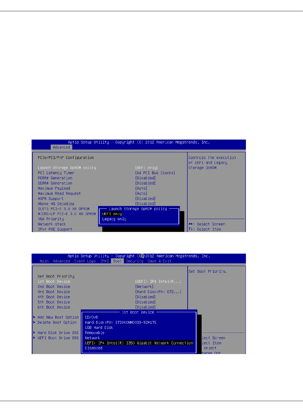
Configure PXE booting over UEFI
This section explains how to configure the Preboot Execution Environment (PXE) to boot a
hardware server from the network over Unified Extensible Firmware Interface (UEFI), which
details the interface between the platform firmware and the operating system at boot time.
During the manual MCP infrastructure deployment, the PXE boot takes place when you add new
physical servers that are not yet loaded with an operating system to your deployment. The
Foundation node is installed with all the necessary software from a virtual machine image. All
other hardware servers are installed remotely by MAAS using PXE boot. If required, you can
configure a server to boot from network over UEFI.
To configure the UEFI network boot:
1. Configure the server in BIOS to use UEFI on boot time:
1. On the Advanced tab, set the Launch Storage OpROM policy option to UEFI only:
2. On the Boot tab, specify the UEFI network connection as the first boot device. For
example:
2. During comissioning through MAAS, verify that the server uses UEFI. For example:
Mirantis Cloud Platform Deployment Guide
©2019, Mirantis Inc. Page 284
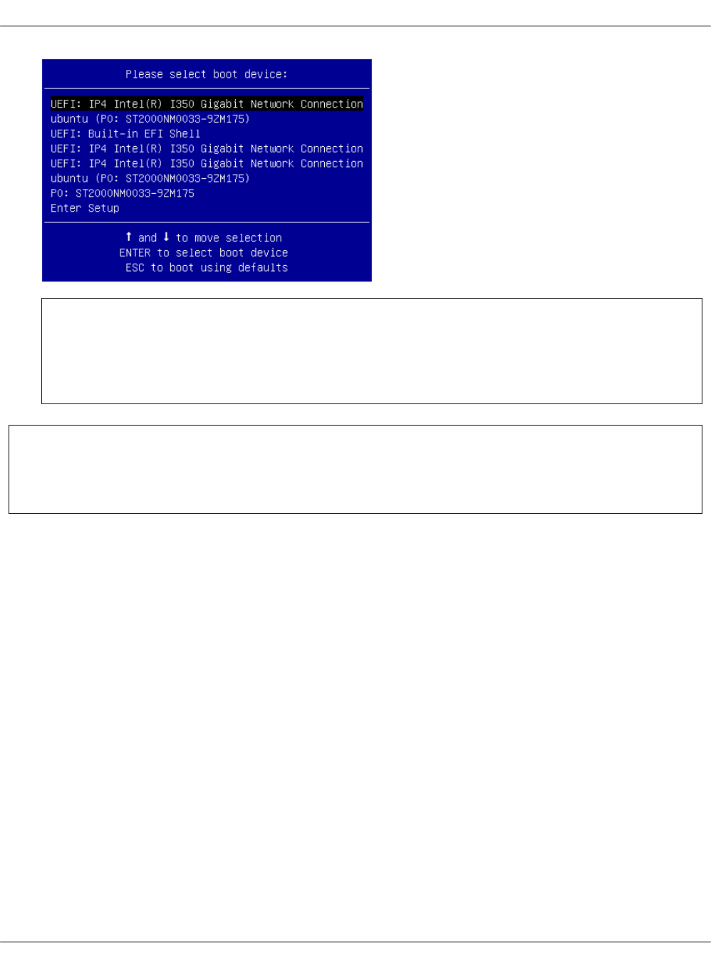

Add a custom disk layout per node in the MCP model
In MAAS, you can define the disk layout, either flat or Logical Volume Manager (LVM), as well as
the partitioning schema per server. This section describes how to define these parameters in
the MAAS section of the MCP model. The disk configuration applies during the deployment
process. If you want to define the disk configuration after deployment, you can use
salt-formula-linux that also has a capability to set up LVM partitioning. But the whole definition
for each Volume Group must be either in the maas or linux section, since the linux state cannot
override or extend an existing Volume Group created using MAAS but can create a new one.
Caution!
You can define the disk configuration in the model before the deployment starts. But be
aware that enforcing of this configuration to MAAS using the salt state must be done after
servers are commissioned and before they are deployed. Basically,
maas.machines.storage works only if a server is in the READY state.
Caution!
The maas.machines.storage state overlaps with the linux.storage state. Therefore, we
recommend using only one of them. If your deployment requires both, be aware that:
•The linux.storage configuration must match the maas.machines.storage
configuration.
•MAAS may use an inexplicit mapping. For example, the following MAAS configuration
will create an inexplicit mapping to sda1. And this specific sda1 device must be
defined in the linux.storage configuration.
maas:
...
vg0:
type: lvm
devices:
- sda
...
You can use several options to design the disk layout in a deployment depending on specific use
cases. This section includes three most common examples that can be combined to get your
desired configuration.
To define a different disk layout with custom parameters
The default layouts used by MAAS are flat and Logical Volume Manager (LVM). Flat layout
creates a root partition on the first disk of a server. LVM creates a Volume Group on this
Mirantis Cloud Platform Deployment Guide
©2019, Mirantis Inc. Page 286

partition with one volume per root. By default, in both types of disk layout, the entire space on
the first disk is used. If you want to change this behavior, redefine the disk layout parameters.
The following examples illustrate a modified configuration of the default values for partition size
as well as LVM names for Volume Group and Logical Volume:
• Flat layout:
maas:
region:
machines:
server1:
disk_layout:
type: flat
root_size: 10G #sda disk has more then 10G
root_device: sda
bootable_device: sda
• LVM layout:
maas:
region:
machines:
server1:
disk_layout:
type: lvm
root_size: 20G #sda disk has more then 20G
root_device: sda
bootable_device: sda
volume_group: vg0
volume_name: root
volume_size: 10G #If not defined, whole root partition is used.
Caution!
When defining the disk layout in the model, do not modify the rest of the disk using the
MAAS dashboard. Each run of maas.machines.storage deletes and recreates the disk
configuration of a server. Currently, this state is not idempotent.
To define a custom partitioning schema
To define a more complex configuration for disks, use the disk section under the disk_layout
parameter.
The following example illustrates how to create partitions on the sda disk and a Volume Group
with Logical Volumes on the sdb disk. Be aware that sdb is also defined without any partitioning
schema. Therefore, you can enforce no partition to be present on sdb. Also, due to the
Mirantis Cloud Platform Deployment Guide
©2019, Mirantis Inc. Page 287

volume_group1 dependency on this device, it must be defined with some configuration in the
model. In the example below, it has no partitioning schema.
Example of creating partitions and Logical Volumes:
maas:
region:
machines:
server3:
disk_layout:
type: custom
bootable_device: sda
disk:
sda:
type: physical
partition_schema:
part1:
size: 10G
type: ext4
mount: '/'
part2:
size: 2G
part3:
size: 3G
sdb:
type: physical
volume_group1:
type: lvm
devices:
- sdb
volume:
tmp:
size: 5G
type: ext4
mount: '/tmp'
log:
size: 7G
type: ext4
mount: '/var/log'
Caution!
The naming convention for partition in MAAS does not allow using custom names.
Therefore, key names in YAML for partition are always part1, part2, ..., partN.
To define the software RAID
Mirantis Cloud Platform Deployment Guide
©2019, Mirantis Inc. Page 288

Using the disk section from the previous example, you can create the software RAID on servers.
You can use this device for LVM or you can define a partitioning schema directly on this device.
The following example illustrates how to create raid„1 on sda and sdb with the partitioning
schema. In this example, we use flat layout that creates a root partition on sda, but this
partition is eventually deleted because sda is defined without any partitioning schema.
Example of creating the software RAID disks:
maas:
region:
machines:
server3:
disk_layout:
type: custom
bootable_device: sda
disk:
sda:
type: physical
sdb:
type: physical
md0:
type: raid
level: 1
devices:
- sda
- sdb
partition_schema:
part1:
size: 10G
type: ext4
mount: '/'
part2:
size: 5G
part3:
size: 25G
To apply changes to MAAS
To enforce the disk configuration on servers in MAAS, run the maas state on a node where the
MAAS model is included. Usually, this is the cfg01 node.
salt-call state.sls maas.machines.storage
Now, proceed with the MCP deployment depending on your use case as described in Provision
physical nodes using MAAS.
Mirantis Cloud Platform Deployment Guide
©2019, Mirantis Inc. Page 289

Enable NTP authentication
This section describes how to enable Network Time Protocol (NTP) authentication in a
deployment model and apply it to your environment.
To configure authentication for NTP:
1. Log in to the Salt Master node.
2. Create the classes/cluster/<cluster_name>/infra/ntp_auth.yml file with the following
configuration as an example:
ntp:
client:
enabled: true
auth:
enabled: true
secrets:
1:
secret_type: 'M'
secret: '<Runrabbitrundigthath>'
trustedkey: true
2:
secret_type: 'M'
secret: '<Howiwishyouwereherew>'
trustedkey: true
stratum:
primary:
server: <ntp1.example.com>
key_id: 1
secondary:
server: <ntp2.example.com>
key_id: 2
In the secrets and stratum sections, specify your own keys and strata servers accordingly.
The key_id parameter for each strata server represents the id of a secret from the secrets
section.
The above configuration example enables authentication for two servers. For a specific use
case, see salt-formula-ntp/README.rst.
3. In the classes/cluster/<cluster_name>/infra/init.yml file, include the following class to
distribute the settings across all nodes:
classes:
- cluster.<cluster_name>.infra.ntp_auth
4. Apply the ntp state on the Salt Master node:
salt '*' state.sls ntp
Mirantis Cloud Platform Deployment Guide
©2019, Mirantis Inc. Page 290


Enable a watchdog
This section describes how to enable a watchdog in your MCP cluster and applies to both
existing and new MCP deployments.
Note
This feature is available as technical preview. Use such configuration for testing and
evaluation purposes only.
The watchdog detects and recovers servers from serious malfunctions which can include
hardware faults as well as program errors. While operating normally, the server resets the
watchdog preventing it from generating a timeout signal. Otherwise, the watchdog initiates
corrective actions to restore the normal operation of a system.
This functionality can be implemented through either a watchdog timer, which is a hardware
device, or a software-only softdog driver.
To install and configure the watchdog:
1. Log in to the Salt Master node.
2. In the classes/cluster/<cluster_name>/init.yml or
classes/cluster/<cluster_name>/init/init.yml file of your Reclass model, include the
following class:
classes:
- system.watchdog.server
3. In the classes/cluster/<cluster_name>/infra/config.yml file of your Reclass model, add the
watchdog server configuration. For example:
watchdog:
server:
admin: root
enabled: true
interval: 1
log_dir: /var/log/watchdog
realtime: yes
timeout: 60
device: /dev/watchdog
# Salt Stack will automatically detect the necessary kernel module
# which needs to be loaded (ex. hpwdt, iTCO_wdt).
# If the hardware model is not predefined in map.jinja, the default
# watchdog driver is used: softdog
# You may specify the kernel module parameters if needed:
kernel:
parameter:
Mirantis Cloud Platform Deployment Guide
©2019, Mirantis Inc. Page 292

soft_panic: 1
parameter: value
parameter_only_without_value: none
4. Select from the following options:
•If you are performing the initial deployment of your environment, the watchdog service
will be installed during the Finalize stage of the Deploy - OpenStack pipeline. See
Deploy an OpenStack environment for details.
•If you are enabling the watchdog service in an existing environment, apply the
changes to the deployment model to install the service:
salt \* state.sls watchdog
5. Verify that the watchdog service is enabled in your deployment:
salt \* cmd.run "service watchdog status"
Mirantis Cloud Platform Deployment Guide
©2019, Mirantis Inc. Page 293

Enable the Linux Audit system
The Linux Audit system enables the system administrator to track security-relevant events by
creating an audit trail, which is a log for every action on the server. More specifically, based on
the pre-configured rules, the audit system creates log entries that record system calls. By
monitoring the events happening on your system, you can reveal violations of system security
policies and adjust the set of audit rules to prevent further misuse or unauthorized activities
within the system.
This section describes how to enable the audit system in your MCP deployment in compliance
with CIS audit benchmarks and applies to both existing and new MCP deployments. Once you
enable the audit system, the Fluentd service of StackLight LMA collects the audit logs and sends
them to Elasticsearch for storage.
To enable the Linux Audit system:
1. Log in to the Salt Master node.
2. In the classes/cluster/<cluster_name>/infra/init.yml file of your Reclass model, include the
following class:
classes:
...
- system.auditd.server.ciscat
3. If required, configure the CIS-CAT rules depending on the needs of your deployment.
4. Select from the following options:
•If you are performing the initial deployment of your environment, the auditd service
will be installed during the MCP cluster deployment.
• If you are enabling the auditd service in an existing environment:
1. Refresh pillars and synchronize Salt modules:
salt '*' saltutil.refresh_pillar
salt '*' saltutil.sync_modules
2. Apply the salt state:
salt '*' state.sls salt
3. Apply the changes to the Reclass model by running the auditd state:
salt \* state.sls auditd
5. Verify that the auditd service is enabled in your deployment:
salt \* service.status auditd
6. Verify that the rules are being applied as expected using the auditctl tool:
Mirantis Cloud Platform Deployment Guide
©2019, Mirantis Inc. Page 294

salt \* cmd.run "auditctl -l"
Mirantis Cloud Platform Deployment Guide
©2019, Mirantis Inc. Page 295

Configure a company name for the SSH and interactive
logon disclaimer
On an SSH and interactive logon to the MCP VCP nodes, a security disclaimer displays. The
disclaimer states that an unauthorised access to or misuse of a computer system is prohibited
under the Computer Misuse Act 1990.
Note
The act is designed to protect computer users against wilful attacks and theft of
information. The act makes it an offence to access or even attempt to access a computer
system without the appropriate authorisation. Therefore, if a hacker makes even
unsuccessful attempts to get into a system, they can be prosecuted using this law.
This section provides an instruction on how to configure the company name managing the
computer from which the operator is required to have authorisation before proceeding.
To configure the company name in the logon disclaimer:
1. Log in to the Salt Master node.
2. To configure the company name for the SSH logon, specify the company name in the
classes/cluster/<cluster_name>/openssh/server/single.yml file in your Reclass model:
classes:
- service.openssh.server
- service.openssh.server.cis
parameters:
_param:
ssh_banner_company_name: COMPANY_NAME
3. To configure the company name for the interactive logon, specify the company name in the
classes/cluster/<cluster_name>/linux/system/banner.yml file in your Reclass model:
parameters:
_param:
banner_company_name: COMPANY_NAME_HERE
4. Apply the changes to your deployment:
salt -C 'I@salt:control' state.sls openssh.server.service linux.system
Now, the logon disclaimer should display the configured company name.
Mirantis Cloud Platform Deployment Guide
©2019, Mirantis Inc. Page 296

Set custom Transmit Queue Length
The Transmit Queue Length (txqueuelen) is a TCP/IP stack network interface value that sets the
number of packets allowed per kernel transmit queue of a network interface device.
By default, the txqueuelen value is set to 1000. Though, MCP enables you to tune the
txqueuelen value for TAP interfaces to optimize VM network performance under high load in
certain scenarios.
To set a custom Transmit Queue Length value for TAP interfaces:
1. Log in to the Salt Master node.
2. Set the tap_custom_txqueuelen parameter for OpenContrail or OVS compute nodes in one
of the following files as required:
•For OpenContrail compute nodes, modify the
cluster/<cluster_name>/opencontrail/networking/compute.yml file.
•For OVS compute nodes, modify the
cluster/<cluster_name>/openstack/networking/compute.yml file.
Example:
linux:
network:
...
tap_custom_txqueuelen: 20000
3. Apply the change by running the linux state:
salt '*' state.sls linux
4. Verify that the txqueuelen value has changed:
1. Log in to the appropriate node.
2. Check the output of the ifconfig <interface_name>. The txqueuelen value should now
equal to the newly set value.
Mirantis Cloud Platform Deployment Guide
©2019, Mirantis Inc. Page 297

Advanced configuration
MCP exposes a number of advanced configuration options.
Enable NFV features
Network Functions Virtualization (NFV) is a powerful technology that leverages virtualization of
particular network functions which allows a better flexibility in network administration and
enables you to use network hardware more efficiently.
MCP supports the following NFV features:
•Data Plane Development Kit or DPDK is a set of libraries and drivers to perform fast packet
processing in the user space that OVS/vRouter can use to move network packets
processing from a kernel to a user space. OVS/vRouter with DPDK acceleration on compute
nodes reduces the processing time of network packets transferred between a host’s
network interface and a guest bypassing the host’s kernel. Moreover, DPDK leverages
benefits of usage of other technologies such as Huge Pages, CPU pinning, and NUMA
topology scheduling.
•SR-IOV is an extension to the PCI Express (PCIe) specification that enables a network
adapter to separate access to its resources among various PCIe hardware functions:
Physical Function (PF) and Virtual Functions (VFs). As a result, you can achieve near
bare-metal performance, since network devices can forward traffic directly to a VF
bypassing the host.
•Multiqueue for DPDK-based vrouters enables the scaling of packet sending/receiving
processing to the number of available vCPUs of a guest by using multiple queues.
The following table shows compatibility matrix for MCP of NFV features for different
deployments.
NFV for MCP compatibility matrix
Type Host OS KernelHugePages DPDK SR-IOV NUMA CPU
pinning Multiqueue
OVS Xenial 4.8 Yes No Yes Yes Yes Yes
Kernel
vRouter
Xenial 4.8 Yes No Yes Yes Yes Yes
DPDK
vRouter
Trusty 4.4 Yes Yes No Yes Yes No (version
3.2)
DPDK
OVS
Xenial 4.8 Yes Yes No Yes Yes Yes
Enable DPDK
Enabling Data Plane Development Kit (DPDK) strongly requires Huge Pages configuration before
an application start. To perform fast packet processing, a DPDK-based network application may
require to use isolated CPUs and resources spread on the multi-NUMA topology. These
configurations are common for both OVS and OpenContrail.
Mirantis Cloud Platform Deployment Guide
©2019, Mirantis Inc. Page 298

Warning
Before you proceed with the DPDK enabling, verify that you have performed the following
procedures:
1. Enable Huge Pages
2. Configure NUMA and CPU pinning architecture
Limitations
The usage of the OVS DPDK or OpenContrail DPDK features in MCP includes the following
limitations.
OVS DPDK limitations:
• OVS DPDK can be used only for tenant traffic
• Compute with DPDK cannot be used for non-DPDK workload
•When deployed with StackLight LMA, the libvirt_domain_interface_stats_* metrics are not
available
OpenContrail DPDK limitations:
•When deployed with StackLight LMA, the libvirt_domain_interface_stats_* metrics are not
available
Enable OVS DPDK
This section explains how to prepare for and enable OVS DPDK in MCP.
Warning
Before you proceed with the DPDK enabling, verify that you have performed the following
procedures:
1. Enable Huge Pages
2. Configure NUMA and CPU pinning architecture
Prepare your environment for OVS DPDK
This section describes the initialization steps needed to prepare your deployment for the
enablement of the OVS DPDK feature.
Mirantis Cloud Platform Deployment Guide
©2019, Mirantis Inc. Page 299

Warning
Before you proceed with the DPDK enabling, verify that you have performed the following
procedures:
1. Enable Huge Pages
2. Configure NUMA and CPU pinning architecture
To prepare your environment for OVS DPDK:
1. Specify the DPDK driver.
DPDK Environment Abstract Layer(EAL) uses either Userspace I/O (UIO) module or VFIO to
provide userspace access on low-level buffers. MCP supports both configurations.
Note
To use VFIO approach, verify that both kernel and BIOS are configured to use I/O
virtualization. This requirement is similar to SR-IOV Intel IOMMU and VT-d being
enabled.
To use one of Userspace I/O drivers, define the compute_dpdk_driver parameter. For
example:
compute_dpdk_driver: uio # vfio
2. In respect to the parameter specified above, configure the DPDK physical driver. There is
one-to-one dependency of what driver must be selected for physical DPDK NIC based on the
configured I/O mechanism. For example:
dpdk0:
...
driver: igb_uio # vfio-pci
3. To enable the physical DPDK device to run several RX/TX queues for better packet
processing, configure the following parameter specifying the number of queues to be used.
For example:
dpdk0:
...
n_rxq: 2 # number of RX/TX queues
Mirantis Cloud Platform Deployment Guide
©2019, Mirantis Inc. Page 300

Note
The increasing number of queues results in PMD threads consuming more cycles to
serve physical device. We strongly recommend that you configure the number of
physical queues not greater that CPUs configured for the DPDK-based application.
Enable OVS DPDK support
Before you proceed with the procedure, verify that you have performed the preparatory steps
described in Prepare your environment for OVS DPDK.
While enabling DPDK for Neutron Open vSwitch, you can configure a number of settings specific
to your environment that assist in optimizing your network performance, such as manual
pinning and others.
To enable OVS DPDK:
1. Verify your NUMA nodes on the host operating system to see what vCPUs are available. For
example:
lscpu | grep NUMA
NUMA node(s): 1
NUMA node0 CPU(s): 0-11
2. Include the class to cluster.<name>.openstack.compute and configure the dpdk0 interface.
Select from the following options:
• Single interface NIC dedicated for DPDK:
...
- system.neutron.compute.nfv.dpdk
...
parameters:
linux:
network:
interfaces:
...
# other interface setup
…
dpdk0:
name: ${_param:dpdk0_name}
pci: ${_param:dpdk0_pci}
driver: igb_uio
enabled: true
type: dpdk_ovs_port
n_rxq: 2
br-prv:
enabled: true
type: dpdk_ovs_bridge
Mirantis Cloud Platform Deployment Guide
©2019, Mirantis Inc. Page 301

• OVS DPDK bond with 2 dedicated NICs
...
- system.neutron.compute.nfv.dpdk
...
parameters:
linux:
network:
interfaces:
...
# other interface setup
…
dpdk0:
name: ${_param:dpdk0_name}
pci: ${_param:dpdk0_pci}
driver: igb_uio
bond: dpdkbond1
enabled: true
type: dpdk_ovs_port
n_rxq: 2
dpdk1:
name: ${_param:dpdk1_name}
pci: ${_param:dpdk1_pci}
driver: igb_uio
bond: dpdkbond1
enabled: true
type: dpdk_ovs_port
n_rxq: 2
dpdkbond1:
enabled: true
bridge: br-prv
type: dpdk_ovs_bond
mode: active-backup
br-prv:
enabled: true
type: dpdk_ovs_bridge
3. Calculate the hexadecimal coremask.
As well as for OpenContrail, OVS-DPDK needs logical cores parameter to be set. Open
vSwitch requires two parameters: lcore mask to DPDK processes and PMD„mask to spawn
threads for poll-mode packet processing drivers. Both parameters must be calculated
respectively to isolated CPUs and are representing hexadecimal numbers. For example, if
we need to take single CPU number 2 for Open vSwitch and 4 CPUs with numbers 5, 6, 10
and 12 for forwarding PMD threads, we need to populate parameters below with the
following numbers:
• The lcores mask example:
Mirantis Cloud Platform Deployment Guide
©2019, Mirantis Inc. Page 302
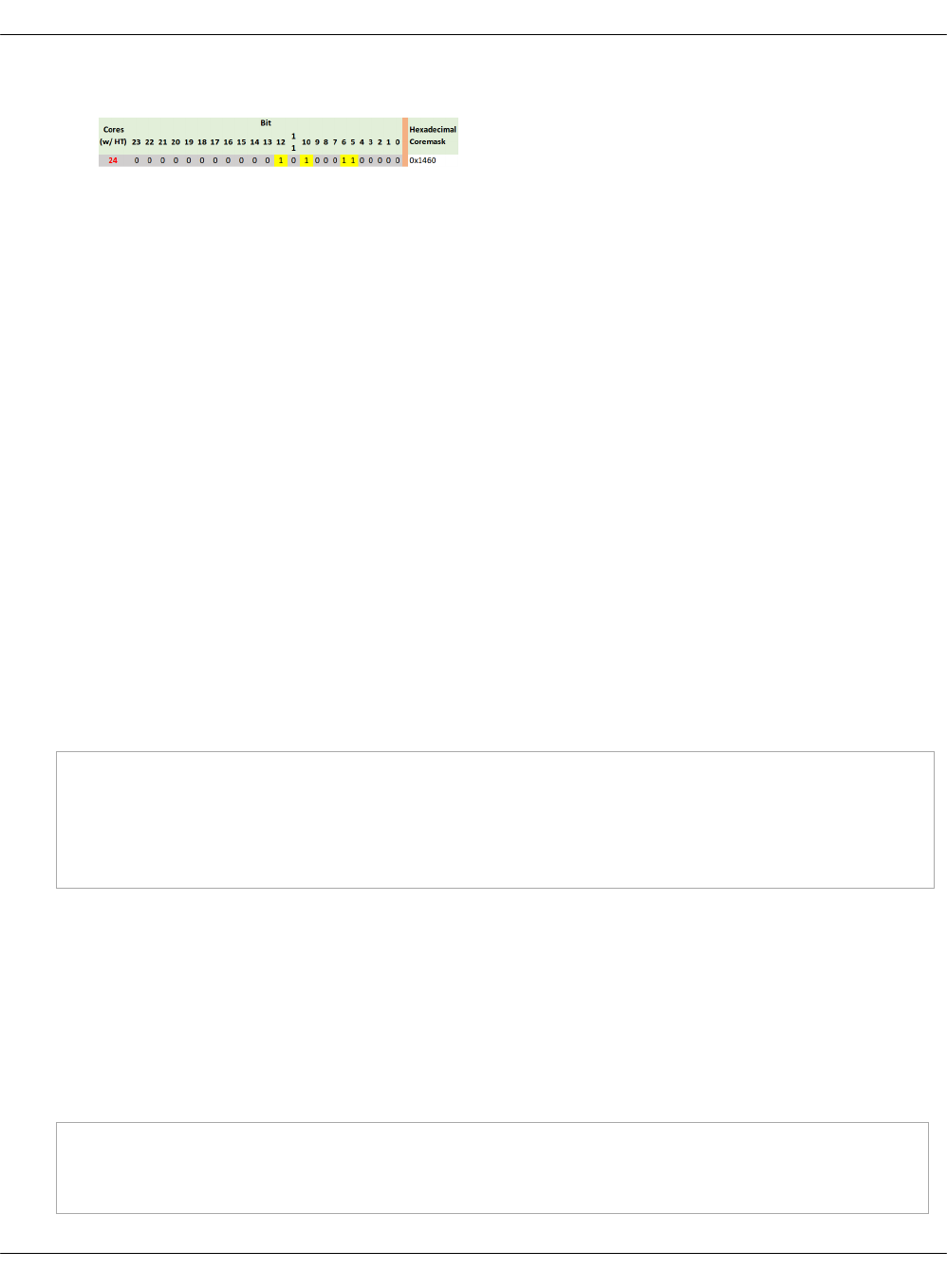
• PMD CPU mask example:
4. Define the parameters in the cluster.<name>.openstack.init if they are the same for all
compute nodes. Otherwise, specify them in cluster.<name>.infra.config:
•dpdk0_name
Name of port being added to OVS bridge
•dpdk0_pci
PCI ID of physical device being added as a DPDK physical interface
•compute_dpdk_driver
Kernel module to provide userspace I/O support
•compute_ovs_pmd_cpu_mask
Hexadecimal mask of CPUs to run DPDK Poll-mode drivers
•compute_ovs_dpdk_socket_mem
Set of amount HugePages in Megabytes to be used by OVS-DPDK daemon taken for
each NUMA node. Set size is equal to NUMA nodes count, elements are divided by
comma
•compute_ovs_dpdk_lcore_mask
Hexadecimal mask of DPDK lcore parameter used to run DPDK processes
•compute_ovs_memory_channels
Number of memory channels to be used.
Example
compute_dpdk_driver: uio
compute_ovs_pmd_cpu_mask: "0x6"
compute_ovs_dpdk_socket_mem: "1024"
compute_ovs_dpdk_lcore_mask: "0x400"
compute_ovs_memory_channels: "2"
5. Optionally, map the port RX queues to specific CPU cores.
Configuring port queue pinning manually may help to achieve maximum network
performance through matching the ports that run specific workloads with specific CPU
cores. Each port can process a certain number of Transmit and Receive (RX/TX) operations,
therefore it is up to the Network Administrator to decide on the most efficient port
mapping. Keeping a constant polling rate on some performance critical ports is essential in
achieving best possible performance.
Example
dpdk0:
...
pmd_rxq_affinity: "0:1,1:2"
Mirantis Cloud Platform Deployment Guide
©2019, Mirantis Inc. Page 303

The example above illustrates pinning of the queue 0 to core 1 and pinning of the queue 1
to core 2, where cores are taken in accordance with pmd_cpu_mask.
6. Specify the MAC address and in some cases PCI for every node.
Example
openstack_compute_node02:
name: ${_param:openstack_compute_node02_hostname}
domain: ${_param:cluster_domain}
classes:
- cluster.${_param:cluster_name}.openstack.compute
params:
salt_master_host: ${_param:reclass_config_master}
linux_system_codename: xenial
dpdk0_name: enp5s0f1
dpdk1_name: enp5s0f2
dpdk0_pci: '"0000:05:00.1"'
dpdk1_pci: '"0000:05:00.2"'
7. If the VXLAN neutron tenant type is selected, set the local IP address on br-prv for VXLAN
tunnel termination:
...
- system.neutron.compute.nfv.dpdk
...
parameters:
linux:
network:
interfaces:
...
# other interface setup
…
br-prv:
enabled: true
type: dpdk_ovs_bridge
address: ${_param:tenant_address}
netmask: 255.255.255.0
8. Select from the following options:
•If you are performing the initial deployment of your environment, proceed with further
environment configurations.
•If you are making changes to an existing environment, re-run salt configuration on the
Salt Master node:
salt "cmp*" state.sls linux.network,neutron
Mirantis Cloud Platform Deployment Guide
©2019, Mirantis Inc. Page 304

Note
For the changes to take effect, servers require a reboot.
9. If you need to set different values for each compute node, define them in
cluster.<NAME>.infra.config.
Example
openstack_compute_node02:
name: ${_param:openstack_compute_node02_hostname}
domain: ${_param:cluster_domain}
classes:
- cluster.${_param:cluster_name}.openstack.compute
params:
salt_master_host: ${_param:reclass_config_master}
linux_system_codename: xenial
dpdk0_name: enp5s0f1
dpdk1_name: enp5s0f2
dpdk0_pci: '"0000:05:00.1"'
dpdk1_pci: '"0000:05:00.2"'
compute_dpdk_driver: uio
compute_ovs_pmd_cpu_mask: "0x6"
compute_ovs_dpdk_socket_mem: "1024"
compute_ovs_dpdk_lcore_mask: "0x400"
compute_ovs_memory_channels: "2"
Enable OpenContrail DPDK
OpenContrail 4.0 uses DPDK libraries version 17.02.
Warning
Before you proceed with the DPDK enabling, verify that you have performed the following
procedures:
1. Enable Huge Pages
2. Configure NUMA and CPU pinning architecture
A workload running on DPDK vRouter does not provide better pps if an application is not DPDK
aware. The performance result is the same as for kernel vRouter.
To enable the OpenContrail DPDK pinning:
1. Verify your NUMA nodes on the host operating system to see what vCPUs are available. For
example:
Mirantis Cloud Platform Deployment Guide
©2019, Mirantis Inc. Page 305

lscpu | grep NUMA
NUMA node(s): 1
NUMA node0 CPU(s): 0-11
2. Include the class to cluster.<name>.openstack.compute and configure the vhost0
interface:
• For a single interface in DPDK:
...
- system.opencontrail.compute.dpdk
...
parameters:
linux:
network:
interfaces:
...
# other interface setup
...
vhost0:
enabled: true
type: eth
address: ${_param:single_address}
netmask: 255.255.255.0
name_servers:
- 8.8.8.8
- 1.1.1.1
3. Set the parameters in cluster.<name>.openstack.init on all compute nodes:
•compute_vrouter_taskset
Hexadecimal mask of CPUs used for DPDK-vRouter processes
•compute_vrouter_socket_mem
Set of amount HugePages in Megabytes to be used by vRouter-DPDK taken for
each NUMA node. Set size is equal to NUMA nodes count, elements are divided by
comma
•compute_vrouter_dpdk_pci
PCI of a DPDK NIC. In case of BOND there must be 0000:00:00.0
4. Calculate the hexadecimal mask. To enhance vRouter with DPDK technology, several
isolated host CPUs should be used for such DPDK processes as statistics, queue
management, memory management, and poll-mode drivers. To perform this, you need to
configure the hexadecimal mask of CPUs to be consumed by vRouter-DPDK.
The way to calculate the hexadecimal mask is simple as a set of CPUs corresponds to the
bits sequence size of CPUs number. 0 on i-th place in this sequence means that CPU
number i will not be taken for usage, and 1 has the opposite meaning. Simple translation of
binary-to-hexadecimal based on bit sequence of size 24 is illustrated below (vRouter is
bound to 4 cores: 14,13,2,1.)
Mirantis Cloud Platform Deployment Guide
©2019, Mirantis Inc. Page 306

5. Pass the hexadecimal mask to vRouter-DPDK command line using the following parameters.
For example:
compute_vrouter_taskset: "-c 1,2" # or hexadecimal 0x6
compute_vrouter_socket_mem: '1024' # or '1024,1024' for 2 NUMA nodes
6. Specify the MAC address and in some cases PCI for every node.
Example
openstack_compute_node02:
name: ${_param:openstack_compute_node02_hostname}
domain: ${_param:cluster_domain}
classes:
- cluster.${_param:cluster_name}.openstack.compute
params:
salt_master_host: ${_param:reclass_config_master}
linux_system_codename: trusty
compute_vrouter_dpdk_mac_address: 00:1b:21:87:21:99
compute_vrouter_dpdk_pci: "'0000:05:00.1'"
primary_first_nic: enp5s0f1 # NIC for vRouter bind
7. Select from the following options:
•If you are performing the initial deployment of your environment, proceed with the
further environment configurations.
•If you are making changes to an existing environment, re-run salt configuration on the
Salt Master node:
salt "cmp*" state.sls opencontrail
Note
For the changes to take effect, servers require a reboot.
8. If you need to set different values for each compute node, define them in
cluster.<NAME>.infra.config.
Example
openstack_compute_node02:
name: ${_param:openstack_compute_node02_hostname}
domain: ${_param:cluster_domain}
classes:
- cluster.${_param:cluster_name}.openstack.compute
Mirantis Cloud Platform Deployment Guide
©2019, Mirantis Inc. Page 307

params:
salt_master_host: ${_param:reclass_config_master}
linux_system_codename: trusty
compute_vrouter_dpdk_mac_address: 00:1b:21:87:21:99
compute_vrouter_dpdk_pci: "'0000:05:00.1'"
compute_vrouter_taskset: "-c 1,2"
compute_vrouter_socket_mem: "1024"
primary_first_nic: enp5s0f1 # NIC for vRouter bind
Enable SR-IOV
Single Root I/O Virtualization (SR-IOV) is an I/O virtualization technology that allows a single PCIe
device to appear as multiple PCIe devices. This helps to optimize the device performance and
capacity, as well as hardware costs.
Prerequisites
If you want to use the SR-IOV feature with OpenContrail or Neutron OVS, your environment must
meet the following prerequisites:
•Intel Virtualization Technology for Directed I/O (VT-d) and Active State Power Management
(ASPM) must be supported and enabled in BIOS
•Physical NIC with Virtual Function (VF) driver installed Enable ASPM (Active State Power
Management) of PCI Devices in BIOS. If required, upgrade BIOS to see ASPM option.
Enable generic SR-IOV configuration
The following procedure is common for both OpenVSwitch and OpenContrail. SR-IOV can be
enabled before or after installation on the MCP cluster model level.
To enable SR-IOV:
1. Include the class to cluster.<NAME>.openstack.compute:
- system.neutron.compute.nfv.sriov
Note
By default, the metadata model contains configuration for 1 NIC dedicated for
SR-IOV.
2. Set the following parameters:
•sriov_nic01_device_name
Name of the interface, where the Virtual Functions are enabled
•sriov_nic01_numvfs
Number of Virtual Functions
Mirantis Cloud Platform Deployment Guide
©2019, Mirantis Inc. Page 308

•sriov_nic01_physical_network
Default is physnet1, label for the physical network the interface belongs to
•sriov_unsafe_interrupts
Default is False, needs to be set to True if your hardware platform does not support
interrupt remapping
For most deployments with 1 NIC for SR-IOV, we recommend the following configuration in
cluster.<name>.openstack.init on all compute nodes:
sriov_nic01_device_name: eth1
sriov_nic01_numvfs: 7
sriov_nic01_physical_network: physnet3
3. If you need to set different values for each compute node, specify them in
cluster.<name>.infra.config.
Example
openstack_compute_node02:
name: ${_param:openstack_compute_node02_hostname}
domain: ${_param:cluster_domain}
classes:
- cluster.${_param:cluster_name}.openstack.compute
params:
salt_master_host: ${_param:reclass_config_master}
linux_system_codename: xenial
sriov_nic01_device_name: eth1
sriov_nic01_numvfs: 7
sriov_nic01_physical_network: physnet3
4. If your hardware does not support interrupt remapping, set the following parameter:
sriov_unsafe_interrupts: True
5. If you need more than one NIC on a compute node, set the following parameters in
cluster.<NAME>.openstack.compute.
Example
...
nova:
compute:
sriov:
sriov_nic01:
devname: eth1
physical_network: physnet3
sriov_nic02:
devname: eth2
physical_network: physnet4
Mirantis Cloud Platform Deployment Guide
©2019, Mirantis Inc. Page 309

sriov_nic03:
devname: eth3
physical_network: physnet5
sriov_nic04:
devname: eth4
physical_network: physnet6
linux:
system:
kernel:
sriov: True
unsafe_interrupts: False
sysfs:
sriov_numvfs:
class/net/eth1/device/sriov_numvfs: 7
class/net/eth2/device/sriov_numvfs: 15
class/net/eth3/device/sriov_numvfs: 15
class/net/eth4/device/sriov_numvfs: 7
6. Select from the following options:
•If you are performing the initial deployment your environment, proceed with the
further environment configurations.
•If you are making changes to an existing environment, re-run the salt configuration on
the Salt Master node:
salt "cmp*" state.sls linux,nova
Configure SR-IOV with OpenContrail
Since OpenContrail does not use Neutron SR-IOV agents, it does not require any special changes
on the Neutron side. Port configuration can be done through the Neutron APIs or the
OpenContrail UI.
Configure SR-IOV with OpenVSwitch
Neutron OVS requires enabling of the sriovnicswitch mechanism driver on the Neutron server
side and the neutron-sriov-nic-agent running on each compute node with this feature enabled.
To configure SR-IOV with OpenVSwitch:
1. Include the class to cluster.<NAME>.openstack.compute:
- system.neutron.compute.nfv.sriov
Note
By default, the metadata model contains configuration for 1 NIC dedicated for
SR-IOV.
Mirantis Cloud Platform Deployment Guide
©2019, Mirantis Inc. Page 310

2. Include the class to cluster.<NAME>.openstack.control:
- system.neutron.control.openvswitch.sriov
3. If you need more than 1 NIC, extend the previous configuration by extra Neutron
cluster.<NAME>.openstack.compute.
Example
...
neutron:
compute:
backend:
sriov:
sriov_nic01:
devname: eth1
physical_network: physnet3
sriov_nic02:
devname: eth2
physical_network: physnet4
sriov_nic03:
devname: eth3
physical_network: physnet5
sriov_nic04:
devname: eth4
physical_network: physnet6
Create instances with SR-IOV ports
To enable the SR-IOV support, you must create virtual instances with SR-IOV ports.
To create virtual instances with SR-IOV ports:
1. Create a network and a subnet with a segmentation ID. For example:
neutron net-create --provider:physical_network=physnet3 \
--provider:segmentation_id=100 net04
neutron subnet-create net04 a.b.c.d/netmask
2. Request the ID of the Neutron network where you want the SR-IOV port to be created. For
example:
net_id=`neutron net-show net04 | grep "\ id\ " | awk '{ print $4 }'`
3. Create an SR-IOV port with one of the available VNIC driver types that are direct, normal,
direct-physical, and macvtap:
port_id=`neutron port-create $net_id --name sriov_port \
--binding:vnic_type direct | grep "\ id\ " | awk '{ print $4 }'`
Mirantis Cloud Platform Deployment Guide
©2019, Mirantis Inc. Page 311

4. Create a virtual instance with the SR-IOV port created in step 3:
nova boot --flavor m1.large --image ubuntu_14.04 --nic port-id=$port_id test-sriov
Seealso
Using SR-IOV functionality in the official OpenStack documentation
Seealso
Enable Multiqueue
Enable Huge Pages
Huge Pages is a technology that supports 2MB and 1GB size memory pages. Huge Pages
reduces time to access data stored in the memory by using bigger memory pages, which leads
to fewer page entries to look up by CPU when choosing a page associated with a current
process. Use of Huge Pages is beneficial in operations and processes that require large amount
of memory.
Warning
Verify that CPU supports HugePages before you proceed.
Enable the Huge Pages support
This section exaplains how to configure the support for the Huge Pages feature in your MCP
depoyment.
To enable Huge Pages:
1. Log in to the host machine.
2. To verify that CPU supports Huge Pages, analyze the system response of the following
command:
cat /proc/cpuinfo
In the system output, search for the parameters:
• PSE - support of 2MB hugepages
• PDPE1GB - support of 1GB hugepages
Mirantis Cloud Platform Deployment Guide
©2019, Mirantis Inc. Page 312

3. Include the class in cluster.<name>.openstack.compute:
- system.nova.compute.nfv.hugepages
4. Set the parameters in cluster.<name>.openstack.init on all compute nodes:
compute_hugepages_size: 1G # or 2M
compute_hugepages_count: 40
compute_hugepages_mount: /mnt/hugepages_1G # or /mnt/hugepages_2M
5. Select from the following options:
•If you are performing the initial deployment your environment, proceed with the
further environment configurations.
•If you are making changes to an existing environment, re-run the salt configuration on
the Salt Master node:
salt "cmp*" state.sls linux,nova
6. Reboot the affected servers.
7. If you need to set different values for each compute node, define them in
cluster.<name>.infra.config for each node.
Example:
openstack_compute_node02:
name: ${_param:openstack_compute_node02_hostname}
domain: ${_param:cluster_domain}
classes:
- cluster.${_param:cluster_name}.openstack.compute
params:
salt_master_host: ${_param:reclass_config_master}
linux_system_codename: xenial
compute_hugepages_size: 1G # or 2M
compute_hugepages_count: 40
compute_hugepages_mount: /mnt/hugepages_1G # or /mnt/hugepages_2M
Seealso
Boot a virtual machine with Huge Pages
Boot a virtual machine with Huge Pages
This section explains how to boot a VM with Huge Pages.
To boot a virtual machine with Huge Pages:
Mirantis Cloud Platform Deployment Guide
©2019, Mirantis Inc. Page 313

1. Create a new flavor or use an existing one to use with Huge Pages. To create a new image
flavor:
. openrc admin admin
nova flavor-create huge 999 1024 4 1
2. Add the size of huge pages to the image flavor:
nova flavor-key huge set hw:mem_page_size=2048
3. Verify the image flavor exists:
nova flavor-show huge
Example of system response
+----------------------------+------------------------------+
| Property | Value |
+----------------------------+------------------------------+
| OS-FLV-DISABLED:disabled | False |
| OS-FLV-EXT-DATA:ephemeral | 0 |
| disk | 4 |
| extra_specs | {"hw:mem_page_size": "2048"} |
| id | 7 |
| name | huge |
| os-flavor-access:is_public | True |
| ram | 1024 |
| rxtx_factor | 1.0 |
| swap | |
| vcpus | 1 |
+----------------------------+------------------------------+
4. Create a new image or use an existing image. You need an Ubuntu image and the default
Cirros image.
To create a new Ubuntu image:
glance --os-image-api-version 1 image-create --name ubuntu \
--location https://cloud-images.ubuntu.com/trusty/current/trusty-server-cloudimg-amd64-disk1.img \
--disk-format qcow2 --container-format bare
5. Boot a new instance using the created flavor:
nova boot --flavor huge --image ubuntu inst1
6. Verify that the new VM uses 512 huge pages:
grep Huge /proc/meminfo
Mirantis Cloud Platform Deployment Guide
©2019, Mirantis Inc. Page 314

Example of system response
AnonHugePages: 1138688 kB
HugePages_Total: 1024
HugePages_Free: 512
HugePages_Rsvd: 0
HugePages_Surp: 0
Hugepagesize: 2048 kB
Configure NUMA and CPU pinning architecture
NUMA and CPU pinning is a shared memory architecture that describes the placement of main
memory modules on processors in a multiprocessor system. You can leverage NUMA when you
have data strongly associated with certain tasks or users. In such case, CPU can use its local
memory module to access data reducing access time.
NUMA usage is beneficial on particular workloads, for example, on configurations where data is
often associated with certain tasks or users.
Enable NUMA and CPU pinning
Before you proceed with enabling DPDK in your deployment, the NUMA and CPU pinning
enablement is required.
To enable NUMA and CPU pinning:
1. Verify your NUMA nodes on the host operating system:
lscpu | grep NUMA
Example of system response
NUMA node(s): 1
NUMA node0 CPU(s): 0-11
2. Include the class to cluster.<NAME>.openstack.compute:
- system.nova.compute.nfv.cpu_pinning
3. Set the parameters in cluster.<name>.openstack.init on all compute nodes:
•compute_kernel_isolcpu
Set of host CPUs to be isolated from system. Kernel will not assign internal
processes on this set of CPUs. This parameter is configured in grub
•nova_cpu_pinning
Subset of CPUs isolated on previous step. This parameter is used by Nova to run
VMs only on isolated CPUs with dedicated pinning. Nova vCPU pinning set is
configured in the nova.conf file after system isolates appropriate CPUs
Mirantis Cloud Platform Deployment Guide
©2019, Mirantis Inc. Page 315

Example
nova_cpu_pinning: "1,2,3,4,5,7,8,9,10,11"
compute_kernel_isolcpu: ${_param:nova_cpu_pinning}
4. Select from the following options:
•If you are performing the initial deployment, proceed with the further environment
configurations.
•If you are making changes to an existing environment, re-run the salt configuration on
the Salt Master node:
salt "cmp*" state.sls linux,nova
Note
To take effect, servers require a reboot.
5. If you need to set different values for each compute node, define them in
cluster.<name>.infra.config.
Example
openstack_compute_node02:
name: ${_param:openstack_compute_node02_hostname}
domain: ${_param:cluster_domain}
classes:
- cluster.${_param:cluster_name}.openstack.compute
params:
salt_master_host: ${_param:reclass_config_master}
linux_system_codename: xenial
nova_cpu_pinning: "1,2,3,4,5,7,8,9,10,11"
compute_kernel_isolcpu: "1,2,3,4,5,7,8,9,10,11"
Boot a VM with two NUMA nodes
This example demonstrates booting a VM with two NUMA nodes.
To boot VM with two NUMA nodes:
1. Create a new flavor or use an existing one to use with NUMA. To create a new flavor, run:
. openrc admin admin
nova flavor-create m1.numa 999 1024 5 4
2. Add numa_nodes to the flavor.
Mirantis Cloud Platform Deployment Guide
©2019, Mirantis Inc. Page 316

Note
vCPUs and RAM will be divided equally between the NUMA nodes.
nova flavor-key m1.numa set hw:numa_nodes=2
nova flavor-show m1.numa
Example of system response:
+----------------------------+------------------------+
| Property | Value |
+----------------------------+------------------------+
| OS-FLV-DISABLED:disabled | False |
| OS-FLV-EXT-DATA:ephemeral | 0 |
| disk | 5 |
| extra_specs | {"hw:numa_nodes": "2"} |
| id | 999 |
| name | m1.numa |
| os-flavor-access:is_public | True |
| ram | 1024 |
| rxtx_factor | 1.0 |
| swap | |
| vcpus | 4 |
+----------------------------+------------------------+
3. Create a new image or use an existing image.
Note
You need an Ubuntu image and the default Cirros image.
To create a new Ubuntu image:
glance --os-image-api-version 1 image-create --name ubuntu \
--location https://cloud-images.ubuntu.com/trusty/current/\
trusty-server-cloudimg-amd64-disk1.img \
--disk-format qcow2 --container-format bare
4. To enable SSH connections:
1. Add a new rule to the security group:
nova secgroup-add-rule default tcp 22 22 0.0.0.0/0
Mirantis Cloud Platform Deployment Guide
©2019, Mirantis Inc. Page 317

2. Create a new SSH key pair or use the existing key pair. To create a new ssh key pair:
ssh-keygen
3. Add the key pair to Nova:
nova keypair-add --pub_key ~/.ssh/id_rsa.pub my_kp
5. Verify free memory before you boot the VM:
numactl -H
Example of system response:
available: 2 nodes (0-1)
node 0 cpus: 0 1
node 0 size: 3856 MB
node 0 free: 718 MB
node 1 cpus: 2 3
node 1 size: 3937 MB
node 1 free: 337 MB
node distances:
node 0 1
0: 10 20
1: 20 10
6. Boot a new instance using the created flavor:
nova boot --flavor m1.numa --image ubuntu --key-name my_kp inst1
7. Verify if free memory has been changed after booting the VM:
numactl -H
Example of system response:
available: 2 nodes (0-1)
node 0 cpus: 0 1
node 0 size: 3856 MB
node 0 free: 293 MB # was 718 MB
node 1 cpus: 2 3
node 1 size: 3937 MB
node 1 free: 81 MB # was 337 MB
node distances:
node 0 1
Mirantis Cloud Platform Deployment Guide
©2019, Mirantis Inc. Page 318

0: 10 20
1: 20 10
8. Retrieve the instance's IP:
nova show inst1 | awk '/network/ {print $5}'
Example of system response:
10.0.0.2
9. Connect to the VM using SSH:
ssh ubuntu@10.0.0.2
10. Install numactl:
sudo apt-get install numactl
11. Verify the NUMA topology on the VM:
numactl -H
Example of system response:
available: 2 nodes (0-1)
node 0 cpus: 0 1
node 0 size: 489 MB
node 0 free: 393 MB
node 1 cpus: 2 3
node 1 size: 503 MB
node 1 free: 323 MB
node distances:
node 0 1
0: 10 20
1: 20 10
Boot a VM with CPU and memory pinning
This example demonstrates booting VM with CPU and memory pinning.
To boot VM with CPU and memory pining:
1. Create a new flavor with specific division of vCPUs and RAM between the NUMA nodes:
. openrc admin admin
nova flavor-create m1.numa_2 9992 1024 5 4
Mirantis Cloud Platform Deployment Guide
©2019, Mirantis Inc. Page 319

2. Add numa_nodes and other specific options to the flavor:
nova flavor-key m1.numa_2 set hw:numa_nodes=2 hw:numa_cpus.0=0,2 \
hw:numa_cpus.1=1,3 hw:numa_mem.0=324 hw:numa_mem.1=700
nova flavor-show m1.numa_2 | grep extra
Example of system response:
| extra_specs | {"hw:numa_cpus.0": "0,2", "hw:numa_cpus.1": "1,3", \
"hw:numa_nodes": "2", "hw:numa_mem.1": "700", "hw:numa_mem.0": "324"} |
3. Create a new image or use an existing image.
Note
You need an Ubuntu image or the default Cirros image.
To create a new Ubuntu image:
glance --os-image-api-version 1 image-create --name ubuntu \
--location https://cloud-images.ubuntu.com/trusty/current/\
trusty-server-cloudimg-amd64-disk1.img \
--disk-format qcow2 --container-format bare
4. To enable SSH connections:
1. Add a new rule to the security group:
nova secgroup-add-rule default tcp 22 22 0.0.0.0/0
2. Create a new SSH key pair or use the existing key pair. To create a new ssh key pair,
run:
ssh-keygen
3. Add the key pair to Nova:
nova keypair-add --pub_key ~/.ssh/id_rsa.pub my_kp
5. Boot a new instance using the created flavor:
nova boot --flavor m1.numa_2 --image ubuntu --key-name my_kp inst2
6. Verify if free memory has been changed after booting the VM:
Mirantis Cloud Platform Deployment Guide
©2019, Mirantis Inc. Page 320

numactl -H
Example of system response:
available: 2 nodes (0-1)
node 0 cpus: 0 1
node 0 size: 3856 MB
node 0 free: 293 MB # was 718 MB
node 1 cpus: 2 3
node 1 size: 3937 MB
node 1 free: 81 MB # was 337 MB
node distances:
node 0 1
0: 10 20
1: 20 10
7. Retrieve the instance's IP:
nova show inst2 | awk '/network/ {print $5}'
Example of system response:
10.0.0.3
8. Connect to the VM using SSH:
ssh ubuntu@10.0.0.3
9. Install numactl:
sudo apt-get install numactl
10. Verify the NUMA topology on the VM:
numactl -H
Example of system response:
available: 2 nodes (0-1)
node 0 cpus: 0 2
node 0 size: 303 MB
node 0 free: 92 MB
node 1 cpus: 1 3
Mirantis Cloud Platform Deployment Guide
©2019, Mirantis Inc. Page 321

node 1 size: 689 MB
node 1 free: 629 MB
node distances:
node 0 1
0: 10 20
1: 20 10
You can see that the NUMA topology has two NUMA nodes. Total RAM size is about 1GB:
• node-0 CPUs are 0 and 2
• node-1 CPUs are 1 and 3, node-1 RAM is about 324 MB
• node-2 RAM is about 700 as specified in the m1.numa_2 flavor
Enable Multiqueue
The MCP Multiqueue enables the scaling of packet sending/receiving processing to the number
of available vCPUs of a guest by using multiple queues. The feature includes:
•Multiqueue for DPDK-based vrouters
Is supported by OpenVSwitch only. Underlay configuration for OVS is a part of DPDK
interfaces and is defined by the n_rxq parameter. For example:
...
- system.neutron.compute.nfv.dpdk
...
parameters:
linux:
network:
interfaces:
...
# other interface setup
…
dpdk0:
name: ${_param:dpdk0_name}
pci: ${_param:dpdk0_pci}
driver: igb_uio
bond: dpdkbond1
enabled: true
type: dpdk_ovs_port
n_rxq: 2
dpdk1:
name: ${_param:dpdk1_name}
pci: ${_param:dpdk1_pci}
driver: igb_uio
bond: dpdkbond1
enabled: true
Mirantis Cloud Platform Deployment Guide
©2019, Mirantis Inc. Page 322

type: dpdk_ovs_port
n_rxq: 2
•Multiqueue Virtio
Is supported by OpenContrail and OVS
Provision a VM with Multiqueue
To provision a VM with Multiqueue:
1. Set the image metadata property with the Multiqueue enabled:
nova image-meta <IMAGE_NAME> set hw_vif_multiqueue_enabled="true"
2. After the VM is spawned, use the following command on the virtio interface in the guest to
enable multiple queues inside the VM:
ethtool –L <INTERFACE_NAME> combined <#queues>
Configure load balancing with OpenStack Octavia
You can use the OpenStack Octavia service with the Neutron LBaaS driver version 2 to provide
advanced load balancing in your OpenStack environment. For the Octavia architecture details
and limitations, see: MCP Reference Architecture: Plan load balancing with OpenStack Octavia.
You can enable Octavia before or after you have an operational OpenStack environment with
Neutron OVS as a networking solution deployed by MCP.
Enable Octavia on a new OpenStack environment
You can enable Octavia before deploying an OpenStack-based MCP cluster and automatically
deploy it together with other OpenStack components using the dedicated Jenkins pipeline.
To enable Octavia on a new OpenStack environment:
1. While generating a deployment metadata model for your new OpenStack-based MCP
cluster as described in Create a deployment metadata model using the Model Designer UI,
select OVS as a networking engine in the Infrastructure parameters section and Openstack
octavia enabled in the Product parameters section of the Model Designer UI.
2. Proceed with further cluster configuration as required. Octavia will be deployed during your
OpenStack environment deployment by the dedicated Jenkins pipeline. For the deployment
details, see: Deploy an OpenStack environment.
Seealso
Example of a load balancing topology
Mirantis Cloud Platform Deployment Guide
©2019, Mirantis Inc. Page 323

Enable Octavia on an existing OpenStack environment
You can enable Octavia with the Neutron lbaasv2 service plugin on an operational OpenStack
environment with Neutron OVS as a networking solution deployed by MCP.
To enable Octavia on an existing OpenStack environment:
1. Log in to the Salt Master node.
2. Add the following class to cluster/<cluster_name>/openstack/database.yml:
- system.galera.server.database.octavia
3. Add the following class to cluster/<cluster_name>/openstack/control_init.yml:
- system.keystone.client.service.octavia
4. Add the following classes to cluster/<cluster_name>/openstack/control.yml:
- system.neutron.control.openvswitch.octavia
- system.keystone.client.service.octavia
- system.glance.client.image.octavia
- system.nova.client.service.octavia
- system.neutron.client.service.octavia
- system.octavia.api.cluster
- system.octavia.client
The system.octavia.api.cluster class configures an Octavia API cluster to run on the
OpenStack controller nodes. Alternatively, if you want to run a single instance of Octavia
API, add the following class instead:
- system.octavia.api.single
5. In cluster/<cluster_name>/infra/config.yml, configure the Octavia management services
(Controller Worker, Health Manager, and Housekeeping) to run on one of the gateway
nodes (gtw01 by default).:
• If you run the OpenStack gateway services in a cluster, add the following class:
- system.reclass.storage.system.openstack_gateway_single_octavia
before
- system.reclass.storage.system.openstack_gateway_cluster
• If you run the OpenStack gateway services in a single mode, add the following class:
- system.reclass.storage.system.openstack_gateway_single_octavia
Mirantis Cloud Platform Deployment Guide
©2019, Mirantis Inc. Page 324

before
- system.reclass.storage.system.openstack_gateway_single
6. Verify that the cluster/<cluster_name>/openstack/octavia_manager.yml file exists and
contains import of the following classes as well as a private key that will be used to log in to
amphorae. For example:
classes:
- system.octavia.manager.single
- system.salt.minion.ca.octavia_ca
- system.salt.minion.cert.octavia.amphora_client
parameters:
_param:
octavia_private_key: |
-----BEGIN RSA PRIVATE KEY-----
MIIEpAIBAAKCAQEAtjnPDJsQToHBtoqIo15mdSYpfi8z6DFMi8Gbo0KCN33OUn5u
OctbdtjUfeuhvI6px1SCnvyWi09Ft8eWwq+KwLCGKbUxLvqKltuJ7K3LIrGXkt+m
qZN4O9XKeVKfZH+mQWkkxRWgX2r8RKNV3GkdNtd74VjhP+R6XSKJQ1Z8b7eHM10v
6IjTY/jPczjK+eyCeEj4qbSnV8eKlqLhhquuSQRmUO2DRSjLVdpdf2BB4/BdWFsD
YOmX7mb8kpEr9vQ+c1JKMXDwD6ehzyU8kE+1kVm5zOeEy4HdYIMpvUfN49P1anRV
2ISQ1ZE+r22IAMKl0tekrGH0e/1NP1DF5rINMwIDAQABAoIBAQCkP/cgpaRNHyg8
ISKIHs67SWqdEm73G3ijgB+JSKmW2w7dzJgN//6xYUAnP/zIuM7PnJ0gMQyBBTMS
NBTv5spqZLKJZYivj6Tb1Ya8jupKm0jEWlMfBo2ZYVrfgFmrfGOfEebSvmuPlh9M
vuzlftmWVSSUOkjODmM9D6QpzgrbpktBuA/WpX+6esMTwJpOcQ5xZWEnHXnVzuTc
SncodVweE4gz6F1qorbqIJz8UAUQ5T0OZTdHzIS1IbamACHWaxQfixAO2s4+BoUK
ANGGZWkfneCxx7lthvY8DiKn7M5cSRnqFyDToGqaLezdkMNlGC7v3U11FF5blSEW
fL1o/HwBAoGBAOavhTr8eqezTchqZvarorFIq7HFWk/l0vguIotu6/wlh1V/KdF+
aLLHgPgJ5j+RrCMvTBoKqMeeHfVGrS2udEy8L1mK6b3meG+tMxU05OA55abmhYn7
7vF0q8XJmYIHIXmuCgF90R8Piscb0eaMlmHW9unKTKo8EOs5j+D8+AMJAoGBAMo4
8WW+D3XiD7fsymsfXalf7VpAt/H834QTbNZJweUWhg11eLutyahyyfjjHV200nNZ
cnU09DWKpBbLg7d1pyT69CNLXpNnxuWCt8oiUjhWCUpNqVm2nDJbUdlRFTzYb2fS
ZC4r0oQaPD5kMLSipjcwzMWe0PniySxNvKXKInFbAoGBAKxW2qD7uKKKuQSOQUft
aAksMmEIAHWKTDdvOA2VG6XvX5DHBLXmy08s7rPfqW06ZjCPCDq4Velzvgvc9koX
d/lP6cvqlL9za+x6p5wjPQ4rEt/CfmdcmOE4eY+1EgLrUt314LHGjjG3ScWAiirE
QyDrGOIGaYoQf89L3KqIMr0JAoGARYAklw8nSSCUvmXHe+Gf0yKA9M/haG28dCwo
780RsqZ3FBEXmYk1EYvCFqQX56jJ25MWX2n/tJcdpifz8Q2ikHcfiTHSI187YI34
lKQPFgWb08m1NnwoWrY//yx63BqWz1vjymqNQ5GwutC8XJi5/6Xp+tGGiRuEgJGH
EIPUKpkCgYAjBIVMkpNiLCREZ6b+qjrPV96ed3iTUt7TqP7yGlFI/OkORFS38xqC
hBP6Fk8iNWuOWQD+ohM/vMMnvIhk5jwlcwn+kF0ra04gi5KBFWSh/ddWMJxUtPC1
2htvlEc6zQAR6QfqXHmwhg1hP81JcpqpicQzCMhkzLoR1DC6stXdLg==
-----END RSA PRIVATE KEY-----
The private key is saved to /etc/octavia/.ssh/octavia_ssh_key on the Octavia manager node.
Mirantis Cloud Platform Deployment Guide
©2019, Mirantis Inc. Page 325

Note
To generate an SSH key pair, run:
ssh-keygen -b 2048 -t rsa -N "" -f ~/.ssh/octavia_ssh_key
7. Verify that the following Octavia parameters are configured in
cluster/<cluster_name>/openstack/init.yml. For example:
parameters:
_param:
octavia_version: ${_param:openstack_version}
octavia_service_host: ${_param:openstack_control_address}
mysql_octavia_password: <db_password>
keystone_octavia_password: <keystone_password>
amp_flavor_id: <amphora-flavor-id>
octavia_hm_bind_ip: 192.168.0.12
octavia_loadbalancer_topology: "SINGLE"
octavia_public_key: |
ssh-rsa AAAAB3NzaC1yc2EAAAADAQABAAABAQC2Oc8MmxBOgcG2ioijXmZ1J
il+LzPoMUyLwZujQoI3fc5Sfm45y1t22NR966G8jqnHVIKe/JaLT0W3x5bCr4
rAsIYptTEu+oqW24nsrcsisZeS36apk3g71cp5Up9kf6ZBaSTFFaBfavxEo1X
caR0213vhWOE/5HpdIolDVnxvt4czXS/oiNNj+M9zOMr57IJ4SPiptKdXx4qW
ouGGq65JBGZQ7YNFKMtV2l1/YEHj8F1YWwNg6ZfuZvySkSv29D5zUkoxcPAPp
6HPJTyQT7WRWbnM54TLgd1ggym9R83j0/VqdFXYhJDVkT6vbYgAwqXS16SsYf
R7/U0/UMXmsg0z root@cfg01
Note
The parameter octavia_public_key should contain a public key generated in the
previous step. In our example, it is taken from ~/.ssh/octavia_ssh_key.pub.
8. Optional. Override the default Octavia parameters in
cluster/<cluster_name>/openstack/octavia_manager.yml. The default parameters are as
follows:
parameters:
octavia:
manager:
certificates:
ca_private_key: '/etc/octavia/certs/private/cakey.pem'
ca_certificate: '/etc/octavia/certs/ca_01.pem'
controller_worker:
Mirantis Cloud Platform Deployment Guide
©2019, Mirantis Inc. Page 326

amp_flavor_id: ${_param:amp_flavor_id}
amp_image_tag: amphora
amp_ssh_key_name: octavia_ssh_key
loadbalancer_topology: 'SINGLE'
haproxy_amphora:
client_cert: '/etc/octavia/certs/client.pem'
client_cert_key: '/etc/octavia/certs/client.key'
client_cert_all: '/etc/octavia/certs/client_all.pem'
server_ca: '/etc/octavia/certs/ca_01.pem'
health_manager:
bind_ip: ${_param:octavia_hm_bind_ip}
heartbeat_key: 'insecure'
house_keeping:
spare_amphora_pool_size: 0
9. Add the configured Octavia roles to the corresponding nodes:
salt-call state.sls reclass.storage
10. Refresh pillars:
salt '*' saltutil.refresh_pillar
11. Update the Salt Minion configuration:
salt-call state.sls salt.minion.service
12. Enable the Neutron lbaasv2 service plugin:
salt -C 'I@neutron:server and *01*' state.sls neutron.server
salt -C 'I@neutron:server' state.sls neutron.server
13. Create the Octavia database:
salt -C 'I@galera:master' state.sls galera
salt -C 'I@galera:slave' state.sls galera -b 1
14. Configure HAProxy for Octavia API:
salt -C 'I@haproxy:proxy' state.sls haproxy
15. Configure NGINX proxy for Octavia API:
salt -C 'I@nginx:server' state.sls nginx
16. Create an Octavia user and endpoints in Keystone:
Mirantis Cloud Platform Deployment Guide
©2019, Mirantis Inc. Page 327

salt -C 'I@keystone:client' state.sls keystone.client
17. Upload an amphora image to Glance:
salt -C 'I@glance:client' state.sls glance.client
18. Create an amphora flavor and a key pair in Nova:
salt -C 'I@nova:client' state.sls nova.client
This state expects you to provide an SSH key that is used to create a key pair.
19. Create the Neutron resources for Octavia:
salt -C 'I@neutron:client' state.sls neutron.client
This state creates security groups and rules for amphora instances and Health Manager, a
management network with a subnet for Octavia, and a port for Health Manager.
20. Update the Salt mine:
salt '*' mine.update
21. Deploy the Octavia services:
salt -C 'I@octavia:api and *01*' state.sls octavia
salt -C 'I@octavia:api' state.sls octavia
salt -C 'I@octavia:manager' state.sls octavia
22. Generate certificates for the Octavia controller-amphora communication:
salt -C 'I@octavia:manager' state.sls salt.minion.ca
salt -C 'I@octavia:manager' state.sls salt.minion.cert
Note
You may need to apply the above states twice before they succeed.
23. Set up the Octavia client:
salt -C 'I@octavia:client' state.sls octavia.client
Mirantis Cloud Platform Deployment Guide
©2019, Mirantis Inc. Page 328
Seealso
Example of a load balancing topology
Example of a load balancing topology
After you enable Octavia on your new or existing OpenStack environment as described in
Configure load balancing with OpenStack Octavia, create a topology for your use case. Each
topology requires you to configure the load balancer, port listener, LBaaS pool, and, optionally,
the Health Monitor with a specific set of parameters.
For the purpose of this example, a topology for balancing traffic between two HTTP servers
listening on port 80 is used. The topology includes the following parameters:
•Back-end servers 10.10.10.7 and 10.10.10.29 in the private-subnet subnet run an HTTP
application that listens on the TCP port 80.
•The public-subnet subnet is a shared external subnet created by the cloud operator which
is accessible from the Internet.
•You must create a load balancer accessible by an IP address from public-subnet that will be
responsible for distributing web requests between the back-end servers.
For more examples, see: OpenStack Octavia documentation
Caution!
Starting the OpenStack Queens release, use only the OpenStack Octavia client. For
details, see OpenStack Queens documentation.
Workflow:
1. Log in to a controller node.
2. Create a load balancer:
neutron lbaas-loadbalancer-create --name lb1 private-subnet
3. Create an HTTP listener:
neutron lbaas-listener-create --name listener1 --loadbalancer \
lb1 --protocol HTTP --protocol-port 80
4. Create a LBaaS pool that will be used as default for listener1:
neutron lbaas-pool-create --name pool1 --lb-algorithm \
ROUND_ROBIN --listener listener1 --protocol HTTP
Mirantis Cloud Platform Deployment Guide
©2019, Mirantis Inc. Page 329

5. Create a health monitor that ensures health of the pool members:
neutron lbaas-healthmonitor-create --delay 5 --name hm1 --timeout \
3 --max-retries 4 --type HTTP --pool pool1
6. Add back end servers 10.10.10.7 and 10.10.10.29 to the pool:
neutron lbaas-member-create --subnet private-subnet --address \
10.10.10.7 --protocol-port 80 --name member1 pool1
neutron lbaas-member-create --subnet private-subnet --address \
10.10.10.29 --protocol-port 80 --name member2 pool1
7. Create a floating IP address in a public network and associate it with a port of the load
balancer VIP:
vip_port_id=$(neutron lbaas-loadbalancer-show lb1 -c vip_port_id -f \
value)
fip_id=$(neutron floatingip-create admin_floating_net -c id -f value)
neutron floatingip-associate $fip_id $vip_port_id
8. Access the VIP floating IP address and verify that requests are distributed between the two
servers.
Example:
$ curl http://172.24.4.14:80
Welcome to addr:10.10.10.7
$ curl http://172.24.4.14:80
Welcome to addr:10.10.10.29
In the example above, an HTTP application that runs on the back-end servers returns an IP
address of the host on which it runs.
Seealso
OpenStack Octavia developer documentation
Configure LDAP integration with MCP
This section describes how to integrate your LDAP server with Keystone and a host operating
system in MCP. This configuration is not enabled by default and, therefore, requires manual
modifications in your cluster model.
Configure LDAP with Keystone server
Mirantis Cloud Platform Deployment Guide
©2019, Mirantis Inc. Page 330

To configure LDAP integration with Keystone server in MCP, you must create a separate file for
this definition in your cluster model. In this section, the ldap.yml file is used as an example. You
must also set up the rights mapping for users and groups. If required, you can also specify
filtering.
To configure LDAP with Keystone server:
1. In your Git project repository, open the cluster/<cluster_name>/openstack/ directory of
your cluster model.
2. In this directory, create the ldap.yml file.
3. Create a configuration for the LDAP integration in the ldap.yml file.
Example:
parameters:
keystone:
server:
service_name: apache2
domain:
example.com:
description: ""
backend: ldap
identity:
backend: ldap
assignment:
backend: sql
ldap:
url: ldap://<LDAP ADDRESS>
bind_user: CN=<UserName>,OU=<OU-name>,DC=<DomainName>,DC=<DomainExtension>
query_scope: sub
page_size: 1000
password: <LDAP PASSWORD>
suffix: DC=<DomainName>,DC=<DomainExtension>
user_tree_dn: DC=<DomainName>,DC=<DomainExtension>
group_tree_dn: DC=<DomainName>,DC=<DomainExtension>
user_objectclass: person
user_id_attribute: sAMAccountName
user_name_attribute: sAMAccountName
user_pass_attribute: userPassword
user_enabled_attribute: userAccountControl
user_mail_attribute: mail
group_objectclass: ""
group_id_attribute: sAMAccountName
group_name_attribute: cn
group_member_attribute: member
group_desc_attribute: cn
filter:
user: "(&(&(objectClass=person)(uidNumber=*))(unixHomeDirectory=*))"
group: ""
4. Optional. Configure the TLS encryption on LDAP traffic as follows:
parameters:
keystone:
Mirantis Cloud Platform Deployment Guide
©2019, Mirantis Inc. Page 331

domain:
example.com:
ldap:
url: ldaps://<LDAP ADDRESS>
tls:
enabled: True
req_cert: demand|allow|never
cacert: |
----BEGIN CERTIFICATE----
...
----END CERTIFICATE----
Note
The req_cert configuration key specifies the client certificate checks to be performed
on incoming TLS sessions from the LDAP server. The possible values for req_cert
include:
•demand
The LDAP server always receives certificate requests. If no certificate is
provided or the provided certificate cannot be verified against the existing
certificate authorities file, the session terminates.
•allow
The LDAP server always receives certificate requests. If no certificate is
provided or the provided certificate cannot be verified against the existing
certificate authorities file, the session proceeds as normal.
•never
A certificate is never requested.
For details, see the Integrate Identity with LDAP section in the upstream Keystone
Administrator Guide.
5. In cluster/<cluster_name>/openstack/control.yml, include the previously created class to
the bottom of the classes section:
classes:
...
cluster.<cluster_name>.openstack.ldap
cluster.<cluster_name>
parameters:
...
6. Add parameters for Horizon to cluster/<cluster_name>/openstack/proxy.yml:
Mirantis Cloud Platform Deployment Guide
©2019, Mirantis Inc. Page 332

parameters:
horizon:
server:
multidomain: true
7. Enforce the Keystone update using the Jenkins Deploy - update service(s) config pipeline or
directly using Salt:
salt -C 'I@keystone:server and *01*' state.sls keystone
salt -C 'I@keystone:server and not *01*' state.sls keystone
salt -C 'I@horizon:server' state.sls horizon
8. Verify the LDAP integration:
source /root/keystonercv3
openstack user list --domain <your_domain>
9. Grant the admin role to a specific user:
1. Obtain the user ID:
openstack user list --domain <your_domain> | grep <user_name>
| <user_id> | <user_name> |
2. Set the admin role:
openstack role add --user <user_id> admin --domain <your_domain>
Configure LDAP with host OS
To configure the pluggable authentication module (PAM) on a host operating system to support
LDAP authentication in MCP, you must create a separate file for this definition in your cluster
model and add it to all the nodes where you want to enable this authentication method.
In this section, the ldap.yml file is used as an example.
To enable PAM authentication:
1. Open the Git project repository with your cluster model.
2. Create the cluster/<cluster_name>/infra/auth/ldap.yml file.
3. Create a configuration for your LDAP server in this file.
Example:
parameters:
linux:
system:
auth:
enabled: true
Mirantis Cloud Platform Deployment Guide
©2019, Mirantis Inc. Page 333

ldap:
enabled: true
binddn: CN=<UserName>,OU=<OU-name>,DC=<DomainName>,DC=<DomainExtension>
bindpw: <Password>
uri: ldap://<LDAP URL>
base: DC=<DomainName>,DC=<DomainExtension>
ldap_version: 3
pagesize: 1000
referrals: "off"
##You can also setup grouping, mapping, and filtering using these parameters.
filter:
passwd: (&(&(objectClass=person)(uidNumber=*))(unixHomeDirectory=*))
shadow: (&(&(objectClass=person)(uidNumber=*))(unixHomeDirectory=*))
group: (&(objectClass=group)(gidNumber=*))
map:
passwd:
uid: sAMAccountName
homeDirectory: unixHomeDirectory
gecos: displayName
loginShell: '"/bin/bash"'
shadow:
uid: sAMAccountName
shadowLastChange: pwdLastSet
4. In cluster/<cluster_name>/openstack/cluster.yml, include the previously created class to
the bottom of the classes section:
classes:
...
cluster.<cluster_name>.infra.auth.ldap
cluster.<cluster_name>
parameters:
...
5. Enforce the linux.system update using the Jenkins Deploy - update service(s) config pipeline
or directly using Salt:
salt '<target_node>*' state.sls linux.system
Mirantis Cloud Platform Deployment Guide
©2019, Mirantis Inc. Page 334

Deploy Keycloak
Keycloak is an open-source identity and access management solution that provides a single
entry point for MCP deployments.
MCP enables you to configure the Keycloak service metadata in a Reclass model using
Cookiecutter and deploy Keycloak together with the CI/CD infrastructure. Therefore, if you are
performing the initial deployment of your MCP cluster, you should have already enabled
Keycloak in your deployment model and deployed Keycloak during the Create a deployment
metadata model using the Model Designer UI and Deploy CI/CD stages.
For existing deployments without Keycloak, follow the procedure below.
Warning
Keycloak identity and access management solution is available as technical preview only.
Use such configuration for testing and evaluation purposes only.
To deploy Keycloak:
1. Log in to the Salt Master node.
2. Prepare the the Keycloak formula:
1. Upload the formula to the Salt Master node:
git clone https://gerrit.mcp.mirantis.net/salt-formulas/keycloak /usr/share/salt-formulas/env/_formulas/keycloak
2. Install the formula:
cd /usr/share/salt-formulas/env/_formulas/keycloak
make install
3. Configure the cluster metadata:
1. Add the following classes to the cluster/cluster_name/cicd/control/init.yml file:
- system.glusterfs.server.volume.keycloak
- system.glusterfs.client.volume.keycloak
- system.haproxy.proxy.listen.keycloak
2. Add the following classes to the cluster/cluster_name/cicd/control/leader.yml file:
- system.docker.swarm.stack.keycloak
- system.docker.swarm.network.keycloak_backend
If required, also add additional classes for the components located in the keycloak
folder on the system level.
Mirantis Cloud Platform Deployment Guide
©2019, Mirantis Inc. Page 335

4. Verify that the metadata contains the required parameters:
reclass --nodeinfo=ci*
salt '*' saltutil.refresh_pillar
salt 'ci*' pillar.get keycloak
5. Deploy Keycloak:
1. Synchronize Salt modules:
salt '*' saltutil.sync_modules
2. Apply the states below strictly in the following order:
# For creating shared volumes
salt '*' state.sls glusterfs
# Generating config files
salt -I 'keycloak:server' state.sls keycloak
# Applying Docker network and creating a Docker stack
salt -I 'docker:swarm:role:master' state.sls docker.client
# Update HAProxy
salt '*' state.sls haproxy.proxy
Deploy Edge Cloud MVP
This section describes how to deploy an Edge Cloud minimum viable product (MVP) based on
the Kubernetes with Calico architecture together with Virtlet and the CNI Genie plugin that
enables the Flannel CNI plugin support.
For demonstration purposes, you can also download a virtual appliance of MCP Edge. For details,
see: MCP Edge.
Warning
Edge Cloud MVP is available as technical preview. Use such configurations for testing and
evaluation purposes only.
To deploy Edge Cloud:
Mirantis Cloud Platform Deployment Guide
©2019, Mirantis Inc. Page 336

1. Provision three KVM nodes and three compute nodes based on Ubuntu Xenial.
Caution!
During provisioning, disable swap on the target nodes, since this feature is not
supported for Edge Cloud MVP.
2. Create bridges on the first KVM node as described in the step 3 of the Prerequisites for MCP
DriveTrain deployment procedure.
3. Set an IP for br-mgm.
4. Enable DHCP on the first interface of the br-mgm network.
5. Create a deployment metadata model:
1. Navigate to the Model Designer web UI and click Create Model.
2. In the Version drop-down menu, select 2018.11.0 and click Continue.
3. In the General parameters section, set the parameters as required and change the
below ones as follows:
1. In Public host, specify ${_param:kubernetes_proxy_address}.
2. In Deployment type, select Physical.
3. In OpenSSH groups, specify lab,k8s_team.
4. In Platform, select Kubernetes.
5. Disable OpenСontrail, StackLight, Ceph, CICD, and OSS.
6. Enable Use default network scheme.
7. Enable Kubernetes Control on KVM.
8. Specify the deploy and control subnets.
4. In the Infrastructure parameters section:
1. Disable MAAS.
2. In Kubernetes Networking, select the following plugins:
• Kubernetes network calico enabled
• Kubernetes network flannel enabled
• Kubernetes network genie enabled
• Kubernetes metallb enabled
3. Set other parameters as required.
5. In the Product parameters section:
1. Specify the KVM hostnames and IP addresses. The KVM hosts must have the
hostnames kvm01,„kvm02,„kvm03 due to a limitation in the Jenkins pipeline jobs.
2. Set the subnets for Calico and Flannel.
Mirantis Cloud Platform Deployment Guide
©2019, Mirantis Inc. Page 337

3. In Metallb addresses, specify the MetalLB public address pool.
4. Select Kubernetes virtlet enabled.
5. Select Kubernetes containerd enabled.
6. In Kubernetes compute count, specify 3.
7. In Kubernetes keepalived vip interface, specify ens3.
8. In Kubernetes network scheme for master nodes, select Virtual - deploy interface
+ single control interface.
9. In Kubernetes network scheme for compute nodes, select the scheme as required.
10. Specify the names of the Kubernetes network interfaces and addresses.
6. Generate the model and obtain the ISO configuration drive from email received after
you generated the deployment metadata model or from the Jenkins pipeline job
artifacts.
6. Log in to the KVM node where the Salt Master node is deployed.
7. Download the ISO configuration drive obtained after completing the step 5 of this
procedure.
8. Create and configure the Salt Master VM. For details, see: Deploy the Salt Master node.
9. Once the Salt Master node is up and running, set the salt-minion configurations on each
kvm and cmp node.
Warning
Due to a limitation in the Jenkins deployment pipeline job, the kvm nodes must have
the minion IDs kvm01.domain, kvm02.domain, kvm03.domain with a proper domain.
10. Verify that all nodes are connected to the Salt Master node using the salt-key state.
11. Verify that all nodes are up and running:
salt '*' test.ping
12. In a web browser, open http://<ip„address>:8081 to access the Jenkins web UI.
Note
The IP address is defined in the classes/cluster/<cluster_name>/cicd/init.yml file of
the Reclass model under the cicd_control_address parameter variable.
13. Log in to the Jenkins web UI as an admin.
Mirantis Cloud Platform Deployment Guide
©2019, Mirantis Inc. Page 338

Note
The password for the admin user is defined in the
classes/cluster/<cluster_name>/cicd/control/init.yml file of the Reclass model under
the openldap_admin_password parameter variable.
14. In the Deploy - OpenStack Jenkins pipeline job, define the STACK_INSTALL: core,kvm,k8s
parameters.
15. Click Build.
Seealso
•View the deployment details
Mirantis Cloud Platform Deployment Guide
©2019, Mirantis Inc. Page 339
