MCUXpresso SDK API Reference Manual LPC55xx
User Manual:
Open the PDF directly: View PDF ![]() .
.
Page Count: 631 [warning: Documents this large are best viewed by clicking the View PDF Link!]
- Introduction
- Driver errors status
- Architectural Overview
- Trademarks
- SPI: Serial Peripheral Interface
- I2C: Inter-Integrated Circuit Driver
- USART: Universal Synchronous/Asynchronous Receiver/Transmitter Driver
- CASPER: The Cryptographic Accelerator and Signal Processing Engine with RAM sharing
- Clock Driver
- Overview
- Data Structure Documentation
- Macro Definition Documentation
- FSL_CLOCK_DRIVER_VERSION
- FSL_SDK_DISABLE_DRIVER_CLOCK_CONTROL
- CLOCK_USR_CFG_PLL_CONFIG_CACHE_COUNT
- ROM_CLOCKS
- SRAM_CLOCKS
- FLASH_CLOCKS
- FMC_CLOCKS
- INPUTMUX_CLOCKS
- IOCON_CLOCKS
- GPIO_CLOCKS
- PINT_CLOCKS
- GINT_CLOCKS
- DMA_CLOCKS
- CRC_CLOCKS
- WWDT_CLOCKS
- RTC_CLOCKS
- MAILBOX_CLOCKS
- LPADC_CLOCKS
- MRT_CLOCKS
- OSTIMER_CLOCKS
- SCT_CLOCKS
- SCTIPU_CLOCKS
- UTICK_CLOCKS
- FLEXCOMM_CLOCKS
- LPUART_CLOCKS
- BI2C_CLOCKS
- LPSPI_CLOCKS
- FLEXI2S_CLOCKS
- USBTYPC_CLOCKS
- CTIMER_CLOCKS
- SDIO_CLOCKS
- USB1CLK_CLOCKS
- FREQME_CLOCKS
- USBRAM_CLOCKS
- OTP_CLOCKS
- RNG_CLOCKS
- USBHMR0_CLOCKS
- USBHSL0_CLOCKS
- HASHCRYPT_CLOCKS
- POWERQUAD_CLOCKS
- PLULUT_CLOCKS
- PUF_CLOCKS
- CASPER_CLOCKS
- ANALOGCTRL_CLOCKS
- HS_LSPI_CLOCKS
- GPIO_SEC_CLOCKS
- GPIO_SEC_INT_CLOCKS
- USBD_CLOCKS
- USBH_CLOCKS
- CLK_GATE_REG_OFFSET_SHIFT
- BUS_CLK
- CLK_ATTACH_ID
- PLL_CONFIGFLAG_USEINRATE
- PLL_SETUPFLAG_POWERUP
- Enumeration Type Documentation
- Function Documentation
- CLOCK_EnableClock
- CLOCK_DisableClock
- CLOCK_SetupFROClocking
- CLOCK_SetFLASHAccessCyclesForFreq
- CLOCK_SetupExtClocking
- CLOCK_SetupI2SMClkClocking
- CLOCK_AttachClk
- CLOCK_GetClockAttachId
- CLOCK_SetClkDiv
- CLOCK_SetRtc1khzClkDiv
- CLOCK_SetRtc1hzClkDiv
- CLOCK_SetFlexCommClock
- CLOCK_GetFlexCommInputClock
- CLOCK_GetFreq
- CLOCK_GetFro12MFreq
- CLOCK_GetFro1MFreq
- CLOCK_GetClockOutClkFreq
- CLOCK_GetAdcClkFreq
- CLOCK_GetUsb0ClkFreq
- CLOCK_GetUsb1ClkFreq
- CLOCK_GetMclkClkFreq
- CLOCK_GetSctClkFreq
- CLOCK_GetSdioClkFreq
- CLOCK_GetExtClkFreq
- CLOCK_GetWdtClkFreq
- CLOCK_GetFroHfFreq
- CLOCK_GetPll0OutFreq
- CLOCK_GetPll1OutFreq
- CLOCK_GetOsc32KFreq
- CLOCK_GetCoreSysClkFreq
- CLOCK_GetI2SMClkFreq
- CLOCK_GetCTimerClkFreq
- CLOCK_GetSystickClkFreq
- CLOCK_GetPLL0InClockRate
- CLOCK_GetPLL1InClockRate
- CLOCK_GetPLL0OutClockRate
- CLOCK_GetPLL1OutClockRate
- CLOCK_SetBypassPLL0
- CLOCK_SetBypassPLL1
- CLOCK_IsPLL0Locked
- CLOCK_IsPLL1Locked
- CLOCK_SetStoredPLLClockRate
- CLOCK_GetPLL0OutFromSetup
- CLOCK_SetupPLLData
- CLOCK_SetupPLL0Prec
- CLOCK_SetPLL0Freq
- CLOCK_SetPLL1Freq
- CLOCK_SetupPLL0Mult
- CLOCK_DisableUsbDevicefs0Clock
- CLOCK_EnableUsbfs0DeviceClock
- CLOCK_EnableUsbfs0HostClock
- CLOCK_EnableUsbhs0PhyPllClock
- CLOCK_EnableUsbhs0DeviceClock
- CLOCK_EnableUsbhs0HostClock
- Common Driver
- Overview
- Macro Definition Documentation
- FSL_RESET_DRIVER_VERSION
- ADC_RSTS
- MAKE_STATUS
- MAKE_VERSION
- FSL_COMMON_DRIVER_VERSION
- DEBUG_CONSOLE_DEVICE_TYPE_NONE
- DEBUG_CONSOLE_DEVICE_TYPE_UART
- DEBUG_CONSOLE_DEVICE_TYPE_LPUART
- DEBUG_CONSOLE_DEVICE_TYPE_LPSCI
- DEBUG_CONSOLE_DEVICE_TYPE_USBCDC
- DEBUG_CONSOLE_DEVICE_TYPE_FLEXCOMM
- DEBUG_CONSOLE_DEVICE_TYPE_IUART
- DEBUG_CONSOLE_DEVICE_TYPE_VUSART
- DEBUG_CONSOLE_DEVICE_TYPE_MINI_USART
- DEBUG_CONSOLE_DEVICE_TYPE_SWO
- ARRAY_SIZE
- Typedef Documentation
- Enumeration Type Documentation
- Function Documentation
- CTIMER: Standard counter/timers
- Overview
- Function groups
- Typical use case
- Data Structure Documentation
- Enumeration Type Documentation
- Function Documentation
- CTIMER_Init
- CTIMER_Deinit
- CTIMER_GetDefaultConfig
- CTIMER_SetupPwmPeriod
- CTIMER_SetupPwm
- CTIMER_UpdatePwmPulsePeriod
- CTIMER_UpdatePwmDutycycle
- CTIMER_SetupMatch
- CTIMER_SetupCapture
- CTIMER_GetTimerCountValue
- CTIMER_RegisterCallBack
- CTIMER_EnableInterrupts
- CTIMER_DisableInterrupts
- CTIMER_GetEnabledInterrupts
- CTIMER_GetStatusFlags
- CTIMER_ClearStatusFlags
- CTIMER_StartTimer
- CTIMER_StopTimer
- CTIMER_Reset
- CMP: Niobe4 cmp driver
- FLEXCOMM: FLEXCOMM Driver
- I2S: I2S Driver
- FMC: Hardware flash signature generator
- GINT: Group GPIO Input Interrupt Driver
- HASHCRYPT
- IAP: In Application Programming Driver
- INPUTMUX: Input Multiplexing Driver
- LPADC: 12-bit SAR Analog-to-Digital Converter Driver
- Overview
- Typical use case
- Data Structure Documentation
- Macro Definition Documentation
- Enumeration Type Documentation
- Function Documentation
- LPADC_Init
- LPADC_GetDefaultConfig
- LPADC_Deinit
- LPADC_Enable
- LPADC_DoResetFIFO
- LPADC_DoResetConfig
- LPADC_GetStatusFlags
- LPADC_ClearStatusFlags
- LPADC_EnableInterrupts
- LPADC_DisableInterrupts
- LPADC_EnableFIFOWatermarkDMA
- LPADC_GetConvResultCount
- LPADC_GetConvResult
- LPADC_SetConvTriggerConfig
- LPADC_GetDefaultConvTriggerConfig
- LPADC_DoSoftwareTrigger
- LPADC_SetConvCommandConfig
- LPADC_GetDefaultConvCommandConfig
- CRC: Cyclic Redundancy Check Driver
- DMA: Direct Memory Access Controller Driver
- Overview
- Typical use case
- Data Structure Documentation
- Macro Definition Documentation
- Typedef Documentation
- Enumeration Type Documentation
- Function Documentation
- DMA_Init
- DMA_Deinit
- DMA_ChannelIsActive
- DMA_EnableChannelInterrupts
- DMA_DisableChannelInterrupts
- DMA_EnableChannel
- DMA_DisableChannel
- DMA_EnableChannelPeriphRq
- DMA_DisableChannelPeriphRq
- DMA_ConfigureChannelTrigger
- DMA_GetRemainingBytes
- DMA_SetChannelPriority
- DMA_GetChannelPriority
- DMA_CreateDescriptor
- DMA_AbortTransfer
- DMA_CreateHandle
- DMA_SetCallback
- DMA_PrepareTransfer
- DMA_SubmitTransfer
- DMA_StartTransfer
- DMA_HandleIRQ
- GPIO: General Purpose I/O
- IOCON: I/O pin configuration
- RTC: Real Time Clock
- Mailbox
- MRT: Multi-Rate Timer
- OTP: One-Time Programmable memory and API
- OSTIMER: OS Event Timer Driver
- PINT: Pin Interrupt and Pattern Match Driver
- Overview
- Pin Interrupt and Pattern match Driver operation
- Typedef Documentation
- Enumeration Type Documentation
- Function Documentation
- PINT_Init
- PINT_PinInterruptConfig
- PINT_PinInterruptGetConfig
- PINT_PinInterruptClrStatus
- PINT_PinInterruptGetStatus
- PINT_PinInterruptClrStatusAll
- PINT_PinInterruptGetStatusAll
- PINT_PinInterruptClrFallFlag
- PINT_PinInterruptGetFallFlag
- PINT_PinInterruptClrFallFlagAll
- PINT_PinInterruptGetFallFlagAll
- PINT_PinInterruptClrRiseFlag
- PINT_PinInterruptGetRiseFlag
- PINT_PinInterruptClrRiseFlagAll
- PINT_PinInterruptGetRiseFlagAll
- PINT_PatternMatchConfig
- PINT_PatternMatchGetConfig
- PINT_PatternMatchGetStatus
- PINT_PatternMatchGetStatusAll
- PINT_PatternMatchResetDetectLogic
- PINT_PatternMatchEnable
- PINT_PatternMatchDisable
- PINT_PatternMatchEnableRXEV
- PINT_PatternMatchDisableRXEV
- PINT_EnableCallback
- PINT_DisableCallback
- PINT_Deinit
- PINT_EnableCallbackByIndex
- PINT_DisableCallbackByIndex
- PLU: Programmable Logic Unit
- Power driver
- Overview
- Function description
- Typical use case
- Data Structure Documentation
- Macro Definition Documentation
- Enumeration Type Documentation
- Function Documentation
- POWER_EnablePD
- POWER_DisablePD
- POWER_SetBodVbatLevel
- POWER_SetBodCoreLevel
- POWER_EnableDeepSleep
- POWER_DisableDeepSleep
- POWER_PowerDownFlash
- POWER_PowerUpFlash
- Power_EnterLowPower
- POWER_CycleCpuAndFlash
- POWER_DeepSleep
- POWER_PowerDown
- POWER_DeepPowerDown
- POWER_EnterSleep
- POWER_EnterDeepSleep
- POWER_EnterPowerDown
- POWER_EnterDeepPowerDown
- POWER_EnterPowerMode
- POWER_GetLibVersion
- POWERQUAD: PowerQuad hardware accelerator
- Overview
- Function groups
- Data Structure Documentation
- Macro Definition Documentation
- FSL_POWERQUAD_DRIVER_VERSION
- PQ_Vector8_FP
- PQ_Vector8_FX
- PQ_Initiate_Vector_Func
- PQ_End_Vector_Func
- PQ_StartVector
- PQ_StartVectorFixed16
- PQ_StartVectorQ15
- PQ_EndVector
- PQ_Vector8F32
- PQ_Vector8Fixed32
- PQ_Vector8Fixed16
- PQ_Vector8Q15
- PQ_DF2_Vector8_FP
- PQ_DF2_Vector8_FX
- PQ_Vector8BiquadDf2F32
- PQ_Vector8BiquadDf2Fixed32
- PQ_Vector8BiquadDf2Fixed16
- PQ_DF2_Cascade_Vector8_FP
- PQ_DF2_Cascade_Vector8_FX
- PQ_Vector8BiqaudDf2CascadeF32
- PQ_Vector8BiqaudDf2CascadeFixed32
- PQ_Vector8BiqaudDf2CascadeFixed16
- POWERQUAD_MAKE_MATRIX_LEN
- PQ_Q31_2_FLOAT
- PQ_Q15_2_FLOAT
- Enumeration Type Documentation
- Function Documentation
- PQ_GetDefaultConfig
- PQ_SetConfig
- PQ_SetCoprocessorScaler
- PQ_Init
- PQ_Deinit
- PQ_SetFormat
- PQ_WaitDone
- PQ_LnF32
- PQ_InvF32
- PQ_SqrtF32
- PQ_InvSqrtF32
- PQ_EtoxF32
- PQ_EtonxF32
- PQ_SinF32
- PQ_CosF32
- PQ_BiquadF32
- PQ_DivF32
- PQ_Biquad1F32
- PQ_LnFixed
- PQ_InvFixed
- PQ_SqrtFixed
- PQ_InvSqrtFixed
- PQ_EtoxFixed
- PQ_EtonxFixed
- PQ_SinQ31
- PQ_SinQ15
- PQ_CosQ31
- PQ_CosQ15
- PQ_BiquadFixed
- PQ_VectorLnF32
- PQ_VectorInvF32
- PQ_VectorSqrtF32
- PQ_VectorInvSqrtF32
- PQ_VectorEtoxF32
- PQ_VectorEtonxF32
- PQ_VectorSinF32
- PQ_VectorCosF32
- PQ_VectorLnFixed32
- PQ_VectorInvFixed32
- PQ_VectorSqrtFixed32
- PQ_VectorInvSqrtFixed32
- PQ_VectorEtoxFixed32
- PQ_VectorEtonxFixed32
- PQ_VectorSinQ15
- PQ_VectorCosQ15
- PQ_VectorSinQ31
- PQ_VectorCosQ31
- PQ_VectorLnFixed16
- PQ_VectorInvFixed16
- PQ_VectorSqrtFixed16
- PQ_VectorInvSqrtFixed16
- PQ_VectorEtoxFixed16
- PQ_VectorEtonxFixed16
- PQ_VectorBiqaudDf2F32
- PQ_VectorBiqaudDf2Fixed32
- PQ_VectorBiqaudDf2Fixed16
- PQ_VectorBiqaudCascadeDf2F32
- PQ_VectorBiqaudCascadeDf2Fixed32
- PQ_VectorBiqaudCascadeDf2Fixed16
- PQ_ArctanFixed
- PQ_ArctanhFixed
- PQ_Biquad1Fixed
- PQ_TransformCFFT
- PQ_TransformRFFT
- PQ_TransformIFFT
- PQ_TransformCDCT
- PQ_TransformRDCT
- PQ_TransformIDCT
- PQ_BiquadBackUpInternalState
- PQ_BiquadRestoreInternalState
- PQ_BiquadCascadeDf2Init
- PQ_BiquadCascadeDf2F32
- PQ_BiquadCascadeDf2Fixed32
- PQ_BiquadCascadeDf2Fixed16
- PQ_FIR
- PQ_FIRIncrement
- PQ_MatrixAddition
- PQ_MatrixSubtraction
- PQ_MatrixMultiplication
- PQ_MatrixProduct
- PQ_VectorDotProduct
- PQ_MatrixInversion
- PQ_MatrixTranspose
- PQ_MatrixScale
- PRINCE: PRINCE bus crypto engine
- RNG: Random Number Generator
- SCTimer: SCTimer/PWM (SCT)
- Overview
- Function groups
- SCTimer State machine and operations
- 16-bit counter mode
- Typical use case
- Data Structure Documentation
- Typedef Documentation
- Enumeration Type Documentation
- Function Documentation
- SCTIMER_Init
- SCTIMER_Deinit
- SCTIMER_GetDefaultConfig
- SCTIMER_SetupPwm
- SCTIMER_UpdatePwmDutycycle
- SCTIMER_EnableInterrupts
- SCTIMER_DisableInterrupts
- SCTIMER_GetEnabledInterrupts
- SCTIMER_GetStatusFlags
- SCTIMER_ClearStatusFlags
- SCTIMER_StartTimer
- SCTIMER_StopTimer
- SCTIMER_CreateAndScheduleEvent
- SCTIMER_ScheduleEvent
- SCTIMER_IncreaseState
- SCTIMER_GetCurrentState
- SCTIMER_SetupCaptureAction
- SCTIMER_SetCallback
- SCTIMER_SetupNextStateAction
- SCTIMER_SetupOutputSetAction
- SCTIMER_SetupOutputClearAction
- SCTIMER_SetupOutputToggleAction
- SCTIMER_SetupCounterLimitAction
- SCTIMER_SetupCounterStopAction
- SCTIMER_SetupCounterStartAction
- SCTIMER_SetupCounterHaltAction
- SCTIMER_SetupDmaTriggerAction
- SCTIMER_EventHandleIRQ
- SDIF: SD/MMC/SDIO card interface
- Overview
- Typical use case
- Data Structure Documentation
- Macro Definition Documentation
- Typedef Documentation
- Enumeration Type Documentation
- Function Documentation
- SDIF_Init
- SDIF_Deinit
- SDIF_SendCardActive
- SDIF_EnableCardClock
- SDIF_EnableLowPowerMode
- SDIF_EnableCardPower
- SDIF_SetCardBusWidth
- SDIF_DetectCardInsert
- SDIF_SetCardClock
- SDIF_Reset
- SDIF_GetCardWriteProtect
- SDIF_AssertHardwareReset
- SDIF_SendCommand
- SDIF_EnableGlobalInterrupt
- SDIF_EnableInterrupt
- SDIF_DisableInterrupt
- SDIF_GetInterruptStatus
- SDIF_ClearInterruptStatus
- SDIF_TransferCreateHandle
- SDIF_EnableDmaInterrupt
- SDIF_DisableDmaInterrupt
- SDIF_GetInternalDMAStatus
- SDIF_ClearInternalDMAStatus
- SDIF_InternalDMAConfig
- SDIF_EnableInternalDMA
- SDIF_SendReadWait
- SDIF_AbortReadData
- SDIF_EnableCEATAInterrupt
- SDIF_TransferNonBlocking
- SDIF_TransferBlocking
- SDIF_ReleaseDMADescriptor
- SDIF_GetCapability
- SDIF_GetControllerStatus
- SDIF_SendCCSD
- SDIF_ConfigClockDelay
- SYSCTL: I2S bridging and signal sharing Configuration
- UTICK: MictoTick Timer Driver
- WWDT: Windowed Watchdog Timer Driver
- Debug Console
- Notification Framework
- Shell
MCUXpresso SDK API Reference Manual
NXP Semiconductors
Document Number: MCUXSDKLPC55XXAPIRM
Rev. 0
Nov 2018

Contents
Chapter Introduction
Chapter Driver errors status
Chapter Architectural Overview
Chapter Trademarks
Chapter SPI: Serial Peripheral Interface
5.1 Overview ........................................ 11
5.2 Typical use case .................................... 11
5.2.1 SPI master transfer using an interrupt method .................... 11
5.2.2 SPI Send/receive using a DMA method ....................... 12
5.3 SPI CMSIS driver ................................... 14
5.3.1 Overview ....................................... 14
5.3.2 Function groups ................................... 14
5.3.3 Typical use case ................................... 15
5.3.4 Data Structure Documentation ............................ 20
5.3.5 Macro Definition Documentation .......................... 24
5.3.6 Enumeration Type Documentation ......................... 24
5.3.7 Function Documentation ............................... 26
5.3.8 Variable Documentation ............................... 36
Chapter I2C: Inter-Integrated Circuit Driver
6.1 Overview ........................................ 37
6.2 Typical use case .................................... 37
6.2.1 Master Operation in functional method ....................... 37
6.2.2 Master Operation in interrupt transactional method ................. 38
6.2.3 Master Operation in DMA transactional method .................. 39
6.2.4 Slave Operation in functional method ........................ 39
6.2.5 Slave Operation in interrupt transactional method .................. 40
6.3 I2C CMSIS Driver ................................... 42
NXP Semiconductors
MCUXpresso SDK API Reference Manual
iii

Section
Number
Contents
Title
Page
Number
Chapter USART: Universal Synchronous/Asynchronous Receiver/Transmitter Driver
7.1 Overview ........................................ 45
7.2 Typical use case .................................... 46
7.2.1 USART Send/receive using a polling method .................... 46
7.2.2 USART Send using an interrupt method ...................... 46
7.2.3 USART Receive using the ringbuffer feature .................... 47
7.2.4 USART Send using the DMA method ........................ 48
7.3 USART CMSIS Driver ................................ 50
Chapter CASPER: The Cryptographic Accelerator and Signal Processing Engine with RA-
M
shar-
ing
8.1 Overview ........................................ 51
8.2 CASPER Driver Initialization and deinitialization ................. 51
8.3 Comments about API usage in RTOS ........................ 51
8.4 Comments about API usage in interrupt handler .................. 51
8.5 CASPER Driver Examples .............................. 51
8.5.1 Simple examples ................................... 51
8.6 casper_driver ...................................... 53
8.6.1 Overview ....................................... 53
8.6.2 Macro Definition Documentation .......................... 53
8.6.3 Enumeration Type Documentation ......................... 54
8.6.4 Function Documentation ............................... 54
8.7 casper_driver_pkha .................................. 56
8.7.1 Overview ....................................... 56
8.7.2 Function Documentation ............................... 56
Chapter Clock Driver
9.1 Overview ........................................ 61
9.2 Data Structure Documentation ............................ 68
9.2.1 struct pll_config_t .................................. 68
9.2.2 struct pll_setup_t ................................... 68
9.3 Macro Definition Documentation ........................... 69
iv
MCUXpresso SDK API Reference Manual
NXP Semiconductors

Section
Number
Contents
Title
Page
Number
9.3.1 FSL_CLOCK_DRIVER_VERSION ........................ 69
9.3.2 FSL_SDK_DISABLE_DRIVER_CLOCK_CONTROL .............. 69
9.3.3 CLOCK_USR_CFG_PLL_CONFIG_CACHE_COUNT .............. 69
9.3.4 ROM_CLOCKS ................................... 69
9.3.5 SRAM_CLOCKS .................................. 70
9.3.6 FLASH_CLOCKS .................................. 70
9.3.7 FMC_CLOCKS ................................... 70
9.3.8 INPUTMUX_CLOCKS ............................... 70
9.3.9 IOCON_CLOCKS .................................. 70
9.3.10 GPIO_CLOCKS ................................... 71
9.3.11 PINT_CLOCKS ................................... 71
9.3.12 GINT_CLOCKS ................................... 71
9.3.13 DMA_CLOCKS ................................... 71
9.3.14 CRC_CLOCKS ................................... 71
9.3.15 WWDT_CLOCKS .................................. 72
9.3.16 RTC_CLOCKS ................................... 72
9.3.17 MAILBOX_CLOCKS ................................ 72
9.3.18 LPADC_CLOCKS .................................. 72
9.3.19 MRT_CLOCKS ................................... 72
9.3.20 OSTIMER_CLOCKS ................................ 73
9.3.21 SCT_CLOCKS ................................... 73
9.3.22 SCTIPU_CLOCKS ................................. 73
9.3.23 UTICK_CLOCKS .................................. 73
9.3.24 FLEXCOMM_CLOCKS .............................. 73
9.3.25 LPUART_CLOCKS ................................. 74
9.3.26 BI2C_CLOCKS ................................... 74
9.3.27 LPSPI_CLOCKS .................................. 74
9.3.28 FLEXI2S_CLOCKS ................................. 74
9.3.29 USBTYPC_CLOCKS ................................ 75
9.3.30 CTIMER_CLOCKS ................................. 75
9.3.31 SDIO_CLOCKS ................................... 75
9.3.32 USB1CLK_CLOCKS ................................ 75
9.3.33 FREQME_CLOCKS ................................. 75
9.3.34 USBRAM_CLOCKS ................................ 76
9.3.35 OTP_CLOCKS ................................... 76
9.3.36 RNG_CLOCKS ................................... 76
9.3.37 USBHMR0_CLOCKS ................................ 76
9.3.38 USBHSL0_CLOCKS ................................ 76
9.3.39 HASHCRYPT_CLOCKS .............................. 77
9.3.40 POWERQUAD_CLOCKS ............................. 77
9.3.41 PLULUT_CLOCKS ................................. 77
9.3.42 PUF_CLOCKS ................................... 77
9.3.43 CASPER_CLOCKS ................................. 77
9.3.44 ANALOGCTRL_CLOCKS ............................. 78
9.3.45 HS_LSPI_CLOCKS ................................. 78
NXP Semiconductors
MCUXpresso SDK API Reference Manual
v

Section
Number
Contents
Title
Page
Number
9.3.46 GPIO_SEC_CLOCKS ................................ 78
9.3.47 GPIO_SEC_INT_CLOCKS ............................. 78
9.3.48 USBD_CLOCKS .................................. 78
9.3.49 USBH_CLOCKS .................................. 79
9.3.50 CLK_GATE_REG_OFFSET_SHIFT ........................ 79
9.3.51 BUS_CLK ...................................... 79
9.3.52 CLK_ATTACH_ID ................................. 79
9.3.53 PLL_CONFIGFLAG_USEINRATE ........................ 79
9.3.54 PLL_SETUPFLAG_POWERUP .......................... 79
9.4 Enumeration Type Documentation .......................... 79
9.4.1 clock_ip_name_t ................................... 79
9.4.2 clock_name_t .................................... 79
9.4.3 ss_progmodfm_t ................................... 80
9.4.4 ss_progmoddp_t ................................... 81
9.4.5 ss_modwvctrl_t ................................... 81
9.4.6 pll_error_t ...................................... 81
9.4.7 clock_usbfs_src_t .................................. 81
9.4.8 clock_usbhs_src_t .................................. 82
9.4.9 clock_usb_phy_src_t ................................. 82
9.5 Function Documentation ............................... 82
9.5.1 CLOCK_EnableClock ................................ 82
9.5.2 CLOCK_DisableClock ............................... 82
9.5.3 CLOCK_SetupFROClocking ............................ 83
9.5.4 CLOCK_SetFLASHAccessCyclesForFreq ..................... 83
9.5.5 CLOCK_SetupExtClocking ............................. 83
9.5.6 CLOCK_SetupI2SMClkClocking .......................... 83
9.5.7 CLOCK_AttachClk ................................. 84
9.5.8 CLOCK_GetClockAttachId ............................. 84
9.5.9 CLOCK_SetClkDiv ................................. 84
9.5.10 CLOCK_SetRtc1khzClkDiv ............................. 85
9.5.11 CLOCK_SetRtc1hzClkDiv ............................. 85
9.5.12 CLOCK_SetFlexCommClock ............................ 85
9.5.13 CLOCK_GetFlexCommInputClock ......................... 86
9.5.14 CLOCK_GetFreq .................................. 86
9.5.15 CLOCK_GetFro12MFreq .............................. 86
9.5.16 CLOCK_GetFro1MFreq ............................... 86
9.5.17 CLOCK_GetClockOutClkFreq ........................... 87
9.5.18 CLOCK_GetAdcClkFreq .............................. 87
9.5.19 CLOCK_GetUsb0ClkFreq .............................. 87
9.5.20 CLOCK_GetUsb1ClkFreq .............................. 87
9.5.21 CLOCK_GetMclkClkFreq .............................. 87
9.5.22 CLOCK_GetSctClkFreq ............................... 87
9.5.23 CLOCK_GetSdioClkFreq .............................. 88
vi
MCUXpresso SDK API Reference Manual
NXP Semiconductors

Section
Number
Contents
Title
Page
Number
9.5.24 CLOCK_GetExtClkFreq ............................... 88
9.5.25 CLOCK_GetWdtClkFreq .............................. 88
9.5.26 CLOCK_GetFroHfFreq ............................... 88
9.5.27 CLOCK_GetPll0OutFreq .............................. 88
9.5.28 CLOCK_GetPll1OutFreq .............................. 88
9.5.29 CLOCK_GetOsc32KFreq .............................. 89
9.5.30 CLOCK_GetCoreSysClkFreq ............................ 89
9.5.31 CLOCK_GetI2SMClkFreq ............................. 89
9.5.32 CLOCK_GetCTimerClkFreq ............................ 89
9.5.33 CLOCK_GetSystickClkFreq ............................ 89
9.5.34 CLOCK_GetPLL0InClockRate ........................... 89
9.5.35 CLOCK_GetPLL1InClockRate ........................... 90
9.5.36 CLOCK_GetPLL0OutClockRate .......................... 90
9.5.37 CLOCK_GetPLL1OutClockRate .......................... 90
9.5.38 CLOCK_SetBypassPLL0 .............................. 90
9.5.39 CLOCK_SetBypassPLL1 .............................. 91
9.5.40 CLOCK_IsPLL0Locked ............................... 91
9.5.41 CLOCK_IsPLL1Locked ............................... 91
9.5.42 CLOCK_SetStoredPLLClockRate ......................... 91
9.5.43 CLOCK_GetPLL0OutFromSetup .......................... 91
9.5.44 CLOCK_SetupPLLData ............................... 92
9.5.45 CLOCK_SetupPLL0Prec .............................. 92
9.5.46 CLOCK_SetPLL0Freq ............................... 93
9.5.47 CLOCK_SetPLL1Freq ............................... 94
9.5.48 CLOCK_SetupPLL0Mult .............................. 94
9.5.49 CLOCK_DisableUsbDevicefs0Clock ........................ 95
9.5.50 CLOCK_EnableUsbfs0DeviceClock ........................ 95
9.5.51 CLOCK_EnableUsbfs0HostClock ......................... 95
9.5.52 CLOCK_EnableUsbhs0PhyPllClock ........................ 96
9.5.53 CLOCK_EnableUsbhs0DeviceClock ........................ 96
9.5.54 CLOCK_EnableUsbhs0HostClock ......................... 96
Chapter Common Driver
10.1 Overview ........................................ 97
10.2 Macro Definition Documentation ...........................102
10.2.1 FSL_RESET_DRIVER_VERSION .........................102
10.2.2 ADC_RSTS .....................................102
10.2.3 MAKE_STATUS ..................................103
10.2.4 MAKE_VERSION .................................103
10.2.5 FSL_COMMON_DRIVER_VERSION .......................103
10.2.6 DEBUG_CONSOLE_DEVICE_TYPE_NONE ...................103
10.2.7 DEBUG_CONSOLE_DEVICE_TYPE_UART ...................103
10.2.8 DEBUG_CONSOLE_DEVICE_TYPE_LPUART .................103
NXP Semiconductors
MCUXpresso SDK API Reference Manual
vii

Section
Number
Contents
Title
Page
Number
10.2.9 DEBUG_CONSOLE_DEVICE_TYPE_LPSCI ...................103
10.2.10 DEBUG_CONSOLE_DEVICE_TYPE_USBCDC .................103
10.2.11 DEBUG_CONSOLE_DEVICE_TYPE_FLEXCOMM ...............103
10.2.12 DEBUG_CONSOLE_DEVICE_TYPE_IUART ..................103
10.2.13 DEBUG_CONSOLE_DEVICE_TYPE_VUSART .................103
10.2.14 DEBUG_CONSOLE_DEVICE_TYPE_MINI_USART ..............103
10.2.15 DEBUG_CONSOLE_DEVICE_TYPE_SWO ...................103
10.2.16 ARRAY_SIZE ....................................103
10.3 Typedef Documentation ................................103
10.3.1 status_t ........................................103
10.4 Enumeration Type Documentation ..........................103
10.4.1 SYSCON_RSTn_t ..................................103
10.4.2 _status_groups ....................................105
10.4.3 _generic_status ....................................107
10.5 Function Documentation ...............................107
10.5.1 RESET_SetPeripheralReset .............................107
10.5.2 RESET_ClearPeripheralReset ............................108
10.5.3 RESET_PeripheralReset ...............................108
10.5.4 EnableIRQ ......................................108
10.5.5 DisableIRQ .....................................109
10.5.6 DisableGlobalIRQ ..................................109
10.5.7 EnableGlobalIRQ ..................................109
10.5.8 SDK_Malloc .....................................110
10.5.9 SDK_Free ......................................110
Chapter CTIMER: Standard counter/timers
11.1 Overview ........................................111
11.2 Function groups ....................................111
11.2.1 Initialization and deinitialization ..........................111
11.2.2 PWM Operations ..................................111
11.2.3 Match Operation ...................................111
11.2.4 Input capture operations ...............................111
11.3 Typical use case ....................................112
11.3.1 Match example ....................................112
11.3.2 PWM output example ................................112
11.4 Data Structure Documentation ............................115
11.4.1 struct ctimer_match_config_t ............................115
11.4.2 struct ctimer_config_t ................................115
viii
MCUXpresso SDK API Reference Manual
NXP Semiconductors

Section
Number
Contents
Title
Page
Number
11.5 Enumeration Type Documentation ..........................115
11.5.1 ctimer_capture_channel_t ..............................115
11.5.2 ctimer_capture_edge_t ................................116
11.5.3 ctimer_match_t ...................................116
11.5.4 ctimer_match_output_control_t ...........................116
11.5.5 ctimer_interrupt_enable_t ..............................116
11.5.6 ctimer_status_flags_t .................................117
11.5.7 ctimer_callback_type_t ...............................117
11.6 Function Documentation ...............................117
11.6.1 CTIMER_Init ....................................117
11.6.2 CTIMER_Deinit ...................................117
11.6.3 CTIMER_GetDefaultConfig .............................118
11.6.4 CTIMER_SetupPwmPeriod .............................118
11.6.5 CTIMER_SetupPwm ................................119
11.6.6 CTIMER_UpdatePwmPulsePeriod .........................119
11.6.7 CTIMER_UpdatePwmDutycycle ..........................120
11.6.8 CTIMER_SetupMatch ................................120
11.6.9 CTIMER_SetupCapture ...............................120
11.6.10 CTIMER_GetTimerCountValue ...........................121
11.6.11 CTIMER_RegisterCallBack .............................121
11.6.12 CTIMER_EnableInterrupts .............................121
11.6.13 CTIMER_DisableInterrupts .............................122
11.6.14 CTIMER_GetEnabledInterrupts ...........................122
11.6.15 CTIMER_GetStatusFlags ..............................122
11.6.16 CTIMER_ClearStatusFlags .............................123
11.6.17 CTIMER_StartTimer ................................124
11.6.18 CTIMER_StopTimer .................................124
11.6.19 CTIMER_Reset ...................................124
Chapter CMP: Niobe4 cmp driver
12.1 Overview ........................................125
12.2 Data Structure Documentation ............................127
12.2.1 struct cmp_config_t .................................127
12.3 Macro Definition Documentation ...........................127
12.3.1 FSL_CMP_DRIVER_VERSION ..........................127
12.4 Enumeration Type Documentation ..........................127
12.4.1 _cmp_vref_select ..................................127
12.4.2 cmp_interrupt_type_t ................................127
12.4.3 cmp_pmux_input_t .................................127
12.4.4 cmp_nmux_input_t .................................128
NXP Semiconductors
MCUXpresso SDK API Reference Manual
ix

Section
Number
Contents
Title
Page
Number
12.5 Function Documentation ...............................128
12.5.1 CMP_Init .......................................128
12.5.2 CMP_Deinit .....................................128
12.5.3 CMP_PmuxSelect ..................................128
12.5.4 CMP_NmuxSelect ..................................129
12.5.5 CMP_EnableLowePowerMode ...........................129
12.5.6 CMP_SetRefStep ..................................129
12.5.7 CMP_VREFSelect ..................................129
12.5.8 CMP_GetOutput ...................................129
12.5.9 CMP_InterruptSourceSelect .............................130
12.5.10 CMP_GetStatus ...................................131
12.5.11 CMP_InterruptTypeSelect ..............................131
12.5.12 CMP_GetInterruptStatus ...............................131
Chapter FLEXCOMM: FLEXCOMM Driver
13.1 Overview ........................................133
13.2 FLEXCOMM Driver .................................134
13.2.1 Overview .......................................134
13.2.2 Macro Definition Documentation ..........................135
13.2.3 Typedef Documentation ...............................135
13.2.4 Enumeration Type Documentation .........................135
13.2.5 Function Documentation ...............................135
13.2.6 Variable Documentation ...............................135
13.3 I2C Driver .......................................136
13.3.1 Overview .......................................136
13.3.2 Macro Definition Documentation ..........................137
13.3.3 Enumeration Type Documentation .........................137
13.4 I2C Master Driver ...................................138
13.4.1 Overview .......................................138
13.4.2 Data Structure Documentation ............................140
13.4.3 Typedef Documentation ...............................143
13.4.4 Enumeration Type Documentation .........................144
13.4.5 Function Documentation ...............................145
13.5 I2C Slave Driver ....................................155
13.5.1 Overview .......................................155
13.5.2 Data Structure Documentation ............................157
13.5.3 Typedef Documentation ...............................160
13.5.4 Enumeration Type Documentation .........................160
13.5.5 Function Documentation ...............................162
x
MCUXpresso SDK API Reference Manual
NXP Semiconductors

Section
Number
Contents
Title
Page
Number
13.6 I2C DMA Driver ....................................170
13.6.1 Overview .......................................170
13.6.2 Data Structure Documentation ............................171
13.6.3 Macro Definition Documentation ..........................172
13.6.4 Typedef Documentation ...............................172
13.6.5 Function Documentation ...............................172
13.7 I2C FreeRTOS Driver .................................175
13.7.1 Overview .......................................175
13.7.2 Data Structure Documentation ............................175
13.7.3 Macro Definition Documentation ..........................176
13.7.4 Function Documentation ...............................176
Chapter I2S: I2S Driver
14.1 Overview ........................................179
14.2 I2S Driver Initialization and Configuration .....................179
14.3 I2S Transmit Data ...................................179
14.4 I2S Interrupt related functions ............................180
14.5 I2S Other functions ..................................180
14.6 I2S Data formats ....................................180
14.6.1 DMA mode .....................................180
14.6.2 Interrupt mode ....................................182
14.7 I2S Driver Examples ..................................183
14.7.1 Interrupt mode examples ...............................183
14.7.2 DMA mode examples ................................184
14.8 I2S Driver .......................................186
14.8.1 Overview .......................................186
14.8.2 Data Structure Documentation ............................188
14.8.3 Macro Definition Documentation ..........................190
14.8.4 Typedef Documentation ...............................190
14.8.5 Enumeration Type Documentation .........................191
14.8.6 Function Documentation ...............................192
14.9 I2S DMA Driver ....................................199
14.9.1 Overview .......................................199
14.9.2 Data Structure Documentation ............................200
14.9.3 Macro Definition Documentation ..........................200
14.9.4 Typedef Documentation ...............................200
NXP Semiconductors
MCUXpresso SDK API Reference Manual
xi

Section
Number
Contents
Title
Page
Number
14.9.5 Function Documentation ...............................201
14.10 SPI DMA Driver ....................................204
14.10.1 Overview .......................................204
14.10.2 Data Structure Documentation ............................205
14.10.3 Macro Definition Documentation ..........................206
14.10.4 Typedef Documentation ...............................206
14.10.5 Function Documentation ...............................206
14.11 SPI FreeRTOS driver .................................211
14.11.1 Overview .......................................211
14.11.2 Data Structure Documentation ............................211
14.11.3 Macro Definition Documentation ..........................212
14.11.4 Function Documentation ...............................212
14.12 USART Driver .....................................214
14.12.1 Overview .......................................214
14.12.2 Data Structure Documentation ............................217
14.12.3 Macro Definition Documentation ..........................220
14.12.4 Typedef Documentation ...............................220
14.12.5 Enumeration Type Documentation .........................220
14.12.6 Function Documentation ...............................222
14.13 USART DMA Driver .................................233
14.13.1 Overview .......................................233
14.13.2 Data Structure Documentation ............................234
14.13.3 Macro Definition Documentation ..........................235
14.13.4 Typedef Documentation ...............................235
14.13.5 Function Documentation ...............................235
14.14 USART FreeRTOS Driver ..............................239
14.14.1 Overview .......................................239
14.14.2 Data Structure Documentation ............................239
14.14.3 Macro Definition Documentation ..........................240
14.14.4 Function Documentation ...............................240
Chapter FMC: Hardware flash signature generator
15.1 Overview ........................................243
15.2 Generate flash signature ................................243
15.3 Macro Definition Documentation ...........................243
15.3.1 FSL_FMC_DRIVER_VERSION ..........................243
15.4 Function Documentation ...............................244
xii
MCUXpresso SDK API Reference Manual
NXP Semiconductors

Section
Number
Contents
Title
Page
Number
15.4.1 FMC_Init .......................................244
15.4.2 FMC_Deinit .....................................245
15.4.3 FMC_GetDefaultConfig ...............................245
15.4.4 FMC_GenerateFlashSignature ............................245
Chapter GINT: Group GPIO Input Interrupt Driver
16.1 Overview ........................................247
16.2 Group GPIO Input Interrupt Driver operation ...................247
16.3 Typical use case ....................................247
16.4 Macro Definition Documentation ...........................248
16.4.1 FSL_GINT_DRIVER_VERSION ..........................248
16.5 Typedef Documentation ................................248
16.5.1 gint_cb_t .......................................248
16.6 Enumeration Type Documentation ..........................248
16.6.1 gint_comb_t .....................................248
16.6.2 gint_trig_t ......................................248
16.7 Function Documentation ...............................249
16.7.1 GINT_Init ......................................249
16.7.2 GINT_SetCtrl ....................................250
16.7.3 GINT_GetCtrl ....................................250
16.7.4 GINT_ConfigPins ..................................251
16.7.5 GINT_GetConfigPins ................................251
16.7.6 GINT_EnableCallback ................................252
16.7.7 GINT_DisableCallback ...............................252
16.7.8 GINT_ClrStatus ...................................252
16.7.9 GINT_GetStatus ...................................253
16.7.10 GINT_Deinit .....................................253
Chapter HASHCRYPT
17.1 Overview ........................................255
17.2 hashcrypt_driver ....................................256
17.2.1 Overview .......................................256
17.2.2 Macro Definition Documentation ..........................256
17.2.3 Enumeration Type Documentation .........................257
17.2.4 Function Documentation ...............................257
17.3 hashcrypt_driver_aes .................................258
NXP Semiconductors
MCUXpresso SDK API Reference Manual
xiii

Section
Number
Contents
Title
Page
Number
17.3.1 Overview .......................................258
17.3.2 Data Structure Documentation ............................259
17.3.3 Enumeration Type Documentation .........................259
17.3.4 Function Documentation ...............................260
17.4 hashcrypt_driver_hash ................................264
17.4.1 Overview .......................................264
17.4.2 Data Structure Documentation ............................264
17.4.3 Macro Definition Documentation ..........................265
17.4.4 Typedef Documentation ...............................265
17.4.5 Function Documentation ...............................265
17.5 hashcrypt_background_driver_hash .........................268
17.5.1 Overview .......................................268
17.5.2 Function Documentation ...............................268
Chapter IAP: In Application Programming Driver
18.1 Overview ........................................271
18.2 In Application Programming operation .......................271
18.3 Typical use case ....................................271
18.3.1 IAP Basic Operations ................................271
18.4 Data Structure Documentation ............................275
18.4.1 struct flash_ecc_log_t ................................275
18.4.2 struct flash_mode_config_t .............................275
18.4.3 struct flash_ffr_config_t ...............................275
18.4.4 struct flash_config_t .................................275
18.5 Macro Definition Documentation ...........................276
18.5.1 MAKE_VERSION .................................276
18.5.2 FSL_FLASH_DRIVER_VERSION .........................276
18.5.3 FSL_FEATURE_FLASH_IP_IS_C040HD_ATFC .................276
18.5.4 kStatusGroupGeneric ................................276
18.5.5 MAKE_STATUS ..................................276
18.5.6 FOUR_CHAR_CODE ................................276
18.6 Enumeration Type Documentation ..........................276
18.6.1 _flash_driver_version_constants ...........................276
18.6.2 _flash_status .....................................277
18.6.3 _flash_driver_api_keys ................................277
18.6.4 flash_property_tag_t .................................278
18.6.5 _flash_max_erase_page_value ............................278
18.6.6 _flash_alignment_property .............................278
xiv
MCUXpresso SDK API Reference Manual
NXP Semiconductors

Section
Number
Contents
Title
Page
Number
18.6.7 _flash_read_ecc_option ...............................278
18.6.8 _flash_read_margin_option .............................278
18.6.9 _flash_read_dmacc_option .............................279
18.6.10 _flash_ramp_control_option .............................279
18.7 Function Documentation ...............................279
18.7.1 FLASH_Init .....................................279
18.7.2 FLASH_Erase ....................................280
18.7.3 FLASH_Program ..................................281
18.7.4 FLASH_VerifyErase .................................282
18.7.5 FLASH_VerifyProgram ...............................283
18.7.6 FLASH_GetProperty ................................284
18.7.7 FLASH_SetProperty .................................284
18.8 IAP_FFR Driver ....................................286
18.8.1 Overview .......................................286
18.8.2 Macro Definition Documentation ..........................287
18.8.3 Enumeration Type Documentation .........................287
18.8.4 Function Documentation ...............................288
Chapter INPUTMUX: Input Multiplexing Driver
19.1 Overview ........................................289
19.2 Input Multiplexing Driver operation .........................289
19.3 Typical use case ....................................289
19.4 Macro Definition Documentation ...........................290
19.4.1 FSL_INPUTMUX_DRIVER_VERSION ......................290
19.5 Enumeration Type Documentation ..........................290
19.5.1 inputmux_connection_t ...............................290
19.6 Function Documentation ...............................291
19.6.1 INPUTMUX_Init ..................................291
19.6.2 INPUTMUX_AttachSignal .............................291
19.6.3 INPUTMUX_Deinit .................................292
Chapter LPADC: 12-bit SAR Analog-to-Digital Converter Driver
20.1 Overview ........................................293
20.2 Typical use case ....................................293
20.2.1 Polling Configuration ................................293
20.2.2 Interrupt Configuration ...............................293
NXP Semiconductors
MCUXpresso SDK API Reference Manual
xv

Section
Number
Contents
Title
Page
Number
20.3 Data Structure Documentation ............................296
20.3.1 struct lpadc_config_t .................................296
20.3.2 struct lpadc_conv_command_config_t ........................297
20.3.3 struct lpadc_conv_trigger_config_t .........................299
20.3.4 struct lpadc_conv_result_t ..............................299
20.4 Macro Definition Documentation ...........................300
20.4.1 FSL_LPADC_DRIVER_VERSION ........................300
20.4.2 LPADC_GET_ACTIVE_COMMAND_STATUS .................300
20.4.3 LPADC_GET_ACTIVE_TRIGGER_STATUE ..................300
20.5 Enumeration Type Documentation ..........................300
20.5.1 _lpadc_status_flags .................................300
20.5.2 _lpadc_interrupt_enable ...............................300
20.5.3 lpadc_sample_scale_mode_t .............................301
20.5.4 lpadc_sample_channel_mode_t ...........................301
20.5.5 lpadc_hardware_average_mode_t ..........................301
20.5.6 lpadc_sample_time_mode_t .............................301
20.5.7 lpadc_hardware_compare_mode_t .........................302
20.5.8 lpadc_conversion_resolution_mode_t ........................302
20.5.9 lpadc_reference_voltage_source_t ..........................302
20.5.10 lpadc_power_level_mode_t .............................303
20.5.11 lpadc_trigger_priority_policy_t ...........................303
20.6 Function Documentation ...............................303
20.6.1 LPADC_Init .....................................303
20.6.2 LPADC_GetDefaultConfig .............................304
20.6.3 LPADC_Deinit ...................................304
20.6.4 LPADC_Enable ...................................304
20.6.5 LPADC_DoResetFIFO ...............................305
20.6.6 LPADC_DoResetConfig ...............................305
20.6.7 LPADC_GetStatusFlags ...............................305
20.6.8 LPADC_ClearStatusFlags ..............................305
20.6.9 LPADC_EnableInterrupts ..............................306
20.6.10 LPADC_DisableInterrupts ..............................306
20.6.11 LPADC_EnableFIFOWatermarkDMA .......................306
20.6.12 LPADC_GetConvResultCount ...........................306
20.6.13 LPADC_GetConvResult ...............................307
20.6.14 LPADC_SetConvTriggerConfig ...........................307
20.6.15 LPADC_GetDefaultConvTriggerConfig ......................307
20.6.16 LPADC_DoSoftwareTrigger ............................308
20.6.17 LPADC_SetConvCommandConfig .........................308
20.6.18 LPADC_GetDefaultConvCommandConfig .....................308
xvi
MCUXpresso SDK API Reference Manual
NXP Semiconductors

Section
Number
Contents
Title
Page
Number
Chapter CRC: Cyclic Redundancy Check Driver
21.1 Overview ........................................311
21.2 CRC Driver Initialization and Configuration ....................311
21.3 CRC Write Data ....................................311
21.4 CRC Get Checksum ..................................311
21.5 Comments about API usage in RTOS ........................312
21.6 Data Structure Documentation ............................313
21.6.1 struct crc_config_t ..................................313
21.7 Macro Definition Documentation ...........................314
21.7.1 FSL_CRC_DRIVER_VERSION ..........................314
21.7.2 CRC_DRIVER_USE_CRC16_CCITT_FALSE_AS_DEFAULT .........314
21.8 Enumeration Type Documentation ..........................314
21.8.1 crc_polynomial_t ..................................314
21.9 Function Documentation ...............................314
21.9.1 CRC_Init .......................................314
21.9.2 CRC_Deinit .....................................315
21.9.3 CRC_Reset ......................................315
21.9.4 CRC_GetDefaultConfig ...............................315
21.9.5 CRC_GetConfig ...................................315
21.9.6 CRC_WriteData ...................................316
21.9.7 CRC_Get32bitResult ................................316
21.9.8 CRC_Get16bitResult ................................316
Chapter DMA: Direct Memory Access Controller Driver
22.1 Overview ........................................319
22.2 Typical use case ....................................319
22.2.1 DMA Operation ...................................319
22.3 Data Structure Documentation ............................322
22.3.1 struct dma_descriptor_t ...............................322
22.3.2 struct dma_xfercfg_t .................................322
22.3.3 struct dma_channel_trigger_t ............................323
22.3.4 struct dma_transfer_config_t ............................323
22.3.5 struct dma_handle_t .................................324
22.4 Macro Definition Documentation ...........................324
NXP Semiconductors
MCUXpresso SDK API Reference Manual
xvii

Section
Number
Contents
Title
Page
Number
22.4.1 FSL_DMA_DRIVER_VERSION ..........................324
22.5 Typedef Documentation ................................324
22.5.1 dma_callback ....................................324
22.6 Enumeration Type Documentation ..........................324
22.6.1 dma_priority_t ....................................324
22.6.2 dma_irq_t ......................................325
22.6.3 dma_trigger_type_t .................................325
22.6.4 dma_trigger_burst_t .................................325
22.6.5 dma_burst_wrap_t ..................................325
22.6.6 dma_transfer_type_t .................................326
22.6.7 _dma_transfer_status ................................326
22.7 Function Documentation ...............................326
22.7.1 DMA_Init ......................................326
22.7.2 DMA_Deinit .....................................326
22.7.3 DMA_ChannelIsActive ...............................326
22.7.4 DMA_EnableChannelInterrupts ...........................327
22.7.5 DMA_DisableChannelInterrupts ..........................327
22.7.6 DMA_EnableChannel ................................327
22.7.7 DMA_DisableChannel ................................327
22.7.8 DMA_EnableChannelPeriphRq ...........................328
22.7.9 DMA_DisableChannelPeriphRq ...........................328
22.7.10 DMA_ConfigureChannelTrigger ..........................328
22.7.11 DMA_GetRemainingBytes .............................329
22.7.12 DMA_SetChannelPriority ..............................329
22.7.13 DMA_GetChannelPriority ..............................329
22.7.14 DMA_CreateDescriptor ...............................329
22.7.15 DMA_AbortTransfer .................................330
22.7.16 DMA_CreateHandle .................................330
22.7.17 DMA_SetCallback ..................................330
22.7.18 DMA_PrepareTransfer ................................331
22.7.19 DMA_SubmitTransfer ................................331
22.7.20 DMA_StartTransfer .................................332
22.7.21 DMA_HandleIRQ ..................................332
Chapter GPIO: General Purpose I/O
23.1 Overview ........................................333
23.2 Function groups ....................................333
23.2.1 Initialization and deinitialization ..........................333
23.2.2 Pin manipulation ...................................333
23.2.3 Port manipulation ..................................333
xviii
MCUXpresso SDK API Reference Manual
NXP Semiconductors

Section
Number
Contents
Title
Page
Number
23.2.4 Port masking .....................................333
23.3 Typical use case ....................................333
23.4 Data Structure Documentation ............................335
23.4.1 struct gpio_pin_config_t ...............................335
23.5 Macro Definition Documentation ...........................335
23.5.1 FSL_GPIO_DRIVER_VERSION ..........................335
23.6 Enumeration Type Documentation ..........................335
23.6.1 gpio_pin_direction_t .................................335
23.7 Function Documentation ...............................335
23.7.1 GPIO_PortInit ....................................335
23.7.2 GPIO_PinInit ....................................335
23.7.3 GPIO_PinWrite ...................................336
23.7.4 GPIO_PinRead ....................................336
23.7.5 GPIO_PortSet ....................................337
23.7.6 GPIO_PortClear ...................................337
23.7.7 GPIO_PortToggle ..................................337
Chapter IOCON: I/O pin configuration
24.1 Overview ........................................339
24.2 Function groups ....................................339
24.2.1 Pin mux set ......................................339
24.2.2 Pin mux set ......................................339
24.3 Typical use case ....................................339
24.4 Data Structure Documentation ............................340
24.4.1 struct iocon_group_t .................................340
24.5 Macro Definition Documentation ...........................340
24.5.1 FSL_IOCON_DRIVER_VERSION .........................340
24.5.2 IOCON_FUNC0 ...................................340
24.6 Function Documentation ...............................340
24.6.1 IOCON_PinMuxSet .................................340
24.6.2 IOCON_SetPinMuxing ...............................341
Chapter RTC: Real Time Clock
25.1 Overview ........................................343
NXP Semiconductors
MCUXpresso SDK API Reference Manual
xix

Section
Number
Contents
Title
Page
Number
25.2 Function groups ....................................343
25.2.1 Initialization and deinitialization ..........................343
25.2.2 Set & Get Datetime .................................343
25.2.3 Set & Get Alarm ...................................343
25.2.4 Start & Stop timer ..................................343
25.2.5 Status .........................................344
25.2.6 Interrupt .......................................344
25.2.7 High resolution timer ................................344
25.3 Typical use case ....................................344
25.3.1 RTC tick example ..................................344
25.4 Data Structure Documentation ............................346
25.4.1 struct rtc_datetime_t .................................346
25.5 Enumeration Type Documentation ..........................346
25.5.1 rtc_interrupt_enable_t ................................346
25.5.2 rtc_status_flags_t ...................................346
25.6 Function Documentation ...............................347
25.6.1 RTC_Init .......................................347
25.6.2 RTC_Deinit .....................................347
25.6.3 RTC_SetDatetime ..................................347
25.6.4 RTC_GetDatetime ..................................347
25.6.5 RTC_SetAlarm ...................................348
25.6.6 RTC_GetAlarm ...................................348
25.6.7 RTC_SetWakeupCount ...............................348
25.6.8 RTC_GetWakeupCount ...............................349
25.6.9 RTC_EnableInterrupts ................................349
25.6.10 RTC_DisableInterrupts ...............................349
25.6.11 RTC_GetEnabledInterrupts .............................349
25.6.12 RTC_GetStatusFlags .................................350
25.6.13 RTC_ClearStatusFlags ................................350
25.6.14 RTC_StartTimer ...................................350
25.6.15 RTC_StopTimer ...................................351
25.6.16 RTC_Reset ......................................351
Chapter Mailbox
26.1 Overview ........................................353
26.2 Typical use case ....................................353
26.3 Macro Definition Documentation ...........................354
26.3.1 FSL_MAILBOX_DRIVER_VERSION .......................354
xx
MCUXpresso SDK API Reference Manual
NXP Semiconductors

Section
Number
Contents
Title
Page
Number
26.4 Function Documentation ...............................354
26.4.1 MAILBOX_Init ...................................354
26.4.2 MAILBOX_Deinit ..................................354
26.4.3 MAILBOX_SetValue ................................355
26.4.4 MAILBOX_GetValue ................................355
26.4.5 MAILBOX_SetValueBits ..............................355
26.4.6 MAILBOX_ClearValueBits .............................356
26.4.7 MAILBOX_GetMutex ................................356
26.4.8 MAILBOX_SetMutex ................................357
Chapter MRT: Multi-Rate Timer
27.1 Overview ........................................359
27.2 Function groups ....................................359
27.2.1 Initialization and deinitialization ..........................359
27.2.2 Timer period Operations ...............................359
27.2.3 Start and Stop timer operations ...........................359
27.2.4 Get and release channel ...............................360
27.2.5 Status .........................................360
27.2.6 Interrupt .......................................360
27.3 Typical use case ....................................360
27.3.1 MRT tick example ..................................360
27.4 Data Structure Documentation ............................362
27.4.1 struct mrt_config_t ..................................362
27.5 Enumeration Type Documentation ..........................362
27.5.1 mrt_chnl_t ......................................362
27.5.2 mrt_timer_mode_t ..................................362
27.5.3 mrt_interrupt_enable_t ................................363
27.5.4 mrt_status_flags_t ..................................363
27.6 Function Documentation ...............................363
27.6.1 MRT_Init ......................................363
27.6.2 MRT_Deinit .....................................363
27.6.3 MRT_GetDefaultConfig ...............................363
27.6.4 MRT_SetupChannelMode ..............................364
27.6.5 MRT_EnableInterrupts ...............................364
27.6.6 MRT_DisableInterrupts ...............................364
27.6.7 MRT_GetEnabledInterrupts .............................365
27.6.8 MRT_GetStatusFlags ................................366
27.6.9 MRT_ClearStatusFlags ...............................366
27.6.10 MRT_UpdateTimerPeriod ..............................366
NXP Semiconductors
MCUXpresso SDK API Reference Manual
xxi

Section
Number
Contents
Title
Page
Number
27.6.11 MRT_GetCurrentTimerCount ............................367
27.6.12 MRT_StartTimer ...................................367
27.6.13 MRT_StopTimer ...................................368
27.6.14 MRT_GetIdleChannel ................................368
27.6.15 MRT_ReleaseChannel ................................368
Chapter OTP: One-Time Programmable memory and API
28.1 Overview ........................................371
28.2 OTP example ......................................371
28.3 Macro Definition Documentation ...........................372
28.3.1 FSL_OTP_DRIVER_VERSION ..........................372
28.4 Enumeration Type Documentation ..........................373
28.4.1 otp_bank_t ......................................373
28.4.2 otp_word_t ......................................373
28.4.3 otp_lock_t ......................................373
28.4.4 _otp_status ......................................373
28.5 Function Documentation ...............................374
28.5.1 OTP_Init .......................................374
28.5.2 OTP_EnableBankWriteMask ............................374
28.5.3 OTP_DisableBankWriteMask ............................374
28.5.4 OTP_EnableBankWriteLock ............................374
28.5.5 OTP_EnableBankReadLock .............................375
28.5.6 OTP_ProgramRegister ................................375
28.5.7 OTP_GetDriverVersion ...............................376
Chapter OSTIMER: OS Event Timer Driver
29.1 Overview ........................................377
29.2 Typical use case ....................................377
29.3 Macro Definition Documentation ...........................378
29.3.1 FSL_OSTIMER_DRIVER_VERSION .......................378
29.4 Typedef Documentation ................................378
29.4.1 ostimer_callback_t ..................................378
29.5 Enumeration Type Documentation ..........................378
29.5.1 _usart_flags .....................................378
29.6 Function Documentation ...............................379
xxii
MCUXpresso SDK API Reference Manual
NXP Semiconductors

Section
Number
Contents
Title
Page
Number
29.6.1 OSTIMER_Init ...................................379
29.6.2 OSTIMER_Deinit ..................................379
29.6.3 OSTIMER_SoftwareReset ..............................380
29.6.4 OSTIMER_GetStatusFlags .............................380
29.6.5 OSTIMER_ClearStatusFlags ............................380
29.6.6 OSTIMER_SetMatchRawValue ...........................381
29.6.7 OSTIMER_SetMatchValue .............................381
29.6.8 OSTIMER_GetCurrentTimerRawValue .......................381
29.6.9 OSTIMER_GetCurrentTimerValue .........................382
29.6.10 OSTIMER_GetCaptureRawValue ..........................382
29.6.11 OSTIMER_GetCaptureValue ............................382
29.6.12 OSTIMER_HandleIRQ ...............................383
Chapter PINT: Pin Interrupt and Pattern Match Driver
30.1 Overview ........................................385
30.2 Pin Interrupt and Pattern match Driver operation .................385
30.2.1 Pin Interrupt use case ................................385
30.2.2 Pattern match use case ................................385
30.3 Typedef Documentation ................................387
30.3.1 pint_cb_t .......................................387
30.4 Enumeration Type Documentation ..........................388
30.4.1 pint_pin_enable_t ..................................388
30.4.2 pint_pin_int_t ....................................388
30.4.3 pint_pmatch_input_src_t ...............................388
30.4.4 pint_pmatch_bslice_t ................................388
30.4.5 pint_pmatch_bslice_cfg_t ..............................389
30.5 Function Documentation ...............................389
30.5.1 PINT_Init ......................................389
30.5.2 PINT_PinInterruptConfig ..............................389
30.5.3 PINT_PinInterruptGetConfig ............................390
30.5.4 PINT_PinInterruptClrStatus .............................390
30.5.5 PINT_PinInterruptGetStatus .............................390
30.5.6 PINT_PinInterruptClrStatusAll ...........................391
30.5.7 PINT_PinInterruptGetStatusAll ...........................391
30.5.8 PINT_PinInterruptClrFallFlag ............................391
30.5.9 PINT_PinInterruptGetFallFlag ...........................392
30.5.10 PINT_PinInterruptClrFallFlagAll ..........................392
30.5.11 PINT_PinInterruptGetFallFlagAll ..........................392
30.5.12 PINT_PinInterruptClrRiseFlag ...........................393
30.5.13 PINT_PinInterruptGetRiseFlag ...........................393
NXP Semiconductors
MCUXpresso SDK API Reference Manual
xxiii

Section
Number
Contents
Title
Page
Number
30.5.14 PINT_PinInterruptClrRiseFlagAll ..........................394
30.5.15 PINT_PinInterruptGetRiseFlagAll .........................394
30.5.16 PINT_PatternMatchConfig .............................394
30.5.17 PINT_PatternMatchGetConfig ............................395
30.5.18 PINT_PatternMatchGetStatus ............................395
30.5.19 PINT_PatternMatchGetStatusAll ..........................396
30.5.20 PINT_PatternMatchResetDetectLogic ........................396
30.5.21 PINT_PatternMatchEnable .............................396
30.5.22 PINT_PatternMatchDisable .............................397
30.5.23 PINT_PatternMatchEnableRXEV ..........................397
30.5.24 PINT_PatternMatchDisableRXEV .........................397
30.5.25 PINT_EnableCallback ................................398
30.5.26 PINT_DisableCallback ...............................398
30.5.27 PINT_Deinit .....................................398
30.5.28 PINT_EnableCallbackByIndex ...........................399
30.5.29 PINT_DisableCallbackByIndex ...........................399
Chapter PLU: Programmable Logic Unit
31.1 Overview ........................................401
31.2 Typical use case ....................................401
31.3 Enumeration Type Documentation ..........................404
31.3.1 plu_lut_index_t ...................................404
31.3.2 plu_lut_in_index_t ..................................405
31.3.3 plu_lut_input_source_t ...............................405
31.3.4 plu_output_index_t .................................406
31.3.5 plu_output_source_t .................................406
31.4 Function Documentation ...............................407
31.4.1 PLU_Init .......................................407
31.4.2 PLU_Deinit .....................................408
31.4.3 PLU_SetLutInputSource ...............................408
31.4.4 PLU_SetOutputSource ................................408
31.4.5 PLU_SetLutTruthTable ...............................408
31.4.6 PLU_ReadOutputState ................................409
Chapter Power driver
32.1 Overview ........................................411
32.2 Function description ..................................411
32.2.1 Power enable and disable ..............................411
32.2.2 Enable and Disable Deep Sleep in Core .......................411
xxiv
MCUXpresso SDK API Reference Manual
NXP Semiconductors

Section
Number
Contents
Title
Page
Number
32.2.3 Entering Power Modes ................................411
32.2.4 Set Voltages for Frequency .............................412
32.3 Typical use case ....................................412
32.3.1 Power Enable and Set Voltage example .......................412
32.4 Data Structure Documentation ............................420
32.4.1 struct LPC_LOWPOWER_T ............................420
32.4.2 struct lowpower_driver_interface_t .........................421
32.5 Macro Definition Documentation ...........................421
32.5.1 LOWPOWER_SRAMRETCTRL_RETEN_RAMX0 ...............421
32.5.2 LOWPOWER_SRAM_LPMODE_MASK .....................421
32.5.3 LOWPOWER_HWWAKE_FORCED .......................421
32.5.4 LOWPOWER_HWWAKE_PERIPHERALS ....................421
32.5.5 LOWPOWER_HWWAKE_SDMA0 ........................421
32.5.6 LOWPOWER_WAKEUPIOSRC_PIO0_INDEX ..................421
32.5.7 LOWPOWER_TIMERCFG_TIMER_RTC1KHZ .................422
32.6 Enumeration Type Documentation ..........................422
32.6.1 LPC_POWER_DOMAIN_T ............................422
32.6.2 power_bod_vbat_level_t ...............................422
32.6.3 power_bod_core_level_t ...............................423
32.6.4 power_bod_hyst_t ..................................423
32.6.5 v_ao_t ........................................423
32.6.6 v_deepsleep_t ....................................424
32.6.7 v_dcdc_t .......................................424
32.7 Function Documentation ...............................425
32.7.1 POWER_EnablePD .................................425
32.7.2 POWER_DisablePD .................................425
32.7.3 POWER_SetBodVbatLevel .............................425
32.7.4 POWER_SetBodCoreLevel .............................426
32.7.5 POWER_EnableDeepSleep .............................426
32.7.6 POWER_DisableDeepSleep .............................426
32.7.7 POWER_PowerDownFlash .............................426
32.7.8 POWER_PowerUpFlash ...............................427
32.7.9 Power_EnterLowPower ...............................427
32.7.10 POWER_CycleCpuAndFlash ............................427
32.7.11 POWER_DeepSleep .................................428
32.7.12 POWER_PowerDown ................................428
32.7.13 POWER_DeepPowerDown .............................429
32.7.14 POWER_EnterSleep .................................430
32.7.15 POWER_EnterDeepSleep ..............................430
32.7.16 POWER_EnterPowerDown .............................430
NXP Semiconductors
MCUXpresso SDK API Reference Manual
xxv

Section
Number
Contents
Title
Page
Number
32.7.17 POWER_EnterDeepPowerDown ..........................431
32.7.18 POWER_EnterPowerMode .............................431
32.7.19 POWER_GetLibVersion ...............................431
Chapter POWERQUAD: PowerQuad hardware accelerator
33.1 Overview ........................................433
33.2 Function groups ....................................434
33.2.1 POWERQUAD functional Operation ........................434
33.3 Data Structure Documentation ............................440
33.3.1 struct pq_prescale_t .................................440
33.3.2 struct pq_config_t ..................................441
33.3.3 struct pq_biquad_param_t ..............................442
33.3.4 struct pq_biquad_state_t ...............................443
33.3.5 struct pq_biquad_cascade_df2_instance .......................443
33.4 Macro Definition Documentation ...........................443
33.4.1 FSL_POWERQUAD_DRIVER_VERSION ....................443
33.4.2 PQ_Vector8_FP ...................................443
33.4.3 PQ_Vector8_FX ...................................444
33.4.4 PQ_Initiate_Vector_Func ..............................444
33.4.5 PQ_End_Vector_Func ................................445
33.4.6 PQ_StartVector ...................................445
33.4.7 PQ_StartVectorFixed16 ...............................445
33.4.8 PQ_StartVectorQ15 .................................447
33.4.9 PQ_EndVector ....................................447
33.4.10 PQ_Vector8F32 ...................................447
33.4.11 PQ_Vector8Fixed32 .................................448
33.4.12 PQ_Vector8Fixed16 .................................448
33.4.13 PQ_Vector8Q15 ...................................448
33.4.14 PQ_DF2_Vector8_FP ................................449
33.4.15 PQ_DF2_Vector8_FX ................................449
33.4.16 PQ_Vector8BiquadDf2F32 .............................450
33.4.17 PQ_Vector8BiquadDf2Fixed32 ...........................450
33.4.18 PQ_Vector8BiquadDf2Fixed16 ...........................451
33.4.19 PQ_DF2_Cascade_Vector8_FP ...........................451
33.4.20 PQ_DF2_Cascade_Vector8_FX ...........................452
33.4.21 PQ_Vector8BiqaudDf2CascadeF32 .........................453
33.4.22 PQ_Vector8BiqaudDf2CascadeFixed32 .......................453
33.4.23 PQ_Vector8BiqaudDf2CascadeFixed16 .......................454
33.4.24 POWERQUAD_MAKE_MATRIX_LEN ......................455
33.4.25 PQ_Q31_2_FLOAT .................................455
33.4.26 PQ_Q15_2_FLOAT .................................455
xxvi
MCUXpresso SDK API Reference Manual
NXP Semiconductors

Section
Number
Contents
Title
Page
Number
33.5 Enumeration Type Documentation ..........................455
33.5.1 pq_computationengine_t ...............................455
33.5.2 pq_format_t .....................................455
33.5.3 pq_cordic_iter_t ...................................455
33.6 Function Documentation ...............................455
33.6.1 PQ_GetDefaultConfig ................................455
33.6.2 PQ_SetConfig ....................................456
33.6.3 PQ_SetCoprocessorScaler ..............................456
33.6.4 PQ_Init ........................................456
33.6.5 PQ_Deinit ......................................457
33.6.6 PQ_SetFormat ....................................457
33.6.7 PQ_WaitDone ....................................457
33.6.8 PQ_LnF32 ......................................457
33.6.9 PQ_InvF32 ......................................457
33.6.10 PQ_SqrtF32 .....................................458
33.6.11 PQ_InvSqrtF32 ...................................458
33.6.12 PQ_EtoxF32 .....................................458
33.6.13 PQ_EtonxF32 ....................................458
33.6.14 PQ_SinF32 ......................................459
33.6.15 PQ_CosF32 .....................................459
33.6.16 PQ_BiquadF32 ....................................459
33.6.17 PQ_DivF32 .....................................459
33.6.18 PQ_Biquad1F32 ...................................460
33.6.19 PQ_LnFixed .....................................460
33.6.20 PQ_InvFixed .....................................460
33.6.21 PQ_SqrtFixed ....................................460
33.6.22 PQ_InvSqrtFixed ...................................461
33.6.23 PQ_EtoxFixed ....................................461
33.6.24 PQ_EtonxFixed ...................................461
33.6.25 PQ_SinQ31 .....................................461
33.6.26 PQ_SinQ15 .....................................462
33.6.27 PQ_CosQ31 .....................................462
33.6.28 PQ_CosQ15 .....................................462
33.6.29 PQ_BiquadFixed ...................................462
33.6.30 PQ_VectorLnF32 ..................................463
33.6.31 PQ_VectorInvF32 ..................................463
33.6.32 PQ_VectorSqrtF32 ..................................463
33.6.33 PQ_VectorInvSqrtF32 ................................463
33.6.34 PQ_VectorEtoxF32 .................................464
33.6.35 PQ_VectorEtonxF32 .................................464
33.6.36 PQ_VectorSinF32 ..................................464
33.6.37 PQ_VectorCosF32 ..................................464
33.6.38 PQ_VectorLnFixed32 ................................465
33.6.39 PQ_VectorInvFixed32 ................................465
NXP Semiconductors
MCUXpresso SDK API Reference Manual
xxvii

Section
Number
Contents
Title
Page
Number
33.6.40 PQ_VectorSqrtFixed32 ...............................465
33.6.41 PQ_VectorInvSqrtFixed32 ..............................465
33.6.42 PQ_VectorEtoxFixed32 ...............................466
33.6.43 PQ_VectorEtonxFixed32 ..............................466
33.6.44 PQ_VectorSinQ15 ..................................466
33.6.45 PQ_VectorCosQ15 ..................................466
33.6.46 PQ_VectorSinQ31 ..................................467
33.6.47 PQ_VectorCosQ31 ..................................467
33.6.48 PQ_VectorLnFixed16 ................................467
33.6.49 PQ_VectorInvFixed16 ................................467
33.6.50 PQ_VectorSqrtFixed16 ...............................468
33.6.51 PQ_VectorInvSqrtFixed16 ..............................468
33.6.52 PQ_VectorEtoxFixed16 ...............................468
33.6.53 PQ_VectorEtonxFixed16 ..............................469
33.6.54 PQ_VectorBiqaudDf2F32 ..............................469
33.6.55 PQ_VectorBiqaudDf2Fixed32 ............................469
33.6.56 PQ_VectorBiqaudDf2Fixed16 ............................469
33.6.57 PQ_VectorBiqaudCascadeDf2F32 ..........................470
33.6.58 PQ_VectorBiqaudCascadeDf2Fixed32 .......................470
33.6.59 PQ_VectorBiqaudCascadeDf2Fixed16 .......................470
33.6.60 PQ_ArctanFixed ...................................471
33.6.61 PQ_ArctanhFixed ..................................471
33.6.62 PQ_Biquad1Fixed ..................................472
33.6.63 PQ_TransformCFFT .................................472
33.6.64 PQ_TransformRFFT .................................472
33.6.65 PQ_TransformIFFT .................................473
33.6.66 PQ_TransformCDCT ................................473
33.6.67 PQ_TransformRDCT ................................473
33.6.68 PQ_TransformIDCT .................................474
33.6.69 PQ_BiquadBackUpInternalState ..........................474
33.6.70 PQ_BiquadRestoreInternalState ...........................474
33.6.71 PQ_BiquadCascadeDf2Init .............................475
33.6.72 PQ_BiquadCascadeDf2F32 .............................475
33.6.73 PQ_BiquadCascadeDf2Fixed32 ...........................475
33.6.74 PQ_BiquadCascadeDf2Fixed16 ...........................476
33.6.75 PQ_FIR .......................................476
33.6.76 PQ_FIRIncrement ..................................476
33.6.77 PQ_MatrixAddition .................................477
33.6.78 PQ_MatrixSubtraction ................................477
33.6.79 PQ_MatrixMultiplication ..............................478
33.6.80 PQ_MatrixProduct ..................................478
33.6.81 PQ_VectorDotProduct ................................478
33.6.82 PQ_MatrixInversion .................................479
33.6.83 PQ_MatrixTranspose ................................479
33.6.84 PQ_MatrixScale ...................................480
xxviii
MCUXpresso SDK API Reference Manual
NXP Semiconductors

Section
Number
Contents
Title
Page
Number
Chapter PRINCE: PRINCE bus crypto engine
34.1 Overview ........................................483
34.2 Macro Definition Documentation ...........................484
34.2.1 FSL_PRINCE_DRIVER_VERSION ........................484
34.3 Enumeration Type Documentation ..........................484
34.3.1 prince_region_t ...................................484
34.3.2 prince_lock_t .....................................484
34.4 Function Documentation ...............................485
34.4.1 PRINCE_EncryptEnable ...............................485
34.4.2 PRINCE_EncryptDisable ..............................486
34.4.3 PRINCE_SetMask ..................................486
34.4.4 PRINCE_SetLock ..................................486
34.4.5 PRINCE_GenNewIV ................................486
34.4.6 PRINCE_LoadIV ..................................488
34.4.7 PRINCE_SetEncryptForAddressRange .......................488
34.4.8 PRINCE_GetRegionSREnable ...........................489
34.4.9 PRINCE_GetRegionBaseAddress ..........................489
34.4.10 PRINCE_SetRegionIV ................................490
34.4.11 PRINCE_SetRegionBaseAddress ..........................490
34.4.12 PRINCE_SetRegionSREnable ............................490
Chapter RNG: Random Number Generator
35.1 Get random data from RNG .............................493
Chapter SCTimer: SCTimer/PWM (SCT)
36.1 Overview ........................................495
36.2 Function groups ....................................495
36.2.1 Initialization and deinitialization ..........................495
36.2.2 PWM Operations ..................................495
36.2.3 Status .........................................495
36.2.4 Interrupt .......................................495
36.3 SCTimer State machine and operations .......................496
36.3.1 SCTimer event operations ..............................496
36.3.2 SCTimer state operations ..............................496
36.3.3 SCTimer action operations ..............................496
36.4 16-bit counter mode ..................................496
NXP Semiconductors
MCUXpresso SDK API Reference Manual
xxix

Section
Number
Contents
Title
Page
Number
36.5 Typical use case ....................................497
36.5.1 PWM output .....................................497
36.6 Data Structure Documentation ............................501
36.6.1 struct sctimer_pwm_signal_param_t ........................501
36.6.2 struct sctimer_config_t ................................502
36.7 Typedef Documentation ................................502
36.7.1 sctimer_event_callback_t ..............................502
36.8 Enumeration Type Documentation ..........................503
36.8.1 sctimer_pwm_mode_t ................................503
36.8.2 sctimer_counter_t ..................................503
36.8.3 sctimer_input_t ...................................503
36.8.4 sctimer_out_t .....................................503
36.8.5 sctimer_pwm_level_select_t .............................504
36.8.6 sctimer_clock_mode_t ................................504
36.8.7 sctimer_clock_select_t ................................504
36.8.8 sctimer_conflict_resolution_t ............................504
36.8.9 sctimer_interrupt_enable_t .............................505
36.8.10 sctimer_status_flags_t ................................505
36.9 Function Documentation ...............................506
36.9.1 SCTIMER_Init ....................................506
36.9.2 SCTIMER_Deinit ..................................506
36.9.3 SCTIMER_GetDefaultConfig ............................506
36.9.4 SCTIMER_SetupPwm ................................507
36.9.5 SCTIMER_UpdatePwmDutycycle .........................507
36.9.6 SCTIMER_EnableInterrupts .............................508
36.9.7 SCTIMER_DisableInterrupts ............................508
36.9.8 SCTIMER_GetEnabledInterrupts ..........................508
36.9.9 SCTIMER_GetStatusFlags .............................509
36.9.10 SCTIMER_ClearStatusFlags ............................509
36.9.11 SCTIMER_StartTimer ................................509
36.9.12 SCTIMER_StopTimer ................................510
36.9.13 SCTIMER_CreateAndScheduleEvent ........................510
36.9.14 SCTIMER_ScheduleEvent .............................511
36.9.15 SCTIMER_IncreaseState ..............................511
36.9.16 SCTIMER_GetCurrentState .............................511
36.9.17 SCTIMER_SetupCaptureAction ...........................512
36.9.18 SCTIMER_SetCallback ...............................512
36.9.19 SCTIMER_SetupNextStateAction ..........................513
36.9.20 SCTIMER_SetupOutputSetAction .........................513
36.9.21 SCTIMER_SetupOutputClearAction ........................513
36.9.22 SCTIMER_SetupOutputToggleAction .......................514
xxx
MCUXpresso SDK API Reference Manual
NXP Semiconductors

Section
Number
Contents
Title
Page
Number
36.9.23 SCTIMER_SetupCounterLimitAction .......................514
36.9.24 SCTIMER_SetupCounterStopAction ........................514
36.9.25 SCTIMER_SetupCounterStartAction ........................515
36.9.26 SCTIMER_SetupCounterHaltAction ........................515
36.9.27 SCTIMER_SetupDmaTriggerAction ........................515
36.9.28 SCTIMER_EventHandleIRQ ............................516
Chapter SDIF: SD/MMC/SDIO card interface
37.1 Overview ........................................517
37.2 Typical use case ....................................517
37.2.1 sdif Operation ....................................517
37.3 Data Structure Documentation ............................522
37.3.1 struct sdif_dma_descriptor_t .............................522
37.3.2 struct sdif_dma_config_t ...............................523
37.3.3 struct sdif_data_t ...................................523
37.3.4 struct sdif_command_t ................................523
37.3.5 struct sdif_transfer_t .................................524
37.3.6 struct sdif_config_t ..................................524
37.3.7 struct sdif_capability_t ................................524
37.3.8 struct sdif_transfer_callback_t ............................525
37.3.9 struct sdif_handle_t .................................525
37.3.10 struct sdif_host_t ...................................526
37.4 Macro Definition Documentation ...........................526
37.4.1 FSL_SDIF_DRIVER_VERSION ..........................526
37.4.2 SDIF_CLOCK_RANGE_NEED_DELAY .....................526
37.5 Typedef Documentation ................................526
37.5.1 sdif_transfer_function_t ...............................526
37.6 Enumeration Type Documentation ..........................526
37.6.1 _sdif_status .....................................526
37.6.2 _sdif_capability_flag .................................527
37.6.3 _sdif_reset_type ...................................527
37.6.4 sdif_bus_width_t ...................................527
37.6.5 _sdif_command_flags ................................528
37.6.6 _sdif_command_type ................................528
37.6.7 _sdif_response_type .................................528
37.6.8 _sdif_interrupt_mask ................................529
37.6.9 _sdif_dma_status ...................................529
37.6.10 _sdif_dma_descriptor_flag ..............................530
37.7 Function Documentation ...............................530
NXP Semiconductors
MCUXpresso SDK API Reference Manual
xxxi

Section
Number
Contents
Title
Page
Number
37.7.1 SDIF_Init ......................................530
37.7.2 SDIF_Deinit .....................................530
37.7.3 SDIF_SendCardActive ................................530
37.7.4 SDIF_EnableCardClock ...............................531
37.7.5 SDIF_EnableLowPowerMode ............................531
37.7.6 SDIF_EnableCardPower ...............................531
37.7.7 SDIF_SetCardBusWidth ...............................531
37.7.8 SDIF_DetectCardInsert ...............................532
37.7.9 SDIF_SetCardClock .................................532
37.7.10 SDIF_Reset .....................................532
37.7.11 SDIF_GetCardWriteProtect .............................533
37.7.12 SDIF_AssertHardwareReset .............................533
37.7.13 SDIF_SendCommand ................................533
37.7.14 SDIF_EnableGlobalInterrupt ............................534
37.7.15 SDIF_EnableInterrupt ................................535
37.7.16 SDIF_DisableInterrupt ................................535
37.7.17 SDIF_GetInterruptStatus ..............................535
37.7.18 SDIF_ClearInterruptStatus .............................535
37.7.19 SDIF_TransferCreateHandle .............................536
37.7.20 SDIF_EnableDmaInterrupt .............................536
37.7.21 SDIF_DisableDmaInterrupt .............................536
37.7.22 SDIF_GetInternalDMAStatus ............................536
37.7.23 SDIF_ClearInternalDMAStatus ...........................537
37.7.24 SDIF_InternalDMAConfig .............................537
37.7.25 SDIF_EnableInternalDMA .............................537
37.7.26 SDIF_SendReadWait ................................538
37.7.27 SDIF_AbortReadData ................................538
37.7.28 SDIF_EnableCEATAInterrupt ...........................538
37.7.29 SDIF_TransferNonBlocking .............................538
37.7.30 SDIF_TransferBlocking ...............................539
37.7.31 SDIF_ReleaseDMADescriptor ...........................539
37.7.32 SDIF_GetCapability .................................539
37.7.33 SDIF_GetControllerStatus ..............................540
37.7.34 SDIF_SendCCSD ..................................540
37.7.35 SDIF_ConfigClockDelay ..............................540
Chapter SYSCTL: I2S bridging and signal sharing Configuration
38.1 Overview ........................................541
38.2 Macro Definition Documentation ...........................542
38.2.1 FSL_SYSCTL_DRIVER_VERSION ........................542
38.3 Enumeration Type Documentation ..........................543
38.3.1 _sysctl_share_set_index ...............................543
xxxii
MCUXpresso SDK API Reference Manual
NXP Semiconductors

Section
Number
Contents
Title
Page
Number
38.3.2 sysctl_fcctrlsel_signal_t ...............................543
38.3.3 _sysctl_share_src ..................................543
38.3.4 _sysctl_dataout_mask ................................543
38.3.5 sysctl_sharedctrlset_signal_t .............................544
38.4 Function Documentation ...............................544
38.4.1 SYSCTL_Init ....................................544
38.4.2 SYSCTL_Deinit ...................................544
38.4.3 SYSCTL_SetFlexcommShareSet ..........................544
38.4.4 SYSCTL_SetShareSet ................................545
38.4.5 SYSCTL_SetShareSetSrc ..............................545
38.4.6 SYSCTL_SetShareSignalSrc ............................545
Chapter UTICK: MictoTick Timer Driver
39.1 Overview ........................................547
39.2 Typical use case ....................................547
39.3 Macro Definition Documentation ...........................548
39.3.1 FSL_UTICK_DRIVER_VERSION .........................548
39.4 Typedef Documentation ................................548
39.4.1 utick_callback_t ...................................548
39.5 Enumeration Type Documentation ..........................548
39.5.1 utick_mode_t .....................................548
39.6 Function Documentation ...............................548
39.6.1 UTICK_Init .....................................548
39.6.2 UTICK_Deinit ....................................548
39.6.3 UTICK_GetStatusFlags ...............................548
39.6.4 UTICK_ClearStatusFlags ..............................549
39.6.5 UTICK_SetTick ...................................549
39.6.6 UTICK_HandleIRQ .................................549
Chapter WWDT: Windowed Watchdog Timer Driver
40.1 Overview ........................................551
40.2 Function groups ....................................551
40.2.1 Initialization and deinitialization ..........................551
40.2.2 Status .........................................551
40.2.3 Interrupt .......................................551
40.2.4 Watch dog Refresh ..................................551
NXP Semiconductors
MCUXpresso SDK API Reference Manual
xxxiii

Section
Number
Contents
Title
Page
Number
40.3 Typical use case ....................................551
40.4 Data Structure Documentation ............................553
40.4.1 struct wwdt_config_t .................................553
40.5 Macro Definition Documentation ...........................553
40.5.1 FSL_WWDT_DRIVER_VERSION .........................553
40.6 Enumeration Type Documentation ..........................553
40.6.1 _wwdt_status_flags_t ................................553
40.7 Function Documentation ...............................554
40.7.1 WWDT_GetDefaultConfig .............................554
40.7.2 WWDT_Init .....................................554
40.7.3 WWDT_Deinit ....................................554
40.7.4 WWDT_Enable ...................................555
40.7.5 WWDT_Disable ...................................555
40.7.6 WWDT_GetStatusFlags ...............................555
40.7.7 WWDT_ClearStatusFlags ..............................556
40.7.8 WWDT_SetWarningValue ..............................556
40.7.9 WWDT_SetTimeoutValue ..............................556
40.7.10 WWDT_SetWindowValue ..............................557
40.7.11 WWDT_Refresh ...................................557
Chapter Debug Console
41.1 Overview ........................................559
41.2 Function groups ....................................559
41.2.1 Initialization .....................................559
41.2.2 Advanced Feature ..................................559
41.3 Typical use case ....................................563
41.4 Macro Definition Documentation ...........................565
41.4.1 SDK_DEBUGCONSOLE ..............................565
41.4.2 SDK_DEBUGCONSOLE_UART .........................565
41.5 Function Documentation ...............................565
41.5.1 DbgConsole_Init ...................................565
41.5.2 DbgConsole_Deinit .................................567
41.5.3 DbgConsole_Printf .................................567
41.5.4 DbgConsole_Putchar ................................567
41.5.5 DbgConsole_Scanf .................................568
41.5.6 DbgConsole_Getchar ................................568
41.5.7 DbgConsole_Flush ..................................569
xxxiv
MCUXpresso SDK API Reference Manual
NXP Semiconductors

Section
Number
Contents
Title
Page
Number
41.5.8 StrFormatPrintf ...................................569
41.5.9 StrFormatScanf ...................................569
41.6 Semihosting .......................................571
41.6.1 Guide Semihosting for IAR .............................571
41.6.2 Guide Semihosting for Keil µVision .........................571
41.6.3 Guide Semihosting for MCUXpresso IDE .....................572
41.6.4 Guide Semihosting for ARMGCC ..........................573
41.7 SWO ..........................................575
41.7.1 Guide SWO for SDK ................................575
41.7.2 Guide SWO for Keil µVision ............................576
41.7.3 Guide SWO for MCUXpresso IDE .........................576
41.7.4 Guide SWO for ARMGCC .............................576
Chapter Notification Framework
42.1 Overview ........................................577
42.2 Notifier Overview ...................................577
42.3 Data Structure Documentation ............................579
42.3.1 struct notifier_notification_block_t .........................579
42.3.2 struct notifier_callback_config_t ...........................580
42.3.3 struct notifier_handle_t ...............................580
42.4 Typedef Documentation ................................581
42.4.1 notifier_user_config_t ................................581
42.4.2 notifier_user_function_t ...............................581
42.4.3 notifier_callback_t ..................................582
42.5 Enumeration Type Documentation ..........................582
42.5.1 _notifier_status ....................................582
42.5.2 notifier_policy_t ...................................583
42.5.3 notifier_notification_type_t .............................583
42.5.4 notifier_callback_type_t ...............................583
42.6 Function Documentation ...............................584
42.6.1 NOTIFIER_CreateHandle ..............................584
42.6.2 NOTIFIER_SwitchConfig ..............................585
42.6.3 NOTIFIER_GetErrorCallbackIndex .........................586
Chapter Shell
43.1 Overview ........................................587
NXP Semiconductors
MCUXpresso SDK API Reference Manual
xxxv

Section
Number
Contents
Title
Page
Number
43.2 Function groups ....................................587
43.2.1 Initialization .....................................587
43.2.2 Advanced Feature ..................................587
43.2.3 Shell Operation ...................................588
43.3 Data Structure Documentation ............................589
43.3.1 struct shell_command_t ...............................589
43.4 Macro Definition Documentation ...........................590
43.4.1 SHELL_NON_BLOCKING_MODE ........................590
43.4.2 SHELL_AUTO_COMPLETE ............................590
43.4.3 SHELL_BUFFER_SIZE ...............................590
43.4.4 SHELL_MAX_ARGS ................................590
43.4.5 SHELL_HISTORY_COUNT ............................590
43.4.6 SHELL_HANDLE_SIZE ..............................590
43.4.7 SHELL_COMMAND_DEFINE ...........................590
43.4.8 SHELL_COMMAND ................................591
43.5 Typedef Documentation ................................591
43.5.1 cmd_function_t ...................................591
43.6 Enumeration Type Documentation ..........................591
43.6.1 shell_status_t .....................................591
43.7 Function Documentation ...............................591
43.7.1 SHELL_Init .....................................591
43.7.2 SHELL_RegisterCommand .............................592
43.7.3 SHELL_UnregisterCommand ............................593
43.7.4 SHELL_Write ....................................593
43.7.5 SHELL_Printf ....................................593
43.7.6 SHELL_Task .....................................594
43.8 Fmc_driver .......................................595
43.8.1 Overview .......................................595
43.8.2 Data Structure Documentation ............................595
43.8.3 Enumeration Type Documentation .........................595
xxxvi
MCUXpresso SDK API Reference Manual
NXP Semiconductors

Chapter 1
Introduction
The MCUXpresso Software Development Kit (MCUXpresso SDK) is a collection of software enable-
ment for NXP Microcontrollers that includes peripheral drivers, multicore support and integrated RTOS
support for FreeRTOSTM . In addition to the base enablement, the MCUXpresso SDK is augmented
with demo applications, driver example projects, and API documentation to help users quickly leverage
the support provided by MCUXpresso SDK. The MCUXpresso SDK Web Builder is available to
provide access to all MCUXpresso SDK packages. See the MCUXpresso Software Development Kit (SD-
K) Release Notes (document MCUXSDKRN) in the Supported Devices section at MCUXpresso-SDK:
Software Development Kit for MCUXpresso for details.
The MCUXpresso SDK is built with the following runtime software components:
• Arm®and DSP standard libraries, and CMSIS-compliant device header files which provide direct
access to the peripheral registers.
• Peripheral drivers that provide stateless, high-performance, ease-of-use APIs. Communication
drivers provide higher-level transactional APIs for a higher-performance option.
• RTOS wrapper driver built on top of MCUXpresso SDK peripheral drivers and leverage native RT-
OS services to better comply to the RTOS cases.
• Real time operation systems (RTOS) for FreeRTOS OS.
• Stacks and middleware in source or object formats including:
–CMSIS-DSP, a suite of common signal processing functions.
–The MCUXpresso SDK comes complete with software examples demonstrating the usage of
the peripheral drivers, RTOS wrapper drivers, middleware, and RTOSes.
All demo applications and driver examples are provided with projects for the following toolchains:
–IAR Embedded Workbench
–GNU Arm Embedded Toolchain
The peripheral drivers and RTOS driver wrappers can be used across multiple devices within the product
family without modification. The configuration items for each driver are encapsulated into C language
data structures. Device-specific configuration information is provided as part of the MCUXpresso SDK
and need not be modified by the user. If necessary, the user is able to modify the peripheral driver and
RTOS wrapper driver configuration during runtime. The driver examples demonstrate how to configure
the drivers by passing the proper configuration data to the APIs. The folder structure is organized to reduce
the total number of includes required to compile a project.
The rest of this document describes the API references in detail for the peripheral drivers and RT-
OS wrapper drivers. For the latest version of this and other MCUXpresso SDK documents, see the
mcuxpresso.nxp.com/apidoc/.
NXP Semiconductors
MCUXpresso SDK API Reference Manual
1

Deliverable Location
Demo Applications <install_dir>/boards/<board_name>/demo_-
apps
Driver Examples <install_dir>/boards/<board_name>/driver_-
examples
Documentation <install_dir>/docs
Middleware <install_dir>/middleware
Drivers <install_dir>/<device_name>/drivers/
CMSIS Standard Arm Cortex-M Headers, math
and DSP Libraries
<install_dir>/CMSIS
Device Startup and Linker <install_dir>/<device_name>/<toolchain>/
MCUXpresso SDK Utilities <install_dir>/devices/<device_name>/utilities
RTOS Kernel Code <install_dir>/rtos
Table 2: MCUXpresso SDK Folder Structure
2
MCUXpresso SDK API Reference Manual
NXP Semiconductors

Chapter 2
Driver errors status
•kStatus_I2C_Busy = 2600
•kStatus_I2C_Idle = 2601
•kStatus_I2C_Nak = 2602
•kStatus_I2C_InvalidParameter = 2603
•kStatus_I2C_BitError = 2604
•kStatus_I2C_ArbitrationLost = 2605
•kStatus_I2C_NoTransferInProgress = 2606
•kStatus_I2C_DmaRequestFail = 2607
• #kStatus_I2C_StartStopError = 2608
• #kStatus_I2C_UnexpectedState = 2609
•kStatus_I2C_Timeout = 2610
•kStatus_I2S_BufferComplete = 2700
•kStatus_I2S_Done = 2701
•kStatus_I2S_Busy = 2702
•kStatus_SPI_Busy = 1400
•kStatus_SPI_Idle = 1401
•kStatus_SPI_Error = 1402
•kStatus_USART_TxBusy = 5700
•kStatus_USART_RxBusy = 5701
•kStatus_USART_TxIdle = 5702
•kStatus_USART_RxIdle = 5703
•kStatus_USART_TxError = 5707
•kStatus_USART_RxError = 5709
•kStatus_USART_RxRingBufferOverrun = 5708
•kStatus_USART_NoiseError = 5710
•kStatus_USART_FramingError = 5711
•kStatus_USART_ParityError = 5712
•kStatus_USART_BaudrateNotSupport = 5713
•kStatus_FLASH_Success = 0
• #kStatus_FLASH_Fail = 1
• #kStatus_OutOfRange = 3
•kStatus_FLASH_InvalidArgument = 4
• #kStatus_FLASHIAP_CountError = 100
•kStatus_FLASH_AlignmentError = 101
•kStatus_FLASH_AddressError = 102
•kStatus_FLASH_AccessError = 103
•kStatus_FLASH_ProtectionViolation = 104
•kStatus_FLASH_CommandFailure = 105
NXP Semiconductors
MCUXpresso SDK API Reference Manual
3

•kStatus_FLASH_UnknownProperty = 106
•kStatus_FLASH_EraseKeyError = 107
•kStatus_FLASH_RegionExecuteOnly = 108
•kStatus_FLASH_ExecuteInRamFunctionNotReady = 109
•kStatus_FLASH_CommandNotSupported = 111
•kStatus_FLASH_HashCheckError = 124
•kStatus_FLASH_BlankIfrPageData = 121
•kStatus_FLASH_EncryptedRegionsEraseNotDoneAtOnce = 122
•kStatus_FLASH_ProgramVerificationNotAllowed = 123
•kStatus_FLASH_HashCheckError = 124
•kStatus_DMA_Busy = 5000
•kStatus_OTP_WrEnableInvalid = 6100
•kStatus_OTP_SomeBitsAlreadyProgrammed = 6101
•kStatus_OTP_AllDataOrMaskZero = 6102
•kStatus_OTP_WriteAccessLocked = 6103
•kStatus_OTP_ReadDataMismatch = 6104
•kStatus_OTP_UsbIdEnabled = 6105
•kStatus_OTP_EthMacEnabled = 6106
•kStatus_OTP_AesKeysEnabled = 6107
•kStatus_OTP_IllegalBank = 6108
•kStatus_OTP_ShufflerConfigNotValid = 6109
•kStatus_OTP_ShufflerNotEnabled = 6110
•kStatus_OTP_ShufflerCanOnlyProgSingleKey = 6111
•kStatus_OTP_IllegalProgramData = 6112
•kStatus_OTP_ReadAccessLocked = 6113
•kStatus_SDIF_DescriptorBufferLenError = 5900
• #kStatue_SDIF_InvalidArgument = 5901
•kStatus_SDIF_SyncCmdTimeout = 5902
•kStatus_SDIF_SendCmdFail = 5903
•kStatus_SDIF_SendCmdErrorBufferFull = 5904
•kStatus_SDIF_DMATransferFailWithFBE = 5905
• #kStatus_SDIF_DMATransferDescriptorUnavaliable = 5906
•kStatus_SDIF_DataTransferFail = 5907
•kStatus_SDIF_ResponseError = 5908
•kStatus_NOTIFIER_ErrorNotificationBefore = 9800
•kStatus_NOTIFIER_ErrorNotificationAfter = 9801
4
MCUXpresso SDK API Reference Manual
NXP Semiconductors
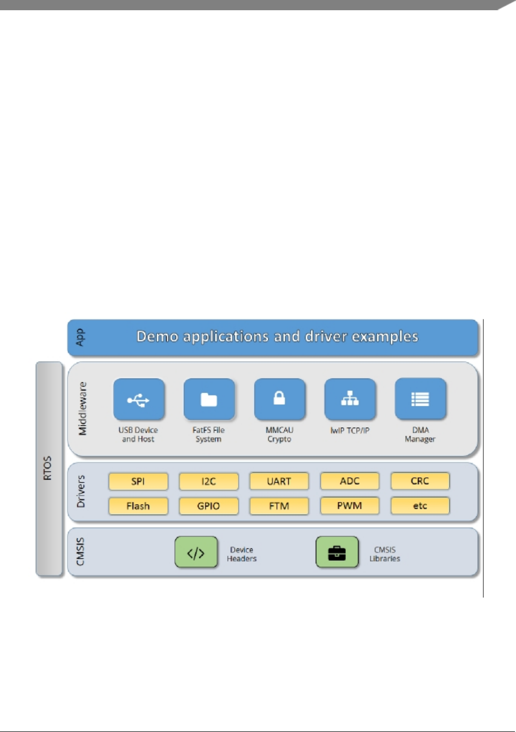
Chapter 3
Architectural Overview
This chapter provides the architectural overview for the MCUXpresso Software Development Kit (MCU-
Xpresso SDK). It describes each layer within the architecture and its associated components.
Overview
The MCUXpresso SDK architecture consists of five key components listed below.
1. The Arm Cortex Microcontroller Software Interface Standard (CMSIS) CORE compliance device-
specific header files, SOC Header, and CMSIS math/DSP libraries.
2. Peripheral Drivers
3. Real-time Operating Systems (RTOS)
4. Stacks and Middleware that integrate with the MCUXpresso SDK
5. Demo Applications based on the MCUXpresso SDK
Figure 1: MCUXpresso SDK Block Diagram
MCU header files
Each supported MCU device in the MCUXpresso SDK has an overall System-on Chip (SoC) memory-
NXP Semiconductors
MCUXpresso SDK API Reference Manual
5

mapped header file. This header file contains the memory map and register base address for each peripheral
and the IRQ vector table with associated vector numbers. The overall SoC header file provides access to
the peripheral registers through pointers and predefined bit masks. In addition to the overall SoC memory-
mapped header file, the MCUXpresso SDK includes a feature header file for each device. The feature
header file allows NXP to deliver a single software driver for a given peripheral. The feature file ensures
that the driver is properly compiled for the target SOC.
CMSIS Support
Along with the SoC header files and peripheral extension header files, the MCUXpresso SDK also includes
common CMSIS header files for the Arm Cortex-M core and the math and DSP libraries from the latest
CMSIS release. The CMSIS DSP library source code is also included for reference.
MCUXpresso SDK Peripheral Drivers
The MCUXpresso SDK peripheral drivers mainly consist of low-level functional APIs for the MCU
product family on-chip peripherals and also of high-level transactional APIs for some bus drivers/DM-
A driver/eDMA driver to quickly enable the peripherals and perform transfers.
All MCUXpresso SDK peripheral drivers only depend on the CMSIS headers, device feature files, fsl_-
common.h, and fsl_clock.h files so that users can easily pull selected drivers and their dependencies into
projects. With the exception of the clock/power-relevant peripherals, each peripheral has its own driver.
Peripheral drivers handle the peripheral clock gating/ungating inside the drivers during initialization and
deinitialization respectively.
Low-level functional APIs provide common peripheral functionality, abstracting the hardware peripheral
register accesses into a set of stateless basic functional operations. These APIs primarily focus on the
control, configuration, and function of basic peripheral operations. The APIs hide the register access
details and various MCU peripheral instantiation differences so that the application can be abstracted from
the low-level hardware details. The API prototypes are intentionally similar to help ensure easy portability
across supported MCUXpresso SDK devices.
Transactional APIs provide a quick method for customers to utilize higher-level functionality of the pe-
ripherals. The transactional APIs utilize interrupts and perform asynchronous operations without user
intervention. Transactional APIs operate on high-level logic that requires data storage for internal oper-
ation context handling. However, the Peripheral Drivers do not allocate this memory space. Rather, the
user passes in the memory to the driver for internal driver operation. Transactional APIs ensure the NVIC
is enabled properly inside the drivers. The transactional APIs do not meet all customer needs, but provide
a baseline for development of custom user APIs.
Note that the transactional drivers never disable an NVIC after use. This is due to the shared nature of
interrupt vectors on devices. It is up to the user to ensure that NVIC interrupts are properly disabled after
usage is complete.
Interrupt handling for transactional APIs
A double weak mechanism is introduced for drivers with transactional API. The double weak indicates
two levels of weak vector entries. See the examples below:
PUBWEAK SPI0_IRQHandler
PUBWEAK SPI0_DriverIRQHandler
SPI0_IRQHandler
6
MCUXpresso SDK API Reference Manual
NXP Semiconductors

LDR R0, =SPI0_DriverIRQHandler
BX R0
The first level of the weak implementation are the functions defined in the vector table. In the devices/<-
DEVICE_NAME>/<TOOLCHAIN>/startup_<DEVICE_NAME>.s/.S file, the implementation of the
first layer weak function calls the second layer of weak function. The implementation of the second
layer weak function (ex. SPI0_DriverIRQHandler) jumps to itself (B .). The MCUXpresso SDK drivers
with transactional APIs provide the reimplementation of the second layer function inside of the peripheral
driver. If the MCUXpresso SDK drivers with transactional APIs are linked into the image, the SPI0_-
DriverIRQHandler is replaced with the function implemented in the MCUXpresso SDK SPI driver.
The reason for implementing the double weak functions is to provide a better user experience when using
the transactional APIs. For drivers with a transactional function, call the transactional APIs and the drivers
complete the interrupt-driven flow. Users are not required to redefine the vector entries out of the box. At
the same time, if users are not satisfied by the second layer weak function implemented in the MCU-
Xpresso SDK drivers, users can redefine the first layer weak function and implement their own interrupt
handler functions to suit their implementation.
The limitation of the double weak mechanism is that it cannot be used for peripherals that share the same
vector entry. For this use case, redefine the first layer weak function to enable the desired peripheral
interrupt functionality. For example, if the MCU’s UART0 and UART1 share the same vector entry,
redefine the UART0_UART1_IRQHandler according to the use case requirements.
Feature Header Files
The peripheral drivers are designed to be reusable regardless of the peripheral functional differences from
one MCU device to another. An overall Peripheral Feature Header File is provided for the MCUXpresso
SDK-supported MCU device to define the features or configuration differences for each sub-family device.
Application
See the Getting Started with MCUXpresso SDK document (MCUXSDKGSUG).
NXP Semiconductors
MCUXpresso SDK API Reference Manual
7

8
MCUXpresso SDK API Reference Manual
NXP Semiconductors

Chapter 4
Trademarks
Information in this document is provided solely to enable system and software implementers to use NXP
products. There are no express or implied copyright licenses granted hereunder to design or fabricate any
integrated circuits based on the information in this document.
How to Reach Us:
Home Page: nxp.com
Web Support: nxp.com/support
NXP makes no warranty, representation, or guarantee regarding the suitability of its products for any
particular purpose, nor does NXP assume any liability arising out of the application or use of any product
or circuit, and specifically disclaims any and all liability, including without limitation consequential or
incidental damages. “Typical” parameters that may be provided in NXP data sheets and/or specifications
can and do vary in different applications, and actual performance may vary over time. All operating
parameters, including “typicals,” must be validated for each customer application by customer’s technical
experts. NXP does not convey any license under its patent rights nor the rights of others. NXP sells
products pursuant to standard terms and conditions of sale, which can be found at the following address:
{http://www. nxp.com/SalesTermsandConditions}{nxp.-com/SalesTermsandConditions}.
NXP, the NXP logo, NXP SECURE CONNECTIONS FOR A SMARTER WORLD, COOLFLUX, EM-
BRACE, GREENCHIP, HITAG, I2C BUS, ICODE, JCOP, LIFE VIBES, MIFARE, MIFARE CLASSIC,
MIFARE DESFire, MIFARE PLUS, MIFARE FLEX, MANTIS, MIFARE ULTRALIGHT, MIFARE4M-
OBILE, MIGLO, NTAG, ROADLINK, SMARTLX, SMARTMX, STARPLUG, TOPFET, TRENCHM-
OS, UCODE, Freescale, the Freescale logo, AltiVec, C-5, CodeTEST, CodeWarrior, ColdFire, ColdFire+,
C-Ware, the Energy Efficient Solutions logo, Kinetis, Layerscape, MagniV, mobileGT, PEG, PowerQUI-
CC, Processor Expert, QorIQ, QorIQ Qonverge, Ready Play, SafeAssure, the SafeAssure logo, StarCore,
Symphony, VortiQa, Vybrid, Airfast, BeeKit, BeeStack, CoreNet, Flexis, MXC, Platform in a Package,
QUICC Engine, SMARTMOS, Tower, TurboLink, and UMEMS are trademarks of NXP B.V. All other
product or service names are the property of their respective owners. AMBA, Arm, Arm7, Arm7TD-
MI, Arm9, Arm11, Artisan, big.LITTLE, Cordio, CoreLink, CoreSight, Cortex, DesignStart, Dynam-
IQ, Jazelle, Keil, Mali, Mbed, Mbed Enabled, NEON, POP, RealView, SecurCore, Socrates, Thumb,
TrustZone, ULINK, ULINK2, ULINK-ME, ULINK-PLUS, ULINKpro, Vision, Versatile are trademarks
or registered trademarks of Arm Limited (or its subsidiaries) in the US and/or elsewhere. The related
technology may be protected by any or all of patents, copyrights, designs and trade secrets. All rights
reserved. Oracle and Java are registered trademarks of Oracle and/or its affiliates. The Power Architecture
and Power.org word marks and the Power and Power.org logos and related marks are trademarks and
service marks licensed by Power.org.
© 2018 NXP B.V.
NXP Semiconductors
MCUXpresso SDK API Reference Manual
9

10
MCUXpresso SDK API Reference Manual
NXP Semiconductors

Chapter 5
SPI: Serial Peripheral Interface
5.1 Overview
The MCUXpresso SDK provides a peripheral driver for the Serial Peripheral Interface (SPI) module of
MCUXpresso SDK devices.
SPI driver includes functional APIs and transactional APIs.
Functional APIs are feature/property target low level APIs. Functional APIs can be used for SPI initializa-
tion/configuration/operation for optimization/customization purpose. Using the functional API requires
the knowledge of the SPI peripheral and how to organize functional APIs to meet the application require-
ments. All functional API use the peripheral base address as the first parameter. SPI functional operation
groups provide the functional API set.
Transactional APIs are transaction target high level APIs. Transactional APIs can be used to enable the
peripheral and in the application if the code size and performance of transactional APIs satisfy the require-
ments. If the code size and performance are a critical requirement, see the transactional API implementa-
tion and write a custom code. All transactional APIs use the spi_handle_t as the first parameter. Initialize
the handle by calling the SPI_MasterTransferCreateHandle() or SPI_SlaveTransferCreateHandle() API.
Transactional APIs support asynchronous transfer. This means that the functions SPI_MasterTransferNon-
Blocking() and SPI_SlaveTransferNonBlocking() set up the interrupt for data transfer. When the transfer
completes, the upper layer is notified through a callback function with the kStatus_SPI_Idle status.
5.2 Typical use case
5.2.1 SPI master transfer using an interrupt method
#define BUFFER_LEN (64)
spi_master_handle_t spiHandle;
spi_master_config_t masterConfig;
spi_transfer_t xfer;
volatile bool isFinished = false;
const uint8_t sendData[BUFFER_LEN] = [......];
uint8_t receiveBuff[BUFFER_LEN];
void SPI_UserCallback(SPI_Type *base, spi_master_handle_t *handle, status_t status, void *userData)
{
isFinished = true;
}
void main(void)
{
//...
SPI_MasterGetDefaultConfig(&masterConfig);
SPI_MasterInit(SPI0, &masterConfig, srcClock_Hz);
SPI_MasterTransferCreateHandle(SPI0, &spiHandle, SPI_UserCallback, NULL);
NXP Semiconductors
MCUXpresso SDK API Reference Manual
11

Typical use case
// Prepare to send.
xfer.txData = sendData;
xfer.rxData = receiveBuff;
xfer.dataSize =sizeof(sendData);
// Send out.
SPI_MasterTransferNonBlocking(SPI0, &spiHandle, &xfer);
// Wait send finished.
while (!isFinished)
{
}
// ...
}
5.2.2 SPI Send/receive using a DMA method
#define BUFFER_LEN (64)
spi_dma_handle_t spiHandle;
dma_handle_t g_spiTxDmaHandle;
dma_handle_t g_spiRxDmaHandle;
spi_config_t masterConfig;
spi_transfer_t xfer;
volatile bool isFinished;
uint8_t sendData[BUFFER_LEN] = ...;
uint8_t receiveBuff[BUFFER_LEN];
void SPI_UserCallback(SPI_Type *base, spi_dma_handle_t *handle, status_t status, void *userData)
{
isFinished = true;
}
void main(void)
{
//...
// Initialize DMA peripheral
DMA_Init(DMA0);
// Initialize SPI peripheral
SPI_MasterGetDefaultConfig(&masterConfig);
masterConfig.sselNum = SPI_SSEL;
SPI_MasterInit(SPI0, &masterConfig, srcClock_Hz);
// Enable DMA channels connected to SPI0 Tx/SPI0 Rx request lines
DMA_EnableChannel(SPI0, SPI_MASTER_TX_CHANNEL);
DMA_EnableChannel(SPI0, SPI_MASTER_RX_CHANNEL);
// Set DMA channels priority
DMA_SetChannelPriority(SPI0, SPI_MASTER_TX_CHANNEL,
kDMA_ChannelPriority3);
DMA_SetChannelPriority(SPI0, SPI_MASTER_RX_CHANNEL,
kDMA_ChannelPriority2);
// Creates the DMA handle.
DMA_CreateHandle(&masterTxHandle, SPI0, SPI_MASTER_TX_CHANNEL);
DMA_CreateHandle(&masterRxHandle, SPI0, SPI_MASTER_RX_CHANNEL);
// Create SPI DMA handle
SPI_MasterTransferCreateHandleDMA(SPI0, spiHandle, SPI_UserCallback,
NULL, &g_spiTxDmaHandle, &g_spiRxDmaHandle);
12
MCUXpresso SDK API Reference Manual
NXP Semiconductors

Typical use case
// Prepares to send.
xfer.txData = sendData;
xfer.rxData = receiveBuff;
xfer.dataSize =sizeof(sendData);
// Sends out.
SPI_MasterTransferDMA(SPI0, &spiHandle, &xfer);
// Waits for send to complete.
while (!isFinished)
{
}
// ...
}
Modules
•SPI CMSIS driver
•SPI DMA Driver
•SPI FreeRTOS driver
NXP Semiconductors
MCUXpresso SDK API Reference Manual
13

SPI CMSIS driver
5.3 SPI CMSIS driver
5.3.1 Overview
This section describes the programming interface of the SPI Cortex Microcontroller Software Interface
Standard (CMSIS) driver. And this driver defines generic peripheral driver interfaces for middleware
making it reusable across a wide range of supported microcontroller devices. The API connects mi-
crocontroller peripherals with middleware that implements for example communication stacks, file sys-
tems, or graphic user interfaces. More information and usage methord see http://www.keil.-
com/pack/doc/cmsis/Driver/html/index.html.
5.3.2 Function groups
5.3.2.1 SPI CMSIS GetVersion Operation
This function group will return the SPI CMSIS Driver version to user.
5.3.2.2 SPI CMSIS GetCapabilities Operation
This function group will return the capabilities of this driver.
5.3.2.3 SPI CMSIS Initialize and Uninitialize Operation
This function will initialize and uninitialize the instance in master mode or slave mode. And this API
must be called before you configure an instance or after you Deinit an instance.The right steps to start
an instance is that you must initialize the instance which been slected firstly,then you can power on the
instance.After these all have been done,you can configure the instance by using control operation.If you
want to Uninitialize the instance, you must power off the instance first.
5.3.2.4 SPI CMSIS Transfer Operation
This function group controls the transfer, master send/receive data, and slave send/receive data.
5.3.2.5 SPI CMSIS Status Operation
This function group gets the SPI transfer status.
5.3.2.6 SPI CMSIS Control Operation
This function can configure instance as master mode or slave mode, set baudrate for master mode transfer,
get current baudrate of master mode transfer,set transfer data bits and other control command.
14
MCUXpresso SDK API Reference Manual
NXP Semiconductors

SPI CMSIS driver
5.3.3 Typical use case
5.3.3.1 Master Operation
/*Variables */
uint8_t masterRxData[TRANSFER_SIZE] = {0U};
uint8_t masterTxData[TRANSFER_SIZE] = {0U};
/*SPI master init*/
DRIVER_MASTER_SPI.Initialize(SPI_MasterSignalEvent_t);
DRIVER_MASTER_SPI.PowerControl(ARM_POWER_FULL);
DRIVER_MASTER_SPI.Control(ARM_SPI_MODE_MASTER, TRANSFER_BAUDRATE);
/*Start master transfer */
DRIVER_MASTER_SPI.Transfer(masterTxData, masterRxData, TRANSFER_SIZE);
/*Master power off */
DRIVER_MASTER_SPI.PowerControl(ARM_POWER_OFF);
/*Master uninitialize */
DRIVER_MASTER_SPI.Uninitialize();
5.3.3.2 Slave Operation
/*Variables */
uint8_t slaveRxData[TRANSFER_SIZE] = {0U};
uint8_t slaveTxData[TRANSFER_SIZE] = {0U};
/*SPI slave init*/
DRIVER_SLAVE_SPI.Initialize(SPI_SlaveSignalEvent_t);
DRIVER_SLAVE_SPI.PowerControl(ARM_POWER_FULL);
DRIVER_SLAVE_SPI.Control(ARM_SPI_MODE_SLAVE, false);
/*Start slave transfer */
DRIVER_SLAVE_SPI.Transfer(slaveTxData, slaveRxData, TRANSFER_SIZE);
/*slave power off */
DRIVER_SLAVE_SPI.PowerControl(ARM_POWER_OFF);
/*slave uninitialize */
DRIVER_SLAVE_SPI.Uninitialize();
This section describes the programming interface of the SPI DMA driver.
Files
• file fsl_spi.h
Data Structures
• struct spi_delay_config_t
SPI delay time configure structure. More...
• struct spi_master_config_t
SPI master user configure structure. More...
• struct spi_slave_config_t
NXP Semiconductors
MCUXpresso SDK API Reference Manual
15

SPI CMSIS driver
SPI slave user configure structure. More...
• struct spi_transfer_t
SPI transfer structure. More...
• struct spi_half_duplex_transfer_t
SPI half-duplex(master only) transfer structure. More...
• struct spi_config_t
Internal configuration structure used in ’spi’ and ’spi_dma’ driver. More...
• struct spi_master_handle_t
SPI transfer handle structure. More...
Macros
• #define SPI_DUMMYDATA (0xFFU)
SPI dummy transfer data, the data is sent while txBuff is NULL.
Typedefs
• typedef spi_master_handle_t spi_slave_handle_t
Slave handle type.
• typedef void(∗spi_master_callback_t )(SPI_Type ∗base, spi_master_handle_t ∗handle, status_t sta-
tus, void ∗userData)
SPI master callback for finished transmit.
• typedef void(∗spi_slave_callback_t )(SPI_Type ∗base, spi_slave_handle_t ∗handle, status_t status,
void ∗userData)
SPI slave callback for finished transmit.
Enumerations
• enum spi_xfer_option_t {
kSPI_FrameDelay = (SPI_FIFOWR_EOF_MASK),
kSPI_FrameAssert = (SPI_FIFOWR_EOT_MASK) }
SPI transfer option.
• enum spi_shift_direction_t {
kSPI_MsbFirst = 0U,
kSPI_LsbFirst = 1U }
SPI data shifter direction options.
• enum spi_clock_polarity_t {
kSPI_ClockPolarityActiveHigh = 0x0U,
kSPI_ClockPolarityActiveLow }
SPI clock polarity configuration.
• enum spi_clock_phase_t {
kSPI_ClockPhaseFirstEdge = 0x0U,
kSPI_ClockPhaseSecondEdge }
SPI clock phase configuration.
16
MCUXpresso SDK API Reference Manual
NXP Semiconductors

SPI CMSIS driver
• enum spi_txfifo_watermark_t {
kSPI_TxFifo0 = 0,
kSPI_TxFifo1 = 1,
kSPI_TxFifo2 = 2,
kSPI_TxFifo3 = 3,
kSPI_TxFifo4 = 4,
kSPI_TxFifo5 = 5,
kSPI_TxFifo6 = 6,
kSPI_TxFifo7 =7}
txFIFO watermark values
• enum spi_rxfifo_watermark_t {
kSPI_RxFifo1 = 0,
kSPI_RxFifo2 = 1,
kSPI_RxFifo3 = 2,
kSPI_RxFifo4 = 3,
kSPI_RxFifo5 = 4,
kSPI_RxFifo6 = 5,
kSPI_RxFifo7 = 6,
kSPI_RxFifo8 =7}
rxFIFO watermark values
• enum spi_data_width_t {
kSPI_Data4Bits = 3,
kSPI_Data5Bits = 4,
kSPI_Data6Bits = 5,
kSPI_Data7Bits = 6,
kSPI_Data8Bits = 7,
kSPI_Data9Bits = 8,
kSPI_Data10Bits = 9,
kSPI_Data11Bits = 10,
kSPI_Data12Bits = 11,
kSPI_Data13Bits = 12,
kSPI_Data14Bits = 13,
kSPI_Data15Bits = 14,
kSPI_Data16Bits = 15 }
Transfer data width.
• enum spi_ssel_t {
kSPI_Ssel0 = 0,
kSPI_Ssel1 = 1,
kSPI_Ssel2 = 2,
kSPI_Ssel3 =3}
Slave select.
• enum spi_spol_t
ssel polarity
• enum _spi_status {
NXP Semiconductors
MCUXpresso SDK API Reference Manual
17

SPI CMSIS driver
kStatus_SPI_Busy = MAKE_STATUS(kStatusGroup_LPC_SPI, 0),
kStatus_SPI_Idle = MAKE_STATUS(kStatusGroup_LPC_SPI, 1),
kStatus_SPI_Error = MAKE_STATUS(kStatusGroup_LPC_SPI, 2),
kStatus_SPI_BaudrateNotSupport }
SPI transfer status.
• enum _spi_interrupt_enable {
kSPI_RxLvlIrq = SPI_FIFOINTENSET_RXLVL_MASK,
kSPI_TxLvlIrq = SPI_FIFOINTENSET_TXLVL_MASK }
SPI interrupt sources.
• enum _spi_statusflags {
kSPI_TxEmptyFlag = SPI_FIFOSTAT_TXEMPTY_MASK,
kSPI_TxNotFullFlag = SPI_FIFOSTAT_TXNOTFULL_MASK,
kSPI_RxNotEmptyFlag = SPI_FIFOSTAT_RXNOTEMPTY_MASK,
kSPI_RxFullFlag = SPI_FIFOSTAT_RXFULL_MASK }
SPI status flags.
Functions
• uint32_t SPI_GetInstance (SPI_Type ∗base)
Returns instance number for SPI peripheral base address.
Variables
• volatile uint8_t s_dummyData []
Global variable for dummy data value setting.
Driver version
• #define FSL_SPI_DRIVER_VERSION (MAKE_VERSION(2, 0, 2))
SPI driver version 2.0.2.
Initialization and deinitialization
• void SPI_MasterGetDefaultConfig (spi_master_config_t ∗config)
Sets the SPI master configuration structure to default values.
•status_t SPI_MasterInit (SPI_Type ∗base, const spi_master_config_t ∗config, uint32_t srcClock_-
Hz)
Initializes the SPI with master configuration.
• void SPI_SlaveGetDefaultConfig (spi_slave_config_t ∗config)
Sets the SPI slave configuration structure to default values.
•status_t SPI_SlaveInit (SPI_Type ∗base, const spi_slave_config_t ∗config)
Initializes the SPI with slave configuration.
• void SPI_Deinit (SPI_Type ∗base)
De-initializes the SPI.
18
MCUXpresso SDK API Reference Manual
NXP Semiconductors

SPI CMSIS driver
• static void SPI_Enable (SPI_Type ∗base, bool enable)
Enable or disable the SPI Master or Slave.
Status
• static uint32_t SPI_GetStatusFlags (SPI_Type ∗base)
Gets the status flag.
Interrupts
• static void SPI_EnableInterrupts (SPI_Type ∗base, uint32_t irqs)
Enables the interrupt for the SPI.
• static void SPI_DisableInterrupts (SPI_Type ∗base, uint32_t irqs)
Disables the interrupt for the SPI.
DMA Control
• void SPI_EnableTxDMA (SPI_Type ∗base, bool enable)
Enables the DMA request from SPI txFIFO.
• void SPI_EnableRxDMA (SPI_Type ∗base, bool enable)
Enables the DMA request from SPI rxFIFO.
Bus Operations
• void ∗SPI_GetConfig (SPI_Type ∗base)
Returns the configurations.
•status_t SPI_MasterSetBaud (SPI_Type ∗base, uint32_t baudrate_Bps, uint32_t srcClock_Hz)
Sets the baud rate for SPI transfer.
• void SPI_WriteData (SPI_Type ∗base, uint16_t data, uint32_t configFlags)
Writes a data into the SPI data register.
• static uint32_t SPI_ReadData (SPI_Type ∗base)
Gets a data from the SPI data register.
• static void SPI_SetTransferDelay (SPI_Type ∗base, const spi_delay_config_t ∗config)
Set delay time for transfer.
• void SPI_SetDummyData (SPI_Type ∗base, uint8_t dummyData)
Set up the dummy data.
Transactional
•status_t SPI_MasterTransferCreateHandle (SPI_Type ∗base, spi_master_handle_t ∗handle, spi_-
master_callback_t callback, void ∗userData)
Initializes the SPI master handle.
•status_t SPI_MasterTransferBlocking (SPI_Type ∗base, spi_transfer_t ∗xfer)
Transfers a block of data using a polling method.
NXP Semiconductors
MCUXpresso SDK API Reference Manual
19

SPI CMSIS driver
•status_t SPI_MasterTransferNonBlocking (SPI_Type ∗base, spi_master_handle_t ∗handle, spi_-
transfer_t ∗xfer)
Performs a non-blocking SPI interrupt transfer.
•status_t SPI_MasterHalfDuplexTransferBlocking (SPI_Type ∗base, spi_half_duplex_transfer_t
∗xfer)
Transfers a block of data using a polling method.
•status_t SPI_MasterHalfDuplexTransferNonBlocking (SPI_Type ∗base, spi_master_handle_t
∗handle, spi_half_duplex_transfer_t ∗xfer)
Performs a non-blocking SPI interrupt transfer.
•status_t SPI_MasterTransferGetCount (SPI_Type ∗base, spi_master_handle_t ∗handle, size_t
∗count)
Gets the master transfer count.
• void SPI_MasterTransferAbort (SPI_Type ∗base, spi_master_handle_t ∗handle)
SPI master aborts a transfer using an interrupt.
• void SPI_MasterTransferHandleIRQ (SPI_Type ∗base, spi_master_handle_t ∗handle)
Interrupts the handler for the SPI.
• static status_t SPI_SlaveTransferCreateHandle (SPI_Type ∗base, spi_slave_handle_t ∗handle, spi_-
slave_callback_t callback, void ∗userData)
Initializes the SPI slave handle.
• static status_t SPI_SlaveTransferNonBlocking (SPI_Type ∗base, spi_slave_handle_t ∗handle, spi_-
transfer_t ∗xfer)
Performs a non-blocking SPI slave interrupt transfer.
• static status_t SPI_SlaveTransferGetCount (SPI_Type ∗base, spi_slave_handle_t ∗handle, size_t
∗count)
Gets the slave transfer count.
• static void SPI_SlaveTransferAbort (SPI_Type ∗base, spi_slave_handle_t ∗handle)
SPI slave aborts a transfer using an interrupt.
• static void SPI_SlaveTransferHandleIRQ (SPI_Type ∗base, spi_slave_handle_t ∗handle)
Interrupts a handler for the SPI slave.
5.3.4 Data Structure Documentation
5.3.4.1 struct spi_delay_config_t
Note: The DLY register controls several programmable delays related to SPI signalling, it stands for how
many SPI clock time will be inserted. The maxinun value of these delay time is 15.
Data Fields
• uint8_t preDelay
Delay between SSEL assertion and the beginning of transfer.
• uint8_t postDelay
Delay between the end of transfer and SSEL deassertion.
• uint8_t frameDelay
Delay between frame to frame.
• uint8_t transferDelay
Delay between transfer to transfer.
20
MCUXpresso SDK API Reference Manual
NXP Semiconductors

SPI CMSIS driver
5.3.4.1.0.1 Field Documentation
5.3.4.1.0.1.1 uint8_t spi_delay_config_t::preDelay
5.3.4.1.0.1.2 uint8_t spi_delay_config_t::postDelay
5.3.4.1.0.1.3 uint8_t spi_delay_config_t::frameDelay
5.3.4.1.0.1.4 uint8_t spi_delay_config_t::transferDelay
5.3.4.2 struct spi_master_config_t
Data Fields
• bool enableLoopback
Enable loopback for test purpose.
• bool enableMaster
Enable SPI at initialization time.
•spi_clock_polarity_t polarity
Clock polarity.
•spi_clock_phase_t phase
Clock phase.
•spi_shift_direction_t direction
MSB or LSB.
• uint32_t baudRate_Bps
Baud Rate for SPI in Hz.
•spi_data_width_t dataWidth
Width of the data.
•spi_ssel_t sselNum
Slave select number.
•spi_spol_t sselPol
Configure active CS polarity.
•spi_txfifo_watermark_t txWatermark
txFIFO watermark
•spi_rxfifo_watermark_t rxWatermark
rxFIFO watermark
•spi_delay_config_t delayConfig
Delay configuration.
5.3.4.2.0.2 Field Documentation
5.3.4.2.0.2.1 spi_delay_config_t spi_master_config_t::delayConfig
5.3.4.3 struct spi_slave_config_t
Data Fields
• bool enableSlave
Enable SPI at initialization time.
•spi_clock_polarity_t polarity
Clock polarity.
NXP Semiconductors
MCUXpresso SDK API Reference Manual
21

SPI CMSIS driver
•spi_clock_phase_t phase
Clock phase.
•spi_shift_direction_t direction
MSB or LSB.
•spi_data_width_t dataWidth
Width of the data.
•spi_spol_t sselPol
Configure active CS polarity.
•spi_txfifo_watermark_t txWatermark
txFIFO watermark
•spi_rxfifo_watermark_t rxWatermark
rxFIFO watermark
5.3.4.4 struct spi_transfer_t
Data Fields
• uint8_t ∗txData
Send buffer.
• uint8_t ∗rxData
Receive buffer.
• uint32_t configFlags
Additional option to control transfer, spi_xfer_option_t.
• size_t dataSize
Transfer bytes.
5.3.4.4.0.3 Field Documentation
5.3.4.4.0.3.1 uint32_t spi_transfer_t::configFlags
5.3.4.5 struct spi_half_duplex_transfer_t
Data Fields
• uint8_t ∗txData
Send buffer.
• uint8_t ∗rxData
Receive buffer.
• size_t txDataSize
Transfer bytes for transmit.
• size_t rxDataSize
Transfer bytes.
• uint32_t configFlags
Transfer configuration flags, spi_xfer_option_t.
• bool isPcsAssertInTransfer
If PCS pin keep assert between transmit and receive.
• bool isTransmitFirst
True for transmit first and false for receive first.
22
MCUXpresso SDK API Reference Manual
NXP Semiconductors

SPI CMSIS driver
5.3.4.5.0.4 Field Documentation
5.3.4.5.0.4.1 uint32_t spi_half_duplex_transfer_t::configFlags
5.3.4.5.0.4.2 bool spi_half_duplex_transfer_t::isPcsAssertInTransfer
true for assert and false for deassert.
5.3.4.5.0.4.3 bool spi_half_duplex_transfer_t::isTransmitFirst
5.3.4.6 struct spi_config_t
5.3.4.7 struct _spi_master_handle
Master handle type.
Data Fields
• uint8_t ∗volatile txData
Transfer buffer.
• uint8_t ∗volatile rxData
Receive buffer.
• volatile size_t txRemainingBytes
Number of data to be transmitted [in bytes].
• volatile size_t rxRemainingBytes
Number of data to be received [in bytes].
• volatile size_t toReceiveCount
Receive data remaining in bytes.
• size_t totalByteCount
A number of transfer bytes.
• volatile uint32_t state
SPI internal state.
•spi_master_callback_t callback
SPI callback.
• void ∗userData
Callback parameter.
• uint8_t dataWidth
Width of the data [Valid values: 1 to 16].
• uint8_t sselNum
Slave select number to be asserted when transferring data [Valid values: 0 to 3].
• uint32_t configFlags
Additional option to control transfer.
•spi_txfifo_watermark_t txWatermark
txFIFO watermark
•spi_rxfifo_watermark_t rxWatermark
rxFIFO watermark
NXP Semiconductors
MCUXpresso SDK API Reference Manual
23

SPI CMSIS driver
5.3.5 Macro Definition Documentation
5.3.5.1 #define FSL_SPI_DRIVER_VERSION (MAKE_VERSION(2, 0, 2))
5.3.5.2 #define SPI_DUMMYDATA (0xFFU)
5.3.6 Enumeration Type Documentation
5.3.6.1 enum spi_xfer_option_t
Enumerator
kSPI_FrameDelay A delay may be inserted, defined in the DLY register.
kSPI_FrameAssert SSEL will be deasserted at the end of a transfer.
5.3.6.2 enum spi_shift_direction_t
Enumerator
kSPI_MsbFirst Data transfers start with most significant bit.
kSPI_LsbFirst Data transfers start with least significant bit.
5.3.6.3 enum spi_clock_polarity_t
Enumerator
kSPI_ClockPolarityActiveHigh Active-high SPI clock (idles low).
kSPI_ClockPolarityActiveLow Active-low SPI clock (idles high).
5.3.6.4 enum spi_clock_phase_t
Enumerator
kSPI_ClockPhaseFirstEdge First edge on SCK occurs at the middle of the first cycle of a data
transfer.
kSPI_ClockPhaseSecondEdge First edge on SCK occurs at the start of the first cycle of a data
transfer.
5.3.6.5 enum spi_txfifo_watermark_t
Enumerator
kSPI_TxFifo0 SPI tx watermark is empty.
24
MCUXpresso SDK API Reference Manual
NXP Semiconductors

SPI CMSIS driver
kSPI_TxFifo1 SPI tx watermark at 1 item.
kSPI_TxFifo2 SPI tx watermark at 2 items.
kSPI_TxFifo3 SPI tx watermark at 3 items.
kSPI_TxFifo4 SPI tx watermark at 4 items.
kSPI_TxFifo5 SPI tx watermark at 5 items.
kSPI_TxFifo6 SPI tx watermark at 6 items.
kSPI_TxFifo7 SPI tx watermark at 7 items.
5.3.6.6 enum spi_rxfifo_watermark_t
Enumerator
kSPI_RxFifo1 SPI rx watermark at 1 item.
kSPI_RxFifo2 SPI rx watermark at 2 items.
kSPI_RxFifo3 SPI rx watermark at 3 items.
kSPI_RxFifo4 SPI rx watermark at 4 items.
kSPI_RxFifo5 SPI rx watermark at 5 items.
kSPI_RxFifo6 SPI rx watermark at 6 items.
kSPI_RxFifo7 SPI rx watermark at 7 items.
kSPI_RxFifo8 SPI rx watermark at 8 items.
5.3.6.7 enum spi_data_width_t
Enumerator
kSPI_Data4Bits 4 bits data width
kSPI_Data5Bits 5 bits data width
kSPI_Data6Bits 6 bits data width
kSPI_Data7Bits 7 bits data width
kSPI_Data8Bits 8 bits data width
kSPI_Data9Bits 9 bits data width
kSPI_Data10Bits 10 bits data width
kSPI_Data11Bits 11 bits data width
kSPI_Data12Bits 12 bits data width
kSPI_Data13Bits 13 bits data width
kSPI_Data14Bits 14 bits data width
kSPI_Data15Bits 15 bits data width
kSPI_Data16Bits 16 bits data width
5.3.6.8 enum spi_ssel_t
Enumerator
kSPI_Ssel0 Slave select 0.
NXP Semiconductors
MCUXpresso SDK API Reference Manual
25

SPI CMSIS driver
kSPI_Ssel1 Slave select 1.
kSPI_Ssel2 Slave select 2.
kSPI_Ssel3 Slave select 3.
5.3.6.9 enum _spi_status
Enumerator
kStatus_SPI_Busy SPI bus is busy.
kStatus_SPI_Idle SPI is idle.
kStatus_SPI_Error SPI error.
kStatus_SPI_BaudrateNotSupport Baudrate is not support in current clock source.
5.3.6.10 enum _spi_interrupt_enable
Enumerator
kSPI_RxLvlIrq Rx level interrupt.
kSPI_TxLvlIrq Tx level interrupt.
5.3.6.11 enum _spi_statusflags
Enumerator
kSPI_TxEmptyFlag txFifo is empty
kSPI_TxNotFullFlag txFifo is not full
kSPI_RxNotEmptyFlag rxFIFO is not empty
kSPI_RxFullFlag rxFIFO is full
5.3.7 Function Documentation
5.3.7.1 uint32_t SPI_GetInstance ( SPI_Type ∗base )
5.3.7.2 void SPI_MasterGetDefaultConfig ( spi_master_config_t ∗config )
The purpose of this API is to get the configuration structure initialized for use in SPI_MasterInit(). User
may use the initialized structure unchanged in SPI_MasterInit(), or modify some fields of the structure
before calling SPI_MasterInit(). After calling this API, the master is ready to transfer. Example:
spi_master_config_t config;
SPI_MasterGetDefaultConfig(&config);
26
MCUXpresso SDK API Reference Manual
NXP Semiconductors

SPI CMSIS driver
Parameters
config pointer to master config structure
5.3.7.3 status_t SPI_MasterInit ( SPI_Type ∗base, const spi_master_config_t ∗config,
uint32_t srcClock_Hz )
The configuration structure can be filled by user from scratch, or be set with default values by SPI_Master-
GetDefaultConfig(). After calling this API, the slave is ready to transfer. Example
spi_master_config_t config = {
.baudRate_Bps = 400000,
...
};
SPI_MasterInit(SPI0, &config);
Parameters
base SPI base pointer
config pointer to master configuration structure
srcClock_Hz Source clock frequency.
5.3.7.4 void SPI_SlaveGetDefaultConfig ( spi_slave_config_t ∗config )
The purpose of this API is to get the configuration structure initialized for use in SPI_SlaveInit(). Modify
some fields of the structure before calling SPI_SlaveInit(). Example:
spi_slave_config_t config;
SPI_SlaveGetDefaultConfig(&config);
Parameters
config pointer to slave configuration structure
5.3.7.5 status_t SPI_SlaveInit ( SPI_Type ∗base, const spi_slave_config_t ∗config )
The configuration structure can be filled by user from scratch or be set with default values by SPI_Slave-
GetDefaultConfig(). After calling this API, the slave is ready to transfer. Example
spi_slave_config_t config = {
.polarity = flexSPIClockPolarity_ActiveHigh;
.phase = flexSPIClockPhase_FirstEdge;
.direction = flexSPIMsbFirst;
...
};
SPI_SlaveInit(SPI0, &config);
NXP Semiconductors
MCUXpresso SDK API Reference Manual
27

SPI CMSIS driver
Parameters
base SPI base pointer
config pointer to slave configuration structure
5.3.7.6 void SPI_Deinit ( SPI_Type ∗base )
Calling this API resets the SPI module, gates the SPI clock. The SPI module can’t work unless calling the
SPI_MasterInit/SPI_SlaveInit to initialize module.
Parameters
base SPI base pointer
5.3.7.7 static void SPI_Enable ( SPI_Type ∗base, bool enable )[inline],[static]
Parameters
base SPI base pointer
enable or disable ( true = enable, false = disable)
5.3.7.8 static uint32_t SPI_GetStatusFlags ( SPI_Type ∗base )[inline],[static]
Parameters
base SPI base pointer
Returns
SPI Status, use status flag to AND _spi_statusflags could get the related status.
5.3.7.9 static void SPI_EnableInterrupts ( SPI_Type ∗base, uint32_t irqs )[inline],
[static]
28
MCUXpresso SDK API Reference Manual
NXP Semiconductors

SPI CMSIS driver
Parameters
base SPI base pointer
irqs SPI interrupt source. The parameter can be any combination of the following values:
• kSPI_RxLvlIrq
• kSPI_TxLvlIrq
5.3.7.10 static void SPI_DisableInterrupts ( SPI_Type ∗base, uint32_t irqs )[inline],
[static]
Parameters
base SPI base pointer
irqs SPI interrupt source. The parameter can be any combination of the following values:
• kSPI_RxLvlIrq
• kSPI_TxLvlIrq
5.3.7.11 void SPI_EnableTxDMA ( SPI_Type ∗base, bool enable )
Parameters
base SPI base pointer
enable True means enable DMA, false means disable DMA
5.3.7.12 void SPI_EnableRxDMA ( SPI_Type ∗base, bool enable )
Parameters
base SPI base pointer
enable True means enable DMA, false means disable DMA
5.3.7.13 void∗SPI_GetConfig ( SPI_Type ∗base )
NXP Semiconductors
MCUXpresso SDK API Reference Manual
29

SPI CMSIS driver
Parameters
base SPI peripheral address.
Returns
return configurations which contain datawidth and SSEL numbers. return data type is a pointer of
spi_config_t.
5.3.7.14 status_t SPI_MasterSetBaud ( SPI_Type ∗base, uint32_t baudrate_Bps, uint32_t
srcClock_Hz )
This is only used in master.
Parameters
base SPI base pointer
baudrate_Bps baud rate needed in Hz.
srcClock_Hz SPI source clock frequency in Hz.
5.3.7.15 void SPI_WriteData ( SPI_Type ∗base, uint16_t data, uint32_t configFlags )
Parameters
base SPI base pointer
data needs to be write.
configFlags transfer configuration options spi_xfer_option_t
5.3.7.16 static uint32_t SPI_ReadData ( SPI_Type ∗base )[inline],[static]
Parameters
base SPI base pointer
Returns
Data in the register.
30
MCUXpresso SDK API Reference Manual
NXP Semiconductors

SPI CMSIS driver
5.3.7.17 static void SPI_SetTransferDelay ( SPI_Type ∗base, const spi_delay_config_t ∗
config )[inline],[static]
the delay uint is SPI clock time, maximum value is 0xF.
Parameters
base SPI base pointer
config configuration for delay option spi_delay_config_t.
5.3.7.18 void SPI_SetDummyData ( SPI_Type ∗base, uint8_t dummyData )
Parameters
base SPI peripheral address.
dummyData Data to be transferred when tx buffer is NULL.
5.3.7.19 status_t SPI_MasterTransferCreateHandle ( SPI_Type ∗base,
spi_master_handle_t ∗handle, spi_master_callback_t callback, void ∗userData
)
This function initializes the SPI master handle which can be used for other SPI master transactional APIs.
Usually, for a specified SPI instance, call this API once to get the initialized handle.
Parameters
base SPI peripheral base address.
handle SPI handle pointer.
callback Callback function.
userData User data.
5.3.7.20 status_t SPI_MasterTransferBlocking ( SPI_Type ∗base, spi_transfer_t ∗xfer )
Parameters
NXP Semiconductors
MCUXpresso SDK API Reference Manual
31

SPI CMSIS driver
base SPI base pointer
xfer pointer to spi_xfer_config_t structure
Return values
kStatus_Success Successfully start a transfer.
kStatus_InvalidArgument Input argument is invalid.
5.3.7.21 status_t SPI_MasterTransferNonBlocking ( SPI_Type ∗base,
spi_master_handle_t ∗handle, spi_transfer_t ∗xfer )
Parameters
base SPI peripheral base address.
handle pointer to spi_master_handle_t structure which stores the transfer state
xfer pointer to spi_xfer_config_t structure
Return values
kStatus_Success Successfully start a transfer.
kStatus_InvalidArgument Input argument is invalid.
kStatus_SPI_Busy SPI is not idle, is running another transfer.
5.3.7.22 status_t SPI_MasterHalfDuplexTransferBlocking ( SPI_Type ∗base,
spi_half_duplex_transfer_t ∗xfer )
This function will do a half-duplex transfer for SPI master, This is a blocking function, which does not
retuen until all transfer have been completed. And data transfer mechanism is half-duplex, users can set
transmit first or receive first.
Parameters
base SPI base pointer
xfer pointer to spi_half_duplex_transfer_t structure
Returns
status of status_t.
32
MCUXpresso SDK API Reference Manual
NXP Semiconductors

SPI CMSIS driver
5.3.7.23 status_t SPI_MasterHalfDuplexTransferNonBlocking ( SPI_Type ∗base,
spi_master_handle_t ∗handle, spi_half_duplex_transfer_t ∗xfer )
This function using polling way to do the first half transimission and using interrupts to do the second half
transimission, the transfer mechanism is half-duplex. When do the second half transimission, code will
return right away. When all data is transferred, the callback function is called.
Parameters
base SPI peripheral base address.
handle pointer to spi_master_handle_t structure which stores the transfer state
xfer pointer to spi_half_duplex_transfer_t structure
Returns
status of status_t.
5.3.7.24 status_t SPI_MasterTransferGetCount ( SPI_Type ∗base, spi_master_handle_t ∗
handle, size_t ∗count )
This function gets the master transfer count.
Parameters
base SPI peripheral base address.
handle Pointer to the spi_master_handle_t structure which stores the transfer state.
count The number of bytes transferred by using the non-blocking transaction.
Returns
status of status_t.
5.3.7.25 void SPI_MasterTransferAbort ( SPI_Type ∗base, spi_master_handle_t ∗handle
)
This function aborts a transfer using an interrupt.
NXP Semiconductors
MCUXpresso SDK API Reference Manual
33

SPI CMSIS driver
Parameters
base SPI peripheral base address.
handle Pointer to the spi_master_handle_t structure which stores the transfer state.
5.3.7.26 void SPI_MasterTransferHandleIRQ ( SPI_Type ∗base, spi_master_handle_t ∗
handle )
Parameters
base SPI peripheral base address.
handle pointer to spi_master_handle_t structure which stores the transfer state.
5.3.7.27 static status_t SPI_SlaveTransferCreateHandle ( SPI_Type ∗base,
spi_slave_handle_t ∗handle, spi_slave_callback_t callback, void ∗userData )
[inline],[static]
This function initializes the SPI slave handle which can be used for other SPI slave transactional APIs.
Usually, for a specified SPI instance, call this API once to get the initialized handle.
Parameters
base SPI peripheral base address.
handle SPI handle pointer.
callback Callback function.
userData User data.
5.3.7.28 static status_t SPI_SlaveTransferNonBlocking ( SPI_Type ∗base,
spi_slave_handle_t ∗handle, spi_transfer_t ∗xfer )[inline],[static]
Note
The API returns immediately after the transfer initialization is finished.
Parameters
34
MCUXpresso SDK API Reference Manual
NXP Semiconductors

SPI CMSIS driver
base SPI peripheral base address.
handle pointer to spi_master_handle_t structure which stores the transfer state
xfer pointer to spi_xfer_config_t structure
Return values
kStatus_Success Successfully start a transfer.
kStatus_InvalidArgument Input argument is invalid.
kStatus_SPI_Busy SPI is not idle, is running another transfer.
5.3.7.29 static status_t SPI_SlaveTransferGetCount ( SPI_Type ∗base, spi_slave_handle_t
∗handle, size_t ∗count )[inline],[static]
This function gets the slave transfer count.
Parameters
base SPI peripheral base address.
handle Pointer to the spi_master_handle_t structure which stores the transfer state.
count The number of bytes transferred by using the non-blocking transaction.
Returns
status of status_t.
5.3.7.30 static void SPI_SlaveTransferAbort ( SPI_Type ∗base, spi_slave_handle_t ∗
handle )[inline],[static]
This function aborts a transfer using an interrupt.
Parameters
base SPI peripheral base address.
handle Pointer to the spi_slave_handle_t structure which stores the transfer state.
5.3.7.31 static void SPI_SlaveTransferHandleIRQ ( SPI_Type ∗base, spi_slave_handle_t ∗
handle )[inline],[static]
NXP Semiconductors
MCUXpresso SDK API Reference Manual
35

SPI CMSIS driver
Parameters
base SPI peripheral base address.
handle pointer to spi_slave_handle_t structure which stores the transfer state
5.3.8 Variable Documentation
5.3.8.1 volatile uint8_t s_dummyData[]
36
MCUXpresso SDK API Reference Manual
NXP Semiconductors

Chapter 6
I2C: Inter-Integrated Circuit Driver
6.1 Overview
The MCUXpresso SDK provides a peripheral driver for the Inter-Integrated Circuit (I2C) module of MC-
UXpresso SDK devices.
The I2C driver includes functional APIs and transactional APIs.
Functional APIs are feature/property target low-level APIs. Functional APIs can be used for the I2C mas-
ter/slave initialization/configuration/operation for optimization/customization purpose. Using the func-
tional APIs requires the knowledge of the I2C master peripheral and how to organize functional APIs to
meet the application requirements. The I2C functional operation groups provide the functional APIs set.
Transactional APIs are transaction target high-level APIs. The transactional APIs can be used to enable
the peripheral quickly and also in the application if the code size and performance of transactional APIs
satisfy the requirements. If the code size and performance are critical requirements, see the transactional
API implementation and write custom code using the functional APIs or accessing the hardware registers.
Transactional APIs support asynchronous transfer. This means that the functions I2C_MasterTransfer-
NonBlocking() set up the interrupt non-blocking transfer. When the transfer completes, the upper layer is
notified through a callback function with the status.
6.2 Typical use case
6.2.1 Master Operation in functional method
i2c_master_config_t masterConfig;
uint8_t status;
status_t result = kStatus_Success;
uint8_t txBuff[BUFFER_SIZE];
/*Get default configuration for master. */
I2C_MasterGetDefaultConfig(&masterConfig);
/*Init I2C master. */
I2C_MasterInit(EXAMPLE_I2C_MASTER_BASEADDR, &masterConfig, I2C_MASTER_CLK);
/*Send start and slave address. */
I2C_MasterStart(EXAMPLE_I2C_MASTER_BASEADDR, 7-bit slave address,
kI2C_Write/kI2C_Read);
/*Wait address sent out. */
while(!((status = I2C_GetStatusFlag(EXAMPLE_I2C_MASTER_BASEADDR)) & kI2C_IntPendingFlag))
{
}
if(status & kI2C_ReceiveNakFlag)
{
return kStatus_I2C_Nak;
}
NXP Semiconductors
MCUXpresso SDK API Reference Manual
37

Typical use case
result = I2C_MasterWriteBlocking(EXAMPLE_I2C_MASTER_BASEADDR, txBuff, BUFFER_SIZE);
if(result)
{
/*If error occours, send STOP. */
I2C_MasterStop(EXAMPLE_I2C_MASTER_BASEADDR, kI2CStop);
return result;
}
while(!(I2C_GetStatusFlag(EXAMPLE_I2C_MASTER_BASEADDR) & kI2C_IntPendingFlag))
{
}
/*Wait all data sent out, send STOP. */
I2C_MasterStop(EXAMPLE_I2C_MASTER_BASEADDR, kI2CStop);
6.2.2 Master Operation in interrupt transactional method
i2c_master_handle_t g_m_handle;
volatile bool g_MasterCompletionFlag = false;
i2c_master_config_t masterConfig;
uint8_t status;
status_t result = kStatus_Success;
uint8_t txBuff[BUFFER_SIZE];
i2c_master_transfer_t masterXfer;
static void i2c_master_callback(I2C_Type *base, i2c_master_handle_t *handle,
status_t status, void *userData)
{
/*Signal transfer success when received success status. */
if (status == kStatus_Success)
{
g_MasterCompletionFlag = true;
}
}
/*Get default configuration for master. */
I2C_MasterGetDefaultConfig(&masterConfig);
/*Init I2C master. */
I2C_MasterInit(EXAMPLE_I2C_MASTER_BASEADDR, &masterConfig, I2C_MASTER_CLK);
masterXfer.slaveAddress = I2C_MASTER_SLAVE_ADDR_7BIT;
masterXfer.direction = kI2C_Write;
masterXfer.subaddress = NULL;
masterXfer.subaddressSize = 0;
masterXfer.data = txBuff;
masterXfer.dataSize = BUFFER_SIZE;
masterXfer.flags = kI2C_TransferDefaultFlag;
I2C_MasterTransferCreateHandle(EXAMPLE_I2C_MASTER_BASEADDR, &g_m_handle,
i2c_master_callback, NULL);
I2C_MasterTransferNonBlocking(EXAMPLE_I2C_MASTER_BASEADDR, &g_m_handle, &
masterXfer);
/*Wait for transfer completed. */
while (!g_MasterCompletionFlag)
{
}
g_MasterCompletionFlag = false;
38
MCUXpresso SDK API Reference Manual
NXP Semiconductors

Typical use case
6.2.3 Master Operation in DMA transactional method
i2c_master_dma_handle_t g_m_dma_handle;
dma_handle_t dmaHandle;
volatile bool g_MasterCompletionFlag = false;
i2c_master_config_t masterConfig;
uint8_t txBuff[BUFFER_SIZE];
i2c_master_transfer_t masterXfer;
static void i2c_master_callback(I2C_Type *base, i2c_master_dma_handle_t *handle,
status_t status, void *userData)
{
/*Signal transfer success when received success status. */
if (status == kStatus_Success)
{
g_MasterCompletionFlag = true;
}
}
/*Get default configuration for master. */
I2C_MasterGetDefaultConfig(&masterConfig);
/*Init I2C master. */
I2C_MasterInit(EXAMPLE_I2C_MASTER_BASEADDR, &masterConfig, I2C_MASTER_CLK);
masterXfer.slaveAddress = I2C_MASTER_SLAVE_ADDR_7BIT;
masterXfer.direction = kI2C_Write;
masterXfer.subaddress = NULL;
masterXfer.subaddressSize = 0;
masterXfer.data = txBuff;
masterXfer.dataSize = BUFFER_SIZE;
masterXfer.flags = kI2C_TransferDefaultFlag;
DMA_EnableChannel(EXAMPLE_DMA, EXAMPLE_I2C_MASTER_CHANNEL);
DMA_CreateHandle(&dmaHandle, EXAMPLE_DMA, EXAMPLE_I2C_MASTER_CHANNEL);
I2C_MasterTransferCreateHandleDMA(EXAMPLE_I2C_MASTER_BASEADDR, &
g_m_dma_handle, i2c_master_callback, NULL, &dmaHandle);
I2C_MasterTransferDMA(EXAMPLE_I2C_MASTER_BASEADDR, &g_m_dma_handle, &masterXfer);
/*Wait for transfer completed. */
while (!g_MasterCompletionFlag)
{
}
g_MasterCompletionFlag = false;
6.2.4 Slave Operation in functional method
i2c_slave_config_t slaveConfig;
uint8_t status;
status_t result = kStatus_Success;
I2C_SlaveGetDefaultConfig(&slaveConfig); /*default configuration 7-bit addressing
mode*/
slaveConfig.slaveAddr = 7-bit address
slaveConfig.addressingMode = kI2C_Address7bit/kI2C_RangeMatch;
I2C_SlaveInit(EXAMPLE_I2C_SLAVE_BASEADDR, &slaveConfig);
/*Wait address match. */
while(!((status = I2C_GetStatusFlag(EXAMPLE_I2C_SLAVE_BASEADDR)) & kI2C_AddressMatchFlag))
{
}
NXP Semiconductors
MCUXpresso SDK API Reference Manual
39

Typical use case
/*Slave transmit, master reading from slave. */
if (status & kI2C_TransferDirectionFlag)
{
result = I2C_SlaveWriteBlocking(EXAMPLE_I2C_SLAVE_BASEADDR);
}
else
{
I2C_SlaveReadBlocking(EXAMPLE_I2C_SLAVE_BASEADDR);
}
return result;
6.2.5 Slave Operation in interrupt transactional method
i2c_slave_config_t slaveConfig;
i2c_slave_handle_t g_s_handle;
volatile bool g_SlaveCompletionFlag = false;
static void i2c_slave_callback(I2C_Type *base, i2c_slave_transfer_t *xfer, void *
userData)
{
switch (xfer->event)
{
/*Transmit request */
case kI2C_SlaveTransmitEvent:
/*Update information for transmit process */
xfer->data = g_slave_buff;
xfer->dataSize = I2C_DATA_LENGTH;
break;
/*Receive request */
case kI2C_SlaveReceiveEvent:
/*Update information for received process */
xfer->data = g_slave_buff;
xfer->dataSize = I2C_DATA_LENGTH;
break;
/*Transfer done */
case kI2C_SlaveCompletionEvent:
g_SlaveCompletionFlag = true;
break;
default:
g_SlaveCompletionFlag = true;
break;
}
}
I2C_SlaveGetDefaultConfig(&slaveConfig); /*default configuration 7-bit addressing
mode*/
slaveConfig.slaveAddr = 7-bit address
slaveConfig.addressingMode = kI2C_Address7bit/kI2C_RangeMatch;
I2C_SlaveInit(EXAMPLE_I2C_SLAVE_BASEADDR, &slaveConfig);
I2C_SlaveTransferCreateHandle(EXAMPLE_I2C_SLAVE_BASEADDR, &g_s_handle,
i2c_slave_callback, NULL);
I2C_SlaveTransferNonBlocking(EXAMPLE_I2C_SLAVE_BASEADDR, &g_s_handle,
kI2C_SlaveCompletionEvent);
/*Wait for transfer completed. */
while (!g_SlaveCompletionFlag)
{
}
40
MCUXpresso SDK API Reference Manual
NXP Semiconductors


I2C CMSIS Driver
6.3 I2C CMSIS Driver
This chapter describes the programming interface of the I2C Cortex Microcontroller Software Interface
Standard (CMSIS) driver. And this driver defines generic peripheral driver interfaces for middleware
making it reusable across a wide range of supported microcontroller devices. The API connects mi-
crocontroller peripherals with middleware that implements for example communication stacks, file sys-
tems, or graphic user interfaces. More information and usage methord see http://www.keil.-
com/pack/doc/cmsis/Driver/html/index.html.
The I2C CMSIS driver includes transactional APIs.
Transactional APIs are transaction target high-level APIs. The transactional APIs can be used to enable
the peripheral quickly and also in the application if the code size and performance of transactional APIs
satisfy the requirements. If the code size and performance are critical requirements, see the transactional
API implementation and write custom code accessing the hardware registers.
void I2C_MasterSignalEvent_t(uint32_t event)
{
if (event == ARM_I2C_EVENT_TRANSFER_DONE)
{
g_MasterCompletionFlag = true;
}
}
/*Init I2C MASTER*/
EXAMPLE_I2C_MASTER.Initialize(I2C_MasterSignalEvent_t);
EXAMPLE_I2C_MASTER.PowerControl(ARM_POWER_FULL);
/*config transmit speed*/
EXAMPLE_I2C_MASTER.Control(ARM_I2C_BUS_SPEED, ARM_I2C_BUS_SPEED_STANDARD);
/*start transmit*/
EXAMPLE_I2C_MASTER.MasterTransmit(I2C_MASTER_SLAVE_ADDR, g_master_buff, I2C_DATA_LENGTH, false);
/*Wait for transfer completed. */
while (!g_MasterCompletionFlag)
{
}
g_MasterCompletionFlag = false;
void I2C_MasterSignalEvent_t(uint32_t event)
{
/*Transfer done */
if (event == ARM_I2C_EVENT_TRANSFER_DONE)
{
g_MasterCompletionFlag = true;
}
}
/*Init DMA*/
DMA_Init(EXAMPLE_DMA);
/*Init I2C MASTER*/
EXAMPLE_I2C_MASTER.Initialize(I2C_MasterSignalEvent_t);
EXAMPLE_I2C_MASTER.PowerControl(ARM_POWER_FULL);
/*config transmit speed*/
EXAMPLE_I2C_MASTER.Control(ARM_I2C_BUS_SPEED, ARM_I2C_BUS_SPEED_STANDARD);
/*start transfer*/
EXAMPLE_I2C_MASTER.MasterReceive(I2C_MASTER_SLAVE_ADDR, g_master_buff, I2C_DATA_LENGTH, false);
42
MCUXpresso SDK API Reference Manual
NXP Semiconductors

I2C CMSIS Driver
/*Wait for transfer completed. */
while (!g_MasterCompletionFlag)
{
}
g_MasterCompletionFlag = false;
void I2C_SlaveSignalEvent_t(uint32_t event)
{
/*Transfer done */
if (event == ARM_I2C_EVENT_TRANSFER_DONE)
{
g_SlaveCompletionFlag = true;
}
}
/*Init I2C SLAVE*/
EXAMPLE_I2C_SLAVE.Initialize(I2C_SlaveSignalEvent_t);
EXAMPLE_I2C_SLAVE.PowerControl(ARM_POWER_FULL);
/*config slave addr*/
EXAMPLE_I2C_SLAVE.Control(ARM_I2C_OWN_ADDRESS, I2C_MASTER_SLAVE_ADDR);
/*start transfer*/
EXAMPLE_I2C_SLAVE.SlaveReceive(g_slave_buff, I2C_DATA_LENGTH);
/*Wait for transfer completed. */
while (!g_SlaveCompletionFlag)
{
}
g_SlaveCompletionFlag = false;
NXP Semiconductors
MCUXpresso SDK API Reference Manual
43

I2C CMSIS Driver
44
MCUXpresso SDK API Reference Manual
NXP Semiconductors

Chapter 7
USART: Universal Synchronous/Asynchronous Receiver/Transmitter
Driver
7.1 Overview
The MCUXpresso SDK provides a peripheral UART driver for the Universal Synchronous Receiver/-
Transmitter (USART) module of MCUXpresso SDK devices. Driver does not support synchronous mode.
The USART driver includes two parts: functional APIs and transactional APIs.
Functional APIs are used for USART initialization/configuration/operation for optimization/customization
purpose. Using the functional API requires the knowledge of the USART peripheral and know how to
organize functional APIs to meet the application requirements. All functional API use the peripheral base
address as the first parameter. USART functional operation groups provide the functional APIs set.
Transactional APIs can be used to enable the peripheral quickly and in the application if the code size
and performance of transactional APIs can satisfy the requirements. If the code size and performance are
critical requirements, see the transactional API implementation and write custom code. All transactional
APIs use the usart_handle_t as the second parameter. Initialize the handle by calling the USART_Transfer-
CreateHandle() API.
Transactional APIs support asynchronous transfer, which means that the functions USART_TransferSend-
NonBlocking() and USART_TransferReceiveNonBlocking() set up an interrupt for data transfer. When
the transfer completes, the upper layer is notified through a callback function with the kStatus_USART_-
TxIdle and kStatus_USART_RxIdle.
Transactional receive APIs support the ring buffer. Prepare the memory for the ring buffer and pass in
the start address and size while calling the USART_TransferCreateHandle(). If passing NULL, the ring
buffer feature is disabled. When the ring buffer is enabled, the received data is saved to the ring buffer in
the background. The USART_TransferReceiveNonBlocking() function first gets data from the ring buffer.
If the ring buffer does not have enough data, the function first returns the data in the ring buffer and then
saves the received data to user memory. When all data is received, the upper layer is informed through a
callback with the kStatus_USART_RxIdle.
If the receive ring buffer is full, the upper layer is informed through a callback with the kStatus_USAR-
T_RxRingBufferOverrun. In the callback function, the upper layer reads data out from the ring buffer. If
not, the oldest data is overwritten by the new data.
The ring buffer size is specified when creating the handle. Note that one byte is reserved for the ring buffer
maintenance. When creating handle using the following code:
USART_TransferCreateHandle(USART0, &handle, USART_UserCallback, NULL);
In this example, the buffer size is 32, but only 31 bytes are used for saving data.
NXP Semiconductors
MCUXpresso SDK API Reference Manual
45

Typical use case
7.2 Typical use case
7.2.1 USART Send/receive using a polling method
uint8_t ch;
USART_GetDefaultConfig(&user_config);
user_config.baudRate_Bps = 115200U;
user_config.enableTx =true;
user_config.enableRx =true;
USART_Init(USART1,&user_config,120000000U);
while(1)
{
USART_ReadBlocking(USART1, &ch, 1);
USART_WriteBlocking(USART1, &ch, 1);
}
7.2.2 USART Send using an interrupt method
usart_handle_t g_usartHandle;
usart_config_t user_config;
usart_transfer_t sendXfer;
usart_transfer_t receiveXfer;
volatile bool txFinished;
volatile bool rxFinished;
uint8_t sendData[] = [’H’,’e’,’l’,’l’,’o’];
uint8_t receiveData[32];
void USART_UserCallback(usart_handle_t *handle, status_t status, void *userData)
{
userData = userData;
if (kStatus_USART_TxIdle == status)
{
txFinished = true;
}
if (kStatus_USART_RxIdle == status)
{
rxFinished = true;
}
}
void main(void)
{
//...
USART_GetDefaultConfig(&user_config);
user_config.baudRate_Bps = 115200U;
user_config.enableTx =true;
user_config.enableRx =true;
USART_Init(USART1, &user_config, 120000000U);
USART_TransferCreateHandle(USART1, &g_usartHandle, USART_UserCallback, NULL);
// Prepare to send.
sendXfer.data = sendData
sendXfer.dataSize =sizeof(sendData);
txFinished = false;
// Send out.
USART_TransferSendNonBlocking(USART1, &g_usartHandle, &sendXfer);
46
MCUXpresso SDK API Reference Manual
NXP Semiconductors

Typical use case
// Wait send finished.
while (!txFinished)
{
}
// Prepare to receive.
receiveXfer.data = receiveData;
receiveXfer.dataSize =sizeof(receiveData);
rxFinished = false;
// Receive.
USART_TransferReceiveNonBlocking(USART1, &g_usartHandle, &receiveXfer,
NULL);
// Wait receive finished.
while (!rxFinished)
{
}
// ...
}
7.2.3 USART Receive using the ringbuffer feature
#define RING_BUFFER_SIZE 64
#define RX_DATA_SIZE 32
usart_handle_t g_usartHandle;
usart_config_t user_config;
usart_transfer_t sendXfer;
usart_transfer_t receiveXfer;
volatile bool txFinished;
volatile bool rxFinished;
uint8_t receiveData[RX_DATA_SIZE];
uint8_t ringBuffer[RING_BUFFER_SIZE];
void USART_UserCallback(usart_handle_t *handle, status_t status, void *userData)
{
userData = userData;
if (kStatus_USART_RxIdle == status)
{
rxFinished = true;
}
}
void main(void)
{
size_t bytesRead;
//...
USART_GetDefaultConfig(&user_config);
user_config.baudRate_Bps = 115200U;
user_config.enableTx =true;
user_config.enableRx =true;
USART_Init(USART1, &user_config, 120000000U);
USART_TransferCreateHandle(USART1, &g_usartHandle, USART_UserCallback, NULL);
USART_TransferStartRingBuffer(USART1, &g_usartHandle, ringBuffer,
RING_BUFFER_SIZE);
// Now the RX is working in background, receive in to ring buffer.
// Prepare to receive.
receiveXfer.data = receiveData;
receiveXfer.dataSize =sizeof(receiveData);
NXP Semiconductors
MCUXpresso SDK API Reference Manual
47

Typical use case
rxFinished = false;
// Receive.
USART_TransferReceiveNonBlocking(USART1, &g_usartHandle, &receiveXfer);
if (bytesRead = RX_DATA_SIZE) /*Have read enough data. */
{
;
}
else
{
if (bytesRead) /*Received some data, process first. */
{
;
}
// Wait receive finished.
while (!rxFinished)
{
}
}
// ...
}
7.2.4 USART Send using the DMA method
usart_handle_t g_usartHandle;
dma_handle_t g_usartTxDmaHandle;
dma_handle_t g_usartRxDmaHandle;
usart_config_t user_config;
usart_transfer_t sendXfer;
usart_transfer_t receiveXfer;
volatile bool txFinished;
volatile bool rxFinished;
uint8_t sendData[] = [’H’,’e’,’l’,’l’,’o’];
uint8_t receiveData[32];
void USART_UserCallback(usart_handle_t *handle, status_t status, void *userData)
{
userData = userData;
if (kStatus_USART_TxIdle == status)
{
txFinished = true;
}
if (kStatus_USART_RxIdle == status)
{
rxFinished = true;
}
}
void main(void)
{
//...
USART_GetDefaultConfig(&user_config);
user_config.baudRate_Bps = 115200U;
user_config.enableTx =true;
user_config.enableRx =true;
USART_Init(USART1, &user_config, 120000000U);
// Set up the DMA
48
MCUXpresso SDK API Reference Manual
NXP Semiconductors

Typical use case
DMA_Init(DMA0);
DMA_EnableChannel(DMA0, USART_TX_DMA_CHANNEL);
DMA_EnableChannel(DMA0, USART_RX_DMA_CHANNEL);
DMA_CreateHandle(&g_usartTxDmaHandle, DMA0, USART_TX_DMA_CHANNEL);
DMA_CreateHandle(&g_usartRxDmaHandle, DMA0, USART_RX_DMA_CHANNEL);
USART_TransferCreateHandleDMA(USART1, &g_usartHandle, USART_UserCallback,
NULL, &g_usartTxDmaHandle, &g_usartRxDmaHandle);
// Prepare to send.
sendXfer.data = sendData
sendXfer.dataSize =sizeof(sendData);
txFinished = false;
// Send out.
USART_TransferSendDMA(USART1, &g_usartHandle, &sendXfer);
// Wait send finished.
while (!txFinished)
{
}
// Prepare to receive.
receiveXfer.data = receiveData;
receiveXfer.dataSize =sizeof(receiveData);
rxFinished = false;
// Receive.
USART_TransferReceiveDMA(USART1, &g_usartHandle, &receiveXfer);
// Wait receive finished.
while (!rxFinished)
{
}
// ...
}
Modules
•USART CMSIS Driver
•USART DMA Driver
•USART Driver
•USART FreeRTOS Driver
NXP Semiconductors
MCUXpresso SDK API Reference Manual
49

USART CMSIS Driver
7.3 USART CMSIS Driver
This chapter describes the programming interface of the USART Cortex Microcontroller Software Inter-
face Standard (CMSIS) driver. And this driver defines generic peripheral driver interfaces for middle-
ware making it reusable across a wide range of supported microcontroller devices. The API connects
microcontroller peripherals with middleware that implements for example communication stacks, file
systems, or graphic user interfaces. More information and usage methord see http://www.keil.-
com/pack/doc/cmsis/Driver/html/index.html.
The USART driver includes transactional APIs.
Transactional APIs can be used to enable the peripheral quickly and in the application if the code size
and performance of transactional APIs can satisfy the requirements. If the code size and performance are
critical requirements please write custom code.
/*USART callback */
void USART_Callback(uint32_t event)
{
if (event == ARM_USART_EVENT_SEND_COMPLETE)
{
txOnGoing = false;
}
}
Driver_USART0.Initialize(USART_Callback);
Driver_USART0.PowerControl(ARM_POWER_FULL);
/*Send g_tipString out. */
txOnGoing = true;
Driver_USART0.Send(g_tipString, sizeof(g_tipString) - 1);
/*Wait send finished */
while (txOnGoing)
{
}
/*USART callback */
void USART_Callback(uint32_t event)
{
if (event == ARM_USART_EVENT_SEND_COMPLETE)
{
txOnGoing = false;
}
}
Driver_USART0.Initialize(USART_Callback);
DMA_Init(DMA0);
Driver_USART0.PowerControl(ARM_POWER_FULL);
/*Send g_tipString out. */
txOnGoing = true;
Driver_USART0.Send(g_tipString, sizeof(g_tipString) - 1);
/*Wait send finished */
while (txOnGoing)
{
}
50
MCUXpresso SDK API Reference Manual
NXP Semiconductors

Chapter 8
CASPER: The Cryptographic Accelerator and Signal Processing
Engine with RAM sharing
8.1 Overview
The MCUXpresso SDK provides a peripheral driver for the Cryptographic Accelerator and Signal Pro-
cessing Engine with RAM sharing (CASPER) module of MCUXpresso SDK devices. The CASPER
peripheral provides acceleration of asymmetric cryptographic algorithms as well as optionally of certain
signal processing algorithms. The cryptographic acceleration is normally used in conjunction with pure-
hardware blocks for hashing and symmetric cryptography, thereby providing performance and energy
efficiency for a range of cryptographic uses.
Blocking synchronous APIs are provided for selected cryptographic algorithms using CASPER hardware.
The driver interface intends to be easily integrated with generic software crypto libraries such as mbedTLS
or wolfSSL. The CASPER operations are complete (and results are made availabe for further usage) when
a function returns. When called, these functions do not return until an CASPER operation is complete.
These functions use main CPU for simple polling loops to determine operation complete or error status and
also for plaintext or ciphertext data movements. The driver functions are not re-entrant. These functions
provide typical interface to upper layer or application software.
8.2 CASPER Driver Initialization and deinitialization
CASPER Driver is initialized by calling the CASPER_Init() function, it resets the CASPER module and
enables it’s clock. CASPER Driver is deinitialized by calling the CASPER_Deinit() function, it disables
CASPER module clock.
8.3 Comments about API usage in RTOS
CASPER operations provided by this driver are not re-entrant. Thus, application software shall ensure
the CASPER module operation is not requested from different tasks or interrupt service routines while an
operation is in progress.
8.4 Comments about API usage in interrupt handler
All APIs shall not be used from interrupt handler as global variables are used.
8.5 CASPER Driver Examples
8.5.1 Simple examples
Refer to the driver examples codes located at <SDK_ROOT>/boards/<BOARD>/driver_examples/casper/
NXP Semiconductors
MCUXpresso SDK API Reference Manual
51


casper_driver
8.6 casper_driver
8.6.1 Overview
Enumerations
• enum casper_operation_t { ,
kCASPER_OpMul6464Sum,
kCASPER_OpMul6464FullSum,
kCASPER_OpMul6464Reduce,
kCASPER_OpAdd64 = 0x08,
kCASPER_OpSub64 = 0x09,
kCASPER_OpDouble64 = 0x0A,
kCASPER_OpXor64 = 0x0B,
kCASPER_OpShiftLeft32,
kCASPER_OpShiftRight32 = 0x11,
kCASPER_OpCopy = 0x14,
kCASPER_OpRemask = 0x15,
kCASPER_OpCompare = 0x16,
kCASPER_OpCompareFast = 0x17 }
CASPER operation.
Functions
• void CASPER_Init (CASPER_Type ∗base)
Enables clock and disables reset for CASPER peripheral.
• void CASPER_Deinit (CASPER_Type ∗base)
Disables clock for CASPER peripheral.
Driver version
• #define FSL_CASPER_DRIVER_VERSION (MAKE_VERSION(2, 0, 0))
CASPER driver version.
8.6.2 Macro Definition Documentation
8.6.2.1 #define FSL_CASPER_DRIVER_VERSION (MAKE_VERSION(2, 0, 0))
Version 2.0.0.
Current version: 2.0.0
Change log:
• Version 2.0.0
NXP Semiconductors
MCUXpresso SDK API Reference Manual
53

casper_driver
–Initial version
8.6.3 Enumeration Type Documentation
8.6.3.1 enum casper_operation_t
Enumerator
kCASPER_OpMul6464Sum Walking 1 or more of J loop, doing r=a∗b using 64x64=128.
kCASPER_OpMul6464FullSum Walking 1 or more of J loop, doing c,r=r+a∗b using 64x64=128,
but assume inner j loop.
kCASPER_OpMul6464Reduce Walking 1 or more of J loop, doing c,r=r+a∗b using 64x64=128, but
sum all of w.
kCASPER_OpAdd64 Walking 1 or more of J loop, doing c,r[-1]=r+a∗b using 64x64=128, but skip
1st write.
kCASPER_OpSub64 Walking add with off_AB, and in/out off_RES doing c,r=r+a+c using
64+64=65.
kCASPER_OpDouble64 Walking subtract with off_AB, and in/out off_RES doing r=r-a uding 64-
64=64, with last borrow implicit if any.
kCASPER_OpXor64 Walking add to self with off_RES doing c,r=r+r+c using 64+64=65.
kCASPER_OpShiftLeft32 Walking XOR with off_AB, and in/out off_RES doing r=r∧a using
64∧64=64.
kCASPER_OpShiftRight32 Walking shift left doing r1,r=(b∗D)|r1, where D is 2∧amt and is loaded
by app (off_CD not used)
kCASPER_OpCopy Walking shift right doing r,r1=(b∗D)|r1, where D is 2∧(32-amt) and is loaded
by app (off_CD not used) and off_RES starts at MSW.
kCASPER_OpRemask Copy from ABoff to resoff, 64b at a time.
kCASPER_OpCompare Copy and mask from ABoff to resoff, 64b at a time.
kCASPER_OpCompareFast Compare two arrays, running all the way to the end.
8.6.4 Function Documentation
8.6.4.1 void CASPER_Init ( CASPER_Type ∗base )
Enable clock and disable reset for CASPER.
Parameters
base CASPER base address
8.6.4.2 void CASPER_Deinit ( CASPER_Type ∗base )
Disable clock and enable reset.
54
MCUXpresso SDK API Reference Manual
NXP Semiconductors

casper_driver
Parameters
base CASPER base address
NXP Semiconductors
MCUXpresso SDK API Reference Manual
55

casper_driver_pkha
8.7 casper_driver_pkha
8.7.1 Overview
Functions
• void CASPER_ModExp (CASPER_Type ∗base, const uint8_t ∗signature, const uint8_t ∗pubN,
size_t wordLen, uint32_t pubE, uint8_t ∗plaintext)
Performs modular exponentiation - (A∧E) mod N.
• void CASPER_ECC_SECP256R1_Mul (CASPER_Type ∗base, uint32_t resX[8], uint32_t resY[8],
uint32_t X[8], uint32_t Y[8], uint32_t scalar[8])
Performs ECC secp256r1 point single scalar multiplication.
• void CASPER_ECC_SECP256R1_MulAdd (CASPER_Type ∗base, uint32_t resX[8], uint32_t res-
Y[8], uint32_t X1[8], uint32_t Y1[8], uint32_t scalar1[8], uint32_t X2[8], uint32_t Y2[8], uint32_t
scalar2[8])
Performs ECC secp256r1 point double scalar multiplication.
• void CASPER_ECC_SECP384R1_Mul (CASPER_Type ∗base, uint32_t resX[12], uint32_t res-
Y[12], uint32_t X[12], uint32_t Y[12], uint32_t scalar[12])
Performs ECC secp384r1 point single scalar multiplication.
• void CASPER_ECC_SECP384R1_MulAdd (CASPER_Type ∗base, uint32_t resX[12], uint32_-
t resY[12], uint32_t X1[12], uint32_t Y1[12], uint32_t scalar1[12], uint32_t X2[12], uint32_t
Y2[12], uint32_t scalar2[12])
Performs ECC secp384r1 point double scalar multiplication.
8.7.2 Function Documentation
8.7.2.1 void CASPER_ModExp ( CASPER_Type ∗base, const uint8_t ∗signature, const
uint8_t ∗pubN, size_t wordLen, uint32_t pubE, uint8_t ∗plaintext )
This function performs modular exponentiation.
Parameters
base CASPER base address
signature first addend (in little endian format)
pubN modulus (in little endian format)
wordLen Size of pubN in bytes
pubE exponent
56
MCUXpresso SDK API Reference Manual
NXP Semiconductors

casper_driver_pkha
out plaintext Output array to store result of operation (in little endian format)
8.7.2.2 void CASPER_ECC_SECP256R1_Mul ( CASPER_Type ∗base, uint32_t resX[8],
uint32_t resY[8], uint32_t X[8], uint32_t Y[8], uint32_t scalar[8] )
This function performs ECC secp256r1 point single scalar multiplication [resX; resY] = scalar ∗[X; Y]
Coordinates are affine in normal form, little endian. Scalars are little endian. All arrays are little endian
byte arrays, uint32_t type is used only to enforce the 32-bit alignment (0-mod-4 address).
Parameters
base CASPER base address
out resX Output X affine coordinate in normal form, little endian.
out resY Output Y affine coordinate in normal form, little endian.
XInput X affine coordinate in normal form, little endian.
YInput Y affine coordinate in normal form, little endian.
scalar Input scalar integer, in normal form, little endian.
8.7.2.3 void CASPER_ECC_SECP256R1_MulAdd ( CASPER_Type ∗base, uint32_t
resX[8], uint32_t resY[8], uint32_t X1[8], uint32_t Y1[8], uint32_t scalar1[8],
uint32_t X2[8], uint32_t Y2[8], uint32_t scalar2[8] )
This function performs ECC secp256r1 point double scalar multiplication [resX; resY] = scalar1 ∗[X1;
Y1] + scalar2 ∗[X2; Y2] Coordinates are affine in normal form, little endian. Scalars are little endian. All
arrays are little endian byte arrays, uint32_t type is used only to enforce the 32-bit alignment (0-mod-4
address).
Parameters
base CASPER base address
out resX Output X affine coordinate.
out resY Output Y affine coordinate.
X1 Input X1 affine coordinate.
NXP Semiconductors
MCUXpresso SDK API Reference Manual
57

casper_driver_pkha
Y1 Input Y1 affine coordinate.
scalar1 Input scalar1 integer.
X2 Input X2 affine coordinate.
Y2 Input Y2 affine coordinate.
scalar2 Input scalar2 integer.
8.7.2.4 void CASPER_ECC_SECP384R1_Mul ( CASPER_Type ∗base, uint32_t resX[12],
uint32_t resY[12], uint32_t X[12], uint32_t Y[12], uint32_t scalar[12] )
This function performs ECC secp384r1 point single scalar multiplication [resX; resY] = scalar ∗[X; Y]
Coordinates are affine in normal form, little endian. Scalars are little endian. All arrays are little endian
byte arrays, uint32_t type is used only to enforce the 32-bit alignment (0-mod-4 address).
Parameters
base CASPER base address
out resX Output X affine coordinate in normal form, little endian.
out resY Output Y affine coordinate in normal form, little endian.
XInput X affine coordinate in normal form, little endian.
YInput Y affine coordinate in normal form, little endian.
scalar Input scalar integer, in normal form, little endian.
8.7.2.5 void CASPER_ECC_SECP384R1_MulAdd ( CASPER_Type ∗base, uint32_t
resX[12], uint32_t resY[12], uint32_t X1[12], uint32_t Y1[12], uint32_t scalar1[12],
uint32_t X2[12], uint32_t Y2[12], uint32_t scalar2[12] )
This function performs ECC secp384r1 point double scalar multiplication [resX; resY] = scalar1 ∗[X1;
Y1] + scalar2 ∗[X2; Y2] Coordinates are affine in normal form, little endian. Scalars are little endian. All
arrays are little endian byte arrays, uint32_t type is used only to enforce the 32-bit alignment (0-mod-4
address).
Parameters
base CASPER base address
58
MCUXpresso SDK API Reference Manual
NXP Semiconductors

casper_driver_pkha
out resX Output X affine coordinate.
out resY Output Y affine coordinate.
X1 Input X1 affine coordinate.
Y1 Input Y1 affine coordinate.
scalar1 Input scalar1 integer.
X2 Input X2 affine coordinate.
Y2 Input Y2 affine coordinate.
scalar2 Input scalar2 integer.
NXP Semiconductors
MCUXpresso SDK API Reference Manual
59

casper_driver_pkha
60
MCUXpresso SDK API Reference Manual
NXP Semiconductors

Chapter 9
Clock Driver
9.1 Overview
The MCUXpresso SDK provides APIs for MCUXpresso SDK devices’ clock operation.
Files
• file fsl_clock.h
Data Structures
• struct pll_config_t
PLL configuration structure. More...
• struct pll_setup_t
PLL0 setup structure This structure can be used to pre-build a PLL setup configuration at run-time and
quickly set the PLL to the configuration. More...
Macros
• #define FSL_SDK_DISABLE_DRIVER_CLOCK_CONTROL 0
Configure whether driver controls clock.
• #define CLOCK_USR_CFG_PLL_CONFIG_CACHE_COUNT 2U
User-defined the size of cache for CLOCK_PllGetConfig() function.
• #define ROM_CLOCKS
Clock ip name array for ROM.
• #define SRAM_CLOCKS
Clock ip name array for SRAM.
• #define FLASH_CLOCKS
Clock ip name array for FLASH.
• #define FMC_CLOCKS
Clock ip name array for FMC.
• #define INPUTMUX_CLOCKS
Clock ip name array for INPUTMUX.
• #define IOCON_CLOCKS
Clock ip name array for IOCON.
• #define GPIO_CLOCKS
Clock ip name array for GPIO.
• #define PINT_CLOCKS
Clock ip name array for PINT.
• #define GINT_CLOCKS
Clock ip name array for GINT.
• #define DMA_CLOCKS
Clock ip name array for DMA.
• #define CRC_CLOCKS
Clock ip name array for CRC.
NXP Semiconductors
MCUXpresso SDK API Reference Manual
61

Overview
• #define WWDT_CLOCKS
Clock ip name array for WWDT.
• #define RTC_CLOCKS
Clock ip name array for RTC.
• #define MAILBOX_CLOCKS
Clock ip name array for Mailbox.
• #define LPADC_CLOCKS
Clock ip name array for LPADC.
• #define MRT_CLOCKS
Clock ip name array for MRT.
• #define OSTIMER_CLOCKS
Clock ip name array for OSTIMER.
• #define SCT_CLOCKS
Clock ip name array for SCT0.
• #define SCTIPU_CLOCKS
Clock ip name array for SCTIPU.
• #define UTICK_CLOCKS
Clock ip name array for UTICK.
• #define FLEXCOMM_CLOCKS
Clock ip name array for FLEXCOMM.
• #define LPUART_CLOCKS
Clock ip name array for LPUART.
• #define BI2C_CLOCKS
Clock ip name array for BI2C.
• #define LPSPI_CLOCKS
Clock ip name array for LSPI.
• #define FLEXI2S_CLOCKS
Clock ip name array for FLEXI2S.
• #define USBTYPC_CLOCKS
Clock ip name array for USBTYPC.
• #define CTIMER_CLOCKS
Clock ip name array for CTIMER.
• #define PVT_CLOCKS
Clock ip name array for PVT.
• #define EZHA_CLOCKS
Clock ip name array for EZHA.
• #define EZHB_CLOCKS
Clock ip name array for EZHB.
• #define COMP_CLOCKS
Clock ip name array for COMP.
• #define SDIO_CLOCKS
Clock ip name array for SDIO.
• #define USB1CLK_CLOCKS
Clock ip name array for USB1CLK.
• #define FREQME_CLOCKS
Clock ip name array for FREQME.
• #define USBRAM_CLOCKS
Clock ip name array for USBRAM.
• #define OTP_CLOCKS
Clock ip name array for OTP.
• #define RNG_CLOCKS
62
MCUXpresso SDK API Reference Manual
NXP Semiconductors

Overview
Clock ip name array for RNG.
• #define USBHMR0_CLOCKS
Clock ip name array for USBHMR0.
• #define USBHSL0_CLOCKS
Clock ip name array for USBHSL0.
• #define HASHCRYPT_CLOCKS
Clock ip name array for HashCrypt.
• #define POWERQUAD_CLOCKS
Clock ip name array for PowerQuad.
• #define PLULUT_CLOCKS
Clock ip name array for PLULUT.
• #define PUF_CLOCKS
Clock ip name array for PUF.
• #define CASPER_CLOCKS
Clock ip name array for CASPER.
• #define ANALOGCTRL_CLOCKS
Clock ip name array for ANALOGCTRL.
• #define HS_LSPI_CLOCKS
Clock ip name array for HS_LSPI.
• #define GPIO_SEC_CLOCKS
Clock ip name array for GPIO_SEC.
• #define GPIO_SEC_INT_CLOCKS
Clock ip name array for GPIO_SEC_INT.
• #define USBD_CLOCKS
Clock ip name array for USBD.
• #define USBH_CLOCKS
Clock ip name array for USBH.
• #define CLK_GATE_REG_OFFSET_SHIFT 8U
Clock gate name used for CLOCK_EnableClock/CLOCK_DisableClock.
• #define BUS_CLK kCLOCK_BusClk
Peripherals clock source definition.
• #define CLK_ATTACH_ID(mux, sel, pos) (((mux << 0U) |((sel + 1) & 0xFU) << 8U) << (pos
∗12U))
Clock Mux Switches The encoding is as follows each connection identified is 32bits wide while 24bits are
valuable starting from LSB upwards.
• #define PLL_CONFIGFLAG_USEINRATE (1 << 0)
PLL configuration structure flags for ’flags’ field These flags control how the PLL configuration function
sets up the PLL setup structure.
• #define PLL_CONFIGFLAG_FORCENOFRACT (1 << 2)
Force non-fractional output mode, PLL output will not use the fractional, automatic bandwidth, or SS
hardware.
• #define PLL_SETUPFLAG_POWERUP (1 << 0)
PLL setup structure flags for ’flags’ field These flags control how the PLL setup function sets up the PLL.
• #define PLL_SETUPFLAG_WAITLOCK (1 << 1)
Setup will wait for PLL lock, implies the PLL will be pwoered on.
• #define PLL_SETUPFLAG_ADGVOLT (1 << 2)
Optimize system voltage for the new PLL rate.
• #define PLL_SETUPFLAG_USEFEEDBACKDIV2 (1 << 3)
Use feedback divider by 2 in divider path.
NXP Semiconductors
MCUXpresso SDK API Reference Manual
63

Overview
Enumerations
• enum clock_ip_name_t
Clock gate name used for CLOCK_EnableClock/CLOCK_DisableClock.
• enum clock_name_t {
kCLOCK_CoreSysClk,
kCLOCK_BusClk,
kCLOCK_ClockOut,
kCLOCK_FroHf,
kCLOCK_Adc,
kCLOCK_Usb0,
kCLOCK_Usb1,
kCLOCK_Pll1Out,
kCLOCK_Mclk,
kCLOCK_Sct,
kCLOCK_SDio,
kCLOCK_Fro12M,
kCLOCK_ExtClk,
kCLOCK_Pll0Out,
kCLOCK_WdtClk,
kCLOCK_FlexI2S,
kCLOCK_Flexcomm0,
kCLOCK_Flexcomm1,
kCLOCK_Flexcomm2,
kCLOCK_Flexcomm3,
kCLOCK_Flexcomm4,
kCLOCK_Flexcomm5,
kCLOCK_Flexcomm6,
kCLOCK_Flexcomm7,
kCLOCK_HsLspi,
kCLOCK_CTmier0,
kCLOCK_CTmier1,
kCLOCK_CTmier2,
kCLOCK_CTmier3,
kCLOCK_CTmier4,
kCLOCK_Systick0,
kCLOCK_Systick1 }
Clock name used to get clock frequency.
• enum ss_progmodfm_t {
kSS_MF_512 = (0 << 20),
kSS_MF_384 = (1 << 20),
kSS_MF_256 = (2 << 20),
kSS_MF_128 = (3 << 20),
kSS_MF_64 = (4 << 20),
kSS_MF_32 = (5 << 20),
kSS_MF_24 = (6 << 20),
64
MCUXpresso SDK API Reference Manual
NXP Semiconductors

Overview
kSS_MF_16 = (7 << 20) }
PLL Spread Spectrum (SS) Programmable modulation frequency See (MF) field in the PLL0SSCG1 regis-
ter in the UM.
• enum ss_progmoddp_t {
kSS_MR_K0 = (0 << 23),
kSS_MR_K1 = (1 << 23),
kSS_MR_K1_5 = (2 << 23),
kSS_MR_K2 = (3 << 23),
kSS_MR_K3 = (4 << 23),
kSS_MR_K4 = (5 << 23),
kSS_MR_K6 = (6 << 23),
kSS_MR_K8 = (7 << 23) }
PLL Spread Spectrum (SS) Programmable frequency modulation depth See (MR) field in the PLL0SSCG1
register in the UM.
• enum ss_modwvctrl_t {
kSS_MC_NOC = (0 << 26),
kSS_MC_RECC = (2 << 26),
kSS_MC_MAXC = (3 << 26) }
PLL Spread Spectrum (SS) Modulation waveform control See (MC) field in the PLL0SSCG1 register in the
UM.
• enum pll_error_t {
kStatus_PLL_Success = MAKE_STATUS(kStatusGroup_Generic, 0),
kStatus_PLL_OutputTooLow = MAKE_STATUS(kStatusGroup_Generic, 1),
kStatus_PLL_OutputTooHigh = MAKE_STATUS(kStatusGroup_Generic, 2),
kStatus_PLL_InputTooLow = MAKE_STATUS(kStatusGroup_Generic, 3),
kStatus_PLL_InputTooHigh = MAKE_STATUS(kStatusGroup_Generic, 4),
kStatus_PLL_OutsideIntLimit = MAKE_STATUS(kStatusGroup_Generic, 5),
kStatus_PLL_CCOTooLow = MAKE_STATUS(kStatusGroup_Generic, 6),
kStatus_PLL_CCOTooHigh = MAKE_STATUS(kStatusGroup_Generic, 7) }
PLL status definitions.
• enum clock_usbfs_src_t {
kCLOCK_UsbfsSrcFro = (uint32_t)kCLOCK_FroHf,
kCLOCK_UsbfsSrcPll0 = (uint32_t)kCLOCK_Pll0Out,
kCLOCK_UsbfsSrcMainClock = (uint32_t)kCLOCK_CoreSysClk,
kCLOCK_UsbfsSrcPll1 = (uint32_t)kCLOCK_Pll1Out,
kCLOCK_UsbfsSrcNone }
USB FS clock source definition.
• enum clock_usbhs_src_t {kCLOCK_UsbSrcUnused = 0xFFFFFFFFU }
USBhs clock source definition.
• enum clock_usb_phy_src_t {kCLOCK_UsbPhySrcExt = 0U }
Source of the USB HS PHY.
Functions
• static void CLOCK_EnableClock (clock_ip_name_t clk)
Enable the clock for specific IP.
• static void CLOCK_DisableClock (clock_ip_name_t clk)
NXP Semiconductors
MCUXpresso SDK API Reference Manual
65

Overview
Disable the clock for specific IP.
•status_t CLOCK_SetupFROClocking (uint32_t iFreq)
Initialize the Core clock to given frequency (12, 48 or 96 MHz). Turns on FRO and uses default CCO, if
freq is 12000000, then high speed output is off, else high speed output is enabled.
• void CLOCK_SetFLASHAccessCyclesForFreq (uint32_t iFreq)
Set the flash wait states for the input freuqency.
•status_t CLOCK_SetupExtClocking (uint32_t iFreq)
Initialize the external osc clock to given frequency.
•status_t CLOCK_SetupI2SMClkClocking (uint32_t iFreq)
Initialize the I2S MCLK clock to given frequency.
• void CLOCK_AttachClk (clock_attach_id_t connection)
Configure the clock selection muxes.
• clock_attach_id_t CLOCK_GetClockAttachId (clock_attach_id_t attachId)
Get the actual clock attach id. This fuction uses the offset in input attach id, then it reads the actual source
value in the register and combine the offset to obtain an actual attach id.
• void CLOCK_SetClkDiv (clock_div_name_t div_name, uint32_t divided_by_value, bool reset)
Setup peripheral clock dividers.
• void CLOCK_SetRtc1khzClkDiv (uint32_t divided_by_value)
Setup rtc 1khz clock divider.
• void CLOCK_SetRtc1hzClkDiv (uint32_t divided_by_value)
Setup rtc 1hz clock divider.
• uint32_t CLOCK_SetFlexCommClock (uint32_t id, uint32_t freq)
Set the flexcomm output frequency.
• uint32_t CLOCK_GetFlexCommInputClock (uint32_t id)
Return Frequency of flexcomm input clock.
• uint32_t CLOCK_GetFreq (clock_name_t clockName)
Return Frequency of selected clock.
• uint32_t CLOCK_GetFro12MFreq (void)
Return Frequency of FRO 12MHz.
• uint32_t CLOCK_GetFro1MFreq (void)
Return Frequency of FRO 1MHz.
• uint32_t CLOCK_GetClockOutClkFreq (void)
Return Frequency of ClockOut.
• uint32_t CLOCK_GetAdcClkFreq (void)
Return Frequency of Adc Clock.
• uint32_t CLOCK_GetUsb0ClkFreq (void)
Return Frequency of Usb0 Clock.
• uint32_t CLOCK_GetUsb1ClkFreq (void)
Return Frequency of Usb1 Clock.
• uint32_t CLOCK_GetMclkClkFreq (void)
Return Frequency of MClk Clock.
• uint32_t CLOCK_GetSctClkFreq (void)
Return Frequency of SCTimer Clock.
• uint32_t CLOCK_GetSdioClkFreq (void)
Return Frequency of SDIO Clock.
• uint32_t CLOCK_GetExtClkFreq (void)
Return Frequency of External Clock.
• uint32_t CLOCK_GetWdtClkFreq (void)
Return Frequency of Watchdog.
• uint32_t CLOCK_GetFroHfFreq (void)
Return Frequency of High-Freq output of FRO.
66
MCUXpresso SDK API Reference Manual
NXP Semiconductors

Overview
• uint32_t CLOCK_GetPll0OutFreq (void)
Return Frequency of PLL.
• uint32_t CLOCK_GetPll1OutFreq (void)
Return Frequency of USB PLL.
• uint32_t CLOCK_GetOsc32KFreq (void)
Return Frequency of 32kHz osc.
• uint32_t CLOCK_GetCoreSysClkFreq (void)
Return Frequency of Core System.
• uint32_t CLOCK_GetI2SMClkFreq (void)
Return Frequency of I2S MCLK Clock.
• uint32_t CLOCK_GetCTimerClkFreq (uint32_t id)
Return Frequency of CTimer functional Clock.
• uint32_t CLOCK_GetSystickClkFreq (uint32_t id)
Return Frequency of SystickClock.
• uint32_t CLOCK_GetPLL0InClockRate (void)
Return PLL0 input clock rate.
• uint32_t CLOCK_GetPLL1InClockRate (void)
Return PLL1 input clock rate.
• uint32_t CLOCK_GetPLL0OutClockRate (bool recompute)
Return PLL0 output clock rate.
• uint32_t CLOCK_GetPLL1OutClockRate (bool recompute)
Return PLL1 output clock rate.
• __STATIC_INLINE void CLOCK_SetBypassPLL0 (bool bypass)
Enables and disables PLL0 bypass mode.
• __STATIC_INLINE void CLOCK_SetBypassPLL1 (bool bypass)
Enables and disables PLL1 bypass mode.
• __STATIC_INLINE bool CLOCK_IsPLL0Locked (void)
Check if PLL is locked or not.
• __STATIC_INLINE bool CLOCK_IsPLL1Locked (void)
Check if PLL1 is locked or not.
• void CLOCK_SetStoredPLLClockRate (uint32_t rate)
Store the current PLL rate.
• uint32_t CLOCK_GetPLL0OutFromSetup (pll_setup_t ∗pSetup)
Return System PLL output clock rate from setup structure.
•pll_error_t CLOCK_SetupPLLData (pll_config_t ∗pControl, pll_setup_t ∗pSetup)
Set PLL output based on the passed PLL setup data.
•pll_error_t CLOCK_SetupPLL0Prec (pll_setup_t ∗pSetup, uint32_t flagcfg)
Set PLL output from PLL setup structure (precise frequency)
•pll_error_t CLOCK_SetPLL0Freq (const pll_setup_t ∗pSetup)
Set PLL output from PLL setup structure (precise frequency)
•pll_error_t CLOCK_SetPLL1Freq (const pll_setup_t ∗pSetup)
Set PLL output from PLL setup structure (precise frequency)
• void CLOCK_SetupPLL0Mult (uint32_t multiply_by, uint32_t input_freq)
Set PLL output based on the multiplier and input frequency.
• static void CLOCK_DisableUsbDevicefs0Clock (clock_ip_name_t clk)
Disable USB clock.
• bool CLOCK_EnableUsbfs0DeviceClock (clock_usbfs_src_t src, uint32_t freq)
Enable USB Device FS clock.
• bool CLOCK_EnableUsbfs0HostClock (clock_usbfs_src_t src, uint32_t freq)
Enable USB HOST FS clock.
• bool CLOCK_EnableUsbhs0PhyPllClock (clock_usb_phy_src_t src, uint32_t freq)
NXP Semiconductors
MCUXpresso SDK API Reference Manual
67

Data Structure Documentation
Enable USB phy clock.
• bool CLOCK_EnableUsbhs0DeviceClock (clock_usbhs_src_t src, uint32_t freq)
Enable USB Device HS clock.
• bool CLOCK_EnableUsbhs0HostClock (clock_usbhs_src_t src, uint32_t freq)
Enable USB HOST HS clock.
Driver version
• #define FSL_CLOCK_DRIVER_VERSION (MAKE_VERSION(2, 0, 3))
CLOCK driver version 2.0.3.
9.2 Data Structure Documentation
9.2.1 struct pll_config_t
This structure can be used to configure the settings for a PLL setup structure. Fill in the desired configu-
ration for the PLL and call the PLL setup function to fill in a PLL setup structure.
Data Fields
• uint32_t desiredRate
Desired PLL rate in Hz.
• uint32_t inputRate
PLL input clock in Hz, only used if PLL_CONFIGFLAG_USEINRATE flag is set.
• uint32_t flags
PLL configuration flags, Or’ed value of PLL_CONFIGFLAG_∗definitions.
•ss_progmodfm_t ss_mf
SS Programmable modulation frequency, only applicable when not using PLL_CONFIGFLAG_FORCE-
NOFRACT flag.
•ss_progmoddp_t ss_mr
SS Programmable frequency modulation depth, only applicable when not using PLL_CONFIGFLAG_F-
ORCENOFRACT flag.
•ss_modwvctrl_t ss_mc
SS Modulation waveform control, only applicable when not using PLL_CONFIGFLAG_FORCENOFRA-
CT flag.
• bool mfDither
false for fixed modulation frequency or true for dithering, only applicable when not using PLL_CONFIG-
FLAG_FORCENOFRACT flag
9.2.2 struct pll_setup_t
It can be populated with the PLL setup function. If powering up or waiting for PLL lock, the PLL input
clock source should be configured prior to PLL setup.
68
MCUXpresso SDK API Reference Manual
NXP Semiconductors

Macro Definition Documentation
Data Fields
• uint32_t pllctrl
PLL control register PLL0CTRL.
• uint32_t pllndec
PLL NDEC register PLL0NDEC.
• uint32_t pllpdec
PLL PDEC register PLL0PDEC.
• uint32_t pllmdec
PLL MDEC registers PLL0PDEC.
• uint32_t pllsscg [2]
PLL SSCTL registers PLL0SSCG.
• uint32_t pllRate
Acutal PLL rate.
• uint32_t flags
PLL setup flags, Or’ed value of PLL_SETUPFLAG_∗definitions.
9.3 Macro Definition Documentation
9.3.1 #define FSL_CLOCK_DRIVER_VERSION (MAKE_VERSION(2, 0, 3))
9.3.2 #define FSL_SDK_DISABLE_DRIVER_CLOCK_CONTROL 0
When set to 0, peripheral drivers will enable clock in initialize function and disable clock in de-initialize
function. When set to 1, peripheral driver will not control the clock, application could control the clock
out of the driver.
Note
All drivers share this feature switcher. If it is set to 1, application should handle clock enable and
disable for all drivers.
9.3.3 #define CLOCK_USR_CFG_PLL_CONFIG_CACHE_COUNT 2U
Once define this MACRO to be non-zero value, CLOCK_PllGetConfig() function would cache the recent
calulation and accelerate the execution to get the right settings.
9.3.4 #define ROM_CLOCKS
Value:
{\
kCLOCK_Rom \
}
NXP Semiconductors
MCUXpresso SDK API Reference Manual
69

Macro Definition Documentation
9.3.5 #define SRAM_CLOCKS
Value:
{\
kCLOCK_Sram1, kCLOCK_Sram2, kCLOCK_Sram3, kCLOCK_Sram4 \
}
9.3.6 #define FLASH_CLOCKS
Value:
{\
kCLOCK_Flash \
}
9.3.7 #define FMC_CLOCKS
Value:
{\
kCLOCK_Fmc \
}
9.3.8 #define INPUTMUX_CLOCKS
Value:
{\
kCLOCK_InputMux0, kCLOCK_InputMux1 \
}
9.3.9 #define IOCON_CLOCKS
Value:
{\
kCLOCK_Iocon \
}
70
MCUXpresso SDK API Reference Manual
NXP Semiconductors

Macro Definition Documentation
9.3.10 #define GPIO_CLOCKS
Value:
{\
kCLOCK_Gpio0, kCLOCK_Gpio1, kCLOCK_Gpio2, kCLOCK_Gpio3, kCLOCK_Gpio4, kCLOCK_Gpio5 \
}
9.3.11 #define PINT_CLOCKS
Value:
{\
kCLOCK_Pint \
}
9.3.12 #define GINT_CLOCKS
Value:
{\
kCLOCK_Gint \
}
9.3.13 #define DMA_CLOCKS
Value:
{\
kCLOCK_Dma0, kCLOCK_Dma1 \
}
9.3.14 #define CRC_CLOCKS
Value:
{\
kCLOCK_Crc \
}
NXP Semiconductors
MCUXpresso SDK API Reference Manual
71

Macro Definition Documentation
9.3.15 #define WWDT_CLOCKS
Value:
{\
kCLOCK_Wwdt \
}
9.3.16 #define RTC_CLOCKS
Value:
{\
kCLOCK_Rtc \
}
9.3.17 #define MAILBOX_CLOCKS
Value:
{\
kCLOCK_Mailbox \
}
9.3.18 #define LPADC_CLOCKS
Value:
{\
kCLOCK_Adc0 \
}
9.3.19 #define MRT_CLOCKS
Value:
{\
kCLOCK_Mrt \
}
72
MCUXpresso SDK API Reference Manual
NXP Semiconductors

Macro Definition Documentation
9.3.20 #define OSTIMER_CLOCKS
Value:
{\
kCLOCK_OsTimer0 \
}
9.3.21 #define SCT_CLOCKS
Value:
{\
kCLOCK_Sct0 \
}
9.3.22 #define SCTIPU_CLOCKS
Value:
{\
kCLOCK_Sctipu \
}
9.3.23 #define UTICK_CLOCKS
Value:
{\
kCLOCK_Utick0 \
}
9.3.24 #define FLEXCOMM_CLOCKS
Value:
{
\
kCLOCK_FlexComm0, kCLOCK_FlexComm1, kCLOCK_FlexComm2, kCLOCK_FlexComm3, kCLOCK_FlexComm4,
kCLOCK_FlexComm5, \
kCLOCK_FlexComm6, kCLOCK_FlexComm7, kCLOCK_Hs_Lspi
\
}
NXP Semiconductors
MCUXpresso SDK API Reference Manual
73

Macro Definition Documentation
9.3.25 #define LPUART_CLOCKS
Value:
{\
kCLOCK_MinUart0, kCLOCK_MinUart1, kCLOCK_MinUart2, kCLOCK_MinUart3, kCLOCK_MinUart4,
kCLOCK_MinUart5, \
kCLOCK_MinUart6, kCLOCK_MinUart7
\
}
9.3.26 #define BI2C_CLOCKS
Value:
{
\
kCLOCK_BI2c0, kCLOCK_BI2c1, kCLOCK_BI2c2, kCLOCK_BI2c3, kCLOCK_BI2c4, kCLOCK_BI2c5, kCLOCK_BI2c6,
kCLOCK_BI2c7 \
}
9.3.27 #define LPSPI_CLOCKS
Value:
{
\
kCLOCK_LSpi0, kCLOCK_LSpi1, kCLOCK_LSpi2, kCLOCK_LSpi3, kCLOCK_LSpi4, kCLOCK_LSpi5, kCLOCK_LSpi6,
kCLOCK_LSpi7 \
}
9.3.28 #define FLEXI2S_CLOCKS
Value:
{\
kCLOCK_FlexI2s0, kCLOCK_FlexI2s1, kCLOCK_FlexI2s2, kCLOCK_FlexI2s3, kCLOCK_FlexI2s4,
kCLOCK_FlexI2s5, \
kCLOCK_FlexI2s6, kCLOCK_FlexI2s7
\
}
74
MCUXpresso SDK API Reference Manual
NXP Semiconductors

Macro Definition Documentation
9.3.29 #define USBTYPC_CLOCKS
Value:
{\
kCLOCK_UsbTypc \
}
9.3.30 #define CTIMER_CLOCKS
Value:
{\
kCLOCK_Timer0, kCLOCK_Timer1, kCLOCK_Timer2, kCLOCK_Timer3, kCLOCK_Timer4 \
}
9.3.31 #define SDIO_CLOCKS
Value:
{\
kCLOCK_Sdio \
}
9.3.32 #define USB1CLK_CLOCKS
Value:
{\
kCLOCK_Usb1Clk \
}
9.3.33 #define FREQME_CLOCKS
Value:
{\
kCLOCK_Freqme \
}
NXP Semiconductors
MCUXpresso SDK API Reference Manual
75

Macro Definition Documentation
9.3.34 #define USBRAM_CLOCKS
Value:
{\
kCLOCK_UsbRam1 \
}
9.3.35 #define OTP_CLOCKS
Value:
{\
kCLOCK_Otp \
}
9.3.36 #define RNG_CLOCKS
Value:
{\
kCLOCK_Rng \
}
9.3.37 #define USBHMR0_CLOCKS
Value:
{\
kCLOCK_Usbhmr0 \
}
9.3.38 #define USBHSL0_CLOCKS
Value:
{\
kCLOCK_Usbhsl0 \
}
76
MCUXpresso SDK API Reference Manual
NXP Semiconductors

Macro Definition Documentation
9.3.39 #define HASHCRYPT_CLOCKS
Value:
{\
kCLOCK_HashCrypt \
}
9.3.40 #define POWERQUAD_CLOCKS
Value:
{\
kCLOCK_PowerQuad \
}
9.3.41 #define PLULUT_CLOCKS
Value:
{\
kCLOCK_PluLut \
}
9.3.42 #define PUF_CLOCKS
Value:
{\
kCLOCK_Puf \
}
9.3.43 #define CASPER_CLOCKS
Value:
{\
kCLOCK_Casper \
}
NXP Semiconductors
MCUXpresso SDK API Reference Manual
77

Macro Definition Documentation
9.3.44 #define ANALOGCTRL_CLOCKS
Value:
{\
kCLOCK_AnalogCtrl \
}
9.3.45 #define HS_LSPI_CLOCKS
Value:
{\
kCLOCK_Hs_Lspi \
}
9.3.46 #define GPIO_SEC_CLOCKS
Value:
{\
kCLOCK_Gpio_Sec \
}
9.3.47 #define GPIO_SEC_INT_CLOCKS
Value:
{\
kCLOCK_Gpio_Sec_Int \
}
9.3.48 #define USBD_CLOCKS
Value:
{\
kCLOCK_Usbd0, kCLOCK_Usbh1, kCLOCK_Usbd1 \
}
78
MCUXpresso SDK API Reference Manual
NXP Semiconductors

Enumeration Type Documentation
9.3.49 #define USBH_CLOCKS
Value:
{\
kCLOCK_Usbh1 \
}
9.3.50 #define CLK_GATE_REG_OFFSET_SHIFT 8U
9.3.51 #define BUS_CLK kCLOCK_BusClk
9.3.52 #define CLK_ATTACH_ID( mux, sel, pos ) (((mux << 0U) |((sel + 1) &
0xFU) << 8U) << (pos ∗12U))
[4 bits for choice, 0 means invalid choice] [8 bits mux ID]∗
9.3.53 #define PLL_CONFIGFLAG_USEINRATE (1 << 0)
When the PLL_CONFIGFLAG_USEINRATE flag is selected, the ’InputRate’ field in the configuration
structure must be assigned with the expected PLL frequency. If the PLL_CONFIGFLAG_USEINRATE
is not used, ’InputRate’ is ignored in the configuration function and the driver will determine the PLL rate
from the currently selected PLL source. This flag might be used to configure the PLL input clock more
accurately when using the WDT oscillator or a more dyanmic CLKIN source.
When the PLL_CONFIGFLAG_FORCENOFRACT flag is selected, the PLL hardware for the automatic
bandwidth selection, Spread Spectrum (SS) support, and fractional M-divider are not used.
Flag to use InputRate in PLL configuration structure for setup
9.3.54 #define PLL_SETUPFLAG_POWERUP (1 << 0)
Setup will power on the PLL after setup
9.4 Enumeration Type Documentation
9.4.1 enum clock_ip_name_t
9.4.2 enum clock_name_t
Enumerator
kCLOCK_CoreSysClk Core/system clock (aka MAIN_CLK)
NXP Semiconductors
MCUXpresso SDK API Reference Manual
79

Enumeration Type Documentation
kCLOCK_BusClk Bus clock (AHB clock)
kCLOCK_ClockOut CLOCKOUT.
kCLOCK_FroHf FRO48/96.
kCLOCK_Adc ADC.
kCLOCK_Usb0 USB0.
kCLOCK_Usb1 USB1.
kCLOCK_Pll1Out PLL1 Output.
kCLOCK_Mclk MCLK.
kCLOCK_Sct SCT.
kCLOCK_SDio SDIO.
kCLOCK_Fro12M FRO12M.
kCLOCK_ExtClk External Clock.
kCLOCK_Pll0Out PLL0 Output.
kCLOCK_WdtClk Watchdog clock.
kCLOCK_FlexI2S FlexI2S clock.
kCLOCK_Flexcomm0 Flexcomm0Clock.
kCLOCK_Flexcomm1 Flexcomm1Clock.
kCLOCK_Flexcomm2 Flexcomm2Clock.
kCLOCK_Flexcomm3 Flexcomm3Clock.
kCLOCK_Flexcomm4 Flexcomm4Clock.
kCLOCK_Flexcomm5 Flexcomm5Clock.
kCLOCK_Flexcomm6 Flexcomm6Clock.
kCLOCK_Flexcomm7 Flexcomm7Clock.
kCLOCK_HsLspi HS LPSPI Clock.
kCLOCK_CTmier0 CTmier0Clock.
kCLOCK_CTmier1 CTmier1Clock.
kCLOCK_CTmier2 CTmier2Clock.
kCLOCK_CTmier3 CTmier3Clock.
kCLOCK_CTmier4 CTmier4Clock.
kCLOCK_Systick0 System Tick 0 Clock.
kCLOCK_Systick1 System Tick 1 Clock.
9.4.3 enum ss_progmodfm_t
Enumerator
kSS_MF_512 Nss = 512 (fm ? 3.9 - 7.8 kHz)
kSS_MF_384 Nss ?= 384 (fm ? 5.2 - 10.4 kHz)
kSS_MF_256 Nss = 256 (fm ? 7.8 - 15.6 kHz)
kSS_MF_128 Nss = 128 (fm ? 15.6 - 31.3 kHz)
kSS_MF_64 Nss = 64 (fm ? 32.3 - 64.5 kHz)
kSS_MF_32 Nss = 32 (fm ? 62.5- 125 kHz)
kSS_MF_24 Nss ?= 24 (fm ? 83.3- 166.6 kHz)
kSS_MF_16 Nss = 16 (fm ? 125- 250 kHz)
80
MCUXpresso SDK API Reference Manual
NXP Semiconductors

Enumeration Type Documentation
9.4.4 enum ss_progmoddp_t
Enumerator
kSS_MR_K0 k = 0 (no spread spectrum)
kSS_MR_K1 k=1
kSS_MR_K1_5 k = 1.5
kSS_MR_K2 k=2
kSS_MR_K3 k=3
kSS_MR_K4 k=4
kSS_MR_K6 k=6
kSS_MR_K8 k=8
9.4.5 enum ss_modwvctrl_t
Compensation for low pass filtering of the PLL to get a triangular modulation at the output of the PLL,
giving a flat frequency spectrum.
Enumerator
kSS_MC_NOC no compensation
kSS_MC_RECC recommended setting
kSS_MC_MAXC max. compensation
9.4.6 enum pll_error_t
Enumerator
kStatus_PLL_Success PLL operation was successful.
kStatus_PLL_OutputTooLow PLL output rate request was too low.
kStatus_PLL_OutputTooHigh PLL output rate request was too high.
kStatus_PLL_InputTooLow PLL input rate is too low.
kStatus_PLL_InputTooHigh PLL input rate is too high.
kStatus_PLL_OutsideIntLimit Requested output rate isn’t possible.
kStatus_PLL_CCOTooLow Requested CCO rate isn’t possible.
kStatus_PLL_CCOTooHigh Requested CCO rate isn’t possible.
9.4.7 enum clock_usbfs_src_t
Enumerator
kCLOCK_UsbfsSrcFro Use FRO 96 MHz.
NXP Semiconductors
MCUXpresso SDK API Reference Manual
81

Function Documentation
kCLOCK_UsbfsSrcPll0 Use PLL0 output.
kCLOCK_UsbfsSrcMainClock Use Main clock.
kCLOCK_UsbfsSrcPll1 Use PLL1 clock.
kCLOCK_UsbfsSrcNone this may be selected in order to reduce power when no output is needed.
9.4.8 enum clock_usbhs_src_t
Enumerator
kCLOCK_UsbSrcUnused Used when the function does not care the clock source.
9.4.9 enum clock_usb_phy_src_t
Enumerator
kCLOCK_UsbPhySrcExt Use external crystal.
9.5 Function Documentation
9.5.1 static void CLOCK_EnableClock ( clock_ip_name_t clk )[inline],
[static]
Parameters
name : Clock to be enabled.
Returns
Nothing
9.5.2 static void CLOCK_DisableClock ( clock_ip_name_t clk )[inline],
[static]
Parameters
82
MCUXpresso SDK API Reference Manual
NXP Semiconductors

Function Documentation
name : Clock to be Disabled.
Returns
Nothing
9.5.3 status_t CLOCK_SetupFROClocking ( uint32_t iFreq )
Parameters
iFreq : Desired frequency (must be one of #CLK_FRO_12MHZ or #CLK_FRO_48MHZ
or #CLK_FRO_96MHZ)
Returns
returns success or fail status.
9.5.4 void CLOCK_SetFLASHAccessCyclesForFreq ( uint32_t iFreq )
Parameters
iFreq : Input frequency
Returns
Nothing
9.5.5 status_t CLOCK_SetupExtClocking ( uint32_t iFreq )
Parameters
iFreq : Desired frequency (must be equal to exact rate in Hz)
Returns
returns success or fail status.
9.5.6 status_t CLOCK_SetupI2SMClkClocking ( uint32_t iFreq )
NXP Semiconductors
MCUXpresso SDK API Reference Manual
83

Function Documentation
Parameters
iFreq : Desired frequency (must be equal to exact rate in Hz)
Returns
returns success or fail status.
9.5.7 void CLOCK_AttachClk ( clock_attach_id_t connection )
Parameters
connection : Clock to be configured.
Returns
Nothing
9.5.8 clock_attach_id_t CLOCK_GetClockAttachId ( clock_attach_id_t attachId )
Parameters
attachId : Clock attach id to get.
Returns
Clock source value.
9.5.9 void CLOCK_SetClkDiv ( clock_div_name_t div_name, uint32_t
divided_by_value, bool reset )
Parameters
84
MCUXpresso SDK API Reference Manual
NXP Semiconductors

Function Documentation
div_name : Clock divider name
divided_by_-
value,:
Value to be divided
reset : Whether to reset the divider counter.
Returns
Nothing
9.5.10 void CLOCK_SetRtc1khzClkDiv ( uint32_t divided_by_value )
Parameters
divided_by_-
value,:
Value to be divided
Returns
Nothing
9.5.11 void CLOCK_SetRtc1hzClkDiv ( uint32_t divided_by_value )
Parameters
divided_by_-
value,:
Value to be divided
Returns
Nothing
9.5.12 uint32_t CLOCK_SetFlexCommClock ( uint32_t id, uint32_t freq )
NXP Semiconductors
MCUXpresso SDK API Reference Manual
85

Function Documentation
Parameters
id : flexcomm instance id freq : output frequency
Returns
0 : the frequency range is out of range. 1 : switch successfully.
9.5.13 uint32_t CLOCK_GetFlexCommInputClock ( uint32_t id )
Parameters
id : flexcomm instance id
Returns
Frequency value
9.5.14 uint32_t CLOCK_GetFreq ( clock_name_t clockName )
Returns
Frequency of selected clock
9.5.15 uint32_t CLOCK_GetFro12MFreq ( void )
Returns
Frequency of FRO 12MHz
9.5.16 uint32_t CLOCK_GetFro1MFreq ( void )
Returns
Frequency of FRO 1MHz
86
MCUXpresso SDK API Reference Manual
NXP Semiconductors

Function Documentation
9.5.17 uint32_t CLOCK_GetClockOutClkFreq ( void )
Returns
Frequency of ClockOut
9.5.18 uint32_t CLOCK_GetAdcClkFreq ( void )
Returns
Frequency of Adc.
9.5.19 uint32_t CLOCK_GetUsb0ClkFreq ( void )
Returns
Frequency of Usb0 Clock.
9.5.20 uint32_t CLOCK_GetUsb1ClkFreq ( void )
Returns
Frequency of Usb1 Clock.
9.5.21 uint32_t CLOCK_GetMclkClkFreq ( void )
Returns
Frequency of MClk Clock.
9.5.22 uint32_t CLOCK_GetSctClkFreq ( void )
Returns
Frequency of SCTimer Clock.
NXP Semiconductors
MCUXpresso SDK API Reference Manual
87

Function Documentation
9.5.23 uint32_t CLOCK_GetSdioClkFreq ( void )
Returns
Frequency of SDIO Clock.
9.5.24 uint32_t CLOCK_GetExtClkFreq ( void )
Returns
Frequency of External Clock. If no external clock is used returns 0.
9.5.25 uint32_t CLOCK_GetWdtClkFreq ( void )
Returns
Frequency of Watchdog
9.5.26 uint32_t CLOCK_GetFroHfFreq ( void )
Returns
Frequency of High-Freq output of FRO
9.5.27 uint32_t CLOCK_GetPll0OutFreq ( void )
Returns
Frequency of PLL
9.5.28 uint32_t CLOCK_GetPll1OutFreq ( void )
Returns
Frequency of PLL
88
MCUXpresso SDK API Reference Manual
NXP Semiconductors

Function Documentation
9.5.29 uint32_t CLOCK_GetOsc32KFreq ( void )
Returns
Frequency of 32kHz osc
9.5.30 uint32_t CLOCK_GetCoreSysClkFreq ( void )
Returns
Frequency of Core System
9.5.31 uint32_t CLOCK_GetI2SMClkFreq ( void )
Returns
Frequency of I2S MCLK Clock
9.5.32 uint32_t CLOCK_GetCTimerClkFreq ( uint32_t id )
Returns
Frequency of CTimer functional Clock
9.5.33 uint32_t CLOCK_GetSystickClkFreq ( uint32_t id )
Returns
Frequency of Systick Clock
9.5.34 uint32_t CLOCK_GetPLL0InClockRate ( void )
Returns
PLL0 input clock rate
NXP Semiconductors
MCUXpresso SDK API Reference Manual
89

Function Documentation
9.5.35 uint32_t CLOCK_GetPLL1InClockRate ( void )
Returns
PLL1 input clock rate
9.5.36 uint32_t CLOCK_GetPLL0OutClockRate ( bool recompute )
Parameters
recompute : Forces a PLL rate recomputation if true
Returns
PLL0 output clock rate
Note
The PLL rate is cached in the driver in a variable as the rate computation function can take some
time to perform. It is recommended to use ’false’ with the ’recompute’ parameter.
9.5.37 uint32_t CLOCK_GetPLL1OutClockRate ( bool recompute )
Parameters
recompute : Forces a PLL rate recomputation if true
Returns
PLL1 output clock rate
Note
The PLL rate is cached in the driver in a variable as the rate computation function can take some
time to perform. It is recommended to use ’false’ with the ’recompute’ parameter.
9.5.38 __STATIC_INLINE void CLOCK_SetBypassPLL0 ( bool bypass )
bypass : true to bypass PLL0 (PLL0 output = PLL0 input, false to disable bypass
Returns
PLL0 output clock rate
90
MCUXpresso SDK API Reference Manual
NXP Semiconductors

Function Documentation
9.5.39 __STATIC_INLINE void CLOCK_SetBypassPLL1 ( bool bypass )
bypass : true to bypass PLL1 (PLL1 output = PLL1 input, false to disable bypass
Returns
PLL1 output clock rate
9.5.40 __STATIC_INLINE bool CLOCK_IsPLL0Locked ( void )
Returns
true if the PLL is locked, false if not locked
9.5.41 __STATIC_INLINE bool CLOCK_IsPLL1Locked ( void )
Returns
true if the PLL1 is locked, false if not locked
9.5.42 void CLOCK_SetStoredPLLClockRate ( uint32_t rate )
Parameters
rate,: Current rate of the PLL
Returns
Nothing
9.5.43 uint32_t CLOCK_GetPLL0OutFromSetup ( pll_setup_t ∗pSetup )
Parameters
NXP Semiconductors
MCUXpresso SDK API Reference Manual
91

Function Documentation
pSetup : Pointer to a PLL setup structure
Returns
System PLL output clock rate the setup structure will generate
9.5.44 pll_error_t CLOCK_SetupPLLData ( pll_config_t ∗pControl, pll_setup_t ∗
pSetup )
Parameters
pControl : Pointer to populated PLL control structure to generate setup with
pSetup : Pointer to PLL setup structure to be filled
Returns
PLL_ERROR_SUCCESS on success, or PLL setup error code
Note
Actual frequency for setup may vary from the desired frequency based on the accuracy of input
clocks, rounding, non-fractional PLL mode, etc.
9.5.45 pll_error_t CLOCK_SetupPLL0Prec ( pll_setup_t ∗pSetup, uint32_t flagcfg
)
Parameters
pSetup : Pointer to populated PLL setup structure
flagcfg : Flag configuration for PLL config structure
Returns
PLL_ERROR_SUCCESS on success, or PLL setup error code
Note
This function will power off the PLL, setup the PLL with the new setup data, and then optionally
powerup the PLL, wait for PLL lock, and adjust system voltages to the new PLL rate. The function
will not alter any source clocks (ie, main systen clock) that may use the PLL, so these should be
setup prior to and after exiting the function.
92
MCUXpresso SDK API Reference Manual
NXP Semiconductors

Function Documentation
9.5.46 pll_error_t CLOCK_SetPLL0Freq ( const pll_setup_t ∗pSetup )
NXP Semiconductors
MCUXpresso SDK API Reference Manual
93

Function Documentation
Parameters
pSetup : Pointer to populated PLL setup structure
Returns
kStatus_PLL_Success on success, or PLL setup error code
Note
This function will power off the PLL, setup the PLL with the new setup data, and then optionally
powerup the PLL, wait for PLL lock, and adjust system voltages to the new PLL rate. The function
will not alter any source clocks (ie, main systen clock) that may use the PLL, so these should be
setup prior to and after exiting the function.
9.5.47 pll_error_t CLOCK_SetPLL1Freq ( const pll_setup_t ∗pSetup )
Parameters
pSetup : Pointer to populated PLL setup structure
Returns
kStatus_PLL_Success on success, or PLL setup error code
Note
This function will power off the PLL, setup the PLL with the new setup data, and then optionally
powerup the PLL, wait for PLL lock, and adjust system voltages to the new PLL rate. The function
will not alter any source clocks (ie, main systen clock) that may use the PLL, so these should be
setup prior to and after exiting the function.
9.5.48 void CLOCK_SetupPLL0Mult ( uint32_t multiply_by, uint32_t input_freq )
94
MCUXpresso SDK API Reference Manual
NXP Semiconductors

Function Documentation
Parameters
multiply_by : multiplier
input_freq : Clock input frequency of the PLL
Returns
Nothing
Note
Unlike the Chip_Clock_SetupSystemPLLPrec() function, this function does not disable or enable
PLL power, wait for PLL lock, or adjust system voltages. These must be done in the application.
The function will not alter any source clocks (ie, main systen clock) that may use the PLL, so these
should be setup prior to and after exiting the function.
9.5.49 static void CLOCK_DisableUsbDevicefs0Clock ( clock_ip_name_t clk )
[inline],[static]
Disable USB clock.
9.5.50 bool CLOCK_EnableUsbfs0DeviceClock ( clock_usbfs_src_t src, uint32_t
freq )
Parameters
src : clock source
freq,: clock frequency Enable USB Device Full Speed clock.
9.5.51 bool CLOCK_EnableUsbfs0HostClock ( clock_usbfs_src_t src, uint32_t freq
)
Parameters
NXP Semiconductors
MCUXpresso SDK API Reference Manual
95

Function Documentation
src : clock source
freq,: clock frequency Enable USB HOST Full Speed clock.
9.5.52 bool CLOCK_EnableUsbhs0PhyPllClock ( clock_usb_phy_src_t src,
uint32_t freq )
Enable USB phy clock.
9.5.53 bool CLOCK_EnableUsbhs0DeviceClock ( clock_usbhs_src_t src, uint32_t
freq )
Enable USB Device High Speed clock.
9.5.54 bool CLOCK_EnableUsbhs0HostClock ( clock_usbhs_src_t src, uint32_t
freq )
Enable USB HOST High Speed clock.
96
MCUXpresso SDK API Reference Manual
NXP Semiconductors

Chapter 10
Common Driver
10.1 Overview
The MCUXpresso SDK provides a driver for the common module of MCUXpresso SDK devices.
Macros
• #define ADC_RSTS
• #define MAKE_STATUS(group, code) ((((group)∗100) + (code)))
Construct a status code value from a group and code number.
• #define MAKE_VERSION(major, minor, bugfix) (((major) << 16) |((minor) << 8) |(bugfix))
Construct the version number for drivers.
• #define DEBUG_CONSOLE_DEVICE_TYPE_NONE 0U
No debug console.
• #define DEBUG_CONSOLE_DEVICE_TYPE_UART 1U
Debug console based on UART.
• #define DEBUG_CONSOLE_DEVICE_TYPE_LPUART 2U
Debug console based on LPUART.
• #define DEBUG_CONSOLE_DEVICE_TYPE_LPSCI 3U
Debug console based on LPSCI.
• #define DEBUG_CONSOLE_DEVICE_TYPE_USBCDC 4U
Debug console based on USBCDC.
• #define DEBUG_CONSOLE_DEVICE_TYPE_FLEXCOMM 5U
Debug console based on FLEXCOMM.
• #define DEBUG_CONSOLE_DEVICE_TYPE_IUART 6U
Debug console based on i.MX UART.
• #define DEBUG_CONSOLE_DEVICE_TYPE_VUSART 7U
Debug console based on LPC_VUSART.
• #define DEBUG_CONSOLE_DEVICE_TYPE_MINI_USART 8U
Debug console based on LPC_USART.
• #define DEBUG_CONSOLE_DEVICE_TYPE_SWO 9U
Debug console based on SWO.
• #define ARRAY_SIZE(x) (sizeof(x) / sizeof((x)[0]))
Computes the number of elements in an array.
Typedefs
• typedef int32_t status_t
Type used for all status and error return values.
NXP Semiconductors
MCUXpresso SDK API Reference Manual
97

Overview
Enumerations
• enum SYSCON_RSTn_t {
kROM_RST_SHIFT_RSTn = 0 |1U,
kSRAM1_RST_SHIFT_RSTn = 0 |3U,
kSRAM2_RST_SHIFT_RSTn = 0 |4U,
kSRAM3_RST_SHIFT_RSTn = 0 |5U,
kSRAM4_RST_SHIFT_RSTn = 0 |6U,
kFLASH_RST_SHIFT_RSTn = 0 |7U,
kFMC_RST_SHIFT_RSTn = 0 |8U,
kSPIFI_RST_SHIFT_RSTn = 0 |10U,
kMUX0_RST_SHIFT_RSTn = 0 |11U,
kIOCON_RST_SHIFT_RSTn = 0 |13U,
kGPIO0_RST_SHIFT_RSTn = 0 |14U,
kGPIO1_RST_SHIFT_RSTn = 0 |15U,
kGPIO2_RST_SHIFT_RSTn = 0 |16U,
kGPIO3_RST_SHIFT_RSTn = 0 |17U,
kPINT_RST_SHIFT_RSTn = 0 |18U,
kGINT_RST_SHIFT_RSTn = 0 |19U,
kDMA0_RST_SHIFT_RSTn = 0 |20U,
kCRC_RST_SHIFT_RSTn = 0 |21U,
kWWDT_RST_SHIFT_RSTn = 0 |22U,
kRTC_RST_SHIFT_RSTn = 0 |23U,
kMAILBOX_RST_SHIFT_RSTn = 0 |24U,
kADC0_RST_SHIFT_RSTn = 0 |27U,
kMRT_RST_SHIFT_RSTn = 65536 |0U,
kOSTIMER0_RST_SHIFT_RSTn = 65536 |1U,
kSCT0_RST_SHIFT_RSTn = 65536 |2U,
kSCTIPU_RST_SHIFT_RSTn = 65536 |6U,
kUTICK_RST_SHIFT_RSTn = 65536 |10U,
kFC0_RST_SHIFT_RSTn = 65536 |11U,
kFC1_RST_SHIFT_RSTn = 65536 |12U,
kFC2_RST_SHIFT_RSTn = 65536 |13U,
kFC3_RST_SHIFT_RSTn = 65536 |14U,
kFC4_RST_SHIFT_RSTn = 65536 |15U,
kFC5_RST_SHIFT_RSTn = 65536 |16U,
kFC6_RST_SHIFT_RSTn = 65536 |17U,
kFC7_RST_SHIFT_RSTn = 65536 |18U,
kCTIMER2_RST_SHIFT_RSTn = 65536 |22U,
kUSB0D_RST_SHIFT_RSTn = 65536 |25U,
kCTIMER0_RST_SHIFT_RSTn = 65536 |26U,
kCTIMER1_RST_SHIFT_RSTn = 65536 |27U,
kPVT_RST_SHIFT_RSTn = 65536 |28U,
kEZHA_RST_SHIFT_RSTn = 65536 |30U,
kEZHB_RST_SHIFT_RSTn = 65536 |31U,
kDMA1_RST_SHIFT_RSTn = 131072 |1U,
kCMP_RST_SHIFT_RSTn = 131072 |2U,
kSDIO_RST_SHIFT_RSTn = 131072 |3U,
kUSB1H_RST_SHIFT_RSTn = 131072 |4U,
kUSB1D_RST_SHIFT_RSTn = 131072 |5U,
kUSB1RAM_RST_SHIFT_RSTn = 131072 |6U,
kUSB1_RST_SHIFT_RSTn = 131072 |7U,
kFREQME_RST_SHIFT_RSTn = 131072 |8U,
kGPIO4_RST_SHIFT_RSTn = 131072 |9U,
kGPIO5_RST_SHIFT_RSTn = 131072 |10U,
kAES_RST_SHIFT_RSTn = 131072 |11U,
kOTP_RST_SHIFT_RSTn = 131072 |12U,
kRNG_RST_SHIFT_RSTn = 131072 |13U,
kMUX1_RST_SHIFT_RSTn = 131072 |14U,
kUSB0HMR_RST_SHIFT_RSTn = 131072 |16U,
kUSB0HSL_RST_SHIFT_RSTn = 131072 |17U,
kHASHCRYPT_RST_SHIFT_RSTn = 131072 |18U,
kPOWERQUAD_RST_SHIFT_RSTn = 131072 |19U,
kPLULUT_RST_SHIFT_RSTn = 131072 |20U,
kCTIMER3_RST_SHIFT_RSTn = 131072 |21U,
kCTIMER4_RST_SHIFT_RSTn = 131072 |22U,
kPUF_RST_SHIFT_RSTn = 131072 |23U,
kCASPER_RST_SHIFT_RSTn = 131072 |24U,
kCAP0_RST_SHIFT_RSTn = 131072 |25U,
kOSTIMER1_RST_SHIFT_RSTn = 131072 |26U,
kANALOGCTL_RST_SHIFT_RSTn = 131072 |27U,
kHSLSPI_RST_SHIFT_RSTn = 131072 |28U,
kGPIOSEC_RST_SHIFT_RSTn = 131072 |29U,
98
MCUXpresso SDK API Reference Manual
NXP Semiconductors


Overview
kStatusGroup_Generic = 0,
kStatusGroup_FLASH = 1,
kStatusGroup_LPSPI = 4,
kStatusGroup_FLEXIO_SPI = 5,
kStatusGroup_DSPI = 6,
kStatusGroup_FLEXIO_UART = 7,
kStatusGroup_FLEXIO_I2C = 8,
kStatusGroup_LPI2C = 9,
kStatusGroup_UART = 10,
kStatusGroup_I2C = 11,
kStatusGroup_LPSCI = 12,
kStatusGroup_LPUART = 13,
kStatusGroup_SPI = 14,
kStatusGroup_XRDC = 15,
kStatusGroup_SEMA42 = 16,
kStatusGroup_SDHC = 17,
kStatusGroup_SDMMC = 18,
kStatusGroup_SAI = 19,
kStatusGroup_MCG = 20,
kStatusGroup_SCG = 21,
kStatusGroup_SDSPI = 22,
kStatusGroup_FLEXIO_I2S = 23,
kStatusGroup_FLEXIO_MCULCD = 24,
kStatusGroup_FLASHIAP = 25,
kStatusGroup_FLEXCOMM_I2C = 26,
kStatusGroup_I2S = 27,
kStatusGroup_IUART = 28,
kStatusGroup_CSI = 29,
kStatusGroup_MIPI_DSI = 30,
kStatusGroup_SDRAMC = 35,
kStatusGroup_POWER = 39,
kStatusGroup_ENET = 40,
kStatusGroup_PHY = 41,
kStatusGroup_TRGMUX = 42,
kStatusGroup_SMARTCARD = 43,
kStatusGroup_LMEM = 44,
kStatusGroup_QSPI = 45,
kStatusGroup_DMA = 50,
kStatusGroup_EDMA = 51,
kStatusGroup_DMAMGR = 52,
kStatusGroup_FLEXCAN = 53,
kStatusGroup_LTC = 54,
kStatusGroup_FLEXIO_CAMERA = 55,
kStatusGroup_LPC_SPI = 56,
kStatusGroup_LPC_USART = 57,
kStatusGroup_DMIC = 58,
kStatusGroup_SDIF = 59,
kStatusGroup_SPIFI = 60,
kStatusGroup_OTP = 61,
kStatusGroup_MCAN = 62,
kStatusGroup_CAAM = 63,
kStatusGroup_ECSPI = 64,
kStatusGroup_USDHC = 65,
kStatusGroup_LPC_I2C = 66,
kStatusGroup_DCP = 67,
kStatusGroup_MSCAN = 68,
kStatusGroup_ESAI = 69,
kStatusGroup_FLEXSPI = 70,
kStatusGroup_MMDC = 71,
kStatusGroup_PDM = 72,
kStatusGroup_SDMA = 73,
kStatusGroup_ICS = 74,
kStatusGroup_SPDIF = 75,
kStatusGroup_LPC_MINISPI = 76,
kStatusGroup_HASHCRYPT = 77,
kStatusGroup_LPC_SPI_SSP = 78,
kStatusGroup_LPC_I2C_1 = 97,
kStatusGroup_NOTIFIER = 98,
kStatusGroup_DebugConsole = 99,
kStatusGroup_SEMC = 100,
kStatusGroup_ApplicationRangeStart = 101,
kStatusGroup_IAP = 102,
kStatusGroup_HAL_GPIO = 121,
kStatusGroup_HAL_UART = 122,
kStatusGroup_HAL_TIMER = 123,
kStatusGroup_HAL_SPI = 124,
kStatusGroup_HAL_I2C = 125,
kStatusGroup_HAL_FLASH = 126,
kStatusGroup_HAL_PWM = 127,
kStatusGroup_HAL_RNG = 128,
kStatusGroup_TIMERMANAGER = 135,
kStatusGroup_SERIALMANAGER = 136,
kStatusGroup_LED = 137,
kStatusGroup_BUTTON = 138,
kStatusGroup_EXTERN_EEPROM = 139,
kStatusGroup_SHELL = 140,
kStatusGroup_MEM_MANAGER = 141,
kStatusGroup_LIST = 142,
kStatusGroup_OSA = 143,
kStatusGroup_COMMON_TASK = 144,
100
MCUXpresso SDK API Reference Manual
NXP Semiconductors

Overview
kStatusGroup_MSG = 145 }
Status group numbers.
• enum _generic_status
Generic status return codes.
Functions
• void RESET_SetPeripheralReset (reset_ip_name_t peripheral)
Assert reset to peripheral.
• void RESET_ClearPeripheralReset (reset_ip_name_t peripheral)
Clear reset to peripheral.
• void RESET_PeripheralReset (reset_ip_name_t peripheral)
Reset peripheral module.
• static status_t EnableIRQ (IRQn_Type interrupt)
Enable specific interrupt.
• static status_t DisableIRQ (IRQn_Type interrupt)
Disable specific interrupt.
• static uint32_t DisableGlobalIRQ (void)
Disable the global IRQ.
• static void EnableGlobalIRQ (uint32_t primask)
Enaable the global IRQ.
• void ∗SDK_Malloc (size_t size, size_t alignbytes)
Allocate memory with given alignment and aligned size.
• void SDK_Free (void ∗ptr)
Free memory.
Driver version
• #define FSL_RESET_DRIVER_VERSION (MAKE_VERSION(2, 0, 0))
reset driver version 2.0.0.
Driver version
• #define FSL_COMMON_DRIVER_VERSION (MAKE_VERSION(2, 0, 1))
common driver version 2.0.1.
Min/max macros
• #define MIN(a, b) ((a) <(b) ? (a) : (b))
• #define MAX(a, b) ((a) >(b) ? (a) : (b))
UINT16_MAX/UINT32_MAX value
• #define UINT16_MAX ((uint16_t)-1)
• #define UINT32_MAX ((uint32_t)-1)
Timer utilities
• #define USEC_TO_COUNT(us, clockFreqInHz) (uint64_t)((uint64_t)us ∗clockFreqInHz /
1000000U)
NXP Semiconductors
MCUXpresso SDK API Reference Manual
101

Macro Definition Documentation
Macro to convert a microsecond period to raw count value.
• #define COUNT_TO_USEC(count, clockFreqInHz) (uint64_t)((uint64_t)count ∗1000000U /
clockFreqInHz)
Macro to convert a raw count value to microsecond.
• #define MSEC_TO_COUNT(ms, clockFreqInHz) (uint64_t)((uint64_t)ms ∗clockFreqInHz / 1000-
U)
Macro to convert a millisecond period to raw count value.
• #define COUNT_TO_MSEC(count, clockFreqInHz) (uint64_t)((uint64_t)count ∗1000U / clock-
FreqInHz)
Macro to convert a raw count value to millisecond.
Alignment variable definition macros
• #define SDK_ALIGN(var, alignbytes) var
• #define SDK_SIZEALIGN(var, alignbytes) ((unsigned int)((var) + ((alignbytes)-1)) & (unsigned
int)(∼(unsigned int)((alignbytes)-1)))
Macro to change a value to a given size aligned value.
Non-cacheable region definition macros
• #define AT_NONCACHEABLE_SECTION(var) var
• #define AT_NONCACHEABLE_SECTION_ALIGN(var, alignbytes) var
• #define AT_NONCACHEABLE_SECTION_INIT(var) var
• #define AT_NONCACHEABLE_SECTION_ALIGN_INIT(var, alignbytes) var
10.2 Macro Definition Documentation
10.2.1 #define FSL_RESET_DRIVER_VERSION (MAKE_VERSION(2, 0, 0))
10.2.2 #define ADC_RSTS
Value:
{\
kADC0_RST_SHIFT_RSTn \
}/*Reset bits for ADC peripheral */
Array initializers with peripheral reset bits
102
MCUXpresso SDK API Reference Manual
NXP Semiconductors

Enumeration Type Documentation
10.2.3 #define MAKE_STATUS( group, code ) ((((group)∗100) + (code)))
10.2.4 #define MAKE_VERSION( major, minor, bugfix ) (((major) << 16) |
((minor) << 8) |(bugfix))
10.2.5 #define FSL_COMMON_DRIVER_VERSION (MAKE_VERSION(2, 0, 1))
10.2.6 #define DEBUG_CONSOLE_DEVICE_TYPE_NONE 0U
10.2.7 #define DEBUG_CONSOLE_DEVICE_TYPE_UART 1U
10.2.8 #define DEBUG_CONSOLE_DEVICE_TYPE_LPUART 2U
10.2.9 #define DEBUG_CONSOLE_DEVICE_TYPE_LPSCI 3U
10.2.10 #define DEBUG_CONSOLE_DEVICE_TYPE_USBCDC 4U
10.2.11 #define DEBUG_CONSOLE_DEVICE_TYPE_FLEXCOMM 5U
10.2.12 #define DEBUG_CONSOLE_DEVICE_TYPE_IUART 6U
10.2.13 #define DEBUG_CONSOLE_DEVICE_TYPE_VUSART 7U
10.2.14 #define DEBUG_CONSOLE_DEVICE_TYPE_MINI_USART 8U
10.2.15 #define DEBUG_CONSOLE_DEVICE_TYPE_SWO 9U
10.2.16 #define ARRAY_SIZE( x) (sizeof(x) / sizeof((x)[0]))
10.3 Typedef Documentation
10.3.1 typedef int32_t status_t
10.4 Enumeration Type Documentation
10.4.1 enum SYSCON_RSTn_t
Defines the enumeration for peripheral reset control bits in PRESETCTRL/ASYNCPRESETCTRL regis-
ters
NXP Semiconductors
MCUXpresso SDK API Reference Manual
103

Enumeration Type Documentation
Enumerator
kROM_RST_SHIFT_RSTn ROM reset control
kSRAM1_RST_SHIFT_RSTn SRAM1 reset control
kSRAM2_RST_SHIFT_RSTn SRAM2 reset control
kSRAM3_RST_SHIFT_RSTn SRAM3 reset control
kSRAM4_RST_SHIFT_RSTn SRAM4 reset control
kFLASH_RST_SHIFT_RSTn Flash controller reset control
kFMC_RST_SHIFT_RSTn Flash accelerator reset control
kSPIFI_RST_SHIFT_RSTn SPIFI reset control
kMUX0_RST_SHIFT_RSTn Input mux0 reset control
kIOCON_RST_SHIFT_RSTn IOCON reset control
kGPIO0_RST_SHIFT_RSTn GPIO0 reset control
kGPIO1_RST_SHIFT_RSTn GPIO1 reset control
kGPIO2_RST_SHIFT_RSTn GPIO2 reset control
kGPIO3_RST_SHIFT_RSTn GPIO3 reset control
kPINT_RST_SHIFT_RSTn Pin interrupt (PINT) reset control
kGINT_RST_SHIFT_RSTn Grouped interrupt (PINT) reset control.
kDMA0_RST_SHIFT_RSTn DMA reset control
kCRC_RST_SHIFT_RSTn CRC reset control
kWWDT_RST_SHIFT_RSTn Watchdog timer reset control
kRTC_RST_SHIFT_RSTn RTC reset control
kMAILBOX_RST_SHIFT_RSTn Mailbox reset control
kADC0_RST_SHIFT_RSTn ADC0 reset control
kMRT_RST_SHIFT_RSTn Multi-rate timer (MRT) reset control
kOSTIMER0_RST_SHIFT_RSTn OSTimer0 reset control
kSCT0_RST_SHIFT_RSTn SCTimer/PWM 0 (SCT0) reset control
kSCTIPU_RST_SHIFT_RSTn SCTIPU reset control
kUTICK_RST_SHIFT_RSTn Micro-tick timer reset control
kFC0_RST_SHIFT_RSTn Flexcomm Interface 0 reset control
kFC1_RST_SHIFT_RSTn Flexcomm Interface 1 reset control
kFC2_RST_SHIFT_RSTn Flexcomm Interface 2 reset control
kFC3_RST_SHIFT_RSTn Flexcomm Interface 3 reset control
kFC4_RST_SHIFT_RSTn Flexcomm Interface 4 reset control
kFC5_RST_SHIFT_RSTn Flexcomm Interface 5 reset control
kFC6_RST_SHIFT_RSTn Flexcomm Interface 6 reset control
kFC7_RST_SHIFT_RSTn Flexcomm Interface 7 reset control
kCTIMER2_RST_SHIFT_RSTn CTimer 2 reset control
kUSB0D_RST_SHIFT_RSTn USB0 Device reset control
kCTIMER0_RST_SHIFT_RSTn CTimer 0 reset control
kCTIMER1_RST_SHIFT_RSTn CTimer 1 reset control
kPVT_RST_SHIFT_RSTn PVT reset control
kEZHA_RST_SHIFT_RSTn EZHA reset control
kEZHB_RST_SHIFT_RSTn EZHB reset control
kDMA1_RST_SHIFT_RSTn DMA1 reset control
104
MCUXpresso SDK API Reference Manual
NXP Semiconductors

Enumeration Type Documentation
kCMP_RST_SHIFT_RSTn CMP reset control
kSDIO_RST_SHIFT_RSTn SDIO reset control
kUSB1H_RST_SHIFT_RSTn USBHS Host reset control
kUSB1D_RST_SHIFT_RSTn USBHS Device reset control
kUSB1RAM_RST_SHIFT_RSTn USB RAM reset control
kUSB1_RST_SHIFT_RSTn USBHS reset control
kFREQME_RST_SHIFT_RSTn FREQME reset control
kGPIO4_RST_SHIFT_RSTn GPIO4 reset control
kGPIO5_RST_SHIFT_RSTn GPIO5 reset control
kAES_RST_SHIFT_RSTn AES reset control
kOTP_RST_SHIFT_RSTn OTP reset control
kRNG_RST_SHIFT_RSTn RNG reset control
kMUX1_RST_SHIFT_RSTn Input mux1 reset control
kUSB0HMR_RST_SHIFT_RSTn USB0HMR reset control
kUSB0HSL_RST_SHIFT_RSTn USB0HSL reset control
kHASHCRYPT_RST_SHIFT_RSTn HASHCRYPT reset control
kPOWERQUAD_RST_SHIFT_RSTn PowerQuad reset control
kPLULUT_RST_SHIFT_RSTn PLU LUT reset control
kCTIMER3_RST_SHIFT_RSTn CTimer 3 reset control
kCTIMER4_RST_SHIFT_RSTn CTimer 4 reset control
kPUF_RST_SHIFT_RSTn PUF reset control
kCASPER_RST_SHIFT_RSTn CASPER reset control
kCAP0_RST_SHIFT_RSTn CASPER reset control
kOSTIMER1_RST_SHIFT_RSTn OSTIMER1 reset control
kANALOGCTL_RST_SHIFT_RSTn ANALOG_CTL reset control
kHSLSPI_RST_SHIFT_RSTn HS LSPI reset control
kGPIOSEC_RST_SHIFT_RSTn GPIO Secure reset control
kGPIOSECINT_RST_SHIFT_RSTn GPIO Secure int reset control
10.4.2 enum _status_groups
Enumerator
kStatusGroup_Generic Group number for generic status codes.
kStatusGroup_FLASH Group number for FLASH status codes.
kStatusGroup_LPSPI Group number for LPSPI status codes.
kStatusGroup_FLEXIO_SPI Group number for FLEXIO SPI status codes.
kStatusGroup_DSPI Group number for DSPI status codes.
kStatusGroup_FLEXIO_UART Group number for FLEXIO UART status codes.
kStatusGroup_FLEXIO_I2C Group number for FLEXIO I2C status codes.
kStatusGroup_LPI2C Group number for LPI2C status codes.
kStatusGroup_UART Group number for UART status codes.
kStatusGroup_I2C Group number for UART status codes.
kStatusGroup_LPSCI Group number for LPSCI status codes.
NXP Semiconductors
MCUXpresso SDK API Reference Manual
105

Enumeration Type Documentation
kStatusGroup_LPUART Group number for LPUART status codes.
kStatusGroup_SPI Group number for SPI status code.
kStatusGroup_XRDC Group number for XRDC status code.
kStatusGroup_SEMA42 Group number for SEMA42 status code.
kStatusGroup_SDHC Group number for SDHC status code.
kStatusGroup_SDMMC Group number for SDMMC status code.
kStatusGroup_SAI Group number for SAI status code.
kStatusGroup_MCG Group number for MCG status codes.
kStatusGroup_SCG Group number for SCG status codes.
kStatusGroup_SDSPI Group number for SDSPI status codes.
kStatusGroup_FLEXIO_I2S Group number for FLEXIO I2S status codes.
kStatusGroup_FLEXIO_MCULCD Group number for FLEXIO LCD status codes.
kStatusGroup_FLASHIAP Group number for FLASHIAP status codes.
kStatusGroup_FLEXCOMM_I2C Group number for FLEXCOMM I2C status codes.
kStatusGroup_I2S Group number for I2S status codes.
kStatusGroup_IUART Group number for IUART status codes.
kStatusGroup_CSI Group number for CSI status codes.
kStatusGroup_MIPI_DSI Group number for MIPI DSI status codes.
kStatusGroup_SDRAMC Group number for SDRAMC status codes.
kStatusGroup_POWER Group number for POWER status codes.
kStatusGroup_ENET Group number for ENET status codes.
kStatusGroup_PHY Group number for PHY status codes.
kStatusGroup_TRGMUX Group number for TRGMUX status codes.
kStatusGroup_SMARTCARD Group number for SMARTCARD status codes.
kStatusGroup_LMEM Group number for LMEM status codes.
kStatusGroup_QSPI Group number for QSPI status codes.
kStatusGroup_DMA Group number for DMA status codes.
kStatusGroup_EDMA Group number for EDMA status codes.
kStatusGroup_DMAMGR Group number for DMAMGR status codes.
kStatusGroup_FLEXCAN Group number for FlexCAN status codes.
kStatusGroup_LTC Group number for LTC status codes.
kStatusGroup_FLEXIO_CAMERA Group number for FLEXIO CAMERA status codes.
kStatusGroup_LPC_SPI Group number for LPC_SPI status codes.
kStatusGroup_LPC_USART Group number for LPC_USART status codes.
kStatusGroup_DMIC Group number for DMIC status codes.
kStatusGroup_SDIF Group number for SDIF status codes.
kStatusGroup_SPIFI Group number for SPIFI status codes.
kStatusGroup_OTP Group number for OTP status codes.
kStatusGroup_MCAN Group number for MCAN status codes.
kStatusGroup_CAAM Group number for CAAM status codes.
kStatusGroup_ECSPI Group number for ECSPI status codes.
kStatusGroup_USDHC Group number for USDHC status codes.
kStatusGroup_LPC_I2C Group number for LPC_I2C status codes.
kStatusGroup_DCP Group number for DCP status codes.
kStatusGroup_MSCAN Group number for MSCAN status codes.
106
MCUXpresso SDK API Reference Manual
NXP Semiconductors

Function Documentation
kStatusGroup_ESAI Group number for ESAI status codes.
kStatusGroup_FLEXSPI Group number for FLEXSPI status codes.
kStatusGroup_MMDC Group number for MMDC status codes.
kStatusGroup_PDM Group number for MIC status codes.
kStatusGroup_SDMA Group number for SDMA status codes.
kStatusGroup_ICS Group number for ICS status codes.
kStatusGroup_SPDIF Group number for SPDIF status codes.
kStatusGroup_LPC_MINISPI Group number for LPC_MINISPI status codes.
kStatusGroup_HASHCRYPT Group number for Hashcrypt status codes.
kStatusGroup_LPC_SPI_SSP Group number for LPC_SPI_SSP status codes.
kStatusGroup_LPC_I2C_1 Group number for LPC_I2C_1 status codes.
kStatusGroup_NOTIFIER Group number for NOTIFIER status codes.
kStatusGroup_DebugConsole Group number for debug console status codes.
kStatusGroup_SEMC Group number for SEMC status codes.
kStatusGroup_ApplicationRangeStart Starting number for application groups.
kStatusGroup_IAP Group number for IAP status codes.
kStatusGroup_HAL_GPIO Group number for HAL GPIO status codes.
kStatusGroup_HAL_UART Group number for HAL UART status codes.
kStatusGroup_HAL_TIMER Group number for HAL TIMER status codes.
kStatusGroup_HAL_SPI Group number for HAL SPI status codes.
kStatusGroup_HAL_I2C Group number for HAL I2C status codes.
kStatusGroup_HAL_FLASH Group number for HAL FLASH status codes.
kStatusGroup_HAL_PWM Group number for HAL PWM status codes.
kStatusGroup_HAL_RNG Group number for HAL RNG status codes.
kStatusGroup_TIMERMANAGER Group number for TiMER MANAGER status codes.
kStatusGroup_SERIALMANAGER Group number for SERIAL MANAGER status codes.
kStatusGroup_LED Group number for LED status codes.
kStatusGroup_BUTTON Group number for BUTTON status codes.
kStatusGroup_EXTERN_EEPROM Group number for EXTERN EEPROM status codes.
kStatusGroup_SHELL Group number for SHELL status codes.
kStatusGroup_MEM_MANAGER Group number for MEM MANAGER status codes.
kStatusGroup_LIST Group number for List status codes.
kStatusGroup_OSA Group number for OSA status codes.
kStatusGroup_COMMON_TASK Group number for Common task status codes.
kStatusGroup_MSG Group number for messaging status codes.
10.4.3 enum _generic_status
10.5 Function Documentation
10.5.1 void RESET_SetPeripheralReset ( reset_ip_name_t peripheral )
Asserts reset signal to specified peripheral module.
NXP Semiconductors
MCUXpresso SDK API Reference Manual
107

Function Documentation
Parameters
peripheral Assert reset to this peripheral. The enum argument contains encoding of reset register
and reset bit position in the reset register.
10.5.2 void RESET_ClearPeripheralReset ( reset_ip_name_t peripheral )
Clears reset signal to specified peripheral module, allows it to operate.
Parameters
peripheral Clear reset to this peripheral. The enum argument contains encoding of reset register
and reset bit position in the reset register.
10.5.3 void RESET_PeripheralReset ( reset_ip_name_t peripheral )
Reset peripheral module.
Parameters
peripheral Peripheral to reset. The enum argument contains encoding of reset register and reset
bit position in the reset register.
10.5.4 static status_t EnableIRQ ( IRQn_Type interrupt )[inline],[static]
Enable LEVEL1 interrupt. For some devices, there might be multiple interrupt levels. For example, there
are NVIC and intmux. Here the interrupts connected to NVIC are the LEVEL1 interrupts, because they
are routed to the core directly. The interrupts connected to intmux are the LEVEL2 interrupts, they are
routed to NVIC first then routed to core.
This function only enables the LEVEL1 interrupts. The number of LEVEL1 interrupts is indicated by the
feature macro FSL_FEATURE_NUMBER_OF_LEVEL1_INT_VECTORS.
Parameters
interrupt The IRQ number.
108
MCUXpresso SDK API Reference Manual
NXP Semiconductors

Function Documentation
Return values
kStatus_Success Interrupt enabled successfully
kStatus_Fail Failed to enable the interrupt
10.5.5 static status_t DisableIRQ ( IRQn_Type interrupt )[inline],[static]
Disable LEVEL1 interrupt. For some devices, there might be multiple interrupt levels. For example, there
are NVIC and intmux. Here the interrupts connected to NVIC are the LEVEL1 interrupts, because they
are routed to the core directly. The interrupts connected to intmux are the LEVEL2 interrupts, they are
routed to NVIC first then routed to core.
This function only disables the LEVEL1 interrupts. The number of LEVEL1 interrupts is indicated by the
feature macro FSL_FEATURE_NUMBER_OF_LEVEL1_INT_VECTORS.
Parameters
interrupt The IRQ number.
Return values
kStatus_Success Interrupt disabled successfully
kStatus_Fail Failed to disable the interrupt
10.5.6 static uint32_t DisableGlobalIRQ ( void ) [inline],[static]
Disable the global interrupt and return the current primask register. User is required to provided the
primask register for the EnableGlobalIRQ().
Returns
Current primask value.
10.5.7 static void EnableGlobalIRQ ( uint32_t primask )[inline],[static]
Set the primask register with the provided primask value but not just enable the primask. The idea is for
the convenience of integration of RTOS. some RTOS get its own management mechanism of primask.
User is required to use the EnableGlobalIRQ() and DisableGlobalIRQ() in pair.
NXP Semiconductors
MCUXpresso SDK API Reference Manual
109

Function Documentation
Parameters
primask value of primask register to be restored. The primask value is supposed to be provided
by the DisableGlobalIRQ().
10.5.8 void∗SDK_Malloc ( size_t size, size_t alignbytes )
This is provided to support the dynamically allocated memory used in cache-able region.
Parameters
size The length required to malloc.
alignbytes The alignment size.
Return values
The allocated memory.
10.5.9 void SDK_Free ( void ∗ptr )
Parameters
ptr The memory to be release.
110
MCUXpresso SDK API Reference Manual
NXP Semiconductors

Chapter 11
CTIMER: Standard counter/timers
11.1 Overview
The MCUXpresso SDK provides a driver for the cTimer module of MCUXpresso SDK devices.
11.2 Function groups
The cTimer driver supports the generation of PWM signals, input capture, and setting up the timer match
conditions.
11.2.1 Initialization and deinitialization
The function CTIMER_Init() initializes the cTimer with specified configurations. The function CT-
IMER_GetDefaultConfig() gets the default configurations. The initialization function configures the
counter/timer mode and input selection when running in counter mode.
The function CTIMER_Deinit() stops the timer and turns off the module clock.
11.2.2 PWM Operations
The function CTIMER_SetupPwm() sets up channels for PWM output. Each channel has its own duty cy-
cle, however the same PWM period is applied to all channels requesting the PWM output. The signal duty
cycle is provided as a percentage of the PWM period. Its value should be between 0 and 100 0=inactive
signal(0% duty cycle) and 100=always active signal (100% duty cycle).
The function CTIMER_UpdatePwmDutycycle() updates the PWM signal duty cycle of a particular chan-
nel.
11.2.3 Match Operation
The function CTIMER_SetupMatch() sets up channels for match operation. Each channel is configured
with a match value: if the counter should stop on match, if counter should reset on match, and output pin
action. The output signal can be cleared, set, or toggled on match.
11.2.4 Input capture operations
The function CTIMER_SetupCapture() sets up an channel for input capture. The user can specify the
capture edge and if a interrupt should be generated when processing the input signal.
NXP Semiconductors
MCUXpresso SDK API Reference Manual
111

Typical use case
11.3 Typical use case
11.3.1 Match example
Set up a match channel to toggle output when a match occurs. Refer to the driver examples codes located
at <SDK_ROOT>/boards/<BOARD>/driver_examples/ctimer
11.3.2 PWM output example
Set up a channel for PWM output. Refer to the driver examples codes located at <SDK_ROO-
T>/boards/<BOARD>/driver_examples/ctimer
Files
• file fsl_ctimer.h
Data Structures
• struct ctimer_match_config_t
Match configuration. More...
• struct ctimer_config_t
Timer configuration structure. More...
Enumerations
• enum ctimer_capture_channel_t {
kCTIMER_Capture_0 = 0U,
kCTIMER_Capture_1,
kCTIMER_Capture_2 }
List of Timer capture channels.
• enum ctimer_capture_edge_t {
kCTIMER_Capture_RiseEdge = 1U,
kCTIMER_Capture_FallEdge = 2U,
kCTIMER_Capture_BothEdge = 3U }
List of capture edge options.
• enum ctimer_match_t {
kCTIMER_Match_0 = 0U,
kCTIMER_Match_1,
kCTIMER_Match_2,
kCTIMER_Match_3 }
List of Timer match registers.
• enum ctimer_match_output_control_t {
kCTIMER_Output_NoAction = 0U,
kCTIMER_Output_Clear,
kCTIMER_Output_Set,
kCTIMER_Output_Toggle }
112
MCUXpresso SDK API Reference Manual
NXP Semiconductors

Typical use case
List of output control options.
• enum ctimer_timer_mode_t
List of Timer modes.
• enum ctimer_interrupt_enable_t {
kCTIMER_Match0InterruptEnable = CTIMER_MCR_MR0I_MASK,
kCTIMER_Match1InterruptEnable = CTIMER_MCR_MR1I_MASK,
kCTIMER_Match2InterruptEnable = CTIMER_MCR_MR2I_MASK,
kCTIMER_Match3InterruptEnable = CTIMER_MCR_MR3I_MASK,
kCTIMER_Capture0InterruptEnable = CTIMER_CCR_CAP0I_MASK,
kCTIMER_Capture1InterruptEnable = CTIMER_CCR_CAP1I_MASK,
kCTIMER_Capture2InterruptEnable = CTIMER_CCR_CAP2I_MASK }
List of Timer interrupts.
• enum ctimer_status_flags_t {
kCTIMER_Match0Flag = CTIMER_IR_MR0INT_MASK,
kCTIMER_Match1Flag = CTIMER_IR_MR1INT_MASK,
kCTIMER_Match2Flag = CTIMER_IR_MR2INT_MASK,
kCTIMER_Match3Flag = CTIMER_IR_MR3INT_MASK,
kCTIMER_Capture0Flag = CTIMER_IR_CR0INT_MASK,
kCTIMER_Capture1Flag = CTIMER_IR_CR1INT_MASK,
kCTIMER_Capture2Flag = CTIMER_IR_CR2INT_MASK }
List of Timer flags.
• enum ctimer_callback_type_t {
kCTIMER_SingleCallback,
kCTIMER_MultipleCallback }
Callback type when registering for a callback.
Functions
• void CTIMER_SetupMatch (CTIMER_Type ∗base, ctimer_match_t matchChannel, const ctimer_-
match_config_t ∗config)
Setup the match register.
• void CTIMER_SetupCapture (CTIMER_Type ∗base, ctimer_capture_channel_t capture, ctimer_-
capture_edge_t edge, bool enableInt)
Setup the capture.
• static uint32_t CTIMER_GetTimerCountValue (CTIMER_Type ∗base)
Get the timer count value from TC register.
• void CTIMER_RegisterCallBack (CTIMER_Type ∗base, ctimer_callback_t ∗cb_func, ctimer_-
callback_type_t cb_type)
Register callback.
• static void CTIMER_Reset (CTIMER_Type ∗base)
Reset the counter.
Driver version
• #define FSL_CTIMER_DRIVER_VERSION (MAKE_VERSION(2, 0, 2))
Version 2.0.2.
NXP Semiconductors
MCUXpresso SDK API Reference Manual
113

Typical use case
Initialization and deinitialization
• void CTIMER_Init (CTIMER_Type ∗base, const ctimer_config_t ∗config)
Ungates the clock and configures the peripheral for basic operation.
• void CTIMER_Deinit (CTIMER_Type ∗base)
Gates the timer clock.
• void CTIMER_GetDefaultConfig (ctimer_config_t ∗config)
Fills in the timers configuration structure with the default settings.
PWM setup operations
•status_t CTIMER_SetupPwmPeriod (CTIMER_Type ∗base, ctimer_match_t matchChannel,
uint32_t pwmPeriod, uint32_t pulsePeriod, bool enableInt)
Configures the PWM signal parameters.
•status_t CTIMER_SetupPwm (CTIMER_Type ∗base, ctimer_match_t matchChannel, uint8_t duty-
CyclePercent, uint32_t pwmFreq_Hz, uint32_t srcClock_Hz, bool enableInt)
Configures the PWM signal parameters.
• static void CTIMER_UpdatePwmPulsePeriod (CTIMER_Type ∗base, ctimer_match_t match-
Channel, uint32_t pulsePeriod)
Updates the pulse period of an active PWM signal.
• void CTIMER_UpdatePwmDutycycle (CTIMER_Type ∗base, ctimer_match_t matchChannel,
uint8_t dutyCyclePercent)
Updates the duty cycle of an active PWM signal.
Interrupt Interface
• static void CTIMER_EnableInterrupts (CTIMER_Type ∗base, uint32_t mask)
Enables the selected Timer interrupts.
• static void CTIMER_DisableInterrupts (CTIMER_Type ∗base, uint32_t mask)
Disables the selected Timer interrupts.
• static uint32_t CTIMER_GetEnabledInterrupts (CTIMER_Type ∗base)
Gets the enabled Timer interrupts.
Status Interface
• static uint32_t CTIMER_GetStatusFlags (CTIMER_Type ∗base)
Gets the Timer status flags.
• static void CTIMER_ClearStatusFlags (CTIMER_Type ∗base, uint32_t mask)
Clears the Timer status flags.
Counter Start and Stop
• static void CTIMER_StartTimer (CTIMER_Type ∗base)
Starts the Timer counter.
• static void CTIMER_StopTimer (CTIMER_Type ∗base)
Stops the Timer counter.
114
MCUXpresso SDK API Reference Manual
NXP Semiconductors

Enumeration Type Documentation
11.4 Data Structure Documentation
11.4.1 struct ctimer_match_config_t
This structure holds the configuration settings for each match register.
Data Fields
• uint32_t matchValue
This is stored in the match register.
• bool enableCounterReset
true: Match will reset the counter false: Match will not reser the counter
• bool enableCounterStop
true: Match will stop the counter false: Match will not stop the counter
•ctimer_match_output_control_t outControl
Action to be taken on a match on the EM bit/output.
• bool outPinInitState
Initial value of the EM bit/output.
• bool enableInterrupt
true: Generate interrupt upon match false: Do not generate interrupt on match
11.4.2 struct ctimer_config_t
This structure holds the configuration settings for the Timer peripheral. To initialize this structure to
reasonable defaults, call the CTIMER_GetDefaultConfig() function and pass a pointer to the configuration
structure instance.
The configuration structure can be made constant so as to reside in flash.
Data Fields
•ctimer_timer_mode_t mode
Timer mode.
•ctimer_capture_channel_t input
Input channel to increment the timer, used only in timer modes that rely on this input signal to increment
TC.
• uint32_t prescale
Prescale value.
11.5 Enumeration Type Documentation
11.5.1 enum ctimer_capture_channel_t
Enumerator
kCTIMER_Capture_0 Timer capture channel 0.
NXP Semiconductors
MCUXpresso SDK API Reference Manual
115

Enumeration Type Documentation
kCTIMER_Capture_1 Timer capture channel 1.
kCTIMER_Capture_2 Timer capture channel 2.
11.5.2 enum ctimer_capture_edge_t
Enumerator
kCTIMER_Capture_RiseEdge Capture on rising edge.
kCTIMER_Capture_FallEdge Capture on falling edge.
kCTIMER_Capture_BothEdge Capture on rising and falling edge.
11.5.3 enum ctimer_match_t
Enumerator
kCTIMER_Match_0 Timer match register 0.
kCTIMER_Match_1 Timer match register 1.
kCTIMER_Match_2 Timer match register 2.
kCTIMER_Match_3 Timer match register 3.
11.5.4 enum ctimer_match_output_control_t
Enumerator
kCTIMER_Output_NoAction No action is taken.
kCTIMER_Output_Clear Clear the EM bit/output to 0.
kCTIMER_Output_Set Set the EM bit/output to 1.
kCTIMER_Output_Toggle Toggle the EM bit/output.
11.5.5 enum ctimer_interrupt_enable_t
Enumerator
kCTIMER_Match0InterruptEnable Match 0 interrupt.
kCTIMER_Match1InterruptEnable Match 1 interrupt.
kCTIMER_Match2InterruptEnable Match 2 interrupt.
kCTIMER_Match3InterruptEnable Match 3 interrupt.
kCTIMER_Capture0InterruptEnable Capture 0 interrupt.
kCTIMER_Capture1InterruptEnable Capture 1 interrupt.
kCTIMER_Capture2InterruptEnable Capture 2 interrupt.
116
MCUXpresso SDK API Reference Manual
NXP Semiconductors

Function Documentation
11.5.6 enum ctimer_status_flags_t
Enumerator
kCTIMER_Match0Flag Match 0 interrupt flag.
kCTIMER_Match1Flag Match 1 interrupt flag.
kCTIMER_Match2Flag Match 2 interrupt flag.
kCTIMER_Match3Flag Match 3 interrupt flag.
kCTIMER_Capture0Flag Capture 0 interrupt flag.
kCTIMER_Capture1Flag Capture 1 interrupt flag.
kCTIMER_Capture2Flag Capture 2 interrupt flag.
11.5.7 enum ctimer_callback_type_t
When registering a callback an array of function pointers is passed the size could be 1 or 8, the callback
type will tell that.
Enumerator
kCTIMER_SingleCallback Single Callback type where there is only one callback for the timer.
based on the status flags different channels needs to be handled differently
kCTIMER_MultipleCallback Multiple Callback type where there can be 8 valid callbacks, one per
channel. for both match/capture
11.6 Function Documentation
11.6.1 void CTIMER_Init ( CTIMER_Type ∗base, const ctimer_config_t ∗config )
Note
This API should be called at the beginning of the application before using the driver.
Parameters
base Ctimer peripheral base address
config Pointer to the user configuration structure.
11.6.2 void CTIMER_Deinit ( CTIMER_Type ∗base )
NXP Semiconductors
MCUXpresso SDK API Reference Manual
117

Function Documentation
Parameters
base Ctimer peripheral base address
11.6.3 void CTIMER_GetDefaultConfig ( ctimer_config_t ∗config )
The default values are:
*config->mode = kCTIMER_TimerMode;
*config->input = kCTIMER_Capture_0;
*config->prescale = 0;
*
Parameters
config Pointer to the user configuration structure.
11.6.4 status_t CTIMER_SetupPwmPeriod ( CTIMER_Type ∗base, ctimer_match_t
matchChannel, uint32_t pwmPeriod, uint32_t pulsePeriod, bool enableInt )
Enables PWM mode on the match channel passed in and will then setup the match value and other match
parameters to generate a PWM signal. This function will assign match channel 3 to set the PWM cycle.
Note
When setting PWM output from multiple output pins, all should use the same PWM period
Parameters
base Ctimer peripheral base address
matchChannel Match pin to be used to output the PWM signal
pwmPeriod PWM period match value
pulsePeriod Pulse width match value
enableInt Enable interrupt when the timer value reaches the match value of the PWM pulse, if
it is 0 then no interrupt is generated
Returns
kStatus_Success on success kStatus_Fail If matchChannel passed in is 3; this channel is reserved to
set the PWM period
118
MCUXpresso SDK API Reference Manual
NXP Semiconductors

Function Documentation
11.6.5 status_t CTIMER_SetupPwm ( CTIMER_Type ∗base, ctimer_match_t
matchChannel, uint8_t dutyCyclePercent, uint32_t pwmFreq_Hz, uint32_t
srcClock_Hz, bool enableInt )
Enables PWM mode on the match channel passed in and will then setup the match value and other match
parameters to generate a PWM signal. This function will assign match channel 3 to set the PWM cycle.
Note
When setting PWM output from multiple output pins, all should use the same PWM frequency.
Please use CTIMER_SetupPwmPeriod to set up the PWM with high resolution.
Parameters
base Ctimer peripheral base address
matchChannel Match pin to be used to output the PWM signal
dutyCycle-
Percent
PWM pulse width; the value should be between 0 to 100
pwmFreq_Hz PWM signal frequency in Hz
srcClock_Hz Timer counter clock in Hz
enableInt Enable interrupt when the timer value reaches the match value of the PWM pulse, if
it is 0 then no interrupt is generated
Returns
kStatus_Success on success kStatus_Fail If matchChannel passed in is 3; this channel is reserved to
set the PWM cycle
11.6.6 static void CTIMER_UpdatePwmPulsePeriod ( CTIMER_Type ∗base,
ctimer_match_t matchChannel, uint32_t pulsePeriod )[inline],
[static]
Parameters
base Ctimer peripheral base address
NXP Semiconductors
MCUXpresso SDK API Reference Manual
119

Function Documentation
matchChannel Match pin to be used to output the PWM signal
pulsePeriod New PWM pulse width match value
11.6.7 void CTIMER_UpdatePwmDutycycle ( CTIMER_Type ∗base,
ctimer_match_t matchChannel, uint8_t dutyCyclePercent )
Note
Please use CTIMER_UpdatePwmPulsePeriod to update the PWM with high resolution.
Parameters
base Ctimer peripheral base address
matchChannel Match pin to be used to output the PWM signal
dutyCycle-
Percent
New PWM pulse width; the value should be between 0 to 100
11.6.8 void CTIMER_SetupMatch ( CTIMER_Type ∗base, ctimer_match_t
matchChannel, const ctimer_match_config_t ∗config )
User configuration is used to setup the match value and action to be taken when a match occurs.
Parameters
base Ctimer peripheral base address
matchChannel Match register to configure
config Pointer to the match configuration structure
11.6.9 void CTIMER_SetupCapture ( CTIMER_Type ∗base, ctimer_capture-
_channel_t capture, ctimer_capture_edge_t edge, bool enableInt
)
Parameters
120
MCUXpresso SDK API Reference Manual
NXP Semiconductors

Function Documentation
base Ctimer peripheral base address
capture Capture channel to configure
edge Edge on the channel that will trigger a capture
enableInt Flag to enable channel interrupts, if enabled then the registered call back is called
upon capture
11.6.10 static uint32_t CTIMER_GetTimerCountValue ( CTIMER_Type ∗base )
[inline],[static]
Parameters
base Ctimer peripheral base address.
Returns
return the timer count value.
11.6.11 void CTIMER_RegisterCallBack ( CTIMER_Type ∗base, ctimer_callback_t
∗cb_func, ctimer_callback_type_t cb_type )
Parameters
base Ctimer peripheral base address
cb_func callback function
cb_type callback function type, singular or multiple
11.6.12 static void CTIMER_EnableInterrupts ( CTIMER_Type ∗base, uint32_t
mask )[inline],[static]
Parameters
NXP Semiconductors
MCUXpresso SDK API Reference Manual
121

Function Documentation
base Ctimer peripheral base address
mask The interrupts to enable. This is a logical OR of members of the enumeration ctimer-
_interrupt_enable_t
11.6.13 static void CTIMER_DisableInterrupts ( CTIMER_Type ∗base, uint32_t
mask )[inline],[static]
Parameters
base Ctimer peripheral base address
mask The interrupts to enable. This is a logical OR of members of the enumeration ctimer-
_interrupt_enable_t
11.6.14 static uint32_t CTIMER_GetEnabledInterrupts ( CTIMER_Type ∗base )
[inline],[static]
Parameters
base Ctimer peripheral base address
Returns
The enabled interrupts. This is the logical OR of members of the enumeration ctimer_interrupt_-
enable_t
11.6.15 static uint32_t CTIMER_GetStatusFlags ( CTIMER_Type ∗base )
[inline],[static]
Parameters
base Ctimer peripheral base address
Returns
The status flags. This is the logical OR of members of the enumeration ctimer_status_flags_t
122
MCUXpresso SDK API Reference Manual
NXP Semiconductors

Function Documentation
11.6.16 static void CTIMER_ClearStatusFlags ( CTIMER_Type ∗base, uint32_t
mask )[inline],[static]
NXP Semiconductors
MCUXpresso SDK API Reference Manual
123

Function Documentation
Parameters
base Ctimer peripheral base address
mask The status flags to clear. This is a logical OR of members of the enumeration ctimer-
_status_flags_t
11.6.17 static void CTIMER_StartTimer ( CTIMER_Type ∗base )[inline],
[static]
Parameters
base Ctimer peripheral base address
11.6.18 static void CTIMER_StopTimer ( CTIMER_Type ∗base )[inline],
[static]
Parameters
base Ctimer peripheral base address
11.6.19 static void CTIMER_Reset ( CTIMER_Type ∗base )[inline],
[static]
The timer counter and prescale counter are reset on the next positive edge of the APB clock.
Parameters
base Ctimer peripheral base address
124
MCUXpresso SDK API Reference Manual
NXP Semiconductors

Chapter 12
CMP: Niobe4 cmp driver
12.1 Overview
The MCUXpresso SDK provides a peripheral driver for the cmp driver module of MCUXpresso SDK
devices.
Data Structures
• struct cmp_config_t
cmp configurataions More...
Enumerations
• enum _cmp_vref_select {
KCMP_VREFSelectVDDA = 1U,
KCMP_VREFSelectInternalVREF = 0U }
VREF select.
• enum cmp_interrupt_type_t {
kCMP_EdgeDisable = 0U << SYSCON_COMP_INT_CTRL_INT_CTRL_SHIFT,
kCMP_EdgeRising = 2U << SYSCON_COMP_INT_CTRL_INT_CTRL_SHIFT,
kCMP_EdgeFalling = 4U << SYSCON_COMP_INT_CTRL_INT_CTRL_SHIFT,
kCMP_EdgeRisingFalling = 6U << SYSCON_COMP_INT_CTRL_INT_CTRL_SHIFT,
kCMP_LevelDisable = 1U << SYSCON_COMP_INT_CTRL_INT_CTRL_SHIFT,
kCMP_LevelHigh = 3U << SYSCON_COMP_INT_CTRL_INT_CTRL_SHIFT,
kCMP_LevelLow = 5U << SYSCON_COMP_INT_CTRL_INT_CTRL_SHIFT,
kCMP_LevelDisable1 = 7U << SYSCON_COMP_INT_CTRL_INT_CTRL_SHIFT }
cmp interrupt type
• enum cmp_pmux_input_t {
kCMP_PInputVREF = 0U << PMC_COMP_PMUX_SHIFT,
kCMP_PInputP0_0 = 1U << PMC_COMP_PMUX_SHIFT,
kCMP_PInputP0_9 = 2U << PMC_COMP_PMUX_SHIFT,
kCMP_PInputP0_18 = 3U << PMC_COMP_PMUX_SHIFT,
kCMP_PInputP1_14 = 4U << PMC_COMP_PMUX_SHIFT,
kCMP_PInputP2_23 = 5U << PMC_COMP_PMUX_SHIFT }
cmp Pmux input source
• enum cmp_nmux_input_t {
kCMP_NInputVREF = 0U << PMC_COMP_NMUX_SHIFT,
kCMP_NInputP0_0 = 1U << PMC_COMP_NMUX_SHIFT,
kCMP_NInputP0_9 = 2U << PMC_COMP_NMUX_SHIFT,
kCMP_NInputP0_18 = 3U << PMC_COMP_NMUX_SHIFT,
kCMP_NInputP1_14 = 4U << PMC_COMP_NMUX_SHIFT,
kCMP_NInputP2_23 = 5U << PMC_COMP_NMUX_SHIFT }
NXP Semiconductors
MCUXpresso SDK API Reference Manual
125

Overview
cmp Nmux input source
Driver version
• #define FSL_CMP_DRIVER_VERSION (MAKE_VERSION(2U, 0U, 0U))
Driver version 2.0.0.
Cmp Initialization and deinitialization
• void CMP_Init (cmp_config_t ∗config)
CMP intialization.
• void CMP_Deinit (void)
CMP deintialization.
cmp functionality
• static void CMP_PmuxSelect (cmp_pmux_input_t pmux_select_source)
select input source for pmux.
• static void CMP_NmuxSelect (cmp_nmux_input_t nmux_select_source)
select input source for nmux.
• static void CMP_EnableLowePowerMode (bool enable)
switch cmp work mode.
• static void CMP_SetRefStep (uint32_t step)
Control reference voltage step, per steps of (VREFINPUT/31).
• static void CMP_EnableHysteresis (bool enable)
cmp enable hysteresis.
• static void CMP_VREFSelect (uint32_t select)
VREF select between internal VREF and VDDA (for the resistive ladder).
• static uint32_t CMP_GetOutput (void)
comparator analog output.
cmp interrupt
• static void CMP_EnableInterrupt (void)
cmp enable interrupt.
• static void CMP_DisableInterrupt (void)
cmp disable interrupt.
• static void CMP_InterruptSourceSelect (bool enable)
Select which Analog comparator output (filtered or un-filtered) is used for interrupt detection.
• static bool CMP_GetStatus (void)
cmp get status.
• static void CMP_ClearStatus (void)
cmp clear interrupt status.
• static void CMP_InterruptTypeSelect (cmp_interrupt_type_t cmp_interrupt_type)
Comparator interrupt type select.
• static bool CMP_GetInterruptStatus (void)
cmp get interrupt status.
126
MCUXpresso SDK API Reference Manual
NXP Semiconductors

Enumeration Type Documentation
12.2 Data Structure Documentation
12.2.1 struct cmp_config_t
Data Fields
• bool enHysteris
low hysteresis
• bool enLowPower
low power mode
•cmp_nmux_input_t nmuxInput
Nmux input select.
•cmp_pmux_input_t pmuxInput
Pmux input select.
12.3 Macro Definition Documentation
12.3.1 #define FSL_CMP_DRIVER_VERSION (MAKE_VERSION(2U, 0U, 0U))
12.4 Enumeration Type Documentation
12.4.1 enum _cmp_vref_select
Enumerator
KCMP_VREFSelectVDDA Select VDDA as VREF.
KCMP_VREFSelectInternalVREF select internal VREF as VREF
12.4.2 enum cmp_interrupt_type_t
Enumerator
kCMP_EdgeDisable disable edge sensitive
kCMP_EdgeRising Edge sensitive, falling edge.
kCMP_EdgeFalling Edge sensitive, rising edge.
kCMP_EdgeRisingFalling Edge sensitive, rising and falling edge.
kCMP_LevelDisable disable level sensitive
kCMP_LevelHigh Level sensitive, high level.
kCMP_LevelLow Level sensitive, low level.
kCMP_LevelDisable1 disable level sensitive
12.4.3 enum cmp_pmux_input_t
Enumerator
kCMP_PInputVREF Cmp Pmux input from VREF.
NXP Semiconductors
MCUXpresso SDK API Reference Manual
127

Function Documentation
kCMP_PInputP0_0 Cmp Pmux input from P0_0.
kCMP_PInputP0_9 Cmp Pmux input from P0_9.
kCMP_PInputP0_18 Cmp Pmux input from P0_18.
kCMP_PInputP1_14 Cmp Pmux input from P1_14.
kCMP_PInputP2_23 Cmp Pmux input from P2_23.
12.4.4 enum cmp_nmux_input_t
Enumerator
kCMP_NInputVREF Cmp Nmux input from VREF.
kCMP_NInputP0_0 Cmp Nmux input from P0_0.
kCMP_NInputP0_9 Cmp Nmux input from P0_9.
kCMP_NInputP0_18 Cmp Nmux input from P0_18.
kCMP_NInputP1_14 Cmp Nmux input from P1_14.
kCMP_NInputP2_23 Cmp Nmux input from P2_23.
12.5 Function Documentation
12.5.1 void CMP_Init ( cmp_config_t ∗config )
Note: The cmp initial function not responsible for cmp power, application shall handle it.
Parameters
config init configurations.
12.5.2 void CMP_Deinit ( void )
Note: The cmp deinit function not responsible for cmp power, application shall handle it.
12.5.3 static void CMP_PmuxSelect ( cmp_pmux_input_t pmux_select_source )
[inline],[static]
Parameters
128
MCUXpresso SDK API Reference Manual
NXP Semiconductors

Function Documentation
pmux_select_-
source
reference cmp_pmux_input_t above.
12.5.4 static void CMP_NmuxSelect ( cmp_nmux_input_t nmux_select_source )
[inline],[static]
Parameters
nmux_select_-
source
reference cmp_nmux_input_t above.
12.5.5 static void CMP_EnableLowePowerMode ( bool enable )[inline],
[static]
Parameters
enable true is enter low power mode, false is enter fast mode
12.5.6 static void CMP_SetRefStep ( uint32_t step )[inline],[static]
Parameters
step reference voltage step, per steps of (VREFINPUT/31).
12.5.7 static void CMP_VREFSelect ( uint32_t select )[inline],[static]
Parameters
select 1 is Select VDDA, 0 is Select internal VREF.
12.5.8 static uint32_t CMP_GetOutput ( void ) [inline],[static]
Returns
1 indicates p is greater than n, 0 indicates n is greater than p.
NXP Semiconductors
MCUXpresso SDK API Reference Manual
129

Function Documentation
12.5.9 static void CMP_InterruptSourceSelect ( bool enable )[inline],
[static]
130
MCUXpresso SDK API Reference Manual
NXP Semiconductors

Function Documentation
Parameters
enable true is Select Analog Comparator raw output (unfiltered) as input for interrupt detec-
tion. false is Select Analog Comparator filtered output as input for interrupt detection.
12.5.10 static bool CMP_GetStatus ( void ) [inline],[static]
Returns
true is interrupt pending, false is no interrupt pending.
12.5.11 static void CMP_InterruptTypeSelect ( cmp_interrupt_type_t
cmp_interrupt_type )[inline],[static]
Parameters
type reference cmp_interrupt_type_t.
12.5.12 static bool CMP_GetInterruptStatus ( void ) [inline],[static]
Returns
true is interrupt pending, false is no interrupt pending.
NXP Semiconductors
MCUXpresso SDK API Reference Manual
131

Function Documentation
132
MCUXpresso SDK API Reference Manual
NXP Semiconductors


FLEXCOMM Driver
13.2 FLEXCOMM Driver
13.2.1 Overview
Typedefs
• typedef void(∗flexcomm_irq_handler_t )(void ∗base, void ∗handle)
Typedef for interrupt handler.
Enumerations
• enum FLEXCOMM_PERIPH_T {
FLEXCOMM_PERIPH_NONE,
FLEXCOMM_PERIPH_USART,
FLEXCOMM_PERIPH_SPI,
FLEXCOMM_PERIPH_I2C,
FLEXCOMM_PERIPH_I2S_TX,
FLEXCOMM_PERIPH_I2S_RX }
FLEXCOMM peripheral modes.
Functions
• uint32_t FLEXCOMM_GetInstance (void ∗base)
Returns instance number for FLEXCOMM module with given base address.
•status_t FLEXCOMM_Init (void ∗base, FLEXCOMM_PERIPH_T periph)
Initializes FLEXCOMM and selects peripheral mode according to the second parameter.
• void FLEXCOMM_SetIRQHandler (void ∗base, flexcomm_irq_handler_t handler, void ∗handle)
Sets IRQ handler for given FLEXCOMM module.
Variables
• IRQn_Type const kFlexcommIrqs []
Array with IRQ number for each FLEXCOMM module.
Driver version
• #define FSL_FLEXCOMM_DRIVER_VERSION (MAKE_VERSION(2, 0, 0))
FlexCOMM driver version 2.0.0.
134
MCUXpresso SDK API Reference Manual
NXP Semiconductors

FLEXCOMM Driver
13.2.2 Macro Definition Documentation
13.2.2.1 #define FSL_FLEXCOMM_DRIVER_VERSION (MAKE_VERSION(2, 0, 0))
13.2.3 Typedef Documentation
13.2.3.1 typedef void(∗flexcomm_irq_handler_t)(void ∗base, void ∗handle)
13.2.4 Enumeration Type Documentation
13.2.4.1 enum FLEXCOMM_PERIPH_T
Enumerator
FLEXCOMM_PERIPH_NONE No peripheral.
FLEXCOMM_PERIPH_USART USART peripheral.
FLEXCOMM_PERIPH_SPI SPI Peripheral.
FLEXCOMM_PERIPH_I2C I2C Peripheral.
FLEXCOMM_PERIPH_I2S_TX I2S TX Peripheral.
FLEXCOMM_PERIPH_I2S_RX I2S RX Peripheral.
13.2.5 Function Documentation
13.2.5.1 uint32_t FLEXCOMM_GetInstance ( void ∗base )
13.2.5.2 status_t FLEXCOMM_Init ( void ∗base, FLEXCOMM_PERIPH_T periph )
13.2.5.3 void FLEXCOMM_SetIRQHandler ( void ∗base, flexcomm_irq_handler_t
handler, void ∗handle )
It is used by drivers register IRQ handler according to FLEXCOMM mode
13.2.6 Variable Documentation
13.2.6.1 IRQn_Type const kFlexcommIrqs[]
NXP Semiconductors
MCUXpresso SDK API Reference Manual
135

I2C Driver
13.3 I2C Driver
13.3.1 Overview
Files
• file fsl_i2c.h
Macros
• #define I2C_WAIT_TIMEOUT 0U /∗Define to zero means keep waiting until the flag is as-
sert/deassert. ∗/
Timeout times for waiting flag.
• #define I2C_STAT_MSTCODE_IDLE (0)
Master Idle State Code.
• #define I2C_STAT_MSTCODE_RXREADY (1)
Master Receive Ready State Code.
• #define I2C_STAT_MSTCODE_TXREADY (2)
Master Transmit Ready State Code.
• #define I2C_STAT_MSTCODE_NACKADR (3)
Master NACK by slave on address State Code.
• #define I2C_STAT_MSTCODE_NACKDAT (4)
Master NACK by slave on data State Code.
Enumerations
• enum _i2c_status {
kStatus_I2C_Busy = MAKE_STATUS(kStatusGroup_FLEXCOMM_I2C, 0),
kStatus_I2C_Idle = MAKE_STATUS(kStatusGroup_FLEXCOMM_I2C, 1),
kStatus_I2C_Nak,
kStatus_I2C_InvalidParameter,
kStatus_I2C_BitError = MAKE_STATUS(kStatusGroup_FLEXCOMM_I2C, 4),
kStatus_I2C_ArbitrationLost = MAKE_STATUS(kStatusGroup_FLEXCOMM_I2C, 5),
kStatus_I2C_NoTransferInProgress,
kStatus_I2C_DmaRequestFail = MAKE_STATUS(kStatusGroup_FLEXCOMM_I2C, 7) ,
kStatus_I2C_Timeout = MAKE_STATUS(kStatusGroup_FLEXCOMM_I2C, 10),
kStatus_I2C_Addr_Nak = MAKE_STATUS(kStatusGroup_FLEXCOMM_I2C, 11) }
I2C status return codes.
Driver version
• #define FSL_I2C_DRIVER_VERSION (MAKE_VERSION(2, 0, 3))
I2C driver version 2.0.3.
136
MCUXpresso SDK API Reference Manual
NXP Semiconductors

I2C Driver
13.3.2 Macro Definition Documentation
13.3.2.1 #define FSL_I2C_DRIVER_VERSION (MAKE_VERSION(2, 0, 3))
13.3.2.2 #define I2C_WAIT_TIMEOUT 0U /∗Define to zero means keep waiting until the
flag is assert/deassert. ∗/
13.3.3 Enumeration Type Documentation
13.3.3.1 enum _i2c_status
Enumerator
kStatus_I2C_Busy The master is already performing a transfer.
kStatus_I2C_Idle The slave driver is idle.
kStatus_I2C_Nak The slave device sent a NAK in response to a byte.
kStatus_I2C_InvalidParameter Unable to proceed due to invalid parameter.
kStatus_I2C_BitError Transferred bit was not seen on the bus.
kStatus_I2C_ArbitrationLost Arbitration lost error.
kStatus_I2C_NoTransferInProgress Attempt to abort a transfer when one is not in progress.
kStatus_I2C_DmaRequestFail DMA request failed.
kStatus_I2C_Timeout Timeout poling status flags.
kStatus_I2C_Addr_Nak NAK received for Address.
NXP Semiconductors
MCUXpresso SDK API Reference Manual
137

I2C Master Driver
13.4 I2C Master Driver
13.4.1 Overview
Data Structures
• struct i2c_master_config_t
Structure with settings to initialize the I2C master module. More...
• struct i2c_master_transfer_t
Non-blocking transfer descriptor structure. More...
• struct i2c_master_handle_t
Driver handle for master non-blocking APIs. More...
Typedefs
• typedef void(∗i2c_master_transfer_callback_t )(I2C_Type ∗base, i2c_master_handle_t ∗handle,
status_t completionStatus, void ∗userData)
Master completion callback function pointer type.
Enumerations
• enum _i2c_master_flags {
kI2C_MasterPendingFlag = I2C_STAT_MSTPENDING_MASK,
kI2C_MasterArbitrationLostFlag,
kI2C_MasterStartStopErrorFlag }
I2C master peripheral flags.
• enum i2c_direction_t {
kI2C_Write = 0U,
kI2C_Read = 1U }
Direction of master and slave transfers.
• enum _i2c_master_transfer_flags {
kI2C_TransferDefaultFlag = 0x00U,
kI2C_TransferNoStartFlag = 0x01U,
kI2C_TransferRepeatedStartFlag = 0x02U,
kI2C_TransferNoStopFlag = 0x04U }
Transfer option flags.
• enum _i2c_transfer_states
States for the state machine used by transactional APIs.
Initialization and deinitialization
• void I2C_MasterGetDefaultConfig (i2c_master_config_t ∗masterConfig)
Provides a default configuration for the I2C master peripheral.
• void I2C_MasterInit (I2C_Type ∗base, const i2c_master_config_t ∗masterConfig, uint32_t src-
Clock_Hz)
138
MCUXpresso SDK API Reference Manual
NXP Semiconductors

I2C Master Driver
Initializes the I2C master peripheral.
• void I2C_MasterDeinit (I2C_Type ∗base)
Deinitializes the I2C master peripheral.
• uint32_t I2C_GetInstance (I2C_Type ∗base)
Returns an instance number given a base address.
• static void I2C_MasterReset (I2C_Type ∗base)
Performs a software reset.
• static void I2C_MasterEnable (I2C_Type ∗base, bool enable)
Enables or disables the I2C module as master.
Status
• static uint32_t I2C_GetStatusFlags (I2C_Type ∗base)
Gets the I2C status flags.
• static void I2C_MasterClearStatusFlags (I2C_Type ∗base, uint32_t statusMask)
Clears the I2C master status flag state.
Interrupts
• static void I2C_EnableInterrupts (I2C_Type ∗base, uint32_t interruptMask)
Enables the I2C master interrupt requests.
• static void I2C_DisableInterrupts (I2C_Type ∗base, uint32_t interruptMask)
Disables the I2C master interrupt requests.
• static uint32_t I2C_GetEnabledInterrupts (I2C_Type ∗base)
Returns the set of currently enabled I2C master interrupt requests.
Bus operations
• void I2C_MasterSetBaudRate (I2C_Type ∗base, uint32_t baudRate_Bps, uint32_t srcClock_Hz)
Sets the I2C bus frequency for master transactions.
• static bool I2C_MasterGetBusIdleState (I2C_Type ∗base)
Returns whether the bus is idle.
•status_t I2C_MasterStart (I2C_Type ∗base, uint8_t address, i2c_direction_t direction)
Sends a START on the I2C bus.
•status_t I2C_MasterStop (I2C_Type ∗base)
Sends a STOP signal on the I2C bus.
• static status_t I2C_MasterRepeatedStart (I2C_Type ∗base, uint8_t address, i2c_direction_t direc-
tion)
Sends a REPEATED START on the I2C bus.
•status_t I2C_MasterWriteBlocking (I2C_Type ∗base, const void ∗txBuff, size_t txSize, uint32_t
flags)
Performs a polling send transfer on the I2C bus.
•status_t I2C_MasterReadBlocking (I2C_Type ∗base, void ∗rxBuff, size_t rxSize, uint32_t flags)
Performs a polling receive transfer on the I2C bus.
•status_t I2C_MasterTransferBlocking (I2C_Type ∗base, i2c_master_transfer_t ∗xfer)
Performs a master polling transfer on the I2C bus.
NXP Semiconductors
MCUXpresso SDK API Reference Manual
139

I2C Master Driver
Non-blocking
• void I2C_MasterTransferCreateHandle (I2C_Type ∗base, i2c_master_handle_t ∗handle, i2c_-
master_transfer_callback_t callback, void ∗userData)
Creates a new handle for the I2C master non-blocking APIs.
•status_t I2C_MasterTransferNonBlocking (I2C_Type ∗base, i2c_master_handle_t ∗handle, i2c_-
master_transfer_t ∗xfer)
Performs a non-blocking transaction on the I2C bus.
•status_t I2C_MasterTransferGetCount (I2C_Type ∗base, i2c_master_handle_t ∗handle, size_t
∗count)
Returns number of bytes transferred so far.
•status_t I2C_MasterTransferAbort (I2C_Type ∗base, i2c_master_handle_t ∗handle)
Terminates a non-blocking I2C master transmission early.
IRQ handler
• void I2C_MasterTransferHandleIRQ (I2C_Type ∗base, i2c_master_handle_t ∗handle)
Reusable routine to handle master interrupts.
13.4.2 Data Structure Documentation
13.4.2.1 struct i2c_master_config_t
This structure holds configuration settings for the I2C peripheral. To initialize this structure to reason-
able defaults, call the I2C_MasterGetDefaultConfig() function and pass a pointer to your configuration
structure instance.
The configuration structure can be made constant so it resides in flash.
Data Fields
• bool enableMaster
Whether to enable master mode.
• uint32_t baudRate_Bps
Desired baud rate in bits per second.
• bool enableTimeout
Enable internal timeout function.
140
MCUXpresso SDK API Reference Manual
NXP Semiconductors

I2C Master Driver
13.4.2.1.0.5 Field Documentation
13.4.2.1.0.5.1 bool i2c_master_config_t::enableMaster
13.4.2.1.0.5.2 uint32_t i2c_master_config_t::baudRate_Bps
13.4.2.1.0.5.3 bool i2c_master_config_t::enableTimeout
13.4.2.2 struct _i2c_master_transfer
I2C master transfer typedef.
This structure is used to pass transaction parameters to the I2C_MasterTransferNonBlocking() API.
Data Fields
• uint32_t flags
Bit mask of options for the transfer.
• uint16_t slaveAddress
The 7-bit slave address.
•i2c_direction_t direction
Either kI2C_Read or kI2C_Write.
• uint32_t subaddress
Sub address.
• size_t subaddressSize
Length of sub address to send in bytes.
• void ∗data
Pointer to data to transfer.
• size_t dataSize
Number of bytes to transfer.
13.4.2.2.0.6 Field Documentation
13.4.2.2.0.6.1 uint32_t i2c_master_transfer_t::flags
See enumeration _i2c_master_transfer_flags for available options. Set to 0 or kI2C_TransferDefaultFlag
for normal transfers.
13.4.2.2.0.6.2 uint16_t i2c_master_transfer_t::slaveAddress
13.4.2.2.0.6.3 i2c_direction_t i2c_master_transfer_t::direction
13.4.2.2.0.6.4 uint32_t i2c_master_transfer_t::subaddress
Transferred MSB first.
13.4.2.2.0.6.5 size_t i2c_master_transfer_t::subaddressSize
Maximum size is 4 bytes.
NXP Semiconductors
MCUXpresso SDK API Reference Manual
141

I2C Master Driver
13.4.2.2.0.6.6 void∗i2c_master_transfer_t::data
13.4.2.2.0.6.7 size_t i2c_master_transfer_t::dataSize
13.4.2.3 struct _i2c_master_handle
I2C master handle typedef.
Note
The contents of this structure are private and subject to change.
Data Fields
• uint8_t state
Transfer state machine current state.
• uint32_t transferCount
Indicates progress of the transfer.
• uint32_t remainingBytes
Remaining byte count in current state.
• uint8_t ∗buf
Buffer pointer for current state.
• i2c_master_transfer_t transfer
Copy of the current transfer info.
•i2c_master_transfer_callback_t completionCallback
Callback function pointer.
• void ∗userData
Application data passed to callback.
142
MCUXpresso SDK API Reference Manual
NXP Semiconductors

I2C Master Driver
13.4.2.3.0.7 Field Documentation
13.4.2.3.0.7.1 uint8_t i2c_master_handle_t::state
13.4.2.3.0.7.2 uint32_t i2c_master_handle_t::remainingBytes
13.4.2.3.0.7.3 uint8_t∗i2c_master_handle_t::buf
13.4.2.3.0.7.4 i2c_master_transfer_t i2c_master_handle_t::transfer
13.4.2.3.0.7.5 i2c_master_transfer_callback_t i2c_master_handle_t::completionCallback
13.4.2.3.0.7.6 void∗i2c_master_handle_t::userData
13.4.3 Typedef Documentation
13.4.3.1 typedef void(∗i2c_master_transfer_callback_t)(I2C_Type ∗base,
i2c_master_handle_t ∗handle, status_t completionStatus, void ∗userData)
This callback is used only for the non-blocking master transfer API. Specify the callback you wish to use
in the call to I2C_MasterTransferCreateHandle().
NXP Semiconductors
MCUXpresso SDK API Reference Manual
143

I2C Master Driver
Parameters
base The I2C peripheral base address.
completion-
Status
Either kStatus_Success or an error code describing how the transfer completed.
userData Arbitrary pointer-sized value passed from the application.
13.4.4 Enumeration Type Documentation
13.4.4.1 enum _i2c_master_flags
Note
These enums are meant to be OR’d together to form a bit mask.
Enumerator
kI2C_MasterPendingFlag The I2C module is waiting for software interaction.
kI2C_MasterArbitrationLostFlag The arbitration of the bus was lost. There was collision on the
bus
kI2C_MasterStartStopErrorFlag There was an error during start or stop phase of the transaction.
13.4.4.2 enum i2c_direction_t
Enumerator
kI2C_Write Master transmit.
kI2C_Read Master receive.
13.4.4.3 enum _i2c_master_transfer_flags
Note
These enumerations are intended to be OR’d together to form a bit mask of options for the _i2c_-
master_transfer::flags field.
Enumerator
kI2C_TransferDefaultFlag Transfer starts with a start signal, stops with a stop signal.
kI2C_TransferNoStartFlag Don’t send a start condition, address, and sub address.
kI2C_TransferRepeatedStartFlag Send a repeated start condition.
kI2C_TransferNoStopFlag Don’t send a stop condition.
144
MCUXpresso SDK API Reference Manual
NXP Semiconductors

I2C Master Driver
13.4.4.4 enum _i2c_transfer_states
13.4.5 Function Documentation
13.4.5.1 void I2C_MasterGetDefaultConfig ( i2c_master_config_t ∗masterConfig )
This function provides the following default configuration for the I2C master peripheral:
*masterConfig->enableMaster = true;
*masterConfig->baudRate_Bps = 100000U;
*masterConfig->enableTimeout = false;
*
After calling this function, you can override any settings in order to customize the configuration, prior to
initializing the master driver with I2C_MasterInit().
Parameters
out masterConfig User provided configuration structure for default values. Refer to i2c_-
master_config_t.
13.4.5.2 void I2C_MasterInit ( I2C_Type ∗base, const i2c_master_config_t ∗
masterConfig, uint32_t srcClock_Hz )
This function enables the peripheral clock and initializes the I2C master peripheral as described by the
user provided configuration. A software reset is performed prior to configuration.
Parameters
base The I2C peripheral base address.
masterConfig User provided peripheral configuration. Use I2C_MasterGetDefaultConfig() to get a
set of defaults that you can override.
srcClock_Hz Frequency in Hertz of the I2C functional clock. Used to calculate the baud rate divi-
sors, filter widths, and timeout periods.
13.4.5.3 void I2C_MasterDeinit ( I2C_Type ∗base )
This function disables the I2C master peripheral and gates the clock. It also performs a software reset to
restore the peripheral to reset conditions.
NXP Semiconductors
MCUXpresso SDK API Reference Manual
145

I2C Master Driver
Parameters
base The I2C peripheral base address.
13.4.5.4 uint32_t I2C_GetInstance ( I2C_Type ∗base )
If an invalid base address is passed, debug builds will assert. Release builds will just return instance
number 0.
Parameters
base The I2C peripheral base address.
Returns
I2C instance number starting from 0.
13.4.5.5 static void I2C_MasterReset ( I2C_Type ∗base )[inline],[static]
Restores the I2C master peripheral to reset conditions.
Parameters
base The I2C peripheral base address.
13.4.5.6 static void I2C_MasterEnable ( I2C_Type ∗base, bool enable )[inline],
[static]
Parameters
base The I2C peripheral base address.
enable Pass true to enable or false to disable the specified I2C as master.
13.4.5.7 static uint32_t I2C_GetStatusFlags ( I2C_Type ∗base )[inline],[static]
A bit mask with the state of all I2C status flags is returned. For each flag, the corresponding bit in the
return value is set if the flag is asserted.
146
MCUXpresso SDK API Reference Manual
NXP Semiconductors

I2C Master Driver
Parameters
base The I2C peripheral base address.
Returns
State of the status flags:
• 1: related status flag is set.
• 0: related status flag is not set.
See Also
_i2c_master_flags
13.4.5.8 static void I2C_MasterClearStatusFlags ( I2C_Type ∗base, uint32_t statusMask
)[inline],[static]
The following status register flags can be cleared:
•kI2C_MasterArbitrationLostFlag
•kI2C_MasterStartStopErrorFlag
Attempts to clear other flags has no effect.
Parameters
base The I2C peripheral base address.
statusMask A bitmask of status flags that are to be cleared. The mask is composed of _i2c_-
master_flags enumerators OR’d together. You may pass the result of a previous call
to I2C_GetStatusFlags().
See Also
_i2c_master_flags.
13.4.5.9 static void I2C_EnableInterrupts ( I2C_Type ∗base, uint32_t interruptMask )
[inline],[static]
NXP Semiconductors
MCUXpresso SDK API Reference Manual
147

I2C Master Driver
Parameters
base The I2C peripheral base address.
interruptMask Bit mask of interrupts to enable. See _i2c_master_flags for the set of constants that
should be OR’d together to form the bit mask.
13.4.5.10 static void I2C_DisableInterrupts ( I2C_Type ∗base, uint32_t interruptMask )
[inline],[static]
Parameters
base The I2C peripheral base address.
interruptMask Bit mask of interrupts to disable. See _i2c_master_flags for the set of constants that
should be OR’d together to form the bit mask.
13.4.5.11 static uint32_t I2C_GetEnabledInterrupts ( I2C_Type ∗base )[inline],
[static]
Parameters
base The I2C peripheral base address.
Returns
A bitmask composed of _i2c_master_flags enumerators OR’d together to indicate the set of enabled
interrupts.
13.4.5.12 void I2C_MasterSetBaudRate ( I2C_Type ∗base, uint32_t baudRate_Bps,
uint32_t srcClock_Hz )
The I2C master is automatically disabled and re-enabled as necessary to configure the baud rate. Do not
call this function during a transfer, or the transfer is aborted.
Parameters
148
MCUXpresso SDK API Reference Manual
NXP Semiconductors

I2C Master Driver
base The I2C peripheral base address.
srcClock_Hz I2C functional clock frequency in Hertz.
baudRate_Bps Requested bus frequency in bits per second.
13.4.5.13 static bool I2C_MasterGetBusIdleState ( I2C_Type ∗base )[inline],
[static]
Requires the master mode to be enabled.
Parameters
base The I2C peripheral base address.
Return values
true Bus is busy.
false Bus is idle.
13.4.5.14 status_t I2C_MasterStart ( I2C_Type ∗base, uint8_t address, i2c_direction_t
direction )
This function is used to initiate a new master mode transfer by sending the START signal. The slave
address is sent following the I2C START signal.
Parameters
base I2C peripheral base pointer
address 7-bit slave device address.
direction Master transfer directions(transmit/receive).
Return values
kStatus_Success Successfully send the start signal.
kStatus_I2C_Busy Current bus is busy.
13.4.5.15 status_t I2C_MasterStop ( I2C_Type ∗base )
NXP Semiconductors
MCUXpresso SDK API Reference Manual
149
I2C Master Driver
Return values
kStatus_Success Successfully send the stop signal.
kStatus_I2C_Timeout Send stop signal failed, timeout.
13.4.5.16 static status_t I2C_MasterRepeatedStart ( I2C_Type ∗base, uint8_t address,
i2c_direction_t direction )[inline],[static]
Parameters
base I2C peripheral base pointer
address 7-bit slave device address.
direction Master transfer directions(transmit/receive).
Return values
kStatus_Success Successfully send the start signal.
kStatus_I2C_Busy Current bus is busy but not occupied by current I2C master.
13.4.5.17 status_t I2C_MasterWriteBlocking ( I2C_Type ∗base, const void ∗txBuff,
size_t txSize, uint32_t flags )
Sends up to txSize number of bytes to the previously addressed slave device. The slave may reply with a
NAK to any byte in order to terminate the transfer early. If this happens, this function returns kStatus_I2-
C_Nak.
Parameters
base The I2C peripheral base address.
txBuff The pointer to the data to be transferred.
txSize The length in bytes of the data to be transferred.
flags Transfer control flag to control special behavior like suppressing start or stop, for
normal transfers use kI2C_TransferDefaultFlag
Return values
150
MCUXpresso SDK API Reference Manual
NXP Semiconductors

I2C Master Driver
kStatus_Success Data was sent successfully.
kStatus_I2C_Busy Another master is currently utilizing the bus.
kStatus_I2C_Nak The slave device sent a NAK in response to a byte.
kStatus_I2C_Arbitration-
Lost
Arbitration lost error.
13.4.5.18 status_t I2C_MasterReadBlocking ( I2C_Type ∗base, void ∗rxBuff, size_t
rxSize, uint32_t flags )
Parameters
base The I2C peripheral base address.
rxBuff The pointer to the data to be transferred.
rxSize The length in bytes of the data to be transferred.
flags Transfer control flag to control special behavior like suppressing start or stop, for
normal transfers use kI2C_TransferDefaultFlag
Return values
kStatus_Success Data was received successfully.
kStatus_I2C_Busy Another master is currently utilizing the bus.
kStatus_I2C_Nak The slave device sent a NAK in response to a byte.
kStatus_I2C_Arbitration-
Lost
Arbitration lost error.
13.4.5.19 status_t I2C_MasterTransferBlocking ( I2C_Type ∗base, i2c_master_transfer_t
∗xfer )
Note
The API does not return until the transfer succeeds or fails due to arbitration lost or receiving a NAK.
Parameters
NXP Semiconductors
MCUXpresso SDK API Reference Manual
151

I2C Master Driver
base I2C peripheral base address.
xfer Pointer to the transfer structure.
Return values
kStatus_Success Successfully complete the data transmission.
kStatus_I2C_Busy Previous transmission still not finished.
kStatus_I2C_Timeout Transfer error, wait signal timeout.
kStatus_I2C_Arbitration-
Lost
Transfer error, arbitration lost.
kStataus_I2C_Nak Transfer error, receive NAK during transfer.
13.4.5.20 void I2C_MasterTransferCreateHandle ( I2C_Type ∗base, i2c_master_handle_t
∗handle, i2c_master_transfer_callback_t callback, void ∗userData )
The creation of a handle is for use with the non-blocking APIs. Once a handle is created, there is not a
corresponding destroy handle. If the user wants to terminate a transfer, the I2C_MasterTransferAbort()
API shall be called.
Parameters
base The I2C peripheral base address.
out handle Pointer to the I2C master driver handle.
callback User provided pointer to the asynchronous callback function.
userData User provided pointer to the application callback data.
13.4.5.21 status_t I2C_MasterTransferNonBlocking ( I2C_Type ∗base,
i2c_master_handle_t ∗handle, i2c_master_transfer_t ∗xfer )
Parameters
base The I2C peripheral base address.
handle Pointer to the I2C master driver handle.
152
MCUXpresso SDK API Reference Manual
NXP Semiconductors

I2C Master Driver
xfer The pointer to the transfer descriptor.
Return values
kStatus_Success The transaction was started successfully.
kStatus_I2C_Busy Either another master is currently utilizing the bus, or a non-blocking trans-
action is already in progress.
13.4.5.22 status_t I2C_MasterTransferGetCount ( I2C_Type ∗base, i2c_master_handle_t
∗handle, size_t ∗count )
Parameters
base The I2C peripheral base address.
handle Pointer to the I2C master driver handle.
out count Number of bytes transferred so far by the non-blocking transaction.
Return values
kStatus_Success
kStatus_I2C_Busy
13.4.5.23 status_t I2C_MasterTransferAbort ( I2C_Type ∗base, i2c_master_handle_t ∗
handle )
Note
It is not safe to call this function from an IRQ handler that has a higher priority than the I2C periph-
eral’s IRQ priority.
Parameters
base The I2C peripheral base address.
handle Pointer to the I2C master driver handle.
NXP Semiconductors
MCUXpresso SDK API Reference Manual
153

I2C Master Driver
Return values
kStatus_Success A transaction was successfully aborted.
kStatus_I2C_Timeout Timeout during polling for flags.
13.4.5.24 void I2C_MasterTransferHandleIRQ ( I2C_Type ∗base, i2c_master_handle_t ∗
handle )
Note
This function does not need to be called unless you are reimplementing the nonblocking API’s inter-
rupt handler routines to add special functionality.
Parameters
base The I2C peripheral base address.
handle Pointer to the I2C master driver handle.
154
MCUXpresso SDK API Reference Manual
NXP Semiconductors

I2C Slave Driver
13.5 I2C Slave Driver
13.5.1 Overview
Data Structures
• struct i2c_slave_address_t
Data structure with 7-bit Slave address and Slave address disable. More...
• struct i2c_slave_config_t
Structure with settings to initialize the I2C slave module. More...
• struct i2c_slave_transfer_t
I2C slave transfer structure. More...
• struct i2c_slave_handle_t
I2C slave handle structure. More...
Typedefs
• typedef void(∗i2c_slave_transfer_callback_t )(I2C_Type ∗base, volatile i2c_slave_transfer_t
∗transfer, void ∗userData)
Slave event callback function pointer type.
Enumerations
• enum _i2c_slave_flags {
kI2C_SlavePendingFlag = I2C_STAT_SLVPENDING_MASK,
kI2C_SlaveNotStretching,
kI2C_SlaveSelected = I2C_STAT_SLVSEL_MASK,
kI2C_SaveDeselected }
I2C slave peripheral flags.
• enum i2c_slave_address_register_t {
kI2C_SlaveAddressRegister0 = 0U,
kI2C_SlaveAddressRegister1 = 1U,
kI2C_SlaveAddressRegister2 = 2U,
kI2C_SlaveAddressRegister3 = 3U }
I2C slave address register.
• enum i2c_slave_address_qual_mode_t {
kI2C_QualModeMask = 0U,
kI2C_QualModeExtend }
I2C slave address match options.
• enum i2c_slave_bus_speed_t
I2C slave bus speed options.
• enum i2c_slave_transfer_event_t {
NXP Semiconductors
MCUXpresso SDK API Reference Manual
155

I2C Slave Driver
kI2C_SlaveAddressMatchEvent = 0x01U,
kI2C_SlaveTransmitEvent = 0x02U,
kI2C_SlaveReceiveEvent = 0x04U,
kI2C_SlaveCompletionEvent = 0x20U,
kI2C_SlaveDeselectedEvent,
kI2C_SlaveAllEvents }
Set of events sent to the callback for non blocking slave transfers.
• enum i2c_slave_fsm_t
I2C slave software finite state machine states.
Slave initialization and deinitialization
• void I2C_SlaveGetDefaultConfig (i2c_slave_config_t ∗slaveConfig)
Provides a default configuration for the I2C slave peripheral.
•status_t I2C_SlaveInit (I2C_Type ∗base, const i2c_slave_config_t ∗slaveConfig, uint32_t srcClock-
_Hz)
Initializes the I2C slave peripheral.
• void I2C_SlaveSetAddress (I2C_Type ∗base, i2c_slave_address_register_t addressRegister, uint8_t
address, bool addressDisable)
Configures Slave Address n register.
• void I2C_SlaveDeinit (I2C_Type ∗base)
Deinitializes the I2C slave peripheral.
• static void I2C_SlaveEnable (I2C_Type ∗base, bool enable)
Enables or disables the I2C module as slave.
Slave status
• static void I2C_SlaveClearStatusFlags (I2C_Type ∗base, uint32_t statusMask)
Clears the I2C status flag state.
Slave bus operations
•status_t I2C_SlaveWriteBlocking (I2C_Type ∗base, const uint8_t ∗txBuff, size_t txSize)
Performs a polling send transfer on the I2C bus.
•status_t I2C_SlaveReadBlocking (I2C_Type ∗base, uint8_t ∗rxBuff, size_t rxSize)
Performs a polling receive transfer on the I2C bus.
Slave non-blocking
• void I2C_SlaveTransferCreateHandle (I2C_Type ∗base, i2c_slave_handle_t ∗handle, i2c_slave_-
transfer_callback_t callback, void ∗userData)
Creates a new handle for the I2C slave non-blocking APIs.
•status_t I2C_SlaveTransferNonBlocking (I2C_Type ∗base, i2c_slave_handle_t ∗handle, uint32_t
eventMask)
156
MCUXpresso SDK API Reference Manual
NXP Semiconductors

I2C Slave Driver
Starts accepting slave transfers.
•status_t I2C_SlaveSetSendBuffer (I2C_Type ∗base, volatile i2c_slave_transfer_t ∗transfer, const
void ∗txData, size_t txSize, uint32_t eventMask)
Starts accepting master read from slave requests.
•status_t I2C_SlaveSetReceiveBuffer (I2C_Type ∗base, volatile i2c_slave_transfer_t ∗transfer, void
∗rxData, size_t rxSize, uint32_t eventMask)
Starts accepting master write to slave requests.
• static uint32_t I2C_SlaveGetReceivedAddress (I2C_Type ∗base, volatile i2c_slave_transfer_t
∗transfer)
Returns the slave address sent by the I2C master.
• void I2C_SlaveTransferAbort (I2C_Type ∗base, i2c_slave_handle_t ∗handle)
Aborts the slave non-blocking transfers.
•status_t I2C_SlaveTransferGetCount (I2C_Type ∗base, i2c_slave_handle_t ∗handle, size_t ∗count)
Gets the slave transfer remaining bytes during a interrupt non-blocking transfer.
Slave IRQ handler
• void I2C_SlaveTransferHandleIRQ (I2C_Type ∗base, i2c_slave_handle_t ∗handle)
Reusable routine to handle slave interrupts.
13.5.2 Data Structure Documentation
13.5.2.1 struct i2c_slave_address_t
Data Fields
• uint8_t address
7-bit Slave address SLVADR.
• bool addressDisable
Slave address disable SADISABLE.
13.5.2.1.0.8 Field Documentation
13.5.2.1.0.8.1 uint8_t i2c_slave_address_t::address
13.5.2.1.0.8.2 bool i2c_slave_address_t::addressDisable
13.5.2.2 struct i2c_slave_config_t
This structure holds configuration settings for the I2C slave peripheral. To initialize this structure to rea-
sonable defaults, call the I2C_SlaveGetDefaultConfig() function and pass a pointer to your configuration
structure instance.
The configuration structure can be made constant so it resides in flash.
NXP Semiconductors
MCUXpresso SDK API Reference Manual
157

I2C Slave Driver
Data Fields
•i2c_slave_address_t address0
Slave’s 7-bit address and disable.
•i2c_slave_address_t address1
Alternate slave 7-bit address and disable.
•i2c_slave_address_t address2
Alternate slave 7-bit address and disable.
•i2c_slave_address_t address3
Alternate slave 7-bit address and disable.
•i2c_slave_address_qual_mode_t qualMode
Qualify mode for slave address 0.
• uint8_t qualAddress
Slave address qualifier for address 0.
•i2c_slave_bus_speed_t busSpeed
Slave bus speed mode.
• bool enableSlave
Enable slave mode.
13.5.2.2.0.9 Field Documentation
13.5.2.2.0.9.1 i2c_slave_address_t i2c_slave_config_t::address0
13.5.2.2.0.9.2 i2c_slave_address_t i2c_slave_config_t::address1
13.5.2.2.0.9.3 i2c_slave_address_t i2c_slave_config_t::address2
13.5.2.2.0.9.4 i2c_slave_address_t i2c_slave_config_t::address3
13.5.2.2.0.9.5 i2c_slave_address_qual_mode_t i2c_slave_config_t::qualMode
13.5.2.2.0.9.6 uint8_t i2c_slave_config_t::qualAddress
13.5.2.2.0.9.7 i2c_slave_bus_speed_t i2c_slave_config_t::busSpeed
If the slave function stretches SCL to allow for software response, it must provide sufficient data setup
time to the master before releasing the stretched clock. This is accomplished by inserting one clock time
of CLKDIV at that point. The busSpeed value is used to configure CLKDIV such that one clock time is
greater than the tSU;DAT value noted in the I2C bus specification for the I2C mode that is being used. If
the busSpeed mode is unknown at compile time, use the longest data setup time kI2C_SlaveStandardMode
(250 ns)
13.5.2.2.0.9.8 bool i2c_slave_config_t::enableSlave
13.5.2.3 struct i2c_slave_transfer_t
Data Fields
• i2c_slave_handle_t ∗handle
Pointer to handle that contains this transfer.
•i2c_slave_transfer_event_t event
158
MCUXpresso SDK API Reference Manual
NXP Semiconductors

I2C Slave Driver
Reason the callback is being invoked.
• uint8_t receivedAddress
Matching address send by master.
• uint32_t eventMask
Mask of enabled events.
• uint8_t ∗rxData
Transfer buffer for receive data.
• const uint8_t ∗txData
Transfer buffer for transmit data.
• size_t txSize
Transfer size.
• size_t rxSize
Transfer size.
• size_t transferredCount
Number of bytes transferred during this transfer.
•status_t completionStatus
Success or error code describing how the transfer completed.
13.5.2.3.0.10 Field Documentation
13.5.2.3.0.10.1 i2c_slave_handle_t∗i2c_slave_transfer_t::handle
13.5.2.3.0.10.2 i2c_slave_transfer_event_t i2c_slave_transfer_t::event
13.5.2.3.0.10.3 uint8_t i2c_slave_transfer_t::receivedAddress
7-bits plus R/nW bit0
13.5.2.3.0.10.4 uint32_t i2c_slave_transfer_t::eventMask
13.5.2.3.0.10.5 size_t i2c_slave_transfer_t::transferredCount
13.5.2.3.0.10.6 status_t i2c_slave_transfer_t::completionStatus
Only applies for kI2C_SlaveCompletionEvent.
13.5.2.4 struct _i2c_slave_handle
I2C slave handle typedef.
Note
The contents of this structure are private and subject to change.
Data Fields
• volatile i2c_slave_transfer_t transfer
I2C slave transfer.
• volatile bool isBusy
NXP Semiconductors
MCUXpresso SDK API Reference Manual
159

I2C Slave Driver
Whether transfer is busy.
• volatile i2c_slave_fsm_t slaveFsm
slave transfer state machine.
•i2c_slave_transfer_callback_t callback
Callback function called at transfer event.
• void ∗userData
Callback parameter passed to callback.
13.5.2.4.0.11 Field Documentation
13.5.2.4.0.11.1 volatile i2c_slave_transfer_t i2c_slave_handle_t::transfer
13.5.2.4.0.11.2 volatile bool i2c_slave_handle_t::isBusy
13.5.2.4.0.11.3 volatile i2c_slave_fsm_t i2c_slave_handle_t::slaveFsm
13.5.2.4.0.11.4 i2c_slave_transfer_callback_t i2c_slave_handle_t::callback
13.5.2.4.0.11.5 void∗i2c_slave_handle_t::userData
13.5.3 Typedef Documentation
13.5.3.1 typedef void(∗i2c_slave_transfer_callback_t)(I2C_Type ∗base, volatile
i2c_slave_transfer_t ∗transfer, void ∗userData)
This callback is used only for the slave non-blocking transfer API. To install a callback, use the I2C_-
SlaveSetCallback() function after you have created a handle.
Parameters
base Base address for the I2C instance on which the event occurred.
transfer Pointer to transfer descriptor containing values passed to and/or from the callback.
userData Arbitrary pointer-sized value passed from the application.
13.5.4 Enumeration Type Documentation
13.5.4.1 enum _i2c_slave_flags
Note
These enums are meant to be OR’d together to form a bit mask.
Enumerator
kI2C_SlavePendingFlag The I2C module is waiting for software interaction.
kI2C_SlaveNotStretching Indicates whether the slave is currently stretching clock (0 = yes, 1 = no).
160
MCUXpresso SDK API Reference Manual
NXP Semiconductors

I2C Slave Driver
kI2C_SlaveSelected Indicates whether the slave is selected by an address match.
kI2C_SaveDeselected Indicates that slave was previously deselected (deselect event took place,
w1c).
13.5.4.2 enum i2c_slave_address_register_t
Enumerator
kI2C_SlaveAddressRegister0 Slave Address 0 register.
kI2C_SlaveAddressRegister1 Slave Address 1 register.
kI2C_SlaveAddressRegister2 Slave Address 2 register.
kI2C_SlaveAddressRegister3 Slave Address 3 register.
13.5.4.3 enum i2c_slave_address_qual_mode_t
Enumerator
kI2C_QualModeMask The SLVQUAL0 field (qualAddress) is used as a logical mask for matching
address0.
kI2C_QualModeExtend The SLVQUAL0 (qualAddress) field is used to extend address 0 matching
in a range of addresses.
13.5.4.4 enum i2c_slave_bus_speed_t
13.5.4.5 enum i2c_slave_transfer_event_t
These event enumerations are used for two related purposes. First, a bit mask created by OR’ing together
events is passed to I2C_SlaveTransferNonBlocking() in order to specify which events to enable. Then,
when the slave callback is invoked, it is passed the current event through its transfer parameter.
Note
These enumerations are meant to be OR’d together to form a bit mask of events.
Enumerator
kI2C_SlaveAddressMatchEvent Received the slave address after a start or repeated start.
kI2C_SlaveTransmitEvent Callback is requested to provide data to transmit (slave-transmitter role).
kI2C_SlaveReceiveEvent Callback is requested to provide a buffer in which to place received data
(slave-receiver role).
kI2C_SlaveCompletionEvent All data in the active transfer have been consumed.
kI2C_SlaveDeselectedEvent The slave function has become deselected (SLVSEL flag changing
from 1 to 0.
kI2C_SlaveAllEvents Bit mask of all available events.
NXP Semiconductors
MCUXpresso SDK API Reference Manual
161

I2C Slave Driver
13.5.5 Function Documentation
13.5.5.1 void I2C_SlaveGetDefaultConfig ( i2c_slave_config_t ∗slaveConfig )
This function provides the following default configuration for the I2C slave peripheral:
*slaveConfig->enableSlave = true;
*slaveConfig->address0.disable = false;
*slaveConfig->address0.address = 0u;
*slaveConfig->address1.disable = true;
*slaveConfig->address2.disable = true;
*slaveConfig->address3.disable = true;
*slaveConfig->busSpeed = kI2C_SlaveStandardMode;
*
After calling this function, override any settings to customize the configuration, prior to initializing the
master driver with I2C_SlaveInit(). Be sure to override at least the address0.address member of the con-
figuration structure with the desired slave address.
Parameters
out slaveConfig User provided configuration structure that is set to default values. Refer
to i2c_slave_config_t.
13.5.5.2 status_t I2C_SlaveInit ( I2C_Type ∗base, const i2c_slave_config_t ∗slaveConfig,
uint32_t srcClock_Hz )
This function enables the peripheral clock and initializes the I2C slave peripheral as described by the user
provided configuration.
Parameters
base The I2C peripheral base address.
slaveConfig User provided peripheral configuration. Use I2C_SlaveGetDefaultConfig() to get a
set of defaults that you can override.
srcClock_Hz Frequency in Hertz of the I2C functional clock. Used to calculate CLKDIV value to
provide enough data setup time for master when slave stretches the clock.
13.5.5.3 void I2C_SlaveSetAddress ( I2C_Type ∗base, i2c_slave_address_register_t
addressRegister, uint8_t address, bool addressDisable )
This function writes new value to Slave Address register.
162
MCUXpresso SDK API Reference Manual
NXP Semiconductors

I2C Slave Driver
Parameters
base The I2C peripheral base address.
address-
Register
The module supports multiple address registers. The parameter determines which one
shall be changed.
address The slave address to be stored to the address register for matching.
addressDisable Disable matching of the specified address register.
13.5.5.4 void I2C_SlaveDeinit ( I2C_Type ∗base )
This function disables the I2C slave peripheral and gates the clock. It also performs a software reset to
restore the peripheral to reset conditions.
Parameters
base The I2C peripheral base address.
13.5.5.5 static void I2C_SlaveEnable ( I2C_Type ∗base, bool enable )[inline],
[static]
Parameters
base The I2C peripheral base address.
enable True to enable or flase to disable.
13.5.5.6 static void I2C_SlaveClearStatusFlags ( I2C_Type ∗base, uint32_t statusMask )
[inline],[static]
The following status register flags can be cleared:
• slave deselected flag
Attempts to clear other flags has no effect.
Parameters
NXP Semiconductors
MCUXpresso SDK API Reference Manual
163

I2C Slave Driver
base The I2C peripheral base address.
statusMask A bitmask of status flags that are to be cleared. The mask is composed of _i2c_-
slave_flags enumerators OR’d together. You may pass the result of a previous call to
I2C_SlaveGetStatusFlags().
See Also
_i2c_slave_flags.
13.5.5.7 status_t I2C_SlaveWriteBlocking ( I2C_Type ∗base, const uint8_t ∗txBuff,
size_t txSize )
The function executes blocking address phase and blocking data phase.
Parameters
base The I2C peripheral base address.
txBuff The pointer to the data to be transferred.
txSize The length in bytes of the data to be transferred.
Returns
kStatus_Success Data has been sent.
kStatus_Fail Unexpected slave state (master data write while master read from slave is expected).
13.5.5.8 status_t I2C_SlaveReadBlocking ( I2C_Type ∗base, uint8_t ∗rxBuff, size_t
rxSize )
The function executes blocking address phase and blocking data phase.
Parameters
base The I2C peripheral base address.
rxBuff The pointer to the data to be transferred.
rxSize The length in bytes of the data to be transferred.
Returns
kStatus_Success Data has been received.
kStatus_Fail Unexpected slave state (master data read while master write to slave is expected).
164
MCUXpresso SDK API Reference Manual
NXP Semiconductors

I2C Slave Driver
13.5.5.9 void I2C_SlaveTransferCreateHandle ( I2C_Type ∗base, i2c_slave_handle_t ∗
handle, i2c_slave_transfer_callback_t callback, void ∗userData )
The creation of a handle is for use with the non-blocking APIs. Once a handle is created, there is not a
corresponding destroy handle. If the user wants to terminate a transfer, the I2C_SlaveTransferAbort() API
shall be called.
Parameters
base The I2C peripheral base address.
out handle Pointer to the I2C slave driver handle.
callback User provided pointer to the asynchronous callback function.
userData User provided pointer to the application callback data.
13.5.5.10 status_t I2C_SlaveTransferNonBlocking ( I2C_Type ∗base, i2c_slave_handle_t
∗handle, uint32_t eventMask )
Call this API after calling I2C_SlaveInit() and I2C_SlaveTransferCreateHandle() to start processing trans-
actions driven by an I2C master. The slave monitors the I2C bus and pass events to the callback that
was passed into the call to I2C_SlaveTransferCreateHandle(). The callback is always invoked from the
interrupt context.
If no slave Tx transfer is busy, a master read from slave request invokes kI2C_SlaveTransmitEvent call-
back. If no slave Rx transfer is busy, a master write to slave request invokes kI2C_SlaveReceiveEvent
callback.
The set of events received by the callback is customizable. To do so, set the eventMask parameter to the
OR’d combination of i2c_slave_transfer_event_t enumerators for the events you wish to receive. The k-
I2C_SlaveTransmitEvent and kI2C_SlaveReceiveEvent events are always enabled and do not need to be
included in the mask. Alternatively, you can pass 0 to get a default set of only the transmit and receive
events that are always enabled. In addition, the kI2C_SlaveAllEvents constant is provided as a convenient
way to enable all events.
Parameters
base The I2C peripheral base address.
handle Pointer to i2c_slave_handle_t structure which stores the transfer state.
eventMask Bit mask formed by OR’ing together i2c_slave_transfer_event_t enumerators to spec-
ify which events to send to the callback. Other accepted values are 0 to get a default
set of only the transmit and receive events, and kI2C_SlaveAllEvents to enable all
events.
NXP Semiconductors
MCUXpresso SDK API Reference Manual
165

I2C Slave Driver
Return values
kStatus_Success Slave transfers were successfully started.
kStatus_I2C_Busy Slave transfers have already been started on this handle.
13.5.5.11 status_t I2C_SlaveSetSendBuffer ( I2C_Type ∗base, volatile
i2c_slave_transfer_t ∗transfer, const void ∗txData, size_t txSize, uint32_t
eventMask )
The function can be called in response to kI2C_SlaveTransmitEvent callback to start a new slave Tx
transfer from within the transfer callback.
The set of events received by the callback is customizable. To do so, set the eventMask parameter to the
OR’d combination of i2c_slave_transfer_event_t enumerators for the events you wish to receive. The k-
I2C_SlaveTransmitEvent and kI2C_SlaveReceiveEvent events are always enabled and do not need to be
included in the mask. Alternatively, you can pass 0 to get a default set of only the transmit and receive
events that are always enabled. In addition, the kI2C_SlaveAllEvents constant is provided as a convenient
way to enable all events.
Parameters
base The I2C peripheral base address.
transfer Pointer to i2c_slave_transfer_t structure.
txData Pointer to data to send to master.
txSize Size of txData in bytes.
eventMask Bit mask formed by OR’ing together i2c_slave_transfer_event_t enumerators to spec-
ify which events to send to the callback. Other accepted values are 0 to get a default
set of only the transmit and receive events, and kI2C_SlaveAllEvents to enable all
events.
Return values
kStatus_Success Slave transfers were successfully started.
kStatus_I2C_Busy Slave transfers have already been started on this handle.
13.5.5.12 status_t I2C_SlaveSetReceiveBuffer ( I2C_Type ∗base, volatile
i2c_slave_transfer_t ∗transfer, void ∗rxData, size_t rxSize, uint32_t eventMask
)
The function can be called in response to kI2C_SlaveReceiveEvent callback to start a new slave Rx transfer
from within the transfer callback.
166
MCUXpresso SDK API Reference Manual
NXP Semiconductors

I2C Slave Driver
The set of events received by the callback is customizable. To do so, set the eventMask parameter to the
OR’d combination of i2c_slave_transfer_event_t enumerators for the events you wish to receive. The k-
I2C_SlaveTransmitEvent and kI2C_SlaveReceiveEvent events are always enabled and do not need to be
included in the mask. Alternatively, you can pass 0 to get a default set of only the transmit and receive
events that are always enabled. In addition, the kI2C_SlaveAllEvents constant is provided as a convenient
way to enable all events.
Parameters
base The I2C peripheral base address.
transfer Pointer to i2c_slave_transfer_t structure.
rxData Pointer to data to store data from master.
rxSize Size of rxData in bytes.
eventMask Bit mask formed by OR’ing together i2c_slave_transfer_event_t enumerators to spec-
ify which events to send to the callback. Other accepted values are 0 to get a default
set of only the transmit and receive events, and kI2C_SlaveAllEvents to enable all
events.
Return values
kStatus_Success Slave transfers were successfully started.
kStatus_I2C_Busy Slave transfers have already been started on this handle.
13.5.5.13 static uint32_t I2C_SlaveGetReceivedAddress ( I2C_Type ∗base, volatile
i2c_slave_transfer_t ∗transfer )[inline],[static]
This function should only be called from the address match event callback kI2C_SlaveAddressMatch-
Event.
Parameters
base The I2C peripheral base address.
transfer The I2C slave transfer.
Returns
The 8-bit address matched by the I2C slave. Bit 0 contains the R/w direction bit, and the 7-bit slave
address is in the upper 7 bits.
13.5.5.14 void I2C_SlaveTransferAbort ( I2C_Type ∗base, i2c_slave_handle_t ∗handle )
NXP Semiconductors
MCUXpresso SDK API Reference Manual
167

I2C Slave Driver
Note
This API could be called at any time to stop slave for handling the bus events.
Parameters
base The I2C peripheral base address.
handle Pointer to i2c_slave_handle_t structure which stores the transfer state.
Return values
kStatus_Success
kStatus_I2C_Idle
13.5.5.15 status_t I2C_SlaveTransferGetCount ( I2C_Type ∗base, i2c_slave_handle_t ∗
handle, size_t ∗count )
Parameters
base I2C base pointer.
handle pointer to i2c_slave_handle_t structure.
count Number of bytes transferred so far by the non-blocking transaction.
Return values
kStatus_InvalidArgument count is Invalid.
kStatus_Success Successfully return the count.
13.5.5.16 void I2C_SlaveTransferHandleIRQ ( I2C_Type ∗base, i2c_slave_handle_t ∗
handle )
Note
This function does not need to be called unless you are reimplementing the non blocking API’s
interrupt handler routines to add special functionality.
168
MCUXpresso SDK API Reference Manual
NXP Semiconductors

I2C Slave Driver
Parameters
base The I2C peripheral base address.
handle Pointer to i2c_slave_handle_t structure which stores the transfer state.
NXP Semiconductors
MCUXpresso SDK API Reference Manual
169

I2C DMA Driver
13.6 I2C DMA Driver
13.6.1 Overview
Data Structures
• struct i2c_master_dma_handle_t
I2C master dma transfer structure. More...
Macros
• #define I2C_MAX_DMA_TRANSFER_COUNT 1024
Maximum lenght of single DMA transfer (determined by capability of the DMA engine)
Typedefs
• typedef void(∗i2c_master_dma_transfer_callback_t )(I2C_Type ∗base, i2c_master_dma_handle_t
∗handle, status_t status, void ∗userData)
I2C master dma transfer callback typedef.
Driver version
• #define FSL_I2C_DMA_DRIVER_VERSION (MAKE_VERSION(2, 0, 3))
I2C DMA driver version 2.0.3.
I2C Block DMA Transfer Operation
• void I2C_MasterTransferCreateHandleDMA (I2C_Type ∗base, i2c_master_dma_handle_t ∗handle,
i2c_master_dma_transfer_callback_t callback, void ∗userData, dma_handle_t ∗dmaHandle)
Init the I2C handle which is used in transcational functions.
•status_t I2C_MasterTransferDMA (I2C_Type ∗base, i2c_master_dma_handle_t ∗handle, i2c_-
master_transfer_t ∗xfer)
Performs a master dma non-blocking transfer on the I2C bus.
•status_t I2C_MasterTransferGetCountDMA (I2C_Type ∗base, i2c_master_dma_handle_t ∗handle,
size_t ∗count)
Get master transfer status during a dma non-blocking transfer.
• void I2C_MasterTransferAbortDMA (I2C_Type ∗base, i2c_master_dma_handle_t ∗handle)
Abort a master dma non-blocking transfer in a early time.
170
MCUXpresso SDK API Reference Manual
NXP Semiconductors

I2C DMA Driver
13.6.2 Data Structure Documentation
13.6.2.1 struct _i2c_master_dma_handle
I2C master dma handle typedef.
Data Fields
• uint8_t state
Transfer state machine current state.
• uint32_t transferCount
Indicates progress of the transfer.
• uint32_t remainingBytesDMA
Remaining byte count to be transferred using DMA.
• uint8_t ∗buf
Buffer pointer for current state.
•dma_handle_t ∗dmaHandle
The DMA handler used.
• i2c_master_transfer_t transfer
Copy of the current transfer info.
•i2c_master_dma_transfer_callback_t completionCallback
Callback function called after dma transfer finished.
• void ∗userData
Callback parameter passed to callback function.
NXP Semiconductors
MCUXpresso SDK API Reference Manual
171

I2C DMA Driver
13.6.2.1.0.12 Field Documentation
13.6.2.1.0.12.1 uint8_t i2c_master_dma_handle_t::state
13.6.2.1.0.12.2 uint32_t i2c_master_dma_handle_t::remainingBytesDMA
13.6.2.1.0.12.3 uint8_t∗i2c_master_dma_handle_t::buf
13.6.2.1.0.12.4 dma_handle_t∗i2c_master_dma_handle_t::dmaHandle
13.6.2.1.0.12.5 i2c_master_transfer_t i2c_master_dma_handle_t::transfer
13.6.2.1.0.12.6 i2c_master_dma_transfer_callback_t i2c_master_dma_handle_t::completion-
Callback
13.6.2.1.0.12.7 void∗i2c_master_dma_handle_t::userData
13.6.3 Macro Definition Documentation
13.6.3.1 #define FSL_I2C_DMA_DRIVER_VERSION (MAKE_VERSION(2, 0, 3))
13.6.4 Typedef Documentation
13.6.4.1 typedef void(∗i2c_master_dma_transfer_callback_t)(I2C_Type ∗base,
i2c_master_dma_handle_t ∗handle, status_t status, void ∗userData)
13.6.5 Function Documentation
13.6.5.1 void I2C_MasterTransferCreateHandleDMA ( I2C_Type ∗base,
i2c_master_dma_handle_t ∗handle, i2c_master_dma_transfer_callback_t
callback, void ∗userData, dma_handle_t ∗dmaHandle )
172
MCUXpresso SDK API Reference Manual
NXP Semiconductors

I2C DMA Driver
Parameters
base I2C peripheral base address
handle pointer to i2c_master_dma_handle_t structure
callback pointer to user callback function
userData user param passed to the callback function
dmaHandle DMA handle pointer
13.6.5.2 status_t I2C_MasterTransferDMA ( I2C_Type ∗base, i2c_master_dma_handle_t ∗
handle, i2c_master_transfer_t ∗xfer )
Parameters
base I2C peripheral base address
handle pointer to i2c_master_dma_handle_t structure
xfer pointer to transfer structure of i2c_master_transfer_t
Return values
kStatus_Success Sucessully complete the data transmission.
kStatus_I2C_Busy Previous transmission still not finished.
kStatus_I2C_Timeout Transfer error, wait signal timeout.
kStatus_I2C_Arbitration-
Lost
Transfer error, arbitration lost.
kStataus_I2C_Nak Transfer error, receive Nak during transfer.
13.6.5.3 status_t I2C_MasterTransferGetCountDMA ( I2C_Type ∗base,
i2c_master_dma_handle_t ∗handle, size_t ∗count )
Parameters
base I2C peripheral base address
handle pointer to i2c_master_dma_handle_t structure
NXP Semiconductors
MCUXpresso SDK API Reference Manual
173

I2C DMA Driver
count Number of bytes transferred so far by the non-blocking transaction.
13.6.5.4 void I2C_MasterTransferAbortDMA ( I2C_Type ∗base, i2c_master_dma_handle_t
∗handle )
Parameters
base I2C peripheral base address
handle pointer to i2c_master_dma_handle_t structure
174
MCUXpresso SDK API Reference Manual
NXP Semiconductors

I2C FreeRTOS Driver
13.7 I2C FreeRTOS Driver
13.7.1 Overview
Data Structures
• struct i2c_rtos_handle_t
I2C FreeRTOS handle. More...
Driver version
• #define FSL_I2C_FREERTOS_DRIVER_VERSION (MAKE_VERSION(2, 0, 3))
I2C freertos driver version 2.0.3.
I2C RTOS Operation
•status_t I2C_RTOS_Init (i2c_rtos_handle_t ∗handle, I2C_Type ∗base, const i2c_master_config_t
∗masterConfig, uint32_t srcClock_Hz)
Initializes I2C.
•status_t I2C_RTOS_Deinit (i2c_rtos_handle_t ∗handle)
Deinitializes the I2C.
•status_t I2C_RTOS_Transfer (i2c_rtos_handle_t ∗handle, i2c_master_transfer_t ∗transfer)
Performs I2C transfer.
13.7.2 Data Structure Documentation
13.7.2.1 struct i2c_rtos_handle_t
Data Fields
• I2C_Type ∗base
I2C base address.
• i2c_master_handle_t drv_handle
A handle of the underlying driver, treated as opaque by the RTOS layer.
•status_t async_status
Transactional state of the underlying driver.
• SemaphoreHandle_t mutex
A mutex to lock the handle during a transfer.
• SemaphoreHandle_t semaphore
A semaphore to notify and unblock task when the transfer ends.
NXP Semiconductors
MCUXpresso SDK API Reference Manual
175

I2C FreeRTOS Driver
13.7.3 Macro Definition Documentation
13.7.3.1 #define FSL_I2C_FREERTOS_DRIVER_VERSION (MAKE_VERSION(2, 0, 3))
13.7.4 Function Documentation
13.7.4.1 status_t I2C_RTOS_Init ( i2c_rtos_handle_t ∗handle, I2C_Type ∗base, const
i2c_master_config_t ∗masterConfig, uint32_t srcClock_Hz )
This function initializes the I2C module and the related RTOS context.
176
MCUXpresso SDK API Reference Manual
NXP Semiconductors

I2C FreeRTOS Driver
Parameters
handle The RTOS I2C handle, the pointer to an allocated space for RTOS context.
base The pointer base address of the I2C instance to initialize.
masterConfig Configuration structure to set-up I2C in master mode.
srcClock_Hz Frequency of input clock of the I2C module.
Returns
status of the operation.
13.7.4.2 status_t I2C_RTOS_Deinit ( i2c_rtos_handle_t ∗handle )
This function deinitializes the I2C module and the related RTOS context.
Parameters
handle The RTOS I2C handle.
13.7.4.3 status_t I2C_RTOS_Transfer ( i2c_rtos_handle_t ∗handle, i2c_master_transfer_t
∗transfer )
This function performs an I2C transfer according to data given in the transfer structure.
Parameters
handle The RTOS I2C handle.
transfer Structure specifying the transfer parameters.
Returns
status of the operation.
NXP Semiconductors
MCUXpresso SDK API Reference Manual
177

I2C FreeRTOS Driver
178
MCUXpresso SDK API Reference Manual
NXP Semiconductors

Chapter 14
I2S: I2S Driver
14.1 Overview
The MCUXpresso SDK provides the peripheral driver for the I2S function of FLEXCOMM module of
MCUXpresso SDK devices.
The I2S module is used to transmit or receive digital audio data. Only transmit or receive is enabled at one
time in one module.
Driver currently supports one (primary) channel pair per one I2S enabled FLEXCOMM module only.
14.2 I2S Driver Initialization and Configuration
I2S_TxInit() and I2S_RxInit() functions ungate the clock for the FLEXCOMM module, assign I2S func-
tion to FLEXCOMM module and configure audio data format and other I2S operational settings. I2S_Tx-
Init() is used when I2S should transmit data, I2S_RxInit() when it should receive data.
I2S_TxGetDefaultConfig() and I2S_RxGetDefaultConfig() functions can be used to set the module con-
figuration structure with default values for transmit and receive function, respectively.
I2S_Deinit() function resets the FLEXCOMM module.
I2S_TxTransferCreateHandle() function creates transactional handle for transmit in interrupt mode.
I2S_RxTransferCreateHandle() function creates transactional handle for receive in interrupt mode.
I2S_TxTransferCreateHandleDMA() function creates transactional handle for transmit in DMA mode.
I2S_RxTransferCreateHandleDMA() function creates transactional handle for receive in DMA mode.
14.3 I2S Transmit Data
I2S_TxTransferNonBlocking() function is used to add data buffer to transmit in interrupt mode. It also
begins transmission if not transmitting yet.
I2S_RxTransferNonBlocking() function is used to add data buffer to receive data into in interrupt mode.
It also begins reception if not receiving yet.
I2S_TxTransferSendDMA() function is used to add data buffer to transmit in DMA mode. It also begins
transmission if not transmitting yet.
I2S_RxTransferReceiveDMA() function is used to add data buffer to receive data into in DMA mode. It
also begins reception if not receiving yet.
The transfer of data will be stopped automatically when all data buffers queued using the above functions
will be processed and no new data buffer is enqueued meanwhile. If the above functions are not called
frequently enough, I2S stop followed by restart may keep occurring resulting in drops audio stream.
NXP Semiconductors
MCUXpresso SDK API Reference Manual
179

I2S Data formats
14.4 I2S Interrupt related functions
I2S_EnableInterrupts() function is used to enable interrupts in FIFO interrupt register. Regular use cases
do not require this function to be called from application code.
I2S_DisableInterrupts() function is used to disable interrupts in FIFO interrupt register. Regular use cases
do not require this function to be called from application code.
I2S_GetEnabledInterrupts() function returns interrupts enabled in FIFO interrupt register. Regular use
cases do not require this function to be called from application code.
I2S_TxHandleIRQ() and I2S_RxHandleIRQ() functions are called from ISR which is invoked when actual
FIFO level decreases to configured watermark value.
I2S_DMACallback() function is called from ISR which is invoked when DMA transfer (actual descriptor)
finishes.
14.5 I2S Other functions
I2S_Enable() function enables I2S function in FLEXCOMM module. Regular use cases do not require
this function to be called from application code.
I2S_Disable() function disables I2S function in FLEXCOMM module. Regular use cases do not require
this function to be called from application code.
I2S_TransferGetErrorCount() function returns the number of FIFO underruns or overruns in interrupt
mode.
I2S_TransferGetCount() function returns the number of bytes transferred in interrupt mode.
I2S_TxTransferAbort() function aborts trasmit operation in interrupt mode.
I2S_RxTransferAbort() function aborts receive operation in interrupt mode.
I2S_TransferAbortDMA() function aborts transmit or receive operation in DMA mode.
14.6 I2S Data formats
14.6.1 DMA mode
Length of buffer for transmit or receive has to be multiply of 4 bytes. Buffer address has to be aligned
to 4-bytes. Data are put into or taken from FIFO unaltered in DMA mode so buffer has to be prepared
according to following information.
If i2s_config_t.dataLength (channel bit width) is between 4 and 16, every word in buffer should contain
data for left and right channels.
MSB LSB
R15 R14R13R12R11R10R09R08R07R06R05R04R03R02R01R00L15L14L13L12L11L10L09L08L07L06L05L04L03L02L01L00
Rnn - right channel bit nn
180
MCUXpresso SDK API Reference Manual
NXP Semiconductors

I2S Data formats
Lnn - left channel bit nn
Note that for example if i2s_config_t.dataLength = 7, bits on positions R07-R15 and L07-L15 are ignored
(buffer "wastes space").
If i2s_config_t.dataLength (channel bit width) is between 17 and 24 and i2s_config_t.pack48 = false:
Even words (counting from zero):
MSB LSB
L23L22L21L20L19L18L17L16L15L14L13L12L11L10L09L08L07L06L05L04L03L02L01L00
Odd words (counting from zero):
MSB LSB
R23R22R21R20R19R18R17R16R15R14R13R12R11R10R09R08R07R06R05R04R03R02R01R00
If i2s_config_t.dataLength (channel bit width) is between 17 and 24 and i2s_config_t.pack48 = true:
Even words (counting from zero):
MSB LSB
R07 R06R05R04R03R02R01R00L23L22L21L20L19L18L17L16L15L14L13L12L11L10L09L08L07L06L05L04L03L02L01L00
Odd words (counting from zero):
MSB LSB
R23R22R21R20R19R18R17R16R15R14R13R12R11R10R09R08
If i2s_config_t.dataLength (channel bit width) is between 25 and 32:
Even words (counting from zero):
MSB LSB
L31 L30L29L28L27L26L25L24L23L22L21L20L19L18L17L16L15L14L13L12L11L10L09L08L07L06L05L04L03L02L01L00
Odd words (counting from zero):
MSB LSB
R31 R30R29R28R27R26R25R24R23R22R21R20R19R18R17R16R15R14R13R12R11R10R09R08R07R06R05R04R03R02R01R00
NXP Semiconductors
MCUXpresso SDK API Reference Manual
181

I2S Data formats
14.6.2 Interrupt mode
If i2s_config_t.dataLength (channel bit width) is 4:
Buffer does not need to be aligned (buffer is read / written by single bytes, each byte contain left and right
channel):
MSB LSB
R03 R02 R01 R00 L03 L02 L01 L00
If i2s_config_t.dataLength (channel bit width) is between 5 and 8:
Length of buffer for transmit or receive has to be multiply of 2 bytes. Buffer address has to be aligned to
2-bytes.
MSB LSB
R07 R06 R05 R04 R03 R02 R01 R00 L07 L06 L05 L04 L03 L02 L01 L00
If i2s_config_t.dataLength (channel bit width) is between 9 and 16:
Length of buffer for transmit or receive has to be multiply of 4 bytes. Buffer address has to be aligned to
4-bytes.
MSB LSB
R15 R14R13R12R11R10R09R08R07R06R05R04R03R02R01R00L15L14L13L12L11L10L09L08L07L06L05L04L03L02L01L00
If i2s_config_t.dataLength (channel bit width) is between 17 and 24 and i2s_config_t.pack48 = false:
Length of buffer for transmit or receive has to be multiply of 6 bytes.
MSB LSB
R23 R22R21R20R19R18R17R16R15R14R13R12R11R10R09R08R07R06R05R04R03R02R01R00L23L22L21L20L19L18L17L16L15L14L13L12L11L10L09L08L07L06L05L04L03L02L01L00
If i2s_config_t.dataLength (channel bit width) is between 17 and 24 and i2s_config_t.pack48 = true:
Length of buffer for transmit or receive has to be multiply of 6 bytes. Buffer address has to be aligned to
4-bytes.
MSB LSB
R23 R22R21R20R19R18R17R16R15R14R13R12R11R10R09R08R07R06R05R04R03R02R01R00L23L22L21L20L19L18L17L16L15L14L13L12L11L10L09L08L07L06L05L04L03L02L01L00
If i2s_config_t.dataLength (channel bit width) is between 25 and 32 and i2s_config_t.oneChannel = false:
Buffer for transmit or receive has to be multiply of 8 bytes. Buffer address has to be aligned to 4-bytes.
182
MCUXpresso SDK API Reference Manual
NXP Semiconductors

I2S Driver Examples
Even words (counting from zero):
MSB LSB
L31 L30L29L28L27L26L25L24L23L22L21L20L19L18L17L16L15L14L13L12L11L10L09L08L07L06L05L04L03L02L01L00
Odd words (counting from zero):
MSB LSB
R31 R30R29R28R27R26R25R24R23R22R21R20R19R18R17R16R15R14R13R12R11R10R09R08R07R06R05R04R03R02R01R00
If i2s_config_t.dataLength (channel bit width) is between 25 and 32 and i2s_config_t.oneChannel = true:
Buffer for transmit or receive has to be multiply of 4 bytes. Buffer address has to be aligned to 4-bytes.
MSB LSB
L31 L30L29L28L27L26L25L24L23L22L21L20L19L18L17L16L15L14L13L12L11L10L09L08L07L06L05L04L03L02L01L00
14.7 I2S Driver Examples
14.7.1 Interrupt mode examples
Transmit example
void StartTransfer(void)
{
i2s_config_t config;
i2s_transfer_t transfer;
i2s_handle_t handle;
I2S_TxGetDefaultConfig(&config);
config.masterSlave =kI2S_MasterSlaveNormalMaster;
config.divider = 32; /*clock frequency/audio sample frequency/channels/channel bit depth */
I2S_TxInit(I2S0, &config);
I2S_TxTransferCreateHandle(I2S0, &handle, TxCallback, NULL);
transfer.data = buffer;
transfer.dataSize =sizeof(buffer);
I2S_TxTransferNonBlocking(I2S0, &handle, transfer);
/*Enqueue next buffer right away so there is no drop in audio data stream when the first buffer
finishes */
I2S_TxTransferNonBlocking(I2S0, &handle, someTransfer);
}
void TxCallback(I2S_Type *base, i2s_handle_t *handle, status_t completionStatus, void *userData)
{
i2s_tranfer_t transfer;
if (completionStatus == kStatus_I2S_BufferComplete)
{
/*Enqueue next buffer */
transfer.data = buffer;
NXP Semiconductors
MCUXpresso SDK API Reference Manual
183

I2S Driver Examples
transfer.dataSize = sizeof(buffer);
I2S_TxTransferNonBlocking(base, handle, transfer);
}
}
Receive example
void StartTransfer(void)
{
i2s_config_t config;
i2s_transfer_t transfer;
i2s_handle_t handle;
I2S_RxGetDefaultConfig(&config);
config.masterSlave =kI2S_MasterSlaveNormalMaster;
config.divider = 32; /*clock frequency/audio sample frequency/channels/channel bit depth */
I2S_RxInit(I2S0, &config);
I2S_RxTransferCreateHandle(I2S0, &handle, RxCallback, NULL);
transfer.data = buffer;
transfer.dataSize =sizeof(buffer);
I2S_RxTransferNonBlocking(I2S0, &handle, transfer);
/*Enqueue next buffer right away so there is no drop in audio data stream when the first buffer
finishes */
I2S_RxTransferNonBlocking(I2S0, &handle, someTransfer);
}
void RxCallback(I2S_Type *base, i2s_handle_t *handle, status_t completionStatus, void *userData)
{
i2s_tranfer_t transfer;
if (completionStatus == kStatus_I2S_BufferComplete)
{
/*Enqueue next buffer */
transfer.data = buffer;
transfer.dataSize = sizeof(buffer);
I2S_RxTransferNonBlocking(base, handle, transfer);
}
}
14.7.2 DMA mode examples
Transmit example
void StartTransfer(void)
{
i2s_config_t config;
i2s_transfer_t transfer;
i2s_dma_handle_t handle;
I2S_TxGetDefaultConfig(&config);
config.masterSlave =kI2S_MasterSlaveNormalMaster;
config.divider = 32; /*clock frequency/audio sample frequency/channels/channel bit depth */
I2S_TxInit(I2S0, &config);
I2S_TxTransferCreateHandleDMA(I2S0, &handle, TxCallback, NULL);
transfer.data = buffer;
transfer.dataSize =sizeof(buffer);
184
MCUXpresso SDK API Reference Manual
NXP Semiconductors

I2S Driver Examples
I2S_TxTransferNonBlockingDMA(I2S0, &handle, transfer);
/*Enqueue next buffer right away so there is no drop in audio data stream when the first buffer
finishes */
I2S_TxTransferNonBlockingDMA(I2S0, &handle, someTransfer);
}
void TxCallback(I2S_Type *base, i2s_dma_handle_t *handle, status_t completionStatus, void *userData
)
{
i2s_tranfer_t transfer;
if (completionStatus == kStatus_I2S_BufferComplete)
{
/*Enqueue next buffer */
transfer.data = buffer;
transfer.dataSize = sizeof(buffer);
I2S_TxTransferNonBlockingDMA(base, handle, transfer);
}
}
Receive example
void StartTransfer(void)
{
i2s_config_t config;
i2s_transfer_t transfer;
i2s_dma_handle_t handle;
I2S_RxGetDefaultConfig(&config);
config.masterSlave =kI2S_MasterSlaveNormalMaster;
config.divider = 32; /*clock frequency/audio sample frequency/channels/channel bit depth */
I2S_RxInit(I2S0, &config);
I2S_RxTransferCreateHandleDMA(I2S0, &handle, RxCallback, NULL);
transfer.data = buffer;
transfer.dataSize =sizeof(buffer);
I2S_RxTransferNonBlockingDMA(I2S0, &handle, transfer);
/*Enqueue next buffer right away so there is no drop in audio data stream when the first buffer
finishes */
I2S_RxTransferNonBlockingDMA(I2S0, &handle, someTransfer);
}
void RxCallback(I2S_Type *base, i2s_dma_handle_t *handle, status_t completionStatus, void *userData
)
{
i2s_tranfer_t transfer;
if (completionStatus == kStatus_I2S_BufferComplete)
{
/*Enqueue next buffer */
transfer.data = buffer;
transfer.dataSize = sizeof(buffer);
I2S_RxTransferNonBlockingDMA(base, handle, transfer);
}
}
Modules
•I2S DMA Driver
•I2S Driver
NXP Semiconductors
MCUXpresso SDK API Reference Manual
185

I2S Driver
14.8 I2S Driver
14.8.1 Overview
Files
• file fsl_i2s.h
Data Structures
• struct i2s_config_t
I2S configuration structure. More...
• struct i2s_transfer_t
Buffer to transfer from or receive audio data into. More...
• struct i2s_handle_t
Members not to be accessed / modified outside of the driver. More...
Macros
• #define I2S_NUM_BUFFERS (4)
Number of buffers .
Typedefs
• typedef void(∗i2s_transfer_callback_t )(I2S_Type ∗base, i2s_handle_t ∗handle, status_-
tcompletionStatus, void ∗userData)
Callback function invoked from transactional API on completion of a single buffer transfer.
Enumerations
• enum _i2s_status {
kStatus_I2S_BufferComplete,
kStatus_I2S_Done = MAKE_STATUS(kStatusGroup_I2S, 1),
kStatus_I2S_Busy }
I2S status codes.
• enum i2s_flags_t {
kI2S_TxErrorFlag = I2S_FIFOINTENSET_TXERR_MASK,
kI2S_TxLevelFlag = I2S_FIFOINTENSET_TXLVL_MASK,
kI2S_RxErrorFlag = I2S_FIFOINTENSET_RXERR_MASK,
kI2S_RxLevelFlag = I2S_FIFOINTENSET_RXLVL_MASK }
I2S flags.
186
MCUXpresso SDK API Reference Manual
NXP Semiconductors

I2S Driver
• enum i2s_master_slave_t {
kI2S_MasterSlaveNormalSlave = 0x0,
kI2S_MasterSlaveWsSyncMaster = 0x1,
kI2S_MasterSlaveExtSckMaster = 0x2,
kI2S_MasterSlaveNormalMaster = 0x3 }
Master / slave mode.
• enum i2s_mode_t {
kI2S_ModeI2sClassic = 0x0,
kI2S_ModeDspWs50 = 0x1,
kI2S_ModeDspWsShort = 0x2,
kI2S_ModeDspWsLong = 0x3 }
I2S mode.
Driver version
• #define FSL_I2S_DRIVER_VERSION (MAKE_VERSION(2, 0, 1))
I2S driver version 2.0.1.
Initialization and deinitialization
• void I2S_TxInit (I2S_Type ∗base, const i2s_config_t ∗config)
Initializes the FLEXCOMM peripheral for I2S transmit functionality.
• void I2S_RxInit (I2S_Type ∗base, const i2s_config_t ∗config)
Initializes the FLEXCOMM peripheral for I2S receive functionality.
• void I2S_TxGetDefaultConfig (i2s_config_t ∗config)
Sets the I2S Tx configuration structure to default values.
• void I2S_RxGetDefaultConfig (i2s_config_t ∗config)
Sets the I2S Rx configuration structure to default values.
• void I2S_Deinit (I2S_Type ∗base)
De-initializes the I2S peripheral.
Non-blocking API
• void I2S_TxTransferCreateHandle (I2S_Type ∗base, i2s_handle_t ∗handle, i2s_transfer_callback_t
callback, void ∗userData)
Initializes handle for transfer of audio data.
•status_t I2S_TxTransferNonBlocking (I2S_Type ∗base, i2s_handle_t ∗handle, i2s_transfer_t trans-
fer)
Begins or queue sending of the given data.
• void I2S_TxTransferAbort (I2S_Type ∗base, i2s_handle_t ∗handle)
Aborts sending of data.
• void I2S_RxTransferCreateHandle (I2S_Type ∗base, i2s_handle_t ∗handle, i2s_transfer_callback_t
callback, void ∗userData)
Initializes handle for reception of audio data.
NXP Semiconductors
MCUXpresso SDK API Reference Manual
187

I2S Driver
•status_t I2S_RxTransferNonBlocking (I2S_Type ∗base, i2s_handle_t ∗handle, i2s_transfer_t trans-
fer)
Begins or queue reception of data into given buffer.
• void I2S_RxTransferAbort (I2S_Type ∗base, i2s_handle_t ∗handle)
Aborts receiving of data.
•status_t I2S_TransferGetCount (I2S_Type ∗base, i2s_handle_t ∗handle, size_t ∗count)
Returns number of bytes transferred so far.
•status_t I2S_TransferGetErrorCount (I2S_Type ∗base, i2s_handle_t ∗handle, size_t ∗count)
Returns number of buffer underruns or overruns.
Enable / disable
• static void I2S_Enable (I2S_Type ∗base)
Enables I2S operation.
• static void I2S_Disable (I2S_Type ∗base)
Disables I2S operation.
Interrupts
• static void I2S_EnableInterrupts (I2S_Type ∗base, uint32_t interruptMask)
Enables I2S FIFO interrupts.
• static void I2S_DisableInterrupts (I2S_Type ∗base, uint32_t interruptMask)
Disables I2S FIFO interrupts.
• static uint32_t I2S_GetEnabledInterrupts (I2S_Type ∗base)
Returns the set of currently enabled I2S FIFO interrupts.
• void I2S_TxHandleIRQ (I2S_Type ∗base, i2s_handle_t ∗handle)
Invoked from interrupt handler when transmit FIFO level decreases.
• void I2S_RxHandleIRQ (I2S_Type ∗base, i2s_handle_t ∗handle)
Invoked from interrupt handler when receive FIFO level decreases.
14.8.2 Data Structure Documentation
14.8.2.1 struct i2s_config_t
Data Fields
•i2s_master_slave_t masterSlave
Master / slave configuration.
•i2s_mode_t mode
I2S mode.
• bool rightLow
Right channel data in low portion of FIFO.
• bool leftJust
Left justify data in FIFO.
• bool sckPol
SCK polarity.
188
MCUXpresso SDK API Reference Manual
NXP Semiconductors

I2S Driver
• bool wsPol
WS polarity.
• uint16_t divider
Flexcomm function clock divider (1 - 4096)
• bool oneChannel
true mono, false stereo
• uint8_t dataLength
Data length (4 - 32)
• uint16_t frameLength
Frame width (4 - 512)
• uint16_t position
Data position in the frame.
• uint8_t watermark
FIFO trigger level.
• bool txEmptyZero
Transmit zero when buffer becomes empty or last item.
• bool pack48
Packing format for 48-bit data (false - 24 bit values, true - alternating 32-bit and 16-bit values)
14.8.2.2 struct i2s_transfer_t
Data Fields
• volatile uint8_t ∗data
Pointer to data buffer.
• volatile size_t dataSize
Buffer size in bytes.
14.8.2.2.0.13 Field Documentation
14.8.2.2.0.13.1 volatile uint8_t∗i2s_transfer_t::data
14.8.2.2.0.13.2 volatile size_t i2s_transfer_t::dataSize
14.8.2.3 struct _i2s_handle
Transactional state of the intialized transfer or receive I2S operation.
Data Fields
• uint32_t state
State of transfer.
•i2s_transfer_callback_t completionCallback
Callback function pointer.
• void ∗userData
Application data passed to callback.
• bool oneChannel
true mono, false stereo
• uint8_t dataLength
NXP Semiconductors
MCUXpresso SDK API Reference Manual
189

I2S Driver
Data length (4 - 32)
• bool pack48
Packing format for 48-bit data (false - 24 bit values, true - alternating 32-bit and 16-bit values)
• bool useFifo48H
When dataLength 17-24: true use FIFOWR48H, false use FIFOWR.
• volatile i2s_transfer_t i2sQueue [I2S_NUM_BUFFERS]
Transfer queue storing transfer buffers.
• volatile uint8_t queueUser
Queue index where user’s next transfer will be stored.
• volatile uint8_t queueDriver
Queue index of buffer actually used by the driver.
• volatile uint32_t errorCount
Number of buffer underruns/overruns.
• volatile uint32_t transferCount
Number of bytes transferred.
• volatile uint8_t watermark
FIFO trigger level.
14.8.3 Macro Definition Documentation
14.8.3.1 #define FSL_I2S_DRIVER_VERSION (MAKE_VERSION(2, 0, 1))
Current version: 2.0.1
Change log:
• Version 2.0.1
–Unify component full name to FLEXCOMM I2S(DMA) Driver
• Version 2.0.0
–initial version
14.8.3.2 #define I2S_NUM_BUFFERS (4)
14.8.4 Typedef Documentation
14.8.4.1 typedef void(∗i2s_transfer_callback_t)(I2S_Type ∗base, i2s_handle_t ∗handle,
status_t completionStatus, void ∗userData)
Parameters
base I2S base pointer.
190
MCUXpresso SDK API Reference Manual
NXP Semiconductors

I2S Driver
handle pointer to I2S transaction.
completion-
Status
status of the transaction.
userData optional pointer to user arguments data.
14.8.5 Enumeration Type Documentation
14.8.5.1 enum _i2s_status
Enumerator
kStatus_I2S_BufferComplete Transfer from/into a single buffer has completed.
kStatus_I2S_Done All buffers transfers have completed.
kStatus_I2S_Busy Already performing a transfer and cannot queue another buffer.
14.8.5.2 enum i2s_flags_t
Note
These enums are meant to be OR’d together to form a bit mask.
Enumerator
kI2S_TxErrorFlag TX error interrupt.
kI2S_TxLevelFlag TX level interrupt.
kI2S_RxErrorFlag RX error interrupt.
kI2S_RxLevelFlag RX level interrupt.
14.8.5.3 enum i2s_master_slave_t
Enumerator
kI2S_MasterSlaveNormalSlave Normal slave.
kI2S_MasterSlaveWsSyncMaster WS synchronized master.
kI2S_MasterSlaveExtSckMaster Master using existing SCK.
kI2S_MasterSlaveNormalMaster Normal master.
14.8.5.4 enum i2s_mode_t
Enumerator
kI2S_ModeI2sClassic I2S classic mode.
NXP Semiconductors
MCUXpresso SDK API Reference Manual
191

I2S Driver
kI2S_ModeDspWs50 DSP mode, WS having 50% duty cycle.
kI2S_ModeDspWsShort DSP mode, WS having one clock long pulse.
kI2S_ModeDspWsLong DSP mode, WS having one data slot long pulse.
14.8.6 Function Documentation
14.8.6.1 void I2S_TxInit ( I2S_Type ∗base, const i2s_config_t ∗config )
Ungates the FLEXCOMM clock and configures the module for I2S transmission using a configuration
structure. The configuration structure can be custom filled or set with default values by I2S_TxGet-
DefaultConfig().
Note
This API should be called at the beginning of the application to use the I2S driver.
Parameters
base I2S base pointer.
config pointer to I2S configuration structure.
14.8.6.2 void I2S_RxInit ( I2S_Type ∗base, const i2s_config_t ∗config )
Ungates the FLEXCOMM clock and configures the module for I2S receive using a configuration structure.
The configuration structure can be custom filled or set with default values by I2S_RxGetDefaultConfig().
Note
This API should be called at the beginning of the application to use the I2S driver.
Parameters
base I2S base pointer.
config pointer to I2S configuration structure.
14.8.6.3 void I2S_TxGetDefaultConfig ( i2s_config_t ∗config )
This API initializes the configuration structure for use in I2S_TxInit(). The initialized structure can remain
unchanged in I2S_TxInit(), or it can be modified before calling I2S_TxInit(). Example:
i2s_config_t config;
I2S_TxGetDefaultConfig(&config);
192
MCUXpresso SDK API Reference Manual
NXP Semiconductors

I2S Driver
Default values:
*config->masterSlave =kI2S_MasterSlaveNormalMaster;
*config->mode =kI2S_ModeI2sClassic;
*config->rightLow =false;
*config->leftJust =false;
*config->pdmData = false;
*config->sckPol =false;
*config->wsPol =false;
*config->divider = 1;
*config->oneChannel =false;
*config->dataLength = 16;
*config->frameLength = 32;
*config->position = 0;
*config->watermark = 4;
*config->txEmptyZero =true;
*config->pack48 =false;
*
Parameters
config pointer to I2S configuration structure.
14.8.6.4 void I2S_RxGetDefaultConfig ( i2s_config_t ∗config )
This API initializes the configuration structure for use in I2S_RxInit(). The initialized structure can remain
unchanged in I2S_RxInit(), or it can be modified before calling I2S_RxInit(). Example:
i2s_config_t config;
I2S_RxGetDefaultConfig(&config);
Default values:
*config->masterSlave =kI2S_MasterSlaveNormalSlave;
*config->mode =kI2S_ModeI2sClassic;
*config->rightLow =false;
*config->leftJust =false;
*config->pdmData = false;
*config->sckPol =false;
*config->wsPol =false;
*config->divider = 1;
*config->oneChannel =false;
*config->dataLength = 16;
*config->frameLength = 32;
*config->position = 0;
*config->watermark = 4;
*config->txEmptyZero =false;
*config->pack48 =false;
*
NXP Semiconductors
MCUXpresso SDK API Reference Manual
193

I2S Driver
Parameters
config pointer to I2S configuration structure.
14.8.6.5 void I2S_Deinit ( I2S_Type ∗base )
This API gates the FLEXCOMM clock. The I2S module can’t operate unless I2S_TxInit or I2S_RxInit is
called to enable the clock.
Parameters
base I2S base pointer.
14.8.6.6 void I2S_TxTransferCreateHandle ( I2S_Type ∗base, i2s_handle_t ∗handle,
i2s_transfer_callback_t callback, void ∗userData )
Parameters
base I2S base pointer.
handle pointer to handle structure.
callback function to be called back when transfer is done or fails.
userData pointer to data passed to callback.
14.8.6.7 status_t I2S_TxTransferNonBlocking ( I2S_Type ∗base, i2s_handle_t ∗handle,
i2s_transfer_t transfer )
Parameters
base I2S base pointer.
handle pointer to handle structure.
transfer data buffer.
Return values
194
MCUXpresso SDK API Reference Manual
NXP Semiconductors

I2S Driver
kStatus_Success
kStatus_I2S_Busy if all queue slots are occupied with unsent buffers.
14.8.6.8 void I2S_TxTransferAbort ( I2S_Type ∗base, i2s_handle_t ∗handle )
Parameters
base I2S base pointer.
handle pointer to handle structure.
14.8.6.9 void I2S_RxTransferCreateHandle ( I2S_Type ∗base, i2s_handle_t ∗handle,
i2s_transfer_callback_t callback, void ∗userData )
Parameters
base I2S base pointer.
handle pointer to handle structure.
callback function to be called back when transfer is done or fails.
userData pointer to data passed to callback.
14.8.6.10 status_t I2S_RxTransferNonBlocking ( I2S_Type ∗base, i2s_handle_t ∗handle,
i2s_transfer_t transfer )
Parameters
base I2S base pointer.
handle pointer to handle structure.
transfer data buffer.
Return values
kStatus_Success
NXP Semiconductors
MCUXpresso SDK API Reference Manual
195

I2S Driver
kStatus_I2S_Busy if all queue slots are occupied with buffers which are not full.
14.8.6.11 void I2S_RxTransferAbort ( I2S_Type ∗base, i2s_handle_t ∗handle )
Parameters
base I2S base pointer.
handle pointer to handle structure.
14.8.6.12 status_t I2S_TransferGetCount ( I2S_Type ∗base, i2s_handle_t ∗handle,
size_t ∗count )
Parameters
base I2S base pointer.
handle pointer to handle structure.
out count number of bytes transferred so far by the non-blocking transaction.
Return values
kStatus_Success
kStatus_NoTransferIn-
Progress
there is no non-blocking transaction currently in progress.
14.8.6.13 status_t I2S_TransferGetErrorCount ( I2S_Type ∗base, i2s_handle_t ∗handle,
size_t ∗count )
Parameters
base I2S base pointer.
handle pointer to handle structure.
out count number of transmit errors encountered so far by the non-blocking trans-
action.
196
MCUXpresso SDK API Reference Manual
NXP Semiconductors

I2S Driver
Return values
kStatus_Success
kStatus_NoTransferIn-
Progress
there is no non-blocking transaction currently in progress.
14.8.6.14 static void I2S_Enable ( I2S_Type ∗base )[inline],[static]
Parameters
base I2S base pointer.
14.8.6.15 static void I2S_Disable ( I2S_Type ∗base )[inline],[static]
Parameters
base I2S base pointer.
14.8.6.16 static void I2S_EnableInterrupts ( I2S_Type ∗base, uint32_t interruptMask )
[inline],[static]
Parameters
base I2S base pointer.
interruptMask bit mask of interrupts to enable. See i2s_flags_t for the set of constants that should be
OR’d together to form the bit mask.
14.8.6.17 static void I2S_DisableInterrupts ( I2S_Type ∗base, uint32_t interruptMask )
[inline],[static]
Parameters
base I2S base pointer.
NXP Semiconductors
MCUXpresso SDK API Reference Manual
197

I2S Driver
interruptMask bit mask of interrupts to enable. See i2s_flags_t for the set of constants that should be
OR’d together to form the bit mask.
14.8.6.18 static uint32_t I2S_GetEnabledInterrupts ( I2S_Type ∗base )[inline],
[static]
Parameters
base I2S base pointer.
Returns
A bitmask composed of i2s_flags_t enumerators OR’d together to indicate the set of enabled inter-
rupts.
14.8.6.19 void I2S_TxHandleIRQ ( I2S_Type ∗base, i2s_handle_t ∗handle )
Parameters
base I2S base pointer.
handle pointer to handle structure.
14.8.6.20 void I2S_RxHandleIRQ ( I2S_Type ∗base, i2s_handle_t ∗handle )
Parameters
base I2S base pointer.
handle pointer to handle structure.
198
MCUXpresso SDK API Reference Manual
NXP Semiconductors

I2S DMA Driver
14.9 I2S DMA Driver
14.9.1 Overview
Data Structures
• struct i2s_dma_handle_t
Members not to be accessed / modified outside of the driver. More...
Typedefs
• typedef void(∗i2s_dma_transfer_callback_t )(I2S_Type ∗base, i2s_dma_handle_t ∗handle, status_t
completionStatus, void ∗userData)
Callback function invoked from DMA API on completion.
Driver version
• #define FSL_I2S_DMA_DRIVER_VERSION (MAKE_VERSION(2, 0, 1))
I2S DMA driver version 2.0.1.
DMA API
• void I2S_TxTransferCreateHandleDMA (I2S_Type ∗base, i2s_dma_handle_t ∗handle, dma_-
handle_t ∗dmaHandle, i2s_dma_transfer_callback_t callback, void ∗userData)
Initializes handle for transfer of audio data.
•status_t I2S_TxTransferSendDMA (I2S_Type ∗base, i2s_dma_handle_t ∗handle, i2s_transfer_-
ttransfer)
Begins or queue sending of the given data.
• void I2S_TransferAbortDMA (I2S_Type ∗base, i2s_dma_handle_t ∗handle)
Aborts transfer of data.
• void I2S_RxTransferCreateHandleDMA (I2S_Type ∗base, i2s_dma_handle_t ∗handle, dma_-
handle_t ∗dmaHandle, i2s_dma_transfer_callback_t callback, void ∗userData)
Initializes handle for reception of audio data.
•status_t I2S_RxTransferReceiveDMA (I2S_Type ∗base, i2s_dma_handle_t ∗handle, i2s_transfer_t
transfer)
Begins or queue reception of data into given buffer.
• void I2S_DMACallback (dma_handle_t ∗handle, void ∗userData, bool transferDone, uint32_t tcds)
Invoked from DMA interrupt handler.
NXP Semiconductors
MCUXpresso SDK API Reference Manual
199

I2S DMA Driver
14.9.2 Data Structure Documentation
14.9.2.1 struct _i2s_dma_handle
Data Fields
• uint32_t state
Internal state of I2S DMA transfer.
•i2s_dma_transfer_callback_t completionCallback
Callback function pointer.
• void ∗userData
Application data passed to callback.
•dma_handle_t ∗dmaHandle
DMA handle.
• volatile i2s_transfer_t i2sQueue [I2S_NUM_BUFFERS]
Transfer queue storing transfer buffers.
• volatile uint8_t queueUser
Queue index where user’s next transfer will be stored.
• volatile uint8_t queueDriver
Queue index of buffer actually used by the driver.
14.9.3 Macro Definition Documentation
14.9.3.1 #define FSL_I2S_DMA_DRIVER_VERSION (MAKE_VERSION(2, 0, 1))
14.9.4 Typedef Documentation
14.9.4.1 typedef void(∗i2s_dma_transfer_callback_t)(I2S_Type ∗base, i2s_dma_handle_t
∗handle, status_t completionStatus, void ∗userData)
Parameters
base I2S base pointer.
handle pointer to I2S transaction.
completion-
Status
status of the transaction.
userData optional pointer to user arguments data.
200
MCUXpresso SDK API Reference Manual
NXP Semiconductors

I2S DMA Driver
14.9.5 Function Documentation
14.9.5.1 void I2S_TxTransferCreateHandleDMA ( I2S_Type ∗base, i2s_dma_handle_t ∗
handle, dma_handle_t ∗dmaHandle, i2s_dma_transfer_callback_t callback,
void ∗userData )
NXP Semiconductors
MCUXpresso SDK API Reference Manual
201
I2S DMA Driver
Parameters
base I2S base pointer.
handle pointer to handle structure.
dmaHandle pointer to dma handle structure.
callback function to be called back when transfer is done or fails.
userData pointer to data passed to callback.
14.9.5.2 status_t I2S_TxTransferSendDMA ( I2S_Type ∗base, i2s_dma_handle_t ∗
handle, i2s_transfer_t transfer )
Parameters
base I2S base pointer.
handle pointer to handle structure.
transfer data buffer.
Return values
kStatus_Success
kStatus_I2S_Busy if all queue slots are occupied with unsent buffers.
14.9.5.3 void I2S_TransferAbortDMA ( I2S_Type ∗base, i2s_dma_handle_t ∗handle )
Parameters
base I2S base pointer.
handle pointer to handle structure.
14.9.5.4 void I2S_RxTransferCreateHandleDMA ( I2S_Type ∗base, i2s_dma_handle_t ∗
handle, dma_handle_t ∗dmaHandle, i2s_dma_transfer_callback_t callback,
void ∗userData )
202
MCUXpresso SDK API Reference Manual
NXP Semiconductors
I2S DMA Driver
Parameters
base I2S base pointer.
handle pointer to handle structure.
dmaHandle pointer to dma handle structure.
callback function to be called back when transfer is done or fails.
userData pointer to data passed to callback.
14.9.5.5 status_t I2S_RxTransferReceiveDMA ( I2S_Type ∗base, i2s_dma_handle_t ∗
handle, i2s_transfer_t transfer )
Parameters
base I2S base pointer.
handle pointer to handle structure.
transfer data buffer.
Return values
kStatus_Success
kStatus_I2S_Busy if all queue slots are occupied with buffers which are not full.
14.9.5.6 void I2S_DMACallback ( dma_handle_t ∗handle, void ∗userData, bool
transferDone, uint32_t tcds )
Parameters
handle pointer to DMA handle structure.
userData argument for user callback.
transferDone if transfer was done.
tcds
NXP Semiconductors
MCUXpresso SDK API Reference Manual
203

SPI DMA Driver
14.10 SPI DMA Driver
14.10.1 Overview
This section describes the programming interface of the SPI DMA driver.
Files
• file fsl_spi_dma.h
Data Structures
• struct spi_dma_handle_t
SPI DMA transfer handle, users should not touch the content of the handle. More...
Typedefs
• typedef void(∗spi_dma_callback_t )(SPI_Type ∗base, spi_dma_handle_t ∗handle, status_t status,
void ∗userData)
SPI DMA callback called at the end of transfer.
Driver version
• #define FSL_SPI_DMA_DRIVER_VERSION (MAKE_VERSION(2, 0, 2))
SPI DMA driver version 2.0.2.
DMA Transactional
•status_t SPI_MasterTransferCreateHandleDMA (SPI_Type ∗base, spi_dma_handle_t ∗handle, spi-
_dma_callback_t callback, void ∗userData, dma_handle_t ∗txHandle, dma_handle_t ∗rxHandle)
Initialize the SPI master DMA handle.
•status_t SPI_MasterTransferDMA (SPI_Type ∗base, spi_dma_handle_t ∗handle, spi_transfer_-
t∗xfer)
Perform a non-blocking SPI transfer using DMA.
•status_t SPI_MasterHalfDuplexTransferDMA (SPI_Type ∗base, spi_dma_handle_t ∗handle, spi_-
half_duplex_transfer_t ∗xfer)
Transfers a block of data using a DMA method.
• static status_t SPI_SlaveTransferCreateHandleDMA (SPI_Type ∗base, spi_dma_handle_t ∗handle,
spi_dma_callback_t callback, void ∗userData, dma_handle_t ∗txHandle, dma_handle_t ∗rxHandle)
Initialize the SPI slave DMA handle.
• static status_t SPI_SlaveTransferDMA (SPI_Type ∗base, spi_dma_handle_t ∗handle, spi_transfer_t
∗xfer)
Perform a non-blocking SPI transfer using DMA.
204
MCUXpresso SDK API Reference Manual
NXP Semiconductors

SPI DMA Driver
• void SPI_MasterTransferAbortDMA (SPI_Type ∗base, spi_dma_handle_t ∗handle)
Abort a SPI transfer using DMA.
•status_t SPI_MasterTransferGetCountDMA (SPI_Type ∗base, spi_dma_handle_t ∗handle, size_-
t∗count)
Gets the master DMA transfer remaining bytes.
• static void SPI_SlaveTransferAbortDMA (SPI_Type ∗base, spi_dma_handle_t ∗handle)
Abort a SPI transfer using DMA.
• static status_t SPI_SlaveTransferGetCountDMA (SPI_Type ∗base, spi_dma_handle_t ∗handle, size-
_t ∗count)
Gets the slave DMA transfer remaining bytes.
14.10.2 Data Structure Documentation
14.10.2.1 struct _spi_dma_handle
Data Fields
• volatile bool txInProgress
Send transfer finished.
• volatile bool rxInProgress
Receive transfer finished.
•dma_handle_t ∗txHandle
DMA handler for SPI send.
•dma_handle_t ∗rxHandle
DMA handler for SPI receive.
• uint8_t bytesPerFrame
Bytes in a frame for SPI tranfer.
•spi_dma_callback_t callback
Callback for SPI DMA transfer.
• void ∗userData
User Data for SPI DMA callback.
• uint32_t state
Internal state of SPI DMA transfer.
• size_t transferSize
Bytes need to be transfer.
NXP Semiconductors
MCUXpresso SDK API Reference Manual
205

SPI DMA Driver
14.10.3 Macro Definition Documentation
14.10.3.1 #define FSL_SPI_DMA_DRIVER_VERSION (MAKE_VERSION(2, 0, 2))
14.10.4 Typedef Documentation
14.10.4.1 typedef void(∗spi_dma_callback_t)(SPI_Type ∗base, spi_dma_handle_t
∗handle, status_t status, void ∗userData)
14.10.5 Function Documentation
14.10.5.1 status_t SPI_MasterTransferCreateHandleDMA ( SPI_Type ∗base,
spi_dma_handle_t ∗handle, spi_dma_callback_t callback, void ∗userData,
dma_handle_t ∗txHandle, dma_handle_t ∗rxHandle )
This function initializes the SPI master DMA handle which can be used for other SPI master transactional
APIs. Usually, for a specified SPI instance, user need only call this API once to get the initialized handle.
206
MCUXpresso SDK API Reference Manual
NXP Semiconductors

SPI DMA Driver
Parameters
base SPI peripheral base address.
handle SPI handle pointer.
callback User callback function called at the end of a transfer.
userData User data for callback.
txHandle DMA handle pointer for SPI Tx, the handle shall be static allocated by users.
rxHandle DMA handle pointer for SPI Rx, the handle shall be static allocated by users.
14.10.5.2 status_t SPI_MasterTransferDMA ( SPI_Type ∗base, spi_dma_handle_t ∗
handle, spi_transfer_t ∗xfer )
Note
This interface returned immediately after transfer initiates, users should call SPI_GetTransferStatus
to poll the transfer status to check whether SPI transfer finished.
Parameters
base SPI peripheral base address.
handle SPI DMA handle pointer.
xfer Pointer to dma transfer structure.
Return values
kStatus_Success Successfully start a transfer.
kStatus_InvalidArgument Input argument is invalid.
kStatus_SPI_Busy SPI is not idle, is running another transfer.
14.10.5.3 status_t SPI_MasterHalfDuplexTransferDMA ( SPI_Type ∗base,
spi_dma_handle_t ∗handle, spi_half_duplex_transfer_t ∗xfer )
This function using polling way to do the first half transimission and using DMA way to do the srcond
half transimission, the transfer mechanism is half-duplex. When do the second half transimission, code
will return right away. When all data is transferred, the callback function is called.
NXP Semiconductors
MCUXpresso SDK API Reference Manual
207

SPI DMA Driver
Parameters
base SPI base pointer
handle A pointer to the spi_master_dma_handle_t structure which stores the transfer state.
transfer A pointer to the spi_half_duplex_transfer_t structure.
Returns
status of status_t.
14.10.5.4 static status_t SPI_SlaveTransferCreateHandleDMA ( SPI_Type ∗base,
spi_dma_handle_t ∗handle, spi_dma_callback_t callback, void ∗userData,
dma_handle_t ∗txHandle, dma_handle_t ∗rxHandle )[inline],[static]
This function initializes the SPI slave DMA handle which can be used for other SPI master transactional
APIs. Usually, for a specified SPI instance, user need only call this API once to get the initialized handle.
Parameters
base SPI peripheral base address.
handle SPI handle pointer.
callback User callback function called at the end of a transfer.
userData User data for callback.
txHandle DMA handle pointer for SPI Tx, the handle shall be static allocated by users.
rxHandle DMA handle pointer for SPI Rx, the handle shall be static allocated by users.
14.10.5.5 static status_t SPI_SlaveTransferDMA ( SPI_Type ∗base, spi_dma_handle_t ∗
handle, spi_transfer_t ∗xfer )[inline],[static]
Note
This interface returned immediately after transfer initiates, users should call SPI_GetTransferStatus
to poll the transfer status to check whether SPI transfer finished.
Parameters
208
MCUXpresso SDK API Reference Manual
NXP Semiconductors

SPI DMA Driver
base SPI peripheral base address.
handle SPI DMA handle pointer.
xfer Pointer to dma transfer structure.
Return values
kStatus_Success Successfully start a transfer.
kStatus_InvalidArgument Input argument is invalid.
kStatus_SPI_Busy SPI is not idle, is running another transfer.
14.10.5.6 void SPI_MasterTransferAbortDMA ( SPI_Type ∗base, spi_dma_handle_t ∗
handle )
Parameters
base SPI peripheral base address.
handle SPI DMA handle pointer.
14.10.5.7 status_t SPI_MasterTransferGetCountDMA ( SPI_Type ∗base,
spi_dma_handle_t ∗handle, size_t ∗count )
This function gets the master DMA transfer remaining bytes.
Parameters
base SPI peripheral base address.
handle A pointer to the spi_dma_handle_t structure which stores the transfer state.
count A number of bytes transferred by the non-blocking transaction.
Returns
status of status_t.
14.10.5.8 static void SPI_SlaveTransferAbortDMA ( SPI_Type ∗base, spi_dma_handle_t
∗handle )[inline],[static]
NXP Semiconductors
MCUXpresso SDK API Reference Manual
209

SPI DMA Driver
Parameters
base SPI peripheral base address.
handle SPI DMA handle pointer.
14.10.5.9 static status_t SPI_SlaveTransferGetCountDMA ( SPI_Type ∗base,
spi_dma_handle_t ∗handle, size_t ∗count )[inline],[static]
This function gets the slave DMA transfer remaining bytes.
Parameters
base SPI peripheral base address.
handle A pointer to the spi_dma_handle_t structure which stores the transfer state.
count A number of bytes transferred by the non-blocking transaction.
Returns
status of status_t.
210
MCUXpresso SDK API Reference Manual
NXP Semiconductors

SPI FreeRTOS driver
14.11 SPI FreeRTOS driver
14.11.1 Overview
This section describes the programming interface of the SPI FreeRTOS driver.
Files
• file fsl_spi_freertos.h
Data Structures
• struct spi_rtos_handle_t
SPI FreeRTOS handle. More...
Driver version
• #define FSL_SPI_FREERTOS_DRIVER_VERSION (MAKE_VERSION(2, 0, 2))
SPI freertos driver version 2.0.2.
SPI RTOS Operation
•status_t SPI_RTOS_Init (spi_rtos_handle_t ∗handle, SPI_Type ∗base, const spi_master_config_t
∗masterConfig, uint32_t srcClock_Hz)
Initializes SPI.
•status_t SPI_RTOS_Deinit (spi_rtos_handle_t ∗handle)
Deinitializes the SPI.
•status_t SPI_RTOS_Transfer (spi_rtos_handle_t ∗handle, spi_transfer_t ∗transfer)
Performs SPI transfer.
14.11.2 Data Structure Documentation
14.11.2.1 struct spi_rtos_handle_t
Data Fields
• SPI_Type ∗base
SPI base address.
• spi_master_handle_t drv_handle
Handle of the underlying driver, treated as opaque by the RTOS layer.
• SemaphoreHandle_t mutex
Mutex to lock the handle during a trasfer.
• SemaphoreHandle_t event
NXP Semiconductors
MCUXpresso SDK API Reference Manual
211

SPI FreeRTOS driver
Semaphore to notify and unblock task when transfer ends.
14.11.3 Macro Definition Documentation
14.11.3.1 #define FSL_SPI_FREERTOS_DRIVER_VERSION (MAKE_VERSION(2, 0, 2))
14.11.4 Function Documentation
14.11.4.1 status_t SPI_RTOS_Init ( spi_rtos_handle_t ∗handle, SPI_Type ∗base, const
spi_master_config_t ∗masterConfig, uint32_t srcClock_Hz )
This function initializes the SPI module and related RTOS context.
Parameters
handle The RTOS SPI handle, the pointer to an allocated space for RTOS context.
base The pointer base address of the SPI instance to initialize.
masterConfig Configuration structure to set-up SPI in master mode.
srcClock_Hz Frequency of input clock of the SPI module.
Returns
status of the operation.
14.11.4.2 status_t SPI_RTOS_Deinit ( spi_rtos_handle_t ∗handle )
This function deinitializes the SPI module and related RTOS context.
Parameters
handle The RTOS SPI handle.
14.11.4.3 status_t SPI_RTOS_Transfer ( spi_rtos_handle_t ∗handle, spi_transfer_t ∗
transfer )
This function performs an SPI transfer according to data given in the transfer structure.
212
MCUXpresso SDK API Reference Manual
NXP Semiconductors

SPI FreeRTOS driver
Parameters
handle The RTOS SPI handle.
transfer Structure specifying the transfer parameters.
Returns
status of the operation.
NXP Semiconductors
MCUXpresso SDK API Reference Manual
213

USART Driver
14.12 USART Driver
14.12.1 Overview
Data Structures
• struct usart_config_t
USART configuration structure. More...
• struct usart_transfer_t
USART transfer structure. More...
• struct usart_handle_t
USART handle structure. More...
Typedefs
• typedef void(∗usart_transfer_callback_t )(USART_Type ∗base, usart_handle_t ∗handle, status_t
status, void ∗userData)
USART transfer callback function.
Enumerations
• enum _usart_status {
kStatus_USART_TxBusy = MAKE_STATUS(kStatusGroup_LPC_USART, 0),
kStatus_USART_RxBusy = MAKE_STATUS(kStatusGroup_LPC_USART, 1),
kStatus_USART_TxIdle = MAKE_STATUS(kStatusGroup_LPC_USART, 2),
kStatus_USART_RxIdle = MAKE_STATUS(kStatusGroup_LPC_USART, 3),
kStatus_USART_TxError = MAKE_STATUS(kStatusGroup_LPC_USART, 7),
kStatus_USART_RxError = MAKE_STATUS(kStatusGroup_LPC_USART, 9),
kStatus_USART_RxRingBufferOverrun = MAKE_STATUS(kStatusGroup_LPC_USART, 8),
kStatus_USART_NoiseError = MAKE_STATUS(kStatusGroup_LPC_USART, 10),
kStatus_USART_FramingError = MAKE_STATUS(kStatusGroup_LPC_USART, 11),
kStatus_USART_ParityError = MAKE_STATUS(kStatusGroup_LPC_USART, 12),
kStatus_USART_BaudrateNotSupport }
Error codes for the USART driver.
• enum usart_parity_mode_t {
kUSART_ParityDisabled = 0x0U,
kUSART_ParityEven = 0x2U,
kUSART_ParityOdd = 0x3U }
USART parity mode.
• enum usart_stop_bit_count_t {
kUSART_OneStopBit = 0U,
kUSART_TwoStopBit = 1U }
USART stop bit count.
• enum usart_data_len_t {
kUSART_7BitsPerChar = 0U,
214
MCUXpresso SDK API Reference Manual
NXP Semiconductors

USART Driver
kUSART_8BitsPerChar = 1U }
USART data size.
• enum usart_txfifo_watermark_t {
kUSART_TxFifo0 = 0,
kUSART_TxFifo1 = 1,
kUSART_TxFifo2 = 2,
kUSART_TxFifo3 = 3,
kUSART_TxFifo4 = 4,
kUSART_TxFifo5 = 5,
kUSART_TxFifo6 = 6,
kUSART_TxFifo7 =7}
txFIFO watermark values
• enum usart_rxfifo_watermark_t {
kUSART_RxFifo1 = 0,
kUSART_RxFifo2 = 1,
kUSART_RxFifo3 = 2,
kUSART_RxFifo4 = 3,
kUSART_RxFifo5 = 4,
kUSART_RxFifo6 = 5,
kUSART_RxFifo7 = 6,
kUSART_RxFifo8 =7}
rxFIFO watermark values
• enum _usart_interrupt_enable
USART interrupt configuration structure, default settings all disabled.
• enum _usart_flags {
kUSART_TxError = (USART_FIFOSTAT_TXERR_MASK),
kUSART_RxError = (USART_FIFOSTAT_RXERR_MASK),
kUSART_TxFifoEmptyFlag = (USART_FIFOSTAT_TXEMPTY_MASK),
kUSART_TxFifoNotFullFlag = (USART_FIFOSTAT_TXNOTFULL_MASK),
kUSART_RxFifoNotEmptyFlag = (USART_FIFOSTAT_RXNOTEMPTY_MASK),
kUSART_RxFifoFullFlag = (USART_FIFOSTAT_RXFULL_MASK),
kOSTIMER_MatchInterruptFlag = (OSTIMER_OSEVENT_CTRL_OSTIMER_INTRFLAG_M-
ASK) }
USART status flags.
Functions
• uint32_t USART_GetInstance (USART_Type ∗base)
Returns instance number for USART peripheral base address.
Driver version
• #define FSL_USART_DRIVER_VERSION (MAKE_VERSION(2, 0, 2))
USART driver version 2.0.2.
NXP Semiconductors
MCUXpresso SDK API Reference Manual
215

USART Driver
Initialization and deinitialization
•status_t USART_Init (USART_Type ∗base, const usart_config_t ∗config, uint32_t srcClock_Hz)
Initializes a USART instance with user configuration structure and peripheral clock.
• void USART_Deinit (USART_Type ∗base)
Deinitializes a USART instance.
• void USART_GetDefaultConfig (usart_config_t ∗config)
Gets the default configuration structure.
•status_t USART_SetBaudRate (USART_Type ∗base, uint32_t baudrate_Bps, uint32_t srcClock_-
Hz)
Sets the USART instance baud rate.
Status
• static uint32_t USART_GetStatusFlags (USART_Type ∗base)
Get USART status flags.
• static void USART_ClearStatusFlags (USART_Type ∗base, uint32_t mask)
Clear USART status flags.
Interrupts
• static void USART_EnableInterrupts (USART_Type ∗base, uint32_t mask)
Enables USART interrupts according to the provided mask.
• static void USART_DisableInterrupts (USART_Type ∗base, uint32_t mask)
Disables USART interrupts according to a provided mask.
• static uint32_t USART_GetEnabledInterrupts (USART_Type ∗base)
Returns enabled USART interrupts.
• static void USART_EnableTxDMA (USART_Type ∗base, bool enable)
Enable DMA for Tx.
• static void USART_EnableRxDMA (USART_Type ∗base, bool enable)
Enable DMA for Rx.
Bus Operations
• static void USART_WriteByte (USART_Type ∗base, uint8_t data)
Writes to the FIFOWR register.
• static uint8_t USART_ReadByte (USART_Type ∗base)
Reads the FIFORD register directly.
• void USART_WriteBlocking (USART_Type ∗base, const uint8_t ∗data, size_t length)
Writes to the TX register using a blocking method.
•status_t USART_ReadBlocking (USART_Type ∗base, uint8_t ∗data, size_t length)
Read RX data register using a blocking method.
216
MCUXpresso SDK API Reference Manual
NXP Semiconductors

USART Driver
Transactional
•status_t USART_TransferCreateHandle (USART_Type ∗base, usart_handle_t ∗handle, usart_-
transfer_callback_t callback, void ∗userData)
Initializes the USART handle.
•status_t USART_TransferSendNonBlocking (USART_Type ∗base, usart_handle_t ∗handle, usart_-
transfer_t ∗xfer)
Transmits a buffer of data using the interrupt method.
• void USART_TransferStartRingBuffer (USART_Type ∗base, usart_handle_t ∗handle, uint8_t
∗ringBuffer, size_t ringBufferSize)
Sets up the RX ring buffer.
• void USART_TransferStopRingBuffer (USART_Type ∗base, usart_handle_t ∗handle)
Aborts the background transfer and uninstalls the ring buffer.
• size_t USART_TransferGetRxRingBufferLength (usart_handle_t ∗handle)
Get the length of received data in RX ring buffer.
• void USART_TransferAbortSend (USART_Type ∗base, usart_handle_t ∗handle)
Aborts the interrupt-driven data transmit.
•status_t USART_TransferGetSendCount (USART_Type ∗base, usart_handle_t ∗handle, uint32_t
∗count)
Get the number of bytes that have been written to USART TX register.
•status_t USART_TransferReceiveNonBlocking (USART_Type ∗base, usart_handle_t ∗handle,
usart_transfer_t ∗xfer, size_t ∗receivedBytes)
Receives a buffer of data using an interrupt method.
• void USART_TransferAbortReceive (USART_Type ∗base, usart_handle_t ∗handle)
Aborts the interrupt-driven data receiving.
•status_t USART_TransferGetReceiveCount (USART_Type ∗base, usart_handle_t ∗handle, uint32-
_t ∗count)
Get the number of bytes that have been received.
• void USART_TransferHandleIRQ (USART_Type ∗base, usart_handle_t ∗handle)
USART IRQ handle function.
14.12.2 Data Structure Documentation
14.12.2.1 struct usart_config_t
Data Fields
• uint32_t baudRate_Bps
USART baud rate.
•usart_parity_mode_t parityMode
Parity mode, disabled (default), even, odd.
•usart_stop_bit_count_t stopBitCount
Number of stop bits, 1 stop bit (default) or 2 stop bits.
•usart_data_len_t bitCountPerChar
Data length - 7 bit, 8 bit.
• bool loopback
Enable peripheral loopback.
• bool enableRx
NXP Semiconductors
MCUXpresso SDK API Reference Manual
217

USART Driver
Enable RX.
• bool enableTx
Enable TX.
•usart_txfifo_watermark_t txWatermark
txFIFO watermark
•usart_rxfifo_watermark_t rxWatermark
rxFIFO watermark
14.12.2.2 struct usart_transfer_t
Data Fields
• uint8_t ∗data
The buffer of data to be transfer.
• size_t dataSize
The byte count to be transfer.
14.12.2.2.0.14 Field Documentation
14.12.2.2.0.14.1 uint8_t∗usart_transfer_t::data
14.12.2.2.0.14.2 size_t usart_transfer_t::dataSize
14.12.2.3 struct _usart_handle
Data Fields
• uint8_t ∗volatile txData
Address of remaining data to send.
• volatile size_t txDataSize
Size of the remaining data to send.
• size_t txDataSizeAll
Size of the data to send out.
• uint8_t ∗volatile rxData
Address of remaining data to receive.
• volatile size_t rxDataSize
Size of the remaining data to receive.
• size_t rxDataSizeAll
Size of the data to receive.
• uint8_t ∗rxRingBuffer
Start address of the receiver ring buffer.
• size_t rxRingBufferSize
Size of the ring buffer.
• volatile uint16_t rxRingBufferHead
Index for the driver to store received data into ring buffer.
• volatile uint16_t rxRingBufferTail
Index for the user to get data from the ring buffer.
•usart_transfer_callback_t callback
Callback function.
• void ∗userData
218
MCUXpresso SDK API Reference Manual
NXP Semiconductors


USART Driver
14.12.2.3.0.15 Field Documentation
14.12.2.3.0.15.1 uint8_t∗volatile usart_handle_t::txData
14.12.2.3.0.15.2 volatile size_t usart_handle_t::txDataSize
14.12.2.3.0.15.3 size_t usart_handle_t::txDataSizeAll
14.12.2.3.0.15.4 uint8_t∗volatile usart_handle_t::rxData
14.12.2.3.0.15.5 volatile size_t usart_handle_t::rxDataSize
14.12.2.3.0.15.6 size_t usart_handle_t::rxDataSizeAll
14.12.2.3.0.15.7 uint8_t∗usart_handle_t::rxRingBuffer
14.12.2.3.0.15.8 size_t usart_handle_t::rxRingBufferSize
14.12.2.3.0.15.9 volatile uint16_t usart_handle_t::rxRingBufferHead
14.12.2.3.0.15.10 volatile uint16_t usart_handle_t::rxRingBufferTail
14.12.2.3.0.15.11 usart_transfer_callback_t usart_handle_t::callback
14.12.2.3.0.15.12 void∗usart_handle_t::userData
14.12.2.3.0.15.13 volatile uint8_t usart_handle_t::txState
14.12.3 Macro Definition Documentation
14.12.3.1 #define FSL_USART_DRIVER_VERSION (MAKE_VERSION(2, 0, 2))
14.12.4 Typedef Documentation
14.12.4.1 typedef void(∗usart_transfer_callback_t)(USART_Type ∗base, usart_handle_t
∗handle, status_t status, void ∗userData)
14.12.5 Enumeration Type Documentation
14.12.5.1 enum _usart_status
Enumerator
kStatus_USART_TxBusy Transmitter is busy.
kStatus_USART_RxBusy Receiver is busy.
kStatus_USART_TxIdle USART transmitter is idle.
kStatus_USART_RxIdle USART receiver is idle.
kStatus_USART_TxError Error happens on txFIFO.
220
MCUXpresso SDK API Reference Manual
NXP Semiconductors

USART Driver
kStatus_USART_RxError Error happens on rxFIFO.
kStatus_USART_RxRingBufferOverrun Error happens on rx ring buffer.
kStatus_USART_NoiseError USART noise error.
kStatus_USART_FramingError USART framing error.
kStatus_USART_ParityError USART parity error.
kStatus_USART_BaudrateNotSupport Baudrate is not support in current clock source.
14.12.5.2 enum usart_parity_mode_t
Enumerator
kUSART_ParityDisabled Parity disabled.
kUSART_ParityEven Parity enabled, type even, bit setting: PE|PT = 10.
kUSART_ParityOdd Parity enabled, type odd, bit setting: PE|PT = 11.
14.12.5.3 enum usart_stop_bit_count_t
Enumerator
kUSART_OneStopBit One stop bit.
kUSART_TwoStopBit Two stop bits.
14.12.5.4 enum usart_data_len_t
Enumerator
kUSART_7BitsPerChar Seven bit mode.
kUSART_8BitsPerChar Eight bit mode.
14.12.5.5 enum usart_txfifo_watermark_t
Enumerator
kUSART_TxFifo0 USART tx watermark is empty.
kUSART_TxFifo1 USART tx watermark at 1 item.
kUSART_TxFifo2 USART tx watermark at 2 items.
kUSART_TxFifo3 USART tx watermark at 3 items.
kUSART_TxFifo4 USART tx watermark at 4 items.
kUSART_TxFifo5 USART tx watermark at 5 items.
kUSART_TxFifo6 USART tx watermark at 6 items.
kUSART_TxFifo7 USART tx watermark at 7 items.
NXP Semiconductors
MCUXpresso SDK API Reference Manual
221

USART Driver
14.12.5.6 enum usart_rxfifo_watermark_t
Enumerator
kUSART_RxFifo1 USART rx watermark at 1 item.
kUSART_RxFifo2 USART rx watermark at 2 items.
kUSART_RxFifo3 USART rx watermark at 3 items.
kUSART_RxFifo4 USART rx watermark at 4 items.
kUSART_RxFifo5 USART rx watermark at 5 items.
kUSART_RxFifo6 USART rx watermark at 6 items.
kUSART_RxFifo7 USART rx watermark at 7 items.
kUSART_RxFifo8 USART rx watermark at 8 items.
14.12.5.7 enum _usart_flags
This provides constants for the USART status flags for use in the USART functions.
Enumerator
kUSART_TxError TEERR bit, sets if TX buffer is error.
kUSART_RxError RXERR bit, sets if RX buffer is error.
kUSART_TxFifoEmptyFlag TXEMPTY bit, sets if TX buffer is empty.
kUSART_TxFifoNotFullFlag TXNOTFULL bit, sets if TX buffer is not full.
kUSART_RxFifoNotEmptyFlag RXNOEMPTY bit, sets if RX buffer is not empty.
kUSART_RxFifoFullFlag RXFULL bit, sets if RX buffer is full.
kOSTIMER_MatchInterruptFlag Match interrupt flag bit, sets if the match value was reached.
14.12.6 Function Documentation
14.12.6.1 uint32_t USART_GetInstance ( USART_Type ∗base )
14.12.6.2 status_t USART_Init ( USART_Type ∗base, const usart_config_t ∗config,
uint32_t srcClock_Hz )
This function configures the USART module with the user-defined settings. The user can configure the
configuration structure and also get the default configuration by using the USART_GetDefaultConfig()
function. Example below shows how to use this API to configure USART.
*usart_config_t usartConfig;
*usartConfig.baudRate_Bps = 115200U;
*usartConfig.parityMode =kUSART_ParityDisabled;
*usartConfig.stopBitCount =kUSART_OneStopBit;
*USART_Init(USART1, &usartConfig, 20000000U);
*
222
MCUXpresso SDK API Reference Manual
NXP Semiconductors

USART Driver
Parameters
base USART peripheral base address.
config Pointer to user-defined configuration structure.
srcClock_Hz USART clock source frequency in HZ.
Return values
kStatus_USART_-
BaudrateNotSupport
Baudrate is not support in current clock source.
kStatus_InvalidArgument USART base address is not valid
kStatus_Success Status USART initialize succeed
14.12.6.3 void USART_Deinit ( USART_Type ∗base )
This function waits for TX complete, disables TX and RX, and disables the USART clock.
Parameters
base USART peripheral base address.
14.12.6.4 void USART_GetDefaultConfig ( usart_config_t ∗config )
This function initializes the USART configuration structure to a default value. The default values are:
usartConfig->baudRate_Bps = 115200U; usartConfig->parityMode = kUSART_ParityDisabled; usart-
Config->stopBitCount = kUSART_OneStopBit; usartConfig->bitCountPerChar = kUSART_8BitsPer-
Char; usartConfig->loopback = false; usartConfig->enableTx = false; usartConfig->enableRx = false;
Parameters
config Pointer to configuration structure.
14.12.6.5 status_t USART_SetBaudRate ( USART_Type ∗base, uint32_t baudrate_Bps,
uint32_t srcClock_Hz )
This function configures the USART module baud rate. This function is used to update the USART
module baud rate after the USART module is initialized by the USART_Init.
*USART_SetBaudRate(USART1, 115200U, 20000000U);
*
NXP Semiconductors
MCUXpresso SDK API Reference Manual
223

USART Driver
Parameters
base USART peripheral base address.
baudrate_Bps USART baudrate to be set.
srcClock_Hz USART clock source freqency in HZ.
Return values
kStatus_USART_-
BaudrateNotSupport
Baudrate is not support in current clock source.
kStatus_Success Set baudrate succeed.
kStatus_InvalidArgument One or more arguments are invalid.
14.12.6.6 static uint32_t USART_GetStatusFlags ( USART_Type ∗base )[inline],
[static]
This function get all USART status flags, the flags are returned as the logical OR value of the enumerators
_usart_flags. To check a specific status, compare the return value with enumerators in _usart_flags. For
example, to check whether the TX is empty:
*if (kUSART_TxFifoNotFullFlag &
USART_GetStatusFlags(USART1))
*{
*...
*}
*
Parameters
base USART peripheral base address.
Returns
USART status flags which are ORed by the enumerators in the _usart_flags.
14.12.6.7 static void USART_ClearStatusFlags ( USART_Type ∗base, uint32_t mask )
[inline],[static]
This function clear supported USART status flags Flags that can be cleared or set are: kUSART_TxError
kUSART_RxError For example:
*USART_ClearStatusFlags(USART1, kUSART_TxError |
kUSART_RxError)
*
224
MCUXpresso SDK API Reference Manual
NXP Semiconductors

USART Driver
Parameters
base USART peripheral base address.
mask status flags to be cleared.
14.12.6.8 static void USART_EnableInterrupts ( USART_Type ∗base, uint32_t mask )
[inline],[static]
This function enables the USART interrupts according to the provided mask. The mask is a logical OR of
enumeration members. See _usart_interrupt_enable. For example, to enable TX empty interrupt and RX
full interrupt:
*USART_EnableInterrupts(USART1, kUSART_TxLevelInterruptEnable |
kUSART_RxLevelInterruptEnable);
*
Parameters
base USART peripheral base address.
mask The interrupts to enable. Logical OR of _usart_interrupt_enable.
14.12.6.9 static void USART_DisableInterrupts ( USART_Type ∗base, uint32_t mask )
[inline],[static]
This function disables the USART interrupts according to a provided mask. The mask is a logical OR of
enumeration members. See _usart_interrupt_enable. This example shows how to disable the TX empty
interrupt and RX full interrupt:
*USART_DisableInterrupts(USART1, kUSART_TxLevelInterruptEnable |
kUSART_RxLevelInterruptEnable);
*
Parameters
base USART peripheral base address.
mask The interrupts to disable. Logical OR of _usart_interrupt_enable.
14.12.6.10 static uint32_t USART_GetEnabledInterrupts ( USART_Type ∗base )
[inline],[static]
This function returns the enabled USART interrupts.
NXP Semiconductors
MCUXpresso SDK API Reference Manual
225

USART Driver
Parameters
base USART peripheral base address.
14.12.6.11 static void USART_WriteByte ( USART_Type ∗base, uint8_t data )
[inline],[static]
This function writes data to the txFIFO directly. The upper layer must ensure that txFIFO has space for
data to write before calling this function.
Parameters
base USART peripheral base address.
data The byte to write.
14.12.6.12 static uint8_t USART_ReadByte ( USART_Type ∗base )[inline],
[static]
This function reads data from the rxFIFO directly. The upper layer must ensure that the rxFIFO is not
empty before calling this function.
Parameters
base USART peripheral base address.
Returns
The byte read from USART data register.
14.12.6.13 void USART_WriteBlocking ( USART_Type ∗base, const uint8_t ∗data, size_t
length )
This function polls the TX register, waits for the TX register to be empty or for the TX FIFO to have room
and writes data to the TX buffer.
Parameters
226
MCUXpresso SDK API Reference Manual
NXP Semiconductors

USART Driver
base USART peripheral base address.
data Start address of the data to write.
length Size of the data to write.
14.12.6.14 status_t USART_ReadBlocking ( USART_Type ∗base, uint8_t ∗data, size_t
length )
This function polls the RX register, waits for the RX register to be full or for RX FIFO to have data and
read data from the TX register.
Parameters
base USART peripheral base address.
data Start address of the buffer to store the received data.
length Size of the buffer.
Return values
kStatus_USART_-
FramingError
Receiver overrun happened while receiving data.
kStatus_USART_Parity-
Error
Noise error happened while receiving data.
kStatus_USART_Noise-
Error
Framing error happened while receiving data.
kStatus_USART_RxError Overflow or underflow rxFIFO happened.
kStatus_Success Successfully received all data.
14.12.6.15 status_t USART_TransferCreateHandle ( USART_Type ∗base, usart_handle_t
∗handle, usart_transfer_callback_t callback, void ∗userData )
This function initializes the USART handle which can be used for other USART transactional APIs.
Usually, for a specified USART instance, call this API once to get the initialized handle.
Parameters
NXP Semiconductors
MCUXpresso SDK API Reference Manual
227

USART Driver
base USART peripheral base address.
handle USART handle pointer.
callback The callback function.
userData The parameter of the callback function.
14.12.6.16 status_t USART_TransferSendNonBlocking ( USART_Type ∗base,
usart_handle_t ∗handle, usart_transfer_t ∗xfer )
This function sends data using an interrupt method. This is a non-blocking function, which returns directly
without waiting for all data to be written to the TX register. When all data is written to the TX register in
the IRQ handler, the USART driver calls the callback function and passes the kStatus_USART_TxIdle as
status parameter.
Note
The kStatus_USART_TxIdle is passed to the upper layer when all data is written to the TX register.
However it does not ensure that all data are sent out. Before disabling the TX, check the kUSART-
_TransmissionCompleteFlag to ensure that the TX is finished.
Parameters
base USART peripheral base address.
handle USART handle pointer.
xfer USART transfer structure. See usart_transfer_t.
Return values
kStatus_Success Successfully start the data transmission.
kStatus_USART_TxBusy Previous transmission still not finished, data not all written to TX register
yet.
kStatus_InvalidArgument Invalid argument.
14.12.6.17 void USART_TransferStartRingBuffer ( USART_Type ∗base, usart_handle_t ∗
handle, uint8_t ∗ringBuffer, size_t ringBufferSize )
This function sets up the RX ring buffer to a specific USART handle.
When the RX ring buffer is used, data received are stored into the ring buffer even when the user doesn’t
call the USART_TransferReceiveNonBlocking() API. If there is already data received in the ring buffer,
the user can get the received data from the ring buffer directly.
228
MCUXpresso SDK API Reference Manual
NXP Semiconductors

USART Driver
Note
When using the RX ring buffer, one byte is reserved for internal use. In other words, if ring-
BufferSize is 32, then only 31 bytes are used for saving data.
Parameters
base USART peripheral base address.
handle USART handle pointer.
ringBuffer Start address of the ring buffer for background receiving. Pass NULL to disable the
ring buffer.
ringBufferSize size of the ring buffer.
14.12.6.18 void USART_TransferStopRingBuffer ( USART_Type ∗base, usart_handle_t ∗
handle )
This function aborts the background transfer and uninstalls the ring buffer.
Parameters
base USART peripheral base address.
handle USART handle pointer.
14.12.6.19 size_t USART_TransferGetRxRingBufferLength ( usart_handle_t ∗handle )
Parameters
handle USART handle pointer.
Returns
Length of received data in RX ring buffer.
14.12.6.20 void USART_TransferAbortSend ( USART_Type ∗base, usart_handle_t ∗
handle )
This function aborts the interrupt driven data sending. The user can get the remainBtyes to find out how
many bytes are still not sent out.
NXP Semiconductors
MCUXpresso SDK API Reference Manual
229

USART Driver
Parameters
base USART peripheral base address.
handle USART handle pointer.
14.12.6.21 status_t USART_TransferGetSendCount ( USART_Type ∗base, usart_handle_t
∗handle, uint32_t ∗count )
This function gets the number of bytes that have been written to USART TX register by interrupt method.
Parameters
base USART peripheral base address.
handle USART handle pointer.
count Send bytes count.
Return values
kStatus_NoTransferIn-
Progress
No send in progress.
kStatus_InvalidArgument Parameter is invalid.
kStatus_Success Get successfully through the parameter count;
14.12.6.22 status_t USART_TransferReceiveNonBlocking ( USART_Type ∗base,
usart_handle_t ∗handle, usart_transfer_t ∗xfer, size_t ∗receivedBytes )
This function receives data using an interrupt method. This is a non-blocking function, which returns
without waiting for all data to be received. If the RX ring buffer is used and not empty, the data in the
ring buffer is copied and the parameter receivedBytes shows how many bytes are copied from the
ring buffer. After copying, if the data in the ring buffer is not enough to read, the receive request is saved
by the USART driver. When the new data arrives, the receive request is serviced first. When all data
is received, the USART driver notifies the upper layer through a callback function and passes the status
parameter kStatus_USART_RxIdle. For example, the upper layer needs 10 bytes but there are only 5 bytes
in the ring buffer. The 5 bytes are copied to the xfer->data and this function returns with the parameter
receivedBytes set to 5. For the left 5 bytes, newly arrived data is saved from the xfer->data[5]. When
5 bytes are received, the USART driver notifies the upper layer. If the RX ring buffer is not enabled, this
function enables the RX and RX interrupt to receive data to the xfer->data. When all data is received, the
upper layer is notified.
230
MCUXpresso SDK API Reference Manual
NXP Semiconductors

USART Driver
Parameters
base USART peripheral base address.
handle USART handle pointer.
xfer USART transfer structure, see usart_transfer_t.
receivedBytes Bytes received from the ring buffer directly.
Return values
kStatus_Success Successfully queue the transfer into transmit queue.
kStatus_USART_RxBusy Previous receive request is not finished.
kStatus_InvalidArgument Invalid argument.
14.12.6.23 void USART_TransferAbortReceive ( USART_Type ∗base, usart_handle_t ∗
handle )
This function aborts the interrupt-driven data receiving. The user can get the remainBytes to find out how
many bytes not received yet.
Parameters
base USART peripheral base address.
handle USART handle pointer.
14.12.6.24 status_t USART_TransferGetReceiveCount ( USART_Type ∗base,
usart_handle_t ∗handle, uint32_t ∗count )
This function gets the number of bytes that have been received.
Parameters
base USART peripheral base address.
handle USART handle pointer.
count Receive bytes count.
NXP Semiconductors
MCUXpresso SDK API Reference Manual
231

USART Driver
Return values
kStatus_NoTransferIn-
Progress
No receive in progress.
kStatus_InvalidArgument Parameter is invalid.
kStatus_Success Get successfully through the parameter count;
14.12.6.25 void USART_TransferHandleIRQ ( USART_Type ∗base, usart_handle_t ∗
handle )
This function handles the USART transmit and receive IRQ request.
Parameters
base USART peripheral base address.
handle USART handle pointer.
232
MCUXpresso SDK API Reference Manual
NXP Semiconductors

USART DMA Driver
14.13 USART DMA Driver
14.13.1 Overview
Files
• file fsl_usart_dma.h
Data Structures
• struct usart_dma_handle_t
UART DMA handle. More...
Typedefs
• typedef void(∗usart_dma_transfer_callback_t )(USART_Type ∗base, usart_dma_handle_t ∗handle,
status_t status, void ∗userData)
UART transfer callback function.
Driver version
• #define FSL_USART_DMA_DRIVER_VERSION (MAKE_VERSION(2, 0, 1))
USART dma driver version 2.0.1.
DMA transactional
•status_t USART_TransferCreateHandleDMA (USART_Type ∗base, usart_dma_handle_t ∗handle,
usart_dma_transfer_callback_t callback, void ∗userData, dma_handle_t ∗txDmaHandle, dma_-
handle_t ∗rxDmaHandle)
Initializes the USART handle which is used in transactional functions.
•status_t USART_TransferSendDMA (USART_Type ∗base, usart_dma_handle_t ∗handle, usart_-
transfer_t ∗xfer)
Sends data using DMA.
•status_t USART_TransferReceiveDMA (USART_Type ∗base, usart_dma_handle_t ∗handle, usart-
_transfer_t ∗xfer)
Receives data using DMA.
• void USART_TransferAbortSendDMA (USART_Type ∗base, usart_dma_handle_t ∗handle)
Aborts the sent data using DMA.
• void USART_TransferAbortReceiveDMA (USART_Type ∗base, usart_dma_handle_t ∗handle)
Aborts the received data using DMA.
•status_t USART_TransferGetReceiveCountDMA (USART_Type ∗base, usart_dma_handle_t
∗handle, uint32_t ∗count)
Get the number of bytes that have been received.
NXP Semiconductors
MCUXpresso SDK API Reference Manual
233

USART DMA Driver
14.13.2 Data Structure Documentation
14.13.2.1 struct _usart_dma_handle
Data Fields
• USART_Type ∗base
UART peripheral base address.
•usart_dma_transfer_callback_t callback
Callback function.
• void ∗userData
UART callback function parameter.
• size_t rxDataSizeAll
Size of the data to receive.
• size_t txDataSizeAll
Size of the data to send out.
•dma_handle_t ∗txDmaHandle
The DMA TX channel used.
•dma_handle_t ∗rxDmaHandle
The DMA RX channel used.
• volatile uint8_t txState
TX transfer state.
• volatile uint8_t rxState
RX transfer state.
234
MCUXpresso SDK API Reference Manual
NXP Semiconductors

USART DMA Driver
14.13.2.1.0.16 Field Documentation
14.13.2.1.0.16.1 USART_Type∗usart_dma_handle_t::base
14.13.2.1.0.16.2 usart_dma_transfer_callback_t usart_dma_handle_t::callback
14.13.2.1.0.16.3 void∗usart_dma_handle_t::userData
14.13.2.1.0.16.4 size_t usart_dma_handle_t::rxDataSizeAll
14.13.2.1.0.16.5 size_t usart_dma_handle_t::txDataSizeAll
14.13.2.1.0.16.6 dma_handle_t∗usart_dma_handle_t::txDmaHandle
14.13.2.1.0.16.7 dma_handle_t∗usart_dma_handle_t::rxDmaHandle
14.13.2.1.0.16.8 volatile uint8_t usart_dma_handle_t::txState
14.13.3 Macro Definition Documentation
14.13.3.1 #define FSL_USART_DMA_DRIVER_VERSION (MAKE_VERSION(2, 0, 1))
14.13.4 Typedef Documentation
14.13.4.1 typedef void(∗usart_dma_transfer_callback_t)(USART_Type ∗base,
usart_dma_handle_t ∗handle, status_t status, void ∗userData)
14.13.5 Function Documentation
14.13.5.1 status_t USART_TransferCreateHandleDMA ( USART_Type ∗base,
usart_dma_handle_t ∗handle, usart_dma_transfer_callback_t callback, void ∗
userData, dma_handle_t ∗txDmaHandle, dma_handle_t ∗rxDmaHandle )
NXP Semiconductors
MCUXpresso SDK API Reference Manual
235

USART DMA Driver
Parameters
base USART peripheral base address.
handle Pointer to usart_dma_handle_t structure.
callback Callback function.
userData User data.
txDmaHandle User-requested DMA handle for TX DMA transfer.
rxDmaHandle User-requested DMA handle for RX DMA transfer.
14.13.5.2 status_t USART_TransferSendDMA ( USART_Type ∗base, usart_dma_handle_t
∗handle, usart_transfer_t ∗xfer )
This function sends data using DMA. This is a non-blocking function, which returns right away. When all
data is sent, the send callback function is called.
Parameters
base USART peripheral base address.
handle USART handle pointer.
xfer USART DMA transfer structure. See usart_transfer_t.
Return values
kStatus_Success if succeed, others failed.
kStatus_USART_TxBusy Previous transfer on going.
kStatus_InvalidArgument Invalid argument.
14.13.5.3 status_t USART_TransferReceiveDMA ( USART_Type ∗base,
usart_dma_handle_t ∗handle, usart_transfer_t ∗xfer )
This function receives data using DMA. This is a non-blocking function, which returns right away. When
all data is received, the receive callback function is called.
Parameters
236
MCUXpresso SDK API Reference Manual
NXP Semiconductors

USART DMA Driver
base USART peripheral base address.
handle Pointer to usart_dma_handle_t structure.
xfer USART DMA transfer structure. See usart_transfer_t.
Return values
kStatus_Success if succeed, others failed.
kStatus_USART_RxBusy Previous transfer on going.
kStatus_InvalidArgument Invalid argument.
14.13.5.4 void USART_TransferAbortSendDMA ( USART_Type ∗base,
usart_dma_handle_t ∗handle )
This function aborts send data using DMA.
Parameters
base USART peripheral base address
handle Pointer to usart_dma_handle_t structure
14.13.5.5 void USART_TransferAbortReceiveDMA ( USART_Type ∗base,
usart_dma_handle_t ∗handle )
This function aborts the received data using DMA.
Parameters
base USART peripheral base address
handle Pointer to usart_dma_handle_t structure
14.13.5.6 status_t USART_TransferGetReceiveCountDMA ( USART_Type ∗base,
usart_dma_handle_t ∗handle, uint32_t ∗count )
This function gets the number of bytes that have been received.
NXP Semiconductors
MCUXpresso SDK API Reference Manual
237

USART DMA Driver
Parameters
base USART peripheral base address.
handle USART handle pointer.
count Receive bytes count.
Return values
kStatus_NoTransferIn-
Progress
No receive in progress.
kStatus_InvalidArgument Parameter is invalid.
kStatus_Success Get successfully through the parameter count;
238
MCUXpresso SDK API Reference Manual
NXP Semiconductors

USART FreeRTOS Driver
14.14 USART FreeRTOS Driver
14.14.1 Overview
Files
• file fsl_usart_freertos.h
Data Structures
• struct rtos_usart_config
FLEX USART configuration structure. More...
• struct usart_rtos_handle_t
FLEX USART FreeRTOS handle. More...
Driver version
• #define FSL_USART_FREERTOS_DRIVER_VERSION (MAKE_VERSION(2, 0, 1))
USART freertos driver version 2.0.1.
USART RTOS Operation
• int USART_RTOS_Init (usart_rtos_handle_t ∗handle, usart_handle_t ∗t_handle, const struct rtos_-
usart_config ∗cfg)
Initializes a USART instance for operation in RTOS.
• int USART_RTOS_Deinit (usart_rtos_handle_t ∗handle)
Deinitializes a USART instance for operation.
USART transactional Operation
• int USART_RTOS_Send (usart_rtos_handle_t ∗handle, const uint8_t ∗buffer, uint32_t length)
Sends data in the background.
• int USART_RTOS_Receive (usart_rtos_handle_t ∗handle, uint8_t ∗buffer, uint32_t length, size_t
∗received)
Receives data.
14.14.2 Data Structure Documentation
14.14.2.1 struct rtos_usart_config
Data Fields
• USART_Type ∗base
NXP Semiconductors
MCUXpresso SDK API Reference Manual
239

USART FreeRTOS Driver
USART base address.
• uint32_t srcclk
USART source clock in Hz.
• uint32_t baudrate
Desired communication speed.
•usart_parity_mode_t parity
Parity setting.
•usart_stop_bit_count_t stopbits
Number of stop bits to use.
• uint8_t ∗buffer
Buffer for background reception.
• uint32_t buffer_size
Size of buffer for background reception.
14.14.2.2 struct usart_rtos_handle_t
Data Fields
• USART_Type ∗base
USART base address.
•usart_transfer_t txTransfer
TX transfer structure.
•usart_transfer_t rxTransfer
RX transfer structure.
• SemaphoreHandle_t rxSemaphore
RX semaphore for resource sharing.
• SemaphoreHandle_t txSemaphore
TX semaphore for resource sharing.
• EventGroupHandle_t rxEvent
RX completion event.
• EventGroupHandle_t txEvent
TX completion event.
• void ∗t_state
Transactional state of the underlying driver.
14.14.3 Macro Definition Documentation
14.14.3.1 #define FSL_USART_FREERTOS_DRIVER_VERSION (MAKE_VERSION(2, 0,
1))
14.14.4 Function Documentation
14.14.4.1 int USART_RTOS_Init ( usart_rtos_handle_t ∗handle, usart_handle_t ∗
t_handle, const struct rtos_usart_config ∗cfg )
240
MCUXpresso SDK API Reference Manual
NXP Semiconductors
USART FreeRTOS Driver
Parameters
handle The RTOS USART handle, the pointer to allocated space for RTOS context.
t_handle The pointer to allocated space where to store transactional layer internal state.
cfg The pointer to the parameters required to configure the USART after initialization.
Returns
0 succeed, others fail.
14.14.4.2 int USART_RTOS_Deinit ( usart_rtos_handle_t ∗handle )
This function deinitializes the USART module, sets all register values to reset value, and releases the
resources.
Parameters
handle The RTOS USART handle.
14.14.4.3 int USART_RTOS_Send ( usart_rtos_handle_t ∗handle, const uint8_t ∗buffer,
uint32_t length )
This function sends data. It is a synchronous API. If the hardware buffer is full, the task is in the blocked
state.
Parameters
handle The RTOS USART handle.
buffer The pointer to buffer to send.
length The number of bytes to send.
14.14.4.4 int USART_RTOS_Receive ( usart_rtos_handle_t ∗handle, uint8_t ∗buffer,
uint32_t length, size_t ∗received )
This function receives data from USART. It is a synchronous API. If data is immediately available, it is
returned immediately and the number of bytes received.
NXP Semiconductors
MCUXpresso SDK API Reference Manual
241

USART FreeRTOS Driver
Parameters
handle The RTOS USART handle.
buffer The pointer to buffer where to write received data.
length The number of bytes to receive.
received The pointer to a variable of size_t where the number of received data is filled.
242
MCUXpresso SDK API Reference Manual
NXP Semiconductors

Chapter 15
FMC: Hardware flash signature generator
15.1 Overview
The MCUXpresso SDK provides a peripheral driver for the Flash Signature generator module of MCU-
Xpresso SDK devices.
The flash module contains a built-in signature generator. This generator can produce a 128-bit signature
from a range of flash memory. A typical usage is to verify the flashed contents against a calculated
signature (for example, during programming). The signature generator can also be accessed via an IAP
function call or ISP command.
15.2 Generate flash signature
1. FMC_GenerateFlashSignature() function generates flash signature for a specified address range.
This example code shows how to generate 128-bit flash signature using the FMC driver.
Refer to the driver examples codes located at <SDK_ROOT>/boards/<BOARD>/driver_examples/fmc
Modules
•Fmc_driver
Functions
• void FMC_Init (FMC_Type ∗base, fmc_config_t ∗config)
Initialize FMC module.
• void FMC_Deinit (FMC_Type ∗base)
Deinit FMC module.
• void FMC_GetDefaultConfig (fmc_config_t ∗config)
Provides default configuration for fmc module.
• void FMC_GenerateFlashSignature (FMC_Type ∗base, uint32_t startAddress, uint32_t length, fmc-
_flash_signature_t ∗flashSignature)
Generate hardware flash signature.
Driver version
• #define FSL_FMC_DRIVER_VERSION (MAKE_VERSION(2U, 0U, 1U))
Driver version 2.0.1.
15.3 Macro Definition Documentation
15.3.1 #define FSL_FMC_DRIVER_VERSION (MAKE_VERSION(2U, 0U, 1U))
NXP Semiconductors
MCUXpresso SDK API Reference Manual
243

Function Documentation
15.4 Function Documentation
15.4.1 void FMC_Init ( FMC_Type ∗base, fmc_config_t ∗config )
This function initialize FMC module with user configuration
244
MCUXpresso SDK API Reference Manual
NXP Semiconductors

Function Documentation
Parameters
base The FMC peripheral base address.
config pointer to user configuration structure.
15.4.2 void FMC_Deinit ( FMC_Type ∗base )
This function De-initialize FMC module.
Parameters
base The FMC peripheral base address.
15.4.3 void FMC_GetDefaultConfig ( fmc_config_t ∗config )
This function provides default configuration for fmc module, the default wait states value is 5.
Parameters
config pointer to user configuration structure.
15.4.4 void FMC_GenerateFlashSignature ( FMC_Type ∗base, uint32_t
startAddress, uint32_t length, fmc_flash_signature_t ∗flashSignature )
This function generates hardware flash signature for specified address range.
Note
This function needs to be excuted out of flash memory.
Parameters
base The FMC peripheral base address.
startAddress Flash start address for signature generation.
NXP Semiconductors
MCUXpresso SDK API Reference Manual
245

Function Documentation
length Length of address range.
flashSignature Pointer which stores the generated flash signarue.
246
MCUXpresso SDK API Reference Manual
NXP Semiconductors

Chapter 16
GINT: Group GPIO Input Interrupt Driver
16.1 Overview
The MCUXpresso SDK provides a driver for the Group GPIO Input Interrupt (GINT).
It can configure one or more pins to generate a group interrupt when the pin conditions are met. The pins
do not have to be configured as GPIO pins.
16.2 Group GPIO Input Interrupt Driver operation
GINT_SetCtrl() and GINT_ConfigPins() functions configure the pins.
GINT_EnableCallback() function enables the callback functionality. Callback function is called when the
pin conditions are met.
16.3 Typical use case
Refer to the driver examples codes located at <SDK_ROOT>/boards/<BOARD>/driver_examples/gint
Files
• file fsl_gint.h
Typedefs
• typedef void(∗gint_cb_t )(void)
GINT Callback function.
Enumerations
• enum gint_comb_t {
kGINT_CombineOr = 0U,
kGINT_CombineAnd = 1U }
GINT combine inputs type.
• enum gint_trig_t {
kGINT_TrigEdge = 0U,
kGINT_TrigLevel = 1U }
GINT trigger type.
Functions
• void GINT_Init (GINT_Type ∗base)
Initialize GINT peripheral.
• void GINT_SetCtrl (GINT_Type ∗base, gint_comb_t comb, gint_trig_t trig, gint_cb_t callback)
NXP Semiconductors
MCUXpresso SDK API Reference Manual
247

Enumeration Type Documentation
Setup GINT peripheral control parameters.
• void GINT_GetCtrl (GINT_Type ∗base, gint_comb_t ∗comb, gint_trig_t ∗trig, gint_cb_t ∗callback)
Get GINT peripheral control parameters.
• void GINT_ConfigPins (GINT_Type ∗base, gint_port_t port, uint32_t polarityMask, uint32_-
t enableMask)
Configure GINT peripheral pins.
• void GINT_GetConfigPins (GINT_Type ∗base, gint_port_t port, uint32_t ∗polarityMask, uint32_t
∗enableMask)
Get GINT peripheral pin configuration.
• void GINT_EnableCallback (GINT_Type ∗base)
Enable callback.
• void GINT_DisableCallback (GINT_Type ∗base)
Disable callback.
• static void GINT_ClrStatus (GINT_Type ∗base)
Clear GINT status.
• static uint32_t GINT_GetStatus (GINT_Type ∗base)
Get GINT status.
• void GINT_Deinit (GINT_Type ∗base)
Deinitialize GINT peripheral.
Driver version
• #define FSL_GINT_DRIVER_VERSION (MAKE_VERSION(2, 0, 1))
Version 2.0.1.
16.4 Macro Definition Documentation
16.4.1 #define FSL_GINT_DRIVER_VERSION (MAKE_VERSION(2, 0, 1))
16.5 Typedef Documentation
16.5.1 typedef void(∗gint_cb_t)(void)
16.6 Enumeration Type Documentation
16.6.1 enum gint_comb_t
Enumerator
kGINT_CombineOr A grouped interrupt is generated when any one of the enabled inputs is active.
kGINT_CombineAnd A grouped interrupt is generated when all enabled inputs are active.
16.6.2 enum gint_trig_t
Enumerator
kGINT_TrigEdge Edge triggered based on polarity.
kGINT_TrigLevel Level triggered based on polarity.
248
MCUXpresso SDK API Reference Manual
NXP Semiconductors

Function Documentation
16.7 Function Documentation
16.7.1 void GINT_Init ( GINT_Type ∗base )
This function initializes the GINT peripheral and enables the clock.
NXP Semiconductors
MCUXpresso SDK API Reference Manual
249

Function Documentation
Parameters
base Base address of the GINT peripheral.
Return values
None.
16.7.2 void GINT_SetCtrl ( GINT_Type ∗base, gint_comb_t comb, gint_trig_t trig,
gint_cb_t callback )
This function sets the control parameters of GINT peripheral.
Parameters
base Base address of the GINT peripheral.
comb Controls if the enabled inputs are logically ORed or ANDed for interrupt generation.
trig Controls if the enabled inputs are level or edge sensitive based on polarity.
callback This function is called when configured group interrupt is generated.
Return values
None.
16.7.3 void GINT_GetCtrl ( GINT_Type ∗base, gint_comb_t ∗comb, gint_trig_t ∗
trig, gint_cb_t ∗callback )
This function returns the control parameters of GINT peripheral.
Parameters
base Base address of the GINT peripheral.
comb Pointer to store combine input value.
trig Pointer to store trigger value.
250
MCUXpresso SDK API Reference Manual
NXP Semiconductors

Function Documentation
callback Pointer to store callback function.
Return values
None.
16.7.4 void GINT_ConfigPins ( GINT_Type ∗base, gint_port_t port, uint32_t
polarityMask, uint32_t enableMask )
This function enables and controls the polarity of enabled pin(s) of a given port.
Parameters
base Base address of the GINT peripheral.
port Port number.
polarityMask Each bit position selects the polarity of the corresponding enabled pin. 0 = The pin is
active LOW. 1 = The pin is active HIGH.
enableMask Each bit position selects if the corresponding pin is enabled or not. 0 = The pin is
disabled. 1 = The pin is enabled.
Return values
None.
16.7.5 void GINT_GetConfigPins ( GINT_Type ∗base, gint_port_t port, uint32_t ∗
polarityMask, uint32_t ∗enableMask )
This function returns the pin configuration of a given port.
Parameters
base Base address of the GINT peripheral.
port Port number.
polarityMask Pointer to store the polarity mask Each bit position indicates the polarity of the corre-
sponding enabled pin. 0 = The pin is active LOW. 1 = The pin is active HIGH.
NXP Semiconductors
MCUXpresso SDK API Reference Manual
251

Function Documentation
enableMask Pointer to store the enable mask. Each bit position indicates if the corresponding pin
is enabled or not. 0 = The pin is disabled. 1 = The pin is enabled.
Return values
None.
16.7.6 void GINT_EnableCallback ( GINT_Type ∗base )
This function enables the interrupt for the selected GINT peripheral. Although the pin(s) are monitored as
soon as they are enabled, the callback function is not enabled until this function is called.
Parameters
base Base address of the GINT peripheral.
Return values
None.
16.7.7 void GINT_DisableCallback ( GINT_Type ∗base )
This function disables the interrupt for the selected GINT peripheral. Although the pins are still being
monitored but the callback function is not called.
Parameters
base Base address of the peripheral.
Return values
None.
16.7.8 static void GINT_ClrStatus ( GINT_Type ∗base )[inline],[static]
This function clears the GINT status bit.
252
MCUXpresso SDK API Reference Manual
NXP Semiconductors

Function Documentation
Parameters
base Base address of the GINT peripheral.
Return values
None.
16.7.9 static uint32_t GINT_GetStatus ( GINT_Type ∗base )[inline],
[static]
This function returns the GINT status.
Parameters
base Base address of the GINT peripheral.
Return values
status = 0 No group interrupt request. = 1 Group interrupt request active.
16.7.10 void GINT_Deinit ( GINT_Type ∗base )
This function disables the GINT clock.
Parameters
base Base address of the GINT peripheral.
Return values
None.
NXP Semiconductors
MCUXpresso SDK API Reference Manual
253

Function Documentation
254
MCUXpresso SDK API Reference Manual
NXP Semiconductors


hashcrypt_driver
17.2 hashcrypt_driver
17.2.1 Overview
Enumerations
• enum hashcrypt_algo_t {
kHASHCRYPT_Sha1 = 1,
kHASHCRYPT_Sha256 = 2,
kHASHCRYPT_Sha512 = 3,
kHASHCRYPT_Aes = 4,
kHASHCRYPT_AesIcb =5}
Algorithm used for Hashcrypt operation.
Functions
• void HASHCRYPT_Init (HASHCRYPT_Type ∗base)
Enables clock and disables reset for HASHCRYPT peripheral.
• void HASHCRYPT_Deinit (HASHCRYPT_Type ∗base)
Disables clock for HASHCRYPT peripheral.
Driver version
• #define FSL_HASHCRYPT_DRIVER_VERSION (MAKE_VERSION(2, 0, 0))
HASHCRYPT driver version.
17.2.2 Macro Definition Documentation
17.2.2.1 #define FSL_HASHCRYPT_DRIVER_VERSION (MAKE_VERSION(2, 0, 0))
Version 2.0.0.
Current version: 2.0.0
Change log:
• Version 2.0.0
–Initial version
256
MCUXpresso SDK API Reference Manual
NXP Semiconductors

hashcrypt_driver
17.2.3 Enumeration Type Documentation
17.2.3.1 enum hashcrypt_algo_t
Enumerator
kHASHCRYPT_Sha1 SHA_1.
kHASHCRYPT_Sha256 SHA_256.
kHASHCRYPT_Sha512 SHA_512.
kHASHCRYPT_Aes AES.
kHASHCRYPT_AesIcb AES_ICB.
17.2.4 Function Documentation
17.2.4.1 void HASHCRYPT_Init ( HASHCRYPT_Type ∗base )
Enable clock and disable reset for HASHCRYPT.
Parameters
base HASHCRYPT base address
17.2.4.2 void HASHCRYPT_Deinit ( HASHCRYPT_Type ∗base )
Disable clock and enable reset.
Parameters
base HASHCRYPT base address
NXP Semiconductors
MCUXpresso SDK API Reference Manual
257

hashcrypt_driver_aes
17.3 hashcrypt_driver_aes
17.3.1 Overview
Data Structures
• struct hashcrypt_handle_t
Specify HASHCRYPT’s key resource. More...
Macros
• #define HASHCRYPT_AES_BLOCK_SIZE 16
AES block size in bytes.
Enumerations
• enum hashcrypt_aes_mode_t {
kHASHCRYPT_AesEcb = 0U,
kHASHCRYPT_AesCbc = 1U,
kHASHCRYPT_AesCtr = 2U }
AES mode.
• enum hashcrypt_aes_keysize_t {
kHASHCRYPT_Aes128 = 0U,
kHASHCRYPT_Aes192 = 1U,
kHASHCRYPT_Aes256 = 2U,
kHASHCRYPT_InvalidKey = 3U }
Size of AES key.
• enum hashcrypt_key_t {
kHASHCRYPT_UserKey = 0xc3c3U,
kHASHCRYPT_SecretKey = 0x3c3cU }
HASHCRYPT key source selection.
Functions
•status_t HASHCRYPT_AES_SetKey (HASHCRYPT_Type ∗base, hashcrypt_handle_t ∗handle,
const uint8_t ∗key, size_t keySize)
Set AES key to hashcrypt_handle_t struct and optionally to HASHCRYPT.
•status_t HASHCRYPT_AES_EncryptEcb (HASHCRYPT_Type ∗base, hashcrypt_handle_-
t∗handle, const uint8_t ∗plaintext, uint8_t ∗ciphertext, size_t size)
Encrypts AES on one or multiple 128-bit block(s).
•status_t HASHCRYPT_AES_DecryptEcb (HASHCRYPT_Type ∗base, hashcrypt_handle_-
t∗handle, const uint8_t ∗ciphertext, uint8_t ∗plaintext, size_t size)
Decrypts AES on one or multiple 128-bit block(s).
•status_t HASHCRYPT_AES_EncryptCbc (HASHCRYPT_Type ∗base, hashcrypt_handle_-
t∗handle, const uint8_t ∗plaintext, uint8_t ∗ciphertext, size_t size, const uint8_t iv[16])
258
MCUXpresso SDK API Reference Manual
NXP Semiconductors

hashcrypt_driver_aes
Encrypts AES using CBC block mode.
•status_t HASHCRYPT_AES_DecryptCbc (HASHCRYPT_Type ∗base, hashcrypt_handle_-
t∗handle, const uint8_t ∗ciphertext, uint8_t ∗plaintext, size_t size, const uint8_t iv[16])
Decrypts AES using CBC block mode.
•status_t HASHCRYPT_AES_CryptCtr (HASHCRYPT_Type ∗base, hashcrypt_handle_t ∗handle,
const uint8_t ∗input, uint8_t ∗output, size_t size, uint8_t counter[HASHCRYPT_AES_BLOCK_S-
IZE], uint8_t counterlast[HASHCRYPT_AES_BLOCK_SIZE], size_t ∗szLeft)
Encrypts or decrypts AES using CTR block mode.
17.3.2 Data Structure Documentation
17.3.2.1 struct hashcrypt_handle_t
Data Fields
• uint32_t keyWord [8]
Copy of user key (set by HASHCRYPT_AES_SetKey().
•hashcrypt_key_t keyType
For operations with key (such as AES encryption/decryption), specify key type.
17.3.2.1.0.17 Field Documentation
17.3.2.1.0.17.1 uint32_t hashcrypt_handle_t::keyWord[8]
17.3.2.1.0.17.2 hashcrypt_key_t hashcrypt_handle_t::keyType
17.3.3 Enumeration Type Documentation
17.3.3.1 enum hashcrypt_aes_mode_t
Enumerator
kHASHCRYPT_AesEcb AES ECB mode.
kHASHCRYPT_AesCbc AES CBC mode.
kHASHCRYPT_AesCtr AES CTR mode.
17.3.3.2 enum hashcrypt_aes_keysize_t
Enumerator
kHASHCRYPT_Aes128 AES 128 bit key.
kHASHCRYPT_Aes192 AES 192 bit key.
kHASHCRYPT_Aes256 AES 256 bit key.
kHASHCRYPT_InvalidKey AES invalid key.
NXP Semiconductors
MCUXpresso SDK API Reference Manual
259

hashcrypt_driver_aes
17.3.3.3 enum hashcrypt_key_t
Enumerator
kHASHCRYPT_UserKey HASHCRYPT user key.
kHASHCRYPT_SecretKey HASHCRYPT secret key (dedicated hw bus from PUF)
17.3.4 Function Documentation
17.3.4.1 status_t HASHCRYPT_AES_SetKey ( HASHCRYPT_Type ∗base,
hashcrypt_handle_t ∗handle, const uint8_t ∗key, size_t keySize )
Sets the AES key for encryption/decryption with the hashcrypt_handle_t structure. The hashcrypt_handle-
_t input argument specifies key source.
Parameters
base HASHCRYPT peripheral base address.
handle Handle used for the request.
key 0-mod-4 aligned pointer to AES key.
keySize AES key size in bytes. Shall equal 16, 24 or 32.
Returns
status from set key operation
17.3.4.2 status_t HASHCRYPT_AES_EncryptEcb ( HASHCRYPT_Type ∗base,
hashcrypt_handle_t ∗handle, const uint8_t ∗plaintext, uint8_t ∗ciphertext,
size_t size )
Encrypts AES. The source plaintext and destination ciphertext can overlap in system memory.
Parameters
base HASHCRYPT peripheral base address
handle Handle used for this request.
plaintext Input plain text to encrypt
260
MCUXpresso SDK API Reference Manual
NXP Semiconductors

hashcrypt_driver_aes
out ciphertext Output cipher text
size Size of input and output data in bytes. Must be multiple of 16 bytes.
Returns
Status from encrypt operation
17.3.4.3 status_t HASHCRYPT_AES_DecryptEcb ( HASHCRYPT_Type ∗base,
hashcrypt_handle_t ∗handle, const uint8_t ∗ciphertext, uint8_t ∗plaintext,
size_t size )
Decrypts AES. The source ciphertext and destination plaintext can overlap in system memory.
Parameters
base HASHCRYPT peripheral base address
handle Handle used for this request.
ciphertext Input plain text to encrypt
out plaintext Output cipher text
size Size of input and output data in bytes. Must be multiple of 16 bytes.
Returns
Status from decrypt operation
17.3.4.4 status_t HASHCRYPT_AES_EncryptCbc ( HASHCRYPT_Type ∗base,
hashcrypt_handle_t ∗handle, const uint8_t ∗plaintext, uint8_t ∗ciphertext,
size_t size, const uint8_t iv[16] )
Parameters
base HASHCRYPT peripheral base address
handle Handle used for this request.
plaintext Input plain text to encrypt
NXP Semiconductors
MCUXpresso SDK API Reference Manual
261

hashcrypt_driver_aes
out ciphertext Output cipher text
size Size of input and output data in bytes. Must be multiple of 16 bytes.
iv Input initial vector to combine with the first input block.
Returns
Status from encrypt operation
17.3.4.5 status_t HASHCRYPT_AES_DecryptCbc ( HASHCRYPT_Type ∗base,
hashcrypt_handle_t ∗handle, const uint8_t ∗ciphertext, uint8_t ∗plaintext,
size_t size, const uint8_t iv[16] )
Parameters
base HASHCRYPT peripheral base address
handle Handle used for this request.
ciphertext Input cipher text to decrypt
out plaintext Output plain text
size Size of input and output data in bytes. Must be multiple of 16 bytes.
iv Input initial vector to combine with the first input block.
Returns
Status from decrypt operation
17.3.4.6 status_t HASHCRYPT_AES_CryptCtr ( HASHCRYPT_Type ∗base,
hashcrypt_handle_t ∗handle, const uint8_t ∗input, uint8_t ∗output,
size_t size, uint8_t counter[HASHCRYPT_AES_BLOCK_SIZE], uint8_t
counterlast[HASHCRYPT_AES_BLOCK_SIZE], size_t ∗szLeft )
Encrypts or decrypts AES using CTR block mode. AES CTR mode uses only forward AES cipher and
same algorithm for encryption and decryption. The only difference between encryption and decryption is
that, for encryption, the input argument is plain text and the output argument is cipher text. For decryption,
the input argument is cipher text and the output argument is plain text.
262
MCUXpresso SDK API Reference Manual
NXP Semiconductors

hashcrypt_driver_aes
Parameters
base HASHCRYPT peripheral base address
handle Handle used for this request.
input Input data for CTR block mode
out output Output data for CTR block mode
size Size of input and output data in bytes
in,out counter Input counter (updates on return)
out counterlast Output cipher of last counter, for chained CTR calls (statefull encryp-
tion). NULL can be passed if chained calls are not used.
out szLeft Output number of bytes in left unused in counterlast block. NULL can
be passed if chained calls are not used.
Returns
Status from encrypt operation
NXP Semiconductors
MCUXpresso SDK API Reference Manual
263

hashcrypt_driver_hash
17.4 hashcrypt_driver_hash
17.4.1 Overview
Data Structures
• struct hashcrypt_hash_ctx_t
Storage type used to save hash context. More...
Macros
• #define HASHCRYPT_HASH_CTX_SIZE 22
HASHCRYPT HASH Context size.
Typedefs
• typedef void(∗hashcrypt_callback_t )(HASHCRYPT_Type ∗base, hashcrypt_hash_ctx_t ∗ctx,
status_t status, void ∗userData)
HASHCRYPT background hash callback function.
Functions
•status_t HASHCRYPT_SHA (HASHCRYPT_Type ∗base, hashcrypt_algo_t algo, const uint8_t
∗input, size_t inputSize, uint8_t ∗output, size_t ∗outputSize)
Create HASH on given data.
•status_t HASHCRYPT_SHA_Init (HASHCRYPT_Type ∗base, hashcrypt_hash_ctx_t ∗ctx,
hashcrypt_algo_t algo)
Initialize HASH context.
•status_t HASHCRYPT_SHA_Update (HASHCRYPT_Type ∗base, hashcrypt_hash_ctx_t ∗ctx,
const uint8_t ∗input, size_t inputSize)
Add data to current HASH.
•status_t HASHCRYPT_SHA_Finish (HASHCRYPT_Type ∗base, hashcrypt_hash_ctx_t ∗ctx,
uint8_t ∗output, size_t ∗outputSize)
Finalize hashing.
17.4.2 Data Structure Documentation
17.4.2.1 struct hashcrypt_hash_ctx_t
Data Fields
• uint32_t x[HASHCRYPT_HASH_CTX_SIZE]
storage
264
MCUXpresso SDK API Reference Manual
NXP Semiconductors

hashcrypt_driver_hash
17.4.3 Macro Definition Documentation
17.4.3.1 #define HASHCRYPT_HASH_CTX_SIZE 22
17.4.4 Typedef Documentation
17.4.4.1 typedef void(∗hashcrypt_callback_t)(HASHCRYPT_Type ∗base,
hashcrypt_hash_ctx_t ∗ctx, status_t status, void ∗userData)
17.4.5 Function Documentation
17.4.5.1 status_t HASHCRYPT_SHA ( HASHCRYPT_Type ∗base, hashcrypt_algo_t algo,
const uint8_t ∗input, size_t inputSize, uint8_t ∗output, size_t ∗outputSize )
Perform the full SHA in one function call. The function is blocking.
NXP Semiconductors
MCUXpresso SDK API Reference Manual
265

hashcrypt_driver_hash
Parameters
base HASHCRYPT peripheral base address
algo Underlaying algorithm to use for hash computation.
input Input data
inputSize Size of input data in bytes
out output Output hash data
out outputSize Output parameter storing the size of the output hash in bytes
Returns
Status of the one call hash operation.
17.4.5.2 status_t HASHCRYPT_SHA_Init ( HASHCRYPT_Type ∗base,
hashcrypt_hash_ctx_t ∗ctx, hashcrypt_algo_t algo )
This function initializes the HASH.
Parameters
base HASHCRYPT peripheral base address
out ctx Output hash context
algo Underlaying algorithm to use for hash computation.
Returns
Status of initialization
17.4.5.3 status_t HASHCRYPT_SHA_Update ( HASHCRYPT_Type ∗base,
hashcrypt_hash_ctx_t ∗ctx, const uint8_t ∗input, size_t inputSize )
Add data to current HASH. This can be called repeatedly with an arbitrary amount of data to be hashed.
The functions blocks. If it returns kStatus_Success, the running hash has been updated (HASHCRYPT
has processed the input data), so the memory at input pointer can be released back to system. The HA-
SHCRYPT context buffer is updated with the running hash and with all necessary information to support
possible context switch.
266
MCUXpresso SDK API Reference Manual
NXP Semiconductors

hashcrypt_driver_hash
Parameters
base HASHCRYPT peripheral base address
in,out ctx HASH context
input Input data
inputSize Size of input data in bytes
Returns
Status of the hash update operation
17.4.5.4 status_t HASHCRYPT_SHA_Finish ( HASHCRYPT_Type ∗base,
hashcrypt_hash_ctx_t ∗ctx, uint8_t ∗output, size_t ∗outputSize )
Outputs the final hash (computed by HASHCRYPT_HASH_Update()) and erases the context.
Parameters
base HASHCRYPT peripheral base address
in,out ctx Input hash context
out output Output hash data
in,out outputSize Optional parameter (can be passed as NULL). On function entry, it spec-
ifies the size of output[] buffer. On function return, it stores the number
of updated output bytes.
Returns
Status of the hash finish operation
NXP Semiconductors
MCUXpresso SDK API Reference Manual
267

hashcrypt_background_driver_hash
17.5 hashcrypt_background_driver_hash
17.5.1 Overview
Functions
• void HASHCRYPT_SHA_SetCallback (HASHCRYPT_Type ∗base, hashcrypt_hash_ctx_t ∗ctx,
hashcrypt_callback_t callback, void ∗userData)
Initializes the HASHCRYPT handle for background hashing.
•status_t HASHCRYPT_SHA_UpdateNonBlocking (HASHCRYPT_Type ∗base, hashcrypt_hash_-
ctx_t ∗ctx, const uint8_t ∗input, size_t inputSize)
Create running hash on given data.
17.5.2 Function Documentation
17.5.2.1 void HASHCRYPT_SHA_SetCallback ( HASHCRYPT_Type ∗base,
hashcrypt_hash_ctx_t ∗ctx, hashcrypt_callback_t callback, void ∗userData )
This function initializes the hash context for background hashing (Non-blocking) APIs. This is less typ-
ical interface to hash function, but can be used for parallel processing, when main CPU has something
else to do. Example is digital signature RSASSA-PKCS1-V1_5-VERIFY((n,e),M,S) algorithm, where
background hashing of M can be started, then CPU can compute S∧e mod n (in parallel with background
hashing) and once the digest becomes available, CPU can proceed to comparison of EM with EM’.
Parameters
base HASHCRYPT peripheral base address.
out ctx Hash context.
callback Callback function.
userData User data (to be passed as an argument to callback function, once call-
back is invoked from isr).
17.5.2.2 status_t HASHCRYPT_SHA_UpdateNonBlocking ( HASHCRYPT_Type ∗base,
hashcrypt_hash_ctx_t ∗ctx, const uint8_t ∗input, size_t inputSize )
Configures the HASHCRYPT to compute new running hash as AHB master and returns immediately. H-
ASHCRYPT AHB Master mode supports only aligned input address and can be called only once per
continuous block of data. Every call to this function must be preceded with HASHCRYPT_SHA_Init()
and finished with HASHCRYPT_SHA_Finish(). Once callback function is invoked by HASHCRYPT isr,
it should set a flag for the main application to finalize the hashing (padding) and to read out the final digest
by calling HASHCRYPT_SHA_Finish().
268
MCUXpresso SDK API Reference Manual
NXP Semiconductors

hashcrypt_background_driver_hash
Parameters
base HASHCRYPT peripheral base address
ctx Specifies callback. Last incomplete 512-bit block of the input is copied into clear
buffer for padding.
input 32-bit word aligned pointer to Input data.
inputSize Size of input data in bytes (must be word aligned)
Returns
Status of the hash update operation.
NXP Semiconductors
MCUXpresso SDK API Reference Manual
269

hashcrypt_background_driver_hash
270
MCUXpresso SDK API Reference Manual
NXP Semiconductors

Chapter 18
IAP: In Application Programming Driver
18.1 Overview
The MCUXpresso SDK provides a driver for the In Application Programming (IAP).
It provides a set of functions to call the on-chip in application programming interface. User code executing
from on-chip RAM can call these function to read information like part id, read and write flash, read and
write ffr.
18.2 In Application Programming operation
FLASH_Init() Initializes the global flash properties structure members
FLASH_Erase() Erases the flash sectors encompassed by parameters passed into function
FLASH_Program() Programs flash with data at locations passed in through parameters
FLASH_VerifyErase() Verifies an erasure of the desired flash area hase been erased
FLASH_VerifyProgram() Verifies programming of the desired flash area hase been programed
FLASH_GetProperty() Returns the desired flash property.
FFR_Init() Generic APIs for FFR
FFR_Deinit() Generic APIs for FFR
FFR_CustomerPagesInit() APIs to access CFPA pages
FFR_InfieldPageWrite() APIs to access CFPA pages
FFR_GetCustomerInfieldData() APIs to access CMPA pages
FFR_GetCustomerData() Read data stored in ’Customer Factory CFG Page
FFR_KeystoreWrite() Read data stored in ’Customer Factory CFG Page
FFR_KeystoreGetAC() Read data stored in ’Customer Factory CFG Page
FFR_KeystoreGetKC() Read data stored in ’Customer Factory CFG Page
FFR_GetUUID() Read data stored in ’NXP Manufacuring Programmed CFG Page
FFR_GetManufactureData() Read data stored in ’NXP Manufacuring Programmed CFG Page
18.3 Typical use case
18.3.1 IAP Basic Operations
Refer to the driver examples codes located at <SDK_ROOT>/boards/<BOARD>/driver_examples/iap1
NXP Semiconductors
MCUXpresso SDK API Reference Manual
271

Typical use case
Modules
•IAP_FFR Driver
Files
• file fsl_iap.h
Data Structures
• struct flash_ecc_log_t
Flash ECC log info. More...
• struct flash_mode_config_t
Flash controller paramter config. More...
• struct flash_ffr_config_t
Flash controller paramter config. More...
• struct flash_config_t
Flash driver state information. More...
Enumerations
• enum flash_property_tag_t {
kFLASH_PropertyPflashSectorSize = 0x00U,
kFLASH_PropertyPflashTotalSize = 0x01U,
kFLASH_PropertyPflashBlockSize = 0x02U,
kFLASH_PropertyPflashBlockCount = 0x03U,
kFLASH_PropertyPflashBlockBaseAddr = 0x04U,
kFLASH_PropertyPflashPageSize = 0x30U,
kFLASH_PropertyPflashSystemFreq = 0x31U,
kFLASH_PropertyFfrSectorSize = 0x40U,
kFLASH_PropertyFfrTotalSize = 0x41U,
kFLASH_PropertyFfrBlockBaseAddr = 0x42U,
kFLASH_PropertyFfrPageSize = 0x43U }
Enumeration for various flash properties.
• enum _flash_max_erase_page_value {kFLASH_MaxPagesToErase = 100U }
Enumeration for flash max pages to erase.
• enum _flash_alignment_property {
kFLASH_AlignementUnitVerifyErase = 4,
kFLASH_AlignementUnitProgram = 512,
kFLASH_AlignementUnitSingleWordRead = 16 }
Enumeration for flash alignment property.
• enum _flash_read_ecc_option {,kFLASH_ReadWithEccOff =1}
Enumeration for flash read ecc option.
• enum _flash_read_margin_option {
kFLASH_ReadMarginNormal = 0,
kFLASH_ReadMarginVsProgram = 1,
kFLASH_ReadMarginVsErase = 2,
kFLASH_ReadMarginIllegalBitCombination =3}
Enumeration for flash read margin option.
272
MCUXpresso SDK API Reference Manual
NXP Semiconductors

Typical use case
• enum _flash_read_dmacc_option {
kFLASH_ReadDmaccDisabled = 0,
kFLASH_ReadDmaccEnabled =1}
Enumeration for flash read dmacc option.
• enum _flash_ramp_control_option {
kFLASH_RampControlDivisionFactorReserved = 0,
kFLASH_RampControlDivisionFactor256 = 1,
kFLASH_RampControlDivisionFactor128 = 2,
kFLASH_RampControlDivisionFactor64 =3}
Enumeration for flash ramp control option.
Flash version
• enum _flash_driver_version_constants {
kFLASH_DriverVersionName = ’F’,
kFLASH_DriverVersionMajor = 2,
kFLASH_DriverVersionMinor = 0,
kFLASH_DriverVersionBugfix =0}
Flash driver version for ROM.
• #define MAKE_VERSION(major, minor, bugfix) (((major) << 16) |((minor) << 8) |(bugfix))
Constructs the version number for drivers.
• #define FSL_FLASH_DRIVER_VERSION (MAKE_VERSION(2, 0, 0))
Flash driver version for SDK.
Flash configuration
• #define FSL_FEATURE_FLASH_IP_IS_C040HD_ATFC (1)
Flash IP Type.
• #define FSL_FEATURE_FLASH_IP_IS_C040HD_FC (0)
NXP Semiconductors
MCUXpresso SDK API Reference Manual
273

Typical use case
Flash status
• enum _flash_status {
kStatus_FLASH_Success = MAKE_STATUS(kStatusGroupGeneric, 0),
kStatus_FLASH_InvalidArgument = MAKE_STATUS(kStatusGroupGeneric, 4),
kStatus_FLASH_SizeError = MAKE_STATUS(kStatusGroupFlashDriver, 0),
kStatus_FLASH_AlignmentError,
kStatus_FLASH_AddressError = MAKE_STATUS(kStatusGroupFlashDriver, 2),
kStatus_FLASH_AccessError,
kStatus_FLASH_ProtectionViolation,
kStatus_FLASH_CommandFailure,
kStatus_FLASH_UnknownProperty = MAKE_STATUS(kStatusGroupFlashDriver, 6),
kStatus_FLASH_EraseKeyError = MAKE_STATUS(kStatusGroupFlashDriver, 7),
kStatus_FLASH_RegionExecuteOnly,
kStatus_FLASH_ExecuteInRamFunctionNotReady,
kStatus_FLASH_CommandNotSupported = MAKE_STATUS(kStatusGroupFlashDriver, 11),
kStatus_FLASH_ReadOnlyProperty = MAKE_STATUS(kStatusGroupFlashDriver, 12),
kStatus_FLASH_InvalidPropertyValue,
kStatus_FLASH_InvalidSpeculationOption,
kStatus_FLASH_EccError,
kStatus_FLASH_CompareError,
kStatus_FLASH_RegulationLoss = MAKE_STATUS(kStatusGroupFlashDriver, 0x12),
kStatus_FLASH_InvalidWaitStateCycles,
kStatus_FLASH_OutOfDateCfpaPage,
kStatus_FLASH_BlankIfrPageData = MAKE_STATUS(kStatusGroupFlashDriver, 0x21),
kStatus_FLASH_EncryptedRegionsEraseNotDoneAtOnce,
kStatus_FLASH_ProgramVerificationNotAllowed,
kStatus_FLASH_HashCheckError }
Flash driver status codes.
• #define kStatusGroupGeneric 0
Flash driver status group.
• #define kStatusGroupFlashDriver 1
• #define MAKE_STATUS(group, code) ((((group)∗100) + (code)))
Constructs a status code value from a group and a code number.
Flash API key
• enum _flash_driver_api_keys {kFLASH_ApiEraseKey = FOUR_CHAR_CODE(’l’, ’f’, ’e’, ’k’) }
Enumeration for Flash driver API keys.
• #define FOUR_CHAR_CODE(a, b, c, d) (((d) << 24) |((c) << 16) |((b) << 8) |((a)))
Constructs the four character code for the Flash driver API key.
Initialization
•status_t FLASH_Init (flash_config_t ∗config)
Initializes the global flash properties structure members.
274
MCUXpresso SDK API Reference Manual
NXP Semiconductors

Data Structure Documentation
Erasing
•status_t FLASH_Erase (flash_config_t ∗config, uint32_t start, uint32_t lengthInBytes, uint32_t key)
Erases the flash sectors encompassed by parameters passed into function.
Programming
•status_t FLASH_Program (flash_config_t ∗config, uint32_t start, uint8_t ∗src, uint32_t lengthIn-
Bytes)
Programs flash with data at locations passed in through parameters.
Verification
•status_t FLASH_VerifyErase (flash_config_t ∗config, uint32_t start, uint32_t lengthInBytes)
Verifies an erasure of the desired flash area at a specified margin level.
•status_t FLASH_VerifyProgram (flash_config_t ∗config, uint32_t start, uint32_t lengthInBytes,
const uint8_t ∗expectedData, uint32_t ∗failedAddress, uint32_t ∗failedData)
Verifies programming of the desired flash area at a specified margin level.
Properties
•status_t FLASH_GetProperty (flash_config_t ∗config, flash_property_tag_t whichProperty, uint32-
_t ∗value)
Returns the desired flash property.
•status_t FLASH_SetProperty (flash_config_t ∗config, flash_property_tag_t whichProperty, uint32_t
value)
Sets the desired flash property.
18.4 Data Structure Documentation
18.4.1 struct flash_ecc_log_t
18.4.2 struct flash_mode_config_t
18.4.3 struct flash_ffr_config_t
18.4.4 struct flash_config_t
An instance of this structure is allocated by the user of the flash driver and passed into each of the driver
APIs.
Data Fields
• uint32_t PFlashBlockBase
A base address of the first PFlash block.
• uint32_t PFlashTotalSize
NXP Semiconductors
MCUXpresso SDK API Reference Manual
275

Enumeration Type Documentation
The size of the combined PFlash block.
• uint32_t PFlashBlockCount
A number of PFlash blocks.
• uint32_t PFlashPageSize
The size in bytes of a page of PFlash.
• uint32_t PFlashSectorSize
The size in bytes of a sector of PFlash.
18.4.4.0.0.18 Field Documentation
18.4.4.0.0.18.1 uint32_t flash_config_t::PFlashTotalSize
18.4.4.0.0.18.2 uint32_t flash_config_t::PFlashBlockCount
18.4.4.0.0.18.3 uint32_t flash_config_t::PFlashPageSize
18.4.4.0.0.18.4 uint32_t flash_config_t::PFlashSectorSize
18.5 Macro Definition Documentation
18.5.1 #define MAKE_VERSION( major, minor, bugfix ) (((major) << 16) |
((minor) << 8) |(bugfix))
18.5.2 #define FSL_FLASH_DRIVER_VERSION (MAKE_VERSION(2, 0, 0))
Version 2.0.0.
18.5.3 #define FSL_FEATURE_FLASH_IP_IS_C040HD_ATFC (1)
18.5.4 #define kStatusGroupGeneric 0
18.5.5 #define MAKE_STATUS( group, code ) ((((group)∗100) + (code)))
18.5.6 #define FOUR_CHAR_CODE( a, b, c, d ) (((d) << 24) |((c) << 16) |((b)
<< 8) |((a)))
18.6 Enumeration Type Documentation
18.6.1 enum _flash_driver_version_constants
Enumerator
kFLASH_DriverVersionName Flash driver version name.
kFLASH_DriverVersionMajor Major flash driver version.
kFLASH_DriverVersionMinor Minor flash driver version.
kFLASH_DriverVersionBugfix Bugfix for flash driver version.
276
MCUXpresso SDK API Reference Manual
NXP Semiconductors

Enumeration Type Documentation
18.6.2 enum _flash_status
Enumerator
kStatus_FLASH_Success API is executed successfully.
kStatus_FLASH_InvalidArgument Invalid argument.
kStatus_FLASH_SizeError Error size.
kStatus_FLASH_AlignmentError Parameter is not aligned with the specified baseline.
kStatus_FLASH_AddressError Address is out of range.
kStatus_FLASH_AccessError Invalid instruction codes and out-of bound addresses.
kStatus_FLASH_ProtectionViolation The program/erase operation is requested to execute on pro-
tected areas.
kStatus_FLASH_CommandFailure Run-time error during command execution.
kStatus_FLASH_UnknownProperty Unknown property.
kStatus_FLASH_EraseKeyError API erase key is invalid.
kStatus_FLASH_RegionExecuteOnly The current region is execute-only.
kStatus_FLASH_ExecuteInRamFunctionNotReady Execute-in-RAM function is not available.
kStatus_FLASH_CommandNotSupported Flash API is not supported.
kStatus_FLASH_ReadOnlyProperty The flash property is read-only.
kStatus_FLASH_InvalidPropertyValue The flash property value is out of range.
kStatus_FLASH_InvalidSpeculationOption The option of flash prefetch speculation is invalid.
kStatus_FLASH_EccError A correctable or uncorrectable error during command execution.
kStatus_FLASH_CompareError Destination and source memory contents do not match.
kStatus_FLASH_RegulationLoss A loss of regulation during read.
kStatus_FLASH_InvalidWaitStateCycles The wait state cycle set to r/w mode is invalid.
kStatus_FLASH_OutOfDateCfpaPage CFPA page version is out of date.
kStatus_FLASH_BlankIfrPageData Blank page cannnot be read.
kStatus_FLASH_EncryptedRegionsEraseNotDoneAtOnce Encrypted flash subregions are not
erased at once.
kStatus_FLASH_ProgramVerificationNotAllowed Program verification is not allowed when the
encryption is enabled.
kStatus_FLASH_HashCheckError Hash check of page data is failed.
18.6.3 enum _flash_driver_api_keys
Note
The resulting value is built with a byte order such that the string being readable in expected order
when viewed in a hex editor, if the value is treated as a 32-bit little endian value.
Enumerator
kFLASH_ApiEraseKey Key value used to validate all flash erase APIs.
NXP Semiconductors
MCUXpresso SDK API Reference Manual
277

Enumeration Type Documentation
18.6.4 enum flash_property_tag_t
Enumerator
kFLASH_PropertyPflashSectorSize Pflash sector size property.
kFLASH_PropertyPflashTotalSize Pflash total size property.
kFLASH_PropertyPflashBlockSize Pflash block size property.
kFLASH_PropertyPflashBlockCount Pflash block count property.
kFLASH_PropertyPflashBlockBaseAddr Pflash block base address property.
kFLASH_PropertyPflashPageSize Pflash page size property.
kFLASH_PropertyPflashSystemFreq System Frequency System Frequency.
kFLASH_PropertyFfrSectorSize FFR sector size property.
kFLASH_PropertyFfrTotalSize FFR total size property.
kFLASH_PropertyFfrBlockBaseAddr FFR block base address property.
kFLASH_PropertyFfrPageSize FFR page size property.
18.6.5 enum _flash_max_erase_page_value
Enumerator
kFLASH_MaxPagesToErase The max value in pages to erase.
18.6.6 enum _flash_alignment_property
Enumerator
kFLASH_AlignementUnitVerifyErase The alignment unit in bytes used for verify erase operation.
kFLASH_AlignementUnitProgram The alignment unit in bytes used for program operation.
kFLASH_AlignementUnitSingleWordRead The alignment unit in bytes used for verify program
operation. The alignment unit in bytes used for SingleWordRead command.
18.6.7 enum _flash_read_ecc_option
Enumerator
kFLASH_ReadWithEccOff ECC is on.
18.6.8 enum _flash_read_margin_option
Enumerator
kFLASH_ReadMarginNormal Normal read.
278
MCUXpresso SDK API Reference Manual
NXP Semiconductors

Function Documentation
kFLASH_ReadMarginVsProgram Margin vs. program
kFLASH_ReadMarginVsErase Margin vs. erase
kFLASH_ReadMarginIllegalBitCombination Illegal bit combination.
18.6.9 enum _flash_read_dmacc_option
Enumerator
kFLASH_ReadDmaccDisabled Memory word.
kFLASH_ReadDmaccEnabled DMACC word.
18.6.10 enum _flash_ramp_control_option
Enumerator
kFLASH_RampControlDivisionFactorReserved Reserved.
kFLASH_RampControlDivisionFactor256 clk48mhz / 256 = 187.5KHz
kFLASH_RampControlDivisionFactor128 clk48mhz / 128 = 375KHz
kFLASH_RampControlDivisionFactor64 clk48mhz / 64 = 750KHz
18.7 Function Documentation
18.7.1 status_t FLASH_Init ( flash_config_t ∗config )
This function checks and initializes the Flash module for the other Flash APIs.
Parameters
config Pointer to the storage for the driver runtime state.
Return values
kStatus_FLASH_Success API was executed successfully.
kStatus_FLASH_Invalid-
Argument
An invalid argument is provided.
NXP Semiconductors
MCUXpresso SDK API Reference Manual
279

Function Documentation
kStatus_FLASH_-
CommandFailure
Run-time error during the command execution.
kStatus_FLASH_-
CommandNotSupported
Flash API is not supported.
kStatus_FLASH_Ecc-
Error
A correctable or uncorrectable error during command execution.
18.7.2 status_t FLASH_Erase ( flash_config_t ∗config, uint32_t start, uint32_t
lengthInBytes, uint32_t key )
This function erases the appropriate number of flash sectors based on the desired start address and length.
Parameters
config The pointer to the storage for the driver runtime state.
start The start address of the desired flash memory to be erased. The start address does not
need to be sector-aligned.
lengthInBytes The length, given in bytes (not words or long-words) to be erased. Must be word-
aligned.
key The value used to validate all flash erase APIs.
Return values
kStatus_FLASH_Success API was executed successfully.
kStatus_FLASH_Invalid-
Argument
An invalid argument is provided.
kStatus_FLASH_-
AlignmentError
The parameter is not aligned with the specified baseline.
kStatus_FLASH_Address-
Error
The address is out of range.
kStatus_FLASH_Erase-
KeyError
The API erase key is invalid.
kStatus_FLASH_-
CommandFailure
Run-time error during the command execution.
280
MCUXpresso SDK API Reference Manual
NXP Semiconductors

Function Documentation
kStatus_FLASH_-
CommandNotSupported
Flash API is not supported.
kStatus_FLASH_Ecc-
Error
A correctable or uncorrectable error during command execution.
18.7.3 status_t FLASH_Program ( flash_config_t ∗config, uint32_t start, uint8_t ∗
src, uint32_t lengthInBytes )
This function programs the flash memory with the desired data for a given flash area as determined by the
start address and the length.
Parameters
config A pointer to the storage for the driver runtime state.
start The start address of the desired flash memory to be programmed. Must be word-
aligned.
src A pointer to the source buffer of data that is to be programmed into the flash.
lengthInBytes The length, given in bytes (not words or long-words), to be programmed. Must be
word-aligned.
Return values
kStatus_FLASH_Success API was executed successfully.
kStatus_FLASH_Invalid-
Argument
An invalid argument is provided.
kStatus_FLASH_-
AlignmentError
Parameter is not aligned with the specified baseline.
kStatus_FLASH_Address-
Error
Address is out of range.
kStatus_FLASH_Access-
Error
Invalid instruction codes and out-of bounds addresses.
kStatus_FLASH_-
CommandFailure
Run-time error during the command execution.
NXP Semiconductors
MCUXpresso SDK API Reference Manual
281

Function Documentation
kStatus_FLASH_-
CommandFailure
Run-time error during the command execution.
kStatus_FLASH_-
CommandNotSupported
Flash API is not supported.
kStatus_FLASH_Ecc-
Error
A correctable or uncorrectable error during command execution.
18.7.4 status_t FLASH_VerifyErase ( flash_config_t ∗config, uint32_t start,
uint32_t lengthInBytes )
This function checks the appropriate number of flash sectors based on the desired start address and length
to check whether the flash is erased to the specified read margin level.
Parameters
config A pointer to the storage for the driver runtime state.
start The start address of the desired flash memory to be verified. The start address does
not need to be sector-aligned but must be word-aligned.
lengthInBytes The length, given in bytes (not words or long-words), to be verified. Must be word-
aligned.
margin Read margin choice.
Return values
kStatus_FLASH_Success API was executed successfully.
kStatus_FLASH_Invalid-
Argument
An invalid argument is provided.
kStatus_FLASH_-
AlignmentError
Parameter is not aligned with specified baseline.
kStatus_FLASH_Address-
Error
Address is out of range.
kStatus_FLASH_Access-
Error
Invalid instruction codes and out-of bounds addresses.
282
MCUXpresso SDK API Reference Manual
NXP Semiconductors

Function Documentation
kStatus_FLASH_-
CommandFailure
Run-time error during the command execution.
kStatus_FLASH_-
CommandFailure
Run-time error during the command execution.
kStatus_FLASH_-
CommandNotSupported
Flash API is not supported.
kStatus_FLASH_Ecc-
Error
A correctable or uncorrectable error during command execution.
18.7.5 status_t FLASH_VerifyProgram ( flash_config_t ∗config, uint32_t start,
uint32_t lengthInBytes, const uint8_t ∗expectedData, uint32_t ∗
failedAddress, uint32_t ∗failedData )
This function verifies the data programed in the flash memory using the Flash Program Check Command
and compares it to the expected data for a given flash area as determined by the start address and length.
Parameters
config A pointer to the storage for the driver runtime state.
start The start address of the desired flash memory to be verified. Must be word-aligned.
lengthInBytes The length, given in bytes (not words or long-words), to be verified. Must be word-
aligned.
expectedData A pointer to the expected data that is to be verified against.
margin Read margin choice.
failedAddress A pointer to the returned failing address.
failedData A pointer to the returned failing data. Some derivatives do not include failed data as
part of the FCCOBx registers. In this case, zeros are returned upon failure.
Return values
kStatus_FLASH_Success API was executed successfully.
kStatus_FLASH_Invalid-
Argument
An invalid argument is provided.
NXP Semiconductors
MCUXpresso SDK API Reference Manual
283

Function Documentation
kStatus_FLASH_-
AlignmentError
Parameter is not aligned with specified baseline.
kStatus_FLASH_Address-
Error
Address is out of range.
kStatus_FLASH_Access-
Error
Invalid instruction codes and out-of bounds addresses.
kStatus_FLASH_-
CommandFailure
Run-time error during the command execution.
kStatus_FLASH_-
CommandFailure
Run-time error during the command execution.
kStatus_FLASH_-
CommandNotSupported
Flash API is not supported.
kStatus_FLASH_Ecc-
Error
A correctable or uncorrectable error during command execution.
18.7.6 status_t FLASH_GetProperty ( flash_config_t ∗config, flash_property_tag_t
whichProperty, uint32_t ∗value )
Parameters
config A pointer to the storage for the driver runtime state.
whichProperty The desired property from the list of properties in enum flash_property_tag_t
value A pointer to the value returned for the desired flash property.
Return values
kStatus_FLASH_Success API was executed successfully.
kStatus_FLASH_Invalid-
Argument
An invalid argument is provided.
kStatus_FLASH_-
UnknownProperty
An unknown property tag.
18.7.7 status_t FLASH_SetProperty ( flash_config_t ∗config, flash_property_tag_t
whichProperty, uint32_t value )
284
MCUXpresso SDK API Reference Manual
NXP Semiconductors

Function Documentation
Parameters
config A pointer to the storage for the driver runtime state.
whichProperty The desired property from the list of properties in enum flash_property_tag_t
value A to set for the desired flash property.
Return values
kStatus_FLASH_Success API was executed successfully.
kStatus_FLASH_Invalid-
Argument
An invalid argument is provided.
kStatus_FLASH_-
UnknownProperty
An unknown property tag.
kStatus_FLASH_Read-
OnlyProperty
An read-only property tag.
NXP Semiconductors
MCUXpresso SDK API Reference Manual
285

IAP_FFR Driver
18.8 IAP_FFR Driver
18.8.1 Overview
Files
• file fsl_iap_ffr.h
Macros
• #define ALIGN_DOWN(x, a) ((x) & (uint32_t)(-((int32_t)(a))))
Alignment(down) utility.
• #define ALIGN_UP(x, a) (-((int32_t)((uint32_t)(-((int32_t)(x))) & (uint32_t)(-((int32_t)(a))))))
Alignment(up) utility.
Enumerations
• enum _flash_ffr_page_offset {
kFfrPageOffset_CFPA = 0,
kFfrPageOffset_CFPA_Scratch = 0,
kFfrPageOffset_CFPA_Cfg = 1,
kFfrPageOffset_CFPA_CfgPong = 2,
kFfrPageOffset_CMPA = 3,
kFfrPageOffset_CMPA_Cfg = 3,
kFfrPageOffset_CMPA_Key = 4,
kFfrPageOffset_NMPA = 7,
kFfrPageOffset_NMPA_Romcp = 7,
kFfrPageOffset_NMPA_Repair = 9,
kFfrPageOffset_NMPA_Cfg = 15,
kFfrPageOffset_NMPA_End = 16 }
• enum _flash_ffr_page_num {
kFfrPageNum_CFPA = 3,
kFfrPageNum_CMPA = 4,
kFfrPageNum_NMPA = 10 }
Functions
•status_t FFR_Init (flash_config_t ∗config)
Generic APIs for FFR.
•status_t FFR_CustomerPagesInit (flash_config_t ∗config)
APIs to access CFPA pages.
•status_t FFR_GetCustomerInfieldData (flash_config_t ∗config, uint8_t ∗pData, uint32_t offset,
uint32_t len)
Read data stored in ’Customer In-field Page’.
286
MCUXpresso SDK API Reference Manual
NXP Semiconductors

IAP_FFR Driver
•status_t FFR_CustFactoryPageWrite (flash_config_t ∗config, uint8_t ∗page_data, bool seal_part)
APIs to access CMPA pages.
•status_t FFR_GetCustomerData (flash_config_t ∗config, uint8_t ∗pData, uint32_t offset, uint32_t
len)
Read data stored in ’Customer Factory CFG Page’.
•status_t FFR_NxpAreaCheckIntegrity (flash_config_t ∗config)
APIs to access NMPA pages.
•status_t FFR_GetManufactureData (flash_config_t ∗config, uint8_t ∗pData, uint32_t offset, uint32-
_t len)
Read data stored in ’NXP Manufacuring Programmed CFG Page’.
Flash IFR version
• #define FSL_FLASH_IFR_DRIVER_VERSION (MAKE_VERSION(2, 0, 0))
Flash IFR driver version for SDK.
18.8.2 Macro Definition Documentation
18.8.2.1 #define FSL_FLASH_IFR_DRIVER_VERSION (MAKE_VERSION(2, 0, 0))
Version 2.0.0.
18.8.2.2 #define ALIGN_DOWN( x, a ) ((x) & (uint32_t)(-((int32_t)(a))))
18.8.2.3 #define ALIGN_UP( x, a ) (-((int32_t)((uint32_t)(-((int32_t)(x))) &
(uint32_t)(-((int32_t)(a))))))
18.8.3 Enumeration Type Documentation
18.8.3.1 enum _flash_ffr_page_offset
Enumerator
kFfrPageOffset_CFPA Customer In-Field programmed area.
kFfrPageOffset_CFPA_Scratch CFPA Scratch page.
kFfrPageOffset_CFPA_Cfg CFPA Configuration area (Ping page)
kFfrPageOffset_CFPA_CfgPong Same as CFPA page (Pong page)
kFfrPageOffset_CMPA Customer Manufacturing programmed area.
kFfrPageOffset_CMPA_Cfg CMPA Configuration area (Part of CMPA)
kFfrPageOffset_CMPA_Key Key Store area (Part of CMPA)
kFfrPageOffset_NMPA NXP Manufacturing programmed area.
kFfrPageOffset_NMPA_Romcp ROM patch area (Part of NMPA)
kFfrPageOffset_NMPA_Repair Repair area (Part of NMPA)
kFfrPageOffset_NMPA_Cfg NMPA configuration area (Part of NMPA)
NXP Semiconductors
MCUXpresso SDK API Reference Manual
287

IAP_FFR Driver
kFfrPageOffset_NMPA_End Reserved (Part of NMPA)
18.8.3.2 enum _flash_ffr_page_num
Enumerator
kFfrPageNum_CFPA Customer In-Field programmed area.
kFfrPageNum_CMPA Customer Manufacturing programmed area.
kFfrPageNum_NMPA NXP Manufacturing programmed area.
18.8.4 Function Documentation
18.8.4.1 status_t FFR_GetCustomerInfieldData ( flash_config_t ∗config, uint8_t ∗pData,
uint32_t offset, uint32_t len )
18.8.4.2 status_t FFR_GetCustomerData ( flash_config_t ∗config, uint8_t ∗pData,
uint32_t offset, uint32_t len )
18.8.4.3 status_t FFR_GetManufactureData ( flash_config_t ∗config, uint8_t ∗pData,
uint32_t offset, uint32_t len )
288
MCUXpresso SDK API Reference Manual
NXP Semiconductors

Chapter 19
INPUTMUX: Input Multiplexing Driver
19.1 Overview
The MCUXpresso SDK provides a driver for the Input multiplexing (INPUTMUX).
It configures the inputs to the pin interrupt block, DMA trigger, and frequency measure function. Once
configured, the clock is not needed for the inputmux.
19.2 Input Multiplexing Driver operation
INPUTMUX_AttachSignal function configures the specified input
19.3 Typical use case
Refer to the driver examples codes located at <SDK_ROOT>/boards/<BOARD>/driver_examples/inputmux
Files
• file fsl_inputmux.h
• file fsl_inputmux_connections.h
Functions
• void INPUTMUX_Init (INPUTMUX_Type ∗base)
Initialize INPUTMUX peripheral.
• void INPUTMUX_AttachSignal (INPUTMUX_Type ∗base, uint32_t index, inputmux_connection-
_t connection)
Attaches a signal.
• void INPUTMUX_Deinit (INPUTMUX_Type ∗base)
Deinitialize INPUTMUX peripheral.
Input multiplexing connections
• enum inputmux_connection_t {
kINPUTMUX_SctGpi0ToSct0 = 0U + (SCT0_INMUX0 << PMUX_SHIFT) ,
kINPUTMUX_DebugHaltedToSct0 = 23U + (SCT0_INMUX0 << PMUX_SHIFT) ,
kINPUTMUX_I2sSharedWs1ToTimer0Captsel = 24U + (TIMER0CAPTSEL0 << PMUX_SHIF-
T) ,
kINPUTMUX_I2sSharedWs1ToTimer1Captsel = 24U + (TIMER1CAPTSEL0 << PMUX_SHIF-
T) ,
kINPUTMUX_I2sSharedWs1ToTimer2Captsel = 24U + (TIMER2CAPTSEL0 << PMUX_SHIF-
NXP Semiconductors
MCUXpresso SDK API Reference Manual
289

Enumeration Type Documentation
T) ,
kINPUTMUX_GpioPort1Pin31ToPintsel = 63U + (PINTSEL0 << PMUX_SHIFT) ,
kINPUTMUX_HashDmaRxToDma0 = 21U + (DMA0_ITRIG_INMUX0 << PMUX_SHIFT) ,
kINPUTMUX_Dma0Adc0Ch1TrigoutToTriginChannels = 22U + (DMA0_OTRIG_INMUX0 <<
PMUX_SHIFT) ,
kINPUTMUX_FreqmeGpioClk_bRef = 7u + (FREQMEAS_REF_REG << PMUX_SHIFT) ,
kINPUTMUX_FreqmeGpioClk_bTarget = 7u + (FREQMEAS_TARGET_REG << PMUX_SHI-
FT) ,
kINPUTMUX_I2sSharedWs1ToTimer3Captsel = 24U + (TIMER3CAPTSEL0 << PMUX_SHIF-
T) ,
kINPUTMUX_GpioPort0Pin31ToPintSecsel = 31U + (PINTSECSEL0 << PMUX_SHIFT) ,
kINPUTMUX_HashDmaRxToDma1 = 14U + (DMA1_ITRIG_INMUX0 << PMUX_SHIFT) }
INPUTMUX connections type.
• #define SCT0_INMUX0 0x00U
Periphinmux IDs.
• #define TIMER0CAPTSEL0 0x20U
• #define TIMER1CAPTSEL0 0x40U
• #define TIMER2CAPTSEL0 0x60U
• #define PINTSEL0 0xC0U
• #define DMA0_ITRIG_INMUX0 0xE0U
• #define DMA0_OTRIG_INMUX0 0x160U
• #define FREQMEAS_REF_REG 0x180U
• #define FREQMEAS_TARGET_REG 0x184U
• #define TIMER3CAPTSEL0 0x1A0U
• #define TIMER4CAPTSEL0 0x1C0U
• #define PINTSECSEL0 0x1E0U
• #define DMA1_ITRIG_INMUX0 0x200U
• #define DMA1_OTRIG_INMUX0 0x240U
• #define PMUX_SHIFT 20U
Driver version
• #define FSL_INPUTMUX_DRIVER_VERSION (MAKE_VERSION(2, 0, 0))
Group interrupt driver version for SDK.
19.4 Macro Definition Documentation
19.4.1 #define FSL_INPUTMUX_DRIVER_VERSION (MAKE_VERSION(2, 0, 0))
Version 2.0.0.
19.5 Enumeration Type Documentation
19.5.1 enum inputmux_connection_t
Enumerator
kINPUTMUX_SctGpi0ToSct0 SCT0 INMUX.
kINPUTMUX_DebugHaltedToSct0 TIMER0 CAPTSEL.
290
MCUXpresso SDK API Reference Manual
NXP Semiconductors

Function Documentation
kINPUTMUX_I2sSharedWs1ToTimer0Captsel TIMER1 CAPTSEL.
kINPUTMUX_I2sSharedWs1ToTimer1Captsel TIMER2 CAPTSEL.
kINPUTMUX_I2sSharedWs1ToTimer2Captsel Pin interrupt select.
kINPUTMUX_GpioPort1Pin31ToPintsel DMA0 Input trigger.
kINPUTMUX_HashDmaRxToDma0 DMA0 output trigger.
kINPUTMUX_Dma0Adc0Ch1TrigoutToTriginChannels Selection for frequency measurement
reference clock.
kINPUTMUX_FreqmeGpioClk_bRef Selection for frequency measurement target clock.
kINPUTMUX_FreqmeGpioClk_bTarget TIMER3 CAPTSEL.
kINPUTMUX_I2sSharedWs1ToTimer3Captsel Timer4 CAPTSEL.
kINPUTMUX_GpioPort0Pin31ToPintSecsel DMA1 Input trigger.
kINPUTMUX_HashDmaRxToDma1 DMA1 output trigger.
19.6 Function Documentation
19.6.1 void INPUTMUX_Init ( INPUTMUX_Type ∗base )
This function enables the INPUTMUX clock.
Parameters
base Base address of the INPUTMUX peripheral.
Return values
None.
19.6.2 void INPUTMUX_AttachSignal ( INPUTMUX_Type ∗base, uint32_t index,
inputmux_connection_t connection )
This function gates the INPUTPMUX clock.
Parameters
base Base address of the INPUTMUX peripheral.
index Destination peripheral to attach the signal to.
connection Selects connection.
NXP Semiconductors
MCUXpresso SDK API Reference Manual
291

Function Documentation
Return values
None.
19.6.3 void INPUTMUX_Deinit ( INPUTMUX_Type ∗base )
This function disables the INPUTMUX clock.
Parameters
base Base address of the INPUTMUX peripheral.
Return values
None.
292
MCUXpresso SDK API Reference Manual
NXP Semiconductors

Chapter 20
LPADC: 12-bit SAR Analog-to-Digital Converter Driver
20.1 Overview
The MCUXpresso SDK provides a peripheral driver for the 12-bit SAR Analog-to-Digital Converter (LP-
ADC) module of MCUXpresso SDK devices.
20.2 Typical use case
20.2.1 Polling Configuration
Refer to the driver examples codes located at <SDK_ROOT>/boards/<BOARD>/driver_examples/lpadc
20.2.2 Interrupt Configuration
Refer to the driver examples codes located at <SDK_ROOT>/boards/<BOARD>/driver_examples/lpadc
Files
• file fsl_lpadc.h
Data Structures
• struct lpadc_config_t
LPADC global configuration. More...
• struct lpadc_conv_command_config_t
Define structure to keep the configuration for conversion command. More...
• struct lpadc_conv_trigger_config_t
Define structure to keep the configuration for conversion trigger. More...
• struct lpadc_conv_result_t
Define the structure to keep the conversion result. More...
Macros
• #define LPADC_GET_ACTIVE_COMMAND_STATUS(statusVal) ((statusVal & ADC_STAT_C-
MDACT_MASK) >> ADC_STAT_CMDACT_SHIFT)
Define the MACRO function to get command status from status value.
• #define LPADC_GET_ACTIVE_TRIGGER_STATUE(statusVal) ((statusVal & ADC_STAT_TR-
GACT_MASK) >> ADC_STAT_TRGACT_SHIFT)
Define the MACRO function to get trigger status from status value.
NXP Semiconductors
MCUXpresso SDK API Reference Manual
293

Typical use case
Enumerations
• enum _lpadc_status_flags {
kLPADC_ResultFIFOOverflowFlag = ADC_STAT_FOF_MASK,
kLPADC_ResultFIFOReadyFlag = ADC_STAT_RDY_MASK }
Define hardware flags of the module.
• enum _lpadc_interrupt_enable {
kLPADC_ResultFIFOOverflowInterruptEnable = ADC_IE_FOFIE_MASK,
kLPADC_FIFOWatermarkInterruptEnable = ADC_IE_FWMIE_MASK }
Define interrupt switchers of the module.
• enum lpadc_sample_scale_mode_t {
kLPADC_SamplePartScale = 0U,
kLPADC_SampleFullScale = 1U }
Define enumeration of sample scale mode.
• enum lpadc_sample_channel_mode_t {
kLPADC_SampleChannelSingleEndSideA = 0U,
kLPADC_SampleChannelSingleEndSideB = 1U }
Define enumeration of channel sample mode.
• enum lpadc_hardware_average_mode_t {
kLPADC_HardwareAverageCount1 = 0U,
kLPADC_HardwareAverageCount2 = 1U,
kLPADC_HardwareAverageCount4 = 2U,
kLPADC_HardwareAverageCount8 = 3U,
kLPADC_HardwareAverageCount16 = 4U,
kLPADC_HardwareAverageCount32 = 5U,
kLPADC_HardwareAverageCount64 = 6U,
kLPADC_HardwareAverageCount128 = 7U }
Define enumeration of hardware average selection.
• enum lpadc_sample_time_mode_t {
kLPADC_SampleTimeADCK3 = 0U,
kLPADC_SampleTimeADCK5 = 1U,
kLPADC_SampleTimeADCK7 = 2U,
kLPADC_SampleTimeADCK11 = 3U,
kLPADC_SampleTimeADCK19 = 4U,
kLPADC_SampleTimeADCK35 = 5U,
kLPADC_SampleTimeADCK67 = 6U,
kLPADC_SampleTimeADCK131 = 7U }
Define enumeration of sample time selection.
• enum lpadc_hardware_compare_mode_t {
kLPADC_HardwareCompareDisabled = 0U,
kLPADC_HardwareCompareStoreOnTrue = 2U,
kLPADC_HardwareCompareRepeatUntilTrue = 3U }
Define enumeration of hardware compare mode.
• enum lpadc_conversion_resolution_mode_t {
kLPADC_ConversionResolutionStandard = 0U,
kLPADC_ConversionResolutionHigh = 1U }
Define enumeration of conversion resolution mode.
294
MCUXpresso SDK API Reference Manual
NXP Semiconductors

Typical use case
• enum lpadc_reference_voltage_source_t {
kLPADC_ReferenceVoltageAlt1 = 0U,
kLPADC_ReferenceVoltageAlt2 = 1U,
kLPADC_ReferenceVoltageAlt3 = 2U }
Define enumeration of reference voltage source.
• enum lpadc_power_level_mode_t {
kLPADC_PowerLevelAlt1 = 0U,
kLPADC_PowerLevelAlt2 = 1U,
kLPADC_PowerLevelAlt3 = 2U,
kLPADC_PowerLevelAlt4 = 3U }
Define enumeration of power configuration.
• enum lpadc_trigger_priority_policy_t {
kLPADC_TriggerPriorityPreemptImmediately = 0U,
kLPADC_TriggerPriorityPreemptSoftly = 1U,
kLPADC_TriggerPriorityPreemptSubsequently }
Define enumeration of trigger priority policy.
Driver version
• #define FSL_LPADC_DRIVER_VERSION (MAKE_VERSION(2, 0, 2))
LPADC driver version 2.0.2.
Initialization & de-initialization.
• void LPADC_Init (ADC_Type ∗base, const lpadc_config_t ∗config)
Initializes the LPADC module.
• void LPADC_GetDefaultConfig (lpadc_config_t ∗config)
Gets an available pre-defined settings for initial configuration.
• void LPADC_Deinit (ADC_Type ∗base)
De-initializes the LPADC module.
• static void LPADC_Enable (ADC_Type ∗base, bool enable)
Switch on/off the LPADC module.
• static void LPADC_DoResetFIFO (ADC_Type ∗base)
Do reset the conversion FIFO.
• static void LPADC_DoResetConfig (ADC_Type ∗base)
Do reset the module’s configuration.
Status
• static uint32_t LPADC_GetStatusFlags (ADC_Type ∗base)
Get status flags.
• static void LPADC_ClearStatusFlags (ADC_Type ∗base, uint32_t mask)
Clear status flags.
Interrupts
• static void LPADC_EnableInterrupts (ADC_Type ∗base, uint32_t mask)
Enable interrupts.
• static void LPADC_DisableInterrupts (ADC_Type ∗base, uint32_t mask)
Disable interrupts.
NXP Semiconductors
MCUXpresso SDK API Reference Manual
295

Data Structure Documentation
DMA Control
• static void LPADC_EnableFIFOWatermarkDMA (ADC_Type ∗base, bool enable)
Switch on/off the DMA trigger for FIFO watermark event.
Trigger and conversion with FIFO.
• static uint32_t LPADC_GetConvResultCount (ADC_Type ∗base)
Get the count of result kept in conversion FIFO.
• bool LPADC_GetConvResult (ADC_Type ∗base, lpadc_conv_result_t ∗result)
Get the result in conversion FIFO.
• void LPADC_SetConvTriggerConfig (ADC_Type ∗base, uint32_t triggerId, const lpadc_conv_-
trigger_config_t ∗config)
Configure the conversion trigger source.
• void LPADC_GetDefaultConvTriggerConfig (lpadc_conv_trigger_config_t ∗config)
Gets an available pre-defined settings for trigger’s configuration.
• static void LPADC_DoSoftwareTrigger (ADC_Type ∗base, uint32_t triggerIdMask)
Do software trigger to conversion command.
• void LPADC_SetConvCommandConfig (ADC_Type ∗base, uint32_t commandId, const lpadc_-
conv_command_config_t ∗config)
Configure conversion command.
• void LPADC_GetDefaultConvCommandConfig (lpadc_conv_command_config_t ∗config)
Gets an available pre-defined settings for conversion command’s configuration.
20.3 Data Structure Documentation
20.3.1 struct lpadc_config_t
This structure would used to keep the settings for initialization.
Data Fields
• bool enableInDozeMode
Control system transition to Stop and Wait power modes while ADC is converting.
• bool enableAnalogPreliminary
ADC analog circuits are pre-enabled and ready to execute conversions without startup delays(at the cost
of higher DC current consumption).
• uint32_t powerUpDelay
When the analog circuits are not pre-enabled, the ADC analog circuits are only powered while the ADC
is active and there is a counted delay defined by this field after an initial trigger transitions the ADC from
its Idle state to allow time for the analog circuits to stabilize.
•lpadc_reference_voltage_source_t referenceVoltageSource
Selects the voltage reference high used for conversions.
•lpadc_power_level_mode_t powerLevelMode
Power Configuration Selection.
•lpadc_trigger_priority_policy_t triggerPrioirtyPolicy
Control how higher priority triggers are handled, see to #lpadc_trigger_priority_policy_mode_t.
• bool enableConvPause
Enables the ADC pausing function.
296
MCUXpresso SDK API Reference Manual
NXP Semiconductors

Data Structure Documentation
• uint32_t convPauseDelay
Controls the duration of pausing during command execution sequencing.
• uint32_t FIFOWatermark
FIFOWatermark is a programmable threshold setting.
20.3.1.0.0.19 Field Documentation
20.3.1.0.0.19.1 bool lpadc_config_t::enableInDozeMode
When enabled in Doze mode, immediate entries to Wait or Stop are allowed. When disabled, the ADC
will wait for the current averaging iteration/FIFO storage to complete before acknowledging stop or wait
mode entry.
20.3.1.0.0.19.2 bool lpadc_config_t::enableAnalogPreliminary
20.3.1.0.0.19.3 uint32_t lpadc_config_t::powerUpDelay
The startup delay count of (powerUpDelay ∗4) ADCK cycles must result in a longer delay than the analog
startup time.
20.3.1.0.0.19.4 lpadc_reference_voltage_source_t lpadc_config_t::referenceVoltageSource
20.3.1.0.0.19.5 lpadc_power_level_mode_t lpadc_config_t::powerLevelMode
20.3.1.0.0.19.6 lpadc_trigger_priority_policy_t lpadc_config_t::triggerPrioirtyPolicy
20.3.1.0.0.19.7 bool lpadc_config_t::enableConvPause
When enabled, a programmable delay is inserted during command execution sequencing between LOOP
iterations, between commands in a sequence, and between conversions when command is executing in
"Compare Until True" configuration.
20.3.1.0.0.19.8 uint32_t lpadc_config_t::convPauseDelay
The pause delay is a count of (convPauseDelay∗4) ADCK cycles. Only available when ADC pausing
function is enabled. The available value range is in 9-bit.
20.3.1.0.0.19.9 uint32_t lpadc_config_t::FIFOWatermark
When the number of datawords stored in the ADC Result FIFO is greater than the value in this field, the
ready flag would be asserted to indicate stored data has reached the programmable threshold.
20.3.2 struct lpadc_conv_command_config_t
Data Fields
•lpadc_sample_channel_mode_t sampleChannelMode
Channel sample mode.
NXP Semiconductors
MCUXpresso SDK API Reference Manual
297

Data Structure Documentation
• uint32_t channelNumber
Channel number, select the channel or channel pair.
• uint32_t chainedNextCommandNumber
Selects the next command to be executed after this command completes.
• bool enableAutoChannelIncrement
Loop with increment: when disabled, the "loopCount" field selects the number of times the selected channel
is converted consecutively; when enabled, the "loopCount" field defines how many consecutive channels
are converted as part of the command execution.
• uint32_t loopCount
Selects how many times this command executes before finish and transition to the next command or Idle
state.
•lpadc_hardware_average_mode_t hardwareAverageMode
Hardware average selection.
•lpadc_sample_time_mode_t sampleTimeMode
Sample time selection.
•lpadc_hardware_compare_mode_t hardwareCompareMode
Hardware compare selection.
• uint32_t hardwareCompareValueHigh
Compare Value High.
• uint32_t hardwareCompareValueLow
Compare Value Low.
20.3.2.0.0.20 Field Documentation
20.3.2.0.0.20.1 lpadc_sample_channel_mode_t lpadc_conv_command_config_t::sampleChannel-
Mode
20.3.2.0.0.20.2 uint32_t lpadc_conv_command_config_t::channelNumber
20.3.2.0.0.20.3 uint32_t lpadc_conv_command_config_t::chainedNextCommandNumber
1-15 is available, 0 is to terminate the chain after this command.
20.3.2.0.0.20.4 bool lpadc_conv_command_config_t::enableAutoChannelIncrement
20.3.2.0.0.20.5 uint32_t lpadc_conv_command_config_t::loopCount
Command executes LOOP+1 times. 0-15 is available.
20.3.2.0.0.20.6 lpadc_hardware_average_mode_t lpadc_conv_command_config_t::hardware-
AverageMode
20.3.2.0.0.20.7 lpadc_sample_time_mode_t lpadc_conv_command_config_t::sampleTimeMode
20.3.2.0.0.20.8 lpadc_hardware_compare_mode_t lpadc_conv_command_config_t::hardware-
CompareMode
20.3.2.0.0.20.9 uint32_t lpadc_conv_command_config_t::hardwareCompareValueHigh
The available value range is in 16-bit.
298
MCUXpresso SDK API Reference Manual
NXP Semiconductors

Data Structure Documentation
20.3.2.0.0.20.10 uint32_t lpadc_conv_command_config_t::hardwareCompareValueLow
The available value range is in 16-bit.
20.3.3 struct lpadc_conv_trigger_config_t
Data Fields
• uint32_t targetCommandId
Select the command from command buffer to execute upon detect of the associated trigger event.
• uint32_t delayPower
Select the trigger delay duration to wait at the start of servicing a trigger event.
• uint32_t priority
Sets the priority of the associated trigger source.
• bool enableHardwareTrigger
Enable hardware trigger source to initiate conversion on the rising edge of the input trigger source or not.
20.3.3.0.0.21 Field Documentation
20.3.3.0.0.21.1 uint32_t lpadc_conv_trigger_config_t::targetCommandId
20.3.3.0.0.21.2 uint32_t lpadc_conv_trigger_config_t::delayPower
When this field is clear, then no delay is incurred. When this field is set to a non-zero value, the duration
for the delay is 2∧delayPower ADCK cycles. The available value range is 4-bit.
20.3.3.0.0.21.3 uint32_t lpadc_conv_trigger_config_t::priority
If two or more triggers have the same priority level setting, the lower order trigger event has the higher
priority. The lower value for this field is for the higher priority, the available value range is 1-bit.
20.3.3.0.0.21.4 bool lpadc_conv_trigger_config_t::enableHardwareTrigger
THe software trigger is always available.
20.3.4 struct lpadc_conv_result_t
Data Fields
• uint32_t commandIdSource
Indicate the command buffer being executed that generated this result.
• uint32_t loopCountIndex
Indicate the loop count value during command execution that generated this result.
• uint32_t triggerIdSource
Indicate the trigger source that initiated a conversion and generated this result.
• uint16_t convValue
Data result.
NXP Semiconductors
MCUXpresso SDK API Reference Manual
299

Enumeration Type Documentation
20.3.4.0.0.22 Field Documentation
20.3.4.0.0.22.1 uint32_t lpadc_conv_result_t::commandIdSource
20.3.4.0.0.22.2 uint32_t lpadc_conv_result_t::loopCountIndex
20.3.4.0.0.22.3 uint32_t lpadc_conv_result_t::triggerIdSource
20.3.4.0.0.22.4 uint16_t lpadc_conv_result_t::convValue
20.4 Macro Definition Documentation
20.4.1 #define FSL_LPADC_DRIVER_VERSION (MAKE_VERSION(2, 0, 2))
20.4.2 #define LPADC_GET_ACTIVE_COMMAND_STATUS( statusVal ) ((statusVal
& ADC_STAT_CMDACT_MASK) >> ADC_STAT_CMDACT_SHIFT)
The statusVal is the return value from LPADC_GetStatusFlags().
20.4.3 #define LPADC_GET_ACTIVE_TRIGGER_STATUE( statusVal ) ((statusVal
& ADC_STAT_TRGACT_MASK) >> ADC_STAT_TRGACT_SHIFT)
The statusVal is the return value from LPADC_GetStatusFlags().
20.5 Enumeration Type Documentation
20.5.1 enum _lpadc_status_flags
Enumerator
kLPADC_ResultFIFOOverflowFlag Indicates that more data has been written to the Result FIFO
than it can hold.
kLPADC_ResultFIFOReadyFlag Indicates when the number of valid datawords in the result FIFO
is greater than the setting watermark level.
20.5.2 enum _lpadc_interrupt_enable
Enumerator
kLPADC_ResultFIFOOverflowInterruptEnable Configures ADC to generate overflow interrupt re-
quests when FOF flag is asserted.
kLPADC_FIFOWatermarkInterruptEnable Configures ADC to generate watermark interrupt re-
quests when RDY flag is asserted.
300
MCUXpresso SDK API Reference Manual
NXP Semiconductors

Enumeration Type Documentation
20.5.3 enum lpadc_sample_scale_mode_t
The sample scale mode is used to reduce the selected ADC analog channel input voltage level by a factor.
The maximum possible voltage on the ADC channel input should be considered when selecting a scale
mode to ensure that the reducing factor always results voltage level at or below the VREFH reference. This
reducing capability allows conversion of analog inputs higher than VREFH. A-side and B-side channel
inputs are both scaled using the scale mode.
Enumerator
kLPADC_SamplePartScale Use divided input voltage signal. (Factor of 30/64).
kLPADC_SampleFullScale Full scale (Factor of 1).
20.5.4 enum lpadc_sample_channel_mode_t
The channel sample mode configures the channel with single-end/differential/dual-single-end, side A/B.
Enumerator
kLPADC_SampleChannelSingleEndSideA Single end mode, using side A.
kLPADC_SampleChannelSingleEndSideB Single end mode, using side B.
20.5.5 enum lpadc_hardware_average_mode_t
It Selects how many ADC conversions are averaged to create the ADC result. An internal storage buffer
is used to capture temporary results while the averaging iterations are executed.
Enumerator
kLPADC_HardwareAverageCount1 Single conversion.
kLPADC_HardwareAverageCount2 2 conversions averaged.
kLPADC_HardwareAverageCount4 4 conversions averaged.
kLPADC_HardwareAverageCount8 8 conversions averaged.
kLPADC_HardwareAverageCount16 16 conversions averaged.
kLPADC_HardwareAverageCount32 32 conversions averaged.
kLPADC_HardwareAverageCount64 64 conversions averaged.
kLPADC_HardwareAverageCount128 128 conversions averaged.
20.5.6 enum lpadc_sample_time_mode_t
The shortest sample time maximizes conversion speed for lower impedance inputs. Extending sample time
allows higher impedance inputs to be accurately sampled. Longer sample times can also be used to lower
NXP Semiconductors
MCUXpresso SDK API Reference Manual
301

Enumeration Type Documentation
overall power consumption when command looping and sequencing is configured and high conversion
rates are not required.
Enumerator
kLPADC_SampleTimeADCK3 3 ADCK cycles total sample time.
kLPADC_SampleTimeADCK5 5 ADCK cycles total sample time.
kLPADC_SampleTimeADCK7 7 ADCK cycles total sample time.
kLPADC_SampleTimeADCK11 11 ADCK cycles total sample time.
kLPADC_SampleTimeADCK19 19 ADCK cycles total sample time.
kLPADC_SampleTimeADCK35 35 ADCK cycles total sample time.
kLPADC_SampleTimeADCK67 69 ADCK cycles total sample time.
kLPADC_SampleTimeADCK131 131 ADCK cycles total sample time.
20.5.7 enum lpadc_hardware_compare_mode_t
After an ADC channel input is sampled and converted and any averaging iterations are performed, this
mode setting guides operation of the automatic compare function to optionally only store when the com-
pare operation is true. When compare is enabled, the conversion result is compared to the compare values.
Enumerator
kLPADC_HardwareCompareDisabled Compare disabled.
kLPADC_HardwareCompareStoreOnTrue Compare enabled. Store on true.
kLPADC_HardwareCompareRepeatUntilTrue Compare enabled. Repeat channel acquisition until
true.
20.5.8 enum lpadc_conversion_resolution_mode_t
Configure the resolution bit in specific conversion type. For detailed resolution accuracy, see to #_lpadc_-
sample_channel_mode
Enumerator
kLPADC_ConversionResolutionStandard Standard resolution. Single-ended 12-bit conversion,
Differential 13-bit conversion with 2’s complement output.
kLPADC_ConversionResolutionHigh High resolution. Single-ended 16-bit conversion; Differen-
tial 16-bit conversion with 2’s complement output.
20.5.9 enum lpadc_reference_voltage_source_t
For detail information, need to check the SoC’s specification.
302
MCUXpresso SDK API Reference Manual
NXP Semiconductors

Function Documentation
Enumerator
kLPADC_ReferenceVoltageAlt1 Option 1 setting.
kLPADC_ReferenceVoltageAlt2 Option 2 setting.
kLPADC_ReferenceVoltageAlt3 Option 3 setting.
20.5.10 enum lpadc_power_level_mode_t
Configures the ADC for power and performance. In the highest power setting the highest conversion rates
will be possible. Refer to the device data sheet for power and performance capabilities for each setting.
Enumerator
kLPADC_PowerLevelAlt1 Lowest power setting.
kLPADC_PowerLevelAlt2 Next lowest power setting.
kLPADC_PowerLevelAlt3 ...
kLPADC_PowerLevelAlt4 Highest power setting.
20.5.11 enum lpadc_trigger_priority_policy_t
This selection controls how higher priority triggers are handled.
Enumerator
kLPADC_TriggerPriorityPreemptImmediately If a higher priority trigger is detected during com-
mand processing, the current conversion is aborted and the new command specified by the trigger
is started.
kLPADC_TriggerPriorityPreemptSoftly If a higher priority trigger is received during command pro-
cessing, the current conversion is completed (including averaging iterations and compare func-
tion if enabled) and stored to the result FIFO before the higher priority trigger/command is
initiated.
kLPADC_TriggerPriorityPreemptSubsequently If a higher priority trigger is received during com-
mand processing, the current command will be completed (averaging, looping, compare) before
servicing the higher priority trigger.
20.6 Function Documentation
20.6.1 void LPADC_Init ( ADC_Type ∗base, const lpadc_config_t ∗config )
NXP Semiconductors
MCUXpresso SDK API Reference Manual
303

Function Documentation
Parameters
base LPADC peripheral base address.
config Pointer to configuration structure. See "lpadc_config_t".
20.6.2 void LPADC_GetDefaultConfig ( lpadc_config_t ∗config )
This function initializes the converter configuration structure with an available settings. The default values
are:
*config->enableInDozeMode = true;
*config->enableAnalogPreliminary = false;
*config->powerUpDelay = 0x80;
*config->referenceVoltageSource = kLPADC_ReferenceVoltageAlt1;
*config->powerLevelMode = kLPADC_PowerLevelAlt1;
*config->triggerPrioirtyPolicy = kLPADC_TriggerPriorityPreemptImmediately
;
*config->enableConvPause = false;
*config->convPauseDelay = 0U;
*config->FIFOWatermark = 0U;
*
Parameters
config Pointer to configuration structure.
20.6.3 void LPADC_Deinit ( ADC_Type ∗base )
Parameters
base LPADC peripheral base address.
20.6.4 static void LPADC_Enable ( ADC_Type ∗base, bool enable )[inline],
[static]
Parameters
304
MCUXpresso SDK API Reference Manual
NXP Semiconductors
Function Documentation
base LPADC peripheral base address.
enable switcher to the module.
20.6.5 static void LPADC_DoResetFIFO ( ADC_Type ∗base )[inline],
[static]
Parameters
base LPADC peripheral base address.
20.6.6 static void LPADC_DoResetConfig ( ADC_Type ∗base )[inline],
[static]
Reset all ADC internal logic and registers, except the Control Register (ADCx_CTRL).
Parameters
base LPADC peripheral base address.
20.6.7 static uint32_t LPADC_GetStatusFlags ( ADC_Type ∗base )[inline],
[static]
Parameters
base LPADC peripheral base address.
Returns
status flags’ mask. See to _lpadc_status_flags.
20.6.8 static void LPADC_ClearStatusFlags ( ADC_Type ∗base, uint32_t mask )
[inline],[static]
Only the flags can be cleared by writing ADCx_STATUS register would be cleared by this API.
NXP Semiconductors
MCUXpresso SDK API Reference Manual
305

Function Documentation
Parameters
base LPADC peripheral base address.
mask Mask value for flags to be cleared. See to _lpadc_status_flags.
20.6.9 static void LPADC_EnableInterrupts ( ADC_Type ∗base, uint32_t mask )
[inline],[static]
Parameters
base LPADC peripheral base address. Mask value for interrupt events. See to _lpadc_-
interrupt_enable.
20.6.10 static void LPADC_DisableInterrupts ( ADC_Type ∗base, uint32_t mask )
[inline],[static]
Parameters
base LPADC peripheral base address.
mask Mask value for interrupt events. See to _lpadc_interrupt_enable.
20.6.11 static void LPADC_EnableFIFOWatermarkDMA ( ADC_Type ∗base, bool
enable )[inline],[static]
Parameters
base LPADC peripheral base address.
enable Switcher to the event.
20.6.12 static uint32_t LPADC_GetConvResultCount ( ADC_Type ∗base )
[inline],[static]
306
MCUXpresso SDK API Reference Manual
NXP Semiconductors

Function Documentation
Parameters
base LPADC peripheral base address.
Returns
The count of result kept in conversion FIFO.
20.6.13 bool LPADC_GetConvResult ( ADC_Type ∗base, lpadc_conv_result_t ∗
result )
Parameters
base LPADC peripheral base address.
result Pointer to structure variable that keeps the conversion result in conversion FIFO.
Returns
Status whether FIFO entry is valid.
20.6.14 void LPADC_SetConvTriggerConfig ( ADC_Type ∗base, uint32_t triggerId,
const lpadc_conv_trigger_config_t ∗config )
Each programmable trigger can launch the conversion command in command buffer.
Parameters
base LPADC peripheral base address.
triggerId ID for each trigger. Typically, the available value range is from 0.
config Pointer to configuration structure. See to lpadc_conv_trigger_config_t.
20.6.15 void LPADC_GetDefaultConvTriggerConfig ( lpadc_conv_trigger_config_t ∗
config )
This function initializes the trigger’s configuration structure with an available settings. The default values
are:
*config->commandIdSource = 0U;
*config->loopCountIndex = 0U;
*config->triggerIdSource = 0U;
*config->enableHardwareTrigger = false;
*
NXP Semiconductors
MCUXpresso SDK API Reference Manual
307

Function Documentation
Parameters
config Pointer to configuration structure.
20.6.16 static void LPADC_DoSoftwareTrigger ( ADC_Type ∗base, uint32_t
triggerIdMask )[inline],[static]
Parameters
base LPADC peripheral base address.
triggerIdMask Mask value for software trigger indexes, which count from zero.
20.6.17 void LPADC_SetConvCommandConfig ( ADC_Type ∗base, uint32_t
commandId, const lpadc_conv_command_config_t ∗config )
Parameters
base LPADC peripheral base address.
commandId ID for command in command buffer. Typically, the available value range is 1 - 15.
config Pointer to configuration structure. See to lpadc_conv_command_config_t.
20.6.18 void LPADC_GetDefaultConvCommandConfig ( lpadc_conv_command_-
config_t ∗config )
This function initializes the conversion command’s configuration structure with an available settings. The
default values are:
*config->sampleScaleMode = kLPADC_SampleFullScale;
*config->channelSampleMode = kLPADC_SampleChannelSingleEndSideA
;
*config->channelNumber = 0U;
*config->chainedNextCmdNumber = 0U;
*config->enableAutoChannelIncrement = false;
*config->loopCount = 0U;
*config->hardwareAverageMode = kLPADC_HardwareAverageCount1;
*config->sampleTimeMode = kLPADC_SampleTimeADCK3;
*config->hardwareCompareMode = kLPADC_HardwareCompareDisabled;
*config->hardwareCompareValueHigh = 0U;
*config->hardwareCompareValueLow = 0U;
*config->conversionResoultuionMode = kLPADC_ConversionResolutionStandard
;
*config->enableWaitTrigger = false;
*
308
MCUXpresso SDK API Reference Manual
NXP Semiconductors

Function Documentation
Parameters
config Pointer to configuration structure.
NXP Semiconductors
MCUXpresso SDK API Reference Manual
309

Function Documentation
310
MCUXpresso SDK API Reference Manual
NXP Semiconductors

Chapter 21
CRC: Cyclic Redundancy Check Driver
21.1 Overview
MCUXpresso SDK provides a peripheral driver for the Cyclic Redundancy Check (CRC) module of MC-
UXpresso SDK devices.
The cyclic redundancy check (CRC) module generates 16/32-bit CRC code for error detection. The CRC
module provides three variants of polynomials, a programmable seed, and other parameters required to
implement a 16-bit or 32-bit CRC standard.
21.2 CRC Driver Initialization and Configuration
CRC_Init() function enables the clock for the CRC module in the LPC SYSCON block and fully (re-
)configures the CRC module according to configuration structure. It also starts checksum computation by
writing the seed.
The seed member of the configuration structure is the initial checksum for which new data can be added
to. When starting new checksum computation, the seed should be set to the initial checksum per the C-
RC protocol specification. For continued checksum operation, the seed should be set to the intermediate
checksum value as obtained from previous calls to CRC_GetConfig() function. After CRC_Init(), one
or multiple CRC_WriteData() calls follow to update checksum with data, then CRC_Get16bitResult() or
CRC_Get32bitResult() follows to read the result. CRC_Init() can be called as many times as required,
which allows for runtime changes of the CRC protocol.
CRC_GetDefaultConfig() function can be used to set the module configuration structure with parameters
for CRC-16/CCITT-FALSE protocol.
CRC_Deinit() function disables clock to the CRC module.
CRC_Reset() performs hardware reset of the CRC module.
21.3 CRC Write Data
The CRC_WriteData() function is used to add data to actual CRC. Internally it tries to use 32-bit reads
and writes for all aligned data in the user buffer and it uses 8-bit reads and writes for all unaligned data in
the user buffer. This function can update CRC with user supplied data chunks of arbitrary size, so one can
update CRC byte by byte or with all bytes at once. Prior call of CRC configuration function CRC_Init()
fully specifies the CRC module configuration for CRC_WriteData() call.
21.4 CRC Get Checksum
The CRC_Get16bitResult() or CRC_Get32bitResult() function is used to read the CRC module checksum
register. The bit reverse and 1’s complement operations are already applied to the result if previously
configured. Use CRC_GetConfig() function to get the actual checksum without bit reverse and 1’s com-
plement applied so it can be used as seed when resuming calculation later.
NXP Semiconductors
MCUXpresso SDK API Reference Manual
311

Comments about API usage in RTOS
CRC_Init() /CRC_WriteData() /CRC_Get16bitResult() to get final checksum.
CRC_Init() /CRC_WriteData() / ... / CRC_WriteData() /CRC_Get16bitResult() to get final checksum.
CRC_Init() /CRC_WriteData() /CRC_GetConfig() to get intermediate checksum to be used as seed value
in future.
CRC_Init() /CRC_WriteData() / ... / CRC_WriteData() /CRC_GetConfig() to get intermediate checksum.
21.5 Comments about API usage in RTOS
If multiple RTOS tasks share the CRC module to compute checksums with different data and/or protocols,
the following needs to be implemented by the user:
The triplets
CRC_Init() /CRC_WriteData() /CRC_Get16bitResult() or CRC_Get32bitResult() or CRC_GetConfig()
Should be protected by RTOS mutex to protect CRC module against concurrent accesses from different
tasks. For example: Refer to the driver examples codes located at <SDK_ROOT>/boards/<BOAR-
D>/driver_examples/crcRefer to the driver examples codes located at <SDK_ROOT>/boards/<BOAR-
D>/driver_examples/crcRefer to the driver examples codes located at <SDK_ROOT>/boards/<BOAR-
D>/driver_examples/crcRefer to the driver examples codes located at <SDK_ROOT>/boards/<BOAR-
D>/driver_examples/crcRefer to the driver examples codes located at <SDK_ROOT>/boards/<BOAR-
D>/driver_examples/crcRefer to the driver examples codes located at <SDK_ROOT>/boards/<BOAR-
D>/driver_examples/crc
Files
• file fsl_crc.h
Data Structures
• struct crc_config_t
CRC protocol configuration. More...
Macros
• #define CRC_DRIVER_USE_CRC16_CCITT_FALSE_AS_DEFAULT 1
Default configuration structure filled by CRC_GetDefaultConfig().
Enumerations
• enum crc_polynomial_t {
kCRC_Polynomial_CRC_CCITT = 0U,
kCRC_Polynomial_CRC_16 = 1U,
kCRC_Polynomial_CRC_32 = 2U }
CRC polynomials to use.
312
MCUXpresso SDK API Reference Manual
NXP Semiconductors

Data Structure Documentation
Functions
• void CRC_Init (CRC_Type ∗base, const crc_config_t ∗config)
Enables and configures the CRC peripheral module.
• static void CRC_Deinit (CRC_Type ∗base)
Disables the CRC peripheral module.
• void CRC_Reset (CRC_Type ∗base)
resets CRC peripheral module.
• void CRC_GetDefaultConfig (crc_config_t ∗config)
Loads default values to CRC protocol configuration structure.
• void CRC_GetConfig (CRC_Type ∗base, crc_config_t ∗config)
Loads actual values configured in CRC peripheral to CRC protocol configuration structure.
• void CRC_WriteData (CRC_Type ∗base, const uint8_t ∗data, size_t dataSize)
Writes data to the CRC module.
• static uint32_t CRC_Get32bitResult (CRC_Type ∗base)
Reads 32-bit checksum from the CRC module.
• static uint16_t CRC_Get16bitResult (CRC_Type ∗base)
Reads 16-bit checksum from the CRC module.
Driver version
• #define FSL_CRC_DRIVER_VERSION (MAKE_VERSION(2, 0, 1))
CRC driver version.
21.6 Data Structure Documentation
21.6.1 struct crc_config_t
This structure holds the configuration for the CRC protocol.
Data Fields
•crc_polynomial_t polynomial
CRC polynomial.
• bool reverseIn
Reverse bits on input.
• bool complementIn
Perform 1’s complement on input.
• bool reverseOut
Reverse bits on output.
• bool complementOut
Perform 1’s complement on output.
• uint32_t seed
Starting checksum value.
NXP Semiconductors
MCUXpresso SDK API Reference Manual
313

Function Documentation
21.6.1.0.0.23 Field Documentation
21.6.1.0.0.23.1 crc_polynomial_t crc_config_t::polynomial
21.6.1.0.0.23.2 bool crc_config_t::reverseIn
21.6.1.0.0.23.3 bool crc_config_t::complementIn
21.6.1.0.0.23.4 bool crc_config_t::reverseOut
21.6.1.0.0.23.5 bool crc_config_t::complementOut
21.6.1.0.0.23.6 uint32_t crc_config_t::seed
21.7 Macro Definition Documentation
21.7.1 #define FSL_CRC_DRIVER_VERSION (MAKE_VERSION(2, 0, 1))
Version 2.0.1.
Current version: 2.0.1
Change log:
• Version 2.0.0
–initial version
• Version 2.0.1
–add explicit type cast when writing to WR_DATA
21.7.2 #define CRC_DRIVER_USE_CRC16_CCITT_FALSE_AS_DEFAULT 1
Uses CRC-16/CCITT-FALSE as default.
21.8 Enumeration Type Documentation
21.8.1 enum crc_polynomial_t
Enumerator
kCRC_Polynomial_CRC_CCITT x∧16+x∧12+x∧5+1
kCRC_Polynomial_CRC_16 x∧16+x∧15+x∧2+1
kCRC_Polynomial_CRC_32 x∧32+x∧26+x∧23+x∧22+x∧16+x∧12+x∧11+x∧10+x∧8+x∧7+x∧5+x∧4+x∧2+x+1
21.9 Function Documentation
21.9.1 void CRC_Init ( CRC_Type ∗base, const crc_config_t ∗config )
This functions enables the CRC peripheral clock in the LPC SYSCON block. It also configures the CRC
engine and starts checksum computation by writing the seed.
314
MCUXpresso SDK API Reference Manual
NXP Semiconductors

Function Documentation
Parameters
base CRC peripheral address.
config CRC module configuration structure.
21.9.2 static void CRC_Deinit ( CRC_Type ∗base )[inline],[static]
This functions disables the CRC peripheral clock in the LPC SYSCON block.
Parameters
base CRC peripheral address.
21.9.3 void CRC_Reset ( CRC_Type ∗base )
Parameters
base CRC peripheral address.
21.9.4 void CRC_GetDefaultConfig ( crc_config_t ∗config )
Loads default values to CRC protocol configuration structure. The default values are:
*config->polynomial = kCRC_Polynomial_CRC_CCITT;
*config->reverseIn = false;
*config->complementIn = false;
*config->reverseOut = false;
*config->complementOut = false;
*config->seed = 0xFFFFU;
*
Parameters
config CRC protocol configuration structure
21.9.5 void CRC_GetConfig ( CRC_Type ∗base, crc_config_t ∗config )
The values, including seed, can be used to resume CRC calculation later.
NXP Semiconductors
MCUXpresso SDK API Reference Manual
315

Function Documentation
Parameters
base CRC peripheral address.
config CRC protocol configuration structure
21.9.6 void CRC_WriteData ( CRC_Type ∗base, const uint8_t ∗data, size_t
dataSize )
Writes input data buffer bytes to CRC data register.
Parameters
base CRC peripheral address.
data Input data stream, MSByte in data[0].
dataSize Size of the input data buffer in bytes.
21.9.7 static uint32_t CRC_Get32bitResult ( CRC_Type ∗base )[inline],
[static]
Reads CRC data register.
Parameters
base CRC peripheral address.
Returns
final 32-bit checksum, after configured bit reverse and complement operations.
21.9.8 static uint16_t CRC_Get16bitResult ( CRC_Type ∗base )[inline],
[static]
Reads CRC data register.
Parameters
316
MCUXpresso SDK API Reference Manual
NXP Semiconductors

Function Documentation
base CRC peripheral address.
Returns
final 16-bit checksum, after configured bit reverse and complement operations.
NXP Semiconductors
MCUXpresso SDK API Reference Manual
317

Function Documentation
318
MCUXpresso SDK API Reference Manual
NXP Semiconductors

Chapter 22
DMA: Direct Memory Access Controller Driver
22.1 Overview
The MCUXpresso SDK provides a peripheral driver for the Direct Memory Access (DMA) of MCU-
Xpresso SDK devices.
22.2 Typical use case
22.2.1 DMA Operation
Refer to the driver examples codes located at <SDK_ROOT>/boards/<BOARD>/driver_examples/dma
Files
• file fsl_dma.h
Data Structures
• struct dma_descriptor_t
DMA descriptor structure. More...
• struct dma_xfercfg_t
DMA transfer configuration. More...
• struct dma_channel_trigger_t
DMA channel trigger. More...
• struct dma_transfer_config_t
DMA transfer configuration. More...
• struct dma_handle_t
DMA transfer handle structure. More...
Typedefs
• typedef void(∗dma_callback )(struct _dma_handle ∗handle, void ∗userData, bool transferDone,
uint32_t intmode)
Define Callback function for DMA.
NXP Semiconductors
MCUXpresso SDK API Reference Manual
319

Typical use case
Enumerations
• enum dma_priority_t {
kDMA_ChannelPriority0 = 0,
kDMA_ChannelPriority1,
kDMA_ChannelPriority2,
kDMA_ChannelPriority3,
kDMA_ChannelPriority4,
kDMA_ChannelPriority5,
kDMA_ChannelPriority6,
kDMA_ChannelPriority7 }
DMA channel priority.
• enum dma_irq_t {
kDMA_IntA,
kDMA_IntB,
kDMA_IntError }
DMA interrupt flags.
• enum dma_trigger_type_t {
kDMA_NoTrigger = 0,
kDMA_LowLevelTrigger = DMA_CHANNEL_CFG_HWTRIGEN(1) |DMA_CHANNEL_CFG-
_TRIGTYPE(1),
kDMA_HighLevelTrigger,
kDMA_FallingEdgeTrigger = DMA_CHANNEL_CFG_HWTRIGEN(1),
kDMA_RisingEdgeTrigger }
DMA trigger type.
• enum dma_trigger_burst_t {
kDMA_SingleTransfer = 0,
kDMA_LevelBurstTransfer = DMA_CHANNEL_CFG_TRIGBURST(1),
kDMA_EdgeBurstTransfer1 = DMA_CHANNEL_CFG_TRIGBURST(1),
kDMA_EdgeBurstTransfer2,
kDMA_EdgeBurstTransfer4,
kDMA_EdgeBurstTransfer8,
kDMA_EdgeBurstTransfer16,
kDMA_EdgeBurstTransfer32,
kDMA_EdgeBurstTransfer64,
kDMA_EdgeBurstTransfer128,
kDMA_EdgeBurstTransfer256,
kDMA_EdgeBurstTransfer512,
kDMA_EdgeBurstTransfer1024 }
DMA trigger burst.
• enum dma_burst_wrap_t {
kDMA_NoWrap = 0,
kDMA_SrcWrap = DMA_CHANNEL_CFG_SRCBURSTWRAP(1),
kDMA_DstWrap = DMA_CHANNEL_CFG_DSTBURSTWRAP(1),
kDMA_SrcAndDstWrap }
DMA burst wrapping.
• enum dma_transfer_type_t {
320
MCUXpresso SDK API Reference Manual
NXP Semiconductors

Typical use case
kDMA_MemoryToMemory = 0x0U,
kDMA_PeripheralToMemory,
kDMA_MemoryToPeripheral,
kDMA_StaticToStatic }
DMA transfer type.
• enum _dma_transfer_status {kStatus_DMA_Busy = MAKE_STATUS(kStatusGroup_DMA, 0) }
DMA transfer status.
Driver version
• #define FSL_DMA_DRIVER_VERSION (MAKE_VERSION(2, 0, 1))
DMA driver version.
DMA initialization and De-initialization
• void DMA_Init (DMA_Type ∗base)
Initializes DMA peripheral.
• void DMA_Deinit (DMA_Type ∗base)
Deinitializes DMA peripheral.
DMA Channel Operation
• static bool DMA_ChannelIsActive (DMA_Type ∗base, uint32_t channel)
Return whether DMA channel is processing transfer.
• static void DMA_EnableChannelInterrupts (DMA_Type ∗base, uint32_t channel)
Enables the interrupt source for the DMA transfer.
• static void DMA_DisableChannelInterrupts (DMA_Type ∗base, uint32_t channel)
Disables the interrupt source for the DMA transfer.
• static void DMA_EnableChannel (DMA_Type ∗base, uint32_t channel)
Enable DMA channel.
• static void DMA_DisableChannel (DMA_Type ∗base, uint32_t channel)
Disable DMA channel.
• static void DMA_EnableChannelPeriphRq (DMA_Type ∗base, uint32_t channel)
Set PERIPHREQEN of channel configuration register.
• static void DMA_DisableChannelPeriphRq (DMA_Type ∗base, uint32_t channel)
Get PERIPHREQEN value of channel configuration register.
• void DMA_ConfigureChannelTrigger (DMA_Type ∗base, uint32_t channel, dma_channel_trigger-
_t ∗trigger)
Set trigger settings of DMA channel.
• uint32_t DMA_GetRemainingBytes (DMA_Type ∗base, uint32_t channel)
Gets the remaining bytes of the current DMA descriptor transfer.
• static void DMA_SetChannelPriority (DMA_Type ∗base, uint32_t channel, dma_priority_t priority)
Set priority of channel configuration register.
• static dma_priority_t DMA_GetChannelPriority (DMA_Type ∗base, uint32_t channel)
Get priority of channel configuration register.
• void DMA_CreateDescriptor (dma_descriptor_t ∗desc, dma_xfercfg_t ∗xfercfg, void ∗srcAddr,
void ∗dstAddr, void ∗nextDesc)
Create application specific DMA descriptor to be used in a chain in transfer.
NXP Semiconductors
MCUXpresso SDK API Reference Manual
321

Data Structure Documentation
DMA Transactional Operation
• void DMA_AbortTransfer (dma_handle_t ∗handle)
Abort running transfer by handle.
• void DMA_CreateHandle (dma_handle_t ∗handle, DMA_Type ∗base, uint32_t channel)
Creates the DMA handle.
• void DMA_SetCallback (dma_handle_t ∗handle, dma_callback callback, void ∗userData)
Installs a callback function for the DMA transfer.
• void DMA_PrepareTransfer (dma_transfer_config_t ∗config, void ∗srcAddr, void ∗dstAddr, uint32-
_t byteWidth, uint32_t transferBytes, dma_transfer_type_t type, void ∗nextDesc)
Prepares the DMA transfer structure.
•status_t DMA_SubmitTransfer (dma_handle_t ∗handle, dma_transfer_config_t ∗config)
Submits the DMA transfer request.
• void DMA_StartTransfer (dma_handle_t ∗handle)
DMA start transfer.
• void DMA_HandleIRQ (void)
DMA IRQ handler for descriptor transfer complete.
22.3 Data Structure Documentation
22.3.1 struct dma_descriptor_t
Data Fields
• volatile uint32_t xfercfg
Transfer configuration.
• void ∗srcEndAddr
Last source address of DMA transfer.
• void ∗dstEndAddr
Last destination address of DMA transfer.
• void ∗linkToNextDesc
Address of next DMA descriptor in chain.
22.3.2 struct dma_xfercfg_t
Data Fields
• bool valid
Descriptor is ready to transfer.
• bool reload
Reload channel configuration register after current descriptor is exhausted.
• bool swtrig
Perform software trigger.
• bool clrtrig
Clear trigger.
• bool intA
Raises IRQ when transfer is done and set IRQA status register flag.
• bool intB
322
MCUXpresso SDK API Reference Manual
NXP Semiconductors

Data Structure Documentation
Raises IRQ when transfer is done and set IRQB status register flag.
• uint8_t byteWidth
Byte width of data to transfer.
• uint8_t srcInc
Increment source address by ’srcInc’ x ’byteWidth’.
• uint8_t dstInc
Increment destination address by ’dstInc’ x ’byteWidth’.
• uint16_t transferCount
Number of transfers.
22.3.2.0.0.24 Field Documentation
22.3.2.0.0.24.1 bool dma_xfercfg_t::swtrig
Transfer if fired when ’valid’ is set
22.3.3 struct dma_channel_trigger_t
Data Fields
•dma_trigger_type_t type
Select hardware trigger as edge triggered or level triggered.
•dma_trigger_burst_t burst
Select whether hardware triggers cause a single or burst transfer.
•dma_burst_wrap_t wrap
Select wrap type, source wrap or dest wrap, or both.
22.3.3.0.0.25 Field Documentation
22.3.3.0.0.25.1 dma_trigger_type_t dma_channel_trigger_t::type
22.3.3.0.0.25.2 dma_trigger_burst_t dma_channel_trigger_t::burst
22.3.3.0.0.25.3 dma_burst_wrap_t dma_channel_trigger_t::wrap
22.3.4 struct dma_transfer_config_t
Data Fields
• uint8_t ∗srcAddr
Source data address.
• uint8_t ∗dstAddr
Destination data address.
• uint8_t ∗nextDesc
Chain custom descriptor.
•dma_xfercfg_t xfercfg
Transfer options.
• bool isPeriph
NXP Semiconductors
MCUXpresso SDK API Reference Manual
323

Enumeration Type Documentation
DMA transfer is driven by peripheral.
22.3.5 struct dma_handle_t
Data Fields
•dma_callback callback
Callback function.
• void ∗userData
Callback function parameter.
• DMA_Type ∗base
DMA peripheral base address.
• uint8_t channel
DMA channel number.
22.3.5.0.0.26 Field Documentation
22.3.5.0.0.26.1 dma_callback dma_handle_t::callback
Invoked when transfer of descriptor with interrupt flag finishes
22.4 Macro Definition Documentation
22.4.1 #define FSL_DMA_DRIVER_VERSION (MAKE_VERSION(2, 0, 1))
Version 2.0.1.
22.5 Typedef Documentation
22.5.1 typedef void(∗dma_callback)(struct _dma_handle ∗handle, void ∗userData,
bool transferDone, uint32_t intmode)
22.6 Enumeration Type Documentation
22.6.1 enum dma_priority_t
Enumerator
kDMA_ChannelPriority0 Highest channel priority - priority 0.
kDMA_ChannelPriority1 Channel priority 1.
kDMA_ChannelPriority2 Channel priority 2.
kDMA_ChannelPriority3 Channel priority 3.
kDMA_ChannelPriority4 Channel priority 4.
kDMA_ChannelPriority5 Channel priority 5.
kDMA_ChannelPriority6 Channel priority 6.
kDMA_ChannelPriority7 Lowest channel priority - priority 7.
324
MCUXpresso SDK API Reference Manual
NXP Semiconductors

Enumeration Type Documentation
22.6.2 enum dma_irq_t
Enumerator
kDMA_IntA DMA interrupt flag A.
kDMA_IntB DMA interrupt flag B.
kDMA_IntError DMA interrupt flag error.
22.6.3 enum dma_trigger_type_t
Enumerator
kDMA_NoTrigger Trigger is disabled.
kDMA_LowLevelTrigger Low level active trigger.
kDMA_HighLevelTrigger High level active trigger.
kDMA_FallingEdgeTrigger Falling edge active trigger.
kDMA_RisingEdgeTrigger Rising edge active trigger.
22.6.4 enum dma_trigger_burst_t
Enumerator
kDMA_SingleTransfer Single transfer.
kDMA_LevelBurstTransfer Burst transfer driven by level trigger.
kDMA_EdgeBurstTransfer1 Perform 1 transfer by edge trigger.
kDMA_EdgeBurstTransfer2 Perform 2 transfers by edge trigger.
kDMA_EdgeBurstTransfer4 Perform 4 transfers by edge trigger.
kDMA_EdgeBurstTransfer8 Perform 8 transfers by edge trigger.
kDMA_EdgeBurstTransfer16 Perform 16 transfers by edge trigger.
kDMA_EdgeBurstTransfer32 Perform 32 transfers by edge trigger.
kDMA_EdgeBurstTransfer64 Perform 64 transfers by edge trigger.
kDMA_EdgeBurstTransfer128 Perform 128 transfers by edge trigger.
kDMA_EdgeBurstTransfer256 Perform 256 transfers by edge trigger.
kDMA_EdgeBurstTransfer512 Perform 512 transfers by edge trigger.
kDMA_EdgeBurstTransfer1024 Perform 1024 transfers by edge trigger.
22.6.5 enum dma_burst_wrap_t
Enumerator
kDMA_NoWrap Wrapping is disabled.
kDMA_SrcWrap Wrapping is enabled for source.
NXP Semiconductors
MCUXpresso SDK API Reference Manual
325

Function Documentation
kDMA_DstWrap Wrapping is enabled for destination.
kDMA_SrcAndDstWrap Wrapping is enabled for source and destination.
22.6.6 enum dma_transfer_type_t
Enumerator
kDMA_MemoryToMemory Transfer from memory to memory (increment source and destination)
kDMA_PeripheralToMemory Transfer from peripheral to memory (increment only destination)
kDMA_MemoryToPeripheral Transfer from memory to peripheral (increment only source)
kDMA_StaticToStatic Peripheral to static memory (do not increment source or destination)
22.6.7 enum _dma_transfer_status
Enumerator
kStatus_DMA_Busy Channel is busy and can’t handle the transfer request.
22.7 Function Documentation
22.7.1 void DMA_Init ( DMA_Type ∗base )
This function enable the DMA clock, set descriptor table and enable DMA peripheral.
Parameters
base DMA peripheral base address.
22.7.2 void DMA_Deinit ( DMA_Type ∗base )
This function gates the DMA clock.
Parameters
base DMA peripheral base address.
22.7.3 static bool DMA_ChannelIsActive ( DMA_Type ∗base, uint32_t channel )
[inline],[static]
326
MCUXpresso SDK API Reference Manual
NXP Semiconductors

Function Documentation
Parameters
base DMA peripheral base address.
channel DMA channel number.
Returns
True for active state, false otherwise.
22.7.4 static void DMA_EnableChannelInterrupts ( DMA_Type ∗base, uint32_t
channel )[inline],[static]
Parameters
base DMA peripheral base address.
channel DMA channel number.
22.7.5 static void DMA_DisableChannelInterrupts ( DMA_Type ∗base, uint32_t
channel )[inline],[static]
Parameters
base DMA peripheral base address.
channel DMA channel number.
22.7.6 static void DMA_EnableChannel ( DMA_Type ∗base, uint32_t channel )
[inline],[static]
Parameters
base DMA peripheral base address.
channel DMA channel number.
22.7.7 static void DMA_DisableChannel ( DMA_Type ∗base, uint32_t channel )
[inline],[static]
NXP Semiconductors
MCUXpresso SDK API Reference Manual
327

Function Documentation
Parameters
base DMA peripheral base address.
channel DMA channel number.
22.7.8 static void DMA_EnableChannelPeriphRq ( DMA_Type ∗base, uint32_t
channel )[inline],[static]
Parameters
base DMA peripheral base address.
channel DMA channel number.
22.7.9 static void DMA_DisableChannelPeriphRq ( DMA_Type ∗base, uint32_t
channel )[inline],[static]
Parameters
base DMA peripheral base address.
channel DMA channel number.
Returns
True for enabled PeriphRq, false for disabled.
22.7.10 void DMA_ConfigureChannelTrigger ( DMA_Type ∗base, uint32_t channel,
dma_channel_trigger_t ∗trigger )
Parameters
base DMA peripheral base address.
channel DMA channel number.
328
MCUXpresso SDK API Reference Manual
NXP Semiconductors

Function Documentation
trigger trigger configuration.
22.7.11 uint32_t DMA_GetRemainingBytes ( DMA_Type ∗base, uint32_t channel )
Parameters
base DMA peripheral base address.
channel DMA channel number.
Returns
The number of bytes which have not been transferred yet.
22.7.12 static void DMA_SetChannelPriority ( DMA_Type ∗base, uint32_t channel,
dma_priority_t priority )[inline],[static]
Parameters
base DMA peripheral base address.
channel DMA channel number.
priority Channel priority value.
22.7.13 static dma_priority_t DMA_GetChannelPriority ( DMA_Type ∗base,
uint32_t channel )[inline],[static]
Parameters
base DMA peripheral base address.
channel DMA channel number.
Returns
Channel priority value.
22.7.14 void DMA_CreateDescriptor ( dma_descriptor_t ∗desc, dma_xfercfg_t ∗
xfercfg, void ∗srcAddr, void ∗dstAddr, void ∗nextDesc )
NXP Semiconductors
MCUXpresso SDK API Reference Manual
329

Function Documentation
Parameters
desc DMA descriptor address.
xfercfg Transfer configuration for DMA descriptor.
srcAddr Address of last item to transmit
dstAddr Address of last item to receive.
nextDesc Address of next descriptor in chain.
22.7.15 void DMA_AbortTransfer ( dma_handle_t ∗handle )
This function aborts DMA transfer specified by handle.
Parameters
handle DMA handle pointer.
22.7.16 void DMA_CreateHandle ( dma_handle_t ∗handle, DMA_Type ∗base,
uint32_t channel )
This function is called if using transaction API for DMA. This function initializes the internal state of
DMA handle.
Parameters
handle DMA handle pointer. The DMA handle stores callback function and parameters.
base DMA peripheral base address.
channel DMA channel number.
22.7.17 void DMA_SetCallback ( dma_handle_t ∗handle, dma_callback callback,
void ∗userData )
This callback is called in DMA IRQ handler. Use the callback to do something after the current major
loop transfer completes.
330
MCUXpresso SDK API Reference Manual
NXP Semiconductors

Function Documentation
Parameters
handle DMA handle pointer.
callback DMA callback function pointer.
userData Parameter for callback function.
22.7.18 void DMA_PrepareTransfer ( dma_transfer_config_t ∗config, void ∗
srcAddr, void ∗dstAddr, uint32_t byteWidth, uint32_t transferBytes,
dma_transfer_type_t type, void ∗nextDesc )
This function prepares the transfer configuration structure according to the user input.
Parameters
config The user configuration structure of type dma_transfer_t.
srcAddr DMA transfer source address.
dstAddr DMA transfer destination address.
byteWidth DMA transfer destination address width(bytes).
transferBytes DMA transfer bytes to be transferred.
type DMA transfer type.
nextDesc Chain custom descriptor to transfer.
Note
The data address and the data width must be consistent. For example, if the SRC is 4 bytes, so the
source address must be 4 bytes aligned, or it shall result in source address error(SAE).
22.7.19 status_t DMA_SubmitTransfer ( dma_handle_t ∗handle,
dma_transfer_config_t ∗config )
This function submits the DMA transfer request according to the transfer configuration structure. If the
user submits the transfer request repeatedly, this function packs an unprocessed request as a TCD and
enables scatter/gather feature to process it in the next time.
NXP Semiconductors
MCUXpresso SDK API Reference Manual
331

Function Documentation
Parameters
handle DMA handle pointer.
config Pointer to DMA transfer configuration structure.
Return values
kStatus_DMA_Success It means submit transfer request succeed.
kStatus_DMA_QueueFull It means TCD queue is full. Submit transfer request is not allowed.
kStatus_DMA_Busy It means the given channel is busy, need to submit request later.
22.7.20 void DMA_StartTransfer ( dma_handle_t ∗handle )
This function enables the channel request. User can call this function after submitting the transfer request
or before submitting the transfer request.
Parameters
handle DMA handle pointer.
22.7.21 void DMA_HandleIRQ ( void )
This function clears the channel major interrupt flag and call the callback function if it is not NULL.
332
MCUXpresso SDK API Reference Manual
NXP Semiconductors

Chapter 23
GPIO: General Purpose I/O
23.1 Overview
The MCUXpresso SDK provides a peripheral driver for the General Purpose I/O (GPIO) module of MC-
UXpresso SDK devices.
23.2 Function groups
23.2.1 Initialization and deinitialization
The function GPIO_PinInit() initializes the GPIO with specified configuration.
23.2.2 Pin manipulation
The function GPIO_PinWrite() set output state of selected GPIO pin. The function GPIO_PinRead() read
input value of selected GPIO pin.
23.2.3 Port manipulation
The function GPIO_PortSet() sets the output level of selected GPIO pins to the logic 1. The function GPI-
O_PortClear() sets the output level of selected GPIO pins to the logic 0. The function GPIO_PortToggle()
reverse the output level of selected GPIO pins. The function GPIO_PortRead() read input value of selected
port.
23.2.4 Port masking
The function GPIO_PortMaskedSet() set port mask, only pins masked by 0 will be enabled in following
functions. The function GPIO_PortMaskedWrite() sets the state of selected GPIO port, only pins masked
by 0 will be affected. The function GPIO_PortMaskedRead() reads the state of selected GPIO port, only
pins masked by 0 are enabled for read, pins masked by 1 are read as 0.
23.3 Typical use case
Example use of GPIO API. Refer to the driver examples codes located at <SDK_ROOT>/boards/<BO-
ARD>/driver_examples/gpio
NXP Semiconductors
MCUXpresso SDK API Reference Manual
333

Typical use case
Files
• file fsl_gpio.h
Data Structures
• struct gpio_pin_config_t
The GPIO pin configuration structure. More...
Enumerations
• enum gpio_pin_direction_t {
kGPIO_DigitalInput = 0U,
kGPIO_DigitalOutput = 1U }
LPC GPIO direction definition.
Functions
• static void GPIO_PortSet (GPIO_Type ∗base, uint32_t port, uint32_t mask)
Sets the output level of the multiple GPIO pins to the logic 1.
• static void GPIO_PortClear (GPIO_Type ∗base, uint32_t port, uint32_t mask)
Sets the output level of the multiple GPIO pins to the logic 0.
• static void GPIO_PortToggle (GPIO_Type ∗base, uint32_t port, uint32_t mask)
Reverses current output logic of the multiple GPIO pins.
Driver version
• #define FSL_GPIO_DRIVER_VERSION (MAKE_VERSION(2, 1, 3))
LPC GPIO driver version 2.1.3.
GPIO Configuration
• void GPIO_PortInit (GPIO_Type ∗base, uint32_t port)
Initializes the GPIO peripheral.
• void GPIO_PinInit (GPIO_Type ∗base, uint32_t port, uint32_t pin, const gpio_pin_config_t
∗config)
Initializes a GPIO pin used by the board.
GPIO Output Operations
• static void GPIO_PinWrite (GPIO_Type ∗base, uint32_t port, uint32_t pin, uint8_t output)
Sets the output level of the one GPIO pin to the logic 1 or 0.
GPIO Input Operations
• static uint32_t GPIO_PinRead (GPIO_Type ∗base, uint32_t port, uint32_t pin)
Reads the current input value of the GPIO PIN.
334
MCUXpresso SDK API Reference Manual
NXP Semiconductors

Function Documentation
23.4 Data Structure Documentation
23.4.1 struct gpio_pin_config_t
Every pin can only be configured as either output pin or input pin at a time. If configured as a input pin,
then leave the outputConfig unused.
Data Fields
•gpio_pin_direction_t pinDirection
GPIO direction, input or output.
• uint8_t outputLogic
Set default output logic, no use in input.
23.5 Macro Definition Documentation
23.5.1 #define FSL_GPIO_DRIVER_VERSION (MAKE_VERSION(2, 1, 3))
23.6 Enumeration Type Documentation
23.6.1 enum gpio_pin_direction_t
Enumerator
kGPIO_DigitalInput Set current pin as digital input.
kGPIO_DigitalOutput Set current pin as digital output.
23.7 Function Documentation
23.7.1 void GPIO_PortInit ( GPIO_Type ∗base, uint32_t port )
This function ungates the GPIO clock.
Parameters
base GPIO peripheral base pointer.
port GPIO port number.
23.7.2 void GPIO_PinInit ( GPIO_Type ∗base, uint32_t port, uint32_t pin, const
gpio_pin_config_t ∗config )
To initialize the GPIO, define a pin configuration, either input or output, in the user file. Then, call the
GPIO_PinInit() function.
This is an example to define an input pin or output pin configuration:
NXP Semiconductors
MCUXpresso SDK API Reference Manual
335

Function Documentation
*// Define a digital input pin configuration,
*gpio_pin_config_t config =
*{
*kGPIO_DigitalInput,
*0,
*}
*//Define a digital output pin configuration,
*gpio_pin_config_t config =
*{
*kGPIO_DigitalOutput,
*0,
*}
*
Parameters
base GPIO peripheral base pointer(Typically GPIO)
port GPIO port number
pin GPIO pin number
config GPIO pin configuration pointer
23.7.3 static void GPIO_PinWrite ( GPIO_Type ∗base, uint32_t port, uint32_t pin,
uint8_t output )[inline],[static]
Parameters
base GPIO peripheral base pointer(Typically GPIO)
port GPIO port number
pin GPIO pin number
output GPIO pin output logic level.
• 0: corresponding pin output low-logic level.
• 1: corresponding pin output high-logic level.
23.7.4 static uint32_t GPIO_PinRead ( GPIO_Type ∗base, uint32_t port, uint32_t
pin )[inline],[static]
Parameters
336
MCUXpresso SDK API Reference Manual
NXP Semiconductors

Function Documentation
base GPIO peripheral base pointer(Typically GPIO)
port GPIO port number
pin GPIO pin number
Return values
GPIO port input value
• 0: corresponding pin input low-logic level.
• 1: corresponding pin input high-logic level.
23.7.5 static void GPIO_PortSet ( GPIO_Type ∗base, uint32_t port, uint32_t mask
)[inline],[static]
Parameters
base GPIO peripheral base pointer(Typically GPIO)
port GPIO port number
mask GPIO pin number macro
23.7.6 static void GPIO_PortClear ( GPIO_Type ∗base, uint32_t port, uint32_t
mask )[inline],[static]
Parameters
base GPIO peripheral base pointer(Typically GPIO)
port GPIO port number
mask GPIO pin number macro
23.7.7 static void GPIO_PortToggle ( GPIO_Type ∗base, uint32_t port, uint32_t
mask )[inline],[static]
NXP Semiconductors
MCUXpresso SDK API Reference Manual
337

Function Documentation
Parameters
base GPIO peripheral base pointer(Typically GPIO)
port GPIO port number
mask GPIO pin number macro
338
MCUXpresso SDK API Reference Manual
NXP Semiconductors

Chapter 24
IOCON: I/O pin configuration
24.1 Overview
The MCUXpresso SDK provides a peripheral driver for the I/O pin configuration (IOCON) module of
MCUXpresso SDK devices.
24.2 Function groups
24.2.1 Pin mux set
The function IOCONPinMuxSet() set pinmux for single pin according to selected configuration.
24.2.2 Pin mux set
The function IOCON_SetPinMuxing() set pinmux for group of pins according to selected configuration.
24.3 Typical use case
Example use of IOCON API to selection of GPIO mode. Refer to the driver examples codes located at
<SDK_ROOT>/boards/<BOARD>/driver_examples/iocon
Files
• file fsl_iocon.h
Data Structures
• struct iocon_group_t
Array of IOCON pin definitions passed to IOCON_SetPinMuxing() must be in this format. More...
Macros
• #define IOCON_FUNC0 0x0
IOCON function and mode selection definitions.
• #define IOCON_FUNC1 0x1
Selects pin function 1.
• #define IOCON_FUNC2 0x2
Selects pin function 2.
• #define IOCON_FUNC3 0x3
Selects pin function 3.
• #define IOCON_FUNC4 0x4
Selects pin function 4.
NXP Semiconductors
MCUXpresso SDK API Reference Manual
339

Function Documentation
• #define IOCON_FUNC5 0x5
Selects pin function 5.
• #define IOCON_FUNC6 0x6
Selects pin function 6.
• #define IOCON_FUNC7 0x7
Selects pin function 7.
Functions
• __STATIC_INLINE void IOCON_PinMuxSet (IOCON_Type ∗base, uint8_t port, uint8_t pin,
uint32_t modefunc)
Sets I/O Control pin mux.
• __STATIC_INLINE void IOCON_SetPinMuxing (IOCON_Type ∗base, const iocon_group_t ∗pin-
Array, uint32_t arrayLength)
Set all I/O Control pin muxing.
Driver version
• #define FSL_IOCON_DRIVER_VERSION (MAKE_VERSION(2, 0, 0))
IOCON driver version 2.0.0.
24.4 Data Structure Documentation
24.4.1 struct iocon_group_t
24.5 Macro Definition Documentation
24.5.1 #define FSL_IOCON_DRIVER_VERSION (MAKE_VERSION(2, 0, 0))
24.5.2 #define IOCON_FUNC0 0x0
Note
See the User Manual for specific modes and functions supported by the various pins.Selects pin
function 0
24.6 Function Documentation
24.6.1 __STATIC_INLINE void IOCON_PinMuxSet ( IOCON_Type ∗base, uint8_t
port, uint8_t pin, uint32_t modefunc )
Parameters
340
MCUXpresso SDK API Reference Manual
NXP Semiconductors

Function Documentation
base : The base of IOCON peripheral on the chip
port : GPIO port to mux
pin : GPIO pin to mux
modefunc : OR’ed values of type IOCON_∗
Returns
Nothing
24.6.2 __STATIC_INLINE void IOCON_SetPinMuxing ( IOCON_Type ∗base, const
iocon_group_t ∗pinArray, uint32_t arrayLength )
Parameters
base : The base of IOCON peripheral on the chip
pinArray : Pointer to array of pin mux selections
arrayLength : Number of entries in pinArray
Returns
Nothing
NXP Semiconductors
MCUXpresso SDK API Reference Manual
341

Function Documentation
342
MCUXpresso SDK API Reference Manual
NXP Semiconductors

Chapter 25
RTC: Real Time Clock
25.1 Overview
The MCUXpresso SDK provides a driver for the Real Time Clock (RTC).
25.2 Function groups
The RTC driver supports operating the module as a time counter.
25.2.1 Initialization and deinitialization
The function RTC_Init() initializes the RTC with specified configurations. The function RTC_GetDefault-
Config() gets the default configurations.
The function RTC_Deinit() disables the RTC timer and disables the module clock.
25.2.2 Set & Get Datetime
The function RTC_SetDatetime() sets the timer period in seconds. User passes in the details in date &
time format by using the below data structure.
Refer to the driver examples codes located at <SDK_ROOT>/boards/<BOARD>/driver_examples/rtc
The function RTC_GetDatetime() reads the current timer value in seconds, converts it to date & time
format and stores it into a datetime structure passed in by the user.
25.2.3 Set & Get Alarm
The function RTC_SetAlarm() sets the alarm time period in seconds. User passes in the details in date &
time format by using the datetime data structure.
The function RTC_GetAlarm() reads the alarm time in seconds, converts it to date & time format and
stores it into a datetime structure passed in by the user.
25.2.4 Start & Stop timer
The function RTC_StartTimer() starts the RTC time counter.
The function RTC_StopTimer() stops the RTC time counter.
NXP Semiconductors
MCUXpresso SDK API Reference Manual
343

Typical use case
25.2.5 Status
Provides functions to get and clear the RTC status.
25.2.6 Interrupt
Provides functions to enable/disable RTC interrupts and get current enabled interrupts.
25.2.7 High resolution timer
Provides functions to enable high resolution timer and set and get the wake time.
25.3 Typical use case
25.3.1 RTC tick example
Example to set the RTC current time and trigger an alarm. Refer to the driver examples codes located at
<SDK_ROOT>/boards/<BOARD>/driver_examples/rtc
Files
• file fsl_rtc.h
Data Structures
• struct rtc_datetime_t
Structure is used to hold the date and time. More...
Enumerations
• enum rtc_interrupt_enable_t {
kRTC_AlarmInterruptEnable = RTC_CTRL_ALARMDPD_EN_MASK,
kRTC_WakeupInterruptEnable = RTC_CTRL_WAKEDPD_EN_MASK }
List of RTC interrupts.
• enum rtc_status_flags_t {
kRTC_AlarmFlag = RTC_CTRL_ALARM1HZ_MASK,
kRTC_WakeupFlag = RTC_CTRL_WAKE1KHZ_MASK }
List of RTC flags.
Functions
• static void RTC_SetWakeupCount (RTC_Type ∗base, uint16_t wakeupValue)
Enable the RTC high resolution timer and set the wake-up time.
• static uint16_t RTC_GetWakeupCount (RTC_Type ∗base)
Read actual RTC counter value.
344
MCUXpresso SDK API Reference Manual
NXP Semiconductors

Typical use case
• static void RTC_Reset (RTC_Type ∗base)
Performs a software reset on the RTC module.
Driver version
• #define FSL_RTC_DRIVER_VERSION (MAKE_VERSION(2, 0, 0))
Version 2.0.0.
Initialization and deinitialization
• void RTC_Init (RTC_Type ∗base)
Ungates the RTC clock and enables the RTC oscillator.
• static void RTC_Deinit (RTC_Type ∗base)
Stop the timer and gate the RTC clock.
Current Time & Alarm
•status_t RTC_SetDatetime (RTC_Type ∗base, const rtc_datetime_t ∗datetime)
Sets the RTC date and time according to the given time structure.
• void RTC_GetDatetime (RTC_Type ∗base, rtc_datetime_t ∗datetime)
Gets the RTC time and stores it in the given time structure.
•status_t RTC_SetAlarm (RTC_Type ∗base, const rtc_datetime_t ∗alarmTime)
Sets the RTC alarm time.
• void RTC_GetAlarm (RTC_Type ∗base, rtc_datetime_t ∗datetime)
Returns the RTC alarm time.
Interrupt Interface
• static void RTC_EnableInterrupts (RTC_Type ∗base, uint32_t mask)
Enables the selected RTC interrupts.
• static void RTC_DisableInterrupts (RTC_Type ∗base, uint32_t mask)
Disables the selected RTC interrupts.
• static uint32_t RTC_GetEnabledInterrupts (RTC_Type ∗base)
Gets the enabled RTC interrupts.
Status Interface
• static uint32_t RTC_GetStatusFlags (RTC_Type ∗base)
Gets the RTC status flags.
• static void RTC_ClearStatusFlags (RTC_Type ∗base, uint32_t mask)
Clears the RTC status flags.
Timer Start and Stop
• static void RTC_StartTimer (RTC_Type ∗base)
Starts the RTC time counter.
• static void RTC_StopTimer (RTC_Type ∗base)
Stops the RTC time counter.
NXP Semiconductors
MCUXpresso SDK API Reference Manual
345

Enumeration Type Documentation
25.4 Data Structure Documentation
25.4.1 struct rtc_datetime_t
Data Fields
• uint16_t year
Range from 1970 to 2099.
• uint8_t month
Range from 1 to 12.
• uint8_t day
Range from 1 to 31 (depending on month).
• uint8_t hour
Range from 0 to 23.
• uint8_t minute
Range from 0 to 59.
• uint8_t second
Range from 0 to 59.
25.4.1.0.0.27 Field Documentation
25.4.1.0.0.27.1 uint16_t rtc_datetime_t::year
25.4.1.0.0.27.2 uint8_t rtc_datetime_t::month
25.4.1.0.0.27.3 uint8_t rtc_datetime_t::day
25.4.1.0.0.27.4 uint8_t rtc_datetime_t::hour
25.4.1.0.0.27.5 uint8_t rtc_datetime_t::minute
25.4.1.0.0.27.6 uint8_t rtc_datetime_t::second
25.5 Enumeration Type Documentation
25.5.1 enum rtc_interrupt_enable_t
Enumerator
kRTC_AlarmInterruptEnable Alarm interrupt.
kRTC_WakeupInterruptEnable Wake-up interrupt.
25.5.2 enum rtc_status_flags_t
Enumerator
kRTC_AlarmFlag Alarm flag.
kRTC_WakeupFlag 1kHz wake-up timer flag
346
MCUXpresso SDK API Reference Manual
NXP Semiconductors

Function Documentation
25.6 Function Documentation
25.6.1 void RTC_Init ( RTC_Type ∗base )
Note
This API should be called at the beginning of the application using the RTC driver.
Parameters
base RTC peripheral base address
25.6.2 static void RTC_Deinit ( RTC_Type ∗base )[inline],[static]
Parameters
base RTC peripheral base address
25.6.3 status_t RTC_SetDatetime ( RTC_Type ∗base, const rtc_datetime_t ∗
datetime )
The RTC counter must be stopped prior to calling this function as writes to the RTC seconds register will
fail if the RTC counter is running.
Parameters
base RTC peripheral base address
datetime Pointer to structure where the date and time details to set are stored
Returns
kStatus_Success: Success in setting the time and starting the RTC kStatus_InvalidArgument: Error
because the datetime format is incorrect
25.6.4 void RTC_GetDatetime ( RTC_Type ∗base, rtc_datetime_t ∗datetime )
NXP Semiconductors
MCUXpresso SDK API Reference Manual
347

Function Documentation
Parameters
base RTC peripheral base address
datetime Pointer to structure where the date and time details are stored.
25.6.5 status_t RTC_SetAlarm ( RTC_Type ∗base, const rtc_datetime_t ∗
alarmTime )
The function checks whether the specified alarm time is greater than the present time. If not, the function
does not set the alarm and returns an error.
Parameters
base RTC peripheral base address
alarmTime Pointer to structure where the alarm time is stored.
Returns
kStatus_Success: success in setting the RTC alarm kStatus_InvalidArgument: Error because the
alarm datetime format is incorrect kStatus_Fail: Error because the alarm time has already passed
25.6.6 void RTC_GetAlarm ( RTC_Type ∗base, rtc_datetime_t ∗datetime )
Parameters
base RTC peripheral base address
datetime Pointer to structure where the alarm date and time details are stored.
25.6.7 static void RTC_SetWakeupCount ( RTC_Type ∗base, uint16_t
wakeupValue )[inline],[static]
Parameters
348
MCUXpresso SDK API Reference Manual
NXP Semiconductors

Function Documentation
base RTC peripheral base address
wakeupValue The value to be loaded into the RTC WAKE register
25.6.8 static uint16_t RTC_GetWakeupCount ( RTC_Type ∗base )[inline],
[static]
Parameters
base RTC peripheral base address
25.6.9 static void RTC_EnableInterrupts ( RTC_Type ∗base, uint32_t mask )
[inline],[static]
Parameters
base RTC peripheral base address
mask The interrupts to enable. This is a logical OR of members of the enumeration rtc_-
interrupt_enable_t
25.6.10 static void RTC_DisableInterrupts ( RTC_Type ∗base, uint32_t mask )
[inline],[static]
Parameters
base RTC peripheral base address
mask The interrupts to enable. This is a logical OR of members of the enumeration rtc_-
interrupt_enable_t
25.6.11 static uint32_t RTC_GetEnabledInterrupts ( RTC_Type ∗base )
[inline],[static]
NXP Semiconductors
MCUXpresso SDK API Reference Manual
349

Function Documentation
Parameters
base RTC peripheral base address
Returns
The enabled interrupts. This is the logical OR of members of the enumeration rtc_interrupt_enable_t
25.6.12 static uint32_t RTC_GetStatusFlags ( RTC_Type ∗base )[inline],
[static]
Parameters
base RTC peripheral base address
Returns
The status flags. This is the logical OR of members of the enumeration rtc_status_flags_t
25.6.13 static void RTC_ClearStatusFlags ( RTC_Type ∗base, uint32_t mask )
[inline],[static]
Parameters
base RTC peripheral base address
mask The status flags to clear. This is a logical OR of members of the enumeration rtc_-
status_flags_t
25.6.14 static void RTC_StartTimer ( RTC_Type ∗base )[inline],[static]
After calling this function, the timer counter increments once a second provided SR[TOF] or SR[TIF] are
not set.
Parameters
350
MCUXpresso SDK API Reference Manual
NXP Semiconductors

Function Documentation
base RTC peripheral base address
25.6.15 static void RTC_StopTimer ( RTC_Type ∗base )[inline],[static]
RTC’s seconds register can be written to only when the timer is stopped.
Parameters
base RTC peripheral base address
25.6.16 static void RTC_Reset ( RTC_Type ∗base )[inline],[static]
This resets all RTC registers to their reset value. The bit is cleared by software explicitly clearing it.
Parameters
base RTC peripheral base address
NXP Semiconductors
MCUXpresso SDK API Reference Manual
351

Function Documentation
352
MCUXpresso SDK API Reference Manual
NXP Semiconductors

Chapter 26
Mailbox
26.1 Overview
The MCUXpresso SDK provides a peripheral driver for the Mailbox module of MCUXpresso SDK de-
vices.
The mailbox driver API provide:
• init/deinit: MAILBOX_Init()/MAILBOX_Deinit()
• read/write from/to mailbox register: MAILBOX_SetValue()/MAILBOX_GetValue()
• set/clear mailbox register bits: MAILBOX_SetValueBits()/MAILBOX_ClearValueBits()
• get/set mutex: MAILBOX_GetMutex()/MAILBOX_SetMutex()
26.2 Typical use case
Example of code on primary core, which cause interrupt on secondary core by writing
to mailbox register.
Refer to the driver examples codes located at <SDK_ROOT>/boards/<BOARD>/driver_examples/mailbox
Example of code on secondary core to handle interrupt from primary core.
Refer to the driver examples codes located at <SDK_ROOT>/boards/<BOARD>/driver_examples/mailbox
Example of code to get/set mutex.
Refer to the driver examples codes located at <SDK_ROOT>/boards/<BOARD>/driver_examples/mailbox
Files
• file fsl_mailbox.h
Enumerations
• enum mailbox_cpu_id_t
CPU ID.
Functions
• static void MAILBOX_SetValue (MAILBOX_Type ∗base, mailbox_cpu_id_t cpu_id, uint32_-
t mboxData)
NXP Semiconductors
MCUXpresso SDK API Reference Manual
353

Function Documentation
Set data value in the mailbox based on the CPU ID.
• static uint32_t MAILBOX_GetValue (MAILBOX_Type ∗base, mailbox_cpu_id_t cpu_id)
Get data in the mailbox based on the CPU ID.
• static void MAILBOX_SetValueBits (MAILBOX_Type ∗base, mailbox_cpu_id_t cpu_id, uint32_t
mboxSetBits)
Set data bits in the mailbox based on the CPU ID.
• static void MAILBOX_ClearValueBits (MAILBOX_Type ∗base, mailbox_cpu_id_t cpu_id, uint32-
_t mboxClrBits)
Clear data bits in the mailbox based on the CPU ID.
• static uint32_t MAILBOX_GetMutex (MAILBOX_Type ∗base)
Get MUTEX state and lock mutex.
• static void MAILBOX_SetMutex (MAILBOX_Type ∗base)
Set MUTEX state.
Driver version
• #define FSL_MAILBOX_DRIVER_VERSION (MAKE_VERSION(2, 1, 0))
MAILBOX driver version 2.1.0.
MAILBOX initialization
• static void MAILBOX_Init (MAILBOX_Type ∗base)
Initializes the MAILBOX module.
• static void MAILBOX_Deinit (MAILBOX_Type ∗base)
De-initializes the MAILBOX module.
26.3 Macro Definition Documentation
26.3.1 #define FSL_MAILBOX_DRIVER_VERSION (MAKE_VERSION(2, 1, 0))
26.4 Function Documentation
26.4.1 static void MAILBOX_Init ( MAILBOX_Type ∗base )[inline],[static]
This function enables the MAILBOX clock only.
Parameters
base MAILBOX peripheral base address.
26.4.2 static void MAILBOX_Deinit ( MAILBOX_Type ∗base )[inline],
[static]
This function disables the MAILBOX clock only.
354
MCUXpresso SDK API Reference Manual
NXP Semiconductors

Function Documentation
Parameters
base MAILBOX peripheral base address.
26.4.3 static void MAILBOX_SetValue ( MAILBOX_Type ∗base, mailbox_cpu_id_t
cpu_id, uint32_t mboxData )[inline],[static]
Parameters
base MAILBOX peripheral base address.
cpu_id CPU id, kMAILBOX_CM0Plus or kMAILBOX_CM4 for LPC5410x and LPC5411x
devices, kMAILBOX_CM33_Core0 or kMAILBOX_CM33_Core1 for LPC55S69
devices.
mboxData Data to send in the mailbox.
Note
Sets a data value to send via the MAILBOX to the other core.
26.4.4 static uint32_t MAILBOX_GetValue ( MAILBOX_Type ∗base,
mailbox_cpu_id_t cpu_id )[inline],[static]
Parameters
base MAILBOX peripheral base address.
cpu_id CPU id, kMAILBOX_CM0Plus or kMAILBOX_CM4 for LPC5410x and LPC5411x
devices, kMAILBOX_CM33_Core0 or kMAILBOX_CM33_Core1 for LPC55S69
devices.
Returns
Current mailbox data.
26.4.5 static void MAILBOX_SetValueBits ( MAILBOX_Type ∗base,
mailbox_cpu_id_t cpu_id, uint32_t mboxSetBits )[inline],[static]
NXP Semiconductors
MCUXpresso SDK API Reference Manual
355

Function Documentation
Parameters
base MAILBOX peripheral base address.
cpu_id CPU id, kMAILBOX_CM0Plus or kMAILBOX_CM4 for LPC5410x and LPC5411x
devices, kMAILBOX_CM33_Core0 or kMAILBOX_CM33_Core1 for LPC55S69
devices.
mboxSetBits Data bits to set in the mailbox.
Note
Sets data bits to send via the MAILBOX to the other core. A value of 0 will do nothing. Only sets
bits selected with a 1 in it’s bit position.
26.4.6 static void MAILBOX_ClearValueBits ( MAILBOX_Type ∗base,
mailbox_cpu_id_t cpu_id, uint32_t mboxClrBits )[inline],[static]
Parameters
base MAILBOX peripheral base address.
cpu_id CPU id, kMAILBOX_CM0Plus or kMAILBOX_CM4 for LPC5410x and LPC5411x
devices, kMAILBOX_CM33_Core0 or kMAILBOX_CM33_Core1 for LPC55S69
devices.
mboxClrBits Data bits to clear in the mailbox.
Note
Clear data bits to send via the MAILBOX to the other core. A value of 0 will do nothing. Only
clears bits selected with a 1 in it’s bit position.
26.4.7 static uint32_t MAILBOX_GetMutex ( MAILBOX_Type ∗base )[inline],
[static]
Parameters
356
MCUXpresso SDK API Reference Manual
NXP Semiconductors

Function Documentation
base MAILBOX peripheral base address.
Returns
See note
Note
Returns ’1’ if the mutex was taken or ’0’ if another resources has the mutex locked. Once a mutex is
taken, it can be returned with the MAILBOX_SetMutex() function.
26.4.8 static void MAILBOX_SetMutex ( MAILBOX_Type ∗base )[inline],
[static]
Parameters
base MAILBOX peripheral base address.
Note
Sets mutex state to ’1’ and allows other resources to get the mutex.
NXP Semiconductors
MCUXpresso SDK API Reference Manual
357

Function Documentation
358
MCUXpresso SDK API Reference Manual
NXP Semiconductors

Chapter 27
MRT: Multi-Rate Timer
27.1 Overview
The MCUXpresso SDK provides a driver for the Multi-Rate Timer (MRT) of MCUXpresso SDK devices.
27.2 Function groups
The MRT driver supports operating the module as a time counter.
27.2.1 Initialization and deinitialization
The function MRT_Init() initializes the MRT with specified configurations. The function MRT_Get-
DefaultConfig() gets the default configurations. The initialization function configures the MRT operating
mode.
The function MRT_Deinit() stops the MRT timers and disables the module clock.
27.2.2 Timer period Operations
The function MRT_UpdateTimerPeriod() is used to update the timer period in units of count. The new
value is immediately loaded or will be loaded at the end of the current time interval.
The function MRT_GetCurrentTimerCount() reads the current timer counting value. This function returns
the real-time timer counting value, in a range from 0 to a timer period.
The timer period operation functions takes the count value in ticks. The user can call the utility macros
provided in fsl_common.h to convert to microseconds or milliseconds
27.2.3 Start and Stop timer operations
The function MRT_StartTimer() starts the timer counting. After calling this function, the timer loads the
period value, counts down to 0 and depending on the timer mode it either loads the respective start value
again or stop. When the timer reaches 0, it generates a trigger pulse and sets the timeout interrupt flag.
The function MRT_StopTimer() stops the timer counting.
NXP Semiconductors
MCUXpresso SDK API Reference Manual
359

Typical use case
27.2.4 Get and release channel
These functions can be used to reserve and release a channel. The function MRT_GetIdleChannel() finds
the available channel. This function returns the lowest available channel number. The function MRT_-
ReleaseChannel() release the channel when the timer is using the multi-task mode. In multi-task mode,
the INUSE flags allow more control over when MRT channels are released for further use.
27.2.5 Status
Provides functions to get and clear the PIT status.
27.2.6 Interrupt
Provides functions to enable/disable PIT interrupts and get current enabled interrupts.
27.3 Typical use case
27.3.1 MRT tick example
Updates the MRT period and toggles an LED periodically. Refer to the driver examples codes located at
<SDK_ROOT>/boards/<BOARD>/driver_examples/mrt
Files
• file fsl_mrt.h
Data Structures
• struct mrt_config_t
MRT configuration structure. More...
Enumerations
• enum mrt_chnl_t {
kMRT_Channel_0 = 0U,
kMRT_Channel_1,
kMRT_Channel_2,
kMRT_Channel_3 }
List of MRT channels.
• enum mrt_timer_mode_t {
kMRT_RepeatMode = (0 << MRT_CHANNEL_CTRL_MODE_SHIFT),
kMRT_OneShotMode = (1 << MRT_CHANNEL_CTRL_MODE_SHIFT),
kMRT_OneShotStallMode = (2 << MRT_CHANNEL_CTRL_MODE_SHIFT) }
List of MRT timer modes.
360
MCUXpresso SDK API Reference Manual
NXP Semiconductors

Typical use case
• enum mrt_interrupt_enable_t {kMRT_TimerInterruptEnable = MRT_CHANNEL_CTRL_INTE-
N_MASK }
List of MRT interrupts.
• enum mrt_status_flags_t {
kMRT_TimerInterruptFlag = MRT_CHANNEL_STAT_INTFLAG_MASK,
kMRT_TimerRunFlag = MRT_CHANNEL_STAT_RUN_MASK }
List of MRT status flags.
Driver version
• #define FSL_MRT_DRIVER_VERSION (MAKE_VERSION(2, 0, 1))
Version 2.0.1.
Initialization and deinitialization
• void MRT_Init (MRT_Type ∗base, const mrt_config_t ∗config)
Ungates the MRT clock and configures the peripheral for basic operation.
• void MRT_Deinit (MRT_Type ∗base)
Gate the MRT clock.
• static void MRT_GetDefaultConfig (mrt_config_t ∗config)
Fill in the MRT config struct with the default settings.
• static void MRT_SetupChannelMode (MRT_Type ∗base, mrt_chnl_t channel, const mrt_timer_-
mode_t mode)
Sets up an MRT channel mode.
Interrupt Interface
• static void MRT_EnableInterrupts (MRT_Type ∗base, mrt_chnl_t channel, uint32_t mask)
Enables the MRT interrupt.
• static void MRT_DisableInterrupts (MRT_Type ∗base, mrt_chnl_t channel, uint32_t mask)
Disables the selected MRT interrupt.
• static uint32_t MRT_GetEnabledInterrupts (MRT_Type ∗base, mrt_chnl_t channel)
Gets the enabled MRT interrupts.
Status Interface
• static uint32_t MRT_GetStatusFlags (MRT_Type ∗base, mrt_chnl_t channel)
Gets the MRT status flags.
• static void MRT_ClearStatusFlags (MRT_Type ∗base, mrt_chnl_t channel, uint32_t mask)
Clears the MRT status flags.
Read and Write the timer period
• void MRT_UpdateTimerPeriod (MRT_Type ∗base, mrt_chnl_t channel, uint32_t count, bool
immediateLoad)
Used to update the timer period in units of count.
• static uint32_t MRT_GetCurrentTimerCount (MRT_Type ∗base, mrt_chnl_t channel)
Reads the current timer counting value.
NXP Semiconductors
MCUXpresso SDK API Reference Manual
361

Enumeration Type Documentation
Timer Start and Stop
• static void MRT_StartTimer (MRT_Type ∗base, mrt_chnl_t channel, uint32_t count)
Starts the timer counting.
• static void MRT_StopTimer (MRT_Type ∗base, mrt_chnl_t channel)
Stops the timer counting.
Get & release channel
• static uint32_t MRT_GetIdleChannel (MRT_Type ∗base)
Find the available channel.
• static void MRT_ReleaseChannel (MRT_Type ∗base, mrt_chnl_t channel)
Release the channel when the timer is using the multi-task mode.
27.4 Data Structure Documentation
27.4.1 struct mrt_config_t
This structure holds the configuration settings for the MRT peripheral. To initialize this structure to rea-
sonable defaults, call the MRT_GetDefaultConfig() function and pass a pointer to your config structure
instance.
The config struct can be made const so it resides in flash
Data Fields
• bool enableMultiTask
true: Timers run in multi-task mode; false: Timers run in hardware status mode
27.5 Enumeration Type Documentation
27.5.1 enum mrt_chnl_t
Enumerator
kMRT_Channel_0 MRT channel number 0.
kMRT_Channel_1 MRT channel number 1.
kMRT_Channel_2 MRT channel number 2.
kMRT_Channel_3 MRT channel number 3.
27.5.2 enum mrt_timer_mode_t
Enumerator
kMRT_RepeatMode Repeat Interrupt mode.
kMRT_OneShotMode One-shot Interrupt mode.
kMRT_OneShotStallMode One-shot stall mode.
362
MCUXpresso SDK API Reference Manual
NXP Semiconductors

Function Documentation
27.5.3 enum mrt_interrupt_enable_t
Enumerator
kMRT_TimerInterruptEnable Timer interrupt enable.
27.5.4 enum mrt_status_flags_t
Enumerator
kMRT_TimerInterruptFlag Timer interrupt flag.
kMRT_TimerRunFlag Indicates state of the timer.
27.6 Function Documentation
27.6.1 void MRT_Init ( MRT_Type ∗base, const mrt_config_t ∗config )
Note
This API should be called at the beginning of the application using the MRT driver.
Parameters
base Multi-Rate timer peripheral base address
config Pointer to user’s MRT config structure. If MRT has MULTITASK bit field in MOD-
CFG reigster, param config is useless.
27.6.2 void MRT_Deinit ( MRT_Type ∗base )
Parameters
base Multi-Rate timer peripheral base address
27.6.3 static void MRT_GetDefaultConfig ( mrt_config_t ∗config )[inline],
[static]
The default values are:
*config->enableMultiTask = false;
*
NXP Semiconductors
MCUXpresso SDK API Reference Manual
363

Function Documentation
Parameters
config Pointer to user’s MRT config structure.
27.6.4 static void MRT_SetupChannelMode ( MRT_Type ∗base, mrt_chnl_t
channel, const mrt_timer_mode_t mode )[inline],[static]
Parameters
base Multi-Rate timer peripheral base address
channel Channel that is being configured.
mode Timer mode to use for the channel.
27.6.5 static void MRT_EnableInterrupts ( MRT_Type ∗base, mrt_chnl_t channel,
uint32_t mask )[inline],[static]
Parameters
base Multi-Rate timer peripheral base address
channel Timer channel number
mask The interrupts to enable. This is a logical OR of members of the enumeration mrt_-
interrupt_enable_t
27.6.6 static void MRT_DisableInterrupts ( MRT_Type ∗base, mrt_chnl_t channel,
uint32_t mask )[inline],[static]
Parameters
base Multi-Rate timer peripheral base address
channel Timer channel number
mask The interrupts to disable. This is a logical OR of members of the enumeration mrt_-
interrupt_enable_t
364
MCUXpresso SDK API Reference Manual
NXP Semiconductors

Function Documentation
27.6.7 static uint32_t MRT_GetEnabledInterrupts ( MRT_Type ∗base, mrt_chnl_t
channel )[inline],[static]
NXP Semiconductors
MCUXpresso SDK API Reference Manual
365

Function Documentation
Parameters
base Multi-Rate timer peripheral base address
channel Timer channel number
Returns
The enabled interrupts. This is the logical OR of members of the enumeration mrt_interrupt_enable-
_t
27.6.8 static uint32_t MRT_GetStatusFlags ( MRT_Type ∗base, mrt_chnl_t
channel )[inline],[static]
Parameters
base Multi-Rate timer peripheral base address
channel Timer channel number
Returns
The status flags. This is the logical OR of members of the enumeration mrt_status_flags_t
27.6.9 static void MRT_ClearStatusFlags ( MRT_Type ∗base, mrt_chnl_t channel,
uint32_t mask )[inline],[static]
Parameters
base Multi-Rate timer peripheral base address
channel Timer channel number
mask The status flags to clear. This is a logical OR of members of the enumeration mrt_-
status_flags_t
27.6.10 void MRT_UpdateTimerPeriod ( MRT_Type ∗base, mrt_chnl_t channel,
uint32_t count, bool immediateLoad )
The new value will be immediately loaded or will be loaded at the end of the current time interval. For
one-shot interrupt mode the new value will be immediately loaded.
366
MCUXpresso SDK API Reference Manual
NXP Semiconductors

Function Documentation
Note
User can call the utility macros provided in fsl_common.h to convert to ticks
Parameters
base Multi-Rate timer peripheral base address
channel Timer channel number
count Timer period in units of ticks
immediateLoad true: Load the new value immediately into the TIMER register; false: Load the new
value at the end of current timer interval
27.6.11 static uint32_t MRT_GetCurrentTimerCount ( MRT_Type ∗base,
mrt_chnl_t channel )[inline],[static]
This function returns the real-time timer counting value, in a range from 0 to a timer period.
Note
User can call the utility macros provided in fsl_common.h to convert ticks to usec or msec
Parameters
base Multi-Rate timer peripheral base address
channel Timer channel number
Returns
Current timer counting value in ticks
27.6.12 static void MRT_StartTimer ( MRT_Type ∗base, mrt_chnl_t channel,
uint32_t count )[inline],[static]
After calling this function, timers load period value, counts down to 0 and depending on the timer mode it
will either load the respective start value again or stop.
Note
User can call the utility macros provided in fsl_common.h to convert to ticks
NXP Semiconductors
MCUXpresso SDK API Reference Manual
367

Function Documentation
Parameters
base Multi-Rate timer peripheral base address
channel Timer channel number.
count Timer period in units of ticks
27.6.13 static void MRT_StopTimer ( MRT_Type ∗base, mrt_chnl_t channel )
[inline],[static]
This function stops the timer from counting.
Parameters
base Multi-Rate timer peripheral base address
channel Timer channel number.
27.6.14 static uint32_t MRT_GetIdleChannel ( MRT_Type ∗base )[inline],
[static]
This function returns the lowest available channel number.
Parameters
base Multi-Rate timer peripheral base address
27.6.15 static void MRT_ReleaseChannel ( MRT_Type ∗base, mrt_chnl_t channel
)[inline],[static]
In multi-task mode, the INUSE flags allow more control over when MRT channels are released for further
use. The user can hold on to a channel acquired by calling MRT_GetIdleChannel() for as long as it is
needed and release it by calling this function. This removes the need to ask for an available channel for
every use.
Parameters
368
MCUXpresso SDK API Reference Manual
NXP Semiconductors

Function Documentation
base Multi-Rate timer peripheral base address
channel Timer channel number.
NXP Semiconductors
MCUXpresso SDK API Reference Manual
369

Function Documentation
370
MCUXpresso SDK API Reference Manual
NXP Semiconductors

Chapter 28
OTP: One-Time Programmable memory and API
28.1 Overview
The MCUXpresso SDK provides a peripheral driver for the OTP module of MCUXpresso SDK devices.
The main clock has to be set to a frequency stated in user manual prior to using OTP driver. OTP memory
is manipulated by calling provided API stored in ROM. MCUXpresso SDK driver encapsulates this.
28.2 OTP example
This example shows how to write to OTP.
Refer to the driver examples codes located at <SDK_ROOT>/boards/<BOARD>/driver_examples/otp
Enumerations
• enum otp_bank_t {
kOTP_Bank0 = 0x1U,
kOTP_Bank1 = 0x2U,
kOTP_Bank2 = 0x4U,
kOTP_Bank3 = 0x8U }
Bank bit flags.
• enum otp_word_t {
kOTP_Word0 = 0x1U,
kOTP_Word1 = 0x2U,
kOTP_Word2 = 0x4U,
kOTP_Word3 = 0x8U }
Bank word bit flags.
• enum otp_lock_t {
kOTP_LockDontLock = 0U,
kOTP_LockLock = 1U }
Lock modifications of a read or write access to a bank register.
• enum _otp_status {
NXP Semiconductors
MCUXpresso SDK API Reference Manual
371

Macro Definition Documentation
kStatus_OTP_WrEnableInvalid = MAKE_STATUS(kStatusGroup_OTP, 0x1U),
kStatus_OTP_SomeBitsAlreadyProgrammed = MAKE_STATUS(kStatusGroup_OTP, 0x2U),
kStatus_OTP_AllDataOrMaskZero = MAKE_STATUS(kStatusGroup_OTP, 0x3U),
kStatus_OTP_WriteAccessLocked = MAKE_STATUS(kStatusGroup_OTP, 0x4U),
kStatus_OTP_ReadDataMismatch = MAKE_STATUS(kStatusGroup_OTP, 0x5U),
kStatus_OTP_UsbIdEnabled = MAKE_STATUS(kStatusGroup_OTP, 0x6U),
kStatus_OTP_EthMacEnabled = MAKE_STATUS(kStatusGroup_OTP, 0x7U),
kStatus_OTP_AesKeysEnabled = MAKE_STATUS(kStatusGroup_OTP, 0x8U),
kStatus_OTP_IllegalBank = MAKE_STATUS(kStatusGroup_OTP, 0x9U),
kStatus_OTP_ShufflerConfigNotValid = MAKE_STATUS(kStatusGroup_OTP, 0xAU),
kStatus_OTP_ShufflerNotEnabled = MAKE_STATUS(kStatusGroup_OTP, 0xBU),
kStatus_OTP_ShufflerCanOnlyProgSingleKey,
kStatus_OTP_IllegalProgramData = MAKE_STATUS(kStatusGroup_OTP, 0xCU),
kStatus_OTP_ReadAccessLocked = MAKE_STATUS(kStatusGroup_OTP, 0xDU) }
OTP error codes.
Functions
• static status_t OTP_Init (void)
Initializes OTP controller.
• static status_t OTP_EnableBankWriteMask (otp_bank_t bankMask)
Unlock one or more OTP banks for write access.
• static status_t OTP_DisableBankWriteMask (otp_bank_t bankMask)
Lock one or more OTP banks for write access.
• static status_t OTP_EnableBankWriteLock (uint32_t bankIndex, otp_word_t regEnableMask, otp-
_word_t regDisableMask, otp_lock_t lockWrite)
Locks or unlocks write access to a register of an OTP bank and possibly lock un/locking of it.
• static status_t OTP_EnableBankReadLock (uint32_t bankIndex, otp_word_t regEnableMask, otp_-
word_t regDisableMask, otp_lock_t lockWrite)
Locks or unlocks read access to a register of an OTP bank and possibly lock un/locking of it.
• static status_t OTP_ProgramRegister (uint32_t bankIndex, uint32_t regIndex, uint32_t value)
Program a single register in an OTP bank.
• static uint32_t OTP_GetDriverVersion (void)
Returns the version of the OTP driver in ROM.
Driver version
• #define FSL_OTP_DRIVER_VERSION (MAKE_VERSION(2, 0, 0))
OTP driver version 2.0.0.
28.3 Macro Definition Documentation
28.3.1 #define FSL_OTP_DRIVER_VERSION (MAKE_VERSION(2, 0, 0))
Current version: 2.0.0
Change log:
• Version 2.0.0
372
MCUXpresso SDK API Reference Manual
NXP Semiconductors

Enumeration Type Documentation
–Initial version.
28.4 Enumeration Type Documentation
28.4.1 enum otp_bank_t
Enumerator
kOTP_Bank0 Bank 0.
kOTP_Bank1 Bank 1.
kOTP_Bank2 Bank 2.
kOTP_Bank3 Bank 3.
28.4.2 enum otp_word_t
Enumerator
kOTP_Word0 Word 0.
kOTP_Word1 Word 1.
kOTP_Word2 Word 2.
kOTP_Word3 Word 3.
28.4.3 enum otp_lock_t
Enumerator
kOTP_LockDontLock Do not lock.
kOTP_LockLock Lock till reset.
28.4.4 enum _otp_status
Enumerator
kStatus_OTP_WrEnableInvalid Write enable invalid.
kStatus_OTP_SomeBitsAlreadyProgrammed Some bits already programmed.
kStatus_OTP_AllDataOrMaskZero All data or mask zero.
kStatus_OTP_WriteAccessLocked Write access locked.
kStatus_OTP_ReadDataMismatch Read data mismatch.
kStatus_OTP_UsbIdEnabled USB ID enabled.
kStatus_OTP_EthMacEnabled Ethernet MAC enabled.
kStatus_OTP_AesKeysEnabled AES keys enabled.
kStatus_OTP_IllegalBank Illegal bank.
NXP Semiconductors
MCUXpresso SDK API Reference Manual
373

Function Documentation
kStatus_OTP_ShufflerConfigNotValid Shuffler config not valid.
kStatus_OTP_ShufflerNotEnabled Shuffler not enabled.
kStatus_OTP_ShufflerCanOnlyProgSingleKey Shuffler can only program single key.
kStatus_OTP_IllegalProgramData Illegal program data.
kStatus_OTP_ReadAccessLocked Read access locked.
28.5 Function Documentation
28.5.1 static status_t OTP_Init ( void ) [inline],[static]
Returns
kStatus_Success upon successful execution, error status otherwise.
28.5.2 static status_t OTP_EnableBankWriteMask ( otp_bank_t bankMask )
[inline],[static]
Parameters
bankMask bit flag that specifies which banks to unlock.
Returns
kStatus_Success upon successful execution, error status otherwise.
28.5.3 static status_t OTP_DisableBankWriteMask ( otp_bank_t bankMask )
[inline],[static]
Parameters
bankMask bit flag that specifies which banks to lock.
Returns
kStatus_Success upon successful execution, error status otherwise.
28.5.4 static status_t OTP_EnableBankWriteLock ( uint32_t bankIndex, otp_word_t
regEnableMask, otp_word_t regDisableMask, otp_lock_t lockWrite )
[inline],[static]
374
MCUXpresso SDK API Reference Manual
NXP Semiconductors

Function Documentation
Parameters
bankIndex OTP bank index, 0 = bank 0, 1 = bank 1 etc.
regEnableMask bit flag that specifies for which words to enable writing.
regDisable-
Mask
bit flag that specifies for which words to disable writing.
lockWrite specifies if access set can be modified or is locked till reset.
Returns
kStatus_Success upon successful execution, error status otherwise.
28.5.5 static status_t OTP_EnableBankReadLock ( uint32_t bankIndex, otp_word_t
regEnableMask, otp_word_t regDisableMask, otp_lock_t lockWrite )
[inline],[static]
Parameters
bankIndex OTP bank index, 0 = bank 0, 1 = bank 1 etc.
regEnableMask bit flag that specifies for which words to enable reading.
regDisable-
Mask
bit flag that specifies for which words to disable reading.
lockWrite specifies if access set can be modified or is locked till reset.
Returns
kStatus_Success upon successful execution, error status otherwise.
28.5.6 static status_t OTP_ProgramRegister ( uint32_t bankIndex, uint32_t
regIndex, uint32_t value )[inline],[static]
Parameters
NXP Semiconductors
MCUXpresso SDK API Reference Manual
375

Function Documentation
bankIndex OTP bank index, 0 = bank 0, 1 = bank 1 etc.
regIndex OTP register index.
value value to write.
Returns
kStatus_Success upon successful execution, error status otherwise.
28.5.7 static uint32_t OTP_GetDriverVersion ( void ) [inline],[static]
Returns
version.
376
MCUXpresso SDK API Reference Manual
NXP Semiconductors

Chapter 29
OSTIMER: OS Event Timer Driver
29.1 Overview
The MCUXpresso SDK provides a peripheral driver for the OSTIMER module of MCUXpresso SDK
devices.
OSTIMER driver is created to help user to operate the OSTIMER module. The OSTIMER timer can be
used as a low power timer. The APIs can be used to enable the OSTIMER module, initialize it and set
the match time, get the current timer count. And the raw value in OS timer register is gray-code type, so
both decimal and gray-code format API were added for users. OSTIMER can be used as a wake up source
from low power mode.
29.2 Typical use case
Refer to the driver examples codes located at <SDK_ROOT>/boards/<BOARD>/driver_examples/ostimer/
Files
• file fsl_ostimer.h
Typedefs
• typedef void(∗ostimer_callback_t )(void)
ostimer callback function.
Enumerations
• enum _usart_flags {
kUSART_TxError = (USART_FIFOSTAT_TXERR_MASK),
kUSART_RxError = (USART_FIFOSTAT_RXERR_MASK),
kUSART_TxFifoEmptyFlag = (USART_FIFOSTAT_TXEMPTY_MASK),
kUSART_TxFifoNotFullFlag = (USART_FIFOSTAT_TXNOTFULL_MASK),
kUSART_RxFifoNotEmptyFlag = (USART_FIFOSTAT_RXNOTEMPTY_MASK),
kUSART_RxFifoFullFlag = (USART_FIFOSTAT_RXFULL_MASK),
kOSTIMER_MatchInterruptFlag = (OSTIMER_OSEVENT_CTRL_OSTIMER_INTRFLAG_M-
ASK) }
OSTIMER status flags.
Driver version
• #define FSL_OSTIMER_DRIVER_VERSION (MAKE_VERSION(2, 0, 0))
UTICK driver version 2.0.0.
NXP Semiconductors
MCUXpresso SDK API Reference Manual
377

Enumeration Type Documentation
Initialization and deinitialization
• void OSTIMER_Init (OSTIMER_Type ∗base)
Initializes an OSTIMER by turning its bus clock on.
• void OSTIMER_Deinit (OSTIMER_Type ∗base)
Deinitializes a OSTIMER instance.
• static void OSTIMER_SoftwareReset (OSTIMER_Type ∗base)
OSTIMER software reset.
• uint32_t OSTIMER_GetStatusFlags (OSTIMER_Type ∗base)
Get OSTIMER status Flags.
• void OSTIMER_ClearStatusFlags (OSTIMER_Type ∗base, uint32_t mask)
Clear Status Interrupt Flags.
• void OSTIMER_SetMatchRawValue (OSTIMER_Type ∗base, uint64_t count, ostimer_callback_t
cb)
Set the match raw value for OSTIMER.
• void OSTIMER_SetMatchValue (OSTIMER_Type ∗base, uint64_t count, ostimer_callback_t cb)
Set the match value for OSTIMER.
• static uint64_t OSTIMER_GetCurrentTimerRawValue (OSTIMER_Type ∗base)
Get current timer raw count value from OSTIMER.
• uint64_t OSTIMER_GetCurrentTimerValue (OSTIMER_Type ∗base)
Get current timer count value from OSTIMER.
• static uint64_t OSTIMER_GetCaptureRawValue (OSTIMER_Type ∗base)
Get the capture value from OSTIMER.
• uint64_t OSTIMER_GetCaptureValue (OSTIMER_Type ∗base)
Get the capture value from OSTIMER.
• void OSTIMER_HandleIRQ (OSTIMER_Type ∗base, ostimer_callback_t cb)
OS timer interrupt Service Handler.
29.3 Macro Definition Documentation
29.3.1 #define FSL_OSTIMER_DRIVER_VERSION (MAKE_VERSION(2, 0, 0))
29.4 Typedef Documentation
29.4.1 typedef void(∗ostimer_callback_t)(void)
29.5 Enumeration Type Documentation
29.5.1 enum _usart_flags
Enumerator
kUSART_TxError TEERR bit, sets if TX buffer is error.
kUSART_RxError RXERR bit, sets if RX buffer is error.
kUSART_TxFifoEmptyFlag TXEMPTY bit, sets if TX buffer is empty.
kUSART_TxFifoNotFullFlag TXNOTFULL bit, sets if TX buffer is not full.
kUSART_RxFifoNotEmptyFlag RXNOEMPTY bit, sets if RX buffer is not empty.
kUSART_RxFifoFullFlag RXFULL bit, sets if RX buffer is full.
kOSTIMER_MatchInterruptFlag Match interrupt flag bit, sets if the match value was reached.
378
MCUXpresso SDK API Reference Manual
NXP Semiconductors

Function Documentation
29.6 Function Documentation
29.6.1 void OSTIMER_Init ( OSTIMER_Type ∗base )
29.6.2 void OSTIMER_Deinit ( OSTIMER_Type ∗base )
This function shuts down OSTIMER bus clock
NXP Semiconductors
MCUXpresso SDK API Reference Manual
379

Function Documentation
Parameters
base OSTIMER peripheral base address.
29.6.3 static void OSTIMER_SoftwareReset ( OSTIMER_Type ∗base )[inline],
[static]
This function will use software to trigger an OSTIMER reset. Please note that, the OS timer reset bit was
in PMC->OSTIMERr register.
Parameters
base OSTIMER peripheral base address.
29.6.4 uint32_t OSTIMER_GetStatusFlags ( OSTIMER_Type ∗base )
This returns the status flag. Currently, only match interrupt flag can be got.
Parameters
base OSTIMER peripheral base address.
Returns
status register value
29.6.5 void OSTIMER_ClearStatusFlags ( OSTIMER_Type ∗base, uint32_t mask )
This clears intrrupt status flag. Currently, only match interrupt flag can be cleared.
Parameters
base OSTIMER peripheral base address.
Returns
none
380
MCUXpresso SDK API Reference Manual
NXP Semiconductors

Function Documentation
29.6.6 void OSTIMER_SetMatchRawValue ( OSTIMER_Type ∗base, uint64_t count,
ostimer_callback_t cb )
This function will set a match value for OSTIMER with an optional callback. And this callback will be
called while the data in dedicated pair match register is equals to the value of central EVTIMER. Please
note that, the data format is gray-code, if decimal data was desired, please using OSTIMER_SetMatch-
Value().
Parameters
base OSTIMER peripheral base address.
count OSTIMER timer match value.(Value is gray-code format)
cb OSTIMER callback (can be left as NULL if none, otherwise should be a void
func(void)).
Returns
none
29.6.7 void OSTIMER_SetMatchValue ( OSTIMER_Type ∗base, uint64_t count,
ostimer_callback_t cb )
This function will set a match value for OSTIMER with an optional callback. And this callback will be
called while the data in dedicated pair match register is equals to the value of central OS TIMER.
Parameters
base OSTIMER peripheral base address.
count OSTIMER timer match value.(Value is decimal format, and this value will be translate
to Gray code internally.)
cb OSTIMER callback (can be left as NULL if none, otherwise should be a void
func(void)).
Returns
none
29.6.8 static uint64_t OSTIMER_GetCurrentTimerRawValue ( OSTIMER_Type ∗
base )[inline],[static]
This function will get a gray code type timer count value from OS timer register. The raw value of timer
count is gray code format.
NXP Semiconductors
MCUXpresso SDK API Reference Manual
381

Function Documentation
Parameters
base OSTIMER peripheral base address.
Returns
Raw value of OSTIMER, gray code format.
29.6.9 uint64_t OSTIMER_GetCurrentTimerValue ( OSTIMER_Type ∗base )
This function will get a decimal timer count value. The RAW value of timer count is gray code format,
will be translated to decimal data internally.
Parameters
base OSTIMER peripheral base address.
Returns
Value of OSTIMER which will be formated to decimal value.
29.6.10 static uint64_t OSTIMER_GetCaptureRawValue ( OSTIMER_Type ∗base )
[inline],[static]
This function will get a captured gray-code value from OSTIMER. The Raw value of timer capture is gray
code format.
Parameters
base OSTIMER peripheral base address.
Returns
Raw value of capture register, data format is gray code.
29.6.11 uint64_t OSTIMER_GetCaptureValue ( OSTIMER_Type ∗base )
This function will get a capture decimal-value from OSTIMER. The RAW value of timer capture is gray
code format, will be translated to decimal data internally.
382
MCUXpresso SDK API Reference Manual
NXP Semiconductors

Function Documentation
Parameters
base OSTIMER peripheral base address.
Returns
Value of capture register, data format is decimal.
29.6.12 void OSTIMER_HandleIRQ ( OSTIMER_Type ∗base, ostimer_callback_t cb
)
This function handles the interrupt and refers to the callback array in the driver to callback user (as per
request in OSTIMER_SetMatchValue()). if no user callback is scheduled, the interrupt will simply be
cleared.
Parameters
base OS timer peripheral base address.
cb callback scheduled for this instance of OS timer
Returns
none
NXP Semiconductors
MCUXpresso SDK API Reference Manual
383

Function Documentation
384
MCUXpresso SDK API Reference Manual
NXP Semiconductors

Chapter 30
PINT: Pin Interrupt and Pattern Match Driver
30.1 Overview
The MCUXpresso SDK provides a driver for the Pin Interrupt and Pattern match (PINT).
It can configure one or more pins to generate a pin interrupt when the pin or pattern match conditions are
met. The pins do not have to be configured as gpio pins however they must be connected to PINT via
INPUTMUX. Only the pin interrupt or pattern match function can be active for interrupt generation. If
the pin interrupt function is enabled then the pattern match function can be used for wakeup via RXEV.
30.2 Pin Interrupt and Pattern match Driver operation
PINT_PinInterruptConfig() function configures the pins for pin interrupt.
PINT_PatternMatchConfig() function configures the pins for pattern match.
30.2.1 Pin Interrupt use case
Refer to the driver examples codes located at <SDK_ROOT>/boards/<BOARD>/driver_examples/pint
30.2.2 Pattern match use case
Refer to the driver examples codes located at <SDK_ROOT>/boards/<BOARD>/driver_examples/pint
Files
• file fsl_pint.h
Typedefs
• typedef void(∗pint_cb_t )(pint_pin_int_t pintr, uint32_t pmatch_status)
PINT Callback function.
Enumerations
• enum pint_pin_enable_t {
kPINT_PinIntEnableNone = 0U,
kPINT_PinIntEnableRiseEdge = PINT_PIN_RISE_EDGE,
kPINT_PinIntEnableFallEdge = PINT_PIN_FALL_EDGE,
kPINT_PinIntEnableBothEdges = PINT_PIN_BOTH_EDGE,
kPINT_PinIntEnableLowLevel = PINT_PIN_LOW_LEVEL,
kPINT_PinIntEnableHighLevel = PINT_PIN_HIGH_LEVEL }
NXP Semiconductors
MCUXpresso SDK API Reference Manual
385

Pin Interrupt and Pattern match Driver operation
PINT Pin Interrupt enable type.
• enum pint_pin_int_t {kPINT_PinInt0 = 0U }
PINT Pin Interrupt type.
• enum pint_pmatch_input_src_t {
kPINT_PatternMatchInp0Src = 0U,
kPINT_PatternMatchInp1Src = 1U,
kPINT_PatternMatchInp2Src = 2U,
kPINT_PatternMatchInp3Src = 3U,
kPINT_PatternMatchInp4Src = 4U,
kPINT_PatternMatchInp5Src = 5U,
kPINT_PatternMatchInp6Src = 6U,
kPINT_PatternMatchInp7Src = 7U }
PINT Pattern Match bit slice input source type.
• enum pint_pmatch_bslice_t {kPINT_PatternMatchBSlice0 = 0U }
PINT Pattern Match bit slice type.
• enum pint_pmatch_bslice_cfg_t {
kPINT_PatternMatchAlways = 0U,
kPINT_PatternMatchStickyRise = 1U,
kPINT_PatternMatchStickyFall = 2U,
kPINT_PatternMatchStickyBothEdges = 3U,
kPINT_PatternMatchHigh = 4U,
kPINT_PatternMatchLow = 5U,
kPINT_PatternMatchNever = 6U,
kPINT_PatternMatchBothEdges = 7U }
PINT Pattern Match configuration type.
Functions
• void PINT_Init (PINT_Type ∗base)
Initialize PINT peripheral.
• void PINT_PinInterruptConfig (PINT_Type ∗base, pint_pin_int_t intr, pint_pin_enable_t enable,
pint_cb_t callback)
Configure PINT peripheral pin interrupt.
• void PINT_PinInterruptGetConfig (PINT_Type ∗base, pint_pin_int_t pintr, pint_pin_enable_t
∗enable, pint_cb_t ∗callback)
Get PINT peripheral pin interrupt configuration.
• static void PINT_PinInterruptClrStatus (PINT_Type ∗base, pint_pin_int_t pintr)
Clear Selected pin interrupt status.
• static uint32_t PINT_PinInterruptGetStatus (PINT_Type ∗base, pint_pin_int_t pintr)
Get Selected pin interrupt status.
• static void PINT_PinInterruptClrStatusAll (PINT_Type ∗base)
Clear all pin interrupts status.
• static uint32_t PINT_PinInterruptGetStatusAll (PINT_Type ∗base)
Get all pin interrupts status.
• static void PINT_PinInterruptClrFallFlag (PINT_Type ∗base, pint_pin_int_t pintr)
Clear Selected pin interrupt fall flag.
• static uint32_t PINT_PinInterruptGetFallFlag (PINT_Type ∗base, pint_pin_int_t pintr)
Get selected pin interrupt fall flag.
• static void PINT_PinInterruptClrFallFlagAll (PINT_Type ∗base)
386
MCUXpresso SDK API Reference Manual
NXP Semiconductors

Typedef Documentation
Clear all pin interrupt fall flags.
• static uint32_t PINT_PinInterruptGetFallFlagAll (PINT_Type ∗base)
Get all pin interrupt fall flags.
• static void PINT_PinInterruptClrRiseFlag (PINT_Type ∗base, pint_pin_int_t pintr)
Clear Selected pin interrupt rise flag.
• static uint32_t PINT_PinInterruptGetRiseFlag (PINT_Type ∗base, pint_pin_int_t pintr)
Get selected pin interrupt rise flag.
• static void PINT_PinInterruptClrRiseFlagAll (PINT_Type ∗base)
Clear all pin interrupt rise flags.
• static uint32_t PINT_PinInterruptGetRiseFlagAll (PINT_Type ∗base)
Get all pin interrupt rise flags.
• void PINT_PatternMatchConfig (PINT_Type ∗base, pint_pmatch_bslice_t bslice, pint_pmatch_cfg-
_t ∗cfg)
Configure PINT pattern match.
• void PINT_PatternMatchGetConfig (PINT_Type ∗base, pint_pmatch_bslice_t bslice, pint_pmatch-
_cfg_t ∗cfg)
Get PINT pattern match configuration.
• static uint32_t PINT_PatternMatchGetStatus (PINT_Type ∗base, pint_pmatch_bslice_t bslice)
Get pattern match bit slice status.
• static uint32_t PINT_PatternMatchGetStatusAll (PINT_Type ∗base)
Get status of all pattern match bit slices.
• uint32_t PINT_PatternMatchResetDetectLogic (PINT_Type ∗base)
Reset pattern match detection logic.
• static void PINT_PatternMatchEnable (PINT_Type ∗base)
Enable pattern match function.
• static void PINT_PatternMatchDisable (PINT_Type ∗base)
Disable pattern match function.
• static void PINT_PatternMatchEnableRXEV (PINT_Type ∗base)
Enable RXEV output.
• static void PINT_PatternMatchDisableRXEV (PINT_Type ∗base)
Disable RXEV output.
• void PINT_EnableCallback (PINT_Type ∗base)
Enable callback.
• void PINT_DisableCallback (PINT_Type ∗base)
Disable callback.
• void PINT_Deinit (PINT_Type ∗base)
Deinitialize PINT peripheral.
• void PINT_EnableCallbackByIndex (PINT_Type ∗base, pint_pin_int_t pintIdx)
enable callback by pin index.
• void PINT_DisableCallbackByIndex (PINT_Type ∗base, pint_pin_int_t pintIdx)
disable callback by pin index.
Driver version
• #define FSL_PINT_DRIVER_VERSION (MAKE_VERSION(2, 0, 2))
Version 2.0.2.
30.3 Typedef Documentation
30.3.1 typedef void(∗pint_cb_t)(pint_pin_int_t pintr, uint32_t pmatch_status)
NXP Semiconductors
MCUXpresso SDK API Reference Manual
387

Enumeration Type Documentation
30.4 Enumeration Type Documentation
30.4.1 enum pint_pin_enable_t
Enumerator
kPINT_PinIntEnableNone Do not generate Pin Interrupt.
kPINT_PinIntEnableRiseEdge Generate Pin Interrupt on rising edge.
kPINT_PinIntEnableFallEdge Generate Pin Interrupt on falling edge.
kPINT_PinIntEnableBothEdges Generate Pin Interrupt on both edges.
kPINT_PinIntEnableLowLevel Generate Pin Interrupt on low level.
kPINT_PinIntEnableHighLevel Generate Pin Interrupt on high level.
30.4.2 enum pint_pin_int_t
Enumerator
kPINT_PinInt0 Pin Interrupt 0.
30.4.3 enum pint_pmatch_input_src_t
Enumerator
kPINT_PatternMatchInp0Src Input source 0.
kPINT_PatternMatchInp1Src Input source 1.
kPINT_PatternMatchInp2Src Input source 2.
kPINT_PatternMatchInp3Src Input source 3.
kPINT_PatternMatchInp4Src Input source 4.
kPINT_PatternMatchInp5Src Input source 5.
kPINT_PatternMatchInp6Src Input source 6.
kPINT_PatternMatchInp7Src Input source 7.
30.4.4 enum pint_pmatch_bslice_t
Enumerator
kPINT_PatternMatchBSlice0 Bit slice 0.
388
MCUXpresso SDK API Reference Manual
NXP Semiconductors

Function Documentation
30.4.5 enum pint_pmatch_bslice_cfg_t
Enumerator
kPINT_PatternMatchAlways Always Contributes to product term match.
kPINT_PatternMatchStickyRise Sticky Rising edge.
kPINT_PatternMatchStickyFall Sticky Falling edge.
kPINT_PatternMatchStickyBothEdges Sticky Rising or Falling edge.
kPINT_PatternMatchHigh High level.
kPINT_PatternMatchLow Low level.
kPINT_PatternMatchNever Never contributes to product term match.
kPINT_PatternMatchBothEdges Either rising or falling edge.
30.5 Function Documentation
30.5.1 void PINT_Init ( PINT_Type ∗base )
This function initializes the PINT peripheral and enables the clock.
Parameters
base Base address of the PINT peripheral.
Return values
None.
30.5.2 void PINT_PinInterruptConfig ( PINT_Type ∗base, pint_pin_int_t intr,
pint_pin_enable_t enable, pint_cb_t callback )
This function configures a given pin interrupt.
Parameters
base Base address of the PINT peripheral.
intr Pin interrupt.
enable Selects detection logic.
callback Callback.
NXP Semiconductors
MCUXpresso SDK API Reference Manual
389
Function Documentation
Return values
None.
30.5.3 void PINT_PinInterruptGetConfig ( PINT_Type ∗base, pint_pin_int_t pintr,
pint_pin_enable_t ∗enable, pint_cb_t ∗callback )
This function returns the configuration of a given pin interrupt.
Parameters
base Base address of the PINT peripheral.
pintr Pin interrupt.
enable Pointer to store the detection logic.
callback Callback.
Return values
None.
30.5.4 static void PINT_PinInterruptClrStatus ( PINT_Type ∗base, pint_pin_int_t
pintr )[inline],[static]
This function clears the selected pin interrupt status.
Parameters
base Base address of the PINT peripheral.
pintr Pin interrupt.
Return values
None.
30.5.5 static uint32_t PINT_PinInterruptGetStatus ( PINT_Type ∗base,
pint_pin_int_t pintr )[inline],[static]
This function returns the selected pin interrupt status.
390
MCUXpresso SDK API Reference Manual
NXP Semiconductors

Function Documentation
Parameters
base Base address of the PINT peripheral.
pintr Pin interrupt.
Return values
status = 0 No pin interrupt request. = 1 Selected Pin interrupt request active.
30.5.6 static void PINT_PinInterruptClrStatusAll ( PINT_Type ∗base )[inline],
[static]
This function clears the status of all pin interrupts.
Parameters
base Base address of the PINT peripheral.
Return values
None.
30.5.7 static uint32_t PINT_PinInterruptGetStatusAll ( PINT_Type ∗base )
[inline],[static]
This function returns the status of all pin interrupts.
Parameters
base Base address of the PINT peripheral.
Return values
status Each bit position indicates the status of corresponding pin interrupt. = 0
No pin interrupt request. = 1 Pin interrupt request active.
30.5.8 static void PINT_PinInterruptClrFallFlag ( PINT_Type ∗base, pint_pin_int_t
pintr )[inline],[static]
This function clears the selected pin interrupt fall flag.
NXP Semiconductors
MCUXpresso SDK API Reference Manual
391

Function Documentation
Parameters
base Base address of the PINT peripheral.
pintr Pin interrupt.
Return values
None.
30.5.9 static uint32_t PINT_PinInterruptGetFallFlag ( PINT_Type ∗base,
pint_pin_int_t pintr )[inline],[static]
This function returns the selected pin interrupt fall flag.
Parameters
base Base address of the PINT peripheral.
pintr Pin interrupt.
Return values
flag = 0 Falling edge has not been detected. = 1 Falling edge has been detected.
30.5.10 static void PINT_PinInterruptClrFallFlagAll ( PINT_Type ∗base )
[inline],[static]
This function clears the fall flag for all pin interrupts.
Parameters
base Base address of the PINT peripheral.
Return values
None.
30.5.11 static uint32_t PINT_PinInterruptGetFallFlagAll ( PINT_Type ∗base )
[inline],[static]
This function returns the fall flag of all pin interrupts.
392
MCUXpresso SDK API Reference Manual
NXP Semiconductors

Function Documentation
Parameters
base Base address of the PINT peripheral.
Return values
flags Each bit position indicates the falling edge detection of the corresponding
pin interrupt. 0 Falling edge has not been detected. = 1 Falling edge has
been detected.
30.5.12 static void PINT_PinInterruptClrRiseFlag ( PINT_Type ∗base,
pint_pin_int_t pintr )[inline],[static]
This function clears the selected pin interrupt rise flag.
Parameters
base Base address of the PINT peripheral.
pintr Pin interrupt.
Return values
None.
30.5.13 static uint32_t PINT_PinInterruptGetRiseFlag ( PINT_Type ∗base,
pint_pin_int_t pintr )[inline],[static]
This function returns the selected pin interrupt rise flag.
Parameters
base Base address of the PINT peripheral.
pintr Pin interrupt.
Return values
NXP Semiconductors
MCUXpresso SDK API Reference Manual
393

Function Documentation
flag = 0 Rising edge has not been detected. = 1 Rising edge has been detected.
30.5.14 static void PINT_PinInterruptClrRiseFlagAll ( PINT_Type ∗base )
[inline],[static]
This function clears the rise flag for all pin interrupts.
Parameters
base Base address of the PINT peripheral.
Return values
None.
30.5.15 static uint32_t PINT_PinInterruptGetRiseFlagAll ( PINT_Type ∗base )
[inline],[static]
This function returns the rise flag of all pin interrupts.
Parameters
base Base address of the PINT peripheral.
Return values
flags Each bit position indicates the rising edge detection of the corresponding
pin interrupt. 0 Rising edge has not been detected. = 1 Rising edge has
been detected.
30.5.16 void PINT_PatternMatchConfig ( PINT_Type ∗base, pint_pmatch_bslice_t
bslice, pint_pmatch_cfg_t ∗cfg )
This function configures a given pattern match bit slice.
394
MCUXpresso SDK API Reference Manual
NXP Semiconductors

Function Documentation
Parameters
base Base address of the PINT peripheral.
bslice Pattern match bit slice number.
cfg Pointer to bit slice configuration.
Return values
None.
30.5.17 void PINT_PatternMatchGetConfig ( PINT_Type ∗base,
pint_pmatch_bslice_t bslice, pint_pmatch_cfg_t ∗cfg )
This function returns the configuration of a given pattern match bit slice.
Parameters
base Base address of the PINT peripheral.
bslice Pattern match bit slice number.
cfg Pointer to bit slice configuration.
Return values
None.
30.5.18 static uint32_t PINT_PatternMatchGetStatus ( PINT_Type ∗base,
pint_pmatch_bslice_t bslice )[inline],[static]
This function returns the status of selected bit slice.
Parameters
base Base address of the PINT peripheral.
bslice Pattern match bit slice number.
Return values
NXP Semiconductors
MCUXpresso SDK API Reference Manual
395

Function Documentation
status = 0 Match has not been detected. = 1 Match has been detected.
30.5.19 static uint32_t PINT_PatternMatchGetStatusAll ( PINT_Type ∗base )
[inline],[static]
This function returns the status of all bit slices.
Parameters
base Base address of the PINT peripheral.
Return values
status Each bit position indicates the match status of corresponding bit slice. = 0
Match has not been detected. = 1 Match has been detected.
30.5.20 uint32_t PINT_PatternMatchResetDetectLogic ( PINT_Type ∗base )
This function resets the pattern match detection logic if any of the product term is matching.
Parameters
base Base address of the PINT peripheral.
Return values
pmstatus Each bit position indicates the match status of corresponding bit slice. = 0
Match was detected. = 1 Match was not detected.
30.5.21 static void PINT_PatternMatchEnable ( PINT_Type ∗base )[inline],
[static]
This function enables the pattern match function.
Parameters
396
MCUXpresso SDK API Reference Manual
NXP Semiconductors

Function Documentation
base Base address of the PINT peripheral.
Return values
None.
30.5.22 static void PINT_PatternMatchDisable ( PINT_Type ∗base )[inline],
[static]
This function disables the pattern match function.
Parameters
base Base address of the PINT peripheral.
Return values
None.
30.5.23 static void PINT_PatternMatchEnableRXEV ( PINT_Type ∗base )
[inline],[static]
This function enables the pattern match RXEV output.
Parameters
base Base address of the PINT peripheral.
Return values
None.
30.5.24 static void PINT_PatternMatchDisableRXEV ( PINT_Type ∗base )
[inline],[static]
This function disables the pattern match RXEV output.
NXP Semiconductors
MCUXpresso SDK API Reference Manual
397

Function Documentation
Parameters
base Base address of the PINT peripheral.
Return values
None.
30.5.25 void PINT_EnableCallback ( PINT_Type ∗base )
This function enables the interrupt for the selected PINT peripheral. Although the pin(s) are monitored as
soon as they are enabled, the callback function is not enabled until this function is called.
Parameters
base Base address of the PINT peripheral.
Return values
None.
30.5.26 void PINT_DisableCallback ( PINT_Type ∗base )
This function disables the interrupt for the selected PINT peripheral. Although the pins are still being
monitored but the callback function is not called.
Parameters
base Base address of the peripheral.
Return values
None.
30.5.27 void PINT_Deinit ( PINT_Type ∗base )
This function disables the PINT clock.
398
MCUXpresso SDK API Reference Manual
NXP Semiconductors

Function Documentation
Parameters
base Base address of the PINT peripheral.
Return values
None.
30.5.28 void PINT_EnableCallbackByIndex ( PINT_Type ∗base, pint_pin_int_t
pintIdx )
This function enables callback by pin index instead of enabling all pins.
Parameters
base Base address of the peripheral.
pinIdx pin index.
Return values
None.
30.5.29 void PINT_DisableCallbackByIndex ( PINT_Type ∗base, pint_pin_int_t
pintIdx )
This function disables callback by pin index instead of disabling all pins.
Parameters
base Base address of the peripheral.
pinIdx pin index.
Return values
None.
NXP Semiconductors
MCUXpresso SDK API Reference Manual
399

Function Documentation
400
MCUXpresso SDK API Reference Manual
NXP Semiconductors

Chapter 31
PLU: Programmable Logic Unit
31.1 Overview
The MCUXpresso SDK provides a peripheral driver for the Programmable Logic Unit module of MCU-
Xpresso SDK devices.
31.2 Typical use case
Example use of PLU API. Refer to the driver examples codes located at <SDK_ROOT>/boards/<BOA-
RD>/driver_examples/plu/
Enumerations
• enum plu_lut_index_t {
kPLU_LUT_0 = 0U,
kPLU_LUT_1 = 1U,
kPLU_LUT_2 = 2U,
kPLU_LUT_3 = 3U,
kPLU_LUT_4 = 4U,
kPLU_LUT_5 = 5U,
kPLU_LUT_6 = 6U,
kPLU_LUT_7 = 7U,
kPLU_LUT_8 = 8U,
kPLU_LUT_9 = 9U,
kPLU_LUT_10 = 10U,
kPLU_LUT_11 = 11U,
kPLU_LUT_12 = 12U,
kPLU_LUT_13 = 13U,
kPLU_LUT_14 = 14U,
kPLU_LUT_15 = 15U,
kPLU_LUT_16 = 16U,
kPLU_LUT_17 = 17U,
kPLU_LUT_18 = 18U,
kPLU_LUT_19 = 19U,
kPLU_LUT_20 = 20U,
kPLU_LUT_21 = 21U,
kPLU_LUT_22 = 22U,
kPLU_LUT_23 = 23U,
kPLU_LUT_24 = 24U,
kPLU_LUT_25 = 25U }
Index of LUT.
NXP Semiconductors
MCUXpresso SDK API Reference Manual
401

Typical use case
• enum plu_lut_in_index_t {
kPLU_LUT_IN_0 = 0U,
kPLU_LUT_IN_1 = 1U,
kPLU_LUT_IN_2 = 2U,
kPLU_LUT_IN_3 = 3U,
kPLU_LUT_IN_4 = 4U }
Inputs of LUT.
• enum plu_lut_input_source_t {
kPLU_LUT_IN_SRC_PLU_IN_0 = 0U,
kPLU_LUT_IN_SRC_PLU_IN_1 = 1U,
kPLU_LUT_IN_SRC_PLU_IN_2 = 2U,
kPLU_LUT_IN_SRC_PLU_IN_3 = 3U,
kPLU_LUT_IN_SRC_PLU_IN_4 = 4U,
kPLU_LUT_IN_SRC_PLU_IN_5 = 5U,
kPLU_LUT_IN_SRC_LUT_OUT_0 = 6U,
kPLU_LUT_IN_SRC_LUT_OUT_1 = 7U,
kPLU_LUT_IN_SRC_LUT_OUT_2 = 8U,
kPLU_LUT_IN_SRC_LUT_OUT_3 = 9U,
kPLU_LUT_IN_SRC_LUT_OUT_4 = 10U,
kPLU_LUT_IN_SRC_LUT_OUT_5 = 11U,
kPLU_LUT_IN_SRC_LUT_OUT_6 = 12U,
kPLU_LUT_IN_SRC_LUT_OUT_7 = 13U,
kPLU_LUT_IN_SRC_LUT_OUT_8 = 14U,
kPLU_LUT_IN_SRC_LUT_OUT_9 = 15U,
kPLU_LUT_IN_SRC_LUT_OUT_10 = 16U,
kPLU_LUT_IN_SRC_LUT_OUT_11 = 17U,
kPLU_LUT_IN_SRC_LUT_OUT_12 = 18U,
kPLU_LUT_IN_SRC_LUT_OUT_13 = 19U,
kPLU_LUT_IN_SRC_LUT_OUT_14 = 20U,
kPLU_LUT_IN_SRC_LUT_OUT_15 = 21U,
kPLU_LUT_IN_SRC_LUT_OUT_16 = 22U,
kPLU_LUT_IN_SRC_LUT_OUT_17 = 23U,
kPLU_LUT_IN_SRC_LUT_OUT_18 = 24U,
kPLU_LUT_IN_SRC_LUT_OUT_19 = 25U,
kPLU_LUT_IN_SRC_LUT_OUT_20 = 26U,
kPLU_LUT_IN_SRC_LUT_OUT_21 = 27U,
kPLU_LUT_IN_SRC_LUT_OUT_22 = 28U,
kPLU_LUT_IN_SRC_LUT_OUT_23 = 29U,
kPLU_LUT_IN_SRC_LUT_OUT_24 = 30U,
kPLU_LUT_IN_SRC_LUT_OUT_25 = 31U,
kPLU_LUT_IN_SRC_FLIPFLOP_0 = 32U,
kPLU_LUT_IN_SRC_FLIPFLOP_1 = 33U,
kPLU_LUT_IN_SRC_FLIPFLOP_2 = 34U,
kPLU_LUT_IN_SRC_FLIPFLOP_3 = 35U }
Available sources of LUT input.
402
MCUXpresso SDK API Reference Manual
NXP Semiconductors

Typical use case
• enum plu_output_index_t {
kPLU_OUTPUT_0 = 0U,
kPLU_OUTPUT_1 = 1U,
kPLU_OUTPUT_2 = 2U,
kPLU_OUTPUT_3 = 3U,
kPLU_OUTPUT_4 = 4U,
kPLU_OUTPUT_5 = 5U,
kPLU_OUTPUT_6 = 6U,
kPLU_OUTPUT_7 = 7U }
PLU output multiplexer registers.
• enum plu_output_source_t {
kPLU_OUT_SRC_LUT_0 = 0U,
kPLU_OUT_SRC_LUT_1 = 1U,
kPLU_OUT_SRC_LUT_2 = 2U,
kPLU_OUT_SRC_LUT_3 = 3U,
kPLU_OUT_SRC_LUT_4 = 4U,
kPLU_OUT_SRC_LUT_5 = 5U,
kPLU_OUT_SRC_LUT_6 = 6U,
kPLU_OUT_SRC_LUT_7 = 7U,
kPLU_OUT_SRC_LUT_8 = 8U,
kPLU_OUT_SRC_LUT_9 = 9U,
kPLU_OUT_SRC_LUT_10 = 10U,
kPLU_OUT_SRC_LUT_11 = 11U,
kPLU_OUT_SRC_LUT_12 = 12U,
kPLU_OUT_SRC_LUT_13 = 13U,
kPLU_OUT_SRC_LUT_14 = 14U,
kPLU_OUT_SRC_LUT_15 = 15U,
kPLU_OUT_SRC_LUT_16 = 16U,
kPLU_OUT_SRC_LUT_17 = 17U,
kPLU_OUT_SRC_LUT_18 = 18U,
kPLU_OUT_SRC_LUT_19 = 19U,
kPLU_OUT_SRC_LUT_20 = 20U,
kPLU_OUT_SRC_LUT_21 = 21U,
kPLU_OUT_SRC_LUT_22 = 22U,
kPLU_OUT_SRC_LUT_23 = 23U,
kPLU_OUT_SRC_LUT_24 = 24U,
kPLU_OUT_SRC_LUT_25 = 25U,
kPLU_OUT_SRC_FLIPFLOP_0 = 26U,
kPLU_OUT_SRC_FLIPFLOP_1 = 27U,
kPLU_OUT_SRC_FLIPFLOP_2 = 28U,
kPLU_OUT_SRC_FLIPFLOP_3 = 29U }
Available sources of PLU output.
NXP Semiconductors
MCUXpresso SDK API Reference Manual
403

Enumeration Type Documentation
Driver version
• #define FSL_PLU_DRIVER_VERSION (MAKE_VERSION(2, 0, 1))
Version 2.0.1.
Initialization and deinitialization
• void PLU_Init (PLU_Type ∗base)
Ungates the PLU clock and reset the module.
• void PLU_Deinit (PLU_Type ∗base)
Gate the PLU clock.
Set input/output source and Truth Table
• static void PLU_SetLutInputSource (PLU_Type ∗base, plu_lut_index_t lutIndex, plu_lut_in_index-
_t lutInIndex, plu_lut_input_source_t inputSrc)
Set Input source of LUT.
• static void PLU_SetOutputSource (PLU_Type ∗base, plu_output_index_t outputIndex, plu_output-
_source_t outputSrc)
Set Output source of PLU.
• static void PLU_SetLutTruthTable (PLU_Type ∗base, plu_lut_index_t lutIndex, uint32_t truth-
Table)
Set Truth Table of LUT.
Read current Output State
• static uint32_t PLU_ReadOutputState (PLU_Type ∗base)
Read the current state of the 8 designated PLU Outputs.
31.3 Enumeration Type Documentation
31.3.1 enum plu_lut_index_t
Enumerator
kPLU_LUT_0 5-input Look-up Table 0
kPLU_LUT_1 5-input Look-up Table 1
kPLU_LUT_2 5-input Look-up Table 2
kPLU_LUT_3 5-input Look-up Table 3
kPLU_LUT_4 5-input Look-up Table 4
kPLU_LUT_5 5-input Look-up Table 5
kPLU_LUT_6 5-input Look-up Table 6
kPLU_LUT_7 5-input Look-up Table 7
kPLU_LUT_8 5-input Look-up Table 8
kPLU_LUT_9 5-input Look-up Table 9
kPLU_LUT_10 5-input Look-up Table 10
kPLU_LUT_11 5-input Look-up Table 11
kPLU_LUT_12 5-input Look-up Table 12
404
MCUXpresso SDK API Reference Manual
NXP Semiconductors

Enumeration Type Documentation
kPLU_LUT_13 5-input Look-up Table 13
kPLU_LUT_14 5-input Look-up Table 14
kPLU_LUT_15 5-input Look-up Table 15
kPLU_LUT_16 5-input Look-up Table 16
kPLU_LUT_17 5-input Look-up Table 17
kPLU_LUT_18 5-input Look-up Table 18
kPLU_LUT_19 5-input Look-up Table 19
kPLU_LUT_20 5-input Look-up Table 20
kPLU_LUT_21 5-input Look-up Table 21
kPLU_LUT_22 5-input Look-up Table 22
kPLU_LUT_23 5-input Look-up Table 23
kPLU_LUT_24 5-input Look-up Table 24
kPLU_LUT_25 5-input Look-up Table 25
31.3.2 enum plu_lut_in_index_t
5 input present for each LUT.
Enumerator
kPLU_LUT_IN_0 LUT input 0.
kPLU_LUT_IN_1 LUT input 1.
kPLU_LUT_IN_2 LUT input 2.
kPLU_LUT_IN_3 LUT input 3.
kPLU_LUT_IN_4 LUT input 4.
31.3.3 enum plu_lut_input_source_t
Enumerator
kPLU_LUT_IN_SRC_PLU_IN_0 Select PLU input 0 to be connected to LUTn Input x.
kPLU_LUT_IN_SRC_PLU_IN_1 Select PLU input 1 to be connected to LUTn Input x.
kPLU_LUT_IN_SRC_PLU_IN_2 Select PLU input 2 to be connected to LUTn Input x.
kPLU_LUT_IN_SRC_PLU_IN_3 Select PLU input 3 to be connected to LUTn Input x.
kPLU_LUT_IN_SRC_PLU_IN_4 Select PLU input 4 to be connected to LUTn Input x.
kPLU_LUT_IN_SRC_PLU_IN_5 Select PLU input 5 to be connected to LUTn Input x.
kPLU_LUT_IN_SRC_LUT_OUT_0 Select LUT output 0 to be connected to LUTn Input x.
kPLU_LUT_IN_SRC_LUT_OUT_1 Select LUT output 1 to be connected to LUTn Input x.
kPLU_LUT_IN_SRC_LUT_OUT_2 Select LUT output 2 to be connected to LUTn Input x.
kPLU_LUT_IN_SRC_LUT_OUT_3 Select LUT output 3 to be connected to LUTn Input x.
kPLU_LUT_IN_SRC_LUT_OUT_4 Select LUT output 4 to be connected to LUTn Input x.
kPLU_LUT_IN_SRC_LUT_OUT_5 Select LUT output 5 to be connected to LUTn Input x.
kPLU_LUT_IN_SRC_LUT_OUT_6 Select LUT output 6 to be connected to LUTn Input x.
NXP Semiconductors
MCUXpresso SDK API Reference Manual
405

Enumeration Type Documentation
kPLU_LUT_IN_SRC_LUT_OUT_7 Select LUT output 7 to be connected to LUTn Input x.
kPLU_LUT_IN_SRC_LUT_OUT_8 Select LUT output 8 to be connected to LUTn Input x.
kPLU_LUT_IN_SRC_LUT_OUT_9 Select LUT output 9 to be connected to LUTn Input x.
kPLU_LUT_IN_SRC_LUT_OUT_10 Select LUT output 10 to be connected to LUTn Input x.
kPLU_LUT_IN_SRC_LUT_OUT_11 Select LUT output 11 to be connected to LUTn Input x.
kPLU_LUT_IN_SRC_LUT_OUT_12 Select LUT output 12 to be connected to LUTn Input x.
kPLU_LUT_IN_SRC_LUT_OUT_13 Select LUT output 13 to be connected to LUTn Input x.
kPLU_LUT_IN_SRC_LUT_OUT_14 Select LUT output 14 to be connected to LUTn Input x.
kPLU_LUT_IN_SRC_LUT_OUT_15 Select LUT output 15 to be connected to LUTn Input x.
kPLU_LUT_IN_SRC_LUT_OUT_16 Select LUT output 16 to be connected to LUTn Input x.
kPLU_LUT_IN_SRC_LUT_OUT_17 Select LUT output 17 to be connected to LUTn Input x.
kPLU_LUT_IN_SRC_LUT_OUT_18 Select LUT output 18 to be connected to LUTn Input x.
kPLU_LUT_IN_SRC_LUT_OUT_19 Select LUT output 19 to be connected to LUTn Input x.
kPLU_LUT_IN_SRC_LUT_OUT_20 Select LUT output 20 to be connected to LUTn Input x.
kPLU_LUT_IN_SRC_LUT_OUT_21 Select LUT output 21 to be connected to LUTn Input x.
kPLU_LUT_IN_SRC_LUT_OUT_22 Select LUT output 22 to be connected to LUTn Input x.
kPLU_LUT_IN_SRC_LUT_OUT_23 Select LUT output 23 to be connected to LUTn Input x.
kPLU_LUT_IN_SRC_LUT_OUT_24 Select LUT output 24 to be connected to LUTn Input x.
kPLU_LUT_IN_SRC_LUT_OUT_25 Select LUT output 25 to be connected to LUTn Input x.
kPLU_LUT_IN_SRC_FLIPFLOP_0 Select Flip-Flops state 0 to be connected to LUTn Input x.
kPLU_LUT_IN_SRC_FLIPFLOP_1 Select Flip-Flops state 1 to be connected to LUTn Input x.
kPLU_LUT_IN_SRC_FLIPFLOP_2 Select Flip-Flops state 2 to be connected to LUTn Input x.
kPLU_LUT_IN_SRC_FLIPFLOP_3 Select Flip-Flops state 3 to be connected to LUTn Input x.
31.3.4 enum plu_output_index_t
Enumerator
kPLU_OUTPUT_0 PLU OUTPUT 0.
kPLU_OUTPUT_1 PLU OUTPUT 1.
kPLU_OUTPUT_2 PLU OUTPUT 2.
kPLU_OUTPUT_3 PLU OUTPUT 3.
kPLU_OUTPUT_4 PLU OUTPUT 4.
kPLU_OUTPUT_5 PLU OUTPUT 5.
kPLU_OUTPUT_6 PLU OUTPUT 6.
kPLU_OUTPUT_7 PLU OUTPUT 7.
31.3.5 enum plu_output_source_t
Enumerator
kPLU_OUT_SRC_LUT_0 Select LUT0 output to be connected to PLU output.
406
MCUXpresso SDK API Reference Manual
NXP Semiconductors

Function Documentation
kPLU_OUT_SRC_LUT_1 Select LUT1 output to be connected to PLU output.
kPLU_OUT_SRC_LUT_2 Select LUT2 output to be connected to PLU output.
kPLU_OUT_SRC_LUT_3 Select LUT3 output to be connected to PLU output.
kPLU_OUT_SRC_LUT_4 Select LUT4 output to be connected to PLU output.
kPLU_OUT_SRC_LUT_5 Select LUT5 output to be connected to PLU output.
kPLU_OUT_SRC_LUT_6 Select LUT6 output to be connected to PLU output.
kPLU_OUT_SRC_LUT_7 Select LUT7 output to be connected to PLU output.
kPLU_OUT_SRC_LUT_8 Select LUT8 output to be connected to PLU output.
kPLU_OUT_SRC_LUT_9 Select LUT9 output to be connected to PLU output.
kPLU_OUT_SRC_LUT_10 Select LUT10 output to be connected to PLU output.
kPLU_OUT_SRC_LUT_11 Select LUT11 output to be connected to PLU output.
kPLU_OUT_SRC_LUT_12 Select LUT12 output to be connected to PLU output.
kPLU_OUT_SRC_LUT_13 Select LUT13 output to be connected to PLU output.
kPLU_OUT_SRC_LUT_14 Select LUT14 output to be connected to PLU output.
kPLU_OUT_SRC_LUT_15 Select LUT15 output to be connected to PLU output.
kPLU_OUT_SRC_LUT_16 Select LUT16 output to be connected to PLU output.
kPLU_OUT_SRC_LUT_17 Select LUT17 output to be connected to PLU output.
kPLU_OUT_SRC_LUT_18 Select LUT18 output to be connected to PLU output.
kPLU_OUT_SRC_LUT_19 Select LUT19 output to be connected to PLU output.
kPLU_OUT_SRC_LUT_20 Select LUT20 output to be connected to PLU output.
kPLU_OUT_SRC_LUT_21 Select LUT21 output to be connected to PLU output.
kPLU_OUT_SRC_LUT_22 Select LUT22 output to be connected to PLU output.
kPLU_OUT_SRC_LUT_23 Select LUT23 output to be connected to PLU output.
kPLU_OUT_SRC_LUT_24 Select LUT24 output to be connected to PLU output.
kPLU_OUT_SRC_LUT_25 Select LUT25 output to be connected to PLU output.
kPLU_OUT_SRC_FLIPFLOP_0 Select Flip-Flops state(0) to be connected to PLU output.
kPLU_OUT_SRC_FLIPFLOP_1 Select Flip-Flops state(1) to be connected to PLU output.
kPLU_OUT_SRC_FLIPFLOP_2 Select Flip-Flops state(2) to be connected to PLU output.
kPLU_OUT_SRC_FLIPFLOP_3 Select Flip-Flops state(3) to be connected to PLU output.
31.4 Function Documentation
31.4.1 void PLU_Init ( PLU_Type ∗base )
Note
This API should be called at the beginning of the application using the PLU driver.
Parameters
NXP Semiconductors
MCUXpresso SDK API Reference Manual
407

Function Documentation
base PLU peripheral base address
31.4.2 void PLU_Deinit ( PLU_Type ∗base )
Parameters
base PLU peripheral base address
31.4.3 static void PLU_SetLutInputSource ( PLU_Type ∗base, plu_lut_index_t
lutIndex, plu_lut_in_index_t lutInIndex, plu_lut_input_source_t inputSrc )
[inline],[static]
Note: An external clock must be applied to the PLU_CLKIN input when using FFs. For each LUT, the
slot associated with the output from LUTn itself is tied low.
Parameters
base PLU peripheral base address.
lutIndex LUT index (see plu_lut_index_t typedef enumeration).
lutInIndex LUT input index (see plu_lut_in_index_t typedef enumeration).
inputSrc LUT input source (see plu_lut_input_source_t typedef enumeration).
31.4.4 static void PLU_SetOutputSource ( PLU_Type ∗base, plu_output_index_t
outputIndex, plu_output_source_t outputSrc )[inline],[static]
Note: An external clock must be applied to the PLU_CLKIN input when using FFs.
Parameters
base PLU peripheral base address.
outputIndex PLU output index (see plu_output_index_t typedef enumeration).
outputSrc PLU output source (see plu_output_source_t typedef enumeration).
31.4.5 static void PLU_SetLutTruthTable ( PLU_Type ∗base, plu_lut_index_t
lutIndex, uint32_t truthTable )[inline],[static]
408
MCUXpresso SDK API Reference Manual
NXP Semiconductors

Function Documentation
Parameters
base PLU peripheral base address.
lutIndex LUT index (see plu_lut_index_t typedef enumeration).
truthTable Truth Table value.
31.4.6 static uint32_t PLU_ReadOutputState ( PLU_Type ∗base )[inline],
[static]
Note: The PLU bus clock must be re-enabled prior to reading the Outpus Register if PLU bus clock is
shut-off.
Parameters
base PLU peripheral base address.
Returns
Current PLU output state value.
NXP Semiconductors
MCUXpresso SDK API Reference Manual
409

Function Documentation
410
MCUXpresso SDK API Reference Manual
NXP Semiconductors

Chapter 32
Power driver
32.1 Overview
The MCUXpresso SDK provides a power driver for the MCUXpresso SDK devices.
32.2 Function description
Power driver and library provides these functions:
• Functions to enable and disable power to different peripherals
• Functions to enable and disable deep sleep in the ARM Core.
• Functions to enter deep sleep mode and deep power down mode
• Functions to set the voltages for different frequency for both normal regulation and low power
regulation modes
32.2.1 Power enable and disable
Power driver provides two API’s POWER_EnablePD() and POWER_DisablePD() to enable or disable
the PDRUNCFG bits in SYSCON The PDRUNCFG has an inverted logic, for example, the peripheral is
powered on when the bit is cleared and powered off when bit is set. The API POWER_DisablePD() is
used to power on a peripheral and POWER_EnablePD() is used to power off a peripheral. The API takes
a parameter type pd_bit_t, which organizes the PDRUNCFG bits. The driver also provides two separate
API’s to power down and power up Flash, POWER_PowerDownFlash(), and POWER_PowerUpFlash()
32.2.2 Enable and Disable Deep Sleep in Core
The power driver provides two API’s POWER_EnableDeepSleep() and POWER_DisableDeepSleep() to
enable or disable the deep sleep bit in the ARM Core. POWER_EnableDeepSleep() is used to enable deep
sleep, and POWER_DisableDeepSleep() is used to disable deep sleep.
32.2.3 Entering Power Modes
The Power library provides two API’s to enter low power modes, for example, Deep Sleep and Deep
Power Down. Deep Sleep is a sleep mode in which the ARM Core, Flash, and many other peripheral
are turned off to save power. The processor can be woken by an IO activity and resumes executing from
next instruction after sleep. If a peripheral or RAM needs to On for wakeup or to retain memory then
those peripheral need to be kept on during deep sleep. Deep power down is a power down mode where
the processor resets upon wake up and during power down the entire part is powered down except for the
NXP Semiconductors
MCUXpresso SDK API Reference Manual
411

Typical use case
RTC. For Deep Power Down only the Reset and RTC Alarm or WakeUp can be wakeup sources. The
power library provides an API POWER_EnterDeepSleep() to enter deep sleep mode. This function takes
a parameter which is a bit mask of the PDRUNCFG register. Any bit that is set is powered on during deep
sleep. This mask would usually has the RAM memory that needs to retain power and also any wakeup
source. The API POWER_EnterDeepPowerDown() is used to enter deep power down mode. This API
also has a parameter but since the voltage is cut off for the peripheral this parameter has no effect
32.2.4 Set Voltages for Frequency
The power library provides API’s to set the voltage for the desired operating frequency of the processor.
The voltage regulation system can be in normal regulation mode or in low power regulation mode. The
API POWER_SetVoltageForFreq() is used to set the voltage for normal regulation mode. Based on the
frequency parameter the optimum voltage level is set. The API POWER_SetLowPowerVoltageForFreq()
is used to set the low-power voltage regulation mode and set the voltages for the desired frequency. For
POWER_SetLowPowerVoltageForFreq() only two FRO frequencies are supported, 12MHz and 48 MHz.
32.3 Typical use case
32.3.1 Power Enable and Set Voltage example
POWER_DisablePD(kPDRUNCFG_PD_FRO_EN); /*!< Ensure FRO is on so that we can switch to its 12MHz mode temporarily
Data Structures
• struct LPC_LOWPOWER_T
Low Power main structure. More...
• struct lowpower_driver_interface_t
Interface for lowpower functions. More...
Macros
• #define LOWPOWER_CFG_LPMODE_ACTIVE 0
ACTIVE mode.
• #define LOWPOWER_CFG_LPMODE_DEEPSLEEP 1
DEEP SLEEP mode.
• #define LOWPOWER_CFG_LPMODE_POWERDOWN 2
POWER DOWN mode.
• #define LOWPOWER_CFG_LPMODE_DEEPPOWERDOWN 3
DEEP POWER DOWN mode.
• #define LOWPOWER_CFG_LPMODE_SLEEP 4
SLEEP mode.
• #define LOWPOWER_CFG_SELCLOCK_1MHZ 0
The 1 MHz clock is used during the configuration of the PMC.
• #define LOWPOWER_CFG_SELCLOCK_12MHZ 1
The 12 MHz clock is used during the configuration \ \ \ \ \ \ \ of the PMC (to speed up PMC configuration
process)
• #define LOWPOWER_CFG_SELMEMSUPPLY_LDOMEM 0
412
MCUXpresso SDK API Reference Manual
NXP Semiconductors

Typical use case
In DEEP SLEEP power mode, the Memories are supplied \ \ \ \ \ \ \ by the LDO_MEM.
• #define LOWPOWER_CFG_SELMEMSUPPLY_LDODEEPSLEEP 1
In DEEP SLEEP power mode, the Memories are supplied \ \ \ \ \ \ \ by the LDO_DEEP_SLEEP (or DCDC)
• #define LOWPOWER_CFG_MEMLOWPOWERMODE_SOURCEBIASING 0
All SRAM instances use "Source Biasing" as low power mode technic \ \ \ \ \ \ \
(it is recommended to set LDO_MEM as high as possible – 1.1V typical – during low power mode)
• #define LOWPOWER_CFG_MEMLOWPOWERMODE_VOLTAGESCALING 1
All SRAM instances use "Voltage Scaling" as low power mode technic \ \ \ \ \ \ \
(it is recommended to set LDO_MEM as low as possible – down to 0.7V – during low power mode)
• #define LOWPOWER_CFG_LDODEEPSLEEPREF_FLASHBUFFER 0
LDO DEEP SLEEP uses Flash Buffer as reference.
• #define LOWPOWER_CFG_LDODEEPSLEEPREF_BANDGAG0P8V 1
LDO DEEP SLEEP uses Band Gap 0.8V as reference.
• #define LOWPOWER_CPURETCTRL_ENA_DISABLE 0
In POWER DOWN mode, CPU Retention is disabled.
• #define LOWPOWER_CPURETCTRL_ENA_ENABLE 1
In POWER DOWN mode, CPU Retention is enabled.
• #define LOWPOWER_SRAMRETCTRL_RETEN_RAMX0 (1UL << 0)
SRAM instances retention control during low power modes.
• #define LOWPOWER_SRAMRETCTRL_RETEN_RAMX1 (1UL << 1)
Enable SRAMX_2 retention when entering in Low power modes.
• #define LOWPOWER_SRAMRETCTRL_RETEN_RAMX2 (1UL << 2)
Enable SRAMX_3 retention when entering in Low power modes.
• #define LOWPOWER_SRAMRETCTRL_RETEN_RAMX3 (1UL << 3)
Enable SRAM0_0 retention when entering in Low power modes.
• #define LOWPOWER_SRAMRETCTRL_RETEN_RAM00 (1UL << 4)
Enable SRAM0_1 retention when entering in Low power modes.
• #define LOWPOWER_SRAMRETCTRL_RETEN_RAM01 (1UL << 5)
Enable SRAM1_0 retention when entering in Low power modes.
• #define LOWPOWER_SRAMRETCTRL_RETEN_RAM10 (1UL << 6)
Enable SRAM2_0 retention when entering in Low power modes.
• #define LOWPOWER_SRAMRETCTRL_RETEN_RAM20 (1UL << 7)
Enable SRAM3_0 retention when entering in Low power modes.
• #define LOWPOWER_SRAMRETCTRL_RETEN_RAM30 (1UL << 8)
Enable SRAM3_1 retention when entering in Low power modes.
• #define LOWPOWER_SRAMRETCTRL_RETEN_RAM31 (1UL << 9)
Enable SRAM4_0 retention when entering in Low power modes.
• #define LOWPOWER_SRAMRETCTRL_RETEN_RAM40 (1UL << 10)
Enable SRAM4_1 retention when entering in Low power modes.
• #define LOWPOWER_SRAMRETCTRL_RETEN_RAM41 (1UL << 11)
Enable SRAM4_2 retention when entering in Low power modes.
• #define LOWPOWER_SRAMRETCTRL_RETEN_RAM42 (1UL << 12)
Enable SRAM4_3 retention when entering in Low power modes.
• #define LOWPOWER_SRAMRETCTRL_RETEN_RAM43 (1UL << 13)
Enable SRAM USB HS retention when entering in Low power modes.
• #define LOWPOWER_SRAMRETCTRL_RETEN_RAM_USB_HS (1UL << 14)
Enable SRAM PUFF retention when entering in Low power modes.
• #define LOWPOWER_SRAM_LPMODE_MASK (0xFUL)
SRAM Low Power Modes.
• #define LOWPOWER_SRAM_LPMODE_ACTIVE (0x6UL)
SRAM Sleep mode (Data retention, fast wake up)
• #define LOWPOWER_SRAM_LPMODE_SLEEP (0xFUL)
NXP Semiconductors
MCUXpresso SDK API Reference Manual
413

Typical use case
SRAM Deep Sleep mode (Data retention, slow wake up)
• #define LOWPOWER_SRAM_LPMODE_DEEPSLEEP (0x8UL)
SRAM Shut Down mode (no data retention)
• #define LOWPOWER_SRAM_LPMODE_SHUTDOWN (0x9UL)
SRAM is powering up.
• #define LOWPOWER_VOLTAGE_LDO_PMU_INDEX 0
LDO Voltage control in Low Power Modes.
• #define WAKEUP_SYS (1ULL << 0) /∗!<[SLEEP, DEEP SLEEP ] ∗/ /∗WWDT0_IRQ and
BOD_IRQ∗/
Low Power Modes Wake up sources.
• #define WAKEUP_SDMA0 (1ULL << 1)
[SLEEP, ]
• #define WAKEUP_GPIO_GLOBALINT0 (1ULL << 2)
[SLEEP, DEEP SLEEP, POWER DOWN ]
• #define WAKEUP_GPIO_GLOBALINT1 (1ULL << 3)
[SLEEP, DEEP SLEEP, POWER DOWN ]
• #define WAKEUP_GPIO_INT0_0 (1ULL << 4)
[SLEEP, DEEP SLEEP ]
• #define WAKEUP_GPIO_INT0_1 (1ULL << 5)
[SLEEP, DEEP SLEEP ]
• #define WAKEUP_GPIO_INT0_2 (1ULL << 6)
[SLEEP, DEEP SLEEP ]
• #define WAKEUP_GPIO_INT0_3 (1ULL << 7)
[SLEEP, DEEP SLEEP ]
• #define WAKEUP_UTICK (1ULL << 8)
[SLEEP, ]
• #define WAKEUP_MRT (1ULL << 9)
[SLEEP, ]
• #define WAKEUP_CTIMER0 (1ULL << 10)
[SLEEP, DEEP SLEEP ]
• #define WAKEUP_CTIMER1 (1ULL << 11)
[SLEEP, DEEP SLEEP ]
• #define WAKEUP_SCT (1ULL << 12)
[SLEEP, ]
• #define WAKEUP_CTIMER3 (1ULL << 13)
[SLEEP, DEEP SLEEP ]
• #define WAKEUP_FLEXCOMM0 (1ULL << 14)
[SLEEP, DEEP SLEEP ]
• #define WAKEUP_FLEXCOMM1 (1ULL << 15)
[SLEEP, DEEP SLEEP ]
• #define WAKEUP_FLEXCOMM2 (1ULL << 16)
[SLEEP, DEEP SLEEP ]
• #define WAKEUP_FLEXCOMM3 (1ULL << 17)
[SLEEP, DEEP SLEEP, POWER DOWN ]
• #define WAKEUP_FLEXCOMM4 (1ULL << 18)
[SLEEP, DEEP SLEEP ]
• #define WAKEUP_FLEXCOMM5 (1ULL << 19)
[SLEEP, DEEP SLEEP ]
• #define WAKEUP_FLEXCOMM6 (1ULL << 20)
[SLEEP, DEEP SLEEP ]
• #define WAKEUP_FLEXCOMM7 (1ULL << 21)
414
MCUXpresso SDK API Reference Manual
NXP Semiconductors

Typical use case
[SLEEP, DEEP SLEEP ]
• #define WAKEUP_ADC (1ULL << 22)
[SLEEP, ]
• #define WAKEUP_ACMP_CAPT (1ULL << 24)
[SLEEP, DEEP SLEEP, POWER DOWN ]
• #define WAKEUP_USB0_NEEDCLK (1ULL << 27)
[SLEEP, DEEP SLEEP ]
• #define WAKEUP_USB0 (1ULL << 28)
[SLEEP, DEEP SLEEP ]
• #define WAKEUP_RTC_LITE_ALARM_WAKEUP (1ULL << 29)
[SLEEP, DEEP SLEEP, POWER DOWN, DEEP POWER DOWN]
• #define WAKEUP_EZH_ARCH_B (1ULL << 30)
[SLEEP, ]
• #define WAKEUP_WAKEUP_MAILBOX (1ULL << 31)
[SLEEP, DEEP SLEEP, POWER DOWN ]
• #define WAKEUP_GPIO_INT0_4 (1ULL << 32)
[SLEEP, DEEP SLEEP ]
• #define WAKEUP_GPIO_INT0_5 (1ULL << 33)
[SLEEP, DEEP SLEEP ]
• #define WAKEUP_GPIO_INT0_6 (1ULL << 34)
[SLEEP, DEEP SLEEP ]
• #define WAKEUP_GPIO_INT0_7 (1ULL << 35)
[SLEEP, DEEP SLEEP ]
• #define WAKEUP_CTIMER2 (1ULL << 36)
[SLEEP, DEEP SLEEP ]
• #define WAKEUP_CTIMER4 (1ULL << 37)
[SLEEP, DEEP SLEEP ]
• #define WAKEUP_OS_EVENT_TIMER (1ULL << 38)
[SLEEP, DEEP SLEEP, POWER DOWN, DEEP POWER DOWN]
• #define WAKEUP_SDIO (1ULL << 42)
[SLEEP, ]
• #define WAKEUP_USB1 (1ULL << 47)
[SLEEP, DEEP SLEEP ]
• #define WAKEUP_USB1_NEEDCLK (1ULL << 48)
[SLEEP, DEEP SLEEP ]
• #define WAKEUP_SEC_HYPERVISOR_CALL (1ULL << 49)
[SLEEP, ]
• #define WAKEUP_SEC_GPIO_INT0_0 (1ULL << 50)
[SLEEP, DEEP SLEEP ]
• #define WAKEUP_SEC_GPIO_INT0_1 (1ULL << 51)
[SLEEP, DEEP SLEEP ]
• #define WAKEUP_PLU (1ULL << 52)
[SLEEP, DEEP SLEEP ]
• #define WAKEUP_SHA (1ULL << 54)
[SLEEP, ]
• #define WAKEUP_CASPER (1ULL << 55)
[SLEEP, ]
• #define WAKEUP_PUFF (1ULL << 56)
[SLEEP, ]
• #define WAKEUP_PQ (1ULL << 57)
[SLEEP, ]
NXP Semiconductors
MCUXpresso SDK API Reference Manual
415

Typical use case
• #define WAKEUP_SDMA1 (1ULL << 58)
[SLEEP, ]
• #define WAKEUP_LSPI_HS (1ULL << 59)
[SLEEP, DEEP SLEEP ]
• #define WAKEUP_ALLWAKEUPIOS (1ULL << 63)
[ , DEEP POWER DOWN]
• #define LOWPOWER_HWWAKE_FORCED (1UL << 0)
Sleep Postpone.
• #define LOWPOWER_HWWAKE_PERIPHERALS (1UL << 1)
Wake for DMA0.
• #define LOWPOWER_HWWAKE_SDMA0 (1UL << 3)
Wake for DMA1.
• #define LOWPOWER_HWWAKE_SDMA1 (1UL << 5)
Need to be set if FRO192M is disable - via PDCTRL0 - in Deep Sleep mode and any of LOWPOWER_-
HWWAKE_PERIPHERALS, LOWPOWER_HWWAKE_SDMA0 or LOWPOWER_HWWAKE_SDMA1 is
set.
• #define LOWPOWER_WAKEUPIOSRC_PIO0_INDEX 0
Wake up I/O sources.
• #define LOWPOWER_WAKEUPIOSRC_PIO1_INDEX 2
Pin P0(28)
• #define LOWPOWER_WAKEUPIOSRC_PIO2_INDEX 4
Pin P1(18)
• #define LOWPOWER_WAKEUPIOSRC_PIO3_INDEX 6
Pin P1(30)
• #define LOWPOWER_WAKEUPIOSRC_DISABLE 0
Wake up is disable.
• #define LOWPOWER_WAKEUPIOSRC_RISING 1
Wake up on rising edge.
• #define LOWPOWER_WAKEUPIOSRC_FALLING 2
Wake up on falling edge.
• #define LOWPOWER_WAKEUPIOSRC_RISING_FALLING 3
Wake up on both rising or falling edges.
• #define LOWPOWER_TIMERCFG_CTRL_INDEX 0
Wake up timers configuration in Low Power Modes.
• #define LOWPOWER_TIMERCFG_CTRL_DISABLE 0
Wake Timer Disable.
• #define LOWPOWER_TIMERCFG_CTRL_ENABLE 1
Wake Timer Enable.
• #define LOWPOWER_TIMERCFG_TIMER_RTC1KHZ 0
Primary Wake up timers configuration in Low Power Modes.
• #define LOWPOWER_TIMERCFG_TIMER_RTC1HZ 1
1 Hz Real Time Counter (RTC) used as wake up source
• #define LOWPOWER_TIMERCFG_TIMER_OSTIMER 2
OS Event Timer used as wake up source.
• #define LOWPOWER_TIMERCFG_OSC32K_FRO32KHZ 0
Wake up Timers uses FRO 32 KHz as clock source.
• #define LOWPOWER_TIMERCFG_OSC32K_XTAL32KHZ 1
Wake up Timers uses Chrystal 32 KHz as clock source.
416
MCUXpresso SDK API Reference Manual
NXP Semiconductors

Typical use case
Enumerations
• enum LPC_POWER_DOMAIN_T {
VD_AON = 0x0,
VD_MEM = 0x1,
VD_DCDC = 0x2,
VD_DEEPSLEEP = 0x3 }
Low Power main structure.
• enum pd_bit_t
Analog components power modes control during low power modes.
• enum power_bod_vbat_level_t {
kPOWER_BodVbatLevel1000mv = 0,
kPOWER_BodVbatLevel1100mv = 1,
kPOWER_BodVbatLevel1200mv = 2,
kPOWER_BodVbatLevel1300mv = 3,
kPOWER_BodVbatLevel1400mv = 4,
kPOWER_BodVbatLevel1500mv = 5,
kPOWER_BodVbatLevel1600mv = 6,
kPOWER_BodVbatLevel1650mv = 7,
kPOWER_BodVbatLevel1700mv = 8,
kPOWER_BodVbatLevel1750mv = 9,
kPOWER_BodVbatLevel1800mv = 10,
kPOWER_BodVbatLevel1900mv = 11,
kPOWER_BodVbatLevel2000mv = 12,
kPOWER_BodVbatLevel2100mv = 13,
kPOWER_BodVbatLevel2200mv = 14,
kPOWER_BodVbatLevel2300mv = 15,
kPOWER_BodVbatLevel2400mv = 16,
kPOWER_BodVbatLevel2500mv = 17,
kPOWER_BodVbatLevel2600mv = 18,
kPOWER_BodVbatLevel2700mv = 19,
kPOWER_BodVbatLevel2806mv = 20,
kPOWER_BodVbatLevel2900mv = 21,
kPOWER_BodVbatLevel3000mv = 22,
kPOWER_BodVbatLevel3100mv = 23,
kPOWER_BodVbatLevel3200mv = 24,
kPOWER_BodVbatLevel3300mv = 25 }
• enum power_bod_core_level_t {
kPOWER_BodCoreLevel600mv = 0,
kPOWER_BodCoreLevel650mv = 1,
kPOWER_BodCoreLevel700mv = 2,
kPOWER_BodCoreLevel750mv = 3,
kPOWER_BodCoreLevel800mv = 4,
kPOWER_BodCoreLevel850mv = 5,
kPOWER_BodCoreLevel900mv = 6,
kPOWER_BodCoreLevel950mv =7}
NXP Semiconductors
MCUXpresso SDK API Reference Manual
417

Typical use case
• enum power_bod_hyst_t {
kPOWER_BodHystLevel25mv = 0U,
kPOWER_BodHystLevel50mv = 1U,
kPOWER_BodHystLevel75mv = 2U,
kPOWER_BodHystLevel100mv = 3U }
• enum v_ao_t {
V_AO_0P700 = 1,
V_AO_0P725 = 2,
V_AO_0P750 = 3,
V_AO_0P775 = 4,
V_AO_0P800 = 5,
V_AO_0P825 = 6,
V_AO_0P850 = 7,
V_AO_0P875 = 8,
V_AO_0P900 = 9,
V_AO_0P960 = 10,
V_AO_0P970 = 11,
V_AO_0P980 = 12,
V_AO_0P990 = 13,
V_AO_1P000 = 14,
V_AO_1P010 = 15,
V_AO_1P020 = 16,
V_AO_1P030 = 17,
V_AO_1P040 = 18,
V_AO_1P050 = 19,
V_AO_1P060 = 20,
V_AO_1P070 = 21,
V_AO_1P080 = 22,
V_AO_1P090 = 23,
V_AO_1P100 = 24,
V_AO_1P110 = 25,
V_AO_1P120 = 26,
V_AO_1P130 = 27,
V_AO_1P140 = 28,
V_AO_1P150 = 29,
V_AO_1P160 = 30,
V_AO_1P220 = 31 }
Always On and Memories LDO voltage settings.
• enum v_deepsleep_t {
418
MCUXpresso SDK API Reference Manual
NXP Semiconductors

Typical use case
V_DEEPSLEEP_0P900 = 0,
V_DEEPSLEEP_0P925 = 1,
V_DEEPSLEEP_0P950 = 2,
V_DEEPSLEEP_0P975 = 3,
V_DEEPSLEEP_1P000 = 4,
V_DEEPSLEEP_1P025 = 5,
V_DEEPSLEEP_1P050 = 6,
V_DEEPSLEEP_1P075 =7}
Deep Sleep LDO voltage settings.
• enum v_dcdc_t {
V_DCDC_0P950 = 0,
V_DCDC_0P975 = 1,
V_DCDC_1P000 = 2,
V_DCDC_1P025 = 3,
V_DCDC_1P050 = 4,
V_DCDC_1P075 = 5,
V_DCDC_1P100 = 6,
V_DCDC_1P125 = 7,
V_DCDC_1P150 = 8,
V_DCDC_1P175 = 9,
V_DCDC_1P200 = 10 }
DCDC voltage settings.
Functions
• static void POWER_EnablePD (pd_bit_t en)
API to enable PDRUNCFG bit in the Syscon.
• static void POWER_DisablePD (pd_bit_t en)
API to disable PDRUNCFG bit in the Syscon.
• static void POWER_SetBodVbatLevel (power_bod_vbat_level_t level, power_bod_hyst_t hyst,
bool enBodVbatReset)
set BOD VBAT level.
• static void POWER_SetBodCoreLevel (power_bod_core_level_t level, power_bod_hyst_t hyst,
bool enBodCoreReset)
set BOD core level.
• static void POWER_EnableDeepSleep (void)
API to enable deep sleep bit in the ARM Core.
• static void POWER_DisableDeepSleep (void)
API to disable deep sleep bit in the ARM Core.
• static void POWER_PowerDownFlash (void)
API to power down flash controller.
• static void POWER_PowerUpFlash (void)
API to power up flash controller.
• void Power_EnterLowPower (LPC_LOWPOWER_T ∗p_lowpower_cfg)
Configures and enters in low power mode.
• void POWER_CycleCpuAndFlash (void)
Shut off the Flash and execute the _WFI(), then power up the Flash after wake-up event This MUST BE
EXECUTED outside the Flash: either from ROM or from SRAM. The rest could stay in Flash. But, for
NXP Semiconductors
MCUXpresso SDK API Reference Manual
419

Data Structure Documentation
consistency, it is preferable to have all functions defined in this file implemented in ROM.
• void POWER_DeepSleep (uint32_t exclude_from_pd, uint32_t sram_retention_ctrl, uint64_t
wakeup_interrupts, uint32_t hardware_wake_ctrl)
Configures and enters in DEEP-SLEEP low power mode.
• void POWER_PowerDown (uint32_t exclude_from_pd, uint32_t sram_retention_ctrl, uint64_-
t wakeup_interrupts, uint32_t cpu_retention_ctrl)
Configures and enters in POWERDOWN low power mode.
• void POWER_DeepPowerDown (uint32_t exclude_from_pd, uint32_t sram_retention_ctrl, uint64-
_t wakeup_interrupts, uint32_t wakeup_io_ctrl)
Configures and enters in DEEPPOWERDOWN low power mode.
• void POWER_EnterSleep (void)
Configures and enters in SLEEP low power mode.
• void POWER_EnterDeepSleep (uint32_t exclude_from_pd)
PMC Deep Sleep function call.
• void POWER_EnterPowerDown (uint32_t exclude_from_pd)
PMC power Down function call.
• void POWER_EnterDeepPowerDown (uint32_t exclude_from_pd)
PMC Deep Power Down function call.
• void POWER_EnterPowerMode (power_mode_cfg_t mode, uint64_t exclude_from_pd)
Power Library API to enter different power mode.
• uint32_t POWER_GetLibVersion (void)
Power Library API to return the library version.
32.4 Data Structure Documentation
32.4.1 struct LPC_LOWPOWER_T
Data Fields
• __IO uint32_t CFG
Low Power Mode Configuration, and miscallenous options.
• __IO uint32_t PDCTRL0
Power Down control : controls power of various modules in the different Low power modes, including
ROM.
• __IO uint32_t SRAMRETCTRL
Power Down control : controls power SRAM instances in the different Low power modes.
• __IO uint32_t CPURETCTRL
CPU0 retention control : controls CPU retention parameters in POWER DOWN modes.
• __IO uint64_t VOLTAGE
Voltage control in Low Power Modes.
• __IO uint64_t WAKEUPSRC
Wake up sources control for sleepcon.
• __IO uint64_t WAKEUPINT
Wake up sources control for ARM.
• __IO uint32_t HWWAKE
Interrupt that can postpone power down modes in case an interrupt is pending when the processor request
deepsleep.
• __IO uint32_t WAKEUPIOSRC
Wake up I/O sources in DEEP POWER DOWN mode.
• __IO uint32_t TIMERCFG
420
MCUXpresso SDK API Reference Manual
NXP Semiconductors

Macro Definition Documentation
Wake up timers configuration.
• __IO uint32_t TIMERCOUNT
Wake up Timer count.
• __IO uint32_t POWERCYCLE
Cancels entry in Low Power mode if set with 0xDEADABBA (might be used by some interrupt handlers)
32.4.2 struct lowpower_driver_interface_t
32.5 Macro Definition Documentation
32.5.1 #define LOWPOWER_SRAMRETCTRL_RETEN_RAMX0 (1UL << 0)
<Enable SRAMX_0 retention when entering in Low power modes Enable SRAMX_1 retention when
entering in Low power modes
32.5.2 #define LOWPOWER_SRAM_LPMODE_MASK (0xFUL)
SRAM functional mode
32.5.3 #define LOWPOWER_HWWAKE_FORCED (1UL << 0)
<Force peripheral clocking to stay on during deep-sleep mode. Wake for Flexcomms. Any Flexcomm F-
IFO reaching the level specified by its own TXLVL will cause peripheral clocking to wake up temporarily
while the related status is asserted
32.5.4 #define LOWPOWER_HWWAKE_PERIPHERALS (1UL << 1)
DMA0 being busy will cause peripheral clocking to remain running until DMA completes. Used in con-
jonction with LOWPOWER_HWWAKE_PERIPHERALS
32.5.5 #define LOWPOWER_HWWAKE_SDMA0 (1UL << 3)
DMA0 being busy will cause peripheral clocking to remain running until DMA completes. Used in con-
jonction with LOWPOWER_HWWAKE_PERIPHERALS
32.5.6 #define LOWPOWER_WAKEUPIOSRC_PIO0_INDEX 0
Pin P1( 1)
NXP Semiconductors
MCUXpresso SDK API Reference Manual
421

Enumeration Type Documentation
32.5.7 #define LOWPOWER_TIMERCFG_TIMER_RTC1KHZ 0
1 KHz Real Time Counter (RTC) used as wake up source
32.6 Enumeration Type Documentation
32.6.1 enum LPC_POWER_DOMAIN_T
Enumerator
VD_AON Digital Always On power domain.
VD_MEM Memories (SRAM) power domain.
VD_DCDC Core logic power domain.
VD_DEEPSLEEP Core logic power domain.
32.6.2 enum power_bod_vbat_level_t
Enumerator
kPOWER_BodVbatLevel1000mv Brown out detector VBAT level 1V.
kPOWER_BodVbatLevel1100mv Brown out detector VBAT level 1.1V.
kPOWER_BodVbatLevel1200mv Brown out detector VBAT level 1.2V.
kPOWER_BodVbatLevel1300mv Brown out detector VBAT level 1.3V.
kPOWER_BodVbatLevel1400mv Brown out detector VBAT level 1.4V.
kPOWER_BodVbatLevel1500mv Brown out detector VBAT level 1.5V.
kPOWER_BodVbatLevel1600mv Brown out detector VBAT level 1.6V.
kPOWER_BodVbatLevel1650mv Brown out detector VBAT level 1.65V.
kPOWER_BodVbatLevel1700mv Brown out detector VBAT level 1.7V.
kPOWER_BodVbatLevel1750mv Brown out detector VBAT level 1.75V.
kPOWER_BodVbatLevel1800mv Brown out detector VBAT level 1.8V.
kPOWER_BodVbatLevel1900mv Brown out detector VBAT level 1.9V.
kPOWER_BodVbatLevel2000mv Brown out detector VBAT level 2V.
kPOWER_BodVbatLevel2100mv Brown out detector VBAT level 2.1V.
kPOWER_BodVbatLevel2200mv Brown out detector VBAT level 2.2V.
kPOWER_BodVbatLevel2300mv Brown out detector VBAT level 2.3V.
kPOWER_BodVbatLevel2400mv Brown out detector VBAT level 2.4V.
kPOWER_BodVbatLevel2500mv Brown out detector VBAT level 2.5V.
kPOWER_BodVbatLevel2600mv Brown out detector VBAT level 2.6V.
kPOWER_BodVbatLevel2700mv Brown out detector VBAT level 2.7V.
kPOWER_BodVbatLevel2806mv Brown out detector VBAT level 2.806V.
kPOWER_BodVbatLevel2900mv Brown out detector VBAT level 2.9V.
kPOWER_BodVbatLevel3000mv Brown out detector VBAT level 3.0V.
kPOWER_BodVbatLevel3100mv Brown out detector VBAT level 3.1V.
kPOWER_BodVbatLevel3200mv Brown out detector VBAT level 3.2V.
422
MCUXpresso SDK API Reference Manual
NXP Semiconductors

Enumeration Type Documentation
kPOWER_BodVbatLevel3300mv Brown out detector VBAT level 3.3V.
32.6.3 enum power_bod_core_level_t
Enumerator
kPOWER_BodCoreLevel600mv Brown out detector core level 600mV.
kPOWER_BodCoreLevel650mv Brown out detector core level 650mV.
kPOWER_BodCoreLevel700mv Brown out detector core level 700mV.
kPOWER_BodCoreLevel750mv Brown out detector core level 750mV.
kPOWER_BodCoreLevel800mv Brown out detector core level 800mV.
kPOWER_BodCoreLevel850mv Brown out detector core level 850mV.
kPOWER_BodCoreLevel900mv Brown out detector core level 900mV.
kPOWER_BodCoreLevel950mv Brown out detector core level 950mV.
32.6.4 enum power_bod_hyst_t
Enumerator
kPOWER_BodHystLevel25mv BOD Hysteresis control level 25mv.
kPOWER_BodHystLevel50mv BOD Hysteresis control level 50mv.
kPOWER_BodHystLevel75mv BOD Hysteresis control level 75mv.
kPOWER_BodHystLevel100mv BOD Hysteresis control level 100mv.
32.6.5 enum v_ao_t
Enumerator
V_AO_0P700 0.7 V
V_AO_0P725 0.725 V
V_AO_0P750 0.75 V
V_AO_0P775 0.775 V
V_AO_0P800 0.8 V
V_AO_0P825 0.825 V
V_AO_0P850 0.85 V
V_AO_0P875 0.875 V
V_AO_0P900 0.9 V
V_AO_0P960 0.96 V
V_AO_0P970 0.97 V
V_AO_0P980 0.98 V
V_AO_0P990 0.99 V
NXP Semiconductors
MCUXpresso SDK API Reference Manual
423

Enumeration Type Documentation
V_AO_1P000 1 V
V_AO_1P010 1.01 V
V_AO_1P020 1.02 V
V_AO_1P030 1.03 V
V_AO_1P040 1.04 V
V_AO_1P050 1.05 V
V_AO_1P060 1.06 V
V_AO_1P070 1.07 V
V_AO_1P080 1.08 V
V_AO_1P090 1.09 V
V_AO_1P100 1.1 V
V_AO_1P110 1.11 V
V_AO_1P120 1.12 V
V_AO_1P130 1.13 V
V_AO_1P140 1.14 V
V_AO_1P150 1.15 V
V_AO_1P160 1.16 V
V_AO_1P220 1.22 V
32.6.6 enum v_deepsleep_t
Enumerator
V_DEEPSLEEP_0P900 0.9 V
V_DEEPSLEEP_0P925 0.925 V
V_DEEPSLEEP_0P950 0.95 V
V_DEEPSLEEP_0P975 0.975 V
V_DEEPSLEEP_1P000 1.000 V
V_DEEPSLEEP_1P025 1.025 V
V_DEEPSLEEP_1P050 1.050 V
V_DEEPSLEEP_1P075 1.075 V
32.6.7 enum v_dcdc_t
Enumerator
V_DCDC_0P950 0.95 V
V_DCDC_0P975 0.975 V
V_DCDC_1P000 1 V
V_DCDC_1P025 1.025 V
V_DCDC_1P050 1.050 V
V_DCDC_1P075 1.075 V
V_DCDC_1P100 1.1 V
424
MCUXpresso SDK API Reference Manual
NXP Semiconductors

Function Documentation
V_DCDC_1P125 1.125 V
V_DCDC_1P150 1.150 V
V_DCDC_1P175 1.175 V
V_DCDC_1P200 1.2 V
32.7 Function Documentation
32.7.1 static void POWER_EnablePD ( pd_bit_t en )[inline],[static]
Note that enabling the bit powers down the peripheral
Parameters
en peripheral for which to enable the PDRUNCFG bit
Returns
none
32.7.2 static void POWER_DisablePD ( pd_bit_t en )[inline],[static]
Note that disabling the bit powers up the peripheral
Parameters
en peripheral for which to disable the PDRUNCFG bit
Returns
none
32.7.3 static void POWER_SetBodVbatLevel ( power_bod_vbat_level_t level,
power_bod_hyst_t hyst, bool enBodVbatReset )[inline],[static]
Parameters
NXP Semiconductors
MCUXpresso SDK API Reference Manual
425

Function Documentation
level BOD detect level
hyst BoD Hysteresis control
enBodVbat-
Reset
VBAT brown out detect reset
32.7.4 static void POWER_SetBodCoreLevel ( power_bod_core_level_t level,
power_bod_hyst_t hyst, bool enBodCoreReset )[inline],[static]
Parameters
level BOD detect level
hyst BoD Hysteresis control
enBodCore-
Reset
core brown out detect reset
32.7.5 static void POWER_EnableDeepSleep ( void ) [inline],[static]
Parameters
none
Returns
none
32.7.6 static void POWER_DisableDeepSleep ( void ) [inline],[static]
Parameters
none
Returns
none
32.7.7 static void POWER_PowerDownFlash ( void ) [inline],[static]
426
MCUXpresso SDK API Reference Manual
NXP Semiconductors

Function Documentation
Parameters
none
Returns
none
32.7.8 static void POWER_PowerUpFlash ( void ) [inline],[static]
Parameters
none
Returns
none
32.7.9 void Power_EnterLowPower ( LPC_LOWPOWER_T ∗p_lowpower_cfg )
Parameters
p_lowpower_-
cfg,:
pointer to a structure that contains all low power mode parameters
Returns
Nothing
!!! IMPORTANT NOTES :
1 - CPU Interrupt Enable registers are updated with p_lowpower_cfg->WAKEUPINT. They are NOT restored by the
API. 2 - The Non Maskable Interrupt (NMI) should be disable before calling this API (otherwise,
there is a risk of Dead Lock). 3 - The HARD FAULT handler should execute from SRAM. (The
Hard fault handler should initiate a full chip reset)
32.7.10 void POWER_CycleCpuAndFlash ( void )
NXP Semiconductors
MCUXpresso SDK API Reference Manual
427

Function Documentation
Parameters
None
Returns
Nothing
32.7.11 void POWER_DeepSleep ( uint32_t exclude_from_pd, uint32_t
sram_retention_ctrl, uint64_t wakeup_interrupts, uint32_t
hardware_wake_ctrl )
Parameters
exclude_from_-
pd,:
sram_-
retention_ctrl,:
wakeup_-
interrupts,:
hardware_-
wake_ctrl,:
Returns
Nothing
!!! IMPORTANT NOTES :
0 - CPU0 & System CLock frequency is switched to FRO12MHz and is NOT restored back by the API.
1 - CPU0 Interrupt Enable registers (NVIC->ISER) are modified by this function. They are restored back in
case of CPU retention or if POWERDOWN is not taken (for instance because an interrupt is pend-
ing). 2 - The Non Maskable Interrupt (NMI) is disabled and its configuration before calling this
function will be restored back if POWERDOWN is not taken (for instance because an RTC or O-
STIMER interrupt is pending). 3 - The HARD FAULT handler should execute from SRAM. (The
Hard fault handler should initiate a full chip reset)
32.7.12 void POWER_PowerDown ( uint32_t exclude_from_pd, uint32_t
sram_retention_ctrl, uint64_t wakeup_interrupts, uint32_t
cpu_retention_ctrl )
428
MCUXpresso SDK API Reference Manual
NXP Semiconductors

Function Documentation
Parameters
exclude_from_-
pd,:
sram_-
retention_ctrl,:
wakeup_-
interrupts,:
cpu_retention-
_ctrl,:
0 = CPU retention is disable / 1 = CPU retention is enabled, all other values are
RESERVED.
Returns
Nothing
!!! IMPORTANT NOTES :
0 - CPU0 & System CLock frequency is switched to FRO12MHz and is NOT restored back by the API.
1 - CPU0 Interrupt Enable registers (NVIC->ISER) are modified by this function. They are restored back in
case of CPU retention or if POWERDOWN is not taken (for instance because an interrupt is pend-
ing). 2 - The Non Maskable Interrupt (NMI) is disabled and its configuration before calling this
function will be restored back if POWERDOWN is not taken (for instance because an RTC or OST-
IMER interrupt is pending). 3 - In case of CPU retention, it is the responsability of the user to make
sure that SRAM instance containing the stack used to call this function WILL BE preserved during
low power (via parameter "sram_retention_ctrl") 4 - The HARD FAULT handler should execute
from SRAM. (The Hard fault handler should initiate a full chip reset)
32.7.13 void POWER_DeepPowerDown ( uint32_t exclude_from_pd, uint32_t
sram_retention_ctrl, uint64_t wakeup_interrupts, uint32_t wakeup_io_ctrl
)
Parameters
exclude_from_-
pd,:
sram_-
retention_ctrl,:
NXP Semiconductors
MCUXpresso SDK API Reference Manual
429

Function Documentation
wakeup_-
interrupts,:
wakeup_io_-
ctrl,:
Returns
Nothing
!!! IMPORTANT NOTES :
0 - CPU0 & System CLock frequency is switched to FRO12MHz and is NOT restored back by the API.
1 - CPU0 Interrupt Enable registers (NVIC->ISER) are modified by this function. They are restored back if
DEEPPOWERDOWN is not taken (for instance because an RTC or OSTIMER interrupt is pending).
2 - The Non Maskable Interrupt (NMI) is disabled and its configuration before calling this function
will be restored back if DEEPPOWERDOWN is not taken (for instance because an RTC or OSTI-
MER interrupt is pending). 3 - The HARD FAULT handler should execute from SRAM. (The Hard
fault handler should initiate a full chip reset)
32.7.14 void POWER_EnterSleep ( void )
Parameters
:
Returns
Nothing
32.7.15 void POWER_EnterDeepSleep ( uint32_t exclude_from_pd )
Returns
nothing
32.7.16 void POWER_EnterPowerDown ( uint32_t exclude_from_pd )
Returns
nothing
430
MCUXpresso SDK API Reference Manual
NXP Semiconductors

Function Documentation
32.7.17 void POWER_EnterDeepPowerDown ( uint32_t exclude_from_pd )
Returns
nothing
32.7.18 void POWER_EnterPowerMode ( power_mode_cfg_t mode, uint64_t
exclude_from_pd )
Parameters
exclude_from_-
pd
Bit mask of the PDRUNCFG0(low 32bits) and PDRUNCFG1(high 32bits) that needs
to be powered on during power mode selected.
Returns
none
32.7.19 uint32_t POWER_GetLibVersion ( void )
Parameters
none
Returns
version number of the power library
NXP Semiconductors
MCUXpresso SDK API Reference Manual
431

Function Documentation
432
MCUXpresso SDK API Reference Manual
NXP Semiconductors

Chapter 33
POWERQUAD: PowerQuad hardware accelerator
33.1 Overview
The MCUXpresso SDK provides driver for the PowerQuad module of MCUXpresso SDK devices.
The PowerQuad hardware accelerator for (fixed/floating point/matrix operation) DSP functions is that idea
is to replace some of the CMSIS DSP functionality with the hardware features provided by this IP.
PowerQuad driver provides the following CMSIS DSP compatible functions:
• Matrix functions
arm_mat_add_q15
arm_mat_add_q31
arm_mat_add_f32
arm_mat_sub_q15
arm_mat_sub_q31
arm_mat_sub_f32
arm_mat_mult_q15
arm_mat_mult_q31
arm_mat_mult_f32
arm_mat_inverse_f32
arm_mat_trans_q15
arm_mat_trans_q31
arm_mat_trans_f32
arm_mat_scale_q15
arm_mat_scale_q31
arm_mat_scale_f32
• Math functions
arm_sqrt_q15
arm_sqrt_q31
arm_sin_q15
arm_sin_q31
arm_sin_f32
arm_cos_q15
arm_cos_q31
arm_cos_f32
• Filter functions
arm_fir_q15
arm_fir_q31
arm_fir_f32
arm_conv_q15
arm_conv_q31
arm_conv_f32
arm_correlate_q15
arm_correlate_q31
arm_correlate_f32
• Transform functions
arm_rfft_q15
arm_rfft_q31
arm_cfft_q15
NXP Semiconductors
MCUXpresso SDK API Reference Manual
433

Function groups
arm_cfft_q31
arm_ifft_q15
arm_ifft_q31
arm_dct4_q15
arm_dct4_q31
Note
CMSIS DSP compatible functions limitations
1. PowerQuad FFT engine only looks at the bottom 27 bits of the input word, down scale the input
data to avoid saturation.
2. When use arm_fir_q15/arm_fir_q31/arm_fir_f32 for incremental, the new data should follow
the old data. For example the array for input data is inputData[], and the array for output
data is outputData[]. The first 32 input data is saved in inputData[0:31], after callling arm_-
fir_xxx(&fir, inputData, outputData, 32), the output data is saved in output-
Data[0:31]. The new input data must be saved from inputData[32], then call arm_fir_-
xxx(&fir, &inputData[32], &outputData[32], 32) for incremental calcula-
tion.
The PowerQuad consists of several internal computation engines: Transform engine, Transcendental func-
tion engine, Trigonometry function engine, Dual biquad IIR filter engine, Matrix accelerator engine, FIR
filter engine, CORDIC engine.
For low level APIs, all function APIs, except using coprocessor instruction and arctan/arctanh API, need
to calling wait done API to wait for calculation complete.
33.2 Function groups
33.2.1 POWERQUAD functional Operation
This group implements the POWERQUAD functional API.
Data Structures
• struct pq_prescale_t
Coprocessor prescale. More...
• struct pq_config_t
powerquad data structure format More...
• struct pq_biquad_param_t
Struct to save biquad parameters. More...
• struct pq_biquad_state_t
Struct to save biquad state. More...
• struct pq_biquad_cascade_df2_instance
Instance structure for the direct form II Biquad cascade filter. More...
Macros
• #define PQ_LN_INF PQ_LN, 1, PQ_TRANS
Parameter used for vector ln(x)
434
MCUXpresso SDK API Reference Manual
NXP Semiconductors

Function groups
• #define PQ_INV_INF PQ_INV, 0, PQ_TRANS
Parameter used for vector 1/x.
• #define PQ_SQRT_INF PQ_SQRT, 0, PQ_TRANS
Parameter used for vector sqrt(x)
• #define PQ_ISQRT_INF PQ_INVSQRT, 0, PQ_TRANS
Parameter used for vector 1/sqrt(x)
• #define PQ_ETOX_INF PQ_ETOX, 0, PQ_TRANS
Parameter used for vector e∧x.
• #define PQ_ETONX_INF PQ_ETONX, 0, PQ_TRANS
Parameter used for vector e∧(-x)
• #define PQ_SIN_INF PQ_SIN, 1, PQ_TRIG
Parameter used for vector sin(x)
• #define PQ_COS_INF PQ_COS, 1, PQ_TRIG
Parameter used for vector cos(x)
• #define PQ_Vector8_FP(middle, last, BATCH_OPCODE, DOUBLE_READ_ADDERS, BATCH-
_MACHINE)
Float data vector calculation.
• #define PQ_Vector8_FX(middle, last, BATCH_OPCODE, DOUBLE_READ_ADDERS, BATCH-
_MACHINE)
Fixed data vector calculation.
• #define PQ_Initiate_Vector_Func(pSrc, pDst)
Start 32-bit data vector calculation.
• #define PQ_End_Vector_Func() __asm volatile("POP {r2-r7}")
End vector calculation.
• #define PQ_StartVector(PSRC, PDST, LENGTH)
Start 32-bit data vector calculation.
• #define PQ_StartVectorFixed16(PSRC, PDST, LENGTH)
Start 16-bit data vector calculation.
• #define PQ_StartVectorQ15(PSRC, PDST, LENGTH)
Start Q15-bit data vector calculation.
• #define PQ_EndVector() __asm volatile("POP {r3-r10} \n")
End vector calculation.
• #define PQ_Vector8F32(BATCH_OPCODE, DOUBLE_READ_ADDERS, BATCH_MACHINE)
Float data vector calculation.
• #define PQ_Vector8Fixed32(BATCH_OPCODE, DOUBLE_READ_ADDERS, BATCH_MACH-
INE)
Fixed 32bits data vector calculation.
• #define PQ_Vector8Fixed16(BATCH_OPCODE, DOUBLE_READ_ADDERS, BATCH_MACH-
INE)
Fixed 32bits data vector calculation.
• #define PQ_Vector8Q15(BATCH_OPCODE, DOUBLE_READ_ADDERS, BATCH_MACHINE)
Q15 data vector calculation.
• #define PQ_DF2_Vector8_FP(middle, last)
Float data vector biquad direct form II calculation.
• #define PQ_DF2_Vector8_FX(middle, last)
Fixed data vector biquad direct form II calculation.
• #define PQ_Vector8BiquadDf2F32()
Float data vector biquad direct form II calculation.
• #define PQ_Vector8BiquadDf2Fixed32()
Fixed 32-bit data vector biquad direct form II calculation.
• #define PQ_Vector8BiquadDf2Fixed16()
NXP Semiconductors
MCUXpresso SDK API Reference Manual
435

Function groups
Fixed 16-bit data vector biquad direct form II calculation.
• #define PQ_DF2_Cascade_Vector8_FP(middle, last)
Float data vector direct form II biquad cascade filter.
• #define PQ_DF2_Cascade_Vector8_FX(middle, last)
Fixed data vector direct form II biquad cascade filter.
• #define PQ_Vector8BiqaudDf2CascadeF32()
Float data vector direct form II biquad cascade filter.
• #define PQ_Vector8BiqaudDf2CascadeFixed32()
Fixed 32-bit data vector direct form II biquad cascade filter.
• #define PQ_Vector8BiqaudDf2CascadeFixed16()
Fixed 16-bit data vector direct form II biquad cascade filter.
• #define POWERQUAD_MAKE_MATRIX_LEN(mat1Row, mat1Col, mat2Col) (((uint32_t)(mat1-
Row) << 0U) |((uint32_t)(mat1Col) << 8U) |((uint32_t)(mat2Col) << 16U))
Make the length used for matrix functions.
• #define PQ_Q31_2_FLOAT(x) (((float)(x)) / 2147483648.0f)
Convert Q31 to float.
• #define PQ_Q15_2_FLOAT(x) (((float)(x)) / 32768.0f)
Convert Q15 to float.
Enumerations
• enum pq_computationengine_t {
kPQ_CP_PQ = 0,
kPQ_CP_MTX = 1,
kPQ_CP_FFT = 2,
kPQ_CP_FIR = 3,
kPQ_CP_CORDIC =5}
powerquad computation engine
• enum pq_format_t {
kPQ_16Bit = 0,
kPQ_32Bit = 1,
kPQ_Float =2}
powerquad data structure format type
• enum pq_cordic_iter_t {
kPQ_Iteration_8 = 0,
kPQ_Iteration_16,
kPQ_Iteration_24 }
CORDIC iteration.
Driver version
• #define FSL_POWERQUAD_DRIVER_VERSION (MAKE_VERSION(2, 0, 0))
Version 2.0.0.
POWERQUAD functional Operation
• void PQ_GetDefaultConfig (pq_config_t ∗config)
Get default configuration.
• void PQ_SetConfig (POWERQUAD_Type ∗base, const pq_config_t ∗config)
436
MCUXpresso SDK API Reference Manual
NXP Semiconductors

Function groups
Set configuration with format/prescale.
• static void PQ_SetCoprocessorScaler (POWERQUAD_Type ∗base, const pq_prescale_t ∗prescale)
set coprocessor scaler for coprocessor instructions, this function is used to set output saturation and
scaleing for input/output.
• void PQ_Init (POWERQUAD_Type ∗base)
Initializes the POWERQUAD module.
• void PQ_Deinit (POWERQUAD_Type ∗base)
De-initializes the POWERQUAD module.
• void PQ_SetFormat (POWERQUAD_Type ∗base, pq_computationengine_t engine, pq_format_-
tformat)
Set format for non-coprecessor instructions.
• static void PQ_WaitDone (POWERQUAD_Type ∗base)
Wait for the completion.
• static void PQ_LnF32 (float ∗pSrc, float ∗pDst)
Processing function for the floating-point natural log.
• static void PQ_InvF32 (float ∗pSrc, float ∗pDst)
Processing function for the floating-point reciprocal.
• static void PQ_SqrtF32 (float ∗pSrc, float ∗pDst)
Processing function for the floating-point square-root.
• static void PQ_InvSqrtF32 (float ∗pSrc, float ∗pDst)
Processing function for the floating-point inverse square-root.
• static void PQ_EtoxF32 (float ∗pSrc, float ∗pDst)
Processing function for the floating-point natural exponent.
• static void PQ_EtonxF32 (float ∗pSrc, float ∗pDst)
Processing function for the floating-point natural exponent with negative parameter.
• static void PQ_SinF32 (float ∗pSrc, float ∗pDst)
Processing function for the floating-point sine.
• static void PQ_CosF32 (float ∗pSrc, float ∗pDst)
Processing function for the floating-point cosine.
• static void PQ_BiquadF32 (float ∗pSrc, float ∗pDst)
Processing function for the floating-point biquad.
• static void PQ_DivF32 (float ∗x1, float ∗x2, float ∗pDst)
Processing function for the floating-point division.
• static void PQ_Biquad1F32 (float ∗pSrc, float ∗pDst)
Processing function for the floating-point biquad.
• static int32_t PQ_LnFixed (int32_t val)
Processing function for the fixed natural log.
• static int32_t PQ_InvFixed (int32_t val)
Processing function for the fixed reciprocal.
• static uint32_t PQ_SqrtFixed (uint32_t val)
Processing function for the fixed square-root.
• static int32_t PQ_InvSqrtFixed (int32_t val)
Processing function for the fixed inverse square-root.
• static int32_t PQ_EtoxFixed (int32_t val)
Processing function for the Fixed natural exponent.
• static int32_t PQ_EtonxFixed (int32_t val)
Processing function for the fixed natural exponent with negative parameter.
• static int32_t PQ_SinQ31 (int32_t val)
Processing function for the fixed sine.
• static int16_t PQ_SinQ15 (int16_t val)
Processing function for the fixed sine.
NXP Semiconductors
MCUXpresso SDK API Reference Manual
437

Function groups
• static int32_t PQ_CosQ31 (int32_t val)
Processing function for the fixed cosine.
• static int16_t PQ_CosQ15 (int16_t val)
Processing function for the fixed sine.
• static int32_t PQ_BiquadFixed (int32_t val)
Processing function for the fixed biquad.
• void PQ_VectorLnF32 (float ∗pSrc, float ∗pDst, int32_t length)
Processing function for the floating-point vectorised natural log.
• void PQ_VectorInvF32 (float ∗pSrc, float ∗pDst, int32_t length)
Processing function for the floating-point vectorised reciprocal.
• void PQ_VectorSqrtF32 (float ∗pSrc, float ∗pDst, int32_t length)
Processing function for the floating-point vectorised square-root.
• void PQ_VectorInvSqrtF32 (float ∗pSrc, float ∗pDst, int32_t length)
Processing function for the floating-point vectorised inverse square-root.
• void PQ_VectorEtoxF32 (float ∗pSrc, float ∗pDst, int32_t length)
Processing function for the floating-point vectorised natural exponent.
• void PQ_VectorEtonxF32 (float ∗pSrc, float ∗pDst, int32_t length)
Processing function for the floating-point vectorised natural exponent with negative parameter.
• void PQ_VectorSinF32 (float ∗pSrc, float ∗pDst, int32_t length)
Processing function for the floating-point vectorised sine.
• void PQ_VectorCosF32 (float ∗pSrc, float ∗pDst, int32_t length)
Processing function for the floating-point vectorised cosine.
• void PQ_VectorLnFixed32 (int32_t ∗pSrc, int32_t ∗pDst, int32_t length)
Processing function for the Q31 vectorised natural log.
• void PQ_VectorInvFixed32 (int32_t ∗pSrc, int32_t ∗pDst, int32_t length)
Processing function for the Q31 vectorised reciprocal.
• void PQ_VectorSqrtFixed32 (int32_t ∗pSrc, int32_t ∗pDst, int32_t length)
Processing function for the 32-bit integer vectorised square-root.
• void PQ_VectorInvSqrtFixed32 (int32_t ∗pSrc, int32_t ∗pDst, int32_t length)
Processing function for the 32-bit integer vectorised inverse square-root.
• void PQ_VectorEtoxFixed32 (int32_t ∗pSrc, int32_t ∗pDst, int32_t length)
Processing function for the 32-bit integer vectorised natural exponent.
• void PQ_VectorEtonxFixed32 (int32_t ∗pSrc, int32_t ∗pDst, int32_t length)
Processing function for the 32-bit integer vectorised natural exponent with negative parameter.
• void PQ_VectorSinQ15 (int16_t ∗pSrc, int16_t ∗pDst, int32_t length)
Processing function for the Q15 vectorised sine.
• void PQ_VectorCosQ15 (int16_t ∗pSrc, int16_t ∗pDst, int32_t length)
Processing function for the Q15 vectorised cosine.
• void PQ_VectorSinQ31 (int32_t ∗pSrc, int32_t ∗pDst, int32_t length)
Processing function for the Q31 vectorised sine.
• void PQ_VectorCosQ31 (int32_t ∗pSrc, int32_t ∗pDst, int32_t length)
Processing function for the Q31 vectorised cosine.
• void PQ_VectorLnFixed16 (int16_t ∗pSrc, int16_t ∗pDst, int32_t length)
Processing function for the 16-bit integer vectorised natural log.
• void PQ_VectorInvFixed16 (int16_t ∗pSrc, int16_t ∗pDst, int32_t length)
Processing function for the 16-bit integer vectorised reciprocal.
• void PQ_VectorSqrtFixed16 (int16_t ∗pSrc, int16_t ∗pDst, int32_t length)
Processing function for the 16-bit integer vectorised square-root.
• void PQ_VectorInvSqrtFixed16 (int16_t ∗pSrc, int16_t ∗pDst, int32_t length)
Processing function for the 16-bit integer vectorised inverse square-root.
• void PQ_VectorEtoxFixed16 (int16_t ∗pSrc, int16_t ∗pDst, int32_t length)
438
MCUXpresso SDK API Reference Manual
NXP Semiconductors

Function groups
Processing function for the 16-bit integer vectorised natural exponent.
• void PQ_VectorEtonxFixed16 (int16_t ∗pSrc, int16_t ∗pDst, int32_t length)
Processing function for the 16-bit integer vectorised natural exponent with negative parameter.
• void PQ_VectorBiqaudDf2F32 (float ∗pSrc, float ∗pDst, int32_t length)
Processing function for the floating-point vectorised biquad direct form II.
• void PQ_VectorBiqaudDf2Fixed32 (int32_t ∗pSrc, int32_t ∗pDst, int32_t length)
Processing function for the 32-bit integer vectorised biquad direct form II.
• void PQ_VectorBiqaudDf2Fixed16 (int16_t ∗pSrc, int16_t ∗pDst, int32_t length)
Processing function for the 16-bit integer vectorised biquad direct form II.
• void PQ_VectorBiqaudCascadeDf2F32 (float ∗pSrc, float ∗pDst, int32_t length)
Processing function for the floating-point vectorised biquad direct form II.
• void PQ_VectorBiqaudCascadeDf2Fixed32 (int32_t ∗pSrc, int32_t ∗pDst, int32_t length)
Processing function for the 32-bit integer vectorised biquad direct form II.
• void PQ_VectorBiqaudCascadeDf2Fixed16 (int16_t ∗pSrc, int16_t ∗pDst, int32_t length)
Processing function for the 16-bit integer vectorised biquad direct form II.
• int32_t PQ_ArctanFixed (POWERQUAD_Type ∗base, int32_t x, int32_t y, pq_cordic_iter_t itera-
tion)
Processing function for the fixed inverse trigonometric.
• int32_t PQ_ArctanhFixed (POWERQUAD_Type ∗base, int32_t x, int32_t y, pq_cordic_iter_t iter-
ation)
Processing function for the fixed inverse trigonometric.
• static int32_t PQ_Biquad1Fixed (int32_t val)
Processing function for the fixed biquad.
• void PQ_TransformCFFT (POWERQUAD_Type ∗base, uint32_t length, void ∗pData, void ∗p-
Result)
Processing function for the complex FFT.
• void PQ_TransformRFFT (POWERQUAD_Type ∗base, uint32_t length, void ∗pData, void ∗p-
Result)
Processing function for the real FFT.
• void PQ_TransformIFFT (POWERQUAD_Type ∗base, uint32_t length, void ∗pData, void ∗p-
Result)
Processing function for the inverse complex FFT.
• void PQ_TransformCDCT (POWERQUAD_Type ∗base, uint32_t length, void ∗pData, void ∗p-
Result)
Processing function for the complex DCT.
• void PQ_TransformRDCT (POWERQUAD_Type ∗base, uint32_t length, void ∗pData, void ∗p-
Result)
Processing function for the real DCT.
• void PQ_TransformIDCT (POWERQUAD_Type ∗base, uint32_t length, void ∗pData, void ∗p-
Result)
Processing function for the inverse complex DCT.
• void PQ_BiquadBackUpInternalState (POWERQUAD_Type ∗base, int32_t biquad_num, pq_-
biquad_state_t ∗state)
Processing function for backup biquad context.
• void PQ_BiquadRestoreInternalState (POWERQUAD_Type ∗base, int32_t biquad_num, pq_-
biquad_state_t ∗state)
Processing function for restore biquad context.
• void PQ_BiquadCascadeDf2Init (pq_biquad_cascade_df2_instance ∗S, uint8_t numStages, pq_-
biquad_state_t ∗pState)
Initialization function for the direct form II Biquad cascade filter.
NXP Semiconductors
MCUXpresso SDK API Reference Manual
439

Data Structure Documentation
• void PQ_BiquadCascadeDf2F32 (const pq_biquad_cascade_df2_instance ∗S, float ∗pSrc, float ∗p-
Dst, uint32_t blockSize)
Processing function for the floating-point direct form II Biquad cascade filter.
• void PQ_BiquadCascadeDf2Fixed32 (const pq_biquad_cascade_df2_instance ∗S, int32_t ∗pSrc,
int32_t ∗pDst, uint32_t blockSize)
Processing function for the Q31 direct form II Biquad cascade filter.
• void PQ_BiquadCascadeDf2Fixed16 (const pq_biquad_cascade_df2_instance ∗S, int16_t ∗pSrc,
int16_t ∗pDst, uint32_t blockSize)
Processing function for the Q15 direct form II Biquad cascade filter.
• void PQ_FIR (POWERQUAD_Type ∗base, void ∗pAData, int32_t ALength, void ∗pBData, int32_t
BLength, void ∗pResult, uint32_t opType)
Processing function for the FIR.
• void PQ_FIRIncrement (POWERQUAD_Type ∗base, int32_t ALength, int32_t BLength, int32_t
xOffset)
Processing function for the incremental FIR.
• void PQ_MatrixAddition (POWERQUAD_Type ∗base, uint32_t length, void ∗pAData, void ∗pB-
Data, void ∗pResult)
Processing function for the matrix addition.
• void PQ_MatrixSubtraction (POWERQUAD_Type ∗base, uint32_t length, void ∗pAData, void ∗p-
BData, void ∗pResult)
Processing function for the matrix subtraction.
• void PQ_MatrixMultiplication (POWERQUAD_Type ∗base, uint32_t length, void ∗pAData, void
∗pBData, void ∗pResult)
Processing function for the matrix multiplication.
• void PQ_MatrixProduct (POWERQUAD_Type ∗base, uint32_t length, void ∗pAData, void ∗pB-
Data, void ∗pResult)
Processing function for the matrix product.
• void PQ_VectorDotProduct (POWERQUAD_Type ∗base, uint32_t length, void ∗pAData, void ∗p-
BData, void ∗pResult)
Processing function for the vector dot product.
• void PQ_MatrixInversion (POWERQUAD_Type ∗base, uint32_t length, void ∗pData, void ∗pTmp-
Data, void ∗pResult)
Processing function for the matrix inverse.
• void PQ_MatrixTranspose (POWERQUAD_Type ∗base, uint32_t length, void ∗pData, void ∗p-
Result)
Processing function for the matrix transpose.
• void PQ_MatrixScale (POWERQUAD_Type ∗base, uint32_t length, float misc, void ∗pData, void
∗pResult)
Processing function for the matrix scale.
33.3 Data Structure Documentation
33.3.1 struct pq_prescale_t
Data Fields
• int8_t inputPrescale
Input prescale.
440
MCUXpresso SDK API Reference Manual
NXP Semiconductors

Data Structure Documentation
• int8_t outputPrescale
Output prescale.
• int8_t outputSaturate
Output saturate at n bits, for example 0x11 is 8 bit space, the value will be truncated at +127 or -128.
33.3.1.0.0.28 Field Documentation
33.3.1.0.0.28.1 int8_t pq_prescale_t::inputPrescale
33.3.1.0.0.28.2 int8_t pq_prescale_t::outputPrescale
33.3.1.0.0.28.3 int8_t pq_prescale_t::outputSaturate
33.3.2 struct pq_config_t
Data Fields
•pq_format_t inputAFormat
Input A format.
• int8_t inputAPrescale
Input A prescale, for example 1.5 can be 1.5∗2∧n if you scale by ’shifting’ (’scaling’ by a factor of n).
•pq_format_t inputBFormat
Input B format.
• int8_t inputBPrescale
Input B prescale.
•pq_format_t outputFormat
Out format.
• int8_t outputPrescale
Out prescale.
•pq_format_t tmpFormat
Temp format.
• int8_t tmpPrescale
Temp prescale.
•pq_format_t machineFormat
Machine format.
• uint32_t ∗tmpBase
Tmp base address.
NXP Semiconductors
MCUXpresso SDK API Reference Manual
441

Data Structure Documentation
33.3.2.0.0.29 Field Documentation
33.3.2.0.0.29.1 pq_format_t pq_config_t::inputAFormat
33.3.2.0.0.29.2 int8_t pq_config_t::inputAPrescale
33.3.2.0.0.29.3 pq_format_t pq_config_t::inputBFormat
33.3.2.0.0.29.4 int8_t pq_config_t::inputBPrescale
33.3.2.0.0.29.5 pq_format_t pq_config_t::outputFormat
33.3.2.0.0.29.6 int8_t pq_config_t::outputPrescale
33.3.2.0.0.29.7 pq_format_t pq_config_t::tmpFormat
33.3.2.0.0.29.8 int8_t pq_config_t::tmpPrescale
33.3.2.0.0.29.9 pq_format_t pq_config_t::machineFormat
33.3.2.0.0.29.10 uint32_t∗pq_config_t::tmpBase
33.3.3 struct pq_biquad_param_t
Data Fields
• float v_n_1
v[n-1], set to 0 when initialization.
• float v_n
v[n], set to 0 when initialization.
• float a_1
a[1]
• float a_2
a[2]
• float b_0
b[0]
• float b_1
b[1]
• float b_2
b[2]
442
MCUXpresso SDK API Reference Manual
NXP Semiconductors

Macro Definition Documentation
33.3.3.0.0.30 Field Documentation
33.3.3.0.0.30.1 float pq_biquad_param_t::v_n_1
33.3.3.0.0.30.2 float pq_biquad_param_t::v_n
33.3.4 struct pq_biquad_state_t
Data Fields
•pq_biquad_param_t param
Filter parameter.
• uint32_t compreg
Internal register, set to 0 when initialization.
33.3.4.0.0.31 Field Documentation
33.3.4.0.0.31.1 pq_biquad_param_t pq_biquad_state_t::param
33.3.4.0.0.31.2 uint32_t pq_biquad_state_t::compreg
33.3.5 struct pq_biquad_cascade_df2_instance
Data Fields
• uint8_t numStages
•pq_biquad_state_t ∗pState
33.3.5.0.0.32 Field Documentation
33.3.5.0.0.32.1 uint8_t pq_biquad_cascade_df2_instance::numStages
Number of 2nd order stages in the filter.
33.3.5.0.0.32.2 pq_biquad_state_t∗pq_biquad_cascade_df2_instance::pState
Points to the array of state coefficients.
33.4 Macro Definition Documentation
33.4.1 #define FSL_POWERQUAD_DRIVER_VERSION (MAKE_VERSION(2, 0, 0))
33.4.2 #define PQ_Vector8_FP( middle, last, BATCH_OPCODE,
DOUBLE_READ_ADDERS, BATCH_MACHINE )
Float data vector calculation, the input data should be Float and must be 8 bytes.
NXP Semiconductors
MCUXpresso SDK API Reference Manual
443

Macro Definition Documentation
Parameters
middle Determine if it is the first set of data, true if not.
last Determine if it is the last set of data, true if yes.
The last three parameters could be PQ_LN_INF, PQ_INV_INF, PQ_SQRT_INF, PQ_ISQRT_INF, PQ_-
ETOX_INF, PQ_ETONX_INF. For example, to calculate sqrt of a vector, use like this:
#define VECTOR_LEN 16
Float input[VECTOR_LEN] = {1.0, 0, 0, 0, 0, 0, 0, 0, 0, 0, 0, 0, 0, 0, 0, 0};
Float output[VECTOR_LEN];
PQ_Initiate_Vector_Func(pSrc,pDst);
PQ_Vector8_FP(false,false,PQ_SQRT_INF);
PQ_Vector8_FP(true,true,PQ_SQRT_INF);
PQ_End_Vector_Func();
33.4.3 #define PQ_Vector8_FX( middle, last, BATCH_OPCODE,
DOUBLE_READ_ADDERS, BATCH_MACHINE )
Fixed data vector calculation, the input data should be Fixed and must be 8 bytes.
Parameters
middle Determine if it is the first set of data, true if not.
last Determine if it is the last set of data, true if yes.
The last three parameters could be PQ_LN_INF, PQ_INV_INF, PQ_SQRT_INF, PQ_ISQRT_INF, PQ_-
ETOX_INF, PQ_ETONX_INF. For example, to calculate sqrt of a vector, use like this:
#define VECTOR_LEN 16
uint32_t input[VECTOR_LEN] = {1, 0, 0, 0, 0, 0, 0, 0, 0, 0, 0, 0, 0, 0, 0, 0};
uint32_t output[VECTOR_LEN];
PQ_Initiate_Vector_Func(pSrc,pDst);
PQ_Vector8_FX(false,false,PQ_SQRT_INF);
PQ_Vector8_FX(true,true,PQ_SQRT_INF);
PQ_End_Vector_Func();
33.4.4 #define PQ_Initiate_Vector_Func( pSrc, pDst )
Value:
__asm volatile(\
"MOV r0, %[psrc] \n" \
"MOV r1, %[pdst] \n" \
"PUSH {r2-r7} \n" \
"LDRD r2,r3,[r0],#8 \n" ::[psrc] "r"(pSrc), \
[pdst] "r"(pDst) \
:"r0","r1")
Start the vector calculation, the input data could be float, int32_t or Q31.
444
MCUXpresso SDK API Reference Manual
NXP Semiconductors

Macro Definition Documentation
Parameters
PSRC Pointer to the source data.
PDST Pointer to the destination data.
33.4.5 #define PQ_End_Vector_Func( ) __asm volatile("POP {r2-r7}")
This function should be called after vector calculation.
33.4.6 #define PQ_StartVector( PSRC, PDST, LENGTH )
Value:
__asm volatile(\
"MOV r0, %[psrc] \n" \
"MOV r1, %[pdst] \n" \
"MOV r2, %[length] \n" \
"PUSH {r3-r10} \n" \
"MOV r3, #0 \n" \
"MOV r10, #0 \n" \
"LDRD r4,r5,[r0],#8 \n" ::[psrc] "r"(PSRC), \
[pdst] "r"(PDST), [length] "r"(LENGTH) \
:"r0","r1","r2")
Start the vector calculation, the input data could be float, int32_t or Q31.
Parameters
PSRC Pointer to the source data.
PDST Pointer to the destination data.
LENGTH Number of the data, must be multiple of 8.
33.4.7 #define PQ_StartVectorFixed16( PSRC, PDST, LENGTH )
Value:
__asm volatile(\
"MOV r0, %[psrc] \n" \
"MOV r1, %[pdst] \n" \
"MOV r2, %[length] \n" \
"PUSH {r3-r10} \n" \
"MOV r3, #0 \n" \
"LDRSH r4,[r0],#2 \n" \
"LDRSH r5,[r0],#2 \n" ::[psrc] "r"(PSRC), \
[pdst] "r"(PDST), [length] "r"(LENGTH) \
:"r0","r1","r2")
NXP Semiconductors
MCUXpresso SDK API Reference Manual
445


Macro Definition Documentation
Parameters
PSRC Pointer to the source data.
PDST Pointer to the destination data.
LENGTH Number of the data, must be multiple of 8.
33.4.8 #define PQ_StartVectorQ15( PSRC, PDST, LENGTH )
Value:
__asm volatile(\
"MOV r0, %[psrc] \n" \
"MOV r1, %[pdst] \n" \
"MOV r2, %[length] \n" \
"PUSH {r3-r10} \n" \
"MOV r3, #0 \n" \
"LDR r5,[r0],#4 \n" \
"LSL r4,r5,#16 \n" \
"BFC r5,#0,#16 \n" ::[psrc] "r"(PSRC), \
[pdst] "r"(PDST), [length] "r"(LENGTH) \
:"r0","r1","r2")
Start the vector calculation, the input data could be Q15. This function should be use with PQ_Vector8-
Q15. This function is dedicate for SinQ15/CosQ15 vector calculation. Because PowerQuad only supports
Q31 Sin/Cos fixed function, so the input Q15 data is left shift 16 bits first, after Q31 calculation, the output
data is right shift 16 bits.
Parameters
PSRC Pointer to the source data.
PDST Pointer to the destination data.
LENGTH Number of the data, must be multiple of 8.
33.4.9 #define PQ_EndVector( ) __asm volatile("POP {r3-r10} \n")
This function should be called after vector calculation.
33.4.10 #define PQ_Vector8F32( BATCH_OPCODE, DOUBLE_READ_ADDERS,
BATCH_MACHINE )
Float data vector calculation, the input data should be float. The parameter could be PQ_LN_INF, PQ_IN-
V_INF, PQ_SQRT_INF, PQ_ISQRT_INF, PQ_ETOX_INF, PQ_ETONX_INF. For example, to calculate
sqrt of a vector, use like this:
NXP Semiconductors
MCUXpresso SDK API Reference Manual
447

Macro Definition Documentation
#define VECTOR_LEN 8
float input[VECTOR_LEN] = {1.0, 2.0, 3.0, 4.0, 5.0, 6.0, 7.0, 8.0};
float output[VECTOR_LEN];
PQ_StartVector(input, output, VECTOR_LEN);
PQ_Vector8F32(PQ_SQRT_INF);
PQ_EndVector();
33.4.11 #define PQ_Vector8Fixed32( BATCH_OPCODE, DOUBLE_READ_ADDER-
S, BATCH_MACHINE )
Float data vector calculation, the input data should be 32-bit integer. The parameter could be PQ_LN_I-
NF, PQ_INV_INF, PQ_SQRT_INF, PQ_ISQRT_INF, PQ_ETOX_INF, PQ_ETONX_INF. PQ_SIN_INF,
PQ_COS_INF. When this function is used for sin/cos calculation, the input data should be in the format
Q1.31. For example, to calculate sqrt of a vector, use like this:
#define VECTOR_LEN 8
int32_t input[VECTOR_LEN] = {1, 4, 9, 16, 25, 36, 49, 64};
int32_t output[VECTOR_LEN];
PQ_StartVector(input, output, VECTOR_LEN);
PQ_Vector8F32(PQ_SQRT_INF);
PQ_EndVector();
33.4.12 #define PQ_Vector8Fixed16( BATCH_OPCODE, DOUBLE_READ_ADDER-
S, BATCH_MACHINE )
Float data vector calculation, the input data should be 16-bit integer. The parameter could be PQ_LN_IN-
F, PQ_INV_INF, PQ_SQRT_INF, PQ_ISQRT_INF, PQ_ETOX_INF, PQ_ETONX_INF. For example, to
calculate sqrt of a vector, use like this:
#define VECTOR_LEN 8
int16_t input[VECTOR_LEN] = {1, 4, 9, 16, 25, 36, 49, 64};
int16_t output[VECTOR_LEN];
PQ_StartVector(input, output, VECTOR_LEN);
PQ_Vector8F32(PQ_SQRT_INF);
PQ_EndVector();
33.4.13 #define PQ_Vector8Q15( BATCH_OPCODE, DOUBLE_READ_ADDERS,
BATCH_MACHINE )
Q15 data vector calculation, this function should only be used for sin/cos Q15 calculation, and the copro-
cessor output prescaler must be set to 31 before this function. This function loads Q15 data and left shift
16 bits, calculate and right shift 16 bits, then stores to the output array. The input range -1 to 1 means -pi
to pi. For example, to calculate sin of a vector, use like this:
448
MCUXpresso SDK API Reference Manual
NXP Semiconductors

Macro Definition Documentation
#define VECTOR_LEN 8
int16_t input[VECTOR_LEN] = {...}
int16_t output[VECTOR_LEN];
const pq_prescale_t prescale =
{
.inputPrescale = 0,
.outputPrescale = 31,
.outputSaturate = 0
};
PQ_SetCoprocessorScaler(POWERQUAD, const pq_prescale_t *prescale);
PQ_StartVectorQ15(pSrc, pDst, length);
PQ_Vector8Q15(PQ_SQRT_INF);
PQ_EndVector();
33.4.14 #define PQ_DF2_Vector8_FP( middle, last )
Biquad filter, the input and output data are float data. Biquad side 0 is used. Example:
#define VECTOR_LEN 16
float input[VECTOR_LEN] = {1024.0, 0, 0, 0, 0, 0, 0, 0, 0, 0, 0, 0, 0, 0, 0, 0};
float output[VECTOR_LEN];
pq_biquad_state_t state =
{
.param =
{
.a_1 = xxx,
.a_2 = xxx,
.b_0 = xxx,
.b_1 = xxx,
.b_2 = xxx,
},
};
PQ_BiquadRestoreInternalState(POWERQUAD, 0, &state);
PQ_Initiate_Vector_Func(pSrc,pDst);
PQ_DF2_Vector8_FP(false,false);
PQ_DF2_Vector8_FP(true,true);
PQ_End_Vector_Func();
33.4.15 #define PQ_DF2_Vector8_FX( middle, last )
Biquad filter, the input and output data are fixed data. Biquad side 0 is used. Example:
#define VECTOR_LEN 16
int32_t input[VECTOR_LEN] = {1024, 0, 0, 0, 0, 0, 0, 0, 0, 0, 0, 0, 0, 0, 0, 0};
int32_t output[VECTOR_LEN];
pq_biquad_state_t state =
{
.param =
{
.a_1 = xxx,
.a_2 = xxx,
.b_0 = xxx,
NXP Semiconductors
MCUXpresso SDK API Reference Manual
449

Macro Definition Documentation
.b_1 = xxx,
.b_2 = xxx,
},
};
PQ_BiquadRestoreInternalState(POWERQUAD, 0, &state);
PQ_Initiate_Vector_Func(pSrc,pDst);
PQ_DF2_Vector8_FX(false,false);
PQ_DF2_Vector8_FX(true,true);
PQ_End_Vector_Func();
33.4.16 #define PQ_Vector8BiquadDf2F32( )
Biquad filter, the input and output data are float data. Biquad side 0 is used. Example:
#define VECTOR_LEN 8
float input[VECTOR_LEN] = {1.0, 2.0, 3.0, 4.0, 5.0, 6.0, 7.0, 8.0};
float output[VECTOR_LEN];
pq_biquad_state_t state =
{
.param =
{
.a_1 = xxx,
.a_2 = xxx,
.b_0 = xxx,
.b_1 = xxx,
.b_2 = xxx,
},
};
PQ_BiquadRestoreInternalState(POWERQUAD, 0, &state);
PQ_StartVector(input, output, VECTOR_LEN);
PQ_Vector8BiquadDf2F32();
PQ_EndVector();
33.4.17 #define PQ_Vector8BiquadDf2Fixed32( )
Biquad filter, the input and output data are Q31 or 32-bit integer. Biquad side 0 is used. Example:
#define VECTOR_LEN 8
int32_t input[VECTOR_LEN] = {1, 2, 3, 4, 5, 6, 7, 8};
int32_t output[VECTOR_LEN];
pq_biquad_state_t state =
{
.param =
{
.a_1 = xxx,
.a_2 = xxx,
.b_0 = xxx,
.b_1 = xxx,
.b_2 = xxx,
},
};
450
MCUXpresso SDK API Reference Manual
NXP Semiconductors

Macro Definition Documentation
PQ_BiquadRestoreInternalState(POWERQUAD, 0, &state);
PQ_StartVector(input, output, VECTOR_LEN);
PQ_Vector8BiquadDf2Fixed32();
PQ_EndVector();
33.4.18 #define PQ_Vector8BiquadDf2Fixed16( )
Biquad filter, the input and output data are Q15 or 16-bit integer. Biquad side 0 is used. Example:
#define VECTOR_LEN 8
int16_t input[VECTOR_LEN] = {1, 2, 3, 4, 5, 6, 7, 8};
int16_t output[VECTOR_LEN];
pq_biquad_state_t state =
{
.param =
{
.a_1 = xxx,
.a_2 = xxx,
.b_0 = xxx,
.b_1 = xxx,
.b_2 = xxx,
},
};
PQ_BiquadRestoreInternalState(POWERQUAD, 0, &state);
PQ_StartVector(input, output, VECTOR_LEN);
PQ_Vector8BiquadDf2Fixed16();
PQ_EndVector();
33.4.19 #define PQ_DF2_Cascade_Vector8_FP( middle, last )
The input and output data are float data. The data flow is input ->biquad side 1 ->biquad side 0 ->
output.
#define VECTOR_LEN 16
float input[VECTOR_LEN] = {1024.0, 0, 0, 0, 0, 0, 0, 0, 0, 0, 0, 0, 0, 0, 0, 0};
float output[VECTOR_LEN];
pq_biquad_state_t state0 =
{
.param =
{
.a_1 = xxx,
.a_2 = xxx,
.b_0 = xxx,
.b_1 = xxx,
.b_2 = xxx,
},
};
pq_biquad_state_t state1 =
{
.param =
{
.a_1 = xxx,
NXP Semiconductors
MCUXpresso SDK API Reference Manual
451

Macro Definition Documentation
.a_2 = xxx,
.b_0 = xxx,
.b_1 = xxx,
.b_2 = xxx,
},
};
PQ_BiquadRestoreInternalState(POWERQUAD, 0, &state0);
PQ_BiquadRestoreInternalState(POWERQUAD, 1, &state1);
PQ_Initiate_Vector_Func(pSrc, pDst);
PQ_DF2_Cascade_Vector8_FP(false,false);
PQ_DF2_Cascade_Vector8_FP(true,true);
PQ_End_Vector_Func();
33.4.20 #define PQ_DF2_Cascade_Vector8_FX( middle, last )
The input and output data are fixed data. The data flow is input ->biquad side 1 ->biquad side 0 ->
output.
#define VECTOR_LEN 16
int32_t input[VECTOR_LEN] = {1024.0, 0, 0, 0, 0, 0, 0, 0, 0, 0, 0, 0, 0, 0, 0, 0};
int32_t output[VECTOR_LEN];
pq_biquad_state_t state0 =
{
.param =
{
.a_1 = xxx,
.a_2 = xxx,
.b_0 = xxx,
.b_1 = xxx,
.b_2 = xxx,
},
};
pq_biquad_state_t state1 =
{
.param =
{
.a_1 = xxx,
.a_2 = xxx,
.b_0 = xxx,
.b_1 = xxx,
.b_2 = xxx,
},
};
PQ_BiquadRestoreInternalState(POWERQUAD, 0, &state0);
PQ_BiquadRestoreInternalState(POWERQUAD, 1, &state1);
PQ_Initiate_Vector_Func(pSrc, pDst);
PQ_DF2_Cascade_Vector8_FX(false,false);
PQ_DF2_Cascade_Vector8_FX(true,true);
PQ_End_Vector_Func();
452
MCUXpresso SDK API Reference Manual
NXP Semiconductors

Macro Definition Documentation
33.4.21 #define PQ_Vector8BiqaudDf2CascadeF32( )
The input and output data are float data. The data flow is input ->biquad side 1 ->biquad side 0 ->
output.
#define VECTOR_LEN 8
float input[VECTOR_LEN] = {1, 2, 3, 4, 5, 6, 7, 8};
float output[VECTOR_LEN];
pq_biquad_state_t state0 =
{
.param =
{
.a_1 = xxx,
.a_2 = xxx,
.b_0 = xxx,
.b_1 = xxx,
.b_2 = xxx,
},
};
pq_biquad_state_t state1 =
{
.param =
{
.a_1 = xxx,
.a_2 = xxx,
.b_0 = xxx,
.b_1 = xxx,
.b_2 = xxx,
},
};
PQ_BiquadRestoreInternalState(POWERQUAD, 0, &state0);
PQ_BiquadRestoreInternalState(POWERQUAD, 1, &state1);
PQ_StartVector(input, output, VECTOR_LEN);
PQ_Vector8BiqaudDf2CascadeF32();
PQ_EndVector();
33.4.22 #define PQ_Vector8BiqaudDf2CascadeFixed32( )
The input and output data are fixed 32-bit data. The data flow is input ->biquad side 1 ->biquad side 0
->output.
#define VECTOR_LEN 8
int32_t input[VECTOR_LEN] = {1, 2, 3, 4, 5, 6, 7, 8};
int32_t output[VECTOR_LEN];
pq_biquad_state_t state0 =
{
.param =
{
.a_1 = xxx,
.a_2 = xxx,
.b_0 = xxx,
.b_1 = xxx,
.b_2 = xxx,
},
};
NXP Semiconductors
MCUXpresso SDK API Reference Manual
453

Macro Definition Documentation
pq_biquad_state_t state1 =
{
.param =
{
.a_1 = xxx,
.a_2 = xxx,
.b_0 = xxx,
.b_1 = xxx,
.b_2 = xxx,
},
};
PQ_BiquadRestoreInternalState(POWERQUAD, 0, &state0);
PQ_BiquadRestoreInternalState(POWERQUAD, 1, &state1);
PQ_StartVector(input, output, VECTOR_LEN);
PQ_Vector8BiqaudDf2CascadeFixed32();
PQ_EndVector();
33.4.23 #define PQ_Vector8BiqaudDf2CascadeFixed16( )
The input and output data are fixed 16-bit data. The data flow is input ->biquad side 1 ->biquad side 0
->output.
#define VECTOR_LEN 8
int32_t input[VECTOR_LEN] = {1, 2, 3, 4, 5, 6, 7, 8};
int32_t output[VECTOR_LEN];
pq_biquad_state_t state0 =
{
.param =
{
.a_1 = xxx,
.a_2 = xxx,
.b_0 = xxx,
.b_1 = xxx,
.b_2 = xxx,
},
};
pq_biquad_state_t state1 =
{
.param =
{
.a_1 = xxx,
.a_2 = xxx,
.b_0 = xxx,
.b_1 = xxx,
.b_2 = xxx,
},
};
PQ_BiquadRestoreInternalState(POWERQUAD, 0, &state0);
PQ_BiquadRestoreInternalState(POWERQUAD, 1, &state1);
PQ_StartVector(input, output, VECTOR_LEN);
PQ_Vector8BiqaudDf2CascadeFixed16();
PQ_EndVector();
454
MCUXpresso SDK API Reference Manual
NXP Semiconductors

Function Documentation
33.4.24 #define POWERQUAD_MAKE_MATRIX_LEN( mat1Row, mat1Col,
mat2Col ) (((uint32_t)(mat1Row) << 0U) |((uint32_t)(mat1Col) << 8U) |
((uint32_t)(mat2Col) << 16U))
33.4.25 #define PQ_Q31_2_FLOAT( x) (((float)(x)) / 2147483648.0f)
33.4.26 #define PQ_Q15_2_FLOAT( x) (((float)(x)) / 32768.0f)
33.5 Enumeration Type Documentation
33.5.1 enum pq_computationengine_t
Enumerator
kPQ_CP_PQ Math engine.
kPQ_CP_MTX Matrix engine.
kPQ_CP_FFT FFT engine.
kPQ_CP_FIR FIR engine.
kPQ_CP_CORDIC CORDIC engine.
33.5.2 enum pq_format_t
Enumerator
kPQ_16Bit Int16 Fixed point.
kPQ_32Bit Int32 Fixed point.
kPQ_Float Float point.
33.5.3 enum pq_cordic_iter_t
Enumerator
kPQ_Iteration_8 Iterate 8 times.
kPQ_Iteration_16 Iterate 16 times.
kPQ_Iteration_24 Iterate 24 times.
33.6 Function Documentation
33.6.1 void PQ_GetDefaultConfig ( pq_config_t ∗config )
This function initializes the POWERQUAD configuration structure to a default value. FORMAT register
field definitions Bits[15:8] scaler (for scaled ’q31’ formats) Bits[5:4] external format. 00b=q15, 01b=q31,
NXP Semiconductors
MCUXpresso SDK API Reference Manual
455

Function Documentation
10b=float Bits[1:0] internal format. 00b=q15, 01b=q31, 10b=float POWERQUAD->INAFORMAT =
(config->inputAPrescale << 8) |(config->inputAFormat << 4) |config->machineFormat
For all Powerquad operations internal format must be float (with the only exception being the FFT related
functions, ie FFT/IFFT/DCT/IDCT which must be set to q31). The default values are: config->inputA-
Format = kPQ_Float; config->inputAPrescale = 0; config->inputBFormat = kPQ_Float; config->input-
BPrescale = 0; config->outputFormat = kPQ_Float; config->outputPrescale = 0; config->tmpFormat =
kPQ_Float; config->tmpPrescale = 0; config->machineFormat = kPQ_Float; config->tmpBase = 0x-
E0000000;
Parameters
config Pointer to "pq_config_t" structure.
33.6.2 void PQ_SetConfig ( POWERQUAD_Type ∗base, const pq_config_t ∗
config )
Parameters
base POWERQUAD peripheral base address
config Pointer to "pq_config_t" structure.
33.6.3 static void PQ_SetCoprocessorScaler ( POWERQUAD_Type ∗base, const
pq_prescale_t ∗prescale )[inline],[static]
Parameters
base POWERQUAD peripheral base address
prescale Pointer to "pq_prescale_t" structure.
33.6.4 void PQ_Init ( POWERQUAD_Type ∗base )
Parameters
456
MCUXpresso SDK API Reference Manual
NXP Semiconductors

Function Documentation
base POWERQUAD peripheral base address.
33.6.5 void PQ_Deinit ( POWERQUAD_Type ∗base )
Parameters
base POWERQUAD peripheral base address.
33.6.6 void PQ_SetFormat ( POWERQUAD_Type ∗base, pq_computationengine_t
engine, pq_format_t format )
Parameters
base POWERQUAD peripheral base address
engine Computation engine
format Data format
33.6.7 static void PQ_WaitDone ( POWERQUAD_Type ∗base )[inline],
[static]
Parameters
base POWERQUAD peripheral base address
33.6.8 static void PQ_LnF32 ( float ∗pSrc, float ∗pDst )[inline],[static]
Parameters
∗pSrc points to the block of input data
∗pDst points to the block of output data
33.6.9 static void PQ_InvF32 ( float ∗pSrc, float ∗pDst )[inline],[static]
NXP Semiconductors
MCUXpresso SDK API Reference Manual
457

Function Documentation
Parameters
∗pSrc points to the block of input data
∗pDst points to the block of output data
33.6.10 static void PQ_SqrtF32 ( float ∗pSrc, float ∗pDst )[inline],
[static]
Parameters
∗pSrc points to the block of input data
∗pDst points to the block of output data
33.6.11 static void PQ_InvSqrtF32 ( float ∗pSrc, float ∗pDst )[inline],
[static]
Parameters
∗pSrc points to the block of input data
∗pDst points to the block of output data
33.6.12 static void PQ_EtoxF32 ( float ∗pSrc, float ∗pDst )[inline],
[static]
Parameters
∗pSrc points to the block of input data
∗pDst points to the block of output data
33.6.13 static void PQ_EtonxF32 ( float ∗pSrc, float ∗pDst )[inline],
[static]
458
MCUXpresso SDK API Reference Manual
NXP Semiconductors

Function Documentation
Parameters
∗pSrc points to the block of input data
∗pDst points to the block of output data
33.6.14 static void PQ_SinF32 ( float ∗pSrc, float ∗pDst )[inline],[static]
Parameters
∗pSrc points to the block of input data
∗pDst points to the block of output data
33.6.15 static void PQ_CosF32 ( float ∗pSrc, float ∗pDst )[inline],
[static]
Parameters
∗pSrc points to the block of input data
∗pDst points to the block of output data
33.6.16 static void PQ_BiquadF32 ( float ∗pSrc, float ∗pDst )[inline],
[static]
Parameters
∗pSrc points to the block of input data
∗pDst points to the block of output data
33.6.17 static void PQ_DivF32 ( float ∗x1, float ∗x2, float ∗pDst )[inline],
[static]
Get x1 / x2.
NXP Semiconductors
MCUXpresso SDK API Reference Manual
459

Function Documentation
Parameters
x1 x1
x2 x2
∗pDst points to the block of output data
33.6.18 static void PQ_Biquad1F32 ( float ∗pSrc, float ∗pDst )[inline],
[static]
Parameters
∗pSrc points to the block of input data
∗pDst points to the block of output data
33.6.19 static int32_t PQ_LnFixed ( int32_t val )[inline],[static]
Parameters
val value to be calculated
Returns
returns ln(val).
33.6.20 static int32_t PQ_InvFixed ( int32_t val )[inline],[static]
Parameters
val value to be calculated
Returns
returns inv(val).
33.6.21 static uint32_t PQ_SqrtFixed ( uint32_t val )[inline],[static]
460
MCUXpresso SDK API Reference Manual
NXP Semiconductors

Function Documentation
Parameters
val value to be calculated
Returns
returns sqrt(val).
33.6.22 static int32_t PQ_InvSqrtFixed ( int32_t val )[inline],[static]
Parameters
val value to be calculated
Returns
returns 1/sqrt(val).
33.6.23 static int32_t PQ_EtoxFixed ( int32_t val )[inline],[static]
Parameters
val value to be calculated
Returns
returns etox∧(val).
33.6.24 static int32_t PQ_EtonxFixed ( int32_t val )[inline],[static]
Parameters
val value to be calculated
Returns
returns etonx∧(val).
33.6.25 static int32_t PQ_SinQ31 ( int32_t val )[inline],[static]
NXP Semiconductors
MCUXpresso SDK API Reference Manual
461

Function Documentation
Parameters
val value to be calculated
Returns
returns sin(val).
33.6.26 static int16_t PQ_SinQ15 ( int16_t val )[inline],[static]
Parameters
val value to be calculated
Returns
returns sin(val).
33.6.27 static int32_t PQ_CosQ31 ( int32_t val )[inline],[static]
Parameters
val value to be calculated
Returns
returns cos(val).
33.6.28 static int16_t PQ_CosQ15 ( int16_t val )[inline],[static]
Parameters
val value to be calculated
Returns
returns sin(val).
33.6.29 static int32_t PQ_BiquadFixed ( int32_t val )[inline],[static]
462
MCUXpresso SDK API Reference Manual
NXP Semiconductors

Function Documentation
Parameters
val value to be calculated
Returns
returns biquad(val).
33.6.30 void PQ_VectorLnF32 ( float ∗pSrc, float ∗pDst, int32_t length )
Parameters
∗pSrc points to the block of input data
∗pDst points to the block of output data
length the block of input data.
33.6.31 void PQ_VectorInvF32 ( float ∗pSrc, float ∗pDst, int32_t length )
Parameters
∗pSrc points to the block of input data
∗pDst points to the block of output data
length the block of input data.
33.6.32 void PQ_VectorSqrtF32 ( float ∗pSrc, float ∗pDst, int32_t length )
Parameters
∗pSrc points to the block of input data
∗pDst points to the block of output data
length the block of input data.
33.6.33 void PQ_VectorInvSqrtF32 ( float ∗pSrc, float ∗pDst, int32_t length )
NXP Semiconductors
MCUXpresso SDK API Reference Manual
463

Function Documentation
Parameters
∗pSrc points to the block of input data
∗pDst points to the block of output data
length the block of input data.
33.6.34 void PQ_VectorEtoxF32 ( float ∗pSrc, float ∗pDst, int32_t length )
Parameters
∗pSrc points to the block of input data
∗pDst points to the block of output data
length the block of input data.
33.6.35 void PQ_VectorEtonxF32 ( float ∗pSrc, float ∗pDst, int32_t length )
Parameters
∗pSrc points to the block of input data
∗pDst points to the block of output data
length the block of input data.
33.6.36 void PQ_VectorSinF32 ( float ∗pSrc, float ∗pDst, int32_t length )
Parameters
∗pSrc points to the block of input data
∗pDst points to the block of output data
length the block of input data.
33.6.37 void PQ_VectorCosF32 ( float ∗pSrc, float ∗pDst, int32_t length )
464
MCUXpresso SDK API Reference Manual
NXP Semiconductors

Function Documentation
Parameters
∗pSrc points to the block of input data
∗pDst points to the block of output data
length the block of input data.
33.6.38 void PQ_VectorLnFixed32 ( int32_t ∗pSrc, int32_t ∗pDst, int32_t length )
Parameters
∗pSrc points to the block of input data
∗pDst points to the block of output data
length the block of input data.
33.6.39 void PQ_VectorInvFixed32 ( int32_t ∗pSrc, int32_t ∗pDst, int32_t length )
Parameters
∗pSrc points to the block of input data
∗pDst points to the block of output data
length the block of input data.
33.6.40 void PQ_VectorSqrtFixed32 ( int32_t ∗pSrc, int32_t ∗pDst, int32_t length
)
Parameters
∗pSrc points to the block of input data
∗pDst points to the block of output data
length the block of input data.
33.6.41 void PQ_VectorInvSqrtFixed32 ( int32_t ∗pSrc, int32_t ∗pDst, int32_t
length )
NXP Semiconductors
MCUXpresso SDK API Reference Manual
465

Function Documentation
Parameters
∗pSrc points to the block of input data
∗pDst points to the block of output data
length the block of input data.
33.6.42 void PQ_VectorEtoxFixed32 ( int32_t ∗pSrc, int32_t ∗pDst, int32_t length
)
Parameters
∗pSrc points to the block of input data
∗pDst points to the block of output data
length the block of input data.
33.6.43 void PQ_VectorEtonxFixed32 ( int32_t ∗pSrc, int32_t ∗pDst, int32_t
length )
Parameters
∗pSrc points to the block of input data
∗pDst points to the block of output data
length the block of input data.
33.6.44 void PQ_VectorSinQ15 ( int16_t ∗pSrc, int16_t ∗pDst, int32_t length )
Parameters
∗pSrc points to the block of input data
∗pDst points to the block of output data
length the block of input data.
33.6.45 void PQ_VectorCosQ15 ( int16_t ∗pSrc, int16_t ∗pDst, int32_t length )
466
MCUXpresso SDK API Reference Manual
NXP Semiconductors

Function Documentation
Parameters
∗pSrc points to the block of input data
∗pDst points to the block of output data
length the block of input data.
33.6.46 void PQ_VectorSinQ31 ( int32_t ∗pSrc, int32_t ∗pDst, int32_t length )
Parameters
∗pSrc points to the block of input data
∗pDst points to the block of output data
length the block of input data.
33.6.47 void PQ_VectorCosQ31 ( int32_t ∗pSrc, int32_t ∗pDst, int32_t length )
Parameters
∗pSrc points to the block of input data
∗pDst points to the block of output data
length the block of input data.
33.6.48 void PQ_VectorLnFixed16 ( int16_t ∗pSrc, int16_t ∗pDst, int32_t length )
Parameters
∗pSrc points to the block of input data
∗pDst points to the block of output data
length the block of input data.
33.6.49 void PQ_VectorInvFixed16 ( int16_t ∗pSrc, int16_t ∗pDst, int32_t length )
NXP Semiconductors
MCUXpresso SDK API Reference Manual
467

Function Documentation
Parameters
∗pSrc points to the block of input data
∗pDst points to the block of output data
length the block of input data.
33.6.50 void PQ_VectorSqrtFixed16 ( int16_t ∗pSrc, int16_t ∗pDst, int32_t length
)
Parameters
∗pSrc points to the block of input data
∗pDst points to the block of output data
length the block of input data.
33.6.51 void PQ_VectorInvSqrtFixed16 ( int16_t ∗pSrc, int16_t ∗pDst, int32_t
length )
Parameters
∗pSrc points to the block of input data
∗pDst points to the block of output data
length the block of input data.
33.6.52 void PQ_VectorEtoxFixed16 ( int16_t ∗pSrc, int16_t ∗pDst, int32_t length
)
Parameters
∗pSrc points to the block of input data
∗pDst points to the block of output data
468
MCUXpresso SDK API Reference Manual
NXP Semiconductors

Function Documentation
length the block of input data.
33.6.53 void PQ_VectorEtonxFixed16 ( int16_t ∗pSrc, int16_t ∗pDst, int32_t
length )
Parameters
∗pSrc points to the block of input data
∗pDst points to the block of output data
length the block of input data.
33.6.54 void PQ_VectorBiqaudDf2F32 ( float ∗pSrc, float ∗pDst, int32_t length )
Parameters
∗pSrc points to the block of input data
∗pDst points to the block of output data
length the block size of input data.
33.6.55 void PQ_VectorBiqaudDf2Fixed32 ( int32_t ∗pSrc, int32_t ∗pDst, int32_t
length )
Parameters
∗pSrc points to the block of input data
∗pDst points to the block of output data
blocksSize the block size of input data
33.6.56 void PQ_VectorBiqaudDf2Fixed16 ( int16_t ∗pSrc, int16_t ∗pDst, int32_t
length )
NXP Semiconductors
MCUXpresso SDK API Reference Manual
469

Function Documentation
Parameters
∗pSrc points to the block of input data
∗pDst points to the block of output data
blocksSize the block size of input data
33.6.57 void PQ_VectorBiqaudCascadeDf2F32 ( float ∗pSrc, float ∗pDst, int32_t
length )
Parameters
∗pSrc points to the block of input data
∗pDst points to the block of output data
blocksSize the block size of input data
33.6.58 void PQ_VectorBiqaudCascadeDf2Fixed32 ( int32_t ∗pSrc, int32_t ∗pDst,
int32_t length )
Parameters
∗pSrc points to the block of input data
∗pDst points to the block of output data
blocksSize the block size of input data
33.6.59 void PQ_VectorBiqaudCascadeDf2Fixed16 ( int16_t ∗pSrc, int16_t ∗pDst,
int32_t length )
Parameters
∗pSrc points to the block of input data
∗pDst points to the block of output data
470
MCUXpresso SDK API Reference Manual
NXP Semiconductors

Function Documentation
blocksSize the block size of input data
33.6.60 int32_t PQ_ArctanFixed ( POWERQUAD_Type ∗base, int32_t x, int32_t y,
pq_cordic_iter_t iteration )
Parameters
base POWERQUAD peripheral base address
xvalue of opposite
yvalue of adjacent
iteration iteration times
Returns
The return value is in the range of -2∧27 to 2∧27, which means -pi to pi.
Note
The sum of x and y should not exceed the range of int32_t.
Larger input number gets higher output accuracy, for example the arctan(0.5), the result of P-
Q_ArctanFixed(POWERQUAD, 100000, 200000, kPQ_Iteration_24) is more accurate than PQ_-
ArctanFixed(POWERQUAD, 1, 2, kPQ_Iteration_24).
33.6.61 int32_t PQ_ArctanhFixed ( POWERQUAD_Type ∗base, int32_t x, int32_t
y, pq_cordic_iter_t iteration )
Parameters
base POWERQUAD peripheral base address
xvalue of opposite
yvalue of adjacent
NXP Semiconductors
MCUXpresso SDK API Reference Manual
471

Function Documentation
iteration iteration times
Returns
The return value is in the range of -2∧27 to 2∧27, which means -1 to 1.
Note
The sum of x and y should not exceed the range of int32_t.
Larger input number gets higher output accuracy, for example the arctanh(0.5), the result of PQ-
_ArctanhFixed(POWERQUAD, 100000, 200000, kPQ_Iteration_24) is more accurate than PQ_-
ArctanhFixed(POWERQUAD, 1, 2, kPQ_Iteration_24).
33.6.62 static int32_t PQ_Biquad1Fixed ( int32_t val )[inline],[static]
Parameters
val value to be calculated
Returns
returns biquad(val).
33.6.63 void PQ_TransformCFFT ( POWERQUAD_Type ∗base, uint32_t length,
void ∗pData, void ∗pResult )
Parameters
base POWERQUAD peripheral base address
length number of input samples
pData input data
pResult output data.
33.6.64 void PQ_TransformRFFT ( POWERQUAD_Type ∗base, uint32_t length,
void ∗pData, void ∗pResult )
472
MCUXpresso SDK API Reference Manual
NXP Semiconductors

Function Documentation
Parameters
base POWERQUAD peripheral base address
length number of input samples
pData input data
pResult output data.
33.6.65 void PQ_TransformIFFT ( POWERQUAD_Type ∗base, uint32_t length,
void ∗pData, void ∗pResult )
Parameters
base POWERQUAD peripheral base address
length number of input samples
pData input data
pResult output data.
33.6.66 void PQ_TransformCDCT ( POWERQUAD_Type ∗base, uint32_t length,
void ∗pData, void ∗pResult )
Parameters
base POWERQUAD peripheral base address
length number of input samples
pData input data
pResult output data.
33.6.67 void PQ_TransformRDCT ( POWERQUAD_Type ∗base, uint32_t length,
void ∗pData, void ∗pResult )
Parameters
NXP Semiconductors
MCUXpresso SDK API Reference Manual
473

Function Documentation
base POWERQUAD peripheral base address
length number of input samples
pData input data
pResult output data.
33.6.68 void PQ_TransformIDCT ( POWERQUAD_Type ∗base, uint32_t length,
void ∗pData, void ∗pResult )
Parameters
base POWERQUAD peripheral base address
length number of input samples
pData input data
pResult output data.
33.6.69 void PQ_BiquadBackUpInternalState ( POWERQUAD_Type ∗base, int32_t
biquad_num, pq_biquad_state_t ∗state )
Parameters
base POWERQUAD peripheral base address
biquad_num biquad side
state point to states.
33.6.70 void PQ_BiquadRestoreInternalState ( POWERQUAD_Type ∗base, int32_t
biquad_num, pq_biquad_state_t ∗state )
Parameters
base POWERQUAD peripheral base address
474
MCUXpresso SDK API Reference Manual
NXP Semiconductors

Function Documentation
biquad_num biquad side
state point to states.
33.6.71 void PQ_BiquadCascadeDf2Init ( pq_biquad_cascade_df2_instance ∗S,
uint8_t numStages, pq_biquad_state_t ∗pState )
Parameters
in,out ∗Spoints to an instance of the filter data structure.
in numStages number of 2nd order stages in the filter.
in ∗pState points to the state buffer.
33.6.72 void PQ_BiquadCascadeDf2F32 ( const pq_biquad_cascade_df2_instance
∗S, float ∗pSrc, float ∗pDst, uint32_t blockSize )
Parameters
in ∗Spoints to an instance of the filter data structure.
in ∗pSrc points to the block of input data.
out ∗pDst points to the block of output data
in blockSize number of samples to process.
33.6.73 void PQ_BiquadCascadeDf2Fixed32 ( const pq_biquad_cascade_-
df2_instance ∗S, int32_t ∗pSrc, int32_t ∗pDst, uint32_t blockSize
)
Parameters
in ∗Spoints to an instance of the filter data structure.
in ∗pSrc points to the block of input data.
NXP Semiconductors
MCUXpresso SDK API Reference Manual
475

Function Documentation
out ∗pDst points to the block of output data
in blockSize number of samples to process.
33.6.74 void PQ_BiquadCascadeDf2Fixed16 ( const pq_biquad_cascade_-
df2_instance ∗S, int16_t ∗pSrc, int16_t ∗pDst, uint32_t blockSize
)
Parameters
in ∗Spoints to an instance of the filter data structure.
in ∗pSrc points to the block of input data.
out ∗pDst points to the block of output data
in blockSize number of samples to process.
33.6.75 void PQ_FIR ( POWERQUAD_Type ∗base, void ∗pAData, int32_t
ALength, void ∗pBData, int32_t BLength, void ∗pResult, uint32_t opType
)
Parameters
base POWERQUAD peripheral base address
pAData the first input sequence
ALength number of the first input sequence
pBData the second input sequence
BLength number of the second input sequence
pResult array for the output data
opType operation type, could be PQ_FIR_FIR, PQ_FIR_CONVOLUTION, PQ_FIR_COR-
RELATION.
33.6.76 void PQ_FIRIncrement ( POWERQUAD_Type ∗base, int32_t ALength,
int32_t BLength, int32_t xOffset )
This function can be used after pq_fir() for incremental FIR
operation when new x data are available
476
MCUXpresso SDK API Reference Manual
NXP Semiconductors

Function Documentation
Parameters
base POWERQUAD peripheral base address
ALength number of input samples
BLength number of taps
xoffset offset for number of input samples
33.6.77 void PQ_MatrixAddition ( POWERQUAD_Type ∗base, uint32_t length,
void ∗pAData, void ∗pBData, void ∗pResult )
Parameters
base POWERQUAD peripheral base address
length rows and cols for matrix. LENGTH register configuration: LENGTH[23:16] = M2
cols LENGTH[15:8] = M1 cols LENGTH[7:0] = M1 rows This could be constructed
using macro POWERQUAD_MAKE_MATRIX_LEN.
pAData input matrix A
pBData input matrix B
pResult array for the output data.
33.6.78 void PQ_MatrixSubtraction ( POWERQUAD_Type ∗base, uint32_t length,
void ∗pAData, void ∗pBData, void ∗pResult )
Parameters
base POWERQUAD peripheral base address
length rows and cols for matrix. LENGTH register configuration: LENGTH[23:16] = M2
cols LENGTH[15:8] = M1 cols LENGTH[7:0] = M1 rows This could be constructed
using macro POWERQUAD_MAKE_MATRIX_LEN.
pAData input matrix A
pBData input matrix B
NXP Semiconductors
MCUXpresso SDK API Reference Manual
477

Function Documentation
pResult array for the output data.
33.6.79 void PQ_MatrixMultiplication ( POWERQUAD_Type ∗base, uint32_t
length, void ∗pAData, void ∗pBData, void ∗pResult )
Parameters
base POWERQUAD peripheral base address
length rows and cols for matrix. LENGTH register configuration: LENGTH[23:16] = M2
cols LENGTH[15:8] = M1 cols LENGTH[7:0] = M1 rows This could be constructed
using macro POWERQUAD_MAKE_MATRIX_LEN.
pAData input matrix A
pBData input matrix B
pResult array for the output data.
33.6.80 void PQ_MatrixProduct ( POWERQUAD_Type ∗base, uint32_t length, void
∗pAData, void ∗pBData, void ∗pResult )
Parameters
base POWERQUAD peripheral base address
length rows and cols for matrix. LENGTH register configuration: LENGTH[23:16] = M2
cols LENGTH[15:8] = M1 cols LENGTH[7:0] = M1 rows This could be constructed
using macro POWERQUAD_MAKE_MATRIX_LEN.
pAData input matrix A
pBData input matrix B
pResult array for the output data.
33.6.81 void PQ_VectorDotProduct ( POWERQUAD_Type ∗base, uint32_t length,
void ∗pAData, void ∗pBData, void ∗pResult )
478
MCUXpresso SDK API Reference Manual
NXP Semiconductors

Function Documentation
Parameters
base POWERQUAD peripheral base address
length length of vector
pAData input vector A
pBData input vector B
pResult array for the output data.
33.6.82 void PQ_MatrixInversion ( POWERQUAD_Type ∗base, uint32_t length,
void ∗pData, void ∗pTmpData, void ∗pResult )
Parameters
base POWERQUAD peripheral base address
length rows and cols for matrix. LENGTH register configuration: LENGTH[23:16] = M2
cols LENGTH[15:8] = M1 cols LENGTH[7:0] = M1 rows This could be constructed
using macro POWERQUAD_MAKE_MATRIX_LEN.
pData input matrix
pTmpData input temporary matrix, pTmpData length not less than pData lenght and 1024 words
is sufficient for the largest supported matrix.
pResult array for the output data, round down for fixed point.
33.6.83 void PQ_MatrixTranspose ( POWERQUAD_Type ∗base, uint32_t length,
void ∗pData, void ∗pResult )
Parameters
base POWERQUAD peripheral base address
length rows and cols for matrix. LENGTH register configuration: LENGTH[23:16] = M2
cols LENGTH[15:8] = M1 cols LENGTH[7:0] = M1 rows This could be constructed
using macro POWERQUAD_MAKE_MATRIX_LEN.
NXP Semiconductors
MCUXpresso SDK API Reference Manual
479

Function Documentation
pData input matrix
pResult array for the output data.
33.6.84 void PQ_MatrixScale ( POWERQUAD_Type ∗base, uint32_t length, float
misc, void ∗pData, void ∗pResult )
Parameters
base POWERQUAD peripheral base address
length rows and cols for matrix. LENGTH register configuration: LENGTH[23:16] = M2
cols LENGTH[15:8] = M1 cols LENGTH[7:0] = M1 rows This could be constructed
using macro POWERQUAD_MAKE_MATRIX_LEN.
misc scaling parameters
pData input matrix
pResult array for the output data.
480
MCUXpresso SDK API Reference Manual
NXP Semiconductors

Chapter 34
PRINCE: PRINCE bus crypto engine
34.1 Overview
The MCUXpresso SDK provides a peripheral driver for the PRINCE bus crypto engine module of MCU-
Xpresso SDK devices.
..
This example code shows how to use the PRINCE driver.
Refer to the driver examples codes located at <SDK_ROOT>/boards/<BOARD>/driver_examples/prince
Enumerations
• enum prince_region_t {
kPRINCE_Region0 = 0U,
kPRINCE_Region1 = 1U,
kPRINCE_Region2 = 2U }
• enum prince_lock_t {
kPRINCE_Region0Lock = 1U,
kPRINCE_Region1Lock = 2U,
kPRINCE_Region2Lock = 4U,
kPRINCE_MaskLock = 256U }
Functions
• static void PRINCE_EncryptEnable (PRINCE_Type ∗base)
Enable data encryption.
• static void PRINCE_EncryptDisable (PRINCE_Type ∗base)
Disable data encryption.
• static void PRINCE_SetMask (PRINCE_Type ∗base, uint64_t mask)
Sets PRINCE data mask.
• static void PRINCE_SetLock (PRINCE_Type ∗base, uint32_t lock)
Locks access for specified region registers or data mask register.
•status_t PRINCE_GenNewIV (prince_region_t region, uint8_t ∗iv_code, bool store, flash_config_t
∗flash_context)
Generate new IV code.
•status_t PRINCE_LoadIV (prince_region_t region, uint8_t ∗iv_code)
Load IV code.
•status_t PRINCE_SetEncryptForAddressRange (prince_region_t region, uint32_t start_address,
uint32_t length, flash_config_t ∗flash_context)
Allow encryption/decryption for specified address range.
•status_t PRINCE_GetRegionSREnable (PRINCE_Type ∗base, prince_region_t region, uint32_t ∗sr-
_enable)
Gets the PRINCE Sub-Region Enable register.
NXP Semiconductors
MCUXpresso SDK API Reference Manual
481

Enumeration Type Documentation
•status_t PRINCE_GetRegionBaseAddress (PRINCE_Type ∗base, prince_region_t region, uint32_t
∗region_base_addr)
Gets the PRINCE region base address register.
•status_t PRINCE_SetRegionIV (PRINCE_Type ∗base, prince_region_t region, const uint8_t iv[8])
Sets the PRINCE region IV.
•status_t PRINCE_SetRegionBaseAddress (PRINCE_Type ∗base, prince_region_t region, uint32_t
region_base_addr)
Sets the PRINCE region base address.
•status_t PRINCE_SetRegionSREnable (PRINCE_Type ∗base, prince_region_t region, uint32_t sr-
_enable)
Sets the PRINCE Sub-Region Enable register.
Driver version
• #define FSL_PRINCE_DRIVER_VERSION (MAKE_VERSION(2, 0, 0))
PRINCE driver version 2.0.0.
34.2 Macro Definition Documentation
34.2.1 #define FSL_PRINCE_DRIVER_VERSION (MAKE_VERSION(2, 0, 0))
Current version: 2.0.0
Change log:
• Version 2.0.0
–Initial version.
34.3 Enumeration Type Documentation
34.3.1 enum prince_region_t
Enumerator
kPRINCE_Region0 PRINCE region 0.
kPRINCE_Region1 PRINCE region 1.
kPRINCE_Region2 PRINCE region 2.
34.3.2 enum prince_lock_t
Enumerator
kPRINCE_Region0Lock PRINCE region 0 lock.
kPRINCE_Region1Lock PRINCE region 1 lock.
kPRINCE_Region2Lock PRINCE region 2 lock.
kPRINCE_MaskLock PRINCE mask register lock.
482
MCUXpresso SDK API Reference Manual
NXP Semiconductors

Function Documentation
34.4 Function Documentation
34.4.1 static void PRINCE_EncryptEnable ( PRINCE_Type ∗base )[inline],
[static]
This function enables PRINCE on-the-fly data encryption.
NXP Semiconductors
MCUXpresso SDK API Reference Manual
483

Function Documentation
Parameters
base PRINCE peripheral address.
34.4.2 static void PRINCE_EncryptDisable ( PRINCE_Type ∗base )[inline],
[static]
This function disables PRINCE on-the-fly data encryption.
Parameters
base PRINCE peripheral address.
34.4.3 static void PRINCE_SetMask ( PRINCE_Type ∗base, uint64_t mask )
[inline],[static]
This function sets the PRINCE mask that is used to mask decrypted data.
Parameters
base PRINCE peripheral address.
mask 64-bit data mask value.
34.4.4 static void PRINCE_SetLock ( PRINCE_Type ∗base, uint32_t lock )
[inline],[static]
This function sets lock on specified region registers or mask register.
Parameters
base PRINCE peripheral address.
lock registers to lock. This is a logical OR of members of the enumeration prince_lock_t
34.4.5 status_t PRINCE_GenNewIV ( prince_region_t region, uint8_t ∗iv_code,
bool store, flash_config_t ∗flash_context )
This function generates new IV code and stores it into the persistent memory. This function is implemented
as a wrapper of the exported ROM bootloader API. Ensure about 800 bytes free space on the stack when
484
MCUXpresso SDK API Reference Manual
NXP Semiconductors

Function Documentation
calling this routine with the store parameter set to true!
NXP Semiconductors
MCUXpresso SDK API Reference Manual
485

Function Documentation
Parameters
region PRINCE region index.
iv_code IV code pointer used for storing the newly generated 52 bytes long IV code.
store flag to allow storing the newly generated IV code into the persistent memory (FFR).
param flash_context pointer to the flash driver context structure.
Returns
kStatus_Success upon success
kStatus_Fail otherwise, kStatus_Fail is also returned if the key code for the particular PRINCE region
is not present in the keystore (though new IV code has been provided)
34.4.6 status_t PRINCE_LoadIV ( prince_region_t region, uint8_t ∗iv_code )
This function enables IV code loading into the PRINCE bus encryption engine. This function is imple-
mented as a wrapper of the exported ROM bootloader API.
Parameters
region PRINCE region index.
iv_code IV code pointer used for passing the IV code.
Returns
kStatus_Success upon success
kStatus_Fail otherwise
34.4.7 status_t PRINCE_SetEncryptForAddressRange ( prince_region_t region,
uint32_t start_address, uint32_t length, flash_config_t ∗flash_context )
This function sets the encryption/decryption for specified address range. This function is implemented as
a wrapper of the exported ROM bootloader API. Ensure about 800 bytes free space on the stack when
calling this routine!
Parameters
486
MCUXpresso SDK API Reference Manual
NXP Semiconductors

Function Documentation
region PRINCE region index.
start_address start address of the area to be encrypted/decrypted.
length length of the area to be encrypted/decrypted. param flash_context pointer to the flash
driver context structure.
Returns
kStatus_Success upon success
kStatus_Fail otherwise
34.4.8 status_t PRINCE_GetRegionSREnable ( PRINCE_Type ∗base,
prince_region_t region, uint32_t ∗sr_enable )
This function gets PRINCE SR_ENABLE register.
Parameters
base PRINCE peripheral address.
region PRINCE region index.
sr_enable Sub-Region Enable register pointer.
Returns
kStatus_Success upon success
kStatus_InvalidArgument
34.4.9 status_t PRINCE_GetRegionBaseAddress ( PRINCE_Type ∗base,
prince_region_t region, uint32_t ∗region_base_addr )
This function gets PRINCE BASE_ADDR register.
Parameters
base PRINCE peripheral address.
NXP Semiconductors
MCUXpresso SDK API Reference Manual
487

Function Documentation
region PRINCE region index.
region_base_-
addr
Region base address pointer.
Returns
kStatus_Success upon success
kStatus_InvalidArgument
34.4.10 status_t PRINCE_SetRegionIV ( PRINCE_Type ∗base, prince_region_t
region, const uint8_t iv[8] )
This function sets specified AES IV for the given region.
Parameters
base PRINCE peripheral address.
region Selection of the PRINCE region to be configured.
iv 64-bit AES IV in little-endian byte order.
34.4.11 status_t PRINCE_SetRegionBaseAddress ( PRINCE_Type ∗base,
prince_region_t region, uint32_t region_base_addr )
This function configures PRINCE region base address.
Parameters
base PRINCE peripheral address.
region Selection of the PRINCE region to be configured.
region_base_-
addr
Base Address for region.
34.4.12 status_t PRINCE_SetRegionSREnable ( PRINCE_Type ∗base,
prince_region_t region, uint32_t sr_enable )
This function configures PRINCE SR_ENABLE register.
488
MCUXpresso SDK API Reference Manual
NXP Semiconductors

Function Documentation
Parameters
base PRINCE peripheral address.
region Selection of the PRINCE region to be configured.
sr_enable Sub-Region Enable register value.
NXP Semiconductors
MCUXpresso SDK API Reference Manual
489

Function Documentation
490
MCUXpresso SDK API Reference Manual
NXP Semiconductors

Chapter 35
RNG: Random Number Generator
The MCUXpresso SDK provides a peripheral driver for the Random Number Generator module of MC-
UXpresso SDK devices.
The Random Number Generator is a hardware module that generates 32-bit random numbers. Internally
it is accessed by calling ROM API. A typical consumer is a pseudo random number generator (PRNG)
which can be implemented to achieve both true randomness and cryptographic strength random numbers
using the RNG output as its entropy seed. The data generated by a RNG is intended for direct use by
functions that generate secret keys, per-message secrets, random challenges, and other similar quantities
used in cryptographic algorithms.
35.1 Get random data from RNG
1. RNG_GetRandomData() function gets random data from the RNG module.
This example code shows how to get 128-bit random data from the RNG driver.
Refer to the driver examples codes located at <SDK_ROOT>/boards/<BOARD>/driver_examples/rng
NXP Semiconductors
MCUXpresso SDK API Reference Manual
491

Get random data from RNG
492
MCUXpresso SDK API Reference Manual
NXP Semiconductors

Chapter 36
SCTimer: SCTimer/PWM (SCT)
36.1 Overview
The MCUXpresso SDK provides a driver for the SCTimer Module (SCT) of MCUXpresso SDK devices.
36.2 Function groups
The SCTimer driver supports the generation of PWM signals. The driver also supports enabling events in
various states of the SCTimer and the actions that will be triggered when an event occurs.
36.2.1 Initialization and deinitialization
The function SCTIMER_Init() initializes the SCTimer with specified configurations. The function SCTI-
MER_GetDefaultConfig() gets the default configurations.
The function SCTIMER_Deinit() halts the SCTimer counter and turns off the module clock.
36.2.2 PWM Operations
The function SCTIMER_SetupPwm() sets up SCTimer channels for PWM output. The function can set
up the PWM signal properties duty cycle and level-mode (active low or high) to use. However, the same
PWM period and PWM mode (edge or center-aligned) is applied to all channels requesting the PWM
output. The signal duty cycle is provided as a percentage of the PWM period. Its value should be between
1 and 100.
The function SCTIMER_UpdatePwmDutycycle() updates the PWM signal duty cycle of a particular SC-
Timer channel.
36.2.3 Status
Provides functions to get and clear the SCTimer status.
36.2.4 Interrupt
Provides functions to enable/disable SCTimer interrupts and get current enabled interrupts.
NXP Semiconductors
MCUXpresso SDK API Reference Manual
493

16-bit counter mode
36.3 SCTimer State machine and operations
The SCTimer has 10 states and each state can have a set of events enabled that can trigger a user specified
action when the event occurs.
36.3.1 SCTimer event operations
The user can create an event and enable it in the current state using the functions SCTIMER_Create-
AndScheduleEvent() and SCTIMER_ScheduleEvent().SCTIMER_CreateAndScheduleEvent() creates a
new event based on the users preference and enables it in the current state. SCTIMER_ScheduleEvent()
enables an event created earlier in the current state.
36.3.2 SCTimer state operations
The user can get the current state number by calling SCTIMER_GetCurrentState(), he can use this state
number to set state transitions when a particular event is triggered.
Once the user has created and enabled events for the current state he can go to the next state by calling
the function SCTIMER_IncreaseState(). The user can then start creating events to be enabled in this new
state.
36.3.3 SCTimer action operations
There are a set of functions that decide what action should be taken when an event is triggered. SCTIMER-
_SetupCaptureAction() sets up which counter to capture and which capture register to read on event trigger.
SCTIMER_SetupNextStateAction() sets up which state the SCTimer state machine should transition to
on event trigger. SCTIMER_SetupOutputSetAction() sets up which pin to set on event trigger. SCTI-
MER_SetupOutputClearAction() sets up which pin to clear on event trigger. SCTIMER_SetupOutput-
ToggleAction() sets up which pin to toggle on event trigger. SCTIMER_SetupCounterLimitAction() sets
up which counter will be limited on event trigger. SCTIMER_SetupCounterStopAction() sets up which
counter will be stopped on event trigger. SCTIMER_SetupCounterStartAction() sets up which counter will
be started on event trigger. SCTIMER_SetupCounterHaltAction() sets up which counter will be halted on
event trigger. SCTIMER_SetupDmaTriggerAction() sets up which DMA request will be activated on
event trigger.
36.4 16-bit counter mode
The SCTimer is configurable to run as two 16-bit counters via the enableCounterUnify flag that is available
in the configuration structure passed in to the SCTIMER_Init() function.
When operating in 16-bit mode, it is important the user specify the appropriate counter to use when
working with the functions: SCTIMER_StartTimer(),SCTIMER_StopTimer(),SCTIMER_CreateAnd-
ScheduleEvent(),SCTIMER_SetupCaptureAction(),SCTIMER_SetupCounterLimitAction(),SCTIM-
494
MCUXpresso SDK API Reference Manual
NXP Semiconductors

Typical use case
ER_SetupCounterStopAction(),SCTIMER_SetupCounterStartAction(), and SCTIMER_SetupCounter-
HaltAction().
36.5 Typical use case
36.5.1 PWM output
Output a PWM signal on 2 SCTimer channels with different duty cycles. Refer to the driver examples
codes located at <SDK_ROOT>/boards/<BOARD>/driver_examples/sctimer
Files
• file fsl_sctimer.h
Data Structures
• struct sctimer_pwm_signal_param_t
Options to configure a SCTimer PWM signal. More...
• struct sctimer_config_t
SCTimer configuration structure. More...
Typedefs
• typedef void(∗sctimer_event_callback_t )(void)
SCTimer callback typedef.
Enumerations
• enum sctimer_pwm_mode_t {
kSCTIMER_EdgeAlignedPwm = 0U,
kSCTIMER_CenterAlignedPwm }
SCTimer PWM operation modes.
• enum sctimer_counter_t {
kSCTIMER_Counter_L = 0U,
kSCTIMER_Counter_H }
SCTimer counters when working as two independent 16-bit counters.
• enum sctimer_input_t {
kSCTIMER_Input_0 = 0U,
kSCTIMER_Input_1,
kSCTIMER_Input_2,
kSCTIMER_Input_3,
kSCTIMER_Input_4,
kSCTIMER_Input_5,
kSCTIMER_Input_6,
kSCTIMER_Input_7 }
List of SCTimer input pins.
NXP Semiconductors
MCUXpresso SDK API Reference Manual
495

Typical use case
• enum sctimer_out_t {
kSCTIMER_Out_0 = 0U,
kSCTIMER_Out_1,
kSCTIMER_Out_2,
kSCTIMER_Out_3,
kSCTIMER_Out_4,
kSCTIMER_Out_5,
kSCTIMER_Out_6,
kSCTIMER_Out_7,
kSCTIMER_Out_8,
kSCTIMER_Out_9 }
List of SCTimer output pins.
• enum sctimer_pwm_level_select_t {
kSCTIMER_LowTrue = 0U,
kSCTIMER_HighTrue }
SCTimer PWM output pulse mode: high-true, low-true or no output.
• enum sctimer_clock_mode_t {
kSCTIMER_System_ClockMode = 0U,
kSCTIMER_Sampled_ClockMode,
kSCTIMER_Input_ClockMode,
kSCTIMER_Asynchronous_ClockMode }
SCTimer clock mode options.
• enum sctimer_clock_select_t {
kSCTIMER_Clock_On_Rise_Input_0 = 0U,
kSCTIMER_Clock_On_Fall_Input_0,
kSCTIMER_Clock_On_Rise_Input_1,
kSCTIMER_Clock_On_Fall_Input_1,
kSCTIMER_Clock_On_Rise_Input_2,
kSCTIMER_Clock_On_Fall_Input_2,
kSCTIMER_Clock_On_Rise_Input_3,
kSCTIMER_Clock_On_Fall_Input_3,
kSCTIMER_Clock_On_Rise_Input_4,
kSCTIMER_Clock_On_Fall_Input_4,
kSCTIMER_Clock_On_Rise_Input_5,
kSCTIMER_Clock_On_Fall_Input_5,
kSCTIMER_Clock_On_Rise_Input_6,
kSCTIMER_Clock_On_Fall_Input_6,
kSCTIMER_Clock_On_Rise_Input_7,
kSCTIMER_Clock_On_Fall_Input_7 }
SCTimer clock select options.
• enum sctimer_conflict_resolution_t {
kSCTIMER_ResolveNone = 0U,
kSCTIMER_ResolveSet,
kSCTIMER_ResolveClear,
kSCTIMER_ResolveToggle }
SCTimer output conflict resolution options.
496
MCUXpresso SDK API Reference Manual
NXP Semiconductors

Typical use case
• enum sctimer_event_t
List of SCTimer event types.
• enum sctimer_interrupt_enable_t {
kSCTIMER_Event0InterruptEnable = (1U << 0),
kSCTIMER_Event1InterruptEnable = (1U << 1),
kSCTIMER_Event2InterruptEnable = (1U << 2),
kSCTIMER_Event3InterruptEnable = (1U << 3),
kSCTIMER_Event4InterruptEnable = (1U << 4),
kSCTIMER_Event5InterruptEnable = (1U << 5),
kSCTIMER_Event6InterruptEnable = (1U << 6),
kSCTIMER_Event7InterruptEnable = (1U << 7),
kSCTIMER_Event8InterruptEnable = (1U << 8),
kSCTIMER_Event9InterruptEnable = (1U << 9),
kSCTIMER_Event10InterruptEnable = (1U << 10),
kSCTIMER_Event11InterruptEnable = (1U << 11),
kSCTIMER_Event12InterruptEnable = (1U << 12) }
List of SCTimer interrupts.
• enum sctimer_status_flags_t {
kSCTIMER_Event0Flag = (1U << 0),
kSCTIMER_Event1Flag = (1U << 1),
kSCTIMER_Event2Flag = (1U << 2),
kSCTIMER_Event3Flag = (1U << 3),
kSCTIMER_Event4Flag = (1U << 4),
kSCTIMER_Event5Flag = (1U << 5),
kSCTIMER_Event6Flag = (1U << 6),
kSCTIMER_Event7Flag = (1U << 7),
kSCTIMER_Event8Flag = (1U << 8),
kSCTIMER_Event9Flag = (1U << 9),
kSCTIMER_Event10Flag = (1U << 10),
kSCTIMER_Event11Flag = (1U << 11),
kSCTIMER_Event12Flag = (1U << 12),
kSCTIMER_BusErrorLFlag,
kSCTIMER_BusErrorHFlag }
List of SCTimer flags.
Driver version
• #define FSL_SCTIMER_DRIVER_VERSION (MAKE_VERSION(2, 0, 1))
Version 2.0.1.
Initialization and deinitialization
•status_t SCTIMER_Init (SCT_Type ∗base, const sctimer_config_t ∗config)
Ungates the SCTimer clock and configures the peripheral for basic operation.
• void SCTIMER_Deinit (SCT_Type ∗base)
Gates the SCTimer clock.
• void SCTIMER_GetDefaultConfig (sctimer_config_t ∗config)
NXP Semiconductors
MCUXpresso SDK API Reference Manual
497

Typical use case
Fills in the SCTimer configuration structure with the default settings.
PWM setup operations
•status_t SCTIMER_SetupPwm (SCT_Type ∗base, const sctimer_pwm_signal_param_t ∗pwm-
Params, sctimer_pwm_mode_t mode, uint32_t pwmFreq_Hz, uint32_t srcClock_Hz, uint32_-
t∗event)
Configures the PWM signal parameters.
• void SCTIMER_UpdatePwmDutycycle (SCT_Type ∗base, sctimer_out_t output, uint8_t duty-
CyclePercent, uint32_t event)
Updates the duty cycle of an active PWM signal.
Interrupt Interface
• static void SCTIMER_EnableInterrupts (SCT_Type ∗base, uint32_t mask)
Enables the selected SCTimer interrupts.
• static void SCTIMER_DisableInterrupts (SCT_Type ∗base, uint32_t mask)
Disables the selected SCTimer interrupts.
• static uint32_t SCTIMER_GetEnabledInterrupts (SCT_Type ∗base)
Gets the enabled SCTimer interrupts.
Status Interface
• static uint32_t SCTIMER_GetStatusFlags (SCT_Type ∗base)
Gets the SCTimer status flags.
• static void SCTIMER_ClearStatusFlags (SCT_Type ∗base, uint32_t mask)
Clears the SCTimer status flags.
Counter Start and Stop
• static void SCTIMER_StartTimer (SCT_Type ∗base, sctimer_counter_t countertoStart)
Starts the SCTimer counter.
• static void SCTIMER_StopTimer (SCT_Type ∗base, sctimer_counter_t countertoStop)
Halts the SCTimer counter.
Functions to create a new event and manage the state logic
•status_t SCTIMER_CreateAndScheduleEvent (SCT_Type ∗base, sctimer_event_t howToMonitor,
uint32_t matchValue, uint32_t whichIO, sctimer_counter_t whichCounter, uint32_t ∗event)
Create an event that is triggered on a match or IO and schedule in current state.
• void SCTIMER_ScheduleEvent (SCT_Type ∗base, uint32_t event)
Enable an event in the current state.
•status_t SCTIMER_IncreaseState (SCT_Type ∗base)
Increase the state by 1.
• uint32_t SCTIMER_GetCurrentState (SCT_Type ∗base)
Provides the current state.
Actions to take in response to an event
•status_t SCTIMER_SetupCaptureAction (SCT_Type ∗base, sctimer_counter_t whichCounter,
uint32_t ∗captureRegister, uint32_t event)
498
MCUXpresso SDK API Reference Manual
NXP Semiconductors

Data Structure Documentation
Setup capture of the counter value on trigger of a selected event.
• void SCTIMER_SetCallback (SCT_Type ∗base, sctimer_event_callback_t callback, uint32_t event)
Receive noticification when the event trigger an interrupt.
• static void SCTIMER_SetupNextStateAction (SCT_Type ∗base, uint32_t nextState, uint32_t event)
Transition to the specified state.
• static void SCTIMER_SetupOutputSetAction (SCT_Type ∗base, uint32_t whichIO, uint32_t event)
Set the Output.
• static void SCTIMER_SetupOutputClearAction (SCT_Type ∗base, uint32_t whichIO, uint32_-
t event)
Clear the Output.
• void SCTIMER_SetupOutputToggleAction (SCT_Type ∗base, uint32_t whichIO, uint32_t event)
Toggle the output level.
• static void SCTIMER_SetupCounterLimitAction (SCT_Type ∗base, sctimer_counter_t which-
Counter, uint32_t event)
Limit the running counter.
• static void SCTIMER_SetupCounterStopAction (SCT_Type ∗base, sctimer_counter_t which-
Counter, uint32_t event)
Stop the running counter.
• static void SCTIMER_SetupCounterStartAction (SCT_Type ∗base, sctimer_counter_t which-
Counter, uint32_t event)
Re-start the stopped counter.
• static void SCTIMER_SetupCounterHaltAction (SCT_Type ∗base, sctimer_counter_t which-
Counter, uint32_t event)
Halt the running counter.
• static void SCTIMER_SetupDmaTriggerAction (SCT_Type ∗base, uint32_t dmaNumber, uint32_t
event)
Generate a DMA request.
• void SCTIMER_EventHandleIRQ (SCT_Type ∗base)
SCTimer interrupt handler.
36.6 Data Structure Documentation
36.6.1 struct sctimer_pwm_signal_param_t
Data Fields
•sctimer_out_t output
The output pin to use to generate the PWM signal.
•sctimer_pwm_level_select_t level
PWM output active level select.
• uint8_t dutyCyclePercent
PWM pulse width, value should be between 1 to 100 100 = always active signal (100% duty cycle).
NXP Semiconductors
MCUXpresso SDK API Reference Manual
499

Typedef Documentation
36.6.1.0.0.33 Field Documentation
36.6.1.0.0.33.1 sctimer_pwm_level_select_t sctimer_pwm_signal_param_t::level
36.6.1.0.0.33.2 uint8_t sctimer_pwm_signal_param_t::dutyCyclePercent
36.6.2 struct sctimer_config_t
This structure holds the configuration settings for the SCTimer peripheral. To initialize this structure to
reasonable defaults, call the SCTMR_GetDefaultConfig() function and pass a pointer to the configuration
structure instance.
The configuration structure can be made constant so as to reside in flash.
Data Fields
• bool enableCounterUnify
true: SCT operates as a unified 32-bit counter; false: SCT operates as two 16-bit counters
•sctimer_clock_mode_t clockMode
SCT clock mode value.
•sctimer_clock_select_t clockSelect
SCT clock select value.
• bool enableBidirection_l
true: Up-down count mode for the L or unified counter false: Up count mode only for the L or unified
counter
• bool enableBidirection_h
true: Up-down count mode for the H or unified counter false: Up count mode only for the H or unified
counter.
• uint8_t prescale_l
Prescale value to produce the L or unified counter clock.
• uint8_t prescale_h
Prescale value to produce the H counter clock.
• uint8_t outInitState
Defines the initial output value.
36.6.2.0.0.34 Field Documentation
36.6.2.0.0.34.1 bool sctimer_config_t::enableBidirection_h
This field is used only if the enableCounterUnify is set to false
36.6.2.0.0.34.2 uint8_t sctimer_config_t::prescale_h
This field is used only if the enableCounterUnify is set to false
36.7 Typedef Documentation
36.7.1 typedef void(∗sctimer_event_callback_t)(void)
500
MCUXpresso SDK API Reference Manual
NXP Semiconductors

Enumeration Type Documentation
36.8 Enumeration Type Documentation
36.8.1 enum sctimer_pwm_mode_t
Enumerator
kSCTIMER_EdgeAlignedPwm Edge-aligned PWM.
kSCTIMER_CenterAlignedPwm Center-aligned PWM.
36.8.2 enum sctimer_counter_t
Enumerator
kSCTIMER_Counter_L Counter L.
kSCTIMER_Counter_H Counter H.
36.8.3 enum sctimer_input_t
Enumerator
kSCTIMER_Input_0 SCTIMER input 0.
kSCTIMER_Input_1 SCTIMER input 1.
kSCTIMER_Input_2 SCTIMER input 2.
kSCTIMER_Input_3 SCTIMER input 3.
kSCTIMER_Input_4 SCTIMER input 4.
kSCTIMER_Input_5 SCTIMER input 5.
kSCTIMER_Input_6 SCTIMER input 6.
kSCTIMER_Input_7 SCTIMER input 7.
36.8.4 enum sctimer_out_t
Enumerator
kSCTIMER_Out_0 SCTIMER output 0.
kSCTIMER_Out_1 SCTIMER output 1.
kSCTIMER_Out_2 SCTIMER output 2.
kSCTIMER_Out_3 SCTIMER output 3.
kSCTIMER_Out_4 SCTIMER output 4.
kSCTIMER_Out_5 SCTIMER output 5.
kSCTIMER_Out_6 SCTIMER output 6.
kSCTIMER_Out_7 SCTIMER output 7.
kSCTIMER_Out_8 SCTIMER output 8.
kSCTIMER_Out_9 SCTIMER output 9.
NXP Semiconductors
MCUXpresso SDK API Reference Manual
501

Enumeration Type Documentation
36.8.5 enum sctimer_pwm_level_select_t
Enumerator
kSCTIMER_LowTrue Low true pulses.
kSCTIMER_HighTrue High true pulses.
36.8.6 enum sctimer_clock_mode_t
Enumerator
kSCTIMER_System_ClockMode System Clock Mode.
kSCTIMER_Sampled_ClockMode Sampled System Clock Mode.
kSCTIMER_Input_ClockMode SCT Input Clock Mode.
kSCTIMER_Asynchronous_ClockMode Asynchronous Mode.
36.8.7 enum sctimer_clock_select_t
Enumerator
kSCTIMER_Clock_On_Rise_Input_0 Rising edges on input 0.
kSCTIMER_Clock_On_Fall_Input_0 Falling edges on input 0.
kSCTIMER_Clock_On_Rise_Input_1 Rising edges on input 1.
kSCTIMER_Clock_On_Fall_Input_1 Falling edges on input 1.
kSCTIMER_Clock_On_Rise_Input_2 Rising edges on input 2.
kSCTIMER_Clock_On_Fall_Input_2 Falling edges on input 2.
kSCTIMER_Clock_On_Rise_Input_3 Rising edges on input 3.
kSCTIMER_Clock_On_Fall_Input_3 Falling edges on input 3.
kSCTIMER_Clock_On_Rise_Input_4 Rising edges on input 4.
kSCTIMER_Clock_On_Fall_Input_4 Falling edges on input 4.
kSCTIMER_Clock_On_Rise_Input_5 Rising edges on input 5.
kSCTIMER_Clock_On_Fall_Input_5 Falling edges on input 5.
kSCTIMER_Clock_On_Rise_Input_6 Rising edges on input 6.
kSCTIMER_Clock_On_Fall_Input_6 Falling edges on input 6.
kSCTIMER_Clock_On_Rise_Input_7 Rising edges on input 7.
kSCTIMER_Clock_On_Fall_Input_7 Falling edges on input 7.
36.8.8 enum sctimer_conflict_resolution_t
Specifies what action should be taken if multiple events dictate that a given output should be both set and
cleared at the same time
502
MCUXpresso SDK API Reference Manual
NXP Semiconductors

Enumeration Type Documentation
Enumerator
kSCTIMER_ResolveNone No change.
kSCTIMER_ResolveSet Set output.
kSCTIMER_ResolveClear Clear output.
kSCTIMER_ResolveToggle Toggle output.
36.8.9 enum sctimer_interrupt_enable_t
Enumerator
kSCTIMER_Event0InterruptEnable Event 0 interrupt.
kSCTIMER_Event1InterruptEnable Event 1 interrupt.
kSCTIMER_Event2InterruptEnable Event 2 interrupt.
kSCTIMER_Event3InterruptEnable Event 3 interrupt.
kSCTIMER_Event4InterruptEnable Event 4 interrupt.
kSCTIMER_Event5InterruptEnable Event 5 interrupt.
kSCTIMER_Event6InterruptEnable Event 6 interrupt.
kSCTIMER_Event7InterruptEnable Event 7 interrupt.
kSCTIMER_Event8InterruptEnable Event 8 interrupt.
kSCTIMER_Event9InterruptEnable Event 9 interrupt.
kSCTIMER_Event10InterruptEnable Event 10 interrupt.
kSCTIMER_Event11InterruptEnable Event 11 interrupt.
kSCTIMER_Event12InterruptEnable Event 12 interrupt.
36.8.10 enum sctimer_status_flags_t
Enumerator
kSCTIMER_Event0Flag Event 0 Flag.
kSCTIMER_Event1Flag Event 1 Flag.
kSCTIMER_Event2Flag Event 2 Flag.
kSCTIMER_Event3Flag Event 3 Flag.
kSCTIMER_Event4Flag Event 4 Flag.
kSCTIMER_Event5Flag Event 5 Flag.
kSCTIMER_Event6Flag Event 6 Flag.
kSCTIMER_Event7Flag Event 7 Flag.
kSCTIMER_Event8Flag Event 8 Flag.
kSCTIMER_Event9Flag Event 9 Flag.
kSCTIMER_Event10Flag Event 10 Flag.
kSCTIMER_Event11Flag Event 11 Flag.
kSCTIMER_Event12Flag Event 12 Flag.
kSCTIMER_BusErrorLFlag Bus error due to write when L counter was not halted.
kSCTIMER_BusErrorHFlag Bus error due to write when H counter was not halted.
NXP Semiconductors
MCUXpresso SDK API Reference Manual
503

Function Documentation
36.9 Function Documentation
36.9.1 status_t SCTIMER_Init ( SCT_Type ∗base, const sctimer_config_t ∗config )
Note
This API should be called at the beginning of the application using the SCTimer driver.
Parameters
base SCTimer peripheral base address
config Pointer to the user configuration structure.
Returns
kStatus_Success indicates success; Else indicates failure.
36.9.2 void SCTIMER_Deinit ( SCT_Type ∗base )
Parameters
base SCTimer peripheral base address
36.9.3 void SCTIMER_GetDefaultConfig ( sctimer_config_t ∗config )
The default values are:
*config->enableCounterUnify = true;
*config->clockMode = kSCTIMER_System_ClockMode;
*config->clockSelect = kSCTIMER_Clock_On_Rise_Input_0;
*config->enableBidirection_l = false;
*config->enableBidirection_h = false;
*config->prescale_l = 0;
*config->prescale_h = 0;
*config->outInitState = 0;
*
Parameters
504
MCUXpresso SDK API Reference Manual
NXP Semiconductors

Function Documentation
config Pointer to the user configuration structure.
36.9.4 status_t SCTIMER_SetupPwm ( SCT_Type ∗base, const
sctimer_pwm_signal_param_t ∗pwmParams, sctimer_pwm_mode_t mode,
uint32_t pwmFreq_Hz, uint32_t srcClock_Hz, uint32_t ∗event )
Call this function to configure the PWM signal period, mode, duty cycle, and edge. This function will
create 2 events; one of the events will trigger on match with the pulse value and the other will trigger
when the counter matches the PWM period. The PWM period event is also used as a limit event to reset
the counter or change direction. Both events are enabled for the same state. The state number can be
retrieved by calling the function SCTIMER_GetCurrentStateNumber(). The counter is set to operate as
one 32-bit counter (unify bit is set to 1). The counter operates in bi-directional mode when generating a
center-aligned PWM.
Note
When setting PWM output from multiple output pins, they all should use the same PWM mode i.e
all PWM’s should be either edge-aligned or center-aligned. When using this API, the PWM signal
frequency of all the initialized channels must be the same. Otherwise all the initialized channels’
PWM signal frequency is equal to the last call to the API’s pwmFreq_Hz.
Parameters
base SCTimer peripheral base address
pwmParams PWM parameters to configure the output
mode PWM operation mode, options available in enumeration sctimer_pwm_mode_t
pwmFreq_Hz PWM signal frequency in Hz
srcClock_Hz SCTimer counter clock in Hz
event Pointer to a variable where the PWM period event number is stored
Returns
kStatus_Success on success kStatus_Fail If we have hit the limit in terms of number of events created
or if an incorrect PWM dutycylce is passed in.
36.9.5 void SCTIMER_UpdatePwmDutycycle ( SCT_Type ∗base, sctimer_out_t
output, uint8_t dutyCyclePercent, uint32_t event )
NXP Semiconductors
MCUXpresso SDK API Reference Manual
505

Function Documentation
Parameters
base SCTimer peripheral base address
output The output to configure
dutyCycle-
Percent
New PWM pulse width; the value should be between 1 to 100
event Event number associated with this PWM signal. This was returned to the user by the
function SCTIMER_SetupPwm().
36.9.6 static void SCTIMER_EnableInterrupts ( SCT_Type ∗base, uint32_t mask )
[inline],[static]
Parameters
base SCTimer peripheral base address
mask The interrupts to enable. This is a logical OR of members of the enumeration sctimer-
_interrupt_enable_t
36.9.7 static void SCTIMER_DisableInterrupts ( SCT_Type ∗base, uint32_t mask )
[inline],[static]
Parameters
base SCTimer peripheral base address
mask The interrupts to enable. This is a logical OR of members of the enumeration sctimer-
_interrupt_enable_t
36.9.8 static uint32_t SCTIMER_GetEnabledInterrupts ( SCT_Type ∗base )
[inline],[static]
Parameters
506
MCUXpresso SDK API Reference Manual
NXP Semiconductors

Function Documentation
base SCTimer peripheral base address
Returns
The enabled interrupts. This is the logical OR of members of the enumeration sctimer_interrupt_-
enable_t
36.9.9 static uint32_t SCTIMER_GetStatusFlags ( SCT_Type ∗base )[inline],
[static]
Parameters
base SCTimer peripheral base address
Returns
The status flags. This is the logical OR of members of the enumeration sctimer_status_flags_t
36.9.10 static void SCTIMER_ClearStatusFlags ( SCT_Type ∗base, uint32_t mask
)[inline],[static]
Parameters
base SCTimer peripheral base address
mask The status flags to clear. This is a logical OR of members of the enumeration sctimer-
_status_flags_t
36.9.11 static void SCTIMER_StartTimer ( SCT_Type ∗base, sctimer_counter_t
countertoStart )[inline],[static]
Parameters
NXP Semiconductors
MCUXpresso SDK API Reference Manual
507

Function Documentation
base SCTimer peripheral base address
countertoStart SCTimer counter to start; if unify mode is set then function always writes to HALT_L
bit
36.9.12 static void SCTIMER_StopTimer ( SCT_Type ∗base, sctimer_counter_t
countertoStop )[inline],[static]
Parameters
base SCTimer peripheral base address
countertoStop SCTimer counter to stop; if unify mode is set then function always writes to HALT_L
bit
36.9.13 status_t SCTIMER_CreateAndScheduleEvent ( SCT_Type ∗base,
sctimer_event_t howToMonitor, uint32_t matchValue, uint32_t whichIO,
sctimer_counter_t whichCounter, uint32_t ∗event )
This function will configure an event using the options provided by the user. If the event type uses the
counter match, then the function will set the user provided match value into a match register and put this
match register number into the event control register. The event is enabled for the current state and the
event number is increased by one at the end. The function returns the event number; this event number
can be used to configure actions to be done when this event is triggered.
Parameters
base SCTimer peripheral base address
howToMonitor Event type; options are available in the enumeration sctimer_interrupt_enable_t
matchValue The match value that will be programmed to a match register
whichIO The input or output that will be involved in event triggering. This field is ignored if
the event type is "match only"
whichCounter SCTimer counter to use when operating in 16-bit mode. In 32-bit mode, this field has
no meaning as we have only 1 unified counter; hence ignored.
508
MCUXpresso SDK API Reference Manual
NXP Semiconductors

Function Documentation
event Pointer to a variable where the new event number is stored
Returns
kStatus_Success on success kStatus_Error if we have hit the limit in terms of number of events
created or if we have reached the limit in terms of number of match registers
36.9.14 void SCTIMER_ScheduleEvent ( SCT_Type ∗base, uint32_t event )
This function will allow the event passed in to trigger in the current state. The event must be created earlier
by either calling the function SCTIMER_SetupPwm() or function SCTIMER_CreateAndScheduleEvent()
.
Parameters
base SCTimer peripheral base address
event Event number to enable in the current state
36.9.15 status_t SCTIMER_IncreaseState ( SCT_Type ∗base )
All future events created by calling the function SCTIMER_ScheduleEvent() will be enabled in this new
state.
Parameters
base SCTimer peripheral base address
Returns
kStatus_Success on success kStatus_Error if we have hit the limit in terms of states used
36.9.16 uint32_t SCTIMER_GetCurrentState ( SCT_Type ∗base )
User can use this to set the next state by calling the function SCTIMER_SetupNextStateAction().
NXP Semiconductors
MCUXpresso SDK API Reference Manual
509

Function Documentation
Parameters
base SCTimer peripheral base address
Returns
The current state
36.9.17 status_t SCTIMER_SetupCaptureAction ( SCT_Type ∗base,
sctimer_counter_t whichCounter, uint32_t ∗captureRegister, uint32_t
event )
Parameters
base SCTimer peripheral base address
whichCounter SCTimer counter to use when operating in 16-bit mode. In 32-bit mode, this field has
no meaning as only the Counter_L bits are used.
captureRegister Pointer to a variable where the capture register number will be returned. User can
read the captured value from this register when the specified event is triggered.
event Event number that will trigger the capture
Returns
kStatus_Success on success kStatus_Error if we have hit the limit in terms of number of
match/capture registers available
36.9.18 void SCTIMER_SetCallback ( SCT_Type ∗base, sctimer_event_callback_t
callback, uint32_t event )
If the interrupt for the event is enabled by the user, then a callback can be registered which will be invoked
when the event is triggered
Parameters
base SCTimer peripheral base address
510
MCUXpresso SDK API Reference Manual
NXP Semiconductors

Function Documentation
event Event number that will trigger the interrupt
callback Function to invoke when the event is triggered
36.9.19 static void SCTIMER_SetupNextStateAction ( SCT_Type ∗base, uint32_t
nextState, uint32_t event )[inline],[static]
This transition will be triggered by the event number that is passed in by the user.
Parameters
base SCTimer peripheral base address
nextState The next state SCTimer will transition to
event Event number that will trigger the state transition
36.9.20 static void SCTIMER_SetupOutputSetAction ( SCT_Type ∗base, uint32_t
whichIO, uint32_t event )[inline],[static]
This output will be set when the event number that is passed in by the user is triggered.
Parameters
base SCTimer peripheral base address
whichIO The output to set
event Event number that will trigger the output change
36.9.21 static void SCTIMER_SetupOutputClearAction ( SCT_Type ∗base, uint32_t
whichIO, uint32_t event )[inline],[static]
This output will be cleared when the event number that is passed in by the user is triggered.
Parameters
base SCTimer peripheral base address
NXP Semiconductors
MCUXpresso SDK API Reference Manual
511

Function Documentation
whichIO The output to clear
event Event number that will trigger the output change
36.9.22 void SCTIMER_SetupOutputToggleAction ( SCT_Type ∗base, uint32_t
whichIO, uint32_t event )
This change in the output level is triggered by the event number that is passed in by the user.
Parameters
base SCTimer peripheral base address
whichIO The output to toggle
event Event number that will trigger the output change
36.9.23 static void SCTIMER_SetupCounterLimitAction ( SCT_Type ∗base,
sctimer_counter_t whichCounter, uint32_t event )[inline],[static]
The counter is limited when the event number that is passed in by the user is triggered.
Parameters
base SCTimer peripheral base address
whichCounter SCTimer counter to use when operating in 16-bit mode. In 32-bit mode, this field has
no meaning as only the Counter_L bits are used.
event Event number that will trigger the counter to be limited
36.9.24 static void SCTIMER_SetupCounterStopAction ( SCT_Type ∗base,
sctimer_counter_t whichCounter, uint32_t event )[inline],[static]
The counter is stopped when the event number that is passed in by the user is triggered.
Parameters
base SCTimer peripheral base address
512
MCUXpresso SDK API Reference Manual
NXP Semiconductors

Function Documentation
whichCounter SCTimer counter to use when operating in 16-bit mode. In 32-bit mode, this field has
no meaning as only the Counter_L bits are used.
event Event number that will trigger the counter to be stopped
36.9.25 static void SCTIMER_SetupCounterStartAction ( SCT_Type ∗base,
sctimer_counter_t whichCounter, uint32_t event )[inline],[static]
The counter will re-start when the event number that is passed in by the user is triggered.
Parameters
base SCTimer peripheral base address
whichCounter SCTimer counter to use when operating in 16-bit mode. In 32-bit mode, this field has
no meaning as only the Counter_L bits are used.
event Event number that will trigger the counter to re-start
36.9.26 static void SCTIMER_SetupCounterHaltAction ( SCT_Type ∗base,
sctimer_counter_t whichCounter, uint32_t event )[inline],[static]
The counter is disabled (halted) when the event number that is passed in by the user is triggered. When
the counter is halted, all further events are disabled. The HALT condition can only be removed by calling
the SCTIMER_StartTimer() function.
Parameters
base SCTimer peripheral base address
whichCounter SCTimer counter to use when operating in 16-bit mode. In 32-bit mode, this field has
no meaning as only the Counter_L bits are used.
event Event number that will trigger the counter to be halted
36.9.27 static void SCTIMER_SetupDmaTriggerAction ( SCT_Type ∗base, uint32_t
dmaNumber, uint32_t event )[inline],[static]
DMA request will be triggered by the event number that is passed in by the user.
NXP Semiconductors
MCUXpresso SDK API Reference Manual
513

Function Documentation
Parameters
base SCTimer peripheral base address
dmaNumber The DMA request to generate
event Event number that will trigger the DMA request
36.9.28 void SCTIMER_EventHandleIRQ ( SCT_Type ∗base )
Parameters
base SCTimer peripheral base address.
514
MCUXpresso SDK API Reference Manual
NXP Semiconductors

Chapter 37
SDIF: SD/MMC/SDIO card interface
37.1 Overview
The MCUXpresso SDK provides a peripheral driver for the SD/MMC/SDIO card interface (sdif) module
of MCUXpresso SDK devices.
37.2 Typical use case
37.2.1 sdif Operation
Refer to the driver examples codes located at <SDK_ROOT>/boards/<BOARD>/driver_examples/sdif
Data Structures
• struct sdif_dma_descriptor_t
define the internal DMA descriptor More...
• struct sdif_dma_config_t
Defines the internal DMA configure structure. More...
• struct sdif_data_t
Card data descriptor. More...
• struct sdif_command_t
Card command descriptor. More...
• struct sdif_transfer_t
Transfer state. More...
• struct sdif_config_t
Data structure to initialize the sdif. More...
• struct sdif_capability_t
SDIF capability information. More...
• struct sdif_transfer_callback_t
sdif callback functions. More...
• struct sdif_handle_t
sdif handle More...
• struct sdif_host_t
sdif host descriptor More...
Macros
• #define SDIF_CLOCK_RANGE_NEED_DELAY (50000000U)
SDIOCLKCTRL setting Below clock delay setting should depend on specific platform, so it can be rede-
fined when timing mismatch issue occur.
• #define SDIF_HIGHSPEED_SAMPLE_DELAY (0U)
High speed mode clk_sample fixed delay.
• #define SDIF_HIGHSPEED_DRV_DELAY (0x1FU)
High speed mode clk_drv fixed delay.
NXP Semiconductors
MCUXpresso SDK API Reference Manual
515

Typical use case
• #define SDIF_HIGHSPEED_SAMPLE_PHASE_SHIFT (0U)
High speed mode clk_sample phase shift.
• #define SDIF_HIGHSPEED_DRV_PHASE_SHIFT (1U) /∗90 degrees clk_drv phase delay ∗/
High speed mode clk_drv phase shift.
• #define SDIF_INTERNAL_DMA_ADDR_ALIGN (4U)
SDIF internal DMA descriptor address and the data buffer address align.
Typedefs
• typedef status_t(∗sdif_transfer_function_t )(SDIF_Type ∗base, sdif_transfer_t ∗content)
sdif transfer function.
Enumerations
• enum _sdif_status {
kStatus_SDIF_DescriptorBufferLenError = MAKE_STATUS(kStatusGroup_SDIF, 0U),
kStatus_SDIF_InvalidArgument = MAKE_STATUS(kStatusGroup_SDIF, 1U),
kStatus_SDIF_SyncCmdTimeout = MAKE_STATUS(kStatusGroup_SDIF, 2U),
kStatus_SDIF_SendCmdFail = MAKE_STATUS(kStatusGroup_SDIF, 3U),
kStatus_SDIF_SendCmdErrorBufferFull,
kStatus_SDIF_DMATransferFailWithFBE,
kStatus_SDIF_DMATransferDescriptorUnavailable,
kStatus_SDIF_DataTransferFail = MAKE_STATUS(kStatusGroup_SDIF, 6U),
kStatus_SDIF_ResponseError = MAKE_STATUS(kStatusGroup_SDIF, 7U),
kStatus_SDIF_DMAAddrNotAlign = MAKE_STATUS(kStatusGroup_SDIF, 8U) }
SDIF status.
• enum _sdif_capability_flag {
kSDIF_SupportHighSpeedFlag = 0x1U,
kSDIF_SupportDmaFlag = 0x2U,
kSDIF_SupportSuspendResumeFlag = 0x4U,
kSDIF_SupportV330Flag = 0x8U,
kSDIF_Support4BitFlag = 0x10U,
kSDIF_Support8BitFlag = 0x20U }
Host controller capabilities flag mask.
• enum _sdif_reset_type {
kSDIF_ResetController,
kSDIF_ResetFIFO = SDIF_CTRL_FIFO_RESET_MASK,
kSDIF_ResetDMAInterface = SDIF_CTRL_DMA_RESET_MASK,
kSDIF_ResetAll }
define the reset type
• enum sdif_bus_width_t {
kSDIF_Bus1BitWidth = 0U,
kSDIF_Bus4BitWidth = 1U,
kSDIF_Bus8BitWidth = 2U }
define the card bus width type
• enum _sdif_command_flags {
516
MCUXpresso SDK API Reference Manual
NXP Semiconductors

Typical use case
kSDIF_CmdResponseExpect = SDIF_CMD_RESPONSE_EXPECT_MASK,
kSDIF_CmdResponseLengthLong = SDIF_CMD_RESPONSE_LENGTH_MASK,
kSDIF_CmdCheckResponseCRC = SDIF_CMD_CHECK_RESPONSE_CRC_MASK,
kSDIF_DataExpect = SDIF_CMD_DATA_EXPECTED_MASK,
kSDIF_DataWriteToCard = SDIF_CMD_READ_WRITE_MASK,
kSDIF_DataStreamTransfer = SDIF_CMD_TRANSFER_MODE_MASK,
kSDIF_DataTransferAutoStop = SDIF_CMD_SEND_AUTO_STOP_MASK,
kSDIF_WaitPreTransferComplete,
kSDIF_TransferStopAbort,
kSDIF_SendInitialization,
kSDIF_CmdUpdateClockRegisterOnly,
kSDIF_CmdtoReadCEATADevice = SDIF_CMD_READ_CEATA_DEVICE_MASK,
kSDIF_CmdExpectCCS = SDIF_CMD_CCS_EXPECTED_MASK,
kSDIF_BootModeEnable = SDIF_CMD_ENABLE_BOOT_MASK,
kSDIF_BootModeExpectAck = SDIF_CMD_EXPECT_BOOT_ACK_MASK,
kSDIF_BootModeDisable = SDIF_CMD_DISABLE_BOOT_MASK,
kSDIF_BootModeAlternate = SDIF_CMD_BOOT_MODE_MASK,
kSDIF_CmdVoltageSwitch = SDIF_CMD_VOLT_SWITCH_MASK,
kSDIF_CmdDataUseHoldReg = SDIF_CMD_USE_HOLD_REG_MASK }
define the command flags
• enum _sdif_command_type {
kCARD_CommandTypeNormal = 0U,
kCARD_CommandTypeSuspend = 1U,
kCARD_CommandTypeResume = 2U,
kCARD_CommandTypeAbort = 3U }
The command type.
• enum _sdif_response_type {
kCARD_ResponseTypeNone = 0U,
kCARD_ResponseTypeR1 = 1U,
kCARD_ResponseTypeR1b = 2U,
kCARD_ResponseTypeR2 = 3U,
kCARD_ResponseTypeR3 = 4U,
kCARD_ResponseTypeR4 = 5U,
kCARD_ResponseTypeR5 = 6U,
kCARD_ResponseTypeR5b = 7U,
kCARD_ResponseTypeR6 = 8U,
kCARD_ResponseTypeR7 = 9U }
The command response type.
• enum _sdif_interrupt_mask {
NXP Semiconductors
MCUXpresso SDK API Reference Manual
517

Typical use case
kSDIF_CardDetect = SDIF_INTMASK_CDET_MASK,
kSDIF_ResponseError = SDIF_INTMASK_RE_MASK,
kSDIF_CommandDone = SDIF_INTMASK_CDONE_MASK,
kSDIF_DataTransferOver = SDIF_INTMASK_DTO_MASK,
kSDIF_WriteFIFORequest = SDIF_INTMASK_TXDR_MASK,
kSDIF_ReadFIFORequest = SDIF_INTMASK_RXDR_MASK,
kSDIF_ResponseCRCError = SDIF_INTMASK_RCRC_MASK,
kSDIF_DataCRCError = SDIF_INTMASK_DCRC_MASK,
kSDIF_ResponseTimeout = SDIF_INTMASK_RTO_MASK,
kSDIF_DataReadTimeout = SDIF_INTMASK_DRTO_MASK,
kSDIF_DataStarvationByHostTimeout = SDIF_INTMASK_HTO_MASK,
kSDIF_FIFOError = SDIF_INTMASK_FRUN_MASK,
kSDIF_HardwareLockError = SDIF_INTMASK_HLE_MASK,
kSDIF_DataStartBitError = SDIF_INTMASK_SBE_MASK,
kSDIF_AutoCmdDone = SDIF_INTMASK_ACD_MASK,
kSDIF_DataEndBitError = SDIF_INTMASK_EBE_MASK,
kSDIF_SDIOInterrupt = SDIF_INTMASK_SDIO_INT_MASK_MASK,
kSDIF_CommandTransferStatus,
kSDIF_DataTransferStatus ,
kSDIF_AllInterruptStatus = 0x1FFFFU }
define the interrupt mask flags
• enum _sdif_dma_status {
kSDIF_DMATransFinishOneDescriptor = SDIF_IDSTS_TI_MASK,
kSDIF_DMARecvFinishOneDescriptor = SDIF_IDSTS_RI_MASK,
kSDIF_DMAFatalBusError = SDIF_IDSTS_FBE_MASK,
kSDIF_DMADescriptorUnavailable = SDIF_IDSTS_DU_MASK,
kSDIF_DMACardErrorSummary = SDIF_IDSTS_CES_MASK,
kSDIF_NormalInterruptSummary = SDIF_IDSTS_NIS_MASK,
kSDIF_AbnormalInterruptSummary = SDIF_IDSTS_AIS_MASK }
define the internal DMA status flags
• enum _sdif_dma_descriptor_flag {
kSDIF_DisableCompleteInterrupt = 1,
kSDIF_DMADescriptorDataBufferEnd = 2,
kSDIF_DMADescriptorDataBufferStart = 3,
kSDIF_DMASecondAddrChained = 4,
kSDIF_DMADescriptorEnd = 5,
kSDIF_DMADescriptorOwnByDMA = 31 }
define the internal DMA descriptor flag
• enum sdif_dma_mode_t
define the internal DMA mode
Functions
• void SDIF_Init (SDIF_Type ∗base, sdif_config_t ∗config)
SDIF module initialization function.
• void SDIF_Deinit (SDIF_Type ∗base)
518
MCUXpresso SDK API Reference Manual
NXP Semiconductors

Typical use case
SDIF module deinit function.
• bool SDIF_SendCardActive (SDIF_Type ∗base, uint32_t timeout)
SDIF send initialize 80 clocks for SD card after initial.
• static void SDIF_EnableCardClock (SDIF_Type ∗base, bool enable)
SDIF module enable/disable card clock.
• static void SDIF_EnableLowPowerMode (SDIF_Type ∗base, bool enable)
SDIF module enable/disable module disable the card clock to enter low power mode when card is idle,for
SDIF cards, if interrupts must be detected, clock should not be stopped.
• static void SDIF_EnableCardPower (SDIF_Type ∗base, bool enable)
enable/disable the card power.
• void SDIF_SetCardBusWidth (SDIF_Type ∗base, sdif_bus_width_t type)
set card data bus width
• static uint32_t SDIF_DetectCardInsert (SDIF_Type ∗base, bool data3)
SDIF module detect card insert status function.
• uint32_t SDIF_SetCardClock (SDIF_Type ∗base, uint32_t srcClock_Hz, uint32_t target_HZ)
Sets the card bus clock frequency.
• bool SDIF_Reset (SDIF_Type ∗base, uint32_t mask, uint32_t timeout)
reset the different block of the interface.
• static uint32_t SDIF_GetCardWriteProtect (SDIF_Type ∗base)
get the card write protect status
• static void SDIF_AssertHardwareReset (SDIF_Type ∗base)
toggle state on hardware reset PIN This is used which card has a reset PIN typically.
•status_t SDIF_SendCommand (SDIF_Type ∗base, sdif_command_t ∗cmd, uint32_t timeout)
send command to the card
• static void SDIF_EnableGlobalInterrupt (SDIF_Type ∗base, bool enable)
SDIF enable/disable global interrupt.
• static void SDIF_EnableInterrupt (SDIF_Type ∗base, uint32_t mask)
SDIF enable interrupt.
• static void SDIF_DisableInterrupt (SDIF_Type ∗base, uint32_t mask)
SDIF disable interrupt.
• static uint32_t SDIF_GetInterruptStatus (SDIF_Type ∗base)
SDIF get interrupt status.
• static void SDIF_ClearInterruptStatus (SDIF_Type ∗base, uint32_t mask)
SDIF clear interrupt status.
• void SDIF_TransferCreateHandle (SDIF_Type ∗base, sdif_handle_t ∗handle, sdif_transfer_-
callback_t ∗callback, void ∗userData)
Creates the SDIF handle.
• static void SDIF_EnableDmaInterrupt (SDIF_Type ∗base, uint32_t mask)
SDIF enable DMA interrupt.
• static void SDIF_DisableDmaInterrupt (SDIF_Type ∗base, uint32_t mask)
SDIF disable DMA interrupt.
• static uint32_t SDIF_GetInternalDMAStatus (SDIF_Type ∗base)
SDIF get internal DMA status.
• static void SDIF_ClearInternalDMAStatus (SDIF_Type ∗base, uint32_t mask)
SDIF clear internal DMA status.
•status_t SDIF_InternalDMAConfig (SDIF_Type ∗base, sdif_dma_config_t ∗config, const uint32_t
∗data, uint32_t dataSize)
SDIF internal DMA config function.
• static void SDIF_EnableInternalDMA (SDIF_Type ∗base, bool enable)
SDIF internal DMA enable.
• static void SDIF_SendReadWait (SDIF_Type ∗base)
NXP Semiconductors
MCUXpresso SDK API Reference Manual
519

Data Structure Documentation
SDIF send read wait to SDIF card function.
• bool SDIF_AbortReadData (SDIF_Type ∗base, uint32_t timeout)
SDIF abort the read data when SDIF card is in suspend state Once assert this bit,data state machine will
be reset which is waiting for the next blocking data,used in SDIO card suspend sequence,should call after
suspend cmd send.
• static void SDIF_EnableCEATAInterrupt (SDIF_Type ∗base, bool enable)
SDIF enable/disable CE-ATA card interrupt this bit should set together with the card register.
•status_t SDIF_TransferNonBlocking (SDIF_Type ∗base, sdif_handle_t ∗handle, sdif_dma_config_t
∗dmaConfig, sdif_transfer_t ∗transfer)
SDIF transfer function data/cmd in a non-blocking way this API should be use in interrupt mode, when
use this API user must call SDIF_TransferCreateHandle first, all status check through interrupt.
•status_t SDIF_TransferBlocking (SDIF_Type ∗base, sdif_dma_config_t ∗dmaConfig, sdif_transfer-
_t ∗transfer)
SDIF transfer function data/cmd in a blocking way.
•status_t SDIF_ReleaseDMADescriptor (SDIF_Type ∗base, sdif_dma_config_t ∗dmaConfig)
SDIF release the DMA descriptor to DMA engine this function should be called when DMA descriptor
unavailable status occurs.
• void SDIF_GetCapability (SDIF_Type ∗base, sdif_capability_t ∗capability)
SDIF return the controller capability.
• static uint32_t SDIF_GetControllerStatus (SDIF_Type ∗base)
SDIF return the controller status.
• static void SDIF_SendCCSD (SDIF_Type ∗base, bool withAutoStop)
SDIF send command complete signal disable to CE-ATA card.
• void SDIF_ConfigClockDelay (uint32_t target_HZ, uint32_t divider)
SDIF config the clock delay This function is used to config the cclk_in delay to sample and driver the data
,should meet the min setup time and hold time, and user need to config this parameter according to your
board setting.
Driver version
• #define FSL_SDIF_DRIVER_VERSION (MAKE_VERSION(2U, 0U, 9U))
Driver version 2.0.9.
37.3 Data Structure Documentation
37.3.1 struct sdif_dma_descriptor_t
Data Fields
• uint32_t dmaDesAttribute
internal DMA attribute control and status
• uint32_t dmaDataBufferSize
internal DMA transfer buffer size control
• const uint32_t ∗dmaDataBufferAddr0
internal DMA buffer 0 addr ,the buffer size must be 32bit aligned
• const uint32_t ∗dmaDataBufferAddr1
internal DMA buffer 1 addr ,the buffer size must be 32bit aligned
520
MCUXpresso SDK API Reference Manual
NXP Semiconductors

Data Structure Documentation
37.3.2 struct sdif_dma_config_t
Data Fields
• bool enableFixBurstLen
fix burst len enable/disable flag,When set, the AHB will
use only SINGLE, INCR4, INCR8 or INCR16 during start of normal burst transfers.
•sdif_dma_mode_t mode
define the DMA mode
• uint8_t dmaDesSkipLen
define the descriptor skip length ,the length between two descriptor this field is special for dual DMA mode
• uint32_t ∗dmaDesBufferStartAddr
internal DMA descriptor start address
• uint32_t dmaDesBufferLen
internal DMA buffer descriptor buffer len ,user need to pay attention to the dma descriptor buffer length
if it is bigger enough for your transfer
37.3.2.0.0.35 Field Documentation
37.3.2.0.0.35.1 bool sdif_dma_config_t::enableFixBurstLen
When reset, the AHB will use SINGLE and INCR burst transfer operations
37.3.3 struct sdif_data_t
Data Fields
• bool streamTransfer
indicate this is a stream data transfer command
• bool enableAutoCommand12
indicate if auto stop will send when data transfer over
• bool enableIgnoreError
indicate if enable ignore error when transfer data
• size_t blockSize
Block size, take care when configure this parameter.
• uint32_t blockCount
Block count.
• uint32_t ∗rxData
data buffer to receive
• const uint32_t ∗txData
data buffer to transfer
37.3.4 struct sdif_command_t
Define card command-related attribute.
NXP Semiconductors
MCUXpresso SDK API Reference Manual
521

Data Structure Documentation
Data Fields
• uint32_t index
Command index.
• uint32_t argument
Command argument.
• uint32_t response [4U]
Response for this command.
• uint32_t type
define the command type
• uint32_t responseType
Command response type.
• uint32_t flags
Cmd flags.
• uint32_t responseErrorFlags
response error flags, need to check the flags when receive the cmd response
37.3.5 struct sdif_transfer_t
Data Fields
•sdif_data_t ∗data
Data to transfer.
•sdif_command_t ∗command
Command to send.
37.3.6 struct sdif_config_t
Data Fields
• uint8_t responseTimeout
command response timeout value
• uint32_t cardDetDebounce_Clock
define the debounce clock count which will used in card detect logic,typical value is 5-25ms
• uint32_t endianMode
define endian mode ,this field is not used in this
module actually, keep for compatible with middleware
• uint32_t dataTimeout
data timeout value
37.3.7 struct sdif_capability_t
Defines a structure to get the capability information of SDIF.
522
MCUXpresso SDK API Reference Manual
NXP Semiconductors

Data Structure Documentation
Data Fields
• uint32_t sdVersion
support SD card/sdio version
• uint32_t mmcVersion
support emmc card version
• uint32_t maxBlockLength
Maximum block length united as byte.
• uint32_t maxBlockCount
Maximum byte count can be transfered.
• uint32_t flags
Capability flags to indicate the support information.
37.3.8 struct sdif_transfer_callback_t
Data Fields
• void(∗cardInserted )(SDIF_Type ∗base, void ∗userData)
card insert call back
• void(∗cardRemoved )(SDIF_Type ∗base, void ∗userData)
card remove call back
• void(∗SDIOInterrupt )(SDIF_Type ∗base, void ∗userData)
SDIO card interrupt occurs.
• void(∗DMADesUnavailable )(SDIF_Type ∗base, void ∗userData)
DMA descriptor unavailable.
• void(∗CommandReload )(SDIF_Type ∗base, void ∗userData)
command buffer full,need re-load
• void(∗TransferComplete )(SDIF_Type ∗base, void ∗handle, status_t status, void ∗userData)
Transfer complete callback.
37.3.9 struct sdif_handle_t
Defines the structure to save the sdif state information and callback function. The detail interrupt status
when send command or transfer data can be obtained from interruptFlags field by using mask defined in
sdif_interrupt_flag_t;
Note
All the fields except interruptFlags and transferredWords must be allocated by the user.
Data Fields
•sdif_data_t ∗volatile data
Data to transfer.
•sdif_command_t ∗volatile command
Command to send.
NXP Semiconductors
MCUXpresso SDK API Reference Manual
523

Enumeration Type Documentation
• volatile uint32_t interruptFlags
Interrupt flags of last transaction.
• volatile uint32_t dmaInterruptFlags
DMA interrupt flags of last transaction.
• volatile uint32_t transferredWords
Words transferred by polling way.
•sdif_transfer_callback_t callback
Callback function.
• void ∗userData
Parameter for transfer complete callback.
37.3.10 struct sdif_host_t
Data Fields
• SDIF_Type ∗base
sdif peripheral base address
• uint32_t sourceClock_Hz
sdif source clock frequency united in Hz
•sdif_config_t config
sdif configuration
•sdif_transfer_function_t transfer
sdif transfer function
•sdif_capability_t capability
sdif capability information
37.4 Macro Definition Documentation
37.4.1 #define FSL_SDIF_DRIVER_VERSION (MAKE_VERSION(2U, 0U, 9U))
37.4.2 #define SDIF_CLOCK_RANGE_NEED_DELAY (50000000U)
Such as: response error/CRC error and so on
clock range value which need to add delay to avoid timing issue
37.5 Typedef Documentation
37.5.1 typedef status_t(∗sdif_transfer_function_t)(SDIF_Type ∗base,
sdif_transfer_t ∗content)
37.6 Enumeration Type Documentation
37.6.1 enum _sdif_status
Enumerator
kStatus_SDIF_DescriptorBufferLenError Set DMA descriptor failed.
524
MCUXpresso SDK API Reference Manual
NXP Semiconductors

Enumeration Type Documentation
kStatus_SDIF_InvalidArgument invalid argument status
kStatus_SDIF_SyncCmdTimeout sync command to CIU timeout status
kStatus_SDIF_SendCmdFail send command to card fail
kStatus_SDIF_SendCmdErrorBufferFull send command to card fail, due to command buffer full
user need to resend this command
kStatus_SDIF_DMATransferFailWithFBE DMA transfer data fail with fatal bus error , to do with
this error :issue a hard reset/controller reset.
kStatus_SDIF_DMATransferDescriptorUnavailable DMA descriptor unavailable.
kStatus_SDIF_DataTransferFail transfer data fail
kStatus_SDIF_ResponseError response error
kStatus_SDIF_DMAAddrNotAlign DMA address not align.
37.6.2 enum _sdif_capability_flag
Enumerator
kSDIF_SupportHighSpeedFlag Support high-speed.
kSDIF_SupportDmaFlag Support DMA.
kSDIF_SupportSuspendResumeFlag Support suspend/resume.
kSDIF_SupportV330Flag Support voltage 3.3V.
kSDIF_Support4BitFlag Support 4 bit mode.
kSDIF_Support8BitFlag Support 8 bit mode.
37.6.3 enum _sdif_reset_type
Enumerator
kSDIF_ResetController reset controller,will reset: BIU/CIU interface CIU and state machine,AB-
ORT_READ_DATA,SEND_IRQ_RESPONSE and READ_WAIT bits of control register,STA-
RT_CMD bit of the command register
kSDIF_ResetFIFO reset data FIFO
kSDIF_ResetDMAInterface reset DMA interface
kSDIF_ResetAll reset all
37.6.4 enum sdif_bus_width_t
Enumerator
kSDIF_Bus1BitWidth 1bit bus width, 1bit mode and 4bit mode share one register bit
kSDIF_Bus4BitWidth 4bit mode mask
kSDIF_Bus8BitWidth support 8 bit mode
NXP Semiconductors
MCUXpresso SDK API Reference Manual
525

Enumeration Type Documentation
37.6.5 enum _sdif_command_flags
Enumerator
kSDIF_CmdResponseExpect command request response
kSDIF_CmdResponseLengthLong command response length long
kSDIF_CmdCheckResponseCRC request check command response CRC
kSDIF_DataExpect request data transfer,either read/write
kSDIF_DataWriteToCard data transfer direction
kSDIF_DataStreamTransfer data transfer mode :stream/block transfer command
kSDIF_DataTransferAutoStop data transfer with auto stop at the end of
kSDIF_WaitPreTransferComplete wait pre transfer complete before sending this cmd
kSDIF_TransferStopAbort when host issue stop or abort cmd to stop data transfer ,this bit should
set so that cmd/data state-machines of CIU can return to idle correctly
kSDIF_SendInitialization send initialization 80 clocks for SD card after power on
kSDIF_CmdUpdateClockRegisterOnly send cmd update the CIU clock register only
kSDIF_CmdtoReadCEATADevice host is perform read access to CE-ATA device
kSDIF_CmdExpectCCS command expect command completion signal signal
kSDIF_BootModeEnable this bit should only be set for mandatory boot mode
kSDIF_BootModeExpectAck boot mode expect ack
kSDIF_BootModeDisable when software set this bit along with START_CMD, CIU terminates the
boot operation
kSDIF_BootModeAlternate select boot mode ,alternate or mandatory
kSDIF_CmdVoltageSwitch this bit set for CMD11 only
kSDIF_CmdDataUseHoldReg cmd and data send to card through the HOLD register
37.6.6 enum _sdif_command_type
Enumerator
kCARD_CommandTypeNormal Normal command.
kCARD_CommandTypeSuspend Suspend command.
kCARD_CommandTypeResume Resume command.
kCARD_CommandTypeAbort Abort command.
37.6.7 enum _sdif_response_type
Define the command response type from card to host controller.
Enumerator
kCARD_ResponseTypeNone Response type: none.
kCARD_ResponseTypeR1 Response type: R1.
526
MCUXpresso SDK API Reference Manual
NXP Semiconductors

Enumeration Type Documentation
kCARD_ResponseTypeR1b Response type: R1b.
kCARD_ResponseTypeR2 Response type: R2.
kCARD_ResponseTypeR3 Response type: R3.
kCARD_ResponseTypeR4 Response type: R4.
kCARD_ResponseTypeR5 Response type: R5.
kCARD_ResponseTypeR5b Response type: R5b.
kCARD_ResponseTypeR6 Response type: R6.
kCARD_ResponseTypeR7 Response type: R7.
37.6.8 enum _sdif_interrupt_mask
Enumerator
kSDIF_CardDetect mask for card detect
kSDIF_ResponseError command response error
kSDIF_CommandDone command transfer over
kSDIF_DataTransferOver data transfer over flag
kSDIF_WriteFIFORequest write FIFO request
kSDIF_ReadFIFORequest read FIFO request
kSDIF_ResponseCRCError response CRC error
kSDIF_DataCRCError data CRC error
kSDIF_ResponseTimeout response timeout
kSDIF_DataReadTimeout read data timeout
kSDIF_DataStarvationByHostTimeout data starvation by host time out
kSDIF_FIFOError indicate the FIFO under run or overrun error
kSDIF_HardwareLockError hardware lock write error
kSDIF_DataStartBitError start bit error
kSDIF_AutoCmdDone indicate the auto command done
kSDIF_DataEndBitError end bit error
kSDIF_SDIOInterrupt interrupt from the SDIO card
kSDIF_CommandTransferStatus command transfer status collection
kSDIF_DataTransferStatus data transfer status collection
kSDIF_AllInterruptStatus all interrupt mask
37.6.9 enum _sdif_dma_status
Enumerator
kSDIF_DMATransFinishOneDescriptor DMA transfer finished for one DMA descriptor.
kSDIF_DMARecvFinishOneDescriptor DMA receive finished for one DMA descriptor.
kSDIF_DMAFatalBusError DMA fatal bus error.
kSDIF_DMADescriptorUnavailable DMA descriptor unavailable.
kSDIF_DMACardErrorSummary card error summary
NXP Semiconductors
MCUXpresso SDK API Reference Manual
527

Function Documentation
kSDIF_NormalInterruptSummary normal interrupt summary
kSDIF_AbnormalInterruptSummary abnormal interrupt summary
37.6.10 enum _sdif_dma_descriptor_flag
Enumerator
kSDIF_DisableCompleteInterrupt disable the complete interrupt flag for the ends in the buffer
pointed to by this descriptor
kSDIF_DMADescriptorDataBufferEnd indicate this descriptor contain the last data buffer of data
kSDIF_DMADescriptorDataBufferStart indicate this descriptor contain the first data buffer of
data,if first buffer size is 0,next descriptor contain the begin of the data
kSDIF_DMASecondAddrChained indicate that the second addr in the descriptor is the next descrip-
tor addr not the data buffer
kSDIF_DMADescriptorEnd indicate that the descriptor list reached its final descriptor
kSDIF_DMADescriptorOwnByDMA indicate the descriptor is own by SD/MMC DMA
37.7 Function Documentation
37.7.1 void SDIF_Init ( SDIF_Type ∗base, sdif_config_t ∗config )
Configures the SDIF according to the user configuration.
Parameters
base SDIF peripheral base address.
config SDIF configuration information.
37.7.2 void SDIF_Deinit ( SDIF_Type ∗base )
user should call this function follow with IP reset
Parameters
base SDIF peripheral base address.
37.7.3 bool SDIF_SendCardActive ( SDIF_Type ∗base, uint32_t timeout )
528
MCUXpresso SDK API Reference Manual
NXP Semiconductors

Function Documentation
Parameters
base SDIF peripheral base address.
timeout value
37.7.4 static void SDIF_EnableCardClock ( SDIF_Type ∗base, bool enable )
[inline],[static]
Parameters
base SDIF peripheral base address.
enable/disable flag
37.7.5 static void SDIF_EnableLowPowerMode ( SDIF_Type ∗base, bool enable )
[inline],[static]
Parameters
base SDIF peripheral base address.
enable/disable flag
37.7.6 static void SDIF_EnableCardPower ( SDIF_Type ∗base, bool enable )
[inline],[static]
once turn power on, software should wait for regulator/switch ramp-up time before trying to initialize card.
Parameters
base SDIF peripheral base address.
enable/disable flag.
37.7.7 void SDIF_SetCardBusWidth ( SDIF_Type ∗base, sdif_bus_width_t type )
NXP Semiconductors
MCUXpresso SDK API Reference Manual
529
Function Documentation
Parameters
base SDIF peripheral base address.
data bus width type
37.7.8 static uint32_t SDIF_DetectCardInsert ( SDIF_Type ∗base, bool data3 )
[inline],[static]
Parameters
base SDIF peripheral base address.
data3 indicate use data3 as card insert detect pin
Return values
1card is inserted 0 card is removed
37.7.9 uint32_t SDIF_SetCardClock ( SDIF_Type ∗base, uint32_t srcClock_Hz,
uint32_t target_HZ )
Parameters
base SDIF peripheral base address.
srcClock_Hz SDIF source clock frequency united in Hz.
target_HZ card bus clock frequency united in Hz.
Returns
The nearest frequency of busClock_Hz configured to SD bus.
37.7.10 bool SDIF_Reset ( SDIF_Type ∗base, uint32_t mask, uint32_t timeout )
530
MCUXpresso SDK API Reference Manual
NXP Semiconductors
Function Documentation
Parameters
base SDIF peripheral base address.
mask indicate which block to reset.
timeout value,set to wait the bit self clear
Returns
reset result.
37.7.11 static uint32_t SDIF_GetCardWriteProtect ( SDIF_Type ∗base )
[inline],[static]
Parameters
base SDIF peripheral base address.
37.7.12 static void SDIF_AssertHardwareReset ( SDIF_Type ∗base )[inline],
[static]
Parameters
base SDIF peripheral base address.
37.7.13 status_t SDIF_SendCommand ( SDIF_Type ∗base, sdif_command_t ∗
cmd, uint32_t timeout )
Parameters
base SDIF peripheral base address.
command configuration collection
timeout value
Returns
command excute status
NXP Semiconductors
MCUXpresso SDK API Reference Manual
531

Function Documentation
37.7.14 static void SDIF_EnableGlobalInterrupt ( SDIF_Type ∗base, bool enable )
[inline],[static]
532
MCUXpresso SDK API Reference Manual
NXP Semiconductors

Function Documentation
Parameters
base SDIF peripheral base address.
enable/disable flag
37.7.15 static void SDIF_EnableInterrupt ( SDIF_Type ∗base, uint32_t mask )
[inline],[static]
Parameters
base SDIF peripheral base address.
interrupt mask
37.7.16 static void SDIF_DisableInterrupt ( SDIF_Type ∗base, uint32_t mask )
[inline],[static]
Parameters
base SDIF peripheral base address.
interrupt mask
37.7.17 static uint32_t SDIF_GetInterruptStatus ( SDIF_Type ∗base )[inline],
[static]
Parameters
base SDIF peripheral base address.
37.7.18 static void SDIF_ClearInterruptStatus ( SDIF_Type ∗base, uint32_t mask )
[inline],[static]
NXP Semiconductors
MCUXpresso SDK API Reference Manual
533

Function Documentation
Parameters
base SDIF peripheral base address.
status mask to clear
37.7.19 void SDIF_TransferCreateHandle ( SDIF_Type ∗base, sdif_handle_t ∗
handle, sdif_transfer_callback_t ∗callback, void ∗userData )
register call back function for interrupt and enable the interrupt
Parameters
base SDIF peripheral base address.
handle SDIF handle pointer.
callback Structure pointer to contain all callback functions.
userData Callback function parameter.
37.7.20 static void SDIF_EnableDmaInterrupt ( SDIF_Type ∗base, uint32_t mask )
[inline],[static]
Parameters
base SDIF peripheral base address.
interrupt mask to set
37.7.21 static void SDIF_DisableDmaInterrupt ( SDIF_Type ∗base, uint32_t mask )
[inline],[static]
Parameters
base SDIF peripheral base address.
interrupt mask to clear
37.7.22 static uint32_t SDIF_GetInternalDMAStatus ( SDIF_Type ∗base )
[inline],[static]
534
MCUXpresso SDK API Reference Manual
NXP Semiconductors

Function Documentation
Parameters
base SDIF peripheral base address.
Returns
the internal DMA status register
37.7.23 static void SDIF_ClearInternalDMAStatus ( SDIF_Type ∗base, uint32_t
mask )[inline],[static]
Parameters
base SDIF peripheral base address.
status mask to clear
37.7.24 status_t SDIF_InternalDMAConfig ( SDIF_Type ∗base, sdif_dma_config_t
∗config, const uint32_t ∗data, uint32_t dataSize )
Parameters
base SDIF peripheral base address.
internal DMA configuration collection
data buffer pointer
data buffer size
37.7.25 static void SDIF_EnableInternalDMA ( SDIF_Type ∗base, bool enable )
[inline],[static]
Parameters
base SDIF peripheral base address.
NXP Semiconductors
MCUXpresso SDK API Reference Manual
535

Function Documentation
enable internal DMA enable or disable flag.
37.7.26 static void SDIF_SendReadWait ( SDIF_Type ∗base )[inline],
[static]
Parameters
base SDIF peripheral base address.
37.7.27 bool SDIF_AbortReadData ( SDIF_Type ∗base, uint32_t timeout )
Parameters
base SDIF peripheral base address.
timeout value to wait this bit self clear which indicate the data machine reset to idle
37.7.28 static void SDIF_EnableCEATAInterrupt ( SDIF_Type ∗base, bool enable )
[inline],[static]
Parameters
base SDIF peripheral base address.
enable/disable flag
37.7.29 status_t SDIF_TransferNonBlocking ( SDIF_Type ∗base, sdif_handle_t ∗
handle, sdif_dma_config_t ∗dmaConfig, sdif_transfer_t ∗transfer )
Parameters
base SDIF peripheral base address.
536
MCUXpresso SDK API Reference Manual
NXP Semiconductors

Function Documentation
sdif handle
DMA config structure This parameter can be config as:
1. NULL In this condition, polling transfer mode is selected
2. avaliable DMA config In this condition, DMA transfer mode is selected
sdif transfer configuration collection
37.7.30 status_t SDIF_TransferBlocking ( SDIF_Type ∗base, sdif_dma_config_t ∗
dmaConfig, sdif_transfer_t ∗transfer )
Parameters
base SDIF peripheral base address.
DMA config structure
1. NULL In this condition, polling transfer mode is selected
2. avaliable DMA config In this condition, DMA transfer mode is selected
sdif transfer configuration collection
37.7.31 status_t SDIF_ReleaseDMADescriptor ( SDIF_Type ∗base,
sdif_dma_config_t ∗dmaConfig )
Parameters
base SDIF peripheral base address.
sdif DMA config pointer
37.7.32 void SDIF_GetCapability ( SDIF_Type ∗base, sdif_capability_t ∗capability
)
Parameters
NXP Semiconductors
MCUXpresso SDK API Reference Manual
537

Function Documentation
base SDIF peripheral base address.
sdif capability pointer
37.7.33 static uint32_t SDIF_GetControllerStatus ( SDIF_Type ∗base )
[inline],[static]
Parameters
base SDIF peripheral base address.
37.7.34 static void SDIF_SendCCSD ( SDIF_Type ∗base, bool withAutoStop )
[inline],[static]
Parameters
base SDIF peripheral base address.
send auto stop flag
37.7.35 void SDIF_ConfigClockDelay ( uint32_t target_HZ, uint32_t divider )
Parameters
target freq work mode
clock divider which is used to decide if use phase shift for delay
538
MCUXpresso SDK API Reference Manual
NXP Semiconductors

Chapter 38
SYSCTL: I2S bridging and signal sharing Configuration
38.1 Overview
The MCUXpresso SDK provides a peripheral driver for the SYSCTL module of MCUXpresso SDK de-
vices. For furter details, see the corresponding chapter.
Files
• file fsl_sysctl.h
• file fsl_sysctl.h
Enumerations
• enum _sysctl_share_set_index {
kSYSCTL_ShareSet0 = 0,
kSYSCTL_ShareSet1 =1}
SYSCTL share set.
• enum sysctl_fcctrlsel_signal_t {
kSYSCTL_FlexcommSignalSCK = SYSCTL_FCCTRLSEL_SCKINSEL_SHIFT,
kSYSCTL_FlexcommSignalWS = SYSCTL_FCCTRLSEL_WSINSEL_SHIFT,
kSYSCTL_FlexcommSignalDataIn = SYSCTL_FCCTRLSEL_DATAINSEL_SHIFT,
kSYSCTL_FlexcommSignalDataOut = SYSCTL_FCCTRLSEL_DATAOUTSEL_SHIFT }
SYSCTL flexcomm signal.
• enum _sysctl_share_src {
kSYSCTL_Flexcomm0 = 0,
kSYSCTL_Flexcomm1 = 1,
kSYSCTL_Flexcomm2 = 2,
kSYSCTL_Flexcomm4 = 4,
kSYSCTL_Flexcomm5 = 5,
kSYSCTL_Flexcomm6 = 6,
kSYSCTL_Flexcomm7 =7}
SYSCTL flexcomm index.
• enum _sysctl_dataout_mask {
kSYSCTL_Flexcomm0DataOut = SYSCTL_SHARECTRLSET_SHAREDCTRLSET_FC0DAT-
AOUTEN_MASK,
kSYSCTL_Flexcomm1DataOut = SYSCTL_SHARECTRLSET_SHAREDCTRLSET_FC1DAT-
AOUTEN_MASK,
kSYSCTL_Flexcomm2DataOut = SYSCTL_SHARECTRLSET_SHAREDCTRLSET_F20DATA-
OUTEN_MASK,
kSYSCTL_Flexcomm6DataOut = SYSCTL_SHARECTRLSET_SHAREDCTRLSET_FC6DAT-
AOUTEN_MASK,
kSYSCTL_Flexcomm7DataOut = SYSCTL_SHARECTRLSET_SHAREDCTRLSET_FC7DAT-
NXP Semiconductors
MCUXpresso SDK API Reference Manual
539

Macro Definition Documentation
AOUTEN_MASK }
SYSCTL shared data out mask.
• enum sysctl_sharedctrlset_signal_t {
kSYSCTL_SharedCtrlSignalSCK = SYSCTL_SHARECTRLSET_SHAREDCTRLSET_SHARE-
DSCKSEL_SHIFT,
kSYSCTL_SharedCtrlSignalWS = SYSCTL_SHARECTRLSET_SHAREDCTRLSET_SHARED-
WSSEL_SHIFT,
kSYSCTL_SharedCtrlSignalDataIn = SYSCTL_SHARECTRLSET_SHAREDCTRLSET_SHAR-
EDDATASEL_SHIFT,
kSYSCTL_SharedCtrlSignalDataOut = SYSCTL_SHARECTRLSET_SHAREDCTRLSET_FC0-
DATAOUTEN_SHIFT }
SYSCTL flexcomm signal.
Driver version
• #define FSL_SYSCTL_DRIVER_VERSION (MAKE_VERSION(2, 0, 0))
Group sysctl driver version for SDK.
Initialization and deinitialization
• void SYSCTL_Init (SYSCTL_Type ∗base)
SYSCTL initial.
• void SYSCTL_Deinit (SYSCTL_Type ∗base)
SYSCTL deinit.
SYSCTL share signal configure
• void SYSCTL_SetFlexcommShareSet (SYSCTL_Type ∗base, uint32_t flexCommIndex, uint32_t
sckSet, uint32_t wsSet, uint32_t dataInSet, uint32_t dataOutSet)
SYSCTL share set configure for flexcomm.
• void SYSCTL_SetShareSet (SYSCTL_Type ∗base, uint32_t flexCommIndex, sysctl_fcctrlsel_-
signal_t signal, uint32_t set)
SYSCTL share set configure for separate signal.
• void SYSCTL_SetShareSetSrc (SYSCTL_Type ∗base, uint32_t setIndex, uint32_t sckShareSrc,
uint32_t wsShareSrc, uint32_t dataInShareSrc, uint32_t dataOutShareSrc)
SYSCTL share set source configure.
• void SYSCTL_SetShareSignalSrc (SYSCTL_Type ∗base, uint32_t setIndex, sysctl_sharedctrlset_-
signal_t signal, uint32_t shareSrc)
SYSCTL sck source configure.
38.2 Macro Definition Documentation
38.2.1 #define FSL_SYSCTL_DRIVER_VERSION (MAKE_VERSION(2, 0, 0))
Version 2.0.0.
540
MCUXpresso SDK API Reference Manual
NXP Semiconductors

Enumeration Type Documentation
38.3 Enumeration Type Documentation
38.3.1 enum _sysctl_share_set_index
Enumerator
kSYSCTL_ShareSet0 share set 0
kSYSCTL_ShareSet1 share set 1
38.3.2 enum sysctl_fcctrlsel_signal_t
Enumerator
kSYSCTL_FlexcommSignalSCK SCK signal.
kSYSCTL_FlexcommSignalWS WS signal.
kSYSCTL_FlexcommSignalDataIn Data in signal.
kSYSCTL_FlexcommSignalDataOut Data out signal.
38.3.3 enum _sysctl_share_src
Enumerator
kSYSCTL_Flexcomm0 share set 0
kSYSCTL_Flexcomm1 share set 1
kSYSCTL_Flexcomm2 share set 2
kSYSCTL_Flexcomm4 share set 4
kSYSCTL_Flexcomm5 share set 5
kSYSCTL_Flexcomm6 share set 6
kSYSCTL_Flexcomm7 share set 7
38.3.4 enum _sysctl_dataout_mask
Enumerator
kSYSCTL_Flexcomm0DataOut share set 0
kSYSCTL_Flexcomm1DataOut share set 1
kSYSCTL_Flexcomm2DataOut share set 2
kSYSCTL_Flexcomm6DataOut share set 6
kSYSCTL_Flexcomm7DataOut share set 7
NXP Semiconductors
MCUXpresso SDK API Reference Manual
541

Function Documentation
38.3.5 enum sysctl_sharedctrlset_signal_t
Enumerator
kSYSCTL_SharedCtrlSignalSCK SCK signal.
kSYSCTL_SharedCtrlSignalWS WS signal.
kSYSCTL_SharedCtrlSignalDataIn Data in signal.
kSYSCTL_SharedCtrlSignalDataOut Data out signal.
38.4 Function Documentation
38.4.1 void SYSCTL_Init ( SYSCTL_Type ∗base )
Parameters
base Base address of the SYSCTL peripheral.
38.4.2 void SYSCTL_Deinit ( SYSCTL_Type ∗base )
Parameters
base Base address of the SYSCTL peripheral.
38.4.3 void SYSCTL_SetFlexcommShareSet ( SYSCTL_Type ∗base, uint32_t
flexCommIndex, uint32_t sckSet, uint32_t wsSet, uint32_t dataInSet,
uint32_t dataOutSet )
Parameters
base Base address of the SYSCTL peripheral.
flexCommIndex index of flexcomm, reference _sysctl_share_src
sckSet share set for sck,reference _sysctl_share_set_index
wsSet share set for ws, reference _sysctl_share_set_index
dataInSet share set for data in, reference _sysctl_share_set_index
542
MCUXpresso SDK API Reference Manual
NXP Semiconductors

Function Documentation
dataOutSet share set for data out, reference _sysctl_share_set_index
38.4.4 void SYSCTL_SetShareSet ( SYSCTL_Type ∗base, uint32_t flexCommIndex,
sysctl_fcctrlsel_signal_t signal, uint32_t set )
Parameters
base Base address of the SYSCTL peripheral
flexCommIndex index of flexcomm,reference _sysctl_share_src
signal FCCTRLSEL signal shift
setIndex share set for sck, reference _sysctl_share_set_index
38.4.5 void SYSCTL_SetShareSetSrc ( SYSCTL_Type ∗base, uint32_t setIndex,
uint32_t sckShareSrc, uint32_t wsShareSrc, uint32_t dataInShareSrc,
uint32_t dataOutShareSrc )
Parameters
base Base address of the SYSCTL peripheral
setIndex index of share set, reference _sysctl_share_set_index
sckShareSrc sck source fro this share set,reference _sysctl_share_src
wsShareSrc ws source fro this share set,reference _sysctl_share_src
dataInShareSrc data in source fro this share set,reference _sysctl_share_src
dataOutShare-
Src
data out source fro this share set,reference _sysctl_share_src
38.4.6 void SYSCTL_SetShareSignalSrc ( SYSCTL_Type ∗base, uint32_t setIndex,
sysctl_sharedctrlset_signal_t signal, uint32_t shareSrc )
Parameters
NXP Semiconductors
MCUXpresso SDK API Reference Manual
543

Function Documentation
base Base address of the SYSCTL peripheral
setIndex index of share set, reference _sysctl_share_set_index
sckShareSrc sck source fro this share set,reference _sysctl_share_src
544
MCUXpresso SDK API Reference Manual
NXP Semiconductors

Chapter 39
UTICK: MictoTick Timer Driver
39.1 Overview
The MCUXpresso SDK provides a peripheral driver for the UTICK module of MCUXpresso SDK devices.
UTICK driver is created to help user to operate the UTICK module. The UTICK timer can be used as a
low power timer. The APIs can be used to enable the UTICK module, initialize it and set the time. UTICK
can be used as a wake up source from low power mode.
39.2 Typical use case
Refer to the driver examples codes located at <SDK_ROOT>/boards/<BOARD>/driver_examples/utick
Files
• file fsl_utick.h
Typedefs
• typedef void(∗utick_callback_t )(void)
UTICK callback function.
Enumerations
• enum utick_mode_t {
kUTICK_Onetime = 0x0U,
kUTICK_Repeat = 0x1U }
UTICK timer operational mode.
Driver version
• #define FSL_UTICK_DRIVER_VERSION (MAKE_VERSION(2, 0, 2))
UTICK driver version 2.0.2.
Initialization and deinitialization
• void UTICK_Init (UTICK_Type ∗base)
Initializes an UTICK by turning its bus clock on.
• void UTICK_Deinit (UTICK_Type ∗base)
Deinitializes a UTICK instance.
• uint32_t UTICK_GetStatusFlags (UTICK_Type ∗base)
Get Status Flags.
• void UTICK_ClearStatusFlags (UTICK_Type ∗base)
Clear Status Interrupt Flags.
NXP Semiconductors
MCUXpresso SDK API Reference Manual
545

Function Documentation
• void UTICK_SetTick (UTICK_Type ∗base, utick_mode_t mode, uint32_t count, utick_callback_t
cb)
Starts UTICK.
• void UTICK_HandleIRQ (UTICK_Type ∗base, utick_callback_t cb)
UTICK Interrupt Service Handler.
39.3 Macro Definition Documentation
39.3.1 #define FSL_UTICK_DRIVER_VERSION (MAKE_VERSION(2, 0, 2))
39.4 Typedef Documentation
39.4.1 typedef void(∗utick_callback_t)(void)
39.5 Enumeration Type Documentation
39.5.1 enum utick_mode_t
Enumerator
kUTICK_Onetime Trigger once.
kUTICK_Repeat Trigger repeatedly.
39.6 Function Documentation
39.6.1 void UTICK_Init ( UTICK_Type ∗base )
39.6.2 void UTICK_Deinit ( UTICK_Type ∗base )
This function shuts down Utick bus clock
Parameters
base UTICK peripheral base address.
39.6.3 uint32_t UTICK_GetStatusFlags ( UTICK_Type ∗base )
This returns the status flag
Parameters
546
MCUXpresso SDK API Reference Manual
NXP Semiconductors
Function Documentation
base UTICK peripheral base address.
Returns
status register value
39.6.4 void UTICK_ClearStatusFlags ( UTICK_Type ∗base )
This clears intr status flag
Parameters
base UTICK peripheral base address.
Returns
none
39.6.5 void UTICK_SetTick ( UTICK_Type ∗base, utick_mode_t mode, uint32_t
count, utick_callback_t cb )
This function starts a repeat/onetime countdown with an optional callback
Parameters
base UTICK peripheral base address.
mode UTICK timer mode (ie kUTICK_onetime or kUTICK_repeat)
count UTICK timer mode (ie kUTICK_onetime or kUTICK_repeat)
cb UTICK callback (can be left as NULL if none, otherwise should be a void func(void))
Returns
none
39.6.6 void UTICK_HandleIRQ ( UTICK_Type ∗base, utick_callback_t cb )
This function handles the interrupt and refers to the callback array in the driver to callback user (as per
request in UTICK_SetTick()). if no user callback is scheduled, the interrupt will simply be cleared.
NXP Semiconductors
MCUXpresso SDK API Reference Manual
547

Function Documentation
Parameters
base UTICK peripheral base address.
cb callback scheduled for this instance of UTICK
Returns
none
548
MCUXpresso SDK API Reference Manual
NXP Semiconductors

Chapter 40
WWDT: Windowed Watchdog Timer Driver
40.1 Overview
The MCUXpresso SDK provides a peripheral driver for the Watchdog module (WDOG) of MCUXpresso
SDK devices.
40.2 Function groups
40.2.1 Initialization and deinitialization
The function WWDT_Init() initializes the watchdog timer with specified configurations. The configura-
tions include timeout value and whether to enable watchdog after init. The function WWDT_GetDefault-
Config() gets the default configurations.
The function WWDT_Deinit() disables the watchdog and the module clock.
40.2.2 Status
Provides functions to get and clear the WWDT status.
40.2.3 Interrupt
Provides functions to enable/disable WWDT interrupts and get current enabled interrupts.
40.2.4 Watch dog Refresh
The function WWDT_Refresh() feeds the WWDT.
40.3 Typical use case
Refer to the driver examples codes located at <SDK_ROOT>/boards/<BOARD>/driver_examples/wwdt
Files
• file fsl_wwdt.h
Data Structures
• struct wwdt_config_t
Describes WWDT configuration structure. More...
NXP Semiconductors
MCUXpresso SDK API Reference Manual
549

Typical use case
Enumerations
• enum _wwdt_status_flags_t {
kWWDT_TimeoutFlag = WWDT_MOD_WDTOF_MASK,
kWWDT_WarningFlag = WWDT_MOD_WDINT_MASK }
WWDT status flags.
Driver version
• #define FSL_WWDT_DRIVER_VERSION (MAKE_VERSION(2, 1, 1))
Defines WWDT driver version 2.1.1.
Refresh sequence
• #define WWDT_FIRST_WORD_OF_REFRESH (0xAAU)
First word of refresh sequence.
• #define WWDT_SECOND_WORD_OF_REFRESH (0x55U)
Second word of refresh sequence.
WWDT Initialization and De-initialization
• void WWDT_GetDefaultConfig (wwdt_config_t ∗config)
Initializes WWDT configure sturcture.
• void WWDT_Init (WWDT_Type ∗base, const wwdt_config_t ∗config)
Initializes the WWDT.
• void WWDT_Deinit (WWDT_Type ∗base)
Shuts down the WWDT.
WWDT Functional Operation
• static void WWDT_Enable (WWDT_Type ∗base)
Enables the WWDT module.
• static void WWDT_Disable (WWDT_Type ∗base)
Disables the WWDT module.
• static uint32_t WWDT_GetStatusFlags (WWDT_Type ∗base)
Gets all WWDT status flags.
• void WWDT_ClearStatusFlags (WWDT_Type ∗base, uint32_t mask)
Clear WWDT flag.
• static void WWDT_SetWarningValue (WWDT_Type ∗base, uint32_t warningValue)
Set the WWDT warning value.
• static void WWDT_SetTimeoutValue (WWDT_Type ∗base, uint32_t timeoutCount)
Set the WWDT timeout value.
• static void WWDT_SetWindowValue (WWDT_Type ∗base, uint32_t windowValue)
Sets the WWDT window value.
• void WWDT_Refresh (WWDT_Type ∗base)
Refreshes the WWDT timer.
550
MCUXpresso SDK API Reference Manual
NXP Semiconductors

Enumeration Type Documentation
40.4 Data Structure Documentation
40.4.1 struct wwdt_config_t
Data Fields
• bool enableWwdt
Enables or disables WWDT.
• bool enableWatchdogReset
true: Watchdog timeout will cause a chip reset false: Watchdog timeout will not cause a chip reset
• bool enableWatchdogProtect
true: Enable watchdog protect i.e timeout value can only be changed after counter is below warning &
window values false: Disable watchdog protect; timeout value can be changed at any time
• bool enableLockOscillator
true: Disabling or powering down the watchdog oscillator is prevented Once set, this bit can only be
cleared by a reset false: Do not lock oscillator
• uint32_t windowValue
Window value, set this to 0xFFFFFF if windowing is not in effect.
• uint32_t timeoutValue
Timeout value.
• uint32_t warningValue
Watchdog time counter value that will generate a warning interrupt.
• uint32_t clockFreq_Hz
Watchdog clock source frequency.
40.4.1.0.0.36 Field Documentation
40.4.1.0.0.36.1 uint32_t wwdt_config_t::warningValue
Set this to 0 for no warning
40.4.1.0.0.36.2 uint32_t wwdt_config_t::clockFreq_Hz
40.5 Macro Definition Documentation
40.5.1 #define FSL_WWDT_DRIVER_VERSION (MAKE_VERSION(2, 1, 1))
40.6 Enumeration Type Documentation
40.6.1 enum _wwdt_status_flags_t
This structure contains the WWDT status flags for use in the WWDT functions.
Enumerator
kWWDT_TimeoutFlag Time-out flag, set when the timer times out.
kWWDT_WarningFlag Warning interrupt flag, set when timer is below the value WDWARNINT.
NXP Semiconductors
MCUXpresso SDK API Reference Manual
551

Function Documentation
40.7 Function Documentation
40.7.1 void WWDT_GetDefaultConfig ( wwdt_config_t ∗config )
This function initializes the WWDT configure structure to default value. The default value are:
*config->enableWwdt = true;
*config->enableWatchdogReset = false;
*config->enableWatchdogProtect = false;
*config->enableLockOscillator = false;
*config->windowValue = 0xFFFFFFU;
*config->timeoutValue = 0xFFFFFFU;
*config->warningValue = 0;
*
Parameters
config Pointer to WWDT config structure.
See Also
wwdt_config_t
40.7.2 void WWDT_Init ( WWDT_Type ∗base, const wwdt_config_t ∗config )
This function initializes the WWDT. When called, the WWDT runs according to the configuration.
Example:
*wwdt_config_t config;
*WWDT_GetDefaultConfig(&config);
*config.timeoutValue = 0x7ffU;
*WWDT_Init(wwdt_base,&config);
*
Parameters
base WWDT peripheral base address
config The configuration of WWDT
40.7.3 void WWDT_Deinit ( WWDT_Type ∗base )
This function shuts down the WWDT.
552
MCUXpresso SDK API Reference Manual
NXP Semiconductors

Function Documentation
Parameters
base WWDT peripheral base address
40.7.4 static void WWDT_Enable ( WWDT_Type ∗base )[inline],[static]
This function write value into WWDT_MOD register to enable the WWDT, it is a write-once bit; once
this bit is set to one and a watchdog feed is performed, the watchdog timer will run permanently.
Parameters
base WWDT peripheral base address
40.7.5 static void WWDT_Disable ( WWDT_Type ∗base )[inline],[static]
This function write value into WWDT_MOD register to disable the WWDT.
Parameters
base WWDT peripheral base address
40.7.6 static uint32_t WWDT_GetStatusFlags ( WWDT_Type ∗base )[inline],
[static]
This function gets all status flags.
Example for getting Timeout Flag:
*uint32_t status;
*status = WWDT_GetStatusFlags(wwdt_base) &
kWWDT_TimeoutFlag;
*
Parameters
base WWDT peripheral base address
Returns
The status flags. This is the logical OR of members of the enumeration _wwdt_status_flags_t
NXP Semiconductors
MCUXpresso SDK API Reference Manual
553

Function Documentation
40.7.7 void WWDT_ClearStatusFlags ( WWDT_Type ∗base, uint32_t mask )
This function clears WWDT status flag.
Example for clearing warning flag:
*WWDT_ClearStatusFlags(wwdt_base, kWWDT_WarningFlag);
*
Parameters
base WWDT peripheral base address
mask The status flags to clear. This is a logical OR of members of the enumeration _wwdt-
_status_flags_t
40.7.8 static void WWDT_SetWarningValue ( WWDT_Type ∗base, uint32_t
warningValue )[inline],[static]
The WDWARNINT register determines the watchdog timer counter value that will generate a watchdog
interrupt. When the watchdog timer counter is no longer greater than the value defined by WARNINT, an
interrupt will be generated after the subsequent WDCLK.
Parameters
base WWDT peripheral base address
warningValue WWDT warning value.
40.7.9 static void WWDT_SetTimeoutValue ( WWDT_Type ∗base, uint32_t
timeoutCount )[inline],[static]
This function sets the timeout value. Every time a feed sequence occurs the value in the TC register is
loaded into the Watchdog timer. Writing a value below 0xFF will cause 0xFF to be loaded into the TC
register. Thus the minimum time-out interval is TWDCLK∗256∗4. If enableWatchdogProtect flag is true
in wwdt_config_t config structure, any attempt to change the timeout value before the watchdog counter
is below the warning and window values will cause a watchdog reset and set the WDTOF flag.
Parameters
554
MCUXpresso SDK API Reference Manual
NXP Semiconductors

Function Documentation
base WWDT peripheral base address
timeoutCount WWDT timeout value, count of WWDT clock tick.
40.7.10 static void WWDT_SetWindowValue ( WWDT_Type ∗base, uint32_t
windowValue )[inline],[static]
The WINDOW register determines the highest TV value allowed when a watchdog feed is performed. If a
feed sequence occurs when timer value is greater than the value in WINDOW, a watchdog event will occur.
To disable windowing, set windowValue to 0xFFFFFF (maximum possible timer value) so windowing is
not in effect.
Parameters
base WWDT peripheral base address
windowValue WWDT window value.
40.7.11 void WWDT_Refresh ( WWDT_Type ∗base )
This function feeds the WWDT. This function should be called before WWDT timer is in timeout. Other-
wise, a reset is asserted.
Parameters
base WWDT peripheral base address
NXP Semiconductors
MCUXpresso SDK API Reference Manual
555

Function Documentation
556
MCUXpresso SDK API Reference Manual
NXP Semiconductors

Chapter 41
Debug Console
41.1 Overview
This chapter describes the programming interface of the debug console driver.
The debug console enables debug log messages to be output via the specified peripheral with frequency of
the peripheral source clock and base address at the specified baud rate. Additionally, it provides input and
output functions to scan and print formatted data.
41.2 Function groups
41.2.1 Initialization
To initialize the debug console, call the DbgConsole_Init() function with these parameters. This function
automatically enables the module and the clock.
status_t DbgConsole_Init(uint8_t instance, uint32_t baudRate, serial_port_type_t
device, uint32_t clkSrcFreq);
Selects the supported debug console hardware device type, such as
typedef enum _serial_port_type
{
kSerialPort_Uart = 1U,
kSerialPort_UsbCdc,
kSerialPort_Swo,
} serial_port_type_t;
After the initialization is successful, stdout and stdin are connected to the selected peripheral.
This example shows how to call the DbgConsole_Init() given the user configuration structure.
DbgConsole_Init(BOARD_DEBUG_UART_INSTANCE, BOARD_DEBUG_UART_BAUDRATE, BOARD_DEBUG_UART_TYPE,
BOARD_DEBUG_UART_CLK_FREQ);
41.2.2 Advanced Feature
The debug console provides input and output functions to scan and print formatted data.
• Support a format specifier for PRINTF following this prototype " %[flags][width][.precision][length]specifier",
which is explained below
NXP Semiconductors
MCUXpresso SDK API Reference Manual
557

Function groups
flags Description
- Left-justified within the given field width. Right-
justified is the default.
+ Forces to precede the result with a plus or minus
sign (+ or -) even for positive numbers. By default,
only negative numbers are preceded with a - sign.
(space) If no sign is written, a blank space is inserted be-
fore the value.
# Used with o, x, or X specifiers the value is pre-
ceded with 0, 0x, or 0X respectively for values
other than zero. Used with e, E and f, it forces
the written output to contain a decimal point even
if no digits would follow. By default, if no digits
follow, no decimal point is written. Used with g or
G the result is the same as with e or E but trailing
zeros are not removed.
0 Left-pads the number with zeroes (0) instead of
spaces, where padding is specified (see width sub-
specifier).
Width Description
(number) A minimum number of characters to be printed. If
the value to be printed is shorter than this number,
the result is padded with blank spaces. The value
is not truncated even if the result is larger.
∗The width is not specified in the format string, but
as an additional integer value argument preceding
the argument that has to be formatted.
558
MCUXpresso SDK API Reference Manual
NXP Semiconductors

Function groups
.precision Description
.number For integer specifiers (d, i, o, u, x, X) precision
specifies the minimum number of digits to be writ-
ten. If the value to be written is shorter than this
number, the result is padded with leading zeros.
The value is not truncated even if the result is
longer. A precision of 0 means that no character
is written for the value 0. For e, E, and f speci-
fiers this is the number of digits to be printed after
the decimal point. For g and G specifiers This
is the maximum number of significant digits to be
printed. For s this is the maximum number of
characters to be printed. By default, all characters
are printed until the ending null character is en-
countered. For c type it has no effect. When no
precision is specified, the default is 1. If the period
is specified without an explicit value for precision,
0 is assumed.
.∗The precision is not specified in the format string,
but as an additional integer value argument pre-
ceding the argument that has to be formatted.
length Description
Do not support
specifier Description
d or i Signed decimal integer
f Decimal floating point
F Decimal floating point capital letters
x Unsigned hexadecimal integer
X Unsigned hexadecimal integer capital letters
o Signed octal
b Binary value
p Pointer address
u Unsigned decimal integer
c Character
s String of characters
n Nothing printed
NXP Semiconductors
MCUXpresso SDK API Reference Manual
559

Function groups
• Support a format specifier for SCANF following this prototype " %[∗][width][length]specifier",
which is explained below
∗Description
An optional starting asterisk indicates that the data is to be read from the stream but ignored. In other
words, it is not stored in the corresponding argument.
width Description
This specifies the maximum number of characters to be read in the current reading operation.
length Description
hh The argument is interpreted as a signed charac-
ter or unsigned character (only applies to integer
specifiers: i, d, o, u, x, and X).
h The argument is interpreted as a short integer
or unsigned short integer (only applies to integer
specifiers: i, d, o, u, x, and X).
l The argument is interpreted as a long integer or
unsigned long integer for integer specifiers (i, d,
o, u, x, and X) and as a wide character or wide
character string for specifiers c and s.
ll The argument is interpreted as a long long integer
or unsigned long long integer for integer specifiers
(i, d, o, u, x, and X) and as a wide character or
wide character string for specifiers c and s.
L The argument is interpreted as a long double (only
applies to floating point specifiers: e, E, f, g, and
G).
j or z or t Not supported
specifier Qualifying Input Type of argument
c Single character: Reads the next
character. If a width different
from 1 is specified, the function
reads width characters and stores
them in the successive locations
of the array passed as argument.
No null character is appended at
the end.
char ∗
560
MCUXpresso SDK API Reference Manual
NXP Semiconductors

Typical use case
specifier Qualifying Input Type of argument
i Integer: : Number optionally
preceded with a + or - sign
int ∗
d Decimal integer: Number op-
tionally preceded with a + or -
sign
int ∗
a, A, e, E, f, F, g, G Floating point: Decimal number
containing a decimal point, op-
tionally preceded by a + or - sign
and optionally followed by the
e or E character and a decimal
number. Two examples of valid
entries are -732.103 and 7.12e4
float ∗
o Octal Integer: int ∗
s String of characters. This reads
subsequent characters until a
white space is found (white
space characters are considered
to be blank, newline, and tab).
char ∗
u Unsigned decimal integer. unsigned int ∗
The debug console has its own printf/scanf/putchar/getchar functions which are defined in the header file.
int DbgConsole_Printf(const char *fmt_s, ...);
int DbgConsole_Putchar(int ch);
int DbgConsole_Scanf(const char *fmt_ptr, ...);
int DbgConsole_Getchar(void);
This utility supports selecting toolchain’s printf/scanf or the MCUXpresso SDK printf/scanf.
#if SDK_DEBUGCONSOLE /*Select printf, scanf, putchar, getchar of SDK version. */
#define PRINTF DbgConsole_Printf
#define SCANF DbgConsole_Scanf
#define PUTCHAR DbgConsole_Putchar
#define GETCHAR DbgConsole_Getchar
#else /*Select printf, scanf, putchar, getchar of toolchain. */
#define PRINTF printf
#define SCANF scanf
#define PUTCHAR putchar
#define GETCHAR getchar
#endif /*SDK_DEBUGCONSOLE */
41.3 Typical use case
Some examples use the PUTCHAR & GETCHAR function
ch = GETCHAR();
PUTCHAR(ch);
NXP Semiconductors
MCUXpresso SDK API Reference Manual
561

Typical use case
Some examples use the PRINTF function
Statement prints the string format.
PRINTF("%s %s\r\n","Hello","world!");
Statement prints the hexadecimal format/
PRINTF("0x%02X hexadecimal number equivalents 255", 255);
Statement prints the decimal floating point and unsigned decimal.
PRINTF("Execution timer: %s\n\rTime: %u ticks %2.5f milliseconds\n\rDONE\n\r","1 day", 86400, 86.4);
Some examples use the SCANF function
PRINTF("Enter a decimal number: ");
SCANF("%d", &i);
PRINTF("\r\nYou have entered %d.\r\n", i, i);
PRINTF("Enter a hexadecimal number: ");
SCANF("%x", &i);
PRINTF("\r\nYou have entered 0x%X (%d).\r\n", i, i);
Print out failure messages using MCUXpresso SDK __assert_func:
void __assert_func(const char *file, int line, const char *func, const char *failedExpr)
{
PRINTF("ASSERT ERROR \" %s \": file \"%s\" Line \"%d\" function name \"%s\"\n", failedExpr, file ,
line, func);
for (;;)
{}
}
Note:
To use ’printf’ and ’scanf’ for GNUC Base, add file ’fsl_sbrk.c’ in path: ..\{package}\devices\{subset}\utilities\fsl-
_sbrk.c to your project.
Modules
•SWO
/∗!
•Semihosting
562
MCUXpresso SDK API Reference Manual
NXP Semiconductors

Function Documentation
Macros
• #define SDK_DEBUGCONSOLE 1U
Definition to select sdk or toolchain printf, scanf.
• #define SDK_DEBUGCONSOLE_UART
Definition to select redirect toolchain printf, scanf to uart or not.
Typedefs
• typedef void(∗printfCb )(char ∗buf, int32_t ∗indicator, char val, int len)
A function pointer which is used when format printf log.
Functions
• int StrFormatPrintf (const char ∗fmt, va_list ap, char ∗buf, printfCb cb)
This function outputs its parameters according to a formatted string.
• int StrFormatScanf (const char ∗line_ptr, char ∗format, va_list args_ptr)
Converts an input line of ASCII characters based upon a provided string format.
Initialization
•status_t DbgConsole_Init (uint8_t instance, uint32_t baudRate, serial_port_type_t device, uint32_t
clkSrcFreq)
Initializes the peripheral used for debug messages.
•status_t DbgConsole_Deinit (void)
De-initializes the peripheral used for debug messages.
• int DbgConsole_Printf (const char ∗formatString,...)
Writes formatted output to the standard output stream.
• int DbgConsole_Putchar (int ch)
Writes a character to stdout.
• int DbgConsole_Scanf (char ∗formatString,...)
Reads formatted data from the standard input stream.
• int DbgConsole_Getchar (void)
Reads a character from standard input.
•status_t DbgConsole_Flush (void)
Debug console flush.
41.4 Macro Definition Documentation
41.4.1 #define SDK_DEBUGCONSOLE 1U
41.4.2 #define SDK_DEBUGCONSOLE_UART
41.5 Function Documentation
41.5.1 status_t DbgConsole_Init ( uint8_t instance, uint32_t baudRate,
serial_port_type_t device, uint32_t clkSrcFreq )
Call this function to enable debug log messages to be output via the specified peripheral initialized by the
serial manager module. After this function has returned, stdout and stdin are connected to the selected
NXP Semiconductors
MCUXpresso SDK API Reference Manual
563

Function Documentation
peripheral.
564
MCUXpresso SDK API Reference Manual
NXP Semiconductors

Function Documentation
Parameters
instance The instance of the module.
baudRate The desired baud rate in bits per second.
device Low level device type for the debug console, can be one of the following.
• kSerialPort_Uart,
• kSerialPort_UsbCdc.
clkSrcFreq Frequency of peripheral source clock.
Returns
Indicates whether initialization was successful or not.
Return values
kStatus_Success Execution successfully
41.5.2 status_t DbgConsole_Deinit ( void )
Call this function to disable debug log messages to be output via the specified peripheral initialized by the
serial manager module.
Returns
Indicates whether de-initialization was successful or not.
41.5.3 int DbgConsole_Printf ( const char ∗formatString, ... )
Call this function to write a formatted output to the standard output stream.
Parameters
formatString Format control string.
Returns
Returns the number of characters printed or a negative value if an error occurs.
41.5.4 int DbgConsole_Putchar ( int ch )
Call this function to write a character to stdout.
NXP Semiconductors
MCUXpresso SDK API Reference Manual
565

Function Documentation
Parameters
ch Character to be written.
Returns
Returns the character written.
41.5.5 int DbgConsole_Scanf ( char ∗formatString, ... )
Call this function to read formatted data from the standard input stream.
Note
Due the limitation in the BM OSA environment (CPU is blocked in the function, other tasks will not
be scheduled), the function cannot be used when the DEBUG_CONSOLE_TRANSFER_NON_B-
LOCKING is set in the BM OSA environment. And an error is returned when the function called in
this case. The suggestion is that polling the non-blocking function DbgConsole_TryGetchar to get
the input char.
Parameters
formatString Format control string.
Returns
Returns the number of fields successfully converted and assigned.
41.5.6 int DbgConsole_Getchar ( void )
Call this function to read a character from standard input.
Note
Due the limitation in the BM OSA environment (CPU is blocked in the function, other tasks will not
be scheduled), the function cannot be used when the DEBUG_CONSOLE_TRANSFER_NON_B-
LOCKING is set in the BM OSA environment. And an error is returned when the function called in
this case. The suggestion is that polling the non-blocking function DbgConsole_TryGetchar to get
the input char.
Returns
Returns the character read.
566
MCUXpresso SDK API Reference Manual
NXP Semiconductors

Function Documentation
41.5.7 status_t DbgConsole_Flush ( void )
Call this function to wait the tx buffer empty. If interrupt transfer is using, make sure the global IRQ is
enable before call this function This function should be called when 1, before enter power down mode 2,
log is required to print to terminal immediately
Returns
Indicates whether wait idle was successful or not.
41.5.8 int StrFormatPrintf ( const char ∗fmt, va_list ap, char ∗buf, printfCb cb )
Note
I/O is performed by calling given function pointer using following (∗func_ptr)(c);
Parameters
in fmt Format string for printf.
in ap Arguments to printf.
in buf pointer to the buffer
cb print callbck function pointer
Returns
Number of characters to be print
41.5.9 int StrFormatScanf ( const char ∗line_ptr, char ∗format, va_list args_ptr )
Parameters
in line_ptr The input line of ASCII data.
in format Format first points to the format string.
in args_ptr The list of parameters.
Returns
Number of input items converted and assigned.
NXP Semiconductors
MCUXpresso SDK API Reference Manual
567

Function Documentation
Return values
IO_EOF When line_ptr is empty string "".
568
MCUXpresso SDK API Reference Manual
NXP Semiconductors

Semihosting
41.6 Semihosting
Semihosting is a mechanism for ARM targets to communicate input/output requests from application code
to a host computer running a debugger. This mechanism can be used, for example, to enable functions in
the C library, such as printf() and scanf(), to use the screen and keyboard of the host rather than having a
screen and keyboard on the target system.
41.6.1 Guide Semihosting for IAR
NOTE: After the setting both "printf" and "scanf" are available for debugging, if you want use PRINTF
with semihosting, please make sure the SDK_DEBUGCONSOLE is disabled.
Step 1: Setting up the environment
1. To set debugger options, choose Project>Options. In the Debugger category, click the Setup tab.
2. Select Run to main and click OK. This ensures that the debug session starts by running the main
function.
3. The project is now ready to be built.
Step 2: Building the project
1. Compile and link the project by choosing Project>Make or F7.
2. Alternatively, click the Make button on the tool bar. The Make command compiles and links those
files that have been modified.
Step 3: Starting semihosting
1. Choose "Semihosting_IAR" project ->"Options" ->"Debugger" ->"J-Link/J-Trace".
2. Choose tab "J-Link/J-Trace" ->"Connection" tab ->"SWD".
3. Choose tab "General Options" ->"Library Configurations", select Semihosted, select Via semihost-
ing.
1. Make sure the SDK_DEBUGCONSOLE_UART is not defined, remove the default definition in
fsl_debug_console.h.
1. Start the project by choosing Project>Download and Debug.
2. Choose View>Terminal I/O to display the output from the I/O operations.
41.6.2 Guide Semihosting for Keil µVision
NOTE: Semihosting is not support by MDK-ARM, use the retargeting functionality of MDK-ARM in-
stead.
NXP Semiconductors
MCUXpresso SDK API Reference Manual
569

Semihosting
Step 1: Setting up the environment
1. Make sure the SDK_DEBUGCONSOLE_UART is not defined, remove the default definition in
fsl_debug_console.h..
2. In menu bar, click Management Run-Time Environment icon, select Compiler, unfold I/O, enable
STDERR/STDIN/STDOUT and set the variant to ITM.
3. Open Project>Options for target or using Alt+F7 or click.
4. Select “Debug” tab, select “J-Link/J-Trace Cortex” and click “Setting button”.
5. Select “Debug” tab and choose Port:SW, then select "Trace" tab, choose "Enable" and click O-
K, please make sure the Core clock is set correctly, enable autodetect max SWO clk, enable ITM
Stimulus Ports 0.
Step 3: Building the project
1. Compile and link the project by choosing Project>Build Target or using F7.
Step 4: Building the project
1. Choose “Debug” on menu bar or Ctrl F5.
2. In menu bar, choose "Serial Window" and click to "Debug (printf) Viewer".
3. Run line by line to see result in Console Window.
41.6.3 Guide Semihosting for MCUXpresso IDE
Step 1: Setting up the environment
1. To set debugger options, choose Project>Properties. select the setting category.
2. Select Tool Settings, unfold MCU C Compile.
3. Select Preprocessor item.
4. Set SDK_DEBUGCONSOLE=0, if set SDK_DEBUGCONSOLE=1, the log will be redirect to the
UART.
Step 2: Building the project
1. Compile and link the project.
Step 3: Starting semihosting
1. Download and debug the project.
2. When the project runs successfully, the result can be seen in the Console window.
Semihosting can also be selected through the "Quick settings" menu in the left bottom window, Quick
settings->SDK Debug Console->Semihost console.
570
MCUXpresso SDK API Reference Manual
NXP Semiconductors

Semihosting
41.6.4 Guide Semihosting for ARMGCC
Step 1: Setting up the environment
1. Turn on "J-LINK GDB Server" ->Select suitable "Target device" ->"OK".
2. Turn on "PuTTY". Set up as follows.
• "Host Name (or IP address)" : localhost
• "Port" :2333
• "Connection type" : Telet.
• Click "Open".
3. Increase "Heap/Stack" for GCC to 0x2000:
Add to "CMakeLists.txt"
SET(CMAKE_EXE_LINKER_FLAGS_RELEASE "${CMAKE_EXE_LINKER_FLAGS_RELEASE}
--defsym=__stack_size__=0x2000")
SET(CMAKE_EXE_LINKER_FLAGS_DEBUG "${CMAKE_EXE_LINKER_FLAGS_DEBUG} --
defsym=__stack_size__=0x2000")
SET(CMAKE_EXE_LINKER_FLAGS_DEBUG "${CMAKE_EXE_LINKER_FLAGS_DEBUG} --
defsym=__heap_size__=0x2000")
SET(CMAKE_EXE_LINKER_FLAGS_RELEASE "${CMAKE_EXE_LINKER_FLAGS_RELEASE}
--defsym=__heap_size__=0x2000")
Step 2: Building the project
1. Change "CMakeLists.txt":
Change "SET(CMAKE_EXE_LINKER_FLAGS_RELEASE "${CMAKE_EXE_LINKER_FLA-
GS_RELEASE} –specs=nano.specs")"
to "SET(CMAKE_EXE_LINKER_FLAGS_RELEASE "${CMAKE_EXE_LINKER_FLAGS_R-
ELEASE} –specs=rdimon.specs")"
Replace paragraph
SET(CMAKE_EXE_LINKER_FLAGS_DEBUG "${CMAKE_EXE_LINKER_FLAGS_DEBU-
G} -fno-common")
SET(CMAKE_EXE_LINKER_FLAGS_DEBUG "${CMAKE_EXE_LINKER_FLAGS_DEBU-
G} -ffunction-sections")
SET(CMAKE_EXE_LINKER_FLAGS_DEBUG "${CMAKE_EXE_LINKER_FLAGS_DEBU-
G} -fdata-sections")
SET(CMAKE_EXE_LINKER_FLAGS_DEBUG "${CMAKE_EXE_LINKER_FLAGS_DEBU-
G} -ffreestanding")
SET(CMAKE_EXE_LINKER_FLAGS_DEBUG "${CMAKE_EXE_LINKER_FLAGS_DEBU-
G} -fno-builtin")
SET(CMAKE_EXE_LINKER_FLAGS_DEBUG "${CMAKE_EXE_LINKER_FLAGS_DEBU-
G} -mthumb")
SET(CMAKE_EXE_LINKER_FLAGS_DEBUG "${CMAKE_EXE_LINKER_FLAGS_DEBU-
G} -mapcs")
NXP Semiconductors
MCUXpresso SDK API Reference Manual
571

Semihosting
SET(CMAKE_EXE_LINKER_FLAGS_DEBUG "${CMAKE_EXE_LINKER_FLAGS_DEBU-
G} -Xlinker")
SET(CMAKE_EXE_LINKER_FLAGS_DEBUG "${CMAKE_EXE_LINKER_FLAGS_DEBU-
G} --gc-sections")
SET(CMAKE_EXE_LINKER_FLAGS_DEBUG "${CMAKE_EXE_LINKER_FLAGS_DEBU-
G} -Xlinker")
SET(CMAKE_EXE_LINKER_FLAGS_DEBUG "${CMAKE_EXE_LINKER_FLAGS_DEBU-
G} -static")
SET(CMAKE_EXE_LINKER_FLAGS_DEBUG "${CMAKE_EXE_LINKER_FLAGS_DEBU-
G} -Xlinker")
SET(CMAKE_EXE_LINKER_FLAGS_DEBUG "${CMAKE_EXE_LINKER_FLAGS_DEBU-
G} -z")
SET(CMAKE_EXE_LINKER_FLAGS_DEBUG "${CMAKE_EXE_LINKER_FLAGS_DEBU-
G} -Xlinker")
SET(CMAKE_EXE_LINKER_FLAGS_DEBUG "${CMAKE_EXE_LINKER_FLAGS_DEBU-
G} muldefs")
To
SET(CMAKE_EXE_LINKER_FLAGS_DEBUG "${CMAKE_EXE_LINKER_FLAGS_DEBU-
G} --specs=rdimon.specs ")
Remove
target_link_libraries(semihosting_ARMGCC.elf debug nosys)
2. Run "build_debug.bat" to build project
Step 3: Starting semihosting
(a) Download the image and set as follows.
cd D:\mcu-sdk-2.0-origin\boards\twrk64f120m\driver_examples\semihosting\armgcc\debug
d:
C:\PROGRA~2\GNUTOO~1\4BD65~1.920\bin\arm-none-eabi-gdb.exe
target remote localhost:2331
monitor reset
monitor semihosting enable
monitor semihosting thumbSWI 0xAB
monitor semihosting IOClient 1
monitor flash device = MK64FN1M0xxx12
load semihosting_ARMGCC.elf
monitor reg pc = (0x00000004)
monitor reg sp = (0x00000000)
continue
(b) After the setting, press "enter". The PuTTY window now shows the printf() output.
572
MCUXpresso SDK API Reference Manual
NXP Semiconductors

SWO
41.7 SWO
/∗!
Serial wire output is a mechanism for ARM targets to output signal from core through a single pin. Some
IDE support SWO also, such IAR and KEIL, both input and output are supported, reference below for
detail.
41.7.1 Guide SWO for SDK
NOTE: After the setting both "printf" and "PRINTF" are available for debugging, JlinkSWOViewer can
be used to capture the output log.
Step 1: Setting up the environment
1. Define DEBUG_CONSOLE_IO_SWO in your project settings.
2. Prepare code, the port and baudrate can be decided by application, clkSrcFreq should be mcu core
clock frequency:
DbgConsole_Init(port, baudrate, DEBUG_CONSOLE_DEVICE_TYPE_SWO,
clkSrcFreq);
3. Use PRINTF or printf to print some thing in application.
Step 2: Building the project
Step 3: Download and run project
41.7.1.1 Guide SWO for IAR
NOTE: After the setting both "printf" and "scanf" are available for debugging.
Step 1: Setting up the environment
1. Choose project ->"Options" ->"Debugger" ->"J-Link/J-Trace".
2. Choose tab "J-Link/J-Trace" ->"Connection" tab ->"SWD".
3. Choose tab "General Options" ->"Library Configurations", select Semihosted, select Via SWO.
1. Make sure the SDK_DEBUGCONSOLE_UART is not defined, remove the default definition in
fsl_debug_console.h..
1. Start the project by choosing Project>Download and Debug.
Step 2: Building the project
Step 3: Starting swo
1. Download and debug application.
NXP Semiconductors
MCUXpresso SDK API Reference Manual
573

SWO
2. Choose View ->Terminal I/O to display the output from the I/O operations.
3. Run application.
41.7.2 Guide SWO for Keil µVision
NOTE: After the setting both "printf" and "scanf" are available for debugging.
Step 1: Setting up the environment
1. Make sure the SDK_DEBUGCONSOLE_UART is not defined, remove the default definition in
fsl_debug_console.h.
2. In menu bar, click Management Run-Time Environment icon, select Compiler, unfold I/O, enable
STDERR/STDIN/STDOUT and set the variant to ITM.
3. Open Project>Options for target or using Alt+F7 or click.
4. Select “Debug” tab, select “J-Link/J-Trace Cortex” and click “Setting button”.
5. Select “Debug” tab and choose Port:SW, then select "Trace" tab, choose "Enable" and click O-
K, please make sure the Core clock is set correctly, enable autodetect max SWO clk, enable ITM
Stimulus Ports 0.
Step 3: Building the project
1. Compile and link the project by choosing Project>Build Target or using F7.
Step 4: Run the project
1. Choose “Debug” on menu bar or Ctrl F5.
2. In menu bar, choose "Serial Window" and click to "Debug (printf) Viewer".
3. Run line by line to see result in Console Window.
41.7.3 Guide SWO for MCUXpresso IDE
NOTE: MCUX support SWO for LPC-Link2 debug probe only.
41.7.4 Guide SWO for ARMGCC
NOTE: ARMGCC has no library support SWO.
574
MCUXpresso SDK API Reference Manual
NXP Semiconductors

Chapter 42
Notification Framework
42.1 Overview
This section describes the programming interface of the Notifier driver.
42.2 Notifier Overview
The Notifier provides a configuration dynamic change service. Based on this service, applications can
switch between pre-defined configurations. The Notifier enables drivers and applications to register call-
back functions to this framework. Each time that the configuration is changed, drivers and applications
receive a notification and change their settings. To simplify, the Notifier only supports the static callback
registration. This means that, for applications, all callback functions are collected into a static table and
passed to the Notifier.
These are the steps for the configuration transition.
1. Before configuration transition, the Notifier sends a "BEFORE" message to the callback table. When
this message is received, IP drivers should check whether any current processes can be stopped and
stop them. If the processes cannot be stopped, the callback function returns an error.
The Notifier supports two types of transition policies, a graceful policy and a forceful policy. When
the graceful policy is used, if some callbacks return an error while sending a "BEFORE" message,
the configuration transition stops and the Notifier sends a "RECOVER" message to all drivers that
have stopped. Then, these drivers can recover the previous status and continue to work. When the
forceful policy is used, drivers are stopped forcefully.
2. After the "BEFORE" message is processed successfully, the system switches to the new configura-
tion.
3. After the configuration changes, the Notifier sends an "AFTER" message to the callback table to
notify drivers that the configuration transition is finished.
This example shows how to use the Notifier in the Power Manager application.
#include "fsl_notifier.h"
// Definition of the Power Manager callback.
status_t callback0(notifier_notification_block_t *notify, void *data)
{
status_t ret = kStatus_Success;
...
...
...
return ret;
}
// Definition of the Power Manager user function.
status_t APP_PowerModeSwitch(notifier_user_config_t *targetConfig, void *
userData)
NXP Semiconductors
MCUXpresso SDK API Reference Manual
575

Notifier Overview
{
...
...
...
}
...
...
...
...
...
// Main function.
int main(void)
{
// Define a notifier handle.
notifier_handle_t powerModeHandle;
// Callback configuration.
user_callback_data_t callbackData0;
notifier_callback_config_t callbackCfg0 = {callback0,
kNOTIFIER_CallbackBeforeAfter,
(void *)&callbackData0};
notifier_callback_config_t callbacks[] = {callbackCfg0};
// Power mode configurations.
power_user_config_t vlprConfig;
power_user_config_t stopConfig;
notifier_user_config_t *powerConfigs[] = {&vlprConfig, &stopConfig};
// Definition of a transition to and out the power modes.
vlprConfig.mode = kAPP_PowerModeVlpr;
vlprConfig.enableLowPowerWakeUpOnInterrupt = false;
stopConfig = vlprConfig;
stopConfig.mode = kAPP_PowerModeStop;
// Create Notifier handle.
NOTIFIER_CreateHandle(&powerModeHandle, powerConfigs, 2U, callbacks, 1U,
APP_PowerModeSwitch, NULL);
...
...
// Power mode switch.
NOTIFIER_switchConfig(&powerModeHandle, targetConfigIndex,
kNOTIFIER_PolicyAgreement);
}
Data Structures
• struct notifier_notification_block_t
notification block passed to the registered callback function. More...
• struct notifier_callback_config_t
Callback configuration structure. More...
• struct notifier_handle_t
Notifier handle structure. More...
Typedefs
• typedef void notifier_user_config_t
Notifier user configuration type.
• typedef status_t(∗notifier_user_function_t )(notifier_user_config_t ∗targetConfig, void ∗userData)
576
MCUXpresso SDK API Reference Manual
NXP Semiconductors

Data Structure Documentation
Notifier user function prototype Use this function to execute specific operations in configuration switch.
• typedef status_t(∗notifier_callback_t )(notifier_notification_block_t ∗notify, void ∗data)
Callback prototype.
Enumerations
• enum _notifier_status {
kStatus_NOTIFIER_ErrorNotificationBefore,
kStatus_NOTIFIER_ErrorNotificationAfter }
Notifier error codes.
• enum notifier_policy_t {
kNOTIFIER_PolicyAgreement,
kNOTIFIER_PolicyForcible }
Notifier policies.
• enum notifier_notification_type_t {
kNOTIFIER_NotifyRecover = 0x00U,
kNOTIFIER_NotifyBefore = 0x01U,
kNOTIFIER_NotifyAfter = 0x02U }
Notification type.
• enum notifier_callback_type_t {
kNOTIFIER_CallbackBefore = 0x01U,
kNOTIFIER_CallbackAfter = 0x02U,
kNOTIFIER_CallbackBeforeAfter = 0x03U }
The callback type, which indicates kinds of notification the callback handles.
Functions
•status_t NOTIFIER_CreateHandle (notifier_handle_t ∗notifierHandle, notifier_user_config_t
∗∗configs, uint8_t configsNumber, notifier_callback_config_t ∗callbacks, uint8_t callbacksNumber,
notifier_user_function_t userFunction, void ∗userData)
Creates a Notifier handle.
•status_t NOTIFIER_SwitchConfig (notifier_handle_t ∗notifierHandle, uint8_t configIndex, notifier-
_policy_t policy)
Switches the configuration according to a pre-defined structure.
• uint8_t NOTIFIER_GetErrorCallbackIndex (notifier_handle_t ∗notifierHandle)
This function returns the last failed notification callback.
42.3 Data Structure Documentation
42.3.1 struct notifier_notification_block_t
Data Fields
•notifier_user_config_t ∗targetConfig
Pointer to target configuration.
•notifier_policy_t policy
Configure transition policy.
•notifier_notification_type_t notifyType
NXP Semiconductors
MCUXpresso SDK API Reference Manual
577

Data Structure Documentation
Configure notification type.
42.3.1.0.0.37 Field Documentation
42.3.1.0.0.37.1 notifier_user_config_t∗notifier_notification_block_t::targetConfig
42.3.1.0.0.37.2 notifier_policy_t notifier_notification_block_t::policy
42.3.1.0.0.37.3 notifier_notification_type_t notifier_notification_block_t::notifyType
42.3.2 struct notifier_callback_config_t
This structure holds the configuration of callbacks. Callbacks of this type are expected to be statically
allocated. This structure contains the following application-defined data. callback - pointer to the callback
function callbackType - specifies when the callback is called callbackData - pointer to the data passed to
the callback.
Data Fields
•notifier_callback_t callback
Pointer to the callback function.
•notifier_callback_type_t callbackType
Callback type.
• void ∗callbackData
Pointer to the data passed to the callback.
42.3.2.0.0.38 Field Documentation
42.3.2.0.0.38.1 notifier_callback_t notifier_callback_config_t::callback
42.3.2.0.0.38.2 notifier_callback_type_t notifier_callback_config_t::callbackType
42.3.2.0.0.38.3 void∗notifier_callback_config_t::callbackData
42.3.3 struct notifier_handle_t
Notifier handle structure. Contains data necessary for the Notifier proper function. Stores references to
registered configurations, callbacks, information about their numbers, user function, user data, and other
internal data. NOTIFIER_CreateHandle() must be called to initialize this handle.
Data Fields
•notifier_user_config_t ∗∗ configsTable
Pointer to configure table.
• uint8_t configsNumber
Number of configurations.
578
MCUXpresso SDK API Reference Manual
NXP Semiconductors

Typedef Documentation
•notifier_callback_config_t ∗callbacksTable
Pointer to callback table.
• uint8_t callbacksNumber
Maximum number of callback configurations.
• uint8_t errorCallbackIndex
Index of callback returns error.
• uint8_t currentConfigIndex
Index of current configuration.
•notifier_user_function_t userFunction
User function.
• void ∗userData
User data passed to user function.
42.3.3.0.0.39 Field Documentation
42.3.3.0.0.39.1 notifier_user_config_t∗∗ notifier_handle_t::configsTable
42.3.3.0.0.39.2 uint8_t notifier_handle_t::configsNumber
42.3.3.0.0.39.3 notifier_callback_config_t∗notifier_handle_t::callbacksTable
42.3.3.0.0.39.4 uint8_t notifier_handle_t::callbacksNumber
42.3.3.0.0.39.5 uint8_t notifier_handle_t::errorCallbackIndex
42.3.3.0.0.39.6 uint8_t notifier_handle_t::currentConfigIndex
42.3.3.0.0.39.7 notifier_user_function_t notifier_handle_t::userFunction
42.3.3.0.0.39.8 void∗notifier_handle_t::userData
42.4 Typedef Documentation
42.4.1 typedef void notifier_user_config_t
Reference of the user defined configuration is stored in an array; the notifier switches between these
configurations based on this array.
42.4.2 typedef status_t(∗notifier_user_function_t)(notifier_user_config_t
∗targetConfig, void ∗userData)
Before and after this function execution, different notification is sent to registered callbacks. If this func-
tion returns any error code, NOTIFIER_SwitchConfig() exits.
NXP Semiconductors
MCUXpresso SDK API Reference Manual
579

Enumeration Type Documentation
Parameters
targetConfig target Configuration.
userData Refers to other specific data passed to user function.
Returns
An error code or kStatus_Success.
42.4.3 typedef status_t(∗notifier_callback_t)(notifier_notification_block_t ∗notify,
void ∗data)
Declaration of a callback. It is common for registered callbacks. Reference to function of this type is part
of the notifier_callback_config_t callback configuration structure. Depending on callback type, function
of this prototype is called (see NOTIFIER_SwitchConfig()) before configuration switch, after it or in both
use cases to notify about the switch progress (see notifier_callback_type_t). When called, the type of the
notification is passed as a parameter along with the reference to the target configuration structure (see
notifier_notification_block_t) and any data passed during the callback registration. When notified before
the configuration switch, depending on the configuration switch policy (see notifier_policy_t), the callback
may deny the execution of the user function by returning an error code different than kStatus_Success (see
NOTIFIER_SwitchConfig()).
Parameters
notify Notification block.
data Callback data. Refers to the data passed during callback registration. Intended to pass
any driver or application data such as internal state information.
Returns
An error code or kStatus_Success.
42.5 Enumeration Type Documentation
42.5.1 enum _notifier_status
Used as return value of Notifier functions.
Enumerator
kStatus_NOTIFIER_ErrorNotificationBefore An error occurs during send "BEFORE" notifica-
tion.
kStatus_NOTIFIER_ErrorNotificationAfter An error occurs during send "AFTER" notification.
580
MCUXpresso SDK API Reference Manual
NXP Semiconductors

Enumeration Type Documentation
42.5.2 enum notifier_policy_t
Defines whether the user function execution is forced or not. For kNOTIFIER_PolicyForcible, the user
function is executed regardless of the callback results, while kNOTIFIER_PolicyAgreement policy is used
to exit NOTIFIER_SwitchConfig() when any of the callbacks returns error code. See also NOTIFIER_-
SwitchConfig() description.
Enumerator
kNOTIFIER_PolicyAgreement NOTIFIER_SwitchConfig() method is exited when any of the call-
backs returns error code.
kNOTIFIER_PolicyForcible The user function is executed regardless of the results.
42.5.3 enum notifier_notification_type_t
Used to notify registered callbacks
Enumerator
kNOTIFIER_NotifyRecover Notify IP to recover to previous work state.
kNOTIFIER_NotifyBefore Notify IP that configuration setting is going to change.
kNOTIFIER_NotifyAfter Notify IP that configuration setting has been changed.
42.5.4 enum notifier_callback_type_t
Used in the callback configuration structure (notifier_callback_config_t) to specify when the registered
callback is called during configuration switch initiated by the NOTIFIER_SwitchConfig(). Callback can
be invoked in following situations.
• Before the configuration switch (Callback return value can affect NOTIFIER_SwitchConfig() exe-
cution. See the NOTIFIER_SwitchConfig() and notifier_policy_t documentation).
• After an unsuccessful attempt to switch configuration
• After a successful configuration switch
Enumerator
kNOTIFIER_CallbackBefore Callback handles BEFORE notification.
kNOTIFIER_CallbackAfter Callback handles AFTER notification.
kNOTIFIER_CallbackBeforeAfter Callback handles BEFORE and AFTER notification.
NXP Semiconductors
MCUXpresso SDK API Reference Manual
581

Function Documentation
42.6 Function Documentation
42.6.1 status_t NOTIFIER_CreateHandle ( notifier_handle_t ∗notifierHandle,
notifier_user_config_t ∗∗ configs, uint8_t configsNumber, notifier_callback-
_config_t ∗callbacks, uint8_t callbacksNumber, notifier_user_function_t
userFunction, void ∗userData )
582
MCUXpresso SDK API Reference Manual
NXP Semiconductors

Function Documentation
Parameters
notifierHandle A pointer to the notifier handle.
configs A pointer to an array with references to all configurations which is handled by the
Notifier.
configsNumber Number of configurations. Size of the configuration array.
callbacks A pointer to an array of callback configurations. If there are no callbacks to register
during Notifier initialization, use NULL value.
callbacks-
Number
Number of registered callbacks. Size of the callbacks array.
userFunction User function.
userData User data passed to user function.
Returns
An error Code or kStatus_Success.
42.6.2 status_t NOTIFIER_SwitchConfig ( notifier_handle_t ∗notifierHandle,
uint8_t configIndex, notifier_policy_t policy )
This function sets the system to the target configuration. Before transition, the Notifier sends notifications
to all callbacks registered to the callback table. Callbacks are invoked in the following order: All registered
callbacks are notified ordered by index in the callbacks array. The same order is used for before and after
switch notifications. The notifications before the configuration switch can be used to obtain confirmation
about the change from registered callbacks. If any registered callback denies the configuration change,
further execution of this function depends on the notifier policy: the configuration change is either forced
(kNOTIFIER_PolicyForcible) or exited (kNOTIFIER_PolicyAgreement). When configuration change is
forced, the result of the before switch notifications are ignored. If an agreement is required, if any call-
back returns an error code, further notifications before switch notifications are cancelled and all already
notified callbacks are re-invoked. The index of the callback which returned error code during pre-switch
notifications is stored (any error codes during callbacks re-invocation are ignored) and NOTIFIER_Get-
ErrorCallback() can be used to get it. Regardless of the policies, if any callback returns an error code,
an error code indicating in which phase the error occurred is returned when NOTIFIER_SwitchConfig()
exits.
Parameters
NXP Semiconductors
MCUXpresso SDK API Reference Manual
583

Function Documentation
notifierHandle pointer to notifier handle
configIndex Index of the target configuration.
policy Transaction policy, kNOTIFIER_PolicyAgreement or kNOTIFIER_PolicyForcible.
Returns
An error code or kStatus_Success.
42.6.3 uint8_t NOTIFIER_GetErrorCallbackIndex ( notifier_handle_t ∗
notifierHandle )
This function returns an index of the last callback that failed during the configuration switch while the last
NOTIFIER_SwitchConfig() was called. If the last NOTIFIER_SwitchConfig() call ended successfully
value equal to callbacks number is returned. The returned value represents an index in the array of static
call-backs.
Parameters
notifierHandle Pointer to the notifier handle
Returns
Callback Index of the last failed callback or value equal to callbacks count.
584
MCUXpresso SDK API Reference Manual
NXP Semiconductors

Chapter 43
Shell
43.1 Overview
This part describes the programming interface of the Shell middleware. Shell controls MCUs by com-
mands via the specified communication peripheral based on the debug console driver.
43.2 Function groups
43.2.1 Initialization
To initialize the Shell middleware, call the SHELL_Init() function with these parameters. This function
automatically enables the middleware.
void SHELL_Init(p_shell_context_t context, send_data_cb_t send_cb, recv_data_cb_t recv_cb, char *
prompt);
Then, after the initialization was successful, call a command to control MCUs.
This example shows how to call the SHELL_Init() given the user configuration structure.
SHELL_Init(&user_context, SHELL_SendDataCallback, SHELL_ReceiveDataCallback, "SHELL>> ");
43.2.2 Advanced Feature
• Support to get a character from standard input devices.
static uint8_t GetChar(p_shell_context_t context);
Commands Description
Help Lists all commands which are supported by Shell.
Exit Exits the Shell program.
strCompare Compares the two input strings.
Input character Description
A Gets the latest command in the history.
B Gets the first command in the history.
C Replaces one character at the right of the pointer.
NXP Semiconductors
MCUXpresso SDK API Reference Manual
585

Function groups
Input character Description
D Replaces one character at the left of the pointer.
Run AutoComplete function
Run cmdProcess function
Clears a command.
43.2.3 Shell Operation
SHELL_Init(&user_context, SHELL_SendDataCallback, SHELL_ReceiveDataCallback, "SHELL>> ");
SHELL_Main(&user_context);
Data Structures
• struct shell_command_t
User command data configuration structure. More...
Macros
• #define SHELL_NON_BLOCKING_MODE SERIAL_MANAGER_NON_BLOCKING_MODE
Whether use non-blocking mode.
• #define SHELL_AUTO_COMPLETE (1U)
Macro to set on/off auto-complete feature.
• #define SHELL_BUFFER_SIZE (64U)
Macro to set console buffer size.
• #define SHELL_MAX_ARGS (8U)
Macro to set maximum arguments in command.
• #define SHELL_HISTORY_COUNT (3U)
Macro to set maximum count of history commands.
• #define SHELL_IGNORE_PARAMETER_COUNT (0xFF)
Macro to bypass arguments check.
• #define SHELL_HANDLE_SIZE (520U)
The handle size of the shell module.
• #define SHELL_COMMAND_DEFINE(command, descriptor, callback, paramCount)
Defines the shell command structure.
• #define SHELL_COMMAND(command) &g_shellCommand##command
Gets the shell command pointer.
Typedefs
• typedef void ∗shell_handle_t
The handle of the shell module.
• typedef shell_status_t(∗cmd_function_t )(shell_handle_t shellHandle, int32_t argc, char ∗∗argv)
User command function prototype.
586
MCUXpresso SDK API Reference Manual
NXP Semiconductors

Data Structure Documentation
Enumerations
• enum shell_status_t {
kStatus_SHELL_Success = kStatus_Success,
kStatus_SHELL_Error = MAKE_STATUS(kStatusGroup_SHELL, 1),
kStatus_SHELL_OpenWriteHandleFailed = MAKE_STATUS(kStatusGroup_SHELL, 2),
kStatus_SHELL_OpenReadHandleFailed = MAKE_STATUS(kStatusGroup_SHELL, 3) }
Shell functional operation
•shell_status_t SHELL_Init (shell_handle_t shellHandle, serial_handle_t serialHandle, char
∗prompt)
Initializes the shell module.
•shell_status_t SHELL_RegisterCommand (shell_handle_t shellHandle, shell_command_t ∗command)
Registers the shell command.
•shell_status_t SHELL_UnregisterCommand (shell_command_t ∗command)
Unregisters the shell command.
•shell_status_t SHELL_Write (shell_handle_t shellHandle, char ∗buffer, uint32_t length)
Sends data to the shell output stream.
• int SHELL_Printf (shell_handle_t shellHandle, const char ∗formatString,...)
Writes formatted output to the shell output stream.
• void SHELL_Task (shell_handle_t shellHandle)
The task function for Shell.
43.3 Data Structure Documentation
43.3.1 struct shell_command_t
Data Fields
• const char ∗pcCommand
The command that is executed.
• char ∗pcHelpString
String that describes how to use the command.
• const cmd_function_t pFuncCallBack
A pointer to the callback function that returns the output generated by the command.
• uint8_t cExpectedNumberOfParameters
Commands expect a fixed number of parameters, which may be zero.
• list_element_t link
link of the element
43.3.1.0.0.40 Field Documentation
43.3.1.0.0.40.1 const char∗shell_command_t::pcCommand
For example "help". It must be all lower case.
NXP Semiconductors
MCUXpresso SDK API Reference Manual
587

Macro Definition Documentation
43.3.1.0.0.40.2 char∗shell_command_t::pcHelpString
It should start with the command itself, and end with "\r\n". For example "help: Returns a list of all the
commands\r\n".
43.3.1.0.0.40.3 const cmd_function_t shell_command_t::pFuncCallBack
43.3.1.0.0.40.4 uint8_t shell_command_t::cExpectedNumberOfParameters
43.4 Macro Definition Documentation
43.4.1 #define SHELL_NON_BLOCKING_MODE SERIAL_MANAGER_NON_BLOCK-
ING_MODE
43.4.2 #define SHELL_AUTO_COMPLETE (1U)
43.4.3 #define SHELL_BUFFER_SIZE (64U)
43.4.4 #define SHELL_MAX_ARGS (8U)
43.4.5 #define SHELL_HISTORY_COUNT (3U)
43.4.6 #define SHELL_HANDLE_SIZE (520U)
It is the sum of the SHELL_HISTORY_COUNT ∗SHELL_BUFFER_SIZE + SHELL_BUFFER_SIZE
+ SERIAL_MANAGER_READ_HANDLE_SIZE + SERIAL_MANAGER_WRITE_HANDLE_SIZE
43.4.7 #define SHELL_COMMAND_DEFINE( command, descriptor, callback,
paramCount )
Value:
\
shell_command_t g_shellCommand##command = { \
(#command), (descriptor), (callback), (paramCount), {0}, \
}
This macro is used to define the shell command structure shell_command_t. And then uses the macro SH-
ELL_COMMAND to get the command structure pointer. The macro should not be used in any function.
This is a example,
*SHELL_COMMAND_DEFINE(exit, "\r\n\"exit\": Exit program\r\n", SHELL_ExitCommand, 0);
*SHELL_RegisterCommand(s_shellHandle, SHELL_COMMAND(exit));
*
588
MCUXpresso SDK API Reference Manual
NXP Semiconductors

Function Documentation
Parameters
command The command string of the command. The double quotes do not need. Such as exit
for "exit", help for "Help", read for "read".
descriptor The description of the command is used for showing the command usage when "help"
is typing.
callback The callback of the command is used to handle the command line when the input
command is matched.
paramCount The max parameter count of the current command.
43.4.8 #define SHELL_COMMAND( command ) &g_shellCommand##command
This macro is used to get the shell command pointer. The macro should not be used before the macro
SHELL_COMMAND_DEFINE is used.
Parameters
command The command string of the command. The double quotes do not need. Such as exit
for "exit", help for "Help", read for "read".
43.5 Typedef Documentation
43.5.1 typedef shell_status_t(∗cmd_function_t)(shell_handle_t shellHandle, int32_t
argc, char ∗∗argv)
43.6 Enumeration Type Documentation
43.6.1 enum shell_status_t
Enumerator
kStatus_SHELL_Success Success.
kStatus_SHELL_Error Failed.
kStatus_SHELL_OpenWriteHandleFailed Open write handle failed.
kStatus_SHELL_OpenReadHandleFailed Open read handle failed.
43.7 Function Documentation
43.7.1 shell_status_t SHELL_Init ( shell_handle_t shellHandle, serial_handle_t
serialHandle, char ∗prompt )
This function must be called before calling all other Shell functions. Call operation the Shell commands
with user-defined settings. The example below shows how to set up the Shell and how to call the SHELL-
_Init function by passing in these parameters. This is an example.
NXP Semiconductors
MCUXpresso SDK API Reference Manual
589

Function Documentation
*static uint8_t s_shellHandleBuffer[SHELL_HANDLE_SIZE];
*static shell_handle_t s_shellHandle = &s_shellHandleBuffer[0];
*SHELL_Init(s_shellHandle, s_serialHandle, "Test@SHELL>");
*
Parameters
shellHandle Pointer to point to a memory space of size SHELL_HANDLE_SIZE allocated by the
caller.
serialHandle The serial manager module handle pointer.
prompt The string prompt pointer of Shell. Only the global variable can be passed.
Return values
kStatus_SHELL_Success The shell initialization succeed.
kStatus_SHELL_Error An error occurred when the shell is initialized.
kStatus_SHELL_Open-
WriteHandleFailed
Open the write handle failed.
kStatus_SHELL_Open-
ReadHandleFailed
Open the read handle failed.
43.7.2 shell_status_t SHELL_RegisterCommand ( shell_handle_t shellHandle,
shell_command_t ∗command )
This function is used to register the shell command by using the command configuration #shell_command-
_config_t. This is a example,
*SHELL_COMMAND_DEFINE(exit, "\r\n\"exit\": Exit program\r\n", SHELL_ExitCommand, 0);
*SHELL_RegisterCommand(s_shellHandle, SHELL_COMMAND(exit));
*
Parameters
shellHandle The shell module handle pointer.
command The command element.
Return values
590
MCUXpresso SDK API Reference Manual
NXP Semiconductors

Function Documentation
kStatus_SHELL_Success Successfully register the command.
kStatus_SHELL_Error An error occurred.
43.7.3 shell_status_t SHELL_UnregisterCommand ( shell_command_t ∗command
)
This function is used to unregister the shell command.
Parameters
command The command element.
Return values
kStatus_SHELL_Success Successfully unregister the command.
43.7.4 shell_status_t SHELL_Write ( shell_handle_t shellHandle, char ∗buffer,
uint32_t length )
This function is used to send data to the shell output stream.
Parameters
shellHandle The shell module handle pointer.
buffer Start address of the data to write.
length Length of the data to write.
Return values
kStatus_SHELL_Success Successfully send data.
kStatus_SHELL_Error An error occurred.
43.7.5 int SHELL_Printf ( shell_handle_t shellHandle, const char ∗formatString,
... )
Call this function to write a formatted output to the shell output stream.
NXP Semiconductors
MCUXpresso SDK API Reference Manual
591

Function Documentation
Parameters
shellHandle The shell module handle pointer.
formatString Format string.
Returns
Returns the number of characters printed or a negative value if an error occurs.
43.7.6 void SHELL_Task ( shell_handle_t shellHandle )
The task function for Shell; The function should be polled by upper layer. This function does not return
until Shell command exit was called.
Parameters
shellHandle The shell module handle pointer.
592
MCUXpresso SDK API Reference Manual
NXP Semiconductors

Fmc_driver
43.8 Fmc_driver
43.8.1 Overview
Data Structures
• struct fmc_flash_signature_t
Defines the generated 128-bit signature. More...
• struct fmc_config_t
fmc config structure. More...
Enumerations
• enum _fmc_flags {kFMC_SignatureGenerationDoneFlag = FMC_FMSTAT_SIG_DONE_MASK
}
fmc peripheral flag.
43.8.2 Data Structure Documentation
43.8.2.1 struct fmc_flash_signature_t
43.8.2.2 struct fmc_config_t
43.8.3 Enumeration Type Documentation
43.8.3.1 enum _fmc_flags
Enumerator
kFMC_SignatureGenerationDoneFlag Flash signature generation done.
NXP Semiconductors
MCUXpresso SDK API Reference Manual
593

Fmc_driver
594
MCUXpresso SDK API Reference Manual
NXP Semiconductors
How to Reach Us:
Home Page:
nxp.com
Web Support:
nxp.com/support
Information in this document is provided solely to enable system and
software implementers to use NXP products. There are no express or
implied copyright licenses granted hereunder to design or fabricate any
integrated circuits based on the information in this document.
NXP makes no warranty, representation, or guarantee regarding the
suitability of its products for any particular purpose, nor does NXP
assume any liability arising out of the application or use of any product
or circuit, and specifically disclaims any and all liability, including without
limitation consequential or incidental damages. “Typical” parameters
that may be provided in NXP data sheets and/or specifications can and
do vary in different applications, and actual performance may vary over
time. All operating parameters, including “typicals,” must be validated for
each customer application by customer’s technical experts. NXP does
not convey any license under its patent rights nor the rights of others.
NXP sells products pursuant to standard terms and conditions of sale,
which can be found at the following address:
nxp.com/SalesTermsandConditions.
While NXP has implemented advanced security features, all products
may be subject to unidentified vulnerabilities. Customers are
responsible for the design and operation of their applications and
products to reduce the effect of these vulnerabilities on customer’s
applications and products, and NXP accepts no liability for any
vulnerability that is discovered. Customers should implement
appropriate design and operating safeguards to minimize the risks
associated with their applications and products.
NXP, the NXP logo, NXP SECURE CONNECTIONS FOR A SMARTER
WORLD, COOLFLUX, EMBRACE, GREENCHIP, HITAG, I2C BUS,
ICODE, JCOP, LIFE VIBES, MIFARE, MIFARE CLASSIC, MIFARE
DESFire, MIFARE PLUS, MIFARE FLEX, MANTIS, MIFARE
ULTRALIGHT, MIFARE4MOBILE, MIGLO, NTAG, ROADLINK,
SMARTLX, SMARTMX, STARPLUG, TOPFET, TRENCHMOS, UCODE,
Freescale, the Freescale logo, AltiVec, C-5, CodeTEST, CodeWarrior,
ColdFire, ColdFire+, C-Ware, the Energy Efficient Solutions logo,
Kinetis, Layerscape, MagniV, mobileGT, PEG, PowerQUICC, Processor
Expert, QorIQ, QorIQ Qonverge, Ready Play, SafeAssure, the
SafeAssure logo, StarCore, Symphony, VortiQa, Vybrid, Airfast, BeeKit,
BeeStack, CoreNet, Flexis, MXC, Platform in a Package, QUICC
Engine, SMARTMOS, Tower, TurboLink, and UMEMS are trademarks of
NXP B.V. All other product or service names are the property of their
respective owners. AMBA, Arm, Arm7, Arm7TDMI, Arm9, Arm11,
Artisan, big.LITTLE, Cordio, CoreLink, CoreSight, Cortex, DesignStart,
DynamIQ, Jazelle, Keil, Mali, Mbed, Mbed Enabled, NEON, POP,
RealView, SecurCore, Socrates, Thumb, TrustZone, ULINK, ULINK2,
ULINK-ME, ULINK-PLUS, ULINKpro, Vision, Versatile are trademarks
or registered trademarks of Arm Limited (or its subsidiaries) in the US
and/or elsewhere. The related technology may be protected by any or
all of patents, copyrights, designs and trade secrets. All rights reserved.
Oracle and Java are registered trademarks of Oracle and/or its affiliates.
The Power Architecture and Power.org word marks and the Power and
Power.org logos and related marks are trademarks and service marks
licensed by Power.org.
© 2018 NXP B.V.
