MCUXpresso SDK API Reference Manual MKE18F16
MCUXpresso%20SDK%20API%20Reference%20Manual_MKE18F16
User Manual:
Open the PDF directly: View PDF ![]() .
.
Page Count: 777 [warning: Documents this large are best viewed by clicking the View PDF Link!]
- MCUXpresso SDK API Reference Manual
- Introduction
- Driver errors status
- Architectural Overview
- Trademarks
- ACMP: Analog Comparator Driver
- Overview
- Typical use case
- Data Structure Documentation
- Macro Definition Documentation
- Enumeration Type Documentation
- Function Documentation
- ACMP_Init
- ACMP_Deinit
- ACMP_GetDefaultConfig
- ACMP_Enable
- ACMP_SetChannelConfig
- ACMP_EnableDMA
- ACMP_EnableWindowMode
- ACMP_SetFilterConfig
- ACMP_SetDACConfig
- ACMP_SetRoundRobinConfig
- ACMP_SetRoundRobinPreState
- ACMP_GetRoundRobinStatusFlags
- ACMP_ClearRoundRobinStatusFlags
- ACMP_GetRoundRobinResult
- ACMP_EnableInterrupts
- ACMP_DisableInterrupts
- ACMP_GetStatusFlags
- ACMP_ClearStatusFlags
- ADC12: Analog-to-Digital Converter
- Overview
- Function groups
- Typical use case
- Data Structure Documentation
- Macro Definition Documentation
- Enumeration Type Documentation
- Function Documentation
- ADC12_Init
- ADC12_Deinit
- ADC12_GetDefaultConfig
- ADC12_SetChannelConfig
- ADC12_GetChannelConversionValue
- ADC12_GetChannelStatusFlags
- ADC12_DoAutoCalibration
- ADC12_SetOffsetValue
- ADC12_SetGainValue
- ADC12_EnableDMA
- ADC12_EnableHardwareTrigger
- ADC12_SetHardwareCompareConfig
- ADC12_SetHardwareAverage
- ADC12_GetStatusFlags
- CRC: Cyclic Redundancy Check Driver
- DAC32: Digital-to-Analog Converter
- Overview
- Function groups
- Typical use case
- Data Structure Documentation
- Macro Definition Documentation
- Enumeration Type Documentation
- Function Documentation
- DAC32_Init
- DAC32_Deinit
- DAC32_GetDefaultConfig
- DAC32_Enable
- DAC32_EnableBuffer
- DAC32_SetBufferConfig
- DAC32_GetDefaultBufferConfig
- DAC32_EnableBufferDMA
- DAC32_SetBufferValue
- DAC32_DoSoftwareTriggerBuffer
- DAC32_GetBufferReadPointer
- DAC32_SetBufferReadPointer
- DAC32_EnableBufferInterrupts
- DAC32_DisableBufferInterrupts
- DAC32_GetBufferStatusFlags
- DAC32_ClearBufferStatusFlags
- DAC32_EnableBufferOutput
- DAC32_EnableTestOutput
- DMAMUX: Direct Memory Access Multiplexer Driver
- eDMA: Enhanced Direct Memory Access (eDMA) Controller Driver
- Overview
- Typical use case
- Data Structure Documentation
- Macro Definition Documentation
- Typedef Documentation
- Enumeration Type Documentation
- Function Documentation
- EDMA_Init
- EDMA_Deinit
- EDMA_InstallTCD
- EDMA_GetDefaultConfig
- EDMA_ResetChannel
- EDMA_SetTransferConfig
- EDMA_SetMinorOffsetConfig
- EDMA_SetChannelPreemptionConfig
- EDMA_SetChannelLink
- EDMA_SetBandWidth
- EDMA_SetModulo
- EDMA_EnableAsyncRequest
- EDMA_EnableAutoStopRequest
- EDMA_EnableChannelInterrupts
- EDMA_DisableChannelInterrupts
- EDMA_TcdReset
- EDMA_TcdSetTransferConfig
- EDMA_TcdSetMinorOffsetConfig
- EDMA_TcdSetChannelLink
- EDMA_TcdSetBandWidth
- EDMA_TcdSetModulo
- EDMA_TcdEnableAutoStopRequest
- EDMA_TcdEnableInterrupts
- EDMA_TcdDisableInterrupts
- EDMA_EnableChannelRequest
- EDMA_DisableChannelRequest
- EDMA_TriggerChannelStart
- EDMA_GetRemainingMajorLoopCount
- EDMA_GetErrorStatusFlags
- EDMA_GetChannelStatusFlags
- EDMA_ClearChannelStatusFlags
- EDMA_CreateHandle
- EDMA_InstallTCDMemory
- EDMA_SetCallback
- EDMA_PrepareTransfer
- EDMA_SubmitTransfer
- EDMA_StartTransfer
- EDMA_StopTransfer
- EDMA_AbortTransfer
- EDMA_GetUnusedTCDNumber
- EDMA_GetNextTCDAddress
- EDMA_HandleIRQ
- EWM: External Watchdog Monitor Driver
- C90TFS Flash Driver
- Overview
- Data Structure Documentation
- struct flash_execute_in_ram_function_config_t
- struct flash_swap_state_config_t
- struct flash_swap_ifr_field_config_t
- union flash_swap_ifr_field_data_t
- union pflash_protection_status_low_t
- struct pflash_protection_status_t
- struct flash_prefetch_speculation_status_t
- struct flash_protection_config_t
- struct flash_access_config_t
- struct flash_operation_config_t
- struct flash_config_t
- Macro Definition Documentation
- Enumeration Type Documentation
- _flash_driver_version_constants
- _flash_status
- _flash_driver_api_keys
- flash_margin_value_t
- flash_security_state_t
- flash_protection_state_t
- flash_execute_only_access_state_t
- flash_property_tag_t
- _flash_execute_in_ram_function_constants
- flash_read_resource_option_t
- _flash_read_resource_range
- _k3_flash_read_once_index
- flash_flexram_function_option_t
- flash_swap_function_option_t
- flash_swap_control_option_t
- flash_swap_state_t
- flash_swap_block_status_t
- flash_partition_flexram_load_option_t
- flash_memory_index_t
- flash_cache_controller_index_t
- flash_cache_clear_process_t
- Function Documentation
- FLASH_Init
- FLASH_SetCallback
- FLASH_PrepareExecuteInRamFunctions
- FLASH_EraseAll
- FLASH_Erase
- FLASH_EraseAllUnsecure
- FLASH_EraseAllExecuteOnlySegments
- FLASH_Program
- FLASH_ProgramOnce
- FLASH_ProgramSection
- FLASH_EepromWrite
- FLASH_ReadResource
- FLASH_ReadOnce
- FLASH_GetSecurityState
- FLASH_SecurityBypass
- FLASH_VerifyEraseAll
- FLASH_VerifyErase
- FLASH_VerifyProgram
- FLASH_VerifyEraseAllExecuteOnlySegments
- FLASH_IsProtected
- FLASH_IsExecuteOnly
- FLASH_GetProperty
- FLASH_SetProperty
- FLASH_SetFlexramFunction
- FLASH_ProgramPartition
- FLASH_PflashSetProtection
- FLASH_PflashGetProtection
- FLASH_DflashSetProtection
- FLASH_DflashGetProtection
- FLASH_EepromSetProtection
- FLASH_EepromGetProtection
- FlexCAN: Flex Controller Area Network Driver
- FlexIO: FlexIO Driver
- FTM: FlexTimer Driver
- Overview
- Function groups
- Register Update
- Typical use case
- Data Structure Documentation
- Enumeration Type Documentation
- ftm_chnl_t
- ftm_fault_input_t
- ftm_pwm_mode_t
- ftm_pwm_level_select_t
- ftm_output_compare_mode_t
- ftm_input_capture_edge_t
- ftm_dual_edge_capture_mode_t
- ftm_quad_decode_mode_t
- ftm_phase_polarity_t
- ftm_deadtime_prescale_t
- ftm_clock_source_t
- ftm_clock_prescale_t
- ftm_bdm_mode_t
- ftm_fault_mode_t
- ftm_external_trigger_t
- ftm_pwm_sync_method_t
- ftm_reload_point_t
- ftm_interrupt_enable_t
- ftm_status_flags_t
- _ftm_quad_decoder_flags
- Function Documentation
- FTM_Init
- FTM_Deinit
- FTM_GetDefaultConfig
- FTM_SetupPwm
- FTM_UpdatePwmDutycycle
- FTM_UpdateChnlEdgeLevelSelect
- FTM_SetupInputCapture
- FTM_SetupOutputCompare
- FTM_SetupDualEdgeCapture
- FTM_SetupFault
- FTM_EnableInterrupts
- FTM_DisableInterrupts
- FTM_GetEnabledInterrupts
- FTM_GetStatusFlags
- FTM_ClearStatusFlags
- FTM_SetTimerPeriod
- FTM_GetCurrentTimerCount
- FTM_StartTimer
- FTM_StopTimer
- FTM_SetSoftwareCtrlEnable
- FTM_SetSoftwareCtrlVal
- FTM_SetGlobalTimeBaseOutputEnable
- FTM_SetOutputMask
- FTM_SetPwmOutputEnable
- FTM_SetFaultControlEnable
- FTM_SetDeadTimeEnable
- FTM_SetComplementaryEnable
- FTM_SetInvertEnable
- FTM_SetupQuadDecode
- FTM_GetQuadDecoderFlags
- FTM_SetQuadDecoderModuloValue
- FTM_GetQuadDecoderCounterValue
- FTM_ClearQuadDecoderCounterValue
- FTM_SetSoftwareTrigger
- FTM_SetWriteProtection
- GPIO: General-Purpose Input/Output Driver
- LMEM: Local Memory Controller Cache Control Driver
- Overview
- Descriptions
- Function groups
- Macro Definition Documentation
- Enumeration Type Documentation
- Function Documentation
- LMEM_EnableCodeCache
- LMEM_EnableCodeWriteBuffer
- LMEM_CodeCacheInvalidateAll
- LMEM_CodeCachePushAll
- LMEM_CodeCacheClearAll
- LMEM_CodeCacheInvalidateLine
- LMEM_CodeCacheInvalidateMultiLines
- LMEM_CodeCachePushLine
- LMEM_CodeCachePushMultiLines
- LMEM_CodeCacheClearLine
- LMEM_CodeCacheClearMultiLines
- LMEM_CodeCacheDemoteRegion
- LPI2C: Low Power I2C Driver
- LPIT: Low-Power Interrupt Timer
- LPSPI: Low Power Serial Peripheral Interface
- LPTMR: Low-Power Timer
- LPUART: Low Power UART Driver
- PDB: Programmable Delay Block
- Overview
- Typical use case
- Data Structure Documentation
- Macro Definition Documentation
- Enumeration Type Documentation
- Function Documentation
- PDB_Init
- PDB_Deinit
- PDB_GetDefaultConfig
- PDB_Enable
- PDB_DoSoftwareTrigger
- PDB_DoLoadValues
- PDB_EnableDMA
- PDB_EnableInterrupts
- PDB_DisableInterrupts
- PDB_GetStatusFlags
- PDB_ClearStatusFlags
- PDB_SetModulusValue
- PDB_GetCounterValue
- PDB_SetCounterDelayValue
- PDB_SetADCPreTriggerConfig
- PDB_SetADCPreTriggerDelayValue
- PDB_GetADCPreTriggerStatusFlags
- PDB_ClearADCPreTriggerStatusFlags
- PDB_SetDACTriggerConfig
- PDB_SetDACTriggerIntervalValue
- PDB_EnablePulseOutTrigger
- PDB_SetPulseOutTriggerDelayValue
- PMC: Power Management Controller
- PORT: Port Control and Interrupts
- PWT: Pulse Width Timer
- RCM: Reset Control Module Driver
- RTC: Real Time Clock
- SIM: System Integration Module Driver
- SMC: System Mode Controller Driver
- TRGMUX: Trigger Mux Driver
- WDOG32: 32-bit Watchdog Timer
- Clock Driver
- DMA Manager
- Debug Console
- Notification Framework
- Shell
- Flexio_mculcd_edma

MCUXpresso SDK API Reference Manual
NXP Semiconductors
Document Number: MCUXSDKKE18APIRM
Rev. 0
May 2018

Contents
Chapter Introduction
Chapter Driver errors status
Chapter Architectural Overview
Chapter Trademarks
Chapter ACMP: Analog Comparator Driver
5.1 Overview ........................................ 11
5.2 Typical use case .................................... 11
5.2.1 Normal Configuration ................................ 11
5.2.2 Interrupt Configuration ............................... 11
5.2.3 Round robin Configuration ............................. 11
5.3 Data Structure Documentation ............................ 14
5.3.1 struct acmp_config_t ................................. 14
5.3.2 struct acmp_channel_config_t ............................ 14
5.3.3 struct acmp_filter_config_t ............................. 15
5.3.4 struct acmp_dac_config_t .............................. 15
5.3.5 struct acmp_round_robin_config_t ......................... 16
5.4 Macro Definition Documentation ........................... 16
5.4.1 FSL_ACMP_DRIVER_VERSION ......................... 16
5.4.2 CMP_C0_CFx_MASK ............................... 16
5.5 Enumeration Type Documentation .......................... 17
5.5.1 _acmp_interrupt_enable ............................... 17
5.5.2 _acmp_status_flags ................................. 17
5.5.3 acmp_offset_mode_t ................................. 17
5.5.4 acmp_hysteresis_mode_t .............................. 17
5.5.5 acmp_reference_voltage_source_t .......................... 18
5.5.6 acmp_port_input_t .................................. 18
5.5.7 acmp_fixed_port_t .................................. 18
5.6 Function Documentation ............................... 18
NXP Semiconductors
MCUXpresso SDK API Reference Manual
iii

Section
Number
Contents
Title
Page
Number
5.6.1 ACMP_Init ...................................... 18
5.6.2 ACMP_Deinit .................................... 18
5.6.3 ACMP_GetDefaultConfig .............................. 19
5.6.4 ACMP_Enable .................................... 19
5.6.5 ACMP_SetChannelConfig .............................. 19
5.6.6 ACMP_EnableDMA ................................. 20
5.6.7 ACMP_EnableWindowMode ............................ 20
5.6.8 ACMP_SetFilterConfig ............................... 20
5.6.9 ACMP_SetDACConfig ............................... 21
5.6.10 ACMP_SetRoundRobinConfig ........................... 21
5.6.11 ACMP_SetRoundRobinPreState .......................... 21
5.6.12 ACMP_GetRoundRobinStatusFlags ......................... 22
5.6.13 ACMP_ClearRoundRobinStatusFlags ........................ 22
5.6.14 ACMP_GetRoundRobinResult ........................... 22
5.6.15 ACMP_EnableInterrupts ............................... 23
5.6.16 ACMP_DisableInterrupts .............................. 23
5.6.17 ACMP_GetStatusFlags ............................... 23
5.6.18 ACMP_ClearStatusFlags .............................. 23
Chapter ADC12: Analog-to-Digital Converter
6.1 Overview ........................................ 25
6.2 Function groups .................................... 25
6.2.1 Initialization and deinitialization .......................... 25
6.2.2 Basic Operations ................................... 25
6.2.3 Advanced Operations ................................ 25
6.3 Typical use case .................................... 25
6.3.1 Normal Configuration ................................ 25
6.3.2 Interrupt Configuration ............................... 26
6.4 Data Structure Documentation ............................ 28
6.4.1 struct adc12_config_t ................................ 28
6.4.2 struct adc12_hardware_compare_config_t ..................... 28
6.4.3 struct adc12_channel_config_t ............................ 29
6.5 Macro Definition Documentation ........................... 29
6.5.1 FSL_ADC12_DRIVER_VERSION ......................... 29
6.6 Enumeration Type Documentation .......................... 29
6.6.1 _adc12_channel_status_flags ............................ 29
6.6.2 _adc12_status_flags ................................. 29
6.6.3 adc12_clock_divider_t ................................ 30
6.6.4 adc12_resolution_t .................................. 30
iv
MCUXpresso SDK API Reference Manual
NXP Semiconductors

Section
Number
Contents
Title
Page
Number
6.6.5 adc12_clock_source_t ................................ 30
6.6.6 adc12_reference_voltage_source_t ......................... 30
6.6.7 adc12_hardware_average_mode_t .......................... 30
6.6.8 adc12_hardware_compare_mode_t ......................... 31
6.7 Function Documentation ............................... 31
6.7.1 ADC12_Init ..................................... 31
6.7.2 ADC12_Deinit .................................... 31
6.7.3 ADC12_GetDefaultConfig .............................. 31
6.7.4 ADC12_SetChannelConfig ............................. 32
6.7.5 ADC12_GetChannelConversionValue ........................ 32
6.7.6 ADC12_GetChannelStatusFlags ........................... 33
6.7.7 ADC12_DoAutoCalibration ............................. 33
6.7.8 ADC12_SetOffsetValue ............................... 34
6.7.9 ADC12_SetGainValue ................................ 34
6.7.10 ADC12_EnableDMA ................................ 34
6.7.11 ADC12_EnableHardwareTrigger .......................... 34
6.7.12 ADC12_SetHardwareCompareConfig ........................ 35
6.7.13 ADC12_SetHardwareAverage ............................ 35
6.7.14 ADC12_GetStatusFlags ............................... 35
Chapter CRC: Cyclic Redundancy Check Driver
7.1 Overview ........................................ 37
7.2 CRC Driver Initialization and Configuration .................... 37
7.3 CRC Write Data .................................... 37
7.4 CRC Get Checksum .................................. 37
7.5 Comments about API usage in RTOS ........................ 38
7.6 Data Structure Documentation ............................ 39
7.6.1 struct crc_config_t .................................. 39
7.7 Macro Definition Documentation ........................... 40
7.7.1 FSL_CRC_DRIVER_VERSION .......................... 40
7.7.2 CRC_DRIVER_USE_CRC16_CCIT_FALSE_AS_DEFAULT .......... 40
7.8 Enumeration Type Documentation .......................... 40
7.8.1 crc_bits_t ....................................... 40
7.8.2 crc_result_t ...................................... 40
7.9 Function Documentation ............................... 40
7.9.1 CRC_Init ....................................... 40
NXP Semiconductors
MCUXpresso SDK API Reference Manual
v

Section
Number
Contents
Title
Page
Number
7.9.2 CRC_Deinit ..................................... 41
7.9.3 CRC_GetDefaultConfig ............................... 41
7.9.4 CRC_WriteData ................................... 41
7.9.5 CRC_Get32bitResult ................................ 42
7.9.6 CRC_Get16bitResult ................................ 42
Chapter DAC32: Digital-to-Analog Converter
8.1 Overview ........................................ 43
8.2 Function groups .................................... 43
8.2.1 Initialization and deinitialization .......................... 43
8.2.2 Buffer ........................................ 43
8.3 Typical use case .................................... 43
8.3.1 Working as a basic DAC without the hardware buffer feature. ........... 43
8.3.2 Working with the hardware buffer. ......................... 44
8.4 Data Structure Documentation ............................ 45
8.4.1 struct dac32_config_t ................................ 45
8.4.2 struct dac32_buffer_config_t ............................ 46
8.5 Macro Definition Documentation ........................... 46
8.5.1 FSL_DAC32_DRIVER_VERSION ......................... 46
8.6 Enumeration Type Documentation .......................... 46
8.6.1 _dac32_buffer_status_flags ............................. 46
8.6.2 _dac32_buffer_interrupt_enable ........................... 47
8.6.3 dac32_reference_voltage_source_t ......................... 47
8.6.4 dac32_buffer_trigger_mode_t ............................ 47
8.6.5 dac32_buffer_watermark_t ............................. 47
8.6.6 dac32_buffer_work_mode_t ............................. 48
8.7 Function Documentation ............................... 48
8.7.1 DAC32_Init ..................................... 48
8.7.2 DAC32_Deinit .................................... 48
8.7.3 DAC32_GetDefaultConfig .............................. 48
8.7.4 DAC32_Enable ................................... 49
8.7.5 DAC32_EnableBuffer ................................ 49
8.7.6 DAC32_SetBufferConfig .............................. 49
8.7.7 DAC32_GetDefaultBufferConfig .......................... 49
8.7.8 DAC32_EnableBufferDMA ............................. 50
8.7.9 DAC32_SetBufferValue ............................... 50
8.7.10 DAC32_DoSoftwareTriggerBuffer ......................... 50
8.7.11 DAC32_GetBufferReadPointer ........................... 50
8.7.12 DAC32_SetBufferReadPointer ........................... 51
vi
MCUXpresso SDK API Reference Manual
NXP Semiconductors

Section
Number
Contents
Title
Page
Number
8.7.13 DAC32_EnableBufferInterrupts ........................... 51
8.7.14 DAC32_DisableBufferInterrupts .......................... 51
8.7.15 DAC32_GetBufferStatusFlags ............................ 52
8.7.16 DAC32_ClearBufferStatusFlags ........................... 52
8.7.17 DAC32_EnableBufferOutput ............................ 52
8.7.18 DAC32_EnableTestOutput ............................. 52
Chapter DMAMUX: Direct Memory Access Multiplexer Driver
9.1 Overview ........................................ 55
9.2 Typical use case .................................... 55
9.2.1 DMAMUX Operation ................................ 55
9.3 Macro Definition Documentation ........................... 55
9.3.1 FSL_DMAMUX_DRIVER_VERSION ....................... 55
9.4 Function Documentation ............................... 56
9.4.1 DMAMUX_Init ................................... 56
9.4.2 DMAMUX_Deinit .................................. 57
9.4.3 DMAMUX_EnableChannel ............................. 57
9.4.4 DMAMUX_DisableChannel ............................ 57
9.4.5 DMAMUX_SetSource ................................ 58
9.4.6 DMAMUX_EnablePeriodTrigger .......................... 58
9.4.7 DMAMUX_DisablePeriodTrigger ......................... 58
Chapter eDMA: Enhanced Direct Memory Access (eDMA) Controller Driver
10.1 Overview ........................................ 59
10.2 Typical use case .................................... 59
10.2.1 eDMA Operation .................................. 59
10.3 Data Structure Documentation ............................ 64
10.3.1 struct edma_config_t ................................. 64
10.3.2 struct edma_transfer_config_t ............................ 65
10.3.3 struct edma_channel_Preemption_config_t ..................... 65
10.3.4 struct edma_minor_offset_config_t ......................... 66
10.3.5 struct edma_tcd_t .................................. 66
10.3.6 struct edma_handle_t ................................ 67
10.4 Macro Definition Documentation ........................... 68
10.4.1 FSL_EDMA_DRIVER_VERSION ......................... 68
10.5 Typedef Documentation ................................ 68
10.5.1 edma_callback .................................... 68
NXP Semiconductors
MCUXpresso SDK API Reference Manual
vii

Section
Number
Contents
Title
Page
Number
10.6 Enumeration Type Documentation .......................... 69
10.6.1 edma_transfer_size_t ................................ 69
10.6.2 edma_modulo_t ................................... 69
10.6.3 edma_bandwidth_t .................................. 70
10.6.4 edma_channel_link_type_t ............................. 70
10.6.5 _edma_channel_status_flags ............................. 70
10.6.6 _edma_error_status_flags .............................. 71
10.6.7 edma_interrupt_enable_t ............................... 71
10.6.8 edma_transfer_type_t ................................ 71
10.6.9 _edma_transfer_status ................................ 71
10.7 Function Documentation ............................... 72
10.7.1 EDMA_Init ..................................... 72
10.7.2 EDMA_Deinit .................................... 73
10.7.3 EDMA_InstallTCD ................................. 73
10.7.4 EDMA_GetDefaultConfig .............................. 73
10.7.5 EDMA_ResetChannel ................................ 74
10.7.6 EDMA_SetTransferConfig ............................. 74
10.7.7 EDMA_SetMinorOffsetConfig ........................... 75
10.7.8 EDMA_SetChannelPreemptionConfig ....................... 75
10.7.9 EDMA_SetChannelLink ............................... 75
10.7.10 EDMA_SetBandWidth ............................... 77
10.7.11 EDMA_SetModulo ................................. 77
10.7.12 EDMA_EnableAsyncRequest ............................ 78
10.7.13 EDMA_EnableAutoStopRequest .......................... 78
10.7.14 EDMA_EnableChannelInterrupts .......................... 78
10.7.15 EDMA_DisableChannelInterrupts .......................... 79
10.7.16 EDMA_TcdReset .................................. 79
10.7.17 EDMA_TcdSetTransferConfig ........................... 79
10.7.18 EDMA_TcdSetMinorOffsetConfig ......................... 81
10.7.19 EDMA_TcdSetChannelLink ............................. 81
10.7.20 EDMA_TcdSetBandWidth ............................. 82
10.7.21 EDMA_TcdSetModulo ............................... 82
10.7.22 EDMA_TcdEnableAutoStopRequest ........................ 83
10.7.23 EDMA_TcdEnableInterrupts ............................ 83
10.7.24 EDMA_TcdDisableInterrupts ............................ 83
10.7.25 EDMA_EnableChannelRequest ........................... 83
10.7.26 EDMA_DisableChannelRequest .......................... 84
10.7.27 EDMA_TriggerChannelStart ............................ 84
10.7.28 EDMA_GetRemainingMajorLoopCount ...................... 84
10.7.29 EDMA_GetErrorStatusFlags ............................ 85
10.7.30 EDMA_GetChannelStatusFlags ........................... 85
10.7.31 EDMA_ClearChannelStatusFlags .......................... 86
10.7.32 EDMA_CreateHandle ................................ 86
10.7.33 EDMA_InstallTCDMemory ............................. 86
viii
MCUXpresso SDK API Reference Manual
NXP Semiconductors

Section
Number
Contents
Title
Page
Number
10.7.34 EDMA_SetCallback ................................. 88
10.7.35 EDMA_PrepareTransfer ............................... 88
10.7.36 EDMA_SubmitTransfer ............................... 89
10.7.37 EDMA_StartTransfer ................................ 89
10.7.38 EDMA_StopTransfer ................................ 89
10.7.39 EDMA_AbortTransfer ................................ 90
10.7.40 EDMA_GetUnusedTCDNumber .......................... 90
10.7.41 EDMA_GetNextTCDAddress ............................ 90
10.7.42 EDMA_HandleIRQ ................................. 91
Chapter EWM: External Watchdog Monitor Driver
11.1 Overview ........................................ 93
11.2 Typical use case .................................... 93
11.3 Data Structure Documentation ............................ 94
11.3.1 struct ewm_config_t ................................. 94
11.4 Macro Definition Documentation ........................... 94
11.4.1 FSL_EWM_DRIVER_VERSION .......................... 94
11.5 Enumeration Type Documentation .......................... 94
11.5.1 _ewm_interrupt_enable_t .............................. 94
11.5.2 _ewm_status_flags_t ................................. 94
11.6 Function Documentation ............................... 95
11.6.1 EWM_Init ...................................... 95
11.6.2 EWM_Deinit ..................................... 95
11.6.3 EWM_GetDefaultConfig .............................. 95
11.6.4 EWM_EnableInterrupts ............................... 96
11.6.5 EWM_DisableInterrupts ............................... 96
11.6.6 EWM_GetStatusFlags ................................ 96
11.6.7 EWM_Refresh .................................... 97
Chapter C90TFS Flash Driver
12.1 Overview ........................................ 99
12.2 Data Structure Documentation ............................107
12.2.1 struct flash_execute_in_ram_function_config_t ...................107
12.2.2 struct flash_swap_state_config_t ...........................108
12.2.3 struct flash_swap_ifr_field_config_t .........................108
12.2.4 union flash_swap_ifr_field_data_t ..........................109
12.2.5 union pflash_protection_status_low_t ........................109
12.2.6 struct pflash_protection_status_t ...........................110
NXP Semiconductors
MCUXpresso SDK API Reference Manual
ix

Section
Number
Contents
Title
Page
Number
12.2.7 struct flash_prefetch_speculation_status_t ......................110
12.2.8 struct flash_protection_config_t ...........................110
12.2.9 struct flash_access_config_t .............................111
12.2.10 struct flash_operation_config_t ...........................111
12.2.11 struct flash_config_t .................................112
12.3 Macro Definition Documentation ...........................114
12.3.1 MAKE_VERSION .................................114
12.3.2 FSL_FLASH_DRIVER_VERSION .........................114
12.3.3 FLASH_SSD_CONFIG_ENABLE_FLEXNVM_SUPPORT ...........114
12.3.4 FLASH_SSD_CONFIG_ENABLE_SECONDARY_FLASH_SUPPORT . . . . . 114
12.3.5 FLASH_DRIVER_IS_FLASH_RESIDENT ....................114
12.3.6 FLASH_DRIVER_IS_EXPORTED .........................114
12.3.7 kStatusGroupGeneric ................................114
12.3.8 MAKE_STATUS ..................................114
12.3.9 FOUR_CHAR_CODE ................................114
12.4 Enumeration Type Documentation ..........................114
12.4.1 _flash_driver_version_constants ...........................114
12.4.2 _flash_status .....................................115
12.4.3 _flash_driver_api_keys ................................115
12.4.4 flash_margin_value_t ................................116
12.4.5 flash_security_state_t ................................116
12.4.6 flash_protection_state_t ...............................116
12.4.7 flash_execute_only_access_state_t .........................116
12.4.8 flash_property_tag_t .................................116
12.4.9 _flash_execute_in_ram_function_constants .....................117
12.4.10 flash_read_resource_option_t ............................117
12.4.11 _flash_read_resource_range .............................117
12.4.12 _k3_flash_read_once_index .............................118
12.4.13 flash_flexram_function_option_t ..........................118
12.4.14 flash_swap_function_option_t ............................118
12.4.15 flash_swap_control_option_t ............................118
12.4.16 flash_swap_state_t ..................................119
12.4.17 flash_swap_block_status_t ..............................119
12.4.18 flash_partition_flexram_load_option_t .......................119
12.4.19 flash_memory_index_t ................................119
12.4.20 flash_cache_controller_index_t ...........................119
12.4.21 flash_cache_clear_process_t .............................120
12.5 Function Documentation ...............................120
12.5.1 FLASH_Init .....................................120
12.5.2 FLASH_SetCallback .................................120
12.5.3 FLASH_PrepareExecuteInRamFunctions ......................121
12.5.4 FLASH_EraseAll ..................................121
x
MCUXpresso SDK API Reference Manual
NXP Semiconductors

Section
Number
Contents
Title
Page
Number
12.5.5 FLASH_Erase ....................................122
12.5.6 FLASH_EraseAllUnsecure .............................123
12.5.7 FLASH_EraseAllExecuteOnlySegments ......................124
12.5.8 FLASH_Program ..................................124
12.5.9 FLASH_ProgramOnce ................................125
12.5.10 FLASH_ProgramSection ..............................126
12.5.11 FLASH_EepromWrite ................................127
12.5.12 FLASH_ReadResource ...............................128
12.5.13 FLASH_ReadOnce .................................129
12.5.14 FLASH_GetSecurityState ..............................130
12.5.15 FLASH_SecurityBypass ...............................130
12.5.16 FLASH_VerifyEraseAll ...............................131
12.5.17 FLASH_VerifyErase .................................132
12.5.18 FLASH_VerifyProgram ...............................133
12.5.19 FLASH_VerifyEraseAllExecuteOnlySegments ...................134
12.5.20 FLASH_IsProtected .................................135
12.5.21 FLASH_IsExecuteOnly ...............................136
12.5.22 FLASH_GetProperty ................................137
12.5.23 FLASH_SetProperty .................................137
12.5.24 FLASH_SetFlexramFunction ............................138
12.5.25 FLASH_ProgramPartition ..............................139
12.5.26 FLASH_PflashSetProtection .............................139
12.5.27 FLASH_PflashGetProtection ............................140
12.5.28 FLASH_DflashSetProtection ............................140
12.5.29 FLASH_DflashGetProtection ............................141
12.5.30 FLASH_EepromSetProtection ............................142
12.5.31 FLASH_EepromGetProtection ...........................142
Chapter FlexCAN: Flex Controller Area Network Driver
13.1 Overview ........................................145
13.2 FlexCAN Driver ....................................146
13.2.1 Overview .......................................146
13.2.2 Typical use case ...................................146
13.2.3 Data Structure Documentation ............................153
13.2.4 Macro Definition Documentation ..........................157
13.2.5 Typedef Documentation ...............................162
13.2.6 Enumeration Type Documentation .........................162
13.2.7 Function Documentation ...............................165
13.3 FlexCAN eDMA Driver ................................179
13.3.1 Overview .......................................179
13.3.2 Data Structure Documentation ............................179
13.3.3 Macro Definition Documentation ..........................180
NXP Semiconductors
MCUXpresso SDK API Reference Manual
xi

Section
Number
Contents
Title
Page
Number
13.3.4 Typedef Documentation ...............................180
13.3.5 Function Documentation ...............................180
Chapter FlexIO: FlexIO Driver
14.1 Overview ........................................183
14.2 FlexIO Driver .....................................184
14.2.1 Overview .......................................184
14.2.2 Data Structure Documentation ............................188
14.2.3 Macro Definition Documentation ..........................191
14.2.4 Typedef Documentation ...............................191
14.2.5 Enumeration Type Documentation .........................191
14.2.6 Function Documentation ...............................195
14.2.7 Variable Documentation ...............................205
14.3 FlexIO Camera Driver ................................206
14.3.1 Overview .......................................206
14.3.2 Typical use case ...................................206
14.3.3 Data Structure Documentation ............................209
14.3.4 Macro Definition Documentation ..........................210
14.3.5 Enumeration Type Documentation .........................210
14.3.6 Function Documentation ...............................211
14.3.7 FlexIO eDMA Camera Driver ............................215
14.4 FlexIO I2C Master Driver ...............................219
14.4.1 Overview .......................................219
14.4.2 Typical use case ...................................219
14.4.3 Data Structure Documentation ............................223
14.4.4 Macro Definition Documentation ..........................226
14.4.5 Typedef Documentation ...............................226
14.4.6 Enumeration Type Documentation .........................226
14.4.7 Function Documentation ...............................227
14.5 FlexIO I2S Driver ...................................236
14.5.1 Overview .......................................236
14.5.2 Typical use case ...................................236
14.5.3 Data Structure Documentation ............................241
14.5.4 Macro Definition Documentation ..........................243
14.5.5 Enumeration Type Documentation .........................243
14.5.6 Function Documentation ...............................245
14.5.7 FlexIO eDMA I2S Driver ..............................255
14.5.8 FlexIO DMA I2S Driver ...............................262
14.6 FlexIO MCU Interface LCD Driver .........................269
xii
MCUXpresso SDK API Reference Manual
NXP Semiconductors

Section
Number
Contents
Title
Page
Number
14.6.1 Overview .......................................269
14.6.2 Typical use case ...................................269
14.6.3 Data Structure Documentation ............................275
14.6.4 Macro Definition Documentation ..........................278
14.6.5 Typedef Documentation ...............................279
14.6.6 Enumeration Type Documentation .........................279
14.6.7 Function Documentation ...............................280
14.6.8 FlexIO eDMA MCU Interface LCD Driver .....................294
14.7 FlexIO SPI Driver ...................................296
14.7.1 Overview .......................................296
14.7.2 Typical use case ...................................296
14.7.3 Data Structure Documentation ............................303
14.7.4 Macro Definition Documentation ..........................307
14.7.5 Typedef Documentation ...............................307
14.7.6 Enumeration Type Documentation .........................307
14.7.7 Function Documentation ...............................309
14.7.8 FlexIO eDMA SPI Driver ..............................322
14.7.9 FlexIO DMA SPI Driver ...............................329
14.8 FlexIO UART Driver .................................336
14.8.1 Overview .......................................336
14.8.2 Typical use case ...................................336
14.8.3 Data Structure Documentation ............................344
14.8.4 Macro Definition Documentation ..........................347
14.8.5 Typedef Documentation ...............................347
14.8.6 Enumeration Type Documentation .........................347
14.8.7 Function Documentation ...............................348
14.8.8 FlexIO eDMA UART Driver ............................360
14.8.9 FlexIO DMA UART Driver .............................366
Chapter FTM: FlexTimer Driver
15.1 Overview ........................................373
15.2 Function groups ....................................373
15.2.1 Initialization and deinitialization ..........................373
15.2.2 PWM Operations ..................................373
15.2.3 Input capture operations ...............................373
15.2.4 Output compare operations .............................374
15.2.5 Quad decode .....................................374
15.2.6 Fault operation ....................................374
15.3 Register Update ....................................374
NXP Semiconductors
MCUXpresso SDK API Reference Manual
xiii

Section
Number
Contents
Title
Page
Number
15.4 Typical use case ....................................375
15.4.1 PWM output .....................................375
15.5 Data Structure Documentation ............................381
15.5.1 struct ftm_chnl_pwm_signal_param_t ........................381
15.5.2 struct ftm_dual_edge_capture_param_t .......................381
15.5.3 struct ftm_phase_params_t .............................382
15.5.4 struct ftm_fault_param_t ...............................382
15.5.5 struct ftm_config_t ..................................382
15.6 Enumeration Type Documentation ..........................383
15.6.1 ftm_chnl_t ......................................383
15.6.2 ftm_fault_input_t ..................................384
15.6.3 ftm_pwm_mode_t ..................................384
15.6.4 ftm_pwm_level_select_t ...............................384
15.6.5 ftm_output_compare_mode_t ............................384
15.6.6 ftm_input_capture_edge_t ..............................384
15.6.7 ftm_dual_edge_capture_mode_t ...........................385
15.6.8 ftm_quad_decode_mode_t ..............................385
15.6.9 ftm_phase_polarity_t ................................385
15.6.10 ftm_deadtime_prescale_t ..............................385
15.6.11 ftm_clock_source_t .................................385
15.6.12 ftm_clock_prescale_t ................................386
15.6.13 ftm_bdm_mode_t ..................................386
15.6.14 ftm_fault_mode_t ..................................386
15.6.15 ftm_external_trigger_t ................................386
15.6.16 ftm_pwm_sync_method_t ..............................387
15.6.17 ftm_reload_point_t ..................................387
15.6.18 ftm_interrupt_enable_t ................................388
15.6.19 ftm_status_flags_t ..................................388
15.6.20 _ftm_quad_decoder_flags ..............................389
15.7 Function Documentation ...............................389
15.7.1 FTM_Init .......................................389
15.7.2 FTM_Deinit .....................................389
15.7.3 FTM_GetDefaultConfig ...............................389
15.7.4 FTM_SetupPwm ...................................390
15.7.5 FTM_UpdatePwmDutycycle ............................390
15.7.6 FTM_UpdateChnlEdgeLevelSelect .........................391
15.7.7 FTM_SetupInputCapture ..............................391
15.7.8 FTM_SetupOutputCompare .............................392
15.7.9 FTM_SetupDualEdgeCapture ............................392
15.7.10 FTM_SetupFault ...................................392
15.7.11 FTM_EnableInterrupts ................................393
15.7.12 FTM_DisableInterrupts ...............................393
xiv
MCUXpresso SDK API Reference Manual
NXP Semiconductors

Section
Number
Contents
Title
Page
Number
15.7.13 FTM_GetEnabledInterrupts .............................393
15.7.14 FTM_GetStatusFlags ................................393
15.7.15 FTM_ClearStatusFlags ...............................394
15.7.16 FTM_SetTimerPeriod ................................394
15.7.17 FTM_GetCurrentTimerCount ............................394
15.7.18 FTM_StartTimer ...................................395
15.7.19 FTM_StopTimer ...................................395
15.7.20 FTM_SetSoftwareCtrlEnable ............................395
15.7.21 FTM_SetSoftwareCtrlVal ..............................396
15.7.22 FTM_SetGlobalTimeBaseOutputEnable ......................396
15.7.23 FTM_SetOutputMask ................................396
15.7.24 FTM_SetPwmOutputEnable .............................396
15.7.25 FTM_SetFaultControlEnable ............................397
15.7.26 FTM_SetDeadTimeEnable .............................397
15.7.27 FTM_SetComplementaryEnable ..........................397
15.7.28 FTM_SetInvertEnable ................................398
15.7.29 FTM_SetupQuadDecode ..............................398
15.7.30 FTM_GetQuadDecoderFlags ............................398
15.7.31 FTM_SetQuadDecoderModuloValue ........................399
15.7.32 FTM_GetQuadDecoderCounterValue ........................400
15.7.33 FTM_ClearQuadDecoderCounterValue .......................400
15.7.34 FTM_SetSoftwareTrigger ..............................400
15.7.35 FTM_SetWriteProtection ..............................400
Chapter GPIO: General-Purpose Input/Output Driver
16.1 Overview ........................................403
16.2 Data Structure Documentation ............................403
16.2.1 struct gpio_pin_config_t ...............................403
16.3 Macro Definition Documentation ...........................404
16.3.1 FSL_GPIO_DRIVER_VERSION ..........................404
16.4 Enumeration Type Documentation ..........................404
16.4.1 gpio_pin_direction_t .................................404
16.5 GPIO Driver ......................................405
16.5.1 Overview .......................................405
16.5.2 Typical use case ...................................405
16.5.3 Function Documentation ...............................406
16.6 FGPIO Driver .....................................410
16.6.1 Typical use case ...................................410
NXP Semiconductors
MCUXpresso SDK API Reference Manual
xv

Section
Number
Contents
Title
Page
Number
Chapter LMEM: Local Memory Controller Cache Control Driver
17.1 Overview ........................................411
17.2 Descriptions ......................................411
17.3 Function groups ....................................411
17.3.1 Local Memory Processor Code Bus Cache Control .................411
17.3.2 Local Memory Processor System Bus Cache Control ................412
17.4 Macro Definition Documentation ...........................414
17.4.1 FSL_LMEM_DRIVER_VERSION .........................414
17.4.2 LMEM_CACHE_LINE_SIZE ...........................414
17.4.3 LMEM_CACHE_SIZE_ONEWAY .........................414
17.5 Enumeration Type Documentation ..........................415
17.5.1 lmem_cache_mode_t ................................415
17.5.2 lmem_cache_region_t ................................415
17.5.3 lmem_cache_line_command_t ...........................415
17.6 Function Documentation ...............................416
17.6.1 LMEM_EnableCodeCache .............................416
17.6.2 LMEM_EnableCodeWriteBuffer ..........................417
17.6.3 LMEM_CodeCacheInvalidateAll ..........................417
17.6.4 LMEM_CodeCachePushAll .............................417
17.6.5 LMEM_CodeCacheClearAll ............................417
17.6.6 LMEM_CodeCacheInvalidateLine .........................418
17.6.7 LMEM_CodeCacheInvalidateMultiLines ......................418
17.6.8 LMEM_CodeCachePushLine ............................418
17.6.9 LMEM_CodeCachePushMultiLines .........................419
17.6.10 LMEM_CodeCacheClearLine ............................419
17.6.11 LMEM_CodeCacheClearMultiLines ........................420
17.6.12 LMEM_CodeCacheDemoteRegion .........................420
Chapter LPI2C: Low Power I2C Driver
18.1 Overview ........................................421
18.2 Macro Definition Documentation ...........................421
18.2.1 FSL_LPI2C_DRIVER_VERSION .........................421
18.2.2 LPI2C_WAIT_TIMEOUT .............................421
18.3 Enumeration Type Documentation ..........................422
18.3.1 _lpi2c_status .....................................422
18.4 LPI2C Master Driver .................................423
xvi
MCUXpresso SDK API Reference Manual
NXP Semiconductors

Section
Number
Contents
Title
Page
Number
18.4.1 Overview .......................................423
18.4.2 Data Structure Documentation ............................426
18.4.3 Typedef Documentation ...............................430
18.4.4 Enumeration Type Documentation .........................430
18.4.5 Function Documentation ...............................433
18.5 LPI2C Slave Driver ..................................447
18.5.1 Overview .......................................447
18.5.2 Data Structure Documentation ............................449
18.5.3 Typedef Documentation ...............................453
18.5.4 Enumeration Type Documentation .........................454
18.5.5 Function Documentation ...............................455
18.6 LPI2C Master DMA Driver ..............................464
18.6.1 Overview .......................................464
18.6.2 Data Structure Documentation ............................464
18.6.3 Typedef Documentation ...............................466
18.6.4 Function Documentation ...............................467
18.7 LPI2C FreeRTOS Driver ...............................470
18.7.1 Overview .......................................470
18.7.2 Macro Definition Documentation ..........................470
18.7.3 Function Documentation ...............................470
Chapter LPIT: Low-Power Interrupt Timer
19.1 Overview ........................................473
19.2 Function groups ....................................473
19.2.1 Initialization and deinitialization ..........................473
19.2.2 Timer period Operations ...............................473
19.2.3 Start and Stop timer operations ...........................473
19.2.4 Status .........................................474
19.2.5 Interrupt .......................................474
19.3 Typical use case ....................................474
19.3.1 LPIT tick example ..................................474
19.4 Data Structure Documentation ............................476
19.4.1 struct lpit_chnl_params_t ..............................476
19.4.2 struct lpit_config_t ..................................477
19.5 Enumeration Type Documentation ..........................477
19.5.1 lpit_chnl_t ......................................477
19.5.2 lpit_timer_modes_t .................................477
19.5.3 lpit_trigger_select_t .................................478
NXP Semiconductors
MCUXpresso SDK API Reference Manual
xvii

Section
Number
Contents
Title
Page
Number
19.5.4 lpit_trigger_source_t .................................478
19.5.5 lpit_interrupt_enable_t ................................478
19.5.6 lpit_status_flags_t ..................................479
19.6 Function Documentation ...............................479
19.6.1 LPIT_Init .......................................479
19.6.2 LPIT_Deinit .....................................479
19.6.3 LPIT_GetDefaultConfig ...............................479
19.6.4 LPIT_SetupChannel .................................480
19.6.5 LPIT_EnableInterrupts ...............................480
19.6.6 LPIT_DisableInterrupts ...............................480
19.6.7 LPIT_GetEnabledInterrupts .............................481
19.6.8 LPIT_GetStatusFlags ................................482
19.6.9 LPIT_ClearStatusFlags ...............................482
19.6.10 LPIT_SetTimerPeriod ................................482
19.6.11 LPIT_GetCurrentTimerCount ............................483
19.6.12 LPIT_StartTimer ...................................483
19.6.13 LPIT_StopTimer ...................................483
19.6.14 LPIT_Reset .....................................484
Chapter LPSPI: Low Power Serial Peripheral Interface
20.1 Overview ........................................485
20.2 LPSPI Peripheral driver ...............................486
20.2.1 Overview .......................................486
20.2.2 Function groups ...................................486
20.2.3 Typical use case ...................................486
20.2.4 Data Structure Documentation ............................493
20.2.5 Macro Definition Documentation ..........................499
20.2.6 Typedef Documentation ...............................500
20.2.7 Enumeration Type Documentation .........................501
20.2.8 Function Documentation ...............................506
20.2.9 Variable Documentation ...............................522
20.3 LPSPI eDMA Driver .................................523
20.3.1 Overview .......................................523
20.3.2 Data Structure Documentation ............................524
20.3.3 Macro Definition Documentation ..........................529
20.3.4 Typedef Documentation ...............................529
20.3.5 Function Documentation ...............................530
20.4 LPSPI FreeRTOS Driver ...............................535
20.4.1 Overview .......................................535
20.4.2 Macro Definition Documentation ..........................535
xviii
MCUXpresso SDK API Reference Manual
NXP Semiconductors

Section
Number
Contents
Title
Page
Number
20.4.3 Function Documentation ...............................535
Chapter LPTMR: Low-Power Timer
21.1 Overview ........................................539
21.2 Function groups ....................................539
21.2.1 Initialization and deinitialization ..........................539
21.2.2 Timer period Operations ...............................539
21.2.3 Start and Stop timer operations ...........................539
21.2.4 Status .........................................540
21.2.5 Interrupt .......................................540
21.3 Typical use case ....................................540
21.3.1 LPTMR tick example ................................540
21.4 Data Structure Documentation ............................542
21.4.1 struct lptmr_config_t .................................542
21.5 Enumeration Type Documentation ..........................543
21.5.1 lptmr_pin_select_t ..................................543
21.5.2 lptmr_pin_polarity_t .................................543
21.5.3 lptmr_timer_mode_t .................................543
21.5.4 lptmr_prescaler_glitch_value_t ...........................543
21.5.5 lptmr_prescaler_clock_select_t ...........................544
21.5.6 lptmr_interrupt_enable_t ...............................544
21.5.7 lptmr_status_flags_t .................................544
21.6 Function Documentation ...............................544
21.6.1 LPTMR_Init .....................................544
21.6.2 LPTMR_Deinit ...................................545
21.6.3 LPTMR_GetDefaultConfig .............................545
21.6.4 LPTMR_EnableInterrupts ..............................545
21.6.5 LPTMR_DisableInterrupts .............................545
21.6.6 LPTMR_GetEnabledInterrupts ...........................546
21.6.7 LPTMR_GetStatusFlags ...............................546
21.6.8 LPTMR_ClearStatusFlags ..............................546
21.6.9 LPTMR_SetTimerPeriod ..............................547
21.6.10 LPTMR_GetCurrentTimerCount ..........................547
21.6.11 LPTMR_StartTimer .................................548
21.6.12 LPTMR_StopTimer .................................548
Chapter LPUART: Low Power UART Driver
22.1 Overview ........................................549
NXP Semiconductors
MCUXpresso SDK API Reference Manual
xix

Section
Number
Contents
Title
Page
Number
22.2 LPUART Driver ....................................550
22.2.1 Overview .......................................550
22.2.2 Typical use case ...................................550
22.2.3 Data Structure Documentation ............................555
22.2.4 Macro Definition Documentation ..........................558
22.2.5 Typedef Documentation ...............................558
22.2.6 Enumeration Type Documentation .........................558
22.2.7 Function Documentation ...............................562
22.3 LPUART DMA Driver ................................576
22.3.1 Overview .......................................576
22.3.2 Data Structure Documentation ............................577
22.3.3 Macro Definition Documentation ..........................578
22.3.4 Typedef Documentation ...............................578
22.3.5 Function Documentation ...............................578
22.4 LPUART eDMA Driver ................................582
22.4.1 Overview .......................................582
22.4.2 Data Structure Documentation ............................583
22.4.3 Macro Definition Documentation ..........................584
22.4.4 Typedef Documentation ...............................584
22.4.5 Function Documentation ...............................584
22.5 LPUART FreeRTOS Driver .............................588
22.5.1 Overview .......................................588
22.5.2 Data Structure Documentation ............................588
22.5.3 Macro Definition Documentation ..........................589
22.5.4 Function Documentation ...............................589
Chapter PDB: Programmable Delay Block
23.1 Overview ........................................591
23.2 Typical use case ....................................591
23.2.1 Working as basic PDB counter with a PDB interrupt. ................591
23.2.2 Working with an additional trigger. The ADC trigger is used as an example. . . . 591
23.3 Data Structure Documentation ............................595
23.3.1 struct pdb_config_t ..................................595
23.3.2 struct pdb_adc_pretrigger_config_t .........................596
23.3.3 struct pdb_dac_trigger_config_t ...........................596
23.4 Macro Definition Documentation ...........................597
23.4.1 FSL_PDB_DRIVER_VERSION ..........................597
23.5 Enumeration Type Documentation ..........................597
xx
MCUXpresso SDK API Reference Manual
NXP Semiconductors

Section
Number
Contents
Title
Page
Number
23.5.1 _pdb_status_flags ..................................597
23.5.2 _pdb_adc_pretrigger_flags ..............................597
23.5.3 _pdb_interrupt_enable ................................597
23.5.4 pdb_load_value_mode_t ...............................597
23.5.5 pdb_prescaler_divider_t ...............................598
23.5.6 pdb_divider_multiplication_factor_t .........................598
23.5.7 pdb_trigger_input_source_t .............................598
23.5.8 pdb_adc_trigger_channel_t .............................599
23.5.9 pdb_adc_pretrigger_t ................................599
23.5.10 pdb_dac_trigger_channel_t .............................600
23.5.11 pdb_pulse_out_trigger_channel_t ..........................600
23.5.12 pdb_pulse_out_channel_mask_t ...........................600
23.6 Function Documentation ...............................601
23.6.1 PDB_Init .......................................601
23.6.2 PDB_Deinit .....................................601
23.6.3 PDB_GetDefaultConfig ...............................601
23.6.4 PDB_Enable .....................................601
23.6.5 PDB_DoSoftwareTrigger ..............................602
23.6.6 PDB_DoLoadValues .................................602
23.6.7 PDB_EnableDMA ..................................602
23.6.8 PDB_EnableInterrupts ................................602
23.6.9 PDB_DisableInterrupts ...............................603
23.6.10 PDB_GetStatusFlags .................................603
23.6.11 PDB_ClearStatusFlags ................................603
23.6.12 PDB_SetModulusValue ...............................603
23.6.13 PDB_GetCounterValue ...............................604
23.6.14 PDB_SetCounterDelayValue ............................604
23.6.15 PDB_SetADCPreTriggerConfig ...........................604
23.6.16 PDB_SetADCPreTriggerDelayValue ........................605
23.6.17 PDB_GetADCPreTriggerStatusFlags ........................605
23.6.18 PDB_ClearADCPreTriggerStatusFlags .......................605
23.6.19 PDB_SetDACTriggerConfig .............................606
23.6.20 PDB_SetDACTriggerIntervalValue .........................606
23.6.21 PDB_EnablePulseOutTrigger ............................606
23.6.22 PDB_SetPulseOutTriggerDelayValue ........................607
Chapter PMC: Power Management Controller
24.1 Overview ........................................609
24.2 Data Structure Documentation ............................609
24.2.1 struct pmc_low_volt_detect_config_t ........................609
24.2.2 struct pmc_low_volt_warning_config_t .......................610
NXP Semiconductors
MCUXpresso SDK API Reference Manual
xxi

Section
Number
Contents
Title
Page
Number
24.3 Macro Definition Documentation ...........................610
24.3.1 FSL_PMC_DRIVER_VERSION ..........................610
24.4 Function Documentation ...............................610
24.4.1 PMC_ConfigureLowVoltDetect ...........................610
24.4.2 PMC_GetLowVoltDetectFlag ............................610
24.4.3 PMC_ClearLowVoltDetectFlag ...........................611
24.4.4 PMC_ConfigureLowVoltWarning ..........................611
24.4.5 PMC_GetLowVoltWarningFlag ...........................611
24.4.6 PMC_ClearLowVoltWarningFlag ..........................612
Chapter PORT: Port Control and Interrupts
25.1 Overview ........................................615
25.2 Data Structure Documentation ............................617
25.2.1 struct port_digital_filter_config_t ..........................617
25.2.2 struct port_pin_config_t ...............................617
25.3 Macro Definition Documentation ...........................617
25.3.1 FSL_PORT_DRIVER_VERSION .........................617
25.4 Enumeration Type Documentation ..........................618
25.4.1 _port_pull ......................................618
25.4.2 _port_passive_filter_enable .............................618
25.4.3 _port_drive_strength .................................618
25.4.4 _port_lock_register .................................618
25.4.5 port_mux_t ......................................618
25.4.6 port_interrupt_t ...................................619
25.4.7 port_digital_filter_clock_source_t ..........................619
25.5 Function Documentation ...............................619
25.5.1 PORT_SetPinConfig .................................619
25.5.2 PORT_SetMultiplePinsConfig ............................620
25.5.3 PORT_SetPinMux ..................................620
25.5.4 PORT_EnablePinsDigitalFilter ...........................621
25.5.5 PORT_SetDigitalFilterConfig ............................621
25.5.6 PORT_SetPinInterruptConfig ............................621
25.5.7 PORT_SetPinDriveStrength .............................622
25.5.8 PORT_GetPinsInterruptFlags ............................623
25.5.9 PORT_ClearPinsInterruptFlags ...........................623
Chapter PWT: Pulse Width Timer
26.1 Overview ........................................625
xxii
MCUXpresso SDK API Reference Manual
NXP Semiconductors

Section
Number
Contents
Title
Page
Number
26.2 Function groups ....................................625
26.2.1 Reset .........................................625
26.2.2 Status .........................................625
26.2.3 Interrupt .......................................625
26.2.4 Start & Stop timer ..................................625
26.2.5 GetInterrupt .....................................626
26.2.6 Get Timer value ...................................626
26.2.7 PWT Operations ...................................626
26.3 Typical use case ....................................626
26.3.1 PWT measure ....................................626
26.4 Data Structure Documentation ............................628
26.4.1 struct pwt_config_t ..................................628
26.5 Enumeration Type Documentation ..........................628
26.5.1 pwt_clock_source_t .................................628
26.5.2 pwt_clock_prescale_t ................................629
26.5.3 pwt_input_select_t ..................................629
26.5.4 _pwt_interrupt_enable ................................629
26.5.5 _pwt_status_flags ..................................629
26.6 Function Documentation ...............................629
26.6.1 PWT_Init .......................................629
26.6.2 PWT_Deinit .....................................630
26.6.3 PWT_GetDefaultConfig ...............................630
26.6.4 PWT_EnableInterrupts ...............................630
26.6.5 PWT_DisableInterrupts ...............................630
26.6.6 PWT_GetEnabledInterrupts .............................631
26.6.7 PWT_GetStatusFlags ................................631
26.6.8 PWT_ClearStatusFlags ...............................631
26.6.9 PWT_StartTimer ...................................632
26.6.10 PWT_StopTimer ...................................632
26.6.11 PWT_GetCurrentTimerCount ............................632
26.6.12 PWT_ReadPositivePulseWidth ...........................632
26.6.13 PWT_ReadNegativePulseWidth ...........................633
26.6.14 PWT_Reset .....................................633
Chapter RCM: Reset Control Module Driver
27.1 Overview ........................................635
27.2 Data Structure Documentation ............................637
27.2.1 struct rcm_version_id_t ...............................637
27.2.2 struct rcm_reset_pin_filter_config_t .........................637
NXP Semiconductors
MCUXpresso SDK API Reference Manual
xxiii

Section
Number
Contents
Title
Page
Number
27.3 Macro Definition Documentation ...........................637
27.3.1 FSL_RCM_DRIVER_VERSION ..........................637
27.4 Enumeration Type Documentation ..........................638
27.4.1 rcm_reset_source_t .................................638
27.4.2 rcm_run_wait_filter_mode_t .............................638
27.4.3 rcm_boot_rom_config_t ...............................638
27.4.4 rcm_reset_delay_t ..................................638
27.4.5 rcm_interrupt_enable_t ...............................639
27.5 Function Documentation ...............................639
27.5.1 RCM_GetVersionId .................................639
27.5.2 RCM_GetResetSourceImplementedStatus .....................639
27.5.3 RCM_GetPreviousResetSources ..........................640
27.5.4 RCM_GetStickyResetSources ............................640
27.5.5 RCM_ClearStickyResetSources ...........................641
27.5.6 RCM_ConfigureResetPinFilter ...........................641
27.5.7 RCM_GetBootRomSource .............................642
27.5.8 RCM_ClearBootRomSource ............................642
27.5.9 RCM_SetForceBootRomSource ...........................642
27.5.10 RCM_SetSystemResetInterruptConfig .......................643
Chapter RTC: Real Time Clock
28.1 Overview ........................................645
28.2 Function groups ....................................645
28.2.1 Initialization and deinitialization ..........................645
28.2.2 Set & Get Datetime .................................645
28.2.3 Set & Get Alarm ...................................645
28.2.4 Start & Stop timer ..................................645
28.2.5 Status .........................................646
28.2.6 Interrupt .......................................646
28.2.7 RTC Oscillator ....................................646
28.2.8 Monotonic Counter .................................646
28.3 Typical use case ....................................646
28.3.1 RTC tick example ..................................646
28.4 Data Structure Documentation ............................648
28.4.1 struct rtc_datetime_t .................................648
28.4.2 struct rtc_config_t ..................................649
28.5 Enumeration Type Documentation ..........................649
28.5.1 rtc_interrupt_enable_t ................................649
28.5.2 rtc_status_flags_t ...................................650
xxiv
MCUXpresso SDK API Reference Manual
NXP Semiconductors

Section
Number
Contents
Title
Page
Number
28.6 Function Documentation ...............................650
28.6.1 RTC_Init .......................................650
28.6.2 RTC_Deinit .....................................650
28.6.3 RTC_GetDefaultConfig ...............................650
28.6.4 RTC_SetDatetime ..................................651
28.6.5 RTC_GetDatetime ..................................651
28.6.6 RTC_SetAlarm ...................................651
28.6.7 RTC_GetAlarm ...................................652
28.6.8 RTC_EnableInterrupts ................................652
28.6.9 RTC_DisableInterrupts ...............................652
28.6.10 RTC_GetEnabledInterrupts .............................652
28.6.11 RTC_GetStatusFlags .................................653
28.6.12 RTC_ClearStatusFlags ................................653
28.6.13 RTC_SetClockSource ................................653
28.6.14 RTC_StartTimer ...................................654
28.6.15 RTC_StopTimer ...................................655
28.6.16 RTC_Reset ......................................655
Chapter SIM: System Integration Module Driver
29.1 Overview ........................................657
29.2 Data Structure Documentation ............................657
29.2.1 struct sim_uid_t ...................................657
29.3 Enumeration Type Documentation ..........................658
29.3.1 _sim_flash_mode ..................................658
29.4 Function Documentation ...............................658
29.4.1 SIM_GetUniqueId ..................................658
29.4.2 SIM_SetFlashMode .................................658
Chapter SMC: System Mode Controller Driver
30.1 Overview ........................................659
30.2 Typical use case ....................................659
30.2.1 Enter wait or stop modes ...............................659
30.3 Data Structure Documentation ............................661
30.3.1 struct smc_version_id_t ...............................661
30.3.2 struct smc_param_t .................................661
30.4 Macro Definition Documentation ...........................662
30.4.1 FSL_SMC_DRIVER_VERSION ..........................662
NXP Semiconductors
MCUXpresso SDK API Reference Manual
xxv

Section
Number
Contents
Title
Page
Number
30.5 Enumeration Type Documentation ..........................662
30.5.1 smc_power_mode_protection_t ...........................662
30.5.2 smc_power_state_t ..................................662
30.5.3 smc_run_mode_t ...................................662
30.5.4 smc_stop_mode_t ..................................663
30.5.5 smc_partial_stop_option_t ..............................663
30.5.6 _smc_status .....................................663
30.6 Function Documentation ...............................663
30.6.1 SMC_GetVersionId .................................663
30.6.2 SMC_GetParam ...................................663
30.6.3 SMC_SetPowerModeProtection ...........................664
30.6.4 SMC_GetPowerModeState .............................664
30.6.5 SMC_PreEnterStopModes ..............................665
30.6.6 SMC_PostExitStopModes ..............................665
30.6.7 SMC_PreEnterWaitModes ..............................665
30.6.8 SMC_PostExitWaitModes ..............................665
30.6.9 SMC_SetPowerModeRun ..............................665
30.6.10 SMC_SetPowerModeHsrun .............................665
30.6.11 SMC_SetPowerModeWait ..............................666
30.6.12 SMC_SetPowerModeStop ..............................666
30.6.13 SMC_SetPowerModeVlpr ..............................666
30.6.14 SMC_SetPowerModeVlpw .............................667
30.6.15 SMC_SetPowerModeVlps ..............................667
Chapter TRGMUX: Trigger Mux Driver
31.1 Overview ........................................669
31.2 Typical use case ....................................669
31.3 Macro Definition Documentation ...........................669
31.3.1 FSL_TRGMUX_DRIVER_VERSION .......................669
31.4 Enumeration Type Documentation ..........................670
31.4.1 _trgmux_status ....................................670
31.4.2 trgmux_trigger_input_t ...............................670
31.5 Function Documentation ...............................670
31.5.1 TRGMUX_LockRegister ..............................670
31.5.2 TRGMUX_SetTriggerSource ............................670
Chapter WDOG32: 32-bit Watchdog Timer
32.1 Overview ........................................673
xxvi
MCUXpresso SDK API Reference Manual
NXP Semiconductors

Section
Number
Contents
Title
Page
Number
32.2 Typical use case ....................................673
32.3 Data Structure Documentation ............................675
32.3.1 struct wdog32_work_mode_t ............................675
32.3.2 struct wdog32_config_t ...............................675
32.4 Macro Definition Documentation ...........................675
32.4.1 FSL_WDOG32_DRIVER_VERSION .......................675
32.5 Enumeration Type Documentation ..........................676
32.5.1 wdog32_clock_source_t ...............................676
32.5.2 wdog32_clock_prescaler_t .............................676
32.5.3 wdog32_test_mode_t ................................676
32.5.4 _wdog32_interrupt_enable_t ............................676
32.5.5 _wdog32_status_flags_t ...............................676
32.6 Function Documentation ...............................677
32.6.1 WDOG32_GetDefaultConfig ............................677
32.6.2 AT_QUICKACCESS_SECTION_CODE ......................677
32.6.3 WDOG32_Deinit ..................................678
32.6.4 WDOG32_Enable ..................................678
32.6.5 WDOG32_Disable ..................................678
32.6.6 WDOG32_EnableInterrupts .............................678
32.6.7 WDOG32_DisableInterrupts ............................680
32.6.8 WDOG32_GetStatusFlags ..............................680
32.6.9 WDOG32_ClearStatusFlags .............................681
32.6.10 WDOG32_SetTimeoutValue .............................681
32.6.11 WDOG32_SetWindowValue ............................682
32.6.12 WDOG32_Unlock ..................................682
32.6.13 WDOG32_Refresh ..................................682
32.6.14 WDOG32_GetCounterValue ............................683
Chapter Clock Driver
33.1 Overview ........................................685
33.2 System Clock Generator (SCG) ............................686
33.2.1 Function description .................................686
33.2.2 Typical use case ...................................688
Chapter DMA Manager
34.1 Overview ........................................691
34.2 Function groups ....................................691
34.2.1 DMAMGR Initialization and De-initialization ...................691
NXP Semiconductors
MCUXpresso SDK API Reference Manual
xxvii

Section
Number
Contents
Title
Page
Number
34.2.2 DMAMGR Operation ................................691
34.3 Typical use case ....................................691
34.3.1 DMAMGR static channel allocattion ........................691
34.3.2 DMAMGR dynamic channel allocation .......................691
34.4 Data Structure Documentation ............................692
34.4.1 struct dmamanager_handle_t ............................692
34.5 Macro Definition Documentation ...........................693
34.5.1 DMAMGR_DYNAMIC_ALLOCATE .......................693
34.6 Enumeration Type Documentation ..........................693
34.6.1 _dma_manager_status ................................693
34.7 Function Documentation ...............................693
34.7.1 DMAMGR_Init ...................................693
34.7.2 DMAMGR_Deinit ..................................694
34.7.3 DMAMGR_RequestChannel ............................694
34.7.4 DMAMGR_ReleaseChannel ............................695
34.7.5 DMAMGR_IsChannelOccupied ...........................696
Chapter Debug Console
35.1 Overview ........................................697
35.2 Function groups ....................................697
35.2.1 Initialization .....................................697
35.2.2 Advanced Feature ..................................698
35.3 Typical use case ....................................701
35.4 Data Structure Documentation ............................704
35.4.1 struct io_state_t ...................................704
35.5 Macro Definition Documentation ...........................704
35.5.1 SDK_DEBUGCONSOLE ..............................704
35.5.2 SDK_DEBUGCONSOLE_UART .........................704
35.6 Typedef Documentation ................................704
35.6.1 notify .........................................704
35.7 Enumeration Type Documentation ..........................705
35.7.1 _swo_protocol ....................................705
35.8 Function Documentation ...............................705
35.8.1 DbgConsole_Init ...................................705
xxviii
MCUXpresso SDK API Reference Manual
NXP Semiconductors

Section
Number
Contents
Title
Page
Number
35.8.2 DbgConsole_Deinit .................................706
35.8.3 DbgConsole_Printf .................................706
35.8.4 DbgConsole_Putchar ................................706
35.8.5 DbgConsole_Scanf .................................707
35.8.6 DbgConsole_Getchar ................................707
35.8.7 DbgConsole_Flush ..................................707
35.8.8 IO_Init ........................................707
35.8.9 IO_Deinit ......................................708
35.8.10 IO_Transfer .....................................708
35.8.11 IO_WaitIdle .....................................708
35.8.12 SWO_Init ......................................709
35.8.13 SWO_Deinit .....................................710
35.8.14 SWO_SendBlocking .................................710
35.8.15 LOG_Init .......................................710
35.8.16 LOG_Deinit .....................................711
35.8.17 LOG_Push ......................................711
35.8.18 LOG_ReadLine ...................................712
35.8.19 LOG_ReadCharacter .................................712
35.8.20 LOG_WaitIdle ....................................712
35.8.21 LOG_Pop ......................................712
35.8.22 StrFormatPrintf ...................................713
35.8.23 StrFormatScanf ...................................713
35.9 Semihosting .......................................715
35.9.1 Guide Semihosting for IAR .............................715
35.9.2 Guide Semihosting for Keil µVision .........................715
35.9.3 Guide Semihosting for MCUXpresso IDE .....................716
35.9.4 Guide Semihosting for ARMGCC ..........................717
35.10 SWO ..........................................719
35.10.1 Guide SWO for SDK ................................719
35.10.2 Guide SWO for Keil µVision ............................720
35.10.3 Guide SWO for MCUXpresso IDE .........................720
35.10.4 Guide SWO for ARMGCC .............................720
Chapter Notification Framework
36.1 Overview ........................................721
36.2 Notifier Overview ...................................721
36.3 Data Structure Documentation ............................723
36.3.1 struct notifier_notification_block_t .........................723
36.3.2 struct notifier_callback_config_t ...........................724
36.3.3 struct notifier_handle_t ...............................724
NXP Semiconductors
MCUXpresso SDK API Reference Manual
xxix

Section
Number
Contents
Title
Page
Number
36.4 Typedef Documentation ................................725
36.4.1 notifier_user_config_t ................................725
36.4.2 notifier_user_function_t ...............................725
36.4.3 notifier_callback_t ..................................726
36.5 Enumeration Type Documentation ..........................726
36.5.1 _notifier_status ....................................726
36.5.2 notifier_policy_t ...................................727
36.5.3 notifier_notification_type_t .............................727
36.5.4 notifier_callback_type_t ...............................727
36.6 Function Documentation ...............................728
36.6.1 NOTIFIER_CreateHandle ..............................728
36.6.2 NOTIFIER_SwitchConfig ..............................729
36.6.3 NOTIFIER_GetErrorCallbackIndex .........................730
Chapter Shell
37.1 Overview ........................................731
37.2 Function groups ....................................731
37.2.1 Initialization .....................................731
37.2.2 Advanced Feature ..................................731
37.2.3 Shell Operation ...................................732
37.3 Data Structure Documentation ............................733
37.3.1 struct shell_context_struct ..............................733
37.3.2 struct shell_command_context_t ...........................734
37.3.3 struct shell_command_context_list_t ........................734
37.4 Macro Definition Documentation ...........................735
37.4.1 SHELL_USE_HISTORY ..............................735
37.4.2 SHELL_SEARCH_IN_HIST ............................735
37.4.3 SHELL_USE_FILE_STREAM ...........................735
37.4.4 SHELL_AUTO_COMPLETE ............................735
37.4.5 SHELL_BUFFER_SIZE ...............................735
37.4.6 SHELL_MAX_ARGS ................................735
37.4.7 SHELL_HIST_MAX ................................735
37.4.8 SHELL_MAX_CMD ................................735
37.5 Typedef Documentation ................................735
37.5.1 send_data_cb_t ....................................735
37.5.2 recv_data_cb_t ....................................735
37.5.3 printf_data_t .....................................735
37.5.4 cmd_function_t ...................................735
xxx
MCUXpresso SDK API Reference Manual
NXP Semiconductors

Section
Number
Contents
Title
Page
Number
37.6 Enumeration Type Documentation ..........................735
37.6.1 fun_key_status_t ...................................735
37.7 Function Documentation ...............................736
37.7.1 SHELL_Init .....................................736
37.7.2 SHELL_RegisterCommand .............................736
37.7.3 SHELL_Main ....................................736
Chapter Flexio_mculcd_edma
38.1 Overview ........................................739
38.2 Data Structure Documentation ............................739
38.2.1 struct _flexio_mculcd_edma_handle .........................739
38.3 Macro Definition Documentation ...........................741
38.3.1 FSL_FLEXIO_MCULCD_EDMA_DRIVER_VERSION .............741
38.4 Typedef Documentation ................................741
38.4.1 flexio_mculcd_edma_transfer_callback_t ......................741
38.5 Function Documentation ...............................741
38.5.1 FLEXIO_MCULCD_TransferCreateHandleEDMA ................741
38.5.2 FLEXIO_MCULCD_TransferEDMA ........................742
38.5.3 FLEXIO_MCULCD_TransferAbortEDMA .....................742
38.5.4 FLEXIO_MCULCD_TransferGetCountEDMA ...................743
NXP Semiconductors
MCUXpresso SDK API Reference Manual
xxxi

Chapter 1
Introduction
The MCUXpresso Software Development Kit (MCUXpresso SDK) is a collection of software enable-
ment for NXP Microcontrollers that includes peripheral drivers, multicore support and integrated RTOS
support for FreeRTOSTM . In addition to the base enablement, the MCUXpresso SDK is augmented
with demo applications, driver example projects, and API documentation to help users quickly leverage
the support provided by MCUXpresso SDK. The MCUXpresso SDK Web Builder is available to
provide access to all MCUXpresso SDK packages. See the MCUXpresso Software Development Kit (SD-
K) Release Notes (document MCUXSDKRN) in the Supported Devices section at MCUXpresso-SDK:
Software Development Kit for MCUXpresso for details.
The MCUXpresso SDK is built with the following runtime software components:
• Arm®and DSP standard libraries, and CMSIS-compliant device header files which provide direct
access to the peripheral registers.
• Peripheral drivers that provide stateless, high-performance, ease-of-use APIs. Communication
drivers provide higher-level transactional APIs for a higher-performance option.
• RTOS wrapper driver built on on top of MCUXpresso SDK peripheral drivers and leverage native
RTOS services to better comply to the RTOS cases.
• Real time operation systems (RTOS) for FreeRTOS OS.
• Stacks and middleware in source or object formats including:
–CMSIS-DSP, a suite of common signal processing functions.
–The MCUXpresso SDK comes complete with software examples demonstrating the usage of
the peripheral drivers, RTOS wrapper drivers, middleware, and RTOSes.
All demo applications and driver examples are provided with projects for the following toolchains:
–IAR Embedded Workbench
–GNU Arm Embedded Toolchain
The peripheral drivers and RTOS driver wrappers can be used across multiple devices within the product
family without modification. The configuration items for each driver are encapsulated into C language
data structures. Device-specific configuration information is provided as part of the MCUXpresso SDK
and need not be modified by the user. If necessary, the user is able to modify the peripheral driver and
RTOS wrapper driver configuration during runtime. The driver examples demonstrate how to configure
the drivers by passing the proper configuration data to the APIs. The folder structure is organized to reduce
the total number of includes required to compile a project.
The rest of this document describes the API references in detail for the peripheral drivers and RT-
OS wrapper drivers. For the latest version of this and other MCUXpresso SDK documents, see the
mcuxpresso.nxp.com/apidoc/.
NXP Semiconductors
MCUXpresso SDK API Reference Manual
1

Deliverable Location
Demo Applications <install_dir>/boards/<board_name>/demo_-
apps
Driver Examples <install_dir>/boards/<board_name>/driver_-
examples
Documentation <install_dir>/docs
Middleware <install_dir>/middleware
Drivers <install_dir>/<device_name>/drivers/
CMSIS Standard Arm Cortex-M Headers, math
and DSP Libraries
<install_dir>/CMSIS
Device Startup and Linker <install_dir>/<device_name>/<toolchain>/
MCUXpresso SDK Utilities <install_dir>/devices/<device_name>/utilities
RTOS Kernel Code <install_dir>/rtos
Table 1: MCUXpresso SDK Folder Structure
2
MCUXpresso SDK API Reference Manual
NXP Semiconductors

Chapter 2
Driver errors status
•kStatus_EDMA_QueueFull = 5100
•kStatus_EDMA_Busy = 5101
•kStatus_FLEXCAN_TxBusy = 5300
•kStatus_FLEXCAN_TxIdle = 5301
•kStatus_FLEXCAN_TxSwitchToRx = 5302
•kStatus_FLEXCAN_RxBusy = 5303
•kStatus_FLEXCAN_RxIdle = 5304
•kStatus_FLEXCAN_RxOverflow = 5305
•kStatus_FLEXCAN_RxFifoBusy = 5306
•kStatus_FLEXCAN_RxFifoIdle = 5307
•kStatus_FLEXCAN_RxFifoOverflow = 5308
•kStatus_FLEXCAN_RxFifoWarning = 5309
•kStatus_FLEXCAN_ErrorStatus = 5310
•kStatus_FLEXCAN_UnHandled = 5311
•kStatus_FLEXIO_CAMERA_RxBusy = 5500
•kStatus_FLEXIO_CAMERA_RxIdle = 5501
•kStatus_FLEXIO_I2C_Busy = 800
•kStatus_FLEXIO_I2C_Idle = 801
•kStatus_FLEXIO_I2C_Nak = 802
•kStatus_FLEXIO_I2S_Idle = 2300
•kStatus_FLEXIO_I2S_TxBusy = 2301
•kStatus_FLEXIO_I2S_RxBusy = 2302
•kStatus_FLEXIO_I2S_Error = 2303
•kStatus_FLEXIO_I2S_QueueFull = 2304
•kStatus_FLEXIO_MCULCD_Idle = 2400
•kStatus_FLEXIO_MCULCD_Busy = 2401
•kStatus_FLEXIO_MCULCD_Error = 2302
•kStatus_FLEXIO_SPI_Busy = 501
•kStatus_FLEXIO_SPI_Idle = 502
•kStatus_FLEXIO_SPI_Error = 503
•kStatus_FLEXIO_UART_TxBusy = 700
•kStatus_FLEXIO_UART_RxBusy = 701
•kStatus_FLEXIO_UART_TxIdle = 702
•kStatus_FLEXIO_UART_RxIdle = 703
•kStatus_FLEXIO_UART_ERROR = 704
•kStatus_FLEXIO_UART_RxRingBufferOverrun = 705
•kStatus_FLEXIO_UART_RxHardwareOverrun = 706
•kStatus_LPI2C_Busy = 900
NXP Semiconductors
MCUXpresso SDK API Reference Manual
3

•kStatus_LPI2C_Idle = 901
•kStatus_LPI2C_Nak = 902
•kStatus_LPI2C_FifoError = 903
•kStatus_LPI2C_BitError = 904
•kStatus_LPI2C_ArbitrationLost = 905
•kStatus_LPI2C_PinLowTimeout = 906
•kStatus_LPI2C_NoTransferInProgress = 907
•kStatus_LPI2C_DmaRequestFail = 908
•kStatus_LPI2C_Timeout = 909
•kStatus_LPSPI_Busy = 400
•kStatus_LPSPI_Error = 401
•kStatus_LPSPI_Idle = 402
•kStatus_LPSPI_OutOfRange = 403
•kStatus_LPUART_TxBusy = 1300
•kStatus_LPUART_RxBusy = 1301
•kStatus_LPUART_TxIdle = 1302
•kStatus_LPUART_RxIdle = 1303
•kStatus_LPUART_TxWatermarkTooLarge = 1304
•kStatus_LPUART_RxWatermarkTooLarge = 1305
•kStatus_LPUART_FlagCannotClearManually = 1306
•kStatus_LPUART_Error = 1307
•kStatus_LPUART_RxRingBufferOverrun = 1308
•kStatus_LPUART_RxHardwareOverrun = 1309
•kStatus_LPUART_NoiseError = 1310
•kStatus_LPUART_FramingError = 1311
•kStatus_LPUART_ParityError = 1312
•kStatus_LPUART_BaudrateNotSupport = 1313
•kStatus_LPUART_IdleLineDetected = 1314
•kStatus_SMC_StopAbort = 3900
•kStatus_TRGMUX_Locked = 4200
•kStatus_DMAMGR_ChannelOccupied = 5200
•kStatus_DMAMGR_ChannelNotUsed = 5201
•kStatus_DMAMGR_NoFreeChannel = 5202
•kStatus_NOTIFIER_ErrorNotificationBefore = 9800
•kStatus_NOTIFIER_ErrorNotificationAfter = 9801
4
MCUXpresso SDK API Reference Manual
NXP Semiconductors
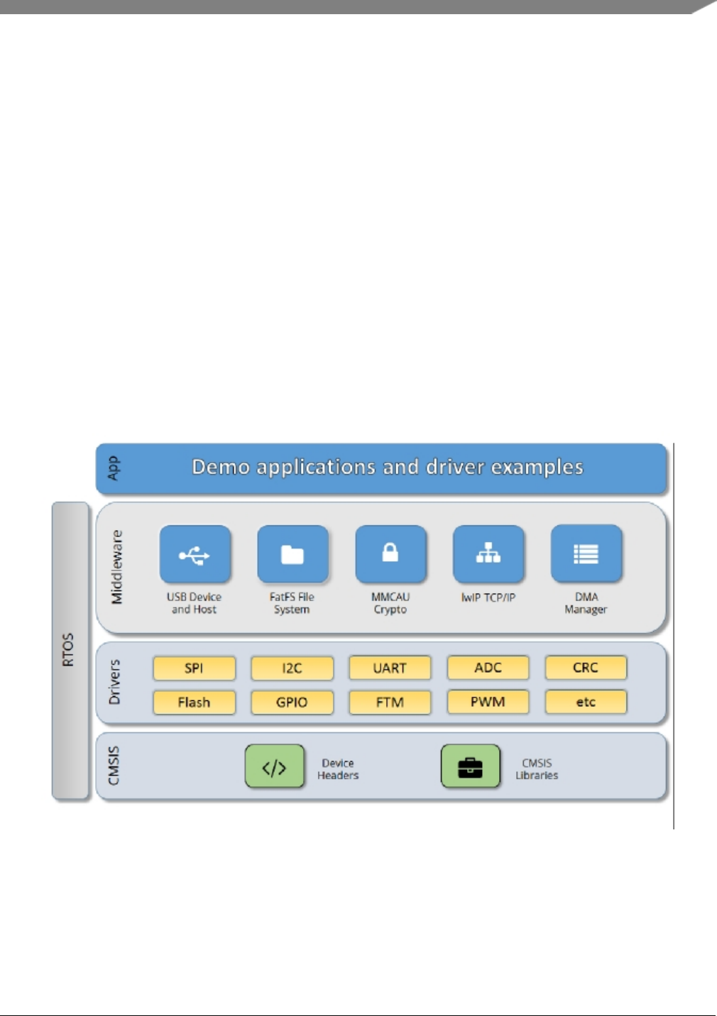
Chapter 3
Architectural Overview
This chapter provides the architectural overview for the MCUXpresso Software Development Kit (MCU-
Xpresso SDK). It describes each layer within the architecture and its associated components.
Overview
The MCUXpresso SDK architecture consists of five key components listed below.
1. The Arm Cortex Microcontroller Software Interface Standard (CMSIS) CORE compliance device-
specific header files, SOC Header, and CMSIS math/DSP libraries.
2. Peripheral Drivers
3. Real-time Operating Systems (RTOS)
4. Stacks and Middleware that integrate with the MCUXpresso SDK
5. Demo Applications based on the MCUXpresso SDK
Figure 1: MCUXpresso SDK Block Diagram
MCU header files
Each supported MCU device in the MCUXpresso SDK has an overall System-on Chip (SoC) memory-
NXP Semiconductors
MCUXpresso SDK API Reference Manual
5

mapped header file. This header file contains the memory map and register base address for each peripheral
and the IRQ vector table with associated vector numbers. The overall SoC header file provides a access to
the peripheral registers through pointers and predefined bit masks. In addition to the overall SoC memory-
mapped header file, the MCUXpresso SDK includes a feature header file for each device. The feature
header file allows NXP to deliver a single software driver for a given peripheral. The feature file ensures
that the driver is properly compiled for the target SOC.
CMSIS Support
Along with the SoC header files and peripheral extension header files, the MCUXpresso SDK also includes
common CMSIS header files for the Arm Cortex-M core and the math and DSP libraries from the latest
CMSIS release. The CMSIS DSP library source code is also included for reference.
MCUXpresso SDK Peripheral Drivers
The MCUXpresso SDK peripheral drivers mainly consist of low-level functional APIs for the MCU
product family on-chip peripherals and also of high-level transactional APIs for some bus drivers/DM-
A driver/eDMA driver to quickly enable the peripherals and perform transfers.
All MCUXpresso SDK peripheral drivers only depend on the CMSIS headers, device feature files, fsl_-
common.h, and fsl_clock.h files so that users can easily pull selected drivers and their dependencies into
projects. With the exception of the clock/power-relevant peripherals, each peripheral has its own driver.
Peripheral drivers handle the peripheral clock gating/ungating inside the drivers during initialization and
deinitialization respectively.
Low-level functional APIs provide common peripheral functionality, abstracting the hardware peripheral
register accesses into a set of stateless basic functional operations. These APIs primarily focus on the
control, configuration, and function of basic peripheral operations. The APIs hide the register access
details and various MCU peripheral instantiation differences so that the application can be abstracted from
the low-level hardware details. The API prototypes are intentionally similar to help ensure easy portability
across supported MCUXpresso SDK devices.
Transactional APIs provide a quick method for customers to utilize higher-level functionality of the pe-
ripherals. The transactional APIs utilize interrupts and perform asynchronous operations without user
intervention. Transactional APIs operate on high-level logic that requires data storage for internal oper-
ation context handling. However, the Peripheral Drivers do not allocate this memory space. Rather, the
user passes in the memory to the driver for internal driver operation. Transactional APIs ensure the NVIC
is enabled properly inside the drivers. The transactional APIs do not meet all customer needs, but provide
a baseline for development of custom user APIs.
Note that the transactional drivers never disable an NVIC after use. This is due to the shared nature of
interrupt vectors on devices. It is up to the user to ensure that NVIC interrupts are properly disabled after
usage is complete.
Interrupt handling for transactional APIs
A double weak mechanism is introduced for drivers with transactional API. The double weak indicates
two levels of weak vector entries. See the examples below:
PUBWEAK SPI0_IRQHandler
PUBWEAK SPI0_DriverIRQHandler
SPI0_IRQHandler
6
MCUXpresso SDK API Reference Manual
NXP Semiconductors

LDR R0, =SPI0_DriverIRQHandler
BX R0
The first level of the weak implementation are the functions defined in the vector table. In the devices/<-
DEVICE_NAME>/<TOOLCHAIN>/startup_<DEVICE_NAME>.s/.S file, the implementation of the
first layer weak function calls the second layer of weak function. The implementation of the second
layer weak function (ex. SPI0_DriverIRQHandler) jumps to itself (B .). The MCUXpresso SDK drivers
with transactional APIs provide the reimplementation of the second layer function inside of the peripheral
driver. If the MCUXpresso SDK drivers with transactional APIs are linked into the image, the SPI0_-
DriverIRQHandler is replaced with the function implemented in the MCUXpresso SDK SPI driver.
The reason for implementing the double weak functions is to provide a better user experience when using
the transactional APIs. For drivers with a transactional function, call the transactional APIs and the drivers
complete the interrupt-driven flow. Users are not required to redefine the vector entries out of the box. At
the same time, if users are not satisfied by the second layer weak function implemented in the MCU-
Xpresso SDK drivers, users can redefine the first layer weak function and implement their own interrupt
handler functions to suit their implementation.
The limitation of the double weak mechanism is that it cannot be used for peripherals that share the same
vector entry. For this use case, redefine the first layer weak function to enable the desired peripheral
interrupt functionality. For example, if the MCU’s UART0 and UART1 share the same vector entry,
redefine the UART0_UART1_IRQHandler according to the use case requirements.
Feature Header Files
The peripheral drivers are designed to be reusable regardless of the peripheral functional differences from
one MCU device to another. An overall Peripheral Feature Header File is provided for the MCUXpresso
SDK-supported MCU device to define the features or configuration differences for each sub-family device.
Application
See the Getting Started with MCUXpresso SDK document (MCUXSDKGSUG).
NXP Semiconductors
MCUXpresso SDK API Reference Manual
7

8
MCUXpresso SDK API Reference Manual
NXP Semiconductors

Chapter 4
Trademarks
Information in this document is provided solely to enable system and software implementers to use NXP
products. There are no express or implied copyright licenses granted hereunder to design or fabricate any
integrated circuits based on the information in this document.
How to Reach Us:
Home Page: nxp.com
Web Support: nxp.com/support
NXP reserves the right to make changes without further notice to any products herein. NXP makes no
warranty, representation, or guarantee regarding the suitability of its products for any particular purpose,
nor does NXP assume any liability arising out of the application or use of any product or circuit, and
specifically disclaims any and all liability, including without limitation consequential or incidental dam-
ages. “Typical” parameters that may be provided in NXP data sheets and/or specifications can and do vary
in different applications, and actual performance may vary over time. All operating parameters, including
“typicals,” must be validated for each customer application by customer’s technical experts. NXP does
not convey any license under its patent rights nor the rights of others. NXP sells products pursuant to
standard terms and conditions of sale, which can be found at the following address: nxp.com/Sales-
TermsandConditions
NXP, the NXP logo, Freescale, the Freescale logo, Kinetis, and Processor Expert are trademarks of N-
XP B.V. Tower is a trademark of NXP B.V. All other product or service names are the property of their
respective owners. Arm, Arm powered logo, Keil, and Cortex are registered trademarks of Arm Limited
(or its subsidiaries) in the EU and/or elsewhere. All rights reserved.
© 2018 NXP B.V.
NXP Semiconductors
MCUXpresso SDK API Reference Manual
9

10
MCUXpresso SDK API Reference Manual
NXP Semiconductors

Chapter 5
ACMP: Analog Comparator Driver
5.1 Overview
The MCUXpresso SDK provides a peripheral driver for the Comparator (ACMP) module of MCUXpresso
SDK devices.
The ACMP driver is created to help the user operate the ACMP module better. This driver can be con-
sidered as a basic comparator with advanced features. The APIs for basic comparator can make the CMP
work as a general comparator, which compares the two input channel’s voltage and creates the output of
the comparator result immediately. The APIs for advanced feature can be used as the plug-in function
based on the basic comparator, and can provide more ways to process the comparator’s output.
5.2 Typical use case
5.2.1 Normal Configuration
Refer to the driver examples codes located at <SDK_ROOT>/boards/<BOARD>/driver_examples/acmp
5.2.2 Interrupt Configuration
Refer to the driver examples codes located at <SDK_ROOT>/boards/<BOARD>/driver_examples/acmp
5.2.3 Round robin Configuration
Refer to the driver examples codes located at <SDK_ROOT>/boards/<BOARD>/driver_examples/acmp
Data Structures
• struct acmp_config_t
Configuration for ACMP. More...
• struct acmp_channel_config_t
Configuration for channel. More...
• struct acmp_filter_config_t
Configuration for filter. More...
• struct acmp_dac_config_t
Configuration for DAC. More...
• struct acmp_round_robin_config_t
Configuration for round robin mode. More...
NXP Semiconductors
MCUXpresso SDK API Reference Manual
11

Typical use case
Macros
• #define CMP_C0_CFx_MASK (CMP_C0_CFR_MASK |CMP_C0_CFF_MASK)
The mask of status flags cleared by writing 1.
Enumerations
• enum _acmp_interrupt_enable {
kACMP_OutputRisingInterruptEnable = (1U << 0U),
kACMP_OutputFallingInterruptEnable = (1U << 1U),
kACMP_RoundRobinInterruptEnable = (1U << 2U) }
Interrupt enable/disable mask.
• enum _acmp_status_flags {
kACMP_OutputRisingEventFlag = CMP_C0_CFR_MASK,
kACMP_OutputFallingEventFlag = CMP_C0_CFF_MASK,
kACMP_OutputAssertEventFlag = CMP_C0_COUT_MASK }
Status flag mask.
• enum acmp_offset_mode_t {
kACMP_OffsetLevel0 = 0U,
kACMP_OffsetLevel1 = 1U }
Comparator hard block offset control.
• enum acmp_hysteresis_mode_t {
kACMP_HysteresisLevel0 = 0U,
kACMP_HysteresisLevel1 = 1U,
kACMP_HysteresisLevel2 = 2U,
kACMP_HysteresisLevel3 = 3U }
Comparator hard block hysteresis control.
• enum acmp_reference_voltage_source_t {
kACMP_VrefSourceVin1 = 0U,
kACMP_VrefSourceVin2 = 1U }
CMP Voltage Reference source.
• enum acmp_port_input_t {
kACMP_PortInputFromDAC = 0U,
kACMP_PortInputFromMux = 1U }
Port input source.
• enum acmp_fixed_port_t {
kACMP_FixedPlusPort = 0U,
kACMP_FixedMinusPort = 1U }
Fixed mux port.
Driver version
• #define FSL_ACMP_DRIVER_VERSION (MAKE_VERSION(2U, 0U, 3U))
ACMP driver version 2.0.3.
Initialization and deinitialization
• void ACMP_Init (CMP_Type ∗base, const acmp_config_t ∗config)
12
MCUXpresso SDK API Reference Manual
NXP Semiconductors

Typical use case
Initializes the ACMP.
• void ACMP_Deinit (CMP_Type ∗base)
Deinitializes the ACMP.
• void ACMP_GetDefaultConfig (acmp_config_t ∗config)
Gets the default configuration for ACMP.
Basic Operations
• void ACMP_Enable (CMP_Type ∗base, bool enable)
Enables or disables the ACMP.
• void ACMP_SetChannelConfig (CMP_Type ∗base, const acmp_channel_config_t ∗config)
Sets the channel configuration.
Advanced Operations
• void ACMP_EnableDMA (CMP_Type ∗base, bool enable)
Enables or disables DMA.
• void ACMP_EnableWindowMode (CMP_Type ∗base, bool enable)
Enables or disables window mode.
• void ACMP_SetFilterConfig (CMP_Type ∗base, const acmp_filter_config_t ∗config)
Configures the filter.
• void ACMP_SetDACConfig (CMP_Type ∗base, const acmp_dac_config_t ∗config)
Configures the internal DAC.
• void ACMP_SetRoundRobinConfig (CMP_Type ∗base, const acmp_round_robin_config_t ∗config)
Configures the round robin mode.
• void ACMP_SetRoundRobinPreState (CMP_Type ∗base, uint32_t mask)
Defines the pre-set state of channels in round robin mode.
• static uint32_t ACMP_GetRoundRobinStatusFlags (CMP_Type ∗base)
Gets the channel input changed flags in round robin mode.
• void ACMP_ClearRoundRobinStatusFlags (CMP_Type ∗base, uint32_t mask)
Clears the channel input changed flags in round robin mode.
• static uint32_t ACMP_GetRoundRobinResult (CMP_Type ∗base)
Gets the round robin result.
Interrupts
• void ACMP_EnableInterrupts (CMP_Type ∗base, uint32_t mask)
Enables interrupts.
• void ACMP_DisableInterrupts (CMP_Type ∗base, uint32_t mask)
Disables interrupts.
Status
• uint32_t ACMP_GetStatusFlags (CMP_Type ∗base)
Gets status flags.
• void ACMP_ClearStatusFlags (CMP_Type ∗base, uint32_t mask)
Clears status flags.
NXP Semiconductors
MCUXpresso SDK API Reference Manual
13

Data Structure Documentation
5.3 Data Structure Documentation
5.3.1 struct acmp_config_t
Data Fields
•acmp_offset_mode_t offsetMode
Offset mode.
•acmp_hysteresis_mode_t hysteresisMode
Hysteresis mode.
• bool enableHighSpeed
Enable High Speed (HS) comparison mode.
• bool enableInvertOutput
Enable inverted comparator output.
• bool useUnfilteredOutput
Set compare output(COUT) to equal COUTA(true) or COUT(false).
• bool enablePinOut
The comparator output is available on the associated pin.
5.3.1.0.0.1 Field Documentation
5.3.1.0.0.1.1 acmp_offset_mode_t acmp_config_t::offsetMode
5.3.1.0.0.1.2 acmp_hysteresis_mode_t acmp_config_t::hysteresisMode
5.3.1.0.0.1.3 bool acmp_config_t::enableHighSpeed
5.3.1.0.0.1.4 bool acmp_config_t::enableInvertOutput
5.3.1.0.0.1.5 bool acmp_config_t::useUnfilteredOutput
5.3.1.0.0.1.6 bool acmp_config_t::enablePinOut
5.3.2 struct acmp_channel_config_t
The comparator’s port can be input from channel mux or DAC. If port input is from channel mux, detailed
channel number for the mux should be configured.
Data Fields
•acmp_port_input_t positivePortInput
Input source of the comparator’s positive port.
• uint32_t plusMuxInput
Plus mux input channel(0∼7).
•acmp_port_input_t negativePortInput
Input source of the comparator’s negative port.
• uint32_t minusMuxInput
Minus mux input channel(0∼7).
14
MCUXpresso SDK API Reference Manual
NXP Semiconductors

Data Structure Documentation
5.3.2.0.0.2 Field Documentation
5.3.2.0.0.2.1 acmp_port_input_t acmp_channel_config_t::positivePortInput
5.3.2.0.0.2.2 uint32_t acmp_channel_config_t::plusMuxInput
5.3.2.0.0.2.3 acmp_port_input_t acmp_channel_config_t::negativePortInput
5.3.2.0.0.2.4 uint32_t acmp_channel_config_t::minusMuxInput
5.3.3 struct acmp_filter_config_t
Data Fields
• bool enableSample
Using external SAMPLE as sampling clock input, or using divided bus clock.
• uint32_t filterCount
Filter Sample Count.
• uint32_t filterPeriod
Filter Sample Period.
5.3.3.0.0.3 Field Documentation
5.3.3.0.0.3.1 bool acmp_filter_config_t::enableSample
5.3.3.0.0.3.2 uint32_t acmp_filter_config_t::filterCount
Available range is 1-7, 0 would cause the filter disabled.
5.3.3.0.0.3.3 uint32_t acmp_filter_config_t::filterPeriod
The divider to bus clock. Available range is 0-255.
5.3.4 struct acmp_dac_config_t
Data Fields
•acmp_reference_voltage_source_t referenceVoltageSource
Supply voltage reference source.
• uint32_t DACValue
Value for DAC Output Voltage.
NXP Semiconductors
MCUXpresso SDK API Reference Manual
15

Macro Definition Documentation
5.3.4.0.0.4 Field Documentation
5.3.4.0.0.4.1 acmp_reference_voltage_source_t acmp_dac_config_t::referenceVoltageSource
5.3.4.0.0.4.2 uint32_t acmp_dac_config_t::DACValue
Available range is 0-63.
5.3.5 struct acmp_round_robin_config_t
Data Fields
•acmp_fixed_port_t fixedPort
Fixed mux port.
• uint32_t fixedChannelNumber
Indicates which channel is fixed in the fixed mux port.
• uint32_t checkerChannelMask
Mask of checker channel index.
• uint32_t sampleClockCount
Specifies how many round-robin clock cycles(0∼3) later the sample takes place.
• uint32_t delayModulus
Comparator and DAC initialization delay modulus.
5.3.5.0.0.5 Field Documentation
5.3.5.0.0.5.1 acmp_fixed_port_t acmp_round_robin_config_t::fixedPort
5.3.5.0.0.5.2 uint32_t acmp_round_robin_config_t::fixedChannelNumber
5.3.5.0.0.5.3 uint32_t acmp_round_robin_config_t::checkerChannelMask
Available range is channel0:0x01 to channel7:0x80 for round-robin checker.
5.3.5.0.0.5.4 uint32_t acmp_round_robin_config_t::sampleClockCount
5.3.5.0.0.5.5 uint32_t acmp_round_robin_config_t::delayModulus
5.4 Macro Definition Documentation
5.4.1 #define FSL_ACMP_DRIVER_VERSION (MAKE_VERSION(2U, 0U, 3U))
5.4.2 #define CMP_C0_CFx_MASK (CMP_C0_CFR_MASK |CMP_C0_CFF_MASK)
16
MCUXpresso SDK API Reference Manual
NXP Semiconductors

Enumeration Type Documentation
5.5 Enumeration Type Documentation
5.5.1 enum _acmp_interrupt_enable
Enumerator
kACMP_OutputRisingInterruptEnable Enable the interrupt when comparator outputs rising.
kACMP_OutputFallingInterruptEnable Enable the interrupt when comparator outputs falling.
kACMP_RoundRobinInterruptEnable Enable the Round-Robin interrupt.
5.5.2 enum _acmp_status_flags
Enumerator
kACMP_OutputRisingEventFlag Rising-edge on compare output has occurred.
kACMP_OutputFallingEventFlag Falling-edge on compare output has occurred.
kACMP_OutputAssertEventFlag Return the current value of the analog comparator output.
5.5.3 enum acmp_offset_mode_t
If OFFSET level is 1, then there is no hysteresis in the case of positive port input crossing negative port
input in the positive direction (or negative port input crossing positive port input in the negative direction).
Hysteresis still exists for positive port input crossing negative port input in the falling direction. If OFFSET
level is 0, then the hysteresis selected by acmp_hysteresis_mode_t is valid for both directions.
Enumerator
kACMP_OffsetLevel0 The comparator hard block output has level 0 offset internally.
kACMP_OffsetLevel1 The comparator hard block output has level 1 offset internally.
5.5.4 enum acmp_hysteresis_mode_t
See chip data sheet to get the actual hysteresis value with each level.
Enumerator
kACMP_HysteresisLevel0 Offset is level 0 and Hysteresis is level 0.
kACMP_HysteresisLevel1 Offset is level 0 and Hysteresis is level 1.
kACMP_HysteresisLevel2 Offset is level 0 and Hysteresis is level 2.
kACMP_HysteresisLevel3 Offset is level 0 and Hysteresis is level 3.
NXP Semiconductors
MCUXpresso SDK API Reference Manual
17

Function Documentation
5.5.5 enum acmp_reference_voltage_source_t
Enumerator
kACMP_VrefSourceVin1 Vin1 is selected as resistor ladder network supply reference Vin.
kACMP_VrefSourceVin2 Vin2 is selected as resistor ladder network supply reference Vin.
5.5.6 enum acmp_port_input_t
Enumerator
kACMP_PortInputFromDAC Port input from the 8-bit DAC output.
kACMP_PortInputFromMux Port input from the analog 8-1 mux.
5.5.7 enum acmp_fixed_port_t
Enumerator
kACMP_FixedPlusPort Only the inputs to the Minus port are swept in each round.
kACMP_FixedMinusPort Only the inputs to the Plus port are swept in each round.
5.6 Function Documentation
5.6.1 void ACMP_Init ( CMP_Type ∗base, const acmp_config_t ∗config )
The default configuration can be got by calling ACMP_GetDefaultConfig().
Parameters
base ACMP peripheral base address.
config Pointer to ACMP configuration structure.
5.6.2 void ACMP_Deinit ( CMP_Type ∗base )
Parameters
18
MCUXpresso SDK API Reference Manual
NXP Semiconductors

Function Documentation
base ACMP peripheral base address.
5.6.3 void ACMP_GetDefaultConfig ( acmp_config_t ∗config )
This function initializes the user configuration structure to default value. The default value are:
Example:
config->enableHighSpeed = false;
config->enableInvertOutput = false;
config->useUnfilteredOutput = false;
config->enablePinOut = false;
config->enableHysteresisBothDirections = false;
config->hysteresisMode = kACMP_hysteresisMode0;
Parameters
config Pointer to ACMP configuration structure.
5.6.4 void ACMP_Enable ( CMP_Type ∗base, bool enable )
Parameters
base ACMP peripheral base address.
enable True to enable the ACMP.
5.6.5 void ACMP_SetChannelConfig ( CMP_Type ∗base, const
acmp_channel_config_t ∗config )
Note that the plus/minus mux’s setting is only valid when the positive/negative port’s input isn’t from DAC
but from channel mux.
Example:
acmp_channel_config_t configStruct = {0};
configStruct.positivePortInput =kACMP_PortInputFromDAC;
configStruct.negativePortInput =kACMP_PortInputFromMux;
configStruct.minusMuxInput = 1U;
ACMP_SetChannelConfig(CMP0, &configStruct);
NXP Semiconductors
MCUXpresso SDK API Reference Manual
19

Function Documentation
Parameters
base ACMP peripheral base address.
config Pointer to channel configuration structure.
5.6.6 void ACMP_EnableDMA ( CMP_Type ∗base, bool enable )
Parameters
base ACMP peripheral base address.
enable True to enable DMA.
5.6.7 void ACMP_EnableWindowMode ( CMP_Type ∗base, bool enable )
Parameters
base ACMP peripheral base address.
enable True to enable window mode.
5.6.8 void ACMP_SetFilterConfig ( CMP_Type ∗base, const acmp_filter_config_t ∗
config )
The filter can be enabled when the filter count is bigger than 1, the filter period is greater than 0 and the
sample clock is from divided bus clock or the filter is bigger than 1 and the sample clock is from external
clock. Detailed usage can be got from the reference manual.
Example:
acmp_filter_config_t configStruct = {0};
configStruct.filterCount = 5U;
configStruct.filterPeriod = 200U;
configStruct.enableSample =false;
ACMP_SetFilterConfig(CMP0, &configStruct);
Parameters
20
MCUXpresso SDK API Reference Manual
NXP Semiconductors

Function Documentation
base ACMP peripheral base address.
config Pointer to filter configuration structure.
5.6.9 void ACMP_SetDACConfig ( CMP_Type ∗base, const acmp_dac_config_t ∗
config )
Example:
acmp_dac_config_t configStruct = {0};
configStruct.referenceVoltageSource =kACMP_VrefSourceVin1;
configStruct.DACValue = 20U;
configStruct.enableOutput = false;
configStruct.workMode = kACMP_DACWorkLowSpeedMode;
ACMP_SetDACConfig(CMP0, &configStruct);
Parameters
base ACMP peripheral base address.
config Pointer to DAC configuration structure. "NULL" is for disabling the feature.
5.6.10 void ACMP_SetRoundRobinConfig ( CMP_Type ∗base, const
acmp_round_robin_config_t ∗config )
Example:
acmp_round_robin_config_t configStruct = {0};
configStruct.fixedPort =kACMP_FixedPlusPort;
configStruct.fixedChannelNumber = 3U;
configStruct.checkerChannelMask = 0xF7U;
configStruct.sampleClockCount = 0U;
configStruct.delayModulus = 0U;
ACMP_SetRoundRobinConfig(CMP0, &configStruct);
Parameters
base ACMP peripheral base address.
config Pointer to round robin mode configuration structure. "NULL" is for disabling the
feature.
5.6.11 void ACMP_SetRoundRobinPreState ( CMP_Type ∗base, uint32_t mask )
Note: The pre-state has different circuit with get-round-robin-result in the SOC even though they are same
bits. So get-round-robin-result can’t return the same value as the value are set by pre-state.
NXP Semiconductors
MCUXpresso SDK API Reference Manual
21

Function Documentation
Parameters
base ACMP peripheral base address.
mask Mask of round robin channel index. Available range is channel0:0x01 to channel7-
:0x80.
5.6.12 static uint32_t ACMP_GetRoundRobinStatusFlags ( CMP_Type ∗base )
[inline],[static]
Parameters
base ACMP peripheral base address.
Returns
Mask of channel input changed asserted flags. Available range is channel0:0x01 to channel7:0x80.
5.6.13 void ACMP_ClearRoundRobinStatusFlags ( CMP_Type ∗base, uint32_t
mask )
Parameters
base ACMP peripheral base address.
mask Mask of channel index. Available range is channel0:0x01 to channel7:0x80.
5.6.14 static uint32_t ACMP_GetRoundRobinResult ( CMP_Type ∗base )
[inline],[static]
Note that the set-pre-state has different circuit with get-round-robin-result in the SOC even though they
are same bits. So ACMP_GetRoundRobinResult() can’t return the same value as the value are set by
ACMP_SetRoundRobinPreState.
Parameters
22
MCUXpresso SDK API Reference Manual
NXP Semiconductors

Function Documentation
base ACMP peripheral base address.
Returns
Mask of round robin channel result. Available range is channel0:0x01 to channel7:0x80.
5.6.15 void ACMP_EnableInterrupts ( CMP_Type ∗base, uint32_t mask )
Parameters
base ACMP peripheral base address.
mask Interrupts mask. See "_acmp_interrupt_enable".
5.6.16 void ACMP_DisableInterrupts ( CMP_Type ∗base, uint32_t mask )
Parameters
base ACMP peripheral base address.
mask Interrupts mask. See "_acmp_interrupt_enable".
5.6.17 uint32_t ACMP_GetStatusFlags ( CMP_Type ∗base )
Parameters
base ACMP peripheral base address.
Returns
Status flags asserted mask. See "_acmp_status_flags".
5.6.18 void ACMP_ClearStatusFlags ( CMP_Type ∗base, uint32_t mask )
NXP Semiconductors
MCUXpresso SDK API Reference Manual
23

Function Documentation
Parameters
base ACMP peripheral base address.
mask Status flags mask. See "_acmp_status_flags".
24
MCUXpresso SDK API Reference Manual
NXP Semiconductors

Chapter 6
ADC12: Analog-to-Digital Converter
6.1 Overview
The MCUXpresso SDK provides a peripheral driver for the Analog-to-Digital Converter (ADC12) module
of MCUXpresso SDK devices.
The ADC12 driver is created to help the user better operate the ADC12 module. This driver can be
considered a basic analog-to-digital converter with advanced features. The APIs for basic operations can
make the ADC12 work as a general converter, which can convert the analog input to be a digital value. The
APIs for advanced operations can be used as the plug-in function based on the basic operations. They can
provide more ways to process the converter’s conversion results, such DMA trigger, hardware compare,
hardware average, and so on.
Note that channel 26 of ADC12 is connected to a internal temperature sensor of the module. If you want
to get the best conversion result of the temperature value, set the field "sampleClockCount" in the structure
"adc12_config_t" to be maximum value when you call the API "ADC12_Init()". This field indicates the
sample time of the analog input signal. A longer sample time makes the conversion result of the analog
input signal more stable and accurate.
6.2 Function groups
6.2.1 Initialization and deinitialization
This function group implement ADC12 initialization and deinitialization API.
6.2.2 Basic Operations
This function group implement basic ADC12 operation API.
6.2.3 Advanced Operations
This function group implement advanced ADC12 operation API.
6.3 Typical use case
6.3.1 Normal Configuration
Refer to the driver examples codes located at <SDK_ROOT>/boards/<BOARD>/driver_examples/adc12
NXP Semiconductors
MCUXpresso SDK API Reference Manual
25

Typical use case
6.3.2 Interrupt Configuration
Refer to the driver examples codes located at <SDK_ROOT>/boards/<BOARD>/driver_examples/adc12
Data Structures
• struct adc12_config_t
Converter configuration. More...
• struct adc12_hardware_compare_config_t
Hardware compare configuration. More...
• struct adc12_channel_config_t
Channel conversion configuration. More...
Macros
• #define FSL_ADC12_DRIVER_VERSION (MAKE_VERSION(2, 0, 0))
ADC12 driver version.
Enumerations
• enum _adc12_channel_status_flags {kADC12_ChannelConversionCompletedFlag = ADC_SC1_-
COCO_MASK }
Channel status flags’ mask.
• enum _adc12_status_flags {
kADC12_ActiveFlag = ADC_SC2_ADACT_MASK,
kADC12_CalibrationFailedFlag = (ADC_SC2_ADACT_MASK << 1U) }
Converter status flags’ mask.
• enum adc12_clock_divider_t {
kADC12_ClockDivider1 = 0U,
kADC12_ClockDivider2 = 1U,
kADC12_ClockDivider4 = 2U,
kADC12_ClockDivider8 = 3U }
Clock divider for the converter.
• enum adc12_resolution_t {
kADC12_Resolution8Bit = 0U,
kADC12_Resolution12Bit = 1U,
kADC12_Resolution10Bit = 2U }
Converter’s resolution.
• enum adc12_clock_source_t {
kADC12_ClockSourceAlt0 = 0U,
kADC12_ClockSourceAlt1 = 1U,
kADC12_ClockSourceAlt2 = 2U,
kADC12_ClockSourceAlt3 = 3U }
Conversion clock source.
• enum adc12_reference_voltage_source_t {
kADC12_ReferenceVoltageSourceVref = 0U,
kADC12_ReferenceVoltageSourceValt = 1U }
Reference voltage source.
26
MCUXpresso SDK API Reference Manual
NXP Semiconductors

Typical use case
• enum adc12_hardware_average_mode_t {
kADC12_HardwareAverageCount4 = 0U,
kADC12_HardwareAverageCount8 = 1U,
kADC12_HardwareAverageCount16 = 2U,
kADC12_HardwareAverageCount32 = 3U,
kADC12_HardwareAverageDisabled = 4U }
Hardware average mode.
• enum adc12_hardware_compare_mode_t {
kADC12_HardwareCompareMode0 = 0U,
kADC12_HardwareCompareMode1 = 1U,
kADC12_HardwareCompareMode2 = 2U,
kADC12_HardwareCompareMode3 = 3U }
Hardware compare mode.
Initialization
• void ADC12_Init (ADC_Type ∗base, const adc12_config_t ∗config)
Initialize the ADC12 module.
• void ADC12_Deinit (ADC_Type ∗base)
De-initialize the ADC12 module.
• void ADC12_GetDefaultConfig (adc12_config_t ∗config)
Gets an available pre-defined settings for converter’s configuration.
Basic Operations
• void ADC12_SetChannelConfig (ADC_Type ∗base, uint32_t channelGroup, const adc12_channel-
_config_t ∗config)
Configure the conversion channel.
• static uint32_t ADC12_GetChannelConversionValue (ADC_Type ∗base, uint32_t channelGroup)
Get the conversion value.
• uint32_t ADC12_GetChannelStatusFlags (ADC_Type ∗base, uint32_t channelGroup)
Get the status flags of channel.
Advanced Operations
• status_t ADC12_DoAutoCalibration (ADC_Type ∗base)
Automate the hardware calibration.
• static void ADC12_SetOffsetValue (ADC_Type ∗base, uint32_t value)
Set the offset value for the conversion result.
• static void ADC12_SetGainValue (ADC_Type ∗base, uint32_t value)
Set the gain value for the conversion result.
• static void ADC12_EnableDMA (ADC_Type ∗base, bool enable)
Enable generating the DMA trigger when conversion is completed.
• static void ADC12_EnableHardwareTrigger (ADC_Type ∗base, bool enable)
Enable of disable the hardware trigger mode.
• void ADC12_SetHardwareCompareConfig (ADC_Type ∗base, const adc12_hardware_compare_-
config_t ∗config)
Configure the hardware compare mode.
• void ADC12_SetHardwareAverage (ADC_Type ∗base, adc12_hardware_average_mode_t mode)
NXP Semiconductors
MCUXpresso SDK API Reference Manual
27

Data Structure Documentation
Set the hardware average mode.
• uint32_t ADC12_GetStatusFlags (ADC_Type ∗base)
Get the status flags of the converter.
6.4 Data Structure Documentation
6.4.1 struct adc12_config_t
Data Fields
•adc12_reference_voltage_source_t referenceVoltageSource
Select the reference voltage source.
•adc12_clock_source_t clockSource
Select the input clock source to converter.
•adc12_clock_divider_t clockDivider
Select the divider of input clock source.
•adc12_resolution_t resolution
Select the sample resolution mode.
• uint32_t sampleClockCount
Select the sample clock count.
• bool enableContinuousConversion
Enable continuous conversion mode.
6.4.1.0.0.6 Field Documentation
6.4.1.0.0.6.1 adc12_reference_voltage_source_t adc12_config_t::referenceVoltageSource
6.4.1.0.0.6.2 adc12_clock_source_t adc12_config_t::clockSource
6.4.1.0.0.6.3 adc12_clock_divider_t adc12_config_t::clockDivider
6.4.1.0.0.6.4 adc12_resolution_t adc12_config_t::resolution
6.4.1.0.0.6.5 uint32_t adc12_config_t::sampleClockCount
Add its value may improve the stability of the conversion result.
6.4.1.0.0.6.6 bool adc12_config_t::enableContinuousConversion
6.4.2 struct adc12_hardware_compare_config_t
Data Fields
•adc12_hardware_compare_mode_t hardwareCompareMode
Select the hardware compare mode.
• int16_t value1
Setting value1 for hardware compare mode.
• int16_t value2
Setting value2 for hardware compare mode.
28
MCUXpresso SDK API Reference Manual
NXP Semiconductors

Enumeration Type Documentation
6.4.2.0.0.7 Field Documentation
6.4.2.0.0.7.1 adc12_hardware_compare_mode_t adc12_hardware_compare_config_t::hardware-
CompareMode
6.4.2.0.0.7.2 int16_t adc12_hardware_compare_config_t::value1
6.4.2.0.0.7.3 int16_t adc12_hardware_compare_config_t::value2
6.4.3 struct adc12_channel_config_t
Data Fields
• uint32_t channelNumber
Setting the conversion channel number.
• bool enableInterruptOnConversionCompleted
Generate a interrupt request once the conversion is completed.
6.4.3.0.0.8 Field Documentation
6.4.3.0.0.8.1 uint32_t adc12_channel_config_t::channelNumber
The available range is 0-31. See channel connection information for each chip in Reference Manual
document.
6.4.3.0.0.8.2 bool adc12_channel_config_t::enableInterruptOnConversionCompleted
6.5 Macro Definition Documentation
6.5.1 #define FSL_ADC12_DRIVER_VERSION (MAKE_VERSION(2, 0, 0))
Version 2.0.0.
6.6 Enumeration Type Documentation
6.6.1 enum _adc12_channel_status_flags
Enumerator
kADC12_ChannelConversionCompletedFlag Conversion done.
6.6.2 enum _adc12_status_flags
Enumerator
kADC12_ActiveFlag Converter is active.
kADC12_CalibrationFailedFlag Calibration is failed.
NXP Semiconductors
MCUXpresso SDK API Reference Manual
29

Enumeration Type Documentation
6.6.3 enum adc12_clock_divider_t
Enumerator
kADC12_ClockDivider1 For divider 1 from the input clock to the module.
kADC12_ClockDivider2 For divider 2 from the input clock to the module.
kADC12_ClockDivider4 For divider 4 from the input clock to the module.
kADC12_ClockDivider8 For divider 8 from the input clock to the module.
6.6.4 enum adc12_resolution_t
Enumerator
kADC12_Resolution8Bit 8 bit resolution.
kADC12_Resolution12Bit 12 bit resolution.
kADC12_Resolution10Bit 10 bit resolution.
6.6.5 enum adc12_clock_source_t
Enumerator
kADC12_ClockSourceAlt0 Alternate clock 1 (ADC_ALTCLK1).
kADC12_ClockSourceAlt1 Alternate clock 2 (ADC_ALTCLK2).
kADC12_ClockSourceAlt2 Alternate clock 3 (ADC_ALTCLK3).
kADC12_ClockSourceAlt3 Alternate clock 4 (ADC_ALTCLK4).
6.6.6 enum adc12_reference_voltage_source_t
Enumerator
kADC12_ReferenceVoltageSourceVref For external pins pair of VrefH and VrefL.
kADC12_ReferenceVoltageSourceValt For alternate reference pair of ValtH and ValtL.
6.6.7 enum adc12_hardware_average_mode_t
Enumerator
kADC12_HardwareAverageCount4 For hardware average with 4 samples.
kADC12_HardwareAverageCount8 For hardware average with 8 samples.
kADC12_HardwareAverageCount16 For hardware average with 16 samples.
kADC12_HardwareAverageCount32 For hardware average with 32 samples.
kADC12_HardwareAverageDisabled Disable the hardware average feature.
30
MCUXpresso SDK API Reference Manual
NXP Semiconductors

Function Documentation
6.6.8 enum adc12_hardware_compare_mode_t
Enumerator
kADC12_HardwareCompareMode0 x<value1.
kADC12_HardwareCompareMode1 x>value1.
kADC12_HardwareCompareMode2 if value1 <= value2, then x <value1 || x>value2; else,
value1 >x>value2.
kADC12_HardwareCompareMode3 if value1 <= value2, then value1 <= x <= value2; else x >=
value1 || x<= value2.
6.7 Function Documentation
6.7.1 void ADC12_Init ( ADC_Type ∗base, const adc12_config_t ∗config )
Parameters
base ADC12 peripheral base address.
config Pointer to "adc12_config_t" structure.
6.7.2 void ADC12_Deinit ( ADC_Type ∗base )
Parameters
base ADC12 peripheral base address.
6.7.3 void ADC12_GetDefaultConfig ( adc12_config_t ∗config )
This function initializes the converter configuration structure with an available settings. The default values
are:
Example:
config->referenceVoltageSource = kADC12_ReferenceVoltageSourceVref;
config->clockSource = kADC12_ClockSourceAlt0;
config->clockDivider = kADC12_ClockDivider1;
config->resolution = kADC12_Resolution8Bit;
config->sampleClockCount = 12U;
config->enableContinuousConversion = false;
NXP Semiconductors
MCUXpresso SDK API Reference Manual
31

Function Documentation
Parameters
config Pointer to "adc12_config_t" structure.
6.7.4 void ADC12_SetChannelConfig ( ADC_Type ∗base, uint32_t channelGroup,
const adc12_channel_config_t ∗config )
This operation triggers the conversion in software trigger mode. In hardware trigger mode, this API
configures the channel while the external trigger source helps to trigger the conversion.
Note that the "Channel Group" has a detailed description. To allow sequential conversions of the ADC to
be triggered by internal peripherals, the ADC can have more than one group of status and control register,
one for each conversion. The channel group parameter indicates which group of registers are used, channel
group 0 is for Group A registers and channel group 1 is for Group B registers. The channel groups are
used in a "ping-pong" approach to control the ADC operation. At any time, only one of the channel groups
is actively controlling ADC conversions. Channel group 0 is used for both software and hardware trigger
modes of operation. Channel groups 1 and greater indicate potentially multiple channel group registers
for use only in hardware trigger mode. See the chip configuration information in the MCU reference
manual about the number of SC1n registers (channel groups) specific to this device. None of the channel
groups 1 or greater are used for software trigger operation and therefore writes to these channel groups
do not initiate a new conversion. Updating channel group 0 while a different channel group is actively
controlling a conversion is allowed and vice versa. Writing any of the channel group registers while that
specific channel group is actively controlling a conversion aborts the current conversion.
Parameters
base ADC12 peripheral base address.
channelGroup Channel group index.
config Pointer to "adc12_channel_config_t" structure.
6.7.5 static uint32_t ADC12_GetChannelConversionValue ( ADC_Type ∗base,
uint32_t channelGroup )[inline],[static]
Parameters
base ADC12 peripheral base address.
32
MCUXpresso SDK API Reference Manual
NXP Semiconductors

Function Documentation
channelGroup Channel group index.
Returns
Conversion value.
6.7.6 uint32_t ADC12_GetChannelStatusFlags ( ADC_Type ∗base, uint32_t
channelGroup )
Parameters
base ADC12 peripheral base address.
channelGroup Channel group index.
Returns
Flags’ mask if indicated flags are asserted. See to "_adc12_channel_status_flags".
6.7.7 status_t ADC12_DoAutoCalibration ( ADC_Type ∗base )
This auto calibration helps to adjust the gain automatically according to the converter’s working environ-
ment. Execute the calibration before conversion. Note that the software trigger should be used during
calibration.
Note
The calibration function has bug in the SOC. The calibration failed flag may be set after calibration
process even if you configure the ADC12 as the reference manual correctly. It is a known issue now
and may be fixed in the future.
Parameters
base ADC12 peripheral base address.
Return values
NXP Semiconductors
MCUXpresso SDK API Reference Manual
33

Function Documentation
kStatus_Success Calibration is done successfully.
kStatus_Fail Calibration is failed.
6.7.8 static void ADC12_SetOffsetValue ( ADC_Type ∗base, uint32_t value )
[inline],[static]
This offset value takes effect on the conversion result. If the offset value is not zero, the conversion result
is substracted by it.
Parameters
base ADC12 peripheral base address.
value Offset value.
6.7.9 static void ADC12_SetGainValue ( ADC_Type ∗base, uint32_t value )
[inline],[static]
This gain value takes effect on the conversion result. If the gain value is not zero, the conversion result is
amplified as it.
Parameters
base ADC12 peripheral base address.
value Gain value.
6.7.10 static void ADC12_EnableDMA ( ADC_Type ∗base, bool enable )
[inline],[static]
Parameters
base ADC12 peripheral base address.
enable Switcher of DMA feature. "true" means to enable, "false" means to disable.
6.7.11 static void ADC12_EnableHardwareTrigger ( ADC_Type ∗base, bool enable
)[inline],[static]
34
MCUXpresso SDK API Reference Manual
NXP Semiconductors

Function Documentation
Parameters
base ADC12 peripheral base address.
enable Switcher of hardware trigger feature. "true" means to enable, "false" means not.
6.7.12 void ADC12_SetHardwareCompareConfig ( ADC_Type ∗base, const
adc12_hardware_compare_config_t ∗config )
The hardware compare mode provides a way to process the conversion result automatically by hardware.
Only the result in compare range is available. To compare the range, see "adc12_hardware_compare_-
mode_t", or the reference manual document for more detailed information.
Parameters
base ADC12 peripheral base address.
config Pointer to "adc12_hardware_compare_config_t" structure. Pass "NULL" to disable
the feature.
6.7.13 void ADC12_SetHardwareAverage ( ADC_Type ∗base,
adc12_hardware_average_mode_t mode )
Hardware average mode provides a way to process the conversion result automatically by hardware. The
multiple conversion results are accumulated and averaged internally. This aids to get more accurate con-
version result.
Parameters
base ADC12 peripheral base address.
mode Setting hardware average mode. See to "adc12_hardware_average_mode_t".
6.7.14 uint32_t ADC12_GetStatusFlags ( ADC_Type ∗base )
Parameters
NXP Semiconductors
MCUXpresso SDK API Reference Manual
35

Function Documentation
base ADC12 peripheral base address.
Returns
Flags’ mask if indicated flags are asserted. See to "_adc12_status_flags".
36
MCUXpresso SDK API Reference Manual
NXP Semiconductors

Chapter 7
CRC: Cyclic Redundancy Check Driver
7.1 Overview
The MCUXpresso SDK provides a peripheral driver for the Cyclic Redundancy Check (CRC) module of
MCUXpresso SDK devices.
The cyclic redundancy check (CRC) module generates 16/32-bit CRC code for error detection. The CRC
module also provides a programmable polynomial, seed, and other parameters required to implement a
16-bit or 32-bit CRC standard.
7.2 CRC Driver Initialization and Configuration
CRC_Init() function enables the clock gate for the CRC module in the SIM module and fully (re-
)configures the CRC module according to the configuration structure. The seed member of the con-
figuration structure is the initial checksum for which new data can be added to. When starting a new
checksum computation, the seed is set to the initial checksum per the CRC protocol specification. For
continued checksum operation, the seed is set to the intermediate checksum value as obtained from previ-
ous calls to CRC_Get16bitResult() or CRC_Get32bitResult() function. After calling the CRC_Init(), one
or multiple CRC_WriteData() calls follow to update the checksum with data and CRC_Get16bitResult()
or CRC_Get32bitResult() follow to read the result. The crcResult member of the configuration structure
determines whether the CRC_Get16bitResult() or CRC_Get32bitResult() return value is a final checksum
or an intermediate checksum. The CRC_Init() function can be called as many times as required allowing
for runtime changes of the CRC protocol.
CRC_GetDefaultConfig() function can be used to set the module configuration structure with parameters
for CRC-16/CCIT-FALSE protocol.
7.3 CRC Write Data
The CRC_WriteData() function adds data to the CRC. Internally, it tries to use 32-bit reads and writes for
all aligned data in the user buffer and 8-bit reads and writes for all unaligned data in the user buffer. This
function can update the CRC with user-supplied data chunks of an arbitrary size, so one can update the
CRC byte by byte or with all bytes at once. Prior to calling the CRC configuration function CRC_Init()
fully specifies the CRC module configuration for the CRC_WriteData() call.
7.4 CRC Get Checksum
The CRC_Get16bitResult() or CRC_Get32bitResult() function reads the CRC module data register. De-
pending on the prior CRC module usage, the return value is either an intermediate checksum or the final
checksum. For example, for 16-bit CRCs the following call sequences can be used.
CRC_Init() /CRC_WriteData() /CRC_Get16bitResult() to get the final checksum.
CRC_Init() /CRC_WriteData() / ... / CRC_WriteData() /CRC_Get16bitResult() to get the final checksum.
NXP Semiconductors
MCUXpresso SDK API Reference Manual
37

Comments about API usage in RTOS
CRC_Init() /CRC_WriteData() /CRC_Get16bitResult() to get an intermediate checksum.
CRC_Init() /CRC_WriteData() / ... / CRC_WriteData() /CRC_Get16bitResult() to get an intermediate
checksum.
7.5 Comments about API usage in RTOS
If multiple RTOS tasks share the CRC module to compute checksums with different data and/or protocols,
the following needs to be implemented by the user.
The triplets
CRC_Init() /CRC_WriteData() /CRC_Get16bitResult() or CRC_Get32bitResult()
The triplets are protected by the RTOS mutex to protect the CRC module against concurrent accesses
from different tasks. This is an example. Refer to the driver examples codes located at <SDK_ROO-
T>/boards/<BOARD>/driver_examples/crcRefer to the driver examples codes located at <SDK_ROO-
T>/boards/<BOARD>/driver_examples/crcRefer to the driver examples codes located at <SDK_ROO-
T>/boards/<BOARD>/driver_examples/crcRefer to the driver examples codes located at <SDK_ROO-
T>/boards/<BOARD>/driver_examples/crcRefer to the driver examples codes located at <SDK_ROO-
T>/boards/<BOARD>/driver_examples/crc
Data Structures
• struct crc_config_t
CRC protocol configuration. More...
Macros
• #define CRC_DRIVER_USE_CRC16_CCIT_FALSE_AS_DEFAULT 1
Default configuration structure filled by CRC_GetDefaultConfig().
Enumerations
• enum crc_bits_t {
kCrcBits16 = 0U,
kCrcBits32 = 1U }
CRC bit width.
• enum crc_result_t {
kCrcFinalChecksum = 0U,
kCrcIntermediateChecksum = 1U }
CRC result type.
Functions
• void CRC_Init (CRC_Type ∗base, const crc_config_t ∗config)
Enables and configures the CRC peripheral module.
• static void CRC_Deinit (CRC_Type ∗base)
Disables the CRC peripheral module.
• void CRC_GetDefaultConfig (crc_config_t ∗config)
38
MCUXpresso SDK API Reference Manual
NXP Semiconductors

Data Structure Documentation
Loads default values to the CRC protocol configuration structure.
• void CRC_WriteData (CRC_Type ∗base, const uint8_t ∗data, size_t dataSize)
Writes data to the CRC module.
• uint32_t CRC_Get32bitResult (CRC_Type ∗base)
Reads the 32-bit checksum from the CRC module.
• uint16_t CRC_Get16bitResult (CRC_Type ∗base)
Reads a 16-bit checksum from the CRC module.
Driver version
• #define FSL_CRC_DRIVER_VERSION (MAKE_VERSION(2, 0, 1))
CRC driver version.
7.6 Data Structure Documentation
7.6.1 struct crc_config_t
This structure holds the configuration for the CRC protocol.
Data Fields
• uint32_t polynomial
CRC Polynomial, MSBit first.
• uint32_t seed
Starting checksum value.
• bool reflectIn
Reflect bits on input.
• bool reflectOut
Reflect bits on output.
• bool complementChecksum
True if the result shall be complement of the actual checksum.
•crc_bits_t crcBits
Selects 16- or 32- bit CRC protocol.
•crc_result_t crcResult
Selects final or intermediate checksum return from CRC_Get16bitResult() or CRC_Get32bitResult()
7.6.1.0.0.9 Field Documentation
7.6.1.0.0.9.1 uint32_t crc_config_t::polynomial
Example polynomial: 0x1021 = 1_0000_0010_0001 = x∧12+x∧5+1
7.6.1.0.0.9.2 bool crc_config_t::reflectIn
7.6.1.0.0.9.3 bool crc_config_t::reflectOut
7.6.1.0.0.9.4 bool crc_config_t::complementChecksum
7.6.1.0.0.9.5 crc_bits_t crc_config_t::crcBits
NXP Semiconductors
MCUXpresso SDK API Reference Manual
39

Function Documentation
7.7 Macro Definition Documentation
7.7.1 #define FSL_CRC_DRIVER_VERSION (MAKE_VERSION(2, 0, 1))
Version 2.0.1.
Current version: 2.0.1
Change log:
• Version 2.0.1
–move DATA and DATALL macro definition from header file to source file
7.7.2 #define CRC_DRIVER_USE_CRC16_CCIT_FALSE_AS_DEFAULT 1
Use CRC16-CCIT-FALSE as defeault.
7.8 Enumeration Type Documentation
7.8.1 enum crc_bits_t
Enumerator
kCrcBits16 Generate 16-bit CRC code.
kCrcBits32 Generate 32-bit CRC code.
7.8.2 enum crc_result_t
Enumerator
kCrcFinalChecksum CRC data register read value is the final checksum. Reflect out and final xor
protocol features are applied.
kCrcIntermediateChecksum CRC data register read value is intermediate checksum (raw value).
Reflect out and final xor protocol feature are not applied. Intermediate checksum can be used as
a seed for CRC_Init() to continue adding data to this checksum.
7.9 Function Documentation
7.9.1 void CRC_Init ( CRC_Type ∗base, const crc_config_t ∗config )
This function enables the clock gate in the SIM module for the CRC peripheral. It also configures the
CRC module and starts a checksum computation by writing the seed.
40
MCUXpresso SDK API Reference Manual
NXP Semiconductors

Function Documentation
Parameters
base CRC peripheral address.
config CRC module configuration structure.
7.9.2 static void CRC_Deinit ( CRC_Type ∗base )[inline],[static]
This function disables the clock gate in the SIM module for the CRC peripheral.
Parameters
base CRC peripheral address.
7.9.3 void CRC_GetDefaultConfig ( crc_config_t ∗config )
Loads default values to the CRC protocol configuration structure. The default values are as follows.
*config->polynomial = 0x1021;
*config->seed = 0xFFFF;
*config->reflectIn = false;
*config->reflectOut = false;
*config->complementChecksum = false;
*config->crcBits = kCrcBits16;
*config->crcResult = kCrcFinalChecksum;
*
Parameters
config CRC protocol configuration structure.
7.9.4 void CRC_WriteData ( CRC_Type ∗base, const uint8_t ∗data, size_t
dataSize )
Writes input data buffer bytes to the CRC data register. The configured type of transpose is applied.
Parameters
NXP Semiconductors
MCUXpresso SDK API Reference Manual
41

Function Documentation
base CRC peripheral address.
data Input data stream, MSByte in data[0].
dataSize Size in bytes of the input data buffer.
7.9.5 uint32_t CRC_Get32bitResult ( CRC_Type ∗base )
Reads the CRC data register (either an intermediate or the final checksum). The configured type of trans-
pose and complement is applied.
Parameters
base CRC peripheral address.
Returns
An intermediate or the final 32-bit checksum, after configured transpose and complement operations.
7.9.6 uint16_t CRC_Get16bitResult ( CRC_Type ∗base )
Reads the CRC data register (either an intermediate or the final checksum). The configured type of trans-
pose and complement is applied.
Parameters
base CRC peripheral address.
Returns
An intermediate or the final 16-bit checksum, after configured transpose and complement operations.
42
MCUXpresso SDK API Reference Manual
NXP Semiconductors

Chapter 8
DAC32: Digital-to-Analog Converter
8.1 Overview
The MCUXpresso SDK provides a peripheral driver for the Digital-to-Analog Converter (DAC32) module
of MCUXpresso SDK devices.
The DAC32 driver includes a basic DAC32 module (converter) and DAC32 buffer.
The basic DAC32 module supports operations unique to the DAC converter in each DAC32 instance. The
APIs in this part are used in the initialization phase, which is necessary for enabling the DAC32 module in
the application. The APIs enable/disable the clock, enable/disable the module, and configure the converter.
Call the initial APIs to prepare the DAC32 module for the application.
The DAC32 buffer operates the DAC32 hardware buffer. The DAC32 module supports a hardware buffer
to keep a group of DAC values to be converted. This feature supports updating the DAC output value
automatically by triggering the buffer read pointer to move in the buffer. Use the APIs to configure the
hardware buffer’s trigger mode, watermark, work mode, and use size. Additionally, the APIs operate the
DMA, interrupts, flags, the pointer (index of buffer), item values, and so on.
The DAC32 buffer plays a major part when using the DAC module, as the most functional features are
designed for the DAC32 hardware buffer.
8.2 Function groups
8.2.1 Initialization and deinitialization
This function group implements APIs for the basic DAC module (converter).
8.2.2 Buffer
This function group implements APIs for the DAC buffer.
8.3 Typical use case
8.3.1 Working as a basic DAC without the hardware buffer feature.
Refer to the driver examples codes located at <SDK_ROOT>/boards/<BOARD>/driver_examples/dac32
NXP Semiconductors
MCUXpresso SDK API Reference Manual
43

Typical use case
8.3.2 Working with the hardware buffer.
Refer to the driver examples codes located at <SDK_ROOT>/boards/<BOARD>/driver_examples/dac32
Data Structures
• struct dac32_config_t
DAC32 module configuration. More...
• struct dac32_buffer_config_t
DAC32 buffer configuration. More...
Macros
• #define FSL_DAC32_DRIVER_VERSION (MAKE_VERSION(2, 0, 1))
DAC32 driver version.
Enumerations
• enum _dac32_buffer_status_flags {
kDAC32_BufferWatermarkFlag = DAC_STATCTRL_DACBFWMF_MASK,
kDAC32_BufferReadPointerTopPositionFlag,
kDAC32_BufferReadPointerBottomPositionFlag }
DAC32 buffer flags.
• enum _dac32_buffer_interrupt_enable {
kDAC32_BufferWatermarkInterruptEnable = DAC_STATCTRL_DACBWIEN_MASK,
kDAC32_BufferReadPointerTopInterruptEnable,
kDAC32_BufferReadPointerBottomInterruptEnable }
DAC32 buffer interrupts.
• enum dac32_reference_voltage_source_t {
kDAC32_ReferenceVoltageSourceVref1 = 0U,
kDAC32_ReferenceVoltageSourceVref2 = 1U }
DAC32 reference voltage source.
• enum dac32_buffer_trigger_mode_t {
kDAC32_BufferTriggerByHardwareMode = 0U,
kDAC32_BufferTriggerBySoftwareMode = 1U }
DAC32 buffer trigger mode.
• enum dac32_buffer_watermark_t {
kDAC32_BufferWatermark1Word = 0U,
kDAC32_BufferWatermark2Word = 1U,
kDAC32_BufferWatermark3Word = 2U,
kDAC32_BufferWatermark4Word = 3U }
DAC32 buffer watermark.
• enum dac32_buffer_work_mode_t {
kDAC32_BufferWorkAsNormalMode = 0U,
kDAC32_BufferWorkAsSwingMode = 1U,
kDAC32_BufferWorkAsOneTimeScanMode = 2U,
kDAC32_BufferWorkAsFIFOMode = 3U }
DAC32 buffer work mode.
44
MCUXpresso SDK API Reference Manual
NXP Semiconductors

Data Structure Documentation
Initialization and deinitiailzation
• void DAC32_Init (DAC_Type ∗base, const dac32_config_t ∗config)
Initializes the DAC32 module.
• void DAC32_Deinit (DAC_Type ∗base)
De-initializes the DAC32 module.
• void DAC32_GetDefaultConfig (dac32_config_t ∗config)
Initializes the DAC32 user configuration structure.
• static void DAC32_Enable (DAC_Type ∗base, bool enable)
Enables the DAC32 module.
Buffer
• static void DAC32_EnableBuffer (DAC_Type ∗base, bool enable)
Enables the DAC32 buffer.
• void DAC32_SetBufferConfig (DAC_Type ∗base, const dac32_buffer_config_t ∗config)
Configures the DAC32 buffer.
• void DAC32_GetDefaultBufferConfig (dac32_buffer_config_t ∗config)
Initializes the DAC32 buffer configuration structure.
• static void DAC32_EnableBufferDMA (DAC_Type ∗base, bool enable)
Enables the DMA for DAC32 buffer.
• void DAC32_SetBufferValue (DAC_Type ∗base, uint32_t index, uint32_t value)
Sets the value for items in the buffer.
• static void DAC32_DoSoftwareTriggerBuffer (DAC_Type ∗base)
Triggers the buffer by software and updates the read pointer of the DAC32 buffer.
• static uint32_t DAC32_GetBufferReadPointer (DAC_Type ∗base)
Gets the current read pointer of the DAC32 buffer.
• static void DAC32_SetBufferReadPointer (DAC_Type ∗base, uint32_t index)
Sets the current read pointer of the DAC32 buffer.
• static void DAC32_EnableBufferInterrupts (DAC_Type ∗base, uint32_t mask)
Enables interrupts for the DAC32 buffer.
• static void DAC32_DisableBufferInterrupts (DAC_Type ∗base, uint32_t mask)
Disables interrupts for the DAC32 buffer.
• static uint32_t DAC32_GetBufferStatusFlags (DAC_Type ∗base)
Gets the flags of events for the DAC32 buffer.
• static void DAC32_ClearBufferStatusFlags (DAC_Type ∗base, uint32_t mask)
Clears the flags of events for the DAC32 buffer.
• static void DAC32_EnableBufferOutput (DAC_Type ∗base, bool enable)
Enable the buffer output.
• static void DAC32_EnableTestOutput (DAC_Type ∗base, bool enable)
Enable the test output.
8.4 Data Structure Documentation
8.4.1 struct dac32_config_t
Data Fields
•dac32_reference_voltage_source_t referenceVoltageSource
Select the DAC32 reference voltage source.
NXP Semiconductors
MCUXpresso SDK API Reference Manual
45

Enumeration Type Documentation
• bool enableLowPowerMode
Enable the low power mode.
8.4.1.0.0.10 Field Documentation
8.4.1.0.0.10.1 dac32_reference_voltage_source_t dac32_config_t::referenceVoltageSource
8.4.1.0.0.10.2 bool dac32_config_t::enableLowPowerMode
8.4.2 struct dac32_buffer_config_t
Data Fields
•dac32_buffer_trigger_mode_t triggerMode
Select the buffer’s trigger mode.
•dac32_buffer_watermark_t watermark
Select the buffer’s watermark.
•dac32_buffer_work_mode_t workMode
Select the buffer’s work mode.
• uint32_t upperLimit
Set the upper limit for buffer index.
8.4.2.0.0.11 Field Documentation
8.4.2.0.0.11.1 dac32_buffer_trigger_mode_t dac32_buffer_config_t::triggerMode
8.4.2.0.0.11.2 dac32_buffer_watermark_t dac32_buffer_config_t::watermark
8.4.2.0.0.11.3 dac32_buffer_work_mode_t dac32_buffer_config_t::workMode
8.4.2.0.0.11.4 uint32_t dac32_buffer_config_t::upperLimit
Normally, 0-15 is available for buffer with 16 item.
8.5 Macro Definition Documentation
8.5.1 #define FSL_DAC32_DRIVER_VERSION (MAKE_VERSION(2, 0, 1))
Version 2.0.1.
8.6 Enumeration Type Documentation
8.6.1 enum _dac32_buffer_status_flags
Enumerator
kDAC32_BufferWatermarkFlag DAC32 Buffer Watermark Flag.
kDAC32_BufferReadPointerTopPositionFlag DAC32 Buffer Read Pointer Top Position Flag.
46
MCUXpresso SDK API Reference Manual
NXP Semiconductors

Enumeration Type Documentation
kDAC32_BufferReadPointerBottomPositionFlag DAC32 Buffer Read Pointer Bottom Position
Flag.
8.6.2 enum _dac32_buffer_interrupt_enable
Enumerator
kDAC32_BufferWatermarkInterruptEnable DAC32 Buffer Watermark Interrupt Enable.
kDAC32_BufferReadPointerTopInterruptEnable DAC32 Buffer Read Pointer Top Flag Interrupt
Enable.
kDAC32_BufferReadPointerBottomInterruptEnable DAC32 Buffer Read Pointer Bottom Flag In-
terrupt Enable.
8.6.3 enum dac32_reference_voltage_source_t
Enumerator
kDAC32_ReferenceVoltageSourceVref1 The DAC32 selects DACREF_1 as the reference voltage.
kDAC32_ReferenceVoltageSourceVref2 The DAC32 selects DACREF_2 as the reference voltage.
8.6.4 enum dac32_buffer_trigger_mode_t
Enumerator
kDAC32_BufferTriggerByHardwareMode The DAC32 hardware trigger is selected.
kDAC32_BufferTriggerBySoftwareMode The DAC32 software trigger is selected.
8.6.5 enum dac32_buffer_watermark_t
Enumerator
kDAC32_BufferWatermark1Word 1 word away from the upper limit.
kDAC32_BufferWatermark2Word 2 words away from the upper limit.
kDAC32_BufferWatermark3Word 3 words away from the upper limit.
kDAC32_BufferWatermark4Word 4 words away from the upper limit.
NXP Semiconductors
MCUXpresso SDK API Reference Manual
47

Function Documentation
8.6.6 enum dac32_buffer_work_mode_t
Enumerator
kDAC32_BufferWorkAsNormalMode Normal mode.
kDAC32_BufferWorkAsSwingMode Swing mode.
kDAC32_BufferWorkAsOneTimeScanMode One-Time Scan mode.
kDAC32_BufferWorkAsFIFOMode FIFO mode.
8.7 Function Documentation
8.7.1 void DAC32_Init ( DAC_Type ∗base, const dac32_config_t ∗config )
This function initializes the DAC32 module, including:
• Enabling the clock for DAC32 module.
• Configuring the DAC32 converter with a user configuration.
• Enabling the DAC32 module.
Parameters
base DAC32 peripheral base address.
config Pointer to the configuration structure. See "dac32_config_t".
8.7.2 void DAC32_Deinit ( DAC_Type ∗base )
This function de-initializes the DAC32 module, including:
• Disabling the DAC32 module.
• Disabling the clock for the DAC32 module.
Parameters
base DAC32 peripheral base address.
8.7.3 void DAC32_GetDefaultConfig ( dac32_config_t ∗config )
This function initializes the user configuration structure to a default value. The default values are:
*config->referenceVoltageSource = kDAC32_ReferenceVoltageSourceVref2;
*config->enableLowPowerMode = false;
*
48
MCUXpresso SDK API Reference Manual
NXP Semiconductors

Function Documentation
Parameters
config Pointer to the configuration structure. See "dac32_config_t".
8.7.4 static void DAC32_Enable ( DAC_Type ∗base, bool enable )[inline],
[static]
Parameters
base DAC32 peripheral base address.
enable Enables the feature or not.
8.7.5 static void DAC32_EnableBuffer ( DAC_Type ∗base, bool enable )
[inline],[static]
Parameters
base DAC32 peripheral base address.
enable Enables the feature or not.
8.7.6 void DAC32_SetBufferConfig ( DAC_Type ∗base, const
dac32_buffer_config_t ∗config )
Parameters
base DAC32 peripheral base address.
config Pointer to the configuration structure. See "dac32_buffer_config_t".
8.7.7 void DAC32_GetDefaultBufferConfig ( dac32_buffer_config_t ∗config )
This function initializes the DAC32 buffer configuration structure to a default value. The default values
are:
*config->triggerMode = kDAC32_BufferTriggerBySoftwareMode;
*config->watermark = kDAC32_BufferWatermark1Word;
*config->workMode = kDAC32_BufferWorkAsNormalMode;
*config->upperLimit = DAC_DAT_COUNT *2U - 1U; // Full buffer is used.
*
NXP Semiconductors
MCUXpresso SDK API Reference Manual
49

Function Documentation
Parameters
config Pointer to the configuration structure. See "dac32_buffer_config_t".
8.7.8 static void DAC32_EnableBufferDMA ( DAC_Type ∗base, bool enable )
[inline],[static]
Parameters
base DAC32 peripheral base address.
enable Enables the feature or not.
8.7.9 void DAC32_SetBufferValue ( DAC_Type ∗base, uint32_t index, uint32_t
value )
Parameters
base DAC32 peripheral base address.
index Setting index for items in the buffer. The available index should not exceed the size
of the DAC32 buffer.
value Setting value for items in the buffer. 12-bits are available.
8.7.10 static void DAC32_DoSoftwareTriggerBuffer ( DAC_Type ∗base )
[inline],[static]
This function triggers the function by software. The read pointer of the DAC32 buffer is updated with one
step after this function is called. Changing the read pointer depends on the buffer’s work mode.
Parameters
base DAC32 peripheral base address.
8.7.11 static uint32_t DAC32_GetBufferReadPointer ( DAC_Type ∗base )
[inline],[static]
This function gets the current read pointer of the DAC32 buffer. The current output value depends on the
item indexed by the read pointer. It is updated by software trigger or hardware trigger.
50
MCUXpresso SDK API Reference Manual
NXP Semiconductors

Function Documentation
Parameters
base DAC32 peripheral base address.
Returns
Current read pointer of DAC32 buffer.
8.7.12 static void DAC32_SetBufferReadPointer ( DAC_Type ∗base, uint32_t index
)[inline],[static]
This function sets the current read pointer of the DAC32 buffer. The current output value depends on the
item indexed by the read pointer. It is updated by software trigger or hardware trigger. After the read
pointer changes, the DAC32 output value also changes.
Parameters
base DAC32 peripheral base address.
index Setting index value for the pointer.
8.7.13 static void DAC32_EnableBufferInterrupts ( DAC_Type ∗base, uint32_t
mask )[inline],[static]
Parameters
base DAC32 peripheral base address.
mask Mask value for interrupts. See "_dac32_buffer_interrupt_enable".
8.7.14 static void DAC32_DisableBufferInterrupts ( DAC_Type ∗base, uint32_t
mask )[inline],[static]
Parameters
NXP Semiconductors
MCUXpresso SDK API Reference Manual
51

Function Documentation
base DAC32 peripheral base address.
mask Mask value for interrupts. See "_dac32_buffer_interrupt_enable".
8.7.15 static uint32_t DAC32_GetBufferStatusFlags ( DAC_Type ∗base )
[inline],[static]
Parameters
base DAC32 peripheral base address.
Returns
Mask value for the asserted flags. See "_dac32_buffer_status_flags".
8.7.16 static void DAC32_ClearBufferStatusFlags ( DAC_Type ∗base, uint32_t
mask )[inline],[static]
Parameters
base DAC32 peripheral base address.
mask Mask value for flags. See "_dac32_buffer_status_flags_t".
8.7.17 static void DAC32_EnableBufferOutput ( DAC_Type ∗base, bool enable )
[inline],[static]
Parameters
base DAC32 peripheral base address.
enable Enable the buffer output or not.
8.7.18 static void DAC32_EnableTestOutput ( DAC_Type ∗base, bool enable )
[inline],[static]
52
MCUXpresso SDK API Reference Manual
NXP Semiconductors

Function Documentation
Parameters
base DAC32 peripheral base address.
enable Enable the test output or not.
NXP Semiconductors
MCUXpresso SDK API Reference Manual
53

Function Documentation
54
MCUXpresso SDK API Reference Manual
NXP Semiconductors

Chapter 9
DMAMUX: Direct Memory Access Multiplexer Driver
9.1 Overview
The MCUXpresso SDK provides a peripheral driver for the Direct Memory Access Multiplexer (DMAM-
UX) of MCUXpresso SDK devices.
9.2 Typical use case
9.2.1 DMAMUX Operation
Refer to the driver examples codes located at <SDK_ROOT>/boards/<BOARD>/driver_examples/dmamux
Driver version
• #define FSL_DMAMUX_DRIVER_VERSION (MAKE_VERSION(2, 0, 2))
DMAMUX driver version 2.0.2.
DMAMUX Initialization and de-initialization
• void DMAMUX_Init (DMAMUX_Type ∗base)
Initializes the DMAMUX peripheral.
• void DMAMUX_Deinit (DMAMUX_Type ∗base)
Deinitializes the DMAMUX peripheral.
DMAMUX Channel Operation
• static void DMAMUX_EnableChannel (DMAMUX_Type ∗base, uint32_t channel)
Enables the DMAMUX channel.
• static void DMAMUX_DisableChannel (DMAMUX_Type ∗base, uint32_t channel)
Disables the DMAMUX channel.
• static void DMAMUX_SetSource (DMAMUX_Type ∗base, uint32_t channel, uint32_t source)
Configures the DMAMUX channel source.
• static void DMAMUX_EnablePeriodTrigger (DMAMUX_Type ∗base, uint32_t channel)
Enables the DMAMUX period trigger.
• static void DMAMUX_DisablePeriodTrigger (DMAMUX_Type ∗base, uint32_t channel)
Disables the DMAMUX period trigger.
9.3 Macro Definition Documentation
9.3.1 #define FSL_DMAMUX_DRIVER_VERSION (MAKE_VERSION(2, 0, 2))
NXP Semiconductors
MCUXpresso SDK API Reference Manual
55

Function Documentation
9.4 Function Documentation
9.4.1 void DMAMUX_Init ( DMAMUX_Type ∗base )
This function ungates the DMAMUX clock.
56
MCUXpresso SDK API Reference Manual
NXP Semiconductors

Function Documentation
Parameters
base DMAMUX peripheral base address.
9.4.2 void DMAMUX_Deinit ( DMAMUX_Type ∗base )
This function gates the DMAMUX clock.
Parameters
base DMAMUX peripheral base address.
9.4.3 static void DMAMUX_EnableChannel ( DMAMUX_Type ∗base, uint32_t
channel )[inline],[static]
This function enables the DMAMUX channel.
Parameters
base DMAMUX peripheral base address.
channel DMAMUX channel number.
9.4.4 static void DMAMUX_DisableChannel ( DMAMUX_Type ∗base, uint32_t
channel )[inline],[static]
This function disables the DMAMUX channel.
Note
The user must disable the DMAMUX channel before configuring it.
Parameters
base DMAMUX peripheral base address.
NXP Semiconductors
MCUXpresso SDK API Reference Manual
57

Function Documentation
channel DMAMUX channel number.
9.4.5 static void DMAMUX_SetSource ( DMAMUX_Type ∗base, uint32_t channel,
uint32_t source )[inline],[static]
Parameters
base DMAMUX peripheral base address.
channel DMAMUX channel number.
source Channel source, which is used to trigger the DMA transfer.
9.4.6 static void DMAMUX_EnablePeriodTrigger ( DMAMUX_Type ∗base, uint32_t
channel )[inline],[static]
This function enables the DMAMUX period trigger feature.
Parameters
base DMAMUX peripheral base address.
channel DMAMUX channel number.
9.4.7 static void DMAMUX_DisablePeriodTrigger ( DMAMUX_Type ∗base, uint32_t
channel )[inline],[static]
This function disables the DMAMUX period trigger.
Parameters
base DMAMUX peripheral base address.
channel DMAMUX channel number.
58
MCUXpresso SDK API Reference Manual
NXP Semiconductors

Chapter 10
eDMA: Enhanced Direct Memory Access (eDMA) Controller Driver
10.1 Overview
The MCUXpresso SDK provides a peripheral driver for the enhanced Direct Memory Access (eDMA) of
MCUXpresso SDK devices.
10.2 Typical use case
10.2.1 eDMA Operation
Refer to the driver examples codes located at <SDK_ROOT>/boards/<BOARD>/driver_examples/edma
Data Structures
• struct edma_config_t
eDMA global configuration structure. More...
• struct edma_transfer_config_t
eDMA transfer configuration More...
• struct edma_channel_Preemption_config_t
eDMA channel priority configuration More...
• struct edma_minor_offset_config_t
eDMA minor offset configuration More...
• struct edma_tcd_t
eDMA TCD. More...
• struct edma_handle_t
eDMA transfer handle structure More...
Macros
• #define DMA_DCHPRI_INDEX(channel) (((channel) & ∼0x03U) |(3 - ((channel)&0x03U)))
Compute the offset unit from DCHPRI3.
• #define DMA_DCHPRIn(base, channel) ((volatile uint8_t ∗)&((base)->DCHPRI3))[DMA_DCH-
PRI_INDEX(channel)]
Get the pointer of DCHPRIn.
Typedefs
• typedef void(∗edma_callback )(struct _edma_handle ∗handle, void ∗userData, bool transferDone,
uint32_t tcds)
Define callback function for eDMA.
NXP Semiconductors
MCUXpresso SDK API Reference Manual
59

Typical use case
Enumerations
• enum edma_transfer_size_t {
kEDMA_TransferSize1Bytes = 0x0U,
kEDMA_TransferSize2Bytes = 0x1U,
kEDMA_TransferSize4Bytes = 0x2U,
kEDMA_TransferSize8Bytes = 0x3U,
kEDMA_TransferSize16Bytes = 0x4U,
kEDMA_TransferSize32Bytes = 0x5U }
eDMA transfer configuration
• enum edma_modulo_t {
kEDMA_ModuloDisable = 0x0U,
kEDMA_Modulo2bytes,
kEDMA_Modulo4bytes,
kEDMA_Modulo8bytes,
kEDMA_Modulo16bytes,
kEDMA_Modulo32bytes,
kEDMA_Modulo64bytes,
kEDMA_Modulo128bytes,
kEDMA_Modulo256bytes,
kEDMA_Modulo512bytes,
kEDMA_Modulo1Kbytes,
kEDMA_Modulo2Kbytes,
kEDMA_Modulo4Kbytes,
kEDMA_Modulo8Kbytes,
kEDMA_Modulo16Kbytes,
kEDMA_Modulo32Kbytes,
kEDMA_Modulo64Kbytes,
kEDMA_Modulo128Kbytes,
kEDMA_Modulo256Kbytes,
kEDMA_Modulo512Kbytes,
kEDMA_Modulo1Mbytes,
kEDMA_Modulo2Mbytes,
kEDMA_Modulo4Mbytes,
kEDMA_Modulo8Mbytes,
kEDMA_Modulo16Mbytes,
kEDMA_Modulo32Mbytes,
kEDMA_Modulo64Mbytes,
kEDMA_Modulo128Mbytes,
kEDMA_Modulo256Mbytes,
kEDMA_Modulo512Mbytes,
kEDMA_Modulo1Gbytes,
kEDMA_Modulo2Gbytes }
eDMA modulo configuration
• enum edma_bandwidth_t {
60
MCUXpresso SDK API Reference Manual
NXP Semiconductors

Typical use case
kEDMA_BandwidthStallNone = 0x0U,
kEDMA_BandwidthStall4Cycle = 0x2U,
kEDMA_BandwidthStall8Cycle = 0x3U }
Bandwidth control.
• enum edma_channel_link_type_t {
kEDMA_LinkNone = 0x0U,
kEDMA_MinorLink,
kEDMA_MajorLink }
Channel link type.
• enum _edma_channel_status_flags {
kEDMA_DoneFlag = 0x1U,
kEDMA_ErrorFlag = 0x2U,
kEDMA_InterruptFlag = 0x4U }
eDMA channel status flags.
• enum _edma_error_status_flags {
kEDMA_DestinationBusErrorFlag = DMA_ES_DBE_MASK,
kEDMA_SourceBusErrorFlag = DMA_ES_SBE_MASK,
kEDMA_ScatterGatherErrorFlag = DMA_ES_SGE_MASK,
kEDMA_NbytesErrorFlag = DMA_ES_NCE_MASK,
kEDMA_DestinationOffsetErrorFlag = DMA_ES_DOE_MASK,
kEDMA_DestinationAddressErrorFlag = DMA_ES_DAE_MASK,
kEDMA_SourceOffsetErrorFlag = DMA_ES_SOE_MASK,
kEDMA_SourceAddressErrorFlag = DMA_ES_SAE_MASK,
kEDMA_ErrorChannelFlag = DMA_ES_ERRCHN_MASK,
kEDMA_ChannelPriorityErrorFlag = DMA_ES_CPE_MASK,
kEDMA_TransferCanceledFlag = DMA_ES_ECX_MASK,
kEDMA_ValidFlag = DMA_ES_VLD_MASK }
eDMA channel error status flags.
• enum edma_interrupt_enable_t {
kEDMA_ErrorInterruptEnable = 0x1U,
kEDMA_MajorInterruptEnable = DMA_CSR_INTMAJOR_MASK,
kEDMA_HalfInterruptEnable = DMA_CSR_INTHALF_MASK }
eDMA interrupt source
• enum edma_transfer_type_t {
kEDMA_MemoryToMemory = 0x0U,
kEDMA_PeripheralToMemory,
kEDMA_MemoryToPeripheral }
eDMA transfer type
• enum _edma_transfer_status {
kStatus_EDMA_QueueFull = MAKE_STATUS(kStatusGroup_EDMA, 0),
kStatus_EDMA_Busy = MAKE_STATUS(kStatusGroup_EDMA, 1) }
eDMA transfer status
Driver version
• #define FSL_EDMA_DRIVER_VERSION (MAKE_VERSION(2, 1, 2))
eDMA driver version
NXP Semiconductors
MCUXpresso SDK API Reference Manual
61

Typical use case
eDMA initialization and de-initialization
• void EDMA_Init (DMA_Type ∗base, const edma_config_t ∗config)
Initializes the eDMA peripheral.
• void EDMA_Deinit (DMA_Type ∗base)
Deinitializes the eDMA peripheral.
• void EDMA_InstallTCD (DMA_Type ∗base, uint32_t channel, edma_tcd_t ∗tcd)
Push content of TCD structure into hardware TCD register.
• void EDMA_GetDefaultConfig (edma_config_t ∗config)
Gets the eDMA default configuration structure.
eDMA Channel Operation
• void EDMA_ResetChannel (DMA_Type ∗base, uint32_t channel)
Sets all TCD registers to default values.
• void EDMA_SetTransferConfig (DMA_Type ∗base, uint32_t channel, const edma_transfer_config-
_t ∗config, edma_tcd_t ∗nextTcd)
Configures the eDMA transfer attribute.
• void EDMA_SetMinorOffsetConfig (DMA_Type ∗base, uint32_t channel, const edma_minor_-
offset_config_t ∗config)
Configures the eDMA minor offset feature.
• static void EDMA_SetChannelPreemptionConfig (DMA_Type ∗base, uint32_t channel, const
edma_channel_Preemption_config_t ∗config)
Configures the eDMA channel preemption feature.
• void EDMA_SetChannelLink (DMA_Type ∗base, uint32_t channel, edma_channel_link_type_-
ttype, uint32_t linkedChannel)
Sets the channel link for the eDMA transfer.
• void EDMA_SetBandWidth (DMA_Type ∗base, uint32_t channel, edma_bandwidth_t bandWidth)
Sets the bandwidth for the eDMA transfer.
• void EDMA_SetModulo (DMA_Type ∗base, uint32_t channel, edma_modulo_t srcModulo, edma-
_modulo_t destModulo)
Sets the source modulo and the destination modulo for the eDMA transfer.
• static void EDMA_EnableAsyncRequest (DMA_Type ∗base, uint32_t channel, bool enable)
Enables an async request for the eDMA transfer.
• static void EDMA_EnableAutoStopRequest (DMA_Type ∗base, uint32_t channel, bool enable)
Enables an auto stop request for the eDMA transfer.
• void EDMA_EnableChannelInterrupts (DMA_Type ∗base, uint32_t channel, uint32_t mask)
Enables the interrupt source for the eDMA transfer.
• void EDMA_DisableChannelInterrupts (DMA_Type ∗base, uint32_t channel, uint32_t mask)
Disables the interrupt source for the eDMA transfer.
eDMA TCD Operation
• void EDMA_TcdReset (edma_tcd_t ∗tcd)
Sets all fields to default values for the TCD structure.
• void EDMA_TcdSetTransferConfig (edma_tcd_t ∗tcd, const edma_transfer_config_t ∗config,
edma_tcd_t ∗nextTcd)
Configures the eDMA TCD transfer attribute.
• void EDMA_TcdSetMinorOffsetConfig (edma_tcd_t ∗tcd, const edma_minor_offset_config_-
t∗config)
62
MCUXpresso SDK API Reference Manual
NXP Semiconductors

Typical use case
Configures the eDMA TCD minor offset feature.
• void EDMA_TcdSetChannelLink (edma_tcd_t ∗tcd, edma_channel_link_type_t type, uint32_-
t linkedChannel)
Sets the channel link for the eDMA TCD.
• static void EDMA_TcdSetBandWidth (edma_tcd_t ∗tcd, edma_bandwidth_t bandWidth)
Sets the bandwidth for the eDMA TCD.
• void EDMA_TcdSetModulo (edma_tcd_t ∗tcd, edma_modulo_t srcModulo, edma_modulo_t dest-
Modulo)
Sets the source modulo and the destination modulo for the eDMA TCD.
• static void EDMA_TcdEnableAutoStopRequest (edma_tcd_t ∗tcd, bool enable)
Sets the auto stop request for the eDMA TCD.
• void EDMA_TcdEnableInterrupts (edma_tcd_t ∗tcd, uint32_t mask)
Enables the interrupt source for the eDMA TCD.
• void EDMA_TcdDisableInterrupts (edma_tcd_t ∗tcd, uint32_t mask)
Disables the interrupt source for the eDMA TCD.
eDMA Channel Transfer Operation
• static void EDMA_EnableChannelRequest (DMA_Type ∗base, uint32_t channel)
Enables the eDMA hardware channel request.
• static void EDMA_DisableChannelRequest (DMA_Type ∗base, uint32_t channel)
Disables the eDMA hardware channel request.
• static void EDMA_TriggerChannelStart (DMA_Type ∗base, uint32_t channel)
Starts the eDMA transfer by using the software trigger.
eDMA Channel Status Operation
• uint32_t EDMA_GetRemainingMajorLoopCount (DMA_Type ∗base, uint32_t channel)
Gets the remaining major loop count from the eDMA current channel TCD.
• static uint32_t EDMA_GetErrorStatusFlags (DMA_Type ∗base)
Gets the eDMA channel error status flags.
• uint32_t EDMA_GetChannelStatusFlags (DMA_Type ∗base, uint32_t channel)
Gets the eDMA channel status flags.
• void EDMA_ClearChannelStatusFlags (DMA_Type ∗base, uint32_t channel, uint32_t mask)
Clears the eDMA channel status flags.
eDMA Transactional Operation
• void EDMA_CreateHandle (edma_handle_t ∗handle, DMA_Type ∗base, uint32_t channel)
Creates the eDMA handle.
• void EDMA_InstallTCDMemory (edma_handle_t ∗handle, edma_tcd_t ∗tcdPool, uint32_t tcdSize)
Installs the TCDs memory pool into the eDMA handle.
• void EDMA_SetCallback (edma_handle_t ∗handle, edma_callback callback, void ∗userData)
Installs a callback function for the eDMA transfer.
• void EDMA_PrepareTransfer (edma_transfer_config_t ∗config, void ∗srcAddr, uint32_t srcWidth,
void ∗destAddr, uint32_t destWidth, uint32_t bytesEachRequest, uint32_t transferBytes, edma_-
transfer_type_t type)
Prepares the eDMA transfer structure.
• status_t EDMA_SubmitTransfer (edma_handle_t ∗handle, const edma_transfer_config_t ∗config)
Submits the eDMA transfer request.
NXP Semiconductors
MCUXpresso SDK API Reference Manual
63

Data Structure Documentation
• void EDMA_StartTransfer (edma_handle_t ∗handle)
eDMA starts transfer.
• void EDMA_StopTransfer (edma_handle_t ∗handle)
eDMA stops transfer.
• void EDMA_AbortTransfer (edma_handle_t ∗handle)
eDMA aborts transfer.
• static uint32_t EDMA_GetUnusedTCDNumber (edma_handle_t ∗handle)
Get unused TCD slot number.
• static uint32_t EDMA_GetNextTCDAddress (edma_handle_t ∗handle)
Get the next tcd address.
• void EDMA_HandleIRQ (edma_handle_t ∗handle)
eDMA IRQ handler for the current major loop transfer completion.
10.3 Data Structure Documentation
10.3.1 struct edma_config_t
Data Fields
• bool enableContinuousLinkMode
Enable (true) continuous link mode.
• bool enableHaltOnError
Enable (true) transfer halt on error.
• bool enableRoundRobinArbitration
Enable (true) round robin channel arbitration method or fixed priority arbitration is used for channel
selection.
• bool enableDebugMode
Enable(true) eDMA debug mode.
10.3.1.0.0.12 Field Documentation
10.3.1.0.0.12.1 bool edma_config_t::enableContinuousLinkMode
Upon minor loop completion, the channel activates again if that channel has a minor loop channel link
enabled and the link channel is itself.
10.3.1.0.0.12.2 bool edma_config_t::enableHaltOnError
Any error causes the HALT bit to set. Subsequently, all service requests are ignored until the HALT bit is
cleared.
10.3.1.0.0.12.3 bool edma_config_t::enableDebugMode
When in debug mode, the eDMA stalls the start of a new channel. Executing channels are allowed to
complete.
64
MCUXpresso SDK API Reference Manual
NXP Semiconductors

Data Structure Documentation
10.3.2 struct edma_transfer_config_t
This structure configures the source/destination transfer attribute.
Data Fields
• uint32_t srcAddr
Source data address.
• uint32_t destAddr
Destination data address.
•edma_transfer_size_t srcTransferSize
Source data transfer size.
•edma_transfer_size_t destTransferSize
Destination data transfer size.
• int16_t srcOffset
Sign-extended offset applied to the current source address to form the next-state value as each source read
is completed.
• int16_t destOffset
Sign-extended offset applied to the current destination address to form the next-state value as each desti-
nation write is completed.
• uint32_t minorLoopBytes
Bytes to transfer in a minor loop.
• uint32_t majorLoopCounts
Major loop iteration count.
10.3.2.0.0.13 Field Documentation
10.3.2.0.0.13.1 uint32_t edma_transfer_config_t::srcAddr
10.3.2.0.0.13.2 uint32_t edma_transfer_config_t::destAddr
10.3.2.0.0.13.3 edma_transfer_size_t edma_transfer_config_t::srcTransferSize
10.3.2.0.0.13.4 edma_transfer_size_t edma_transfer_config_t::destTransferSize
10.3.2.0.0.13.5 int16_t edma_transfer_config_t::srcOffset
10.3.2.0.0.13.6 int16_t edma_transfer_config_t::destOffset
10.3.2.0.0.13.7 uint32_t edma_transfer_config_t::majorLoopCounts
10.3.3 struct edma_channel_Preemption_config_t
Data Fields
• bool enableChannelPreemption
If true: a channel can be suspended by other channel with higher priority.
• bool enablePreemptAbility
NXP Semiconductors
MCUXpresso SDK API Reference Manual
65

Data Structure Documentation
If true: a channel can suspend other channel with low priority.
• uint8_t channelPriority
Channel priority.
10.3.4 struct edma_minor_offset_config_t
Data Fields
• bool enableSrcMinorOffset
Enable(true) or Disable(false) source minor loop offset.
• bool enableDestMinorOffset
Enable(true) or Disable(false) destination minor loop offset.
• uint32_t minorOffset
Offset for a minor loop mapping.
10.3.4.0.0.14 Field Documentation
10.3.4.0.0.14.1 bool edma_minor_offset_config_t::enableSrcMinorOffset
10.3.4.0.0.14.2 bool edma_minor_offset_config_t::enableDestMinorOffset
10.3.4.0.0.14.3 uint32_t edma_minor_offset_config_t::minorOffset
10.3.5 struct edma_tcd_t
This structure is same as TCD register which is described in reference manual, and is used to configure
the scatter/gather feature as a next hardware TCD.
Data Fields
• __IO uint32_t SADDR
SADDR register, used to save source address.
• __IO uint16_t SOFF
SOFF register, save offset bytes every transfer.
• __IO uint16_t ATTR
ATTR register, source/destination transfer size and modulo.
• __IO uint32_t NBYTES
Nbytes register, minor loop length in bytes.
• __IO uint32_t SLAST
SLAST register.
• __IO uint32_t DADDR
DADDR register, used for destination address.
• __IO uint16_t DOFF
DOFF register, used for destination offset.
• __IO uint16_t CITER
CITER register, current minor loop numbers, for unfinished minor loop.
• __IO uint32_t DLAST_SGA
66
MCUXpresso SDK API Reference Manual
NXP Semiconductors

Data Structure Documentation
DLASTSGA register, next stcd address used in scatter-gather mode.
• __IO uint16_t CSR
CSR register, for TCD control status.
• __IO uint16_t BITER
BITER register, begin minor loop count.
10.3.5.0.0.15 Field Documentation
10.3.5.0.0.15.1 __IO uint16_t edma_tcd_t::CITER
10.3.5.0.0.15.2 __IO uint16_t edma_tcd_t::BITER
10.3.6 struct edma_handle_t
Data Fields
•edma_callback callback
Callback function for major count exhausted.
• void ∗userData
Callback function parameter.
• DMA_Type ∗base
eDMA peripheral base address.
•edma_tcd_t ∗tcdPool
Pointer to memory stored TCDs.
• uint8_t channel
eDMA channel number.
• volatile int8_t header
The first TCD index.
• volatile int8_t tail
The last TCD index.
• volatile int8_t tcdUsed
The number of used TCD slots.
• volatile int8_t tcdSize
The total number of TCD slots in the queue.
• uint8_t flags
The status of the current channel.
NXP Semiconductors
MCUXpresso SDK API Reference Manual
67

Typedef Documentation
10.3.6.0.0.16 Field Documentation
10.3.6.0.0.16.1 edma_callback edma_handle_t::callback
10.3.6.0.0.16.2 void∗edma_handle_t::userData
10.3.6.0.0.16.3 DMA_Type∗edma_handle_t::base
10.3.6.0.0.16.4 edma_tcd_t∗edma_handle_t::tcdPool
10.3.6.0.0.16.5 uint8_t edma_handle_t::channel
10.3.6.0.0.16.6 volatile int8_t edma_handle_t::header
Should point to the next TCD to be loaded into the eDMA engine.
10.3.6.0.0.16.7 volatile int8_t edma_handle_t::tail
Should point to the next TCD to be stored into the memory pool.
10.3.6.0.0.16.8 volatile int8_t edma_handle_t::tcdUsed
Should reflect the number of TCDs can be used/loaded in the memory.
10.3.6.0.0.16.9 volatile int8_t edma_handle_t::tcdSize
10.3.6.0.0.16.10 uint8_t edma_handle_t::flags
10.4 Macro Definition Documentation
10.4.1 #define FSL_EDMA_DRIVER_VERSION (MAKE_VERSION(2, 1, 2))
Version 2.1.2.
10.5 Typedef Documentation
10.5.1 typedef void(∗edma_callback)(struct _edma_handle ∗handle, void
∗userData, bool transferDone, uint32_t tcds)
This callback function is called in the EDMA interrupt handle. In normal mode, run into callback function
means the transfer users need is done. In scatter gather mode, run into callback function means a transfer
control block (tcd) is finished. Not all transfer finished, users can get the finished tcd numbers using
interface EDMA_GetUnusedTCDNumber.
68
MCUXpresso SDK API Reference Manual
NXP Semiconductors

Enumeration Type Documentation
Parameters
handle EDMA handle pointer, users shall not touch the values inside.
userData The callback user paramter pointer. Users can use this paramter to involve things
users need to change in EDMA callback function.
transferDone If the current loaded transfer done. In normal mode it means if all transfer done.
In scatter gather mode, this paramter shows is the current transfer block in EDM-
A regsiter is done. As the load of core is different, it will be different if the new
tcd loaded into EDMA registers while this callback called. If true, it always means
new tcd still not loaded into registers, while false means new tcd already loaded into
registers.
tcds How many tcds are done from the last callback. This parameter only used in scatter
gather mode. It tells user how many tcds are finished between the last callback and
this.
10.6 Enumeration Type Documentation
10.6.1 enum edma_transfer_size_t
Enumerator
kEDMA_TransferSize1Bytes Source/Destination data transfer size is 1 byte every time.
kEDMA_TransferSize2Bytes Source/Destination data transfer size is 2 bytes every time.
kEDMA_TransferSize4Bytes Source/Destination data transfer size is 4 bytes every time.
kEDMA_TransferSize8Bytes Source/Destination data transfer size is 8 bytes every time.
kEDMA_TransferSize16Bytes Source/Destination data transfer size is 16 bytes every time.
kEDMA_TransferSize32Bytes Source/Destination data transfer size is 32 bytes every time.
10.6.2 enum edma_modulo_t
Enumerator
kEDMA_ModuloDisable Disable modulo.
kEDMA_Modulo2bytes Circular buffer size is 2 bytes.
kEDMA_Modulo4bytes Circular buffer size is 4 bytes.
kEDMA_Modulo8bytes Circular buffer size is 8 bytes.
kEDMA_Modulo16bytes Circular buffer size is 16 bytes.
kEDMA_Modulo32bytes Circular buffer size is 32 bytes.
kEDMA_Modulo64bytes Circular buffer size is 64 bytes.
kEDMA_Modulo128bytes Circular buffer size is 128 bytes.
kEDMA_Modulo256bytes Circular buffer size is 256 bytes.
kEDMA_Modulo512bytes Circular buffer size is 512 bytes.
kEDMA_Modulo1Kbytes Circular buffer size is 1 K bytes.
NXP Semiconductors
MCUXpresso SDK API Reference Manual
69

Enumeration Type Documentation
kEDMA_Modulo2Kbytes Circular buffer size is 2 K bytes.
kEDMA_Modulo4Kbytes Circular buffer size is 4 K bytes.
kEDMA_Modulo8Kbytes Circular buffer size is 8 K bytes.
kEDMA_Modulo16Kbytes Circular buffer size is 16 K bytes.
kEDMA_Modulo32Kbytes Circular buffer size is 32 K bytes.
kEDMA_Modulo64Kbytes Circular buffer size is 64 K bytes.
kEDMA_Modulo128Kbytes Circular buffer size is 128 K bytes.
kEDMA_Modulo256Kbytes Circular buffer size is 256 K bytes.
kEDMA_Modulo512Kbytes Circular buffer size is 512 K bytes.
kEDMA_Modulo1Mbytes Circular buffer size is 1 M bytes.
kEDMA_Modulo2Mbytes Circular buffer size is 2 M bytes.
kEDMA_Modulo4Mbytes Circular buffer size is 4 M bytes.
kEDMA_Modulo8Mbytes Circular buffer size is 8 M bytes.
kEDMA_Modulo16Mbytes Circular buffer size is 16 M bytes.
kEDMA_Modulo32Mbytes Circular buffer size is 32 M bytes.
kEDMA_Modulo64Mbytes Circular buffer size is 64 M bytes.
kEDMA_Modulo128Mbytes Circular buffer size is 128 M bytes.
kEDMA_Modulo256Mbytes Circular buffer size is 256 M bytes.
kEDMA_Modulo512Mbytes Circular buffer size is 512 M bytes.
kEDMA_Modulo1Gbytes Circular buffer size is 1 G bytes.
kEDMA_Modulo2Gbytes Circular buffer size is 2 G bytes.
10.6.3 enum edma_bandwidth_t
Enumerator
kEDMA_BandwidthStallNone No eDMA engine stalls.
kEDMA_BandwidthStall4Cycle eDMA engine stalls for 4 cycles after each read/write.
kEDMA_BandwidthStall8Cycle eDMA engine stalls for 8 cycles after each read/write.
10.6.4 enum edma_channel_link_type_t
Enumerator
kEDMA_LinkNone No channel link.
kEDMA_MinorLink Channel link after each minor loop.
kEDMA_MajorLink Channel link while major loop count exhausted.
10.6.5 enum _edma_channel_status_flags
Enumerator
kEDMA_DoneFlag DONE flag, set while transfer finished, CITER value exhausted.
70
MCUXpresso SDK API Reference Manual
NXP Semiconductors

Enumeration Type Documentation
kEDMA_ErrorFlag eDMA error flag, an error occurred in a transfer
kEDMA_InterruptFlag eDMA interrupt flag, set while an interrupt occurred of this channel
10.6.6 enum _edma_error_status_flags
Enumerator
kEDMA_DestinationBusErrorFlag Bus error on destination address.
kEDMA_SourceBusErrorFlag Bus error on the source address.
kEDMA_ScatterGatherErrorFlag Error on the Scatter/Gather address, not 32byte aligned.
kEDMA_NbytesErrorFlag NBYTES/CITER configuration error.
kEDMA_DestinationOffsetErrorFlag Destination offset not aligned with destination size.
kEDMA_DestinationAddressErrorFlag Destination address not aligned with destination size.
kEDMA_SourceOffsetErrorFlag Source offset not aligned with source size.
kEDMA_SourceAddressErrorFlag Source address not aligned with source size.
kEDMA_ErrorChannelFlag Error channel number of the cancelled channel number.
kEDMA_ChannelPriorityErrorFlag Channel priority is not unique.
kEDMA_TransferCanceledFlag Transfer cancelled.
kEDMA_ValidFlag No error occurred, this bit is 0. Otherwise, it is 1.
10.6.7 enum edma_interrupt_enable_t
Enumerator
kEDMA_ErrorInterruptEnable Enable interrupt while channel error occurs.
kEDMA_MajorInterruptEnable Enable interrupt while major count exhausted.
kEDMA_HalfInterruptEnable Enable interrupt while major count to half value.
10.6.8 enum edma_transfer_type_t
Enumerator
kEDMA_MemoryToMemory Transfer from memory to memory.
kEDMA_PeripheralToMemory Transfer from peripheral to memory.
kEDMA_MemoryToPeripheral Transfer from memory to peripheral.
10.6.9 enum _edma_transfer_status
Enumerator
kStatus_EDMA_QueueFull TCD queue is full.
kStatus_EDMA_Busy Channel is busy and can’t handle the transfer request.
NXP Semiconductors
MCUXpresso SDK API Reference Manual
71

Function Documentation
10.7 Function Documentation
10.7.1 void EDMA_Init ( DMA_Type ∗base, const edma_config_t ∗config )
This function ungates the eDMA clock and configures the eDMA peripheral according to the configuration
structure.
72
MCUXpresso SDK API Reference Manual
NXP Semiconductors

Function Documentation
Parameters
base eDMA peripheral base address.
config A pointer to the configuration structure, see "edma_config_t".
Note
This function enables the minor loop map feature.
10.7.2 void EDMA_Deinit ( DMA_Type ∗base )
This function gates the eDMA clock.
Parameters
base eDMA peripheral base address.
10.7.3 void EDMA_InstallTCD ( DMA_Type ∗base, uint32_t channel, edma_tcd_t ∗
tcd )
Parameters
base EDMA peripheral base address.
channel EDMA channel number.
tcd Point to TCD structure.
10.7.4 void EDMA_GetDefaultConfig ( edma_config_t ∗config )
This function sets the configuration structure to default values. The default configuration is set to the
following values.
*config.enableContinuousLinkMode = false;
*config.enableHaltOnError = true;
*config.enableRoundRobinArbitration = false;
*config.enableDebugMode = false;
*
NXP Semiconductors
MCUXpresso SDK API Reference Manual
73

Function Documentation
Parameters
config A pointer to the eDMA configuration structure.
10.7.5 void EDMA_ResetChannel ( DMA_Type ∗base, uint32_t channel )
This function sets TCD registers for this channel to default values.
Parameters
base eDMA peripheral base address.
channel eDMA channel number.
Note
This function must not be called while the channel transfer is ongoing or it causes unpredictable
results.
This function enables the auto stop request feature.
10.7.6 void EDMA_SetTransferConfig ( DMA_Type ∗base, uint32_t channel, const
edma_transfer_config_t ∗config, edma_tcd_t ∗nextTcd )
This function configures the transfer attribute, including source address, destination address, transfer size,
address offset, and so on. It also configures the scatter gather feature if the user supplies the TCD address.
Example:
*edma_transfer_t config;
*edma_tcd_t tcd;
*config.srcAddr = ..;
*config.destAddr = ..;
*...
*EDMA_SetTransferConfig(DMA0, channel, &config, &stcd);
*
Parameters
base eDMA peripheral base address.
74
MCUXpresso SDK API Reference Manual
NXP Semiconductors

Function Documentation
channel eDMA channel number.
config Pointer to eDMA transfer configuration structure.
nextTcd Point to TCD structure. It can be NULL if users do not want to enable scatter/gather
feature.
Note
If nextTcd is not NULL, it means scatter gather feature is enabled and DREQ bit is cleared in the
previous transfer configuration, which is set in the eDMA_ResetChannel.
10.7.7 void EDMA_SetMinorOffsetConfig ( DMA_Type ∗base, uint32_t channel,
const edma_minor_offset_config_t ∗config )
The minor offset means that the signed-extended value is added to the source address or destination address
after each minor loop.
Parameters
base eDMA peripheral base address.
channel eDMA channel number.
config A pointer to the minor offset configuration structure.
10.7.8 static void EDMA_SetChannelPreemptionConfig ( DMA_Type ∗base,
uint32_t channel, const edma_channel_Preemption_config_t ∗config )
[inline],[static]
This function configures the channel preemption attribute and the priority of the channel.
Parameters
base eDMA peripheral base address.
channel eDMA channel number
config A pointer to the channel preemption configuration structure.
10.7.9 void EDMA_SetChannelLink ( DMA_Type ∗base, uint32_t channel,
edma_channel_link_type_t type, uint32_t linkedChannel )
This function configures either the minor link or the major link mode. The minor link means that the
channel link is triggered every time CITER decreases by 1. The major link means that the channel link is
NXP Semiconductors
MCUXpresso SDK API Reference Manual
75

Function Documentation
triggered when the CITER is exhausted.
76
MCUXpresso SDK API Reference Manual
NXP Semiconductors

Function Documentation
Parameters
base eDMA peripheral base address.
channel eDMA channel number.
type A channel link type, which can be one of the following:
• kEDMA_LinkNone
• kEDMA_MinorLink
• kEDMA_MajorLink
linkedChannel The linked channel number.
Note
Users should ensure that DONE flag is cleared before calling this interface, or the configuration is
invalid.
10.7.10 void EDMA_SetBandWidth ( DMA_Type ∗base, uint32_t channel,
edma_bandwidth_t bandWidth )
Because the eDMA processes the minor loop, it continuously generates read/write sequences until the
minor count is exhausted. The bandwidth forces the eDMA to stall after the completion of each read/write
access to control the bus request bandwidth seen by the crossbar switch.
Parameters
base eDMA peripheral base address.
channel eDMA channel number.
bandWidth A bandwidth setting, which can be one of the following:
• kEDMABandwidthStallNone
• kEDMABandwidthStall4Cycle
• kEDMABandwidthStall8Cycle
10.7.11 void EDMA_SetModulo ( DMA_Type ∗base, uint32_t channel,
edma_modulo_t srcModulo, edma_modulo_t destModulo )
This function defines a specific address range specified to be the value after (SADDR + SOFF)/(DADDR
+ DOFF) calculation is performed or the original register value. It provides the ability to implement a
circular data queue easily.
NXP Semiconductors
MCUXpresso SDK API Reference Manual
77

Function Documentation
Parameters
base eDMA peripheral base address.
channel eDMA channel number.
srcModulo A source modulo value.
destModulo A destination modulo value.
10.7.12 static void EDMA_EnableAsyncRequest ( DMA_Type ∗base, uint32_t
channel, bool enable )[inline],[static]
Parameters
base eDMA peripheral base address.
channel eDMA channel number.
enable The command to enable (true) or disable (false).
10.7.13 static void EDMA_EnableAutoStopRequest ( DMA_Type ∗base, uint32_t
channel, bool enable )[inline],[static]
If enabling the auto stop request, the eDMA hardware automatically disables the hardware channel request.
Parameters
base eDMA peripheral base address.
channel eDMA channel number.
enable The command to enable (true) or disable (false).
10.7.14 void EDMA_EnableChannelInterrupts ( DMA_Type ∗base, uint32_t
channel, uint32_t mask )
Parameters
78
MCUXpresso SDK API Reference Manual
NXP Semiconductors

Function Documentation
base eDMA peripheral base address.
channel eDMA channel number.
mask The mask of interrupt source to be set. Users need to use the defined edma_interrupt-
_enable_t type.
10.7.15 void EDMA_DisableChannelInterrupts ( DMA_Type ∗base, uint32_t
channel, uint32_t mask )
Parameters
base eDMA peripheral base address.
channel eDMA channel number.
mask The mask of the interrupt source to be set. Use the defined edma_interrupt_enable_t
type.
10.7.16 void EDMA_TcdReset ( edma_tcd_t ∗tcd )
This function sets all fields for this TCD structure to default value.
Parameters
tcd Pointer to the TCD structure.
Note
This function enables the auto stop request feature.
10.7.17 void EDMA_TcdSetTransferConfig ( edma_tcd_t ∗tcd, const
edma_transfer_config_t ∗config, edma_tcd_t ∗nextTcd )
The TCD is a transfer control descriptor. The content of the TCD is the same as the hardware TC-
D registers. The STCD is used in the scatter-gather mode. This function configures the TCD transfer
attribute, including source address, destination address, transfer size, address offset, and so on. It also
configures the scatter gather feature if the user supplies the next TCD address. Example:
*edma_transfer_t config = {
*...
*}
*edma_tcd_t tcd __aligned(32);
*edma_tcd_t nextTcd __aligned(32);
NXP Semiconductors
MCUXpresso SDK API Reference Manual
79


Function Documentation
Parameters
tcd Pointer to the TCD structure.
config Pointer to eDMA transfer configuration structure.
nextTcd Pointer to the next TCD structure. It can be NULL if users do not want to enable
scatter/gather feature.
Note
TCD address should be 32 bytes aligned or it causes an eDMA error.
If the nextTcd is not NULL, the scatter gather feature is enabled and DREQ bit is cleared in the
previous transfer configuration, which is set in the EDMA_TcdReset.
10.7.18 void EDMA_TcdSetMinorOffsetConfig ( edma_tcd_t ∗tcd, const
edma_minor_offset_config_t ∗config )
A minor offset is a signed-extended value added to the source address or a destination address after each
minor loop.
Parameters
tcd A point to the TCD structure.
config A pointer to the minor offset configuration structure.
10.7.19 void EDMA_TcdSetChannelLink ( edma_tcd_t ∗tcd,
edma_channel_link_type_t type, uint32_t linkedChannel )
This function configures either a minor link or a major link. The minor link means the channel link is
triggered every time CITER decreases by 1. The major link means that the channel link is triggered when
the CITER is exhausted.
Note
Users should ensure that DONE flag is cleared before calling this interface, or the configuration is
invalid.
NXP Semiconductors
MCUXpresso SDK API Reference Manual
81

Function Documentation
Parameters
tcd Point to the TCD structure.
type Channel link type, it can be one of:
• kEDMA_LinkNone
• kEDMA_MinorLink
• kEDMA_MajorLink
linkedChannel The linked channel number.
10.7.20 static void EDMA_TcdSetBandWidth ( edma_tcd_t ∗tcd,
edma_bandwidth_t bandWidth )[inline],[static]
Because the eDMA processes the minor loop, it continuously generates read/write sequences until the
minor count is exhausted. The bandwidth forces the eDMA to stall after the completion of each read/write
access to control the bus request bandwidth seen by the crossbar switch.
Parameters
tcd A pointer to the TCD structure.
bandWidth A bandwidth setting, which can be one of the following:
• kEDMABandwidthStallNone
• kEDMABandwidthStall4Cycle
• kEDMABandwidthStall8Cycle
10.7.21 void EDMA_TcdSetModulo ( edma_tcd_t ∗tcd, edma_modulo_t
srcModulo, edma_modulo_t destModulo )
This function defines a specific address range specified to be the value after (SADDR + SOFF)/(DADDR
+ DOFF) calculation is performed or the original register value. It provides the ability to implement a
circular data queue easily.
Parameters
tcd A pointer to the TCD structure.
82
MCUXpresso SDK API Reference Manual
NXP Semiconductors

Function Documentation
srcModulo A source modulo value.
destModulo A destination modulo value.
10.7.22 static void EDMA_TcdEnableAutoStopRequest ( edma_tcd_t ∗tcd, bool
enable )[inline],[static]
If enabling the auto stop request, the eDMA hardware automatically disables the hardware channel request.
Parameters
tcd A pointer to the TCD structure.
enable The command to enable (true) or disable (false).
10.7.23 void EDMA_TcdEnableInterrupts ( edma_tcd_t ∗tcd, uint32_t mask )
Parameters
tcd Point to the TCD structure.
mask The mask of interrupt source to be set. Users need to use the defined edma_interrupt-
_enable_t type.
10.7.24 void EDMA_TcdDisableInterrupts ( edma_tcd_t ∗tcd, uint32_t mask )
Parameters
tcd Point to the TCD structure.
mask The mask of interrupt source to be set. Users need to use the defined edma_interrupt-
_enable_t type.
10.7.25 static void EDMA_EnableChannelRequest ( DMA_Type ∗base, uint32_t
channel )[inline],[static]
This function enables the hardware channel request.
NXP Semiconductors
MCUXpresso SDK API Reference Manual
83

Function Documentation
Parameters
base eDMA peripheral base address.
channel eDMA channel number.
10.7.26 static void EDMA_DisableChannelRequest ( DMA_Type ∗base, uint32_t
channel )[inline],[static]
This function disables the hardware channel request.
Parameters
base eDMA peripheral base address.
channel eDMA channel number.
10.7.27 static void EDMA_TriggerChannelStart ( DMA_Type ∗base, uint32_t
channel )[inline],[static]
This function starts a minor loop transfer.
Parameters
base eDMA peripheral base address.
channel eDMA channel number.
10.7.28 uint32_t EDMA_GetRemainingMajorLoopCount ( DMA_Type ∗base,
uint32_t channel )
This function checks the TCD (Task Control Descriptor) status for a specified eDMA channel and returns
the number of major loop count that has not finished.
Parameters
base eDMA peripheral base address.
84
MCUXpresso SDK API Reference Manual
NXP Semiconductors

Function Documentation
channel eDMA channel number.
Returns
Major loop count which has not been transferred yet for the current TCD.
Note
1. This function can only be used to get unfinished major loop count of transfer without the next
TCD, or it might be inaccuracy.
1. The unfinished/remaining transfer bytes cannot be obtained directly from registers while the
channel is running. Because to calculate the remaining bytes, the initial NBYTES configured
in DMA_TCDn_NBYTES_MLNO register is needed while the eDMA IP does not support
getting it while a channel is active. In another word, the NBYTES value reading is always
the actual (decrementing) NBYTES value the dma_engine is working with while a channel is
running. Consequently, to get the remaining transfer bytes, a software-saved initial value of
NBYTES (for example copied before enabling the channel) is needed. The formula to calcu-
late it is shown below: RemainingBytes = RemainingMajorLoopCount ∗NBYTES(initially
configured)
10.7.29 static uint32_t EDMA_GetErrorStatusFlags ( DMA_Type ∗base )
[inline],[static]
Parameters
base eDMA peripheral base address.
Returns
The mask of error status flags. Users need to use the _edma_error_status_flags type to decode the
return variables.
10.7.30 uint32_t EDMA_GetChannelStatusFlags ( DMA_Type ∗base, uint32_t
channel )
NXP Semiconductors
MCUXpresso SDK API Reference Manual
85

Function Documentation
Parameters
base eDMA peripheral base address.
channel eDMA channel number.
Returns
The mask of channel status flags. Users need to use the _edma_channel_status_flags type to decode
the return variables.
10.7.31 void EDMA_ClearChannelStatusFlags ( DMA_Type ∗base, uint32_t
channel, uint32_t mask )
Parameters
base eDMA peripheral base address.
channel eDMA channel number.
mask The mask of channel status to be cleared. Users need to use the defined _edma_-
channel_status_flags type.
10.7.32 void EDMA_CreateHandle ( edma_handle_t ∗handle, DMA_Type ∗base,
uint32_t channel )
This function is called if using the transactional API for eDMA. This function initializes the internal state
of the eDMA handle.
Parameters
handle eDMA handle pointer. The eDMA handle stores callback function and parameters.
base eDMA peripheral base address.
channel eDMA channel number.
10.7.33 void EDMA_InstallTCDMemory ( edma_handle_t ∗handle, edma_tcd_t ∗
tcdPool, uint32_t tcdSize )
This function is called after the EDMA_CreateHandle to use scatter/gather feature. This function shall
only be used while users need to use scatter gather mode. Scatter gather mode enables EDMA to load
a new transfer control block (tcd) in hardware, and automatically reconfigure that DMA channel for a
86
MCUXpresso SDK API Reference Manual
NXP Semiconductors

Function Documentation
new transfer. Users need to preapre tcd memory and also configure tcds using interface EDMA_Submit-
Transfer.
NXP Semiconductors
MCUXpresso SDK API Reference Manual
87

Function Documentation
Parameters
handle eDMA handle pointer.
tcdPool A memory pool to store TCDs. It must be 32 bytes aligned.
tcdSize The number of TCD slots.
10.7.34 void EDMA_SetCallback ( edma_handle_t ∗handle, edma_callback
callback, void ∗userData )
This callback is called in the eDMA IRQ handler. Use the callback to do something after the current major
loop transfer completes. This function will be called every time one tcd finished transfer.
Parameters
handle eDMA handle pointer.
callback eDMA callback function pointer.
userData A parameter for the callback function.
10.7.35 void EDMA_PrepareTransfer ( edma_transfer_config_t ∗config, void ∗
srcAddr, uint32_t srcWidth, void ∗destAddr, uint32_t destWidth, uint32_t
bytesEachRequest, uint32_t transferBytes, edma_transfer_type_t type )
This function prepares the transfer configuration structure according to the user input.
Parameters
config The user configuration structure of type edma_transfer_t.
srcAddr eDMA transfer source address.
srcWidth eDMA transfer source address width(bytes).
destAddr eDMA transfer destination address.
destWidth eDMA transfer destination address width(bytes).
bytesEach-
Request
eDMA transfer bytes per channel request.
88
MCUXpresso SDK API Reference Manual
NXP Semiconductors

Function Documentation
transferBytes eDMA transfer bytes to be transferred.
type eDMA transfer type.
Note
The data address and the data width must be consistent. For example, if the SRC is 4 bytes, the
source address must be 4 bytes aligned, or it results in source address error (SAE).
10.7.36 status_t EDMA_SubmitTransfer ( edma_handle_t ∗handle, const
edma_transfer_config_t ∗config )
This function submits the eDMA transfer request according to the transfer configuration structure. In
scatter gather mode, call this function will add a configured tcd to the circular list of tcd pool. The tcd
pools is setup by call function EDMA_InstallTCDMemory before.
Parameters
handle eDMA handle pointer.
config Pointer to eDMA transfer configuration structure.
Return values
kStatus_EDMA_Success It means submit transfer request succeed.
kStatus_EDMA_Queue-
Full
It means TCD queue is full. Submit transfer request is not allowed.
kStatus_EDMA_Busy It means the given channel is busy, need to submit request later.
10.7.37 void EDMA_StartTransfer ( edma_handle_t ∗handle )
This function enables the channel request. Users can call this function after submitting the transfer request
or before submitting the transfer request.
Parameters
handle eDMA handle pointer.
10.7.38 void EDMA_StopTransfer ( edma_handle_t ∗handle )
This function disables the channel request to pause the transfer. Users can call EDMA_StartTransfer()
again to resume the transfer.
NXP Semiconductors
MCUXpresso SDK API Reference Manual
89

Function Documentation
Parameters
handle eDMA handle pointer.
10.7.39 void EDMA_AbortTransfer ( edma_handle_t ∗handle )
This function disables the channel request and clear transfer status bits. Users can submit another transfer
after calling this API.
Parameters
handle DMA handle pointer.
10.7.40 static uint32_t EDMA_GetUnusedTCDNumber ( edma_handle_t ∗handle )
[inline],[static]
This function gets current tcd index which is run. If the TCD pool pointer is NULL, it will return 0.
Parameters
handle DMA handle pointer.
Returns
The unused tcd slot number.
10.7.41 static uint32_t EDMA_GetNextTCDAddress ( edma_handle_t ∗handle )
[inline],[static]
This function gets the next tcd address. If this is last TCD, return 0.
Parameters
handle DMA handle pointer.
Returns
The next TCD address.
90
MCUXpresso SDK API Reference Manual
NXP Semiconductors

Function Documentation
10.7.42 void EDMA_HandleIRQ ( edma_handle_t ∗handle )
This function clears the channel major interrupt flag and calls the callback function if it is not NULL.
Note: For the case using TCD queue, when the major iteration count is exhausted, additional operations
are performed. These include the final address adjustments and reloading of the BITER field into the CI-
TER. Assertion of an optional interrupt request also occurs at this time, as does a possible fetch of a new
TCD from memory using the scatter/gather address pointer included in the descriptor (if scatter/gather is
enabled).
For instance, when the time interrupt of TCD[0] happens, the TCD[1] has already been loaded into the
eDMA engine. As sga and sga_index are calculated based on the DLAST_SGA bitfield lies in the TC-
D_CSR register, the sga_index in this case should be 2 (DLAST_SGA of TCD[1] stores the address of
TCD[2]). Thus, the "tcdUsed" updated should be (tcdUsed - 2U) which indicates the number of TCDs can
be loaded in the memory pool (because TCD[0] and TCD[1] have been loaded into the eDMA engine at
this point already.).
For the last two continuous ISRs in a scatter/gather process, they both load the last TCD (The last ISR does
not load a new TCD) from the memory pool to the eDMA engine when major loop completes. Therefore,
ensure that the header and tcdUsed updated are identical for them. tcdUsed are both 0 in this case as no
TCD to be loaded.
See the "eDMA basic data flow" in the eDMA Functional description part of the Reference Manual for
further details.
Parameters
handle eDMA handle pointer.
NXP Semiconductors
MCUXpresso SDK API Reference Manual
91

Function Documentation
92
MCUXpresso SDK API Reference Manual
NXP Semiconductors

Chapter 11
EWM: External Watchdog Monitor Driver
11.1 Overview
The MCUXpresso SDK provides a peripheral driver for the module of MCUXpresso SDK devices.
11.2 Typical use case
Refer to the driver examples codes located at <SDK_ROOT>/boards/<BOARD>/driver_examples/ewm
Data Structures
• struct ewm_config_t
Describes EWM clock source. More...
Enumerations
• enum _ewm_interrupt_enable_t {kEWM_InterruptEnable = EWM_CTRL_INTEN_MASK }
EWM interrupt configuration structure with default settings all disabled.
• enum _ewm_status_flags_t {kEWM_RunningFlag = EWM_CTRL_EWMEN_MASK }
EWM status flags.
Driver version
• #define FSL_EWM_DRIVER_VERSION (MAKE_VERSION(2, 0, 1))
EWM driver version 2.0.1.
EWM initialization and de-initialization
• void EWM_Init (EWM_Type ∗base, const ewm_config_t ∗config)
Initializes the EWM peripheral.
• void EWM_Deinit (EWM_Type ∗base)
Deinitializes the EWM peripheral.
• void EWM_GetDefaultConfig (ewm_config_t ∗config)
Initializes the EWM configuration structure.
EWM functional Operation
• static void EWM_EnableInterrupts (EWM_Type ∗base, uint32_t mask)
Enables the EWM interrupt.
• static void EWM_DisableInterrupts (EWM_Type ∗base, uint32_t mask)
Disables the EWM interrupt.
• static uint32_t EWM_GetStatusFlags (EWM_Type ∗base)
Gets all status flags.
• void EWM_Refresh (EWM_Type ∗base)
Services the EWM.
NXP Semiconductors
MCUXpresso SDK API Reference Manual
93

Enumeration Type Documentation
11.3 Data Structure Documentation
11.3.1 struct ewm_config_t
Data structure for EWM configuration.
This structure is used to configure the EWM.
Data Fields
• bool enableEwm
Enable EWM module.
• bool enableEwmInput
Enable EWM_in input.
• bool setInputAssertLogic
EWM_in signal assertion state.
• bool enableInterrupt
Enable EWM interrupt.
• uint8_t prescaler
Clock prescaler value.
• uint8_t compareLowValue
Compare low-register value.
• uint8_t compareHighValue
Compare high-register value.
11.4 Macro Definition Documentation
11.4.1 #define FSL_EWM_DRIVER_VERSION (MAKE_VERSION(2, 0, 1))
11.5 Enumeration Type Documentation
11.5.1 enum _ewm_interrupt_enable_t
This structure contains the settings for all of EWM interrupt configurations.
Enumerator
kEWM_InterruptEnable Enable the EWM to generate an interrupt.
11.5.2 enum _ewm_status_flags_t
This structure contains the constants for the EWM status flags for use in the EWM functions.
Enumerator
kEWM_RunningFlag Running flag, set when EWM is enabled.
94
MCUXpresso SDK API Reference Manual
NXP Semiconductors

Function Documentation
11.6 Function Documentation
11.6.1 void EWM_Init ( EWM_Type ∗base, const ewm_config_t ∗config )
This function is used to initialize the EWM. After calling, the EWM runs immediately according to the
configuration. Note that, except for the interrupt enable control bit, other control bits and registers are
write once after a CPU reset. Modifying them more than once generates a bus transfer error.
This is an example.
*ewm_config_t config;
*EWM_GetDefaultConfig(&config);
*config.compareHighValue = 0xAAU;
*EWM_Init(ewm_base,&config);
*
Parameters
base EWM peripheral base address
config The configuration of the EWM
11.6.2 void EWM_Deinit ( EWM_Type ∗base )
This function is used to shut down the EWM.
Parameters
base EWM peripheral base address
11.6.3 void EWM_GetDefaultConfig ( ewm_config_t ∗config )
This function initializes the EWM configuration structure to default values. The default values are as
follows.
*ewmConfig->enableEwm = true;
*ewmConfig->enableEwmInput = false;
*ewmConfig->setInputAssertLogic = false;
*ewmConfig->enableInterrupt = false;
*ewmConfig->ewm_lpo_clock_source_t = kEWM_LpoClockSource0;
*ewmConfig->prescaler = 0;
*ewmConfig->compareLowValue = 0;
*ewmConfig->compareHighValue = 0xFEU;
*
NXP Semiconductors
MCUXpresso SDK API Reference Manual
95

Function Documentation
Parameters
config Pointer to the EWM configuration structure.
See Also
ewm_config_t
11.6.4 static void EWM_EnableInterrupts ( EWM_Type ∗base, uint32_t mask )
[inline],[static]
This function enables the EWM interrupt.
Parameters
base EWM peripheral base address
mask The interrupts to enable The parameter can be combination of the following source if
defined
• kEWM_InterruptEnable
11.6.5 static void EWM_DisableInterrupts ( EWM_Type ∗base, uint32_t mask )
[inline],[static]
This function enables the EWM interrupt.
Parameters
base EWM peripheral base address
mask The interrupts to disable The parameter can be combination of the following source
if defined
• kEWM_InterruptEnable
11.6.6 static uint32_t EWM_GetStatusFlags ( EWM_Type ∗base )[inline],
[static]
This function gets all status flags.
This is an example for getting the running flag.
96
MCUXpresso SDK API Reference Manual
NXP Semiconductors

Function Documentation
*uint32_t status;
*status = EWM_GetStatusFlags(ewm_base) & kEWM_RunningFlag;
*
Parameters
base EWM peripheral base address
Returns
State of the status flag: asserted (true) or not-asserted (false).
See Also
_ewm_status_flags_t
• True: a related status flag has been set.
• False: a related status flag is not set.
11.6.7 void EWM_Refresh ( EWM_Type ∗base )
This function resets the EWM counter to zero.
Parameters
base EWM peripheral base address
NXP Semiconductors
MCUXpresso SDK API Reference Manual
97

Function Documentation
98
MCUXpresso SDK API Reference Manual
NXP Semiconductors

Chapter 12
C90TFS Flash Driver
12.1 Overview
The flash provides the C90TFS Flash driver of MCUXpresso SDK devices with the C90TFS Flash module
inside.
The flash driver provides general APIs to handle specific operations on the C90TFS/FTFx Flash module.
The user can use those APIs directly in the application. In addition, it provides internal functions called
by the driver. Although these functions are not meant to be called from the user’s application directly, the
APIs can still be used.
Data Structures
• struct flash_execute_in_ram_function_config_t
Flash execute-in-RAM function information. More...
• struct flash_swap_state_config_t
Flash Swap information. More...
• struct flash_swap_ifr_field_config_t
Flash Swap IFR fields. More...
• union flash_swap_ifr_field_data_t
Flash Swap IFR field data. More...
• union pflash_protection_status_low_t
PFlash protection status - low 32bit. More...
• struct pflash_protection_status_t
PFlash protection status - full. More...
• struct flash_prefetch_speculation_status_t
Flash prefetch speculation status. More...
• struct flash_protection_config_t
Active flash protection information for the current operation. More...
• struct flash_access_config_t
Active flash Execute-Only access information for the current operation. More...
• struct flash_operation_config_t
Active flash information for the current operation. More...
• struct flash_config_t
Flash driver state information. More...
Typedefs
• typedef void(∗flash_callback_t )(void)
A callback type used for the Pflash block.
NXP Semiconductors
MCUXpresso SDK API Reference Manual
99

Overview
Enumerations
• enum flash_margin_value_t {
kFLASH_MarginValueNormal,
kFLASH_MarginValueUser,
kFLASH_MarginValueFactory,
kFLASH_MarginValueInvalid }
Enumeration for supported flash margin levels.
• enum flash_security_state_t {
kFLASH_SecurityStateNotSecure,
kFLASH_SecurityStateBackdoorEnabled,
kFLASH_SecurityStateBackdoorDisabled }
Enumeration for the three possible flash security states.
• enum flash_protection_state_t {
kFLASH_ProtectionStateUnprotected,
kFLASH_ProtectionStateProtected,
kFLASH_ProtectionStateMixed }
Enumeration for the three possible flash protection levels.
• enum flash_execute_only_access_state_t {
kFLASH_AccessStateUnLimited,
kFLASH_AccessStateExecuteOnly,
kFLASH_AccessStateMixed }
Enumeration for the three possible flash execute access levels.
• enum flash_property_tag_t {
kFLASH_PropertyPflashSectorSize = 0x00U,
kFLASH_PropertyPflashTotalSize = 0x01U,
kFLASH_PropertyPflashBlockSize = 0x02U,
kFLASH_PropertyPflashBlockCount = 0x03U,
kFLASH_PropertyPflashBlockBaseAddr = 0x04U,
kFLASH_PropertyPflashFacSupport = 0x05U,
kFLASH_PropertyPflashAccessSegmentSize = 0x06U,
kFLASH_PropertyPflashAccessSegmentCount = 0x07U,
kFLASH_PropertyFlexRamBlockBaseAddr = 0x08U,
kFLASH_PropertyFlexRamTotalSize = 0x09U,
kFLASH_PropertyDflashSectorSize = 0x10U,
kFLASH_PropertyDflashTotalSize = 0x11U,
kFLASH_PropertyDflashBlockSize = 0x12U,
kFLASH_PropertyDflashBlockCount = 0x13U,
kFLASH_PropertyDflashBlockBaseAddr = 0x14U,
kFLASH_PropertyEepromTotalSize = 0x15U,
kFLASH_PropertyFlashMemoryIndex = 0x20U,
kFLASH_PropertyFlashCacheControllerIndex = 0x21U }
Enumeration for various flash properties.
• enum _flash_execute_in_ram_function_constants {
kFLASH_ExecuteInRamFunctionMaxSizeInWords = 16U,
kFLASH_ExecuteInRamFunctionTotalNum = 2U }
Constants for execute-in-RAM flash function.
100
MCUXpresso SDK API Reference Manual
NXP Semiconductors

Overview
• enum flash_read_resource_option_t {
kFLASH_ResourceOptionFlashIfr,
kFLASH_ResourceOptionVersionId = 0x01U }
Enumeration for the two possible options of flash read resource command.
• enum _flash_read_resource_range {
kFLASH_ResourceRangePflashIfrSizeInBytes = 1024U,
kFLASH_ResourceRangeVersionIdSizeInBytes = 8U,
kFLASH_ResourceRangeVersionIdStart = 0x08U,
kFLASH_ResourceRangeVersionIdEnd = 0x0FU,
kFLASH_ResourceRangePflashSwapIfrStart = 0x40000U,
kFLASH_ResourceRangePflashSwapIfrEnd,
kFLASH_ResourceRangeDflashIfrStart = 0x800000U,
kFLASH_ResourceRangeDflashIfrEnd = 0x8003FFU }
Enumeration for the range of special-purpose flash resource.
• enum _k3_flash_read_once_index {
kFLASH_RecordIndexSwapAddr = 0xA1U,
kFLASH_RecordIndexSwapEnable = 0xA2U,
kFLASH_RecordIndexSwapDisable = 0xA3U }
Enumeration for the index of read/program once record.
• enum flash_flexram_function_option_t {
kFLASH_FlexramFunctionOptionAvailableAsRam = 0xFFU,
kFLASH_FlexramFunctionOptionAvailableForEeprom = 0x00U }
Enumeration for the two possilbe options of set FlexRAM function command.
• enum _flash_acceleration_ram_property
Enumeration for acceleration RAM property.
• enum flash_swap_function_option_t {
kFLASH_SwapFunctionOptionEnable = 0x00U,
kFLASH_SwapFunctionOptionDisable = 0x01U }
Enumeration for the possible options of Swap function.
• enum flash_swap_control_option_t {
kFLASH_SwapControlOptionIntializeSystem = 0x01U,
kFLASH_SwapControlOptionSetInUpdateState = 0x02U,
kFLASH_SwapControlOptionSetInCompleteState = 0x04U,
kFLASH_SwapControlOptionReportStatus = 0x08U,
kFLASH_SwapControlOptionDisableSystem = 0x10U }
Enumeration for the possible options of Swap control commands.
• enum flash_swap_state_t {
kFLASH_SwapStateUninitialized = 0x00U,
kFLASH_SwapStateReady = 0x01U,
kFLASH_SwapStateUpdate = 0x02U,
kFLASH_SwapStateUpdateErased = 0x03U,
kFLASH_SwapStateComplete = 0x04U,
kFLASH_SwapStateDisabled = 0x05U }
Enumeration for the possible flash Swap status.
• enum flash_swap_block_status_t {
kFLASH_SwapBlockStatusLowerHalfProgramBlocksAtZero,
kFLASH_SwapBlockStatusUpperHalfProgramBlocksAtZero }
NXP Semiconductors
MCUXpresso SDK API Reference Manual
101

Overview
Enumeration for the possible flash Swap block status
• enum flash_partition_flexram_load_option_t {
kFLASH_PartitionFlexramLoadOptionLoadedWithValidEepromData,
kFLASH_PartitionFlexramLoadOptionNotLoaded = 0x01U }
Enumeration for the FlexRAM load during reset option.
• enum flash_memory_index_t {
kFLASH_MemoryIndexPrimaryFlash = 0x00U,
kFLASH_MemoryIndexSecondaryFlash = 0x01U }
Enumeration for the flash memory index.
• enum flash_cache_controller_index_t {
kFLASH_CacheControllerIndexForCore0 = 0x00U,
kFLASH_CacheControllerIndexForCore1 = 0x01U }
Enumeration for the flash cache controller index.
• enum flash_prefetch_speculation_option_t
Enumeration for the two possible options of flash prefetch speculation.
• enum flash_cache_clear_process_t {
kFLASH_CacheClearProcessPre = 0x00U,
kFLASH_CacheClearProcessPost = 0x01U }
Flash cache clear process code.
Flash version
• enum _flash_driver_version_constants {
kFLASH_DriverVersionName = ’F’,
kFLASH_DriverVersionMajor = 2,
kFLASH_DriverVersionMinor = 3,
kFLASH_DriverVersionBugfix =1}
Flash driver version for ROM.
• #define MAKE_VERSION(major, minor, bugfix) (((major) << 16) |((minor) << 8) |(bugfix))
Constructs the version number for drivers.
• #define FSL_FLASH_DRIVER_VERSION (MAKE_VERSION(2, 3, 1))
Flash driver version for SDK.
Flash configuration
• #define FLASH_SSD_CONFIG_ENABLE_FLEXNVM_SUPPORT 1
Indicates whether to support FlexNVM in the Flash driver.
• #define FLASH_SSD_IS_FLEXNVM_ENABLED (FLASH_SSD_CONFIG_ENABLE_FLEXN-
VM_SUPPORT && FSL_FEATURE_FLASH_HAS_FLEX_NVM)
Indicates whether the FlexNVM is enabled in the Flash driver.
• #define FLASH_SSD_CONFIG_ENABLE_SECONDARY_FLASH_SUPPORT 1
Indicates whether to support Secondary flash in the Flash driver.
• #define FLASH_SSD_IS_SECONDARY_FLASH_ENABLED (0)
Indicates whether the secondary flash is supported in the Flash driver.
• #define FLASH_DRIVER_IS_FLASH_RESIDENT 1
Flash driver location.
• #define FLASH_DRIVER_IS_EXPORTED 0
Flash Driver Export option.
102
MCUXpresso SDK API Reference Manual
NXP Semiconductors

Overview
Flash status
• enum _flash_status {
kStatus_FLASH_Success = MAKE_STATUS(kStatusGroupGeneric, 0),
kStatus_FLASH_InvalidArgument = MAKE_STATUS(kStatusGroupGeneric, 4),
kStatus_FLASH_SizeError = MAKE_STATUS(kStatusGroupFlashDriver, 0),
kStatus_FLASH_AlignmentError,
kStatus_FLASH_AddressError = MAKE_STATUS(kStatusGroupFlashDriver, 2),
kStatus_FLASH_AccessError,
kStatus_FLASH_ProtectionViolation,
kStatus_FLASH_CommandFailure,
kStatus_FLASH_UnknownProperty = MAKE_STATUS(kStatusGroupFlashDriver, 6),
kStatus_FLASH_EraseKeyError = MAKE_STATUS(kStatusGroupFlashDriver, 7),
kStatus_FLASH_RegionExecuteOnly,
kStatus_FLASH_ExecuteInRamFunctionNotReady,
kStatus_FLASH_PartitionStatusUpdateFailure,
kStatus_FLASH_SetFlexramAsEepromError,
kStatus_FLASH_RecoverFlexramAsRamError,
kStatus_FLASH_SetFlexramAsRamError = MAKE_STATUS(kStatusGroupFlashDriver, 13),
kStatus_FLASH_RecoverFlexramAsEepromError,
kStatus_FLASH_CommandNotSupported = MAKE_STATUS(kStatusGroupFlashDriver, 15),
kStatus_FLASH_SwapSystemNotInUninitialized,
kStatus_FLASH_SwapIndicatorAddressError,
kStatus_FLASH_ReadOnlyProperty = MAKE_STATUS(kStatusGroupFlashDriver, 18),
kStatus_FLASH_InvalidPropertyValue,
kStatus_FLASH_InvalidSpeculationOption }
Flash driver status codes.
• #define kStatusGroupGeneric 0
Flash driver status group.
• #define kStatusGroupFlashDriver 1
• #define MAKE_STATUS(group, code) ((((group)∗100) + (code)))
Constructs a status code value from a group and a code number.
Flash API key
• enum _flash_driver_api_keys {kFLASH_ApiEraseKey = FOUR_CHAR_CODE(’k’, ’f’, ’e’, ’k’) }
Enumeration for Flash driver API keys.
• #define FOUR_CHAR_CODE(a, b, c, d) (((d) << 24) |((c) << 16) |((b) << 8) |((a)))
Constructs the four character code for the Flash driver API key.
Initialization
• status_t FLASH_Init (flash_config_t ∗config)
Initializes the global flash properties structure members.
• status_t FLASH_SetCallback (flash_config_t ∗config, flash_callback_t callback)
Sets the desired flash callback function.
• status_t FLASH_PrepareExecuteInRamFunctions (flash_config_t ∗config)
Prepares flash execute-in-RAM functions.
NXP Semiconductors
MCUXpresso SDK API Reference Manual
103

Overview
Erasing
• status_t FLASH_EraseAll (flash_config_t ∗config, uint32_t key)
Erases entire flash.
• status_t FLASH_Erase (flash_config_t ∗config, uint32_t start, uint32_t lengthInBytes, uint32_t key)
Erases the flash sectors encompassed by parameters passed into function.
• status_t FLASH_EraseAllUnsecure (flash_config_t ∗config, uint32_t key)
Erases the entire flash, including protected sectors.
• status_t FLASH_EraseAllExecuteOnlySegments (flash_config_t ∗config, uint32_t key)
Erases all program flash execute-only segments defined by the FXACC registers.
Programming
• status_t FLASH_Program (flash_config_t ∗config, uint32_t start, uint32_t ∗src, uint32_t lengthIn-
Bytes)
Programs flash with data at locations passed in through parameters.
• status_t FLASH_ProgramOnce (flash_config_t ∗config, uint32_t index, uint32_t ∗src, uint32_-
t lengthInBytes)
Programs Program Once Field through parameters.
• status_t FLASH_ProgramSection (flash_config_t ∗config, uint32_t start, uint32_t ∗src, uint32_t
lengthInBytes)
Programs flash with data at locations passed in through parameters via the Program Section command.
• status_t FLASH_EepromWrite (flash_config_t ∗config, uint32_t start, uint8_t ∗src, uint32_t length-
InBytes)
Programs the EEPROM with data at locations passed in through parameters.
Reading
• status_t FLASH_ReadResource (flash_config_t ∗config, uint32_t start, uint32_t ∗dst, uint32_-
t lengthInBytes, flash_read_resource_option_t option)
Reads the resource with data at locations passed in through parameters.
• status_t FLASH_ReadOnce (flash_config_t ∗config, uint32_t index, uint32_t ∗dst, uint32_t length-
InBytes)
Reads the Program Once Field through parameters.
Security
• status_t FLASH_GetSecurityState (flash_config_t ∗config, flash_security_state_t ∗state)
Returns the security state via the pointer passed into the function.
• status_t FLASH_SecurityBypass (flash_config_t ∗config, const uint8_t ∗backdoorKey)
Allows users to bypass security with a backdoor key.
Verification
• status_t FLASH_VerifyEraseAll (flash_config_t ∗config, flash_margin_value_t margin)
Verifies erasure of the entire flash at a specified margin level.
• status_t FLASH_VerifyErase (flash_config_t ∗config, uint32_t start, uint32_t lengthInBytes, flash-
_margin_value_t margin)
Verifies an erasure of the desired flash area at a specified margin level.
104
MCUXpresso SDK API Reference Manual
NXP Semiconductors

Overview
• status_t FLASH_VerifyProgram (flash_config_t ∗config, uint32_t start, uint32_t lengthInBytes,
const uint32_t ∗expectedData, flash_margin_value_t margin, uint32_t ∗failedAddress, uint32_-
t∗failedData)
Verifies programming of the desired flash area at a specified margin level.
• status_t FLASH_VerifyEraseAllExecuteOnlySegments (flash_config_t ∗config, flash_margin_-
value_t margin)
Verifies whether the program flash execute-only segments have been erased to the specified read margin
level.
Protection
• status_t FLASH_IsProtected (flash_config_t ∗config, uint32_t start, uint32_t lengthInBytes, flash_-
protection_state_t ∗protection_state)
Returns the protection state of the desired flash area via the pointer passed into the function.
• status_t FLASH_IsExecuteOnly (flash_config_t ∗config, uint32_t start, uint32_t lengthInBytes,
flash_execute_only_access_state_t ∗access_state)
Returns the access state of the desired flash area via the pointer passed into the function.
Properties
• status_t FLASH_GetProperty (flash_config_t ∗config, flash_property_tag_t whichProperty, uint32-
_t ∗value)
Returns the desired flash property.
• status_t FLASH_SetProperty (flash_config_t ∗config, flash_property_tag_t whichProperty, uint32_t
value)
Sets the desired flash property.
FlexRAM
• status_t FLASH_SetFlexramFunction (flash_config_t ∗config, flash_flexram_function_option_t op-
tion)
Sets the FlexRAM function command.
FlexNVM
Configures the Swap function or checks the the swap state of the Flash module.
Parameters
config A pointer to the storage for the driver runtime state.
address Address used to configure the flash Swap function.
option The possible option used to configure Flash Swap function or check the flash Swap
status
NXP Semiconductors
MCUXpresso SDK API Reference Manual
105

Overview
returnInfo A pointer to the data which is used to return the information of flash Swap.
Return values
kStatus_FLASH_Success API was executed successfully.
kStatus_FLASH_Invalid-
Argument
An invalid argument is provided.
kStatus_FLASH_-
AlignmentError
Parameter is not aligned with specified baseline.
kStatus_FLASH_Swap-
IndicatorAddressError
Swap indicator address is invalid.
kStatus_FLASH_Execute-
InRamFunctionNotReady
Execute-in-RAM function is not available.
kStatus_FLASH_Access-
Error
Invalid instruction codes and out-of bounds addresses.
kStatus_FLASH_-
ProtectionViolation
The program/erase operation is requested to execute on protected areas.
kStatus_FLASH_-
CommandFailure
Run-time error during the command execution.
Swaps the lower half flash with the higher half flash.
Parameters
config A pointer to the storage for the driver runtime state.
address Address used to configure the flash swap function
option The possible option used to configure the Flash Swap function or check the flash
Swap status.
Return values
kStatus_FLASH_Success API was executed successfully.
kStatus_FLASH_Invalid-
Argument
An invalid argument is provided.
kStatus_FLASH_-
AlignmentError
Parameter is not aligned with specified baseline.
106
MCUXpresso SDK API Reference Manual
NXP Semiconductors

Data Structure Documentation
kStatus_FLASH_Swap-
IndicatorAddressError
Swap indicator address is invalid.
kStatus_FLASH_Execute-
InRamFunctionNotReady
Execute-in-RAM function is not available.
kStatus_FLASH_Access-
Error
Invalid instruction codes and out-of bounds addresses.
kStatus_FLASH_-
ProtectionViolation
The program/erase operation is requested to execute on protected areas.
kStatus_FLASH_-
CommandFailure
Run-time error during command execution.
kStatus_FLASH_Swap-
SystemNotInUninitialized
Swap system is not in an uninitialzed state.
• status_t FLASH_ProgramPartition (flash_config_t ∗config, flash_partition_flexram_load_option_t
option, uint32_t eepromDataSizeCode, uint32_t flexnvmPartitionCode)
Prepares the FlexNVM block for use as data flash, EEPROM backup, or a combination of both and ini-
tializes the FlexRAM.
Flash Protection Utilities
• status_t FLASH_PflashSetProtection (flash_config_t ∗config, pflash_protection_status_t ∗protect-
Status)
Sets the PFlash Protection to the intended protection status.
• status_t FLASH_PflashGetProtection (flash_config_t ∗config, pflash_protection_status_t ∗protect-
Status)
Gets the PFlash protection status.
• status_t FLASH_DflashSetProtection (flash_config_t ∗config, uint8_t protectStatus)
Sets the DFlash protection to the intended protection status.
• status_t FLASH_DflashGetProtection (flash_config_t ∗config, uint8_t ∗protectStatus)
Gets the DFlash protection status.
• status_t FLASH_EepromSetProtection (flash_config_t ∗config, uint8_t protectStatus)
Sets the EEPROM protection to the intended protection status.
• status_t FLASH_EepromGetProtection (flash_config_t ∗config, uint8_t ∗protectStatus)
Gets the DFlash protection status.
12.2 Data Structure Documentation
12.2.1 struct flash_execute_in_ram_function_config_t
Data Fields
• uint32_t activeFunctionCount
Number of available execute-in-RAM functions.
• uint32_t ∗flashRunCommand
Execute-in-RAM function: flash_run_command.
• uint32_t ∗flashCommonBitOperation
NXP Semiconductors
MCUXpresso SDK API Reference Manual
107

Data Structure Documentation
Execute-in-RAM function: flash_common_bit_operation.
12.2.1.0.0.17 Field Documentation
12.2.1.0.0.17.1 uint32_t flash_execute_in_ram_function_config_t::activeFunctionCount
12.2.1.0.0.17.2 uint32_t∗flash_execute_in_ram_function_config_t::flashRunCommand
12.2.1.0.0.17.3 uint32_t∗flash_execute_in_ram_function_config_t::flashCommonBitOperation
12.2.2 struct flash_swap_state_config_t
Data Fields
•flash_swap_state_t flashSwapState
The current Swap system status.
•flash_swap_block_status_t currentSwapBlockStatus
The current Swap block status.
•flash_swap_block_status_t nextSwapBlockStatus
The next Swap block status.
12.2.2.0.0.18 Field Documentation
12.2.2.0.0.18.1 flash_swap_state_t flash_swap_state_config_t::flashSwapState
12.2.2.0.0.18.2 flash_swap_block_status_t flash_swap_state_config_t::currentSwapBlockStatus
12.2.2.0.0.18.3 flash_swap_block_status_t flash_swap_state_config_t::nextSwapBlockStatus
12.2.3 struct flash_swap_ifr_field_config_t
Data Fields
• uint16_t swapIndicatorAddress
A Swap indicator address field.
• uint16_t swapEnableWord
A Swap enable word field.
• uint8_t reserved0 [4]
A reserved field.
• uint8_t reserved1 [2]
A reserved field.
• uint16_t swapDisableWord
A Swap disable word field.
• uint8_t reserved2 [4]
A reserved field.
108
MCUXpresso SDK API Reference Manual
NXP Semiconductors

Data Structure Documentation
12.2.3.0.0.19 Field Documentation
12.2.3.0.0.19.1 uint16_t flash_swap_ifr_field_config_t::swapIndicatorAddress
12.2.3.0.0.19.2 uint16_t flash_swap_ifr_field_config_t::swapEnableWord
12.2.3.0.0.19.3 uint8_t flash_swap_ifr_field_config_t::reserved0[4]
12.2.3.0.0.19.4 uint8_t flash_swap_ifr_field_config_t::reserved1[2]
12.2.3.0.0.19.5 uint16_t flash_swap_ifr_field_config_t::swapDisableWord
12.2.3.0.0.19.6 uint8_t flash_swap_ifr_field_config_t::reserved2[4]
12.2.4 union flash_swap_ifr_field_data_t
Data Fields
• uint32_t flashSwapIfrData [2]
A flash Swap IFR field data .
•flash_swap_ifr_field_config_t flashSwapIfrField
A flash Swap IFR field structure.
12.2.4.0.0.20 Field Documentation
12.2.4.0.0.20.1 uint32_t flash_swap_ifr_field_data_t::flashSwapIfrData[2]
12.2.4.0.0.20.2 flash_swap_ifr_field_config_t flash_swap_ifr_field_data_t::flashSwapIfrField
12.2.5 union pflash_protection_status_low_t
Data Fields
• uint32_t protl32b
PROT[31:0] .
• uint8_t protsl
PROTS[7:0] .
• uint8_t protsh
PROTS[15:8] .
NXP Semiconductors
MCUXpresso SDK API Reference Manual
109

Data Structure Documentation
12.2.5.0.0.21 Field Documentation
12.2.5.0.0.21.1 uint32_t pflash_protection_status_low_t::protl32b
12.2.5.0.0.21.2 uint8_t pflash_protection_status_low_t::protsl
12.2.5.0.0.21.3 uint8_t pflash_protection_status_low_t::protsh
12.2.6 struct pflash_protection_status_t
Data Fields
•pflash_protection_status_low_t valueLow32b
PROT[31:0] or PROTS[15:0].
12.2.6.0.0.22 Field Documentation
12.2.6.0.0.22.1 pflash_protection_status_low_t pflash_protection_status_t::valueLow32b
12.2.7 struct flash_prefetch_speculation_status_t
Data Fields
•flash_prefetch_speculation_option_t instructionOption
Instruction speculation.
•flash_prefetch_speculation_option_t dataOption
Data speculation.
12.2.7.0.0.23 Field Documentation
12.2.7.0.0.23.1 flash_prefetch_speculation_option_t flash_prefetch_speculation_status_t-
::instructionOption
12.2.7.0.0.23.2 flash_prefetch_speculation_option_t flash_prefetch_speculation_status_t::data-
Option
12.2.8 struct flash_protection_config_t
Data Fields
• uint32_t regionBase
Base address of flash protection region.
• uint32_t regionSize
size of flash protection region.
• uint32_t regionCount
flash protection region count.
110
MCUXpresso SDK API Reference Manual
NXP Semiconductors

Data Structure Documentation
12.2.8.0.0.24 Field Documentation
12.2.8.0.0.24.1 uint32_t flash_protection_config_t::regionBase
12.2.8.0.0.24.2 uint32_t flash_protection_config_t::regionSize
12.2.8.0.0.24.3 uint32_t flash_protection_config_t::regionCount
12.2.9 struct flash_access_config_t
Data Fields
• uint32_t SegmentBase
Base address of flash Execute-Only segment.
• uint32_t SegmentSize
size of flash Execute-Only segment.
• uint32_t SegmentCount
flash Execute-Only segment count.
12.2.9.0.0.25 Field Documentation
12.2.9.0.0.25.1 uint32_t flash_access_config_t::SegmentBase
12.2.9.0.0.25.2 uint32_t flash_access_config_t::SegmentSize
12.2.9.0.0.25.3 uint32_t flash_access_config_t::SegmentCount
12.2.10 struct flash_operation_config_t
Data Fields
• uint32_t convertedAddress
A converted address for the current flash type.
• uint32_t activeSectorSize
A sector size of the current flash type.
• uint32_t activeBlockSize
A block size of the current flash type.
• uint32_t blockWriteUnitSize
The write unit size.
• uint32_t sectorCmdAddressAligment
An erase sector command address alignment.
• uint32_t partCmdAddressAligment
A program/verify part command address alignment.
• 32_t resourceCmdAddressAligment
A read resource command address alignment.
• uint32_t checkCmdAddressAligment
A program check command address alignment.
NXP Semiconductors
MCUXpresso SDK API Reference Manual
111

Data Structure Documentation
12.2.10.0.0.26 Field Documentation
12.2.10.0.0.26.1 uint32_t flash_operation_config_t::convertedAddress
12.2.10.0.0.26.2 uint32_t flash_operation_config_t::activeSectorSize
12.2.10.0.0.26.3 uint32_t flash_operation_config_t::activeBlockSize
12.2.10.0.0.26.4 uint32_t flash_operation_config_t::blockWriteUnitSize
12.2.10.0.0.26.5 uint32_t flash_operation_config_t::sectorCmdAddressAligment
12.2.10.0.0.26.6 uint32_t flash_operation_config_t::partCmdAddressAligment
12.2.10.0.0.26.7 uint32_t flash_operation_config_t::resourceCmdAddressAligment
12.2.10.0.0.26.8 uint32_t flash_operation_config_t::checkCmdAddressAligment
12.2.11 struct flash_config_t
An instance of this structure is allocated by the user of the flash driver and passed into each of the driver
APIs.
Data Fields
• uint32_t PFlashBlockBase
A base address of the first PFlash block.
• uint32_t PFlashTotalSize
The size of the combined PFlash block.
• uint8_t PFlashBlockCount
A number of PFlash blocks.
• uint8_t FlashMemoryIndex
0 - primary flash; 1 - secondary flash
• uint8_t FlashCacheControllerIndex
0 - Controller for core 0; 1 - Controller for core 1
• uint8_t Reserved0
Reserved field 0.
• uint32_t PFlashSectorSize
The size in bytes of a sector of PFlash.
•flash_callback_t PFlashCallback
The callback function for the flash API.
• uint32_t PFlashAccessSegmentSize
A size in bytes of an access segment of PFlash.
• uint32_t PFlashAccessSegmentCount
A number of PFlash access segments.
• uint32_t ∗flashExecuteInRamFunctionInfo
An information structure of the flash execute-in-RAM function.
• uint32_t FlexRAMBlockBase
For the FlexNVM device, this is the base address of the FlexRAM.
112
MCUXpresso SDK API Reference Manual
NXP Semiconductors

Data Structure Documentation
• uint32_t FlexRAMTotalSize
For the FlexNVM device, this is the size of the FlexRAM.
• uint32_t DFlashBlockBase
For the FlexNVM device, this is the base address of the D-Flash memory (FlexNVM memory)
• uint32_t DFlashTotalSize
For the FlexNVM device, this is the total size of the FlexNVM memory;.
• uint32_t EEpromTotalSize
For the FlexNVM device, this is the size in bytes of the EEPROM area which was partitioned from FlexR-
AM.
12.2.11.0.0.27 Field Documentation
12.2.11.0.0.27.1 uint32_t flash_config_t::PFlashTotalSize
12.2.11.0.0.27.2 uint8_t flash_config_t::PFlashBlockCount
12.2.11.0.0.27.3 uint32_t flash_config_t::PFlashSectorSize
12.2.11.0.0.27.4 flash_callback_t flash_config_t::PFlashCallback
12.2.11.0.0.27.5 uint32_t flash_config_t::PFlashAccessSegmentSize
12.2.11.0.0.27.6 uint32_t flash_config_t::PFlashAccessSegmentCount
12.2.11.0.0.27.7 uint32_t∗flash_config_t::flashExecuteInRamFunctionInfo
12.2.11.0.0.27.8 uint32_t flash_config_t::FlexRAMBlockBase
For the non-FlexNVM device, this is the base address of the acceleration RAM memory
12.2.11.0.0.27.9 uint32_t flash_config_t::FlexRAMTotalSize
For the non-FlexNVM device, this is the size of the acceleration RAM memory
12.2.11.0.0.27.10 uint32_t flash_config_t::DFlashBlockBase
For the non-FlexNVM device, this field is unused
12.2.11.0.0.27.11 uint32_t flash_config_t::DFlashTotalSize
For the non-FlexNVM device, this field is unused
12.2.11.0.0.27.12 uint32_t flash_config_t::EEpromTotalSize
For the non-FlexNVM device, this field is unused
NXP Semiconductors
MCUXpresso SDK API Reference Manual
113

Enumeration Type Documentation
12.3 Macro Definition Documentation
12.3.1 #define MAKE_VERSION( major, minor, bugfix ) (((major) << 16) |
((minor) << 8) |(bugfix))
12.3.2 #define FSL_FLASH_DRIVER_VERSION (MAKE_VERSION(2, 3, 1))
Version 2.3.1.
12.3.3 #define FLASH_SSD_CONFIG_ENABLE_FLEXNVM_SUPPORT 1
Enables the FlexNVM support by default.
12.3.4 #define FLASH_SSD_CONFIG_ENABLE_SECONDARY_FLASH_SUPPORT 1
Enables the secondary flash support by default.
12.3.5 #define FLASH_DRIVER_IS_FLASH_RESIDENT 1
Used for the flash resident application.
12.3.6 #define FLASH_DRIVER_IS_EXPORTED 0
Used for the MCUXpresso SDK application.
12.3.7 #define kStatusGroupGeneric 0
12.3.8 #define MAKE_STATUS( group, code ) ((((group)∗100) + (code)))
12.3.9 #define FOUR_CHAR_CODE( a, b, c, d ) (((d) << 24) |((c) << 16) |((b)
<< 8) |((a)))
12.4 Enumeration Type Documentation
12.4.1 enum _flash_driver_version_constants
Enumerator
kFLASH_DriverVersionName Flash driver version name.
114
MCUXpresso SDK API Reference Manual
NXP Semiconductors

Enumeration Type Documentation
kFLASH_DriverVersionMajor Major flash driver version.
kFLASH_DriverVersionMinor Minor flash driver version.
kFLASH_DriverVersionBugfix Bugfix for flash driver version.
12.4.2 enum _flash_status
Enumerator
kStatus_FLASH_Success API is executed successfully.
kStatus_FLASH_InvalidArgument Invalid argument.
kStatus_FLASH_SizeError Error size.
kStatus_FLASH_AlignmentError Parameter is not aligned with the specified baseline.
kStatus_FLASH_AddressError Address is out of range.
kStatus_FLASH_AccessError Invalid instruction codes and out-of bound addresses.
kStatus_FLASH_ProtectionViolation The program/erase operation is requested to execute on pro-
tected areas.
kStatus_FLASH_CommandFailure Run-time error during command execution.
kStatus_FLASH_UnknownProperty Unknown property.
kStatus_FLASH_EraseKeyError API erase key is invalid.
kStatus_FLASH_RegionExecuteOnly The current region is execute-only.
kStatus_FLASH_ExecuteInRamFunctionNotReady Execute-in-RAM function is not available.
kStatus_FLASH_PartitionStatusUpdateFailure Failed to update partition status.
kStatus_FLASH_SetFlexramAsEepromError Failed to set FlexRAM as EEPROM.
kStatus_FLASH_RecoverFlexramAsRamError Failed to recover FlexRAM as RAM.
kStatus_FLASH_SetFlexramAsRamError Failed to set FlexRAM as RAM.
kStatus_FLASH_RecoverFlexramAsEepromError Failed to recover FlexRAM as EEPROM.
kStatus_FLASH_CommandNotSupported Flash API is not supported.
kStatus_FLASH_SwapSystemNotInUninitialized Swap system is not in an uninitialzed state.
kStatus_FLASH_SwapIndicatorAddressError The swap indicator address is invalid.
kStatus_FLASH_ReadOnlyProperty The flash property is read-only.
kStatus_FLASH_InvalidPropertyValue The flash property value is out of range.
kStatus_FLASH_InvalidSpeculationOption The option of flash prefetch speculation is invalid.
12.4.3 enum _flash_driver_api_keys
Note
The resulting value is built with a byte order such that the string being readable in expected order
when viewed in a hex editor, if the value is treated as a 32-bit little endian value.
Enumerator
kFLASH_ApiEraseKey Key value used to validate all flash erase APIs.
NXP Semiconductors
MCUXpresso SDK API Reference Manual
115

Enumeration Type Documentation
12.4.4 enum flash_margin_value_t
Enumerator
kFLASH_MarginValueNormal Use the ’normal’ read level for 1s.
kFLASH_MarginValueUser Apply the ’User’ margin to the normal read-1 level.
kFLASH_MarginValueFactory Apply the ’Factory’ margin to the normal read-1 level.
kFLASH_MarginValueInvalid Not real margin level, Used to determine the range of valid margin
level.
12.4.5 enum flash_security_state_t
Enumerator
kFLASH_SecurityStateNotSecure Flash is not secure.
kFLASH_SecurityStateBackdoorEnabled Flash backdoor is enabled.
kFLASH_SecurityStateBackdoorDisabled Flash backdoor is disabled.
12.4.6 enum flash_protection_state_t
Enumerator
kFLASH_ProtectionStateUnprotected Flash region is not protected.
kFLASH_ProtectionStateProtected Flash region is protected.
kFLASH_ProtectionStateMixed Flash is mixed with protected and unprotected region.
12.4.7 enum flash_execute_only_access_state_t
Enumerator
kFLASH_AccessStateUnLimited Flash region is unlimited.
kFLASH_AccessStateExecuteOnly Flash region is execute only.
kFLASH_AccessStateMixed Flash is mixed with unlimited and execute only region.
12.4.8 enum flash_property_tag_t
Enumerator
kFLASH_PropertyPflashSectorSize Pflash sector size property.
kFLASH_PropertyPflashTotalSize Pflash total size property.
116
MCUXpresso SDK API Reference Manual
NXP Semiconductors

Enumeration Type Documentation
kFLASH_PropertyPflashBlockSize Pflash block size property.
kFLASH_PropertyPflashBlockCount Pflash block count property.
kFLASH_PropertyPflashBlockBaseAddr Pflash block base address property.
kFLASH_PropertyPflashFacSupport Pflash fac support property.
kFLASH_PropertyPflashAccessSegmentSize Pflash access segment size property.
kFLASH_PropertyPflashAccessSegmentCount Pflash access segment count property.
kFLASH_PropertyFlexRamBlockBaseAddr FlexRam block base address property.
kFLASH_PropertyFlexRamTotalSize FlexRam total size property.
kFLASH_PropertyDflashSectorSize Dflash sector size property.
kFLASH_PropertyDflashTotalSize Dflash total size property.
kFLASH_PropertyDflashBlockSize Dflash block size property.
kFLASH_PropertyDflashBlockCount Dflash block count property.
kFLASH_PropertyDflashBlockBaseAddr Dflash block base address property.
kFLASH_PropertyEepromTotalSize EEPROM total size property.
kFLASH_PropertyFlashMemoryIndex Flash memory index property.
kFLASH_PropertyFlashCacheControllerIndex Flash cache controller index property.
12.4.9 enum _flash_execute_in_ram_function_constants
Enumerator
kFLASH_ExecuteInRamFunctionMaxSizeInWords The maximum size of execute-in-RAM func-
tion.
kFLASH_ExecuteInRamFunctionTotalNum Total number of execute-in-RAM functions.
12.4.10 enum flash_read_resource_option_t
Enumerator
kFLASH_ResourceOptionFlashIfr Select code for Program flash 0 IFR, Program flash swap 0 IFR,
Data flash 0 IFR.
kFLASH_ResourceOptionVersionId Select code for the version ID.
12.4.11 enum _flash_read_resource_range
Enumerator
kFLASH_ResourceRangePflashIfrSizeInBytes Pflash IFR size in byte.
kFLASH_ResourceRangeVersionIdSizeInBytes Version ID IFR size in byte.
kFLASH_ResourceRangeVersionIdStart Version ID IFR start address.
kFLASH_ResourceRangeVersionIdEnd Version ID IFR end address.
NXP Semiconductors
MCUXpresso SDK API Reference Manual
117

Enumeration Type Documentation
kFLASH_ResourceRangePflashSwapIfrStart Pflash swap IFR start address.
kFLASH_ResourceRangePflashSwapIfrEnd Pflash swap IFR end address.
kFLASH_ResourceRangeDflashIfrStart Dflash IFR start address.
kFLASH_ResourceRangeDflashIfrEnd Dflash IFR end address.
12.4.12 enum _k3_flash_read_once_index
Enumerator
kFLASH_RecordIndexSwapAddr Index of Swap indicator address.
kFLASH_RecordIndexSwapEnable Index of Swap system enable.
kFLASH_RecordIndexSwapDisable Index of Swap system disable.
12.4.13 enum flash_flexram_function_option_t
Enumerator
kFLASH_FlexramFunctionOptionAvailableAsRam An option used to make FlexRAM available
as RAM.
kFLASH_FlexramFunctionOptionAvailableForEeprom An option used to make FlexRAM avail-
able for EEPROM.
12.4.14 enum flash_swap_function_option_t
Enumerator
kFLASH_SwapFunctionOptionEnable An option used to enable the Swap function.
kFLASH_SwapFunctionOptionDisable An option used to disable the Swap function.
12.4.15 enum flash_swap_control_option_t
Enumerator
kFLASH_SwapControlOptionIntializeSystem An option used to initialize the Swap system.
kFLASH_SwapControlOptionSetInUpdateState An option used to set the Swap in an update state.
kFLASH_SwapControlOptionSetInCompleteState An option used to set the Swap in a complete
state.
kFLASH_SwapControlOptionReportStatus An option used to report the Swap status.
kFLASH_SwapControlOptionDisableSystem An option used to disable the Swap status.
118
MCUXpresso SDK API Reference Manual
NXP Semiconductors

Enumeration Type Documentation
12.4.16 enum flash_swap_state_t
Enumerator
kFLASH_SwapStateUninitialized Flash Swap system is in an uninitialized state.
kFLASH_SwapStateReady Flash Swap system is in a ready state.
kFLASH_SwapStateUpdate Flash Swap system is in an update state.
kFLASH_SwapStateUpdateErased Flash Swap system is in an updateErased state.
kFLASH_SwapStateComplete Flash Swap system is in a complete state.
kFLASH_SwapStateDisabled Flash Swap system is in a disabled state.
12.4.17 enum flash_swap_block_status_t
Enumerator
kFLASH_SwapBlockStatusLowerHalfProgramBlocksAtZero Swap block status is that lower half
program block at zero.
kFLASH_SwapBlockStatusUpperHalfProgramBlocksAtZero Swap block status is that upper half
program block at zero.
12.4.18 enum flash_partition_flexram_load_option_t
Enumerator
kFLASH_PartitionFlexramLoadOptionLoadedWithValidEepromData FlexRAM is loaded with
valid EEPROM data during reset sequence.
kFLASH_PartitionFlexramLoadOptionNotLoaded FlexRAM is not loaded during reset sequence.
12.4.19 enum flash_memory_index_t
Enumerator
kFLASH_MemoryIndexPrimaryFlash Current flash memory is primary flash.
kFLASH_MemoryIndexSecondaryFlash Current flash memory is secondary flash.
12.4.20 enum flash_cache_controller_index_t
Enumerator
kFLASH_CacheControllerIndexForCore0 Current flash cache controller is for core 0.
kFLASH_CacheControllerIndexForCore1 Current flash cache controller is for core 1.
NXP Semiconductors
MCUXpresso SDK API Reference Manual
119

Function Documentation
12.4.21 enum flash_cache_clear_process_t
Enumerator
kFLASH_CacheClearProcessPre Pre flash cache clear process.
kFLASH_CacheClearProcessPost Post flash cache clear process.
12.5 Function Documentation
12.5.1 status_t FLASH_Init ( flash_config_t ∗config )
This function checks and initializes the Flash module for the other Flash APIs.
Parameters
config Pointer to the storage for the driver runtime state.
Return values
kStatus_FLASH_Success API was executed successfully.
kStatus_FLASH_Invalid-
Argument
An invalid argument is provided.
kStatus_FLASH_Execute-
InRamFunctionNotReady
Execute-in-RAM function is not available.
kStatus_FLASH_-
PartitionStatusUpdate-
Failure
Failed to update the partition status.
12.5.2 status_t FLASH_SetCallback ( flash_config_t ∗config, flash_callback_t
callback )
Parameters
config Pointer to the storage for the driver runtime state.
callback A callback function to be stored in the driver.
Return values
120
MCUXpresso SDK API Reference Manual
NXP Semiconductors

Function Documentation
kStatus_FLASH_Success API was executed successfully.
kStatus_FLASH_Invalid-
Argument
An invalid argument is provided.
12.5.3 status_t FLASH_PrepareExecuteInRamFunctions ( flash_config_t ∗config )
Parameters
config Pointer to the storage for the driver runtime state.
Return values
kStatus_FLASH_Success API was executed successfully.
kStatus_FLASH_Invalid-
Argument
An invalid argument is provided.
12.5.4 status_t FLASH_EraseAll ( flash_config_t ∗config, uint32_t key )
Parameters
config Pointer to the storage for the driver runtime state.
key A value used to validate all flash erase APIs.
Return values
kStatus_FLASH_Success API was executed successfully.
kStatus_FLASH_Invalid-
Argument
An invalid argument is provided.
kStatus_FLASH_Erase-
KeyError
API erase key is invalid.
kStatus_FLASH_Execute-
InRamFunctionNotReady
Execute-in-RAM function is not available.
NXP Semiconductors
MCUXpresso SDK API Reference Manual
121

Function Documentation
kStatus_FLASH_Access-
Error
Invalid instruction codes and out-of bounds addresses.
kStatus_FLASH_-
ProtectionViolation
The program/erase operation is requested to execute on protected areas.
kStatus_FLASH_-
CommandFailure
Run-time error during command execution.
kStatus_FLASH_-
PartitionStatusUpdate-
Failure
Failed to update the partition status.
12.5.5 status_t FLASH_Erase ( flash_config_t ∗config, uint32_t start, uint32_t
lengthInBytes, uint32_t key )
This function erases the appropriate number of flash sectors based on the desired start address and length.
Parameters
config The pointer to the storage for the driver runtime state.
start The start address of the desired flash memory to be erased. The start address does not
need to be sector-aligned but must be word-aligned.
lengthInBytes The length, given in bytes (not words or long-words) to be erased. Must be word-
aligned.
key The value used to validate all flash erase APIs.
Return values
kStatus_FLASH_Success API was executed successfully.
kStatus_FLASH_Invalid-
Argument
An invalid argument is provided.
kStatus_FLASH_-
AlignmentError
The parameter is not aligned with the specified baseline.
kStatus_FLASH_Address-
Error
The address is out of range.
122
MCUXpresso SDK API Reference Manual
NXP Semiconductors

Function Documentation
kStatus_FLASH_Erase-
KeyError
The API erase key is invalid.
kStatus_FLASH_Execute-
InRamFunctionNotReady
Execute-in-RAM function is not available.
kStatus_FLASH_Access-
Error
Invalid instruction codes and out-of bounds addresses.
kStatus_FLASH_-
ProtectionViolation
The program/erase operation is requested to execute on protected areas.
kStatus_FLASH_-
CommandFailure
Run-time error during the command execution.
12.5.6 status_t FLASH_EraseAllUnsecure ( flash_config_t ∗config, uint32_t key )
Parameters
config Pointer to the storage for the driver runtime state.
key A value used to validate all flash erase APIs.
Return values
kStatus_FLASH_Success API was executed successfully.
kStatus_FLASH_Invalid-
Argument
An invalid argument is provided.
kStatus_FLASH_Erase-
KeyError
API erase key is invalid.
kStatus_FLASH_Execute-
InRamFunctionNotReady
Execute-in-RAM function is not available.
kStatus_FLASH_Access-
Error
Invalid instruction codes and out-of bounds addresses.
kStatus_FLASH_-
ProtectionViolation
The program/erase operation is requested to execute on protected areas.
NXP Semiconductors
MCUXpresso SDK API Reference Manual
123

Function Documentation
kStatus_FLASH_-
CommandFailure
Run-time error during command execution.
kStatus_FLASH_-
PartitionStatusUpdate-
Failure
Failed to update the partition status.
12.5.7 status_t FLASH_EraseAllExecuteOnlySegments ( flash_config_t ∗config,
uint32_t key )
Parameters
config Pointer to the storage for the driver runtime state.
key A value used to validate all flash erase APIs.
Return values
kStatus_FLASH_Success API was executed successfully.
kStatus_FLASH_Invalid-
Argument
An invalid argument is provided.
kStatus_FLASH_Erase-
KeyError
API erase key is invalid.
kStatus_FLASH_Execute-
InRamFunctionNotReady
Execute-in-RAM function is not available.
kStatus_FLASH_Access-
Error
Invalid instruction codes and out-of bounds addresses.
kStatus_FLASH_-
ProtectionViolation
The program/erase operation is requested to execute on protected areas.
kStatus_FLASH_-
CommandFailure
Run-time error during the command execution.
12.5.8 status_t FLASH_Program ( flash_config_t ∗config, uint32_t start, uint32_t
∗src, uint32_t lengthInBytes )
This function programs the flash memory with the desired data for a given flash area as determined by the
start address and the length.
124
MCUXpresso SDK API Reference Manual
NXP Semiconductors

Function Documentation
Parameters
config A pointer to the storage for the driver runtime state.
start The start address of the desired flash memory to be programmed. Must be word-
aligned.
src A pointer to the source buffer of data that is to be programmed into the flash.
lengthInBytes The length, given in bytes (not words or long-words), to be programmed. Must be
word-aligned.
Return values
kStatus_FLASH_Success API was executed successfully.
kStatus_FLASH_Invalid-
Argument
An invalid argument is provided.
kStatus_FLASH_-
AlignmentError
Parameter is not aligned with the specified baseline.
kStatus_FLASH_Address-
Error
Address is out of range.
kStatus_FLASH_Execute-
InRamFunctionNotReady
Execute-in-RAM function is not available.
kStatus_FLASH_Access-
Error
Invalid instruction codes and out-of bounds addresses.
kStatus_FLASH_-
ProtectionViolation
The program/erase operation is requested to execute on protected areas.
kStatus_FLASH_-
CommandFailure
Run-time error during the command execution.
12.5.9 status_t FLASH_ProgramOnce ( flash_config_t ∗config, uint32_t index,
uint32_t ∗src, uint32_t lengthInBytes )
This function programs the Program Once Field with the desired data for a given flash area as determined
by the index and length.
Parameters
NXP Semiconductors
MCUXpresso SDK API Reference Manual
125

Function Documentation
config A pointer to the storage for the driver runtime state.
index The index indicating which area of the Program Once Field to be programmed.
src A pointer to the source buffer of data that is to be programmed into the Program Once
Field.
lengthInBytes The length, given in bytes (not words or long-words), to be programmed. Must be
word-aligned.
Return values
kStatus_FLASH_Success API was executed successfully.
kStatus_FLASH_Invalid-
Argument
An invalid argument is provided.
kStatus_FLASH_Execute-
InRamFunctionNotReady
Execute-in-RAM function is not available.
kStatus_FLASH_Access-
Error
Invalid instruction codes and out-of bounds addresses.
kStatus_FLASH_-
ProtectionViolation
The program/erase operation is requested to execute on protected areas.
kStatus_FLASH_-
CommandFailure
Run-time error during the command execution.
12.5.10 status_t FLASH_ProgramSection ( flash_config_t ∗config, uint32_t start,
uint32_t ∗src, uint32_t lengthInBytes )
This function programs the flash memory with the desired data for a given flash area as determined by the
start address and length.
Parameters
config A pointer to the storage for the driver runtime state.
start The start address of the desired flash memory to be programmed. Must be word-
aligned.
src A pointer to the source buffer of data that is to be programmed into the flash.
lengthInBytes The length, given in bytes (not words or long-words), to be programmed. Must be
word-aligned.
126
MCUXpresso SDK API Reference Manual
NXP Semiconductors

Function Documentation
Return values
kStatus_FLASH_Success API was executed successfully.
kStatus_FLASH_Invalid-
Argument
An invalid argument is provided.
kStatus_FLASH_-
AlignmentError
Parameter is not aligned with specified baseline.
kStatus_FLASH_Address-
Error
Address is out of range.
kStatus_FLASH_Set-
FlexramAsRamError
Failed to set flexram as RAM.
kStatus_FLASH_Execute-
InRamFunctionNotReady
Execute-in-RAM function is not available.
kStatus_FLASH_Access-
Error
Invalid instruction codes and out-of bounds addresses.
kStatus_FLASH_-
ProtectionViolation
The program/erase operation is requested to execute on protected areas.
kStatus_FLASH_-
CommandFailure
Run-time error during command execution.
kStatus_FLASH_Recover-
FlexramAsEepromError
Failed to recover FlexRAM as EEPROM.
12.5.11 status_t FLASH_EepromWrite ( flash_config_t ∗config, uint32_t start,
uint8_t ∗src, uint32_t lengthInBytes )
This function programs the emulated EEPROM with the desired data for a given flash area as determined
by the start address and length.
Parameters
config A pointer to the storage for the driver runtime state.
start The start address of the desired flash memory to be programmed. Must be word-
aligned.
NXP Semiconductors
MCUXpresso SDK API Reference Manual
127

Function Documentation
src A pointer to the source buffer of data that is to be programmed into the flash.
lengthInBytes The length, given in bytes (not words or long-words), to be programmed. Must be
word-aligned.
Return values
kStatus_FLASH_Success API was executed successfully.
kStatus_FLASH_Invalid-
Argument
An invalid argument is provided.
kStatus_FLASH_Address-
Error
Address is out of range.
kStatus_FLASH_Set-
FlexramAsEepromError
Failed to set flexram as eeprom.
kStatus_FLASH_-
ProtectionViolation
The program/erase operation is requested to execute on protected areas.
kStatus_FLASH_Recover-
FlexramAsRamError
Failed to recover the FlexRAM as RAM.
12.5.12 status_t FLASH_ReadResource ( flash_config_t ∗config, uint32_t start,
uint32_t ∗dst, uint32_t lengthInBytes, flash_read_resource_option_t
option )
This function reads the flash memory with the desired location for a given flash area as determined by the
start address and length.
Parameters
config A pointer to the storage for the driver runtime state.
start The start address of the desired flash memory to be programmed. Must be word-
aligned.
dst A pointer to the destination buffer of data that is used to store data to be read.
lengthInBytes The length, given in bytes (not words or long-words), to be read. Must be word-
aligned.
128
MCUXpresso SDK API Reference Manual
NXP Semiconductors

Function Documentation
option The resource option which indicates which area should be read back.
Return values
kStatus_FLASH_Success API was executed successfully.
kStatus_FLASH_Invalid-
Argument
An invalid argument is provided.
kStatus_FLASH_-
AlignmentError
Parameter is not aligned with the specified baseline.
kStatus_FLASH_Execute-
InRamFunctionNotReady
Execute-in-RAM function is not available.
kStatus_FLASH_Access-
Error
Invalid instruction codes and out-of bounds addresses.
kStatus_FLASH_-
ProtectionViolation
The program/erase operation is requested to execute on protected areas.
kStatus_FLASH_-
CommandFailure
Run-time error during the command execution.
12.5.13 status_t FLASH_ReadOnce ( flash_config_t ∗config, uint32_t index,
uint32_t ∗dst, uint32_t lengthInBytes )
This function reads the read once feild with given index and length.
Parameters
config A pointer to the storage for the driver runtime state.
index The index indicating the area of program once field to be read.
dst A pointer to the destination buffer of data that is used to store data to be read.
lengthInBytes The length, given in bytes (not words or long-words), to be programmed. Must be
word-aligned.
Return values
kStatus_FLASH_Success API was executed successfully.
NXP Semiconductors
MCUXpresso SDK API Reference Manual
129

Function Documentation
kStatus_FLASH_Invalid-
Argument
An invalid argument is provided.
kStatus_FLASH_Execute-
InRamFunctionNotReady
Execute-in-RAM function is not available.
kStatus_FLASH_Access-
Error
Invalid instruction codes and out-of bounds addresses.
kStatus_FLASH_-
ProtectionViolation
The program/erase operation is requested to execute on protected areas.
kStatus_FLASH_-
CommandFailure
Run-time error during the command execution.
12.5.14 status_t FLASH_GetSecurityState ( flash_config_t ∗config,
flash_security_state_t ∗state )
This function retrieves the current flash security status, including the security enabling state and the back-
door key enabling state.
Parameters
config A pointer to storage for the driver runtime state.
state A pointer to the value returned for the current security status code:
Return values
kStatus_FLASH_Success API was executed successfully.
kStatus_FLASH_Invalid-
Argument
An invalid argument is provided.
12.5.15 status_t FLASH_SecurityBypass ( flash_config_t ∗config, const uint8_t ∗
backdoorKey )
If the MCU is in secured state, this function unsecures the MCU by comparing the provided backdoor key
with ones in the flash configuration field.
Parameters
130
MCUXpresso SDK API Reference Manual
NXP Semiconductors

Function Documentation
config A pointer to the storage for the driver runtime state.
backdoorKey A pointer to the user buffer containing the backdoor key.
Return values
kStatus_FLASH_Success API was executed successfully.
kStatus_FLASH_Invalid-
Argument
An invalid argument is provided.
kStatus_FLASH_Execute-
InRamFunctionNotReady
Execute-in-RAM function is not available.
kStatus_FLASH_Access-
Error
Invalid instruction codes and out-of bounds addresses.
kStatus_FLASH_-
ProtectionViolation
The program/erase operation is requested to execute on protected areas.
kStatus_FLASH_-
CommandFailure
Run-time error during the command execution.
12.5.16 status_t FLASH_VerifyEraseAll ( flash_config_t ∗config,
flash_margin_value_t margin )
This function checks whether the flash is erased to the specified read margin level.
Parameters
config A pointer to the storage for the driver runtime state.
margin Read margin choice.
Return values
kStatus_FLASH_Success API was executed successfully.
kStatus_FLASH_Invalid-
Argument
An invalid argument is provided.
kStatus_FLASH_Execute-
InRamFunctionNotReady
Execute-in-RAM function is not available.
NXP Semiconductors
MCUXpresso SDK API Reference Manual
131

Function Documentation
kStatus_FLASH_Access-
Error
Invalid instruction codes and out-of bounds addresses.
kStatus_FLASH_-
ProtectionViolation
The program/erase operation is requested to execute on protected areas.
kStatus_FLASH_-
CommandFailure
Run-time error during the command execution.
12.5.17 status_t FLASH_VerifyErase ( flash_config_t ∗config, uint32_t start,
uint32_t lengthInBytes, flash_margin_value_t margin )
This function checks the appropriate number of flash sectors based on the desired start address and length
to check whether the flash is erased to the specified read margin level.
Parameters
config A pointer to the storage for the driver runtime state.
start The start address of the desired flash memory to be verified. The start address does
not need to be sector-aligned but must be word-aligned.
lengthInBytes The length, given in bytes (not words or long-words), to be verified. Must be word-
aligned.
margin Read margin choice.
Return values
kStatus_FLASH_Success API was executed successfully.
kStatus_FLASH_Invalid-
Argument
An invalid argument is provided.
kStatus_FLASH_-
AlignmentError
Parameter is not aligned with specified baseline.
kStatus_FLASH_Address-
Error
Address is out of range.
kStatus_FLASH_Execute-
InRamFunctionNotReady
Execute-in-RAM function is not available.
132
MCUXpresso SDK API Reference Manual
NXP Semiconductors

Function Documentation
kStatus_FLASH_Access-
Error
Invalid instruction codes and out-of bounds addresses.
kStatus_FLASH_-
ProtectionViolation
The program/erase operation is requested to execute on protected areas.
kStatus_FLASH_-
CommandFailure
Run-time error during the command execution.
12.5.18 status_t FLASH_VerifyProgram ( flash_config_t ∗config, uint32_t
start, uint32_t lengthInBytes, const uint32_t ∗expectedData,
flash_margin_value_t margin, uint32_t ∗failedAddress, uint32_t ∗
failedData )
This function verifies the data programed in the flash memory using the Flash Program Check Command
and compares it to the expected data for a given flash area as determined by the start address and length.
Parameters
config A pointer to the storage for the driver runtime state.
start The start address of the desired flash memory to be verified. Must be word-aligned.
lengthInBytes The length, given in bytes (not words or long-words), to be verified. Must be word-
aligned.
expectedData A pointer to the expected data that is to be verified against.
margin Read margin choice.
failedAddress A pointer to the returned failing address.
failedData A pointer to the returned failing data. Some derivatives do not include failed data as
part of the FCCOBx registers. In this case, zeros are returned upon failure.
Return values
kStatus_FLASH_Success API was executed successfully.
kStatus_FLASH_Invalid-
Argument
An invalid argument is provided.
kStatus_FLASH_-
AlignmentError
Parameter is not aligned with specified baseline.
NXP Semiconductors
MCUXpresso SDK API Reference Manual
133

Function Documentation
kStatus_FLASH_Address-
Error
Address is out of range.
kStatus_FLASH_Execute-
InRamFunctionNotReady
Execute-in-RAM function is not available.
kStatus_FLASH_Access-
Error
Invalid instruction codes and out-of bounds addresses.
kStatus_FLASH_-
ProtectionViolation
The program/erase operation is requested to execute on protected areas.
kStatus_FLASH_-
CommandFailure
Run-time error during the command execution.
12.5.19 status_t FLASH_VerifyEraseAllExecuteOnlySegments ( flash_config_t ∗
config, flash_margin_value_t margin )
Parameters
config A pointer to the storage for the driver runtime state.
margin Read margin choice.
Return values
kStatus_FLASH_Success API was executed successfully.
kStatus_FLASH_Invalid-
Argument
An invalid argument is provided.
kStatus_FLASH_Execute-
InRamFunctionNotReady
Execute-in-RAM function is not available.
kStatus_FLASH_Access-
Error
Invalid instruction codes and out-of bounds addresses.
kStatus_FLASH_-
ProtectionViolation
The program/erase operation is requested to execute on protected areas.
kStatus_FLASH_-
CommandFailure
Run-time error during the command execution.
134
MCUXpresso SDK API Reference Manual
NXP Semiconductors

Function Documentation
12.5.20 status_t FLASH_IsProtected ( flash_config_t ∗config, uint32_t start,
uint32_t lengthInBytes, flash_protection_state_t ∗protection_state )
This function retrieves the current flash protect status for a given flash area as determined by the start
address and length.
NXP Semiconductors
MCUXpresso SDK API Reference Manual
135

Function Documentation
Parameters
config A pointer to the storage for the driver runtime state.
start The start address of the desired flash memory to be checked. Must be word-aligned.
lengthInBytes The length, given in bytes (not words or long-words) to be checked. Must be word-
aligned.
protection_-
state
A pointer to the value returned for the current protection status code for the desired
flash area.
Return values
kStatus_FLASH_Success API was executed successfully.
kStatus_FLASH_Invalid-
Argument
An invalid argument is provided.
kStatus_FLASH_-
AlignmentError
Parameter is not aligned with specified baseline.
kStatus_FLASH_Address-
Error
The address is out of range.
12.5.21 status_t FLASH_IsExecuteOnly ( flash_config_t ∗config, uint32_t start,
uint32_t lengthInBytes, flash_execute_only_access_state_t ∗access_state )
This function retrieves the current flash access status for a given flash area as determined by the start
address and length.
Parameters
config A pointer to the storage for the driver runtime state.
start The start address of the desired flash memory to be checked. Must be word-aligned.
lengthInBytes The length, given in bytes (not words or long-words), to be checked. Must be word-
aligned.
access_state A pointer to the value returned for the current access status code for the desired flash
area.
Return values
136
MCUXpresso SDK API Reference Manual
NXP Semiconductors

Function Documentation
kStatus_FLASH_Success API was executed successfully.
kStatus_FLASH_Invalid-
Argument
An invalid argument is provided.
kStatus_FLASH_-
AlignmentError
The parameter is not aligned to the specified baseline.
kStatus_FLASH_Address-
Error
The address is out of range.
12.5.22 status_t FLASH_GetProperty ( flash_config_t ∗config,
flash_property_tag_t whichProperty, uint32_t ∗value )
Parameters
config A pointer to the storage for the driver runtime state.
whichProperty The desired property from the list of properties in enum flash_property_tag_t
value A pointer to the value returned for the desired flash property.
Return values
kStatus_FLASH_Success API was executed successfully.
kStatus_FLASH_Invalid-
Argument
An invalid argument is provided.
kStatus_FLASH_-
UnknownProperty
An unknown property tag.
12.5.23 status_t FLASH_SetProperty ( flash_config_t ∗config,
flash_property_tag_t whichProperty, uint32_t value )
Parameters
config A pointer to the storage for the driver runtime state.
whichProperty The desired property from the list of properties in enum flash_property_tag_t
NXP Semiconductors
MCUXpresso SDK API Reference Manual
137

Function Documentation
value A to set for the desired flash property.
Return values
kStatus_FLASH_Success API was executed successfully.
kStatus_FLASH_Invalid-
Argument
An invalid argument is provided.
kStatus_FLASH_-
UnknownProperty
An unknown property tag.
kStatus_FLASH_Invalid-
PropertyValue
An invalid property value.
kStatus_FLASH_Read-
OnlyProperty
An read-only property tag.
12.5.24 status_t FLASH_SetFlexramFunction ( flash_config_t ∗config,
flash_flexram_function_option_t option )
Parameters
config A pointer to the storage for the driver runtime state.
option The option used to set the work mode of FlexRAM.
Return values
kStatus_FLASH_Success API was executed successfully.
kStatus_FLASH_Invalid-
Argument
An invalid argument is provided.
kStatus_FLASH_Execute-
InRamFunctionNotReady
Execute-in-RAM function is not available.
kStatus_FLASH_Access-
Error
Invalid instruction codes and out-of bounds addresses.
kStatus_FLASH_-
ProtectionViolation
The program/erase operation is requested to execute on protected areas.
138
MCUXpresso SDK API Reference Manual
NXP Semiconductors

Function Documentation
kStatus_FLASH_-
CommandFailure
Run-time error during the command execution.
12.5.25 status_t FLASH_ProgramPartition ( flash_config_t ∗config, flash_-
partition_flexram_load_option_t option, uint32_t eepromDataSizeCode,
uint32_t flexnvmPartitionCode )
Parameters
config Pointer to storage for the driver runtime state.
option The option used to set FlexRAM load behavior during reset.
eepromData-
SizeCode
Determines the amount of FlexRAM used in each of the available EEPROM subsys-
tems.
flexnvm-
PartitionCode
Specifies how to split the FlexNVM block between data flash memory and EEPROM
backup memory supporting EEPROM functions.
Return values
kStatus_FLASH_Success API was executed successfully.
kStatus_FLASH_Invalid-
Argument
Invalid argument is provided.
kStatus_FLASH_Execute-
InRamFunctionNotReady
Execute-in-RAM function is not available.
kStatus_FLASH_Access-
Error
Invalid instruction codes and out-of bounds addresses.
kStatus_FLASH_-
ProtectionViolation
The program/erase operation is requested to execute on protected areas.
kStatus_FLASH_-
CommandFailure
Run-time error during command execution.
12.5.26 status_t FLASH_PflashSetProtection ( flash_config_t ∗config,
pflash_protection_status_t ∗protectStatus )
NXP Semiconductors
MCUXpresso SDK API Reference Manual
139

Function Documentation
Parameters
config A pointer to storage for the driver runtime state.
protectStatus The expected protect status to set to the PFlash protection register. Each bit is cor-
responding to protection of 1/32(64) of the total PFlash. The least significant bit is
corresponding to the lowest address area of PFlash. The most significant bit is corre-
sponding to the highest address area of PFlash. There are two possible cases as shown
below: 0: this area is protected. 1: this area is unprotected.
Return values
kStatus_FLASH_Success API was executed successfully.
kStatus_FLASH_Invalid-
Argument
An invalid argument is provided.
kStatus_FLASH_-
CommandFailure
Run-time error during command execution.
12.5.27 status_t FLASH_PflashGetProtection ( flash_config_t ∗config,
pflash_protection_status_t ∗protectStatus )
Parameters
config A pointer to the storage for the driver runtime state.
protectStatus Protect status returned by the PFlash IP. Each bit is corresponding to the protection of
1/32(64) of the total PFlash. The least significant bit corresponds to the lowest address
area of the PFlash. The most significant bit corresponds to the highest address area
of PFlash. There are two possible cases as shown below: 0: this area is protected. 1:
this area is unprotected.
Return values
kStatus_FLASH_Success API was executed successfully.
kStatus_FLASH_Invalid-
Argument
An invalid argument is provided.
12.5.28 status_t FLASH_DflashSetProtection ( flash_config_t ∗config, uint8_t
protectStatus )
140
MCUXpresso SDK API Reference Manual
NXP Semiconductors

Function Documentation
Parameters
config A pointer to the storage for the driver runtime state.
protectStatus The expected protect status to set to the DFlash protection register. Each bit cor-
responds to the protection of the 1/8 of the total DFlash. The least significant bit
corresponds to the lowest address area of the DFlash. The most significant bit cor-
responds to the highest address area of the DFlash. There are two possible cases as
shown below: 0: this area is protected. 1: this area is unprotected.
Return values
kStatus_FLASH_Success API was executed successfully.
kStatus_FLASH_Invalid-
Argument
An invalid argument is provided.
kStatus_FLASH_-
CommandNotSupported
Flash API is not supported.
kStatus_FLASH_-
CommandFailure
Run-time error during command execution.
12.5.29 status_t FLASH_DflashGetProtection ( flash_config_t ∗config, uint8_t ∗
protectStatus )
Parameters
config A pointer to the storage for the driver runtime state.
protectStatus DFlash Protect status returned by the PFlash IP. Each bit corresponds to the protection
of the 1/8 of the total DFlash. The least significant bit corresponds to the lowest
address area of the DFlash. The most significant bit corresponds to the highest address
area of the DFlash, and so on. There are two possible cases as below: 0: this area is
protected. 1: this area is unprotected.
Return values
kStatus_FLASH_Success API was executed successfully.
kStatus_FLASH_Invalid-
Argument
An invalid argument is provided.
NXP Semiconductors
MCUXpresso SDK API Reference Manual
141

Function Documentation
kStatus_FLASH_-
CommandNotSupported
Flash API is not supported.
12.5.30 status_t FLASH_EepromSetProtection ( flash_config_t ∗config, uint8_t
protectStatus )
Parameters
config A pointer to the storage for the driver runtime state.
protectStatus The expected protect status to set to the EEPROM protection register. Each bit cor-
responds to the protection of the 1/8 of the total EEPROM. The least significant bit
corresponds to the lowest address area of the EEPROM. The most significant bit cor-
responds to the highest address area of EEPROM, and so on. There are two possible
cases as shown below: 0: this area is protected. 1: this area is unprotected.
Return values
kStatus_FLASH_Success API was executed successfully.
kStatus_FLASH_Invalid-
Argument
An invalid argument is provided.
kStatus_FLASH_-
CommandNotSupported
Flash API is not supported.
kStatus_FLASH_-
CommandFailure
Run-time error during command execution.
12.5.31 status_t FLASH_EepromGetProtection ( flash_config_t ∗config, uint8_t ∗
protectStatus )
Parameters
config A pointer to the storage for the driver runtime state.
protectStatus DFlash Protect status returned by the PFlash IP. Each bit corresponds to the protection
of the 1/8 of the total EEPROM. The least significant bit corresponds to the lowest
address area of the EEPROM. The most significant bit corresponds to the highest
address area of the EEPROM. There are two possible cases as below: 0: this area is
protected. 1: this area is unprotected.
142
MCUXpresso SDK API Reference Manual
NXP Semiconductors


Function Documentation
144
MCUXpresso SDK API Reference Manual
NXP Semiconductors


FlexCAN Driver
13.2 FlexCAN Driver
13.2.1 Overview
This section describes the programming interface of the FlexCAN driver. The FlexCAN driver configures
FlexCAN module and provides functional and transactional interfaces to build the FlexCAN application.
13.2.2 Typical use case
13.2.2.1 Message Buffer Send Operation
Refer to the driver examples codes located at <SDK_ROOT>/boards/<BOARD>/driver_examples/flexcan
13.2.2.2 Message Buffer Receive Operation
Refer to the driver examples codes located at <SDK_ROOT>/boards/<BOARD>/driver_examples/flexcan
13.2.2.3 Receive FIFO Operation
Refer to the driver examples codes located at <SDK_ROOT>/boards/<BOARD>/driver_examples/flexcan
Data Structures
• struct flexcan_frame_t
FlexCAN message frame structure. More...
• struct flexcan_timing_config_t
FlexCAN protocol timing characteristic configuration structure. More...
• struct flexcan_config_t
FlexCAN module configuration structure. More...
• struct flexcan_rx_mb_config_t
FlexCAN Receive Message Buffer configuration structure. More...
• struct flexcan_rx_fifo_config_t
FlexCAN Rx FIFO configuration structure. More...
• struct flexcan_mb_transfer_t
FlexCAN Message Buffer transfer. More...
• struct flexcan_fifo_transfer_t
FlexCAN Rx FIFO transfer. More...
• struct flexcan_handle_t
FlexCAN handle structure. More...
146
MCUXpresso SDK API Reference Manual
NXP Semiconductors

FlexCAN Driver
Macros
• #define FLEXCAN_ID_STD(id) (((uint32_t)(((uint32_t)(id)) << CAN_ID_STD_SHIFT)) & CA-
N_ID_STD_MASK)
FlexCAN Frame ID helper macro.
• #define FLEXCAN_ID_EXT(id)
Extend Frame ID helper macro.
• #define FLEXCAN_RX_MB_STD_MASK(id, rtr, ide)
FlexCAN Rx Message Buffer Mask helper macro.
• #define FLEXCAN_RX_MB_EXT_MASK(id, rtr, ide)
Extend Rx Message Buffer Mask helper macro.
• #define FLEXCAN_RX_FIFO_STD_MASK_TYPE_A(id, rtr, ide)
FlexCAN Rx FIFO Mask helper macro.
• #define FLEXCAN_RX_FIFO_STD_MASK_TYPE_B_HIGH(id, rtr, ide)
Standard Rx FIFO Mask helper macro Type B upper part helper macro.
• #define FLEXCAN_RX_FIFO_STD_MASK_TYPE_B_LOW(id, rtr, ide)
Standard Rx FIFO Mask helper macro Type B lower part helper macro.
• #define FLEXCAN_RX_FIFO_STD_MASK_TYPE_C_HIGH(id) (((uint32_t)(id)&0x7F8) <<
21)
Standard Rx FIFO Mask helper macro Type C upper part helper macro.
• #define FLEXCAN_RX_FIFO_STD_MASK_TYPE_C_MID_HIGH(id) (((uint32_t)(id)&0x7F8)
<< 13)
Standard Rx FIFO Mask helper macro Type C mid-upper part helper macro.
• #define FLEXCAN_RX_FIFO_STD_MASK_TYPE_C_MID_LOW(id) (((uint32_t)(id)&0x7F8)
<< 5)
Standard Rx FIFO Mask helper macro Type C mid-lower part helper macro.
• #define FLEXCAN_RX_FIFO_STD_MASK_TYPE_C_LOW(id) (((uint32_t)(id)&0x7F8) >> 3)
Standard Rx FIFO Mask helper macro Type C lower part helper macro.
• #define FLEXCAN_RX_FIFO_EXT_MASK_TYPE_A(id, rtr, ide)
Extend Rx FIFO Mask helper macro Type A helper macro.
• #define FLEXCAN_RX_FIFO_EXT_MASK_TYPE_B_HIGH(id, rtr, ide)
Extend Rx FIFO Mask helper macro Type B upper part helper macro.
• #define FLEXCAN_RX_FIFO_EXT_MASK_TYPE_B_LOW(id, rtr, ide)
Extend Rx FIFO Mask helper macro Type B lower part helper macro.
• #define FLEXCAN_RX_FIFO_EXT_MASK_TYPE_C_HIGH(id) ((FLEXCAN_ID_EXT(id) &
0x1FE00000) << 3)
Extend Rx FIFO Mask helper macro Type C upper part helper macro.
• #define FLEXCAN_RX_FIFO_EXT_MASK_TYPE_C_MID_HIGH(id)
Extend Rx FIFO Mask helper macro Type C mid-upper part helper macro.
• #define FLEXCAN_RX_FIFO_EXT_MASK_TYPE_C_MID_LOW(id)
Extend Rx FIFO Mask helper macro Type C mid-lower part helper macro.
• #define FLEXCAN_RX_FIFO_EXT_MASK_TYPE_C_LOW(id) ((FLEXCAN_ID_EXT(id) &
0x1FE00000) >> 21)
Extend Rx FIFO Mask helper macro Type C lower part helper macro.
• #define FLEXCAN_RX_FIFO_STD_FILTER_TYPE_A(id, rtr, ide) FLEXCAN_RX_FIFO_STD-
_MASK_TYPE_A(id, rtr, ide)
FlexCAN Rx FIFO Filter helper macro.
• #define FLEXCAN_RX_FIFO_STD_FILTER_TYPE_B_HIGH(id, rtr, ide)
Standard Rx FIFO Filter helper macro Type B upper part helper macro.
• #define FLEXCAN_RX_FIFO_STD_FILTER_TYPE_B_LOW(id, rtr, ide)
NXP Semiconductors
MCUXpresso SDK API Reference Manual
147

FlexCAN Driver
Standard Rx FIFO Filter helper macro Type B lower part helper macro.
• #define FLEXCAN_RX_FIFO_STD_FILTER_TYPE_C_HIGH(id)
Standard Rx FIFO Filter helper macro Type C upper part helper macro.
• #define FLEXCAN_RX_FIFO_STD_FILTER_TYPE_C_MID_HIGH(id)
Standard Rx FIFO Filter helper macro Type C mid-upper part helper macro.
• #define FLEXCAN_RX_FIFO_STD_FILTER_TYPE_C_MID_LOW(id)
Standard Rx FIFO Filter helper macro Type C mid-lower part helper macro.
• #define FLEXCAN_RX_FIFO_STD_FILTER_TYPE_C_LOW(id)
Standard Rx FIFO Filter helper macro Type C lower part helper macro.
• #define FLEXCAN_RX_FIFO_EXT_FILTER_TYPE_A(id, rtr, ide) FLEXCAN_RX_FIFO_EXT-
_MASK_TYPE_A(id, rtr, ide)
Extend Rx FIFO Filter helper macro Type A helper macro.
• #define FLEXCAN_RX_FIFO_EXT_FILTER_TYPE_B_HIGH(id, rtr, ide)
Extend Rx FIFO Filter helper macro Type B upper part helper macro.
• #define FLEXCAN_RX_FIFO_EXT_FILTER_TYPE_B_LOW(id, rtr, ide)
Extend Rx FIFO Filter helper macro Type B lower part helper macro.
• #define FLEXCAN_RX_FIFO_EXT_FILTER_TYPE_C_HIGH(id)
Extend Rx FIFO Filter helper macro Type C upper part helper macro.
• #define FLEXCAN_RX_FIFO_EXT_FILTER_TYPE_C_MID_HIGH(id)
Extend Rx FIFO Filter helper macro Type C mid-upper part helper macro.
• #define FLEXCAN_RX_FIFO_EXT_FILTER_TYPE_C_MID_LOW(id)
Extend Rx FIFO Filter helper macro Type C mid-lower part helper macro.
• #define FLEXCAN_RX_FIFO_EXT_FILTER_TYPE_C_LOW(id) FLEXCAN_RX_FIFO_EXT_-
MASK_TYPE_C_LOW(id)
Extend Rx FIFO Filter helper macro Type C lower part helper macro.
Typedefs
• typedef void(∗flexcan_transfer_callback_t )(CAN_Type ∗base, flexcan_handle_t ∗handle, status_t
status, uint32_t result, void ∗userData)
FlexCAN transfer callback function.
Enumerations
• enum _flexcan_status {
kStatus_FLEXCAN_TxBusy = MAKE_STATUS(kStatusGroup_FLEXCAN, 0),
kStatus_FLEXCAN_TxIdle = MAKE_STATUS(kStatusGroup_FLEXCAN, 1),
kStatus_FLEXCAN_TxSwitchToRx,
kStatus_FLEXCAN_RxBusy = MAKE_STATUS(kStatusGroup_FLEXCAN, 3),
kStatus_FLEXCAN_RxIdle = MAKE_STATUS(kStatusGroup_FLEXCAN, 4),
kStatus_FLEXCAN_RxOverflow = MAKE_STATUS(kStatusGroup_FLEXCAN, 5),
kStatus_FLEXCAN_RxFifoBusy = MAKE_STATUS(kStatusGroup_FLEXCAN, 6),
kStatus_FLEXCAN_RxFifoIdle = MAKE_STATUS(kStatusGroup_FLEXCAN, 7),
kStatus_FLEXCAN_RxFifoOverflow = MAKE_STATUS(kStatusGroup_FLEXCAN, 8),
kStatus_FLEXCAN_RxFifoWarning = MAKE_STATUS(kStatusGroup_FLEXCAN, 9),
kStatus_FLEXCAN_ErrorStatus = MAKE_STATUS(kStatusGroup_FLEXCAN, 10),
148
MCUXpresso SDK API Reference Manual
NXP Semiconductors

FlexCAN Driver
kStatus_FLEXCAN_UnHandled = MAKE_STATUS(kStatusGroup_FLEXCAN, 11) }
FlexCAN transfer status.
• enum flexcan_frame_format_t {
kFLEXCAN_FrameFormatStandard = 0x0U,
kFLEXCAN_FrameFormatExtend = 0x1U }
FlexCAN frame format.
• enum flexcan_frame_type_t {
kFLEXCAN_FrameTypeData = 0x0U,
kFLEXCAN_FrameTypeRemote = 0x1U }
FlexCAN frame type.
• enum flexcan_clock_source_t {
kFLEXCAN_ClkSrcOsc = 0x0U,
kFLEXCAN_ClkSrcPeri = 0x1U }
FlexCAN clock source.
• enum flexcan_rx_fifo_filter_type_t {
kFLEXCAN_RxFifoFilterTypeA = 0x0U,
kFLEXCAN_RxFifoFilterTypeB,
kFLEXCAN_RxFifoFilterTypeC,
kFLEXCAN_RxFifoFilterTypeD = 0x3U }
FlexCAN Rx Fifo Filter type.
• enum flexcan_rx_fifo_priority_t {
kFLEXCAN_RxFifoPrioLow = 0x0U,
kFLEXCAN_RxFifoPrioHigh = 0x1U }
FlexCAN Rx FIFO priority.
• enum _flexcan_interrupt_enable {
kFLEXCAN_BusOffInterruptEnable = CAN_CTRL1_BOFFMSK_MASK,
kFLEXCAN_ErrorInterruptEnable = CAN_CTRL1_ERRMSK_MASK,
kFLEXCAN_RxWarningInterruptEnable = CAN_CTRL1_RWRNMSK_MASK,
kFLEXCAN_TxWarningInterruptEnable = CAN_CTRL1_TWRNMSK_MASK,
kFLEXCAN_WakeUpInterruptEnable = CAN_MCR_WAKMSK_MASK }
FlexCAN interrupt configuration structure, default settings all disabled.
• enum _flexcan_flags {
kFLEXCAN_SynchFlag = CAN_ESR1_SYNCH_MASK,
kFLEXCAN_TxWarningIntFlag = CAN_ESR1_TWRNINT_MASK,
kFLEXCAN_RxWarningIntFlag = CAN_ESR1_RWRNINT_MASK,
kFLEXCAN_TxErrorWarningFlag = CAN_ESR1_TXWRN_MASK,
kFLEXCAN_RxErrorWarningFlag = CAN_ESR1_RXWRN_MASK,
kFLEXCAN_IdleFlag = CAN_ESR1_IDLE_MASK,
kFLEXCAN_FaultConfinementFlag = CAN_ESR1_FLTCONF_MASK,
kFLEXCAN_TransmittingFlag = CAN_ESR1_TX_MASK,
kFLEXCAN_ReceivingFlag = CAN_ESR1_RX_MASK,
kFLEXCAN_BusOffIntFlag = CAN_ESR1_BOFFINT_MASK,
kFLEXCAN_ErrorIntFlag = CAN_ESR1_ERRINT_MASK,
kFLEXCAN_WakeUpIntFlag = CAN_ESR1_WAKINT_MASK,
kFLEXCAN_ErrorFlag }
FlexCAN status flags.
• enum _flexcan_error_flags {
NXP Semiconductors
MCUXpresso SDK API Reference Manual
149

FlexCAN Driver
kFLEXCAN_StuffingError = CAN_ESR1_STFERR_MASK,
kFLEXCAN_FormError = CAN_ESR1_FRMERR_MASK,
kFLEXCAN_CrcError = CAN_ESR1_CRCERR_MASK,
kFLEXCAN_AckError = CAN_ESR1_ACKERR_MASK,
kFLEXCAN_Bit0Error = CAN_ESR1_BIT0ERR_MASK,
kFLEXCAN_Bit1Error = CAN_ESR1_BIT1ERR_MASK }
FlexCAN error status flags.
• enum _flexcan_rx_fifo_flags {
kFLEXCAN_RxFifoOverflowFlag = CAN_IFLAG1_BUF7I_MASK,
kFLEXCAN_RxFifoWarningFlag = CAN_IFLAG1_BUF6I_MASK,
kFLEXCAN_RxFifoFrameAvlFlag = CAN_IFLAG1_BUF5I_MASK }
FlexCAN Rx FIFO status flags.
Driver version
• #define FSL_FLEXCAN_DRIVER_VERSION (MAKE_VERSION(2, 2, 0))
FlexCAN driver version 2.2.0.
Initialization and deinitialization
• uint32_t FLEXCAN_GetInstance (CAN_Type ∗base)
Get the FlexCAN instance from peripheral base address.
• void FLEXCAN_Init (CAN_Type ∗base, const flexcan_config_t ∗config, uint32_t sourceClock_Hz)
Initializes a FlexCAN instance.
• void FLEXCAN_Deinit (CAN_Type ∗base)
De-initializes a FlexCAN instance.
• void FLEXCAN_GetDefaultConfig (flexcan_config_t ∗config)
Gets the default configuration structure.
Configuration.
• void FLEXCAN_SetTimingConfig (CAN_Type ∗base, const flexcan_timing_config_t ∗config)
Sets the FlexCAN protocol timing characteristic.
• void FLEXCAN_SetRxMbGlobalMask (CAN_Type ∗base, uint32_t mask)
Sets the FlexCAN receive message buffer global mask.
• void FLEXCAN_SetRxFifoGlobalMask (CAN_Type ∗base, uint32_t mask)
Sets the FlexCAN receive FIFO global mask.
• void FLEXCAN_SetRxIndividualMask (CAN_Type ∗base, uint8_t maskIdx, uint32_t mask)
Sets the FlexCAN receive individual mask.
• void FLEXCAN_SetTxMbConfig (CAN_Type ∗base, uint8_t mbIdx, bool enable)
Configures a FlexCAN transmit message buffer.
• void FLEXCAN_SetRxMbConfig (CAN_Type ∗base, uint8_t mbIdx, const flexcan_rx_mb_config-
_t ∗config, bool enable)
Configures a FlexCAN Receive Message Buffer.
• void FLEXCAN_SetRxFifoConfig (CAN_Type ∗base, const flexcan_rx_fifo_config_t ∗config, bool
enable)
150
MCUXpresso SDK API Reference Manual
NXP Semiconductors

FlexCAN Driver
Configures the FlexCAN Rx FIFO.
Status
• static uint32_t FLEXCAN_GetStatusFlags (CAN_Type ∗base)
Gets the FlexCAN module interrupt flags.
• static void FLEXCAN_ClearStatusFlags (CAN_Type ∗base, uint32_t mask)
Clears status flags with the provided mask.
• static void FLEXCAN_GetBusErrCount (CAN_Type ∗base, uint8_t ∗txErrBuf, uint8_t ∗rxErrBuf)
Gets the FlexCAN Bus Error Counter value.
• static uint32_t FLEXCAN_GetMbStatusFlags (CAN_Type ∗base, uint32_t mask)
Gets the FlexCAN Message Buffer interrupt flags.
• static void FLEXCAN_ClearMbStatusFlags (CAN_Type ∗base, uint32_t mask)
Clears the FlexCAN Message Buffer interrupt flags.
Interrupts
• static void FLEXCAN_EnableInterrupts (CAN_Type ∗base, uint32_t mask)
Enables FlexCAN interrupts according to the provided mask.
• static void FLEXCAN_DisableInterrupts (CAN_Type ∗base, uint32_t mask)
Disables FlexCAN interrupts according to the provided mask.
• static void FLEXCAN_EnableMbInterrupts (CAN_Type ∗base, uint32_t mask)
Enables FlexCAN Message Buffer interrupts.
• static void FLEXCAN_DisableMbInterrupts (CAN_Type ∗base, uint32_t mask)
Disables FlexCAN Message Buffer interrupts.
DMA Control
• void FLEXCAN_EnableRxFifoDMA (CAN_Type ∗base, bool enable)
Enables or disables the FlexCAN Rx FIFO DMA request.
• static uint32_t FLEXCAN_GetRxFifoHeadAddr (CAN_Type ∗base)
Gets the Rx FIFO Head address.
Bus Operations
• static void FLEXCAN_Enable (CAN_Type ∗base, bool enable)
Enables or disables the FlexCAN module operation.
• status_t FLEXCAN_WriteTxMb (CAN_Type ∗base, uint8_t mbIdx, const flexcan_frame_t ∗tx-
Frame)
Writes a FlexCAN Message to the Transmit Message Buffer.
• status_t FLEXCAN_ReadRxMb (CAN_Type ∗base, uint8_t mbIdx, flexcan_frame_t ∗rxFrame)
Reads a FlexCAN Message from Receive Message Buffer.
• status_t FLEXCAN_ReadRxFifo (CAN_Type ∗base, flexcan_frame_t ∗rxFrame)
Reads a FlexCAN Message from Rx FIFO.
NXP Semiconductors
MCUXpresso SDK API Reference Manual
151

FlexCAN Driver
Transactional
• status_t FLEXCAN_TransferSendBlocking (CAN_Type ∗base, uint8_t mbIdx, flexcan_frame_-
t∗txFrame)
Performs a polling send transaction on the CAN bus.
• status_t FLEXCAN_TransferReceiveBlocking (CAN_Type ∗base, uint8_t mbIdx, flexcan_frame_t
∗rxFrame)
Performs a polling receive transaction on the CAN bus.
• status_t FLEXCAN_TransferReceiveFifoBlocking (CAN_Type ∗base, flexcan_frame_t ∗rxFrame)
Performs a polling receive transaction from Rx FIFO on the CAN bus.
• void FLEXCAN_TransferCreateHandle (CAN_Type ∗base, flexcan_handle_t ∗handle, flexcan_-
transfer_callback_t callback, void ∗userData)
Initializes the FlexCAN handle.
• status_t FLEXCAN_TransferSendNonBlocking (CAN_Type ∗base, flexcan_handle_t ∗handle,
flexcan_mb_transfer_t ∗xfer)
Sends a message using IRQ.
• status_t FLEXCAN_TransferReceiveNonBlocking (CAN_Type ∗base, flexcan_handle_t ∗handle,
flexcan_mb_transfer_t ∗xfer)
Receives a message using IRQ.
• status_t FLEXCAN_TransferReceiveFifoNonBlocking (CAN_Type ∗base, flexcan_handle_-
t∗handle, flexcan_fifo_transfer_t ∗xfer)
Receives a message from Rx FIFO using IRQ.
• void FLEXCAN_TransferAbortSend (CAN_Type ∗base, flexcan_handle_t ∗handle, uint8_t mbIdx)
Aborts the interrupt driven message send process.
• void FLEXCAN_TransferAbortReceive (CAN_Type ∗base, flexcan_handle_t ∗handle, uint8_t mb-
Idx)
Aborts the interrupt driven message receive process.
• void FLEXCAN_TransferAbortReceiveFifo (CAN_Type ∗base, flexcan_handle_t ∗handle)
Aborts the interrupt driven message receive from Rx FIFO process.
• void FLEXCAN_TransferHandleIRQ (CAN_Type ∗base, flexcan_handle_t ∗handle)
FlexCAN IRQ handle function.
152
MCUXpresso SDK API Reference Manual
NXP Semiconductors

FlexCAN Driver
13.2.3 Data Structure Documentation
13.2.3.1 struct flexcan_frame_t
13.2.3.1.0.28 Field Documentation
13.2.3.1.0.28.1 uint32_t flexcan_frame_t::timestamp
13.2.3.1.0.28.2 uint32_t flexcan_frame_t::length
13.2.3.1.0.28.3 uint32_t flexcan_frame_t::type
13.2.3.1.0.28.4 uint32_t flexcan_frame_t::format
13.2.3.1.0.28.5 uint32_t flexcan_frame_t::__pad0__
13.2.3.1.0.28.6 uint32_t flexcan_frame_t::idhit
13.2.3.1.0.28.7 uint32_t flexcan_frame_t::id
13.2.3.1.0.28.8 uint32_t flexcan_frame_t::dataWord0
13.2.3.1.0.28.9 uint32_t flexcan_frame_t::dataWord1
13.2.3.1.0.28.10 uint8_t flexcan_frame_t::dataByte3
13.2.3.1.0.28.11 uint8_t flexcan_frame_t::dataByte2
13.2.3.1.0.28.12 uint8_t flexcan_frame_t::dataByte1
13.2.3.1.0.28.13 uint8_t flexcan_frame_t::dataByte0
13.2.3.1.0.28.14 uint8_t flexcan_frame_t::dataByte7
13.2.3.1.0.28.15 uint8_t flexcan_frame_t::dataByte6
13.2.3.1.0.28.16 uint8_t flexcan_frame_t::dataByte5
13.2.3.1.0.28.17 uint8_t flexcan_frame_t::dataByte4
13.2.3.2 struct flexcan_timing_config_t
Data Fields
• uint16_t preDivider
Clock Pre-scaler Division Factor.
• uint8_t rJumpwidth
Re-sync Jump Width.
• uint8_t phaseSeg1
Phase Segment 1.
NXP Semiconductors
MCUXpresso SDK API Reference Manual
153

FlexCAN Driver
• uint8_t phaseSeg2
Phase Segment 2.
• uint8_t propSeg
Propagation Segment.
13.2.3.2.0.29 Field Documentation
13.2.3.2.0.29.1 uint16_t flexcan_timing_config_t::preDivider
13.2.3.2.0.29.2 uint8_t flexcan_timing_config_t::rJumpwidth
13.2.3.2.0.29.3 uint8_t flexcan_timing_config_t::phaseSeg1
13.2.3.2.0.29.4 uint8_t flexcan_timing_config_t::phaseSeg2
13.2.3.2.0.29.5 uint8_t flexcan_timing_config_t::propSeg
13.2.3.3 struct flexcan_config_t
Data Fields
• uint32_t baudRate
FlexCAN baud rate in bps.
•flexcan_clock_source_t clkSrc
Clock source for FlexCAN Protocol Engine.
• uint8_t maxMbNum
The maximum number of Message Buffers used by user.
• bool enableLoopBack
Enable or Disable Loop Back Self Test Mode.
• bool enableSelfWakeup
Enable or Disable Self Wakeup Mode.
• bool enableIndividMask
Enable or Disable Rx Individual Mask.
154
MCUXpresso SDK API Reference Manual
NXP Semiconductors

FlexCAN Driver
13.2.3.3.0.30 Field Documentation
13.2.3.3.0.30.1 uint32_t flexcan_config_t::baudRate
13.2.3.3.0.30.2 flexcan_clock_source_t flexcan_config_t::clkSrc
13.2.3.3.0.30.3 uint8_t flexcan_config_t::maxMbNum
13.2.3.3.0.30.4 bool flexcan_config_t::enableLoopBack
13.2.3.3.0.30.5 bool flexcan_config_t::enableSelfWakeup
13.2.3.3.0.30.6 bool flexcan_config_t::enableIndividMask
13.2.3.4 struct flexcan_rx_mb_config_t
This structure is used as the parameter of FLEXCAN_SetRxMbConfig() function. The FLEXCAN_-
SetRxMbConfig() function is used to configure FlexCAN Receive Message Buffer. The function abort
previous receiving process, clean the Message Buffer and activate the Rx Message Buffer using given
Message Buffer setting.
Data Fields
• uint32_t id
CAN Message Buffer Frame Identifier, should be set using FLEXCAN_ID_EXT() or FLEXCAN_ID_STD()
macro.
•flexcan_frame_format_t format
CAN Frame Identifier format(Standard of Extend).
•flexcan_frame_type_t type
CAN Frame Type(Data or Remote).
13.2.3.4.0.31 Field Documentation
13.2.3.4.0.31.1 uint32_t flexcan_rx_mb_config_t::id
13.2.3.4.0.31.2 flexcan_frame_format_t flexcan_rx_mb_config_t::format
13.2.3.4.0.31.3 flexcan_frame_type_t flexcan_rx_mb_config_t::type
13.2.3.5 struct flexcan_rx_fifo_config_t
Data Fields
• uint32_t ∗idFilterTable
Pointer to the FlexCAN Rx FIFO identifier filter table.
• uint8_t idFilterNum
The quantity of filter elements.
•flexcan_rx_fifo_filter_type_t idFilterType
The FlexCAN Rx FIFO Filter type.
NXP Semiconductors
MCUXpresso SDK API Reference Manual
155

FlexCAN Driver
•flexcan_rx_fifo_priority_t priority
The FlexCAN Rx FIFO receive priority.
13.2.3.5.0.32 Field Documentation
13.2.3.5.0.32.1 uint32_t∗flexcan_rx_fifo_config_t::idFilterTable
13.2.3.5.0.32.2 uint8_t flexcan_rx_fifo_config_t::idFilterNum
13.2.3.5.0.32.3 flexcan_rx_fifo_filter_type_t flexcan_rx_fifo_config_t::idFilterType
13.2.3.5.0.32.4 flexcan_rx_fifo_priority_t flexcan_rx_fifo_config_t::priority
13.2.3.6 struct flexcan_mb_transfer_t
Data Fields
•flexcan_frame_t ∗frame
The buffer of CAN Message to be transfer.
• uint8_t mbIdx
The index of Message buffer used to transfer Message.
13.2.3.6.0.33 Field Documentation
13.2.3.6.0.33.1 flexcan_frame_t∗flexcan_mb_transfer_t::frame
13.2.3.6.0.33.2 uint8_t flexcan_mb_transfer_t::mbIdx
13.2.3.7 struct flexcan_fifo_transfer_t
Data Fields
•flexcan_frame_t ∗frame
The buffer of CAN Message to be received from Rx FIFO.
13.2.3.7.0.34 Field Documentation
13.2.3.7.0.34.1 flexcan_frame_t∗flexcan_fifo_transfer_t::frame
13.2.3.8 struct _flexcan_handle
FlexCAN handle structure definition.
Data Fields
•flexcan_transfer_callback_t callback
Callback function.
• void ∗userData
FlexCAN callback function parameter.
•flexcan_frame_t ∗volatile mbFrameBuf [CAN_WORD1_COUNT]
156
MCUXpresso SDK API Reference Manual
NXP Semiconductors

FlexCAN Driver
The buffer for received data from Message Buffers.
•flexcan_frame_t ∗volatile rxFifoFrameBuf
The buffer for received data from Rx FIFO.
• volatile uint8_t mbState [CAN_WORD1_COUNT]
Message Buffer transfer state.
• volatile uint8_t rxFifoState
Rx FIFO transfer state.
13.2.3.8.0.35 Field Documentation
13.2.3.8.0.35.1 flexcan_transfer_callback_t flexcan_handle_t::callback
13.2.3.8.0.35.2 void∗flexcan_handle_t::userData
13.2.3.8.0.35.3 flexcan_frame_t∗volatile flexcan_handle_t::mbFrameBuf[CAN_WORD1_COUNT]
13.2.3.8.0.35.4 flexcan_frame_t∗volatile flexcan_handle_t::rxFifoFrameBuf
13.2.3.8.0.35.5 volatile uint8_t flexcan_handle_t::mbState[CAN_WORD1_COUNT]
13.2.3.8.0.35.6 volatile uint8_t flexcan_handle_t::rxFifoState
13.2.4 Macro Definition Documentation
13.2.4.1 #define FSL_FLEXCAN_DRIVER_VERSION (MAKE_VERSION(2, 2, 0))
13.2.4.2 #define FLEXCAN_ID_STD( id ) (((uint32_t)(((uint32_t)(id)) <<
CAN_ID_STD_SHIFT)) & CAN_ID_STD_MASK)
Standard Frame ID helper macro.
13.2.4.3 #define FLEXCAN_ID_EXT( id )
Value:
(((uint32_t)(((uint32_t)(id)) << CAN_ID_EXT_SHIFT)) & \
(CAN_ID_EXT_MASK | CAN_ID_STD_MASK))
13.2.4.4 #define FLEXCAN_RX_MB_STD_MASK( id, rtr, ide )
Value:
(((uint32_t)((uint32_t)(rtr) << 31) | (uint32_t)((uint32_t)(ide) << 30)) | \
FLEXCAN_ID_STD(id))
Standard Rx Message Buffer Mask helper macro.
NXP Semiconductors
MCUXpresso SDK API Reference Manual
157

FlexCAN Driver
13.2.4.5 #define FLEXCAN_RX_MB_EXT_MASK( id, rtr, ide )
Value:
(((uint32_t)((uint32_t)(rtr) << 31) | (uint32_t)((uint32_t)(ide) << 30)) | \
FLEXCAN_ID_EXT(id))
13.2.4.6 #define FLEXCAN_RX_FIFO_STD_MASK_TYPE_A( id, rtr, ide )
Value:
(((uint32_t)((uint32_t)(rtr) << 31) | (uint32_t)((uint32_t)(ide) << 30)) | \
(FLEXCAN_ID_STD(id) << 1))
Standard Rx FIFO Mask helper macro Type A helper macro.
13.2.4.7 #define FLEXCAN_RX_FIFO_STD_MASK_TYPE_B_HIGH( id, rtr, ide )
Value:
(((uint32_t)((uint32_t)(rtr) << 31) | (uint32_t)((uint32_t)(ide) << 30)) | \
(((uint32_t)(id)&0x7FF) << 19))
13.2.4.8 #define FLEXCAN_RX_FIFO_STD_MASK_TYPE_B_LOW( id, rtr, ide )
Value:
(((uint32_t)((uint32_t)(rtr) << 15) | (uint32_t)((uint32_t)(ide) << 14)) | \
(((uint32_t)(id)&0x7FF) << 3))
13.2.4.9 #define FLEXCAN_RX_FIFO_STD_MASK_TYPE_C_HIGH( id
) (((uint32_t)(id)&0x7F8) << 21)
13.2.4.10 #define FLEXCAN_RX_FIFO_STD_MASK_TYPE_C_MID_HIGH( id
) (((uint32_t)(id)&0x7F8) << 13)
13.2.4.11 #define FLEXCAN_RX_FIFO_STD_MASK_TYPE_C_MID_LOW( id
) (((uint32_t)(id)&0x7F8) << 5)
13.2.4.12 #define FLEXCAN_RX_FIFO_STD_MASK_TYPE_C_LOW( id
) (((uint32_t)(id)&0x7F8) >> 3)
13.2.4.13 #define FLEXCAN_RX_FIFO_EXT_MASK_TYPE_A( id, rtr, ide )
Value:
158
MCUXpresso SDK API Reference Manual
NXP Semiconductors

FlexCAN Driver
(((uint32_t)((uint32_t)(rtr) << 31) | (uint32_t)((uint32_t)(ide) << 30)) | \
(FLEXCAN_ID_EXT(id) << 1))
13.2.4.14 #define FLEXCAN_RX_FIFO_EXT_MASK_TYPE_B_HIGH( id, rtr, ide )
Value:
(\
((uint32_t)((uint32_t)(rtr) << 31) | (uint32_t)((uint32_t)(ide) << 30)) | \
((FLEXCAN_ID_EXT(id) & 0x1FFF8000) \
<< 1))
13.2.4.15 #define FLEXCAN_RX_FIFO_EXT_MASK_TYPE_B_LOW( id, rtr, ide )
Value:
(((uint32_t)((uint32_t)(rtr) << 15) | (uint32_t)((uint32_t)(ide) << 14)) | \
((FLEXCAN_ID_EXT(id) & 0x1FFF8000) >> \
15))
13.2.4.16 #define FLEXCAN_RX_FIFO_EXT_MASK_TYPE_C_HIGH( id
) ((FLEXCAN_ID_EXT(id) & 0x1FE00000) << 3)
13.2.4.17 #define FLEXCAN_RX_FIFO_EXT_MASK_TYPE_C_MID_HIGH( id )
Value:
((FLEXCAN_ID_EXT(id) & 0x1FE00000) >> \
5)
13.2.4.18 #define FLEXCAN_RX_FIFO_EXT_MASK_TYPE_C_MID_LOW( id )
Value:
((FLEXCAN_ID_EXT(id) & 0x1FE00000) >> \
13)
13.2.4.19 #define FLEXCAN_RX_FIFO_EXT_MASK_TYPE_C_LOW( id
) ((FLEXCAN_ID_EXT(id) & 0x1FE00000) >> 21)
13.2.4.20 #define FLEXCAN_RX_FIFO_STD_FILTER_TYPE_A( id, rtr, ide
)FLEXCAN_RX_FIFO_STD_MASK_TYPE_A(id, rtr, ide)
Standard Rx FIFO Filter helper macro Type A helper macro.
NXP Semiconductors
MCUXpresso SDK API Reference Manual
159

FlexCAN Driver
13.2.4.21 #define FLEXCAN_RX_FIFO_STD_FILTER_TYPE_B_HIGH( id, rtr, ide )
Value:
FLEXCAN_RX_FIFO_STD_MASK_TYPE_B_HIGH(\
id, rtr, ide)
13.2.4.22 #define FLEXCAN_RX_FIFO_STD_FILTER_TYPE_B_LOW( id, rtr, ide )
Value:
FLEXCAN_RX_FIFO_STD_MASK_TYPE_B_LOW(\
id, rtr, ide)
13.2.4.23 #define FLEXCAN_RX_FIFO_STD_FILTER_TYPE_C_HIGH( id )
Value:
FLEXCAN_RX_FIFO_STD_MASK_TYPE_C_HIGH(\
id)
13.2.4.24 #define FLEXCAN_RX_FIFO_STD_FILTER_TYPE_C_MID_HIGH( id )
Value:
FLEXCAN_RX_FIFO_STD_MASK_TYPE_C_MID_HIGH(\
id)
13.2.4.25 #define FLEXCAN_RX_FIFO_STD_FILTER_TYPE_C_MID_LOW( id )
Value:
FLEXCAN_RX_FIFO_STD_MASK_TYPE_C_MID_LOW(\
id)
13.2.4.26 #define FLEXCAN_RX_FIFO_STD_FILTER_TYPE_C_LOW( id )
Value:
FLEXCAN_RX_FIFO_STD_MASK_TYPE_C_LOW(
\
id)
\\\\\\
160
MCUXpresso SDK API Reference Manual
NXP Semiconductors

FlexCAN Driver
13.2.4.27 #define FLEXCAN_RX_FIFO_EXT_FILTER_TYPE_A( id, rtr, ide
)FLEXCAN_RX_FIFO_EXT_MASK_TYPE_A(id, rtr, ide)
13.2.4.28 #define FLEXCAN_RX_FIFO_EXT_FILTER_TYPE_B_HIGH( id, rtr, ide )
Value:
FLEXCAN_RX_FIFO_EXT_MASK_TYPE_B_HIGH(\
id, rtr, ide)
13.2.4.29 #define FLEXCAN_RX_FIFO_EXT_FILTER_TYPE_B_LOW( id, rtr, ide )
Value:
FLEXCAN_RX_FIFO_EXT_MASK_TYPE_B_LOW(\
id, rtr, ide)
13.2.4.30 #define FLEXCAN_RX_FIFO_EXT_FILTER_TYPE_C_HIGH( id )
Value:
FLEXCAN_RX_FIFO_EXT_MASK_TYPE_C_HIGH(
\
id)
\\\\\\
13.2.4.31 #define FLEXCAN_RX_FIFO_EXT_FILTER_TYPE_C_MID_HIGH( id )
Value:
FLEXCAN_RX_FIFO_EXT_MASK_TYPE_C_MID_HIGH(\
id)
13.2.4.32 #define FLEXCAN_RX_FIFO_EXT_FILTER_TYPE_C_MID_LOW( id )
Value:
FLEXCAN_RX_FIFO_EXT_MASK_TYPE_C_MID_LOW(\
id)
NXP Semiconductors
MCUXpresso SDK API Reference Manual
161

FlexCAN Driver
13.2.4.33 #define FLEXCAN_RX_FIFO_EXT_FILTER_TYPE_C_LOW( id
)FLEXCAN_RX_FIFO_EXT_MASK_TYPE_C_LOW(id)
13.2.5 Typedef Documentation
13.2.5.1 typedef void(∗flexcan_transfer_callback_t)(CAN_Type ∗base, flexcan_handle_t
∗handle, status_t status, uint32_t result, void ∗userData)
The FlexCAN transfer callback returns a value from the underlying layer. If the status equals to kStatus-
_FLEXCAN_ErrorStatus, the result parameter is the Content of FlexCAN status register which can be
used to get the working status(or error status) of FlexCAN module. If the status equals to other FlexCAN
Message Buffer transfer status, the result is the index of Message Buffer that generate transfer event. If
the status equals to other FlexCAN Message Buffer transfer status, the result is meaningless and should
be Ignored.
13.2.6 Enumeration Type Documentation
13.2.6.1 enum _flexcan_status
Enumerator
kStatus_FLEXCAN_TxBusy Tx Message Buffer is Busy.
kStatus_FLEXCAN_TxIdle Tx Message Buffer is Idle.
kStatus_FLEXCAN_TxSwitchToRx Remote Message is send out and Message buffer changed to
Receive one.
kStatus_FLEXCAN_RxBusy Rx Message Buffer is Busy.
kStatus_FLEXCAN_RxIdle Rx Message Buffer is Idle.
kStatus_FLEXCAN_RxOverflow Rx Message Buffer is Overflowed.
kStatus_FLEXCAN_RxFifoBusy Rx Message FIFO is Busy.
kStatus_FLEXCAN_RxFifoIdle Rx Message FIFO is Idle.
kStatus_FLEXCAN_RxFifoOverflow Rx Message FIFO is overflowed.
kStatus_FLEXCAN_RxFifoWarning Rx Message FIFO is almost overflowed.
kStatus_FLEXCAN_ErrorStatus FlexCAN Module Error and Status.
kStatus_FLEXCAN_UnHandled UnHadled Interrupt asserted.
13.2.6.2 enum flexcan_frame_format_t
Enumerator
kFLEXCAN_FrameFormatStandard Standard frame format attribute.
kFLEXCAN_FrameFormatExtend Extend frame format attribute.
162
MCUXpresso SDK API Reference Manual
NXP Semiconductors

FlexCAN Driver
13.2.6.3 enum flexcan_frame_type_t
Enumerator
kFLEXCAN_FrameTypeData Data frame type attribute.
kFLEXCAN_FrameTypeRemote Remote frame type attribute.
13.2.6.4 enum flexcan_clock_source_t
Enumerator
kFLEXCAN_ClkSrcOsc FlexCAN Protocol Engine clock from Oscillator.
kFLEXCAN_ClkSrcPeri FlexCAN Protocol Engine clock from Peripheral Clock.
13.2.6.5 enum flexcan_rx_fifo_filter_type_t
Enumerator
kFLEXCAN_RxFifoFilterTypeA One full ID (standard and extended) per ID Filter element.
kFLEXCAN_RxFifoFilterTypeB Two full standard IDs or two partial 14-bit ID slices per ID Filter
Table element.
kFLEXCAN_RxFifoFilterTypeC Four partial 8-bit Standard or extended ID slices per ID Filter Ta-
ble element.
kFLEXCAN_RxFifoFilterTypeD All frames rejected.
13.2.6.6 enum flexcan_rx_fifo_priority_t
The matching process starts from the Rx MB(or Rx FIFO) with higher priority. If no MB(or Rx FIFO
filter) is satisfied, the matching process goes on with the Rx FIFO(or Rx MB) with lower priority.
Enumerator
kFLEXCAN_RxFifoPrioLow Matching process start from Rx Message Buffer first.
kFLEXCAN_RxFifoPrioHigh Matching process start from Rx FIFO first.
13.2.6.7 enum _flexcan_interrupt_enable
This structure contains the settings for all of the FlexCAN Module interrupt configurations. Note: FlexC-
AN Message Buffers and Rx FIFO have their own interrupts.
Enumerator
kFLEXCAN_BusOffInterruptEnable Bus Off interrupt.
NXP Semiconductors
MCUXpresso SDK API Reference Manual
163

FlexCAN Driver
kFLEXCAN_ErrorInterruptEnable Error interrupt.
kFLEXCAN_RxWarningInterruptEnable Rx Warning interrupt.
kFLEXCAN_TxWarningInterruptEnable Tx Warning interrupt.
kFLEXCAN_WakeUpInterruptEnable Wake Up interrupt.
13.2.6.8 enum _flexcan_flags
This provides constants for the FlexCAN status flags for use in the FlexCAN functions. Note: The CPU
read action clears FlEXCAN_ErrorFlag, therefore user need to read FlEXCAN_ErrorFlag and distinguish
which error is occur using _flexcan_error_flags enumerations.
Enumerator
kFLEXCAN_SynchFlag CAN Synchronization Status.
kFLEXCAN_TxWarningIntFlag Tx Warning Interrupt Flag.
kFLEXCAN_RxWarningIntFlag Rx Warning Interrupt Flag.
kFLEXCAN_TxErrorWarningFlag Tx Error Warning Status.
kFLEXCAN_RxErrorWarningFlag Rx Error Warning Status.
kFLEXCAN_IdleFlag CAN IDLE Status Flag.
kFLEXCAN_FaultConfinementFlag Fault Confinement State Flag.
kFLEXCAN_TransmittingFlag FlexCAN In Transmission Status.
kFLEXCAN_ReceivingFlag FlexCAN In Reception Status.
kFLEXCAN_BusOffIntFlag Bus Off Interrupt Flag.
kFLEXCAN_ErrorIntFlag Error Interrupt Flag.
kFLEXCAN_WakeUpIntFlag Wake-Up Interrupt Flag.
kFLEXCAN_ErrorFlag All FlexCAN Error Status.
13.2.6.9 enum _flexcan_error_flags
The FlexCAN Error Status enumerations is used to report current error of the FlexCAN bus. This enumer-
ations should be used with KFLEXCAN_ErrorFlag in _flexcan_flags enumerations to ditermine which
error is generated.
Enumerator
kFLEXCAN_StuffingError Stuffing Error.
kFLEXCAN_FormError Form Error.
kFLEXCAN_CrcError Cyclic Redundancy Check Error.
kFLEXCAN_AckError Received no ACK on transmission.
kFLEXCAN_Bit0Error Unable to send dominant bit.
kFLEXCAN_Bit1Error Unable to send recessive bit.
164
MCUXpresso SDK API Reference Manual
NXP Semiconductors

FlexCAN Driver
13.2.6.10 enum _flexcan_rx_fifo_flags
The FlexCAN Rx FIFO Status enumerations are used to determine the status of the Rx FIFO. Because Rx
FIFO occupy the MB0 ∼MB7 (Rx Fifo filter also occupies more Message Buffer space), Rx FIFO status
flags are mapped to the corresponding Message Buffer status flags.
Enumerator
kFLEXCAN_RxFifoOverflowFlag Rx FIFO overflow flag.
kFLEXCAN_RxFifoWarningFlag Rx FIFO almost full flag.
kFLEXCAN_RxFifoFrameAvlFlag Frames available in Rx FIFO flag.
13.2.7 Function Documentation
13.2.7.1 uint32_t FLEXCAN_GetInstance ( CAN_Type ∗base )
Parameters
base FlexCAN peripheral base address.
Returns
FlexCAN instance.
13.2.7.2 void FLEXCAN_Init ( CAN_Type ∗base, const flexcan_config_t ∗config, uint32_t
sourceClock_Hz )
This function initializes the FlexCAN module with user-defined settings. This example shows how to
set up the flexcan_config_t parameters and how to call the FLEXCAN_Init function by passing in these
parameters.
*flexcan_config_t flexcanConfig;
*flexcanConfig.clkSrc =kFLEXCAN_ClkSrcOsc;
*flexcanConfig.baudRate = 1000000U;
*flexcanConfig.maxMbNum = 16;
*flexcanConfig.enableLoopBack =false;
*flexcanConfig.enableSelfWakeup =false;
*flexcanConfig.enableIndividMask =false;
*flexcanConfig.enableDoze = false;
*flexcanConfig.timingConfig = timingConfig;
*FLEXCAN_Init(CAN0, &flexcanConfig, 8000000UL);
*
NXP Semiconductors
MCUXpresso SDK API Reference Manual
165

FlexCAN Driver
Parameters
base FlexCAN peripheral base address.
config Pointer to the user-defined configuration structure.
sourceClock_-
Hz
FlexCAN Protocol Engine clock source frequency in Hz.
13.2.7.3 void FLEXCAN_Deinit ( CAN_Type ∗base )
This function disables the FlexCAN module clock and sets all register values to the reset value.
Parameters
base FlexCAN peripheral base address.
13.2.7.4 void FLEXCAN_GetDefaultConfig ( flexcan_config_t ∗config )
This function initializes the FlexCAN configuration structure to default values. The default values are
as follows. flexcanConfig->clkSrc = KFLEXCAN_ClkSrcOsc; flexcanConfig->baudRate = 1000000-
U; flexcanConfig->maxMbNum = 16; flexcanConfig->enableLoopBack = false; flexcanConfig->enable-
SelfWakeup = false; flexcanConfig->enableIndividMask = false; flexcanConfig->enableDoze = false;
flexcanConfig.timingConfig = timingConfig;
Parameters
config Pointer to the FlexCAN configuration structure.
13.2.7.5 void FLEXCAN_SetTimingConfig ( CAN_Type ∗base, const
flexcan_timing_config_t ∗config )
This function gives user settings to CAN bus timing characteristic. The function is for an experienced
user. For less experienced users, call the FLEXCAN_Init() and fill the baud rate field with a desired value.
This provides the default timing characteristics to the module.
Note that calling FLEXCAN_SetTimingConfig() overrides the baud rate set in FLEXCAN_Init().
Parameters
166
MCUXpresso SDK API Reference Manual
NXP Semiconductors

FlexCAN Driver
base FlexCAN peripheral base address.
config Pointer to the timing configuration structure.
13.2.7.6 void FLEXCAN_SetRxMbGlobalMask ( CAN_Type ∗base, uint32_t mask )
This function sets the global mask for the FlexCAN message buffer in a matching process. The configu-
ration is only effective when the Rx individual mask is disabled in the FLEXCAN_Init().
Parameters
base FlexCAN peripheral base address.
mask Rx Message Buffer Global Mask value.
13.2.7.7 void FLEXCAN_SetRxFifoGlobalMask ( CAN_Type ∗base, uint32_t mask )
This function sets the global mask for FlexCAN FIFO in a matching process.
Parameters
base FlexCAN peripheral base address.
mask Rx Fifo Global Mask value.
13.2.7.8 void FLEXCAN_SetRxIndividualMask ( CAN_Type ∗base, uint8_t maskIdx,
uint32_t mask )
This function sets the individual mask for the FlexCAN matching process. The configuration is only
effective when the Rx individual mask is enabled in the FLEXCAN_Init(). If the Rx FIFO is disabled, the
individual mask is applied to the corresponding Message Buffer. If the Rx FIFO is enabled, the individual
mask for Rx FIFO occupied Message Buffer is applied to the Rx Filter with the same index. Note that
only the first 32 individual masks can be used as the Rx FIFO filter mask.
Parameters
base FlexCAN peripheral base address.
maskIdx The Index of individual Mask.
NXP Semiconductors
MCUXpresso SDK API Reference Manual
167

FlexCAN Driver
mask Rx Individual Mask value.
13.2.7.9 void FLEXCAN_SetTxMbConfig ( CAN_Type ∗base, uint8_t mbIdx, bool enable
)
This function aborts the previous transmission, cleans the Message Buffer, and configures it as a Transmit
Message Buffer.
Parameters
base FlexCAN peripheral base address.
mbIdx The Message Buffer index.
enable Enable/disable Tx Message Buffer.
• true: Enable Tx Message Buffer.
• false: Disable Tx Message Buffer.
13.2.7.10 void FLEXCAN_SetRxMbConfig ( CAN_Type ∗base, uint8_t mbIdx, const
flexcan_rx_mb_config_t ∗config, bool enable )
This function cleans a FlexCAN build-in Message Buffer and configures it as a Receive Message Buffer.
Parameters
base FlexCAN peripheral base address.
mbIdx The Message Buffer index.
config Pointer to the FlexCAN Message Buffer configuration structure.
enable Enable/disable Rx Message Buffer.
• true: Enable Rx Message Buffer.
• false: Disable Rx Message Buffer.
13.2.7.11 void FLEXCAN_SetRxFifoConfig ( CAN_Type ∗base, const
flexcan_rx_fifo_config_t ∗config, bool enable )
This function configures the Rx FIFO with given Rx FIFO configuration.
168
MCUXpresso SDK API Reference Manual
NXP Semiconductors

FlexCAN Driver
Parameters
base FlexCAN peripheral base address.
config Pointer to the FlexCAN Rx FIFO configuration structure.
enable Enable/disable Rx FIFO.
• true: Enable Rx FIFO.
• false: Disable Rx FIFO.
13.2.7.12 static uint32_t FLEXCAN_GetStatusFlags ( CAN_Type ∗base )[inline],
[static]
This function gets all FlexCAN status flags. The flags are returned as the logical OR value of the enumer-
ators _flexcan_flags. To check the specific status, compare the return value with enumerators in _flexcan-
_flags.
Parameters
base FlexCAN peripheral base address.
Returns
FlexCAN status flags which are ORed by the enumerators in the _flexcan_flags.
13.2.7.13 static void FLEXCAN_ClearStatusFlags ( CAN_Type ∗base, uint32_t mask )
[inline],[static]
This function clears the FlexCAN status flags with a provided mask. An automatically cleared flag can’t
be cleared by this function.
Parameters
base FlexCAN peripheral base address.
mask The status flags to be cleared, it is logical OR value of _flexcan_flags.
13.2.7.14 static void FLEXCAN_GetBusErrCount ( CAN_Type ∗base, uint8_t ∗txErrBuf,
uint8_t ∗rxErrBuf )[inline],[static]
This function gets the FlexCAN Bus Error Counter value for both Tx and Rx direction. These values may
be needed in the upper layer error handling.
NXP Semiconductors
MCUXpresso SDK API Reference Manual
169

FlexCAN Driver
Parameters
base FlexCAN peripheral base address.
txErrBuf Buffer to store Tx Error Counter value.
rxErrBuf Buffer to store Rx Error Counter value.
13.2.7.15 static uint32_t FLEXCAN_GetMbStatusFlags ( CAN_Type ∗base, uint32_t mask
)[inline],[static]
This function gets the interrupt flags of a given Message Buffers.
Parameters
base FlexCAN peripheral base address.
mask The ORed FlexCAN Message Buffer mask.
Returns
The status of given Message Buffers.
13.2.7.16 static void FLEXCAN_ClearMbStatusFlags ( CAN_Type ∗base, uint32_t mask )
[inline],[static]
This function clears the interrupt flags of a given Message Buffers.
Parameters
base FlexCAN peripheral base address.
mask The ORed FlexCAN Message Buffer mask.
13.2.7.17 static void FLEXCAN_EnableInterrupts ( CAN_Type ∗base, uint32_t mask )
[inline],[static]
This function enables the FlexCAN interrupts according to the provided mask. The mask is a logical OR
of enumeration members, see _flexcan_interrupt_enable.
170
MCUXpresso SDK API Reference Manual
NXP Semiconductors

FlexCAN Driver
Parameters
base FlexCAN peripheral base address.
mask The interrupts to enable. Logical OR of _flexcan_interrupt_enable.
13.2.7.18 static void FLEXCAN_DisableInterrupts ( CAN_Type ∗base, uint32_t mask )
[inline],[static]
This function disables the FlexCAN interrupts according to the provided mask. The mask is a logical OR
of enumeration members, see _flexcan_interrupt_enable.
Parameters
base FlexCAN peripheral base address.
mask The interrupts to disable. Logical OR of _flexcan_interrupt_enable.
13.2.7.19 static void FLEXCAN_EnableMbInterrupts ( CAN_Type ∗base, uint32_t mask )
[inline],[static]
This function enables the interrupts of given Message Buffers.
Parameters
base FlexCAN peripheral base address.
mask The ORed FlexCAN Message Buffer mask.
13.2.7.20 static void FLEXCAN_DisableMbInterrupts ( CAN_Type ∗base, uint32_t mask )
[inline],[static]
This function disables the interrupts of given Message Buffers.
Parameters
base FlexCAN peripheral base address.
mask The ORed FlexCAN Message Buffer mask.
13.2.7.21 void FLEXCAN_EnableRxFifoDMA ( CAN_Type ∗base, bool enable )
This function enables or disables the DMA feature of FlexCAN build-in Rx FIFO.
NXP Semiconductors
MCUXpresso SDK API Reference Manual
171

FlexCAN Driver
Parameters
base FlexCAN peripheral base address.
enable true to enable, false to disable.
13.2.7.22 static uint32_t FLEXCAN_GetRxFifoHeadAddr ( CAN_Type ∗base )
[inline],[static]
This function returns the FlexCAN Rx FIFO Head address, which is mainly used for the DMA/eDMA use
case.
Parameters
base FlexCAN peripheral base address.
Returns
FlexCAN Rx FIFO Head address.
13.2.7.23 static void FLEXCAN_Enable ( CAN_Type ∗base, bool enable )[inline],
[static]
This function enables or disables the FlexCAN module.
Parameters
base FlexCAN base pointer.
enable true to enable, false to disable.
13.2.7.24 status_t FLEXCAN_WriteTxMb ( CAN_Type ∗base, uint8_t mbIdx, const
flexcan_frame_t ∗txFrame )
This function writes a CAN Message to the specified Transmit Message Buffer and changes the Message
Buffer state to start CAN Message transmit. After that the function returns immediately.
Parameters
172
MCUXpresso SDK API Reference Manual
NXP Semiconductors

FlexCAN Driver
base FlexCAN peripheral base address.
mbIdx The FlexCAN Message Buffer index.
txFrame Pointer to CAN message frame to be sent.
Return values
kStatus_Success - Write Tx Message Buffer Successfully.
kStatus_Fail - Tx Message Buffer is currently in use.
13.2.7.25 status_t FLEXCAN_ReadRxMb ( CAN_Type ∗base, uint8_t mbIdx,
flexcan_frame_t ∗rxFrame )
This function reads a CAN message from a specified Receive Message Buffer. The function fills a receive
CAN message frame structure with just received data and activates the Message Buffer again. The function
returns immediately.
Parameters
base FlexCAN peripheral base address.
mbIdx The FlexCAN Message Buffer index.
rxFrame Pointer to CAN message frame structure for reception.
Return values
kStatus_Success - Rx Message Buffer is full and has been read successfully.
kStatus_FLEXCAN_Rx-
Overflow
- Rx Message Buffer is already overflowed and has been read successfully.
kStatus_Fail - Rx Message Buffer is empty.
13.2.7.26 status_t FLEXCAN_ReadRxFifo ( CAN_Type ∗base, flexcan_frame_t ∗rxFrame
)
This function reads a CAN message from the FlexCAN build-in Rx FIFO.
Parameters
NXP Semiconductors
MCUXpresso SDK API Reference Manual
173

FlexCAN Driver
base FlexCAN peripheral base address.
rxFrame Pointer to CAN message frame structure for reception.
Return values
kStatus_Success - Read Message from Rx FIFO successfully.
kStatus_Fail - Rx FIFO is not enabled.
13.2.7.27 status_t FLEXCAN_TransferSendBlocking ( CAN_Type ∗base, uint8_t mbIdx,
flexcan_frame_t ∗txFrame )
Note that a transfer handle does not need to be created before calling this API.
Parameters
base FlexCAN peripheral base pointer.
mbIdx The FlexCAN Message Buffer index.
txFrame Pointer to CAN message frame to be sent.
Return values
kStatus_Success - Write Tx Message Buffer Successfully.
kStatus_Fail - Tx Message Buffer is currently in use.
13.2.7.28 status_t FLEXCAN_TransferReceiveBlocking ( CAN_Type ∗base, uint8_t
mbIdx, flexcan_frame_t ∗rxFrame )
Note that a transfer handle does not need to be created before calling this API.
Parameters
base FlexCAN peripheral base pointer.
mbIdx The FlexCAN Message Buffer index.
rxFrame Pointer to CAN message frame structure for reception.
Return values
174
MCUXpresso SDK API Reference Manual
NXP Semiconductors

FlexCAN Driver
kStatus_Success - Rx Message Buffer is full and has been read successfully.
kStatus_FLEXCAN_Rx-
Overflow
- Rx Message Buffer is already overflowed and has been read successfully.
kStatus_Fail - Rx Message Buffer is empty.
13.2.7.29 status_t FLEXCAN_TransferReceiveFifoBlocking ( CAN_Type ∗base,
flexcan_frame_t ∗rxFrame )
Note that a transfer handle does not need to be created before calling this API.
Parameters
base FlexCAN peripheral base pointer.
rxFrame Pointer to CAN message frame structure for reception.
Return values
kStatus_Success - Read Message from Rx FIFO successfully.
kStatus_Fail - Rx FIFO is not enabled.
13.2.7.30 void FLEXCAN_TransferCreateHandle ( CAN_Type ∗base, flexcan_handle_t ∗
handle, flexcan_transfer_callback_t callback, void ∗userData )
This function initializes the FlexCAN handle, which can be used for other FlexCAN transactional APIs.
Usually, for a specified FlexCAN instance, call this API once to get the initialized handle.
Parameters
base FlexCAN peripheral base address.
handle FlexCAN handle pointer.
callback The callback function.
userData The parameter of the callback function.
13.2.7.31 status_t FLEXCAN_TransferSendNonBlocking ( CAN_Type ∗base,
flexcan_handle_t ∗handle, flexcan_mb_transfer_t ∗xfer )
This function sends a message using IRQ. This is a non-blocking function, which returns right away.
When messages have been sent out, the send callback function is called.
NXP Semiconductors
MCUXpresso SDK API Reference Manual
175

FlexCAN Driver
Parameters
base FlexCAN peripheral base address.
handle FlexCAN handle pointer.
xfer FlexCAN Message Buffer transfer structure. See the flexcan_mb_transfer_t.
Return values
kStatus_Success Start Tx Message Buffer sending process successfully.
kStatus_Fail Write Tx Message Buffer failed.
kStatus_FLEXCAN_Tx-
Busy
Tx Message Buffer is in use.
13.2.7.32 status_t FLEXCAN_TransferReceiveNonBlocking ( CAN_Type ∗base,
flexcan_handle_t ∗handle, flexcan_mb_transfer_t ∗xfer )
This function receives a message using IRQ. This is non-blocking function, which returns right away.
When the message has been received, the receive callback function is called.
Parameters
base FlexCAN peripheral base address.
handle FlexCAN handle pointer.
xfer FlexCAN Message Buffer transfer structure. See the flexcan_mb_transfer_t.
Return values
kStatus_Success - Start Rx Message Buffer receiving process successfully.
kStatus_FLEXCAN_Rx-
Busy
- Rx Message Buffer is in use.
13.2.7.33 status_t FLEXCAN_TransferReceiveFifoNonBlocking ( CAN_Type ∗base,
flexcan_handle_t ∗handle, flexcan_fifo_transfer_t ∗xfer )
This function receives a message using IRQ. This is a non-blocking function, which returns right away.
When all messages have been received, the receive callback function is called.
176
MCUXpresso SDK API Reference Manual
NXP Semiconductors

FlexCAN Driver
Parameters
base FlexCAN peripheral base address.
handle FlexCAN handle pointer.
xfer FlexCAN Rx FIFO transfer structure. See the flexcan_fifo_transfer_t.
Return values
kStatus_Success - Start Rx FIFO receiving process successfully.
kStatus_FLEXCAN_Rx-
FifoBusy
- Rx FIFO is currently in use.
13.2.7.34 void FLEXCAN_TransferAbortSend ( CAN_Type ∗base, flexcan_handle_t ∗
handle, uint8_t mbIdx )
This function aborts the interrupt driven message send process.
Parameters
base FlexCAN peripheral base address.
handle FlexCAN handle pointer.
mbIdx The FlexCAN Message Buffer index.
13.2.7.35 void FLEXCAN_TransferAbortReceive ( CAN_Type ∗base, flexcan_handle_t ∗
handle, uint8_t mbIdx )
This function aborts the interrupt driven message receive process.
Parameters
base FlexCAN peripheral base address.
handle FlexCAN handle pointer.
mbIdx The FlexCAN Message Buffer index.
13.2.7.36 void FLEXCAN_TransferAbortReceiveFifo ( CAN_Type ∗base, flexcan_handle_t
∗handle )
This function aborts the interrupt driven message receive from Rx FIFO process.
NXP Semiconductors
MCUXpresso SDK API Reference Manual
177

FlexCAN Driver
Parameters
base FlexCAN peripheral base address.
handle FlexCAN handle pointer.
13.2.7.37 void FLEXCAN_TransferHandleIRQ ( CAN_Type ∗base, flexcan_handle_t ∗
handle )
This function handles the FlexCAN Error, the Message Buffer, and the Rx FIFO IRQ request.
Parameters
base FlexCAN peripheral base address.
handle FlexCAN handle pointer.
178
MCUXpresso SDK API Reference Manual
NXP Semiconductors

FlexCAN eDMA Driver
13.3 FlexCAN eDMA Driver
13.3.1 Overview
Data Structures
• struct flexcan_edma_handle_t
FlexCAN eDMA handle. More...
Typedefs
• typedef void(∗flexcan_edma_transfer_callback_t )(CAN_Type ∗base, flexcan_edma_handle_t
∗handle, status_t status, void ∗userData)
FlexCAN transfer callback function.
Driver version
• #define FSL_FLEXCAN_EDMA_DRIVER_VERSION (MAKE_VERSION(2, 2, 0))
FlexCAN EDMA driver version 2.2.0.
eDMA transactional
• void FLEXCAN_TransferCreateHandleEDMA (CAN_Type ∗base, flexcan_edma_handle_-
t∗handle, flexcan_edma_transfer_callback_t callback, void ∗userData, edma_handle_t ∗rxFifo-
EdmaHandle)
Initializes the FlexCAN handle, which is used in transactional functions.
• status_t FLEXCAN_TransferReceiveFifoEDMA (CAN_Type ∗base, flexcan_edma_handle_t
∗handle, flexcan_fifo_transfer_t ∗xfer)
Receives the CAN Message from the Rx FIFO using eDMA.
• void FLEXCAN_TransferAbortReceiveFifoEDMA (CAN_Type ∗base, flexcan_edma_handle_t
∗handle)
Aborts the receive process which used eDMA.
13.3.2 Data Structure Documentation
13.3.2.1 struct _flexcan_edma_handle
Data Fields
•flexcan_edma_transfer_callback_t callback
Callback function.
• void ∗userData
FlexCAN callback function parameter.
•edma_handle_t ∗rxFifoEdmaHandle
NXP Semiconductors
MCUXpresso SDK API Reference Manual
179

FlexCAN eDMA Driver
The EDMA Rx FIFO channel used.
• volatile uint8_t rxFifoState
Rx FIFO transfer state.
13.3.2.1.0.36 Field Documentation
13.3.2.1.0.36.1 flexcan_edma_transfer_callback_t flexcan_edma_handle_t::callback
13.3.2.1.0.36.2 void∗flexcan_edma_handle_t::userData
13.3.2.1.0.36.3 edma_handle_t∗flexcan_edma_handle_t::rxFifoEdmaHandle
13.3.2.1.0.36.4 volatile uint8_t flexcan_edma_handle_t::rxFifoState
13.3.3 Macro Definition Documentation
13.3.3.1 #define FSL_FLEXCAN_EDMA_DRIVER_VERSION (MAKE_VERSION(2, 2, 0))
13.3.4 Typedef Documentation
13.3.4.1 typedef void(∗flexcan_edma_transfer_callback_t)(CAN_Type ∗base,
flexcan_edma_handle_t ∗handle, status_t status, void ∗userData)
13.3.5 Function Documentation
13.3.5.1 void FLEXCAN_TransferCreateHandleEDMA ( CAN_Type ∗base,
flexcan_edma_handle_t ∗handle, flexcan_edma_transfer_callback_t callback,
void ∗userData, edma_handle_t ∗rxFifoEdmaHandle )
Parameters
base FlexCAN peripheral base address.
handle Pointer to flexcan_edma_handle_t structure.
callback The callback function.
userData The parameter of the callback function.
rxFifoEdma-
Handle
User-requested DMA handle for Rx FIFO DMA transfer.
13.3.5.2 status_t FLEXCAN_TransferReceiveFifoEDMA ( CAN_Type ∗base,
flexcan_edma_handle_t ∗handle, flexcan_fifo_transfer_t ∗xfer )
This function receives the CAN Message using eDMA. This is a non-blocking function, which returns
right away. After the CAN Message is received, the receive callback function is called.
180
MCUXpresso SDK API Reference Manual
NXP Semiconductors

FlexCAN eDMA Driver
Parameters
base FlexCAN peripheral base address.
handle Pointer to flexcan_edma_handle_t structure.
xfer FlexCAN Rx FIFO EDMA transfer structure, see flexcan_fifo_transfer_t.
Return values
kStatus_Success if succeed, others failed.
kStatus_FLEXCAN_Rx-
FifoBusy
Previous transfer ongoing.
13.3.5.3 void FLEXCAN_TransferAbortReceiveFifoEDMA ( CAN_Type ∗base,
flexcan_edma_handle_t ∗handle )
This function aborts the receive process which used eDMA.
Parameters
base FlexCAN peripheral base address.
handle Pointer to flexcan_edma_handle_t structure.
NXP Semiconductors
MCUXpresso SDK API Reference Manual
181

FlexCAN eDMA Driver
182
MCUXpresso SDK API Reference Manual
NXP Semiconductors

Chapter 14
FlexIO: FlexIO Driver
14.1 Overview
The MCUXpresso SDK provides a generic driver and multiple protocol-specific FlexIO drivers for the
FlexIO module of MCUXpresso SDK devices.
Modules
•FlexIO Camera Driver
•FlexIO Driver
•FlexIO I2C Master Driver
•FlexIO I2S Driver
•FlexIO MCU Interface LCD Driver
•FlexIO SPI Driver
•FlexIO UART Driver
NXP Semiconductors
MCUXpresso SDK API Reference Manual
183

FlexIO Driver
14.2 FlexIO Driver
14.2.1 Overview
Data Structures
• struct flexio_config_t
Define FlexIO user configuration structure. More...
• struct flexio_timer_config_t
Define FlexIO timer configuration structure. More...
• struct flexio_shifter_config_t
Define FlexIO shifter configuration structure. More...
Macros
• #define FLEXIO_TIMER_TRIGGER_SEL_PININPUT(x) ((uint32_t)(x) << 1U)
Calculate FlexIO timer trigger.
Typedefs
• typedef void(∗flexio_isr_t )(void ∗base, void ∗handle)
typedef for FlexIO simulated driver interrupt handler.
Enumerations
• enum flexio_timer_trigger_polarity_t {
kFLEXIO_TimerTriggerPolarityActiveHigh = 0x0U,
kFLEXIO_TimerTriggerPolarityActiveLow = 0x1U }
Define time of timer trigger polarity.
• enum flexio_timer_trigger_source_t {
kFLEXIO_TimerTriggerSourceExternal = 0x0U,
kFLEXIO_TimerTriggerSourceInternal = 0x1U }
Define type of timer trigger source.
• enum flexio_pin_config_t {
kFLEXIO_PinConfigOutputDisabled = 0x0U,
kFLEXIO_PinConfigOpenDrainOrBidirection = 0x1U,
kFLEXIO_PinConfigBidirectionOutputData = 0x2U,
kFLEXIO_PinConfigOutput = 0x3U }
Define type of timer/shifter pin configuration.
• enum flexio_pin_polarity_t {
kFLEXIO_PinActiveHigh = 0x0U,
kFLEXIO_PinActiveLow = 0x1U }
Definition of pin polarity.
184
MCUXpresso SDK API Reference Manual
NXP Semiconductors

FlexIO Driver
• enum flexio_timer_mode_t {
kFLEXIO_TimerModeDisabled = 0x0U,
kFLEXIO_TimerModeDual8BitBaudBit = 0x1U,
kFLEXIO_TimerModeDual8BitPWM = 0x2U,
kFLEXIO_TimerModeSingle16Bit = 0x3U }
Define type of timer work mode.
• enum flexio_timer_output_t {
kFLEXIO_TimerOutputOneNotAffectedByReset = 0x0U,
kFLEXIO_TimerOutputZeroNotAffectedByReset = 0x1U,
kFLEXIO_TimerOutputOneAffectedByReset = 0x2U,
kFLEXIO_TimerOutputZeroAffectedByReset = 0x3U }
Define type of timer initial output or timer reset condition.
• enum flexio_timer_decrement_source_t {
kFLEXIO_TimerDecSrcOnFlexIOClockShiftTimerOutput = 0x0U,
kFLEXIO_TimerDecSrcOnTriggerInputShiftTimerOutput = 0x1U,
kFLEXIO_TimerDecSrcOnPinInputShiftPinInput = 0x2U,
kFLEXIO_TimerDecSrcOnTriggerInputShiftTriggerInput = 0x3U }
Define type of timer decrement.
• enum flexio_timer_reset_condition_t {
kFLEXIO_TimerResetNever = 0x0U,
kFLEXIO_TimerResetOnTimerPinEqualToTimerOutput = 0x2U,
kFLEXIO_TimerResetOnTimerTriggerEqualToTimerOutput = 0x3U,
kFLEXIO_TimerResetOnTimerPinRisingEdge = 0x4U,
kFLEXIO_TimerResetOnTimerTriggerRisingEdge = 0x6U,
kFLEXIO_TimerResetOnTimerTriggerBothEdge = 0x7U }
Define type of timer reset condition.
• enum flexio_timer_disable_condition_t {
kFLEXIO_TimerDisableNever = 0x0U,
kFLEXIO_TimerDisableOnPreTimerDisable = 0x1U,
kFLEXIO_TimerDisableOnTimerCompare = 0x2U,
kFLEXIO_TimerDisableOnTimerCompareTriggerLow = 0x3U,
kFLEXIO_TimerDisableOnPinBothEdge = 0x4U,
kFLEXIO_TimerDisableOnPinBothEdgeTriggerHigh = 0x5U,
kFLEXIO_TimerDisableOnTriggerFallingEdge = 0x6U }
Define type of timer disable condition.
• enum flexio_timer_enable_condition_t {
kFLEXIO_TimerEnabledAlways = 0x0U,
kFLEXIO_TimerEnableOnPrevTimerEnable = 0x1U,
kFLEXIO_TimerEnableOnTriggerHigh = 0x2U,
kFLEXIO_TimerEnableOnTriggerHighPinHigh = 0x3U,
kFLEXIO_TimerEnableOnPinRisingEdge = 0x4U,
kFLEXIO_TimerEnableOnPinRisingEdgeTriggerHigh = 0x5U,
kFLEXIO_TimerEnableOnTriggerRisingEdge = 0x6U,
kFLEXIO_TimerEnableOnTriggerBothEdge = 0x7U }
Define type of timer enable condition.
• enum flexio_timer_stop_bit_condition_t {
NXP Semiconductors
MCUXpresso SDK API Reference Manual
185

FlexIO Driver
kFLEXIO_TimerStopBitDisabled = 0x0U,
kFLEXIO_TimerStopBitEnableOnTimerCompare = 0x1U,
kFLEXIO_TimerStopBitEnableOnTimerDisable = 0x2U,
kFLEXIO_TimerStopBitEnableOnTimerCompareDisable = 0x3U }
Define type of timer stop bit generate condition.
• enum flexio_timer_start_bit_condition_t {
kFLEXIO_TimerStartBitDisabled = 0x0U,
kFLEXIO_TimerStartBitEnabled = 0x1U }
Define type of timer start bit generate condition.
• enum flexio_shifter_timer_polarity_t
Define type of timer polarity for shifter control.
• enum flexio_shifter_mode_t {
kFLEXIO_ShifterDisabled = 0x0U,
kFLEXIO_ShifterModeReceive = 0x1U,
kFLEXIO_ShifterModeTransmit = 0x2U,
kFLEXIO_ShifterModeMatchStore = 0x4U,
kFLEXIO_ShifterModeMatchContinuous = 0x5U }
Define type of shifter working mode.
• enum flexio_shifter_input_source_t {
kFLEXIO_ShifterInputFromPin = 0x0U,
kFLEXIO_ShifterInputFromNextShifterOutput = 0x1U }
Define type of shifter input source.
• enum flexio_shifter_stop_bit_t {
kFLEXIO_ShifterStopBitDisable = 0x0U,
kFLEXIO_ShifterStopBitLow = 0x2U,
kFLEXIO_ShifterStopBitHigh = 0x3U }
Define of STOP bit configuration.
• enum flexio_shifter_start_bit_t {
kFLEXIO_ShifterStartBitDisabledLoadDataOnEnable = 0x0U,
kFLEXIO_ShifterStartBitDisabledLoadDataOnShift = 0x1U,
kFLEXIO_ShifterStartBitLow = 0x2U,
kFLEXIO_ShifterStartBitHigh = 0x3U }
Define type of START bit configuration.
• enum flexio_shifter_buffer_type_t {
kFLEXIO_ShifterBuffer = 0x0U,
kFLEXIO_ShifterBufferBitSwapped = 0x1U,
kFLEXIO_ShifterBufferByteSwapped = 0x2U,
kFLEXIO_ShifterBufferBitByteSwapped = 0x3U }
Define FlexIO shifter buffer type.
Variables
• FLEXIO_Type ∗const s_flexioBases []
Pointers to flexio bases for each instance.
• const clock_ip_name_t s_flexioClocks []
Pointers to flexio clocks for each instance.
186
MCUXpresso SDK API Reference Manual
NXP Semiconductors

FlexIO Driver
Driver version
• #define FSL_FLEXIO_DRIVER_VERSION (MAKE_VERSION(2, 0, 2))
FlexIO driver version 2.0.2.
FlexIO Initialization and De-initialization
• void FLEXIO_GetDefaultConfig (flexio_config_t ∗userConfig)
Gets the default configuration to configure the FlexIO module.
• void FLEXIO_Init (FLEXIO_Type ∗base, const flexio_config_t ∗userConfig)
Configures the FlexIO with a FlexIO configuration.
• void FLEXIO_Deinit (FLEXIO_Type ∗base)
Gates the FlexIO clock.
• uint32_t FLEXIO_GetInstance (FLEXIO_Type ∗base)
Get instance number for FLEXIO module.
FlexIO Basic Operation
• void FLEXIO_Reset (FLEXIO_Type ∗base)
Resets the FlexIO module.
• static void FLEXIO_Enable (FLEXIO_Type ∗base, bool enable)
Enables the FlexIO module operation.
• static uint32_t FLEXIO_ReadPinInput (FLEXIO_Type ∗base)
Reads the input data on each of the FlexIO pins.
• void FLEXIO_SetShifterConfig (FLEXIO_Type ∗base, uint8_t index, const flexio_shifter_config_t
∗shifterConfig)
Configures the shifter with the shifter configuration.
• void FLEXIO_SetTimerConfig (FLEXIO_Type ∗base, uint8_t index, const flexio_timer_config_t
∗timerConfig)
Configures the timer with the timer configuration.
FlexIO Interrupt Operation
• static void FLEXIO_EnableShifterStatusInterrupts (FLEXIO_Type ∗base, uint32_t mask)
Enables the shifter status interrupt.
• static void FLEXIO_DisableShifterStatusInterrupts (FLEXIO_Type ∗base, uint32_t mask)
Disables the shifter status interrupt.
• static void FLEXIO_EnableShifterErrorInterrupts (FLEXIO_Type ∗base, uint32_t mask)
Enables the shifter error interrupt.
• static void FLEXIO_DisableShifterErrorInterrupts (FLEXIO_Type ∗base, uint32_t mask)
Disables the shifter error interrupt.
• static void FLEXIO_EnableTimerStatusInterrupts (FLEXIO_Type ∗base, uint32_t mask)
Enables the timer status interrupt.
• static void FLEXIO_DisableTimerStatusInterrupts (FLEXIO_Type ∗base, uint32_t mask)
Disables the timer status interrupt.
NXP Semiconductors
MCUXpresso SDK API Reference Manual
187

FlexIO Driver
FlexIO Status Operation
• static uint32_t FLEXIO_GetShifterStatusFlags (FLEXIO_Type ∗base)
Gets the shifter status flags.
• static void FLEXIO_ClearShifterStatusFlags (FLEXIO_Type ∗base, uint32_t mask)
Clears the shifter status flags.
• static uint32_t FLEXIO_GetShifterErrorFlags (FLEXIO_Type ∗base)
Gets the shifter error flags.
• static void FLEXIO_ClearShifterErrorFlags (FLEXIO_Type ∗base, uint32_t mask)
Clears the shifter error flags.
• static uint32_t FLEXIO_GetTimerStatusFlags (FLEXIO_Type ∗base)
Gets the timer status flags.
• static void FLEXIO_ClearTimerStatusFlags (FLEXIO_Type ∗base, uint32_t mask)
Clears the timer status flags.
FlexIO DMA Operation
• static void FLEXIO_EnableShifterStatusDMA (FLEXIO_Type ∗base, uint32_t mask, bool enable)
Enables/disables the shifter status DMA.
• uint32_t FLEXIO_GetShifterBufferAddress (FLEXIO_Type ∗base, flexio_shifter_buffer_type_-
ttype, uint8_t index)
Gets the shifter buffer address for the DMA transfer usage.
• status_t FLEXIO_RegisterHandleIRQ (void ∗base, void ∗handle, flexio_isr_t isr)
Registers the handle and the interrupt handler for the FlexIO-simulated peripheral.
• status_t FLEXIO_UnregisterHandleIRQ (void ∗base)
Unregisters the handle and the interrupt handler for the FlexIO-simulated peripheral.
14.2.2 Data Structure Documentation
14.2.2.1 struct flexio_config_t
Data Fields
• bool enableFlexio
Enable/disable FlexIO module.
• bool enableInDoze
Enable/disable FlexIO operation in doze mode.
• bool enableInDebug
Enable/disable FlexIO operation in debug mode.
• bool enableFastAccess
Enable/disable fast access to FlexIO registers, fast access requires
the FlexIO clock to be at least twice the frequency of the bus clock.
188
MCUXpresso SDK API Reference Manual
NXP Semiconductors

FlexIO Driver
14.2.2.1.0.37 Field Documentation
14.2.2.1.0.37.1 bool flexio_config_t::enableFastAccess
14.2.2.2 struct flexio_timer_config_t
Data Fields
• uint32_t triggerSelect
The internal trigger selection number using MACROs.
•flexio_timer_trigger_polarity_t triggerPolarity
Trigger Polarity.
•flexio_timer_trigger_source_t triggerSource
Trigger Source, internal (see ’trgsel’) or external.
•flexio_pin_config_t pinConfig
Timer Pin Configuration.
• uint32_t pinSelect
Timer Pin number Select.
•flexio_pin_polarity_t pinPolarity
Timer Pin Polarity.
•flexio_timer_mode_t timerMode
Timer work Mode.
•flexio_timer_output_t timerOutput
Configures the initial state of the Timer Output and
whether it is affected by the Timer reset.
•flexio_timer_decrement_source_t timerDecrement
Configures the source of the Timer decrement and the
source of the Shift clock.
•flexio_timer_reset_condition_t timerReset
Configures the condition that causes the timer counter
(and optionally the timer output) to be reset.
•flexio_timer_disable_condition_t timerDisable
Configures the condition that causes the Timer to be
disabled and stop decrementing.
•flexio_timer_enable_condition_t timerEnable
Configures the condition that causes the Timer to be
enabled and start decrementing.
•flexio_timer_stop_bit_condition_t timerStop
Timer STOP Bit generation.
•flexio_timer_start_bit_condition_t timerStart
Timer STRAT Bit generation.
• uint32_t timerCompare
Value for Timer Compare N Register.
NXP Semiconductors
MCUXpresso SDK API Reference Manual
189

FlexIO Driver
14.2.2.2.0.38 Field Documentation
14.2.2.2.0.38.1 uint32_t flexio_timer_config_t::triggerSelect
14.2.2.2.0.38.2 flexio_timer_trigger_polarity_t flexio_timer_config_t::triggerPolarity
14.2.2.2.0.38.3 flexio_timer_trigger_source_t flexio_timer_config_t::triggerSource
14.2.2.2.0.38.4 flexio_pin_config_t flexio_timer_config_t::pinConfig
14.2.2.2.0.38.5 uint32_t flexio_timer_config_t::pinSelect
14.2.2.2.0.38.6 flexio_pin_polarity_t flexio_timer_config_t::pinPolarity
14.2.2.2.0.38.7 flexio_timer_mode_t flexio_timer_config_t::timerMode
14.2.2.2.0.38.8 flexio_timer_output_t flexio_timer_config_t::timerOutput
14.2.2.2.0.38.9 flexio_timer_decrement_source_t flexio_timer_config_t::timerDecrement
14.2.2.2.0.38.10 flexio_timer_reset_condition_t flexio_timer_config_t::timerReset
14.2.2.2.0.38.11 flexio_timer_disable_condition_t flexio_timer_config_t::timerDisable
14.2.2.2.0.38.12 flexio_timer_enable_condition_t flexio_timer_config_t::timerEnable
14.2.2.2.0.38.13 flexio_timer_stop_bit_condition_t flexio_timer_config_t::timerStop
14.2.2.2.0.38.14 flexio_timer_start_bit_condition_t flexio_timer_config_t::timerStart
14.2.2.2.0.38.15 uint32_t flexio_timer_config_t::timerCompare
14.2.2.3 struct flexio_shifter_config_t
Data Fields
• uint32_t timerSelect
Selects which Timer is used for controlling the
logic/shift register and generating the Shift clock.
•flexio_shifter_timer_polarity_t timerPolarity
Timer Polarity.
•flexio_pin_config_t pinConfig
Shifter Pin Configuration.
• uint32_t pinSelect
Shifter Pin number Select.
•flexio_pin_polarity_t pinPolarity
Shifter Pin Polarity.
•flexio_shifter_mode_t shifterMode
Configures the mode of the Shifter.
•flexio_shifter_input_source_t inputSource
Selects the input source for the shifter.
190
MCUXpresso SDK API Reference Manual
NXP Semiconductors

FlexIO Driver
•flexio_shifter_stop_bit_t shifterStop
Shifter STOP bit.
•flexio_shifter_start_bit_t shifterStart
Shifter START bit.
14.2.2.3.0.39 Field Documentation
14.2.2.3.0.39.1 uint32_t flexio_shifter_config_t::timerSelect
14.2.2.3.0.39.2 flexio_shifter_timer_polarity_t flexio_shifter_config_t::timerPolarity
14.2.2.3.0.39.3 flexio_pin_config_t flexio_shifter_config_t::pinConfig
14.2.2.3.0.39.4 uint32_t flexio_shifter_config_t::pinSelect
14.2.2.3.0.39.5 flexio_pin_polarity_t flexio_shifter_config_t::pinPolarity
14.2.2.3.0.39.6 flexio_shifter_mode_t flexio_shifter_config_t::shifterMode
14.2.2.3.0.39.7 flexio_shifter_input_source_t flexio_shifter_config_t::inputSource
14.2.2.3.0.39.8 flexio_shifter_stop_bit_t flexio_shifter_config_t::shifterStop
14.2.2.3.0.39.9 flexio_shifter_start_bit_t flexio_shifter_config_t::shifterStart
14.2.3 Macro Definition Documentation
14.2.3.1 #define FSL_FLEXIO_DRIVER_VERSION (MAKE_VERSION(2, 0, 2))
14.2.3.2 #define FLEXIO_TIMER_TRIGGER_SEL_PININPUT( x) ((uint32_t)(x) << 1U)
14.2.4 Typedef Documentation
14.2.4.1 typedef void(∗flexio_isr_t)(void ∗base, void ∗handle)
14.2.5 Enumeration Type Documentation
14.2.5.1 enum flexio_timer_trigger_polarity_t
Enumerator
kFLEXIO_TimerTriggerPolarityActiveHigh Active high.
kFLEXIO_TimerTriggerPolarityActiveLow Active low.
NXP Semiconductors
MCUXpresso SDK API Reference Manual
191

FlexIO Driver
14.2.5.2 enum flexio_timer_trigger_source_t
Enumerator
kFLEXIO_TimerTriggerSourceExternal External trigger selected.
kFLEXIO_TimerTriggerSourceInternal Internal trigger selected.
14.2.5.3 enum flexio_pin_config_t
Enumerator
kFLEXIO_PinConfigOutputDisabled Pin output disabled.
kFLEXIO_PinConfigOpenDrainOrBidirection Pin open drain or bidirectional output enable.
kFLEXIO_PinConfigBidirectionOutputData Pin bidirectional output data.
kFLEXIO_PinConfigOutput Pin output.
14.2.5.4 enum flexio_pin_polarity_t
Enumerator
kFLEXIO_PinActiveHigh Active high.
kFLEXIO_PinActiveLow Active low.
14.2.5.5 enum flexio_timer_mode_t
Enumerator
kFLEXIO_TimerModeDisabled Timer Disabled.
kFLEXIO_TimerModeDual8BitBaudBit Dual 8-bit counters baud/bit mode.
kFLEXIO_TimerModeDual8BitPWM Dual 8-bit counters PWM mode.
kFLEXIO_TimerModeSingle16Bit Single 16-bit counter mode.
14.2.5.6 enum flexio_timer_output_t
Enumerator
kFLEXIO_TimerOutputOneNotAffectedByReset Logic one when enabled and is not affected by
timer reset.
kFLEXIO_TimerOutputZeroNotAffectedByReset Logic zero when enabled and is not affected by
timer reset.
kFLEXIO_TimerOutputOneAffectedByReset Logic one when enabled and on timer reset.
kFLEXIO_TimerOutputZeroAffectedByReset Logic zero when enabled and on timer reset.
192
MCUXpresso SDK API Reference Manual
NXP Semiconductors

FlexIO Driver
14.2.5.7 enum flexio_timer_decrement_source_t
Enumerator
kFLEXIO_TimerDecSrcOnFlexIOClockShiftTimerOutput Decrement counter on FlexIO clock,
Shift clock equals Timer output.
kFLEXIO_TimerDecSrcOnTriggerInputShiftTimerOutput Decrement counter on Trigger input
(both edges), Shift clock equals Timer output.
kFLEXIO_TimerDecSrcOnPinInputShiftPinInput Decrement counter on Pin input (both edges),
Shift clock equals Pin input.
kFLEXIO_TimerDecSrcOnTriggerInputShiftTriggerInput Decrement counter on Trigger input
(both edges), Shift clock equals Trigger input.
14.2.5.8 enum flexio_timer_reset_condition_t
Enumerator
kFLEXIO_TimerResetNever Timer never reset.
kFLEXIO_TimerResetOnTimerPinEqualToTimerOutput Timer reset on Timer Pin equal to Timer
Output.
kFLEXIO_TimerResetOnTimerTriggerEqualToTimerOutput Timer reset on Timer Trigger equal
to Timer Output.
kFLEXIO_TimerResetOnTimerPinRisingEdge Timer reset on Timer Pin rising edge.
kFLEXIO_TimerResetOnTimerTriggerRisingEdge Timer reset on Trigger rising edge.
kFLEXIO_TimerResetOnTimerTriggerBothEdge Timer reset on Trigger rising or falling edge.
14.2.5.9 enum flexio_timer_disable_condition_t
Enumerator
kFLEXIO_TimerDisableNever Timer never disabled.
kFLEXIO_TimerDisableOnPreTimerDisable Timer disabled on Timer N-1 disable.
kFLEXIO_TimerDisableOnTimerCompare Timer disabled on Timer compare.
kFLEXIO_TimerDisableOnTimerCompareTriggerLow Timer disabled on Timer compare and
Trigger Low.
kFLEXIO_TimerDisableOnPinBothEdge Timer disabled on Pin rising or falling edge.
kFLEXIO_TimerDisableOnPinBothEdgeTriggerHigh Timer disabled on Pin rising or falling edge
provided Trigger is high.
kFLEXIO_TimerDisableOnTriggerFallingEdge Timer disabled on Trigger falling edge.
14.2.5.10 enum flexio_timer_enable_condition_t
Enumerator
kFLEXIO_TimerEnabledAlways Timer always enabled.
NXP Semiconductors
MCUXpresso SDK API Reference Manual
193

FlexIO Driver
kFLEXIO_TimerEnableOnPrevTimerEnable Timer enabled on Timer N-1 enable.
kFLEXIO_TimerEnableOnTriggerHigh Timer enabled on Trigger high.
kFLEXIO_TimerEnableOnTriggerHighPinHigh Timer enabled on Trigger high and Pin high.
kFLEXIO_TimerEnableOnPinRisingEdge Timer enabled on Pin rising edge.
kFLEXIO_TimerEnableOnPinRisingEdgeTriggerHigh Timer enabled on Pin rising edge and Trig-
ger high.
kFLEXIO_TimerEnableOnTriggerRisingEdge Timer enabled on Trigger rising edge.
kFLEXIO_TimerEnableOnTriggerBothEdge Timer enabled on Trigger rising or falling edge.
14.2.5.11 enum flexio_timer_stop_bit_condition_t
Enumerator
kFLEXIO_TimerStopBitDisabled Stop bit disabled.
kFLEXIO_TimerStopBitEnableOnTimerCompare Stop bit is enabled on timer compare.
kFLEXIO_TimerStopBitEnableOnTimerDisable Stop bit is enabled on timer disable.
kFLEXIO_TimerStopBitEnableOnTimerCompareDisable Stop bit is enabled on timer compare
and timer disable.
14.2.5.12 enum flexio_timer_start_bit_condition_t
Enumerator
kFLEXIO_TimerStartBitDisabled Start bit disabled.
kFLEXIO_TimerStartBitEnabled Start bit enabled.
14.2.5.13 enum flexio_shifter_timer_polarity_t
14.2.5.14 enum flexio_shifter_mode_t
Enumerator
kFLEXIO_ShifterDisabled Shifter is disabled.
kFLEXIO_ShifterModeReceive Receive mode.
kFLEXIO_ShifterModeTransmit Transmit mode.
kFLEXIO_ShifterModeMatchStore Match store mode.
kFLEXIO_ShifterModeMatchContinuous Match continuous mode.
14.2.5.15 enum flexio_shifter_input_source_t
Enumerator
kFLEXIO_ShifterInputFromPin Shifter input from pin.
kFLEXIO_ShifterInputFromNextShifterOutput Shifter input from Shifter N+1.
194
MCUXpresso SDK API Reference Manual
NXP Semiconductors

FlexIO Driver
14.2.5.16 enum flexio_shifter_stop_bit_t
Enumerator
kFLEXIO_ShifterStopBitDisable Disable shifter stop bit.
kFLEXIO_ShifterStopBitLow Set shifter stop bit to logic low level.
kFLEXIO_ShifterStopBitHigh Set shifter stop bit to logic high level.
14.2.5.17 enum flexio_shifter_start_bit_t
Enumerator
kFLEXIO_ShifterStartBitDisabledLoadDataOnEnable Disable shifter start bit, transmitter loads
data on enable.
kFLEXIO_ShifterStartBitDisabledLoadDataOnShift Disable shifter start bit, transmitter loads
data on first shift.
kFLEXIO_ShifterStartBitLow Set shifter start bit to logic low level.
kFLEXIO_ShifterStartBitHigh Set shifter start bit to logic high level.
14.2.5.18 enum flexio_shifter_buffer_type_t
Enumerator
kFLEXIO_ShifterBuffer Shifter Buffer N Register.
kFLEXIO_ShifterBufferBitSwapped Shifter Buffer N Bit Byte Swapped Register.
kFLEXIO_ShifterBufferByteSwapped Shifter Buffer N Byte Swapped Register.
kFLEXIO_ShifterBufferBitByteSwapped Shifter Buffer N Bit Swapped Register.
14.2.6 Function Documentation
14.2.6.1 void FLEXIO_GetDefaultConfig ( flexio_config_t ∗userConfig )
The configuration can used directly to call the FLEXIO_Configure().
Example:
flexio_config_t config;
FLEXIO_GetDefaultConfig(&config);
NXP Semiconductors
MCUXpresso SDK API Reference Manual
195

FlexIO Driver
Parameters
userConfig pointer to flexio_config_t structure
14.2.6.2 void FLEXIO_Init ( FLEXIO_Type ∗base, const flexio_config_t ∗userConfig )
The configuration structure can be filled by the user or be set with default values by FLEXIO_GetDefault-
Config().
Example
flexio_config_t config = {
.enableFlexio =true,
.enableInDoze = false,
.enableInDebug = true,
.enableFastAccess = false
};
FLEXIO_Configure(base, &config);
Parameters
base FlexIO peripheral base address
userConfig pointer to flexio_config_t structure
14.2.6.3 void FLEXIO_Deinit ( FLEXIO_Type ∗base )
Call this API to stop the FlexIO clock.
Note
After calling this API, call the FLEXO_Init to use the FlexIO module.
Parameters
base FlexIO peripheral base address
14.2.6.4 uint32_t FLEXIO_GetInstance ( FLEXIO_Type ∗base )
196
MCUXpresso SDK API Reference Manual
NXP Semiconductors

FlexIO Driver
Parameters
base FLEXIO peripheral base address.
14.2.6.5 void FLEXIO_Reset ( FLEXIO_Type ∗base )
Parameters
base FlexIO peripheral base address
14.2.6.6 static void FLEXIO_Enable ( FLEXIO_Type ∗base, bool enable )[inline],
[static]
Parameters
base FlexIO peripheral base address
enable true to enable, false to disable.
14.2.6.7 static uint32_t FLEXIO_ReadPinInput ( FLEXIO_Type ∗base )[inline],
[static]
Parameters
base FlexIO peripheral base address
Returns
FlexIO pin input data
14.2.6.8 void FLEXIO_SetShifterConfig ( FLEXIO_Type ∗base, uint8_t index, const
flexio_shifter_config_t ∗shifterConfig )
The configuration structure covers both the SHIFTCTL and SHIFTCFG registers. To configure the shifter
to the proper mode, select which timer controls the shifter to shift, whether to generate start bit/stop bit,
and the polarity of start bit and stop bit.
Example
flexio_shifter_config_t config = {
.timerSelect = 0,
NXP Semiconductors
MCUXpresso SDK API Reference Manual
197

FlexIO Driver
.timerPolarity = kFLEXIO_ShifterTimerPolarityOnPositive,
.pinConfig = kFLEXIO_PinConfigOpenDrainOrBidirection,
.pinPolarity = kFLEXIO_PinActiveLow,
.shifterMode = kFLEXIO_ShifterModeTransmit,
.inputSource = kFLEXIO_ShifterInputFromPin,
.shifterStop = kFLEXIO_ShifterStopBitHigh,
.shifterStart = kFLEXIO_ShifterStartBitLow
};
FLEXIO_SetShifterConfig(base, &config);
Parameters
base FlexIO peripheral base address
index Shifter index
shifterConfig Pointer to flexio_shifter_config_t structure
14.2.6.9 void FLEXIO_SetTimerConfig ( FLEXIO_Type ∗base, uint8_t index, const
flexio_timer_config_t ∗timerConfig )
The configuration structure covers both the TIMCTL and TIMCFG registers. To configure the timer to the
proper mode, select trigger source for timer and the timer pin output and the timing for timer.
Example
flexio_timer_config_t config = {
.triggerSelect = FLEXIO_TIMER_TRIGGER_SEL_SHIFTnSTAT(0),
.triggerPolarity = kFLEXIO_TimerTriggerPolarityActiveLow,
.triggerSource = kFLEXIO_TimerTriggerSourceInternal,
.pinConfig = kFLEXIO_PinConfigOpenDrainOrBidirection,
.pinSelect = 0,
.pinPolarity = kFLEXIO_PinActiveHigh,
.timerMode = kFLEXIO_TimerModeDual8BitBaudBit,
.timerOutput = kFLEXIO_TimerOutputZeroNotAffectedByReset,
.timerDecrement = kFLEXIO_TimerDecSrcOnFlexIOClockShiftTimerOutput
,
.timerReset = kFLEXIO_TimerResetOnTimerPinEqualToTimerOutput,
.timerDisable = kFLEXIO_TimerDisableOnTimerCompare,
.timerEnable = kFLEXIO_TimerEnableOnTriggerHigh,
.timerStop = kFLEXIO_TimerStopBitEnableOnTimerDisable,
.timerStart = kFLEXIO_TimerStartBitEnabled
};
FLEXIO_SetTimerConfig(base, &config);
Parameters
base FlexIO peripheral base address
198
MCUXpresso SDK API Reference Manual
NXP Semiconductors

FlexIO Driver
index Timer index
timerConfig Pointer to the flexio_timer_config_t structure
14.2.6.10 static void FLEXIO_EnableShifterStatusInterrupts ( FLEXIO_Type ∗base,
uint32_t mask )[inline],[static]
The interrupt generates when the corresponding SSF is set.
Parameters
base FlexIO peripheral base address
mask The shifter status mask which can be calculated by (1 << shifter index)
Note
For multiple shifter status interrupt enable, for example, two shifter status enable, can calculate the
mask by using ((1 << shifter index0) |(1 << shifter index1))
14.2.6.11 static void FLEXIO_DisableShifterStatusInterrupts ( FLEXIO_Type ∗base,
uint32_t mask )[inline],[static]
The interrupt won’t generate when the corresponding SSF is set.
Parameters
base FlexIO peripheral base address
mask The shifter status mask which can be calculated by (1 << shifter index)
Note
For multiple shifter status interrupt enable, for example, two shifter status enable, can calculate the
mask by using ((1 << shifter index0) |(1 << shifter index1))
14.2.6.12 static void FLEXIO_EnableShifterErrorInterrupts ( FLEXIO_Type ∗base,
uint32_t mask )[inline],[static]
The interrupt generates when the corresponding SEF is set.
NXP Semiconductors
MCUXpresso SDK API Reference Manual
199

FlexIO Driver
Parameters
base FlexIO peripheral base address
mask The shifter error mask which can be calculated by (1 << shifter index)
Note
For multiple shifter error interrupt enable, for example, two shifter error enable, can calculate the
mask by using ((1 << shifter index0) |(1 << shifter index1))
14.2.6.13 static void FLEXIO_DisableShifterErrorInterrupts ( FLEXIO_Type ∗base,
uint32_t mask )[inline],[static]
The interrupt won’t generate when the corresponding SEF is set.
Parameters
base FlexIO peripheral base address
mask The shifter error mask which can be calculated by (1 << shifter index)
Note
For multiple shifter error interrupt enable, for example, two shifter error enable, can calculate the
mask by using ((1 << shifter index0) |(1 << shifter index1))
14.2.6.14 static void FLEXIO_EnableTimerStatusInterrupts ( FLEXIO_Type ∗base,
uint32_t mask )[inline],[static]
The interrupt generates when the corresponding SSF is set.
Parameters
base FlexIO peripheral base address
mask The timer status mask which can be calculated by (1 << timer index)
Note
For multiple timer status interrupt enable, for example, two timer status enable, can calculate the
mask by using ((1 << timer index0) |(1 << timer index1))
200
MCUXpresso SDK API Reference Manual
NXP Semiconductors

FlexIO Driver
14.2.6.15 static void FLEXIO_DisableTimerStatusInterrupts ( FLEXIO_Type ∗base,
uint32_t mask )[inline],[static]
The interrupt won’t generate when the corresponding SSF is set.
NXP Semiconductors
MCUXpresso SDK API Reference Manual
201

FlexIO Driver
Parameters
base FlexIO peripheral base address
mask The timer status mask which can be calculated by (1 << timer index)
Note
For multiple timer status interrupt enable, for example, two timer status enable, can calculate the
mask by using ((1 << timer index0) |(1 << timer index1))
14.2.6.16 static uint32_t FLEXIO_GetShifterStatusFlags ( FLEXIO_Type ∗base )
[inline],[static]
Parameters
base FlexIO peripheral base address
Returns
Shifter status flags
14.2.6.17 static void FLEXIO_ClearShifterStatusFlags ( FLEXIO_Type ∗base, uint32_t
mask )[inline],[static]
Parameters
base FlexIO peripheral base address
mask The shifter status mask which can be calculated by (1 << shifter index)
Note
For clearing multiple shifter status flags, for example, two shifter status flags, can calculate the mask
by using ((1 << shifter index0) |(1 << shifter index1))
14.2.6.18 static uint32_t FLEXIO_GetShifterErrorFlags ( FLEXIO_Type ∗base )
[inline],[static]
202
MCUXpresso SDK API Reference Manual
NXP Semiconductors

FlexIO Driver
Parameters
base FlexIO peripheral base address
Returns
Shifter error flags
14.2.6.19 static void FLEXIO_ClearShifterErrorFlags ( FLEXIO_Type ∗base, uint32_t
mask )[inline],[static]
Parameters
base FlexIO peripheral base address
mask The shifter error mask which can be calculated by (1 << shifter index)
Note
For clearing multiple shifter error flags, for example, two shifter error flags, can calculate the mask
by using ((1 << shifter index0) |(1 << shifter index1))
14.2.6.20 static uint32_t FLEXIO_GetTimerStatusFlags ( FLEXIO_Type ∗base )
[inline],[static]
Parameters
base FlexIO peripheral base address
Returns
Timer status flags
14.2.6.21 static void FLEXIO_ClearTimerStatusFlags ( FLEXIO_Type ∗base, uint32_t
mask )[inline],[static]
NXP Semiconductors
MCUXpresso SDK API Reference Manual
203

FlexIO Driver
Parameters
base FlexIO peripheral base address
mask The timer status mask which can be calculated by (1 << timer index)
Note
For clearing multiple timer status flags, for example, two timer status flags, can calculate the mask
by using ((1 << timer index0) |(1 << timer index1))
14.2.6.22 static void FLEXIO_EnableShifterStatusDMA ( FLEXIO_Type ∗base, uint32_t
mask, bool enable )[inline],[static]
The DMA request generates when the corresponding SSF is set.
Note
For multiple shifter status DMA enables, for example, calculate the mask by using ((1 << shifter
index0) |(1 << shifter index1))
Parameters
base FlexIO peripheral base address
mask The shifter status mask which can be calculated by (1 << shifter index)
enable True to enable, false to disable.
14.2.6.23 uint32_t FLEXIO_GetShifterBufferAddress ( FLEXIO_Type ∗base,
flexio_shifter_buffer_type_t type, uint8_t index )
Parameters
base FlexIO peripheral base address
type Shifter type of flexio_shifter_buffer_type_t
index Shifter index
Returns
Corresponding shifter buffer index
14.2.6.24 status_t FLEXIO_RegisterHandleIRQ ( void ∗base, void ∗handle, flexio_isr_t
isr )
204
MCUXpresso SDK API Reference Manual
NXP Semiconductors

FlexIO Driver
Parameters
base Pointer to the FlexIO simulated peripheral type.
handle Pointer to the handler for FlexIO simulated peripheral.
isr FlexIO simulated peripheral interrupt handler.
Return values
kStatus_Success Successfully create the handle.
kStatus_OutOfRange The FlexIO type/handle/ISR table out of range.
14.2.6.25 status_t FLEXIO_UnregisterHandleIRQ ( void ∗base )
Parameters
base Pointer to the FlexIO simulated peripheral type.
Return values
kStatus_Success Successfully create the handle.
kStatus_OutOfRange The FlexIO type/handle/ISR table out of range.
14.2.7 Variable Documentation
14.2.7.1 FLEXIO_Type∗const s_flexioBases[ ]
14.2.7.2 const clock_ip_name_t s_flexioClocks[]
NXP Semiconductors
MCUXpresso SDK API Reference Manual
205

FlexIO Camera Driver
14.3 FlexIO Camera Driver
14.3.1 Overview
The MCUXpresso SDK provides a driver for the camera function using Flexible I/O.
FlexIO Camera driver includes functional APIs and eDMA transactional APIs. Functional APIs target
low level APIs. Users can use functional APIs for FlexIO Camera initialization/configuration/operation
purpose. Using the functional API requires knowledge of the FlexIO Camera peripheral and how to
organize functional APIs to meet the requirements of the application. All functional API use the FLE-
XIO_CAMERA_Type ∗as the first parameter. FlexIO Camera functional operation groups provide the
functional APIs set.
eDMA transactional APIs target high-level APIs. Users can use the transactional API to enable the pe-
ripheral quickly and can also use in the application if the code size and performance of transactional APIs
satisfy requirements. If the code size and performance are critical requirements, see the transactional API
implementation and write custom code. All transactional APIs use the flexio_camera_edma_handle_t as
the second parameter. Users need to initialize the handle by calling the FLEXIO_CAMERA_Transfer-
CreateHandleEDMA() API.
eDMA transactional APIs support asynchronous receive. This means that the functions FLEXIO_CAME-
RA_TransferReceiveEDMA() set up an interrupt for data receive. When the receive is complete, the upper
layer is notified through a callback function with the status kStatus_FLEXIO_CAMERA_RxIdle.
14.3.2 Typical use case
14.3.2.1 FlexIO Camera Receive using eDMA method
volatile uint32_t isEDMAGetOnePictureFinish = false;
edma_handle_t g_edmaHandle;
flexio_camera_edma_handle_t g_cameraEdmaHandle;
edma_config_t edmaConfig;
FLEXIO_CAMERA_Type g_FlexioCameraDevice = {.flexioBase = FLEXIO0,
.datPinStartIdx = 24U, /*fxio_pin 24 -31 are used. */
.pclkPinIdx = 1U, /*fxio_pin 1 is used as pclk pin. */
.hrefPinIdx = 18U, /*flexio_pin 18 is used as href pin. */
.shifterStartIdx = 0U, /*Shifter 0 = 7 are used. */
.shifterCount = 8U,
.timerIdx = 0U};
flexio_camera_config_t cameraConfig;
/*Configure DMAMUX */
DMAMUX_Init(DMAMUX0);
/*Configure DMA */
EDMA_GetDefaultConfig(&edmaConfig);
EDMA_Init(DMA0, &edmaConfig);
DMAMUX_SetSource(DMAMUX0, DMA_CHN_FLEXIO_TO_FRAMEBUFF, (g_FlexioCameraDevice.
shifterStartIdx + 1U));
DMAMUX_EnableChannel(DMAMUX0, DMA_CHN_FLEXIO_TO_FRAMEBUFF);
EDMA_CreateHandle(&g_edmaHandle, DMA0, DMA_CHN_FLEXIO_TO_FRAMEBUFF);
FLEXIO_CAMERA_GetDefaultConfig(&cameraConfig);
FLEXIO_CAMERA_Init(&g_FlexioCameraDevice, &cameraConfig);
/*Clear all the flag. */
206
MCUXpresso SDK API Reference Manual
NXP Semiconductors

FlexIO Camera Driver
FLEXIO_CAMERA_ClearStatusFlags(&g_FlexioCameraDevice,
kFLEXIO_CAMERA_RxDataRegFullFlag |
kFLEXIO_CAMERA_RxErrorFlag);
FLEXIO_ClearTimerStatusFlags(FLEXIO0, 0xFF);
FLEXIO_CAMERA_TransferCreateHandleEDMA(&g_FlexioCameraDevice, &
g_cameraEdmaHandle, FLEXIO_CAMERA_UserCallback, NULL,
&g_edmaHandle);
cameraTransfer.dataAddress = (uint32_t)u16CameraFrameBuffer;
cameraTransfer.dataNum = sizeof(u16CameraFrameBuffer);
FLEXIO_CAMERA_TransferReceiveEDMA(&g_FlexioCameraDevice, &
g_cameraEdmaHandle, &cameraTransfer);
while (!(isEDMAGetOnePictureFinish))
{
;
}
/*A callback function is also needed */
void FLEXIO_CAMERA_UserCallback(FLEXIO_CAMERA_Type *base,
flexio_camera_edma_handle_t *handle,
status_t status,
void *userData)
{
userData = userData;
/*eDMA Transfer finished */
if (kStatus_FLEXIO_CAMERA_RxIdle == status)
{
isEDMAGetOnePictureFinish = true;
}
}
Modules
•FlexIO eDMA Camera Driver
Data Structures
• struct FLEXIO_CAMERA_Type
Define structure of configuring the FlexIO Camera device. More...
• struct flexio_camera_config_t
Define FlexIO Camera user configuration structure. More...
• struct flexio_camera_transfer_t
Define FlexIO Camera transfer structure. More...
Macros
• #define FLEXIO_CAMERA_PARALLEL_DATA_WIDTH (8U)
Define the Camera CPI interface is constantly 8-bit width.
Enumerations
• enum _flexio_camera_status {
kStatus_FLEXIO_CAMERA_RxBusy = MAKE_STATUS(kStatusGroup_FLEXIO_CAMERA,
NXP Semiconductors
MCUXpresso SDK API Reference Manual
207

FlexIO Camera Driver
0),
kStatus_FLEXIO_CAMERA_RxIdle = MAKE_STATUS(kStatusGroup_FLEXIO_CAMERA, 1)
}
Error codes for the Camera driver.
• enum _flexio_camera_status_flags {
kFLEXIO_CAMERA_RxDataRegFullFlag = 0x1U,
kFLEXIO_CAMERA_RxErrorFlag = 0x2U }
Define FlexIO Camera status mask.
Driver version
• #define FSL_FLEXIO_CAMERA_DRIVER_VERSION (MAKE_VERSION(2, 1, 2))
FlexIO Camera driver version 2.1.2.
Initialization and configuration
• void FLEXIO_CAMERA_Init (FLEXIO_CAMERA_Type ∗base, const flexio_camera_config_-
t∗config)
Ungates the FlexIO clock, resets the FlexIO module, and configures the FlexIO Camera.
• void FLEXIO_CAMERA_Deinit (FLEXIO_CAMERA_Type ∗base)
Resets the FLEXIO_CAMERA shifer and timer config.
• void FLEXIO_CAMERA_GetDefaultConfig (flexio_camera_config_t ∗config)
Gets the default configuration to configure the FlexIO Camera.
• static void FLEXIO_CAMERA_Enable (FLEXIO_CAMERA_Type ∗base, bool enable)
Enables/disables the FlexIO Camera module operation.
Status
• uint32_t FLEXIO_CAMERA_GetStatusFlags (FLEXIO_CAMERA_Type ∗base)
Gets the FlexIO Camera status flags.
• void FLEXIO_CAMERA_ClearStatusFlags (FLEXIO_CAMERA_Type ∗base, uint32_t mask)
Clears the receive buffer full flag manually.
Interrupts
• void FLEXIO_CAMERA_EnableInterrupt (FLEXIO_CAMERA_Type ∗base)
Switches on the interrupt for receive buffer full event.
• void FLEXIO_CAMERA_DisableInterrupt (FLEXIO_CAMERA_Type ∗base)
Switches off the interrupt for receive buffer full event.
DMA support
• static void FLEXIO_CAMERA_EnableRxDMA (FLEXIO_CAMERA_Type ∗base, bool enable)
208
MCUXpresso SDK API Reference Manual
NXP Semiconductors

FlexIO Camera Driver
Enables/disables the FlexIO Camera receive DMA.
• static uint32_t FLEXIO_CAMERA_GetRxBufferAddress (FLEXIO_CAMERA_Type ∗base)
Gets the data from the receive buffer.
14.3.3 Data Structure Documentation
14.3.3.1 struct FLEXIO_CAMERA_Type
Data Fields
• FLEXIO_Type ∗flexioBase
FlexIO module base address.
• uint32_t datPinStartIdx
First data pin (D0) index for flexio_camera.
• uint32_t pclkPinIdx
Pixel clock pin (PCLK) index for flexio_camera.
• uint32_t hrefPinIdx
Horizontal sync pin (HREF) index for flexio_camera.
• uint32_t shifterStartIdx
First shifter index used for flexio_camera data FIFO.
• uint32_t shifterCount
The count of shifters that are used as flexio_camera data FIFO.
• uint32_t timerIdx
Timer index used for flexio_camera in FlexIO.
14.3.3.1.0.40 Field Documentation
14.3.3.1.0.40.1 FLEXIO_Type∗FLEXIO_CAMERA_Type::flexioBase
14.3.3.1.0.40.2 uint32_t FLEXIO_CAMERA_Type::datPinStartIdx
Then the successive following FLEXIO_CAMERA_DATA_WIDTH-1 pins are used as D1-D7.
14.3.3.1.0.40.3 uint32_t FLEXIO_CAMERA_Type::pclkPinIdx
14.3.3.1.0.40.4 uint32_t FLEXIO_CAMERA_Type::hrefPinIdx
14.3.3.1.0.40.5 uint32_t FLEXIO_CAMERA_Type::shifterStartIdx
14.3.3.1.0.40.6 uint32_t FLEXIO_CAMERA_Type::shifterCount
14.3.3.1.0.40.7 uint32_t FLEXIO_CAMERA_Type::timerIdx
14.3.3.2 struct flexio_camera_config_t
Data Fields
• bool enablecamera
Enable/disable FlexIO Camera TX & RX.
NXP Semiconductors
MCUXpresso SDK API Reference Manual
209

FlexIO Camera Driver
• bool enableInDoze
Enable/disable FlexIO operation in doze mode.
• bool enableInDebug
Enable/disable FlexIO operation in debug mode.
• bool enableFastAccess
Enable/disable fast access to FlexIO registers,
fast access requires the FlexIO clock to be at least twice the frequency of the bus clock.
14.3.3.2.0.41 Field Documentation
14.3.3.2.0.41.1 bool flexio_camera_config_t::enablecamera
14.3.3.2.0.41.2 bool flexio_camera_config_t::enableFastAccess
14.3.3.3 struct flexio_camera_transfer_t
Data Fields
• uint32_t dataAddress
Transfer buffer.
• uint32_t dataNum
Transfer num.
14.3.4 Macro Definition Documentation
14.3.4.1 #define FSL_FLEXIO_CAMERA_DRIVER_VERSION (MAKE_VERSION(2, 1, 2))
14.3.4.2 #define FLEXIO_CAMERA_PARALLEL_DATA_WIDTH (8U)
14.3.5 Enumeration Type Documentation
14.3.5.1 enum _flexio_camera_status
Enumerator
kStatus_FLEXIO_CAMERA_RxBusy Receiver is busy.
kStatus_FLEXIO_CAMERA_RxIdle Camera receiver is idle.
14.3.5.2 enum _flexio_camera_status_flags
Enumerator
kFLEXIO_CAMERA_RxDataRegFullFlag Receive buffer full flag.
kFLEXIO_CAMERA_RxErrorFlag Receive buffer error flag.
210
MCUXpresso SDK API Reference Manual
NXP Semiconductors

FlexIO Camera Driver
14.3.6 Function Documentation
14.3.6.1 void FLEXIO_CAMERA_Init ( FLEXIO_CAMERA_Type ∗base, const
flexio_camera_config_t ∗config )
NXP Semiconductors
MCUXpresso SDK API Reference Manual
211

FlexIO Camera Driver
Parameters
base Pointer to FLEXIO_CAMERA_Type structure
config Pointer to flexio_camera_config_t structure
14.3.6.2 void FLEXIO_CAMERA_Deinit ( FLEXIO_CAMERA_Type ∗base )
Note
After calling this API, call FLEXO_CAMERA_Init to use the FlexIO Camera module.
Parameters
base Pointer to FLEXIO_CAMERA_Type structure
14.3.6.3 void FLEXIO_CAMERA_GetDefaultConfig ( flexio_camera_config_t ∗config )
The configuration can be used directly for calling the FLEXIO_CAMERA_Init(). Example:
flexio_camera_config_t config;
FLEXIO_CAMERA_GetDefaultConfig(&userConfig);
Parameters
config Pointer to the flexio_camera_config_t structure
14.3.6.4 static void FLEXIO_CAMERA_Enable ( FLEXIO_CAMERA_Type ∗base, bool
enable )[inline],[static]
Parameters
base Pointer to the FLEXIO_CAMERA_Type
enable True to enable, false does not have any effect.
14.3.6.5 uint32_t FLEXIO_CAMERA_GetStatusFlags ( FLEXIO_CAMERA_Type ∗base )
212
MCUXpresso SDK API Reference Manual
NXP Semiconductors

FlexIO Camera Driver
Parameters
base Pointer to FLEXIO_CAMERA_Type structure
Returns
FlexIO shifter status flags
• FLEXIO_SHIFTSTAT_SSF_MASK
• 0
14.3.6.6 void FLEXIO_CAMERA_ClearStatusFlags ( FLEXIO_CAMERA_Type ∗base,
uint32_t mask )
Parameters
base Pointer to the device.
mask status flag The parameter can be any combination of the following values:
• kFLEXIO_CAMERA_RxDataRegFullFlag
• kFLEXIO_CAMERA_RxErrorFlag
14.3.6.7 void FLEXIO_CAMERA_EnableInterrupt ( FLEXIO_CAMERA_Type ∗base )
Parameters
base Pointer to the device.
14.3.6.8 void FLEXIO_CAMERA_DisableInterrupt ( FLEXIO_CAMERA_Type ∗base )
Parameters
base Pointer to the device.
14.3.6.9 static void FLEXIO_CAMERA_EnableRxDMA ( FLEXIO_CAMERA_Type ∗base,
bool enable )[inline],[static]
NXP Semiconductors
MCUXpresso SDK API Reference Manual
213

FlexIO Camera Driver
Parameters
base Pointer to FLEXIO_CAMERA_Type structure
enable True to enable, false to disable.
The FlexIO Camera mode can’t work without the DMA or eDMA support, Usually, it needs at least two
DMA or eDMA channels, one for transferring data from Camera, such as 0V7670 to FlexIO buffer,
another is for transferring data from FlexIO buffer to LCD.
14.3.6.10 static uint32_t FLEXIO_CAMERA_GetRxBufferAddress (
FLEXIO_CAMERA_Type ∗base )[inline],[static]
Parameters
base Pointer to the device.
Returns
data Pointer to the buffer that keeps the data with count of base->shifterCount .
214
MCUXpresso SDK API Reference Manual
NXP Semiconductors

FlexIO Camera Driver
14.3.7 FlexIO eDMA Camera Driver
14.3.7.1 Overview
Data Structures
• struct flexio_camera_edma_handle_t
Camera eDMA handle. More...
Typedefs
• typedef void(∗flexio_camera_edma_transfer_callback_t )(FLEXIO_CAMERA_Type ∗base, flexio-
_camera_edma_handle_t ∗handle, status_t status, void ∗userData)
Camera transfer callback function.
Driver version
• #define FSL_FLEXIO_CAMERA_EDMA_DRIVER_VERSION (MAKE_VERSION(2, 1, 2))
FlexIO Camera EDMA driver version 2.1.2.
eDMA transactional
• status_t FLEXIO_CAMERA_TransferCreateHandleEDMA (FLEXIO_CAMERA_Type ∗base,
flexio_camera_edma_handle_t ∗handle, flexio_camera_edma_transfer_callback_t callback, void
∗userData, edma_handle_t ∗rxEdmaHandle)
Initializes the Camera handle, which is used in transactional functions.
• status_t FLEXIO_CAMERA_TransferReceiveEDMA (FLEXIO_CAMERA_Type ∗base, flexio_-
camera_edma_handle_t ∗handle, flexio_camera_transfer_t ∗xfer)
Receives data using eDMA.
• void FLEXIO_CAMERA_TransferAbortReceiveEDMA (FLEXIO_CAMERA_Type ∗base, flexio-
_camera_edma_handle_t ∗handle)
Aborts the receive data which used the eDMA.
• status_t FLEXIO_CAMERA_TransferGetReceiveCountEDMA (FLEXIO_CAMERA_Type ∗base,
flexio_camera_edma_handle_t ∗handle, size_t ∗count)
Gets the remaining bytes to be received.
14.3.7.2 Data Structure Documentation
14.3.7.2.1 struct _flexio_camera_edma_handle
Forward declaration of the handle typedef.
Data Fields
•flexio_camera_edma_transfer_callback_t callback
NXP Semiconductors
MCUXpresso SDK API Reference Manual
215

FlexIO Camera Driver
Callback function.
• void ∗userData
Camera callback function parameter.
• size_t rxSize
Total bytes to be received.
•edma_handle_t ∗rxEdmaHandle
The eDMA RX channel used.
• uint8_t nbytes
eDMA minor byte transfer count initially configured.
• volatile uint8_t rxState
RX transfer state.
14.3.7.2.1.1 Field Documentation
14.3.7.2.1.1.1 flexio_camera_edma_transfer_callback_t flexio_camera_edma_handle_t::callback
14.3.7.2.1.1.2 void∗flexio_camera_edma_handle_t::userData
14.3.7.2.1.1.3 size_t flexio_camera_edma_handle_t::rxSize
14.3.7.2.1.1.4 edma_handle_t∗flexio_camera_edma_handle_t::rxEdmaHandle
14.3.7.2.1.1.5 uint8_t flexio_camera_edma_handle_t::nbytes
14.3.7.3 Macro Definition Documentation
14.3.7.3.1 #define FSL_FLEXIO_CAMERA_EDMA_DRIVER_VERSION (MAKE_VERSION(2, 1, 2))
14.3.7.4 Typedef Documentation
14.3.7.4.1 typedef void(∗flexio_camera_edma_transfer_callback_t)(FLEXIO_CAMERA_Type
∗base, flexio_camera_edma_handle_t ∗handle, status_t status, void ∗userData)
14.3.7.5 Function Documentation
14.3.7.5.1 status_t FLEXIO_CAMERA_TransferCreateHandleEDMA ( FLEXIO_CAMERA_Type
∗base, flexio_camera_edma_handle_t ∗handle, flexio_camera_edma_transfer-
_callback_t callback, void ∗userData, edma_handle_t ∗rxEdmaHandle
)
Parameters
base Pointer to the FLEXIO_CAMERA_Type.
216
MCUXpresso SDK API Reference Manual
NXP Semiconductors

FlexIO Camera Driver
handle Pointer to flexio_camera_edma_handle_t structure.
callback The callback function.
userData The parameter of the callback function.
rxEdmaHandle User requested DMA handle for RX DMA transfer.
Return values
kStatus_Success Successfully create the handle.
kStatus_OutOfRange The FlexIO Camera eDMA type/handle table out of range.
14.3.7.5.2 status_t FLEXIO_CAMERA_TransferReceiveEDMA ( FLEXIO_CAMERA_Type ∗base,
flexio_camera_edma_handle_t ∗handle, flexio_camera_transfer_t ∗xfer )
This function receives data using eDMA. This is a non-blocking function, which returns right away. When
all data is received, the receive callback function is called.
Parameters
base Pointer to the FLEXIO_CAMERA_Type.
handle Pointer to the flexio_camera_edma_handle_t structure.
xfer Camera eDMA transfer structure, see flexio_camera_transfer_t.
Return values
kStatus_Success if succeeded, others failed.
kStatus_CAMERA_Rx-
Busy
Previous transfer on going.
14.3.7.5.3 void FLEXIO_CAMERA_TransferAbortReceiveEDMA ( FLEXIO_CAMERA_Type ∗
base, flexio_camera_edma_handle_t ∗handle )
This function aborts the receive data which used the eDMA.
Parameters
base Pointer to the FLEXIO_CAMERA_Type.
NXP Semiconductors
MCUXpresso SDK API Reference Manual
217

FlexIO Camera Driver
handle Pointer to the flexio_camera_edma_handle_t structure.
14.3.7.5.4 status_t FLEXIO_CAMERA_TransferGetReceiveCountEDMA ( FLEXIO_CAM-
ERA_Type ∗base, flexio_camera_edma_handle_t ∗handle, size_t ∗count
)
This function gets the number of bytes still not received.
Parameters
base Pointer to the FLEXIO_CAMERA_Type.
handle Pointer to the flexio_camera_edma_handle_t structure.
count Number of bytes sent so far by the non-blocking transaction.
Return values
kStatus_Success Succeed get the transfer count.
kStatus_InvalidArgument The count parameter is invalid.
218
MCUXpresso SDK API Reference Manual
NXP Semiconductors

FlexIO I2C Master Driver
14.4 FlexIO I2C Master Driver
14.4.1 Overview
The MCUXpresso SDK provides a peripheral driver for I2C master function using Flexible I/O module of
MCUXpresso SDK devices.
The FlexIO I2C master driver includes functional APIs and transactional APIs.
Functional APIs target low level APIs. Functional APIs can be used for the FlexIO I2C master initial-
ization/configuration/operation for the optimization/customization purpose. Using the functional APIs
requires the knowledge of the FlexIO I2C master peripheral and how to organize functional APIs to meet
the application requirements. The FlexIO I2C master functional operation groups provide the functional
APIs set.
Transactional APIs target high-level APIs. The transactional APIs can be used to enable the peripheral
quickly and also in the application if the code size and performance of transactional APIs satisfy the
requirements. If the code size and performance are critical requirements, see the transactional API imple-
mentation and write custom code using the functional APIs or accessing the hardware registers.
Transactional APIs support an asynchronous transfer. This means that the functions FLEXIO_I2C_-
MasterTransferNonBlocking() set up the interrupt non-blocking transfer. When the transfer completes,
the upper layer is notified through a callback function with the kStatus_Success status.
14.4.2 Typical use case
14.4.2.1 FlexIO I2C master transfer using an interrupt method
flexio_i2c_master_handle_t g_m_handle;
flexio_i2c_master_config_t masterConfig;
flexio_i2c_master_transfer_t masterXfer;
volatile bool completionFlag = false;
const uint8_t sendData[] = [......];
FLEXIO_I2C_Type i2cDev;
void FLEXIO_I2C_MasterCallback(FLEXIO_I2C_Type *base, status_t status, void *userData)
{
userData = userData;
if (kStatus_Success == status)
{
completionFlag = true;
}
}
void main(void)
{
//...
FLEXIO_I2C_MasterGetDefaultConfig(&masterConfig);
FLEXIO_I2C_MasterInit(&i2cDev, &user_config);
FLEXIO_I2C_MasterTransferCreateHandle(&i2cDev, &g_m_handle,
FLEXIO_I2C_MasterCallback, NULL);
// Prepares to send.
NXP Semiconductors
MCUXpresso SDK API Reference Manual
219

FlexIO I2C Master Driver
masterXfer.slaveAddress = g_accel_address[0];
masterXfer.direction = kI2C_Read;
masterXfer.subaddress = &who_am_i_reg;
masterXfer.subaddressSize = 1;
masterXfer.data = &who_am_i_value;
masterXfer.dataSize = 1;
masterXfer.flags = kI2C_TransferDefaultFlag;
// Sends out.
FLEXIO_I2C_MasterTransferNonBlocking(&i2cDev, &g_m_handle, &
masterXfer);
// Wait for sending is complete.
while (!completionFlag)
{
}
// ...
}
Data Structures
• struct FLEXIO_I2C_Type
Define FlexIO I2C master access structure typedef. More...
• struct flexio_i2c_master_config_t
Define FlexIO I2C master user configuration structure. More...
• struct flexio_i2c_master_transfer_t
Define FlexIO I2C master transfer structure. More...
• struct flexio_i2c_master_handle_t
Define FlexIO I2C master handle structure. More...
Typedefs
• typedef void(∗flexio_i2c_master_transfer_callback_t )(FLEXIO_I2C_Type ∗base, flexio_i2c_-
master_handle_t ∗handle, status_t status, void ∗userData)
FlexIO I2C master transfer callback typedef.
Enumerations
• enum _flexio_i2c_status {
kStatus_FLEXIO_I2C_Busy = MAKE_STATUS(kStatusGroup_FLEXIO_I2C, 0),
kStatus_FLEXIO_I2C_Idle = MAKE_STATUS(kStatusGroup_FLEXIO_I2C, 1),
kStatus_FLEXIO_I2C_Nak = MAKE_STATUS(kStatusGroup_FLEXIO_I2C, 2) }
FlexIO I2C transfer status.
• enum _flexio_i2c_master_interrupt {
kFLEXIO_I2C_TxEmptyInterruptEnable = 0x1U,
kFLEXIO_I2C_RxFullInterruptEnable = 0x2U }
Define FlexIO I2C master interrupt mask.
• enum _flexio_i2c_master_status_flags {
220
MCUXpresso SDK API Reference Manual
NXP Semiconductors

FlexIO I2C Master Driver
kFLEXIO_I2C_TxEmptyFlag = 0x1U,
kFLEXIO_I2C_RxFullFlag = 0x2U,
kFLEXIO_I2C_ReceiveNakFlag = 0x4U }
Define FlexIO I2C master status mask.
• enum flexio_i2c_direction_t {
kFLEXIO_I2C_Write = 0x0U,
kFLEXIO_I2C_Read = 0x1U }
Direction of master transfer.
Driver version
• #define FSL_FLEXIO_I2C_MASTER_DRIVER_VERSION (MAKE_VERSION(2, 1, 5))
FlexIO I2C master driver version 2.1.5.
Initialization and deinitialization
• status_t FLEXIO_I2C_MasterInit (FLEXIO_I2C_Type ∗base, flexio_i2c_master_config_t ∗master-
Config, uint32_t srcClock_Hz)
Ungates the FlexIO clock, resets the FlexIO module, and configures the FlexIO I2C hardware configura-
tion.
• void FLEXIO_I2C_MasterDeinit (FLEXIO_I2C_Type ∗base)
De-initializes the FlexIO I2C master peripheral.
• void FLEXIO_I2C_MasterGetDefaultConfig (flexio_i2c_master_config_t ∗masterConfig)
Gets the default configuration to configure the FlexIO module.
• static void FLEXIO_I2C_MasterEnable (FLEXIO_I2C_Type ∗base, bool enable)
Enables/disables the FlexIO module operation.
Status
• uint32_t FLEXIO_I2C_MasterGetStatusFlags (FLEXIO_I2C_Type ∗base)
Gets the FlexIO I2C master status flags.
• void FLEXIO_I2C_MasterClearStatusFlags (FLEXIO_I2C_Type ∗base, uint32_t mask)
Clears the FlexIO I2C master status flags.
Interrupts
• void FLEXIO_I2C_MasterEnableInterrupts (FLEXIO_I2C_Type ∗base, uint32_t mask)
Enables the FlexIO i2c master interrupt requests.
• void FLEXIO_I2C_MasterDisableInterrupts (FLEXIO_I2C_Type ∗base, uint32_t mask)
Disables the FlexIO I2C master interrupt requests.
NXP Semiconductors
MCUXpresso SDK API Reference Manual
221

FlexIO I2C Master Driver
Bus Operations
• void FLEXIO_I2C_MasterSetBaudRate (FLEXIO_I2C_Type ∗base, uint32_t baudRate_Bps,
uint32_t srcClock_Hz)
Sets the FlexIO I2C master transfer baudrate.
• void FLEXIO_I2C_MasterStart (FLEXIO_I2C_Type ∗base, uint8_t address, flexio_i2c_direction_t
direction)
Sends START + 7-bit address to the bus.
• void FLEXIO_I2C_MasterStop (FLEXIO_I2C_Type ∗base)
Sends the stop signal on the bus.
• void FLEXIO_I2C_MasterRepeatedStart (FLEXIO_I2C_Type ∗base)
Sends the repeated start signal on the bus.
• void FLEXIO_I2C_MasterAbortStop (FLEXIO_I2C_Type ∗base)
Sends the stop signal when transfer is still on-going.
• void FLEXIO_I2C_MasterEnableAck (FLEXIO_I2C_Type ∗base, bool enable)
Configures the sent ACK/NAK for the following byte.
• status_t FLEXIO_I2C_MasterSetTransferCount (FLEXIO_I2C_Type ∗base, uint8_t count)
Sets the number of bytes to be transferred from a start signal to a stop signal.
• static void FLEXIO_I2C_MasterWriteByte (FLEXIO_I2C_Type ∗base, uint32_t data)
Writes one byte of data to the I2C bus.
• static uint8_t FLEXIO_I2C_MasterReadByte (FLEXIO_I2C_Type ∗base)
Reads one byte of data from the I2C bus.
• status_t FLEXIO_I2C_MasterWriteBlocking (FLEXIO_I2C_Type ∗base, const uint8_t ∗txBuff,
uint8_t txSize)
Sends a buffer of data in bytes.
• void FLEXIO_I2C_MasterReadBlocking (FLEXIO_I2C_Type ∗base, uint8_t ∗rxBuff, uint8_t rx-
Size)
Receives a buffer of bytes.
• status_t FLEXIO_I2C_MasterTransferBlocking (FLEXIO_I2C_Type ∗base, flexio_i2c_master_-
transfer_t ∗xfer)
Performs a master polling transfer on the I2C bus.
Transactional
• status_t FLEXIO_I2C_MasterTransferCreateHandle (FLEXIO_I2C_Type ∗base, flexio_i2c_-
master_handle_t ∗handle, flexio_i2c_master_transfer_callback_t callback, void ∗userData)
Initializes the I2C handle which is used in transactional functions.
• status_t FLEXIO_I2C_MasterTransferNonBlocking (FLEXIO_I2C_Type ∗base, flexio_i2c_-
master_handle_t ∗handle, flexio_i2c_master_transfer_t ∗xfer)
Performs a master interrupt non-blocking transfer on the I2C bus.
• status_t FLEXIO_I2C_MasterTransferGetCount (FLEXIO_I2C_Type ∗base, flexio_i2c_master_-
handle_t ∗handle, size_t ∗count)
Gets the master transfer status during a interrupt non-blocking transfer.
• void FLEXIO_I2C_MasterTransferAbort (FLEXIO_I2C_Type ∗base, flexio_i2c_master_handle_t
∗handle)
Aborts an interrupt non-blocking transfer early.
• void FLEXIO_I2C_MasterTransferHandleIRQ (void ∗i2cType, void ∗i2cHandle)
Master interrupt handler.
222
MCUXpresso SDK API Reference Manual
NXP Semiconductors

FlexIO I2C Master Driver
14.4.3 Data Structure Documentation
14.4.3.1 struct FLEXIO_I2C_Type
Data Fields
• FLEXIO_Type ∗flexioBase
FlexIO base pointer.
• uint8_t SDAPinIndex
Pin select for I2C SDA.
• uint8_t SCLPinIndex
Pin select for I2C SCL.
• uint8_t shifterIndex [2]
Shifter index used in FlexIO I2C.
• uint8_t timerIndex [2]
Timer index used in FlexIO I2C.
14.4.3.1.0.1 Field Documentation
14.4.3.1.0.1.1 FLEXIO_Type∗FLEXIO_I2C_Type::flexioBase
14.4.3.1.0.1.2 uint8_t FLEXIO_I2C_Type::SDAPinIndex
14.4.3.1.0.1.3 uint8_t FLEXIO_I2C_Type::SCLPinIndex
14.4.3.1.0.1.4 uint8_t FLEXIO_I2C_Type::shifterIndex[2]
14.4.3.1.0.1.5 uint8_t FLEXIO_I2C_Type::timerIndex[2]
14.4.3.2 struct flexio_i2c_master_config_t
Data Fields
• bool enableMaster
Enables the FlexIO I2C peripheral at initialization time.
• bool enableInDoze
Enable/disable FlexIO operation in doze mode.
• bool enableInDebug
Enable/disable FlexIO operation in debug mode.
• bool enableFastAccess
Enable/disable fast access to FlexIO registers, fast access requires
the FlexIO clock to be at least twice the frequency of the bus clock.
• uint32_t baudRate_Bps
Baud rate in Bps.
NXP Semiconductors
MCUXpresso SDK API Reference Manual
223

FlexIO I2C Master Driver
14.4.3.2.0.2 Field Documentation
14.4.3.2.0.2.1 bool flexio_i2c_master_config_t::enableMaster
14.4.3.2.0.2.2 bool flexio_i2c_master_config_t::enableInDoze
14.4.3.2.0.2.3 bool flexio_i2c_master_config_t::enableInDebug
14.4.3.2.0.2.4 bool flexio_i2c_master_config_t::enableFastAccess
14.4.3.2.0.2.5 uint32_t flexio_i2c_master_config_t::baudRate_Bps
14.4.3.3 struct flexio_i2c_master_transfer_t
Data Fields
• uint32_t flags
Transfer flag which controls the transfer, reserved for FlexIO I2C.
• uint8_t slaveAddress
7-bit slave address.
•flexio_i2c_direction_t direction
Transfer direction, read or write.
• uint32_t subaddress
Sub address.
• uint8_t subaddressSize
Size of command buffer.
• uint8_t volatile ∗data
Transfer buffer.
• volatile size_t dataSize
Transfer size.
14.4.3.3.0.3 Field Documentation
14.4.3.3.0.3.1 uint32_t flexio_i2c_master_transfer_t::flags
14.4.3.3.0.3.2 uint8_t flexio_i2c_master_transfer_t::slaveAddress
14.4.3.3.0.3.3 flexio_i2c_direction_t flexio_i2c_master_transfer_t::direction
14.4.3.3.0.3.4 uint32_t flexio_i2c_master_transfer_t::subaddress
Transferred MSB first.
224
MCUXpresso SDK API Reference Manual
NXP Semiconductors

FlexIO I2C Master Driver
14.4.3.3.0.3.5 uint8_t flexio_i2c_master_transfer_t::subaddressSize
14.4.3.3.0.3.6 uint8_t volatile∗flexio_i2c_master_transfer_t::data
14.4.3.3.0.3.7 volatile size_t flexio_i2c_master_transfer_t::dataSize
14.4.3.4 struct _flexio_i2c_master_handle
FlexIO I2C master handle typedef.
Data Fields
•flexio_i2c_master_transfer_t transfer
FlexIO I2C master transfer copy.
• size_t transferSize
Total bytes to be transferred.
• uint8_t state
Transfer state maintained during transfer.
•flexio_i2c_master_transfer_callback_t completionCallback
Callback function called at transfer event.
• void ∗userData
Callback parameter passed to callback function.
14.4.3.4.0.4 Field Documentation
14.4.3.4.0.4.1 flexio_i2c_master_transfer_t flexio_i2c_master_handle_t::transfer
14.4.3.4.0.4.2 size_t flexio_i2c_master_handle_t::transferSize
14.4.3.4.0.4.3 uint8_t flexio_i2c_master_handle_t::state
14.4.3.4.0.4.4 flexio_i2c_master_transfer_callback_t flexio_i2c_master_handle_t::completion-
Callback
Callback function called at transfer event.
NXP Semiconductors
MCUXpresso SDK API Reference Manual
225

FlexIO I2C Master Driver
14.4.3.4.0.4.5 void∗flexio_i2c_master_handle_t::userData
14.4.4 Macro Definition Documentation
14.4.4.1 #define FSL_FLEXIO_I2C_MASTER_DRIVER_VERSION (MAKE_VERSION(2, 1,
5))
14.4.5 Typedef Documentation
14.4.5.1 typedef void(∗flexio_i2c_master_transfer_callback_t)(FLEXIO_I2C_Type ∗base,
flexio_i2c_master_handle_t ∗handle, status_t status, void ∗userData)
14.4.6 Enumeration Type Documentation
14.4.6.1 enum _flexio_i2c_status
Enumerator
kStatus_FLEXIO_I2C_Busy I2C is busy doing transfer.
kStatus_FLEXIO_I2C_Idle I2C is busy doing transfer.
kStatus_FLEXIO_I2C_Nak NAK received during transfer.
14.4.6.2 enum _flexio_i2c_master_interrupt
Enumerator
kFLEXIO_I2C_TxEmptyInterruptEnable Tx buffer empty interrupt enable.
kFLEXIO_I2C_RxFullInterruptEnable Rx buffer full interrupt enable.
14.4.6.3 enum _flexio_i2c_master_status_flags
Enumerator
kFLEXIO_I2C_TxEmptyFlag Tx shifter empty flag.
kFLEXIO_I2C_RxFullFlag Rx shifter full/Transfer complete flag.
kFLEXIO_I2C_ReceiveNakFlag Receive NAK flag.
14.4.6.4 enum flexio_i2c_direction_t
Enumerator
kFLEXIO_I2C_Write Master send to slave.
kFLEXIO_I2C_Read Master receive from slave.
226
MCUXpresso SDK API Reference Manual
NXP Semiconductors

FlexIO I2C Master Driver
14.4.7 Function Documentation
14.4.7.1 status_t FLEXIO_I2C_MasterInit ( FLEXIO_I2C_Type ∗base,
flexio_i2c_master_config_t ∗masterConfig, uint32_t srcClock_Hz )
Example
FLEXIO_I2C_Type base = {
.flexioBase = FLEXIO,
.SDAPinIndex = 0,
.SCLPinIndex = 1,
.shifterIndex = {0,1},
.timerIndex = {0,1}
};
flexio_i2c_master_config_t config = {
.enableInDoze =false,
.enableInDebug = true,
.enableFastAccess = false,
.baudRate_Bps = 100000
};
FLEXIO_I2C_MasterInit(base, &config, srcClock_Hz);
Parameters
base Pointer to FLEXIO_I2C_Type structure.
masterConfig Pointer to flexio_i2c_master_config_t structure.
srcClock_Hz FlexIO source clock in Hz.
Return values
kStatus_Success Initialization successful
kStatus_InvalidArgument The source clock exceed upper range limitation
14.4.7.2 void FLEXIO_I2C_MasterDeinit ( FLEXIO_I2C_Type ∗base )
Calling this API Resets the FlexIO I2C master shifer and timer config, module can’t work unless the
FLEXIO_I2C_MasterInit is called.
Parameters
base pointer to FLEXIO_I2C_Type structure.
14.4.7.3 void FLEXIO_I2C_MasterGetDefaultConfig ( flexio_i2c_master_config_t ∗
masterConfig )
The configuration can be used directly for calling the FLEXIO_I2C_MasterInit().
NXP Semiconductors
MCUXpresso SDK API Reference Manual
227

FlexIO I2C Master Driver
Example:
flexio_i2c_master_config_t config;
FLEXIO_I2C_MasterGetDefaultConfig(&config);
Parameters
masterConfig Pointer to flexio_i2c_master_config_t structure.
14.4.7.4 static void FLEXIO_I2C_MasterEnable ( FLEXIO_I2C_Type ∗base, bool enable
)[inline],[static]
Parameters
base Pointer to FLEXIO_I2C_Type structure.
enable Pass true to enable module, false does not have any effect.
14.4.7.5 uint32_t FLEXIO_I2C_MasterGetStatusFlags ( FLEXIO_I2C_Type ∗base )
Parameters
base Pointer to FLEXIO_I2C_Type structure
Returns
Status flag, use status flag to AND _flexio_i2c_master_status_flags can get the related status.
14.4.7.6 void FLEXIO_I2C_MasterClearStatusFlags ( FLEXIO_I2C_Type ∗base, uint32_t
mask )
Parameters
base Pointer to FLEXIO_I2C_Type structure.
mask Status flag. The parameter can be any combination of the following values:
• kFLEXIO_I2C_RxFullFlag
• kFLEXIO_I2C_ReceiveNakFlag
14.4.7.7 void FLEXIO_I2C_MasterEnableInterrupts ( FLEXIO_I2C_Type ∗base, uint32_t
mask )
228
MCUXpresso SDK API Reference Manual
NXP Semiconductors

FlexIO I2C Master Driver
Parameters
base Pointer to FLEXIO_I2C_Type structure.
mask Interrupt source. Currently only one interrupt request source:
• kFLEXIO_I2C_TransferCompleteInterruptEnable
14.4.7.8 void FLEXIO_I2C_MasterDisableInterrupts ( FLEXIO_I2C_Type ∗base, uint32_t
mask )
Parameters
base Pointer to FLEXIO_I2C_Type structure.
mask Interrupt source.
14.4.7.9 void FLEXIO_I2C_MasterSetBaudRate ( FLEXIO_I2C_Type ∗base, uint32_t
baudRate_Bps, uint32_t srcClock_Hz )
Parameters
base Pointer to FLEXIO_I2C_Type structure
baudRate_Bps the baud rate value in HZ
srcClock_Hz source clock in HZ
14.4.7.10 void FLEXIO_I2C_MasterStart ( FLEXIO_I2C_Type ∗base, uint8_t address,
flexio_i2c_direction_t direction )
Note
This API should be called when the transfer configuration is ready to send a START signal and 7-bit
address to the bus. This is a non-blocking API, which returns directly after the address is put into
the data register but the address transfer is not finished on the bus. Ensure that the kFLEXIO_I2C_-
RxFullFlag status is asserted before calling this API.
NXP Semiconductors
MCUXpresso SDK API Reference Manual
229

FlexIO I2C Master Driver
Parameters
base Pointer to FLEXIO_I2C_Type structure.
address 7-bit address.
direction transfer direction. This parameter is one of the values in flexio_i2c_direction_t:
• kFLEXIO_I2C_Write: Transmit
• kFLEXIO_I2C_Read: Receive
14.4.7.11 void FLEXIO_I2C_MasterStop ( FLEXIO_I2C_Type ∗base )
Parameters
base Pointer to FLEXIO_I2C_Type structure.
14.4.7.12 void FLEXIO_I2C_MasterRepeatedStart ( FLEXIO_I2C_Type ∗base )
Parameters
base Pointer to FLEXIO_I2C_Type structure.
14.4.7.13 void FLEXIO_I2C_MasterAbortStop ( FLEXIO_I2C_Type ∗base )
Parameters
base Pointer to FLEXIO_I2C_Type structure.
14.4.7.14 void FLEXIO_I2C_MasterEnableAck ( FLEXIO_I2C_Type ∗base, bool enable )
Parameters
base Pointer to FLEXIO_I2C_Type structure.
enable True to configure send ACK, false configure to send NAK.
14.4.7.15 status_t FLEXIO_I2C_MasterSetTransferCount ( FLEXIO_I2C_Type ∗base,
uint8_t count )
230
MCUXpresso SDK API Reference Manual
NXP Semiconductors

FlexIO I2C Master Driver
Note
Call this API before a transfer begins because the timer generates a number of clocks according to
the number of bytes that need to be transferred.
Parameters
base Pointer to FLEXIO_I2C_Type structure.
count Number of bytes need to be transferred from a start signal to a re-start/stop signal
Return values
kStatus_Success Successfully configured the count.
kStatus_InvalidArgument Input argument is invalid.
14.4.7.16 static void FLEXIO_I2C_MasterWriteByte ( FLEXIO_I2C_Type ∗base, uint32_t
data )[inline],[static]
Note
This is a non-blocking API, which returns directly after the data is put into the data register but the
data transfer is not finished on the bus. Ensure that the TxEmptyFlag is asserted before calling this
API.
Parameters
base Pointer to FLEXIO_I2C_Type structure.
data a byte of data.
14.4.7.17 static uint8_t FLEXIO_I2C_MasterReadByte ( FLEXIO_I2C_Type ∗base )
[inline],[static]
Note
This is a non-blocking API, which returns directly after the data is read from the data register. Ensure
that the data is ready in the register.
NXP Semiconductors
MCUXpresso SDK API Reference Manual
231

FlexIO I2C Master Driver
Parameters
base Pointer to FLEXIO_I2C_Type structure.
Returns
data byte read.
14.4.7.18 status_t FLEXIO_I2C_MasterWriteBlocking ( FLEXIO_I2C_Type ∗base, const
uint8_t ∗txBuff, uint8_t txSize )
Note
This function blocks via polling until all bytes have been sent.
Parameters
base Pointer to FLEXIO_I2C_Type structure.
txBuff The data bytes to send.
txSize The number of data bytes to send.
Return values
kStatus_Success Successfully write data.
kStatus_FLEXIO_I2C_-
Nak
Receive NAK during writing data.
14.4.7.19 void FLEXIO_I2C_MasterReadBlocking ( FLEXIO_I2C_Type ∗base, uint8_t ∗
rxBuff, uint8_t rxSize )
Note
This function blocks via polling until all bytes have been received.
Parameters
232
MCUXpresso SDK API Reference Manual
NXP Semiconductors

FlexIO I2C Master Driver
base Pointer to FLEXIO_I2C_Type structure.
rxBuff The buffer to store the received bytes.
rxSize The number of data bytes to be received.
14.4.7.20 status_t FLEXIO_I2C_MasterTransferBlocking ( FLEXIO_I2C_Type ∗base,
flexio_i2c_master_transfer_t ∗xfer )
Note
The API does not return until the transfer succeeds or fails due to receiving NAK.
Parameters
base pointer to FLEXIO_I2C_Type structure.
xfer pointer to flexio_i2c_master_transfer_t structure.
Returns
status of status_t.
14.4.7.21 status_t FLEXIO_I2C_MasterTransferCreateHandle ( FLEXIO_I2C_Type ∗base,
flexio_i2c_master_handle_t ∗handle, flexio_i2c_master_transfer_callback_t
callback, void ∗userData )
Parameters
base Pointer to FLEXIO_I2C_Type structure.
handle Pointer to flexio_i2c_master_handle_t structure to store the transfer state.
callback Pointer to user callback function.
userData User param passed to the callback function.
Return values
kStatus_Success Successfully create the handle.
NXP Semiconductors
MCUXpresso SDK API Reference Manual
233

FlexIO I2C Master Driver
kStatus_OutOfRange The FlexIO type/handle/isr table out of range.
14.4.7.22 status_t FLEXIO_I2C_MasterTransferNonBlocking ( FLEXIO_I2C_Type ∗base,
flexio_i2c_master_handle_t ∗handle, flexio_i2c_master_transfer_t ∗xfer )
Note
The API returns immediately after the transfer initiates. Call FLEXIO_I2C_MasterGetTransfer-
Count to poll the transfer status to check whether the transfer is finished. If the return status is not
kStatus_FLEXIO_I2C_Busy, the transfer is finished.
Parameters
base Pointer to FLEXIO_I2C_Type structure
handle Pointer to flexio_i2c_master_handle_t structure which stores the transfer state
xfer pointer to flexio_i2c_master_transfer_t structure
Return values
kStatus_Success Successfully start a transfer.
kStatus_FLEXIO_I2C_-
Busy
FlexIO I2C is not idle, is running another transfer.
14.4.7.23 status_t FLEXIO_I2C_MasterTransferGetCount ( FLEXIO_I2C_Type ∗base,
flexio_i2c_master_handle_t ∗handle, size_t ∗count )
Parameters
base Pointer to FLEXIO_I2C_Type structure.
handle Pointer to flexio_i2c_master_handle_t structure which stores the transfer state.
count Number of bytes transferred so far by the non-blocking transaction.
Return values
kStatus_InvalidArgument count is Invalid.
234
MCUXpresso SDK API Reference Manual
NXP Semiconductors

FlexIO I2C Master Driver
kStatus_Success Successfully return the count.
14.4.7.24 void FLEXIO_I2C_MasterTransferAbort ( FLEXIO_I2C_Type ∗base,
flexio_i2c_master_handle_t ∗handle )
Note
This API can be called at any time when an interrupt non-blocking transfer initiates to abort the
transfer early.
Parameters
base Pointer to FLEXIO_I2C_Type structure
handle Pointer to flexio_i2c_master_handle_t structure which stores the transfer state
14.4.7.25 void FLEXIO_I2C_MasterTransferHandleIRQ ( void ∗i2cType, void ∗i2cHandle
)
Parameters
i2cType Pointer to FLEXIO_I2C_Type structure
i2cHandle Pointer to flexio_i2c_master_transfer_t structure
NXP Semiconductors
MCUXpresso SDK API Reference Manual
235

FlexIO I2S Driver
14.5 FlexIO I2S Driver
14.5.1 Overview
The MCUXpresso SDK provides a peripheral driver for I2S function using Flexible I/O module of MCU-
Xpresso SDK devices.
The FlexIO I2S driver includes functional APIs and transactional APIs.
Functional APIs are feature/property target low level APIs.
Functional APIs can be used for FlexIO I2S initialization/configuration/operation for optimiza-
tion/customization purpose. Using the functional API requires the knowledge of the FlexIO I2S peripheral
and how to organize functional APIs to meet the application requirements. All functional API use the pe-
ripheral base address as the first parameter. FlexIO I2S functional operation groups provide the functional
APIs set.
Transactional APIs are transaction target high level APIs. The transactional APIs can be used to enable
the peripheral and also in the application if the code size and performance of transactional APIs can
satisfy requirements. If the code size and performance are critical requirements, see the transactional API
implementation and write custom code. All transactional APIs use the sai_handle_t as the first parameter.
Initialize the handle by calling the FlexIO_I2S_TransferTxCreateHandle() or FlexIO_I2S_TransferRx-
CreateHandle() API.
Transactional APIs support asynchronous transfer. This means that the functions FLEXIO_I2S_Transfer-
SendNonBlocking() and FLEXIO_I2S_TransferReceiveNonBlocking() set up an interrupt for data trans-
fer. When the transfer completes, the upper layer is notified through a callback function with the kStatus-
_FLEXIO_I2S_TxIdle and kStatus_FLEXIO_I2S_RxIdle status.
14.5.2 Typical use case
14.5.2.1 FlexIO I2S send/receive using an interrupt method
sai_handle_t g_saiTxHandle;
sai_config_t user_config;
sai_transfer_t sendXfer;
volatile bool txFinished;
volatile bool rxFinished;
const uint8_t sendData[] = [......];
void FLEXIO_I2S_UserCallback(sai_handle_t *handle, status_t status, void *userData)
{
userData = userData;
if (kStatus_FLEXIO_I2S_TxIdle == status)
{
txFinished = true;
}
}
void main(void)
{
//...
FLEXIO_I2S_TxGetDefaultConfig(&user_config);
236
MCUXpresso SDK API Reference Manual
NXP Semiconductors

FlexIO I2S Driver
FLEXIO_I2S_TxInit(FLEXIO I2S0, &user_config);
FLEXIO_I2S_TransferTxCreateHandle(FLEXIO I2S0, &g_saiHandle,
FLEXIO_I2S_UserCallback, NULL);
//Configures the SAI format.
FLEXIO_I2S_TransferTxSetTransferFormat(FLEXIO I2S0, &g_saiHandle, mclkSource, mclk);
// Prepares to send.
sendXfer.data = sendData
sendXfer.dataSize = sizeof(sendData)/sizeof(sendData[0]);
txFinished = false;
// Sends out.
FLEXIO_I2S_TransferSendNonBlocking(FLEXIO I2S0, &g_saiHandle, &
sendXfer);
// Waiting to send is finished.
while (!txFinished)
{
}
// ...
}
14.5.2.2 FLEXIO_I2S send/receive using a DMA method
sai_handle_t g_saiHandle;
dma_handle_t g_saiTxDmaHandle;
dma_handle_t g_saiRxDmaHandle;
sai_config_t user_config;
sai_transfer_t sendXfer;
volatile bool txFinished;
uint8_t sendData[] = ...;
void FLEXIO_I2S_UserCallback(sai_handle_t *handle, status_t status, void *userData)
{
userData = userData;
if (kStatus_FLEXIO_I2S_TxIdle == status)
{
txFinished = true;
}
}
void main(void)
{
//...
FLEXIO_I2S_TxGetDefaultConfig(&user_config);
FLEXIO_I2S_TxInit(FLEXIO I2S0, &user_config);
// Sets up the DMA.
DMAMUX_Init(DMAMUX0);
DMAMUX_SetSource(DMAMUX0, FLEXIO_I2S_TX_DMA_CHANNEL, FLEXIO_I2S_TX_DMA_REQUEST);
DMAMUX_EnableChannel(DMAMUX0, FLEXIO_I2S_TX_DMA_CHANNEL);
DMA_Init(DMA0);
/*Creates the DMA handle. */
DMA_TransferTxCreateHandle(&g_saiTxDmaHandle, DMA0, FLEXIO_I2S_TX_DMA_CHANNEL);
FLEXIO_I2S_TransferTxCreateHandleDMA(FLEXIO I2S0, &g_saiTxDmaHandle
, FLEXIO_I2S_UserCallback, NULL);
NXP Semiconductors
MCUXpresso SDK API Reference Manual
237

FlexIO I2S Driver
// Prepares to send.
sendXfer.data = sendData
sendXfer.dataSize = sizeof(sendData)/sizeof(sendData[0]);
txFinished = false;
// Sends out.
FLEXIO_I2S_TransferSendDMA(&g_saiHandle, &sendXfer);
// Waiting to send is finished.
while (!txFinished)
{
}
// ...
}
Modules
•FlexIO DMA I2S Driver
•FlexIO eDMA I2S Driver
Data Structures
• struct FLEXIO_I2S_Type
Define FlexIO I2S access structure typedef. More...
• struct flexio_i2s_config_t
FlexIO I2S configure structure. More...
• struct flexio_i2s_format_t
FlexIO I2S audio format, FlexIO I2S only support the same format in Tx and Rx. More...
• struct flexio_i2s_transfer_t
Define FlexIO I2S transfer structure. More...
• struct flexio_i2s_handle_t
Define FlexIO I2S handle structure. More...
Macros
• #define FLEXIO_I2S_XFER_QUEUE_SIZE (4)
FlexIO I2S transfer queue size, user can refine it according to use case.
Typedefs
• typedef void(∗flexio_i2s_callback_t )(FLEXIO_I2S_Type ∗base, flexio_i2s_handle_t ∗handle,
status_t status, void ∗userData)
FlexIO I2S xfer callback prototype.
238
MCUXpresso SDK API Reference Manual
NXP Semiconductors

FlexIO I2S Driver
Enumerations
• enum _flexio_i2s_status {
kStatus_FLEXIO_I2S_Idle = MAKE_STATUS(kStatusGroup_FLEXIO_I2S, 0),
kStatus_FLEXIO_I2S_TxBusy = MAKE_STATUS(kStatusGroup_FLEXIO_I2S, 1),
kStatus_FLEXIO_I2S_RxBusy = MAKE_STATUS(kStatusGroup_FLEXIO_I2S, 2),
kStatus_FLEXIO_I2S_Error = MAKE_STATUS(kStatusGroup_FLEXIO_I2S, 3),
kStatus_FLEXIO_I2S_QueueFull = MAKE_STATUS(kStatusGroup_FLEXIO_I2S, 4) }
FlexIO I2S transfer status.
• enum flexio_i2s_master_slave_t {
kFLEXIO_I2S_Master = 0x0U,
kFLEXIO_I2S_Slave = 0x1U }
Master or slave mode.
• enum _flexio_i2s_interrupt_enable {
kFLEXIO_I2S_TxDataRegEmptyInterruptEnable = 0x1U,
kFLEXIO_I2S_RxDataRegFullInterruptEnable = 0x2U }
Define FlexIO FlexIO I2S interrupt mask.
• enum _flexio_i2s_status_flags {
kFLEXIO_I2S_TxDataRegEmptyFlag = 0x1U,
kFLEXIO_I2S_RxDataRegFullFlag = 0x2U }
Define FlexIO FlexIO I2S status mask.
• enum flexio_i2s_sample_rate_t {
kFLEXIO_I2S_SampleRate8KHz = 8000U,
kFLEXIO_I2S_SampleRate11025Hz = 11025U,
kFLEXIO_I2S_SampleRate12KHz = 12000U,
kFLEXIO_I2S_SampleRate16KHz = 16000U,
kFLEXIO_I2S_SampleRate22050Hz = 22050U,
kFLEXIO_I2S_SampleRate24KHz = 24000U,
kFLEXIO_I2S_SampleRate32KHz = 32000U,
kFLEXIO_I2S_SampleRate44100Hz = 44100U,
kFLEXIO_I2S_SampleRate48KHz = 48000U,
kFLEXIO_I2S_SampleRate96KHz = 96000U }
Audio sample rate.
• enum flexio_i2s_word_width_t {
kFLEXIO_I2S_WordWidth8bits = 8U,
kFLEXIO_I2S_WordWidth16bits = 16U,
kFLEXIO_I2S_WordWidth24bits = 24U,
kFLEXIO_I2S_WordWidth32bits = 32U }
Audio word width.
Driver version
• #define FSL_FLEXIO_I2S_DRIVER_VERSION (MAKE_VERSION(2, 1, 4))
FlexIO I2S driver version 2.1.4.
NXP Semiconductors
MCUXpresso SDK API Reference Manual
239

FlexIO I2S Driver
Initialization and deinitialization
• void FLEXIO_I2S_Init (FLEXIO_I2S_Type ∗base, const flexio_i2s_config_t ∗config)
Initializes the FlexIO I2S.
• void FLEXIO_I2S_GetDefaultConfig (flexio_i2s_config_t ∗config)
Sets the FlexIO I2S configuration structure to default values.
• void FLEXIO_I2S_Deinit (FLEXIO_I2S_Type ∗base)
De-initializes the FlexIO I2S.
• static void FLEXIO_I2S_Enable (FLEXIO_I2S_Type ∗base, bool enable)
Enables/disables the FlexIO I2S module operation.
Status
• uint32_t FLEXIO_I2S_GetStatusFlags (FLEXIO_I2S_Type ∗base)
Gets the FlexIO I2S status flags.
Interrupts
• void FLEXIO_I2S_EnableInterrupts (FLEXIO_I2S_Type ∗base, uint32_t mask)
Enables the FlexIO I2S interrupt.
• void FLEXIO_I2S_DisableInterrupts (FLEXIO_I2S_Type ∗base, uint32_t mask)
Disables the FlexIO I2S interrupt.
DMA Control
• static void FLEXIO_I2S_TxEnableDMA (FLEXIO_I2S_Type ∗base, bool enable)
Enables/disables the FlexIO I2S Tx DMA requests.
• static void FLEXIO_I2S_RxEnableDMA (FLEXIO_I2S_Type ∗base, bool enable)
Enables/disables the FlexIO I2S Rx DMA requests.
• static uint32_t FLEXIO_I2S_TxGetDataRegisterAddress (FLEXIO_I2S_Type ∗base)
Gets the FlexIO I2S send data register address.
• static uint32_t FLEXIO_I2S_RxGetDataRegisterAddress (FLEXIO_I2S_Type ∗base)
Gets the FlexIO I2S receive data register address.
Bus Operations
• void FLEXIO_I2S_MasterSetFormat (FLEXIO_I2S_Type ∗base, flexio_i2s_format_t ∗format,
uint32_t srcClock_Hz)
Configures the FlexIO I2S audio format in master mode.
• void FLEXIO_I2S_SlaveSetFormat (FLEXIO_I2S_Type ∗base, flexio_i2s_format_t ∗format)
Configures the FlexIO I2S audio format in slave mode.
• void FLEXIO_I2S_WriteBlocking (FLEXIO_I2S_Type ∗base, uint8_t bitWidth, uint8_t ∗txData,
size_t size)
Sends data using a blocking method.
• static void FLEXIO_I2S_WriteData (FLEXIO_I2S_Type ∗base, uint8_t bitWidth, uint32_t data)
240
MCUXpresso SDK API Reference Manual
NXP Semiconductors

FlexIO I2S Driver
Writes data into a data register.
• void FLEXIO_I2S_ReadBlocking (FLEXIO_I2S_Type ∗base, uint8_t bitWidth, uint8_t ∗rxData,
size_t size)
Receives a piece of data using a blocking method.
• static uint32_t FLEXIO_I2S_ReadData (FLEXIO_I2S_Type ∗base)
Reads a data from the data register.
Transactional
• void FLEXIO_I2S_TransferTxCreateHandle (FLEXIO_I2S_Type ∗base, flexio_i2s_handle_t
∗handle, flexio_i2s_callback_t callback, void ∗userData)
Initializes the FlexIO I2S handle.
• void FLEXIO_I2S_TransferSetFormat (FLEXIO_I2S_Type ∗base, flexio_i2s_handle_t ∗handle,
flexio_i2s_format_t ∗format, uint32_t srcClock_Hz)
Configures the FlexIO I2S audio format.
• void FLEXIO_I2S_TransferRxCreateHandle (FLEXIO_I2S_Type ∗base, flexio_i2s_handle_t
∗handle, flexio_i2s_callback_t callback, void ∗userData)
Initializes the FlexIO I2S receive handle.
• status_t FLEXIO_I2S_TransferSendNonBlocking (FLEXIO_I2S_Type ∗base, flexio_i2s_handle_t
∗handle, flexio_i2s_transfer_t ∗xfer)
Performs an interrupt non-blocking send transfer on FlexIO I2S.
• status_t FLEXIO_I2S_TransferReceiveNonBlocking (FLEXIO_I2S_Type ∗base, flexio_i2s_-
handle_t ∗handle, flexio_i2s_transfer_t ∗xfer)
Performs an interrupt non-blocking receive transfer on FlexIO I2S.
• void FLEXIO_I2S_TransferAbortSend (FLEXIO_I2S_Type ∗base, flexio_i2s_handle_t ∗handle)
Aborts the current send.
• void FLEXIO_I2S_TransferAbortReceive (FLEXIO_I2S_Type ∗base, flexio_i2s_handle_t ∗handle)
Aborts the current receive.
• status_t FLEXIO_I2S_TransferGetSendCount (FLEXIO_I2S_Type ∗base, flexio_i2s_handle_t
∗handle, size_t ∗count)
Gets the remaining bytes to be sent.
• status_t FLEXIO_I2S_TransferGetReceiveCount (FLEXIO_I2S_Type ∗base, flexio_i2s_handle_t
∗handle, size_t ∗count)
Gets the remaining bytes to be received.
• void FLEXIO_I2S_TransferTxHandleIRQ (void ∗i2sBase, void ∗i2sHandle)
Tx interrupt handler.
• void FLEXIO_I2S_TransferRxHandleIRQ (void ∗i2sBase, void ∗i2sHandle)
Rx interrupt handler.
14.5.3 Data Structure Documentation
14.5.3.1 struct FLEXIO_I2S_Type
Data Fields
• FLEXIO_Type ∗flexioBase
FlexIO base pointer.
NXP Semiconductors
MCUXpresso SDK API Reference Manual
241

FlexIO I2S Driver
• uint8_t txPinIndex
Tx data pin index in FlexIO pins.
• uint8_t rxPinIndex
Rx data pin index.
• uint8_t bclkPinIndex
Bit clock pin index.
• uint8_t fsPinIndex
Frame sync pin index.
• uint8_t txShifterIndex
Tx data shifter index.
• uint8_t rxShifterIndex
Rx data shifter index.
• uint8_t bclkTimerIndex
Bit clock timer index.
• uint8_t fsTimerIndex
Frame sync timer index.
14.5.3.2 struct flexio_i2s_config_t
Data Fields
• bool enableI2S
Enable FlexIO I2S.
•flexio_i2s_master_slave_t masterSlave
Master or slave.
•flexio_pin_polarity_t txPinPolarity
Tx data pin polarity, active high or low.
•flexio_pin_polarity_t rxPinPolarity
Rx data pin polarity.
•flexio_pin_polarity_t bclkPinPolarity
Bit clock pin polarity.
•flexio_pin_polarity_t fsPinPolarity
Frame sync pin polarity.
•flexio_shifter_timer_polarity_t txTimerPolarity
Tx data valid on bclk rising or falling edge.
•flexio_shifter_timer_polarity_t rxTimerPolarity
Rx data valid on bclk rising or falling edge.
14.5.3.3 struct flexio_i2s_format_t
Data Fields
• uint8_t bitWidth
Bit width of audio data, always 8/16/24/32 bits.
• uint32_t sampleRate_Hz
Sample rate of the audio data.
242
MCUXpresso SDK API Reference Manual
NXP Semiconductors

FlexIO I2S Driver
14.5.3.4 struct flexio_i2s_transfer_t
Data Fields
• uint8_t ∗data
Data buffer start pointer.
• size_t dataSize
Bytes to be transferred.
14.5.3.4.0.5 Field Documentation
14.5.3.4.0.5.1 size_t flexio_i2s_transfer_t::dataSize
14.5.3.5 struct _flexio_i2s_handle
Data Fields
• uint32_t state
Internal state.
•flexio_i2s_callback_t callback
Callback function called at transfer event.
• void ∗userData
Callback parameter passed to callback function.
• uint8_t bitWidth
Bit width for transfer, 8/16/24/32bits.
•flexio_i2s_transfer_t queue [FLEXIO_I2S_XFER_QUEUE_SIZE]
Transfer queue storing queued transfer.
• size_t transferSize [FLEXIO_I2S_XFER_QUEUE_SIZE]
Data bytes need to transfer.
• volatile uint8_t queueUser
Index for user to queue transfer.
• volatile uint8_t queueDriver
Index for driver to get the transfer data and size.
14.5.4 Macro Definition Documentation
14.5.4.1 #define FSL_FLEXIO_I2S_DRIVER_VERSION (MAKE_VERSION(2, 1, 4))
14.5.4.2 #define FLEXIO_I2S_XFER_QUEUE_SIZE (4)
14.5.5 Enumeration Type Documentation
14.5.5.1 enum _flexio_i2s_status
Enumerator
kStatus_FLEXIO_I2S_Idle FlexIO I2S is in idle state.
kStatus_FLEXIO_I2S_TxBusy FlexIO I2S Tx is busy.
NXP Semiconductors
MCUXpresso SDK API Reference Manual
243

FlexIO I2S Driver
kStatus_FLEXIO_I2S_RxBusy FlexIO I2S Tx is busy.
kStatus_FLEXIO_I2S_Error FlexIO I2S error occurred.
kStatus_FLEXIO_I2S_QueueFull FlexIO I2S transfer queue is full.
14.5.5.2 enum flexio_i2s_master_slave_t
Enumerator
kFLEXIO_I2S_Master Master mode.
kFLEXIO_I2S_Slave Slave mode.
14.5.5.3 enum _flexio_i2s_interrupt_enable
Enumerator
kFLEXIO_I2S_TxDataRegEmptyInterruptEnable Transmit buffer empty interrupt enable.
kFLEXIO_I2S_RxDataRegFullInterruptEnable Receive buffer full interrupt enable.
14.5.5.4 enum _flexio_i2s_status_flags
Enumerator
kFLEXIO_I2S_TxDataRegEmptyFlag Transmit buffer empty flag.
kFLEXIO_I2S_RxDataRegFullFlag Receive buffer full flag.
14.5.5.5 enum flexio_i2s_sample_rate_t
Enumerator
kFLEXIO_I2S_SampleRate8KHz Sample rate 8000Hz.
kFLEXIO_I2S_SampleRate11025Hz Sample rate 11025Hz.
kFLEXIO_I2S_SampleRate12KHz Sample rate 12000Hz.
kFLEXIO_I2S_SampleRate16KHz Sample rate 16000Hz.
kFLEXIO_I2S_SampleRate22050Hz Sample rate 22050Hz.
kFLEXIO_I2S_SampleRate24KHz Sample rate 24000Hz.
kFLEXIO_I2S_SampleRate32KHz Sample rate 32000Hz.
kFLEXIO_I2S_SampleRate44100Hz Sample rate 44100Hz.
kFLEXIO_I2S_SampleRate48KHz Sample rate 48000Hz.
kFLEXIO_I2S_SampleRate96KHz Sample rate 96000Hz.
244
MCUXpresso SDK API Reference Manual
NXP Semiconductors

FlexIO I2S Driver
14.5.5.6 enum flexio_i2s_word_width_t
Enumerator
kFLEXIO_I2S_WordWidth8bits Audio data width 8 bits.
kFLEXIO_I2S_WordWidth16bits Audio data width 16 bits.
kFLEXIO_I2S_WordWidth24bits Audio data width 24 bits.
kFLEXIO_I2S_WordWidth32bits Audio data width 32 bits.
14.5.6 Function Documentation
14.5.6.1 void FLEXIO_I2S_Init ( FLEXIO_I2S_Type ∗base, const flexio_i2s_config_t ∗
config )
This API configures FlexIO pins and shifter to I2S and configures the FlexIO I2S with a configuration
structure. The configuration structure can be filled by the user, or be set with default values by FLEXIO_-
I2S_GetDefaultConfig().
Note
This API should be called at the beginning of the application to use the FlexIO I2S driver. Otherwise,
any access to the FlexIO I2S module can cause hard fault because the clock is not enabled.
Parameters
base FlexIO I2S base pointer
config FlexIO I2S configure structure.
14.5.6.2 void FLEXIO_I2S_GetDefaultConfig ( flexio_i2s_config_t ∗config )
The purpose of this API is to get the configuration structure initialized for use in FLEXIO_I2S_Init().
Users may use the initialized structure unchanged in FLEXIO_I2S_Init() or modify some fields of the
structure before calling FLEXIO_I2S_Init().
Parameters
config pointer to master configuration structure
14.5.6.3 void FLEXIO_I2S_Deinit ( FLEXIO_I2S_Type ∗base )
Calling this API resets the FlexIO I2S shifter and timer config. After calling this API, call the FLEXO_-
I2S_Init to use the FlexIO I2S module.
NXP Semiconductors
MCUXpresso SDK API Reference Manual
245

FlexIO I2S Driver
Parameters
base FlexIO I2S base pointer
14.5.6.4 static void FLEXIO_I2S_Enable ( FLEXIO_I2S_Type ∗base, bool enable )
[inline],[static]
Parameters
base Pointer to FLEXIO_I2S_Type
enable True to enable, false dose not have any effect.
14.5.6.5 uint32_t FLEXIO_I2S_GetStatusFlags ( FLEXIO_I2S_Type ∗base )
Parameters
base Pointer to FLEXIO_I2S_Type structure
Returns
Status flag, which are ORed by the enumerators in the _flexio_i2s_status_flags.
14.5.6.6 void FLEXIO_I2S_EnableInterrupts ( FLEXIO_I2S_Type ∗base, uint32_t mask )
This function enables the FlexIO UART interrupt.
Parameters
base Pointer to FLEXIO_I2S_Type structure
mask interrupt source
14.5.6.7 void FLEXIO_I2S_DisableInterrupts ( FLEXIO_I2S_Type ∗base, uint32_t mask
)
This function enables the FlexIO UART interrupt.
246
MCUXpresso SDK API Reference Manual
NXP Semiconductors

FlexIO I2S Driver
Parameters
base pointer to FLEXIO_I2S_Type structure
mask interrupt source
14.5.6.8 static void FLEXIO_I2S_TxEnableDMA ( FLEXIO_I2S_Type ∗base, bool enable
)[inline],[static]
Parameters
base FlexIO I2S base pointer
enable True means enable DMA, false means disable DMA.
14.5.6.9 static void FLEXIO_I2S_RxEnableDMA ( FLEXIO_I2S_Type ∗base, bool enable
)[inline],[static]
Parameters
base FlexIO I2S base pointer
enable True means enable DMA, false means disable DMA.
14.5.6.10 static uint32_t FLEXIO_I2S_TxGetDataRegisterAddress ( FLEXIO_I2S_Type ∗
base )[inline],[static]
This function returns the I2S data register address, mainly used by DMA/eDMA.
Parameters
base Pointer to FLEXIO_I2S_Type structure
Returns
FlexIO i2s send data register address.
14.5.6.11 static uint32_t FLEXIO_I2S_RxGetDataRegisterAddress ( FLEXIO_I2S_Type ∗
base )[inline],[static]
This function returns the I2S data register address, mainly used by DMA/eDMA.
NXP Semiconductors
MCUXpresso SDK API Reference Manual
247

FlexIO I2S Driver
Parameters
base Pointer to FLEXIO_I2S_Type structure
Returns
FlexIO i2s receive data register address.
14.5.6.12 void FLEXIO_I2S_MasterSetFormat ( FLEXIO_I2S_Type ∗base,
flexio_i2s_format_t ∗format, uint32_t srcClock_Hz )
Audio format can be changed in run-time of FlexIO I2S. This function configures the sample rate and
audio data format to be transferred.
Parameters
base Pointer to FLEXIO_I2S_Type structure
format Pointer to FlexIO I2S audio data format structure.
srcClock_Hz I2S master clock source frequency in Hz.
14.5.6.13 void FLEXIO_I2S_SlaveSetFormat ( FLEXIO_I2S_Type ∗base,
flexio_i2s_format_t ∗format )
Audio format can be changed in run-time of FlexIO I2S. This function configures the sample rate and
audio data format to be transferred.
Parameters
base Pointer to FLEXIO_I2S_Type structure
format Pointer to FlexIO I2S audio data format structure.
14.5.6.14 void FLEXIO_I2S_WriteBlocking ( FLEXIO_I2S_Type ∗base, uint8_t bitWidth,
uint8_t ∗txData, size_t size )
Note
This function blocks via polling until data is ready to be sent.
248
MCUXpresso SDK API Reference Manual
NXP Semiconductors

FlexIO I2S Driver
Parameters
base FlexIO I2S base pointer.
bitWidth How many bits in a audio word, usually 8/16/24/32 bits.
txData Pointer to the data to be written.
size Bytes to be written.
14.5.6.15 static void FLEXIO_I2S_WriteData ( FLEXIO_I2S_Type ∗base, uint8_t
bitWidth, uint32_t data )[inline],[static]
Parameters
base FlexIO I2S base pointer.
bitWidth How many bits in a audio word, usually 8/16/24/32 bits.
data Data to be written.
14.5.6.16 void FLEXIO_I2S_ReadBlocking ( FLEXIO_I2S_Type ∗base, uint8_t bitWidth,
uint8_t ∗rxData, size_t size )
Note
This function blocks via polling until data is ready to be sent.
Parameters
base FlexIO I2S base pointer
bitWidth How many bits in a audio word, usually 8/16/24/32 bits.
rxData Pointer to the data to be read.
size Bytes to be read.
14.5.6.17 static uint32_t FLEXIO_I2S_ReadData ( FLEXIO_I2S_Type ∗base )
[inline],[static]
NXP Semiconductors
MCUXpresso SDK API Reference Manual
249

FlexIO I2S Driver
Parameters
base FlexIO I2S base pointer
Returns
Data read from data register.
14.5.6.18 void FLEXIO_I2S_TransferTxCreateHandle ( FLEXIO_I2S_Type ∗base,
flexio_i2s_handle_t ∗handle, flexio_i2s_callback_t callback, void ∗userData )
This function initializes the FlexIO I2S handle which can be used for other FlexIO I2S transactional APIs.
Call this API once to get the initialized handle.
Parameters
base Pointer to FLEXIO_I2S_Type structure
handle Pointer to flexio_i2s_handle_t structure to store the transfer state.
callback FlexIO I2S callback function, which is called while finished a block.
userData User parameter for the FlexIO I2S callback.
14.5.6.19 void FLEXIO_I2S_TransferSetFormat ( FLEXIO_I2S_Type ∗base,
flexio_i2s_handle_t ∗handle, flexio_i2s_format_t ∗format, uint32_t
srcClock_Hz )
Audio format can be changed at run-time of FlexIO I2S. This function configures the sample rate and
audio data format to be transferred.
Parameters
base Pointer to FLEXIO_I2S_Type structure.
handle FlexIO I2S handle pointer.
format Pointer to audio data format structure.
srcClock_Hz FlexIO I2S bit clock source frequency in Hz. This parameter should be 0 while in
slave mode.
14.5.6.20 void FLEXIO_I2S_TransferRxCreateHandle ( FLEXIO_I2S_Type ∗base,
flexio_i2s_handle_t ∗handle, flexio_i2s_callback_t callback, void ∗userData )
This function initializes the FlexIO I2S handle which can be used for other FlexIO I2S transactional APIs.
Call this API once to get the initialized handle.
250
MCUXpresso SDK API Reference Manual
NXP Semiconductors

FlexIO I2S Driver
Parameters
base Pointer to FLEXIO_I2S_Type structure.
handle Pointer to flexio_i2s_handle_t structure to store the transfer state.
callback FlexIO I2S callback function, which is called while finished a block.
userData User parameter for the FlexIO I2S callback.
14.5.6.21 status_t FLEXIO_I2S_TransferSendNonBlocking ( FLEXIO_I2S_Type ∗base,
flexio_i2s_handle_t ∗handle, flexio_i2s_transfer_t ∗xfer )
Note
The API returns immediately after transfer initiates. Call FLEXIO_I2S_GetRemainingBytes to poll
the transfer status and check whether the transfer is finished. If the return status is 0, the transfer is
finished.
Parameters
base Pointer to FLEXIO_I2S_Type structure.
handle Pointer to flexio_i2s_handle_t structure which stores the transfer state
xfer Pointer to flexio_i2s_transfer_t structure
Return values
kStatus_Success Successfully start the data transmission.
kStatus_FLEXIO_I2S_Tx-
Busy
Previous transmission still not finished, data not all written to TX register
yet.
kStatus_InvalidArgument The input parameter is invalid.
14.5.6.22 status_t FLEXIO_I2S_TransferReceiveNonBlocking ( FLEXIO_I2S_Type ∗
base, flexio_i2s_handle_t ∗handle, flexio_i2s_transfer_t ∗xfer )
Note
The API returns immediately after transfer initiates. Call FLEXIO_I2S_GetRemainingBytes to poll
the transfer status to check whether the transfer is finished. If the return status is 0, the transfer is
finished.
NXP Semiconductors
MCUXpresso SDK API Reference Manual
251

FlexIO I2S Driver
Parameters
base Pointer to FLEXIO_I2S_Type structure.
handle Pointer to flexio_i2s_handle_t structure which stores the transfer state
xfer Pointer to flexio_i2s_transfer_t structure
Return values
kStatus_Success Successfully start the data receive.
kStatus_FLEXIO_I2S_-
RxBusy
Previous receive still not finished.
kStatus_InvalidArgument The input parameter is invalid.
14.5.6.23 void FLEXIO_I2S_TransferAbortSend ( FLEXIO_I2S_Type ∗base,
flexio_i2s_handle_t ∗handle )
Note
This API can be called at any time when interrupt non-blocking transfer initiates to abort the transfer
in a early time.
Parameters
base Pointer to FLEXIO_I2S_Type structure.
handle Pointer to flexio_i2s_handle_t structure which stores the transfer state
14.5.6.24 void FLEXIO_I2S_TransferAbortReceive ( FLEXIO_I2S_Type ∗base,
flexio_i2s_handle_t ∗handle )
Note
This API can be called at any time when interrupt non-blocking transfer initiates to abort the transfer
in a early time.
Parameters
252
MCUXpresso SDK API Reference Manual
NXP Semiconductors

FlexIO I2S Driver
base Pointer to FLEXIO_I2S_Type structure.
handle Pointer to flexio_i2s_handle_t structure which stores the transfer state
14.5.6.25 status_t FLEXIO_I2S_TransferGetSendCount ( FLEXIO_I2S_Type ∗base,
flexio_i2s_handle_t ∗handle, size_t ∗count )
Parameters
base Pointer to FLEXIO_I2S_Type structure.
handle Pointer to flexio_i2s_handle_t structure which stores the transfer state
count Bytes sent.
Return values
kStatus_Success Succeed get the transfer count.
kStatus_NoTransferIn-
Progress
There is not a non-blocking transaction currently in progress.
14.5.6.26 status_t FLEXIO_I2S_TransferGetReceiveCount ( FLEXIO_I2S_Type ∗base,
flexio_i2s_handle_t ∗handle, size_t ∗count )
Parameters
base Pointer to FLEXIO_I2S_Type structure.
handle Pointer to flexio_i2s_handle_t structure which stores the transfer state
Returns
count Bytes received.
Return values
kStatus_Success Succeed get the transfer count.
kStatus_NoTransferIn-
Progress
There is not a non-blocking transaction currently in progress.
14.5.6.27 void FLEXIO_I2S_TransferTxHandleIRQ ( void ∗i2sBase, void ∗i2sHandle )
NXP Semiconductors
MCUXpresso SDK API Reference Manual
253

FlexIO I2S Driver
Parameters
i2sBase Pointer to FLEXIO_I2S_Type structure.
i2sHandle Pointer to flexio_i2s_handle_t structure
14.5.6.28 void FLEXIO_I2S_TransferRxHandleIRQ ( void ∗i2sBase, void ∗i2sHandle )
Parameters
i2sBase Pointer to FLEXIO_I2S_Type structure.
i2sHandle Pointer to flexio_i2s_handle_t structure.
254
MCUXpresso SDK API Reference Manual
NXP Semiconductors

FlexIO I2S Driver
14.5.7 FlexIO eDMA I2S Driver
14.5.7.1 Overview
Data Structures
• struct flexio_i2s_edma_handle_t
FlexIO I2S DMA transfer handle, users should not touch the content of the handle. More...
Typedefs
• typedef void(∗flexio_i2s_edma_callback_t )(FLEXIO_I2S_Type ∗base, flexio_i2s_edma_handle_t
∗handle, status_t status, void ∗userData)
FlexIO I2S eDMA transfer callback function for finish and error.
Driver version
• #define FSL_FLEXIO_I2S_EDMA_DRIVER_VERSION (MAKE_VERSION(2, 1, 4))
FlexIO I2S EDMA driver version 2.1.4.
eDMA Transactional
• void FLEXIO_I2S_TransferTxCreateHandleEDMA (FLEXIO_I2S_Type ∗base, flexio_i2s_edma-
_handle_t ∗handle, flexio_i2s_edma_callback_t callback, void ∗userData, edma_handle_t ∗dma-
Handle)
Initializes the FlexIO I2S eDMA handle.
• void FLEXIO_I2S_TransferRxCreateHandleEDMA (FLEXIO_I2S_Type ∗base, flexio_i2s_edma-
_handle_t ∗handle, flexio_i2s_edma_callback_t callback, void ∗userData, edma_handle_t ∗dma-
Handle)
Initializes the FlexIO I2S Rx eDMA handle.
• void FLEXIO_I2S_TransferSetFormatEDMA (FLEXIO_I2S_Type ∗base, flexio_i2s_edma_-
handle_t ∗handle, flexio_i2s_format_t ∗format, uint32_t srcClock_Hz)
Configures the FlexIO I2S Tx audio format.
• status_t FLEXIO_I2S_TransferSendEDMA (FLEXIO_I2S_Type ∗base, flexio_i2s_edma_handle_t
∗handle, flexio_i2s_transfer_t ∗xfer)
Performs a non-blocking FlexIO I2S transfer using DMA.
• status_t FLEXIO_I2S_TransferReceiveEDMA (FLEXIO_I2S_Type ∗base, flexio_i2s_edma_-
handle_t ∗handle, flexio_i2s_transfer_t ∗xfer)
Performs a non-blocking FlexIO I2S receive using eDMA.
• void FLEXIO_I2S_TransferAbortSendEDMA (FLEXIO_I2S_Type ∗base, flexio_i2s_edma_-
handle_t ∗handle)
Aborts a FlexIO I2S transfer using eDMA.
• void FLEXIO_I2S_TransferAbortReceiveEDMA (FLEXIO_I2S_Type ∗base, flexio_i2s_edma_-
handle_t ∗handle)
Aborts a FlexIO I2S receive using eDMA.
NXP Semiconductors
MCUXpresso SDK API Reference Manual
255

FlexIO I2S Driver
• status_t FLEXIO_I2S_TransferGetSendCountEDMA (FLEXIO_I2S_Type ∗base, flexio_i2s_edma-
_handle_t ∗handle, size_t ∗count)
Gets the remaining bytes to be sent.
• status_t FLEXIO_I2S_TransferGetReceiveCountEDMA (FLEXIO_I2S_Type ∗base, flexio_i2s_-
edma_handle_t ∗handle, size_t ∗count)
Get the remaining bytes to be received.
14.5.7.2 Data Structure Documentation
14.5.7.2.1 struct _flexio_i2s_edma_handle
Data Fields
•edma_handle_t ∗dmaHandle
DMA handler for FlexIO I2S send.
• uint8_t bytesPerFrame
Bytes in a frame.
• uint8_t nbytes
eDMA minor byte transfer count initially configured.
• uint32_t state
Internal state for FlexIO I2S eDMA transfer.
•flexio_i2s_edma_callback_t callback
Callback for users while transfer finish or error occurred.
• void ∗userData
User callback parameter.
•edma_tcd_t tcd [FLEXIO_I2S_XFER_QUEUE_SIZE+1U]
TCD pool for eDMA transfer.
•flexio_i2s_transfer_t queue [FLEXIO_I2S_XFER_QUEUE_SIZE]
Transfer queue storing queued transfer.
• size_t transferSize [FLEXIO_I2S_XFER_QUEUE_SIZE]
Data bytes need to transfer.
• volatile uint8_t queueUser
Index for user to queue transfer.
• volatile uint8_t queueDriver
Index for driver to get the transfer data and size.
256
MCUXpresso SDK API Reference Manual
NXP Semiconductors

FlexIO I2S Driver
14.5.7.2.1.1 Field Documentation
14.5.7.2.1.1.1 uint8_t flexio_i2s_edma_handle_t::nbytes
14.5.7.2.1.1.2 edma_tcd_t flexio_i2s_edma_handle_t::tcd[FLEXIO_I2S_XFER_QUEUE_SIZ-
E+1U]
14.5.7.2.1.1.3 flexio_i2s_transfer_t flexio_i2s_edma_handle_t::queue[FLEXIO_I2S_XFER_QUE-
UE_SIZE]
14.5.7.2.1.1.4 volatile uint8_t flexio_i2s_edma_handle_t::queueUser
14.5.7.3 Macro Definition Documentation
14.5.7.3.1 #define FSL_FLEXIO_I2S_EDMA_DRIVER_VERSION (MAKE_VERSION(2, 1, 4))
14.5.7.4 Function Documentation
14.5.7.4.1 void FLEXIO_I2S_TransferTxCreateHandleEDMA ( FLEXIO_I2S_Type ∗base,
flexio_i2s_edma_handle_t ∗handle, flexio_i2s_edma_callback_t callback, void ∗
userData, edma_handle_t ∗dmaHandle )
This function initializes the FlexIO I2S master DMA handle which can be used for other FlexIO I2S master
transactional APIs. Usually, for a specified FlexIO I2S instance, call this API once to get the initialized
handle.
Parameters
base FlexIO I2S peripheral base address.
handle FlexIO I2S eDMA handle pointer.
callback FlexIO I2S eDMA callback function called while finished a block.
userData User parameter for callback.
dmaHandle eDMA handle for FlexIO I2S. This handle is a static value allocated by users.
14.5.7.4.2 void FLEXIO_I2S_TransferRxCreateHandleEDMA ( FLEXIO_I2S_Type ∗base,
flexio_i2s_edma_handle_t ∗handle, flexio_i2s_edma_callback_t callback, void ∗
userData, edma_handle_t ∗dmaHandle )
This function initializes the FlexIO I2S slave DMA handle which can be used for other FlexIO I2S master
transactional APIs. Usually, for a specified FlexIO I2S instance, call this API once to get the initialized
handle.
NXP Semiconductors
MCUXpresso SDK API Reference Manual
257

FlexIO I2S Driver
Parameters
base FlexIO I2S peripheral base address.
handle FlexIO I2S eDMA handle pointer.
callback FlexIO I2S eDMA callback function called while finished a block.
userData User parameter for callback.
dmaHandle eDMA handle for FlexIO I2S. This handle is a static value allocated by users.
14.5.7.4.3 void FLEXIO_I2S_TransferSetFormatEDMA ( FLEXIO_I2S_Type ∗base,
flexio_i2s_edma_handle_t ∗handle, flexio_i2s_format_t ∗format, uint32_t
srcClock_Hz )
Audio format can be changed in run-time of FlexIO I2S. This function configures the sample rate and
audio data format to be transferred. This function also sets the eDMA parameter according to format.
Parameters
base FlexIO I2S peripheral base address.
handle FlexIO I2S eDMA handle pointer
format Pointer to FlexIO I2S audio data format structure.
srcClock_Hz FlexIO I2S clock source frequency in Hz, it should be 0 while in slave mode.
Return values
kStatus_Success Audio format set successfully.
kStatus_InvalidArgument The input arguments is invalid.
14.5.7.4.4 status_t FLEXIO_I2S_TransferSendEDMA ( FLEXIO_I2S_Type ∗base,
flexio_i2s_edma_handle_t ∗handle, flexio_i2s_transfer_t ∗xfer )
Note
This interface returned immediately after transfer initiates. Users should call FLEXIO_I2S_Get-
TransferStatus to poll the transfer status and check whether the FlexIO I2S transfer is finished.
Parameters
258
MCUXpresso SDK API Reference Manual
NXP Semiconductors

FlexIO I2S Driver
base FlexIO I2S peripheral base address.
handle FlexIO I2S DMA handle pointer.
xfer Pointer to DMA transfer structure.
Return values
kStatus_Success Start a FlexIO I2S eDMA send successfully.
kStatus_InvalidArgument The input arguments is invalid.
kStatus_TxBusy FlexIO I2S is busy sending data.
14.5.7.4.5 status_t FLEXIO_I2S_TransferReceiveEDMA ( FLEXIO_I2S_Type ∗base,
flexio_i2s_edma_handle_t ∗handle, flexio_i2s_transfer_t ∗xfer )
Note
This interface returned immediately after transfer initiates. Users should call FLEXIO_I2S_Get-
ReceiveRemainingBytes to poll the transfer status and check whether the FlexIO I2S transfer is
finished.
Parameters
base FlexIO I2S peripheral base address.
handle FlexIO I2S DMA handle pointer.
xfer Pointer to DMA transfer structure.
Return values
kStatus_Success Start a FlexIO I2S eDMA receive successfully.
kStatus_InvalidArgument The input arguments is invalid.
kStatus_RxBusy FlexIO I2S is busy receiving data.
14.5.7.4.6 void FLEXIO_I2S_TransferAbortSendEDMA ( FLEXIO_I2S_Type ∗base,
flexio_i2s_edma_handle_t ∗handle )
Parameters
NXP Semiconductors
MCUXpresso SDK API Reference Manual
259

FlexIO I2S Driver
base FlexIO I2S peripheral base address.
handle FlexIO I2S DMA handle pointer.
14.5.7.4.7 void FLEXIO_I2S_TransferAbortReceiveEDMA ( FLEXIO_I2S_Type ∗base,
flexio_i2s_edma_handle_t ∗handle )
Parameters
base FlexIO I2S peripheral base address.
handle FlexIO I2S DMA handle pointer.
14.5.7.4.8 status_t FLEXIO_I2S_TransferGetSendCountEDMA ( FLEXIO_I2S_Type ∗base,
flexio_i2s_edma_handle_t ∗handle, size_t ∗count )
Parameters
base FlexIO I2S peripheral base address.
handle FlexIO I2S DMA handle pointer.
count Bytes sent.
Return values
kStatus_Success Succeed get the transfer count.
kStatus_NoTransferIn-
Progress
There is not a non-blocking transaction currently in progress.
14.5.7.4.9 status_t FLEXIO_I2S_TransferGetReceiveCountEDMA ( FLEXIO_I2S_Type ∗base,
flexio_i2s_edma_handle_t ∗handle, size_t ∗count )
Parameters
base FlexIO I2S peripheral base address.
handle FlexIO I2S DMA handle pointer.
260
MCUXpresso SDK API Reference Manual
NXP Semiconductors

FlexIO I2S Driver
count Bytes received.
Return values
kStatus_Success Succeed get the transfer count.
kStatus_NoTransferIn-
Progress
There is not a non-blocking transaction currently in progress.
NXP Semiconductors
MCUXpresso SDK API Reference Manual
261

FlexIO I2S Driver
14.5.8 FlexIO DMA I2S Driver
14.5.8.1 Overview
Data Structures
• struct flexio_i2s_dma_handle_t
FlexIO I2S DMA transfer handle, users should not touch the content of the handle. More...
Typedefs
• typedef void(∗flexio_i2s_dma_callback_t )(FLEXIO_I2S_Type ∗base, flexio_i2s_dma_handle_-
t∗handle, status_t status, void ∗userData)
FlexIO I2S DMA transfer callback function for finish and error.
Driver version
• #define FSL_FLEXIO_I2S_DMA_DRIVER_VERSION (MAKE_VERSION(2, 1, 4))
FlexIO I2S DMA driver version 2.1.4.
DMA Transactional
• void FLEXIO_I2S_TransferTxCreateHandleDMA (FLEXIO_I2S_Type ∗base, flexio_i2s_dma-
_handle_t ∗handle, flexio_i2s_dma_callback_t callback, void ∗userData, dma_handle_t ∗dma-
Handle)
Initializes the FlexIO I2S DMA handle.
• void FLEXIO_I2S_TransferRxCreateHandleDMA (FLEXIO_I2S_Type ∗base, flexio_i2s_dma-
_handle_t ∗handle, flexio_i2s_dma_callback_t callback, void ∗userData, dma_handle_t ∗dma-
Handle)
Initializes the FlexIO I2S Rx DMA handle.
• void FLEXIO_I2S_TransferSetFormatDMA (FLEXIO_I2S_Type ∗base, flexio_i2s_dma_handle_t
∗handle, flexio_i2s_format_t ∗format, uint32_t srcClock_Hz)
Configures the FlexIO I2S Tx audio format.
• status_t FLEXIO_I2S_TransferSendDMA (FLEXIO_I2S_Type ∗base, flexio_i2s_dma_handle_-
t∗handle, flexio_i2s_transfer_t ∗xfer)
Performs a non-blocking FlexIO I2S transfer using DMA.
• status_t FLEXIO_I2S_TransferReceiveDMA (FLEXIO_I2S_Type ∗base, flexio_i2s_dma_handle_t
∗handle, flexio_i2s_transfer_t ∗xfer)
Performs a non-blocking FlexIO I2S receive using DMA.
• void FLEXIO_I2S_TransferAbortSendDMA (FLEXIO_I2S_Type ∗base, flexio_i2s_dma_handle_t
∗handle)
Aborts a FlexIO I2S transfer using DMA.
• void FLEXIO_I2S_TransferAbortReceiveDMA (FLEXIO_I2S_Type ∗base, flexio_i2s_dma_-
handle_t ∗handle)
Aborts a FlexIO I2S receive using DMA.
262
MCUXpresso SDK API Reference Manual
NXP Semiconductors

FlexIO I2S Driver
• status_t FLEXIO_I2S_TransferGetSendCountDMA (FLEXIO_I2S_Type ∗base, flexio_i2s_dma_-
handle_t ∗handle, size_t ∗count)
Gets the remaining bytes to be sent.
• status_t FLEXIO_I2S_TransferGetReceiveCountDMA (FLEXIO_I2S_Type ∗base, flexio_i2s_-
dma_handle_t ∗handle, size_t ∗count)
Gets the remaining bytes to be received.
14.5.8.2 Data Structure Documentation
14.5.8.2.1 struct _flexio_i2s_dma_handle
Data Fields
• dma_handle_t ∗dmaHandle
DMA handler for FlexIO I2S send.
• uint8_t bytesPerFrame
Bytes in a frame.
• uint32_t state
Internal state for FlexIO I2S DMA transfer.
•flexio_i2s_dma_callback_t callback
Callback for users while transfer finish or error occurred.
• void ∗userData
User callback parameter.
•flexio_i2s_transfer_t queue [FLEXIO_I2S_XFER_QUEUE_SIZE]
Transfer queue storing queued transfer.
• size_t transferSize [FLEXIO_I2S_XFER_QUEUE_SIZE]
Data bytes need to transfer.
• volatile uint8_t queueUser
Index for user to queue transfer.
• volatile uint8_t queueDriver
Index for driver to get the transfer data and size.
NXP Semiconductors
MCUXpresso SDK API Reference Manual
263

FlexIO I2S Driver
14.5.8.2.1.1 Field Documentation
14.5.8.2.1.1.1 flexio_i2s_transfer_t flexio_i2s_dma_handle_t::queue[FLEXIO_I2S_XFER_QUE-
UE_SIZE]
14.5.8.2.1.1.2 volatile uint8_t flexio_i2s_dma_handle_t::queueUser
14.5.8.3 Macro Definition Documentation
14.5.8.3.1 #define FSL_FLEXIO_I2S_DMA_DRIVER_VERSION (MAKE_VERSION(2, 1, 4))
14.5.8.4 Function Documentation
14.5.8.4.1 void FLEXIO_I2S_TransferTxCreateHandleDMA ( FLEXIO_I2S_Type ∗base,
flexio_i2s_dma_handle_t ∗handle, flexio_i2s_dma_callback_t callback, void ∗
userData, dma_handle_t ∗dmaHandle )
This function initializes the FlexIO I2S master DMA handle which can be used for other FlexIO I2S master
transactional APIs. Usually, for a specified FlexIO I2S instance, call this API once to get the initialized
handle.
Parameters
base FlexIO I2S peripheral base address.
handle FlexIO I2S DMA handle pointer.
callback FlexIO I2S DMA callback function called while finished a block.
userData User parameter for callback.
dmaHandle DMA handle for FlexIO I2S. This handle is a static value allocated by users.
14.5.8.4.2 void FLEXIO_I2S_TransferRxCreateHandleDMA ( FLEXIO_I2S_Type ∗base,
flexio_i2s_dma_handle_t ∗handle, flexio_i2s_dma_callback_t callback, void ∗
userData, dma_handle_t ∗dmaHandle )
This function initializes the FlexIO I2S slave DMA handle which can be used for other FlexIO I2S master
transactional APIs. Usually, for a specified FlexIO I2S instance, call this API once to get the initialized
handle.
Parameters
264
MCUXpresso SDK API Reference Manual
NXP Semiconductors

FlexIO I2S Driver
base FlexIO I2S peripheral base address.
handle FlexIO I2S DMA handle pointer.
callback FlexIO I2S DMA callback function called while finished a block.
userData User parameter for callback.
dmaHandle DMA handle for FlexIO I2S. This handle is a static value allocated by users.
14.5.8.4.3 void FLEXIO_I2S_TransferSetFormatDMA ( FLEXIO_I2S_Type ∗base,
flexio_i2s_dma_handle_t ∗handle, flexio_i2s_format_t ∗format, uint32_t srcClock_Hz
)
Audio format can be changed at run-time of FlexIO I2S. This function configures the sample rate and
audio data format to be transferred. This function also sets the DMA parameter according to the format.
Parameters
base FlexIO I2S peripheral base address.
handle FlexIO I2S DMA handle pointer
format Pointer to FlexIO I2S audio data format structure.
srcClock_Hz FlexIO I2S clock source frequency in Hz. It should be 0 while in slave mode.
Return values
kStatus_Success Audio format set successfully.
kStatus_InvalidArgument The input arguments is invalid.
14.5.8.4.4 status_t FLEXIO_I2S_TransferSendDMA ( FLEXIO_I2S_Type ∗base,
flexio_i2s_dma_handle_t ∗handle, flexio_i2s_transfer_t ∗xfer )
Note
This interface returns immediately after transfer initiates. Call FLEXIO_I2S_GetTransferStatus to
poll the transfer status and check whether FLEXIO I2S transfer finished.
Parameters
NXP Semiconductors
MCUXpresso SDK API Reference Manual
265

FlexIO I2S Driver
base FlexIO I2S peripheral base address.
handle FlexIO I2S DMA handle pointer.
xfer Pointer to DMA transfer structure.
Return values
kStatus_Success Start a FlexIO I2S DMA send successfully.
kStatus_InvalidArgument The input arguments is invalid.
kStatus_TxBusy FlexIO I2S is busy sending data.
14.5.8.4.5 status_t FLEXIO_I2S_TransferReceiveDMA ( FLEXIO_I2S_Type ∗base,
flexio_i2s_dma_handle_t ∗handle, flexio_i2s_transfer_t ∗xfer )
Note
This interface returns immediately after transfer initiates. Call FLEXIO_I2S_GetReceive-
RemainingBytes to poll the transfer status to check whether the FlexIO I2S transfer is finished.
Parameters
base FlexIO I2S peripheral base address.
handle FlexIO I2S DMA handle pointer.
xfer Pointer to DMA transfer structure.
Return values
kStatus_Success Start a FlexIO I2S DMA receive successfully.
kStatus_InvalidArgument The input arguments is invalid.
kStatus_RxBusy FlexIO I2S is busy receiving data.
14.5.8.4.6 void FLEXIO_I2S_TransferAbortSendDMA ( FLEXIO_I2S_Type ∗base,
flexio_i2s_dma_handle_t ∗handle )
Parameters
266
MCUXpresso SDK API Reference Manual
NXP Semiconductors

FlexIO I2S Driver
base FlexIO I2S peripheral base address.
handle FlexIO I2S DMA handle pointer.
14.5.8.4.7 void FLEXIO_I2S_TransferAbortReceiveDMA ( FLEXIO_I2S_Type ∗base,
flexio_i2s_dma_handle_t ∗handle )
Parameters
base FlexIO I2S peripheral base address.
handle FlexIO I2S DMA handle pointer.
14.5.8.4.8 status_t FLEXIO_I2S_TransferGetSendCountDMA ( FLEXIO_I2S_Type ∗base,
flexio_i2s_dma_handle_t ∗handle, size_t ∗count )
Parameters
base FlexIO I2S peripheral base address.
handle FlexIO I2S DMA handle pointer.
count Bytes sent.
Return values
kStatus_Success Succeed get the transfer count.
kStatus_NoTransferIn-
Progress
There is not a non-blocking transaction currently in progress.
14.5.8.4.9 status_t FLEXIO_I2S_TransferGetReceiveCountDMA ( FLEXIO_I2S_Type ∗base,
flexio_i2s_dma_handle_t ∗handle, size_t ∗count )
Parameters
base FlexIO I2S peripheral base address.
handle FlexIO I2S DMA handle pointer.
NXP Semiconductors
MCUXpresso SDK API Reference Manual
267

FlexIO I2S Driver
count Bytes received.
Return values
kStatus_Success Succeed get the transfer count.
kStatus_NoTransferIn-
Progress
There is not a non-blocking transaction currently in progress.
268
MCUXpresso SDK API Reference Manual
NXP Semiconductors

FlexIO MCU Interface LCD Driver
14.6 FlexIO MCU Interface LCD Driver
14.6.1 Overview
The MCUXpresso SDK provides a peripheral driver for LCD (8080 or 6800 interface) function using
Flexible I/O module of MCUXpresso SDK devices.
The FlexIO LCD driver supports both 8-bit and 16-bit data bus, 8080 and 6800 interface. User could
change the macro FLEXIO_MCULCD_DATA_BUS_WIDTH to choose 8-bit data bus or 16-bit data bus.
The FlexIO LCD driver supports three kinds of data transfer:
1. Send a data array. For example, send the LCD image data to the LCD controller.
2. Send a value many times. For example, send 0 many times to clean the LCD screen.
3. Read data into a data array. For example, read image from LCD controller.
The FlexIO LCD driver includes functional APIs and transactional APIs.
Functional APIs are feature/property target low level APIs. Functional APIs can be used for FlexIO LCD
initialization/configuration/operation for optimization/customization purpose. Using the functional API
requires the knowledge of the FlexIO LCD peripheral and how to organize functional APIs to meet the
application requirements. All functional API use the peripheral base address as the first parameter. FlexIO
LCD functional operation groups provide the functional APIs set.
Transactional APIs are transaction target high level APIs. The transactional APIs can be used to enable
the peripheral and also in the application if the code size and performance of transactional APIs can
satisfy requirements. If the code size and performance are critical requirements, see the transactional API
implementation and write custom code.
Transactional APIs support asynchronous transfer. This means that the function FLEXIO_MCULCD_-
TransferNonBlocking sets up an interrupt for data transfer. When the transfer completes, the upper layer
is notified through a callback function with the kStatus_FLEXIO_MCULCD_Idle status.
14.6.2 Typical use case
14.6.2.1 FlexIO LCD send/receive using functional APIs
This example shows how to send command, or write and read data using the functional APIs. The data
bus is 16-bit.
uint16_t dataToSend[] = { ... };
uint16_t dataToReceive[] = { ... };
FLEXIO_MCULCD_Type flexioLcdDev;
flexio_MCULCD_transfer_t xfer;
flexio_MCULCD_config_t config;
FLEXIO_MCULCD_GetDefaultConfig(&config);
FLEXIO_MCULCD_Init(&flexioLcdDev, &config, 120000000);
// Method 1:
FLEXIO_MCULCD_StartTransfer(&flexioLcdDev);
NXP Semiconductors
MCUXpresso SDK API Reference Manual
269

FlexIO MCU Interface LCD Driver
FLEXIO_MCULCD_WriteCommandBlocking(&flexioLcdDev, command1);
FLEXIO_MCULCD_StopTransfer(&flexioLcdDev);
// Method 2:
xfer.command = command1;
xfer.dataCount = 0; // Only send command, no data transfer.
FLEXIO_MCULCD_TransferBlocking(&flexioLcdDev, &xfer);
// Method 1:
FLEXIO_MCULCD_StartTransfer(&flexioLcdDev);
FLEXIO_MCULCD_WriteCommandBlocking(&flexioLcdDev, command2);
FLEXIO_MCULCD_WriteDataArrayBlocking(&flexioLcdDev, dataToSend, sizeof(
dataToSend));
FLEXIO_MCULCD_StopTransfer(&flexioLcdDev);
// Method 2:
xfer.command = command2;
xfer.mode = kFLEXIO_MCULCD_WriteArray;
xfer.dataAddrOrSameValue = (uint32_t)dataToSend;
xfer.dataCount = sizeof(dataToSend);
FLEXIO_MCULCD_TransferBlocking(&flexioLcdDev, &xfer);
// Method 1:
FLEXIO_MCULCD_StartTransfer(&flexioLcdDev);
FLEXIO_MCULCD_WriteCommandBlocking(&flexioLcdDev, command2);
FLEXIO_MCULCD_WriteSameValueBlocking(&flexioLcdDev, value, 1000); //
Send value 1000 times
FLEXIO_MCULCD_StopTransfer(&flexioLcdDev);
// Method 2:
xfer.command = command2;
xfer.mode = kFLEXIO_MCULCD_WriteSameValue;
xfer.dataAddrOrSameValue = value;
xfer.dataCount = 1000;
FLEXIO_MCULCD_TransferBlocking(&flexioLcdDev, &xfer);
// Method 1:
FLEXIO_MCULCD_StartTransfer(&flexioLcdDev);
FLEXIO_MCULCD_WriteCommandBlocking(&flexioLcdDev, command3);
FLEXIO_MCULCD_ReadDataArrayBlocking(&flexioLcdDev, dataToReceive, sizeof
(dataToReceive));
FLEXIO_MCULCD_StopTransfer(&flexioLcdDev);
// Method 2:
xfer.command = command3;
xfer.mode = kFLEXIO_MCULCD_ReadArray;
xfer.dataAddrOrSameValue = (uint32_t)dataToReceive;
xfer.dataCount = sizeof(dataToReceive);
FLEXIO_MCULCD_TransferBlocking(&flexioLcdDev, &xfer);
14.6.2.2 FlexIO LCD send/receive using interrupt transactional APIs
flexio_MCULCD_handle_t handle;
volatile bool completeFlag = false;
void flexioLcdCallback(FLEXIO_MCULCD_Type *base, flexio_MCULCD_handle_t *handle, status_t
status, void *userData)
{
if (kStatus_FLEXIO_MCULCD_Idle == status)
{
completeFlag = true;
}
}
void main(void)
270
MCUXpresso SDK API Reference Manual
NXP Semiconductors

FlexIO MCU Interface LCD Driver
{
// Init the FlexIO LCD driver.
FLEXIO_MCULCD_Init(...);
// Create the transactional handle.
FLEXIO_MCULCD_TransferCreateHandle(&flexioLcdDev, &handle,
flexioLcdCallback, NULL);
xfer.command = command1;
xfer.dataCount = 0; // Only send command, no data transfer.
completeFlag = false;
FLEXIO_MCULCD_TransferNonBlocking(&flexioLcdDev, &xfer);
// When only send method, it is not necessary to wait for the callback,
// because the command is sent using a blocking method internally. The
// command has been sent out after the function FLEXIO_MCULCD_TransferNonBlocking
// returns.
while (!completeFlag)
{
}
xfer.command = command2;
xfer.mode = kFLEXIO_MCULCD_WriteArray;
xfer.dataAddrOrSameValue = (uint32_t)dataToSend;
xfer.dataCount = sizeof(dataToSend);
completeFlag = false;
FLEXIO_MCULCD_TransferNonBlocking(&flexioLcdDev, &handle, &xfer);
while (!completeFlag)
{
}
xfer.command = command2;
xfer.mode = kFLEXIO_MCULCD_WriteSameValue;
xfer.dataAddrOrSameValue = value;
xfer.dataCount = 1000;
completeFlag = false;
FLEXIO_MCULCD_TransferNonBlocking(&flexioLcdDev, &handle, &xfer);
while (!completeFlag)
{
}
xfer.command = command3;
xfer.mode = kFLEXIO_MCULCD_ReadArray;
xfer.dataAddrOrSameValue = (uint32_t)dataToReceive;
xfer.dataCount = sizeof(dataToReceive);
completeFlag = false;
FLEXIO_MCULCD_TransferNonBlocking(&flexioLcdDev, &handle, &xfer);
while (!completeFlag)
{
}
}
Modules
•FlexIO eDMA MCU Interface LCD Driver
SDK provide eDMA transactional APIs to transfer data using eDMA, the eDMA method is similar with
interrupt transactional method.
NXP Semiconductors
MCUXpresso SDK API Reference Manual
271

FlexIO MCU Interface LCD Driver
Data Structures
• struct FLEXIO_MCULCD_Type
Define FlexIO MCULCD access structure typedef. More...
• struct flexio_mculcd_config_t
Define FlexIO MCULCD configuration structure. More...
• struct flexio_mculcd_transfer_t
Define FlexIO MCULCD transfer structure. More...
• struct flexio_mculcd_handle_t
Define FlexIO MCULCD handle structure. More...
Macros
• #define FLEXIO_MCULCD_WAIT_COMPLETE_TIME 512
The delay time to wait for FLEXIO transmit complete.
• #define FLEXIO_MCULCD_DATA_BUS_WIDTH 16
The data bus width, must be 8 or 16.
Typedefs
• typedef void(∗flexio_mculcd_pin_func_t )(bool set)
Function to set or clear the CS and RS pin.
• typedef void(∗flexio_mculcd_transfer_callback_t )(FLEXIO_MCULCD_Type ∗base, flexio_-
mculcd_handle_t ∗handle, status_t status, void ∗userData)
FlexIO MCULCD callback for finished tranfer.
Enumerations
• enum _flexio_mculcd_status {
kStatus_FLEXIO_MCULCD_Idle = MAKE_STATUS(kStatusGroup_FLEXIO_MCULCD, 0),
kStatus_FLEXIO_MCULCD_Busy = MAKE_STATUS(kStatusGroup_FLEXIO_MCULCD, 1),
kStatus_FLEXIO_MCULCD_Error = MAKE_STATUS(kStatusGroup_FLEXIO_MCULCD, 2) }
FlexIO LCD transfer status.
• enum flexio_mculcd_bus_t {
kFLEXIO_MCULCD_8080,
kFLEXIO_MCULCD_6800 }
Define FlexIO MCULCD bus type.
• enum _flexio_mculcd_interrupt_enable {
kFLEXIO_MCULCD_TxEmptyInterruptEnable = (1U << 0U),
kFLEXIO_MCULCD_RxFullInterruptEnable = (1U << 1U) }
Define FlexIO MCULCD interrupt mask.
• enum _flexio_mculcd_status_flags {
kFLEXIO_MCULCD_TxEmptyFlag = (1U << 0U),
kFLEXIO_MCULCD_RxFullFlag = (1U << 1U) }
Define FlexIO MCULCD status mask.
272
MCUXpresso SDK API Reference Manual
NXP Semiconductors

FlexIO MCU Interface LCD Driver
• enum _flexio_mculcd_dma_enable {
kFLEXIO_MCULCD_TxDmaEnable = 0x1U,
kFLEXIO_MCULCD_RxDmaEnable = 0x2U }
Define FlexIO MCULCD DMA mask.
• enum flexio_mculcd_transfer_mode_t {
kFLEXIO_MCULCD_ReadArray,
kFLEXIO_MCULCD_WriteArray,
kFLEXIO_MCULCD_WriteSameValue }
Transfer mode.
Driver version
• #define FSL_FLEXIO_MCULCD_DRIVER_VERSION (MAKE_VERSION(2, 0, 2))
FlexIO MCULCD driver version 2.0.2.
FlexIO MCULCD Configuration
• status_t FLEXIO_MCULCD_Init (FLEXIO_MCULCD_Type ∗base, flexio_mculcd_config_t
∗config, uint32_t srcClock_Hz)
Ungates the FlexIO clock, resets the FlexIO module, configures the FlexIO MCULCD hardware, and
configures the FlexIO MCULCD with FlexIO MCULCD configuration.
• void FLEXIO_MCULCD_Deinit (FLEXIO_MCULCD_Type ∗base)
Resets the FLEXIO_MCULCD timer and shifter configuration.
• void FLEXIO_MCULCD_GetDefaultConfig (flexio_mculcd_config_t ∗config)
Gets the default configuration to configure the FlexIO MCULCD.
Status
• uint32_t FLEXIO_MCULCD_GetStatusFlags (FLEXIO_MCULCD_Type ∗base)
Gets FlexIO MCULCD status flags.
• void FLEXIO_MCULCD_ClearStatusFlags (FLEXIO_MCULCD_Type ∗base, uint32_t mask)
Clears FlexIO MCULCD status flags.
Interrupts
• void FLEXIO_MCULCD_EnableInterrupts (FLEXIO_MCULCD_Type ∗base, uint32_t mask)
Enables the FlexIO MCULCD interrupt.
• void FLEXIO_MCULCD_DisableInterrupts (FLEXIO_MCULCD_Type ∗base, uint32_t mask)
Disables the FlexIO MCULCD interrupt.
DMA Control
• static void FLEXIO_MCULCD_EnableTxDMA (FLEXIO_MCULCD_Type ∗base, bool enable)
NXP Semiconductors
MCUXpresso SDK API Reference Manual
273

FlexIO MCU Interface LCD Driver
Enables/disables the FlexIO MCULCD transmit DMA.
• static void FLEXIO_MCULCD_EnableRxDMA (FLEXIO_MCULCD_Type ∗base, bool enable)
Enables/disables the FlexIO MCULCD receive DMA.
• static uint32_t FLEXIO_MCULCD_GetTxDataRegisterAddress (FLEXIO_MCULCD_Type
∗base)
Gets the FlexIO MCULCD transmit data register address.
• static uint32_t FLEXIO_MCULCD_GetRxDataRegisterAddress (FLEXIO_MCULCD_Type
∗base)
Gets the FlexIO MCULCD receive data register address.
Bus Operations
• status_t FLEXIO_MCULCD_SetBaudRate (FLEXIO_MCULCD_Type ∗base, uint32_t baudRate-
_Bps, uint32_t srcClock_Hz)
Set desired baud rate.
• void FLEXIO_MCULCD_SetSingleBeatWriteConfig (FLEXIO_MCULCD_Type ∗base)
Configures the FLEXIO MCULCD to multiple beats write mode.
• void FLEXIO_MCULCD_ClearSingleBeatWriteConfig (FLEXIO_MCULCD_Type ∗base)
Clear the FLEXIO MCULCD multiple beats write mode configuration.
• void FLEXIO_MCULCD_SetSingleBeatReadConfig (FLEXIO_MCULCD_Type ∗base)
Configures the FLEXIO MCULCD to multiple beats read mode.
• void FLEXIO_MCULCD_ClearSingleBeatReadConfig (FLEXIO_MCULCD_Type ∗base)
Clear the FLEXIO MCULCD multiple beats read mode configuration.
• void FLEXIO_MCULCD_SetMultiBeatsWriteConfig (FLEXIO_MCULCD_Type ∗base)
Configures the FLEXIO MCULCD to multiple beats write mode.
• void FLEXIO_MCULCD_ClearMultiBeatsWriteConfig (FLEXIO_MCULCD_Type ∗base)
Clear the FLEXIO MCULCD multiple beats write mode configuration.
• void FLEXIO_MCULCD_SetMultiBeatsReadConfig (FLEXIO_MCULCD_Type ∗base)
Configures the FLEXIO MCULCD to multiple beats read mode.
• void FLEXIO_MCULCD_ClearMultiBeatsReadConfig (FLEXIO_MCULCD_Type ∗base)
Clear the FLEXIO MCULCD multiple beats read mode configuration.
• static void FLEXIO_MCULCD_Enable (FLEXIO_MCULCD_Type ∗base, bool enable)
Enables/disables the FlexIO MCULCD module operation.
• uint32_t FLEXIO_MCULCD_ReadData (FLEXIO_MCULCD_Type ∗base)
Read data from the FLEXIO MCULCD RX shifter buffer.
• static void FLEXIO_MCULCD_WriteData (FLEXIO_MCULCD_Type ∗base, uint32_t data)
Write data into the FLEXIO MCULCD TX shifter buffer.
• static void FLEXIO_MCULCD_StartTransfer (FLEXIO_MCULCD_Type ∗base)
Assert the nCS to start transfer.
• static void FLEXIO_MCULCD_StopTransfer (FLEXIO_MCULCD_Type ∗base)
De-assert the nCS to stop transfer.
• void FLEXIO_MCULCD_WaitTransmitComplete (void)
Wait for transmit data send out finished.
• void FLEXIO_MCULCD_WriteCommandBlocking (FLEXIO_MCULCD_Type ∗base, uint32_-
t command)
Send command in blocking way.
• void FLEXIO_MCULCD_WriteDataArrayBlocking (FLEXIO_MCULCD_Type ∗base, void ∗data,
size_t size)
Send data array in blocking way.
274
MCUXpresso SDK API Reference Manual
NXP Semiconductors

FlexIO MCU Interface LCD Driver
• void FLEXIO_MCULCD_ReadDataArrayBlocking (FLEXIO_MCULCD_Type ∗base, void ∗data,
size_t size)
Read data into array in blocking way.
• void FLEXIO_MCULCD_WriteSameValueBlocking (FLEXIO_MCULCD_Type ∗base, uint32_-
t sameValue, size_t size)
Send the same value many times in blocking way.
• void FLEXIO_MCULCD_TransferBlocking (FLEXIO_MCULCD_Type ∗base, flexio_mculcd_-
transfer_t ∗xfer)
Performs a polling transfer.
Transactional
• status_t FLEXIO_MCULCD_TransferCreateHandle (FLEXIO_MCULCD_Type ∗base, flexio_-
mculcd_handle_t ∗handle, flexio_mculcd_transfer_callback_t callback, void ∗userData)
Initializes the FlexIO MCULCD handle, which is used in transactional functions.
• status_t FLEXIO_MCULCD_TransferNonBlocking (FLEXIO_MCULCD_Type ∗base, flexio_-
mculcd_handle_t ∗handle, flexio_mculcd_transfer_t ∗xfer)
Transfer data using IRQ.
• void FLEXIO_MCULCD_TransferAbort (FLEXIO_MCULCD_Type ∗base, flexio_mculcd_-
handle_t ∗handle)
Aborts the data transfer, which used IRQ.
• status_t FLEXIO_MCULCD_TransferGetCount (FLEXIO_MCULCD_Type ∗base, flexio_mculcd-
_handle_t ∗handle, size_t ∗count)
Gets the data transfer status which used IRQ.
• void FLEXIO_MCULCD_TransferHandleIRQ (void ∗base, void ∗handle)
FlexIO MCULCD IRQ handler function.
14.6.3 Data Structure Documentation
14.6.3.1 struct FLEXIO_MCULCD_Type
Data Fields
• FLEXIO_Type ∗flexioBase
FlexIO base pointer.
•flexio_mculcd_bus_t busType
The bus type, 8080 or 6800.
• uint8_t dataPinStartIndex
Start index of the data pin, the FlexIO pin dataPinStartIndex to (dataPinStartIndex + FLEXIO_MCULC-
D_DATA_BUS_WIDTH -1) will be used for data transfer.
• uint8_t ENWRPinIndex
Pin select for WR(8080 mode), EN(6800 mode).
• uint8_t RDPinIndex
Pin select for RD(8080 mode), not used in 6800 mode.
• uint8_t txShifterStartIndex
Start index of shifters used for data write, it must be 0 or 4.
• uint8_t txShifterEndIndex
NXP Semiconductors
MCUXpresso SDK API Reference Manual
275

FlexIO MCU Interface LCD Driver
End index of shifters used for data write.
• uint8_t rxShifterStartIndex
Start index of shifters used for data read.
• uint8_t rxShifterEndIndex
End index of shifters used for data read, it must be 3 or 7.
• uint8_t timerIndex
Timer index used in FlexIO MCULCD.
•flexio_mculcd_pin_func_t setCSPin
Function to set or clear the CS pin.
•flexio_mculcd_pin_func_t setRSPin
Function to set or clear the RS pin.
•flexio_mculcd_pin_func_t setRDWRPin
Function to set or clear the RD/WR pin, only used in 6800 mode.
14.6.3.1.0.1 Field Documentation
14.6.3.1.0.1.1 FLEXIO_Type∗FLEXIO_MCULCD_Type::flexioBase
14.6.3.1.0.1.2 flexio_mculcd_bus_t FLEXIO_MCULCD_Type::busType
14.6.3.1.0.1.3 uint8_t FLEXIO_MCULCD_Type::dataPinStartIndex
Only support data bus width 8 and 16.
14.6.3.1.0.1.4 uint8_t FLEXIO_MCULCD_Type::ENWRPinIndex
14.6.3.1.0.1.5 uint8_t FLEXIO_MCULCD_Type::RDPinIndex
14.6.3.1.0.1.6 uint8_t FLEXIO_MCULCD_Type::txShifterStartIndex
14.6.3.1.0.1.7 uint8_t FLEXIO_MCULCD_Type::txShifterEndIndex
14.6.3.1.0.1.8 uint8_t FLEXIO_MCULCD_Type::rxShifterStartIndex
14.6.3.1.0.1.9 uint8_t FLEXIO_MCULCD_Type::rxShifterEndIndex
14.6.3.1.0.1.10 uint8_t FLEXIO_MCULCD_Type::timerIndex
14.6.3.1.0.1.11 flexio_mculcd_pin_func_t FLEXIO_MCULCD_Type::setCSPin
14.6.3.1.0.1.12 flexio_mculcd_pin_func_t FLEXIO_MCULCD_Type::setRSPin
14.6.3.1.0.1.13 flexio_mculcd_pin_func_t FLEXIO_MCULCD_Type::setRDWRPin
14.6.3.2 struct flexio_mculcd_config_t
Data Fields
• bool enable
Enable/disable FlexIO MCULCD after configuration.
• bool enableInDoze
276
MCUXpresso SDK API Reference Manual
NXP Semiconductors

FlexIO MCU Interface LCD Driver
Enable/disable FlexIO operation in doze mode.
• bool enableInDebug
Enable/disable FlexIO operation in debug mode.
• bool enableFastAccess
Enable/disable fast access to FlexIO registers,
fast access requires the FlexIO clock to be at least twice the frequency of the bus clock.
• uint32_t baudRate_Bps
Baud rate in Bps.
14.6.3.2.0.2 Field Documentation
14.6.3.2.0.2.1 bool flexio_mculcd_config_t::enable
14.6.3.2.0.2.2 bool flexio_mculcd_config_t::enableInDoze
14.6.3.2.0.2.3 bool flexio_mculcd_config_t::enableInDebug
14.6.3.2.0.2.4 bool flexio_mculcd_config_t::enableFastAccess
14.6.3.2.0.2.5 uint32_t flexio_mculcd_config_t::baudRate_Bps
14.6.3.3 struct flexio_mculcd_transfer_t
Data Fields
• uint32_t command
Command to send.
•flexio_mculcd_transfer_mode_t mode
Transfer mode.
• uint32_t dataAddrOrSameValue
When sending the same value for many times, this is the value to send.
• size_t dataSize
How many bytes to transfer.
14.6.3.3.0.3 Field Documentation
14.6.3.3.0.3.1 uint32_t flexio_mculcd_transfer_t::command
14.6.3.3.0.3.2 flexio_mculcd_transfer_mode_t flexio_mculcd_transfer_t::mode
14.6.3.3.0.3.3 uint32_t flexio_mculcd_transfer_t::dataAddrOrSameValue
When writing or reading array, this is the address of the data array.
14.6.3.3.0.3.4 size_t flexio_mculcd_transfer_t::dataSize
14.6.3.4 struct _flexio_mculcd_handle
typedef for flexio_mculcd_handle_t in advance.
NXP Semiconductors
MCUXpresso SDK API Reference Manual
277

FlexIO MCU Interface LCD Driver
Data Fields
• uint32_t dataAddrOrSameValue
When sending the same value for many times, this is the value to send.
• size_t dataCount
Total count to be transferred.
• volatile size_t remainingCount
Remaining count to transfer.
• volatile uint32_t state
FlexIO MCULCD internal state.
•flexio_mculcd_transfer_callback_t completionCallback
FlexIO MCULCD transfer completed callback.
• void ∗userData
Callback parameter.
14.6.3.4.0.4 Field Documentation
14.6.3.4.0.4.1 uint32_t flexio_mculcd_handle_t::dataAddrOrSameValue
When writing or reading array, this is the address of the data array.
14.6.3.4.0.4.2 size_t flexio_mculcd_handle_t::dataCount
14.6.3.4.0.4.3 volatile size_t flexio_mculcd_handle_t::remainingCount
14.6.3.4.0.4.4 volatile uint32_t flexio_mculcd_handle_t::state
14.6.3.4.0.4.5 flexio_mculcd_transfer_callback_t flexio_mculcd_handle_t::completionCallback
14.6.3.4.0.4.6 void∗flexio_mculcd_handle_t::userData
14.6.4 Macro Definition Documentation
14.6.4.1 #define FSL_FLEXIO_MCULCD_DRIVER_VERSION (MAKE_VERSION(2, 0, 2))
14.6.4.2 #define FLEXIO_MCULCD_WAIT_COMPLETE_TIME 512
Currently there is no method to detect whether the data has been sent out from the shifter, so the driver
use a software delay for this. When the data is written to shifter buffer, the driver call the delay function
to wait for the data shift out. If this value is too small, then the last few bytes might be lost when writing
data using interrupt method or DMA method.
278
MCUXpresso SDK API Reference Manual
NXP Semiconductors

FlexIO MCU Interface LCD Driver
14.6.5 Typedef Documentation
14.6.5.1 typedef void(∗flexio_mculcd_pin_func_t)(bool set)
14.6.5.2 typedef void(∗flexio_mculcd_transfer_callback_t)(FLEXIO_MCULCD_Type
∗base, flexio_mculcd_handle_t ∗handle, status_t status, void ∗userData)
When tranfer finished, the callback function is called and returns the status as kStatus_FLEXIO_MC-
ULCD_Idle.
14.6.6 Enumeration Type Documentation
14.6.6.1 enum _flexio_mculcd_status
Enumerator
kStatus_FLEXIO_MCULCD_Idle FlexIO LCD is idle.
kStatus_FLEXIO_MCULCD_Busy FlexIO LCD is busy.
kStatus_FLEXIO_MCULCD_Error FlexIO LCD error occurred.
14.6.6.2 enum flexio_mculcd_bus_t
Enumerator
kFLEXIO_MCULCD_8080 Using Intel 8080 bus.
kFLEXIO_MCULCD_6800 Using Motorola 6800 bus.
14.6.6.3 enum _flexio_mculcd_interrupt_enable
Enumerator
kFLEXIO_MCULCD_TxEmptyInterruptEnable Transmit buffer empty interrupt enable.
kFLEXIO_MCULCD_RxFullInterruptEnable Receive buffer full interrupt enable.
14.6.6.4 enum _flexio_mculcd_status_flags
Enumerator
kFLEXIO_MCULCD_TxEmptyFlag Transmit buffer empty flag.
kFLEXIO_MCULCD_RxFullFlag Receive buffer full flag.
NXP Semiconductors
MCUXpresso SDK API Reference Manual
279

FlexIO MCU Interface LCD Driver
14.6.6.5 enum _flexio_mculcd_dma_enable
Enumerator
kFLEXIO_MCULCD_TxDmaEnable Tx DMA request source.
kFLEXIO_MCULCD_RxDmaEnable Rx DMA request source.
14.6.6.6 enum flexio_mculcd_transfer_mode_t
Enumerator
kFLEXIO_MCULCD_ReadArray Read data into an array.
kFLEXIO_MCULCD_WriteArray Write data from an array.
kFLEXIO_MCULCD_WriteSameValue Write the same value many times.
14.6.7 Function Documentation
14.6.7.1 status_t FLEXIO_MCULCD_Init ( FLEXIO_MCULCD_Type ∗base,
flexio_mculcd_config_t ∗config, uint32_t srcClock_Hz )
The configuration structure can be filled by the user, or be set with default values by the FLEXIO_MCU-
LCD_GetDefaultConfig.
Parameters
base Pointer to the FLEXIO_MCULCD_Type structure.
config Pointer to the flexio_mculcd_config_t structure.
srcClock_Hz FlexIO source clock in Hz.
Return values
kStatus_Success Initialization success.
kStatus_InvalidArgument Initialization failed because of invalid argument.
14.6.7.2 void FLEXIO_MCULCD_Deinit ( FLEXIO_MCULCD_Type ∗base )
Parameters
280
MCUXpresso SDK API Reference Manual
NXP Semiconductors

FlexIO MCU Interface LCD Driver
base Pointer to the FLEXIO_MCULCD_Type.
14.6.7.3 void FLEXIO_MCULCD_GetDefaultConfig ( flexio_mculcd_config_t ∗config )
The default configuration value is:
*config->enable = true;
*config->enableInDoze = false;
*config->enableInDebug = true;
*config->enableFastAccess = true;
*config->baudRate_Bps = 96000000U;
*
Parameters
Config Pointer to the flexio_mculcd_config_t structure.
14.6.7.4 uint32_t FLEXIO_MCULCD_GetStatusFlags ( FLEXIO_MCULCD_Type ∗base )
Parameters
base Pointer to the FLEXIO_MCULCD_Type structure.
Returns
status flag; OR’ed value or the _flexio_mculcd_status_flags.
Note
Don’t use this function with DMA APIs.
14.6.7.5 void FLEXIO_MCULCD_ClearStatusFlags ( FLEXIO_MCULCD_Type ∗base,
uint32_t mask )
Parameters
NXP Semiconductors
MCUXpresso SDK API Reference Manual
281

FlexIO MCU Interface LCD Driver
base Pointer to the FLEXIO_MCULCD_Type structure.
mask Status to clear, it is the OR’ed value of _flexio_mculcd_status_flags.
Note
Don’t use this function with DMA APIs.
14.6.7.6 void FLEXIO_MCULCD_EnableInterrupts ( FLEXIO_MCULCD_Type ∗base,
uint32_t mask )
This function enables the FlexIO MCULCD interrupt.
Parameters
base Pointer to the FLEXIO_MCULCD_Type structure.
mask Interrupts to enable, it is the OR’ed value of _flexio_mculcd_interrupt_enable.
14.6.7.7 void FLEXIO_MCULCD_DisableInterrupts ( FLEXIO_MCULCD_Type ∗base,
uint32_t mask )
This function disables the FlexIO MCULCD interrupt.
Parameters
base Pointer to the FLEXIO_MCULCD_Type structure.
mask Interrupts to disable, it is the OR’ed value of _flexio_mculcd_interrupt_enable.
14.6.7.8 static void FLEXIO_MCULCD_EnableTxDMA ( FLEXIO_MCULCD_Type ∗base,
bool enable )[inline],[static]
Parameters
base Pointer to the FLEXIO_MCULCD_Type structure.
mask MCULCD DMA source.
282
MCUXpresso SDK API Reference Manual
NXP Semiconductors

FlexIO MCU Interface LCD Driver
enable True means enable DMA, false means disable DMA.
14.6.7.9 static void FLEXIO_MCULCD_EnableRxDMA ( FLEXIO_MCULCD_Type ∗base,
bool enable )[inline],[static]
Parameters
base Pointer to the FLEXIO_MCULCD_Type structure.
mask MCULCD DMA source.
enable True means enable DMA, false means disable DMA.
14.6.7.10 static uint32_t FLEXIO_MCULCD_GetTxDataRegisterAddress (
FLEXIO_MCULCD_Type ∗base )[inline],[static]
This function returns the MCULCD data register address, which is mainly used by DMA/eDMA.
Parameters
base Pointer to the FLEXIO_MCULCD_Type structure.
Returns
FlexIO MCULCD transmit data register address.
14.6.7.11 static uint32_t FLEXIO_MCULCD_GetRxDataRegisterAddress (
FLEXIO_MCULCD_Type ∗base )[inline],[static]
This function returns the MCULCD data register address, which is mainly used by DMA/eDMA.
Parameters
base Pointer to the FLEXIO_MCULCD_Type structure.
Returns
FlexIO MCULCD receive data register address.
14.6.7.12 status_t FLEXIO_MCULCD_SetBaudRate ( FLEXIO_MCULCD_Type ∗base,
uint32_t baudRate_Bps, uint32_t srcClock_Hz )
NXP Semiconductors
MCUXpresso SDK API Reference Manual
283

FlexIO MCU Interface LCD Driver
Parameters
base Pointer to the FLEXIO_MCULCD_Type structure.
baudRate_Bps Desired baud rate.
srcClock_Hz FLEXIO clock frequency in Hz.
Return values
kStatus_Success Set successfully.
kStatus_InvalidArgument Could not set the baud rate.
14.6.7.13 void FLEXIO_MCULCD_SetSingleBeatWriteConfig ( FLEXIO_MCULCD_Type
∗base )
At the begining multiple beats write operation, the FLEXIO MCULCD is configured to multiple beats
write mode using this function. After write operation, the configuration is cleared by FLEXIO_MCULC-
D_ClearSingleBeatWriteConfig.
Parameters
base Pointer to the FLEXIO_MCULCD_Type.
Note
This is an internal used function, upper layer should not use.
14.6.7.14 void FLEXIO_MCULCD_ClearSingleBeatWriteConfig ( FLEXIO_MCULCD_-
Type ∗base )
Clear the write configuration set by FLEXIO_MCULCD_SetSingleBeatWriteConfig.
Parameters
base Pointer to the FLEXIO_MCULCD_Type.
Note
This is an internal used function, upper layer should not use.
284
MCUXpresso SDK API Reference Manual
NXP Semiconductors

FlexIO MCU Interface LCD Driver
14.6.7.15 void FLEXIO_MCULCD_SetSingleBeatReadConfig ( FLEXIO_MCULCD_Type
∗base )
At the begining or multiple beats read operation, the FLEXIO MCULCD is configured to multiple beats
read mode using this function. After read operation, the configuration is cleared by FLEXIO_MCULCD-
_ClearSingleBeatReadConfig.
Parameters
base Pointer to the FLEXIO_MCULCD_Type.
Note
This is an internal used function, upper layer should not use.
14.6.7.16 void FLEXIO_MCULCD_ClearSingleBeatReadConfig ( FLEXIO_MCULCD_-
Type ∗base )
Clear the read configuration set by FLEXIO_MCULCD_SetSingleBeatReadConfig.
Parameters
base Pointer to the FLEXIO_MCULCD_Type.
Note
This is an internal used function, upper layer should not use.
14.6.7.17 void FLEXIO_MCULCD_SetMultiBeatsWriteConfig ( FLEXIO_MCULCD_Type
∗base )
At the begining multiple beats write operation, the FLEXIO MCULCD is configured to multiple beats
write mode using this function. After write operation, the configuration is cleared by FLEXIO_MCULC-
D_ClearMultBeatsWriteConfig.
Parameters
base Pointer to the FLEXIO_MCULCD_Type.
Note
This is an internal used function, upper layer should not use.
NXP Semiconductors
MCUXpresso SDK API Reference Manual
285

FlexIO MCU Interface LCD Driver
14.6.7.18 void FLEXIO_MCULCD_ClearMultiBeatsWriteConfig ( FLEXIO_MCULCD_-
Type ∗base )
Clear the write configuration set by FLEXIO_MCULCD_SetMultBeatsWriteConfig.
286
MCUXpresso SDK API Reference Manual
NXP Semiconductors

FlexIO MCU Interface LCD Driver
Parameters
base Pointer to the FLEXIO_MCULCD_Type.
Note
This is an internal used function, upper layer should not use.
14.6.7.19 void FLEXIO_MCULCD_SetMultiBeatsReadConfig ( FLEXIO_MCULCD_Type
∗base )
At the begining or multiple beats read operation, the FLEXIO MCULCD is configured to multiple beats
read mode using this function. After read operation, the configuration is cleared by FLEXIO_MCULCD-
_ClearMultBeatsReadConfig.
Parameters
base Pointer to the FLEXIO_MCULCD_Type.
Note
This is an internal used function, upper layer should not use.
14.6.7.20 void FLEXIO_MCULCD_ClearMultiBeatsReadConfig ( FLEXIO_MCULCD_-
Type ∗base )
Clear the read configuration set by FLEXIO_MCULCD_SetMultBeatsReadConfig.
Parameters
base Pointer to the FLEXIO_MCULCD_Type.
Note
This is an internal used function, upper layer should not use.
14.6.7.21 static void FLEXIO_MCULCD_Enable ( FLEXIO_MCULCD_Type ∗base, bool
enable )[inline],[static]
NXP Semiconductors
MCUXpresso SDK API Reference Manual
287

FlexIO MCU Interface LCD Driver
Parameters
base Pointer to the FLEXIO_MCULCD_Type.
enable True to enable, false does not have any effect.
14.6.7.22 uint32_t FLEXIO_MCULCD_ReadData ( FLEXIO_MCULCD_Type ∗base )
Read data from the RX shift buffer directly, it does no check whether the buffer is empty or not.
If the data bus width is 8-bit:
*uint8_t value;
*value = (uint8_t)FLEXIO_MCULCD_ReadData(base);
*
If the data bus width is 16-bit:
*uint16_t value;
*value = (uint16_t)FLEXIO_MCULCD_ReadData(base);
*
Note
This function returns the RX shifter buffer value (32-bit) directly. The return value should be con-
verted according to data bus width.
Parameters
base Pointer to the FLEXIO_MCULCD_Type structure.
Returns
The data read out.
Note
Don’t use this function with DMA APIs.
14.6.7.23 static void FLEXIO_MCULCD_WriteData ( FLEXIO_MCULCD_Type ∗base,
uint32_t data )[inline],[static]
Write data into the TX shift buffer directly, it does no check whether the buffer is full or not.
288
MCUXpresso SDK API Reference Manual
NXP Semiconductors

FlexIO MCU Interface LCD Driver
Parameters
base Pointer to the FLEXIO_MCULCD_Type structure.
data The data to write.
Note
Don’t use this function with DMA APIs.
14.6.7.24 static void FLEXIO_MCULCD_StartTransfer ( FLEXIO_MCULCD_Type ∗base
)[inline],[static]
Parameters
base Pointer to the FLEXIO_MCULCD_Type structure.
14.6.7.25 static void FLEXIO_MCULCD_StopTransfer ( FLEXIO_MCULCD_Type ∗base
)[inline],[static]
Parameters
base Pointer to the FLEXIO_MCULCD_Type structure.
14.6.7.26 void FLEXIO_MCULCD_WaitTransmitComplete ( void )
Currently there is no effective method to wait for the data send out from the shiter, so here use a while
loop to wait.
Note
This is an internal used function.
14.6.7.27 void FLEXIO_MCULCD_WriteCommandBlocking ( FLEXIO_MCULCD_Type ∗
base, uint32_t command )
This function sends the command and returns when the command has been sent out.
NXP Semiconductors
MCUXpresso SDK API Reference Manual
289

FlexIO MCU Interface LCD Driver
Parameters
base Pointer to the FLEXIO_MCULCD_Type structure.
command The command to send.
14.6.7.28 void FLEXIO_MCULCD_WriteDataArrayBlocking ( FLEXIO_MCULCD_Type ∗
base, void ∗data, size_t size )
This function sends the data array and returns when the data sent out.
Parameters
base Pointer to the FLEXIO_MCULCD_Type structure.
data The data array to send.
size How many bytes to write.
14.6.7.29 void FLEXIO_MCULCD_ReadDataArrayBlocking ( FLEXIO_MCULCD_Type ∗
base, void ∗data, size_t size )
This function reads the data into array and returns when the data read finished.
Parameters
base Pointer to the FLEXIO_MCULCD_Type structure.
data The array to save the data.
size How many bytes to read.
14.6.7.30 void FLEXIO_MCULCD_WriteSameValueBlocking ( FLEXIO_MCULCD_Type ∗
base, uint32_t sameValue, size_t size )
This function sends the same value many times. It could be used to clear the LCD screen. If the data bus
width is 8, this function will send LSB 8 bits of sameValue for size times. If the data bus is 16, this
function will send LSB 16 bits of sameValue for size / 2 times.
Parameters
290
MCUXpresso SDK API Reference Manual
NXP Semiconductors

FlexIO MCU Interface LCD Driver
base Pointer to the FLEXIO_MCULCD_Type structure.
sameValue The same value to send.
size How many bytes to send.
14.6.7.31 void FLEXIO_MCULCD_TransferBlocking ( FLEXIO_MCULCD_Type ∗base,
flexio_mculcd_transfer_t ∗xfer )
Note
The API does not return until the transfer finished.
Parameters
base pointer to FLEXIO_MCULCD_Type structure.
xfer pointer to flexio_mculcd_transfer_t structure.
14.6.7.32 status_t FLEXIO_MCULCD_TransferCreateHandle ( FLEXIO_MCULCD_Type
∗base, flexio_mculcd_handle_t ∗handle, flexio_mculcd_transfer_callback_t
callback, void ∗userData )
Parameters
base Pointer to the FLEXIO_MCULCD_Type structure.
handle Pointer to the flexio_mculcd_handle_t structure to store the transfer state.
callback The callback function.
userData The parameter of the callback function.
Return values
kStatus_Success Successfully create the handle.
kStatus_OutOfRange The FlexIO type/handle/ISR table out of range.
14.6.7.33 status_t FLEXIO_MCULCD_TransferNonBlocking ( FLEXIO_MCULCD_Type ∗
base, flexio_mculcd_handle_t ∗handle, flexio_mculcd_transfer_t ∗xfer )
This function sends data using IRQ. This is a non-blocking function, which returns right away. When all
data is sent out/received, the callback function is called.
NXP Semiconductors
MCUXpresso SDK API Reference Manual
291

FlexIO MCU Interface LCD Driver
Parameters
base Pointer to the FLEXIO_MCULCD_Type structure.
handle Pointer to the flexio_mculcd_handle_t structure to store the transfer state.
xfer FlexIO MCULCD transfer structure. See flexio_mculcd_transfer_t.
Return values
kStatus_Success Successfully start a transfer.
kStatus_InvalidArgument Input argument is invalid.
kStatus_FLEXIO_MCUL-
CD_Busy
MCULCD is busy with another transfer.
14.6.7.34 void FLEXIO_MCULCD_TransferAbort ( FLEXIO_MCULCD_Type ∗base,
flexio_mculcd_handle_t ∗handle )
Parameters
base Pointer to the FLEXIO_MCULCD_Type structure.
handle Pointer to the flexio_mculcd_handle_t structure to store the transfer state.
14.6.7.35 status_t FLEXIO_MCULCD_TransferGetCount ( FLEXIO_MCULCD_Type ∗
base, flexio_mculcd_handle_t ∗handle, size_t ∗count )
Parameters
base Pointer to the FLEXIO_MCULCD_Type structure.
handle Pointer to the flexio_mculcd_handle_t structure to store the transfer state.
count How many bytes transferred so far by the non-blocking transaction.
Return values
kStatus_Success Get the transferred count Successfully.
kStatus_NoTransferIn-
Progress
No tranfer in process.
14.6.7.36 void FLEXIO_MCULCD_TransferHandleIRQ ( void ∗base, void ∗handle )
292
MCUXpresso SDK API Reference Manual
NXP Semiconductors


FlexIO MCU Interface LCD Driver
14.6.8 FlexIO eDMA MCU Interface LCD Driver
SDK provide eDMA transactional APIs to transfer data using eDMA, the eDMA method is similar with
interrupt transactional method.
Note
eDMA transactional functions use multiple beats method for better performance, in contrast, the
blocking functions and interupt functions use single beat method. The function FLEXIO_MCUL-
CD_ReadData,FLEXIO_MCULCD_WriteData,FLEXIO_MCULCD_GetStatusFlags, and FLEX-
IO_MCULCD_ClearStatusFlags are only used for single beat case, so don’t use these functions to
work together with eDMA functions.
flexio_MCULCD_edma_handle_t handle;
volatile bool completeFlag = false;
edma_handle_t rxEdmaHandle;
edma_handle_t txEdmaHandle;
void flexioLcdCallback(FLEXIO_MCULCD_Type *base, flexio_MCULCD_edma_handle_t *handle,
status_t status, void *userData)
{
if (kStatus_FLEXIO_MCULCD_Idle == status)
{
completeFlag = true;
}
}
void main(void)
{
// Create the edma Handle.
EDMA_CreateHandle(&rxEdmaHandle, DMA0, channel);
EDMA_CreateHandle(&txEdmaHandle, DMA0, channel);
// Configure the DMAMUX.
// ...
// rxEdmaHandle should use the last FlexIO RX shifters as DMA requst source.
// txEdmaHandle should use the first FlexIO TX shifters as DMA requst source.
// Init the FlexIO LCD driver.
FLEXIO_MCULCD_Init(...);
// Create the transactional handle.
FLEXIO_MCULCD_TransferCreateHandleEDMA(&flexioLcdDev, &handle,
flexioLcdCallback, NULL, &txEdmaHandle, &rxEdmaHandle);
xfer.command = command2;
xfer.mode = kFLEXIO_MCULCD_WriteArray;
xfer.dataAddrOrSameValue = (uint32_t)dataToSend;
xfer.dataCount = sizeof(dataToSend);
completeFlag = false;
FLEXIO_MCULCD_TransferEDMA(&flexioLcdDev, &handle, &xfer);
while (!completeFlag)
{
}
xfer.command = command2;
xfer.mode = kFLEXIO_MCULCD_WriteSameValue;
xfer.dataAddrOrSameValue = value;
xfer.dataCount = 1000;
completeFlag = false;
FLEXIO_MCULCD_TransferEDMA(&flexioLcdDev, &handle, &xfer);
294
MCUXpresso SDK API Reference Manual
NXP Semiconductors

FlexIO MCU Interface LCD Driver
while (!completeFlag)
{
}
xfer.command = command3;
xfer.mode = kFLEXIO_MCULCD_ReadArray;
xfer.dataAddrOrSameValue = (uint32_t)dataToReceive;
xfer.dataCount = sizeof(dataToReceive);
completeFlag = false;
FLEXIO_MCULCD_TransferEDMA(&flexioLcdDev, &handle, &xfer);
while (!completeFlag)
{
}
}
NXP Semiconductors
MCUXpresso SDK API Reference Manual
295

FlexIO SPI Driver
14.7 FlexIO SPI Driver
14.7.1 Overview
The MCUXpresso SDK provides a peripheral driver for an SPI function using the Flexible I/O module of
MCUXpresso SDK devices.
FlexIO SPI driver includes functional APIs and transactional APIs.
Functional APIs target low-level APIs. Functional APIs can be used for FlexIO SPI initializa-
tion/configuration/operation for optimization/customization purpose. Using the functional API requires
the knowledge of the FlexIO SPI peripheral and how to organize functional APIs to meet the application
requirements. All functional API use the FLEXIO_SPI_Type ∗base as the first parameter. FlexIO SPI
functional operation groups provide the functional API set.
Transactional APIs target high-level APIs. Transactional APIs can be used to enable the peripheral and
also in the application if the code size and performance of transactional APIs can satisfy requirements.
If the code size and performance are critical requirements, see the transactional API implementation and
write custom code. All transactional APIs use the flexio_spi_master_handle_t/flexio_spi_slave_handle_t
as the second parameter. Initialize the handle by calling the FLEXIO_SPI_MasterTransferCreateHandle()
or FLEXIO_SPI_SlaveTransferCreateHandle() API.
Transactional APIs support asynchronous transfer. This means that the functions FLEXIO_SPI_Master-
TransferNonBlocking()/FLEXIO_SPI_SlaveTransferNonBlocking() set up an interrupt for data transfer.
When the transfer is complete, the upper layer is notified through a callback function with the kStatus_F-
LEXIO_SPI_Idle status.
Note that the FlexIO SPI slave driver only supports discontinuous PCS access, which is a limitation. The
FlexIO SPI slave driver can support continuous PCS, but the slave cannot adapt discontinuous and contin-
uous PCS automatically. Users can change the timer disable mode in FLEXIO_SPI_SlaveInit manually,
from kFLEXIO_TimerDisableOnTimerCompare to kFLEXIO_TimerDisableNever to enable a discontin-
uous PCS access. Only CPHA = 0 is supported.
14.7.2 Typical use case
14.7.2.1 FlexIO SPI send/receive using an interrupt method
flexio_spi_master_handle_t g_spiHandle;
FLEXIO_SPI_Type spiDev;
volatile bool txFinished;
static uint8_t srcBuff[BUFFER_SIZE];
static uint8_t destBuff[BUFFER_SIZE];
void FLEXIO_SPI_MasterUserCallback(FLEXIO_SPI_Type *base, flexio_spi_master_handle_t *handle
, status_t status, void *userData)
{
userData = userData;
if (kStatus_FLEXIO_SPI_Idle == status)
{
txFinished = true;
}
296
MCUXpresso SDK API Reference Manual
NXP Semiconductors

FlexIO SPI Driver
}
void main(void)
{
//...
flexio_spi_transfer_t xfer = {0};
flexio_spi_master_config_t userConfig;
FLEXIO_SPI_MasterGetDefaultConfig(&userConfig);
userConfig.baudRate_Bps = 500000U;
spiDev.flexioBase = BOARD_FLEXIO_BASE;
spiDev.SDOPinIndex = FLEXIO_SPI_MOSI_PIN;
spiDev.SDIPinIndex = FLEXIO_SPI_MISO_PIN;
spiDev.SCKPinIndex = FLEXIO_SPI_SCK_PIN;
spiDev.CSnPinIndex = FLEXIO_SPI_CSn_PIN;
spiDev.shifterIndex[0] = 0U;
spiDev.shifterIndex[1] = 1U;
spiDev.timerIndex[0] = 0U;
spiDev.timerIndex[1] = 1U;
FLEXIO_SPI_MasterInit(&spiDev, &userConfig, FLEXIO_CLOCK_FREQUENCY);
xfer.txData = srcBuff;
xfer.rxData = destBuff;
xfer.dataSize = BUFFER_SIZE;
xfer.flags =kFLEXIO_SPI_8bitMsb;
FLEXIO_SPI_MasterTransferCreateHandle(&spiDev, &g_spiHandle,
FLEXIO_SPI_MasterUserCallback, NULL);
FLEXIO_SPI_MasterTransferNonBlocking(&spiDev, &g_spiHandle, &xfer);
// Send finished.
while (!txFinished)
{
}
// ...
}
14.7.2.2 FlexIO_SPI Send/Receive in DMA way
dma_handle_t g_spiTxDmaHandle;
dma_handle_t g_spiRxDmaHandle;
flexio_spi_master_handle_t g_spiHandle;
FLEXIO_SPI_Type spiDev;
volatile bool txFinished;
static uint8_t srcBuff[BUFFER_SIZE];
static uint8_t destBuff[BUFFER_SIZE];
void FLEXIO_SPI_MasterUserCallback(FLEXIO_SPI_Type *base, flexio_spi_master_dma_handle_t
*handle, status_t status, void *userData)
{
userData = userData;
if (kStatus_FLEXIO_SPI_Idle == status)
{
txFinished = true;
}
}
void main(void)
{
flexio_spi_transfer_t xfer = {0};
flexio_spi_master_config_t userConfig;
FLEXIO_SPI_MasterGetDefaultConfig(&userConfig);
NXP Semiconductors
MCUXpresso SDK API Reference Manual
297

FlexIO SPI Driver
userConfig.baudRate_Bps = 500000U;
spiDev.flexioBase = BOARD_FLEXIO_BASE;
spiDev.SDOPinIndex = FLEXIO_SPI_MOSI_PIN;
spiDev.SDIPinIndex = FLEXIO_SPI_MISO_PIN;
spiDev.SCKPinIndex = FLEXIO_SPI_SCK_PIN;
spiDev.CSnPinIndex = FLEXIO_SPI_CSn_PIN;
spiDev.shifterIndex[0] = 0U;
spiDev.shifterIndex[1] = 1U;
spiDev.timerIndex[0] = 0U;
spiDev.timerIndex[1] = 1U;
/*Init DMAMUX. */
DMAMUX_Init(EXAMPLE_FLEXIO_SPI_DMAMUX_BASEADDR)
/*Init the DMA/EDMA module */
#if defined(FSL_FEATURE_SOC_DMA_COUNT) && FSL_FEATURE_SOC_DMA_COUNT > 0U
DMA_Init(EXAMPLE_FLEXIO_SPI_DMA_BASEADDR);
DMA_CreateHandle(&txHandle, EXAMPLE_FLEXIO_SPI_DMA_BASEADDR, FLEXIO_SPI_TX_DMA_CHANNEL);
DMA_CreateHandle(&rxHandle, EXAMPLE_FLEXIO_SPI_DMA_BASEADDR, FLEXIO_SPI_RX_DMA_CHANNEL);
#endif /*FSL_FEATURE_SOC_DMA_COUNT */
#if defined(FSL_FEATURE_SOC_EDMA_COUNT) && FSL_FEATURE_SOC_EDMA_COUNT > 0U
edma_config_t edmaConfig;
EDMA_GetDefaultConfig(&edmaConfig);
EDMA_Init(EXAMPLE_FLEXIO_SPI_DMA_BASEADDR, &edmaConfig);
EDMA_CreateHandle(&txHandle, EXAMPLE_FLEXIO_SPI_DMA_BASEADDR,
FLEXIO_SPI_TX_DMA_CHANNEL);
EDMA_CreateHandle(&rxHandle, EXAMPLE_FLEXIO_SPI_DMA_BASEADDR,
FLEXIO_SPI_RX_DMA_CHANNEL);
#endif /*FSL_FEATURE_SOC_EDMA_COUNT */
dma_request_source_tx = (dma_request_source_t)(FLEXIO_DMA_REQUEST_BASE + spiDev.
shifterIndex[0]);
dma_request_source_rx = (dma_request_source_t)(FLEXIO_DMA_REQUEST_BASE + spiDev.
shifterIndex[1]);
/*Requests DMA channels for transmit and receive. */
DMAMUX_SetSource(EXAMPLE_FLEXIO_SPI_DMAMUX_BASEADDR, FLEXIO_SPI_TX_DMA_CHANNEL, (
dma_request_source_t)dma_request_source_tx);
DMAMUX_SetSource(EXAMPLE_FLEXIO_SPI_DMAMUX_BASEADDR, FLEXIO_SPI_RX_DMA_CHANNEL, (
dma_request_source_t)dma_request_source_rx);
DMAMUX_EnableChannel(EXAMPLE_FLEXIO_SPI_DMAMUX_BASEADDR,
FLEXIO_SPI_TX_DMA_CHANNEL);
DMAMUX_EnableChannel(EXAMPLE_FLEXIO_SPI_DMAMUX_BASEADDR,
FLEXIO_SPI_RX_DMA_CHANNEL);
FLEXIO_SPI_MasterInit(&spiDev, &userConfig, FLEXIO_CLOCK_FREQUENCY);
/*Initializes the buffer. */
for (i = 0; i < BUFFER_SIZE; i++)
{
srcBuff[i] = i;
}
/*Sends to the slave. */
xfer.txData = srcBuff;
xfer.rxData = destBuff;
xfer.dataSize = BUFFER_SIZE;
xfer.flags =kFLEXIO_SPI_8bitMsb;
FLEXIO_SPI_MasterTransferCreateHandleDMA(&spiDev, &
g_spiHandle, FLEXIO_SPI_MasterUserCallback, NULL, &g_spiTxDmaHandle, &g_spiRxDmaHandle);
FLEXIO_SPI_MasterTransferDMA(&spiDev, &g_spiHandle, &xfer);
// Send finished.
while (!txFinished)
{
298
MCUXpresso SDK API Reference Manual
NXP Semiconductors

FlexIO SPI Driver
}
// ...
}
Modules
•FlexIO DMA SPI Driver
•FlexIO eDMA SPI Driver
Data Structures
• struct FLEXIO_SPI_Type
Define FlexIO SPI access structure typedef. More...
• struct flexio_spi_master_config_t
Define FlexIO SPI master configuration structure. More...
• struct flexio_spi_slave_config_t
Define FlexIO SPI slave configuration structure. More...
• struct flexio_spi_transfer_t
Define FlexIO SPI transfer structure. More...
• struct flexio_spi_master_handle_t
Define FlexIO SPI handle structure. More...
Macros
• #define FLEXIO_SPI_DUMMYDATA (0xFFFFU)
FlexIO SPI dummy transfer data, the data is sent while txData is NULL.
Typedefs
• typedef flexio_spi_master_handle_t flexio_spi_slave_handle_t
Slave handle is the same with master handle.
• typedef void(∗flexio_spi_master_transfer_callback_t )(FLEXIO_SPI_Type ∗base, flexio_spi_-
master_handle_t ∗handle, status_t status, void ∗userData)
FlexIO SPI master callback for finished transmit.
• typedef void(∗flexio_spi_slave_transfer_callback_t )(FLEXIO_SPI_Type ∗base, flexio_spi_slave-
_handle_t ∗handle, status_t status, void ∗userData)
FlexIO SPI slave callback for finished transmit.
Enumerations
• enum _flexio_spi_status {
kStatus_FLEXIO_SPI_Busy = MAKE_STATUS(kStatusGroup_FLEXIO_SPI, 1),
kStatus_FLEXIO_SPI_Idle = MAKE_STATUS(kStatusGroup_FLEXIO_SPI, 2),
kStatus_FLEXIO_SPI_Error = MAKE_STATUS(kStatusGroup_FLEXIO_SPI, 3) }
NXP Semiconductors
MCUXpresso SDK API Reference Manual
299

FlexIO SPI Driver
Error codes for the FlexIO SPI driver.
• enum flexio_spi_clock_phase_t {
kFLEXIO_SPI_ClockPhaseFirstEdge = 0x0U,
kFLEXIO_SPI_ClockPhaseSecondEdge = 0x1U }
FlexIO SPI clock phase configuration.
• enum flexio_spi_shift_direction_t {
kFLEXIO_SPI_MsbFirst = 0,
kFLEXIO_SPI_LsbFirst =1}
FlexIO SPI data shifter direction options.
• enum flexio_spi_data_bitcount_mode_t {
kFLEXIO_SPI_8BitMode = 0x08U,
kFLEXIO_SPI_16BitMode = 0x10U }
FlexIO SPI data length mode options.
• enum _flexio_spi_interrupt_enable {
kFLEXIO_SPI_TxEmptyInterruptEnable = 0x1U,
kFLEXIO_SPI_RxFullInterruptEnable = 0x2U }
Define FlexIO SPI interrupt mask.
• enum _flexio_spi_status_flags {
kFLEXIO_SPI_TxBufferEmptyFlag = 0x1U,
kFLEXIO_SPI_RxBufferFullFlag = 0x2U }
Define FlexIO SPI status mask.
• enum _flexio_spi_dma_enable {
kFLEXIO_SPI_TxDmaEnable = 0x1U,
kFLEXIO_SPI_RxDmaEnable = 0x2U,
kFLEXIO_SPI_DmaAllEnable = 0x3U }
Define FlexIO SPI DMA mask.
• enum _flexio_spi_transfer_flags {
kFLEXIO_SPI_8bitMsb = 0x1U,
kFLEXIO_SPI_8bitLsb = 0x2U,
kFLEXIO_SPI_16bitMsb = 0x9U,
kFLEXIO_SPI_16bitLsb = 0xaU }
Define FlexIO SPI transfer flags.
Driver version
• #define FSL_FLEXIO_SPI_DRIVER_VERSION (MAKE_VERSION(2, 1, 3))
FlexIO SPI driver version 2.1.3.
FlexIO SPI Configuration
• void FLEXIO_SPI_MasterInit (FLEXIO_SPI_Type ∗base, flexio_spi_master_config_t ∗master-
Config, uint32_t srcClock_Hz)
Ungates the FlexIO clock, resets the FlexIO module, configures the FlexIO SPI master hardware, and
configures the FlexIO SPI with FlexIO SPI master configuration.
• void FLEXIO_SPI_MasterDeinit (FLEXIO_SPI_Type ∗base)
Resets the FlexIO SPI timer and shifter config.
300
MCUXpresso SDK API Reference Manual
NXP Semiconductors

FlexIO SPI Driver
• void FLEXIO_SPI_MasterGetDefaultConfig (flexio_spi_master_config_t ∗masterConfig)
Gets the default configuration to configure the FlexIO SPI master.
• void FLEXIO_SPI_SlaveInit (FLEXIO_SPI_Type ∗base, flexio_spi_slave_config_t ∗slaveConfig)
Ungates the FlexIO clock, resets the FlexIO module, configures the FlexIO SPI slave hardware configura-
tion, and configures the FlexIO SPI with FlexIO SPI slave configuration.
• void FLEXIO_SPI_SlaveDeinit (FLEXIO_SPI_Type ∗base)
Gates the FlexIO clock.
• void FLEXIO_SPI_SlaveGetDefaultConfig (flexio_spi_slave_config_t ∗slaveConfig)
Gets the default configuration to configure the FlexIO SPI slave.
Status
• uint32_t FLEXIO_SPI_GetStatusFlags (FLEXIO_SPI_Type ∗base)
Gets FlexIO SPI status flags.
• void FLEXIO_SPI_ClearStatusFlags (FLEXIO_SPI_Type ∗base, uint32_t mask)
Clears FlexIO SPI status flags.
Interrupts
• void FLEXIO_SPI_EnableInterrupts (FLEXIO_SPI_Type ∗base, uint32_t mask)
Enables the FlexIO SPI interrupt.
• void FLEXIO_SPI_DisableInterrupts (FLEXIO_SPI_Type ∗base, uint32_t mask)
Disables the FlexIO SPI interrupt.
DMA Control
• void FLEXIO_SPI_EnableDMA (FLEXIO_SPI_Type ∗base, uint32_t mask, bool enable)
Enables/disables the FlexIO SPI transmit DMA.
• static uint32_t FLEXIO_SPI_GetTxDataRegisterAddress (FLEXIO_SPI_Type ∗base, flexio_spi_-
shift_direction_t direction)
Gets the FlexIO SPI transmit data register address for MSB first transfer.
• static uint32_t FLEXIO_SPI_GetRxDataRegisterAddress (FLEXIO_SPI_Type ∗base, flexio_spi_-
shift_direction_t direction)
Gets the FlexIO SPI receive data register address for the MSB first transfer.
Bus Operations
• static void FLEXIO_SPI_Enable (FLEXIO_SPI_Type ∗base, bool enable)
Enables/disables the FlexIO SPI module operation.
• void FLEXIO_SPI_MasterSetBaudRate (FLEXIO_SPI_Type ∗base, uint32_t baudRate_Bps,
uint32_t srcClockHz)
Sets baud rate for the FlexIO SPI transfer, which is only used for the master.
• static void FLEXIO_SPI_WriteData (FLEXIO_SPI_Type ∗base, flexio_spi_shift_direction_t direc-
tion, uint16_t data)
Writes one byte of data, which is sent using the MSB method.
NXP Semiconductors
MCUXpresso SDK API Reference Manual
301

FlexIO SPI Driver
• static uint16_t FLEXIO_SPI_ReadData (FLEXIO_SPI_Type ∗base, flexio_spi_shift_direction_t di-
rection)
Reads 8 bit/16 bit data.
• void FLEXIO_SPI_WriteBlocking (FLEXIO_SPI_Type ∗base, flexio_spi_shift_direction_t direc-
tion, const uint8_t ∗buffer, size_t size)
Sends a buffer of data bytes.
• void FLEXIO_SPI_ReadBlocking (FLEXIO_SPI_Type ∗base, flexio_spi_shift_direction_t direc-
tion, uint8_t ∗buffer, size_t size)
Receives a buffer of bytes.
• void FLEXIO_SPI_MasterTransferBlocking (FLEXIO_SPI_Type ∗base, flexio_spi_transfer_t
∗xfer)
Receives a buffer of bytes.
Transactional
• status_t FLEXIO_SPI_MasterTransferCreateHandle (FLEXIO_SPI_Type ∗base, flexio_spi_-
master_handle_t ∗handle, flexio_spi_master_transfer_callback_t callback, void ∗userData)
Initializes the FlexIO SPI Master handle, which is used in transactional functions.
• status_t FLEXIO_SPI_MasterTransferNonBlocking (FLEXIO_SPI_Type ∗base, flexio_spi_master-
_handle_t ∗handle, flexio_spi_transfer_t ∗xfer)
Master transfer data using IRQ.
• void FLEXIO_SPI_MasterTransferAbort (FLEXIO_SPI_Type ∗base, flexio_spi_master_handle_t
∗handle)
Aborts the master data transfer, which used IRQ.
• status_t FLEXIO_SPI_MasterTransferGetCount (FLEXIO_SPI_Type ∗base, flexio_spi_master_-
handle_t ∗handle, size_t ∗count)
Gets the data transfer status which used IRQ.
• void FLEXIO_SPI_MasterTransferHandleIRQ (void ∗spiType, void ∗spiHandle)
FlexIO SPI master IRQ handler function.
• status_t FLEXIO_SPI_SlaveTransferCreateHandle (FLEXIO_SPI_Type ∗base, flexio_spi_slave_-
handle_t ∗handle, flexio_spi_slave_transfer_callback_t callback, void ∗userData)
Initializes the FlexIO SPI Slave handle, which is used in transactional functions.
• status_t FLEXIO_SPI_SlaveTransferNonBlocking (FLEXIO_SPI_Type ∗base, flexio_spi_slave_-
handle_t ∗handle, flexio_spi_transfer_t ∗xfer)
Slave transfer data using IRQ.
• static void FLEXIO_SPI_SlaveTransferAbort (FLEXIO_SPI_Type ∗base, flexio_spi_slave_handle-
_t ∗handle)
Aborts the slave data transfer which used IRQ, share same API with master.
• static status_t FLEXIO_SPI_SlaveTransferGetCount (FLEXIO_SPI_Type ∗base, flexio_spi_slave-
_handle_t ∗handle, size_t ∗count)
Gets the data transfer status which used IRQ, share same API with master.
• void FLEXIO_SPI_SlaveTransferHandleIRQ (void ∗spiType, void ∗spiHandle)
FlexIO SPI slave IRQ handler function.
302
MCUXpresso SDK API Reference Manual
NXP Semiconductors

FlexIO SPI Driver
14.7.3 Data Structure Documentation
14.7.3.1 struct FLEXIO_SPI_Type
Data Fields
• FLEXIO_Type ∗flexioBase
FlexIO base pointer.
• uint8_t SDOPinIndex
Pin select for data output.
• uint8_t SDIPinIndex
Pin select for data input.
• uint8_t SCKPinIndex
Pin select for clock.
• uint8_t CSnPinIndex
Pin select for enable.
• uint8_t shifterIndex [2]
Shifter index used in FlexIO SPI.
• uint8_t timerIndex [2]
Timer index used in FlexIO SPI.
14.7.3.1.0.5 Field Documentation
14.7.3.1.0.5.1 FLEXIO_Type∗FLEXIO_SPI_Type::flexioBase
14.7.3.1.0.5.2 uint8_t FLEXIO_SPI_Type::SDOPinIndex
14.7.3.1.0.5.3 uint8_t FLEXIO_SPI_Type::SDIPinIndex
14.7.3.1.0.5.4 uint8_t FLEXIO_SPI_Type::SCKPinIndex
14.7.3.1.0.5.5 uint8_t FLEXIO_SPI_Type::CSnPinIndex
14.7.3.1.0.5.6 uint8_t FLEXIO_SPI_Type::shifterIndex[2]
14.7.3.1.0.5.7 uint8_t FLEXIO_SPI_Type::timerIndex[2]
14.7.3.2 struct flexio_spi_master_config_t
Data Fields
• bool enableMaster
Enable/disable FlexIO SPI master after configuration.
• bool enableInDoze
Enable/disable FlexIO operation in doze mode.
• bool enableInDebug
Enable/disable FlexIO operation in debug mode.
• bool enableFastAccess
Enable/disable fast access to FlexIO registers,
fast access requires the FlexIO clock to be at least twice the frequency of the bus clock.
NXP Semiconductors
MCUXpresso SDK API Reference Manual
303

FlexIO SPI Driver
• uint32_t baudRate_Bps
Baud rate in Bps.
•flexio_spi_clock_phase_t phase
Clock phase.
•flexio_spi_data_bitcount_mode_t dataMode
8bit or 16bit mode.
14.7.3.2.0.6 Field Documentation
14.7.3.2.0.6.1 bool flexio_spi_master_config_t::enableMaster
14.7.3.2.0.6.2 bool flexio_spi_master_config_t::enableInDoze
14.7.3.2.0.6.3 bool flexio_spi_master_config_t::enableInDebug
14.7.3.2.0.6.4 bool flexio_spi_master_config_t::enableFastAccess
14.7.3.2.0.6.5 uint32_t flexio_spi_master_config_t::baudRate_Bps
14.7.3.2.0.6.6 flexio_spi_clock_phase_t flexio_spi_master_config_t::phase
14.7.3.2.0.6.7 flexio_spi_data_bitcount_mode_t flexio_spi_master_config_t::dataMode
14.7.3.3 struct flexio_spi_slave_config_t
Data Fields
• bool enableSlave
Enable/disable FlexIO SPI slave after configuration.
• bool enableInDoze
Enable/disable FlexIO operation in doze mode.
• bool enableInDebug
Enable/disable FlexIO operation in debug mode.
• bool enableFastAccess
Enable/disable fast access to FlexIO registers,
fast access requires the FlexIO clock to be at least twice the frequency of the bus clock.
•flexio_spi_clock_phase_t phase
Clock phase.
•flexio_spi_data_bitcount_mode_t dataMode
8bit or 16bit mode.
304
MCUXpresso SDK API Reference Manual
NXP Semiconductors

FlexIO SPI Driver
14.7.3.3.0.7 Field Documentation
14.7.3.3.0.7.1 bool flexio_spi_slave_config_t::enableSlave
14.7.3.3.0.7.2 bool flexio_spi_slave_config_t::enableInDoze
14.7.3.3.0.7.3 bool flexio_spi_slave_config_t::enableInDebug
14.7.3.3.0.7.4 bool flexio_spi_slave_config_t::enableFastAccess
14.7.3.3.0.7.5 flexio_spi_clock_phase_t flexio_spi_slave_config_t::phase
14.7.3.3.0.7.6 flexio_spi_data_bitcount_mode_t flexio_spi_slave_config_t::dataMode
14.7.3.4 struct flexio_spi_transfer_t
Data Fields
• uint8_t ∗txData
Send buffer.
• uint8_t ∗rxData
Receive buffer.
• size_t dataSize
Transfer bytes.
• uint8_t flags
FlexIO SPI control flag, MSB first or LSB first.
14.7.3.4.0.8 Field Documentation
14.7.3.4.0.8.1 uint8_t∗flexio_spi_transfer_t::txData
14.7.3.4.0.8.2 uint8_t∗flexio_spi_transfer_t::rxData
14.7.3.4.0.8.3 size_t flexio_spi_transfer_t::dataSize
14.7.3.4.0.8.4 uint8_t flexio_spi_transfer_t::flags
14.7.3.5 struct _flexio_spi_master_handle
typedef for flexio_spi_master_handle_t in advance.
Data Fields
• uint8_t ∗txData
Transfer buffer.
• uint8_t ∗rxData
Receive buffer.
• size_t transferSize
Total bytes to be transferred.
• volatile size_t txRemainingBytes
NXP Semiconductors
MCUXpresso SDK API Reference Manual
305

FlexIO SPI Driver
Send data remaining in bytes.
• volatile size_t rxRemainingBytes
Receive data remaining in bytes.
• volatile uint32_t state
FlexIO SPI internal state.
• uint8_t bytePerFrame
SPI mode, 2bytes or 1byte in a frame.
•flexio_spi_shift_direction_t direction
Shift direction.
•flexio_spi_master_transfer_callback_t callback
FlexIO SPI callback.
• void ∗userData
Callback parameter.
306
MCUXpresso SDK API Reference Manual
NXP Semiconductors

FlexIO SPI Driver
14.7.3.5.0.9 Field Documentation
14.7.3.5.0.9.1 uint8_t∗flexio_spi_master_handle_t::txData
14.7.3.5.0.9.2 uint8_t∗flexio_spi_master_handle_t::rxData
14.7.3.5.0.9.3 size_t flexio_spi_master_handle_t::transferSize
14.7.3.5.0.9.4 volatile size_t flexio_spi_master_handle_t::txRemainingBytes
14.7.3.5.0.9.5 volatile size_t flexio_spi_master_handle_t::rxRemainingBytes
14.7.3.5.0.9.6 volatile uint32_t flexio_spi_master_handle_t::state
14.7.3.5.0.9.7 flexio_spi_shift_direction_t flexio_spi_master_handle_t::direction
14.7.3.5.0.9.8 flexio_spi_master_transfer_callback_t flexio_spi_master_handle_t::callback
14.7.3.5.0.9.9 void∗flexio_spi_master_handle_t::userData
14.7.4 Macro Definition Documentation
14.7.4.1 #define FSL_FLEXIO_SPI_DRIVER_VERSION (MAKE_VERSION(2, 1, 3))
14.7.4.2 #define FLEXIO_SPI_DUMMYDATA (0xFFFFU)
14.7.5 Typedef Documentation
14.7.5.1 typedef flexio_spi_master_handle_t flexio_spi_slave_handle_t
14.7.6 Enumeration Type Documentation
14.7.6.1 enum _flexio_spi_status
Enumerator
kStatus_FLEXIO_SPI_Busy FlexIO SPI is busy.
kStatus_FLEXIO_SPI_Idle SPI is idle.
kStatus_FLEXIO_SPI_Error FlexIO SPI error.
14.7.6.2 enum flexio_spi_clock_phase_t
Enumerator
kFLEXIO_SPI_ClockPhaseFirstEdge First edge on SPSCK occurs at the middle of the first cycle
of a data transfer.
NXP Semiconductors
MCUXpresso SDK API Reference Manual
307

FlexIO SPI Driver
kFLEXIO_SPI_ClockPhaseSecondEdge First edge on SPSCK occurs at the start of the first cycle
of a data transfer.
14.7.6.3 enum flexio_spi_shift_direction_t
Enumerator
kFLEXIO_SPI_MsbFirst Data transfers start with most significant bit.
kFLEXIO_SPI_LsbFirst Data transfers start with least significant bit.
14.7.6.4 enum flexio_spi_data_bitcount_mode_t
Enumerator
kFLEXIO_SPI_8BitMode 8-bit data transmission mode.
kFLEXIO_SPI_16BitMode 16-bit data transmission mode.
14.7.6.5 enum _flexio_spi_interrupt_enable
Enumerator
kFLEXIO_SPI_TxEmptyInterruptEnable Transmit buffer empty interrupt enable.
kFLEXIO_SPI_RxFullInterruptEnable Receive buffer full interrupt enable.
14.7.6.6 enum _flexio_spi_status_flags
Enumerator
kFLEXIO_SPI_TxBufferEmptyFlag Transmit buffer empty flag.
kFLEXIO_SPI_RxBufferFullFlag Receive buffer full flag.
14.7.6.7 enum _flexio_spi_dma_enable
Enumerator
kFLEXIO_SPI_TxDmaEnable Tx DMA request source.
kFLEXIO_SPI_RxDmaEnable Rx DMA request source.
kFLEXIO_SPI_DmaAllEnable All DMA request source.
308
MCUXpresso SDK API Reference Manual
NXP Semiconductors

FlexIO SPI Driver
14.7.6.8 enum _flexio_spi_transfer_flags
Enumerator
kFLEXIO_SPI_8bitMsb FlexIO SPI 8-bit MSB first.
kFLEXIO_SPI_8bitLsb FlexIO SPI 8-bit LSB first.
kFLEXIO_SPI_16bitMsb FlexIO SPI 16-bit MSB first.
kFLEXIO_SPI_16bitLsb FlexIO SPI 16-bit LSB first.
14.7.7 Function Documentation
14.7.7.1 void FLEXIO_SPI_MasterInit ( FLEXIO_SPI_Type ∗base,
flexio_spi_master_config_t ∗masterConfig, uint32_t srcClock_Hz )
The configuration structure can be filled by the user, or be set with default values by the FLEXIO_SPI_-
MasterGetDefaultConfig().
Note
FlexIO SPI master only support CPOL = 0, which means clock inactive low.
Example
FLEXIO_SPI_Type spiDev = {
.flexioBase = FLEXIO,
.SDOPinIndex = 0,
.SDIPinIndex = 1,
.SCKPinIndex = 2,
.CSnPinIndex = 3,
.shifterIndex = {0,1},
.timerIndex = {0,1}
};
flexio_spi_master_config_t config = {
.enableMaster =true,
.enableInDoze = false,
.enableInDebug = true,
.enableFastAccess = false,
.baudRate_Bps = 500000,
.phase = kFLEXIO_SPI_ClockPhaseFirstEdge,
.direction = kFLEXIO_SPI_MsbFirst,
.dataMode = kFLEXIO_SPI_8BitMode
};
FLEXIO_SPI_MasterInit(&spiDev, &config, srcClock_Hz);
Parameters
NXP Semiconductors
MCUXpresso SDK API Reference Manual
309

FlexIO SPI Driver
base Pointer to the FLEXIO_SPI_Type structure.
masterConfig Pointer to the flexio_spi_master_config_t structure.
srcClock_Hz FlexIO source clock in Hz.
14.7.7.2 void FLEXIO_SPI_MasterDeinit ( FLEXIO_SPI_Type ∗base )
Parameters
base Pointer to the FLEXIO_SPI_Type.
14.7.7.3 void FLEXIO_SPI_MasterGetDefaultConfig ( flexio_spi_master_config_t ∗
masterConfig )
The configuration can be used directly by calling the FLEXIO_SPI_MasterConfigure(). Example:
flexio_spi_master_config_t masterConfig;
FLEXIO_SPI_MasterGetDefaultConfig(&masterConfig);
Parameters
masterConfig Pointer to the flexio_spi_master_config_t structure.
14.7.7.4 void FLEXIO_SPI_SlaveInit ( FLEXIO_SPI_Type ∗base,
flexio_spi_slave_config_t ∗slaveConfig )
The configuration structure can be filled by the user, or be set with default values by the FLEXIO_SPI_-
SlaveGetDefaultConfig().
Note
Only one timer is needed in the FlexIO SPI slave. As a result, the second timer index is ignored.
FlexIO SPI slave only support CPOL = 0, which means clock inactive low. Example
FLEXIO_SPI_Type spiDev = {
.flexioBase = FLEXIO,
.SDOPinIndex = 0,
.SDIPinIndex = 1,
.SCKPinIndex = 2,
.CSnPinIndex = 3,
.shifterIndex = {0,1},
.timerIndex = {0}
};
flexio_spi_slave_config_t config = {
.enableSlave =true,
.enableInDoze = false,
310
MCUXpresso SDK API Reference Manual
NXP Semiconductors

FlexIO SPI Driver
.enableInDebug = true,
.enableFastAccess = false,
.phase = kFLEXIO_SPI_ClockPhaseFirstEdge,
.direction = kFLEXIO_SPI_MsbFirst,
.dataMode = kFLEXIO_SPI_8BitMode
};
FLEXIO_SPI_SlaveInit(&spiDev, &config);
Parameters
base Pointer to the FLEXIO_SPI_Type structure.
slaveConfig Pointer to the flexio_spi_slave_config_t structure.
14.7.7.5 void FLEXIO_SPI_SlaveDeinit ( FLEXIO_SPI_Type ∗base )
Parameters
base Pointer to the FLEXIO_SPI_Type.
14.7.7.6 void FLEXIO_SPI_SlaveGetDefaultConfig ( flexio_spi_slave_config_t ∗
slaveConfig )
The configuration can be used directly for calling the FLEXIO_SPI_SlaveConfigure(). Example:
flexio_spi_slave_config_t slaveConfig;
FLEXIO_SPI_SlaveGetDefaultConfig(&slaveConfig);
Parameters
slaveConfig Pointer to the flexio_spi_slave_config_t structure.
14.7.7.7 uint32_t FLEXIO_SPI_GetStatusFlags ( FLEXIO_SPI_Type ∗base )
Parameters
base Pointer to the FLEXIO_SPI_Type structure.
Returns
status flag; Use the status flag to AND the following flag mask and get the status.
• kFLEXIO_SPI_TxEmptyFlag
• kFLEXIO_SPI_RxEmptyFlag
NXP Semiconductors
MCUXpresso SDK API Reference Manual
311

FlexIO SPI Driver
14.7.7.8 void FLEXIO_SPI_ClearStatusFlags ( FLEXIO_SPI_Type ∗base, uint32_t mask
)
312
MCUXpresso SDK API Reference Manual
NXP Semiconductors

FlexIO SPI Driver
Parameters
base Pointer to the FLEXIO_SPI_Type structure.
mask status flag The parameter can be any combination of the following values:
• kFLEXIO_SPI_TxEmptyFlag
• kFLEXIO_SPI_RxEmptyFlag
14.7.7.9 void FLEXIO_SPI_EnableInterrupts ( FLEXIO_SPI_Type ∗base, uint32_t mask
)
This function enables the FlexIO SPI interrupt.
Parameters
base Pointer to the FLEXIO_SPI_Type structure.
mask interrupt source. The parameter can be any combination of the following values:
• kFLEXIO_SPI_RxFullInterruptEnable
• kFLEXIO_SPI_TxEmptyInterruptEnable
14.7.7.10 void FLEXIO_SPI_DisableInterrupts ( FLEXIO_SPI_Type ∗base, uint32_t
mask )
This function disables the FlexIO SPI interrupt.
Parameters
base Pointer to the FLEXIO_SPI_Type structure.
mask interrupt source The parameter can be any combination of the following values:
• kFLEXIO_SPI_RxFullInterruptEnable
• kFLEXIO_SPI_TxEmptyInterruptEnable
14.7.7.11 void FLEXIO_SPI_EnableDMA ( FLEXIO_SPI_Type ∗base, uint32_t mask,
bool enable )
This function enables/disables the FlexIO SPI Tx DMA, which means that asserting the kFLEXIO_SPI_-
TxEmptyFlag does/doesn’t trigger the DMA request.
NXP Semiconductors
MCUXpresso SDK API Reference Manual
313

FlexIO SPI Driver
Parameters
base Pointer to the FLEXIO_SPI_Type structure.
mask SPI DMA source.
enable True means enable DMA, false means disable DMA.
14.7.7.12 static uint32_t FLEXIO_SPI_GetTxDataRegisterAddress ( FLEXIO_SPI_Type ∗
base, flexio_spi_shift_direction_t direction )[inline],[static]
This function returns the SPI data register address, which is mainly used by DMA/eDMA.
Parameters
base Pointer to the FLEXIO_SPI_Type structure.
direction Shift direction of MSB first or LSB first.
Returns
FlexIO SPI transmit data register address.
14.7.7.13 static uint32_t FLEXIO_SPI_GetRxDataRegisterAddress ( FLEXIO_SPI_Type ∗
base, flexio_spi_shift_direction_t direction )[inline],[static]
This function returns the SPI data register address, which is mainly used by DMA/eDMA.
Parameters
base Pointer to the FLEXIO_SPI_Type structure.
direction Shift direction of MSB first or LSB first.
Returns
FlexIO SPI receive data register address.
14.7.7.14 static void FLEXIO_SPI_Enable ( FLEXIO_SPI_Type ∗base, bool enable )
[inline],[static]
314
MCUXpresso SDK API Reference Manual
NXP Semiconductors

FlexIO SPI Driver
Parameters
base Pointer to the FLEXIO_SPI_Type.
enable True to enable, false does not have any effect.
14.7.7.15 void FLEXIO_SPI_MasterSetBaudRate ( FLEXIO_SPI_Type ∗base, uint32_t
baudRate_Bps, uint32_t srcClockHz )
Parameters
base Pointer to the FLEXIO_SPI_Type structure.
baudRate_Bps Baud Rate needed in Hz.
srcClockHz SPI source clock frequency in Hz.
14.7.7.16 static void FLEXIO_SPI_WriteData ( FLEXIO_SPI_Type ∗base,
flexio_spi_shift_direction_t direction, uint16_t data )[inline],[static]
Note
This is a non-blocking API, which returns directly after the data is put into the data register but the
data transfer is not finished on the bus. Ensure that the TxEmptyFlag is asserted before calling this
API.
Parameters
base Pointer to the FLEXIO_SPI_Type structure.
direction Shift direction of MSB first or LSB first.
data 8 bit/16 bit data.
14.7.7.17 static uint16_t FLEXIO_SPI_ReadData ( FLEXIO_SPI_Type ∗base,
flexio_spi_shift_direction_t direction )[inline],[static]
Note
This is a non-blocking API, which returns directly after the data is read from the data register. Ensure
that the RxFullFlag is asserted before calling this API.
NXP Semiconductors
MCUXpresso SDK API Reference Manual
315

FlexIO SPI Driver
Parameters
base Pointer to the FLEXIO_SPI_Type structure.
direction Shift direction of MSB first or LSB first.
Returns
8 bit/16 bit data received.
14.7.7.18 void FLEXIO_SPI_WriteBlocking ( FLEXIO_SPI_Type ∗base,
flexio_spi_shift_direction_t direction, const uint8_t ∗buffer, size_t size )
Note
This function blocks using the polling method until all bytes have been sent.
Parameters
base Pointer to the FLEXIO_SPI_Type structure.
direction Shift direction of MSB first or LSB first.
buffer The data bytes to send.
size The number of data bytes to send.
14.7.7.19 void FLEXIO_SPI_ReadBlocking ( FLEXIO_SPI_Type ∗base,
flexio_spi_shift_direction_t direction, uint8_t ∗buffer, size_t size )
Note
This function blocks using the polling method until all bytes have been received.
Parameters
base Pointer to the FLEXIO_SPI_Type structure.
direction Shift direction of MSB first or LSB first.
buffer The buffer to store the received bytes.
316
MCUXpresso SDK API Reference Manual
NXP Semiconductors

FlexIO SPI Driver
size The number of data bytes to be received.
direction Shift direction of MSB first or LSB first.
14.7.7.20 void FLEXIO_SPI_MasterTransferBlocking ( FLEXIO_SPI_Type ∗base,
flexio_spi_transfer_t ∗xfer )
Note
This function blocks via polling until all bytes have been received.
Parameters
base pointer to FLEXIO_SPI_Type structure
xfer FlexIO SPI transfer structure, see flexio_spi_transfer_t.
14.7.7.21 status_t FLEXIO_SPI_MasterTransferCreateHandle ( FLEXIO_SPI_Type ∗base,
flexio_spi_master_handle_t ∗handle, flexio_spi_master_transfer_callback_t
callback, void ∗userData )
Parameters
base Pointer to the FLEXIO_SPI_Type structure.
handle Pointer to the flexio_spi_master_handle_t structure to store the transfer state.
callback The callback function.
userData The parameter of the callback function.
Return values
kStatus_Success Successfully create the handle.
kStatus_OutOfRange The FlexIO type/handle/ISR table out of range.
14.7.7.22 status_t FLEXIO_SPI_MasterTransferNonBlocking ( FLEXIO_SPI_Type ∗base,
flexio_spi_master_handle_t ∗handle, flexio_spi_transfer_t ∗xfer )
This function sends data using IRQ. This is a non-blocking function, which returns right away. When all
data is sent out/received, the callback function is called.
NXP Semiconductors
MCUXpresso SDK API Reference Manual
317

FlexIO SPI Driver
Parameters
base Pointer to the FLEXIO_SPI_Type structure.
handle Pointer to the flexio_spi_master_handle_t structure to store the transfer state.
xfer FlexIO SPI transfer structure. See flexio_spi_transfer_t.
Return values
kStatus_Success Successfully start a transfer.
kStatus_InvalidArgument Input argument is invalid.
kStatus_FLEXIO_SPI_-
Busy
SPI is not idle, is running another transfer.
14.7.7.23 void FLEXIO_SPI_MasterTransferAbort ( FLEXIO_SPI_Type ∗base,
flexio_spi_master_handle_t ∗handle )
Parameters
base Pointer to the FLEXIO_SPI_Type structure.
handle Pointer to the flexio_spi_master_handle_t structure to store the transfer state.
14.7.7.24 status_t FLEXIO_SPI_MasterTransferGetCount ( FLEXIO_SPI_Type ∗base,
flexio_spi_master_handle_t ∗handle, size_t ∗count )
Parameters
base Pointer to the FLEXIO_SPI_Type structure.
handle Pointer to the flexio_spi_master_handle_t structure to store the transfer state.
count Number of bytes transferred so far by the non-blocking transaction.
Return values
kStatus_InvalidArgument count is Invalid.
kStatus_Success Successfully return the count.
14.7.7.25 void FLEXIO_SPI_MasterTransferHandleIRQ ( void ∗spiType, void ∗spiHandle
)
318
MCUXpresso SDK API Reference Manual
NXP Semiconductors

FlexIO SPI Driver
Parameters
spiType Pointer to the FLEXIO_SPI_Type structure.
spiHandle Pointer to the flexio_spi_master_handle_t structure to store the transfer state.
14.7.7.26 status_t FLEXIO_SPI_SlaveTransferCreateHandle ( FLEXIO_SPI_Type ∗base,
flexio_spi_slave_handle_t ∗handle, flexio_spi_slave_transfer_callback_t
callback, void ∗userData )
Parameters
base Pointer to the FLEXIO_SPI_Type structure.
handle Pointer to the flexio_spi_slave_handle_t structure to store the transfer state.
callback The callback function.
userData The parameter of the callback function.
Return values
kStatus_Success Successfully create the handle.
kStatus_OutOfRange The FlexIO type/handle/ISR table out of range.
14.7.7.27 status_t FLEXIO_SPI_SlaveTransferNonBlocking ( FLEXIO_SPI_Type ∗base,
flexio_spi_slave_handle_t ∗handle, flexio_spi_transfer_t ∗xfer )
This function sends data using IRQ. This is a non-blocking function, which returns right away. When all
data is sent out/received, the callback function is called.
Parameters
handle Pointer to the flexio_spi_slave_handle_t structure to store the transfer state.
base Pointer to the FLEXIO_SPI_Type structure.
xfer FlexIO SPI transfer structure. See flexio_spi_transfer_t.
Return values
NXP Semiconductors
MCUXpresso SDK API Reference Manual
319

FlexIO SPI Driver
kStatus_Success Successfully start a transfer.
kStatus_InvalidArgument Input argument is invalid.
kStatus_FLEXIO_SPI_-
Busy
SPI is not idle; it is running another transfer.
14.7.7.28 static void FLEXIO_SPI_SlaveTransferAbort ( FLEXIO_SPI_Type ∗base,
flexio_spi_slave_handle_t ∗handle )[inline],[static]
Parameters
base Pointer to the FLEXIO_SPI_Type structure.
handle Pointer to the flexio_spi_slave_handle_t structure to store the transfer state.
14.7.7.29 static status_t FLEXIO_SPI_SlaveTransferGetCount ( FLEXIO_SPI_Type
∗base, flexio_spi_slave_handle_t ∗handle, size_t ∗count )[inline],
[static]
Parameters
base Pointer to the FLEXIO_SPI_Type structure.
handle Pointer to the flexio_spi_slave_handle_t structure to store the transfer state.
count Number of bytes transferred so far by the non-blocking transaction.
Return values
kStatus_InvalidArgument count is Invalid.
kStatus_Success Successfully return the count.
14.7.7.30 void FLEXIO_SPI_SlaveTransferHandleIRQ ( void ∗spiType, void ∗spiHandle )
Parameters
spiType Pointer to the FLEXIO_SPI_Type structure.
320
MCUXpresso SDK API Reference Manual
NXP Semiconductors

FlexIO SPI Driver
spiHandle Pointer to the flexio_spi_slave_handle_t structure to store the transfer state.
NXP Semiconductors
MCUXpresso SDK API Reference Manual
321

FlexIO SPI Driver
14.7.8 FlexIO eDMA SPI Driver
14.7.8.1 Overview
Data Structures
• struct flexio_spi_master_edma_handle_t
FlexIO SPI eDMA transfer handle, users should not touch the content of the handle. More...
Typedefs
• typedef
flexio_spi_master_edma_handle_t flexio_spi_slave_edma_handle_t
Slave handle is the same with master handle.
• typedef void(∗flexio_spi_master_edma_transfer_callback_t )(FLEXIO_SPI_Type ∗base, flexio_-
spi_master_edma_handle_t ∗handle, status_t status, void ∗userData)
FlexIO SPI master callback for finished transmit.
• typedef void(∗flexio_spi_slave_edma_transfer_callback_t )(FLEXIO_SPI_Type ∗base, flexio_spi-
_slave_edma_handle_t ∗handle, status_t status, void ∗userData)
FlexIO SPI slave callback for finished transmit.
Driver version
• #define FSL_FLEXIO_SPI_EDMA_DRIVER_VERSION (MAKE_VERSION(2, 1, 3))
FlexIO SPI EDMA driver version 2.1.3.
eDMA Transactional
• status_t FLEXIO_SPI_MasterTransferCreateHandleEDMA (FLEXIO_SPI_Type ∗base, flexio_-
spi_master_edma_handle_t ∗handle, flexio_spi_master_edma_transfer_callback_t callback, void
∗userData, edma_handle_t ∗txHandle, edma_handle_t ∗rxHandle)
Initializes the FlexIO SPI master eDMA handle.
• status_t FLEXIO_SPI_MasterTransferEDMA (FLEXIO_SPI_Type ∗base, flexio_spi_master_-
edma_handle_t ∗handle, flexio_spi_transfer_t ∗xfer)
Performs a non-blocking FlexIO SPI transfer using eDMA.
• void FLEXIO_SPI_MasterTransferAbortEDMA (FLEXIO_SPI_Type ∗base, flexio_spi_master_-
edma_handle_t ∗handle)
Aborts a FlexIO SPI transfer using eDMA.
• status_t FLEXIO_SPI_MasterTransferGetCountEDMA (FLEXIO_SPI_Type ∗base, flexio_spi_-
master_edma_handle_t ∗handle, size_t ∗count)
Gets the remaining bytes for FlexIO SPI eDMA transfer.
• static void FLEXIO_SPI_SlaveTransferCreateHandleEDMA (FLEXIO_SPI_Type ∗base, flexio-
_spi_slave_edma_handle_t ∗handle, flexio_spi_slave_edma_transfer_callback_t callback, void
∗userData, edma_handle_t ∗txHandle, edma_handle_t ∗rxHandle)
Initializes the FlexIO SPI slave eDMA handle.
322
MCUXpresso SDK API Reference Manual
NXP Semiconductors

FlexIO SPI Driver
• status_t FLEXIO_SPI_SlaveTransferEDMA (FLEXIO_SPI_Type ∗base, flexio_spi_slave_edma_-
handle_t ∗handle, flexio_spi_transfer_t ∗xfer)
Performs a non-blocking FlexIO SPI transfer using eDMA.
• static void FLEXIO_SPI_SlaveTransferAbortEDMA (FLEXIO_SPI_Type ∗base, flexio_spi_slave-
_edma_handle_t ∗handle)
Aborts a FlexIO SPI transfer using eDMA.
• static status_t FLEXIO_SPI_SlaveTransferGetCountEDMA (FLEXIO_SPI_Type ∗base, flexio_spi-
_slave_edma_handle_t ∗handle, size_t ∗count)
Gets the remaining bytes to be transferred for FlexIO SPI eDMA.
14.7.8.2 Data Structure Documentation
14.7.8.2.1 struct _flexio_spi_master_edma_handle
typedef for flexio_spi_master_edma_handle_t in advance.
Data Fields
• size_t transferSize
Total bytes to be transferred.
• uint8_t nbytes
eDMA minor byte transfer count initially configured.
• bool txInProgress
Send transfer in progress.
• bool rxInProgress
Receive transfer in progress.
•edma_handle_t ∗txHandle
DMA handler for SPI send.
•edma_handle_t ∗rxHandle
DMA handler for SPI receive.
•flexio_spi_master_edma_transfer_callback_t callback
Callback for SPI DMA transfer.
• void ∗userData
User Data for SPI DMA callback.
NXP Semiconductors
MCUXpresso SDK API Reference Manual
323

FlexIO SPI Driver
14.7.8.2.1.1 Field Documentation
14.7.8.2.1.1.1 size_t flexio_spi_master_edma_handle_t::transferSize
14.7.8.2.1.1.2 uint8_t flexio_spi_master_edma_handle_t::nbytes
14.7.8.3 Macro Definition Documentation
14.7.8.3.1 #define FSL_FLEXIO_SPI_EDMA_DRIVER_VERSION (MAKE_VERSION(2, 1, 3))
14.7.8.4 Typedef Documentation
14.7.8.4.1 typedef flexio_spi_master_edma_handle_t flexio_spi_slave_edma_handle_t
14.7.8.5 Function Documentation
14.7.8.5.1 status_t FLEXIO_SPI_MasterTransferCreateHandleEDMA ( FLEXIO_SPI_Type ∗base,
flexio_spi_master_edma_handle_t ∗handle, flexio_spi_master_edma_transfer_-
callback_t callback, void ∗userData, edma_handle_t ∗txHandle, edma_handle_t ∗
rxHandle )
This function initializes the FlexIO SPI master eDMA handle which can be used for other FlexIO SPI
master transactional APIs. For a specified FlexIO SPI instance, call this API once to get the initialized
handle.
Parameters
base Pointer to FLEXIO_SPI_Type structure.
handle Pointer to flexio_spi_master_edma_handle_t structure to store the transfer state.
callback SPI callback, NULL means no callback.
userData callback function parameter.
txHandle User requested eDMA handle for FlexIO SPI RX eDMA transfer.
rxHandle User requested eDMA handle for FlexIO SPI TX eDMA transfer.
Return values
kStatus_Success Successfully create the handle.
kStatus_OutOfRange The FlexIO SPI eDMA type/handle table out of range.
14.7.8.5.2 status_t FLEXIO_SPI_MasterTransferEDMA ( FLEXIO_SPI_Type ∗base,
flexio_spi_master_edma_handle_t ∗handle, flexio_spi_transfer_t ∗xfer )
324
MCUXpresso SDK API Reference Manual
NXP Semiconductors

FlexIO SPI Driver
Note
This interface returns immediately after transfer initiates. Call FLEXIO_SPI_MasterGetTransfer-
CountEDMA to poll the transfer status and check whether the FlexIO SPI transfer is finished.
Parameters
base Pointer to FLEXIO_SPI_Type structure.
handle Pointer to flexio_spi_master_edma_handle_t structure to store the transfer state.
xfer Pointer to FlexIO SPI transfer structure.
Return values
kStatus_Success Successfully start a transfer.
kStatus_InvalidArgument Input argument is invalid.
kStatus_FLEXIO_SPI_-
Busy
FlexIO SPI is not idle, is running another transfer.
14.7.8.5.3 void FLEXIO_SPI_MasterTransferAbortEDMA ( FLEXIO_SPI_Type ∗base,
flexio_spi_master_edma_handle_t ∗handle )
Parameters
base Pointer to FLEXIO_SPI_Type structure.
handle FlexIO SPI eDMA handle pointer.
14.7.8.5.4 status_t FLEXIO_SPI_MasterTransferGetCountEDMA ( FLEXIO_SPI_Type ∗base,
flexio_spi_master_edma_handle_t ∗handle, size_t ∗count )
Parameters
base Pointer to FLEXIO_SPI_Type structure.
handle FlexIO SPI eDMA handle pointer.
count Number of bytes transferred so far by the non-blocking transaction.
NXP Semiconductors
MCUXpresso SDK API Reference Manual
325

FlexIO SPI Driver
14.7.8.5.5 static void FLEXIO_SPI_SlaveTransferCreateHandleEDMA ( FLEXIO_SPI_Type ∗base,
flexio_spi_slave_edma_handle_t ∗handle, flexio_spi_slave_edma_transfer_callback_t
callback, void ∗userData, edma_handle_t ∗txHandle, edma_handle_t ∗rxHandle )
[inline],[static]
This function initializes the FlexIO SPI slave eDMA handle.
326
MCUXpresso SDK API Reference Manual
NXP Semiconductors

FlexIO SPI Driver
Parameters
base Pointer to FLEXIO_SPI_Type structure.
handle Pointer to flexio_spi_slave_edma_handle_t structure to store the transfer state.
callback SPI callback, NULL means no callback.
userData callback function parameter.
txHandle User requested eDMA handle for FlexIO SPI TX eDMA transfer.
rxHandle User requested eDMA handle for FlexIO SPI RX eDMA transfer.
14.7.8.5.6 status_t FLEXIO_SPI_SlaveTransferEDMA ( FLEXIO_SPI_Type ∗base,
flexio_spi_slave_edma_handle_t ∗handle, flexio_spi_transfer_t ∗xfer )
Note
This interface returns immediately after transfer initiates. Call FLEXIO_SPI_SlaveGetTransfer-
CountEDMA to poll the transfer status and check whether the FlexIO SPI transfer is finished.
Parameters
base Pointer to FLEXIO_SPI_Type structure.
handle Pointer to flexio_spi_slave_edma_handle_t structure to store the transfer state.
xfer Pointer to FlexIO SPI transfer structure.
Return values
kStatus_Success Successfully start a transfer.
kStatus_InvalidArgument Input argument is invalid.
kStatus_FLEXIO_SPI_-
Busy
FlexIO SPI is not idle, is running another transfer.
14.7.8.5.7 static void FLEXIO_SPI_SlaveTransferAbortEDMA ( FLEXIO_SPI_Type ∗base,
flexio_spi_slave_edma_handle_t ∗handle )[inline],[static]
Parameters
NXP Semiconductors
MCUXpresso SDK API Reference Manual
327

FlexIO SPI Driver
base Pointer to FLEXIO_SPI_Type structure.
handle Pointer to flexio_spi_slave_edma_handle_t structure to store the transfer state.
14.7.8.5.8 static status_t FLEXIO_SPI_SlaveTransferGetCountEDMA ( FLEXIO_SPI_Type
∗base, flexio_spi_slave_edma_handle_t ∗handle, size_t ∗count )[inline],
[static]
Parameters
base Pointer to FLEXIO_SPI_Type structure.
handle FlexIO SPI eDMA handle pointer.
count Number of bytes transferred so far by the non-blocking transaction.
328
MCUXpresso SDK API Reference Manual
NXP Semiconductors

FlexIO SPI Driver
14.7.9 FlexIO DMA SPI Driver
14.7.9.1 Overview
Data Structures
• struct flexio_spi_master_dma_handle_t
FlexIO SPI DMA transfer handle, users should not touch the content of the handle. More...
Typedefs
• typedef
flexio_spi_master_dma_handle_t flexio_spi_slave_dma_handle_t
Slave handle is the same with master handle.
• typedef void(∗flexio_spi_master_dma_transfer_callback_t )(FLEXIO_SPI_Type ∗base, flexio_spi-
_master_dma_handle_t ∗handle, status_t status, void ∗userData)
FlexIO SPI master callback for finished transmit.
• typedef void(∗flexio_spi_slave_dma_transfer_callback_t )(FLEXIO_SPI_Type ∗base, flexio_spi_-
slave_dma_handle_t ∗handle, status_t status, void ∗userData)
FlexIO SPI slave callback for finished transmit.
Driver version
• #define FSL_FLEXIO_SPI_DMA_DRIVER_VERSION (MAKE_VERSION(2, 1, 3))
FlexIO SPI DMA driver version 2.1.3.
DMA Transactional
• status_t FLEXIO_SPI_MasterTransferCreateHandleDMA (FLEXIO_SPI_Type ∗base, flexio_spi-
_master_dma_handle_t ∗handle, flexio_spi_master_dma_transfer_callback_t callback, void ∗user-
Data, dma_handle_t ∗txHandle, dma_handle_t ∗rxHandle)
Initializes the FLEXO SPI master DMA handle.
• status_t FLEXIO_SPI_MasterTransferDMA (FLEXIO_SPI_Type ∗base, flexio_spi_master_dma_-
handle_t ∗handle, flexio_spi_transfer_t ∗xfer)
Performs a non-blocking FlexIO SPI transfer using DMA.
• void FLEXIO_SPI_MasterTransferAbortDMA (FLEXIO_SPI_Type ∗base, flexio_spi_master_-
dma_handle_t ∗handle)
Aborts a FlexIO SPI transfer using DMA.
• status_t FLEXIO_SPI_MasterTransferGetCountDMA (FLEXIO_SPI_Type ∗base, flexio_spi_-
master_dma_handle_t ∗handle, size_t ∗count)
Gets the remaining bytes for FlexIO SPI DMA transfer.
• static void FLEXIO_SPI_SlaveTransferCreateHandleDMA (FLEXIO_SPI_Type ∗base, flexio_spi-
_slave_dma_handle_t ∗handle, flexio_spi_slave_dma_transfer_callback_t callback, void ∗userData,
dma_handle_t ∗txHandle, dma_handle_t ∗rxHandle)
Initializes the FlexIO SPI slave DMA handle.
NXP Semiconductors
MCUXpresso SDK API Reference Manual
329

FlexIO SPI Driver
• status_t FLEXIO_SPI_SlaveTransferDMA (FLEXIO_SPI_Type ∗base, flexio_spi_slave_dma_-
handle_t ∗handle, flexio_spi_transfer_t ∗xfer)
Performs a non-blocking FlexIO SPI transfer using DMA.
• static void FLEXIO_SPI_SlaveTransferAbortDMA (FLEXIO_SPI_Type ∗base, flexio_spi_slave_-
dma_handle_t ∗handle)
Aborts a FlexIO SPI transfer using DMA.
• static status_t FLEXIO_SPI_SlaveTransferGetCountDMA (FLEXIO_SPI_Type ∗base, flexio_spi_-
slave_dma_handle_t ∗handle, size_t ∗count)
Gets the remaining bytes to be transferred for FlexIO SPI DMA.
14.7.9.2 Data Structure Documentation
14.7.9.2.1 struct _flexio_spi_master_dma_handle
typedef for flexio_spi_master_dma_handle_t in advance.
Data Fields
• size_t transferSize
Total bytes to be transferred.
• bool txInProgress
Send transfer in progress.
• bool rxInProgress
Receive transfer in progress.
• dma_handle_t ∗txHandle
DMA handler for SPI send.
• dma_handle_t ∗rxHandle
DMA handler for SPI receive.
•flexio_spi_master_dma_transfer_callback_t callback
Callback for SPI DMA transfer.
• void ∗userData
User Data for SPI DMA callback.
330
MCUXpresso SDK API Reference Manual
NXP Semiconductors

FlexIO SPI Driver
14.7.9.2.1.1 Field Documentation
14.7.9.2.1.1.1 size_t flexio_spi_master_dma_handle_t::transferSize
14.7.9.3 Macro Definition Documentation
14.7.9.3.1 #define FSL_FLEXIO_SPI_DMA_DRIVER_VERSION (MAKE_VERSION(2, 1, 3))
14.7.9.4 Typedef Documentation
14.7.9.4.1 typedef flexio_spi_master_dma_handle_t flexio_spi_slave_dma_handle_t
14.7.9.5 Function Documentation
14.7.9.5.1 status_t FLEXIO_SPI_MasterTransferCreateHandleDMA ( FLEXIO_SPI_Type ∗base,
flexio_spi_master_dma_handle_t ∗handle, flexio_spi_master_dma_transfer_callback-
_t callback, void ∗userData, dma_handle_t ∗txHandle, dma_handle_t ∗rxHandle
)
This function initializes the FLEXO SPI master DMA handle which can be used for other FLEXO SPI
master transactional APIs. Usually, for a specified FLEXO SPI instance, call this API once to get the
initialized handle.
Parameters
base Pointer to FLEXIO_SPI_Type structure.
handle Pointer to flexio_spi_master_dma_handle_t structure to store the transfer state.
callback SPI callback, NULL means no callback.
userData callback function parameter.
txHandle User requested DMA handle for FlexIO SPI RX DMA transfer.
rxHandle User requested DMA handle for FlexIO SPI TX DMA transfer.
Return values
kStatus_Success Successfully create the handle.
kStatus_OutOfRange The FlexIO SPI DMA type/handle table out of range.
14.7.9.5.2 status_t FLEXIO_SPI_MasterTransferDMA ( FLEXIO_SPI_Type ∗base,
flexio_spi_master_dma_handle_t ∗handle, flexio_spi_transfer_t ∗xfer )
NXP Semiconductors
MCUXpresso SDK API Reference Manual
331

FlexIO SPI Driver
Note
This interface returned immediately after transfer initiates. Call FLEXIO_SPI_MasterGetTransfer-
CountDMA to poll the transfer status to check whether the FlexIO SPI transfer is finished.
Parameters
base Pointer to FLEXIO_SPI_Type structure.
handle Pointer to flexio_spi_master_dma_handle_t structure to store the transfer state.
xfer Pointer to FlexIO SPI transfer structure.
Return values
kStatus_Success Successfully start a transfer.
kStatus_InvalidArgument Input argument is invalid.
kStatus_FLEXIO_SPI_-
Busy
FlexIO SPI is not idle, is running another transfer.
14.7.9.5.3 void FLEXIO_SPI_MasterTransferAbortDMA ( FLEXIO_SPI_Type ∗base,
flexio_spi_master_dma_handle_t ∗handle )
Parameters
base Pointer to FLEXIO_SPI_Type structure.
handle FlexIO SPI DMA handle pointer.
14.7.9.5.4 status_t FLEXIO_SPI_MasterTransferGetCountDMA ( FLEXIO_SPI_Type ∗base,
flexio_spi_master_dma_handle_t ∗handle, size_t ∗count )
Parameters
base Pointer to FLEXIO_SPI_Type structure.
handle FlexIO SPI DMA handle pointer.
count Number of bytes transferred so far by the non-blocking transaction.
332
MCUXpresso SDK API Reference Manual
NXP Semiconductors

FlexIO SPI Driver
14.7.9.5.5 static void FLEXIO_SPI_SlaveTransferCreateHandleDMA ( FLEXIO_SPI_Type ∗base,
flexio_spi_slave_dma_handle_t ∗handle, flexio_spi_slave_dma_transfer_callback_t
callback, void ∗userData, dma_handle_t ∗txHandle, dma_handle_t ∗rxHandle )
[inline],[static]
This function initializes the FlexIO SPI slave DMA handle.
NXP Semiconductors
MCUXpresso SDK API Reference Manual
333

FlexIO SPI Driver
Parameters
base Pointer to FLEXIO_SPI_Type structure.
handle Pointer to flexio_spi_slave_dma_handle_t structure to store the transfer state.
callback SPI callback, NULL means no callback.
userData callback function parameter.
txHandle User requested DMA handle for FlexIO SPI TX DMA transfer.
rxHandle User requested DMA handle for FlexIO SPI RX DMA transfer.
14.7.9.5.6 status_t FLEXIO_SPI_SlaveTransferDMA ( FLEXIO_SPI_Type ∗base,
flexio_spi_slave_dma_handle_t ∗handle, flexio_spi_transfer_t ∗xfer )
Note
This interface returns immediately after transfer initiates. Call FLEXIO_SPI_SlaveGetTransfer-
CountDMA to poll the transfer status and check whether the FlexIO SPI transfer is finished.
Parameters
base Pointer to FLEXIO_SPI_Type structure.
handle Pointer to flexio_spi_slave_dma_handle_t structure to store the transfer state.
xfer Pointer to FlexIO SPI transfer structure.
Return values
kStatus_Success Successfully start a transfer.
kStatus_InvalidArgument Input argument is invalid.
kStatus_FLEXIO_SPI_-
Busy
FlexIO SPI is not idle, is running another transfer.
14.7.9.5.7 static void FLEXIO_SPI_SlaveTransferAbortDMA ( FLEXIO_SPI_Type ∗base,
flexio_spi_slave_dma_handle_t ∗handle )[inline],[static]
Parameters
334
MCUXpresso SDK API Reference Manual
NXP Semiconductors

FlexIO SPI Driver
base Pointer to FLEXIO_SPI_Type structure.
handle Pointer to flexio_spi_slave_dma_handle_t structure to store the transfer state.
14.7.9.5.8 static status_t FLEXIO_SPI_SlaveTransferGetCountDMA ( FLEXIO_SPI_Type ∗base,
flexio_spi_slave_dma_handle_t ∗handle, size_t ∗count )[inline],[static]
Parameters
base Pointer to FLEXIO_SPI_Type structure.
handle FlexIO SPI DMA handle pointer.
count Number of bytes transferred so far by the non-blocking transaction.
NXP Semiconductors
MCUXpresso SDK API Reference Manual
335

FlexIO UART Driver
14.8 FlexIO UART Driver
14.8.1 Overview
The MCUXpresso SDK provides a peripheral driver for the Universal Asynchronous Receiver/Transmitter
(UART) function using the Flexible I/O.
FlexIO UART driver includes functional APIs and transactional APIs. Functional APIs target low-level
APIs. Functional APIs can be used for the FlexIO UART initialization/configuration/operation for opti-
mization/customization purpose. Using the functional APIs requires the knowledge of the FlexIO UART
peripheral and how to organize functional APIs to meet the application requirements. All functional API
use the FLEXIO_UART_Type ∗as the first parameter. FlexIO UART functional operation groups provide
the functional APIs set.
Transactional APIs target high-level APIs. Transactional APIs can be used to enable the peripheral and
also in the application if the code size and performance of transactional APIs satisfy requirements. If the
code size and performance are critical requirements, see the transactional API implementation and write
custom code. All transactional APIs use the flexio_uart_handle_t as the second parameter. Initialize the
handle by calling the FLEXIO_UART_TransferCreateHandle() API.
Transactional APIs support asynchronous transfer. This means that the functions FLEXIO_UART_Send-
NonBlocking() and FLEXIO_UART_ReceiveNonBlocking() set up an interrupt for data transfer. When
the transfer is complete, the upper layer is notified through a callback function with the kStatus_FLEXI-
O_UART_TxIdle and kStatus_FLEXIO_UART_RxIdle status.
Transactional receive APIs support the ring buffer. Prepare the memory for the ring buffer and pass in the
start address and size through calling the FLEXIO_UART_InstallRingBuffer(). When the ring buffer is
enabled, the received data is saved to the ring buffer in the background. The function FLEXIO_UART_-
ReceiveNonBlocking() first gets data the from the ring buffer. If ring buffer does not have enough data,
the function returns the data to the ring buffer and saves the received data to user memory. When all data is
received, the upper layer is informed through a callback with the statuskStatus_FLEXIO_UART_RxIdle
status.
If the receive ring buffer is full, the upper layer is informed through a callback with status kStatus_FL-
EXIO_UART_RxRingBufferOverrun. In the callback function, the upper layer reads data from the ring
buffer. If not, the oldest data is overwritten by the new data.
The ring buffer size is specified when calling the FLEXIO_UART_InstallRingBuffer. Note that one byte
is reserved for the ring buffer maintenance. Create a handle as follows.
FLEXIO_UART_InstallRingBuffer(&uartDev, &handle, &ringBuffer, 32);
In this example, the buffer size is 32. However, only 31 bytes are used for saving data.
14.8.2 Typical use case
14.8.2.1 FlexIO UART send/receive using a polling method
uint8_t ch;
336
MCUXpresso SDK API Reference Manual
NXP Semiconductors

FlexIO UART Driver
FLEXIO_UART_Type uartDev;
status_t result = kStatus_Success;
flexio_uart_user_config user_config;
FLEXIO_UART_GetDefaultConfig(&user_config);
user_config.baudRate_Bps = 115200U;
user_config.enableUart = true;
uartDev.flexioBase = BOARD_FLEXIO_BASE;
uartDev.TxPinIndex = FLEXIO_UART_TX_PIN;
uartDev.RxPinIndex = FLEXIO_UART_RX_PIN;
uartDev.shifterIndex[0] = 0U;
uartDev.shifterIndex[1] = 1U;
uartDev.timerIndex[0] = 0U;
uartDev.timerIndex[1] = 1U;
result = FLEXIO_UART_Init(&uartDev, &user_config, 48000000U);
//Check if configuration is correct.
if(result != kStatus_Success)
{
return;
}
FLEXIO_UART_WriteBlocking(&uartDev, txbuff, sizeof(txbuff));
while(1)
{
FLEXIO_UART_ReadBlocking(&uartDev, &ch, 1);
FLEXIO_UART_WriteBlocking(&uartDev, &ch, 1);
}
14.8.2.2 FlexIO UART send/receive using an interrupt method
FLEXIO_UART_Type uartDev;
flexio_uart_handle_t g_uartHandle;
flexio_uart_config_t user_config;
flexio_uart_transfer_t sendXfer;
flexio_uart_transfer_t receiveXfer;
volatile bool txFinished;
volatile bool rxFinished;
uint8_t sendData[] = [’H’,’e’,’l’,’l’,’o’];
uint8_t receiveData[32];
void FLEXIO_UART_UserCallback(FLEXIO_UART_Type *base, flexio_uart_handle_t *handle,
status_t status, void *userData)
{
userData = userData;
if (kStatus_FLEXIO_UART_TxIdle == status)
{
txFinished = true;
}
if (kStatus_FLEXIO_UART_RxIdle == status)
{
rxFinished = true;
}
}
void main(void)
{
//...
FLEXIO_UART_GetDefaultConfig(&user_config);
user_config.baudRate_Bps = 115200U;
user_config.enableUart =true;
NXP Semiconductors
MCUXpresso SDK API Reference Manual
337

FlexIO UART Driver
uartDev.flexioBase = BOARD_FLEXIO_BASE;
uartDev.TxPinIndex = FLEXIO_UART_TX_PIN;
uartDev.RxPinIndex = FLEXIO_UART_RX_PIN;
uartDev.shifterIndex[0] = 0U;
uartDev.shifterIndex[1] = 1U;
uartDev.timerIndex[0] = 0U;
uartDev.timerIndex[1] = 1U;
result = FLEXIO_UART_Init(&uartDev, &user_config, 120000000U);
//Check if configuration is correct.
if(result != kStatus_Success)
{
return;
}
FLEXIO_UART_TransferCreateHandle(&uartDev, &g_uartHandle,
FLEXIO_UART_UserCallback, NULL);
// Prepares to send.
sendXfer.data = sendData;
sendXfer.dataSize =sizeof(sendData)/sizeof(sendData[0]);
txFinished = false;
// Sends out.
FLEXIO_UART_SendNonBlocking(&uartDev, &g_uartHandle, &sendXfer);
// Send finished.
while (!txFinished)
{
}
// Prepares to receive.
receiveXfer.data = receiveData;
receiveXfer.dataSize =sizeof(receiveData)/sizeof(receiveData[0]);
rxFinished = false;
// Receives.
FLEXIO_UART_ReceiveNonBlocking(&uartDev, &g_uartHandle, &receiveXfer, NULL);
// Receive finished.
while (!rxFinished)
{
}
// ...
}
14.8.2.3 FlexIO UART receive using the ringbuffer feature
#define RING_BUFFER_SIZE 64
#define RX_DATA_SIZE 32
FLEXIO_UART_Type uartDev;
flexio_uart_handle_t g_uartHandle;
flexio_uart_config_t user_config;
flexio_uart_transfer_t sendXfer;
flexio_uart_transfer_t receiveXfer;
volatile bool txFinished;
volatile bool rxFinished;
uint8_t receiveData[RX_DATA_SIZE];
uint8_t ringBuffer[RING_BUFFER_SIZE];
void FLEXIO_UART_UserCallback(FLEXIO_UART_Type *base, flexio_uart_handle_t *handle,
status_t status, void *userData)
{
338
MCUXpresso SDK API Reference Manual
NXP Semiconductors

FlexIO UART Driver
userData = userData;
if (kStatus_FLEXIO_UART_RxIdle == status)
{
rxFinished = true;
}
}
void main(void)
{
size_t bytesRead;
//...
FLEXIO_UART_GetDefaultConfig(&user_config);
user_config.baudRate_Bps = 115200U;
user_config.enableUart =true;
uartDev.flexioBase = BOARD_FLEXIO_BASE;
uartDev.TxPinIndex = FLEXIO_UART_TX_PIN;
uartDev.RxPinIndex = FLEXIO_UART_RX_PIN;
uartDev.shifterIndex[0] = 0U;
uartDev.shifterIndex[1] = 1U;
uartDev.timerIndex[0] = 0U;
uartDev.timerIndex[1] = 1U;
result = FLEXIO_UART_Init(&uartDev, &user_config, 48000000U);
//Check if configuration is correct.
if(result != kStatus_Success)
{
return;
}
FLEXIO_UART_TransferCreateHandle(&uartDev, &g_uartHandle,
FLEXIO_UART_UserCallback, NULL);
FLEXIO_UART_InstallRingBuffer(&uartDev, &g_uartHandle, ringBuffer, RING_BUFFER_SIZE);
// Receive is working in the background to the ring buffer.
// Prepares to receive.
receiveXfer.data = receiveData;
receiveXfer.dataSize = RX_DATA_SIZE;
rxFinished = false;
// Receives.
FLEXIO_UART_ReceiveNonBlocking(&uartDev, &g_uartHandle, &receiveXfer, &bytesRead);
if (bytesRead = RX_DATA_SIZE) /*Have read enough data. */
{
;
}
else
{
if (bytesRead) /*Received some data, process first. */
{
;
}
// Receive finished.
while (!rxFinished)
{
}
}
// ...
}
NXP Semiconductors
MCUXpresso SDK API Reference Manual
339

FlexIO UART Driver
14.8.2.4 FlexIO UART send/receive using a DMA method
FLEXIO_UART_Type uartDev;
flexio_uart_handle_t g_uartHandle;
dma_handle_t g_uartTxDmaHandle;
dma_handle_t g_uartRxDmaHandle;
flexio_uart_config_t user_config;
flexio_uart_transfer_t sendXfer;
flexio_uart_transfer_t receiveXfer;
volatile bool txFinished;
volatile bool rxFinished;
uint8_t sendData[] = [’H’,’e’,’l’,’l’,’o’];
uint8_t receiveData[32];
void FLEXIO_UART_UserCallback(FLEXIO_UART_Type *base, flexio_uart_handle_t *handle,
status_t status, void *userData)
{
userData = userData;
if (kStatus_FLEXIO_UART_TxIdle == status)
{
txFinished = true;
}
if (kStatus_FLEXIO_UART_RxIdle == status)
{
rxFinished = true;
}
}
void main(void)
{
//...
FLEXIO_UART_GetDefaultConfig(&user_config);
user_config.baudRate_Bps = 115200U;
user_config.enableUart =true;
uartDev.flexioBase = BOARD_FLEXIO_BASE;
uartDev.TxPinIndex = FLEXIO_UART_TX_PIN;
uartDev.RxPinIndex = FLEXIO_UART_RX_PIN;
uartDev.shifterIndex[0] = 0U;
uartDev.shifterIndex[1] = 1U;
uartDev.timerIndex[0] = 0U;
uartDev.timerIndex[1] = 1U;
result = FLEXIO_UART_Init(&uartDev, &user_config, 48000000U);
//Check if configuration is correct.
if(result != kStatus_Success)
{
return;
}
/*Init DMAMUX. */
DMAMUX_Init(EXAMPLE_FLEXIO_UART_DMAMUX_BASEADDR)
/*Init the DMA/EDMA module */
#if defined(FSL_FEATURE_SOC_DMA_COUNT) && FSL_FEATURE_SOC_DMA_COUNT > 0U
DMA_Init(EXAMPLE_FLEXIO_UART_DMA_BASEADDR);
DMA_CreateHandle(&g_uartTxDmaHandle, EXAMPLE_FLEXIO_UART_DMA_BASEADDR, FLEXIO_UART_TX_DMA_CHANNEL);
DMA_CreateHandle(&g_uartRxDmaHandle, EXAMPLE_FLEXIO_UART_DMA_BASEADDR, FLEXIO_UART_RX_DMA_CHANNEL);
#endif /*FSL_FEATURE_SOC_DMA_COUNT */
#if defined(FSL_FEATURE_SOC_EDMA_COUNT) && FSL_FEATURE_SOC_EDMA_COUNT > 0U
edma_config_t edmaConfig;
EDMA_GetDefaultConfig(&edmaConfig);
EDMA_Init(EXAMPLE_FLEXIO_UART_DMA_BASEADDR, &edmaConfig);
340
MCUXpresso SDK API Reference Manual
NXP Semiconductors

FlexIO UART Driver
EDMA_CreateHandle(&g_uartTxDmaHandle, EXAMPLE_FLEXIO_UART_DMA_BASEADDR,
FLEXIO_UART_TX_DMA_CHANNEL);
EDMA_CreateHandle(&g_uartRxDmaHandle, EXAMPLE_FLEXIO_UART_DMA_BASEADDR,
FLEXIO_UART_RX_DMA_CHANNEL);
#endif /*FSL_FEATURE_SOC_EDMA_COUNT */
dma_request_source_tx = (dma_request_source_t)(FLEXIO_DMA_REQUEST_BASE + uartDev.
shifterIndex[0]);
dma_request_source_rx = (dma_request_source_t)(FLEXIO_DMA_REQUEST_BASE + uartDev.
shifterIndex[1]);
/*Requests DMA channels for transmit and receive. */
DMAMUX_SetSource(EXAMPLE_FLEXIO_UART_DMAMUX_BASEADDR, FLEXIO_UART_TX_DMA_CHANNEL, (
dma_request_source_t)dma_request_source_tx);
DMAMUX_SetSource(EXAMPLE_FLEXIO_UART_DMAMUX_BASEADDR, FLEXIO_UART_RX_DMA_CHANNEL, (
dma_request_source_t)dma_request_source_rx);
DMAMUX_EnableChannel(EXAMPLE_FLEXIO_UART_DMAMUX_BASEADDR,
FLEXIO_UART_TX_DMA_CHANNEL);
DMAMUX_EnableChannel(EXAMPLE_FLEXIO_UART_DMAMUX_BASEADDR,
FLEXIO_UART_RX_DMA_CHANNEL);
FLEXIO_UART_TransferCreateHandleDMA(&uartDev, &g_uartHandle,
FLEXIO_UART_UserCallback, NULL, &g_uartTxDmaHandle, &g_uartRxDmaHandle);
// Prepares to send.
sendXfer.data = sendData
sendXfer.dataSize =sizeof(sendData)/sizeof(sendData[0]);
txFinished = false;
// Sends out.
FLEXIO_UART_SendDMA(&uartDev, &g_uartHandle, &sendXfer);
// Send finished.
while (!txFinished)
{
}
// Prepares to receive.
receiveXfer.data = receiveData;
receiveXfer.dataSize =sizeof(receiveData)/sizeof(receiveData[0]);
rxFinished = false;
// Receives.
FLEXIO_UART_ReceiveDMA(&uartDev, &g_uartHandle, &receiveXfer, NULL);
// Receive finished.
while (!rxFinished)
{
}
// ...
}
Modules
•FlexIO DMA UART Driver
•FlexIO eDMA UART Driver
Data Structures
• struct FLEXIO_UART_Type
NXP Semiconductors
MCUXpresso SDK API Reference Manual
341

FlexIO UART Driver
Define FlexIO UART access structure typedef. More...
• struct flexio_uart_config_t
Define FlexIO UART user configuration structure. More...
• struct flexio_uart_transfer_t
Define FlexIO UART transfer structure. More...
• struct flexio_uart_handle_t
Define FLEXIO UART handle structure. More...
Typedefs
• typedef void(∗flexio_uart_transfer_callback_t )(FLEXIO_UART_Type ∗base, flexio_uart_handle-
_t ∗handle, status_t status, void ∗userData)
FlexIO UART transfer callback function.
Enumerations
• enum _flexio_uart_status {
kStatus_FLEXIO_UART_TxBusy = MAKE_STATUS(kStatusGroup_FLEXIO_UART, 0),
kStatus_FLEXIO_UART_RxBusy = MAKE_STATUS(kStatusGroup_FLEXIO_UART, 1),
kStatus_FLEXIO_UART_TxIdle = MAKE_STATUS(kStatusGroup_FLEXIO_UART, 2),
kStatus_FLEXIO_UART_RxIdle = MAKE_STATUS(kStatusGroup_FLEXIO_UART, 3),
kStatus_FLEXIO_UART_ERROR = MAKE_STATUS(kStatusGroup_FLEXIO_UART, 4),
kStatus_FLEXIO_UART_RxRingBufferOverrun,
kStatus_FLEXIO_UART_RxHardwareOverrun = MAKE_STATUS(kStatusGroup_FLEXIO_UA-
RT, 6) }
Error codes for the UART driver.
• enum flexio_uart_bit_count_per_char_t {
kFLEXIO_UART_7BitsPerChar = 7U,
kFLEXIO_UART_8BitsPerChar = 8U,
kFLEXIO_UART_9BitsPerChar = 9U }
FlexIO UART bit count per char.
• enum _flexio_uart_interrupt_enable {
kFLEXIO_UART_TxDataRegEmptyInterruptEnable = 0x1U,
kFLEXIO_UART_RxDataRegFullInterruptEnable = 0x2U }
Define FlexIO UART interrupt mask.
• enum _flexio_uart_status_flags {
kFLEXIO_UART_TxDataRegEmptyFlag = 0x1U,
kFLEXIO_UART_RxDataRegFullFlag = 0x2U,
kFLEXIO_UART_RxOverRunFlag = 0x4U }
Define FlexIO UART status mask.
Driver version
• #define FSL_FLEXIO_UART_DRIVER_VERSION (MAKE_VERSION(2, 1, 4))
FlexIO UART driver version 2.1.4.
342
MCUXpresso SDK API Reference Manual
NXP Semiconductors

FlexIO UART Driver
Initialization and deinitialization
• status_t FLEXIO_UART_Init (FLEXIO_UART_Type ∗base, const flexio_uart_config_t ∗user-
Config, uint32_t srcClock_Hz)
Ungates the FlexIO clock, resets the FlexIO module, configures FlexIO UART hardware, and configures
the FlexIO UART with FlexIO UART configuration.
• void FLEXIO_UART_Deinit (FLEXIO_UART_Type ∗base)
Resets the FlexIO UART shifter and timer config.
• void FLEXIO_UART_GetDefaultConfig (flexio_uart_config_t ∗userConfig)
Gets the default configuration to configure the FlexIO UART.
Status
• uint32_t FLEXIO_UART_GetStatusFlags (FLEXIO_UART_Type ∗base)
Gets the FlexIO UART status flags.
• void FLEXIO_UART_ClearStatusFlags (FLEXIO_UART_Type ∗base, uint32_t mask)
Gets the FlexIO UART status flags.
Interrupts
• void FLEXIO_UART_EnableInterrupts (FLEXIO_UART_Type ∗base, uint32_t mask)
Enables the FlexIO UART interrupt.
• void FLEXIO_UART_DisableInterrupts (FLEXIO_UART_Type ∗base, uint32_t mask)
Disables the FlexIO UART interrupt.
DMA Control
• static uint32_t FLEXIO_UART_GetTxDataRegisterAddress (FLEXIO_UART_Type ∗base)
Gets the FlexIO UARt transmit data register address.
• static uint32_t FLEXIO_UART_GetRxDataRegisterAddress (FLEXIO_UART_Type ∗base)
Gets the FlexIO UART receive data register address.
• static void FLEXIO_UART_EnableTxDMA (FLEXIO_UART_Type ∗base, bool enable)
Enables/disables the FlexIO UART transmit DMA.
• static void FLEXIO_UART_EnableRxDMA (FLEXIO_UART_Type ∗base, bool enable)
Enables/disables the FlexIO UART receive DMA.
Bus Operations
• static void FLEXIO_UART_Enable (FLEXIO_UART_Type ∗base, bool enable)
Enables/disables the FlexIO UART module operation.
• static void FLEXIO_UART_WriteByte (FLEXIO_UART_Type ∗base, const uint8_t ∗buffer)
Writes one byte of data.
• static void FLEXIO_UART_ReadByte (FLEXIO_UART_Type ∗base, uint8_t ∗buffer)
Reads one byte of data.
NXP Semiconductors
MCUXpresso SDK API Reference Manual
343

FlexIO UART Driver
• void FLEXIO_UART_WriteBlocking (FLEXIO_UART_Type ∗base, const uint8_t ∗txData, size_t
txSize)
Sends a buffer of data bytes.
• void FLEXIO_UART_ReadBlocking (FLEXIO_UART_Type ∗base, uint8_t ∗rxData, size_t rx-
Size)
Receives a buffer of bytes.
Transactional
• status_t FLEXIO_UART_TransferCreateHandle (FLEXIO_UART_Type ∗base, flexio_uart_-
handle_t ∗handle, flexio_uart_transfer_callback_t callback, void ∗userData)
Initializes the UART handle.
• void FLEXIO_UART_TransferStartRingBuffer (FLEXIO_UART_Type ∗base, flexio_uart_handle-
_t ∗handle, uint8_t ∗ringBuffer, size_t ringBufferSize)
Sets up the RX ring buffer.
• void FLEXIO_UART_TransferStopRingBuffer (FLEXIO_UART_Type ∗base, flexio_uart_handle-
_t ∗handle)
Aborts the background transfer and uninstalls the ring buffer.
• status_t FLEXIO_UART_TransferSendNonBlocking (FLEXIO_UART_Type ∗base, flexio_uart_-
handle_t ∗handle, flexio_uart_transfer_t ∗xfer)
Transmits a buffer of data using the interrupt method.
• void FLEXIO_UART_TransferAbortSend (FLEXIO_UART_Type ∗base, flexio_uart_handle_t
∗handle)
Aborts the interrupt-driven data transmit.
• status_t FLEXIO_UART_TransferGetSendCount (FLEXIO_UART_Type ∗base, flexio_uart_-
handle_t ∗handle, size_t ∗count)
Gets the number of bytes sent.
• status_t FLEXIO_UART_TransferReceiveNonBlocking (FLEXIO_UART_Type ∗base, flexio_-
uart_handle_t ∗handle, flexio_uart_transfer_t ∗xfer, size_t ∗receivedBytes)
Receives a buffer of data using the interrupt method.
• void FLEXIO_UART_TransferAbortReceive (FLEXIO_UART_Type ∗base, flexio_uart_handle_t
∗handle)
Aborts the receive data which was using IRQ.
• status_t FLEXIO_UART_TransferGetReceiveCount (FLEXIO_UART_Type ∗base, flexio_uart_-
handle_t ∗handle, size_t ∗count)
Gets the number of bytes received.
• void FLEXIO_UART_TransferHandleIRQ (void ∗uartType, void ∗uartHandle)
FlexIO UART IRQ handler function.
14.8.3 Data Structure Documentation
14.8.3.1 struct FLEXIO_UART_Type
Data Fields
• FLEXIO_Type ∗flexioBase
344
MCUXpresso SDK API Reference Manual
NXP Semiconductors

FlexIO UART Driver
FlexIO base pointer.
• uint8_t TxPinIndex
Pin select for UART_Tx.
• uint8_t RxPinIndex
Pin select for UART_Rx.
• uint8_t shifterIndex [2]
Shifter index used in FlexIO UART.
• uint8_t timerIndex [2]
Timer index used in FlexIO UART.
14.8.3.1.0.1 Field Documentation
14.8.3.1.0.1.1 FLEXIO_Type∗FLEXIO_UART_Type::flexioBase
14.8.3.1.0.1.2 uint8_t FLEXIO_UART_Type::TxPinIndex
14.8.3.1.0.1.3 uint8_t FLEXIO_UART_Type::RxPinIndex
14.8.3.1.0.1.4 uint8_t FLEXIO_UART_Type::shifterIndex[2]
14.8.3.1.0.1.5 uint8_t FLEXIO_UART_Type::timerIndex[2]
14.8.3.2 struct flexio_uart_config_t
Data Fields
• bool enableUart
Enable/disable FlexIO UART TX & RX.
• bool enableInDoze
Enable/disable FlexIO operation in doze mode.
• bool enableInDebug
Enable/disable FlexIO operation in debug mode.
• bool enableFastAccess
Enable/disable fast access to FlexIO registers,
fast access requires the FlexIO clock to be at least twice the frequency of the bus clock.
• uint32_t baudRate_Bps
Baud rate in Bps.
•flexio_uart_bit_count_per_char_t bitCountPerChar
number of bits, 7/8/9 -bit
NXP Semiconductors
MCUXpresso SDK API Reference Manual
345

FlexIO UART Driver
14.8.3.2.0.2 Field Documentation
14.8.3.2.0.2.1 bool flexio_uart_config_t::enableUart
14.8.3.2.0.2.2 bool flexio_uart_config_t::enableFastAccess
14.8.3.2.0.2.3 uint32_t flexio_uart_config_t::baudRate_Bps
14.8.3.3 struct flexio_uart_transfer_t
Data Fields
• uint8_t ∗data
Transfer buffer.
• size_t dataSize
Transfer size.
14.8.3.4 struct _flexio_uart_handle
Data Fields
• uint8_t ∗volatile txData
Address of remaining data to send.
• volatile size_t txDataSize
Size of the remaining data to send.
• uint8_t ∗volatile rxData
Address of remaining data to receive.
• volatile size_t rxDataSize
Size of the remaining data to receive.
• size_t txDataSizeAll
Total bytes to be sent.
• size_t rxDataSizeAll
Total bytes to be received.
• uint8_t ∗rxRingBuffer
Start address of the receiver ring buffer.
• size_t rxRingBufferSize
Size of the ring buffer.
• volatile uint16_t rxRingBufferHead
Index for the driver to store received data into ring buffer.
• volatile uint16_t rxRingBufferTail
Index for the user to get data from the ring buffer.
•flexio_uart_transfer_callback_t callback
Callback function.
• void ∗userData
UART callback function parameter.
• volatile uint8_t txState
TX transfer state.
• volatile uint8_t rxState
RX transfer state.
346
MCUXpresso SDK API Reference Manual
NXP Semiconductors

FlexIO UART Driver
14.8.3.4.0.3 Field Documentation
14.8.3.4.0.3.1 uint8_t∗volatile flexio_uart_handle_t::txData
14.8.3.4.0.3.2 volatile size_t flexio_uart_handle_t::txDataSize
14.8.3.4.0.3.3 uint8_t∗volatile flexio_uart_handle_t::rxData
14.8.3.4.0.3.4 volatile size_t flexio_uart_handle_t::rxDataSize
14.8.3.4.0.3.5 size_t flexio_uart_handle_t::txDataSizeAll
14.8.3.4.0.3.6 size_t flexio_uart_handle_t::rxDataSizeAll
14.8.3.4.0.3.7 uint8_t∗flexio_uart_handle_t::rxRingBuffer
14.8.3.4.0.3.8 size_t flexio_uart_handle_t::rxRingBufferSize
14.8.3.4.0.3.9 volatile uint16_t flexio_uart_handle_t::rxRingBufferHead
14.8.3.4.0.3.10 volatile uint16_t flexio_uart_handle_t::rxRingBufferTail
14.8.3.4.0.3.11 flexio_uart_transfer_callback_t flexio_uart_handle_t::callback
14.8.3.4.0.3.12 void∗flexio_uart_handle_t::userData
14.8.3.4.0.3.13 volatile uint8_t flexio_uart_handle_t::txState
14.8.4 Macro Definition Documentation
14.8.4.1 #define FSL_FLEXIO_UART_DRIVER_VERSION (MAKE_VERSION(2, 1, 4))
14.8.5 Typedef Documentation
14.8.5.1 typedef void(∗flexio_uart_transfer_callback_t)(FLEXIO_UART_Type ∗base,
flexio_uart_handle_t ∗handle, status_t status, void ∗userData)
14.8.6 Enumeration Type Documentation
14.8.6.1 enum _flexio_uart_status
Enumerator
kStatus_FLEXIO_UART_TxBusy Transmitter is busy.
kStatus_FLEXIO_UART_RxBusy Receiver is busy.
kStatus_FLEXIO_UART_TxIdle UART transmitter is idle.
kStatus_FLEXIO_UART_RxIdle UART receiver is idle.
kStatus_FLEXIO_UART_ERROR ERROR happens on UART.
NXP Semiconductors
MCUXpresso SDK API Reference Manual
347

FlexIO UART Driver
kStatus_FLEXIO_UART_RxRingBufferOverrun UART RX software ring buffer overrun.
kStatus_FLEXIO_UART_RxHardwareOverrun UART RX receiver overrun.
14.8.6.2 enum flexio_uart_bit_count_per_char_t
Enumerator
kFLEXIO_UART_7BitsPerChar 7-bit data characters
kFLEXIO_UART_8BitsPerChar 8-bit data characters
kFLEXIO_UART_9BitsPerChar 9-bit data characters
14.8.6.3 enum _flexio_uart_interrupt_enable
Enumerator
kFLEXIO_UART_TxDataRegEmptyInterruptEnable Transmit buffer empty interrupt enable.
kFLEXIO_UART_RxDataRegFullInterruptEnable Receive buffer full interrupt enable.
14.8.6.4 enum _flexio_uart_status_flags
Enumerator
kFLEXIO_UART_TxDataRegEmptyFlag Transmit buffer empty flag.
kFLEXIO_UART_RxDataRegFullFlag Receive buffer full flag.
kFLEXIO_UART_RxOverRunFlag Receive buffer over run flag.
14.8.7 Function Documentation
14.8.7.1 status_t FLEXIO_UART_Init ( FLEXIO_UART_Type ∗base, const
flexio_uart_config_t ∗userConfig, uint32_t srcClock_Hz )
The configuration structure can be filled by the user or be set with default values by FLEXIO_UART_-
GetDefaultConfig().
Example
FLEXIO_UART_Type base = {
.flexioBase = FLEXIO,
.TxPinIndex = 0,
.RxPinIndex = 1,
.shifterIndex = {0,1},
.timerIndex = {0,1}
};
flexio_uart_config_t config = {
.enableInDoze =false,
348
MCUXpresso SDK API Reference Manual
NXP Semiconductors

FlexIO UART Driver
.enableInDebug = true,
.enableFastAccess = false,
.baudRate_Bps = 115200U,
.bitCountPerChar = 8
};
FLEXIO_UART_Init(base, &config, srcClock_Hz);
Parameters
base Pointer to the FLEXIO_UART_Type structure.
userConfig Pointer to the flexio_uart_config_t structure.
srcClock_Hz FlexIO source clock in Hz.
Return values
kStatus_Success Configuration success
kStatus_InvalidArgument Buadrate configuration out of range
14.8.7.2 void FLEXIO_UART_Deinit ( FLEXIO_UART_Type ∗base )
Note
After calling this API, call the FLEXO_UART_Init to use the FlexIO UART module.
Parameters
base Pointer to FLEXIO_UART_Type structure
14.8.7.3 void FLEXIO_UART_GetDefaultConfig ( flexio_uart_config_t ∗userConfig )
The configuration can be used directly for calling the FLEXIO_UART_Init(). Example:
flexio_uart_config_t config;
FLEXIO_UART_GetDefaultConfig(&userConfig);
Parameters
userConfig Pointer to the flexio_uart_config_t structure.
14.8.7.4 uint32_t FLEXIO_UART_GetStatusFlags ( FLEXIO_UART_Type ∗base )
NXP Semiconductors
MCUXpresso SDK API Reference Manual
349

FlexIO UART Driver
Parameters
base Pointer to the FLEXIO_UART_Type structure.
Returns
FlexIO UART status flags.
14.8.7.5 void FLEXIO_UART_ClearStatusFlags ( FLEXIO_UART_Type ∗base, uint32_t
mask )
Parameters
base Pointer to the FLEXIO_UART_Type structure.
mask Status flag. The parameter can be any combination of the following values:
• kFLEXIO_UART_TxDataRegEmptyFlag
• kFLEXIO_UART_RxEmptyFlag
• kFLEXIO_UART_RxOverRunFlag
14.8.7.6 void FLEXIO_UART_EnableInterrupts ( FLEXIO_UART_Type ∗base, uint32_t
mask )
This function enables the FlexIO UART interrupt.
Parameters
base Pointer to the FLEXIO_UART_Type structure.
mask Interrupt source.
14.8.7.7 void FLEXIO_UART_DisableInterrupts ( FLEXIO_UART_Type ∗base, uint32_t
mask )
This function disables the FlexIO UART interrupt.
Parameters
350
MCUXpresso SDK API Reference Manual
NXP Semiconductors

FlexIO UART Driver
base Pointer to the FLEXIO_UART_Type structure.
mask Interrupt source.
14.8.7.8 static uint32_t FLEXIO_UART_GetTxDataRegisterAddress (
FLEXIO_UART_Type ∗base )[inline],[static]
This function returns the UART data register address, which is mainly used by DMA/eDMA.
Parameters
base Pointer to the FLEXIO_UART_Type structure.
Returns
FlexIO UART transmit data register address.
14.8.7.9 static uint32_t FLEXIO_UART_GetRxDataRegisterAddress (
FLEXIO_UART_Type ∗base )[inline],[static]
This function returns the UART data register address, which is mainly used by DMA/eDMA.
Parameters
base Pointer to the FLEXIO_UART_Type structure.
Returns
FlexIO UART receive data register address.
14.8.7.10 static void FLEXIO_UART_EnableTxDMA ( FLEXIO_UART_Type ∗base, bool
enable )[inline],[static]
This function enables/disables the FlexIO UART Tx DMA, which means asserting the kFLEXIO_UAR-
T_TxDataRegEmptyFlag does/doesn’t trigger the DMA request.
Parameters
NXP Semiconductors
MCUXpresso SDK API Reference Manual
351

FlexIO UART Driver
base Pointer to the FLEXIO_UART_Type structure.
enable True to enable, false to disable.
14.8.7.11 static void FLEXIO_UART_EnableRxDMA ( FLEXIO_UART_Type ∗base, bool
enable )[inline],[static]
This function enables/disables the FlexIO UART Rx DMA, which means asserting kFLEXIO_UART_-
RxDataRegFullFlag does/doesn’t trigger the DMA request.
Parameters
base Pointer to the FLEXIO_UART_Type structure.
enable True to enable, false to disable.
14.8.7.12 static void FLEXIO_UART_Enable ( FLEXIO_UART_Type ∗base, bool enable
)[inline],[static]
Parameters
base Pointer to the FLEXIO_UART_Type.
enable True to enable, false does not have any effect.
14.8.7.13 static void FLEXIO_UART_WriteByte ( FLEXIO_UART_Type ∗base, const
uint8_t ∗buffer )[inline],[static]
Note
This is a non-blocking API, which returns directly after the data is put into the data register. Ensure
that the TxEmptyFlag is asserted before calling this API.
Parameters
base Pointer to the FLEXIO_UART_Type structure.
buffer The data bytes to send.
14.8.7.14 static void FLEXIO_UART_ReadByte ( FLEXIO_UART_Type ∗base, uint8_t ∗
buffer )[inline],[static]
352
MCUXpresso SDK API Reference Manual
NXP Semiconductors

FlexIO UART Driver
Note
This is a non-blocking API, which returns directly after the data is read from the data register. Ensure
that the RxFullFlag is asserted before calling this API.
Parameters
base Pointer to the FLEXIO_UART_Type structure.
buffer The buffer to store the received bytes.
14.8.7.15 void FLEXIO_UART_WriteBlocking ( FLEXIO_UART_Type ∗base, const
uint8_t ∗txData, size_t txSize )
Note
This function blocks using the polling method until all bytes have been sent.
Parameters
base Pointer to the FLEXIO_UART_Type structure.
txData The data bytes to send.
txSize The number of data bytes to send.
14.8.7.16 void FLEXIO_UART_ReadBlocking ( FLEXIO_UART_Type ∗base, uint8_t ∗
rxData, size_t rxSize )
Note
This function blocks using the polling method until all bytes have been received.
Parameters
base Pointer to the FLEXIO_UART_Type structure.
rxData The buffer to store the received bytes.
rxSize The number of data bytes to be received.
14.8.7.17 status_t FLEXIO_UART_TransferCreateHandle ( FLEXIO_UART_Type ∗base,
flexio_uart_handle_t ∗handle, flexio_uart_transfer_callback_t callback, void ∗
userData )
This function initializes the FlexIO UART handle, which can be used for other FlexIO UART transactional
APIs. Call this API once to get the initialized handle.
NXP Semiconductors
MCUXpresso SDK API Reference Manual
353

FlexIO UART Driver
The UART driver supports the "background" receiving, which means that users can set up a RX ring buffer
optionally. Data received is stored into the ring buffer even when the user doesn’t call the FLEXIO_UAR-
T_TransferReceiveNonBlocking() API. If there is already data received in the ring buffer, users can get the
received data from the ring buffer directly. The ring buffer is disabled if passing NULL as ringBuffer.
Parameters
base to FLEXIO_UART_Type structure.
handle Pointer to the flexio_uart_handle_t structure to store the transfer state.
callback The callback function.
userData The parameter of the callback function.
Return values
kStatus_Success Successfully create the handle.
kStatus_OutOfRange The FlexIO type/handle/ISR table out of range.
14.8.7.18 void FLEXIO_UART_TransferStartRingBuffer ( FLEXIO_UART_Type ∗base,
flexio_uart_handle_t ∗handle, uint8_t ∗ringBuffer, size_t ringBufferSize )
This function sets up the RX ring buffer to a specific UART handle.
When the RX ring buffer is used, data received is stored into the ring buffer even when the user doesn’t
call the UART_ReceiveNonBlocking() API. If there is already data received in the ring buffer, users can
get the received data from the ring buffer directly.
Note
When using the RX ring buffer, one byte is reserved for internal use. In other words, if ring-
BufferSize is 32, only 31 bytes are used for saving data.
Parameters
base Pointer to the FLEXIO_UART_Type structure.
handle Pointer to the flexio_uart_handle_t structure to store the transfer state.
ringBuffer Start address of ring buffer for background receiving. Pass NULL to disable the ring
buffer.
354
MCUXpresso SDK API Reference Manual
NXP Semiconductors

FlexIO UART Driver
ringBufferSize Size of the ring buffer.
14.8.7.19 void FLEXIO_UART_TransferStopRingBuffer ( FLEXIO_UART_Type ∗base,
flexio_uart_handle_t ∗handle )
This function aborts the background transfer and uninstalls the ring buffer.
Parameters
base Pointer to the FLEXIO_UART_Type structure.
handle Pointer to the flexio_uart_handle_t structure to store the transfer state.
14.8.7.20 status_t FLEXIO_UART_TransferSendNonBlocking ( FLEXIO_UART_Type ∗
base, flexio_uart_handle_t ∗handle, flexio_uart_transfer_t ∗xfer )
This function sends data using an interrupt method. This is a non-blocking function, which returns directly
without waiting for all data to be written to the TX register. When all data is written to the TX register in
ISR, the FlexIO UART driver calls the callback function and passes the kStatus_FLEXIO_UART_TxIdle
as status parameter.
Note
The kStatus_FLEXIO_UART_TxIdle is passed to the upper layer when all data is written to the TX
register. However, it does not ensure that all data is sent out.
Parameters
base Pointer to the FLEXIO_UART_Type structure.
handle Pointer to the flexio_uart_handle_t structure to store the transfer state.
xfer FlexIO UART transfer structure. See flexio_uart_transfer_t.
Return values
kStatus_Success Successfully starts the data transmission.
kStatus_UART_TxBusy Previous transmission still not finished, data not written to the TX register.
NXP Semiconductors
MCUXpresso SDK API Reference Manual
355

FlexIO UART Driver
14.8.7.21 void FLEXIO_UART_TransferAbortSend ( FLEXIO_UART_Type ∗base,
flexio_uart_handle_t ∗handle )
This function aborts the interrupt-driven data sending. Get the remainBytes to find out how many bytes
are still not sent out.
356
MCUXpresso SDK API Reference Manual
NXP Semiconductors

FlexIO UART Driver
Parameters
base Pointer to the FLEXIO_UART_Type structure.
handle Pointer to the flexio_uart_handle_t structure to store the transfer state.
14.8.7.22 status_t FLEXIO_UART_TransferGetSendCount ( FLEXIO_UART_Type ∗
base, flexio_uart_handle_t ∗handle, size_t ∗count )
This function gets the number of bytes sent driven by interrupt.
Parameters
base Pointer to the FLEXIO_UART_Type structure.
handle Pointer to the flexio_uart_handle_t structure to store the transfer state.
count Number of bytes sent so far by the non-blocking transaction.
Return values
kStatus_NoTransferIn-
Progress
transfer has finished or no transfer in progress.
kStatus_Success Successfully return the count.
14.8.7.23 status_t FLEXIO_UART_TransferReceiveNonBlocking ( FLEXIO_UART_Type
∗base, flexio_uart_handle_t ∗handle, flexio_uart_transfer_t ∗xfer, size_t ∗
receivedBytes )
This function receives data using the interrupt method. This is a non-blocking function, which returns
without waiting for all data to be received. If the RX ring buffer is used and not empty, the data in ring
buffer is copied and the parameter receivedBytes shows how many bytes are copied from the ring
buffer. After copying, if the data in ring buffer is not enough to read, the receive request is saved by the
UART driver. When new data arrives, the receive request is serviced first. When all data is received, the
UART driver notifies the upper layer through a callback function and passes the status parameter kStatus_-
UART_RxIdle. For example, if the upper layer needs 10 bytes but there are only 5 bytes in the ring buffer,
the 5 bytes are copied to xfer->data. This function returns with the parameter receivedBytes set to
5. For the last 5 bytes, newly arrived data is saved from the xfer->data[5]. When 5 bytes are received, the
UART driver notifies upper layer. If the RX ring buffer is not enabled, this function enables the RX and
RX interrupt to receive data to xfer->data. When all data is received, the upper layer is notified.
NXP Semiconductors
MCUXpresso SDK API Reference Manual
357

FlexIO UART Driver
Parameters
base Pointer to the FLEXIO_UART_Type structure.
handle Pointer to the flexio_uart_handle_t structure to store the transfer state.
xfer UART transfer structure. See flexio_uart_transfer_t.
receivedBytes Bytes received from the ring buffer directly.
Return values
kStatus_Success Successfully queue the transfer into the transmit queue.
kStatus_FLEXIO_UART-
_RxBusy
Previous receive request is not finished.
14.8.7.24 void FLEXIO_UART_TransferAbortReceive ( FLEXIO_UART_Type ∗base,
flexio_uart_handle_t ∗handle )
This function aborts the receive data which was using IRQ.
Parameters
base Pointer to the FLEXIO_UART_Type structure.
handle Pointer to the flexio_uart_handle_t structure to store the transfer state.
14.8.7.25 status_t FLEXIO_UART_TransferGetReceiveCount ( FLEXIO_UART_Type ∗
base, flexio_uart_handle_t ∗handle, size_t ∗count )
This function gets the number of bytes received driven by interrupt.
Parameters
base Pointer to the FLEXIO_UART_Type structure.
handle Pointer to the flexio_uart_handle_t structure to store the transfer state.
count Number of bytes received so far by the non-blocking transaction.
Return values
358
MCUXpresso SDK API Reference Manual
NXP Semiconductors

FlexIO UART Driver
kStatus_NoTransferIn-
Progress
transfer has finished or no transfer in progress.
kStatus_Success Successfully return the count.
14.8.7.26 void FLEXIO_UART_TransferHandleIRQ ( void ∗uartType, void ∗uartHandle )
This function processes the FlexIO UART transmit and receives the IRQ request.
Parameters
uartType Pointer to the FLEXIO_UART_Type structure.
uartHandle Pointer to the flexio_uart_handle_t structure to store the transfer state.
NXP Semiconductors
MCUXpresso SDK API Reference Manual
359

FlexIO UART Driver
14.8.8 FlexIO eDMA UART Driver
14.8.8.1 Overview
Data Structures
• struct flexio_uart_edma_handle_t
UART eDMA handle. More...
Typedefs
• typedef void(∗flexio_uart_edma_transfer_callback_t )(FLEXIO_UART_Type ∗base, flexio_uart_-
edma_handle_t ∗handle, status_t status, void ∗userData)
UART transfer callback function.
Driver version
• #define FSL_FLEXIO_UART_EDMA_DRIVER_VERSION (MAKE_VERSION(2, 1, 4))
FlexIO UART EDMA driver version 2.1.4.
eDMA transactional
• status_t FLEXIO_UART_TransferCreateHandleEDMA (FLEXIO_UART_Type ∗base, flexio_uart-
_edma_handle_t ∗handle, flexio_uart_edma_transfer_callback_t callback, void ∗userData, edma_-
handle_t ∗txEdmaHandle, edma_handle_t ∗rxEdmaHandle)
Initializes the UART handle which is used in transactional functions.
• status_t FLEXIO_UART_TransferSendEDMA (FLEXIO_UART_Type ∗base, flexio_uart_edma_-
handle_t ∗handle, flexio_uart_transfer_t ∗xfer)
Sends data using eDMA.
• status_t FLEXIO_UART_TransferReceiveEDMA (FLEXIO_UART_Type ∗base, flexio_uart_-
edma_handle_t ∗handle, flexio_uart_transfer_t ∗xfer)
Receives data using eDMA.
• void FLEXIO_UART_TransferAbortSendEDMA (FLEXIO_UART_Type ∗base, flexio_uart_-
edma_handle_t ∗handle)
Aborts the sent data which using eDMA.
• void FLEXIO_UART_TransferAbortReceiveEDMA (FLEXIO_UART_Type ∗base, flexio_uart_-
edma_handle_t ∗handle)
Aborts the receive data which using eDMA.
• status_t FLEXIO_UART_TransferGetSendCountEDMA (FLEXIO_UART_Type ∗base, flexio_-
uart_edma_handle_t ∗handle, size_t ∗count)
Gets the number of bytes sent out.
• status_t FLEXIO_UART_TransferGetReceiveCountEDMA (FLEXIO_UART_Type ∗base, flexio-
_uart_edma_handle_t ∗handle, size_t ∗count)
Gets the number of bytes received.
360
MCUXpresso SDK API Reference Manual
NXP Semiconductors

FlexIO UART Driver
14.8.8.2 Data Structure Documentation
14.8.8.2.1 struct _flexio_uart_edma_handle
Data Fields
•flexio_uart_edma_transfer_callback_t callback
Callback function.
• void ∗userData
UART callback function parameter.
• size_t txDataSizeAll
Total bytes to be sent.
• size_t rxDataSizeAll
Total bytes to be received.
•edma_handle_t ∗txEdmaHandle
The eDMA TX channel used.
•edma_handle_t ∗rxEdmaHandle
The eDMA RX channel used.
• uint8_t nbytes
eDMA minor byte transfer count initially configured.
• volatile uint8_t txState
TX transfer state.
• volatile uint8_t rxState
RX transfer state.
NXP Semiconductors
MCUXpresso SDK API Reference Manual
361

FlexIO UART Driver
14.8.8.2.1.1 Field Documentation
14.8.8.2.1.1.1 flexio_uart_edma_transfer_callback_t flexio_uart_edma_handle_t::callback
14.8.8.2.1.1.2 void∗flexio_uart_edma_handle_t::userData
14.8.8.2.1.1.3 size_t flexio_uart_edma_handle_t::txDataSizeAll
14.8.8.2.1.1.4 size_t flexio_uart_edma_handle_t::rxDataSizeAll
14.8.8.2.1.1.5 edma_handle_t∗flexio_uart_edma_handle_t::txEdmaHandle
14.8.8.2.1.1.6 edma_handle_t∗flexio_uart_edma_handle_t::rxEdmaHandle
14.8.8.2.1.1.7 uint8_t flexio_uart_edma_handle_t::nbytes
14.8.8.2.1.1.8 volatile uint8_t flexio_uart_edma_handle_t::txState
14.8.8.3 Macro Definition Documentation
14.8.8.3.1 #define FSL_FLEXIO_UART_EDMA_DRIVER_VERSION (MAKE_VERSION(2, 1, 4))
14.8.8.4 Typedef Documentation
14.8.8.4.1 typedef void(∗flexio_uart_edma_transfer_callback_t)(FLEXIO_UART_Type ∗base,
flexio_uart_edma_handle_t ∗handle, status_t status, void ∗userData)
14.8.8.5 Function Documentation
14.8.8.5.1 status_t FLEXIO_UART_TransferCreateHandleEDMA ( FLEXIO_UART_Type ∗base,
flexio_uart_edma_handle_t ∗handle, flexio_uart_edma_transfer_callback_t callback,
void ∗userData, edma_handle_t ∗txEdmaHandle, edma_handle_t ∗rxEdmaHandle )
362
MCUXpresso SDK API Reference Manual
NXP Semiconductors

FlexIO UART Driver
Parameters
base Pointer to FLEXIO_UART_Type.
handle Pointer to flexio_uart_edma_handle_t structure.
callback The callback function.
userData The parameter of the callback function.
rxEdmaHandle User requested DMA handle for RX DMA transfer.
txEdmaHandle User requested DMA handle for TX DMA transfer.
Return values
kStatus_Success Successfully create the handle.
kStatus_OutOfRange The FlexIO SPI eDMA type/handle table out of range.
14.8.8.5.2 status_t FLEXIO_UART_TransferSendEDMA ( FLEXIO_UART_Type ∗base,
flexio_uart_edma_handle_t ∗handle, flexio_uart_transfer_t ∗xfer )
This function sends data using eDMA. This is a non-blocking function, which returns right away. When
all data is sent out, the send callback function is called.
Parameters
base Pointer to FLEXIO_UART_Type
handle UART handle pointer.
xfer UART eDMA transfer structure, see flexio_uart_transfer_t.
Return values
kStatus_Success if succeed, others failed.
kStatus_FLEXIO_UART-
_TxBusy
Previous transfer on going.
14.8.8.5.3 status_t FLEXIO_UART_TransferReceiveEDMA ( FLEXIO_UART_Type ∗base,
flexio_uart_edma_handle_t ∗handle, flexio_uart_transfer_t ∗xfer )
This function receives data using eDMA. This is a non-blocking function, which returns right away. When
all data is received, the receive callback function is called.
NXP Semiconductors
MCUXpresso SDK API Reference Manual
363

FlexIO UART Driver
Parameters
base Pointer to FLEXIO_UART_Type
handle Pointer to flexio_uart_edma_handle_t structure
xfer UART eDMA transfer structure, see flexio_uart_transfer_t.
Return values
kStatus_Success if succeed, others failed.
kStatus_UART_RxBusy Previous transfer on going.
14.8.8.5.4 void FLEXIO_UART_TransferAbortSendEDMA ( FLEXIO_UART_Type ∗base,
flexio_uart_edma_handle_t ∗handle )
This function aborts sent data which using eDMA.
Parameters
base Pointer to FLEXIO_UART_Type
handle Pointer to flexio_uart_edma_handle_t structure
14.8.8.5.5 void FLEXIO_UART_TransferAbortReceiveEDMA ( FLEXIO_UART_Type ∗base,
flexio_uart_edma_handle_t ∗handle )
This function aborts the receive data which using eDMA.
Parameters
base Pointer to FLEXIO_UART_Type
handle Pointer to flexio_uart_edma_handle_t structure
14.8.8.5.6 status_t FLEXIO_UART_TransferGetSendCountEDMA ( FLEXIO_UART_Type ∗base,
flexio_uart_edma_handle_t ∗handle, size_t ∗count )
This function gets the number of bytes sent out.
364
MCUXpresso SDK API Reference Manual
NXP Semiconductors

FlexIO UART Driver
Parameters
base Pointer to FLEXIO_UART_Type
handle Pointer to flexio_uart_edma_handle_t structure
count Number of bytes sent so far by the non-blocking transaction.
Return values
kStatus_NoTransferIn-
Progress
transfer has finished or no transfer in progress.
kStatus_Success Successfully return the count.
14.8.8.5.7 status_t FLEXIO_UART_TransferGetReceiveCountEDMA ( FLEXIO_UART_Type ∗
base, flexio_uart_edma_handle_t ∗handle, size_t ∗count )
This function gets the number of bytes received.
Parameters
base Pointer to FLEXIO_UART_Type
handle Pointer to flexio_uart_edma_handle_t structure
count Number of bytes received so far by the non-blocking transaction.
Return values
kStatus_NoTransferIn-
Progress
transfer has finished or no transfer in progress.
kStatus_Success Successfully return the count.
NXP Semiconductors
MCUXpresso SDK API Reference Manual
365

FlexIO UART Driver
14.8.9 FlexIO DMA UART Driver
14.8.9.1 Overview
Data Structures
• struct flexio_uart_dma_handle_t
UART DMA handle. More...
Typedefs
• typedef void(∗flexio_uart_dma_transfer_callback_t )(FLEXIO_UART_Type ∗base, flexio_uart_-
dma_handle_t ∗handle, status_t status, void ∗userData)
UART transfer callback function.
Driver version
• #define FSL_FLEXIO_UART_DMA_DRIVER_VERSION (MAKE_VERSION(2, 1, 4))
FlexIO UART DMA driver version 2.1.4.
eDMA transactional
• status_t FLEXIO_UART_TransferCreateHandleDMA (FLEXIO_UART_Type ∗base, flexio_uart-
_dma_handle_t ∗handle, flexio_uart_dma_transfer_callback_t callback, void ∗userData, dma_-
handle_t ∗txDmaHandle, dma_handle_t ∗rxDmaHandle)
Initializes the FLEXIO_UART handle which is used in transactional functions.
• status_t FLEXIO_UART_TransferSendDMA (FLEXIO_UART_Type ∗base, flexio_uart_dma_-
handle_t ∗handle, flexio_uart_transfer_t ∗xfer)
Sends data using DMA.
• status_t FLEXIO_UART_TransferReceiveDMA (FLEXIO_UART_Type ∗base, flexio_uart_dma_-
handle_t ∗handle, flexio_uart_transfer_t ∗xfer)
Receives data using DMA.
• void FLEXIO_UART_TransferAbortSendDMA (FLEXIO_UART_Type ∗base, flexio_uart_dma_-
handle_t ∗handle)
Aborts the sent data which using DMA.
• void FLEXIO_UART_TransferAbortReceiveDMA (FLEXIO_UART_Type ∗base, flexio_uart_-
dma_handle_t ∗handle)
Aborts the receive data which using DMA.
• status_t FLEXIO_UART_TransferGetSendCountDMA (FLEXIO_UART_Type ∗base, flexio_uart-
_dma_handle_t ∗handle, size_t ∗count)
Gets the number of bytes sent out.
• status_t FLEXIO_UART_TransferGetReceiveCountDMA (FLEXIO_UART_Type ∗base, flexio_-
uart_dma_handle_t ∗handle, size_t ∗count)
Gets the number of bytes received.
366
MCUXpresso SDK API Reference Manual
NXP Semiconductors

FlexIO UART Driver
14.8.9.2 Data Structure Documentation
14.8.9.2.1 struct _flexio_uart_dma_handle
Data Fields
•flexio_uart_dma_transfer_callback_t callback
Callback function.
• void ∗userData
UART callback function parameter.
• size_t txDataSizeAll
Total bytes to be sent.
• size_t rxDataSizeAll
Total bytes to be received.
• dma_handle_t ∗txDmaHandle
The DMA TX channel used.
• dma_handle_t ∗rxDmaHandle
The DMA RX channel used.
• volatile uint8_t txState
TX transfer state.
• volatile uint8_t rxState
RX transfer state.
NXP Semiconductors
MCUXpresso SDK API Reference Manual
367

FlexIO UART Driver
14.8.9.2.1.1 Field Documentation
14.8.9.2.1.1.1 flexio_uart_dma_transfer_callback_t flexio_uart_dma_handle_t::callback
14.8.9.2.1.1.2 void∗flexio_uart_dma_handle_t::userData
14.8.9.2.1.1.3 size_t flexio_uart_dma_handle_t::txDataSizeAll
14.8.9.2.1.1.4 size_t flexio_uart_dma_handle_t::rxDataSizeAll
14.8.9.2.1.1.5 dma_handle_t∗flexio_uart_dma_handle_t::txDmaHandle
14.8.9.2.1.1.6 dma_handle_t∗flexio_uart_dma_handle_t::rxDmaHandle
14.8.9.2.1.1.7 volatile uint8_t flexio_uart_dma_handle_t::txState
14.8.9.3 Macro Definition Documentation
14.8.9.3.1 #define FSL_FLEXIO_UART_DMA_DRIVER_VERSION (MAKE_VERSION(2, 1, 4))
14.8.9.4 Typedef Documentation
14.8.9.4.1 typedef void(∗flexio_uart_dma_transfer_callback_t)(FLEXIO_UART_Type ∗base,
flexio_uart_dma_handle_t ∗handle, status_t status, void ∗userData)
14.8.9.5 Function Documentation
14.8.9.5.1 status_t FLEXIO_UART_TransferCreateHandleDMA ( FLEXIO_UART_Type ∗base,
flexio_uart_dma_handle_t ∗handle, flexio_uart_dma_transfer_callback_t callback,
void ∗userData, dma_handle_t ∗txDmaHandle, dma_handle_t ∗rxDmaHandle )
368
MCUXpresso SDK API Reference Manual
NXP Semiconductors

FlexIO UART Driver
Parameters
base Pointer to FLEXIO_UART_Type structure.
handle Pointer to flexio_uart_dma_handle_t structure.
callback FlexIO UART callback, NULL means no callback.
userData User callback function data.
txDmaHandle User requested DMA handle for TX DMA transfer.
rxDmaHandle User requested DMA handle for RX DMA transfer.
Return values
kStatus_Success Successfully create the handle.
kStatus_OutOfRange The FlexIO UART DMA type/handle table out of range.
14.8.9.5.2 status_t FLEXIO_UART_TransferSendDMA ( FLEXIO_UART_Type ∗base,
flexio_uart_dma_handle_t ∗handle, flexio_uart_transfer_t ∗xfer )
This function send data using DMA. This is non-blocking function, which returns right away. When all
data is sent out, the send callback function is called.
Parameters
base Pointer to FLEXIO_UART_Type structure
handle Pointer to flexio_uart_dma_handle_t structure
xfer FLEXIO_UART DMA transfer structure, see flexio_uart_transfer_t.
Return values
kStatus_Success if succeed, others failed.
kStatus_FLEXIO_UART-
_TxBusy
Previous transfer on going.
14.8.9.5.3 status_t FLEXIO_UART_TransferReceiveDMA ( FLEXIO_UART_Type ∗base,
flexio_uart_dma_handle_t ∗handle, flexio_uart_transfer_t ∗xfer )
This function receives data using DMA. This is non-blocking function, which returns right away. When
all data is received, the receive callback function is called.
NXP Semiconductors
MCUXpresso SDK API Reference Manual
369

FlexIO UART Driver
Parameters
base Pointer to FLEXIO_UART_Type structure
handle Pointer to flexio_uart_dma_handle_t structure
xfer FLEXIO_UART DMA transfer structure, see flexio_uart_transfer_t.
Return values
kStatus_Success if succeed, others failed.
kStatus_FLEXIO_UART-
_RxBusy
Previous transfer on going.
14.8.9.5.4 void FLEXIO_UART_TransferAbortSendDMA ( FLEXIO_UART_Type ∗base,
flexio_uart_dma_handle_t ∗handle )
This function aborts the sent data which using DMA.
Parameters
base Pointer to FLEXIO_UART_Type structure
handle Pointer to flexio_uart_dma_handle_t structure
14.8.9.5.5 void FLEXIO_UART_TransferAbortReceiveDMA ( FLEXIO_UART_Type ∗base,
flexio_uart_dma_handle_t ∗handle )
This function aborts the receive data which using DMA.
Parameters
base Pointer to FLEXIO_UART_Type structure
handle Pointer to flexio_uart_dma_handle_t structure
14.8.9.5.6 status_t FLEXIO_UART_TransferGetSendCountDMA ( FLEXIO_UART_Type ∗base,
flexio_uart_dma_handle_t ∗handle, size_t ∗count )
This function gets the number of bytes sent out.
370
MCUXpresso SDK API Reference Manual
NXP Semiconductors

FlexIO UART Driver
Parameters
base Pointer to FLEXIO_UART_Type structure
handle Pointer to flexio_uart_dma_handle_t structure
count Number of bytes sent so far by the non-blocking transaction.
Return values
kStatus_NoTransferIn-
Progress
transfer has finished or no transfer in progress.
kStatus_Success Successfully return the count.
14.8.9.5.7 status_t FLEXIO_UART_TransferGetReceiveCountDMA ( FLEXIO_UART_Type ∗
base, flexio_uart_dma_handle_t ∗handle, size_t ∗count )
This function gets the number of bytes received.
Parameters
base Pointer to FLEXIO_UART_Type structure
handle Pointer to flexio_uart_dma_handle_t structure
count Number of bytes received so far by the non-blocking transaction.
Return values
kStatus_NoTransferIn-
Progress
transfer has finished or no transfer in progress.
kStatus_Success Successfully return the count.
NXP Semiconductors
MCUXpresso SDK API Reference Manual
371

FlexIO UART Driver
372
MCUXpresso SDK API Reference Manual
NXP Semiconductors

Chapter 15
FTM: FlexTimer Driver
15.1 Overview
The MCUXpresso SDK provides a driver for the FlexTimer Module (FTM) of MCUXpresso SDK devices.
15.2 Function groups
The FTM driver supports the generation of PWM signals, input capture, dual edge capture, output com-
pare, and quadrature decoder modes. The driver also supports configuring each of the FTM fault inputs.
15.2.1 Initialization and deinitialization
The function FTM_Init() initializes the FTM with specified configurations. The function FTM_Get-
DefaultConfig() gets the default configurations. The initialization function configures the FTM for the
requested register update mode for registers with buffers. It also sets up the FTM’s fault operation mode
and FTM behavior in the BDM mode.
The function FTM_Deinit() disables the FTM counter and turns off the module clock.
15.2.2 PWM Operations
The function FTM_SetupPwm() sets up FTM channels for the PWM output. The function sets up the PW-
M signal properties for multiple channels. Each channel has its own duty cycle and level-mode specified.
However, the same PWM period and PWM mode is applied to all channels requesting the PWM output.
The signal duty cycle is provided as a percentage of the PWM period. Its value should be between 0 and
100 0=inactive signal (0% duty cycle) and 100=always active signal (100% duty cycle).
The function FTM_UpdatePwmDutycycle() updates the PWM signal duty cycle of a particular FTM chan-
nel.
The function FTM_UpdateChnlEdgeLevelSelect() updates the level select bits of a particular FTM chan-
nel. This can be used to disable the PWM output when making changes to the PWM signal.
15.2.3 Input capture operations
The function FTM_SetupInputCapture() sets up an FTM channel for the input capture. The user can
specify the capture edge and a filter value to be used when processing the input signal.
The function FTM_SetupDualEdgeCapture() can be used to measure the pulse width of a signal. A channel
pair is used during capture with the input signal coming through a channel n. The user can specify whether
NXP Semiconductors
MCUXpresso SDK API Reference Manual
373

Register Update
to use one-shot or continuous capture, the capture edge for each channel, and any filter value to be used
when processing the input signal.
15.2.4 Output compare operations
The function FTM_SetupOutputCompare() sets up an FTM channel for the output comparison. The user
can specify the channel output on a successful comparison and a comparison value.
15.2.5 Quad decode
The function FTM_SetupQuadDecode() sets up FTM channels 0 and 1 for quad decoding. The user can
specify the quad decoding mode, polarity, and filter properties for each input signal.
15.2.6 Fault operation
The function FTM_SetupFault() sets up the properties for each fault. The user can specify the fault polarity
and whether to use a filter on a fault input. The overall fault filter value and fault control mode are set up
during initialization.
15.3 Register Update
Some of the FTM registers have buffers. The driver supports various methods to update these registers
with the content of the register buffer. The registers can be updated using the PWM synchronized loading
or an intermediate point loading. The update mechanism for register with buffers can be specified through
the following fields available in the configuration structure. Refer to the driver examples codes located at
<SDK_ROOT>/boards/<BOARD>/driver_examples/ftmMultiple PWM synchronization update modes
can be used by providing an OR’ed list of options available in the enumeration ftm_pwm_sync_method_t
to the pwmSyncMode field.
When using an intermediate reload points, the PWM synchnronization is not required. Multiple reload
points can be used by providing an OR’ed list of options available in the enumeration ftm_reload_point_t
to the reloadPoints field.
The driver initialization function sets up the appropriate bits in the FTM module based on the register
update options selected.
If software PWM synchronization is used, the below function can be used to initiate a software trigger.
Refer to the driver examples codes located at <SDK_ROOT>/boards/<BOARD>/driver_examples/ftm
374
MCUXpresso SDK API Reference Manual
NXP Semiconductors

Typical use case
15.4 Typical use case
15.4.1 PWM output
Output a PWM signal on two FTM channels with different duty cycles. Periodically update the PW-
M signal duty cycle. Refer to the driver examples codes located at <SDK_ROOT>/boards/<BOAR-
D>/driver_examples/ftm
Data Structures
• struct ftm_chnl_pwm_signal_param_t
Options to configure a FTM channel’s PWM signal. More...
• struct ftm_dual_edge_capture_param_t
FlexTimer dual edge capture parameters. More...
• struct ftm_phase_params_t
FlexTimer quadrature decode phase parameters. More...
• struct ftm_fault_param_t
Structure is used to hold the parameters to configure a FTM fault. More...
• struct ftm_config_t
FTM configuration structure. More...
Enumerations
• enum ftm_chnl_t {
kFTM_Chnl_0 = 0U,
kFTM_Chnl_1,
kFTM_Chnl_2,
kFTM_Chnl_3,
kFTM_Chnl_4,
kFTM_Chnl_5,
kFTM_Chnl_6,
kFTM_Chnl_7 }
List of FTM channels.
• enum ftm_fault_input_t {
kFTM_Fault_0 = 0U,
kFTM_Fault_1,
kFTM_Fault_2,
kFTM_Fault_3 }
List of FTM faults.
• enum ftm_pwm_mode_t {
kFTM_EdgeAlignedPwm = 0U,
kFTM_CenterAlignedPwm,
kFTM_CombinedPwm }
FTM PWM operation modes.
• enum ftm_pwm_level_select_t {
kFTM_NoPwmSignal = 0U,
kFTM_LowTrue,
kFTM_HighTrue }
NXP Semiconductors
MCUXpresso SDK API Reference Manual
375

Typical use case
FTM PWM output pulse mode: high-true, low-true or no output.
• enum ftm_output_compare_mode_t {
kFTM_NoOutputSignal = (1U << FTM_CnSC_MSA_SHIFT),
kFTM_ToggleOnMatch = ((1U << FTM_CnSC_MSA_SHIFT) |(1U << FTM_CnSC_ELSA_S-
HIFT)),
kFTM_ClearOnMatch = ((1U << FTM_CnSC_MSA_SHIFT) |(2U << FTM_CnSC_ELSA_SH-
IFT)),
kFTM_SetOnMatch = ((1U << FTM_CnSC_MSA_SHIFT) |(3U << FTM_CnSC_ELSA_SHIF-
T)) }
FlexTimer output compare mode.
• enum ftm_input_capture_edge_t {
kFTM_RisingEdge = (1U << FTM_CnSC_ELSA_SHIFT),
kFTM_FallingEdge = (2U << FTM_CnSC_ELSA_SHIFT),
kFTM_RiseAndFallEdge = (3U << FTM_CnSC_ELSA_SHIFT) }
FlexTimer input capture edge.
• enum ftm_dual_edge_capture_mode_t {
kFTM_OneShot = 0U,
kFTM_Continuous = (1U << FTM_CnSC_MSA_SHIFT) }
FlexTimer dual edge capture modes.
• enum ftm_quad_decode_mode_t {
kFTM_QuadPhaseEncode = 0U,
kFTM_QuadCountAndDir }
FlexTimer quadrature decode modes.
• enum ftm_phase_polarity_t {
kFTM_QuadPhaseNormal = 0U,
kFTM_QuadPhaseInvert }
FlexTimer quadrature phase polarities.
• enum ftm_deadtime_prescale_t {
kFTM_Deadtime_Prescale_1 = 1U,
kFTM_Deadtime_Prescale_4,
kFTM_Deadtime_Prescale_16 }
FlexTimer pre-scaler factor for the dead time insertion.
• enum ftm_clock_source_t {
kFTM_SystemClock = 1U,
kFTM_FixedClock,
kFTM_ExternalClock }
FlexTimer clock source selection.
• enum ftm_clock_prescale_t {
kFTM_Prescale_Divide_1 = 0U,
kFTM_Prescale_Divide_2,
kFTM_Prescale_Divide_4,
kFTM_Prescale_Divide_8,
kFTM_Prescale_Divide_16,
kFTM_Prescale_Divide_32,
kFTM_Prescale_Divide_64,
kFTM_Prescale_Divide_128 }
FlexTimer pre-scaler factor selection for the clock source.
376
MCUXpresso SDK API Reference Manual
NXP Semiconductors

Typical use case
• enum ftm_bdm_mode_t {
kFTM_BdmMode_0 = 0U,
kFTM_BdmMode_1,
kFTM_BdmMode_2,
kFTM_BdmMode_3 }
Options for the FlexTimer behaviour in BDM Mode.
• enum ftm_fault_mode_t {
kFTM_Fault_Disable = 0U,
kFTM_Fault_EvenChnls,
kFTM_Fault_AllChnlsMan,
kFTM_Fault_AllChnlsAuto }
Options for the FTM fault control mode.
• enum ftm_external_trigger_t {
kFTM_Chnl0Trigger = (1U << 4),
kFTM_Chnl1Trigger = (1U << 5),
kFTM_Chnl2Trigger = (1U << 0),
kFTM_Chnl3Trigger = (1U << 1),
kFTM_Chnl4Trigger = (1U << 2),
kFTM_Chnl5Trigger = (1U << 3),
kFTM_Chnl6Trigger,
kFTM_Chnl7Trigger,
kFTM_InitTrigger = (1U << 6),
kFTM_ReloadInitTrigger = (1U << 7) }
FTM external trigger options.
• enum ftm_pwm_sync_method_t {
kFTM_SoftwareTrigger = FTM_SYNC_SWSYNC_MASK,
kFTM_HardwareTrigger_0 = FTM_SYNC_TRIG0_MASK,
kFTM_HardwareTrigger_1 = FTM_SYNC_TRIG1_MASK,
kFTM_HardwareTrigger_2 = FTM_SYNC_TRIG2_MASK }
FlexTimer PWM sync options to update registers with buffer.
• enum ftm_reload_point_t {
kFTM_Chnl0Match = (1U << 0),
kFTM_Chnl1Match = (1U << 1),
kFTM_Chnl2Match = (1U << 2),
kFTM_Chnl3Match = (1U << 3),
kFTM_Chnl4Match = (1U << 4),
kFTM_Chnl5Match = (1U << 5),
kFTM_Chnl6Match = (1U << 6),
kFTM_Chnl7Match = (1U << 7),
kFTM_CntMax = (1U << 8),
kFTM_CntMin = (1U << 9),
kFTM_HalfCycMatch = (1U << 10) }
FTM options available as loading point for register reload.
• enum ftm_interrupt_enable_t {
NXP Semiconductors
MCUXpresso SDK API Reference Manual
377

Typical use case
kFTM_Chnl0InterruptEnable = (1U << 0),
kFTM_Chnl1InterruptEnable = (1U << 1),
kFTM_Chnl2InterruptEnable = (1U << 2),
kFTM_Chnl3InterruptEnable = (1U << 3),
kFTM_Chnl4InterruptEnable = (1U << 4),
kFTM_Chnl5InterruptEnable = (1U << 5),
kFTM_Chnl6InterruptEnable = (1U << 6),
kFTM_Chnl7InterruptEnable = (1U << 7),
kFTM_FaultInterruptEnable = (1U << 8),
kFTM_TimeOverflowInterruptEnable = (1U << 9),
kFTM_ReloadInterruptEnable = (1U << 10) }
List of FTM interrupts.
• enum ftm_status_flags_t {
kFTM_Chnl0Flag = (1U << 0),
kFTM_Chnl1Flag = (1U << 1),
kFTM_Chnl2Flag = (1U << 2),
kFTM_Chnl3Flag = (1U << 3),
kFTM_Chnl4Flag = (1U << 4),
kFTM_Chnl5Flag = (1U << 5),
kFTM_Chnl6Flag = (1U << 6),
kFTM_Chnl7Flag = (1U << 7),
kFTM_FaultFlag = (1U << 8),
kFTM_TimeOverflowFlag = (1U << 9),
kFTM_ChnlTriggerFlag = (1U << 10),
kFTM_ReloadFlag = (1U << 11) }
List of FTM flags.
• enum _ftm_quad_decoder_flags {
kFTM_QuadDecoderCountingIncreaseFlag = FTM_QDCTRL_QUADIR_MASK,
kFTM_QuadDecoderCountingOverflowOnTopFlag = FTM_QDCTRL_TOFDIR_MASK }
List of FTM Quad Decoder flags.
Functions
• void FTM_SetupFault (FTM_Type ∗base, ftm_fault_input_t faultNumber, const ftm_fault_param_t
∗faultParams)
Sets up the working of the FTM fault protection.
• static void FTM_SetGlobalTimeBaseOutputEnable (FTM_Type ∗base, bool enable)
Enables or disables the FTM global time base signal generation to other FTMs.
• static void FTM_SetOutputMask (FTM_Type ∗base, ftm_chnl_t chnlNumber, bool mask)
Sets the FTM peripheral timer channel output mask.
• static void FTM_SetPwmOutputEnable (FTM_Type ∗base, ftm_chnl_t chnlNumber, bool value)
Allows users to enable an output on an FTM channel.
• static void FTM_SetSoftwareTrigger (FTM_Type ∗base, bool enable)
Enables or disables the FTM software trigger for PWM synchronization.
• static void FTM_SetWriteProtection (FTM_Type ∗base, bool enable)
Enables or disables the FTM write protection.
378
MCUXpresso SDK API Reference Manual
NXP Semiconductors

Typical use case
Driver version
• #define FSL_FTM_DRIVER_VERSION (MAKE_VERSION(2, 0, 4))
Version 2.0.4.
Initialization and deinitialization
• status_t FTM_Init (FTM_Type ∗base, const ftm_config_t ∗config)
Ungates the FTM clock and configures the peripheral for basic operation.
• void FTM_Deinit (FTM_Type ∗base)
Gates the FTM clock.
• void FTM_GetDefaultConfig (ftm_config_t ∗config)
Fills in the FTM configuration structure with the default settings.
Channel mode operations
• status_t FTM_SetupPwm (FTM_Type ∗base, const ftm_chnl_pwm_signal_param_t ∗chnlParams,
uint8_t numOfChnls, ftm_pwm_mode_t mode, uint32_t pwmFreq_Hz, uint32_t srcClock_Hz)
Configures the PWM signal parameters.
• void FTM_UpdatePwmDutycycle (FTM_Type ∗base, ftm_chnl_t chnlNumber, ftm_pwm_mode_t
currentPwmMode, uint8_t dutyCyclePercent)
Updates the duty cycle of an active PWM signal.
• void FTM_UpdateChnlEdgeLevelSelect (FTM_Type ∗base, ftm_chnl_t chnlNumber, uint8_t level)
Updates the edge level selection for a channel.
• void FTM_SetupInputCapture (FTM_Type ∗base, ftm_chnl_t chnlNumber, ftm_input_capture_-
edge_t captureMode, uint32_t filterValue)
Enables capturing an input signal on the channel using the function parameters.
• void FTM_SetupOutputCompare (FTM_Type ∗base, ftm_chnl_t chnlNumber, ftm_output_-
compare_mode_t compareMode, uint32_t compareValue)
Configures the FTM to generate timed pulses.
• void FTM_SetupDualEdgeCapture (FTM_Type ∗base, ftm_chnl_t chnlPairNumber, const ftm_-
dual_edge_capture_param_t ∗edgeParam, uint32_t filterValue)
Configures the dual edge capture mode of the FTM.
Interrupt Interface
• void FTM_EnableInterrupts (FTM_Type ∗base, uint32_t mask)
Enables the selected FTM interrupts.
• void FTM_DisableInterrupts (FTM_Type ∗base, uint32_t mask)
Disables the selected FTM interrupts.
• uint32_t FTM_GetEnabledInterrupts (FTM_Type ∗base)
Gets the enabled FTM interrupts.
Status Interface
• uint32_t FTM_GetStatusFlags (FTM_Type ∗base)
Gets the FTM status flags.
• void FTM_ClearStatusFlags (FTM_Type ∗base, uint32_t mask)
Clears the FTM status flags.
NXP Semiconductors
MCUXpresso SDK API Reference Manual
379

Typical use case
Read and write the timer period
• static void FTM_SetTimerPeriod (FTM_Type ∗base, uint32_t ticks)
Sets the timer period in units of ticks.
• static uint32_t FTM_GetCurrentTimerCount (FTM_Type ∗base)
Reads the current timer counting value.
Timer Start and Stop
• static void FTM_StartTimer (FTM_Type ∗base, ftm_clock_source_t clockSource)
Starts the FTM counter.
• static void FTM_StopTimer (FTM_Type ∗base)
Stops the FTM counter.
Software output control
• static void FTM_SetSoftwareCtrlEnable (FTM_Type ∗base, ftm_chnl_t chnlNumber, bool value)
Enables or disables the channel software output control.
• static void FTM_SetSoftwareCtrlVal (FTM_Type ∗base, ftm_chnl_t chnlNumber, bool value)
Sets the channel software output control value.
Channel pair operations
• static void FTM_SetFaultControlEnable (FTM_Type ∗base, ftm_chnl_t chnlPairNumber, bool
value)
This function enables/disables the fault control in a channel pair.
• static void FTM_SetDeadTimeEnable (FTM_Type ∗base, ftm_chnl_t chnlPairNumber, bool value)
This function enables/disables the dead time insertion in a channel pair.
• static void FTM_SetComplementaryEnable (FTM_Type ∗base, ftm_chnl_t chnlPairNumber, bool
value)
This function enables/disables complementary mode in a channel pair.
• static void FTM_SetInvertEnable (FTM_Type ∗base, ftm_chnl_t chnlPairNumber, bool value)
This function enables/disables inverting control in a channel pair.
Quad Decoder
• void FTM_SetupQuadDecode (FTM_Type ∗base, const ftm_phase_params_t ∗phaseAParams,
const ftm_phase_params_t ∗phaseBParams, ftm_quad_decode_mode_t quadMode)
Configures the parameters and activates the quadrature decoder mode.
• static uint32_t FTM_GetQuadDecoderFlags (FTM_Type ∗base)
Gets the FTM Quad Decoder flags.
• static void FTM_SetQuadDecoderModuloValue (FTM_Type ∗base, uint32_t startValue, uint32_t
overValue)
Sets the modulo values for Quad Decoder.
• static uint32_t FTM_GetQuadDecoderCounterValue (FTM_Type ∗base)
Gets the current Quad Decoder counter value.
• static void FTM_ClearQuadDecoderCounterValue (FTM_Type ∗base)
Clears the current Quad Decoder counter value.
380
MCUXpresso SDK API Reference Manual
NXP Semiconductors

Data Structure Documentation
15.5 Data Structure Documentation
15.5.1 struct ftm_chnl_pwm_signal_param_t
Data Fields
•ftm_chnl_t chnlNumber
The channel/channel pair number.
•ftm_pwm_level_select_t level
PWM output active level select.
• uint8_t dutyCyclePercent
PWM pulse width, value should be between 0 to 100 0 = inactive signal(0% duty cycle)...
• uint8_t firstEdgeDelayPercent
Used only in combined PWM mode to generate an asymmetrical PWM.
15.5.1.0.7.1 Field Documentation
15.5.1.0.7.1.1 ftm_chnl_t ftm_chnl_pwm_signal_param_t::chnlNumber
In combined mode, this represents the channel pair number.
15.5.1.0.7.1.2 ftm_pwm_level_select_t ftm_chnl_pwm_signal_param_t::level
15.5.1.0.7.1.3 uint8_t ftm_chnl_pwm_signal_param_t::dutyCyclePercent
100 = always active signal (100% duty cycle).
15.5.1.0.7.1.4 uint8_t ftm_chnl_pwm_signal_param_t::firstEdgeDelayPercent
Specifies the delay to the first edge in a PWM period. If unsure leave as 0; Should be specified as a
percentage of the PWM period
15.5.2 struct ftm_dual_edge_capture_param_t
Data Fields
•ftm_dual_edge_capture_mode_t mode
Dual Edge Capture mode.
•ftm_input_capture_edge_t currChanEdgeMode
Input capture edge select for channel n.
•ftm_input_capture_edge_t nextChanEdgeMode
Input capture edge select for channel n+1.
NXP Semiconductors
MCUXpresso SDK API Reference Manual
381

Data Structure Documentation
15.5.3 struct ftm_phase_params_t
Data Fields
• bool enablePhaseFilter
True: enable phase filter; false: disable filter.
• uint32_t phaseFilterVal
Filter value, used only if phase filter is enabled.
•ftm_phase_polarity_t phasePolarity
Phase polarity.
15.5.4 struct ftm_fault_param_t
Data Fields
• bool enableFaultInput
True: Fault input is enabled; false: Fault input is disabled.
• bool faultLevel
True: Fault polarity is active low; in other words, ’0’ indicates a fault; False: Fault polarity is active high.
• bool useFaultFilter
True: Use the filtered fault signal; False: Use the direct path from fault input.
15.5.5 struct ftm_config_t
This structure holds the configuration settings for the FTM peripheral. To initialize this structure to reason-
able defaults, call the FTM_GetDefaultConfig() function and pass a pointer to the configuration structure
instance.
The configuration structure can be made constant so as to reside in flash.
Data Fields
•ftm_clock_prescale_t prescale
FTM clock prescale value.
•ftm_bdm_mode_t bdmMode
FTM behavior in BDM mode.
• uint32_t pwmSyncMode
Synchronization methods to use to update buffered registers; Multiple update modes can be used by pro-
viding an OR’ed list of options available in enumeration ftm_pwm_sync_method_t.
• uint32_t reloadPoints
FTM reload points; When using this, the PWM synchronization is not required.
•ftm_fault_mode_t faultMode
FTM fault control mode.
• uint8_t faultFilterValue
Fault input filter value.
382
MCUXpresso SDK API Reference Manual
NXP Semiconductors

Enumeration Type Documentation
•ftm_deadtime_prescale_t deadTimePrescale
The dead time prescalar value.
• uint32_t deadTimeValue
The dead time value deadTimeValue’s available range is 0-1023 when register has DTVALEX, otherwise
its available range is 0-63.
• uint32_t extTriggers
External triggers to enable.
• uint8_t chnlInitState
Defines the initialization value of the channels in OUTINT register.
• uint8_t chnlPolarity
Defines the output polarity of the channels in POL register.
• bool useGlobalTimeBase
True: Use of an external global time base is enabled; False: disabled.
15.5.5.0.7.2 Field Documentation
15.5.5.0.7.2.1 uint32_t ftm_config_t::pwmSyncMode
15.5.5.0.7.2.2 uint32_t ftm_config_t::reloadPoints
Multiple reload points can be used by providing an OR’ed list of options available in enumeration ftm_-
reload_point_t.
15.5.5.0.7.2.3 uint32_t ftm_config_t::deadTimeValue
15.5.5.0.7.2.4 uint32_t ftm_config_t::extTriggers
Multiple trigger sources can be enabled by providing an OR’ed list of options available in enumeration
ftm_external_trigger_t.
15.6 Enumeration Type Documentation
15.6.1 enum ftm_chnl_t
Note
Actual number of available channels is SoC dependent
Enumerator
kFTM_Chnl_0 FTM channel number 0.
kFTM_Chnl_1 FTM channel number 1.
kFTM_Chnl_2 FTM channel number 2.
kFTM_Chnl_3 FTM channel number 3.
kFTM_Chnl_4 FTM channel number 4.
kFTM_Chnl_5 FTM channel number 5.
kFTM_Chnl_6 FTM channel number 6.
kFTM_Chnl_7 FTM channel number 7.
NXP Semiconductors
MCUXpresso SDK API Reference Manual
383

Enumeration Type Documentation
15.6.2 enum ftm_fault_input_t
Enumerator
kFTM_Fault_0 FTM fault 0 input pin.
kFTM_Fault_1 FTM fault 1 input pin.
kFTM_Fault_2 FTM fault 2 input pin.
kFTM_Fault_3 FTM fault 3 input pin.
15.6.3 enum ftm_pwm_mode_t
Enumerator
kFTM_EdgeAlignedPwm Edge-aligned PWM.
kFTM_CenterAlignedPwm Center-aligned PWM.
kFTM_CombinedPwm Combined PWM.
15.6.4 enum ftm_pwm_level_select_t
Enumerator
kFTM_NoPwmSignal No PWM output on pin.
kFTM_LowTrue Low true pulses.
kFTM_HighTrue High true pulses.
15.6.5 enum ftm_output_compare_mode_t
Enumerator
kFTM_NoOutputSignal No channel output when counter reaches CnV.
kFTM_ToggleOnMatch Toggle output.
kFTM_ClearOnMatch Clear output.
kFTM_SetOnMatch Set output.
15.6.6 enum ftm_input_capture_edge_t
Enumerator
kFTM_RisingEdge Capture on rising edge only.
kFTM_FallingEdge Capture on falling edge only.
kFTM_RiseAndFallEdge Capture on rising or falling edge.
384
MCUXpresso SDK API Reference Manual
NXP Semiconductors

Enumeration Type Documentation
15.6.7 enum ftm_dual_edge_capture_mode_t
Enumerator
kFTM_OneShot One-shot capture mode.
kFTM_Continuous Continuous capture mode.
15.6.8 enum ftm_quad_decode_mode_t
Enumerator
kFTM_QuadPhaseEncode Phase A and Phase B encoding mode.
kFTM_QuadCountAndDir Count and direction encoding mode.
15.6.9 enum ftm_phase_polarity_t
Enumerator
kFTM_QuadPhaseNormal Phase input signal is not inverted.
kFTM_QuadPhaseInvert Phase input signal is inverted.
15.6.10 enum ftm_deadtime_prescale_t
Enumerator
kFTM_Deadtime_Prescale_1 Divide by 1.
kFTM_Deadtime_Prescale_4 Divide by 4.
kFTM_Deadtime_Prescale_16 Divide by 16.
15.6.11 enum ftm_clock_source_t
Enumerator
kFTM_SystemClock System clock selected.
kFTM_FixedClock Fixed frequency clock.
kFTM_ExternalClock External clock.
NXP Semiconductors
MCUXpresso SDK API Reference Manual
385

Enumeration Type Documentation
15.6.12 enum ftm_clock_prescale_t
Enumerator
kFTM_Prescale_Divide_1 Divide by 1.
kFTM_Prescale_Divide_2 Divide by 2.
kFTM_Prescale_Divide_4 Divide by 4.
kFTM_Prescale_Divide_8 Divide by 8.
kFTM_Prescale_Divide_16 Divide by 16.
kFTM_Prescale_Divide_32 Divide by 32.
kFTM_Prescale_Divide_64 Divide by 64.
kFTM_Prescale_Divide_128 Divide by 128.
15.6.13 enum ftm_bdm_mode_t
Enumerator
kFTM_BdmMode_0 FTM counter stopped, CH(n)F bit can be set, FTM channels in functional
mode, writes to MOD,CNTIN and C(n)V registers bypass the register buffers.
kFTM_BdmMode_1 FTM counter stopped, CH(n)F bit is not set, FTM channels outputs are forced
to their safe value , writes to MOD,CNTIN and C(n)V registers bypass the register buffers.
kFTM_BdmMode_2 FTM counter stopped, CH(n)F bit is not set, FTM channels outputs are frozen
when chip enters in BDM mode, writes to MOD,CNTIN and C(n)V registers bypass the register
buffers.
kFTM_BdmMode_3 FTM counter in functional mode, CH(n)F bit can be set, FTM channels in
functional mode, writes to MOD,CNTIN and C(n)V registers is in fully functional mode.
15.6.14 enum ftm_fault_mode_t
Enumerator
kFTM_Fault_Disable Fault control is disabled for all channels.
kFTM_Fault_EvenChnls Enabled for even channels only(0,2,4,6) with manual fault clearing.
kFTM_Fault_AllChnlsMan Enabled for all channels with manual fault clearing.
kFTM_Fault_AllChnlsAuto Enabled for all channels with automatic fault clearing.
15.6.15 enum ftm_external_trigger_t
386
MCUXpresso SDK API Reference Manual
NXP Semiconductors

Enumeration Type Documentation
Note
Actual available external trigger sources are SoC-specific
Enumerator
kFTM_Chnl0Trigger Generate trigger when counter equals chnl 0 CnV reg.
kFTM_Chnl1Trigger Generate trigger when counter equals chnl 1 CnV reg.
kFTM_Chnl2Trigger Generate trigger when counter equals chnl 2 CnV reg.
kFTM_Chnl3Trigger Generate trigger when counter equals chnl 3 CnV reg.
kFTM_Chnl4Trigger Generate trigger when counter equals chnl 4 CnV reg.
kFTM_Chnl5Trigger Generate trigger when counter equals chnl 5 CnV reg.
kFTM_Chnl6Trigger Available on certain SoC’s, generate trigger when counter equals chnl 6 CnV
reg.
kFTM_Chnl7Trigger Available on certain SoC’s, generate trigger when counter equals chnl 7 CnV
reg.
kFTM_InitTrigger Generate Trigger when counter is updated with CNTIN.
kFTM_ReloadInitTrigger Available on certain SoC’s, trigger on reload point.
15.6.16 enum ftm_pwm_sync_method_t
Enumerator
kFTM_SoftwareTrigger Software triggers PWM sync.
kFTM_HardwareTrigger_0 Hardware trigger 0 causes PWM sync.
kFTM_HardwareTrigger_1 Hardware trigger 1 causes PWM sync.
kFTM_HardwareTrigger_2 Hardware trigger 2 causes PWM sync.
15.6.17 enum ftm_reload_point_t
Note
Actual available reload points are SoC-specific
Enumerator
kFTM_Chnl0Match Channel 0 match included as a reload point.
kFTM_Chnl1Match Channel 1 match included as a reload point.
kFTM_Chnl2Match Channel 2 match included as a reload point.
kFTM_Chnl3Match Channel 3 match included as a reload point.
kFTM_Chnl4Match Channel 4 match included as a reload point.
kFTM_Chnl5Match Channel 5 match included as a reload point.
kFTM_Chnl6Match Channel 6 match included as a reload point.
kFTM_Chnl7Match Channel 7 match included as a reload point.
NXP Semiconductors
MCUXpresso SDK API Reference Manual
387

Enumeration Type Documentation
kFTM_CntMax Use in up-down count mode only, reload when counter reaches the maximum value.
kFTM_CntMin Use in up-down count mode only, reload when counter reaches the minimum value.
kFTM_HalfCycMatch Available on certain SoC’s, half cycle match reload point.
15.6.18 enum ftm_interrupt_enable_t
Note
Actual available interrupts are SoC-specific
Enumerator
kFTM_Chnl0InterruptEnable Channel 0 interrupt.
kFTM_Chnl1InterruptEnable Channel 1 interrupt.
kFTM_Chnl2InterruptEnable Channel 2 interrupt.
kFTM_Chnl3InterruptEnable Channel 3 interrupt.
kFTM_Chnl4InterruptEnable Channel 4 interrupt.
kFTM_Chnl5InterruptEnable Channel 5 interrupt.
kFTM_Chnl6InterruptEnable Channel 6 interrupt.
kFTM_Chnl7InterruptEnable Channel 7 interrupt.
kFTM_FaultInterruptEnable Fault interrupt.
kFTM_TimeOverflowInterruptEnable Time overflow interrupt.
kFTM_ReloadInterruptEnable Reload interrupt; Available only on certain SoC’s.
15.6.19 enum ftm_status_flags_t
Note
Actual available flags are SoC-specific
Enumerator
kFTM_Chnl0Flag Channel 0 Flag.
kFTM_Chnl1Flag Channel 1 Flag.
kFTM_Chnl2Flag Channel 2 Flag.
kFTM_Chnl3Flag Channel 3 Flag.
kFTM_Chnl4Flag Channel 4 Flag.
kFTM_Chnl5Flag Channel 5 Flag.
kFTM_Chnl6Flag Channel 6 Flag.
kFTM_Chnl7Flag Channel 7 Flag.
kFTM_FaultFlag Fault Flag.
388
MCUXpresso SDK API Reference Manual
NXP Semiconductors

Function Documentation
kFTM_TimeOverflowFlag Time overflow Flag.
kFTM_ChnlTriggerFlag Channel trigger Flag.
kFTM_ReloadFlag Reload Flag; Available only on certain SoC’s.
15.6.20 enum _ftm_quad_decoder_flags
Enumerator
kFTM_QuadDecoderCountingIncreaseFlag Counting direction is increasing (FTM counter incre-
ment), or the direction is decreasing.
kFTM_QuadDecoderCountingOverflowOnTopFlag Indicates if the TOF bit was set on the top or
the bottom of counting.
15.7 Function Documentation
15.7.1 status_t FTM_Init ( FTM_Type ∗base, const ftm_config_t ∗config )
Note
This API should be called at the beginning of the application which is using the FTM driver.
Parameters
base FTM peripheral base address
config Pointer to the user configuration structure.
Returns
kStatus_Success indicates success; Else indicates failure.
15.7.2 void FTM_Deinit ( FTM_Type ∗base )
Parameters
base FTM peripheral base address
15.7.3 void FTM_GetDefaultConfig ( ftm_config_t ∗config )
The default values are:
NXP Semiconductors
MCUXpresso SDK API Reference Manual
389

Function Documentation
*config->prescale = kFTM_Prescale_Divide_1;
*config->bdmMode = kFTM_BdmMode_0;
*config->pwmSyncMode = kFTM_SoftwareTrigger;
*config->reloadPoints = 0;
*config->faultMode = kFTM_Fault_Disable;
*config->faultFilterValue = 0;
*config->deadTimePrescale = kFTM_Deadtime_Prescale_1;
*config->deadTimeValue = 0;
*config->extTriggers = 0;
*config->chnlInitState = 0;
*config->chnlPolarity = 0;
*config->useGlobalTimeBase = false;
*
Parameters
config Pointer to the user configuration structure.
15.7.4 status_t FTM_SetupPwm ( FTM_Type ∗base, const ftm_chnl_pwm_signal-
_param_t ∗chnlParams, uint8_t numOfChnls, ftm_pwm_mode_t mode,
uint32_t pwmFreq_Hz, uint32_t srcClock_Hz )
Call this function to configure the PWM signal period, mode, duty cycle, and edge. Use this function to
configure all FTM channels that are used to output a PWM signal.
Parameters
base FTM peripheral base address
chnlParams Array of PWM channel parameters to configure the channel(s)
numOfChnls Number of channels to configure; This should be the size of the array passed in
mode PWM operation mode, options available in enumeration ftm_pwm_mode_t
pwmFreq_Hz PWM signal frequency in Hz
srcClock_Hz FTM counter clock in Hz
Returns
kStatus_Success if the PWM setup was successful kStatus_Error on failure
15.7.5 void FTM_UpdatePwmDutycycle ( FTM_Type ∗base, ftm_chnl_t
chnlNumber, ftm_pwm_mode_t currentPwmMode, uint8_t
dutyCyclePercent )
390
MCUXpresso SDK API Reference Manual
NXP Semiconductors

Function Documentation
Parameters
base FTM peripheral base address
chnlNumber The channel/channel pair number. In combined mode, this represents the channel pair
number
currentPwm-
Mode
The current PWM mode set during PWM setup
dutyCycle-
Percent
New PWM pulse width; The value should be between 0 to 100 0=inactive signal(0%
duty cycle)... 100=active signal (100% duty cycle)
15.7.6 void FTM_UpdateChnlEdgeLevelSelect ( FTM_Type ∗base, ftm_chnl_t
chnlNumber, uint8_t level )
Parameters
base FTM peripheral base address
chnlNumber The channel number
level The level to be set to the ELSnB:ELSnA field; Valid values are 00, 01, 10, 11. See
the Kinetis SoC reference manual for details about this field.
15.7.7 void FTM_SetupInputCapture ( FTM_Type ∗base, ftm_chnl_t chnlNumber,
ftm_input_capture_edge_t captureMode, uint32_t filterValue )
When the edge specified in the captureMode argument occurs on the channel, the FTM counter is captured
into the CnV register. The user has to read the CnV register separately to get this value. The filter function
is disabled if the filterVal argument passed in is 0. The filter function is available only for channels 0, 1, 2,
3.
Parameters
base FTM peripheral base address
chnlNumber The channel number
captureMode Specifies which edge to capture
NXP Semiconductors
MCUXpresso SDK API Reference Manual
391

Function Documentation
filterValue Filter value, specify 0 to disable filter. Available only for channels 0-3.
15.7.8 void FTM_SetupOutputCompare ( FTM_Type ∗base, ftm_chnl_t
chnlNumber, ftm_output_compare_mode_t compareMode, uint32_t
compareValue )
When the FTM counter matches the value of compareVal argument (this is written into CnV reg), the
channel output is changed based on what is specified in the compareMode argument.
Parameters
base FTM peripheral base address
chnlNumber The channel number
compareMode Action to take on the channel output when the compare condition is met
compareValue Value to be programmed in the CnV register.
15.7.9 void FTM_SetupDualEdgeCapture ( FTM_Type ∗base, ftm_chnl_t
chnlPairNumber, const ftm_dual_edge_capture_param_t ∗edgeParam,
uint32_t filterValue )
This function sets up the dual edge capture mode on a channel pair. The capture edge for the channel pair
and the capture mode (one-shot or continuous) is specified in the parameter argument. The filter function
is disabled if the filterVal argument passed is zero. The filter function is available only on channels 0 and
2. The user has to read the channel CnV registers separately to get the capture values.
Parameters
base FTM peripheral base address
chnlPair-
Number
The FTM channel pair number; options are 0, 1, 2, 3
edgeParam Sets up the dual edge capture function
filterValue Filter value, specify 0 to disable filter. Available only for channel pair 0 and 1.
15.7.10 void FTM_SetupFault ( FTM_Type ∗base, ftm_fault_input_t faultNumber,
const ftm_fault_param_t ∗faultParams )
FTM can have up to 4 fault inputs. This function sets up fault parameters, fault level, and a filter.
392
MCUXpresso SDK API Reference Manual
NXP Semiconductors

Function Documentation
Parameters
base FTM peripheral base address
faultNumber FTM fault to configure.
faultParams Parameters passed in to set up the fault
15.7.11 void FTM_EnableInterrupts ( FTM_Type ∗base, uint32_t mask )
Parameters
base FTM peripheral base address
mask The interrupts to enable. This is a logical OR of members of the enumeration ftm_-
interrupt_enable_t
15.7.12 void FTM_DisableInterrupts ( FTM_Type ∗base, uint32_t mask )
Parameters
base FTM peripheral base address
mask The interrupts to enable. This is a logical OR of members of the enumeration ftm_-
interrupt_enable_t
15.7.13 uint32_t FTM_GetEnabledInterrupts ( FTM_Type ∗base )
Parameters
base FTM peripheral base address
Returns
The enabled interrupts. This is the logical OR of members of the enumeration ftm_interrupt_enable-
_t
15.7.14 uint32_t FTM_GetStatusFlags ( FTM_Type ∗base )
NXP Semiconductors
MCUXpresso SDK API Reference Manual
393

Function Documentation
Parameters
base FTM peripheral base address
Returns
The status flags. This is the logical OR of members of the enumeration ftm_status_flags_t
15.7.15 void FTM_ClearStatusFlags ( FTM_Type ∗base, uint32_t mask )
Parameters
base FTM peripheral base address
mask The status flags to clear. This is a logical OR of members of the enumeration ftm_-
status_flags_t
15.7.16 static void FTM_SetTimerPeriod ( FTM_Type ∗base, uint32_t ticks )
[inline],[static]
Timers counts from 0 until it equals the count value set here. The count value is written to the MOD
register.
Note
1. This API allows the user to use the FTM module as a timer. Do not mix usage of this API with
FTM’s PWM setup API’s.
2. Call the utility macros provided in the fsl_common.h to convert usec or msec to ticks.
Parameters
base FTM peripheral base address
ticks A timer period in units of ticks, which should be equal or greater than 1.
15.7.17 static uint32_t FTM_GetCurrentTimerCount ( FTM_Type ∗base )
[inline],[static]
This function returns the real-time timer counting value in a range from 0 to a timer period.
394
MCUXpresso SDK API Reference Manual
NXP Semiconductors

Function Documentation
Note
Call the utility macros provided in the fsl_common.h to convert ticks to usec or msec.
Parameters
base FTM peripheral base address
Returns
The current counter value in ticks
15.7.18 static void FTM_StartTimer ( FTM_Type ∗base, ftm_clock_source_t
clockSource )[inline],[static]
Parameters
base FTM peripheral base address
clockSource FTM clock source; After the clock source is set, the counter starts running.
15.7.19 static void FTM_StopTimer ( FTM_Type ∗base )[inline],[static]
Parameters
base FTM peripheral base address
15.7.20 static void FTM_SetSoftwareCtrlEnable ( FTM_Type ∗base, ftm_chnl_t
chnlNumber, bool value )[inline],[static]
Parameters
base FTM peripheral base address
chnlNumber Channel to be enabled or disabled
NXP Semiconductors
MCUXpresso SDK API Reference Manual
395

Function Documentation
value true: channel output is affected by software output control false: channel output is
unaffected by software output control
15.7.21 static void FTM_SetSoftwareCtrlVal ( FTM_Type ∗base, ftm_chnl_t
chnlNumber, bool value )[inline],[static]
Parameters
base FTM peripheral base address.
chnlNumber Channel to be configured
value true to set 1, false to set 0
15.7.22 static void FTM_SetGlobalTimeBaseOutputEnable ( FTM_Type ∗base,
bool enable )[inline],[static]
Parameters
base FTM peripheral base address
enable true to enable, false to disable
15.7.23 static void FTM_SetOutputMask ( FTM_Type ∗base, ftm_chnl_t
chnlNumber, bool mask )[inline],[static]
Parameters
base FTM peripheral base address
chnlNumber Channel to be configured
mask true: masked, channel is forced to its inactive state; false: unmasked
15.7.24 static void FTM_SetPwmOutputEnable ( FTM_Type ∗base, ftm_chnl_t
chnlNumber, bool value )[inline],[static]
To enable the PWM channel output call this function with val=true. For input mode, call this function
with val=false.
396
MCUXpresso SDK API Reference Manual
NXP Semiconductors

Function Documentation
Parameters
base FTM peripheral base address
chnlNumber Channel to be configured
value true: enable output; false: output is disabled, used in input mode
15.7.25 static void FTM_SetFaultControlEnable ( FTM_Type ∗base, ftm_chnl_t
chnlPairNumber, bool value )[inline],[static]
Parameters
base FTM peripheral base address
chnlPair-
Number
The FTM channel pair number; options are 0, 1, 2, 3
value true: Enable fault control for this channel pair; false: No fault control
15.7.26 static void FTM_SetDeadTimeEnable ( FTM_Type ∗base, ftm_chnl_t
chnlPairNumber, bool value )[inline],[static]
Parameters
base FTM peripheral base address
chnlPair-
Number
The FTM channel pair number; options are 0, 1, 2, 3
value true: Insert dead time in this channel pair; false: No dead time inserted
15.7.27 static void FTM_SetComplementaryEnable ( FTM_Type ∗base, ftm_chnl_t
chnlPairNumber, bool value )[inline],[static]
Parameters
base FTM peripheral base address
NXP Semiconductors
MCUXpresso SDK API Reference Manual
397

Function Documentation
chnlPair-
Number
The FTM channel pair number; options are 0, 1, 2, 3
value true: enable complementary mode; false: disable complementary mode
15.7.28 static void FTM_SetInvertEnable ( FTM_Type ∗base, ftm_chnl_t
chnlPairNumber, bool value )[inline],[static]
Parameters
base FTM peripheral base address
chnlPair-
Number
The FTM channel pair number; options are 0, 1, 2, 3
value true: enable inverting; false: disable inverting
15.7.29 void FTM_SetupQuadDecode ( FTM_Type ∗base, const
ftm_phase_params_t ∗phaseAParams, const ftm_phase_params_t ∗
phaseBParams, ftm_quad_decode_mode_t quadMode )
Parameters
base FTM peripheral base address
phaseAParams Phase A configuration parameters
phaseBParams Phase B configuration parameters
quadMode Selects encoding mode used in quadrature decoder mode
15.7.30 static uint32_t FTM_GetQuadDecoderFlags ( FTM_Type ∗base )
[inline],[static]
Parameters
base FTM peripheral base address.
Returns
Flag mask of FTM Quad Decoder, see _ftm_quad_decoder_flags.
398
MCUXpresso SDK API Reference Manual
NXP Semiconductors

Function Documentation
15.7.31 static void FTM_SetQuadDecoderModuloValue ( FTM_Type ∗base,
uint32_t startValue, uint32_t overValue )[inline],[static]
The modulo values configure the minimum and maximum values that the Quad decoder counter can reach.
After the counter goes over, the counter value goes to the other side and decrease/increase again.
NXP Semiconductors
MCUXpresso SDK API Reference Manual
399

Function Documentation
Parameters
base FTM peripheral base address.
startValue The low limit value for Quad Decoder counter.
overValue The high limit value for Quad Decoder counter.
15.7.32 static uint32_t FTM_GetQuadDecoderCounterValue ( FTM_Type ∗base )
[inline],[static]
Parameters
base FTM peripheral base address.
Returns
Current quad Decoder counter value.
15.7.33 static void FTM_ClearQuadDecoderCounterValue ( FTM_Type ∗base )
[inline],[static]
The counter is set as the initial value.
Parameters
base FTM peripheral base address.
15.7.34 static void FTM_SetSoftwareTrigger ( FTM_Type ∗base, bool enable )
[inline],[static]
Parameters
base FTM peripheral base address
enable true: software trigger is selected, false: software trigger is not selected
15.7.35 static void FTM_SetWriteProtection ( FTM_Type ∗base, bool enable )
[inline],[static]
400
MCUXpresso SDK API Reference Manual
NXP Semiconductors

Function Documentation
Parameters
base FTM peripheral base address
enable true: Write-protection is enabled, false: Write-protection is disabled
NXP Semiconductors
MCUXpresso SDK API Reference Manual
401

Function Documentation
402
MCUXpresso SDK API Reference Manual
NXP Semiconductors

Chapter 16
GPIO: General-Purpose Input/Output Driver
16.1 Overview
Modules
•FGPIO Driver
•GPIO Driver
Data Structures
• struct gpio_pin_config_t
The GPIO pin configuration structure. More...
Enumerations
• enum gpio_pin_direction_t {
kGPIO_DigitalInput = 0U,
kGPIO_DigitalOutput = 1U }
GPIO direction definition.
Driver version
• #define FSL_GPIO_DRIVER_VERSION (MAKE_VERSION(2, 2, 1))
GPIO driver version 2.2.1.
16.2 Data Structure Documentation
16.2.1 struct gpio_pin_config_t
Each pin can only be configured as either an output pin or an input pin at a time. If configured as an input
pin, leave the outputConfig unused. Note that in some use cases, the corresponding port property should
be configured in advance with the PORT_SetPinConfig().
Data Fields
•gpio_pin_direction_t pinDirection
GPIO direction, input or output.
• uint8_t outputLogic
Set a default output logic, which has no use in input.
NXP Semiconductors
MCUXpresso SDK API Reference Manual
403

Enumeration Type Documentation
16.3 Macro Definition Documentation
16.3.1 #define FSL_GPIO_DRIVER_VERSION (MAKE_VERSION(2, 2, 1))
16.4 Enumeration Type Documentation
16.4.1 enum gpio_pin_direction_t
Enumerator
kGPIO_DigitalInput Set current pin as digital input.
kGPIO_DigitalOutput Set current pin as digital output.
404
MCUXpresso SDK API Reference Manual
NXP Semiconductors

GPIO Driver
16.5 GPIO Driver
16.5.1 Overview
The MCUXpresso SDK provides a peripheral driver for the General-Purpose Input/Output (GPIO) module
of MCUXpresso SDK devices.
16.5.2 Typical use case
16.5.2.1 Output Operation
Refer to the driver examples codes located at <SDK_ROOT>/boards/<BOARD>/driver_examples/gpio
16.5.2.2 Input Operation
Refer to the driver examples codes located at <SDK_ROOT>/boards/<BOARD>/driver_examples/gpio
GPIO Configuration
• void GPIO_PinInit (GPIO_Type ∗base, uint32_t pin, const gpio_pin_config_t ∗config)
Initializes a GPIO pin used by the board.
GPIO Output Operations
• static void GPIO_PinWrite (GPIO_Type ∗base, uint32_t pin, uint8_t output)
Sets the output level of the multiple GPIO pins to the logic 1 or 0.
• static void GPIO_WritePinOutput (GPIO_Type ∗base, uint32_t pin, uint8_t output)
Sets the output level of the multiple GPIO pins to the logic 1 or 0.
• static void GPIO_PortSet (GPIO_Type ∗base, uint32_t mask)
Sets the output level of the multiple GPIO pins to the logic 1.
• static void GPIO_SetPinsOutput (GPIO_Type ∗base, uint32_t mask)
Sets the output level of the multiple GPIO pins to the logic 1.
• static void GPIO_PortClear (GPIO_Type ∗base, uint32_t mask)
Sets the output level of the multiple GPIO pins to the logic 0.
• static void GPIO_ClearPinsOutput (GPIO_Type ∗base, uint32_t mask)
Sets the output level of the multiple GPIO pins to the logic 0.
• static void GPIO_PortToggle (GPIO_Type ∗base, uint32_t mask)
Reverses the current output logic of the multiple GPIO pins.
• static void GPIO_TogglePinsOutput (GPIO_Type ∗base, uint32_t mask)
Reverses the current output logic of the multiple GPIO pins.
GPIO Input Operations
• static uint32_t GPIO_PinRead (GPIO_Type ∗base, uint32_t pin)
NXP Semiconductors
MCUXpresso SDK API Reference Manual
405

GPIO Driver
Reads the current input value of the GPIO port.
• static uint32_t GPIO_ReadPinInput (GPIO_Type ∗base, uint32_t pin)
Reads the current input value of the GPIO port.
GPIO Interrupt
• uint32_t GPIO_PortGetInterruptFlags (GPIO_Type ∗base)
Reads the GPIO port interrupt status flag.
• static uint32_t GPIO_GetPinsInterruptFlags (GPIO_Type ∗base)
Reads the GPIO port interrupt status flag.
• void GPIO_PortClearInterruptFlags (GPIO_Type ∗base, uint32_t mask)
Clears multiple GPIO pin interrupt status flags.
• static void GPIO_ClearPinsInterruptFlags (GPIO_Type ∗base, uint32_t mask)
Clears multiple GPIO pin interrupt status flags.
16.5.3 Function Documentation
16.5.3.1 void GPIO_PinInit ( GPIO_Type ∗base, uint32_t pin, const gpio_pin_config_t ∗
config )
To initialize the GPIO, define a pin configuration, as either input or output, in the user file. Then, call the
GPIO_PinInit() function.
This is an example to define an input pin or an output pin configuration.
*// Define a digital input pin configuration,
*gpio_pin_config_t config =
*{
*kGPIO_DigitalInput,
*0,
*}
*//Define a digital output pin configuration,
*gpio_pin_config_t config =
*{
*kGPIO_DigitalOutput,
*0,
*}
*
Parameters
base GPIO peripheral base pointer (GPIOA, GPIOB, GPIOC, and so on.)
pin GPIO port pin number
406
MCUXpresso SDK API Reference Manual
NXP Semiconductors

GPIO Driver
config GPIO pin configuration pointer
16.5.3.2 static void GPIO_PinWrite ( GPIO_Type ∗base, uint32_t pin, uint8_t output )
[inline],[static]
Parameters
base GPIO peripheral base pointer (GPIOA, GPIOB, GPIOC, and so on.)
pin GPIO pin number
output GPIO pin output logic level.
• 0: corresponding pin output low-logic level.
• 1: corresponding pin output high-logic level.
16.5.3.3 static void GPIO_WritePinOutput ( GPIO_Type ∗base, uint32_t pin, uint8_t
output )[inline],[static]
16.5.3.4 static void GPIO_PortSet ( GPIO_Type ∗base, uint32_t mask )[inline],
[static]
Parameters
base GPIO peripheral base pointer (GPIOA, GPIOB, GPIOC, and so on.)
mask GPIO pin number macro
16.5.3.5 static void GPIO_SetPinsOutput ( GPIO_Type ∗base, uint32_t mask )
[inline],[static]
16.5.3.6 static void GPIO_PortClear ( GPIO_Type ∗base, uint32_t mask )[inline],
[static]
Parameters
NXP Semiconductors
MCUXpresso SDK API Reference Manual
407

GPIO Driver
base GPIO peripheral base pointer (GPIOA, GPIOB, GPIOC, and so on.)
mask GPIO pin number macro
16.5.3.7 static void GPIO_ClearPinsOutput ( GPIO_Type ∗base, uint32_t mask )
[inline],[static]
Parameters
base GPIO peripheral base pointer (GPIOA, GPIOB, GPIOC, and so on.)
mask GPIO pin number macro
16.5.3.8 static void GPIO_PortToggle ( GPIO_Type ∗base, uint32_t mask )[inline],
[static]
Parameters
base GPIO peripheral base pointer (GPIOA, GPIOB, GPIOC, and so on.)
mask GPIO pin number macro
16.5.3.9 static void GPIO_TogglePinsOutput ( GPIO_Type ∗base, uint32_t mask )
[inline],[static]
16.5.3.10 static uint32_t GPIO_PinRead ( GPIO_Type ∗base, uint32_t pin )[inline],
[static]
Parameters
base GPIO peripheral base pointer (GPIOA, GPIOB, GPIOC, and so on.)
pin GPIO pin number
Return values
GPIO port input value
• 0: corresponding pin input low-logic level.
• 1: corresponding pin input high-logic level.
408
MCUXpresso SDK API Reference Manual
NXP Semiconductors

GPIO Driver
16.5.3.11 static uint32_t GPIO_ReadPinInput ( GPIO_Type ∗base, uint32_t pin )
[inline],[static]
16.5.3.12 uint32_t GPIO_PortGetInterruptFlags ( GPIO_Type ∗base )
If a pin is configured to generate the DMA request, the corresponding flag is cleared automatically at the
completion of the requested DMA transfer. Otherwise, the flag remains set until a logic one is written to
that flag. If configured for a level sensitive interrupt that remains asserted, the flag is set again immediately.
Parameters
base GPIO peripheral base pointer (GPIOA, GPIOB, GPIOC, and so on.)
Return values
The current GPIO port interrupt status flag, for example, 0x00010001 means
the pin 0 and 17 have the interrupt.
16.5.3.13 static uint32_t GPIO_GetPinsInterruptFlags ( GPIO_Type ∗base )[inline],
[static]
16.5.3.14 void GPIO_PortClearInterruptFlags ( GPIO_Type ∗base, uint32_t mask )
Parameters
base GPIO peripheral base pointer (GPIOA, GPIOB, GPIOC, and so on.)
mask GPIO pin number macro
16.5.3.15 static void GPIO_ClearPinsInterruptFlags ( GPIO_Type ∗base, uint32_t mask )
[inline],[static]
NXP Semiconductors
MCUXpresso SDK API Reference Manual
409

FGPIO Driver
16.6 FGPIO Driver
This chapter describes the programming interface of the FGPIO driver. The FGPIO driver configures the
FGPIO module and provides a functional interface to build the GPIO application.
Note
FGPIO (Fast GPIO) is only available in a few MCUs. FGPIO and GPIO share the same peripheral
but use different registers. FGPIO is closer to the core than the regular GPIO and it’s faster to read
and write.
16.6.1 Typical use case
16.6.1.1 Output Operation
Refer to the driver examples codes located at <SDK_ROOT>/boards/<BOARD>/driver_examples/gpio
16.6.1.2 Input Operation
Refer to the driver examples codes located at <SDK_ROOT>/boards/<BOARD>/driver_examples/gpio
410
MCUXpresso SDK API Reference Manual
NXP Semiconductors
Chapter 17
LMEM: Local Memory Controller Cache Control Driver
17.1 Overview
The MCUXpresso SDK provides a peripheral driver for the Local Memory Controller Cache Controller
module of MCUXpresso SDK devices.
17.2 Descriptions
The LMEM Cache peripheral driver allows the user to enable/disable the cache and to perform cache main-
tenance operations such as invalidate, push, and clear. These maintenance operations may be performed
on the Processor Code (PC) bus or Both Processor Code (PC) and Processor System (PS) bus.
The devices contain a Processor Code (PC) bus and a Processor System (PS) bus as follows. The Processor
Code (PC) bus - a 32-bit address space bus with low-order addresses (0x0000_0000 through 0x1FFF_F-
FFF) used normally for code access. The Processor System (PS) bus - a 32-bit address space bus with
high-order addresses (0x2000_0000 through 0xFFFF_FFFF) used normally for data accesses.
Some MCU devices have caches available for the PC bus and PS bus, others may only have a PC bus
cache, while some do not have PC or PS caches at all. See the appropriate reference manual for cache
availability.
Cache maintenance operations:
command description
Invalidate U nconditionally clear valid and modify bits of a cache entry.
Push P ush a cache entry if it is valid and modified, then clear the modified bit. If the entry is not valid or not modified, leave as is. A cache push is synonymous with a cache flush.
Clear P ush a cache entry if it is valid and modified, then clear the valid and modified bits. If the entry is not valid or not modified, clear the valid bit.
The above cache maintenance operations may be performed on the entire cache or on a line-basis. The
peripheral driver API names distinguish between the two using the terms "All" or Line".
17.3 Function groups
17.3.1 Local Memory Processor Code Bus Cache Control
The invalidate command can be performed on the entire cache, one line, or multiple lines by calling LM-
EM_CodeCacheInvalidateAll(),LMEM_CodeCacheInvalidateLine(), and LMEM_CodeCacheInvalidate-
MultiLines().
NXP Semiconductors
MCUXpresso SDK API Reference Manual
411

Function groups
The push command can be performed on the entire cache, one line, or multiple lines by calling LMEM_-
CodeCachePushAll(),LMEM_CodeCachePushLine(), and LMEM_CodeCachePushMultiLines().
The clear command can be performed on the entire cache, one line, or multiple lines by calling LMEM_-
CodeCacheClearAll(),LMEM_CodeCacheClearLine(), and LMEM_CodeCacheClearMultiLines().
Note that the parameter "address" must be supplied, which indicates the physical address of the line to
perform the one line cache maintenance operation. In addition, the length of the number of bytes should
be supplied for multiple line operation. The function determines if the length meets or exceeds 1/2 the
cache size because the cache contains 2 WAYs, half of the cache is in WAY0 and the other half in W-
AY1 and if so, performs a cache maintenance "all" operation which is faster than performing the cache
maintenance on a line-basis.
Cache Demotion: Cache region demotion - Demoting the cache mode reduces the cache function applied
to a memory region from write-back to write-through to non-cacheable. The cache region demote function
checks to see if the requested cache mode is higher than or equal to the current cache mode, and if so,
returns an error. After a region is demoted, its cache mode can only be raised by a reset, which returns it
to its default state. To demote a cache region, call the LMEM_CodeCacheDemoteRegion().
Note that the address region assignment of the 16 subregions is device-specific and is detailed in the
Chip Configuration part of the SoC reference manual. The LMEM provides typedef enums for each
of the 16 regions, starting with "kLMEM_CacheRegion0" and ending with "kLMEM_CacheRegion15".
The parameter cacheMode is of type lmem_cache_mode_t. This provides typedef enums for each of the
cache modes, such as "kLMEM_CacheNonCacheable", "kLMEM_CacheWriteThrough", and "kLMEM-
_CacheWriteBack". Cache Enable and Disable: The cache enable function enables the PC bus cache
and the write buffer. However, before enabling these, the function first performs an invalidate all. Call
LMEM_EnableCodeCache() to enable a particular bus cache.
17.3.2 Local Memory Processor System Bus Cache Control
The invalidate command can be performed on the entire cache, one line, or multiple lines by calling
LMEM_SystemCacheInvalidateAll(), LMEM_SystemCacheInvalidateLine(), and LMEM_SystemCache-
InvalidateMultiLines().
The push command can be performed on the entire cache, one line, or multiple lines by calling LMEM_-
SystemCachePushAll(), LMEM_SystemCachePushLine(), and LMEM_SystemCachePushMultiLines().
The clear command can be performed on the entire cache, one line, or multiple lines by calling LM-
EM_SystemCacheClearAll(), LMEM_SystemCacheClearLine(), and LMEM_SystemCacheClearMulti-
Lines().
Note that the parameter "address" must be supplied, which indicates the physical address of the line to
perform the one line cache maintenance operation. In addition, the length of the number of bytes should
be supplied for multiple lines operation. The function determines if the length meets or exceeds 1/2 the
cache size because the cache contains 2 WAYs, half of the cache is in WAY0 and the other half in W-
AY1 and if so, performs a cache maintenance "all" operation which is faster than performing the cache
maintenance on a line-basis.
412
MCUXpresso SDK API Reference Manual
NXP Semiconductors

Function groups
Cache Demotion: Cache region demotion - Demoting the cache mode reduces the cache function applied
to a memory region from write-back to write-through to non-cacheable. The cache region demote function
checks to see if the requested cache mode is higher than or equal to the current cache mode, and if so,
returns an error. After a region is demoted, its cache mode can only be raised by a reset, which returns it
to its default state. To demote a cache region, call the LMEM_SystemCacheDemoteRegion().
Note that the address region assignment of the 16 subregions is device-specific and is described in the Chip
Configuration part of the SoC reference manual. The LMEM provides typedef enumerations for each of
the 16 regions, starting with "kLMEM_CacheRegion0" and ending with "kLMEM_CacheRegion15". The
parameter cacheMode is of type lmem_cache_mode_t. This provides typedef enumerations for each of
the cache modes, such as "kLMEM_CacheNonCacheable", "kLMEM_CacheWriteThrough", and "kLM-
EM_CacheWriteBack". Cache Enable and Disable: The cache enable function enables the PS bus cache
and the write buffer. However, before enabling these, the function first performs an invalidate all. Call
LMEM_EnableSystemCache() to enable a particular bus cache.
Macros
• #define LMEM_CACHE_LINE_SIZE (0x10U)
Cache line is 16-bytes.
• #define LMEM_CACHE_SIZE_ONEWAY (4096U)
Cache size is 4K-bytes one way.
Enumerations
• enum lmem_cache_mode_t {
kLMEM_NonCacheable = 0x0U,
kLMEM_CacheWriteThrough = 0x2U,
kLMEM_CacheWriteBack = 0x3U }
LMEM cache mode options.
• enum lmem_cache_region_t {
kLMEM_CacheRegion15 = 0U,
kLMEM_CacheRegion14,
kLMEM_CacheRegion13,
kLMEM_CacheRegion12,
kLMEM_CacheRegion11,
kLMEM_CacheRegion10,
kLMEM_CacheRegion9,
kLMEM_CacheRegion8,
kLMEM_CacheRegion7,
kLMEM_CacheRegion6,
kLMEM_CacheRegion5,
kLMEM_CacheRegion4,
kLMEM_CacheRegion3,
kLMEM_CacheRegion2,
kLMEM_CacheRegion1,
kLMEM_CacheRegion0 }
LMEM cache regions.
NXP Semiconductors
MCUXpresso SDK API Reference Manual
413

Macro Definition Documentation
• enum lmem_cache_line_command_t {
kLMEM_CacheLineSearchReadOrWrite = 0U,
kLMEM_CacheLineInvalidate,
kLMEM_CacheLinePush,
kLMEM_CacheLineClear }
LMEM cache line command.
Driver version
• #define FSL_LMEM_DRIVER_VERSION (MAKE_VERSION(2, 1, 0))
LMEM controller driver version 2.1.0.
Local Memory Processor Code Bus Cache Control
• void LMEM_EnableCodeCache (LMEM_Type ∗base, bool enable)
Enables/disables the processor code bus cache.
• static void LMEM_EnableCodeWriteBuffer (LMEM_Type ∗base, bool enable)
Enables/disables the processor code bus write buffer.
• void LMEM_CodeCacheInvalidateAll (LMEM_Type ∗base)
Invalidates the processor code bus cache.
• void LMEM_CodeCachePushAll (LMEM_Type ∗base)
Pushes all modified lines in the processor code bus cache.
• void LMEM_CodeCacheClearAll (LMEM_Type ∗base)
Clears the processor code bus cache.
• void LMEM_CodeCacheInvalidateLine (LMEM_Type ∗base, uint32_t address)
Invalidates a specific line in the processor code bus cache.
• void LMEM_CodeCacheInvalidateMultiLines (LMEM_Type ∗base, uint32_t address, uint32_-
t length)
Invalidates multiple lines in the processor code bus cache.
• void LMEM_CodeCachePushLine (LMEM_Type ∗base, uint32_t address)
Pushes a specific modified line in the processor code bus cache.
• void LMEM_CodeCachePushMultiLines (LMEM_Type ∗base, uint32_t address, uint32_t length)
Pushes multiple modified lines in the processor code bus cache.
• void LMEM_CodeCacheClearLine (LMEM_Type ∗base, uint32_t address)
Clears a specific line in the processor code bus cache.
• void LMEM_CodeCacheClearMultiLines (LMEM_Type ∗base, uint32_t address, uint32_t length)
Clears multiple lines in the processor code bus cache.
• status_t LMEM_CodeCacheDemoteRegion (LMEM_Type ∗base, lmem_cache_region_t region,
lmem_cache_mode_t cacheMode)
Demotes the cache mode of a region in processor code bus cache.
17.4 Macro Definition Documentation
17.4.1 #define FSL_LMEM_DRIVER_VERSION (MAKE_VERSION(2, 1, 0))
17.4.2 #define LMEM_CACHE_LINE_SIZE (0x10U)
17.4.3 #define LMEM_CACHE_SIZE_ONEWAY (4096U)
414
MCUXpresso SDK API Reference Manual
NXP Semiconductors

Enumeration Type Documentation
17.5 Enumeration Type Documentation
17.5.1 enum lmem_cache_mode_t
Enumerator
kLMEM_NonCacheable Cache mode: non-cacheable.
kLMEM_CacheWriteThrough Cache mode: write-through.
kLMEM_CacheWriteBack Cache mode: write-back.
17.5.2 enum lmem_cache_region_t
Enumerator
kLMEM_CacheRegion15 Cache Region 15.
kLMEM_CacheRegion14 Cache Region 14.
kLMEM_CacheRegion13 Cache Region 13.
kLMEM_CacheRegion12 Cache Region 12.
kLMEM_CacheRegion11 Cache Region 11.
kLMEM_CacheRegion10 Cache Region 10.
kLMEM_CacheRegion9 Cache Region 9.
kLMEM_CacheRegion8 Cache Region 8.
kLMEM_CacheRegion7 Cache Region 7.
kLMEM_CacheRegion6 Cache Region 6.
kLMEM_CacheRegion5 Cache Region 5.
kLMEM_CacheRegion4 Cache Region 4.
kLMEM_CacheRegion3 Cache Region 3.
kLMEM_CacheRegion2 Cache Region 2.
kLMEM_CacheRegion1 Cache Region 1.
kLMEM_CacheRegion0 Cache Region 0.
17.5.3 enum lmem_cache_line_command_t
Enumerator
kLMEM_CacheLineSearchReadOrWrite Cache line search and read or write.
kLMEM_CacheLineInvalidate Cache line invalidate.
kLMEM_CacheLinePush Cache line push.
kLMEM_CacheLineClear Cache line clear.
NXP Semiconductors
MCUXpresso SDK API Reference Manual
415

Function Documentation
17.6 Function Documentation
17.6.1 void LMEM_EnableCodeCache ( LMEM_Type ∗base, bool enable )
This function enables/disables the cache. The function first invalidates the entire cache and then en-
ables/disables both the cache and write buffers.
416
MCUXpresso SDK API Reference Manual
NXP Semiconductors

Function Documentation
Parameters
base LMEM peripheral base address.
enable The enable or disable flag. true - enable the code cache. false - disable the code cache.
17.6.2 static void LMEM_EnableCodeWriteBuffer ( LMEM_Type ∗base, bool
enable )[inline],[static]
Parameters
base LMEM peripheral base address.
enable The enable or disable flag. true - enable the code bus write buffer. false - disable the
code bus write buffer.
17.6.3 void LMEM_CodeCacheInvalidateAll ( LMEM_Type ∗base )
This function invalidates the cache both ways, which means that it unconditionally clears valid bits and
modifies bits of a cache entry.
Parameters
base LMEM peripheral base address.
17.6.4 void LMEM_CodeCachePushAll ( LMEM_Type ∗base )
This function pushes all modified lines in both ways in the entire cache. It pushes a cache entry if it is
valid and modified and clears the modified bit. If the entry is not valid or not modified, leave as is. This
action does not clear the valid bit. A cache push is synonymous with a cache flush.
Parameters
base LMEM peripheral base address.
17.6.5 void LMEM_CodeCacheClearAll ( LMEM_Type ∗base )
This function clears the entire cache and pushes (flushes) and invalidates the operation. Clear - Pushes a
cache entry if it is valid and modified, then clears the valid and modified bits. If the entry is not valid or
not modified, clear the valid bit.
NXP Semiconductors
MCUXpresso SDK API Reference Manual
417

Function Documentation
Parameters
base LMEM peripheral base address.
17.6.6 void LMEM_CodeCacheInvalidateLine ( LMEM_Type ∗base, uint32_t
address )
This function invalidates a specific line in the cache based on the physical address passed in by the user.
Invalidate - Unconditionally clears valid and modified bits of a cache entry.
Parameters
base LMEM peripheral base address.
address The physical address of the cache line. Should be 16-byte aligned address. If not, it
is changed to the 16-byte aligned memory address.
17.6.7 void LMEM_CodeCacheInvalidateMultiLines ( LMEM_Type ∗base, uint32_t
address, uint32_t length )
This function invalidates multiple lines in the cache based on the physical address and length in bytes
passed in by the user. If the function detects that the length meets or exceeds half the cache, the function
performs an entire cache invalidate function, which is more efficient than invalidating the cache line-by-
line. Because the cache consists of two ways and line commands based on the physical address searches
both ways, check half the total amount of cache. Invalidate - Unconditionally clear valid and modified bits
of a cache entry.
Parameters
base LMEM peripheral base address.
address The physical address of the cache line. Should be 16-byte aligned address. If not, it
is changed to the 16-byte aligned memory address.
length The length in bytes of the total amount of cache lines.
17.6.8 void LMEM_CodeCachePushLine ( LMEM_Type ∗base, uint32_t address )
This function pushes a specific modified line based on the physical address passed in by the user. Push -
Push a cache entry if it is valid and modified, then clear the modified bit. If the entry is not valid or not
modified, leave as is. This action does not clear the valid bit. A cache push is synonymous with a cache
flush.
418
MCUXpresso SDK API Reference Manual
NXP Semiconductors

Function Documentation
Parameters
base LMEM peripheral base address.
address The physical address of the cache line. Should be 16-byte aligned address. If not, it
is changed to the 16-byte aligned memory address.
17.6.9 void LMEM_CodeCachePushMultiLines ( LMEM_Type ∗base, uint32_t
address, uint32_t length )
This function pushes multiple modified lines in the cache based on the physical address and length in
bytes passed in by the user. If the function detects that the length meets or exceeds half of the cache,
the function performs an cache push function, which is more efficient than pushing the modified lines in
the cache line-by-line. Because the cache consists of two ways and line commands based on the physical
address searches both ways, check half the total amount of cache. Push - Push a cache entry if it is valid
and modified, then clear the modified bit. If the entry is not valid or not modified, leave as is. This action
does not clear the valid bit. A cache push is synonymous with a cache flush.
Parameters
base LMEM peripheral base address.
address The physical address of the cache line. Should be 16-byte aligned address. If not, it
is changed to the 16-byte aligned memory address.
length The length in bytes of the total amount of cache lines.
17.6.10 void LMEM_CodeCacheClearLine ( LMEM_Type ∗base, uint32_t address )
This function clears a specific line based on the physical address passed in by the user. Clear - Push a cache
entry if it is valid and modified, then clear the valid and modify bits. If entry not valid or not modified,
clear the valid bit.
Parameters
base LMEM peripheral base address.
address The physical address of the cache line. Should be 16-byte aligned address. If not, it
is changed to the 16-byte aligned memory address.
NXP Semiconductors
MCUXpresso SDK API Reference Manual
419

Function Documentation
17.6.11 void LMEM_CodeCacheClearMultiLines ( LMEM_Type ∗base, uint32_t
address, uint32_t length )
This function clears multiple lines in the cache based on the physical address and length in bytes passed
in by the user. If the function detects that the length meets or exceeds half the total amount of cache,
the function performs a cache clear function which is more efficient than clearing the lines in the cache
line-by-line. Because the cache consists of two ways and line commands based on the physical address
searches both ways, check half the total amount of cache. Clear - Push a cache entry if it is valid and
modified, then clear the valid and modify bits. If entry not valid or not modified, clear the valid bit.
Parameters
base LMEM peripheral base address.
address The physical address of the cache line. Should be 16-byte aligned address. If not, it
is changed to the 16-byte aligned memory address.
length The length in bytes of the total amount of cache lines.
17.6.12 status_t LMEM_CodeCacheDemoteRegion ( LMEM_Type ∗base,
lmem_cache_region_t region, lmem_cache_mode_t cacheMode )
This function allows the user to demote the cache mode of a region within the device’s memory map.
Demoting the cache mode reduces the cache function applied to a memory region from write-back to
write-through to non-cacheable. The function checks to see if the requested cache mode is higher than
or equal to the current cache mode, and if so, returns an error. After a region is demoted, its cache mode
can only be raised by a reset, which returns it to its default state which is the highest cache configure for
each region. To maintain cache coherency, changes to the cache mode should be completed while the
address space being changed is not being accessed or the cache is disabled. Before a cache mode change,
this function completes a cache clear all command to push and invalidate any cache entries that may have
changed.
Parameters
base LMEM peripheral base address.
region The desired region to demote of type lmem_cache_region_t.
cacheMode The new, demoted cache mode of type lmem_cache_mode_t.
Returns
The execution result. kStatus_Success The cache demote operation is successful. kStatus_Fail The
cache demote operation is failure.
420
MCUXpresso SDK API Reference Manual
NXP Semiconductors

Chapter 18
LPI2C: Low Power I2C Driver
18.1 Overview
Modules
•LPI2C FreeRTOS Driver
•LPI2C Master DMA Driver
•LPI2C Master Driver
•LPI2C Slave Driver
Macros
• #define LPI2C_WAIT_TIMEOUT 0U /∗Define to zero means keep waiting until the flag is as-
sert/deassert. ∗/
Timeout times for waiting flag.
Enumerations
• enum _lpi2c_status {
kStatus_LPI2C_Busy = MAKE_STATUS(kStatusGroup_LPI2C, 0),
kStatus_LPI2C_Idle = MAKE_STATUS(kStatusGroup_LPI2C, 1),
kStatus_LPI2C_Nak = MAKE_STATUS(kStatusGroup_LPI2C, 2),
kStatus_LPI2C_FifoError = MAKE_STATUS(kStatusGroup_LPI2C, 3),
kStatus_LPI2C_BitError = MAKE_STATUS(kStatusGroup_LPI2C, 4),
kStatus_LPI2C_ArbitrationLost = MAKE_STATUS(kStatusGroup_LPI2C, 5),
kStatus_LPI2C_PinLowTimeout,
kStatus_LPI2C_NoTransferInProgress,
kStatus_LPI2C_DmaRequestFail = MAKE_STATUS(kStatusGroup_LPI2C, 8),
kStatus_LPI2C_Timeout = MAKE_STATUS(kStatusGroup_LPI2C, 9) }
LPI2C status return codes.
Driver version
• #define FSL_LPI2C_DRIVER_VERSION (MAKE_VERSION(2, 1, 5))
LPI2C driver version 2.1.5.
18.2 Macro Definition Documentation
18.2.1 #define FSL_LPI2C_DRIVER_VERSION (MAKE_VERSION(2, 1, 5))
18.2.2 #define LPI2C_WAIT_TIMEOUT 0U /∗Define to zero means keep waiting until
the flag is assert/deassert. ∗/
NXP Semiconductors
MCUXpresso SDK API Reference Manual
421

Enumeration Type Documentation
18.3 Enumeration Type Documentation
18.3.1 enum _lpi2c_status
Enumerator
kStatus_LPI2C_Busy The master is already performing a transfer.
kStatus_LPI2C_Idle The slave driver is idle.
kStatus_LPI2C_Nak The slave device sent a NAK in response to a byte.
kStatus_LPI2C_FifoError FIFO under run or overrun.
kStatus_LPI2C_BitError Transferred bit was not seen on the bus.
kStatus_LPI2C_ArbitrationLost Arbitration lost error.
kStatus_LPI2C_PinLowTimeout SCL or SDA were held low longer than the timeout.
kStatus_LPI2C_NoTransferInProgress Attempt to abort a transfer when one is not in progress.
kStatus_LPI2C_DmaRequestFail DMA request failed.
kStatus_LPI2C_Timeout Timeout poling status flags.
422
MCUXpresso SDK API Reference Manual
NXP Semiconductors

LPI2C Master Driver
18.4 LPI2C Master Driver
18.4.1 Overview
Data Structures
• struct lpi2c_master_config_t
Structure with settings to initialize the LPI2C master module. More...
• struct lpi2c_data_match_config_t
LPI2C master data match configuration structure. More...
• struct lpi2c_master_transfer_t
Non-blocking transfer descriptor structure. More...
• struct lpi2c_master_handle_t
Driver handle for master non-blocking APIs. More...
Typedefs
• typedef void(∗lpi2c_master_transfer_callback_t )(LPI2C_Type ∗base, lpi2c_master_handle_t
∗handle, status_t completionStatus, void ∗userData)
Master completion callback function pointer type.
Enumerations
• enum _lpi2c_master_flags {
kLPI2C_MasterTxReadyFlag = LPI2C_MSR_TDF_MASK,
kLPI2C_MasterRxReadyFlag = LPI2C_MSR_RDF_MASK,
kLPI2C_MasterEndOfPacketFlag = LPI2C_MSR_EPF_MASK,
kLPI2C_MasterStopDetectFlag = LPI2C_MSR_SDF_MASK,
kLPI2C_MasterNackDetectFlag = LPI2C_MSR_NDF_MASK,
kLPI2C_MasterArbitrationLostFlag = LPI2C_MSR_ALF_MASK,
kLPI2C_MasterFifoErrFlag = LPI2C_MSR_FEF_MASK,
kLPI2C_MasterPinLowTimeoutFlag = LPI2C_MSR_PLTF_MASK,
kLPI2C_MasterDataMatchFlag = LPI2C_MSR_DMF_MASK,
kLPI2C_MasterBusyFlag = LPI2C_MSR_MBF_MASK,
kLPI2C_MasterBusBusyFlag = LPI2C_MSR_BBF_MASK }
LPI2C master peripheral flags.
• enum lpi2c_direction_t {
kLPI2C_Write = 0U,
kLPI2C_Read = 1U }
Direction of master and slave transfers.
• enum lpi2c_master_pin_config_t {
NXP Semiconductors
MCUXpresso SDK API Reference Manual
423

LPI2C Master Driver
kLPI2C_2PinOpenDrain = 0x0U,
kLPI2C_2PinOutputOnly = 0x1U,
kLPI2C_2PinPushPull = 0x2U,
kLPI2C_4PinPushPull = 0x3U,
kLPI2C_2PinOpenDrainWithSeparateSlave,
kLPI2C_2PinOutputOnlyWithSeparateSlave,
kLPI2C_2PinPushPullWithSeparateSlave,
kLPI2C_4PinPushPullWithInvertedOutput = 0x7U }
LPI2C pin configuration.
• enum lpi2c_host_request_source_t {
kLPI2C_HostRequestExternalPin = 0x0U,
kLPI2C_HostRequestInputTrigger = 0x1U }
LPI2C master host request selection.
• enum lpi2c_host_request_polarity_t {
kLPI2C_HostRequestPinActiveLow = 0x0U,
kLPI2C_HostRequestPinActiveHigh = 0x1U }
LPI2C master host request pin polarity configuration.
• enum lpi2c_data_match_config_mode_t {
kLPI2C_MatchDisabled = 0x0U,
kLPI2C_1stWordEqualsM0OrM1 = 0x2U,
kLPI2C_AnyWordEqualsM0OrM1 = 0x3U,
kLPI2C_1stWordEqualsM0And2ndWordEqualsM1,
kLPI2C_AnyWordEqualsM0AndNextWordEqualsM1,
kLPI2C_1stWordAndM1EqualsM0AndM1,
kLPI2C_AnyWordAndM1EqualsM0AndM1 }
LPI2C master data match configuration modes.
• enum _lpi2c_master_transfer_flags {
kLPI2C_TransferDefaultFlag = 0x00U,
kLPI2C_TransferNoStartFlag = 0x01U,
kLPI2C_TransferRepeatedStartFlag = 0x02U,
kLPI2C_TransferNoStopFlag = 0x04U }
Transfer option flags.
Initialization and deinitialization
• void LPI2C_MasterGetDefaultConfig (lpi2c_master_config_t ∗masterConfig)
Provides a default configuration for the LPI2C master peripheral.
• void LPI2C_MasterInit (LPI2C_Type ∗base, const lpi2c_master_config_t ∗masterConfig, uint32_t
sourceClock_Hz)
Initializes the LPI2C master peripheral.
• void LPI2C_MasterDeinit (LPI2C_Type ∗base)
Deinitializes the LPI2C master peripheral.
• void LPI2C_MasterConfigureDataMatch (LPI2C_Type ∗base, const lpi2c_data_match_config_-
t∗config)
Configures LPI2C master data match feature.
• status_t LPI2C_MasterCheckAndClearError (LPI2C_Type ∗base, uint32_t status)
424
MCUXpresso SDK API Reference Manual
NXP Semiconductors

LPI2C Master Driver
• status_t LPI2C_CheckForBusyBus (LPI2C_Type ∗base)
• static void LPI2C_MasterReset (LPI2C_Type ∗base)
Performs a software reset.
• static void LPI2C_MasterEnable (LPI2C_Type ∗base, bool enable)
Enables or disables the LPI2C module as master.
Status
• static uint32_t LPI2C_MasterGetStatusFlags (LPI2C_Type ∗base)
Gets the LPI2C master status flags.
• static void LPI2C_MasterClearStatusFlags (LPI2C_Type ∗base, uint32_t statusMask)
Clears the LPI2C master status flag state.
Interrupts
• static void LPI2C_MasterEnableInterrupts (LPI2C_Type ∗base, uint32_t interruptMask)
Enables the LPI2C master interrupt requests.
• static void LPI2C_MasterDisableInterrupts (LPI2C_Type ∗base, uint32_t interruptMask)
Disables the LPI2C master interrupt requests.
• static uint32_t LPI2C_MasterGetEnabledInterrupts (LPI2C_Type ∗base)
Returns the set of currently enabled LPI2C master interrupt requests.
DMA control
• static void LPI2C_MasterEnableDMA (LPI2C_Type ∗base, bool enableTx, bool enableRx)
Enables or disables LPI2C master DMA requests.
• static uint32_t LPI2C_MasterGetTxFifoAddress (LPI2C_Type ∗base)
Gets LPI2C master transmit data register address for DMA transfer.
• static uint32_t LPI2C_MasterGetRxFifoAddress (LPI2C_Type ∗base)
Gets LPI2C master receive data register address for DMA transfer.
FIFO control
• static void LPI2C_MasterSetWatermarks (LPI2C_Type ∗base, size_t txWords, size_t rxWords)
Sets the watermarks for LPI2C master FIFOs.
• static void LPI2C_MasterGetFifoCounts (LPI2C_Type ∗base, size_t ∗rxCount, size_t ∗txCount)
Gets the current number of words in the LPI2C master FIFOs.
Bus operations
• void LPI2C_MasterSetBaudRate (LPI2C_Type ∗base, uint32_t sourceClock_Hz, uint32_t baud-
Rate_Hz)
Sets the I2C bus frequency for master transactions.
• static bool LPI2C_MasterGetBusIdleState (LPI2C_Type ∗base)
NXP Semiconductors
MCUXpresso SDK API Reference Manual
425

LPI2C Master Driver
Returns whether the bus is idle.
• status_t LPI2C_MasterStart (LPI2C_Type ∗base, uint8_t address, lpi2c_direction_t dir)
Sends a START signal and slave address on the I2C bus.
• static status_t LPI2C_MasterRepeatedStart (LPI2C_Type ∗base, uint8_t address, lpi2c_direction_t
dir)
Sends a repeated START signal and slave address on the I2C bus.
• status_t LPI2C_MasterSend (LPI2C_Type ∗base, const void ∗txBuff, size_t txSize)
Performs a polling send transfer on the I2C bus.
• status_t LPI2C_MasterReceive (LPI2C_Type ∗base, void ∗rxBuff, size_t rxSize)
Performs a polling receive transfer on the I2C bus.
• status_t LPI2C_MasterStop (LPI2C_Type ∗base)
Sends a STOP signal on the I2C bus.
• status_t LPI2C_MasterTransferBlocking (LPI2C_Type ∗base, lpi2c_master_transfer_t ∗transfer)
Performs a master polling transfer on the I2C bus.
Non-blocking
• void LPI2C_MasterTransferCreateHandle (LPI2C_Type ∗base, lpi2c_master_handle_t ∗handle,
lpi2c_master_transfer_callback_t callback, void ∗userData)
Creates a new handle for the LPI2C master non-blocking APIs.
• status_t LPI2C_MasterTransferNonBlocking (LPI2C_Type ∗base, lpi2c_master_handle_t ∗handle,
lpi2c_master_transfer_t ∗transfer)
Performs a non-blocking transaction on the I2C bus.
• status_t LPI2C_MasterTransferGetCount (LPI2C_Type ∗base, lpi2c_master_handle_t ∗handle,
size_t ∗count)
Returns number of bytes transferred so far.
• void LPI2C_MasterTransferAbort (LPI2C_Type ∗base, lpi2c_master_handle_t ∗handle)
Terminates a non-blocking LPI2C master transmission early.
IRQ handler
• void LPI2C_MasterTransferHandleIRQ (LPI2C_Type ∗base, lpi2c_master_handle_t ∗handle)
Reusable routine to handle master interrupts.
18.4.2 Data Structure Documentation
18.4.2.1 struct lpi2c_master_config_t
This structure holds configuration settings for the LPI2C peripheral. To initialize this structure to reason-
able defaults, call the LPI2C_MasterGetDefaultConfig() function and pass a pointer to your configuration
structure instance.
The configuration structure can be made constant so it resides in flash.
426
MCUXpresso SDK API Reference Manual
NXP Semiconductors

LPI2C Master Driver
Data Fields
• bool enableMaster
Whether to enable master mode.
• bool enableDoze
Whether master is enabled in doze mode.
• bool debugEnable
Enable transfers to continue when halted in debug mode.
• bool ignoreAck
Whether to ignore ACK/NACK.
•lpi2c_master_pin_config_t pinConfig
The pin configuration option.
• uint32_t baudRate_Hz
Desired baud rate in Hertz.
• uint32_t busIdleTimeout_ns
Bus idle timeout in nanoseconds.
• uint32_t pinLowTimeout_ns
Pin low timeout in nanoseconds.
• uint8_t sdaGlitchFilterWidth_ns
Width in nanoseconds of glitch filter on SDA pin.
• uint8_t sclGlitchFilterWidth_ns
Width in nanoseconds of glitch filter on SCL pin.
• struct {
bool enable
Enable host request.
lpi2c_host_request_source_t source
Host request source.
lpi2c_host_request_polarity_t polarity
Host request pin polarity.
}hostRequest
Host request options.
18.4.2.1.0.3 Field Documentation
18.4.2.1.0.3.1 bool lpi2c_master_config_t::enableMaster
18.4.2.1.0.3.2 bool lpi2c_master_config_t::enableDoze
18.4.2.1.0.3.3 bool lpi2c_master_config_t::debugEnable
18.4.2.1.0.3.4 bool lpi2c_master_config_t::ignoreAck
18.4.2.1.0.3.5 lpi2c_master_pin_config_t lpi2c_master_config_t::pinConfig
18.4.2.1.0.3.6 uint32_t lpi2c_master_config_t::baudRate_Hz
18.4.2.1.0.3.7 uint32_t lpi2c_master_config_t::busIdleTimeout_ns
Set to 0 to disable.
NXP Semiconductors
MCUXpresso SDK API Reference Manual
427

LPI2C Master Driver
18.4.2.1.0.3.8 uint32_t lpi2c_master_config_t::pinLowTimeout_ns
Set to 0 to disable.
18.4.2.1.0.3.9 uint8_t lpi2c_master_config_t::sdaGlitchFilterWidth_ns
Set to 0 to disable.
18.4.2.1.0.3.10 uint8_t lpi2c_master_config_t::sclGlitchFilterWidth_ns
Set to 0 to disable.
18.4.2.1.0.3.11 bool lpi2c_master_config_t::enable
18.4.2.1.0.3.12 lpi2c_host_request_source_t lpi2c_master_config_t::source
18.4.2.1.0.3.13 lpi2c_host_request_polarity_t lpi2c_master_config_t::polarity
18.4.2.1.0.3.14 struct { ... } lpi2c_master_config_t::hostRequest
18.4.2.2 struct lpi2c_data_match_config_t
Data Fields
•lpi2c_data_match_config_mode_t matchMode
Data match configuration setting.
• bool rxDataMatchOnly
When set to true, received data is ignored until a successful match.
• uint32_t match0
Match value 0.
• uint32_t match1
Match value 1.
18.4.2.2.0.4 Field Documentation
18.4.2.2.0.4.1 lpi2c_data_match_config_mode_t lpi2c_data_match_config_t::matchMode
18.4.2.2.0.4.2 bool lpi2c_data_match_config_t::rxDataMatchOnly
18.4.2.2.0.4.3 uint32_t lpi2c_data_match_config_t::match0
18.4.2.2.0.4.4 uint32_t lpi2c_data_match_config_t::match1
18.4.2.3 struct _lpi2c_master_transfer
This structure is used to pass transaction parameters to the LPI2C_MasterTransferNonBlocking() API.
Data Fields
• uint32_t flags
428
MCUXpresso SDK API Reference Manual
NXP Semiconductors

LPI2C Master Driver
Bit mask of options for the transfer.
• uint16_t slaveAddress
The 7-bit slave address.
•lpi2c_direction_t direction
Either kLPI2C_Read or kLPI2C_Write.
• uint32_t subaddress
Sub address.
• size_t subaddressSize
Length of sub address to send in bytes.
• void ∗data
Pointer to data to transfer.
• size_t dataSize
Number of bytes to transfer.
18.4.2.3.0.5 Field Documentation
18.4.2.3.0.5.1 uint32_t lpi2c_master_transfer_t::flags
See enumeration _lpi2c_master_transfer_flags for available options. Set to 0 or kLPI2C_TransferDefault-
Flag for normal transfers.
18.4.2.3.0.5.2 uint16_t lpi2c_master_transfer_t::slaveAddress
18.4.2.3.0.5.3 lpi2c_direction_t lpi2c_master_transfer_t::direction
18.4.2.3.0.5.4 uint32_t lpi2c_master_transfer_t::subaddress
Transferred MSB first.
18.4.2.3.0.5.5 size_t lpi2c_master_transfer_t::subaddressSize
Maximum size is 4 bytes.
18.4.2.3.0.5.6 void∗lpi2c_master_transfer_t::data
18.4.2.3.0.5.7 size_t lpi2c_master_transfer_t::dataSize
18.4.2.4 struct _lpi2c_master_handle
Note
The contents of this structure are private and subject to change.
Data Fields
• uint8_t state
Transfer state machine current state.
• uint16_t remainingBytes
Remaining byte count in current state.
• uint8_t ∗buf
NXP Semiconductors
MCUXpresso SDK API Reference Manual
429

LPI2C Master Driver
Buffer pointer for current state.
• uint16_t commandBuffer [7]
LPI2C command sequence.
• lpi2c_master_transfer_t transfer
Copy of the current transfer info.
•lpi2c_master_transfer_callback_t completionCallback
Callback function pointer.
• void ∗userData
Application data passed to callback.
18.4.2.4.0.6 Field Documentation
18.4.2.4.0.6.1 uint8_t lpi2c_master_handle_t::state
18.4.2.4.0.6.2 uint16_t lpi2c_master_handle_t::remainingBytes
18.4.2.4.0.6.3 uint8_t∗lpi2c_master_handle_t::buf
18.4.2.4.0.6.4 uint16_t lpi2c_master_handle_t::commandBuffer[7]
18.4.2.4.0.6.5 lpi2c_master_transfer_t lpi2c_master_handle_t::transfer
18.4.2.4.0.6.6 lpi2c_master_transfer_callback_t lpi2c_master_handle_t::completionCallback
18.4.2.4.0.6.7 void∗lpi2c_master_handle_t::userData
18.4.3 Typedef Documentation
18.4.3.1 typedef void(∗lpi2c_master_transfer_callback_t)(LPI2C_Type ∗base,
lpi2c_master_handle_t ∗handle, status_t completionStatus, void ∗userData)
This callback is used only for the non-blocking master transfer API. Specify the callback you wish to use
in the call to LPI2C_MasterTransferCreateHandle().
Parameters
base The LPI2C peripheral base address.
completion-
Status
Either #kStatus_Success or an error code describing how the transfer completed.
userData Arbitrary pointer-sized value passed from the application.
18.4.4 Enumeration Type Documentation
18.4.4.1 enum _lpi2c_master_flags
The following status register flags can be cleared:
430
MCUXpresso SDK API Reference Manual
NXP Semiconductors

LPI2C Master Driver
•kLPI2C_MasterEndOfPacketFlag
•kLPI2C_MasterStopDetectFlag
•kLPI2C_MasterNackDetectFlag
•kLPI2C_MasterArbitrationLostFlag
•kLPI2C_MasterFifoErrFlag
•kLPI2C_MasterPinLowTimeoutFlag
•kLPI2C_MasterDataMatchFlag
All flags except kLPI2C_MasterBusyFlag and kLPI2C_MasterBusBusyFlag can be enabled as interrupts.
Note
These enums are meant to be OR’d together to form a bit mask.
Enumerator
kLPI2C_MasterTxReadyFlag Transmit data flag.
kLPI2C_MasterRxReadyFlag Receive data flag.
kLPI2C_MasterEndOfPacketFlag End Packet flag.
kLPI2C_MasterStopDetectFlag Stop detect flag.
kLPI2C_MasterNackDetectFlag NACK detect flag.
kLPI2C_MasterArbitrationLostFlag Arbitration lost flag.
kLPI2C_MasterFifoErrFlag FIFO error flag.
kLPI2C_MasterPinLowTimeoutFlag Pin low timeout flag.
kLPI2C_MasterDataMatchFlag Data match flag.
kLPI2C_MasterBusyFlag Master busy flag.
kLPI2C_MasterBusBusyFlag Bus busy flag.
18.4.4.2 enum lpi2c_direction_t
Enumerator
kLPI2C_Write Master transmit.
kLPI2C_Read Master receive.
18.4.4.3 enum lpi2c_master_pin_config_t
Enumerator
kLPI2C_2PinOpenDrain LPI2C Configured for 2-pin open drain mode.
kLPI2C_2PinOutputOnly LPI2C Configured for 2-pin output only mode (ultra-fast mode)
kLPI2C_2PinPushPull LPI2C Configured for 2-pin push-pull mode.
kLPI2C_4PinPushPull LPI2C Configured for 4-pin push-pull mode.
kLPI2C_2PinOpenDrainWithSeparateSlave LPI2C Configured for 2-pin open drain mode with
separate LPI2C slave.
NXP Semiconductors
MCUXpresso SDK API Reference Manual
431

LPI2C Master Driver
kLPI2C_2PinOutputOnlyWithSeparateSlave LPI2C Configured for 2-pin output only mode(ultra-
fast mode) with separate LPI2C slave.
kLPI2C_2PinPushPullWithSeparateSlave LPI2C Configured for 2-pin push-pull mode with sepa-
rate LPI2C slave.
kLPI2C_4PinPushPullWithInvertedOutput LPI2C Configured for 4-pin push-pull mode(inverted
outputs)
18.4.4.4 enum lpi2c_host_request_source_t
Enumerator
kLPI2C_HostRequestExternalPin Select the LPI2C_HREQ pin as the host request input.
kLPI2C_HostRequestInputTrigger Select the input trigger as the host request input.
18.4.4.5 enum lpi2c_host_request_polarity_t
Enumerator
kLPI2C_HostRequestPinActiveLow Configure the LPI2C_HREQ pin active low.
kLPI2C_HostRequestPinActiveHigh Configure the LPI2C_HREQ pin active high.
18.4.4.6 enum lpi2c_data_match_config_mode_t
Enumerator
kLPI2C_MatchDisabled LPI2C Match Disabled.
kLPI2C_1stWordEqualsM0OrM1 LPI2C Match Enabled and 1st data word equals MATCH0 OR
MATCH1.
kLPI2C_AnyWordEqualsM0OrM1 LPI2C Match Enabled and any data word equals MATCH0 OR
MATCH1.
kLPI2C_1stWordEqualsM0And2ndWordEqualsM1 LPI2C Match Enabled and 1st data word
equals MATCH0, 2nd data equals MATCH1.
kLPI2C_AnyWordEqualsM0AndNextWordEqualsM1 LPI2C Match Enabled and any data word
equals MATCH0, next data equals MATCH1.
kLPI2C_1stWordAndM1EqualsM0AndM1 LPI2C Match Enabled and 1st data word and MATCH0
equals MATCH0 and MATCH1.
kLPI2C_AnyWordAndM1EqualsM0AndM1 LPI2C Match Enabled and any data word and MAT-
CH0 equals MATCH0 and MATCH1.
432
MCUXpresso SDK API Reference Manual
NXP Semiconductors

LPI2C Master Driver
18.4.4.7 enum _lpi2c_master_transfer_flags
Note
These enumerations are intended to be OR’d together to form a bit mask of options for the _lpi2c_-
master_transfer::flags field.
Enumerator
kLPI2C_TransferDefaultFlag Transfer starts with a start signal, stops with a stop signal.
kLPI2C_TransferNoStartFlag Don’t send a start condition, address, and sub address.
kLPI2C_TransferRepeatedStartFlag Send a repeated start condition.
kLPI2C_TransferNoStopFlag Don’t send a stop condition.
18.4.5 Function Documentation
18.4.5.1 void LPI2C_MasterGetDefaultConfig ( lpi2c_master_config_t ∗masterConfig )
This function provides the following default configuration for the LPI2C master peripheral:
*masterConfig->enableMaster =true;
*masterConfig->debugEnable = false;
*masterConfig->ignoreAck = false;
*masterConfig->pinConfig = kLPI2C_2PinOpenDrain;
*masterConfig->baudRate_Hz = 100000U;
*masterConfig->busIdleTimeout_ns = 0;
*masterConfig->pinLowTimeout_ns = 0;
*masterConfig->sdaGlitchFilterWidth_ns = 0;
*masterConfig->sclGlitchFilterWidth_ns = 0;
*masterConfig->hostRequest.enable = false;
*masterConfig->hostRequest.source = kLPI2C_HostRequestExternalPin;
*masterConfig->hostRequest.polarity = kLPI2C_HostRequestPinActiveHigh;
*
After calling this function, you can override any settings in order to customize the configuration, prior to
initializing the master driver with LPI2C_MasterInit().
Parameters
out masterConfig User provided configuration structure for default values. Refer to lpi2c-
_master_config_t.
18.4.5.2 void LPI2C_MasterInit ( LPI2C_Type ∗base, const lpi2c_master_config_t ∗
masterConfig, uint32_t sourceClock_Hz )
This function enables the peripheral clock and initializes the LPI2C master peripheral as described by the
user provided configuration. A software reset is performed prior to configuration.
NXP Semiconductors
MCUXpresso SDK API Reference Manual
433

LPI2C Master Driver
Parameters
base The LPI2C peripheral base address.
masterConfig User provided peripheral configuration. Use LPI2C_MasterGetDefaultConfig() to get
a set of defaults that you can override.
sourceClock_-
Hz
Frequency in Hertz of the LPI2C functional clock. Used to calculate the baud rate
divisors, filter widths, and timeout periods.
18.4.5.3 void LPI2C_MasterDeinit ( LPI2C_Type ∗base )
This function disables the LPI2C master peripheral and gates the clock. It also performs a software reset
to restore the peripheral to reset conditions.
Parameters
base The LPI2C peripheral base address.
18.4.5.4 void LPI2C_MasterConfigureDataMatch ( LPI2C_Type ∗base, const
lpi2c_data_match_config_t ∗config )
Parameters
base The LPI2C peripheral base address.
config Settings for the data match feature.
18.4.5.5 static void LPI2C_MasterReset ( LPI2C_Type ∗base )[inline],[static]
Restores the LPI2C master peripheral to reset conditions.
Parameters
base The LPI2C peripheral base address.
18.4.5.6 static void LPI2C_MasterEnable ( LPI2C_Type ∗base, bool enable )[inline],
[static]
434
MCUXpresso SDK API Reference Manual
NXP Semiconductors

LPI2C Master Driver
Parameters
base The LPI2C peripheral base address.
enable Pass true to enable or false to disable the specified LPI2C as master.
18.4.5.7 static uint32_t LPI2C_MasterGetStatusFlags ( LPI2C_Type ∗base )[inline],
[static]
A bit mask with the state of all LPI2C master status flags is returned. For each flag, the corresponding bit
in the return value is set if the flag is asserted.
Parameters
base The LPI2C peripheral base address.
Returns
State of the status flags:
• 1: related status flag is set.
• 0: related status flag is not set.
See Also
_lpi2c_master_flags
18.4.5.8 static void LPI2C_MasterClearStatusFlags ( LPI2C_Type ∗base, uint32_t
statusMask )[inline],[static]
The following status register flags can be cleared:
•kLPI2C_MasterEndOfPacketFlag
•kLPI2C_MasterStopDetectFlag
•kLPI2C_MasterNackDetectFlag
•kLPI2C_MasterArbitrationLostFlag
•kLPI2C_MasterFifoErrFlag
•kLPI2C_MasterPinLowTimeoutFlag
•kLPI2C_MasterDataMatchFlag
Attempts to clear other flags has no effect.
NXP Semiconductors
MCUXpresso SDK API Reference Manual
435

LPI2C Master Driver
Parameters
base The LPI2C peripheral base address.
statusMask A bitmask of status flags that are to be cleared. The mask is composed of _lpi2c_-
master_flags enumerators OR’d together. You may pass the result of a previous call
to LPI2C_MasterGetStatusFlags().
See Also
_lpi2c_master_flags.
18.4.5.9 static void LPI2C_MasterEnableInterrupts ( LPI2C_Type ∗base, uint32_t
interruptMask )[inline],[static]
All flags except kLPI2C_MasterBusyFlag and kLPI2C_MasterBusBusyFlag can be enabled as interrupts.
Parameters
base The LPI2C peripheral base address.
interruptMask Bit mask of interrupts to enable. See _lpi2c_master_flags for the set of constants that
should be OR’d together to form the bit mask.
18.4.5.10 static void LPI2C_MasterDisableInterrupts ( LPI2C_Type ∗base, uint32_t
interruptMask )[inline],[static]
All flags except kLPI2C_MasterBusyFlag and kLPI2C_MasterBusBusyFlag can be enabled as interrupts.
Parameters
base The LPI2C peripheral base address.
interruptMask Bit mask of interrupts to disable. See _lpi2c_master_flags for the set of constants that
should be OR’d together to form the bit mask.
18.4.5.11 static uint32_t LPI2C_MasterGetEnabledInterrupts ( LPI2C_Type ∗base )
[inline],[static]
436
MCUXpresso SDK API Reference Manual
NXP Semiconductors

LPI2C Master Driver
Parameters
base The LPI2C peripheral base address.
Returns
A bitmask composed of _lpi2c_master_flags enumerators OR’d together to indicate the set of en-
abled interrupts.
18.4.5.12 static void LPI2C_MasterEnableDMA ( LPI2C_Type ∗base, bool enableTx, bool
enableRx )[inline],[static]
Parameters
base The LPI2C peripheral base address.
enableTx Enable flag for transmit DMA request. Pass true for enable, false for disable.
enableRx Enable flag for receive DMA request. Pass true for enable, false for disable.
18.4.5.13 static uint32_t LPI2C_MasterGetTxFifoAddress ( LPI2C_Type ∗base )
[inline],[static]
Parameters
base The LPI2C peripheral base address.
Returns
The LPI2C Master Transmit Data Register address.
18.4.5.14 static uint32_t LPI2C_MasterGetRxFifoAddress ( LPI2C_Type ∗base )
[inline],[static]
Parameters
NXP Semiconductors
MCUXpresso SDK API Reference Manual
437

LPI2C Master Driver
base The LPI2C peripheral base address.
Returns
The LPI2C Master Receive Data Register address.
18.4.5.15 static void LPI2C_MasterSetWatermarks ( LPI2C_Type ∗base, size_t txWords,
size_t rxWords )[inline],[static]
Parameters
base The LPI2C peripheral base address.
txWords Transmit FIFO watermark value in words. The kLPI2C_MasterTxReadyFlag flag is
set whenever the number of words in the transmit FIFO is equal or less than txWords.
Writing a value equal or greater than the FIFO size is truncated.
rxWords Receive FIFO watermark value in words. The kLPI2C_MasterRxReadyFlag flag is
set whenever the number of words in the receive FIFO is greater than rxWords. Writ-
ing a value equal or greater than the FIFO size is truncated.
18.4.5.16 static void LPI2C_MasterGetFifoCounts ( LPI2C_Type ∗base, size_t ∗rxCount,
size_t ∗txCount )[inline],[static]
Parameters
base The LPI2C peripheral base address.
out txCount Pointer through which the current number of words in the transmit FIFO
is returned. Pass NULL if this value is not required.
out rxCount Pointer through which the current number of words in the receive FIFO
is returned. Pass NULL if this value is not required.
18.4.5.17 void LPI2C_MasterSetBaudRate ( LPI2C_Type ∗base, uint32_t sourceClock_Hz,
uint32_t baudRate_Hz )
The LPI2C master is automatically disabled and re-enabled as necessary to configure the baud rate. Do
not call this function during a transfer, or the transfer is aborted.
438
MCUXpresso SDK API Reference Manual
NXP Semiconductors

LPI2C Master Driver
Note
Please note that the second parameter is the clock frequency of LPI2C module, the third parameter
means user configured bus baudrate, this implementation is different from other I2C drivers which
use baudrate configuration as second parameter and source clock frequency as third parameter.
NXP Semiconductors
MCUXpresso SDK API Reference Manual
439

LPI2C Master Driver
Parameters
base The LPI2C peripheral base address.
sourceClock_-
Hz
LPI2C functional clock frequency in Hertz.
baudRate_Hz Requested bus frequency in Hertz.
18.4.5.18 static bool LPI2C_MasterGetBusIdleState ( LPI2C_Type ∗base )[inline],
[static]
Requires the master mode to be enabled.
Parameters
base The LPI2C peripheral base address.
Return values
true Bus is busy.
false Bus is idle.
18.4.5.19 status_t LPI2C_MasterStart ( LPI2C_Type ∗base, uint8_t address,
lpi2c_direction_t dir )
This function is used to initiate a new master mode transfer. First, the bus state is checked to ensure
that another master is not occupying the bus. Then a START signal is transmitted, followed by the 7-bit
address specified in the address parameter. Note that this function does not actually wait until the START
and address are successfully sent on the bus before returning.
Parameters
base The LPI2C peripheral base address.
address 7-bit slave device address, in bits [6:0].
dir Master transfer direction, either kLPI2C_Read or kLPI2C_Write. This parameter is
used to set the R/w bit (bit 0) in the transmitted slave address.
440
MCUXpresso SDK API Reference Manual
NXP Semiconductors

LPI2C Master Driver
Return values
#kStatus_Success START signal and address were successfully enqueued in the transmit FI-
FO.
kStatus_LPI2C_Busy Another master is currently utilizing the bus.
18.4.5.20 static status_t LPI2C_MasterRepeatedStart ( LPI2C_Type ∗base, uint8_t
address, lpi2c_direction_t dir )[inline],[static]
This function is used to send a Repeated START signal when a transfer is already in progress. Like
LPI2C_MasterStart(), it also sends the specified 7-bit address.
Note
This function exists primarily to maintain compatible APIs between LPI2C and I2C drivers, as well
as to better document the intent of code that uses these APIs.
Parameters
base The LPI2C peripheral base address.
address 7-bit slave device address, in bits [6:0].
dir Master transfer direction, either kLPI2C_Read or kLPI2C_Write. This parameter is
used to set the R/w bit (bit 0) in the transmitted slave address.
Return values
#kStatus_Success Repeated START signal and address were successfully enqueued in the
transmit FIFO.
kStatus_LPI2C_Busy Another master is currently utilizing the bus.
18.4.5.21 status_t LPI2C_MasterSend ( LPI2C_Type ∗base, const void ∗txBuff, size_t
txSize )
Sends up to txSize number of bytes to the previously addressed slave device. The slave may reply with a
NAK to any byte in order to terminate the transfer early. If this happens, this function returns kStatus_L-
PI2C_Nak.
NXP Semiconductors
MCUXpresso SDK API Reference Manual
441

LPI2C Master Driver
Parameters
base The LPI2C peripheral base address.
txBuff The pointer to the data to be transferred.
txSize The length in bytes of the data to be transferred.
Return values
#kStatus_Success Data was sent successfully.
kStatus_LPI2C_Busy Another master is currently utilizing the bus.
kStatus_LPI2C_Nak The slave device sent a NAK in response to a byte.
kStatus_LPI2C_FifoError FIFO under run or over run.
kStatus_LPI2C_-
ArbitrationLost
Arbitration lost error.
kStatus_LPI2C_PinLow-
Timeout
SCL or SDA were held low longer than the timeout.
18.4.5.22 status_t LPI2C_MasterReceive ( LPI2C_Type ∗base, void ∗rxBuff, size_t
rxSize )
Parameters
base The LPI2C peripheral base address.
rxBuff The pointer to the data to be transferred.
rxSize The length in bytes of the data to be transferred.
Return values
#kStatus_Success Data was received successfully.
kStatus_LPI2C_Busy Another master is currently utilizing the bus.
kStatus_LPI2C_Nak The slave device sent a NAK in response to a byte.
kStatus_LPI2C_FifoError FIFO under run or overrun.
kStatus_LPI2C_-
ArbitrationLost
Arbitration lost error.
442
MCUXpresso SDK API Reference Manual
NXP Semiconductors

LPI2C Master Driver
kStatus_LPI2C_PinLow-
Timeout
SCL or SDA were held low longer than the timeout.
18.4.5.23 status_t LPI2C_MasterStop ( LPI2C_Type ∗base )
This function does not return until the STOP signal is seen on the bus, or an error occurs.
Parameters
base The LPI2C peripheral base address.
Return values
#kStatus_Success The STOP signal was successfully sent on the bus and the transaction ter-
minated.
kStatus_LPI2C_Busy Another master is currently utilizing the bus.
kStatus_LPI2C_Nak The slave device sent a NAK in response to a byte.
kStatus_LPI2C_FifoError FIFO under run or overrun.
kStatus_LPI2C_-
ArbitrationLost
Arbitration lost error.
kStatus_LPI2C_PinLow-
Timeout
SCL or SDA were held low longer than the timeout.
18.4.5.24 status_t LPI2C_MasterTransferBlocking ( LPI2C_Type ∗base,
lpi2c_master_transfer_t ∗transfer )
Note
The API does not return until the transfer succeeds or fails due to error happens during transfer.
Parameters
base The LPI2C peripheral base address.
transfer Pointer to the transfer structure.
Return values
NXP Semiconductors
MCUXpresso SDK API Reference Manual
443

LPI2C Master Driver
#kStatus_Success Data was received successfully.
kStatus_LPI2C_Busy Another master is currently utilizing the bus.
kStatus_LPI2C_Nak The slave device sent a NAK in response to a byte.
kStatus_LPI2C_FifoError FIFO under run or overrun.
kStatus_LPI2C_-
ArbitrationLost
Arbitration lost error.
kStatus_LPI2C_PinLow-
Timeout
SCL or SDA were held low longer than the timeout.
18.4.5.25 void LPI2C_MasterTransferCreateHandle ( LPI2C_Type ∗base,
lpi2c_master_handle_t ∗handle, lpi2c_master_transfer_callback_t callback,
void ∗userData )
The creation of a handle is for use with the non-blocking APIs. Once a handle is created, there is not a
corresponding destroy handle. If the user wants to terminate a transfer, the LPI2C_MasterTransferAbort()
API shall be called.
Note
The function also enables the NVIC IRQ for the input LPI2C. Need to notice that on some SoCs
the LPI2C IRQ is connected to INTMUX, in this case user needs to enable the associated INTMUX
IRQ in application.
Parameters
base The LPI2C peripheral base address.
out handle Pointer to the LPI2C master driver handle.
callback User provided pointer to the asynchronous callback function.
userData User provided pointer to the application callback data.
18.4.5.26 status_t LPI2C_MasterTransferNonBlocking ( LPI2C_Type ∗base,
lpi2c_master_handle_t ∗handle, lpi2c_master_transfer_t ∗transfer )
Parameters
444
MCUXpresso SDK API Reference Manual
NXP Semiconductors

LPI2C Master Driver
base The LPI2C peripheral base address.
handle Pointer to the LPI2C master driver handle.
transfer The pointer to the transfer descriptor.
Return values
#kStatus_Success The transaction was started successfully.
kStatus_LPI2C_Busy Either another master is currently utilizing the bus, or a non-blocking trans-
action is already in progress.
18.4.5.27 status_t LPI2C_MasterTransferGetCount ( LPI2C_Type ∗base,
lpi2c_master_handle_t ∗handle, size_t ∗count )
Parameters
base The LPI2C peripheral base address.
handle Pointer to the LPI2C master driver handle.
out count Number of bytes transferred so far by the non-blocking transaction.
Return values
#kStatus_Success
#kStatus_NoTransferIn-
Progress
There is not a non-blocking transaction currently in progress.
18.4.5.28 void LPI2C_MasterTransferAbort ( LPI2C_Type ∗base, lpi2c_master_handle_t
∗handle )
Note
It is not safe to call this function from an IRQ handler that has a higher priority than the LPI2C
peripheral’s IRQ priority.
Parameters
NXP Semiconductors
MCUXpresso SDK API Reference Manual
445

LPI2C Master Driver
base The LPI2C peripheral base address.
handle Pointer to the LPI2C master driver handle.
Return values
#kStatus_Success A transaction was successfully aborted.
kStatus_LPI2C_Idle There is not a non-blocking transaction currently in progress.
18.4.5.29 void LPI2C_MasterTransferHandleIRQ ( LPI2C_Type ∗base,
lpi2c_master_handle_t ∗handle )
Note
This function does not need to be called unless you are reimplementing the nonblocking API’s inter-
rupt handler routines to add special functionality.
Parameters
base The LPI2C peripheral base address.
handle Pointer to the LPI2C master driver handle.
446
MCUXpresso SDK API Reference Manual
NXP Semiconductors

LPI2C Slave Driver
18.5 LPI2C Slave Driver
18.5.1 Overview
Data Structures
• struct lpi2c_slave_config_t
Structure with settings to initialize the LPI2C slave module. More...
• struct lpi2c_slave_transfer_t
LPI2C slave transfer structure. More...
• struct lpi2c_slave_handle_t
LPI2C slave handle structure. More...
Typedefs
• typedef void(∗lpi2c_slave_transfer_callback_t )(LPI2C_Type ∗base, lpi2c_slave_transfer_-
t∗transfer, void ∗userData)
Slave event callback function pointer type.
Enumerations
• enum _lpi2c_slave_flags {
kLPI2C_SlaveTxReadyFlag = LPI2C_SSR_TDF_MASK,
kLPI2C_SlaveRxReadyFlag = LPI2C_SSR_RDF_MASK,
kLPI2C_SlaveAddressValidFlag = LPI2C_SSR_AVF_MASK,
kLPI2C_SlaveTransmitAckFlag = LPI2C_SSR_TAF_MASK,
kLPI2C_SlaveRepeatedStartDetectFlag = LPI2C_SSR_RSF_MASK,
kLPI2C_SlaveStopDetectFlag = LPI2C_SSR_SDF_MASK,
kLPI2C_SlaveBitErrFlag = LPI2C_SSR_BEF_MASK,
kLPI2C_SlaveFifoErrFlag = LPI2C_SSR_FEF_MASK,
kLPI2C_SlaveAddressMatch0Flag = LPI2C_SSR_AM0F_MASK,
kLPI2C_SlaveAddressMatch1Flag = LPI2C_SSR_AM1F_MASK,
kLPI2C_SlaveGeneralCallFlag = LPI2C_SSR_GCF_MASK,
kLPI2C_SlaveBusyFlag = LPI2C_SSR_SBF_MASK,
kLPI2C_SlaveBusBusyFlag = LPI2C_SSR_BBF_MASK }
LPI2C slave peripheral flags.
• enum lpi2c_slave_address_match_t {
kLPI2C_MatchAddress0 = 0U,
kLPI2C_MatchAddress0OrAddress1 = 2U,
kLPI2C_MatchAddress0ThroughAddress1 = 6U }
LPI2C slave address match options.
• enum lpi2c_slave_transfer_event_t {
NXP Semiconductors
MCUXpresso SDK API Reference Manual
447

LPI2C Slave Driver
kLPI2C_SlaveAddressMatchEvent = 0x01U,
kLPI2C_SlaveTransmitEvent = 0x02U,
kLPI2C_SlaveReceiveEvent = 0x04U,
kLPI2C_SlaveTransmitAckEvent = 0x08U,
kLPI2C_SlaveRepeatedStartEvent = 0x10U,
kLPI2C_SlaveCompletionEvent = 0x20U,
kLPI2C_SlaveAllEvents }
Set of events sent to the callback for non blocking slave transfers.
Slave initialization and deinitialization
• void LPI2C_SlaveGetDefaultConfig (lpi2c_slave_config_t ∗slaveConfig)
Provides a default configuration for the LPI2C slave peripheral.
• void LPI2C_SlaveInit (LPI2C_Type ∗base, const lpi2c_slave_config_t ∗slaveConfig, uint32_-
t sourceClock_Hz)
Initializes the LPI2C slave peripheral.
• void LPI2C_SlaveDeinit (LPI2C_Type ∗base)
Deinitializes the LPI2C slave peripheral.
• static void LPI2C_SlaveReset (LPI2C_Type ∗base)
Performs a software reset of the LPI2C slave peripheral.
• static void LPI2C_SlaveEnable (LPI2C_Type ∗base, bool enable)
Enables or disables the LPI2C module as slave.
Slave status
• static uint32_t LPI2C_SlaveGetStatusFlags (LPI2C_Type ∗base)
Gets the LPI2C slave status flags.
• static void LPI2C_SlaveClearStatusFlags (LPI2C_Type ∗base, uint32_t statusMask)
Clears the LPI2C status flag state.
Slave interrupts
• static void LPI2C_SlaveEnableInterrupts (LPI2C_Type ∗base, uint32_t interruptMask)
Enables the LPI2C slave interrupt requests.
• static void LPI2C_SlaveDisableInterrupts (LPI2C_Type ∗base, uint32_t interruptMask)
Disables the LPI2C slave interrupt requests.
• static uint32_t LPI2C_SlaveGetEnabledInterrupts (LPI2C_Type ∗base)
Returns the set of currently enabled LPI2C slave interrupt requests.
Slave DMA control
• static void LPI2C_SlaveEnableDMA (LPI2C_Type ∗base, bool enableAddressValid, bool enable-
Rx, bool enableTx)
Enables or disables the LPI2C slave peripheral DMA requests.
448
MCUXpresso SDK API Reference Manual
NXP Semiconductors

LPI2C Slave Driver
Slave bus operations
• static bool LPI2C_SlaveGetBusIdleState (LPI2C_Type ∗base)
Returns whether the bus is idle.
• static void LPI2C_SlaveTransmitAck (LPI2C_Type ∗base, bool ackOrNack)
Transmits either an ACK or NAK on the I2C bus in response to a byte from the master.
• static uint32_t LPI2C_SlaveGetReceivedAddress (LPI2C_Type ∗base)
Returns the slave address sent by the I2C master.
• status_t LPI2C_SlaveSend (LPI2C_Type ∗base, const void ∗txBuff, size_t txSize, size_t ∗actualTx-
Size)
Performs a polling send transfer on the I2C bus.
• status_t LPI2C_SlaveReceive (LPI2C_Type ∗base, void ∗rxBuff, size_t rxSize, size_t ∗actualRx-
Size)
Performs a polling receive transfer on the I2C bus.
Slave non-blocking
• void LPI2C_SlaveTransferCreateHandle (LPI2C_Type ∗base, lpi2c_slave_handle_t ∗handle, lpi2c-
_slave_transfer_callback_t callback, void ∗userData)
Creates a new handle for the LPI2C slave non-blocking APIs.
• status_t LPI2C_SlaveTransferNonBlocking (LPI2C_Type ∗base, lpi2c_slave_handle_t ∗handle,
uint32_t eventMask)
Starts accepting slave transfers.
• status_t LPI2C_SlaveTransferGetCount (LPI2C_Type ∗base, lpi2c_slave_handle_t ∗handle, size_t
∗count)
Gets the slave transfer status during a non-blocking transfer.
• void LPI2C_SlaveTransferAbort (LPI2C_Type ∗base, lpi2c_slave_handle_t ∗handle)
Aborts the slave non-blocking transfers.
Slave IRQ handler
• void LPI2C_SlaveTransferHandleIRQ (LPI2C_Type ∗base, lpi2c_slave_handle_t ∗handle)
Reusable routine to handle slave interrupts.
18.5.2 Data Structure Documentation
18.5.2.1 struct lpi2c_slave_config_t
This structure holds configuration settings for the LPI2C slave peripheral. To initialize this structure to
reasonable defaults, call the LPI2C_SlaveGetDefaultConfig() function and pass a pointer to your configu-
ration structure instance.
The configuration structure can be made constant so it resides in flash.
NXP Semiconductors
MCUXpresso SDK API Reference Manual
449

LPI2C Slave Driver
Data Fields
• bool enableSlave
Enable slave mode.
• uint8_t address0
Slave’s 7-bit address.
• uint8_t address1
Alternate slave 7-bit address.
•lpi2c_slave_address_match_t addressMatchMode
Address matching options.
• bool filterDozeEnable
Enable digital glitch filter in doze mode.
• bool filterEnable
Enable digital glitch filter.
• bool enableGeneralCall
Enable general call address matching.
• bool ignoreAck
Continue transfers after a NACK is detected.
• bool enableReceivedAddressRead
Enable reading the address received address as the first byte of data.
• uint32_t sdaGlitchFilterWidth_ns
Width in nanoseconds of the digital filter on the SDA signal.
• uint32_t sclGlitchFilterWidth_ns
Width in nanoseconds of the digital filter on the SCL signal.
• uint32_t dataValidDelay_ns
Width in nanoseconds of the data valid delay.
• uint32_t clockHoldTime_ns
Width in nanoseconds of the clock hold time.
• bool enableAck
Enables SCL clock stretching during slave-transmit address byte(s) and slave-receiver address and data
byte(s) to allow software to write the Transmit ACK Register before the ACK or NACK is transmitted.
• bool enableTx
Enables SCL clock stretching when the transmit data flag is set during a slave-transmit transfer.
• bool enableRx
Enables SCL clock stretching when receive data flag is set during a slave-receive transfer.
• bool enableAddress
Enables SCL clock stretching when the address valid flag is asserted.
450
MCUXpresso SDK API Reference Manual
NXP Semiconductors

LPI2C Slave Driver
18.5.2.1.0.7 Field Documentation
18.5.2.1.0.7.1 bool lpi2c_slave_config_t::enableSlave
18.5.2.1.0.7.2 uint8_t lpi2c_slave_config_t::address0
18.5.2.1.0.7.3 uint8_t lpi2c_slave_config_t::address1
18.5.2.1.0.7.4 lpi2c_slave_address_match_t lpi2c_slave_config_t::addressMatchMode
18.5.2.1.0.7.5 bool lpi2c_slave_config_t::filterDozeEnable
18.5.2.1.0.7.6 bool lpi2c_slave_config_t::filterEnable
18.5.2.1.0.7.7 bool lpi2c_slave_config_t::enableGeneralCall
18.5.2.1.0.7.8 bool lpi2c_slave_config_t::enableAck
Clock stretching occurs when transmitting the 9th bit. When enableAckSCLStall is enabled, there is no
need to set either enableRxDataSCLStall or enableAddressSCLStall.
18.5.2.1.0.7.9 bool lpi2c_slave_config_t::enableTx
18.5.2.1.0.7.10 bool lpi2c_slave_config_t::enableRx
18.5.2.1.0.7.11 bool lpi2c_slave_config_t::enableAddress
18.5.2.1.0.7.12 bool lpi2c_slave_config_t::ignoreAck
18.5.2.1.0.7.13 bool lpi2c_slave_config_t::enableReceivedAddressRead
18.5.2.1.0.7.14 uint32_t lpi2c_slave_config_t::sdaGlitchFilterWidth_ns
18.5.2.1.0.7.15 uint32_t lpi2c_slave_config_t::sclGlitchFilterWidth_ns
18.5.2.1.0.7.16 uint32_t lpi2c_slave_config_t::dataValidDelay_ns
18.5.2.1.0.7.17 uint32_t lpi2c_slave_config_t::clockHoldTime_ns
18.5.2.2 struct lpi2c_slave_transfer_t
Data Fields
•lpi2c_slave_transfer_event_t event
Reason the callback is being invoked.
• uint8_t receivedAddress
Matching address send by master.
• uint8_t ∗data
Transfer buffer.
• size_t dataSize
Transfer size.
NXP Semiconductors
MCUXpresso SDK API Reference Manual
451

LPI2C Slave Driver
• status_t completionStatus
Success or error code describing how the transfer completed.
• size_t transferredCount
Number of bytes actually transferred since start or last repeated start.
18.5.2.2.0.8 Field Documentation
18.5.2.2.0.8.1 lpi2c_slave_transfer_event_t lpi2c_slave_transfer_t::event
18.5.2.2.0.8.2 uint8_t lpi2c_slave_transfer_t::receivedAddress
18.5.2.2.0.8.3 status_t lpi2c_slave_transfer_t::completionStatus
Only applies for kLPI2C_SlaveCompletionEvent.
18.5.2.2.0.8.4 size_t lpi2c_slave_transfer_t::transferredCount
18.5.2.3 struct _lpi2c_slave_handle
Note
The contents of this structure are private and subject to change.
Data Fields
•lpi2c_slave_transfer_t transfer
LPI2C slave transfer copy.
• bool isBusy
Whether transfer is busy.
• bool wasTransmit
Whether the last transfer was a transmit.
• uint32_t eventMask
Mask of enabled events.
• uint32_t transferredCount
Count of bytes transferred.
•lpi2c_slave_transfer_callback_t callback
Callback function called at transfer event.
• void ∗userData
Callback parameter passed to callback.
452
MCUXpresso SDK API Reference Manual
NXP Semiconductors

LPI2C Slave Driver
18.5.2.3.0.9 Field Documentation
18.5.2.3.0.9.1 lpi2c_slave_transfer_t lpi2c_slave_handle_t::transfer
18.5.2.3.0.9.2 bool lpi2c_slave_handle_t::isBusy
18.5.2.3.0.9.3 bool lpi2c_slave_handle_t::wasTransmit
18.5.2.3.0.9.4 uint32_t lpi2c_slave_handle_t::eventMask
18.5.2.3.0.9.5 uint32_t lpi2c_slave_handle_t::transferredCount
18.5.2.3.0.9.6 lpi2c_slave_transfer_callback_t lpi2c_slave_handle_t::callback
18.5.2.3.0.9.7 void∗lpi2c_slave_handle_t::userData
18.5.3 Typedef Documentation
18.5.3.1 typedef void(∗lpi2c_slave_transfer_callback_t)(LPI2C_Type ∗base,
lpi2c_slave_transfer_t ∗transfer, void ∗userData)
This callback is used only for the slave non-blocking transfer API. To install a callback, use the LPI2C_-
SlaveSetCallback() function after you have created a handle.
NXP Semiconductors
MCUXpresso SDK API Reference Manual
453

LPI2C Slave Driver
Parameters
base Base address for the LPI2C instance on which the event occurred.
transfer Pointer to transfer descriptor containing values passed to and/or from the callback.
userData Arbitrary pointer-sized value passed from the application.
18.5.4 Enumeration Type Documentation
18.5.4.1 enum _lpi2c_slave_flags
The following status register flags can be cleared:
•kLPI2C_SlaveRepeatedStartDetectFlag
•kLPI2C_SlaveStopDetectFlag
•kLPI2C_SlaveBitErrFlag
•kLPI2C_SlaveFifoErrFlag
All flags except kLPI2C_SlaveBusyFlag and kLPI2C_SlaveBusBusyFlag can be enabled as interrupts.
Note
These enumerations are meant to be OR’d together to form a bit mask.
Enumerator
kLPI2C_SlaveTxReadyFlag Transmit data flag.
kLPI2C_SlaveRxReadyFlag Receive data flag.
kLPI2C_SlaveAddressValidFlag Address valid flag.
kLPI2C_SlaveTransmitAckFlag Transmit ACK flag.
kLPI2C_SlaveRepeatedStartDetectFlag Repeated start detect flag.
kLPI2C_SlaveStopDetectFlag Stop detect flag.
kLPI2C_SlaveBitErrFlag Bit error flag.
kLPI2C_SlaveFifoErrFlag FIFO error flag.
kLPI2C_SlaveAddressMatch0Flag Address match 0 flag.
kLPI2C_SlaveAddressMatch1Flag Address match 1 flag.
kLPI2C_SlaveGeneralCallFlag General call flag.
kLPI2C_SlaveBusyFlag Master busy flag.
kLPI2C_SlaveBusBusyFlag Bus busy flag.
18.5.4.2 enum lpi2c_slave_address_match_t
Enumerator
kLPI2C_MatchAddress0 Match only address 0.
454
MCUXpresso SDK API Reference Manual
NXP Semiconductors

LPI2C Slave Driver
kLPI2C_MatchAddress0OrAddress1 Match either address 0 or address 1.
kLPI2C_MatchAddress0ThroughAddress1 Match a range of slave addresses from address 0
through address 1.
18.5.4.3 enum lpi2c_slave_transfer_event_t
These event enumerations are used for two related purposes. First, a bit mask created by OR’ing together
events is passed to LPI2C_SlaveTransferNonBlocking() in order to specify which events to enable. Then,
when the slave callback is invoked, it is passed the current event through its transfer parameter.
Note
These enumerations are meant to be OR’d together to form a bit mask of events.
Enumerator
kLPI2C_SlaveAddressMatchEvent Received the slave address after a start or repeated start.
kLPI2C_SlaveTransmitEvent Callback is requested to provide data to transmit (slave-transmitter
role).
kLPI2C_SlaveReceiveEvent Callback is requested to provide a buffer in which to place received
data (slave-receiver role).
kLPI2C_SlaveTransmitAckEvent Callback needs to either transmit an ACK or NACK.
kLPI2C_SlaveRepeatedStartEvent A repeated start was detected.
kLPI2C_SlaveCompletionEvent A stop was detected, completing the transfer.
kLPI2C_SlaveAllEvents Bit mask of all available events.
18.5.5 Function Documentation
18.5.5.1 void LPI2C_SlaveGetDefaultConfig ( lpi2c_slave_config_t ∗slaveConfig )
This function provides the following default configuration for the LPI2C slave peripheral:
*slaveConfig->enableSlave =true;
*slaveConfig->address0 = 0U;
*slaveConfig->address1 = 0U;
*slaveConfig->addressMatchMode = kLPI2C_MatchAddress0;
*slaveConfig->filterDozeEnable = true;
*slaveConfig->filterEnable = true;
*slaveConfig->enableGeneralCall = false;
*slaveConfig->sclStall.enableAck = false;
*slaveConfig->sclStall.enableTx = true;
*slaveConfig->sclStall.enableRx = true;
*slaveConfig->sclStall.enableAddress = true;
*slaveConfig->ignoreAck = false;
*slaveConfig->enableReceivedAddressRead = false;
*slaveConfig->sdaGlitchFilterWidth_ns = 0;
*slaveConfig->sclGlitchFilterWidth_ns = 0;
*slaveConfig->dataValidDelay_ns = 0;
*slaveConfig->clockHoldTime_ns = 0;
*
NXP Semiconductors
MCUXpresso SDK API Reference Manual
455

LPI2C Slave Driver
After calling this function, override any settings to customize the configuration, prior to initializing the
master driver with LPI2C_SlaveInit(). Be sure to override at least the address0 member of the configura-
tion structure with the desired slave address.
Parameters
out slaveConfig User provided configuration structure that is set to default values. Refer
to lpi2c_slave_config_t.
18.5.5.2 void LPI2C_SlaveInit ( LPI2C_Type ∗base, const lpi2c_slave_config_t ∗
slaveConfig, uint32_t sourceClock_Hz )
This function enables the peripheral clock and initializes the LPI2C slave peripheral as described by the
user provided configuration.
Parameters
base The LPI2C peripheral base address.
slaveConfig User provided peripheral configuration. Use LPI2C_SlaveGetDefaultConfig() to get
a set of defaults that you can override.
sourceClock_-
Hz
Frequency in Hertz of the LPI2C functional clock. Used to calculate the filter widths,
data valid delay, and clock hold time.
18.5.5.3 void LPI2C_SlaveDeinit ( LPI2C_Type ∗base )
This function disables the LPI2C slave peripheral and gates the clock. It also performs a software reset to
restore the peripheral to reset conditions.
Parameters
base The LPI2C peripheral base address.
18.5.5.4 static void LPI2C_SlaveReset ( LPI2C_Type ∗base )[inline],[static]
Parameters
456
MCUXpresso SDK API Reference Manual
NXP Semiconductors

LPI2C Slave Driver
base The LPI2C peripheral base address.
18.5.5.5 static void LPI2C_SlaveEnable ( LPI2C_Type ∗base, bool enable )[inline],
[static]
Parameters
base The LPI2C peripheral base address.
enable Pass true to enable or false to disable the specified LPI2C as slave.
18.5.5.6 static uint32_t LPI2C_SlaveGetStatusFlags ( LPI2C_Type ∗base )[inline],
[static]
A bit mask with the state of all LPI2C slave status flags is returned. For each flag, the corresponding bit
in the return value is set if the flag is asserted.
Parameters
base The LPI2C peripheral base address.
Returns
State of the status flags:
• 1: related status flag is set.
• 0: related status flag is not set.
See Also
_lpi2c_slave_flags
18.5.5.7 static void LPI2C_SlaveClearStatusFlags ( LPI2C_Type ∗base, uint32_t
statusMask )[inline],[static]
The following status register flags can be cleared:
•kLPI2C_SlaveRepeatedStartDetectFlag
•kLPI2C_SlaveStopDetectFlag
•kLPI2C_SlaveBitErrFlag
•kLPI2C_SlaveFifoErrFlag
Attempts to clear other flags has no effect.
NXP Semiconductors
MCUXpresso SDK API Reference Manual
457

LPI2C Slave Driver
Parameters
base The LPI2C peripheral base address.
statusMask A bitmask of status flags that are to be cleared. The mask is composed of _lpi2c_-
slave_flags enumerators OR’d together. You may pass the result of a previous call to
LPI2C_SlaveGetStatusFlags().
See Also
_lpi2c_slave_flags.
18.5.5.8 static void LPI2C_SlaveEnableInterrupts ( LPI2C_Type ∗base, uint32_t
interruptMask )[inline],[static]
All flags except kLPI2C_SlaveBusyFlag and kLPI2C_SlaveBusBusyFlag can be enabled as interrupts.
Parameters
base The LPI2C peripheral base address.
interruptMask Bit mask of interrupts to enable. See _lpi2c_slave_flags for the set of constants that
should be OR’d together to form the bit mask.
18.5.5.9 static void LPI2C_SlaveDisableInterrupts ( LPI2C_Type ∗base, uint32_t
interruptMask )[inline],[static]
All flags except kLPI2C_SlaveBusyFlag and kLPI2C_SlaveBusBusyFlag can be enabled as interrupts.
Parameters
base The LPI2C peripheral base address.
interruptMask Bit mask of interrupts to disable. See _lpi2c_slave_flags for the set of constants that
should be OR’d together to form the bit mask.
18.5.5.10 static uint32_t LPI2C_SlaveGetEnabledInterrupts ( LPI2C_Type ∗base )
[inline],[static]
458
MCUXpresso SDK API Reference Manual
NXP Semiconductors

LPI2C Slave Driver
Parameters
base The LPI2C peripheral base address.
Returns
A bitmask composed of _lpi2c_slave_flags enumerators OR’d together to indicate the set of enabled
interrupts.
18.5.5.11 static void LPI2C_SlaveEnableDMA ( LPI2C_Type ∗base, bool
enableAddressValid, bool enableRx, bool enableTx )[inline],[static]
Parameters
base The LPI2C peripheral base address.
enableAddress-
Valid
Enable flag for the address valid DMA request. Pass true for enable, false for disable.
The address valid DMA request is shared with the receive data DMA request.
enableRx Enable flag for the receive data DMA request. Pass true for enable, false for disable.
enableTx Enable flag for the transmit data DMA request. Pass true for enable, false for disable.
18.5.5.12 static bool LPI2C_SlaveGetBusIdleState ( LPI2C_Type ∗base )[inline],
[static]
Requires the slave mode to be enabled.
Parameters
base The LPI2C peripheral base address.
Return values
true Bus is busy.
false Bus is idle.
18.5.5.13 static void LPI2C_SlaveTransmitAck ( LPI2C_Type ∗base, bool ackOrNack )
[inline],[static]
Use this function to send an ACK or NAK when the kLPI2C_SlaveTransmitAckFlag is asserted. This
only happens if you enable the sclStall.enableAck field of the lpi2c_slave_config_t configuration structure
used to initialize the slave peripheral.
NXP Semiconductors
MCUXpresso SDK API Reference Manual
459

LPI2C Slave Driver
Parameters
base The LPI2C peripheral base address.
ackOrNack Pass true for an ACK or false for a NAK.
18.5.5.14 static uint32_t LPI2C_SlaveGetReceivedAddress ( LPI2C_Type ∗base )
[inline],[static]
This function should only be called if the kLPI2C_SlaveAddressValidFlag is asserted.
Parameters
base The LPI2C peripheral base address.
Returns
The 8-bit address matched by the LPI2C slave. Bit 0 contains the R/w direction bit, and the 7-bit
slave address is in the upper 7 bits.
18.5.5.15 status_t LPI2C_SlaveSend ( LPI2C_Type ∗base, const void ∗txBuff, size_t
txSize, size_t ∗actualTxSize )
Parameters
base The LPI2C peripheral base address.
txBuff The pointer to the data to be transferred.
txSize The length in bytes of the data to be transferred.
out actualTxSize
Returns
Error or success status returned by API.
18.5.5.16 status_t LPI2C_SlaveReceive ( LPI2C_Type ∗base, void ∗rxBuff, size_t rxSize,
size_t ∗actualRxSize )
460
MCUXpresso SDK API Reference Manual
NXP Semiconductors

LPI2C Slave Driver
Parameters
base The LPI2C peripheral base address.
rxBuff The pointer to the data to be transferred.
rxSize The length in bytes of the data to be transferred.
out actualRxSize
Returns
Error or success status returned by API.
18.5.5.17 void LPI2C_SlaveTransferCreateHandle ( LPI2C_Type ∗base,
lpi2c_slave_handle_t ∗handle, lpi2c_slave_transfer_callback_t callback, void ∗
userData )
The creation of a handle is for use with the non-blocking APIs. Once a handle is created, there is not a
corresponding destroy handle. If the user wants to terminate a transfer, the LPI2C_SlaveTransferAbort()
API shall be called.
Note
The function also enables the NVIC IRQ for the input LPI2C. Need to notice that on some SoCs
the LPI2C IRQ is connected to INTMUX, in this case user needs to enable the associated INTMUX
IRQ in application.
Parameters
base The LPI2C peripheral base address.
out handle Pointer to the LPI2C slave driver handle.
callback User provided pointer to the asynchronous callback function.
userData User provided pointer to the application callback data.
18.5.5.18 status_t LPI2C_SlaveTransferNonBlocking ( LPI2C_Type ∗base,
lpi2c_slave_handle_t ∗handle, uint32_t eventMask )
Call this API after calling I2C_SlaveInit() and LPI2C_SlaveTransferCreateHandle() to start processing
transactions driven by an I2C master. The slave monitors the I2C bus and pass events to the callback that
was passed into the call to LPI2C_SlaveTransferCreateHandle(). The callback is always invoked from the
interrupt context.
The set of events received by the callback is customizable. To do so, set the eventMask parameter to the
OR’d combination of lpi2c_slave_transfer_event_t enumerators for the events you wish to receive. The
NXP Semiconductors
MCUXpresso SDK API Reference Manual
461

LPI2C Slave Driver
kLPI2C_SlaveTransmitEvent and kLPI2C_SlaveReceiveEvent events are always enabled and do not need
to be included in the mask. Alternatively, you can pass 0 to get a default set of only the transmit and
receive events that are always enabled. In addition, the kLPI2C_SlaveAllEvents constant is provided as a
convenient way to enable all events.
Parameters
base The LPI2C peripheral base address.
handle Pointer to #lpi2c_slave_handle_t structure which stores the transfer state.
eventMask Bit mask formed by OR’ing together lpi2c_slave_transfer_event_t enumerators to
specify which events to send to the callback. Other accepted values are 0 to get a
default set of only the transmit and receive events, and kLPI2C_SlaveAllEvents to
enable all events.
Return values
#kStatus_Success Slave transfers were successfully started.
kStatus_LPI2C_Busy Slave transfers have already been started on this handle.
18.5.5.19 status_t LPI2C_SlaveTransferGetCount ( LPI2C_Type ∗base,
lpi2c_slave_handle_t ∗handle, size_t ∗count )
Parameters
base The LPI2C peripheral base address.
handle Pointer to i2c_slave_handle_t structure.
out count Pointer to a value to hold the number of bytes transferred. May be NU-
LL if the count is not required.
Return values
#kStatus_Success
#kStatus_NoTransferIn-
Progress
18.5.5.20 void LPI2C_SlaveTransferAbort ( LPI2C_Type ∗base, lpi2c_slave_handle_t ∗
handle )
462
MCUXpresso SDK API Reference Manual
NXP Semiconductors

LPI2C Slave Driver
Note
This API could be called at any time to stop slave for handling the bus events.
Parameters
base The LPI2C peripheral base address.
handle Pointer to #lpi2c_slave_handle_t structure which stores the transfer state.
Return values
#kStatus_Success
kStatus_LPI2C_Idle
18.5.5.21 void LPI2C_SlaveTransferHandleIRQ ( LPI2C_Type ∗base, lpi2c_slave_handle_t
∗handle )
Note
This function does not need to be called unless you are reimplementing the non blocking API’s
interrupt handler routines to add special functionality.
Parameters
base The LPI2C peripheral base address.
handle Pointer to #lpi2c_slave_handle_t structure which stores the transfer state.
NXP Semiconductors
MCUXpresso SDK API Reference Manual
463

LPI2C Master DMA Driver
18.6 LPI2C Master DMA Driver
18.6.1 Overview
Data Structures
• struct lpi2c_master_edma_handle_t
Driver handle for master DMA APIs. More...
Typedefs
• typedef void(∗lpi2c_master_edma_transfer_callback_t )(LPI2C_Type ∗base, lpi2c_master_edma_-
handle_t ∗handle, status_t completionStatus, void ∗userData)
Master DMA completion callback function pointer type.
Master DMA
• void LPI2C_MasterCreateEDMAHandle (LPI2C_Type ∗base, lpi2c_master_edma_handle_t
∗handle, edma_handle_t ∗rxDmaHandle, edma_handle_t ∗txDmaHandle, lpi2c_master_edma_-
transfer_callback_t callback, void ∗userData)
Create a new handle for the LPI2C master DMA APIs.
• status_t LPI2C_MasterTransferEDMA (LPI2C_Type ∗base, lpi2c_master_edma_handle_t ∗handle,
lpi2c_master_transfer_t ∗transfer)
Performs a non-blocking DMA-based transaction on the I2C bus.
• status_t LPI2C_MasterTransferGetCountEDMA (LPI2C_Type ∗base, lpi2c_master_edma_handle-
_t ∗handle, size_t ∗count)
Returns number of bytes transferred so far.
• status_t LPI2C_MasterTransferAbortEDMA (LPI2C_Type ∗base, lpi2c_master_edma_handle_-
t∗handle)
Terminates a non-blocking LPI2C master transmission early.
18.6.2 Data Structure Documentation
18.6.2.1 struct _lpi2c_master_edma_handle
Note
The contents of this structure are private and subject to change.
Data Fields
• LPI2C_Type ∗base
LPI2C base pointer.
• bool isBusy
464
MCUXpresso SDK API Reference Manual
NXP Semiconductors

LPI2C Master DMA Driver
Transfer state machine current state.
• uint8_t nbytes
eDMA minor byte transfer count initially configured.
• uint16_t commandBuffer [7]
LPI2C command sequence.
• lpi2c_master_transfer_t transfer
Copy of the current transfer info.
•lpi2c_master_edma_transfer_callback_t completionCallback
Callback function pointer.
• void ∗userData
Application data passed to callback.
•edma_handle_t ∗rx
Handle for receive DMA channel.
•edma_handle_t ∗tx
Handle for transmit DMA channel.
•edma_tcd_t tcds [2]
Software TCD.
18.6.2.1.0.10 Field Documentation
18.6.2.1.0.10.1 LPI2C_Type∗lpi2c_master_edma_handle_t::base
18.6.2.1.0.10.2 bool lpi2c_master_edma_handle_t::isBusy
18.6.2.1.0.10.3 uint8_t lpi2c_master_edma_handle_t::nbytes
18.6.2.1.0.10.4 uint16_t lpi2c_master_edma_handle_t::commandBuffer[7]
18.6.2.1.0.10.5 lpi2c_master_transfer_t lpi2c_master_edma_handle_t::transfer
18.6.2.1.0.10.6 lpi2c_master_edma_transfer_callback_t lpi2c_master_edma_handle_t-
::completionCallback
18.6.2.1.0.10.7 void∗lpi2c_master_edma_handle_t::userData
18.6.2.1.0.10.8 edma_handle_t∗lpi2c_master_edma_handle_t::rx
18.6.2.1.0.10.9 edma_handle_t∗lpi2c_master_edma_handle_t::tx
18.6.2.1.0.10.10 edma_tcd_t lpi2c_master_edma_handle_t::tcds[2]
Two are allocated to provide enough room to align to 32-bytes.
NXP Semiconductors
MCUXpresso SDK API Reference Manual
465

LPI2C Master DMA Driver
18.6.3 Typedef Documentation
18.6.3.1 typedef void(∗lpi2c_master_edma_transfer_callback_t)(LPI2C_Type ∗base,
lpi2c_master_edma_handle_t ∗handle, status_t completionStatus, void
∗userData)
This callback is used only for the non-blocking master transfer API. Specify the callback you wish to use
in the call to LPI2C_MasterCreateEDMAHandle().
466
MCUXpresso SDK API Reference Manual
NXP Semiconductors

LPI2C Master DMA Driver
Parameters
base The LPI2C peripheral base address.
handle Handle associated with the completed transfer.
completion-
Status
Either #kStatus_Success or an error code describing how the transfer completed.
userData Arbitrary pointer-sized value passed from the application.
18.6.4 Function Documentation
18.6.4.1 void LPI2C_MasterCreateEDMAHandle ( LPI2C_Type ∗base, lpi2c_master_-
edma_handle_t ∗handle, edma_handle_t ∗rxDmaHandle, edma_handle_t
∗txDmaHandle, lpi2c_master_edma_transfer_callback_t callback, void ∗
userData )
The creation of a handle is for use with the DMA APIs. Once a handle is created, there is not a correspond-
ing destroy handle. If the user wants to terminate a transfer, the LPI2C_MasterTransferAbortEDMA() API
shall be called.
For devices where the LPI2C send and receive DMA requests are OR’d together, the txDmaHandle pa-
rameter is ignored and may be set to NULL.
Parameters
base The LPI2C peripheral base address.
out handle Pointer to the LPI2C master driver handle.
rxDmaHandle Handle for the eDMA receive channel. Created by the user prior to
calling this function.
txDmaHandle Handle for the eDMA transmit channel. Created by the user prior to
calling this function.
callback User provided pointer to the asynchronous callback function.
userData User provided pointer to the application callback data.
18.6.4.2 status_t LPI2C_MasterTransferEDMA ( LPI2C_Type ∗base, lpi2c_-
master_edma_handle_t ∗handle, lpi2c_master_transfer_t ∗transfer
)
The callback specified when the handle was created is invoked when the transaction has completed.
NXP Semiconductors
MCUXpresso SDK API Reference Manual
467

LPI2C Master DMA Driver
Parameters
base The LPI2C peripheral base address.
handle Pointer to the LPI2C master driver handle.
transfer The pointer to the transfer descriptor.
Return values
#kStatus_Success The transaction was started successfully.
kStatus_LPI2C_Busy Either another master is currently utilizing the bus, or another DMA trans-
action is already in progress.
18.6.4.3 status_t LPI2C_MasterTransferGetCountEDMA ( LPI2C_Type ∗base,
lpi2c_master_edma_handle_t ∗handle, size_t ∗count )
Parameters
base The LPI2C peripheral base address.
handle Pointer to the LPI2C master driver handle.
out count Number of bytes transferred so far by the non-blocking transaction.
Return values
#kStatus_Success
#kStatus_NoTransferIn-
Progress
There is not a DMA transaction currently in progress.
18.6.4.4 status_t LPI2C_MasterTransferAbortEDMA ( LPI2C_Type ∗base,
lpi2c_master_edma_handle_t ∗handle )
Note
It is not safe to call this function from an IRQ handler that has a higher priority than the eDMA
peripheral’s IRQ priority.
468
MCUXpresso SDK API Reference Manual
NXP Semiconductors

LPI2C Master DMA Driver
Parameters
base The LPI2C peripheral base address.
handle Pointer to the LPI2C master driver handle.
Return values
#kStatus_Success A transaction was successfully aborted.
kStatus_LPI2C_Idle There is not a DMA transaction currently in progress.
NXP Semiconductors
MCUXpresso SDK API Reference Manual
469

LPI2C FreeRTOS Driver
18.7 LPI2C FreeRTOS Driver
18.7.1 Overview
Driver version
• #define FSL_LPI2C_FREERTOS_DRIVER_VERSION (MAKE_VERSION(2, 1, 5))
LPI2C freertos driver version 2.1.5.
LPI2C RTOS Operation
• status_t LPI2C_RTOS_Init (lpi2c_rtos_handle_t ∗handle, LPI2C_Type ∗base, const lpi2c_master-
_config_t ∗masterConfig, uint32_t srcClock_Hz)
Initializes LPI2C.
• status_t LPI2C_RTOS_Deinit (lpi2c_rtos_handle_t ∗handle)
Deinitializes the LPI2C.
• status_t LPI2C_RTOS_Transfer (lpi2c_rtos_handle_t ∗handle, lpi2c_master_transfer_t ∗transfer)
Performs I2C transfer.
18.7.2 Macro Definition Documentation
18.7.2.1 #define FSL_LPI2C_FREERTOS_DRIVER_VERSION (MAKE_VERSION(2, 1, 5))
18.7.3 Function Documentation
18.7.3.1 status_t LPI2C_RTOS_Init ( lpi2c_rtos_handle_t ∗handle, LPI2C_Type ∗base,
const lpi2c_master_config_t ∗masterConfig, uint32_t srcClock_Hz )
This function initializes the LPI2C module and related RTOS context.
Parameters
handle The RTOS LPI2C handle, the pointer to an allocated space for RTOS context.
base The pointer base address of the LPI2C instance to initialize.
masterConfig Configuration structure to set-up LPI2C in master mode.
srcClock_Hz Frequency of input clock of the LPI2C module.
Returns
status of the operation.
470
MCUXpresso SDK API Reference Manual
NXP Semiconductors

LPI2C FreeRTOS Driver
18.7.3.2 status_t LPI2C_RTOS_Deinit ( lpi2c_rtos_handle_t ∗handle )
This function deinitializes the LPI2C module and related RTOS context.
NXP Semiconductors
MCUXpresso SDK API Reference Manual
471

LPI2C FreeRTOS Driver
Parameters
handle The RTOS LPI2C handle.
18.7.3.3 status_t LPI2C_RTOS_Transfer ( lpi2c_rtos_handle_t ∗handle,
lpi2c_master_transfer_t ∗transfer )
This function performs an I2C transfer using LPI2C module according to data given in the transfer struc-
ture.
Parameters
handle The RTOS LPI2C handle.
transfer Structure specifying the transfer parameters.
Returns
status of the operation.
472
MCUXpresso SDK API Reference Manual
NXP Semiconductors

Chapter 19
LPIT: Low-Power Interrupt Timer
19.1 Overview
The MCUXpresso SDK provides a driver for the Low-Power Interrupt Timer (LPIT) of MCUXpresso
SDK devices.
19.2 Function groups
The LPIT driver supports operating the module as a time counter.
19.2.1 Initialization and deinitialization
The function LPIT_Init() initializes the LPIT with specified configurations. The function LPIT_Get-
DefaultConfig() gets the default configurations. The initialization function configures the LPIT operation
in doze mode and debug mode.
The function LPIT_SetupChannel() configures the operation of each LPIT channel.
The function LPIT_Deinit() disables the LPIT module and disables the module clock.
19.2.2 Timer period Operations
The function LPITR_SetTimerPeriod() sets the timer period in units of count. Timers begin counting
down from the value set by this function until it reaches 0.
The function LPIT_GetCurrentTimerCount() reads the current timer counting value. This function returns
the real-time timer counting value, in a range from 0 to a timer period.
The timer period operation functions takes the count value in ticks. User can call the utility macros
provided in fsl_common.h to convert to microseconds or milliseconds
19.2.3 Start and Stop timer operations
The function LPIT_StartTimer() starts the timer counting. After calling this function, the timer loads the
period value set earlier via the LPIT_SetPeriod() function and starts counting down to 0. When the timer
reaches 0, it generates a trigger pulse and sets the timeout interrupt flag.
The function LPIT_StopTimer() stops the timer counting.
NXP Semiconductors
MCUXpresso SDK API Reference Manual
473

Typical use case
19.2.4 Status
Provides functions to get and clear the LPIT status.
19.2.5 Interrupt
Provides functions to enable/disable LPIT interrupts and get current enabled interrupts.
19.3 Typical use case
19.3.1 LPIT tick example
Updates the LPIT period and toggles an LED periodically. Refer to the driver examples codes located at
<SDK_ROOT>/boards/<BOARD>/driver_examples/lpit
Data Structures
• struct lpit_chnl_params_t
Structure to configure the channel timer. More...
• struct lpit_config_t
LPIT configuration structure. More...
Functions
• static void LPIT_Reset (LPIT_Type ∗base)
Performs a software reset on the LPIT module.
Driver version
• enum lpit_chnl_t {
kLPIT_Chnl_0 = 0U,
kLPIT_Chnl_1,
kLPIT_Chnl_2,
kLPIT_Chnl_3 }
List of LPIT channels.
• enum lpit_timer_modes_t {
kLPIT_PeriodicCounter = 0U,
kLPIT_DualPeriodicCounter,
kLPIT_TriggerAccumulator,
kLPIT_InputCapture }
Mode options available for the LPIT timer.
• enum lpit_trigger_select_t {
474
MCUXpresso SDK API Reference Manual
NXP Semiconductors

Typical use case
kLPIT_Trigger_TimerChn0 = 0U,
kLPIT_Trigger_TimerChn1,
kLPIT_Trigger_TimerChn2,
kLPIT_Trigger_TimerChn3,
kLPIT_Trigger_TimerChn4,
kLPIT_Trigger_TimerChn5,
kLPIT_Trigger_TimerChn6,
kLPIT_Trigger_TimerChn7,
kLPIT_Trigger_TimerChn8,
kLPIT_Trigger_TimerChn9,
kLPIT_Trigger_TimerChn10,
kLPIT_Trigger_TimerChn11,
kLPIT_Trigger_TimerChn12,
kLPIT_Trigger_TimerChn13,
kLPIT_Trigger_TimerChn14,
kLPIT_Trigger_TimerChn15 }
Trigger options available.
• enum lpit_trigger_source_t {
kLPIT_TriggerSource_External = 0U,
kLPIT_TriggerSource_Internal }
Trigger source options available.
• enum lpit_interrupt_enable_t {
kLPIT_Channel0TimerInterruptEnable = (1U << 0),
kLPIT_Channel1TimerInterruptEnable = (1U << 1),
kLPIT_Channel2TimerInterruptEnable = (1U << 2),
kLPIT_Channel3TimerInterruptEnable = (1U << 3) }
List of LPIT interrupts.
• enum lpit_status_flags_t {
kLPIT_Channel0TimerFlag = (1U << 0),
kLPIT_Channel1TimerFlag = (1U << 1),
kLPIT_Channel2TimerFlag = (1U << 2),
kLPIT_Channel3TimerFlag = (1U << 3) }
List of LPIT status flags.
• #define FSL_LPIT_DRIVER_VERSION (MAKE_VERSION(2, 0, 0))
Version 2.0.0.
Initialization and deinitialization
• void LPIT_Init (LPIT_Type ∗base, const lpit_config_t ∗config)
Ungates the LPIT clock and configures the peripheral for a basic operation.
• void LPIT_Deinit (LPIT_Type ∗base)
Disables the module and gates the LPIT clock.
• void LPIT_GetDefaultConfig (lpit_config_t ∗config)
Fills in the LPIT configuration structure with default settings.
• status_t LPIT_SetupChannel (LPIT_Type ∗base, lpit_chnl_t channel, const lpit_chnl_params_-
t∗chnlSetup)
Sets up an LPIT channel based on the user’s preference.
NXP Semiconductors
MCUXpresso SDK API Reference Manual
475

Data Structure Documentation
Interrupt Interface
• static void LPIT_EnableInterrupts (LPIT_Type ∗base, uint32_t mask)
Enables the selected PIT interrupts.
• static void LPIT_DisableInterrupts (LPIT_Type ∗base, uint32_t mask)
Disables the selected PIT interrupts.
• static uint32_t LPIT_GetEnabledInterrupts (LPIT_Type ∗base)
Gets the enabled LPIT interrupts.
Status Interface
• static uint32_t LPIT_GetStatusFlags (LPIT_Type ∗base)
Gets the LPIT status flags.
• static void LPIT_ClearStatusFlags (LPIT_Type ∗base, uint32_t mask)
Clears the LPIT status flags.
Read and Write the timer period
• static void LPIT_SetTimerPeriod (LPIT_Type ∗base, lpit_chnl_t channel, uint32_t ticks)
Sets the timer period in units of count.
• static uint32_t LPIT_GetCurrentTimerCount (LPIT_Type ∗base, lpit_chnl_t channel)
Reads the current timer counting value.
Timer Start and Stop
• static void LPIT_StartTimer (LPIT_Type ∗base, lpit_chnl_t channel)
Starts the timer counting.
• static void LPIT_StopTimer (LPIT_Type ∗base, lpit_chnl_t channel)
Stops the timer counting.
19.4 Data Structure Documentation
19.4.1 struct lpit_chnl_params_t
Data Fields
• bool chainChannel
true: Timer chained to previous timer; false: Timer not chained
•lpit_timer_modes_t timerMode
Timers mode of operation.
•lpit_trigger_select_t triggerSelect
Trigger selection for the timer.
•lpit_trigger_source_t triggerSource
Decides if we use external or internal trigger.
• bool enableReloadOnTrigger
true: Timer reloads when a trigger is detected; false: No effect
• bool enableStopOnTimeout
true: Timer will stop after timeout; false: does not stop after timeout
• bool enableStartOnTrigger
true: Timer starts when a trigger is detected; false: decrement immediately
476
MCUXpresso SDK API Reference Manual
NXP Semiconductors

Enumeration Type Documentation
19.4.1.0.0.11 Field Documentation
19.4.1.0.0.11.1 lpit_timer_modes_t lpit_chnl_params_t::timerMode
19.4.1.0.0.11.2 lpit_trigger_source_t lpit_chnl_params_t::triggerSource
19.4.2 struct lpit_config_t
This structure holds the configuration settings for the LPIT peripheral. To initialize this structure to reason-
able defaults, call the LPIT_GetDefaultConfig() function and pass a pointer to the configuration structure
instance.
The configuration structure can be made constant so as to reside in flash.
Data Fields
• bool enableRunInDebug
true: Timers run in debug mode; false: Timers stop in debug mode
• bool enableRunInDoze
true: Timers run in doze mode; false: Timers stop in doze mode
19.5 Enumeration Type Documentation
19.5.1 enum lpit_chnl_t
Note
Actual number of available channels is SoC-dependent
Enumerator
kLPIT_Chnl_0 LPIT channel number 0.
kLPIT_Chnl_1 LPIT channel number 1.
kLPIT_Chnl_2 LPIT channel number 2.
kLPIT_Chnl_3 LPIT channel number 3.
19.5.2 enum lpit_timer_modes_t
Enumerator
kLPIT_PeriodicCounter Use the all 32-bits, counter loads and decrements to zero.
kLPIT_DualPeriodicCounter Counter loads, lower 16-bits decrement to zero, then upper 16-bits
decrement.
kLPIT_TriggerAccumulator Counter loads on first trigger and decrements on each trigger.
kLPIT_InputCapture Counter loads with 0xFFFFFFFF, decrements to zero. It stores the inverse of
the current value when a input trigger is detected
NXP Semiconductors
MCUXpresso SDK API Reference Manual
477

Enumeration Type Documentation
19.5.3 enum lpit_trigger_select_t
This is used for both internal and external trigger sources. The actual trigger options available is SoC-
specific, user should refer to the reference manual.
Enumerator
kLPIT_Trigger_TimerChn0 Channel 0 is selected as a trigger source.
kLPIT_Trigger_TimerChn1 Channel 1 is selected as a trigger source.
kLPIT_Trigger_TimerChn2 Channel 2 is selected as a trigger source.
kLPIT_Trigger_TimerChn3 Channel 3 is selected as a trigger source.
kLPIT_Trigger_TimerChn4 Channel 4 is selected as a trigger source.
kLPIT_Trigger_TimerChn5 Channel 5 is selected as a trigger source.
kLPIT_Trigger_TimerChn6 Channel 6 is selected as a trigger source.
kLPIT_Trigger_TimerChn7 Channel 7 is selected as a trigger source.
kLPIT_Trigger_TimerChn8 Channel 8 is selected as a trigger source.
kLPIT_Trigger_TimerChn9 Channel 9 is selected as a trigger source.
kLPIT_Trigger_TimerChn10 Channel 10 is selected as a trigger source.
kLPIT_Trigger_TimerChn11 Channel 11 is selected as a trigger source.
kLPIT_Trigger_TimerChn12 Channel 12 is selected as a trigger source.
kLPIT_Trigger_TimerChn13 Channel 13 is selected as a trigger source.
kLPIT_Trigger_TimerChn14 Channel 14 is selected as a trigger source.
kLPIT_Trigger_TimerChn15 Channel 15 is selected as a trigger source.
19.5.4 enum lpit_trigger_source_t
Enumerator
kLPIT_TriggerSource_External Use external trigger input.
kLPIT_TriggerSource_Internal Use internal trigger.
19.5.5 enum lpit_interrupt_enable_t
Note
Number of timer channels are SoC-specific. See the SoC Reference Manual.
Enumerator
kLPIT_Channel0TimerInterruptEnable Channel 0 Timer interrupt.
kLPIT_Channel1TimerInterruptEnable Channel 1 Timer interrupt.
kLPIT_Channel2TimerInterruptEnable Channel 2 Timer interrupt.
kLPIT_Channel3TimerInterruptEnable Channel 3 Timer interrupt.
478
MCUXpresso SDK API Reference Manual
NXP Semiconductors

Function Documentation
19.5.6 enum lpit_status_flags_t
Note
Number of timer channels are SoC-specific. See the SoC Reference Manual.
Enumerator
kLPIT_Channel0TimerFlag Channel 0 Timer interrupt flag.
kLPIT_Channel1TimerFlag Channel 1 Timer interrupt flag.
kLPIT_Channel2TimerFlag Channel 2 Timer interrupt flag.
kLPIT_Channel3TimerFlag Channel 3 Timer interrupt flag.
19.6 Function Documentation
19.6.1 void LPIT_Init ( LPIT_Type ∗base, const lpit_config_t ∗config )
This function issues a software reset to reset all channels and registers except the Module Control register.
Note
This API should be called at the beginning of the application using the LPIT driver.
Parameters
base LPIT peripheral base address.
config Pointer to the user configuration structure.
19.6.2 void LPIT_Deinit ( LPIT_Type ∗base )
Parameters
base LPIT peripheral base address.
19.6.3 void LPIT_GetDefaultConfig ( lpit_config_t ∗config )
The default values are:
*config->enableRunInDebug = false;
*config->enableRunInDoze = false;
*
NXP Semiconductors
MCUXpresso SDK API Reference Manual
479

Function Documentation
Parameters
config Pointer to the user configuration structure.
19.6.4 status_t LPIT_SetupChannel ( LPIT_Type ∗base, lpit_chnl_t channel,
const lpit_chnl_params_t ∗chnlSetup )
This function sets up the operation mode to one of the options available in the enumeration lpit_timer_-
modes_t. It sets the trigger source as either internal or external, trigger selection and the timers behaviour
when a timeout occurs. It also chains the timer if a prior timer if requested by the user.
Parameters
base LPIT peripheral base address.
channel Channel that is being configured.
chnlSetup Configuration parameters.
19.6.5 static void LPIT_EnableInterrupts ( LPIT_Type ∗base, uint32_t mask )
[inline],[static]
Parameters
base LPIT peripheral base address.
mask The interrupts to enable. This is a logical OR of members of the enumeration lpit_-
interrupt_enable_t
19.6.6 static void LPIT_DisableInterrupts ( LPIT_Type ∗base, uint32_t mask )
[inline],[static]
Parameters
base LPIT peripheral base address.
mask The interrupts to enable. This is a logical OR of members of the enumeration lpit_-
interrupt_enable_t
480
MCUXpresso SDK API Reference Manual
NXP Semiconductors

Function Documentation
19.6.7 static uint32_t LPIT_GetEnabledInterrupts ( LPIT_Type ∗base )
[inline],[static]
NXP Semiconductors
MCUXpresso SDK API Reference Manual
481

Function Documentation
Parameters
base LPIT peripheral base address.
Returns
The enabled interrupts. This is the logical OR of members of the enumeration lpit_interrupt_enable_t
19.6.8 static uint32_t LPIT_GetStatusFlags ( LPIT_Type ∗base )[inline],
[static]
Parameters
base LPIT peripheral base address.
Returns
The status flags. This is the logical OR of members of the enumeration lpit_status_flags_t
19.6.9 static void LPIT_ClearStatusFlags ( LPIT_Type ∗base, uint32_t mask )
[inline],[static]
Parameters
base LPIT peripheral base address.
mask The status flags to clear. This is a logical OR of members of the enumeration lpit_-
status_flags_t
19.6.10 static void LPIT_SetTimerPeriod ( LPIT_Type ∗base, lpit_chnl_t channel,
uint32_t ticks )[inline],[static]
Timers begin counting down from the value set by this function until it reaches 0, at which point it gen-
erates an interrupt and loads this register value again. Writing a new value to this register does not restart
the timer. Instead, the value is loaded after the timer expires.
Note
User can call the utility macros provided in fsl_common.h to convert to ticks.
482
MCUXpresso SDK API Reference Manual
NXP Semiconductors

Function Documentation
Parameters
base LPIT peripheral base address.
channel Timer channel number.
ticks Timer period in units of ticks.
19.6.11 static uint32_t LPIT_GetCurrentTimerCount ( LPIT_Type ∗base,
lpit_chnl_t channel )[inline],[static]
This function returns the real-time timer counting value, in a range from 0 to a timer period.
Note
User can call the utility macros provided in fsl_common.h to convert ticks to microseconds or mil-
liseconds.
Parameters
base LPIT peripheral base address.
channel Timer channel number.
Returns
Current timer counting value in ticks.
19.6.12 static void LPIT_StartTimer ( LPIT_Type ∗base, lpit_chnl_t channel )
[inline],[static]
After calling this function, timers load the period value and count down to 0. When the timer reaches 0, it
generates a trigger pulse and sets the timeout interrupt flag.
Parameters
base LPIT peripheral base address.
channel Timer channel number.
19.6.13 static void LPIT_StopTimer ( LPIT_Type ∗base, lpit_chnl_t channel )
[inline],[static]
NXP Semiconductors
MCUXpresso SDK API Reference Manual
483

Function Documentation
Parameters
base LPIT peripheral base address.
channel Timer channel number.
19.6.14 static void LPIT_Reset ( LPIT_Type ∗base )[inline],[static]
This resets all channels and registers except the Module Control Register.
Parameters
base LPIT peripheral base address.
484
MCUXpresso SDK API Reference Manual
NXP Semiconductors

Chapter 20
LPSPI: Low Power Serial Peripheral Interface
20.1 Overview
The MCUXpresso SDK provides a peripheral driver for the Low Power Serial Peripheral Interface (LPSPI)
module of MCUXpresso SDK devices.
Modules
•LPSPI FreeRTOS Driver
•LPSPI Peripheral driver
•LPSPI eDMA Driver
NXP Semiconductors
MCUXpresso SDK API Reference Manual
485

LPSPI Peripheral driver
20.2 LPSPI Peripheral driver
20.2.1 Overview
This section describes the programming interface of the LPSPI Peripheral driver. The LPSPI driver con-
figures LPSPI module, provides the functional and transactional interfaces to build the LPSPI application.
20.2.2 Function groups
20.2.2.1 LPSPI Initialization and De-initialization
This function group initializes the default configuration structure for master and slave, initializes the LPSPI
master with a master configuration, initializes the LPSPI slave with a slave configuration, and de-initializes
the LPSPI module.
20.2.2.2 LPSPI Basic Operation
This function group enables/disables the LPSPI module both interrupt and DMA, gets the data register
address for the DMA transfer, sets master and slave, starts and stops the transfer, and so on.
20.2.2.3 LPSPI Transfer Operation
This function group controls the transfer, master send/receive data, and slave send/receive data.
20.2.2.4 LPSPI Status Operation
This function group gets/clears the LPSPI status.
20.2.2.5 LPSPI Block Transfer Operation
This function group transfers a block of data, gets the transfer status, and aborts the transfer.
20.2.3 Typical use case
20.2.3.1 Master Operation
Refer to the driver examples codes located at <SDK_ROOT>/boards/<BOARD>/driver_examples/lpspi
486
MCUXpresso SDK API Reference Manual
NXP Semiconductors

LPSPI Peripheral driver
20.2.3.2 Slave Operation
Refer to the driver examples codes located at <SDK_ROOT>/boards/<BOARD>/driver_examples/lpspi
Data Structures
• struct lpspi_master_config_t
LPSPI master configuration structure. More...
• struct lpspi_slave_config_t
LPSPI slave configuration structure. More...
• struct lpspi_transfer_t
LPSPI master/slave transfer structure. More...
• struct lpspi_master_handle_t
LPSPI master transfer handle structure used for transactional API. More...
• struct lpspi_slave_handle_t
LPSPI slave transfer handle structure used for transactional API. More...
Macros
• #define LPSPI_DUMMY_DATA (0x00U)
LPSPI dummy data if no Tx data.
• #define LPSPI_MASTER_PCS_SHIFT (4U)
LPSPI master PCS shift macro , internal used.
• #define LPSPI_MASTER_PCS_MASK (0xF0U)
LPSPI master PCS shift macro , internal used.
• #define LPSPI_SLAVE_PCS_SHIFT (4U)
LPSPI slave PCS shift macro , internal used.
• #define LPSPI_SLAVE_PCS_MASK (0xF0U)
LPSPI slave PCS shift macro , internal used.
Typedefs
• typedef void(∗lpspi_master_transfer_callback_t )(LPSPI_Type ∗base, lpspi_master_handle_t
∗handle, status_t status, void ∗userData)
Master completion callback function pointer type.
• typedef void(∗lpspi_slave_transfer_callback_t )(LPSPI_Type ∗base, lpspi_slave_handle_t ∗handle,
status_t status, void ∗userData)
Slave completion callback function pointer type.
Enumerations
• enum _lpspi_status {
kStatus_LPSPI_Busy = MAKE_STATUS(kStatusGroup_LPSPI, 0),
kStatus_LPSPI_Error = MAKE_STATUS(kStatusGroup_LPSPI, 1),
kStatus_LPSPI_Idle = MAKE_STATUS(kStatusGroup_LPSPI, 2),
NXP Semiconductors
MCUXpresso SDK API Reference Manual
487

LPSPI Peripheral driver
kStatus_LPSPI_OutOfRange = MAKE_STATUS(kStatusGroup_LPSPI, 3) }
Status for the LPSPI driver.
• enum _lpspi_flags {
kLPSPI_TxDataRequestFlag = LPSPI_SR_TDF_MASK,
kLPSPI_RxDataReadyFlag = LPSPI_SR_RDF_MASK,
kLPSPI_WordCompleteFlag = LPSPI_SR_WCF_MASK,
kLPSPI_FrameCompleteFlag = LPSPI_SR_FCF_MASK,
kLPSPI_TransferCompleteFlag = LPSPI_SR_TCF_MASK,
kLPSPI_TransmitErrorFlag = LPSPI_SR_TEF_MASK,
kLPSPI_ReceiveErrorFlag = LPSPI_SR_REF_MASK,
kLPSPI_DataMatchFlag = LPSPI_SR_DMF_MASK,
kLPSPI_ModuleBusyFlag = LPSPI_SR_MBF_MASK,
kLPSPI_AllStatusFlag }
LPSPI status flags in SPIx_SR register.
• enum _lpspi_interrupt_enable {
kLPSPI_TxInterruptEnable = LPSPI_IER_TDIE_MASK,
kLPSPI_RxInterruptEnable = LPSPI_IER_RDIE_MASK,
kLPSPI_WordCompleteInterruptEnable = LPSPI_IER_WCIE_MASK,
kLPSPI_FrameCompleteInterruptEnable = LPSPI_IER_FCIE_MASK,
kLPSPI_TransferCompleteInterruptEnable = LPSPI_IER_TCIE_MASK,
kLPSPI_TransmitErrorInterruptEnable = LPSPI_IER_TEIE_MASK,
kLPSPI_ReceiveErrorInterruptEnable = LPSPI_IER_REIE_MASK,
kLPSPI_DataMatchInterruptEnable = LPSPI_IER_DMIE_MASK,
kLPSPI_AllInterruptEnable }
LPSPI interrupt source.
• enum _lpspi_dma_enable {
kLPSPI_TxDmaEnable = LPSPI_DER_TDDE_MASK,
kLPSPI_RxDmaEnable = LPSPI_DER_RDDE_MASK }
LPSPI DMA source.
• enum lpspi_master_slave_mode_t {
kLPSPI_Master = 1U,
kLPSPI_Slave = 0U }
LPSPI master or slave mode configuration.
• enum lpspi_which_pcs_t {
kLPSPI_Pcs0 = 0U,
kLPSPI_Pcs1 = 1U,
kLPSPI_Pcs2 = 2U,
kLPSPI_Pcs3 = 3U }
LPSPI Peripheral Chip Select (PCS) configuration (which PCS to configure).
• enum lpspi_pcs_polarity_config_t {
kLPSPI_PcsActiveHigh = 1U,
kLPSPI_PcsActiveLow = 0U }
LPSPI Peripheral Chip Select (PCS) Polarity configuration.
• enum _lpspi_pcs_polarity {
488
MCUXpresso SDK API Reference Manual
NXP Semiconductors

LPSPI Peripheral driver
kLPSPI_Pcs0ActiveLow = 1U << 0,
kLPSPI_Pcs1ActiveLow = 1U << 1,
kLPSPI_Pcs2ActiveLow = 1U << 2,
kLPSPI_Pcs3ActiveLow = 1U << 3,
kLPSPI_PcsAllActiveLow = 0xFU }
LPSPI Peripheral Chip Select (PCS) Polarity.
• enum lpspi_clock_polarity_t {
kLPSPI_ClockPolarityActiveHigh = 0U,
kLPSPI_ClockPolarityActiveLow = 1U }
LPSPI clock polarity configuration.
• enum lpspi_clock_phase_t {
kLPSPI_ClockPhaseFirstEdge = 0U,
kLPSPI_ClockPhaseSecondEdge = 1U }
LPSPI clock phase configuration.
• enum lpspi_shift_direction_t {
kLPSPI_MsbFirst = 0U,
kLPSPI_LsbFirst = 1U }
LPSPI data shifter direction options.
• enum lpspi_host_request_select_t {
kLPSPI_HostReqExtPin = 0U,
kLPSPI_HostReqInternalTrigger = 1U }
LPSPI Host Request select configuration.
• enum lpspi_match_config_t {
kLPSI_MatchDisabled = 0x0U,
kLPSI_1stWordEqualsM0orM1 = 0x2U,
kLPSI_AnyWordEqualsM0orM1 = 0x3U,
kLPSI_1stWordEqualsM0and2ndWordEqualsM1 = 0x4U,
kLPSI_AnyWordEqualsM0andNxtWordEqualsM1 = 0x5U,
kLPSI_1stWordAndM1EqualsM0andM1 = 0x6U,
kLPSI_AnyWordAndM1EqualsM0andM1 = 0x7U }
LPSPI Match configuration options.
• enum lpspi_pin_config_t {
kLPSPI_SdiInSdoOut = 0U,
kLPSPI_SdiInSdiOut = 1U,
kLPSPI_SdoInSdoOut = 2U,
kLPSPI_SdoInSdiOut = 3U }
LPSPI pin (SDO and SDI) configuration.
• enum lpspi_data_out_config_t {
kLpspiDataOutRetained = 0U,
kLpspiDataOutTristate = 1U }
LPSPI data output configuration.
• enum lpspi_transfer_width_t {
kLPSPI_SingleBitXfer = 0U,
kLPSPI_TwoBitXfer = 1U,
kLPSPI_FourBitXfer = 2U }
LPSPI transfer width configuration.
• enum lpspi_delay_type_t {
NXP Semiconductors
MCUXpresso SDK API Reference Manual
489

LPSPI Peripheral driver
kLPSPI_PcsToSck = 1U,
kLPSPI_LastSckToPcs,
kLPSPI_BetweenTransfer }
LPSPI delay type selection.
• enum _lpspi_transfer_config_flag_for_master {
kLPSPI_MasterPcs0 = 0U << LPSPI_MASTER_PCS_SHIFT,
kLPSPI_MasterPcs1 = 1U << LPSPI_MASTER_PCS_SHIFT,
kLPSPI_MasterPcs2 = 2U << LPSPI_MASTER_PCS_SHIFT,
kLPSPI_MasterPcs3 = 3U << LPSPI_MASTER_PCS_SHIFT,
kLPSPI_MasterPcsContinuous = 1U << 20,
kLPSPI_MasterByteSwap }
Use this enumeration for LPSPI master transfer configFlags.
• enum _lpspi_transfer_config_flag_for_slave {
kLPSPI_SlavePcs0 = 0U << LPSPI_SLAVE_PCS_SHIFT,
kLPSPI_SlavePcs1 = 1U << LPSPI_SLAVE_PCS_SHIFT,
kLPSPI_SlavePcs2 = 2U << LPSPI_SLAVE_PCS_SHIFT,
kLPSPI_SlavePcs3 = 3U << LPSPI_SLAVE_PCS_SHIFT,
kLPSPI_SlaveByteSwap }
Use this enumeration for LPSPI slave transfer configFlags.
• enum _lpspi_transfer_state {
kLPSPI_Idle = 0x0U,
kLPSPI_Busy,
kLPSPI_Error }
LPSPI transfer state, which is used for LPSPI transactional API state machine.
Variables
• volatile uint8_t g_lpspiDummyData []
Global variable for dummy data value setting.
Driver version
• #define FSL_LPSPI_DRIVER_VERSION (MAKE_VERSION(2, 0, 2))
LPSPI driver version 2.0.1.
Initialization and deinitialization
• void LPSPI_MasterInit (LPSPI_Type ∗base, const lpspi_master_config_t ∗masterConfig, uint32_t
srcClock_Hz)
Initializes the LPSPI master.
• void LPSPI_MasterGetDefaultConfig (lpspi_master_config_t ∗masterConfig)
Sets the lpspi_master_config_t structure to default values.
• void LPSPI_SlaveInit (LPSPI_Type ∗base, const lpspi_slave_config_t ∗slaveConfig)
LPSPI slave configuration.
490
MCUXpresso SDK API Reference Manual
NXP Semiconductors

LPSPI Peripheral driver
• void LPSPI_SlaveGetDefaultConfig (lpspi_slave_config_t ∗slaveConfig)
Sets the lpspi_slave_config_t structure to default values.
• void LPSPI_Deinit (LPSPI_Type ∗base)
De-initializes the LPSPI peripheral.
• void LPSPI_Reset (LPSPI_Type ∗base)
Restores the LPSPI peripheral to reset state.
• static void LPSPI_Enable (LPSPI_Type ∗base, bool enable)
Enables the LPSPI peripheral and sets the MCR MDIS to 0.
Status
• static uint32_t LPSPI_GetStatusFlags (LPSPI_Type ∗base)
Gets the LPSPI status flag state.
• static uint32_t LPSPI_GetTxFifoSize (LPSPI_Type ∗base)
Gets the LPSPI Tx FIFO size.
• static uint32_t LPSPI_GetRxFifoSize (LPSPI_Type ∗base)
Gets the LPSPI Rx FIFO size.
• static uint32_t LPSPI_GetTxFifoCount (LPSPI_Type ∗base)
Gets the LPSPI Tx FIFO count.
• static uint32_t LPSPI_GetRxFifoCount (LPSPI_Type ∗base)
Gets the LPSPI Rx FIFO count.
• static void LPSPI_ClearStatusFlags (LPSPI_Type ∗base, uint32_t statusFlags)
Clears the LPSPI status flag.
Interrupts
• static void LPSPI_EnableInterrupts (LPSPI_Type ∗base, uint32_t mask)
Enables the LPSPI interrupts.
• static void LPSPI_DisableInterrupts (LPSPI_Type ∗base, uint32_t mask)
Disables the LPSPI interrupts.
DMA Control
• static void LPSPI_EnableDMA (LPSPI_Type ∗base, uint32_t mask)
Enables the LPSPI DMA request.
• static void LPSPI_DisableDMA (LPSPI_Type ∗base, uint32_t mask)
Disables the LPSPI DMA request.
• static uint32_t LPSPI_GetTxRegisterAddress (LPSPI_Type ∗base)
Gets the LPSPI Transmit Data Register address for a DMA operation.
• static uint32_t LPSPI_GetRxRegisterAddress (LPSPI_Type ∗base)
Gets the LPSPI Receive Data Register address for a DMA operation.
Bus Operations
• uint32_t LPSPI_GetInstance (LPSPI_Type ∗base)
Get instance number for LPSPI module.
NXP Semiconductors
MCUXpresso SDK API Reference Manual
491

LPSPI Peripheral driver
• bool LPSPI_CheckTransferArgument (lpspi_transfer_t ∗transfer, uint32_t bitsPerFrame, uint32_t
bytesPerFrame)
Check the argument for transfer .
• static void LPSPI_SetMasterSlaveMode (LPSPI_Type ∗base, lpspi_master_slave_mode_t mode)
Configures the LPSPI for either master or slave.
• static bool LPSPI_IsMaster (LPSPI_Type ∗base)
Returns whether the LPSPI module is in master mode.
• static void LPSPI_FlushFifo (LPSPI_Type ∗base, bool flushTxFifo, bool flushRxFifo)
Flushes the LPSPI FIFOs.
• static void LPSPI_SetFifoWatermarks (LPSPI_Type ∗base, uint32_t txWater, uint32_t rxWater)
Sets the transmit and receive FIFO watermark values.
• static void LPSPI_SetAllPcsPolarity (LPSPI_Type ∗base, uint32_t mask)
Configures all LPSPI peripheral chip select polarities simultaneously.
• static void LPSPI_SetFrameSize (LPSPI_Type ∗base, uint32_t frameSize)
Configures the frame size.
• uint32_t LPSPI_MasterSetBaudRate (LPSPI_Type ∗base, uint32_t baudRate_Bps, uint32_t src-
Clock_Hz, uint32_t ∗tcrPrescaleValue)
Sets the LPSPI baud rate in bits per second.
• void LPSPI_MasterSetDelayScaler (LPSPI_Type ∗base, uint32_t scaler, lpspi_delay_type_t which-
Delay)
Manually configures a specific LPSPI delay parameter (module must be disabled to change the delay
values).
• uint32_t LPSPI_MasterSetDelayTimes (LPSPI_Type ∗base, uint32_t delayTimeInNanoSec, lpspi-
_delay_type_t whichDelay, uint32_t srcClock_Hz)
Calculates the delay based on the desired delay input in nanoseconds (module must be disabled to change
the delay values).
• static void LPSPI_WriteData (LPSPI_Type ∗base, uint32_t data)
Writes data into the transmit data buffer.
• static uint32_t LPSPI_ReadData (LPSPI_Type ∗base)
Reads data from the data buffer.
• void LPSPI_SetDummyData (LPSPI_Type ∗base, uint8_t dummyData)
Set up the dummy data.
Transactional
• void LPSPI_MasterTransferCreateHandle (LPSPI_Type ∗base, lpspi_master_handle_t ∗handle,
lpspi_master_transfer_callback_t callback, void ∗userData)
Initializes the LPSPI master handle.
• status_t LPSPI_MasterTransferBlocking (LPSPI_Type ∗base, lpspi_transfer_t ∗transfer)
LPSPI master transfer data using a polling method.
• status_t LPSPI_MasterTransferNonBlocking (LPSPI_Type ∗base, lpspi_master_handle_t ∗handle,
lpspi_transfer_t ∗transfer)
LPSPI master transfer data using an interrupt method.
• status_t LPSPI_MasterTransferGetCount (LPSPI_Type ∗base, lpspi_master_handle_t ∗handle, size-
_t ∗count)
Gets the master transfer remaining bytes.
• void LPSPI_MasterTransferAbort (LPSPI_Type ∗base, lpspi_master_handle_t ∗handle)
LPSPI master abort transfer which uses an interrupt method.
• void LPSPI_MasterTransferHandleIRQ (LPSPI_Type ∗base, lpspi_master_handle_t ∗handle)
492
MCUXpresso SDK API Reference Manual
NXP Semiconductors

LPSPI Peripheral driver
LPSPI Master IRQ handler function.
• void LPSPI_SlaveTransferCreateHandle (LPSPI_Type ∗base, lpspi_slave_handle_t ∗handle, lpspi-
_slave_transfer_callback_t callback, void ∗userData)
Initializes the LPSPI slave handle.
• status_t LPSPI_SlaveTransferNonBlocking (LPSPI_Type ∗base, lpspi_slave_handle_t ∗handle,
lpspi_transfer_t ∗transfer)
LPSPI slave transfer data using an interrupt method.
• status_t LPSPI_SlaveTransferGetCount (LPSPI_Type ∗base, lpspi_slave_handle_t ∗handle, size_t
∗count)
Gets the slave transfer remaining bytes.
• void LPSPI_SlaveTransferAbort (LPSPI_Type ∗base, lpspi_slave_handle_t ∗handle)
LPSPI slave aborts a transfer which uses an interrupt method.
• void LPSPI_SlaveTransferHandleIRQ (LPSPI_Type ∗base, lpspi_slave_handle_t ∗handle)
LPSPI Slave IRQ handler function.
20.2.4 Data Structure Documentation
20.2.4.1 struct lpspi_master_config_t
Data Fields
• uint32_t baudRate
Baud Rate for LPSPI.
• uint32_t bitsPerFrame
Bits per frame, minimum 8, maximum 4096.
•lpspi_clock_polarity_t cpol
Clock polarity.
•lpspi_clock_phase_t cpha
Clock phase.
•lpspi_shift_direction_t direction
MSB or LSB data shift direction.
• uint32_t pcsToSckDelayInNanoSec
PCS to SCK delay time in nanoseconds, setting to 0 sets the minimum delay.
• uint32_t lastSckToPcsDelayInNanoSec
Last SCK to PCS delay time in nanoseconds, setting to 0 sets the minimum delay.
• uint32_t betweenTransferDelayInNanoSec
After the SCK delay time with nanoseconds, setting to 0 sets the minimum
delay.
•lpspi_which_pcs_t whichPcs
Desired Peripheral Chip Select (PCS).
•lpspi_pcs_polarity_config_t pcsActiveHighOrLow
Desired PCS active high or low.
•lpspi_pin_config_t pinCfg
Configures which pins are used for input and output data during single bit transfers.
•lpspi_data_out_config_t dataOutConfig
Configures if the output data is tristated between accesses (LPSPI_PCS is negated).
NXP Semiconductors
MCUXpresso SDK API Reference Manual
493

LPSPI Peripheral driver
20.2.4.1.0.12 Field Documentation
20.2.4.1.0.12.1 uint32_t lpspi_master_config_t::baudRate
20.2.4.1.0.12.2 uint32_t lpspi_master_config_t::bitsPerFrame
20.2.4.1.0.12.3 lpspi_clock_polarity_t lpspi_master_config_t::cpol
20.2.4.1.0.12.4 lpspi_clock_phase_t lpspi_master_config_t::cpha
20.2.4.1.0.12.5 lpspi_shift_direction_t lpspi_master_config_t::direction
20.2.4.1.0.12.6 uint32_t lpspi_master_config_t::pcsToSckDelayInNanoSec
It sets the boundary value if out of range.
20.2.4.1.0.12.7 uint32_t lpspi_master_config_t::lastSckToPcsDelayInNanoSec
It sets the boundary value if out of range.
20.2.4.1.0.12.8 uint32_t lpspi_master_config_t::betweenTransferDelayInNanoSec
It sets the boundary value if out of range.
20.2.4.1.0.12.9 lpspi_which_pcs_t lpspi_master_config_t::whichPcs
20.2.4.1.0.12.10 lpspi_pin_config_t lpspi_master_config_t::pinCfg
20.2.4.1.0.12.11 lpspi_data_out_config_t lpspi_master_config_t::dataOutConfig
20.2.4.2 struct lpspi_slave_config_t
Data Fields
• uint32_t bitsPerFrame
Bits per frame, minimum 8, maximum 4096.
•lpspi_clock_polarity_t cpol
Clock polarity.
•lpspi_clock_phase_t cpha
Clock phase.
•lpspi_shift_direction_t direction
MSB or LSB data shift direction.
•lpspi_which_pcs_t whichPcs
Desired Peripheral Chip Select (pcs)
•lpspi_pcs_polarity_config_t pcsActiveHighOrLow
Desired PCS active high or low.
•lpspi_pin_config_t pinCfg
Configures which pins are used for input and output data during single bit transfers.
•lpspi_data_out_config_t dataOutConfig
Configures if the output data is tristated between accesses (LPSPI_PCS is negated).
494
MCUXpresso SDK API Reference Manual
NXP Semiconductors

LPSPI Peripheral driver
20.2.4.2.0.13 Field Documentation
20.2.4.2.0.13.1 uint32_t lpspi_slave_config_t::bitsPerFrame
20.2.4.2.0.13.2 lpspi_clock_polarity_t lpspi_slave_config_t::cpol
20.2.4.2.0.13.3 lpspi_clock_phase_t lpspi_slave_config_t::cpha
20.2.4.2.0.13.4 lpspi_shift_direction_t lpspi_slave_config_t::direction
20.2.4.2.0.13.5 lpspi_pin_config_t lpspi_slave_config_t::pinCfg
20.2.4.2.0.13.6 lpspi_data_out_config_t lpspi_slave_config_t::dataOutConfig
20.2.4.3 struct lpspi_transfer_t
Data Fields
• uint8_t ∗txData
Send buffer.
• uint8_t ∗rxData
Receive buffer.
• volatile size_t dataSize
Transfer bytes.
• uint32_t configFlags
Transfer transfer configuration flags.
20.2.4.3.0.14 Field Documentation
20.2.4.3.0.14.1 uint8_t∗lpspi_transfer_t::txData
20.2.4.3.0.14.2 uint8_t∗lpspi_transfer_t::rxData
20.2.4.3.0.14.3 volatile size_t lpspi_transfer_t::dataSize
20.2.4.3.0.14.4 uint32_t lpspi_transfer_t::configFlags
Set from _lpspi_transfer_config_flag_for_master if the transfer is used for master or _lpspi_transfer_-
config_flag_for_slave enumeration if the transfer is used for slave.
20.2.4.4 struct _lpspi_master_handle
Forward declaration of the _lpspi_master_handle typedefs.
Data Fields
• volatile bool isPcsContinuous
Is PCS continuous in transfer.
• volatile bool writeTcrInIsr
NXP Semiconductors
MCUXpresso SDK API Reference Manual
495

LPSPI Peripheral driver
A flag that whether should write TCR in ISR.
• volatile bool isByteSwap
A flag that whether should byte swap.
• volatile uint8_t fifoSize
FIFO dataSize.
• volatile uint8_t rxWatermark
Rx watermark.
• volatile uint8_t bytesEachWrite
Bytes for each write TDR.
• volatile uint8_t bytesEachRead
Bytes for each read RDR.
• uint8_t ∗volatile txData
Send buffer.
• uint8_t ∗volatile rxData
Receive buffer.
• volatile size_t txRemainingByteCount
Number of bytes remaining to send.
• volatile size_t rxRemainingByteCount
Number of bytes remaining to receive.
• volatile uint32_t writeRegRemainingTimes
Write TDR register remaining times.
• volatile uint32_t readRegRemainingTimes
Read RDR register remaining times.
• uint32_t totalByteCount
Number of transfer bytes.
• uint32_t txBuffIfNull
Used if the txData is NULL.
• volatile uint8_t state
LPSPI transfer state , _lpspi_transfer_state.
•lpspi_master_transfer_callback_t callback
Completion callback.
• void ∗userData
Callback user data.
496
MCUXpresso SDK API Reference Manual
NXP Semiconductors

LPSPI Peripheral driver
20.2.4.4.0.15 Field Documentation
20.2.4.4.0.15.1 volatile bool lpspi_master_handle_t::isPcsContinuous
20.2.4.4.0.15.2 volatile bool lpspi_master_handle_t::writeTcrInIsr
20.2.4.4.0.15.3 volatile bool lpspi_master_handle_t::isByteSwap
20.2.4.4.0.15.4 volatile uint8_t lpspi_master_handle_t::fifoSize
20.2.4.4.0.15.5 volatile uint8_t lpspi_master_handle_t::rxWatermark
20.2.4.4.0.15.6 volatile uint8_t lpspi_master_handle_t::bytesEachWrite
20.2.4.4.0.15.7 volatile uint8_t lpspi_master_handle_t::bytesEachRead
20.2.4.4.0.15.8 uint8_t∗volatile lpspi_master_handle_t::txData
20.2.4.4.0.15.9 uint8_t∗volatile lpspi_master_handle_t::rxData
20.2.4.4.0.15.10 volatile size_t lpspi_master_handle_t::txRemainingByteCount
20.2.4.4.0.15.11 volatile size_t lpspi_master_handle_t::rxRemainingByteCount
20.2.4.4.0.15.12 volatile uint32_t lpspi_master_handle_t::writeRegRemainingTimes
20.2.4.4.0.15.13 volatile uint32_t lpspi_master_handle_t::readRegRemainingTimes
20.2.4.4.0.15.14 uint32_t lpspi_master_handle_t::txBuffIfNull
20.2.4.4.0.15.15 volatile uint8_t lpspi_master_handle_t::state
20.2.4.4.0.15.16 lpspi_master_transfer_callback_t lpspi_master_handle_t::callback
20.2.4.4.0.15.17 void∗lpspi_master_handle_t::userData
20.2.4.5 struct _lpspi_slave_handle
Forward declaration of the _lpspi_slave_handle typedefs.
Data Fields
• volatile bool isByteSwap
A flag that whether should byte swap.
• volatile uint8_t fifoSize
FIFO dataSize.
• volatile uint8_t rxWatermark
Rx watermark.
• volatile uint8_t bytesEachWrite
Bytes for each write TDR.
NXP Semiconductors
MCUXpresso SDK API Reference Manual
497

LPSPI Peripheral driver
• volatile uint8_t bytesEachRead
Bytes for each read RDR.
• uint8_t ∗volatile txData
Send buffer.
• uint8_t ∗volatile rxData
Receive buffer.
• volatile size_t txRemainingByteCount
Number of bytes remaining to send.
• volatile size_t rxRemainingByteCount
Number of bytes remaining to receive.
• volatile uint32_t writeRegRemainingTimes
Write TDR register remaining times.
• volatile uint32_t readRegRemainingTimes
Read RDR register remaining times.
• uint32_t totalByteCount
Number of transfer bytes.
• volatile uint8_t state
LPSPI transfer state , _lpspi_transfer_state.
• volatile uint32_t errorCount
Error count for slave transfer.
•lpspi_slave_transfer_callback_t callback
Completion callback.
• void ∗userData
Callback user data.
498
MCUXpresso SDK API Reference Manual
NXP Semiconductors

LPSPI Peripheral driver
20.2.4.5.0.16 Field Documentation
20.2.4.5.0.16.1 volatile bool lpspi_slave_handle_t::isByteSwap
20.2.4.5.0.16.2 volatile uint8_t lpspi_slave_handle_t::fifoSize
20.2.4.5.0.16.3 volatile uint8_t lpspi_slave_handle_t::rxWatermark
20.2.4.5.0.16.4 volatile uint8_t lpspi_slave_handle_t::bytesEachWrite
20.2.4.5.0.16.5 volatile uint8_t lpspi_slave_handle_t::bytesEachRead
20.2.4.5.0.16.6 uint8_t∗volatile lpspi_slave_handle_t::txData
20.2.4.5.0.16.7 uint8_t∗volatile lpspi_slave_handle_t::rxData
20.2.4.5.0.16.8 volatile size_t lpspi_slave_handle_t::txRemainingByteCount
20.2.4.5.0.16.9 volatile size_t lpspi_slave_handle_t::rxRemainingByteCount
20.2.4.5.0.16.10 volatile uint32_t lpspi_slave_handle_t::writeRegRemainingTimes
20.2.4.5.0.16.11 volatile uint32_t lpspi_slave_handle_t::readRegRemainingTimes
20.2.4.5.0.16.12 volatile uint8_t lpspi_slave_handle_t::state
20.2.4.5.0.16.13 volatile uint32_t lpspi_slave_handle_t::errorCount
20.2.4.5.0.16.14 lpspi_slave_transfer_callback_t lpspi_slave_handle_t::callback
20.2.4.5.0.16.15 void∗lpspi_slave_handle_t::userData
20.2.5 Macro Definition Documentation
20.2.5.1 #define FSL_LPSPI_DRIVER_VERSION (MAKE_VERSION(2, 0, 2))
20.2.5.2 #define LPSPI_DUMMY_DATA (0x00U)
Dummy data used for tx if there is not txData.
NXP Semiconductors
MCUXpresso SDK API Reference Manual
499

LPSPI Peripheral driver
20.2.5.3 #define LPSPI_MASTER_PCS_SHIFT (4U)
20.2.5.4 #define LPSPI_MASTER_PCS_MASK (0xF0U)
20.2.5.5 #define LPSPI_SLAVE_PCS_SHIFT (4U)
20.2.5.6 #define LPSPI_SLAVE_PCS_MASK (0xF0U)
20.2.6 Typedef Documentation
20.2.6.1 typedef void(∗lpspi_master_transfer_callback_t)(LPSPI_Type ∗base,
lpspi_master_handle_t ∗handle, status_t status, void ∗userData)
500
MCUXpresso SDK API Reference Manual
NXP Semiconductors

LPSPI Peripheral driver
Parameters
base LPSPI peripheral address.
handle Pointer to the handle for the LPSPI master.
status Success or error code describing whether the transfer is completed.
userData Arbitrary pointer-dataSized value passed from the application.
20.2.6.2 typedef void(∗lpspi_slave_transfer_callback_t)(LPSPI_Type ∗base,
lpspi_slave_handle_t ∗handle, status_t status, void ∗userData)
Parameters
base LPSPI peripheral address.
handle Pointer to the handle for the LPSPI slave.
status Success or error code describing whether the transfer is completed.
userData Arbitrary pointer-dataSized value passed from the application.
20.2.7 Enumeration Type Documentation
20.2.7.1 enum _lpspi_status
Enumerator
kStatus_LPSPI_Busy LPSPI transfer is busy.
kStatus_LPSPI_Error LPSPI driver error.
kStatus_LPSPI_Idle LPSPI is idle.
kStatus_LPSPI_OutOfRange LPSPI transfer out Of range.
20.2.7.2 enum _lpspi_flags
Enumerator
kLPSPI_TxDataRequestFlag Transmit data flag.
kLPSPI_RxDataReadyFlag Receive data flag.
kLPSPI_WordCompleteFlag Word Complete flag.
kLPSPI_FrameCompleteFlag Frame Complete flag.
kLPSPI_TransferCompleteFlag Transfer Complete flag.
kLPSPI_TransmitErrorFlag Transmit Error flag (FIFO underrun)
kLPSPI_ReceiveErrorFlag Receive Error flag (FIFO overrun)
kLPSPI_DataMatchFlag Data Match flag.
NXP Semiconductors
MCUXpresso SDK API Reference Manual
501

LPSPI Peripheral driver
kLPSPI_ModuleBusyFlag Module Busy flag.
kLPSPI_AllStatusFlag Used for clearing all w1c status flags.
20.2.7.3 enum _lpspi_interrupt_enable
Enumerator
kLPSPI_TxInterruptEnable Transmit data interrupt enable.
kLPSPI_RxInterruptEnable Receive data interrupt enable.
kLPSPI_WordCompleteInterruptEnable Word complete interrupt enable.
kLPSPI_FrameCompleteInterruptEnable Frame complete interrupt enable.
kLPSPI_TransferCompleteInterruptEnable Transfer complete interrupt enable.
kLPSPI_TransmitErrorInterruptEnable Transmit error interrupt enable(FIFO underrun)
kLPSPI_ReceiveErrorInterruptEnable Receive Error interrupt enable (FIFO overrun)
kLPSPI_DataMatchInterruptEnable Data Match interrupt enable.
kLPSPI_AllInterruptEnable All above interrupts enable.
20.2.7.4 enum _lpspi_dma_enable
Enumerator
kLPSPI_TxDmaEnable Transmit data DMA enable.
kLPSPI_RxDmaEnable Receive data DMA enable.
20.2.7.5 enum lpspi_master_slave_mode_t
Enumerator
kLPSPI_Master LPSPI peripheral operates in master mode.
kLPSPI_Slave LPSPI peripheral operates in slave mode.
20.2.7.6 enum lpspi_which_pcs_t
Enumerator
kLPSPI_Pcs0 PCS[0].
kLPSPI_Pcs1 PCS[1].
kLPSPI_Pcs2 PCS[2].
kLPSPI_Pcs3 PCS[3].
502
MCUXpresso SDK API Reference Manual
NXP Semiconductors

LPSPI Peripheral driver
20.2.7.7 enum lpspi_pcs_polarity_config_t
Enumerator
kLPSPI_PcsActiveHigh PCS Active High (idles low)
kLPSPI_PcsActiveLow PCS Active Low (idles high)
20.2.7.8 enum _lpspi_pcs_polarity
Enumerator
kLPSPI_Pcs0ActiveLow Pcs0 Active Low (idles high).
kLPSPI_Pcs1ActiveLow Pcs1 Active Low (idles high).
kLPSPI_Pcs2ActiveLow Pcs2 Active Low (idles high).
kLPSPI_Pcs3ActiveLow Pcs3 Active Low (idles high).
kLPSPI_PcsAllActiveLow Pcs0 to Pcs5 Active Low (idles high).
20.2.7.9 enum lpspi_clock_polarity_t
Enumerator
kLPSPI_ClockPolarityActiveHigh CPOL=0. Active-high LPSPI clock (idles low)
kLPSPI_ClockPolarityActiveLow CPOL=1. Active-low LPSPI clock (idles high)
20.2.7.10 enum lpspi_clock_phase_t
Enumerator
kLPSPI_ClockPhaseFirstEdge CPHA=0. Data is captured on the leading edge of the SCK and
changed on the following edge.
kLPSPI_ClockPhaseSecondEdge CPHA=1. Data is changed on the leading edge of the SCK and
captured on the following edge.
20.2.7.11 enum lpspi_shift_direction_t
Enumerator
kLPSPI_MsbFirst Data transfers start with most significant bit.
kLPSPI_LsbFirst Data transfers start with least significant bit.
NXP Semiconductors
MCUXpresso SDK API Reference Manual
503

LPSPI Peripheral driver
20.2.7.12 enum lpspi_host_request_select_t
Enumerator
kLPSPI_HostReqExtPin Host Request is an ext pin.
kLPSPI_HostReqInternalTrigger Host Request is an internal trigger.
20.2.7.13 enum lpspi_match_config_t
Enumerator
kLPSI_MatchDisabled LPSPI Match Disabled.
kLPSI_1stWordEqualsM0orM1 LPSPI Match Enabled.
kLPSI_AnyWordEqualsM0orM1 LPSPI Match Enabled.
kLPSI_1stWordEqualsM0and2ndWordEqualsM1 LPSPI Match Enabled.
kLPSI_AnyWordEqualsM0andNxtWordEqualsM1 LPSPI Match Enabled.
kLPSI_1stWordAndM1EqualsM0andM1 LPSPI Match Enabled.
kLPSI_AnyWordAndM1EqualsM0andM1 LPSPI Match Enabled.
20.2.7.14 enum lpspi_pin_config_t
Enumerator
kLPSPI_SdiInSdoOut LPSPI SDI input, SDO output.
kLPSPI_SdiInSdiOut LPSPI SDI input, SDI output.
kLPSPI_SdoInSdoOut LPSPI SDO input, SDO output.
kLPSPI_SdoInSdiOut LPSPI SDO input, SDI output.
20.2.7.15 enum lpspi_data_out_config_t
Enumerator
kLpspiDataOutRetained Data out retains last value when chip select is de-asserted.
kLpspiDataOutTristate Data out is tristated when chip select is de-asserted.
20.2.7.16 enum lpspi_transfer_width_t
Enumerator
kLPSPI_SingleBitXfer 1-bit shift at a time, data out on SDO, in on SDI (normal mode)
kLPSPI_TwoBitXfer 2-bits shift out on SDO/SDI and in on SDO/SDI
kLPSPI_FourBitXfer 4-bits shift out on SDO/SDI/PCS[3:2] and in on SDO/SDI/PCS[3:2]
504
MCUXpresso SDK API Reference Manual
NXP Semiconductors

LPSPI Peripheral driver
20.2.7.17 enum lpspi_delay_type_t
Enumerator
kLPSPI_PcsToSck PCS-to-SCK delay.
kLPSPI_LastSckToPcs Last SCK edge to PCS delay.
kLPSPI_BetweenTransfer Delay between transfers.
20.2.7.18 enum _lpspi_transfer_config_flag_for_master
Enumerator
kLPSPI_MasterPcs0 LPSPI master transfer use PCS0 signal.
kLPSPI_MasterPcs1 LPSPI master transfer use PCS1 signal.
kLPSPI_MasterPcs2 LPSPI master transfer use PCS2 signal.
kLPSPI_MasterPcs3 LPSPI master transfer use PCS3 signal.
kLPSPI_MasterPcsContinuous Is PCS signal continuous.
kLPSPI_MasterByteSwap Is master swap the byte. For example, when want to send data 1 2 3 4 5
6 7 8 (suppose you set lpspi_shift_direction_t to MSB).
1. If you set bitPerFrame = 8 , no matter the kLPSPI_MasterByteSwapyou flag is used or not,
the waveform is 1 2 3 4 5 6 7 8.
2. If you set bitPerFrame = 16 : (1) the waveform is 2 1 4 3 6 5 8 7 if you do not use the
kLPSPI_MasterByteSwap flag. (2) the waveform is 1 2 3 4 5 6 7 8 if you use the kLPSPI_-
MasterByteSwap flag.
3. If you set bitPerFrame = 32 : (1) the waveform is 4 3 2 1 8 7 6 5 if you do not use the
kLPSPI_MasterByteSwap flag. (2) the waveform is 1 2 3 4 5 6 7 8 if you use the kLPSPI_-
MasterByteSwap flag.
20.2.7.19 enum _lpspi_transfer_config_flag_for_slave
Enumerator
kLPSPI_SlavePcs0 LPSPI slave transfer use PCS0 signal.
kLPSPI_SlavePcs1 LPSPI slave transfer use PCS1 signal.
kLPSPI_SlavePcs2 LPSPI slave transfer use PCS2 signal.
kLPSPI_SlavePcs3 LPSPI slave transfer use PCS3 signal.
kLPSPI_SlaveByteSwap Is slave swap the byte. For example, when want to send data 1 2 3 4 5 6 7
8 (suppose you set lpspi_shift_direction_t to MSB).
1. If you set bitPerFrame = 8 , no matter the kLPSPI_SlaveByteSwap flag is used or not, the
waveform is 1 2 3 4 5 6 7 8.
2. If you set bitPerFrame = 16 : (1) the waveform is 2 1 4 3 6 5 8 7 if you do not use the
kLPSPI_SlaveByteSwap flag. (2) the waveform is 1 2 3 4 5 6 7 8 if you use the kLPSPI_-
SlaveByteSwap flag.
NXP Semiconductors
MCUXpresso SDK API Reference Manual
505

LPSPI Peripheral driver
3. If you set bitPerFrame = 32 : (1) the waveform is 4 3 2 1 8 7 6 5 if you do not use the
kLPSPI_SlaveByteSwap flag. (2) the waveform is 1 2 3 4 5 6 7 8 if you use the kLPSPI_-
SlaveByteSwap flag.
20.2.7.20 enum _lpspi_transfer_state
Enumerator
kLPSPI_Idle Nothing in the transmitter/receiver.
kLPSPI_Busy Transfer queue is not finished.
kLPSPI_Error Transfer error.
20.2.8 Function Documentation
20.2.8.1 void LPSPI_MasterInit ( LPSPI_Type ∗base, const lpspi_master_config_t ∗
masterConfig, uint32_t srcClock_Hz )
Parameters
base LPSPI peripheral address.
masterConfig Pointer to structure lpspi_master_config_t.
srcClock_Hz Module source input clock in Hertz
20.2.8.2 void LPSPI_MasterGetDefaultConfig ( lpspi_master_config_t ∗masterConfig )
This API initializes the configuration structure for LPSPI_MasterInit(). The initialized structure can
remain unchanged in LPSPI_MasterInit(), or can be modified before calling the LPSPI_MasterInit().
Example:
*lpspi_master_config_t masterConfig;
*LPSPI_MasterGetDefaultConfig(&masterConfig);
*
Parameters
masterConfig pointer to lpspi_master_config_t structure
20.2.8.3 void LPSPI_SlaveInit ( LPSPI_Type ∗base, const lpspi_slave_config_t ∗
slaveConfig )
506
MCUXpresso SDK API Reference Manual
NXP Semiconductors

LPSPI Peripheral driver
Parameters
base LPSPI peripheral address.
slaveConfig Pointer to a structure lpspi_slave_config_t.
20.2.8.4 void LPSPI_SlaveGetDefaultConfig ( lpspi_slave_config_t ∗slaveConfig )
This API initializes the configuration structure for LPSPI_SlaveInit(). The initialized structure can remain
unchanged in LPSPI_SlaveInit() or can be modified before calling the LPSPI_SlaveInit(). Example:
*lpspi_slave_config_t slaveConfig;
*LPSPI_SlaveGetDefaultConfig(&slaveConfig);
*
Parameters
slaveConfig pointer to lpspi_slave_config_t structure.
20.2.8.5 void LPSPI_Deinit ( LPSPI_Type ∗base )
Call this API to disable the LPSPI clock.
Parameters
base LPSPI peripheral address.
20.2.8.6 void LPSPI_Reset ( LPSPI_Type ∗base )
Note that this function sets all registers to reset state. As a result, the LPSPI module can’t work after
calling this API.
Parameters
base LPSPI peripheral address.
20.2.8.7 static void LPSPI_Enable ( LPSPI_Type ∗base, bool enable )[inline],
[static]
NXP Semiconductors
MCUXpresso SDK API Reference Manual
507

LPSPI Peripheral driver
Parameters
base LPSPI peripheral address.
enable Pass true to enable module, false to disable module.
20.2.8.8 static uint32_t LPSPI_GetStatusFlags ( LPSPI_Type ∗base )[inline],
[static]
Parameters
base LPSPI peripheral address.
Returns
The LPSPI status(in SR register).
20.2.8.9 static uint32_t LPSPI_GetTxFifoSize ( LPSPI_Type ∗base )[inline],
[static]
Parameters
base LPSPI peripheral address.
Returns
The LPSPI Tx FIFO size.
20.2.8.10 static uint32_t LPSPI_GetRxFifoSize ( LPSPI_Type ∗base )[inline],
[static]
Parameters
base LPSPI peripheral address.
Returns
The LPSPI Rx FIFO size.
20.2.8.11 static uint32_t LPSPI_GetTxFifoCount ( LPSPI_Type ∗base )[inline],
[static]
508
MCUXpresso SDK API Reference Manual
NXP Semiconductors

LPSPI Peripheral driver
Parameters
base LPSPI peripheral address.
Returns
The number of words in the transmit FIFO.
20.2.8.12 static uint32_t LPSPI_GetRxFifoCount ( LPSPI_Type ∗base )[inline],
[static]
Parameters
base LPSPI peripheral address.
Returns
The number of words in the receive FIFO.
20.2.8.13 static void LPSPI_ClearStatusFlags ( LPSPI_Type ∗base, uint32_t statusFlags
)[inline],[static]
This function clears the desired status bit by using a write-1-to-clear. The user passes in the base and the
desired status flag bit to clear. The list of status flags is defined in the _lpspi_flags. Example usage:
*LPSPI_ClearStatusFlags(base, kLPSPI_TxDataRequestFlag|
kLPSPI_RxDataReadyFlag);
*
Parameters
base LPSPI peripheral address.
statusFlags The status flag used from type _lpspi_flags.
<The status flags are cleared by writing 1 (w1c).
20.2.8.14 static void LPSPI_EnableInterrupts ( LPSPI_Type ∗base, uint32_t mask )
[inline],[static]
This function configures the various interrupt masks of the LPSPI. The parameters are base and an interrupt
mask. Note that, for Tx fill and Rx FIFO drain requests, enabling the interrupt request disables the DMA
request.
*LPSPI_EnableInterrupts(base, kLPSPI_TxInterruptEnable |
kLPSPI_RxInterruptEnable );
*
NXP Semiconductors
MCUXpresso SDK API Reference Manual
509

LPSPI Peripheral driver
Parameters
base LPSPI peripheral address.
mask The interrupt mask; Use the enum _lpspi_interrupt_enable.
20.2.8.15 static void LPSPI_DisableInterrupts ( LPSPI_Type ∗base, uint32_t mask )
[inline],[static]
*LPSPI_DisableInterrupts(base, kLPSPI_TxInterruptEnable |
kLPSPI_RxInterruptEnable );
*
Parameters
base LPSPI peripheral address.
mask The interrupt mask; Use the enum _lpspi_interrupt_enable.
20.2.8.16 static void LPSPI_EnableDMA ( LPSPI_Type ∗base, uint32_t mask )
[inline],[static]
This function configures the Rx and Tx DMA mask of the LPSPI. The parameters are base and a DMA
mask.
*LPSPI_EnableDMA(base, kLPSPI_TxDmaEnable |
kLPSPI_RxDmaEnable);
*
Parameters
base LPSPI peripheral address.
mask The interrupt mask; Use the enum _lpspi_dma_enable.
20.2.8.17 static void LPSPI_DisableDMA ( LPSPI_Type ∗base, uint32_t mask )
[inline],[static]
This function configures the Rx and Tx DMA mask of the LPSPI. The parameters are base and a DMA
mask.
*SPI_DisableDMA(base, kLPSPI_TxDmaEnable |
kLPSPI_RxDmaEnable);
*
510
MCUXpresso SDK API Reference Manual
NXP Semiconductors

LPSPI Peripheral driver
Parameters
base LPSPI peripheral address.
mask The interrupt mask; Use the enum _lpspi_dma_enable.
20.2.8.18 static uint32_t LPSPI_GetTxRegisterAddress ( LPSPI_Type ∗base )
[inline],[static]
This function gets the LPSPI Transmit Data Register address because this value is needed for the DMA
operation. This function can be used for either master or slave mode.
Parameters
base LPSPI peripheral address.
Returns
The LPSPI Transmit Data Register address.
20.2.8.19 static uint32_t LPSPI_GetRxRegisterAddress ( LPSPI_Type ∗base )
[inline],[static]
This function gets the LPSPI Receive Data Register address because this value is needed for the DMA
operation. This function can be used for either master or slave mode.
Parameters
base LPSPI peripheral address.
Returns
The LPSPI Receive Data Register address.
20.2.8.20 uint32_t LPSPI_GetInstance ( LPSPI_Type ∗base )
Parameters
NXP Semiconductors
MCUXpresso SDK API Reference Manual
511

LPSPI Peripheral driver
base LPSPI peripheral base address.
Returns
Return the value of LPSPI instance.
20.2.8.21 bool LPSPI_CheckTransferArgument ( lpspi_transfer_t ∗transfer, uint32_t
bitsPerFrame, uint32_t bytesPerFrame )
Parameters
transfer the transfer struct to be used.
bitPerFrame The bit size of one frame.
bytePerFrame The byte size of one frame.
Returns
Return true for right and false for wrong.
20.2.8.22 static void LPSPI_SetMasterSlaveMode ( LPSPI_Type ∗base,
lpspi_master_slave_mode_t mode )[inline],[static]
Note that the CFGR1 should only be written when the LPSPI is disabled (LPSPIx_CR_MEN = 0).
Parameters
base LPSPI peripheral address.
mode Mode setting (master or slave) of type lpspi_master_slave_mode_t.
20.2.8.23 static bool LPSPI_IsMaster ( LPSPI_Type ∗base )[inline],[static]
Parameters
base LPSPI peripheral address.
Returns
Returns true if the module is in master mode or false if the module is in slave mode.
512
MCUXpresso SDK API Reference Manual
NXP Semiconductors

LPSPI Peripheral driver
20.2.8.24 static void LPSPI_FlushFifo ( LPSPI_Type ∗base, bool flushTxFifo, bool
flushRxFifo )[inline],[static]
NXP Semiconductors
MCUXpresso SDK API Reference Manual
513

LPSPI Peripheral driver
Parameters
base LPSPI peripheral address.
flushTxFifo Flushes (true) the Tx FIFO, else do not flush (false) the Tx FIFO.
flushRxFifo Flushes (true) the Rx FIFO, else do not flush (false) the Rx FIFO.
20.2.8.25 static void LPSPI_SetFifoWatermarks ( LPSPI_Type ∗base, uint32_t txWater,
uint32_t rxWater )[inline],[static]
This function allows the user to set the receive and transmit FIFO watermarks. The function does not
compare the watermark settings to the FIFO size. The FIFO watermark should not be equal to or greater
than the FIFO size. It is up to the higher level driver to make this check.
Parameters
base LPSPI peripheral address.
txWater The TX FIFO watermark value. Writing a value equal or greater than the FIFO size
is truncated.
rxWater The RX FIFO watermark value. Writing a value equal or greater than the FIFO size
is truncated.
20.2.8.26 static void LPSPI_SetAllPcsPolarity ( LPSPI_Type ∗base, uint32_t mask )
[inline],[static]
Note that the CFGR1 should only be written when the LPSPI is disabled (LPSPIx_CR_MEN = 0).
This is an example: PCS0 and PCS1 set to active low and other PCSs set to active high. Note that the
number of PCS is device-specific.
*LPSPI_SetAllPcsPolarity(base, kLPSPI_Pcs0ActiveLow |
kLPSPI_Pcs1ActiveLow);
*
Parameters
base LPSPI peripheral address.
mask The PCS polarity mask; Use the enum _lpspi_pcs_polarity.
514
MCUXpresso SDK API Reference Manual
NXP Semiconductors

LPSPI Peripheral driver
20.2.8.27 static void LPSPI_SetFrameSize ( LPSPI_Type ∗base, uint32_t frameSize )
[inline],[static]
The minimum frame size is 8-bits and the maximum frame size is 4096-bits. If the frame size is less than
or equal to 32-bits, the word size and frame size are identical. If the frame size is greater than 32-bits, the
word size is 32-bits for each word except the last (the last word contains the remainder bits if the frame
size is not divisible by 32). The minimum word size is 2-bits. A frame size of 33-bits (or similar) is not
supported.
Note 1: The transmit command register should be initialized before enabling the LPSPI in slave mode,
although the command register does not update until after the LPSPI is enabled. After it is enabled, the
transmit command register should only be changed if the LPSPI is idle.
Note 2: The transmit and command FIFO is a combined FIFO that includes both transmit data and com-
mand words. That means the TCR register should be written to when the Tx FIFO is not full.
Parameters
base LPSPI peripheral address.
frameSize The frame size in number of bits.
20.2.8.28 uint32_t LPSPI_MasterSetBaudRate ( LPSPI_Type ∗base, uint32_t
baudRate_Bps, uint32_t srcClock_Hz, uint32_t ∗tcrPrescaleValue )
This function takes in the desired bitsPerSec (baud rate) and calculates the nearest possible baud rate
without exceeding the desired baud rate and returns the calculated baud rate in bits-per-second. It requires
the caller to provide the frequency of the module source clock (in Hertz). Note that the baud rate does not
go into effect until the Transmit Control Register (TCR) is programmed with the prescale value. Hence,
this function returns the prescale tcrPrescaleValue parameter for later programming in the TCR. The higher
level peripheral driver should alert the user of an out of range baud rate input.
Note that the LPSPI module must first be disabled before configuring this. Note that the LPSPI module
must be configured for master mode before configuring this.
Parameters
base LPSPI peripheral address.
baudRate_Bps The desired baud rate in bits per second.
srcClock_Hz Module source input clock in Hertz.
NXP Semiconductors
MCUXpresso SDK API Reference Manual
515

LPSPI Peripheral driver
tcrPrescale-
Value
The TCR prescale value needed to program the TCR.
Returns
The actual calculated baud rate. This function may also return a "0" if the LPSPI is not configured
for master mode or if the LPSPI module is not disabled.
20.2.8.29 void LPSPI_MasterSetDelayScaler ( LPSPI_Type ∗base, uint32_t scaler,
lpspi_delay_type_t whichDelay )
This function configures the following: SCK to PCS delay, or PCS to SCK delay, or The configurations
must occur between the transfer delay.
The delay names are available in type lpspi_delay_type_t.
The user passes the desired delay along with the delay value. This allows the user to directly set the delay
values if they have pre-calculated them or if they simply wish to manually increment the value.
Note that the LPSPI module must first be disabled before configuring this. Note that the LPSPI module
must be configured for master mode before configuring this.
Parameters
base LPSPI peripheral address.
scaler The 8-bit delay value 0x00 to 0xFF (255).
whichDelay The desired delay to configure, must be of type lpspi_delay_type_t.
20.2.8.30 uint32_t LPSPI_MasterSetDelayTimes ( LPSPI_Type ∗base, uint32_t
delayTimeInNanoSec, lpspi_delay_type_t whichDelay, uint32_t srcClock_Hz )
This function calculates the values for the following: SCK to PCS delay, or PCS to SCK delay, or The
configurations must occur between the transfer delay.
The delay names are available in type lpspi_delay_type_t.
The user passes the desired delay and the desired delay value in nano-seconds. The function calculates
the value needed for the desired delay parameter and returns the actual calculated delay because an exact
delay match may not be possible. In this case, the closest match is calculated without going below the
desired delay value input. It is possible to input a very large delay value that exceeds the capability of the
part, in which case the maximum supported delay is returned. It is up to the higher level peripheral driver
to alert the user of an out of range delay input.
Note that the LPSPI module must be configured for master mode before configuring this. And note that
the delayTime = LPSPI_clockSource / (PRESCALE ∗Delay_scaler).
516
MCUXpresso SDK API Reference Manual
NXP Semiconductors

LPSPI Peripheral driver
Parameters
base LPSPI peripheral address.
delayTimeIn-
NanoSec
The desired delay value in nano-seconds.
whichDelay The desired delay to configuration, which must be of type lpspi_delay_type_t.
srcClock_Hz Module source input clock in Hertz.
Returns
actual Calculated delay value in nano-seconds.
20.2.8.31 static void LPSPI_WriteData ( LPSPI_Type ∗base, uint32_t data )[inline],
[static]
This function writes data passed in by the user to the Transmit Data Register (TDR). The user can pass up
to 32-bits of data to load into the TDR. If the frame size exceeds 32-bits, the user has to manage sending
the data one 32-bit word at a time. Any writes to the TDR result in an immediate push to the transmit
FIFO. This function can be used for either master or slave modes.
Parameters
base LPSPI peripheral address.
data The data word to be sent.
20.2.8.32 static uint32_t LPSPI_ReadData ( LPSPI_Type ∗base )[inline],[static]
This function reads the data from the Receive Data Register (RDR). This function can be used for either
master or slave mode.
Parameters
base LPSPI peripheral address.
Returns
The data read from the data buffer.
20.2.8.33 void LPSPI_SetDummyData ( LPSPI_Type ∗base, uint8_t dummyData )
NXP Semiconductors
MCUXpresso SDK API Reference Manual
517

LPSPI Peripheral driver
Parameters
base LPSPI peripheral address.
dummyData Data to be transferred when tx buffer is NULL. Note: This API has no effect when
LPSPI in slave interrupt mode, because driver will set the TXMSK bit to 1 if txData
is NULL, no data is loaded from transmit FIFO and output pin is tristated.
20.2.8.34 void LPSPI_MasterTransferCreateHandle ( LPSPI_Type ∗base,
lpspi_master_handle_t ∗handle, lpspi_master_transfer_callback_t callback,
void ∗userData )
This function initializes the LPSPI handle, which can be used for other LPSPI transactional APIs. Usually,
for a specified LPSPI instance, call this API once to get the initialized handle.
Parameters
base LPSPI peripheral address.
handle LPSPI handle pointer to lpspi_master_handle_t.
callback DSPI callback.
userData callback function parameter.
20.2.8.35 status_t LPSPI_MasterTransferBlocking ( LPSPI_Type ∗base, lpspi_transfer_t
∗transfer )
This function transfers data using a polling method. This is a blocking function, which does not return
until all transfers have been completed.
Note: The transfer data size should be integer multiples of bytesPerFrame if bytesPerFrame is less than or
equal to 4. For bytesPerFrame greater than 4: The transfer data size should be equal to bytesPerFrame if
the bytesPerFrame is not integer multiples of 4. Otherwise, the transfer data size can be an integer multiple
of bytesPerFrame.
Parameters
base LPSPI peripheral address.
transfer pointer to lpspi_transfer_t structure.
Returns
status of status_t.
518
MCUXpresso SDK API Reference Manual
NXP Semiconductors

LPSPI Peripheral driver
20.2.8.36 status_t LPSPI_MasterTransferNonBlocking ( LPSPI_Type ∗base,
lpspi_master_handle_t ∗handle, lpspi_transfer_t ∗transfer )
This function transfers data using an interrupt method. This is a non-blocking function, which returns
right away. When all data is transferred, the callback function is called.
Note: The transfer data size should be integer multiples of bytesPerFrame if bytesPerFrame is less than or
equal to 4. For bytesPerFrame greater than 4: The transfer data size should be equal to bytesPerFrame if
the bytesPerFrame is not integer multiples of 4. Otherwise, the transfer data size can be an integer multiple
of bytesPerFrame.
Parameters
base LPSPI peripheral address.
handle pointer to lpspi_master_handle_t structure which stores the transfer state.
transfer pointer to lpspi_transfer_t structure.
Returns
status of status_t.
20.2.8.37 status_t LPSPI_MasterTransferGetCount ( LPSPI_Type ∗base,
lpspi_master_handle_t ∗handle, size_t ∗count )
This function gets the master transfer remaining bytes.
Parameters
base LPSPI peripheral address.
handle pointer to lpspi_master_handle_t structure which stores the transfer state.
count Number of bytes transferred so far by the non-blocking transaction.
Returns
status of status_t.
20.2.8.38 void LPSPI_MasterTransferAbort ( LPSPI_Type ∗base, lpspi_master_handle_t
∗handle )
This function aborts a transfer which uses an interrupt method.
NXP Semiconductors
MCUXpresso SDK API Reference Manual
519

LPSPI Peripheral driver
Parameters
base LPSPI peripheral address.
handle pointer to lpspi_master_handle_t structure which stores the transfer state.
20.2.8.39 void LPSPI_MasterTransferHandleIRQ ( LPSPI_Type ∗base,
lpspi_master_handle_t ∗handle )
This function processes the LPSPI transmit and receive IRQ.
Parameters
base LPSPI peripheral address.
handle pointer to lpspi_master_handle_t structure which stores the transfer state.
20.2.8.40 void LPSPI_SlaveTransferCreateHandle ( LPSPI_Type ∗base,
lpspi_slave_handle_t ∗handle, lpspi_slave_transfer_callback_t callback, void ∗
userData )
This function initializes the LPSPI handle, which can be used for other LPSPI transactional APIs. Usually,
for a specified LPSPI instance, call this API once to get the initialized handle.
Parameters
base LPSPI peripheral address.
handle LPSPI handle pointer to lpspi_slave_handle_t.
callback DSPI callback.
userData callback function parameter.
20.2.8.41 status_t LPSPI_SlaveTransferNonBlocking ( LPSPI_Type ∗base,
lpspi_slave_handle_t ∗handle, lpspi_transfer_t ∗transfer )
This function transfer data using an interrupt method. This is a non-blocking function, which returns right
away. When all data is transferred, the callback function is called.
Note: The transfer data size should be integer multiples of bytesPerFrame if bytesPerFrame is less than
or equal to 4. For bytesPerFrame greater than 4: The transfer data size should be equal to bytesPerFrame
if the bytesPerFrame is not an integer multiple of 4. Otherwise, the transfer data size can be an integer
multiple of bytesPerFrame.
520
MCUXpresso SDK API Reference Manual
NXP Semiconductors

LPSPI Peripheral driver
Parameters
base LPSPI peripheral address.
handle pointer to lpspi_slave_handle_t structure which stores the transfer state.
transfer pointer to lpspi_transfer_t structure.
Returns
status of status_t.
20.2.8.42 status_t LPSPI_SlaveTransferGetCount ( LPSPI_Type ∗base,
lpspi_slave_handle_t ∗handle, size_t ∗count )
This function gets the slave transfer remaining bytes.
Parameters
base LPSPI peripheral address.
handle pointer to lpspi_slave_handle_t structure which stores the transfer state.
count Number of bytes transferred so far by the non-blocking transaction.
Returns
status of status_t.
20.2.8.43 void LPSPI_SlaveTransferAbort ( LPSPI_Type ∗base, lpspi_slave_handle_t ∗
handle )
This function aborts a transfer which uses an interrupt method.
Parameters
base LPSPI peripheral address.
handle pointer to lpspi_slave_handle_t structure which stores the transfer state.
20.2.8.44 void LPSPI_SlaveTransferHandleIRQ ( LPSPI_Type ∗base,
lpspi_slave_handle_t ∗handle )
This function processes the LPSPI transmit and receives an IRQ.
NXP Semiconductors
MCUXpresso SDK API Reference Manual
521

LPSPI Peripheral driver
Parameters
base LPSPI peripheral address.
handle pointer to lpspi_slave_handle_t structure which stores the transfer state.
20.2.9 Variable Documentation
20.2.9.1 volatile uint8_t g_lpspiDummyData[]
522
MCUXpresso SDK API Reference Manual
NXP Semiconductors

LPSPI eDMA Driver
20.3 LPSPI eDMA Driver
20.3.1 Overview
Data Structures
• struct lpspi_master_edma_handle_t
LPSPI master eDMA transfer handle structure used for transactional API. More...
• struct lpspi_slave_edma_handle_t
LPSPI slave eDMA transfer handle structure used for transactional API. More...
Typedefs
• typedef void(∗lpspi_master_edma_transfer_callback_t )(LPSPI_Type ∗base, lpspi_master_edma_-
handle_t ∗handle, status_t status, void ∗userData)
Completion callback function pointer type.
• typedef void(∗lpspi_slave_edma_transfer_callback_t )(LPSPI_Type ∗base, lpspi_slave_edma_-
handle_t ∗handle, status_t status, void ∗userData)
Completion callback function pointer type.
Functions
• void LPSPI_MasterTransferCreateHandleEDMA (LPSPI_Type ∗base, lpspi_master_edma_handle-
_t ∗handle, lpspi_master_edma_transfer_callback_t callback, void ∗userData, edma_handle_t
∗edmaRxRegToRxDataHandle, edma_handle_t ∗edmaTxDataToTxRegHandle)
Initializes the LPSPI master eDMA handle.
• status_t LPSPI_MasterTransferEDMA (LPSPI_Type ∗base, lpspi_master_edma_handle_t ∗handle,
lpspi_transfer_t ∗transfer)
LPSPI master transfer data using eDMA.
• void LPSPI_MasterTransferAbortEDMA (LPSPI_Type ∗base, lpspi_master_edma_handle_-
t∗handle)
LPSPI master aborts a transfer which is using eDMA.
• status_t LPSPI_MasterTransferGetCountEDMA (LPSPI_Type ∗base, lpspi_master_edma_handle_t
∗handle, size_t ∗count)
Gets the master eDMA transfer remaining bytes.
• void LPSPI_SlaveTransferCreateHandleEDMA (LPSPI_Type ∗base, lpspi_slave_edma_handle_t
∗handle, lpspi_slave_edma_transfer_callback_t callback, void ∗userData, edma_handle_t ∗edma-
RxRegToRxDataHandle, edma_handle_t ∗edmaTxDataToTxRegHandle)
Initializes the LPSPI slave eDMA handle.
• status_t LPSPI_SlaveTransferEDMA (LPSPI_Type ∗base, lpspi_slave_edma_handle_t ∗handle,
lpspi_transfer_t ∗transfer)
LPSPI slave transfers data using eDMA.
• void LPSPI_SlaveTransferAbortEDMA (LPSPI_Type ∗base, lpspi_slave_edma_handle_t ∗handle)
LPSPI slave aborts a transfer which is using eDMA.
• status_t LPSPI_SlaveTransferGetCountEDMA (LPSPI_Type ∗base, lpspi_slave_edma_handle_-
t∗handle, size_t ∗count)
NXP Semiconductors
MCUXpresso SDK API Reference Manual
523

LPSPI eDMA Driver
Gets the slave eDMA transfer remaining bytes.
Driver version
• #define FSL_LPSPI_EDMA_DRIVER_VERSION (MAKE_VERSION(2, 0, 2))
LPSPI EDMA driver version 2.0.2.
20.3.2 Data Structure Documentation
20.3.2.1 struct _lpspi_master_edma_handle
Forward declaration of the _lpspi_master_edma_handle typedefs.
Data Fields
• volatile bool isPcsContinuous
Is PCS continuous in transfer.
• volatile bool isByteSwap
A flag that whether should byte swap.
• volatile uint8_t fifoSize
FIFO dataSize.
• volatile uint8_t rxWatermark
Rx watermark.
• volatile uint8_t bytesEachWrite
Bytes for each write TDR.
• volatile uint8_t bytesEachRead
Bytes for each read RDR.
• volatile uint8_t bytesLastRead
Bytes for last read RDR.
• volatile uint8_t isThereExtraRxBytes
Is there extra RX byte.
• uint8_t ∗volatile txData
Send buffer.
• uint8_t ∗volatile rxData
Receive buffer.
• volatile size_t txRemainingByteCount
Number of bytes remaining to send.
• volatile size_t rxRemainingByteCount
Number of bytes remaining to receive.
• volatile uint32_t writeRegRemainingTimes
Write TDR register remaining times.
• volatile uint32_t readRegRemainingTimes
Read RDR register remaining times.
• uint32_t totalByteCount
Number of transfer bytes.
• uint32_t txBuffIfNull
Used if there is not txData for DMA purpose.
524
MCUXpresso SDK API Reference Manual
NXP Semiconductors

LPSPI eDMA Driver
• uint32_t rxBuffIfNull
Used if there is not rxData for DMA purpose.
• uint32_t transmitCommand
Used to write TCR for DMA purpose.
• volatile uint8_t state
LPSPI transfer state , _lpspi_transfer_state.
• uint8_t nbytes
eDMA minor byte transfer count initially configured.
•lpspi_master_edma_transfer_callback_t callback
Completion callback.
• void ∗userData
Callback user data.
•edma_handle_t ∗edmaRxRegToRxDataHandle
edma_handle_t handle point used for RxReg to RxData buff
•edma_handle_t ∗edmaTxDataToTxRegHandle
edma_handle_t handle point used for TxData to TxReg buff
•edma_tcd_t lpspiSoftwareTCD [3]
SoftwareTCD, internal used.
NXP Semiconductors
MCUXpresso SDK API Reference Manual
525

LPSPI eDMA Driver
20.3.2.1.0.17 Field Documentation
20.3.2.1.0.17.1 volatile bool lpspi_master_edma_handle_t::isPcsContinuous
20.3.2.1.0.17.2 volatile bool lpspi_master_edma_handle_t::isByteSwap
20.3.2.1.0.17.3 volatile uint8_t lpspi_master_edma_handle_t::fifoSize
20.3.2.1.0.17.4 volatile uint8_t lpspi_master_edma_handle_t::rxWatermark
20.3.2.1.0.17.5 volatile uint8_t lpspi_master_edma_handle_t::bytesEachWrite
20.3.2.1.0.17.6 volatile uint8_t lpspi_master_edma_handle_t::bytesEachRead
20.3.2.1.0.17.7 volatile uint8_t lpspi_master_edma_handle_t::bytesLastRead
20.3.2.1.0.17.8 volatile uint8_t lpspi_master_edma_handle_t::isThereExtraRxBytes
20.3.2.1.0.17.9 uint8_t∗volatile lpspi_master_edma_handle_t::txData
20.3.2.1.0.17.10 uint8_t∗volatile lpspi_master_edma_handle_t::rxData
20.3.2.1.0.17.11 volatile size_t lpspi_master_edma_handle_t::txRemainingByteCount
20.3.2.1.0.17.12 volatile size_t lpspi_master_edma_handle_t::rxRemainingByteCount
20.3.2.1.0.17.13 volatile uint32_t lpspi_master_edma_handle_t::writeRegRemainingTimes
20.3.2.1.0.17.14 volatile uint32_t lpspi_master_edma_handle_t::readRegRemainingTimes
20.3.2.1.0.17.15 uint32_t lpspi_master_edma_handle_t::txBuffIfNull
20.3.2.1.0.17.16 uint32_t lpspi_master_edma_handle_t::rxBuffIfNull
20.3.2.1.0.17.17 uint32_t lpspi_master_edma_handle_t::transmitCommand
20.3.2.1.0.17.18 volatile uint8_t lpspi_master_edma_handle_t::state
20.3.2.1.0.17.19 uint8_t lpspi_master_edma_handle_t::nbytes
20.3.2.1.0.17.20 lpspi_master_edma_transfer_callback_t lpspi_master_edma_handle_t::callback
20.3.2.1.0.17.21 void∗lpspi_master_edma_handle_t::userData
20.3.2.2 struct _lpspi_slave_edma_handle
Forward declaration of the _lpspi_slave_edma_handle typedefs.
526
MCUXpresso SDK API Reference Manual
NXP Semiconductors

LPSPI eDMA Driver
Data Fields
• volatile bool isByteSwap
A flag that whether should byte swap.
• volatile uint8_t fifoSize
FIFO dataSize.
• volatile uint8_t rxWatermark
Rx watermark.
• volatile uint8_t bytesEachWrite
Bytes for each write TDR.
• volatile uint8_t bytesEachRead
Bytes for each read RDR.
• volatile uint8_t bytesLastRead
Bytes for last read RDR.
• volatile uint8_t isThereExtraRxBytes
Is there extra RX byte.
• uint8_t nbytes
eDMA minor byte transfer count initially configured.
• uint8_t ∗volatile txData
Send buffer.
• uint8_t ∗volatile rxData
Receive buffer.
• volatile size_t txRemainingByteCount
Number of bytes remaining to send.
• volatile size_t rxRemainingByteCount
Number of bytes remaining to receive.
• volatile uint32_t writeRegRemainingTimes
Write TDR register remaining times.
• volatile uint32_t readRegRemainingTimes
Read RDR register remaining times.
• uint32_t totalByteCount
Number of transfer bytes.
• uint32_t txBuffIfNull
Used if there is not txData for DMA purpose.
• uint32_t rxBuffIfNull
Used if there is not rxData for DMA purpose.
• volatile uint8_t state
LPSPI transfer state.
• uint32_t errorCount
Error count for slave transfer.
•lpspi_slave_edma_transfer_callback_t callback
Completion callback.
• void ∗userData
Callback user data.
•edma_handle_t ∗edmaRxRegToRxDataHandle
edma_handle_t handle point used for RxReg to RxData buff
•edma_handle_t ∗edmaTxDataToTxRegHandle
edma_handle_t handle point used for TxData to TxReg
•edma_tcd_t lpspiSoftwareTCD [2]
SoftwareTCD, internal used.
NXP Semiconductors
MCUXpresso SDK API Reference Manual
527

LPSPI eDMA Driver
528
MCUXpresso SDK API Reference Manual
NXP Semiconductors

LPSPI eDMA Driver
20.3.2.2.0.18 Field Documentation
20.3.2.2.0.18.1 volatile bool lpspi_slave_edma_handle_t::isByteSwap
20.3.2.2.0.18.2 volatile uint8_t lpspi_slave_edma_handle_t::fifoSize
20.3.2.2.0.18.3 volatile uint8_t lpspi_slave_edma_handle_t::rxWatermark
20.3.2.2.0.18.4 volatile uint8_t lpspi_slave_edma_handle_t::bytesEachWrite
20.3.2.2.0.18.5 volatile uint8_t lpspi_slave_edma_handle_t::bytesEachRead
20.3.2.2.0.18.6 volatile uint8_t lpspi_slave_edma_handle_t::bytesLastRead
20.3.2.2.0.18.7 volatile uint8_t lpspi_slave_edma_handle_t::isThereExtraRxBytes
20.3.2.2.0.18.8 uint8_t lpspi_slave_edma_handle_t::nbytes
20.3.2.2.0.18.9 uint8_t∗volatile lpspi_slave_edma_handle_t::txData
20.3.2.2.0.18.10 uint8_t∗volatile lpspi_slave_edma_handle_t::rxData
20.3.2.2.0.18.11 volatile size_t lpspi_slave_edma_handle_t::txRemainingByteCount
20.3.2.2.0.18.12 volatile size_t lpspi_slave_edma_handle_t::rxRemainingByteCount
20.3.2.2.0.18.13 volatile uint32_t lpspi_slave_edma_handle_t::writeRegRemainingTimes
20.3.2.2.0.18.14 volatile uint32_t lpspi_slave_edma_handle_t::readRegRemainingTimes
20.3.2.2.0.18.15 uint32_t lpspi_slave_edma_handle_t::txBuffIfNull
20.3.2.2.0.18.16 uint32_t lpspi_slave_edma_handle_t::rxBuffIfNull
20.3.2.2.0.18.17 volatile uint8_t lpspi_slave_edma_handle_t::state
20.3.2.2.0.18.18 uint32_t lpspi_slave_edma_handle_t::errorCount
20.3.2.2.0.18.19 lpspi_slave_edma_transfer_callback_t lpspi_slave_edma_handle_t::callback
20.3.2.2.0.18.20 void∗lpspi_slave_edma_handle_t::userData
20.3.3 Macro Definition Documentation
20.3.3.1 #define FSL_LPSPI_EDMA_DRIVER_VERSION (MAKE_VERSION(2, 0, 2))
20.3.4 Typedef Documentation
20.3.4.1 typedef void(∗lpspi_master_edma_transfer_callback_t)(LPSPI_Type ∗base,
lpspi_master_edma_handle_t ∗handle, status_t status, void ∗userData)
NXP Semiconductors
MCUXpresso SDK API Reference Manual
529

LPSPI eDMA Driver
Parameters
base LPSPI peripheral base address.
handle Pointer to the handle for the LPSPI master.
status Success or error code describing whether the transfer completed.
userData Arbitrary pointer-dataSized value passed from the application.
20.3.4.2 typedef void(∗lpspi_slave_edma_transfer_callback_t)(LPSPI_Type ∗base,
lpspi_slave_edma_handle_t ∗handle, status_t status, void ∗userData)
Parameters
base LPSPI peripheral base address.
handle Pointer to the handle for the LPSPI slave.
status Success or error code describing whether the transfer completed.
userData Arbitrary pointer-dataSized value passed from the application.
20.3.5 Function Documentation
20.3.5.1 void LPSPI_MasterTransferCreateHandleEDMA ( LPSPI_Type ∗base,
lpspi_master_edma_handle_t ∗handle, lpspi_master_edma_transfer_callback_t
callback, void ∗userData, edma_handle_t ∗edmaRxRegToRxDataHandle,
edma_handle_t ∗edmaTxDataToTxRegHandle )
This function initializes the LPSPI eDMA handle which can be used for other LPSPI transactional APIs.
Usually, for a specified LPSPI instance, call this API once to get the initialized handle.
Note that the LPSPI eDMA has a separated (Rx and Rx as two sources) or shared (Rx and Tx are the
same source) DMA request source. (1) For a separated DMA request source, enable and set the Rx
DMAMUX source for edmaRxRegToRxDataHandle and Tx DMAMUX source for edmaIntermediaryTo-
TxRegHandle. (2) For a shared DMA request source, enable and set the Rx/Rx DMAMUX source for
edmaRxRegToRxDataHandle.
Parameters
base LPSPI peripheral base address.
530
MCUXpresso SDK API Reference Manual
NXP Semiconductors

LPSPI eDMA Driver
handle LPSPI handle pointer to lpspi_master_edma_handle_t.
callback LPSPI callback.
userData callback function parameter.
edmaRxRegTo-
RxDataHandle
edmaRxRegToRxDataHandle pointer to edma_handle_t.
edmaTxData-
ToTxReg-
Handle
edmaTxDataToTxRegHandle pointer to edma_handle_t.
20.3.5.2 status_t LPSPI_MasterTransferEDMA ( LPSPI_Type ∗base,
lpspi_master_edma_handle_t ∗handle, lpspi_transfer_t ∗transfer )
This function transfers data using eDMA. This is a non-blocking function, which returns right away. When
all data is transferred, the callback function is called.
Note: The transfer data size should be an integer multiple of bytesPerFrame if bytesPerFrame is less than
or equal to 4. For bytesPerFrame greater than 4: The transfer data size should be equal to bytesPerFrame
if the bytesPerFrame is not an integer multiple of 4. Otherwise, the transfer data size can be an integer
multiple of bytesPerFrame.
Parameters
base LPSPI peripheral base address.
handle pointer to lpspi_master_edma_handle_t structure which stores the transfer state.
transfer pointer to lpspi_transfer_t structure.
Returns
status of status_t.
20.3.5.3 void LPSPI_MasterTransferAbortEDMA ( LPSPI_Type ∗base,
lpspi_master_edma_handle_t ∗handle )
This function aborts a transfer which is using eDMA.
Parameters
NXP Semiconductors
MCUXpresso SDK API Reference Manual
531

LPSPI eDMA Driver
base LPSPI peripheral base address.
handle pointer to lpspi_master_edma_handle_t structure which stores the transfer state.
20.3.5.4 status_t LPSPI_MasterTransferGetCountEDMA ( LPSPI_Type ∗base,
lpspi_master_edma_handle_t ∗handle, size_t ∗count )
This function gets the master eDMA transfer remaining bytes.
Parameters
base LPSPI peripheral base address.
handle pointer to lpspi_master_edma_handle_t structure which stores the transfer state.
count Number of bytes transferred so far by the EDMA transaction.
Returns
status of status_t.
20.3.5.5 void LPSPI_SlaveTransferCreateHandleEDMA ( LPSPI_Type ∗base,
lpspi_slave_edma_handle_t ∗handle, lpspi_slave_edma_transfer_callback_t
callback, void ∗userData, edma_handle_t ∗edmaRxRegToRxDataHandle,
edma_handle_t ∗edmaTxDataToTxRegHandle )
This function initializes the LPSPI eDMA handle which can be used for other LPSPI transactional APIs.
Usually, for a specified LPSPI instance, call this API once to get the initialized handle.
Note that LPSPI eDMA has a separated (Rx and Tx as two sources) or shared (Rx and Tx as the same
source) DMA request source.
(1) For a separated DMA request source, enable and set the Rx DMAMUX source for edmaRxRegToRx-
DataHandle and Tx DMAMUX source for edmaTxDataToTxRegHandle. (2) For a shared DMA request
source, enable and set the Rx/Rx DMAMUX source for edmaRxRegToRxDataHandle .
Parameters
base LPSPI peripheral base address.
handle LPSPI handle pointer to lpspi_slave_edma_handle_t.
532
MCUXpresso SDK API Reference Manual
NXP Semiconductors

LPSPI eDMA Driver
callback LPSPI callback.
userData callback function parameter.
edmaRxRegTo-
RxDataHandle
edmaRxRegToRxDataHandle pointer to edma_handle_t.
edmaTxData-
ToTxReg-
Handle
edmaTxDataToTxRegHandle pointer to edma_handle_t.
20.3.5.6 status_t LPSPI_SlaveTransferEDMA ( LPSPI_Type ∗base,
lpspi_slave_edma_handle_t ∗handle, lpspi_transfer_t ∗transfer )
This function transfers data using eDMA. This is a non-blocking function, which return right away. When
all data is transferred, the callback function is called.
Note: The transfer data size should be an integer multiple of bytesPerFrame if bytesPerFrame is less than
or equal to 4. For bytesPerFrame greater than 4: The transfer data size should be equal to bytesPerFrame
if the bytesPerFrame is not an integer multiple of 4. Otherwise, the transfer data size can be an integer
multiple of bytesPerFrame.
Parameters
base LPSPI peripheral base address.
handle pointer to lpspi_slave_edma_handle_t structure which stores the transfer state.
transfer pointer to lpspi_transfer_t structure.
Returns
status of status_t.
20.3.5.7 void LPSPI_SlaveTransferAbortEDMA ( LPSPI_Type ∗base,
lpspi_slave_edma_handle_t ∗handle )
This function aborts a transfer which is using eDMA.
Parameters
NXP Semiconductors
MCUXpresso SDK API Reference Manual
533

LPSPI eDMA Driver
base LPSPI peripheral base address.
handle pointer to lpspi_slave_edma_handle_t structure which stores the transfer state.
20.3.5.8 status_t LPSPI_SlaveTransferGetCountEDMA ( LPSPI_Type ∗base,
lpspi_slave_edma_handle_t ∗handle, size_t ∗count )
This function gets the slave eDMA transfer remaining bytes.
Parameters
base LPSPI peripheral base address.
handle pointer to lpspi_slave_edma_handle_t structure which stores the transfer state.
count Number of bytes transferred so far by the eDMA transaction.
Returns
status of status_t.
534
MCUXpresso SDK API Reference Manual
NXP Semiconductors

LPSPI FreeRTOS Driver
20.4 LPSPI FreeRTOS Driver
20.4.1 Overview
Driver version
• #define FSL_LPSPI_FREERTOS_DRIVER_VERSION (MAKE_VERSION(2, 0, 2))
LPSPI freertos driver version 2.0.2.
LPSPI RTOS Operation
• status_t LPSPI_RTOS_Init (lpspi_rtos_handle_t ∗handle, LPSPI_Type ∗base, const lpspi_master_-
config_t ∗masterConfig, uint32_t srcClock_Hz)
Initializes LPSPI.
• status_t LPSPI_RTOS_Deinit (lpspi_rtos_handle_t ∗handle)
Deinitializes the LPSPI.
• status_t LPSPI_RTOS_Transfer (lpspi_rtos_handle_t ∗handle, lpspi_transfer_t ∗transfer)
Performs SPI transfer.
20.4.2 Macro Definition Documentation
20.4.2.1 #define FSL_LPSPI_FREERTOS_DRIVER_VERSION (MAKE_VERSION(2, 0, 2))
20.4.3 Function Documentation
20.4.3.1 status_t LPSPI_RTOS_Init ( lpspi_rtos_handle_t ∗handle, LPSPI_Type ∗base,
const lpspi_master_config_t ∗masterConfig, uint32_t srcClock_Hz )
This function initializes the LPSPI module and related RTOS context.
Parameters
handle The RTOS LPSPI handle, the pointer to an allocated space for RTOS context.
base The pointer base address of the LPSPI instance to initialize.
masterConfig Configuration structure to set-up LPSPI in master mode.
srcClock_Hz Frequency of input clock of the LPSPI module.
Returns
status of the operation.
NXP Semiconductors
MCUXpresso SDK API Reference Manual
535

LPSPI FreeRTOS Driver
20.4.3.2 status_t LPSPI_RTOS_Deinit ( lpspi_rtos_handle_t ∗handle )
This function deinitializes the LPSPI module and related RTOS context.
536
MCUXpresso SDK API Reference Manual
NXP Semiconductors

LPSPI FreeRTOS Driver
Parameters
handle The RTOS LPSPI handle.
20.4.3.3 status_t LPSPI_RTOS_Transfer ( lpspi_rtos_handle_t ∗handle, lpspi_transfer_t
∗transfer )
This function performs an SPI transfer according to data given in the transfer structure.
Parameters
handle The RTOS LPSPI handle.
transfer Structure specifying the transfer parameters.
Returns
status of the operation.
NXP Semiconductors
MCUXpresso SDK API Reference Manual
537

LPSPI FreeRTOS Driver
538
MCUXpresso SDK API Reference Manual
NXP Semiconductors

Chapter 21
LPTMR: Low-Power Timer
21.1 Overview
The MCUXpresso SDK provides a driver for the Low-Power Timer (LPTMR) of MCUXpresso SDK
devices.
21.2 Function groups
The LPTMR driver supports operating the module as a time counter or as a pulse counter.
21.2.1 Initialization and deinitialization
The function LPTMR_Init() initializes the LPTMR with specified configurations. The function LPTMR_-
GetDefaultConfig() gets the default configurations. The initialization function configures the LPTMR for
a timer or a pulse counter mode mode. It also sets up the LPTMR’s free running mode operation and a
clock source.
The function LPTMR_DeInit() disables the LPTMR module and gates the module clock.
21.2.2 Timer period Operations
The function LPTMR_SetTimerPeriod() sets the timer period in units of count. Timers counts from 0 to
the count value set here.
The function LPTMR_GetCurrentTimerCount() reads the current timer counting value. This function
returns the real-time timer counting value ranging from 0 to a timer period.
The timer period operation function takes the count value in ticks. Call the utility macros provided in the
fsl_common.h file to convert to microseconds or milliseconds.
21.2.3 Start and Stop timer operations
The function LPTMR_StartTimer() starts the timer counting. After calling this function, the timer counts
up to the counter value set earlier by using the LPTMR_SetPeriod() function. Each time the timer reaches
the count value and increments, it generates a trigger pulse and sets the timeout interrupt flag. An interrupt
is also triggered if the timer interrupt is enabled.
The function LPTMR_StopTimer() stops the timer counting and resets the timer’s counter register.
NXP Semiconductors
MCUXpresso SDK API Reference Manual
539

Typical use case
21.2.4 Status
Provides functions to get and clear the LPTMR status.
21.2.5 Interrupt
Provides functions to enable/disable LPTMR interrupts and get the currently enabled interrupts.
21.3 Typical use case
21.3.1 LPTMR tick example
Updates the LPTMR period and toggles an LED periodically. Refer to the driver examples codes located
at <SDK_ROOT>/boards/<BOARD>/driver_examples/lptmr
Data Structures
• struct lptmr_config_t
LPTMR config structure. More...
Enumerations
• enum lptmr_pin_select_t {
kLPTMR_PinSelectInput_0 = 0x0U,
kLPTMR_PinSelectInput_1 = 0x1U,
kLPTMR_PinSelectInput_2 = 0x2U,
kLPTMR_PinSelectInput_3 = 0x3U }
LPTMR pin selection used in pulse counter mode.
• enum lptmr_pin_polarity_t {
kLPTMR_PinPolarityActiveHigh = 0x0U,
kLPTMR_PinPolarityActiveLow = 0x1U }
LPTMR pin polarity used in pulse counter mode.
• enum lptmr_timer_mode_t {
kLPTMR_TimerModeTimeCounter = 0x0U,
kLPTMR_TimerModePulseCounter = 0x1U }
LPTMR timer mode selection.
• enum lptmr_prescaler_glitch_value_t {
540
MCUXpresso SDK API Reference Manual
NXP Semiconductors

Typical use case
kLPTMR_Prescale_Glitch_0 = 0x0U,
kLPTMR_Prescale_Glitch_1 = 0x1U,
kLPTMR_Prescale_Glitch_2 = 0x2U,
kLPTMR_Prescale_Glitch_3 = 0x3U,
kLPTMR_Prescale_Glitch_4 = 0x4U,
kLPTMR_Prescale_Glitch_5 = 0x5U,
kLPTMR_Prescale_Glitch_6 = 0x6U,
kLPTMR_Prescale_Glitch_7 = 0x7U,
kLPTMR_Prescale_Glitch_8 = 0x8U,
kLPTMR_Prescale_Glitch_9 = 0x9U,
kLPTMR_Prescale_Glitch_10 = 0xAU,
kLPTMR_Prescale_Glitch_11 = 0xBU,
kLPTMR_Prescale_Glitch_12 = 0xCU,
kLPTMR_Prescale_Glitch_13 = 0xDU,
kLPTMR_Prescale_Glitch_14 = 0xEU,
kLPTMR_Prescale_Glitch_15 = 0xFU }
LPTMR prescaler/glitch filter values.
• enum lptmr_prescaler_clock_select_t {
kLPTMR_PrescalerClock_0 = 0x0U,
kLPTMR_PrescalerClock_1 = 0x1U,
kLPTMR_PrescalerClock_2 = 0x2U,
kLPTMR_PrescalerClock_3 = 0x3U }
LPTMR prescaler/glitch filter clock select.
• enum lptmr_interrupt_enable_t {kLPTMR_TimerInterruptEnable = LPTMR_CSR_TIE_MASK }
List of the LPTMR interrupts.
• enum lptmr_status_flags_t {kLPTMR_TimerCompareFlag = LPTMR_CSR_TCF_MASK }
List of the LPTMR status flags.
Driver version
• #define FSL_LPTMR_DRIVER_VERSION (MAKE_VERSION(2, 0, 1))
Version 2.0.1.
Initialization and deinitialization
• void LPTMR_Init (LPTMR_Type ∗base, const lptmr_config_t ∗config)
Ungates the LPTMR clock and configures the peripheral for a basic operation.
• void LPTMR_Deinit (LPTMR_Type ∗base)
Gates the LPTMR clock.
• void LPTMR_GetDefaultConfig (lptmr_config_t ∗config)
Fills in the LPTMR configuration structure with default settings.
Interrupt Interface
• static void LPTMR_EnableInterrupts (LPTMR_Type ∗base, uint32_t mask)
Enables the selected LPTMR interrupts.
• static void LPTMR_DisableInterrupts (LPTMR_Type ∗base, uint32_t mask)
Disables the selected LPTMR interrupts.
NXP Semiconductors
MCUXpresso SDK API Reference Manual
541

Data Structure Documentation
• static uint32_t LPTMR_GetEnabledInterrupts (LPTMR_Type ∗base)
Gets the enabled LPTMR interrupts.
Status Interface
• static uint32_t LPTMR_GetStatusFlags (LPTMR_Type ∗base)
Gets the LPTMR status flags.
• static void LPTMR_ClearStatusFlags (LPTMR_Type ∗base, uint32_t mask)
Clears the LPTMR status flags.
Read and write the timer period
• static void LPTMR_SetTimerPeriod (LPTMR_Type ∗base, uint32_t ticks)
Sets the timer period in units of count.
• static uint32_t LPTMR_GetCurrentTimerCount (LPTMR_Type ∗base)
Reads the current timer counting value.
Timer Start and Stop
• static void LPTMR_StartTimer (LPTMR_Type ∗base)
Starts the timer.
• static void LPTMR_StopTimer (LPTMR_Type ∗base)
Stops the timer.
21.4 Data Structure Documentation
21.4.1 struct lptmr_config_t
This structure holds the configuration settings for the LPTMR peripheral. To initialize this structure to
reasonable defaults, call the LPTMR_GetDefaultConfig() function and pass a pointer to your configuration
structure instance.
The configuration struct can be made constant so it resides in flash.
Data Fields
•lptmr_timer_mode_t timerMode
Time counter mode or pulse counter mode.
•lptmr_pin_select_t pinSelect
LPTMR pulse input pin select; used only in pulse counter mode.
•lptmr_pin_polarity_t pinPolarity
LPTMR pulse input pin polarity; used only in pulse counter mode.
• bool enableFreeRunning
True: enable free running, counter is reset on overflow False: counter is reset when the compare flag is
set.
• bool bypassPrescaler
True: bypass prescaler; false: use clock from prescaler.
•lptmr_prescaler_clock_select_t prescalerClockSource
542
MCUXpresso SDK API Reference Manual
NXP Semiconductors

Enumeration Type Documentation
LPTMR clock source.
•lptmr_prescaler_glitch_value_t value
Prescaler or glitch filter value.
21.5 Enumeration Type Documentation
21.5.1 enum lptmr_pin_select_t
Enumerator
kLPTMR_PinSelectInput_0 Pulse counter input 0 is selected.
kLPTMR_PinSelectInput_1 Pulse counter input 1 is selected.
kLPTMR_PinSelectInput_2 Pulse counter input 2 is selected.
kLPTMR_PinSelectInput_3 Pulse counter input 3 is selected.
21.5.2 enum lptmr_pin_polarity_t
Enumerator
kLPTMR_PinPolarityActiveHigh Pulse Counter input source is active-high.
kLPTMR_PinPolarityActiveLow Pulse Counter input source is active-low.
21.5.3 enum lptmr_timer_mode_t
Enumerator
kLPTMR_TimerModeTimeCounter Time Counter mode.
kLPTMR_TimerModePulseCounter Pulse Counter mode.
21.5.4 enum lptmr_prescaler_glitch_value_t
Enumerator
kLPTMR_Prescale_Glitch_0 Prescaler divide 2, glitch filter does not support this setting.
kLPTMR_Prescale_Glitch_1 Prescaler divide 4, glitch filter 2.
kLPTMR_Prescale_Glitch_2 Prescaler divide 8, glitch filter 4.
kLPTMR_Prescale_Glitch_3 Prescaler divide 16, glitch filter 8.
kLPTMR_Prescale_Glitch_4 Prescaler divide 32, glitch filter 16.
kLPTMR_Prescale_Glitch_5 Prescaler divide 64, glitch filter 32.
kLPTMR_Prescale_Glitch_6 Prescaler divide 128, glitch filter 64.
kLPTMR_Prescale_Glitch_7 Prescaler divide 256, glitch filter 128.
kLPTMR_Prescale_Glitch_8 Prescaler divide 512, glitch filter 256.
NXP Semiconductors
MCUXpresso SDK API Reference Manual
543

Function Documentation
kLPTMR_Prescale_Glitch_9 Prescaler divide 1024, glitch filter 512.
kLPTMR_Prescale_Glitch_10 Prescaler divide 2048 glitch filter 1024.
kLPTMR_Prescale_Glitch_11 Prescaler divide 4096, glitch filter 2048.
kLPTMR_Prescale_Glitch_12 Prescaler divide 8192, glitch filter 4096.
kLPTMR_Prescale_Glitch_13 Prescaler divide 16384, glitch filter 8192.
kLPTMR_Prescale_Glitch_14 Prescaler divide 32768, glitch filter 16384.
kLPTMR_Prescale_Glitch_15 Prescaler divide 65536, glitch filter 32768.
21.5.5 enum lptmr_prescaler_clock_select_t
Note
Clock connections are SoC-specific
Enumerator
kLPTMR_PrescalerClock_0 Prescaler/glitch filter clock 0 selected.
kLPTMR_PrescalerClock_1 Prescaler/glitch filter clock 1 selected.
kLPTMR_PrescalerClock_2 Prescaler/glitch filter clock 2 selected.
kLPTMR_PrescalerClock_3 Prescaler/glitch filter clock 3 selected.
21.5.6 enum lptmr_interrupt_enable_t
Enumerator
kLPTMR_TimerInterruptEnable Timer interrupt enable.
21.5.7 enum lptmr_status_flags_t
Enumerator
kLPTMR_TimerCompareFlag Timer compare flag.
21.6 Function Documentation
21.6.1 void LPTMR_Init ( LPTMR_Type ∗base, const lptmr_config_t ∗config )
Note
This API should be called at the beginning of the application using the LPTMR driver.
544
MCUXpresso SDK API Reference Manual
NXP Semiconductors

Function Documentation
Parameters
base LPTMR peripheral base address
config A pointer to the LPTMR configuration structure.
21.6.2 void LPTMR_Deinit ( LPTMR_Type ∗base )
Parameters
base LPTMR peripheral base address
21.6.3 void LPTMR_GetDefaultConfig ( lptmr_config_t ∗config )
The default values are as follows.
*config->timerMode = kLPTMR_TimerModeTimeCounter;
*config->pinSelect = kLPTMR_PinSelectInput_0;
*config->pinPolarity = kLPTMR_PinPolarityActiveHigh;
*config->enableFreeRunning = false;
*config->bypassPrescaler = true;
*config->prescalerClockSource = kLPTMR_PrescalerClock_1;
*config->value = kLPTMR_Prescale_Glitch_0;
*
Parameters
config A pointer to the LPTMR configuration structure.
21.6.4 static void LPTMR_EnableInterrupts ( LPTMR_Type ∗base, uint32_t mask )
[inline],[static]
Parameters
base LPTMR peripheral base address
mask The interrupts to enable. This is a logical OR of members of the enumeration lptmr-
_interrupt_enable_t
21.6.5 static void LPTMR_DisableInterrupts ( LPTMR_Type ∗base, uint32_t mask
)[inline],[static]
NXP Semiconductors
MCUXpresso SDK API Reference Manual
545

Function Documentation
Parameters
base LPTMR peripheral base address
mask The interrupts to disable. This is a logical OR of members of the enumeration lptmr-
_interrupt_enable_t.
21.6.6 static uint32_t LPTMR_GetEnabledInterrupts ( LPTMR_Type ∗base )
[inline],[static]
Parameters
base LPTMR peripheral base address
Returns
The enabled interrupts. This is the logical OR of members of the enumeration lptmr_interrupt_-
enable_t
21.6.7 static uint32_t LPTMR_GetStatusFlags ( LPTMR_Type ∗base )[inline],
[static]
Parameters
base LPTMR peripheral base address
Returns
The status flags. This is the logical OR of members of the enumeration lptmr_status_flags_t
21.6.8 static void LPTMR_ClearStatusFlags ( LPTMR_Type ∗base, uint32_t mask
)[inline],[static]
Parameters
546
MCUXpresso SDK API Reference Manual
NXP Semiconductors

Function Documentation
base LPTMR peripheral base address
mask The status flags to clear. This is a logical OR of members of the enumeration lptmr_-
status_flags_t.
21.6.9 static void LPTMR_SetTimerPeriod ( LPTMR_Type ∗base, uint32_t ticks )
[inline],[static]
Timers counts from 0 until it equals the count value set here. The count value is written to the CMR
register.
Note
1. The TCF flag is set with the CNR equals the count provided here and then increments.
2. Call the utility macros provided in the fsl_common.h to convert to ticks.
Parameters
base LPTMR peripheral base address
ticks A timer period in units of ticks, which should be equal or greater than 1.
21.6.10 static uint32_t LPTMR_GetCurrentTimerCount ( LPTMR_Type ∗base )
[inline],[static]
This function returns the real-time timer counting value in a range from 0 to a timer period.
Note
Call the utility macros provided in the fsl_common.h to convert ticks to usec or msec.
Parameters
base LPTMR peripheral base address
Returns
The current counter value in ticks
NXP Semiconductors
MCUXpresso SDK API Reference Manual
547

Function Documentation
21.6.11 static void LPTMR_StartTimer ( LPTMR_Type ∗base )[inline],
[static]
After calling this function, the timer counts up to the CMR register value. Each time the timer reaches
the CMR value and then increments, it generates a trigger pulse and sets the timeout interrupt flag. An
interrupt is also triggered if the timer interrupt is enabled.
Parameters
base LPTMR peripheral base address
21.6.12 static void LPTMR_StopTimer ( LPTMR_Type ∗base )[inline],
[static]
This function stops the timer and resets the timer’s counter register.
Parameters
base LPTMR peripheral base address
548
MCUXpresso SDK API Reference Manual
NXP Semiconductors


LPUART Driver
22.2 LPUART Driver
22.2.1 Overview
The MCUXpresso SDK provides a peripheral driver for the Low Power UART (LPUART) module of
MCUXpresso SDK devices.
22.2.2 Typical use case
22.2.2.1 LPUART Operation
Refer to the driver examples codes located at <SDK_ROOT>/boards/<BOARD>/driver_examples/lpuart
Data Structures
• struct lpuart_config_t
LPUART configuration structure. More...
• struct lpuart_transfer_t
LPUART transfer structure. More...
• struct lpuart_handle_t
LPUART handle structure. More...
Typedefs
• typedef void(∗lpuart_transfer_callback_t )(LPUART_Type ∗base, lpuart_handle_t ∗handle, status-
_t status, void ∗userData)
LPUART transfer callback function.
550
MCUXpresso SDK API Reference Manual
NXP Semiconductors

LPUART Driver
Enumerations
• enum _lpuart_status {
kStatus_LPUART_TxBusy = MAKE_STATUS(kStatusGroup_LPUART, 0),
kStatus_LPUART_RxBusy = MAKE_STATUS(kStatusGroup_LPUART, 1),
kStatus_LPUART_TxIdle = MAKE_STATUS(kStatusGroup_LPUART, 2),
kStatus_LPUART_RxIdle = MAKE_STATUS(kStatusGroup_LPUART, 3),
kStatus_LPUART_TxWatermarkTooLarge = MAKE_STATUS(kStatusGroup_LPUART, 4),
kStatus_LPUART_RxWatermarkTooLarge = MAKE_STATUS(kStatusGroup_LPUART, 5),
kStatus_LPUART_FlagCannotClearManually = MAKE_STATUS(kStatusGroup_LPUART, 6),
kStatus_LPUART_Error = MAKE_STATUS(kStatusGroup_LPUART, 7),
kStatus_LPUART_RxRingBufferOverrun,
kStatus_LPUART_RxHardwareOverrun = MAKE_STATUS(kStatusGroup_LPUART, 9),
kStatus_LPUART_NoiseError = MAKE_STATUS(kStatusGroup_LPUART, 10),
kStatus_LPUART_FramingError = MAKE_STATUS(kStatusGroup_LPUART, 11),
kStatus_LPUART_ParityError = MAKE_STATUS(kStatusGroup_LPUART, 12),
kStatus_LPUART_BaudrateNotSupport,
kStatus_LPUART_IdleLineDetected = MAKE_STATUS(kStatusGroup_LPUART, 14) }
Error codes for the LPUART driver.
• enum lpuart_parity_mode_t {
kLPUART_ParityDisabled = 0x0U,
kLPUART_ParityEven = 0x2U,
kLPUART_ParityOdd = 0x3U }
LPUART parity mode.
• enum lpuart_data_bits_t {
kLPUART_EightDataBits = 0x0U,
kLPUART_SevenDataBits = 0x1U }
LPUART data bits count.
• enum lpuart_stop_bit_count_t {
kLPUART_OneStopBit = 0U,
kLPUART_TwoStopBit = 1U }
LPUART stop bit count.
• enum lpuart_transmit_cts_source_t {
kLPUART_CtsSourcePin = 0U,
kLPUART_CtsSourceMatchResult = 1U }
LPUART transmit CTS source.
• enum lpuart_transmit_cts_config_t {
kLPUART_CtsSampleAtStart = 0U,
kLPUART_CtsSampleAtIdle = 1U }
LPUART transmit CTS configure.
• enum lpuart_idle_type_select_t {
kLPUART_IdleTypeStartBit = 0U,
kLPUART_IdleTypeStopBit = 1U }
LPUART idle flag type defines when the receiver starts counting.
• enum lpuart_idle_config_t {
NXP Semiconductors
MCUXpresso SDK API Reference Manual
551

LPUART Driver
kLPUART_IdleCharacter1 = 0U,
kLPUART_IdleCharacter2 = 1U,
kLPUART_IdleCharacter4 = 2U,
kLPUART_IdleCharacter8 = 3U,
kLPUART_IdleCharacter16 = 4U,
kLPUART_IdleCharacter32 = 5U,
kLPUART_IdleCharacter64 = 6U,
kLPUART_IdleCharacter128 = 7U }
LPUART idle detected configuration.
• enum _lpuart_interrupt_enable {
kLPUART_LinBreakInterruptEnable = (LPUART_BAUD_LBKDIE_MASK >> 8),
kLPUART_RxActiveEdgeInterruptEnable = (LPUART_BAUD_RXEDGIE_MASK >> 8),
kLPUART_TxDataRegEmptyInterruptEnable = (LPUART_CTRL_TIE_MASK),
kLPUART_TransmissionCompleteInterruptEnable = (LPUART_CTRL_TCIE_MASK),
kLPUART_RxDataRegFullInterruptEnable = (LPUART_CTRL_RIE_MASK),
kLPUART_IdleLineInterruptEnable = (LPUART_CTRL_ILIE_MASK),
kLPUART_RxOverrunInterruptEnable = (LPUART_CTRL_ORIE_MASK),
kLPUART_NoiseErrorInterruptEnable = (LPUART_CTRL_NEIE_MASK),
kLPUART_FramingErrorInterruptEnable = (LPUART_CTRL_FEIE_MASK),
kLPUART_ParityErrorInterruptEnable = (LPUART_CTRL_PEIE_MASK),
kLPUART_TxFifoOverflowInterruptEnable = (LPUART_FIFO_TXOFE_MASK >> 8),
kLPUART_RxFifoUnderflowInterruptEnable = (LPUART_FIFO_RXUFE_MASK >> 8) }
LPUART interrupt configuration structure, default settings all disabled.
• enum _lpuart_flags {
kLPUART_TxDataRegEmptyFlag,
kLPUART_TransmissionCompleteFlag,
kLPUART_RxDataRegFullFlag,
kLPUART_IdleLineFlag = (LPUART_STAT_IDLE_MASK),
kLPUART_RxOverrunFlag = (LPUART_STAT_OR_MASK),
kLPUART_NoiseErrorFlag = (LPUART_STAT_NF_MASK),
kLPUART_FramingErrorFlag,
kLPUART_ParityErrorFlag = (LPUART_STAT_PF_MASK),
kLPUART_LinBreakFlag = (LPUART_STAT_LBKDIF_MASK),
kLPUART_RxActiveEdgeFlag,
kLPUART_RxActiveFlag,
kLPUART_DataMatch1Flag = LPUART_STAT_MA1F_MASK,
kLPUART_DataMatch2Flag = LPUART_STAT_MA2F_MASK,
kLPUART_NoiseErrorInRxDataRegFlag,
kLPUART_ParityErrorInRxDataRegFlag,
kLPUART_TxFifoEmptyFlag = (LPUART_FIFO_TXEMPT_MASK >> 16),
kLPUART_RxFifoEmptyFlag = (LPUART_FIFO_RXEMPT_MASK >> 16),
kLPUART_TxFifoOverflowFlag,
kLPUART_RxFifoUnderflowFlag }
LPUART status flags.
552
MCUXpresso SDK API Reference Manual
NXP Semiconductors

LPUART Driver
Driver version
• #define FSL_LPUART_DRIVER_VERSION (MAKE_VERSION(2, 2, 5))
LPUART driver version 2.2.5.
Software Reset
• static void LPUART_SoftwareReset (LPUART_Type ∗base)
Resets the LPUART using software.
Initialization and deinitialization
• status_t LPUART_Init (LPUART_Type ∗base, const lpuart_config_t ∗config, uint32_t srcClock_-
Hz)
Initializes an LPUART instance with the user configuration structure and the peripheral clock.
• void LPUART_Deinit (LPUART_Type ∗base)
Deinitializes a LPUART instance.
• void LPUART_GetDefaultConfig (lpuart_config_t ∗config)
Gets the default configuration structure.
• status_t LPUART_SetBaudRate (LPUART_Type ∗base, uint32_t baudRate_Bps, uint32_t src-
Clock_Hz)
Sets the LPUART instance baudrate.
Status
• uint32_t LPUART_GetStatusFlags (LPUART_Type ∗base)
Gets LPUART status flags.
• status_t LPUART_ClearStatusFlags (LPUART_Type ∗base, uint32_t mask)
Clears status flags with a provided mask.
Interrupts
• void LPUART_EnableInterrupts (LPUART_Type ∗base, uint32_t mask)
Enables LPUART interrupts according to a provided mask.
• void LPUART_DisableInterrupts (LPUART_Type ∗base, uint32_t mask)
Disables LPUART interrupts according to a provided mask.
• uint32_t LPUART_GetEnabledInterrupts (LPUART_Type ∗base)
Gets enabled LPUART interrupts.
• static uint32_t LPUART_GetDataRegisterAddress (LPUART_Type ∗base)
Gets the LPUART data register address.
• static void LPUART_EnableTxDMA (LPUART_Type ∗base, bool enable)
Enables or disables the LPUART transmitter DMA request.
• static void LPUART_EnableRxDMA (LPUART_Type ∗base, bool enable)
Enables or disables the LPUART receiver DMA.
NXP Semiconductors
MCUXpresso SDK API Reference Manual
553

LPUART Driver
Bus Operations
• uint32_t LPUART_GetInstance (LPUART_Type ∗base)
Get the LPUART instance from peripheral base address.
• static void LPUART_EnableTx (LPUART_Type ∗base, bool enable)
Enables or disables the LPUART transmitter.
• static void LPUART_EnableRx (LPUART_Type ∗base, bool enable)
Enables or disables the LPUART receiver.
• static void LPUART_WriteByte (LPUART_Type ∗base, uint8_t data)
Writes to the transmitter register.
• static uint8_t LPUART_ReadByte (LPUART_Type ∗base)
Reads the receiver register.
• void LPUART_WriteBlocking (LPUART_Type ∗base, const uint8_t ∗data, size_t length)
Writes to the transmitter register using a blocking method.
• status_t LPUART_ReadBlocking (LPUART_Type ∗base, uint8_t ∗data, size_t length)
Reads the receiver data register using a blocking method.
Transactional
• void LPUART_TransferCreateHandle (LPUART_Type ∗base, lpuart_handle_t ∗handle, lpuart_-
transfer_callback_t callback, void ∗userData)
Initializes the LPUART handle.
• status_t LPUART_TransferSendNonBlocking (LPUART_Type ∗base, lpuart_handle_t ∗handle,
lpuart_transfer_t ∗xfer)
Transmits a buffer of data using the interrupt method.
• void LPUART_TransferStartRingBuffer (LPUART_Type ∗base, lpuart_handle_t ∗handle, uint8_t
∗ringBuffer, size_t ringBufferSize)
Sets up the RX ring buffer.
• void LPUART_TransferStopRingBuffer (LPUART_Type ∗base, lpuart_handle_t ∗handle)
Aborts the background transfer and uninstalls the ring buffer.
• size_t LPUART_TransferGetRxRingBufferLength (LPUART_Type ∗base, lpuart_handle_-
t∗handle)
Get the length of received data in RX ring buffer.
• void LPUART_TransferAbortSend (LPUART_Type ∗base, lpuart_handle_t ∗handle)
Aborts the interrupt-driven data transmit.
• status_t LPUART_TransferGetSendCount (LPUART_Type ∗base, lpuart_handle_t ∗handle, uint32-
_t ∗count)
Gets the number of bytes that have been written to the LPUART transmitter register.
• status_t LPUART_TransferReceiveNonBlocking (LPUART_Type ∗base, lpuart_handle_t ∗handle,
lpuart_transfer_t ∗xfer, size_t ∗receivedBytes)
Receives a buffer of data using the interrupt method.
• void LPUART_TransferAbortReceive (LPUART_Type ∗base, lpuart_handle_t ∗handle)
Aborts the interrupt-driven data receiving.
• status_t LPUART_TransferGetReceiveCount (LPUART_Type ∗base, lpuart_handle_t ∗handle,
uint32_t ∗count)
Gets the number of bytes that have been received.
• void LPUART_TransferHandleIRQ (LPUART_Type ∗base, lpuart_handle_t ∗handle)
LPUART IRQ handle function.
• void LPUART_TransferHandleErrorIRQ (LPUART_Type ∗base, lpuart_handle_t ∗handle)
554
MCUXpresso SDK API Reference Manual
NXP Semiconductors

LPUART Driver
LPUART Error IRQ handle function.
22.2.3 Data Structure Documentation
22.2.3.1 struct lpuart_config_t
Data Fields
• uint32_t baudRate_Bps
LPUART baud rate.
•lpuart_parity_mode_t parityMode
Parity mode, disabled (default), even, odd.
•lpuart_data_bits_t dataBitsCount
Data bits count, eight (default), seven.
• bool isMsb
Data bits order, LSB (default), MSB.
•lpuart_stop_bit_count_t stopBitCount
Number of stop bits, 1 stop bit (default) or 2 stop bits.
• uint8_t txFifoWatermark
TX FIFO watermark.
• uint8_t rxFifoWatermark
RX FIFO watermark.
• bool enableRxRTS
RX RTS enable.
• bool enableTxCTS
TX CTS enable.
•lpuart_transmit_cts_source_t txCtsSource
TX CTS source.
•lpuart_transmit_cts_config_t txCtsConfig
TX CTS configure.
•lpuart_idle_type_select_t rxIdleType
RX IDLE type.
•lpuart_idle_config_t rxIdleConfig
RX IDLE configuration.
• bool enableTx
Enable TX.
• bool enableRx
Enable RX.
NXP Semiconductors
MCUXpresso SDK API Reference Manual
555

LPUART Driver
22.2.3.1.0.19 Field Documentation
22.2.3.1.0.19.1 lpuart_idle_type_select_t lpuart_config_t::rxIdleType
22.2.3.1.0.19.2 lpuart_idle_config_t lpuart_config_t::rxIdleConfig
22.2.3.2 struct lpuart_transfer_t
Data Fields
• uint8_t ∗data
The buffer of data to be transfer.
• size_t dataSize
The byte count to be transfer.
22.2.3.2.0.20 Field Documentation
22.2.3.2.0.20.1 uint8_t∗lpuart_transfer_t::data
22.2.3.2.0.20.2 size_t lpuart_transfer_t::dataSize
22.2.3.3 struct _lpuart_handle
Data Fields
• uint8_t ∗volatile txData
Address of remaining data to send.
• volatile size_t txDataSize
Size of the remaining data to send.
• size_t txDataSizeAll
Size of the data to send out.
• uint8_t ∗volatile rxData
Address of remaining data to receive.
• volatile size_t rxDataSize
Size of the remaining data to receive.
• size_t rxDataSizeAll
Size of the data to receive.
• uint8_t ∗rxRingBuffer
Start address of the receiver ring buffer.
• size_t rxRingBufferSize
Size of the ring buffer.
• volatile uint16_t rxRingBufferHead
Index for the driver to store received data into ring buffer.
• volatile uint16_t rxRingBufferTail
Index for the user to get data from the ring buffer.
•lpuart_transfer_callback_t callback
Callback function.
• void ∗userData
LPUART callback function parameter.
• volatile uint8_t txState
TX transfer state.
556
MCUXpresso SDK API Reference Manual
NXP Semiconductors


LPUART Driver
22.2.3.3.0.21 Field Documentation
22.2.3.3.0.21.1 uint8_t∗volatile lpuart_handle_t::txData
22.2.3.3.0.21.2 volatile size_t lpuart_handle_t::txDataSize
22.2.3.3.0.21.3 size_t lpuart_handle_t::txDataSizeAll
22.2.3.3.0.21.4 uint8_t∗volatile lpuart_handle_t::rxData
22.2.3.3.0.21.5 volatile size_t lpuart_handle_t::rxDataSize
22.2.3.3.0.21.6 size_t lpuart_handle_t::rxDataSizeAll
22.2.3.3.0.21.7 uint8_t∗lpuart_handle_t::rxRingBuffer
22.2.3.3.0.21.8 size_t lpuart_handle_t::rxRingBufferSize
22.2.3.3.0.21.9 volatile uint16_t lpuart_handle_t::rxRingBufferHead
22.2.3.3.0.21.10 volatile uint16_t lpuart_handle_t::rxRingBufferTail
22.2.3.3.0.21.11 lpuart_transfer_callback_t lpuart_handle_t::callback
22.2.3.3.0.21.12 void∗lpuart_handle_t::userData
22.2.3.3.0.21.13 volatile uint8_t lpuart_handle_t::txState
22.2.3.3.0.21.14 volatile uint8_t lpuart_handle_t::rxState
22.2.3.3.0.21.15 bool lpuart_handle_t::isSevenDataBits
22.2.4 Macro Definition Documentation
22.2.4.1 #define FSL_LPUART_DRIVER_VERSION (MAKE_VERSION(2, 2, 5))
22.2.5 Typedef Documentation
22.2.5.1 typedef void(∗lpuart_transfer_callback_t)(LPUART_Type ∗base, lpuart_handle_t
∗handle, status_t status, void ∗userData)
22.2.6 Enumeration Type Documentation
22.2.6.1 enum _lpuart_status
Enumerator
kStatus_LPUART_TxBusy TX busy.
558
MCUXpresso SDK API Reference Manual
NXP Semiconductors

LPUART Driver
kStatus_LPUART_RxBusy RX busy.
kStatus_LPUART_TxIdle LPUART transmitter is idle.
kStatus_LPUART_RxIdle LPUART receiver is idle.
kStatus_LPUART_TxWatermarkTooLarge TX FIFO watermark too large.
kStatus_LPUART_RxWatermarkTooLarge RX FIFO watermark too large.
kStatus_LPUART_FlagCannotClearManually Some flag can’t manually clear.
kStatus_LPUART_Error Error happens on LPUART.
kStatus_LPUART_RxRingBufferOverrun LPUART RX software ring buffer overrun.
kStatus_LPUART_RxHardwareOverrun LPUART RX receiver overrun.
kStatus_LPUART_NoiseError LPUART noise error.
kStatus_LPUART_FramingError LPUART framing error.
kStatus_LPUART_ParityError LPUART parity error.
kStatus_LPUART_BaudrateNotSupport Baudrate is not support in current clock source.
kStatus_LPUART_IdleLineDetected IDLE flag.
22.2.6.2 enum lpuart_parity_mode_t
Enumerator
kLPUART_ParityDisabled Parity disabled.
kLPUART_ParityEven Parity enabled, type even, bit setting: PE|PT = 10.
kLPUART_ParityOdd Parity enabled, type odd, bit setting: PE|PT = 11.
22.2.6.3 enum lpuart_data_bits_t
Enumerator
kLPUART_EightDataBits Eight data bit.
kLPUART_SevenDataBits Seven data bit.
22.2.6.4 enum lpuart_stop_bit_count_t
Enumerator
kLPUART_OneStopBit One stop bit.
kLPUART_TwoStopBit Two stop bits.
22.2.6.5 enum lpuart_transmit_cts_source_t
Enumerator
kLPUART_CtsSourcePin CTS resource is the LPUART_CTS pin.
kLPUART_CtsSourceMatchResult CTS resource is the match result.
NXP Semiconductors
MCUXpresso SDK API Reference Manual
559

LPUART Driver
22.2.6.6 enum lpuart_transmit_cts_config_t
Enumerator
kLPUART_CtsSampleAtStart CTS input is sampled at the start of each character.
kLPUART_CtsSampleAtIdle CTS input is sampled when the transmitter is idle.
22.2.6.7 enum lpuart_idle_type_select_t
Enumerator
kLPUART_IdleTypeStartBit Start counting after a valid start bit.
kLPUART_IdleTypeStopBit Start conuting after a stop bit.
22.2.6.8 enum lpuart_idle_config_t
This structure defines the number of idle characters that must be received before the IDLE flag is set.
Enumerator
kLPUART_IdleCharacter1 the number of idle characters.
kLPUART_IdleCharacter2 the number of idle characters.
kLPUART_IdleCharacter4 the number of idle characters.
kLPUART_IdleCharacter8 the number of idle characters.
kLPUART_IdleCharacter16 the number of idle characters.
kLPUART_IdleCharacter32 the number of idle characters.
kLPUART_IdleCharacter64 the number of idle characters.
kLPUART_IdleCharacter128 the number of idle characters.
22.2.6.9 enum _lpuart_interrupt_enable
This structure contains the settings for all LPUART interrupt configurations.
Enumerator
kLPUART_LinBreakInterruptEnable LIN break detect.
kLPUART_RxActiveEdgeInterruptEnable Receive Active Edge.
kLPUART_TxDataRegEmptyInterruptEnable Transmit data register empty.
kLPUART_TransmissionCompleteInterruptEnable Transmission complete.
kLPUART_RxDataRegFullInterruptEnable Receiver data register full.
kLPUART_IdleLineInterruptEnable Idle line.
kLPUART_RxOverrunInterruptEnable Receiver Overrun.
kLPUART_NoiseErrorInterruptEnable Noise error flag.
560
MCUXpresso SDK API Reference Manual
NXP Semiconductors

LPUART Driver
kLPUART_FramingErrorInterruptEnable Framing error flag.
kLPUART_ParityErrorInterruptEnable Parity error flag.
kLPUART_TxFifoOverflowInterruptEnable Transmit FIFO Overflow.
kLPUART_RxFifoUnderflowInterruptEnable Receive FIFO Underflow.
22.2.6.10 enum _lpuart_flags
This provides constants for the LPUART status flags for use in the LPUART functions.
Enumerator
kLPUART_TxDataRegEmptyFlag Transmit data register empty flag, sets when transmit buffer is
empty.
kLPUART_TransmissionCompleteFlag Transmission complete flag, sets when transmission activ-
ity complete.
kLPUART_RxDataRegFullFlag Receive data register full flag, sets when the receive data buffer is
full.
kLPUART_IdleLineFlag Idle line detect flag, sets when idle line detected.
kLPUART_RxOverrunFlag Receive Overrun, sets when new data is received before data is read
from receive register.
kLPUART_NoiseErrorFlag Receive takes 3 samples of each received bit. If any of these samples
differ, noise flag sets
kLPUART_FramingErrorFlag Frame error flag, sets if logic 0 was detected where stop bit ex-
pected.
kLPUART_ParityErrorFlag If parity enabled, sets upon parity error detection.
kLPUART_LinBreakFlag LIN break detect interrupt flag, sets when LIN break char detected and
LIN circuit enabled.
kLPUART_RxActiveEdgeFlag Receive pin active edge interrupt flag, sets when active edge de-
tected.
kLPUART_RxActiveFlag Receiver Active Flag (RAF), sets at beginning of valid start bit.
kLPUART_DataMatch1Flag The next character to be read from LPUART_DATA matches MA1.
kLPUART_DataMatch2Flag The next character to be read from LPUART_DATA matches MA2.
kLPUART_NoiseErrorInRxDataRegFlag NOISY bit, sets if noise detected in current data word.
kLPUART_ParityErrorInRxDataRegFlag PARITYE bit, sets if noise detected in current data
word.
kLPUART_TxFifoEmptyFlag TXEMPT bit, sets if transmit buffer is empty.
kLPUART_RxFifoEmptyFlag RXEMPT bit, sets if receive buffer is empty.
kLPUART_TxFifoOverflowFlag TXOF bit, sets if transmit buffer overflow occurred.
kLPUART_RxFifoUnderflowFlag RXUF bit, sets if receive buffer underflow occurred.
NXP Semiconductors
MCUXpresso SDK API Reference Manual
561

LPUART Driver
22.2.7 Function Documentation
22.2.7.1 static void LPUART_SoftwareReset ( LPUART_Type ∗base )[inline],
[static]
This function resets all internal logic and registers except the Global Register. Remains set until cleared
by software.
562
MCUXpresso SDK API Reference Manual
NXP Semiconductors

LPUART Driver
Parameters
base LPUART peripheral base address.
22.2.7.2 status_t LPUART_Init ( LPUART_Type ∗base, const lpuart_config_t ∗config,
uint32_t srcClock_Hz )
This function configures the LPUART module with user-defined settings. Call the LPUART_GetDefault-
Config() function to configure the configuration structure and get the default configuration. The example
below shows how to use this API to configure the LPUART.
*lpuart_config_t lpuartConfig;
*lpuartConfig.baudRate_Bps = 115200U;
*lpuartConfig.parityMode =kLPUART_ParityDisabled;
*lpuartConfig.dataBitsCount =kLPUART_EightDataBits;
*lpuartConfig.isMsb =false;
*lpuartConfig.stopBitCount =kLPUART_OneStopBit;
*lpuartConfig.txFifoWatermark = 0;
*lpuartConfig.rxFifoWatermark = 1;
*LPUART_Init(LPUART1, &lpuartConfig, 20000000U);
*
Parameters
base LPUART peripheral base address.
config Pointer to a user-defined configuration structure.
srcClock_Hz LPUART clock source frequency in HZ.
Return values
kStatus_LPUART_-
BaudrateNotSupport
Baudrate is not support in current clock source.
kStatus_Success LPUART initialize succeed
22.2.7.3 void LPUART_Deinit ( LPUART_Type ∗base )
This function waits for transmit to complete, disables TX and RX, and disables the LPUART clock.
Parameters
NXP Semiconductors
MCUXpresso SDK API Reference Manual
563

LPUART Driver
base LPUART peripheral base address.
22.2.7.4 void LPUART_GetDefaultConfig ( lpuart_config_t ∗config )
This function initializes the LPUART configuration structure to a default value. The default values are-
: lpuartConfig->baudRate_Bps = 115200U; lpuartConfig->parityMode = kLPUART_ParityDisabled;
lpuartConfig->dataBitsCount = kLPUART_EightDataBits; lpuartConfig->isMsb = false; lpuartConfig-
>stopBitCount = kLPUART_OneStopBit; lpuartConfig->txFifoWatermark = 0; lpuartConfig->rxFifo-
Watermark = 1; lpuartConfig->rxIdleType = kLPUART_IdleTypeStartBit; lpuartConfig->rxIdleConfig =
kLPUART_IdleCharacter1; lpuartConfig->enableTx = false; lpuartConfig->enableRx = false;
Parameters
config Pointer to a configuration structure.
22.2.7.5 status_t LPUART_SetBaudRate ( LPUART_Type ∗base, uint32_t baudRate_Bps,
uint32_t srcClock_Hz )
This function configures the LPUART module baudrate. This function is used to update the LPUART
module baudrate after the LPUART module is initialized by the LPUART_Init.
*LPUART_SetBaudRate(LPUART1, 115200U, 20000000U);
*
Parameters
base LPUART peripheral base address.
baudRate_Bps LPUART baudrate to be set.
srcClock_Hz LPUART clock source frequency in HZ.
Return values
kStatus_LPUART_-
BaudrateNotSupport
Baudrate is not supported in the current clock source.
kStatus_Success Set baudrate succeeded.
22.2.7.6 uint32_t LPUART_GetStatusFlags ( LPUART_Type ∗base )
This function gets all LPUART status flags. The flags are returned as the logical OR value of the enu-
merators _lpuart_flags. To check for a specific status, compare the return value with enumerators in the
_lpuart_flags. For example, to check whether the TX is empty:
564
MCUXpresso SDK API Reference Manual
NXP Semiconductors

LPUART Driver
*if (kLPUART_TxDataRegEmptyFlag &
LPUART_GetStatusFlags(LPUART1))
*{
*...
*}
*
Parameters
base LPUART peripheral base address.
Returns
LPUART status flags which are ORed by the enumerators in the _lpuart_flags.
22.2.7.7 status_t LPUART_ClearStatusFlags ( LPUART_Type ∗base, uint32_t mask )
This function clears LPUART status flags with a provided mask. Automatically cleared flags can’t
be cleared by this function. Flags that can only cleared or set by hardware are: kLPUART_TxData-
RegEmptyFlag, kLPUART_TransmissionCompleteFlag, kLPUART_RxDataRegFullFlag, kLPUART_-
RxActiveFlag, kLPUART_NoiseErrorInRxDataRegFlag, kLPUART_ParityErrorInRxDataRegFlag, kL-
PUART_TxFifoEmptyFlag,kLPUART_RxFifoEmptyFlag Note: This API should be called when the Tx/-
Rx is idle, otherwise it takes no effects.
Parameters
base LPUART peripheral base address.
mask the status flags to be cleared. The user can use the enumerators in the _lpuart_status-
_flag_t to do the OR operation and get the mask.
Returns
0 succeed, others failed.
Return values
kStatus_LPUART_Flag-
CannotClearManually
The flag can’t be cleared by this function but it is cleared automatically by
hardware.
NXP Semiconductors
MCUXpresso SDK API Reference Manual
565

LPUART Driver
kStatus_Success Status in the mask are cleared.
22.2.7.8 void LPUART_EnableInterrupts ( LPUART_Type ∗base, uint32_t mask )
This function enables the LPUART interrupts according to a provided mask. The mask is a logical OR of
enumeration members. See the _lpuart_interrupt_enable. This examples shows how to enable TX empty
interrupt and RX full interrupt:
*LPUART_EnableInterrupts(LPUART1,
kLPUART_TxDataRegEmptyInterruptEnable |
kLPUART_RxDataRegFullInterruptEnable);
*
Parameters
base LPUART peripheral base address.
mask The interrupts to enable. Logical OR of _uart_interrupt_enable.
22.2.7.9 void LPUART_DisableInterrupts ( LPUART_Type ∗base, uint32_t mask )
This function disables the LPUART interrupts according to a provided mask. The mask is a logical OR of
enumeration members. See _lpuart_interrupt_enable. This example shows how to disable the TX empty
interrupt and RX full interrupt:
*LPUART_DisableInterrupts(LPUART1,
kLPUART_TxDataRegEmptyInterruptEnable |
kLPUART_RxDataRegFullInterruptEnable);
*
Parameters
base LPUART peripheral base address.
mask The interrupts to disable. Logical OR of _lpuart_interrupt_enable.
22.2.7.10 uint32_t LPUART_GetEnabledInterrupts ( LPUART_Type ∗base )
This function gets the enabled LPUART interrupts. The enabled interrupts are returned as the logical OR
value of the enumerators _lpuart_interrupt_enable. To check a specific interrupt enable status, compare
the return value with enumerators in _lpuart_interrupt_enable. For example, to check whether the TX
empty interrupt is enabled:
566
MCUXpresso SDK API Reference Manual
NXP Semiconductors

LPUART Driver
*uint32_t enabledInterrupts = LPUART_GetEnabledInterrupts(LPUART1);
*
*if (kLPUART_TxDataRegEmptyInterruptEnable & enabledInterrupts)
*{
*...
*}
*
Parameters
base LPUART peripheral base address.
Returns
LPUART interrupt flags which are logical OR of the enumerators in _lpuart_interrupt_enable.
22.2.7.11 static uint32_t LPUART_GetDataRegisterAddress ( LPUART_Type ∗base )
[inline],[static]
This function returns the LPUART data register address, which is mainly used by the DMA/eDMA.
Parameters
base LPUART peripheral base address.
Returns
LPUART data register addresses which are used both by the transmitter and receiver.
22.2.7.12 static void LPUART_EnableTxDMA ( LPUART_Type ∗base, bool enable )
[inline],[static]
This function enables or disables the transmit data register empty flag, STAT[TDRE], to generate DMA
requests.
Parameters
base LPUART peripheral base address.
enable True to enable, false to disable.
22.2.7.13 static void LPUART_EnableRxDMA ( LPUART_Type ∗base, bool enable )
[inline],[static]
This function enables or disables the receiver data register full flag, STAT[RDRF], to generate DMA
requests.
NXP Semiconductors
MCUXpresso SDK API Reference Manual
567

LPUART Driver
Parameters
base LPUART peripheral base address.
enable True to enable, false to disable.
22.2.7.14 uint32_t LPUART_GetInstance ( LPUART_Type ∗base )
Parameters
base LPUART peripheral base address.
Returns
LPUART instance.
22.2.7.15 static void LPUART_EnableTx ( LPUART_Type ∗base, bool enable )
[inline],[static]
This function enables or disables the LPUART transmitter.
Parameters
base LPUART peripheral base address.
enable True to enable, false to disable.
22.2.7.16 static void LPUART_EnableRx ( LPUART_Type ∗base, bool enable )
[inline],[static]
This function enables or disables the LPUART receiver.
Parameters
base LPUART peripheral base address.
enable True to enable, false to disable.
22.2.7.17 static void LPUART_WriteByte ( LPUART_Type ∗base, uint8_t data )
[inline],[static]
This function writes data to the transmitter register directly. The upper layer must ensure that the TX
register is empty or that the TX FIFO has room before calling this function.
568
MCUXpresso SDK API Reference Manual
NXP Semiconductors

LPUART Driver
Parameters
base LPUART peripheral base address.
data Data write to the TX register.
22.2.7.18 static uint8_t LPUART_ReadByte ( LPUART_Type ∗base )[inline],
[static]
This function reads data from the receiver register directly. The upper layer must ensure that the receiver
register is full or that the RX FIFO has data before calling this function.
Parameters
base LPUART peripheral base address.
Returns
Data read from data register.
22.2.7.19 void LPUART_WriteBlocking ( LPUART_Type ∗base, const uint8_t ∗data,
size_t length )
This function polls the transmitter register, waits for the register to be empty or for TX FIFO to have room,
and writes data to the transmitter buffer.
Note
This function does not check whether all data has been sent out to the bus. Before disabling the
transmitter, check the kLPUART_TransmissionCompleteFlag to ensure that the transmit is finished.
Parameters
base LPUART peripheral base address.
data Start address of the data to write.
length Size of the data to write.
22.2.7.20 status_t LPUART_ReadBlocking ( LPUART_Type ∗base, uint8_t ∗data, size_t
length )
This function polls the receiver register, waits for the receiver register full or receiver FIFO has data, and
reads data from the TX register.
NXP Semiconductors
MCUXpresso SDK API Reference Manual
569

LPUART Driver
Parameters
base LPUART peripheral base address.
data Start address of the buffer to store the received data.
length Size of the buffer.
Return values
kStatus_LPUART_Rx-
HardwareOverrun
Receiver overrun happened while receiving data.
kStatus_LPUART_Noise-
Error
Noise error happened while receiving data.
kStatus_LPUART_-
FramingError
Framing error happened while receiving data.
kStatus_LPUART_Parity-
Error
Parity error happened while receiving data.
kStatus_Success Successfully received all data.
22.2.7.21 void LPUART_TransferCreateHandle ( LPUART_Type ∗base, lpuart_handle_t ∗
handle, lpuart_transfer_callback_t callback, void ∗userData )
This function initializes the LPUART handle, which can be used for other LPUART transactional APIs.
Usually, for a specified LPUART instance, call this API once to get the initialized handle.
The LPUART driver supports the "background" receiving, which means that user can set up an RX ring
buffer optionally. Data received is stored into the ring buffer even when the user doesn’t call the LP-
UART_TransferReceiveNonBlocking() API. If there is already data received in the ring buffer, the user
can get the received data from the ring buffer directly. The ring buffer is disabled if passing NULL as
ringBuffer.
Parameters
base LPUART peripheral base address.
handle LPUART handle pointer.
callback Callback function.
userData User data.
570
MCUXpresso SDK API Reference Manual
NXP Semiconductors

LPUART Driver
22.2.7.22 status_t LPUART_TransferSendNonBlocking ( LPUART_Type ∗base,
lpuart_handle_t ∗handle, lpuart_transfer_t ∗xfer )
This function send data using an interrupt method. This is a non-blocking function, which returns directly
without waiting for all data written to the transmitter register. When all data is written to the TX register
in the ISR, the LPUART driver calls the callback function and passes the kStatus_LPUART_TxIdle as
status parameter.
Note
The kStatus_LPUART_TxIdle is passed to the upper layer when all data are written to the TX
register. However, there is no check to ensure that all the data sent out. Before disabling the T-
X, check the kLPUART_TransmissionCompleteFlag to ensure that the transmit is finished.
Parameters
base LPUART peripheral base address.
handle LPUART handle pointer.
xfer LPUART transfer structure, see lpuart_transfer_t.
Return values
kStatus_Success Successfully start the data transmission.
kStatus_LPUART_TxBusy Previous transmission still not finished, data not all written to the TX reg-
ister.
kStatus_InvalidArgument Invalid argument.
22.2.7.23 void LPUART_TransferStartRingBuffer ( LPUART_Type ∗base, lpuart_handle_t
∗handle, uint8_t ∗ringBuffer, size_t ringBufferSize )
This function sets up the RX ring buffer to a specific UART handle.
When the RX ring buffer is used, data received is stored into the ring buffer even when the user doesn’t
call the UART_TransferReceiveNonBlocking() API. If there is already data received in the ring buffer, the
user can get the received data from the ring buffer directly.
Note
When using RX ring buffer, one byte is reserved for internal use. In other words, if ringBuffer-
Size is 32, then only 31 bytes are used for saving data.
NXP Semiconductors
MCUXpresso SDK API Reference Manual
571

LPUART Driver
Parameters
base LPUART peripheral base address.
handle LPUART handle pointer.
ringBuffer Start address of ring buffer for background receiving. Pass NULL to disable the ring
buffer.
ringBufferSize size of the ring buffer.
22.2.7.24 void LPUART_TransferStopRingBuffer ( LPUART_Type ∗base, lpuart_handle_t
∗handle )
This function aborts the background transfer and uninstalls the ring buffer.
Parameters
base LPUART peripheral base address.
handle LPUART handle pointer.
22.2.7.25 size_t LPUART_TransferGetRxRingBufferLength ( LPUART_Type ∗base,
lpuart_handle_t ∗handle )
handle LPUART handle pointer.
Returns
Length of received data in RX ring buffer.
22.2.7.26 void LPUART_TransferAbortSend ( LPUART_Type ∗base, lpuart_handle_t ∗
handle )
This function aborts the interrupt driven data sending. The user can get the remainBtyes to find out how
many bytes are not sent out.
Parameters
572
MCUXpresso SDK API Reference Manual
NXP Semiconductors

LPUART Driver
base LPUART peripheral base address.
handle LPUART handle pointer.
22.2.7.27 status_t LPUART_TransferGetSendCount ( LPUART_Type ∗base,
lpuart_handle_t ∗handle, uint32_t ∗count )
This function gets the number of bytes that have been written to LPUART TX register by an interrupt
method.
Parameters
base LPUART peripheral base address.
handle LPUART handle pointer.
count Send bytes count.
Return values
kStatus_NoTransferIn-
Progress
No send in progress.
kStatus_InvalidArgument Parameter is invalid.
kStatus_Success Get successfully through the parameter count;
22.2.7.28 status_t LPUART_TransferReceiveNonBlocking ( LPUART_Type ∗base,
lpuart_handle_t ∗handle, lpuart_transfer_t ∗xfer, size_t ∗receivedBytes )
This function receives data using an interrupt method. This is a non-blocking function which returns
without waiting to ensure that all data are received. If the RX ring buffer is used and not empty, the data in
the ring buffer is copied and the parameter receivedBytes shows how many bytes are copied from the
ring buffer. After copying, if the data in the ring buffer is not enough for read, the receive request is saved
by the LPUART driver. When the new data arrives, the receive request is serviced first. When all data
is received, the LPUART driver notifies the upper layer through a callback function and passes a status
parameter kStatus_UART_RxIdle. For example, the upper layer needs 10 bytes but there are only 5 bytes
in ring buffer. The 5 bytes are copied to xfer->data, which returns with the parameter receivedBytes
set to 5. For the remaining 5 bytes, the newly arrived data is saved from xfer->data[5]. When 5 bytes are
received, the LPUART driver notifies the upper layer. If the RX ring buffer is not enabled, this function
enables the RX and RX interrupt to receive data to xfer->data. When all data is received, the upper layer
is notified.
NXP Semiconductors
MCUXpresso SDK API Reference Manual
573

LPUART Driver
Parameters
base LPUART peripheral base address.
handle LPUART handle pointer.
xfer LPUART transfer structure, see #uart_transfer_t.
receivedBytes Bytes received from the ring buffer directly.
Return values
kStatus_Success Successfully queue the transfer into the transmit queue.
kStatus_LPUART_Rx-
Busy
Previous receive request is not finished.
kStatus_InvalidArgument Invalid argument.
22.2.7.29 void LPUART_TransferAbortReceive ( LPUART_Type ∗base, lpuart_handle_t ∗
handle )
This function aborts the interrupt-driven data receiving. The user can get the remainBytes to find out how
many bytes not received yet.
Parameters
base LPUART peripheral base address.
handle LPUART handle pointer.
22.2.7.30 status_t LPUART_TransferGetReceiveCount ( LPUART_Type ∗base,
lpuart_handle_t ∗handle, uint32_t ∗count )
This function gets the number of bytes that have been received.
Parameters
base LPUART peripheral base address.
handle LPUART handle pointer.
count Receive bytes count.
574
MCUXpresso SDK API Reference Manual
NXP Semiconductors

LPUART Driver
Return values
kStatus_NoTransferIn-
Progress
No receive in progress.
kStatus_InvalidArgument Parameter is invalid.
kStatus_Success Get successfully through the parameter count;
22.2.7.31 void LPUART_TransferHandleIRQ ( LPUART_Type ∗base, lpuart_handle_t ∗
handle )
This function handles the LPUART transmit and receive IRQ request.
Parameters
base LPUART peripheral base address.
handle LPUART handle pointer.
22.2.7.32 void LPUART_TransferHandleErrorIRQ ( LPUART_Type ∗base, lpuart_handle_t
∗handle )
This function handles the LPUART error IRQ request.
Parameters
base LPUART peripheral base address.
handle LPUART handle pointer.
NXP Semiconductors
MCUXpresso SDK API Reference Manual
575

LPUART DMA Driver
22.3 LPUART DMA Driver
22.3.1 Overview
Data Structures
• struct lpuart_dma_handle_t
LPUART DMA handle. More...
Typedefs
• typedef void(∗lpuart_dma_transfer_callback_t )(LPUART_Type ∗base, lpuart_dma_handle_t
∗handle, status_t status, void ∗userData)
LPUART transfer callback function.
Driver version
• #define FSL_LPUART_DMA_DRIVER_VERSION (MAKE_VERSION(2, 2, 5))
LPUART DMA driver version 2.2.5.
EDMA transactional
• void LPUART_TransferCreateHandleDMA (LPUART_Type ∗base, lpuart_dma_handle_t ∗handle,
lpuart_dma_transfer_callback_t callback, void ∗userData, dma_handle_t ∗txDmaHandle, dma_-
handle_t ∗rxDmaHandle)
Initializes the LPUART handle which is used in transactional functions.
• status_t LPUART_TransferSendDMA (LPUART_Type ∗base, lpuart_dma_handle_t ∗handle,
lpuart_transfer_t ∗xfer)
Sends data using DMA.
• status_t LPUART_TransferReceiveDMA (LPUART_Type ∗base, lpuart_dma_handle_t ∗handle,
lpuart_transfer_t ∗xfer)
Receives data using DMA.
• void LPUART_TransferAbortSendDMA (LPUART_Type ∗base, lpuart_dma_handle_t ∗handle)
Aborts the sent data using DMA.
• void LPUART_TransferAbortReceiveDMA (LPUART_Type ∗base, lpuart_dma_handle_t ∗handle)
Aborts the received data using DMA.
• status_t LPUART_TransferGetSendCountDMA (LPUART_Type ∗base, lpuart_dma_handle_t
∗handle, uint32_t ∗count)
Gets the number of bytes written to the LPUART TX register.
• status_t LPUART_TransferGetReceiveCountDMA (LPUART_Type ∗base, lpuart_dma_handle_-
t∗handle, uint32_t ∗count)
Gets the number of received bytes.
576
MCUXpresso SDK API Reference Manual
NXP Semiconductors

LPUART DMA Driver
22.3.2 Data Structure Documentation
22.3.2.1 struct _lpuart_dma_handle
Data Fields
•lpuart_dma_transfer_callback_t callback
Callback function.
• void ∗userData
LPUART callback function parameter.
• size_t rxDataSizeAll
Size of the data to receive.
• size_t txDataSizeAll
Size of the data to send out.
• dma_handle_t ∗txDmaHandle
The DMA TX channel used.
• dma_handle_t ∗rxDmaHandle
The DMA RX channel used.
• volatile uint8_t txState
TX transfer state.
• volatile uint8_t rxState
RX transfer state.
NXP Semiconductors
MCUXpresso SDK API Reference Manual
577

LPUART DMA Driver
22.3.2.1.0.22 Field Documentation
22.3.2.1.0.22.1 lpuart_dma_transfer_callback_t lpuart_dma_handle_t::callback
22.3.2.1.0.22.2 void∗lpuart_dma_handle_t::userData
22.3.2.1.0.22.3 size_t lpuart_dma_handle_t::rxDataSizeAll
22.3.2.1.0.22.4 size_t lpuart_dma_handle_t::txDataSizeAll
22.3.2.1.0.22.5 dma_handle_t∗lpuart_dma_handle_t::txDmaHandle
22.3.2.1.0.22.6 dma_handle_t∗lpuart_dma_handle_t::rxDmaHandle
22.3.2.1.0.22.7 volatile uint8_t lpuart_dma_handle_t::txState
22.3.3 Macro Definition Documentation
22.3.3.1 #define FSL_LPUART_DMA_DRIVER_VERSION (MAKE_VERSION(2, 2, 5))
22.3.4 Typedef Documentation
22.3.4.1 typedef void(∗lpuart_dma_transfer_callback_t)(LPUART_Type ∗base,
lpuart_dma_handle_t ∗handle, status_t status, void ∗userData)
22.3.5 Function Documentation
22.3.5.1 void LPUART_TransferCreateHandleDMA ( LPUART_Type ∗base,
lpuart_dma_handle_t ∗handle, lpuart_dma_transfer_callback_t callback, void ∗
userData, dma_handle_t ∗txDmaHandle, dma_handle_t ∗rxDmaHandle )
578
MCUXpresso SDK API Reference Manual
NXP Semiconductors

LPUART DMA Driver
Parameters
base LPUART peripheral base address.
handle Pointer to lpuart_dma_handle_t structure.
callback Callback function.
userData User data.
txDmaHandle User-requested DMA handle for TX DMA transfer.
rxDmaHandle User-requested DMA handle for RX DMA transfer.
22.3.5.2 status_t LPUART_TransferSendDMA ( LPUART_Type ∗base,
lpuart_dma_handle_t ∗handle, lpuart_transfer_t ∗xfer )
This function sends data using DMA. This is a non-blocking function, which returns right away. When all
data is sent, the send callback function is called.
Parameters
base LPUART peripheral base address.
handle LPUART handle pointer.
xfer LPUART DMA transfer structure. See lpuart_transfer_t.
Return values
kStatus_Success if succeed, others failed.
kStatus_LPUART_TxBusy Previous transfer on going.
kStatus_InvalidArgument Invalid argument.
22.3.5.3 status_t LPUART_TransferReceiveDMA ( LPUART_Type ∗base,
lpuart_dma_handle_t ∗handle, lpuart_transfer_t ∗xfer )
This function receives data using DMA. This is a non-blocking function, which returns right away. When
all data is received, the receive callback function is called.
Parameters
NXP Semiconductors
MCUXpresso SDK API Reference Manual
579

LPUART DMA Driver
base LPUART peripheral base address.
handle Pointer to lpuart_dma_handle_t structure.
xfer LPUART DMA transfer structure. See lpuart_transfer_t.
Return values
kStatus_Success if succeed, others failed.
kStatus_LPUART_Rx-
Busy
Previous transfer on going.
kStatus_InvalidArgument Invalid argument.
22.3.5.4 void LPUART_TransferAbortSendDMA ( LPUART_Type ∗base,
lpuart_dma_handle_t ∗handle )
This function aborts send data using DMA.
Parameters
base LPUART peripheral base address
handle Pointer to lpuart_dma_handle_t structure
22.3.5.5 void LPUART_TransferAbortReceiveDMA ( LPUART_Type ∗base,
lpuart_dma_handle_t ∗handle )
This function aborts the received data using DMA.
Parameters
base LPUART peripheral base address
handle Pointer to lpuart_dma_handle_t structure
22.3.5.6 status_t LPUART_TransferGetSendCountDMA ( LPUART_Type ∗base,
lpuart_dma_handle_t ∗handle, uint32_t ∗count )
This function gets the number of bytes that have been written to LPUART TX register by DMA.
580
MCUXpresso SDK API Reference Manual
NXP Semiconductors

LPUART DMA Driver
Parameters
base LPUART peripheral base address.
handle LPUART handle pointer.
count Send bytes count.
Return values
kStatus_NoTransferIn-
Progress
No send in progress.
kStatus_InvalidArgument Parameter is invalid.
kStatus_Success Get successfully through the parameter count;
22.3.5.7 status_t LPUART_TransferGetReceiveCountDMA ( LPUART_Type ∗base,
lpuart_dma_handle_t ∗handle, uint32_t ∗count )
This function gets the number of received bytes.
Parameters
base LPUART peripheral base address.
handle LPUART handle pointer.
count Receive bytes count.
Return values
kStatus_NoTransferIn-
Progress
No receive in progress.
kStatus_InvalidArgument Parameter is invalid.
kStatus_Success Get successfully through the parameter count;
NXP Semiconductors
MCUXpresso SDK API Reference Manual
581

LPUART eDMA Driver
22.4 LPUART eDMA Driver
22.4.1 Overview
Data Structures
• struct lpuart_edma_handle_t
LPUART eDMA handle. More...
Typedefs
• typedef void(∗lpuart_edma_transfer_callback_t )(LPUART_Type ∗base, lpuart_edma_handle_-
t∗handle, status_t status, void ∗userData)
LPUART transfer callback function.
Driver version
• #define FSL_LPUART_EDMA_DRIVER_VERSION (MAKE_VERSION(2, 2, 5))
LPUART EDMA driver version 2.2.5.
eDMA transactional
• void LPUART_TransferCreateHandleEDMA (LPUART_Type ∗base, lpuart_edma_handle_-
t∗handle, lpuart_edma_transfer_callback_t callback, void ∗userData, edma_handle_t ∗txEdma-
Handle, edma_handle_t ∗rxEdmaHandle)
Initializes the LPUART handle which is used in transactional functions.
• status_t LPUART_SendEDMA (LPUART_Type ∗base, lpuart_edma_handle_t ∗handle, lpuart_-
transfer_t ∗xfer)
Sends data using eDMA.
• status_t LPUART_ReceiveEDMA (LPUART_Type ∗base, lpuart_edma_handle_t ∗handle, lpuart_-
transfer_t ∗xfer)
Receives data using eDMA.
• void LPUART_TransferAbortSendEDMA (LPUART_Type ∗base, lpuart_edma_handle_t ∗handle)
Aborts the sent data using eDMA.
• void LPUART_TransferAbortReceiveEDMA (LPUART_Type ∗base, lpuart_edma_handle_-
t∗handle)
Aborts the received data using eDMA.
• status_t LPUART_TransferGetSendCountEDMA (LPUART_Type ∗base, lpuart_edma_handle_-
t∗handle, uint32_t ∗count)
Gets the number of bytes written to the LPUART TX register.
• status_t LPUART_TransferGetReceiveCountEDMA (LPUART_Type ∗base, lpuart_edma_handle-
_t ∗handle, uint32_t ∗count)
Gets the number of received bytes.
582
MCUXpresso SDK API Reference Manual
NXP Semiconductors

LPUART eDMA Driver
22.4.2 Data Structure Documentation
22.4.2.1 struct _lpuart_edma_handle
Data Fields
•lpuart_edma_transfer_callback_t callback
Callback function.
• void ∗userData
LPUART callback function parameter.
• size_t rxDataSizeAll
Size of the data to receive.
• size_t txDataSizeAll
Size of the data to send out.
•edma_handle_t ∗txEdmaHandle
The eDMA TX channel used.
•edma_handle_t ∗rxEdmaHandle
The eDMA RX channel used.
• uint8_t nbytes
eDMA minor byte transfer count initially configured.
• volatile uint8_t txState
TX transfer state.
• volatile uint8_t rxState
RX transfer state.
NXP Semiconductors
MCUXpresso SDK API Reference Manual
583

LPUART eDMA Driver
22.4.2.1.0.23 Field Documentation
22.4.2.1.0.23.1 lpuart_edma_transfer_callback_t lpuart_edma_handle_t::callback
22.4.2.1.0.23.2 void∗lpuart_edma_handle_t::userData
22.4.2.1.0.23.3 size_t lpuart_edma_handle_t::rxDataSizeAll
22.4.2.1.0.23.4 size_t lpuart_edma_handle_t::txDataSizeAll
22.4.2.1.0.23.5 edma_handle_t∗lpuart_edma_handle_t::txEdmaHandle
22.4.2.1.0.23.6 edma_handle_t∗lpuart_edma_handle_t::rxEdmaHandle
22.4.2.1.0.23.7 uint8_t lpuart_edma_handle_t::nbytes
22.4.2.1.0.23.8 volatile uint8_t lpuart_edma_handle_t::txState
22.4.3 Macro Definition Documentation
22.4.3.1 #define FSL_LPUART_EDMA_DRIVER_VERSION (MAKE_VERSION(2, 2, 5))
22.4.4 Typedef Documentation
22.4.4.1 typedef void(∗lpuart_edma_transfer_callback_t)(LPUART_Type ∗base,
lpuart_edma_handle_t ∗handle, status_t status, void ∗userData)
22.4.5 Function Documentation
22.4.5.1 void LPUART_TransferCreateHandleEDMA ( LPUART_Type ∗base,
lpuart_edma_handle_t ∗handle, lpuart_edma_transfer_callback_t callback, void
∗userData, edma_handle_t ∗txEdmaHandle, edma_handle_t ∗rxEdmaHandle )
584
MCUXpresso SDK API Reference Manual
NXP Semiconductors

LPUART eDMA Driver
Parameters
base LPUART peripheral base address.
handle Pointer to lpuart_edma_handle_t structure.
callback Callback function.
userData User data.
txEdmaHandle User requested DMA handle for TX DMA transfer.
rxEdmaHandle User requested DMA handle for RX DMA transfer.
22.4.5.2 status_t LPUART_SendEDMA ( LPUART_Type ∗base, lpuart_edma_handle_t ∗
handle, lpuart_transfer_t ∗xfer )
This function sends data using eDMA. This is a non-blocking function, which returns right away. When
all data is sent, the send callback function is called.
Parameters
base LPUART peripheral base address.
handle LPUART handle pointer.
xfer LPUART eDMA transfer structure. See lpuart_transfer_t.
Return values
kStatus_Success if succeed, others failed.
kStatus_LPUART_TxBusy Previous transfer on going.
kStatus_InvalidArgument Invalid argument.
22.4.5.3 status_t LPUART_ReceiveEDMA ( LPUART_Type ∗base, lpuart_edma_handle_t
∗handle, lpuart_transfer_t ∗xfer )
This function receives data using eDMA. This is non-blocking function, which returns right away. When
all data is received, the receive callback function is called.
Parameters
NXP Semiconductors
MCUXpresso SDK API Reference Manual
585

LPUART eDMA Driver
base LPUART peripheral base address.
handle Pointer to lpuart_edma_handle_t structure.
xfer LPUART eDMA transfer structure, see lpuart_transfer_t.
Return values
kStatus_Success if succeed, others fail.
kStatus_LPUART_Rx-
Busy
Previous transfer ongoing.
kStatus_InvalidArgument Invalid argument.
22.4.5.4 void LPUART_TransferAbortSendEDMA ( LPUART_Type ∗base,
lpuart_edma_handle_t ∗handle )
This function aborts the sent data using eDMA.
Parameters
base LPUART peripheral base address.
handle Pointer to lpuart_edma_handle_t structure.
22.4.5.5 void LPUART_TransferAbortReceiveEDMA ( LPUART_Type ∗base,
lpuart_edma_handle_t ∗handle )
This function aborts the received data using eDMA.
Parameters
base LPUART peripheral base address.
handle Pointer to lpuart_edma_handle_t structure.
22.4.5.6 status_t LPUART_TransferGetSendCountEDMA ( LPUART_Type ∗base,
lpuart_edma_handle_t ∗handle, uint32_t ∗count )
This function gets the number of bytes written to the LPUART TX register by DMA.
586
MCUXpresso SDK API Reference Manual
NXP Semiconductors

LPUART eDMA Driver
Parameters
base LPUART peripheral base address.
handle LPUART handle pointer.
count Send bytes count.
Return values
kStatus_NoTransferIn-
Progress
No send in progress.
kStatus_InvalidArgument Parameter is invalid.
kStatus_Success Get successfully through the parameter count;
22.4.5.7 status_t LPUART_TransferGetReceiveCountEDMA ( LPUART_Type ∗base,
lpuart_edma_handle_t ∗handle, uint32_t ∗count )
This function gets the number of received bytes.
Parameters
base LPUART peripheral base address.
handle LPUART handle pointer.
count Receive bytes count.
Return values
kStatus_NoTransferIn-
Progress
No receive in progress.
kStatus_InvalidArgument Parameter is invalid.
kStatus_Success Get successfully through the parameter count;
NXP Semiconductors
MCUXpresso SDK API Reference Manual
587

LPUART FreeRTOS Driver
22.5 LPUART FreeRTOS Driver
22.5.1 Overview
Data Structures
• struct lpuart_rtos_config_t
LPUART RTOS configuration structure. More...
Driver version
• #define FSL_LPUART_FREERTOS_DRIVER_VERSION (MAKE_VERSION(2, 2, 5))
LPUART freertos driver version 2.2.5.
LPUART RTOS Operation
• int LPUART_RTOS_Init (lpuart_rtos_handle_t ∗handle, lpuart_handle_t ∗t_handle, const lpuart_-
rtos_config_t ∗cfg)
Initializes an LPUART instance for operation in RTOS.
• int LPUART_RTOS_Deinit (lpuart_rtos_handle_t ∗handle)
Deinitializes an LPUART instance for operation.
LPUART transactional Operation
• int LPUART_RTOS_Send (lpuart_rtos_handle_t ∗handle, const uint8_t ∗buffer, uint32_t length)
Sends data in the background.
• int LPUART_RTOS_Receive (lpuart_rtos_handle_t ∗handle, uint8_t ∗buffer, uint32_t length, size_t
∗received)
Receives data.
22.5.2 Data Structure Documentation
22.5.2.1 struct lpuart_rtos_config_t
Data Fields
• LPUART_Type ∗base
UART base address.
• uint32_t srcclk
UART source clock in Hz.
• uint32_t baudrate
Desired communication speed.
•lpuart_parity_mode_t parity
Parity setting.
588
MCUXpresso SDK API Reference Manual
NXP Semiconductors

LPUART FreeRTOS Driver
•lpuart_stop_bit_count_t stopbits
Number of stop bits to use.
• uint8_t ∗buffer
Buffer for background reception.
• uint32_t buffer_size
Size of buffer for background reception.
22.5.3 Macro Definition Documentation
22.5.3.1 #define FSL_LPUART_FREERTOS_DRIVER_VERSION (MAKE_VERSION(2, 2,
5))
22.5.4 Function Documentation
22.5.4.1 int LPUART_RTOS_Init ( lpuart_rtos_handle_t ∗handle, lpuart_handle_t ∗
t_handle, const lpuart_rtos_config_t ∗cfg )
Parameters
handle The RTOS LPUART handle, the pointer to an allocated space for RTOS context.
t_handle The pointer to an allocated space to store the transactional layer internal state.
cfg The pointer to the parameters required to configure the LPUART after initialization.
Returns
0 succeed, others failed
22.5.4.2 int LPUART_RTOS_Deinit ( lpuart_rtos_handle_t ∗handle )
This function deinitializes the LPUART module, sets all register value to the reset value, and releases the
resources.
Parameters
handle The RTOS LPUART handle.
22.5.4.3 int LPUART_RTOS_Send ( lpuart_rtos_handle_t ∗handle, const uint8_t ∗buffer,
uint32_t length )
This function sends data. It is an synchronous API. If the hardware buffer is full, the task is in the blocked
state.
NXP Semiconductors
MCUXpresso SDK API Reference Manual
589

LPUART FreeRTOS Driver
Parameters
handle The RTOS LPUART handle.
buffer The pointer to buffer to send.
length The number of bytes to send.
22.5.4.4 int LPUART_RTOS_Receive ( lpuart_rtos_handle_t ∗handle, uint8_t ∗buffer,
uint32_t length, size_t ∗received )
This function receives data from LPUART. It is an synchronous API. If any data is immediately available
it is returned immediately and the number of bytes received.
Parameters
handle The RTOS LPUART handle.
buffer The pointer to buffer where to write received data.
length The number of bytes to receive.
received The pointer to a variable of size_t where the number of received data is filled.
590
MCUXpresso SDK API Reference Manual
NXP Semiconductors

Chapter 23
PDB: Programmable Delay Block
23.1 Overview
The MCUXpresso SDK provides a peripheral driver for the Programmable Delay Block (PDB) module of
MCUXpresso SDK devices.
The PDB driver includes a basic PDB counter, trigger generators for ADC, DAC, and pulse-out.
The basic PDB counter can be used as a general programmable timer with an interrupt. The counter
increases automatically with the divided clock signal after it is triggered to start by an external trigger
input or the software trigger. There are "milestones" for the output trigger event. When the counter is
equal to any of these "milestones", the corresponding trigger is generated and sent out to other modules.
These "milestones" are for the following events.
• Counter delay interrupt, which is the interrupt for the PDB module
• ADC pre-trigger to trigger the ADC conversion
• DAC interval trigger to trigger the DAC buffer and move the buffer read pointer
• Pulse-out triggers to generate a single of rising and falling edges, which can be assembled to a
window.
The "milestone" values have a flexible load mode. To call the APIs to set these value is equivalent to
writing data to their buffer. The loading event occurs as the load mode describes. This design ensures that
all "milestones" can be updated at the same time.
23.2 Typical use case
23.2.1 Working as basic PDB counter with a PDB interrupt.
Refer to the driver examples codes located at <SDK_ROOT>/boards/<BOARD>/driver_examples/pdb
23.2.2 Working with an additional trigger. The ADC trigger is used as an example.
Refer to the driver examples codes located at <SDK_ROOT>/boards/<BOARD>/driver_examples/pdb
Data Structures
• struct pdb_config_t
PDB module configuration. More...
• struct pdb_adc_pretrigger_config_t
PDB ADC Pre-trigger configuration. More...
• struct pdb_dac_trigger_config_t
PDB DAC trigger configuration. More...
NXP Semiconductors
MCUXpresso SDK API Reference Manual
591

Typical use case
Enumerations
• enum _pdb_status_flags {
kPDB_LoadOKFlag = PDB_SC_LDOK_MASK,
kPDB_DelayEventFlag = PDB_SC_PDBIF_MASK }
PDB flags.
• enum _pdb_adc_pretrigger_flags {
kPDB_ADCPreTriggerChannel0Flag = PDB_S_CF(1U << 0),
kPDB_ADCPreTriggerChannel1Flag = PDB_S_CF(1U << 1),
kPDB_ADCPreTriggerChannel0ErrorFlag = PDB_S_ERR(1U << 0),
kPDB_ADCPreTriggerChannel1ErrorFlag = PDB_S_ERR(1U << 1) }
PDB ADC PreTrigger channel flags.
• enum _pdb_interrupt_enable {
kPDB_SequenceErrorInterruptEnable = PDB_SC_PDBEIE_MASK,
kPDB_DelayInterruptEnable = PDB_SC_PDBIE_MASK }
PDB buffer interrupts.
• enum pdb_load_value_mode_t {
kPDB_LoadValueImmediately = 0U,
kPDB_LoadValueOnCounterOverflow = 1U,
kPDB_LoadValueOnTriggerInput = 2U,
kPDB_LoadValueOnCounterOverflowOrTriggerInput = 3U }
PDB load value mode.
• enum pdb_prescaler_divider_t {
kPDB_PrescalerDivider1 = 0U,
kPDB_PrescalerDivider2 = 1U,
kPDB_PrescalerDivider4 = 2U,
kPDB_PrescalerDivider8 = 3U,
kPDB_PrescalerDivider16 = 4U,
kPDB_PrescalerDivider32 = 5U,
kPDB_PrescalerDivider64 = 6U,
kPDB_PrescalerDivider128 = 7U }
Prescaler divider.
• enum pdb_divider_multiplication_factor_t {
kPDB_DividerMultiplicationFactor1 = 0U,
kPDB_DividerMultiplicationFactor10 = 1U,
kPDB_DividerMultiplicationFactor20 = 2U,
kPDB_DividerMultiplicationFactor40 = 3U }
Multiplication factor select for prescaler.
• enum pdb_trigger_input_source_t {
592
MCUXpresso SDK API Reference Manual
NXP Semiconductors

Typical use case
kPDB_TriggerInput0 = 0U,
kPDB_TriggerInput1 = 1U,
kPDB_TriggerInput2 = 2U,
kPDB_TriggerInput3 = 3U,
kPDB_TriggerInput4 = 4U,
kPDB_TriggerInput5 = 5U,
kPDB_TriggerInput6 = 6U,
kPDB_TriggerInput7 = 7U,
kPDB_TriggerInput8 = 8U,
kPDB_TriggerInput9 = 9U,
kPDB_TriggerInput10 = 10U,
kPDB_TriggerInput11 = 11U,
kPDB_TriggerInput12 = 12U,
kPDB_TriggerInput13 = 13U,
kPDB_TriggerInput14 = 14U,
kPDB_TriggerSoftware = 15U }
Trigger input source.
• enum pdb_adc_trigger_channel_t {
kPDB_ADCTriggerChannel0 = 0U,
kPDB_ADCTriggerChannel1 = 1U,
kPDB_ADCTriggerChannel2 = 2U,
kPDB_ADCTriggerChannel3 = 3U }
List of PDB ADC trigger channels.
• enum pdb_adc_pretrigger_t {
kPDB_ADCPreTrigger0 = 0U,
kPDB_ADCPreTrigger1 = 1U,
kPDB_ADCPreTrigger2 = 2U,
kPDB_ADCPreTrigger3 = 3U,
kPDB_ADCPreTrigger4 = 4U,
kPDB_ADCPreTrigger5 = 5U,
kPDB_ADCPreTrigger6 = 6U,
kPDB_ADCPreTrigger7 = 7U }
List of PDB ADC pretrigger.
• enum pdb_dac_trigger_channel_t {
kPDB_DACTriggerChannel0 = 0U,
kPDB_DACTriggerChannel1 = 1U }
List of PDB DAC trigger channels.
• enum pdb_pulse_out_trigger_channel_t {
kPDB_PulseOutTriggerChannel0 = 0U,
kPDB_PulseOutTriggerChannel1 = 1U,
kPDB_PulseOutTriggerChannel2 = 2U,
kPDB_PulseOutTriggerChannel3 = 3U }
List of PDB pulse out trigger channels.
• enum pdb_pulse_out_channel_mask_t {
NXP Semiconductors
MCUXpresso SDK API Reference Manual
593

Typical use case
kPDB_PulseOutChannel0Mask = (1U << 0U),
kPDB_PulseOutChannel1Mask = (1U << 1U),
kPDB_PulseOutChannel2Mask = (1U << 2U),
kPDB_PulseOutChannel3Mask = (1U << 3U) }
List of PDB pulse out trigger channels mask.
Driver version
• #define FSL_PDB_DRIVER_VERSION (MAKE_VERSION(2, 0, 1))
PDB driver version 2.0.1.
Initialization
• void PDB_Init (PDB_Type ∗base, const pdb_config_t ∗config)
Initializes the PDB module.
• void PDB_Deinit (PDB_Type ∗base)
De-initializes the PDB module.
• void PDB_GetDefaultConfig (pdb_config_t ∗config)
Initializes the PDB user configuration structure.
• static void PDB_Enable (PDB_Type ∗base, bool enable)
Enables the PDB module.
Basic Counter
• static void PDB_DoSoftwareTrigger (PDB_Type ∗base)
Triggers the PDB counter by software.
• static void PDB_DoLoadValues (PDB_Type ∗base)
Loads the counter values.
• static void PDB_EnableDMA (PDB_Type ∗base, bool enable)
Enables the DMA for the PDB module.
• static void PDB_EnableInterrupts (PDB_Type ∗base, uint32_t mask)
Enables the interrupts for the PDB module.
• static void PDB_DisableInterrupts (PDB_Type ∗base, uint32_t mask)
Disables the interrupts for the PDB module.
• static uint32_t PDB_GetStatusFlags (PDB_Type ∗base)
Gets the status flags of the PDB module.
• static void PDB_ClearStatusFlags (PDB_Type ∗base, uint32_t mask)
Clears the status flags of the PDB module.
• static void PDB_SetModulusValue (PDB_Type ∗base, uint32_t value)
Specifies the counter period.
• static uint32_t PDB_GetCounterValue (PDB_Type ∗base)
Gets the PDB counter’s current value.
• static void PDB_SetCounterDelayValue (PDB_Type ∗base, uint32_t value)
Sets the value for the PDB counter delay event.
ADC Pre-trigger
• static void PDB_SetADCPreTriggerConfig (PDB_Type ∗base, pdb_adc_trigger_channel_t channel,
pdb_adc_pretrigger_config_t ∗config)
Configures the ADC pre-trigger in the PDB module.
594
MCUXpresso SDK API Reference Manual
NXP Semiconductors

Data Structure Documentation
• static void PDB_SetADCPreTriggerDelayValue (PDB_Type ∗base, pdb_adc_trigger_channel_-
tchannel, pdb_adc_pretrigger_t pretriggerNumber, uint32_t value)
Sets the value for the ADC pre-trigger delay event.
• static uint32_t PDB_GetADCPreTriggerStatusFlags (PDB_Type ∗base, pdb_adc_trigger_channel_t
channel)
Gets the ADC pre-trigger’s status flags.
• static void PDB_ClearADCPreTriggerStatusFlags (PDB_Type ∗base, pdb_adc_trigger_channel_t
channel, uint32_t mask)
Clears the ADC pre-trigger status flags.
DAC Interval Trigger
• void PDB_SetDACTriggerConfig (PDB_Type ∗base, pdb_dac_trigger_channel_t channel, pdb_-
dac_trigger_config_t ∗config)
Configures the DAC trigger in the PDB module.
• static void PDB_SetDACTriggerIntervalValue (PDB_Type ∗base, pdb_dac_trigger_channel_t chan-
nel, uint32_t value)
Sets the value for the DAC interval event.
Pulse-Out Trigger
• static void PDB_EnablePulseOutTrigger (PDB_Type ∗base, pdb_pulse_out_channel_mask_t
channelMask, bool enable)
Enables the pulse out trigger channels.
• static void PDB_SetPulseOutTriggerDelayValue (PDB_Type ∗base, pdb_pulse_out_trigger_-
channel_t channel, uint32_t value1, uint32_t value2)
Sets event values for the pulse out trigger.
23.3 Data Structure Documentation
23.3.1 struct pdb_config_t
Data Fields
•pdb_load_value_mode_t loadValueMode
Select the load value mode.
•pdb_prescaler_divider_t prescalerDivider
Select the prescaler divider.
•pdb_divider_multiplication_factor_t dividerMultiplicationFactor
Multiplication factor select for prescaler.
•pdb_trigger_input_source_t triggerInputSource
Select the trigger input source.
• bool enableContinuousMode
Enable the PDB operation in Continuous mode.
NXP Semiconductors
MCUXpresso SDK API Reference Manual
595

Data Structure Documentation
23.3.1.0.0.24 Field Documentation
23.3.1.0.0.24.1 pdb_load_value_mode_t pdb_config_t::loadValueMode
23.3.1.0.0.24.2 pdb_prescaler_divider_t pdb_config_t::prescalerDivider
23.3.1.0.0.24.3 pdb_divider_multiplication_factor_t pdb_config_t::dividerMultiplicationFactor
23.3.1.0.0.24.4 pdb_trigger_input_source_t pdb_config_t::triggerInputSource
23.3.1.0.0.24.5 bool pdb_config_t::enableContinuousMode
23.3.2 struct pdb_adc_pretrigger_config_t
Data Fields
• uint32_t enablePreTriggerMask
PDB Channel Pre-trigger Enable.
• uint32_t enableOutputMask
PDB Channel Pre-trigger Output Select.
• uint32_t enableBackToBackOperationMask
PDB Channel pre-trigger Back-to-Back Operation Enable.
23.3.2.0.0.25 Field Documentation
23.3.2.0.0.25.1 uint32_t pdb_adc_pretrigger_config_t::enablePreTriggerMask
23.3.2.0.0.25.2 uint32_t pdb_adc_pretrigger_config_t::enableOutputMask
PDB channel’s corresponding pre-trigger asserts when the counter reaches the channel delay register.
23.3.2.0.0.25.3 uint32_t pdb_adc_pretrigger_config_t::enableBackToBackOperationMask
Back-to-back operation enables the ADC conversions complete to trigger the next PDB channel pre-trigger
and trigger output, so that the ADC conversions can be triggered on next set of configuration and results
registers.
23.3.3 struct pdb_dac_trigger_config_t
Data Fields
• bool enableExternalTriggerInput
Enables the external trigger for DAC interval counter.
• bool enableIntervalTrigger
Enables the DAC interval trigger.
596
MCUXpresso SDK API Reference Manual
NXP Semiconductors

Enumeration Type Documentation
23.3.3.0.0.26 Field Documentation
23.3.3.0.0.26.1 bool pdb_dac_trigger_config_t::enableExternalTriggerInput
23.3.3.0.0.26.2 bool pdb_dac_trigger_config_t::enableIntervalTrigger
23.4 Macro Definition Documentation
23.4.1 #define FSL_PDB_DRIVER_VERSION (MAKE_VERSION(2, 0, 1))
23.5 Enumeration Type Documentation
23.5.1 enum _pdb_status_flags
Enumerator
kPDB_LoadOKFlag This flag is automatically cleared when the values in buffers are loaded into
the internal registers after the LDOK bit is set or the PDBEN is cleared.
kPDB_DelayEventFlag PDB timer delay event flag.
23.5.2 enum _pdb_adc_pretrigger_flags
Enumerator
kPDB_ADCPreTriggerChannel0Flag Pre-trigger 0 flag.
kPDB_ADCPreTriggerChannel1Flag Pre-trigger 1 flag.
kPDB_ADCPreTriggerChannel0ErrorFlag Pre-trigger 0 Error.
kPDB_ADCPreTriggerChannel1ErrorFlag Pre-trigger 1 Error.
23.5.3 enum _pdb_interrupt_enable
Enumerator
kPDB_SequenceErrorInterruptEnable PDB sequence error interrupt enable.
kPDB_DelayInterruptEnable PDB delay interrupt enable.
23.5.4 enum pdb_load_value_mode_t
Selects the mode to load the internal values after doing the load operation (write 1 to PDBx_SC[LDOK]).
These values are for the following operations.
• PDB counter (PDBx_MOD, PDBx_IDLY)
• ADC trigger (PDBx_CHnDLYm)
NXP Semiconductors
MCUXpresso SDK API Reference Manual
597

Enumeration Type Documentation
• DAC trigger (PDBx_DACINTx)
• CMP trigger (PDBx_POyDLY)
Enumerator
kPDB_LoadValueImmediately Load immediately after 1 is written to LDOK.
kPDB_LoadValueOnCounterOverflow Load when the PDB counter overflows (reaches the MOD
register value).
kPDB_LoadValueOnTriggerInput Load a trigger input event is detected.
kPDB_LoadValueOnCounterOverflowOrTriggerInput Load either when the PDB counter over-
flows or a trigger input is detected.
23.5.5 enum pdb_prescaler_divider_t
Counting uses the peripheral clock divided by multiplication factor selected by times of MULT.
Enumerator
kPDB_PrescalerDivider1 Divider x1.
kPDB_PrescalerDivider2 Divider x2.
kPDB_PrescalerDivider4 Divider x4.
kPDB_PrescalerDivider8 Divider x8.
kPDB_PrescalerDivider16 Divider x16.
kPDB_PrescalerDivider32 Divider x32.
kPDB_PrescalerDivider64 Divider x64.
kPDB_PrescalerDivider128 Divider x128.
23.5.6 enum pdb_divider_multiplication_factor_t
Selects the multiplication factor of the prescaler divider for the counter clock.
Enumerator
kPDB_DividerMultiplicationFactor1 Multiplication factor is 1.
kPDB_DividerMultiplicationFactor10 Multiplication factor is 10.
kPDB_DividerMultiplicationFactor20 Multiplication factor is 20.
kPDB_DividerMultiplicationFactor40 Multiplication factor is 40.
23.5.7 enum pdb_trigger_input_source_t
Selects the trigger input source for the PDB. The trigger input source can be internal or external (EXTRG
pin), or the software trigger. See chip configuration details for the actual PDB input trigger connections.
598
MCUXpresso SDK API Reference Manual
NXP Semiconductors

Enumeration Type Documentation
Enumerator
kPDB_TriggerInput0 Trigger-In 0.
kPDB_TriggerInput1 Trigger-In 1.
kPDB_TriggerInput2 Trigger-In 2.
kPDB_TriggerInput3 Trigger-In 3.
kPDB_TriggerInput4 Trigger-In 4.
kPDB_TriggerInput5 Trigger-In 5.
kPDB_TriggerInput6 Trigger-In 6.
kPDB_TriggerInput7 Trigger-In 7.
kPDB_TriggerInput8 Trigger-In 8.
kPDB_TriggerInput9 Trigger-In 9.
kPDB_TriggerInput10 Trigger-In 10.
kPDB_TriggerInput11 Trigger-In 11.
kPDB_TriggerInput12 Trigger-In 12.
kPDB_TriggerInput13 Trigger-In 13.
kPDB_TriggerInput14 Trigger-In 14.
kPDB_TriggerSoftware Trigger-In 15, software trigger.
23.5.8 enum pdb_adc_trigger_channel_t
Note
Actual number of available channels is SoC dependent
Enumerator
kPDB_ADCTriggerChannel0 PDB ADC trigger channel number 0.
kPDB_ADCTriggerChannel1 PDB ADC trigger channel number 1.
kPDB_ADCTriggerChannel2 PDB ADC trigger channel number 2.
kPDB_ADCTriggerChannel3 PDB ADC trigger channel number 3.
23.5.9 enum pdb_adc_pretrigger_t
Note
Actual number of available pretrigger channels is SoC dependent
Enumerator
kPDB_ADCPreTrigger0 PDB ADC pretrigger number 0.
kPDB_ADCPreTrigger1 PDB ADC pretrigger number 1.
kPDB_ADCPreTrigger2 PDB ADC pretrigger number 2.
kPDB_ADCPreTrigger3 PDB ADC pretrigger number 3.
NXP Semiconductors
MCUXpresso SDK API Reference Manual
599

Enumeration Type Documentation
kPDB_ADCPreTrigger4 PDB ADC pretrigger number 4.
kPDB_ADCPreTrigger5 PDB ADC pretrigger number 5.
kPDB_ADCPreTrigger6 PDB ADC pretrigger number 6.
kPDB_ADCPreTrigger7 PDB ADC pretrigger number 7.
23.5.10 enum pdb_dac_trigger_channel_t
Note
Actual number of available channels is SoC dependent
Enumerator
kPDB_DACTriggerChannel0 PDB DAC trigger channel number 0.
kPDB_DACTriggerChannel1 PDB DAC trigger channel number 1.
23.5.11 enum pdb_pulse_out_trigger_channel_t
Note
Actual number of available channels is SoC dependent
Enumerator
kPDB_PulseOutTriggerChannel0 PDB pulse out trigger channel number 0.
kPDB_PulseOutTriggerChannel1 PDB pulse out trigger channel number 1.
kPDB_PulseOutTriggerChannel2 PDB pulse out trigger channel number 2.
kPDB_PulseOutTriggerChannel3 PDB pulse out trigger channel number 3.
23.5.12 enum pdb_pulse_out_channel_mask_t
Note
Actual number of available channels mask is SoC dependent
Enumerator
kPDB_PulseOutChannel0Mask PDB pulse out trigger channel number 0 mask.
kPDB_PulseOutChannel1Mask PDB pulse out trigger channel number 1 mask.
kPDB_PulseOutChannel2Mask PDB pulse out trigger channel number 2 mask.
kPDB_PulseOutChannel3Mask PDB pulse out trigger channel number 3 mask.
600
MCUXpresso SDK API Reference Manual
NXP Semiconductors

Function Documentation
23.6 Function Documentation
23.6.1 void PDB_Init ( PDB_Type ∗base, const pdb_config_t ∗config )
This function initializes the PDB module. The operations included are as follows.
• Enable the clock for PDB instance.
• Configure the PDB module.
• Enable the PDB module.
Parameters
base PDB peripheral base address.
config Pointer to the configuration structure. See "pdb_config_t".
23.6.2 void PDB_Deinit ( PDB_Type ∗base )
Parameters
base PDB peripheral base address.
23.6.3 void PDB_GetDefaultConfig ( pdb_config_t ∗config )
This function initializes the user configuration structure to a default value. The default values are as
follows.
*config->loadValueMode = kPDB_LoadValueImmediately;
*config->prescalerDivider = kPDB_PrescalerDivider1;
*config->dividerMultiplicationFactor = kPDB_DividerMultiplicationFactor1
;
*config->triggerInputSource = kPDB_TriggerSoftware;
*config->enableContinuousMode = false;
*
Parameters
config Pointer to configuration structure. See "pdb_config_t".
23.6.4 static void PDB_Enable ( PDB_Type ∗base, bool enable )[inline],
[static]
NXP Semiconductors
MCUXpresso SDK API Reference Manual
601

Function Documentation
Parameters
base PDB peripheral base address.
enable Enable the module or not.
23.6.5 static void PDB_DoSoftwareTrigger ( PDB_Type ∗base )[inline],
[static]
Parameters
base PDB peripheral base address.
23.6.6 static void PDB_DoLoadValues ( PDB_Type ∗base )[inline],
[static]
This function loads the counter values from the internal buffer. See "pdb_load_value_mode_t" about PD-
B’s load mode.
Parameters
base PDB peripheral base address.
23.6.7 static void PDB_EnableDMA ( PDB_Type ∗base, bool enable )[inline],
[static]
Parameters
base PDB peripheral base address.
enable Enable the feature or not.
23.6.8 static void PDB_EnableInterrupts ( PDB_Type ∗base, uint32_t mask )
[inline],[static]
602
MCUXpresso SDK API Reference Manual
NXP Semiconductors

Function Documentation
Parameters
base PDB peripheral base address.
mask Mask value for interrupts. See "_pdb_interrupt_enable".
23.6.9 static void PDB_DisableInterrupts ( PDB_Type ∗base, uint32_t mask )
[inline],[static]
Parameters
base PDB peripheral base address.
mask Mask value for interrupts. See "_pdb_interrupt_enable".
23.6.10 static uint32_t PDB_GetStatusFlags ( PDB_Type ∗base )[inline],
[static]
Parameters
base PDB peripheral base address.
Returns
Mask value for asserted flags. See "_pdb_status_flags".
23.6.11 static void PDB_ClearStatusFlags ( PDB_Type ∗base, uint32_t mask )
[inline],[static]
Parameters
base PDB peripheral base address.
mask Mask value of flags. See "_pdb_status_flags".
23.6.12 static void PDB_SetModulusValue ( PDB_Type ∗base, uint32_t value )
[inline],[static]
NXP Semiconductors
MCUXpresso SDK API Reference Manual
603

Function Documentation
Parameters
base PDB peripheral base address.
value Setting value for the modulus. 16-bit is available.
23.6.13 static uint32_t PDB_GetCounterValue ( PDB_Type ∗base )[inline],
[static]
Parameters
base PDB peripheral base address.
Returns
PDB counter’s current value.
23.6.14 static void PDB_SetCounterDelayValue ( PDB_Type ∗base, uint32_t value
)[inline],[static]
Parameters
base PDB peripheral base address.
value Setting value for PDB counter delay event. 16-bit is available.
23.6.15 static void PDB_SetADCPreTriggerConfig ( PDB_Type ∗base,
pdb_adc_trigger_channel_t channel, pdb_adc_pretrigger_config_t ∗config
)[inline],[static]
Parameters
base PDB peripheral base address.
channel Channel index for ADC instance.
604
MCUXpresso SDK API Reference Manual
NXP Semiconductors

Function Documentation
config Pointer to the configuration structure. See "pdb_adc_pretrigger_config_t".
23.6.16 static void PDB_SetADCPreTriggerDelayValue ( PDB_Type ∗
base, pdb_adc_trigger_channel_t channel, pdb_adc_pretrigger_t
pretriggerNumber, uint32_t value )[inline],[static]
This function sets the value for ADC pre-trigger delay event. It specifies the delay value for the channel’s
corresponding pre-trigger. The pre-trigger asserts when the PDB counter is equal to the set value.
Parameters
base PDB peripheral base address.
channel Channel index for ADC instance.
pretrigger-
Number
Channel group index for ADC instance.
value Setting value for ADC pre-trigger delay event. 16-bit is available.
23.6.17 static uint32_t PDB_GetADCPreTriggerStatusFlags ( PDB_Type ∗base,
pdb_adc_trigger_channel_t channel )[inline],[static]
Parameters
base PDB peripheral base address.
channel Channel index for ADC instance.
Returns
Mask value for asserted flags. See "_pdb_adc_pretrigger_flags".
23.6.18 static void PDB_ClearADCPreTriggerStatusFlags ( PDB_Type ∗base,
pdb_adc_trigger_channel_t channel, uint32_t mask )[inline],
[static]
NXP Semiconductors
MCUXpresso SDK API Reference Manual
605

Function Documentation
Parameters
base PDB peripheral base address.
channel Channel index for ADC instance.
mask Mask value for flags. See "_pdb_adc_pretrigger_flags".
23.6.19 void PDB_SetDACTriggerConfig ( PDB_Type ∗base, pdb_dac-
_trigger_channel_t channel, pdb_dac_trigger_config_t ∗config
)
Parameters
base PDB peripheral base address.
channel Channel index for DAC instance.
config Pointer to the configuration structure. See "pdb_dac_trigger_config_t".
23.6.20 static void PDB_SetDACTriggerIntervalValue ( PDB_Type ∗base,
pdb_dac_trigger_channel_t channel, uint32_t value )[inline],
[static]
This fucntion sets the value for DAC interval event. DAC interval trigger triggers the DAC module to
update the buffer when the DAC interval counter is equal to the set value.
Parameters
base PDB peripheral base address.
channel Channel index for DAC instance.
value Setting value for the DAC interval event.
23.6.21 static void PDB_EnablePulseOutTrigger ( PDB_Type ∗base,
pdb_pulse_out_channel_mask_t channelMask, bool enable )[inline],
[static]
606
MCUXpresso SDK API Reference Manual
NXP Semiconductors

Function Documentation
Parameters
base PDB peripheral base address.
channelMask Channel mask value for multiple pulse out trigger channel.
enable Whether the feature is enabled or not.
23.6.22 static void PDB_SetPulseOutTriggerDelayValue ( PDB_Type ∗base,
pdb_pulse_out_trigger_channel_t channel, uint32_t value1, uint32_t
value2 )[inline],[static]
This function is used to set event values for the pulse output trigger. These pulse output trigger delay
values specify the delay for the PDB Pulse-out. Pulse-out goes high when the PDB counter is equal to the
pulse output high value (value1). Pulse-out goes low when the PDB counter is equal to the pulse output
low value (value2).
Parameters
base PDB peripheral base address.
channel Channel index for pulse out trigger channel.
value1 Setting value for pulse out high.
value2 Setting value for pulse out low.
NXP Semiconductors
MCUXpresso SDK API Reference Manual
607

Function Documentation
608
MCUXpresso SDK API Reference Manual
NXP Semiconductors

Chapter 24
PMC: Power Management Controller
24.1 Overview
The MCUXpresso SDK provides a peripheral driver for the Power Management Controller (PMC) module
of MCUXpresso SDK devices. The PMC module contains internal voltage regulator, power on reset, low-
voltage detect system, and high-voltage detect system.
Data Structures
• struct pmc_low_volt_detect_config_t
Low-voltage Detect Configuration Structure. More...
• struct pmc_low_volt_warning_config_t
Low-voltage Warning Configuration Structure. More...
Driver version
• #define FSL_PMC_DRIVER_VERSION (MAKE_VERSION(2, 0, 0))
PMC driver version.
Power Management Controller Control APIs
• void PMC_ConfigureLowVoltDetect (PMC_Type ∗base, const pmc_low_volt_detect_config_-
t∗config)
Configures the low-voltage detect setting.
• static bool PMC_GetLowVoltDetectFlag (PMC_Type ∗base)
Gets the Low-voltage Detect Flag status.
• static void PMC_ClearLowVoltDetectFlag (PMC_Type ∗base)
Acknowledges clearing the Low-voltage Detect flag.
• void PMC_ConfigureLowVoltWarning (PMC_Type ∗base, const pmc_low_volt_warning_config_t
∗config)
Configures the low-voltage warning setting.
• static bool PMC_GetLowVoltWarningFlag (PMC_Type ∗base)
Gets the Low-voltage Warning Flag status.
• static void PMC_ClearLowVoltWarningFlag (PMC_Type ∗base)
Acknowledges the Low-voltage Warning flag.
24.2 Data Structure Documentation
24.2.1 struct pmc_low_volt_detect_config_t
Data Fields
• bool enableInt
NXP Semiconductors
MCUXpresso SDK API Reference Manual
609

Function Documentation
Enable interrupt when Low-voltage detect.
• bool enableReset
Enable system reset when Low-voltage detect.
24.2.2 struct pmc_low_volt_warning_config_t
Data Fields
• bool enableInt
Enable interrupt when low-voltage warning.
24.3 Macro Definition Documentation
24.3.1 #define FSL_PMC_DRIVER_VERSION (MAKE_VERSION(2, 0, 0))
Version 2.0.0.
24.4 Function Documentation
24.4.1 void PMC_ConfigureLowVoltDetect ( PMC_Type ∗base, const
pmc_low_volt_detect_config_t ∗config )
This function configures the low-voltage detect setting, including the trip point voltage setting, enables or
disables the interrupt, enables or disables the system reset.
Parameters
base PMC peripheral base address.
config Low-voltage detect configuration structure.
24.4.2 static bool PMC_GetLowVoltDetectFlag ( PMC_Type ∗base )[inline],
[static]
This function reads the current LVDF status. If it returns 1, a low-voltage event is detected.
Parameters
base PMC peripheral base address.
610
MCUXpresso SDK API Reference Manual
NXP Semiconductors

Function Documentation
Returns
Current low-voltage detect flag
• true: Low-voltage detected
• false: Low-voltage not detected
24.4.3 static void PMC_ClearLowVoltDetectFlag ( PMC_Type ∗base )[inline],
[static]
This function acknowledges the low-voltage detection errors (write 1 to clear LVDF).
Parameters
base PMC peripheral base address.
24.4.4 void PMC_ConfigureLowVoltWarning ( PMC_Type ∗base, const
pmc_low_volt_warning_config_t ∗config )
This function configures the low-voltage warning setting, including the trip point voltage setting and en-
abling or disabling the interrupt.
Parameters
base PMC peripheral base address.
config Low-voltage warning configuration structure.
24.4.5 static bool PMC_GetLowVoltWarningFlag ( PMC_Type ∗base )[inline],
[static]
This function polls the current LVWF status. When 1 is returned, it indicates a low-voltage warning event.
LVWF is set when V Supply transitions below the trip point or after reset and V Supply is already below
the V LVW.
Parameters
base PMC peripheral base address.
Returns
Current LVWF status
• true: Low-voltage Warning Flag is set.
• false: the Low-voltage Warning does not happen.
NXP Semiconductors
MCUXpresso SDK API Reference Manual
611

Function Documentation
24.4.6 static void PMC_ClearLowVoltWarningFlag ( PMC_Type ∗base )
[inline],[static]
This function acknowledges the low voltage warning errors (write 1 to clear LVWF).
612
MCUXpresso SDK API Reference Manual
NXP Semiconductors

Function Documentation
Parameters
base PMC peripheral base address.
NXP Semiconductors
MCUXpresso SDK API Reference Manual
613

Function Documentation
614
MCUXpresso SDK API Reference Manual
NXP Semiconductors

Chapter 25
PORT: Port Control and Interrupts
25.1 Overview
The MCUXpresso SDK provides a driver for the Port Control and Interrupts (PORT) module of MCU-
Xpresso SDK devices.
Data Structures
• struct port_digital_filter_config_t
PORT digital filter feature configuration definition. More...
• struct port_pin_config_t
PORT pin configuration structure. More...
Enumerations
• enum _port_pull {
kPORT_PullDisable = 0U,
kPORT_PullDown = 2U,
kPORT_PullUp = 3U }
Internal resistor pull feature selection.
• enum _port_passive_filter_enable {
kPORT_PassiveFilterDisable = 0U,
kPORT_PassiveFilterEnable = 1U }
Passive filter feature enable/disable.
• enum _port_drive_strength {
kPORT_LowDriveStrength = 0U,
kPORT_HighDriveStrength = 1U }
Configures the drive strength.
• enum _port_lock_register {
kPORT_UnlockRegister = 0U,
kPORT_LockRegister = 1U }
Unlock/lock the pin control register field[15:0].
• enum port_mux_t {
NXP Semiconductors
MCUXpresso SDK API Reference Manual
615

Overview
kPORT_PinDisabledOrAnalog = 0U,
kPORT_MuxAsGpio = 1U,
kPORT_MuxAlt2 = 2U,
kPORT_MuxAlt3 = 3U,
kPORT_MuxAlt4 = 4U,
kPORT_MuxAlt5 = 5U,
kPORT_MuxAlt6 = 6U,
kPORT_MuxAlt7 = 7U,
kPORT_MuxAlt8 = 8U,
kPORT_MuxAlt9 = 9U,
kPORT_MuxAlt10 = 10U,
kPORT_MuxAlt11 = 11U,
kPORT_MuxAlt12 = 12U,
kPORT_MuxAlt13 = 13U,
kPORT_MuxAlt14 = 14U,
kPORT_MuxAlt15 = 15U }
Pin mux selection.
• enum port_interrupt_t {
kPORT_InterruptOrDMADisabled = 0x0U,
kPORT_DMARisingEdge = 0x1U,
kPORT_DMAFallingEdge = 0x2U,
kPORT_DMAEitherEdge = 0x3U,
kPORT_InterruptLogicZero = 0x8U,
kPORT_InterruptRisingEdge = 0x9U,
kPORT_InterruptFallingEdge = 0xAU,
kPORT_InterruptEitherEdge = 0xBU,
kPORT_InterruptLogicOne = 0xCU }
Configures the interrupt generation condition.
• enum port_digital_filter_clock_source_t {
kPORT_BusClock = 0U,
kPORT_LpoClock = 1U }
Digital filter clock source selection.
Driver version
• #define FSL_PORT_DRIVER_VERSION (MAKE_VERSION(2, 0, 2))
Version 2.0.2.
Configuration
• static void PORT_SetPinConfig (PORT_Type ∗base, uint32_t pin, const port_pin_config_t ∗config)
Sets the port PCR register.
• static void PORT_SetMultiplePinsConfig (PORT_Type ∗base, uint32_t mask, const port_pin_-
config_t ∗config)
Sets the port PCR register for multiple pins.
• static void PORT_SetPinMux (PORT_Type ∗base, uint32_t pin, port_mux_t mux)
Configures the pin muxing.
616
MCUXpresso SDK API Reference Manual
NXP Semiconductors

Macro Definition Documentation
• static void PORT_EnablePinsDigitalFilter (PORT_Type ∗base, uint32_t mask, bool enable)
Enables the digital filter in one port, each bit of the 32-bit register represents one pin.
• static void PORT_SetDigitalFilterConfig (PORT_Type ∗base, const port_digital_filter_config_-
t∗config)
Sets the digital filter in one port, each bit of the 32-bit register represents one pin.
Interrupt
• static void PORT_SetPinInterruptConfig (PORT_Type ∗base, uint32_t pin, port_interrupt_t config)
Configures the port pin interrupt/DMA request.
• static void PORT_SetPinDriveStrength (PORT_Type ∗base, uint32_t pin, uint8_t strength)
Configures the port pin drive strength.
• static uint32_t PORT_GetPinsInterruptFlags (PORT_Type ∗base)
Reads the whole port status flag.
• static void PORT_ClearPinsInterruptFlags (PORT_Type ∗base, uint32_t mask)
Clears the multiple pin interrupt status flag.
25.2 Data Structure Documentation
25.2.1 struct port_digital_filter_config_t
Data Fields
• uint32_t digitalFilterWidth
Set digital filter width.
•port_digital_filter_clock_source_t clockSource
Set digital filter clockSource.
25.2.2 struct port_pin_config_t
Data Fields
• uint16_t pullSelect: 2
No-pull/pull-down/pull-up select.
• uint16_t passiveFilterEnable: 1
Passive filter enable/disable.
• uint16_t driveStrength: 1
Fast/slow drive strength configure.
• uint16_t mux: 3
Pin mux Configure.
• uint16_t lockRegister: 1
Lock/unlock the PCR field[15:0].
25.3 Macro Definition Documentation
25.3.1 #define FSL_PORT_DRIVER_VERSION (MAKE_VERSION(2, 0, 2))
NXP Semiconductors
MCUXpresso SDK API Reference Manual
617

Enumeration Type Documentation
25.4 Enumeration Type Documentation
25.4.1 enum _port_pull
Enumerator
kPORT_PullDisable Internal pull-up/down resistor is disabled.
kPORT_PullDown Internal pull-down resistor is enabled.
kPORT_PullUp Internal pull-up resistor is enabled.
25.4.2 enum _port_passive_filter_enable
Enumerator
kPORT_PassiveFilterDisable Passive input filter is disabled.
kPORT_PassiveFilterEnable Passive input filter is enabled.
25.4.3 enum _port_drive_strength
Enumerator
kPORT_LowDriveStrength Low-drive strength is configured.
kPORT_HighDriveStrength High-drive strength is configured.
25.4.4 enum _port_lock_register
Enumerator
kPORT_UnlockRegister Pin Control Register fields [15:0] are not locked.
kPORT_LockRegister Pin Control Register fields [15:0] are locked.
25.4.5 enum port_mux_t
Enumerator
kPORT_PinDisabledOrAnalog Corresponding pin is disabled, but is used as an analog pin.
kPORT_MuxAsGpio Corresponding pin is configured as GPIO.
kPORT_MuxAlt2 Chip-specific.
kPORT_MuxAlt3 Chip-specific.
kPORT_MuxAlt4 Chip-specific.
kPORT_MuxAlt5 Chip-specific.
618
MCUXpresso SDK API Reference Manual
NXP Semiconductors

Function Documentation
kPORT_MuxAlt6 Chip-specific.
kPORT_MuxAlt7 Chip-specific.
kPORT_MuxAlt8 Chip-specific.
kPORT_MuxAlt9 Chip-specific.
kPORT_MuxAlt10 Chip-specific.
kPORT_MuxAlt11 Chip-specific.
kPORT_MuxAlt12 Chip-specific.
kPORT_MuxAlt13 Chip-specific.
kPORT_MuxAlt14 Chip-specific.
kPORT_MuxAlt15 Chip-specific.
25.4.6 enum port_interrupt_t
Enumerator
kPORT_InterruptOrDMADisabled Interrupt/DMA request is disabled.
kPORT_DMARisingEdge DMA request on rising edge.
kPORT_DMAFallingEdge DMA request on falling edge.
kPORT_DMAEitherEdge DMA request on either edge.
kPORT_InterruptLogicZero Interrupt when logic zero.
kPORT_InterruptRisingEdge Interrupt on rising edge.
kPORT_InterruptFallingEdge Interrupt on falling edge.
kPORT_InterruptEitherEdge Interrupt on either edge.
kPORT_InterruptLogicOne Interrupt when logic one.
25.4.7 enum port_digital_filter_clock_source_t
Enumerator
kPORT_BusClock Digital filters are clocked by the bus clock.
kPORT_LpoClock Digital filters are clocked by the 1 kHz LPO clock.
25.5 Function Documentation
25.5.1 static void PORT_SetPinConfig ( PORT_Type ∗base, uint32_t pin, const
port_pin_config_t ∗config )[inline],[static]
This is an example to define an input pin or output pin PCR configuration.
*// Define a digital input pin PCR configuration
*port_pin_config_t config = {
*kPORT_PullUp,
*kPORT_FastSlewRate,
*kPORT_PassiveFilterDisable,
NXP Semiconductors
MCUXpresso SDK API Reference Manual
619

Function Documentation
*kPORT_OpenDrainDisable,
*kPORT_LowDriveStrength,
*kPORT_MuxAsGpio,
*kPORT_UnLockRegister,
*};
*
Parameters
base PORT peripheral base pointer.
pin PORT pin number.
config PORT PCR register configuration structure.
25.5.2 static void PORT_SetMultiplePinsConfig ( PORT_Type ∗base, uint32_t
mask, const port_pin_config_t ∗config )[inline],[static]
This is an example to define input pins or output pins PCR configuration.
*// Define a digital input pin PCR configuration
*port_pin_config_t config = {
*kPORT_PullUp ,
*kPORT_PullEnable,
*kPORT_FastSlewRate,
*kPORT_PassiveFilterDisable,
*kPORT_OpenDrainDisable,
*kPORT_LowDriveStrength,
*kPORT_MuxAsGpio,
*kPORT_UnlockRegister,
*};
*
Parameters
base PORT peripheral base pointer.
mask PORT pin number macro.
config PORT PCR register configuration structure.
25.5.3 static void PORT_SetPinMux ( PORT_Type ∗base, uint32_t pin,
port_mux_t mux )[inline],[static]
620
MCUXpresso SDK API Reference Manual
NXP Semiconductors

Function Documentation
Parameters
base PORT peripheral base pointer.
pin PORT pin number.
mux pin muxing slot selection.
•kPORT_PinDisabledOrAnalog: Pin disabled or work in analog function.
•kPORT_MuxAsGpio : Set as GPIO.
•kPORT_MuxAlt2 : chip-specific.
•kPORT_MuxAlt3 : chip-specific.
•kPORT_MuxAlt4 : chip-specific.
•kPORT_MuxAlt5 : chip-specific.
•kPORT_MuxAlt6 : chip-specific.
•kPORT_MuxAlt7 : chip-specific. : This function is NOT recommended to
use together with the PORT_SetPinsConfig, because the PORT_SetPinsConfig
need to configure the pin mux anyway (Otherwise the pin mux is reset to zero :
kPORT_PinDisabledOrAnalog). This function is recommended to use to reset
the pin mux
25.5.4 static void PORT_EnablePinsDigitalFilter ( PORT_Type ∗base, uint32_t
mask, bool enable )[inline],[static]
Parameters
base PORT peripheral base pointer.
mask PORT pin number macro.
25.5.5 static void PORT_SetDigitalFilterConfig ( PORT_Type ∗base, const
port_digital_filter_config_t ∗config )[inline],[static]
Parameters
base PORT peripheral base pointer.
config PORT digital filter configuration structure.
25.5.6 static void PORT_SetPinInterruptConfig ( PORT_Type ∗base, uint32_t pin,
port_interrupt_t config )[inline],[static]
NXP Semiconductors
MCUXpresso SDK API Reference Manual
621

Function Documentation
Parameters
base PORT peripheral base pointer.
pin PORT pin number.
config PORT pin interrupt configuration.
•kPORT_InterruptOrDMADisabled: Interrupt/DMA request disabled.
•kPORT_DMARisingEdge : DMA request on rising edge(if the DMA requests
exit).
•kPORT_DMAFallingEdge: DMA request on falling edge(if the DMA requests
exit).
•kPORT_DMAEitherEdge : DMA request on either edge(if the DMA requests
exit).
• #kPORT_FlagRisingEdge : Flag sets on rising edge(if the Flag states exit).
• #kPORT_FlagFallingEdge : Flag sets on falling edge(if the Flag states exit).
• #kPORT_FlagEitherEdge : Flag sets on either edge(if the Flag states exit).
•kPORT_InterruptLogicZero : Interrupt when logic zero.
•kPORT_InterruptRisingEdge : Interrupt on rising edge.
•kPORT_InterruptFallingEdge: Interrupt on falling edge.
•kPORT_InterruptEitherEdge : Interrupt on either edge.
•kPORT_InterruptLogicOne : Interrupt when logic one.
• #kPORT_ActiveHighTriggerOutputEnable : Enable active high-trigger output
(if the trigger states exit).
• #kPORT_ActiveLowTriggerOutputEnable : Enable active low-trigger output
(if the trigger states exit).
25.5.7 static void PORT_SetPinDriveStrength ( PORT_Type ∗base, uint32_t pin,
uint8_t strength )[inline],[static]
Parameters
base PORT peripheral base pointer.
pin PORT pin number.
config PORT pin drive strength
•kPORT_LowDriveStrength = 0U - Low-drive strength is configured.
•kPORT_HighDriveStrength = 1U - High-drive strength is configured.
622
MCUXpresso SDK API Reference Manual
NXP Semiconductors

Function Documentation
25.5.8 static uint32_t PORT_GetPinsInterruptFlags ( PORT_Type ∗base )
[inline],[static]
If a pin is configured to generate the DMA request, the corresponding flag is cleared automatically at the
completion of the requested DMA transfer. Otherwise, the flag remains set until a logic one is written to
that flag. If configured for a level sensitive interrupt that remains asserted, the flag is set again immediately.
Parameters
base PORT peripheral base pointer.
Returns
Current port interrupt status flags, for example, 0x00010001 means the pin 0 and 16 have the inter-
rupt.
25.5.9 static void PORT_ClearPinsInterruptFlags ( PORT_Type ∗base, uint32_t
mask )[inline],[static]
Parameters
base PORT peripheral base pointer.
mask PORT pin number macro.
NXP Semiconductors
MCUXpresso SDK API Reference Manual
623

Function Documentation
624
MCUXpresso SDK API Reference Manual
NXP Semiconductors

Chapter 26
PWT: Pulse Width Timer
26.1 Overview
The MCUXpresso SDK provides a driver for the Pulse Width Timer (PWT) of MCUXpresso SDK devices.
26.2 Function groups
The PWT driver supports capture or measure the pulse width mapping on its input channels. The counter
of PWT has two selectable clock sources, and supports up to BUS_CLK with internal timer clock. PWT
module supports programmable positive or negative pulse edges, and programmable interrupt generation
upon pulse width values or counter overflow.
Initialization and deinitialization {#PWTInit&PWTDeinit}
The function PWT_Init() initializes the PWT with specified configurations. The function PWT_Get-
DefaultConfig() gets the default configurations. The initialization function configures the PWT for the
requested register update mode for register with buffers.
The function PWT_Deinit() disables the PWT counter and turns off the module clock.
26.2.1 Reset
The function PWT_Reset() is built into PWT as a mechanism used to reset/restart the pulse width timer.
26.2.2 Status
Provides functions to get and clear the PWT status.
26.2.3 Interrupt
Provides functions to enable/disable PWT interrupts and get current enabled interrupts.
26.2.4 Start & Stop timer
The function PWT_StartTimer() starts the PWT time counter.
The function PWT_StopTimer() stops the PWT time counter.
NXP Semiconductors
MCUXpresso SDK API Reference Manual
625

Typical use case
26.2.5 GetInterrupt
Provides functions to generate Overflow/Pulse Width Data Ready Interrupt.
26.2.6 Get Timer value
The function PWT_GetCurrentTimerCount() is set to read the current counter value.
The function PWT_ReadPositivePulseWidth() is set to read the positive pulse width.
The function PWT_ReadNegativePulseWidth() is set to read the negative pulse width.
26.2.7 PWT Operations
Input capture operations
The input capture operations sets up an channel for input capture.
The function EdgeCapture can be used to measure the pulse width of a signal. A channel is used during
capture with the input signal coming through a channel n. The capture edge for each channel, and any
filter value to be used when processing the input signal.
26.3 Typical use case
26.3.1 PWT measure
This is an example code to measure the pulse width:
Refer to the driver examples codes located at <SDK_ROOT>/boards/<BOARD>/driver_examples/pwt
Data Structures
• struct pwt_config_t
PWT configuration structure. More...
Macros
• #define FSL_PWT_DRIVER_VERSION (MAKE_VERSION(2, 0, 0))
Version 2.0.0.
Enumerations
• enum pwt_clock_source_t {
kPWT_BusClock = 0U,
kPWT_AlternativeClock }
PWT clock source selection.
626
MCUXpresso SDK API Reference Manual
NXP Semiconductors

Typical use case
• enum pwt_clock_prescale_t {
kPWT_Prescale_Divide_1 = 0U,
kPWT_Prescale_Divide_2,
kPWT_Prescale_Divide_4,
kPWT_Prescale_Divide_8,
kPWT_Prescale_Divide_16,
kPWT_Prescale_Divide_32,
kPWT_Prescale_Divide_64,
kPWT_Prescale_Divide_128 }
PWT prescaler factor selection for clock source.
• enum pwt_input_select_t {
kPWT_InputPort_0 = 0U,
kPWT_InputPort_1,
kPWT_InputPort_2,
kPWT_InputPort_3 }
PWT input port selection.
• enum _pwt_interrupt_enable {
kPWT_PulseWidthReadyInterruptEnable = PWT_CS_PRDYIE_MASK,
kPWT_CounterOverflowInterruptEnable = PWT_CS_POVIE_MASK }
List of PWT interrupts.
• enum _pwt_status_flags {
kPWT_CounterOverflowFlag = PWT_CS_PWTOV_MASK,
kPWT_PulseWidthValidFlag = PWT_CS_PWTRDY_MASK }
List of PWT flags.
Functions
• static uint16_t PWT_GetCurrentTimerCount (PWT_Type ∗base)
Reads the current counter value.
• static uint16_t PWT_ReadPositivePulseWidth (PWT_Type ∗base)
Reads the positive pulse width.
• static uint16_t PWT_ReadNegativePulseWidth (PWT_Type ∗base)
Reads the negative pulse width.
• static void PWT_Reset (PWT_Type ∗base)
Performs a software reset on the PWT module.
Initialization and deinitialization
• void PWT_Init (PWT_Type ∗base, const pwt_config_t ∗config)
Ungates the PWT clock and configures the peripheral for basic operation.
• void PWT_Deinit (PWT_Type ∗base)
Gates the PWT clock.
• void PWT_GetDefaultConfig (pwt_config_t ∗config)
Fills in the PWT configuration structure with the default settings.
Interrupt Interface
• static void PWT_EnableInterrupts (PWT_Type ∗base, uint32_t mask)
NXP Semiconductors
MCUXpresso SDK API Reference Manual
627

Enumeration Type Documentation
Enables the selected PWT interrupts.
• static void PWT_DisableInterrupts (PWT_Type ∗base, uint32_t mask)
Disables the selected PWT interrupts.
• static uint32_t PWT_GetEnabledInterrupts (PWT_Type ∗base)
Gets the enabled PWT interrupts.
Status Interface
• static uint32_t PWT_GetStatusFlags (PWT_Type ∗base)
Gets the PWT status flags.
• static void PWT_ClearStatusFlags (PWT_Type ∗base, uint32_t mask)
Clears the PWT status flags.
Timer Start and Stop
• static void PWT_StartTimer (PWT_Type ∗base)
Starts the PWT counter.
• static void PWT_StopTimer (PWT_Type ∗base)
Stops the PWT counter.
26.4 Data Structure Documentation
26.4.1 struct pwt_config_t
This structure holds the configuration settings for the PWT peripheral. To initialize this structure to reason-
able defaults, call the PWT_GetDefaultConfig() function and pass a pointer to the configuration structure
instance.
The configuration structure can be made constant so as to reside in flash.
Data Fields
•pwt_clock_source_t clockSource
Clock source for the counter.
•pwt_clock_prescale_t prescale
Pre-scaler to divide down the clock.
•pwt_input_select_t inputSelect
PWT Pulse input port selection.
• bool enableFirstCounterLoad
true: Load the first counter value to registers; false: Do not load first counter value
26.5 Enumeration Type Documentation
26.5.1 enum pwt_clock_source_t
Enumerator
kPWT_BusClock The Bus clock is used as the clock source of PWT counter.
kPWT_AlternativeClock Alternative clock is used as the clock source of PWT counter.
628
MCUXpresso SDK API Reference Manual
NXP Semiconductors

Function Documentation
26.5.2 enum pwt_clock_prescale_t
Enumerator
kPWT_Prescale_Divide_1 PWT clock divided by 1.
kPWT_Prescale_Divide_2 PWT clock divided by 2.
kPWT_Prescale_Divide_4 PWT clock divided by 4.
kPWT_Prescale_Divide_8 PWT clock divided by 8.
kPWT_Prescale_Divide_16 PWT clock divided by 16.
kPWT_Prescale_Divide_32 PWT clock divided by 32.
kPWT_Prescale_Divide_64 PWT clock divided by 64.
kPWT_Prescale_Divide_128 PWT clock divided by 128.
26.5.3 enum pwt_input_select_t
Enumerator
kPWT_InputPort_0 PWT input comes from PWTIN[0].
kPWT_InputPort_1 PWT input comes from PWTIN[1].
kPWT_InputPort_2 PWT input comes from PWTIN[2].
kPWT_InputPort_3 PWT input comes from PWTIN[3].
26.5.4 enum _pwt_interrupt_enable
Enumerator
kPWT_PulseWidthReadyInterruptEnable Pulse width data ready interrupt.
kPWT_CounterOverflowInterruptEnable Counter overflow interrupt.
26.5.5 enum _pwt_status_flags
Enumerator
kPWT_CounterOverflowFlag Counter overflow flag.
kPWT_PulseWidthValidFlag Pulse width valid flag.
26.6 Function Documentation
26.6.1 void PWT_Init ( PWT_Type ∗base, const pwt_config_t ∗config )
Note
This API should be called at the beginning of the application using the PWT driver.
NXP Semiconductors
MCUXpresso SDK API Reference Manual
629

Function Documentation
Parameters
base PWT peripheral base address
config Pointer to the user configuration structure.
26.6.2 void PWT_Deinit ( PWT_Type ∗base )
Parameters
base PWT peripheral base address
26.6.3 void PWT_GetDefaultConfig ( pwt_config_t ∗config )
The default values are:
*config->clockSource = kPWT_BusClock;
*config->prescale = kPWT_Prescale_Divide_1;
*config->inputSelect = kPWT_InputPort_0;
*config->enableFirstCounterLoad = false;
*
Parameters
config Pointer to the user configuration structure.
26.6.4 static void PWT_EnableInterrupts ( PWT_Type ∗base, uint32_t mask )
[inline],[static]
Parameters
base PWT peripheral base address
mask The interrupts to enable. This is a logical OR of members of the enumeration ::pwt_-
interrupt_enable_t
26.6.5 static void PWT_DisableInterrupts ( PWT_Type ∗base, uint32_t mask )
[inline],[static]
630
MCUXpresso SDK API Reference Manual
NXP Semiconductors

Function Documentation
Parameters
base PWT peripheral base address
mask The interrupts to enable. This is a logical OR of members of the enumeration ::pwt_-
interrupt_enable_t
26.6.6 static uint32_t PWT_GetEnabledInterrupts ( PWT_Type ∗base )
[inline],[static]
Parameters
base PWT peripheral base address
Returns
The enabled interrupts. This is the logical OR of members of the enumeration ::pwt_interrupt_-
enable_t
26.6.7 static uint32_t PWT_GetStatusFlags ( PWT_Type ∗base )[inline],
[static]
Parameters
base PWT peripheral base address
Returns
The status flags. This is the logical OR of members of the enumeration ::pwt_status_flags_t
26.6.8 static void PWT_ClearStatusFlags ( PWT_Type ∗base, uint32_t mask )
[inline],[static]
Parameters
NXP Semiconductors
MCUXpresso SDK API Reference Manual
631

Function Documentation
base PWT peripheral base address
mask The status flags to clear. This is a logical OR of members of the enumeration ::pwt_-
status_flags_t
26.6.9 static void PWT_StartTimer ( PWT_Type ∗base )[inline],[static]
Parameters
base PWT peripheral base address
26.6.10 static void PWT_StopTimer ( PWT_Type ∗base )[inline],[static]
Parameters
base PWT peripheral base address
26.6.11 static uint16_t PWT_GetCurrentTimerCount ( PWT_Type ∗base )
[inline],[static]
This function returns the timer counting value
Parameters
base PWT peripheral base address
Returns
Current 16-bit timer counter value
26.6.12 static uint16_t PWT_ReadPositivePulseWidth ( PWT_Type ∗base )
[inline],[static]
This function reads the low and high registers and returns the 16-bit positive pulse width
632
MCUXpresso SDK API Reference Manual
NXP Semiconductors

Function Documentation
Parameters
base PWT peripheral base address.
Returns
The 16-bit positive pulse width.
26.6.13 static uint16_t PWT_ReadNegativePulseWidth ( PWT_Type ∗base )
[inline],[static]
This function reads the low and high registers and returns the 16-bit negative pulse width
Parameters
base PWT peripheral base address.
Returns
The 16-bit negative pulse width.
26.6.14 static void PWT_Reset ( PWT_Type ∗base )[inline],[static]
Parameters
base PWT peripheral base address
NXP Semiconductors
MCUXpresso SDK API Reference Manual
633

Function Documentation
634
MCUXpresso SDK API Reference Manual
NXP Semiconductors

Chapter 27
RCM: Reset Control Module Driver
27.1 Overview
The MCUXpresso SDK provides a peripheral driver for the Reset Control Module (RCM) module of
MCUXpresso SDK devices.
Data Structures
• struct rcm_version_id_t
IP version ID definition. More...
• struct rcm_reset_pin_filter_config_t
Reset pin filter configuration. More...
Enumerations
• enum rcm_reset_source_t {
kRCM_SourceLvd = RCM_SRS_LVD_MASK,
kRCM_SourceLoc = RCM_SRS_LOC_MASK,
kRCM_SourceLol = RCM_SRS_LOL_MASK,
kRCM_SourceWdog = RCM_SRS_WDOG_MASK,
kRCM_SourcePin = RCM_SRS_PIN_MASK,
kRCM_SourcePor = RCM_SRS_POR_MASK,
kRCM_SourceJtag = RCM_SRS_JTAG_MASK,
kRCM_SourceLockup = RCM_SRS_LOCKUP_MASK,
kRCM_SourceSw = RCM_SRS_SW_MASK,
kRCM_SourceMdmap = RCM_SRS_MDM_AP_MASK,
kRCM_SourceSackerr = RCM_SRS_SACKERR_MASK }
System Reset Source Name definitions.
• enum rcm_run_wait_filter_mode_t {
kRCM_FilterDisable = 0U,
kRCM_FilterBusClock = 1U,
kRCM_FilterLpoClock = 2U }
Reset pin filter select in Run and Wait modes.
• enum rcm_boot_rom_config_t {
kRCM_BootFlash = 0U,
kRCM_BootRomCfg0 = 1U,
kRCM_BootRomFopt = 2U,
kRCM_BootRomBoth = 3U }
Boot from ROM configuration.
• enum rcm_reset_delay_t {
NXP Semiconductors
MCUXpresso SDK API Reference Manual
635

Overview
kRCM_ResetDelay8Lpo = 0U,
kRCM_ResetDelay32Lpo = 1U,
kRCM_ResetDelay128Lpo = 2U,
kRCM_ResetDelay512Lpo = 3U }
Maximum delay time from interrupt asserts to system reset.
• enum rcm_interrupt_enable_t {
kRCM_IntNone = 0U,
kRCM_IntLossOfClk = RCM_SRIE_LOC_MASK,
kRCM_IntLossOfLock = RCM_SRIE_LOL_MASK,
kRCM_IntWatchDog = RCM_SRIE_WDOG_MASK,
kRCM_IntExternalPin = RCM_SRIE_PIN_MASK,
kRCM_IntGlobal = RCM_SRIE_GIE_MASK,
kRCM_IntCoreLockup = RCM_SRIE_LOCKUP_MASK,
kRCM_IntSoftware = RCM_SRIE_SW_MASK,
kRCM_IntStopModeAckErr = RCM_SRIE_SACKERR_MASK,
kRCM_IntAll }
System reset interrupt enable bit definitions.
Driver version
• #define FSL_RCM_DRIVER_VERSION (MAKE_VERSION(2, 0, 1))
RCM driver version 2.0.1.
Reset Control Module APIs
• static void RCM_GetVersionId (RCM_Type ∗base, rcm_version_id_t ∗versionId)
Gets the RCM version ID.
• static uint32_t RCM_GetResetSourceImplementedStatus (RCM_Type ∗base)
Gets the reset source implemented status.
• static uint32_t RCM_GetPreviousResetSources (RCM_Type ∗base)
Gets the reset source status which caused a previous reset.
• static uint32_t RCM_GetStickyResetSources (RCM_Type ∗base)
Gets the sticky reset source status.
• static void RCM_ClearStickyResetSources (RCM_Type ∗base, uint32_t sourceMasks)
Clears the sticky reset source status.
• void RCM_ConfigureResetPinFilter (RCM_Type ∗base, const rcm_reset_pin_filter_config_t
∗config)
Configures the reset pin filter.
• static rcm_boot_rom_config_t RCM_GetBootRomSource (RCM_Type ∗base)
Gets the ROM boot source.
• static void RCM_ClearBootRomSource (RCM_Type ∗base)
Clears the ROM boot source flag.
• void RCM_SetForceBootRomSource (RCM_Type ∗base, rcm_boot_rom_config_t config)
Forces the boot from ROM.
• static void RCM_SetSystemResetInterruptConfig (RCM_Type ∗base, uint32_t intMask, rcm_reset-
_delay_t delay)
Sets the system reset interrupt configuration.
636
MCUXpresso SDK API Reference Manual
NXP Semiconductors

Macro Definition Documentation
27.2 Data Structure Documentation
27.2.1 struct rcm_version_id_t
Data Fields
• uint16_t feature
Feature Specification Number.
• uint8_t minor
Minor version number.
• uint8_t major
Major version number.
27.2.1.0.0.27 Field Documentation
27.2.1.0.0.27.1 uint16_t rcm_version_id_t::feature
27.2.1.0.0.27.2 uint8_t rcm_version_id_t::minor
27.2.1.0.0.27.3 uint8_t rcm_version_id_t::major
27.2.2 struct rcm_reset_pin_filter_config_t
Data Fields
• bool enableFilterInStop
Reset pin filter select in stop mode.
•rcm_run_wait_filter_mode_t filterInRunWait
Reset pin filter in run/wait mode.
• uint8_t busClockFilterCount
Reset pin bus clock filter width.
27.2.2.0.0.28 Field Documentation
27.2.2.0.0.28.1 bool rcm_reset_pin_filter_config_t::enableFilterInStop
27.2.2.0.0.28.2 rcm_run_wait_filter_mode_t rcm_reset_pin_filter_config_t::filterInRunWait
27.2.2.0.0.28.3 uint8_t rcm_reset_pin_filter_config_t::busClockFilterCount
27.3 Macro Definition Documentation
27.3.1 #define FSL_RCM_DRIVER_VERSION (MAKE_VERSION(2, 0, 1))
NXP Semiconductors
MCUXpresso SDK API Reference Manual
637

Enumeration Type Documentation
27.4 Enumeration Type Documentation
27.4.1 enum rcm_reset_source_t
Enumerator
kRCM_SourceLvd Low-voltage detect reset.
kRCM_SourceLoc Loss of clock reset.
kRCM_SourceLol Loss of lock reset.
kRCM_SourceWdog Watchdog reset.
kRCM_SourcePin External pin reset.
kRCM_SourcePor Power on reset.
kRCM_SourceJtag JTAG generated reset.
kRCM_SourceLockup Core lock up reset.
kRCM_SourceSw Software reset.
kRCM_SourceMdmap MDM-AP system reset.
kRCM_SourceSackerr Parameter could get all reset flags.
27.4.2 enum rcm_run_wait_filter_mode_t
Enumerator
kRCM_FilterDisable All filtering disabled.
kRCM_FilterBusClock Bus clock filter enabled.
kRCM_FilterLpoClock LPO clock filter enabled.
27.4.3 enum rcm_boot_rom_config_t
Enumerator
kRCM_BootFlash Boot from flash.
kRCM_BootRomCfg0 Boot from boot ROM due to BOOTCFG0.
kRCM_BootRomFopt Boot from boot ROM due to FOPT[7].
kRCM_BootRomBoth Boot from boot ROM due to both BOOTCFG0 and FOPT[7].
27.4.4 enum rcm_reset_delay_t
Enumerator
kRCM_ResetDelay8Lpo Delay 8 LPO cycles.
kRCM_ResetDelay32Lpo Delay 32 LPO cycles.
kRCM_ResetDelay128Lpo Delay 128 LPO cycles.
kRCM_ResetDelay512Lpo Delay 512 LPO cycles.
638
MCUXpresso SDK API Reference Manual
NXP Semiconductors

Function Documentation
27.4.5 enum rcm_interrupt_enable_t
Enumerator
kRCM_IntNone No interrupt enabled.
kRCM_IntLossOfClk Loss of clock interrupt.
kRCM_IntLossOfLock Loss of lock interrupt.
kRCM_IntWatchDog Watch dog interrupt.
kRCM_IntExternalPin External pin interrupt.
kRCM_IntGlobal Global interrupts.
kRCM_IntCoreLockup Core lock up interrupt.
kRCM_IntSoftware software interrupt
kRCM_IntStopModeAckErr Stop mode ACK error interrupt.
kRCM_IntAll Enable all interrupts.
27.5 Function Documentation
27.5.1 static void RCM_GetVersionId ( RCM_Type ∗base, rcm_version_id_t ∗
versionId )[inline],[static]
This function gets the RCM version ID including the major version number, the minor version number,
and the feature specification number.
Parameters
base RCM peripheral base address.
versionId Pointer to the version ID structure.
27.5.2 static uint32_t RCM_GetResetSourceImplementedStatus ( RCM_Type ∗base
)[inline],[static]
This function gets the RCM parameter that indicates whether the corresponding reset source is imple-
mented. Use source masks defined in the rcm_reset_source_t to get the desired source status.
This is an example.
uint32_t status;
// To test whether the MCU is reset using Watchdog.
status = RCM_GetResetSourceImplementedStatus(RCM) & (
kRCM_SourceWdog |kRCM_SourcePin);
NXP Semiconductors
MCUXpresso SDK API Reference Manual
639

Function Documentation
Parameters
base RCM peripheral base address.
Returns
All reset source implemented status bit map.
27.5.3 static uint32_t RCM_GetPreviousResetSources ( RCM_Type ∗base )
[inline],[static]
This function gets the current reset source status. Use source masks defined in the rcm_reset_source_t to
get the desired source status.
This is an example.
uint32_t resetStatus;
// To get all reset source statuses.
resetStatus = RCM_GetPreviousResetSources(RCM) & kRCM_SourceAll;
// To test whether the MCU is reset using Watchdog.
resetStatus = RCM_GetPreviousResetSources(RCM) &
kRCM_SourceWdog;
// To test multiple reset sources.
resetStatus = RCM_GetPreviousResetSources(RCM) & (
kRCM_SourceWdog |kRCM_SourcePin);
Parameters
base RCM peripheral base address.
Returns
All reset source status bit map.
27.5.4 static uint32_t RCM_GetStickyResetSources ( RCM_Type ∗base )
[inline],[static]
This function gets the current reset source status that has not been cleared by software for a specific source.
This is an example.
640
MCUXpresso SDK API Reference Manual
NXP Semiconductors

Function Documentation
uint32_t resetStatus;
// To get all reset source statuses.
resetStatus = RCM_GetStickyResetSources(RCM) & kRCM_SourceAll;
// To test whether the MCU is reset using Watchdog.
resetStatus = RCM_GetStickyResetSources(RCM) &
kRCM_SourceWdog;
// To test multiple reset sources.
resetStatus = RCM_GetStickyResetSources(RCM) & (
kRCM_SourceWdog |kRCM_SourcePin);
Parameters
base RCM peripheral base address.
Returns
All reset source status bit map.
27.5.5 static void RCM_ClearStickyResetSources ( RCM_Type ∗base, uint32_t
sourceMasks )[inline],[static]
This function clears the sticky system reset flags indicated by source masks.
This is an example.
// Clears multiple reset sources.
RCM_ClearStickyResetSources(kRCM_SourceWdog |
kRCM_SourcePin);
Parameters
base RCM peripheral base address.
sourceMasks reset source status bit map
27.5.6 void RCM_ConfigureResetPinFilter ( RCM_Type ∗base, const
rcm_reset_pin_filter_config_t ∗config )
This function sets the reset pin filter including the filter source, filter width, and so on.
NXP Semiconductors
MCUXpresso SDK API Reference Manual
641

Function Documentation
Parameters
base RCM peripheral base address.
config Pointer to the configuration structure.
27.5.7 static rcm_boot_rom_config_t RCM_GetBootRomSource ( RCM_Type ∗
base )[inline],[static]
This function gets the ROM boot source during the last chip reset.
Parameters
base RCM peripheral base address.
Returns
The ROM boot source.
27.5.8 static void RCM_ClearBootRomSource ( RCM_Type ∗base )[inline],
[static]
This function clears the ROM boot source flag.
Parameters
base Register base address of RCM
27.5.9 void RCM_SetForceBootRomSource ( RCM_Type ∗base,
rcm_boot_rom_config_t config )
This function forces booting from ROM during all subsequent system resets.
Parameters
base RCM peripheral base address.
642
MCUXpresso SDK API Reference Manual
NXP Semiconductors

Function Documentation
config Boot configuration.
27.5.10 static void RCM_SetSystemResetInterruptConfig ( RCM_Type ∗base,
uint32_t intMask, rcm_reset_delay_t delay )[inline],[static]
For a graceful shut down, the RCM supports delaying the assertion of the system reset for a period of
time when the reset interrupt is generated. This function can be used to enable the interrupt and the delay
period. The interrupts are passed in as bit mask. See rcm_int_t for details. For example, to delay a reset
for 512 LPO cycles after the WDOG timeout or loss-of-clock occurs, configure as follows: RCM_Set-
SystemResetInterruptConfig(kRCM_IntWatchDog |kRCM_IntLossOfClk, kRCM_ResetDelay512Lpo);
Parameters
base RCM peripheral base address.
intMask Bit mask of the system reset interrupts to enable. See rcm_interrupt_enable_t for
details.
Delay Bit mask of the system reset interrupts to enable.
NXP Semiconductors
MCUXpresso SDK API Reference Manual
643

Function Documentation
644
MCUXpresso SDK API Reference Manual
NXP Semiconductors

Chapter 28
RTC: Real Time Clock
28.1 Overview
The MCUXpresso SDK provides a driver for the Real Time Clock (RTC) of MCUXpresso SDK devices.
28.2 Function groups
The RTC driver supports operating the module as a time counter.
28.2.1 Initialization and deinitialization
The function RTC_Init() initializes the RTC with specified configurations. The function RTC_GetDefault-
Config() gets the default configurations.
The function RTC_Deinit() disables the RTC timer and disables the module clock.
28.2.2 Set & Get Datetime
The function RTC_SetDatetime() sets the timer period in seconds. Users pass in the details in date & time
format by using the below data structure.
Refer to the driver examples codes located at <SDK_ROOT>/boards/<BOARD>/driver_examples/rtc
The function RTC_GetDatetime() reads the current timer value in seconds, converts it to date & time
format and stores it into a datetime structure passed in by the user.
28.2.3 Set & Get Alarm
The function RTC_SetAlarm() sets the alarm time period in seconds. Users pass in the details in date &
time format by using the datetime data structure.
The function RTC_GetAlarm() reads the alarm time in seconds, converts it to date & time format and
stores it into a datetime structure passed in by the user.
28.2.4 Start & Stop timer
The function RTC_StartTimer() starts the RTC time counter.
The function RTC_StopTimer() stops the RTC time counter.
NXP Semiconductors
MCUXpresso SDK API Reference Manual
645

Typical use case
28.2.5 Status
Provides functions to get and clear the RTC status.
28.2.6 Interrupt
Provides functions to enable/disable RTC interrupts and get current enabled interrupts.
28.2.7 RTC Oscillator
Some SoC’s allow control of the RTC oscillator through the RTC module.
The function RTC_SetOscCapLoad() allows the user to modify the capacitor load configuration of the
RTC oscillator.
28.2.8 Monotonic Counter
Some SoC’s have a 64-bit Monotonic counter available in the RTC module.
The function RTC_SetMonotonicCounter() writes a 64-bit to the counter.
The function RTC_GetMonotonicCounter() reads the monotonic counter and returns the 64-bit counter
value to the user.
The function RTC_IncrementMonotonicCounter() increments the Monotonic Counter by one.
28.3 Typical use case
28.3.1 RTC tick example
Example to set the RTC current time and trigger an alarm. Refer to the driver examples codes located at
<SDK_ROOT>/boards/<BOARD>/driver_examples/rtc
Data Structures
• struct rtc_datetime_t
Structure is used to hold the date and time. More...
• struct rtc_config_t
RTC config structure. More...
Enumerations
• enum rtc_interrupt_enable_t {
kRTC_TimeInvalidInterruptEnable = (1U << 0U),
kRTC_TimeOverflowInterruptEnable = (1U << 1U),
kRTC_AlarmInterruptEnable = (1U << 2U),
646
MCUXpresso SDK API Reference Manual
NXP Semiconductors

Typical use case
kRTC_SecondsInterruptEnable = (1U << 3U) }
List of RTC interrupts.
• enum rtc_status_flags_t {
kRTC_TimeInvalidFlag = (1U << 0U),
kRTC_TimeOverflowFlag = (1U << 1U),
kRTC_AlarmFlag = (1U << 2U) }
List of RTC flags.
Functions
• static void RTC_SetClockSource (RTC_Type ∗base)
Set RTC clock source.
• static void RTC_Reset (RTC_Type ∗base)
Performs a software reset on the RTC module.
Driver version
• #define FSL_RTC_DRIVER_VERSION (MAKE_VERSION(2, 0, 0))
Version 2.0.0.
Initialization and deinitialization
• void RTC_Init (RTC_Type ∗base, const rtc_config_t ∗config)
Ungates the RTC clock and configures the peripheral for basic operation.
• static void RTC_Deinit (RTC_Type ∗base)
Stops the timer and gate the RTC clock.
• void RTC_GetDefaultConfig (rtc_config_t ∗config)
Fills in the RTC config struct with the default settings.
Current Time & Alarm
• status_t RTC_SetDatetime (RTC_Type ∗base, const rtc_datetime_t ∗datetime)
Sets the RTC date and time according to the given time structure.
• void RTC_GetDatetime (RTC_Type ∗base, rtc_datetime_t ∗datetime)
Gets the RTC time and stores it in the given time structure.
• status_t RTC_SetAlarm (RTC_Type ∗base, const rtc_datetime_t ∗alarmTime)
Sets the RTC alarm time.
• void RTC_GetAlarm (RTC_Type ∗base, rtc_datetime_t ∗datetime)
Returns the RTC alarm time.
Interrupt Interface
• void RTC_EnableInterrupts (RTC_Type ∗base, uint32_t mask)
Enables the selected RTC interrupts.
• void RTC_DisableInterrupts (RTC_Type ∗base, uint32_t mask)
Disables the selected RTC interrupts.
• uint32_t RTC_GetEnabledInterrupts (RTC_Type ∗base)
Gets the enabled RTC interrupts.
NXP Semiconductors
MCUXpresso SDK API Reference Manual
647

Data Structure Documentation
Status Interface
• uint32_t RTC_GetStatusFlags (RTC_Type ∗base)
Gets the RTC status flags.
• void RTC_ClearStatusFlags (RTC_Type ∗base, uint32_t mask)
Clears the RTC status flags.
Timer Start and Stop
• static void RTC_StartTimer (RTC_Type ∗base)
Starts the RTC time counter.
• static void RTC_StopTimer (RTC_Type ∗base)
Stops the RTC time counter.
28.4 Data Structure Documentation
28.4.1 struct rtc_datetime_t
Data Fields
• uint16_t year
Range from 1970 to 2099.
• uint8_t month
Range from 1 to 12.
• uint8_t day
Range from 1 to 31 (depending on month).
• uint8_t hour
Range from 0 to 23.
• uint8_t minute
Range from 0 to 59.
• uint8_t second
Range from 0 to 59.
648
MCUXpresso SDK API Reference Manual
NXP Semiconductors

Enumeration Type Documentation
28.4.1.0.0.29 Field Documentation
28.4.1.0.0.29.1 uint16_t rtc_datetime_t::year
28.4.1.0.0.29.2 uint8_t rtc_datetime_t::month
28.4.1.0.0.29.3 uint8_t rtc_datetime_t::day
28.4.1.0.0.29.4 uint8_t rtc_datetime_t::hour
28.4.1.0.0.29.5 uint8_t rtc_datetime_t::minute
28.4.1.0.0.29.6 uint8_t rtc_datetime_t::second
28.4.2 struct rtc_config_t
This structure holds the configuration settings for the RTC peripheral. To initialize this structure to rea-
sonable defaults, call the RTC_GetDefaultConfig() function and pass a pointer to your config structure
instance.
The config struct can be made const so it resides in flash
Data Fields
• bool wakeupSelect
true: Wakeup pin outputs the 32 KHz clock; false:Wakeup pin used to wakeup the chip
• bool updateMode
true: Registers can be written even when locked under certain conditions, false: No writes allowed when
registers are locked
• bool supervisorAccess
true: Non-supervisor accesses are allowed; false: Non-supervisor accesses are not supported
• uint32_t compensationInterval
Compensation interval that is written to the CIR field in RTC TCR Register.
• uint32_t compensationTime
Compensation time that is written to the TCR field in RTC TCR Register.
28.5 Enumeration Type Documentation
28.5.1 enum rtc_interrupt_enable_t
Enumerator
kRTC_TimeInvalidInterruptEnable Time invalid interrupt.
kRTC_TimeOverflowInterruptEnable Time overflow interrupt.
kRTC_AlarmInterruptEnable Alarm interrupt.
kRTC_SecondsInterruptEnable Seconds interrupt.
NXP Semiconductors
MCUXpresso SDK API Reference Manual
649

Function Documentation
28.5.2 enum rtc_status_flags_t
Enumerator
kRTC_TimeInvalidFlag Time invalid flag.
kRTC_TimeOverflowFlag Time overflow flag.
kRTC_AlarmFlag Alarm flag.
28.6 Function Documentation
28.6.1 void RTC_Init ( RTC_Type ∗base, const rtc_config_t ∗config )
This function issues a software reset if the timer invalid flag is set.
Note
This API should be called at the beginning of the application using the RTC driver.
Parameters
base RTC peripheral base address
config Pointer to the user’s RTC configuration structure.
28.6.2 static void RTC_Deinit ( RTC_Type ∗base )[inline],[static]
Parameters
base RTC peripheral base address
28.6.3 void RTC_GetDefaultConfig ( rtc_config_t ∗config )
The default values are as follows.
*config->wakeupSelect = false;
*config->updateMode = false;
*config->supervisorAccess = false;
*config->compensationInterval = 0;
*config->compensationTime = 0;
*
650
MCUXpresso SDK API Reference Manual
NXP Semiconductors

Function Documentation
Parameters
config Pointer to the user’s RTC configuration structure.
28.6.4 status_t RTC_SetDatetime ( RTC_Type ∗base, const rtc_datetime_t ∗
datetime )
The RTC counter must be stopped prior to calling this function because writes to the RTC seconds register
fail if the RTC counter is running.
Parameters
base RTC peripheral base address
datetime Pointer to the structure where the date and time details are stored.
Returns
kStatus_Success: Success in setting the time and starting the RTC kStatus_InvalidArgument: Error
because the datetime format is incorrect
28.6.5 void RTC_GetDatetime ( RTC_Type ∗base, rtc_datetime_t ∗datetime )
Parameters
base RTC peripheral base address
datetime Pointer to the structure where the date and time details are stored.
28.6.6 status_t RTC_SetAlarm ( RTC_Type ∗base, const rtc_datetime_t ∗
alarmTime )
The function checks whether the specified alarm time is greater than the present time. If not, the function
does not set the alarm and returns an error.
Parameters
NXP Semiconductors
MCUXpresso SDK API Reference Manual
651

Function Documentation
base RTC peripheral base address
alarmTime Pointer to the structure where the alarm time is stored.
Returns
kStatus_Success: success in setting the RTC alarm kStatus_InvalidArgument: Error because the
alarm datetime format is incorrect kStatus_Fail: Error because the alarm time has already passed
28.6.7 void RTC_GetAlarm ( RTC_Type ∗base, rtc_datetime_t ∗datetime )
Parameters
base RTC peripheral base address
datetime Pointer to the structure where the alarm date and time details are stored.
28.6.8 void RTC_EnableInterrupts ( RTC_Type ∗base, uint32_t mask )
Parameters
base RTC peripheral base address
mask The interrupts to enable. This is a logical OR of members of the enumeration rtc_-
interrupt_enable_t
28.6.9 void RTC_DisableInterrupts ( RTC_Type ∗base, uint32_t mask )
Parameters
base RTC peripheral base address
mask The interrupts to enable. This is a logical OR of members of the enumeration rtc_-
interrupt_enable_t
28.6.10 uint32_t RTC_GetEnabledInterrupts ( RTC_Type ∗base )
652
MCUXpresso SDK API Reference Manual
NXP Semiconductors

Function Documentation
Parameters
base RTC peripheral base address
Returns
The enabled interrupts. This is the logical OR of members of the enumeration rtc_interrupt_enable_t
28.6.11 uint32_t RTC_GetStatusFlags ( RTC_Type ∗base )
Parameters
base RTC peripheral base address
Returns
The status flags. This is the logical OR of members of the enumeration rtc_status_flags_t
28.6.12 void RTC_ClearStatusFlags ( RTC_Type ∗base, uint32_t mask )
Parameters
base RTC peripheral base address
mask The status flags to clear. This is a logical OR of members of the enumeration rtc_-
status_flags_t
28.6.13 static void RTC_SetClockSource ( RTC_Type ∗base )[inline],
[static]
Parameters
base RTC peripheral base address
Note
After setting this bit, wait the oscillator startup time before enabling the time counter to allow the
32.768 kHz clock time to stabilize.
NXP Semiconductors
MCUXpresso SDK API Reference Manual
653

Function Documentation
28.6.14 static void RTC_StartTimer ( RTC_Type ∗base )[inline],[static]
After calling this function, the timer counter increments once a second provided SR[TOF] or SR[TIF] are
not set.
654
MCUXpresso SDK API Reference Manual
NXP Semiconductors

Function Documentation
Parameters
base RTC peripheral base address
28.6.15 static void RTC_StopTimer ( RTC_Type ∗base )[inline],[static]
RTC’s seconds register can be written to only when the timer is stopped.
Parameters
base RTC peripheral base address
28.6.16 static void RTC_Reset ( RTC_Type ∗base )[inline],[static]
This resets all RTC registers except for the SWR bit and the RTC_WAR and RTC_RAR registers. The
SWR bit is cleared by software explicitly clearing it.
Parameters
base RTC peripheral base address
NXP Semiconductors
MCUXpresso SDK API Reference Manual
655

Function Documentation
656
MCUXpresso SDK API Reference Manual
NXP Semiconductors

Chapter 29
SIM: System Integration Module Driver
29.1 Overview
The MCUXpresso SDK provides a peripheral driver for the System Integration Module (SIM) of MCU-
Xpresso SDK devices.
Data Structures
• struct sim_uid_t
Unique ID. More...
Enumerations
• enum _sim_flash_mode {
kSIM_FlashDisableInWait = SIM_FCFG1_FLASHDOZE_MASK,
kSIM_FlashDisable = SIM_FCFG1_FLASHDIS_MASK }
Flash enable mode.
Functions
• void SIM_GetUniqueId (sim_uid_t ∗uid)
Gets the unique identification register value.
• static void SIM_SetFlashMode (uint8_t mode)
Sets the flash enable mode.
Driver version
• #define FSL_SIM_DRIVER_VERSION (MAKE_VERSION(2, 1, 0))
Driver version 2.0.0.
29.2 Data Structure Documentation
29.2.1 struct sim_uid_t
Data Fields
• uint32_t MH
UIDMH.
• uint32_t ML
UIDML.
• uint32_t L
UIDL.
NXP Semiconductors
MCUXpresso SDK API Reference Manual
657

Function Documentation
29.2.1.0.0.30 Field Documentation
29.2.1.0.0.30.1 uint32_t sim_uid_t::MH
29.2.1.0.0.30.2 uint32_t sim_uid_t::ML
29.2.1.0.0.30.3 uint32_t sim_uid_t::L
29.3 Enumeration Type Documentation
29.3.1 enum _sim_flash_mode
Enumerator
kSIM_FlashDisableInWait Disable flash in wait mode.
kSIM_FlashDisable Disable flash in normal mode.
29.4 Function Documentation
29.4.1 void SIM_GetUniqueId ( sim_uid_t ∗uid )
Parameters
uid Pointer to the structure to save the UID value.
29.4.2 static void SIM_SetFlashMode ( uint8_t mode )[inline],[static]
Parameters
mode The mode to set; see _sim_flash_mode for mode details.
658
MCUXpresso SDK API Reference Manual
NXP Semiconductors

Chapter 30
SMC: System Mode Controller Driver
30.1 Overview
The MCUXpresso SDK provides a peripheral driver for the System Mode Controller (SMC) module of
MCUXpresso SDK devices. The SMC module sequences the system in and out of all low-power stop and
run modes.
API functions are provided to configure the system for working in a dedicated power mode. For different
power modes, SMC_SetPowerModexxx() function accepts different parameters. System power mode state
transitions are not available between power modes. For details about available transitions, see the power
mode transitions section in the SoC reference manual.
30.2 Typical use case
30.2.1 Enter wait or stop modes
SMC driver provides APIs to set MCU to different wait modes and stop modes. Pre and post functions are
used for setting the modes. The pre functions and post functions are used as follows.
1. Disable/enable the interrupt through PRIMASK. This is an example use case. The application sets
the wakeup interrupt and calls SMC function SMC_SetPowerModeStop to set the MCU to STOP
mode, but the wakeup interrupt happens so quickly that the ISR completes before the function S-
MC_SetPowerModeStop. As a result, the MCU enters the STOP mode and never is woken up by
the interrupt. In this use case, the application first disables the interrupt through PRIMASK, sets the
wakeup interrupt, and enters the STOP mode. After wakeup, enable the interrupt through PRIMAS-
K. The MCU can still be woken up by disabling the interrupt through PRIMASK. The pre and post
functions handle the PRIMASK.
2. Disable/enable the flash speculation. When entering stop modes, the flash speculation might be
interrupted. As a result, pre functions disable the flash speculation and post functions enable it.
SMC_PreEnterStopModes();
/*Enable the wakeup interrupt here. */
SMC_SetPowerModeStop(SMC, kSMC_PartialStop);
SMC_PostExitStopModes();
Data Structures
• struct smc_version_id_t
IP version ID definition. More...
• struct smc_param_t
IP parameter definition. More...
NXP Semiconductors
MCUXpresso SDK API Reference Manual
659

Typical use case
Enumerations
• enum smc_power_mode_protection_t {
kSMC_AllowPowerModeVlp = SMC_PMPROT_AVLP_MASK,
kSMC_AllowPowerModeHsrun = SMC_PMPROT_AHSRUN_MASK,
kSMC_AllowPowerModeAll }
Power Modes Protection.
• enum smc_power_state_t {
kSMC_PowerStateRun = 0x01U << 0U,
kSMC_PowerStateStop = 0x01U << 1U,
kSMC_PowerStateVlpr = 0x01U << 2U,
kSMC_PowerStateVlpw = 0x01U << 3U,
kSMC_PowerStateVlps = 0x01U << 4U,
kSMC_PowerStateHsrun = 0x01U << 7U }
Power Modes in PMSTAT.
• enum smc_run_mode_t {
kSMC_RunNormal = 0U,
kSMC_RunVlpr = 2U,
kSMC_Hsrun = 3U }
Run mode definition.
• enum smc_stop_mode_t {
kSMC_StopNormal = 0U,
kSMC_StopVlps = 2U }
Stop mode definition.
• enum smc_partial_stop_option_t {
kSMC_PartialStop = 0U,
kSMC_PartialStop1 = 1U,
kSMC_PartialStop2 = 2U }
Partial STOP option.
• enum _smc_status {kStatus_SMC_StopAbort = MAKE_STATUS(kStatusGroup_POWER, 0) }
SMC configuration status.
Driver version
• #define FSL_SMC_DRIVER_VERSION (MAKE_VERSION(2, 0, 3))
SMC driver version 2.0.3.
System mode controller APIs
• static void SMC_GetVersionId (SMC_Type ∗base, smc_version_id_t ∗versionId)
Gets the SMC version ID.
• void SMC_GetParam (SMC_Type ∗base, smc_param_t ∗param)
Gets the SMC parameter.
• static void SMC_SetPowerModeProtection (SMC_Type ∗base, uint8_t allowedModes)
Configures all power mode protection settings.
• static smc_power_state_t SMC_GetPowerModeState (SMC_Type ∗base)
Gets the current power mode status.
• void SMC_PreEnterStopModes (void)
Prepares to enter stop modes.
660
MCUXpresso SDK API Reference Manual
NXP Semiconductors

Data Structure Documentation
• void SMC_PostExitStopModes (void)
Recovers after wake up from stop modes.
• void SMC_PreEnterWaitModes (void)
Prepares to enter wait modes.
• void SMC_PostExitWaitModes (void)
Recovers after wake up from stop modes.
• status_t SMC_SetPowerModeRun (SMC_Type ∗base)
Configures the system to RUN power mode.
• status_t SMC_SetPowerModeHsrun (SMC_Type ∗base)
Configures the system to HSRUN power mode.
• status_t SMC_SetPowerModeWait (SMC_Type ∗base)
Configures the system to WAIT power mode.
• status_t SMC_SetPowerModeStop (SMC_Type ∗base, smc_partial_stop_option_t option)
Configures the system to Stop power mode.
• status_t SMC_SetPowerModeVlpr (SMC_Type ∗base)
Configures the system to VLPR power mode.
• status_t SMC_SetPowerModeVlpw (SMC_Type ∗base)
Configures the system to VLPW power mode.
• status_t SMC_SetPowerModeVlps (SMC_Type ∗base)
Configures the system to VLPS power mode.
30.3 Data Structure Documentation
30.3.1 struct smc_version_id_t
Data Fields
• uint16_t feature
Feature Specification Number.
• uint8_t minor
Minor version number.
• uint8_t major
Major version number.
30.3.1.0.0.31 Field Documentation
30.3.1.0.0.31.1 uint16_t smc_version_id_t::feature
30.3.1.0.0.31.2 uint8_t smc_version_id_t::minor
30.3.1.0.0.31.3 uint8_t smc_version_id_t::major
30.3.2 struct smc_param_t
Data Fields
• bool hsrunEnable
HSRUN mode enable.
• bool llsEnable
NXP Semiconductors
MCUXpresso SDK API Reference Manual
661

Enumeration Type Documentation
LLS mode enable.
• bool lls2Enable
LLS2 mode enable.
• bool vlls0Enable
VLLS0 mode enable.
30.3.2.0.0.32 Field Documentation
30.3.2.0.0.32.1 bool smc_param_t::hsrunEnable
30.3.2.0.0.32.2 bool smc_param_t::llsEnable
30.3.2.0.0.32.3 bool smc_param_t::lls2Enable
30.3.2.0.0.32.4 bool smc_param_t::vlls0Enable
30.4 Macro Definition Documentation
30.4.1 #define FSL_SMC_DRIVER_VERSION (MAKE_VERSION(2, 0, 3))
30.5 Enumeration Type Documentation
30.5.1 enum smc_power_mode_protection_t
Enumerator
kSMC_AllowPowerModeVlp Allow Very-Low-power Mode.
kSMC_AllowPowerModeHsrun Allow High-speed Run mode.
kSMC_AllowPowerModeAll Allow all power mode.
30.5.2 enum smc_power_state_t
Enumerator
kSMC_PowerStateRun 0000_0001 - Current power mode is RUN
kSMC_PowerStateStop 0000_0010 - Current power mode is STOP
kSMC_PowerStateVlpr 0000_0100 - Current power mode is VLPR
kSMC_PowerStateVlpw 0000_1000 - Current power mode is VLPW
kSMC_PowerStateVlps 0001_0000 - Current power mode is VLPS
kSMC_PowerStateHsrun 1000_0000 - Current power mode is HSRUN
30.5.3 enum smc_run_mode_t
Enumerator
kSMC_RunNormal Normal RUN mode.
662
MCUXpresso SDK API Reference Manual
NXP Semiconductors

Function Documentation
kSMC_RunVlpr Very-low-power RUN mode.
kSMC_Hsrun High-speed Run mode (HSRUN).
30.5.4 enum smc_stop_mode_t
Enumerator
kSMC_StopNormal Normal STOP mode.
kSMC_StopVlps Very-low-power STOP mode.
30.5.5 enum smc_partial_stop_option_t
Enumerator
kSMC_PartialStop STOP - Normal Stop mode.
kSMC_PartialStop1 Partial Stop with both system and bus clocks disabled.
kSMC_PartialStop2 Partial Stop with system clock disabled and bus clock enabled.
30.5.6 enum _smc_status
Enumerator
kStatus_SMC_StopAbort Entering Stop mode is abort.
30.6 Function Documentation
30.6.1 static void SMC_GetVersionId ( SMC_Type ∗base, smc_version_id_t ∗
versionId )[inline],[static]
This function gets the SMC version ID, including major version number, minor version number, and
feature specification number.
Parameters
base SMC peripheral base address.
versionId Pointer to the version ID structure.
30.6.2 void SMC_GetParam ( SMC_Type ∗base, smc_param_t ∗param )
This function gets the SMC parameter including the enabled power mdoes.
NXP Semiconductors
MCUXpresso SDK API Reference Manual
663

Function Documentation
Parameters
base SMC peripheral base address.
param Pointer to the SMC param structure.
30.6.3 static void SMC_SetPowerModeProtection ( SMC_Type ∗base, uint8_t
allowedModes )[inline],[static]
This function configures the power mode protection settings for supported power modes in the specified
chip family. The available power modes are defined in the smc_power_mode_protection_t. This should
be done at an early system level initialization stage. See the reference manual for details. This register can
only write once after the power reset.
The allowed modes are passed as bit map. For example, to allow LLS and VLLS, use SMC_SetPower-
ModeProtection(kSMC_AllowPowerModeVlls |kSMC_AllowPowerModeVlps). To allow all modes, use
SMC_SetPowerModeProtection(kSMC_AllowPowerModeAll).
Parameters
base SMC peripheral base address.
allowedModes Bitmap of the allowed power modes.
30.6.4 static smc_power_state_t SMC_GetPowerModeState ( SMC_Type ∗base )
[inline],[static]
This function returns the current power mode status. After the application switches the power mode, it
should always check the status to check whether it runs into the specified mode or not. The application
should check this mode before switching to a different mode. The system requires that only certain modes
can switch to other specific modes. See the reference manual for details and the smc_power_state_t for
information about the power status.
Parameters
base SMC peripheral base address.
664
MCUXpresso SDK API Reference Manual
NXP Semiconductors

Function Documentation
Returns
Current power mode status.
30.6.5 void SMC_PreEnterStopModes ( void )
This function should be called before entering STOP/VLPS/LLS/VLLS modes.
30.6.6 void SMC_PostExitStopModes ( void )
This function should be called after wake up from STOP/VLPS/LLS/VLLS modes. It is used with SMC-
_PreEnterStopModes.
30.6.7 void SMC_PreEnterWaitModes ( void )
This function should be called before entering WAIT/VLPW modes.
30.6.8 void SMC_PostExitWaitModes ( void )
This function should be called after wake up from WAIT/VLPW modes. It is used with SMC_PreEnter-
WaitModes.
30.6.9 status_t SMC_SetPowerModeRun ( SMC_Type ∗base )
Parameters
base SMC peripheral base address.
Returns
SMC configuration error code.
30.6.10 status_t SMC_SetPowerModeHsrun ( SMC_Type ∗base )
NXP Semiconductors
MCUXpresso SDK API Reference Manual
665

Function Documentation
Parameters
base SMC peripheral base address.
Returns
SMC configuration error code.
30.6.11 status_t SMC_SetPowerModeWait ( SMC_Type ∗base )
Parameters
base SMC peripheral base address.
Returns
SMC configuration error code.
30.6.12 status_t SMC_SetPowerModeStop ( SMC_Type ∗base,
smc_partial_stop_option_t option )
Parameters
base SMC peripheral base address.
option Partial Stop mode option.
Returns
SMC configuration error code.
30.6.13 status_t SMC_SetPowerModeVlpr ( SMC_Type ∗base )
Parameters
666
MCUXpresso SDK API Reference Manual
NXP Semiconductors

Function Documentation
base SMC peripheral base address.
Returns
SMC configuration error code.
30.6.14 status_t SMC_SetPowerModeVlpw ( SMC_Type ∗base )
Parameters
base SMC peripheral base address.
Returns
SMC configuration error code.
30.6.15 status_t SMC_SetPowerModeVlps ( SMC_Type ∗base )
Parameters
base SMC peripheral base address.
Returns
SMC configuration error code.
NXP Semiconductors
MCUXpresso SDK API Reference Manual
667

Function Documentation
668
MCUXpresso SDK API Reference Manual
NXP Semiconductors

Chapter 31
TRGMUX: Trigger Mux Driver
31.1 Overview
The MCUXpresso SDK provides driver for the Trigger Mux (TRGMUX) module of MCUXpresso SDK
devices.
31.2 Typical use case
Refer to the driver examples codes located at <SDK_ROOT>/boards/<BOARD>/driver_examples/trgmux
Enumerations
• enum _trgmux_status {kStatus_TRGMUX_Locked = MAKE_STATUS(kStatusGroup_TRGMU-
X, 0) }
TRGMUX configure status.
• enum trgmux_trigger_input_t {
kTRGMUX_TriggerInput0 = TRGMUX_TRGCFG_SEL0_SHIFT,
kTRGMUX_TriggerInput1 = TRGMUX_TRGCFG_SEL1_SHIFT,
kTRGMUX_TriggerInput2 = TRGMUX_TRGCFG_SEL2_SHIFT,
kTRGMUX_TriggerInput3 = TRGMUX_TRGCFG_SEL3_SHIFT }
Defines the MUX select for peripheral trigger input.
Driver version
• #define FSL_TRGMUX_DRIVER_VERSION (MAKE_VERSION(2, 0, 0))
TRGMUX driver version 2.0.0.
TRGMUX Functional Operation
• static void TRGMUX_LockRegister (TRGMUX_Type ∗base, uint32_t index)
Sets the flag of the register which is used to mark writeable.
• status_t TRGMUX_SetTriggerSource (TRGMUX_Type ∗base, uint32_t index, trgmux_trigger_-
input_t input, uint32_t trigger_src)
Configures the trigger source of the appointed peripheral.
31.3 Macro Definition Documentation
31.3.1 #define FSL_TRGMUX_DRIVER_VERSION (MAKE_VERSION(2, 0, 0))
NXP Semiconductors
MCUXpresso SDK API Reference Manual
669

Function Documentation
31.4 Enumeration Type Documentation
31.4.1 enum _trgmux_status
Enumerator
kStatus_TRGMUX_Locked Configure failed for register is locked.
31.4.2 enum trgmux_trigger_input_t
Enumerator
kTRGMUX_TriggerInput0 The MUX select for peripheral trigger input 0.
kTRGMUX_TriggerInput1 The MUX select for peripheral trigger input 1.
kTRGMUX_TriggerInput2 The MUX select for peripheral trigger input 2.
kTRGMUX_TriggerInput3 The MUX select for peripheral trigger input 3.
31.5 Function Documentation
31.5.1 static void TRGMUX_LockRegister ( TRGMUX_Type ∗base, uint32_t index
)[inline],[static]
The function sets the flag of the register which is used to mark writeable. Example:
TRGMUX_LockRegister(TRGMUX0,kTRGMUX_Trgmux0Dmamux0);
Parameters
base TRGMUX peripheral base address.
index The index of the TRGMUX register, see the enum trgmux_device_t defined in <SO-
C>.h.
31.5.2 status_t TRGMUX_SetTriggerSource ( TRGMUX_Type ∗base, uint32_t
index, trgmux_trigger_input_t input, uint32_t trigger_src )
The function configures the trigger source of the appointed peripheral. Example:
TRGMUX_SetTriggerSource(TRGMUX0, kTRGMUX_Trgmux0Dmamux0,
kTRGMUX_TriggerInput0, kTRGMUX_SourcePortPin);
670
MCUXpresso SDK API Reference Manual
NXP Semiconductors

Function Documentation
Parameters
base TRGMUX peripheral base address.
index The index of the TRGMUX register, see the enum trgmux_device_t defined in <SO-
C>.h.
input The MUX select for peripheral trigger input
trigger_src The trigger inputs for various peripherals. See the enum trgmux_source_t defined in
<SOC>.h.
Return values
kStatus_Success Configured successfully.
kStatus_TRGMUX_-
Locked
Configuration failed because the register is locked.
NXP Semiconductors
MCUXpresso SDK API Reference Manual
671

Function Documentation
672
MCUXpresso SDK API Reference Manual
NXP Semiconductors

Chapter 32
WDOG32: 32-bit Watchdog Timer
32.1 Overview
The MCUXpresso SDK provides a peripheral driver for the WDOG32 module of MCUXpresso SDK
devices.
32.2 Typical use case
Refer to the driver examples codes located at <SDK_ROOT>/boards/<BOARD>/driver_examples/wdog32
Data Structures
• struct wdog32_work_mode_t
Defines WDOG32 work mode. More...
• struct wdog32_config_t
Describes WDOG32 configuration structure. More...
Enumerations
• enum wdog32_clock_source_t {
kWDOG32_ClockSource0 = 0U,
kWDOG32_ClockSource1 = 1U,
kWDOG32_ClockSource2 = 2U,
kWDOG32_ClockSource3 = 3U }
Describes WDOG32 clock source.
• enum wdog32_clock_prescaler_t {
kWDOG32_ClockPrescalerDivide1 = 0x0U,
kWDOG32_ClockPrescalerDivide256 = 0x1U }
Describes the selection of the clock prescaler.
• enum wdog32_test_mode_t {
kWDOG32_TestModeDisabled = 0U,
kWDOG32_UserModeEnabled = 1U,
kWDOG32_LowByteTest = 2U,
kWDOG32_HighByteTest = 3U }
Describes WDOG32 test mode.
• enum _wdog32_interrupt_enable_t {kWDOG32_InterruptEnable = WDOG_CS_INT_MASK }
WDOG32 interrupt configuration structure.
• enum _wdog32_status_flags_t {
kWDOG32_RunningFlag = WDOG_CS_EN_MASK,
kWDOG32_InterruptFlag = WDOG_CS_FLG_MASK }
WDOG32 status flags.
NXP Semiconductors
MCUXpresso SDK API Reference Manual
673

Typical use case
Unlock sequence
• #define WDOG_FIRST_WORD_OF_UNLOCK (WDOG_UPDATE_KEY & 0xFFFFU)
First word of unlock sequence.
• #define WDOG_SECOND_WORD_OF_UNLOCK ((WDOG_UPDATE_KEY >> 16U)& 0xFF-
FFU)
Second word of unlock sequence.
Refresh sequence
• #define WDOG_FIRST_WORD_OF_REFRESH (WDOG_REFRESH_KEY & 0xFFFFU)
First word of refresh sequence.
• #define WDOG_SECOND_WORD_OF_REFRESH ((WDOG_REFRESH_KEY >> 16U)& 0xF-
FFFU)
Second word of refresh sequence.
Driver version
• #define FSL_WDOG32_DRIVER_VERSION (MAKE_VERSION(2, 0, 1))
WDOG32 driver version 2.0.1.
WDOG32 Initialization and De-initialization
• void WDOG32_GetDefaultConfig (wdog32_config_t ∗config)
Initializes the WDOG32 configuration structure.
•AT_QUICKACCESS_SECTION_CODE (void WDOG32_Init(WDOG_Type ∗base, const
wdog32_config_t ∗config))
Initializes the WDOG32 module.
• void WDOG32_Deinit (WDOG_Type ∗base)
De-initializes the WDOG32 module.
WDOG32 functional Operation
• static void WDOG32_Enable (WDOG_Type ∗base)
Enables the WDOG32 module.
• static void WDOG32_Disable (WDOG_Type ∗base)
Disables the WDOG32 module.
• static void WDOG32_EnableInterrupts (WDOG_Type ∗base, uint32_t mask)
Enables the WDOG32 interrupt.
• static void WDOG32_DisableInterrupts (WDOG_Type ∗base, uint32_t mask)
Disables the WDOG32 interrupt.
• static uint32_t WDOG32_GetStatusFlags (WDOG_Type ∗base)
Gets the WDOG32 all status flags.
• void WDOG32_ClearStatusFlags (WDOG_Type ∗base, uint32_t mask)
Clears the WDOG32 flag.
• static void WDOG32_SetTimeoutValue (WDOG_Type ∗base, uint16_t timeoutCount)
Sets the WDOG32 timeout value.
• static void WDOG32_SetWindowValue (WDOG_Type ∗base, uint16_t windowValue)
Sets the WDOG32 window value.
• static void WDOG32_Unlock (WDOG_Type ∗base)
674
MCUXpresso SDK API Reference Manual
NXP Semiconductors

Macro Definition Documentation
Unlocks the WDOG32 register written.
• static void WDOG32_Refresh (WDOG_Type ∗base)
Refreshes the WDOG32 timer.
• static uint16_t WDOG32_GetCounterValue (WDOG_Type ∗base)
Gets the WDOG32 counter value.
32.3 Data Structure Documentation
32.3.1 struct wdog32_work_mode_t
Data Fields
• bool enableWait
Enables or disables WDOG32 in wait mode.
• bool enableStop
Enables or disables WDOG32 in stop mode.
• bool enableDebug
Enables or disables WDOG32 in debug mode.
32.3.2 struct wdog32_config_t
Data Fields
• bool enableWdog32
Enables or disables WDOG32.
•wdog32_clock_source_t clockSource
Clock source select.
•wdog32_clock_prescaler_t prescaler
Clock prescaler value.
•wdog32_work_mode_t workMode
Configures WDOG32 work mode in debug stop and wait mode.
•wdog32_test_mode_t testMode
Configures WDOG32 test mode.
• bool enableUpdate
Update write-once register enable.
• bool enableInterrupt
Enables or disables WDOG32 interrupt.
• bool enableWindowMode
Enables or disables WDOG32 window mode.
• uint16_t windowValue
Window value.
• uint16_t timeoutValue
Timeout value.
32.4 Macro Definition Documentation
32.4.1 #define FSL_WDOG32_DRIVER_VERSION (MAKE_VERSION(2, 0, 1))
NXP Semiconductors
MCUXpresso SDK API Reference Manual
675

Enumeration Type Documentation
32.5 Enumeration Type Documentation
32.5.1 enum wdog32_clock_source_t
Enumerator
kWDOG32_ClockSource0 Clock source 0.
kWDOG32_ClockSource1 Clock source 1.
kWDOG32_ClockSource2 Clock source 2.
kWDOG32_ClockSource3 Clock source 3.
32.5.2 enum wdog32_clock_prescaler_t
Enumerator
kWDOG32_ClockPrescalerDivide1 Divided by 1.
kWDOG32_ClockPrescalerDivide256 Divided by 256.
32.5.3 enum wdog32_test_mode_t
Enumerator
kWDOG32_TestModeDisabled Test Mode disabled.
kWDOG32_UserModeEnabled User Mode enabled.
kWDOG32_LowByteTest Test Mode enabled, only low byte is used.
kWDOG32_HighByteTest Test Mode enabled, only high byte is used.
32.5.4 enum _wdog32_interrupt_enable_t
This structure contains the settings for all of the WDOG32 interrupt configurations.
Enumerator
kWDOG32_InterruptEnable Interrupt is generated before forcing a reset.
32.5.5 enum _wdog32_status_flags_t
This structure contains the WDOG32 status flags for use in the WDOG32 functions.
Enumerator
kWDOG32_RunningFlag Running flag, set when WDOG32 is enabled.
kWDOG32_InterruptFlag Interrupt flag, set when interrupt occurs.
676
MCUXpresso SDK API Reference Manual
NXP Semiconductors

Function Documentation
32.6 Function Documentation
32.6.1 void WDOG32_GetDefaultConfig ( wdog32_config_t ∗config )
This function initializes the WDOG32 configuration structure to default values. The default values are:
*wdog32Config->enableWdog32 = true;
*wdog32Config->clockSource = kWDOG32_ClockSource1;
*wdog32Config->prescaler = kWDOG32_ClockPrescalerDivide1;
*wdog32Config->workMode.enableWait = true;
*wdog32Config->workMode.enableStop = false;
*wdog32Config->workMode.enableDebug = false;
*wdog32Config->testMode = kWDOG32_TestModeDisabled;
*wdog32Config->enableUpdate = true;
*wdog32Config->enableInterrupt = false;
*wdog32Config->enableWindowMode = false;
*wdog32Config->windowValue = 0U;
*wdog32Config->timeoutValue = 0xFFFFU;
*
Parameters
config Pointer to the WDOG32 configuration structure.
See Also
wdog32_config_t
32.6.2 AT_QUICKACCESS_SECTION_CODE ( void WDOG32_InitWDOG_Type
∗base, const wdog32_config_t ∗config )
This function initializes the WDOG32. To reconfigure the WDOG32 without forcing a reset first, enable-
Update must be set to true in the configuration.
Example:
*wdog32_config_t config;
*WDOG32_GetDefaultConfig(&config);
*config.timeoutValue = 0x7ffU;
*config.enableUpdate =true;
*WDOG32_Init(wdog_base,&config);
*
Parameters
NXP Semiconductors
MCUXpresso SDK API Reference Manual
677

Function Documentation
base WDOG32 peripheral base address.
config The configuration of the WDOG32.
32.6.3 void WDOG32_Deinit ( WDOG_Type ∗base )
This function shuts down the WDOG32. Ensure that the WDOG_CS.UPDATE is 1, which means that the
register update is enabled.
Parameters
base WDOG32 peripheral base address.
32.6.4 static void WDOG32_Enable ( WDOG_Type ∗base )[inline],
[static]
This function writes a value into the WDOG_CS register to enable the WDOG32. The WDOG_CS register
is a write-once register. Ensure that the WCT window is still open and this register has not been written in
this WCT while the function is called.
Parameters
base WDOG32 peripheral base address.
32.6.5 static void WDOG32_Disable ( WDOG_Type ∗base )[inline],
[static]
This function writes a value into the WDOG_CS register to disable the WDOG32. The WDOG_CS
register is a write-once register. Ensure that the WCT window is still open and this register has not been
written in this WCT while the function is called.
Parameters
base WDOG32 peripheral base address
32.6.6 static void WDOG32_EnableInterrupts ( WDOG_Type ∗base, uint32_t mask
)[inline],[static]
This function writes a value into the WDOG_CS register to enable the WDOG32 interrupt. The WDOG-
_CS register is a write-once register. Ensure that the WCT window is still open and this register has not
678
MCUXpresso SDK API Reference Manual
NXP Semiconductors

Function Documentation
been written in this WCT while the function is called.
NXP Semiconductors
MCUXpresso SDK API Reference Manual
679

Function Documentation
Parameters
base WDOG32 peripheral base address.
mask The interrupts to enable. The parameter can be a combination of the following source
if defined:
• kWDOG32_InterruptEnable
32.6.7 static void WDOG32_DisableInterrupts ( WDOG_Type ∗base, uint32_t mask
)[inline],[static]
This function writes a value into the WDOG_CS register to disable the WDOG32 interrupt. The WDOG-
_CS register is a write-once register. Ensure that the WCT window is still open and this register has not
been written in this WCT while the function is called.
Parameters
base WDOG32 peripheral base address.
mask The interrupts to disabled. The parameter can be a combination of the following
source if defined:
• kWDOG32_InterruptEnable
32.6.8 static uint32_t WDOG32_GetStatusFlags ( WDOG_Type ∗base )
[inline],[static]
This function gets all status flags.
Example to get the running flag:
*uint32_t status;
*status = WDOG32_GetStatusFlags(wdog_base) &
kWDOG32_RunningFlag;
*
Parameters
680
MCUXpresso SDK API Reference Manual
NXP Semiconductors

Function Documentation
base WDOG32 peripheral base address
Returns
State of the status flag: asserted (true) or not-asserted (false).
See Also
_wdog32_status_flags_t
• true: related status flag has been set.
• false: related status flag is not set.
32.6.9 void WDOG32_ClearStatusFlags ( WDOG_Type ∗base, uint32_t mask )
This function clears the WDOG32 status flag.
Example to clear an interrupt flag:
*WDOG32_ClearStatusFlags(wdog_base,
kWDOG32_InterruptFlag);
*
Parameters
base WDOG32 peripheral base address.
mask The status flags to clear. The parameter can be any combination of the following
values:
• kWDOG32_InterruptFlag
32.6.10 static void WDOG32_SetTimeoutValue ( WDOG_Type ∗base, uint16_t
timeoutCount )[inline],[static]
This function writes a timeout value into the WDOG_TOVAL register. The WDOG_TOVAL register is
a write-once register. Ensure that the WCT window is still open and this register has not been written in
this WCT while the function is called.
NXP Semiconductors
MCUXpresso SDK API Reference Manual
681

Function Documentation
Parameters
base WDOG32 peripheral base address
timeoutCount WDOG32 timeout value, count of WDOG32 clock ticks.
32.6.11 static void WDOG32_SetWindowValue ( WDOG_Type ∗base, uint16_t
windowValue )[inline],[static]
This function writes a window value into the WDOG_WIN register. The WDOG_WIN register is a write-
once register. Ensure that the WCT window is still open and this register has not been written in this WCT
while the function is called.
Parameters
base WDOG32 peripheral base address.
windowValue WDOG32 window value.
32.6.12 static void WDOG32_Unlock ( WDOG_Type ∗base )[inline],
[static]
This function unlocks the WDOG32 register written.
Before starting the unlock sequence and following the configuration, disable the global interrupts. Oth-
erwise, an interrupt could effectively invalidate the unlock sequence and the WCT may expire. After the
configuration finishes, re-enable the global interrupts.
Parameters
base WDOG32 peripheral base address
32.6.13 static void WDOG32_Refresh ( WDOG_Type ∗base )[inline],
[static]
This function feeds the WDOG32. This function should be called before the Watchdog timer is in timeout.
Otherwise, a reset is asserted.
682
MCUXpresso SDK API Reference Manual
NXP Semiconductors

Function Documentation
Parameters
base WDOG32 peripheral base address
32.6.14 static uint16_t WDOG32_GetCounterValue ( WDOG_Type ∗base )
[inline],[static]
This function gets the WDOG32 counter value.
Parameters
base WDOG32 peripheral base address.
Returns
Current WDOG32 counter value.
NXP Semiconductors
MCUXpresso SDK API Reference Manual
683

Function Documentation
684
MCUXpresso SDK API Reference Manual
NXP Semiconductors


System Clock Generator (SCG)
33.2 System Clock Generator (SCG)
The MCUXpresso SDK provides a peripheral driver for the System Clock Generator (SCG) module of
MCUXpresso SDK devices.
33.2.1 Function description
The SCG module contains the system PLL (SPLL), a slow internal reference clock (SIRC), a fast internal
reference clock (FIRC), a low power FLL, and the system oscillator clock (SOSC). They can be configured
separately as the source of MCU system clocks. Accordingly, the SCG driver provides these functions:
• MCU system clock configuration.
• SCG SOSC configuration.
• SCG SIRC configuration.
• SCG FIRC configuration.
• SCG SPLL configuration.
• SCG LPFLL configuration.
33.2.1.1 MCU System Clock
MCU system clock configurations include the clock source selection and the clock dividers. The con-
figurations for VLPR, RUN, and HSRUN modes are set separately using the CLOCK_SetVlprMode-
SysClkConfig(), CLOCK_SetRunModeSysClkConfig(), and the CLOCK_SetHsrunModeSysClkConfig()
functions to configure the MCU system clock.
The current MCU system clock configuration can be obtained with the function CLOCK_GetCurSysClk-
Config(). The current MCU system clock frequency can be obtained with the CLOCK_GetSysClkFreq()
function.
33.2.1.2 SCG System OSC Clock
The functions CLOCK_InitSysOsc()/CLOCK_DeinitSysOsc() are used for the SOSC clock initialization.
The function CLOCK_InitSysOsc disables the SOSC internally and re-configures it. As a result, ensure
that the SOSC is not used while calling these functions.
The SOSC clock can be used directly as the MCU system clock source. The SOSCDIV1_CLK, SOSCD-
IV2_CLK, and SOSCDIV3_CLK can be used as the peripheral clock source. The clocks frequencies can
be obtained by functions CLOCK_GetSysOscFreq() and CLOCK_GetSysOscAsyncFreq().
To configure the SOSC monitor mode, use the function CLOCK_SetSysOscMonitorMode(). The clock
error status can be received and cleared with the CLOCK_IsSysOscErr() and CLOCK_ClearSysOscErr()
functions.
686
MCUXpresso SDK API Reference Manual
NXP Semiconductors

System Clock Generator (SCG)
33.2.1.3 SCG Slow IRC Clock
The functions CLOCK_InitSirc()/CLOCK_DeinitSirc() are used for the SIRC clock initialization. The
function CLOCK_InitSirc disables the SIRC internally and re-configures it. Ensure that the SIRC is not
used while calling these functions.
The SIRC clock can be used directly as the MCU system clock source. The SIRCDIV1_CLK, SIRCDI-
V2_CLK, and SIRCDIV3_CLK can be used as the peripheral clock source. The clocks frequencies can
be received with functions CLOCK_GetSircFreq() and CLOCK_GetSircAsyncFreq().
33.2.1.4 SCG Fast IRC Clock
The functions CLOCK_InitFirc()/CLOCK_DeinitFirc() are used for the FIRC clock initialization. The
function CLOCK_InitFirc disables the FIRC internally and re-configures it. Ensure that the FIRC is not
used while calling these functions.
The FIRC clock can be used directly as the MCU system clock source. The FIRCDIV1_CLK, FIRCDI-
V2_CLK, and FIRCDIV3_CLK can be used as the peripheral clock source. The clocks frequencies could
be obtained by functions CLOCK_GetFircFreq() and CLOCK_GetFircAsyncFreq().
The FIRC can be trimmed by the external clock. See the Section "Typical use case" to enable the FIRC
trim.
33.2.1.5 SCG Low Power FLL Clock
The functions CLOCK_InitLpFll()/CLOCK_DeinitLpFll() are used for the LPFLL clock initialization.
The function CLOCK_InitLpFll disables the LPFLL internally and re-configures it. Ensure that the LPF-
LL is not used while calling these functions.
The LPFLL clock can be used directly as the MCU system clock source. The LPFLLDIV1_CLK, LPFL-
LDIV2_CLK, and LPFLLDIV3_CLK can be used as the peripheral clock source. The clocks frequencies
could be obtained by functions CLOCK_GetLpFllFreq() and CLOCK_GetLpFllAsyncFreq().
The LPFLL can be trimmed by the external clock, specific the trimConfig in scg_lpfll_config_t to enable
the clock trim.
33.2.1.6 SCG System PLL Clock
The functions CLOCK_InitSysPll()/CLOCK_DeinitSysPll() are used for the SPLL clock initialization.
The function CLOCK_InitSysPll disables the SPLL internally and re-configures it. Ensure that the SPLL
is not used while calling these functions.
To generate the desired SPLL frequency, PREDIV and MULT value must be set properly while initializing
the SPLL. The function CLOCK_GetSysPllMultDiv() calculates the PREDIV and MULT. Passing in the
reference clock frequency and the desired output frequency, the function returns the PREDIV and MULT
which generate the frequency closest to the desired frequency.
NXP Semiconductors
MCUXpresso SDK API Reference Manual
687

System Clock Generator (SCG)
Because the SPLL is based on the FIRC or SOSC, the FIRC or SOSC must be enabled first before the
SPLL initialization. Also, when re-configuring the FIRC or SOSC, be careful with the SPLL.
The SPLL clock can be used directly as the MCU system clock source. The SPLLDIV1_CLK, SPLLD-
IV2_CLK, and SPLLDIV3_CLK can be used as the peripheral clock source. The clocks frequencies can
be obtained with functions CLOCK_GetSysPllFreq() and CLOCK_GetSysPllAsyncFreq().
To configure the SPLL monitor mode, use the function CLOCK_SetSysPllMonitorMode(). The clock
error status can be received and cleared by the CLOCK_IsSysPllErr() and CLOCK_ClearSysPllErr().
33.2.1.7 SCG clock valid check
The functions such as the CLOCK_IsFircValid() are used to check whether a specific clock is valid or not.
See "Typical use case" for details.
The clocks are valid after the initialization functions such as the CLOCK_InitFirc(). As a result, it is not
necessary to call the CLOCK_IsFircValid() after the CLOCK_InitFirc().
33.2.2 Typical use case
33.2.2.1 FIRC clock trim
During the FIRC initialization, applications can choose whether to enable trim or not.
1. Trim is not enabled. Refer to the driver examples codes located at <SDK_ROOT>/boards/<BOA-
RD>/driver_examples/scg
2. Trim is enabled. Refer to the driver examples codes located at <SDK_ROOT>/boards/<BOAR-
D>/driver_examples/scg
33.2.2.2 SPLL initialization
The following code shows how to set up the SCG SPLL. The SPLL uses the SOSC as a reference clock.
Refer to the driver examples codes located at <SDK_ROOT>/boards/<BOARD>/driver_examples/scg
33.2.2.3 System clock configuration
While changing the system clock configuration, the actual system clock does not change until the target
clock source is valid. Ensure that the clock source is valid before using it. The functions such as CLOC-
K_IsSircValid() are used for this purpose.
The SCG has a dedicated system clock configuration registers for VLPR, RUN, and HSRUN modes.
During the power mode change, the system clock configuration may change too. In this case, check
whether the clock source is valid during the power mode change.
In the following example, the SIRC is used as the system clock source in VLPR mode, the FIRC is used
as a system clock source in RUN mode, and the SPLL is used as a system clock source in HSRUN mode.
688
MCUXpresso SDK API Reference Manual
NXP Semiconductors

System Clock Generator (SCG)
The example work flow:
1. SIRC, FIRC, and SPLL are all enabled in RUN mode.
2. MCU enters VLPR mode. In VLPR mode, FIRC, and SPLL are disabled automatically.
3. MCU enters RUN mode. Wait for the FIRC to become valid.
4. MCU enters HSRUN mode. In step 3, the SPLL is already enabled, but may not be valid. Wait
for it to become valid when entering HSRUN mode. Refer to the driver examples codes located at
<SDK_ROOT>/boards/<BOARD>/driver_examples/scg
NXP Semiconductors
MCUXpresso SDK API Reference Manual
689

System Clock Generator (SCG)
690
MCUXpresso SDK API Reference Manual
NXP Semiconductors

Chapter 34
DMA Manager
34.1 Overview
DMA Manager provides a series of functions to manage the DMAMUX instances and channels.
34.2 Function groups
34.2.1 DMAMGR Initialization and De-initialization
This function group initializes and deinitializes the DMA Manager.
34.2.2 DMAMGR Operation
This function group requests/releases the DMAMUX channel and configures the channel request source.
34.3 Typical use case
34.3.1 DMAMGR static channel allocattion
uint8_t channel;
dmamanager_handle_t dmamanager_handle;
/*Initialize DMAMGR */
DMAMGR_Init(&dmamanager_handle, EXAMPLE_DMA_BASEADDR, DMA_CHANNEL_NUMBER, startChannel);
/*Request a DMAMUX channel by static allocate mechanism */
channel = kDMAMGR_STATIC_ALLOCATE;
DMAMGR_RequestChannel(&dmamanager_handle, kDmaRequestMux0AlwaysOn63, channel, &handle)
;
34.3.2 DMAMGR dynamic channel allocation
uint8_t channel;
dmamanager_handle_t dmamanager_handle;
/*Initialize DMAMGR */
DMAMGR_Init(&dmamanager_handle, EXAMPLE_DMA_BASEADDR, DMA_CHANNEL_NUMBER, startChannel);
/*Request a DMAMUX channel by Dynamic allocate mechanism */
channel = DMAMGR_DYNAMIC_ALLOCATE;
DMAMGR_RequestChannel(&dmamanager_handle, kDmaRequestMux0AlwaysOn63, channel, &handle)
;
Data Structures
• struct dmamanager_handle_t
dmamanager handle typedef. More...
NXP Semiconductors
MCUXpresso SDK API Reference Manual
691

Data Structure Documentation
Macros
• #define DMAMGR_DYNAMIC_ALLOCATE 0xFFU
Dynamic channel allocation mechanism.
Enumerations
• enum _dma_manager_status {
kStatus_DMAMGR_ChannelOccupied = MAKE_STATUS(kStatusGroup_DMAMGR, 0),
kStatus_DMAMGR_ChannelNotUsed = MAKE_STATUS(kStatusGroup_DMAMGR, 1),
kStatus_DMAMGR_NoFreeChannel = MAKE_STATUS(kStatusGroup_DMAMGR, 2) }
DMA manager status.
DMAMGR Initialization and De-initialization
• void DMAMGR_Init (dmamanager_handle_t ∗dmamanager_handle, DMA_Type ∗dma_base,
uint32_t channelNum, uint32_t startChannel)
Initializes the DMA manager.
• void DMAMGR_Deinit (dmamanager_handle_t ∗dmamanager_handle)
Deinitializes the DMA manager.
DMAMGR Operation
• status_t DMAMGR_RequestChannel (dmamanager_handle_t ∗dmamanager_handle, uint32_t
requestSource, uint32_t channel, void ∗handle)
Requests a DMA channel.
• status_t DMAMGR_ReleaseChannel (dmamanager_handle_t ∗dmamanager_handle, void ∗handle)
Releases a DMA channel.
• bool DMAMGR_IsChannelOccupied (dmamanager_handle_t ∗dmamanager_handle, uint32_t
channel)
Get a DMA channel status.
34.4 Data Structure Documentation
34.4.1 struct dmamanager_handle_t
Note
The contents of this structure are private and subject to change.
This dma manager handle structure is used to store the parameters transfered by users.And users shall not
free the memory before calling DMAMGR_Deinit, also shall not modify the contents of the memory.
Data Fields
• void ∗dma_base
Peripheral DMA instance.
• uint32_t channelNum
692
MCUXpresso SDK API Reference Manual
NXP Semiconductors

Function Documentation
Channel numbers for the DMA instance which need to be managed by dma manager.
• uint32_t startChannel
The start channel that can be managed by dma manager,users need to transfer it with a certain number or
NULL.
• bool s_DMAMGR_Channels [64]
The s_DMAMGR_Channels is used to store dma manager state.
• uint32_t DmamuxInstanceStart
The DmamuxInstance is used to calculate the DMAMUX Instance according to the DMA Instance.
• uint32_t multiple
The multiple is used to calculate the multiple between DMAMUX count and DMA count.
34.4.1.0.0.33 Field Documentation
34.4.1.0.0.33.1 void∗dmamanager_handle_t::dma_base
34.4.1.0.0.33.2 uint32_t dmamanager_handle_t::channelNum
34.4.1.0.0.33.3 uint32_t dmamanager_handle_t::startChannel
34.4.1.0.0.33.4 bool dmamanager_handle_t::s_DMAMGR_Channels[64]
34.4.1.0.0.33.5 uint32_t dmamanager_handle_t::DmamuxInstanceStart
34.4.1.0.0.33.6 uint32_t dmamanager_handle_t::multiple
34.5 Macro Definition Documentation
34.5.1 #define DMAMGR_DYNAMIC_ALLOCATE 0xFFU
34.6 Enumeration Type Documentation
34.6.1 enum _dma_manager_status
Enumerator
kStatus_DMAMGR_ChannelOccupied Channel has been occupied.
kStatus_DMAMGR_ChannelNotUsed Channel has not been used.
kStatus_DMAMGR_NoFreeChannel All channels have been occupied.
34.7 Function Documentation
34.7.1 void DMAMGR_Init ( dmamanager_handle_t ∗dmamanager_handle,
DMA_Type ∗dma_base, uint32_t channelNum, uint32_t startChannel )
This function initializes the DMA manager, ungates the DMAMUX clocks, and initializes the eDMA or
DMA peripherals.
NXP Semiconductors
MCUXpresso SDK API Reference Manual
693

Function Documentation
Parameters
dmamanager_-
handle
DMA manager handle pointer, this structure is maintained by dma manager inter-
nal,users only need to transfer the structure to the function. And users shall not free
the memory before calling DMAMGR_Deinit, also shall not modify the contents of
the memory.
dma_base Peripheral DMA instance base pointer.
dmamux_base Peripheral DMAMUX instance base pointer.
channelNum Channel numbers for the DMA instance which need to be managed by dma manager.
startChannel The start channel that can be managed by dma manager.
34.7.2 void DMAMGR_Deinit ( dmamanager_handle_t ∗dmamanager_handle )
This function deinitializes the DMA manager, disables the DMAMUX channels, gates the DMAMUX
clocks, and deinitializes the eDMA or DMA peripherals.
Parameters
dmamanager_-
handle
DMA manager handle pointer, this structure is maintained by dma manager inter-
nal,users only need to transfer the structure to the function. And users shall not free
the memory before calling DMAMGR_Deinit, also shall not modify the contents of
the memory.
34.7.3 status_t DMAMGR_RequestChannel ( dmamanager_handle_t ∗
dmamanager_handle, uint32_t requestSource, uint32_t channel, void ∗
handle )
This function requests a DMA channel which is not occupied. The two channels to allocate the mechanism
are dynamic and static channels. For the dynamic allocation mechanism (channe = DMAMGR_DYNAM-
IC_ALLOCATE), DMAMGR allocates a DMA channel according to the given request source and start-
Channel and then configures it. For static allocation mechanism, DMAMGR configures the given channel
according to the given request source and channel number.
694
MCUXpresso SDK API Reference Manual
NXP Semiconductors

Function Documentation
Parameters
dmamanager_-
handle
DMA manager handle pointer, this structure is maintained by dma manager inter-
nal,users only need to transfer the structure to the function. And users shall not free
the memory before calling DMAMGR_Deinit, also shall not modify the contents of
the memory.
requestSource DMA channel request source number. See the soc.h, see the enum dma_request_-
source_t
channel The channel number users want to occupy. If using the dynamic channel allocate
mechanism, set the channel equal to DMAMGR_DYNAMIC_ALLOCATE.
handle DMA or eDMA handle pointer.
Return values
kStatus_Success In a dynamic/static channel allocation mechanism, allocate the DMAMUX
channel successfully.
kStatus_DMAMGR_No-
FreeChannel
In a dynamic channel allocation mechanism, all DMAMUX channels are
occupied.
kStatus_DMAMGR_-
ChannelOccupied
In a static channel allocation mechanism, the given channel is occupied.
34.7.4 status_t DMAMGR_ReleaseChannel ( dmamanager_handle_t ∗
dmamanager_handle, void ∗handle )
This function releases an occupied DMA channel.
Parameters
dmamanager_-
handle
DMA manager handle pointer, this structure is maintained by dma manager inter-
nal,users only need to transfer the structure to the function. And users shall not free
the memory before calling DMAMGR_Deinit, also shall not modify the contents of
the memory.
handle DMA or eDMA handle pointer.
Return values
NXP Semiconductors
MCUXpresso SDK API Reference Manual
695

Function Documentation
kStatus_Success Releases the given channel successfully.
kStatus_DMAMGR_-
ChannelNotUsed
The given channel to be released had not been used before.
34.7.5 bool DMAMGR_IsChannelOccupied ( dmamanager_handle_t ∗
dmamanager_handle, uint32_t channel )
This function get a DMA channel status. Return 0 indicates the channel has not been used, return 1
indicates the channel has been occupied.
Parameters
dmamanager_-
handle
DMA manager handle pointer, this structure is maintained by dma manager inter-
nal,users only need to transfer the structure to the function. And users shall not free
the memory before calling DMAMGR_Deinit, also shall not modify the contents of
the memory.
channel The channel number that users want get its status.
696
MCUXpresso SDK API Reference Manual
NXP Semiconductors

Chapter 35
Debug Console
35.1 Overview
This chapter describes the programming interface of the debug console driver.
The debug console enables debug log messages to be output via the specified peripheral with frequency of
the peripheral source clock and base address at the specified baud rate. Additionally, it provides input and
output functions to scan and print formatted data.It is consist of log, str, io. Log layer is used to handle the
formatted log, push log to buffer or flush log to IO. STR layer is used to format the printf and scanf log.
IO layer is a warpper of various uart peripheral.
35.2 Function groups
35.2.1 Initialization
To initialize the debug console, call the DbgConsole_Init() function with these parameters. This function
automatically enables the module and the clock.
/*
*@brief Initializes the peripheral used to debug messages.
*
*@param baseAddr Indicates which address of the peripheral is used to send debug messages.
*@param baudRate The desired baud rate in bits per second.
*@param device Low level device type for the debug console, can be one of:
*@arg DEBUG_CONSOLE_DEVICE_TYPE_UART,
*@arg DEBUG_CONSOLE_DEVICE_TYPE_LPUART,
*@arg DEBUG_CONSOLE_DEVICE_TYPE_LPSCI,
*@arg DEBUG_CONSOLE_DEVICE_TYPE_USBCDC.
*@param clkSrcFreq Frequency of peripheral source clock.
*
*@return Whether initialization was successful or not.
*/
status_t DbgConsole_Init(uint32_t baseAddr, uint32_t baudRate, uint8_t device, uint32_t
clkSrcFreq)
Selects the supported debug console hardware device type, such as
DEBUG_CONSOLE_DEVICE_TYPE_NONE
DEBUG_CONSOLE_DEVICE_TYPE_LPSCI
DEBUG_CONSOLE_DEVICE_TYPE_UART
DEBUG_CONSOLE_DEVICE_TYPE_LPUART
DEBUG_CONSOLE_DEVICE_TYPE_USBCDC
After the initialization is successful, stdout and stdin are connected to the selected peripheral.
This example shows how to call the DbgConsole_Init() given the user configuration structure.
uint32_t uartClkSrcFreq = CLOCK_GetFreq(BOARD_DEBUG_UART_CLKSRC);
DbgConsole_Init(BOARD_DEBUG_UART_BASEADDR, BOARD_DEBUG_UART_BAUDRATE,
DEBUG_CONSOLE_DEVICE_TYPE_UART, uartClkSrcFreq);
NXP Semiconductors
MCUXpresso SDK API Reference Manual
697

Function groups
35.2.2 Advanced Feature
The debug console provides input and output functions to scan and print formatted data.
• Support a format specifier for PRINTF following this prototype " %[flags][width][.precision][length]specifier",
which is explained below
flags Description
- Left-justified within the given field width. Right-
justified is the default.
+ Forces to precede the result with a plus or minus
sign (+ or -) even for positive numbers. By default,
only negative numbers are preceded with a - sign.
(space) If no sign is written, a blank space is inserted be-
fore the value.
# Used with o, x, or X specifiers the value is pre-
ceded with 0, 0x, or 0X respectively for values
other than zero. Used with e, E and f, it forces
the written output to contain a decimal point even
if no digits would follow. By default, if no digits
follow, no decimal point is written. Used with g or
G the result is the same as with e or E but trailing
zeros are not removed.
0 Left-pads the number with zeroes (0) instead of
spaces, where padding is specified (see width sub-
specifier).
Width Description
(number) A minimum number of characters to be printed. If
the value to be printed is shorter than this number,
the result is padded with blank spaces. The value
is not truncated even if the result is larger.
∗The width is not specified in the format string, but
as an additional integer value argument preceding
the argument that has to be formatted.
698
MCUXpresso SDK API Reference Manual
NXP Semiconductors

Function groups
.precision Description
.number For integer specifiers (d, i, o, u, x, X) precision
specifies the minimum number of digits to be writ-
ten. If the value to be written is shorter than this
number, the result is padded with leading zeros.
The value is not truncated even if the result is
longer. A precision of 0 means that no character
is written for the value 0. For e, E, and f speci-
fiers this is the number of digits to be printed after
the decimal point. For g and G specifiers This
is the maximum number of significant digits to be
printed. For s this is the maximum number of
characters to be printed. By default, all characters
are printed until the ending null character is en-
countered. For c type it has no effect. When no
precision is specified, the default is 1. If the period
is specified without an explicit value for precision,
0 is assumed.
.∗The precision is not specified in the format string,
but as an additional integer value argument pre-
ceding the argument that has to be formatted.
length Description
Do not support
specifier Description
d or i Signed decimal integer
f Decimal floating point
F Decimal floating point capital letters
x Unsigned hexadecimal integer
X Unsigned hexadecimal integer capital letters
o Signed octal
b Binary value
p Pointer address
u Unsigned decimal integer
c Character
s String of characters
n Nothing printed
NXP Semiconductors
MCUXpresso SDK API Reference Manual
699

Function groups
• Support a format specifier for SCANF following this prototype " %[∗][width][length]specifier",
which is explained below
∗Description
An optional starting asterisk indicates that the data is to be read from the stream but ignored. In other
words, it is not stored in the corresponding argument.
width Description
This specifies the maximum number of characters to be read in the current reading operation.
length Description
hh The argument is interpreted as a signed charac-
ter or unsigned character (only applies to integer
specifiers: i, d, o, u, x, and X).
h The argument is interpreted as a short integer
or unsigned short integer (only applies to integer
specifiers: i, d, o, u, x, and X).
l The argument is interpreted as a long integer or
unsigned long integer for integer specifiers (i, d,
o, u, x, and X) and as a wide character or wide
character string for specifiers c and s.
ll The argument is interpreted as a long long integer
or unsigned long long integer for integer specifiers
(i, d, o, u, x, and X) and as a wide character or
wide character string for specifiers c and s.
L The argument is interpreted as a long double (only
applies to floating point specifiers: e, E, f, g, and
G).
j or z or t Not supported
specifier Qualifying Input Type of argument
c Single character: Reads the next
character. If a width different
from 1 is specified, the function
reads width characters and stores
them in the successive locations
of the array passed as argument.
No null character is appended at
the end.
char ∗
700
MCUXpresso SDK API Reference Manual
NXP Semiconductors

Typical use case
specifier Qualifying Input Type of argument
i Integer: : Number optionally
preceded with a + or - sign
int ∗
d Decimal integer: Number op-
tionally preceded with a + or -
sign
int ∗
a, A, e, E, f, F, g, G Floating point: Decimal number
containing a decimal point, op-
tionally preceded by a + or - sign
and optionally followed by the
e or E character and a decimal
number. Two examples of valid
entries are -732.103 and 7.12e4
float ∗
o Octal Integer: int ∗
s String of characters. This reads
subsequent characters until a
white space is found (white
space characters are considered
to be blank, newline, and tab).
char ∗
u Unsigned decimal integer. unsigned int ∗
The debug console has its own printf/scanf/putchar/getchar functions which are defined in the header file.
int DbgConsole_Printf(const char *fmt_s, ...);
int DbgConsole_Putchar(int ch);
int DbgConsole_Scanf(const char *fmt_ptr, ...);
int DbgConsole_Getchar(void);
This utility supports selecting toolchain’s printf/scanf or the MCUXpresso SDK printf/scanf.
#if SDK_DEBUGCONSOLE /*Select printf, scanf, putchar, getchar of SDK version. */
#define PRINTF DbgConsole_Printf
#define SCANF DbgConsole_Scanf
#define PUTCHAR DbgConsole_Putchar
#define GETCHAR DbgConsole_Getchar
#else /*Select printf, scanf, putchar, getchar of toolchain. */
#define PRINTF printf
#define SCANF scanf
#define PUTCHAR putchar
#define GETCHAR getchar
#endif /*SDK_DEBUGCONSOLE */
35.3 Typical use case
Some examples use the PUTCHAR & GETCHAR function
ch = GETCHAR();
PUTCHAR(ch);
NXP Semiconductors
MCUXpresso SDK API Reference Manual
701

Typical use case
Some examples use the PRINTF function
Statement prints the string format.
PRINTF("%s %s\r\n","Hello","world!");
Statement prints the hexadecimal format/
PRINTF("0x%02X hexadecimal number equivalents 255", 255);
Statement prints the decimal floating point and unsigned decimal.
PRINTF("Execution timer: %s\n\rTime: %u ticks %2.5f milliseconds\n\rDONE\n\r","1 day", 86400, 86.4);
Some examples use the SCANF function
PRINTF("Enter a decimal number: ");
SCANF("%d", &i);
PRINTF("\r\nYou have entered %d.\r\n", i, i);
PRINTF("Enter a hexadecimal number: ");
SCANF("%x", &i);
PRINTF("\r\nYou have entered 0x%X (%d).\r\n", i, i);
Print out failure messages using MCUXpresso SDK __assert_func:
void __assert_func(const char *file, int line, const char *func, const char *failedExpr)
{
PRINTF("ASSERT ERROR \" %s \": file \"%s\" Line \"%d\" function name \"%s\"\n", failedExpr, file ,
line, func);
for (;;)
{}
}
Note:
To use ’printf’ and ’scanf’ for GNUC Base, add file ’fsl_sbrk.c’ in path: ..\{package}\devices\{subset}\utilities\fsl-
_sbrk.c to your project.
Modules
•SWO
/∗!
•Semihosting
Data Structures
• struct io_state_t
State structure storing io. More...
702
MCUXpresso SDK API Reference Manual
NXP Semiconductors

Typical use case
Macros
• #define SDK_DEBUGCONSOLE 1U
Definition to select sdk or toolchain printf, scanf.
• #define SDK_DEBUGCONSOLE_UART
Definition to select redirect toolchain printf, scanf to uart or not.
Typedefs
• typedef void(∗notify )(size_t ∗size, bool rx, bool tx)
define a notify callback for IO
• typedef void(∗printfCb )(char ∗buf, int32_t ∗indicator, char val, int len)
A function pointer which is used when format printf log.
Enumerations
• enum _swo_protocol {
kSWO_ProtocolManchester = 1U,
kSWO_ProtocolNrz = 2U }
Functions
• void IO_Init (io_state_t ∗io, uint32_t baudRate, uint32_t clkSrcFreq, uint8_t ∗ringBuffer)
io init function.
• status_t IO_Deinit (void)
Deinit IO.
• status_t IO_Transfer (uint8_t ∗ch, size_t size, bool tx)
io transfer function.
• status_t IO_WaitIdle (void)
io wait idle.
• status_t SWO_Init (uint32_t port, uint32_t baudRate, uint32_t clkSrcFreq)
io init function.
• void SWO_Deinit (uint32_t port)
Deinit IO.
• status_t SWO_SendBlocking (uint32_t port, uint8_t ∗ch, size_t size)
io transfer function.
• status_t LOG_Init (uint32_t baseAddr, uint8_t device, uint32_t baudRate, uint32_t clkSrcFreq)
Initializes.
• void LOG_Deinit (void)
De-Initializes.
• int LOG_Push (uint8_t ∗buf, size_t size)
log push interface
• int LOG_ReadLine (uint8_t ∗buf, size_t size)
log read one line function
• int LOG_ReadCharacter (uint8_t ∗ch)
log read one character function
• status_t LOG_WaitIdle (void)
wait log and io idle
• int LOG_Pop (uint8_t ∗buf, size_t size)
log pop function
• int StrFormatPrintf (const char ∗fmt, va_list ap, char ∗buf, printfCb cb)
NXP Semiconductors
MCUXpresso SDK API Reference Manual
703

Typedef Documentation
This function outputs its parameters according to a formatted string.
• int StrFormatScanf (const char ∗line_ptr, char ∗format, va_list args_ptr)
Converts an input line of ASCII characters based upon a provided string format.
Initialization
• status_t DbgConsole_Init (uint32_t baseAddr, uint32_t baudRate, uint8_t device, uint32_t clkSrc-
Freq)
Initializes the peripheral used for debug messages.
• status_t DbgConsole_Deinit (void)
De-initializes the peripheral used for debug messages.
• int DbgConsole_Printf (const char ∗fmt_s,...)
Writes formatted output to the standard output stream.
• int DbgConsole_Putchar (int ch)
Writes a character to stdout.
• int DbgConsole_Scanf (char ∗fmt_ptr,...)
Reads formatted data from the standard input stream.
• int DbgConsole_Getchar (void)
Reads a character from standard input.
• status_t DbgConsole_Flush (void)
Debug console flush log.
35.4 Data Structure Documentation
35.4.1 struct io_state_t
Data Fields
• void ∗ioBase
Base of the IP register.
• uint8_t ioType
device type
35.4.1.0.0.34 Field Documentation
35.4.1.0.0.34.1 void∗io_state_t::ioBase
35.5 Macro Definition Documentation
35.5.1 #define SDK_DEBUGCONSOLE 1U
35.5.2 #define SDK_DEBUGCONSOLE_UART
35.6 Typedef Documentation
35.6.1 typedef void(∗notify)(size_t ∗size, bool rx, bool tx)
704
MCUXpresso SDK API Reference Manual
NXP Semiconductors

Function Documentation
Parameters
size,transfer data size.
rx,indicate a rx transfer is success.
tx,indicate a tx transfer is success.
35.7 Enumeration Type Documentation
35.7.1 enum _swo_protocol
Enumerator
kSWO_ProtocolManchester SWO manchester protocol.
kSWO_ProtocolNrz SWO UART/NRZ protocol.
35.8 Function Documentation
35.8.1 status_t DbgConsole_Init ( uint32_t baseAddr, uint32_t baudRate, uint8_t
device, uint32_t clkSrcFreq )
Call this function to enable debug log messages to be output via the specified peripheral, frequency of
peripheral source clock, and base address at the specified baud rate. After this function has returned,
stdout and stdin are connected to the selected peripheral.
Parameters
baseAddr Indicates the address of the peripheral used to send debug messages.
baudRate The desired baud rate in bits per second.
device Low level device type for the debug console, can be one of the following.
• DEBUG_CONSOLE_DEVICE_TYPE_UART,
• DEBUG_CONSOLE_DEVICE_TYPE_LPUART,
• DEBUG_CONSOLE_DEVICE_TYPE_LPSCI,
• DEBUG_CONSOLE_DEVICE_TYPE_USBCDC.
NXP Semiconductors
MCUXpresso SDK API Reference Manual
705

Function Documentation
clkSrcFreq Frequency of peripheral source clock.
Returns
Indicates whether initialization was successful or not.
Return values
kStatus_Success Execution successfully
kStatus_Fail Execution failure
kStatus_InvalidArgument Invalid argument existed
35.8.2 status_t DbgConsole_Deinit ( void )
Call this function to disable debug log messages to be output via the specified peripheral base address and
at the specified baud rate.
Returns
Indicates whether de-initialization was successful or not.
35.8.3 int DbgConsole_Printf ( const char ∗fmt_s, ... )
Call this function to write a formatted output to the standard output stream.
Parameters
fmt_s Format control string.
Returns
Returns the number of characters printed or a negative value if an error occurs.
35.8.4 int DbgConsole_Putchar ( int ch )
Call this function to write a character to stdout.
706
MCUXpresso SDK API Reference Manual
NXP Semiconductors

Function Documentation
Parameters
ch Character to be written.
Returns
Returns the character written.
35.8.5 int DbgConsole_Scanf ( char ∗fmt_ptr, ... )
Call this function to read formatted data from the standard input stream.
Parameters
fmt_ptr Format control string.
Returns
Returns the number of fields successfully converted and assigned.
35.8.6 int DbgConsole_Getchar ( void )
Call this function to read a character from standard input.
Returns
Returns the character read.
35.8.7 status_t DbgConsole_Flush ( void )
Call this function to wait the buffer empty and io idle before. If interrupt transfer is using, make sure the
global IRQ is enable before call this function This function should be called when 1, before enter power
down mode 2, log is required to print to terminal immediately
Returns
Indicates whether wait idle was successful or not.
35.8.8 void IO_Init ( io_state_t ∗io, uint32_t baudRate, uint32_t clkSrcFreq,
uint8_t ∗ringBuffer )
Call this function to init IO.
NXP Semiconductors
MCUXpresso SDK API Reference Manual
707

Function Documentation
Parameters
io configuration pointer
baudRate baud rate
clkSrcFreq clock freq
ringbuffer used to receive character
35.8.9 status_t IO_Deinit ( void )
Call this function to Deinit IO.
Returns
deinit status
35.8.10 status_t IO_Transfer ( uint8_t ∗ch, size_t size, bool tx )
Call this function to transfer log. Print log:
*IO_Transfer(ch, size, true);
*
Scanf log:
*IO_Transfer(ch, size, false);
*
Parameters
ch transfer buffer pointer
size transfer size
tx indicate the transfer is TX or RX
35.8.11 status_t IO_WaitIdle ( void )
Call this function to wait the io idle
Returns
Indicates whether wait idle was successful or not.
708
MCUXpresso SDK API Reference Manual
NXP Semiconductors

Function Documentation
35.8.12 status_t SWO_Init ( uint32_t port, uint32_t baudRate, uint32_t clkSrcFreq
)
Call this function to init SWO.
NXP Semiconductors
MCUXpresso SDK API Reference Manual
709

Function Documentation
Parameters
port port used to transfer data
baudRate SWO clock
clkSrcFreq core clock frequency
35.8.13 void SWO_Deinit ( uint32_t port )
Call this function to Deinit SWO.
Parameters
port port to deinit.
Returns
deinit status
35.8.14 status_t SWO_SendBlocking ( uint32_t port, uint8_t ∗ch, size_t size )
Call this function to print log.
Parameters
port port used to transfer data
ch transfer buffer pointer
size transfer size
35.8.15 status_t LOG_Init ( uint32_t baseAddr, uint8_t device, uint32_t baudRate,
uint32_t clkSrcFreq )
Call this function to init the buffer
Parameters
710
MCUXpresso SDK API Reference Manual
NXP Semiconductors

Function Documentation
base-
Addr,device
base address
device,device type
baud-
Rate,device
communicate baudrate
clkSrc-
Freq,device
source clock freq
Returns
Indicates whether initialization was successful or not.
Return values
kStatus_Success Execution successfully
kStatus_Fail Execution failure
35.8.16 void LOG_Deinit ( void )
Call this function to deinit the buffer
Returns
Indicates whether Deinit was successful or not.
35.8.17 int LOG_Push ( uint8_t ∗buf, size_t size )
Call this function to print log
Parameters
fmt,buffer pointer
size,avaliable size
Returns
indicate the push size
NXP Semiconductors
MCUXpresso SDK API Reference Manual
711

Function Documentation
Return values
indicate buffer is full or transfer fail.
size return the push log size.
35.8.18 int LOG_ReadLine ( uint8_t ∗buf, size_t size )
Call this function to print log
Parameters
fmt,buffer pointer
size,avaliable size the number of the recieved character
35.8.19 int LOG_ReadCharacter ( uint8_t ∗ch )
Call this function to GETCHAR
Parameters
ch receive address the number of the recieved character
35.8.20 status_t LOG_WaitIdle ( void )
Call this function to wait log buffer empty and io idle before enter low power mode.
Returns
Indicates whether wait idle was successful or not.
35.8.21 int LOG_Pop ( uint8_t ∗buf, size_t size )
Call this function to pop log from buffer.
712
MCUXpresso SDK API Reference Manual
NXP Semiconductors

Function Documentation
Parameters
buf buffer address to pop
size log size to pop
Returns
pop log size.
35.8.22 int StrFormatPrintf ( const char ∗fmt, va_list ap, char ∗buf, printfCb cb )
Note
I/O is performed by calling given function pointer using following (∗func_ptr)(c);
Parameters
in fmt_ptr Format string for printf.
in args_ptr Arguments to printf.
in buf pointer to the buffer
cb print callbck function pointer
Returns
Number of characters to be print
35.8.23 int StrFormatScanf ( const char ∗line_ptr, char ∗format, va_list args_ptr )
Parameters
in line_ptr The input line of ASCII data.
in format Format first points to the format string.
in args_ptr The list of parameters.
Returns
Number of input items converted and assigned.
NXP Semiconductors
MCUXpresso SDK API Reference Manual
713

Function Documentation
Return values
IO_EOF When line_ptr is empty string "".
714
MCUXpresso SDK API Reference Manual
NXP Semiconductors

Semihosting
35.9 Semihosting
Semihosting is a mechanism for ARM targets to communicate input/output requests from application code
to a host computer running a debugger. This mechanism can be used, for example, to enable functions in
the C library, such as printf() and scanf(), to use the screen and keyboard of the host rather than having a
screen and keyboard on the target system.
35.9.1 Guide Semihosting for IAR
NOTE: After the setting both "printf" and "scanf" are available for debugging, if you want use PRINTF
with semihosting, please make sure the SDK_DEBUGCONSOLE is disabled.
Step 1: Setting up the environment
1. To set debugger options, choose Project>Options. In the Debugger category, click the Setup tab.
2. Select Run to main and click OK. This ensures that the debug session starts by running the main
function.
3. The project is now ready to be built.
Step 2: Building the project
1. Compile and link the project by choosing Project>Make or F7.
2. Alternatively, click the Make button on the tool bar. The Make command compiles and links those
files that have been modified.
Step 3: Starting semihosting
1. Choose "Semihosting_IAR" project ->"Options" ->"Debugger" ->"J-Link/J-Trace".
2. Choose tab "J-Link/J-Trace" ->"Connection" tab ->"SWD".
3. Choose tab "General Options" ->"Library Configurations", select Semihosted, select Via semihost-
ing.
1. Make sure the SDK_DEBUGCONSOLE_UART is not defined, remove the default definition in
fsl_debug_console.h.
1. Start the project by choosing Project>Download and Debug.
2. Choose View>Terminal I/O to display the output from the I/O operations.
35.9.2 Guide Semihosting for Keil µVision
NOTE: Semihosting is not support by MDK-ARM, use the retargeting functionality of MDK-ARM in-
stead.
NXP Semiconductors
MCUXpresso SDK API Reference Manual
715

Semihosting
Step 1: Setting up the environment
1. Make sure the SDK_DEBUGCONSOLE_UART is not defined, remove the default definition in
fsl_debug_console.h..
2. In menu bar, click Management Run-Time Environment icon, select Compiler, unfold I/O, enable
STDERR/STDIN/STDOUT and set the variant to ITM.
3. Open Project>Options for target or using Alt+F7 or click.
4. Select “Debug” tab, select “J-Link/J-Trace Cortex” and click “Setting button”.
5. Select “Debug” tab and choose Port:SW, then select "Trace" tab, choose "Enable" and click O-
K, please make sure the Core clock is set correctly, enable autodetect max SWO clk, enable ITM
Stimulus Ports 0.
Step 3: Building the project
1. Compile and link the project by choosing Project>Build Target or using F7.
Step 4: Building the project
1. Choose “Debug” on menu bar or Ctrl F5.
2. In menu bar, choose "Serial Window" and click to "Debug (printf) Viewer".
3. Run line by line to see result in Console Window.
35.9.3 Guide Semihosting for MCUXpresso IDE
Step 1: Setting up the environment
1. To set debugger options, choose Project>Properties. select the setting category.
2. Select Tool Settings, unfold MCU C Compile.
3. Select Preprocessor item.
4. Set SDK_DEBUGCONSOLE=0, if set SDK_DEBUGCONSOLE=1, the log will be redirect to the
UART.
Step 2: Building the project
1. Compile and link the project.
Step 3: Starting semihosting
1. Download and debug the project.
2. When the project runs successfully, the result can be seen in the Console window.
Semihosting can also be selected through the "Quick settings" menu in the left bottom window, Quick
settings->SDK Debug Console->Semihost console.
716
MCUXpresso SDK API Reference Manual
NXP Semiconductors

Semihosting
35.9.4 Guide Semihosting for ARMGCC
Step 1: Setting up the environment
1. Turn on "J-LINK GDB Server" ->Select suitable "Target device" ->"OK".
2. Turn on "PuTTY". Set up as follows.
• "Host Name (or IP address)" : localhost
• "Port" :2333
• "Connection type" : Telet.
• Click "Open".
3. Increase "Heap/Stack" for GCC to 0x2000:
Add to "CMakeLists.txt"
SET(CMAKE_EXE_LINKER_FLAGS_RELEASE "${CMAKE_EXE_LINKER_FLAGS_RELEASE}
--defsym=__stack_size__=0x2000")
SET(CMAKE_EXE_LINKER_FLAGS_DEBUG "${CMAKE_EXE_LINKER_FLAGS_DEBUG} --
defsym=__stack_size__=0x2000")
SET(CMAKE_EXE_LINKER_FLAGS_DEBUG "${CMAKE_EXE_LINKER_FLAGS_DEBUG} --
defsym=__heap_size__=0x2000")
SET(CMAKE_EXE_LINKER_FLAGS_RELEASE "${CMAKE_EXE_LINKER_FLAGS_RELEASE}
--defsym=__heap_size__=0x2000")
Step 2: Building the project
1. Change "CMakeLists.txt":
Change "SET(CMAKE_EXE_LINKER_FLAGS_RELEASE "${CMAKE_EXE_LINKER_FLA-
GS_RELEASE} –specs=nano.specs")"
to "SET(CMAKE_EXE_LINKER_FLAGS_RELEASE "${CMAKE_EXE_LINKER_FLAGS_R-
ELEASE} –specs=rdimon.specs")"
Replace paragraph
SET(CMAKE_EXE_LINKER_FLAGS_DEBUG "${CMAKE_EXE_LINKER_FLAGS_DEBU-
G} -fno-common")
SET(CMAKE_EXE_LINKER_FLAGS_DEBUG "${CMAKE_EXE_LINKER_FLAGS_DEBU-
G} -ffunction-sections")
SET(CMAKE_EXE_LINKER_FLAGS_DEBUG "${CMAKE_EXE_LINKER_FLAGS_DEBU-
G} -fdata-sections")
SET(CMAKE_EXE_LINKER_FLAGS_DEBUG "${CMAKE_EXE_LINKER_FLAGS_DEBU-
G} -ffreestanding")
SET(CMAKE_EXE_LINKER_FLAGS_DEBUG "${CMAKE_EXE_LINKER_FLAGS_DEBU-
G} -fno-builtin")
SET(CMAKE_EXE_LINKER_FLAGS_DEBUG "${CMAKE_EXE_LINKER_FLAGS_DEBU-
G} -mthumb")
SET(CMAKE_EXE_LINKER_FLAGS_DEBUG "${CMAKE_EXE_LINKER_FLAGS_DEBU-
G} -mapcs")
NXP Semiconductors
MCUXpresso SDK API Reference Manual
717

Semihosting
SET(CMAKE_EXE_LINKER_FLAGS_DEBUG "${CMAKE_EXE_LINKER_FLAGS_DEBU-
G} -Xlinker")
SET(CMAKE_EXE_LINKER_FLAGS_DEBUG "${CMAKE_EXE_LINKER_FLAGS_DEBU-
G} --gc-sections")
SET(CMAKE_EXE_LINKER_FLAGS_DEBUG "${CMAKE_EXE_LINKER_FLAGS_DEBU-
G} -Xlinker")
SET(CMAKE_EXE_LINKER_FLAGS_DEBUG "${CMAKE_EXE_LINKER_FLAGS_DEBU-
G} -static")
SET(CMAKE_EXE_LINKER_FLAGS_DEBUG "${CMAKE_EXE_LINKER_FLAGS_DEBU-
G} -Xlinker")
SET(CMAKE_EXE_LINKER_FLAGS_DEBUG "${CMAKE_EXE_LINKER_FLAGS_DEBU-
G} -z")
SET(CMAKE_EXE_LINKER_FLAGS_DEBUG "${CMAKE_EXE_LINKER_FLAGS_DEBU-
G} -Xlinker")
SET(CMAKE_EXE_LINKER_FLAGS_DEBUG "${CMAKE_EXE_LINKER_FLAGS_DEBU-
G} muldefs")
To
SET(CMAKE_EXE_LINKER_FLAGS_DEBUG "${CMAKE_EXE_LINKER_FLAGS_DEBU-
G} --specs=rdimon.specs ")
Remove
target_link_libraries(semihosting_ARMGCC.elf debug nosys)
2. Run "build_debug.bat" to build project
Step 3: Starting semihosting
(a) Download the image and set as follows.
cd D:\mcu-sdk-2.0-origin\boards\twrk64f120m\driver_examples\semihosting\armgcc\debug
d:
C:\PROGRA~2\GNUTOO~1\4BD65~1.920\bin\arm-none-eabi-gdb.exe
target remote localhost:2331
monitor reset
monitor semihosting enable
monitor semihosting thumbSWI 0xAB
monitor semihosting IOClient 1
monitor flash device = MK64FN1M0xxx12
load semihosting_ARMGCC.elf
monitor reg pc = (0x00000004)
monitor reg sp = (0x00000000)
continue
(b) After the setting, press "enter". The PuTTY window now shows the printf() output.
718
MCUXpresso SDK API Reference Manual
NXP Semiconductors

SWO
35.10 SWO
/∗!
Serial wire output is a mechanism for ARM targets to output signal from core through a single pin. Some
IDE support SWO also, such IAR and KEIL, both input and output are supported, reference below for
detail.
35.10.1 Guide SWO for SDK
NOTE: After the setting both "printf" and "PRINTF" are available for debugging, JlinkSWOViewer can
be used to capture the output log.
Step 1: Setting up the environment
1. Define DEBUG_CONSOLE_IO_SWO in your project settings.
2. Prepare code, the port and baudrate can be decided by application, clkSrcFreq should be mcu core
clock frequency:
DbgConsole_Init(port, baudrate, DEBUG_CONSOLE_DEVICE_TYPE_SWO, clkSrcFreq);
3. Use PRINTF or printf to print some thing in application.
Step 2: Building the project
Step 3: Download and run project
35.10.1.1 Guide SWO for IAR
NOTE: After the setting both "printf" and "scanf" are available for debugging.
Step 1: Setting up the environment
1. Choose project ->"Options" ->"Debugger" ->"J-Link/J-Trace".
2. Choose tab "J-Link/J-Trace" ->"Connection" tab ->"SWD".
3. Choose tab "General Options" ->"Library Configurations", select Semihosted, select Via SWO.
1. Make sure the SDK_DEBUGCONSOLE_UART is not defined, remove the default definition in
fsl_debug_console.h..
1. Start the project by choosing Project>Download and Debug.
Step 2: Building the project
Step 3: Starting swo
1. Download and debug application.
2. Choose View ->Terminal I/O to display the output from the I/O operations.
NXP Semiconductors
MCUXpresso SDK API Reference Manual
719

SWO
3. Run application.
35.10.2 Guide SWO for Keil µVision
NOTE: After the setting both "printf" and "scanf" are available for debugging.
Step 1: Setting up the environment
1. Make sure the SDK_DEBUGCONSOLE_UART is not defined, remove the default definition in
fsl_debug_console.h.
2. In menu bar, click Management Run-Time Environment icon, select Compiler, unfold I/O, enable
STDERR/STDIN/STDOUT and set the variant to ITM.
3. Open Project>Options for target or using Alt+F7 or click.
4. Select “Debug” tab, select “J-Link/J-Trace Cortex” and click “Setting button”.
5. Select “Debug” tab and choose Port:SW, then select "Trace" tab, choose "Enable" and click O-
K, please make sure the Core clock is set correctly, enable autodetect max SWO clk, enable ITM
Stimulus Ports 0.
Step 3: Building the project
1. Compile and link the project by choosing Project>Build Target or using F7.
Step 4: Run the project
1. Choose “Debug” on menu bar or Ctrl F5.
2. In menu bar, choose "Serial Window" and click to "Debug (printf) Viewer".
3. Run line by line to see result in Console Window.
35.10.3 Guide SWO for MCUXpresso IDE
NOTE: MCUX support SWO for LPC-Link2 debug probe only.
35.10.4 Guide SWO for ARMGCC
NOTE: ARMGCC has no library support SWO.
720
MCUXpresso SDK API Reference Manual
NXP Semiconductors

Chapter 36
Notification Framework
36.1 Overview
This section describes the programming interface of the Notifier driver.
36.2 Notifier Overview
The Notifier provides a configuration dynamic change service. Based on this service, applications can
switch between pre-defined configurations. The Notifier enables drivers and applications to register call-
back functions to this framework. Each time that the configuration is changed, drivers and applications
receive a notification and change their settings. To simplify, the Notifier only supports the static callback
registration. This means that, for applications, all callback functions are collected into a static table and
passed to the Notifier.
These are the steps for the configuration transition.
1. Before configuration transition, the Notifier sends a "BEFORE" message to the callback table. When
this message is received, IP drivers should check whether any current processes can be stopped and
stop them. If the processes cannot be stopped, the callback function returns an error.
The Notifier supports two types of transition policies, a graceful policy and a forceful policy. When
the graceful policy is used, if some callbacks return an error while sending a "BEFORE" message,
the configuration transition stops and the Notifier sends a "RECOVER" message to all drivers that
have stopped. Then, these drivers can recover the previous status and continue to work. When the
forceful policy is used, drivers are stopped forcefully.
2. After the "BEFORE" message is processed successfully, the system switches to the new configura-
tion.
3. After the configuration changes, the Notifier sends an "AFTER" message to the callback table to
notify drivers that the configuration transition is finished.
This example shows how to use the Notifier in the Power Manager application.
#include "fsl_notifier.h"
// Definition of the Power Manager callback.
status_t callback0(notifier_notification_block_t *
notify,void *data)
{
status_t ret = kStatus_Success;
...
...
...
return ret;
}
// Definition of the Power Manager user function.
status_t APP_PowerModeSwitch(notifier_user_config_t *targetConfig, void *userData)
NXP Semiconductors
MCUXpresso SDK API Reference Manual
721

Notifier Overview
{
...
...
...
}
...
...
...
...
...
// Main function.
int main(void)
{
// Define a notifier handle.
notifier_handle_t powerModeHandle;
// Callback configuration.
user_callback_data_t callbackData0;
notifier_callback_config_t callbackCfg0 = {callback0,
kNOTIFIER_CallbackBeforeAfter,
(void *)&callbackData0};
notifier_callback_config_t callbacks[] = {callbackCfg0};
// Power mode configurations.
power_user_config_t vlprConfig;
power_user_config_t stopConfig;
notifier_user_config_t *powerConfigs[] = {&vlprConfig, &stopConfig};
// Definition of a transition to and out the power modes.
vlprConfig.mode = kAPP_PowerModeVlpr;
vlprConfig.enableLowPowerWakeUpOnInterrupt = false;
stopConfig = vlprConfig;
stopConfig.mode = kAPP_PowerModeStop;
// Create Notifier handle.
NOTIFIER_CreateHandle(&powerModeHandle, powerConfigs, 2U, callbacks, 1U,
APP_PowerModeSwitch, NULL);
...
...
// Power mode switch.
NOTIFIER_switchConfig(&powerModeHandle, targetConfigIndex,
kNOTIFIER_PolicyAgreement);
}
Data Structures
• struct notifier_notification_block_t
notification block passed to the registered callback function. More...
• struct notifier_callback_config_t
Callback configuration structure. More...
• struct notifier_handle_t
Notifier handle structure. More...
Typedefs
• typedef void notifier_user_config_t
Notifier user configuration type.
• typedef status_t(∗notifier_user_function_t )(notifier_user_config_t ∗targetConfig, void ∗userData)
722
MCUXpresso SDK API Reference Manual
NXP Semiconductors

Data Structure Documentation
Notifier user function prototype Use this function to execute specific operations in configuration switch.
• typedef status_t(∗notifier_callback_t )(notifier_notification_block_t ∗notify, void ∗data)
Callback prototype.
Enumerations
• enum _notifier_status {
kStatus_NOTIFIER_ErrorNotificationBefore,
kStatus_NOTIFIER_ErrorNotificationAfter }
Notifier error codes.
• enum notifier_policy_t {
kNOTIFIER_PolicyAgreement,
kNOTIFIER_PolicyForcible }
Notifier policies.
• enum notifier_notification_type_t {
kNOTIFIER_NotifyRecover = 0x00U,
kNOTIFIER_NotifyBefore = 0x01U,
kNOTIFIER_NotifyAfter = 0x02U }
Notification type.
• enum notifier_callback_type_t {
kNOTIFIER_CallbackBefore = 0x01U,
kNOTIFIER_CallbackAfter = 0x02U,
kNOTIFIER_CallbackBeforeAfter = 0x03U }
The callback type, which indicates kinds of notification the callback handles.
Functions
• status_t NOTIFIER_CreateHandle (notifier_handle_t ∗notifierHandle, notifier_user_config_t
∗∗configs, uint8_t configsNumber, notifier_callback_config_t ∗callbacks, uint8_t callbacksNumber,
notifier_user_function_t userFunction, void ∗userData)
Creates a Notifier handle.
• status_t NOTIFIER_SwitchConfig (notifier_handle_t ∗notifierHandle, uint8_t configIndex, notifier-
_policy_t policy)
Switches the configuration according to a pre-defined structure.
• uint8_t NOTIFIER_GetErrorCallbackIndex (notifier_handle_t ∗notifierHandle)
This function returns the last failed notification callback.
36.3 Data Structure Documentation
36.3.1 struct notifier_notification_block_t
Data Fields
•notifier_user_config_t ∗targetConfig
Pointer to target configuration.
•notifier_policy_t policy
Configure transition policy.
•notifier_notification_type_t notifyType
NXP Semiconductors
MCUXpresso SDK API Reference Manual
723

Data Structure Documentation
Configure notification type.
36.3.1.0.0.35 Field Documentation
36.3.1.0.0.35.1 notifier_user_config_t∗notifier_notification_block_t::targetConfig
36.3.1.0.0.35.2 notifier_policy_t notifier_notification_block_t::policy
36.3.1.0.0.35.3 notifier_notification_type_t notifier_notification_block_t::notifyType
36.3.2 struct notifier_callback_config_t
This structure holds the configuration of callbacks. Callbacks of this type are expected to be statically
allocated. This structure contains the following application-defined data. callback - pointer to the callback
function callbackType - specifies when the callback is called callbackData - pointer to the data passed to
the callback.
Data Fields
•notifier_callback_t callback
Pointer to the callback function.
•notifier_callback_type_t callbackType
Callback type.
• void ∗callbackData
Pointer to the data passed to the callback.
36.3.2.0.0.36 Field Documentation
36.3.2.0.0.36.1 notifier_callback_t notifier_callback_config_t::callback
36.3.2.0.0.36.2 notifier_callback_type_t notifier_callback_config_t::callbackType
36.3.2.0.0.36.3 void∗notifier_callback_config_t::callbackData
36.3.3 struct notifier_handle_t
Notifier handle structure. Contains data necessary for the Notifier proper function. Stores references to
registered configurations, callbacks, information about their numbers, user function, user data, and other
internal data. NOTIFIER_CreateHandle() must be called to initialize this handle.
Data Fields
•notifier_user_config_t ∗∗ configsTable
Pointer to configure table.
• uint8_t configsNumber
Number of configurations.
724
MCUXpresso SDK API Reference Manual
NXP Semiconductors

Typedef Documentation
•notifier_callback_config_t ∗callbacksTable
Pointer to callback table.
• uint8_t callbacksNumber
Maximum number of callback configurations.
• uint8_t errorCallbackIndex
Index of callback returns error.
• uint8_t currentConfigIndex
Index of current configuration.
•notifier_user_function_t userFunction
User function.
• void ∗userData
User data passed to user function.
36.3.3.0.0.37 Field Documentation
36.3.3.0.0.37.1 notifier_user_config_t∗∗ notifier_handle_t::configsTable
36.3.3.0.0.37.2 uint8_t notifier_handle_t::configsNumber
36.3.3.0.0.37.3 notifier_callback_config_t∗notifier_handle_t::callbacksTable
36.3.3.0.0.37.4 uint8_t notifier_handle_t::callbacksNumber
36.3.3.0.0.37.5 uint8_t notifier_handle_t::errorCallbackIndex
36.3.3.0.0.37.6 uint8_t notifier_handle_t::currentConfigIndex
36.3.3.0.0.37.7 notifier_user_function_t notifier_handle_t::userFunction
36.3.3.0.0.37.8 void∗notifier_handle_t::userData
36.4 Typedef Documentation
36.4.1 typedef void notifier_user_config_t
Reference of the user defined configuration is stored in an array; the notifier switches between these
configurations based on this array.
36.4.2 typedef status_t(∗notifier_user_function_t)(notifier_user_config_t
∗targetConfig, void ∗userData)
Before and after this function execution, different notification is sent to registered callbacks. If this func-
tion returns any error code, NOTIFIER_SwitchConfig() exits.
NXP Semiconductors
MCUXpresso SDK API Reference Manual
725

Enumeration Type Documentation
Parameters
targetConfig target Configuration.
userData Refers to other specific data passed to user function.
Returns
An error code or kStatus_Success.
36.4.3 typedef status_t(∗notifier_callback_t)(notifier_notification_block_t ∗notify,
void ∗data)
Declaration of a callback. It is common for registered callbacks. Reference to function of this type is part
of the notifier_callback_config_t callback configuration structure. Depending on callback type, function
of this prototype is called (see NOTIFIER_SwitchConfig()) before configuration switch, after it or in both
use cases to notify about the switch progress (see notifier_callback_type_t). When called, the type of the
notification is passed as a parameter along with the reference to the target configuration structure (see
notifier_notification_block_t) and any data passed during the callback registration. When notified before
the configuration switch, depending on the configuration switch policy (see notifier_policy_t), the callback
may deny the execution of the user function by returning an error code different than kStatus_Success (see
NOTIFIER_SwitchConfig()).
Parameters
notify Notification block.
data Callback data. Refers to the data passed during callback registration. Intended to pass
any driver or application data such as internal state information.
Returns
An error code or kStatus_Success.
36.5 Enumeration Type Documentation
36.5.1 enum _notifier_status
Used as return value of Notifier functions.
Enumerator
kStatus_NOTIFIER_ErrorNotificationBefore An error occurs during send "BEFORE" notifica-
tion.
kStatus_NOTIFIER_ErrorNotificationAfter An error occurs during send "AFTER" notification.
726
MCUXpresso SDK API Reference Manual
NXP Semiconductors

Enumeration Type Documentation
36.5.2 enum notifier_policy_t
Defines whether the user function execution is forced or not. For kNOTIFIER_PolicyForcible, the user
function is executed regardless of the callback results, while kNOTIFIER_PolicyAgreement policy is used
to exit NOTIFIER_SwitchConfig() when any of the callbacks returns error code. See also NOTIFIER_-
SwitchConfig() description.
Enumerator
kNOTIFIER_PolicyAgreement NOTIFIER_SwitchConfig() method is exited when any of the call-
backs returns error code.
kNOTIFIER_PolicyForcible The user function is executed regardless of the results.
36.5.3 enum notifier_notification_type_t
Used to notify registered callbacks
Enumerator
kNOTIFIER_NotifyRecover Notify IP to recover to previous work state.
kNOTIFIER_NotifyBefore Notify IP that configuration setting is going to change.
kNOTIFIER_NotifyAfter Notify IP that configuration setting has been changed.
36.5.4 enum notifier_callback_type_t
Used in the callback configuration structure (notifier_callback_config_t) to specify when the registered
callback is called during configuration switch initiated by the NOTIFIER_SwitchConfig(). Callback can
be invoked in following situations.
• Before the configuration switch (Callback return value can affect NOTIFIER_SwitchConfig() exe-
cution. See the NOTIFIER_SwitchConfig() and notifier_policy_t documentation).
• After an unsuccessful attempt to switch configuration
• After a successful configuration switch
Enumerator
kNOTIFIER_CallbackBefore Callback handles BEFORE notification.
kNOTIFIER_CallbackAfter Callback handles AFTER notification.
kNOTIFIER_CallbackBeforeAfter Callback handles BEFORE and AFTER notification.
NXP Semiconductors
MCUXpresso SDK API Reference Manual
727

Function Documentation
36.6 Function Documentation
36.6.1 status_t NOTIFIER_CreateHandle ( notifier_handle_t ∗notifierHandle,
notifier_user_config_t ∗∗ configs, uint8_t configsNumber, notifier_callback-
_config_t ∗callbacks, uint8_t callbacksNumber, notifier_user_function_t
userFunction, void ∗userData )
728
MCUXpresso SDK API Reference Manual
NXP Semiconductors

Function Documentation
Parameters
notifierHandle A pointer to the notifier handle.
configs A pointer to an array with references to all configurations which is handled by the
Notifier.
configsNumber Number of configurations. Size of the configuration array.
callbacks A pointer to an array of callback configurations. If there are no callbacks to register
during Notifier initialization, use NULL value.
callbacks-
Number
Number of registered callbacks. Size of the callbacks array.
userFunction User function.
userData User data passed to user function.
Returns
An error Code or kStatus_Success.
36.6.2 status_t NOTIFIER_SwitchConfig ( notifier_handle_t ∗notifierHandle,
uint8_t configIndex, notifier_policy_t policy )
This function sets the system to the target configuration. Before transition, the Notifier sends notifications
to all callbacks registered to the callback table. Callbacks are invoked in the following order: All registered
callbacks are notified ordered by index in the callbacks array. The same order is used for before and after
switch notifications. The notifications before the configuration switch can be used to obtain confirmation
about the change from registered callbacks. If any registered callback denies the configuration change,
further execution of this function depends on the notifier policy: the configuration change is either forced
(kNOTIFIER_PolicyForcible) or exited (kNOTIFIER_PolicyAgreement). When configuration change is
forced, the result of the before switch notifications are ignored. If an agreement is required, if any call-
back returns an error code, further notifications before switch notifications are cancelled and all already
notified callbacks are re-invoked. The index of the callback which returned error code during pre-switch
notifications is stored (any error codes during callbacks re-invocation are ignored) and NOTIFIER_Get-
ErrorCallback() can be used to get it. Regardless of the policies, if any callback returns an error code,
an error code indicating in which phase the error occurred is returned when NOTIFIER_SwitchConfig()
exits.
Parameters
NXP Semiconductors
MCUXpresso SDK API Reference Manual
729

Function Documentation
notifierHandle pointer to notifier handle
configIndex Index of the target configuration.
policy Transaction policy, kNOTIFIER_PolicyAgreement or kNOTIFIER_PolicyForcible.
Returns
An error code or kStatus_Success.
36.6.3 uint8_t NOTIFIER_GetErrorCallbackIndex ( notifier_handle_t ∗
notifierHandle )
This function returns an index of the last callback that failed during the configuration switch while the last
NOTIFIER_SwitchConfig() was called. If the last NOTIFIER_SwitchConfig() call ended successfully
value equal to callbacks number is returned. The returned value represents an index in the array of static
call-backs.
Parameters
notifierHandle Pointer to the notifier handle
Returns
Callback Index of the last failed callback or value equal to callbacks count.
730
MCUXpresso SDK API Reference Manual
NXP Semiconductors

Chapter 37
Shell
37.1 Overview
This part describes the programming interface of the Shell middleware. Shell controls MCUs by com-
mands via the specified communication peripheral based on the debug console driver.
37.2 Function groups
37.2.1 Initialization
To initialize the Shell middleware, call the SHELL_Init() function with these parameters. This function
automatically enables the middleware.
void SHELL_Init(p_shell_context_t context, send_data_cb_t send_cb,
recv_data_cb_t recv_cb, char *prompt);
Then, after the initialization was successful, call a command to control MCUs.
This example shows how to call the SHELL_Init() given the user configuration structure.
SHELL_Init(&user_context, SHELL_SendDataCallback, SHELL_ReceiveDataCallback, "SHELL>> ");
37.2.2 Advanced Feature
• Support to get a character from standard input devices.
static uint8_t GetChar(p_shell_context_t context);
Commands Description
Help Lists all commands which are supported by Shell.
Exit Exits the Shell program.
strCompare Compares the two input strings.
Input character Description
A Gets the latest command in the history.
B Gets the first command in the history.
C Replaces one character at the right of the pointer.
NXP Semiconductors
MCUXpresso SDK API Reference Manual
731

Function groups
Input character Description
D Replaces one character at the left of the pointer.
Run AutoComplete function
Run cmdProcess function
Clears a command.
37.2.3 Shell Operation
SHELL_Init(&user_context, SHELL_SendDataCallback, SHELL_ReceiveDataCallback, "SHELL>> ");
SHELL_Main(&user_context);
Data Structures
• struct p_shell_context_t
Data structure for Shell environment. More...
• struct shell_command_context_t
User command data structure. More...
• struct shell_command_context_list_t
Structure list command. More...
Macros
• #define SHELL_USE_HISTORY (0U)
Macro to set on/off history feature.
• #define SHELL_SEARCH_IN_HIST (1U)
Macro to set on/off history feature.
• #define SHELL_USE_FILE_STREAM (0U)
Macro to select method stream.
• #define SHELL_AUTO_COMPLETE (1U)
Macro to set on/off auto-complete feature.
• #define SHELL_BUFFER_SIZE (64U)
Macro to set console buffer size.
• #define SHELL_MAX_ARGS (8U)
Macro to set maximum arguments in command.
• #define SHELL_HIST_MAX (3U)
Macro to set maximum count of history commands.
• #define SHELL_MAX_CMD (20U)
Macro to set maximum count of commands.
• #define SHELL_OPTIONAL_PARAMS (0xFF)
Macro to bypass arguments check.
Typedefs
• typedef void(∗send_data_cb_t )(uint8_t ∗buf, uint32_t len)
Shell user send data callback prototype.
• typedef void(∗recv_data_cb_t )(uint8_t ∗buf, uint32_t len)
732
MCUXpresso SDK API Reference Manual
NXP Semiconductors

Data Structure Documentation
Shell user receiver data callback prototype.
• typedef int(∗printf_data_t )(const char ∗format,...)
Shell user printf data prototype.
• typedef int32_t(∗cmd_function_t )(p_shell_context_t context, int32_t argc, char ∗∗argv)
User command function prototype.
Enumerations
• enum fun_key_status_t {
kSHELL_Normal = 0U,
kSHELL_Special = 1U,
kSHELL_Function = 2U }
A type for the handle special key.
Shell functional operation
• void SHELL_Init (p_shell_context_t context, send_data_cb_t send_cb, recv_data_cb_t recv_cb,
printf_data_t shell_printf, char ∗prompt)
Enables the clock gate and configures the Shell module according to the configuration structure.
• int32_t SHELL_RegisterCommand (const shell_command_context_t ∗command_context)
Shell register command.
• int32_t SHELL_Main (p_shell_context_t context)
Main loop for Shell.
37.3 Data Structure Documentation
37.3.1 struct shell_context_struct
Data Fields
• char ∗prompt
Prompt string.
• enum _fun_key_status stat
Special key status.
• char line [SHELL_BUFFER_SIZE]
Consult buffer.
• uint8_t cmd_num
Number of user commands.
• uint8_t l_pos
Total line position.
• uint8_t c_pos
Current line position.
•send_data_cb_t send_data_func
Send data interface operation.
•recv_data_cb_t recv_data_func
Receive data interface operation.
• uint16_t hist_current
Current history command in hist buff.
• uint16_t hist_count
NXP Semiconductors
MCUXpresso SDK API Reference Manual
733

Data Structure Documentation
Total history command in hist buff.
• char hist_buf [SHELL_HIST_MAX][SHELL_BUFFER_SIZE]
History buffer.
• bool exit
Exit Flag.
37.3.2 struct shell_command_context_t
Data Fields
• const char ∗pcCommand
The command that is executed.
• char ∗pcHelpString
String that describes how to use the command.
• const cmd_function_t pFuncCallBack
A pointer to the callback function that returns the output generated by the command.
• uint8_t cExpectedNumberOfParameters
Commands expect a fixed number of parameters, which may be zero.
37.3.2.0.0.38 Field Documentation
37.3.2.0.0.38.1 const char∗shell_command_context_t::pcCommand
For example "help". It must be all lower case.
37.3.2.0.0.38.2 char∗shell_command_context_t::pcHelpString
It should start with the command itself, and end with "\r\n". For example "help: Returns a list of all the
commands\r\n".
37.3.2.0.0.38.3 const cmd_function_t shell_command_context_t::pFuncCallBack
37.3.2.0.0.38.4 uint8_t shell_command_context_t::cExpectedNumberOfParameters
37.3.3 struct shell_command_context_list_t
Data Fields
• const shell_command_context_t ∗CommandList [SHELL_MAX_CMD]
The command table list.
• uint8_t numberOfCommandInList
The total command in list.
734
MCUXpresso SDK API Reference Manual
NXP Semiconductors

Enumeration Type Documentation
37.4 Macro Definition Documentation
37.4.1 #define SHELL_USE_HISTORY (0U)
37.4.2 #define SHELL_SEARCH_IN_HIST (1U)
37.4.3 #define SHELL_USE_FILE_STREAM (0U)
37.4.4 #define SHELL_AUTO_COMPLETE (1U)
37.4.5 #define SHELL_BUFFER_SIZE (64U)
37.4.6 #define SHELL_MAX_ARGS (8U)
37.4.7 #define SHELL_HIST_MAX (3U)
37.4.8 #define SHELL_MAX_CMD (20U)
37.5 Typedef Documentation
37.5.1 typedef void(∗send_data_cb_t)(uint8_t ∗buf, uint32_t len)
37.5.2 typedef void(∗recv_data_cb_t)(uint8_t ∗buf, uint32_t len)
37.5.3 typedef int(∗printf_data_t)(const char ∗format,...)
37.5.4 typedef int32_t(∗cmd_function_t)(p_shell_context_t context, int32_t argc,
char ∗∗argv)
37.6 Enumeration Type Documentation
37.6.1 enum fun_key_status_t
Enumerator
kSHELL_Normal Normal key.
kSHELL_Special Special key.
kSHELL_Function Function key.
NXP Semiconductors
MCUXpresso SDK API Reference Manual
735

Function Documentation
37.7 Function Documentation
37.7.1 void SHELL_Init ( p_shell_context_t context, send_data_cb_t send_cb,
recv_data_cb_t recv_cb, printf_data_t shell_printf, char ∗prompt )
This function must be called before calling all other Shell functions. Call operation the Shell commands
with user-defined settings. The example below shows how to set up the middleware Shell and how to call
the SHELL_Init function by passing in these parameters. This is an example.
*shell_context_struct user_context;
*SHELL_Init(&user_context, SendDataFunc, ReceiveDataFunc, "SHELL>> ");
*
Parameters
context The pointer to the Shell environment and runtime states.
send_cb The pointer to call back send data function.
recv_cb The pointer to call back receive data function.
prompt The string prompt of Shell
37.7.2 int32_t SHELL_RegisterCommand ( const shell_command_context_t ∗
command_context )
Parameters
command_-
context
The pointer to the command data structure.
Returns
-1 if error or 0 if success
37.7.3 int32_t SHELL_Main ( p_shell_context_t context )
Main loop for Shell; After this function is called, Shell begins to initialize the basic variables and starts to
work.
736
MCUXpresso SDK API Reference Manual
NXP Semiconductors

Function Documentation
Parameters
context The pointer to the Shell environment and runtime states.
Returns
This function does not return until Shell command exit was called.
NXP Semiconductors
MCUXpresso SDK API Reference Manual
737

Function Documentation
738
MCUXpresso SDK API Reference Manual
NXP Semiconductors

Chapter 38
Flexio_mculcd_edma
38.1 Overview
Data Structures
• struct flexio_mculcd_edma_handle_t
FlexIO MCULCD eDMA transfer handle, users should not touch the content of the handle. More...
Macros
• #define FSL_FLEXIO_MCULCD_EDMA_DRIVER_VERSION (MAKE_VERSION(2, 0, 2))
FlexIO MCULCD EDMA driver version 2.0.2.
Typedefs
• typedef void(∗flexio_mculcd_edma_transfer_callback_t )(FLEXIO_MCULCD_Type ∗base, flexio-
_mculcd_edma_handle_t ∗handle, status_t status, void ∗userData)
FlexIO MCULCD master callback for transfer complete.
eDMA Transactional
• status_t FLEXIO_MCULCD_TransferCreateHandleEDMA (FLEXIO_MCULCD_Type ∗base,
flexio_mculcd_edma_handle_t ∗handle, flexio_mculcd_edma_transfer_callback_t callback, void
∗userData, edma_handle_t ∗txEdmaHandle, edma_handle_t ∗rxEdmaHandle)
Initializes the FLEXO MCULCD master eDMA handle.
• status_t FLEXIO_MCULCD_TransferEDMA (FLEXIO_MCULCD_Type ∗base, flexio_mculcd_-
edma_handle_t ∗handle, flexio_mculcd_transfer_t ∗xfer)
Performs a non-blocking FlexIO MCULCD transfer using eDMA.
• void FLEXIO_MCULCD_TransferAbortEDMA (FLEXIO_MCULCD_Type ∗base, flexio_mculcd-
_edma_handle_t ∗handle)
Aborts a FlexIO MCULCD transfer using eDMA.
• status_t FLEXIO_MCULCD_TransferGetCountEDMA (FLEXIO_MCULCD_Type ∗base, flexio_-
mculcd_edma_handle_t ∗handle, size_t ∗count)
Gets the remaining bytes for FlexIO MCULCD eDMA transfer.
38.2 Data Structure Documentation
38.2.1 struct _flexio_mculcd_edma_handle
typedef for flexio_mculcd_edma_handle_t in advance.
NXP Semiconductors
MCUXpresso SDK API Reference Manual
739

Data Structure Documentation
Data Fields
•FLEXIO_MCULCD_Type ∗base
Pointer to the FLEXIO_MCULCD_Type.
• uint8_t txShifterNum
Number of shifters used for TX.
• uint8_t rxShifterNum
Number of shifters used for RX.
• uint32_t minorLoopBytes
eDMA transfer minor loop bytes.
•edma_modulo_t txEdmaModulo
Modulo value for the FlexIO shifter buffer access.
•edma_modulo_t rxEdmaModulo
Modulo value for the FlexIO shifter buffer access.
• uint32_t dataAddrOrSameValue
When sending the same value for many times, this is the value to send.
• size_t dataCount
Total count to be transferred.
• volatile size_t remainingCount
Remaining count still not transfered.
• volatile uint32_t state
FlexIO MCULCD driver internal state.
•edma_handle_t ∗txEdmaHandle
DMA handle for MCULCD TX.
•edma_handle_t ∗rxEdmaHandle
DMA handle for MCULCD RX.
•flexio_mculcd_edma_transfer_callback_t completionCallback
Callback for MCULCD DMA transfer.
• void ∗userData
User Data for MCULCD DMA callback.
38.2.1.0.0.39 Field Documentation
38.2.1.0.0.39.1 FLEXIO_MCULCD_Type∗flexio_mculcd_edma_handle_t::base
38.2.1.0.0.39.2 uint8_t flexio_mculcd_edma_handle_t::txShifterNum
38.2.1.0.0.39.3 uint8_t flexio_mculcd_edma_handle_t::rxShifterNum
38.2.1.0.0.39.4 uint32_t flexio_mculcd_edma_handle_t::minorLoopBytes
38.2.1.0.0.39.5 edma_modulo_t flexio_mculcd_edma_handle_t::txEdmaModulo
38.2.1.0.0.39.6 edma_modulo_t flexio_mculcd_edma_handle_t::rxEdmaModulo
38.2.1.0.0.39.7 uint32_t flexio_mculcd_edma_handle_t::dataAddrOrSameValue
When writing or reading array, this is the address of the data array.
740
MCUXpresso SDK API Reference Manual
NXP Semiconductors

Function Documentation
38.2.1.0.0.39.8 size_t flexio_mculcd_edma_handle_t::dataCount
38.2.1.0.0.39.9 volatile size_t flexio_mculcd_edma_handle_t::remainingCount
38.2.1.0.0.39.10 volatile uint32_t flexio_mculcd_edma_handle_t::state
38.3 Macro Definition Documentation
38.3.1 #define FSL_FLEXIO_MCULCD_EDMA_DRIVER_VERSION (MAKE_VERSI-
ON(2, 0, 2))
38.4 Typedef Documentation
38.4.1 typedef void(∗flexio_mculcd_edma_transfer_callback_t)(FLEXIO_MCUL-
CD_Type ∗base, flexio_mculcd_edma_handle_t ∗handle, status_t status,
void ∗userData)
When tranfer finished, the callback function is called and returns the status as kStatus_FLEXIO_MC-
ULCD_Idle.
38.5 Function Documentation
38.5.1 status_t FLEXIO_MCULCD_TransferCreateHandleEDMA ( FLEXIO-
_MCULCD_Type ∗base, flexio_mculcd_edma_handle_t ∗handle,
flexio_mculcd_edma_transfer_callback_t callback, void ∗userData,
edma_handle_t ∗txEdmaHandle, edma_handle_t ∗rxEdmaHandle )
This function initializes the FLEXO MCULCD master eDMA handle which can be used for other FLEXO
MCULCD transactional APIs. For a specified FLEXO MCULCD instance, call this API once to get the
initialized handle.
Parameters
base Pointer to FLEXIO_MCULCD_Type structure.
handle Pointer to flexio_mculcd_edma_handle_t structure to store the transfer state.
callback MCULCD transfer complete callback, NULL means no callback.
userData callback function parameter.
txEdmaHandle User requested eDMA handle for FlexIO MCULCD eDMA TX, the DMA request
source of this handle should be the first of TX shifters.
NXP Semiconductors
MCUXpresso SDK API Reference Manual
741

Function Documentation
rxEdmaHandle User requested eDMA handle for FlexIO MCULCD eDMA RX, the DMA request
source of this handle should be the last of RX shifters.
Return values
kStatus_Success Successfully create the handle.
38.5.2 status_t FLEXIO_MCULCD_TransferEDMA ( FLEXIO_MCULCD_Type ∗
base, flexio_mculcd_edma_handle_t ∗handle, flexio_mculcd_transfer_t ∗
xfer )
This function returns immediately after transfer initiates. To check whether the tranfer is completed, user
could:
1. Use the transfer completed callback;
2. Polling function FLEXIO_MCULCD_GetTransferCountEDMA
Parameters
base pointer to FLEXIO_MCULCD_Type structure.
handle pointer to flexio_mculcd_edma_handle_t structure to store the transfer state.
xfer Pointer to FlexIO MCULCD transfer structure.
Return values
kStatus_Success Successfully start a transfer.
kStatus_InvalidArgument Input argument is invalid.
kStatus_FLEXIO_MCUL-
CD_Busy
FlexIO MCULCD is not idle, it is running another transfer.
38.5.3 void FLEXIO_MCULCD_TransferAbortEDMA ( FLEXIO_MCULCD_Type ∗
base, flexio_mculcd_edma_handle_t ∗handle )
Parameters
742
MCUXpresso SDK API Reference Manual
NXP Semiconductors

Function Documentation
base pointer to FLEXIO_MCULCD_Type structure.
handle FlexIO MCULCD eDMA handle pointer.
38.5.4 status_t FLEXIO_MCULCD_TransferGetCountEDMA ( FLEXIO_MCULC-
D_Type ∗base, flexio_mculcd_edma_handle_t ∗handle, size_t ∗count
)
Parameters
base pointer to FLEXIO_MCULCD_Type structure.
handle FlexIO MCULCD eDMA handle pointer.
count Number of count transferred so far by the eDMA transaction.
Return values
kStatus_Success Get the transferred count Successfully.
kStatus_NoTransferIn-
Progress
No tranfer in process.
NXP Semiconductors
MCUXpresso SDK API Reference Manual
743

Function Documentation
744
MCUXpresso SDK API Reference Manual
NXP Semiconductors

How to Reach Us:
Home Page:
nxp.com
Web Support:
nxp.com/support
Information in this document is provided solely to enable system and
software implementers to use NXP products. There are no express or
implied copyright licenses granted hereunder to design or fabricate any
integrated circuits based on the information in this document.
NXP reserves the right to make changes without further notice to any
products herein. NXP makes no warranty, representation, or guarantee
regarding the suitability of its products for any particular purpose, nor
does NXP assume any liability arising out of the application or use of
any product or circuit, and specifically disclaims any and all liability,
including without limitation consequential or incidental damages.
“Typical” parameters that may be provided in NXP data sheets and/or
specifications can and do vary in different applications, and actual
performance may vary over time. All operating parameters, including
“typicals,” must be validated for each customer application by
customer’s technical experts. NXP does not convey any license under
its patent rights nor the rights of others. NXP sells products pursuant to
standard terms and conditions of sale, which can be found at the
following address: nxp.com/SalesTermsandConditions.
NXP, the NXP logo, Freescale, the Freescale logo, Kinetis, Processor
Expert are trademarks of NXP B.V. Tower is a trademark of NXP. All
other product or service names are the property of their respective
owners. Arm and Cortex are registered trademarks of Arm Limited (or
its subsidiaries) in the EU and/or elsewhere. All rights reserved.
© 2018 NXP B.V.
Document Number: MCUXSDKKE18APIRM
Rev. 0
May 2018
