MCUXpresso SDK API Reference Manual MKL25Z4
User Manual:
Open the PDF directly: View PDF ![]() .
.
Page Count: 521 [warning: Documents this large are best viewed by clicking the View PDF Link!]
- MCUXpresso SDK API Reference Manual
- Introduction
- Driver errors status
- Architectural Overview
- Trademarks
- ADC16: 16-bit SAR Analog-to-Digital Converter Driver
- Overview
- Typical use case
- Data Structure Documentation
- Macro Definition Documentation
- Enumeration Type Documentation
- Function Documentation
- ADC16_Init
- ADC16_Deinit
- ADC16_GetDefaultConfig
- ADC16_DoAutoCalibration
- ADC16_SetOffsetValue
- ADC16_EnableDMA
- ADC16_EnableHardwareTrigger
- ADC16_SetChannelMuxMode
- ADC16_SetHardwareCompareConfig
- ADC16_SetHardwareAverage
- ADC16_GetStatusFlags
- ADC16_ClearStatusFlags
- ADC16_SetChannelConfig
- ADC16_GetChannelConversionValue
- ADC16_GetChannelStatusFlags
- CMP: Analog Comparator Driver
- COP: Watchdog Driver
- DAC: Digital-to-Analog Converter Driver
- Overview
- Typical use case
- Data Structure Documentation
- Macro Definition Documentation
- Enumeration Type Documentation
- Function Documentation
- DAC_Init
- DAC_Deinit
- DAC_GetDefaultConfig
- DAC_Enable
- DAC_EnableBuffer
- DAC_SetBufferConfig
- DAC_GetDefaultBufferConfig
- DAC_EnableBufferDMA
- DAC_SetBufferValue
- DAC_DoSoftwareTriggerBuffer
- DAC_GetBufferReadPointer
- DAC_SetBufferReadPointer
- DAC_EnableBufferInterrupts
- DAC_DisableBufferInterrupts
- DAC_GetBufferStatusFlags
- DAC_ClearBufferStatusFlags
- DMA: Direct Memory Access Controller Driver
- Overview
- Typical use case
- Data Structure Documentation
- Macro Definition Documentation
- Typedef Documentation
- Enumeration Type Documentation
- Function Documentation
- DMA_Init
- DMA_Deinit
- DMA_ResetChannel
- DMA_SetTransferConfig
- DMA_SetChannelLinkConfig
- DMA_SetSourceAddress
- DMA_SetDestinationAddress
- DMA_SetTransferSize
- DMA_SetModulo
- DMA_EnableCycleSteal
- DMA_EnableAutoAlign
- DMA_EnableAsyncRequest
- DMA_EnableInterrupts
- DMA_DisableInterrupts
- DMA_EnableChannelRequest
- DMA_DisableChannelRequest
- DMA_TriggerChannelStart
- DMA_GetRemainingBytes
- DMA_GetChannelStatusFlags
- DMA_ClearChannelStatusFlags
- DMA_CreateHandle
- DMA_SetCallback
- DMA_PrepareTransfer
- DMA_SubmitTransfer
- DMA_StartTransfer
- DMA_StopTransfer
- DMA_AbortTransfer
- DMA_HandleIRQ
- DMAMUX: Direct Memory Access Multiplexer Driver
- C90TFS Flash Driver
- Overview
- Data Structure Documentation
- struct flash_execute_in_ram_function_config_t
- struct flash_swap_state_config_t
- struct flash_swap_ifr_field_config_t
- union flash_swap_ifr_field_data_t
- union pflash_protection_status_low_t
- struct pflash_protection_status_t
- struct flash_prefetch_speculation_status_t
- struct flash_protection_config_t
- struct flash_access_config_t
- struct flash_operation_config_t
- struct flash_config_t
- Macro Definition Documentation
- Enumeration Type Documentation
- _flash_driver_version_constants
- _flash_status
- _flash_driver_api_keys
- flash_margin_value_t
- flash_security_state_t
- flash_protection_state_t
- flash_execute_only_access_state_t
- flash_property_tag_t
- _flash_execute_in_ram_function_constants
- flash_read_resource_option_t
- _flash_read_resource_range
- _k3_flash_read_once_index
- flash_flexram_function_option_t
- flash_swap_function_option_t
- flash_swap_control_option_t
- flash_swap_state_t
- flash_swap_block_status_t
- flash_partition_flexram_load_option_t
- flash_memory_index_t
- flash_cache_controller_index_t
- flash_cache_clear_process_t
- Function Documentation
- FLASH_Init
- FLASH_SetCallback
- FLASH_PrepareExecuteInRamFunctions
- FLASH_EraseAll
- FLASH_Erase
- FLASH_EraseAllExecuteOnlySegments
- FLASH_Program
- FLASH_ProgramOnce
- FLASH_ReadResource
- FLASH_ReadOnce
- FLASH_GetSecurityState
- FLASH_SecurityBypass
- FLASH_VerifyEraseAll
- FLASH_VerifyErase
- FLASH_VerifyProgram
- FLASH_VerifyEraseAllExecuteOnlySegments
- FLASH_IsProtected
- FLASH_IsExecuteOnly
- FLASH_GetProperty
- FLASH_SetProperty
- FLASH_PflashSetProtection
- FLASH_PflashGetProtection
- GPIO: General-Purpose Input/Output Driver
- I2C: Inter-Integrated Circuit Driver
- LLWU: Low-Leakage Wakeup Unit Driver
- LPSCI: Universal Asynchronous Receiver/Transmitter
- LPTMR: Low-Power Timer
- PIT: Periodic Interrupt Timer
- PMC: Power Management Controller
- PORT: Port Control and Interrupts
- RCM: Reset Control Module Driver
- RTC: Real Time Clock
- SIM: System Integration Module Driver
- SMC: System Mode Controller Driver
- SPI: Serial Peripheral Interface Driver
- TPM: Timer PWM Module
- Overview
- Typical use case
- Data Structure Documentation
- Enumeration Type Documentation
- Function Documentation
- TPM_Init
- TPM_Deinit
- TPM_GetDefaultConfig
- TPM_SetupPwm
- TPM_UpdatePwmDutycycle
- TPM_UpdateChnlEdgeLevelSelect
- TPM_SetupInputCapture
- TPM_SetupOutputCompare
- TPM_EnableInterrupts
- TPM_DisableInterrupts
- TPM_GetEnabledInterrupts
- TPM_GetStatusFlags
- TPM_ClearStatusFlags
- TPM_SetTimerPeriod
- TPM_GetCurrentTimerCount
- TPM_StartTimer
- TPM_StopTimer
- TSI: Touch Sensing Input
- UART: Universal Asynchronous Receiver/Transmitter Driver
- Clock Driver
- Overview
- Get frequency
- External clock frequency
- Data Structure Documentation
- Macro Definition Documentation
- Enumeration Type Documentation
- clock_name_t
- clock_usb_src_t
- clock_ip_name_t
- osc_mode_t
- _osc_cap_load
- _oscer_enable_mode
- mcg_fll_src_t
- mcg_irc_mode_t
- mcg_dmx32_t
- mcg_drs_t
- mcg_pll_ref_src_t
- mcg_clkout_src_t
- mcg_atm_select_t
- mcg_oscsel_t
- mcg_pll_clk_select_t
- mcg_monitor_mode_t
- _mcg_status
- _mcg_status_flags_t
- _mcg_irclk_enable_mode
- _mcg_pll_enable_mode
- mcg_mode_t
- Function Documentation
- CLOCK_EnableClock
- CLOCK_DisableClock
- CLOCK_SetEr32kClock
- CLOCK_SetPllFllSelClock
- CLOCK_SetTpmClock
- CLOCK_SetLpsci0Clock
- CLOCK_EnableUsbfs0Clock
- CLOCK_DisableUsbfs0Clock
- CLOCK_SetClkOutClock
- CLOCK_SetRtcClkOutClock
- CLOCK_GetFreq
- CLOCK_GetCoreSysClkFreq
- CLOCK_GetPlatClkFreq
- CLOCK_GetBusClkFreq
- CLOCK_GetFlashClkFreq
- CLOCK_GetPllFllSelClkFreq
- CLOCK_GetEr32kClkFreq
- CLOCK_GetOsc0ErClkFreq
- CLOCK_SetSimConfig
- CLOCK_SetSimSafeDivs
- CLOCK_GetOutClkFreq
- CLOCK_GetFllFreq
- CLOCK_GetInternalRefClkFreq
- CLOCK_GetFixedFreqClkFreq
- CLOCK_GetPll0Freq
- CLOCK_SetLowPowerEnable
- CLOCK_SetInternalRefClkConfig
- CLOCK_SetExternalRefClkConfig
- CLOCK_SetFllExtRefDiv
- CLOCK_EnablePll0
- CLOCK_DisablePll0
- CLOCK_CalcPllDiv
- CLOCK_SetOsc0MonitorMode
- CLOCK_SetPll0MonitorMode
- CLOCK_GetStatusFlags
- CLOCK_ClearStatusFlags
- OSC_SetExtRefClkConfig
- OSC_SetCapLoad
- CLOCK_InitOsc0
- CLOCK_DeinitOsc0
- CLOCK_SetXtal0Freq
- CLOCK_SetXtal32Freq
- CLOCK_TrimInternalRefClk
- CLOCK_GetMode
- CLOCK_SetFeiMode
- CLOCK_SetFeeMode
- CLOCK_SetFbiMode
- CLOCK_SetFbeMode
- CLOCK_SetBlpiMode
- CLOCK_SetBlpeMode
- CLOCK_SetPbeMode
- CLOCK_SetPeeMode
- CLOCK_ExternalModeToFbeModeQuick
- CLOCK_InternalModeToFbiModeQuick
- CLOCK_BootToFeiMode
- CLOCK_BootToFeeMode
- CLOCK_BootToBlpiMode
- CLOCK_BootToBlpeMode
- CLOCK_BootToPeeMode
- CLOCK_SetMcgConfig
- Variable Documentation
- Multipurpose Clock Generator (MCG)
- DMA Manager
- Secure Digital Card/Embedded MultiMedia Card (CARD)
- Overview
- Data Structure Documentation
- Macro Definition Documentation
- Enumeration Type Documentation
- Function Documentation
- SD_Init
- SD_Deinit
- SD_CheckReadOnly
- SD_ReadBlocks
- SD_WriteBlocks
- SD_EraseBlocks
- MMC_Init
- MMC_Deinit
- MMC_CheckReadOnly
- MMC_ReadBlocks
- MMC_WriteBlocks
- MMC_EraseGroups
- MMC_SelectPartition
- MMC_SetBootConfig
- SDIO_CardInActive
- SDIO_IO_Write_Direct
- SDIO_IO_Read_Direct
- SDIO_IO_Write_Extended
- SDIO_IO_Read_Extended
- SDIO_GetCardCapability
- SDIO_SetBlockSize
- SDIO_CardReset
- SDIO_SetDataBusWidth
- SDIO_SwitchToHighSpeed
- SDIO_ReadCIS
- SDIO_Init
- SDIO_EnableIOInterrupt
- SDIO_EnableIO
- SDIO_SelectIO
- SDIO_AbortIO
- SDIO_DeInit
- HOST_NotSupport
- CardInsertDetect
- HOST_Init
- HOST_Deinit
- SPI based Secure Digital Card (SDSPI)
- Debug Console
- Notification Framework
- Shell

MCUXpresso SDK API Reference Manual
NXP Semiconductors
Document Number: MCUXSDKKL25APIRM
Rev. 0
Mar 2017

Contents
Chapter Introduction
Chapter Driver errors status
Chapter Architectural Overview
Chapter Trademarks
Chapter ADC16: 16-bit SAR Analog-to-Digital Converter Driver
5.1 Overview ........................................ 11
5.2 Typical use case .................................... 11
5.2.1 Polling Configuration ................................ 11
5.2.2 Interrupt Configuration ............................... 11
5.3 Data Structure Documentation ............................ 15
5.3.1 struct adc16_config_t ................................ 15
5.3.2 struct adc16_hardware_compare_config_t ..................... 16
5.3.3 struct adc16_channel_config_t ............................ 16
5.4 Macro Definition Documentation ........................... 17
5.4.1 FSL_ADC16_DRIVER_VERSION ......................... 17
5.5 Enumeration Type Documentation .......................... 17
5.5.1 _adc16_channel_status_flags ............................ 17
5.5.2 _adc16_status_flags ................................. 17
5.5.3 adc16_channel_mux_mode_t ............................ 17
5.5.4 adc16_clock_divider_t ................................ 18
5.5.5 adc16_resolution_t .................................. 18
5.5.6 adc16_clock_source_t ................................ 18
5.5.7 adc16_long_sample_mode_t ............................. 18
5.5.8 adc16_reference_voltage_source_t ......................... 19
5.5.9 adc16_hardware_average_mode_t .......................... 19
5.5.10 adc16_hardware_compare_mode_t ......................... 19
5.6 Function Documentation ............................... 19
5.6.1 ADC16_Init ..................................... 19
NXP Semiconductors
MCUXpresso SDK API Reference Manual
iii

Section
Number
Contents
Title
Page
Number
5.6.2 ADC16_Deinit .................................... 20
5.6.3 ADC16_GetDefaultConfig .............................. 20
5.6.4 ADC16_DoAutoCalibration ............................. 20
5.6.5 ADC16_SetOffsetValue ............................... 21
5.6.6 ADC16_EnableDMA ................................ 21
5.6.7 ADC16_EnableHardwareTrigger .......................... 21
5.6.8 ADC16_SetChannelMuxMode ........................... 22
5.6.9 ADC16_SetHardwareCompareConfig ........................ 22
5.6.10 ADC16_SetHardwareAverage ............................ 22
5.6.11 ADC16_GetStatusFlags ............................... 23
5.6.12 ADC16_ClearStatusFlags .............................. 23
5.6.13 ADC16_SetChannelConfig ............................. 23
5.6.14 ADC16_GetChannelConversionValue ........................ 25
5.6.15 ADC16_GetChannelStatusFlags ........................... 25
Chapter CMP: Analog Comparator Driver
6.1 Overview ........................................ 27
6.2 Typical use case .................................... 27
6.2.1 Polling Configuration ................................ 27
6.2.2 Interrupt Configuration ............................... 28
6.3 Data Structure Documentation ............................ 30
6.3.1 struct cmp_config_t ................................. 30
6.3.2 struct cmp_filter_config_t .............................. 31
6.3.3 struct cmp_dac_config_t ............................... 31
6.4 Macro Definition Documentation ........................... 32
6.4.1 FSL_CMP_DRIVER_VERSION .......................... 32
6.5 Enumeration Type Documentation .......................... 32
6.5.1 _cmp_interrupt_enable ............................... 32
6.5.2 _cmp_status_flags .................................. 32
6.5.3 cmp_hysteresis_mode_t ............................... 32
6.5.4 cmp_reference_voltage_source_t .......................... 32
6.6 Function Documentation ............................... 33
6.6.1 CMP_Init ....................................... 33
6.6.2 CMP_Deinit ..................................... 33
6.6.3 CMP_Enable ..................................... 33
6.6.4 CMP_GetDefaultConfig ............................... 34
6.6.5 CMP_SetInputChannels ............................... 34
6.6.6 CMP_EnableDMA .................................. 34
6.6.7 CMP_SetFilterConfig ................................ 35
iv
MCUXpresso SDK API Reference Manual
NXP Semiconductors

Section
Number
Contents
Title
Page
Number
6.6.8 CMP_SetDACConfig ................................ 35
6.6.9 CMP_EnableInterrupts ............................... 35
6.6.10 CMP_DisableInterrupts ............................... 35
6.6.11 CMP_GetStatusFlags ................................ 36
6.6.12 CMP_ClearStatusFlags ............................... 36
Chapter COP: Watchdog Driver
7.1 Overview ........................................ 37
7.2 Typical use case .................................... 37
7.3 Data Structure Documentation ............................ 38
7.3.1 struct cop_config_t .................................. 38
7.4 Macro Definition Documentation ........................... 38
7.4.1 FSL_COP_DRIVER_VERSION .......................... 38
7.5 Enumeration Type Documentation .......................... 38
7.5.1 cop_clock_source_t ................................. 38
7.5.2 cop_timeout_cycles_t ................................ 38
7.6 Function Documentation ............................... 39
7.6.1 COP_GetDefaultConfig ............................... 39
7.6.2 COP_Init ....................................... 39
7.6.3 COP_Disable ..................................... 39
7.6.4 COP_Refresh .................................... 41
Chapter DAC: Digital-to-Analog Converter Driver
8.1 Overview ........................................ 43
8.2 Typical use case .................................... 43
8.2.1 Working as a basic DAC without the hardware buffer feature ........... 43
8.2.2 Working with the hardware buffer .......................... 43
8.3 Data Structure Documentation ............................ 46
8.3.1 struct dac_config_t .................................. 46
8.3.2 struct dac_buffer_config_t .............................. 46
8.4 Macro Definition Documentation ........................... 47
8.4.1 FSL_DAC_DRIVER_VERSION .......................... 47
8.5 Enumeration Type Documentation .......................... 47
8.5.1 _dac_buffer_status_flags ............................... 47
8.5.2 _dac_buffer_interrupt_enable ............................ 47
NXP Semiconductors
MCUXpresso SDK API Reference Manual
v

Section
Number
Contents
Title
Page
Number
8.5.3 dac_reference_voltage_source_t ........................... 47
8.5.4 dac_buffer_trigger_mode_t ............................. 47
8.5.5 dac_buffer_work_mode_t .............................. 47
8.6 Function Documentation ............................... 48
8.6.1 DAC_Init ....................................... 48
8.6.2 DAC_Deinit ..................................... 48
8.6.3 DAC_GetDefaultConfig ............................... 48
8.6.4 DAC_Enable ..................................... 48
8.6.5 DAC_EnableBuffer ................................. 49
8.6.6 DAC_SetBufferConfig ................................ 49
8.6.7 DAC_GetDefaultBufferConfig ........................... 49
8.6.8 DAC_EnableBufferDMA .............................. 49
8.6.9 DAC_SetBufferValue ................................ 50
8.6.10 DAC_DoSoftwareTriggerBuffer ........................... 50
8.6.11 DAC_GetBufferReadPointer ............................ 50
8.6.12 DAC_SetBufferReadPointer ............................. 51
8.6.13 DAC_EnableBufferInterrupts ............................ 51
8.6.14 DAC_DisableBufferInterrupts ............................ 51
8.6.15 DAC_GetBufferStatusFlags ............................. 51
8.6.16 DAC_ClearBufferStatusFlags ............................ 51
Chapter DMA: Direct Memory Access Controller Driver
9.1 Overview ........................................ 53
9.2 Typical use case .................................... 53
9.2.1 DMA Operation ................................... 53
9.3 Data Structure Documentation ............................ 56
9.3.1 struct dma_transfer_config_t ............................ 56
9.3.2 struct dma_channel_link_config_t .......................... 57
9.3.3 struct dma_handle_t ................................. 57
9.4 Macro Definition Documentation ........................... 58
9.4.1 FSL_DMA_DRIVER_VERSION .......................... 58
9.5 Typedef Documentation ................................ 58
9.5.1 dma_callback .................................... 58
9.6 Enumeration Type Documentation .......................... 58
9.6.1 _dma_channel_status_flags ............................. 58
9.6.2 dma_transfer_size_t ................................. 58
9.6.3 dma_modulo_t .................................... 58
9.6.4 dma_channel_link_type_t .............................. 59
9.6.5 dma_transfer_type_t ................................. 59
vi
MCUXpresso SDK API Reference Manual
NXP Semiconductors

Section
Number
Contents
Title
Page
Number
9.6.6 dma_transfer_options_t ............................... 59
9.7 Function Documentation ............................... 60
9.7.1 DMA_Init ...................................... 60
9.7.2 DMA_Deinit ..................................... 61
9.7.3 DMA_ResetChannel ................................. 61
9.7.4 DMA_SetTransferConfig .............................. 61
9.7.5 DMA_SetChannelLinkConfig ............................ 62
9.7.6 DMA_SetSourceAddress .............................. 62
9.7.7 DMA_SetDestinationAddress ............................ 62
9.7.8 DMA_SetTransferSize ................................ 63
9.7.9 DMA_SetModulo .................................. 63
9.7.10 DMA_EnableCycleSteal ............................... 63
9.7.11 DMA_EnableAutoAlign ............................... 64
9.7.12 DMA_EnableAsyncRequest ............................. 64
9.7.13 DMA_EnableInterrupts ............................... 64
9.7.14 DMA_DisableInterrupts ............................... 65
9.7.15 DMA_EnableChannelRequest ............................ 65
9.7.16 DMA_DisableChannelRequest ........................... 65
9.7.17 DMA_TriggerChannelStart ............................. 65
9.7.18 DMA_GetRemainingBytes ............................. 66
9.7.19 DMA_GetChannelStatusFlags ............................ 66
9.7.20 DMA_ClearChannelStatusFlags ........................... 66
9.7.21 DMA_CreateHandle ................................. 67
9.7.22 DMA_SetCallback .................................. 67
9.7.23 DMA_PrepareTransfer ................................ 67
9.7.24 DMA_SubmitTransfer ................................ 68
9.7.25 DMA_StartTransfer ................................. 68
9.7.26 DMA_StopTransfer ................................. 69
9.7.27 DMA_AbortTransfer ................................. 69
9.7.28 DMA_HandleIRQ .................................. 69
Chapter DMAMUX: Direct Memory Access Multiplexer Driver
10.1 Overview ........................................ 71
10.2 Typical use case .................................... 71
10.2.1 DMAMUX Operation ................................ 71
10.3 Macro Definition Documentation ........................... 71
10.3.1 FSL_DMAMUX_DRIVER_VERSION ....................... 71
10.4 Function Documentation ............................... 72
10.4.1 DMAMUX_Init ................................... 72
10.4.2 DMAMUX_Deinit .................................. 73
NXP Semiconductors
MCUXpresso SDK API Reference Manual
vii

Section
Number
Contents
Title
Page
Number
10.4.3 DMAMUX_EnableChannel ............................. 73
10.4.4 DMAMUX_DisableChannel ............................ 73
10.4.5 DMAMUX_SetSource ................................ 74
10.4.6 DMAMUX_EnablePeriodTrigger .......................... 74
10.4.7 DMAMUX_DisablePeriodTrigger ......................... 74
Chapter C90TFS Flash Driver
11.1 Overview ........................................ 75
11.2 Data Structure Documentation ............................ 84
11.2.1 struct flash_execute_in_ram_function_config_t ................... 84
11.2.2 struct flash_swap_state_config_t ........................... 84
11.2.3 struct flash_swap_ifr_field_config_t ......................... 84
11.2.4 union flash_swap_ifr_field_data_t .......................... 85
11.2.5 union pflash_protection_status_low_t ........................ 85
11.2.6 struct pflash_protection_status_t ........................... 86
11.2.7 struct flash_prefetch_speculation_status_t ...................... 86
11.2.8 struct flash_protection_config_t ........................... 86
11.2.9 struct flash_access_config_t ............................. 87
11.2.10 struct flash_operation_config_t ........................... 87
11.2.11 struct flash_config_t ................................. 88
11.3 Macro Definition Documentation ........................... 90
11.3.1 MAKE_VERSION ................................. 90
11.3.2 FSL_FLASH_DRIVER_VERSION ......................... 90
11.3.3 FLASH_SSD_CONFIG_ENABLE_FLEXNVM_SUPPORT ........... 90
11.3.4 FLASH_SSD_CONFIG_ENABLE_SECONDARY_FLASH_SUPPORT ..... 90
11.3.5 FLASH_DRIVER_IS_FLASH_RESIDENT .................... 90
11.3.6 FLASH_DRIVER_IS_EXPORTED ......................... 90
11.3.7 kStatusGroupGeneric ................................ 90
11.3.8 MAKE_STATUS .................................. 90
11.3.9 FOUR_CHAR_CODE ................................ 90
11.4 Enumeration Type Documentation .......................... 90
11.4.1 _flash_driver_version_constants ........................... 90
11.4.2 _flash_status ..................................... 91
11.4.3 _flash_driver_api_keys ................................ 91
11.4.4 flash_margin_value_t ................................ 92
11.4.5 flash_security_state_t ................................ 92
11.4.6 flash_protection_state_t ............................... 92
11.4.7 flash_execute_only_access_state_t ......................... 92
11.4.8 flash_property_tag_t ................................. 92
11.4.9 _flash_execute_in_ram_function_constants ..................... 93
11.4.10 flash_read_resource_option_t ............................ 93
viii
MCUXpresso SDK API Reference Manual
NXP Semiconductors

Section
Number
Contents
Title
Page
Number
11.4.11 _flash_read_resource_range ............................. 93
11.4.12 _k3_flash_read_once_index ............................. 94
11.4.13 flash_flexram_function_option_t .......................... 94
11.4.14 flash_swap_function_option_t ............................ 94
11.4.15 flash_swap_control_option_t ............................ 94
11.4.16 flash_swap_state_t .................................. 95
11.4.17 flash_swap_block_status_t .............................. 95
11.4.18 flash_partition_flexram_load_option_t ....................... 95
11.4.19 flash_memory_index_t ................................ 95
11.4.20 flash_cache_controller_index_t ........................... 95
11.4.21 flash_cache_clear_process_t ............................. 96
11.5 Function Documentation ............................... 96
11.5.1 FLASH_Init ..................................... 96
11.5.2 FLASH_SetCallback ................................. 96
11.5.3 FLASH_PrepareExecuteInRamFunctions ...................... 97
11.5.4 FLASH_EraseAll .................................. 97
11.5.5 FLASH_Erase .................................... 98
11.5.6 FLASH_EraseAllExecuteOnlySegments ...................... 99
11.5.7 FLASH_Program ..................................100
11.5.8 FLASH_ProgramOnce ................................101
11.5.9 FLASH_ReadResource ...............................102
11.5.10 FLASH_ReadOnce .................................103
11.5.11 FLASH_GetSecurityState ..............................104
11.5.12 FLASH_SecurityBypass ...............................104
11.5.13 FLASH_VerifyEraseAll ...............................105
11.5.14 FLASH_VerifyErase .................................106
11.5.15 FLASH_VerifyProgram ...............................107
11.5.16 FLASH_VerifyEraseAllExecuteOnlySegments ...................108
11.5.17 FLASH_IsProtected .................................109
11.5.18 FLASH_IsExecuteOnly ...............................110
11.5.19 FLASH_GetProperty ................................111
11.5.20 FLASH_SetProperty .................................111
11.5.21 FLASH_PflashSetProtection .............................112
11.5.22 FLASH_PflashGetProtection ............................112
Chapter GPIO: General-Purpose Input/Output Driver
12.1 Overview ........................................115
12.2 Data Structure Documentation ............................115
12.2.1 struct gpio_pin_config_t ...............................115
12.3 Macro Definition Documentation ...........................116
12.3.1 FSL_GPIO_DRIVER_VERSION ..........................116
NXP Semiconductors
MCUXpresso SDK API Reference Manual
ix

Section
Number
Contents
Title
Page
Number
12.4 Enumeration Type Documentation ..........................116
12.4.1 gpio_pin_direction_t .................................116
12.5 GPIO Driver ......................................117
12.5.1 Overview .......................................117
12.5.2 Typical use case ...................................117
12.5.3 Function Documentation ...............................118
12.6 FGPIO Driver .....................................121
12.6.1 Typical use case ...................................121
Chapter I2C: Inter-Integrated Circuit Driver
13.1 Overview ........................................123
13.2 I2C Driver .......................................124
13.2.1 Overview .......................................124
13.2.2 Typical use case ...................................124
13.2.3 Data Structure Documentation ............................131
13.2.4 Macro Definition Documentation ..........................136
13.2.5 Typedef Documentation ...............................136
13.2.6 Enumeration Type Documentation .........................136
13.2.7 Function Documentation ...............................138
13.3 I2C eDMA Driver ...................................153
13.3.1 Overview .......................................153
13.3.2 Data Structure Documentation ............................153
13.3.3 Typedef Documentation ...............................154
13.3.4 Function Documentation ...............................154
13.4 I2C DMA Driver ....................................157
13.4.1 Overview .......................................157
13.4.2 Data Structure Documentation ............................157
13.4.3 Typedef Documentation ...............................158
13.4.4 Function Documentation ...............................158
13.5 I2C FreeRTOS Driver .................................160
13.5.1 Overview .......................................160
13.5.2 Function Documentation ...............................160
Chapter LLWU: Low-Leakage Wakeup Unit Driver
14.1 Overview ........................................163
14.2 External wakeup pins configurations .........................163
x
MCUXpresso SDK API Reference Manual
NXP Semiconductors

Section
Number
Contents
Title
Page
Number
14.3 Internal wakeup modules configurations .......................163
14.4 Digital pin filter for external wakeup pin configurations ..............163
14.5 Data Structure Documentation ............................164
14.5.1 struct llwu_external_pin_filter_mode_t .......................164
14.6 Macro Definition Documentation ...........................164
14.6.1 FSL_LLWU_DRIVER_VERSION .........................164
14.7 Enumeration Type Documentation ..........................164
14.7.1 llwu_external_pin_mode_t ..............................164
14.7.2 llwu_pin_filter_mode_t ...............................165
14.8 Function Documentation ...............................165
14.8.1 LLWU_SetExternalWakeupPinMode ........................165
14.8.2 LLWU_GetExternalWakeupPinFlag ........................165
14.8.3 LLWU_ClearExternalWakeupPinFlag .......................166
14.8.4 LLWU_EnableInternalModuleInterruptWakup ...................167
14.8.5 LLWU_GetInternalWakeupModuleFlag ......................167
14.8.6 LLWU_SetPinFilterMode ..............................167
14.8.7 LLWU_GetPinFilterFlag ..............................168
14.8.8 LLWU_ClearPinFilterFlag .............................168
Chapter LPSCI: Universal Asynchronous Receiver/Transmitter
15.1 Overview ........................................169
15.2 LPSCI Driver .....................................170
15.2.1 Overview .......................................170
15.2.2 Function groups ...................................170
15.2.3 Typical use case ...................................171
15.2.4 Data Structure Documentation ............................175
15.2.5 Macro Definition Documentation ..........................176
15.2.6 Typedef Documentation ...............................176
15.2.7 Enumeration Type Documentation .........................176
15.2.8 Function Documentation ...............................178
15.3 LPSCI DMA Driver ..................................191
15.3.1 Overview .......................................191
15.3.2 Data Structure Documentation ............................191
15.3.3 Typedef Documentation ...............................192
15.3.4 Function Documentation ...............................192
15.4 LPSCI FreeRTOS Driver ...............................196
15.4.1 Overview .......................................196
NXP Semiconductors
MCUXpresso SDK API Reference Manual
xi

Section
Number
Contents
Title
Page
Number
15.4.2 Data Structure Documentation ............................196
15.4.3 Function Documentation ...............................197
Chapter LPTMR: Low-Power Timer
16.1 Overview ........................................201
16.2 Function groups ....................................201
16.2.1 Initialization and deinitialization ..........................201
16.2.2 Timer period Operations ...............................201
16.2.3 Start and Stop timer operations ...........................201
16.2.4 Status .........................................202
16.2.5 Interrupt .......................................202
16.3 Typical use case ....................................202
16.3.1 LPTMR tick example ................................202
16.4 Data Structure Documentation ............................204
16.4.1 struct lptmr_config_t .................................204
16.5 Enumeration Type Documentation ..........................205
16.5.1 lptmr_pin_select_t ..................................205
16.5.2 lptmr_pin_polarity_t .................................205
16.5.3 lptmr_timer_mode_t .................................205
16.5.4 lptmr_prescaler_glitch_value_t ...........................206
16.5.5 lptmr_prescaler_clock_select_t ...........................206
16.5.6 lptmr_interrupt_enable_t ...............................206
16.5.7 lptmr_status_flags_t .................................207
16.6 Function Documentation ...............................207
16.6.1 LPTMR_Init .....................................207
16.6.2 LPTMR_Deinit ...................................207
16.6.3 LPTMR_GetDefaultConfig .............................207
16.6.4 LPTMR_EnableInterrupts ..............................208
16.6.5 LPTMR_DisableInterrupts .............................208
16.6.6 LPTMR_GetEnabledInterrupts ...........................208
16.6.7 LPTMR_GetStatusFlags ...............................208
16.6.8 LPTMR_ClearStatusFlags ..............................209
16.6.9 LPTMR_SetTimerPeriod ..............................209
16.6.10 LPTMR_GetCurrentTimerCount ..........................209
16.6.11 LPTMR_StartTimer .................................210
16.6.12 LPTMR_StopTimer .................................210
xii
MCUXpresso SDK API Reference Manual
NXP Semiconductors

Section
Number
Contents
Title
Page
Number
Chapter PIT: Periodic Interrupt Timer
17.1 Overview ........................................211
17.2 Function groups ....................................211
17.2.1 Initialization and deinitialization ..........................211
17.2.2 Timer period Operations ...............................211
17.2.3 Start and Stop timer operations ...........................211
17.2.4 Status .........................................212
17.2.5 Interrupt .......................................212
17.3 Typical use case ....................................212
17.3.1 PIT tick example ...................................212
17.4 Data Structure Documentation ............................214
17.4.1 struct pit_config_t ..................................214
17.5 Enumeration Type Documentation ..........................214
17.5.1 pit_chnl_t ......................................214
17.5.2 pit_interrupt_enable_t ................................215
17.5.3 pit_status_flags_t ...................................215
17.6 Function Documentation ...............................215
17.6.1 PIT_Init .......................................215
17.6.2 PIT_Deinit ......................................215
17.6.3 PIT_GetDefaultConfig ................................215
17.6.4 PIT_SetTimerChainMode ..............................216
17.6.5 PIT_EnableInterrupts ................................216
17.6.6 PIT_DisableInterrupts ................................216
17.6.7 PIT_GetEnabledInterrupts ..............................217
17.6.8 PIT_GetStatusFlags .................................217
17.6.9 PIT_ClearStatusFlags ................................217
17.6.10 PIT_SetTimerPeriod .................................218
17.6.11 PIT_GetCurrentTimerCount .............................218
17.6.12 PIT_StartTimer ...................................219
17.6.13 PIT_StopTimer ....................................219
17.6.14 PIT_GetLifetimeTimerCount ............................219
Chapter PMC: Power Management Controller
18.1 Overview ........................................221
18.2 Data Structure Documentation ............................222
18.2.1 struct pmc_low_volt_detect_config_t ........................222
18.2.2 struct pmc_low_volt_warning_config_t .......................222
18.2.3 struct pmc_bandgap_buffer_config_t ........................222
NXP Semiconductors
MCUXpresso SDK API Reference Manual
xiii

Section
Number
Contents
Title
Page
Number
18.3 Macro Definition Documentation ...........................223
18.3.1 FSL_PMC_DRIVER_VERSION ..........................223
18.4 Enumeration Type Documentation ..........................223
18.4.1 pmc_low_volt_detect_volt_select_t .........................223
18.4.2 pmc_low_volt_warning_volt_select_t ........................223
18.5 Function Documentation ...............................223
18.5.1 PMC_ConfigureLowVoltDetect ...........................223
18.5.2 PMC_GetLowVoltDetectFlag ............................224
18.5.3 PMC_ClearLowVoltDetectFlag ...........................224
18.5.4 PMC_ConfigureLowVoltWarning ..........................224
18.5.5 PMC_GetLowVoltWarningFlag ...........................225
18.5.6 PMC_ClearLowVoltWarningFlag ..........................225
18.5.7 PMC_ConfigureBandgapBuffer ...........................225
18.5.8 PMC_GetPeriphIOIsolationFlag ...........................226
18.5.9 PMC_ClearPeriphIOIsolationFlag ..........................226
18.5.10 PMC_IsRegulatorInRunRegulation .........................226
Chapter PORT: Port Control and Interrupts
19.1 Overview ........................................229
19.2 Typical configuration use case ............................229
19.2.1 Input PORT configuration ..............................229
19.2.2 I2C PORT Configuration ..............................229
19.3 Data Structure Documentation ............................231
19.3.1 struct port_pin_config_t ...............................231
19.4 Macro Definition Documentation ...........................231
19.4.1 FSL_PORT_DRIVER_VERSION .........................231
19.5 Enumeration Type Documentation ..........................231
19.5.1 _port_pull ......................................231
19.5.2 _port_slew_rate ...................................232
19.5.3 _port_passive_filter_enable .............................232
19.5.4 _port_drive_strength .................................232
19.5.5 port_mux_t ......................................232
19.5.6 port_interrupt_t ...................................233
19.6 Function Documentation ...............................233
19.6.1 PORT_SetPinConfig .................................233
19.6.2 PORT_SetMultiplePinsConfig ............................233
19.6.3 PORT_SetPinMux ..................................234
19.6.4 PORT_SetPinInterruptConfig ............................234
xiv
MCUXpresso SDK API Reference Manual
NXP Semiconductors

Section
Number
Contents
Title
Page
Number
19.6.5 PORT_GetPinsInterruptFlags ............................235
19.6.6 PORT_ClearPinsInterruptFlags ...........................236
Chapter RCM: Reset Control Module Driver
20.1 Overview ........................................239
20.2 Data Structure Documentation ............................240
20.2.1 struct rcm_reset_pin_filter_config_t .........................240
20.3 Macro Definition Documentation ...........................240
20.3.1 FSL_RCM_DRIVER_VERSION ..........................240
20.4 Enumeration Type Documentation ..........................240
20.4.1 rcm_reset_source_t .................................240
20.4.2 rcm_run_wait_filter_mode_t .............................241
20.5 Function Documentation ...............................241
20.5.1 RCM_GetPreviousResetSources ..........................241
20.5.2 RCM_ConfigureResetPinFilter ...........................241
Chapter RTC: Real Time Clock
21.1 Overview ........................................243
21.2 Function groups ....................................243
21.2.1 Initialization and deinitialization ..........................243
21.2.2 Set & Get Datetime .................................243
21.2.3 Set & Get Alarm ...................................243
21.2.4 Start & Stop timer ..................................244
21.2.5 Status .........................................244
21.2.6 Interrupt .......................................244
21.2.7 RTC Oscillator ....................................244
21.2.8 Monotonic Counter .................................244
21.3 Typical use case ....................................244
21.3.1 RTC tick example ..................................244
21.4 Data Structure Documentation ............................247
21.4.1 struct rtc_datetime_t .................................247
21.4.2 struct rtc_config_t ..................................248
21.5 Enumeration Type Documentation ..........................249
21.5.1 rtc_interrupt_enable_t ................................249
21.5.2 rtc_status_flags_t ...................................249
21.5.3 rtc_osc_cap_load_t .................................249
NXP Semiconductors
MCUXpresso SDK API Reference Manual
xv

Section
Number
Contents
Title
Page
Number
21.6 Function Documentation ...............................249
21.6.1 RTC_Init .......................................249
21.6.2 RTC_Deinit .....................................250
21.6.3 RTC_GetDefaultConfig ...............................250
21.6.4 RTC_SetDatetime ..................................250
21.6.5 RTC_GetDatetime ..................................251
21.6.6 RTC_SetAlarm ...................................251
21.6.7 RTC_GetAlarm ...................................251
21.6.8 RTC_EnableInterrupts ................................252
21.6.9 RTC_DisableInterrupts ...............................252
21.6.10 RTC_GetEnabledInterrupts .............................252
21.6.11 RTC_GetStatusFlags .................................252
21.6.12 RTC_ClearStatusFlags ................................253
21.6.13 RTC_StartTimer ...................................253
21.6.14 RTC_StopTimer ...................................253
21.6.15 RTC_SetOscCapLoad ................................253
21.6.16 RTC_Reset ......................................254
Chapter SIM: System Integration Module Driver
22.1 Overview ........................................255
22.2 Data Structure Documentation ............................256
22.2.1 struct sim_uid_t ...................................256
22.3 Enumeration Type Documentation ..........................256
22.3.1 _sim_usb_volt_reg_enable_mode ..........................256
22.3.2 _sim_flash_mode ..................................256
22.4 Function Documentation ...............................256
22.4.1 SIM_SetUsbVoltRegulatorEnableMode .......................256
22.4.2 SIM_GetUniqueId ..................................258
22.4.3 SIM_SetFlashMode .................................258
Chapter SMC: System Mode Controller Driver
23.1 Overview ........................................259
23.2 Typical use case ....................................259
23.2.1 Enter wait or stop modes ...............................259
23.3 Data Structure Documentation ............................261
23.3.1 struct smc_power_mode_vlls_config_t .......................261
23.4 Macro Definition Documentation ...........................261
23.4.1 FSL_SMC_DRIVER_VERSION ..........................261
xvi
MCUXpresso SDK API Reference Manual
NXP Semiconductors

Section
Number
Contents
Title
Page
Number
23.5 Enumeration Type Documentation ..........................262
23.5.1 smc_power_mode_protection_t ...........................262
23.5.2 smc_power_state_t ..................................262
23.5.3 smc_run_mode_t ...................................262
23.5.4 smc_stop_mode_t ..................................262
23.5.5 smc_stop_submode_t ................................263
23.5.6 smc_partial_stop_option_t ..............................263
23.5.7 _smc_status .....................................263
23.6 Function Documentation ...............................263
23.6.1 SMC_SetPowerModeProtection ...........................263
23.6.2 SMC_GetPowerModeState .............................264
23.6.3 SMC_PreEnterStopModes ..............................264
23.6.4 SMC_PostExitStopModes ..............................264
23.6.5 SMC_PreEnterWaitModes ..............................264
23.6.6 SMC_PostExitWaitModes ..............................264
23.6.7 SMC_SetPowerModeRun ..............................265
23.6.8 SMC_SetPowerModeWait ..............................266
23.6.9 SMC_SetPowerModeStop ..............................266
23.6.10 SMC_SetPowerModeVlpr ..............................266
23.6.11 SMC_SetPowerModeVlpw .............................267
23.6.12 SMC_SetPowerModeVlps ..............................267
23.6.13 SMC_SetPowerModeLls ..............................267
23.6.14 SMC_SetPowerModeVlls ..............................267
Chapter SPI: Serial Peripheral Interface Driver
24.1 Overview ........................................269
24.2 SPI Driver .......................................270
24.2.1 Overview .......................................270
24.2.2 Typical use case ...................................270
24.2.3 Data Structure Documentation ............................275
24.2.4 Macro Definition Documentation ..........................277
24.2.5 Enumeration Type Documentation .........................277
24.2.6 Function Documentation ...............................279
24.3 SPI DMA Driver ....................................289
24.3.1 Overview .......................................289
24.3.2 Data Structure Documentation ............................290
24.3.3 Typedef Documentation ...............................290
24.3.4 Function Documentation ...............................290
24.4 SPI FreeRTOS driver .................................295
24.4.1 Overview .......................................295
NXP Semiconductors
MCUXpresso SDK API Reference Manual
xvii

Section
Number
Contents
Title
Page
Number
24.4.2 Function Documentation ...............................295
Chapter TPM: Timer PWM Module
25.1 Overview ........................................297
25.2 Typical use case ....................................298
25.2.1 PWM output .....................................298
25.3 Data Structure Documentation ............................302
25.3.1 struct tpm_chnl_pwm_signal_param_t .......................302
25.3.2 struct tpm_config_t .................................302
25.4 Enumeration Type Documentation ..........................303
25.4.1 tpm_chnl_t ......................................303
25.4.2 tpm_pwm_mode_t ..................................303
25.4.3 tpm_pwm_level_select_t ...............................303
25.4.4 tpm_trigger_select_t .................................304
25.4.5 tpm_output_compare_mode_t ............................304
25.4.6 tpm_input_capture_edge_t ..............................304
25.4.7 tpm_clock_source_t .................................304
25.4.8 tpm_clock_prescale_t ................................305
25.4.9 tpm_interrupt_enable_t ...............................305
25.4.10 tpm_status_flags_t ..................................305
25.5 Function Documentation ...............................305
25.5.1 TPM_Init .......................................305
25.5.2 TPM_Deinit .....................................306
25.5.3 TPM_GetDefaultConfig ...............................306
25.5.4 TPM_SetupPwm ...................................306
25.5.5 TPM_UpdatePwmDutycycle ............................307
25.5.6 TPM_UpdateChnlEdgeLevelSelect .........................307
25.5.7 TPM_SetupInputCapture ..............................308
25.5.8 TPM_SetupOutputCompare .............................308
25.5.9 TPM_EnableInterrupts ................................308
25.5.10 TPM_DisableInterrupts ...............................309
25.5.11 TPM_GetEnabledInterrupts .............................309
25.5.12 TPM_GetStatusFlags ................................309
25.5.13 TPM_ClearStatusFlags ...............................309
25.5.14 TPM_SetTimerPeriod ................................310
25.5.15 TPM_GetCurrentTimerCount ............................310
25.5.16 TPM_StartTimer ...................................311
25.5.17 TPM_StopTimer ...................................312
xviii
MCUXpresso SDK API Reference Manual
NXP Semiconductors

Section
Number
Contents
Title
Page
Number
Chapter TSI: Touch Sensing Input
26.1 Overview ........................................313
26.2 TSIv4 Driver ......................................314
26.2.1 Overview .......................................314
26.2.2 Typical use case ...................................314
26.2.3 Data Structure Documentation ............................318
26.2.4 Enumeration Type Documentation .........................319
26.2.5 Function Documentation ...............................323
Chapter UART: Universal Asynchronous Receiver/Transmitter Driver
27.1 Overview ........................................335
27.2 UART Driver ......................................336
27.2.1 Overview .......................................336
27.2.2 Typical use case ...................................336
27.2.3 Data Structure Documentation ............................344
27.2.4 Macro Definition Documentation ..........................346
27.2.5 Typedef Documentation ...............................346
27.2.6 Enumeration Type Documentation .........................346
27.2.7 Function Documentation ...............................348
27.3 UART DMA Driver ..................................361
27.3.1 Overview .......................................361
27.3.2 Data Structure Documentation ............................361
27.3.3 Typedef Documentation ...............................362
27.3.4 Function Documentation ...............................362
27.4 UART eDMA Driver ..................................366
27.4.1 Overview .......................................366
27.4.2 Data Structure Documentation ............................366
27.4.3 Typedef Documentation ...............................367
27.4.4 Function Documentation ...............................367
27.5 UART FreeRTOS Driver ...............................371
27.5.1 Overview .......................................371
27.5.2 Data Structure Documentation ............................371
27.5.3 Function Documentation ...............................372
Chapter Clock Driver
28.1 Overview ........................................375
28.2 Get frequency .....................................375
NXP Semiconductors
MCUXpresso SDK API Reference Manual
xix

Section
Number
Contents
Title
Page
Number
28.3 External clock frequency ...............................375
28.4 Data Structure Documentation ............................382
28.4.1 struct sim_clock_config_t ..............................382
28.4.2 struct oscer_config_t .................................383
28.4.3 struct osc_config_t ..................................383
28.4.4 struct mcg_pll_config_t ...............................384
28.4.5 struct mcg_config_t .................................384
28.5 Macro Definition Documentation ...........................385
28.5.1 MCG_CONFIG_CHECK_PARAM .........................385
28.5.2 FSL_SDK_DISABLE_DRIVER_CLOCK_CONTROL ..............385
28.5.3 FSL_CLOCK_DRIVER_VERSION ........................386
28.5.4 DMAMUX_CLOCKS ................................386
28.5.5 RTC_CLOCKS ...................................386
28.5.6 SPI_CLOCKS ....................................386
28.5.7 PIT_CLOCKS ....................................386
28.5.8 PORT_CLOCKS ...................................387
28.5.9 TSI_CLOCKS ....................................387
28.5.10 DAC_CLOCKS ...................................387
28.5.11 LPTMR_CLOCKS .................................387
28.5.12 ADC16_CLOCKS ..................................387
28.5.13 DMA_CLOCKS ...................................388
28.5.14 UART0_CLOCKS ..................................388
28.5.15 UART_CLOCKS ..................................388
28.5.16 TPM_CLOCKS ...................................388
28.5.17 I2C_CLOCKS ....................................388
28.5.18 FTF_CLOCKS ....................................389
28.5.19 CMP_CLOCKS ...................................389
28.5.20 SYS_CLK ......................................389
28.6 Enumeration Type Documentation ..........................389
28.6.1 clock_name_t ....................................389
28.6.2 clock_usb_src_t ...................................390
28.6.3 clock_ip_name_t ...................................390
28.6.4 osc_mode_t .....................................390
28.6.5 _osc_cap_load ....................................390
28.6.6 _oscer_enable_mode .................................390
28.6.7 mcg_fll_src_t .....................................390
28.6.8 mcg_irc_mode_t ...................................391
28.6.9 mcg_dmx32_t ....................................391
28.6.10 mcg_drs_t ......................................391
28.6.11 mcg_pll_ref_src_t ..................................391
28.6.12 mcg_clkout_src_t ..................................391
28.6.13 mcg_atm_select_t ..................................392
xx
MCUXpresso SDK API Reference Manual
NXP Semiconductors

Section
Number
Contents
Title
Page
Number
28.6.14 mcg_oscsel_t .....................................392
28.6.15 mcg_pll_clk_select_t ................................392
28.6.16 mcg_monitor_mode_t ................................392
28.6.17 _mcg_status .....................................392
28.6.18 _mcg_status_flags_t .................................393
28.6.19 _mcg_irclk_enable_mode ..............................393
28.6.20 _mcg_pll_enable_mode ...............................393
28.6.21 mcg_mode_t .....................................393
28.7 Function Documentation ...............................393
28.7.1 CLOCK_EnableClock ................................393
28.7.2 CLOCK_DisableClock ...............................394
28.7.3 CLOCK_SetEr32kClock ...............................394
28.7.4 CLOCK_SetPllFllSelClock .............................394
28.7.5 CLOCK_SetTpmClock ...............................394
28.7.6 CLOCK_SetLpsci0Clock ..............................394
28.7.7 CLOCK_EnableUsbfs0Clock ............................394
28.7.8 CLOCK_DisableUsbfs0Clock ............................394
28.7.9 CLOCK_SetClkOutClock ..............................395
28.7.10 CLOCK_SetRtcClkOutClock ............................395
28.7.11 CLOCK_GetFreq ..................................395
28.7.12 CLOCK_GetCoreSysClkFreq ............................396
28.7.13 CLOCK_GetPlatClkFreq ..............................396
28.7.14 CLOCK_GetBusClkFreq ..............................396
28.7.15 CLOCK_GetFlashClkFreq .............................396
28.7.16 CLOCK_GetPllFllSelClkFreq ............................396
28.7.17 CLOCK_GetEr32kClkFreq .............................397
28.7.18 CLOCK_GetOsc0ErClkFreq ............................397
28.7.19 CLOCK_SetSimConfig ...............................397
28.7.20 CLOCK_SetSimSafeDivs ..............................397
28.7.21 CLOCK_GetOutClkFreq ..............................397
28.7.22 CLOCK_GetFllFreq .................................398
28.7.23 CLOCK_GetInternalRefClkFreq ..........................398
28.7.24 CLOCK_GetFixedFreqClkFreq ...........................398
28.7.25 CLOCK_GetPll0Freq ................................398
28.7.26 CLOCK_SetLowPowerEnable ...........................398
28.7.27 CLOCK_SetInternalRefClkConfig .........................399
28.7.28 CLOCK_SetExternalRefClkConfig .........................399
28.7.29 CLOCK_SetFllExtRefDiv ..............................400
28.7.30 CLOCK_EnablePll0 .................................400
28.7.31 CLOCK_DisablePll0 ................................400
28.7.32 CLOCK_CalcPllDiv .................................400
28.7.33 CLOCK_SetOsc0MonitorMode ...........................401
28.7.34 CLOCK_SetPll0MonitorMode ...........................401
28.7.35 CLOCK_GetStatusFlags ...............................401
NXP Semiconductors
MCUXpresso SDK API Reference Manual
xxi

Section
Number
Contents
Title
Page
Number
28.7.36 CLOCK_ClearStatusFlags ..............................402
28.7.37 OSC_SetExtRefClkConfig ..............................402
28.7.38 OSC_SetCapLoad ..................................403
28.7.39 CLOCK_InitOsc0 ..................................403
28.7.40 CLOCK_DeinitOsc0 .................................403
28.7.41 CLOCK_SetXtal0Freq ................................403
28.7.42 CLOCK_SetXtal32Freq ...............................404
28.7.43 CLOCK_TrimInternalRefClk ............................404
28.7.44 CLOCK_GetMode ..................................405
28.7.45 CLOCK_SetFeiMode ................................405
28.7.46 CLOCK_SetFeeMode ................................405
28.7.47 CLOCK_SetFbiMode ................................406
28.7.48 CLOCK_SetFbeMode ................................407
28.7.49 CLOCK_SetBlpiMode ................................408
28.7.50 CLOCK_SetBlpeMode ...............................408
28.7.51 CLOCK_SetPbeMode ................................409
28.7.52 CLOCK_SetPeeMode ................................409
28.7.53 CLOCK_ExternalModeToFbeModeQuick .....................410
28.7.54 CLOCK_InternalModeToFbiModeQuick ......................410
28.7.55 CLOCK_BootToFeiMode ..............................411
28.7.56 CLOCK_BootToFeeMode ..............................411
28.7.57 CLOCK_BootToBlpiMode .............................412
28.7.58 CLOCK_BootToBlpeMode .............................412
28.7.59 CLOCK_BootToPeeMode ..............................413
28.7.60 CLOCK_SetMcgConfig ...............................413
28.8 Variable Documentation ................................414
28.8.1 g_xtal0Freq .....................................414
28.8.2 g_xtal32Freq .....................................414
28.9 Multipurpose Clock Generator (MCG) .......................415
28.9.1 Function description .................................415
28.9.2 Typical use case ...................................417
28.9.3 Code Configuration Option .............................420
Chapter DMA Manager
29.1 Overview ........................................423
29.2 Function groups ....................................423
29.2.1 DMAMGR Initialization and De-initialization ...................423
29.2.2 DMAMGR Operation ................................423
29.3 Typical use case ....................................423
29.3.1 DMAMGR static channel allocattion ........................423
xxii
MCUXpresso SDK API Reference Manual
NXP Semiconductors

Section
Number
Contents
Title
Page
Number
29.3.2 DMAMGR dynamic channel allocation .......................423
29.4 Data Structure Documentation ............................424
29.4.1 struct dmamanager_handle_t ............................424
29.5 Macro Definition Documentation ...........................425
29.5.1 DMAMGR_DYNAMIC_ALLOCATE .......................425
29.6 Enumeration Type Documentation ..........................425
29.6.1 _dma_manager_status ................................425
29.7 Function Documentation ...............................425
29.7.1 DMAMGR_Init ...................................425
29.7.2 DMAMGR_Deinit ..................................426
29.7.3 DMAMGR_RequestChannel ............................426
29.7.4 DMAMGR_ReleaseChannel ............................427
29.7.5 DMAMGR_IsChannelOccupied ...........................428
Chapter Secure Digital Card/Embedded MultiMedia Card (CARD)
30.1 Overview ........................................429
30.2 Data Structure Documentation ............................434
30.2.1 struct sd_card_t ...................................434
30.2.2 struct sdio_card_t ..................................435
30.2.3 struct mmc_card_t ..................................436
30.2.4 struct mmc_boot_config_t ..............................437
30.3 Macro Definition Documentation ...........................437
30.3.1 FSL_SDMMC_DRIVER_VERSION ........................437
30.4 Enumeration Type Documentation ..........................437
30.4.1 _sdmmc_status ....................................437
30.4.2 _sd_card_flag ....................................438
30.4.3 _mmc_card_flag ...................................439
30.4.4 card_operation_voltage_t ..............................439
30.4.5 _host_endian_mode .................................439
30.5 Function Documentation ...............................439
30.5.1 SD_Init ........................................439
30.5.2 SD_Deinit ......................................440
30.5.3 SD_CheckReadOnly .................................441
30.5.4 SD_ReadBlocks ...................................441
30.5.5 SD_WriteBlocks ...................................442
30.5.6 SD_EraseBlocks ...................................443
30.5.7 MMC_Init ......................................443
NXP Semiconductors
MCUXpresso SDK API Reference Manual
xxiii

Section
Number
Contents
Title
Page
Number
30.5.8 MMC_Deinit .....................................444
30.5.9 MMC_CheckReadOnly ...............................444
30.5.10 MMC_ReadBlocks .................................445
30.5.11 MMC_WriteBlocks .................................445
30.5.12 MMC_EraseGroups .................................446
30.5.13 MMC_SelectPartition ................................447
30.5.14 MMC_SetBootConfig ................................447
30.5.15 SDIO_CardInActive .................................448
30.5.16 SDIO_IO_Write_Direct ...............................448
30.5.17 SDIO_IO_Read_Direct ...............................449
30.5.18 SDIO_IO_Write_Extended .............................450
30.5.19 SDIO_IO_Read_Extended ..............................450
30.5.20 SDIO_GetCardCapability ..............................451
30.5.21 SDIO_SetBlockSize .................................451
30.5.22 SDIO_CardReset ...................................452
30.5.23 SDIO_SetDataBusWidth ...............................452
30.5.24 SDIO_SwitchToHighSpeed .............................453
30.5.25 SDIO_ReadCIS ...................................453
30.5.26 SDIO_Init ......................................454
30.5.27 SDIO_EnableIOInterrupt ..............................455
30.5.28 SDIO_EnableIO ...................................456
30.5.29 SDIO_SelectIO ...................................456
30.5.30 SDIO_AbortIO ....................................456
30.5.31 SDIO_DeInit .....................................457
30.5.32 HOST_NotSupport .................................457
30.5.33 CardInsertDetect ...................................457
30.5.34 HOST_Init ......................................458
30.5.35 HOST_Deinit ....................................458
Chapter SPI based Secure Digital Card (SDSPI)
31.1 Overview ........................................459
31.2 Data Structure Documentation ............................461
31.2.1 struct sdspi_command_t ...............................461
31.2.2 struct sdspi_host_t ..................................461
31.2.3 struct sdspi_card_t ..................................461
31.3 Enumeration Type Documentation ..........................462
31.3.1 _sdspi_status .....................................462
31.3.2 _sdspi_card_flag ...................................463
31.3.3 sdspi_response_type_t ................................463
31.4 Function Documentation ...............................463
31.4.1 SDSPI_Init ......................................463
xxiv
MCUXpresso SDK API Reference Manual
NXP Semiconductors

Section
Number
Contents
Title
Page
Number
31.4.2 SDSPI_Deinit ....................................464
31.4.3 SDSPI_CheckReadOnly ...............................464
31.4.4 SDSPI_ReadBlocks .................................465
31.4.5 SDSPI_WriteBlocks .................................465
Chapter Debug Console
32.1 Overview ........................................467
32.2 Function groups ....................................467
32.2.1 Initialization .....................................467
32.2.2 Advanced Feature ..................................468
32.3 Typical use case ....................................471
32.4 Semihosting .......................................473
32.4.1 Guide Semihosting for IAR .............................473
32.4.2 Guide Semihosting for Keil µVision .........................473
32.4.3 Guide Semihosting for KDS .............................475
32.4.4 Guide Semihosting for ATL .............................475
32.4.5 Guide Semihosting for ARMGCC ..........................476
Chapter Notification Framework
33.1 Overview ........................................479
33.2 Notifier Overview ...................................479
33.3 Data Structure Documentation ............................481
33.3.1 struct notifier_notification_block_t .........................481
33.3.2 struct notifier_callback_config_t ...........................482
33.3.3 struct notifier_handle_t ...............................482
33.4 Typedef Documentation ................................483
33.4.1 notifier_user_config_t ................................483
33.4.2 notifier_user_function_t ...............................483
33.4.3 notifier_callback_t ..................................484
33.5 Enumeration Type Documentation ..........................484
33.5.1 _notifier_status ....................................484
33.5.2 notifier_policy_t ...................................485
33.5.3 notifier_notification_type_t .............................485
33.5.4 notifier_callback_type_t ...............................485
33.6 Function Documentation ...............................486
33.6.1 NOTIFIER_CreateHandle ..............................486
NXP Semiconductors
MCUXpresso SDK API Reference Manual
xxv

Section
Number
Contents
Title
Page
Number
33.6.2 NOTIFIER_SwitchConfig ..............................487
33.6.3 NOTIFIER_GetErrorCallbackIndex .........................488
Chapter Shell
34.1 Overview ........................................489
34.2 Function groups ....................................489
34.2.1 Initialization .....................................489
34.2.2 Advanced Feature ..................................489
34.2.3 Shell Operation ...................................490
34.3 Data Structure Documentation ............................491
34.3.1 struct shell_context_struct ..............................491
34.3.2 struct shell_command_context_t ...........................492
34.3.3 struct shell_command_context_list_t ........................492
34.4 Macro Definition Documentation ...........................493
34.4.1 SHELL_USE_HISTORY ..............................493
34.4.2 SHELL_SEARCH_IN_HIST ............................493
34.4.3 SHELL_USE_FILE_STREAM ...........................493
34.4.4 SHELL_AUTO_COMPLETE ............................493
34.4.5 SHELL_BUFFER_SIZE ...............................493
34.4.6 SHELL_MAX_ARGS ................................493
34.4.7 SHELL_HIST_MAX ................................493
34.4.8 SHELL_MAX_CMD ................................493
34.5 Typedef Documentation ................................493
34.5.1 send_data_cb_t ....................................493
34.5.2 recv_data_cb_t ....................................493
34.5.3 printf_data_t .....................................493
34.5.4 cmd_function_t ...................................493
34.6 Enumeration Type Documentation ..........................493
34.6.1 fun_key_status_t ...................................493
34.7 Function Documentation ...............................494
34.7.1 SHELL_Init .....................................494
34.7.2 SHELL_RegisterCommand .............................494
34.7.3 SHELL_Main ....................................494
xxvi
MCUXpresso SDK API Reference Manual
NXP Semiconductors

Chapter 1
Introduction
The MCUXpresso Software Development Kit (MCUXpresso SDK) is a collection of software enable-
ment for NXP Microcontrollers that includes peripheral drivers, multicore support, USB stack, and in-
tegrated RTOS support for FreeRTOSTM . In addition to the base enablement, the MCUXpresso SD-
K is augmented with demo applications, driver example projects, and API documentation to help users
quickly leverage the support provided by MCUXpresso SDK. The KEx Web UI is available to pro-
vide access to all MCUXpresso SDK packages. See the MCUXpresso Software Development Kit (SD-
K) Release Notes (document MCUXSDKRN) in the Supported Devices section at MCUXpresso-SDK:
Software Development Kit for MCUXpresso for details.
The MCUXpresso SDK is built with the following runtime software components:
• ARM®and DSP standard libraries, and CMSIS-compliant device header files which provide direct
access to the peripheral registers.
• Peripheral drivers that provide stateless, high-performance, ease-of-use APIs. Communication
drivers provide higher-level transactional APIs for a higher-performance option.
• RTOS wrapper driver built on on top of MCUXpresso SDK peripheral drivers and leverage native
RTOS services to better comply to the RTOS cases.
• Real time operation systems (RTOS) for FreeRTOS OS.
• Stacks and middleware in source or object formats including:
–A USB device, host, and OTG stack with comprehensive USB class support.
–CMSIS-DSP, a suite of common signal processing functions.
–The MCUXpresso SDK comes complete with software examples demonstrating the usage of
the peripheral drivers, RTOS wrapper drivers, middleware, and RTOSes.
All demo applications and driver examples are provided with projects for the following toolchains:
–IAR Embedded Workbench
–Keil MDK
–MCUXpresso IDE
The peripheral drivers and RTOS driver wrappers can be used across multiple devices within the product
family without modification. The configuration items for each driver are encapsulated into C language
data structures. Device-specific configuration information is provided as part of the MCUXpresso SDK
and need not be modified by the user. If necessary, the user is able to modify the peripheral driver and
RTOS wrapper driver configuration during runtime. The driver examples demonstrate how to configure
the drivers by passing the proper configuration data to the APIs. The folder structure is organized to reduce
the total number of includes required to compile a project.
The rest of this document describes the API references in detail for the peripheral drivers and RTOS
wrapper drivers. For the latest version of this and other MCUXpresso SDK documents, see the kex.-
nxp.com/apidoc.
NXP Semiconductors
MCUXpresso SDK API Reference Manual
1

2
MCUXpresso SDK API Reference Manual
NXP Semiconductors
Deliverable Location
Demo Applications <install_dir>/boards/<board_name>/demo_-
apps
Driver Examples <install_dir>/boards/<board_name>/driver_-
examples
Documentation <install_dir>/docs
Middleware <install_dir>/middleware
Drivers <install_dir>/<device_name>/drivers/
CMSIS Standard ARM Cortex-M Headers, math
and DSP Libraries
<install_dir>/CMSIS
Device Startup and Linker <install_dir>/<device_name>/<toolchain>/
MCUXpresso SDK Utilities <install_dir>/devices/<device_name>/utilities
RTOS Kernel Code <install_dir>/rtos
Table 2: MCUXpresso SDK Folder Structure

Chapter 2
Driver errors status
• #kStatus_DMA_Busy = 5000
•kStatus_SMC_StopAbort = 3900
•kStatus_SPI_Busy = 1400
•kStatus_SPI_Idle = 1401
•kStatus_SPI_Error = 1402
•kStatus_DMAMGR_ChannelOccupied = 5200
•kStatus_DMAMGR_ChannelNotUsed = 5201
•kStatus_DMAMGR_NoFreeChannel = 5202
•kStatus_NOTIFIER_ErrorNotificationBefore = 9800
•kStatus_NOTIFIER_ErrorNotificationAfter = 9801
NXP Semiconductors
MCUXpresso SDK API Reference Manual
3

4
MCUXpresso SDK API Reference Manual
NXP Semiconductors
Chapter 3
Architectural Overview
This chapter provides the architectural overview for the MCUXpresso Software Development Kit (MCU-
Xpresso SDK). It describes each layer within the architecture and its associated components.
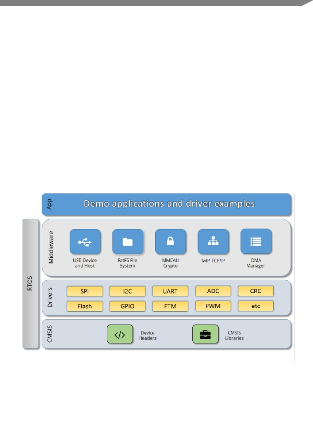
Overview
The MCUXpresso SDK architecture consists of five key components listed below.
1. The ARM Cortex Microcontroller Software Interface Standard (CMSIS) CORE compliance device-
specific header files, SOC Header, and CMSIS math/DSP libraries.
2. Peripheral Drivers
3. Real-time Operating Systems (RTOS)
4. Stacks and Middleware that integrate with the MCUXpresso SDK
5. Demo Applications based on the MCUXpresso SDK
Figure 1: MCUXpresso SDK Block Diagram
MCU header files
Each supported MCU device in the MCUXpresso SDK has an overall System-on Chip (SoC) memory-
NXP Semiconductors
MCUXpresso SDK API Reference Manual
5

mapped header file. This header file contains the memory map and register base address for each peripheral
and the IRQ vector table with associated vector numbers. The overall SoC header file provides a access to
the peripheral registers through pointers and predefined bit masks. In addition to the overall SoC memory-
mapped header file, the MCUXpresso SDK includes a feature header file for each device. The feature
header file allows NXP to deliver a single software driver for a given peripheral. The feature file ensures
that the driver is properly compiled for the target SOC.
CMSIS Support
Along with the SoC header files and peripheral extension header files, the MCUXpresso SDK also includes
common CMSIS header files for the ARM Cortex-M core and the math and DSP libraries from the latest
CMSIS release. The CMSIS DSP library source code is also included for reference.
MCUXpresso SDK Peripheral Drivers
The MCUXpresso SDK peripheral drivers mainly consist of low-level functional APIs for the MCU
product family on-chip peripherals and also of high-level transactional APIs for some bus drivers/DM-
A driver/eDMA driver to quickly enable the peripherals and perform transfers.
All MCUXpresso SDK peripheral drivers only depend on the CMSIS headers, device feature files, fsl_-
common.h, and fsl_clock.h files so that users can easily pull selected drivers and their dependencies into
projects. With the exception of the clock/power-relevant peripherals, each peripheral has its own driver.
Peripheral drivers handle the peripheral clock gating/ungating inside the drivers during initialization and
deinitialization respectively.
Low-level functional APIs provide common peripheral functionality, abstracting the hardware peripheral
register accesses into a set of stateless basic functional operations. These APIs primarily focus on the
control, configuration, and function of basic peripheral operations. The APIs hide the register access
details and various MCU peripheral instantiation differences so that the application can be abstracted from
the low-level hardware details. The API prototypes are intentionally similar to help ensure easy portability
across supported MCUXpresso SDK devices.
Transactional APIs provide a quick method for customers to utilize higher-level functionality of the pe-
ripherals. The transactional APIs utilize interrupts and perform asynchronous operations without user
intervention. Transactional APIs operate on high-level logic that requires data storage for internal oper-
ation context handling. However, the Peripheral Drivers do not allocate this memory space. Rather, the
user passes in the memory to the driver for internal driver operation. Transactional APIs ensure the NVIC
is enabled properly inside the drivers. The transactional APIs do not meet all customer needs, but provide
a baseline for development of custom user APIs.
Note that the transactional drivers never disable an NVIC after use. This is due to the shared nature of
interrupt vectors on devices. It is up to the user to ensure that NVIC interrupts are properly disabled after
usage is complete.
Interrupt handling for transactional APIs
A double weak mechanism is introduced for drivers with transactional API. The double weak indicates
two levels of weak vector entries. See the examples below:
PUBWEAK SPI0_IRQHandler
PUBWEAK SPI0_DriverIRQHandler
SPI0_IRQHandler
6
MCUXpresso SDK API Reference Manual
NXP Semiconductors

LDR R0, =SPI0_DriverIRQHandler
BX R0
The first level of the weak implementation are the functions defined in the vector table. In the devices/<-
DEVICE_NAME>/<TOOLCHAIN>/startup_<DEVICE_NAME>.s/.S file, the implementation of the
first layer weak function calls the second layer of weak function. The implementation of the second
layer weak function (ex. SPI0_DriverIRQHandler) jumps to itself (B .). The MCUXpresso SDK drivers
with transactional APIs provide the reimplementation of the second layer function inside of the peripheral
driver. If the MCUXpresso SDK drivers with transactional APIs are linked into the image, the SPI0_-
DriverIRQHandler is replaced with the function implemented in the MCUXpresso SDK SPI driver.
The reason for implementing the double weak functions is to provide a better user experience when using
the transactional APIs. For drivers with a transactional function, call the transactional APIs and the drivers
complete the interrupt-driven flow. Users are not required to redefine the vector entries out of the box. At
the same time, if users are not satisfied by the second layer weak function implemented in the MCU-
Xpresso SDK drivers, users can redefine the first layer weak function and implement their own interrupt
handler functions to suit their implementation.
The limitation of the double weak mechanism is that it cannot be used for peripherals that share the same
vector entry. For this use case, redefine the first layer weak function to enable the desired peripheral
interrupt functionality. For example, if the MCU’s UART0 and UART1 share the same vector entry,
redefine the UART0_UART1_IRQHandler according to the use case requirements.
Feature Header Files
The peripheral drivers are designed to be reusable regardless of the peripheral functional differences from
one MCU device to another. An overall Peripheral Feature Header File is provided for the MCUXpresso
SDK-supported MCU device to define the features or configuration differences for each sub-family device.
Application
See the Getting Started with MCUXpresso SDK document (MCUXSDKGSUG).
NXP Semiconductors
MCUXpresso SDK API Reference Manual
7

8
MCUXpresso SDK API Reference Manual
NXP Semiconductors

Chapter 4
Trademarks
Information in this document is provided solely to enable system and software implementers to use NXP
products. There are no express or implied copyright licenses granted hereunder to design or fabricate any
integrated circuits based on the information in this document.
How to Reach Us:
Home Page: nxp.com
Web Support: nxp.com/support
NXP reserves the right to make changes without further notice to any products herein. NXP makes no
warranty, representation, or guarantee regarding the suitability of its products for any particular purpose,
nor does NXP assume any liability arising out of the application or use of any product or circuit, and
specifically disclaims any and all liability, including without limitation consequential or incidental dam-
ages. “Typical” parameters that may be provided in NXP data sheets and/or specifications can and do vary
in different applications, and actual performance may vary over time. All operating parameters, including
“typicals,” must be validated for each customer application by customer’s technical experts. NXP does
not convey any license under its patent rights nor the rights of others. NXP sells products pursuant to
standard terms and conditions of sale, which can be found at the following address: nxp.com/Sales-
TermsandConditions
NXP, the NXP logo, Freescale, the Freescale logo, Kinetis, and Processor Expert are trademarks of N-
XP B.V. Tower is a trademark of NXP B.V. All other product or service names are the property of their
respective owners. ARM, ARM powered logo, Keil, and Cortex are registered trademarks of ARM Limited
(or its subsidiaries) in the EU and/or elsewhere. All rights reserved.
© 2017 NXP B.V.
NXP Semiconductors
MCUXpresso SDK API Reference Manual
9

10
MCUXpresso SDK API Reference Manual
NXP Semiconductors

Chapter 5
ADC16: 16-bit SAR Analog-to-Digital Converter Driver
5.1 Overview
The MCUXpresso SDK provides a peripheral driver for the 16-bit SAR Analog-to-Digital Converter (A-
DC16) module of MCUXpresso SDK devices.
5.2 Typical use case
5.2.1 Polling Configuration
adc16_config_t adc16ConfigStruct;
adc16_channel_config_t adc16ChannelConfigStruct;
ADC16_Init(DEMO_ADC16_INSTANCE);
ADC16_GetDefaultConfig(&adc16ConfigStruct);
ADC16_Configure(DEMO_ADC16_INSTANCE, &adc16ConfigStruct);
ADC16_EnableHardwareTrigger(DEMO_ADC16_INSTANCE, false);
#if defined(FSL_FEATURE_ADC16_HAS_CALIBRATION) && FSL_FEATURE_ADC16_HAS_CALIBRATION
if (kStatus_Success == ADC16_DoAutoCalibration(DEMO_ADC16_INSTANCE))
{
PRINTF("ADC16_DoAutoCalibration() Done.\r\n");
}
else
{
PRINTF("ADC16_DoAutoCalibration() Failed.\r\n");
}
#endif // FSL_FEATURE_ADC16_HAS_CALIBRATION
adc16ChannelConfigStruct.channelNumber = DEMO_ADC16_USER_CHANNEL;
adc16ChannelConfigStruct.enableInterruptOnConversionCompleted =
false;
#if defined(FSL_FEATURE_ADC16_HAS_DIFF_MODE) && FSL_FEATURE_ADC16_HAS_DIFF_MODE
adc16ChannelConfigStruct.enableDifferentialConversion =false;
#endif // FSL_FEATURE_ADC16_HAS_DIFF_MODE
while(1)
{
GETCHAR(); // Input any key in terminal console.
ADC16_ChannelConfigure(DEMO_ADC16_INSTANCE, DEMO_ADC16_CHANNEL_GROUP, &adc16ChannelConfigStruct);
while (kADC16_ChannelConversionDoneFlag !=
ADC16_ChannelGetStatusFlags(DEMO_ADC16_INSTANCE, DEMO_ADC16_CHANNEL_GROUP))
{
}
PRINTF("ADC Value: %d\r\n", ADC16_ChannelGetConversionValue(DEMO_ADC16_INSTANCE,
DEMO_ADC16_CHANNEL_GROUP));
}
5.2.2 Interrupt Configuration
volatile bool g_Adc16ConversionDoneFlag = false;
volatile uint32_t g_Adc16ConversionValue;
volatile uint32_t g_Adc16InterruptCount = 0U;
NXP Semiconductors
MCUXpresso SDK API Reference Manual
11

Typical use case
// ...
adc16_config_t adc16ConfigStruct;
adc16_channel_config_t adc16ChannelConfigStruct;
ADC16_Init(DEMO_ADC16_INSTANCE);
ADC16_GetDefaultConfig(&adc16ConfigStruct);
ADC16_Configure(DEMO_ADC16_INSTANCE, &adc16ConfigStruct);
ADC16_EnableHardwareTrigger(DEMO_ADC16_INSTANCE, false);
#if defined(FSL_FEATURE_ADC16_HAS_CALIBRATION) && FSL_FEATURE_ADC16_HAS_CALIBRATION
if (ADC16_DoAutoCalibration(DEMO_ADC16_INSTANCE))
{
PRINTF("ADC16_DoAutoCalibration() Done.\r\n");
}
else
{
PRINTF("ADC16_DoAutoCalibration() Failed.\r\n");
}
#endif // FSL_FEATURE_ADC16_HAS_CALIBRATION
adc16ChannelConfigStruct.channelNumber = DEMO_ADC16_USER_CHANNEL;
adc16ChannelConfigStruct.enableInterruptOnConversionCompleted =
true;// Enable the interrupt.
#if defined(FSL_FEATURE_ADC16_HAS_DIFF_MODE) && FSL_FEATURE_ADC16_HAS_DIFF_MODE
adc16ChannelConfigStruct.enableDifferentialConversion =false;
#endif // FSL_FEATURE_ADC16_HAS_DIFF_MODE
while(1)
{
GETCHAR(); // Input a key in the terminal console.
g_Adc16ConversionDoneFlag = false;
ADC16_ChannelConfigure(DEMO_ADC16_INSTANCE, DEMO_ADC16_CHANNEL_GROUP, &adc16ChannelConfigStruct);
while (!g_Adc16ConversionDoneFlag)
{
}
PRINTF("ADC Value: %d\r\n", g_Adc16ConversionValue);
PRINTF("ADC Interrupt Count: %d\r\n", g_Adc16InterruptCount);
}
// ...
void DEMO_ADC16_IRQHandler(void)
{
g_Adc16ConversionDoneFlag = true;
// Read the conversion result to clear the conversion completed flag.
g_Adc16ConversionValue = ADC16_ChannelConversionValue(DEMO_ADC16_INSTANCE, DEMO_ADC16_CHANNEL_GROUP
);
g_Adc16InterruptCount++;
}
Data Structures
• struct adc16_config_t
ADC16 converter configuration. More...
• struct adc16_hardware_compare_config_t
ADC16 Hardware comparison configuration. More...
• struct adc16_channel_config_t
ADC16 channel conversion configuration. More...
Enumerations
• enum _adc16_channel_status_flags {kADC16_ChannelConversionDoneFlag = ADC_SC1_COC-
O_MASK }
12
MCUXpresso SDK API Reference Manual
NXP Semiconductors

Typical use case
Channel status flags.
• enum _adc16_status_flags {
kADC16_ActiveFlag = ADC_SC2_ADACT_MASK,
kADC16_CalibrationFailedFlag = ADC_SC3_CALF_MASK }
Converter status flags.
• enum adc16_channel_mux_mode_t {
kADC16_ChannelMuxA = 0U,
kADC16_ChannelMuxB = 1U }
Channel multiplexer mode for each channel.
• enum adc16_clock_divider_t {
kADC16_ClockDivider1 = 0U,
kADC16_ClockDivider2 = 1U,
kADC16_ClockDivider4 = 2U,
kADC16_ClockDivider8 = 3U }
Clock divider for the converter.
• enum adc16_resolution_t {
kADC16_Resolution8or9Bit = 0U,
kADC16_Resolution12or13Bit = 1U,
kADC16_Resolution10or11Bit = 2U,
kADC16_ResolutionSE8Bit = kADC16_Resolution8or9Bit,
kADC16_ResolutionSE12Bit = kADC16_Resolution12or13Bit,
kADC16_ResolutionSE10Bit = kADC16_Resolution10or11Bit,
kADC16_ResolutionDF9Bit = kADC16_Resolution8or9Bit,
kADC16_ResolutionDF13Bit = kADC16_Resolution12or13Bit,
kADC16_ResolutionDF11Bit = kADC16_Resolution10or11Bit,
kADC16_Resolution16Bit = 3U,
kADC16_ResolutionSE16Bit = kADC16_Resolution16Bit,
kADC16_ResolutionDF16Bit = kADC16_Resolution16Bit }
Converter’s resolution.
• enum adc16_clock_source_t {
kADC16_ClockSourceAlt0 = 0U,
kADC16_ClockSourceAlt1 = 1U,
kADC16_ClockSourceAlt2 = 2U,
kADC16_ClockSourceAlt3 = 3U,
kADC16_ClockSourceAsynchronousClock = kADC16_ClockSourceAlt3 }
Clock source.
• enum adc16_long_sample_mode_t {
kADC16_LongSampleCycle24 = 0U,
kADC16_LongSampleCycle16 = 1U,
kADC16_LongSampleCycle10 = 2U,
kADC16_LongSampleCycle6 = 3U,
kADC16_LongSampleDisabled = 4U }
Long sample mode.
• enum adc16_reference_voltage_source_t {
kADC16_ReferenceVoltageSourceVref = 0U,
kADC16_ReferenceVoltageSourceValt = 1U }
NXP Semiconductors
MCUXpresso SDK API Reference Manual
13

Typical use case
Reference voltage source.
• enum adc16_hardware_average_mode_t {
kADC16_HardwareAverageCount4 = 0U,
kADC16_HardwareAverageCount8 = 1U,
kADC16_HardwareAverageCount16 = 2U,
kADC16_HardwareAverageCount32 = 3U,
kADC16_HardwareAverageDisabled = 4U }
Hardware average mode.
• enum adc16_hardware_compare_mode_t {
kADC16_HardwareCompareMode0 = 0U,
kADC16_HardwareCompareMode1 = 1U,
kADC16_HardwareCompareMode2 = 2U,
kADC16_HardwareCompareMode3 = 3U }
Hardware compare mode.
Driver version
• #define FSL_ADC16_DRIVER_VERSION (MAKE_VERSION(2, 0, 0))
ADC16 driver version 2.0.0.
Initialization
• void ADC16_Init (ADC_Type ∗base, const adc16_config_t ∗config)
Initializes the ADC16 module.
• void ADC16_Deinit (ADC_Type ∗base)
De-initializes the ADC16 module.
• void ADC16_GetDefaultConfig (adc16_config_t ∗config)
Gets an available pre-defined settings for the converter’s configuration.
• status_t ADC16_DoAutoCalibration (ADC_Type ∗base)
Automates the hardware calibration.
• static void ADC16_SetOffsetValue (ADC_Type ∗base, int16_t value)
Sets the offset value for the conversion result.
Advanced Features
• static void ADC16_EnableDMA (ADC_Type ∗base, bool enable)
Enables generating the DMA trigger when the conversion is complete.
• static void ADC16_EnableHardwareTrigger (ADC_Type ∗base, bool enable)
Enables the hardware trigger mode.
• void ADC16_SetChannelMuxMode (ADC_Type ∗base, adc16_channel_mux_mode_t mode)
Sets the channel mux mode.
• void ADC16_SetHardwareCompareConfig (ADC_Type ∗base, const adc16_hardware_compare_-
config_t ∗config)
Configures the hardware compare mode.
• void ADC16_SetHardwareAverage (ADC_Type ∗base, adc16_hardware_average_mode_t mode)
Sets the hardware average mode.
• uint32_t ADC16_GetStatusFlags (ADC_Type ∗base)
Gets the status flags of the converter.
• void ADC16_ClearStatusFlags (ADC_Type ∗base, uint32_t mask)
Clears the status flags of the converter.
14
MCUXpresso SDK API Reference Manual
NXP Semiconductors

Data Structure Documentation
Conversion Channel
• void ADC16_SetChannelConfig (ADC_Type ∗base, uint32_t channelGroup, const adc16_channel-
_config_t ∗config)
Configures the conversion channel.
• static uint32_t ADC16_GetChannelConversionValue (ADC_Type ∗base, uint32_t channelGroup)
Gets the conversion value.
• uint32_t ADC16_GetChannelStatusFlags (ADC_Type ∗base, uint32_t channelGroup)
Gets the status flags of channel.
5.3 Data Structure Documentation
5.3.1 struct adc16_config_t
Data Fields
•adc16_reference_voltage_source_t referenceVoltageSource
Select the reference voltage source.
•adc16_clock_source_t clockSource
Select the input clock source to converter.
• bool enableAsynchronousClock
Enable the asynchronous clock output.
•adc16_clock_divider_t clockDivider
Select the divider of input clock source.
•adc16_resolution_t resolution
Select the sample resolution mode.
•adc16_long_sample_mode_t longSampleMode
Select the long sample mode.
• bool enableHighSpeed
Enable the high-speed mode.
• bool enableLowPower
Enable low power.
• bool enableContinuousConversion
Enable continuous conversion mode.
NXP Semiconductors
MCUXpresso SDK API Reference Manual
15

Data Structure Documentation
5.3.1.0.0.1 Field Documentation
5.3.1.0.0.1.1 adc16_reference_voltage_source_t adc16_config_t::referenceVoltageSource
5.3.1.0.0.1.2 adc16_clock_source_t adc16_config_t::clockSource
5.3.1.0.0.1.3 bool adc16_config_t::enableAsynchronousClock
5.3.1.0.0.1.4 adc16_clock_divider_t adc16_config_t::clockDivider
5.3.1.0.0.1.5 adc16_resolution_t adc16_config_t::resolution
5.3.1.0.0.1.6 adc16_long_sample_mode_t adc16_config_t::longSampleMode
5.3.1.0.0.1.7 bool adc16_config_t::enableHighSpeed
5.3.1.0.0.1.8 bool adc16_config_t::enableLowPower
5.3.1.0.0.1.9 bool adc16_config_t::enableContinuousConversion
5.3.2 struct adc16_hardware_compare_config_t
Data Fields
•adc16_hardware_compare_mode_t hardwareCompareMode
Select the hardware compare mode.
• int16_t value1
Setting value1 for hardware compare mode.
• int16_t value2
Setting value2 for hardware compare mode.
5.3.2.0.0.2 Field Documentation
5.3.2.0.0.2.1 adc16_hardware_compare_mode_t adc16_hardware_compare_config_t::hardware-
CompareMode
See "adc16_hardware_compare_mode_t".
5.3.2.0.0.2.2 int16_t adc16_hardware_compare_config_t::value1
5.3.2.0.0.2.3 int16_t adc16_hardware_compare_config_t::value2
5.3.3 struct adc16_channel_config_t
Data Fields
• uint32_t channelNumber
Setting the conversion channel number.
• bool enableInterruptOnConversionCompleted
16
MCUXpresso SDK API Reference Manual
NXP Semiconductors

Enumeration Type Documentation
Generate an interrupt request once the conversion is completed.
• bool enableDifferentialConversion
Using Differential sample mode.
5.3.3.0.0.3 Field Documentation
5.3.3.0.0.3.1 uint32_t adc16_channel_config_t::channelNumber
The available range is 0-31. See channel connection information for each chip in Reference Manual
document.
5.3.3.0.0.3.2 bool adc16_channel_config_t::enableInterruptOnConversionCompleted
5.3.3.0.0.3.3 bool adc16_channel_config_t::enableDifferentialConversion
5.4 Macro Definition Documentation
5.4.1 #define FSL_ADC16_DRIVER_VERSION (MAKE_VERSION(2, 0, 0))
5.5 Enumeration Type Documentation
5.5.1 enum _adc16_channel_status_flags
Enumerator
kADC16_ChannelConversionDoneFlag Conversion done.
5.5.2 enum _adc16_status_flags
Enumerator
kADC16_ActiveFlag Converter is active.
kADC16_CalibrationFailedFlag Calibration is failed.
5.5.3 enum adc16_channel_mux_mode_t
For some ADC16 channels, there are two pin selections in channel multiplexer. For example, ADC0_SE4a
and ADC0_SE4b are the different channels that share the same channel number.
Enumerator
kADC16_ChannelMuxA For channel with channel mux a.
kADC16_ChannelMuxB For channel with channel mux b.
NXP Semiconductors
MCUXpresso SDK API Reference Manual
17

Enumeration Type Documentation
5.5.4 enum adc16_clock_divider_t
Enumerator
kADC16_ClockDivider1 For divider 1 from the input clock to the module.
kADC16_ClockDivider2 For divider 2 from the input clock to the module.
kADC16_ClockDivider4 For divider 4 from the input clock to the module.
kADC16_ClockDivider8 For divider 8 from the input clock to the module.
5.5.5 enum adc16_resolution_t
Enumerator
kADC16_Resolution8or9Bit Single End 8-bit or Differential Sample 9-bit.
kADC16_Resolution12or13Bit Single End 12-bit or Differential Sample 13-bit.
kADC16_Resolution10or11Bit Single End 10-bit or Differential Sample 11-bit.
kADC16_ResolutionSE8Bit Single End 8-bit.
kADC16_ResolutionSE12Bit Single End 12-bit.
kADC16_ResolutionSE10Bit Single End 10-bit.
kADC16_ResolutionDF9Bit Differential Sample 9-bit.
kADC16_ResolutionDF13Bit Differential Sample 13-bit.
kADC16_ResolutionDF11Bit Differential Sample 11-bit.
kADC16_Resolution16Bit Single End 16-bit or Differential Sample 16-bit.
kADC16_ResolutionSE16Bit Single End 16-bit.
kADC16_ResolutionDF16Bit Differential Sample 16-bit.
5.5.6 enum adc16_clock_source_t
Enumerator
kADC16_ClockSourceAlt0 Selection 0 of the clock source.
kADC16_ClockSourceAlt1 Selection 1 of the clock source.
kADC16_ClockSourceAlt2 Selection 2 of the clock source.
kADC16_ClockSourceAlt3 Selection 3 of the clock source.
kADC16_ClockSourceAsynchronousClock Using internal asynchronous clock.
5.5.7 enum adc16_long_sample_mode_t
Enumerator
kADC16_LongSampleCycle24 20 extra ADCK cycles, 24 ADCK cycles total.
kADC16_LongSampleCycle16 12 extra ADCK cycles, 16 ADCK cycles total.
18
MCUXpresso SDK API Reference Manual
NXP Semiconductors

Function Documentation
kADC16_LongSampleCycle10 6 extra ADCK cycles, 10 ADCK cycles total.
kADC16_LongSampleCycle6 2 extra ADCK cycles, 6 ADCK cycles total.
kADC16_LongSampleDisabled Disable the long sample feature.
5.5.8 enum adc16_reference_voltage_source_t
Enumerator
kADC16_ReferenceVoltageSourceVref For external pins pair of VrefH and VrefL.
kADC16_ReferenceVoltageSourceValt For alternate reference pair of ValtH and ValtL.
5.5.9 enum adc16_hardware_average_mode_t
Enumerator
kADC16_HardwareAverageCount4 For hardware average with 4 samples.
kADC16_HardwareAverageCount8 For hardware average with 8 samples.
kADC16_HardwareAverageCount16 For hardware average with 16 samples.
kADC16_HardwareAverageCount32 For hardware average with 32 samples.
kADC16_HardwareAverageDisabled Disable the hardware average feature.
5.5.10 enum adc16_hardware_compare_mode_t
Enumerator
kADC16_HardwareCompareMode0 x<value1.
kADC16_HardwareCompareMode1 x>value1.
kADC16_HardwareCompareMode2 if value1 <= value2, then x <value1 || x>value2; else,
value1 >x>value2.
kADC16_HardwareCompareMode3 if value1 <= value2, then value1 <= x <= value2; else x >=
value1 || x<= value2.
5.6 Function Documentation
5.6.1 void ADC16_Init ( ADC_Type ∗base, const adc16_config_t ∗config )
NXP Semiconductors
MCUXpresso SDK API Reference Manual
19

Function Documentation
Parameters
base ADC16 peripheral base address.
config Pointer to configuration structure. See "adc16_config_t".
5.6.2 void ADC16_Deinit ( ADC_Type ∗base )
Parameters
base ADC16 peripheral base address.
5.6.3 void ADC16_GetDefaultConfig ( adc16_config_t ∗config )
This function initializes the converter configuration structure with available settings. The default values
are as follows.
*config->referenceVoltageSource = kADC16_ReferenceVoltageSourceVref
;
*config->clockSource = kADC16_ClockSourceAsynchronousClock
;
*config->enableAsynchronousClock = true;
*config->clockDivider = kADC16_ClockDivider8;
*config->resolution = kADC16_ResolutionSE12Bit;
*config->longSampleMode = kADC16_LongSampleDisabled;
*config->enableHighSpeed = false;
*config->enableLowPower = false;
*config->enableContinuousConversion = false;
*
Parameters
config Pointer to the configuration structure.
5.6.4 status_t ADC16_DoAutoCalibration ( ADC_Type ∗base )
This auto calibration helps to adjust the plus/minus side gain automatically. Execute the calibration before
using the converter. Note that the hardware trigger should be used during the calibration.
20
MCUXpresso SDK API Reference Manual
NXP Semiconductors

Function Documentation
Parameters
base ADC16 peripheral base address.
Returns
Execution status.
Return values
kStatus_Success Calibration is done successfully.
kStatus_Fail Calibration has failed.
5.6.5 static void ADC16_SetOffsetValue ( ADC_Type ∗base, int16_t value )
[inline],[static]
This offset value takes effect on the conversion result. If the offset value is not zero, the reading result is
subtracted by it. Note, the hardware calibration fills the offset value automatically.
Parameters
base ADC16 peripheral base address.
value Setting offset value.
5.6.6 static void ADC16_EnableDMA ( ADC_Type ∗base, bool enable )
[inline],[static]
Parameters
base ADC16 peripheral base address.
enable Switcher of the DMA feature. "true" means enabled, "false" means not enabled.
5.6.7 static void ADC16_EnableHardwareTrigger ( ADC_Type ∗base, bool enable )
[inline],[static]
NXP Semiconductors
MCUXpresso SDK API Reference Manual
21

Function Documentation
Parameters
base ADC16 peripheral base address.
enable Switcher of the hardware trigger feature. "true" means enabled, "false" means not
enabled.
5.6.8 void ADC16_SetChannelMuxMode ( ADC_Type ∗base,
adc16_channel_mux_mode_t mode )
Some sample pins share the same channel index. The channel mux mode decides which pin is used for an
indicated channel.
Parameters
base ADC16 peripheral base address.
mode Setting channel mux mode. See "adc16_channel_mux_mode_t".
5.6.9 void ADC16_SetHardwareCompareConfig ( ADC_Type ∗base, const
adc16_hardware_compare_config_t ∗config )
The hardware compare mode provides a way to process the conversion result automatically by using
hardware. Only the result in the compare range is available. To compare the range, see "adc16_hardware-
_compare_mode_t" or the appopriate reference manual for more information.
Parameters
base ADC16 peripheral base address.
config Pointer to the "adc16_hardware_compare_config_t" structure. Passing "NULL" dis-
ables the feature.
5.6.10 void ADC16_SetHardwareAverage ( ADC_Type ∗base,
adc16_hardware_average_mode_t mode )
The hardware average mode provides a way to process the conversion result automatically by using hard-
ware. The multiple conversion results are accumulated and averaged internally making them easier to
read.
22
MCUXpresso SDK API Reference Manual
NXP Semiconductors

Function Documentation
Parameters
base ADC16 peripheral base address.
mode Setting the hardware average mode. See "adc16_hardware_average_mode_t".
5.6.11 uint32_t ADC16_GetStatusFlags ( ADC_Type ∗base )
Parameters
base ADC16 peripheral base address.
Returns
Flags’ mask if indicated flags are asserted. See "_adc16_status_flags".
5.6.12 void ADC16_ClearStatusFlags ( ADC_Type ∗base, uint32_t mask )
Parameters
base ADC16 peripheral base address.
mask Mask value for the cleared flags. See "_adc16_status_flags".
5.6.13 void ADC16_SetChannelConfig ( ADC_Type ∗base, uint32_t channelGroup,
const adc16_channel_config_t ∗config )
This operation triggers the conversion when in software trigger mode. When in hardware trigger mode,
this API configures the channel while the external trigger source helps to trigger the conversion.
Note that the "Channel Group" has a detailed description. To allow sequential conversions of the ADC
to be triggered by internal peripherals, the ADC has more than one group of status and control registers,
one for each conversion. The channel group parameter indicates which group of registers are used, for
example, channel group 0 is for Group A registers and channel group 1 is for Group B registers. The
channel groups are used in a "ping-pong" approach to control the ADC operation. At any point, only
one of the channel groups is actively controlling ADC conversions. The channel group 0 is used for
both software and hardware trigger modes. Channel group 1 and greater indicates multiple channel group
registers for use only in hardware trigger mode. See the chip configuration information in the appropriate
MCU reference manual for the number of SC1n registers (channel groups) specific to this device. Channel
group 1 or greater are not used for software trigger operation. Therefore, writing to these channel groups
does not initiate a new conversion. Updating the channel group 0 while a different channel group is
NXP Semiconductors
MCUXpresso SDK API Reference Manual
23

Function Documentation
actively controlling a conversion is allowed and vice versa. Writing any of the channel group registers
while that specific channel group is actively controlling a conversion aborts the current conversion.
24
MCUXpresso SDK API Reference Manual
NXP Semiconductors

Function Documentation
Parameters
base ADC16 peripheral base address.
channelGroup Channel group index.
config Pointer to the "adc16_channel_config_t" structure for the conversion channel.
5.6.14 static uint32_t ADC16_GetChannelConversionValue ( ADC_Type ∗base,
uint32_t channelGroup )[inline],[static]
Parameters
base ADC16 peripheral base address.
channelGroup Channel group index.
Returns
Conversion value.
5.6.15 uint32_t ADC16_GetChannelStatusFlags ( ADC_Type ∗base, uint32_t
channelGroup )
Parameters
base ADC16 peripheral base address.
channelGroup Channel group index.
Returns
Flags’ mask if indicated flags are asserted. See "_adc16_channel_status_flags".
NXP Semiconductors
MCUXpresso SDK API Reference Manual
25

Function Documentation
26
MCUXpresso SDK API Reference Manual
NXP Semiconductors

Chapter 6
CMP: Analog Comparator Driver
6.1 Overview
The MCUXpresso SDK provides a peripheral driver for the Analog Comparator (CMP) module of MCU-
Xpresso SDK devices.
The CMP driver is a basic comparator with advanced features. The APIs for the basic comparator enable
the CMP to compare the two voltages of the two input channels and create the output of the comparator
result. The APIs for advanced features can be used as the plug-in functions based on the basic comparator.
They can process the comparator’s output with hardware support.
6.2 Typical use case
6.2.1 Polling Configuration
int main(void)
{
cmp_config_t mCmpConfigStruct;
cmp_dac_config_t mCmpDacConfigStruct;
// ...
// Configures the comparator.
CMP_Init(DEMO_CMP_INSTANCE);
CMP_GetDefaultConfig(&mCmpConfigStruct);
CMP_Configure(DEMO_CMP_INSTANCE, &mCmpConfigStruct);
// Configures the DAC channel.
mCmpDacConfigStruct.referenceVoltageSource =
kCMP_VrefSourceVin2;// VCC.
mCmpDacConfigStruct.DACValue = 32U; // Half voltage of logic high-level.
CMP_SetDACConfig(DEMO_CMP_INSTANCE, &mCmpDacConfigStruct);
CMP_SetInputChannels(DEMO_CMP_INSTANCE, DEMO_CMP_USER_CHANNEL, DEMO_CMP_DAC_CHANNEL
);
while (1)
{
if (0U != (kCMP_OutputAssertEventFlag &
CMP_GetStatusFlags(DEMO_CMP_INSTANCE)))
{
// Do something.
}
else
{
// Do something.
}
}
}
NXP Semiconductors
MCUXpresso SDK API Reference Manual
27

Typical use case
6.2.2 Interrupt Configuration
volatile uint32_t g_CmpFlags = 0U;
// ...
void DEMO_CMP_IRQ_HANDLER_FUNC(void)
{
g_CmpFlags = CMP_GetStatusFlags(DEMO_CMP_INSTANCE);
CMP_ClearStatusFlags(DEMO_CMP_INSTANCE, kCMP_OutputRisingEventFlag |
kCMP_OutputFallingEventFlag);
if (0U != (g_CmpFlags & kCMP_OutputRisingEventFlag))
{
// Do something.
}
else if (0U != (g_CmpFlags & kCMP_OutputFallingEventFlag))
{
// Do something.
}
}
int main(void)
{
cmp_config_t mCmpConfigStruct;
cmp_dac_config_t mCmpDacConfigStruct;
// ...
EnableIRQ(DEMO_CMP_IRQ_ID);
// ...
// Configures the comparator.
CMP_Init(DEMO_CMP_INSTANCE);
CMP_GetDefaultConfig(&mCmpConfigStruct);
CMP_Configure(DEMO_CMP_INSTANCE, &mCmpConfigStruct);
// Configures the DAC channel.
mCmpDacConfigStruct.referenceVoltageSource =
kCMP_VrefSourceVin2;// VCC.
mCmpDacConfigStruct.DACValue = 32U; // Half voltage of logic high-level.
CMP_SetDACConfig(DEMO_CMP_INSTANCE, &mCmpDacConfigStruct);
CMP_SetInputChannels(DEMO_CMP_INSTANCE, DEMO_CMP_USER_CHANNEL, DEMO_CMP_DAC_CHANNEL
);
// Enables the output rising and falling interrupts.
CMP_EnableInterrupts(DEMO_CMP_INSTANCE,
kCMP_OutputRisingInterruptEnable |
kCMP_OutputFallingInterruptEnable);
while (1)
{
}
}
Data Structures
• struct cmp_config_t
Configures the comparator. More...
• struct cmp_filter_config_t
Configures the filter. More...
• struct cmp_dac_config_t
Configures the internal DAC. More...
28
MCUXpresso SDK API Reference Manual
NXP Semiconductors

Typical use case
Enumerations
• enum _cmp_interrupt_enable {
kCMP_OutputRisingInterruptEnable = CMP_SCR_IER_MASK,
kCMP_OutputFallingInterruptEnable = CMP_SCR_IEF_MASK }
Interrupt enable/disable mask.
• enum _cmp_status_flags {
kCMP_OutputRisingEventFlag = CMP_SCR_CFR_MASK,
kCMP_OutputFallingEventFlag = CMP_SCR_CFF_MASK,
kCMP_OutputAssertEventFlag = CMP_SCR_COUT_MASK }
Status flags’ mask.
• enum cmp_hysteresis_mode_t {
kCMP_HysteresisLevel0 = 0U,
kCMP_HysteresisLevel1 = 1U,
kCMP_HysteresisLevel2 = 2U,
kCMP_HysteresisLevel3 = 3U }
CMP Hysteresis mode.
• enum cmp_reference_voltage_source_t {
kCMP_VrefSourceVin1 = 0U,
kCMP_VrefSourceVin2 = 1U }
CMP Voltage Reference source.
Driver version
• #define FSL_CMP_DRIVER_VERSION (MAKE_VERSION(2, 0, 0))
CMP driver version 2.0.0.
Initialization
• void CMP_Init (CMP_Type ∗base, const cmp_config_t ∗config)
Initializes the CMP.
• void CMP_Deinit (CMP_Type ∗base)
De-initializes the CMP module.
• static void CMP_Enable (CMP_Type ∗base, bool enable)
Enables/disables the CMP module.
• void CMP_GetDefaultConfig (cmp_config_t ∗config)
Initializes the CMP user configuration structure.
• void CMP_SetInputChannels (CMP_Type ∗base, uint8_t positiveChannel, uint8_t negativeChannel)
Sets the input channels for the comparator.
Advanced Features
• void CMP_EnableDMA (CMP_Type ∗base, bool enable)
Enables/disables the DMA request for rising/falling events.
• void CMP_SetFilterConfig (CMP_Type ∗base, const cmp_filter_config_t ∗config)
Configures the filter.
• void CMP_SetDACConfig (CMP_Type ∗base, const cmp_dac_config_t ∗config)
Configures the internal DAC.
• void CMP_EnableInterrupts (CMP_Type ∗base, uint32_t mask)
Enables the interrupts.
NXP Semiconductors
MCUXpresso SDK API Reference Manual
29

Data Structure Documentation
• void CMP_DisableInterrupts (CMP_Type ∗base, uint32_t mask)
Disables the interrupts.
Results
• uint32_t CMP_GetStatusFlags (CMP_Type ∗base)
Gets the status flags.
• void CMP_ClearStatusFlags (CMP_Type ∗base, uint32_t mask)
Clears the status flags.
6.3 Data Structure Documentation
6.3.1 struct cmp_config_t
Data Fields
• bool enableCmp
Enable the CMP module.
•cmp_hysteresis_mode_t hysteresisMode
CMP Hysteresis mode.
• bool enableHighSpeed
Enable High-speed (HS) comparison mode.
• bool enableInvertOutput
Enable the inverted comparator output.
• bool useUnfilteredOutput
Set the compare output(COUT) to equal COUTA(true) or COUT(false).
• bool enablePinOut
The comparator output is available on the associated pin.
• bool enableTriggerMode
Enable the trigger mode.
30
MCUXpresso SDK API Reference Manual
NXP Semiconductors

Data Structure Documentation
6.3.1.0.0.4 Field Documentation
6.3.1.0.0.4.1 bool cmp_config_t::enableCmp
6.3.1.0.0.4.2 cmp_hysteresis_mode_t cmp_config_t::hysteresisMode
6.3.1.0.0.4.3 bool cmp_config_t::enableHighSpeed
6.3.1.0.0.4.4 bool cmp_config_t::enableInvertOutput
6.3.1.0.0.4.5 bool cmp_config_t::useUnfilteredOutput
6.3.1.0.0.4.6 bool cmp_config_t::enablePinOut
6.3.1.0.0.4.7 bool cmp_config_t::enableTriggerMode
6.3.2 struct cmp_filter_config_t
Data Fields
• uint8_t filterCount
Filter Sample Count.
• uint8_t filterPeriod
Filter Sample Period.
6.3.2.0.0.5 Field Documentation
6.3.2.0.0.5.1 uint8_t cmp_filter_config_t::filterCount
Available range is 1-7; 0 disables the filter.
6.3.2.0.0.5.2 uint8_t cmp_filter_config_t::filterPeriod
The divider to the bus clock. Available range is 0-255.
6.3.3 struct cmp_dac_config_t
Data Fields
•cmp_reference_voltage_source_t referenceVoltageSource
Supply voltage reference source.
• uint8_t DACValue
Value for the DAC Output Voltage.
NXP Semiconductors
MCUXpresso SDK API Reference Manual
31

Enumeration Type Documentation
6.3.3.0.0.6 Field Documentation
6.3.3.0.0.6.1 cmp_reference_voltage_source_t cmp_dac_config_t::referenceVoltageSource
6.3.3.0.0.6.2 uint8_t cmp_dac_config_t::DACValue
Available range is 0-63.
6.4 Macro Definition Documentation
6.4.1 #define FSL_CMP_DRIVER_VERSION (MAKE_VERSION(2, 0, 0))
6.5 Enumeration Type Documentation
6.5.1 enum _cmp_interrupt_enable
Enumerator
kCMP_OutputRisingInterruptEnable Comparator interrupt enable rising.
kCMP_OutputFallingInterruptEnable Comparator interrupt enable falling.
6.5.2 enum _cmp_status_flags
Enumerator
kCMP_OutputRisingEventFlag Rising-edge on the comparison output has occurred.
kCMP_OutputFallingEventFlag Falling-edge on the comparison output has occurred.
kCMP_OutputAssertEventFlag Return the current value of the analog comparator output.
6.5.3 enum cmp_hysteresis_mode_t
Enumerator
kCMP_HysteresisLevel0 Hysteresis level 0.
kCMP_HysteresisLevel1 Hysteresis level 1.
kCMP_HysteresisLevel2 Hysteresis level 2.
kCMP_HysteresisLevel3 Hysteresis level 3.
6.5.4 enum cmp_reference_voltage_source_t
Enumerator
kCMP_VrefSourceVin1 Vin1 is selected as a resistor ladder network supply reference Vin.
kCMP_VrefSourceVin2 Vin2 is selected as a resistor ladder network supply reference Vin.
32
MCUXpresso SDK API Reference Manual
NXP Semiconductors
Function Documentation
6.6 Function Documentation
6.6.1 void CMP_Init ( CMP_Type ∗base, const cmp_config_t ∗config )
This function initializes the CMP module. The operations included are as follows.
• Enabling the clock for CMP module.
• Configuring the comparator.
• Enabling the CMP module. Note that for some devices, multiple CMP instances share the same
clock gate. In this case, to enable the clock for any instance enables all CMPs. See the appropriate
MCU reference manual for the clock assignment of the CMP.
Parameters
base CMP peripheral base address.
config Pointer to the configuration structure.
6.6.2 void CMP_Deinit ( CMP_Type ∗base )
This function de-initializes the CMP module. The operations included are as follows.
• Disabling the CMP module.
• Disabling the clock for CMP module.
This function disables the clock for the CMP. Note that for some devices, multiple CMP instances share
the same clock gate. In this case, before disabling the clock for the CMP, ensure that all the CMP instances
are not used.
Parameters
base CMP peripheral base address.
6.6.3 static void CMP_Enable ( CMP_Type ∗base, bool enable )[inline],
[static]
Parameters
base CMP peripheral base address.
NXP Semiconductors
MCUXpresso SDK API Reference Manual
33

Function Documentation
enable Enables or disables the module.
6.6.4 void CMP_GetDefaultConfig ( cmp_config_t ∗config )
This function initializes the user configuration structure to these default values.
*config->enableCmp = true;
*config->hysteresisMode = kCMP_HysteresisLevel0;
*config->enableHighSpeed = false;
*config->enableInvertOutput = false;
*config->useUnfilteredOutput = false;
*config->enablePinOut = false;
*config->enableTriggerMode = false;
*
Parameters
config Pointer to the configuration structure.
6.6.5 void CMP_SetInputChannels ( CMP_Type ∗base, uint8_t positiveChannel,
uint8_t negativeChannel )
This function sets the input channels for the comparator. Note that two input channels cannot be set the
same way in the application. When the user selects the same input from the analog mux to the positive
and negative port, the comparator is disabled automatically.
Parameters
base CMP peripheral base address.
positive-
Channel
Positive side input channel number. Available range is 0-7.
negative-
Channel
Negative side input channel number. Available range is 0-7.
6.6.6 void CMP_EnableDMA ( CMP_Type ∗base, bool enable )
This function enables/disables the DMA request for rising/falling events. Either event triggers the genera-
tion of the DMA request from CMP if the DMA feature is enabled. Both events are ignored for generating
the DMA request from the CMP if the DMA is disabled.
34
MCUXpresso SDK API Reference Manual
NXP Semiconductors
Function Documentation
Parameters
base CMP peripheral base address.
enable Enables or disables the feature.
6.6.7 void CMP_SetFilterConfig ( CMP_Type ∗base, const cmp_filter_config_t ∗
config )
Parameters
base CMP peripheral base address.
config Pointer to the configuration structure.
6.6.8 void CMP_SetDACConfig ( CMP_Type ∗base, const cmp_dac_config_t ∗
config )
Parameters
base CMP peripheral base address.
config Pointer to the configuration structure. "NULL" disables the feature.
6.6.9 void CMP_EnableInterrupts ( CMP_Type ∗base, uint32_t mask )
Parameters
base CMP peripheral base address.
mask Mask value for interrupts. See "_cmp_interrupt_enable".
6.6.10 void CMP_DisableInterrupts ( CMP_Type ∗base, uint32_t mask )
Parameters
NXP Semiconductors
MCUXpresso SDK API Reference Manual
35

Function Documentation
base CMP peripheral base address.
mask Mask value for interrupts. See "_cmp_interrupt_enable".
6.6.11 uint32_t CMP_GetStatusFlags ( CMP_Type ∗base )
Parameters
base CMP peripheral base address.
Returns
Mask value for the asserted flags. See "_cmp_status_flags".
6.6.12 void CMP_ClearStatusFlags ( CMP_Type ∗base, uint32_t mask )
Parameters
base CMP peripheral base address.
mask Mask value for the flags. See "_cmp_status_flags".
36
MCUXpresso SDK API Reference Manual
NXP Semiconductors

Chapter 7
COP: Watchdog Driver
7.1 Overview
The MCUXpresso SDK provides a peripheral driver for the Computer Operating Properly module (COP)
of MCUXpresso SDK devices.
7.2 Typical use case
cop_config_t config;
COP_GetDefaultConfig(&config);
config.timeoutCycles =kCOP_2Power8CyclesOr2Power16Cycles;
COP_Init(sim_base,&config);
Data Structures
• struct cop_config_t
Describes COP configuration structure. More...
Enumerations
• enum cop_clock_source_t {
kCOP_LpoClock = 0U,
kCOP_BusClock = 3U }
COP clock source selection.
• enum cop_timeout_cycles_t {
kCOP_2Power5CyclesOr2Power13Cycles = 1U,
kCOP_2Power8CyclesOr2Power16Cycles = 2U,
kCOP_2Power10CyclesOr2Power18Cycles = 3U }
Define the COP timeout cycles.
Driver version
• #define FSL_COP_DRIVER_VERSION (MAKE_VERSION(2, 0, 0))
COP driver version 2.0.0.
COP refresh sequence.
• #define COP_FIRST_BYTE_OF_REFRESH (0x55U)
First byte of refresh sequence.
• #define COP_SECOND_BYTE_OF_REFRESH (0xAAU)
Second byte of refresh sequence.
NXP Semiconductors
MCUXpresso SDK API Reference Manual
37

Enumeration Type Documentation
COP Functional Operation
• void COP_GetDefaultConfig (cop_config_t ∗config)
Initializes the COP configuration structure.
• void COP_Init (SIM_Type ∗base, const cop_config_t ∗config)
Initializes the COP module.
• static void COP_Disable (SIM_Type ∗base)
De-initializes the COP module.
• void COP_Refresh (SIM_Type ∗base)
Refreshes the COP timer.
7.3 Data Structure Documentation
7.3.1 struct cop_config_t
Data Fields
• bool enableWindowMode
COP run mode: window mode or normal mode.
•cop_clock_source_t clockSource
Set COP clock source.
•cop_timeout_cycles_t timeoutCycles
Set COP timeout value.
7.4 Macro Definition Documentation
7.4.1 #define FSL_COP_DRIVER_VERSION (MAKE_VERSION(2, 0, 0))
7.5 Enumeration Type Documentation
7.5.1 enum cop_clock_source_t
Enumerator
kCOP_LpoClock COP clock sourced from LPO.
kCOP_BusClock COP clock sourced from Bus clock.
7.5.2 enum cop_timeout_cycles_t
Enumerator
kCOP_2Power5CyclesOr2Power13Cycles 2∧5 or 2∧13 clock cycles
kCOP_2Power8CyclesOr2Power16Cycles 2∧8 or 2∧16 clock cycles
kCOP_2Power10CyclesOr2Power18Cycles 2∧10 or 2∧18 clock cycles
38
MCUXpresso SDK API Reference Manual
NXP Semiconductors

Function Documentation
7.6 Function Documentation
7.6.1 void COP_GetDefaultConfig ( cop_config_t ∗config )
This function initializes the COP configuration structure to default values. The default values are:
*copConfig->enableWindowMode = false;
*copConfig->timeoutMode = kCOP_LongTimeoutMode;
*copConfig->enableStop = false;
*copConfig->enableDebug = false;
*copConfig->clockSource = kCOP_LpoClock;
*copConfig->timeoutCycles = kCOP_2Power10CyclesOr2Power18Cycles;
*
Parameters
config Pointer to the COP configuration structure.
See Also
cop_config_t
7.6.2 void COP_Init ( SIM_Type ∗base, const cop_config_t ∗config )
This function configures the COP. After it is called, the COP starts running according to the configura-
tion. Because all COP control registers are write-once only, the COP_Init function and the COP_Disable
function can be called only once. A second call has no effect.
Example:
*cop_config_t config;
*COP_GetDefaultConfig(&config);
*config.timeoutCycles =kCOP_2Power8CyclesOr2Power16Cycles
;
*COP_Init(sim_base,&config);
*
Parameters
base SIM peripheral base address.
config The configuration of COP.
7.6.3 static void COP_Disable ( SIM_Type ∗base )[inline],[static]
This dedicated function is not provided. Instead, the COP_Disable function can be used to disable the
COP.
NXP Semiconductors
MCUXpresso SDK API Reference Manual
39

Function Documentation
Disables the COP module.
This function disables the COP Watchdog. Note: The COP configuration register is a write-once after
reset. To disable the COP Watchdog, call this function first.
40
MCUXpresso SDK API Reference Manual
NXP Semiconductors

Function Documentation
Parameters
base SIM peripheral base address.
7.6.4 void COP_Refresh ( SIM_Type ∗base )
This function feeds the COP.
Parameters
base SIM peripheral base address.
NXP Semiconductors
MCUXpresso SDK API Reference Manual
41

Function Documentation
42
MCUXpresso SDK API Reference Manual
NXP Semiconductors

Chapter 8
DAC: Digital-to-Analog Converter Driver
8.1 Overview
The MCUXpresso SDK provides a peripheral driver for the Digital-to-Analog Converter (DAC) module
of MCUXpresso SDK devices.
The DAC driver includes a basic DAC module (converter) and a DAC buffer.
The basic DAC module supports operations unique to the DAC converter in each DAC instance. The
APIs in this part are used in the initialization phase, which enables the DAC module in the application.
The APIs enable/disable the clock, enable/disable the module, and configure the converter. Call the initial
APIs to prepare the DAC module for the application. The DAC buffer operates the DAC hardware buffer.
The DAC module supports a hardware buffer to keep a group of DAC values to be converted. This feature
supports updating the DAC output value automatically by triggering the buffer read pointer to move in
the buffer. Use the APIs to configure the hardware buffer’s trigger mode, watermark, work mode, and use
size. Additionally, the APIs operate the DMA, interrupts, flags, the pointer (the index of the buffer), item
values, and so on.
Note that the most functional features are designed for the DAC hardware buffer.
8.2 Typical use case
8.2.1 Working as a basic DAC without the hardware buffer feature
// ...
// Configures the DAC.
DAC_GetDefaultConfig(&dacConfigStruct);
DAC_Init(DEMO_DAC_INSTANCE, &dacConfigStruct);
DAC_Enable(DEMO_DAC_INSTANCE, true);
DAC_SetBufferReadPointer(DEMO_DAC_INSTANCE, 0U);
// ...
DAC_SetBufferValue(DEMO_DAC_INSTANCE, 0U, dacValue);
8.2.2 Working with the hardware buffer
// ...
EnableIRQ(DEMO_DAC_IRQ_ID);
// ...
// Configures the DAC.
DAC_GetDefaultConfig(&dacConfigStruct);
DAC_Init(DEMO_DAC_INSTANCE, &dacConfigStruct);
DAC_Enable(DEMO_DAC_INSTANCE, true);
NXP Semiconductors
MCUXpresso SDK API Reference Manual
43

Typical use case
// Configures the DAC buffer.
DAC_GetDefaultBufferConfig(&dacBufferConfigStruct);
DAC_SetBufferConfig(DEMO_DAC_INSTANCE, &dacBufferConfigStruct);
DAC_SetBufferReadPointer(DEMO_DAC_INSTANCE, 0U); // Make sure the read pointer
to the start.
for (index = 0U, dacValue = 0; index < DEMO_DAC_USED_BUFFER_SIZE; index++, dacValue += (0xFFFU /
DEMO_DAC_USED_BUFFER_SIZE))
{
DAC_SetBufferValue(DEMO_DAC_INSTANCE, index, dacValue);
}
// Clears flags.
#if defined(FSL_FEATURE_DAC_HAS_WATERMARK_DETECTION) && FSL_FEATURE_DAC_HAS_WATERMARK_DETECTION
g_DacBufferWatermarkInterruptFlag = false;
#endif // FSL_FEATURE_DAC_HAS_WATERMARK_DETECTION
g_DacBufferReadPointerTopPositionInterruptFlag = false;
g_DacBufferReadPointerBottomPositionInterruptFlag = false;
// Enables interrupts.
mask = 0U;
#if defined(FSL_FEATURE_DAC_HAS_WATERMARK_DETECTION) && FSL_FEATURE_DAC_HAS_WATERMARK_DETECTION
mask |= kDAC_BufferWatermarkInterruptEnable;
#endif // FSL_FEATURE_DAC_HAS_WATERMARK_DETECTION
mask |= kDAC_BufferReadPointerTopInterruptEnable |
kDAC_BufferReadPointerBottomInterruptEnable;
DAC_EnableBuffer(DEMO_DAC_INSTANCE, true);
DAC_EnableBufferInterrupts(DEMO_DAC_INSTANCE, mask);
// ISR for the DAC interrupt.
void DEMO_DAC_IRQ_HANDLER_FUNC(void)
{
uint32_t flags = DAC_GetBufferStatusFlags(DEMO_DAC_INSTANCE);
#if defined(FSL_FEATURE_DAC_HAS_WATERMARK_DETECTION) && FSL_FEATURE_DAC_HAS_WATERMARK_DETECTION
if (kDAC_BufferWatermarkFlag == (kDAC_BufferWatermarkFlag & flags))
{
g_DacBufferWatermarkInterruptFlag = true;
}
#endif // FSL_FEATURE_DAC_HAS_WATERMARK_DETECTION
if (kDAC_BufferReadPointerTopPositionFlag == (
kDAC_BufferReadPointerTopPositionFlag & flags))
{
g_DacBufferReadPointerTopPositionInterruptFlag = true;
}
if (kDAC_BufferReadPointerBottomPositionFlag == (
kDAC_BufferReadPointerBottomPositionFlag & flags))
{
g_DacBufferReadPointerBottomPositionInterruptFlag = true;
}
DAC_ClearBufferStatusFlags(DEMO_DAC_INSTANCE, flags); /*Clear flags. */
}
Data Structures
• struct dac_config_t
DAC module configuration. More...
• struct dac_buffer_config_t
DAC buffer configuration. More...
Enumerations
• enum _dac_buffer_status_flags {
kDAC_BufferReadPointerTopPositionFlag = DAC_SR_DACBFRPTF_MASK,
kDAC_BufferReadPointerBottomPositionFlag = DAC_SR_DACBFRPBF_MASK }
44
MCUXpresso SDK API Reference Manual
NXP Semiconductors

Typical use case
DAC buffer flags.
• enum _dac_buffer_interrupt_enable {
kDAC_BufferReadPointerTopInterruptEnable = DAC_C0_DACBTIEN_MASK,
kDAC_BufferReadPointerBottomInterruptEnable = DAC_C0_DACBBIEN_MASK }
DAC buffer interrupts.
• enum dac_reference_voltage_source_t {
kDAC_ReferenceVoltageSourceVref1 = 0U,
kDAC_ReferenceVoltageSourceVref2 = 1U }
DAC reference voltage source.
• enum dac_buffer_trigger_mode_t {
kDAC_BufferTriggerByHardwareMode = 0U,
kDAC_BufferTriggerBySoftwareMode = 1U }
DAC buffer trigger mode.
• enum dac_buffer_work_mode_t {
kDAC_BufferWorkAsNormalMode = 0U,
kDAC_BufferWorkAsOneTimeScanMode }
DAC buffer work mode.
Driver version
• #define FSL_DAC_DRIVER_VERSION (MAKE_VERSION(2, 0, 1))
DAC driver version 2.0.1.
Initialization
• void DAC_Init (DAC_Type ∗base, const dac_config_t ∗config)
Initializes the DAC module.
• void DAC_Deinit (DAC_Type ∗base)
De-initializes the DAC module.
• void DAC_GetDefaultConfig (dac_config_t ∗config)
Initializes the DAC user configuration structure.
• static void DAC_Enable (DAC_Type ∗base, bool enable)
Enables the DAC module.
Buffer
• static void DAC_EnableBuffer (DAC_Type ∗base, bool enable)
Enables the DAC buffer.
• void DAC_SetBufferConfig (DAC_Type ∗base, const dac_buffer_config_t ∗config)
Configures the CMP buffer.
• void DAC_GetDefaultBufferConfig (dac_buffer_config_t ∗config)
Initializes the DAC buffer configuration structure.
• static void DAC_EnableBufferDMA (DAC_Type ∗base, bool enable)
Enables the DMA for DAC buffer.
• void DAC_SetBufferValue (DAC_Type ∗base, uint8_t index, uint16_t value)
Sets the value for items in the buffer.
• static void DAC_DoSoftwareTriggerBuffer (DAC_Type ∗base)
Triggers the buffer using software and updates the read pointer of the DAC buffer.
• static uint8_t DAC_GetBufferReadPointer (DAC_Type ∗base)
Gets the current read pointer of the DAC buffer.
NXP Semiconductors
MCUXpresso SDK API Reference Manual
45

Data Structure Documentation
• void DAC_SetBufferReadPointer (DAC_Type ∗base, uint8_t index)
Sets the current read pointer of the DAC buffer.
• void DAC_EnableBufferInterrupts (DAC_Type ∗base, uint32_t mask)
Enables interrupts for the DAC buffer.
• void DAC_DisableBufferInterrupts (DAC_Type ∗base, uint32_t mask)
Disables interrupts for the DAC buffer.
• uint32_t DAC_GetBufferStatusFlags (DAC_Type ∗base)
Gets the flags of events for the DAC buffer.
• void DAC_ClearBufferStatusFlags (DAC_Type ∗base, uint32_t mask)
Clears the flags of events for the DAC buffer.
8.3 Data Structure Documentation
8.3.1 struct dac_config_t
Data Fields
•dac_reference_voltage_source_t referenceVoltageSource
Select the DAC reference voltage source.
• bool enableLowPowerMode
Enable the low-power mode.
8.3.1.0.0.7 Field Documentation
8.3.1.0.0.7.1 dac_reference_voltage_source_t dac_config_t::referenceVoltageSource
8.3.1.0.0.7.2 bool dac_config_t::enableLowPowerMode
8.3.2 struct dac_buffer_config_t
Data Fields
•dac_buffer_trigger_mode_t triggerMode
Select the buffer’s trigger mode.
•dac_buffer_work_mode_t workMode
Select the buffer’s work mode.
• uint8_t upperLimit
Set the upper limit for the buffer index.
8.3.2.0.0.8 Field Documentation
8.3.2.0.0.8.1 dac_buffer_trigger_mode_t dac_buffer_config_t::triggerMode
8.3.2.0.0.8.2 dac_buffer_work_mode_t dac_buffer_config_t::workMode
8.3.2.0.0.8.3 uint8_t dac_buffer_config_t::upperLimit
Normally, 0-15 is available for a buffer with 16 items.
46
MCUXpresso SDK API Reference Manual
NXP Semiconductors

Enumeration Type Documentation
8.4 Macro Definition Documentation
8.4.1 #define FSL_DAC_DRIVER_VERSION (MAKE_VERSION(2, 0, 1))
8.5 Enumeration Type Documentation
8.5.1 enum _dac_buffer_status_flags
Enumerator
kDAC_BufferReadPointerTopPositionFlag DAC Buffer Read Pointer Top Position Flag.
kDAC_BufferReadPointerBottomPositionFlag DAC Buffer Read Pointer Bottom Position Flag.
8.5.2 enum _dac_buffer_interrupt_enable
Enumerator
kDAC_BufferReadPointerTopInterruptEnable DAC Buffer Read Pointer Top Flag Interrupt En-
able.
kDAC_BufferReadPointerBottomInterruptEnable DAC Buffer Read Pointer Bottom Flag Inter-
rupt Enable.
8.5.3 enum dac_reference_voltage_source_t
Enumerator
kDAC_ReferenceVoltageSourceVref1 The DAC selects DACREF_1 as the reference voltage.
kDAC_ReferenceVoltageSourceVref2 The DAC selects DACREF_2 as the reference voltage.
8.5.4 enum dac_buffer_trigger_mode_t
Enumerator
kDAC_BufferTriggerByHardwareMode The DAC hardware trigger is selected.
kDAC_BufferTriggerBySoftwareMode The DAC software trigger is selected.
8.5.5 enum dac_buffer_work_mode_t
Enumerator
kDAC_BufferWorkAsNormalMode Normal mode.
kDAC_BufferWorkAsOneTimeScanMode One-Time Scan mode.
NXP Semiconductors
MCUXpresso SDK API Reference Manual
47

Function Documentation
8.6 Function Documentation
8.6.1 void DAC_Init ( DAC_Type ∗base, const dac_config_t ∗config )
This function initializes the DAC module including the following operations.
• Enabling the clock for DAC module.
• Configuring the DAC converter with a user configuration.
• Enabling the DAC module.
Parameters
base DAC peripheral base address.
config Pointer to the configuration structure. See "dac_config_t".
8.6.2 void DAC_Deinit ( DAC_Type ∗base )
This function de-initializes the DAC module including the following operations.
• Disabling the DAC module.
• Disabling the clock for the DAC module.
Parameters
base DAC peripheral base address.
8.6.3 void DAC_GetDefaultConfig ( dac_config_t ∗config )
This function initializes the user configuration structure to a default value. The default values are as
follows.
*config->referenceVoltageSource = kDAC_ReferenceVoltageSourceVref2;
*config->enableLowPowerMode = false;
*
Parameters
config Pointer to the configuration structure. See "dac_config_t".
8.6.4 static void DAC_Enable ( DAC_Type ∗base, bool enable )[inline],
[static]
48
MCUXpresso SDK API Reference Manual
NXP Semiconductors

Function Documentation
Parameters
base DAC peripheral base address.
enable Enables or disables the feature.
8.6.5 static void DAC_EnableBuffer ( DAC_Type ∗base, bool enable )[inline],
[static]
Parameters
base DAC peripheral base address.
enable Enables or disables the feature.
8.6.6 void DAC_SetBufferConfig ( DAC_Type ∗base, const dac_buffer_config_t ∗
config )
Parameters
base DAC peripheral base address.
config Pointer to the configuration structure. See "dac_buffer_config_t".
8.6.7 void DAC_GetDefaultBufferConfig ( dac_buffer_config_t ∗config )
This function initializes the DAC buffer configuration structure to default values. The default values are
as follows.
*config->triggerMode = kDAC_BufferTriggerBySoftwareMode;
*config->watermark = kDAC_BufferWatermark1Word;
*config->workMode = kDAC_BufferWorkAsNormalMode;
*config->upperLimit = DAC_DATL_COUNT - 1U;
*
Parameters
NXP Semiconductors
MCUXpresso SDK API Reference Manual
49

Function Documentation
config Pointer to the configuration structure. See "dac_buffer_config_t".
8.6.8 static void DAC_EnableBufferDMA ( DAC_Type ∗base, bool enable )
[inline],[static]
Parameters
base DAC peripheral base address.
enable Enables or disables the feature.
8.6.9 void DAC_SetBufferValue ( DAC_Type ∗base, uint8_t index, uint16_t value )
Parameters
base DAC peripheral base address.
index Setting the index for items in the buffer. The available index should not exceed the
size of the DAC buffer.
value Setting the value for items in the buffer. 12-bits are available.
8.6.10 static void DAC_DoSoftwareTriggerBuffer ( DAC_Type ∗base )[inline],
[static]
This function triggers the function using software. The read pointer of the DAC buffer is updated with one
step after this function is called. Changing the read pointer depends on the buffer’s work mode.
Parameters
base DAC peripheral base address.
8.6.11 static uint8_t DAC_GetBufferReadPointer ( DAC_Type ∗base )[inline],
[static]
This function gets the current read pointer of the DAC buffer. The current output value depends on the
item indexed by the read pointer. It is updated either by a software trigger or a hardware trigger.
50
MCUXpresso SDK API Reference Manual
NXP Semiconductors

Function Documentation
Parameters
base DAC peripheral base address.
Returns
The current read pointer of the DAC buffer.
8.6.12 void DAC_SetBufferReadPointer ( DAC_Type ∗base, uint8_t index )
This function sets the current read pointer of the DAC buffer. The current output value depends on the
item indexed by the read pointer. It is updated either by a software trigger or a hardware trigger. After the
read pointer changes, the DAC output value also changes.
Parameters
base DAC peripheral base address.
index Setting an index value for the pointer.
8.6.13 void DAC_EnableBufferInterrupts ( DAC_Type ∗base, uint32_t mask )
Parameters
base DAC peripheral base address.
mask Mask value for interrupts. See "_dac_buffer_interrupt_enable".
8.6.14 void DAC_DisableBufferInterrupts ( DAC_Type ∗base, uint32_t mask )
Parameters
base DAC peripheral base address.
mask Mask value for interrupts. See "_dac_buffer_interrupt_enable".
8.6.15 uint32_t DAC_GetBufferStatusFlags ( DAC_Type ∗base )
NXP Semiconductors
MCUXpresso SDK API Reference Manual
51

Function Documentation
Parameters
base DAC peripheral base address.
Returns
Mask value for the asserted flags. See "_dac_buffer_status_flags".
8.6.16 void DAC_ClearBufferStatusFlags ( DAC_Type ∗base, uint32_t mask )
Parameters
base DAC peripheral base address.
mask Mask value for flags. See "_dac_buffer_status_flags_t".
52
MCUXpresso SDK API Reference Manual
NXP Semiconductors

Chapter 9
DMA: Direct Memory Access Controller Driver
9.1 Overview
The MCUXpresso SDK provides a peripheral driver for the Direct Memory Access (DMA) of MCU-
Xpresso SDK devices.
9.2 Typical use case
9.2.1 DMA Operation
dma_transfer_config_t transferConfig;
uint32_t transferDone = false;
DMA_Init(DMA0);
DMA_CreateHandle(&g_DMA_Handle, DMA0, channel);
DMA_InstallCallback(&g_DMA_Handle, DMA_Callback, &transferDone);
DMA_PrepareTransfer(&transferConfig, srcAddr, srcWidth, destAddr, destWidth,
transferBytes,
kDMA_MemoryToMemory);
DMA_SubmitTransfer(&g_DMA_Handle, &transferConfig, true);
DMA_StartTransfer(&g_DMA_Handle);
/*Wait for DMA transfer finish */
while (transferDone != true);
Data Structures
• struct dma_transfer_config_t
DMA transfer configuration structure. More...
• struct dma_channel_link_config_t
DMA transfer configuration structure. More...
• struct dma_handle_t
DMA DMA handle structure. More...
Typedefs
• typedef void(∗dma_callback )(struct _dma_handle ∗handle, void ∗userData)
Callback function prototype for the DMA driver.
Enumerations
• enum _dma_channel_status_flags {
kDMA_TransactionsBCRFlag = DMA_DSR_BCR_BCR_MASK,
kDMA_TransactionsDoneFlag = DMA_DSR_BCR_DONE_MASK,
kDMA_TransactionsBusyFlag = DMA_DSR_BCR_BSY_MASK,
kDMA_TransactionsRequestFlag = DMA_DSR_BCR_REQ_MASK,
kDMA_BusErrorOnDestinationFlag = DMA_DSR_BCR_BED_MASK,
kDMA_BusErrorOnSourceFlag = DMA_DSR_BCR_BES_MASK,
NXP Semiconductors
MCUXpresso SDK API Reference Manual
53

Typical use case
kDMA_ConfigurationErrorFlag = DMA_DSR_BCR_CE_MASK }
status flag for the DMA driver.
• enum dma_transfer_size_t {
kDMA_Transfersize32bits = 0x0U,
kDMA_Transfersize8bits,
kDMA_Transfersize16bits }
DMA transfer size type.
• enum dma_modulo_t {
kDMA_ModuloDisable = 0x0U,
kDMA_Modulo16Bytes,
kDMA_Modulo32Bytes,
kDMA_Modulo64Bytes,
kDMA_Modulo128Bytes,
kDMA_Modulo256Bytes,
kDMA_Modulo512Bytes,
kDMA_Modulo1KBytes,
kDMA_Modulo2KBytes,
kDMA_Modulo4KBytes,
kDMA_Modulo8KBytes,
kDMA_Modulo16KBytes,
kDMA_Modulo32KBytes,
kDMA_Modulo64KBytes,
kDMA_Modulo128KBytes,
kDMA_Modulo256KBytes }
Configuration type for the DMA modulo.
• enum dma_channel_link_type_t {
kDMA_ChannelLinkDisable = 0x0U,
kDMA_ChannelLinkChannel1AndChannel2,
kDMA_ChannelLinkChannel1,
kDMA_ChannelLinkChannel1AfterBCR0 }
DMA channel link type.
• enum dma_transfer_type_t {
kDMA_MemoryToMemory = 0x0U,
kDMA_PeripheralToMemory,
kDMA_MemoryToPeripheral }
DMA transfer type.
• enum dma_transfer_options_t {
kDMA_NoOptions = 0x0U,
kDMA_EnableInterrupt }
DMA transfer options.
• enum _dma_transfer_status
DMA transfer status.
Driver version
• #define FSL_DMA_DRIVER_VERSION (MAKE_VERSION(2, 0, 1))
DMA driver version 2.0.1.
54
MCUXpresso SDK API Reference Manual
NXP Semiconductors

Typical use case
DMA Initialization and De-initialization
• void DMA_Init (DMA_Type ∗base)
Initializes the DMA peripheral.
• void DMA_Deinit (DMA_Type ∗base)
Deinitializes the DMA peripheral.
DMA Channel Operation
• void DMA_ResetChannel (DMA_Type ∗base, uint32_t channel)
Resets the DMA channel.
• void DMA_SetTransferConfig (DMA_Type ∗base, uint32_t channel, const dma_transfer_config_t
∗config)
Configures the DMA transfer attribute.
• void DMA_SetChannelLinkConfig (DMA_Type ∗base, uint32_t channel, const dma_channel_link-
_config_t ∗config)
Configures the DMA channel link feature.
• static void DMA_SetSourceAddress (DMA_Type ∗base, uint32_t channel, uint32_t srcAddr)
Sets the DMA source address for the DMA transfer.
• static void DMA_SetDestinationAddress (DMA_Type ∗base, uint32_t channel, uint32_t destAddr)
Sets the DMA destination address for the DMA transfer.
• static void DMA_SetTransferSize (DMA_Type ∗base, uint32_t channel, uint32_t size)
Sets the DMA transfer size for the DMA transfer.
• void DMA_SetModulo (DMA_Type ∗base, uint32_t channel, dma_modulo_t srcModulo, dma_-
modulo_t destModulo)
Sets the DMA modulo for the DMA transfer.
• static void DMA_EnableCycleSteal (DMA_Type ∗base, uint32_t channel, bool enable)
Enables the DMA cycle steal for the DMA transfer.
• static void DMA_EnableAutoAlign (DMA_Type ∗base, uint32_t channel, bool enable)
Enables the DMA auto align for the DMA transfer.
• static void DMA_EnableAsyncRequest (DMA_Type ∗base, uint32_t channel, bool enable)
Enables the DMA async request for the DMA transfer.
• static void DMA_EnableInterrupts (DMA_Type ∗base, uint32_t channel)
Enables an interrupt for the DMA transfer.
• static void DMA_DisableInterrupts (DMA_Type ∗base, uint32_t channel)
Disables an interrupt for the DMA transfer.
DMA Channel Transfer Operation
• static void DMA_EnableChannelRequest (DMA_Type ∗base, uint32_t channel)
Enables the DMA hardware channel request.
• static void DMA_DisableChannelRequest (DMA_Type ∗base, uint32_t channel)
Disables the DMA hardware channel request.
• static void DMA_TriggerChannelStart (DMA_Type ∗base, uint32_t channel)
Starts the DMA transfer with a software trigger.
DMA Channel Status Operation
• static uint32_t DMA_GetRemainingBytes (DMA_Type ∗base, uint32_t channel)
Gets the remaining bytes of the current DMA transfer.
• static uint32_t DMA_GetChannelStatusFlags (DMA_Type ∗base, uint32_t channel)
NXP Semiconductors
MCUXpresso SDK API Reference Manual
55

Data Structure Documentation
Gets the DMA channel status flags.
• static void DMA_ClearChannelStatusFlags (DMA_Type ∗base, uint32_t channel, uint32_t mask)
Clears the DMA channel status flags.
DMA Channel Transactional Operation
• void DMA_CreateHandle (dma_handle_t ∗handle, DMA_Type ∗base, uint32_t channel)
Creates the DMA handle.
• void DMA_SetCallback (dma_handle_t ∗handle, dma_callback callback, void ∗userData)
Sets the DMA callback function.
• void DMA_PrepareTransfer (dma_transfer_config_t ∗config, void ∗srcAddr, uint32_t srcWidth,
void ∗destAddr, uint32_t destWidth, uint32_t transferBytes, dma_transfer_type_t type)
Prepares the DMA transfer configuration structure.
• status_t DMA_SubmitTransfer (dma_handle_t ∗handle, const dma_transfer_config_t ∗config,
uint32_t options)
Submits the DMA transfer request.
• static void DMA_StartTransfer (dma_handle_t ∗handle)
DMA starts a transfer.
• static void DMA_StopTransfer (dma_handle_t ∗handle)
DMA stops a transfer.
• void DMA_AbortTransfer (dma_handle_t ∗handle)
DMA aborts a transfer.
• void DMA_HandleIRQ (dma_handle_t ∗handle)
DMA IRQ handler for current transfer complete.
9.3 Data Structure Documentation
9.3.1 struct dma_transfer_config_t
Data Fields
• uint32_t srcAddr
DMA transfer source address.
• uint32_t destAddr
DMA destination address.
• bool enableSrcIncrement
Source address increase after each transfer.
•dma_transfer_size_t srcSize
Source transfer size unit.
• bool enableDestIncrement
Destination address increase after each transfer.
•dma_transfer_size_t destSize
Destination transfer unit.
• uint32_t transferSize
The number of bytes to be transferred.
56
MCUXpresso SDK API Reference Manual
NXP Semiconductors

Data Structure Documentation
9.3.1.0.0.9 Field Documentation
9.3.1.0.0.9.1 uint32_t dma_transfer_config_t::srcAddr
9.3.1.0.0.9.2 uint32_t dma_transfer_config_t::destAddr
9.3.1.0.0.9.3 bool dma_transfer_config_t::enableSrcIncrement
9.3.1.0.0.9.4 dma_transfer_size_t dma_transfer_config_t::srcSize
9.3.1.0.0.9.5 bool dma_transfer_config_t::enableDestIncrement
9.3.1.0.0.9.6 dma_transfer_size_t dma_transfer_config_t::destSize
9.3.1.0.0.9.7 uint32_t dma_transfer_config_t::transferSize
9.3.2 struct dma_channel_link_config_t
Data Fields
•dma_channel_link_type_t linkType
Channel link type.
• uint32_t channel1
The index of channel 1.
• uint32_t channel2
The index of channel 2.
9.3.2.0.0.10 Field Documentation
9.3.2.0.0.10.1 dma_channel_link_type_t dma_channel_link_config_t::linkType
9.3.2.0.0.10.2 uint32_t dma_channel_link_config_t::channel1
9.3.2.0.0.10.3 uint32_t dma_channel_link_config_t::channel2
9.3.3 struct dma_handle_t
Data Fields
• DMA_Type ∗base
DMA peripheral address.
• uint8_t channel
DMA channel used.
•dma_callback callback
DMA callback function.
• void ∗userData
Callback parameter.
NXP Semiconductors
MCUXpresso SDK API Reference Manual
57

Enumeration Type Documentation
9.3.3.0.0.11 Field Documentation
9.3.3.0.0.11.1 DMA_Type∗dma_handle_t::base
9.3.3.0.0.11.2 uint8_t dma_handle_t::channel
9.3.3.0.0.11.3 dma_callback dma_handle_t::callback
9.3.3.0.0.11.4 void∗dma_handle_t::userData
9.4 Macro Definition Documentation
9.4.1 #define FSL_DMA_DRIVER_VERSION (MAKE_VERSION(2, 0, 1))
9.5 Typedef Documentation
9.5.1 typedef void(∗dma_callback)(struct _dma_handle ∗handle, void ∗userData)
9.6 Enumeration Type Documentation
9.6.1 enum _dma_channel_status_flags
Enumerator
kDMA_TransactionsBCRFlag Contains the number of bytes yet to be transferred for a given block.
kDMA_TransactionsDoneFlag Transactions Done.
kDMA_TransactionsBusyFlag Transactions Busy.
kDMA_TransactionsRequestFlag Transactions Request.
kDMA_BusErrorOnDestinationFlag Bus Error on Destination.
kDMA_BusErrorOnSourceFlag Bus Error on Source.
kDMA_ConfigurationErrorFlag Configuration Error.
9.6.2 enum dma_transfer_size_t
Enumerator
kDMA_Transfersize32bits 32 bits are transferred for every read/write
kDMA_Transfersize8bits 8 bits are transferred for every read/write
kDMA_Transfersize16bits 16b its are transferred for every read/write
9.6.3 enum dma_modulo_t
Enumerator
kDMA_ModuloDisable Buffer disabled.
58
MCUXpresso SDK API Reference Manual
NXP Semiconductors

Enumeration Type Documentation
kDMA_Modulo16Bytes Circular buffer size is 16 bytes.
kDMA_Modulo32Bytes Circular buffer size is 32 bytes.
kDMA_Modulo64Bytes Circular buffer size is 64 bytes.
kDMA_Modulo128Bytes Circular buffer size is 128 bytes.
kDMA_Modulo256Bytes Circular buffer size is 256 bytes.
kDMA_Modulo512Bytes Circular buffer size is 512 bytes.
kDMA_Modulo1KBytes Circular buffer size is 1 KB.
kDMA_Modulo2KBytes Circular buffer size is 2 KB.
kDMA_Modulo4KBytes Circular buffer size is 4 KB.
kDMA_Modulo8KBytes Circular buffer size is 8 KB.
kDMA_Modulo16KBytes Circular buffer size is 16 KB.
kDMA_Modulo32KBytes Circular buffer size is 32 KB.
kDMA_Modulo64KBytes Circular buffer size is 64 KB.
kDMA_Modulo128KBytes Circular buffer size is 128 KB.
kDMA_Modulo256KBytes Circular buffer size is 256 KB.
9.6.4 enum dma_channel_link_type_t
Enumerator
kDMA_ChannelLinkDisable No channel link.
kDMA_ChannelLinkChannel1AndChannel2 Perform a link to channel LCH1 after each cycle-
steal transfer. followed by a link to LCH2 after the BCR decrements to 0.
kDMA_ChannelLinkChannel1 Perform a link to LCH1 after each cycle-steal transfer.
kDMA_ChannelLinkChannel1AfterBCR0 Perform a link to LCH1 after the BCR decrements.
9.6.5 enum dma_transfer_type_t
Enumerator
kDMA_MemoryToMemory Memory to Memory transfer.
kDMA_PeripheralToMemory Peripheral to Memory transfer.
kDMA_MemoryToPeripheral Memory to Peripheral transfer.
9.6.6 enum dma_transfer_options_t
Enumerator
kDMA_NoOptions Transfer without options.
kDMA_EnableInterrupt Enable interrupt while transfer complete.
NXP Semiconductors
MCUXpresso SDK API Reference Manual
59

Function Documentation
9.7 Function Documentation
9.7.1 void DMA_Init ( DMA_Type ∗base )
This function ungates the DMA clock.
60
MCUXpresso SDK API Reference Manual
NXP Semiconductors

Function Documentation
Parameters
base DMA peripheral base address.
9.7.2 void DMA_Deinit ( DMA_Type ∗base )
This function gates the DMA clock.
Parameters
base DMA peripheral base address.
9.7.3 void DMA_ResetChannel ( DMA_Type ∗base, uint32_t channel )
Sets all register values to reset values and enables the cycle steal and auto stop channel request features.
Parameters
base DMA peripheral base address.
channel DMA channel number.
9.7.4 void DMA_SetTransferConfig ( DMA_Type ∗base, uint32_t channel, const
dma_transfer_config_t ∗config )
This function configures the transfer attribute including the source address, destination address, transfer
size, and so on. This example shows how to set up the the dma_transfer_config_t parameters and how to
call the DMA_ConfigBasicTransfer function.
*dma_transfer_config_t transferConfig;
*memset(&transferConfig, 0, sizeof(transferConfig));
*transferConfig.srcAddr = (uint32_t)srcAddr;
*transferConfig.destAddr = (uint32_t)destAddr;
*transferConfig.enbaleSrcIncrement = true;
*transferConfig.enableDestIncrement =true;
*transferConfig.srcSize =kDMA_Transfersize32bits;
*transferConfig.destSize =kDMA_Transfersize32bits;
*transferConfig.transferSize =sizeof(uint32_t) *BUFF_LENGTH;
*DMA_SetTransferConfig(DMA0, 0, &transferConfig);
*
NXP Semiconductors
MCUXpresso SDK API Reference Manual
61
Function Documentation
Parameters
base DMA peripheral base address.
channel DMA channel number.
config Pointer to the DMA transfer configuration structure.
9.7.5 void DMA_SetChannelLinkConfig ( DMA_Type ∗base, uint32_t channel,
const dma_channel_link_config_t ∗config )
This function allows DMA channels to have their transfers linked. The current DMA channel triggers a
DMA request to the linked channels (LCH1 or LCH2) depending on the channel link type. Perform a link
to channel LCH1 after each cycle-steal transfer followed by a link to LCH2 after the BCR decrements to 0
if the type is kDMA_ChannelLinkChannel1AndChannel2. Perform a link to LCH1 after each cycle-steal
transfer if the type is kDMA_ChannelLinkChannel1. Perform a link to LCH1 after the BCR decrements
to 0 if the type is kDMA_ChannelLinkChannel1AfterBCR0.
Parameters
base DMA peripheral base address.
channel DMA channel number.
config Pointer to the channel link configuration structure.
9.7.6 static void DMA_SetSourceAddress ( DMA_Type ∗base, uint32_t channel,
uint32_t srcAddr )[inline],[static]
Parameters
base DMA peripheral base address.
channel DMA channel number.
srcAddr DMA source address.
9.7.7 static void DMA_SetDestinationAddress ( DMA_Type ∗base, uint32_t
channel, uint32_t destAddr )[inline],[static]
62
MCUXpresso SDK API Reference Manual
NXP Semiconductors

Function Documentation
Parameters
base DMA peripheral base address.
channel DMA channel number.
destAddr DMA destination address.
9.7.8 static void DMA_SetTransferSize ( DMA_Type ∗base, uint32_t channel,
uint32_t size )[inline],[static]
Parameters
base DMA peripheral base address.
channel DMA channel number.
size The number of bytes to be transferred.
9.7.9 void DMA_SetModulo ( DMA_Type ∗base, uint32_t channel, dma_modulo_t
srcModulo, dma_modulo_t destModulo )
This function defines a specific address range specified to be the value after (SAR + SSIZE)/(DAR + DS-
IZE) calculation is performed or the original register value. It provides the ability to implement a circular
data queue easily.
Parameters
base DMA peripheral base address.
channel DMA channel number.
srcModulo source address modulo.
destModulo destination address modulo.
9.7.10 static void DMA_EnableCycleSteal ( DMA_Type ∗base, uint32_t channel,
bool enable )[inline],[static]
If the cycle steal feature is enabled (true), the DMA controller forces a single read/write transfer per
request, or it continuously makes read/write transfers until the BCR decrements to 0.
NXP Semiconductors
MCUXpresso SDK API Reference Manual
63

Function Documentation
Parameters
base DMA peripheral base address.
channel DMA channel number.
enable The command for enable (true) or disable (false).
9.7.11 static void DMA_EnableAutoAlign ( DMA_Type ∗base, uint32_t channel,
bool enable )[inline],[static]
If the auto align feature is enabled (true), the appropriate address register increments regardless of DINC
or SINC.
Parameters
base DMA peripheral base address.
channel DMA channel number.
enable The command for enable (true) or disable (false).
9.7.12 static void DMA_EnableAsyncRequest ( DMA_Type ∗base, uint32_t
channel, bool enable )[inline],[static]
If the async request feature is enabled (true), the DMA supports asynchronous DREQs while the MCU is
in stop mode.
Parameters
base DMA peripheral base address.
channel DMA channel number.
enable The command for enable (true) or disable (false).
9.7.13 static void DMA_EnableInterrupts ( DMA_Type ∗base, uint32_t channel )
[inline],[static]
64
MCUXpresso SDK API Reference Manual
NXP Semiconductors

Function Documentation
Parameters
base DMA peripheral base address.
channel DMA channel number.
9.7.14 static void DMA_DisableInterrupts ( DMA_Type ∗base, uint32_t channel )
[inline],[static]
Parameters
base DMA peripheral base address.
channel DMA channel number.
9.7.15 static void DMA_EnableChannelRequest ( DMA_Type ∗base, uint32_t
channel )[inline],[static]
Parameters
base DMA peripheral base address.
channel The DMA channel number.
9.7.16 static void DMA_DisableChannelRequest ( DMA_Type ∗base, uint32_t
channel )[inline],[static]
Parameters
base DMA peripheral base address.
channel DMA channel number.
9.7.17 static void DMA_TriggerChannelStart ( DMA_Type ∗base, uint32_t channel
)[inline],[static]
This function starts only one read/write iteration.
NXP Semiconductors
MCUXpresso SDK API Reference Manual
65

Function Documentation
Parameters
base DMA peripheral base address.
channel The DMA channel number.
9.7.18 static uint32_t DMA_GetRemainingBytes ( DMA_Type ∗base, uint32_t
channel )[inline],[static]
Parameters
base DMA peripheral base address.
channel DMA channel number.
Returns
The number of bytes which have not been transferred yet.
9.7.19 static uint32_t DMA_GetChannelStatusFlags ( DMA_Type ∗base, uint32_t
channel )[inline],[static]
Parameters
base DMA peripheral base address.
channel DMA channel number.
Returns
The mask of the channel status. Use the _dma_channel_status_flags type to decode the return 32 bit
variables.
9.7.20 static void DMA_ClearChannelStatusFlags ( DMA_Type ∗base, uint32_t
channel, uint32_t mask )[inline],[static]
66
MCUXpresso SDK API Reference Manual
NXP Semiconductors
Function Documentation
Parameters
base DMA peripheral base address.
channel DMA channel number.
mask The mask of the channel status to be cleared. Use the defined _dma_channel_status-
_flags type.
9.7.21 void DMA_CreateHandle ( dma_handle_t ∗handle, DMA_Type ∗base,
uint32_t channel )
This function is called first if using the transactional API for the DMA. This function initializes the internal
state of the DMA handle.
Parameters
handle DMA handle pointer. The DMA handle stores callback function and parameters.
base DMA peripheral base address.
channel DMA channel number.
9.7.22 void DMA_SetCallback ( dma_handle_t ∗handle, dma_callback callback,
void ∗userData )
This callback is called in the DMA IRQ handler. Use the callback to do something after the current transfer
complete.
Parameters
handle DMA handle pointer.
callback DMA callback function pointer.
userData Parameter for callback function. If it is not needed, just set to NULL.
9.7.23 void DMA_PrepareTransfer ( dma_transfer_config_t ∗config, void ∗
srcAddr, uint32_t srcWidth, void ∗destAddr, uint32_t destWidth, uint32_t
transferBytes, dma_transfer_type_t type )
This function prepares the transfer configuration structure according to the user input.
NXP Semiconductors
MCUXpresso SDK API Reference Manual
67

Function Documentation
Parameters
config Pointer to the user configuration structure of type dma_transfer_config_t.
srcAddr DMA transfer source address.
srcWidth DMA transfer source address width (byte).
destAddr DMA transfer destination address.
destWidth DMA transfer destination address width (byte).
transferBytes DMA transfer bytes to be transferred.
type DMA transfer type.
9.7.24 status_t DMA_SubmitTransfer ( dma_handle_t ∗handle, const
dma_transfer_config_t ∗config, uint32_t options )
This function submits the DMA transfer request according to the transfer configuration structure.
Parameters
handle DMA handle pointer.
config Pointer to DMA transfer configuration structure.
options Additional configurations for transfer. Use the defined dma_transfer_options_t type.
Return values
kStatus_DMA_Success It indicates that the DMA submit transfer request succeeded.
kStatus_DMA_Busy It indicates that the DMA is busy. Submit transfer request is not allowed.
Note
This function can’t process multi transfer request.
9.7.25 static void DMA_StartTransfer ( dma_handle_t ∗handle )[inline],
[static]
This function enables the channel request. Call this function after submitting a transfer request.
68
MCUXpresso SDK API Reference Manual
NXP Semiconductors

Function Documentation
Parameters
handle DMA handle pointer.
Return values
kStatus_DMA_Success It indicates that the DMA start transfer succeed.
kStatus_DMA_Busy It indicates that the DMA has started a transfer.
9.7.26 static void DMA_StopTransfer ( dma_handle_t ∗handle )[inline],
[static]
This function disables the channel request to stop a DMA transfer. The transfer can be resumed by calling
the DMA_StartTransfer.
Parameters
handle DMA handle pointer.
9.7.27 void DMA_AbortTransfer ( dma_handle_t ∗handle )
This function disables the channel request and clears all status bits. Submit another transfer after calling
this API.
Parameters
handle DMA handle pointer.
9.7.28 void DMA_HandleIRQ ( dma_handle_t ∗handle )
This function clears the channel interrupt flag and calls the callback function if it is not NULL.
Parameters
handle DMA handle pointer.
NXP Semiconductors
MCUXpresso SDK API Reference Manual
69

Function Documentation
70
MCUXpresso SDK API Reference Manual
NXP Semiconductors

Chapter 10
DMAMUX: Direct Memory Access Multiplexer Driver
10.1 Overview
The MCUXpresso SDK provides a peripheral driver for the Direct Memory Access Multiplexer (DMAM-
UX) of MCUXpresso SDK devices.
10.2 Typical use case
10.2.1 DMAMUX Operation
DMAMUX_Init(DMAMUX0);
DMAMUX_SetSource(DMAMUX0, channel, source);
DMAMUX_EnableChannel(DMAMUX0, channel);
...
DMAMUX_DisableChannel(DMAMUX, channel);
DMAMUX_Deinit(DMAMUX0);
Driver version
• #define FSL_DMAMUX_DRIVER_VERSION (MAKE_VERSION(2, 0, 2))
DMAMUX driver version 2.0.2.
DMAMUX Initialization and de-initialization
• void DMAMUX_Init (DMAMUX_Type ∗base)
Initializes the DMAMUX peripheral.
• void DMAMUX_Deinit (DMAMUX_Type ∗base)
Deinitializes the DMAMUX peripheral.
DMAMUX Channel Operation
• static void DMAMUX_EnableChannel (DMAMUX_Type ∗base, uint32_t channel)
Enables the DMAMUX channel.
• static void DMAMUX_DisableChannel (DMAMUX_Type ∗base, uint32_t channel)
Disables the DMAMUX channel.
• static void DMAMUX_SetSource (DMAMUX_Type ∗base, uint32_t channel, uint32_t source)
Configures the DMAMUX channel source.
• static void DMAMUX_EnablePeriodTrigger (DMAMUX_Type ∗base, uint32_t channel)
Enables the DMAMUX period trigger.
• static void DMAMUX_DisablePeriodTrigger (DMAMUX_Type ∗base, uint32_t channel)
Disables the DMAMUX period trigger.
10.3 Macro Definition Documentation
10.3.1 #define FSL_DMAMUX_DRIVER_VERSION (MAKE_VERSION(2, 0, 2))
NXP Semiconductors
MCUXpresso SDK API Reference Manual
71

Function Documentation
10.4 Function Documentation
10.4.1 void DMAMUX_Init ( DMAMUX_Type ∗base )
This function ungates the DMAMUX clock.
72
MCUXpresso SDK API Reference Manual
NXP Semiconductors

Function Documentation
Parameters
base DMAMUX peripheral base address.
10.4.2 void DMAMUX_Deinit ( DMAMUX_Type ∗base )
This function gates the DMAMUX clock.
Parameters
base DMAMUX peripheral base address.
10.4.3 static void DMAMUX_EnableChannel ( DMAMUX_Type ∗base, uint32_t
channel )[inline],[static]
This function enables the DMAMUX channel.
Parameters
base DMAMUX peripheral base address.
channel DMAMUX channel number.
10.4.4 static void DMAMUX_DisableChannel ( DMAMUX_Type ∗base, uint32_t
channel )[inline],[static]
This function disables the DMAMUX channel.
Note
The user must disable the DMAMUX channel before configuring it.
Parameters
base DMAMUX peripheral base address.
NXP Semiconductors
MCUXpresso SDK API Reference Manual
73

Function Documentation
channel DMAMUX channel number.
10.4.5 static void DMAMUX_SetSource ( DMAMUX_Type ∗base, uint32_t channel,
uint32_t source )[inline],[static]
Parameters
base DMAMUX peripheral base address.
channel DMAMUX channel number.
source Channel source, which is used to trigger the DMA transfer.
10.4.6 static void DMAMUX_EnablePeriodTrigger ( DMAMUX_Type ∗base, uint32_t
channel )[inline],[static]
This function enables the DMAMUX period trigger feature.
Parameters
base DMAMUX peripheral base address.
channel DMAMUX channel number.
10.4.7 static void DMAMUX_DisablePeriodTrigger ( DMAMUX_Type ∗base,
uint32_t channel )[inline],[static]
This function disables the DMAMUX period trigger.
Parameters
base DMAMUX peripheral base address.
channel DMAMUX channel number.
74
MCUXpresso SDK API Reference Manual
NXP Semiconductors

Chapter 11
C90TFS Flash Driver
11.1 Overview
The flash provides the C90TFS Flash driver of MCUXpresso SDK devices with the C90TFS Flash mod-
ule inside. The flash driver provides general APIs to handle specific operations on C90TFS/FTFx Flash
module. The user can use those APIs directly in the application. In addition, it provides internal func-
tions called by the driver. Although these functions are not meant to be called from the user’s application
directly, the APIs can still be used.
Data Structures
• struct flash_execute_in_ram_function_config_t
Flash execute-in-RAM function information. More...
• struct flash_swap_state_config_t
Flash Swap information. More...
• struct flash_swap_ifr_field_config_t
Flash Swap IFR fields. More...
• union flash_swap_ifr_field_data_t
Flash Swap IFR field data. More...
• union pflash_protection_status_low_t
PFlash protection status - low 32bit. More...
• struct pflash_protection_status_t
PFlash protection status - full. More...
• struct flash_prefetch_speculation_status_t
Flash prefetch speculation status. More...
• struct flash_protection_config_t
Active flash protection information for the current operation. More...
• struct flash_access_config_t
Active flash Execute-Only access information for the current operation. More...
• struct flash_operation_config_t
Active flash information for the current operation. More...
• struct flash_config_t
Flash driver state information. More...
Typedefs
• typedef void(∗flash_callback_t )(void)
A callback type used for the Pflash block.
Enumerations
• enum flash_margin_value_t {
kFLASH_MarginValueNormal,
kFLASH_MarginValueUser,
kFLASH_MarginValueFactory,
NXP Semiconductors
MCUXpresso SDK API Reference Manual
75

Overview
kFLASH_MarginValueInvalid }
Enumeration for supported flash margin levels.
• enum flash_security_state_t {
kFLASH_SecurityStateNotSecure,
kFLASH_SecurityStateBackdoorEnabled,
kFLASH_SecurityStateBackdoorDisabled }
Enumeration for the three possible flash security states.
• enum flash_protection_state_t {
kFLASH_ProtectionStateUnprotected,
kFLASH_ProtectionStateProtected,
kFLASH_ProtectionStateMixed }
Enumeration for the three possible flash protection levels.
• enum flash_execute_only_access_state_t {
kFLASH_AccessStateUnLimited,
kFLASH_AccessStateExecuteOnly,
kFLASH_AccessStateMixed }
Enumeration for the three possible flash execute access levels.
• enum flash_property_tag_t {
kFLASH_PropertyPflashSectorSize = 0x00U,
kFLASH_PropertyPflashTotalSize = 0x01U,
kFLASH_PropertyPflashBlockSize = 0x02U,
kFLASH_PropertyPflashBlockCount = 0x03U,
kFLASH_PropertyPflashBlockBaseAddr = 0x04U,
kFLASH_PropertyPflashFacSupport = 0x05U,
kFLASH_PropertyPflashAccessSegmentSize = 0x06U,
kFLASH_PropertyPflashAccessSegmentCount = 0x07U,
kFLASH_PropertyFlexRamBlockBaseAddr = 0x08U,
kFLASH_PropertyFlexRamTotalSize = 0x09U,
kFLASH_PropertyDflashSectorSize = 0x10U,
kFLASH_PropertyDflashTotalSize = 0x11U,
kFLASH_PropertyDflashBlockSize = 0x12U,
kFLASH_PropertyDflashBlockCount = 0x13U,
kFLASH_PropertyDflashBlockBaseAddr = 0x14U,
kFLASH_PropertyEepromTotalSize = 0x15U,
kFLASH_PropertyFlashMemoryIndex = 0x20U,
kFLASH_PropertyFlashCacheControllerIndex = 0x21U }
Enumeration for various flash properties.
• enum _flash_execute_in_ram_function_constants {
kFLASH_ExecuteInRamFunctionMaxSizeInWords = 16U,
kFLASH_ExecuteInRamFunctionTotalNum = 2U }
Constants for execute-in-RAM flash function.
• enum flash_read_resource_option_t {
kFLASH_ResourceOptionFlashIfr,
kFLASH_ResourceOptionVersionId = 0x01U }
Enumeration for the two possible options of flash read resource command.
• enum _flash_read_resource_range {
76
MCUXpresso SDK API Reference Manual
NXP Semiconductors

Overview
kFLASH_ResourceRangePflashIfrSizeInBytes = 256U,
kFLASH_ResourceRangeVersionIdSizeInBytes = 8U,
kFLASH_ResourceRangeVersionIdStart = 0x00U,
kFLASH_ResourceRangeVersionIdEnd = 0x07U ,
kFLASH_ResourceRangePflashSwapIfrEnd,
kFLASH_ResourceRangeDflashIfrStart = 0x800000U,
kFLASH_ResourceRangeDflashIfrEnd = 0x8003FFU }
Enumeration for the range of special-purpose flash resource.
• enum _k3_flash_read_once_index {
kFLASH_RecordIndexSwapAddr = 0xA1U,
kFLASH_RecordIndexSwapEnable = 0xA2U,
kFLASH_RecordIndexSwapDisable = 0xA3U }
Enumeration for the index of read/program once record.
• enum flash_flexram_function_option_t {
kFLASH_FlexramFunctionOptionAvailableAsRam = 0xFFU,
kFLASH_FlexramFunctionOptionAvailableForEeprom = 0x00U }
Enumeration for the two possilbe options of set FlexRAM function command.
• enum _flash_acceleration_ram_property
Enumeration for acceleration RAM property.
• enum flash_swap_function_option_t {
kFLASH_SwapFunctionOptionEnable = 0x00U,
kFLASH_SwapFunctionOptionDisable = 0x01U }
Enumeration for the possible options of Swap function.
• enum flash_swap_control_option_t {
kFLASH_SwapControlOptionIntializeSystem = 0x01U,
kFLASH_SwapControlOptionSetInUpdateState = 0x02U,
kFLASH_SwapControlOptionSetInCompleteState = 0x04U,
kFLASH_SwapControlOptionReportStatus = 0x08U,
kFLASH_SwapControlOptionDisableSystem = 0x10U }
Enumeration for the possible options of Swap control commands.
• enum flash_swap_state_t {
kFLASH_SwapStateUninitialized = 0x00U,
kFLASH_SwapStateReady = 0x01U,
kFLASH_SwapStateUpdate = 0x02U,
kFLASH_SwapStateUpdateErased = 0x03U,
kFLASH_SwapStateComplete = 0x04U,
kFLASH_SwapStateDisabled = 0x05U }
Enumeration for the possible flash Swap status.
• enum flash_swap_block_status_t {
kFLASH_SwapBlockStatusLowerHalfProgramBlocksAtZero,
kFLASH_SwapBlockStatusUpperHalfProgramBlocksAtZero }
Enumeration for the possible flash Swap block status
• enum flash_partition_flexram_load_option_t {
kFLASH_PartitionFlexramLoadOptionLoadedWithValidEepromData,
kFLASH_PartitionFlexramLoadOptionNotLoaded = 0x01U }
Enumeration for the FlexRAM load during reset option.
• enum flash_memory_index_t {
NXP Semiconductors
MCUXpresso SDK API Reference Manual
77

Overview
kFLASH_MemoryIndexPrimaryFlash = 0x00U,
kFLASH_MemoryIndexSecondaryFlash = 0x01U }
Enumeration for the flash memory index.
• enum flash_cache_controller_index_t {
kFLASH_CacheControllerIndexForCore0 = 0x00U,
kFLASH_CacheControllerIndexForCore1 = 0x01U }
Enumeration for the flash cache controller index.
• enum flash_prefetch_speculation_option_t
Enumeration for the two possible options of flash prefetch speculation.
• enum flash_cache_clear_process_t {
kFLASH_CacheClearProcessPre = 0x00U,
kFLASH_CacheClearProcessPost = 0x01U }
Flash cache clear process code.
Flash version
• enum _flash_driver_version_constants {
kFLASH_DriverVersionName = ’F’,
kFLASH_DriverVersionMajor = 2,
kFLASH_DriverVersionMinor = 3,
kFLASH_DriverVersionBugfix =1}
Flash driver version for ROM.
• #define MAKE_VERSION(major, minor, bugfix) (((major) << 16) |((minor) << 8) |(bugfix))
Constructs the version number for drivers.
• #define FSL_FLASH_DRIVER_VERSION (MAKE_VERSION(2, 3, 1))
Flash driver version for SDK.
Flash configuration
• #define FLASH_SSD_CONFIG_ENABLE_FLEXNVM_SUPPORT 1
Indicates whether to support FlexNVM in the Flash driver.
• #define FLASH_SSD_IS_FLEXNVM_ENABLED (FLASH_SSD_CONFIG_ENABLE_FLEXN-
VM_SUPPORT && FSL_FEATURE_FLASH_HAS_FLEX_NVM)
Indicates whether the FlexNVM is enabled in the Flash driver.
• #define FLASH_SSD_CONFIG_ENABLE_SECONDARY_FLASH_SUPPORT 1
Indicates whether to support Secondary flash in the Flash driver.
• #define FLASH_SSD_IS_SECONDARY_FLASH_ENABLED (0)
Indicates whether the secondary flash is supported in the Flash driver.
• #define FLASH_DRIVER_IS_FLASH_RESIDENT 1
Flash driver location.
• #define FLASH_DRIVER_IS_EXPORTED 0
Flash Driver Export option.
78
MCUXpresso SDK API Reference Manual
NXP Semiconductors

Overview
Flash status
• enum _flash_status {
kStatus_FLASH_Success = MAKE_STATUS(kStatusGroupGeneric, 0),
kStatus_FLASH_InvalidArgument = MAKE_STATUS(kStatusGroupGeneric, 4),
kStatus_FLASH_SizeError = MAKE_STATUS(kStatusGroupFlashDriver, 0),
kStatus_FLASH_AlignmentError,
kStatus_FLASH_AddressError = MAKE_STATUS(kStatusGroupFlashDriver, 2),
kStatus_FLASH_AccessError,
kStatus_FLASH_ProtectionViolation,
kStatus_FLASH_CommandFailure,
kStatus_FLASH_UnknownProperty = MAKE_STATUS(kStatusGroupFlashDriver, 6),
kStatus_FLASH_EraseKeyError = MAKE_STATUS(kStatusGroupFlashDriver, 7),
kStatus_FLASH_RegionExecuteOnly,
kStatus_FLASH_ExecuteInRamFunctionNotReady,
kStatus_FLASH_PartitionStatusUpdateFailure,
kStatus_FLASH_SetFlexramAsEepromError,
kStatus_FLASH_RecoverFlexramAsRamError,
kStatus_FLASH_SetFlexramAsRamError = MAKE_STATUS(kStatusGroupFlashDriver, 13),
kStatus_FLASH_RecoverFlexramAsEepromError,
kStatus_FLASH_CommandNotSupported = MAKE_STATUS(kStatusGroupFlashDriver, 15),
kStatus_FLASH_SwapSystemNotInUninitialized,
kStatus_FLASH_SwapIndicatorAddressError,
kStatus_FLASH_ReadOnlyProperty = MAKE_STATUS(kStatusGroupFlashDriver, 18),
kStatus_FLASH_InvalidPropertyValue,
kStatus_FLASH_InvalidSpeculationOption }
Flash driver status codes.
• #define kStatusGroupGeneric 0
Flash driver status group.
• #define kStatusGroupFlashDriver 1
• #define MAKE_STATUS(group, code) ((((group)∗100) + (code)))
Constructs a status code value from a group and a code number.
Flash API key
• enum _flash_driver_api_keys {kFLASH_ApiEraseKey = FOUR_CHAR_CODE(’k’, ’f’, ’e’, ’k’) }
Enumeration for Flash driver API keys.
• #define FOUR_CHAR_CODE(a, b, c, d) (((d) << 24) |((c) << 16) |((b) << 8) |((a)))
Constructs the four character code for the Flash driver API key.
Initialization
• status_t FLASH_Init (flash_config_t ∗config)
Initializes the global flash properties structure members.
• status_t FLASH_SetCallback (flash_config_t ∗config, flash_callback_t callback)
Sets the desired flash callback function.
• status_t FLASH_PrepareExecuteInRamFunctions (flash_config_t ∗config)
Prepares flash execute-in-RAM functions.
NXP Semiconductors
MCUXpresso SDK API Reference Manual
79

Overview
Erasing
• status_t FLASH_EraseAll (flash_config_t ∗config, uint32_t key)
Erases entire flash.
• status_t FLASH_Erase (flash_config_t ∗config, uint32_t start, uint32_t lengthInBytes, uint32_t key)
Erases the flash sectors encompassed by parameters passed into function.
• status_t FLASH_EraseAllExecuteOnlySegments (flash_config_t ∗config, uint32_t key)
Erases the entire flash, including protected sectors.
Programming
• status_t FLASH_Program (flash_config_t ∗config, uint32_t start, uint32_t ∗src, uint32_t lengthIn-
Bytes)
Programs flash with data at locations passed in through parameters.
• status_t FLASH_ProgramOnce (flash_config_t ∗config, uint32_t index, uint32_t ∗src, uint32_-
t lengthInBytes)
Programs Program Once Field through parameters.
Reading
Programs flash with data at locations passed in through parameters via the Program Section command.
This function programs the flash memory with the desired data for a given flash area as determined by the
start address and length.
Parameters
config A pointer to the storage for the driver runtime state.
start The start address of the desired flash memory to be programmed. Must be word-
aligned.
src A pointer to the source buffer of data that is to be programmed into the flash.
lengthInBytes The length, given in bytes (not words or long-words), to be programmed. Must be
word-aligned.
Return values
kStatus_FLASH_Success API was executed successfully.
kStatus_FLASH_Invalid-
Argument
An invalid argument is provided.
kStatus_FLASH_-
AlignmentError
Parameter is not aligned with specified baseline.
80
MCUXpresso SDK API Reference Manual
NXP Semiconductors

Overview
kStatus_FLASH_Address-
Error
Address is out of range.
kStatus_FLASH_Set-
FlexramAsRamError
Failed to set flexram as RAM.
kStatus_FLASH_Execute-
InRamFunctionNotReady
Execute-in-RAM function is not available.
kStatus_FLASH_Access-
Error
Invalid instruction codes and out-of bounds addresses.
kStatus_FLASH_-
ProtectionViolation
The program/erase operation is requested to execute on protected areas.
kStatus_FLASH_-
CommandFailure
Run-time error during command execution.
kStatus_FLASH_Recover-
FlexramAsEepromError
Failed to recover FlexRAM as EEPROM.
Programs the EEPROM with data at locations passed in through parameters.
This function programs the emulated EEPROM with the desired data for a given flash area as determined
by the start address and length.
Parameters
config A pointer to the storage for the driver runtime state.
start The start address of the desired flash memory to be programmed. Must be word-
aligned.
src A pointer to the source buffer of data that is to be programmed into the flash.
lengthInBytes The length, given in bytes (not words or long-words), to be programmed. Must be
word-aligned.
Return values
kStatus_FLASH_Success API was executed successfully.
kStatus_FLASH_Invalid-
Argument
An invalid argument is provided.
kStatus_FLASH_Address-
Error
Address is out of range.
NXP Semiconductors
MCUXpresso SDK API Reference Manual
81

Overview
kStatus_FLASH_Set-
FlexramAsEepromError
Failed to set flexram as eeprom.
kStatus_FLASH_-
ProtectionViolation
The program/erase operation is requested to execute on protected areas.
kStatus_FLASH_Recover-
FlexramAsRamError
Failed to recover the FlexRAM as RAM.
• status_t FLASH_ReadResource (flash_config_t ∗config, uint32_t start, uint32_t ∗dst, uint32_-
t lengthInBytes, flash_read_resource_option_t option)
Reads the resource with data at locations passed in through parameters.
• status_t FLASH_ReadOnce (flash_config_t ∗config, uint32_t index, uint32_t ∗dst, uint32_t length-
InBytes)
Reads the Program Once Field through parameters.
Security
• status_t FLASH_GetSecurityState (flash_config_t ∗config, flash_security_state_t ∗state)
Returns the security state via the pointer passed into the function.
• status_t FLASH_SecurityBypass (flash_config_t ∗config, const uint8_t ∗backdoorKey)
Allows users to bypass security with a backdoor key.
Verification
• status_t FLASH_VerifyEraseAll (flash_config_t ∗config, flash_margin_value_t margin)
Verifies erasure of the entire flash at a specified margin level.
• status_t FLASH_VerifyErase (flash_config_t ∗config, uint32_t start, uint32_t lengthInBytes, flash-
_margin_value_t margin)
Verifies an erasure of the desired flash area at a specified margin level.
• status_t FLASH_VerifyProgram (flash_config_t ∗config, uint32_t start, uint32_t lengthInBytes,
const uint32_t ∗expectedData, flash_margin_value_t margin, uint32_t ∗failedAddress, uint32_-
t∗failedData)
Verifies programming of the desired flash area at a specified margin level.
• status_t FLASH_VerifyEraseAllExecuteOnlySegments (flash_config_t ∗config, flash_margin_-
value_t margin)
Verifies whether the program flash execute-only segments have been erased to the specified read margin
level.
Protection
• status_t FLASH_IsProtected (flash_config_t ∗config, uint32_t start, uint32_t lengthInBytes, flash_-
protection_state_t ∗protection_state)
Returns the protection state of the desired flash area via the pointer passed into the function.
• status_t FLASH_IsExecuteOnly (flash_config_t ∗config, uint32_t start, uint32_t lengthInBytes,
flash_execute_only_access_state_t ∗access_state)
Returns the access state of the desired flash area via the pointer passed into the function.
82
MCUXpresso SDK API Reference Manual
NXP Semiconductors

Overview
Properties
• status_t FLASH_GetProperty (flash_config_t ∗config, flash_property_tag_t whichProperty, uint32-
_t ∗value)
Returns the desired flash property.
• status_t FLASH_SetProperty (flash_config_t ∗config, flash_property_tag_t whichProperty, uint32_t
value)
Sets the desired flash property.
Flash Protection Utilities
Prepares the FlexNVM block for use as data flash, EEPROM backup, or a combination of both and ini-
tializes the FlexRAM.
Parameters
config Pointer to storage for the driver runtime state.
option The option used to set FlexRAM load behavior during reset.
eepromData-
SizeCode
Determines the amount of FlexRAM used in each of the available EEPROM subsys-
tems.
flexnvm-
PartitionCode
Specifies how to split the FlexNVM block between data flash memory and EEPROM
backup memory supporting EEPROM functions.
Return values
kStatus_FLASH_Success API was executed successfully.
kStatus_FLASH_Invalid-
Argument
Invalid argument is provided.
kStatus_FLASH_Execute-
InRamFunctionNotReady
Execute-in-RAM function is not available.
kStatus_FLASH_Access-
Error
Invalid instruction codes and out-of bounds addresses.
kStatus_FLASH_-
ProtectionViolation
The program/erase operation is requested to execute on protected areas.
kStatus_FLASH_-
CommandFailure
Run-time error during command execution.
• status_t FLASH_PflashSetProtection (flash_config_t ∗config, pflash_protection_status_t ∗protect-
Status)
Sets the PFlash Protection to the intended protection status.
• status_t FLASH_PflashGetProtection (flash_config_t ∗config, pflash_protection_status_t ∗protect-
Status)
Gets the PFlash protection status.
NXP Semiconductors
MCUXpresso SDK API Reference Manual
83

Data Structure Documentation
11.2 Data Structure Documentation
11.2.1 struct flash_execute_in_ram_function_config_t
Data Fields
• uint32_t activeFunctionCount
Number of available execute-in-RAM functions.
• uint32_t ∗flashRunCommand
Execute-in-RAM function: flash_run_command.
• uint32_t ∗flashCommonBitOperation
Execute-in-RAM function: flash_common_bit_operation.
11.2.1.0.0.12 Field Documentation
11.2.1.0.0.12.1 uint32_t flash_execute_in_ram_function_config_t::activeFunctionCount
11.2.1.0.0.12.2 uint32_t∗flash_execute_in_ram_function_config_t::flashRunCommand
11.2.1.0.0.12.3 uint32_t∗flash_execute_in_ram_function_config_t::flashCommonBitOperation
11.2.2 struct flash_swap_state_config_t
Data Fields
•flash_swap_state_t flashSwapState
The current Swap system status.
•flash_swap_block_status_t currentSwapBlockStatus
The current Swap block status.
•flash_swap_block_status_t nextSwapBlockStatus
The next Swap block status.
11.2.2.0.0.13 Field Documentation
11.2.2.0.0.13.1 flash_swap_state_t flash_swap_state_config_t::flashSwapState
11.2.2.0.0.13.2 flash_swap_block_status_t flash_swap_state_config_t::currentSwapBlockStatus
11.2.2.0.0.13.3 flash_swap_block_status_t flash_swap_state_config_t::nextSwapBlockStatus
11.2.3 struct flash_swap_ifr_field_config_t
Data Fields
• uint16_t swapIndicatorAddress
A Swap indicator address field.
• uint16_t swapEnableWord
A Swap enable word field.
• uint8_t reserved0 [4]
84
MCUXpresso SDK API Reference Manual
NXP Semiconductors

Data Structure Documentation
A reserved field.
11.2.3.0.0.14 Field Documentation
11.2.3.0.0.14.1 uint16_t flash_swap_ifr_field_config_t::swapIndicatorAddress
11.2.3.0.0.14.2 uint16_t flash_swap_ifr_field_config_t::swapEnableWord
11.2.3.0.0.14.3 uint8_t flash_swap_ifr_field_config_t::reserved0[4]
11.2.4 union flash_swap_ifr_field_data_t
Data Fields
• uint32_t flashSwapIfrData [2]
A flash Swap IFR field data .
•flash_swap_ifr_field_config_t flashSwapIfrField
A flash Swap IFR field structure.
11.2.4.0.0.15 Field Documentation
11.2.4.0.0.15.1 uint32_t flash_swap_ifr_field_data_t::flashSwapIfrData[2]
11.2.4.0.0.15.2 flash_swap_ifr_field_config_t flash_swap_ifr_field_data_t::flashSwapIfrField
11.2.5 union pflash_protection_status_low_t
Data Fields
• uint32_t protl32b
PROT[31:0] .
• uint8_t protsl
PROTS[7:0] .
• uint8_t protsh
PROTS[15:8] .
NXP Semiconductors
MCUXpresso SDK API Reference Manual
85

Data Structure Documentation
11.2.5.0.0.16 Field Documentation
11.2.5.0.0.16.1 uint32_t pflash_protection_status_low_t::protl32b
11.2.5.0.0.16.2 uint8_t pflash_protection_status_low_t::protsl
11.2.5.0.0.16.3 uint8_t pflash_protection_status_low_t::protsh
11.2.6 struct pflash_protection_status_t
Data Fields
•pflash_protection_status_low_t valueLow32b
PROT[31:0] or PROTS[15:0].
11.2.6.0.0.17 Field Documentation
11.2.6.0.0.17.1 pflash_protection_status_low_t pflash_protection_status_t::valueLow32b
11.2.7 struct flash_prefetch_speculation_status_t
Data Fields
•flash_prefetch_speculation_option_t instructionOption
Instruction speculation.
•flash_prefetch_speculation_option_t dataOption
Data speculation.
11.2.7.0.0.18 Field Documentation
11.2.7.0.0.18.1 flash_prefetch_speculation_option_t flash_prefetch_speculation_status_t-
::instructionOption
11.2.7.0.0.18.2 flash_prefetch_speculation_option_t flash_prefetch_speculation_status_t::data-
Option
11.2.8 struct flash_protection_config_t
Data Fields
• uint32_t regionBase
Base address of flash protection region.
• uint32_t regionSize
size of flash protection region.
• uint32_t regionCount
flash protection region count.
86
MCUXpresso SDK API Reference Manual
NXP Semiconductors

Data Structure Documentation
11.2.8.0.0.19 Field Documentation
11.2.8.0.0.19.1 uint32_t flash_protection_config_t::regionBase
11.2.8.0.0.19.2 uint32_t flash_protection_config_t::regionSize
11.2.8.0.0.19.3 uint32_t flash_protection_config_t::regionCount
11.2.9 struct flash_access_config_t
Data Fields
• uint32_t SegmentBase
Base address of flash Execute-Only segment.
• uint32_t SegmentSize
size of flash Execute-Only segment.
• uint32_t SegmentCount
flash Execute-Only segment count.
11.2.9.0.0.20 Field Documentation
11.2.9.0.0.20.1 uint32_t flash_access_config_t::SegmentBase
11.2.9.0.0.20.2 uint32_t flash_access_config_t::SegmentSize
11.2.9.0.0.20.3 uint32_t flash_access_config_t::SegmentCount
11.2.10 struct flash_operation_config_t
Data Fields
• uint32_t convertedAddress
A converted address for the current flash type.
• uint32_t activeSectorSize
A sector size of the current flash type.
• uint32_t activeBlockSize
A block size of the current flash type.
• uint32_t blockWriteUnitSize
The write unit size.
• uint32_t sectorCmdAddressAligment
An erase sector command address alignment.
• uint32_t partCmdAddressAligment
A program/verify part command address alignment.
• 32_t resourceCmdAddressAligment
A read resource command address alignment.
• uint32_t checkCmdAddressAligment
A program check command address alignment.
NXP Semiconductors
MCUXpresso SDK API Reference Manual
87

Data Structure Documentation
11.2.10.0.0.21 Field Documentation
11.2.10.0.0.21.1 uint32_t flash_operation_config_t::convertedAddress
11.2.10.0.0.21.2 uint32_t flash_operation_config_t::activeSectorSize
11.2.10.0.0.21.3 uint32_t flash_operation_config_t::activeBlockSize
11.2.10.0.0.21.4 uint32_t flash_operation_config_t::blockWriteUnitSize
11.2.10.0.0.21.5 uint32_t flash_operation_config_t::sectorCmdAddressAligment
11.2.10.0.0.21.6 uint32_t flash_operation_config_t::partCmdAddressAligment
11.2.10.0.0.21.7 uint32_t flash_operation_config_t::resourceCmdAddressAligment
11.2.10.0.0.21.8 uint32_t flash_operation_config_t::checkCmdAddressAligment
11.2.11 struct flash_config_t
An instance of this structure is allocated by the user of the flash driver and passed into each of the driver
APIs.
Data Fields
• uint32_t PFlashBlockBase
A base address of the first PFlash block.
• uint32_t PFlashTotalSize
The size of the combined PFlash block.
• uint8_t PFlashBlockCount
A number of PFlash blocks.
• uint8_t FlashMemoryIndex
0 - primary flash; 1 - secondary flash
• uint8_t FlashCacheControllerIndex
0 - Controller for core 0; 1 - Controller for core 1
• uint8_t Reserved0
Reserved field 0.
• uint32_t PFlashSectorSize
The size in bytes of a sector of PFlash.
•flash_callback_t PFlashCallback
The callback function for the flash API.
• uint32_t PFlashAccessSegmentSize
A size in bytes of an access segment of PFlash.
• uint32_t PFlashAccessSegmentCount
A number of PFlash access segments.
• uint32_t ∗flashExecuteInRamFunctionInfo
An information structure of the flash execute-in-RAM function.
• uint32_t FlexRAMBlockBase
For the FlexNVM device, this is the base address of the FlexRAM.
88
MCUXpresso SDK API Reference Manual
NXP Semiconductors

Data Structure Documentation
• uint32_t FlexRAMTotalSize
For the FlexNVM device, this is the size of the FlexRAM.
• uint32_t DFlashBlockBase
For the FlexNVM device, this is the base address of the D-Flash memory (FlexNVM memory)
• uint32_t DFlashTotalSize
For the FlexNVM device, this is the total size of the FlexNVM memory;.
• uint32_t EEpromTotalSize
For the FlexNVM device, this is the size in bytes of the EEPROM area which was partitioned from FlexR-
AM.
11.2.11.0.0.22 Field Documentation
11.2.11.0.0.22.1 uint32_t flash_config_t::PFlashTotalSize
11.2.11.0.0.22.2 uint8_t flash_config_t::PFlashBlockCount
11.2.11.0.0.22.3 uint32_t flash_config_t::PFlashSectorSize
11.2.11.0.0.22.4 flash_callback_t flash_config_t::PFlashCallback
11.2.11.0.0.22.5 uint32_t flash_config_t::PFlashAccessSegmentSize
11.2.11.0.0.22.6 uint32_t flash_config_t::PFlashAccessSegmentCount
11.2.11.0.0.22.7 uint32_t∗flash_config_t::flashExecuteInRamFunctionInfo
11.2.11.0.0.22.8 uint32_t flash_config_t::FlexRAMBlockBase
For the non-FlexNVM device, this is the base address of the acceleration RAM memory
11.2.11.0.0.22.9 uint32_t flash_config_t::FlexRAMTotalSize
For the non-FlexNVM device, this is the size of the acceleration RAM memory
11.2.11.0.0.22.10 uint32_t flash_config_t::DFlashBlockBase
For the non-FlexNVM device, this field is unused
11.2.11.0.0.22.11 uint32_t flash_config_t::DFlashTotalSize
For the non-FlexNVM device, this field is unused
11.2.11.0.0.22.12 uint32_t flash_config_t::EEpromTotalSize
For the non-FlexNVM device, this field is unused
NXP Semiconductors
MCUXpresso SDK API Reference Manual
89

Enumeration Type Documentation
11.3 Macro Definition Documentation
11.3.1 #define MAKE_VERSION( major, minor, bugfix ) (((major) << 16) |
((minor) << 8) |(bugfix))
11.3.2 #define FSL_FLASH_DRIVER_VERSION (MAKE_VERSION(2, 3, 1))
Version 2.3.1.
11.3.3 #define FLASH_SSD_CONFIG_ENABLE_FLEXNVM_SUPPORT 1
Enables the FlexNVM support by default.
11.3.4 #define FLASH_SSD_CONFIG_ENABLE_SECONDARY_FLASH_SUPPORT 1
Enables the secondary flash support by default.
11.3.5 #define FLASH_DRIVER_IS_FLASH_RESIDENT 1
Used for the flash resident application.
11.3.6 #define FLASH_DRIVER_IS_EXPORTED 0
Used for the KSDK application.
11.3.7 #define kStatusGroupGeneric 0
11.3.8 #define MAKE_STATUS( group, code ) ((((group)∗100) + (code)))
11.3.9 #define FOUR_CHAR_CODE( a, b, c, d ) (((d) << 24) |((c) << 16) |((b)
<< 8) |((a)))
11.4 Enumeration Type Documentation
11.4.1 enum _flash_driver_version_constants
Enumerator
kFLASH_DriverVersionName Flash driver version name.
90
MCUXpresso SDK API Reference Manual
NXP Semiconductors

Enumeration Type Documentation
kFLASH_DriverVersionMajor Major flash driver version.
kFLASH_DriverVersionMinor Minor flash driver version.
kFLASH_DriverVersionBugfix Bugfix for flash driver version.
11.4.2 enum _flash_status
Enumerator
kStatus_FLASH_Success API is executed successfully.
kStatus_FLASH_InvalidArgument Invalid argument.
kStatus_FLASH_SizeError Error size.
kStatus_FLASH_AlignmentError Parameter is not aligned with the specified baseline.
kStatus_FLASH_AddressError Address is out of range.
kStatus_FLASH_AccessError Invalid instruction codes and out-of bound addresses.
kStatus_FLASH_ProtectionViolation The program/erase operation is requested to execute on pro-
tected areas.
kStatus_FLASH_CommandFailure Run-time error during command execution.
kStatus_FLASH_UnknownProperty Unknown property.
kStatus_FLASH_EraseKeyError API erase key is invalid.
kStatus_FLASH_RegionExecuteOnly The current region is execute-only.
kStatus_FLASH_ExecuteInRamFunctionNotReady Execute-in-RAM function is not available.
kStatus_FLASH_PartitionStatusUpdateFailure Failed to update partition status.
kStatus_FLASH_SetFlexramAsEepromError Failed to set FlexRAM as EEPROM.
kStatus_FLASH_RecoverFlexramAsRamError Failed to recover FlexRAM as RAM.
kStatus_FLASH_SetFlexramAsRamError Failed to set FlexRAM as RAM.
kStatus_FLASH_RecoverFlexramAsEepromError Failed to recover FlexRAM as EEPROM.
kStatus_FLASH_CommandNotSupported Flash API is not supported.
kStatus_FLASH_SwapSystemNotInUninitialized Swap system is not in an uninitialzed state.
kStatus_FLASH_SwapIndicatorAddressError The swap indicator address is invalid.
kStatus_FLASH_ReadOnlyProperty The flash property is read-only.
kStatus_FLASH_InvalidPropertyValue The flash property value is out of range.
kStatus_FLASH_InvalidSpeculationOption The option of flash prefetch speculation is invalid.
11.4.3 enum _flash_driver_api_keys
Note
The resulting value is built with a byte order such that the string being readable in expected order
when viewed in a hex editor, if the value is treated as a 32-bit little endian value.
Enumerator
kFLASH_ApiEraseKey Key value used to validate all flash erase APIs.
NXP Semiconductors
MCUXpresso SDK API Reference Manual
91

Enumeration Type Documentation
11.4.4 enum flash_margin_value_t
Enumerator
kFLASH_MarginValueNormal Use the ’normal’ read level for 1s.
kFLASH_MarginValueUser Apply the ’User’ margin to the normal read-1 level.
kFLASH_MarginValueFactory Apply the ’Factory’ margin to the normal read-1 level.
kFLASH_MarginValueInvalid Not real margin level, Used to determine the range of valid margin
level.
11.4.5 enum flash_security_state_t
Enumerator
kFLASH_SecurityStateNotSecure Flash is not secure.
kFLASH_SecurityStateBackdoorEnabled Flash backdoor is enabled.
kFLASH_SecurityStateBackdoorDisabled Flash backdoor is disabled.
11.4.6 enum flash_protection_state_t
Enumerator
kFLASH_ProtectionStateUnprotected Flash region is not protected.
kFLASH_ProtectionStateProtected Flash region is protected.
kFLASH_ProtectionStateMixed Flash is mixed with protected and unprotected region.
11.4.7 enum flash_execute_only_access_state_t
Enumerator
kFLASH_AccessStateUnLimited Flash region is unlimited.
kFLASH_AccessStateExecuteOnly Flash region is execute only.
kFLASH_AccessStateMixed Flash is mixed with unlimited and execute only region.
11.4.8 enum flash_property_tag_t
Enumerator
kFLASH_PropertyPflashSectorSize Pflash sector size property.
kFLASH_PropertyPflashTotalSize Pflash total size property.
92
MCUXpresso SDK API Reference Manual
NXP Semiconductors

Enumeration Type Documentation
kFLASH_PropertyPflashBlockSize Pflash block size property.
kFLASH_PropertyPflashBlockCount Pflash block count property.
kFLASH_PropertyPflashBlockBaseAddr Pflash block base address property.
kFLASH_PropertyPflashFacSupport Pflash fac support property.
kFLASH_PropertyPflashAccessSegmentSize Pflash access segment size property.
kFLASH_PropertyPflashAccessSegmentCount Pflash access segment count property.
kFLASH_PropertyFlexRamBlockBaseAddr FlexRam block base address property.
kFLASH_PropertyFlexRamTotalSize FlexRam total size property.
kFLASH_PropertyDflashSectorSize Dflash sector size property.
kFLASH_PropertyDflashTotalSize Dflash total size property.
kFLASH_PropertyDflashBlockSize Dflash block size property.
kFLASH_PropertyDflashBlockCount Dflash block count property.
kFLASH_PropertyDflashBlockBaseAddr Dflash block base address property.
kFLASH_PropertyEepromTotalSize EEPROM total size property.
kFLASH_PropertyFlashMemoryIndex Flash memory index property.
kFLASH_PropertyFlashCacheControllerIndex Flash cache controller index property.
11.4.9 enum _flash_execute_in_ram_function_constants
Enumerator
kFLASH_ExecuteInRamFunctionMaxSizeInWords The maximum size of execute-in-RAM func-
tion.
kFLASH_ExecuteInRamFunctionTotalNum Total number of execute-in-RAM functions.
11.4.10 enum flash_read_resource_option_t
Enumerator
kFLASH_ResourceOptionFlashIfr Select code for Program flash 0 IFR, Program flash swap 0 IFR,
Data flash 0 IFR.
kFLASH_ResourceOptionVersionId Select code for the version ID.
11.4.11 enum _flash_read_resource_range
Enumerator
kFLASH_ResourceRangePflashIfrSizeInBytes Pflash IFR size in byte.
kFLASH_ResourceRangeVersionIdSizeInBytes Version ID IFR size in byte.
kFLASH_ResourceRangeVersionIdStart Version ID IFR start address.
kFLASH_ResourceRangeVersionIdEnd Version ID IFR end address.
NXP Semiconductors
MCUXpresso SDK API Reference Manual
93

Enumeration Type Documentation
kFLASH_ResourceRangePflashSwapIfrEnd Pflash swap IFR end address.
kFLASH_ResourceRangeDflashIfrStart Dflash IFR start address.
kFLASH_ResourceRangeDflashIfrEnd Dflash IFR end address.
11.4.12 enum _k3_flash_read_once_index
Enumerator
kFLASH_RecordIndexSwapAddr Index of Swap indicator address.
kFLASH_RecordIndexSwapEnable Index of Swap system enable.
kFLASH_RecordIndexSwapDisable Index of Swap system disable.
11.4.13 enum flash_flexram_function_option_t
Enumerator
kFLASH_FlexramFunctionOptionAvailableAsRam An option used to make FlexRAM available
as RAM.
kFLASH_FlexramFunctionOptionAvailableForEeprom An option used to make FlexRAM avail-
able for EEPROM.
11.4.14 enum flash_swap_function_option_t
Enumerator
kFLASH_SwapFunctionOptionEnable An option used to enable the Swap function.
kFLASH_SwapFunctionOptionDisable An option used to disable the Swap function.
11.4.15 enum flash_swap_control_option_t
Enumerator
kFLASH_SwapControlOptionIntializeSystem An option used to initialize the Swap system.
kFLASH_SwapControlOptionSetInUpdateState An option used to set the Swap in an update state.
kFLASH_SwapControlOptionSetInCompleteState An option used to set the Swap in a complete
state.
kFLASH_SwapControlOptionReportStatus An option used to report the Swap status.
kFLASH_SwapControlOptionDisableSystem An option used to disable the Swap status.
94
MCUXpresso SDK API Reference Manual
NXP Semiconductors

Enumeration Type Documentation
11.4.16 enum flash_swap_state_t
Enumerator
kFLASH_SwapStateUninitialized Flash Swap system is in an uninitialized state.
kFLASH_SwapStateReady Flash Swap system is in a ready state.
kFLASH_SwapStateUpdate Flash Swap system is in an update state.
kFLASH_SwapStateUpdateErased Flash Swap system is in an updateErased state.
kFLASH_SwapStateComplete Flash Swap system is in a complete state.
kFLASH_SwapStateDisabled Flash Swap system is in a disabled state.
11.4.17 enum flash_swap_block_status_t
Enumerator
kFLASH_SwapBlockStatusLowerHalfProgramBlocksAtZero Swap block status is that lower half
program block at zero.
kFLASH_SwapBlockStatusUpperHalfProgramBlocksAtZero Swap block status is that upper half
program block at zero.
11.4.18 enum flash_partition_flexram_load_option_t
Enumerator
kFLASH_PartitionFlexramLoadOptionLoadedWithValidEepromData FlexRAM is loaded with
valid EEPROM data during reset sequence.
kFLASH_PartitionFlexramLoadOptionNotLoaded FlexRAM is not loaded during reset sequence.
11.4.19 enum flash_memory_index_t
Enumerator
kFLASH_MemoryIndexPrimaryFlash Current flash memory is primary flash.
kFLASH_MemoryIndexSecondaryFlash Current flash memory is secondary flash.
11.4.20 enum flash_cache_controller_index_t
Enumerator
kFLASH_CacheControllerIndexForCore0 Current flash cache controller is for core 0.
kFLASH_CacheControllerIndexForCore1 Current flash cache controller is for core 1.
NXP Semiconductors
MCUXpresso SDK API Reference Manual
95

Function Documentation
11.4.21 enum flash_cache_clear_process_t
Enumerator
kFLASH_CacheClearProcessPre Pre flash cache clear process.
kFLASH_CacheClearProcessPost Post flash cache clear process.
11.5 Function Documentation
11.5.1 status_t FLASH_Init ( flash_config_t ∗config )
This function checks and initializes the Flash module for the other Flash APIs.
Parameters
config Pointer to the storage for the driver runtime state.
Return values
kStatus_FLASH_Success API was executed successfully.
kStatus_FLASH_Invalid-
Argument
An invalid argument is provided.
kStatus_FLASH_Execute-
InRamFunctionNotReady
Execute-in-RAM function is not available.
kStatus_FLASH_-
PartitionStatusUpdate-
Failure
Failed to update the partition status.
11.5.2 status_t FLASH_SetCallback ( flash_config_t ∗config, flash_callback_t
callback )
Parameters
config Pointer to the storage for the driver runtime state.
callback A callback function to be stored in the driver.
Return values
96
MCUXpresso SDK API Reference Manual
NXP Semiconductors

Function Documentation
kStatus_FLASH_Success API was executed successfully.
kStatus_FLASH_Invalid-
Argument
An invalid argument is provided.
11.5.3 status_t FLASH_PrepareExecuteInRamFunctions ( flash_config_t ∗config )
Parameters
config Pointer to the storage for the driver runtime state.
Return values
kStatus_FLASH_Success API was executed successfully.
kStatus_FLASH_Invalid-
Argument
An invalid argument is provided.
11.5.4 status_t FLASH_EraseAll ( flash_config_t ∗config, uint32_t key )
Parameters
config Pointer to the storage for the driver runtime state.
key A value used to validate all flash erase APIs.
Return values
kStatus_FLASH_Success API was executed successfully.
kStatus_FLASH_Invalid-
Argument
An invalid argument is provided.
kStatus_FLASH_Erase-
KeyError
API erase key is invalid.
kStatus_FLASH_Execute-
InRamFunctionNotReady
Execute-in-RAM function is not available.
NXP Semiconductors
MCUXpresso SDK API Reference Manual
97

Function Documentation
kStatus_FLASH_Access-
Error
Invalid instruction codes and out-of bounds addresses.
kStatus_FLASH_-
ProtectionViolation
The program/erase operation is requested to execute on protected areas.
kStatus_FLASH_-
CommandFailure
Run-time error during command execution.
kStatus_FLASH_-
PartitionStatusUpdate-
Failure
Failed to update the partition status.
11.5.5 status_t FLASH_Erase ( flash_config_t ∗config, uint32_t start, uint32_t
lengthInBytes, uint32_t key )
This function erases the appropriate number of flash sectors based on the desired start address and length.
Parameters
config The pointer to the storage for the driver runtime state.
start The start address of the desired flash memory to be erased. The start address does not
need to be sector-aligned but must be word-aligned.
lengthInBytes The length, given in bytes (not words or long-words) to be erased. Must be word-
aligned.
key The value used to validate all flash erase APIs.
Return values
kStatus_FLASH_Success API was executed successfully.
kStatus_FLASH_Invalid-
Argument
An invalid argument is provided.
kStatus_FLASH_-
AlignmentError
The parameter is not aligned with the specified baseline.
kStatus_FLASH_Address-
Error
The address is out of range.
98
MCUXpresso SDK API Reference Manual
NXP Semiconductors

Function Documentation
kStatus_FLASH_Erase-
KeyError
The API erase key is invalid.
kStatus_FLASH_Execute-
InRamFunctionNotReady
Execute-in-RAM function is not available.
kStatus_FLASH_Access-
Error
Invalid instruction codes and out-of bounds addresses.
kStatus_FLASH_-
ProtectionViolation
The program/erase operation is requested to execute on protected areas.
kStatus_FLASH_-
CommandFailure
Run-time error during the command execution.
11.5.6 status_t FLASH_EraseAllExecuteOnlySegments ( flash_config_t ∗config,
uint32_t key )
Parameters
config Pointer to the storage for the driver runtime state.
key A value used to validate all flash erase APIs.
Return values
kStatus_FLASH_Success API was executed successfully.
kStatus_FLASH_Invalid-
Argument
An invalid argument is provided.
kStatus_FLASH_Erase-
KeyError
API erase key is invalid.
kStatus_FLASH_Execute-
InRamFunctionNotReady
Execute-in-RAM function is not available.
kStatus_FLASH_Access-
Error
Invalid instruction codes and out-of bounds addresses.
kStatus_FLASH_-
ProtectionViolation
The program/erase operation is requested to execute on protected areas.
NXP Semiconductors
MCUXpresso SDK API Reference Manual
99

Function Documentation
kStatus_FLASH_-
CommandFailure
Run-time error during command execution.
kStatus_FLASH_-
PartitionStatusUpdate-
Failure
Failed to update the partition status.
Erases all program flash execute-only segments defined by the FXACC registers.
Parameters
config Pointer to the storage for the driver runtime state.
key A value used to validate all flash erase APIs.
Return values
kStatus_FLASH_Success API was executed successfully.
kStatus_FLASH_Invalid-
Argument
An invalid argument is provided.
kStatus_FLASH_Erase-
KeyError
API erase key is invalid.
kStatus_FLASH_Execute-
InRamFunctionNotReady
Execute-in-RAM function is not available.
kStatus_FLASH_Access-
Error
Invalid instruction codes and out-of bounds addresses.
kStatus_FLASH_-
ProtectionViolation
The program/erase operation is requested to execute on protected areas.
kStatus_FLASH_-
CommandFailure
Run-time error during the command execution.
11.5.7 status_t FLASH_Program ( flash_config_t ∗config, uint32_t start, uint32_t
∗src, uint32_t lengthInBytes )
This function programs the flash memory with the desired data for a given flash area as determined by the
start address and the length.
Parameters
100
MCUXpresso SDK API Reference Manual
NXP Semiconductors

Function Documentation
config A pointer to the storage for the driver runtime state.
start The start address of the desired flash memory to be programmed. Must be word-
aligned.
src A pointer to the source buffer of data that is to be programmed into the flash.
lengthInBytes The length, given in bytes (not words or long-words), to be programmed. Must be
word-aligned.
Return values
kStatus_FLASH_Success API was executed successfully.
kStatus_FLASH_Invalid-
Argument
An invalid argument is provided.
kStatus_FLASH_-
AlignmentError
Parameter is not aligned with the specified baseline.
kStatus_FLASH_Address-
Error
Address is out of range.
kStatus_FLASH_Execute-
InRamFunctionNotReady
Execute-in-RAM function is not available.
kStatus_FLASH_Access-
Error
Invalid instruction codes and out-of bounds addresses.
kStatus_FLASH_-
ProtectionViolation
The program/erase operation is requested to execute on protected areas.
kStatus_FLASH_-
CommandFailure
Run-time error during the command execution.
11.5.8 status_t FLASH_ProgramOnce ( flash_config_t ∗config, uint32_t index,
uint32_t ∗src, uint32_t lengthInBytes )
This function programs the Program Once Field with the desired data for a given flash area as determined
by the index and length.
Parameters
config A pointer to the storage for the driver runtime state.
NXP Semiconductors
MCUXpresso SDK API Reference Manual
101

Function Documentation
index The index indicating which area of the Program Once Field to be programmed.
src A pointer to the source buffer of data that is to be programmed into the Program Once
Field.
lengthInBytes The length, given in bytes (not words or long-words), to be programmed. Must be
word-aligned.
Return values
kStatus_FLASH_Success API was executed successfully.
kStatus_FLASH_Invalid-
Argument
An invalid argument is provided.
kStatus_FLASH_Execute-
InRamFunctionNotReady
Execute-in-RAM function is not available.
kStatus_FLASH_Access-
Error
Invalid instruction codes and out-of bounds addresses.
kStatus_FLASH_-
ProtectionViolation
The program/erase operation is requested to execute on protected areas.
kStatus_FLASH_-
CommandFailure
Run-time error during the command execution.
11.5.9 status_t FLASH_ReadResource ( flash_config_t ∗config, uint32_t start,
uint32_t ∗dst, uint32_t lengthInBytes, flash_read_resource_option_t option
)
This function reads the flash memory with the desired location for a given flash area as determined by the
start address and length.
Parameters
config A pointer to the storage for the driver runtime state.
start The start address of the desired flash memory to be programmed. Must be word-
aligned.
dst A pointer to the destination buffer of data that is used to store data to be read.
lengthInBytes The length, given in bytes (not words or long-words), to be read. Must be word-
aligned.
102
MCUXpresso SDK API Reference Manual
NXP Semiconductors

Function Documentation
option The resource option which indicates which area should be read back.
Return values
kStatus_FLASH_Success API was executed successfully.
kStatus_FLASH_Invalid-
Argument
An invalid argument is provided.
kStatus_FLASH_-
AlignmentError
Parameter is not aligned with the specified baseline.
kStatus_FLASH_Execute-
InRamFunctionNotReady
Execute-in-RAM function is not available.
kStatus_FLASH_Access-
Error
Invalid instruction codes and out-of bounds addresses.
kStatus_FLASH_-
ProtectionViolation
The program/erase operation is requested to execute on protected areas.
kStatus_FLASH_-
CommandFailure
Run-time error during the command execution.
11.5.10 status_t FLASH_ReadOnce ( flash_config_t ∗config, uint32_t index,
uint32_t ∗dst, uint32_t lengthInBytes )
This function reads the read once feild with given index and length.
Parameters
config A pointer to the storage for the driver runtime state.
index The index indicating the area of program once field to be read.
dst A pointer to the destination buffer of data that is used to store data to be read.
lengthInBytes The length, given in bytes (not words or long-words), to be programmed. Must be
word-aligned.
Return values
kStatus_FLASH_Success API was executed successfully.
NXP Semiconductors
MCUXpresso SDK API Reference Manual
103

Function Documentation
kStatus_FLASH_Invalid-
Argument
An invalid argument is provided.
kStatus_FLASH_Execute-
InRamFunctionNotReady
Execute-in-RAM function is not available.
kStatus_FLASH_Access-
Error
Invalid instruction codes and out-of bounds addresses.
kStatus_FLASH_-
ProtectionViolation
The program/erase operation is requested to execute on protected areas.
kStatus_FLASH_-
CommandFailure
Run-time error during the command execution.
11.5.11 status_t FLASH_GetSecurityState ( flash_config_t ∗config,
flash_security_state_t ∗state )
This function retrieves the current flash security status, including the security enabling state and the back-
door key enabling state.
Parameters
config A pointer to storage for the driver runtime state.
state A pointer to the value returned for the current security status code:
Return values
kStatus_FLASH_Success API was executed successfully.
kStatus_FLASH_Invalid-
Argument
An invalid argument is provided.
11.5.12 status_t FLASH_SecurityBypass ( flash_config_t ∗config, const uint8_t ∗
backdoorKey )
If the MCU is in secured state, this function unsecures the MCU by comparing the provided backdoor key
with ones in the flash configuration field.
Parameters
104
MCUXpresso SDK API Reference Manual
NXP Semiconductors

Function Documentation
config A pointer to the storage for the driver runtime state.
backdoorKey A pointer to the user buffer containing the backdoor key.
Return values
kStatus_FLASH_Success API was executed successfully.
kStatus_FLASH_Invalid-
Argument
An invalid argument is provided.
kStatus_FLASH_Execute-
InRamFunctionNotReady
Execute-in-RAM function is not available.
kStatus_FLASH_Access-
Error
Invalid instruction codes and out-of bounds addresses.
kStatus_FLASH_-
ProtectionViolation
The program/erase operation is requested to execute on protected areas.
kStatus_FLASH_-
CommandFailure
Run-time error during the command execution.
11.5.13 status_t FLASH_VerifyEraseAll ( flash_config_t ∗config,
flash_margin_value_t margin )
This function checks whether the flash is erased to the specified read margin level.
Parameters
config A pointer to the storage for the driver runtime state.
margin Read margin choice.
Return values
kStatus_FLASH_Success API was executed successfully.
kStatus_FLASH_Invalid-
Argument
An invalid argument is provided.
kStatus_FLASH_Execute-
InRamFunctionNotReady
Execute-in-RAM function is not available.
NXP Semiconductors
MCUXpresso SDK API Reference Manual
105

Function Documentation
kStatus_FLASH_Access-
Error
Invalid instruction codes and out-of bounds addresses.
kStatus_FLASH_-
ProtectionViolation
The program/erase operation is requested to execute on protected areas.
kStatus_FLASH_-
CommandFailure
Run-time error during the command execution.
11.5.14 status_t FLASH_VerifyErase ( flash_config_t ∗config, uint32_t start,
uint32_t lengthInBytes, flash_margin_value_t margin )
This function checks the appropriate number of flash sectors based on the desired start address and length
to check whether the flash is erased to the specified read margin level.
Parameters
config A pointer to the storage for the driver runtime state.
start The start address of the desired flash memory to be verified. The start address does
not need to be sector-aligned but must be word-aligned.
lengthInBytes The length, given in bytes (not words or long-words), to be verified. Must be word-
aligned.
margin Read margin choice.
Return values
kStatus_FLASH_Success API was executed successfully.
kStatus_FLASH_Invalid-
Argument
An invalid argument is provided.
kStatus_FLASH_-
AlignmentError
Parameter is not aligned with specified baseline.
kStatus_FLASH_Address-
Error
Address is out of range.
kStatus_FLASH_Execute-
InRamFunctionNotReady
Execute-in-RAM function is not available.
106
MCUXpresso SDK API Reference Manual
NXP Semiconductors

Function Documentation
kStatus_FLASH_Access-
Error
Invalid instruction codes and out-of bounds addresses.
kStatus_FLASH_-
ProtectionViolation
The program/erase operation is requested to execute on protected areas.
kStatus_FLASH_-
CommandFailure
Run-time error during the command execution.
11.5.15 status_t FLASH_VerifyProgram ( flash_config_t ∗config, uint32_t
start, uint32_t lengthInBytes, const uint32_t ∗expectedData,
flash_margin_value_t margin, uint32_t ∗failedAddress, uint32_t ∗
failedData )
This function verifies the data programed in the flash memory using the Flash Program Check Command
and compares it to the expected data for a given flash area as determined by the start address and length.
Parameters
config A pointer to the storage for the driver runtime state.
start The start address of the desired flash memory to be verified. Must be word-aligned.
lengthInBytes The length, given in bytes (not words or long-words), to be verified. Must be word-
aligned.
expectedData A pointer to the expected data that is to be verified against.
margin Read margin choice.
failedAddress A pointer to the returned failing address.
failedData A pointer to the returned failing data. Some derivatives do not include failed data as
part of the FCCOBx registers. In this case, zeros are returned upon failure.
Return values
kStatus_FLASH_Success API was executed successfully.
kStatus_FLASH_Invalid-
Argument
An invalid argument is provided.
kStatus_FLASH_-
AlignmentError
Parameter is not aligned with specified baseline.
NXP Semiconductors
MCUXpresso SDK API Reference Manual
107

Function Documentation
kStatus_FLASH_Address-
Error
Address is out of range.
kStatus_FLASH_Execute-
InRamFunctionNotReady
Execute-in-RAM function is not available.
kStatus_FLASH_Access-
Error
Invalid instruction codes and out-of bounds addresses.
kStatus_FLASH_-
ProtectionViolation
The program/erase operation is requested to execute on protected areas.
kStatus_FLASH_-
CommandFailure
Run-time error during the command execution.
11.5.16 status_t FLASH_VerifyEraseAllExecuteOnlySegments ( flash_config_t ∗
config, flash_margin_value_t margin )
Parameters
config A pointer to the storage for the driver runtime state.
margin Read margin choice.
Return values
kStatus_FLASH_Success API was executed successfully.
kStatus_FLASH_Invalid-
Argument
An invalid argument is provided.
kStatus_FLASH_Execute-
InRamFunctionNotReady
Execute-in-RAM function is not available.
kStatus_FLASH_Access-
Error
Invalid instruction codes and out-of bounds addresses.
kStatus_FLASH_-
ProtectionViolation
The program/erase operation is requested to execute on protected areas.
kStatus_FLASH_-
CommandFailure
Run-time error during the command execution.
108
MCUXpresso SDK API Reference Manual
NXP Semiconductors

Function Documentation
11.5.17 status_t FLASH_IsProtected ( flash_config_t ∗config, uint32_t start,
uint32_t lengthInBytes, flash_protection_state_t ∗protection_state )
This function retrieves the current flash protect status for a given flash area as determined by the start
address and length.
NXP Semiconductors
MCUXpresso SDK API Reference Manual
109

Function Documentation
Parameters
config A pointer to the storage for the driver runtime state.
start The start address of the desired flash memory to be checked. Must be word-aligned.
lengthInBytes The length, given in bytes (not words or long-words) to be checked. Must be word-
aligned.
protection_-
state
A pointer to the value returned for the current protection status code for the desired
flash area.
Return values
kStatus_FLASH_Success API was executed successfully.
kStatus_FLASH_Invalid-
Argument
An invalid argument is provided.
kStatus_FLASH_-
AlignmentError
Parameter is not aligned with specified baseline.
kStatus_FLASH_Address-
Error
The address is out of range.
11.5.18 status_t FLASH_IsExecuteOnly ( flash_config_t ∗config, uint32_t start,
uint32_t lengthInBytes, flash_execute_only_access_state_t ∗access_state )
This function retrieves the current flash access status for a given flash area as determined by the start
address and length.
Parameters
config A pointer to the storage for the driver runtime state.
start The start address of the desired flash memory to be checked. Must be word-aligned.
lengthInBytes The length, given in bytes (not words or long-words), to be checked. Must be word-
aligned.
access_state A pointer to the value returned for the current access status code for the desired flash
area.
110
MCUXpresso SDK API Reference Manual
NXP Semiconductors

Function Documentation
Return values
kStatus_FLASH_Success API was executed successfully.
kStatus_FLASH_Invalid-
Argument
An invalid argument is provided.
kStatus_FLASH_-
AlignmentError
The parameter is not aligned to the specified baseline.
kStatus_FLASH_Address-
Error
The address is out of range.
11.5.19 status_t FLASH_GetProperty ( flash_config_t ∗config,
flash_property_tag_t whichProperty, uint32_t ∗value )
Parameters
config A pointer to the storage for the driver runtime state.
whichProperty The desired property from the list of properties in enum flash_property_tag_t
value A pointer to the value returned for the desired flash property.
Return values
kStatus_FLASH_Success API was executed successfully.
kStatus_FLASH_Invalid-
Argument
An invalid argument is provided.
kStatus_FLASH_-
UnknownProperty
An unknown property tag.
11.5.20 status_t FLASH_SetProperty ( flash_config_t ∗config,
flash_property_tag_t whichProperty, uint32_t value )
Parameters
config A pointer to the storage for the driver runtime state.
NXP Semiconductors
MCUXpresso SDK API Reference Manual
111

Function Documentation
whichProperty The desired property from the list of properties in enum flash_property_tag_t
value A to set for the desired flash property.
Return values
kStatus_FLASH_Success API was executed successfully.
kStatus_FLASH_Invalid-
Argument
An invalid argument is provided.
kStatus_FLASH_-
UnknownProperty
An unknown property tag.
kStatus_FLASH_Invalid-
PropertyValue
An invalid property value.
kStatus_FLASH_Read-
OnlyProperty
An read-only property tag.
11.5.21 status_t FLASH_PflashSetProtection ( flash_config_t ∗config,
pflash_protection_status_t ∗protectStatus )
Parameters
config A pointer to storage for the driver runtime state.
protectStatus The expected protect status to set to the PFlash protection register. Each bit is cor-
responding to protection of 1/32(64) of the total PFlash. The least significant bit is
corresponding to the lowest address area of PFlash. The most significant bit is corre-
sponding to the highest address area of PFlash. There are two possible cases as shown
below: 0: this area is protected. 1: this area is unprotected.
Return values
kStatus_FLASH_Success API was executed successfully.
kStatus_FLASH_Invalid-
Argument
An invalid argument is provided.
kStatus_FLASH_-
CommandFailure
Run-time error during command execution.
11.5.22 status_t FLASH_PflashGetProtection ( flash_config_t ∗config,
pflash_protection_status_t ∗protectStatus )
112
MCUXpresso SDK API Reference Manual
NXP Semiconductors

Function Documentation
Parameters
config A pointer to the storage for the driver runtime state.
protectStatus Protect status returned by the PFlash IP. Each bit is corresponding to the protection of
1/32(64) of the total PFlash. The least significant bit corresponds to the lowest address
area of the PFlash. The most significant bit corresponds to the highest address area
of PFlash. There are two possible cases as shown below: 0: this area is protected. 1:
this area is unprotected.
Return values
kStatus_FLASH_Success API was executed successfully.
kStatus_FLASH_Invalid-
Argument
An invalid argument is provided.
NXP Semiconductors
MCUXpresso SDK API Reference Manual
113

Function Documentation
114
MCUXpresso SDK API Reference Manual
NXP Semiconductors

Chapter 12
GPIO: General-Purpose Input/Output Driver
12.1 Overview
Modules
•FGPIO Driver
•GPIO Driver
Data Structures
• struct gpio_pin_config_t
The GPIO pin configuration structure. More...
Enumerations
• enum gpio_pin_direction_t {
kGPIO_DigitalInput = 0U,
kGPIO_DigitalOutput = 1U }
GPIO direction definition.
Driver version
• #define FSL_GPIO_DRIVER_VERSION (MAKE_VERSION(2, 1, 1))
GPIO driver version 2.1.1.
12.2 Data Structure Documentation
12.2.1 struct gpio_pin_config_t
Each pin can only be configured as either an output pin or an input pin at a time. If configured as an input
pin, leave the outputConfig unused. Note that in some use cases, the corresponding port property should
be configured in advance with the PORT_SetPinConfig().
Data Fields
•gpio_pin_direction_t pinDirection
GPIO direction, input or output.
• uint8_t outputLogic
Set a default output logic, which has no use in input.
NXP Semiconductors
MCUXpresso SDK API Reference Manual
115

Enumeration Type Documentation
12.3 Macro Definition Documentation
12.3.1 #define FSL_GPIO_DRIVER_VERSION (MAKE_VERSION(2, 1, 1))
12.4 Enumeration Type Documentation
12.4.1 enum gpio_pin_direction_t
Enumerator
kGPIO_DigitalInput Set current pin as digital input.
kGPIO_DigitalOutput Set current pin as digital output.
116
MCUXpresso SDK API Reference Manual
NXP Semiconductors

GPIO Driver
12.5 GPIO Driver
12.5.1 Overview
The MCUXpresso SDK provides a peripheral driver for the General-Purpose Input/Output (GPIO) module
of MCUXpresso SDK devices.
12.5.2 Typical use case
12.5.2.1 Output Operation
/*Output pin configuration */
gpio_pin_config_t led_config =
{
kGpioDigitalOutput,
1,
};
/*Sets the configuration */
GPIO_PinInit(GPIO_LED, LED_PINNUM, &led_config);
12.5.2.2 Input Operation
/*Input pin configuration */
PORT_SetPinInterruptConfig(BOARD_SW2_PORT, BOARD_SW2_GPIO_PIN,
kPORT_InterruptFallingEdge);
NVIC_EnableIRQ(BOARD_SW2_IRQ);
gpio_pin_config_t sw1_config =
{
kGpioDigitalInput,
0,
};
/*Sets the input pin configuration */
GPIO_PinInit(GPIO_SW1, SW1_PINNUM, &sw1_config);
GPIO Configuration
• void GPIO_PinInit (GPIO_Type ∗base, uint32_t pin, const gpio_pin_config_t ∗config)
Initializes a GPIO pin used by the board.
GPIO Output Operations
• static void GPIO_WritePinOutput (GPIO_Type ∗base, uint32_t pin, uint8_t output)
Sets the output level of the multiple GPIO pins to the logic 1 or 0.
• static void GPIO_SetPinsOutput (GPIO_Type ∗base, uint32_t mask)
Sets the output level of the multiple GPIO pins to the logic 1.
• static void GPIO_ClearPinsOutput (GPIO_Type ∗base, uint32_t mask)
Sets the output level of the multiple GPIO pins to the logic 0.
• static void GPIO_TogglePinsOutput (GPIO_Type ∗base, uint32_t mask)
Reverses the current output logic of the multiple GPIO pins.
NXP Semiconductors
MCUXpresso SDK API Reference Manual
117

GPIO Driver
GPIO Input Operations
• static uint32_t GPIO_ReadPinInput (GPIO_Type ∗base, uint32_t pin)
Reads the current input value of the GPIO port.
GPIO Interrupt
• uint32_t GPIO_GetPinsInterruptFlags (GPIO_Type ∗base)
Reads the GPIO port interrupt status flag.
• void GPIO_ClearPinsInterruptFlags (GPIO_Type ∗base, uint32_t mask)
Clears multiple GPIO pin interrupt status flags.
12.5.3 Function Documentation
12.5.3.1 void GPIO_PinInit ( GPIO_Type ∗base, uint32_t pin, const gpio_pin_config_t ∗
config )
To initialize the GPIO, define a pin configuration, as either input or output, in the user file. Then, call the
GPIO_PinInit() function.
This is an example to define an input pin or an output pin configuration.
*// Define a digital input pin configuration,
*gpio_pin_config_t config =
*{
*kGPIO_DigitalInput,
*0,
*}
*//Define a digital output pin configuration,
*gpio_pin_config_t config =
*{
*kGPIO_DigitalOutput,
*0,
*}
*
Parameters
base GPIO peripheral base pointer (GPIOA, GPIOB, GPIOC, and so on.)
pin GPIO port pin number
config GPIO pin configuration pointer
12.5.3.2 static void GPIO_WritePinOutput ( GPIO_Type ∗base, uint32_t pin, uint8_t
output )[inline],[static]
118
MCUXpresso SDK API Reference Manual
NXP Semiconductors

GPIO Driver
Parameters
base GPIO peripheral base pointer (GPIOA, GPIOB, GPIOC, and so on.)
pin GPIO pin number
output GPIO pin output logic level.
• 0: corresponding pin output low-logic level.
• 1: corresponding pin output high-logic level.
12.5.3.3 static void GPIO_SetPinsOutput ( GPIO_Type ∗base, uint32_t mask )
[inline],[static]
Parameters
base GPIO peripheral base pointer (GPIOA, GPIOB, GPIOC, and so on.)
mask GPIO pin number macro
12.5.3.4 static void GPIO_ClearPinsOutput ( GPIO_Type ∗base, uint32_t mask )
[inline],[static]
Parameters
base GPIO peripheral base pointer (GPIOA, GPIOB, GPIOC, and so on.)
mask GPIO pin number macro
12.5.3.5 static void GPIO_TogglePinsOutput ( GPIO_Type ∗base, uint32_t mask )
[inline],[static]
Parameters
base GPIO peripheral base pointer (GPIOA, GPIOB, GPIOC, and so on.)
mask GPIO pin number macro
12.5.3.6 static uint32_t GPIO_ReadPinInput ( GPIO_Type ∗base, uint32_t pin )
[inline],[static]
NXP Semiconductors
MCUXpresso SDK API Reference Manual
119
GPIO Driver
Parameters
base GPIO peripheral base pointer (GPIOA, GPIOB, GPIOC, and so on.)
pin GPIO pin number
Return values
GPIO port input value
• 0: corresponding pin input low-logic level.
• 1: corresponding pin input high-logic level.
12.5.3.7 uint32_t GPIO_GetPinsInterruptFlags ( GPIO_Type ∗base )
If a pin is configured to generate the DMA request, the corresponding flag is cleared automatically at the
completion of the requested DMA transfer. Otherwise, the flag remains set until a logic one is written to
that flag. If configured for a level sensitive interrupt that remains asserted, the flag is set again immediately.
Parameters
base GPIO peripheral base pointer (GPIOA, GPIOB, GPIOC, and so on.)
Return values
The current GPIO port interrupt status flag, for example, 0x00010001 means
the pin 0 and 17 have the interrupt.
12.5.3.8 void GPIO_ClearPinsInterruptFlags ( GPIO_Type ∗base, uint32_t mask )
Parameters
base GPIO peripheral base pointer (GPIOA, GPIOB, GPIOC, and so on.)
mask GPIO pin number macro
120
MCUXpresso SDK API Reference Manual
NXP Semiconductors

FGPIO Driver
12.6 FGPIO Driver
This chapter describes the programming interface of the FGPIO driver. The FGPIO driver configures the
FGPIO module and provides a functional interface to build the GPIO application.
Note
FGPIO (Fast GPIO) is only available in a few MCUs. FGPIO and GPIO share the same peripheral
but use different registers. FGPIO is closer to the core than the regular GPIO and it’s faster to read
and write.
12.6.1 Typical use case
12.6.1.1 Output Operation
/*Output pin configuration */
gpio_pin_config_t led_config =
{
kGpioDigitalOutput,
1,
};
/*Sets the configuration */
FGPIO_PinInit(FGPIO_LED, LED_PINNUM, &led_config);
12.6.1.2 Input Operation
/*Input pin configuration */
PORT_SetPinInterruptConfig(BOARD_SW2_PORT, BOARD_SW2_FGPIO_PIN,
kPORT_InterruptFallingEdge);
NVIC_EnableIRQ(BOARD_SW2_IRQ);
gpio_pin_config_t sw1_config =
{
kGpioDigitalInput,
0,
};
/*Sets the input pin configuration */
FGPIO_PinInit(FGPIO_SW1, SW1_PINNUM, &sw1_config);
NXP Semiconductors
MCUXpresso SDK API Reference Manual
121

FGPIO Driver
122
MCUXpresso SDK API Reference Manual
NXP Semiconductors


I2C Driver
13.2 I2C Driver
13.2.1 Overview
The MCUXpresso SDK provides a peripheral driver for the Inter-Integrated Circuit (I2C) module of MC-
UXpresso SDK devices.
The I2C driver includes functional APIs and transactional APIs.
Functional APIs target the low-level APIs. Functional APIs can be used for the I2C master/slave initializa-
tion/configuration/operation for optimization/customization purpose. Using the functional APIs requires
knowing the I2C master peripheral and how to organize functional APIs to meet the application require-
ments. The I2C functional operation groups provide the functional APIs set.
Transactional APIs target the high-level APIs. The transactional APIs can be used to enable the periph-
eral quickly and also in the application if the code size and performance of transactional APIs satisfy
the requirements. If the code size and performance are critical requirements, see the transactional API
implementation and write custom code using the functional APIs or accessing the hardware registers.
Transactional APIs support asynchronous transfer. This means that the functions I2C_MasterTransfer-
NonBlocking() set up the interrupt non-blocking transfer. When the transfer completes, the upper layer is
notified through a callback function with the status.
13.2.2 Typical use case
13.2.2.1 Master Operation in functional method
i2c_master_config_t masterConfig;
uint8_t status;
status_t result = kStatus_Success;
uint8_t txBuff[BUFFER_SIZE];
/*Gets the default configuration for master. */
I2C_MasterGetDefaultConfig(&masterConfig);
/*Inititializes the I2C master. */
I2C_MasterInit(EXAMPLE_I2C_MASTER_BASEADDR, &masterConfig, I2C_MASTER_CLK);
/*Sends a start and a slave address. */
I2C_MasterStart(EXAMPLE_I2C_MASTER_BASEADDR, 7-bit slave address,
kI2C_Write/kI2C_Read);
/*Waits for the sent out address. */
while(!((status = I2C_GetStatusFlag(EXAMPLE_I2C_MASTER_BASEADDR)) & kI2C_IntPendingFlag))
{
}
if(status & kI2C_ReceiveNakFlag)
{
return kStatus_I2C_Nak;
}
result = I2C_MasterWriteBlocking(EXAMPLE_I2C_MASTER_BASEADDR, txBuff, BUFFER_SIZE,
kI2C_TransferDefaultFlag);
if(result)
124
MCUXpresso SDK API Reference Manual
NXP Semiconductors

I2C Driver
{
return result;
}
13.2.2.2 Master Operation in interrupt transactional method
i2c_master_handle_t g_m_handle;
volatile bool g_MasterCompletionFlag = false;
i2c_master_config_t masterConfig;
uint8_t status;
status_t result = kStatus_Success;
uint8_t txBuff[BUFFER_SIZE];
i2c_master_transfer_t masterXfer;
static void i2c_master_callback(I2C_Type *base, i2c_master_handle_t *handle, status_t status, void *
userData)
{
/*Signal transfer success when received success status. */
if (status == kStatus_Success)
{
g_MasterCompletionFlag = true;
}
}
/*Gets a default configuration for master. */
I2C_MasterGetDefaultConfig(&masterConfig);
/*Initializes the I2C master. */
I2C_MasterInit(EXAMPLE_I2C_MASTER_BASEADDR, &masterConfig, I2C_MASTER_CLK);
masterXfer.slaveAddress = I2C_MASTER_SLAVE_ADDR_7BIT;
masterXfer.direction =kI2C_Write;
masterXfer.subaddress = NULL;
masterXfer.subaddressSize = 0;
masterXfer.data = txBuff;
masterXfer.dataSize = BUFFER_SIZE;
masterXfer.flags =kI2C_TransferDefaultFlag;
I2C_MasterTransferCreateHandle(EXAMPLE_I2C_MASTER_BASEADDR, &g_m_handle,
i2c_master_callback, NULL);
I2C_MasterTransferNonBlocking(EXAMPLE_I2C_MASTER_BASEADDR, &g_m_handle, &
masterXfer);
/*Waits for a transfer to be completed. */
while (!g_MasterCompletionFlag)
{
}
g_MasterCompletionFlag = false;
13.2.2.3 Master Operation in DMA transactional method
i2c_master_dma_handle_t g_m_dma_handle;
dma_handle_t dmaHandle;
volatile bool g_MasterCompletionFlag = false;
i2c_master_config_t masterConfig;
uint8_t txBuff[BUFFER_SIZE];
i2c_master_transfer_t masterXfer;
static void i2c_master_callback(I2C_Type *base, i2c_master_dma_handle_t *handle, status_t status, void *
userData)
{
/*Signal transfer success when received success status. */
if (status == kStatus_Success)
NXP Semiconductors
MCUXpresso SDK API Reference Manual
125

I2C Driver
{
g_MasterCompletionFlag = true;
}
}
/*Gets the default configuration for the master. */
I2C_MasterGetDefaultConfig(&masterConfig);
/*Initializes the I2C master. */
I2C_MasterInit(EXAMPLE_I2C_MASTER_BASEADDR, &masterConfig, I2C_MASTER_CLK);
masterXfer.slaveAddress = I2C_MASTER_SLAVE_ADDR_7BIT;
masterXfer.direction =kI2C_Write;
masterXfer.subaddress = NULL;
masterXfer.subaddressSize = 0;
masterXfer.data = txBuff;
masterXfer.dataSize = BUFFER_SIZE;
masterXfer.flags =kI2C_TransferDefaultFlag;
DMAMGR_RequestChannel((dma_request_source_t)DMA_REQUEST_SRC, 0, &dmaHandle);
I2C_MasterTransferCreateHandleDMA(EXAMPLE_I2C_MASTER_BASEADDR, &
g_m_dma_handle, i2c_master_callback, NULL, &dmaHandle);
I2C_MasterTransferDMA(EXAMPLE_I2C_MASTER_BASEADDR, &g_m_dma_handle, &masterXfer);
/*Wait for transfer completed. */
while (!g_MasterCompletionFlag)
{
}
g_MasterCompletionFlag = false;
13.2.2.4 Slave Operation in functional method
i2c_slave_config_t slaveConfig;
uint8_t status;
status_t result = kStatus_Success;
I2C_SlaveGetDefaultConfig(&slaveConfig); /*A default configuration 7-bit
addressing mode*/
slaveConfig.slaveAddr = 7-bit address
slaveConfig.addressingMode =kI2C_Address7bit/
kI2C_RangeMatch;
I2C_SlaveInit(EXAMPLE_I2C_SLAVE_BASEADDR, &slaveConfig, I2C_SLAVE_CLK);
/*Waits for an address match. */
while(!((status = I2C_GetStatusFlag(EXAMPLE_I2C_SLAVE_BASEADDR)) & kI2C_AddressMatchFlag))
{
}
/*A slave transmits; master is reading from the slave. */
if (status & kI2C_TransferDirectionFlag)
{
result = I2C_SlaveWriteBlocking(EXAMPLE_I2C_SLAVE_BASEADDR, txBuff, BUFFER_SIZE);
}
else
{
I2C_SlaveReadBlocking(EXAMPLE_I2C_SLAVE_BASEADDR, rxBuff, BUFFER_SIZE);
}
return result;
126
MCUXpresso SDK API Reference Manual
NXP Semiconductors

I2C Driver
13.2.2.5 Slave Operation in interrupt transactional method
i2c_slave_config_t slaveConfig;
i2c_slave_handle_t g_s_handle;
volatile bool g_SlaveCompletionFlag = false;
static void i2c_slave_callback(I2C_Type *base, i2c_slave_transfer_t *xfer, void *
userData)
{
switch (xfer->event)
{
/*Transmit request */
case kI2C_SlaveTransmitEvent:
/*Update information for transmit process */
xfer->data = g_slave_buff;
xfer->dataSize = I2C_DATA_LENGTH;
break;
/*Receives request */
case kI2C_SlaveReceiveEvent:
/*Update information for received process */
xfer->data = g_slave_buff;
xfer->dataSize = I2C_DATA_LENGTH;
break;
/*Transfer is done */
case kI2C_SlaveCompletionEvent:
g_SlaveCompletionFlag = true;
break;
default:
g_SlaveCompletionFlag = true;
break;
}
}
I2C_SlaveGetDefaultConfig(&slaveConfig); /*A default configuration 7-bit
addressing mode*/
slaveConfig.slaveAddr = 7-bit address
slaveConfig.addressingMode =kI2C_Address7bit/
kI2C_RangeMatch;
I2C_SlaveInit(EXAMPLE_I2C_SLAVE_BASEADDR, &slaveConfig, I2C_SLAVE_CLK);
I2C_SlaveTransferCreateHandle(EXAMPLE_I2C_SLAVE_BASEADDR, &g_s_handle,
i2c_slave_callback, NULL);
I2C_SlaveTransferNonBlocking(EXAMPLE_I2C_SLAVE_BASEADDR, &g_s_handle,
kI2C_SlaveCompletionEvent);
/*Waits for a transfer to be completed. */
while (!g_SlaveCompletionFlag)
{
}
g_SlaveCompletionFlag = false;
Data Structures
• struct i2c_master_config_t
I2C master user configuration. More...
• struct i2c_slave_config_t
I2C slave user configuration. More...
• struct i2c_master_transfer_t
NXP Semiconductors
MCUXpresso SDK API Reference Manual
127

I2C Driver
I2C master transfer structure. More...
• struct i2c_master_handle_t
I2C master handle structure. More...
• struct i2c_slave_transfer_t
I2C slave transfer structure. More...
• struct i2c_slave_handle_t
I2C slave handle structure. More...
Typedefs
• typedef void(∗i2c_master_transfer_callback_t )(I2C_Type ∗base, i2c_master_handle_t ∗handle,
status_t status, void ∗userData)
I2C master transfer callback typedef.
• typedef void(∗i2c_slave_transfer_callback_t )(I2C_Type ∗base, i2c_slave_transfer_t ∗xfer, void
∗userData)
I2C slave transfer callback typedef.
Enumerations
• enum _i2c_status {
kStatus_I2C_Busy = MAKE_STATUS(kStatusGroup_I2C, 0),
kStatus_I2C_Idle = MAKE_STATUS(kStatusGroup_I2C, 1),
kStatus_I2C_Nak = MAKE_STATUS(kStatusGroup_I2C, 2),
kStatus_I2C_ArbitrationLost = MAKE_STATUS(kStatusGroup_I2C, 3),
kStatus_I2C_Timeout = MAKE_STATUS(kStatusGroup_I2C, 4),
kStatus_I2C_Addr_Nak = MAKE_STATUS(kStatusGroup_I2C, 5) }
I2C status return codes.
• enum _i2c_flags {
kI2C_ReceiveNakFlag = I2C_S_RXAK_MASK,
kI2C_IntPendingFlag = I2C_S_IICIF_MASK,
kI2C_TransferDirectionFlag = I2C_S_SRW_MASK,
kI2C_RangeAddressMatchFlag = I2C_S_RAM_MASK,
kI2C_ArbitrationLostFlag = I2C_S_ARBL_MASK,
kI2C_BusBusyFlag = I2C_S_BUSY_MASK,
kI2C_AddressMatchFlag = I2C_S_IAAS_MASK,
kI2C_TransferCompleteFlag = I2C_S_TCF_MASK,
kI2C_StopDetectFlag = I2C_FLT_STOPF_MASK << 8 }
I2C peripheral flags.
• enum _i2c_interrupt_enable {
kI2C_GlobalInterruptEnable = I2C_C1_IICIE_MASK,
kI2C_StopDetectInterruptEnable = I2C_FLT_STOPIE_MASK }
I2C feature interrupt source.
• enum i2c_direction_t {
kI2C_Write = 0x0U,
kI2C_Read = 0x1U }
128
MCUXpresso SDK API Reference Manual
NXP Semiconductors

I2C Driver
The direction of master and slave transfers.
• enum i2c_slave_address_mode_t {
kI2C_Address7bit = 0x0U,
kI2C_RangeMatch = 0X2U }
Addressing mode.
• enum _i2c_master_transfer_flags {
kI2C_TransferDefaultFlag = 0x0U,
kI2C_TransferNoStartFlag = 0x1U,
kI2C_TransferRepeatedStartFlag = 0x2U,
kI2C_TransferNoStopFlag = 0x4U }
I2C transfer control flag.
• enum i2c_slave_transfer_event_t {
kI2C_SlaveAddressMatchEvent = 0x01U,
kI2C_SlaveTransmitEvent = 0x02U,
kI2C_SlaveReceiveEvent = 0x04U,
kI2C_SlaveTransmitAckEvent = 0x08U,
kI2C_SlaveCompletionEvent = 0x20U,
kI2C_SlaveGenaralcallEvent = 0x40U,
kI2C_SlaveAllEvents }
Set of events sent to the callback for nonblocking slave transfers.
Driver version
• #define FSL_I2C_DRIVER_VERSION (MAKE_VERSION(2, 0, 3))
I2C driver version 2.0.3.
Initialization and deinitialization
• void I2C_MasterInit (I2C_Type ∗base, const i2c_master_config_t ∗masterConfig, uint32_t src-
Clock_Hz)
Initializes the I2C peripheral.
• void I2C_SlaveInit (I2C_Type ∗base, const i2c_slave_config_t ∗slaveConfig, uint32_t srcClock_-
Hz)
Initializes the I2C peripheral.
• void I2C_MasterDeinit (I2C_Type ∗base)
De-initializes the I2C master peripheral.
• void I2C_SlaveDeinit (I2C_Type ∗base)
De-initializes the I2C slave peripheral.
• void I2C_MasterGetDefaultConfig (i2c_master_config_t ∗masterConfig)
Sets the I2C master configuration structure to default values.
• void I2C_SlaveGetDefaultConfig (i2c_slave_config_t ∗slaveConfig)
Sets the I2C slave configuration structure to default values.
• static void I2C_Enable (I2C_Type ∗base, bool enable)
Enables or disabless the I2C peripheral operation.
NXP Semiconductors
MCUXpresso SDK API Reference Manual
129

I2C Driver
Status
• uint32_t I2C_MasterGetStatusFlags (I2C_Type ∗base)
Gets the I2C status flags.
• static uint32_t I2C_SlaveGetStatusFlags (I2C_Type ∗base)
Gets the I2C status flags.
• static void I2C_MasterClearStatusFlags (I2C_Type ∗base, uint32_t statusMask)
Clears the I2C status flag state.
• static void I2C_SlaveClearStatusFlags (I2C_Type ∗base, uint32_t statusMask)
Clears the I2C status flag state.
Interrupts
• void I2C_EnableInterrupts (I2C_Type ∗base, uint32_t mask)
Enables I2C interrupt requests.
• void I2C_DisableInterrupts (I2C_Type ∗base, uint32_t mask)
Disables I2C interrupt requests.
DMA Control
• static void I2C_EnableDMA (I2C_Type ∗base, bool enable)
Enables/disables the I2C DMA interrupt.
• static uint32_t I2C_GetDataRegAddr (I2C_Type ∗base)
Gets the I2C tx/rx data register address.
Bus Operations
• void I2C_MasterSetBaudRate (I2C_Type ∗base, uint32_t baudRate_Bps, uint32_t srcClock_Hz)
Sets the I2C master transfer baud rate.
• status_t I2C_MasterStart (I2C_Type ∗base, uint8_t address, i2c_direction_t direction)
Sends a START on the I2C bus.
• status_t I2C_MasterStop (I2C_Type ∗base)
Sends a STOP signal on the I2C bus.
• status_t I2C_MasterRepeatedStart (I2C_Type ∗base, uint8_t address, i2c_direction_t direction)
Sends a REPEATED START on the I2C bus.
• status_t I2C_MasterWriteBlocking (I2C_Type ∗base, const uint8_t ∗txBuff, size_t txSize, uint32_t
flags)
Performs a polling send transaction on the I2C bus.
• status_t I2C_MasterReadBlocking (I2C_Type ∗base, uint8_t ∗rxBuff, size_t rxSize, uint32_t flags)
Performs a polling receive transaction on the I2C bus.
• status_t I2C_SlaveWriteBlocking (I2C_Type ∗base, const uint8_t ∗txBuff, size_t txSize)
Performs a polling send transaction on the I2C bus.
• void I2C_SlaveReadBlocking (I2C_Type ∗base, uint8_t ∗rxBuff, size_t rxSize)
Performs a polling receive transaction on the I2C bus.
• status_t I2C_MasterTransferBlocking (I2C_Type ∗base, i2c_master_transfer_t ∗xfer)
Performs a master polling transfer on the I2C bus.
130
MCUXpresso SDK API Reference Manual
NXP Semiconductors

I2C Driver
Transactional
• void I2C_MasterTransferCreateHandle (I2C_Type ∗base, i2c_master_handle_t ∗handle, i2c_-
master_transfer_callback_t callback, void ∗userData)
Initializes the I2C handle which is used in transactional functions.
• status_t I2C_MasterTransferNonBlocking (I2C_Type ∗base, i2c_master_handle_t ∗handle, i2c_-
master_transfer_t ∗xfer)
Performs a master interrupt non-blocking transfer on the I2C bus.
• status_t I2C_MasterTransferGetCount (I2C_Type ∗base, i2c_master_handle_t ∗handle, size_t
∗count)
Gets the master transfer status during a interrupt non-blocking transfer.
• void I2C_MasterTransferAbort (I2C_Type ∗base, i2c_master_handle_t ∗handle)
Aborts an interrupt non-blocking transfer early.
• void I2C_MasterTransferHandleIRQ (I2C_Type ∗base, void ∗i2cHandle)
Master interrupt handler.
• void I2C_SlaveTransferCreateHandle (I2C_Type ∗base, i2c_slave_handle_t ∗handle, i2c_slave_-
transfer_callback_t callback, void ∗userData)
Initializes the I2C handle which is used in transactional functions.
• status_t I2C_SlaveTransferNonBlocking (I2C_Type ∗base, i2c_slave_handle_t ∗handle, uint32_t
eventMask)
Starts accepting slave transfers.
• void I2C_SlaveTransferAbort (I2C_Type ∗base, i2c_slave_handle_t ∗handle)
Aborts the slave transfer.
• status_t I2C_SlaveTransferGetCount (I2C_Type ∗base, i2c_slave_handle_t ∗handle, size_t ∗count)
Gets the slave transfer remaining bytes during a interrupt non-blocking transfer.
• void I2C_SlaveTransferHandleIRQ (I2C_Type ∗base, void ∗i2cHandle)
Slave interrupt handler.
13.2.3 Data Structure Documentation
13.2.3.1 struct i2c_master_config_t
Data Fields
• bool enableMaster
Enables the I2C peripheral at initialization time.
• bool enableStopHold
Controls the stop hold enable.
• uint32_t baudRate_Bps
Baud rate configuration of I2C peripheral.
• uint8_t glitchFilterWidth
Controls the width of the glitch.
NXP Semiconductors
MCUXpresso SDK API Reference Manual
131

I2C Driver
13.2.3.1.0.23 Field Documentation
13.2.3.1.0.23.1 bool i2c_master_config_t::enableMaster
13.2.3.1.0.23.2 bool i2c_master_config_t::enableStopHold
13.2.3.1.0.23.3 uint32_t i2c_master_config_t::baudRate_Bps
13.2.3.1.0.23.4 uint8_t i2c_master_config_t::glitchFilterWidth
13.2.3.2 struct i2c_slave_config_t
Data Fields
• bool enableSlave
Enables the I2C peripheral at initialization time.
• bool enableGeneralCall
Enables the general call addressing mode.
• bool enableWakeUp
Enables/disables waking up MCU from low-power mode.
• bool enableBaudRateCtl
Enables/disables independent slave baud rate on SCL in very fast I2C modes.
• uint16_t slaveAddress
A slave address configuration.
• uint16_t upperAddress
A maximum boundary slave address used in a range matching mode.
•i2c_slave_address_mode_t addressingMode
An addressing mode configuration of i2c_slave_address_mode_config_t.
• uint32_t sclStopHoldTime_ns
the delay from the rising edge of SCL (I2C clock) to the rising edge of SDA (I2C data) while SCL is high
(stop condition), SDA hold time and SCL start hold time are also configured according to the SCL stop
hold time.
132
MCUXpresso SDK API Reference Manual
NXP Semiconductors

I2C Driver
13.2.3.2.0.24 Field Documentation
13.2.3.2.0.24.1 bool i2c_slave_config_t::enableSlave
13.2.3.2.0.24.2 bool i2c_slave_config_t::enableGeneralCall
13.2.3.2.0.24.3 bool i2c_slave_config_t::enableWakeUp
13.2.3.2.0.24.4 bool i2c_slave_config_t::enableBaudRateCtl
13.2.3.2.0.24.5 uint16_t i2c_slave_config_t::slaveAddress
13.2.3.2.0.24.6 uint16_t i2c_slave_config_t::upperAddress
13.2.3.2.0.24.7 i2c_slave_address_mode_t i2c_slave_config_t::addressingMode
13.2.3.2.0.24.8 uint32_t i2c_slave_config_t::sclStopHoldTime_ns
13.2.3.3 struct i2c_master_transfer_t
Data Fields
• uint32_t flags
A transfer flag which controls the transfer.
• uint8_t slaveAddress
7-bit slave address.
•i2c_direction_t direction
A transfer direction, read or write.
• uint32_t subaddress
A sub address.
• uint8_t subaddressSize
A size of the command buffer.
• uint8_t ∗volatile data
A transfer buffer.
• volatile size_t dataSize
A transfer size.
13.2.3.3.0.25 Field Documentation
13.2.3.3.0.25.1 uint32_t i2c_master_transfer_t::flags
13.2.3.3.0.25.2 uint8_t i2c_master_transfer_t::slaveAddress
13.2.3.3.0.25.3 i2c_direction_t i2c_master_transfer_t::direction
13.2.3.3.0.25.4 uint32_t i2c_master_transfer_t::subaddress
Transferred MSB first.
NXP Semiconductors
MCUXpresso SDK API Reference Manual
133

I2C Driver
13.2.3.3.0.25.5 uint8_t i2c_master_transfer_t::subaddressSize
13.2.3.3.0.25.6 uint8_t∗volatile i2c_master_transfer_t::data
13.2.3.3.0.25.7 volatile size_t i2c_master_transfer_t::dataSize
13.2.3.4 struct _i2c_master_handle
I2C master handle typedef.
Data Fields
•i2c_master_transfer_t transfer
I2C master transfer copy.
• size_t transferSize
Total bytes to be transferred.
• uint8_t state
A transfer state maintained during transfer.
•i2c_master_transfer_callback_t completionCallback
A callback function called when the transfer is finished.
• void ∗userData
A callback parameter passed to the callback function.
13.2.3.4.0.26 Field Documentation
13.2.3.4.0.26.1 i2c_master_transfer_t i2c_master_handle_t::transfer
13.2.3.4.0.26.2 size_t i2c_master_handle_t::transferSize
13.2.3.4.0.26.3 uint8_t i2c_master_handle_t::state
13.2.3.4.0.26.4 i2c_master_transfer_callback_t i2c_master_handle_t::completionCallback
13.2.3.4.0.26.5 void∗i2c_master_handle_t::userData
13.2.3.5 struct i2c_slave_transfer_t
Data Fields
•i2c_slave_transfer_event_t event
A reason that the callback is invoked.
• uint8_t ∗volatile data
A transfer buffer.
• volatile size_t dataSize
A transfer size.
• status_t completionStatus
Success or error code describing how the transfer completed.
• size_t transferredCount
A number of bytes actually transferred since the start or since the last repeated start.
134
MCUXpresso SDK API Reference Manual
NXP Semiconductors

I2C Driver
13.2.3.5.0.27 Field Documentation
13.2.3.5.0.27.1 i2c_slave_transfer_event_t i2c_slave_transfer_t::event
13.2.3.5.0.27.2 uint8_t∗volatile i2c_slave_transfer_t::data
13.2.3.5.0.27.3 volatile size_t i2c_slave_transfer_t::dataSize
13.2.3.5.0.27.4 status_t i2c_slave_transfer_t::completionStatus
Only applies for kI2C_SlaveCompletionEvent.
13.2.3.5.0.27.5 size_t i2c_slave_transfer_t::transferredCount
13.2.3.6 struct _i2c_slave_handle
I2C slave handle typedef.
Data Fields
• volatile bool isBusy
Indicates whether a transfer is busy.
•i2c_slave_transfer_t transfer
I2C slave transfer copy.
• uint32_t eventMask
A mask of enabled events.
•i2c_slave_transfer_callback_t callback
A callback function called at the transfer event.
• void ∗userData
A callback parameter passed to the callback.
NXP Semiconductors
MCUXpresso SDK API Reference Manual
135

I2C Driver
13.2.3.6.0.28 Field Documentation
13.2.3.6.0.28.1 volatile bool i2c_slave_handle_t::isBusy
13.2.3.6.0.28.2 i2c_slave_transfer_t i2c_slave_handle_t::transfer
13.2.3.6.0.28.3 uint32_t i2c_slave_handle_t::eventMask
13.2.3.6.0.28.4 i2c_slave_transfer_callback_t i2c_slave_handle_t::callback
13.2.3.6.0.28.5 void∗i2c_slave_handle_t::userData
13.2.4 Macro Definition Documentation
13.2.4.1 #define FSL_I2C_DRIVER_VERSION (MAKE_VERSION(2, 0, 3))
13.2.5 Typedef Documentation
13.2.5.1 typedef void(∗i2c_master_transfer_callback_t)(I2C_Type ∗base,
i2c_master_handle_t ∗handle, status_t status, void ∗userData)
13.2.5.2 typedef void(∗i2c_slave_transfer_callback_t)(I2C_Type ∗base,
i2c_slave_transfer_t ∗xfer, void ∗userData)
13.2.6 Enumeration Type Documentation
13.2.6.1 enum _i2c_status
Enumerator
kStatus_I2C_Busy I2C is busy with current transfer.
kStatus_I2C_Idle Bus is Idle.
kStatus_I2C_Nak NAK received during transfer.
kStatus_I2C_ArbitrationLost Arbitration lost during transfer.
kStatus_I2C_Timeout Wait event timeout.
kStatus_I2C_Addr_Nak NAK received during the address probe.
13.2.6.2 enum _i2c_flags
The following status register flags can be cleared:
•kI2C_ArbitrationLostFlag
•kI2C_IntPendingFlag
• #kI2C_StartDetectFlag
•kI2C_StopDetectFlag
136
MCUXpresso SDK API Reference Manual
NXP Semiconductors

I2C Driver
Note
These enumerations are meant to be OR’d together to form a bit mask.
Enumerator
kI2C_ReceiveNakFlag I2C receive NAK flag.
kI2C_IntPendingFlag I2C interrupt pending flag.
kI2C_TransferDirectionFlag I2C transfer direction flag.
kI2C_RangeAddressMatchFlag I2C range address match flag.
kI2C_ArbitrationLostFlag I2C arbitration lost flag.
kI2C_BusBusyFlag I2C bus busy flag.
kI2C_AddressMatchFlag I2C address match flag.
kI2C_TransferCompleteFlag I2C transfer complete flag.
kI2C_StopDetectFlag I2C stop detect flag.
13.2.6.3 enum _i2c_interrupt_enable
Enumerator
kI2C_GlobalInterruptEnable I2C global interrupt.
kI2C_StopDetectInterruptEnable I2C stop detect interrupt.
13.2.6.4 enum i2c_direction_t
Enumerator
kI2C_Write Master transmits to the slave.
kI2C_Read Master receives from the slave.
13.2.6.5 enum i2c_slave_address_mode_t
Enumerator
kI2C_Address7bit 7-bit addressing mode.
kI2C_RangeMatch Range address match addressing mode.
13.2.6.6 enum _i2c_master_transfer_flags
Enumerator
kI2C_TransferDefaultFlag A transfer starts with a start signal, stops with a stop signal.
kI2C_TransferNoStartFlag A transfer starts without a start signal.
kI2C_TransferRepeatedStartFlag A transfer starts with a repeated start signal.
kI2C_TransferNoStopFlag A transfer ends without a stop signal.
NXP Semiconductors
MCUXpresso SDK API Reference Manual
137

I2C Driver
13.2.6.7 enum i2c_slave_transfer_event_t
These event enumerations are used for two related purposes. First, a bit mask created by OR’ing together
events is passed to I2C_SlaveTransferNonBlocking() to specify which events to enable. Then, when the
slave callback is invoked, it is passed the current event through its transfer parameter.
Note
These enumerations are meant to be OR’d together to form a bit mask of events.
Enumerator
kI2C_SlaveAddressMatchEvent Received the slave address after a start or repeated start.
kI2C_SlaveTransmitEvent A callback is requested to provide data to transmit (slave-transmitter
role).
kI2C_SlaveReceiveEvent A callback is requested to provide a buffer in which to place received data
(slave-receiver role).
kI2C_SlaveTransmitAckEvent A callback needs to either transmit an ACK or NACK.
kI2C_SlaveCompletionEvent A stop was detected or finished transfer, completing the transfer.
kI2C_SlaveGenaralcallEvent Received the general call address after a start or repeated start.
kI2C_SlaveAllEvents A bit mask of all available events.
13.2.7 Function Documentation
13.2.7.1 void I2C_MasterInit ( I2C_Type ∗base, const i2c_master_config_t ∗
masterConfig, uint32_t srcClock_Hz )
Call this API to ungate the I2C clock and configure the I2C with master configuration.
Note
This API should be called at the beginning of the application. Otherwise, any operation to the I2C
module can cause a hard fault because the clock is not enabled. The configuration structure can be
custom filled or it can be set with default values by using the I2C_MasterGetDefaultConfig(). After
calling this API, the master is ready to transfer. This is an example.
*i2c_master_config_t config = {
*.enableMaster =true,
*.enableStopHold = false,
*.highDrive = false,
*.baudRate_Bps = 100000,
*.glitchFilterWidth = 0
*};
*I2C_MasterInit(I2C0, &config, 12000000U);
*
138
MCUXpresso SDK API Reference Manual
NXP Semiconductors

I2C Driver
Parameters
base I2C base pointer
masterConfig A pointer to the master configuration structure
srcClock_Hz I2C peripheral clock frequency in Hz
13.2.7.2 void I2C_SlaveInit ( I2C_Type ∗base, const i2c_slave_config_t ∗slaveConfig,
uint32_t srcClock_Hz )
Call this API to ungate the I2C clock and initialize the I2C with the slave configuration.
Note
This API should be called at the beginning of the application. Otherwise, any operation to the I2C
module can cause a hard fault because the clock is not enabled. The configuration structure can
partly be set with default values by I2C_SlaveGetDefaultConfig() or it can be custom filled by the
user. This is an example.
*i2c_slave_config_t config = {
*.enableSlave =true,
*.enableGeneralCall = false,
*.addressingMode = kI2C_Address7bit,
*.slaveAddress = 0x1DU,
*.enableWakeUp = false,
*.enablehighDrive = false,
*.enableBaudRateCtl = false,
*.sclStopHoldTime_ns = 4000
*};
*I2C_SlaveInit(I2C0, &config, 12000000U);
*
Parameters
base I2C base pointer
slaveConfig A pointer to the slave configuration structure
srcClock_Hz I2C peripheral clock frequency in Hz
13.2.7.3 void I2C_MasterDeinit ( I2C_Type ∗base )
Call this API to gate the I2C clock. The I2C master module can’t work unless the I2C_MasterInit is called.
NXP Semiconductors
MCUXpresso SDK API Reference Manual
139

I2C Driver
Parameters
base I2C base pointer
13.2.7.4 void I2C_SlaveDeinit ( I2C_Type ∗base )
Calling this API gates the I2C clock. The I2C slave module can’t work unless the I2C_SlaveInit is called
to enable the clock.
Parameters
base I2C base pointer
13.2.7.5 void I2C_MasterGetDefaultConfig ( i2c_master_config_t ∗masterConfig )
The purpose of this API is to get the configuration structure initialized for use in the I2C_Master-
Configure(). Use the initialized structure unchanged in the I2C_MasterConfigure() or modify the structure
before calling the I2C_MasterConfigure(). This is an example.
*i2c_master_config_t config;
*I2C_MasterGetDefaultConfig(&config);
*
Parameters
masterConfig A pointer to the master configuration structure.
13.2.7.6 void I2C_SlaveGetDefaultConfig ( i2c_slave_config_t ∗slaveConfig )
The purpose of this API is to get the configuration structure initialized for use in the I2C_SlaveConfigure().
Modify fields of the structure before calling the I2C_SlaveConfigure(). This is an example.
*i2c_slave_config_t config;
*I2C_SlaveGetDefaultConfig(&config);
*
Parameters
140
MCUXpresso SDK API Reference Manual
NXP Semiconductors

I2C Driver
slaveConfig A pointer to the slave configuration structure.
13.2.7.7 static void I2C_Enable ( I2C_Type ∗base, bool enable )[inline],[static]
Parameters
base I2C base pointer
enable Pass true to enable and false to disable the module.
13.2.7.8 uint32_t I2C_MasterGetStatusFlags ( I2C_Type ∗base )
Parameters
base I2C base pointer
Returns
status flag, use status flag to AND _i2c_flags to get the related status.
13.2.7.9 static uint32_t I2C_SlaveGetStatusFlags ( I2C_Type ∗base )[inline],
[static]
Parameters
base I2C base pointer
Returns
status flag, use status flag to AND _i2c_flags to get the related status.
13.2.7.10 static void I2C_MasterClearStatusFlags ( I2C_Type ∗base, uint32_t statusMask
)[inline],[static]
The following status register flags can be cleared kI2C_ArbitrationLostFlag and kI2C_IntPendingFlag.
NXP Semiconductors
MCUXpresso SDK API Reference Manual
141

I2C Driver
Parameters
base I2C base pointer
statusMask The status flag mask, defined in type i2c_status_flag_t. The parameter can be any
combination of the following values:
• kI2C_StartDetectFlag (if available)
• kI2C_StopDetectFlag (if available)
• kI2C_ArbitrationLostFlag
• kI2C_IntPendingFlagFlag
13.2.7.11 static void I2C_SlaveClearStatusFlags ( I2C_Type ∗base, uint32_t statusMask
)[inline],[static]
The following status register flags can be cleared kI2C_ArbitrationLostFlag and kI2C_IntPendingFlag
Parameters
base I2C base pointer
statusMask The status flag mask, defined in type i2c_status_flag_t. The parameter can be any
combination of the following values:
• kI2C_StartDetectFlag (if available)
• kI2C_StopDetectFlag (if available)
• kI2C_ArbitrationLostFlag
• kI2C_IntPendingFlagFlag
13.2.7.12 void I2C_EnableInterrupts ( I2C_Type ∗base, uint32_t mask )
Parameters
base I2C base pointer
mask interrupt source The parameter can be combination of the following source if defined:
• kI2C_GlobalInterruptEnable
• kI2C_StopDetectInterruptEnable/kI2C_StartDetectInterruptEnable
• kI2C_SdaTimeoutInterruptEnable
13.2.7.13 void I2C_DisableInterrupts ( I2C_Type ∗base, uint32_t mask )
142
MCUXpresso SDK API Reference Manual
NXP Semiconductors

I2C Driver
Parameters
base I2C base pointer
mask interrupt source The parameter can be combination of the following source if defined:
• kI2C_GlobalInterruptEnable
• kI2C_StopDetectInterruptEnable/kI2C_StartDetectInterruptEnable
• kI2C_SdaTimeoutInterruptEnable
13.2.7.14 static void I2C_EnableDMA ( I2C_Type ∗base, bool enable )[inline],
[static]
Parameters
base I2C base pointer
enable true to enable, false to disable
13.2.7.15 static uint32_t I2C_GetDataRegAddr ( I2C_Type ∗base )[inline],
[static]
This API is used to provide a transfer address for I2C DMA transfer configuration.
Parameters
base I2C base pointer
Returns
data register address
13.2.7.16 void I2C_MasterSetBaudRate ( I2C_Type ∗base, uint32_t baudRate_Bps,
uint32_t srcClock_Hz )
Parameters
NXP Semiconductors
MCUXpresso SDK API Reference Manual
143

I2C Driver
base I2C base pointer
baudRate_Bps the baud rate value in bps
srcClock_Hz Source clock
13.2.7.17 status_t I2C_MasterStart ( I2C_Type ∗base, uint8_t address, i2c_direction_t
direction )
This function is used to initiate a new master mode transfer by sending the START signal. The slave
address is sent following the I2C START signal.
Parameters
base I2C peripheral base pointer
address 7-bit slave device address.
direction Master transfer directions(transmit/receive).
Return values
kStatus_Success Successfully send the start signal.
kStatus_I2C_Busy Current bus is busy.
13.2.7.18 status_t I2C_MasterStop ( I2C_Type ∗base )
Return values
kStatus_Success Successfully send the stop signal.
kStatus_I2C_Timeout Send stop signal failed, timeout.
13.2.7.19 status_t I2C_MasterRepeatedStart ( I2C_Type ∗base, uint8_t address,
i2c_direction_t direction )
Parameters
base I2C peripheral base pointer
address 7-bit slave device address.
direction Master transfer directions(transmit/receive).
144
MCUXpresso SDK API Reference Manual
NXP Semiconductors

I2C Driver
Return values
kStatus_Success Successfully send the start signal.
kStatus_I2C_Busy Current bus is busy but not occupied by current I2C master.
13.2.7.20 status_t I2C_MasterWriteBlocking ( I2C_Type ∗base, const uint8_t ∗txBuff,
size_t txSize, uint32_t flags )
Parameters
base The I2C peripheral base pointer.
txBuff The pointer to the data to be transferred.
txSize The length in bytes of the data to be transferred.
flags Transfer control flag to decide whether need to send a stop, use kI2C_Transfer-
DefaultFlag to issue a stop and kI2C_TransferNoStop to not send a stop.
Return values
kStatus_Success Successfully complete the data transmission.
kStatus_I2C_Arbitration-
Lost
Transfer error, arbitration lost.
kStataus_I2C_Nak Transfer error, receive NAK during transfer.
13.2.7.21 status_t I2C_MasterReadBlocking ( I2C_Type ∗base, uint8_t ∗rxBuff, size_t
rxSize, uint32_t flags )
Note
The I2C_MasterReadBlocking function stops the bus before reading the final byte. Without stopping
the bus prior for the final read, the bus issues another read, resulting in garbage data being read into
the data register.
Parameters
base I2C peripheral base pointer.
rxBuff The pointer to the data to store the received data.
rxSize The length in bytes of the data to be received.
flags Transfer control flag to decide whether need to send a stop, use kI2C_Transfer-
DefaultFlag to issue a stop and kI2C_TransferNoStop to not send a stop.
NXP Semiconductors
MCUXpresso SDK API Reference Manual
145
I2C Driver
Return values
kStatus_Success Successfully complete the data transmission.
kStatus_I2C_Timeout Send stop signal failed, timeout.
13.2.7.22 status_t I2C_SlaveWriteBlocking ( I2C_Type ∗base, const uint8_t ∗txBuff,
size_t txSize )
Parameters
base The I2C peripheral base pointer.
txBuff The pointer to the data to be transferred.
txSize The length in bytes of the data to be transferred.
Return values
kStatus_Success Successfully complete the data transmission.
kStatus_I2C_Arbitration-
Lost
Transfer error, arbitration lost.
kStataus_I2C_Nak Transfer error, receive NAK during transfer.
13.2.7.23 void I2C_SlaveReadBlocking ( I2C_Type ∗base, uint8_t ∗rxBuff, size_t rxSize
)
Parameters
base I2C peripheral base pointer.
rxBuff The pointer to the data to store the received data.
rxSize The length in bytes of the data to be received.
13.2.7.24 status_t I2C_MasterTransferBlocking ( I2C_Type ∗base, i2c_master_transfer_t
∗xfer )
Note
The API does not return until the transfer succeeds or fails due to arbitration lost or receiving a NAK.
146
MCUXpresso SDK API Reference Manual
NXP Semiconductors
I2C Driver
Parameters
base I2C peripheral base address.
xfer Pointer to the transfer structure.
Return values
kStatus_Success Successfully complete the data transmission.
kStatus_I2C_Busy Previous transmission still not finished.
kStatus_I2C_Timeout Transfer error, wait signal timeout.
kStatus_I2C_Arbitration-
Lost
Transfer error, arbitration lost.
kStataus_I2C_Nak Transfer error, receive NAK during transfer.
13.2.7.25 void I2C_MasterTransferCreateHandle ( I2C_Type ∗base, i2c_master_handle_t
∗handle, i2c_master_transfer_callback_t callback, void ∗userData )
Parameters
base I2C base pointer.
handle pointer to i2c_master_handle_t structure to store the transfer state.
callback pointer to user callback function.
userData user parameter passed to the callback function.
13.2.7.26 status_t I2C_MasterTransferNonBlocking ( I2C_Type ∗base,
i2c_master_handle_t ∗handle, i2c_master_transfer_t ∗xfer )
Note
Calling the API returns immediately after transfer initiates. The user needs to call I2C_MasterGet-
TransferCount to poll the transfer status to check whether the transfer is finished. If the return status
is not kStatus_I2C_Busy, the transfer is finished.
Parameters
base I2C base pointer.
handle pointer to i2c_master_handle_t structure which stores the transfer state.
xfer pointer to i2c_master_transfer_t structure.
NXP Semiconductors
MCUXpresso SDK API Reference Manual
147
I2C Driver
Return values
kStatus_Success Successfully start the data transmission.
kStatus_I2C_Busy Previous transmission still not finished.
kStatus_I2C_Timeout Transfer error, wait signal timeout.
13.2.7.27 status_t I2C_MasterTransferGetCount ( I2C_Type ∗base, i2c_master_handle_t
∗handle, size_t ∗count )
Parameters
base I2C base pointer.
handle pointer to i2c_master_handle_t structure which stores the transfer state.
count Number of bytes transferred so far by the non-blocking transaction.
Return values
kStatus_InvalidArgument count is Invalid.
kStatus_Success Successfully return the count.
13.2.7.28 void I2C_MasterTransferAbort ( I2C_Type ∗base, i2c_master_handle_t ∗
handle )
Note
This API can be called at any time when an interrupt non-blocking transfer initiates to abort the
transfer early.
Parameters
base I2C base pointer.
handle pointer to i2c_master_handle_t structure which stores the transfer state
13.2.7.29 void I2C_MasterTransferHandleIRQ ( I2C_Type ∗base, void ∗i2cHandle )
148
MCUXpresso SDK API Reference Manual
NXP Semiconductors

I2C Driver
Parameters
base I2C base pointer.
i2cHandle pointer to i2c_master_handle_t structure.
13.2.7.30 void I2C_SlaveTransferCreateHandle ( I2C_Type ∗base, i2c_slave_handle_t ∗
handle, i2c_slave_transfer_callback_t callback, void ∗userData )
Parameters
base I2C base pointer.
handle pointer to i2c_slave_handle_t structure to store the transfer state.
callback pointer to user callback function.
userData user parameter passed to the callback function.
13.2.7.31 status_t I2C_SlaveTransferNonBlocking ( I2C_Type ∗base, i2c_slave_handle_t
∗handle, uint32_t eventMask )
Call this API after calling the I2C_SlaveInit() and I2C_SlaveTransferCreateHandle() to start processing
transactions driven by an I2C master. The slave monitors the I2C bus and passes events to the callback
that was passed into the call to I2C_SlaveTransferCreateHandle(). The callback is always invoked from
the interrupt context.
The set of events received by the callback is customizable. To do so, set the eventMask parameter to the
OR’d combination of i2c_slave_transfer_event_t enumerators for the events you wish to receive. The k-
I2C_SlaveTransmitEvent and #kLPI2C_SlaveReceiveEvent events are always enabled and do not need to
be included in the mask. Alternatively, pass 0 to get a default set of only the transmit and receive events
that are always enabled. In addition, the kI2C_SlaveAllEvents constant is provided as a convenient way
to enable all events.
Parameters
base The I2C peripheral base address.
handle Pointer to #i2c_slave_handle_t structure which stores the transfer state.
eventMask Bit mask formed by OR’ing together i2c_slave_transfer_event_t enumerators to spec-
ify which events to send to the callback. Other accepted values are 0 to get a default
set of only the transmit and receive events, and kI2C_SlaveAllEvents to enable all
events.
NXP Semiconductors
MCUXpresso SDK API Reference Manual
149

I2C Driver
Return values
#kStatus_Success Slave transfers were successfully started.
kStatus_I2C_Busy Slave transfers have already been started on this handle.
13.2.7.32 void I2C_SlaveTransferAbort ( I2C_Type ∗base, i2c_slave_handle_t ∗handle )
Note
This API can be called at any time to stop slave for handling the bus events.
Parameters
base I2C base pointer.
handle pointer to i2c_slave_handle_t structure which stores the transfer state.
13.2.7.33 status_t I2C_SlaveTransferGetCount ( I2C_Type ∗base, i2c_slave_handle_t ∗
handle, size_t ∗count )
Parameters
base I2C base pointer.
handle pointer to i2c_slave_handle_t structure.
count Number of bytes transferred so far by the non-blocking transaction.
Return values
kStatus_InvalidArgument count is Invalid.
kStatus_Success Successfully return the count.
13.2.7.34 void I2C_SlaveTransferHandleIRQ ( I2C_Type ∗base, void ∗i2cHandle )
Parameters
150
MCUXpresso SDK API Reference Manual
NXP Semiconductors

I2C Driver
base I2C base pointer.
i2cHandle pointer to i2c_slave_handle_t structure which stores the transfer state
NXP Semiconductors
MCUXpresso SDK API Reference Manual
151

I2C eDMA Driver
13.3 I2C eDMA Driver
13.3.1 Overview
Data Structures
• struct i2c_master_edma_handle_t
I2C master eDMA transfer structure. More...
Typedefs
• typedef void(∗i2c_master_edma_transfer_callback_t )(I2C_Type ∗base, i2c_master_edma_handle-
_t ∗handle, status_t status, void ∗userData)
I2C master eDMA transfer callback typedef.
I2C Block eDMA Transfer Operation
• void I2C_MasterCreateEDMAHandle (I2C_Type ∗base, i2c_master_edma_handle_t ∗handle, i2c_-
master_edma_transfer_callback_t callback, void ∗userData, edma_handle_t ∗edmaHandle)
Initializes the I2C handle which is used in transcational functions.
• status_t I2C_MasterTransferEDMA (I2C_Type ∗base, i2c_master_edma_handle_t ∗handle, i2c_-
master_transfer_t ∗xfer)
Performs a master eDMA non-blocking transfer on the I2C bus.
• status_t I2C_MasterTransferGetCountEDMA (I2C_Type ∗base, i2c_master_edma_handle_-
t∗handle, size_t ∗count)
Gets a master transfer status during the eDMA non-blocking transfer.
• void I2C_MasterTransferAbortEDMA (I2C_Type ∗base, i2c_master_edma_handle_t ∗handle)
Aborts a master eDMA non-blocking transfer early.
13.3.2 Data Structure Documentation
13.3.2.1 struct _i2c_master_edma_handle
I2C master eDMA handle typedef.
Data Fields
•i2c_master_transfer_t transfer
I2C master transfer structure.
• size_t transferSize
Total bytes to be transferred.
• uint8_t nbytes
eDMA minor byte transfer count initially configured.
• uint8_t state
152
MCUXpresso SDK API Reference Manual
NXP Semiconductors

I2C eDMA Driver
I2C master transfer status.
• edma_handle_t ∗dmaHandle
The eDMA handler used.
•i2c_master_edma_transfer_callback_t completionCallback
A callback function called after the eDMA transfer is finished.
• void ∗userData
A callback parameter passed to the callback function.
13.3.2.1.0.29 Field Documentation
13.3.2.1.0.29.1 i2c_master_transfer_t i2c_master_edma_handle_t::transfer
13.3.2.1.0.29.2 size_t i2c_master_edma_handle_t::transferSize
13.3.2.1.0.29.3 uint8_t i2c_master_edma_handle_t::nbytes
13.3.2.1.0.29.4 uint8_t i2c_master_edma_handle_t::state
13.3.2.1.0.29.5 edma_handle_t∗i2c_master_edma_handle_t::dmaHandle
13.3.2.1.0.29.6 i2c_master_edma_transfer_callback_t i2c_master_edma_handle_t::completion-
Callback
13.3.2.1.0.29.7 void∗i2c_master_edma_handle_t::userData
13.3.3 Typedef Documentation
13.3.3.1 typedef void(∗i2c_master_edma_transfer_callback_t)(I2C_Type ∗base,
i2c_master_edma_handle_t ∗handle, status_t status, void ∗userData)
13.3.4 Function Documentation
13.3.4.1 void I2C_MasterCreateEDMAHandle ( I2C_Type ∗base, i2c_master_edma_-
handle_t ∗handle, i2c_master_edma_transfer_callback_t callback, void ∗
userData, edma_handle_t ∗edmaHandle )
Parameters
base I2C peripheral base address.
handle A pointer to the i2c_master_edma_handle_t structure.
callback A pointer to the user callback function.
NXP Semiconductors
MCUXpresso SDK API Reference Manual
153
I2C eDMA Driver
userData A user parameter passed to the callback function.
edmaHandle eDMA handle pointer.
13.3.4.2 status_t I2C_MasterTransferEDMA ( I2C_Type ∗base, i2c_-
master_edma_handle_t ∗handle, i2c_master_transfer_t ∗xfer
)
Parameters
base I2C peripheral base address.
handle A pointer to the i2c_master_edma_handle_t structure.
xfer A pointer to the transfer structure of i2c_master_transfer_t.
Return values
kStatus_Success Sucessfully completed the data transmission.
kStatus_I2C_Busy A previous transmission is still not finished.
kStatus_I2C_Timeout Transfer error, waits for a signal timeout.
kStatus_I2C_Arbitration-
Lost
Transfer error, arbitration lost.
kStataus_I2C_Nak Transfer error, receive NAK during transfer.
13.3.4.3 status_t I2C_MasterTransferGetCountEDMA ( I2C_Type ∗base,
i2c_master_edma_handle_t ∗handle, size_t ∗count )
Parameters
base I2C peripheral base address.
handle A pointer to the i2c_master_edma_handle_t structure.
count A number of bytes transferred by the non-blocking transaction.
13.3.4.4 void I2C_MasterTransferAbortEDMA ( I2C_Type ∗base, i2c_master_edma_-
handle_t ∗handle )
154
MCUXpresso SDK API Reference Manual
NXP Semiconductors

I2C eDMA Driver
Parameters
base I2C peripheral base address.
handle A pointer to the i2c_master_edma_handle_t structure.
NXP Semiconductors
MCUXpresso SDK API Reference Manual
155

I2C DMA Driver
13.4 I2C DMA Driver
13.4.1 Overview
Data Structures
• struct i2c_master_dma_handle_t
I2C master DMA transfer structure. More...
Typedefs
• typedef void(∗i2c_master_dma_transfer_callback_t )(I2C_Type ∗base, i2c_master_dma_handle_t
∗handle, status_t status, void ∗userData)
I2C master DMA transfer callback typedef.
I2C Block DMA Transfer Operation
• void I2C_MasterTransferCreateHandleDMA (I2C_Type ∗base, i2c_master_dma_handle_t ∗handle,
i2c_master_dma_transfer_callback_t callback, void ∗userData, dma_handle_t ∗dmaHandle)
Initializes the I2C handle which is used in transcational functions.
• status_t I2C_MasterTransferDMA (I2C_Type ∗base, i2c_master_dma_handle_t ∗handle, i2c_-
master_transfer_t ∗xfer)
Performs a master DMA non-blocking transfer on the I2C bus.
• status_t I2C_MasterTransferGetCountDMA (I2C_Type ∗base, i2c_master_dma_handle_t ∗handle,
size_t ∗count)
Gets a master transfer status during a DMA non-blocking transfer.
• void I2C_MasterTransferAbortDMA (I2C_Type ∗base, i2c_master_dma_handle_t ∗handle)
Aborts a master DMA non-blocking transfer early.
13.4.2 Data Structure Documentation
13.4.2.1 struct _i2c_master_dma_handle
I2C master DMA handle typedef.
Data Fields
•i2c_master_transfer_t transfer
I2C master transfer struct.
• size_t transferSize
Total bytes to be transferred.
• uint8_t state
I2C master transfer status.
•dma_handle_t ∗dmaHandle
156
MCUXpresso SDK API Reference Manual
NXP Semiconductors

I2C DMA Driver
The DMA handler used.
•i2c_master_dma_transfer_callback_t completionCallback
A callback function called after the DMA transfer finished.
• void ∗userData
A callback parameter passed to the callback function.
13.4.2.1.0.30 Field Documentation
13.4.2.1.0.30.1 i2c_master_transfer_t i2c_master_dma_handle_t::transfer
13.4.2.1.0.30.2 size_t i2c_master_dma_handle_t::transferSize
13.4.2.1.0.30.3 uint8_t i2c_master_dma_handle_t::state
13.4.2.1.0.30.4 dma_handle_t∗i2c_master_dma_handle_t::dmaHandle
13.4.2.1.0.30.5 i2c_master_dma_transfer_callback_t i2c_master_dma_handle_t::completion-
Callback
13.4.2.1.0.30.6 void∗i2c_master_dma_handle_t::userData
13.4.3 Typedef Documentation
13.4.3.1 typedef void(∗i2c_master_dma_transfer_callback_t)(I2C_Type ∗base,
i2c_master_dma_handle_t ∗handle, status_t status, void ∗userData)
13.4.4 Function Documentation
13.4.4.1 void I2C_MasterTransferCreateHandleDMA ( I2C_Type ∗base,
i2c_master_dma_handle_t ∗handle, i2c_master_dma_transfer_callback_t
callback, void ∗userData, dma_handle_t ∗dmaHandle )
Parameters
base I2C peripheral base address
handle Pointer to the i2c_master_dma_handle_t structure
callback Pointer to the user callback function
userData A user parameter passed to the callback function
dmaHandle DMA handle pointer
13.4.4.2 status_t I2C_MasterTransferDMA ( I2C_Type ∗base, i2c_master_dma_handle_t
∗handle, i2c_master_transfer_t ∗xfer )
NXP Semiconductors
MCUXpresso SDK API Reference Manual
157

I2C DMA Driver
Parameters
base I2C peripheral base address
handle A pointer to the i2c_master_dma_handle_t structure
xfer A pointer to the transfer structure of the i2c_master_transfer_t
Return values
kStatus_Success Sucessfully completes the data transmission.
kStatus_I2C_Busy A previous transmission is still not finished.
kStatus_I2C_Timeout A transfer error, waits for the signal timeout.
kStatus_I2C_Arbitration-
Lost
A transfer error, arbitration lost.
kStataus_I2C_Nak A transfer error, receives NAK during transfer.
13.4.4.3 status_t I2C_MasterTransferGetCountDMA ( I2C_Type ∗base,
i2c_master_dma_handle_t ∗handle, size_t ∗count )
Parameters
base I2C peripheral base address
handle A pointer to the i2c_master_dma_handle_t structure
count A number of bytes transferred so far by the non-blocking transaction.
13.4.4.4 void I2C_MasterTransferAbortDMA ( I2C_Type ∗base, i2c_master_dma_handle_t
∗handle )
Parameters
base I2C peripheral base address
handle A pointer to the i2c_master_dma_handle_t structure.
158
MCUXpresso SDK API Reference Manual
NXP Semiconductors

I2C FreeRTOS Driver
13.5 I2C FreeRTOS Driver
13.5.1 Overview
I2C RTOS Operation
• status_t I2C_RTOS_Init (i2c_rtos_handle_t ∗handle, I2C_Type ∗base, const i2c_master_config_t
∗masterConfig, uint32_t srcClock_Hz)
Initializes I2C.
• status_t I2C_RTOS_Deinit (i2c_rtos_handle_t ∗handle)
Deinitializes the I2C.
• status_t I2C_RTOS_Transfer (i2c_rtos_handle_t ∗handle, i2c_master_transfer_t ∗transfer)
Performs the I2C transfer.
13.5.2 Function Documentation
13.5.2.1 status_t I2C_RTOS_Init ( i2c_rtos_handle_t ∗handle, I2C_Type ∗base, const
i2c_master_config_t ∗masterConfig, uint32_t srcClock_Hz )
This function initializes the I2C module and the related RTOS context.
Parameters
handle The RTOS I2C handle, the pointer to an allocated space for RTOS context.
base The pointer base address of the I2C instance to initialize.
masterConfig The configuration structure to set-up I2C in master mode.
srcClock_Hz The frequency of an input clock of the I2C module.
Returns
status of the operation.
13.5.2.2 status_t I2C_RTOS_Deinit ( i2c_rtos_handle_t ∗handle )
This function deinitializes the I2C module and the related RTOS context.
Parameters
NXP Semiconductors
MCUXpresso SDK API Reference Manual
159

I2C FreeRTOS Driver
handle The RTOS I2C handle.
13.5.2.3 status_t I2C_RTOS_Transfer ( i2c_rtos_handle_t ∗handle, i2c_master_transfer_t
∗transfer )
This function performs the I2C transfer according to the data given in the transfer structure.
Parameters
handle The RTOS I2C handle.
transfer A structure specifying the transfer parameters.
Returns
status of the operation.
160
MCUXpresso SDK API Reference Manual
NXP Semiconductors

Chapter 14
LLWU: Low-Leakage Wakeup Unit Driver
14.1 Overview
The MCUXpresso SDK provides a peripheral driver for the Low-Leakage Wakeup Unit (LLWU) module
of MCUXpresso SDK devices. The LLWU module allows the user to select external pin sources and
internal modules as a wake-up source from low-leakage power modes.
14.2 External wakeup pins configurations
Configures the external wakeup pins’ working modes, gets, and clears the wake pin flags. External wakeup
pins are accessed by the pinIndex, which is started from 1. Numbers of the external pins depend on the
SoC configuration.
14.3 Internal wakeup modules configurations
Enables/disables the internal wakeup modules and gets the module flags. Internal modules are accessed
by moduleIndex, which is started from 1. Numbers of external pins depend the on SoC configuration.
14.4 Digital pin filter for external wakeup pin configurations
Configures the digital pin filter of the external wakeup pins’ working modes, gets, and clears the pin filter
flags. Digital pin filters are accessed by the filterIndex, which is started from 1. Numbers of external
pins depend on the SoC configuration.
Data Structures
• struct llwu_external_pin_filter_mode_t
An external input pin filter control structure. More...
Enumerations
• enum llwu_external_pin_mode_t {
kLLWU_ExternalPinDisable = 0U,
kLLWU_ExternalPinRisingEdge = 1U,
kLLWU_ExternalPinFallingEdge = 2U,
kLLWU_ExternalPinAnyEdge = 3U }
External input pin control modes.
• enum llwu_pin_filter_mode_t {
kLLWU_PinFilterDisable = 0U,
kLLWU_PinFilterRisingEdge = 1U,
kLLWU_PinFilterFallingEdge = 2U,
kLLWU_PinFilterAnyEdge = 3U }
Digital filter control modes.
NXP Semiconductors
MCUXpresso SDK API Reference Manual
161

Enumeration Type Documentation
Driver version
• #define FSL_LLWU_DRIVER_VERSION (MAKE_VERSION(2, 0, 1))
LLWU driver version 2.0.1.
Low-Leakage Wakeup Unit Control APIs
• void LLWU_SetExternalWakeupPinMode (LLWU_Type ∗base, uint32_t pinIndex, llwu_external-
_pin_mode_t pinMode)
Sets the external input pin source mode.
• bool LLWU_GetExternalWakeupPinFlag (LLWU_Type ∗base, uint32_t pinIndex)
Gets the external wakeup source flag.
• void LLWU_ClearExternalWakeupPinFlag (LLWU_Type ∗base, uint32_t pinIndex)
Clears the external wakeup source flag.
• static void LLWU_EnableInternalModuleInterruptWakup (LLWU_Type ∗base, uint32_t module-
Index, bool enable)
Enables/disables the internal module source.
• static bool LLWU_GetInternalWakeupModuleFlag (LLWU_Type ∗base, uint32_t moduleIndex)
Gets the external wakeup source flag.
• void LLWU_SetPinFilterMode (LLWU_Type ∗base, uint32_t filterIndex, llwu_external_pin_filter-
_mode_t filterMode)
Sets the pin filter configuration.
• bool LLWU_GetPinFilterFlag (LLWU_Type ∗base, uint32_t filterIndex)
Gets the pin filter configuration.
• void LLWU_ClearPinFilterFlag (LLWU_Type ∗base, uint32_t filterIndex)
Clears the pin filter configuration.
14.5 Data Structure Documentation
14.5.1 struct llwu_external_pin_filter_mode_t
Data Fields
• uint32_t pinIndex
A pin number.
•llwu_pin_filter_mode_t filterMode
Filter mode.
14.6 Macro Definition Documentation
14.6.1 #define FSL_LLWU_DRIVER_VERSION (MAKE_VERSION(2, 0, 1))
14.7 Enumeration Type Documentation
14.7.1 enum llwu_external_pin_mode_t
Enumerator
kLLWU_ExternalPinDisable Pin disabled as a wakeup input.
162
MCUXpresso SDK API Reference Manual
NXP Semiconductors

Function Documentation
kLLWU_ExternalPinRisingEdge Pin enabled with the rising edge detection.
kLLWU_ExternalPinFallingEdge Pin enabled with the falling edge detection.
kLLWU_ExternalPinAnyEdge Pin enabled with any change detection.
14.7.2 enum llwu_pin_filter_mode_t
Enumerator
kLLWU_PinFilterDisable Filter disabled.
kLLWU_PinFilterRisingEdge Filter positive edge detection.
kLLWU_PinFilterFallingEdge Filter negative edge detection.
kLLWU_PinFilterAnyEdge Filter any edge detection.
14.8 Function Documentation
14.8.1 void LLWU_SetExternalWakeupPinMode ( LLWU_Type ∗base, uint32_t
pinIndex, llwu_external_pin_mode_t pinMode )
This function sets the external input pin source mode that is used as a wake up source.
Parameters
base LLWU peripheral base address.
pinIndex A pin index to be enabled as an external wakeup source starting from 1.
pinMode A pin configuration mode defined in the llwu_external_pin_modes_t.
14.8.2 bool LLWU_GetExternalWakeupPinFlag ( LLWU_Type ∗base, uint32_t
pinIndex )
This function checks the external pin flag to detect whether the MCU is woken up by the specific pin.
Parameters
base LLWU peripheral base address.
pinIndex A pin index, which starts from 1.
Returns
True if the specific pin is a wakeup source.
NXP Semiconductors
MCUXpresso SDK API Reference Manual
163

Function Documentation
14.8.3 void LLWU_ClearExternalWakeupPinFlag ( LLWU_Type ∗base, uint32_t
pinIndex )
This function clears the external wakeup source flag for a specific pin.
164
MCUXpresso SDK API Reference Manual
NXP Semiconductors

Function Documentation
Parameters
base LLWU peripheral base address.
pinIndex A pin index, which starts from 1.
14.8.4 static void LLWU_EnableInternalModuleInterruptWakup ( LLWU_Type ∗
base, uint32_t moduleIndex, bool enable )[inline],[static]
This function enables/disables the internal module source mode that is used as a wake up source.
Parameters
base LLWU peripheral base address.
moduleIndex A module index to be enabled as an internal wakeup source starting from 1.
enable An enable or a disable setting
14.8.5 static bool LLWU_GetInternalWakeupModuleFlag ( LLWU_Type ∗base,
uint32_t moduleIndex )[inline],[static]
This function checks the external pin flag to detect whether the system is woken up by the specific pin.
Parameters
base LLWU peripheral base address.
moduleIndex A module index, which starts from 1.
Returns
True if the specific pin is a wake up source.
14.8.6 void LLWU_SetPinFilterMode ( LLWU_Type ∗base, uint32_t filterIndex,
llwu_external_pin_filter_mode_t filterMode )
This function sets the pin filter configuration.
NXP Semiconductors
MCUXpresso SDK API Reference Manual
165
Function Documentation
Parameters
base LLWU peripheral base address.
filterIndex A pin filter index used to enable/disable the digital filter, starting from 1.
filterMode A filter mode configuration
14.8.7 bool LLWU_GetPinFilterFlag ( LLWU_Type ∗base, uint32_t filterIndex )
This function gets the pin filter flag.
Parameters
base LLWU peripheral base address.
filterIndex A pin filter index, which starts from 1.
Returns
True if the flag is a source of the existing low-leakage power mode.
14.8.8 void LLWU_ClearPinFilterFlag ( LLWU_Type ∗base, uint32_t filterIndex )
This function clears the pin filter flag.
Parameters
base LLWU peripheral base address.
filterIndex A pin filter index to clear the flag, starting from 1.
166
MCUXpresso SDK API Reference Manual
NXP Semiconductors


LPSCI Driver
15.2 LPSCI Driver
15.2.1 Overview
The MCUXpresso SDK provides a peripheral driver for the Universal Asynchronous Receiver/Transmitter
(LPSCI) module of MCUXpresso SDK devices.
The LPSCI driver can be split into 2 parts: functional APIs and transactional APIs.
Functional APIs are feature/property target low level APIs. Functional APIs can be used for the LPSCI
initialization/configuration/operation for optimization/customization purpose. Using the functional API
requires knowledge of the LPSCI peripheral and how to organize functional APIs to meet the application
requirements. All functional APIs use the peripheral base address as the first parameter. The LPSCI
functional operation groups provide the functional APIs set.
The transactional APIs are transaction target high level APIs. Transactional APIs can be used to enable the
peripheral quickly and also in the user’s application if the code size and performance of transactional APIs
can satisfy the user’s requirements. If there are special requirements for the code size and performance,
see the transactional API implementation and write custom code. All transactional APIs use the lpsci-
_handle_t as the second parameter. Initialize the handle by calling the LPSCI_TransferCreateHandle()
API.
Transactional APIs support queue feature for both transmit/receive. Whenever the user calls the LPSCI-
_TransferSendNonBlocking() or LPSCI_TransferReceiveNonBlocking(), the transfer structure is queued
into the internally maintained software queue. The driver automatically continues the transmit/receive if
the queue is not empty. When a transfer is finished, the callback is called to inform the user about the
completion.
The LPSCI transactional APIs support the background receive. Provide the ringbuffer address and size
while calling the LPSCI_TransferCreateHandle() API. The driver automatically starts receiving the data
from the receive buffer into the ringbuffer. When the user makes subsequent calls to the LPSCI_Receive-
DataIRQ(), the driver provides the received data in the ringbuffer for user buffer directly and queues the
left buffer into the receive queue.
15.2.2 Function groups
15.2.2.1 LPSCI functional Operation
This function group implements the LPSCI functional API. Functional APIs are feature-oriented.
15.2.2.2 LPSCI transactional Operation
This function group implements the LPSCI transactional API.
168
MCUXpresso SDK API Reference Manual
NXP Semiconductors

LPSCI Driver
15.2.2.3 LPSCI transactional Operation
This function group implements the LPSCI DMA transactional API.
15.2.3 Typical use case
15.2.3.1 LPSCI Operation
uint8_t ch;
LPSCI_GetDefaultConfig(UART0,&user_config);
user_config.baudRate = 115200U;
LPSCI_Init(UART0,&user_config,120000000U);
LPSCI_EnableTx(UART0, true);
LPSCI_EnableRx(UART0, true);
LPSCI_WriteBlocking(UART0, txbuff, sizeof(txbuff)-1);
while(1)
{
LPSCI_ReadBlocking(UART0,&ch, 1);
LPSCI_WriteBlocking(UART0, &ch, 1);
}
15.2.3.2 LPSCI Send/Receive using an interrupt method
15.2.3.3 LPSCI Receive using the ringbuffer feature
15.2.3.4 LPSCI Send/Receive using the DMA method
Data Structures
• struct lpsci_config_t
LPSCI configure structure. More...
• struct lpsci_transfer_t
LPSCI transfer structure. More...
NXP Semiconductors
MCUXpresso SDK API Reference Manual
169

LPSCI Driver
Driver version
• enum _lpsci_status {
kStatus_LPSCI_TxBusy = MAKE_STATUS(kStatusGroup_LPSCI, 0),
kStatus_LPSCI_RxBusy = MAKE_STATUS(kStatusGroup_LPSCI, 1),
kStatus_LPSCI_TxIdle = MAKE_STATUS(kStatusGroup_LPSCI, 2),
kStatus_LPSCI_RxIdle = MAKE_STATUS(kStatusGroup_LPSCI, 3),
kStatus_LPSCI_FlagCannotClearManually,
kStatus_LPSCI_BaudrateNotSupport,
kStatus_LPSCI_Error = MAKE_STATUS(kStatusGroup_LPSCI, 6),
kStatus_LPSCI_RxRingBufferOverrun,
kStatus_LPSCI_RxHardwareOverrun = MAKE_STATUS(kStatusGroup_LPSCI, 8),
kStatus_LPSCI_NoiseError = MAKE_STATUS(kStatusGroup_LPSCI, 9),
kStatus_LPSCI_FramingError = MAKE_STATUS(kStatusGroup_LPSCI, 10),
kStatus_LPSCI_ParityError = MAKE_STATUS(kStatusGroup_LPSCI, 11) }
Error codes for the LPSCI driver.
• enum lpsci_parity_mode_t {
kLPSCI_ParityDisabled = 0x0U,
kLPSCI_ParityEven = 0x2U,
kLPSCI_ParityOdd = 0x3U }
LPSCI parity mode.
• enum lpsci_stop_bit_count_t {
kLPSCI_OneStopBit = 0U,
kLPSCI_TwoStopBit = 1U }
LPSCI stop bit count.
• enum _lpsci_interrupt_enable_t {
kLPSCI_LinBreakInterruptEnable = (UART0_BDH_LBKDIE_MASK),
kLPSCI_RxActiveEdgeInterruptEnable = (UART0_BDH_RXEDGIE_MASK),
kLPSCI_TxDataRegEmptyInterruptEnable = (UART0_C2_TIE_MASK << 8),
kLPSCI_TransmissionCompleteInterruptEnable = (UART0_C2_TCIE_MASK << 8),
kLPSCI_RxDataRegFullInterruptEnable = (UART0_C2_RIE_MASK << 8),
kLPSCI_IdleLineInterruptEnable = (UART0_C2_ILIE_MASK << 8),
kLPSCI_RxOverrunInterruptEnable = (UART0_C3_ORIE_MASK << 16),
kLPSCI_NoiseErrorInterruptEnable = (UART0_C3_NEIE_MASK << 16),
kLPSCI_FramingErrorInterruptEnable = (UART0_C3_FEIE_MASK << 16),
kLPSCI_ParityErrorInterruptEnable = (UART0_C3_PEIE_MASK << 16) }
LPSCI interrupt configuration structure, default settings all disabled.
• enum _lpsci_status_flag_t {
170
MCUXpresso SDK API Reference Manual
NXP Semiconductors

LPSCI Driver
kLPSCI_TxDataRegEmptyFlag = (UART0_S1_TDRE_MASK),
kLPSCI_TransmissionCompleteFlag,
kLPSCI_RxDataRegFullFlag,
kLPSCI_IdleLineFlag = (UART0_S1_IDLE_MASK),
kLPSCI_RxOverrunFlag,
kLPSCI_NoiseErrorFlag = (UART0_S1_NF_MASK),
kLPSCI_FramingErrorFlag,
kLPSCI_ParityErrorFlag = (UART0_S1_PF_MASK),
kLPSCI_LinBreakFlag,
kLPSCI_RxActiveEdgeFlag,
kLPSCI_RxActiveFlag }
LPSCI status flags.
• typedef void(∗lpsci_transfer_callback_t )(UART0_Type ∗base, lpsci_handle_t ∗handle, status_t
status, void ∗userData)
LPSCI transfer callback function.
• #define FSL_LPSCI_DRIVER_VERSION (MAKE_VERSION(2, 0, 3))
LPSCI driver version 2.0.3.
Initialization and deinitialization
• status_t LPSCI_Init (UART0_Type ∗base, const lpsci_config_t ∗config, uint32_t srcClock_Hz)
Initializes an LPSCI instance with the user configuration structure and the peripheral clock.
• void LPSCI_Deinit (UART0_Type ∗base)
Deinitializes an LPSCI instance.
• void LPSCI_GetDefaultConfig (lpsci_config_t ∗config)
Gets the default configuration structure and saves the configuration to a user-provided pointer.
• status_t LPSCI_SetBaudRate (UART0_Type ∗base, uint32_t baudRate_Bps, uint32_t srcClock_-
Hz)
Sets the LPSCI instance baudrate.
Status
• uint32_t LPSCI_GetStatusFlags (UART0_Type ∗base)
Gets LPSCI status flags.
• status_t LPSCI_ClearStatusFlags (UART0_Type ∗base, uint32_t mask)
Interrupts
• void LPSCI_EnableInterrupts (UART0_Type ∗base, uint32_t mask)
Enables an LPSCI interrupt according to a provided mask.
• void LPSCI_DisableInterrupts (UART0_Type ∗base, uint32_t mask)
Disables the LPSCI interrupt according to a provided mask.
• uint32_t LPSCI_GetEnabledInterrupts (UART0_Type ∗base)
Gets the enabled LPSCI interrupts.
NXP Semiconductors
MCUXpresso SDK API Reference Manual
171

LPSCI Driver
DMA Control
• static uint32_t LPSCI_GetDataRegisterAddress (UART0_Type ∗base)
Gets the LPSCI data register address.
• static void LPSCI_EnableTxDMA (UART0_Type ∗base, bool enable)
Enables or disable LPSCI transmitter DMA request.
• static void LPSCI_EnableRxDMA (UART0_Type ∗base, bool enable)
Enables or disables the LPSCI receiver DMA.
Bus Operations
• static void LPSCI_EnableTx (UART0_Type ∗base, bool enable)
Enables or disables the LPSCI transmitter.
• static void LPSCI_EnableRx (UART0_Type ∗base, bool enable)
Enables or disables the LPSCI receiver.
• static void LPSCI_WriteByte (UART0_Type ∗base, uint8_t data)
Writes to the TX register.
• static uint8_t LPSCI_ReadByte (UART0_Type ∗base)
Reads the RX data register.
• void LPSCI_WriteBlocking (UART0_Type ∗base, const uint8_t ∗data, size_t length)
Writes to the TX register using a blocking method.
• status_t LPSCI_ReadBlocking (UART0_Type ∗base, uint8_t ∗data, size_t length)
Reads the RX register using a blocking method.
Transactional
• void LPSCI_TransferCreateHandle (UART0_Type ∗base, lpsci_handle_t ∗handle, lpsci_transfer_-
callback_t callback, void ∗userData)
Initializes the LPSCI handle.
• void LPSCI_TransferStartRingBuffer (UART0_Type ∗base, lpsci_handle_t ∗handle, uint8_t ∗ring-
Buffer, size_t ringBufferSize)
Sets up the RX ring buffer.
• void LPSCI_TransferStopRingBuffer (UART0_Type ∗base, lpsci_handle_t ∗handle)
Aborts the background transfer and uninstalls the ring buffer.
• status_t LPSCI_TransferSendNonBlocking (UART0_Type ∗base, lpsci_handle_t ∗handle, lpsci_-
transfer_t ∗xfer)
Transmits a buffer of data using the interrupt method.
• void LPSCI_TransferAbortSend (UART0_Type ∗base, lpsci_handle_t ∗handle)
Aborts the interrupt-driven data transmit.
• status_t LPSCI_TransferGetSendCount (UART0_Type ∗base, lpsci_handle_t ∗handle, uint32_-
t∗count)
Get the number of bytes that have been written to LPSCI TX register.
• status_t LPSCI_TransferReceiveNonBlocking (UART0_Type ∗base, lpsci_handle_t ∗handle, lpsci-
_transfer_t ∗xfer, size_t ∗receivedBytes)
Receives buffer of data using the interrupt method.
• void LPSCI_TransferAbortReceive (UART0_Type ∗base, lpsci_handle_t ∗handle)
Aborts interrupt driven data receiving.
172
MCUXpresso SDK API Reference Manual
NXP Semiconductors

LPSCI Driver
• status_t LPSCI_TransferGetReceiveCount (UART0_Type ∗base, lpsci_handle_t ∗handle, uint32_t
∗count)
Get the number of bytes that have been received.
• void LPSCI_TransferHandleIRQ (UART0_Type ∗base, lpsci_handle_t ∗handle)
LPSCI IRQ handle function.
• void LPSCI_TransferHandleErrorIRQ (UART0_Type ∗base, lpsci_handle_t ∗handle)
LPSCI Error IRQ handle function.
15.2.4 Data Structure Documentation
15.2.4.1 struct lpsci_config_t
Data Fields
• uint32_t baudRate_Bps
LPSCI baud rate.
•lpsci_parity_mode_t parityMode
Parity mode, disabled (default), even, odd.
•lpsci_stop_bit_count_t stopBitCount
Number of stop bits, 1 stop bit (default) or 2 stop bits.
• bool enableTx
Enable TX.
• bool enableRx
Enable RX.
15.2.4.2 struct lpsci_transfer_t
Data Fields
• uint8_t ∗data
The buffer of data to be transfer.
• size_t dataSize
The byte count to be transfer.
NXP Semiconductors
MCUXpresso SDK API Reference Manual
173

LPSCI Driver
15.2.4.2.0.31 Field Documentation
15.2.4.2.0.31.1 uint8_t∗lpsci_transfer_t::data
15.2.4.2.0.31.2 size_t lpsci_transfer_t::dataSize
15.2.5 Macro Definition Documentation
15.2.5.1 #define FSL_LPSCI_DRIVER_VERSION (MAKE_VERSION(2, 0, 3))
15.2.6 Typedef Documentation
15.2.6.1 typedef void(∗lpsci_transfer_callback_t)(UART0_Type ∗base, lpsci_handle_t
∗handle, status_t status, void ∗userData)
15.2.7 Enumeration Type Documentation
15.2.7.1 enum _lpsci_status
Enumerator
kStatus_LPSCI_TxBusy Transmitter is busy.
kStatus_LPSCI_RxBusy Receiver is busy.
kStatus_LPSCI_TxIdle Transmitter is idle.
kStatus_LPSCI_RxIdle Receiver is idle.
kStatus_LPSCI_FlagCannotClearManually Status flag can’t be manually cleared.
kStatus_LPSCI_BaudrateNotSupport Baudrate is not support in current clock source.
kStatus_LPSCI_Error Error happens on LPSCI.
kStatus_LPSCI_RxRingBufferOverrun LPSCI RX software ring buffer overrun.
kStatus_LPSCI_RxHardwareOverrun LPSCI RX receiver overrun.
kStatus_LPSCI_NoiseError LPSCI noise error.
kStatus_LPSCI_FramingError LPSCI framing error.
kStatus_LPSCI_ParityError LPSCI parity error.
15.2.7.2 enum lpsci_parity_mode_t
Enumerator
kLPSCI_ParityDisabled Parity disabled.
kLPSCI_ParityEven Parity enabled, type even, bit setting: PE|PT = 10.
kLPSCI_ParityOdd Parity enabled, type odd, bit setting: PE|PT = 11.
174
MCUXpresso SDK API Reference Manual
NXP Semiconductors

LPSCI Driver
15.2.7.3 enum lpsci_stop_bit_count_t
Enumerator
kLPSCI_OneStopBit One stop bit.
kLPSCI_TwoStopBit Two stop bits.
15.2.7.4 enum _lpsci_interrupt_enable_t
This structure contains the settings for all LPSCI interrupt configurations.
Enumerator
kLPSCI_LinBreakInterruptEnable LIN break detect interrupt.
kLPSCI_RxActiveEdgeInterruptEnable RX Active Edge interrupt.
kLPSCI_TxDataRegEmptyInterruptEnable Transmit data register empty interrupt.
kLPSCI_TransmissionCompleteInterruptEnable Transmission complete interrupt.
kLPSCI_RxDataRegFullInterruptEnable Receiver data register full interrupt.
kLPSCI_IdleLineInterruptEnable Idle line interrupt.
kLPSCI_RxOverrunInterruptEnable Receiver Overrun interrupt.
kLPSCI_NoiseErrorInterruptEnable Noise error flag interrupt.
kLPSCI_FramingErrorInterruptEnable Framing error flag interrupt.
kLPSCI_ParityErrorInterruptEnable Parity error flag interrupt.
15.2.7.5 enum _lpsci_status_flag_t
This provides constants for the LPSCI status flags for use in the LPSCI functions.
Enumerator
kLPSCI_TxDataRegEmptyFlag Tx data register empty flag, sets when Tx buffer is empty.
kLPSCI_TransmissionCompleteFlag Transmission complete flag, sets when transmission activity
complete.
kLPSCI_RxDataRegFullFlag Rx data register full flag, sets when the receive data buffer is full.
kLPSCI_IdleLineFlag Idle line detect flag, sets when idle line detected.
kLPSCI_RxOverrunFlag Rx Overrun, sets when new data is received before data is read from re-
ceive register.
kLPSCI_NoiseErrorFlag Rx takes 3 samples of each received bit. If any of these samples differ,
noise flag sets
kLPSCI_FramingErrorFlag Frame error flag, sets if logic 0 was detected where stop bit expected.
kLPSCI_ParityErrorFlag If parity enabled, sets upon parity error detection.
kLPSCI_LinBreakFlag LIN break detect interrupt flag, sets when LIN break char detected and LIN
circuit enabled.
kLPSCI_RxActiveEdgeFlag Rx pin active edge interrupt flag, sets when active edge detected.
kLPSCI_RxActiveFlag Receiver Active Flag (RAF), sets at beginning of valid start bit.
NXP Semiconductors
MCUXpresso SDK API Reference Manual
175

LPSCI Driver
15.2.8 Function Documentation
15.2.8.1 status_t LPSCI_Init ( UART0_Type ∗base, const lpsci_config_t ∗config, uint32_t
srcClock_Hz )
This function configures the LPSCI module with user-defined settings. The user can configure the con-
figuration structure and can also get the default configuration by calling the LPSCI_GetDefaultConfig()
function. Example below shows how to use this API to configure the LPSCI.
*lpsci_config_t lpsciConfig;
*lpsciConfig.baudRate_Bps = 115200U;
*lpsciConfig.parityMode =kLPSCI_ParityDisabled;
*lpsciConfig.stopBitCount =kLPSCI_OneStopBit;
*LPSCI_Init(UART0, &lpsciConfig, 20000000U);
*
Parameters
base LPSCI peripheral base address.
config Pointer to user-defined configuration structure.
srcClock_Hz LPSCI clock source frequency in HZ.
Return values
kStatus_LPSCI_-
BaudrateNotSupport
Baudrate is not support in current clock source.
kStatus_Success LPSCI initialize succeed
15.2.8.2 void LPSCI_Deinit ( UART0_Type ∗base )
This function waits for TX complete, disables TX and RX, and disables the LPSCI clock.
Parameters
base LPSCI peripheral base address.
15.2.8.3 void LPSCI_GetDefaultConfig ( lpsci_config_t ∗config )
This function initializes the LPSCI configure structure to default value. the default value are: lpsciConfig-
>baudRate_Bps = 115200U; lpsciConfig->parityMode = kLPSCI_ParityDisabled; lpsciConfig->stop-
BitCount = kLPSCI_OneStopBit; lpsciConfig->enableTx = false; lpsciConfig->enableRx = false;
176
MCUXpresso SDK API Reference Manual
NXP Semiconductors

LPSCI Driver
Parameters
config Pointer to configuration structure.
15.2.8.4 status_t LPSCI_SetBaudRate ( UART0_Type ∗base, uint32_t baudRate_Bps,
uint32_t srcClock_Hz )
This function configures the LPSCI module baudrate. This function is used to update the LPSCI module
baudrate after the LPSCI module is initialized with the LPSCI_Init.
*LPSCI_SetBaudRate(UART0, 115200U, 20000000U);
*
Parameters
base LPSCI peripheral base address.
baudRate_Bps LPSCI baudrate to be set.
srcClock_Hz LPSCI clock source frequency in HZ.
Return values
kStatus_LPSCI_-
BaudrateNotSupport
Baudrate is not supported in the current clock source.
kStatus_Success Set baudrate succeed
15.2.8.5 uint32_t LPSCI_GetStatusFlags ( UART0_Type ∗base )
This function gets all LPSCI status flags. The flags are returned as the logical OR value of the enumerators
_lpsci_flags. To check a specific status, compare the return value to the enumerators in _LPSCI_flags. For
example, to check whether the TX is empty:
*if (kLPSCI_TxDataRegEmptyFlag |
LPSCI_GetStatusFlags(UART0))
*{
*...
*}
*
NXP Semiconductors
MCUXpresso SDK API Reference Manual
177

LPSCI Driver
Parameters
base LPSCI peripheral base address.
Returns
LPSCI status flags which are ORed by the enumerators in the _lpsci_flags.
15.2.8.6 void LPSCI_EnableInterrupts ( UART0_Type ∗base, uint32_t mask )
This function enables the LPSCI interrupts according to a provided mask. The mask is a logical OR of
enumeration members. See _lpsci_interrupt_enable. For example, to enable the TX empty interrupt and
RX full interrupt:
*LPSCI_EnableInterrupts(UART0,
kLPSCI_TxDataRegEmptyInterruptEnable |
kLPSCI_RxDataRegFullInterruptEnable);
*
Parameters
base LPSCI peripheral base address.
mask The interrupts to enable. Logical OR of _lpsci_interrupt_enable.
15.2.8.7 void LPSCI_DisableInterrupts ( UART0_Type ∗base, uint32_t mask )
This function disables the LPSCI interrupts according to a provided mask. The mask is a logical OR of
enumeration members. See _lpsci_interrupt_enable. For example, to disable TX empty interrupt and RX
full interrupt:
*LPSCI_DisableInterrupts(UART0,
kLPSCI_TxDataRegEmptyInterruptEnable |
kLPSCI_RxDataRegFullInterruptEnable);
*
Parameters
base LPSCI peripheral base address.
178
MCUXpresso SDK API Reference Manual
NXP Semiconductors

LPSCI Driver
mask The interrupts to disable. Logical OR of _LPSCI_interrupt_enable.
15.2.8.8 uint32_t LPSCI_GetEnabledInterrupts ( UART0_Type ∗base )
This function gets the enabled LPSCI interrupts, which are returned as the logical OR value of the enumer-
ators _lpsci_interrupt_enable. To check a specific interrupts enable status, compare the return value to the
enumerators in _LPSCI_interrupt_enable. For example, to check whether TX empty interrupt is enabled:
*uint32_t enabledInterrupts = LPSCI_GetEnabledInterrupts(UART0);
*
*if (kLPSCI_TxDataRegEmptyInterruptEnable & enabledInterrupts)
*{
*...
*}
*
Parameters
base LPSCI peripheral base address.
Returns
LPSCI interrupt flags which are logical OR of the enumerators in _LPSCI_interrupt_enable.
15.2.8.9 static uint32_t LPSCI_GetDataRegisterAddress ( UART0_Type ∗base )
[inline],[static]
This function returns the LPSCI data register address, which is mainly used by DMA/eDMA case.
Parameters
base LPSCI peripheral base address.
Returns
LPSCI data register address which are used both by transmitter and receiver.
15.2.8.10 static void LPSCI_EnableTxDMA ( UART0_Type ∗base, bool enable )
[inline],[static]
This function enables or disables the transmit data register empty flag, S1[TDRE], to generate DMA
requests.
NXP Semiconductors
MCUXpresso SDK API Reference Manual
179

LPSCI Driver
Parameters
base LPSCI peripheral base address.
enable True to enable, false to disable.
15.2.8.11 static void LPSCI_EnableRxDMA ( UART0_Type ∗base, bool enable )
[inline],[static]
This function enables or disables the receiver data register full flag, S1[RDRF], to generate DMA requests.
Parameters
base LPSCI peripheral base address.
enable True to enable, false to disable.
15.2.8.12 static void LPSCI_EnableTx ( UART0_Type ∗base, bool enable )[inline],
[static]
This function enables or disables the LPSCI transmitter.
Parameters
base LPSCI peripheral base address.
enable True to enable, false to disable.
15.2.8.13 static void LPSCI_EnableRx ( UART0_Type ∗base, bool enable )[inline],
[static]
This function enables or disables the LPSCI receiver.
Parameters
base LPSCI peripheral base address.
enable True to enable, false to disable.
15.2.8.14 static void LPSCI_WriteByte ( UART0_Type ∗base, uint8_t data )[inline],
[static]
This function writes data to the TX register directly. The upper layer must ensure that the TX register is
empty before calling this function.
180
MCUXpresso SDK API Reference Manual
NXP Semiconductors
LPSCI Driver
Parameters
base LPSCI peripheral base address.
data Data write to TX register.
15.2.8.15 static uint8_t LPSCI_ReadByte ( UART0_Type ∗base )[inline],[static]
This function reads data from the RX register directly. The upper layer must ensure that the RX register is
full before calling this function.
Parameters
base LPSCI peripheral base address.
Returns
Data read from RX data register.
15.2.8.16 void LPSCI_WriteBlocking ( UART0_Type ∗base, const uint8_t ∗data, size_t
length )
This function polls the TX register, waits for the TX register empty, and writes data to the TX buffer.
Note
This function does not check whether all the data has been sent out to bus, so before disable TX,
check kLPSCI_TransmissionCompleteFlag to ensure the TX is finished.
Parameters
base LPSCI peripheral base address.
data Start address of the data to write.
length Size of the data to write.
15.2.8.17 status_t LPSCI_ReadBlocking ( UART0_Type ∗base, uint8_t ∗data, size_t
length )
This function polls the RX register, waits for the RX register to be full, and reads data from the RX register.
NXP Semiconductors
MCUXpresso SDK API Reference Manual
181

LPSCI Driver
Parameters
base LPSCI peripheral base address.
data Start address of the buffer to store the received data.
length Size of the buffer.
Return values
kStatus_LPSCI_Rx-
HardwareOverrun
Receiver overrun happened while receiving data.
kStatus_LPSCI_Noise-
Error
Noise error happened while receiving data.
kStatus_LPSCI_Framing-
Error
Framing error happened while receiving data.
kStatus_LPSCI_Parity-
Error
Parity error happened while receiving data.
kStatus_Success Successfully received all data.
15.2.8.18 void LPSCI_TransferCreateHandle ( UART0_Type ∗base, lpsci_handle_t ∗
handle, lpsci_transfer_callback_t callback, void ∗userData )
This function initializes the LPSCI handle, which can be used for other LPSCI transactional APIs. Usually,
for a specified LPSCI instance, call this API once to get the initialized handle.
LPSCI driver supports the "background" receiving, which means that the user can set up an RX ring buffer
optionally. Data received are stored into the ring buffer even when the user doesn’t call the LPSCI_-
TransferReceiveNonBlocking() API. If there is already data received in the ring buffer, get the received
data from the ring buffer directly. The ring buffer is disabled if pass NULL as ringBuffer.
Parameters
handle LPSCI handle pointer.
base LPSCI peripheral base address.
ringBuffer Start address of ring buffer for background receiving. Pass NULL to disable the ring
buffer.
182
MCUXpresso SDK API Reference Manual
NXP Semiconductors

LPSCI Driver
ringBufferSize size of the ring buffer.
15.2.8.19 void LPSCI_TransferStartRingBuffer ( UART0_Type ∗base, lpsci_handle_t ∗
handle, uint8_t ∗ringBuffer, size_t ringBufferSize )
This function sets up the RX ring buffer to a specific LPSCI handle.
When the RX ring buffer is used, data received is stored into the ring buffer even when the user doesn’t
call the LPSCI_TransferReceiveNonBlocking() API. If there is already data received in the ring buffer, the
user can get the received data from the ring buffer directly.
Note
When using the RX ring buffer, one byte is reserved for internal use. In other words, if ring-
BufferSize is 32, only 31 bytes are used for saving data.
Parameters
base LPSCI peripheral base address.
handle LPSCI handle pointer.
ringBuffer Start address of ring buffer for background receiving. Pass NULL to disable the ring
buffer.
ringBufferSize size of the ring buffer.
15.2.8.20 void LPSCI_TransferStopRingBuffer ( UART0_Type ∗base, lpsci_handle_t ∗
handle )
This function aborts the background transfer and uninstalls the ringbuffer.
Parameters
base LPSCI peripheral base address.
handle LPSCI handle pointer.
15.2.8.21 status_t LPSCI_TransferSendNonBlocking ( UART0_Type ∗base,
lpsci_handle_t ∗handle, lpsci_transfer_t ∗xfer )
This function sends data using the interrupt method. This is a non-blocking function, which returns directly
without waiting for all data to be written to the TX register. When all data is written to the TX register in
ISR, LPSCI driver calls the callback function and passes the kStatus_LPSCI_TxIdle as status parameter.
NXP Semiconductors
MCUXpresso SDK API Reference Manual
183

LPSCI Driver
Note
The kStatus_LPSCI_TxIdle is passed to the upper layer when all data is written to the TX register.
However, it does not ensure that all data is sent out. Before disabling the TX, check the kLPSCI_-
TransmissionCompleteFlag to ensure that the TX is complete.
Parameters
handle LPSCI handle pointer.
xfer LPSCI transfer structure, refer to #LPSCI_transfer_t.
Return values
kStatus_Success Successfully start the data transmission.
kStatus_LPSCI_TxBusy Previous transmission still not finished, data not all written to the TX reg-
ister.
kStatus_InvalidArgument Invalid argument.
15.2.8.22 void LPSCI_TransferAbortSend ( UART0_Type ∗base, lpsci_handle_t ∗handle
)
This function aborts the interrupt driven data send.
Parameters
handle LPSCI handle pointer.
15.2.8.23 status_t LPSCI_TransferGetSendCount ( UART0_Type ∗base, lpsci_handle_t ∗
handle, uint32_t ∗count )
This function gets the number of bytes that have been written to LPSCI TX register by interrupt method.
Parameters
base LPSCI peripheral base address.
handle LPSCI handle pointer.
184
MCUXpresso SDK API Reference Manual
NXP Semiconductors
LPSCI Driver
count Send bytes count.
Return values
kStatus_NoTransferIn-
Progress
No send in progress.
kStatus_InvalidArgument Parameter is invalid.
kStatus_Success Get successfully through the parameter count;
15.2.8.24 status_t LPSCI_TransferReceiveNonBlocking ( UART0_Type ∗base,
lpsci_handle_t ∗handle, lpsci_transfer_t ∗xfer, size_t ∗receivedBytes )
This function receives data using the interrupt method. This is a non-blocking function which returns
without waiting for all data to be received. If the RX ring buffer is used and not empty, the data in ring
buffer is copied and the parameter receivedBytes shows how many bytes are copied from the ring
buffer. After copying, if the data in ring buffer is not enough to read, the receive request is saved by the
LPSCI driver. When new data arrives, the receive request is serviced first. When all data is received, the
LPSCI driver notifies the upper layer through a callback function and passes the status parameter kStatus-
_LPSCI_RxIdle. For example, the upper layer needs 10 bytes but there are only 5 bytes in the ring buffer.
The 5 bytes are copied to the xfer->data and the function returns with the parameter receivedBytes
set to 5. For the remaining 5 bytes, newly arrived data is saved from the xfer->data[5]. When 5 bytes
are received, the LPSCI driver notifies the upper layer. If the RX ring buffer is not enabled, this function
enables the RX and RX interrupt to receive data to the xfer->data. When all data is received, the upper
layer is notified.
Parameters
handle LPSCI handle pointer.
xfer lpsci transfer structure. See lpsci_transfer_t.
receivedBytes Bytes received from the ring buffer directly.
Return values
kStatus_Success Successfully queue the transfer into transmit queue.
kStatus_LPSCI_RxBusy Previous receive request is not finished.
kStatus_InvalidArgument Invalid argument.
NXP Semiconductors
MCUXpresso SDK API Reference Manual
185

LPSCI Driver
15.2.8.25 void LPSCI_TransferAbortReceive ( UART0_Type ∗base, lpsci_handle_t ∗
handle )
This function aborts interrupt driven data receiving.
186
MCUXpresso SDK API Reference Manual
NXP Semiconductors
LPSCI Driver
Parameters
handle LPSCI handle pointer.
15.2.8.26 status_t LPSCI_TransferGetReceiveCount ( UART0_Type ∗base,
lpsci_handle_t ∗handle, uint32_t ∗count )
This function gets the number of bytes that have been received.
Parameters
base LPSCI peripheral base address.
handle LPSCI handle pointer.
count Receive bytes count.
Return values
kStatus_NoTransferIn-
Progress
No receive in progress.
kStatus_InvalidArgument Parameter is invalid.
kStatus_Success Get successfully through the parameter count;
15.2.8.27 void LPSCI_TransferHandleIRQ ( UART0_Type ∗base, lpsci_handle_t ∗handle
)
This function handles the LPSCI transmit and receive IRQ request.
Parameters
handle LPSCI handle pointer.
15.2.8.28 void LPSCI_TransferHandleErrorIRQ ( UART0_Type ∗base, lpsci_handle_t ∗
handle )
This function handle the LPSCI error IRQ request.
NXP Semiconductors
MCUXpresso SDK API Reference Manual
187

LPSCI Driver
Parameters
handle LPSCI handle pointer.
188
MCUXpresso SDK API Reference Manual
NXP Semiconductors

LPSCI DMA Driver
15.3 LPSCI DMA Driver
15.3.1 Overview
Data Structures
• struct lpsci_dma_handle_t
LPSCI DMA handle. More...
Typedefs
• typedef void(∗lpsci_dma_transfer_callback_t )(UART0_Type ∗base, lpsci_dma_handle_t ∗handle,
status_t status, void ∗userData)
LPSCI transfer callback function.
eDMA transactional
• void LPSCI_TransferCreateHandleDMA (UART0_Type ∗base, lpsci_dma_handle_t ∗handle, lpsci-
_dma_transfer_callback_t callback, void ∗userData, dma_handle_t ∗txDmaHandle, dma_handle_t
∗rxDmaHandle)
Initializes the LPSCI handle which is used in transactional functions.
• status_t LPSCI_TransferSendDMA (UART0_Type ∗base, lpsci_dma_handle_t ∗handle, lpsci_-
transfer_t ∗xfer)
Sends data using DMA.
• status_t LPSCI_TransferReceiveDMA (UART0_Type ∗base, lpsci_dma_handle_t ∗handle, lpsci_-
transfer_t ∗xfer)
Receives data using DMA.
• void LPSCI_TransferAbortSendDMA (UART0_Type ∗base, lpsci_dma_handle_t ∗handle)
Aborts the sent data using DMA.
• void LPSCI_TransferAbortReceiveDMA (UART0_Type ∗base, lpsci_dma_handle_t ∗handle)
Aborts the receive data using DMA.
• status_t LPSCI_TransferGetSendCountDMA (UART0_Type ∗base, lpsci_dma_handle_t ∗handle,
uint32_t ∗count)
Gets the number of bytes written to the LPSCI TX register.
• status_t LPSCI_TransferGetReceiveCountDMA (UART0_Type ∗base, lpsci_dma_handle_-
t∗handle, uint32_t ∗count)
Gets the number of bytes that have been received.
15.3.2 Data Structure Documentation
15.3.2.1 struct _lpsci_dma_handle
Data Fields
• UART0_Type ∗base
NXP Semiconductors
MCUXpresso SDK API Reference Manual
189

LPSCI DMA Driver
LPSCI peripheral base address.
•lpsci_dma_transfer_callback_t callback
Callback function.
• void ∗userData
UART callback function parameter.
• size_t rxDataSizeAll
Size of the data to receive.
• size_t txDataSizeAll
Size of the data to send out.
•dma_handle_t ∗txDmaHandle
The DMA TX channel used.
•dma_handle_t ∗rxDmaHandle
The DMA RX channel used.
• volatile uint8_t txState
TX transfer state.
• volatile uint8_t rxState
RX transfer state.
15.3.2.1.0.32 Field Documentation
15.3.2.1.0.32.1 UART0_Type∗lpsci_dma_handle_t::base
15.3.2.1.0.32.2 lpsci_dma_transfer_callback_t lpsci_dma_handle_t::callback
15.3.2.1.0.32.3 void∗lpsci_dma_handle_t::userData
15.3.2.1.0.32.4 size_t lpsci_dma_handle_t::rxDataSizeAll
15.3.2.1.0.32.5 size_t lpsci_dma_handle_t::txDataSizeAll
15.3.2.1.0.32.6 dma_handle_t∗lpsci_dma_handle_t::txDmaHandle
15.3.2.1.0.32.7 dma_handle_t∗lpsci_dma_handle_t::rxDmaHandle
15.3.2.1.0.32.8 volatile uint8_t lpsci_dma_handle_t::txState
15.3.3 Typedef Documentation
15.3.3.1 typedef void(∗lpsci_dma_transfer_callback_t)(UART0_Type ∗base,
lpsci_dma_handle_t ∗handle, status_t status, void ∗userData)
15.3.4 Function Documentation
15.3.4.1 void LPSCI_TransferCreateHandleDMA ( UART0_Type ∗base,
lpsci_dma_handle_t ∗handle, lpsci_dma_transfer_callback_t callback, void ∗
userData, dma_handle_t ∗txDmaHandle, dma_handle_t ∗rxDmaHandle )
190
MCUXpresso SDK API Reference Manual
NXP Semiconductors
LPSCI DMA Driver
Parameters
handle Pointer to lpsci_dma_handle_t structure
base LPSCI peripheral base address
rxDmaHandle User requested DMA handle for RX DMA transfer
txDmaHandle User requested DMA handle for TX DMA transfer
15.3.4.2 status_t LPSCI_TransferSendDMA ( UART0_Type ∗base, lpsci_dma_handle_t ∗
handle, lpsci_transfer_t ∗xfer )
This function sends data using DMA. This is a non-blocking function, which returns immediately. When
all data is sent, the send callback function is called.
Parameters
handle LPSCI handle pointer.
xfer LPSCI DMA transfer structure, see lpsci_transfer_t.
Return values
kStatus_Success if successful, others failed.
kStatus_LPSCI_TxBusy Previous transfer on going.
kStatus_InvalidArgument Invalid argument.
15.3.4.3 status_t LPSCI_TransferReceiveDMA ( UART0_Type ∗base, lpsci_dma_handle_t
∗handle, lpsci_transfer_t ∗xfer )
This function receives data using DMA. This is a non-blocking function, which returns immediately. When
all data is received, the receive callback function is called.
Parameters
handle Pointer to lpsci_dma_handle_t structure
xfer LPSCI DMA transfer structure, see lpsci_transfer_t.
Return values
NXP Semiconductors
MCUXpresso SDK API Reference Manual
191
LPSCI DMA Driver
kStatus_Success if successful, others failed.
kStatus_LPSCI_RxBusy Previous transfer on going.
kStatus_InvalidArgument Invalid argument.
15.3.4.4 void LPSCI_TransferAbortSendDMA ( UART0_Type ∗base, lpsci_dma_handle_t
∗handle )
This function aborts the sent data using DMA.
Parameters
handle Pointer to lpsci_dma_handle_t structure.
15.3.4.5 void LPSCI_TransferAbortReceiveDMA ( UART0_Type ∗base,
lpsci_dma_handle_t ∗handle )
This function aborts the receive data using DMA.
Parameters
handle Pointer to lpsci_dma_handle_t structure.
15.3.4.6 status_t LPSCI_TransferGetSendCountDMA ( UART0_Type ∗base,
lpsci_dma_handle_t ∗handle, uint32_t ∗count )
This function gets the number of bytes that have been written to the LPSCI TX register by DMA.
Parameters
base LPSCI peripheral base address.
handle LPSCI handle pointer.
count Send bytes count.
Return values
192
MCUXpresso SDK API Reference Manual
NXP Semiconductors

LPSCI DMA Driver
kStatus_NoTransferIn-
Progress
No send in progress.
kStatus_InvalidArgument Parameter is invalid.
kStatus_Success Get successfully through the parameter count;
15.3.4.7 status_t LPSCI_TransferGetReceiveCountDMA ( UART0_Type ∗base,
lpsci_dma_handle_t ∗handle, uint32_t ∗count )
This function gets the number of bytes that have been received.
Parameters
base LPSCI peripheral base address.
handle LPSCI handle pointer.
count Receive bytes count.
Return values
kStatus_NoTransferIn-
Progress
No receive in progress.
kStatus_InvalidArgument Parameter is invalid.
kStatus_Success Get successfully through the parameter count;
NXP Semiconductors
MCUXpresso SDK API Reference Manual
193

LPSCI FreeRTOS Driver
15.4 LPSCI FreeRTOS Driver
15.4.1 Overview
Data Structures
• struct lpsci_rtos_config_t
LPSCI RTOS configuration structure. More...
LPSCI RTOS Operation
• int LPSCI_RTOS_Init (lpsci_rtos_handle_t ∗handle, lpsci_handle_t ∗t_handle, const lpsci_rtos_-
config_t ∗cfg)
Initializes an LPSCI instance for operation in RTOS.
• int LPSCI_RTOS_Deinit (lpsci_rtos_handle_t ∗handle)
Deinitializes an LPSCI instance for operation.
LPSCI transactional Operation
• int LPSCI_RTOS_Send (lpsci_rtos_handle_t ∗handle, const uint8_t ∗buffer, uint32_t length)
Send data in background.
• int LPSCI_RTOS_Receive (lpsci_rtos_handle_t ∗handle, uint8_t ∗buffer, uint32_t length, size_t
∗received)
Receives data.
15.4.2 Data Structure Documentation
15.4.2.1 struct lpsci_rtos_config_t
Data Fields
• UART0_Type ∗base
LPSCI base address.
• uint32_t srcclk
LPSCI source clock in Hz.
• uint32_t baudrate
Desired communication speed.
•lpsci_parity_mode_t parity
Parity setting.
•lpsci_stop_bit_count_t stopbits
Number of stop bits to use.
• uint8_t ∗buffer
Buffer for background reception.
• uint32_t buffer_size
Size of buffer for background reception.
194
MCUXpresso SDK API Reference Manual
NXP Semiconductors

LPSCI FreeRTOS Driver
15.4.3 Function Documentation
15.4.3.1 int LPSCI_RTOS_Init ( lpsci_rtos_handle_t ∗handle, lpsci_handle_t ∗t_handle,
const lpsci_rtos_config_t ∗cfg )
NXP Semiconductors
MCUXpresso SDK API Reference Manual
195
LPSCI FreeRTOS Driver
Parameters
handle The RTOS LPSCI handle, the pointer to allocated space for RTOS context.
t_handle The pointer to allocated space where to store transactional layer internal state.
cfg The pointer to the parameters required to configure the LPSCI after initialization.
Returns
0 succeed, others failed
15.4.3.2 int LPSCI_RTOS_Deinit ( lpsci_rtos_handle_t ∗handle )
This function deinitializes the LPSCI modulem, set all register value to reset value and releases the re-
sources.
Parameters
handle The RTOS LPSCI handle.
15.4.3.3 int LPSCI_RTOS_Send ( lpsci_rtos_handle_t ∗handle, const uint8_t ∗buffer,
uint32_t length )
This function sends data. It is synchronous API. If the HW buffer is full, the task is in the blocked state.
Parameters
handle The RTOS LPSCI handle.
buffer The pointer to buffer to send.
length The number of bytes to send.
15.4.3.4 int LPSCI_RTOS_Receive ( lpsci_rtos_handle_t ∗handle, uint8_t ∗buffer,
uint32_t length, size_t ∗received )
It is synchronous API.
This function receives data from LPSCI. If any data is immediately available it is returned immediately
and the number of bytes received.
196
MCUXpresso SDK API Reference Manual
NXP Semiconductors

LPSCI FreeRTOS Driver
Parameters
handle The RTOS LPSCI handle.
buffer The pointer to buffer where to write received data.
length The number of bytes to receive.
received The pointer to variable of size_t where the number of received data is filled.
NXP Semiconductors
MCUXpresso SDK API Reference Manual
197

LPSCI FreeRTOS Driver
198
MCUXpresso SDK API Reference Manual
NXP Semiconductors

Chapter 16
LPTMR: Low-Power Timer
16.1 Overview
The MCUXpresso SDK provides a driver for the Low-Power Timer (LPTMR) of MCUXpresso SDK
devices.
16.2 Function groups
The LPTMR driver supports operating the module as a time counter or as a pulse counter.
16.2.1 Initialization and deinitialization
The function LPTMR_Init() initializes the LPTMR with specified configurations. The function LPTMR_-
GetDefaultConfig() gets the default configurations. The initialization function configures the LPTMR for
a timer or a pulse counter mode mode. It also sets up the LPTMR’s free running mode operation and a
clock source.
The function LPTMR_DeInit() disables the LPTMR module and gates the module clock.
16.2.2 Timer period Operations
The function LPTMR_SetTimerPeriod() sets the timer period in units of count. Timers counts from 0 to
the count value set here.
The function LPTMR_GetCurrentTimerCount() reads the current timer counting value. This function
returns the real-time timer counting value ranging from 0 to a timer period.
The timer period operation function takes the count value in ticks. Call the utility macros provided in the
fsl_common.h file to convert to microseconds or milliseconds.
16.2.3 Start and Stop timer operations
The function LPTMR_StartTimer() starts the timer counting. After calling this function, the timer counts
up to the counter value set earlier by using the LPTMR_SetPeriod() function. Each time the timer reaches
the count value and increments, it generates a trigger pulse and sets the timeout interrupt flag. An interrupt
is also triggered if the timer interrupt is enabled.
The function LPTMR_StopTimer() stops the timer counting and resets the timer’s counter register.
NXP Semiconductors
MCUXpresso SDK API Reference Manual
199

Typical use case
16.2.4 Status
Provides functions to get and clear the LPTMR status.
16.2.5 Interrupt
Provides functions to enable/disable LPTMR interrupts and get the currently enabled interrupts.
16.3 Typical use case
16.3.1 LPTMR tick example
Updates the LPTMR period and toggles an LED periodically.
int main(void)
{
uint32_t currentCounter = 0U;
lptmr_config_t lptmrConfig;
LED_INIT();
/*Board pin, clock, debug console initialization */
BOARD_InitHardware();
/*Configures the LPTMR */
LPTMR_GetDefaultConfig(&lptmrConfig);
/*Initializes the LPTMR */
LPTMR_Init(LPTMR0, &lptmrConfig);
/*Sets the timer period */
LPTMR_SetTimerPeriod(LPTMR0, USEC_TO_COUNT(1000000U, LPTMR_SOURCE_CLOCK));
/*Enables a timer interrupt */
LPTMR_EnableInterrupts(LPTMR0,
kLPTMR_TimerInterruptEnable);
/*Enables the NVIC */
EnableIRQ(LPTMR0_IRQn);
PRINTF("Low Power Timer Example\r\n");
/*Starts counting */
LPTMR_StartTimer(LPTMR0);
while (1)
{
if (currentCounter != lptmrCounter)
{
currentCounter = lptmrCounter;
PRINTF("LPTMR interrupt No.%d \r\n", currentCounter);
}
}
}
Data Structures
• struct lptmr_config_t
LPTMR config structure. More...
200
MCUXpresso SDK API Reference Manual
NXP Semiconductors

Typical use case
Enumerations
• enum lptmr_pin_select_t {
kLPTMR_PinSelectInput_0 = 0x0U,
kLPTMR_PinSelectInput_1 = 0x1U,
kLPTMR_PinSelectInput_2 = 0x2U,
kLPTMR_PinSelectInput_3 = 0x3U }
LPTMR pin selection used in pulse counter mode.
• enum lptmr_pin_polarity_t {
kLPTMR_PinPolarityActiveHigh = 0x0U,
kLPTMR_PinPolarityActiveLow = 0x1U }
LPTMR pin polarity used in pulse counter mode.
• enum lptmr_timer_mode_t {
kLPTMR_TimerModeTimeCounter = 0x0U,
kLPTMR_TimerModePulseCounter = 0x1U }
LPTMR timer mode selection.
• enum lptmr_prescaler_glitch_value_t {
kLPTMR_Prescale_Glitch_0 = 0x0U,
kLPTMR_Prescale_Glitch_1 = 0x1U,
kLPTMR_Prescale_Glitch_2 = 0x2U,
kLPTMR_Prescale_Glitch_3 = 0x3U,
kLPTMR_Prescale_Glitch_4 = 0x4U,
kLPTMR_Prescale_Glitch_5 = 0x5U,
kLPTMR_Prescale_Glitch_6 = 0x6U,
kLPTMR_Prescale_Glitch_7 = 0x7U,
kLPTMR_Prescale_Glitch_8 = 0x8U,
kLPTMR_Prescale_Glitch_9 = 0x9U,
kLPTMR_Prescale_Glitch_10 = 0xAU,
kLPTMR_Prescale_Glitch_11 = 0xBU,
kLPTMR_Prescale_Glitch_12 = 0xCU,
kLPTMR_Prescale_Glitch_13 = 0xDU,
kLPTMR_Prescale_Glitch_14 = 0xEU,
kLPTMR_Prescale_Glitch_15 = 0xFU }
LPTMR prescaler/glitch filter values.
• enum lptmr_prescaler_clock_select_t {
kLPTMR_PrescalerClock_0 = 0x0U,
kLPTMR_PrescalerClock_1 = 0x1U,
kLPTMR_PrescalerClock_2 = 0x2U,
kLPTMR_PrescalerClock_3 = 0x3U }
LPTMR prescaler/glitch filter clock select.
• enum lptmr_interrupt_enable_t {kLPTMR_TimerInterruptEnable = LPTMR_CSR_TIE_MASK }
List of the LPTMR interrupts.
• enum lptmr_status_flags_t {kLPTMR_TimerCompareFlag = LPTMR_CSR_TCF_MASK }
List of the LPTMR status flags.
Driver version
• #define FSL_LPTMR_DRIVER_VERSION (MAKE_VERSION(2, 0, 1))
NXP Semiconductors
MCUXpresso SDK API Reference Manual
201

Data Structure Documentation
Version 2.0.1.
Initialization and deinitialization
• void LPTMR_Init (LPTMR_Type ∗base, const lptmr_config_t ∗config)
Ungates the LPTMR clock and configures the peripheral for a basic operation.
• void LPTMR_Deinit (LPTMR_Type ∗base)
Gates the LPTMR clock.
• void LPTMR_GetDefaultConfig (lptmr_config_t ∗config)
Fills in the LPTMR configuration structure with default settings.
Interrupt Interface
• static void LPTMR_EnableInterrupts (LPTMR_Type ∗base, uint32_t mask)
Enables the selected LPTMR interrupts.
• static void LPTMR_DisableInterrupts (LPTMR_Type ∗base, uint32_t mask)
Disables the selected LPTMR interrupts.
• static uint32_t LPTMR_GetEnabledInterrupts (LPTMR_Type ∗base)
Gets the enabled LPTMR interrupts.
Status Interface
• static uint32_t LPTMR_GetStatusFlags (LPTMR_Type ∗base)
Gets the LPTMR status flags.
• static void LPTMR_ClearStatusFlags (LPTMR_Type ∗base, uint32_t mask)
Clears the LPTMR status flags.
Read and write the timer period
• static void LPTMR_SetTimerPeriod (LPTMR_Type ∗base, uint32_t ticks)
Sets the timer period in units of count.
• static uint32_t LPTMR_GetCurrentTimerCount (LPTMR_Type ∗base)
Reads the current timer counting value.
Timer Start and Stop
• static void LPTMR_StartTimer (LPTMR_Type ∗base)
Starts the timer.
• static void LPTMR_StopTimer (LPTMR_Type ∗base)
Stops the timer.
16.4 Data Structure Documentation
16.4.1 struct lptmr_config_t
This structure holds the configuration settings for the LPTMR peripheral. To initialize this structure to
reasonable defaults, call the LPTMR_GetDefaultConfig() function and pass a pointer to your configuration
structure instance.
The configuration struct can be made constant so it resides in flash.
202
MCUXpresso SDK API Reference Manual
NXP Semiconductors

Enumeration Type Documentation
Data Fields
•lptmr_timer_mode_t timerMode
Time counter mode or pulse counter mode.
•lptmr_pin_select_t pinSelect
LPTMR pulse input pin select; used only in pulse counter mode.
•lptmr_pin_polarity_t pinPolarity
LPTMR pulse input pin polarity; used only in pulse counter mode.
• bool enableFreeRunning
True: enable free running, counter is reset on overflow False: counter is reset when the compare flag is
set.
• bool bypassPrescaler
True: bypass prescaler; false: use clock from prescaler.
•lptmr_prescaler_clock_select_t prescalerClockSource
LPTMR clock source.
•lptmr_prescaler_glitch_value_t value
Prescaler or glitch filter value.
16.5 Enumeration Type Documentation
16.5.1 enum lptmr_pin_select_t
Enumerator
kLPTMR_PinSelectInput_0 Pulse counter input 0 is selected.
kLPTMR_PinSelectInput_1 Pulse counter input 1 is selected.
kLPTMR_PinSelectInput_2 Pulse counter input 2 is selected.
kLPTMR_PinSelectInput_3 Pulse counter input 3 is selected.
16.5.2 enum lptmr_pin_polarity_t
Enumerator
kLPTMR_PinPolarityActiveHigh Pulse Counter input source is active-high.
kLPTMR_PinPolarityActiveLow Pulse Counter input source is active-low.
16.5.3 enum lptmr_timer_mode_t
Enumerator
kLPTMR_TimerModeTimeCounter Time Counter mode.
kLPTMR_TimerModePulseCounter Pulse Counter mode.
NXP Semiconductors
MCUXpresso SDK API Reference Manual
203

Enumeration Type Documentation
16.5.4 enum lptmr_prescaler_glitch_value_t
Enumerator
kLPTMR_Prescale_Glitch_0 Prescaler divide 2, glitch filter does not support this setting.
kLPTMR_Prescale_Glitch_1 Prescaler divide 4, glitch filter 2.
kLPTMR_Prescale_Glitch_2 Prescaler divide 8, glitch filter 4.
kLPTMR_Prescale_Glitch_3 Prescaler divide 16, glitch filter 8.
kLPTMR_Prescale_Glitch_4 Prescaler divide 32, glitch filter 16.
kLPTMR_Prescale_Glitch_5 Prescaler divide 64, glitch filter 32.
kLPTMR_Prescale_Glitch_6 Prescaler divide 128, glitch filter 64.
kLPTMR_Prescale_Glitch_7 Prescaler divide 256, glitch filter 128.
kLPTMR_Prescale_Glitch_8 Prescaler divide 512, glitch filter 256.
kLPTMR_Prescale_Glitch_9 Prescaler divide 1024, glitch filter 512.
kLPTMR_Prescale_Glitch_10 Prescaler divide 2048 glitch filter 1024.
kLPTMR_Prescale_Glitch_11 Prescaler divide 4096, glitch filter 2048.
kLPTMR_Prescale_Glitch_12 Prescaler divide 8192, glitch filter 4096.
kLPTMR_Prescale_Glitch_13 Prescaler divide 16384, glitch filter 8192.
kLPTMR_Prescale_Glitch_14 Prescaler divide 32768, glitch filter 16384.
kLPTMR_Prescale_Glitch_15 Prescaler divide 65536, glitch filter 32768.
16.5.5 enum lptmr_prescaler_clock_select_t
Note
Clock connections are SoC-specific
Enumerator
kLPTMR_PrescalerClock_0 Prescaler/glitch filter clock 0 selected.
kLPTMR_PrescalerClock_1 Prescaler/glitch filter clock 1 selected.
kLPTMR_PrescalerClock_2 Prescaler/glitch filter clock 2 selected.
kLPTMR_PrescalerClock_3 Prescaler/glitch filter clock 3 selected.
16.5.6 enum lptmr_interrupt_enable_t
Enumerator
kLPTMR_TimerInterruptEnable Timer interrupt enable.
204
MCUXpresso SDK API Reference Manual
NXP Semiconductors

Function Documentation
16.5.7 enum lptmr_status_flags_t
Enumerator
kLPTMR_TimerCompareFlag Timer compare flag.
16.6 Function Documentation
16.6.1 void LPTMR_Init ( LPTMR_Type ∗base, const lptmr_config_t ∗config )
Note
This API should be called at the beginning of the application using the LPTMR driver.
Parameters
base LPTMR peripheral base address
config A pointer to the LPTMR configuration structure.
16.6.2 void LPTMR_Deinit ( LPTMR_Type ∗base )
Parameters
base LPTMR peripheral base address
16.6.3 void LPTMR_GetDefaultConfig ( lptmr_config_t ∗config )
The default values are as follows.
*config->timerMode = kLPTMR_TimerModeTimeCounter;
*config->pinSelect = kLPTMR_PinSelectInput_0;
*config->pinPolarity = kLPTMR_PinPolarityActiveHigh;
*config->enableFreeRunning = false;
*config->bypassPrescaler = true;
*config->prescalerClockSource = kLPTMR_PrescalerClock_1;
*config->value = kLPTMR_Prescale_Glitch_0;
*
Parameters
NXP Semiconductors
MCUXpresso SDK API Reference Manual
205

Function Documentation
config A pointer to the LPTMR configuration structure.
16.6.4 static void LPTMR_EnableInterrupts ( LPTMR_Type ∗base, uint32_t mask )
[inline],[static]
Parameters
base LPTMR peripheral base address
mask The interrupts to enable. This is a logical OR of members of the enumeration lptmr-
_interrupt_enable_t
16.6.5 static void LPTMR_DisableInterrupts ( LPTMR_Type ∗base, uint32_t mask
)[inline],[static]
Parameters
base LPTMR peripheral base address
mask The interrupts to disable. This is a logical OR of members of the enumeration lptmr-
_interrupt_enable_t.
16.6.6 static uint32_t LPTMR_GetEnabledInterrupts ( LPTMR_Type ∗base )
[inline],[static]
Parameters
base LPTMR peripheral base address
Returns
The enabled interrupts. This is the logical OR of members of the enumeration lptmr_interrupt_-
enable_t
16.6.7 static uint32_t LPTMR_GetStatusFlags ( LPTMR_Type ∗base )[inline],
[static]
206
MCUXpresso SDK API Reference Manual
NXP Semiconductors

Function Documentation
Parameters
base LPTMR peripheral base address
Returns
The status flags. This is the logical OR of members of the enumeration lptmr_status_flags_t
16.6.8 static void LPTMR_ClearStatusFlags ( LPTMR_Type ∗base, uint32_t mask
)[inline],[static]
Parameters
base LPTMR peripheral base address
mask The status flags to clear. This is a logical OR of members of the enumeration lptmr_-
status_flags_t.
16.6.9 static void LPTMR_SetTimerPeriod ( LPTMR_Type ∗base, uint32_t ticks )
[inline],[static]
Timers counts from 0 until it equals the count value set here. The count value is written to the CMR
register.
Note
1. The TCF flag is set with the CNR equals the count provided here and then increments.
2. Call the utility macros provided in the fsl_common.h to convert to ticks.
Parameters
base LPTMR peripheral base address
ticks A timer period in units of ticks, which should be equal or greater than 1.
16.6.10 static uint32_t LPTMR_GetCurrentTimerCount ( LPTMR_Type ∗base )
[inline],[static]
This function returns the real-time timer counting value in a range from 0 to a timer period.
NXP Semiconductors
MCUXpresso SDK API Reference Manual
207

Function Documentation
Note
Call the utility macros provided in the fsl_common.h to convert ticks to usec or msec.
Parameters
base LPTMR peripheral base address
Returns
The current counter value in ticks
16.6.11 static void LPTMR_StartTimer ( LPTMR_Type ∗base )[inline],
[static]
After calling this function, the timer counts up to the CMR register value. Each time the timer reaches
the CMR value and then increments, it generates a trigger pulse and sets the timeout interrupt flag. An
interrupt is also triggered if the timer interrupt is enabled.
Parameters
base LPTMR peripheral base address
16.6.12 static void LPTMR_StopTimer ( LPTMR_Type ∗base )[inline],
[static]
This function stops the timer and resets the timer’s counter register.
Parameters
base LPTMR peripheral base address
208
MCUXpresso SDK API Reference Manual
NXP Semiconductors

Chapter 17
PIT: Periodic Interrupt Timer
17.1 Overview
The MCUXpresso SDK provides a driver for the Periodic Interrupt Timer (PIT) of MCUXpresso SDK
devices.
17.2 Function groups
The PIT driver supports operating the module as a time counter.
17.2.1 Initialization and deinitialization
The function PIT_Init() initializes the PIT with specified configurations. The function PIT_GetDefault-
Config() gets the default configurations. The initialization function configures the PIT operation in debug
mode.
The function PIT_SetTimerChainMode() configures the chain mode operation of each PIT channel.
The function PIT_Deinit() disables the PIT timers and disables the module clock.
17.2.2 Timer period Operations
The function PITR_SetTimerPeriod() sets the timer period in units of count. Timers begin counting down
from the value set by this function until it reaches 0.
The function PIT_GetCurrentTimerCount() reads the current timer counting value. This function returns
the real-time timer counting value, in a range from 0 to a timer period.
The timer period operation functions takes the count value in ticks. Users can call the utility macros
provided in fsl_common.h to convert to microseconds or milliseconds.
17.2.3 Start and Stop timer operations
The function PIT_StartTimer() starts the timer counting. After calling this function, the timer loads the
period value set earlier via the PIT_SetPeriod() function and starts counting down to 0. When the timer
reaches 0, it generates a trigger pulse and sets the timeout interrupt flag.
The function PIT_StopTimer() stops the timer counting.
NXP Semiconductors
MCUXpresso SDK API Reference Manual
209

Typical use case
17.2.4 Status
Provides functions to get and clear the PIT status.
17.2.5 Interrupt
Provides functions to enable/disable PIT interrupts and get current enabled interrupts.
17.3 Typical use case
17.3.1 PIT tick example
Updates the PIT period and toggles an LED periodically.
int main(void)
{
/*Structure of initialize PIT */
pit_config_t pitConfig;
/*Initialize and enable LED */
LED_INIT();
/*Board pin, clock, debug console init */
BOARD_InitHardware();
PIT_GetDefaultConfig(&pitConfig);
/*Init pit module */
PIT_Init(PIT, &pitConfig);
/*Set timer period for channel 0 */
PIT_SetTimerPeriod(PIT, kPIT_Chnl_0, USEC_TO_COUNT(1000000U,
PIT_SOURCE_CLOCK));
/*Enable timer interrupts for channel 0 */
PIT_EnableInterrupts(PIT, kPIT_Chnl_0,
kPIT_TimerInterruptEnable);
/*Enable at the NVIC */
EnableIRQ(PIT_IRQ_ID);
/*Start channel 0 */
PRINTF("\r\nStarting channel No.0 ...");
PIT_StartTimer(PIT, kPIT_Chnl_0);
while (true)
{
/*Check whether occur interupt and toggle LED */
if (true == pitIsrFlag)
{
PRINTF("\r\n Channel No.0 interrupt is occured !");
LED_TOGGLE();
pitIsrFlag = false;
}
}
}
210
MCUXpresso SDK API Reference Manual
NXP Semiconductors

Typical use case
Data Structures
• struct pit_config_t
PIT configuration structure. More...
Enumerations
• enum pit_chnl_t {
kPIT_Chnl_0 = 0U,
kPIT_Chnl_1,
kPIT_Chnl_2,
kPIT_Chnl_3 }
List of PIT channels.
• enum pit_interrupt_enable_t {kPIT_TimerInterruptEnable = PIT_TCTRL_TIE_MASK }
List of PIT interrupts.
• enum pit_status_flags_t {kPIT_TimerFlag = PIT_TFLG_TIF_MASK }
List of PIT status flags.
Functions
• uint64_t PIT_GetLifetimeTimerCount (PIT_Type ∗base)
Reads the current lifetime counter value.
Driver version
• #define FSL_PIT_DRIVER_VERSION (MAKE_VERSION(2, 0, 0))
Version 2.0.0.
Initialization and deinitialization
• void PIT_Init (PIT_Type ∗base, const pit_config_t ∗config)
Ungates the PIT clock, enables the PIT module, and configures the peripheral for basic operations.
• void PIT_Deinit (PIT_Type ∗base)
Gates the PIT clock and disables the PIT module.
• static void PIT_GetDefaultConfig (pit_config_t ∗config)
Fills in the PIT configuration structure with the default settings.
• static void PIT_SetTimerChainMode (PIT_Type ∗base, pit_chnl_t channel, bool enable)
Enables or disables chaining a timer with the previous timer.
Interrupt Interface
• static void PIT_EnableInterrupts (PIT_Type ∗base, pit_chnl_t channel, uint32_t mask)
Enables the selected PIT interrupts.
• static void PIT_DisableInterrupts (PIT_Type ∗base, pit_chnl_t channel, uint32_t mask)
Disables the selected PIT interrupts.
• static uint32_t PIT_GetEnabledInterrupts (PIT_Type ∗base, pit_chnl_t channel)
Gets the enabled PIT interrupts.
NXP Semiconductors
MCUXpresso SDK API Reference Manual
211

Enumeration Type Documentation
Status Interface
• static uint32_t PIT_GetStatusFlags (PIT_Type ∗base, pit_chnl_t channel)
Gets the PIT status flags.
• static void PIT_ClearStatusFlags (PIT_Type ∗base, pit_chnl_t channel, uint32_t mask)
Clears the PIT status flags.
Read and Write the timer period
• static void PIT_SetTimerPeriod (PIT_Type ∗base, pit_chnl_t channel, uint32_t count)
Sets the timer period in units of count.
• static uint32_t PIT_GetCurrentTimerCount (PIT_Type ∗base, pit_chnl_t channel)
Reads the current timer counting value.
Timer Start and Stop
• static void PIT_StartTimer (PIT_Type ∗base, pit_chnl_t channel)
Starts the timer counting.
• static void PIT_StopTimer (PIT_Type ∗base, pit_chnl_t channel)
Stops the timer counting.
17.4 Data Structure Documentation
17.4.1 struct pit_config_t
This structure holds the configuration settings for the PIT peripheral. To initialize this structure to rea-
sonable defaults, call the PIT_GetDefaultConfig() function and pass a pointer to your config structure
instance.
The configuration structure can be made constant so it resides in flash.
Data Fields
• bool enableRunInDebug
true: Timers run in debug mode; false: Timers stop in debug mode
17.5 Enumeration Type Documentation
17.5.1 enum pit_chnl_t
Note
Actual number of available channels is SoC dependent
Enumerator
kPIT_Chnl_0 PIT channel number 0.
kPIT_Chnl_1 PIT channel number 1.
212
MCUXpresso SDK API Reference Manual
NXP Semiconductors

Function Documentation
kPIT_Chnl_2 PIT channel number 2.
kPIT_Chnl_3 PIT channel number 3.
17.5.2 enum pit_interrupt_enable_t
Enumerator
kPIT_TimerInterruptEnable Timer interrupt enable.
17.5.3 enum pit_status_flags_t
Enumerator
kPIT_TimerFlag Timer flag.
17.6 Function Documentation
17.6.1 void PIT_Init ( PIT_Type ∗base, const pit_config_t ∗config )
Note
This API should be called at the beginning of the application using the PIT driver.
Parameters
base PIT peripheral base address
config Pointer to the user’s PIT config structure
17.6.2 void PIT_Deinit ( PIT_Type ∗base )
Parameters
base PIT peripheral base address
17.6.3 static void PIT_GetDefaultConfig ( pit_config_t ∗config )[inline],
[static]
The default values are as follows.
*config->enableRunInDebug = false;
*
NXP Semiconductors
MCUXpresso SDK API Reference Manual
213

Function Documentation
Parameters
config Pointer to the onfiguration structure.
17.6.4 static void PIT_SetTimerChainMode ( PIT_Type ∗base, pit_chnl_t channel,
bool enable )[inline],[static]
When a timer has a chain mode enabled, it only counts after the previous timer has expired. If the timer
n-1 has counted down to 0, counter n decrements the value by one. Each timer is 32-bits, which allows the
developers to chain timers together and form a longer timer (64-bits and larger). The first timer (timer 0)
can’t be chained to any other timer.
Parameters
base PIT peripheral base address
channel Timer channel number which is chained with the previous timer
enable Enable or disable chain. true: Current timer is chained with the previous timer. false:
Timer doesn’t chain with other timers.
17.6.5 static void PIT_EnableInterrupts ( PIT_Type ∗base, pit_chnl_t channel,
uint32_t mask )[inline],[static]
Parameters
base PIT peripheral base address
channel Timer channel number
mask The interrupts to enable. This is a logical OR of members of the enumeration pit_-
interrupt_enable_t
17.6.6 static void PIT_DisableInterrupts ( PIT_Type ∗base, pit_chnl_t channel,
uint32_t mask )[inline],[static]
Parameters
214
MCUXpresso SDK API Reference Manual
NXP Semiconductors
Function Documentation
base PIT peripheral base address
channel Timer channel number
mask The interrupts to disable. This is a logical OR of members of the enumeration pit_-
interrupt_enable_t
17.6.7 static uint32_t PIT_GetEnabledInterrupts ( PIT_Type ∗base, pit_chnl_t
channel )[inline],[static]
Parameters
base PIT peripheral base address
channel Timer channel number
Returns
The enabled interrupts. This is the logical OR of members of the enumeration pit_interrupt_enable_t
17.6.8 static uint32_t PIT_GetStatusFlags ( PIT_Type ∗base, pit_chnl_t channel )
[inline],[static]
Parameters
base PIT peripheral base address
channel Timer channel number
Returns
The status flags. This is the logical OR of members of the enumeration pit_status_flags_t
17.6.9 static void PIT_ClearStatusFlags ( PIT_Type ∗base, pit_chnl_t channel,
uint32_t mask )[inline],[static]
NXP Semiconductors
MCUXpresso SDK API Reference Manual
215

Function Documentation
Parameters
base PIT peripheral base address
channel Timer channel number
mask The status flags to clear. This is a logical OR of members of the enumeration pit_-
status_flags_t
17.6.10 static void PIT_SetTimerPeriod ( PIT_Type ∗base, pit_chnl_t channel,
uint32_t count )[inline],[static]
Timers begin counting from the value set by this function until it reaches 0, then it generates an interrupt
and load this register value again. Writing a new value to this register does not restart the timer. Instead,
the value is loaded after the timer expires.
Note
Users can call the utility macros provided in fsl_common.h to convert to ticks.
Parameters
base PIT peripheral base address
channel Timer channel number
count Timer period in units of ticks
17.6.11 static uint32_t PIT_GetCurrentTimerCount ( PIT_Type ∗base, pit_chnl_t
channel )[inline],[static]
This function returns the real-time timer counting value, in a range from 0 to a timer period.
Note
Users can call the utility macros provided in fsl_common.h to convert ticks to usec or msec.
Parameters
216
MCUXpresso SDK API Reference Manual
NXP Semiconductors

Function Documentation
base PIT peripheral base address
channel Timer channel number
Returns
Current timer counting value in ticks
17.6.12 static void PIT_StartTimer ( PIT_Type ∗base, pit_chnl_t channel )
[inline],[static]
After calling this function, timers load period value, count down to 0 and then load the respective start
value again. Each time a timer reaches 0, it generates a trigger pulse and sets the timeout interrupt flag.
Parameters
base PIT peripheral base address
channel Timer channel number.
17.6.13 static void PIT_StopTimer ( PIT_Type ∗base, pit_chnl_t channel )
[inline],[static]
This function stops every timer counting. Timers reload their periods respectively after the next time they
call the PIT_DRV_StartTimer.
Parameters
base PIT peripheral base address
channel Timer channel number.
17.6.14 uint64_t PIT_GetLifetimeTimerCount ( PIT_Type ∗base )
The lifetime timer is a 64-bit timer which chains timer 0 and timer 1 together. Timer 0 and 1 are chained
by calling the PIT_SetTimerChainMode before using this timer. The period of lifetime timer is equal to
the "period of timer 0 ∗period of timer 1". For the 64-bit value, the higher 32-bit has the value of timer 1,
and the lower 32-bit has the value of timer 0.
NXP Semiconductors
MCUXpresso SDK API Reference Manual
217

Function Documentation
Parameters
base PIT peripheral base address
Returns
Current lifetime timer value
218
MCUXpresso SDK API Reference Manual
NXP Semiconductors

Chapter 18
PMC: Power Management Controller
18.1 Overview
The MCUXpresso SDK provides a Peripheral driver for the Power Management Controller (PMC) module
of MCUXpresso SDK devices. The PMC module contains internal voltage regulator, power on reset, low-
voltage detect system, and high-voltage detect system.
Data Structures
• struct pmc_low_volt_detect_config_t
Low-voltage Detect Configuration Structure. More...
• struct pmc_low_volt_warning_config_t
Low-voltage Warning Configuration Structure. More...
• struct pmc_bandgap_buffer_config_t
Bandgap Buffer configuration. More...
Enumerations
• enum pmc_low_volt_detect_volt_select_t {
kPMC_LowVoltDetectLowTrip = 0U,
kPMC_LowVoltDetectHighTrip = 1U }
Low-voltage Detect Voltage Select.
• enum pmc_low_volt_warning_volt_select_t {
kPMC_LowVoltWarningLowTrip = 0U,
kPMC_LowVoltWarningMid1Trip = 1U,
kPMC_LowVoltWarningMid2Trip = 2U,
kPMC_LowVoltWarningHighTrip = 3U }
Low-voltage Warning Voltage Select.
Driver version
• #define FSL_PMC_DRIVER_VERSION (MAKE_VERSION(2, 0, 0))
PMC driver version.
Power Management Controller Control APIs
• void PMC_ConfigureLowVoltDetect (PMC_Type ∗base, const pmc_low_volt_detect_config_-
t∗config)
Configures the low-voltage detect setting.
• static bool PMC_GetLowVoltDetectFlag (PMC_Type ∗base)
Gets the Low-voltage Detect Flag status.
• static void PMC_ClearLowVoltDetectFlag (PMC_Type ∗base)
Acknowledges clearing the Low-voltage Detect flag.
NXP Semiconductors
MCUXpresso SDK API Reference Manual
219

Data Structure Documentation
• void PMC_ConfigureLowVoltWarning (PMC_Type ∗base, const pmc_low_volt_warning_config_t
∗config)
Configures the low-voltage warning setting.
• static bool PMC_GetLowVoltWarningFlag (PMC_Type ∗base)
Gets the Low-voltage Warning Flag status.
• static void PMC_ClearLowVoltWarningFlag (PMC_Type ∗base)
Acknowledges the Low-voltage Warning flag.
• void PMC_ConfigureBandgapBuffer (PMC_Type ∗base, const pmc_bandgap_buffer_config_t
∗config)
Configures the PMC bandgap.
• static bool PMC_GetPeriphIOIsolationFlag (PMC_Type ∗base)
Gets the acknowledge Peripherals and I/O pads isolation flag.
• static void PMC_ClearPeriphIOIsolationFlag (PMC_Type ∗base)
Acknowledges the isolation flag to Peripherals and I/O pads.
• static bool PMC_IsRegulatorInRunRegulation (PMC_Type ∗base)
Gets the regulator regulation status.
18.2 Data Structure Documentation
18.2.1 struct pmc_low_volt_detect_config_t
Data Fields
• bool enableInt
Enable interrupt when Low-voltage detect.
• bool enableReset
Enable system reset when Low-voltage detect.
•pmc_low_volt_detect_volt_select_t voltSelect
Low-voltage detect trip point voltage selection.
18.2.2 struct pmc_low_volt_warning_config_t
Data Fields
• bool enableInt
Enable interrupt when low-voltage warning.
•pmc_low_volt_warning_volt_select_t voltSelect
Low-voltage warning trip point voltage selection.
18.2.3 struct pmc_bandgap_buffer_config_t
Data Fields
• bool enable
Enable bandgap buffer.
• bool enableInLowPowerMode
220
MCUXpresso SDK API Reference Manual
NXP Semiconductors

Function Documentation
Enable bandgap buffer in low-power mode.
18.2.3.0.0.33 Field Documentation
18.2.3.0.0.33.1 bool pmc_bandgap_buffer_config_t::enable
18.2.3.0.0.33.2 bool pmc_bandgap_buffer_config_t::enableInLowPowerMode
18.3 Macro Definition Documentation
18.3.1 #define FSL_PMC_DRIVER_VERSION (MAKE_VERSION(2, 0, 0))
Version 2.0.0.
18.4 Enumeration Type Documentation
18.4.1 enum pmc_low_volt_detect_volt_select_t
Enumerator
kPMC_LowVoltDetectLowTrip Low-trip point selected (VLVD = VLVDL )
kPMC_LowVoltDetectHighTrip High-trip point selected (VLVD = VLVDH )
18.4.2 enum pmc_low_volt_warning_volt_select_t
Enumerator
kPMC_LowVoltWarningLowTrip Low-trip point selected (VLVW = VLVW1)
kPMC_LowVoltWarningMid1Trip Mid 1 trip point selected (VLVW = VLVW2)
kPMC_LowVoltWarningMid2Trip Mid 2 trip point selected (VLVW = VLVW3)
kPMC_LowVoltWarningHighTrip High-trip point selected (VLVW = VLVW4)
18.5 Function Documentation
18.5.1 void PMC_ConfigureLowVoltDetect ( PMC_Type ∗base, const
pmc_low_volt_detect_config_t ∗config )
This function configures the low-voltage detect setting, including the trip point voltage setting, enables or
disables the interrupt, enables or disables the system reset.
Parameters
NXP Semiconductors
MCUXpresso SDK API Reference Manual
221

Function Documentation
base PMC peripheral base address.
config Low-voltage detect configuration structure.
18.5.2 static bool PMC_GetLowVoltDetectFlag ( PMC_Type ∗base )[inline],
[static]
This function reads the current LVDF status. If it returns 1, a low-voltage event is detected.
Parameters
base PMC peripheral base address.
Returns
Current low-voltage detect flag
• true: Low-voltage detected
• false: Low-voltage not detected
18.5.3 static void PMC_ClearLowVoltDetectFlag ( PMC_Type ∗base )[inline],
[static]
This function acknowledges the low-voltage detection errors (write 1 to clear LVDF).
Parameters
base PMC peripheral base address.
18.5.4 void PMC_ConfigureLowVoltWarning ( PMC_Type ∗base, const
pmc_low_volt_warning_config_t ∗config )
This function configures the low-voltage warning setting, including the trip point voltage setting and en-
abling or disabling the interrupt.
Parameters
222
MCUXpresso SDK API Reference Manual
NXP Semiconductors
Function Documentation
base PMC peripheral base address.
config Low-voltage warning configuration structure.
18.5.5 static bool PMC_GetLowVoltWarningFlag ( PMC_Type ∗base )[inline],
[static]
This function polls the current LVWF status. When 1 is returned, it indicates a low-voltage warning event.
LVWF is set when V Supply transitions below the trip point or after reset and V Supply is already below
the V LVW.
Parameters
base PMC peripheral base address.
Returns
Current LVWF status
• true: Low-voltage Warning Flag is set.
• false: the Low-voltage Warning does not happen.
18.5.6 static void PMC_ClearLowVoltWarningFlag ( PMC_Type ∗base )
[inline],[static]
This function acknowledges the low voltage warning errors (write 1 to clear LVWF).
Parameters
base PMC peripheral base address.
18.5.7 void PMC_ConfigureBandgapBuffer ( PMC_Type ∗base, const
pmc_bandgap_buffer_config_t ∗config )
This function configures the PMC bandgap, including the drive select and behavior in low-power mode.
Parameters
NXP Semiconductors
MCUXpresso SDK API Reference Manual
223
Function Documentation
base PMC peripheral base address.
config Pointer to the configuration structure
18.5.8 static bool PMC_GetPeriphIOIsolationFlag ( PMC_Type ∗base )
[inline],[static]
This function reads the Acknowledge Isolation setting that indicates whether certain peripherals and the
I/O pads are in a latched state as a result of having been in the VLLS mode.
Parameters
base PMC peripheral base address.
base Base address for current PMC instance.
Returns
ACK isolation 0 - Peripherals and I/O pads are in a normal run state. 1 - Certain peripherals and I/O
pads are in an isolated and latched state.
18.5.9 static void PMC_ClearPeriphIOIsolationFlag ( PMC_Type ∗base )
[inline],[static]
This function clears the ACK Isolation flag. Writing one to this setting when it is set releases the I/O pads
and certain peripherals to their normal run mode state.
Parameters
base PMC peripheral base address.
18.5.10 static bool PMC_IsRegulatorInRunRegulation ( PMC_Type ∗base )
[inline],[static]
This function returns the regulator to run a regulation status. It provides the current status of the internal
voltage regulator.
224
MCUXpresso SDK API Reference Manual
NXP Semiconductors

Function Documentation
Parameters
base PMC peripheral base address.
base Base address for current PMC instance.
Returns
Regulation status 0 - Regulator is in a stop regulation or in transition to/from the regulation. 1 -
Regulator is in a run regulation.
NXP Semiconductors
MCUXpresso SDK API Reference Manual
225

Function Documentation
226
MCUXpresso SDK API Reference Manual
NXP Semiconductors

Chapter 19
PORT: Port Control and Interrupts
19.1 Overview
The MCUXpresso SDK provides a driver for the Port Control and Interrupts (PORT) module of MCU-
Xpresso SDK devices.
19.2 Typical configuration use case
19.2.1 Input PORT configuration
/*Input pin PORT configuration */
port_pin_config_t config = {
kPORT_PullUp,
kPORT_FastSlewRate,
kPORT_PassiveFilterDisable,
kPORT_OpenDrainDisable,
kPORT_LowDriveStrength,
kPORT_MuxAsGpio,
kPORT_UnLockRegister,
};
/*Sets the configuration */
PORT_SetPinConfig(PORTA, 4, &config);
19.2.2 I2C PORT Configuration
/*I2C pin PORTconfiguration */
port_pin_config_t config = {
kPORT_PullUp,
kPORT_FastSlewRate,
kPORT_PassiveFilterDisable,
kPORT_OpenDrainEnable,
kPORT_LowDriveStrength,
kPORT_MuxAlt5,
kPORT_UnLockRegister,
};
PORT_SetPinConfig(PORTE,24u,&config);
PORT_SetPinConfig(PORTE,25u,&config);
Data Structures
• struct port_pin_config_t
PORT pin configuration structure. More...
Enumerations
• enum _port_pull {
kPORT_PullDisable = 0U,
kPORT_PullDown = 2U,
kPORT_PullUp = 3U }
NXP Semiconductors
MCUXpresso SDK API Reference Manual
227

Typical configuration use case
Internal resistor pull feature selection.
• enum _port_slew_rate {
kPORT_FastSlewRate = 0U,
kPORT_SlowSlewRate = 1U }
Slew rate selection.
• enum _port_passive_filter_enable {
kPORT_PassiveFilterDisable = 0U,
kPORT_PassiveFilterEnable = 1U }
Passive filter feature enable/disable.
• enum _port_drive_strength {
kPORT_LowDriveStrength = 0U,
kPORT_HighDriveStrength = 1U }
Configures the drive strength.
• enum port_mux_t {
kPORT_PinDisabledOrAnalog = 0U,
kPORT_MuxAsGpio = 1U,
kPORT_MuxAlt2 = 2U,
kPORT_MuxAlt3 = 3U,
kPORT_MuxAlt4 = 4U,
kPORT_MuxAlt5 = 5U,
kPORT_MuxAlt6 = 6U,
kPORT_MuxAlt7 = 7U,
kPORT_MuxAlt8 = 8U,
kPORT_MuxAlt9 = 9U,
kPORT_MuxAlt10 = 10U,
kPORT_MuxAlt11 = 11U,
kPORT_MuxAlt12 = 12U,
kPORT_MuxAlt13 = 13U,
kPORT_MuxAlt14 = 14U,
kPORT_MuxAlt15 = 15U }
Pin mux selection.
• enum port_interrupt_t {
kPORT_InterruptOrDMADisabled = 0x0U,
kPORT_DMARisingEdge = 0x1U,
kPORT_DMAFallingEdge = 0x2U,
kPORT_DMAEitherEdge = 0x3U,
kPORT_InterruptLogicZero = 0x8U,
kPORT_InterruptRisingEdge = 0x9U,
kPORT_InterruptFallingEdge = 0xAU,
kPORT_InterruptEitherEdge = 0xBU,
kPORT_InterruptLogicOne = 0xCU }
Configures the interrupt generation condition.
Driver version
• #define FSL_PORT_DRIVER_VERSION (MAKE_VERSION(2, 0, 2))
Version 2.0.2.
228
MCUXpresso SDK API Reference Manual
NXP Semiconductors

Enumeration Type Documentation
Configuration
• static void PORT_SetPinConfig (PORT_Type ∗base, uint32_t pin, const port_pin_config_t ∗config)
Sets the port PCR register.
• static void PORT_SetMultiplePinsConfig (PORT_Type ∗base, uint32_t mask, const port_pin_-
config_t ∗config)
Sets the port PCR register for multiple pins.
• static void PORT_SetPinMux (PORT_Type ∗base, uint32_t pin, port_mux_t mux)
Configures the pin muxing.
Interrupt
• static void PORT_SetPinInterruptConfig (PORT_Type ∗base, uint32_t pin, port_interrupt_t config)
Configures the port pin interrupt/DMA request.
• static uint32_t PORT_GetPinsInterruptFlags (PORT_Type ∗base)
Reads the whole port status flag.
• static void PORT_ClearPinsInterruptFlags (PORT_Type ∗base, uint32_t mask)
Clears the multiple pin interrupt status flag.
19.3 Data Structure Documentation
19.3.1 struct port_pin_config_t
Data Fields
• uint16_t pullSelect: 2
No-pull/pull-down/pull-up select.
• uint16_t slewRate: 1
Fast/slow slew rate Configure.
• uint16_t passiveFilterEnable: 1
Passive filter enable/disable.
• uint16_t driveStrength: 1
Fast/slow drive strength configure.
• uint16_t mux: 3
Pin mux Configure.
19.4 Macro Definition Documentation
19.4.1 #define FSL_PORT_DRIVER_VERSION (MAKE_VERSION(2, 0, 2))
19.5 Enumeration Type Documentation
19.5.1 enum _port_pull
Enumerator
kPORT_PullDisable Internal pull-up/down resistor is disabled.
kPORT_PullDown Internal pull-down resistor is enabled.
kPORT_PullUp Internal pull-up resistor is enabled.
NXP Semiconductors
MCUXpresso SDK API Reference Manual
229

Enumeration Type Documentation
19.5.2 enum _port_slew_rate
Enumerator
kPORT_FastSlewRate Fast slew rate is configured.
kPORT_SlowSlewRate Slow slew rate is configured.
19.5.3 enum _port_passive_filter_enable
Enumerator
kPORT_PassiveFilterDisable Passive input filter is disabled.
kPORT_PassiveFilterEnable Passive input filter is enabled.
19.5.4 enum _port_drive_strength
Enumerator
kPORT_LowDriveStrength Low-drive strength is configured.
kPORT_HighDriveStrength High-drive strength is configured.
19.5.5 enum port_mux_t
Enumerator
kPORT_PinDisabledOrAnalog Corresponding pin is disabled, but is used as an analog pin.
kPORT_MuxAsGpio Corresponding pin is configured as GPIO.
kPORT_MuxAlt2 Chip-specific.
kPORT_MuxAlt3 Chip-specific.
kPORT_MuxAlt4 Chip-specific.
kPORT_MuxAlt5 Chip-specific.
kPORT_MuxAlt6 Chip-specific.
kPORT_MuxAlt7 Chip-specific.
kPORT_MuxAlt8 Chip-specific.
kPORT_MuxAlt9 Chip-specific.
kPORT_MuxAlt10 Chip-specific.
kPORT_MuxAlt11 Chip-specific.
kPORT_MuxAlt12 Chip-specific.
kPORT_MuxAlt13 Chip-specific.
kPORT_MuxAlt14 Chip-specific.
kPORT_MuxAlt15 Chip-specific.
230
MCUXpresso SDK API Reference Manual
NXP Semiconductors

Function Documentation
19.5.6 enum port_interrupt_t
Enumerator
kPORT_InterruptOrDMADisabled Interrupt/DMA request is disabled.
kPORT_DMARisingEdge DMA request on rising edge.
kPORT_DMAFallingEdge DMA request on falling edge.
kPORT_DMAEitherEdge DMA request on either edge.
kPORT_InterruptLogicZero Interrupt when logic zero.
kPORT_InterruptRisingEdge Interrupt on rising edge.
kPORT_InterruptFallingEdge Interrupt on falling edge.
kPORT_InterruptEitherEdge Interrupt on either edge.
kPORT_InterruptLogicOne Interrupt when logic one.
19.6 Function Documentation
19.6.1 static void PORT_SetPinConfig ( PORT_Type ∗base, uint32_t pin, const
port_pin_config_t ∗config )[inline],[static]
This is an example to define an input pin or output pin PCR configuration.
*// Define a digital input pin PCR configuration
*port_pin_config_t config = {
*kPORT_PullUp,
*kPORT_FastSlewRate,
*kPORT_PassiveFilterDisable,
*kPORT_OpenDrainDisable,
*kPORT_LowDriveStrength,
*kPORT_MuxAsGpio,
*kPORT_UnLockRegister,
*};
*
Parameters
base PORT peripheral base pointer.
pin PORT pin number.
config PORT PCR register configuration structure.
19.6.2 static void PORT_SetMultiplePinsConfig ( PORT_Type ∗base, uint32_t
mask, const port_pin_config_t ∗config )[inline],[static]
This is an example to define input pins or output pins PCR configuration.
*// Define a digital input pin PCR configuration
*port_pin_config_t config = {
*kPORT_PullUp ,
NXP Semiconductors
MCUXpresso SDK API Reference Manual
231

Function Documentation
*kPORT_PullEnable,
*kPORT_FastSlewRate,
*kPORT_PassiveFilterDisable,
*kPORT_OpenDrainDisable,
*kPORT_LowDriveStrength,
*kPORT_MuxAsGpio,
*kPORT_UnlockRegister,
*};
*
Parameters
base PORT peripheral base pointer.
mask PORT pin number macro.
config PORT PCR register configuration structure.
19.6.3 static void PORT_SetPinMux ( PORT_Type ∗base, uint32_t pin,
port_mux_t mux )[inline],[static]
Parameters
base PORT peripheral base pointer.
pin PORT pin number.
mux pin muxing slot selection.
•kPORT_PinDisabledOrAnalog: Pin disabled or work in analog function.
•kPORT_MuxAsGpio : Set as GPIO.
•kPORT_MuxAlt2 : chip-specific.
•kPORT_MuxAlt3 : chip-specific.
•kPORT_MuxAlt4 : chip-specific.
•kPORT_MuxAlt5 : chip-specific.
•kPORT_MuxAlt6 : chip-specific.
•kPORT_MuxAlt7 : chip-specific. : This function is NOT recommended to
use together with the PORT_SetPinsConfig, because the PORT_SetPinsConfig
need to configure the pin mux anyway (Otherwise the pin mux is reset to zero :
kPORT_PinDisabledOrAnalog). This function is recommended to use to reset
the pin mux
19.6.4 static void PORT_SetPinInterruptConfig ( PORT_Type ∗base, uint32_t pin,
port_interrupt_t config )[inline],[static]
232
MCUXpresso SDK API Reference Manual
NXP Semiconductors

Function Documentation
Parameters
base PORT peripheral base pointer.
pin PORT pin number.
config PORT pin interrupt configuration.
•kPORT_InterruptOrDMADisabled: Interrupt/DMA request disabled.
•kPORT_DMARisingEdge : DMA request on rising edge(if the DMA requests
exit).
•kPORT_DMAFallingEdge: DMA request on falling edge(if the DMA requests
exit).
•kPORT_DMAEitherEdge : DMA request on either edge(if the DMA requests
exit).
• #kPORT_FlagRisingEdge : Flag sets on rising edge(if the Flag states exit).
• #kPORT_FlagFallingEdge : Flag sets on falling edge(if the Flag states exit).
• #kPORT_FlagEitherEdge : Flag sets on either edge(if the Flag states exit).
•kPORT_InterruptLogicZero : Interrupt when logic zero.
•kPORT_InterruptRisingEdge : Interrupt on rising edge.
•kPORT_InterruptFallingEdge: Interrupt on falling edge.
•kPORT_InterruptEitherEdge : Interrupt on either edge.
•kPORT_InterruptLogicOne : Interrupt when logic one.
• #kPORT_ActiveHighTriggerOutputEnable : Enable active high-trigger output
(if the trigger states exit).
• #kPORT_ActiveLowTriggerOutputEnable : Enable active low-trigger output
(if the trigger states exit).
19.6.5 static uint32_t PORT_GetPinsInterruptFlags ( PORT_Type ∗base )
[inline],[static]
If a pin is configured to generate the DMA request, the corresponding flag is cleared automatically at the
completion of the requested DMA transfer. Otherwise, the flag remains set until a logic one is written to
that flag. If configured for a level sensitive interrupt that remains asserted, the flag is set again immediately.
Parameters
base PORT peripheral base pointer.
Returns
Current port interrupt status flags, for example, 0x00010001 means the pin 0 and 16 have the inter-
rupt.
NXP Semiconductors
MCUXpresso SDK API Reference Manual
233

Function Documentation
19.6.6 static void PORT_ClearPinsInterruptFlags ( PORT_Type ∗base, uint32_t
mask )[inline],[static]
234
MCUXpresso SDK API Reference Manual
NXP Semiconductors

Function Documentation
Parameters
base PORT peripheral base pointer.
mask PORT pin number macro.
NXP Semiconductors
MCUXpresso SDK API Reference Manual
235

Function Documentation
236
MCUXpresso SDK API Reference Manual
NXP Semiconductors

Chapter 20
RCM: Reset Control Module Driver
20.1 Overview
The MCUXpresso SDK provides a Peripheral driver for the Reset Control Module (RCM) module of
MCUXpresso SDK devices.
Data Structures
• struct rcm_reset_pin_filter_config_t
Reset pin filter configuration. More...
Enumerations
• enum rcm_reset_source_t {
kRCM_SourceWakeup = RCM_SRS0_WAKEUP_MASK,
kRCM_SourceLvd = RCM_SRS0_LVD_MASK,
kRCM_SourceLoc = RCM_SRS0_LOC_MASK,
kRCM_SourceLol = RCM_SRS0_LOL_MASK,
kRCM_SourceWdog = RCM_SRS0_WDOG_MASK,
kRCM_SourcePin = RCM_SRS0_PIN_MASK,
kRCM_SourcePor = RCM_SRS0_POR_MASK,
kRCM_SourceLockup = RCM_SRS1_LOCKUP_MASK << 8U,
kRCM_SourceSw = RCM_SRS1_SW_MASK << 8U,
kRCM_SourceMdmap = RCM_SRS1_MDM_AP_MASK << 8U,
kRCM_SourceSackerr = RCM_SRS1_SACKERR_MASK << 8U }
System Reset Source Name definitions.
• enum rcm_run_wait_filter_mode_t {
kRCM_FilterDisable = 0U,
kRCM_FilterBusClock = 1U,
kRCM_FilterLpoClock = 2U }
Reset pin filter select in Run and Wait modes.
Driver version
• #define FSL_RCM_DRIVER_VERSION (MAKE_VERSION(2, 0, 1))
RCM driver version 2.0.1.
Reset Control Module APIs
• static uint32_t RCM_GetPreviousResetSources (RCM_Type ∗base)
Gets the reset source status which caused a previous reset.
NXP Semiconductors
MCUXpresso SDK API Reference Manual
237

Enumeration Type Documentation
• void RCM_ConfigureResetPinFilter (RCM_Type ∗base, const rcm_reset_pin_filter_config_t
∗config)
Configures the reset pin filter.
20.2 Data Structure Documentation
20.2.1 struct rcm_reset_pin_filter_config_t
Data Fields
• bool enableFilterInStop
Reset pin filter select in stop mode.
•rcm_run_wait_filter_mode_t filterInRunWait
Reset pin filter in run/wait mode.
• uint8_t busClockFilterCount
Reset pin bus clock filter width.
20.2.1.0.0.34 Field Documentation
20.2.1.0.0.34.1 bool rcm_reset_pin_filter_config_t::enableFilterInStop
20.2.1.0.0.34.2 rcm_run_wait_filter_mode_t rcm_reset_pin_filter_config_t::filterInRunWait
20.2.1.0.0.34.3 uint8_t rcm_reset_pin_filter_config_t::busClockFilterCount
20.3 Macro Definition Documentation
20.3.1 #define FSL_RCM_DRIVER_VERSION (MAKE_VERSION(2, 0, 1))
20.4 Enumeration Type Documentation
20.4.1 enum rcm_reset_source_t
Enumerator
kRCM_SourceWakeup Low-leakage wakeup reset.
kRCM_SourceLvd Low-voltage detect reset.
kRCM_SourceLoc Loss of clock reset.
kRCM_SourceLol Loss of lock reset.
kRCM_SourceWdog Watchdog reset.
kRCM_SourcePin External pin reset.
kRCM_SourcePor Power on reset.
kRCM_SourceLockup Core lock up reset.
kRCM_SourceSw Software reset.
kRCM_SourceMdmap MDM-AP system reset.
kRCM_SourceSackerr Parameter could get all reset flags.
238
MCUXpresso SDK API Reference Manual
NXP Semiconductors

Function Documentation
20.4.2 enum rcm_run_wait_filter_mode_t
Enumerator
kRCM_FilterDisable All filtering disabled.
kRCM_FilterBusClock Bus clock filter enabled.
kRCM_FilterLpoClock LPO clock filter enabled.
20.5 Function Documentation
20.5.1 static uint32_t RCM_GetPreviousResetSources ( RCM_Type ∗base )
[inline],[static]
This function gets the current reset source status. Use source masks defined in the rcm_reset_source_t to
get the desired source status.
This is an example.
uint32_t resetStatus;
// To get all reset source statuses.
resetStatus = RCM_GetPreviousResetSources(RCM) & kRCM_SourceAll;
// To test whether the MCU is reset using Watchdog.
resetStatus = RCM_GetPreviousResetSources(RCM) &
kRCM_SourceWdog;
// To test multiple reset sources.
resetStatus = RCM_GetPreviousResetSources(RCM) & (
kRCM_SourceWdog |kRCM_SourcePin);
Parameters
base RCM peripheral base address.
Returns
All reset source status bit map.
20.5.2 void RCM_ConfigureResetPinFilter ( RCM_Type ∗base, const
rcm_reset_pin_filter_config_t ∗config )
This function sets the reset pin filter including the filter source, filter width, and so on.
NXP Semiconductors
MCUXpresso SDK API Reference Manual
239

Function Documentation
Parameters
base RCM peripheral base address.
config Pointer to the configuration structure.
240
MCUXpresso SDK API Reference Manual
NXP Semiconductors

Chapter 21
RTC: Real Time Clock
21.1 Overview
The MCUXpresso SDK provides a driver for the Real Time Clock (RTC) of MCUXpresso SDK devices.
21.2 Function groups
The RTC driver supports operating the module as a time counter.
21.2.1 Initialization and deinitialization
The function RTC_Init() initializes the RTC with specified configurations. The function RTC_GetDefault-
Config() gets the default configurations.
The function RTC_Deinit() disables the RTC timer and disables the module clock.
21.2.2 Set & Get Datetime
The function RTC_SetDatetime() sets the timer period in seconds. Users pass in the details in date & time
format by using the below data structure.
typedef struct _rtc_datetime
{
uint16_t year;
uint8_t month;
uint8_t day;
uint8_t hour;
uint8_t minute;
uint8_t second;
}rtc_datetime_t;
The function RTC_GetDatetime() reads the current timer value in seconds, converts it to date & time
format and stores it into a datetime structure passed in by the user.
21.2.3 Set & Get Alarm
The function RTC_SetAlarm() sets the alarm time period in seconds. Users pass in the details in date &
time format by using the datetime data structure.
The function RTC_GetAlarm() reads the alarm time in seconds, converts it to date & time format and
stores it into a datetime structure passed in by the user.
NXP Semiconductors
MCUXpresso SDK API Reference Manual
241

Typical use case
21.2.4 Start & Stop timer
The function RTC_StartTimer() starts the RTC time counter.
The function RTC_StopTimer() stops the RTC time counter.
21.2.5 Status
Provides functions to get and clear the RTC status.
21.2.6 Interrupt
Provides functions to enable/disable RTC interrupts and get current enabled interrupts.
21.2.7 RTC Oscillator
Some SoC’s allow control of the RTC oscillator through the RTC module.
The function RTC_SetOscCapLoad() allows the user to modify the capacitor load configuration of the
RTC oscillator.
21.2.8 Monotonic Counter
Some SoC’s have a 64-bit Monotonic counter available in the RTC module.
The function RTC_SetMonotonicCounter() writes a 64-bit to the counter.
The function RTC_GetMonotonicCounter() reads the monotonic counter and returns the 64-bit counter
value to the user.
The function RTC_IncrementMonotonicCounter() increments the Monotonic Counter by one.
21.3 Typical use case
21.3.1 RTC tick example
Example to set the RTC current time and trigger an alarm.
int main(void)
{
uint32_t sec;
uint32_t currSeconds;
rtc_datetime_t date;
rtc_config_t rtcConfig;
/*Board pin, clock, debug console init */
242
MCUXpresso SDK API Reference Manual
NXP Semiconductors

Typical use case
BOARD_InitHardware();
/*Init RTC */
RTC_GetDefaultConfig(&rtcConfig);
RTC_Init(RTC, &rtcConfig);
/*Select RTC clock source */
BOARD_SetRtcClockSource();
PRINTF("RTC example: set up time to wake up an alarm\r\n");
/*Set a start date time and start RT */
date.year = 2014U;
date.month = 12U;
date.day = 25U;
date.hour = 19U;
date.minute = 0;
date.second = 0;
/*RTC time counter has to be stopped before setting the date & time in the TSR register */
RTC_StopTimer(RTC);
/*Set RTC time to default */
RTC_SetDatetime(RTC, &date);
/*Enable RTC alarm interrupt */
RTC_EnableInterrupts(RTC, kRTC_AlarmInterruptEnable);
/*Enable at the NVIC */
EnableIRQ(RTC_IRQn);
/*Start the RTC time counter */
RTC_StartTimer(RTC);
/*This loop will set the RTC alarm */
while (1)
{
busyWait = true;
/*Get date time */
RTC_GetDatetime(RTC, &date);
/*print default time */
PRINTF("Current datetime: %04hd-%02hd-%02hd %02hd:%02hd:%02hd\r\n", date.
year, date.month, date.day, date.hour,
date.minute, date.second);
/*Get alarm time from the user */
sec = 0;
PRINTF("Input the number of second to wait for alarm \r\n");
PRINTF("The second must be positive value\r\n");
while (sec < 1)
{
SCANF("%d", &sec);
}
/*Read the RTC seconds register to get current time in seconds */
currSeconds = RTC->TSR;
/*Add alarm seconds to current time */
currSeconds += sec;
/*Set alarm time in seconds */
RTC->TAR = currSeconds;
/*Get alarm time */
RTC_GetAlarm(RTC, &date);
/*Print alarm time */
PRINTF("Alarm will occur at: %04hd-%02hd-%02hd %02hd:%02hd:%02hd\r\n", date.
year, date.month, date.day,
NXP Semiconductors
MCUXpresso SDK API Reference Manual
243

Typical use case
date.hour, date.minute, date.second);
/*Wait until alarm occurs */
while (busyWait)
{
}
PRINTF("\r\n Alarm occurs !!!! ");
}
}
Data Structures
• struct rtc_datetime_t
Structure is used to hold the date and time. More...
• struct rtc_config_t
RTC config structure. More...
Enumerations
• enum rtc_interrupt_enable_t {
kRTC_TimeInvalidInterruptEnable = RTC_IER_TIIE_MASK,
kRTC_TimeOverflowInterruptEnable = RTC_IER_TOIE_MASK,
kRTC_AlarmInterruptEnable = RTC_IER_TAIE_MASK,
kRTC_SecondsInterruptEnable = RTC_IER_TSIE_MASK }
List of RTC interrupts.
• enum rtc_status_flags_t {
kRTC_TimeInvalidFlag = RTC_SR_TIF_MASK,
kRTC_TimeOverflowFlag = RTC_SR_TOF_MASK,
kRTC_AlarmFlag = RTC_SR_TAF_MASK }
List of RTC flags.
• enum rtc_osc_cap_load_t {
kRTC_Capacitor_2p = RTC_CR_SC2P_MASK,
kRTC_Capacitor_4p = RTC_CR_SC4P_MASK,
kRTC_Capacitor_8p = RTC_CR_SC8P_MASK,
kRTC_Capacitor_16p = RTC_CR_SC16P_MASK }
List of RTC Oscillator capacitor load settings.
Functions
• static void RTC_SetOscCapLoad (RTC_Type ∗base, uint32_t capLoad)
This function sets the specified capacitor configuration for the RTC oscillator.
• static void RTC_Reset (RTC_Type ∗base)
Performs a software reset on the RTC module.
Driver version
• #define FSL_RTC_DRIVER_VERSION (MAKE_VERSION(2, 0, 0))
Version 2.0.0.
244
MCUXpresso SDK API Reference Manual
NXP Semiconductors

Data Structure Documentation
Initialization and deinitialization
• void RTC_Init (RTC_Type ∗base, const rtc_config_t ∗config)
Ungates the RTC clock and configures the peripheral for basic operation.
• static void RTC_Deinit (RTC_Type ∗base)
Stops the timer and gate the RTC clock.
• void RTC_GetDefaultConfig (rtc_config_t ∗config)
Fills in the RTC config struct with the default settings.
Current Time & Alarm
• status_t RTC_SetDatetime (RTC_Type ∗base, const rtc_datetime_t ∗datetime)
Sets the RTC date and time according to the given time structure.
• void RTC_GetDatetime (RTC_Type ∗base, rtc_datetime_t ∗datetime)
Gets the RTC time and stores it in the given time structure.
• status_t RTC_SetAlarm (RTC_Type ∗base, const rtc_datetime_t ∗alarmTime)
Sets the RTC alarm time.
• void RTC_GetAlarm (RTC_Type ∗base, rtc_datetime_t ∗datetime)
Returns the RTC alarm time.
Interrupt Interface
• static void RTC_EnableInterrupts (RTC_Type ∗base, uint32_t mask)
Enables the selected RTC interrupts.
• static void RTC_DisableInterrupts (RTC_Type ∗base, uint32_t mask)
Disables the selected RTC interrupts.
• static uint32_t RTC_GetEnabledInterrupts (RTC_Type ∗base)
Gets the enabled RTC interrupts.
Status Interface
• static uint32_t RTC_GetStatusFlags (RTC_Type ∗base)
Gets the RTC status flags.
• void RTC_ClearStatusFlags (RTC_Type ∗base, uint32_t mask)
Clears the RTC status flags.
Timer Start and Stop
• static void RTC_StartTimer (RTC_Type ∗base)
Starts the RTC time counter.
• static void RTC_StopTimer (RTC_Type ∗base)
Stops the RTC time counter.
21.4 Data Structure Documentation
21.4.1 struct rtc_datetime_t
Data Fields
• uint16_t year
NXP Semiconductors
MCUXpresso SDK API Reference Manual
245

Data Structure Documentation
Range from 1970 to 2099.
• uint8_t month
Range from 1 to 12.
• uint8_t day
Range from 1 to 31 (depending on month).
• uint8_t hour
Range from 0 to 23.
• uint8_t minute
Range from 0 to 59.
• uint8_t second
Range from 0 to 59.
21.4.1.0.0.35 Field Documentation
21.4.1.0.0.35.1 uint16_t rtc_datetime_t::year
21.4.1.0.0.35.2 uint8_t rtc_datetime_t::month
21.4.1.0.0.35.3 uint8_t rtc_datetime_t::day
21.4.1.0.0.35.4 uint8_t rtc_datetime_t::hour
21.4.1.0.0.35.5 uint8_t rtc_datetime_t::minute
21.4.1.0.0.35.6 uint8_t rtc_datetime_t::second
21.4.2 struct rtc_config_t
This structure holds the configuration settings for the RTC peripheral. To initialize this structure to rea-
sonable defaults, call the RTC_GetDefaultConfig() function and pass a pointer to your config structure
instance.
The config struct can be made const so it resides in flash
Data Fields
• bool wakeupSelect
true: Wakeup pin outputs the 32 KHz clock; false:Wakeup pin used to wakeup the chip
• bool updateMode
true: Registers can be written even when locked under certain conditions, false: No writes allowed when
registers are locked
• bool supervisorAccess
true: Non-supervisor accesses are allowed; false: Non-supervisor accesses are not supported
• uint32_t compensationInterval
Compensation interval that is written to the CIR field in RTC TCR Register.
• uint32_t compensationTime
Compensation time that is written to the TCR field in RTC TCR Register.
246
MCUXpresso SDK API Reference Manual
NXP Semiconductors

Function Documentation
21.5 Enumeration Type Documentation
21.5.1 enum rtc_interrupt_enable_t
Enumerator
kRTC_TimeInvalidInterruptEnable Time invalid interrupt.
kRTC_TimeOverflowInterruptEnable Time overflow interrupt.
kRTC_AlarmInterruptEnable Alarm interrupt.
kRTC_SecondsInterruptEnable Seconds interrupt.
21.5.2 enum rtc_status_flags_t
Enumerator
kRTC_TimeInvalidFlag Time invalid flag.
kRTC_TimeOverflowFlag Time overflow flag.
kRTC_AlarmFlag Alarm flag.
21.5.3 enum rtc_osc_cap_load_t
Enumerator
kRTC_Capacitor_2p 2 pF capacitor load
kRTC_Capacitor_4p 4 pF capacitor load
kRTC_Capacitor_8p 8 pF capacitor load
kRTC_Capacitor_16p 16 pF capacitor load
21.6 Function Documentation
21.6.1 void RTC_Init ( RTC_Type ∗base, const rtc_config_t ∗config )
This function issues a software reset if the timer invalid flag is set.
Note
This API should be called at the beginning of the application using the RTC driver.
NXP Semiconductors
MCUXpresso SDK API Reference Manual
247

Function Documentation
Parameters
base RTC peripheral base address
config Pointer to the user’s RTC configuration structure.
21.6.2 static void RTC_Deinit ( RTC_Type ∗base )[inline],[static]
Parameters
base RTC peripheral base address
21.6.3 void RTC_GetDefaultConfig ( rtc_config_t ∗config )
The default values are as follows.
*config->wakeupSelect = false;
*config->updateMode = false;
*config->supervisorAccess = false;
*config->compensationInterval = 0;
*config->compensationTime = 0;
*
Parameters
config Pointer to the user’s RTC configuration structure.
21.6.4 status_t RTC_SetDatetime ( RTC_Type ∗base, const rtc_datetime_t ∗
datetime )
The RTC counter must be stopped prior to calling this function because writes to the RTC seconds register
fail if the RTC counter is running.
Parameters
base RTC peripheral base address
248
MCUXpresso SDK API Reference Manual
NXP Semiconductors

Function Documentation
datetime Pointer to the structure where the date and time details are stored.
Returns
kStatus_Success: Success in setting the time and starting the RTC kStatus_InvalidArgument: Error
because the datetime format is incorrect
21.6.5 void RTC_GetDatetime ( RTC_Type ∗base, rtc_datetime_t ∗datetime )
Parameters
base RTC peripheral base address
datetime Pointer to the structure where the date and time details are stored.
21.6.6 status_t RTC_SetAlarm ( RTC_Type ∗base, const rtc_datetime_t ∗
alarmTime )
The function checks whether the specified alarm time is greater than the present time. If not, the function
does not set the alarm and returns an error.
Parameters
base RTC peripheral base address
alarmTime Pointer to the structure where the alarm time is stored.
Returns
kStatus_Success: success in setting the RTC alarm kStatus_InvalidArgument: Error because the
alarm datetime format is incorrect kStatus_Fail: Error because the alarm time has already passed
21.6.7 void RTC_GetAlarm ( RTC_Type ∗base, rtc_datetime_t ∗datetime )
Parameters
NXP Semiconductors
MCUXpresso SDK API Reference Manual
249

Function Documentation
base RTC peripheral base address
datetime Pointer to the structure where the alarm date and time details are stored.
21.6.8 static void RTC_EnableInterrupts ( RTC_Type ∗base, uint32_t mask )
[inline],[static]
Parameters
base RTC peripheral base address
mask The interrupts to enable. This is a logical OR of members of the enumeration rtc_-
interrupt_enable_t
21.6.9 static void RTC_DisableInterrupts ( RTC_Type ∗base, uint32_t mask )
[inline],[static]
Parameters
base RTC peripheral base address
mask The interrupts to enable. This is a logical OR of members of the enumeration rtc_-
interrupt_enable_t
21.6.10 static uint32_t RTC_GetEnabledInterrupts ( RTC_Type ∗base )
[inline],[static]
Parameters
base RTC peripheral base address
Returns
The enabled interrupts. This is the logical OR of members of the enumeration rtc_interrupt_enable_t
21.6.11 static uint32_t RTC_GetStatusFlags ( RTC_Type ∗base )[inline],
[static]
250
MCUXpresso SDK API Reference Manual
NXP Semiconductors

Function Documentation
Parameters
base RTC peripheral base address
Returns
The status flags. This is the logical OR of members of the enumeration rtc_status_flags_t
21.6.12 void RTC_ClearStatusFlags ( RTC_Type ∗base, uint32_t mask )
Parameters
base RTC peripheral base address
mask The status flags to clear. This is a logical OR of members of the enumeration rtc_-
status_flags_t
21.6.13 static void RTC_StartTimer ( RTC_Type ∗base )[inline],[static]
After calling this function, the timer counter increments once a second provided SR[TOF] or SR[TIF] are
not set.
Parameters
base RTC peripheral base address
21.6.14 static void RTC_StopTimer ( RTC_Type ∗base )[inline],[static]
RTC’s seconds register can be written to only when the timer is stopped.
Parameters
base RTC peripheral base address
21.6.15 static void RTC_SetOscCapLoad ( RTC_Type ∗base, uint32_t capLoad )
[inline],[static]
NXP Semiconductors
MCUXpresso SDK API Reference Manual
251

Function Documentation
Parameters
base RTC peripheral base address
capLoad Oscillator loads to enable. This is a logical OR of members of the enumeration rtc_-
osc_cap_load_t
21.6.16 static void RTC_Reset ( RTC_Type ∗base )[inline],[static]
This resets all RTC registers except for the SWR bit and the RTC_WAR and RTC_RAR registers. The
SWR bit is cleared by software explicitly clearing it.
Parameters
base RTC peripheral base address
252
MCUXpresso SDK API Reference Manual
NXP Semiconductors

Chapter 22
SIM: System Integration Module Driver
22.1 Overview
The MCUXpresso SDK provides a peripheral driver for the System Integration Module (SIM) of MCU-
Xpresso SDK devices.
Data Structures
• struct sim_uid_t
Unique ID. More...
Enumerations
• enum _sim_usb_volt_reg_enable_mode {
kSIM_UsbVoltRegEnable = SIM_SOPT1_USBREGEN_MASK,
kSIM_UsbVoltRegEnableInLowPower = SIM_SOPT1_USBVSTBY_MASK,
kSIM_UsbVoltRegEnableInStop = SIM_SOPT1_USBSSTBY_MASK,
kSIM_UsbVoltRegEnableInAllModes }
USB voltage regulator enable setting.
• enum _sim_flash_mode {
kSIM_FlashDisableInWait = SIM_FCFG1_FLASHDOZE_MASK,
kSIM_FlashDisable = SIM_FCFG1_FLASHDIS_MASK }
Flash enable mode.
Functions
• void SIM_SetUsbVoltRegulatorEnableMode (uint32_t mask)
Sets the USB voltage regulator setting.
• void SIM_GetUniqueId (sim_uid_t ∗uid)
Gets the unique identification register value.
• static void SIM_SetFlashMode (uint8_t mode)
Sets the flash enable mode.
Driver version
• #define FSL_SIM_DRIVER_VERSION (MAKE_VERSION(2, 0, 0))
Driver version 2.0.0.
NXP Semiconductors
MCUXpresso SDK API Reference Manual
253

Function Documentation
22.2 Data Structure Documentation
22.2.1 struct sim_uid_t
Data Fields
• uint32_t MH
UIDMH.
• uint32_t ML
UIDML.
• uint32_t L
UIDL.
22.2.1.0.0.36 Field Documentation
22.2.1.0.0.36.1 uint32_t sim_uid_t::MH
22.2.1.0.0.36.2 uint32_t sim_uid_t::ML
22.2.1.0.0.36.3 uint32_t sim_uid_t::L
22.3 Enumeration Type Documentation
22.3.1 enum _sim_usb_volt_reg_enable_mode
Enumerator
kSIM_UsbVoltRegEnable Enable voltage regulator.
kSIM_UsbVoltRegEnableInLowPower Enable voltage regulator in VLPR/VLPW modes.
kSIM_UsbVoltRegEnableInStop Enable voltage regulator in STOP/VLPS/LLS/VLLS modes.
kSIM_UsbVoltRegEnableInAllModes Enable voltage regulator in all power modes.
22.3.2 enum _sim_flash_mode
Enumerator
kSIM_FlashDisableInWait Disable flash in wait mode.
kSIM_FlashDisable Disable flash in normal mode.
22.4 Function Documentation
22.4.1 void SIM_SetUsbVoltRegulatorEnableMode ( uint32_t mask )
This function configures whether the USB voltage regulator is enabled in normal RUN mode, STOP/-
VLPS/LLS/VLLS modes, and VLPR/VLPW modes. The configurations are passed in as mask value of
_sim_usb_volt_reg_enable_mode. For example, to enable USB voltage regulator in RUN/VLPR/VLPW
modes and disable in STOP/VLPS/LLS/VLLS mode, use:
254
MCUXpresso SDK API Reference Manual
NXP Semiconductors

Function Documentation
SIM_SetUsbVoltRegulatorEnableMode(kSIM_UsbVoltRegEnable |kSIM_UsbVoltRegEnableInLow-
Power);
NXP Semiconductors
MCUXpresso SDK API Reference Manual
255

Function Documentation
Parameters
mask USB voltage regulator enable setting.
22.4.2 void SIM_GetUniqueId ( sim_uid_t ∗uid )
Parameters
uid Pointer to the structure to save the UID value.
22.4.3 static void SIM_SetFlashMode ( uint8_t mode )[inline],[static]
Parameters
mode The mode to set; see _sim_flash_mode for mode details.
256
MCUXpresso SDK API Reference Manual
NXP Semiconductors

Chapter 23
SMC: System Mode Controller Driver
23.1 Overview
The MCUXpresso SDK provides a peripheral driver for the System Mode Controller (SMC) module of
MCUXpresso SDK devices. The SMC module sequences the system in and out of all low-power stop and
run modes.
API functions are provided to configure the system for working in a dedicated power mode. For different
power modes, SMC_SetPowerModexxx() function accepts different parameters. System power mode state
transitions are not available between power modes. For details about available transitions, see the power
mode transitions section in the SoC reference manual.
23.2 Typical use case
23.2.1 Enter wait or stop modes
SMC driver provides APIs to set MCU to different wait modes and stop modes. Pre and post functions are
used for setting the modes. The pre functions and post functions are used as follows.
1. Disable/enable the interrupt through PRIMASK. This is an example use case. The application sets
the wakeup interrupt and calls SMC function SMC_SetPowerModeStop to set the MCU to STOP
mode, but the wakeup interrupt happens so quickly that the ISR completes before the function S-
MC_SetPowerModeStop. As a result, the MCU enters the STOP mode and never is woken up by
the interrupt. In this use case, the application first disables the interrupt through PRIMASK, sets the
wakeup interrupt, and enters the STOP mode. After wakeup, enable the interrupt through PRIMAS-
K. The MCU can still be woken up by disabling the interrupt through PRIMASK. The pre and post
functions handle the PRIMASK.
2. Disable/enable the flash speculation. When entering stop modes, the flash speculation might be
interrupted. As a result, pre functions disable the flash speculation and post functions enable it.
SMC_PreEnterStopModes();
/*Enable the wakeup interrupt here. */
SMC_SetPowerModeStop(SMC, kSMC_PartialStop);
SMC_PostExitStopModes();
Data Structures
• struct smc_power_mode_vlls_config_t
SMC Very Low-Leakage Stop power mode configuration. More...
NXP Semiconductors
MCUXpresso SDK API Reference Manual
257

Typical use case
Enumerations
• enum smc_power_mode_protection_t {
kSMC_AllowPowerModeVlls = SMC_PMPROT_AVLLS_MASK,
kSMC_AllowPowerModeLls = SMC_PMPROT_ALLS_MASK,
kSMC_AllowPowerModeVlp = SMC_PMPROT_AVLP_MASK,
kSMC_AllowPowerModeAll }
Power Modes Protection.
• enum smc_power_state_t {
kSMC_PowerStateRun = 0x01U << 0U,
kSMC_PowerStateStop = 0x01U << 1U,
kSMC_PowerStateVlpr = 0x01U << 2U,
kSMC_PowerStateVlpw = 0x01U << 3U,
kSMC_PowerStateVlps = 0x01U << 4U,
kSMC_PowerStateLls = 0x01U << 5U,
kSMC_PowerStateVlls = 0x01U << 6U }
Power Modes in PMSTAT.
• enum smc_run_mode_t {
kSMC_RunNormal = 0U,
kSMC_RunVlpr = 2U }
Run mode definition.
• enum smc_stop_mode_t {
kSMC_StopNormal = 0U,
kSMC_StopVlps = 2U,
kSMC_StopLls = 3U,
kSMC_StopVlls = 4U }
Stop mode definition.
• enum smc_stop_submode_t {
kSMC_StopSub0 = 0U,
kSMC_StopSub1 = 1U,
kSMC_StopSub2 = 2U,
kSMC_StopSub3 = 3U }
VLLS/LLS stop sub mode definition.
• enum smc_partial_stop_option_t {
kSMC_PartialStop = 0U,
kSMC_PartialStop1 = 1U,
kSMC_PartialStop2 = 2U }
Partial STOP option.
• enum _smc_status {kStatus_SMC_StopAbort = MAKE_STATUS(kStatusGroup_POWER, 0) }
SMC configuration status.
Driver version
• #define FSL_SMC_DRIVER_VERSION (MAKE_VERSION(2, 0, 3))
SMC driver version 2.0.3.
258
MCUXpresso SDK API Reference Manual
NXP Semiconductors

Macro Definition Documentation
System mode controller APIs
• static void SMC_SetPowerModeProtection (SMC_Type ∗base, uint8_t allowedModes)
Configures all power mode protection settings.
• static smc_power_state_t SMC_GetPowerModeState (SMC_Type ∗base)
Gets the current power mode status.
• void SMC_PreEnterStopModes (void)
Prepares to enter stop modes.
• void SMC_PostExitStopModes (void)
Recovers after wake up from stop modes.
• static void SMC_PreEnterWaitModes (void)
Prepares to enter wait modes.
• static void SMC_PostExitWaitModes (void)
Recovers after wake up from stop modes.
• status_t SMC_SetPowerModeRun (SMC_Type ∗base)
Configures the system to RUN power mode.
• status_t SMC_SetPowerModeWait (SMC_Type ∗base)
Configures the system to WAIT power mode.
• status_t SMC_SetPowerModeStop (SMC_Type ∗base, smc_partial_stop_option_t option)
Configures the system to Stop power mode.
• status_t SMC_SetPowerModeVlpr (SMC_Type ∗base)
Configures the system to VLPR power mode.
• status_t SMC_SetPowerModeVlpw (SMC_Type ∗base)
Configures the system to VLPW power mode.
• status_t SMC_SetPowerModeVlps (SMC_Type ∗base)
Configures the system to VLPS power mode.
• status_t SMC_SetPowerModeLls (SMC_Type ∗base)
Configures the system to LLS power mode.
• status_t SMC_SetPowerModeVlls (SMC_Type ∗base, const smc_power_mode_vlls_config_t
∗config)
Configures the system to VLLS power mode.
23.3 Data Structure Documentation
23.3.1 struct smc_power_mode_vlls_config_t
Data Fields
•smc_stop_submode_t subMode
Very Low-leakage Stop sub-mode.
• bool enablePorDetectInVlls0
Enable Power on reset detect in VLLS mode.
23.4 Macro Definition Documentation
23.4.1 #define FSL_SMC_DRIVER_VERSION (MAKE_VERSION(2, 0, 3))
NXP Semiconductors
MCUXpresso SDK API Reference Manual
259

Enumeration Type Documentation
23.5 Enumeration Type Documentation
23.5.1 enum smc_power_mode_protection_t
Enumerator
kSMC_AllowPowerModeVlls Allow Very-low-leakage Stop Mode.
kSMC_AllowPowerModeLls Allow Low-leakage Stop Mode.
kSMC_AllowPowerModeVlp Allow Very-Low-power Mode.
kSMC_AllowPowerModeAll Allow all power mode.
23.5.2 enum smc_power_state_t
Enumerator
kSMC_PowerStateRun 0000_0001 - Current power mode is RUN
kSMC_PowerStateStop 0000_0010 - Current power mode is STOP
kSMC_PowerStateVlpr 0000_0100 - Current power mode is VLPR
kSMC_PowerStateVlpw 0000_1000 - Current power mode is VLPW
kSMC_PowerStateVlps 0001_0000 - Current power mode is VLPS
kSMC_PowerStateLls 0010_0000 - Current power mode is LLS
kSMC_PowerStateVlls 0100_0000 - Current power mode is VLLS
23.5.3 enum smc_run_mode_t
Enumerator
kSMC_RunNormal Normal RUN mode.
kSMC_RunVlpr Very-low-power RUN mode.
23.5.4 enum smc_stop_mode_t
Enumerator
kSMC_StopNormal Normal STOP mode.
kSMC_StopVlps Very-low-power STOP mode.
kSMC_StopLls Low-leakage Stop mode.
kSMC_StopVlls Very-low-leakage Stop mode.
260
MCUXpresso SDK API Reference Manual
NXP Semiconductors

Function Documentation
23.5.5 enum smc_stop_submode_t
Enumerator
kSMC_StopSub0 Stop submode 0, for VLLS0/LLS0.
kSMC_StopSub1 Stop submode 1, for VLLS1/LLS1.
kSMC_StopSub2 Stop submode 2, for VLLS2/LLS2.
kSMC_StopSub3 Stop submode 3, for VLLS3/LLS3.
23.5.6 enum smc_partial_stop_option_t
Enumerator
kSMC_PartialStop STOP - Normal Stop mode.
kSMC_PartialStop1 Partial Stop with both system and bus clocks disabled.
kSMC_PartialStop2 Partial Stop with system clock disabled and bus clock enabled.
23.5.7 enum _smc_status
Enumerator
kStatus_SMC_StopAbort Entering Stop mode is abort.
23.6 Function Documentation
23.6.1 static void SMC_SetPowerModeProtection ( SMC_Type ∗base, uint8_t
allowedModes )[inline],[static]
This function configures the power mode protection settings for supported power modes in the specified
chip family. The available power modes are defined in the smc_power_mode_protection_t. This should
be done at an early system level initialization stage. See the reference manual for details. This register can
only write once after the power reset.
The allowed modes are passed as bit map. For example, to allow LLS and VLLS, use SMC_SetPower-
ModeProtection(kSMC_AllowPowerModeVlls |kSMC_AllowPowerModeVlps). To allow all modes, use
SMC_SetPowerModeProtection(kSMC_AllowPowerModeAll).
Parameters
NXP Semiconductors
MCUXpresso SDK API Reference Manual
261

Function Documentation
base SMC peripheral base address.
allowedModes Bitmap of the allowed power modes.
23.6.2 static smc_power_state_t SMC_GetPowerModeState ( SMC_Type ∗base )
[inline],[static]
This function returns the current power mode status. After the application switches the power mode, it
should always check the status to check whether it runs into the specified mode or not. The application
should check this mode before switching to a different mode. The system requires that only certain modes
can switch to other specific modes. See the reference manual for details and the smc_power_state_t for
information about the power status.
Parameters
base SMC peripheral base address.
Returns
Current power mode status.
23.6.3 void SMC_PreEnterStopModes ( void )
This function should be called before entering STOP/VLPS/LLS/VLLS modes.
23.6.4 void SMC_PostExitStopModes ( void )
This function should be called after wake up from STOP/VLPS/LLS/VLLS modes. It is used with SMC-
_PreEnterStopModes.
23.6.5 static void SMC_PreEnterWaitModes ( void ) [inline],[static]
This function should be called before entering WAIT/VLPW modes.
23.6.6 static void SMC_PostExitWaitModes ( void ) [inline],[static]
This function should be called after wake up from WAIT/VLPW modes. It is used with SMC_PreEnter-
WaitModes.
262
MCUXpresso SDK API Reference Manual
NXP Semiconductors

Function Documentation
23.6.7 status_t SMC_SetPowerModeRun ( SMC_Type ∗base )
NXP Semiconductors
MCUXpresso SDK API Reference Manual
263
Function Documentation
Parameters
base SMC peripheral base address.
Returns
SMC configuration error code.
23.6.8 status_t SMC_SetPowerModeWait ( SMC_Type ∗base )
Parameters
base SMC peripheral base address.
Returns
SMC configuration error code.
23.6.9 status_t SMC_SetPowerModeStop ( SMC_Type ∗base,
smc_partial_stop_option_t option )
Parameters
base SMC peripheral base address.
option Partial Stop mode option.
Returns
SMC configuration error code.
23.6.10 status_t SMC_SetPowerModeVlpr ( SMC_Type ∗base )
Parameters
264
MCUXpresso SDK API Reference Manual
NXP Semiconductors

Function Documentation
base SMC peripheral base address.
Returns
SMC configuration error code.
23.6.11 status_t SMC_SetPowerModeVlpw ( SMC_Type ∗base )
Parameters
base SMC peripheral base address.
Returns
SMC configuration error code.
23.6.12 status_t SMC_SetPowerModeVlps ( SMC_Type ∗base )
Parameters
base SMC peripheral base address.
Returns
SMC configuration error code.
23.6.13 status_t SMC_SetPowerModeLls ( SMC_Type ∗base )
Parameters
base SMC peripheral base address.
Returns
SMC configuration error code.
23.6.14 status_t SMC_SetPowerModeVlls ( SMC_Type ∗base, const
smc_power_mode_vlls_config_t ∗config )
NXP Semiconductors
MCUXpresso SDK API Reference Manual
265

Function Documentation
Parameters
base SMC peripheral base address.
config The VLLS power mode configuration structure.
Returns
SMC configuration error code.
266
MCUXpresso SDK API Reference Manual
NXP Semiconductors


SPI Driver
24.2 SPI Driver
24.2.1 Overview
SPI driver includes functional APIs and transactional APIs.
Functional APIs are feature/property target low level APIs. Functional APIs can be used for SPI initializa-
tion/configuration/operation for optimization/customization purpose. Using the functional API requires
the knowledge of the SPI peripheral and how to organize functional APIs to meet the application require-
ments. All functional API use the peripheral base address as the first parameter. SPI functional operation
groups provide the functional API set.
Transactional APIs are transaction target high level APIs. Transactional APIs can be used to enable the
peripheral and in the application if the code size and performance of transactional APIs satisfy the require-
ments. If the code size and performance are a critical requirement, see the transactional API implementa-
tion and write a custom code. All transactional APIs use the spi_handle_t as the first parameter. Initialize
the handle by calling the SPI_MasterTransferCreateHandle() or SPI_SlaveTransferCreateHandle() API.
Transactional APIs support asynchronous transfer. This means that the functions SPI_MasterTransferNon-
Blocking() and SPI_SlaveTransferNonBlocking() set up the interrupt for data transfer. When the transfer
completes, the upper layer is notified through a callback function with the kStatus_SPI_Idle status.
24.2.2 Typical use case
24.2.2.1 SPI master transfer using an interrupt method
#define BUFFER_LEN (64)
spi_master_handle_t spiHandle;
spi_master_config_t masterConfig;
spi_transfer_t xfer;
volatile bool isFinished = false;
const uint8_t sendData[BUFFER_LEN] = [......];
uint8_t receiveBuff[BUFFER_LEN];
void SPI_UserCallback(SPI_Type *base, spi_master_handle_t *handle, status_t status, void *userData)
{
isFinished = true;
}
void main(void)
{
//...
SPI_MasterGetDefaultConfig(&masterConfig);
SPI_MasterInit(SPI0, &masterConfig);
SPI_MasterTransferCreateHandle(SPI0, &spiHandle, SPI_UserCallback, NULL);
// Prepare to send.
xfer.txData = sendData;
xfer.rxData = receiveBuff;
xfer.dataSize = BUFFER_LEN;
// Send out.
SPI_MasterTransferNonBlocking(SPI0, &spiHandle, &xfer);
268
MCUXpresso SDK API Reference Manual
NXP Semiconductors

SPI Driver
// Wait send finished.
while (!isFinished)
{
}
// ...
}
24.2.2.2 SPI Send/receive using a DMA method
#define BUFFER_LEN (64)
spi_dma_handle_t spiHandle;
dma_handle_t g_spiTxDmaHandle;
dma_handle_t g_spiRxDmaHandle;
spi_config_t masterConfig;
spi_transfer_t xfer;
volatile bool isFinished;
uint8_t sendData[BUFFER_LEN] = ...;
uint8_t receiveBuff[BUFFER_LEN];
void SPI_UserCallback(SPI_Type *base, spi_dma_handle_t *handle, status_t status, void *userData)
{
isFinished = true;
}
void main(void)
{
//...
SPI_MasterGetDefaultConfig(&masterConfig);
SPI_MasterInit(SPI0, &masterConfig);
// Sets up the DMA.
DMAMUX_Init(DMAMUX0);
DMAMUX_SetSource(DMAMUX0, SPI_TX_DMA_CHANNEL, SPI_TX_DMA_REQUEST);
DMAMUX_EnableChannel(DMAMUX0, SPI_TX_DMA_CHANNEL);
DMAMUX_SetSource(DMAMUX0, SPI_RX_DMA_CHANNEL, SPI_RX_DMA_REQUEST);
DMAMUX_EnableChannel(DMAMUX0, SPI_RX_DMA_CHANNEL);
DMA_Init(DMA0);
/*Creates the DMA handle. */
DMA_CreateHandle(&g_spiTxDmaHandle, DMA0, SPI_TX_DMA_CHANNEL);
DMA_CreateHandle(&g_spiRxDmaHandle, DMA0, SPI_RX_DMA_CHANNEL);
SPI_MasterTransferCreateHandleDMA(SPI0, spiHandle, &g_spiTxDmaHandle,
&g_spiRxDmaHandle, SPI_UserCallback, NULL);
// Prepares to send.
xfer.txData = sendData;
xfer.rxData = receiveBuff;
xfer.dataSize = BUFFER_LEN;
// Sends out.
SPI_MasterTransferDMA(SPI0, &spiHandle, &xfer);
// Waits for send to complete.
while (!isFinished)
{
}
// ...
}
NXP Semiconductors
MCUXpresso SDK API Reference Manual
269

SPI Driver
Data Structures
• struct spi_master_config_t
SPI master user configure structure. More...
• struct spi_slave_config_t
SPI slave user configure structure. More...
• struct spi_transfer_t
SPI transfer structure. More...
• struct spi_master_handle_t
SPI transfer handle structure. More...
Macros
• #define SPI_DUMMYDATA (0xFFU)
SPI dummy transfer data, the data is sent while txBuff is NULL.
Typedefs
• typedef spi_master_handle_t spi_slave_handle_t
Slave handle is the same with master handle.
• typedef void(∗spi_master_callback_t )(SPI_Type ∗base, spi_master_handle_t ∗handle, status_t sta-
tus, void ∗userData)
SPI master callback for finished transmit.
• typedef void(∗spi_slave_callback_t )(SPI_Type ∗base, spi_slave_handle_t ∗handle, status_t status,
void ∗userData)
SPI master callback for finished transmit.
Enumerations
• enum _spi_status {
kStatus_SPI_Busy = MAKE_STATUS(kStatusGroup_SPI, 0),
kStatus_SPI_Idle = MAKE_STATUS(kStatusGroup_SPI, 1),
kStatus_SPI_Error = MAKE_STATUS(kStatusGroup_SPI, 2) }
Return status for the SPI driver.
• enum spi_clock_polarity_t {
kSPI_ClockPolarityActiveHigh = 0x0U,
kSPI_ClockPolarityActiveLow }
SPI clock polarity configuration.
• enum spi_clock_phase_t {
kSPI_ClockPhaseFirstEdge = 0x0U,
kSPI_ClockPhaseSecondEdge }
SPI clock phase configuration.
• enum spi_shift_direction_t {
kSPI_MsbFirst = 0x0U,
kSPI_LsbFirst }
270
MCUXpresso SDK API Reference Manual
NXP Semiconductors

SPI Driver
SPI data shifter direction options.
• enum spi_ss_output_mode_t {
kSPI_SlaveSelectAsGpio = 0x0U,
kSPI_SlaveSelectFaultInput = 0x2U,
kSPI_SlaveSelectAutomaticOutput = 0x3U }
SPI slave select output mode options.
• enum spi_pin_mode_t {
kSPI_PinModeNormal = 0x0U,
kSPI_PinModeInput = 0x1U,
kSPI_PinModeOutput = 0x3U }
SPI pin mode options.
• enum spi_data_bitcount_mode_t {
kSPI_8BitMode = 0x0U,
kSPI_16BitMode }
SPI data length mode options.
• enum _spi_interrupt_enable {
kSPI_RxFullAndModfInterruptEnable = 0x1U,
kSPI_TxEmptyInterruptEnable = 0x2U,
kSPI_MatchInterruptEnable = 0x4U }
SPI interrupt sources.
• enum _spi_flags {
kSPI_RxBufferFullFlag = SPI_S_SPRF_MASK,
kSPI_MatchFlag = SPI_S_SPMF_MASK,
kSPI_TxBufferEmptyFlag = SPI_S_SPTEF_MASK,
kSPI_ModeFaultFlag = SPI_S_MODF_MASK }
SPI status flags.
• enum _spi_dma_enable_t {
kSPI_TxDmaEnable = SPI_C2_TXDMAE_MASK,
kSPI_RxDmaEnable = SPI_C2_RXDMAE_MASK,
kSPI_DmaAllEnable = (SPI_C2_TXDMAE_MASK |SPI_C2_RXDMAE_MASK) }
SPI DMA source.
Driver version
• #define FSL_SPI_DRIVER_VERSION (MAKE_VERSION(2, 0, 3))
SPI driver version 2.0.3.
Initialization and deinitialization
• void SPI_MasterGetDefaultConfig (spi_master_config_t ∗config)
Sets the SPI master configuration structure to default values.
• void SPI_MasterInit (SPI_Type ∗base, const spi_master_config_t ∗config, uint32_t srcClock_Hz)
Initializes the SPI with master configuration.
• void SPI_SlaveGetDefaultConfig (spi_slave_config_t ∗config)
Sets the SPI slave configuration structure to default values.
• void SPI_SlaveInit (SPI_Type ∗base, const spi_slave_config_t ∗config)
NXP Semiconductors
MCUXpresso SDK API Reference Manual
271

SPI Driver
Initializes the SPI with slave configuration.
• void SPI_Deinit (SPI_Type ∗base)
De-initializes the SPI.
• static void SPI_Enable (SPI_Type ∗base, bool enable)
Enables or disables the SPI.
Status
• uint32_t SPI_GetStatusFlags (SPI_Type ∗base)
Gets the status flag.
Interrupts
• void SPI_EnableInterrupts (SPI_Type ∗base, uint32_t mask)
Enables the interrupt for the SPI.
• void SPI_DisableInterrupts (SPI_Type ∗base, uint32_t mask)
Disables the interrupt for the SPI.
DMA Control
• static void SPI_EnableDMA (SPI_Type ∗base, uint32_t mask, bool enable)
Enables the DMA source for SPI.
• static uint32_t SPI_GetDataRegisterAddress (SPI_Type ∗base)
Gets the SPI tx/rx data register address.
Bus Operations
• void SPI_MasterSetBaudRate (SPI_Type ∗base, uint32_t baudRate_Bps, uint32_t srcClock_Hz)
Sets the baud rate for SPI transfer.
• static void SPI_SetMatchData (SPI_Type ∗base, uint32_t matchData)
Sets the match data for SPI.
• void SPI_WriteBlocking (SPI_Type ∗base, uint8_t ∗buffer, size_t size)
Sends a buffer of data bytes using a blocking method.
• void SPI_WriteData (SPI_Type ∗base, uint16_t data)
Writes a data into the SPI data register.
• uint16_t SPI_ReadData (SPI_Type ∗base)
Gets a data from the SPI data register.
Transactional
• void SPI_MasterTransferCreateHandle (SPI_Type ∗base, spi_master_handle_t ∗handle, spi_master-
_callback_t callback, void ∗userData)
Initializes the SPI master handle.
• status_t SPI_MasterTransferBlocking (SPI_Type ∗base, spi_transfer_t ∗xfer)
272
MCUXpresso SDK API Reference Manual
NXP Semiconductors

SPI Driver
Transfers a block of data using a polling method.
• status_t SPI_MasterTransferNonBlocking (SPI_Type ∗base, spi_master_handle_t ∗handle, spi_-
transfer_t ∗xfer)
Performs a non-blocking SPI interrupt transfer.
• status_t SPI_MasterTransferGetCount (SPI_Type ∗base, spi_master_handle_t ∗handle, size_t
∗count)
Gets the bytes of the SPI interrupt transferred.
• void SPI_MasterTransferAbort (SPI_Type ∗base, spi_master_handle_t ∗handle)
Aborts an SPI transfer using interrupt.
• void SPI_MasterTransferHandleIRQ (SPI_Type ∗base, spi_master_handle_t ∗handle)
Interrupts the handler for the SPI.
• void SPI_SlaveTransferCreateHandle (SPI_Type ∗base, spi_slave_handle_t ∗handle, spi_slave_-
callback_t callback, void ∗userData)
Initializes the SPI slave handle.
• static status_t SPI_SlaveTransferNonBlocking (SPI_Type ∗base, spi_slave_handle_t ∗handle, spi_-
transfer_t ∗xfer)
Performs a non-blocking SPI slave interrupt transfer.
• static status_t SPI_SlaveTransferGetCount (SPI_Type ∗base, spi_slave_handle_t ∗handle, size_t
∗count)
Gets the bytes of the SPI interrupt transferred.
• static void SPI_SlaveTransferAbort (SPI_Type ∗base, spi_slave_handle_t ∗handle)
Aborts an SPI slave transfer using interrupt.
• void SPI_SlaveTransferHandleIRQ (SPI_Type ∗base, spi_slave_handle_t ∗handle)
Interrupts a handler for the SPI slave.
24.2.3 Data Structure Documentation
24.2.3.1 struct spi_master_config_t
Data Fields
• bool enableMaster
Enable SPI at initialization time.
• bool enableStopInWaitMode
SPI stop in wait mode.
•spi_clock_polarity_t polarity
Clock polarity.
•spi_clock_phase_t phase
Clock phase.
•spi_shift_direction_t direction
MSB or LSB.
•spi_ss_output_mode_t outputMode
SS pin setting.
•spi_pin_mode_t pinMode
SPI pin mode select.
• uint32_t baudRate_Bps
Baud Rate for SPI in Hz.
NXP Semiconductors
MCUXpresso SDK API Reference Manual
273

SPI Driver
24.2.3.2 struct spi_slave_config_t
Data Fields
• bool enableSlave
Enable SPI at initialization time.
• bool enableStopInWaitMode
SPI stop in wait mode.
•spi_clock_polarity_t polarity
Clock polarity.
•spi_clock_phase_t phase
Clock phase.
•spi_shift_direction_t direction
MSB or LSB.
24.2.3.3 struct spi_transfer_t
Data Fields
• uint8_t ∗txData
Send buffer.
• uint8_t ∗rxData
Receive buffer.
• size_t dataSize
Transfer bytes.
• uint32_t flags
SPI control flag, useless to SPI.
24.2.3.3.0.37 Field Documentation
24.2.3.3.0.37.1 uint32_t spi_transfer_t::flags
24.2.3.4 struct _spi_master_handle
Data Fields
• uint8_t ∗volatile txData
Transfer buffer.
• uint8_t ∗volatile rxData
Receive buffer.
• volatile size_t txRemainingBytes
Send data remaining in bytes.
• volatile size_t rxRemainingBytes
Receive data remaining in bytes.
• volatile uint32_t state
SPI internal state.
• size_t transferSize
Bytes to be transferred.
• uint8_t bytePerFrame
SPI mode, 2bytes or 1byte in a frame.
274
MCUXpresso SDK API Reference Manual
NXP Semiconductors

SPI Driver
• uint8_t watermark
Watermark value for SPI transfer.
•spi_master_callback_t callback
SPI callback.
• void ∗userData
Callback parameter.
24.2.4 Macro Definition Documentation
24.2.4.1 #define FSL_SPI_DRIVER_VERSION (MAKE_VERSION(2, 0, 3))
24.2.4.2 #define SPI_DUMMYDATA (0xFFU)
24.2.5 Enumeration Type Documentation
24.2.5.1 enum _spi_status
Enumerator
kStatus_SPI_Busy SPI bus is busy.
kStatus_SPI_Idle SPI is idle.
kStatus_SPI_Error SPI error.
24.2.5.2 enum spi_clock_polarity_t
Enumerator
kSPI_ClockPolarityActiveHigh Active-high SPI clock (idles low).
kSPI_ClockPolarityActiveLow Active-low SPI clock (idles high).
24.2.5.3 enum spi_clock_phase_t
Enumerator
kSPI_ClockPhaseFirstEdge First edge on SPSCK occurs at the middle of the first cycle of a data
transfer.
kSPI_ClockPhaseSecondEdge First edge on SPSCK occurs at the start of the first cycle of a data
transfer.
24.2.5.4 enum spi_shift_direction_t
Enumerator
kSPI_MsbFirst Data transfers start with most significant bit.
NXP Semiconductors
MCUXpresso SDK API Reference Manual
275

SPI Driver
kSPI_LsbFirst Data transfers start with least significant bit.
24.2.5.5 enum spi_ss_output_mode_t
Enumerator
kSPI_SlaveSelectAsGpio Slave select pin configured as GPIO.
kSPI_SlaveSelectFaultInput Slave select pin configured for fault detection.
kSPI_SlaveSelectAutomaticOutput Slave select pin configured for automatic SPI output.
24.2.5.6 enum spi_pin_mode_t
Enumerator
kSPI_PinModeNormal Pins operate in normal, single-direction mode.
kSPI_PinModeInput Bidirectional mode. Master: MOSI pin is input; Slave: MISO pin is input.
kSPI_PinModeOutput Bidirectional mode. Master: MOSI pin is output; Slave: MISO pin is output.
24.2.5.7 enum spi_data_bitcount_mode_t
Enumerator
kSPI_8BitMode 8-bit data transmission mode
kSPI_16BitMode 16-bit data transmission mode
24.2.5.8 enum _spi_interrupt_enable
Enumerator
kSPI_RxFullAndModfInterruptEnable Receive buffer full (SPRF) and mode fault (MODF) inter-
rupt.
kSPI_TxEmptyInterruptEnable Transmit buffer empty interrupt.
kSPI_MatchInterruptEnable Match interrupt.
24.2.5.9 enum _spi_flags
Enumerator
kSPI_RxBufferFullFlag Read buffer full flag.
kSPI_MatchFlag Match flag.
kSPI_TxBufferEmptyFlag Transmit buffer empty flag.
kSPI_ModeFaultFlag Mode fault flag.
276
MCUXpresso SDK API Reference Manual
NXP Semiconductors

SPI Driver
24.2.5.10 enum _spi_dma_enable_t
Enumerator
kSPI_TxDmaEnable Tx DMA request source.
kSPI_RxDmaEnable Rx DMA request source.
kSPI_DmaAllEnable All DMA request source.
24.2.6 Function Documentation
24.2.6.1 void SPI_MasterGetDefaultConfig ( spi_master_config_t ∗config )
The purpose of this API is to get the configuration structure initialized for use in SPI_MasterInit(). User
may use the initialized structure unchanged in SPI_MasterInit(), or modify some fields of the structure
before calling SPI_MasterInit(). After calling this API, the master is ready to transfer. Example:
spi_master_config_t config;
SPI_MasterGetDefaultConfig(&config);
Parameters
config pointer to master config structure
24.2.6.2 void SPI_MasterInit ( SPI_Type ∗base, const spi_master_config_t ∗config,
uint32_t srcClock_Hz )
The configuration structure can be filled by user from scratch, or be set with default values by SPI_Master-
GetDefaultConfig(). After calling this API, the slave is ready to transfer. Example
spi_master_config_t config = {
.baudRate_Bps = 400000,
...
};
SPI_MasterInit(SPI0, &config);
Parameters
base SPI base pointer
NXP Semiconductors
MCUXpresso SDK API Reference Manual
277
SPI Driver
config pointer to master configuration structure
srcClock_Hz Source clock frequency.
24.2.6.3 void SPI_SlaveGetDefaultConfig ( spi_slave_config_t ∗config )
The purpose of this API is to get the configuration structure initialized for use in SPI_SlaveInit(). Modify
some fields of the structure before calling SPI_SlaveInit(). Example:
spi_slave_config_t config;
SPI_SlaveGetDefaultConfig(&config);
Parameters
config pointer to slave configuration structure
24.2.6.4 void SPI_SlaveInit ( SPI_Type ∗base, const spi_slave_config_t ∗config )
The configuration structure can be filled by user from scratch or be set with default values by SPI_Slave-
GetDefaultConfig(). After calling this API, the slave is ready to transfer. Example
spi_slave_config_t config = {
.polarity = kSPIClockPolarity_ActiveHigh;
.phase = kSPIClockPhase_FirstEdge;
.direction = kSPIMsbFirst;
...
};
SPI_MasterInit(SPI0, &config);
Parameters
base SPI base pointer
config pointer to master configuration structure
24.2.6.5 void SPI_Deinit ( SPI_Type ∗base )
Calling this API resets the SPI module, gates the SPI clock. The SPI module can’t work unless calling the
SPI_MasterInit/SPI_SlaveInit to initialize module.
278
MCUXpresso SDK API Reference Manual
NXP Semiconductors

SPI Driver
Parameters
base SPI base pointer
24.2.6.6 static void SPI_Enable ( SPI_Type ∗base, bool enable )[inline],[static]
Parameters
base SPI base pointer
enable pass true to enable module, false to disable module
24.2.6.7 uint32_t SPI_GetStatusFlags ( SPI_Type ∗base )
Parameters
base SPI base pointer
Returns
SPI Status, use status flag to AND _spi_flags could get the related status.
24.2.6.8 void SPI_EnableInterrupts ( SPI_Type ∗base, uint32_t mask )
Parameters
base SPI base pointer
mask SPI interrupt source. The parameter can be any combination of the following values:
• kSPI_RxFullAndModfInterruptEnable
• kSPI_TxEmptyInterruptEnable
• kSPI_MatchInterruptEnable
• kSPI_RxFifoNearFullInterruptEnable
• kSPI_TxFifoNearEmptyInterruptEnable
24.2.6.9 void SPI_DisableInterrupts ( SPI_Type ∗base, uint32_t mask )
NXP Semiconductors
MCUXpresso SDK API Reference Manual
279

SPI Driver
Parameters
base SPI base pointer
mask SPI interrupt source. The parameter can be any combination of the following values:
• kSPI_RxFullAndModfInterruptEnable
• kSPI_TxEmptyInterruptEnable
• kSPI_MatchInterruptEnable
• kSPI_RxFifoNearFullInterruptEnable
• kSPI_TxFifoNearEmptyInterruptEnable
24.2.6.10 static void SPI_EnableDMA ( SPI_Type ∗base, uint32_t mask, bool enable )
[inline],[static]
Parameters
base SPI base pointer
source SPI DMA source.
enable True means enable DMA, false means disable DMA
24.2.6.11 static uint32_t SPI_GetDataRegisterAddress ( SPI_Type ∗base )[inline],
[static]
This API is used to provide a transfer address for the SPI DMA transfer configuration.
Parameters
base SPI base pointer
Returns
data register address
24.2.6.12 void SPI_MasterSetBaudRate ( SPI_Type ∗base, uint32_t baudRate_Bps,
uint32_t srcClock_Hz )
This is only used in master.
280
MCUXpresso SDK API Reference Manual
NXP Semiconductors

SPI Driver
Parameters
base SPI base pointer
baudRate_Bps baud rate needed in Hz.
srcClock_Hz SPI source clock frequency in Hz.
24.2.6.13 static void SPI_SetMatchData ( SPI_Type ∗base, uint32_t matchData )
[inline],[static]
The match data is a hardware comparison value. When the value received in the SPI receive data buffer
equals the hardware comparison value, the SPI Match Flag in the S register (S[SPMF]) sets. This can also
generate an interrupt if the enable bit sets.
Parameters
base SPI base pointer
matchData Match data.
24.2.6.14 void SPI_WriteBlocking ( SPI_Type ∗base, uint8_t ∗buffer, size_t size )
Note
This function blocks via polling until all bytes have been sent.
Parameters
base SPI base pointer
buffer The data bytes to send
size The number of data bytes to send
24.2.6.15 void SPI_WriteData ( SPI_Type ∗base, uint16_t data )
Parameters
base SPI base pointer
NXP Semiconductors
MCUXpresso SDK API Reference Manual
281
SPI Driver
data needs to be write.
24.2.6.16 uint16_t SPI_ReadData ( SPI_Type ∗base )
Parameters
base SPI base pointer
Returns
Data in the register.
24.2.6.17 void SPI_MasterTransferCreateHandle ( SPI_Type ∗base, spi_master_handle_t
∗handle, spi_master_callback_t callback, void ∗userData )
This function initializes the SPI master handle which can be used for other SPI master transactional APIs.
Usually, for a specified SPI instance, call this API once to get the initialized handle.
Parameters
base SPI peripheral base address.
handle SPI handle pointer.
callback Callback function.
userData User data.
24.2.6.18 status_t SPI_MasterTransferBlocking ( SPI_Type ∗base, spi_transfer_t ∗xfer )
Parameters
base SPI base pointer
xfer pointer to spi_xfer_config_t structure
Return values
282
MCUXpresso SDK API Reference Manual
NXP Semiconductors
SPI Driver
kStatus_Success Successfully start a transfer.
kStatus_InvalidArgument Input argument is invalid.
24.2.6.19 status_t SPI_MasterTransferNonBlocking ( SPI_Type ∗base,
spi_master_handle_t ∗handle, spi_transfer_t ∗xfer )
Note
The API immediately returns after transfer initialization is finished. Call SPI_GetStatusIRQ() to get
the transfer status.
If SPI transfer data frame size is 16 bits, the transfer size cannot be an odd number.
Parameters
base SPI peripheral base address.
handle pointer to spi_master_handle_t structure which stores the transfer state
xfer pointer to spi_xfer_config_t structure
Return values
kStatus_Success Successfully start a transfer.
kStatus_InvalidArgument Input argument is invalid.
kStatus_SPI_Busy SPI is not idle, is running another transfer.
24.2.6.20 status_t SPI_MasterTransferGetCount ( SPI_Type ∗base, spi_master_handle_t
∗handle, size_t ∗count )
Parameters
base SPI peripheral base address.
handle Pointer to SPI transfer handle, this should be a static variable.
count Transferred bytes of SPI master.
Return values
NXP Semiconductors
MCUXpresso SDK API Reference Manual
283
SPI Driver
kStatus_SPI_Success Succeed get the transfer count.
kStatus_NoTransferIn-
Progress
There is not a non-blocking transaction currently in progress.
24.2.6.21 void SPI_MasterTransferAbort ( SPI_Type ∗base, spi_master_handle_t ∗
handle )
Parameters
base SPI peripheral base address.
handle Pointer to SPI transfer handle, this should be a static variable.
24.2.6.22 void SPI_MasterTransferHandleIRQ ( SPI_Type ∗base, spi_master_handle_t ∗
handle )
Parameters
base SPI peripheral base address.
handle pointer to spi_master_handle_t structure which stores the transfer state.
24.2.6.23 void SPI_SlaveTransferCreateHandle ( SPI_Type ∗base, spi_slave_handle_t ∗
handle, spi_slave_callback_t callback, void ∗userData )
This function initializes the SPI slave handle which can be used for other SPI slave transactional APIs.
Usually, for a specified SPI instance, call this API once to get the initialized handle.
Parameters
base SPI peripheral base address.
handle SPI handle pointer.
callback Callback function.
userData User data.
24.2.6.24 static status_t SPI_SlaveTransferNonBlocking ( SPI_Type ∗base,
spi_slave_handle_t ∗handle, spi_transfer_t ∗xfer )[inline],[static]
284
MCUXpresso SDK API Reference Manual
NXP Semiconductors
SPI Driver
Note
The API returns immediately after the transfer initialization is finished. Call SPI_GetStatusIRQ() to
get the transfer status.
If SPI transfer data frame size is 16 bits, the transfer size cannot be an odd number.
Parameters
base SPI peripheral base address.
handle pointer to spi_master_handle_t structure which stores the transfer state
xfer pointer to spi_xfer_config_t structure
Return values
kStatus_Success Successfully start a transfer.
kStatus_InvalidArgument Input argument is invalid.
kStatus_SPI_Busy SPI is not idle, is running another transfer.
24.2.6.25 static status_t SPI_SlaveTransferGetCount ( SPI_Type ∗base,
spi_slave_handle_t ∗handle, size_t ∗count )[inline],[static]
Parameters
base SPI peripheral base address.
handle Pointer to SPI transfer handle, this should be a static variable.
count Transferred bytes of SPI slave.
Return values
kStatus_SPI_Success Succeed get the transfer count.
kStatus_NoTransferIn-
Progress
There is not a non-blocking transaction currently in progress.
24.2.6.26 static void SPI_SlaveTransferAbort ( SPI_Type ∗base, spi_slave_handle_t ∗
handle )[inline],[static]
NXP Semiconductors
MCUXpresso SDK API Reference Manual
285

SPI Driver
Parameters
base SPI peripheral base address.
handle Pointer to SPI transfer handle, this should be a static variable.
24.2.6.27 void SPI_SlaveTransferHandleIRQ ( SPI_Type ∗base, spi_slave_handle_t ∗
handle )
Parameters
base SPI peripheral base address.
handle pointer to spi_slave_handle_t structure which stores the transfer state
286
MCUXpresso SDK API Reference Manual
NXP Semiconductors

SPI DMA Driver
24.3 SPI DMA Driver
24.3.1 Overview
This section describes the programming interface of the SPI DMA driver.
Data Structures
• struct spi_dma_handle_t
SPI DMA transfer handle, users should not touch the content of the handle. More...
Typedefs
• typedef void(∗spi_dma_callback_t )(SPI_Type ∗base, spi_dma_handle_t ∗handle, status_t status,
void ∗userData)
SPI DMA callback called at the end of transfer.
DMA Transactional
• void SPI_MasterTransferCreateHandleDMA (SPI_Type ∗base, spi_dma_handle_t ∗handle, spi_-
dma_callback_t callback, void ∗userData, dma_handle_t ∗txHandle, dma_handle_t ∗rxHandle)
Initialize the SPI master DMA handle.
• status_t SPI_MasterTransferDMA (SPI_Type ∗base, spi_dma_handle_t ∗handle, spi_transfer_-
t∗xfer)
Perform a non-blocking SPI transfer using DMA.
• void SPI_MasterTransferAbortDMA (SPI_Type ∗base, spi_dma_handle_t ∗handle)
Abort a SPI transfer using DMA.
• status_t SPI_MasterTransferGetCountDMA (SPI_Type ∗base, spi_dma_handle_t ∗handle, size_-
t∗count)
Get the transferred bytes for SPI slave DMA.
• static void SPI_SlaveTransferCreateHandleDMA (SPI_Type ∗base, spi_dma_handle_t ∗handle, spi-
_dma_callback_t callback, void ∗userData, dma_handle_t ∗txHandle, dma_handle_t ∗rxHandle)
Initialize the SPI slave DMA handle.
• static status_t SPI_SlaveTransferDMA (SPI_Type ∗base, spi_dma_handle_t ∗handle, spi_transfer_t
∗xfer)
Perform a non-blocking SPI transfer using DMA.
• static void SPI_SlaveTransferAbortDMA (SPI_Type ∗base, spi_dma_handle_t ∗handle)
Abort a SPI transfer using DMA.
• static status_t SPI_SlaveTransferGetCountDMA (SPI_Type ∗base, spi_dma_handle_t ∗handle, size-
_t ∗count)
Get the transferred bytes for SPI slave DMA.
NXP Semiconductors
MCUXpresso SDK API Reference Manual
287

SPI DMA Driver
24.3.2 Data Structure Documentation
24.3.2.1 struct _spi_dma_handle
Data Fields
• bool txInProgress
Send transfer finished.
• bool rxInProgress
Receive transfer finished.
•dma_handle_t ∗txHandle
DMA handler for SPI send.
•dma_handle_t ∗rxHandle
DMA handler for SPI receive.
• uint8_t bytesPerFrame
Bytes in a frame for SPI tranfer.
•spi_dma_callback_t callback
Callback for SPI DMA transfer.
• void ∗userData
User Data for SPI DMA callback.
• uint32_t state
Internal state of SPI DMA transfer.
• size_t transferSize
Bytes need to be transfer.
24.3.3 Typedef Documentation
24.3.3.1 typedef void(∗spi_dma_callback_t)(SPI_Type ∗base, spi_dma_handle_t ∗handle,
status_t status, void ∗userData)
24.3.4 Function Documentation
24.3.4.1 void SPI_MasterTransferCreateHandleDMA ( SPI_Type ∗base, spi_dma_handle_t
∗handle, spi_dma_callback_t callback, void ∗userData, dma_handle_t ∗
txHandle, dma_handle_t ∗rxHandle )
This function initializes the SPI master DMA handle which can be used for other SPI master transactional
APIs. Usually, for a specified SPI instance, user need only call this API once to get the initialized handle.
Parameters
288
MCUXpresso SDK API Reference Manual
NXP Semiconductors

SPI DMA Driver
base SPI peripheral base address.
handle SPI handle pointer.
callback User callback function called at the end of a transfer.
userData User data for callback.
txHandle DMA handle pointer for SPI Tx, the handle shall be static allocated by users.
rxHandle DMA handle pointer for SPI Rx, the handle shall be static allocated by users.
24.3.4.2 status_t SPI_MasterTransferDMA ( SPI_Type ∗base, spi_dma_handle_t ∗
handle, spi_transfer_t ∗xfer )
Note
This interface returned immediately after transfer initiates, users should call SPI_GetTransferStatus
to poll the transfer status to check whether SPI transfer finished.
Parameters
base SPI peripheral base address.
handle SPI DMA handle pointer.
xfer Pointer to dma transfer structure.
Return values
kStatus_Success Successfully start a transfer.
kStatus_InvalidArgument Input argument is invalid.
kStatus_SPI_Busy SPI is not idle, is running another transfer.
24.3.4.3 void SPI_MasterTransferAbortDMA ( SPI_Type ∗base, spi_dma_handle_t ∗
handle )
Parameters
base SPI peripheral base address.
NXP Semiconductors
MCUXpresso SDK API Reference Manual
289
SPI DMA Driver
handle SPI DMA handle pointer.
24.3.4.4 status_t SPI_MasterTransferGetCountDMA ( SPI_Type ∗base, spi_dma_handle_t
∗handle, size_t ∗count )
Parameters
base SPI peripheral base address.
handle SPI DMA handle pointer.
count Transferred bytes.
Return values
kStatus_SPI_Success Succeed get the transfer count.
kStatus_NoTransferIn-
Progress
There is not a non-blocking transaction currently in progress.
24.3.4.5 static void SPI_SlaveTransferCreateHandleDMA ( SPI_Type ∗base,
spi_dma_handle_t ∗handle, spi_dma_callback_t callback, void ∗userData,
dma_handle_t ∗txHandle, dma_handle_t ∗rxHandle )[inline],[static]
This function initializes the SPI slave DMA handle which can be used for other SPI master transactional
APIs. Usually, for a specified SPI instance, user need only call this API once to get the initialized handle.
Parameters
base SPI peripheral base address.
handle SPI handle pointer.
callback User callback function called at the end of a transfer.
userData User data for callback.
txHandle DMA handle pointer for SPI Tx, the handle shall be static allocated by users.
rxHandle DMA handle pointer for SPI Rx, the handle shall be static allocated by users.
24.3.4.6 static status_t SPI_SlaveTransferDMA ( SPI_Type ∗base, spi_dma_handle_t ∗
handle, spi_transfer_t ∗xfer )[inline],[static]
290
MCUXpresso SDK API Reference Manual
NXP Semiconductors
SPI DMA Driver
Note
This interface returned immediately after transfer initiates, users should call SPI_GetTransferStatus
to poll the transfer status to check whether SPI transfer finished.
Parameters
base SPI peripheral base address.
handle SPI DMA handle pointer.
xfer Pointer to dma transfer structure.
Return values
kStatus_Success Successfully start a transfer.
kStatus_InvalidArgument Input argument is invalid.
kStatus_SPI_Busy SPI is not idle, is running another transfer.
24.3.4.7 static void SPI_SlaveTransferAbortDMA ( SPI_Type ∗base, spi_dma_handle_t ∗
handle )[inline],[static]
Parameters
base SPI peripheral base address.
handle SPI DMA handle pointer.
24.3.4.8 static status_t SPI_SlaveTransferGetCountDMA ( SPI_Type ∗base,
spi_dma_handle_t ∗handle, size_t ∗count )[inline],[static]
Parameters
base SPI peripheral base address.
handle SPI DMA handle pointer.
count Transferred bytes.
Return values
NXP Semiconductors
MCUXpresso SDK API Reference Manual
291

SPI DMA Driver
kStatus_SPI_Success Succeed get the transfer count.
kStatus_NoTransferIn-
Progress
There is not a non-blocking transaction currently in progress.
292
MCUXpresso SDK API Reference Manual
NXP Semiconductors

SPI FreeRTOS driver
24.4 SPI FreeRTOS driver
24.4.1 Overview
This section describes the programming interface of the SPI FreeRTOS driver.
SPI RTOS Operation
• status_t SPI_RTOS_Init (spi_rtos_handle_t ∗handle, SPI_Type ∗base, const spi_master_config_t
∗masterConfig, uint32_t srcClock_Hz)
Initializes SPI.
• status_t SPI_RTOS_Deinit (spi_rtos_handle_t ∗handle)
Deinitializes the SPI.
• status_t SPI_RTOS_Transfer (spi_rtos_handle_t ∗handle, spi_transfer_t ∗transfer)
Performs SPI transfer.
24.4.2 Function Documentation
24.4.2.1 status_t SPI_RTOS_Init ( spi_rtos_handle_t ∗handle, SPI_Type ∗base, const
spi_master_config_t ∗masterConfig, uint32_t srcClock_Hz )
This function initializes the SPI module and related RTOS context.
Parameters
handle The RTOS SPI handle, the pointer to an allocated space for RTOS context.
base The pointer base address of the SPI instance to initialize.
masterConfig Configuration structure to set-up SPI in master mode.
srcClock_Hz Frequency of input clock of the SPI module.
Returns
status of the operation.
24.4.2.2 status_t SPI_RTOS_Deinit ( spi_rtos_handle_t ∗handle )
This function deinitializes the SPI module and related RTOS context.
NXP Semiconductors
MCUXpresso SDK API Reference Manual
293

SPI FreeRTOS driver
Parameters
handle The RTOS SPI handle.
24.4.2.3 status_t SPI_RTOS_Transfer ( spi_rtos_handle_t ∗handle, spi_transfer_t ∗
transfer )
This function performs an SPI transfer according to data given in the transfer structure.
Parameters
handle The RTOS SPI handle.
transfer Structure specifying the transfer parameters.
Returns
status of the operation.
294
MCUXpresso SDK API Reference Manual
NXP Semiconductors

Chapter 25
TPM: Timer PWM Module
25.1 Overview
The MCUXpresso SDK provides a driver for the Timer PWM Module (TPM) of MCUXpresso SDK
devices.
The TPM driver supports the generation of PWM signals, input capture, and output compare modes.
On some SoCs, the driver supports the generation of combined PWM signals, dual-edge capture, and
quadrature decoder modes. The driver also supports configuring each of the TPM fault inputs. The fault
input is available only on some SoCs.
The function TPM_Init() initializes the TPM with a specified configurations. The function TPM_Get-
DefaultConfig() gets the default configurations. On some SoCs, the initialization function issues a software
reset to reset the TPM internal logic. The initialization function configures the TPM’s behavior when it
receives a trigger input and its operation in doze and debug modes.
The function TPM_Deinit() disables the TPM counter and turns off the module clock.
The function TPM_SetupPwm() sets up TPM channels for the PWM output. The function can set up the
PWM signal properties for multiple channels. Each channel has its own tpm_chnl_pwm_signal_param_t
structure that is used to specify the output signals duty cycle and level-mode. However, the same PWM
period and PWM mode is applied to all channels requesting a PWM output. The signal duty cycle is
provided as a percentage of the PWM period. Its value should be between 0 and 100 where 0=inactive
signal (0% duty cycle) and 100=always active signal (100% duty cycle). When generating a combined
PWM signal, the channel number passed refers to a channel pair number, for example 0 refers to channel
0 and 1, 1 refers to channels 2 and 3.
The function TPM_UpdatePwmDutycycle() updates the PWM signal duty cycle of a particular TPM chan-
nel.
The function TPM_UpdateChnlEdgeLevelSelect() updates the level select bits of a particular TPM chan-
nel. This can be used to disable the PWM output when making changes to the PWM signal.
The function TPM_SetupInputCapture() sets up a TPM channel for input capture. The user can specify
the capture edge.
The function TPM_SetupDualEdgeCapture() can be used to measure the pulse width of a signal. This is
available only for certain SoCs. A channel pair is used during the capture with the input signal coming
through a channel that can be configured. The user can specify the capture edge for each channel and any
filter value to be used when processing the input signal.
The function TPM_SetupOutputCompare() sets up a TPM channel for output comparison. The user can
specify the channel output on a successful comparison and a comparison value.
The function TPM_SetupQuadDecode() sets up TPM channels 0 and 1 for quad decode, which is available
only for certain SoCs. The user can specify the quad decode mode, polarity, and filter properties for each
NXP Semiconductors
MCUXpresso SDK API Reference Manual
295

Typical use case
input signal.
The function TPM_SetupFault() sets up the properties for each fault, which is available only for certain
SoCs. The user can specify the fault polarity and whether to use a filter on a fault input. The overall fault
filter value and fault control mode are set up during initialization.
Provides functions to get and clear the TPM status.
Provides functions to enable/disable TPM interrupts and get current enabled interrupts.
25.2 Typical use case
25.2.1 PWM output
Output the PWM signal on 2 TPM channels with different duty cycles. Periodically update the PWM
signal duty cycle.
int main(void)
{
bool brightnessUp = true;/*Indicates whether the LED is brighter or dimmer. */
tpm_config_t tpmInfo;
uint8_t updatedDutycycle = 0U;
tpm_chnl_pwm_signal_param_t tpmParam[2];
/*Configures the TPM parameters with frequency 24 kHZ. */
tpmParam[0].chnlNumber = (tpm_chnl_t)BOARD_FIRST_TPM_CHANNEL;
tpmParam[0].level =kTPM_LowTrue;
tpmParam[0].dutyCyclePercent = 0U;
tpmParam[1].chnlNumber = (tpm_chnl_t)BOARD_SECOND_TPM_CHANNEL;
tpmParam[1].level =kTPM_LowTrue;
tpmParam[1].dutyCyclePercent = 0U;
/*Board pin, clock, and debug console initialization. */
BOARD_InitHardware();
TPM_GetDefaultConfig(&tpmInfo);
/*Initializes the TPM module. */
TPM_Init(BOARD_TPM_BASEADDR, &tpmInfo);
TPM_SetupPwm(BOARD_TPM_BASEADDR, tpmParam, 2U,
kTPM_EdgeAlignedPwm, 24000U, TPM_SOURCE_CLOCK);
TPM_StartTimer(BOARD_TPM_BASEADDR, kTPM_SystemClock);
while (1)
{
/*Delays to see the change of LED brightness. */
delay();
if (brightnessUp)
{
/*Increases a duty cycle until it reaches a limited value. */
if (++updatedDutycycle == 100U)
{
brightnessUp = false;
}
}
else
{
/*Decreases a duty cycle until it reaches a limited value. */
if (--updatedDutycycle == 0U)
{
brightnessUp = true;
296
MCUXpresso SDK API Reference Manual
NXP Semiconductors

Typical use case
}
}
/*Starts PWM mode with an updated duty cycle. */
TPM_UpdatePwmDutycycle(BOARD_TPM_BASEADDR, (
tpm_chnl_t)BOARD_FIRST_TPM_CHANNEL, kTPM_EdgeAlignedPwm,
updatedDutycycle);
TPM_UpdatePwmDutycycle(BOARD_TPM_BASEADDR, (
tpm_chnl_t)BOARD_SECOND_TPM_CHANNEL, kTPM_EdgeAlignedPwm,
updatedDutycycle);
}
}
Data Structures
• struct tpm_chnl_pwm_signal_param_t
Options to configure a TPM channel’s PWM signal. More...
• struct tpm_config_t
TPM config structure. More...
Enumerations
• enum tpm_chnl_t {
kTPM_Chnl_0 = 0U,
kTPM_Chnl_1,
kTPM_Chnl_2,
kTPM_Chnl_3,
kTPM_Chnl_4,
kTPM_Chnl_5,
kTPM_Chnl_6,
kTPM_Chnl_7 }
List of TPM channels.
• enum tpm_pwm_mode_t {
kTPM_EdgeAlignedPwm = 0U,
kTPM_CenterAlignedPwm }
TPM PWM operation modes.
• enum tpm_pwm_level_select_t {
kTPM_NoPwmSignal = 0U,
kTPM_LowTrue,
kTPM_HighTrue }
TPM PWM output pulse mode: high-true, low-true or no output.
• enum tpm_trigger_select_t
Trigger options available.
• enum tpm_output_compare_mode_t {
kTPM_NoOutputSignal = (1U << TPM_CnSC_MSA_SHIFT),
kTPM_ToggleOnMatch = ((1U << TPM_CnSC_MSA_SHIFT) |(1U << TPM_CnSC_ELSA_S-
HIFT)),
kTPM_ClearOnMatch = ((1U << TPM_CnSC_MSA_SHIFT) |(2U << TPM_CnSC_ELSA_SH-
IFT)),
kTPM_SetOnMatch = ((1U << TPM_CnSC_MSA_SHIFT) |(3U << TPM_CnSC_ELSA_SHIF-
T)),
kTPM_HighPulseOutput = ((3U << TPM_CnSC_MSA_SHIFT) |(1U << TPM_CnSC_ELSA_-
NXP Semiconductors
MCUXpresso SDK API Reference Manual
297

Typical use case
SHIFT)),
kTPM_LowPulseOutput = ((3U << TPM_CnSC_MSA_SHIFT) |(2U << TPM_CnSC_ELSA_S-
HIFT)) }
TPM output compare modes.
• enum tpm_input_capture_edge_t {
kTPM_RisingEdge = (1U << TPM_CnSC_ELSA_SHIFT),
kTPM_FallingEdge = (2U << TPM_CnSC_ELSA_SHIFT),
kTPM_RiseAndFallEdge = (3U << TPM_CnSC_ELSA_SHIFT) }
TPM input capture edge.
• enum tpm_clock_source_t {
kTPM_SystemClock = 1U,
kTPM_ExternalClock }
TPM clock source selection.
• enum tpm_clock_prescale_t {
kTPM_Prescale_Divide_1 = 0U,
kTPM_Prescale_Divide_2,
kTPM_Prescale_Divide_4,
kTPM_Prescale_Divide_8,
kTPM_Prescale_Divide_16,
kTPM_Prescale_Divide_32,
kTPM_Prescale_Divide_64,
kTPM_Prescale_Divide_128 }
TPM prescale value selection for the clock source.
• enum tpm_interrupt_enable_t {
kTPM_Chnl0InterruptEnable = (1U << 0),
kTPM_Chnl1InterruptEnable = (1U << 1),
kTPM_Chnl2InterruptEnable = (1U << 2),
kTPM_Chnl3InterruptEnable = (1U << 3),
kTPM_Chnl4InterruptEnable = (1U << 4),
kTPM_Chnl5InterruptEnable = (1U << 5),
kTPM_Chnl6InterruptEnable = (1U << 6),
kTPM_Chnl7InterruptEnable = (1U << 7),
kTPM_TimeOverflowInterruptEnable = (1U << 8) }
List of TPM interrupts.
• enum tpm_status_flags_t {
kTPM_Chnl0Flag = (1U << 0),
kTPM_Chnl1Flag = (1U << 1),
kTPM_Chnl2Flag = (1U << 2),
kTPM_Chnl3Flag = (1U << 3),
kTPM_Chnl4Flag = (1U << 4),
kTPM_Chnl5Flag = (1U << 5),
kTPM_Chnl6Flag = (1U << 6),
kTPM_Chnl7Flag = (1U << 7),
kTPM_TimeOverflowFlag = (1U << 8) }
List of TPM flags.
298
MCUXpresso SDK API Reference Manual
NXP Semiconductors

Typical use case
Driver version
• #define FSL_TPM_DRIVER_VERSION (MAKE_VERSION(2, 0, 2))
Version 2.0.2.
Initialization and deinitialization
• void TPM_Init (TPM_Type ∗base, const tpm_config_t ∗config)
Ungates the TPM clock and configures the peripheral for basic operation.
• void TPM_Deinit (TPM_Type ∗base)
Stops the counter and gates the TPM clock.
• void TPM_GetDefaultConfig (tpm_config_t ∗config)
Fill in the TPM config struct with the default settings.
Channel mode operations
• status_t TPM_SetupPwm (TPM_Type ∗base, const tpm_chnl_pwm_signal_param_t ∗chnlParams,
uint8_t numOfChnls, tpm_pwm_mode_t mode, uint32_t pwmFreq_Hz, uint32_t srcClock_Hz)
Configures the PWM signal parameters.
• void TPM_UpdatePwmDutycycle (TPM_Type ∗base, tpm_chnl_t chnlNumber, tpm_pwm_mode_t
currentPwmMode, uint8_t dutyCyclePercent)
Update the duty cycle of an active PWM signal.
• void TPM_UpdateChnlEdgeLevelSelect (TPM_Type ∗base, tpm_chnl_t chnlNumber, uint8_t level)
Update the edge level selection for a channel.
• void TPM_SetupInputCapture (TPM_Type ∗base, tpm_chnl_t chnlNumber, tpm_input_capture_-
edge_t captureMode)
Enables capturing an input signal on the channel using the function parameters.
• void TPM_SetupOutputCompare (TPM_Type ∗base, tpm_chnl_t chnlNumber, tpm_output_-
compare_mode_t compareMode, uint32_t compareValue)
Configures the TPM to generate timed pulses.
Interrupt Interface
• void TPM_EnableInterrupts (TPM_Type ∗base, uint32_t mask)
Enables the selected TPM interrupts.
• void TPM_DisableInterrupts (TPM_Type ∗base, uint32_t mask)
Disables the selected TPM interrupts.
• uint32_t TPM_GetEnabledInterrupts (TPM_Type ∗base)
Gets the enabled TPM interrupts.
Status Interface
• static uint32_t TPM_GetStatusFlags (TPM_Type ∗base)
Gets the TPM status flags.
• static void TPM_ClearStatusFlags (TPM_Type ∗base, uint32_t mask)
Clears the TPM status flags.
Read and write the timer period
• static void TPM_SetTimerPeriod (TPM_Type ∗base, uint32_t ticks)
NXP Semiconductors
MCUXpresso SDK API Reference Manual
299

Data Structure Documentation
Sets the timer period in units of ticks.
• static uint32_t TPM_GetCurrentTimerCount (TPM_Type ∗base)
Reads the current timer counting value.
Timer Start and Stop
• static void TPM_StartTimer (TPM_Type ∗base, tpm_clock_source_t clockSource)
Starts the TPM counter.
• static void TPM_StopTimer (TPM_Type ∗base)
Stops the TPM counter.
25.3 Data Structure Documentation
25.3.1 struct tpm_chnl_pwm_signal_param_t
Data Fields
•tpm_chnl_t chnlNumber
TPM channel to configure.
•tpm_pwm_level_select_t level
PWM output active level select.
• uint8_t dutyCyclePercent
PWM pulse width, value should be between 0 to 100 0=inactive signal(0% duty cycle)...
25.3.1.0.0.38 Field Documentation
25.3.1.0.0.38.1 tpm_chnl_t tpm_chnl_pwm_signal_param_t::chnlNumber
In combined mode (available in some SoC’s, this represents the channel pair number
25.3.1.0.0.38.2 uint8_t tpm_chnl_pwm_signal_param_t::dutyCyclePercent
100=always active signal (100% duty cycle)
25.3.2 struct tpm_config_t
This structure holds the configuration settings for the TPM peripheral. To initialize this structure to rea-
sonable defaults, call the TPM_GetDefaultConfig() function and pass a pointer to your config structure
instance.
The config struct can be made const so it resides in flash
Data Fields
•tpm_clock_prescale_t prescale
Select TPM clock prescale value.
• bool useGlobalTimeBase
300
MCUXpresso SDK API Reference Manual
NXP Semiconductors

Enumeration Type Documentation
true: Use of an external global time base is enabled; false: disabled
•tpm_trigger_select_t triggerSelect
Input trigger to use for controlling the counter operation.
• bool enableDoze
true: TPM counter is paused in doze mode; false: TPM counter continues in doze mode
• bool enableDebugMode
true: TPM counter continues in debug mode; false: TPM counter is paused in debug mode
• bool enableReloadOnTrigger
true: TPM counter is reloaded on trigger; false: TPM counter not reloaded
• bool enableStopOnOverflow
true: TPM counter stops after overflow; false: TPM counter continues running after overflow
• bool enableStartOnTrigger
true: TPM counter only starts when a trigger is detected; false: TPM counter starts immediately
25.4 Enumeration Type Documentation
25.4.1 enum tpm_chnl_t
Note
Actual number of available channels is SoC dependent
Enumerator
kTPM_Chnl_0 TPM channel number 0.
kTPM_Chnl_1 TPM channel number 1.
kTPM_Chnl_2 TPM channel number 2.
kTPM_Chnl_3 TPM channel number 3.
kTPM_Chnl_4 TPM channel number 4.
kTPM_Chnl_5 TPM channel number 5.
kTPM_Chnl_6 TPM channel number 6.
kTPM_Chnl_7 TPM channel number 7.
25.4.2 enum tpm_pwm_mode_t
Enumerator
kTPM_EdgeAlignedPwm Edge aligned PWM.
kTPM_CenterAlignedPwm Center aligned PWM.
25.4.3 enum tpm_pwm_level_select_t
Enumerator
kTPM_NoPwmSignal No PWM output on pin.
NXP Semiconductors
MCUXpresso SDK API Reference Manual
301

Enumeration Type Documentation
kTPM_LowTrue Low true pulses.
kTPM_HighTrue High true pulses.
25.4.4 enum tpm_trigger_select_t
This is used for both internal & external trigger sources (external option available in certain SoC’s)
Note
The actual trigger options available is SoC-specific.
25.4.5 enum tpm_output_compare_mode_t
Enumerator
kTPM_NoOutputSignal No channel output when counter reaches CnV.
kTPM_ToggleOnMatch Toggle output.
kTPM_ClearOnMatch Clear output.
kTPM_SetOnMatch Set output.
kTPM_HighPulseOutput Pulse output high.
kTPM_LowPulseOutput Pulse output low.
25.4.6 enum tpm_input_capture_edge_t
Enumerator
kTPM_RisingEdge Capture on rising edge only.
kTPM_FallingEdge Capture on falling edge only.
kTPM_RiseAndFallEdge Capture on rising or falling edge.
25.4.7 enum tpm_clock_source_t
Enumerator
kTPM_SystemClock System clock.
kTPM_ExternalClock External clock.
302
MCUXpresso SDK API Reference Manual
NXP Semiconductors

Function Documentation
25.4.8 enum tpm_clock_prescale_t
Enumerator
kTPM_Prescale_Divide_1 Divide by 1.
kTPM_Prescale_Divide_2 Divide by 2.
kTPM_Prescale_Divide_4 Divide by 4.
kTPM_Prescale_Divide_8 Divide by 8.
kTPM_Prescale_Divide_16 Divide by 16.
kTPM_Prescale_Divide_32 Divide by 32.
kTPM_Prescale_Divide_64 Divide by 64.
kTPM_Prescale_Divide_128 Divide by 128.
25.4.9 enum tpm_interrupt_enable_t
Enumerator
kTPM_Chnl0InterruptEnable Channel 0 interrupt.
kTPM_Chnl1InterruptEnable Channel 1 interrupt.
kTPM_Chnl2InterruptEnable Channel 2 interrupt.
kTPM_Chnl3InterruptEnable Channel 3 interrupt.
kTPM_Chnl4InterruptEnable Channel 4 interrupt.
kTPM_Chnl5InterruptEnable Channel 5 interrupt.
kTPM_Chnl6InterruptEnable Channel 6 interrupt.
kTPM_Chnl7InterruptEnable Channel 7 interrupt.
kTPM_TimeOverflowInterruptEnable Time overflow interrupt.
25.4.10 enum tpm_status_flags_t
Enumerator
kTPM_Chnl0Flag Channel 0 flag.
kTPM_Chnl1Flag Channel 1 flag.
kTPM_Chnl2Flag Channel 2 flag.
kTPM_Chnl3Flag Channel 3 flag.
kTPM_Chnl4Flag Channel 4 flag.
kTPM_Chnl5Flag Channel 5 flag.
kTPM_Chnl6Flag Channel 6 flag.
kTPM_Chnl7Flag Channel 7 flag.
kTPM_TimeOverflowFlag Time overflow flag.
25.5 Function Documentation
25.5.1 void TPM_Init ( TPM_Type ∗base, const tpm_config_t ∗config )
NXP Semiconductors
MCUXpresso SDK API Reference Manual
303

Function Documentation
Note
This API should be called at the beginning of the application using the TPM driver.
Parameters
base TPM peripheral base address
config Pointer to user’s TPM config structure.
25.5.2 void TPM_Deinit ( TPM_Type ∗base )
Parameters
base TPM peripheral base address
25.5.3 void TPM_GetDefaultConfig ( tpm_config_t ∗config )
The default values are:
*config->prescale = kTPM_Prescale_Divide_1;
*config->useGlobalTimeBase = false;
*config->dozeEnable = false;
*config->dbgMode = false;
*config->enableReloadOnTrigger = false;
*config->enableStopOnOverflow = false;
*config->enableStartOnTrigger = false;
*#if FSL_FEATURE_TPM_HAS_PAUSE_COUNTER_ON_TRIGGER
*config->enablePauseOnTrigger = false;
*#endif
*config->triggerSelect = kTPM_Trigger_Select_0;
*#if FSL_FEATURE_TPM_HAS_EXTERNAL_TRIGGER_SELECTION
*config->triggerSource = kTPM_TriggerSource_External;
*#endif
*
Parameters
config Pointer to user’s TPM config structure.
25.5.4 status_t TPM_SetupPwm ( TPM_Type ∗base, const tpm_chnl_pwm_signal-
_param_t ∗chnlParams, uint8_t numOfChnls, tpm_pwm_mode_t mode,
uint32_t pwmFreq_Hz, uint32_t srcClock_Hz )
User calls this function to configure the PWM signals period, mode, dutycycle and edge. Use this function
to configure all the TPM channels that will be used to output a PWM signal
304
MCUXpresso SDK API Reference Manual
NXP Semiconductors

Function Documentation
Parameters
base TPM peripheral base address
chnlParams Array of PWM channel parameters to configure the channel(s)
numOfChnls Number of channels to configure, this should be the size of the array passed in
mode PWM operation mode, options available in enumeration tpm_pwm_mode_t
pwmFreq_Hz PWM signal frequency in Hz
srcClock_Hz TPM counter clock in Hz
Returns
kStatus_Success if the PWM setup was successful, kStatus_Error on failure
25.5.5 void TPM_UpdatePwmDutycycle ( TPM_Type ∗base, tpm_chnl_t
chnlNumber, tpm_pwm_mode_t currentPwmMode, uint8_t
dutyCyclePercent )
Parameters
base TPM peripheral base address
chnlNumber The channel number. In combined mode, this represents the channel pair number
currentPwm-
Mode
The current PWM mode set during PWM setup
dutyCycle-
Percent
New PWM pulse width, value should be between 0 to 100 0=inactive signal(0% duty
cycle)... 100=active signal (100% duty cycle)
25.5.6 void TPM_UpdateChnlEdgeLevelSelect ( TPM_Type ∗base, tpm_chnl_t
chnlNumber, uint8_t level )
Parameters
base TPM peripheral base address
NXP Semiconductors
MCUXpresso SDK API Reference Manual
305
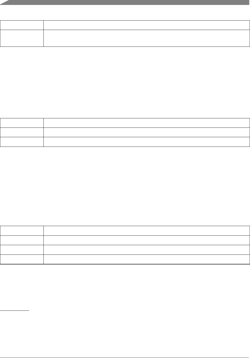
Function Documentation
chnlNumber The channel number
level The level to be set to the ELSnB:ELSnA field; valid values are 00, 01, 10, 11. See the
appropriate SoC reference manual for details about this field.
25.5.7 void TPM_SetupInputCapture ( TPM_Type ∗base, tpm_chnl_t chnlNumber,
tpm_input_capture_edge_t captureMode )
When the edge specified in the captureMode argument occurs on the channel, the TPM counter is captured
into the CnV register. The user has to read the CnV register separately to get this value.
Parameters
base TPM peripheral base address
chnlNumber The channel number
captureMode Specifies which edge to capture
25.5.8 void TPM_SetupOutputCompare ( TPM_Type ∗base, tpm_chnl_t
chnlNumber, tpm_output_compare_mode_t compareMode, uint32_t
compareValue )
When the TPM counter matches the value of compareVal argument (this is written into CnV reg), the
channel output is changed based on what is specified in the compareMode argument.
Parameters
base TPM peripheral base address
chnlNumber The channel number
compareMode Action to take on the channel output when the compare condition is met
compareValue Value to be programmed in the CnV register.
25.5.9 void TPM_EnableInterrupts ( TPM_Type ∗base, uint32_t mask )
Parameters
306
MCUXpresso SDK API Reference Manual
NXP Semiconductors

Function Documentation
base TPM peripheral base address
mask The interrupts to enable. This is a logical OR of members of the enumeration tpm_-
interrupt_enable_t
25.5.10 void TPM_DisableInterrupts ( TPM_Type ∗base, uint32_t mask )
Parameters
base TPM peripheral base address
mask The interrupts to disable. This is a logical OR of members of the enumeration tpm_-
interrupt_enable_t
25.5.11 uint32_t TPM_GetEnabledInterrupts ( TPM_Type ∗base )
Parameters
base TPM peripheral base address
Returns
The enabled interrupts. This is the logical OR of members of the enumeration tpm_interrupt_enable-
_t
25.5.12 static uint32_t TPM_GetStatusFlags ( TPM_Type ∗base )[inline],
[static]
Parameters
base TPM peripheral base address
Returns
The status flags. This is the logical OR of members of the enumeration tpm_status_flags_t
25.5.13 static void TPM_ClearStatusFlags ( TPM_Type ∗base, uint32_t mask )
[inline],[static]
NXP Semiconductors
MCUXpresso SDK API Reference Manual
307

Function Documentation
Parameters
base TPM peripheral base address
mask The status flags to clear. This is a logical OR of members of the enumeration tpm_-
status_flags_t
25.5.14 static void TPM_SetTimerPeriod ( TPM_Type ∗base, uint32_t ticks )
[inline],[static]
Timers counts from 0 until it equals the count value set here. The count value is written to the MOD
register.
Note
1. This API allows the user to use the TPM module as a timer. Do not mix usage of this API with
TPM’s PWM setup API’s.
2. Call the utility macros provided in the fsl_common.h to convert usec or msec to ticks.
Parameters
base TPM peripheral base address
ticks A timer period in units of ticks, which should be equal or greater than 1.
25.5.15 static uint32_t TPM_GetCurrentTimerCount ( TPM_Type ∗base )
[inline],[static]
This function returns the real-time timer counting value in a range from 0 to a timer period.
Note
Call the utility macros provided in the fsl_common.h to convert ticks to usec or msec.
Parameters
base TPM peripheral base address
Returns
The current counter value in ticks
308
MCUXpresso SDK API Reference Manual
NXP Semiconductors

Function Documentation
25.5.16 static void TPM_StartTimer ( TPM_Type ∗base, tpm_clock_source_t
clockSource )[inline],[static]
NXP Semiconductors
MCUXpresso SDK API Reference Manual
309

Function Documentation
Parameters
base TPM peripheral base address
clockSource TPM clock source; once clock source is set the counter will start running
25.5.17 static void TPM_StopTimer ( TPM_Type ∗base )[inline],[static]
Parameters
base TPM peripheral base address
310
MCUXpresso SDK API Reference Manual
NXP Semiconductors


TSIv4 Driver
26.2 TSIv4 Driver
26.2.1 Overview
The MCUXpresso SDK provides driver for the Touch Sensing Input (TSI) module of MCUXpresso SDK
devices.
26.2.2 Typical use case
26.2.2.1 TSI Operation
TSI_Init(TSI0);
TSI_Configure(TSI0, &user_config);
TSI_SetMeasuredChannelNumber(TSI0, channelMask);
TSI_EnableInterrupts(TSI0, kTSI_GlobalInterruptEnable |
kTSI_EndOfScanInterruptEnable);
TSI_EnableSoftwareTriggerScan(TSI0);
TSI_EnableModule(TSI0);
while(1)
{
TSI_StartSoftwareTrigger(TSI0);
TSI_GetCounter(TSI0);
}
Data Structures
• struct tsi_calibration_data_t
TSI calibration data storage. More...
• struct tsi_config_t
TSI configuration structure. More...
Macros
• #define ALL_FLAGS_MASK (TSI_GENCS_EOSF_MASK |TSI_GENCS_OUTRGF_MASK)
TSI status flags macro collection.
• #define TSI_V4_EXTCHRG_RESISTOR_BIT_SHIFT TSI_GENCS_EXTCHRG_SHIFT
resistor bit shift in EXTCHRG bit-field
• #define TSI_V4_EXTCHRG_FILTER_BITS_SHIFT (1U + TSI_GENCS_EXTCHRG_SHIFT)
filter bits shift in EXTCHRG bit-field
• #define TSI_V4_EXTCHRG_RESISTOR_BIT_CLEAR ((uint32_t)((∼(ALL_FLAGS_MASK |T-
SI_GENCS_EXTCHRG_MASK)) |(3U << TSI_V4_EXTCHRG_FILTER_BITS_SHIFT)))
macro of clearing the resistor bit in EXTCHRG bit-field
• #define TSI_V4_EXTCHRG_FILTER_BITS_CLEAR ((uint32_t)((∼(ALL_FLAGS_MASK |TS-
I_GENCS_EXTCHRG_MASK)) |(1U << TSI_V4_EXTCHRG_RESISTOR_BIT_SHIFT)))
macro of clearing the filter bits in EXTCHRG bit-field
312
MCUXpresso SDK API Reference Manual
NXP Semiconductors

TSIv4 Driver
Enumerations
• enum tsi_n_consecutive_scans_t {
kTSI_ConsecutiveScansNumber_1time = 0U,
kTSI_ConsecutiveScansNumber_2time = 1U,
kTSI_ConsecutiveScansNumber_3time = 2U,
kTSI_ConsecutiveScansNumber_4time = 3U,
kTSI_ConsecutiveScansNumber_5time = 4U,
kTSI_ConsecutiveScansNumber_6time = 5U,
kTSI_ConsecutiveScansNumber_7time = 6U,
kTSI_ConsecutiveScansNumber_8time = 7U,
kTSI_ConsecutiveScansNumber_9time = 8U,
kTSI_ConsecutiveScansNumber_10time = 9U,
kTSI_ConsecutiveScansNumber_11time = 10U,
kTSI_ConsecutiveScansNumber_12time = 11U,
kTSI_ConsecutiveScansNumber_13time = 12U,
kTSI_ConsecutiveScansNumber_14time = 13U,
kTSI_ConsecutiveScansNumber_15time = 14U,
kTSI_ConsecutiveScansNumber_16time = 15U,
kTSI_ConsecutiveScansNumber_17time = 16U,
kTSI_ConsecutiveScansNumber_18time = 17U,
kTSI_ConsecutiveScansNumber_19time = 18U,
kTSI_ConsecutiveScansNumber_20time = 19U,
kTSI_ConsecutiveScansNumber_21time = 20U,
kTSI_ConsecutiveScansNumber_22time = 21U,
kTSI_ConsecutiveScansNumber_23time = 22U,
kTSI_ConsecutiveScansNumber_24time = 23U,
kTSI_ConsecutiveScansNumber_25time = 24U,
kTSI_ConsecutiveScansNumber_26time = 25U,
kTSI_ConsecutiveScansNumber_27time = 26U,
kTSI_ConsecutiveScansNumber_28time = 27U,
kTSI_ConsecutiveScansNumber_29time = 28U,
kTSI_ConsecutiveScansNumber_30time = 29U,
kTSI_ConsecutiveScansNumber_31time = 30U,
kTSI_ConsecutiveScansNumber_32time = 31U }
TSI number of scan intervals for each electrode.
• enum tsi_electrode_osc_prescaler_t {
kTSI_ElecOscPrescaler_1div = 0U,
kTSI_ElecOscPrescaler_2div = 1U,
kTSI_ElecOscPrescaler_4div = 2U,
kTSI_ElecOscPrescaler_8div = 3U,
kTSI_ElecOscPrescaler_16div = 4U,
kTSI_ElecOscPrescaler_32div = 5U,
kTSI_ElecOscPrescaler_64div = 6U,
kTSI_ElecOscPrescaler_128div = 7U }
NXP Semiconductors
MCUXpresso SDK API Reference Manual
313

TSIv4 Driver
TSI electrode oscillator prescaler.
• enum tsi_analog_mode_t {
kTSI_AnalogModeSel_Capacitive = 0U,
kTSI_AnalogModeSel_NoiseNoFreqLim = 4U,
kTSI_AnalogModeSel_NoiseFreqLim = 8U,
kTSI_AnalogModeSel_AutoNoise = 12U }
TSI analog mode select.
• enum tsi_reference_osc_charge_current_t {
kTSI_RefOscChargeCurrent_500nA = 0U,
kTSI_RefOscChargeCurrent_1uA = 1U,
kTSI_RefOscChargeCurrent_2uA = 2U,
kTSI_RefOscChargeCurrent_4uA = 3U,
kTSI_RefOscChargeCurrent_8uA = 4U,
kTSI_RefOscChargeCurrent_16uA = 5U,
kTSI_RefOscChargeCurrent_32uA = 6U,
kTSI_RefOscChargeCurrent_64uA = 7U }
TSI Reference oscillator charge and discharge current select.
• enum tsi_osc_voltage_rails_t {
kTSI_OscVolRailsOption_0 = 0U,
kTSI_OscVolRailsOption_1 = 1U,
kTSI_OscVolRailsOption_2 = 2U,
kTSI_OscVolRailsOption_3 = 3U }
TSI oscilator’s voltage rails.
• enum tsi_external_osc_charge_current_t {
kTSI_ExtOscChargeCurrent_500nA = 0U,
kTSI_ExtOscChargeCurrent_1uA = 1U,
kTSI_ExtOscChargeCurrent_2uA = 2U,
kTSI_ExtOscChargeCurrent_4uA = 3U,
kTSI_ExtOscChargeCurrent_8uA = 4U,
kTSI_ExtOscChargeCurrent_16uA = 5U,
kTSI_ExtOscChargeCurrent_32uA = 6U,
kTSI_ExtOscChargeCurrent_64uA = 7U }
TSI External oscillator charge and discharge current select.
• enum tsi_series_resistor_t {
kTSI_SeriesResistance_32k = 0U,
kTSI_SeriesResistance_187k = 1U }
TSI series resistance RS value select.
• enum tsi_filter_bits_t {
kTSI_FilterBits_3 = 0U,
kTSI_FilterBits_2 = 1U,
kTSI_FilterBits_1 = 2U,
kTSI_FilterBits_0 = 3U }
TSI series filter bits select.
• enum tsi_status_flags_t {
kTSI_EndOfScanFlag = TSI_GENCS_EOSF_MASK,
kTSI_OutOfRangeFlag = TSI_GENCS_OUTRGF_MASK }
314
MCUXpresso SDK API Reference Manual
NXP Semiconductors

TSIv4 Driver
TSI status flags.
• enum tsi_interrupt_enable_t {
kTSI_GlobalInterruptEnable = 1U,
kTSI_OutOfRangeInterruptEnable = 2U,
kTSI_EndOfScanInterruptEnable = 4U }
TSI feature interrupt source.
Functions
• void TSI_Init (TSI_Type ∗base, const tsi_config_t ∗config)
Initializes hardware.
• void TSI_Deinit (TSI_Type ∗base)
De-initializes hardware.
• void TSI_GetNormalModeDefaultConfig (tsi_config_t ∗userConfig)
Gets the TSI normal mode user configuration structure.
• void TSI_GetLowPowerModeDefaultConfig (tsi_config_t ∗userConfig)
Gets the TSI low power mode default user configuration structure.
• void TSI_Calibrate (TSI_Type ∗base, tsi_calibration_data_t ∗calBuff)
Hardware calibration.
• void TSI_EnableInterrupts (TSI_Type ∗base, uint32_t mask)
Enables the TSI interrupt requests.
• void TSI_DisableInterrupts (TSI_Type ∗base, uint32_t mask)
Disables the TSI interrupt requests.
• static uint32_t TSI_GetStatusFlags (TSI_Type ∗base)
Gets an interrupt flag.
• void TSI_ClearStatusFlags (TSI_Type ∗base, uint32_t mask)
Clears the interrupt flag.
• static uint32_t TSI_GetScanTriggerMode (TSI_Type ∗base)
Gets the TSI scan trigger mode.
• static bool TSI_IsScanInProgress (TSI_Type ∗base)
Gets the scan in progress flag.
• static void TSI_SetElectrodeOSCPrescaler (TSI_Type ∗base, tsi_electrode_osc_prescaler_-
tprescaler)
Sets the prescaler.
• static void TSI_SetNumberOfScans (TSI_Type ∗base, tsi_n_consecutive_scans_t number)
Sets the number of scans (NSCN).
• static void TSI_EnableModule (TSI_Type ∗base, bool enable)
Enables/disables the TSI module.
• static void TSI_EnableLowPower (TSI_Type ∗base, bool enable)
Sets the TSI low power STOP mode as enabled or disabled.
• static void TSI_EnableHardwareTriggerScan (TSI_Type ∗base, bool enable)
Enables/disables the hardware trigger scan.
• static void TSI_StartSoftwareTrigger (TSI_Type ∗base)
Starts a software trigger measurement (triggers a new measurement).
• static void TSI_SetMeasuredChannelNumber (TSI_Type ∗base, uint8_t channel)
Sets the the measured channel number.
• static uint8_t TSI_GetMeasuredChannelNumber (TSI_Type ∗base)
Gets the current measured channel number.
• static void TSI_EnableDmaTransfer (TSI_Type ∗base, bool enable)
NXP Semiconductors
MCUXpresso SDK API Reference Manual
315

TSIv4 Driver
Enables/disables the DMA transfer.
• static uint16_t TSI_GetCounter (TSI_Type ∗base)
Gets the conversion counter value.
• static void TSI_SetLowThreshold (TSI_Type ∗base, uint16_t low_threshold)
Sets the TSI wake-up channel low threshold.
• static void TSI_SetHighThreshold (TSI_Type ∗base, uint16_t high_threshold)
Sets the TSI wake-up channel high threshold.
• static void TSI_SetAnalogMode (TSI_Type ∗base, tsi_analog_mode_t mode)
Sets the analog mode of the TSI module.
• static uint8_t TSI_GetNoiseModeResult (TSI_Type ∗base)
Gets the noise mode result of the TSI module.
• static void TSI_SetReferenceChargeCurrent (TSI_Type ∗base, tsi_reference_osc_charge_current_t
current)
Sets the reference oscillator charge current.
• static void TSI_SetElectrodeChargeCurrent (TSI_Type ∗base, tsi_external_osc_charge_current_-
tcurrent)
Sets the external electrode charge current.
• static void TSI_SetOscVoltageRails (TSI_Type ∗base, tsi_osc_voltage_rails_t dvolt)
Sets the oscillator’s voltage rails.
• static void TSI_SetElectrodeSeriesResistor (TSI_Type ∗base, tsi_series_resistor_t resistor)
Sets the electrode series resistance value in EXTCHRG[0] bit.
• static void TSI_SetFilterBits (TSI_Type ∗base, tsi_filter_bits_t filter)
Sets the electrode filter bits value in EXTCHRG[2:1] bits.
Driver version
• #define FSL_TSI_DRIVER_VERSION (MAKE_VERSION(2, 1, 2))
TSI driver version.
26.2.3 Data Structure Documentation
26.2.3.1 struct tsi_calibration_data_t
Data Fields
• uint16_t calibratedData [FSL_FEATURE_TSI_CHANNEL_COUNT]
TSI calibration data storage buffer.
26.2.3.2 struct tsi_config_t
This structure contains the settings for the most common TSI configurations including the TSI module
charge currents, number of scans, thresholds, and so on.
Data Fields
• uint16_t thresh
316
MCUXpresso SDK API Reference Manual
NXP Semiconductors

TSIv4 Driver
High threshold.
• uint16_t thresl
Low threshold.
•tsi_electrode_osc_prescaler_t prescaler
Prescaler.
•tsi_external_osc_charge_current_t extchrg
Electrode charge current.
•tsi_reference_osc_charge_current_t refchrg
Reference charge current.
•tsi_n_consecutive_scans_t nscn
Number of scans.
•tsi_analog_mode_t mode
TSI mode of operation.
•tsi_osc_voltage_rails_t dvolt
Oscillator’s voltage rails.
•tsi_series_resistor_t resistor
Series resistance value.
•tsi_filter_bits_t filter
Noise mode filter bits.
26.2.3.2.0.39 Field Documentation
26.2.3.2.0.39.1 uint16_t tsi_config_t::thresh
26.2.3.2.0.39.2 uint16_t tsi_config_t::thresl
26.2.3.2.0.39.3 tsi_n_consecutive_scans_t tsi_config_t::nscn
26.2.3.2.0.39.4 tsi_analog_mode_t tsi_config_t::mode
26.2.3.2.0.39.5 tsi_osc_voltage_rails_t tsi_config_t::dvolt
26.2.4 Enumeration Type Documentation
26.2.4.1 enum tsi_n_consecutive_scans_t
These constants define the tsi number of consecutive scans in a TSI instance for each electrode.
Enumerator
kTSI_ConsecutiveScansNumber_1time Once per electrode.
kTSI_ConsecutiveScansNumber_2time Twice per electrode.
kTSI_ConsecutiveScansNumber_3time 3 times consecutive scan
kTSI_ConsecutiveScansNumber_4time 4 times consecutive scan
kTSI_ConsecutiveScansNumber_5time 5 times consecutive scan
kTSI_ConsecutiveScansNumber_6time 6 times consecutive scan
kTSI_ConsecutiveScansNumber_7time 7 times consecutive scan
kTSI_ConsecutiveScansNumber_8time 8 times consecutive scan
kTSI_ConsecutiveScansNumber_9time 9 times consecutive scan
kTSI_ConsecutiveScansNumber_10time 10 times consecutive scan
NXP Semiconductors
MCUXpresso SDK API Reference Manual
317

TSIv4 Driver
kTSI_ConsecutiveScansNumber_11time 11 times consecutive scan
kTSI_ConsecutiveScansNumber_12time 12 times consecutive scan
kTSI_ConsecutiveScansNumber_13time 13 times consecutive scan
kTSI_ConsecutiveScansNumber_14time 14 times consecutive scan
kTSI_ConsecutiveScansNumber_15time 15 times consecutive scan
kTSI_ConsecutiveScansNumber_16time 16 times consecutive scan
kTSI_ConsecutiveScansNumber_17time 17 times consecutive scan
kTSI_ConsecutiveScansNumber_18time 18 times consecutive scan
kTSI_ConsecutiveScansNumber_19time 19 times consecutive scan
kTSI_ConsecutiveScansNumber_20time 20 times consecutive scan
kTSI_ConsecutiveScansNumber_21time 21 times consecutive scan
kTSI_ConsecutiveScansNumber_22time 22 times consecutive scan
kTSI_ConsecutiveScansNumber_23time 23 times consecutive scan
kTSI_ConsecutiveScansNumber_24time 24 times consecutive scan
kTSI_ConsecutiveScansNumber_25time 25 times consecutive scan
kTSI_ConsecutiveScansNumber_26time 26 times consecutive scan
kTSI_ConsecutiveScansNumber_27time 27 times consecutive scan
kTSI_ConsecutiveScansNumber_28time 28 times consecutive scan
kTSI_ConsecutiveScansNumber_29time 29 times consecutive scan
kTSI_ConsecutiveScansNumber_30time 30 times consecutive scan
kTSI_ConsecutiveScansNumber_31time 31 times consecutive scan
kTSI_ConsecutiveScansNumber_32time 32 times consecutive scan
26.2.4.2 enum tsi_electrode_osc_prescaler_t
These constants define the TSI electrode oscillator prescaler in a TSI instance.
Enumerator
kTSI_ElecOscPrescaler_1div Electrode oscillator frequency divided by 1.
kTSI_ElecOscPrescaler_2div Electrode oscillator frequency divided by 2.
kTSI_ElecOscPrescaler_4div Electrode oscillator frequency divided by 4.
kTSI_ElecOscPrescaler_8div Electrode oscillator frequency divided by 8.
kTSI_ElecOscPrescaler_16div Electrode oscillator frequency divided by 16.
kTSI_ElecOscPrescaler_32div Electrode oscillator frequency divided by 32.
kTSI_ElecOscPrescaler_64div Electrode oscillator frequency divided by 64.
kTSI_ElecOscPrescaler_128div Electrode oscillator frequency divided by 128.
26.2.4.3 enum tsi_analog_mode_t
Set up TSI analog modes in a TSI instance.
Enumerator
kTSI_AnalogModeSel_Capacitive Active TSI capacitive sensing mode.
318
MCUXpresso SDK API Reference Manual
NXP Semiconductors

TSIv4 Driver
kTSI_AnalogModeSel_NoiseNoFreqLim Single threshold noise detection mode with no freq. lim-
itation.
kTSI_AnalogModeSel_NoiseFreqLim Single threshold noise detection mode with freq. limitation.
kTSI_AnalogModeSel_AutoNoise Active TSI analog in automatic noise detection mode.
26.2.4.4 enum tsi_reference_osc_charge_current_t
These constants define the TSI Reference oscillator charge current select in a TSI (REFCHRG) instance.
Enumerator
kTSI_RefOscChargeCurrent_500nA Reference oscillator charge current is 500 µA.
kTSI_RefOscChargeCurrent_1uA Reference oscillator charge current is 1 µA.
kTSI_RefOscChargeCurrent_2uA Reference oscillator charge current is 2 µA.
kTSI_RefOscChargeCurrent_4uA Reference oscillator charge current is 4 µA.
kTSI_RefOscChargeCurrent_8uA Reference oscillator charge current is 8 µA.
kTSI_RefOscChargeCurrent_16uA Reference oscillator charge current is 16 µA.
kTSI_RefOscChargeCurrent_32uA Reference oscillator charge current is 32 µA.
kTSI_RefOscChargeCurrent_64uA Reference oscillator charge current is 64 µA.
26.2.4.5 enum tsi_osc_voltage_rails_t
These bits indicate the oscillator’s voltage rails.
Enumerator
kTSI_OscVolRailsOption_0 DVOLT value option 0, the value may differ on different platforms.
kTSI_OscVolRailsOption_1 DVOLT value option 1, the value may differ on different platforms.
kTSI_OscVolRailsOption_2 DVOLT value option 2, the value may differ on different platforms.
kTSI_OscVolRailsOption_3 DVOLT value option 3, the value may differ on different platforms.
26.2.4.6 enum tsi_external_osc_charge_current_t
These bits indicate the electrode oscillator charge and discharge current value in TSI (EXTCHRG) in-
stance.
Enumerator
kTSI_ExtOscChargeCurrent_500nA External oscillator charge current is 500 µA.
kTSI_ExtOscChargeCurrent_1uA External oscillator charge current is 1 µA.
kTSI_ExtOscChargeCurrent_2uA External oscillator charge current is 2 µA.
kTSI_ExtOscChargeCurrent_4uA External oscillator charge current is 4 µA.
NXP Semiconductors
MCUXpresso SDK API Reference Manual
319

TSIv4 Driver
kTSI_ExtOscChargeCurrent_8uA External oscillator charge current is 8 µA.
kTSI_ExtOscChargeCurrent_16uA External oscillator charge current is 16 µA.
kTSI_ExtOscChargeCurrent_32uA External oscillator charge current is 32 µA.
kTSI_ExtOscChargeCurrent_64uA External oscillator charge current is 64 µA.
26.2.4.7 enum tsi_series_resistor_t
These bits indicate the electrode RS series resistance for the noise mode in TSI (EXTCHRG) instance.
Enumerator
kTSI_SeriesResistance_32k Series Resistance is 32 kilo ohms.
kTSI_SeriesResistance_187k Series Resistance is 18 7 kilo ohms.
26.2.4.8 enum tsi_filter_bits_t
These bits indicate the count of the filter bits in TSI noise mode EXTCHRG[2:1] bits
Enumerator
kTSI_FilterBits_3 3 filter bits, 8 peaks increments the cnt+1
kTSI_FilterBits_2 2 filter bits, 4 peaks increments the cnt+1
kTSI_FilterBits_1 1 filter bits, 2 peaks increments the cnt+1
kTSI_FilterBits_0 no filter bits,1 peak increments the cnt+1
26.2.4.9 enum tsi_status_flags_t
Enumerator
kTSI_EndOfScanFlag End-Of-Scan flag.
kTSI_OutOfRangeFlag Out-Of-Range flag.
26.2.4.10 enum tsi_interrupt_enable_t
Enumerator
kTSI_GlobalInterruptEnable TSI module global interrupt.
kTSI_OutOfRangeInterruptEnable Out-Of-Range interrupt.
kTSI_EndOfScanInterruptEnable End-Of-Scan interrupt.
320
MCUXpresso SDK API Reference Manual
NXP Semiconductors

TSIv4 Driver
26.2.5 Function Documentation
26.2.5.1 void TSI_Init ( TSI_Type ∗base, const tsi_config_t ∗config )
Initializes the peripheral to the targeted state specified by parameter configuration, such as sets prescalers,
number of scans, clocks, delta voltage series resistor, filter bits, reference, and electrode charge current
and threshold.
Parameters
base TSI peripheral base address.
config Pointer to TSI module configuration structure.
Returns
none
26.2.5.2 void TSI_Deinit ( TSI_Type ∗base )
De-initializes the peripheral to default state.
Parameters
base TSI peripheral base address.
Returns
none
26.2.5.3 void TSI_GetNormalModeDefaultConfig ( tsi_config_t ∗userConfig )
This interface sets userConfig structure to a default value. The configuration structure only includes the
settings for the whole TSI. The user configure is set to these values:
userConfig->prescaler = kTSI_ElecOscPrescaler_2div;
userConfig->extchrg = kTSI_ExtOscChargeCurrent_500nA;
userConfig->refchrg = kTSI_RefOscChargeCurrent_4uA;
userConfig->nscn = kTSI_ConsecutiveScansNumber_10time;
userConfig->mode = kTSI_AnalogModeSel_Capacitive;
userConfig->dvolt = kTSI_OscVolRailsOption_0;
userConfig->thresh = 0U;
userConfig->thresl = 0U;
NXP Semiconductors
MCUXpresso SDK API Reference Manual
321

TSIv4 Driver
Parameters
userConfig Pointer to the TSI user configuration structure.
26.2.5.4 void TSI_GetLowPowerModeDefaultConfig ( tsi_config_t ∗userConfig )
This interface sets userConfig structure to a default value. The configuration structure only includes the
settings for the whole TSI. The user configure is set to these values:
userConfig->prescaler = kTSI_ElecOscPrescaler_2div;
userConfig->extchrg = kTSI_ExtOscChargeCurrent_500nA;
userConfig->refchrg = kTSI_RefOscChargeCurrent_4uA;
userConfig->nscn = kTSI_ConsecutiveScansNumber_10time;
userConfig->mode = kTSI_AnalogModeSel_Capacitive;
userConfig->dvolt = kTSI_OscVolRailsOption_0;
userConfig->thresh = 400U;
userConfig->thresl = 0U;
Parameters
userConfig Pointer to the TSI user configuration structure.
26.2.5.5 void TSI_Calibrate ( TSI_Type ∗base, tsi_calibration_data_t ∗calBuff )
Calibrates the peripheral to fetch the initial counter value of the enabled electrodes. This API is mostly
used at initial application setup. Call this function after the TSI_Init API and use the calibrated counter
values to set up applications (such as to determine under which counter value we can confirm a touch event
occurs).
Parameters
base TSI peripheral base address.
calBuff Data buffer that store the calibrated counter value.
Returns
none
26.2.5.6 void TSI_EnableInterrupts ( TSI_Type ∗base, uint32_t mask )
322
MCUXpresso SDK API Reference Manual
NXP Semiconductors

TSIv4 Driver
Parameters
base TSI peripheral base address.
mask interrupt source The parameter can be combination of the following source if defined:
• kTSI_GlobalInterruptEnable
• kTSI_EndOfScanInterruptEnable
• kTSI_OutOfRangeInterruptEnable
26.2.5.7 void TSI_DisableInterrupts ( TSI_Type ∗base, uint32_t mask )
Parameters
base TSI peripheral base address.
mask interrupt source The parameter can be combination of the following source if defined:
• kTSI_GlobalInterruptEnable
• kTSI_EndOfScanInterruptEnable
• kTSI_OutOfRangeInterruptEnable
26.2.5.8 static uint32_t TSI_GetStatusFlags ( TSI_Type ∗base )[inline],[static]
This function gets the TSI interrupt flags.
Parameters
base TSI peripheral base address.
Returns
The mask of these status flags combination.
26.2.5.9 void TSI_ClearStatusFlags ( TSI_Type ∗base, uint32_t mask )
This function clears the TSI interrupt flag, automatically cleared flags can’t be cleared by this function.
NXP Semiconductors
MCUXpresso SDK API Reference Manual
323
TSIv4 Driver
Parameters
base TSI peripheral base address.
mask The status flags to clear.
26.2.5.10 static uint32_t TSI_GetScanTriggerMode ( TSI_Type ∗base )[inline],
[static]
Parameters
base TSI peripheral base address.
Returns
Scan trigger mode.
26.2.5.11 static bool TSI_IsScanInProgress ( TSI_Type ∗base )[inline],[static]
Parameters
base TSI peripheral base address.
Returns
True - scan is in progress. False - scan is not in progress.
26.2.5.12 static void TSI_SetElectrodeOSCPrescaler ( TSI_Type ∗base,
tsi_electrode_osc_prescaler_t prescaler )[inline],[static]
Parameters
base TSI peripheral base address.
prescaler Prescaler value.
Returns
none.
26.2.5.13 static void TSI_SetNumberOfScans ( TSI_Type ∗base,
tsi_n_consecutive_scans_t number )[inline],[static]
324
MCUXpresso SDK API Reference Manual
NXP Semiconductors

TSIv4 Driver
Parameters
base TSI peripheral base address.
number Number of scans.
Returns
none.
26.2.5.14 static void TSI_EnableModule ( TSI_Type ∗base, bool enable )[inline],
[static]
Parameters
base TSI peripheral base address.
enable Choose whether to enable or disable module;
• true Enable TSI module;
• false Disable TSI module;
Returns
none.
26.2.5.15 static void TSI_EnableLowPower ( TSI_Type ∗base, bool enable )[inline],
[static]
This enables the TSI module function in low power modes.
Parameters
base TSI peripheral base address.
enable Choose to enable or disable STOP mode.
• true Enable module in STOP mode;
• false Disable module in STOP mode;
Returns
none.
NXP Semiconductors
MCUXpresso SDK API Reference Manual
325

TSIv4 Driver
26.2.5.16 static void TSI_EnableHardwareTriggerScan ( TSI_Type ∗base, bool enable )
[inline],[static]
326
MCUXpresso SDK API Reference Manual
NXP Semiconductors

TSIv4 Driver
Parameters
base TSI peripheral base address.
enable Choose to enable hardware trigger or software trigger scan.
• true Enable hardware trigger scan;
• false Enable software trigger scan;
Returns
none.
26.2.5.17 static void TSI_StartSoftwareTrigger ( TSI_Type ∗base )[inline],
[static]
Parameters
base TSI peripheral base address.
Returns
none.
26.2.5.18 static void TSI_SetMeasuredChannelNumber ( TSI_Type ∗base, uint8_t
channel )[inline],[static]
Parameters
base TSI peripheral base address.
channel Channel number 0 ... 15.
Returns
none.
26.2.5.19 static uint8_t TSI_GetMeasuredChannelNumber ( TSI_Type ∗base )
[inline],[static]
NXP Semiconductors
MCUXpresso SDK API Reference Manual
327

TSIv4 Driver
Parameters
base TSI peripheral base address.
Returns
uint8_t Channel number 0 ... 15.
26.2.5.20 static void TSI_EnableDmaTransfer ( TSI_Type ∗base, bool enable )
[inline],[static]
Parameters
base TSI peripheral base address.
enable Choose to enable DMA transfer or not.
• true Enable DMA transfer;
• false Disable DMA transfer;
Returns
none.
26.2.5.21 static uint16_t TSI_GetCounter ( TSI_Type ∗base )[inline],[static]
Parameters
base TSI peripheral base address.
Returns
Accumulated scan counter value ticked by the reference clock.
26.2.5.22 static void TSI_SetLowThreshold ( TSI_Type ∗base, uint16_t low_threshold )
[inline],[static]
328
MCUXpresso SDK API Reference Manual
NXP Semiconductors

TSIv4 Driver
Parameters
base TSI peripheral base address.
low_threshold Low counter threshold.
Returns
none.
26.2.5.23 static void TSI_SetHighThreshold ( TSI_Type ∗base, uint16_t high_threshold )
[inline],[static]
Parameters
base TSI peripheral base address.
high_threshold High counter threshold.
Returns
none.
26.2.5.24 static void TSI_SetAnalogMode ( TSI_Type ∗base, tsi_analog_mode_t mode )
[inline],[static]
Parameters
base TSI peripheral base address.
mode Mode value.
Returns
none.
26.2.5.25 static uint8_t TSI_GetNoiseModeResult ( TSI_Type ∗base )[inline],
[static]
NXP Semiconductors
MCUXpresso SDK API Reference Manual
329

TSIv4 Driver
Parameters
base TSI peripheral base address.
Returns
Value of the GENCS[MODE] bit-fields.
26.2.5.26 static void TSI_SetReferenceChargeCurrent ( TSI_Type ∗base,
tsi_reference_osc_charge_current_t current )[inline],[static]
Parameters
base TSI peripheral base address.
current The reference oscillator charge current.
Returns
none.
26.2.5.27 static void TSI_SetElectrodeChargeCurrent ( TSI_Type ∗base,
tsi_external_osc_charge_current_t current )[inline],[static]
Parameters
base TSI peripheral base address.
current External electrode charge current.
Returns
none.
26.2.5.28 static void TSI_SetOscVoltageRails ( TSI_Type ∗base, tsi_osc_voltage_rails_t
dvolt )[inline],[static]
330
MCUXpresso SDK API Reference Manual
NXP Semiconductors

TSIv4 Driver
Parameters
base TSI peripheral base address.
dvolt The voltage rails.
Returns
none.
26.2.5.29 static void TSI_SetElectrodeSeriesResistor ( TSI_Type ∗base,
tsi_series_resistor_t resistor )[inline],[static]
Parameters
base TSI peripheral base address.
resistor Series resistance.
Returns
none.
26.2.5.30 static void TSI_SetFilterBits ( TSI_Type ∗base, tsi_filter_bits_t filter )
[inline],[static]
Parameters
base TSI peripheral base address.
filter Series resistance.
Returns
none.
NXP Semiconductors
MCUXpresso SDK API Reference Manual
331

TSIv4 Driver
332
MCUXpresso SDK API Reference Manual
NXP Semiconductors


UART Driver
27.2 UART Driver
27.2.1 Overview
The MCUXpresso SDK provides a peripheral driver for the Universal Asynchronous Receiver/Transmitter
(UART) module of MCUXpresso SDK devices.
The UART driver includes functional APIs and transactional APIs.
Functional APIs are used for UART initialization/configuration/operation for optimization/customization
purpose. Using the functional API requires the knowledge of the UART peripheral and how to organize
functional APIs to meet the application requirements. All functional APIs use the peripheral base address
as the first parameter. UART functional operation groups provide the functional API set.
Transactional APIs can be used to enable the peripheral quickly and in the application if the code size
and performance of transactional APIs can satisfy the requirements. If the code size and performance are
critical requirements, see the transactional API implementation and write custom code. All transactional
APIs use the uart_handle_t as the second parameter. Initialize the handle by calling the UART_Transfer-
CreateHandle() API.
Transactional APIs support asynchronous transfer, which means that the functions UART_TransferSend-
NonBlocking() and UART_TransferReceiveNonBlocking() set up an interrupt for data transfer. When the
transfer completes, the upper layer is notified through a callback function with the kStatus_UART_TxIdle
and kStatus_UART_RxIdle.
Transactional receive APIs support the ring buffer. Prepare the memory for the ring buffer and pass in the
start address and size while calling the UART_TransferCreateHandle(). If passing NULL, the ring buffer
feature is disabled. When the ring buffer is enabled, the received data is saved to the ring buffer in the
background. The UART_TransferReceiveNonBlocking() function first gets data from the ring buffer. If
the ring buffer does not have enough data, the function first returns the data in the ring buffer and then
saves the received data to user memory. When all data is received, the upper layer is informed through a
callback with the kStatus_UART_RxIdle.
If the receive ring buffer is full, the upper layer is informed through a callback with the kStatus_UART-
_RxRingBufferOverrun. In the callback function, the upper layer reads data out from the ring buffer. If
not, existing data is overwritten by the new data.
The ring buffer size is specified when creating the handle. Note that one byte is reserved for the ring buffer
maintenance. When creating handle using the following code.
UART_TransferCreateHandle(UART0, &handle, UART_UserCallback, NULL);
In this example, the buffer size is 32, but only 31 bytes are used for saving data.
27.2.2 Typical use case
27.2.2.1 UART Send/receive using a polling method
uint8_t ch;
334
MCUXpresso SDK API Reference Manual
NXP Semiconductors

UART Driver
UART_GetDefaultConfig(&user_config);
user_config.baudRate_Bps = 115200U;
user_config.enableTx =true;
user_config.enableRx =true;
UART_Init(UART1,&user_config,120000000U);
while(1)
{
UART_ReadBlocking(UART1, &ch, 1);
UART_WriteBlocking(UART1, &ch, 1);
}
27.2.2.2 UART Send/receive using an interrupt method
uart_handle_t g_uartHandle;
uart_config_t user_config;
uart_transfer_t sendXfer;
uart_transfer_t receiveXfer;
volatile bool txFinished;
volatile bool rxFinished;
uint8_t sendData[] = [’H’,’e’,’l’,’l’,’o’];
uint8_t receiveData[32];
void UART_UserCallback(uart_handle_t *handle, status_t status, void *userData)
{
userData = userData;
if (kStatus_UART_TxIdle == status)
{
txFinished = true;
}
if (kStatus_UART_RxIdle == status)
{
rxFinished = true;
}
}
void main(void)
{
//...
UART_GetDefaultConfig(&user_config);
user_config.baudRate_Bps = 115200U;
user_config.enableTx =true;
user_config.enableRx =true;
UART_Init(UART1, &user_config, 120000000U);
UART_TransferCreateHandle(UART1, &g_uartHandle, UART_UserCallback, NULL);
// Prepare to send.
sendXfer.data = sendData
sendXfer.dataSize =sizeof(sendData)/sizeof(sendData[0]);
txFinished = false;
// Send out.
UART_TransferSendNonBlocking(&g_uartHandle, &g_uartHandle, &sendXfer);
// Wait send finished.
while (!txFinished)
{
}
// Prepare to receive.
NXP Semiconductors
MCUXpresso SDK API Reference Manual
335

UART Driver
receiveXfer.data = receiveData;
receiveXfer.dataSize =sizeof(receiveData)/sizeof(receiveData[0]);
rxFinished = false;
// Receive.
UART_TransferReceiveNonBlocking(&g_uartHandle, &g_uartHandle, &
receiveXfer);
// Wait receive finished.
while (!rxFinished)
{
}
// ...
}
27.2.2.3 UART Receive using the ringbuffer feature
#define RING_BUFFER_SIZE 64
#define RX_DATA_SIZE 32
uart_handle_t g_uartHandle;
uart_config_t user_config;
uart_transfer_t sendXfer;
uart_transfer_t receiveXfer;
volatile bool txFinished;
volatile bool rxFinished;
uint8_t receiveData[RX_DATA_SIZE];
uint8_t ringBuffer[RING_BUFFER_SIZE];
void UART_UserCallback(uart_handle_t *handle, status_t status, void *userData)
{
userData = userData;
if (kStatus_UART_RxIdle == status)
{
rxFinished = true;
}
}
void main(void)
{
size_t bytesRead;
//...
UART_GetDefaultConfig(&user_config);
user_config.baudRate_Bps = 115200U;
user_config.enableTx =true;
user_config.enableRx =true;
UART_Init(UART1, &user_config, 120000000U);
UART_TransferCreateHandle(UART1, &g_uartHandle, UART_UserCallback, NULL);
// Now the RX is working in background, receive in to ring buffer.
// Prepare to receive.
receiveXfer.data = receiveData;
receiveXfer.dataSize = RX_DATA_SIZE;
rxFinished = false;
// Receive.
UART_TransferReceiveNonBlocking(UART1, &g_uartHandle, &receiveXfer);
if (bytesRead = RX_DATA_SIZE) /*Have read enough data. */
{
336
MCUXpresso SDK API Reference Manual
NXP Semiconductors

UART Driver
;
}
else
{
if (bytesRead) /*Received some data, process first. */
{
;
}
// Wait receive finished.
while (!rxFinished)
{
}
}
// ...
}
27.2.2.4 UART Send/Receive using the DMA method
uart_handle_t g_uartHandle;
dma_handle_t g_uartTxDmaHandle;
dma_handle_t g_uartRxDmaHandle;
uart_config_t user_config;
uart_transfer_t sendXfer;
uart_transfer_t receiveXfer;
volatile bool txFinished;
volatile bool rxFinished;
uint8_t sendData[] = [’H’,’e’,’l’,’l’,’o’];
uint8_t receiveData[32];
void UART_UserCallback(uart_handle_t *handle, status_t status, void *userData)
{
userData = userData;
if (kStatus_UART_TxIdle == status)
{
txFinished = true;
}
if (kStatus_UART_RxIdle == status)
{
rxFinished = true;
}
}
void main(void)
{
//...
UART_GetDefaultConfig(&user_config);
user_config.baudRate_Bps = 115200U;
user_config.enableTx =true;
user_config.enableRx =true;
UART_Init(UART1, &user_config, 120000000U);
// Set up the DMA
DMAMUX_Init(DMAMUX0);
DMAMUX_SetSource(DMAMUX0, UART_TX_DMA_CHANNEL, UART_TX_DMA_REQUEST);
DMAMUX_EnableChannel(DMAMUX0, UART_TX_DMA_CHANNEL);
DMAMUX_SetSource(DMAMUX0, UART_RX_DMA_CHANNEL, UART_RX_DMA_REQUEST);
DMAMUX_EnableChannel(DMAMUX0, UART_RX_DMA_CHANNEL);
DMA_Init(DMA0);
NXP Semiconductors
MCUXpresso SDK API Reference Manual
337

UART Driver
/*Create DMA handle. */
DMA_CreateHandle(&g_uartTxDmaHandle, DMA0, UART_TX_DMA_CHANNEL);
DMA_CreateHandle(&g_uartRxDmaHandle, DMA0, UART_RX_DMA_CHANNEL);
UART_TransferCreateHandleDMA(UART1, &g_uartHandle, UART_UserCallback, NULL,
&g_uartTxDmaHandle, &g_uartRxDmaHandle);
// Prepare to send.
sendXfer.data = sendData
sendXfer.dataSize =sizeof(sendData)/sizeof(sendData[0]);
txFinished = false;
// Send out.
UART_TransferSendDMA(UART1, &g_uartHandle, &sendXfer);
// Wait send finished.
while (!txFinished)
{
}
// Prepare to receive.
receiveXfer.data = receiveData;
receiveXfer.dataSize =sizeof(receiveData)/sizeof(receiveData[0]);
rxFinished = false;
// Receive.
UART_TransferReceiveDMA(UART1, &g_uartHandle, &receiveXfer);
// Wait receive finished.
while (!rxFinished)
{
}
// ...
}
Data Structures
• struct uart_config_t
UART configuration structure. More...
• struct uart_transfer_t
UART transfer structure. More...
• struct uart_handle_t
UART handle structure. More...
Typedefs
• typedef void(∗uart_transfer_callback_t )(UART_Type ∗base, uart_handle_t ∗handle, status_t sta-
tus, void ∗userData)
UART transfer callback function.
338
MCUXpresso SDK API Reference Manual
NXP Semiconductors

UART Driver
Enumerations
• enum _uart_status {
kStatus_UART_TxBusy = MAKE_STATUS(kStatusGroup_UART, 0),
kStatus_UART_RxBusy = MAKE_STATUS(kStatusGroup_UART, 1),
kStatus_UART_TxIdle = MAKE_STATUS(kStatusGroup_UART, 2),
kStatus_UART_RxIdle = MAKE_STATUS(kStatusGroup_UART, 3),
kStatus_UART_TxWatermarkTooLarge = MAKE_STATUS(kStatusGroup_UART, 4),
kStatus_UART_RxWatermarkTooLarge = MAKE_STATUS(kStatusGroup_UART, 5),
kStatus_UART_FlagCannotClearManually,
kStatus_UART_Error = MAKE_STATUS(kStatusGroup_UART, 7),
kStatus_UART_RxRingBufferOverrun = MAKE_STATUS(kStatusGroup_UART, 8),
kStatus_UART_RxHardwareOverrun = MAKE_STATUS(kStatusGroup_UART, 9),
kStatus_UART_NoiseError = MAKE_STATUS(kStatusGroup_UART, 10),
kStatus_UART_FramingError = MAKE_STATUS(kStatusGroup_UART, 11),
kStatus_UART_ParityError = MAKE_STATUS(kStatusGroup_UART, 12),
kStatus_UART_BaudrateNotSupport }
Error codes for the UART driver.
• enum uart_parity_mode_t {
kUART_ParityDisabled = 0x0U,
kUART_ParityEven = 0x2U,
kUART_ParityOdd = 0x3U }
UART parity mode.
• enum uart_stop_bit_count_t {
kUART_OneStopBit = 0U,
kUART_TwoStopBit = 1U }
UART stop bit count.
• enum _uart_interrupt_enable {
kUART_LinBreakInterruptEnable = (UART_BDH_LBKDIE_MASK),
kUART_RxActiveEdgeInterruptEnable = (UART_BDH_RXEDGIE_MASK),
kUART_TxDataRegEmptyInterruptEnable = (UART_C2_TIE_MASK << 8),
kUART_TransmissionCompleteInterruptEnable = (UART_C2_TCIE_MASK << 8),
kUART_RxDataRegFullInterruptEnable = (UART_C2_RIE_MASK << 8),
kUART_IdleLineInterruptEnable = (UART_C2_ILIE_MASK << 8),
kUART_RxOverrunInterruptEnable = (UART_C3_ORIE_MASK << 16),
kUART_NoiseErrorInterruptEnable = (UART_C3_NEIE_MASK << 16),
kUART_FramingErrorInterruptEnable = (UART_C3_FEIE_MASK << 16),
kUART_ParityErrorInterruptEnable = (UART_C3_PEIE_MASK << 16) }
UART interrupt configuration structure, default settings all disabled.
• enum _uart_flags {
NXP Semiconductors
MCUXpresso SDK API Reference Manual
339

UART Driver
kUART_TxDataRegEmptyFlag = (UART_S1_TDRE_MASK),
kUART_TransmissionCompleteFlag = (UART_S1_TC_MASK),
kUART_RxDataRegFullFlag = (UART_S1_RDRF_MASK),
kUART_IdleLineFlag = (UART_S1_IDLE_MASK),
kUART_RxOverrunFlag = (UART_S1_OR_MASK),
kUART_NoiseErrorFlag = (UART_S1_NF_MASK),
kUART_FramingErrorFlag = (UART_S1_FE_MASK),
kUART_ParityErrorFlag = (UART_S1_PF_MASK),
kUART_LinBreakFlag,
kUART_RxActiveEdgeFlag,
kUART_RxActiveFlag }
UART status flags.
Driver version
• #define FSL_UART_DRIVER_VERSION (MAKE_VERSION(2, 1, 4))
UART driver version 2.1.4.
Initialization and deinitialization
• status_t UART_Init (UART_Type ∗base, const uart_config_t ∗config, uint32_t srcClock_Hz)
Initializes a UART instance with a user configuration structure and peripheral clock.
• void UART_Deinit (UART_Type ∗base)
Deinitializes a UART instance.
• void UART_GetDefaultConfig (uart_config_t ∗config)
Gets the default configuration structure.
• status_t UART_SetBaudRate (UART_Type ∗base, uint32_t baudRate_Bps, uint32_t srcClock_Hz)
Sets the UART instance baud rate.
Status
• uint32_t UART_GetStatusFlags (UART_Type ∗base)
Gets UART status flags.
• status_t UART_ClearStatusFlags (UART_Type ∗base, uint32_t mask)
Clears status flags with the provided mask.
Interrupts
• void UART_EnableInterrupts (UART_Type ∗base, uint32_t mask)
Enables UART interrupts according to the provided mask.
• void UART_DisableInterrupts (UART_Type ∗base, uint32_t mask)
Disables the UART interrupts according to the provided mask.
• uint32_t UART_GetEnabledInterrupts (UART_Type ∗base)
Gets the enabled UART interrupts.
340
MCUXpresso SDK API Reference Manual
NXP Semiconductors

UART Driver
DMA Control
• static uint32_t UART_GetDataRegisterAddress (UART_Type ∗base)
Gets the UART data register address.
• static void UART_EnableTxDMA (UART_Type ∗base, bool enable)
Enables or disables the UART transmitter DMA request.
• static void UART_EnableRxDMA (UART_Type ∗base, bool enable)
Enables or disables the UART receiver DMA.
Bus Operations
• static void UART_EnableTx (UART_Type ∗base, bool enable)
Enables or disables the UART transmitter.
• static void UART_EnableRx (UART_Type ∗base, bool enable)
Enables or disables the UART receiver.
• static void UART_WriteByte (UART_Type ∗base, uint8_t data)
Writes to the TX register.
• static uint8_t UART_ReadByte (UART_Type ∗base)
Reads the RX register directly.
• void UART_WriteBlocking (UART_Type ∗base, const uint8_t ∗data, size_t length)
Writes to the TX register using a blocking method.
• status_t UART_ReadBlocking (UART_Type ∗base, uint8_t ∗data, size_t length)
Read RX data register using a blocking method.
Transactional
• void UART_TransferCreateHandle (UART_Type ∗base, uart_handle_t ∗handle, uart_transfer_-
callback_t callback, void ∗userData)
Initializes the UART handle.
• void UART_TransferStartRingBuffer (UART_Type ∗base, uart_handle_t ∗handle, uint8_t ∗ring-
Buffer, size_t ringBufferSize)
Sets up the RX ring buffer.
• void UART_TransferStopRingBuffer (UART_Type ∗base, uart_handle_t ∗handle)
Aborts the background transfer and uninstalls the ring buffer.
• status_t UART_TransferSendNonBlocking (UART_Type ∗base, uart_handle_t ∗handle, uart_-
transfer_t ∗xfer)
Transmits a buffer of data using the interrupt method.
• void UART_TransferAbortSend (UART_Type ∗base, uart_handle_t ∗handle)
Aborts the interrupt-driven data transmit.
• status_t UART_TransferGetSendCount (UART_Type ∗base, uart_handle_t ∗handle, uint32_t
∗count)
Gets the number of bytes written to the UART TX register.
• status_t UART_TransferReceiveNonBlocking (UART_Type ∗base, uart_handle_t ∗handle, uart_-
transfer_t ∗xfer, size_t ∗receivedBytes)
Receives a buffer of data using an interrupt method.
• void UART_TransferAbortReceive (UART_Type ∗base, uart_handle_t ∗handle)
Aborts the interrupt-driven data receiving.
NXP Semiconductors
MCUXpresso SDK API Reference Manual
341

UART Driver
• status_t UART_TransferGetReceiveCount (UART_Type ∗base, uart_handle_t ∗handle, uint32_-
t∗count)
Gets the number of bytes that have been received.
• void UART_TransferHandleIRQ (UART_Type ∗base, uart_handle_t ∗handle)
UART IRQ handle function.
• void UART_TransferHandleErrorIRQ (UART_Type ∗base, uart_handle_t ∗handle)
UART Error IRQ handle function.
27.2.3 Data Structure Documentation
27.2.3.1 struct uart_config_t
Data Fields
• uint32_t baudRate_Bps
UART baud rate.
•uart_parity_mode_t parityMode
Parity mode, disabled (default), even, odd.
•uart_stop_bit_count_t stopBitCount
Number of stop bits, 1 stop bit (default) or 2 stop bits.
• bool enableTx
Enable TX.
• bool enableRx
Enable RX.
27.2.3.2 struct uart_transfer_t
Data Fields
• uint8_t ∗data
The buffer of data to be transfer.
• size_t dataSize
The byte count to be transfer.
27.2.3.2.0.40 Field Documentation
27.2.3.2.0.40.1 uint8_t∗uart_transfer_t::data
27.2.3.2.0.40.2 size_t uart_transfer_t::dataSize
27.2.3.3 struct _uart_handle
Data Fields
• uint8_t ∗volatile txData
Address of remaining data to send.
• volatile size_t txDataSize
Size of the remaining data to send.
342
MCUXpresso SDK API Reference Manual
NXP Semiconductors

UART Driver
• size_t txDataSizeAll
Size of the data to send out.
• uint8_t ∗volatile rxData
Address of remaining data to receive.
• volatile size_t rxDataSize
Size of the remaining data to receive.
• size_t rxDataSizeAll
Size of the data to receive.
• uint8_t ∗rxRingBuffer
Start address of the receiver ring buffer.
• size_t rxRingBufferSize
Size of the ring buffer.
• volatile uint16_t rxRingBufferHead
Index for the driver to store received data into ring buffer.
• volatile uint16_t rxRingBufferTail
Index for the user to get data from the ring buffer.
•uart_transfer_callback_t callback
Callback function.
• void ∗userData
UART callback function parameter.
• volatile uint8_t txState
TX transfer state.
• volatile uint8_t rxState
RX transfer state.
NXP Semiconductors
MCUXpresso SDK API Reference Manual
343

UART Driver
27.2.3.3.0.41 Field Documentation
27.2.3.3.0.41.1 uint8_t∗volatile uart_handle_t::txData
27.2.3.3.0.41.2 volatile size_t uart_handle_t::txDataSize
27.2.3.3.0.41.3 size_t uart_handle_t::txDataSizeAll
27.2.3.3.0.41.4 uint8_t∗volatile uart_handle_t::rxData
27.2.3.3.0.41.5 volatile size_t uart_handle_t::rxDataSize
27.2.3.3.0.41.6 size_t uart_handle_t::rxDataSizeAll
27.2.3.3.0.41.7 uint8_t∗uart_handle_t::rxRingBuffer
27.2.3.3.0.41.8 size_t uart_handle_t::rxRingBufferSize
27.2.3.3.0.41.9 volatile uint16_t uart_handle_t::rxRingBufferHead
27.2.3.3.0.41.10 volatile uint16_t uart_handle_t::rxRingBufferTail
27.2.3.3.0.41.11 uart_transfer_callback_t uart_handle_t::callback
27.2.3.3.0.41.12 void∗uart_handle_t::userData
27.2.3.3.0.41.13 volatile uint8_t uart_handle_t::txState
27.2.4 Macro Definition Documentation
27.2.4.1 #define FSL_UART_DRIVER_VERSION (MAKE_VERSION(2, 1, 4))
27.2.5 Typedef Documentation
27.2.5.1 typedef void(∗uart_transfer_callback_t)(UART_Type ∗base, uart_handle_t
∗handle, status_t status, void ∗userData)
27.2.6 Enumeration Type Documentation
27.2.6.1 enum _uart_status
Enumerator
kStatus_UART_TxBusy Transmitter is busy.
kStatus_UART_RxBusy Receiver is busy.
kStatus_UART_TxIdle UART transmitter is idle.
kStatus_UART_RxIdle UART receiver is idle.
kStatus_UART_TxWatermarkTooLarge TX FIFO watermark too large.
344
MCUXpresso SDK API Reference Manual
NXP Semiconductors

UART Driver
kStatus_UART_RxWatermarkTooLarge RX FIFO watermark too large.
kStatus_UART_FlagCannotClearManually UART flag can’t be manually cleared.
kStatus_UART_Error Error happens on UART.
kStatus_UART_RxRingBufferOverrun UART RX software ring buffer overrun.
kStatus_UART_RxHardwareOverrun UART RX receiver overrun.
kStatus_UART_NoiseError UART noise error.
kStatus_UART_FramingError UART framing error.
kStatus_UART_ParityError UART parity error.
kStatus_UART_BaudrateNotSupport Baudrate is not support in current clock source.
27.2.6.2 enum uart_parity_mode_t
Enumerator
kUART_ParityDisabled Parity disabled.
kUART_ParityEven Parity enabled, type even, bit setting: PE|PT = 10.
kUART_ParityOdd Parity enabled, type odd, bit setting: PE|PT = 11.
27.2.6.3 enum uart_stop_bit_count_t
Enumerator
kUART_OneStopBit One stop bit.
kUART_TwoStopBit Two stop bits.
27.2.6.4 enum _uart_interrupt_enable
This structure contains the settings for all of the UART interrupt configurations.
Enumerator
kUART_LinBreakInterruptEnable LIN break detect interrupt.
kUART_RxActiveEdgeInterruptEnable RX active edge interrupt.
kUART_TxDataRegEmptyInterruptEnable Transmit data register empty interrupt.
kUART_TransmissionCompleteInterruptEnable Transmission complete interrupt.
kUART_RxDataRegFullInterruptEnable Receiver data register full interrupt.
kUART_IdleLineInterruptEnable Idle line interrupt.
kUART_RxOverrunInterruptEnable Receiver overrun interrupt.
kUART_NoiseErrorInterruptEnable Noise error flag interrupt.
kUART_FramingErrorInterruptEnable Framing error flag interrupt.
kUART_ParityErrorInterruptEnable Parity error flag interrupt.
NXP Semiconductors
MCUXpresso SDK API Reference Manual
345

UART Driver
27.2.6.5 enum _uart_flags
This provides constants for the UART status flags for use in the UART functions.
Enumerator
kUART_TxDataRegEmptyFlag TX data register empty flag.
kUART_TransmissionCompleteFlag Transmission complete flag.
kUART_RxDataRegFullFlag RX data register full flag.
kUART_IdleLineFlag Idle line detect flag.
kUART_RxOverrunFlag RX overrun flag.
kUART_NoiseErrorFlag RX takes 3 samples of each received bit. If any of these samples differ,
noise flag sets
kUART_FramingErrorFlag Frame error flag, sets if logic 0 was detected where stop bit expected.
kUART_ParityErrorFlag If parity enabled, sets upon parity error detection.
kUART_LinBreakFlag LIN break detect interrupt flag, sets when LIN break char detected and LIN
circuit enabled.
kUART_RxActiveEdgeFlag RX pin active edge interrupt flag, sets when active edge detected.
kUART_RxActiveFlag Receiver Active Flag (RAF), sets at beginning of valid start bit.
27.2.7 Function Documentation
27.2.7.1 status_t UART_Init ( UART_Type ∗base, const uart_config_t ∗config, uint32_t
srcClock_Hz )
This function configures the UART module with the user-defined settings. The user can configure the
configuration structure and also get the default configuration by using the UART_GetDefaultConfig()
function. The example below shows how to use this API to configure UART.
*uart_config_t uartConfig;
*uartConfig.baudRate_Bps = 115200U;
*uartConfig.parityMode =kUART_ParityDisabled;
*uartConfig.stopBitCount =kUART_OneStopBit;
*uartConfig.txFifoWatermark = 0;
*uartConfig.rxFifoWatermark = 1;
*UART_Init(UART1, &uartConfig, 20000000U);
*
Parameters
base UART peripheral base address.
346
MCUXpresso SDK API Reference Manual
NXP Semiconductors

UART Driver
config Pointer to the user-defined configuration structure.
srcClock_Hz UART clock source frequency in HZ.
Return values
kStatus_UART_Baudrate-
NotSupport
Baudrate is not support in current clock source.
kStatus_Success Status UART initialize succeed
27.2.7.2 void UART_Deinit ( UART_Type ∗base )
This function waits for TX complete, disables TX and RX, and disables the UART clock.
Parameters
base UART peripheral base address.
27.2.7.3 void UART_GetDefaultConfig ( uart_config_t ∗config )
This function initializes the UART configuration structure to a default value. The default values are
as follows. uartConfig->baudRate_Bps = 115200U; uartConfig->bitCountPerChar = kUART_8BitsPer-
Char; uartConfig->parityMode = kUART_ParityDisabled; uartConfig->stopBitCount = kUART_One-
StopBit; uartConfig->txFifoWatermark = 0; uartConfig->rxFifoWatermark = 1; uartConfig->enableTx =
false; uartConfig->enableRx = false;
Parameters
config Pointer to configuration structure.
27.2.7.4 status_t UART_SetBaudRate ( UART_Type ∗base, uint32_t baudRate_Bps,
uint32_t srcClock_Hz )
This function configures the UART module baud rate. This function is used to update the UART module
baud rate after the UART module is initialized by the UART_Init.
*UART_SetBaudRate(UART1, 115200U, 20000000U);
*
NXP Semiconductors
MCUXpresso SDK API Reference Manual
347

UART Driver
Parameters
base UART peripheral base address.
baudRate_Bps UART baudrate to be set.
srcClock_Hz UART clock source freqency in Hz.
Return values
kStatus_UART_Baudrate-
NotSupport
Baudrate is not support in the current clock source.
kStatus_Success Set baudrate succeeded.
27.2.7.5 uint32_t UART_GetStatusFlags ( UART_Type ∗base )
This function gets all UART status flags. The flags are returned as the logical OR value of the enumerators
_uart_flags. To check a specific status, compare the return value with enumerators in _uart_flags. For
example, to check whether the TX is empty, do the following.
*if (kUART_TxDataRegEmptyFlag &UART_GetStatusFlags(UART1))
*{
*...
*}
*
Parameters
base UART peripheral base address.
Returns
UART status flags which are ORed by the enumerators in the _uart_flags.
27.2.7.6 status_t UART_ClearStatusFlags ( UART_Type ∗base, uint32_t mask )
This function clears UART status flags with a provided mask. An automatically cleared flag can’t be
cleared by this function. These flags can only be cleared or set by hardware. kUART_TxDataRegEmpty-
Flag, kUART_TransmissionCompleteFlag, kUART_RxDataRegFullFlag, kUART_RxActiveFlag, kUA-
RT_NoiseErrorInRxDataRegFlag, kUART_ParityErrorInRxDataRegFlag, kUART_TxFifoEmptyFlag,k-
UART_RxFifoEmptyFlag Note that this API should be called when the Tx/Rx is idle. Otherwise it has no
effect.
348
MCUXpresso SDK API Reference Manual
NXP Semiconductors

UART Driver
Parameters
base UART peripheral base address.
mask The status flags to be cleared; it is logical OR value of _uart_flags.
Return values
kStatus_UART_Flag-
CannotClearManually
The flag can’t be cleared by this function but it is cleared automatically by
hardware.
kStatus_Success Status in the mask is cleared.
27.2.7.7 void UART_EnableInterrupts ( UART_Type ∗base, uint32_t mask )
This function enables the UART interrupts according to the provided mask. The mask is a logical OR of
enumeration members. See _uart_interrupt_enable. For example, to enable TX empty interrupt and RX
full interrupt, do the following.
*UART_EnableInterrupts(UART1,
kUART_TxDataRegEmptyInterruptEnable |
kUART_RxDataRegFullInterruptEnable);
*
Parameters
base UART peripheral base address.
mask The interrupts to enable. Logical OR of _uart_interrupt_enable.
27.2.7.8 void UART_DisableInterrupts ( UART_Type ∗base, uint32_t mask )
This function disables the UART interrupts according to the provided mask. The mask is a logical OR of
enumeration members. See _uart_interrupt_enable. For example, to disable TX empty interrupt and RX
full interrupt do the following.
*UART_DisableInterrupts(UART1,
kUART_TxDataRegEmptyInterruptEnable |
kUART_RxDataRegFullInterruptEnable);
*
NXP Semiconductors
MCUXpresso SDK API Reference Manual
349

UART Driver
Parameters
base UART peripheral base address.
mask The interrupts to disable. Logical OR of _uart_interrupt_enable.
27.2.7.9 uint32_t UART_GetEnabledInterrupts ( UART_Type ∗base )
This function gets the enabled UART interrupts. The enabled interrupts are returned as the logical OR
value of the enumerators _uart_interrupt_enable. To check a specific interrupts enable status, compare
the return value with enumerators in _uart_interrupt_enable. For example, to check whether TX empty
interrupt is enabled, do the following.
*uint32_t enabledInterrupts = UART_GetEnabledInterrupts(UART1);
*
*if (kUART_TxDataRegEmptyInterruptEnable & enabledInterrupts)
*{
*...
*}
*
Parameters
base UART peripheral base address.
Returns
UART interrupt flags which are logical OR of the enumerators in _uart_interrupt_enable.
27.2.7.10 static uint32_t UART_GetDataRegisterAddress ( UART_Type ∗base )
[inline],[static]
This function returns the UART data register address, which is mainly used by DMA/eDMA.
Parameters
base UART peripheral base address.
Returns
UART data register addresses which are used both by the transmitter and the receiver.
27.2.7.11 static void UART_EnableTxDMA ( UART_Type ∗base, bool enable )
[inline],[static]
This function enables or disables the transmit data register empty flag, S1[TDRE], to generate the DMA
requests.
350
MCUXpresso SDK API Reference Manual
NXP Semiconductors

UART Driver
Parameters
base UART peripheral base address.
enable True to enable, false to disable.
27.2.7.12 static void UART_EnableRxDMA ( UART_Type ∗base, bool enable )
[inline],[static]
This function enables or disables the receiver data register full flag, S1[RDRF], to generate DMA requests.
Parameters
base UART peripheral base address.
enable True to enable, false to disable.
27.2.7.13 static void UART_EnableTx ( UART_Type ∗base, bool enable )[inline],
[static]
This function enables or disables the UART transmitter.
Parameters
base UART peripheral base address.
enable True to enable, false to disable.
27.2.7.14 static void UART_EnableRx ( UART_Type ∗base, bool enable )[inline],
[static]
This function enables or disables the UART receiver.
Parameters
base UART peripheral base address.
enable True to enable, false to disable.
27.2.7.15 static void UART_WriteByte ( UART_Type ∗base, uint8_t data )[inline],
[static]
This function writes data to the TX register directly. The upper layer must ensure that the TX register is
empty or TX FIFO has empty room before calling this function.
NXP Semiconductors
MCUXpresso SDK API Reference Manual
351
UART Driver
Parameters
base UART peripheral base address.
data The byte to write.
27.2.7.16 static uint8_t UART_ReadByte ( UART_Type ∗base )[inline],[static]
This function reads data from the RX register directly. The upper layer must ensure that the RX register is
full or that the TX FIFO has data before calling this function.
Parameters
base UART peripheral base address.
Returns
The byte read from UART data register.
27.2.7.17 void UART_WriteBlocking ( UART_Type ∗base, const uint8_t ∗data, size_t
length )
This function polls the TX register, waits for the TX register to be empty or for the TX FIFO to have room
and writes data to the TX buffer.
Note
This function does not check whether all data is sent out to the bus. Before disabling the TX, check
kUART_TransmissionCompleteFlag to ensure that the TX is finished.
Parameters
base UART peripheral base address.
data Start address of the data to write.
length Size of the data to write.
27.2.7.18 status_t UART_ReadBlocking ( UART_Type ∗base, uint8_t ∗data, size_t
length )
This function polls the RX register, waits for the RX register to be full or for RX FIFO to have data, and
reads data from the TX register.
352
MCUXpresso SDK API Reference Manual
NXP Semiconductors

UART Driver
Parameters
base UART peripheral base address.
data Start address of the buffer to store the received data.
length Size of the buffer.
Return values
kStatus_UART_Rx-
HardwareOverrun
Receiver overrun occurred while receiving data.
kStatus_UART_Noise-
Error
A noise error occurred while receiving data.
kStatus_UART_Framing-
Error
A framing error occurred while receiving data.
kStatus_UART_Parity-
Error
A parity error occurred while receiving data.
kStatus_Success Successfully received all data.
27.2.7.19 void UART_TransferCreateHandle ( UART_Type ∗base, uart_handle_t ∗handle,
uart_transfer_callback_t callback, void ∗userData )
This function initializes the UART handle which can be used for other UART transactional APIs. Usually,
for a specified UART instance, call this API once to get the initialized handle.
Parameters
base UART peripheral base address.
handle UART handle pointer.
callback The callback function.
userData The parameter of the callback function.
27.2.7.20 void UART_TransferStartRingBuffer ( UART_Type ∗base, uart_handle_t ∗
handle, uint8_t ∗ringBuffer, size_t ringBufferSize )
This function sets up the RX ring buffer to a specific UART handle.
When the RX ring buffer is used, data received are stored into the ring buffer even when the user doesn’t
call the UART_TransferReceiveNonBlocking() API. If data is already received in the ring buffer, the user
can get the received data from the ring buffer directly.
NXP Semiconductors
MCUXpresso SDK API Reference Manual
353

UART Driver
Note
When using the RX ring buffer, one byte is reserved for internal use. In other words, if ring-
BufferSize is 32, only 31 bytes are used for saving data.
Parameters
base UART peripheral base address.
handle UART handle pointer.
ringBuffer Start address of the ring buffer for background receiving. Pass NULL to disable the
ring buffer.
ringBufferSize Size of the ring buffer.
27.2.7.21 void UART_TransferStopRingBuffer ( UART_Type ∗base, uart_handle_t ∗
handle )
This function aborts the background transfer and uninstalls the ring buffer.
Parameters
base UART peripheral base address.
handle UART handle pointer.
27.2.7.22 status_t UART_TransferSendNonBlocking ( UART_Type ∗base, uart_handle_t
∗handle, uart_transfer_t ∗xfer )
This function sends data using an interrupt method. This is a non-blocking function, which returns directly
without waiting for all data to be written to the TX register. When all data is written to the TX register
in the ISR, the UART driver calls the callback function and passes the kStatus_UART_TxIdle as status
parameter.
Note
The kStatus_UART_TxIdle is passed to the upper layer when all data is written to the TX register.
However, it does not ensure that all data is sent out. Before disabling the TX, check the kUART_-
TransmissionCompleteFlag to ensure that the TX is finished.
354
MCUXpresso SDK API Reference Manual
NXP Semiconductors
UART Driver
Parameters
base UART peripheral base address.
handle UART handle pointer.
xfer UART transfer structure. See uart_transfer_t.
Return values
kStatus_Success Successfully start the data transmission.
kStatus_UART_TxBusy Previous transmission still not finished; data not all written to TX register
yet.
kStatus_InvalidArgument Invalid argument.
27.2.7.23 void UART_TransferAbortSend ( UART_Type ∗base, uart_handle_t ∗handle )
This function aborts the interrupt-driven data sending. The user can get the remainBytes to find out how
many bytes are not sent out.
Parameters
base UART peripheral base address.
handle UART handle pointer.
27.2.7.24 status_t UART_TransferGetSendCount ( UART_Type ∗base, uart_handle_t ∗
handle, uint32_t ∗count )
This function gets the number of bytes written to the UART TX register by using the interrupt method.
Parameters
base UART peripheral base address.
handle UART handle pointer.
count Send bytes count.
Return values
NXP Semiconductors
MCUXpresso SDK API Reference Manual
355

UART Driver
kStatus_NoTransferIn-
Progress
No send in progress.
kStatus_InvalidArgument The parameter is invalid.
kStatus_Success Get successfully through the parameter count;
27.2.7.25 status_t UART_TransferReceiveNonBlocking ( UART_Type ∗base,
uart_handle_t ∗handle, uart_transfer_t ∗xfer, size_t ∗receivedBytes )
This function receives data using an interrupt method. This is a non-blocking function, which returns
without waiting for all data to be received. If the RX ring buffer is used and not empty, the data in the ring
buffer is copied and the parameter receivedBytes shows how many bytes are copied from the ring
buffer. After copying, if the data in the ring buffer is not enough to read, the receive request is saved by the
UART driver. When the new data arrives, the receive request is serviced first. When all data is received,
the UART driver notifies the upper layer through a callback function and passes the status parameter k-
Status_UART_RxIdle. For example, the upper layer needs 10 bytes but there are only 5 bytes in the ring
buffer. The 5 bytes are copied to the xfer->data and this function returns with the parameter received-
Bytes set to 5. For the left 5 bytes, newly arrived data is saved from the xfer->data[5]. When 5 bytes
are received, the UART driver notifies the upper layer. If the RX ring buffer is not enabled, this function
enables the RX and RX interrupt to receive data to the xfer->data. When all data is received, the upper
layer is notified.
Parameters
base UART peripheral base address.
handle UART handle pointer.
xfer UART transfer structure, see uart_transfer_t.
receivedBytes Bytes received from the ring buffer directly.
Return values
kStatus_Success Successfully queue the transfer into transmit queue.
kStatus_UART_RxBusy Previous receive request is not finished.
kStatus_InvalidArgument Invalid argument.
27.2.7.26 void UART_TransferAbortReceive ( UART_Type ∗base, uart_handle_t ∗handle
)
This function aborts the interrupt-driven data receiving. The user can get the remainBytes to know how
many bytes are not received yet.
356
MCUXpresso SDK API Reference Manual
NXP Semiconductors
UART Driver
Parameters
base UART peripheral base address.
handle UART handle pointer.
27.2.7.27 status_t UART_TransferGetReceiveCount ( UART_Type ∗base, uart_handle_t ∗
handle, uint32_t ∗count )
This function gets the number of bytes that have been received.
Parameters
base UART peripheral base address.
handle UART handle pointer.
count Receive bytes count.
Return values
kStatus_NoTransferIn-
Progress
No receive in progress.
kStatus_InvalidArgument Parameter is invalid.
kStatus_Success Get successfully through the parameter count;
27.2.7.28 void UART_TransferHandleIRQ ( UART_Type ∗base, uart_handle_t ∗handle )
This function handles the UART transmit and receive IRQ request.
Parameters
base UART peripheral base address.
handle UART handle pointer.
27.2.7.29 void UART_TransferHandleErrorIRQ ( UART_Type ∗base, uart_handle_t ∗
handle )
This function handles the UART error IRQ request.
NXP Semiconductors
MCUXpresso SDK API Reference Manual
357

UART Driver
Parameters
base UART peripheral base address.
handle UART handle pointer.
358
MCUXpresso SDK API Reference Manual
NXP Semiconductors

UART DMA Driver
27.3 UART DMA Driver
27.3.1 Overview
Data Structures
• struct uart_dma_handle_t
UART DMA handle. More...
Typedefs
• typedef void(∗uart_dma_transfer_callback_t )(UART_Type ∗base, uart_dma_handle_t ∗handle,
status_t status, void ∗userData)
UART transfer callback function.
eDMA transactional
• void UART_TransferCreateHandleDMA (UART_Type ∗base, uart_dma_handle_t ∗handle, uart_-
dma_transfer_callback_t callback, void ∗userData, dma_handle_t ∗txDmaHandle, dma_handle_t
∗rxDmaHandle)
Initializes the UART handle which is used in transactional functions and sets the callback.
• status_t UART_TransferSendDMA (UART_Type ∗base, uart_dma_handle_t ∗handle, uart_-
transfer_t ∗xfer)
Sends data using DMA.
• status_t UART_TransferReceiveDMA (UART_Type ∗base, uart_dma_handle_t ∗handle, uart_-
transfer_t ∗xfer)
Receives data using DMA.
• void UART_TransferAbortSendDMA (UART_Type ∗base, uart_dma_handle_t ∗handle)
Aborts the send data using DMA.
• void UART_TransferAbortReceiveDMA (UART_Type ∗base, uart_dma_handle_t ∗handle)
Aborts the received data using DMA.
• status_t UART_TransferGetSendCountDMA (UART_Type ∗base, uart_dma_handle_t ∗handle,
uint32_t ∗count)
Gets the number of bytes written to UART TX register.
• status_t UART_TransferGetReceiveCountDMA (UART_Type ∗base, uart_dma_handle_t ∗handle,
uint32_t ∗count)
Gets the number of bytes that have been received.
27.3.2 Data Structure Documentation
27.3.2.1 struct _uart_dma_handle
Data Fields
• UART_Type ∗base
NXP Semiconductors
MCUXpresso SDK API Reference Manual
359

UART DMA Driver
UART peripheral base address.
•uart_dma_transfer_callback_t callback
Callback function.
• void ∗userData
UART callback function parameter.
• size_t rxDataSizeAll
Size of the data to receive.
• size_t txDataSizeAll
Size of the data to send out.
•dma_handle_t ∗txDmaHandle
The DMA TX channel used.
•dma_handle_t ∗rxDmaHandle
The DMA RX channel used.
• volatile uint8_t txState
TX transfer state.
• volatile uint8_t rxState
RX transfer state.
27.3.2.1.0.42 Field Documentation
27.3.2.1.0.42.1 UART_Type∗uart_dma_handle_t::base
27.3.2.1.0.42.2 uart_dma_transfer_callback_t uart_dma_handle_t::callback
27.3.2.1.0.42.3 void∗uart_dma_handle_t::userData
27.3.2.1.0.42.4 size_t uart_dma_handle_t::rxDataSizeAll
27.3.2.1.0.42.5 size_t uart_dma_handle_t::txDataSizeAll
27.3.2.1.0.42.6 dma_handle_t∗uart_dma_handle_t::txDmaHandle
27.3.2.1.0.42.7 dma_handle_t∗uart_dma_handle_t::rxDmaHandle
27.3.2.1.0.42.8 volatile uint8_t uart_dma_handle_t::txState
27.3.3 Typedef Documentation
27.3.3.1 typedef void(∗uart_dma_transfer_callback_t)(UART_Type ∗base,
uart_dma_handle_t ∗handle, status_t status, void ∗userData)
27.3.4 Function Documentation
27.3.4.1 void UART_TransferCreateHandleDMA ( UART_Type ∗base, uart_dma_handle_t
∗handle, uart_dma_transfer_callback_t callback, void ∗userData,
dma_handle_t ∗txDmaHandle, dma_handle_t ∗rxDmaHandle )
360
MCUXpresso SDK API Reference Manual
NXP Semiconductors
UART DMA Driver
Parameters
base UART peripheral base address.
handle Pointer to the uart_dma_handle_t structure.
callback UART callback, NULL means no callback.
userData User callback function data.
rxDmaHandle User requested DMA handle for the RX DMA transfer.
txDmaHandle User requested DMA handle for the TX DMA transfer.
27.3.4.2 status_t UART_TransferSendDMA ( UART_Type ∗base, uart_dma_handle_t ∗
handle, uart_transfer_t ∗xfer )
This function sends data using DMA. This is non-blocking function, which returns right away. When all
data is sent, the send callback function is called.
Parameters
base UART peripheral base address.
handle UART handle pointer.
xfer UART DMA transfer structure. See uart_transfer_t.
Return values
kStatus_Success if succeeded; otherwise failed.
kStatus_UART_TxBusy Previous transfer ongoing.
kStatus_InvalidArgument Invalid argument.
27.3.4.3 status_t UART_TransferReceiveDMA ( UART_Type ∗base, uart_dma_handle_t ∗
handle, uart_transfer_t ∗xfer )
This function receives data using DMA. This is non-blocking function, which returns right away. When
all data is received, the receive callback function is called.
Parameters
NXP Semiconductors
MCUXpresso SDK API Reference Manual
361

UART DMA Driver
base UART peripheral base address.
handle Pointer to the uart_dma_handle_t structure.
xfer UART DMA transfer structure. See uart_transfer_t.
Return values
kStatus_Success if succeeded; otherwise failed.
kStatus_UART_RxBusy Previous transfer on going.
kStatus_InvalidArgument Invalid argument.
27.3.4.4 void UART_TransferAbortSendDMA ( UART_Type ∗base, uart_dma_handle_t ∗
handle )
This function aborts the sent data using DMA.
Parameters
base UART peripheral base address.
handle Pointer to uart_dma_handle_t structure.
27.3.4.5 void UART_TransferAbortReceiveDMA ( UART_Type ∗base, uart_dma_handle_t
∗handle )
This function abort receive data which using DMA.
Parameters
base UART peripheral base address.
handle Pointer to uart_dma_handle_t structure.
27.3.4.6 status_t UART_TransferGetSendCountDMA ( UART_Type ∗base,
uart_dma_handle_t ∗handle, uint32_t ∗count )
This function gets the number of bytes written to UART TX register by DMA.
362
MCUXpresso SDK API Reference Manual
NXP Semiconductors
UART DMA Driver
Parameters
base UART peripheral base address.
handle UART handle pointer.
count Send bytes count.
Return values
kStatus_NoTransferIn-
Progress
No send in progress.
kStatus_InvalidArgument Parameter is invalid.
kStatus_Success Get successfully through the parameter count;
27.3.4.7 status_t UART_TransferGetReceiveCountDMA ( UART_Type ∗base,
uart_dma_handle_t ∗handle, uint32_t ∗count )
This function gets the number of bytes that have been received.
Parameters
base UART peripheral base address.
handle UART handle pointer.
count Receive bytes count.
Return values
kStatus_NoTransferIn-
Progress
No receive in progress.
kStatus_InvalidArgument Parameter is invalid.
kStatus_Success Get successfully through the parameter count;
NXP Semiconductors
MCUXpresso SDK API Reference Manual
363

UART eDMA Driver
27.4 UART eDMA Driver
27.4.1 Overview
Data Structures
• struct uart_edma_handle_t
UART eDMA handle. More...
Typedefs
• typedef void(∗uart_edma_transfer_callback_t )(UART_Type ∗base, uart_edma_handle_t ∗handle,
status_t status, void ∗userData)
UART transfer callback function.
eDMA transactional
• void UART_TransferCreateHandleEDMA (UART_Type ∗base, uart_edma_handle_t ∗handle, uart-
_edma_transfer_callback_t callback, void ∗userData, edma_handle_t ∗txEdmaHandle, edma_-
handle_t ∗rxEdmaHandle)
Initializes the UART handle which is used in transactional functions.
• status_t UART_SendEDMA (UART_Type ∗base, uart_edma_handle_t ∗handle, uart_transfer_-
t∗xfer)
Sends data using eDMA.
• status_t UART_ReceiveEDMA (UART_Type ∗base, uart_edma_handle_t ∗handle, uart_transfer_t
∗xfer)
Receives data using eDMA.
• void UART_TransferAbortSendEDMA (UART_Type ∗base, uart_edma_handle_t ∗handle)
Aborts the sent data using eDMA.
• void UART_TransferAbortReceiveEDMA (UART_Type ∗base, uart_edma_handle_t ∗handle)
Aborts the receive data using eDMA.
• status_t UART_TransferGetSendCountEDMA (UART_Type ∗base, uart_edma_handle_t ∗handle,
uint32_t ∗count)
Gets the number of bytes that have been written to UART TX register.
• status_t UART_TransferGetReceiveCountEDMA (UART_Type ∗base, uart_edma_handle_-
t∗handle, uint32_t ∗count)
Gets the number of received bytes.
27.4.2 Data Structure Documentation
27.4.2.1 struct _uart_edma_handle
Data Fields
•uart_edma_transfer_callback_t callback
364
MCUXpresso SDK API Reference Manual
NXP Semiconductors

UART eDMA Driver
Callback function.
• void ∗userData
UART callback function parameter.
• size_t rxDataSizeAll
Size of the data to receive.
• size_t txDataSizeAll
Size of the data to send out.
• edma_handle_t ∗txEdmaHandle
The eDMA TX channel used.
• edma_handle_t ∗rxEdmaHandle
The eDMA RX channel used.
• uint8_t nbytes
eDMA minor byte transfer count initially configured.
• volatile uint8_t txState
TX transfer state.
• volatile uint8_t rxState
RX transfer state.
27.4.2.1.0.43 Field Documentation
27.4.2.1.0.43.1 uart_edma_transfer_callback_t uart_edma_handle_t::callback
27.4.2.1.0.43.2 void∗uart_edma_handle_t::userData
27.4.2.1.0.43.3 size_t uart_edma_handle_t::rxDataSizeAll
27.4.2.1.0.43.4 size_t uart_edma_handle_t::txDataSizeAll
27.4.2.1.0.43.5 edma_handle_t∗uart_edma_handle_t::txEdmaHandle
27.4.2.1.0.43.6 edma_handle_t∗uart_edma_handle_t::rxEdmaHandle
27.4.2.1.0.43.7 uint8_t uart_edma_handle_t::nbytes
27.4.2.1.0.43.8 volatile uint8_t uart_edma_handle_t::txState
27.4.3 Typedef Documentation
27.4.3.1 typedef void(∗uart_edma_transfer_callback_t)(UART_Type ∗base,
uart_edma_handle_t ∗handle, status_t status, void ∗userData)
27.4.4 Function Documentation
27.4.4.1 void UART_TransferCreateHandleEDMA ( UART_Type ∗base,
uart_edma_handle_t ∗handle, uart_edma_transfer_callback_t callback, void ∗
userData, edma_handle_t ∗txEdmaHandle, edma_handle_t ∗rxEdmaHandle )
NXP Semiconductors
MCUXpresso SDK API Reference Manual
365
UART eDMA Driver
Parameters
base UART peripheral base address.
handle Pointer to the uart_edma_handle_t structure.
callback UART callback, NULL means no callback.
userData User callback function data.
rxEdmaHandle User-requested DMA handle for RX DMA transfer.
txEdmaHandle User-requested DMA handle for TX DMA transfer.
27.4.4.2 status_t UART_SendEDMA ( UART_Type ∗base, uart_edma_handle_t ∗handle,
uart_transfer_t ∗xfer )
This function sends data using eDMA. This is a non-blocking function, which returns right away. When
all data is sent, the send callback function is called.
Parameters
base UART peripheral base address.
handle UART handle pointer.
xfer UART eDMA transfer structure. See uart_transfer_t.
Return values
kStatus_Success if succeeded; otherwise failed.
kStatus_UART_TxBusy Previous transfer ongoing.
kStatus_InvalidArgument Invalid argument.
27.4.4.3 status_t UART_ReceiveEDMA ( UART_Type ∗base, uart_edma_handle_t ∗
handle, uart_transfer_t ∗xfer )
This function receives data using eDMA. This is a non-blocking function, which returns right away. When
all data is received, the receive callback function is called.
Parameters
366
MCUXpresso SDK API Reference Manual
NXP Semiconductors
UART eDMA Driver
base UART peripheral base address.
handle Pointer to the uart_edma_handle_t structure.
xfer UART eDMA transfer structure. See uart_transfer_t.
Return values
kStatus_Success if succeeded; otherwise failed.
kStatus_UART_RxBusy Previous transfer ongoing.
kStatus_InvalidArgument Invalid argument.
27.4.4.4 void UART_TransferAbortSendEDMA ( UART_Type ∗base, uart_edma_handle_t
∗handle )
This function aborts sent data using eDMA.
Parameters
base UART peripheral base address.
handle Pointer to the uart_edma_handle_t structure.
27.4.4.5 void UART_TransferAbortReceiveEDMA ( UART_Type ∗base,
uart_edma_handle_t ∗handle )
This function aborts receive data using eDMA.
Parameters
base UART peripheral base address.
handle Pointer to the uart_edma_handle_t structure.
27.4.4.6 status_t UART_TransferGetSendCountEDMA ( UART_Type ∗base,
uart_edma_handle_t ∗handle, uint32_t ∗count )
This function gets the number of bytes that have been written to UART TX register by DMA.
NXP Semiconductors
MCUXpresso SDK API Reference Manual
367
UART eDMA Driver
Parameters
base UART peripheral base address.
handle UART handle pointer.
count Send bytes count.
Return values
kStatus_NoTransferIn-
Progress
No send in progress.
kStatus_InvalidArgument Parameter is invalid.
kStatus_Success Get successfully through the parameter count;
27.4.4.7 status_t UART_TransferGetReceiveCountEDMA ( UART_Type ∗base,
uart_edma_handle_t ∗handle, uint32_t ∗count )
This function gets the number of received bytes.
Parameters
base UART peripheral base address.
handle UART handle pointer.
count Receive bytes count.
Return values
kStatus_NoTransferIn-
Progress
No receive in progress.
kStatus_InvalidArgument Parameter is invalid.
kStatus_Success Get successfully through the parameter count;
368
MCUXpresso SDK API Reference Manual
NXP Semiconductors

UART FreeRTOS Driver
27.5 UART FreeRTOS Driver
27.5.1 Overview
Data Structures
• struct uart_rtos_config_t
UART configuration structure. More...
UART RTOS Operation
• int UART_RTOS_Init (uart_rtos_handle_t ∗handle, uart_handle_t ∗t_handle, const uart_rtos_-
config_t ∗cfg)
Initializes a UART instance for operation in RTOS.
• int UART_RTOS_Deinit (uart_rtos_handle_t ∗handle)
Deinitializes a UART instance for operation.
UART transactional Operation
• int UART_RTOS_Send (uart_rtos_handle_t ∗handle, const uint8_t ∗buffer, uint32_t length)
Sends data in the background.
• int UART_RTOS_Receive (uart_rtos_handle_t ∗handle, uint8_t ∗buffer, uint32_t length, size_t
∗received)
Receives data.
27.5.2 Data Structure Documentation
27.5.2.1 struct uart_rtos_config_t
Data Fields
• UART_Type ∗base
UART base address.
• uint32_t srcclk
UART source clock in Hz.
• uint32_t baudrate
Desired communication speed.
•uart_parity_mode_t parity
Parity setting.
•uart_stop_bit_count_t stopbits
Number of stop bits to use.
• uint8_t ∗buffer
Buffer for background reception.
• uint32_t buffer_size
Size of buffer for background reception.
NXP Semiconductors
MCUXpresso SDK API Reference Manual
369

UART FreeRTOS Driver
27.5.3 Function Documentation
27.5.3.1 int UART_RTOS_Init ( uart_rtos_handle_t ∗handle, uart_handle_t ∗t_handle,
const uart_rtos_config_t ∗cfg )
370
MCUXpresso SDK API Reference Manual
NXP Semiconductors
UART FreeRTOS Driver
Parameters
handle The RTOS UART handle, the pointer to an allocated space for RTOS context.
t_handle The pointer to the allocated space to store the transactional layer internal state.
cfg The pointer to the parameters required to configure the UART after initialization.
Returns
0 succeed; otherwise fail.
27.5.3.2 int UART_RTOS_Deinit ( uart_rtos_handle_t ∗handle )
This function deinitializes the UART module, sets all register values to reset value, and frees the resources.
Parameters
handle The RTOS UART handle.
27.5.3.3 int UART_RTOS_Send ( uart_rtos_handle_t ∗handle, const uint8_t ∗buffer,
uint32_t length )
This function sends data. It is a synchronous API. If the hardware buffer is full, the task is in the blocked
state.
Parameters
handle The RTOS UART handle.
buffer The pointer to the buffer to send.
length The number of bytes to send.
27.5.3.4 int UART_RTOS_Receive ( uart_rtos_handle_t ∗handle, uint8_t ∗buffer,
uint32_t length, size_t ∗received )
This function receives data from UART. It is a synchronous API. If data is immediately available, it is
returned immediately and the number of bytes received.
NXP Semiconductors
MCUXpresso SDK API Reference Manual
371

UART FreeRTOS Driver
Parameters
handle The RTOS UART handle.
buffer The pointer to the buffer to write received data.
length The number of bytes to receive.
received The pointer to a variable of size_t where the number of received data is filled.
372
MCUXpresso SDK API Reference Manual
NXP Semiconductors

Chapter 28
Clock Driver
28.1 Overview
The MCUXpresso SDK provides APIs for MCUXpresso SDK devices’ clock operation.
28.2 Get frequency
A centralized function CLOCK_GetFreq gets different clock type frequencies by passing a clock name.
For example, pass a kCLOCK_CoreSysClk to get the core clock and pass a kCLOCK_BusClk to get the
bus clock. Additionally, there are separate functions to get the frequency. For example, use CLOCK-
_GetCoreSysClkFreq to get the core clock frequency and CLOCK_GetBusClkFreq to get the bus clock
frequency. Using these functions reduces the image size.
28.3 External clock frequency
The external clocks EXTAL0/EXTAL1/EXTAL32 are decided by the board level design. The Clock
driver uses variables g_xtal0Freq/g_xtal1Freq/g_xtal32Freq to save clock frequencies. Likewise, the APIs
CLOCK_SetXtal0Freq, CLOCK_SetXtal1Freq, and CLOCK_SetXtal32Freq are used to set these vari-
ables.
The upper layer must set these values correctly. For example, after OSC0(SYSOSC) is initialized using
CLOCK_InitOsc0 or CLOCK_InitSysOsc, the upper layer should call the CLOCK_SetXtal0Freq. Other-
wise, the clock frequency get functions may not receive valid values. This is useful for multicore platforms
where only one core calls CLOCK_InitOsc0 to initialize OSC0 and other cores call CLOCK_SetXtal0-
Freq.
Modules
•Multipurpose Clock Generator (MCG)
Files
• file fsl_clock.h
Data Structures
• struct sim_clock_config_t
SIM configuration structure for clock setting. More...
• struct oscer_config_t
OSC configuration for OSCERCLK. More...
• struct osc_config_t
OSC Initialization Configuration Structure. More...
• struct mcg_pll_config_t
NXP Semiconductors
MCUXpresso SDK API Reference Manual
373

External clock frequency
MCG PLL configuration. More...
• struct mcg_config_t
MCG mode change configuration structure. More...
Macros
• #define MCG_CONFIG_CHECK_PARAM 0U
Configures whether to check a parameter in a function.
• #define FSL_SDK_DISABLE_DRIVER_CLOCK_CONTROL 0
Configure whether driver controls clock.
• #define DMAMUX_CLOCKS
Clock ip name array for DMAMUX.
• #define RTC_CLOCKS
Clock ip name array for RTC.
• #define SPI_CLOCKS
Clock ip name array for SPI.
• #define PIT_CLOCKS
Clock ip name array for PIT.
• #define PORT_CLOCKS
Clock ip name array for PORT.
• #define TSI_CLOCKS
Clock ip name array for TSI.
• #define DAC_CLOCKS
Clock ip name array for DAC.
• #define LPTMR_CLOCKS
Clock ip name array for LPTMR.
• #define ADC16_CLOCKS
Clock ip name array for ADC16.
• #define DMA_CLOCKS
Clock ip name array for DMA.
• #define UART0_CLOCKS
Clock ip name array for LPSCI/UART0.
• #define UART_CLOCKS
Clock ip name array for UART.
• #define TPM_CLOCKS
Clock ip name array for TPM.
• #define I2C_CLOCKS
Clock ip name array for I2C.
• #define FTF_CLOCKS
Clock ip name array for FTF.
• #define CMP_CLOCKS
Clock ip name array for CMP.
• #define LPO_CLK_FREQ 1000U
LPO clock frequency.
• #define SYS_CLK kCLOCK_CoreSysClk
Peripherals clock source definition.
374
MCUXpresso SDK API Reference Manual
NXP Semiconductors

External clock frequency
Enumerations
• enum clock_name_t {
kCLOCK_CoreSysClk,
kCLOCK_PlatClk,
kCLOCK_BusClk,
kCLOCK_FlexBusClk,
kCLOCK_FlashClk,
kCLOCK_PllFllSelClk,
kCLOCK_Er32kClk,
kCLOCK_Osc0ErClk,
kCLOCK_McgFixedFreqClk,
kCLOCK_McgInternalRefClk,
kCLOCK_McgFllClk,
kCLOCK_McgPll0Clk,
kCLOCK_McgExtPllClk,
kCLOCK_LpoClk }
Clock name used to get clock frequency.
• enum clock_usb_src_t {
kCLOCK_UsbSrcPll0 = SIM_SOPT2_USBSRC(1U) |SIM_SOPT2_PLLFLLSEL(1U),
kCLOCK_UsbSrcExt = SIM_SOPT2_USBSRC(0U) }
USB clock source definition.
• enum clock_ip_name_t
Clock gate name used for CLOCK_EnableClock/CLOCK_DisableClock.
• enum osc_mode_t {
kOSC_ModeExt = 0U,
kOSC_ModeOscLowPower = MCG_C2_EREFS0_MASK,
kOSC_ModeOscHighGain }
OSC work mode.
• enum _osc_cap_load {
kOSC_Cap2P = OSC_CR_SC2P_MASK,
kOSC_Cap4P = OSC_CR_SC4P_MASK,
kOSC_Cap8P = OSC_CR_SC8P_MASK,
kOSC_Cap16P = OSC_CR_SC16P_MASK }
Oscillator capacitor load setting.
• enum _oscer_enable_mode {
kOSC_ErClkEnable = OSC_CR_ERCLKEN_MASK,
kOSC_ErClkEnableInStop = OSC_CR_EREFSTEN_MASK }
OSCERCLK enable mode.
• enum mcg_fll_src_t {
kMCG_FllSrcExternal,
kMCG_FllSrcInternal }
MCG FLL reference clock source select.
• enum mcg_irc_mode_t {
kMCG_IrcSlow,
kMCG_IrcFast }
MCG internal reference clock select.
NXP Semiconductors
MCUXpresso SDK API Reference Manual
375

External clock frequency
• enum mcg_dmx32_t {
kMCG_Dmx32Default,
kMCG_Dmx32Fine }
MCG DCO Maximum Frequency with 32.768 kHz Reference.
• enum mcg_drs_t {
kMCG_DrsLow,
kMCG_DrsMid,
kMCG_DrsMidHigh,
kMCG_DrsHigh }
MCG DCO range select.
• enum mcg_pll_ref_src_t {
kMCG_PllRefOsc0,
kMCG_PllRefOsc1 }
MCG PLL reference clock select.
• enum mcg_clkout_src_t {
kMCG_ClkOutSrcOut,
kMCG_ClkOutSrcInternal,
kMCG_ClkOutSrcExternal }
MCGOUT clock source.
• enum mcg_atm_select_t {
kMCG_AtmSel32k,
kMCG_AtmSel4m }
MCG Automatic Trim Machine Select.
• enum mcg_oscsel_t {
kMCG_OscselOsc,
kMCG_OscselRtc }
MCG OSC Clock Select.
• enum mcg_pll_clk_select_t {kMCG_PllClkSelPll0 }
MCG PLLCS select.
• enum mcg_monitor_mode_t {
kMCG_MonitorNone,
kMCG_MonitorInt,
kMCG_MonitorReset }
MCG clock monitor mode.
• enum _mcg_status {
kStatus_MCG_ModeUnreachable = MAKE_STATUS(kStatusGroup_MCG, 0),
kStatus_MCG_ModeInvalid = MAKE_STATUS(kStatusGroup_MCG, 1),
kStatus_MCG_AtmBusClockInvalid = MAKE_STATUS(kStatusGroup_MCG, 2),
kStatus_MCG_AtmDesiredFreqInvalid = MAKE_STATUS(kStatusGroup_MCG, 3),
kStatus_MCG_AtmIrcUsed = MAKE_STATUS(kStatusGroup_MCG, 4),
kStatus_MCG_AtmHardwareFail = MAKE_STATUS(kStatusGroup_MCG, 5),
kStatus_MCG_SourceUsed = MAKE_STATUS(kStatusGroup_MCG, 6) }
MCG status.
• enum _mcg_status_flags_t {
kMCG_Osc0LostFlag = (1U << 0U),
kMCG_Osc0InitFlag = (1U << 1U),
kMCG_Pll0LostFlag = (1U << 5U),
376
MCUXpresso SDK API Reference Manual
NXP Semiconductors

External clock frequency
kMCG_Pll0LockFlag = (1U << 6U) }
MCG status flags.
• enum _mcg_irclk_enable_mode {
kMCG_IrclkEnable = MCG_C1_IRCLKEN_MASK,
kMCG_IrclkEnableInStop = MCG_C1_IREFSTEN_MASK }
MCG internal reference clock (MCGIRCLK) enable mode definition.
• enum _mcg_pll_enable_mode {
kMCG_PllEnableIndependent = MCG_C5_PLLCLKEN0_MASK,
kMCG_PllEnableInStop = MCG_C5_PLLSTEN0_MASK }
MCG PLL clock enable mode definition.
• enum mcg_mode_t {
kMCG_ModeFEI = 0U,
kMCG_ModeFBI,
kMCG_ModeBLPI,
kMCG_ModeFEE,
kMCG_ModeFBE,
kMCG_ModeBLPE,
kMCG_ModePBE,
kMCG_ModePEE,
kMCG_ModeError }
MCG mode definitions.
Functions
• static void CLOCK_EnableClock (clock_ip_name_t name)
Enable the clock for specific IP.
• static void CLOCK_DisableClock (clock_ip_name_t name)
Disable the clock for specific IP.
• static void CLOCK_SetEr32kClock (uint32_t src)
Set ERCLK32K source.
• static void CLOCK_SetPllFllSelClock (uint32_t src)
Set PLLFLLSEL clock source.
• static void CLOCK_SetTpmClock (uint32_t src)
Set TPM clock source.
• static void CLOCK_SetLpsci0Clock (uint32_t src)
Set LPSCI0 (UART0) clock source.
• bool CLOCK_EnableUsbfs0Clock (clock_usb_src_t src, uint32_t freq)
Enable USB FS clock.
• static void CLOCK_DisableUsbfs0Clock (void)
Disable USB FS clock.
• static void CLOCK_SetClkOutClock (uint32_t src)
Set CLKOUT source.
• static void CLOCK_SetRtcClkOutClock (uint32_t src)
Set RTC_CLKOUT source.
• static void CLOCK_SetOutDiv (uint32_t outdiv1, uint32_t outdiv4)
Set the SIM_CLKDIV1[OUTDIV1], SIM_CLKDIV1[OUTDIV4].
• uint32_t CLOCK_GetFreq (clock_name_t clockName)
Gets the clock frequency for a specific clock name.
• uint32_t CLOCK_GetCoreSysClkFreq (void)
NXP Semiconductors
MCUXpresso SDK API Reference Manual
377

External clock frequency
Get the core clock or system clock frequency.
• uint32_t CLOCK_GetPlatClkFreq (void)
Get the platform clock frequency.
• uint32_t CLOCK_GetBusClkFreq (void)
Get the bus clock frequency.
• uint32_t CLOCK_GetFlashClkFreq (void)
Get the flash clock frequency.
• uint32_t CLOCK_GetPllFllSelClkFreq (void)
Get the output clock frequency selected by SIM[PLLFLLSEL].
• uint32_t CLOCK_GetEr32kClkFreq (void)
Get the external reference 32K clock frequency (ERCLK32K).
• uint32_t CLOCK_GetOsc0ErClkFreq (void)
Get the OSC0 external reference clock frequency (OSC0ERCLK).
• void CLOCK_SetSimConfig (sim_clock_config_t const ∗config)
Set the clock configure in SIM module.
• static void CLOCK_SetSimSafeDivs (void)
Set the system clock dividers in SIM to safe value.
Variables
• uint32_t g_xtal0Freq
External XTAL0 (OSC0) clock frequency.
• uint32_t g_xtal32Freq
External XTAL32/EXTAL32/RTC_CLKIN clock frequency.
Driver version
• #define FSL_CLOCK_DRIVER_VERSION (MAKE_VERSION(2, 2, 1))
CLOCK driver version 2.2.1.
MCG frequency functions.
• uint32_t CLOCK_GetOutClkFreq (void)
Gets the MCG output clock (MCGOUTCLK) frequency.
• uint32_t CLOCK_GetFllFreq (void)
Gets the MCG FLL clock (MCGFLLCLK) frequency.
• uint32_t CLOCK_GetInternalRefClkFreq (void)
Gets the MCG internal reference clock (MCGIRCLK) frequency.
• uint32_t CLOCK_GetFixedFreqClkFreq (void)
Gets the MCG fixed frequency clock (MCGFFCLK) frequency.
• uint32_t CLOCK_GetPll0Freq (void)
Gets the MCG PLL0 clock (MCGPLL0CLK) frequency.
MCG clock configuration.
• static void CLOCK_SetLowPowerEnable (bool enable)
Enables or disables the MCG low power.
• status_t CLOCK_SetInternalRefClkConfig (uint8_t enableMode, mcg_irc_mode_t ircs, uint8_t fcr-
div)
Configures the Internal Reference clock (MCGIRCLK).
378
MCUXpresso SDK API Reference Manual
NXP Semiconductors

External clock frequency
• status_t CLOCK_SetExternalRefClkConfig (mcg_oscsel_t oscsel)
Selects the MCG external reference clock.
• static void CLOCK_SetFllExtRefDiv (uint8_t frdiv)
Set the FLL external reference clock divider value.
• void CLOCK_EnablePll0 (mcg_pll_config_t const ∗config)
Enables the PLL0 in FLL mode.
• static void CLOCK_DisablePll0 (void)
Disables the PLL0 in FLL mode.
• uint32_t CLOCK_CalcPllDiv (uint32_t refFreq, uint32_t desireFreq, uint8_t ∗prdiv, uint8_t ∗vdiv)
Calculates the PLL divider setting for a desired output frequency.
MCG clock lock monitor functions.
• void CLOCK_SetOsc0MonitorMode (mcg_monitor_mode_t mode)
Sets the OSC0 clock monitor mode.
• void CLOCK_SetPll0MonitorMode (mcg_monitor_mode_t mode)
Sets the PLL0 clock monitor mode.
• uint32_t CLOCK_GetStatusFlags (void)
Gets the MCG status flags.
• void CLOCK_ClearStatusFlags (uint32_t mask)
Clears the MCG status flags.
OSC configuration
• static void OSC_SetExtRefClkConfig (OSC_Type ∗base, oscer_config_t const ∗config)
Configures the OSC external reference clock (OSCERCLK).
• static void OSC_SetCapLoad (OSC_Type ∗base, uint8_t capLoad)
Sets the capacitor load configuration for the oscillator.
• void CLOCK_InitOsc0 (osc_config_t const ∗config)
Initializes the OSC0.
• void CLOCK_DeinitOsc0 (void)
Deinitializes the OSC0.
External clock frequency
• static void CLOCK_SetXtal0Freq (uint32_t freq)
Sets the XTAL0 frequency based on board settings.
• static void CLOCK_SetXtal32Freq (uint32_t freq)
Sets the XTAL32/RTC_CLKIN frequency based on board settings.
MCG auto-trim machine.
• status_t CLOCK_TrimInternalRefClk (uint32_t extFreq, uint32_t desireFreq, uint32_t ∗actualFreq,
mcg_atm_select_t atms)
Auto trims the internal reference clock.
MCG mode functions.
•mcg_mode_t CLOCK_GetMode (void)
Gets the current MCG mode.
NXP Semiconductors
MCUXpresso SDK API Reference Manual
379

Data Structure Documentation
• status_t CLOCK_SetFeiMode (mcg_dmx32_t dmx32, mcg_drs_t drs, void(∗fllStableDelay)(void))
Sets the MCG to FEI mode.
• status_t CLOCK_SetFeeMode (uint8_t frdiv, mcg_dmx32_t dmx32, mcg_drs_t drs, void(∗fllStable-
Delay)(void))
Sets the MCG to FEE mode.
• status_t CLOCK_SetFbiMode (mcg_dmx32_t dmx32, mcg_drs_t drs, void(∗fllStableDelay)(void))
Sets the MCG to FBI mode.
• status_t CLOCK_SetFbeMode (uint8_t frdiv, mcg_dmx32_t dmx32, mcg_drs_t drs, void(∗fllStable-
Delay)(void))
Sets the MCG to FBE mode.
• status_t CLOCK_SetBlpiMode (void)
Sets the MCG to BLPI mode.
• status_t CLOCK_SetBlpeMode (void)
Sets the MCG to BLPE mode.
• status_t CLOCK_SetPbeMode (mcg_pll_clk_select_t pllcs, mcg_pll_config_t const ∗config)
Sets the MCG to PBE mode.
• status_t CLOCK_SetPeeMode (void)
Sets the MCG to PEE mode.
• status_t CLOCK_ExternalModeToFbeModeQuick (void)
Switches the MCG to FBE mode from the external mode.
• status_t CLOCK_InternalModeToFbiModeQuick (void)
Switches the MCG to FBI mode from internal modes.
• status_t CLOCK_BootToFeiMode (mcg_dmx32_t dmx32, mcg_drs_t drs, void(∗fllStable-
Delay)(void))
Sets the MCG to FEI mode during system boot up.
• status_t CLOCK_BootToFeeMode (mcg_oscsel_t oscsel, uint8_t frdiv, mcg_dmx32_t dmx32, mcg-
_drs_t drs, void(∗fllStableDelay)(void))
Sets the MCG to FEE mode during system bootup.
• status_t CLOCK_BootToBlpiMode (uint8_t fcrdiv, mcg_irc_mode_t ircs, uint8_t ircEnableMode)
Sets the MCG to BLPI mode during system boot up.
• status_t CLOCK_BootToBlpeMode (mcg_oscsel_t oscsel)
Sets the MCG to BLPE mode during sytem boot up.
• status_t CLOCK_BootToPeeMode (mcg_oscsel_t oscsel, mcg_pll_clk_select_t pllcs, mcg_pll_-
config_t const ∗config)
Sets the MCG to PEE mode during system boot up.
• status_t CLOCK_SetMcgConfig (mcg_config_t const ∗config)
Sets the MCG to a target mode.
28.4 Data Structure Documentation
28.4.1 struct sim_clock_config_t
Data Fields
• uint8_t er32kSrc
ERCLK32K source selection.
• uint32_t clkdiv1
SIM_CLKDIV1.
380
MCUXpresso SDK API Reference Manual
NXP Semiconductors

Data Structure Documentation
28.4.1.0.0.44 Field Documentation
28.4.1.0.0.44.1 uint8_t sim_clock_config_t::er32kSrc
28.4.1.0.0.44.2 uint32_t sim_clock_config_t::clkdiv1
28.4.2 struct oscer_config_t
Data Fields
• uint8_t enableMode
OSCERCLK enable mode.
28.4.2.0.0.45 Field Documentation
28.4.2.0.0.45.1 uint8_t oscer_config_t::enableMode
OR’ed value of _oscer_enable_mode.
28.4.3 struct osc_config_t
Defines the configuration data structure to initialize the OSC. When porting to a new board, set the fol-
lowing members according to the board setting:
1. freq: The external frequency.
2. workMode: The OSC module mode.
Data Fields
• uint32_t freq
External clock frequency.
• uint8_t capLoad
Capacitor load setting.
•osc_mode_t workMode
OSC work mode setting.
•oscer_config_t oscerConfig
Configuration for OSCERCLK.
NXP Semiconductors
MCUXpresso SDK API Reference Manual
381

Data Structure Documentation
28.4.3.0.0.46 Field Documentation
28.4.3.0.0.46.1 uint32_t osc_config_t::freq
28.4.3.0.0.46.2 uint8_t osc_config_t::capLoad
28.4.3.0.0.46.3 osc_mode_t osc_config_t::workMode
28.4.3.0.0.46.4 oscer_config_t osc_config_t::oscerConfig
28.4.4 struct mcg_pll_config_t
Data Fields
• uint8_t enableMode
Enable mode.
• uint8_t prdiv
Reference divider PRDIV.
• uint8_t vdiv
VCO divider VDIV.
28.4.4.0.0.47 Field Documentation
28.4.4.0.0.47.1 uint8_t mcg_pll_config_t::enableMode
OR’ed value of _mcg_pll_enable_mode.
28.4.4.0.0.47.2 uint8_t mcg_pll_config_t::prdiv
28.4.4.0.0.47.3 uint8_t mcg_pll_config_t::vdiv
28.4.5 struct mcg_config_t
When porting to a new board, set the following members according to the board setting:
1. frdiv: If the FLL uses the external reference clock, set this value to ensure that the external reference
clock divided by frdiv is in the 31.25 kHz to 39.0625 kHz range.
2. The PLL reference clock divider PRDIV: PLL reference clock frequency after PRDIV should be in
the FSL_FEATURE_MCG_PLL_REF_MIN to FSL_FEATURE_MCG_PLL_REF_MAX range.
Data Fields
•mcg_mode_t mcgMode
MCG mode.
• uint8_t irclkEnableMode
MCGIRCLK enable mode.
•mcg_irc_mode_t ircs
Source, MCG_C2[IRCS].
382
MCUXpresso SDK API Reference Manual
NXP Semiconductors

Macro Definition Documentation
• uint8_t fcrdiv
Divider, MCG_SC[FCRDIV].
• uint8_t frdiv
Divider MCG_C1[FRDIV].
•mcg_drs_t drs
DCO range MCG_C4[DRST_DRS].
•mcg_dmx32_t dmx32
MCG_C4[DMX32].
•mcg_pll_config_t pll0Config
MCGPLL0CLK configuration.
28.4.5.0.0.48 Field Documentation
28.4.5.0.0.48.1 mcg_mode_t mcg_config_t::mcgMode
28.4.5.0.0.48.2 uint8_t mcg_config_t::irclkEnableMode
28.4.5.0.0.48.3 mcg_irc_mode_t mcg_config_t::ircs
28.4.5.0.0.48.4 uint8_t mcg_config_t::fcrdiv
28.4.5.0.0.48.5 uint8_t mcg_config_t::frdiv
28.4.5.0.0.48.6 mcg_drs_t mcg_config_t::drs
28.4.5.0.0.48.7 mcg_dmx32_t mcg_config_t::dmx32
28.4.5.0.0.48.8 mcg_pll_config_t mcg_config_t::pll0Config
28.5 Macro Definition Documentation
28.5.1 #define MCG_CONFIG_CHECK_PARAM 0U
Some MCG settings must be changed with conditions, for example:
1. MCGIRCLK settings, such as the source, divider, and the trim value should not change when MC-
GIRCLK is used as a system clock source.
2. MCG_C7[OSCSEL] should not be changed when the external reference clock is used as a system
clock source. For example, in FBE/BLPE/PBE modes.
3. The users should only switch between the supported clock modes.
MCG functions check the parameter and MCG status before setting, if not allowed to change, the functions
return error. The parameter checking increases code size, if code size is a critical requirement, change M-
CG_CONFIG_CHECK_PARAM to 0 to disable parameter checking.
28.5.2 #define FSL_SDK_DISABLE_DRIVER_CLOCK_CONTROL 0
When set to 0, peripheral drivers will enable clock in initialize function and disable clock in de-initialize
function. When set to 1, peripheral driver will not control the clock, application could contol the clock out
NXP Semiconductors
MCUXpresso SDK API Reference Manual
383

Macro Definition Documentation
of the driver.
Note
All drivers share this feature switcher. If it is set to 1, application should handle clock enable and
disable for all drivers.
28.5.3 #define FSL_CLOCK_DRIVER_VERSION (MAKE_VERSION(2, 2, 1))
28.5.4 #define DMAMUX_CLOCKS
Value:
{\
kCLOCK_Dmamux0 \
}
28.5.5 #define RTC_CLOCKS
Value:
{\
kCLOCK_Rtc0 \
}
28.5.6 #define SPI_CLOCKS
Value:
{\
kCLOCK_Spi0, kCLOCK_Spi1 \
}
28.5.7 #define PIT_CLOCKS
Value:
{\
kCLOCK_Pit0 \
}
384
MCUXpresso SDK API Reference Manual
NXP Semiconductors

Macro Definition Documentation
28.5.8 #define PORT_CLOCKS
Value:
{\
kCLOCK_PortA, kCLOCK_PortB, kCLOCK_PortC, kCLOCK_PortD, kCLOCK_PortE \
}
28.5.9 #define TSI_CLOCKS
Value:
{\
kCLOCK_Tsi0 \
}
28.5.10 #define DAC_CLOCKS
Value:
{\
kCLOCK_Dac0 \
}
28.5.11 #define LPTMR_CLOCKS
Value:
{\
kCLOCK_Lptmr0 \
}
28.5.12 #define ADC16_CLOCKS
Value:
{\
kCLOCK_Adc0 \
}
NXP Semiconductors
MCUXpresso SDK API Reference Manual
385

Macro Definition Documentation
28.5.13 #define DMA_CLOCKS
Value:
{\
kCLOCK_Dma0 \
}
28.5.14 #define UART0_CLOCKS
Value:
{\
kCLOCK_Uart0 \
}
28.5.15 #define UART_CLOCKS
Value:
{\
kCLOCK_IpInvalid, kCLOCK_Uart1, kCLOCK_Uart2 \
}
28.5.16 #define TPM_CLOCKS
Value:
{\
kCLOCK_Tpm0, kCLOCK_Tpm1, kCLOCK_Tpm2 \
}
28.5.17 #define I2C_CLOCKS
Value:
{\
kCLOCK_I2c0, kCLOCK_I2c1 \
}
386
MCUXpresso SDK API Reference Manual
NXP Semiconductors

Enumeration Type Documentation
28.5.18 #define FTF_CLOCKS
Value:
{\
kCLOCK_Ftf0 \
}
28.5.19 #define CMP_CLOCKS
Value:
{\
kCLOCK_Cmp0 \
}
28.5.20 #define SYS_CLK kCLOCK_CoreSysClk
28.6 Enumeration Type Documentation
28.6.1 enum clock_name_t
Enumerator
kCLOCK_CoreSysClk Core/system clock.
kCLOCK_PlatClk Platform clock.
kCLOCK_BusClk Bus clock.
kCLOCK_FlexBusClk FlexBus clock.
kCLOCK_FlashClk Flash clock.
kCLOCK_PllFllSelClk The clock after SIM[PLLFLLSEL].
kCLOCK_Er32kClk External reference 32K clock (ERCLK32K)
kCLOCK_Osc0ErClk OSC0 external reference clock (OSC0ERCLK)
kCLOCK_McgFixedFreqClk MCG fixed frequency clock (MCGFFCLK)
kCLOCK_McgInternalRefClk MCG internal reference clock (MCGIRCLK)
kCLOCK_McgFllClk MCGFLLCLK.
kCLOCK_McgPll0Clk MCGPLL0CLK.
kCLOCK_McgExtPllClk EXT_PLLCLK.
kCLOCK_LpoClk LPO clock.
NXP Semiconductors
MCUXpresso SDK API Reference Manual
387

Enumeration Type Documentation
28.6.2 enum clock_usb_src_t
Enumerator
kCLOCK_UsbSrcPll0 Use PLL0.
kCLOCK_UsbSrcExt Use USB_CLKIN.
28.6.3 enum clock_ip_name_t
28.6.4 enum osc_mode_t
Enumerator
kOSC_ModeExt Use an external clock.
kOSC_ModeOscLowPower Oscillator low power.
kOSC_ModeOscHighGain Oscillator high gain.
28.6.5 enum _osc_cap_load
Enumerator
kOSC_Cap2P 2 pF capacitor load
kOSC_Cap4P 4 pF capacitor load
kOSC_Cap8P 8 pF capacitor load
kOSC_Cap16P 16 pF capacitor load
28.6.6 enum _oscer_enable_mode
Enumerator
kOSC_ErClkEnable Enable.
kOSC_ErClkEnableInStop Enable in stop mode.
28.6.7 enum mcg_fll_src_t
Enumerator
kMCG_FllSrcExternal External reference clock is selected.
kMCG_FllSrcInternal The slow internal reference clock is selected.
388
MCUXpresso SDK API Reference Manual
NXP Semiconductors

Enumeration Type Documentation
28.6.8 enum mcg_irc_mode_t
Enumerator
kMCG_IrcSlow Slow internal reference clock selected.
kMCG_IrcFast Fast internal reference clock selected.
28.6.9 enum mcg_dmx32_t
Enumerator
kMCG_Dmx32Default DCO has a default range of 25%.
kMCG_Dmx32Fine DCO is fine-tuned for maximum frequency with 32.768 kHz reference.
28.6.10 enum mcg_drs_t
Enumerator
kMCG_DrsLow Low frequency range.
kMCG_DrsMid Mid frequency range.
kMCG_DrsMidHigh Mid-High frequency range.
kMCG_DrsHigh High frequency range.
28.6.11 enum mcg_pll_ref_src_t
Enumerator
kMCG_PllRefOsc0 Selects OSC0 as PLL reference clock.
kMCG_PllRefOsc1 Selects OSC1 as PLL reference clock.
28.6.12 enum mcg_clkout_src_t
Enumerator
kMCG_ClkOutSrcOut Output of the FLL is selected (reset default)
kMCG_ClkOutSrcInternal Internal reference clock is selected.
kMCG_ClkOutSrcExternal External reference clock is selected.
NXP Semiconductors
MCUXpresso SDK API Reference Manual
389

Enumeration Type Documentation
28.6.13 enum mcg_atm_select_t
Enumerator
kMCG_AtmSel32k 32 kHz Internal Reference Clock selected
kMCG_AtmSel4m 4 MHz Internal Reference Clock selected
28.6.14 enum mcg_oscsel_t
Enumerator
kMCG_OscselOsc Selects System Oscillator (OSCCLK)
kMCG_OscselRtc Selects 32 kHz RTC Oscillator.
28.6.15 enum mcg_pll_clk_select_t
Enumerator
kMCG_PllClkSelPll0 PLL0 output clock is selected.
28.6.16 enum mcg_monitor_mode_t
Enumerator
kMCG_MonitorNone Clock monitor is disabled.
kMCG_MonitorInt Trigger interrupt when clock lost.
kMCG_MonitorReset System reset when clock lost.
28.6.17 enum _mcg_status
Enumerator
kStatus_MCG_ModeUnreachable Can’t switch to target mode.
kStatus_MCG_ModeInvalid Current mode invalid for the specific function.
kStatus_MCG_AtmBusClockInvalid Invalid bus clock for ATM.
kStatus_MCG_AtmDesiredFreqInvalid Invalid desired frequency for ATM.
kStatus_MCG_AtmIrcUsed IRC is used when using ATM.
kStatus_MCG_AtmHardwareFail Hardware fail occurs during ATM.
kStatus_MCG_SourceUsed Can’t change the clock source because it is in use.
390
MCUXpresso SDK API Reference Manual
NXP Semiconductors

Function Documentation
28.6.18 enum _mcg_status_flags_t
Enumerator
kMCG_Osc0LostFlag OSC0 lost.
kMCG_Osc0InitFlag OSC0 crystal initialized.
kMCG_Pll0LostFlag PLL0 lost.
kMCG_Pll0LockFlag PLL0 locked.
28.6.19 enum _mcg_irclk_enable_mode
Enumerator
kMCG_IrclkEnable MCGIRCLK enable.
kMCG_IrclkEnableInStop MCGIRCLK enable in stop mode.
28.6.20 enum _mcg_pll_enable_mode
Enumerator
kMCG_PllEnableIndependent MCGPLLCLK enable independent of the MCG clock mode. Gen-
erally, the PLL is disabled in FLL modes (FEI/FBI/FEE/FBE). Setting the PLL clock enable
independent, enables the PLL in the FLL modes.
kMCG_PllEnableInStop MCGPLLCLK enable in STOP mode.
28.6.21 enum mcg_mode_t
Enumerator
kMCG_ModeFEI FEI - FLL Engaged Internal.
kMCG_ModeFBI FBI - FLL Bypassed Internal.
kMCG_ModeBLPI BLPI - Bypassed Low Power Internal.
kMCG_ModeFEE FEE - FLL Engaged External.
kMCG_ModeFBE FBE - FLL Bypassed External.
kMCG_ModeBLPE BLPE - Bypassed Low Power External.
kMCG_ModePBE PBE - PLL Bypassed External.
kMCG_ModePEE PEE - PLL Engaged External.
kMCG_ModeError Unknown mode.
28.7 Function Documentation
28.7.1 static void CLOCK_EnableClock ( clock_ip_name_t name )[inline],
[static]
NXP Semiconductors
MCUXpresso SDK API Reference Manual
391

Function Documentation
Parameters
name Which clock to enable, see clock_ip_name_t.
28.7.2 static void CLOCK_DisableClock ( clock_ip_name_t name )[inline],
[static]
Parameters
name Which clock to disable, see clock_ip_name_t.
28.7.3 static void CLOCK_SetEr32kClock ( uint32_t src )[inline],[static]
28.7.4 static void CLOCK_SetPllFllSelClock ( uint32_t src )[inline],
[static]
28.7.5 static void CLOCK_SetTpmClock ( uint32_t src )[inline],[static]
28.7.6 static void CLOCK_SetLpsci0Clock ( uint32_t src )[inline],[static]
28.7.7 bool CLOCK_EnableUsbfs0Clock ( clock_usb_src_t src, uint32_t freq )
Parameters
src USB FS clock source.
freq The frequency specified by src.
Return values
true The clock is set successfully.
false The clock source is invalid to get proper USB FS clock.
28.7.8 static void CLOCK_DisableUsbfs0Clock ( void ) [inline],[static]
Disable USB FS clock.
392
MCUXpresso SDK API Reference Manual
NXP Semiconductors

Function Documentation
28.7.9 static void CLOCK_SetClkOutClock ( uint32_t src )[inline],[static]
28.7.10 static void CLOCK_SetRtcClkOutClock ( uint32_t src )[inline],
[static]
28.7.11 uint32_t CLOCK_GetFreq ( clock_name_t clockName )
This function checks the current clock configurations and then calculates the clock frequency for a specific
clock name defined in clock_name_t. The MCG must be properly configured before using this function.
NXP Semiconductors
MCUXpresso SDK API Reference Manual
393

Function Documentation
Parameters
clockName Clock names defined in clock_name_t
Returns
Clock frequency value in Hertz
28.7.12 uint32_t CLOCK_GetCoreSysClkFreq ( void )
Returns
Clock frequency in Hz.
28.7.13 uint32_t CLOCK_GetPlatClkFreq ( void )
Returns
Clock frequency in Hz.
28.7.14 uint32_t CLOCK_GetBusClkFreq ( void )
Returns
Clock frequency in Hz.
28.7.15 uint32_t CLOCK_GetFlashClkFreq ( void )
Returns
Clock frequency in Hz.
28.7.16 uint32_t CLOCK_GetPllFllSelClkFreq ( void )
Returns
Clock frequency in Hz.
394
MCUXpresso SDK API Reference Manual
NXP Semiconductors

Function Documentation
28.7.17 uint32_t CLOCK_GetEr32kClkFreq ( void )
Returns
Clock frequency in Hz.
28.7.18 uint32_t CLOCK_GetOsc0ErClkFreq ( void )
Returns
Clock frequency in Hz.
28.7.19 void CLOCK_SetSimConfig ( sim_clock_config_t const ∗config )
This function sets system layer clock settings in SIM module.
Parameters
config Pointer to the configure structure.
28.7.20 static void CLOCK_SetSimSafeDivs ( void ) [inline],[static]
The system level clocks (core clock, bus clock, flexbus clock and flash clock) must be in allowed ranges.
During MCG clock mode switch, the MCG output clock changes then the system level clocks may be out
of range. This function could be used before MCG mode change, to make sure system level clocks are in
allowed range.
Parameters
config Pointer to the configure structure.
28.7.21 uint32_t CLOCK_GetOutClkFreq ( void )
This function gets the MCG output clock frequency in Hz based on the current MCG register value.
Returns
The frequency of MCGOUTCLK.
NXP Semiconductors
MCUXpresso SDK API Reference Manual
395

Function Documentation
28.7.22 uint32_t CLOCK_GetFllFreq ( void )
This function gets the MCG FLL clock frequency in Hz based on the current MCG register value. The
FLL is enabled in FEI/FBI/FEE/FBE mode and disabled in low power state in other modes.
Returns
The frequency of MCGFLLCLK.
28.7.23 uint32_t CLOCK_GetInternalRefClkFreq ( void )
This function gets the MCG internal reference clock frequency in Hz based on the current MCG register
value.
Returns
The frequency of MCGIRCLK.
28.7.24 uint32_t CLOCK_GetFixedFreqClkFreq ( void )
This function gets the MCG fixed frequency clock frequency in Hz based on the current MCG register
value.
Returns
The frequency of MCGFFCLK.
28.7.25 uint32_t CLOCK_GetPll0Freq ( void )
This function gets the MCG PLL0 clock frequency in Hz based on the current MCG register value.
Returns
The frequency of MCGPLL0CLK.
28.7.26 static void CLOCK_SetLowPowerEnable ( bool enable )[inline],
[static]
Enabling the MCG low power disables the PLL and FLL in bypass modes. In other words, in FBE and
PBE modes, enabling low power sets the MCG to BLPE mode. In FBI and PBI modes, enabling low
power sets the MCG to BLPI mode. When disabling the MCG low power, the PLL or FLL are enabled
based on MCG settings.
396
MCUXpresso SDK API Reference Manual
NXP Semiconductors
Function Documentation
Parameters
enable True to enable MCG low power, false to disable MCG low power.
28.7.27 status_t CLOCK_SetInternalRefClkConfig ( uint8_t enableMode,
mcg_irc_mode_t ircs, uint8_t fcrdiv )
This function sets the MCGIRCLK base on parameters. It also selects the IRC source. If the fast IRC is
used, this function sets the fast IRC divider. This function also sets whether the MCGIRCLK is enabled in
stop mode. Calling this function in FBI/PBI/BLPI modes may change the system clock. As a result, using
the function in these modes it is not allowed.
Parameters
enableMode MCGIRCLK enable mode, OR’ed value of _mcg_irclk_enable_mode.
ircs MCGIRCLK clock source, choose fast or slow.
fcrdiv Fast IRC divider setting (FCRDIV).
Return values
kStatus_MCG_Source-
Used
Because the internall reference clock is used as a clock source, the confu-
ration should not be changed. Otherwise, a glitch occurs.
kStatus_Success MCGIRCLK configuration finished successfully.
28.7.28 status_t CLOCK_SetExternalRefClkConfig ( mcg_oscsel_t oscsel )
Selects the MCG external reference clock source, changes the MCG_C7[OSCSEL], and waits for the
clock source to be stable. Because the external reference clock should not be changed in FEE/FBE/BLP-
E/PBE/PEE modes, do not call this function in these modes.
Parameters
oscsel MCG external reference clock source, MCG_C7[OSCSEL].
Return values
NXP Semiconductors
MCUXpresso SDK API Reference Manual
397

Function Documentation
kStatus_MCG_Source-
Used
Because the external reference clock is used as a clock source, the confu-
ration should not be changed. Otherwise, a glitch occurs.
kStatus_Success External reference clock set successfully.
28.7.29 static void CLOCK_SetFllExtRefDiv ( uint8_t frdiv )[inline],
[static]
Sets the FLL external reference clock divider value, the register MCG_C1[FRDIV].
Parameters
frdiv The FLL external reference clock divider value, MCG_C1[FRDIV].
28.7.30 void CLOCK_EnablePll0 ( mcg_pll_config_t const ∗config )
This function sets us the PLL0 in FLL mode and reconfigures the PLL0. Ensure that the PLL reference
clock is enabled before calling this function and that the PLL0 is not used as a clock source. The function
CLOCK_CalcPllDiv gets the correct PLL divider values.
Parameters
config Pointer to the configuration structure.
28.7.31 static void CLOCK_DisablePll0 ( void ) [inline],[static]
This function disables the PLL0 in FLL mode. It should be used together with the CLOCK_EnablePll0.
28.7.32 uint32_t CLOCK_CalcPllDiv ( uint32_t refFreq, uint32_t desireFreq,
uint8_t ∗prdiv, uint8_t ∗vdiv )
This function calculates the correct reference clock divider (PRDIV) and VCO divider (VDIV) to generate
a desired PLL output frequency. It returns the closest frequency match with the corresponding PRDIV/-
VDIV returned from parameters. If a desired frequency is not valid, this function returns 0.
398
MCUXpresso SDK API Reference Manual
NXP Semiconductors
Function Documentation
Parameters
refFreq PLL reference clock frequency.
desireFreq Desired PLL output frequency.
prdiv PRDIV value to generate desired PLL frequency.
vdiv VDIV value to generate desired PLL frequency.
Returns
Closest frequency match that the PLL was able generate.
28.7.33 void CLOCK_SetOsc0MonitorMode ( mcg_monitor_mode_t mode )
This function sets the OSC0 clock monitor mode. See mcg_monitor_mode_t for details.
Parameters
mode Monitor mode to set.
28.7.34 void CLOCK_SetPll0MonitorMode ( mcg_monitor_mode_t mode )
This function sets the PLL0 clock monitor mode. See mcg_monitor_mode_t for details.
Parameters
mode Monitor mode to set.
28.7.35 uint32_t CLOCK_GetStatusFlags ( void )
This function gets the MCG clock status flags. All status flags are returned as a logical OR of the enumer-
ation _mcg_status_flags_t. To check a specific flag, compare the return value with the flag.
Example:
// To check the clock lost lock status of OSC0 and PLL0.
uint32_t mcgFlags;
mcgFlags = CLOCK_GetStatusFlags();
if (mcgFlags & kMCG_Osc0LostFlag)
{
// OSC0 clock lock lost. Do something.
}
NXP Semiconductors
MCUXpresso SDK API Reference Manual
399

Function Documentation
if (mcgFlags & kMCG_Pll0LostFlag)
{
// PLL0 clock lock lost. Do something.
}
Returns
Logical OR value of the _mcg_status_flags_t.
28.7.36 void CLOCK_ClearStatusFlags ( uint32_t mask )
This function clears the MCG clock lock lost status. The parameter is a logical OR value of the flags to
clear. See _mcg_status_flags_t.
Example:
// To clear the clock lost lock status flags of OSC0 and PLL0.
CLOCK_ClearStatusFlags(kMCG_Osc0LostFlag | kMCG_Pll0LostFlag);
Parameters
mask The status flags to clear. This is a logical OR of members of the enumeration _mcg_-
status_flags_t.
28.7.37 static void OSC_SetExtRefClkConfig ( OSC_Type ∗base, oscer_config_t
const ∗config )[inline],[static]
This function configures the OSC external reference clock (OSCERCLK). This is an example to enable
the OSCERCLK in normal and stop modes and also set the output divider to 1:
oscer_config_t config =
{
.enableMode =kOSC_ErClkEnable |
kOSC_ErClkEnableInStop,
.erclkDiv = 1U,
};
OSC_SetExtRefClkConfig(OSC, &config);
400
MCUXpresso SDK API Reference Manual
NXP Semiconductors
Function Documentation
Parameters
base OSC peripheral address.
config Pointer to the configuration structure.
28.7.38 static void OSC_SetCapLoad ( OSC_Type ∗base, uint8_t capLoad )
[inline],[static]
This function sets the specified capacitors configuration for the oscillator. This should be done in the early
system level initialization function call based on the system configuration.
Parameters
base OSC peripheral address.
capLoad OR’ed value for the capacitor load option, see _osc_cap_load.
Example:
// To enable only 2 pF and 8 pF capacitor load, please use like this.
OSC_SetCapLoad(OSC, kOSC_Cap2P |kOSC_Cap8P);
28.7.39 void CLOCK_InitOsc0 ( osc_config_t const ∗config )
This function initializes the OSC0 according to the board configuration.
Parameters
config Pointer to the OSC0 configuration structure.
28.7.40 void CLOCK_DeinitOsc0 ( void )
This function deinitializes the OSC0.
28.7.41 static void CLOCK_SetXtal0Freq ( uint32_t freq )[inline],[static]
NXP Semiconductors
MCUXpresso SDK API Reference Manual
401

Function Documentation
Parameters
freq The XTAL0/EXTAL0 input clock frequency in Hz.
28.7.42 static void CLOCK_SetXtal32Freq ( uint32_t freq )[inline],[static]
Parameters
freq The XTAL32/EXTAL32/RTC_CLKIN input clock frequency in Hz.
28.7.43 status_t CLOCK_TrimInternalRefClk ( uint32_t extFreq, uint32_t
desireFreq, uint32_t ∗actualFreq, mcg_atm_select_t atms )
This function trims the internal reference clock by using the external clock. If successful, it returns the
kStatus_Success and the frequency after trimming is received in the parameter actualFreq. If an error
occurs, the error code is returned.
Parameters
extFreq External clock frequency, which should be a bus clock.
desireFreq Frequency to trim to.
actualFreq Actual frequency after trimming.
atms Trim fast or slow internal reference clock.
Return values
kStatus_Success ATM success.
kStatus_MCG_AtmBus-
ClockInvalid
The bus clock is not in allowed range for the ATM.
kStatus_MCG_Atm-
DesiredFreqInvalid
MCGIRCLK could not be trimmed to the desired frequency.
kStatus_MCG_AtmIrc-
Used
Could not trim because MCGIRCLK is used as a bus clock source.
402
MCUXpresso SDK API Reference Manual
NXP Semiconductors

Function Documentation
kStatus_MCG_Atm-
HardwareFail
Hardware fails while trimming.
28.7.44 mcg_mode_t CLOCK_GetMode ( void )
This function checks the MCG registers and determines the current MCG mode.
Returns
Current MCG mode or error code; See mcg_mode_t.
28.7.45 status_t CLOCK_SetFeiMode ( mcg_dmx32_t dmx32, mcg_drs_t drs,
void(∗)(void) fllStableDelay )
This function sets the MCG to FEI mode. If setting to FEI mode fails from the current mode, this function
returns an error.
Parameters
dmx32 DMX32 in FEI mode.
drs The DCO range selection.
fllStableDelay Delay function to ensure that the FLL is stable. Passing NULL does not cause a delay.
Return values
kStatus_MCG_Mode-
Unreachable
Could not switch to the target mode.
kStatus_Success Switched to the target mode successfully.
Note
If dmx32 is set to kMCG_Dmx32Fine, the slow IRC must not be trimmed to a frequency above
32768 Hz.
28.7.46 status_t CLOCK_SetFeeMode ( uint8_t frdiv, mcg_dmx32_t dmx32,
mcg_drs_t drs, void(∗)(void) fllStableDelay )
This function sets the MCG to FEE mode. If setting to FEE mode fails from the current mode, this function
returns an error.
NXP Semiconductors
MCUXpresso SDK API Reference Manual
403
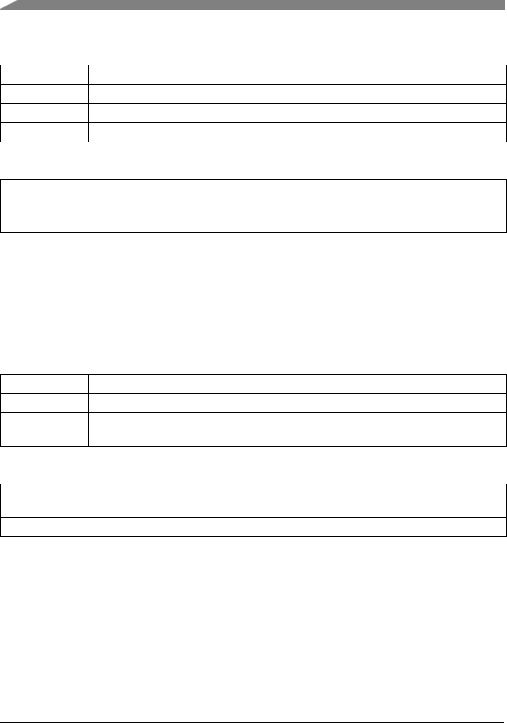
Function Documentation
Parameters
frdiv FLL reference clock divider setting, FRDIV.
dmx32 DMX32 in FEE mode.
drs The DCO range selection.
fllStableDelay Delay function to make sure FLL is stable. Passing NULL does not cause a delay.
Return values
kStatus_MCG_Mode-
Unreachable
Could not switch to the target mode.
kStatus_Success Switched to the target mode successfully.
28.7.47 status_t CLOCK_SetFbiMode ( mcg_dmx32_t dmx32, mcg_drs_t drs,
void(∗)(void) fllStableDelay )
This function sets the MCG to FBI mode. If setting to FBI mode fails from the current mode, this function
returns an error.
Parameters
dmx32 DMX32 in FBI mode.
drs The DCO range selection.
fllStableDelay Delay function to make sure FLL is stable. If the FLL is not used in FBI mode, this
parameter can be NULL. Passing NULL does not cause a delay.
Return values
kStatus_MCG_Mode-
Unreachable
Could not switch to the target mode.
kStatus_Success Switched to the target mode successfully.
404
MCUXpresso SDK API Reference Manual
NXP Semiconductors

Function Documentation
Note
If dmx32 is set to kMCG_Dmx32Fine, the slow IRC must not be trimmed to frequency above 32768
Hz.
28.7.48 status_t CLOCK_SetFbeMode ( uint8_t frdiv, mcg_dmx32_t dmx32,
mcg_drs_t drs, void(∗)(void) fllStableDelay )
This function sets the MCG to FBE mode. If setting to FBE mode fails from the current mode, this
function returns an error.
NXP Semiconductors
MCUXpresso SDK API Reference Manual
405

Function Documentation
Parameters
frdiv FLL reference clock divider setting, FRDIV.
dmx32 DMX32 in FBE mode.
drs The DCO range selection.
fllStableDelay Delay function to make sure FLL is stable. If the FLL is not used in FBE mode, this
parameter can be NULL. Passing NULL does not cause a delay.
Return values
kStatus_MCG_Mode-
Unreachable
Could not switch to the target mode.
kStatus_Success Switched to the target mode successfully.
28.7.49 status_t CLOCK_SetBlpiMode ( void )
This function sets the MCG to BLPI mode. If setting to BLPI mode fails from the current mode, this
function returns an error.
Return values
kStatus_MCG_Mode-
Unreachable
Could not switch to the target mode.
kStatus_Success Switched to the target mode successfully.
28.7.50 status_t CLOCK_SetBlpeMode ( void )
This function sets the MCG to BLPE mode. If setting to BLPE mode fails from the current mode, this
function returns an error.
Return values
kStatus_MCG_Mode-
Unreachable
Could not switch to the target mode.
406
MCUXpresso SDK API Reference Manual
NXP Semiconductors
Function Documentation
kStatus_Success Switched to the target mode successfully.
28.7.51 status_t CLOCK_SetPbeMode ( mcg_pll_clk_select_t pllcs,
mcg_pll_config_t const ∗config )
This function sets the MCG to PBE mode. If setting to PBE mode fails from the current mode, this
function returns an error.
Parameters
pllcs The PLL selection, PLLCS.
config Pointer to the PLL configuration.
Return values
kStatus_MCG_Mode-
Unreachable
Could not switch to the target mode.
kStatus_Success Switched to the target mode successfully.
Note
1. The parameter pllcs selects the PLL. For platforms with only one PLL, the parameter pllcs
is kept for interface compatibility.
2. The parameter config is the PLL configuration structure. On some platforms, it is possible
to choose the external PLL directly, which renders the configuration structure not necessary. In
this case, pass in NULL. For example: CLOCK_SetPbeMode(kMCG_OscselOsc, kMCG_Pll-
ClkSelExtPll, NULL);
28.7.52 status_t CLOCK_SetPeeMode ( void )
This function sets the MCG to PEE mode.
Return values
kStatus_MCG_Mode-
Unreachable
Could not switch to the target mode.
NXP Semiconductors
MCUXpresso SDK API Reference Manual
407

Function Documentation
kStatus_Success Switched to the target mode successfully.
Note
This function only changes the CLKS to use the PLL/FLL output. If the PRDIV/VDIV are different
than in the PBE mode, set them up in PBE mode and wait. When the clock is stable, switch to PEE
mode.
28.7.53 status_t CLOCK_ExternalModeToFbeModeQuick ( void )
This function switches the MCG from external modes (PEE/PBE/BLPE/FEE) to the FBE mode quickly.
The external clock is used as the system clock souce and PLL is disabled. However, the FLL settings are
not configured. This is a lite function with a small code size, which is useful during the mode switch. For
example, to switch from PEE mode to FEI mode:
*CLOCK_ExternalModeToFbeModeQuick();
*CLOCK_SetFeiMode(...);
*
Return values
kStatus_Success Switched successfully.
kStatus_MCG_Mode-
Invalid
If the current mode is not an external mode, do not call this function.
28.7.54 status_t CLOCK_InternalModeToFbiModeQuick ( void )
This function switches the MCG from internal modes (PEI/PBI/BLPI/FEI) to the FBI mode quickly. The
MCGIRCLK is used as the system clock souce and PLL is disabled. However, FLL settings are not
configured. This is a lite function with a small code size, which is useful during the mode switch. For
example, to switch from PEI mode to FEE mode:
*CLOCK_InternalModeToFbiModeQuick();
*CLOCK_SetFeeMode(...);
*
408
MCUXpresso SDK API Reference Manual
NXP Semiconductors

Function Documentation
Return values
kStatus_Success Switched successfully.
kStatus_MCG_Mode-
Invalid
If the current mode is not an internal mode, do not call this function.
28.7.55 status_t CLOCK_BootToFeiMode ( mcg_dmx32_t dmx32, mcg_drs_t drs,
void(∗)(void) fllStableDelay )
This function sets the MCG to FEI mode from the reset mode. It can also be used to set up MCG during
system boot up.
Parameters
dmx32 DMX32 in FEI mode.
drs The DCO range selection.
fllStableDelay Delay function to ensure that the FLL is stable.
Return values
kStatus_MCG_Mode-
Unreachable
Could not switch to the target mode.
kStatus_Success Switched to the target mode successfully.
Note
If dmx32 is set to kMCG_Dmx32Fine, the slow IRC must not be trimmed to frequency above 32768
Hz.
28.7.56 status_t CLOCK_BootToFeeMode ( mcg_oscsel_t oscsel, uint8_t frdiv,
mcg_dmx32_t dmx32, mcg_drs_t drs, void(∗)(void) fllStableDelay )
This function sets MCG to FEE mode from the reset mode. It can also be used to set up the MCG during
system boot up.
Parameters
NXP Semiconductors
MCUXpresso SDK API Reference Manual
409
Function Documentation
oscsel OSC clock select, OSCSEL.
frdiv FLL reference clock divider setting, FRDIV.
dmx32 DMX32 in FEE mode.
drs The DCO range selection.
fllStableDelay Delay function to ensure that the FLL is stable.
Return values
kStatus_MCG_Mode-
Unreachable
Could not switch to the target mode.
kStatus_Success Switched to the target mode successfully.
28.7.57 status_t CLOCK_BootToBlpiMode ( uint8_t fcrdiv, mcg_irc_mode_t ircs,
uint8_t ircEnableMode )
This function sets the MCG to BLPI mode from the reset mode. It can also be used to set up the MCG
during sytem boot up.
Parameters
fcrdiv Fast IRC divider, FCRDIV.
ircs The internal reference clock to select, IRCS.
ircEnableMode The MCGIRCLK enable mode, OR’ed value of _mcg_irclk_enable_mode.
Return values
kStatus_MCG_Source-
Used
Could not change MCGIRCLK setting.
kStatus_Success Switched to the target mode successfully.
28.7.58 status_t CLOCK_BootToBlpeMode ( mcg_oscsel_t oscsel )
This function sets the MCG to BLPE mode from the reset mode. It can also be used to set up the MCG
during sytem boot up.
410
MCUXpresso SDK API Reference Manual
NXP Semiconductors

Function Documentation
Parameters
oscsel OSC clock select, MCG_C7[OSCSEL].
Return values
kStatus_MCG_Mode-
Unreachable
Could not switch to the target mode.
kStatus_Success Switched to the target mode successfully.
28.7.59 status_t CLOCK_BootToPeeMode ( mcg_oscsel_t oscsel,
mcg_pll_clk_select_t pllcs, mcg_pll_config_t const ∗config )
This function sets the MCG to PEE mode from reset mode. It can also be used to set up the MCG during
system boot up.
Parameters
oscsel OSC clock select, MCG_C7[OSCSEL].
pllcs The PLL selection, PLLCS.
config Pointer to the PLL configuration.
Return values
kStatus_MCG_Mode-
Unreachable
Could not switch to the target mode.
kStatus_Success Switched to the target mode successfully.
28.7.60 status_t CLOCK_SetMcgConfig ( mcg_config_t const ∗config )
This function sets MCG to a target mode defined by the configuration structure. If switching to the target
mode fails, this function chooses the correct path.
Parameters
config Pointer to the target MCG mode configuration structure.
Returns
Return kStatus_Success if switched successfully; Otherwise, it returns an error code _mcg_status.
NXP Semiconductors
MCUXpresso SDK API Reference Manual
411

Variable Documentation
Note
If the external clock is used in the target mode, ensure that it is enabled. For example, if the OSC0
is used, set up OSC0 correctly before calling this function.
28.8 Variable Documentation
28.8.1 uint32_t g_xtal0Freq
The XTAL0/EXTAL0 (OSC0) clock frequency in Hz. When the clock is set up, use the function CLOC-
K_SetXtal0Freq to set the value in the clock driver. For example, if XTAL0 is 8 MHz:
*CLOCK_InitOsc0(...); // Set up the OSC0
*CLOCK_SetXtal0Freq(80000000); // Set the XTAL0 value to the clock driver.
*
This is important for the multicore platforms where only one core needs to set up the OSC0 using the
CLOCK_InitOsc0. All other cores need to call the CLOCK_SetXtal0Freq to get a valid clock frequency.
28.8.2 uint32_t g_xtal32Freq
The XTAL32/EXTAL32/RTC_CLKIN clock frequency in Hz. When the clock is set up, use the function
CLOCK_SetXtal32Freq to set the value in the clock driver.
This is important for the multicore platforms where only one core needs to set up the clock. All other
cores need to call the CLOCK_SetXtal32Freq to get a valid clock frequency.
412
MCUXpresso SDK API Reference Manual
NXP Semiconductors

Multipurpose Clock Generator (MCG)
28.9 Multipurpose Clock Generator (MCG)
The MCUXpresso SDK provides a peripheral driver for the module of MCUXpresso SDK devices.
28.9.1 Function description
MCG driver provides these functions:
• Functions to get the MCG clock frequency.
• Functions to configure the MCG clock, such as PLLCLK and MCGIRCLK.
• Functions for the MCG clock lock lost monitor.
• Functions for the OSC configuration.
• Functions for the MCG auto-trim machine.
• Functions for the MCG mode.
28.9.1.1 MCG frequency functions
MCG module provides clocks, such as MCGOUTCLK, MCGIRCLK, MCGFFCLK, MCGFLLCLK and
MCGPLLCLK. The MCG driver provides functions to get the frequency of these clocks, such as C-
LOCK_GetOutClkFreq(),CLOCK_GetInternalRefClkFreq(),CLOCK_GetFixedFreqClkFreq(),CLOC-
K_GetFllFreq(),CLOCK_GetPll0Freq(), CLOCK_GetPll1Freq(), and CLOCK_GetExtPllFreq(). These
functions get the clock frequency based on the current MCG registers.
28.9.1.2 MCG clock configuration
The MCG driver provides functions to configure the internal reference clock (MCGIRCLK), the external
reference clock, and MCGPLLCLK.
The function CLOCK_SetInternalRefClkConfig() configures the MCGIRCLK, including the source and
the driver. Do not change MCGIRCLK when the MCG mode is BLPI/FBI/PBI because the MCGIRCLK
is used as a system clock in these modes and changing settings makes the system clock unstable.
The function CLOCK_SetExternalRefClkConfig() configures the external reference clock source (MCG-
_C7[OSCSEL]). Do not call this function when the MCG mode is BLPE/FBE/PBE/FEE/PEE because
the external reference clock is used as a clock source in these modes. Changing the external reference
clock source requires at least a 50 microseconds wait. The function CLOCK_SetExternalRefClkConfig()
implements a for loop delay internally. The for loop delay assumes that the system clock is 96 MHz,
which ensures at least 50 micro seconds delay. However, when the system clock is slow, the delay time
may significantly increase. This for loop count can be optimized for better performance for specific cases.
The MCGPLLCLK is disabled in FBE/FEE/FBI/FEI modes by default. Applications can enable the M-
CGPLLCLK in these modes using the functions CLOCK_EnablePll0() and CLOCK_EnablePll1(). To
enable the MCGPLLCLK, the PLL reference clock divider(PRDIV) and the PLL VCO divider(VDIV)
must be set to a proper value. The function CLOCK_CalcPllDiv() helps to get the PRDIV/VDIV.
NXP Semiconductors
MCUXpresso SDK API Reference Manual
413

Multipurpose Clock Generator (MCG)
28.9.1.3 MCG clock lock monitor functions
The MCG module monitors the OSC and the PLL clock lock status. The MCG driver provides the func-
tions to set the clock monitor mode, check the clock lost status, and clear the clock lost status.
28.9.1.4 OSC configuration
The MCG is needed together with the OSC module to enable the OSC clock. The function CLOCK_Init-
Osc0() CLOCK_InitOsc1 uses the MCG and OSC to initialize the OSC. The OSC should be configured
based on the board design.
28.9.1.5 MCG auto-trim machine
The MCG provides an auto-trim machine to trim the MCG internal reference clock based on the external
reference clock (BUS clock). During clock trimming, the MCG must not work in FEI/FBI/BLPI/PBI/PEI
modes. The function CLOCK_TrimInternalRefClk() is used for the auto clock trimming.
28.9.1.6 MCG mode functions
The function CLOCK_GetMcgMode returns the current MCG mode. The MCG can only switch between
the neighbouring modes. If the target mode is not current mode’s neighbouring mode, the application must
choose the proper switch path. For example, to switch to PEE mode from FEI mode, use FEI ->FBE ->
PBE ->PEE.
For the MCG modes, the MCG driver provides three kinds of functions:
The first type of functions involve functions CLOCK_SetXxxMode, such as CLOCK_SetFeiMode().
These functions only set the MCG mode from neighbouring modes. If switching to the target mode
directly from current mode is not possible, the functions return an error.
The second type of functions are the functions CLOCK_BootToXxxMode, such as CLOCK_BootToFei-
Mode(). These functions set the MCG to specific modes from reset mode. Because the source mode and
target mode are specific, these functions choose the best switch path. The functions are also useful to set
up the system clock during boot up.
The third type of functions is the CLOCK_SetMcgConfig(). This function chooses the right path to switch
to the target mode. It is easy to use, but introduces a large code size.
Whenever the FLL settings change, there should be a 1 millisecond delay to ensure that the FLL is stable.
The function CLOCK_SetMcgConfig() implements a for loop delay internally to ensure that the FLL is
stable. The for loop delay assumes that the system clock is 96 MHz, which ensures at least 1 millisecond
delay. However, when the system clock is slow, the delay time may increase significantly. The for loop
count can be optimized for better performance according to a specific use case.
414
MCUXpresso SDK API Reference Manual
NXP Semiconductors

Multipurpose Clock Generator (MCG)
28.9.2 Typical use case
The function CLOCK_SetMcgConfig is used to switch between any modes. However, this heavy-light
function introduces a large code size. This section shows how to use the mode function to implement a
quick and light-weight switch between typical specific modes. Note that the step to enable the external
clock is not included in the following steps. Enable the corresponding clock before using it as a clock
source.
28.9.2.1 Switch between BLPI and FEI
Use case Steps Functions
BLPI ->FEI
BLPI ->FBI CLOCK_InternalModeToFbi-
ModeQuick(...)
FBI ->FEI CLOCK_SetFeiMode(...)
Configure MCGIRCLK if need CLOCK_SetInternalRefClk-
Config(...)
FEI ->BLPI
Configure MCGIRCLK if need CLOCK_SetInternalRefClk-
Config(...)
FEI ->FBI CLOCK_SetFbiMode(...) with
fllStableDelay=NULL
FBI ->BLPI CLOCK_SetLowPower-
Enable(true)
28.9.2.2 Switch between BLPI and FEE
Use case Steps Functions
BLPI ->FEE
BLPI ->FBI CLOCK_InternalModeToFbi-
ModeQuick(...)
Change external clock source if
need
CLOCK_SetExternalRefClk-
Config(...)
FBI ->FEE CLOCK_SetFeeMode(...)
FEE ->BLPI
Configure MCGIRCLK if need CLOCK_SetInternalRefClk-
Config(...)
FEE ->FBI CLOCK_SetFbiMode(...) with
fllStableDelay=NULL
FBI ->BLPI CLOCK_SetLowPower-
Enable(true)
NXP Semiconductors
MCUXpresso SDK API Reference Manual
415

Multipurpose Clock Generator (MCG)
28.9.2.3 Switch between BLPI and PEE
Use case Steps Functions
BLPI ->PEE
BLPI ->FBI CLOCK_InternalModeToFbi-
ModeQuick(...)
Change external clock source if
need
CLOCK_SetExternalRefClk-
Config(...)
FBI ->FBE CLOCK_SetFbeMode(...) // fll-
StableDelay=NULL
FBE ->PBE CLOCK_SetPbeMode(...)
PBE ->PEE CLOCK_SetPeeMode(...)
PEE ->BLPI
PEE ->FBE CLOCK_ExternalModeToFbe-
ModeQuick(...)
Configure MCGIRCLK if need CLOCK_SetInternalRefClk-
Config(...)
FBE ->FBI CLOCK_SetFbiMode(...) with
fllStableDelay=NULL
FBI ->BLPI CLOCK_SetLowPower-
Enable(true)
28.9.2.4 Switch between BLPE and PEE
This table applies when using the same external clock source (MCG_C7[OSCSEL]) in BLPE mode and
PEE mode.
Use case Steps Functions
BLPE ->PEE BLPE ->PBE CLOCK_SetPbeMode(...)
PBE ->PEE CLOCK_SetPeeMode(...)
PEE ->BLPE PEE ->FBE CLOCK_ExternalModeToFbe-
ModeQuick(...)
FBE ->BLPE CLOCK_SetLowPower-
Enable(true)
If using different external clock sources (MCG_C7[OSCSEL]) in BLPE mode and PEE mode, call the
CLOCK_SetExternalRefClkConfig() in FBI or FEI mode to change the external reference clock.
Use case Steps Functions
BLPE ->PEE
BLPE ->FBE CLOCK_ExternalModeToFbe-
ModeQuick(...)
416
MCUXpresso SDK API Reference Manual
NXP Semiconductors

Multipurpose Clock Generator (MCG)
FBE ->FBI CLOCK_SetFbiMode(...) with
fllStableDelay=NULL
Change source CLOCK_SetExternalRefClk-
Config(...)
FBI ->FBE CLOCK_SetFbeMode(...) with
fllStableDelay=NULL
FBE ->PBE CLOCK_SetPbeMode(...)
PBE ->PEE CLOCK_SetPeeMode(...)
PEE ->BLPE
PEE ->FBE CLOCK_ExternalModeToFbe-
ModeQuick(...)
FBE ->FBI CLOCK_SetFbiMode(...) with
fllStableDelay=NULL
Change source CLOCK_SetExternalRefClk-
Config(...)
PBI ->FBE CLOCK_SetFbeMode(...) with
fllStableDelay=NULL
FBE ->BLPE CLOCK_SetLowPower-
Enable(true)
28.9.2.5 Switch between BLPE and FEE
This table applies when using the same external clock source (MCG_C7[OSCSEL]) in BLPE mode and
FEE mode.
Use case Steps Functions
BLPE ->FEE BLPE ->FBE CLOCK_ExternalModeToFbe-
ModeQuick(...)
FBE ->FEE CLOCK_SetFeeMode(...)
FEE ->BLPE PEE ->FBE CLOCK_SetPbeMode(...)
FBE ->BLPE CLOCK_SetLowPower-
Enable(true)
If using different external clock sources (MCG_C7[OSCSEL]) in BLPE mode and FEE mode, call the
CLOCK_SetExternalRefClkConfig() in FBI or FEI mode to change the external reference clock.
Use case Steps Functions
BLPE ->FEE
BLPE ->FBE CLOCK_ExternalModeToFbe-
ModeQuick(...)
NXP Semiconductors
MCUXpresso SDK API Reference Manual
417

Multipurpose Clock Generator (MCG)
FBE ->FBI CLOCK_SetFbiMode(...) with
fllStableDelay=NULL
Change source CLOCK_SetExternalRefClk-
Config(...)
FBI ->FEE CLOCK_SetFeeMode(...)
FEE ->BLPE
FEE ->FBI CLOCK_SetFbiMode(...) with
fllStableDelay=NULL
Change source CLOCK_SetExternalRefClk-
Config(...)
PBI ->FBE CLOCK_SetFbeMode(...) with
fllStableDelay=NULL
FBE ->BLPE CLOCK_SetLowPower-
Enable(true)
28.9.2.6 Switch between BLPI and PEI
Use case Steps Functions
BLPI ->PEI
BLPI ->PBI CLOCK_SetPbiMode(...)
PBI ->PEI CLOCK_SetPeiMode(...)
Configure MCGIRCLK if need CLOCK_SetInternalRefClk-
Config(...)
PEI ->BLPI
Configure MCGIRCLK if need CLOCK_SetInternalRefClk-
Config
PEI ->FBI CLOCK_InternalModeToFbi-
ModeQuick(...)
FBI ->BLPI CLOCK_SetLowPower-
Enable(true)
28.9.3 Code Configuration Option
28.9.3.1 MCG_USER_CONFIG_FLL_STABLE_DELAY_EN
When switching to use FLL with function CLOCK_SetFeiMode() and CLOCK_SetFeeMode(), there is
an internal function CLOCK_FllStableDelay(). It is used to delay a few ms so that to wait the FLL to be
stable enough. By default, it is implemented in driver code like:
#ifndef MCG_USER_CONFIG_FLL_STABLE_DELAY_EN
void CLOCK_FllStableDelay(void)
{
/*
418
MCUXpresso SDK API Reference Manual
NXP Semiconductors

Multipurpose Clock Generator (MCG)
Should wait at least 1ms. Because in these modes, the core clock is 100MHz
at most, so this function could obtain the 1ms delay.
*/
volatile uint32_t i = 30000U;
while (i--)
{
__NOP();
}
}
#endif /*MCG_USER_CONFIG_FLL_STABLE_DELAY_EN */
Once user is willing to create his own delay funcion, just assert the macro MCG_USER_CONFIG_FLL-
_STABLE_DELAY_EN, and then define function CLOCK_FllStableDelay in the application code.
NXP Semiconductors
MCUXpresso SDK API Reference Manual
419

Multipurpose Clock Generator (MCG)
420
MCUXpresso SDK API Reference Manual
NXP Semiconductors

Chapter 29
DMA Manager
29.1 Overview
DMA Manager provides a series of functions to manage the DMAMUX instances and channels.
29.2 Function groups
29.2.1 DMAMGR Initialization and De-initialization
This function group initializes and deinitializes the DMA Manager.
29.2.2 DMAMGR Operation
This function group requests/releases the DMAMUX channel and configures the channel request source.
29.3 Typical use case
29.3.1 DMAMGR static channel allocattion
uint8_t channel;
dmamanager_handle_t dmamanager_handle;
/*Initialize DMAMGR */
DMAMGR_Init(&dmamanager_handle, EXAMPLE_DMA_BASEADDR, DMA_CHANNEL_NUMBER, startChannel);
/*Request a DMAMUX channel by static allocate mechanism */
channel = kDMAMGR_STATIC_ALLOCATE;
DMAMGR_RequestChannel(&dmamanager_handle, kDmaRequestMux0AlwaysOn63, channel, &handle)
;
29.3.2 DMAMGR dynamic channel allocation
uint8_t channel;
dmamanager_handle_t dmamanager_handle;
/*Initialize DMAMGR */
DMAMGR_Init(&dmamanager_handle, EXAMPLE_DMA_BASEADDR, DMA_CHANNEL_NUMBER, startChannel);
/*Request a DMAMUX channel by Dynamic allocate mechanism */
channel = DMAMGR_DYNAMIC_ALLOCATE;
DMAMGR_RequestChannel(&dmamanager_handle, kDmaRequestMux0AlwaysOn63, channel, &handle)
;
Data Structures
• struct dmamanager_handle_t
dmamanager handle typedef. More...
NXP Semiconductors
MCUXpresso SDK API Reference Manual
421

Data Structure Documentation
Macros
• #define DMAMGR_DYNAMIC_ALLOCATE 0xFFU
Dynamic channel allocation mechanism.
Enumerations
• enum _dma_manager_status {
kStatus_DMAMGR_ChannelOccupied = MAKE_STATUS(kStatusGroup_DMAMGR, 0),
kStatus_DMAMGR_ChannelNotUsed = MAKE_STATUS(kStatusGroup_DMAMGR, 1),
kStatus_DMAMGR_NoFreeChannel = MAKE_STATUS(kStatusGroup_DMAMGR, 2) }
DMA manager status.
DMAMGR Initialization and De-initialization
• void DMAMGR_Init (dmamanager_handle_t ∗dmamanager_handle, DMA_Type ∗dma_base,
uint32_t channelNum, uint32_t startChannel)
Initializes the DMA manager.
• void DMAMGR_Deinit (dmamanager_handle_t ∗dmamanager_handle)
Deinitializes the DMA manager.
DMAMGR Operation
• status_t DMAMGR_RequestChannel (dmamanager_handle_t ∗dmamanager_handle, uint32_t
requestSource, uint32_t channel, void ∗handle)
Requests a DMA channel.
• status_t DMAMGR_ReleaseChannel (dmamanager_handle_t ∗dmamanager_handle, void ∗handle)
Releases a DMA channel.
• bool DMAMGR_IsChannelOccupied (dmamanager_handle_t ∗dmamanager_handle, uint32_t
channel)
Get a DMA channel status.
29.4 Data Structure Documentation
29.4.1 struct dmamanager_handle_t
Note
The contents of this structure are private and subject to change.
This dma manager handle structure is used to store the parameters transfered by users.And users shall not
free the memory before calling DMAMGR_Deinit, also shall not modify the contents of the memory.
Data Fields
• void ∗dma_base
Peripheral DMA instance.
• uint32_t channelNum
422
MCUXpresso SDK API Reference Manual
NXP Semiconductors

Function Documentation
Channel numbers for the DMA instance which need to be managed by dma manager.
• uint32_t startChannel
The start channel that can be managed by dma manager,users need to transfer it with a certain number or
NULL.
• bool s_DMAMGR_Channels [64]
The s_DMAMGR_Channels is used to store dma manager state.
• uint32_t DmamuxInstanceStart
The DmamuxInstance is used to calculate the DMAMUX Instance according to the DMA Instance.
• uint32_t multiple
The multiple is used to calculate the multiple between DMAMUX count and DMA count.
29.4.1.0.0.49 Field Documentation
29.4.1.0.0.49.1 void∗dmamanager_handle_t::dma_base
29.4.1.0.0.49.2 uint32_t dmamanager_handle_t::channelNum
29.4.1.0.0.49.3 uint32_t dmamanager_handle_t::startChannel
29.4.1.0.0.49.4 bool dmamanager_handle_t::s_DMAMGR_Channels[64]
29.4.1.0.0.49.5 uint32_t dmamanager_handle_t::DmamuxInstanceStart
29.4.1.0.0.49.6 uint32_t dmamanager_handle_t::multiple
29.5 Macro Definition Documentation
29.5.1 #define DMAMGR_DYNAMIC_ALLOCATE 0xFFU
29.6 Enumeration Type Documentation
29.6.1 enum _dma_manager_status
Enumerator
kStatus_DMAMGR_ChannelOccupied Channel has been occupied.
kStatus_DMAMGR_ChannelNotUsed Channel has not been used.
kStatus_DMAMGR_NoFreeChannel All channels have been occupied.
29.7 Function Documentation
29.7.1 void DMAMGR_Init ( dmamanager_handle_t ∗dmamanager_handle,
DMA_Type ∗dma_base, uint32_t channelNum, uint32_t startChannel )
This function initializes the DMA manager, ungates the DMAMUX clocks, and initializes the eDMA or
DMA peripherals.
NXP Semiconductors
MCUXpresso SDK API Reference Manual
423

Function Documentation
Parameters
dmamanager_-
handle
DMA manager handle pointer, this structure is maintained by dma manager inter-
nal,users only need to transfer the structure to the function. And users shall not free
the memory before calling DMAMGR_Deinit, also shall not modify the contents of
the memory.
dma_base Peripheral DMA instance base pointer.
dmamux_base Peripheral DMAMUX instance base pointer.
channelNum Channel numbers for the DMA instance which need to be managed by dma manager.
startChannel The start channel that can be managed by dma manager.
29.7.2 void DMAMGR_Deinit ( dmamanager_handle_t ∗dmamanager_handle )
This function deinitializes the DMA manager, disables the DMAMUX channels, gates the DMAMUX
clocks, and deinitializes the eDMA or DMA peripherals.
Parameters
dmamanager_-
handle
DMA manager handle pointer, this structure is maintained by dma manager inter-
nal,users only need to transfer the structure to the function. And users shall not free
the memory before calling DMAMGR_Deinit, also shall not modify the contents of
the memory.
29.7.3 status_t DMAMGR_RequestChannel ( dmamanager_handle_t ∗
dmamanager_handle, uint32_t requestSource, uint32_t channel, void ∗
handle )
This function requests a DMA channel which is not occupied. The two channels to allocate the mechanism
are dynamic and static channels. For the dynamic allocation mechanism (channe = DMAMGR_DYNAM-
IC_ALLOCATE), DMAMGR allocates a DMA channel according to the given request source and start-
Channel and then configures it. For static allocation mechanism, DMAMGR configures the given channel
according to the given request source and channel number.
424
MCUXpresso SDK API Reference Manual
NXP Semiconductors

Function Documentation
Parameters
dmamanager_-
handle
DMA manager handle pointer, this structure is maintained by dma manager inter-
nal,users only need to transfer the structure to the function. And users shall not free
the memory before calling DMAMGR_Deinit, also shall not modify the contents of
the memory.
requestSource DMA channel request source number. See the soc.h, see the enum dma_request_-
source_t
channel The channel number users want to occupy. If using the dynamic channel allocate
mechanism, set the channel equal to DMAMGR_DYNAMIC_ALLOCATE.
handle DMA or eDMA handle pointer.
Return values
kStatus_Success In a dynamic/static channel allocation mechanism, allocate the DMAMUX
channel successfully.
kStatus_DMAMGR_No-
FreeChannel
In a dynamic channel allocation mechanism, all DMAMUX channels are
occupied.
kStatus_DMAMGR_-
ChannelOccupied
In a static channel allocation mechanism, the given channel is occupied.
29.7.4 status_t DMAMGR_ReleaseChannel ( dmamanager_handle_t ∗
dmamanager_handle, void ∗handle )
This function releases an occupied DMA channel.
Parameters
dmamanager_-
handle
DMA manager handle pointer, this structure is maintained by dma manager inter-
nal,users only need to transfer the structure to the function. And users shall not free
the memory before calling DMAMGR_Deinit, also shall not modify the contents of
the memory.
handle DMA or eDMA handle pointer.
Return values
NXP Semiconductors
MCUXpresso SDK API Reference Manual
425

Function Documentation
kStatus_Success Releases the given channel successfully.
kStatus_DMAMGR_-
ChannelNotUsed
The given channel to be released had not been used before.
29.7.5 bool DMAMGR_IsChannelOccupied ( dmamanager_handle_t ∗
dmamanager_handle, uint32_t channel )
This function get a DMA channel status. Return 0 indicates the channel has not been used, return 1
indicates the channel has been occupied.
Parameters
dmamanager_-
handle
DMA manager handle pointer, this structure is maintained by dma manager inter-
nal,users only need to transfer the structure to the function. And users shall not free
the memory before calling DMAMGR_Deinit, also shall not modify the contents of
the memory.
channel The channel number that users want get its status.
426
MCUXpresso SDK API Reference Manual
NXP Semiconductors

Chapter 30
Secure Digital Card/Embedded MultiMedia Card (CARD)
30.1 Overview
The MCUXpresso SDK provides a driver to access the Secure Digital Card and Embedded MultiMedia
Card based on the SDHC driver.
Function groups
This function group implements the SD card functional API.
This function group implements the MMC card functional API.
Typical use case
/*Initialize SDHC. */
sdhcConfig->cardDetectDat3 = false;
sdhcConfig->endianMode = kSDHC_EndianModeLittle;
sdhcConfig->dmaMode = kSDHC_DmaModeAdma2;
sdhcConfig->readWatermarkLevel = 0x80U;
sdhcConfig->writeWatermarkLevel = 0x80U;
SDHC_Init(BOARD_SDHC_BASEADDR, sdhcConfig);
/*Save host information. */
card->host.base = BOARD_SDHC_BASEADDR;
card->host.sourceClock_Hz = CLOCK_GetFreq(BOARD_SDHC_CLKSRC);
card->host.transfer = SDHC_TransferFunction;
/*Init card. */
if (SD_Init(card))
{
PRINTF("\r\nSD card init failed.\r\n");
}
while (true)
{
if (kStatus_Success != SD_WriteBlocks(card, g_dataWrite, DATA_BLOCK_START,
DATA_BLOCK_COUNT))
{
PRINTF("Write multiple data blocks failed.\r\n");
}
if (kStatus_Success != SD_ReadBlocks(card, g_dataRead, DATA_BLOCK_START, DATA_BLOCK_COUNT)
)
{
PRINTF("Read multiple data blocks failed.\r\n");
}
if (kStatus_Success != SD_EraseBlocks(card, DATA_BLOCK_START, DATA_BLOCK_COUNT))
{
PRINTF("Erase multiple data blocks failed.\r\n");
}
}
SD_Deinit(card);
/*Initialize SDHC. */
NXP Semiconductors
MCUXpresso SDK API Reference Manual
427

Overview
sdhcConfig->cardDetectDat3 = false;
sdhcConfig->endianMode = kSDHC_EndianModeLittle;
sdhcConfig->dmaMode = kSDHC_DmaModeAdma2;
sdhcConfig->readWatermarkLevel = 0x80U;
sdhcConfig->writeWatermarkLevel = 0x80U;
SDHC_Init(BOARD_SDHC_BASEADDR, sdhcConfig);
/*Save host information. */
card->host.base = BOARD_SDHC_BASEADDR;
card->host.sourceClock_Hz = CLOCK_GetFreq(BOARD_SDHC_CLKSRC);
card->host.transfer = SDHC_TransferFunction;
/*Init card. */
if (MMC_Init(card))
{
PRINTF("\n MMC card init failed \n");
}
while (true)
{
if (kStatus_Success != MMC_WriteBlocks(card, g_dataWrite, DATA_BLOCK_START,
DATA_BLOCK_COUNT))
{
PRINTF("Write multiple data blocks failed.\r\n");
}
if (kStatus_Success != MMC_ReadBlocks(card, g_dataRead, DATA_BLOCK_START,
DATA_BLOCK_COUNT))
{
PRINTF("Read multiple data blocks failed.\r\n");
}
}
MMC_Deinit(card);
Data Structures
• struct sd_card_t
SD card state. More...
• struct sdio_card_t
SDIO card state. More...
• struct mmc_card_t
SD card state. More...
• struct mmc_boot_config_t
MMC card boot configuration definition. More...
Macros
• #define FSL_SDMMC_DRIVER_VERSION (MAKE_VERSION(2U, 1U, 2U)) /∗2.1.2∗/
Driver version.
• #define FSL_SDMMC_DEFAULT_BLOCK_SIZE (512U)
Default block size.
• #define HOST_NOT_SUPPORT 0U
use this define to indicate the host not support feature
• #define HOST_SUPPORT 1U
use this define to indicate the host support feature
428
MCUXpresso SDK API Reference Manual
NXP Semiconductors

Overview
Enumerations
• enum _sdmmc_status {
kStatus_SDMMC_NotSupportYet = MAKE_STATUS(kStatusGroup_SDMMC, 0U),
kStatus_SDMMC_TransferFailed = MAKE_STATUS(kStatusGroup_SDMMC, 1U),
kStatus_SDMMC_SetCardBlockSizeFailed = MAKE_STATUS(kStatusGroup_SDMMC, 2U),
kStatus_SDMMC_HostNotSupport = MAKE_STATUS(kStatusGroup_SDMMC, 3U),
kStatus_SDMMC_CardNotSupport = MAKE_STATUS(kStatusGroup_SDMMC, 4U),
kStatus_SDMMC_AllSendCidFailed = MAKE_STATUS(kStatusGroup_SDMMC, 5U),
kStatus_SDMMC_SendRelativeAddressFailed = MAKE_STATUS(kStatusGroup_SDMMC, 6U),
kStatus_SDMMC_SendCsdFailed = MAKE_STATUS(kStatusGroup_SDMMC, 7U),
kStatus_SDMMC_SelectCardFailed = MAKE_STATUS(kStatusGroup_SDMMC, 8U),
kStatus_SDMMC_SendScrFailed = MAKE_STATUS(kStatusGroup_SDMMC, 9U),
kStatus_SDMMC_SetDataBusWidthFailed = MAKE_STATUS(kStatusGroup_SDMMC, 10U),
kStatus_SDMMC_GoIdleFailed = MAKE_STATUS(kStatusGroup_SDMMC, 11U),
kStatus_SDMMC_HandShakeOperationConditionFailed,
kStatus_SDMMC_SendApplicationCommandFailed,
kStatus_SDMMC_SwitchFailed = MAKE_STATUS(kStatusGroup_SDMMC, 14U),
kStatus_SDMMC_StopTransmissionFailed = MAKE_STATUS(kStatusGroup_SDMMC, 15U),
kStatus_SDMMC_WaitWriteCompleteFailed = MAKE_STATUS(kStatusGroup_SDMMC, 16U),
kStatus_SDMMC_SetBlockCountFailed = MAKE_STATUS(kStatusGroup_SDMMC, 17U),
kStatus_SDMMC_SetRelativeAddressFailed = MAKE_STATUS(kStatusGroup_SDMMC, 18U),
kStatus_SDMMC_SwitchBusTimingFailed = MAKE_STATUS(kStatusGroup_SDMMC, 19U),
kStatus_SDMMC_SendExtendedCsdFailed = MAKE_STATUS(kStatusGroup_SDMMC, 20U),
kStatus_SDMMC_ConfigureBootFailed = MAKE_STATUS(kStatusGroup_SDMMC, 21U),
kStatus_SDMMC_ConfigureExtendedCsdFailed = MAKE_STATUS(kStatusGroup_SDMMC, 22-
U),
kStatus_SDMMC_EnableHighCapacityEraseFailed,
kStatus_SDMMC_SendTestPatternFailed = MAKE_STATUS(kStatusGroup_SDMMC, 24U),
kStatus_SDMMC_ReceiveTestPatternFailed = MAKE_STATUS(kStatusGroup_SDMMC, 25U),
kStatus_SDMMC_SDIO_ResponseError = MAKE_STATUS(kStatusGroup_SDMMC, 26U),
kStatus_SDMMC_SDIO_InvalidArgument,
kStatus_SDMMC_SDIO_SendOperationConditionFail,
kStatus_SDMMC_InvalidVoltage = MAKE_STATUS(kStatusGroup_SDMMC, 29U),
kStatus_SDMMC_SDIO_SwitchHighSpeedFail = MAKE_STATUS(kStatusGroup_SDMMC, 30-
U),
kStatus_SDMMC_SDIO_ReadCISFail = MAKE_STATUS(kStatusGroup_SDMMC, 31U),
kStatus_SDMMC_SDIO_InvalidCard = MAKE_STATUS(kStatusGroup_SDMMC, 32U),
kStatus_SDMMC_TuningFail = MAKE_STATUS(kStatusGroup_SDMMC, 33U),
kStatus_SDMMC_SwitchVoltageFail = MAKE_STATUS(kStatusGroup_SDMMC, 34U),
kStatus_SDMMC_ReTuningRequest = MAKE_STATUS(kStatusGroup_SDMMC, 35U),
kStatus_SDMMC_SetDriverStrengthFail = MAKE_STATUS(kStatusGroup_SDMMC, 36U),
kStatus_SDMMC_SetPowerClassFail = MAKE_STATUS(kStatusGroup_SDMMC, 37U) }
SD/MMC card API’s running status.
• enum _sd_card_flag {
NXP Semiconductors
MCUXpresso SDK API Reference Manual
429

Overview
kSD_SupportHighCapacityFlag = (1U << 1U),
kSD_Support4BitWidthFlag = (1U << 2U),
kSD_SupportSdhcFlag = (1U << 3U),
kSD_SupportSdxcFlag = (1U << 4U),
kSD_SupportVoltage180v = (1U << 5U),
kSD_SupportSetBlockCountCmd = (1U << 6U),
kSD_SupportSpeedClassControlCmd = (1U << 7U) }
SD card flags.
• enum _mmc_card_flag {
kMMC_SupportHighSpeed26MHZFlag = (1U << 0U),
kMMC_SupportHighSpeed52MHZFlag = (1U << 1U),
kMMC_SupportHighSpeedDDR52MHZ180V300VFlag = (1 << 2U),
kMMC_SupportHighSpeedDDR52MHZ120VFlag = (1 << 3U),
kMMC_SupportHS200200MHZ180VFlag = (1 << 4U),
kMMC_SupportHS200200MHZ120VFlag = (1 << 5U),
kMMC_SupportHS400DDR200MHZ180VFlag = (1 << 6U),
kMMC_SupportHS400DDR200MHZ120VFlag = (1 << 7U),
kMMC_SupportHighCapacityFlag = (1U << 8U),
kMMC_SupportAlternateBootFlag = (1U << 9U),
kMMC_SupportDDRBootFlag = (1U << 10U),
kMMC_SupportHighSpeedBootFlag = (1U << 11U),
kMMC_DataBusWidth4BitFlag = (1U << 12U),
kMMC_DataBusWidth8BitFlag = (1U << 13U),
kMMC_DataBusWidth1BitFlag = (1U << 14U) }
MMC card flags.
• enum card_operation_voltage_t {
kCARD_OperationVoltageNone = 0U,
kCARD_OperationVoltage330V = 1U,
kCARD_OperationVoltage300V = 2U,
kCARD_OperationVoltage180V = 3U }
card operation voltage
• enum _host_endian_mode {
kHOST_EndianModeBig = 0U,
kHOST_EndianModeHalfWordBig = 1U,
kHOST_EndianModeLittle = 2U }
host Endian mode corresponding to driver define
SDCARD Function
• status_t SD_Init (sd_card_t ∗card)
Initializes the card on a specific host controller.
• void SD_Deinit (sd_card_t ∗card)
Deinitializes the card.
• bool SD_CheckReadOnly (sd_card_t ∗card)
Checks whether the card is write-protected.
• status_t SD_ReadBlocks (sd_card_t ∗card, uint8_t ∗buffer, uint32_t startBlock, uint32_t block-
Count)
430
MCUXpresso SDK API Reference Manual
NXP Semiconductors

Overview
Reads blocks from the specific card.
• status_t SD_WriteBlocks (sd_card_t ∗card, const uint8_t ∗buffer, uint32_t startBlock, uint32_t
blockCount)
Writes blocks of data to the specific card.
• status_t SD_EraseBlocks (sd_card_t ∗card, uint32_t startBlock, uint32_t blockCount)
Erases blocks of the specific card.
MMCCARD Function
• status_t MMC_Init (mmc_card_t ∗card)
Initializes the MMC card.
• void MMC_Deinit (mmc_card_t ∗card)
Deinitializes the card.
• bool MMC_CheckReadOnly (mmc_card_t ∗card)
Checks if the card is read-only.
• status_t MMC_ReadBlocks (mmc_card_t ∗card, uint8_t ∗buffer, uint32_t startBlock, uint32_-
t blockCount)
Reads data blocks from the card.
• status_t MMC_WriteBlocks (mmc_card_t ∗card, const uint8_t ∗buffer, uint32_t startBlock, uint32-
_t blockCount)
Writes data blocks to the card.
• status_t MMC_EraseGroups (mmc_card_t ∗card, uint32_t startGroup, uint32_t endGroup)
Erases groups of the card.
• status_t MMC_SelectPartition (mmc_card_t ∗card, mmc_access_partition_t partitionNumber)
Selects the partition to access.
• status_t MMC_SetBootConfig (mmc_card_t ∗card, const mmc_boot_config_t ∗config)
Configures the boot activity of the card.
• status_t SDIO_CardInActive (sdio_card_t ∗card)
set SDIO card to inactive state
• status_t SDIO_IO_Write_Direct (sdio_card_t ∗card, sdio_func_num_t func, uint32_t regAddr,
uint8_t ∗data, bool raw)
IO direct write transfer function.
• status_t SDIO_IO_Read_Direct (sdio_card_t ∗card, sdio_func_num_t func, uint32_t regAddr,
uint8_t ∗data)
IO direct read transfer function.
• status_t SDIO_IO_Write_Extended (sdio_card_t ∗card, sdio_func_num_t func, uint32_t regAddr,
uint8_t ∗buffer, uint32_t count, uint32_t flags)
IO extended write transfer function.
• status_t SDIO_IO_Read_Extended (sdio_card_t ∗card, sdio_func_num_t func, uint32_t regAddr,
uint8_t ∗buffer, uint32_t count, uint32_t flags)
IO extended read transfer function.
• status_t SDIO_GetCardCapability (sdio_card_t ∗card, sdio_func_num_t func)
get SDIO card capability
• status_t SDIO_SetBlockSize (sdio_card_t ∗card, sdio_func_num_t func, uint32_t blockSize)
set SDIO card block size
• status_t SDIO_CardReset (sdio_card_t ∗card)
set SDIO card reset
• status_t SDIO_SetDataBusWidth (sdio_card_t ∗card, sdio_bus_width_t busWidth)
set SDIO card data bus width
• status_t SDIO_SwitchToHighSpeed (sdio_card_t ∗card)
NXP Semiconductors
MCUXpresso SDK API Reference Manual
431

Data Structure Documentation
switch the card to high speed
• status_t SDIO_ReadCIS (sdio_card_t ∗card, sdio_func_num_t func, const uint32_t ∗tupleList,
uint32_t tupleNum)
read SDIO card CIS for each function
• status_t SDIO_Init (sdio_card_t ∗card)
SDIO card init function.
• status_t SDIO_EnableIOInterrupt (sdio_card_t ∗card, sdio_func_num_t func, bool enable)
enable IO interrupt
• status_t SDIO_EnableIO (sdio_card_t ∗card, sdio_func_num_t func, bool enable)
enable IO and wait IO ready
• status_t SDIO_SelectIO (sdio_card_t ∗card, sdio_func_num_t func)
select IO
• status_t SDIO_AbortIO (sdio_card_t ∗card, sdio_func_num_t func)
Abort IO transfer.
• void SDIO_DeInit (sdio_card_t ∗card)
SDIO card deinit.
adaptor function
• static status_t HOST_NotSupport (void ∗parameter)
host not support function, this function is used for host not support feature
• status_t CardInsertDetect (HOST_TYPE ∗hostBase)
Detect card insert, only need for SD cases.
• status_t HOST_Init (void ∗host)
Init host controller.
• void HOST_Deinit (void ∗host)
Deinit host controller.
30.2 Data Structure Documentation
30.2.1 struct sd_card_t
Define the card structure including the necessary fields to identify and describe the card.
Data Fields
• HOST_CONFIG host
Host information.
• bool isHostReady
use this flag to indicate if need host re-init or not
• uint32_t busClock_Hz
SD bus clock frequency united in Hz.
• uint32_t relativeAddress
Relative address of the card.
• uint32_t version
Card version.
• uint32_t flags
Flags in _sd_card_flag.
• uint32_t rawCid [4U]
432
MCUXpresso SDK API Reference Manual
NXP Semiconductors

Data Structure Documentation
Raw CID content.
• uint32_t rawCsd [4U]
Raw CSD content.
• uint32_t rawScr [2U]
Raw CSD content.
• uint32_t ocr
Raw OCR content.
• sd_cid_t cid
CID.
• sd_csd_t csd
CSD.
• sd_scr_t scr
SCR.
• uint32_t blockCount
Card total block number.
• uint32_t blockSize
Card block size.
• sd_timing_mode_t currentTiming
current timing mode
• sd_driver_strength_t driverStrength
driver strength
• sd_max_current_t maxCurrent
card current limit
•card_operation_voltage_t operationVoltage
card operation voltage
30.2.2 struct sdio_card_t
Define the card structure including the necessary fields to identify and describe the card.
Data Fields
• HOST_CONFIG host
Host information.
• bool isHostReady
use this flag to indicate if need host re-init or not
• bool memPresentFlag
indicate if memory present
• uint32_t busClock_Hz
SD bus clock frequency united in Hz.
• uint32_t relativeAddress
Relative address of the card.
• uint8_t sdVersion
SD version.
• uint8_t sdioVersion
SDIO version.
• uint8_t cccrVersioin
CCCR version.
NXP Semiconductors
MCUXpresso SDK API Reference Manual
433

Data Structure Documentation
• uint8_t ioTotalNumber
total number of IO function
• uint32_t cccrflags
Flags in _sd_card_flag.
• uint32_t io0blockSize
record the io0 block size
• uint32_t ocr
Raw OCR content, only 24bit avalible for SDIO card.
• uint32_t commonCISPointer
point to common CIS
• sdio_fbr_t ioFBR [7U]
FBR table.
• sdio_common_cis_t commonCIS
CIS table.
• sdio_func_cis_t funcCIS [7U]
function CIS table
30.2.3 struct mmc_card_t
Define the card structure including the necessary fields to identify and describe the card.
Data Fields
• HOST_CONFIG host
Host information.
• bool isHostReady
use this flag to indicate if need host re-init or not
• uint32_t busClock_Hz
MMC bus clock united in Hz.
• uint32_t relativeAddress
Relative address of the card.
• bool enablePreDefinedBlockCount
Enable PRE-DEFINED block count when read/write.
• uint32_t flags
Capability flag in _mmc_card_flag.
• uint32_t rawCid [4U]
Raw CID content.
• uint32_t rawCsd [4U]
Raw CSD content.
• uint32_t rawExtendedCsd [MMC_EXTENDED_CSD_BYTES/4U]
Raw MMC Extended CSD content.
• uint32_t ocr
Raw OCR content.
• mmc_cid_t cid
CID.
• mmc_csd_t csd
CSD.
• mmc_extended_csd_t extendedCsd
434
MCUXpresso SDK API Reference Manual
NXP Semiconductors

Enumeration Type Documentation
Extended CSD.
• uint32_t blockSize
Card block size.
• uint32_t userPartitionBlocks
Card total block number in user partition.
• uint32_t bootPartitionBlocks
Boot partition size united as block size.
• uint32_t eraseGroupBlocks
Erase group size united as block size.
• mmc_access_partition_t currentPartition
Current access partition.
• mmc_voltage_window_t hostVoltageWindow
Host voltage window.
• mmc_high_speed_timing_t currentTiming
indicate the current host timing mode
30.2.4 struct mmc_boot_config_t
Data Fields
• bool enableBootAck
Enable boot ACK.
• mmc_boot_partition_enable_t bootPartition
Boot partition.
• bool retainBootBusWidth
If retain boot bus width.
• mmc_data_bus_width_t bootDataBusWidth
Boot data bus width.
30.3 Macro Definition Documentation
30.3.1 #define FSL_SDMMC_DRIVER_VERSION (MAKE_VERSION(2U, 1U, 2U))
/∗2.1.2∗/
30.4 Enumeration Type Documentation
30.4.1 enum _sdmmc_status
Enumerator
kStatus_SDMMC_NotSupportYet Haven’t supported.
kStatus_SDMMC_TransferFailed Send command failed.
kStatus_SDMMC_SetCardBlockSizeFailed Set block size failed.
kStatus_SDMMC_HostNotSupport Host doesn’t support.
kStatus_SDMMC_CardNotSupport Card doesn’t support.
kStatus_SDMMC_AllSendCidFailed Send CID failed.
kStatus_SDMMC_SendRelativeAddressFailed Send relative address failed.
NXP Semiconductors
MCUXpresso SDK API Reference Manual
435

Enumeration Type Documentation
kStatus_SDMMC_SendCsdFailed Send CSD failed.
kStatus_SDMMC_SelectCardFailed Select card failed.
kStatus_SDMMC_SendScrFailed Send SCR failed.
kStatus_SDMMC_SetDataBusWidthFailed Set bus width failed.
kStatus_SDMMC_GoIdleFailed Go idle failed.
kStatus_SDMMC_HandShakeOperationConditionFailed Send Operation Condition failed.
kStatus_SDMMC_SendApplicationCommandFailed Send application command failed.
kStatus_SDMMC_SwitchFailed Switch command failed.
kStatus_SDMMC_StopTransmissionFailed Stop transmission failed.
kStatus_SDMMC_WaitWriteCompleteFailed Wait write complete failed.
kStatus_SDMMC_SetBlockCountFailed Set block count failed.
kStatus_SDMMC_SetRelativeAddressFailed Set relative address failed.
kStatus_SDMMC_SwitchBusTimingFailed Switch high speed failed.
kStatus_SDMMC_SendExtendedCsdFailed Send EXT_CSD failed.
kStatus_SDMMC_ConfigureBootFailed Configure boot failed.
kStatus_SDMMC_ConfigureExtendedCsdFailed Configure EXT_CSD failed.
kStatus_SDMMC_EnableHighCapacityEraseFailed Enable high capacity erase failed.
kStatus_SDMMC_SendTestPatternFailed Send test pattern failed.
kStatus_SDMMC_ReceiveTestPatternFailed Receive test pattern failed.
kStatus_SDMMC_SDIO_ResponseError sdio response error
kStatus_SDMMC_SDIO_InvalidArgument sdio invalid argument response error
kStatus_SDMMC_SDIO_SendOperationConditionFail sdio send operation condition fail
kStatus_SDMMC_InvalidVoltage invaild voltage
kStatus_SDMMC_SDIO_SwitchHighSpeedFail switch to high speed fail
kStatus_SDMMC_SDIO_ReadCISFail read CIS fail
kStatus_SDMMC_SDIO_InvalidCard invaild SDIO card
kStatus_SDMMC_TuningFail tuning fail
kStatus_SDMMC_SwitchVoltageFail switch voltage fail
kStatus_SDMMC_ReTuningRequest retuning request
kStatus_SDMMC_SetDriverStrengthFail set driver strength fail
kStatus_SDMMC_SetPowerClassFail set power class fail
30.4.2 enum _sd_card_flag
Enumerator
kSD_SupportHighCapacityFlag Support high capacity.
kSD_Support4BitWidthFlag Support 4-bit data width.
kSD_SupportSdhcFlag Card is SDHC.
kSD_SupportSdxcFlag Card is SDXC.
kSD_SupportVoltage180v card support 1.8v voltage
kSD_SupportSetBlockCountCmd card support cmd23 flag
kSD_SupportSpeedClassControlCmd card support speed class control flag
436
MCUXpresso SDK API Reference Manual
NXP Semiconductors

Function Documentation
30.4.3 enum _mmc_card_flag
Enumerator
kMMC_SupportHighSpeed26MHZFlag Support high speed 26MHZ.
kMMC_SupportHighSpeed52MHZFlag Support high speed 52MHZ.
kMMC_SupportHighSpeedDDR52MHZ180V300VFlag ddr 52MHZ 1.8V or 3.0V
kMMC_SupportHighSpeedDDR52MHZ120VFlag DDR 52MHZ 1.2V.
kMMC_SupportHS200200MHZ180VFlag HS200 ,200MHZ,1.8V.
kMMC_SupportHS200200MHZ120VFlag HS200, 200MHZ, 1.2V.
kMMC_SupportHS400DDR200MHZ180VFlag HS400, DDR, 200MHZ,1.8V.
kMMC_SupportHS400DDR200MHZ120VFlag HS400, DDR, 200MHZ,1.2V.
kMMC_SupportHighCapacityFlag Support high capacity.
kMMC_SupportAlternateBootFlag Support alternate boot.
kMMC_SupportDDRBootFlag support DDR boot flag
kMMC_SupportHighSpeedBootFlag support high speed boot flag
kMMC_DataBusWidth4BitFlag current data bus is 4 bit mode
kMMC_DataBusWidth8BitFlag current data bus is 8 bit mode
kMMC_DataBusWidth1BitFlag current data bus is 1 bit mode
30.4.4 enum card_operation_voltage_t
Enumerator
kCARD_OperationVoltageNone indicate current voltage setting is not setting bu suser
kCARD_OperationVoltage330V card operation voltage around 3.3v
kCARD_OperationVoltage300V card operation voltage around 3.0v
kCARD_OperationVoltage180V card operation voltage around 31.8v
30.4.5 enum _host_endian_mode
Enumerator
kHOST_EndianModeBig Big endian mode.
kHOST_EndianModeHalfWordBig Half word big endian mode.
kHOST_EndianModeLittle Little endian mode.
30.5 Function Documentation
30.5.1 status_t SD_Init ( sd_card_t ∗card )
This function initializes the card on a specific host controller.
NXP Semiconductors
MCUXpresso SDK API Reference Manual
437

Function Documentation
Parameters
card Card descriptor.
Return values
kStatus_SDMMC_Go-
IdleFailed
Go idle failed.
kStatus_SDMMC_Not-
SupportYet
Card not support.
kStatus_SDMMC_Send-
OperationCondition-
Failed
Send operation condition failed.
kStatus_SDMMC_All-
SendCidFailed
Send CID failed.
kStatus_SDMMC_Send-
RelativeAddressFailed
Send relative address failed.
kStatus_SDMMC_Send-
CsdFailed
Send CSD failed.
kStatus_SDMMC_Select-
CardFailed
Send SELECT_CARD command failed.
kStatus_SDMMC_Send-
ScrFailed
Send SCR failed.
kStatus_SDMMC_SetBus-
WidthFailed
Set bus width failed.
kStatus_SDMMC_Switch-
HighSpeedFailed
Switch high speed failed.
kStatus_SDMMC_Set-
CardBlockSizeFailed
Set card block size failed.
kStatus_Success Operate successfully.
30.5.2 void SD_Deinit ( sd_card_t ∗card )
This function deinitializes the specific card.
438
MCUXpresso SDK API Reference Manual
NXP Semiconductors
Function Documentation
Parameters
card Card descriptor.
30.5.3 bool SD_CheckReadOnly ( sd_card_t ∗card )
This function checks if the card is write-protected via the CSD register.
Parameters
card The specific card.
Return values
true Card is read only.
false Card isn’t read only.
30.5.4 status_t SD_ReadBlocks ( sd_card_t ∗card, uint8_t ∗buffer, uint32_t
startBlock, uint32_t blockCount )
This function reads blocks from the specific card with default block size defined by the SDHC_CARD_-
DEFAULT_BLOCK_SIZE.
Parameters
card Card descriptor.
buffer The buffer to save the data read from card.
startBlock The start block index.
blockCount The number of blocks to read.
Return values
kStatus_InvalidArgument Invalid argument.
kStatus_SDMMC_Card-
NotSupport
Card not support.
NXP Semiconductors
MCUXpresso SDK API Reference Manual
439

Function Documentation
kStatus_SDMMC_Not-
SupportYet
Not support now.
kStatus_SDMMC_Wait-
WriteCompleteFailed
Send status failed.
kStatus_SDMMC_-
TransferFailed
Transfer failed.
kStatus_SDMMC_Stop-
TransmissionFailed
Stop transmission failed.
kStatus_Success Operate successfully.
30.5.5 status_t SD_WriteBlocks ( sd_card_t ∗card, const uint8_t ∗buffer, uint32_t
startBlock, uint32_t blockCount )
This function writes blocks to the specific card with default block size 512 bytes.
Parameters
card Card descriptor.
buffer The buffer holding the data to be written to the card.
startBlock The start block index.
blockCount The number of blocks to write.
Return values
kStatus_InvalidArgument Invalid argument.
kStatus_SDMMC_Not-
SupportYet
Not support now.
kStatus_SDMMC_Card-
NotSupport
Card not support.
kStatus_SDMMC_Wait-
WriteCompleteFailed
Send status failed.
kStatus_SDMMC_-
TransferFailed
Transfer failed.
440
MCUXpresso SDK API Reference Manual
NXP Semiconductors

Function Documentation
kStatus_SDMMC_Stop-
TransmissionFailed
Stop transmission failed.
kStatus_Success Operate successfully.
30.5.6 status_t SD_EraseBlocks ( sd_card_t ∗card, uint32_t startBlock, uint32_t
blockCount )
This function erases blocks of the specific card with default block size 512 bytes.
Parameters
card Card descriptor.
startBlock The start block index.
blockCount The number of blocks to erase.
Return values
kStatus_InvalidArgument Invalid argument.
kStatus_SDMMC_Wait-
WriteCompleteFailed
Send status failed.
kStatus_SDMMC_-
TransferFailed
Transfer failed.
kStatus_SDMMC_Wait-
WriteCompleteFailed
Send status failed.
kStatus_Success Operate successfully.
30.5.7 status_t MMC_Init ( mmc_card_t ∗card )
Parameters
card Card descriptor.
Return values
NXP Semiconductors
MCUXpresso SDK API Reference Manual
441

Function Documentation
kStatus_SDMMC_Go-
IdleFailed
Go idle failed.
kStatus_SDMMC_Send-
OperationCondition-
Failed
Send operation condition failed.
kStatus_SDMMC_All-
SendCidFailed
Send CID failed.
kStatus_SDMMC_Set-
RelativeAddressFailed
Set relative address failed.
kStatus_SDMMC_Send-
CsdFailed
Send CSD failed.
kStatus_SDMMC_Card-
NotSupport
Card not support.
kStatus_SDMMC_Select-
CardFailed
Send SELECT_CARD command failed.
kStatus_SDMMC_Send-
ExtendedCsdFailed
Send EXT_CSD failed.
kStatus_SDMMC_SetBus-
WidthFailed
Set bus width failed.
kStatus_SDMMC_Switch-
HighSpeedFailed
Switch high speed failed.
kStatus_SDMMC_Set-
CardBlockSizeFailed
Set card block size failed.
kStatus_Success Operate successfully.
30.5.8 void MMC_Deinit ( mmc_card_t ∗card )
Parameters
card Card descriptor.
30.5.9 bool MMC_CheckReadOnly ( mmc_card_t ∗card )
442
MCUXpresso SDK API Reference Manual
NXP Semiconductors

Function Documentation
Parameters
card Card descriptor.
Return values
true Card is read only.
false Card isn’t read only.
30.5.10 status_t MMC_ReadBlocks ( mmc_card_t ∗card, uint8_t ∗buffer, uint32_t
startBlock, uint32_t blockCount )
Parameters
card Card descriptor.
buffer The buffer to save data.
startBlock The start block index.
blockCount The number of blocks to read.
Return values
kStatus_InvalidArgument Invalid argument.
kStatus_SDMMC_Card-
NotSupport
Card not support.
kStatus_SDMMC_Set-
BlockCountFailed
Set block count failed.
kStatus_SDMMC_-
TransferFailed
Transfer failed.
kStatus_SDMMC_Stop-
TransmissionFailed
Stop transmission failed.
kStatus_Success Operate successfully.
30.5.11 status_t MMC_WriteBlocks ( mmc_card_t ∗card, const uint8_t ∗buffer,
uint32_t startBlock, uint32_t blockCount )
NXP Semiconductors
MCUXpresso SDK API Reference Manual
443

Function Documentation
Parameters
card Card descriptor.
buffer The buffer to save data blocks.
startBlock Start block number to write.
blockCount Block count.
Return values
kStatus_InvalidArgument Invalid argument.
kStatus_SDMMC_Not-
SupportYet
Not support now.
kStatus_SDMMC_Set-
BlockCountFailed
Set block count failed.
kStatus_SDMMC_Wait-
WriteCompleteFailed
Send status failed.
kStatus_SDMMC_-
TransferFailed
Transfer failed.
kStatus_SDMMC_Stop-
TransmissionFailed
Stop transmission failed.
kStatus_Success Operate successfully.
30.5.12 status_t MMC_EraseGroups ( mmc_card_t ∗card, uint32_t startGroup,
uint32_t endGroup )
Erase group is the smallest erase unit in MMC card. The erase range is [startGroup, endGroup].
Parameters
card Card descriptor.
startGroup Start group number.
endGroup End group number.
Return values
444
MCUXpresso SDK API Reference Manual
NXP Semiconductors

Function Documentation
kStatus_InvalidArgument Invalid argument.
kStatus_SDMMC_Wait-
WriteCompleteFailed
Send status failed.
kStatus_SDMMC_-
TransferFailed
Transfer failed.
kStatus_Success Operate successfully.
30.5.13 status_t MMC_SelectPartition ( mmc_card_t ∗card,
mmc_access_partition_t partitionNumber )
Parameters
card Card descriptor.
partition-
Number
The partition number.
Return values
kStatus_SDMMC_-
ConfigureExtendedCsd-
Failed
Configure EXT_CSD failed.
kStatus_Success Operate successfully.
30.5.14 status_t MMC_SetBootConfig ( mmc_card_t ∗card, const
mmc_boot_config_t ∗config )
Parameters
card Card descriptor.
config Boot configuration structure.
Return values
NXP Semiconductors
MCUXpresso SDK API Reference Manual
445

Function Documentation
kStatus_SDMMC_Not-
SupportYet
Not support now.
kStatus_SDMMC_-
ConfigureExtendedCsd-
Failed
Configure EXT_CSD failed.
kStatus_SDMMC_-
ConfigureBootFailed
Configure boot failed.
kStatus_Success Operate successfully.
30.5.15 status_t SDIO_CardInActive ( sdio_card_t ∗card )
Parameters
card Card descriptor.
Return values
kStatus_SDMMC_-
TransferFailed
kStatus_Success
30.5.16 status_t SDIO_IO_Write_Direct ( sdio_card_t ∗card, sdio_func_num_t
func, uint32_t regAddr, uint8_t ∗data, bool raw )
Parameters
card Card descriptor.
function IO numner
register address
the data pinter to write
raw flag, indicate read after write or write only
Return values
446
MCUXpresso SDK API Reference Manual
NXP Semiconductors
Function Documentation
kStatus_SDMMC_-
TransferFailed
kStatus_Success
30.5.17 status_t SDIO_IO_Read_Direct ( sdio_card_t ∗card, sdio_func_num_t
func, uint32_t regAddr, uint8_t ∗data )
Parameters
card Card descriptor.
function IO number
register address
data pointer to read
Return values
kStatus_SDMMC_-
TransferFailed
kStatus_Success
30.5.18 status_t SDIO_IO_Write_Extended ( sdio_card_t ∗card, sdio_func_num_t
func, uint32_t regAddr, uint8_t ∗buffer, uint32_t count, uint32_t flags )
Parameters
card Card descriptor.
function IO number
register address
data buffer to write
data count
write flags
NXP Semiconductors
MCUXpresso SDK API Reference Manual
447

Function Documentation
Return values
kStatus_SDMMC_-
TransferFailed
kStatus_SDMMC_SDIO-
_InvalidArgument
kStatus_Success
30.5.19 status_t SDIO_IO_Read_Extended ( sdio_card_t ∗card, sdio_func_num_t
func, uint32_t regAddr, uint8_t ∗buffer, uint32_t count, uint32_t flags )
Parameters
card Card descriptor.
function IO number
register address
data buffer to read
data count
write flags
Return values
kStatus_SDMMC_-
TransferFailed
kStatus_SDMMC_SDIO-
_InvalidArgument
kStatus_Success
30.5.20 status_t SDIO_GetCardCapability ( sdio_card_t ∗card, sdio_func_num_t
func )
Parameters
card Card descriptor.
function IO number
448
MCUXpresso SDK API Reference Manual
NXP Semiconductors

Function Documentation
Return values
kStatus_SDMMC_-
TransferFailed
kStatus_Success
30.5.21 status_t SDIO_SetBlockSize ( sdio_card_t ∗card, sdio_func_num_t func,
uint32_t blockSize )
Parameters
card Card descriptor.
function io number
block size
Return values
kStatus_SDMMC_Set-
CardBlockSizeFailed
kStatus_SDMMC_SDIO-
_InvalidArgument
kStatus_Success
30.5.22 status_t SDIO_CardReset ( sdio_card_t ∗card )
Parameters
card Card descriptor.
Return values
kStatus_SDMMC_-
TransferFailed
kStatus_Success
30.5.23 status_t SDIO_SetDataBusWidth ( sdio_card_t ∗card, sdio_bus_width_t
busWidth )
NXP Semiconductors
MCUXpresso SDK API Reference Manual
449

Function Documentation
Parameters
card Card descriptor.
data bus width
Return values
kStatus_SDMMC_-
TransferFailed
kStatus_Success
30.5.24 status_t SDIO_SwitchToHighSpeed ( sdio_card_t ∗card )
Parameters
card Card descriptor.
Return values
kStatus_SDMMC_-
TransferFailed
kStatus_SDMMC_SDIO-
_SwitchHighSpeedFail
kStatus_Success
30.5.25 status_t SDIO_ReadCIS ( sdio_card_t ∗card, sdio_func_num_t func,
const uint32_t ∗tupleList, uint32_t tupleNum )
Parameters
card Card descriptor.
function io number
tuple code list
tuple code number
450
MCUXpresso SDK API Reference Manual
NXP Semiconductors

Function Documentation
Return values
kStatus_SDMMC_SDIO-
_ReadCISFail
kStatus_SDMMC_-
TransferFailed
kStatus_Success
30.5.26 status_t SDIO_Init ( sdio_card_t ∗card )
Parameters
card Card descriptor.
Return values
kStatus_SDMMC_Go-
IdleFailed
kStatus_SDMMC_Hand-
ShakeOperation-
ConditionFailed
kStatus_SDMMC_SDIO-
_InvalidCard
kStatus_SDMMC_SDIO-
_InvalidVoltage
kStatus_SDMMC_Send-
RelativeAddressFailed
kStatus_SDMMC_Select-
CardFailed
kStatus_SDMMC_SDIO-
_SwitchHighSpeedFail
kStatus_SDMMC_SDIO-
_ReadCISFail
kStatus_SDMMC_-
TransferFailed
kStatus_Success
NXP Semiconductors
MCUXpresso SDK API Reference Manual
451

Function Documentation
30.5.27 status_t SDIO_EnableIOInterrupt ( sdio_card_t ∗card, sdio_func_num_t
func, bool enable )
452
MCUXpresso SDK API Reference Manual
NXP Semiconductors
Function Documentation
Parameters
card Card descriptor.
function IO number
enable/disable flag
Return values
kStatus_SDMMC_-
TransferFailed
kStatus_Success
30.5.28 status_t SDIO_EnableIO ( sdio_card_t ∗card, sdio_func_num_t func, bool
enable )
Parameters
card Card descriptor.
function IO number
enable/disable flag
Return values
kStatus_SDMMC_-
TransferFailed
kStatus_Success
30.5.29 status_t SDIO_SelectIO ( sdio_card_t ∗card, sdio_func_num_t func )
Parameters
card Card descriptor.
function IO number
NXP Semiconductors
MCUXpresso SDK API Reference Manual
453
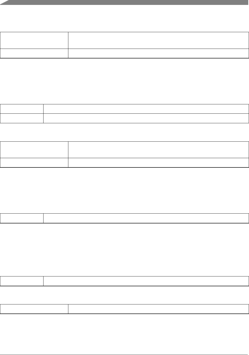
Function Documentation
Return values
kStatus_SDMMC_-
TransferFailed
kStatus_Success
30.5.30 status_t SDIO_AbortIO ( sdio_card_t ∗card, sdio_func_num_t func )
Parameters
card Card descriptor.
function IO number
Return values
kStatus_SDMMC_-
TransferFailed
kStatus_Success
30.5.31 void SDIO_DeInit ( sdio_card_t ∗card )
Parameters
card Card descriptor.
30.5.32 static status_t HOST_NotSupport ( void ∗parameter )[inline],
[static]
Parameters
void parameter ,used to avoid build warning
Return values
kStatus_Fail,host do not suppport
454
MCUXpresso SDK API Reference Manual
NXP Semiconductors

Function Documentation
30.5.33 status_t CardInsertDetect ( HOST_TYPE ∗hostBase )
NXP Semiconductors
MCUXpresso SDK API Reference Manual
455
Function Documentation
Parameters
hostBase the pointer to host base address
Return values
kStatus_Success detect card insert
kStatus_Fail card insert event fail
30.5.34 status_t HOST_Init ( void ∗host )
Parameters
host the pointer to host structure in card structure.
Return values
kStatus_Success host init success
kStatus_Fail event fail
30.5.35 void HOST_Deinit ( void ∗host )
Parameters
host the pointer to host structure in card structure.
456
MCUXpresso SDK API Reference Manual
NXP Semiconductors

Chapter 31
SPI based Secure Digital Card (SDSPI)
31.1 Overview
The MCUXpresso SDK provides a driver to access the Secure Digital Card based on the SPI driver.
Function groups
This function group implements the SD card functional API in the SPI mode.
Typical use case
/*SPI_Init(). */
/*Register the SDSPI driver callback. */
/*Initializes card. */
if (kStatus_Success != SDSPI_Init(card))
{
SDSPI_Deinit(card)
return;
}
/*Read/Write card */
memset(g_testWriteBuffer, 0x17U, sizeof(g_testWriteBuffer));
while (true)
{
memset(g_testReadBuffer, 0U, sizeof(g_testReadBuffer));
SDSPI_WriteBlocks(card, g_testWriteBuffer, TEST_START_BLOCK, TEST_BLOCK_COUNT);
SDSPI_ReadBlocks(card, g_testReadBuffer, TEST_START_BLOCK, TEST_BLOCK_COUNT);
if (memcmp(g_testReadBuffer, g_testReadBuffer, sizeof(g_testWriteBuffer)))
{
break;
}
}
Data Structures
• struct sdspi_command_t
SDSPI command. More...
• struct sdspi_host_t
SDSPI host state. More...
• struct sdspi_card_t
SD Card Structure. More...
NXP Semiconductors
MCUXpresso SDK API Reference Manual
457

Overview
Enumerations
• enum _sdspi_status {
kStatus_SDSPI_SetFrequencyFailed = MAKE_STATUS(kStatusGroup_SDSPI, 0U),
kStatus_SDSPI_ExchangeFailed = MAKE_STATUS(kStatusGroup_SDSPI, 1U),
kStatus_SDSPI_WaitReadyFailed = MAKE_STATUS(kStatusGroup_SDSPI, 2U),
kStatus_SDSPI_ResponseError = MAKE_STATUS(kStatusGroup_SDSPI, 3U),
kStatus_SDSPI_WriteProtected = MAKE_STATUS(kStatusGroup_SDSPI, 4U),
kStatus_SDSPI_GoIdleFailed = MAKE_STATUS(kStatusGroup_SDSPI, 5U),
kStatus_SDSPI_SendCommandFailed = MAKE_STATUS(kStatusGroup_SDSPI, 6U),
kStatus_SDSPI_ReadFailed = MAKE_STATUS(kStatusGroup_SDSPI, 7U),
kStatus_SDSPI_WriteFailed = MAKE_STATUS(kStatusGroup_SDSPI, 8U),
kStatus_SDSPI_SendInterfaceConditionFailed,
kStatus_SDSPI_SendOperationConditionFailed,
kStatus_SDSPI_ReadOcrFailed = MAKE_STATUS(kStatusGroup_SDSPI, 11U),
kStatus_SDSPI_SetBlockSizeFailed = MAKE_STATUS(kStatusGroup_SDSPI, 12U),
kStatus_SDSPI_SendCsdFailed = MAKE_STATUS(kStatusGroup_SDSPI, 13U),
kStatus_SDSPI_SendCidFailed = MAKE_STATUS(kStatusGroup_SDSPI, 14U),
kStatus_SDSPI_StopTransmissionFailed = MAKE_STATUS(kStatusGroup_SDSPI, 15U),
kStatus_SDSPI_SendApplicationCommandFailed }
SDSPI API status.
• enum _sdspi_card_flag {
kSDSPI_SupportHighCapacityFlag = (1U << 0U),
kSDSPI_SupportSdhcFlag = (1U << 1U),
kSDSPI_SupportSdxcFlag = (1U << 2U),
kSDSPI_SupportSdscFlag = (1U << 3U) }
SDSPI card flag.
• enum sdspi_response_type_t {
kSDSPI_ResponseTypeR1 = 0U,
kSDSPI_ResponseTypeR1b = 1U,
kSDSPI_ResponseTypeR2 = 2U,
kSDSPI_ResponseTypeR3 = 3U,
kSDSPI_ResponseTypeR7 = 4U }
SDSPI response type.
SDSPI Function
• status_t SDSPI_Init (sdspi_card_t ∗card)
Initializes the card on a specific SPI instance.
• void SDSPI_Deinit (sdspi_card_t ∗card)
Deinitializes the card.
• bool SDSPI_CheckReadOnly (sdspi_card_t ∗card)
Checks whether the card is write-protected.
• status_t SDSPI_ReadBlocks (sdspi_card_t ∗card, uint8_t ∗buffer, uint32_t startBlock, uint32_-
t blockCount)
Reads blocks from the specific card.
• status_t SDSPI_WriteBlocks (sdspi_card_t ∗card, uint8_t ∗buffer, uint32_t startBlock, uint32_t
blockCount)
458
MCUXpresso SDK API Reference Manual
NXP Semiconductors

Data Structure Documentation
Writes blocks of data to the specific card.
31.2 Data Structure Documentation
31.2.1 struct sdspi_command_t
Data Fields
• uint8_t index
Command index.
• uint32_t argument
Command argument.
• uint8_t responseType
Response type.
• uint8_t response [5U]
Response content.
31.2.2 struct sdspi_host_t
Data Fields
• uint32_t busBaudRate
Bus baud rate.
• status_t(∗setFrequency )(uint32_t frequency)
Set frequency of SPI.
• status_t(∗exchange )(uint8_t ∗in, uint8_t ∗out, uint32_t size)
Exchange data over SPI.
• uint32_t(∗getCurrentMilliseconds )(void)
Get current time in milliseconds.
31.2.3 struct sdspi_card_t
Define the card structure including the necessary fields to identify and describe the card.
Data Fields
•sdspi_host_t ∗host
Host state information.
• uint32_t relativeAddress
Relative address of the card.
• uint32_t flags
Flags defined in _sdspi_card_flag.
• uint8_t rawCid [16U]
Raw CID content.
• uint8_t rawCsd [16U]
NXP Semiconductors
MCUXpresso SDK API Reference Manual
459

Enumeration Type Documentation
Raw CSD content.
• uint8_t rawScr [8U]
Raw SCR content.
• uint32_t ocr
Raw OCR content.
• sd_cid_t cid
CID.
• sd_csd_t csd
CSD.
• sd_scr_t scr
SCR.
• uint32_t blockCount
Card total block number.
• uint32_t blockSize
Card block size.
31.2.3.0.0.50 Field Documentation
31.2.3.0.0.50.1 uint32_t sdspi_card_t::flags
31.3 Enumeration Type Documentation
31.3.1 enum _sdspi_status
Enumerator
kStatus_SDSPI_SetFrequencyFailed Set frequency failed.
kStatus_SDSPI_ExchangeFailed Exchange data on SPI bus failed.
kStatus_SDSPI_WaitReadyFailed Wait card ready failed.
kStatus_SDSPI_ResponseError Response is error.
kStatus_SDSPI_WriteProtected Write protected.
kStatus_SDSPI_GoIdleFailed Go idle failed.
kStatus_SDSPI_SendCommandFailed Send command failed.
kStatus_SDSPI_ReadFailed Read data failed.
kStatus_SDSPI_WriteFailed Write data failed.
kStatus_SDSPI_SendInterfaceConditionFailed Send interface condition failed.
kStatus_SDSPI_SendOperationConditionFailed Send operation condition failed.
kStatus_SDSPI_ReadOcrFailed Read OCR failed.
kStatus_SDSPI_SetBlockSizeFailed Set block size failed.
kStatus_SDSPI_SendCsdFailed Send CSD failed.
kStatus_SDSPI_SendCidFailed Send CID failed.
kStatus_SDSPI_StopTransmissionFailed Stop transmission failed.
kStatus_SDSPI_SendApplicationCommandFailed Send application command failed.
460
MCUXpresso SDK API Reference Manual
NXP Semiconductors

Function Documentation
31.3.2 enum _sdspi_card_flag
Enumerator
kSDSPI_SupportHighCapacityFlag Card is high capacity.
kSDSPI_SupportSdhcFlag Card is SDHC.
kSDSPI_SupportSdxcFlag Card is SDXC.
kSDSPI_SupportSdscFlag Card is SDSC.
31.3.3 enum sdspi_response_type_t
Enumerator
kSDSPI_ResponseTypeR1 Response 1.
kSDSPI_ResponseTypeR1b Response 1 with busy.
kSDSPI_ResponseTypeR2 Response 2.
kSDSPI_ResponseTypeR3 Response 3.
kSDSPI_ResponseTypeR7 Response 7.
31.4 Function Documentation
31.4.1 status_t SDSPI_Init ( sdspi_card_t ∗card )
This function initializes the card on a specific SPI instance.
Parameters
card Card descriptor
Return values
kStatus_SDSPI_Set-
FrequencyFailed
Set frequency failed.
kStatus_SDSPI_GoIdle-
Failed
Go idle failed.
kStatus_SDSPI_Send-
InterfaceConditionFailed
Send interface condition failed.
NXP Semiconductors
MCUXpresso SDK API Reference Manual
461

Function Documentation
kStatus_SDSPI_Send-
OperationCondition-
Failed
Send operation condition failed.
kStatus_Timeout Send command timeout.
kStatus_SDSPI_Not-
SupportYet
Not support yet.
kStatus_SDSPI_ReadOcr-
Failed
Read OCR failed.
kStatus_SDSPI_SetBlock-
SizeFailed
Set block size failed.
kStatus_SDSPI_SendCsd-
Failed
Send CSD failed.
kStatus_SDSPI_SendCid-
Failed
Send CID failed.
kStatus_Success Operate successfully.
31.4.2 void SDSPI_Deinit ( sdspi_card_t ∗card )
This function deinitializes the specific card.
Parameters
card Card descriptor
31.4.3 bool SDSPI_CheckReadOnly ( sdspi_card_t ∗card )
This function checks if the card is write-protected via CSD register.
Parameters
card Card descriptor.
Return values
462
MCUXpresso SDK API Reference Manual
NXP Semiconductors

Function Documentation
true Card is read only.
false Card isn’t read only.
31.4.4 status_t SDSPI_ReadBlocks ( sdspi_card_t ∗card, uint8_t ∗buffer, uint32_t
startBlock, uint32_t blockCount )
This function reads blocks from specific card.
Parameters
card Card descriptor.
buffer the buffer to hold the data read from card
startBlock the start block index
blockCount the number of blocks to read
Return values
kStatus_SDSPI_Send-
CommandFailed
Send command failed.
kStatus_SDSPI_Read-
Failed
Read data failed.
kStatus_SDSPI_Stop-
TransmissionFailed
Stop transmission failed.
kStatus_Success Operate successfully.
31.4.5 status_t SDSPI_WriteBlocks ( sdspi_card_t ∗card, uint8_t ∗buffer, uint32_t
startBlock, uint32_t blockCount )
This function writes blocks to specific card
Parameters
card Card descriptor.
buffer the buffer holding the data to be written to the card
NXP Semiconductors
MCUXpresso SDK API Reference Manual
463

Function Documentation
startBlock the start block index
blockCount the number of blocks to write
Return values
kStatus_SDSPI_Write-
Protected
Card is write protected.
kStatus_SDSPI_Send-
CommandFailed
Send command failed.
kStatus_SDSPI_-
ResponseError
Response is error.
kStatus_SDSPI_Write-
Failed
Write data failed.
kStatus_SDSPI_-
ExchangeFailed
Exchange data over SPI failed.
kStatus_SDSPI_Wait-
ReadyFailed
Wait card to be ready status failed.
kStatus_Success Operate successfully.
464
MCUXpresso SDK API Reference Manual
NXP Semiconductors

Chapter 32
Debug Console
32.1 Overview
This chapter describes the programming interface of the debug console driver.
The debug console enables debug log messages to be output via the specified peripheral with frequency of
the peripheral source clock and base address at the specified baud rate. Additionally, it provides input and
output functions to scan and print formatted data.
32.2 Function groups
32.2.1 Initialization
To initialize the debug console, call the DbgConsole_Init() function with these parameters. This function
automatically enables the module and the clock.
/*
*@brief Initializes the the peripheral used to debug messages.
*
*@param baseAddr Indicates which address of the peripheral is used to send debug messages.
*@param baudRate The desired baud rate in bits per second.
*@param device Low level device type for the debug console, can be one of:
*@arg DEBUG_CONSOLE_DEVICE_TYPE_UART,
*@arg DEBUG_CONSOLE_DEVICE_TYPE_LPUART,
*@arg DEBUG_CONSOLE_DEVICE_TYPE_LPSCI,
*@arg DEBUG_CONSOLE_DEVICE_TYPE_USBCDC.
*@param clkSrcFreq Frequency of peripheral source clock.
*
*@return Whether initialization was successful or not.
*/
status_t DbgConsole_Init(uint32_t baseAddr, uint32_t baudRate, uint8_t device, uint32_t clkSrcFreq)
Selects the supported debug console hardware device type, such as
DEBUG_CONSOLE_DEVICE_TYPE_NONE
DEBUG_CONSOLE_DEVICE_TYPE_LPSCI
DEBUG_CONSOLE_DEVICE_TYPE_UART
DEBUG_CONSOLE_DEVICE_TYPE_LPUART
DEBUG_CONSOLE_DEVICE_TYPE_USBCDC
After the initialization is successful, stdout and stdin are connected to the selected peripheral. The debug
console state is stored in the debug_console_state_t structure, such as shown here.
typedef struct DebugConsoleState
{
uint8_t type;
void*base;
debug_console_ops_t ops;
} debug_console_state_t;
NXP Semiconductors
MCUXpresso SDK API Reference Manual
465

Function groups
This example shows how to call the DbgConsole_Init() given the user configuration structure.
uint32_t uartClkSrcFreq = CLOCK_GetFreq(BOARD_DEBUG_UART_CLKSRC);
DbgConsole_Init(BOARD_DEBUG_UART_BASEADDR, BOARD_DEBUG_UART_BAUDRATE, DEBUG_CONSOLE_DEVICE_TYPE_UART,
uartClkSrcFreq);
32.2.2 Advanced Feature
The debug console provides input and output functions to scan and print formatted data.
• Support a format specifier for PRINTF following this prototype " %[flags][width][.precision][length]specifier",
which is explained below
flags Description
- Left-justified within the given field width. Right-
justified is the default.
+ Forces to precede the result with a plus or minus
sign (+ or -) even for positive numbers. By default,
only negative numbers are preceded with a - sign.
(space) If no sign is written, a blank space is inserted be-
fore the value.
# Used with o, x, or X specifiers the value is pre-
ceded with 0, 0x, or 0X respectively for values
other than zero. Used with e, E and f, it forces
the written output to contain a decimal point even
if no digits would follow. By default, if no digits
follow, no decimal point is written. Used with g or
G the result is the same as with e or E but trailing
zeros are not removed.
0 Left-pads the number with zeroes (0) instead of
spaces, where padding is specified (see width sub-
specifier).
Width Description
(number) A minimum number of characters to be printed. If
the value to be printed is shorter than this number,
the result is padded with blank spaces. The value
is not truncated even if the result is larger.
∗The width is not specified in the format string, but
as an additional integer value argument preceding
the argument that has to be formatted.
466
MCUXpresso SDK API Reference Manual
NXP Semiconductors

Function groups
.precision Description
.number For integer specifiers (d, i, o, u, x, X) precision
specifies the minimum number of digits to be writ-
ten. If the value to be written is shorter than this
number, the result is padded with leading zeros.
The value is not truncated even if the result is
longer. A precision of 0 means that no character
is written for the value 0. For e, E, and f speci-
fiers this is the number of digits to be printed after
the decimal point. For g and G specifiers This
is the maximum number of significant digits to be
printed. For s this is the maximum number of
characters to be printed. By default, all characters
are printed until the ending null character is en-
countered. For c type it has no effect. When no
precision is specified, the default is 1. If the period
is specified without an explicit value for precision,
0 is assumed.
.∗The precision is not specified in the format string,
but as an additional integer value argument pre-
ceding the argument that has to be formatted.
length Description
Do not support
specifier Description
d or i Signed decimal integer
f Decimal floating point
F Decimal floating point capital letters
x Unsigned hexadecimal integer
X Unsigned hexadecimal integer capital letters
o Signed octal
b Binary value
p Pointer address
u Unsigned decimal integer
c Character
s String of characters
n Nothing printed
NXP Semiconductors
MCUXpresso SDK API Reference Manual
467

Function groups
• Support a format specifier for SCANF following this prototype " %[∗][width][length]specifier",
which is explained below
∗Description
An optional starting asterisk indicates that the data is to be read from the stream but ignored. In other
words, it is not stored in the corresponding argument.
width Description
This specifies the maximum number of characters to be read in the current reading operation.
length Description
hh The argument is interpreted as a signed charac-
ter or unsigned character (only applies to integer
specifiers: i, d, o, u, x, and X).
h The argument is interpreted as a short integer
or unsigned short integer (only applies to integer
specifiers: i, d, o, u, x, and X).
l The argument is interpreted as a long integer or
unsigned long integer for integer specifiers (i, d,
o, u, x, and X) and as a wide character or wide
character string for specifiers c and s.
ll The argument is interpreted as a long long integer
or unsigned long long integer for integer specifiers
(i, d, o, u, x, and X) and as a wide character or
wide character string for specifiers c and s.
L The argument is interpreted as a long double (only
applies to floating point specifiers: e, E, f, g, and
G).
j or z or t Not supported
specifier Qualifying Input Type of argument
c Single character: Reads the next
character. If a width different
from 1 is specified, the function
reads width characters and stores
them in the successive locations
of the array passed as argument.
No null character is appended at
the end.
char ∗
468
MCUXpresso SDK API Reference Manual
NXP Semiconductors

Typical use case
specifier Qualifying Input Type of argument
i Integer: : Number optionally
preceded with a + or - sign
int ∗
d Decimal integer: Number op-
tionally preceded with a + or -
sign
int ∗
a, A, e, E, f, F, g, G Floating point: Decimal number
containing a decimal point, op-
tionally preceded by a + or - sign
and optionally followed by the
e or E character and a decimal
number. Two examples of valid
entries are -732.103 and 7.12e4
float ∗
o Octal Integer: int ∗
s String of characters. This reads
subsequent characters until a
white space is found (white
space characters are considered
to be blank, newline, and tab).
char ∗
u Unsigned decimal integer. unsigned int ∗
The debug console has its own printf/scanf/putchar/getchar functions which are defined in the header file.
int DbgConsole_Printf(const char *fmt_s, ...);
int DbgConsole_Putchar(int ch);
int DbgConsole_Scanf(const char *fmt_ptr, ...);
int DbgConsole_Getchar(void);
This utility supports selecting toolchain’s printf/scanf or the MCUXpresso SDK printf/scanf.
#if SDK_DEBUGCONSOLE /*Select printf, scanf, putchar, getchar of SDK version. */
#define PRINTF DbgConsole_Printf
#define SCANF DbgConsole_Scanf
#define PUTCHAR DbgConsole_Putchar
#define GETCHAR DbgConsole_Getchar
#else /*Select printf, scanf, putchar, getchar of toolchain. */
#define PRINTF printf
#define SCANF scanf
#define PUTCHAR putchar
#define GETCHAR getchar
#endif /*SDK_DEBUGCONSOLE */
32.3 Typical use case
Some examples use the PUTCHAR & GETCHAR function
ch = GETCHAR();
PUTCHAR(ch);
NXP Semiconductors
MCUXpresso SDK API Reference Manual
469

Typical use case
Some examples use the PRINTF function
Statement prints the string format.
PRINTF("%s %s\r\n","Hello","world!");
Statement prints the hexadecimal format/
PRINTF("0x%02X hexadecimal number equivalents 255", 255);
Statement prints the decimal floating point and unsigned decimal.
PRINTF("Execution timer: %s\n\rTime: %u ticks %2.5f milliseconds\n\rDONE\n\r","1 day", 86400, 86.4);
Some examples use the SCANF function
PRINTF("Enter a decimal number: ");
SCANF("%d", &i);
PRINTF("\r\nYou have entered %d.\r\n", i, i);
PRINTF("Enter a hexadecimal number: ");
SCANF("%x", &i);
PRINTF("\r\nYou have entered 0x%X (%d).\r\n", i, i);
Print out failure messages using KSDK __assert_func:
void __assert_func(const char *file, int line, const char *func, const char *failedExpr)
{
PRINTF("ASSERT ERROR \" %s \": file \"%s\" Line \"%d\" function name \"%s\"\n", failedExpr, file ,
line, func);
for (;;)
{}
}
Note:
To use ’printf’ and ’scanf’ for GNUC Base, add file ’fsl_sbrk.c’ in path: ..\{package}\devices\{subset}\utilities\fsl-
_sbrk.c to your project.
Modules
•Semihosting
470
MCUXpresso SDK API Reference Manual
NXP Semiconductors

Semihosting
32.4 Semihosting
Semihosting is a mechanism for ARM targets to communicate input/output requests from application code
to a host computer running a debugger. This mechanism can be used, for example, to enable functions in
the C library, such as printf() and scanf(), to use the screen and keyboard of the host rather than having a
screen and keyboard on the target system.
32.4.1 Guide Semihosting for IAR
NOTE: After the setting both "printf" and "scanf" are available for debugging.
Step 1: Setting up the environment
1. To set debugger options, choose Project>Options. In the Debugger category, click the Setup tab.
2. Select Run to main and click OK. This ensures that the debug session starts by running the main
function.
3. The project is now ready to be built.
Step 2: Building the project
1. Compile and link the project by choosing Project>Make or F7.
2. Alternatively, click the Make button on the tool bar. The Make command compiles and links those
files that have been modified.
Step 3: Starting semihosting
1. Choose "Semihosting_IAR" project ->"Options" ->"Debugger" ->"J-Link/J-Trace".
2. Choose tab "J-Link/J-Trace" ->"Connection" tab ->"SWD".
3. Start the project by choosing Project>Download and Debug.
4. Choose View>Terminal I/O to display the output from the I/O operations.
32.4.2 Guide Semihosting for Keil µVision
NOTE: Keil supports Semihosting only for Cortex-M3/Cortex-M4 cores.
Step 1: Prepare code
Remove function fputc and fgetc is used to support KEIL in "fsl_debug_console.c" and add the following
code to project.
#pragma import(__use_no_semihosting_swi)
volatile int ITM_RxBuffer = ITM_RXBUFFER_EMPTY; /*used for Debug Input */
NXP Semiconductors
MCUXpresso SDK API Reference Manual
471

Semihosting
struct __FILE
{
int handle;
};
FILE __stdout;
FILE __stdin;
int fputc(int ch, FILE *f)
{
return (ITM_SendChar(ch));
}
int fgetc(FILE *f)
{/*blocking */
while (ITM_CheckChar() != 1)
;
return (ITM_ReceiveChar());
}
int ferror(FILE *f)
{
/*Your implementation of ferror */
return EOF;
}
void _ttywrch(int ch)
{
ITM_SendChar(ch);
}
void _sys_exit(int return_code)
{
label:
goto label; /*endless loop */
}
Step 2: Setting up the environment
1. In menu bar, choose Project>Options for target or using Alt+F7 or click.
2. Select "Target" tab and not select "Use MicroLIB".
3. Select “Debug” tab, select “J-Link/J-Trace Cortex” and click “Setting button”.
4. Select “Debug” tab and choose Port:SW, then select "Trace" tab, choose "Enable" and click OK.
Step 3: Building the project
1. Compile and link the project by choosing Project>Build Target or using F7.
Step 4: Building the project
1. Choose “Debug” on menu bar or Ctrl F5.
2. In menu bar, choose "Serial Window" and click to "Debug (printf) Viewer".
3. Run line by line to see result in Console Window.
472
MCUXpresso SDK API Reference Manual
NXP Semiconductors

Semihosting
32.4.3 Guide Semihosting for KDS
NOTE: After the setting use "printf" for debugging.
Step 1: Setting up the environment
1. In menu bar, choose Project>Properties>C/C++ Build>Settings>Tool Settings.
2. Select “Libraries” on “Cross ARM C Linker” and delete “nosys”.
3. Select “Miscellaneous” on "Cross ARM C Linker”, add “-specs=rdimon.specs” to “Other link
flages” and tick “Use newlib-nano”, and click OK.
Step 2: Building the project
1. In menu bar, choose Project>Build Project.
Step 3: Starting semihosting
1. In Debug configurations, choose "Startup" tab, tick “Enable semihosting and Telnet”. Press “Apply”
and “Debug”.
2. After clicking Debug, the Window is displayed same as below. Run line by line to see the result in
the Console Window.
32.4.4 Guide Semihosting for ATL
NOTE: J-Link has to be used to enable semihosting.
Step 1: Prepare code
Add the following code to the project.
int _write(int file, char *ptr, int len)
{
/*Implement your write code here. This is used by puts and printf. */
int i=0;
for(i=0 ; i<len ; i++)
ITM_SendChar((*ptr++));
return len;
}
Step 2: Setting up the environment
1. In menu bar, choose Debug Configurations. In tab "Embedded C/C++ Aplication" choose "-
Semihosting_ATL_xxx debug J-Link".
2. In tab "Debugger" set up as follows.
• JTAG mode must be selected
NXP Semiconductors
MCUXpresso SDK API Reference Manual
473

Semihosting
• SWV tracing must be enabled
• Enter the Core Clock frequency, which is hardware board-specific.
• Enter the desired SWO Clock frequency. The latter depends on the JTAG Probe and must be a
multiple of the Core Clock value.
3. Click "Apply" and "Debug".
Step 3: Starting semihosting
1. In the Views menu, expand the submenu SWV and open the docking view “SWV Console". 2. Open
the SWV settings panel by clicking the "Configure Serial Wire Viewer" button in the SWV Console
view toolbar. 3. Configure the data ports to be traced by enabling the ITM channel 0 check-box
in the ITM stimulus ports group: Choose "EXETRC: Trace Exceptions" and In tab "ITM Stimulus
Ports" choose "Enable Port" 0. Then click "OK".
2. It is recommended not to enable other SWV trace functionalities at the same time because this may
over use the SWO pin causing packet loss due to a limited bandwidth (certain other SWV tracing
capabilities can send a lot of data at very high-speed). Save the SWV configuration by clicking the
OK button. The configuration is saved with other debug configurations and remains effective until
changed.
3. Press the red Start/Stop Trace button to send the SWV configuration to the target board to enable
SWV trace recoding. The board does not send any SWV packages until it is properly configured.
The SWV Configuration must be present, if the configuration registers on the target board are reset.
Also, tracing does not start until the target starts to execute.
4. Start the target execution again by pressing the green Resume Debug button.
5. The SWV console now shows the printf() output.
32.4.5 Guide Semihosting for ARMGCC
Step 1: Setting up the environment
1. Turn on "J-LINK GDB Server" ->Select suitable "Target device" ->"OK".
2. Turn on "PuTTY". Set up as follows.
• "Host Name (or IP address)" : localhost
• "Port" :2333
• "Connection type" : Telet.
• Click "Open".
3. Increase "Heap/Stack" for GCC to 0x2000:
Add to "CMakeLists.txt"
SET(CMAKE_EXE_LINKER_FLAGS_RELEASE "${CMAKE_EXE_LINKER_FLAGS_RELEASE}
--defsym=__stack_size__=0x2000")
SET(CMAKE_EXE_LINKER_FLAGS_DEBUG "${CMAKE_EXE_LINKER_FLAGS_DEBUG} --
defsym=__stack_size__=0x2000")
SET(CMAKE_EXE_LINKER_FLAGS_DEBUG "${CMAKE_EXE_LINKER_FLAGS_DEBUG} --
474
MCUXpresso SDK API Reference Manual
NXP Semiconductors

Semihosting
defsym=__heap_size__=0x2000")
SET(CMAKE_EXE_LINKER_FLAGS_RELEASE "${CMAKE_EXE_LINKER_FLAGS_RELEASE}
--defsym=__heap_size__=0x2000")
Step 2: Building the project
1. Change "CMakeLists.txt":
Change "SET(CMAKE_EXE_LINKER_FLAGS_RELEASE "${CMAKE_EXE_LINKER_FLA-
GS_RELEASE} –specs=nano.specs")"
to "SET(CMAKE_EXE_LINKER_FLAGS_RELEASE "${CMAKE_EXE_LINKER_FLAGS_R-
ELEASE} –specs=rdimon.specs")"
Replace paragraph
SET(CMAKE_EXE_LINKER_FLAGS_DEBUG "${CMAKE_EXE_LINKER_FLAGS_DEBU-
G} -fno-common")
SET(CMAKE_EXE_LINKER_FLAGS_DEBUG "${CMAKE_EXE_LINKER_FLAGS_DEBU-
G} -ffunction-sections")
SET(CMAKE_EXE_LINKER_FLAGS_DEBUG "${CMAKE_EXE_LINKER_FLAGS_DEBU-
G} -fdata-sections")
SET(CMAKE_EXE_LINKER_FLAGS_DEBUG "${CMAKE_EXE_LINKER_FLAGS_DEBU-
G} -ffreestanding")
SET(CMAKE_EXE_LINKER_FLAGS_DEBUG "${CMAKE_EXE_LINKER_FLAGS_DEBU-
G} -fno-builtin")
SET(CMAKE_EXE_LINKER_FLAGS_DEBUG "${CMAKE_EXE_LINKER_FLAGS_DEBU-
G} -mthumb")
SET(CMAKE_EXE_LINKER_FLAGS_DEBUG "${CMAKE_EXE_LINKER_FLAGS_DEBU-
G} -mapcs")
SET(CMAKE_EXE_LINKER_FLAGS_DEBUG "${CMAKE_EXE_LINKER_FLAGS_DEBU-
G} -Xlinker")
SET(CMAKE_EXE_LINKER_FLAGS_DEBUG "${CMAKE_EXE_LINKER_FLAGS_DEBU-
G} --gc-sections")
SET(CMAKE_EXE_LINKER_FLAGS_DEBUG "${CMAKE_EXE_LINKER_FLAGS_DEBU-
G} -Xlinker")
SET(CMAKE_EXE_LINKER_FLAGS_DEBUG "${CMAKE_EXE_LINKER_FLAGS_DEBU-
G} -static")
SET(CMAKE_EXE_LINKER_FLAGS_DEBUG "${CMAKE_EXE_LINKER_FLAGS_DEBU-
G} -Xlinker")
SET(CMAKE_EXE_LINKER_FLAGS_DEBUG "${CMAKE_EXE_LINKER_FLAGS_DEBU-
G} -z")
SET(CMAKE_EXE_LINKER_FLAGS_DEBUG "${CMAKE_EXE_LINKER_FLAGS_DEBU-
G} -Xlinker")
SET(CMAKE_EXE_LINKER_FLAGS_DEBUG "${CMAKE_EXE_LINKER_FLAGS_DEBU-
G} muldefs")
To
SET(CMAKE_EXE_LINKER_FLAGS_DEBUG "${CMAKE_EXE_LINKER_FLAGS_DEBU-
NXP Semiconductors
MCUXpresso SDK API Reference Manual
475

Semihosting
G} --specs=rdimon.specs ")
Remove
target_link_libraries(semihosting_ARMGCC.elf debug nosys)
2. Run "build_debug.bat" to build project
Step 3: Starting semihosting
(a) Download the image and set as follows.
cd D:\mcu-sdk-2.0-origin\boards\twrk64f120m\driver_examples\semihosting\armgcc\debug
d:
C:\PROGRA~2\GNUTOO~1\4BD65~1.920\bin\arm-none-eabi-gdb.exe
target remote localhost:2331
monitor reset
monitor semihosting enable
monitor semihosting thumbSWI 0xAB
monitor semihosting IOClient 1
monitor flash device = MK64FN1M0xxx12
load semihosting_ARMGCC.elf
monitor reg pc = (0x00000004)
monitor reg sp = (0x00000000)
continue
(b) After the setting, press "enter". The PuTTY window now shows the printf() output.
476
MCUXpresso SDK API Reference Manual
NXP Semiconductors

Chapter 33
Notification Framework
33.1 Overview
This section describes the programming interface of the Notifier driver.
33.2 Notifier Overview
The Notifier provides a configuration dynamic change service. Based on this service, applications can
switch between pre-defined configurations. The Notifier enables drivers and applications to register call-
back functions to this framework. Each time that the configuration is changed, drivers and applications
receive a notification and change their settings. To simplify, the Notifier only supports the static callback
registration. This means that, for applications, all callback functions are collected into a static table and
passed to the Notifier.
These are the steps for the configuration transition.
1. Before configuration transition, the Notifier sends a "BEFORE" message to the callback table. When
this message is received, IP drivers should check whether any current processes can be stopped and
stop them. If the processes cannot be stopped, the callback function returns an error.
The Notifier supports two types of transition policies, a graceful policy and a forceful policy. When
the graceful policy is used, if some callbacks return an error while sending a "BEFORE" message,
the configuration transition stops and the Notifier sends a "RECOVER" message to all drivers that
have stopped. Then, these drivers can recover the previous status and continue to work. When the
forceful policy is used, drivers are stopped forcefully.
2. After the "BEFORE" message is processed successfully, the system switches to the new configura-
tion.
3. After the configuration changes, the Notifier sends an "AFTER" message to the callback table to
notify drivers that the configuration transition is finished.
This example shows how to use the Notifier in the Power Manager application.
#include "fsl_notifier.h"
// Definition of the Power Manager callback.
status_t callback0(notifier_notification_block_t *notify, void *data)
{
status_t ret = kStatus_Success;
...
...
...
return ret;
}
// Definition of the Power Manager user function.
status_t APP_PowerModeSwitch(notifier_user_config_t *targetConfig, void *userData)
{
NXP Semiconductors
MCUXpresso SDK API Reference Manual
477

Notifier Overview
...
...
...
}
...
...
...
...
...
// Main function.
int main(void)
{
// Define a notifier handle.
notifier_handle_t powerModeHandle;
// Callback configuration.
user_callback_data_t callbackData0;
notifier_callback_config_t callbackCfg0 = {callback0,
kNOTIFIER_CallbackBeforeAfter,
(void *)&callbackData0};
notifier_callback_config_t callbacks[] = {callbackCfg0};
// Power mode configurations.
power_user_config_t vlprConfig;
power_user_config_t stopConfig;
notifier_user_config_t *powerConfigs[] = {&vlprConfig, &stopConfig};
// Definition of a transition to and out the power modes.
vlprConfig.mode = kAPP_PowerModeVlpr;
vlprConfig.enableLowPowerWakeUpOnInterrupt = false;
stopConfig = vlprConfig;
stopConfig.mode = kAPP_PowerModeStop;
// Create Notifier handle.
NOTIFIER_CreateHandle(&powerModeHandle, powerConfigs, 2U, callbacks, 1U,
APP_PowerModeSwitch, NULL);
...
...
// Power mode switch.
NOTIFIER_switchConfig(&powerModeHandle, targetConfigIndex,
kNOTIFIER_PolicyAgreement);
}
Data Structures
• struct notifier_notification_block_t
notification block passed to the registered callback function. More...
• struct notifier_callback_config_t
Callback configuration structure. More...
• struct notifier_handle_t
Notifier handle structure. More...
Typedefs
• typedef void notifier_user_config_t
Notifier user configuration type.
• typedef status_t(∗notifier_user_function_t )(notifier_user_config_t ∗targetConfig, void ∗userData)
Notifier user function prototype Use this function to execute specific operations in configuration switch.
478
MCUXpresso SDK API Reference Manual
NXP Semiconductors

Data Structure Documentation
• typedef status_t(∗notifier_callback_t )(notifier_notification_block_t ∗notify, void ∗data)
Callback prototype.
Enumerations
• enum _notifier_status {
kStatus_NOTIFIER_ErrorNotificationBefore,
kStatus_NOTIFIER_ErrorNotificationAfter }
Notifier error codes.
• enum notifier_policy_t {
kNOTIFIER_PolicyAgreement,
kNOTIFIER_PolicyForcible }
Notifier policies.
• enum notifier_notification_type_t {
kNOTIFIER_NotifyRecover = 0x00U,
kNOTIFIER_NotifyBefore = 0x01U,
kNOTIFIER_NotifyAfter = 0x02U }
Notification type.
• enum notifier_callback_type_t {
kNOTIFIER_CallbackBefore = 0x01U,
kNOTIFIER_CallbackAfter = 0x02U,
kNOTIFIER_CallbackBeforeAfter = 0x03U }
The callback type, which indicates kinds of notification the callback handles.
Functions
• status_t NOTIFIER_CreateHandle (notifier_handle_t ∗notifierHandle, notifier_user_config_t
∗∗configs, uint8_t configsNumber, notifier_callback_config_t ∗callbacks, uint8_t callbacksNumber,
notifier_user_function_t userFunction, void ∗userData)
Creates a Notifier handle.
• status_t NOTIFIER_SwitchConfig (notifier_handle_t ∗notifierHandle, uint8_t configIndex, notifier-
_policy_t policy)
Switches the configuration according to a pre-defined structure.
• uint8_t NOTIFIER_GetErrorCallbackIndex (notifier_handle_t ∗notifierHandle)
This function returns the last failed notification callback.
33.3 Data Structure Documentation
33.3.1 struct notifier_notification_block_t
Data Fields
•notifier_user_config_t ∗targetConfig
Pointer to target configuration.
•notifier_policy_t policy
Configure transition policy.
•notifier_notification_type_t notifyType
Configure notification type.
NXP Semiconductors
MCUXpresso SDK API Reference Manual
479

Data Structure Documentation
33.3.1.0.0.51 Field Documentation
33.3.1.0.0.51.1 notifier_user_config_t∗notifier_notification_block_t::targetConfig
33.3.1.0.0.51.2 notifier_policy_t notifier_notification_block_t::policy
33.3.1.0.0.51.3 notifier_notification_type_t notifier_notification_block_t::notifyType
33.3.2 struct notifier_callback_config_t
This structure holds the configuration of callbacks. Callbacks of this type are expected to be statically
allocated. This structure contains the following application-defined data. callback - pointer to the callback
function callbackType - specifies when the callback is called callbackData - pointer to the data passed to
the callback.
Data Fields
•notifier_callback_t callback
Pointer to the callback function.
•notifier_callback_type_t callbackType
Callback type.
• void ∗callbackData
Pointer to the data passed to the callback.
33.3.2.0.0.52 Field Documentation
33.3.2.0.0.52.1 notifier_callback_t notifier_callback_config_t::callback
33.3.2.0.0.52.2 notifier_callback_type_t notifier_callback_config_t::callbackType
33.3.2.0.0.52.3 void∗notifier_callback_config_t::callbackData
33.3.3 struct notifier_handle_t
Notifier handle structure. Contains data necessary for the Notifier proper function. Stores references to
registered configurations, callbacks, information about their numbers, user function, user data, and other
internal data. NOTIFIER_CreateHandle() must be called to initialize this handle.
Data Fields
•notifier_user_config_t ∗∗ configsTable
Pointer to configure table.
• uint8_t configsNumber
Number of configurations.
•notifier_callback_config_t ∗callbacksTable
Pointer to callback table.
480
MCUXpresso SDK API Reference Manual
NXP Semiconductors

Typedef Documentation
• uint8_t callbacksNumber
Maximum number of callback configurations.
• uint8_t errorCallbackIndex
Index of callback returns error.
• uint8_t currentConfigIndex
Index of current configuration.
•notifier_user_function_t userFunction
User function.
• void ∗userData
User data passed to user function.
33.3.3.0.0.53 Field Documentation
33.3.3.0.0.53.1 notifier_user_config_t∗∗ notifier_handle_t::configsTable
33.3.3.0.0.53.2 uint8_t notifier_handle_t::configsNumber
33.3.3.0.0.53.3 notifier_callback_config_t∗notifier_handle_t::callbacksTable
33.3.3.0.0.53.4 uint8_t notifier_handle_t::callbacksNumber
33.3.3.0.0.53.5 uint8_t notifier_handle_t::errorCallbackIndex
33.3.3.0.0.53.6 uint8_t notifier_handle_t::currentConfigIndex
33.3.3.0.0.53.7 notifier_user_function_t notifier_handle_t::userFunction
33.3.3.0.0.53.8 void∗notifier_handle_t::userData
33.4 Typedef Documentation
33.4.1 typedef void notifier_user_config_t
Reference of the user defined configuration is stored in an array; the notifier switches between these
configurations based on this array.
33.4.2 typedef status_t(∗notifier_user_function_t)(notifier_user_config_t
∗targetConfig, void ∗userData)
Before and after this function execution, different notification is sent to registered callbacks. If this func-
tion returns any error code, NOTIFIER_SwitchConfig() exits.
Parameters
NXP Semiconductors
MCUXpresso SDK API Reference Manual
481

Enumeration Type Documentation
targetConfig target Configuration.
userData Refers to other specific data passed to user function.
Returns
An error code or kStatus_Success.
33.4.3 typedef status_t(∗notifier_callback_t)(notifier_notification_block_t ∗notify,
void ∗data)
Declaration of a callback. It is common for registered callbacks. Reference to function of this type is part
of the notifier_callback_config_t callback configuration structure. Depending on callback type, function
of this prototype is called (see NOTIFIER_SwitchConfig()) before configuration switch, after it or in both
use cases to notify about the switch progress (see notifier_callback_type_t). When called, the type of the
notification is passed as a parameter along with the reference to the target configuration structure (see
notifier_notification_block_t) and any data passed during the callback registration. When notified before
the configuration switch, depending on the configuration switch policy (see notifier_policy_t), the callback
may deny the execution of the user function by returning an error code different than kStatus_Success (see
NOTIFIER_SwitchConfig()).
Parameters
notify Notification block.
data Callback data. Refers to the data passed during callback registration. Intended to pass
any driver or application data such as internal state information.
Returns
An error code or kStatus_Success.
33.5 Enumeration Type Documentation
33.5.1 enum _notifier_status
Used as return value of Notifier functions.
Enumerator
kStatus_NOTIFIER_ErrorNotificationBefore An error occurs during send "BEFORE" notifica-
tion.
kStatus_NOTIFIER_ErrorNotificationAfter An error occurs during send "AFTER" notification.
482
MCUXpresso SDK API Reference Manual
NXP Semiconductors

Enumeration Type Documentation
33.5.2 enum notifier_policy_t
Defines whether the user function execution is forced or not. For kNOTIFIER_PolicyForcible, the user
function is executed regardless of the callback results, while kNOTIFIER_PolicyAgreement policy is used
to exit NOTIFIER_SwitchConfig() when any of the callbacks returns error code. See also NOTIFIER_-
SwitchConfig() description.
Enumerator
kNOTIFIER_PolicyAgreement NOTIFIER_SwitchConfig() method is exited when any of the call-
backs returns error code.
kNOTIFIER_PolicyForcible The user function is executed regardless of the results.
33.5.3 enum notifier_notification_type_t
Used to notify registered callbacks
Enumerator
kNOTIFIER_NotifyRecover Notify IP to recover to previous work state.
kNOTIFIER_NotifyBefore Notify IP that configuration setting is going to change.
kNOTIFIER_NotifyAfter Notify IP that configuration setting has been changed.
33.5.4 enum notifier_callback_type_t
Used in the callback configuration structure (notifier_callback_config_t) to specify when the registered
callback is called during configuration switch initiated by the NOTIFIER_SwitchConfig(). Callback can
be invoked in following situations.
• Before the configuration switch (Callback return value can affect NOTIFIER_SwitchConfig() exe-
cution. See the NOTIFIER_SwitchConfig() and notifier_policy_t documentation).
• After an unsuccessful attempt to switch configuration
• After a successful configuration switch
Enumerator
kNOTIFIER_CallbackBefore Callback handles BEFORE notification.
kNOTIFIER_CallbackAfter Callback handles AFTER notification.
kNOTIFIER_CallbackBeforeAfter Callback handles BEFORE and AFTER notification.
NXP Semiconductors
MCUXpresso SDK API Reference Manual
483

Function Documentation
33.6 Function Documentation
33.6.1 status_t NOTIFIER_CreateHandle ( notifier_handle_t ∗notifierHandle,
notifier_user_config_t ∗∗ configs, uint8_t configsNumber, notifier_callback-
_config_t ∗callbacks, uint8_t callbacksNumber, notifier_user_function_t
userFunction, void ∗userData )
484
MCUXpresso SDK API Reference Manual
NXP Semiconductors

Function Documentation
Parameters
notifierHandle A pointer to the notifier handle.
configs A pointer to an array with references to all configurations which is handled by the
Notifier.
configsNumber Number of configurations. Size of the configuration array.
callbacks A pointer to an array of callback configurations. If there are no callbacks to register
during Notifier initialization, use NULL value.
callbacks-
Number
Number of registered callbacks. Size of the callbacks array.
userFunction User function.
userData User data passed to user function.
Returns
An error Code or kStatus_Success.
33.6.2 status_t NOTIFIER_SwitchConfig ( notifier_handle_t ∗notifierHandle,
uint8_t configIndex, notifier_policy_t policy )
This function sets the system to the target configuration. Before transition, the Notifier sends notifications
to all callbacks registered to the callback table. Callbacks are invoked in the following order: All registered
callbacks are notified ordered by index in the callbacks array. The same order is used for before and after
switch notifications. The notifications before the configuration switch can be used to obtain confirmation
about the change from registered callbacks. If any registered callback denies the configuration change,
further execution of this function depends on the notifier policy: the configuration change is either forced
(kNOTIFIER_PolicyForcible) or exited (kNOTIFIER_PolicyAgreement). When configuration change is
forced, the result of the before switch notifications are ignored. If an agreement is required, if any call-
back returns an error code, further notifications before switch notifications are cancelled and all already
notified callbacks are re-invoked. The index of the callback which returned error code during pre-switch
notifications is stored (any error codes during callbacks re-invocation are ignored) and NOTIFIER_Get-
ErrorCallback() can be used to get it. Regardless of the policies, if any callback returns an error code,
an error code indicating in which phase the error occurred is returned when NOTIFIER_SwitchConfig()
exits.
Parameters
NXP Semiconductors
MCUXpresso SDK API Reference Manual
485

Function Documentation
notifierHandle pointer to notifier handle
configIndex Index of the target configuration.
policy Transaction policy, kNOTIFIER_PolicyAgreement or kNOTIFIER_PolicyForcible.
Returns
An error code or kStatus_Success.
33.6.3 uint8_t NOTIFIER_GetErrorCallbackIndex ( notifier_handle_t ∗
notifierHandle )
This function returns an index of the last callback that failed during the configuration switch while the last
NOTIFIER_SwitchConfig() was called. If the last NOTIFIER_SwitchConfig() call ended successfully
value equal to callbacks number is returned. The returned value represents an index in the array of static
call-backs.
Parameters
notifierHandle Pointer to the notifier handle
Returns
Callback Index of the last failed callback or value equal to callbacks count.
486
MCUXpresso SDK API Reference Manual
NXP Semiconductors

Chapter 34
Shell
34.1 Overview
This part describes the programming interface of the Shell middleware. Shell controls MCUs by com-
mands via the specified communication peripheral based on the debug console driver.
34.2 Function groups
34.2.1 Initialization
To initialize the Shell middleware, call the SHELL_Init() function with these parameters. This function
automatically enables the middleware.
void SHELL_Init(p_shell_context_t context, send_data_cb_t send_cb,
recv_data_cb_t recv_cb, char *prompt);
Then, after the initialization was successful, call a command to control MCUs.
This example shows how to call the SHELL_Init() given the user configuration structure.
SHELL_Init(&user_context, SHELL_SendDataCallback, SHELL_ReceiveDataCallback, "SHELL>> ");
34.2.2 Advanced Feature
• Support to get a character from standard input devices.
static uint8_t GetChar(p_shell_context_t context);
Commands Description
Help Lists all commands which are supported by Shell.
Exit Exits the Shell program.
strCompare Compares the two input strings.
Input character Description
A Gets the latest command in the history.
B Gets the first command in the history.
C Replaces one character at the right of the pointer.
NXP Semiconductors
MCUXpresso SDK API Reference Manual
487

Function groups
Input character Description
D Replaces one character at the left of the pointer.
Run AutoComplete function
Run cmdProcess function
Clears a command.
34.2.3 Shell Operation
SHELL_Init(&user_context, SHELL_SendDataCallback, SHELL_ReceiveDataCallback, "SHELL>> ");
SHELL_Main(&user_context);
Data Structures
• struct p_shell_context_t
Data structure for Shell environment. More...
• struct shell_command_context_t
User command data structure. More...
• struct shell_command_context_list_t
Structure list command. More...
Macros
• #define SHELL_USE_HISTORY (0U)
Macro to set on/off history feature.
• #define SHELL_SEARCH_IN_HIST (1U)
Macro to set on/off history feature.
• #define SHELL_USE_FILE_STREAM (0U)
Macro to select method stream.
• #define SHELL_AUTO_COMPLETE (1U)
Macro to set on/off auto-complete feature.
• #define SHELL_BUFFER_SIZE (64U)
Macro to set console buffer size.
• #define SHELL_MAX_ARGS (8U)
Macro to set maximum arguments in command.
• #define SHELL_HIST_MAX (3U)
Macro to set maximum count of history commands.
• #define SHELL_MAX_CMD (20U)
Macro to set maximum count of commands.
• #define SHELL_OPTIONAL_PARAMS (0xFF)
Macro to bypass arguments check.
Typedefs
• typedef void(∗send_data_cb_t )(uint8_t ∗buf, uint32_t len)
Shell user send data callback prototype.
• typedef void(∗recv_data_cb_t )(uint8_t ∗buf, uint32_t len)
488
MCUXpresso SDK API Reference Manual
NXP Semiconductors

Data Structure Documentation
Shell user receiver data callback prototype.
• typedef int(∗printf_data_t )(const char ∗format,...)
Shell user printf data prototype.
• typedef int32_t(∗cmd_function_t )(p_shell_context_t context, int32_t argc, char ∗∗argv)
User command function prototype.
Enumerations
• enum fun_key_status_t {
kSHELL_Normal = 0U,
kSHELL_Special = 1U,
kSHELL_Function = 2U }
A type for the handle special key.
Shell functional operation
• void SHELL_Init (p_shell_context_t context, send_data_cb_t send_cb, recv_data_cb_t recv_cb,
printf_data_t shell_printf, char ∗prompt)
Enables the clock gate and configures the Shell module according to the configuration structure.
• int32_t SHELL_RegisterCommand (const shell_command_context_t ∗command_context)
Shell register command.
• int32_t SHELL_Main (p_shell_context_t context)
Main loop for Shell.
34.3 Data Structure Documentation
34.3.1 struct shell_context_struct
Data Fields
• char ∗prompt
Prompt string.
• enum _fun_key_status stat
Special key status.
• char line [SHELL_BUFFER_SIZE]
Consult buffer.
• uint8_t cmd_num
Number of user commands.
• uint8_t l_pos
Total line position.
• uint8_t c_pos
Current line position.
•send_data_cb_t send_data_func
Send data interface operation.
•recv_data_cb_t recv_data_func
Receive data interface operation.
• uint16_t hist_current
Current history command in hist buff.
• uint16_t hist_count
NXP Semiconductors
MCUXpresso SDK API Reference Manual
489

Data Structure Documentation
Total history command in hist buff.
• char hist_buf [SHELL_HIST_MAX][SHELL_BUFFER_SIZE]
History buffer.
• bool exit
Exit Flag.
34.3.2 struct shell_command_context_t
Data Fields
• const char ∗pcCommand
The command that is executed.
• char ∗pcHelpString
String that describes how to use the command.
• const cmd_function_t pFuncCallBack
A pointer to the callback function that returns the output generated by the command.
• uint8_t cExpectedNumberOfParameters
Commands expect a fixed number of parameters, which may be zero.
34.3.2.0.0.54 Field Documentation
34.3.2.0.0.54.1 const char∗shell_command_context_t::pcCommand
For example "help". It must be all lower case.
34.3.2.0.0.54.2 char∗shell_command_context_t::pcHelpString
It should start with the command itself, and end with "\r\n". For example "help: Returns a list of all the
commands\r\n".
34.3.2.0.0.54.3 const cmd_function_t shell_command_context_t::pFuncCallBack
34.3.2.0.0.54.4 uint8_t shell_command_context_t::cExpectedNumberOfParameters
34.3.3 struct shell_command_context_list_t
Data Fields
• const shell_command_context_t ∗CommandList [SHELL_MAX_CMD]
The command table list.
• uint8_t numberOfCommandInList
The total command in list.
490
MCUXpresso SDK API Reference Manual
NXP Semiconductors

Enumeration Type Documentation
34.4 Macro Definition Documentation
34.4.1 #define SHELL_USE_HISTORY (0U)
34.4.2 #define SHELL_SEARCH_IN_HIST (1U)
34.4.3 #define SHELL_USE_FILE_STREAM (0U)
34.4.4 #define SHELL_AUTO_COMPLETE (1U)
34.4.5 #define SHELL_BUFFER_SIZE (64U)
34.4.6 #define SHELL_MAX_ARGS (8U)
34.4.7 #define SHELL_HIST_MAX (3U)
34.4.8 #define SHELL_MAX_CMD (20U)
34.5 Typedef Documentation
34.5.1 typedef void(∗send_data_cb_t)(uint8_t ∗buf, uint32_t len)
34.5.2 typedef void(∗recv_data_cb_t)(uint8_t ∗buf, uint32_t len)
34.5.3 typedef int(∗printf_data_t)(const char ∗format,...)
34.5.4 typedef int32_t(∗cmd_function_t)(p_shell_context_t context, int32_t argc,
char ∗∗argv)
34.6 Enumeration Type Documentation
34.6.1 enum fun_key_status_t
Enumerator
kSHELL_Normal Normal key.
kSHELL_Special Special key.
kSHELL_Function Function key.
NXP Semiconductors
MCUXpresso SDK API Reference Manual
491
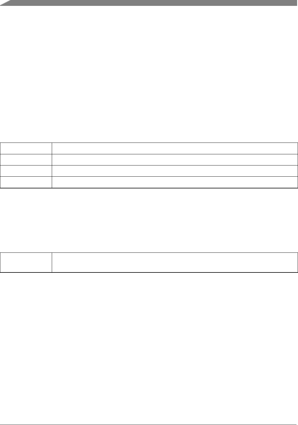
Function Documentation
34.7 Function Documentation
34.7.1 void SHELL_Init ( p_shell_context_t context, send_data_cb_t send_cb,
recv_data_cb_t recv_cb, printf_data_t shell_printf, char ∗prompt )
This function must be called before calling all other Shell functions. Call operation the Shell commands
with user-defined settings. The example below shows how to set up the middleware Shell and how to call
the SHELL_Init function by passing in these parameters. This is an example.
*shell_context_struct user_context;
*SHELL_Init(&user_context, SendDataFunc, ReceiveDataFunc, "SHELL>> ");
*
Parameters
context The pointer to the Shell environment and runtime states.
send_cb The pointer to call back send data function.
recv_cb The pointer to call back receive data function.
prompt The string prompt of Shell
34.7.2 int32_t SHELL_RegisterCommand ( const shell_command_context_t ∗
command_context )
Parameters
command_-
context
The pointer to the command data structure.
Returns
-1 if error or 0 if success
34.7.3 int32_t SHELL_Main ( p_shell_context_t context )
Main loop for Shell; After this function is called, Shell begins to initialize the basic variables and starts to
work.
492
MCUXpresso SDK API Reference Manual
NXP Semiconductors

Function Documentation
Parameters
context The pointer to the Shell environment and runtime states.
Returns
This function does not return until Shell command exit was called.
NXP Semiconductors
MCUXpresso SDK API Reference Manual
493

Function Documentation
494
MCUXpresso SDK API Reference Manual
NXP Semiconductors

How to Reach Us:
Home Page:
nxp.com
Web Support:
nxp.com/support
Information in this document is provided solely to enable system and
software implementers to use NXP products. There are no express or
implied copyright licenses granted hereunder to design or fabricate any
integrated circuits based on the information in this document.
NXP reserves the right to make changes without further notice to any
products herein. NXP makes no warranty, representation, or guarantee
regarding the suitability of its products for any particular purpose, nor
does NXP assume any liability arising out of the application or use of
any product or circuit, and specifically disclaims any and all liability,
including without limitation consequential or incidental damages.
“Typical” parameters that may be provided in NXP data sheets and/or
specifications can and do vary in different applications, and actual
performance may vary over time. All operating parameters, including
“typicals,” must be validated for each customer application by
customer’s technical experts. NXP does not convey any license under
its patent rights nor the rights of others. NXP sells products pursuant to
standard terms and conditions of sale, which can be found at the
following address: nxp.com/SalesTermsandConditions.
NXP, the NXP logo, Freescale, the Freescale logo, Kinetis, Processor
Expert are trademarks of NXP B.V. Tower is a trademark of NXP. All
other product or service names are the property of their respective
owners. ARM, ARM Powered logo, and Cortex are registered
trademarks of ARM Limited (or its subsidiaries) in the EU and/or
elsewhere. All rights reserved.
© 2017 NXP B.V.
Document Number: MCUXSDKKL25APIRM
Rev. 0
Mar 2017
