MCUXpresso SDK USB Stack User's Guide
User Manual:
Open the PDF directly: View PDF ![]() .
.
Page Count: 50
- MCUXpresso SDK USB Stack User's Guide
- Contents
- 1 Overview
- 2 Build the USB examples in MCUXpresso SDK
- 3 Porting to a new platform
- 4 Developing a new USB application
- 5 USB compliance tests
- 6 Revision history

MCUXpresso SDK USB Stack
User’s Guide
NXP Semiconductors Document Number: MCUXSDKUSBSUG
User's Guide Rev 8, 05/2018

Contents
Chapter 1 Overview............................................................................................. 4
Chapter 2 Build the USB examples in MCUXpresso SDK................................5
2.1 Requirements for building USB examples....................................................................................................................5
2.1.1 Hardware....................................................................................................................................................... 5
2.1.2 Software........................................................................................................................................................ 5
2.2 USB code structure......................................................................................................................................................5
2.3 Compiling or running the USB stack and examples.....................................................................................................6
2.3.1 Step-by-step guide for MCUXpresso IDE......................................................................................................7
2.3.2 Step-by-step guide for IAR.......................................................................................................................... 12
2.3.3 Step-by-step guide for Keil µVision5........................................................................................................... 13
2.3.4 Step-by-step guide for ARM GCC............................................................................................................... 14
2.3.4.1 Setup tool chains..........................................................................................................................14
2.3.4.2 Install GCC ARM embedded tool chain....................................................................................... 14
2.3.4.3 Install MinGW...............................................................................................................................14
2.3.4.4 Add new system environment variable ARMGCC_DIR................................................................15
2.3.4.5 Install CMake............................................................................................................................... 16
2.3.4.6 Build the USB demo.....................................................................................................................17
2.3.4.7 Run a demo application............................................................................................................... 18
2.4 USB stack configuration.............................................................................................................................................20
2.4.1 Device configuration....................................................................................................................................20
2.4.2 Host configuration....................................................................................................................................... 21
2.4.3 USB OSA resource configuration................................................................................................................21
2.4.4 USB cache-related MACROs definitions.....................................................................................................22
Chapter 3 Porting to a new platform................................................................ 25
3.1 System-on-Chip (SoC) files........................................................................................................................................25
3.2 Board files.................................................................................................................................................................. 25
3.3 Porting examples....................................................................................................................................................... 27
3.3.1 Copy a new platform example.....................................................................................................................27
3.3.2 Porting the example.................................................................................................................................... 27
3.3.3 Modify the example project......................................................................................................................... 29
3.3.4 USB host CDC example..............................................................................................................................31
3.3.5 USB device MSC SD card example............................................................................................................32
3.3.6 USB device audio speaker example........................................................................................................... 32
3.3.7 USB device CCID Smart card example...................................................................................................... 33
Chapter 4 Developing a new USB application................................................ 34
4.1 Developing a new USB device application.................................................................................................................34
4.1.1 Application interfaces.................................................................................................................................. 34
4.1.2 How to develop a new device application.................................................................................................... 34
4.1.2.1 Changing the usb_device_descriptor.c file................................................................................... 35
Contents
MCUXpresso SDK USB Stack User’s Guide, Revision 8, May 2018
2NXP Semiconductors

4.1.2.2 Changing the usb_device_descriptor.h file ..................................................................................41
4.1.2.3 Changing the application file........................................................................................................ 41
4.2 Developing a New USB Host Application...................................................................................................................41
4.2.1 Background.................................................................................................................................................41
4.2.2 How to develop a new host application.......................................................................................................42
4.2.2.1 Creating a project.........................................................................................................................42
4.2.2.2 Main application function flow...................................................................................................... 43
4.2.2.3 Event callback function................................................................................................................ 44
4.2.2.4 Class initialization........................................................................................................................ 47
4.2.2.5 Sending/Receiving data to/from the device..................................................................................47
Chapter 5 USB compliance tests......................................................................48
Chapter 6 Revision history............................................................................... 49
Contents
MCUXpresso SDK USB Stack User’s Guide, Revision 8, May 2018
NXP Semiconductors 3

Chapter 1
Overview
This document provides the following:
• Detailed steps to compile the USB examples, download a binary image, and run the examples.
• Detailed steps to port the USB stack to a new platform.
• Detailed steps to develop a new application based on the existing classes in the USB stack.
Overview
MCUXpresso SDK USB Stack User’s Guide, Revision 8, May 2018
4NXP Semiconductors

Chapter 2
Build the USB examples in MCUXpresso SDK
This section describes how to compile the USB stack and examples, download a binary image, and run the examples.
2.1 Requirements for building USB examples
The TWR-K22F120M Tower System module or FRDM-K64F Freedom platform is used as an example in this document. The
process for compiling, downloading, and running examples is similar on all other boards. For a detailed version of the toolchain
software, see the MCUXpresso SDK Release Notes (document MCUXSDKRN).
2.1.1 Hardware
• TWR-K22F120M Tower System module and (optional) TWR-SER Tower System module and Elevator
• MCUXpresso SDK Boards
• J-Link debugger (optional)
• USB cables
2.1.2 Software
• MCUXpresso SDK release package
• IAR Embedded Workbench for ARM® Version 8.11.3
• Keil µVision5 Integrated Development Environment Version 5.23 , available for ARM® Cortex®-M4 devices
• MCUXpresso IDE v10.1.0
• Makefiles support with GCC revision 6-2017-q2-update from ARM Embedded
2.2 USB code structure
The USB code is located in the folder:
<install_dir>/middleware/usb
Requirements for building USB examples
MCUXpresso SDK USB Stack User’s Guide, Revision 8, May 2018
NXP Semiconductors 5
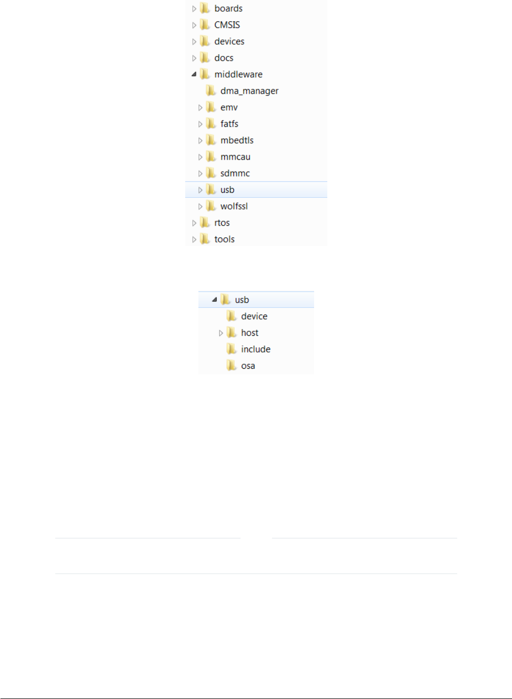
Figure 1. MCUXpresso SDK folder structure
The USB folder includes the source code for stack and examples. Note that the version number of the USB folder may vary.
Figure 2. USB folder structure
The USB folder includes three subfolders:
• device
This subfolder includes the controller driver and common device driver for the USB device.
• include
This subfolder includes the definitions and structures for the USB stack.
• osa
This subfolder includes the adapter interfaces for various OSes.
For different USB stack versions, the folder structure may be a little different. See the folder structure in the release
package to get the exact folder structure.
NOTE
2.3 Compiling or running the USB stack and examples
Build the USB examples in MCUXpresso SDK
MCUXpresso SDK USB Stack User’s Guide, Revision 8, May 2018
6NXP Semiconductors
The USB example maybe not support all compilers. The steps below just provide information on how to compile
and run on all compilers. To know which compilers have support for the USB example, see the specific MCUXpresso
SDK documentation.
NOTE
2.3.1 Step-by-step guide for MCUXpresso IDE
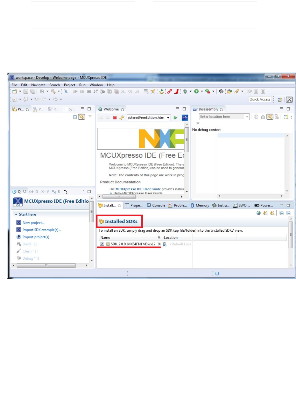
1. Prepare a compressed release package , such as SDK_2.0_FRDM-K64F.zip.
2. Open MCUXpresso IDE and drag and drop the MCUXpresso SDK (zip file/folder) into the ‘Installed SDKs’. The MCUXpresso
SDK should install.
Figure 3. Installed SDK
3. To select an example, select the “Import SDK example(s) [To match the figure]” button. Click the “Next” button after selecting
the available board.
Compiling or running the USB stack and examples
MCUXpresso SDK USB Stack User’s Guide, Revision 8, May 2018
NXP Semiconductors 7
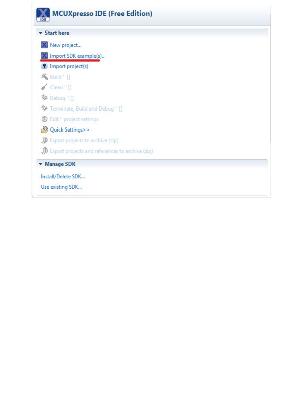
Figure 4. Import project button
Build the USB examples in MCUXpresso SDK
MCUXpresso SDK USB Stack User’s Guide, Revision 8, May 2018
8NXP Semiconductors
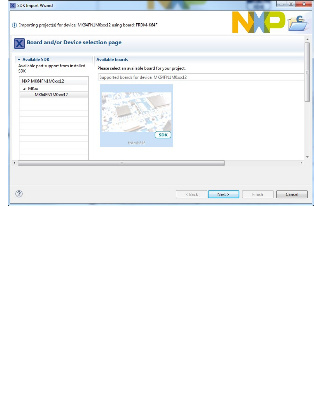
Figure 5. Select boards
4. To import one example, click the “Finish” button after selecting the available example.
Compiling or running the USB stack and examples
MCUXpresso SDK USB Stack User’s Guide, Revision 8, May 2018
NXP Semiconductors 9
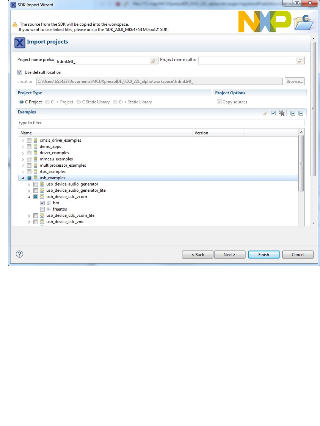
Figure 6. Import project
5. After importing, the window should look like the below figure.
Build the USB examples in MCUXpresso SDK
MCUXpresso SDK USB Stack User’s Guide, Revision 8, May 2018
10 NXP Semiconductors
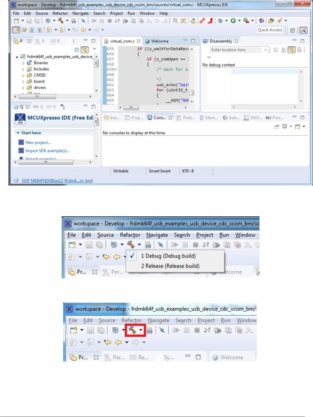
Figure 7. The USB projects workspace
6. Choose the appropriate build target, “Debug” or “Release”, by left-clicking the build configuration icon as show in the below
figure.
Figure 8. Manage build configuration button
7. If the project build does not begin after selecting the desired target, left-click the build icon to start the build.
Figure 9. Build project button
8. To check debugger configurations, click the down arrow next to the green debug button and select “Debug Configurations”.
Compiling or running the USB stack and examples
MCUXpresso SDK USB Stack User’s Guide, Revision 8, May 2018
NXP Semiconductors 11
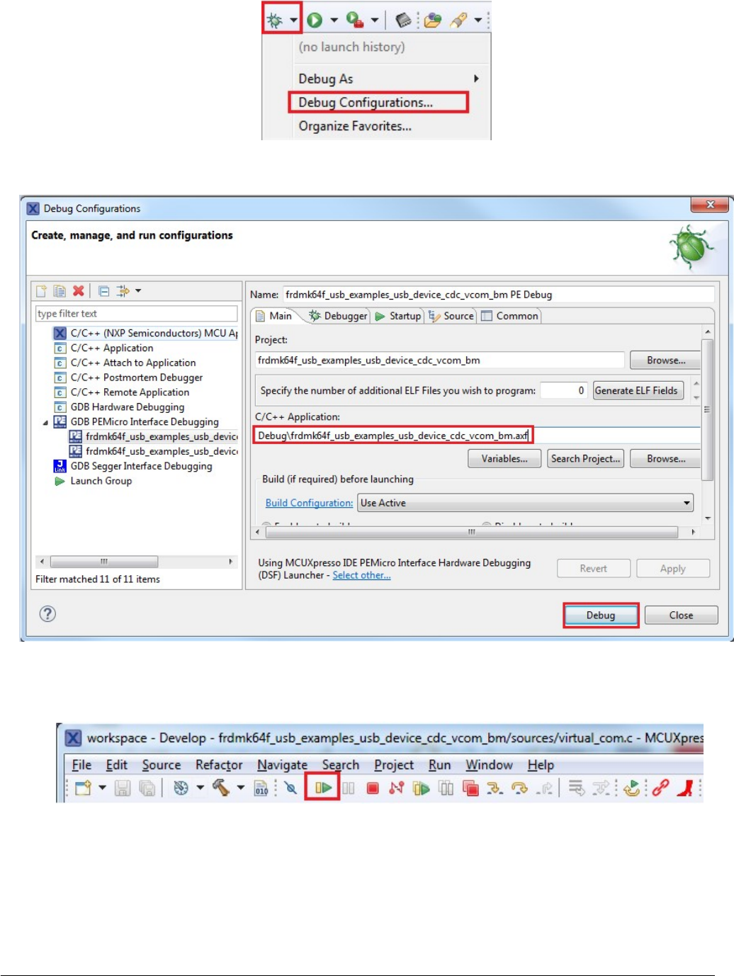
Figure 10. Configure debug button
9. After verifying the debugger configurations are correct, click the “Debug” button.
Figure 11. MCUXpresso IDE debug configurations
10. The application is downloaded to the target and automatically runs to main():
11. Run the code by clicking the “Resume” button to start the application:
Figure 12. Resume button
12. See the example-specific document for more test information.
2.3.2 Step-by-step guide for IAR
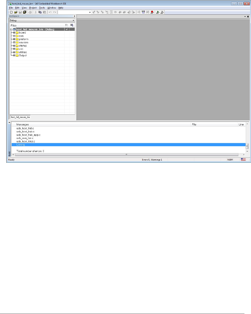
This section shows how to use IAR. Open IAR as shown in this figure:
Build the USB examples in MCUXpresso SDK
MCUXpresso SDK USB Stack User’s Guide, Revision 8, May 2018
12 NXP Semiconductors
1. Open the worksace corresponding to different examples.
For example, the workspace file is located at: <install_dir>/boards/twrk22f120m/usb_examples/usb_host_hid_mouse/bm/
iar/host_hid_mouse_bm.eww.
Figure 13. IAR workspace
2. Build the host_hid_mouse_bm example.
3. Connect the micro USB cable from a PC to the J25 of the TWR-K22F120M Tower System module to power on the board.
4. Click the “Download and Debug” button. Wait for the download to complete.
5. Click the “Go” button to run the example.
6. See the example-specific readme.pdf for more test information.
2.3.3 Step-by-step guide for Keil µVision5
This section shows how to use Keil µVision5. Open Keil µVision5 as shown in this figure:
1. Open the workspace corresponding to different examples.
For example, the workspace file is located in <install_dir>/boards/twrk22f120m/usb_examples/usb_host_hid_mouse/bm/
mdk/host_hid_mouse_bm.uvmpw.
Compiling or running the USB stack and examples
MCUXpresso SDK USB Stack User’s Guide, Revision 8, May 2018
NXP Semiconductors 13
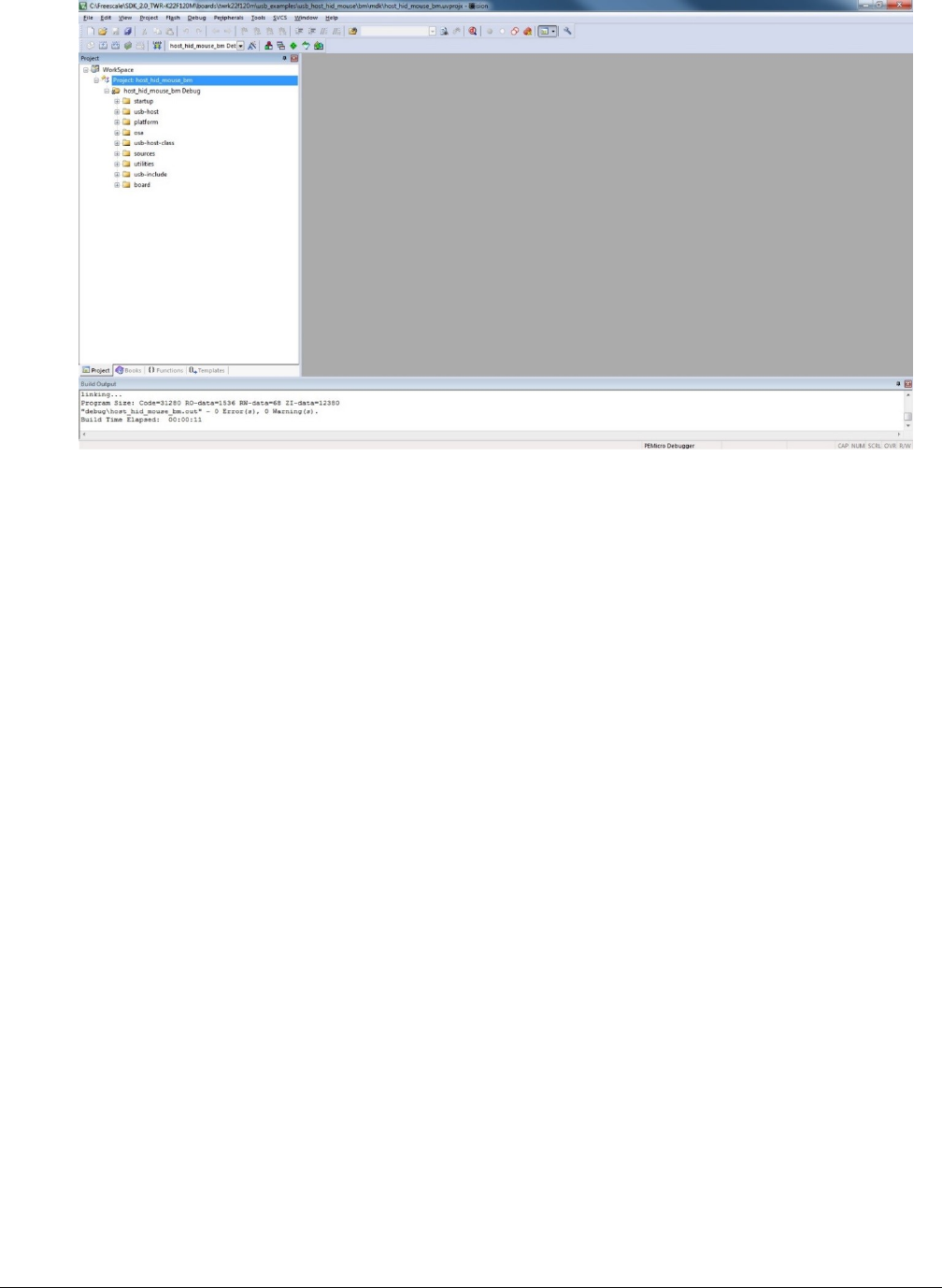
Figure 14. Keil µVision5 workspace
2. Build the host_hid_mouse_bm example.
3. Click the “Start/Stop” debug session button. Wait for the download to complete.
4. Click the “Go” button to run the example.
5. See the example-specific readme.pdf for more test information.
2.3.4 Step-by-step guide for ARM GCC
2.3.4.1 Setup tool chains
2.3.4.2 Install GCC ARM embedded tool chain
Download and install the installer from www.launchpad.net/gcc-arm-embedded.
2.3.4.3 Install MinGW
1. Download the latest mingw-get-setup.exe.
2. Install the GCC ARM Embedded toolchain. The recommended path is C:/MINGW. However, you may install to any location.
Note that the installation path may not contain a space.
3. Ensure that the mingw32-base and msys-base are selected under Basic Setup.
4. Click “Installation” and “Apply changes”.
Build the USB examples in MCUXpresso SDK
MCUXpresso SDK USB Stack User’s Guide, Revision 8, May 2018
14 NXP Semiconductors
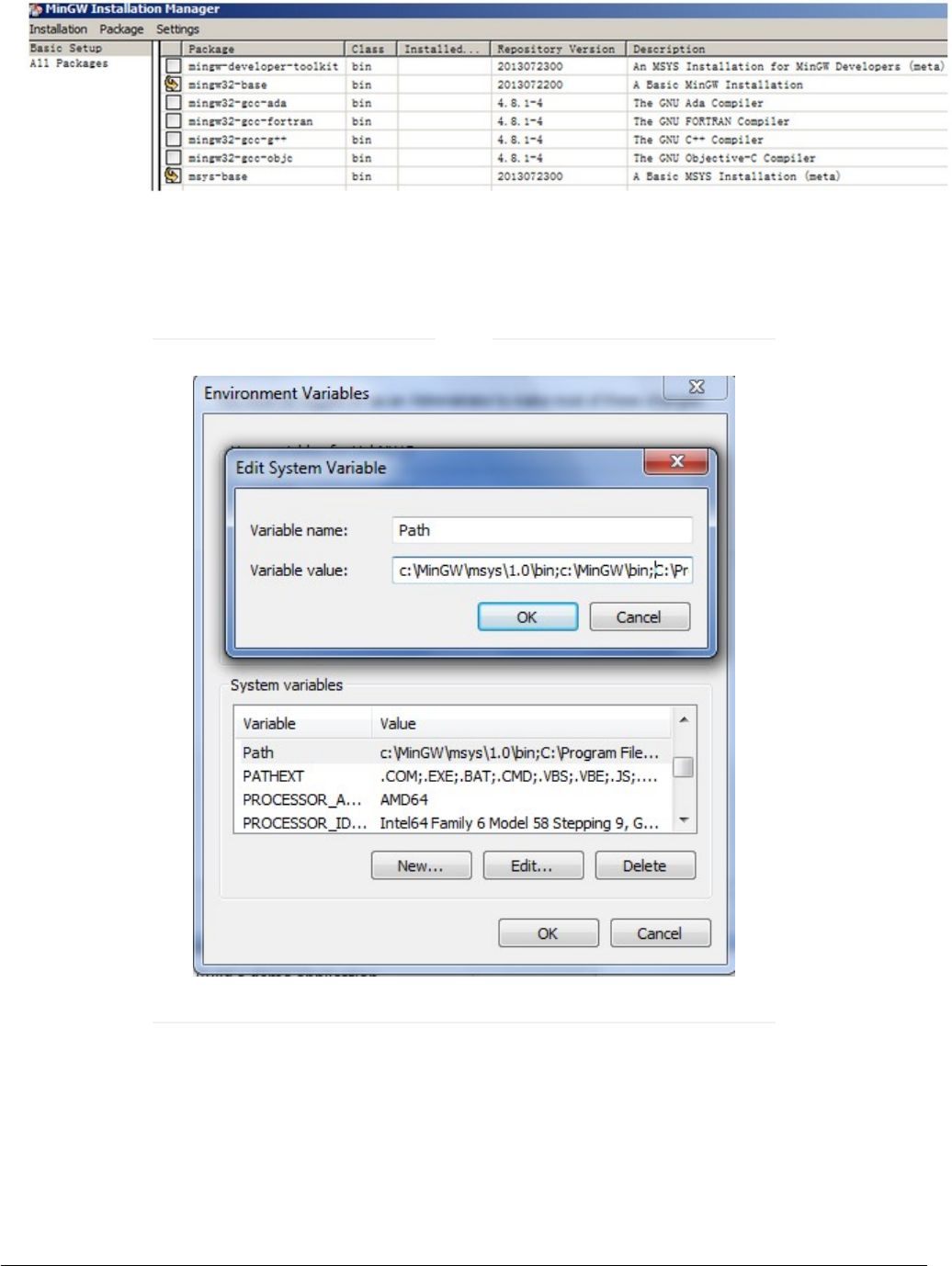
Figure 15. Setup MinGW and MSYS
5. Add paths C:/MINGW/msys/1.0/bin;C:/MINGW/bin to the system environment. Note that, if the GCC ARM Embedded tool
chain was installed somewhere other than the recommended location, the system paths added should reflect this change.
An example using the recommended installation locations is shown below.
There is a high chance that if the paths are not set correctly, the tool chain will not work properly.
Figure 16. Add Path to systems environment
NOTE
2.3.4.4 Add new system environment variable ARMGCC_DIR
Create a new system environment variable ARMGCC_DIR. The value of this variable should be the short name of the ARM GCC
Embedded tool chain installation path.
Compiling or running the USB stack and examples
MCUXpresso SDK USB Stack User’s Guide, Revision 8, May 2018
NXP Semiconductors 15
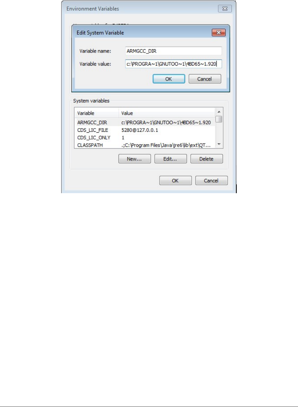
Figure 17. Add ARMGCC_DIR system variable
2.3.4.5 Install CMake
1. Download CMake 3.0.1 from www.cmake.org/cmake/resources/software.html.
2. Install Cmake 3.0.1 and ensure that the option "Add CMake to system PATH" is selected.
Build the USB examples in MCUXpresso SDK
MCUXpresso SDK USB Stack User’s Guide, Revision 8, May 2018
16 NXP Semiconductors
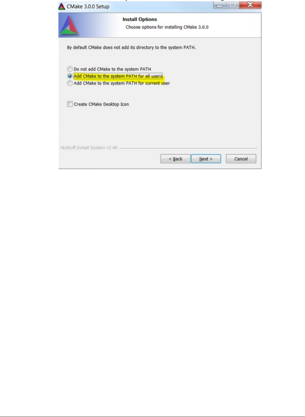
Figure 18. Install CMake
2.3.4.6 Build the USB demo
1. Change the directory to the project directory:
2. <install_dir>/boards/twrk22f120m/usb_examples/usb_host_hid_mouse/bm/armgcc. Run the build_all.bat. The build
output is shown in this figure:
Compiling or running the USB stack and examples
MCUXpresso SDK USB Stack User’s Guide, Revision 8, May 2018
NXP Semiconductors 17
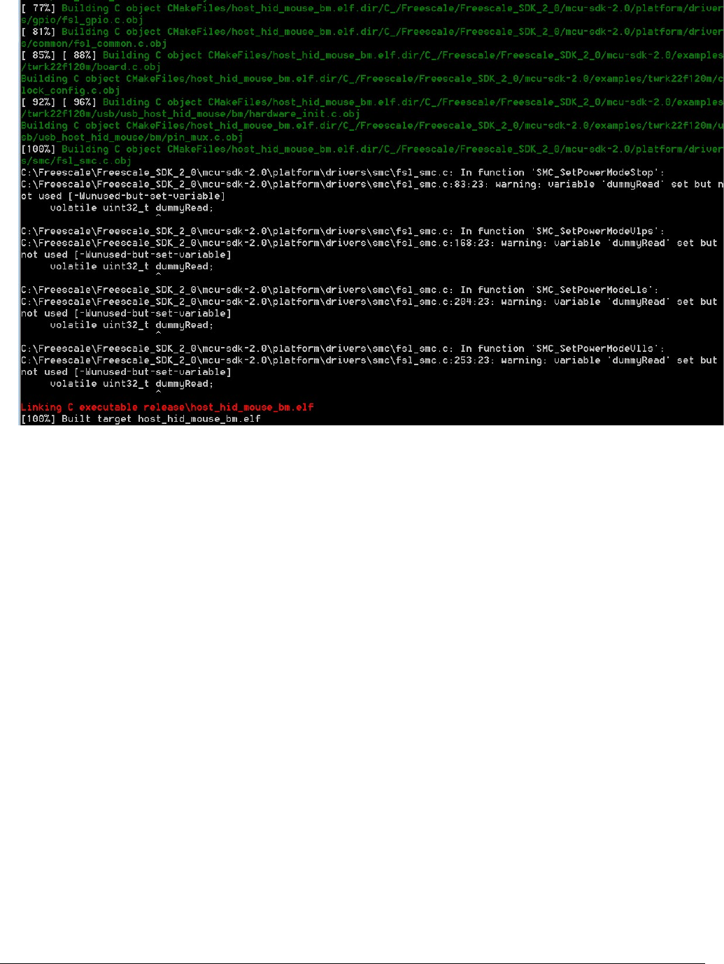
Figure 19. USB host demo built successfully
2.3.4.7 Run a demo application
This section describes steps to run a demo application using J-Link GDB Server application.
1. Connect the J-Link debug port to the SWD/JTAG connector of the board.
2. Open the J-Link GDB Server application and modify your connection settings as shown in this figure.
Build the USB examples in MCUXpresso SDK
MCUXpresso SDK USB Stack User’s Guide, Revision 8, May 2018
18 NXP Semiconductors
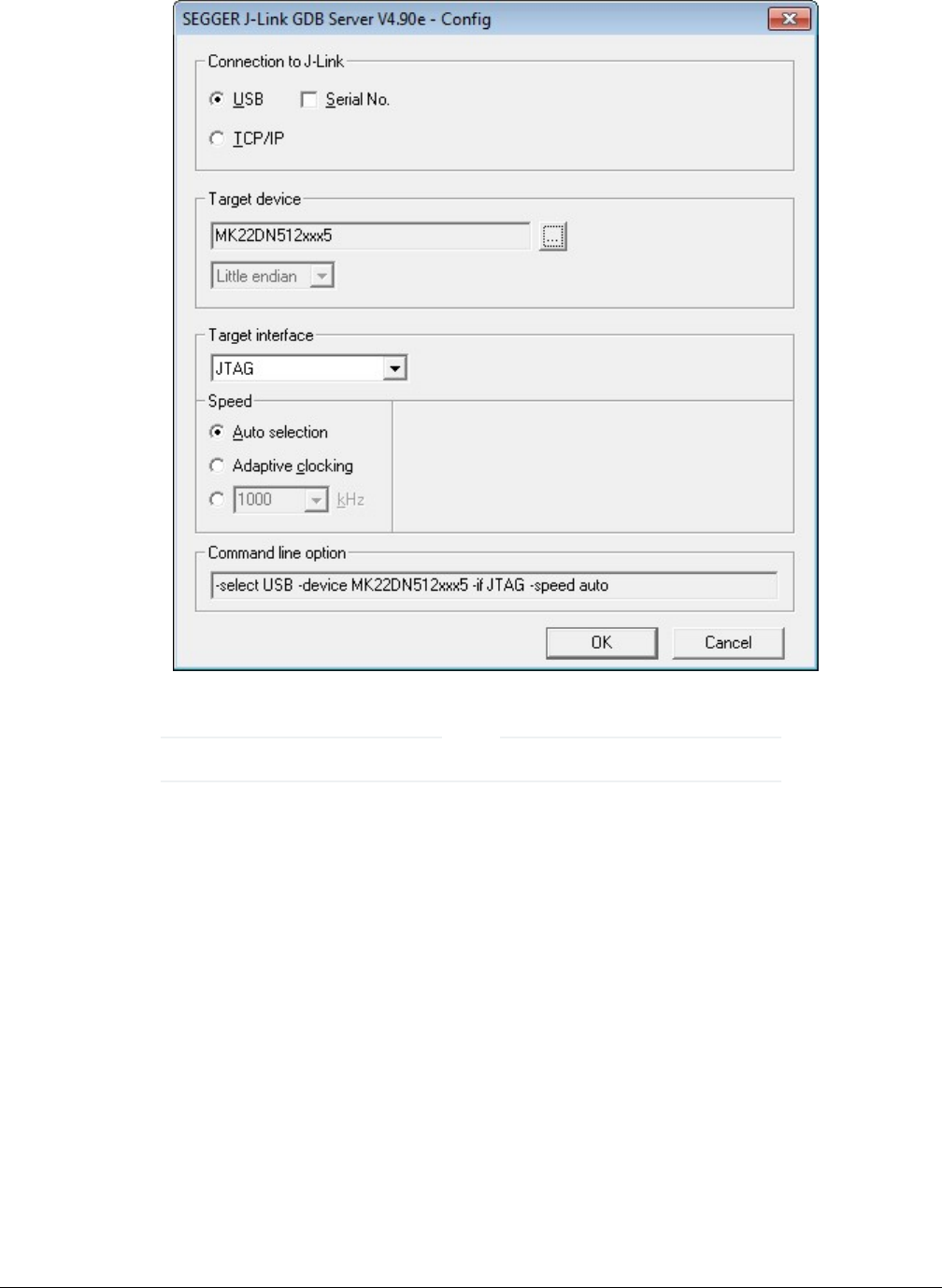
Figure 20. SEGGER J-Link GDB Server configuration
The target device selection should be MK22FN512xxx12. The target interface should be SWD.
NOTE
3. After connected, the screen should resemble this figure:
Compiling or running the USB stack and examples
MCUXpresso SDK USB Stack User’s Guide, Revision 8, May 2018
NXP Semiconductors 19
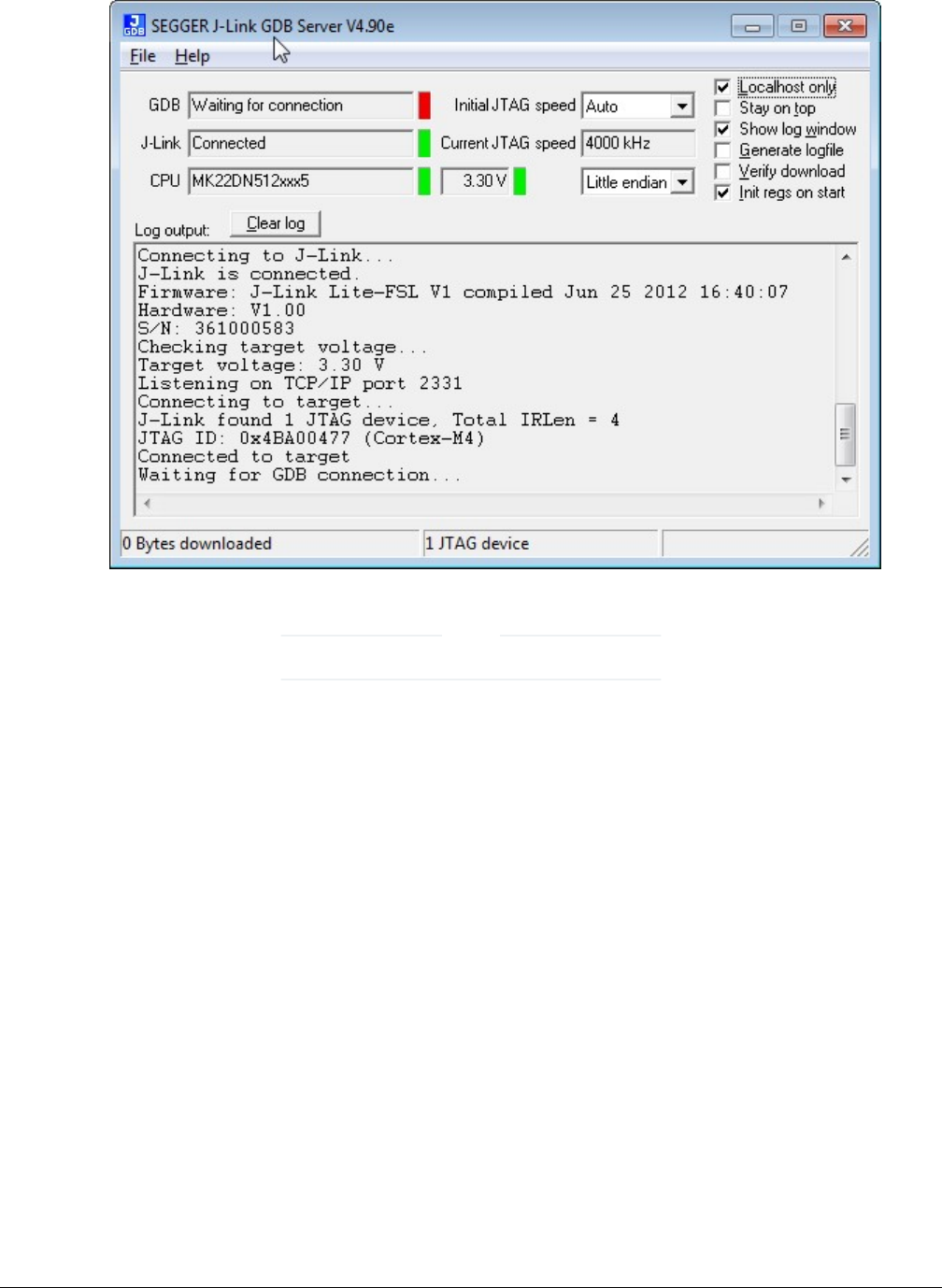
Figure 21. SEGGER J-Link GDB Server screen after successful connection
The CPU selection should be CPU to: MK22FN512xxx12.
NOTE
4. Open the ARM GCC command prompt and change the directory to the output directory of the desired demo. For this
example, the directory is:
<install_dir>/boards/twrk22f120m/usb_examples/usb_host_hid_mouse/bm/armgcc/debug.
5. Run the command “arm-none-eabi-gdb.exe <DEMO_NAME>.elf”. Run these commands:
• “target remote localhost: 2331”
• “monitor reset”
• “monitor halt”
• “load”
• “monitor reset”
6. The application is downloaded and connected. Execute the “monitor go” command to start the demo application.
7. See the example-specific document for more test information.
2.4 USB stack configuration
2.4.1 Device configuration
A device configuration file is set up for each example, such as:
Build the USB examples in MCUXpresso SDK
MCUXpresso SDK USB Stack User’s Guide, Revision 8, May 2018
20 NXP Semiconductors

<install_dir>/boards/twrk22f120m/usb_examples/usb_host_hid_mouse
This file is used to either enable or disable the USB class driver and to configure the interface type (high-speed or full speed).
The object number is configurable either to decrease the memory usage or to meet specific requirements.
If the device stack configuration is changed, rebuild the example projects. For each device, follow these steps.
If the board is a Tower or Freedom platform, enable the following macros:
Enable this macro for full speed.
#define USB_DEVICE_CONFIG_KHCI (0U)
Enable this macro if the board supports high-speed.
#define USB_DEVICE_CONFIG_EHCI (0U)
If board is part of the LPC series, enable the following macros:
Enable this macro for full speed.
#define USB_DEVICE_CONFIG_LPCIP3511FS (0U)
Enable this macro if the board supports high-speed.
#define USB_DEVICE_CONFIG_LPCIP3511HS (0U)
2.4.2 Host configuration
A host configuration file is set up for each example, such as:
<install_dir>/boards/twrk22f120m/usb/usb_host_hid_mouse/bm/usb_host_config.h
This file is used to either enable or disable the USB class driver. The object number is configurable either to decrease the memory
usage or to meet specific requirements.
If the Host stack configuration is changed, rebuild the example projects.
For each Host, follow these steps.
If the board is a Tower for Freedom platform, enable the following macros:
Enable this macro for full speed.
#define USB_HOST_CONFIG_KHCI (0U)
Enable this macro if the board supports high-speed.
#define USB_HOST_CONFIG_EHCI (0U)
If board is part of the LPC series, enable the following macros:
Enable this macro for full speed.
#define USB_HOST_CONFIG_OHCI (0U)
Enable this macro if the board supports high-speed.
#define USB_HOST_CONFIG_IP3516HS (0U)
2.4.3 USB OSA resource configuration
In the USB stack, some static resources for USB OSA, such as event and message, are defined. The user should update the
configuration number if the resource is not enough.
For bare metal, the related macro is in usb_osa_bm.c.
USB stack configuration
MCUXpresso SDK USB Stack User’s Guide, Revision 8, May 2018
NXP Semiconductors 21

#define USB_OSA_BM_EVENT_COUNT (2U)
#define USB_OSA_BM_SEM_COUNT (1U)
#define USB_OSA_BM_MSGQ_COUNT (1U)
#define USB_OSA_BM_MSG_COUNT (8U)
#define USB_OSA_BM_MSG_SIZE (4U)
For FreeRTOS OS, if the configSUPPORT_STATIC_ALLOCATION macro is enabled, the related macro is in usb_osa_freertos.c.
#define USB_OSA_FREERTOS_EVENT_COUNT (2U)
#define USB_OSA_FREERTOS_SEM_COUNT (1U)
#define USB_OSA_FREERTOS_MUTEX_COUNT (3U)
#define USB_OSA_FREERTOS_MSGQ_COUNT (1U)
#define USB_OSA_FREERTOS_MSG_COUNT (8U)
#define USB_OSA_FREERTOS_MSG_SIZE (4U)
2.4.4 USB cache-related MACROs definitions
There are few MACROs in the USB stack to define USB data attributes.
• USB_STACK_USE_DEDICATED_RAM
The following values are used to configure the USB stack to use dedicated RAM or not.
1. USB_STACK_DEDICATED_RAM_TYPE_BDT_GLOBAL - The USB device global variables (controller data and device
stack data) are put into the USB-dedicated RAM.
2. USB_STACK_DEDICATED_RAM_TYPE_BDT - The USB device controller global variables (BDT data) are put into the
USB-dedicated RAM.
3. 0 - There is no USB-dedicated RAM.
• USB_DEVICE_CONFIG_BUFFER_PROPERTY_CACHEABLE
The following values are used to configure the device stack cache to be enabled or not.
0: disabled
1: enable
• USB_HOST_CONFIG_BUFFER_PROPERTY_CACHEABLE
The following values are used to configure host stack cache to be enabled or not.
0: disable
1: enable
Based on the above MACROs, the following cache-related MACROs are defined in the USB stack.
Table 1. Cache and global variable attribute relation
USB_DEVICE_CONFIG_BUFFER_PROPERTY_CACHEABLE ||
USB_HOST_CONFIG_BUFFER_PROPERTY_CACHEABLE
USB_STACK_USE_DEDICATED_RAM
’s Value
1 0
Build the USB examples in MCUXpresso SDK
MCUXpresso SDK USB Stack User’s Guide, Revision 8, May 2018
22 NXP Semiconductors
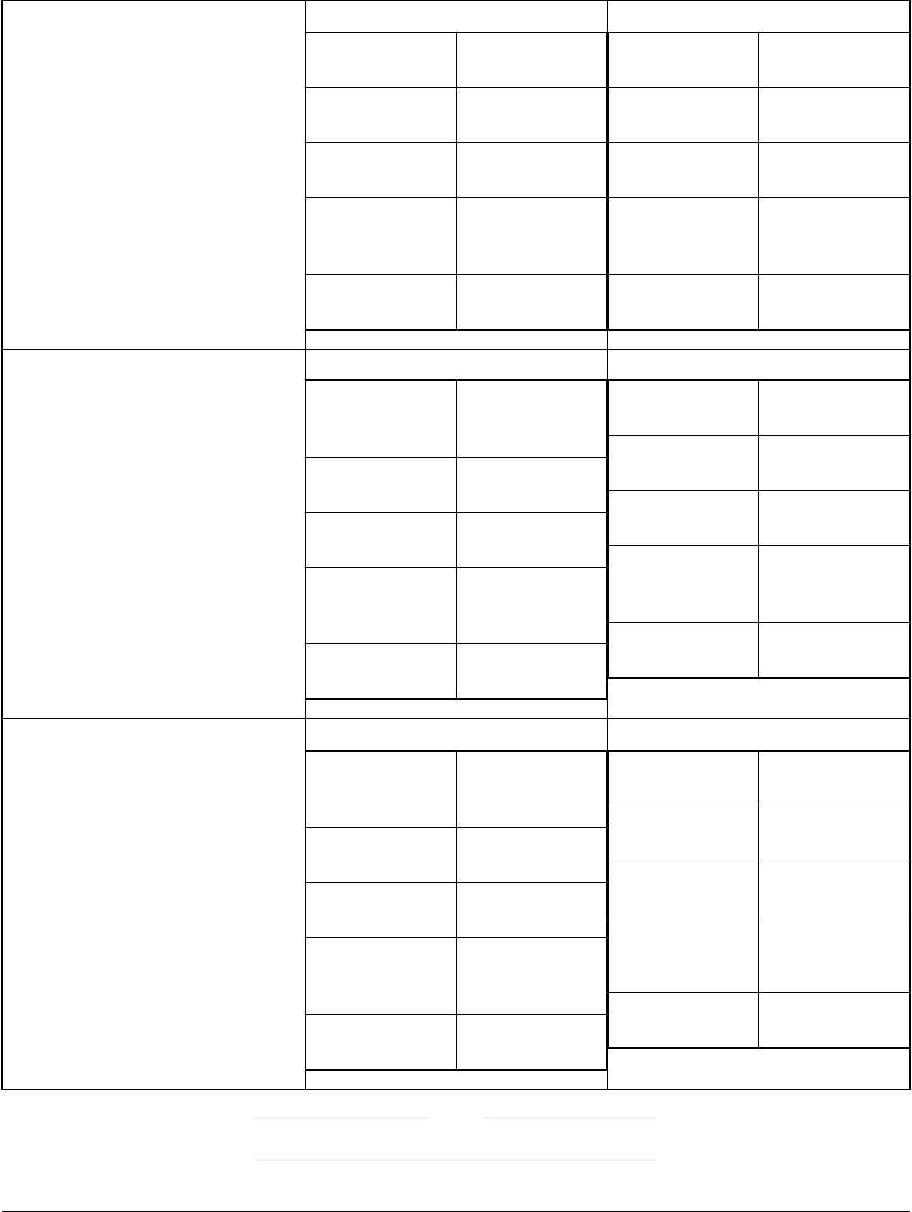
Table 1. Cache and global variable attribute relation (continued)
USB_STACK_DEDICATED_RAM_TYPE
_BDT_GLOBAL USB_GLOBAL dedicated ram,
stack use only
USB_BDT dedicated ram,
stack use only
USB_CONTROLL
ER_DATA
NonCachable,
stack use only
USB_DMA_NONI
NIT_DATA_ALIGN(
n)
cachable ram &
alignment
USB_DMA_INIT_D
ATA_ALIGN(n)
cachable ram &
alignment
USB_GLOBAL dedicated ram,
stack use only
USB_BDT dedicated ram,
stack use only
USB_CONTROLL
ER_DATA
dedicated ram,
stack use only
USB_DMA_NONI
NIT_DATA_ALIGN(
n)
alignment
USB_DMA_INIT_D
ATA_ALIGN(n)
alignment
USB_STACK_DEDICATED_RAM_TYPE
_BDT USB_GLOBAL cachable ram &
alignment, stack
use only
USB_BDT dedicated ram,
stack use only
USB_CONTROLL
ER_DATA
NonCachable,
stack use only
USB_DMA_NONI
NIT_DATA_ALIGN(
n)
cachable ram &
alignment
USB_DMA_INIT_D
ATA_ALIGN(n)
cachable ram &
alignment
USB_GLOBAL Put in bss, stack
use only
USB_BDT dedicated ram,
stack use only
USB_CONTROLL
ER_DATA
NULL, stack use
only
USB_DMA_NONI
NIT_DATA_ALIGN(
n)
alignment
USB_DMA_INIT_D
ATA_ALIGN(n)
alignment
0
USB_GLOBAL cachable ram &
alignment, stack
use only
USB_BDT NonCachable,
stack use only
USB_CONTROLL
ER_DATA
NonCachable,
stack use only
USB_DMA_NONI
NIT_DATA_ALIGN(
n)
cachable ram &
alignment
USB_DMA_INIT_D
ATA_ALIGN(n)
cachable ram &
alignment
USB_GLOBAL Put in bss, stack
use only
USB_BDT Put in bss, stack
use only
USB_CONTROLL
ER_DATA
NULL, stack use
only
USB_DMA_NONI
NIT_DATA_ALIGN(
n)
alignment
USB_DMA_INIT_D
ATA_ALIGN(n)
alignment
“NULL” means that the MACRO is empty and has no influence.
NOTE
USB stack configuration
MCUXpresso SDK USB Stack User’s Guide, Revision 8, May 2018
NXP Semiconductors 23

There are four assistant MACROs:
USB_DATA_ALIGN_SIZE Used in USB stack and application, defines the default align
size for USB data.
USB_DATA_ALIGN_SIZE_MULTIPLE(n) Used in USB stack and application, calculates the value that is
multiple of the data align size.
USB_DMA_DATA_NONCACHEABLE Used in USB stack and application, puts data in the
noncacheable region if the cache is enabled.
USB_GLOBAL_DEDICATED_RAM Used in USB stack and application, puts data in the dedicated
RAM if dedicated RAM is enabled.
Build the USB examples in MCUXpresso SDK
MCUXpresso SDK USB Stack User’s Guide, Revision 8, May 2018
24 NXP Semiconductors
Chapter 3
Porting to a new platform
To port the USB stack to a new platform in the MCUXpresso SDK, the SoC-related files, board-related files, and a linker file for a
specified compiler are required.
Assume that the new platform’s name is “xxxk22f120m” based on the MK22F51212 SoC.
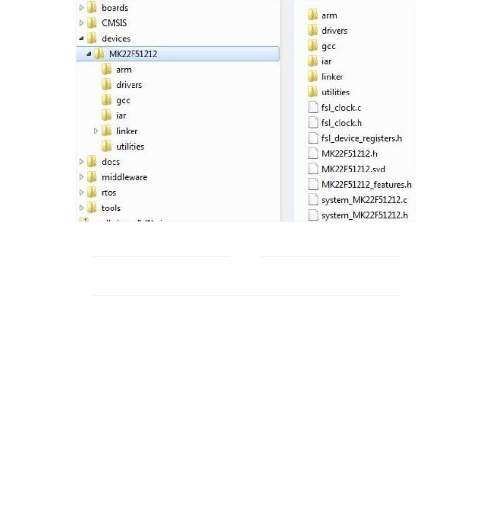
3.1 System-on-Chip (SoC) files
SoC source/header files are in the following directory, which are available by default from MCUXpresso SDK.
Figure 22. SoC header file directory
Linker files for each toolchain are in the linker directory.
Different toolchains’ SoC startup assembler files are in the Arm, GCC, and IAR directories.
NOTE
3.2 Board files
The files for the board configuration and the clock configuration on a specific platform are needed to enable the USB stack.
The clock configuration files are shown in the following image.
System-on-Chip (SoC) files
MCUXpresso SDK USB Stack User’s Guide, Revision 8, May 2018
NXP Semiconductors 25
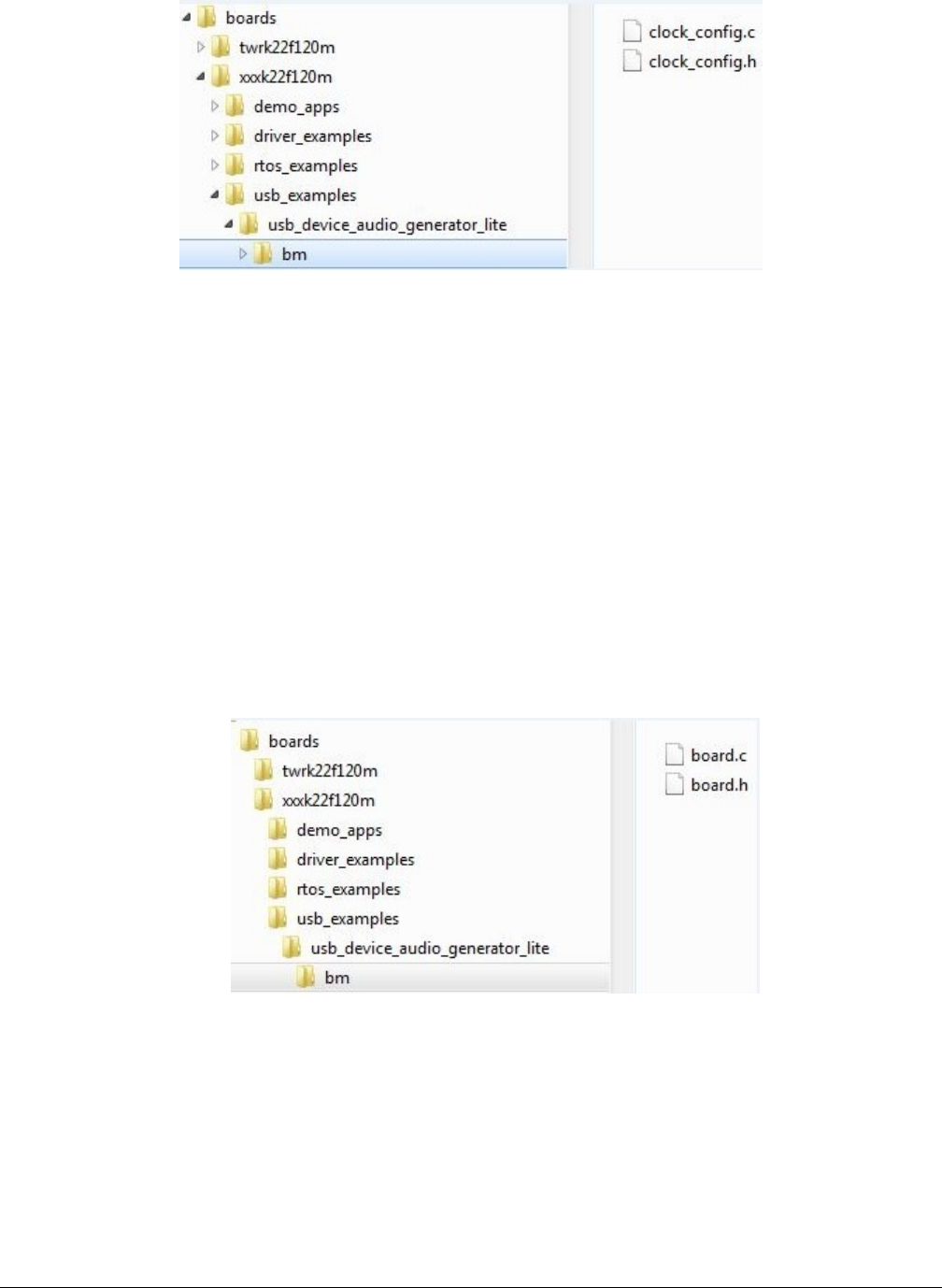
Figure 23. Clock configuration files
1. Create a folder “xxxk22f120m” under the examples directory.
2. Copy the clock_config.c and clock_config.h file from the similar platform. For example, the TWR-K22F120M Tower System
module.
3. Ensure that BOARD_BootClockxxx is implemented in the clock_config.c file. For example, BOARD_BootClockRUN and
BOARD_BootClockHSRUN. The user can change the function name. However, the BOARD_InitHardware must call the
function. BOARD_InitHardware is introduced later.
The board clock initialization is based on the board crystal oscillator. Ensure that the following two MACROs are defined
in the clock_config.h file:
#define BOARD_XTAL0_CLK_HZ 8000000U
#define BOARD_XTAL32K_CLK_HZ 32768U
The user can updatethe MACROs according to the board design. For example, if the XTAL0 crystal oscillator is 16000000U
and the XTAL32K is 32768U, change the following MACROs as follows:
#define BOARD_XTAL0_CLK_HZ 16000000U
#define BOARD_XTAL32K_CLK_HZ 32768U
The board configuration files are shown in the following image:
Figure 24. Board configuration files
4. Copy board.c and board.h from the similar platform. For example, the TWR-K22F120M platform. Ensure that the
BOARD_InitDebugConsole is implemented in board.c file and that the BOARD_InitHardware calls the function. The
BOARD_InitHardware function is introduced later.
The Debug console-related MACROS are needed in the board.h file, as follows:
#define BOARD_DEBUG_UART_TYPE DEBUG_CONSOLE_DEVICE_TYPE_UART
#define BOARD_DEBUG_UART_BASEADDR (uint32_t) UART2
#define BOARD_DEBUG_UART_CLKSRC BUS_CLK
#define BOARD_DEBUG_UART_BAUDRATE 115200
Porting to a new platform
MCUXpresso SDK USB Stack User’s Guide, Revision 8, May 2018
26 NXP Semiconductors
Update the MACROs according to the board design. For example, the default UART instance on the board is LPUART1,
the type of default UART instance on one specific platform is LPUART, and the LPUART clock source is the external clock.
In this case, change the above MACROs as follows:
#define BOARD_DEBUG_UART_TYPE DEBUG_CONSOLE_DEVICE_TYPE_LPUART
#define BOARD_DEBUG_UART_BASEADDR (uint32_t) LPUART1
#define BOARD_DEBUG_UART_CLKSRC kCLOCK_Osc0ErClk
#define BOARD_DEBUG_UART_BAUDRATE 115200
Note that there are three kinds of UART instances provided in MCUXpresso SDK devices, UART, LPUART, and LPSCI.
The interfaces of the UART instance are different. To provide a uniform UART interface to a USB Host example in which
the UART function is used, a UART instance wrapper is provided. The wrapper is implemented in the usb_uart_drv.c,
usb_lpuart_drv.c, or usb_lpsci_drv.c file and has a common header file usb_uart_drv.h. For a different UART instance, use
the corresponding UART instance wrapper file in the project.
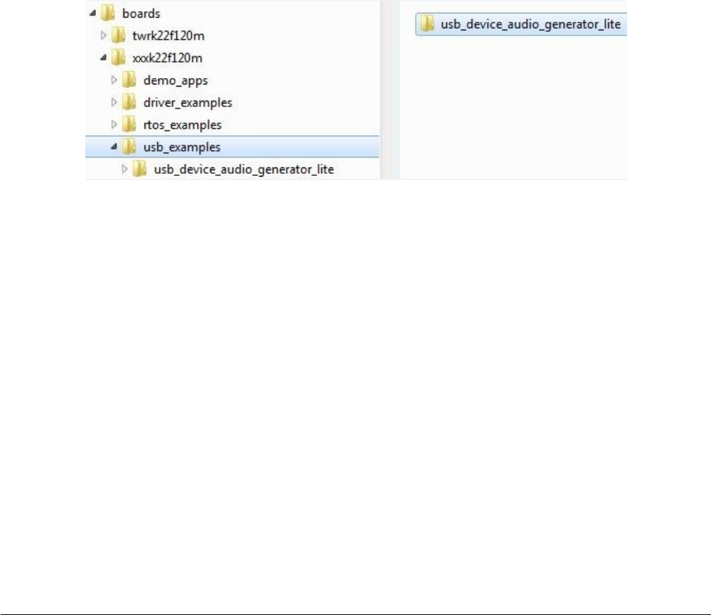
3.3 Porting examples
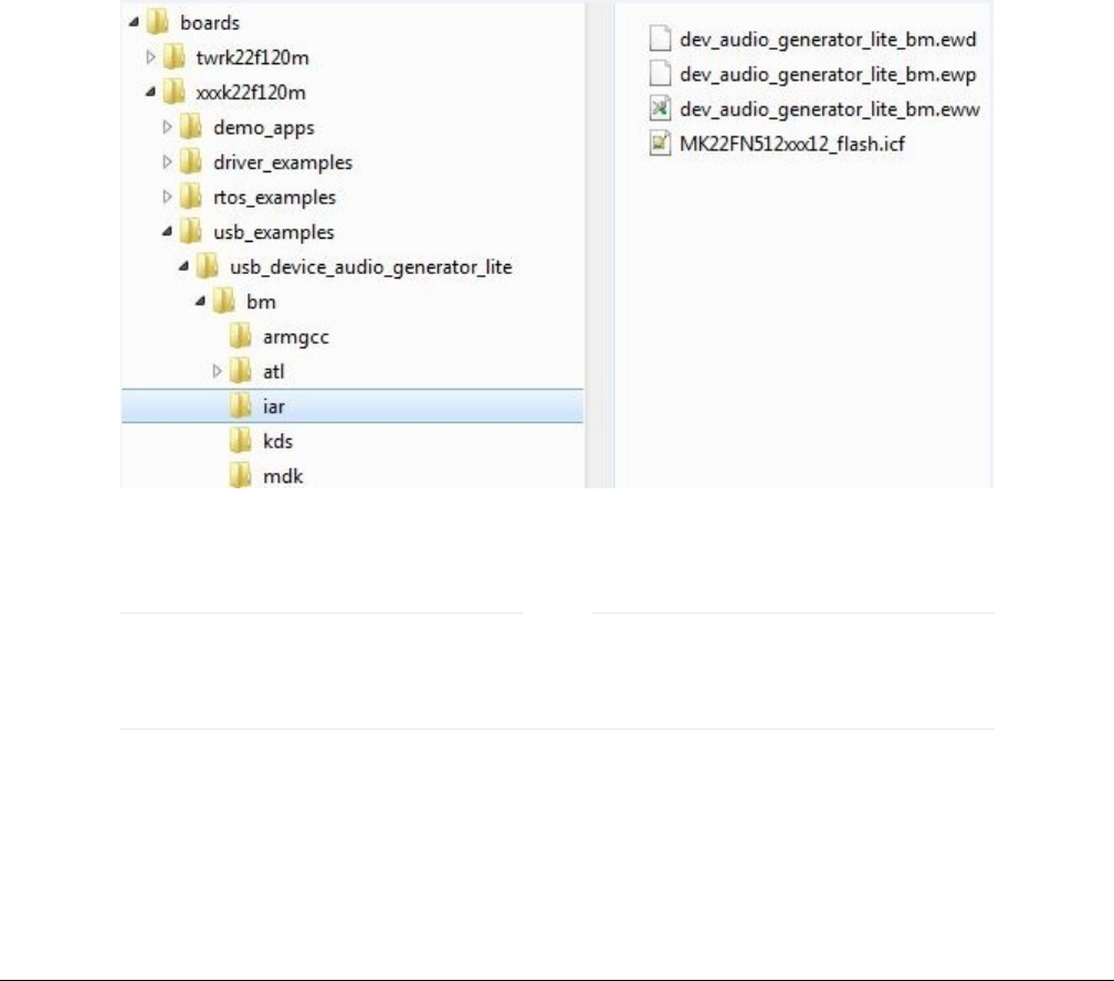
3.3.1 Copy a new platform example
The platform USB examples directory is shown in the following figure.
Figure 25. USB examples directory
Copy the existed example’s whole directory from the similar platform, which ensures that all example source files and project files
are copied.
For example, copy the twrk22f120m/usb/usb_device_audio_generator_lite to the twrkxx/usb location, which ensures that sources
files and project files for usb_device_audio_generator_lite example are copied.
3.3.2 Porting the example
For different examples, different pins are used. As a result, the pin_mux.c/h files are needed to assign different pins to a specific
functionality. Check the board schematic for correct pin settings.
Example-related port pin configurations are required in the following files:
Porting examples
MCUXpresso SDK USB Stack User’s Guide, Revision 8, May 2018
NXP Semiconductors 27
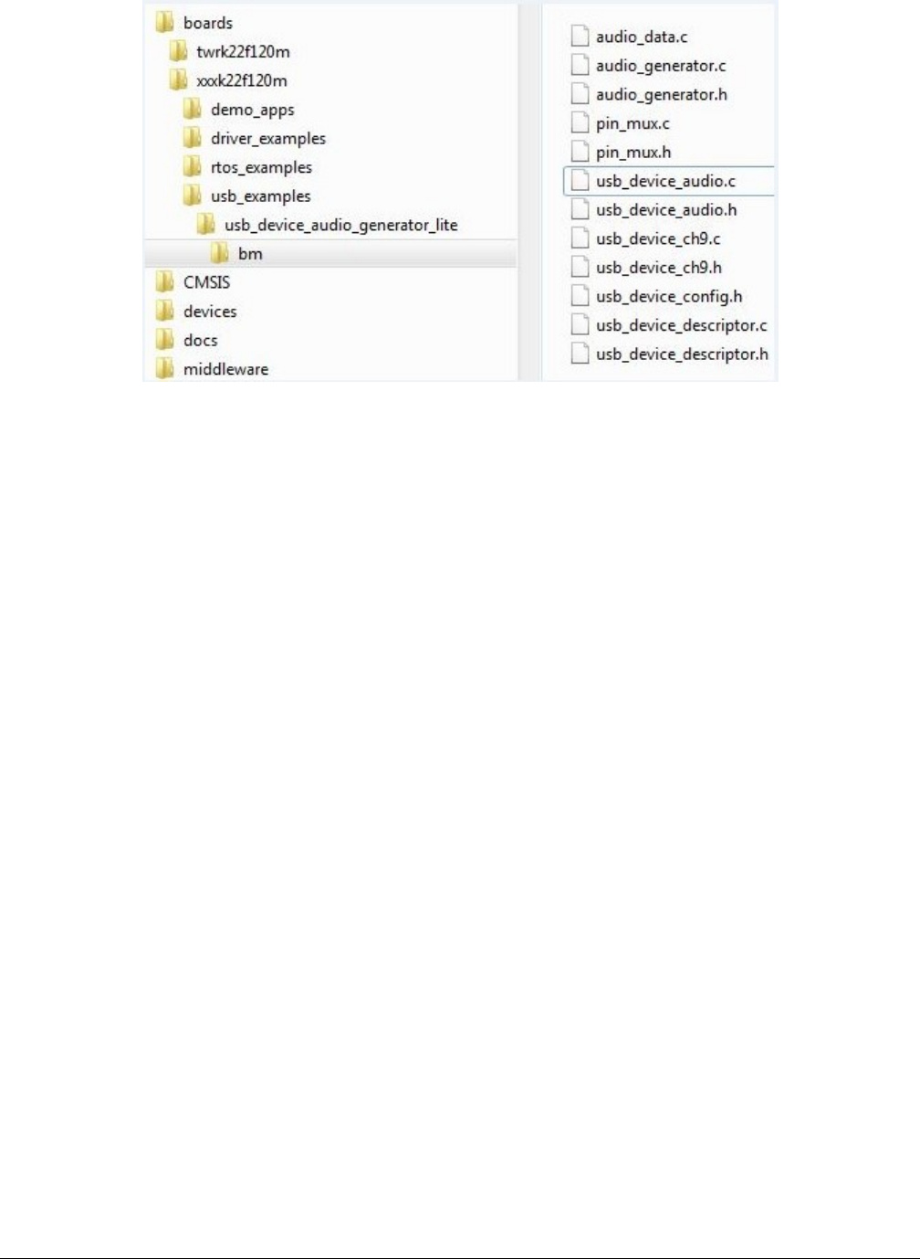
Figure 26. Example-related port pin configuration files
Ensure the BOARD_InitPins function is implemented in the pin_mux.c file. In this function, the port clock and pin mux are initialized.
Ensure that the BOARD_InitHardware calls the function. The BOARD_InitHardware function will be introduced later.
For example, on the TWR-K65F180M board, the VBUS of the USB Host is controlled by the PORTD_8 as a GPIO. Therefore, the
PORTD clock needs to be enabled first and then the PORTD_8 configured to GPIO functionality. The debug console uses UART2.
The TX/RX pins are PORTE_16 and PORTE_17. As a result, the clock of PORTE needs to be enabled first and then the PORTE_16
and PORTE_17 configured to alternative 3.
This is example code for TWR-K65F180M:
void BOARD_InitPins(void)
{
/* Initialize UART2 pins below */
CLOCK_EnableClock(kCLOCK_PortE);
PORT_SetPinMux(PORTE, 16u, kPORT_MuxAlt3);
PORT_SetPinMux(PORTE, 17u, kPORT_MuxAlt3);
/* Initialize usb vbus pin */
CLOCK_EnableClock(kCLOCK_PortD);
PORT_SetPinMux(PORTD, 8u, kPORT_MuxAsGpio);
}
Check the specific board design to find out which port is used to control the USB VBUS and which port is used for the debug
console. For example, in the customer’s board design, the PORTC_15 is used to control the USB VBUS, and PORTD_1 and
PORTD_2 is used for debug console. The following shows the example code:
void BOARD_InitPins(void)
{
/* Initialize UART2 pins below */
CLOCK_EnableClock(kCLOCK_PortD);
PORT_SetPinMux(PORTD, 1u, kPORT_MuxAlt3);
PORT_SetPinMux(PORTD, 2u, kPORT_MuxAlt3);
/* Initialize usb vbus pin */
CLOCK_EnableClock(kCLOCK_PortC);
PORT_SetPinMux(PORTC, 15u, kPORT_MuxAsGpio);
}
The VBUS must output high. The following is example code for TWR-K65F180M:
void BOARD_InitHardware(void)
{
gpio_pin_config_t pinConfig;
BOARD_InitPins();
Porting to a new platform
MCUXpresso SDK USB Stack User’s Guide, Revision 8, May 2018
28 NXP Semiconductors
BOARD_BootClockRUN();
BOARD_InitDebugConsole();
/* vbus gpio output high */
pinConfig.pinDirection = kGPIO_DigitalOutput;
pinConfig.outputLogic = 1U;
GPIO_PinInit(PTD, 8U, &pinConfig);
}
The user can change the function as follows:
void BOARD_InitHardware(void)
{
gpio_pin_config_t pinConfig;
BOARD_InitPins();
BOARD_BootClockxxx();
BOARD_InitDebugConsole();
/* vbus gpio output high */
pinConfig.pinDirection = kGPIO_DigitalOutput;
pinConfig.outputLogic = 1U;
GPIO_PinInit(PTC, 15U, &pinConfig);
}
3.3.3 Modify the example project
USB example project files are kept in the example directory, as shown in the following figure.
Figure 27. Modify the example project
1. Open the project and change the SoC.
a. Check the project SoC and update to the porting platform SoC.
b. Update the SoC full name, platform name, and board type name macros if the SoC is updated. For example,
for TWR-K22F120M, update the CPU_MK22FN512VDC12, TWR_K22F120M, and TOWER macros.
NOTE
2. Check the files in startup group, for example (IAR):
Porting examples
MCUXpresso SDK USB Stack User’s Guide, Revision 8, May 2018
NXP Semiconductors 29
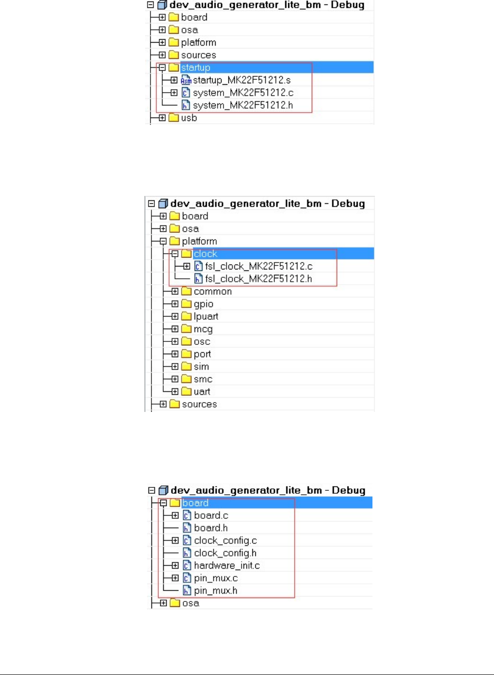
Figure 28. Check files in startup group
Ensure that the system_MK22F51212.c, system_MK22F51212.h, and strtup_MK22F51212.s are the porting SoC files. Also
change the include path.
3. Check the files in the platform/clock group, for example (IAR):
Figure 29. Check files in platform/clock group
Ensure that the fsl_clock_MK22F51212.c, and fsl_clock_MK22F51212.h are porting SoC files. Additionally, change the
include path.
4. Change the files in board group, for example (IAR):
Figure 30. Change files in board group
Porting to a new platform
MCUXpresso SDK USB Stack User’s Guide, Revision 8, May 2018
30 NXP Semiconductors
Ensure that board.c, board.h, clock_config.c, and clock_config.h are porting platform files. Additionally, change the include
path.
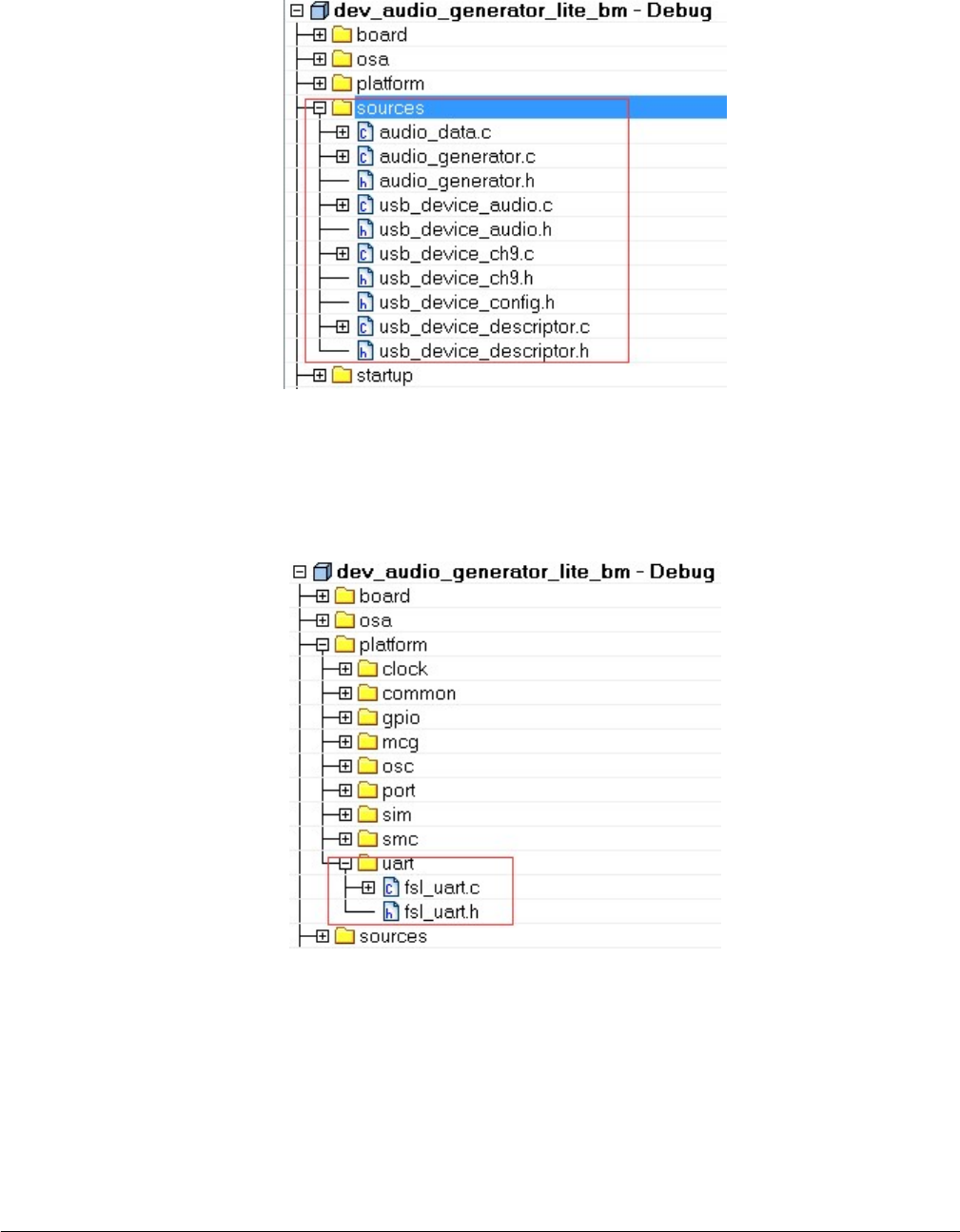
5. Check the files in the sources group, for example (IAR):
Figure 31. Check files in source group
The example application source files are copied when copying the example directory. Change the include path.
6. Change the linker file to the new platform. Ensure that the linker file is the porting SoC file.
7. Debug console may use UART, LPUART, or LPSCI according to the platform. As a result, the example project needs to
contain UART, LPUART, or LPSCI driver files according to the platform.
Figure 32. UART, LPUART, and LPSCI files
For example, for TWR-K22F120M all UART files are all in the project. In another example, TWR-K80F150M, all LPUART
files are in the project.
3.3.4 USB host CDC example
The MCUXpresso SDK debug console can be based on The MCUXpresso SDK UART, LPUART, or LPSCI driver. Because
different platforms may use different drivers, the CDC has a wrapper code. The files, which call the corresponding driver API
Porting examples
MCUXpresso SDK USB Stack User’s Guide, Revision 8, May 2018
NXP Semiconductors 31

according to the debug console use UART, LPUART, or LPSCI. The utility uses the BOARD_DEBUG_UART_TYPE toidentify the
UART type. To use a different UART instance, use the corresponding UART instance wrapper file.
The MCUXpresso SDK debug console only enables send. The Host CDC example needs the receive function. Therefore,
configuration MACROs need to be defined in the board.h file. The debug console and the Host CDC share the same configuration.
This is an example:
#define BOARD_DEBUG_UART_TYPE DEBUG_CONSOLE_DEVICE_TYPE_UART
#define BOARD_DEBUG_UART_BASEADDR (uint32_t)UART1
#define BOARD_DEBUG_UART_CLKSRC kCLOCK_CoreSysClk
#define BOARD_DEBUG_UART_BAUDRATE 115200
Update MACROs according to board design. For example, the default UART instance on the board is LPUART1, the type of default
UART instance on one specific platform is LPUART, and the LPUART clock source is the external clock. In this case, change the
above MACROs as follows:
#define BOARD_DEBUG_UART_TYPE DEBUG_CONSOLE_DEVICE_TYPE_LPUART
#define BOARD_DEBUG_UART_BASEADDR (uint32_t) LPUART1
#define BOARD_DEBUG_UART_CLKSRC kCLOCK_Osc0ErClk
#define BOARD_DEBUG_UART_BAUDRATE 115200
3.3.5 USB device MSC SD card example
USB device MSC SD card example needs SDHC driver support and SD card support. The example works only if the platform
supports both SD card and the SDHC. To enable this example using the same code, the following MACROs are defined in the
board.h file:
#define BOARD_SDHC_BASEADDR SDHC
#define BOARD_SDHC_CLKSRC kCLOCK_CoreSysClk
#define BOARD_SDHC_CD_GPIO_BASE GPIOB
#define BOARD_SDHC_CD_GPIO_PIN 20U
#define BOARD_SDHC_CD_PORT_BASE PORTB
#define BOARD_SDHC_CD_PORT_IRQ PORTB_IRQn
#define BOARD_SDHC_CD_PORT_IRQ_HANDLER PORTB_IRQHandler
Update the MACROs according to the board design. For example, the SD card detection GPIO on the board is PORTD_1. In this
case, change the above MACROs as follows:
#define BOARD_SDHC_BASEADDR SDHC
#define BOARD_SDHC_CLKSRC kCLOCK_CoreSysClk
#define BOARD_SDHC_CD_GPIO_BASE GPIOD
#define BOARD_SDHC_CD_GPIO_PIN 1U
#define BOARD_SDHC_CD_PORT_BASE PORTD
#define BOARD_SDHC_CD_PORT_IRQ PORTD_IRQn
#define BOARD_SDHC_CD_PORT_IRQ_HANDLER PORTD_IRQHandler
3.3.6 USB device audio speaker example
USB device audio speaker example needs the I2C, SAI, and DMA driver support.
The instance of SAI (I2S) and I2C are defined in the app.h file in the example directory as follows:
#define DEMO_SAI I2S0
#define DEMO_I2C I2C0
#define DEMO_SAI_CLKSRC kCLOCK_CoreSysClk
Update the MACROs according to board design. For example, the I2S instance on the board is I2S2. In this case, change the
above MACROs as follows:
#define DEMO_SAI I2S2
#define DEMO_I2C I2C2
#define DEMO_SAI_CLKSRC kCLOCK_CoreSysClk
Porting to a new platform
MCUXpresso SDK USB Stack User’s Guide, Revision 8, May 2018
32 NXP Semiconductors

3.3.7 USB device CCID Smart card example
The example is based on the EMVL1 stack, which works on the EMV protocol. As a result, the example can only be ported to the
platform that supports both the EMVL1 stack and the EMV protocol.
Porting examples
MCUXpresso SDK USB Stack User’s Guide, Revision 8, May 2018
NXP Semiconductors 33

Chapter 4
Developing a new USB application
The following sections provide information regarding how to develop a new USB application.
4.1 Developing a new USB device application
This chapter introduces how to develop a new USB device application. The user needs to use the application interface and the
following steps to develop a new application.
4.1.1 Application interfaces
The interface definition between the application and the classes includes the calls shown in the following table:
Table 2. Application and classes interface definition
API Call Description
Class Initialization This API is used to initialize the class.
Receive Data This API is used by the application to receive data from the host
system.
Send Data This API is used by the application to send data to the host
system.
USB descriptor-related callback Handles the callback to get the descriptor.
USB Device call back function Handles the callback by the class driver to inform the
application about various USB bus events.
USB Class-specific call back function Handles the specific callback of the class.
4.1.2 How to develop a new device application
Perform these steps to develop a new device application:
1. Create a new application directory under <install_dir>/boards/<board>/usb_examples/
usb_device_<class>_<application> to locate the application source files and header files. For example,
<install_dir>/boards/<board>/usb_examples/usb_device_hid_test.
2. Copy the following files from the similar existing applications to the application directory that is created in Step 1.
usb_device_descriptor.c
usb_device_descriptor.h
The usb_device_descriptor.c and usb_device_descriptor.h files contain the USB descriptors that are dependent on
the application and the class driver.
3. Copy the bm directory from the similar existing application directory to the new application directory. Remove the unused
project directory from the bm directory. Modify the project directory name to the new application project name. For example,
to create toolchain-IAR, board-frdmk64 class-hid related application, create the new application hid_test
based on a similar existing application hid_mouse.
Change <install_dir>/boards/<board>/usb_examples/usb_device_hid_mouse to <install_dir>/boards/
<board>/usb_examples/usb_device_hid_test
Developing a new USB application
MCUXpresso SDK USB Stack User’s Guide, Revision 8, May 2018
34 NXP Semiconductors
4. Modify the project file name to the new application project file name, for example, from dev_hid_mouse_bm.ewp to
dev_hid_test_bm.ewp. Globally replace the existing name to the new project name by editing the project files. The
dev_hid_test_bm.ewp file includes the new application project setting.
5. Create a new source file to implement the main application functions and callback functions. The name of this file is similar
to the new application name, such as mouse.c and keyboard.c.
The following sections describe the steps to change application files created in the steps above to match the new application.
4.1.2.1 Changing the usb_device_descriptor.c file
This file contains the class driver interface. It also contains USB standard descriptors such as device descriptor, configuration
descriptor, string descriptor, and the other class-specific descriptors that are provided to class driver when required.
The lists below show user-modifiable variable types for an already implemented class driver. The user should also modify the
corresponding MACROs defined in the usb_device_descriptor.h file. See the MCUXpresso SDK API Reference Manual
(document MCUXSDKAPIRM) for details.
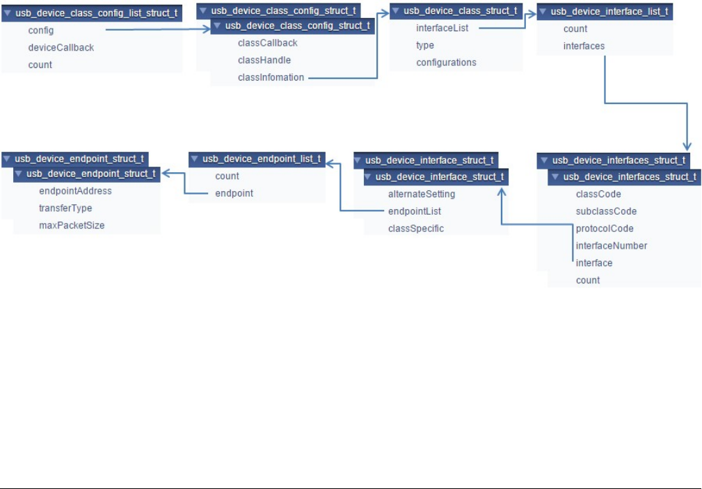
• usb_device_endpoint_struct_t;
• usb_device_endpoint_list_t;
• usb_device_interface_struct_t;
• usb_device_interfaces_struct_t;
• usb_device_interface_list_t;
• usb_device_class_struct_t;
• usb_device_class_config_struct_t;
• usb_device_class_config_list_struct_t;
This diagram shows the relationship between these items:
Figure 33. Relationship diagram
This is the sample code implementation of the endpoint descriptor for the HID class:
/* HID mouse endpoint information */
usb_device_endpoint_struct_t g_UsbDeviceHidMouseEndpoints[USB_HID_MOUSE_ENDPOINT_COUNT] =
{
/* HID mouse interrupt IN pipe */
{
USB_HID_MOUSE_ENDPOINT_IN | (USB_IN <<
USB_DESCRIPTOR_ENDPOINT_ADDRESS_DIRECTION_SHIFT),
Developing a new USB device application
MCUXpresso SDK USB Stack User’s Guide, Revision 8, May 2018
NXP Semiconductors 35

USB_ENDPOINT_INTERRUPT,
FS_HID_MOUSE_INTERRUPT_IN_PACKET_SIZE,
},
};
The endpoint address, transfer type, and max packet size in this variable are defined in the usb_device_descriptor.h file. The user
may change these value as required. For example, to implement a CDC class application:
/* Define endpoint for a communication class */
usb_device_endpoint_struct_t g_UsbDeviceCdcVcomCicEndpoints[USB_CDC_VCOM_ENDPOINT_CIC_COUNT]
= {
{
USB_CDC_VCOM_INTERRUPT_IN_ENDPOINT | (USB_IN << 7U), USB_ENDPOINT_INTERRUPT,
FS_CDC_VCOM_INTERRUPT_IN_PACKET_SIZE,
},
};
/* Define endpoint for data class */
usb_device_endpoint_struct_t g_UsbDeviceCdcVcomDicEndpoints[USB_CDC_VCOM_ENDPOINT_DIC_COUNT]
= {
{
USB_CDC_VCOM_BULK_IN_ENDPOINT | (USB_IN << 7U), USB_ENDPOINT_BULK,
FS_CDC_VCOM_BULK_IN_PACKET_SIZE,
},
{
USB_CDC_VCOM_BULK_OUT_ENDPOINT | (USB_OUT << 7U), USB_ENDPOINT_BULK,
FS_CDC_VCOM_BULK_OUT_PACKET_SIZE,
}
};
The endpoint count and alternate setting of the interface may differ in various applications. The user may change these values
as required. For example, the interface structure of a CDC class application is as follows:
/* Define interface for communication class */
usb_device_interface_struct_t g_UsbDeviceCdcVcomCommunicationInterface[] = {{
1U,
{
USB_CDC_VCOM_ENDPOINT_CIC_COUNT, g_UsbDeviceCdcVcomCicEndpoints,
},
}};
/* Define interface for data class */
usb_device_interface_struct_t g_UsbDeviceCdcVcomDataInterface[] =
{
{
0,
{
USB_CDC_VCOM_ENDPOINT_DIC_COUNT,
g_UsbDeviceCdcVcomDicEndpoints,
},
NULL
}
};
The class code, subclass code, and protocol code may differ in various classes. For example, the usb_device_interfaces_struct
of a CDC class is as follows:
/* Define interfaces for the virtual com */
usb_device_interfaces_struct_t g_UsbDeviceCdcVcomInterfaces[USB_CDC_VCOM_INTERFACE_COUNT] = {
{USB_CDC_VCOM_CIC_CLASS, USB_CDC_VCOM_CIC_SUBCLASS, USB_CDC_VCOM_CIC_PROTOCOL,
USB_CDC_VCOM_COMM_INTERFACE_INDEX,
g_UsbDeviceCdcVcomCommunicationInterface,
sizeof(g_UsbDeviceCdcVcomCommunicationInterface) /
sizeof(usb_device_interfaces_struct_t)},
{USB_CDC_VCOM_DIC_CLASS, USB_CDC_VCOM_DIC_SUBCLASS, USB_CDC_VCOM_DIC_PROTOCOL,
USB_CDC_VCOM_DATA_INTERFACE_INDEX,
g_UsbDeviceCdcVcomDataInterface, sizeof(g_UsbDeviceCdcVcomDataInterface) /
sizeof(usb_device_interfaces_struct_t)},
};
Developing a new USB application
MCUXpresso SDK USB Stack User’s Guide, Revision 8, May 2018
36 NXP Semiconductors

The interface count may differ in various applications. For example, the usb_device_interface_list of a CDC class application is
as follows:
/* Define configurations for virtual com */
usb_device_interface_list_t g_UsbDeviceCdcVcomInterfaceList[USB_DEVICE_CONFIGURATION_COUNT]
= {
{
USB_CDC_VCOM_INTERFACE_COUNT, g_UsbDeviceCdcVcomInterfaces,
},
};
The interface list, class type and configuration count may differ in various applications. For example, the usb_device_class_struct
of a CDC class application is as follows:
/* Define class information for virtual com */
usb_device_class_struct_t g_UsbDeviceCdcVcomConfig = {
g_UsbDeviceCdcVcomInterfaceList, kUSB_DeviceClassTypeCdc, USB_DEVICE_CONFIGURATION_COUNT,
};
• g_UsbDeviceDescriptor
This variable contains the USB Device Descriptor.
Sample code implementation of the device descriptor for the HID class is shown as follows:
uint8_t g_UsbDeviceDescriptor[USB_DESCRIPTOR_LENGTH_DEVICE] =
{
USB_DESCRIPTOR_LENGTH_DEVICE, /* Size of this descriptor in bytes */
USB_DESCRIPTOR_TYPE_DEVICE, /* DEVICE Descriptor Type */
USB_SHORT_GET_LOW(USB_DEVICE_SPECIFIC_BCD_VERSION),
USB_SHORT_GET_HIGH(USB_DEVICE_SPECIFIC_BCD_VERSION),/* USB Specification Release
Number in
Binary-Coded Decimal (i.e., 2.10
is 210H). */
USB_DEVICE_CLASS, /* Class code (assigned by the USB-IF). */
USB_DEVICE_SUBCLASS, /* Subclass code (assigned by the USB-IF). */
USB_DEVICE_PROTOCOL, /* Protocol code (assigned by the USB-IF). */
USB_CONTROL_MAX_PACKET_SIZE, /* Maximum packet size for endpoint zero
(only 8, 16, 32, or 64 are valid) */
0xA2U, 0x15U, /* Vendor ID (assigned by the USB-IF) */
0x7CU, 0x00U, /* Product ID (assigned by the manufacturer) */
USB_SHORT_GET_LOW(USB_DEVICE_DEMO_BCD_VERSION),
USB_SHORT_GET_HIGH(USB_DEVICE_DEMO_BCD_VERSION),/* Device release number in binary-
coded decimal */
0x01U, /* Index of string descriptor describing manufacturer */
0x02U, /* Index of string descriptor describing product */
0x00U, /* Index of string descriptor describing the
device serial number */
USB_DEVICE_CONFIGURATION_COUNT, /* Number of possible configurations */
};
The macros in the variable above are defined in the usb_device_descriptor.h file, such as the USB_DEVICE_CLASS,
USB_DEVICE_SUBCLASS, and USB_DEVICE_PROTOCOL. Those values may need to be modified as required. The vendor
ID and product ID can also be modified.
• g_UsbDeviceConfigurationDescriptor
This variable contains the USB Configuration Descriptor.
Sample code implementation of the configuration descriptor for the HID class is providing in the following:
uint8_t g_UsbDeviceConfigurationDescriptor[USB_DESCRIPTOR_LENGTH_CONFIGURATION_ALL] =
{
USB_DESCRIPTOR_LENGTH_CONFIGURE, /* Size of this descriptor in bytes */
USB_DESCRIPTOR_TYPE_CONFIGURE, /* CONFIGURATION Descriptor Type */
USB_SHORT_GET_LOW(USB_DESCRIPTOR_LENGTH_CONFIGURATION_ALL),
USB_SHORT_GET_HIGH(USB_DESCRIPTOR_LENGTH_CONFIGURATION_ALL),/* Total length of data
returned for this configuration. */
USB_HID_MOUSE_INTERFACE_COUNT, /* Number of interfaces supported by this configuration
*/
USB_HID_MOUSE_CONFIGURE_INDEX, /* Value to use as an argument to the
Developing a new USB device application
MCUXpresso SDK USB Stack User’s Guide, Revision 8, May 2018
NXP Semiconductors 37

SetConfiguration() request to select this configuration
*/
0x00U, /* Index of string descriptor describing this
configuration */
(USB_DESCRIPTOR_CONFIGURE_ATTRIBUTE_D7_MASK) |
(USB_DEVICE_CONFIG_SELF_POWER << USB_DESCRIPTOR_CONFIGURE_ATTRIBUTE_SELF_POWERED_SHIFT)
|
(USB_DEVICE_CONFIG_REMOTE_WAKEUP <<
USB_DESCRIPTOR_CONFIGURE_ATTRIBUTE_REMOTE_WAKEUP_SHIFT),
/* Configuration characteristics
D7: Reserved (set to one)
D6: Self-powered
D5: Remote Wakeup
D4...0: Reserved (reset to zero)
*/
USB_DEVICE_MAX_POWER, /* Maximum power consumption of the USB
* device from the bus in this specific
* configuration when the device is fully
* operational. Expressed in 2 mA units
* (i.e., 50 = 100 mA).
*/
The macro USB_DESCRIPTOR_LENGTH_CONFIGURATION_ALL, which is defined in the usb_device_descriptor.h, needs to
be modified to equal the size of this variable. The interface count and configuration index may differ in various applications. For
example, this part of a CDC class application is as shown below:
/* Size of this descriptor in bytes */
USB_DESCRIPTOR_LENGTH_CONFIGURE,
/* CONFIGURATION Descriptor Type */
USB_DESCRIPTOR_TYPE_CONFIGURE,
/* Total length of data returned for this configuration. */
USB_SHORT_GET_LOW(USB_DESCRIPTOR_LENGTH_CONFIGURATION_ALL),
USB_SHORT_GET_HIGH(USB_DESCRIPTOR_LENGTH_CONFIGURATION_ALL),
/* Number of interfaces supported by this configuration */
USB_CDC_VCOM_INTERFACE_COUNT,
/* Value to use as an argument to the SetConfiguration() request to select this
configuration */
USB_CDC_VCOM_CONFIGURE_INDEX,
/* Index of string descriptor describing this configuration */
0,
/* Configuration characteristics D7: Reserved (set to one) D6: Self-powered D5: Remote
Wakeup D4...0: Reserved
(reset to zero) */
(USB_DESCRIPTOR_CONFIGURE_ATTRIBUTE_D7_MASK) |
(USB_DEVICE_CONFIG_SELF_POWER <<
USB_DESCRIPTOR_CONFIGURE_ATTRIBUTE_SELF_POWERED_SHIFT) |
(USB_DEVICE_CONFIG_REMOTE_WAKEUP <<
USB_DESCRIPTOR_CONFIGURE_ATTRIBUTE_REMOTE_WAKEUP_SHIFT),
/* Maximum power consumption of the USB * device from the bus in this specific *
configuration when the device is
fully * operational. Expressed in 2 mA units * (i.e., 50 = 100 mA). */
USB_DEVICE_MAX_POWER,
The interface descriptor may differ from various applications. For example, the interface descriptor of a CDC class application
would be as shown below.
/* Communication Interface Descriptor */
USB_DESCRIPTOR_LENGTH_INTERFACE, USB_DESCRIPTOR_TYPE_INTERFACE,
USB_CDC_VCOM_COMM_INTERFACE_INDEX, 0x00,
USB_CDC_VCOM_ENDPOINT_CIC_COUNT, USB_CDC_VCOM_CIC_CLASS, USB_CDC_VCOM_CIC_SUBCLASS,
USB_CDC_VCOM_CIC_PROTOCOL,
0x00, /* Interface Description String Index*/
The class specific descriptor may differ from various applications. For example, the class specific descriptor of a CDC class
application would be as shown below.
/* CDC Class-Specific descriptor */
USB_DESCRIPTOR_LENGTH_CDC_HEADER_FUNC, /* Size of this descriptor in bytes */
USB_DESCRIPTOR_TYPE_CDC_CS_INTERFACE, /* CS_INTERFACE Descriptor Type */
HEADER_FUNC_DESC, 0x10,
Developing a new USB application
MCUXpresso SDK USB Stack User’s Guide, Revision 8, May 2018
38 NXP Semiconductors

0x01, /* USB Class Definitions for Communications the Communication specification version
1.10 */
USB_DESCRIPTOR_LENGTH_CDC_CALL_MANAG, /* Size of this descriptor in bytes */
USB_DESCRIPTOR_TYPE_CDC_CS_INTERFACE, /* CS_INTERFACE Descriptor Type */
CALL_MANAGEMENT_FUNC_DESC,
0x01, /*Bit 0: Whether device handle call management itself 1, Bit 1: Whether device can
send/receive call
management information over a Data Class Interface 0 */
0x01, /* Indicates multiplexed commands are handled via data interface */
USB_DESCRIPTOR_LENGTH_CDC_ABSTRACT, /* Size of this descriptor in bytes */
USB_DESCRIPTOR_TYPE_CDC_CS_INTERFACE, /* CS_INTERFACE Descriptor Type */
USB_CDC_ABSTRACT_CONTROL_FUNC_DESC,
0x06, /* Bit 0: Whether device supports the request combination of Set_Comm_Feature,
Clear_Comm_Feature, and
Get_Comm_Feature 0, Bit 1: Whether device supports the request combination of
Set_Line_Coding,
Set_Control_Line_State, Get_Line_Coding, and the notification Serial_State 1,
Bit ... */
USB_DESCRIPTOR_LENGTH_CDC_UNION_FUNC, /* Size of this descriptor in bytes */
USB_DESCRIPTOR_TYPE_CDC_CS_INTERFACE, /* CS_INTERFACE Descriptor Type */
USB_CDC_UNION_FUNC_DESC, 0x00, /* The interface number of the Communications or
Data Class interface */
0x01, /* Interface number of subordinate interface in the
Union */
The endpoint descriptor may differ from various applications. For example, the endpoint descriptor of a CDC class application is
as follows:
/*Notification Endpoint descriptor */
USB_DESCRIPTOR_LENGTH_ENDPOINT, USB_DESCRIPTOR_TYPE_ENDPOINT,
USB_CDC_VCOM_INTERRUPT_IN_ENDPOINT | (USB_IN << 7U),
USB_ENDPOINT_INTERRUPT, USB_SHORT_GET_LOW(FS_CDC_VCOM_INTERRUPT_IN_PACKET_SIZE),
USB_SHORT_GET_HIGH(FS_CDC_VCOM_INTERRUPT_IN_PACKET_SIZE),
FS_CDC_VCOM_INTERRUPT_IN_INTERVAL,
}
• String Descriptors
Users can modify string descriptors to customize their product. String descriptors are written in the UNICODE format. An
appropriate language identification number is specified in the USB_STR_0. Multiple language support can also be added.
• USB_DeviceGetDeviceDescriptor
This interface function is invoked by the application. This call is made when the application receives the
kUSB_DeviceEventGetDeviceDescriptor event from the Host. Mandatory descriptors that an application is required to
implement are as follows:
— Device Descriptor
— Configuration Descriptor
— Class-Specific Descriptors (For example, for HID class implementation, Report Descriptor, and HID Descriptor)
Apart from the mandatory descriptors, an application should also implement various string descriptors as specified by the
Device Descriptor and other configuration descriptors.
Sample code for HID class application is as follows:
/* Get device descriptor request */
usb_status_t USB_DeviceGetDeviceDescriptor(usb_device_handle handle,
usb_device_get_device_descriptor_struct_t
*deviceDescriptor)
{
deviceDescriptor->buffer = g_UsbDeviceDescriptor;
deviceDescriptor->length = USB_DESCRIPTOR_LENGTH_DEVICE;
return kStatus_USB_Success;
}
Developing a new USB device application
MCUXpresso SDK USB Stack User’s Guide, Revision 8, May 2018
NXP Semiconductors 39

The user may assign the appropriate variable of the device descriptor. For example, if the device descriptor variable name is
g_UsbDeviceDescriptorUser, the sample code is as follows:
/* Get device descriptor request */
usb_status_t USB_DeviceGetDeviceDescriptor(usb_device_handle handle,
usb_device_get_device_descriptor_struct_t
*deviceDescriptor)
{
deviceDescriptor->buffer = g_UsbDeviceDescriptorUser;
deviceDescriptor->length = USB_DESCRIPTOR_LENGTH_DEVICE;
return kStatus_USB_Success;
}
• USB_DeviceGetConfigurationDescriptor
This interface function is invoked by the application. This call is made when the application receives the
kUSB_DeviceEventGetConfigurationDescriptor event from the Host.
/* Get device configuration descriptor request */
usb_status_t USB_DeviceGetConfigurationDescriptor(
usb_device_handle handle, usb_device_get_configuration_descriptor_struct_t
*configurationDescriptor)
{
if (USB_HID_MOUSE_CONFIGURE_INDEX > configurationDescriptor->configuration)
{
configurationDescriptor->buffer = g_UsbDeviceConfigurationDescriptor;
configurationDescriptor->length = USB_DESCRIPTOR_LENGTH_CONFIGURATION_ALL;
return kStatus_USB_Success;
}
return kStatus_USB_InvalidRequest;
}
The macro HID_MOUSE_CONFIGURE_INDEX may differ from various applications. For example, the implementation of a CDC
class application would be as follows:
usb_status_t USB_DeviceGetConfigurationDescriptor(
usb_device_handle handle, usb_device_get_configuration_descriptor_struct_t
*configurationDescriptor)
{
if (USB_CDC_VCOM_CONFIGURE_INDEX > configurationDescriptor->configuration)
{
configurationDescriptor->buffer = g_UsbDeviceConfigurationDescriptor;
configurationDescriptor->length = USB_DESCRIPTOR_LENGTH_CONFIGURATION_ALL;
return kStatus_USB_Success;
}
return kStatus_USB_InvalidRequest;
}
• USB_DeviceGetStringDescriptor
This interface function is invoked by the application. This call is made when the application receives the
kUSB_DeviceEventGetStringDescriptor event from the Host.
See the usb_device_hid_mouse example for sample code.
• USB_DeviceGetHidReportDescriptor
This interface function is invoked by the application. This call is made when the application receives the
kUSB_DeviceEventGetHidReportDescriptor event from the Host.
See the usb_device_hid_mouse example for sample code.
• USB_DeviceSetSpeed
Because HS and FS descriptors are different, the device descriptors and configurations need to be updated to match the
current speed. By default, the device descriptors and configurations are configured using FS parameters for EHCI, KHCI,
and other controllers, such as LPC IP3511. When the EHCI is enabled, the application needs to call this function to update
the device by using the current speed. The updated information includes the endpoint max packet size, endpoint interval,
and so on.
Developing a new USB application
MCUXpresso SDK USB Stack User’s Guide, Revision 8, May 2018
40 NXP Semiconductors

4.1.2.2 Changing the usb_device_descriptor.h file
This file is mandatory for the application to implement. The usb_device_descriptor.c file includes this file for function prototype
definitions. When the user modifies the usb_device_descriptor.c, MACROs in this file should also be modified.
4.1.2.3 Changing the application file
•Main application function
The main application function is provided by two functions: USB_DeviceApplicationInit and APP_task (optional).
The USB_DeviceApplicationInit enables the clock and the USB interrupt and also initialize the specific USB class. See the
usb_device_hid_mouse example for the sample code.
•USB device call back function
The device callback function handles the USB device-specific requests. See the usb_device_hid_mouse example for the
sample code.
•USB Class-specific call back function
The class callback function handles the USB class-specific requests. See the usb_device_hid_mouse example for the sample
code.
4.2 Developing a New USB Host Application
4.2.1 Background
In the USB system, the host software controls the bus and talks to the target devices following the rules defined by the specification.
A device is represented by a configuration that is a collection of one or more interfaces. Each interface comprises one or more
endpoints. Each endpoint is represented as a logical pipe from the application software perspective.
The host application software registers a callback with the USB host stack, which notifies the application about the device attach/
detach events and determines whether the device is supported or not. The following figure shows the enumeration and detachment
flow.
Developing a New USB Host Application
MCUXpresso SDK USB Stack User’s Guide, Revision 8, May 2018
NXP Semiconductors 41
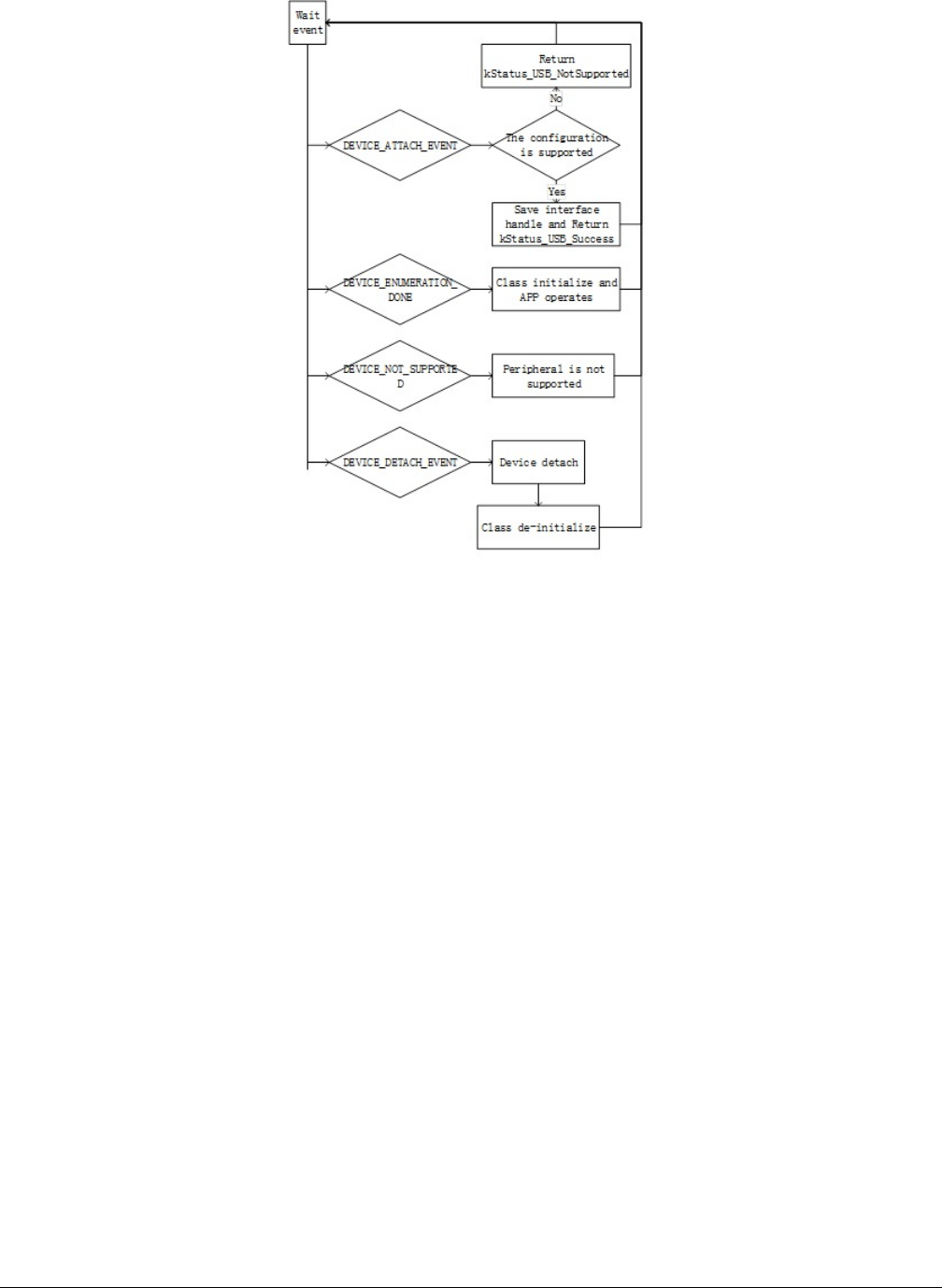
Figure 34. Enumeration and detachment flow
The USB host stack is a few lines of code executed before starting communication with the USB device. The examples on the
USB stack are written with class driver APIs. Class drivers work with the host API as a supplement to the functionality. They make
it easy to achieve the target functionality (see example sources for details) without dealing with the implementation of standard
routines. The following code steps are taken inside a host application driver for any specific device.
4.2.2 How to develop a new host application
4.2.2.1 Creating a project
Perform the following steps to create a project.
• Create a new application directory under <install_dir>/boards/<board>/usb_examples/
usb_host_<class>_<application> to locate the application source files and header files. For example, <install_dir>/
boards/<board>/usb_examples/usb_host_hid_mouse.
• Copy the following files from the similar existing applications to the application directory that is created in step 1.
app.c
usb_host_config.h
The app.c file contains the common initialization code for USB host and the usb_host_config.h file contains the configuration
MACROs for the USB host.
• Copy the bm directory from the similar existing application directory to the new application directory. Remove the unused
project directory from the bm directory. Modify the project directory name to the new application project name. For example,
to create toolchain-IAR, board-frdmk64 class-hid related application , create the new application hid_test
based on a similar existing application hid_mouse.
Copy <install_dir>/boards/frdmk64f/usb_examples/usb_host_hid_mouse/bm
Developing a new USB application
MCUXpresso SDK USB Stack User’s Guide, Revision 8, May 2018
42 NXP Semiconductors
to <install_dir>/boards/frdmk64f/usb_examples/usb_host_hid_test/bm
• Modify the project file name to the new application project file name, for example, from host_hid_mouse_bm.ewp to
host_hid_test_bm.ewp . Globally replace the existing name to the new project name by editing the project files. The
host_hid_test_bm.ewp file includes the new application project setting.
•Create a new source file to implement the main application function, application task function, and the callback function. The
name of this file is similar to the new application name, such as host_mouse.c and host_keyboard.c.
The following sections describe the steps to modify application files created in the steps above to match the new application.
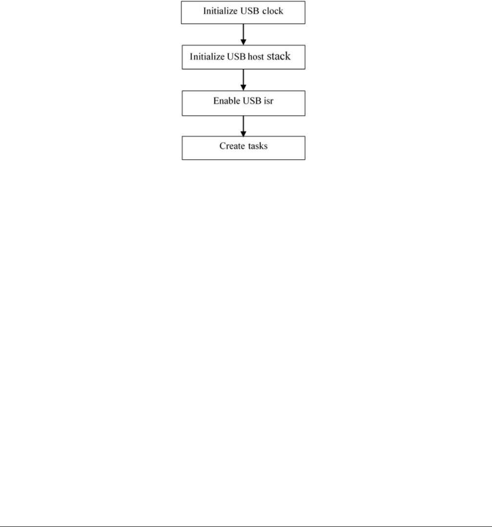
4.2.2.2 Main application function flow
In the main application function, follow these steps:
Figure 35. Main application function flow
• Initialize the USB clock.
Call the MCUXpresso SDK API to initialize the KHCI, or the EHCI USB clock.
• Initialize the host controller.
This allows the stack to initialize the necessary memory required to run the stack and register the callback function to the
stack.
For example:status = USB_HostInit(CONTROLLER_ID, &g_HostHandle, USB_HostEvent);
• Enable the USB ISR.
Set the USB interrupt priority and enable the USB interrupt.
• Initialize the host stack task and application task.
For example (Bare metal):
while (1)
{
#if (defined(USB_HOST_CONFIG_KHCI) && (USB_HOST_CONFIG_KHCI > 0U))
USB_HostKhciTaskFunction(g_HostHandle);
#endif /* USB_HOST_CONFIG_KHCI */
#if (defined(USB_HOST_CONFIG_EHCI) && (USB_HOST_CONFIG_EHCI > 0U))
USB_HostEhciTaskFunction(g_HostHandle);
#endif /* USB_HOST_CONFIG_EHCI */
USB_HostMsdTask(&g_MsdCommandInstance);
}
Note that in this code, the g_MsdCommandInstance variable contains all states and pointers used by the application to control
or operate the device. If implementing the application task as USB_HostHidTestTask and use g_HidTestInstance to maintain
the application states, modify the code as follows:
Developing a New USB Host Application
MCUXpresso SDK USB Stack User’s Guide, Revision 8, May 2018
NXP Semiconductors 43

while (1)
{
#if (defined(USB_HOST_CONFIG_KHCI) && (USB_HOST_CONFIG_KHCI > 0U))
USB_HostKhciTaskFunction(g_HostHandle);
#endif /* USB_HOST_CONFIG_KHCI */
#if (defined(USB_HOST_CONFIG_EHCI) && (USB_HOST_CONFIG_EHCI > 0U))
USB_HostEhciTaskFunction(g_HostHandle);
#endif /* USB_HOST_CONFIG_EHCI */
USB_HostHidTestTask(&g_HidTestInstance);
}
4.2.2.3 Event callback function
In the app.c file, there is one USB_HostEvent function. By default, the function is registered to the host stack when calling the
USB_HostInit. In the USB Host stack, customers do not have to write any enumeration code. When the device is connected to
the host controller, the USB Host stack enumerates the device. The device attach/detach events are notified by this callback
function.
Application needs to implement one or more functions to correspond to one class process. These application functions are called
in the USB_HostEvent. The device’s configuration handle and interface list are passed to the application through the function so
that the application can determine whether the device is supported by this application.
There are four events in the callback: kUSB_HostEventAttach, kUSB_HostEventNotSupported,
kUSB_HostEventEnumerationDone, and kUSB_HostEventDetach.
The events occur as follows:
• When one device is attached, host stack notifies kUSB_HostEventAttach.
•The application returns kStatus_USB_Success to notify the host stack that the device configuration is supported by this class
application, or return the kStatus_USB_NotSupported to notify the host stack that the device configuration is not supported
by this class application.
• The Host stack continues for enumeration if the device is supported by the application and notifies
kUSB_HostEventEnumerationDone when the enumeration is done.
• The Host stack checks the next device’s configuration if the current configuration is not supported by the application.
• When the Host stack checks all configurations and all are not supported by the application, it notifies the
kUSB_HostEventNotSupported.
• When the device detaches, the Host stack notifies the kUSB_HostEventDetach.
This is the sample code for the HID mouse application. The USB_HostHidMouseEvent function should be called bythe
USB_HostEvent. In this code, the g_HostHidMouse variable contains all states and pointers used by the application to control or
operate the device:
usb_status_t USB_HostHidMouseEvent
(
usb_device_handle deviceHandle,
usb_host_configuration_handle configurationHandle,
uint32_t eventCode
)
{
/* Process the same and supported device's configuration handle */
static usb_host_configuration_handle s_ConfigHandle = NULL;
usb_status_t status = kStatus_USB_Success;
uint8_t id;
usb_host_configuration_t *configuration;
uint8_t interfaceIndex;
usb_host_interface_t *interface;
switch (eventCode)
{
case kUSB_HostEventAttach:
/* judge whether is configurationHandle supported */
configuration = (usb_host_configuration_t *)configurationHandle;
Developing a new USB application
MCUXpresso SDK USB Stack User’s Guide, Revision 8, May 2018
44 NXP Semiconductors

for (interfaceIndex = 0; interfaceIndex < configuration->interfaceCount; +
+interfaceIndex)
{
interface = &configuration->interfaceList[interfaceIndex];
id = interface->interfaceDesc->bInterfaceClass;
if (id != USB_HOST_HID_CLASS_CODE)
{
continue;
}
id = interface->interfaceDesc->bInterfaceSubClass;
if ((id != USB_HOST_HID_SUBCLASS_CODE_NONE) && (id !=
USB_HOST_HID_SUBCLASS_CODE_BOOT))
{
continue;
}
id = interface->interfaceDesc->bInterfaceProtocol;
if (id != USB_HOST_HID_PROTOCOL_MOUSE)
{
continue;
}
else
{
/* the interface is supported by the application */
g_HostHidMouse.deviceHandle = deviceHandle;
g_HostHidMouse.interfaceHandle = interface;
s_ConfigHandle = configurationHandle;
return kStatus_USB_Success;
}
}
status = kStatus_USB_NotSupported;
break;
case kUSB_HostEventNotSupported:
break;
case kUSB_HostEventEnumerationDone:
if (s_ConfigHandle == configurationHandle)
{
if ((g_HostHidMouse.deviceHandle != NULL) && (g_HostHidMouse.interfaceHandle !
= NULL))
{
/* the device enumeration is done */
if (g_HostHidMouse.deviceState == kStatus_DEV_Idle)
{
g_HostHidMouse.deviceState = kStatus_DEV_Attached;
}
else
{
usb_echo("not idle mouse instance\r\n");
}
}
}
break;
case kUSB_HostEventDetach:
if (s_ConfigHandle == configurationHandle)
{
/* the device is detached */
s_ConfigHandle = NULL;
if (g_HostHidMouse.deviceState != kStatus_DEV_Idle)
{
g_HostHidMouse.deviceState = kStatus_DEV_Detached;
}
}
break;
default:
break;
}
return status;
}
Developing a New USB Host Application
MCUXpresso SDK USB Stack User’s Guide, Revision 8, May 2018
NXP Semiconductors 45

If implementing the callback as USB_HostHidTestEvent, use g_HidTestInstance, and support the device that the class code is
USB_HOST_HID_TEST_CLASS_CODE, sub-class code is USB_HOST_HID_TEST_SUBCLASS_CODE, and the protocol is
USB_HOST_HID_TEST_PROTOCOL. The code can be modified as follows:
usb_status_t USB_HostHidMouseEvent
(
usb_device_handle deviceHandle,
usb_host_configuration_handle configurationHandle,
uint32_t eventCode
)
{
/* Process the same and supported device's configuration handle */
static usb_host_configuration_handle s_ConfigHandle = NULL;
usb_status_t status = kStatus_USB_Success;
uint8_t id;
usb_host_configuration_t *configuration;
uint8_t interfaceIndex;
usb_host_interface_t *interface;
switch (eventCode)
{
case kUSB_HostEventAttach:
/* judge whether is configurationHandle supported */
configuration = (usb_host_configuration_t *)configurationHandle;
for (interfaceIndex = 0; interfaceIndex < configuration->interfaceCount; +
+interfaceIndex)
{
interface = &configuration->interfaceList[interfaceIndex];
id = interface->interfaceDesc->bInterfaceClass;
if (id != USB_HOST_HID_TEST_CLASS_CODE)
{
continue;
}
id = interface->interfaceDesc->bInterfaceSubClass;
if (id != USB_HOST_HID_TEST_SUBCLASS_CODE)
{
continue;
}
id = interface->interfaceDesc->bInterfaceProtocol;
if (id != USB_HOST_HID_TEST_PROTOCOL)
{
continue;
}
else
{
/* the interface is supported by the application */
g_HidTestInstance.deviceHandle = deviceHandle;
g_HidTestInstance.interfaceHandle = interface;
s_ConfigHandle = configurationHandle;
return kStatus_USB_Success;
}
}
status = kStatus_USB_NotSupported;
break;
case kUSB_HostEventNotSupported:
break;
case kUSB_HostEventEnumerationDone:
if (s_ConfigHandle == configurationHandle)
{
if ((g_HidTestInstance.deviceHandle != NULL) &&
(g_HidTestInstance.interfaceHandle != NULL))
{
/* the device enumeration is done */
if (g_HidTestInstance.deviceState == kStatus_DEV_Idle)
{
g_HidTestInstance.deviceState = kStatus_DEV_Attached;
}
else
{
Developing a new USB application
MCUXpresso SDK USB Stack User’s Guide, Revision 8, May 2018
46 NXP Semiconductors
usb_echo("not idle mouse instance\r\n");
}
}
}
break;
case kUSB_HostEventDetach:
if (s_ConfigHandle == configurationHandle)
{
/* the device is detached */
s_ConfigHandle = NULL;
if (g_HidTestInstance.deviceState != kStatus_DEV_Idle)
{
g_HidTestInstance.deviceState = kStatus_DEV_Detached;
}
}
break;
default:
break;
}
return status;
}
Note that the kStatus_DEV_Attached, kStatus_DEV_Detached MACROs are defined in the example.
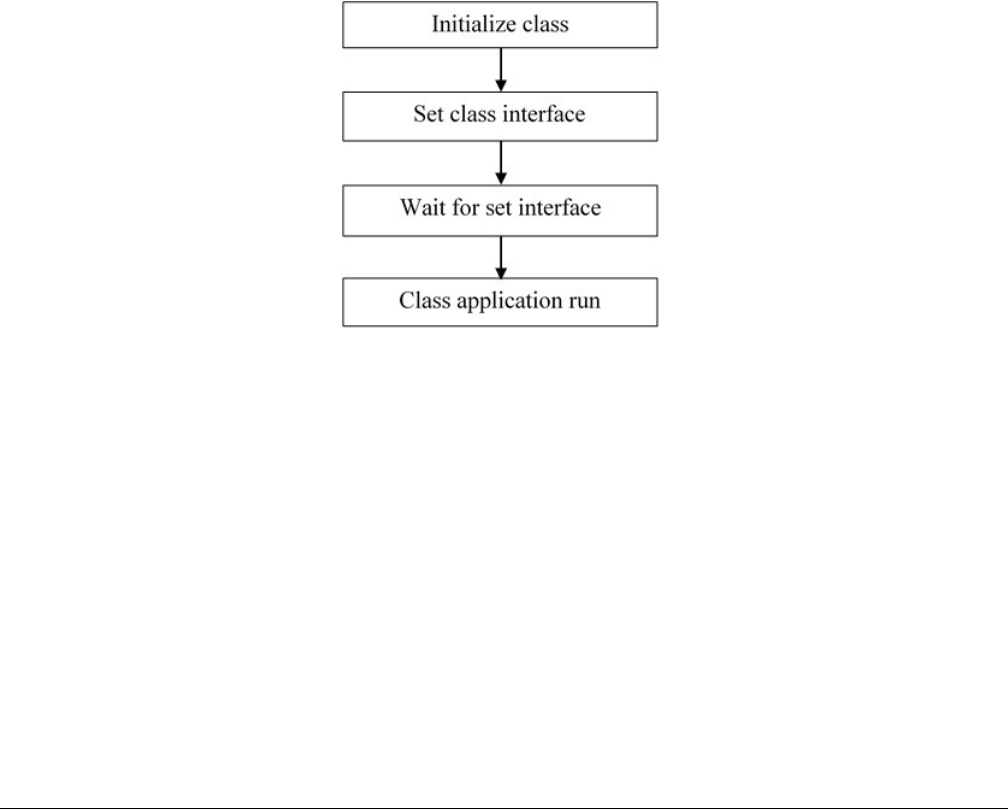
4.2.2.4 Class initialization
When the supported device is attached, the device’s class needs to be initialized.
For example, the HID mouse initialization flow is as follows:
Figure 36. HID mouse initialization flow
• Call class initialization function to initialize the class instance.
• Call class set interface function to set the class interface
• When the set interface callback returns successfully, the application can run.
4.2.2.5 Sending/Receiving data to/from the device
The transfer flow is as follows:
1. Call the USB_hostClassxxx API to begin the transfer.
2. The transfer result is notified by the callback function that is passed as a parameter.
3. The HID mouse host uses the following code to receive data from the device:USB_HostHidRecv(classHandle,
mouseBuffer, bufferLength, callbackFunction, callbackParameter);
Developing a New USB Host Application
MCUXpresso SDK USB Stack User’s Guide, Revision 8, May 2018
NXP Semiconductors 47

Chapter 5
USB compliance tests
For the device, this is enabled on "dev_hid_mouse_bm" as an example.
enable USB_DEVICE_CONFIG_USB20_TEST_MODE (0U)
The macro is defined in usb_device_config.h. Use the TWR-K65F180M Tower System module as an example. The file path is
<install_dir>/boards/twrk65f180m/usb_examples/usb_device_hid_mouse/bm/usb_device_config.h.
For the host, this is enabled on "host_mad_fatfs_bm" as an example.
enable USB_HOST_CONFIG_COMPLIANCE_TEST (0U)
The macro is defined in the usb_host_config.h file.
For example, for the TWR-K65F180M Tower System module, the file path is
<install_dir>/boards/twrk65f180m/usb_examples/usb_host_msd_fatfs/bm/usb_host_config.h
USB compliance tests
MCUXpresso SDK USB Stack User’s Guide, Revision 8, May 2018
48 NXP Semiconductors

Chapter 6
Revision history
This table summarizes revisions to this document since the release of the previous version.
Table 3. Revision history
Revision number Date Substantive changes
1 01/2016 KSDK 2.0.0 release
2 08/2016 Added LPC content for release
3 09/2016 Updated for KSDK 2.0.0 release 5
4 11/2016 Updated IAR version and USB code
structure version, Section 2.4.1 and
Section 2.4.2.
5 03/2017 Updated for MCUXpresso SDK
6 04/2017 Added note in Section 2.3
7 11/2017 MCUXpresso SDK 2.3.0 release
8 05/2018 Updated Section 4.1.2.1., "Changing
the usb_device_descriptor.c file"
Removed Section 2.3.4, "Step-by-step
guide for Kinetis Design Studio (KDS)
IDE", Updated for MCUXpresso SDK
2.4.0 release
MCUXpresso SDK USB Stack User’s Guide, Revision 8, May 2018
NXP Semiconductors 49

How To Reach Us
Home Page:
nxp.com
Web Support:
nxp.com/support
Information in this document is provided solely to enable system and software implementers to
use NXP products. There are no express or implied copyright licenses granted hereunder to
design or fabricate any integrated circuits based on the information in this document. NXP
reserves the right to make changes without further notice to any products herein.
NXP makes no warranty, representation, or guarantee regarding the suitability of its products for
any particular purpose, nor does NXP assume any liability arising out of the application or use
of any product or circuit, and specifically disclaims any and all liability, including without limitation
consequential or incidental damages. “Typical” parameters that may be provided in NXP data
sheets and/or specifications can and do vary in different applications, and actual performance
may vary over time. All operating parameters, including “typicals,” must be validated for each
customer application by customer's technical experts. NXP does not convey any license under
its patent rights nor the rights of others. NXP sells products pursuant to standard terms and
conditions of sale, which can be found at the following address: nxp.com/
SalesTermsandConditions.
NXP, the NXP logo, NXP SECURE CONNECTIONS FOR A SMARTER WORLD, All other
product or service names are the property of their respective owners. ARM, AMBA, ARM
Powered, are registered trademarks of ARM Limited (or its subsidiaries) in the EU and/or
elsewhere. All rights reserved.
Ⓒ 2018 NXP B.V.
