MIPS64 Architecture Volume II:The Instruction Set MD00086 MIPS® For Programmers II A: The MIPS32® Manual Rev
User Manual:
Open the PDF directly: View PDF ![]() .
.
Page Count: 463 [warning: Documents this large are best viewed by clicking the View PDF Link!]
- MIPS® Architecture for Programmers Volume II-A: The MIPS32® Instruction Set Manual
- Table of Contents
- List of Figures
- List of Tables
- About This Book
- Guide to the Instruction Set
- The MIPS32® Instruction Set
- 3.1 Compliance and Subsetting
- 3.2 Alphabetical List of Instructions
- ABS.fmt
- ADD
- ADD.fmt
- ADDI
- ADDIU
- ADDIUPC
- ADDU
- ALIGN
- ALNV.PS
- ALUIPC
- AND
- ANDI
- AUI
- AUIPC
- B
- BAL
- BALC
- BC
- BC1EQZ BC1NEZ
- BC1F
- BC1FL
- BC1T
- BC1TL
- BC2EQZ BC2NEZ
- BC2F
- BC2FL
- BC2T
- BC2TL
- BEQ
- BEQL
- BGEZ
- BGEZAL
- B{LE,GE,GT,LT,EQ,NE}ZALC
- BGEZALL
- B<cond>C
- BGEZL
- BGTZ
- BGTZL
- BITSWAP
- BLEZ
- BLEZL
- BLTZ
- BLTZAL
- BLTZALL
- BLTZL
- BNE
- BNEL
- BOVC BNVC
- BREAK
- C.cond.fmt
- CACHE
- CACHEE
- CEIL.L.fmt
- CEIL.W.fmt
- CFC1
- CFC2
- CLASS.fmt
- CLO
- CLZ
- CMP.condn.fmt
- COP2
- CTC1
- CTC2
- CVT.D.fmt
- CVT.L.fmt
- CVT.PS.S
- CVT.S.PL
- CVT.S.PU
- CVT.S.fmt
- CVT.W.fmt
- DDIV
- DDIVU
- DERET
- DI
- DIV
- DIV MOD DIVU MODU
- DIV.fmt
- DIVU
- DVP
- EHB
- EI
- ERET
- ERETNC
- EVP
- EXT
- FLOOR.L.fmt
- FLOOR.W.fmt
- INS
- J
- JAL
- JALR
- JALR.HB
- JALX
- JIALC
- JIC
- JR
- JR.HB
- LB
- LBE
- LBU
- LBUE
- LDC1
- LDC2
- LDXC1
- LH
- LHE
- LHU
- LHUE
- LL
- LLE
- LLWP
- LLWPE
- LSA
- LUI
- LUXC1
- LW
- LWC1
- LWC2
- LWE
- LWL
- LWLE
- LWPC
- LWR
- LWRE
- LWXC1
- MADD
- MADD.fmt
- MADDF.fmt MSUBF.fmt
- MADDU
- MAX.fmt MIN.fmt MAXA.fmt MINA.fmt
- MFC0
- MFC1
- MFC2
- MFHC0
- MFHC1
- MFHC2
- MFHI
- MFLO
- MOV.fmt
- MOVF
- MOVF.fmt
- MOVN
- MOVN.fmt
- MOVT
- MOVT.fmt
- MOVZ
- MOVZ.fmt
- MSUB
- MSUB.fmt
- MSUBU
- MTC0
- MTC1
- MTC2
- MTHC0
- MTHC1
- MTHC2
- MTHI
- MTLO
- MUL
- MUL MUH MULU MUHU
- MUL.fmt
- MULT
- MULTU
- NAL
- NEG.fmt
- NMADD.fmt
- NMSUB.fmt
- NOP
- NOR
- OR
- ORI
- PAUSE
- PLL.PS
- PLU.PS
- PREF
- PREFE
- PREFX
- PUL.PS
- PUU.PS
- RDHWR
- RDPGPR
- RECIP.fmt
- RINT.fmt
- ROTR
- ROTRV
- ROUND.L.fmt
- ROUND.W.fmt
- RSQRT.fmt
- SB
- SBE
- SC
- SCE
- SCWP
- SCWPE
- SDBBP
- SDC1
- SDC2
- SDXC1
- SEB
- SEH
- SEL.fmt
- SELEQZ SELNEZ
- SELEQZ.fmt SELNEQZ.fmt
- SH
- SHE
- SIGRIE
- SLL
- SLLV
- SLT
- SLTI
- SLTIU
- SLTU
- SQRT.fmt
- SRA
- SRAV
- SRL
- SRLV
- SSNOP
- SUB
- SUB.fmt
- SUBU
- SUXC1
- SW
- SWC1
- SWC2
- SWE
- SWL
- SWLE
- SWR
- SWRE
- SWXC1
- SYNC
- SYNCI
- SYSCALL
- TEQ
- TEQI
- TGE
- TGEI
- TGEIU
- TGEU
- TLBINV
- TLBINVF
- TLBP
- TLBR
- TLBWI
- TLBWR
- TLT
- TLTI
- TLTIU
- TLTU
- TNE
- TNEI
- TRUNC.L.fmt
- TRUNC.W.fmt
- WAIT
- WRPGPR
- WSBH
- XOR
- XORI
- Instruction Bit Encodings
- Revision History

Document Number: MD00086
Revision 6.05
May 20, 2016
MIPS® Architecture for Programmers
Volume II-A: The MIPS32® Instruction
Set Manual

The MIPS32® Instruction Set Manual, Revision 6.05
Public. This publication contains proprietary information which is subject to change without notice and is supplied ‘as is’, without any warranty of any kind.
3The MIPS32® Instruction Set Manual, Revision 6.05
Table of Contents
Chapter 1: About This Book .................................................................................................................. 2
1.1: Typographical Conventions ......................................................................................................................... 3
1.1.1: Italic Text............................................................................................................................................ 3
1.1.2: Bold Text ............................................................................................................................................ 3
1.1.3: Courier Text ....................................................................................................................................... 3
1.2: UNPREDICTABLE and UNDEFINED ......................................................................................................... 3
1.2.1: UNPREDICTABLE ............................................................................................................................. 3
1.2.2: UNDEFINED ...................................................................................................................................... 4
1.2.3: UNSTABLE ........................................................................................................................................ 4
1.3: Special Symbols in Pseudocode Notation................................................................................................... 4
1.4: Notation for Register Field Accessibility ...................................................................................................... 7
1.5: For More Information ................................................................................................................................... 9
Chapter 2: Guide to the Instruction Set.............................................................................................. 10
2.1: Understanding the Instruction Fields ......................................................................................................... 10
2.1.1: Instruction Fields.............................................................................................................................. 12
2.1.2: Instruction Descriptive Name and Mnemonic................................................................................... 12
2.1.3: Format Field ..................................................................................................................................... 12
2.1.4: Purpose Field ................................................................................................................................... 13
2.1.5: Description Field .............................................................................................................................. 13
2.1.6: Restrictions Field.............................................................................................................................. 13
2.1.7: Availability and Compatibility Fields ................................................................................................. 14
2.1.8: Operation Field................................................................................................................................. 15
2.1.9: Exceptions Field............................................................................................................................... 15
2.1.10: Programming Notes and Implementation Notes Fields.................................................................. 15
2.2: Operation Section Notation and Functions................................................................................................ 16
2.2.1: Instruction Execution Ordering......................................................................................................... 16
2.2.2: Pseudocode Functions..................................................................................................................... 16
2.3: Op and Function Subfield Notation............................................................................................................ 27
2.4: FPU Instructions ........................................................................................................................................ 27
Chapter 3: The MIPS32® Instruction Set ............................................................................................ 29
3.1: Compliance and Subsetting....................................................................................................................... 29
3.1.1: Subsetting of Non-Privileged Architecture ....................................................................................... 29
3.2: Alphabetical List of Instructions ................................................................................................................. 31
ABS.fmt ......................................................................................................................................................... 32
ADD............................................................................................................................................................... 33
ADD.fmt......................................................................................................................................................... 34
ADDI.............................................................................................................................................................. 35
ADDIU ........................................................................................................................................................... 36
ADDIUPC ...................................................................................................................................................... 37
ADDU ............................................................................................................................................................ 38
ALIGN............................................................................................................................................................ 39
ALNV.PS ....................................................................................................................................................... 41
ALUIPC ......................................................................................................................................................... 43
AND............................................................................................................................................................... 44
ANDI.............................................................................................................................................................. 45
The MIPS32® Instruction Set Manual, Revision 6.05 4
AUI ................................................................................................................................................................ 47
AUIPC ........................................................................................................................................................... 48
B .................................................................................................................................................................... 49
BAL................................................................................................................................................................ 50
BALC ............................................................................................................................................................. 52
BC ................................................................................................................................................................. 53
BC1EQZ BC1NEZ......................................................................................................................................... 54
BC1F ............................................................................................................................................................. 56
BC1FL ........................................................................................................................................................... 58
BC1T ............................................................................................................................................................. 60
BC1TL ........................................................................................................................................................... 62
BC2EQZ BC2NEZ......................................................................................................................................... 64
BC2F ............................................................................................................................................................. 66
BC2FL ........................................................................................................................................................... 67
BC2T ............................................................................................................................................................. 69
BC2TL ........................................................................................................................................................... 70
BEQ............................................................................................................................................................... 72
BEQL............................................................................................................................................................. 73
BGEZ............................................................................................................................................................. 75
BGEZAL ........................................................................................................................................................ 76
B{LE,GE,GT,LT,EQ,NE}ZALC ...................................................................................................................... 77
BGEZALL ...................................................................................................................................................... 80
B<cond>C ..................................................................................................................................................... 82
BGEZL........................................................................................................................................................... 86
BGTZ............................................................................................................................................................. 88
BGTZL........................................................................................................................................................... 89
BITSWAP ..................................................................................................................................................... 91
BLEZ ............................................................................................................................................................. 93
BLEZL ........................................................................................................................................................... 94
BLTZ.............................................................................................................................................................. 96
BLTZAL ......................................................................................................................................................... 97
BLTZALL ....................................................................................................................................................... 98
BLTZL.......................................................................................................................................................... 100
BNE ............................................................................................................................................................. 102
BNEL ........................................................................................................................................................... 103
BOVC BNVC ............................................................................................................................................... 105
BREAK ........................................................................................................................................................ 107
C.cond.fmt ................................................................................................................................................... 108
CACHE........................................................................................................................................................ 112
CACHEE ..................................................................................................................................................... 119
CEIL.L.fmt ................................................................................................................................................... 125
CEIL.W.fmt .................................................................................................................................................. 126
CFC1 ........................................................................................................................................................... 127
CFC2 ........................................................................................................................................................... 129
CLASS.fmt................................................................................................................................................... 130
CLO ............................................................................................................................................................. 132
CLZ.............................................................................................................................................................. 133
CMP.condn.fmt............................................................................................................................................ 134
COP2........................................................................................................................................................... 139
CTC1 ........................................................................................................................................................... 140
CTC2 ........................................................................................................................................................... 143
CVT.D.fmt.................................................................................................................................................... 144
CVT.L.fmt .................................................................................................................................................... 145
5The MIPS32® Instruction Set Manual, Revision 6.05
CVT.PS.S .................................................................................................................................................... 146
CVT.S.PL .................................................................................................................................................... 148
CVT.S.PU.................................................................................................................................................... 149
CVT.S.fmt.................................................................................................................................................... 150
CVT.W.fmt................................................................................................................................................... 151
DDIV............................................................................................................................................................ 152
DDIVU ......................................................................................................................................................... 153
DERET ........................................................................................................................................................ 154
DI................................................................................................................................................................. 155
DIV .............................................................................................................................................................. 156
DIV MOD DIVU MODU ............................................................................................................................... 158
DIV.fmt ........................................................................................................................................................ 160
DIVU............................................................................................................................................................ 161
DVP ............................................................................................................................................................. 162
EHB ............................................................................................................................................................. 165
EI ................................................................................................................................................................. 166
ERET........................................................................................................................................................... 167
ERETNC...................................................................................................................................................... 169
EVP ............................................................................................................................................................. 171
EXT ............................................................................................................................................................. 173
FLOOR.L.fmt ............................................................................................................................................... 175
FLOOR.W.fmt.............................................................................................................................................. 176
INS .............................................................................................................................................................. 177
J................................................................................................................................................................... 179
JAL .............................................................................................................................................................. 180
JALR............................................................................................................................................................ 181
JALR.HB...................................................................................................................................................... 183
JALX............................................................................................................................................................ 187
JIALC........................................................................................................................................................... 189
JIC ............................................................................................................................................................... 191
JR ................................................................................................................................................................ 192
JR.HB .......................................................................................................................................................... 194
LB ................................................................................................................................................................ 197
LBE.............................................................................................................................................................. 198
LBU ............................................................................................................................................................. 199
LBUE ........................................................................................................................................................... 200
LDC1 ........................................................................................................................................................... 201
LDC2 ........................................................................................................................................................... 202
LDXC1......................................................................................................................................................... 204
LH................................................................................................................................................................ 205
LHE ............................................................................................................................................................. 206
LHU ............................................................................................................................................................. 207
LHUE........................................................................................................................................................... 208
LL ................................................................................................................................................................ 209
LLE .............................................................................................................................................................. 211
LLWP........................................................................................................................................................... 213
LLWPE ........................................................................................................................................................ 215
LSA ............................................................................................................................................................. 217
LUI............................................................................................................................................................... 218
LUXC1......................................................................................................................................................... 219
LW ............................................................................................................................................................... 220
LWC1 .......................................................................................................................................................... 221
LWC2 .......................................................................................................................................................... 222
The MIPS32® Instruction Set Manual, Revision 6.05 6
LWE............................................................................................................................................................. 224
LWL ............................................................................................................................................................. 225
LWLE........................................................................................................................................................... 227
LWPC .......................................................................................................................................................... 230
LWR ............................................................................................................................................................ 231
LWRE .......................................................................................................................................................... 234
LWXC1 ........................................................................................................................................................ 237
MADD.......................................................................................................................................................... 238
MADD.fmt.................................................................................................................................................... 239
MADDF.fmt MSUBF.fmt .............................................................................................................................. 242
MADDU ....................................................................................................................................................... 244
MAX.fmt MIN.fmt MAXA.fmt MINA.fmt........................................................................................................ 245
MFC0........................................................................................................................................................... 249
MFC1........................................................................................................................................................... 250
MFC2........................................................................................................................................................... 251
MFHC0 ........................................................................................................................................................ 252
MFHC1 ........................................................................................................................................................ 253
MFHC2 ........................................................................................................................................................ 254
MFHI............................................................................................................................................................ 255
MFLO .......................................................................................................................................................... 256
MOV.fmt ...................................................................................................................................................... 257
MOVF .......................................................................................................................................................... 258
MOVF.fmt .................................................................................................................................................... 259
MOVN.......................................................................................................................................................... 261
MOVN.fmt.................................................................................................................................................... 262
MOVT .......................................................................................................................................................... 263
MOVT.fmt .................................................................................................................................................... 264
MOVZ .......................................................................................................................................................... 266
MOVZ.fmt .................................................................................................................................................... 267
MSUB .......................................................................................................................................................... 268
MSUB.fmt .................................................................................................................................................... 269
MSUBU ....................................................................................................................................................... 271
MTC0........................................................................................................................................................... 272
MTC1........................................................................................................................................................... 274
MTC2........................................................................................................................................................... 275
MTHC0 ........................................................................................................................................................ 276
MTHC1 ........................................................................................................................................................ 277
MTHC2 ........................................................................................................................................................ 278
MTHI............................................................................................................................................................ 279
MTLO .......................................................................................................................................................... 280
MUL............................................................................................................................................................. 281
MUL MUH MULU MUHU ............................................................................................................................ 282
MUL.fmt....................................................................................................................................................... 284
MULT........................................................................................................................................................... 285
MULTU ........................................................................................................................................................ 286
NAL ............................................................................................................................................................. 287
NEG.fmt....................................................................................................................................................... 288
NMADD.fmt ................................................................................................................................................. 289
NMSUB.fmt ................................................................................................................................................. 291
NOP............................................................................................................................................................. 293
NOR ............................................................................................................................................................ 294
OR ............................................................................................................................................................... 295
ORI .............................................................................................................................................................. 296
7The MIPS32® Instruction Set Manual, Revision 6.05
PAUSE ........................................................................................................................................................ 298
PLL.PS ........................................................................................................................................................ 300
PLU.PS........................................................................................................................................................ 301
PREF........................................................................................................................................................... 302
PREFE ........................................................................................................................................................ 306
PREFX ........................................................................................................................................................ 310
PUL.PS........................................................................................................................................................ 311
PUU.PS ....................................................................................................................................................... 312
RDHWR....................................................................................................................................................... 313
RDPGPR ..................................................................................................................................................... 316
RECIP.fmt ................................................................................................................................................... 317
RINT.fmt ...................................................................................................................................................... 318
ROTR .......................................................................................................................................................... 320
ROTRV........................................................................................................................................................ 321
ROUND.L.fmt .............................................................................................................................................. 322
ROUND.W.fmt............................................................................................................................................. 323
RSQRT.fmt.................................................................................................................................................. 324
SB................................................................................................................................................................ 325
SBE ............................................................................................................................................................. 326
SC ............................................................................................................................................................... 327
SCE ............................................................................................................................................................. 330
SCWP.......................................................................................................................................................... 333
SCWPE ....................................................................................................................................................... 335
SDBBP ........................................................................................................................................................ 338
SDC1........................................................................................................................................................... 339
SDC2........................................................................................................................................................... 340
SDXC1 ........................................................................................................................................................ 341
SEB ............................................................................................................................................................. 342
SEH ............................................................................................................................................................. 343
SEL.fmt........................................................................................................................................................ 344
SELEQZ SELNEZ ....................................................................................................................................... 346
SELEQZ.fmt SELNEQZ.fmt ........................................................................................................................ 348
SH ............................................................................................................................................................... 350
SHE ............................................................................................................................................................. 351
SIGRIE ........................................................................................................................................................ 353
SLL .............................................................................................................................................................. 354
SLLV............................................................................................................................................................ 355
SLT.............................................................................................................................................................. 356
SLTI............................................................................................................................................................. 357
SLTIU .......................................................................................................................................................... 358
SLTU ........................................................................................................................................................... 359
SQRT.fmt .................................................................................................................................................... 360
SRA ............................................................................................................................................................. 361
SRAV........................................................................................................................................................... 362
SRL ............................................................................................................................................................. 363
SRLV ........................................................................................................................................................... 364
SSNOP........................................................................................................................................................ 365
SUB ............................................................................................................................................................. 366
SUB.fmt ....................................................................................................................................................... 367
SUBU .......................................................................................................................................................... 368
SUXC1 ........................................................................................................................................................ 369
SW............................................................................................................................................................... 370
SWC1 .......................................................................................................................................................... 371
The MIPS32® Instruction Set Manual, Revision 6.05 8
SWC2 .......................................................................................................................................................... 372
SWE ............................................................................................................................................................ 373
SWL............................................................................................................................................................. 374
SWLE .......................................................................................................................................................... 377
SWR ............................................................................................................................................................ 379
SWRE.......................................................................................................................................................... 382
SWXC1........................................................................................................................................................ 384
SYNC .......................................................................................................................................................... 385
SYNCI ......................................................................................................................................................... 390
SYSCALL .................................................................................................................................................... 393
TEQ ............................................................................................................................................................. 394
TEQI ............................................................................................................................................................ 395
TGE ............................................................................................................................................................. 396
TGEI ............................................................................................................................................................ 397
TGEIU ......................................................................................................................................................... 398
TGEU .......................................................................................................................................................... 399
TLBINV........................................................................................................................................................ 400
TLBINVF...................................................................................................................................................... 403
TLBP ........................................................................................................................................................... 405
TLBR ........................................................................................................................................................... 406
TLBWI ......................................................................................................................................................... 408
TLBWR........................................................................................................................................................ 410
TLT .............................................................................................................................................................. 412
TLTI ............................................................................................................................................................. 413
TLTIU .......................................................................................................................................................... 414
TLTU ........................................................................................................................................................... 415
TNE ............................................................................................................................................................. 416
TNEI ............................................................................................................................................................ 417
TRUNC.L.fmt............................................................................................................................................... 418
TRUNC.W.fmt ............................................................................................................................................. 419
WAIT ........................................................................................................................................................... 420
WRPGPR .................................................................................................................................................... 422
WSBH.......................................................................................................................................................... 423
XOR............................................................................................................................................................. 424
XORI............................................................................................................................................................ 425
Appendix A: Instruction Bit Encodings............................................................................................ 426
A.1: Instruction Encodings and Instruction Classes ....................................................................................... 426
A.2: Instruction Bit Encoding Tables............................................................................................................... 426
A.3: Floating Point Unit Instruction Format Encodings ................................................................................... 437
A.4: Release 6 Instruction Encodings............................................................................................................. 439
Appendix B: Revision History ........................................................................................................... 444
1The MIPS32® Instruction Set Manual, Revision 6.05
List of Figures
Figure 2.1: Example of Instruction Description ....................................................................................................... 11
Figure 2.2: Example of Instruction Fields................................................................................................................ 12
Figure 2.3: Example of Instruction Descriptive Name and Mnemonic .................................................................... 12
Figure 2.4: Example of Instruction Format.............................................................................................................. 12
Figure 2.5: Example of Instruction Purpose............................................................................................................ 13
Figure 2.6: Example of Instruction Description ....................................................................................................... 13
Figure 2.7: Example of Instruction Restrictions ...................................................................................................... 14
Figure 2.8: Example of Instruction Operation ......................................................................................................... 15
Figure 2.9: Example of Instruction Exception ......................................................................................................... 15
Figure 2.10: Example of Instruction Programming Notes ....................................................................................... 16
Figure 2.11: COP_LW Pseudocode Function ......................................................................................................... 16
Figure 2.12: COP_LD Pseudocode Function.......................................................................................................... 17
Figure 2.13: COP_SW Pseudocode Function ........................................................................................................ 17
Figure 2.14: COP_SD Pseudocode Function ......................................................................................................... 17
Figure 2.15: CoprocessorOperation Pseudocode Function .................................................................................... 18
Figure 2.16: MisalignedSupport Pseudocode Function .......................................................................................... 18
Figure 2.17: AddressTranslation Pseudocode Function ......................................................................................... 19
Figure 2.18: LoadMemory Pseudocode Function ................................................................................................... 19
Figure 2.19: StoreMemory Pseudocode Function .................................................................................................. 20
Figure 2.20: Prefetch Pseudocode Function........................................................................................................... 20
Figure 2.21: SyncOperation Pseudocode Function ................................................................................................ 21
Figure 2.22: ValueFPR Pseudocode Function........................................................................................................ 21
Figure 2.23: StoreFPR Pseudocode Function ........................................................................................................ 22
Figure 2.24: CheckFPException Pseudocode Function ......................................................................................... 23
Figure 2.25: FPConditionCode Pseudocode Function............................................................................................ 23
Figure 2.26: SetFPConditionCode Pseudocode Function ...................................................................................... 24
Figure 2.27: sign_extend Pseudocode Functions................................................................................................... 24
Figure 2.28: memory_address Pseudocode Function ............................................................................................ 25
Figure 2.29: Instruction Fetch Implicit memory_address Wrapping ........................................................................ 25
Figure 2.30: AddressTranslation implicit memory_address Wrapping.................................................................... 25
Figure 2.31: SignalException Pseudocode Function .............................................................................................. 26
Figure 2.32: SignalDebugBreakpointException Pseudocode Function .................................................................. 26
Figure 2.33: SignalDebugModeBreakpointException Pseudocode Function.......................................................... 26
Figure 2.34: NullifyCurrentInstruction PseudoCode Function................................................................................. 26
Figure 2.35: PolyMult Pseudocode Function .......................................................................................................... 27
Figure 3.1: ALIGN operation (32-bit)....................................................................................................................... 39
Figure 3.2: Example of an ALNV.PS Operation...................................................................................................... 41
Figure 3.3: Usage of Address Fields to Select Index and Way............................................................................. 113
Figure 3.4: Usage of Address Fields to Select Index and Way............................................................................. 119
Figure 3.5: Operation of the EXT Instruction ........................................................................................................ 173
Figure 3.6: Operation of the INS Instruction ......................................................................................................... 177
Figure 4.1: Unaligned Word Load Using LWL and LWR....................................................................................... 225
Figure 4.2: Bytes Loaded by LWL Instruction ....................................................................................................... 226
Figure 4.3: Unaligned Word Load Using LWLE and LWRE.................................................................................. 227
Figure 4.4: Bytes Loaded by LWLE Instruction..................................................................................................... 228
Figure 4.5: Unaligned Word Load Using LWL and LWR....................................................................................... 231
Figure 4.6: Bytes Loaded by LWR Instruction ...................................................................................................... 232
The MIPS32® Instruction Set Manual, Revision 6.05 2
Figure 4.7: Unaligned Word Load Using LWLE and LWRE.................................................................................. 234
Figure 4.8: Bytes Loaded by LWRE Instruction .................................................................................................... 235
Figure 5.9: Unaligned Word Store Using SWL and SWR ..................................................................................... 374
Figure 5.10: Bytes Stored by an SWL Instruction ................................................................................................. 375
Figure 5.11: Unaligned Word Store Using SWLE and SWRE .............................................................................. 377
Figure 5.12: Bytes Stored by an SWLE Instruction............................................................................................... 378
Figure 5.13: Unaligned Word Store Using SWR and SWL ................................................................................... 379
Figure 5.14: Bytes Stored by SWR Instruction ..................................................................................................... 380
Figure 5.15: Unaligned Word Store Using SWRE and SWLE .............................................................................. 382
Figure 5.16: Bytes Stored by SWRE Instruction ................................................................................................... 383
Figure A.1: Sample Bit Encoding Table ................................................................................................................ 427
1The MIPS32® Instruction Set Manual, Revision 6.05
List of Tables
Table 1.1: Symbols Used in Instruction Operation Statements................................................................................. 4
Table 1.2: Read/Write Register Field Notation ......................................................................................................... 7
Table 2.1: AccessLength Specifications for Loads/Stores...................................................................................... 20
Table 3.1: FPU Comparisons Without Special Operand Exceptions .................................................................... 109
Table 3.2: FPU Comparisons With Special Operand Exceptions for QNaNs ....................................................... 110
Table 3.3: Usage of Effective Address.................................................................................................................. 112
Table 3.4: Encoding of Bits[17:16] of CACHE Instruction ..................................................................................... 113
Table 3.5: Encoding of Bits [20:18] of the CACHE Instruction.............................................................................. 114
Table 3.6: Usage of Effective Address.................................................................................................................. 119
Table 3.7: Encoding of Bits[17:16] of CACHEE Instruction .................................................................................. 120
Table 3.8: Encoding of Bits [20:18] of the CACHEE Instruction ........................................................................... 121
Table 4.1: Special Cases for FP MAX, MIN, MAXA, MINA................................................................................... 247
Table 5.2: Values of hint Field for PREF Instruction ............................................................................................. 303
Table 5.3: Values of hint Field for PREFE Instruction........................................................................................... 307
Table 5.4: RDHWR Register Numbers ................................................................................................................. 313
Table 5.5: Encodings of the Bits[10:6] of the SYNC instruction; the SType Field................................................. 387
Table A.1: Symbols Used in the Instruction Encoding Tables .............................................................................. 427
Table A.2: MIPS32 Encoding of the Opcode Field ............................................................................................... 429
Table A.3: MIPS32 SPECIAL Opcode Encoding of Function Field ...................................................................... 430
Table A.4: MIPS32 REGIMM Encoding of rt Field ................................................................................................ 430
Table A.5: MIPS32 SPECIAL2 Encoding of Function Field .................................................................................. 431
Table A.6: MIPS32 SPECIAL3 Encoding of Function Field for Release 2 of the Architecture.............................. 431
Table A.7: MIPS32 MOVCI6R Encoding of tf Bit .................................................................................................. 431
Table A.8: MIPS32 SRL Encoding of Shift/Rotate ................................................................................................ 432
Table A.9: MIPS32 SRLV Encoding of Shift/Rotate.............................................................................................. 432
Table A.10: MIPS32 BSHFL Encoding of sa Field................................................................................................ 432
Table A.11: MIPS32 COP0 Encoding of rs Field .................................................................................................. 433
Table A.12: MIPS32 COP0 Encoding of Function Field When rs=CO.................................................................. 433
Table A.13: PCREL Encoding of Minor Opcode Field .......................................................................................... 433
Table A.14: MIPS32 Encoding of rs Field ............................................................................................................. 434
Table A.15: MIPS32 COP1 Encoding of Function Field When rs=S..................................................................... 434
Table A.16: MIPS32 COP1 Encoding of Function Field When rs=D .................................................................... 435
Table A.17: MIPS32 COP1 Encoding of Function Field When rs=W or L........................................................... 435
Table A.18: MIPS32 COP1 Encoding of Function Field When rs=PS ................................................................. 436
Table A.19: MIPS32 COP1 Encoding of tf Bit When rs=S, D, or PS6R, Function=MOVCF6R ............................ 436
Table A.20: MIPS32 COP2 Encoding of rs Field .................................................................................................. 436
Table A.21: MIPS32 COP1X6R Encoding of Function Field ................................................................................ 437
Table A.22: Floating Point Unit Instruction Format Encodings.............................................................................. 437
Table A.23: Release 6 MUL/DIV encodings ......................................................................................................... 440
Table A.24: Release 6 PC-relative family encoding.............................................................................................. 440
Table A.25: Release 6 PC-relative family encoding bitstrings .............................................................................. 441
Table A.26: B*C compact branch encodings ........................................................................................................ 442

Chapter 1
The MIPS32® Instruction Set Manual, Revision 6.05 2
About This Book
The MIPS32® Instruction Set Manual comes as part of a multi-volume set.
• Volume I-A describes conventions used throughout the document set, and provides an introduction to the
MIPS32® Architecture
• Volume I-B describes conventions used throughout the document set, and provides an introduction to the micro-
MIPS™ Architecture
• Volume II-A provides detailed descriptions of each instruction in the MIPS32® instruction set
• Volume II-B provides detailed descriptions of each instruction in the microMIPS32™ instruction set
• Volume III describes the MIPS32® and microMIPS32™ Privileged Resource Architecture which defines and
governs the behavior of the privileged resources included in a MIPS® processor implementation
• Volume IV-a describes the MIPS16e™ Application-Specific Extension to the MIPS32® Architecture. Beginning
with Release 3 of the Architecture, microMIPS is the preferred solution for smaller code size. Release 6 removes
MIPS16e: MIPS16e cannot be implemented with Release 6.
• Volume IV-b describes the MDMX™ Application-Specific Extension to the MIPS64® Architecture and
microMIPS64™. It is not applicable to the MIPS32® document set nor the microMIPS32™ document set. With
Release 5 of the Architecture, MDMX is deprecated. MDMX and MSA can not be implemented at the same
time. Release 6 removes MDMX: MDMX cannot be implemented with Release 6.
• Volume IV-c describes the MIPS-3D® Application-Specific Extension to the MIPS® Architecture. Release 6
removes MIPS-3D: MIPS-3D cannot be implemented with Release 6.
• Volume IV-d describes the SmartMIPS®Application-Specific Extension to the MIPS32® Architecture and the
microMIPS32™ Architecture . Release 6 removes SmartMIPS: SmartMIPS cannot be implemented with
Release 6, neither MIPS32 Release 6 nor MIPS64 Release 6.
• Volume IV-e describes the MIPS® DSP Module to the MIPS® Architecture.
• Volume IV-f describes the MIPS® MT Module to the MIPS® Architecture
• Volume IV-h describes the MIPS® MCU Application-Specific Extension to the MIPS® Architecture
• Volume IV-i describes the MIPS® Virtualization Module to the MIPS® Architecture
• Volume IV-j describes the MIPS® SIMD Architecture Module to the MIPS® Architecture

About This Book
3The MIPS32® Instruction Set Manual, Revision 6.05
1.1 Typographical Conventions
This section describes the use of italic, bold and courier fonts in this book.
1.1.1 Italic Text
•is used for emphasis
•is used for bits, fields, and registers that are important from a software perspective (for instance, address bits
used by software, and programmable fields and registers), and various floating point instruction formats, such as
S and D
• is used for the memory access types, such as cached and uncached
1.1.2 Bold Text
• represents a term that is being defined
•is used for bits and fields that are important from a hardware perspective (for instance, register bits, which are
not programmable but accessible only to hardware)
• is used for ranges of numbers; the range is indicated by an ellipsis. For instance, 5..1 indicates numbers
5 through 1
• is used to emphasize UNPREDICTABLE and UNDEFINED behavior, as defined below.
1.1.3 Courier Text
Courier fixed-width font is used for text that is displayed on the screen, and for examples of code and instruction
pseudocode.
1.2 UNPREDICTABLE and UNDEFINED
The terms UNPREDICTABLE and UNDEFINED are used throughout this book to describe the behavior of the pro-
cessor in certain cases. UNDEFINED behavior or operations can occur only as the result of executing instructions in
a privileged mode (i.e., in Kernel Mode or Debug Mode, or with the CP0 usable bit set in the Status register). Unpriv-
ileged software can never cause UNDEFINED behavior or operations. Conversely, both privileged and unprivileged
software can cause UNPREDICTABLE results or operations.
1.2.1 UNPREDICTABLE
UNPREDICTABLE results may vary from processor implementation to implementation, instruction to instruction,
or as a function of time on the same implementation or instruction. Software can never depend on results that are
UNPREDICTABLE. UNPREDICTABLE operations may cause a result to be generated or not. If a result is gener-
ated, it is UNPREDICTABLE. UNPREDICTABLE operations may cause arbitrary exceptions.
UNPREDICTABLE results or operations have several implementation restrictions:
• Implementations of operations generating UNPREDICTABLE results must not depend on any data source
(memory or internal state) which is inaccessible in the current processor mode

1.3 Special Symbols in Pseudocode Notation
The MIPS32® Instruction Set Manual, Revision 6.05 4
•UNPREDICTABLE operations must not read, write, or modify the contents of memory or internal state which
is inaccessible in the current processor mode. For example, UNPREDICTABLE operations executed in user
mode must not access memory or internal state that is only accessible in Kernel Mode or Debug Mode or in
another process
•UNPREDICTABLE operations must not halt or hang the processor
1.2.2 UNDEFINED
UNDEFINED operations or behavior may vary from processor implementation to implementation, instruction to
instruction, or as a function of time on the same implementation or instruction. UNDEFINED operations or behavior
may vary from nothing to creating an environment in which execution can no longer continue. UNDEFINED opera-
tions or behavior may cause data loss.
UNDEFINED operations or behavior has one implementation restriction:
•UNDEFINED operations or behavior must not cause the processor to hang (that is, enter a state from which
there is no exit other than powering down the processor). The assertion of any of the reset signals must restore
the processor to an operational state
1.2.3 UNSTABLE
UNSTABLE results or values may vary as a function of time on the same implementation or instruction. Unlike
UNPREDICTABLE values, software may depend on the fact that a sampling of an UNSTABLE value results in a
legal transient value that was correct at some point in time prior to the sampling.
UNSTABLE values have one implementation restriction:
• Implementations of operations generating UNSTABLE results must not depend on any data source (memory or
internal state) which is inaccessible in the current processor mode
1.3 Special Symbols in Pseudocode Notation
In this book, algorithmic descriptions of an operation are described using a high-level language pseudocode resem-
bling Pascal. Special symbols used in the pseudocode notation are listed in Table 1.1.
Table 1.1 Symbols Used in Instruction Operation Statements
Symbol Meaning
Assignment
, ≠Tests for equality and inequality
Bit string concatenation
xyA y-bit string formed by y copies of the single-bit value x
b#n A constant value n in base b. For instance 10#100 represents the decimal value 100, 2#100 represents the
binary value 100 (decimal 4), and 16#100 represents the hexadecimal value 100 (decimal 256). If the "b#"
prefix is omitted, the default base is 10.
0bn A constant value n in base 2. For instance 0b100 represents the binary value 100 (decimal 4).
0xn A constant value n in base 16. For instance 0x100 represents the hexadecimal value 100 (decimal 256).

About This Book
5The MIPS32® Instruction Set Manual, Revision 6.05
xy..z Selection of bits y through z of bit string x. Little-endian bit notation (rightmost bit is 0) is used. If y is less
than z, this expression is an empty (zero length) bit string.
x.bit[y] Bit y of bitstring x. Alternative to the traditional MIPS notation xy.
x.bits[y..z] Selection of bits y through z of bit string x. Alternative to the traditional MIPS notation xy..z.
x.byte[y] Byte y of bitstring x. Equivalent to the traditional MIPS notation x8*y+7..8*y.
x.bytes[y..z] Selection of bytes y through z of bit string x. Alternative to the traditional MIPS notation x8*y+7..8*z.
x.halfword[y]
x.word[i]
x.doubleword[i]
Similar extraction of particular bitfields (used in e.g., MSA packed SIMD vectors).
x.bit31, x.byte0, etc. Examples of abbreviated form of x.bit[y], etc. notation, when y is a constant.
x.fieldy Selection of a named subfield of bitstring x, typically a register or instruction encoding.
More formally described as “Field y of register x”.
For example, FIR.D = “the D bit of the Coprocessor 1 Floating-point Implementation Register (FIR)”.
, 2’s complement or floating point arithmetic: addition, subtraction
*, 2’s complement or floating point multiplication (both used for either)
div 2’s complement integer division
mod 2’s complement modulo
Floating point division
2’s complement less-than comparison
2’s complement greater-than comparison
2’s complement less-than or equal comparison
≥2’s complement greater-than or equal comparison
nor Bitwise logical NOR
xor Bitwise logical XOR
and Bitwise logical AND
or Bitwise logical OR
not Bitwise inversion
&& Logical (non-Bitwise) AND
<< Logical Shift left (shift in zeros at right-hand-side)
>> Logical Shift right (shift in zeros at left-hand-side)
GPRLEN The length in bits (32 or 64) of the CPU general-purpose registers
GPR[x] CPU general-purpose register x. The content of GPR[0] is always zero. In Release 2 of the Architecture,
GPR[x] is a short-hand notation for SGPR[ SRSCtlCSS, x].
SGPR[s,x] In Release 2 of the Architecture and subsequent releases, multiple copies of the CPU general-purpose regis-
ters may be implemented. SGPR[s,x] refers to GPR set s, register x.
FPR[x] Floating Point operand register x
FCC[CC] Floating Point condition code CC. FCC[0] has the same value as COC[1].
Release 6 removes the floating point condition codes.
FPR[x] Floating Point (Coprocessor unit 1), general register x
Table 1.1 Symbols Used in Instruction Operation Statements (Continued)
Symbol Meaning

1.3 Special Symbols in Pseudocode Notation
The MIPS32® Instruction Set Manual, Revision 6.05 6
CPR[z,x,s] Coprocessor unit z, general register x, select s
CP2CPR[x] Coprocessor unit 2, general register x
CCR[z,x] Coprocessor unit z, control register x
CP2CCR[x] Coprocessor unit 2, control register x
COC[z] Coprocessor unit z condition signal
Xlat[x] Translation of the MIPS16e GPR number x into the corresponding 32-bit GPR number
BigEndianMem Endian mode as configured at chip reset (0 Little-Endian, 1 Big-Endian). Specifies the endianness of
the memory interface (see LoadMemory and StoreMemory pseudocode function descriptions) and the endi-
anness of Kernel and Supervisor mode execution.
BigEndianCPU The endianness for load and store instructions (0 Little-Endian, 1 Big-Endian). In User mode, this
endianness may be switched by setting the RE bit in the Status register. Thus, BigEndianCPU may be com-
puted as (BigEndianMem XOR ReverseEndian).
ReverseEndian Signal to reverse the endianness of load and store instructions. This feature is available in User mode only,
and is implemented by setting the RE bit of the Status register. Thus, ReverseEndian may be computed as
(SRRE and User mode).
LLbit Bit of virtual state used to specify operation for instructions that provide atomic read-modify-write. LLbit is
set when a linked load occurs and is tested by the conditional store. It is cleared, during other CPU operation,
when a store to the location would no longer be atomic. In particular, it is cleared by exception return instruc-
tions.
I:,
I+n:,
I-n:
This occurs as a prefix to Operation description lines and functions as a label. It indicates the instruction
time during which the pseudocode appears to “execute.” Unless otherwise indicated, all effects of the current
instruction appear to occur during the instruction time of the current instruction. No label is equivalent to a
time label of I. Sometimes effects of an instruction appear to occur either earlier or later — that is, during the
instruction time of another instruction. When this happens, the instruction operation is written in sections
labeled with the instruction time, relative to the current instruction I, in which the effect of that pseudocode
appears to occur. For example, an instruction may have a result that is not available until after the next
instruction. Such an instruction has the portion of the instruction operation description that writes the result
register in a section labeled I+1.
The effect of pseudocode statements for the current instruction labeled I+1 appears to occur “at the same
time” as the effect of pseudocode statements labeled I for the following instruction. Within one pseudocode
sequence, the effects of the statements take place in order. However, between sequences of statements for
different instructions that occur “at the same time,” there is no defined order. Programs must not depend on a
particular order of evaluation between such sections.
PC The Program Counter value. During the instruction time of an instruction, this is the address of the instruc-
tion word. The address of the instruction that occurs during the next instruction time is determined by assign-
ing a value to PC during an instruction time. If no value is assigned to PC during an instruction time by any
pseudocode statement, it is automatically incremented by either 2 (in the case of a 16-bit MIPS16e instruc-
tion) or 4 before the next instruction time. A taken branch assigns the target address to the PC during the
instruction time of the instruction in the branch delay slot.
In the MIPS Architecture, the PC value is only visible indirectly, such as when the processor stores the restart
address into a GPR on a jump-and-link or branch-and-link instruction, or into a Coprocessor 0 register on an
exception. Release 6 adds PC-relative address computation and load instructions. The PC value contains a
full 32-bit address, all of which are significant during a memory reference.
Table 1.1 Symbols Used in Instruction Operation Statements (Continued)
Symbol Meaning

About This Book
7The MIPS32® Instruction Set Manual, Revision 6.05
1.4 Notation for Register Field Accessibility
In this document, the read/write properties of register fields use the notations shown in Table 1.1.
ISA Mode In processors that implement the MIPS16e Application Specific Extension or the microMIPS base architec-
tures, the ISA Mode is a single-bit register that determines in which mode the processor is executing, as fol-
lows:
In the MIPS Architecture, the ISA Mode value is only visible indirectly, such as when the processor stores a
combined value of the upper bits of PC and the ISA Mode into a GPR on a jump-and-link or branch-and-link
instruction, or into a Coprocessor 0 register on an exception.
PABITS The number of physical address bits implemented is represented by the symbol PABITS. As such, if 36 phys-
ical address bits were implemented, the size of the physical address space would be 2PA B I T S = 236 bytes.
FP32RegistersMode Indicates whether the FPU has 32-bit or 64-bit floating point registers (FPRs). In MIPS32 Release 1, the FPU
has 32, 32-bit FPRs, in which 64-bit data types are stored in even-odd pairs of FPRs. In MIPS64, (and
optionally in MIPS32 Release2 and Release 3) the FPU has 32 64-bit FPRs in which 64-bit data types are
stored in any FPR.
In MIPS32 Release 1 implementations, FP32RegistersMode is always a 0. MIPS64 implementations have a
compatibility mode in which the processor references the FPRs as if it were a MIPS32 implementation. In
such a case FP32RegisterMode is computed from the FR bit in the Status register. If this bit is a 0, the pro-
cessor operates as if it had 32, 32-bit FPRs. If this bit is a 1, the processor operates with 32 64-bit FPRs.
The value of FP32RegistersMode is computed from the FR bit in the Status register.
InstructionInBranchDe-
laySlot
Indicates whether the instruction at the Program Counter address was executed in the delay slot of a branch
or jump. This condition reflects the dynamic state of the instruction, not the static state. That is, the value is
false if a branch or jump occurs to an instruction whose PC immediately follows a branch or jump, but which
is not executed in the delay slot of a branch or jump.
SignalException(excep-
tion, argument)
Causes an exception to be signaled, using the exception parameter as the type of exception and the argument
parameter as an exception-specific argument). Control does not return from this pseudocode function—the
exception is signaled at the point of the call.
Table 1.2 Read/Write Register Field Notation
Read/Write
Notation Hardware Interpretation Software Interpretation
R/W A field in which all bits are readable and writable by software and, potentially, by hardware.
Hardware updates of this field are visible by software read. Software updates of this field are visible by
hardware read.
If the Reset State of this field is ‘‘Undefined’’, either software or hardware must initialize the value before
the first read will return a predictable value. This should not be confused with the formal definition of
UNDEFINED behavior.
Table 1.1 Symbols Used in Instruction Operation Statements (Continued)
Symbol Meaning
Encoding Meaning
0 The processor is executing 32-bit MIPS instructions
1 The processor is executing MIIPS16e or microMIPS
instructions

1.4 Notation for Register Field Accessibility
The MIPS32® Instruction Set Manual, Revision 6.05 8
R A field which is either static or is updated only by
hardware.
If the Reset State of this field is either ‘‘0’’, ‘‘Pre-
set’’, or ‘‘Externally Set’’, hardware initializes this
field to zero or to the appropriate state, respectively,
on powerup. The term ‘‘Preset’’ is used to suggest
that the processor establishes the appropriate state,
whereas the term ‘‘Externally Set’’ is used to sug-
gest that the state is established via an external
source (e.g., personality pins or initialization bit
stream). These terms are suggestions only, and are
not intended to act as a requirement on the imple-
mentation.
If the Reset State of this field is ‘‘Undefined’’, hard-
ware updates this field only under those conditions
specified in the description of the field.
A field to which the value written by software is
ignored by hardware. Software may write any value
to this field without affecting hardware behavior.
Software reads of this field return the last value
updated by hardware.
If the Reset State of this field is ‘‘Undefined’’, soft-
ware reads of this field result in an UNPREDICT-
ABLE value except after a hardware update done
under the conditions specified in the description of
the field.
R0 R0 = reserved, read as zero, ignore writes by soft-
ware.
Hardware ignores software writes to an R0 field.
Neither the occurrence of such writes, nor the val-
ues written, affects hardware behavior.
Hardware always returns 0 to software reads of R0
fields.
The Reset State of an R0 field must always be 0.
If software performs an mtc0 instruction which
writes a non-zero value to an R0 field, the write to
the R0 field will be ignored, but permitted writes to
other fields in the register will not be affected.
Architectural Compatibility: R0 fields are reserved,
and may be used for not-yet-defined purposes in
future revisions of the architecture.
When writing an R0 field, current software should
only write either all 0s, or, preferably, write back the
same value that was read from the field.
Current software should not assume that the value
read from R0 fields is zero, because this may not be
true on future hardware.
Future revisions of the architecture may redefine an
R0 field, but must do so in such a way that software
which is unaware of the new definition and either
writes zeros or writes back the value it has read from
the field will continue to work correctly.
Writing back the same value that was read is guaran-
teed to have no unexpected effects on current or
future hardware behavior. (Except for non-atomicity
of such read-writes.)
Writing zeros to an R0 field may not be preferred
because in the future this may interfere with the oper-
ation of other software which has been updated for
the new field definition.
Table 1.2 Read/Write Register Field Notation (Continued)
Read/Write
Notation Hardware Interpretation Software Interpretation

About This Book
9The MIPS32® Instruction Set Manual, Revision 6.05
1.5 For More Information
MIPS processor manuals and additional information about MIPS products can be found at http://www.PLSV.com.
.
0Release 6
Release 6 legacy “0” behaves like R0 - read as zero, nonzero writes ignored.
Legacy “0” should not be defined for any new control register fields; R0 should be used instead.
HW returns 0 when read.
HW ignores writes.
Only zero should be written, or, value read from reg-
ister.
pre-Release 6
pre-Release 6 legacy “0” - read as zero, nonzero writes UNDEFINED
A field which hardware does not update, and for
which hardware can assume a zero value.
A field to which the value written by software must
be zero. Software writes of non-zero values to this
field may result in UNDEFINED behavior of the
hardware. Software reads of this field return zero as
long as all previous software writes are zero.
If the Reset State of this field is ‘‘Undefined’’, soft-
ware must write this field with zero before it is guar-
anteed to read as zero.
R/W0 Like R/W, except that writes of non-zero to a R/W0 field are ignored.
E.g. Status.NMI
Hardware may set or clear an R/W0 bit.
Hardware ignores software writes of nonzero to an
R/W0 field. Neither the occurrence of such writes,
nor the values written, affects hardware behavior.
Software writes of 0 to an R/W0 field may have an
effect.
Hardware may return 0 or nonzero to software
reads of an R/W0 bit.
If software performs an mtc0 instruction which
writes a non-zero value to an R/W0 field, the write
to the R/W0 field will be ignored, but permitted
writes to other fields in the register will not be
affected.
Software can only clear an R/W0 bit.
Software writes 0 to an R/W0 field to clear the field.
Software writes nonzero to an R/W0 bit in order to
guarantee that the bit is not affected by the write.
Table 1.2 Read/Write Register Field Notation (Continued)
Read/Write
Notation Hardware Interpretation Software Interpretation

Chapter 2
The MIPS32® Instruction Set Manual, Revision 6.05 10
Guide to the Instruction Set
This chapter provides a detailed guide to understanding the instruction descriptions, which are listed in alphabetical
order in the tables at the beginning of the next chapter.
2.1 Understanding the Instruction Fields
Figure 2.1 shows an example instruction. Following the figure are descriptions of the fields listed below:
• “Instruction Fields” on page 12
• “Instruction Descriptive Name and Mnemonic” on page 12
• “Format Field” on page 12
• “Purpose Field” on page 13
• “Description Field” on page 13
• “Restrictions Field” on page 13
• “Operation Field” on page 15
• “Exceptions Field” on page 15
• “Programming Notes and Implementation Notes Fields” on page 15
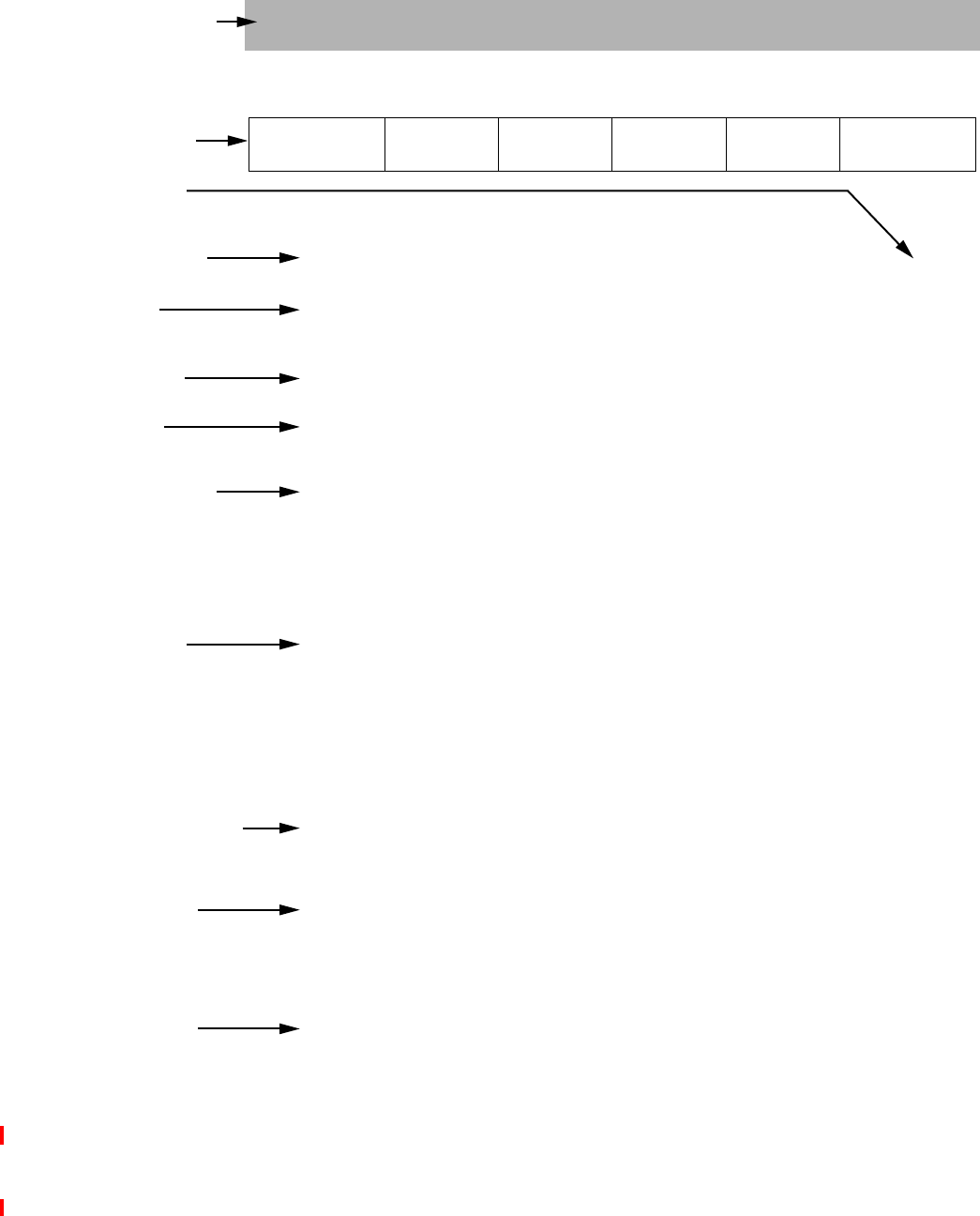
Guide to the Instruction Set
11 The MIPS32® Instruction Set Manual, Revision 6.05
Figure 2.1 Example of Instruction Description
EXAMPLE
31 26 25 21 20 16 15 11 10 6 5 0
SPECIAL
000000 0rtrd0
00000
EXAMPLE
000000
6 5555 6
Format: EXAMPLE fd,rs,rt MIPS3
2
Purpose: Example Instruction Name
To execute an EXAMPLE op.
Description: GPR[rd] GPR[r]s exampleop GPR[rt]
This section describes the operation of the instruction in text, tables, and illustrations. It
includes information that would be difficult to encode in the Operation section.
Restrictions:
This section lists any restrictions for the instruction. This can include values of the instruc
-
tion encoding fields such as register specifiers, operand values, operand formats, address
alignment, instruction scheduling hazards, and type of memory access for addressed loca-
tions.
Operation:
/* This section describes the operation of an instruction in */
/* a high-level pseudo-language. It is precise in ways that */
/* the Description section is not, but is also missing */
/* information that is hard to express in pseudocode. */
temp GPR[rs] exampleop GPR[rt]
GPR[rd] sign_extend(temp31..0)
Exceptions:
A list of exceptions taken by the instruction.
Programming Notes:
Information useful to programmers, but not necessary to describe the operation of the
instruction.
Implementation Notes:
Like Programming Notes, except for processor implementors.
ELPMAXEemaN noitcurtsnI elpmaxE
ĸ
ĸ
ĸ
Instruction Mnemonic and
Descriptive Name
Instruction Encoding
Constant and Variable
Field Names and Values
A
rchitecture Level at
which Instruction Was
Defined/Redefined
Assembler Format(s) for
Each Definition
Short Description
Symbolic Description
Full Description of
Instruction Operation
Restrictions on Instruction
and Operands
High-Level Language
Description of the
Instruction Operation
Exceptions that the Instruction
Can Cause
Notes for Programmers
Notes for Implementers

2.1 Understanding the Instruction Fields
The MIPS32® Instruction Set Manual, Revision 6.05 12
2.1.1 Instruction Fields
Fields encoding the instruction word are shown in register form at the top of the instruction description. The follow-
ing rules are followed:
• The values of constant fields and the opcode names are listed in uppercase (SPECIAL and ADD in Figure 2.2).
Constant values in a field are shown in binary below the symbolic or hexadecimal value.
• All variable fields are listed with the lowercase names used in the instruction description (rs, rt, and rd in Figure
2.2).
• Fields that contain zeros but are not named are unused fields that are required to be zero (bits 10:6 in Figure 2.2).
If such fields are set to non-zero values, the operation of the processor is UNPREDICTABLE.
Figure 2.2 Example of Instruction Fields
2.1.2 Instruction Descriptive Name and Mnemonic
The instruction descriptive name and mnemonic are printed as page headings for each instruction, as shown in Figure
2.3.
Figure 2.3 Example of Instruction Descriptive Name and Mnemonic
2.1.3 Format Field
The assembler formats for the instruction and the architecture level at which the instruction was originally defined are
given in the Format field. If the instruction definition was later extended, the architecture levels at which it was
extended and the assembler formats for the extended definition are shown in their order of extension (for an example,
see C.cond.fmt). The MIPS architecture levels are inclusive; higher architecture levels include all instructions in pre-
vious levels. Extensions to instructions are backwards compatible. The original assembler formats are valid for the
extended architecture.
Figure 2.4 Example of Instruction Format
The assembler format is shown with literal parts of the assembler instruction printed in uppercase characters. The
variable parts, the operands, are shown as the lowercase names of the appropriate fields.
The architectural level at which the instruction was first defined, for example “MIPS32” is shown at the right side of
the page. Instructions introduced at different times by different ISA family members, are indicated by markings such
31 26 25 21 20 16 15 11 10 6 5 0
SPECIAL
000000
0
00000
ADD
100000
6 5555 6
rs rt rd
Add Word ADD
Format: ADD fd,rs,rt MIPS32

Guide to the Instruction Set
13 The MIPS32® Instruction Set Manual, Revision 6.05
as “MIPS64, MIPS32 Release 2”. Instructions removed by particular architecture release are indicated in the Avail-
ability section.
There can be more than one assembler format for each architecture level. Floating point operations on formatted data
show an assembly format with the actual assembler mnemonic for each valid value of the fmt field. For example, the
ADD.fmt instruction lists both ADD.S and ADD.D.
The assembler format lines sometimes include parenthetical comments to help explain variations in the formats (once
again, see C.cond.fmt). These comments are not a part of the assembler format.
2.1.4 Purpose Field
The Purpose field gives a short description of the use of the instruction.
Figure 2.5 Example of Instruction Purpose
2.1.5 Description Field
If a one-line symbolic description of the instruction is feasible, it appears immediately to the right of the Description
heading. The main purpose is to show how fields in the instruction are used in the arithmetic or logical operation.
Figure 2.6 Example of Instruction Description
The body of the section is a description of the operation of the instruction in text, tables, and figures. This description
complements the high-level language description in the Operation section.
This section uses acronyms for register descriptions. “GPR rt” is CPU general-purpose register specified by the
instruction field rt. “FPR fs” is the floating point operand register specified by the instruction field fs. “CP1 register
fd” is the coprocessor 1 general register specified by the instruction field fd. “FCSR” is the floating point Control /
Status register.
2.1.6 Restrictions Field
The Restrictions field documents any possible restrictions that may affect the instruction. Most restrictions fall into
one of the following six categories:
•V
alid values for instruction fields (for example, see floating point ADD.fmt)
Purpose: Add Word
To add 32-bit integers. If an overflow occurs, then trap.
Description: GPR[rd] GPR[rs] + GPR[rt]
The 32-bit word value in GPR rt is added to the 32-bit value in GPR rs to produce a 32-bit
result.
• If the addition results in 32-bit 2’s complement arithmetic overflow, the destination
register is not modified and an Integer Overflow exception occurs.
• If the addition does not overflow, the 32-bit result is placed into GPR rd.

2.1 Understanding the Instruction Fields
The MIPS32® Instruction Set Manual, Revision 6.05 14
• ALIGNMENT requirements for memory addresses (for example, see LW)
• Valid values of operands (for example, see ALNV.PS)
• Valid operand formats (for example, see floating point ADD.fmt)
• Order of instructions necessary to guarantee correct execution. These ordering constraints avoid pipeline hazards
for which some processors do not have hardware interlocks (for example, see MUL).
• Valid memory access types (for example, see LL/SC)
Figure 2.7 Example of Instruction Restrictions
2.1.7 Availability and Compatibility Fields
The Availability and Compatibility sections are not provided for all instructions. These sections list considerations
relevant to whether and how an implementation may implement some instructions, when software may use such
instructions, and how software can determine if an instruction or feature is present. Such considerations include:
• Some instructions are not present on all architecture releases. Sometimes the implementation is required to
signal a Reserved Instruction exception, but sometimes executing such an instruction encoding is architec-
turally defined to give UNPREDICTABLE results.
• Some instructions are available for implementations of a particular architecture release, but may be provided
only if an optional feature is implemented. Control register bits typically allow software to determine if the
feature is present.
• Some instructions may not behave the same way on all implementations. Typically this involves behavior
that was UNPREDICTABLE in some implementations, but which is made architectural and guaranteed con-
sistent so that software can rely on it in subsequent architecture releases.
• Some instructions are prohibited for certain architecture releases and/or optional feature combinations.
• Some instructions may be removed for certain architecture releases. Implementations may then be required
to signal a Reserved Instruction exception for the removed instruction encoding; but sometimes the instruc-
tion encoding is reused for other instructions.
All of these considerations may apply to the same instruction. If such considerations applicable to an instruction are
simple, the architecture level in which an instruction was defined or redefined in the Format field, and/or the Restric-
tions section, may be sufficient; but if the set of such considerations applicable to an instruction is complicated, the
Availability and Compatibility sections may be provided.
Restrictions:
None

Guide to the Instruction Set
15 The MIPS32® Instruction Set Manual, Revision 6.05
2.1.8 Operation Field
The Operation field describes the operation of the instruction as pseudocode in a high-level language notation resem-
bling Pascal. This formal description complements the Description section; it is not complete in itself because many
of the restrictions are either difficult to include in the pseudocode or are omitted for legibility.
Figure 2.8 Example of Instruction Operation
See 2.2 “Operation Section Notation and Functions” on page 16 for more information on the formal notation used
here.
2.1.9 Exceptions Field
The Exceptions field lists the exceptions that can be caused by Operation of the instruction. It omits exceptions that
can be caused by the instruction fetch, for instance, TLB Refill, and also omits exceptions that can be caused by asyn-
chronous external events such as an Interrupt. Although a Bus Error exception may be caused by the operation of a
load or store instruction, this section does not list Bus Error for load and store instructions because the relationship
between load and store instructions and external error indications, like Bus Error, are dependent upon the implemen-
tation.
Figure 2.9 Example of Instruction Exception
An instruction may cause implementation-dependent exceptions that are not present in the Exceptions section.
2.1.10 Programming Notes and Implementation Notes Fields
The Notes sections contain material that is useful for programmers and implementors, respectively, but that is not
necessary to describe the instruction and does not belong in the description sections.
Operation:
temp (GPR[rs]31||GPR[rs]31..0) + (GPR[rt]31||GPR[rt]31..0)
if temp32 temp31 then
SignalException(IntegerOverflow)
else
GPR[rd] temp
endif
Exceptions:
Integer Overflow

2.2 Operation Section Notation and Functions
The MIPS32® Instruction Set Manual, Revision 6.05 16
Figure 2.10 Example of Instruction Programming Notes
2.2 Operation Section Notation and Functions
In an instruction description, the Operation section uses a high-level language notation to describe the operation per-
formed by each instruction. Special symbols used in the pseudocode are described in the previous chapter. Specific
pseudocode functions are described below.
This section presents information about the following topics:
• “Instruction Execution Ordering” on page 16
• “Pseudocode Functions” on page 16
2.2.1 Instruction Execution Ordering
Each of the high-level language statements in the Operations section are executed sequentially (except as constrained
by conditional and loop constructs).
2.2.2 Pseudocode Functions
There are several functions used in the pseudocode descriptions. These are used either to make the pseudocode more
readable, to abstract implementation-specific behavior, or both. These functions are defined in this section, and
include the following:
• “Coprocessor General Register Access Functions” on page 16
• “Memory Operation Functions” on page 18
• “Floating Point Functions” on page 21
• “Miscellaneous Functions” on page 25
2.2.2.1 Coprocessor General Register Access Functions
Defined coprocessors, except for CP0, have instructions to exchange words and doublewords between coprocessor
general registers and the rest of the system. What a coprocessor does with a word or doubleword supplied to it and
how a coprocessor supplies a word or doubleword is defined by the coprocessor itself. This behavior is abstracted
into the functions described in this section.
2.2.2.1.1 COP_LW
The COP_LW function defines the action taken by coprocessor z when supplied with a word from memory during a
load word operation. The action is coprocessor-specific. The typical action would be to store the contents of mem-
word in coprocessor general register rt.
Figure 2.11 COP_LW Pseudocode Function
COP_LW (z, rt, memword)
Programming Notes:
ADDU performs the same arithmetic operation but does not trap on overflow.

Guide to the Instruction Set
17 The MIPS32® Instruction Set Manual, Revision 6.05
z: The coprocessor unit number
rt: Coprocessor general register specifier
memword: A 32-bit word value supplied to the coprocessor
/* Coprocessor-dependent action */
endfunction COP_LW
2.2.2.1.2 COP_LD
The COP_LD function defines the action taken by coprocessor z when supplied with a doubleword from memory
during a load doubleword operation. The action is coprocessor-specific. The typical action would be to store the con-
tents of memdouble in coprocessor general register rt.
Figure 2.12 COP_LD Pseudocode Function
COP_LD (z, rt, memdouble)
z: The coprocessor unit number
rt: Coprocessor general register specifier
memdouble: 64-bit doubleword value supplied to the coprocessor.
/* Coprocessor-dependent action */
endfunction COP_LD
2.2.2.1.3 COP_SW
The COP_SW function defines the action taken by coprocessor z to supply a word of data during a store word opera-
tion. The action is coprocessor-specific. The typical action would be to supply the contents of the low-order word in
coprocessor general register rt.
Figure 2.13 COP_SW Pseudocode Function
dataword COP_SW (z, rt)
z: The coprocessor unit number
rt: Coprocessor general register specifier
dataword: 32-bit word value
/* Coprocessor-dependent action */
endfunction COP_SW
2.2.2.1.4 COP_SD
The COP_SD function defines the action taken by coprocessor z to supply a doubleword of data during a store dou-
bleword operation. The action is coprocessor-specific. The typical action would be to supply the contents of the low-
order doubleword in coprocessor general register rt.
Figure 2.14 COP_SD Pseudocode Function
datadouble COP_SD (z, rt)
z: The coprocessor unit number
rt: Coprocessor general register specifier
datadouble: 64-bit doubleword value
/* Coprocessor-dependent action */

2.2 Operation Section Notation and Functions
The MIPS32® Instruction Set Manual, Revision 6.05 18
endfunction COP_SD
2.2.2.1.5 CoprocessorOperation
The CoprocessorOperation function performs the specified Coprocessor operation.
Figure 2.15 CoprocessorOperation Pseudocode Function
CoprocessorOperation (z, cop_fun)
/* z: Coprocessor unit number */
/* cop_fun: Coprocessor function from function field of instruction */
/* Transmit the cop_fun value to coprocessor z */
endfunction CoprocessorOperation
2.2.2.2 Memory Operation Functions
Regardless of byte ordering (big- or little-endian), the address of a halfword, word, or doubleword is the smallest byte
address of the bytes that form the object. For big-endian ordering this is the most-significant byte; for a little-endian
ordering this is the least-significant byte.
In the Operation pseudocode for load and store operations, the following functions summarize the handling of virtual
addresses and the access of physical memory. The size of the data item to be loaded or stored is passed in the Access-
Length field. The valid constant names and values are shown in Table 2.1. The bytes within the addressed unit of
memory (word for 32-bit processors or doubleword for 64-bit processors) that are used can be determined directly
from the AccessLength and the two or three low-order bits of the address.
2.2.2.2.1 Misaligned Support
MIPS processors originally required all memory accesses to be naturally aligned. MSA (the MIPS SIMD Architec-
ture) supported misaligned memory accesses for its 128 bit packed SIMD vector loads and stores, from its introduc-
tion in MIPS Release 5. Release 6 requires systems to provide support for misaligned memory accesses for all
ordinary memory reference instructions: the system must provide a mechanism to complete a misaligned memory ref-
erence for this instruction, ranging from full execution in hardware to trap-and-emulate.
The pseudocode function MisalignedSupport encapsulates the version number check to determine if misalignment is
supported for an ordinary memory access.
Figure 2.16 MisalignedSupport Pseudocode Function
predicate MisalignedSupport ()
return Config.AR ≥ 2 // Architecture Revision 2 corresponds to MIPS Release 6.
end function
See Appendix B, “Misaligned Memory Accesses” on page 511 for a more detailed discussion of misalignment,
including pseudocode functions for the actual misaligned memory access.
2.2.2.2.2 AddressTranslation
The AddressTranslation function translates a virtual address to a physical address and its cacheability and coherency
attribute, describing the mechanism used to resolve the memory reference.

Guide to the Instruction Set
19 The MIPS32® Instruction Set Manual, Revision 6.05
Given the virtual address vAddr, and whether the reference is to Instructions or Data (IorD), find the corresponding
physical address (pAddr) and the cacheability and coherency attribute (CCA) used to resolve the reference. If the vir-
tual address is in one of the unmapped address spaces, the physical address and CCA are determined directly by the
virtual address. If the virtual address is in one of the mapped address spaces then the TLB or fixed mapping MMU
determines the physical address and access type; if the required translation is not present in the TLB or the desired
access is not permitted, the function fails and an exception is taken.
Figure 2.17 AddressTranslation Pseudocode Function
(pAddr, CCA) AddressTranslation (vAddr, IorD, LorS)
/* pAddr: physical address */
/* CCA: Cacheability&Coherency Attribute,the method used to access caches*/
/* and memory and resolve the reference */
/* vAddr: virtual address */
/* IorD: Indicates whether access is for INSTRUCTION or DATA */
/* LorS: Indicates whether access is for LOAD or STORE */
/* See the address translation description for the appropriate MMU */
/* type in Volume III of this book for the exact translation mechanism */
endfunction AddressTranslation
2.2.2.2.3 LoadMemory
The LoadMemory function loads a value from memory.
This action uses cache and main memory as specified in both the Cacheability and Coherency Attribute (CCA) and
the access (IorD) to find the contents of AccessLength memory bytes, starting at physical location pAddr. The data is
returned in a fixed-width naturally aligned memory element (MemElem). The low-order 2 (or 3) bits of the address
and the AccessLength indicate which of the bytes within MemElem need to be passed to the processor. If the memory
access type of the reference is uncached, only the referenced bytes are read from memory and marked as valid within
the memory element. If the access type is cached but the data is not present in cache, an implementation-specific size
and alignment block of memory is read and loaded into the cache to satisfy a load reference. At a minimum, this
block is the entire memory element.
Figure 2.18 LoadMemory Pseudocode Function
MemElem LoadMemory (CCA, AccessLength, pAddr, vAddr, IorD)
/* MemElem: Data is returned in a fixed width with a natural alignment. The */
/* width is the same size as the CPU general-purpose register, */
/* 32 or 64 bits, aligned on a 32- or 64-bit boundary, */
/* respectively. */
/* CCA: Cacheability&CoherencyAttribute=method used to access caches */
/* and memory and resolve the reference */
/* AccessLength: Length, in bytes, of access */
/* pAddr: physical address */
/* vAddr: virtual address */
/* IorD: Indicates whether access is for Instructions or Data */
endfunction LoadMemory

2.2 Operation Section Notation and Functions
The MIPS32® Instruction Set Manual, Revision 6.05 20
2.2.2.2.4 StoreMemory
The StoreMemory function stores a value to memory.
The specified data is stored into the physical location pAddr using the memory hierarchy (data caches and main mem-
ory) as specified by the Cacheability and Coherency Attribute (CCA). The MemElem contains the data for an aligned,
fixed-width memory element (a word for 32-bit processors, a doubleword for 64-bit processors), though only the
bytes that are actually stored to memory need be valid. The low-order two (or three) bits of pAddr and the AccessLen-
gth field indicate which of the bytes within the MemElem data should be stored; only these bytes in memory will
actually be changed.
Figure 2.19 StoreMemory Pseudocode Function
StoreMemory (CCA, AccessLength, MemElem, pAddr, vAddr)
/* CCA: Cacheability&Coherency Attribute, the method used to access */
/* caches and memory and resolve the reference. */
/* AccessLength: Length, in bytes, of access */
/* MemElem: Data in the width and alignment of a memory element. */
/* The width is the same size as the CPU general */
/* purpose register, either 4 or 8 bytes, */
/* aligned on a 4- or 8-byte boundary. For a */
/* partial-memory-element store, only the bytes that will be*/
/* stored must be valid.*/
/* pAddr: physical address */
/* vAddr: virtual address */
endfunction StoreMemory
2.2.2.2.5 Prefetch
The Prefetch function prefetches data from memory.
Prefetch is an advisory instruction for which an implementation-specific action is taken. The action taken may
increase performance but must not change the meaning of the program or alter architecturally visible state.
Figure 2.20 Prefetch Pseudocode Function
Prefetch (CCA, pAddr, vAddr, DATA, hint)
/* CCA: Cacheability&Coherency Attribute, the method used to access */
/* caches and memory and resolve the reference. */
/* pAddr: physical address */
/* vAddr: virtual address */
/* DATA: Indicates that access is for DATA */
/* hint: hint that indicates the possible use of the data */
endfunction Prefetch
Table 2.1 lists the data access lengths and their labels for loads and stores.
Table 2.1 AccessLength Specifications for Loads/Stores
AccessLength Name Value Meaning
DOUBLEWORD 7 8 bytes (64 bits)

Guide to the Instruction Set
21 The MIPS32® Instruction Set Manual, Revision 6.05
2.2.2.2.6 SyncOperation
The SyncOperation function orders loads and stores to synchronize shared memory.
This action makes the effects of the synchronizable loads and stores indicated by stype occur in the same order for all
processors.
Figure 2.21 SyncOperation Pseudocode Function
SyncOperation(stype)
/* stype: Type of load/store ordering to perform. */
/* Perform implementation-dependent operation to complete the */
/* required synchronization operation */
endfunction SyncOperation
2.2.2.3 Floating Point Functions
The pseudocode shown in below specifies how the unformatted contents loaded or moved to CP1 registers are inter-
preted to form a formatted value. If an FPR contains a value in some format, rather than unformatted contents from a
load (uninterpreted), it is valid to interpret the value in that format (but not to interpret it in a different format).
2.2.2.3.1 ValueFPR
The ValueFPR function returns a formatted value from the floating point registers.
Figure 2.22 ValueFPR Pseudocode Function
value ValueFPR(fpr, fmt)
/* value: The formattted value from the FPR */
/* fpr: The FPR number */
/* fmt: The format of the data, one of: */
/* S, D, W, L, PS, */
/* OB, QH, */
/* UNINTERPRETED_WORD, */
/* UNINTERPRETED_DOUBLEWORD */
/* The UNINTERPRETED values are used to indicate that the datatype */
/* is not known as, for example, in SWC1 and SDC1 */
SEPTIBYTE 6 7 bytes (56 bits)
SEXTIBYTE 5 6 bytes (48 bits)
QUINTIBYTE 4 5 bytes (40 bits)
WORD 3 4 bytes (32 bits)
TRIPLEBYTE 2 3 bytes (24 bits)
HALFWORD 1 2 bytes (16 bits)
BYTE 0 1 byte (8 bits)
Table 2.1 AccessLength Specifications for Loads/Stores
AccessLength Name Value Meaning

2.2 Operation Section Notation and Functions
The MIPS32® Instruction Set Manual, Revision 6.05 22
case fmt of
S, W, UNINTERPRETED_WORD:
valueFPR FPR[fpr]
D, UNINTERPRETED_DOUBLEWORD:
if (FP32RegistersMode 0)
if (fpr0 0) then
valueFPR UNPREDICTABLE
else
valueFPR FPR[fpr1]31..0 FPR[fpr]31..0
endif
else
valueFPR FPR[fpr]
endif
L:
if (FP32RegistersMode 0) then
valueFPR UNPREDICTABLE
else
valueFPR FPR[fpr]
endif
DEFAULT:
valueFPR UNPREDICTABLE
endcase
endfunction ValueFPR
The pseudocode shown below specifies the way a binary encoding representing a formatted value is stored into CP1
registers by a computational or move operation. This binary representation is visible to store or move-from instruc-
tions. Once an FPR receives a value from the StoreFPR(), it is not valid to interpret the value with ValueFPR() in a
different format.
2.2.2.3.2 StoreFPR
Figure 2.23 StoreFPR Pseudocode Function
StoreFPR (fpr, fmt, value)
/* fpr: The FPR number */
/* fmt: The format of the data, one of: */
/* S, D, W, L, PS, */
/* OB, QH, */
/* UNINTERPRETED_WORD, */
/* UNINTERPRETED_DOUBLEWORD */
/* value: The formattted value to be stored into the FPR */
/* The UNINTERPRETED values are used to indicate that the datatype */
/* is not known as, for example, in LWC1 and LDC1 */
case fmt of
S, W, UNINTERPRETED_WORD:
FPR[fpr] value
D, UNINTERPRETED_DOUBLEWORD:

Guide to the Instruction Set
23 The MIPS32® Instruction Set Manual, Revision 6.05
if (FP32RegistersMode 0)
if (fpr0 0) then
UNPREDICTABLE
else
FPR[fpr] UNPREDICTABLE32 value31..0
FPR[fpr1] UNPREDICTABLE32 value63..32
endif
else
FPR[fpr] value
endif
L:
if (FP32RegistersMode 0) then
UNPREDICTABLE
else
FPR[fpr] value
endif
endcase
endfunction StoreFPR
2.2.2.3.3 CheckFPException
The pseudocode shown below checks for an enabled floating point exception and conditionally signals the exception.
Figure 2.24 CheckFPException Pseudocode Function
CheckFPException()
/* A floating point exception is signaled if the E bit of the Cause field is a 1 */
/* (Unimplemented Operations have no enable) or if any bit in the Cause field */
/* and the corresponding bit in the Enable field are both 1 */
if ( (FCSR17 1) or
((FCSR16..12 and FCSR11..7) 0)) ) then
SignalException(FloatingPointException)
endif
endfunction CheckFPException
2.2.2.3.4 FPConditionCode
The FPConditionCode function returns the value of a specific floating point condition code.
Figure 2.25 FPConditionCode Pseudocode Function
tf FPConditionCode(cc)
/* tf: The value of the specified condition code */
/* cc: The Condition code number in the range 0..7 */
if cc = 0 then
FPConditionCode FCSR23
else
FPConditionCode FCSR24+cc

2.2 Operation Section Notation and Functions
The MIPS32® Instruction Set Manual, Revision 6.05 24
endif
endfunction FPConditionCode
2.2.2.3.5 SetFPConditionCode
The SetFPConditionCode function writes a new value to a specific floating point condition code.
Figure 2.26 SetFPConditionCode Pseudocode Function
SetFPConditionCode(cc, tf)
if cc = 0 then
FCSR FCSR31..24 || tf || FCSR22..0
else
FCSR FCSR31..25+cc || tf || FCSR23+cc..0
endif
endfunction SetFPConditionCode
2.2.2.4 Pseudocode Functions Related to Sign and Zero Extension
2.2.2.4.1 Sign extension and zero extension in pseudocode
Much pseudocode uses a generic function sign_extend without specifying from what bit position the extension is
done, when the intention is obvious. E.g. sign_extend(immediate16) or sign_extend(disp9).
However, sometimes it is necessary to specify the bit position. For example, sign_extend(temp31..0) or the
more complicated (offset15)GPRLEN-(16+2) || offset || 02.
The explicit notation sign_extend.nbits(val) or sign_extend(val,nbits) is suggested as a simpli-
fication. They say to sign extend as if an nbits-sized signed integer. The width to be sign extended to is usually appar-
ent by context, and is usually GPRLEN, 32 or 64 bits. The previous examples then become.
sign_extend(temp31..0)
= sign_extend.32(temp)
and
(offset15)GPRLEN-(16+2) || offset || 02
= sign_extend.16(offset)<<2
Note that sign_extend.N(value) extends from bit position N-1, if the bits are numbered 0..N-1 as is typical.
The explicit notations sign_extend.nbits(val) or sign_extend(val,nbits) is used as a simplifica-
tion. These notations say to sign extend as if an nbits-sized signed integer. The width to be sign extended to is usually
apparent by context, and is usually GPRLEN, 32 or 64 bits.
Figure 2.27 sign_extend Pseudocode Functions
sign_extend.nbits(val) = sign_extend(val,nbits) /* syntactic equivalents */
function sign_extend(val,nbits)
return (valnbits-1)GPRLEN-nbits || valnbits-1..0
end function
The earlier examples can be expressed as
(offset15)GPRLEN-(16+2) || offset || 02

Guide to the Instruction Set
25 The MIPS32® Instruction Set Manual, Revision 6.05
= sign_extend.16(offset) << 2)
and
sign_extend(temp31..0)
= sign_extend.32(temp)
Similarly for zero_extension, although zero extension is less common than sign extension in the MIPS ISA.
Floating point may use notations such as zero_extend.fmt corresponding to the format of the FPU instruction.
E.g. zero_extend.S and zero_extend.D are equivalent to zero_extend.32 and zero_extend.64.
Existing pseudocode may use any of these, or other, notations.
2.2.2.4.2 memory_address
The pseudocode function memory_address performs mode-dependent address space wrapping for compatibility
between MIPS32 and MIPS64. It is applied to all memory references. It may be specified explicitly in some places,
particularly for new memory reference instructions, but it is also declared to apply implicitly to all memory refer-
ences as defined below. In addition, certain instructions that are used to calculate effective memory addresses but
which are not themselves memory accesses specify memory_address explicitly in their pseudocode.
Figure 2.28 memory_address Pseudocode Function
function memory_address(ea)
return ea
end function
On a 32-bit CPU, memory_address returns its 32-bit effective address argument unaffected.
In addition to the use of memory_address for all memory references (including load and store instructions, LL/
SC), Release 6 extends this behavior to control transfers (branch and call instructions), and to the PC-relative address
calculation instructions (ADDIUPC, AUIPC, ALUIPC). In newer instructions the function is explicit in the pseudo-
code.
Implicit address space wrapping for all instruction fetches is described by the following pseudocode fragment which
should be considered part of instruction fetch:
Figure 2.29 Instruction Fetch Implicit memory_address Wrapping
PC memory_address( PC )
( instruction_data, length ) instruction_fetch( PC )
/* decode and execute instruction */
Implicit address space wrapping for all data memory accesses is described by the following pseudocode, which is
inserted at the top of the AddressTranslation pseudocode function:
Figure 2.30 AddressTranslation implicit memory_address Wrapping
(pAddr, CCA) AddressTranslation (vAddr, IorD, LorS)
vAddr memory_address(vAddr)
In addition to its use in instruction pseudocode,
2.2.2.5 Miscellaneous Functions
This section lists miscellaneous functions not covered in previous sections.

2.2 Operation Section Notation and Functions
The MIPS32® Instruction Set Manual, Revision 6.05 26
2.2.2.5.1 SignalException
The SignalException function signals an exception condition.
This action results in an exception that aborts the instruction. The instruction operation pseudocode never sees a
return from this function call.
Figure 2.31 SignalException Pseudocode Function
SignalException(Exception, argument)
/* Exception: The exception condition that exists. */
/* argument: A exception-dependent argument, if any */
endfunction SignalException
2.2.2.5.2 SignalDebugBreakpointException
The SignalDebugBreakpointException function signals a condition that causes entry into Debug Mode from non-
Debug Mode.
This action results in an exception that aborts the instruction. The instruction operation pseudocode never sees a
return from this function call.
Figure 2.32 SignalDebugBreakpointException Pseudocode Function
SignalDebugBreakpointException()
endfunction SignalDebugBreakpointException
2.2.2.5.3 SignalDebugModeBreakpointException
The SignalDebugModeBreakpointException function signals a condition that causes entry into Debug Mode from
Debug Mode (i.e., an exception generated while already running in Debug Mode).
This action results in an exception that aborts the instruction. The instruction operation pseudocode never sees a
return from this function call.
Figure 2.33 SignalDebugModeBreakpointException Pseudocode Function
SignalDebugModeBreakpointException()
endfunction SignalDebugModeBreakpointException
2.2.2.5.4 NullifyCurrentInstruction
The NullifyCurrentInstruction function nullifies the current instruction.
The instruction is aborted, inhibiting not only the functional effect of the instruction, but also inhibiting all exceptions
detected during fetch, decode, or execution of the instruction in question. For branch-likely instructions, nullification
kills the instruction in the delay slot of the branch likely instruction.
Figure 2.34 NullifyCurrentInstruction PseudoCode Function
NullifyCurrentInstruction()

Guide to the Instruction Set
27 The MIPS32® Instruction Set Manual, Revision 6.05
endfunction NullifyCurrentInstruction
2.2.2.5.5 PolyMult
The PolyMult function multiplies two binary polynomial coefficients.
Figure 2.35 PolyMult Pseudocode Function
PolyMult(x, y)
temp 0
for i in 0 .. 31
if xi = 1 then
temp temp xor (y(31-i)..0 || 0i)
endif
endfor
PolyMult temp
endfunction PolyMult
2.3 Op and Function Subfield Notation
In some instructions, the instruction subfields op and function can have constant 5- or 6-bit values. When reference is
made to these instructions, uppercase mnemonics are used. For instance, in the floating point ADD instruction,
op=COP1 and function=ADD. In other cases, a single field has both fixed and variable subfields, so the name con-
tains both upper- and lowercase characters.
2.4 FPU Instructions
In the detailed description of each FPU instruction, all variable subfields in an instruction format (such as fs, ft, imme-
diate, and so on) are shown in lowercase. The instruction name (such as ADD, SUB, and so on) is shown in upper-
case.
For the sake of clarity, an alias is sometimes used for a variable subfield in the formats of specific instructions. For
example, rs=base in the format for load and store instructions. Such an alias is always lowercase since it refers to a
variable subfield.
Bit encodings for mnemonics are given in Volume I, in the chapters describing the CPU, FPU, MDMX, and MIPS16e
instructions.
See “Op and Function Subfield Notation” on page 27 for a description of the op and function subfields.

2.4 FPU Instructions
The MIPS32® Instruction Set Manual, Revision 6.05 28

Chapter 3
The MIPS32® Instruction Set Manual, Revision 6.05 29
The MIPS32® Instruction Set
3.1 Compliance and Subsetting
To be compliant with the MIPS32 Architecture, designs must implement a set of required features, as described in
this document set. To allow implementation flexibility, the MIPS32 Architecture provides subsetting rules. An imple-
mentation that follows these rules is compliant with the MIPS32 Architecture as long as it adheres strictly to the rules,
and fully implements the remaining instructions. Supersetting of the MIPS32 Architecture is only allowed by adding
functions to the SPECIAL2, COP2, or both major opcodes, by adding control for co-processors via the COP2, LWC2,
SWC2, LDC2, and/or SDC2, or via the addition of approved Application Specific Extensions.
Release 6 removes all instructions under the SPECIAL2 major opcode, either by removing them or moving them to
the COP2 major opcode. All coprocessor 2 support instructions (for example, LWC2) have been moved to the COP2
major opcode. Supersetting of the Release 6 architecture is only allowed in the COP2 major opcode, or via the addi-
tion of approved Application Specific Extensions. SPECIAL2 is reserved for MIPS.
Note: The use of COP3 as a customizable coprocessor has been removed in the Release 2 of the MIPS32 architecture.
The COP3 is reserved for the future extension of the architecture. Implementations using Release1 of the MIPS32
architecture are strongly discouraged from using the COP3 opcode for a user-available coprocessor as doing so will
limit the potential for an upgrade path to a 64-bit floating point unit.
The instruction set subsetting rules are described in the subsections below, and also the following rule:
•Co-dependence of Architecture Features: MIPSr5™ (also called Release 5) and subsequent releases (such as
Release 6) include a number of features. Some are optional; some are required. Features provided by a release,
such as MIPSr5 or later, whether optional or required, must be consistent. If any feature that is introduced by a
particular release is implemented (such as a feature described as part of Release 5 and not any earlier release)
then all other features must be implemented in a manner consistent with that release. For example: the VZ and
MSA features are introduced by Release 5 but are optional. The FR=1 64-bit FPU register model was optional
when introduced earlier, but is now required by Release 5 if any FPU is implemented. If any or all of VZ or MSA
are implemented, then Release 5 is implied, and then if an FPU is implemented, it must implement the FR=1 64-
bit FPU register model.
3.1.1 Subsetting of Non-Privileged Architecture
• All non-privileged (do not need access to Coprocessor 0) CPU (non-FPU) instructions must be implemented —
no subsetting of these are allowed — per the MIPS Instruction Set Architecture release supported.
• If any instruction is subsetted out based on the rules below, an attempt to execute that instruction must cause the
appropriate exception (typically Reserved Instruction or Coprocessor Unusable).
• The FPU and related support instructions, such as CPU conditional branches on FPU conditions (pre-Release 6
BC1T/BC1F, Release 6 BC1NEQZ) and CPU conditional moves on FPU conditions (pre-Release 6 MOVT/
MOVF), may be omitted. Software may determine if an FPU is implemented by checking the state of the FP bit
in the Config1 CP0 register. Software may determine which FPU data types are implemented by checking the

3.1 Compliance and Subsetting
The MIPS32® Instruction Set Manual, Revision 6.05 30
appropriate bits in the FIR CP1 register. The following allowable FPU subsets are compliant with the MIPS32
architecture:
• No FPU
Config1.FP=0
• FPU with S, and W formats and all supporting instructions.
This 32-bit subset is permitted by Release 6, but prohibited by pre-Release 6 releases.
Config1.FP=1, Status.FR=0, FIR.S=FIR.L=1, FIR.D=FIR.L=FIR.PS=0.
• FPU with S, D, W, and L formats and all supporting instructions
Config1.FP=1, Status.FR=(see below), FIR.S=FIR.L=FIR.D=FIR.L=1, FIR.PS=0.
pre-MIPSr5 permits this 64-bit configuration, and allows both FPU register modes. Status.FR=0 support is
required but Status.FR=1 support is optional.
MIPSr5 permits this 64-bit configuration, and requires both FPU register modes, i.e. both Status.FR=0 and
Status.FR=1 support are required.
Release 6 permits this 64-bit configuration, but requires Status.FR=1 and FIR.F64=1. Release 6 prohibits
Status.FR=0 if FIR.D=1 or FIR.L=1.
• FPU with S, D, PS, W, and L formats and all supporting instructions
Config1.FP=1, Status.FR=0/1, FIR.S=FIR.L=FIR.D=FIR.L=FIR.PS=1.
Release 6 prohibits this mode, and any mode with FIR.PS=1 paired single support.
• In Release 5 of the Architecture, if floating point is implemented then FR=1 is required. I.e. the 64-bit FPU,
with the FR=1 64-bit FPU register model, is required. The FR=0 32-bit FPU register model continues to be
required.
• Coprocessor 2 is optional and may be omitted. Software may determine if Coprocessor 2 is implemented by
checking the state of the C2 bit in the Config1 CP0 register. If Coprocessor 2 is implemented, the Coprocessor 2
interface instructions (BC2, CFC2, COP2, CTC2, LDC2, LWC2, MFC2, MTC2, SDC2, and SWC2) may be
omitted on an instruction-by-instruction basis.
• The caches are optional. The Config1DL and Config1IL fields denote whether the first level caches are present or
not.
• Instruction, CP0 Register, and CP1 Control Register fields that are marked “Reserved” or shown as “0” in the
description of that field are reserved for future use by the architecture and are not available to implementations.
Implementations may only use those fields that are explicitly reserved for implementation dependent use.
• Supported Modules/ASEs are optional and may be subsetted out. In most cases, software may determine if a sup-
ported Module/ASE is implemented by checking the appropriate bit in the Config1 or Config3 or Config4 CP0
register. If they are implemented, they must implement the entire ISA applicable to the component, or implement
subsets that are approved by the Module/ASE specifications.

The MIPS32® Instruction Set
31 The MIPS32® Instruction Set Manual, Revision 6.05
• EJTAG is optional and may be subsetted out. If it is implemented, it must implement only those subsets that are
approved by the EJTAG specification. If EJTAG is not implemented, the EJTAG instructions (SDBBP and
DERET) can be subsetted out.
• In MIPS Release 3, there are two architecture branches (MIPS32/64 and microMIPS32/64). A single device is
allowed to implement both architecture branches. The Privileged Resource Architecture (COP0) registers do not
mode-switch in width (32-bit vs. 64-bit). For this reason, if a device implements both architecture branches, the
address/data widths must be consistent. If a device implements MIPS64 and also implements microMIPS, it must
implement microMIPS64 not just microMIPS32. Simiarly, If a device implements microMIPS64 and also imple-
ments MIPS32/64, it must implement MIPS64 not just MIPS32.
• Prior to Release 6, the JALX instruction is required if and only if ISA mode-switching is possible. If both of the
architecture branches are implemented (MIPS32/64 and microMIPS32/64) or if MIPS16e is implemented then
the JALX instructions are required. If only one branch of the architecture family and MIPS16e is not imple-
mented then the JALX instruction is not implemented. The JALX instruction was removed in Release 6.
3.2 Alphabetical List of Instructions
The following pages present detailed descriptions of instructions, arranged alphabetical order of opcode mnemonic
(except where several similar instructions are described together.)

ABS.fmt
I
Floating Point Absolute Value
The MIPS32® Instruction Set Manual, Revision 6.05 32
Format: ABS.fmt
ABS.S fd, fs MIPS32
ABS.D fd, fs MIPS32
ABS.PS fd, fs MIPS64,MIPS32 Release 2, removed in Release 6
Purpose: Floating Point Absolute Value
Description: FPR[fd] abs(FPR[fs])
The absolute value of the value in FPR fs is placed in FPR fd. The operand and result are values in format fmt.
ABS.PS takes the absolute value of the two values in FPR fs independently, and ORs together any generated excep-
tions.
The Cause bits are ORed into the Flag bits if no exception is taken.
If FIRHas2008=0 or FCSRABS2008=0 then this operation is arithmetic. For this case, any NaN operand signals invalid
operation.
If FCSRABS2008=1 then this operation is non-arithmetic. For this case, both regular floating point numbers and NAN
values are treated alike, only the sign bit is affected by this instruction. No IEEE exception can be generated for this
case, and the FCSRCause and FCSRFlags fields are not modified.
Restrictions:
The fields fs and fd must specify FPRs valid for operands of type fmt. If the fields are not valid, the result is UNPRE-
DICTABLE.
The operand must be a value in format fmt; if it is not, the result is UNPREDICTABLE and the value of the operand
FPR becomes UNPREDICTABLE.
The result of ABS.PS is UNPREDICTABLE if the processor is executing in the FR=0 32-bit FPU register model.
ABS.PS is predictable if executing on a 64-bit FPU in the FR=1 mode, but not with FR=0, and not on a 32-bit FPU.
Availability and Compatibility:
ABS.PS has been removed in Release 6.
Operation:
StoreFPR(fd, fmt, AbsoluteValue(ValueFPR(fs, fmt)))
Exceptions:
Coprocessor Unusable, Reserved Instruction
Floating Point Exceptions:
Unimplemented Operation, Invalid Operation
31 26 25 21 20 16 15 11 10 6 5 0
COP1
010001 fmt 0
00000 fs fd ABS
000101
6 5555 6

ADD
I
Add Word
The MIPS32® Instruction Set Manual, Revision 6.05 33
Format: ADD rd, rs, rt MIPS32
Purpose: Add Word
To add 32-bit integers. If an overflow occurs, then trap.
Description: GPR[rd] GPR[rs] + GPR[rt]
The 32-bit word value in GPR rt is added to the 32-bit value in GPR rs to produce a 32-bit result.
• If the addition results in 32-bit 2’s complement arithmetic overflow, the destination register is not modified and
an Integer Overflow exception occurs.
• If the addition does not overflow, the 32-bit result is placed into GPR rd.
Restrictions:
None
Operation:
temp (GPR[rs]31||GPR[rs]31..0) + (GPR[rt]31||GPR[rt]31..0)
if temp32 temp31 then
SignalException(IntegerOverflow)
else
GPR[rd] temp
endif
Exceptions:
Integer Overflow
Programming Notes:
ADDU performs the same arithmetic operation but does not trap on overflow.
31 26 25 21 20 16 15 11 10 6 5 0
SPECIAL
000000 rs rt rd 0
00000
ADD
100000
6 5555 6

ADD.fmt Floating Point Add
34 The MIPS32® Instruction Set Manual, Revision 6.05
Format: ADD.fmt
ADD.S fd, fs, ft MIPS32
ADD.D fd, fs, ft MIPS32
ADD.PS fd, fs, ft MIPS64,MIPS32 Release 2, removed in Release 6
Purpose: Floating Point Add
To add floating point values.
Description: FPR[fd] FPR[fs] + FPR[ft]
The value in FPR ft is added to the value in FPR fs. The result is calculated to infinite precision, rounded by using to
the current rounding mode in FCSR, and placed into FPR fd. The operands and result are values in format fmt.
ADD.PS adds the upper and lower halves of FPR fs and FPR ft independently, and ORs together any generated excep-
tions.
The Cause bits are ORed into the Flag bits if no exception is taken.
Restrictions:
The fields fs, ft, and fd must specify FPRs valid for operands of type fmt. If the fields are not valid, the result is
UNPREDICTABLE.
The operands must be values in format fmt. If the fields are not, the result is UNPREDICTABLE and the value of the
operand FPRs becomes UNPREDICTABLE.
The result of ADD.PS is UNPREDICTABLE if the processor is executing in the FR=0 32-bit FPU register model.
ADD.PS is predictable if executing on a 64-bit FPU in the FR=1 mode, but not with FR=0, and not on a 32-bit FPU.
Availability and Compatibility:
ADD.PS has been removed in Release 6.
Operation:
StoreFPR (fd, fmt, ValueFPR(fs, fmt) fmt ValueFPR(ft, fmt))
Exceptions:
Coprocessor Unusable, Reserved Instruction
Floating Point Exceptions:
Unimplemented Operation, Invalid Operation, Inexact, Overflow, Underflow
31 26 25 21 20 16 15 11 10 6 5 0
COP1
010001 fmt ft fs fd ADD
000000
6 5555 6

ADDI
I
Add Immediate Word
The MIPS32® Instruction Set Manual, Revision 6.05 35
Format: ADDI rt, rs, immediate MIPS32, removed in Release 6
Purpose: Add Immediate Word
To add a constant to a 32-bit integer. If overflow occurs, then trap.
Description: GPR[rt] GPR[rs] + immediate
The 16-bit signed immediate is added to the 32-bit value in GPR rs to produce a 32-bit result.
• If the addition results in 32-bit 2’s complement arithmetic overflow, the destination register is not modified and
an Integer Overflow exception occurs.
• If the addition does not overflow, the 32-bit result is placed into GPR rt.
Restrictions:
Availability and Compatibility:
This instruction has been removed in Release 6. The encoding has been reused for other instructions introduced by
Release 6.
Operation:
temp (GPR[rs]31||GPR[rs]31..0) + sign_extend(immediate)
if temp32 temp31 then
SignalException(IntegerOverflow)
else
GPR[rt] temp
endif
Exceptions:
Integer Overflow
Programming Notes:
ADDIU performs the same arithmetic operation but does not trap on overflow.
31 26 25 21 20 16 15 0
ADDI
001000 rs rt immediate
655 16

ADDIU
I
Add Immediate Unsigned Word
The MIPS32® Instruction Set Manual, Revision 6.05 36
Format: ADDIU rt, rs, immediate MIPS32
Purpose: Add Immediate Unsigned Word
To add a constant to a 32-bit integer.
Description: GPR[rt] GPR[rs] + immediate
The 16-bit signed immediate is added to the 32-bit value in GPR rs and the 32-bit arithmetic result is placed into
GPR rt.
No Integer Overflow exception occurs under any circumstances.
Restrictions:
None
Operation:
temp GPR[rs] + sign_extend(immediate)
GPR[rt] temp
Exceptions:
None
Programming Notes:
The term “unsigned” in the instruction name is a misnomer; this operation is 32-bit modulo arithmetic that does not
trap on overflow. This instruction is appropriate for unsigned arithmetic, such as address arithmetic, or integer arith-
metic environments that ignore overflow, such as C language arithmetic.
31 26 25 21 20 16 15 0
ADDIU
001001 rs rt immediate
655 16

ADDIUPC
I
Add Immediate to PC (unsigned - non-trapping)
The MIPS32® Instruction Set Manual, Revision 6.05 37
Format: ADDIUPC rs,immediate MIPS32 Release 6
Purpose: Add Immediate to PC (unsigned - non-trapping)
Description: GPR[rs] ( PC + sign_extend( immediate << 2 ) )
This instruction performs a PC-relative address calculation. The 19-bit immediate is shifted left by 2 bits, sign-
extended, and added to the address of the ADDIUPC instruction. The result is placed in GPR rs.
Restrictions:
None
Availability and Compatibility:
This instruction is introduced by and required as of Release 6.
Operation:
GPR[rs] ( PC + sign_extend( immediate << 2 ) )
Exceptions:
None
Programming Notes:
The term “unsigned” in this instruction mnemonic is a misnomer. “Unsigned” here means “non-trapping”. It does not
trap on a signed 32-bit overflow. ADDIUPC corresponds to unsigned ADDIU, which does not trap on overflow, as
opposed to ADDI, which does trap on overflow.
31 26 25 21 20 19 18 0
PCREL
111011 rs ADDIUPC
00
immediate
652 19

ADDU Add Unsigned Word
38 The MIPS32® Instruction Set Manual, Revision 6.05
Format: ADDU rd, rs, rt MIPS32
Purpose: Add Unsigned Word
To add 32-bit integers.
Description: GPR[rd] GPR[rs] + GPR[rt]
The 32-bit word value in GPR rt is added to the 32-bit value in GPR rs and the 32-bit arithmetic result is placed into
GPR rd.
No Integer Overflow exception occurs under any circumstances.
Restrictions:
None
Operation:
temp GPR[rs] + GPR[rt]
GPR[rd] temp
Exceptions:
None
Programming Notes:
The term “unsigned” in the instruction name is a misnomer; this operation is 32-bit modulo arithmetic that does not
trap on overflow. This instruction is appropriate for unsigned arithmetic, such as address arithmetic, or integer arith-
metic environments that ignore overflow, such as C language arithmetic.
31 26 25 21 20 16 15 11 10 6 5 0
SPECIAL
000000 rs rt rd 0
00000
ADDU
100001
6 5555 6

ALIGN
I
Concatenate two GPRs, and extract a contiguous subset at a byte position
The MIPS32® Instruction Set Manual, Revision 6.05 39
Format: ALIGN
ALIGN rd,rs,rt,bp MIPS32 Release 6
Purpose: Concatenate two GPRs, and extract a contiguous subset at a byte position
Description: GPR[rd] (GPR[rt] << (8*bp)) or (GPR[rs] >> (GPRLEN-8*bp))
The input registers GPR rt and GPR rs are concatenated, and a register width contiguous subset is extracted, which is
specified by the byte pointer bp.
The ALIGN instruction operates on 32-bit words, and has a 2-bit byte position field bp.
• The 32-bit word in GPR rt is left shifted as a 32-bit value by bp byte positions. The 32-bit word in register rs is
right shifted as a 32-bit value by (4-bp) byte positions. These shifts are logical shifts, zero-filling. The shifted
values are then or-ed together to create a 32-bit result that is written to destination GPR rd.
Restrictions:
Executing ALIGN with shift count bp=0 acts like a register to register move operation, and is redundant, and there-
fore discouraged. Software should not generate ALIGN with shift count bp=0.
Availability and Compatibility:
The ALIGN instruction is introduced by and required as of Release 6.
Programming Notes:
Release 6 ALIGN instruction corresponds to the pre-Release 6 DSP Module BALIGN instruction, except that
BALIGN with shift counts of 0 and 2 are specified as being UNPREDICTABLE, whereas ALIGN defines all bp val-
ues, discouraging only bp=0.
Graphically,
Figure 3.1 ALIGN operation (32-bit)
Operation:
tmp_rt_hi unsigned_word(GPR[rt]) << (8*bp)
tmp_rs_lo unsigned_word(GPR[rs]) >> (8*(4-bp))
tmp tmp_rt_hi or tmp_rt_lo
GPR[rd] tmp
/* end of instruction */
31 2625 2120 1615 1110 8765 0
SPECIAL3
011111 rs rt rd ALIGN
010 bp BSHFL
100000
6 555
32 6
bp 44-bp
GPR[rt] GPR[rs]
GPR[rd]

ALIGN Concatenate two GPRs, and extract a contiguous subset at a byte position
40 The MIPS32® Instruction Set Manual, Revision 6.05
Exceptions:
None
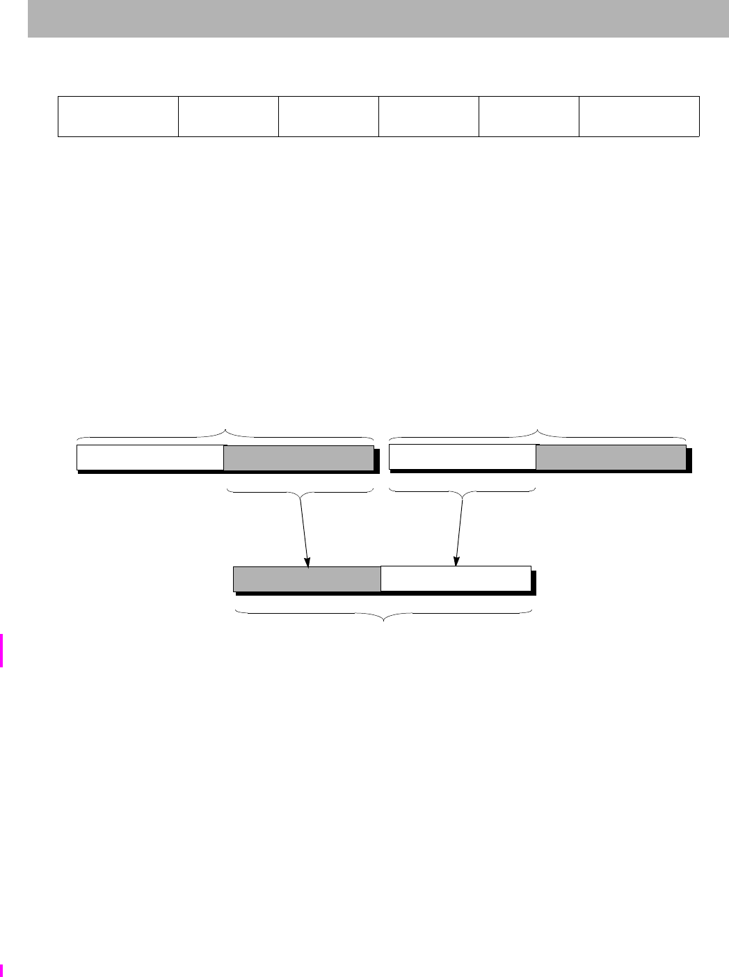
ALNV.PS
I
Floating Point Align Variable
The MIPS32® Instruction Set Manual, Revision 6.05 41
Format: ALNV.PS fd, fs, ft, rs MIPS64,MIPS32 Release 2, removed in Release 6
Purpose: Floating Point Align Variable
To align a misaligned pair of paired single values.
Description: FPR[fd] ByteAlign(GPR[rs]2..0, FPR[fs], FPR[ft])
FPR fs is concatenated with FPR ft and this value is funnel-shifted by GPR rs2..0 bytes, and written into FPR fd. If
GPR rs2..0 is 0, FPR fd receives FPR fs. If GPR rs2..0 is 4, the operation depends on the current endianness.
Figure 3-1 illustrates the following example: for a big-endian operation and a byte alignment of 4, the upper half of
FPR fd receives the lower half of the paired single value in fs, and the lower half of FPR fd receives the upper half of
the paired single value in FPR ft.
Figure 3.2 Example of an ALNV.PS Operation
The move is non arithmetic; it causes no IEEE 754 exceptions, and the FCSRCause and FCSRFlags fields are not
modified.
Restrictions:
The fields fs, ft, and fd must specify FPRs valid for operands of type PS. If the fields are not valid, the result is
UNPREDICTABLE.
If GPR rs1..0 are non-zero, the results are UNPREDICTABLE.
The result of this instruction is UNPREDICTABLE if the processor is executing in the FR=0 32-bit FPU register
model. The instruction is predictable if executing on a 64-bit FPU in the FR=1 mode, but not with FR=0, and not on
a 32-bit FPU.
Availability and Compatibility:
This instruction has been removed in Release 6.
Operation:
if GPR[rs]2..0 = 0 then
31 26 25 21 20 16 15 11 10 6 5 0
COP1X
010011 rs ft fs fd ALNV.PS
011110
6 5555 6
63 3132 0
63 3132 0
63 3132 0
FPR[ft]FPR[fs]

ALNV.PS
I
Floating Point Align Variable
The MIPS32® Instruction Set Manual, Revision 6.05 42
StoreFPR(fd, PS,ValueFPR(fs,PS))
else if GPR[rs]2..0 4 then
UNPREDICTABLE
else if BigEndianCPU then
StoreFPR(fd, PS, ValueFPR(fs, PS)31..0 || ValueFPR(ft,PS)63..32)
else
StoreFPR(fd, PS, ValueFPR(ft, PS)31..0 || ValueFPR(fs,PS)63..32)
endif
Exceptions:
Coprocessor Unusable, Reserved Instruction
Programming Notes:
ALNV.PS is designed to be used with LUXC1 to load 8 bytes of data from any 4-byte boundary. For example:
/* Copy T2 bytes (a multiple of 16) of data T0 to T1, T0 unaligned, T1 aligned.
Reads one dw beyond the end of T0. */
LUXC1 F0, 0(T0) /* set up by reading 1st src dw */
LI T3, 0 /* index into src and dst arrays */
ADDIU T4, T0, 8 /* base for odd dw loads */
ADDIU T5, T1, -8/* base for odd dw stores */
LOOP:
LUXC1 F1, T3(T4)
ALNV.PS F2, F0, F1, T0/* switch F0, F1 for little-endian */
SDC1 F2, T3(T1)
ADDIU T3, T3, 16
LUXC1 F0, T3(T0)
ALNV.PS F2, F1, F0, T0/* switch F1, F0 for little-endian */
BNE T3, T2, LOOP
SDC1 F2, T3(T5)
DONE:
ALNV.PS is also useful with SUXC1 to store paired-single results in a vector loop to a possibly misaligned address:
/* T1[i] = T0[i] + F8, T0 aligned, T1 unaligned. */
CVT.PS.S F8, F8, F8/* make addend paired-single */
/* Loop header computes 1st pair into F0, stores high half if T1 */
/* misaligned */
LOOP:
LDC1 F2, T3(T4)/* get T0[i+2]/T0[i+3] */
ADD.PS F1, F2, F8/* compute T1[i+2]/T1[i+3] */
ALNV.PS F3, F0, F1, T1/* align to dst memory */
SUXC1 F3, T3(T1)/* store to T1[i+0]/T1[i+1] */
ADDIU T3, 16 /* i = i + 4 */
LDC1 F2, T3(T0)/* get T0[i+0]/T0[i+1] */
ADD.PS F0, F2, F8/* compute T1[i+0]/T1[i+1] */
ALNV.PS F3, F1, F0, T1/* align to dst memory */
BNE T3, T2, LOOP
SUXC1 F3, T3(T5)/* store to T1[i+2]/T1[i+3] */
/* Loop trailer stores all or half of F0, depending on T1 alignment */

ALUIPC
I
Aligned Add Upper Immediate to PC
The MIPS32® Instruction Set Manual, Revision 6.05 43
Format: ALUIPC rs,immediate MIPS32 Release 6
Purpose: Aligned Add Upper Immediate to PC
Description: GPR[rs] ~0x0FFFF & ( PC + sign_extend( immediate << 16 ) )
This instruction performs a PC-relative address calculation. The 16-bit immediate is shifted left by 16 bits, sign-
extended, and added to the address of the ALUIPC instruction. The low 16 bits of the result are cleared, that is the
result is aligned on a 64K boundary. The result is placed in GPR rs.
Restrictions:
None
Availability and Compatibility:
This instruction is introduced by and required as of Release 6.
Operation:
GPR[rs] ~0x0FFFF & ( PC + sign_extend( immediate << 16 ) )
Exceptions:
None
31 26 25 21 20 16 15 0
PCREL
111011 rs ALUIPC
11111 immediate
655 16

AND and
44 The MIPS32® Instruction Set Manual, Revision 6.05
Format: AND rd, rs, rt MIPS32
Purpose: and
To do a bitwise logical AND.
Description: GPR[rd] GPR[rs] and GPR[rt]
The contents of GPR rs are combined with the contents of GPR rt in a bitwise logical AND operation. The result is
placed into GPR rd.
Restrictions:
None
Operation:
GPR[rd] GPR[rs] and GPR[rt]
Exceptions:
None
31 26 25 21 20 16 15 11 10 6 5 0
SPECIAL
000000 rs rt rd 0
00000
AND
100100
6 5555 6

ANDI
I
and immediate
The MIPS32® Instruction Set Manual, Revision 6.05 45
Format: ANDI rt, rs, immediate MIPS32
Purpose: and immediate
To do a bitwise logical AND with a constant
Description: GPR[rt] GPR[rs] and zero_extend(immediate)
The 16-bit immediate is zero-extended to the left and combined with the contents of GPR rs in a bitwise logical AND
operation. The result is placed into GPR rt.
Restrictions:
None
Operation:
GPR[rt] GPR[rs] and zero_extend(immediate)
Exceptions:
None
31 26 25 21 20 16 15 0
ANDI
001100 rs rt immediate
655 16

ANDI and immediate
46 The MIPS32® Instruction Set Manual, Revision 6.05

AUI
I
Add Immediate to Upper Bits
The MIPS32® Instruction Set Manual, Revision 6.05 47
Format: AUI rt, rs immediate MIPS32 Release 6
Purpose: Add Immediate to Upper Bits
Add Upper Immediate
Description:
GPR[rt] GPR[rs] + sign_extend(immediate << 16)
The 16 bit immediate is shifted left 16 bits, sign-extended, and added to the register rs, storing the result in rt.
In Release 6, LUI is an assembly idiom for AUI with rs=0.
Restrictions:
Availability and Compatibility:
AUI is introduced by and required as of Release 6.
Operation:
GPR[rt] GPR[rs] + sign_extend(immediate << 16)
Exceptions:
None.
Programming Notes:
AUI can be used to synthesize large constants in situations where it is not convenient to load a large constant from
memory. To simplify hardware that may recognize sequences of instructions as generating large constants, AUI
should be used in a stylized manner.
To create an integer:
LUI rd, imm_low(rtmp)
ORI rd, rd, imm_upper
To create a large offset for a memory access whose address is of the form rbase+large_offset:
AUI rtmp, rbase, imm_upper
LW rd, (rtmp)imm_low
To create a large constant operand for an instruction of the form rd:=rs+large_immediate
or rd:=rs-large_immediate:
AUI rtmp, rs, imm_upper
ADDIU rd, rtmp, imm_low
31 26 25 21 20 16 15 0
AUI
001111 rs rt immediate
655 16

AUIPC Add Upper Immediate to PC
48 The MIPS32® Instruction Set Manual, Revision 6.05
Format: AUIPC rs, immediate MIPS32 Release 6
Purpose: Add Upper Immediate to PC
Description: GPR[rs] ( PC + ( immediate << 16 ) )
This instruction performs a PC-relative address calculation. The 16-bit immediate is shifted left by 16 bits, sign-
extended, and added to the address of the AUIPC instruction. The result is placed in GPR rs.
Restrictions:
None
Availability and Compatibility:
This instruction is introduced by and required as of Release 6.
Operation:
GPR[rs] ( PC + ( immediate << 16 ) )
Exceptions:
None
31 26 25 21 20 16 15 0
PCREL
111011 rs AUIPC
11110 immediate
655 16

B
I
Unconditional Branch
The MIPS32® Instruction Set Manual, Revision 6.05 49
Format: B offset Assembly Idiom
Purpose: Unconditional Branch
To do an unconditional branch.
Description: branch
B offset is the assembly idiom used to denote an unconditional branch. The actual instruction is interpreted by the
hardware as BEQ r0, r0, offset.
An 18-bit signed offset (the 16-bit offset field shifted left 2 bits) is added to the address of the instruction following
the branch (not the branch itself), in the branch delay slot, to form a PC-relative effective target address.
Restrictions:
Control Transfer Instructions (CTIs) should not be placed in branch delay slots or Release 6 forbidden slots. CTIs
include all branches and jumps, NAL, ERET, ERETNC, DERET, WAIT, and PAUSE.
Pre-Release 6: Processor operation is UNPREDICTABLE if a control transfer instruction (CTI) is placed in the
delay slot of a branch or jump.
Release 6: If a control transfer instruction (CTI) is executed in the delay slot of a branch or jump, Release 6 imple-
mentations are required to signal a Reserved Instruction exception.
Operation:
I: target_offset sign_extend(offset || 02)
I+1: PC PC + target_offset
Exceptions:
None
Programming Notes:
With the 18-bit signed instruction offset, the conditional branch range is 128 Kbytes. Use jump (J) or jump register
(JR) or the Release 6 branch compact (BC) instructions to branch to addresses outside this range.
31 26 25 21 20 16 15 0
BEQ
000100
0
00000
0
00000 offset
655 16

BAL
I
Branch and Link
The MIPS32® Instruction Set Manual, Revision 6.05 50
Format: BAL offset Assembly Idiom MIPS32, MIPS32 Release 6
Purpose: Branch and Link
To do an unconditional PC-relative procedure call.
Description: procedure_call
Place the return address link in GPR 31. The return link is the address of the second instruction following the branch,
where execution continues after a procedure call.
An 18-bit signed offset (the 16-bit offset field shifted left 2-bits) is added to the address of the instruction following
the branch (not the branch itself), in the branch delay slot, to form a PC-relative effective target address.
Restrictions:
Control Transfer Instructions (CTIs) should not be placed in branch delay slots or Release 6 forbidden slots. CTIs
include all branches and jumps, NAL, ERET, ERETNC, DERET, WAIT, and PAUSE.
Pre-Release 6: Processor operation is UNPREDICTABLE if a control transfer instruction (CTI) is placed in the
delay slot of a branch or jump.
Release 6: If a control transfer instruction (CTI) is executed in the delay slot of a branch or jump, Release 6 imple-
mentations are required to signal a Reserved Instruction exception.
Availability and Compatibility:
Pre-Release 6: BAL offset is the assembly idiom used to denote an unconditional branch. The actual instruction is
interpreted by the hardware as BGEZAL r0, offset.
Release 6 keeps the BAL special case of BGEZAL, but removes all other instances of BGEZAL. BGEZAL with rs
any register other than GPR[0] is required to signal a Reserved Instruction exception.
Operation:
I: target_offset sign_extend(offset || 02)
GPR[31] PC + 8
I+1: PC PC + target_offset
Exceptions:
None
Programming Notes:
BAL without a corresponding return should NOT be used to read the PC. Doing so is likely to cause a performance
loss on processors with a return address predictor.
pre-Release 6:
31 26 25 21 20 16 15 0
REGIMM
000001 00000 BGEZAL
10001 offset
655 16
Release 6:
31 26 25 21 20 16 15 0
REGIMM
000001
0
00000
BAL
10001 offset
655 16

BAL Branch and Link
51 The MIPS32® Instruction Set Manual, Revision 6.05
With the 18-bit signed instruction offset, the conditional branch range is 128 KBytes. Use jump and link (JAL) or
jump and link register (JALR) instructions for procedure calls to addresses outside this range.

BALC
I
Branch and Link, Compact
The MIPS32® Instruction Set Manual, Revision 6.05 52
Format: BALC offset MIPS32 Release 6
Purpose: Branch and Link, Compact
To do an unconditional PC-relative procedure call.
Description: procedure_call (no delay slot)
Place the return address link in GPR 31. The return link is the address of the instruction immediately following the
branch, where execution continues after a procedure call. (Because compact branches have no delay slots, see below.)
A 28-bit signed offset (the 26-bit offset field shifted left 2 bits) is added to the address of the instruction following the
branch (not the branch itself), to form a PC-relative effective target address.
Compact branches do not have delay slots. The instruction after the branch is NOT executed when the branch is
taken.
Restrictions:
This instruction is an unconditional, always taken, compact branch. It does not have a forbidden slot, that is, a
Reserved Instruction exception is not caused by a Control Transfer Instruction placed in the slot following the branch.
Availability and Compatibility:
This instruction is introduced by and required as of Release 6.
Release 6 instruction BALC occupies the same encoding as pre-Release 6 instruction SWC2. The SWC2 instruction
has been moved to the COP2 major opcode in MIPS Release 6.
Exceptions:
None
Operation:
target_offset sign_extend( offset || 02 )
GPR[31] PC+4
PC PC+4 + sign_extend(target_offset)
31 26 25 0
BALC
111010 offset
626

BC Branch, Compact
53 The MIPS32® Instruction Set Manual, Revision 6.05
Format: BC offset MIPS32 Release 6
Purpose: Branch, Compact
Description: PC PC+4 + sign_extend( offset << 2)
A 28-bit signed offset (the 26-bit offset field shifted left 2 bits) is added to the address of the instruction following the
branch (not the branch itself), to form a PC-relative effective target address.
Compact branches have no delay slot: the instruction after the branch is NOT executed when the branch is taken.
Restrictions:
This instruction is an unconditional, always taken, compact branch. It does not have a forbidden slot, that is, a
Reserved Instruction exception is not caused by a Control Transfer Instruction placed in the slot following the branch.
Availability and Compatibility:
This instruction is introduced by and required as of Release 6.
Release 6 instruction BC occupies the same encoding as pre-Release 6 instruction LWC2. The LWC2 instruction has
been moved to the COP2 major opcode in MIPS Release 6.
Exceptions:
None
Operation:
target_offset sign_extend( offset || 02 )
PC ( PC+4 + sign_extend(target_offset) )
31 26 25 0
BC
110010 offset
626

BC1EQZ BC1NEZ
I
Branch if Coprocessor 1 (FPU) Register Bit 0 Equal/Not Equal to Zero
The MIPS32® Instruction Set Manual, Revision 6.05 54
Format: BC1EQZ BC1NEZ
BC1EQZ ft, offset MIPS32 Release 6
BC1NEZ ft, offset MIPS32 Release 6
Purpose: Branch if Coprocessor 1 (FPU) Register Bit 0 Equal/Not Equal to Zero
BC1EQZ: Branch if Coprocessor 1 (FPU) Register Bit 0 is Equal to Zero
BC1NEZ: Branch if Coprocessor 1 (FPR) Register Bit 0 is Not Equal to Zero
Description:
BC1EQZ: if FPR[ft] & 1 = 0 then branch
BC1NEZ: if FPR[ft] & 1 0 then branch
The condition is evaluated on FPU register ft.
• For BC1EQZ, the condition is true if and only if bit 0 of the FPU register ft is zero.
• For BC1NEZ, the condition is true if and only if bit 0 of the FPU register ft is non-zero.
If the condition is false, the branch is not taken, and execution continues with the next instruction.
A 18-bit signed offset (the 16-bit offset field shifted left 2 bits) is added to the address of the instruction following the
branch (not the branch itself), to form a PC-relative effective target address. Execute the instruction in the delay slot
before the instruction at the target.
Restrictions:
If access to Coprocessor 1 is not enabled, a Coprocessor Unusable Exception is signaled.
Because these instructions BC1EQZ and BC1NEZ do not depend on a particular floating point data type, they operate
whenever Coprocessor 1 is enabled.
Control Transfer Instructions (CTIs) should not be placed in branch delay slots or Release 6 forbidden slots. CTIs
include all branches and jumps, NAL, ERET, ERETNC, DERET, WAIT, and PAUSE.
If a control transfer instruction (CTI) is executed in the delay slot of a branch or jump, Release 6 implementations are
required to signal a Reserved Instruction exception.
Availability and Compatibility:
These instructions are introduced by and required as of Release 6.
Exceptions:
Coprocessor Unusable1
Operation:
31 26 25 21 20 16 15 0
COP1
010001
BC1EQZ
01001 ft offset
COP1
010001
BC1NEZ
01101 ft offset
655 16
1. In Release 6, BC1EQZ and BC1NEZ are required, if the FPU is implemented. They must not signal a Reserved Instruction
exception. They can signal a Coprocessor Unusable Exception.

BC1EQZ BC1NEZ Branch if Coprocessor 1 (FPU) Register Bit 0 Equal/Not Equal to Zero
55 The MIPS32® Instruction Set Manual, Revision 6.05
tmp ValueFPR(ft, UNINTERPRETED_WORD)
BC1EQZ: cond tmp & 1 = 0
BC1NEZ: cond tmp & 1 0
if cond then
I: target_PC ( PC+4 + sign_extend( offset << 2 )
I+1: PC target_PC
Programming Notes:
Release 6: These instructions, BC1EQZ and BC1NEZ, replace the pre-Release 6 instructions BC1F and BC1T. These
Release 6 FPU branches depend on bit 0 of the scalar FPU register.
Note: BC1EQZ and BC1NEZ do not have a format or data type width. The same instructions are used for branches
based on conditions involving any format, including 32-bit S (single precision) and W (word) format, and 64-bit D
(double precision) and L (longword) format, as well as 128-bit MSA. The FPU scalar comparison instructions
CMP.condn.fmt produce an all ones or all zeros truth mask of their format width with the upper bits (where applica-
ble) UNPREDICTABLE. BC1EQZ and BC1NEZ consume only bit 0 of the CMP.condn.fmt output value, and there-
fore operate correctly independent of fmt.

BC1F
I
Branch on FP False
The MIPS32® Instruction Set Manual, Revision 6.05 56
Format: BC1F offset (cc = 0 implied) MIPS32, removed in Release 6
BC1F cc, offset MIPS32, removed in Release 6
Purpose: Branch on FP False
To test an FP condition code and do a PC-relative conditional branch.
Description: if FPConditionCode(cc) = 0 then branch
An 18-bit signed offset (the 16-bit offset field shifted left 2 bits) is added to the address of the instruction following
the branch (not the branch itself) in the branch delay slot to form a PC-relative effective target address. If the FP con-
dition code bit cc is false (0), the program branches to the effective target address after the instruction in the delay slot
is executed. An FP condition code is set by the FP compare instruction, C.cond.fmt.
Restrictions:
Processor operation is UNPREDICTABLE if a control transfer instruction (CTI) is placed in the delay slot of a
branch or jump.
Availability and Compatibility:
This instruction has been removed in Release 6.
Operation:
I: condition FPConditionCode(cc) = 0
target_offset (offset15)GPRLEN-(16+2) || offset || 02
I+1: if condition then
PC PC + target_offset
endif
Exceptions:
Coprocessor Unusable, Reserved Instruction
Floating Point Exceptions:
Unimplemented Operation
Programming Notes:
With the 18-bit signed instruction offset, the conditional branch range is 128 KBytes. Use jump (J) or jump register
(JR) to branch to addresses outside this range.
This instruction has been removed in Release 6 and has been replaced by the BC1EQZ instruction. Refer to the
‘BC1EQZ’ instruction in this manual for more information.
Historical Information:
The MIPS I architecture defines a single floating point condition code, implemented as the coprocessor 1 condition
signal (Cp1Cond) and the C bit in the FP Control/Status register. MIPS I, II, and III architectures must have the CC
field set to 0, which is implied by the first format in the “Format” section.
The MIPS IV and MIPS32 architectures add seven more Condition Code bits to the original condition code 0. FP
compare and conditional branch instructions specify the Condition Code bit to set or test. Both assembler formats are
31 26 25 21 20 18 17 16 15 0
COP1
010001
BC
01000 cc nd
0
tf
0offset
65311 16

BC1F Branch on FP False
57 The MIPS32® Instruction Set Manual, Revision 6.05
valid for MIPS IV and MIPS32.

BC1FL
I
Branch on FP False Likely
The MIPS32® Instruction Set Manual, Revision 6.05 58
Format: BC1FL offset (cc = 0 implied) MIPS32, removed in Release 6
BC1FL cc, offset MIPS32, removed in Release 6
Purpose: Branch on FP False Likely
To test an FP condition code and make a PC-relative conditional branch; execute the instruction in the delay slot only
if the branch is taken.
Description: if FPConditionCode(cc) = 0 then branch_likely
An 18-bit signed offset (the 16-bit offset field shifted left 2 bits) is added to the address of the instruction following
the branch (not the branch itself) in the branch delay slot to form a PC-relative effective target address. If the FP Con-
dition Code bit cc is false (0), the program branches to the effective target address after the instruction in the delay
slot is executed. If the branch is not taken, the instruction in the delay slot is not executed.
An FP condition code is set by the FP compare instruction, C.cond.fmt.
Restrictions:
Processor operation is UNPREDICTABLE if a branch, jump, ERET, DERET, or WAIT instruction is placed in the
delay slot of a branch or jump.
Availability and Compatibility:
This instruction has been removed in Release 6.
Operation:
This operation specification is for the general Branch On Condition operation with the tf (true/false) and nd (nullify
delay slot) fields as variables. The individual instructions BC1F, BC1FL, BC1T, and BC1TL have specific values for
tf and nd.
I: condition FPConditionCode(cc) = 0
target_offset (offset15)GPRLEN-(16+2) || offset || 02
I+1: if condition then
PC PC + target_offset
else
NullifyCurrentInstruction()
endif
Exceptions:
Coprocessor Unusable, Reserved Instruction
Floating Point Exceptions:
Unimplemented Operation
Implementation Note:
Some implementations always predict that the branch will be taken, and do not use nor do they update the branch
internal processor branch prediction tables for this instruction. To maintain performance compatibility, future imple-
mentations are encouraged to do the same.
31 26 25 21 20 18 17 16 15 0
COP1
010001
BC
01000 cc nd
1
tf
0offset
65311 16

BC1FL Branch on FP False Likely
59 The MIPS32® Instruction Set Manual, Revision 6.05
Programming Notes:
With the 18-bit signed instruction offset, the conditional branch range is 128 KBytes. Use jump (J) or jump register
(JR) to branch to addresses outside this range.
In Pre-Release 6 implementations, software is strongly encouraged to avoid the use of the Branch Likely instructions,
as they will be removed from a future revision of the MIPS Architecture.
Some implementations always predict the branch will be taken, so there is a significant penalty if the branch is not
taken. Software should only use this instruction when there is a very high probability (98% or more) that the branch
will be taken. If the branch is not likely to be taken or if the probability of a taken branch is unknown, software is
encouraged to use the BC1F instruction instead.
Historical Information:
The MIPS I architecture defines a single floating point condition code, implemented as the coprocessor 1 condition
signal (Cp1Cond) and the C bit in the FP Control/Status register. MIPS I, II, and III architectures must have the CC
field set to 0, which is implied by the first format in the “Format” section.
The MIPS IV and MIPS32 architectures add seven more Condition Code bits to the original condition code 0. FP
compare and conditional branch instructions specify the Condition Code bit to set or test. Both assembler formats are
valid for MIPS IV and MIPS32.

BC1T
I
Branch on FP True
The MIPS32® Instruction Set Manual, Revision 6.05 60
Format: BC1T offset (cc = 0 implied) MIPS32, removed in Release 6
BC1T cc, offset MIPS32, removed in Release 6
Purpose: Branch on FP True
To test an FP condition code and do a PC-relative conditional branch.
Description: if FPConditionCode(cc) = 1 then branch
An 18-bit signed offset (the 16-bit offset field shifted left 2 bits) is added to the address of the instruction following
the branch (not the branch itself) in the branch delay slot to form a PC-relative effective target address. If the FP con-
dition code bit cc is true (1), the program branches to the effective target address after the instruction in the delay slot
is executed. An FP condition code is set by the FP compare instruction, C.cond.fmt.
Restrictions:
Processor operation is UNPREDICTABLE if a control transfer instruction (CTI) is placed in the delay slot of a
branch or jump.
Availability and Compatibility:
This instruction has been removed in Release 6.
Operation:
I: condition FPConditionCode(cc) = 1
target_offset (offset15)GPRLEN-(16+2) || offset || 02
I+1: if condition then
PC PC + target_offset
endif
Exceptions:
Coprocessor Unusable, Reserved Instruction
Floating Point Exceptions:
Unimplemented Operation
Programming Notes:
With the 18-bit signed instruction offset, the conditional branch range is 128 KBytes. Use jump (J) or jump register
(JR) to branch to addresses outside this range.
This instruction has been replaced by the BC1NEZ instruction. Refer to the ‘BC1NEZ’ instruction in this manual for
more information.
Historical Information:
The MIPS I architecture defines a single floating point condition code, implemented as the coprocessor 1 condition
signal (Cp1Cond) and the C bit in the FP Control/Status register. MIPS I, II, and III architectures must have the CC
field set to 0, which is implied by the first format in the “Format” section.
31 26 25 21 20 18 17 16 15 0
COP1
010001
BC
01000 cc nd
0
tf
1offset
65311 16

BC1T Branch on FP True
61 The MIPS32® Instruction Set Manual, Revision 6.05
The MIPS IV and MIPS32 architectures add seven more Condition Code bits to the original condition code 0. FP
compare and conditional branch instructions specify the Condition Code bit to set or test. Both assembler formats are
valid for MIPS IV and MIPS32.

BC1TL
I
Branch on FP True Likely
The MIPS32® Instruction Set Manual, Revision 6.05 62
Format: BC1TL offset (cc = 0 implied) MIPS32, removed in Release 6
BC1TL cc, offset MIPS32, removed in Release 6
Purpose: Branch on FP True Likely
To test an FP condition code and do a PC-relative conditional branch; execute the instruction in the delay slot only if
the branch is taken.
Description: if FPConditionCode(cc) = 1 then branch_likely
An 18-bit signed offset (the 16-bit offset field shifted left 2 bits) is added to the address of the instruction following
the branch (not the branch itself) in the branch delay slot to form a PC-relative effective target address. If the FP Con-
dition Code bit cc is true (1), the program branches to the effective target address after the instruction in the delay slot
is executed. If the branch is not taken, the instruction in the delay slot is not executed.
An FP condition code is set by the FP compare instruction, C.cond.fmt.
Restrictions:
Processor operation is UNPREDICTABLE if a branch, jump, ERET, DERET, or WAIT instruction is placed in the
delay slot of a branch or jump.
Availability and Compatibility:
This instruction has been removed in Release 6.
Operation:
This operation specification is for the general Branch On Condition operation with the tf (true/false) and nd (nullify
delay slot) fields as variables. The individual instructions BC1F, BC1FL, BC1T, and BC1TL have specific values for
tf and nd.
I: condition FPConditionCode(cc) = 1
target_offset (offset15)GPRLEN-(16+2) || offset || 02
I+1: if condition then
PC PC + target_offset
else
NullifyCurrentInstruction()
endif
Exceptions:
Coprocessor Unusable, Reserved Instruction
Floating Point Exceptions:
Unimplemented Operation
Implementation Note:
Some implementations always predict that the branch will be taken, and do not use nor do they update the branch
internal processor branch prediction tables for this instruction. To maintain performance compatibility, future imple-
mentations are encouraged to do the same.
31 26 25 21 20 18 17 16 15 0
COP1
010001
BC
01000 cc nd
1
tf
1offset
65311 16

BC1TL Branch on FP True Likely
63 The MIPS32® Instruction Set Manual, Revision 6.05
Programming Notes:
With the 18-bit signed instruction offset, the conditional branch range is 128 KBytes. Use jump (J) or jump register
(JR) to branch to addresses outside this range.
In Pre-Release 6 implementations, software is strongly encouraged to avoid the use of the Branch Likely instructions,
as they will be removed from a future revision of the MIPS Architecture.
Some implementations always predict the branch will be taken, so there is a significant penalty if the branch is not
taken. Software should only use this instruction when there is a very high probability (98% or more) that the branch
will be taken. If the branch is not likely to be taken or if the probability of a taken branch is unknown, software is
encouraged to use the BC1T instruction instead.
Historical Information:
The MIPS I architecture defines a single floating point condition code, implemented as the coprocessor 1 condition
signal (Cp1Cond) and the C bit in the FP Control/Status register. MIPS I, II, and III architectures must have the CC
field set to 0, which is implied by the first format in the “Format” section.
The MIPS IV and MIPS32 architectures add seven more Condition Code bits to the original condition code 0. FP
compare and conditional branch instructions specify the Condition Code bit to set or test. Both assembler formats are
valid for MIPS IV and MIPS32.

BC2EQZ BC2NEZ
I
Branch if Coprocessor 2 Condition (Register) Equal/Not Equal to Zero
The MIPS32® Instruction Set Manual, Revision 6.05 64
Format: BC2EQZ BC2NEZ
BC2EQZ ct, offset MIPS32 Release 6
BC2NEZ ct, offset MIPS32 Release 6
Purpose: Branch if Coprocessor 2 Condition (Register) Equal/Not Equal to Zero
BC2EQZ: Branch if Coprocessor 2 Condition (Register) is Equal to Zero
BC2NEZ: Branch if Coprocessor 2 Condition (Register) is Not Equal to Zero
Description:
BC2EQZ: if COP2Condition[ct] = 0 then branch
BC2NEZ: if COP2Condition[ct] 0 then branch
The 5-bit field ct specifies a coprocessor 2 condition.
• For BC2EQZ if the coprocessor 2 condition is true the branch is taken.
• For BC2NEZ if the coprocessor 2 condition is false the branch is taken.
A 18-bit signed offset (the 16-bit offset field shifted left 2 bits) is added to the address of the instruction following the
branch (not the branch itself), to form a PC-relative effective target address. Execute the instruction in the delay slot
before the instruction at the target.
Restrictions:
Control Transfer Instructions (CTIs) should not be placed in branch delay slots or Release 6 forbidden slots. CTIs
include all branches and jumps, NAL, ERET, ERETNC, DERET, WAIT, and PAUSE.
If a control transfer instruction (CTI) is executed in the delay slot of a branch or jump, Release 6 implementations are
required to signal a Reserved Instruction exception.
If access to Coprocessor 2 is not enabled, a Coprocessor Unusable Exception is signaled.
Availability and Compatibility:
These instructions are introduced by and required as of Release 6.
Exceptions:
Coprocessor Unusable, Reserved Instruction
Operation:
tmpcond Coprocessor2Condition(ct)
if BC2EQZ then
tmpcond not(tmpcond)
endif
if tmpcond then
PC PC+4 + sign_extend( immediate << 2 ) )
endif
31 26 25 21 20 16 15 0
COP2
010010
BC2EQZ
01001 ct offset
COP2
010010
BC2NEZ
01101 ct offset
655 16

BC2EQZ BC2NEZ Branch if Coprocessor 2 Condition (Register) Equal/Not Equal to Zero
65 The MIPS32® Instruction Set Manual, Revision 6.05
Implementation Notes:
As of Release 6 these instructions, BC2EQZ and BC2NEZ, replace the pre-Release 6 instructions BC2F and BC2T,
which had a 3-bit condition code field (as well as nullify and true/false bits). Release 6 makes all 5 bits of the ct con-
dition code available to the coprocessor designer as a condition specifier.
A customer defined coprocessor instruction set can implement any sort of condition it wants. For example, it could
implement up to 32 single-bit flags, specified by the 5-bit field ct. It could also implement conditions encoded as
values in a coprocessor register (such as testing the least significant bit of a coprocessor register) as done by Release
6 instructions BC1EQZ/BC1NEZ.

BC2F
I
Branch on COP2 False
The MIPS32® Instruction Set Manual, Revision 6.05 66
Format: BC2F offset (cc = 0 implied) MIPS32, removed in Release 6
BC2F cc, offset MIPS32, removed in Release 6
Purpose: Branch on COP2 False
To test a COP2 condition code and do a PC-relative conditional branch.
Description: if COP2Condition(cc) = 0 then branch
An 18-bit signed offset (the 16-bit offset field shifted left 2 bits) is added to the address of the instruction following
the branch (not the branch itself) in the branch delay slot to form a PC-relative effective target address. If the COP2
condition specified by cc is false (0), the program branches to the effective target address after the instruction in the
delay slot is executed.
Restrictions:
Processor operation is UNPREDICTABLE if a control transfer instruction (CTI) is placed in the delay slot of a
branch or jump.
Availability and Compatibility:
This instruction has been removed in Release 6.
Operation:
I: condition COP2Condition(cc) = 0
target_offset (offset15)GPRLEN-(16+2) || offset || 02
I+1: if condition then
PC PC + target_offset
endif
Exceptions:
Coprocessor Unusable, Reserved Instruction
Programming Notes:
With the 18-bit signed instruction offset, the conditional branch range is 128 KBytes. Use jump (J) or jump register
(JR) to branch to addresses outside this range.
This instruction has been replaced by the BC2EQZ instruction. Refer to the ‘BC2EQZ’ instruction in this manual for
more information.
31 26 25 21 20 18 17 16 15 0
COP2
010010
BC
01000 cc nd
0
tf
0offset
65311 16

BC2FL Branch on COP2 False Likely
67 The MIPS32® Instruction Set Manual, Revision 6.05
Format: BC2FL offset (cc = 0 implied) MIPS32, removed in Release 6
BC2FL cc, offset MIPS32, removed in Release 6
Purpose: Branch on COP2 False Likely
To test a COP2 condition code and make a PC-relative conditional branch; execute the instruction in the delay slot
only if the branch is taken.
Description: if COP2Condition(cc) = 0 then branch_likely
An 18-bit signed offset (the 16-bit offset field shifted left 2 bits) is added to the address of the instruction following
the branch (not the branch itself) in the branch delay slot to form a PC-relative effective target address. If the COP2
condition specified by cc is false (0), the program branches to the effective target address after the instruction in the
delay slot is executed. If the branch is not taken, the instruction in the delay slot is not executed.
Restrictions:
Processor operation is UNPREDICTABLE if a branch, jump, ERET, DERET, or WAIT instruction is placed in the
delay slot of a branch or jump.
Availability and Compatibility:
This instruction has been removed in Release 6.
Operation:
This operation specification is for the general Branch On Condition operation with the tf (true/false) and nd (nullify
delay slot) fields as variables. The individual instructions BC2F, BC2FL, BC2T, and BC2TL have specific values for
tf and nd.
I: condition COP2Condition(cc) = 0
target_offset (offset15)GPRLEN-(16+2) || offset || 02
I+1: if condition then
PC PC + target_offset
else
NullifyCurrentInstruction()
endif
Exceptions:
Coprocessor Unusable, Reserved Instruction
Implementation Note:
Some implementations always predict that the branch will be taken, and do not use nor do they update the branch
internal processor branch prediction tables for this instruction. To maintain performance compatibility, future imple-
mentations are encouraged to do the same.
Programming Notes:
With the 18-bit signed instruction offset, the conditional branch range is 128 KBytes. Use jump (J) or jump register
(JR) to branch to addresses outside this range.
In Pre-Release 6 implementations, software is strongly encouraged to avoid the use of the Branch Likely instructions,
31 26 25 21 20 18 17 16 15 0
COP2
010010
BC
01000 cc nd
1
tf
0offset
65311 16

BC2FL
I
Branch on COP2 False Likely
The MIPS32® Instruction Set Manual, Revision 6.05 68
as they will be removed from a future revision of the MIPS Architecture.
Some implementations always predict the branch will be taken, so there is a significant penalty if the branch is not
taken. Software should only use this instruction when there is a very high probability (98% or more) that the branch
will be taken. If the branch is not likely to be taken or if the probability of a taken branch is unknown, software is
encouraged to use the BC2F instruction instead.

BC2T Branch on COP2 True
69 The MIPS32® Instruction Set Manual, Revision 6.05
Format: BC2T offset (cc = 0 implied) MIPS32, removed in Release 6
BC2T cc, offset MIPS32, removed in Release 6
Purpose: Branch on COP2 True
To test a COP2 condition code and do a PC-relative conditional branch.
Description: if COP2Condition(cc) = 1 then branch
An 18-bit signed offset (the 16-bit offset field shifted left 2 bits) is added to the address of the instruction following
the branch (not the branch itself) in the branch delay slot to form a PC-relative effective target address. If the COP2
condition specified by cc is true (1), the program branches to the effective target address after the instruction in the
delay slot is executed.
Restrictions:
Processor operation is UNPREDICTABLE if a control transfer instruction (CTI) is placed in the delay slot of a
branch or jump.
Availability and Compatibility:
This instruction has been removed in Release 6.
Operation:
I: condition COP2Condition(cc) = 1
target_offset (offset15)GPRLEN-(16+2) || offset || 02
I+1: if condition then
PC PC + target_offset
endif
Exceptions:
Coprocessor Unusable, Reserved Instruction
Programming Notes:
With the 18-bit signed instruction offset, the conditional branch range is 128 KBytes. Use jump (J) or jump register
(JR) to branch to addresses outside this range.
This instruction has been replaced by the BC2NEZ instruction. Refer to the ‘BC2NEZ’ instruction in this manual for
more information.
31 26 25 21 20 18 17 16 15 0
COP2
010010
BC
01000 cc nd
0
tf
1offset
65311 16

BC2TL
I
Branch on COP2 True Likely
The MIPS32® Instruction Set Manual, Revision 6.05 70
Format: BC2TL offset (cc = 0 implied) MIPS32, removed in Release 6
BC2TL cc, offset MIPS32, removed in Release 6
Purpose: Branch on COP2 True Likely
To test a COP2 condition code and do a PC-relative conditional branch; execute the instruction in the delay slot only
if the branch is taken.
Description: if COP2Condition(cc) = 1 then branch_likely
An 18-bit signed offset (the 16-bit offset field shifted left 2 bits) is added to the address of the instruction following
the branch (not the branch itself) in the branch delay slot to form a PC-relative effective target address. If the COP2
condition specified by cc is true (1), the program branches to the effective target address after the instruction in the
delay slot is executed. If the branch is not taken, the instruction in the delay slot is not executed.
Restrictions:
Processor operation is UNPREDICTABLE if a branch, jump, ERET, DERET, or WAIT instruction is placed in the
delay slot of a branch or jump.
Availability and Compatibility:
This instruction has been removed in Release 6.
Operation:
This operation specification is for the general Branch On Condition operation with the tf (true/false) and nd (nullify
delay slot) fields as variables. The individual instructions BC2F, BC2FL, BC2T, and BC2TL have specific values for
tf and nd.
I: condition COP2Condition(cc) = 1
target_offset (offset15)GPRLEN-(16+2) || offset || 02
I+1: if condition then
PC PC + target_offset
else
NullifyCurrentInstruction()
endif
Exceptions:
Coprocessor Unusable, Reserved Instruction
Implementation Note:
Some implementations always predict that the branch will be taken, and do not use nor do they update the branch
internal processor branch prediction tables for this instruction. To maintain performance compatibility, future imple-
mentations are encouraged to do the same.
Programming Notes:
With the 18-bit signed instruction offset, the conditional branch range is 128 KBytes. Use jump (J) or jump register
(JR) to branch to addresses outside this range.
In Pre-Release 6 implementations, software is strongly encouraged to avoid the use of the Branch Likely instructions,
31 26 25 21 20 18 17 16 15 0
COP2
010010
BC
01000 cc nd
1
tf
1offset
65311 16

BC2TL Branch on COP2 True Likely
71 The MIPS32® Instruction Set Manual, Revision 6.05
as they will be removed from a future revision of the MIPS Architecture.
Some implementations always predict the branch will be taken, so there is a significant penalty if the branch is not
taken. Software should only use this instruction when there is a very high probability (98% or more) that the branch
will be taken. If the branch is not likely to be taken or if the probability of a taken branch is unknown, software is
encouraged to use the BC2T instruction instead.

BEQ
I
Branch on Equal
The MIPS32® Instruction Set Manual, Revision 6.05 72
Format: BEQ rs, rt, offset MIPS32
Purpose: Branch on Equal
To compare GPRs then do a PC-relative conditional branch.
Description: if GPR[rs] = GPR[rt] then branch
An 18-bit signed offset (the 16-bit offset field shifted left 2 bits) is added to the address of the instruction following
the branch (not the branch itself), in the branch delay slot, to form a PC-relative effective target address.
If the contents of GPR rs and GPR rt are equal, branch to the effective target address after the instruction in the delay
slot is executed.
Restrictions:
Control Transfer Instructions (CTIs) should not be placed in branch delay slots or Release 6 forbidden slots. CTIs
include all branches and jumps, NAL, ERET, ERETNC, DERET, WAIT, and PAUSE.
Pre-Release 6: Processor operation is UNPREDICTABLE if a control transfer instruction (CTI) is placed in the
delay slot of a branch or jump.
Release 6: If a control transfer instruction (CTI) is executed in the delay slot of a branch or jump, Release 6 imple-
mentations are required to signal a Reserved Instruction exception.
Operation:
I: target_offset sign_extend(offset || 02)
condition (GPR[rs] = GPR[rt])
I+1: if condition then
PC PC + target_offset
endif
Exceptions:
None
Programming Notes:
With the 18-bit signed instruction offset, the conditional branch range is 128 KBytes. Use jump (J) or jump register
(JR) to branch to addresses outside this range.
BEQ r0, r0 offset, expressed as B offset, is the assembly idiom used to denote an unconditional branch.
31 26 25 21 20 16 15 0
BEQ
000100 rs rt offset
655 16

BEQL Branch on Equal Likely
73 The MIPS32® Instruction Set Manual, Revision 6.05
Format: BEQL rs, rt, offset MIPS32, removed in Release 6
Purpose: Branch on Equal Likely
To compare GPRs then do a PC-relative conditional branch; execute the delay slot only if the branch is taken.
Description: if GPR[rs] = GPR[rt] then branch_likely
An 18-bit signed offset (the 16-bit offset field shifted left 2 bits) is added to the address of the instruction following
the branch (not the branch itself), in the branch delay slot, to form a PC-relative effective target address.
If the contents of GPR rs and GPR rt are equal, branch to the target address after the instruction in the delay slot is
executed. If the branch is not taken, the instruction in the delay slot is not executed.
Restrictions:
Processor operation is UNPREDICTABLE if a branch, jump, ERET, DERET, or WAIT instruction is placed in the
delay slot of a branch or jump.
Availability and Compatibility:
This instruction has been removed in Release 6.
Operation:
I: target_offset sign_extend(offset || 02)
condition (GPR[rs] = GPR[rt])
I+1: if condition then
PC PC + target_offset
else
NullifyCurrentInstruction()
endif
Exceptions:
None
Implementation Note:
Some implementations always predict that the branch will be taken, and do not use nor do they update the branch
internal processor branch prediction tables for this instruction. To maintain performance compatibility, future imple-
mentations are encouraged to do the same.
Programming Notes:
With the 18-bit signed instruction offset, the conditional branch range is 128 KBytes. Use jump (J) or jump register
(JR) to branch to addresses outside this range.
In Pre-Release 6 implementations, software is strongly encouraged to avoid the use of the Branch Likely instructions,
as they will be removed from a future revision of the MIPS Architecture.
Some implementations always predict the branch will be taken, so there is a significant penalty if the branch is not
taken. Software should only use this instruction when there is a very high probability (98% or more) that the branch
will be taken. If the branch is not likely to be taken or if the probability of a taken branch is unknown, software is
encouraged to use the BEQ instruction instead.
31 26 25 21 20 16 15 0
BEQL
010100 rs rt offset
655 16

BEQL
I
Branch on Equal Likely
The MIPS32® Instruction Set Manual, Revision 6.05 74
Historical Information:
In the MIPS I architecture, this instruction signaled a Reserved Instruction exception.

BGEZ Branch on Greater Than or Equal to Zero
75 The MIPS32® Instruction Set Manual, Revision 6.05
Format: BGEZ rs, offset MIPS32
Purpose: Branch on Greater Than or Equal to Zero
To test a GPR then do a PC-relative conditional branch
Description: if GPR[rs] 0 then branch
An 18-bit signed offset (the 16-bit offset field shifted left 2 bits) is added to the address of the instruction following
the branch (not the branch itself), in the branch delay slot, to form a PC-relative effective target address.
If the contents of GPR rs are greater than or equal to zero (sign bit is 0), branch to the effective target address after the
instruction in the delay slot is executed.
Restrictions:
Control Transfer Instructions (CTIs) should not be placed in branch delay slots or Release 6 forbidden slots. CTIs
include all branches and jumps, NAL, ERET, ERETNC, DERET, WAIT, and PAUSE.
Pre-Release 6: Processor operation is UNPREDICTABLE if a control transfer instruction (CTI) is placed in the
delay slot of a branch or jump.
Release 6: If a control transfer instruction (CTI) is executed in the delay slot of a branch or jump, Release 6 imple-
mentations are required to signal a Reserved Instruction exception.
Operation:
I: target_offset sign_extend(offset || 02)
condition GPR[rs] 0GPRLEN
I+1: if condition then
PC PC + target_offset
endif
Exceptions:
None
Programming Notes:
With the 18-bit signed instruction offset, the conditional branch range is 128 KBytes. Use jump (J) or jump register
(JR) to branch to addresses outside this range.
31 26 25 21 20 16 15 0
REGIMM
000001 rs BGEZ
00001 offset
655 16

BGEZAL
I
Branch on Greater Than or Equal to Zero and Link
The MIPS32® Instruction Set Manual, Revision 6.05 76
Format: BGEZAL rs, offset MIPS32, removed in Release 6
Purpose: Branch on Greater Than or Equal to Zero and Link
To test a GPR then do a PC-relative conditional procedure call
Description: if GPR[rs] 0 then procedure_call
Place the return address link in GPR 31. The return link is the address of the second instruction following the branch,
where execution continues after a procedure call.
An 18-bit signed offset (the 16-bit offset field shifted left 2 bits) is added to the address of the instruction following
the branch (not the branch itself), in the branch delay slot, to form a PC-relative effective target address.
If the contents of GPR rs are greater than or equal to zero (sign bit is 0), branch to the effective target address after the
instruction in the delay slot is executed.
Availability and Compatibility
This instruction has been removed in Release 6 with the exception of special case BAL (unconditional Branch and
Link) which was an alias for BGEZAL with rs=0.
Restrictions:
Processor operation is UNPREDICTABLE if a control transfer instruction (CTI) is placed in the delay slot of a
branch or jump.
Branch-and-link Restartability: GPR 31 must not be used for the source register rs, because such an instruction does
not have the same effect when reexecuted. The result of executing such an instruction is UNPREDICTABLE. This
restriction permits an exception handler to resume execution by reexecuting the branch when an exception occurs in
the branch delay slot or forbidden slot.
Operation:
I: target_offset sign_extend(offset || 02)
condition GPR[rs] 0GPRLEN
GPR[31] PC + 8
I+1: if condition then
PC PC + target_offset
endif
Exceptions:
None
Programming Notes:
With the 18-bit signed instruction offset, the conditional branch range is 128 KBytes. Use jump and link (JAL) or
jump and link register (JALR) instructions for procedure calls to addresses outside this range.
BGEZAL r0, offset, expressed as BAL offset, is the assembly idiom used to denote a PC-relative branch and link.
BAL is used in a manner similar to JAL, but provides PC-relative addressing and a more limited target PC range.
31 26 25 21 20 16 15 0
REGIMM
000001 rs BGEZAL
10001 offset
655 16

B{LE,GE,GT,LT,EQ,NE}ZALC
I
Compact Zero-Compare and Branch-and-Link Instructions
The MIPS32® Instruction Set Manual, Revision 6.05 77
Format: B{LE,GE,GT,LT,EQ,NE}ZALC
BLEZALC rt, offset MIPS32 Release 6
BGEZALC rt, offset MIPS32 Release 6
BGTZALC rt, offset MIPS32 Release 6
BLTZALC rt, offset MIPS32 Release 6
BEQZALC rt, offset MIPS32 Release 6
BNEZALC rt, offset MIPS32 Release 6
Purpose: Compact Zero-Compare and Branch-and-Link Instructions
BLEZALC: Compact branch-and-link if GPR rt is less than or equal to zero
BGEZALC: Compact branch-and-link if GPR rt is greater than or equal to zero
BGTZALC: Compact branch-and-link if GPR rt is greater than zero
BLTZALC: Compact branch-and-link if GPR rt is less than to zero
BEQZALC: Compact branch-and-link if GPR rt is equal to zero
BNEZALC: Compact branch-and-link if GPR rt is not equal to zero
Description: if condition(GPR[rt]) then procedure_call branch (no delay slot)
The condition is evaluated. If the condition is true, the branch is taken.
Places the return address link in GPR 31. The return link is the address of the instruction immediately following the
branch, where execution continues after a procedure call.
The return address link is unconditionally updated.
A 18-bit signed offset (the 16-bit offset field shifted left 2 bits) is added to the address of the instruction following the
branch (not the branch itself), to form a PC-relative effective target address.
31 26 25 21 20 16 15 0
POP06
000110
BLEZALC
offset
00000 rt 00000
POP06
000110
BGEZALC
rs = rt 00000 offset
rs rt
POP07
000111
BGTZALC
offset
00000 rt 00000
POP07
000111
BLTZALC
rs = rt 00000 offset
rs rt
POP10
001000
BEQZALC
rs < rt offset
00000 rt 00000
POP30
011000
BNEZALC
rs < rt offset
00000 rt 00000
655 16

B{LE,GE,GT,LT,EQ,NE}ZALC Compact Zero-Compare and Branch-and-Link Instructions
78 The MIPS32® Instruction Set Manual, Revision 6.05
BLEZALC: the condition is true if and only if GPR rt is less than or equal to zero.
BGEZALC: the condition is true if and only if GPR rt is greater than or equal to zero.
BLTZALC: the condition is true if and only if GPR rt is less than zero.
BGTZALC: the condition is true if and only if GPR rt is greater than zero.
BEQZALC: the condition is true if and only if GPR rt is equal to zero.
BNEZALC: the condition is true if and only if GPR rt is not equal to zero.
Compact branches do not have delay slots. The instruction after a compact branch is only executed if the branch is not
taken.
Restrictions:
Control Transfer Instructions (CTIs) should not be placed in branch delay slots or Release 6 forbidden slots. CTIs
include all branches and jumps, NAL, ERET, ERETNC, DERET, WAIT, and PAUSE.
If a control transfer instruction (CTI) is executed in the forbidden slot of a compact branch, Release 6 implementa-
tions are required to signal a Reserved Instruction exception, but only when the branch is not taken.
Branch-and-link Restartability: GPR 31 must not be used for the source registers, because such an instruction does
not have the same effect when reexecuted. The result of executing such an instruction is UNPREDICTABLE. This
restriction permits an exception handler to resume execution by reexecuting the branch when an exception occurs in
the branch delay slot or forbidden slot.
Availability and Compatibility:
These instructions are introduced by and required as of Release 6.
• BEQZALC reuses the opcode assigned to pre-Release 6 ADDI.
• BNEZALC reuses the opcode assigned to pre-Release 6 MIPS64 DADDI.
These instructions occupy primary opcode spaces originally allocated to other instructions. BLEZALC and
BGEZALC have the same primary opcode as BLEZ, and are distinguished by rs and rt register numbers. Similarly,
BGTZALC and BLTZALC have the same primary opcode as BGTZ, and are distinguished by register fields.
BEQZALC and BNEZALC reuse the primary opcodes ADDI and DADDI.
Exceptions:
None
Operation:
GPR[31] PC+4
target_offset sign_extend( offset || 02 )
BLTZALC: cond GPR[rt] < 0
BLEZALC: cond GPR[rt] 0
BGEZALC: cond GPR[rt] 0
BGTZALC: cond GPR[rt] > 0
BEQZALC: cond GPR[rt] = 0
BNEZALC: cond GPR[rt] 0
if cond then
PC ( PC+4+ sign_extend( target_offset ) )
endif
Programming Notes:
Software that performs incomplete instruction decode may incorrectly decode these new instructions, because of their

B{LE,GE,GT,LT,EQ,NE}ZALC
I
Compact Zero-Compare and Branch-and-Link Instructions
The MIPS32® Instruction Set Manual, Revision 6.05 79
very tight encoding. For example, a disassembler might look only at the primary opcode field, instruction bits 31-26,
to decode BLEZL without checking that the “rt” field is zero. Such software violated the pre-Release 6 architecture
specification.
With the 16-bit offset shifted left 2 bits and sign extended, the conditional branch range is ± 128 KBytes. Other
instructions such as pre-Release 6 JAL and JALR, or Release 6 JIALC and BALC have larger ranges. In particular,
BALC, with a 26-bit offset shifted by 2 bits, has a 28-bit range, ± 128 MBytes. Code sequences using AUIPC and
JIALC allow still greater PC-relative range.

BGEZALL
I
Branch on Greater Than or Equal to Zero and Link Likely
The MIPS32® Instruction Set Manual, Revision 6.05 80
Format: BGEZALL rs, offset MIPS32, removed in Release 6
Purpose: Branch on Greater Than or Equal to Zero and Link Likely
To test a GPR then do a PC-relative conditional procedure call; execute the delay slot only if the branch is taken.
Description: if GPR[rs] 0 then procedure_call_likely
Place the return address link in GPR 31. The return link is the address of the second instruction following the branch,
where execution continues after a procedure call.
An 18-bit signed offset (the 16-bit offset field shifted left 2 bits) is added to the address of the instruction following
the branch (not the branch itself), in the branch delay slot, to form a PC-relative effective target address.
If the contents of GPR rs are greater than or equal to zero (sign bit is 0), branch to the effective target address after the
instruction in the delay slot is executed. If the branch is not taken, the instruction in the delay slot is not executed.
Restrictions:
Processor operation is UNPREDICTABLE if a control transfer instruction (CTI) is placed in the delay slot of a
branch or jump.
Branch-and-link Restartability: GPR 31 must not be used for the source register rs, because such an instruction does
not have the same effect when reexecuted. The result of executing such an instruction is UNPREDICTABLE. This
restriction permits an exception handler to resume execution by reexecuting the branch when an exception occurs in
the branch delay slot.
Availability and Compatibility:
This instruction has been removed in Release 6.
Operation:
I: target_offset sign_extend(offset || 02)
condition GPR[rs] 0GPRLEN
GPR[31] PC + 8
I+1: if condition then
PC PC + target_offset
else
NullifyCurrentInstruction()
endif
Exceptions:
None
Programming Notes:
With the 18-bit signed instruction offset, the conditional branch range is 128 KBytes. Use jump and link (JAL) or
jump and link register (JALR) instructions for procedure calls to addresses outside this range.
Some implementations always predict the branch will be taken, so there is a significant penalty if the branch is not
taken. Software should only use this instruction when there is a very high probability (98% or more) that the branch
will be taken. If the branch is not likely to be taken or if the probability of a taken branch is unknown, software is
31 26 25 21 20 16 15 0
REGIMM
000001 rs BGEZALL
10011 offset
655 16

BGEZALL
I
Branch on Greater Than or Equal to Zero and Link Likely
The MIPS32® Instruction Set Manual, Revision 6.05 81
encouraged to use the BGEZAL instruction instead.
Historical Information:
In the MIPS I architecture, this instruction signaled a Reserved Instruction exception.

B<cond>C Compact Compare-and-Branch Instructions
82 The MIPS32® Instruction Set Manual, Revision 6.05
Format: B<cond>C rs, rt, offset MIPS32 Release 6
Purpose: Compact Compare-and-Branch Instructions
Format Details:
Equal/Not-Equal register-register compare and branch with 16-bit offset:
BEQC rs, rt, offset MIPS32 Release 6
BNEC rs, rt, offset MIPS32 Release 6
31 26 25 21 20 16 15 0
POP26
010110
BLEZC
offset
00000 rt 00000
POP26
010110
BGEZC rs = rt
offset
rs 00000 rt 00000
POP26
010110
BGEC (BLEC) rs rt
offset
rs 00000 rt 00000
POP27
010111
BGTZC
offset
00000 rt 00000
POP27
010111
BLTZC rs = rt
offset
rs 00000 rt 00000
POP27
010111
BLTC (BGTC) rs rt
offset
rs 00000 rt 00000
POP06
000110
BGEUC (BLEUC) rs rt
offset
rs 00000 rt 00000
POP07
000111
BLTUC (BGTUC) rs rt
offset
rs 00000 rt 00000
POP10
001000
BEQC rs < rt
offset
rs 00000 rt 00000
POP30
011000
BNEC rs < rt
offset
rs 00000 rt 00000
655 16
31 26 25 21 20 0
POP66
110110
BEQZC
rs 00000
rs
offset
POP76
111110
BNEZC
rs 00000
rs
offset
65 21

B<cond>C
I
Compact Compare-and-Branch Instructions
The MIPS32® Instruction Set Manual, Revision 6.05 83
Signed register-register compare and branch with 16-bit offset:
BLTC rs, rt, offset MIPS32 Release 6
BGEC rs, rt, offset MIPS32 Release 6
Unsigned register-register compare and branch with 16-bit offset:
BLTUC rs, rt, offset MIPS32 Release 6
BGEUC rs, rt, offset MIPS32 Release 6
Assembly idioms with reversed operands for signed/unsigned compare-and-branch:
BGTC rt, rs, offset Assembly Idiom
BLEC rt, rs, offset Assembly Idiom
BGTUC rt, rs, offset Assembly Idiom
BLEUC rt, rs, offset Assembly Idiom
Signed Compare register to Zero and branch with 16-bit offset:
BLTZC rt, offset MIPS32 Release 6
BLEZC rt, offset MIPS32 Release 6
BGEZC rt, offset MIPS32 Release 6
BGTZC rt, offset MIPS32 Release 6
Equal/Not-equal Compare register to Zero and branch with 21-bit offset:
BEQZC rs, offset MIPS32 Release 6
BNEZC rs, offset MIPS32 Release 6
Description: if condition(GPR[rs] and/or GPR[rt]) then compact branch (no delay slot)
The condition is evaluated. If the condition is true, the branch is taken.
An 18/23-bit signed offset (the 16/21-bit offset field shifted left 2 bits) is added to the address of the instruction fol-
lowing the branch (not the branch itself), to form a PC-relative effective target address.
The offset is 16 bits for most compact branches, including BLTC, BLEC, BGEC, BGTC, BNEQC, BNEC, BLTUC,
BLEUC, BGEUC, BGTC, BLTZC, BLEZC, BGEZC, BGTZC. The offset is 21 bits for BEQZC and BNEZC.
Compact branches have no delay slot: the instruction after the branch is NOT executed if the branch is taken.
The conditions are as follows:
Equal/Not-equal register-register compare-and-branch with 16-bit offset:
BEQC: Compact branch if GPRs are equal
BNEC: Compact branch if GPRs are not equal
Signed register-register compare and branch with 16-bit offset:
BLTC: Compact branch if GPR rs is less than GPR rt
BGEC: Compact branch if GPR rs is greater than or equal to GPR rt
Unsigned register-register compare and branch with 16-bit offset:
BLTUC: Compact branch if GPR rs is less than GPR rt, unsigned
BGEUC: Compact branch if GPR rs is greater than or equal to GPR rt, unsigned
Assembly Idioms with Operands Reversed:
BLEC: Compact branch if GPR rt is less than or equal to GPR rs (alias for BGEC)
BGTC: Compact branch if GPR rt is greater than GPR rs (alias for BLTC)
BLEUC: Compact branch if GPR rt is less than or equal to GPR rt, unsigned (alias for BGEUC)
BGTUC: Compact branch if GPR rt is greater than GPR rs, unsigned (alias for BLTUC)

B<cond>C Compact Compare-and-Branch Instructions
84 The MIPS32® Instruction Set Manual, Revision 6.05
Compare register to zero and branch with 16-bit offset:
BLTZC: Compact branch if GPR rt is less than zero
BLEZC: Compact branch if GPR rt is less than or equal to zero
BGEZC: Compact branch if GPR rt is greater than or equal to zero
BGTZC: Compact branch if GPR rt is greater than zero
Compare register to zero and branch with 21-bit offset:
BEQZC: Compact branch if GPR rs is equal to zero
BNEZC: Compact branch if GPR rs is not equal to zero
Restrictions:
Control Transfer Instructions (CTIs) should not be placed in branch delay slots or Release 6 forbidden slots. CTIs
include all branches and jumps, NAL, ERET, ERETNC, DERET, WAIT, and PAUSE.
If a control transfer instruction (CTI) is placed in the forbidden slot of a compact branch, Release 6 implementations
are required to signal a Reserved Instruction exception, but only when the branch is not taken.
Availability and Compatibility:
These instructions are introduced by and required as of Release 6.
• BEQZC reuses the opcode assigned to pre-Release 6 LDC2.
• BNEZC reuses the opcode assigned to pre-Release 6 SDC2.
• BEQC reuses the opcode assigned to pre-Release 6 ADDI.
• BNEC reuses the opcode assigned to pre-Release 6 MIPD64 DADDI.
Exceptions:
None
Operation:
target_offset sign_extend( offset || 02 )
/* Register-register compare and branch, 16 bit offset: */
/* Equal / Not-Equal */
BEQC: cond GPR[rs] = GPR[rt]
BNEC: cond GPR[rs] GPR[rt]
/* Signed */
BLTC: cond GPR[rs] < GPR[rt]
BGEC: cond GPR[rs] GPR[rt]
/* Unsigned: */
BLTUC: cond unsigned(GPR[rs]) < unsigned(GPR[rt])
BGEUC: cond unsigned(GPR[rs]) unsigned(GPR[rt])
/* Compare register to zero, small offset: */
BLTZC: cond GPR[rt] < 0
BLEZC: cond GPR[rt] 0
BGEZC: cond GPR[rt] 0
BGTZC: cond GPR[rt] > 0
/* Compare register to zero, large offset: */
BEQZC: cond GPR[rs] = 0
BNEZC: cond GPR[rs] 0
if cond then
PC ( PC+4+ sign_extend( offset ) )

B<cond>C
I
Compact Compare-and-Branch Instructions
The MIPS32® Instruction Set Manual, Revision 6.05 85
end if
Programming Notes:
Legacy software that performs incomplete instruction decode may incorrectly decode these new instructions, because
of their very tight encoding. For example, a disassembler that looks only at the primary opcode field (instruction bits
31-26) to decode BLEZL without checking that the “rt” field is zero violates the pre-Release 6 architecture specifica-
tion. Complete instruction decode allows reuse of pre-Release 6 BLEZL opcode for Release 6 conditional branches.

BGEZL Branch on Greater Than or Equal to Zero Likely
86 The MIPS32® Instruction Set Manual, Revision 6.05
Format: BGEZL rs, offset MIPS32, removed in Release 6
Purpose: Branch on Greater Than or Equal to Zero Likely
To test a GPR then do a PC-relative conditional branch; execute the delay slot only if the branch is taken.
Description: if GPR[rs] 0 then branch_likely
An 18-bit signed offset (the 16-bit offset field shifted left 2 bits) is added to the address of the instruction following
the branch (not the branch itself), in the branch delay slot, to form a PC-relative effective target address.
If the contents of GPR rs are greater than or equal to zero (sign bit is 0), branch to the effective target address after the
instruction in the delay slot is executed. If the branch is not taken, the instruction in the delay slot is not executed.
Restrictions:
Processor operation is UNPREDICTABLE if a branch, jump, ERET, DERET, or WAIT instruction is placed in the
delay slot of a branch or jump.
Availability and Compatibility:
This instruction has been removed in Release 6.
Operation:
I: target_offset sign_extend(offset || 02)
condition GPR[rs] 0GPRLEN
I+1: if condition then
PC PC + target_offset
else
NullifyCurrentInstruction()
endif
Exceptions:
None
Implementation Note:
Some implementations always predict that the branch will be taken, and do not use nor do they update the branch
internal processor branch prediction tables for this instruction. To maintain performance compatibility, future imple-
mentations are encouraged to do the same.
Programming Notes:
With the 18-bit signed instruction offset, the conditional branch range is 128 KBytes. Use jump (J) or jump register
(JR) to branch to addresses outside this range.
In Pre-Release 6 implementations, software is strongly encouraged to avoid the use of the Branch Likely instructions,
as they will be removed from a future revision of the MIPS Architecture.
Some implementations always predict the branch will be taken, so there is a significant penalty if the branch is not
taken. Software should only use this instruction when there is a very high probability (98% or more) that the branch
will be taken. If the branch is not likely to be taken or if the probability of a taken branch is unknown, software is
encouraged to use the BGEZ instruction instead.
31 26 25 21 20 16 15 0
REGIMM
000001 rs BGEZL
00011 offset
655 16

BGEZL
I
Branch on Greater Than or Equal to Zero Likely
The MIPS32® Instruction Set Manual, Revision 6.05 87
Historical Information:
In the MIPS I architecture, this instruction signaled a Reserved Instruction exception.

BGTZ Branch on Greater Than Zero
88 The MIPS32® Instruction Set Manual, Revision 6.05
Format: BGTZ rs, offset MIPS32
Purpose: Branch on Greater Than Zero
To test a GPR then do a PC-relative conditional branch.
Description: if GPR[rs] > 0 then branch
An 18-bit signed offset (the 16-bit offset field shifted left 2 bits) is added to the address of the instruction following
the branch (not the branch itself), in the branch delay slot, to form a PC-relative effective target address.
If the contents of GPR rs are greater than zero (sign bit is 0 but value not zero), branch to the effective target address
after the instruction in the delay slot is executed.
Restrictions:
Control Transfer Instructions (CTIs) should not be placed in branch delay slots or Release 6 forbidden slots. CTIs
include all branches and jumps, NAL, ERET, ERETNC, DERET, WAIT, and PAUSE.
Pre-Release 6: Processor operation is UNPREDICTABLE if a control transfer instruction (CTI) is placed in the
delay slot of a branch or jump.
Release 6: If a control transfer instruction (CTI) is executed in the delay slot of a branch or jump, Release 6 imple-
mentations are required to signal a Reserved Instruction exception.
Operation:
I: target_offset sign_extend(offset || 02)
condition GPR[rs] > 0GPRLEN
I+1: if condition then
PC PC + target_offset
endif
Exceptions:
None
Programming Notes:
With the 18-bit signed instruction offset, the conditional branch range is 128 KBytes. Use jump (J) or jump register
(JR) to branch to addresses outside this range.
31 26 25 21 20 16 15 0
BGTZ
000111 rs 0
00000 offset
655 16

BGTZL
I
Branch on Greater Than Zero Likely
The MIPS32® Instruction Set Manual, Revision 6.05 89
Format: BGTZL rs, offset MIPS32, removed in Release 6
Purpose: Branch on Greater Than Zero Likely
To test a GPR then do a PC-relative conditional branch; execute the delay slot only if the branch is taken.
Description: if GPR[rs] > 0 then branch_likely
An 18-bit signed offset (the 16-bit offset field shifted left 2 bits) is added to the address of the instruction following
the branch (not the branch itself), in the branch delay slot, to form a PC-relative effective target address.
If the contents of GPR rs are greater than zero (sign bit is 0 but value not zero), branch to the effective target address
after the instruction in the delay slot is executed. If the branch is not taken, the instruction in the delay slot is not exe-
cuted.
Restrictions:
Processor operation is UNPREDICTABLE if a branch, jump, ERET, DERET, or WAIT instruction is placed in the
delay slot of a branch or jump.
Availability and Compatibility:
This instruction has been removed in Release 6.
Operation:
I: target_offset sign_extend(offset || 02)
condition GPR[rs] > 0GPRLEN
I+1: if condition then
PC PC + target_offset
else
NullifyCurrentInstruction()
endif
Exceptions:
None
Implementation Note:
Some implementations always predict that the branch will be taken, and do not use nor do they update the branch
internal processor branch prediction tables for this instruction. To maintain performance compatibility, future imple-
mentations are encouraged to do the same.
Programming Notes:
With the 18-bit signed instruction offset, the conditional branch range is 128 KBytes. Use jump (J) or jump register
(JR) to branch to addresses outside this range.
In Pre-Release 6 implementations, software is strongly encouraged to avoid the use of the Branch Likely instructions,
as they will be removed from a future revision of the MIPS Architecture.
Some implementations always predict the branch will be taken, so there is a significant penalty if the branch is not
taken. Software should only use this instruction when there is a very high probability (98% or more) that the branch
will be taken. If the branch is not likely to be taken or if the probability of a taken branch is unknown, software is
31 26 25 21 20 16 15 0
BGTZL
010111 rs 0
00000 offset
655 16

BGTZL Branch on Greater Than Zero Likely
90 The MIPS32® Instruction Set Manual, Revision 6.05
encouraged to use the BGTZ instruction instead.
Historical Information:
In the MIPS I architecture, this instruction signaled a Reserved Instruction exception.

BITSWAP
I
Swaps (reverses) bits in each byte
The MIPS32® Instruction Set Manual, Revision 6.05 91
Format: BITSWAP
BITSWAP rd,rt MIPS32 Release 6
Purpose: Swaps (reverses) bits in each byte
Description: GPR[rd].byte(i) reverse_bits_in_byte(GPR[rt].byte(i)), for all
bytes i
Each byte in input GPR rt is moved to the same byte position in output GPR rd, with bits in each byte reversed.
BITSWAP operates on all 4 bytes of a 32-bit GPR on a 32-bit CPU.
Restrictions:
None.
Availability and Compatibility:
The BITSWAP instruction is introduced by and required as of Release 6.
Operation:
BITSWAP:
for i in 0 to 3 do /* for all bytes in 32-bit GPR width */
tmp.byte(i) reverse_bits_in_byte( GPR[rt].byte(i) )
endfor
GPR[rd] tmp
where
function reverse_bits_in_byte(inbyte)
outbyte7 inbyte0
outbyte6 inbyte1
outbyte5 inbyte2
outbyte4 inbyte3
outbyte3 inbyte4
outbyte2 inbyte5
outbyte1 inbyte6
outbyte0 inbyte7
return outbyte
end function
Exceptions:
None
Programming Notes:
The Release 6 BITSWAP instruction corresponds to the DSP Module BITREV instruction, except that the latter bit-
reverses the least-significant 16-bit halfword of the input register, zero extending the rest, while BITSWAP operates
on 32-bits.
31 26 25 21 20 16 15 11 10 6 5 0
SPECIAL3
011111 00000 rt rd BITSWAP
00000
BSHFL
100000
6 5555 6

BITSWAP Swaps (reverses) bits in each byte
92 The MIPS32® Instruction Set Manual, Revision 6.05

BLEZ
I
Branch on Less Than or Equal to Zero
The MIPS32® Instruction Set Manual, Revision 6.05 93
Format: BLEZ rs, offset MIPS32
Purpose: Branch on Less Than or Equal to Zero
To test a GPR then do a PC-relative conditional branch.
Description: if GPR[rs] 0 then branch
An 18-bit signed offset (the 16-bit offset field shifted left 2 bits) is added to the address of the instruction following
the branch (not the branch itself), in the branch delay slot, to form a PC-relative effective target address.
If the contents of GPR rs are less than or equal to zero (sign bit is 1 or value is zero), branch to the effective target
address after the instruction in the delay slot is executed.
Restrictions:
Control Transfer Instructions (CTIs) should not be placed in branch delay slots or Release 6 forbidden slots. CTIs
include all branches and jumps, NAL, ERET, ERETNC, DERET, WAIT, and PAUSE.
Pre-Release 6: Processor operation is UNPREDICTABLE if a control transfer instruction (CTI) is placed in the
delay slot of a branch or jump.
Release 6: If a control transfer instruction (CTI) is executed in the delay slot of a branch or jump, Release 6 imple-
mentations are required to signal a Reserved Instruction exception.
Operation:
I: target_offset sign_extend(offset || 02)
condition GPR[rs] 0GPRLEN
I+1: if condition then
PC PC + target_offset
endif
Exceptions:
None
Programming Notes:
With the 18-bit signed instruction offset, the conditional branch range is 128 KBytes. Use jump (J) or jump register
(JR) to branch to addresses outside this range.
31 26 25 21 20 16 15 0
BLEZ
000110 rs 0
00000 offset
655 16

BLEZL Branch on Less Than or Equal to Zero Likely
94 The MIPS32® Instruction Set Manual, Revision 6.05
Format: BLEZL rs, offset MIPS32, removed in Release 6
Purpose: Branch on Less Than or Equal to Zero Likely
To test a GPR then do a PC-relative conditional branch; execute the delay slot only if the branch is taken.
Description: if GPR[rs] 0 then branch_likely
An 18-bit signed offset (the 16-bit offset field shifted left 2 bits) is added to the address of the instruction following
the branch (not the branch itself), in the branch delay slot, to form a PC-relative effective target address.
If the contents of GPR rs are less than or equal to zero (sign bit is 1 or value is zero), branch to the effective target
address after the instruction in the delay slot is executed. If the branch is not taken, the instruction in the delay slot is
not executed.
Restrictions:
Processor operation is UNPREDICTABLE if a branch, jump, ERET, DERET, or WAIT instruction is placed in the
delay slot of a branch or jump.
Availability and Compatibility:
This instruction has been removed in Release 6.
Operation:
I: target_offset sign_extend(offset || 02)
condition GPR[rs] 0GPRLEN
I+1: if condition then
PC PC + target_offset
else
NullifyCurrentInstruction()
endif
Exceptions:
None
Implementation Note:
Some implementations always predict that the branch will be taken, and do not use nor do they update the branch
internal processor branch prediction tables for this instruction. To maintain performance compatibility, future imple-
mentations are encouraged to do the same.
Programming Notes:
With the 18-bit signed instruction offset, the conditional branch range is 128 KBytes. Use jump (J) or jump register
(JR) to branch to addresses outside this range.
In Pre-Release 6 implementations, software is strongly encouraged to avoid the use of the Branch Likely instructions,
as they will be removed from a future revision of the MIPS Architecture.
Some implementations always predict the branch will be taken, so there is a significant penalty if the branch is not
taken. Software should only use this instruction when there is a very high probability (98% or more) that the branch
will be taken. If the branch is not likely to be taken or if the probability of a taken branch is unknown, software is
31 26 25 21 20 16 15 0
BLEZL
010110 rs 0
00000 offset
655 16

BLEZL
I
Branch on Less Than or Equal to Zero Likely
The MIPS32® Instruction Set Manual, Revision 6.05 95
encouraged to use the BLEZ instruction instead.
Historical Information:
In the MIPS I architecture, this instruction signaled a Reserved Instruction exception.

BLTZ Branch on Less Than Zero
96 The MIPS32® Instruction Set Manual, Revision 6.05
Format: BLTZ rs, offset MIPS32
Purpose: Branch on Less Than Zero
To test a GPR then do a PC-relative conditional branch.
Description: if GPR[rs] < 0 then branch
An 18-bit signed offset (the 16-bit offset field shifted left 2 bits) is added to the address of the instruction following
the branch (not the branch itself), in the branch delay slot, to form a PC-relative effective target address.
If the contents of GPR rs are less than zero (sign bit is 1), branch to the effective target address after the instruction in
the delay slot is executed.
Restrictions:
Control Transfer Instructions (CTIs) should not be placed in branch delay slots or Release 6 forbidden slots. CTIs
include all branches and jumps, NAL, ERET, ERETNC, DERET, WAIT, and PAUSE.
Pre-Release 6: Processor operation is UNPREDICTABLE if a control transfer instruction (CTI) is placed in the
delay slot of a branch or jump.
Release 6: If a control transfer instruction (CTI) is executed in the delay slot of a branch or jump, Release 6 imple-
mentations are required to signal a Reserved Instruction exception.
Operation:
I: target_offset sign_extend(offset || 02)
condition GPR[rs] < 0GPRLEN
I+1: if condition then
PC PC + target_offset
endif
Exceptions:
None
Programming Notes:
With the 18-bit signed instruction offset, the conditional branch range is 128 KBytes. Use jump and link (JAL) or
jump and link register (JALR) instructions for procedure calls to addresses outside this range.
31 26 25 21 20 16 15 0
REGIMM
000001 rs BLTZ
00000 offset
655 16

BLTZAL
I
Branch on Less Than Zero and Link
The MIPS32® Instruction Set Manual, Revision 6.05 97
Format: BLTZAL rs, offset MIPS32, removed in Release 6
Purpose: Branch on Less Than Zero and Link
To test a GPR then do a PC-relative conditional procedure call.
Description: if GPR[rs] < 0 then procedure_call
Place the return address link in GPR 31. The return link is the address of the second instruction following the branch,
where execution continues after a procedure call.
An 18-bit signed offset (the 16-bit offset field shifted left 2 bits) is added to the address of the instruction following
the branch (not the branch itself), in the branch delay slot, to form a PC-relative effective target address.
If the contents of GPR rs are less than zero (sign bit is 1), branch to the effective target address after the instruction in
the delay slot is executed.
Availability and Compatibility:
This instruction has been removed in Release 6.
The special case BLTZAL r0, offset, has been retained as NAL in Release 6.
Restrictions:
Processor operation is UNPREDICTABLE if a branch, jump, ERET, DERET, or WAIT instruction is placed in the
delay slot of a branch or jump.
Branch-and-link Restartability: GPR 31 must not be used for the source register rs, because such an instruction does
not have the same effect when re-executed. The result of executing such an instruction is UNPREDICTABLE. This
restriction permits an exception handler to resume execution by re-executing the branch when an exception occurs in
the branch delay slot.
Operation:
I: target_offset sign_extend(offset || 02)
condition GPR[rs] < 0GPRLEN
GPR[31] PC + 8
I+1: if condition then
PC PC + target_offset
endif
Exceptions:
None
Programming Notes:
With the 18-bit signed instruction offset, the conditional branch range is 128 KBytes. Use jump and link (JAL) or
jump and link register (JALR) instructions for procedure calls to addresses outside this range.
31 26 25 21 20 16 15 0
REGIMM
000001 rs BLTZAL
10000 offset
655 16

BLTZALL Branch on Less Than Zero and Link Likely
98 The MIPS32® Instruction Set Manual, Revision 6.05
Format: BLTZALL rs, offset MIPS32, removed in Release 6
Purpose: Branch on Less Than Zero and Link Likely
To test a GPR then do a PC-relative conditional procedure call; execute the delay slot only if the branch is taken.
Description: if GPR[rs] < 0 then procedure_call_likely
Place the return address link in GPR 31. The return link is the address of the second instruction following the branch,
where execution continues after a procedure call.
An 18-bit signed offset (the 16-bit offset field shifted left 2 bits) is added to the address of the instruction following
the branch (not the branch itself), in the branch delay slot, to form a PC-relative effective target address.
If the contents of GPR rs are less than zero (sign bit is 1), branch to the effective target address after the instruction in
the delay slot is executed. If the branch is not taken, the instruction in the delay slot is not executed.
Restrictions:
Processor operation is UNPREDICTABLE if a control transfer instruction (CTI) is placed in the delay slot of a
branch or jump.
Branch-and-link Restartability: GPR 31 must not be used for the source register rs, because such an instruction does
not have the same effect when reexecuted. The result of executing such an instruction is UNPREDICTABLE. This
restriction permits an exception handler to resume execution by reexecuting the branch when an exception occurs in
the branch delay slot.
Availability and Compatibility:
This instruction has been removed in Release 6.
Operation:
I: target_offset sign_extend(offset || 02)
condition GPR[rs] < 0GPRLEN
GPR[31] PC + 8
I+1: if condition then
PC PC + target_offset
else
NullifyCurrentInstruction()
endif
Exceptions:
None
Implementation Note:
Some implementations always predict that the branch will be taken, and do not use nor do they update the branch
internal processor branch prediction tables for this instruction. To maintain performance compatibility, future imple-
mentations are encouraged to do the same.
Programming Notes:
With the 18-bit signed instruction offset, the conditional branch range is 128 KBytes. Use jump and link (JAL) or
31 26 25 21 20 16 15 0
REGIMM
000001 rs BLTZALL
10010 offset
655 16

BLTZALL
I
Branch on Less Than Zero and Link Likely
The MIPS32® Instruction Set Manual, Revision 6.05 99
jump and link register (JALR) instructions for procedure calls to addresses outside this range.
In Pre-Release 6 implementations, software is strongly encouraged to avoid the use of the Branch Likely instructions,
as they will be removed from a future revision of the MIPS Architecture.
Some implementations always predict the branch will be taken, so there is a significant penalty if the branch is not
taken. Software should only use this instruction when there is a very high probability (98% or more) that the branch
will be taken. If the branch is not likely to be taken or if the probability of a taken branch is unknown, software is
encouraged to use the BLTZAL instruction instead.
Historical Information:
In the MIPS I architecture, this instruction signaled a Reserved Instruction exception.

BLTZL Branch on Less Than Zero Likely
100 The MIPS32® Instruction Set Manual, Revision 6.05
Format: BLTZL rs, offset MIPS32, removed in Release 6
Purpose: Branch on Less Than Zero Likely
To test a GPR then do a PC-relative conditional branch; execute the delay slot only if the branch is taken.
Description: if GPR[rs] < 0 then branch_likely
An 18-bit signed offset (the 16-bit offset field shifted left 2 bits) is added to the address of the instruction following
the branch (not the branch itself), in the branch delay slot, to form a PC-relative effective target address.
If the contents of GPR rs are less than zero (sign bit is 1), branch to the effective target address after the instruction in
the delay slot is executed. If the branch is not taken, the instruction in the delay slot is not executed.
Restrictions:
Processor operation is UNPREDICTABLE if a branch, jump, ERET, DERET, or WAIT instruction is placed in the
delay slot of a branch or jump.
Availability and Compatibility:
This instruction has been removed in Release 6.
Operation:
I: target_offset sign_extend(offset || 02)
condition GPR[rs] < 0GPRLEN
I+1: if condition then
PC PC + target_offset
else
NullifyCurrentInstruction()
endif
Exceptions:
None
Implementation Note:
Some implementations always predict that the branch will be taken, and do not use nor do they update the branch
internal processor branch prediction tables for this instruction. To maintain performance compatibility, future imple-
mentations are encouraged to do the same.
Programming Notes:
With the 18-bit signed instruction offset, the conditional branch range is 128 KBytes. Use jump (J) or jump register
(JR) to branch to addresses outside this range.
In Pre-Release 6 implementations, software is strongly encouraged to avoid the use of the Branch Likely instructions,
as they will be removed from a future revision of the MIPS Architecture.
Some implementations always predict the branch will be taken, so there is a significant penalty if the branch is not
taken. Software should only use this instruction when there is a very high probability (98% or more) that the branch
will be taken. If the branch is not likely to be taken or if the probability of a taken branch is unknown, software is
encouraged to use the BLTZ instruction instead.
31 26 25 21 20 16 15 0
REGIMM
000001 rs BLTZL
00010 offset
655 16

BLTZL
I
Branch on Less Than Zero Likely
The MIPS32® Instruction Set Manual, Revision 6.05 101
Historical Information:
In the MIPS I architecture, this instruction signaled a Reserved Instruction exception.

BNE Branch on Not Equal
102 The MIPS32® Instruction Set Manual, Revision 6.05
Format: BNE rs, rt, offset MIPS32
Purpose: Branch on Not Equal
To compare GPRs then do a PC-relative conditional branch
Description: if GPR[rs] GPR[rt] then branch
An 18-bit signed offset (the 16-bit offset field shifted left 2 bits) is added to the address of the instruction following
the branch (not the branch itself), in the branch delay slot, to form a PC-relative effective target address.
If the contents of GPR rs and GPR rt are not equal, branch to the effective target address after the instruction in the
delay slot is executed.
Restrictions:
Control Transfer Instructions (CTIs) should not be placed in branch delay slots or Release 6 forbidden slots. CTIs
include all branches and jumps, NAL, ERET, ERETNC, DERET, WAIT, and PAUSE.
Pre-Release 6: Processor operation is UNPREDICTABLE if a control transfer instruction (CTI) is placed in the
delay slot of a branch or jump.
Release 6: If a control transfer instruction (CTI) is executed in the delay slot of a branch or jump, Release 6 imple-
mentations are required to signal a Reserved Instruction exception.
Operation:
I: target_offset sign_extend(offset || 02)
condition (GPR[rs] GPR[rt])
I+1: if condition then
PC PC + target_offset
endif
Exceptions:
None
Programming Notes:
With the 18-bit signed instruction offset, the conditional branch range is 128 KBytes. Use jump (J) or jump register
(JR) to branch to addresses outside this range.
31 26 25 21 20 16 15 0
BNE
000101 rs rt offset
655 16

BNEL
I
Branch on Not Equal Likely
The MIPS32® Instruction Set Manual, Revision 6.05 103
Format: BNEL rs, rt, offset MIPS32, removed in Release 6
Purpose: Branch on Not Equal Likely
To compare GPRs then do a PC-relative conditional branch; execute the delay slot only if the branch is taken.
Description: if GPR[rs] GPR[rt] then branch_likely
An 18-bit signed offset (the 16-bit offset field shifted left 2 bits) is added to the address of the instruction following
the branch (not the branch itself), in the branch delay slot, to form a PC-relative effective target address.
If the contents of GPR rs and GPR rt are not equal, branch to the effective target address after the instruction in the
delay slot is executed. If the branch is not taken, the instruction in the delay slot is not executed.
Restrictions:
Processor operation is UNPREDICTABLE if a branch, jump, ERET, DERET, or WAIT instruction is placed in the
delay slot of a branch or jump.
Availability and Compatibility:
This instruction has been removed in Release 6.
Operation:
I: target_offset sign_extend(offset || 02)
condition (GPR[rs] GPR[rt])
I+1: if condition then
PC PC + target_offset
else
NullifyCurrentInstruction()
endif
Exceptions:
None
Implementation Note:
Some implementations always predict that the branch will be taken, and do not use nor do they update the branch
internal processor branch prediction tables for this instruction. To maintain performance compatibility, future imple-
mentations are encouraged to do the same.
Programming Notes:
With the 18-bit signed instruction offset, the conditional branch range is 128 KBytes. Use jump (J) or jump register
(JR) to branch to addresses outside this range.
In Pre-Release 6 implementations, software is strongly encouraged to avoid the use of the Branch Likely instructions,
as they will be removed from a future revision of the MIPS Architecture.
Some implementations always predict the branch will be taken, so there is a significant penalty if the branch is not
taken. Software should only use this instruction when there is a very high probability (98% or more) that the branch
will be taken. If the branch is not likely to be taken or if the probability of a taken branch is unknown, software is
encouraged to use the BNE instruction instead.
31 26 25 21 20 16 15 0
BNEL
010101 rs rt offset
655 16

BNEL Branch on Not Equal Likely
104 The MIPS32® Instruction Set Manual, Revision 6.05
Historical Information:
In the MIPS I architecture, this instruction signaled a Reserved Instruction exception.

BOVC BNVC
I
Branch on Overflow, Compact; Branch on No Overflow, Compact
The MIPS32® Instruction Set Manual, Revision 6.05 105
Format: BOVC BNVC
BOVC rs,rt,offset MIPS32 Release 6
BNVC rs,rt,offset MIPS32 Release 6
Purpose: Branch on Overflow, Compact; Branch on No Overflow, Compact
BOVC: Detect overflow for add (signed 32 bits) and branch if overflow.
BNVC: Detect overflow for add (signed 32 bits) and branch if no overflow.
Description: branch if/if-not NotWordValue(GPR[rs]+GPR[rt])
• BOVC performs a signed 32-bit addition of rs and rt. BOVC discards the sum, but detects signed 32-bit inte-
ger overflow of the sum, and branches if such overflow is detected.
• BNVC performs a signed 32-bit addition of rs and rt. BNVC discards the sum, but detects signed 32-bit inte-
ger overflow of the sum, and branches if such overflow is not detected.
BOVC and BNVC are compact branches—they have no branch delay slots, but do have a forbidden slot.
A 18-bit signed offset (the 16-bit offset field shifted left 2 bits) is added to the address of the instruction following the
branch (not the branch itself), to form a PC-relative effective target address.
The special case with rt=0 (for example, GPR[0]) is allowed. On MIPS32, BOVC rs,r0 offset never branches, while
BNVC rs,r0 offset always branches.
The special case of rs=0 and rt=0 is allowed. BOVC never branches, while BNVC always branches.
Restrictions:
Control Transfer Instructions (CTIs) should not be placed in branch delay slots or Release 6 forbidden slots. CTIs
include all branches and jumps, NAL, ERET, ERETNC, DERET, WAIT, and PAUSE.
If a control transfer instruction (CTI) is executed in the forbidden slot of a compact branch, Release 6 implementa-
tions are required to signal a Reserved Instruction exception, but only when the branch is not taken.
Availability and Compatibility:
These instructions are introduced by and required as of Release 6.
See section A.4 on page 439 in Volume II for a complete overview of Release 6 instruction encodings. Brief notes
related to these instructions:
• BOVC uses the primary opcode allocated to MIPS32 pre-Release 6 ADDI. Release 6 reuses the ADDI primary
opcode for BOVC and other instructions, distinguished by register numbers.
• BNVC uses the primary opcode allocated to MIPS64 pre-Release 6 DADDI. Release 6 reuses the DADDI pri-
mary opcode for BNVC and other instructions, distinguished by register numbers.
Operation:
temp1 GPR[rs]
temp2 GPR[rt]
31 26 25 21 20 16 15 0
POP10
001000
BOVC rs >=rt
offset
rs rt
POP30
011000
BNVC rs>=rt
offset
rs rt
655 16

BOVC BNVC Branch on Overflow, Compact; Branch on No Overflow, Compact
106 The MIPS32® Instruction Set Manual, Revision 6.05
tempd temp1 + temp2 // wider than 32-bit precision
sum_overflow (tempd32 tempd31)
BOVC: cond sum_overflow
BNVC: cond not( sum_overflow )
if cond then
PC ( PC+4 + sign_extend( offset << 2 ) )
endif
Exceptions:
None

BREAK
I
Breakpoint
The MIPS32® Instruction Set Manual, Revision 6.05 107
Format: BREAK MIPS32
Purpose: Breakpoint
To cause a Breakpoint exception
Description:
A breakpoint exception occurs, immediately and unconditionally transferring control to the exception handler. The
code field is available for use as software parameters, but is retrieved by the exception handler only by loading the
contents of the memory word containing the instruction.
Restrictions:
None
Operation:
SignalException(Breakpoint)
Exceptions:
Breakpoint
31 26 25 65 0
SPECIAL
000000 code BREAK
001101
620 6

C.cond.fmt Floating Point Compare
108 The MIPS32® Instruction Set Manual, Revision 6.05
Format: C.cond.fmt
C.cond.S fs, ft (cc = 0 implied) MIPS32, removed in Release 6
C.cond.D fs, ft (cc = 0 implied) MIPS32, removed in Release 6
C.cond.PS fs, ft(cc = 0 implied) MIPS32 Release 2, removed in Release 6
C.cond.S cc, fs, ft MIPS32, removed in Release 6
C.cond.D cc, fs, ft MIPS32, removed in Release 6
C.cond.PS cc, fs, ft MIPS32 Release 2, removed in Release 6
Purpose: Floating Point Compare
To compare FP values and record the Boolean result in a condition code.
Description: FPConditionCode(cc) FPR[fs] compare_cond FPR[ft]
The value in FPR fs is compared to the value in FPR ft; the values are in format fmt. The comparison is exact and nei-
ther overflows nor underflows.
If the comparison specified by the cond field of the instruction is true for the operand values, the result is true; other-
wise, the result is false. If no exception is taken, the result is written into condition code CC; true is 1 and false is 0.
In the cond field of the instruction: cond2..1 specify the nature of the comparison (equals, less than, and so on). cond0
specifies whether the comparison is ordered or unordered, that is, false or true if any operand is a NaN; cond3 indi-
cates whether the instruction should signal an exception on QNaN inputs, or not (see Table 3.2).
C.cond.PS compares the upper and lower halves of FPR fs and FPR ft independently and writes the results into condi-
tion codes CC +1 and CC respectively. The CC number must be even. If the number is not even the operation of the
instruction is UNPREDICTABLE.
If one of the values is an SNaN, or cond3 is set and at least one of the values is a QNaN, an Invalid Operation condi-
tion is raised and the Invalid Operation flag is set in the FCSR. If the Invalid Operation Enable bit is set in the FCSR,
no result is written and an Invalid Operation exception is taken immediately. Otherwise, the Boolean result is written
into condition code CC.
There are four mutually exclusive ordering relations for comparing floating point values; one relation is always true
and the others are false. The familiar relations are greater than, less than, and equal. In addition, the IEEE floating
point standard defines the relation unordered, which is true when at least one operand value is NaN; NaN compares
unordered with everything, including itself. Comparisons ignore the sign of zero, so +0 equals -0.
The comparison condition is a logical predicate, or equation, of the ordering relations such as less than or equal,
equal, not less than, or unordered or equal. Compare distinguishes among the 16 comparison predicates. The Bool-
ean result of the instruction is obtained by substituting the Boolean value of each ordering relation for the two FP val-
ues in the equation. If the equal relation is true, for example, then all four example predicates above yield a true
result. If the unordered relation is true then only the final predicate, unordered or equal, yields a true result.
Logical negation of a compare result allows eight distinct comparisons to test for the 16 predicates as shown in Table
3.2. Each mnemonic tests for both a predicate and its logical negation. For each mnemonic, compare tests the truth of
the first predicate. When the first predicate is true, the result is true as shown in the “If Predicate Is True” column, and
the second predicate must be false, and vice versa. (Note that the False predicate is never true and False/True do not
follow the normal pattern.)
The truth of the second predicate is the logical negation of the instruction result. After a compare instruction, test for
the truth of the first predicate can be made with the Branch on FP True (BC1T) instruction and the truth of the second
31 2625 2120 1615 1110 876543 0
COP1
010001 fmt ft fs cc 0 A
0
FC
11 cond
6 55531124

C.cond.fmt
I
Floating Point Compare
The MIPS32® Instruction Set Manual, Revision 6.05 109
can be made with Branch on FP False (BC1F).
Table 3.2 shows another set of eight compare operations, distinguished by a cond3 value of 1 and testing the same 16
conditions. For these additional comparisons, if at least one of the operands is a NaN, including Quiet NaN, then an
Invalid Operation condition is raised. If the Invalid Operation condition is enabled in the FCSR, an Invalid Operation
exception occurs.
Table 3.1 FPU Comparisons Without Special Operand Exceptions
Instruction Comparison Predicate Comparison CC Result Instruction
Cond
Mnemonic
Name of Predicate and Logically Negated
Predicate (Abbreviation)
Relation
Values If Predicate
Is True
Inv Op
Excp. if
QNaN?
Condition
Field
><=? 3 2..0
F False [this predicate is always False] FFFF F No 0 0
True (T) TTTT
UN Unordered F F F T T 1
Ordered (OR) T T T F F
EQ Equal F F T F T 2
Not Equal (NEQ) T T F T F
UEQ Unordered or Equal F F T T T 3
Ordered or Greater Than or Less Than (OGL) T T F F F
OLT Ordered or Less Than F T F F T 4
Unordered or Greater Than or Equal (UGE) T F T T F
ULT Unordered or Less Than F T F T T 5
Ordered or Greater Than or Equal (OGE) T F T F F
OLE Ordered or Less Than or Equal F T T F T 6
Unordered or Greater Than (UGT) T F F T F
ULE Unordered or Less Than or Equal F T T T T 7
Ordered or Greater Than (OGT) T F F F F
Key: ? = unordered, > = greater than, < = less than, = is equal, T = True, F = False

C.cond.fmt Floating Point Compare
110 The MIPS32® Instruction Set Manual, Revision 6.05
Table 3.2 FPU Comparisons With Special Operand Exceptions for QNaNs
Restrictions:
The fields fs and ft must specify FPRs valid for operands of type fmt. If the fields are not valid, the result is UNPRE-
DICTABLE.
The operands must be values in format fmt; if they are not, the result is UNPREDICTABLE and the value of the
operand FPRs becomes UNPREDICTABLE.
The result of C.cond.PS is UNPREDICTABLE if the processor is executing in the FR=0 32-bit FPU register model;
it is predictable if executing on a 64-bit FPU in the FR=1 mode, but not with FR=0, and not on a 32-bit FPU,.
The result of C.cond.PS is UNPREDICTABLE if the condition code number is odd.
Availability and Compatibility:
This instruction has been removed in Release 6 and has been replaced by the ‘CMP.cond.fmt’ instruction. Refer to the
CMP.cond.fmt instruction in this manual for more information. Release 6 does not support Paired Single (PS).
Operation:
if SNaN(ValueFPR(fs, fmt)) or SNaN(ValueFPR(ft, fmt)) or
QNaN(ValueFPR(fs, fmt)) or QNaN(ValueFPR(ft, fmt)) then
less false
equal false
unordered true
if (SNaN(ValueFPR(fs,fmt)) or SNaN(ValueFPR(ft,fmt))) or
(cond3 and (QNaN(ValueFPR(fs,fmt)) or QNaN(ValueFPR(ft,fmt)))) then
Instruction Comparison Predicate Comparison CC Result Instruction
Cond
Mnemonic
Name of Predicate and Logically Negated
Predicate (Abbreviation)
Relation
Values If Predicate
Is True
Inv Op
Excp If
QNaN?
Condition
Field
><=? 3 2..0
SF Signaling False [this predicate always False] FFFF F Yes 1 0
Signaling True (ST) TTTT
NGLE Not Greater Than or Less Than or Equal F F F T T 1
Greater Than or Less Than or Equal (GLE) T T T F F
SEQ Signaling Equal F F T F T 2
Signaling Not Equal (SNE) T T F T F
NGL Not Greater Than or Less Than F F T T T 3
Greater Than or Less Than (GL) T T F F F
LT Less Than F T F F T 4
Not Less Than (NLT) T F T T F
NGE Not Greater Than or Equal F T F T T 5
Greater Than or Equal (GE) T F T F F
LE Less Than or Equal F T T F T 6
Not Less Than or Equal (NLE) T F F T F
NGT Not Greater Than F T T T T 7
Greater Than (GT) T F F F F
Key: ? = unordered, > = greater than, < = less than, = is equal, T = True, F = False

C.cond.fmt
I
Floating Point Compare
The MIPS32® Instruction Set Manual, Revision 6.05 111
SignalException(InvalidOperation)
endif
else
less ValueFPR(fs, fmt) <fmt ValueFPR(ft, fmt)
equal ValueFPR(fs, fmt) =fmt ValueFPR(ft, fmt)
unordered false
endif
condition (cond2 and less) or (cond1 and equal)
or (cond0 and unordered)
SetFPConditionCode(cc, condition)
For C.cond.PS, the pseudo code above is repeated for both halves of the operand registers, treating each half as an
independent single-precision values. Exceptions on the two halves are logically ORed and reported together. The
results of the lower half comparison are written to condition code CC; the results of the upper half comparison are
written to condition code CC+1.
Exceptions:
Coprocessor Unusable, Reserved Instruction
Floating Point Exceptions:
Unimplemented Operation, Invalid Operation
Programming Notes:
FP computational instructions, including compare, that receive an operand value of Signaling NaN raise the Invalid
Operation condition. Comparisons that raise the Invalid Operation condition for Quiet NaNs in addition to SNaNs
permit a simpler programming model if NaNs are errors. Using these compares, programs do not need explicit code
to check for QNaNs causing the unordered relation. Instead, they take an exception and allow the exception handling
system to deal with the error when it occurs. For example, consider a comparison in which we want to know if two
numbers are equal, but for which unordered would be an error.
# comparisons using explicit tests for QNaN
c.eq.d $f2,$f4 # check for equal
nop
bc1t L2 # it is equal
c.un.d $f2,$f4 # it is not equal,
# but might be unordered
bc1t ERROR # unordered goes off to an error handler
# not-equal-case code here
...
# equal-case code here
L2:
# --------------------------------------------------------------
# comparison using comparisons that signal QNaN
c.seq.d $f2,$f4 # check for equal
nop
bc1t L2 # it is equal
nop
# it is not unordered here
...
# not-equal-case code here
...
# equal-case code here

CACHE Perform Cache Operation
112 The MIPS32® Instruction Set Manual, Revision 6.05
Format: CACHE op, offset(base) MIPS32
Purpose: Perform Cache Operation
To perform the cache operation specified by op.
Description:
The 9-bit offset is sign-extended and added to the contents of the base register to form an effective address. The effec-
tive address is used in one of the following ways based on the operation to be performed and the type of cache as
described in the following table.
pre-Release 6
31 26 25 21 20 16 15 0
CACHE
101111 base op offset
655 16
Release 6
31 26 25 21 20 16 15 7 6 5 0
SPECIAL3
011111 base op offset 0 CACHE
100101
655 916
Table 3.3 Usage of Effective Address
Operation
Requires an
Type of
Cache Usage of Effective Address
Address Virtual The effective address is used to address the cache. An address translation may or
may not be performed on the effective address (with the possibility that a TLB
Refill or TLB Invalid exception might occur)
Address Physical The effective address is translated by the MMU to a physical address. The physical
address is then used to address the cache
Index N/A The effective address is translated by the MMU to a physical address. It is imple-
mentation dependent whether the effective address or the translated physical
address is used to index the cache. As such, an unmapped address (such as within
kseg0) should always be used for cache operations that require an index. See the
Programming Notes section below.
Assuming that the total cache size in bytes is CS, the associativity is A, and the
number of bytes per tag is BPT, the following calculations give the fields of the
address which specify the way and the index:
OffsetBit Log2(BPT)
IndexBit Log2(CS / A)
WayBit IndexBit + Ceiling(Log2(A))
Way AddrWayBit-1..IndexBit
Index AddrIndexBit-1..OffsetBit
For a direct-mapped cache, the Way calculation is ignored and the Index value fully
specifies the cache tag. This is shown symbolically in the figure below.

CACHE
I
Perform Cache Operation
The MIPS32® Instruction Set Manual, Revision 6.05 113
Figure 3.3 Usage of Address Fields to Select Index and Way
A TLB Refill and TLB Invalid (both with cause code equal TLBL) exception can occur on any operation. For index
operations (where the address is used to index the cache but need not match the cache tag), software must use
unmapped addresses to avoid TLB exceptions. This instruction never causes TLB Modified exceptions nor TLB
Refill exceptions with a cause code of TLBS. This instruction never causes Execute-Inhibit nor Read-Inhibit excep-
tions.
The effective address may be an arbitrarily-aligned by address. The CACHE instruction never causes an Address
Error Exception due to an non-aligned address.
As a result, a Cache Error exception may occur because of some operations performed by this instruction. For exam-
ple, if a Writeback operation detects a cache or bus error during the processing of the operation, that error is reported
via a Cache Error exception. Also, a Bus Error Exception may occur if a bus operation invoked by this instruction is
terminated in an error. However, cache error exceptions must not be triggered by an Index Load Tag or Index Store
tag operation, as these operations are used for initialization and diagnostic purposes.
An Address Error Exception (with cause code equal AdEL) may occur if the effective address references a portion of
the kernel address space which would normally result in such an exception. It is implementation dependent whether
such an exception does occur.
It is implementation dependent whether a data watch is triggered by a cache instruction whose address matches the
Watch register address match conditions.
The CACHE instruction and the memory transactions which are sourced by the CACHE instruction, such as cache
refill or cache writeback, obey the ordering and completion rules of the SYNC instruction.
Bits [17:16] of the instruction specify the cache on which to perform the operation, as follows:
Bits [20:18] of the instruction specify the operation to perform. To provide software with a consistent base of cache
operations, certain encodings must be supported on all processors. The remaining encodings are recommended
When implementing multiple level of caches and where the hardware maintains the smaller cache as a proper subset
of a larger cache (every address which is resident in the smaller cache is also resident in the larger cache; also known
as the inclusion property). It is recommended that the CACHE instructions which operate on the larger, outer-level
cache; must first operate on the smaller, inner-level cache. For example, a Hit_Writeback _Invalidate operation tar-
geting the Secondary cache, must first operate on the primary data cache first. If the CACHE instruction implementa-
tion does not follow this policy then any software which flushes the caches must mimic this behavior. That is, the
software sequences must first operate on the inner cache then operate on the outer cache. The software must place a
SYNC instruction after the CACHE instruction whenever there are possible writebacks from the inner cache to
Table 3.4 Encoding of Bits[17:16] of CACHE Instruction
Code Name Cache
0b00 I Primary Instruction
0b01 D Primary Data or Unified Primary
0b10 T Tertiary
0b11 S Secondary
Way
0
Index
OffsetBit
IndexBit
Way Bit
Unused byte index
Unused Way Index Byte Index
0
WayBit IndexBit OffsetBit

CACHE Perform Cache Operation
114 The MIPS32® Instruction Set Manual, Revision 6.05
ensure that the writeback data is resident in the outer cache before operating on the outer cache. If neither the CACHE
instruction implementation nor the software cache flush sequence follow this policy, then the inclusion property of
the caches can be broken, which might be a condition that the cache management hardware cannot properly deal with.
When implementing multiple level of caches without the inclusion property, the use of a SYNC instruction after the
CACHE instruction is still needed whenever writeback data has to be resident in the next level of memory hierarchy.
For multiprocessor implementations that maintain coherent caches, some of the Hit type of CACHE instruction oper-
ations may optionally affect all coherent caches within the implementation. If the effective address uses a coherent
Cache Coherency Attribute (CCA), then the operation is globalized, meaning it is broadcast to all of the coherent
caches within the system. If the effective address does not use one of the coherent CCAs, there is no broadcast of the
operation. If multiple levels of caches are to be affected by one CACHE instruction, all of the affected cache levels
must be processed in the same manner - either all affected cache levels use the globalized behavior or all affected
cache levels use the non-globalized behavior.
Table 3.5 Encoding of Bits [20:18] of the CACHE Instruction
Code Caches Name
Effective
Address
Operand
Type Operation
Compliance
Implemented
0b000 I Index Invalidate Index Set the state of the cache block at the specified
index to invalid.
This required encoding may be used by software
to invalidate the entire instruction cache by step-
ping through all valid indices.
Required
D Index Writeback
Invalidate / Index
Invalidate
Index For a write-back cache: If the state of the cache
block at the specified index is valid and dirty,
write the block back to the memory address
specified by the cache tag. After that operation
is completed, set the state of the cache block to
invalid. If the block is valid but not dirty, set the
state of the block to invalid.
For a write-through cache: Set the state of the
cache block at the specified index to invalid.
This required encoding may be used by software
to invalidate the entire data cache by stepping
through all valid indices. The Index Store Tag
must be used to initialize the cache at power up.
Required
S, T Index Writeback
Invalidate / Index
Invalidate
Index Required if S, T cache
is implemented
0b001 All Index Load Tag Index Read the tag for the cache block at the specified
index into the TagLo and TagHi Coprocessor 0
registers. If the DataLo and DataHi registers
are implemented, also read the data correspond-
ing to the byte index into the DataLo and
DataHi registers. This operation must not cause
a Cache Error Exception.
The granularity and alignment of the data read
into the DataLo and DataHi registers is imple-
mentation-dependent, but is typically the result
of an aligned access to the cache, ignoring the
appropriate low-order bits of the byte index.
Recommended

CACHE
I
Perform Cache Operation
The MIPS32® Instruction Set Manual, Revision 6.05 115
0b010 All Index Store Tag Index Write the tag for the cache block at the specified
index from the TagLo and TagHi Coprocessor 0
registers. This operation must not cause a Cache
Error Exception.
This required encoding may be used by software
to initialize the entire instruction or data caches
by stepping through all valid indices. Doing so
requires that the TagLo and TagHi registers
associated with the cache be initialized first.
Required
0b011 All Implementation
Dependent
Unspecified Available for implementation-dependent opera-
tion.
Optional
0b100 I, D Hit Invalidate Address If the cache block contains the specified
address, set the state of the cache block to
invalid.
This required encoding may be used by software
to invalidate a range of addresses from the
instruction cache by stepping through the
address range by the line size of the cache.
In multiprocessor implementations with coher-
ent caches, the operation may optionally be
broadcast to all coherent caches within the sys-
tem.
Required (Instruction
Cache Encoding
Only), Recom-
mended otherwise
S, T Hit Invalidate Address Optional, if
Hit_Invalidate_D is
implemented, the S
and T variants are rec-
ommended.
0b101 I Fill Address Fill the cache from the specified address. Recommended
D Hit Writeback Inval-
idate / Hit Invalidate
Address For a write-back cache: If the cache block con-
tains the specified address and it is valid and
dirty, write the contents back to memory. After
that operation is completed, set the state of the
cache block to invalid. If the block is valid but
not dirty, set the state of the block to invalid.
For a write-through cache: If the cache block
contains the specified address, set the state of
the cache block to invalid.
This required encoding may be used by software
to invalidate a range of addresses from the data
cache by stepping through the address range by
the line size of the cache.
In multiprocessor implementations with coher-
ent caches, the operation may optionally be
broadcast to all coherent caches within the sys-
tem.
Required
S, T Hit Writeback Inval-
idate / Hit Invalidate
Address Required if S, T cache
is implemented
Table 3.5 Encoding of Bits [20:18] of the CACHE Instruction (Continued)
Code Caches Name
Effective
Address
Operand
Type Operation
Compliance
Implemented

CACHE Perform Cache Operation
116 The MIPS32® Instruction Set Manual, Revision 6.05
0b110 D Hit Writeback Address If the cache block contains the specified address
and it is valid and dirty, write the contents back
to memory. After the operation is completed,
leave the state of the line valid, but clear the
dirty state. For a write-through cache, this oper-
ation may be treated as a nop.
In multiprocessor implementations with coher-
ent caches, the operation may optionally be
broadcast to all coherent caches within the sys-
tem.
Recommended
S, T Hit Writeback Address Optional, if
Hit_Writeback_D is
implemented, the S
and T variants are rec-
ommended.
0b111 I, D Fetch and Lock Address If the cache does not contain the specified
address, fill it from memory, performing a write-
back if required. Set the state to valid and
locked.
If the cache already contains the specified
address, set the state to locked. In set-associative
or fully-associative caches, the way selected on
a fill from memory is implementation depen-
dent.
The lock state may be cleared by executing an
Index Invalidate, Index Writeback Invalidate,
Hit Invalidate, or Hit Writeback Invalidate oper-
ation to the locked line, or via an Index Store
Tag operation to the line that clears the lock bit.
Clearing the lock state via Index Store Tag is
dependent on the implementation-dependent
cache tag and cache line organization, and that
Index and Index Writeback Invalidate opera-
tions are dependent on cache line organization.
Only Hit and Hit Writeback Invalidate opera-
tions are generally portable across implementa-
tions.
It is implementation dependent whether a locked
line is displaced as the result of an external
invalidate or intervention that hits on the locked
line. Software must not depend on the locked
line remaining in the cache if an external invali-
date or intervention would invalidate the line if
it were not locked.
It is implementation dependent whether a Fetch
and Lock operation affects more than one line.
For example, more than one line around the ref-
erenced address may be fetched and locked. It is
recommended that only the single line contain-
ing the referenced address be affected.
Recommended
Table 3.5 Encoding of Bits [20:18] of the CACHE Instruction (Continued)
Code Caches Name
Effective
Address
Operand
Type Operation
Compliance
Implemented

CACHE
I
Perform Cache Operation
The MIPS32® Instruction Set Manual, Revision 6.05 117
Restrictions:
The operation of this instruction is UNDEFINED for any operation/cache combination that is not implemented. In
Release 6, the instruction in this case should perform no operation.
The operation of this instruction is UNDEFINED if the operation requires an address, and that address is uncache-
able. In Release 6, the instruction in this case should perform no operation.
The operation of the instruction is UNPREDICTABLE if the cache line that contains the CACHE instruction is the
target of an invalidate or a writeback invalidate.
If this instruction is used to lock all ways of a cache at a specific cache index, the behavior of that cache to subsequent
cache misses to that cache index is UNDEFINED.
If access to Coprocessor 0 is not enabled, a Coprocessor Unusable Exception is signaled.
Any use of this instruction that can cause cacheline writebacks should be followed by a subsequent SYNC instruction
to avoid hazards where the writeback data is not yet visible at the next level of the memory hierarchy.
This instruction does not produce an exception for a misaligned memory address, since it has no memory access size.
Availability and Compatibility:
This instruction has been recoded for Release 6.
Operation:
vAddr GPR[base] + sign_extend(offset)
(pAddr, uncached) AddressTranslation(vAddr, DataReadReference)
CacheOp(op, vAddr, pAddr)
Exceptions:
TLB Refill Exception.
TLB Invalid Exception
Coprocessor Unusable Exception
Address Error Exception
Cache Error Exception
Bus Error Exception
Programming Notes:
Release 6 architecture implements a 9-bit offset, whereas all release levels lower than Release 6 implement a 16-bit
offset.
For cache operations that require an index, it is implementation dependent whether the effective address or the trans-
lated physical address is used as the cache index. Therefore, the index value should always be converted to an
unmapped address (such as an kseg0 address - by ORing the index with 0x80000000 before being used by the cache
instruction). For example, the following code sequence performs a data cache Index Store Tag operation using the
index passed in GPR a0:
li a1, 0x80000000 /* Base of kseg0 segment */
or a0, a0, a1 /* Convert index to kseg0 address */
cache DCIndexStTag, 0(a1) /* Perform the index store tag operation */

CACHE Perform Cache Operation
118 The MIPS32® Instruction Set Manual, Revision 6.05

CACHEE
I
Perform Cache Operation EVA
The MIPS32® Instruction Set Manual, Revision 6.05 119
Format: CACHEE op, offset(base) MIPS32
Purpose: Perform Cache Operation EVA
To perform the cache operation specified by op using a user mode virtual address while in kernel mode.
Description:
The 9-bit offset is sign-extended and added to the contents of the base register to form an effective address. The effec-
tive address is used in one of the following ways based on the operation to be performed and the type of cache as
described in the following table.
Figure 3.4 Usage of Address Fields to Select Index and Way
A TLB Refill and TLB Invalid (both with cause code equal TLBL) exception can occur on any operation. For index
31 26 25 21 20 16 15 7 6 5 0
SPECIAL3
011111 base op offset 0CACHEE
011011
655 9
16
Table 3.6 Usage of Effective Address
Operation
Requires an
Type of
Cache Usage of Effective Address
Address Virtual The effective address is used to address the cache. An address translation may or
may not be performed on the effective address (with the possibility that a TLB
Refill or TLB Invalid exception might occur)
Address Physical The effective address is translated by the MMU to a physical address. The physical
address is then used to address the cache
Index N/A The effective address is translated by the MMU to a physical address. It is imple-
mentation dependent whether the effective address or the translated physical
address is used to index the cache. As such, a kseg0 address should always be used
for cache operations that require an index. See the Programming Notes section
below.
Assuming that the total cache size in bytes is CS, the associativity is A, and the
number of bytes per tag is BPT, the following calculations give the fields of the
address which specify the way and the index:
OffsetBit Log2(BPT)
IndexBit Log2(CS / A)
WayBit IndexBit + Ceiling(Log2(A))
Way AddrWayBit-1..IndexBit
Index AddrIndexBit-1..OffsetBit
For a direct-mapped cache, the Way calculation is ignored and the Index value fully
specifies the cache tag. This is shown symbolically in the figure below.
Way
0
Index
OffsetBit
IndexBit
Way Bit
Unused byte index
Unused Way Index Byte Index
0
WayBit IndexBit OffsetBit

CACHEE Perform Cache Operation EVA
120 The MIPS32® Instruction Set Manual, Revision 6.05
operations (where the address is used to index the cache but need not match the cache tag) software should use
unmapped addresses to avoid TLB exceptions. This instruction never causes TLB Modified exceptions nor TLB
Refill exceptions with a cause code of TLBS. This instruction never causes Execute-Inhibit nor Read-Inhibit excep-
tions.
The effective address may be an arbitrarily-aligned by address. The CACHEE instruction never causes an Address
Error Exception due to an non-aligned address.
A Cache Error exception may occur as a by-product of some operations performed by this instruction. For example, if
a Writeback operation detects a cache or bus error during the processing of the operation, that error is reported via a
Cache Error exception. Similarly, a Bus Error Exception may occur if a bus operation invoked by this instruction is
terminated in an error. However, cache error exceptions must not be triggered by an Index Load Tag or Index Store
tag operation, as these operations are used for initialization and diagnostic purposes.
An Address Error Exception (with cause code equal AdEL) may occur if the effective address references a portion of
the kernel address space which would normally result in such an exception. It is implementation dependent whether
such an exception does occur.
It is implementation dependent whether a data watch is triggered by a cache instruction whose address matches the
Watch register address match conditions.
The CACHEE instruction and the memory transactions which are sourced by the CACHEE instruction, such as cache
refill or cache writeback, obey the ordering and completion rules of the SYNC instruction.
Bits [17:16] of the instruction specify the cache on which to perform the operation, as follows:
Bits [20:18] of the instruction specify the operation to perform. To provide software with a consistent base of cache
operations, certain encodings must be supported on all processors. The remaining encodings are recommended
When implementing multiple level of caches and where the hardware maintains the smaller cache as a proper subset
of a larger cache, it is recommended that the CACHEE instructions must first operate on the smaller, inner-level
cache. For example, a Hit_Writeback _Invalidate operation targeting the Secondary cache, must first operate on the
primary data cache first. If the CACHEE instruction implementation does not follow this policy then any software
which flushes the caches must mimic this behavior. That is, the software sequences must first operate on the inner
cache then operate on the outer cache. The software must place a SYNC instruction after the CACHEE instruction
whenever there are possible writebacks from the inner cache to ensure that the writeback data is resident in the outer
cache before operating on the outer cache. If neither the CACHEE instruction implementation nor the software cache
flush sequence follow this policy, then the inclusion property of the caches can be broken, which might be a condition
that the cache management hardware cannot properly deal with.
When implementing multiple level of caches without the inclusion property, you must use SYNC instruction after the
CACHEE instruction whenever writeback data has to be resident in the next level of memory hierarchy.
For multiprocessor implementations that maintain coherent caches, some of the Hit type of CACHEE instruction
operations may optionally affect all coherent caches within the implementation. If the effective address uses a coher-
ent Cache Coherency Attribute (CCA), then the operation is globalized, meaning it is broadcast to all of the coherent
Table 3.7 Encoding of Bits[17:16] of CACHEE Instruction
Code Name Cache
0b00 I Primary Instruction
0b01 D Primary Data or Unified Primary
0b10 T Tertiary
0b11 S Secondary

CACHEE
I
Perform Cache Operation EVA
The MIPS32® Instruction Set Manual, Revision 6.05 121
caches within the system. If the effective address does not use one of the coherent CCAs, there is no broadcast of the
operation. If multiple levels of caches are to be affected by one CACHEE instruction, all of the affected cache levels
must be processed in the same manner — either all affected cache levels use the globalized behavior or all affected
cache levels use the non-globalized behavior.
The CACHEE instruction functions the same as the CACHE instruction, except that address translation is performed
using the user mode virtual address space mapping in the TLB when accessing an address within a memory segment
configured to use the MUSUK access mode. Memory segments using UUSK or MUSK access modes are also acces-
sible . Refer to Volume III, Enhanced Virtual Addressing section for additional information.
Implementation of this instruction is specified by the Config5EVA field being set to 1.
Table 3.8 Encoding of Bits [20:18] of the CACHEE Instruction
Code Caches Name
Effective
Address
Operand
Type Operation
Compliance
Implemented
0b000 I Index Invalidate Index Set the state of the cache block at the specified
index to invalid.
This required encoding may be used by software
to invalidate the entire instruction cache by step-
ping through all valid indices.
Required
D Index Writeback
Invalidate / Index
Invalidate
Index For a write-back cache: If the state of the cache
block at the specified index is valid and dirty,
write the block back to the memory address
specified by the cache tag. After that operation
is completed, set the state of the cache block to
invalid. If the block is valid but not dirty, set the
state of the block to invalid.
For a write-through cache: Set the state of the
cache block at the specified index to invalid.
This required encoding may be used by software
to invalidate the entire data cache by stepping
through all valid indices. Note that Index Store
Tag should be used to initialize the cache at
power up.
Required
S, T Index Writeback
Invalidate / Index
Invalidate
Index Required if S, T cache
is implemented
0b001 All Index Load Tag Index Read the tag for the cache block at the specified
index into the TagLo and TagHi Coprocessor 0
registers. If the DataLo and DataHi registers
are implemented, also read the data correspond-
ing to the byte index into the DataLo and
DataHi registers. This operation must not cause
a Cache Error Exception.
The granularity and alignment of the data read
into the DataLo and DataHi registers is imple-
mentation-dependent, but is typically the result
of an aligned access to the cache, ignoring the
appropriate low-order bits of the byte index.
Recommended

CACHEE Perform Cache Operation EVA
122 The MIPS32® Instruction Set Manual, Revision 6.05
0b010 All Index Store Tag Index Write the tag for the cache block at the specified
index from the TagLo and TagHi Coprocessor 0
registers. This operation must not cause a Cache
Error Exception.
This required encoding may be used by software
to initialize the entire instruction or data caches
by stepping through all valid indices. Doing so
requires that the TagLo and TagHi registers
associated with the cache be initialized first.
Required
0b011 All Implementation
Dependent
Unspecified Available for implementation-dependent opera-
tion.
Optional
0b100 I, D Hit Invalidate Address If the cache block contains the specified
address, set the state of the cache block to
invalid.
This required encoding may be used by software
to invalidate a range of addresses from the
instruction cache by stepping through the
address range by the line size of the cache.
In multiprocessor implementations with coher-
ent caches, the operation may optionally be
broadcast to all coherent caches within the sys-
tem.
Required (Instruction
Cache Encoding
Only), Recom-
mended otherwise
S, T Hit Invalidate Address Optional, if
Hit_Invalidate_D is
implemented, the S
and T variants are rec-
ommended.
0b101 I Fill Address Fill the cache from the specified address. Recommended
D Hit Writeback Inval-
idate / Hit Invalidate
Address For a write-back cache: If the cache block con-
tains the specified address and it is valid and
dirty, write the contents back to memory. After
that operation is completed, set the state of the
cache block to invalid. If the block is valid but
not dirty, set the state of the block to invalid.
For a write-through cache: If the cache block
contains the specified address, set the state of
the cache block to invalid.
This required encoding may be used by software
to invalidate a range of addresses from the data
cache by stepping through the address range by
the line size of the cache.
In multiprocessor implementations with coher-
ent caches, the operation may optionally be
broadcast to all coherent caches within the sys-
tem.
Required
S, T Hit Writeback Inval-
idate / Hit Invalidate
Address Required if S, T cache
is implemented
Table 3.8 Encoding of Bits [20:18] of the CACHEE Instruction (Continued)
Code Caches Name
Effective
Address
Operand
Type Operation
Compliance
Implemented

CACHEE
I
Perform Cache Operation EVA
The MIPS32® Instruction Set Manual, Revision 6.05 123
0b110 D Hit Writeback Address If the cache block contains the specified address
and it is valid and dirty, write the contents back
to memory. After the operation is completed,
leave the state of the line valid, but clear the
dirty state. For a write-through cache, this oper-
ation may be treated as a nop.
In multiprocessor implementations with coher-
ent caches, the operation may optionally be
broadcast to all coherent caches within the sys-
tem.
Recommended
S, T Hit Writeback Address Optional, if
Hit_Writeback_D is
implemented, the S
and T variants are rec-
ommended.
0b111 I, D Fetch and Lock Address If the cache does not contain the specified
address, fill it from memory, performing a write-
back if required. Set the state to valid and
locked.
If the cache already contains the specified
address, set the state to locked. In set-associative
or fully-associative caches, the way selected on
a fill from memory is implementation depen-
dent.
The lock state may be cleared by executing an
Index Invalidate, Index Writeback Invalidate,
Hit Invalidate, or Hit Writeback Invalidate oper-
ation to the locked line, or via an Index Store
Tag operation to the line that clears the lock bit.
Clearing the lock state via Index Store Tag is
dependent on the implementation-dependent
cache tag and cache line organization, and that
Index and Index Writeback Invalidate opera-
tions are dependent on cache line organization.
Only Hit and Hit Writeback Invalidate opera-
tions are generally portable across implementa-
tions.
It is implementation dependent whether a locked
line is displaced as the result of an external
invalidate or intervention that hits on the locked
line. Software must not depend on the locked
line remaining in the cache if an external invali-
date or intervention would invalidate the line if
it were not locked.
It is implementation dependent whether a Fetch
and Lock operation affects more than one line.
For example, more than one line around the ref-
erenced address may be fetched and locked. It is
recommended that only the single line contain-
ing the referenced address be affected.
Recommended
Table 3.8 Encoding of Bits [20:18] of the CACHEE Instruction (Continued)
Code Caches Name
Effective
Address
Operand
Type Operation
Compliance
Implemented

CACHEE Perform Cache Operation EVA
124 The MIPS32® Instruction Set Manual, Revision 6.05
Restrictions:
The operation of this instruction is UNDEFINED for any operation/cache combination that is not implemented. In
Release 6, the instruction in this case should perform no operation.
The operation of this instruction is UNDEFINED if the operation requires an address, and that address is uncache-
able. In Release 6, the instruction in this case should perform no operation.
The operation of the instruction is UNPREDICTABLE if the cache line that contains the CACHEE instruction is the
target of an invalidate or a writeback invalidate.
If this instruction is used to lock all ways of a cache at a specific cache index, the behavior of that cache to subsequent
cache misses to that cache index is UNDEFINED.
Any use of this instruction that can cause cacheline writebacks should be followed by a subsequent SYNC instruction
to avoid hazards where the writeback data is not yet visible at the next level of the memory hierarchy.
Only usable when access to Coprocessor0 is enabled and when accessing an address within a segment configured
using UUSK, MUSK or MUSUK access mode.
This instruction does not produce an exception for a misaligned memory address, since it has no memory access size.
Operation:
vAddr GPR[base] + sign_extend(offset)
(pAddr, uncached) AddressTranslation(vAddr, DataReadReference)
CacheOp(op, vAddr, pAddr)
Exceptions:
TLB Refill Exception.
TLB Invalid Exception
Coprocessor Unusable Exception
Reserved Instruction
Address Error Exception
Cache Error Exception
Bus Error Exception
Programming Notes:
For cache operations that require an index, it is implementation dependent whether the effective address or the trans-
lated physical address is used as the cache index. Therefore, the index value should always be converted to a kseg0
address by ORing the index with 0x80000000 before being used by the cache instruction. For example, the following
code sequence performs a data cache Index Store Tag operation using the index passed in GPR a0:
li a1, 0x80000000 /* Base of kseg0 segment */
or a0, a0, a1 /* Convert index to kseg0 address */
cache DCIndexStTag, 0(a1) /* Perform the index store tag operation */

CEIL.L.fmt
I
Fixed Point Ceiling Convert to Long Fixed Point
The MIPS32® Instruction Set Manual, Revision 6.05 125
Format: CEIL.L.fmt
CEIL.L.S fd, fs MIPS32 Release 2
CEIL.L.D fd, fs MIPS32 Release 2
Purpose: Fixed Point Ceiling Convert to Long Fixed Point
To convert an FP value to 64-bit fixed point, rounding up.
Description: FPR[fd] convert_and_round(FPR[fs])
The value in FPR fs, in format fmt, is converted to a value in 64-bit long fixed point format and rounding toward +
(rounding mode 2). The result is placed in FPR fd.
When the source value is Infinity, NaN, or rounds to an integer outside the range -263 to 263-1, the result cannot be
represented correctly, an IEEE Invalid Operation condition exists, and the Invalid Operation flag is set in the FCSR. If
the Invalid Operation Enable bit is set in the FCSR, no result is written to fd and an Invalid Operation exception is
taken immediately. Otherwise, a default result is written to fd. On cores with FCSRNAN2008=0, the default result is
263–1. On cores with FCSRNAN2008=1, the default result is:
• 0 when the input value is NaN
•2
63–1 when the input value is + or rounds to a number larger than 263–1
•-2
63–1 when the input value is – or rounds to a number smaller than -263–1
Restrictions:
The fields fs and fd must specify valid FPRs: fs for type fmt and fd for long fixed point. If the fields are not valid, the
result is UNPREDICTABLE.
The operand must be a value in format fmt; if it is not, the result is UNPREDICTABLE and the value of the operand
FPR becomes UNPREDICTABLE.
The result of this instruction is UNPREDICTABLE if the processor is executing in the FR=0 32-bit FPU register
model; it is predictable if executing on a 64-bit FPU in the FR=1 mode, but not with FR=0, and not on a 32-bit FPU.
Operation:
StoreFPR(fd, L, ConvertFmt(ValueFPR(fs, fmt), fmt, L))
Exceptions:
Coprocessor Unusable, Reserved Instruction
Floating Point Exceptions:
Invalid Operation, Unimplemented Operation, Inexact
31 26 25 21 20 16 15 11 10 6 5 0
COP1
010001 fmt 0
00000 fs fd CEIL.L
001010
6 5555 6

CEIL.W.fmt Floating Point Ceiling Convert to Word Fixed Point
126 The MIPS32® Instruction Set Manual, Revision 6.05
Format: CEIL.W.fmt
CEIL.W.S fd, fs MIPS32
CEIL.W.D fd, fs MIPS32
Purpose: Floating Point Ceiling Convert to Word Fixed Point
To convert an FP value to 32-bit fixed point, rounding up
Description: FPR[fd] convert_and_round(FPR[fs])
The value in FPR fs, in format fmt, is converted to a value in 32-bit word fixed point format and rounding toward +
(rounding mode 2). The result is placed in FPR fd.
When the source value is Infinity, NaN, or rounds to an integer outside the range -231 to 231-1, the result cannot be
represented correctly, an IEEE Invalid Operation condition exists, and the Invalid Operation flag is set in the FCSR. If
the Invalid Operation Enable bit is set in the FCSR, no result is written to fd and an Invalid Operation exception is
taken immediately. Otherwise, a default result is written to fd. On cores with FCSRNAN2008=0, the default result is
231–1. On cores with FCSRNAN2008=1, the default result is:
• 0 when the input value is NaN
•2
31–1 when the input value is + or rounds to a number larger than 231–1
•-2
31–1 when the input value is – or rounds to a number smaller than -231–1
Restrictions:
The fields fs and fd must specify valid FPRs; fs for type fmt and fd for word fixed point. If the fields are not valid, the
result is UNPREDICTABLE.
The operand must be a value in format fmt; if it is not, the result is UNPREDICTABLE and the value of the operand
FPR becomes UNPREDICTABLE.
Operation:
StoreFPR(fd, W, ConvertFmt(ValueFPR(fs, fmt), fmt, W))
Exceptions:
Coprocessor Unusable, Reserved Instruction
Floating Point Exceptions:
Invalid Operation, Unimplemented Operation, Inexact
31 26 25 21 20 16 15 11 10 6 5 0
COP1
010001 fmt 0
00000 fs fd CEIL.W
001110
6 5555 6

CFC1
I
Move Control Word From Floating Point
The MIPS32® Instruction Set Manual, Revision 6.05 127
Format: CFC1 rt, fs MIPS32
Purpose: Move Control Word From Floating Point
To copy a word from an FPU control register to a GPR.
Description: GPR[rt] FP_Control[fs]
Copy the 32-bit word from FP (coprocessor 1) control register fs into GPR rt.
The definition of this instruction has been extended in Release 5 to support user mode read and write of StatusFR
under the control of Config5UFR. This optional feature is meant to facilitate transition from FR=0 to FR=1 float-
ing-point register modes in order to obsolete FR=0 mode in a future architecture release. User code may set and clear
StatusFR without kernel intervention, providing kernel explicitly provides permission.
This UFR facility is not supported in Release 6 because Release 6 only allows FR=1 mode. Accessing the UFR and
UNFR registers causes a Reserved Instruction exception in Release 6 because FIRUFRP is always 0.
The definition of this instruction has been extended in Release 6 to allow user code to read and modify the
Config5FRE bit. Such modification is allowed when this bit is present (as indicated by FIRUFRP) and user mode
modification of the bit is enabled by the kernel (as indicated by Config5UFE). Setting Config5FRE to 1 causes all
floating point instructions which are not compatible with FR=1 mode to take an Reserved Instruction exception. This
makes it possible to run pre-Release 6 FR=0 floating point code on a Release 6 core which only supports FR=1 mode,
provided the kernel has been set up to trap and emulate FR=0 behavior for these instructions. These instructions
include floating-point arithmetic instructions that read/write single-precision registers, LWC1, SWC1, MTC1, and
MFC1 instructions.
The FRE facility uses COP1 register aliases FRE and NFRE to access Config5FRE.
Restrictions:
There are a few control registers defined for the floating point unit. Prior to Release 6, the result is UNPREDICT-
ABLE if fs specifies a register that does not exist. In Release 6 and later, a Reserved Instruction exception occurs if fs
specifies a register that does not exist.
The result is UNPREDICTABLE if fs specifies the UNFR or NFRE write-only control. Release 6 and later imple-
mentations are required to produce a Reserved Instruction exception; software must assume it is UNPREDICT-
ABLE.
Operation:
if fs = 0 then
temp FIR
elseif fs = 1 then /* read UFR (CP1 Register 1) */
if FIRUFRP then
if not Config5UFR then SignalException(ReservedInstruction) endif
temp StatusFR
else
if ConfigAR ≥ 2 SignalException(ReservedInstruction) /* Release 6 traps */
endif
temp UNPREDICTABLE
endif
31 26 25 21 20 16 15 11 10 0
COP1
010001
CF
00010 rt fs 0
000 0000 0000
6 555 11

CFC1 Move Control Word From Floating Point
128 The MIPS32® Instruction Set Manual, Revision 6.05
elseif fs = 4 then /* read fs=4 UNFR not supported for reading - UFR suffices */
if ConfigAR ≥ 2 SignalException(ReservedInstruction) /* Release 6 traps */
endif
temp UNPREDICTABLE
elseif fs=5 then /* user read of FRE, if permitted */
if ConfigAR 2 then temp UNPREDICTABLE
else
if not Config5UFR then SignalException(ReservedInstruction) endif
temp 031 || Config5FRE
endif
elseif fs = 25 then /* FCCR */
temp 024 || FCSR31..25 || FCSR23
elseif fs = 26 then /* FEXR */
temp 014 || FCSR17..12 || 05 || FCSR6..2 || 02
elseif fs = 28 then /* FENR */
temp 020 || FCSR11.7 || 04 || FCSR24 || FCSR1..0
elseif fs = 31 then /* FCSR */
temp FCSR
else
if Config2AR ≥ 2 SignalException(ReservedInstruction)
/*Release 6 traps; includes NFRE*/
endif
temp UNPREDICTABLE
endif
if Config2AR < 2 then
GPR[rt] temp
endif
Exceptions:
Coprocessor Unusable, Reserved Instruction
Historical Information:
For the MIPS I, II and III architectures, the contents of GPR rt are UNPREDICTABLE for the instruction immedi-
ately following CFC1.
MIPS V and MIPS32 introduced the three control registers that access portions of FCSR. These registers were not
available in MIPS I, II, III, or IV.
MIPS32 Release 5 introduced the UFR and UNFR register aliases that allow user level access to StatusFR. Release 6
removes them.

CFC2
I
Move Control Word From Coprocessor 2
The MIPS32® Instruction Set Manual, Revision 6.05 129
Format: CFC2 rt, Impl MIPS32
The syntax shown above is an example using CFC1 as a model. The specific syntax is implementation dependent.
Purpose: Move Control Word From Coprocessor 2
To copy a word from a Coprocessor 2 control register to a GPR
Description: GPR[rt] CP2CCR[Impl]
Copy the 32-bit word from the Coprocessor 2 control register denoted by the Impl field. The interpretation of the
Impl field is left entirely to the Coprocessor 2 implementation and is not specified by the architecture.
Restrictions:
The result is UNPREDICTABLE if Impl specifies a register that does not exist.
Operation:
temp CP2CCR[Impl]
GPR[rt] temp
Exceptions:
Coprocessor Unusable, Reserved Instruction
31 26 25 21 20 16 15 11 10 0
COP2
010010
CF
00010 rt Impl
655 16

CLASS.fmt Scalar Floating-Point Class Mask
130 The MIPS32® Instruction Set Manual, Revision 6.05
Format: CLASS.fmt
CLASS.S fd,fs MIPS32 Release 6
CLASS.D fd,fs MIPS32 Release 6
Purpose: Scalar Floating-Point Class Mask
Scalar floating-point class shown as a bit mask for Zero, Negative, Infinite, Subnormal, Quiet NaN, or Signaling
NaN.
Description: FPR[fd] class(FPR[fs])
Stores in fd a bit mask reflecting the floating-point class of the floating point scalar value fs.
The mask has 10 bits as follows. Bits 0 and 1 indicate NaN values: signaling NaN (bit 0) and quiet NaN (bit 1). Bits
2, 3, 4, 5 classify negative values: infinity (bit 2), normal (bit 3), subnormal (bit 4), and zero (bit 5). Bits 6, 7, 8, 9
classify positive values: infinity (bit 6), normal (bit 7), subnormal (bit 8), and zero (bit 9).
This instruction corresponds to the class operation of the IEEE Standard for Floating-Point Arithmetic 754TM-2008.
This scalar FPU instruction also corresponds to the vector FCLASS.df instruction of MSA.
The input values and generated bit masks are not affected by the flush-subnormal-to-zero mode FCSR.FS.
The input operand is a scalar value in floating-point data format fmt. Bits beyond the width of fmt are ignored. The
result is a 10-bit bitmask as described above, zero extended to fmt-width bits. Coprocessor register bits beyond fmt-
width bits are UNPREDICTABLE (e.g., for CLASS.S bits 32-63 are UNPREDICTABLE on a 64-bit FPU, while bits
32-128 bits are UNPREDICTABLE if the processor supports MSA).
Restrictions:
No data-dependent exceptions are possible.
Availability and Compatibility:
This instruction is introduced by and required as of Release 6.
CLASS.fmt is defined only for formats S and D. Other formats must produce a Reserved Instruction exception
(unless used for a different instruction).
Operation:
if not IsCoprocessorEnabled(1)
then SignalException(CoprocessorUnusable, 1) endif
if not IsFloatingPointImplemented(fmt))
then SignalException(ReservedInstruction) endif
fin ValueFPR(fs,fmt)
masktmp ClassFP(fin, fmt)
StoreFPR (fd, fmt, ftmp )
/* end of instruction */
function ClassFP(tt, ts, n)
/* Implementation defined class operation. */
endfunction ClassFP
31 26 25 21 20 16 15 11 10 6 5 0
COP1
010001 fmt 00000 fs fd CLASS
011011
6 5552 9

CLASS.fmt
I
Scalar Floating-Point Class Mask
The MIPS32® Instruction Set Manual, Revision 6.05 131
Exceptions:
Coprocessor Unusable, Reserved Instruction
Floating Point Exceptions:
Unimplemented Operation

CLO Count Leading Ones in Word
132 The MIPS32® Instruction Set Manual, Revision 6.05
Format: CLO rd, rs MIPS32
Purpose: Count Leading Ones in Word
To count the number of leading ones in a word.
Description: GPR[rd] count_leading_ones GPR[rs]
Bits 31..0 of GPR rs are scanned from most significant to least significant bit. The number of leading ones is counted
and the result is written to GPR rd. If all of bits 31..0 were set in GPR rs, the result written to GPR rd is 32.
Restrictions:
Pre-Release 6: To be compliant with the MIPS32Architecture, software must place the same GPR number in both the
rt and rd fields of the instruction. The operation of the instruction is UNPREDICTABLE if the rt and rd fields of the
instruction contain different values. Release 6’s new instruction encoding does not contain an rt field.
Availability and Compatibility:
This instruction has been recoded for Release 6.
Operation:
temp 32
for i in 31 .. 0
if GPR[rs]i = 0 then
temp 31 - i
break
endif
endfor
GPR[rd] temp
Exceptions:
None
Programming Notes:
As shown in the instruction drawing above, the Release 6 architecture sets the ‘rt’ field to a value of 00000.
pre-Release 6
31 26 25 21 20 16 15 11 10 6 5 0
SPECIAL2
011100 rs rt rd 0
00000
CLO
100001
6 5555 6
Release 6
31 26 25 21 20 16 15 11 10 6 5 0
SPECIAL
000000 rs 00000 rd 00001 CLO
010001
6 5555 6

CLZ
I
Count Leading Zeros in Word
The MIPS32® Instruction Set Manual, Revision 6.05 133
Format: CLZ rd, rs MIPS32
Purpose: Count Leading Zeros in Word
Count the number of leading zeros in a word.
Description: GPR[rd] count_leading_zeros GPR[rs]
Bits 31..0 of GPR rs are scanned from most significant to least significant bit. The number of leading zeros is counted
and the result is written to GPR rd. If no bits were set in GPR rs, the result written to GPR rdis 32.
Restrictions:
Pre-Release 6: To be compliant with the MIPS32 Architecture, software must place the same GPR number in both the
rt and rd fields of the instruction. The operation of the instruction is UNPREDICTABLE if the rt and rd fields of the
instruction contain different values. Release 6’s new instruction encoding does not contain an rt field.
Availability and Compatibility:
This instruction has been recoded for Release 6.
Operation:
temp 32
for i in 31 .. 0
if GPR[rs]i = 1 then
temp 31 - i
break
endif
endfor
GPR[rd] temp
Exceptions:
None
Programming Notes:
Release 6 sets the ‘rt’ field to a value of 00000.
pre-Release 6
31 26 25 21 20 16 15 11 10 6 5 0
SPECIAL2
011100 rs rt rd 0
00000
CLZ
100000
6 5555 6
Release 6
31 26 25 21 20 16 15 11 10 6 5 0
SPECIAL
000000 rs 00000 rd 00001 CLZ
010000
6 5555 6

CMP.condn.fmt Floating Point Compare Setting Mask
134 The MIPS32® Instruction Set Manual, Revision 6.05
Format: CMP.condn.fmt
CMP.condn.S fd, fs, ft MIPS32 Release 6
CMP.condn.D fd, fs, ft MIPS32 Release 6
Purpose: Floating Point Compare Setting Mask
To compare FP values and record the result as a format-width mask of all 0s or all 1s in a floating point register
Description: FPR[fd] FPR[fs] compare_cond FPR[ft]
The value in FPR fs is compared to the value in FPR ft.
The comparison is exact and neither overflows nor underflows.
If the comparison specified by the condn field of the instruction is true for the operand values, the result is true; other-
wise, the result is false. If no exception is taken, the result is written into FPR fd; true is all 1s and false is all 0s,
repeated the operand width of fmt. All other bits beyond the operand width fmt are UNPREDICTABLE. For example,
a 32-bit single precision comparison writes a mask of 32 0s or 1s into bits 0 to 31 of FPR fd. It makes bits 32 to 63
UNPREDICTABLE if a 64-bit FPU without MSA is present. It makes bits 32 to 127 UNPREDICTABLE if MSA is
present.
The values are in format fmt. These instructions, however, do not use an fmt field to determine the data type.
The condn field of the instruction specifies the nature of the comparison: equals, less than, and so on, unordered or
ordered, signalling or quiet, as specified in Table 3.9 “Comparing CMP.condn.fmt, IEEE 754-2008, C.cond.fmt, and
MSA FP compares” on page 136.
Release 6: The condn field bits have specific purposes: cond4, and cond2..1 specify the nature of the comparison
(equals, less than, and so on); cond0 specifies whether the comparison is ordered or unordered, that is false or true if
any operand is a NaN; cond3 indicates whether the instruction should signal an exception on QNaN inputs. However,
in the future the MIPS ISA may be extended in ways that do not preserve these meanings.
All encodings of the condn field that are not specified (for example, items shaded in Table 3.9) are reserved in
Release 6 and produce a Reserved Instruction exception.
If one of the values is an SNaN, or if a signalling comparison is specified and at least one of the values is a QNaN, an
Invalid Operation condition is raised and the Invalid Operation flag is set in the FCSR. If the Invalid Operation
Enable bit is set in the FCSR, no result is written and an Invalid Operation exception is taken immediately. Otherwise,
the mask result is written into FPR fd.
There are four mutually exclusive ordering relations for comparing floating point values; one relation is always true
and the others are false. The familiar relations are greater than, less than, and equal. In addition, the IEEE floating
point standard defines the relation unordered, which is true when at least one operand value is NaN; NaN compares
unordered with everything, including itself. Comparisons ignore the sign of zero, so +0 equals -0.
The comparison condition is a logical predicate, or equation, of the ordering relations such as less than or equal,
equal, not less than, or unordered or equal. Compare distinguishes among the 16 comparison predicates. The Bool-
ean result of the instruction is obtained by substituting the Boolean value of each ordering relation for the two FP val-
ues in the equation. For example: If the equal relation is true, then all four example predicates above yield a true
result. If the unordered relation is true then only the final predicate, unordered or equal, yields a true result.
31 26 25 21 20 16 15 11 10 6 5 4 0
COP1
010001
CMP.condn.S
10100 ft fs fd 0 condn
COP1
010001
CMP.condn.D
10101 ft fs fd 0 condn
6 555515

CMP.condn.fmt
I
Floating Point Compare Setting Mask
The MIPS32® Instruction Set Manual, Revision 6.05 135
The predicates implemented are described in Table 3.9 “Comparing CMP.condn.fmt, IEEE 754-2008, C.cond.fmt,
and MSA FP compares” on page 136. Not all of the 16 IEEE predicates are implemented directly by hardware. For
the directed comparisons (LT, LE, GT, GE) the missing predicates can be obtained by reversing the FPR register
operands ft and fs. For example, the hardware implements the “Ordered Less Than” predicate LT(fs,ft); reversing the
operands LT(ft,fs) produces the dual predicate “Unordered or Greater Than or Equal” UGE(fs,ft). Table 3.9 shows
these mappings. Reversing inputs is ineffective for the symmetric predicates such as EQ; Release 6 implements these
negative predicates directly, so that all mask values can be generated in a single instruction.
Table 3.9 compares CMP.condn.fmt to (1) the MIPS32 Pre-Release 6 C.cond.fmt instructions, and (2) the (MSA)
MIPS SIMD Architecture packed vector floating point comparison instructions. CMP.condn.fmt provides exactly the
same comparisons for FPU scalar values that MSA provides for packed vectors, with similar mnemonics.
CMP.condn.fmt provides a superset of the MIPS32 Release 5 C.cond.fmt comparisons.
In addition, Table 3.9 shows the corresponding IEEE 754-2008 comparison operations.
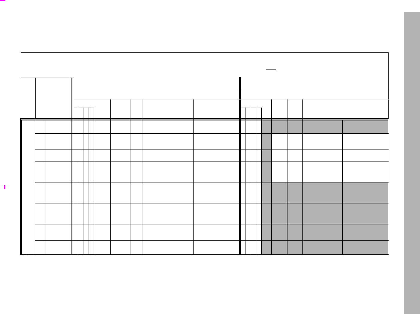
CMP.condn.fmt Floating Point Compare Setting Mask
136 The MIPS32® Instruction Set Manual, Revision 6.05
.
Table 3.9 Comparing CMP.condn.fmt, IEEE 754-2008, C.cond.fmt, and MSA FP compares
Shaded entries in the table are unimplemented, and reserved.
Instruction Encodings
CMP.condn.fmt: 010001 fffff ttttt sssss ddddd 0ccccc
C.cond.fmt: 010001 fffff ttttt sssss CCC00 11cccc
MSA: 011110 oooof ttttt sssss ddddd mmmmmm
Invalid Operand
Exception
MSA: operation
oooo Bits 25…22
C: cond
cccc - Bits 3..0
CMP: condn
cccccc - Bits 3..0
MSA: minor opcode mmmmmm Bits 5…0 = 26 - 011010
CMP: condn Bit 5..4 = 00 C: only applicable
MSA: minor opcode mmmmmm Bits 5…0 = 28 - 011100
CMP: condn Bit 5..4 = 01 C: not applicable
Predicates Negated Predicates
Relation
C
.condn.fmt
MSA
CMP
.condn.fmt
Long names IEEE
Relation
C
.condn.fmt
MSA
CMP
.condn.fmt
Long names IEEE
><=? ><=?
no (non-signalling)
yes (always signal SNaN)
0 0000 FFFF F FCAF AF False
Always False TTTT TAT True
Always True
1 0001 FFFT UN FCUN UN Unordered compareQuietUnordered
?
isUnordered
TTTFOR FCOR OR Ordered compareQuietOrdered
<=>
NOT(isUnordered)
2 0010 FFTF EQ FCEQ EQ Equal compareQuietEqual
=TTFT
NEQ FCUNE UNE Not Equal compareQuietNotEqual
?<>, NOT(=),
3 0011 FFTT UEQ FCUEQ UEQ Unordered or Equal TTFFOGL FCNE NE
Ordered
Greater Than
or Less Than
4 0100 FTFF OLT FCLT LT Ordered Less Than compareQuietLess
isLess TFTT
UGE UGE
Unordered or
Greater Than
or Equal
compareQuietNotLess
?>=, NOT(isLess)
5 0101 FTFT ULT FCULT ULT Unordered or Less
Than
compareQuietLessUnor-
dered
?<, NOT(isGreaterEqual)
TFTF
OGE OGE
Ordered
Greater Than
or Equal
compareQuiet-
GreatrEqual
isGreaterEqual
6 0110 FTTF OLE FCLE LE Ordered Less than or
Equal compareQuietLessEqual
isLessEqual TFFT
UGT UGT Unordered or
Greater Than
compareQuietGreaterUn-
ordered
?>, NOT(isLessEqual)
7 0111 FTTT ULE FCULE ULE Unordered or Less
Than or Equal compareQuietNotGreater
?<=, NOT(isGreater) TFFF
OGT OGT Ordered
Greater Than compareQuietGreater
isGreater
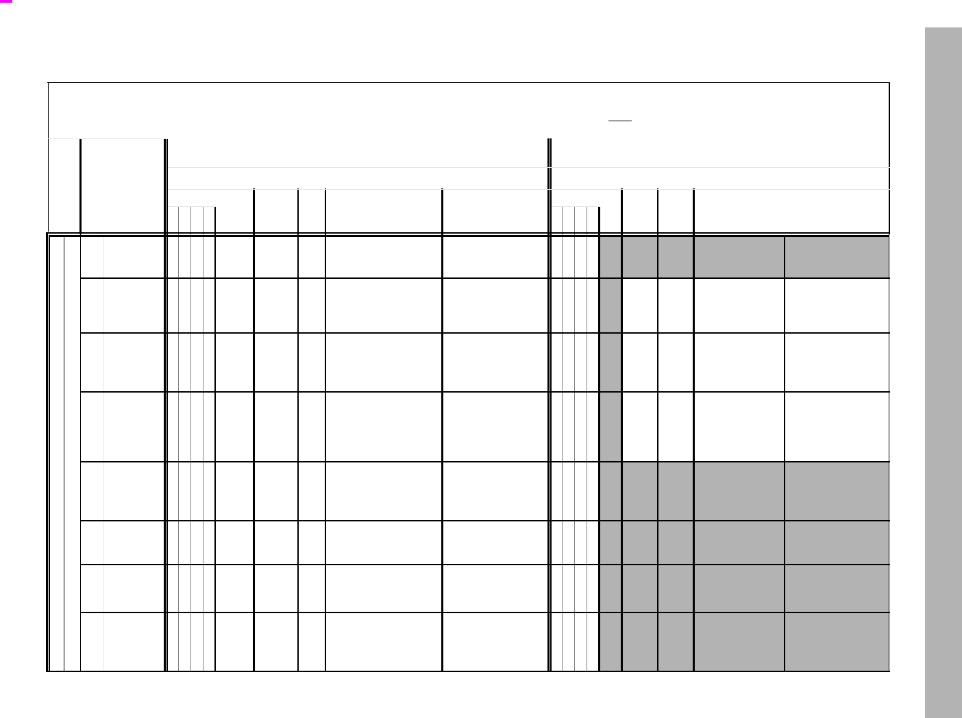
CMP.condn.fmt Floating Point Compare Setting Mask
137 The MIPS32® Instruction Set Manual, Revision 6.05
.
yes (signalling)
8 1000 FFFF SF FSAF SAF
Signalling False
Signalling
Always False
TTTT ST SAT
Signalling True
Signalling
Always True
9 1001 FFFT NGLE FSUN SUN
Not Greater Than or
Less Than or Equal
Signalling Unordered TTTFGLE FSOR SOR
Greater Than or
Less Than or Equal
Signalling
Ordered
10 1010 FFTF SEQ FSEQ SEQ
Signalling Equal
Ordered Signalling
Equal compareSignalling Equal TTFT
SNE FSUNE SUNE
Signalling Not Equal
Signalling Unor-
dered or Not
Equal
compareSignalling-
NotEqual
11 1011 FFTT NGL FSUEQSUEQ
Not Greater Than or
Less Than
Signalling Unordered
or Equal
TTFF GL FSNE SNE
Greater Than or
Less Than
Signalling
Ordered
Not Equal
12 1100 FTFF LT FSLT SLT
Less Than
Ordered Signalling
Less Than
compareSignallingLess
<TFTTNLT SUGE
Not Less Than
Signalling
Unordered or
Greater Than or
Equal
compareSignallingNot-
Less
NOT(<)
13 1101 FTFT NGE FSULT SULT
Not Greater Than or Equal
Unordered or Less
Than
compareSignalling-
LessUnordered
NOT(>=)
TFTF GE SOGE Signalling Ordered
Greater Than or
Equal
compareSignalling-
GreaterEqual
>=,
14 1110 FTTF LE FSLE SLE
Less Than or Equal
Ordered Signalling
Less Than or Equal
compareSignalling-
LessEqual
<=,
TFFT
NLE SUGT
Not Less Than or
Equal
Signalling Unordered
or Greater Than
compareSignalling-
GreaterUnordered
NOT(<=)
15 1111 FTTT NGT FSULE SULE
Not Greater Than
Signalling Unordered
or Less Than or
Equal
compareSignalling-
NotGreater
NOT(>)
TFFF GT SOGT Greater Than
Signalling Ordered
Greater Than
compareSignalling-
Greater
>
Table 3.9 Comparing CMP.condn.fmt, IEEE 754-2008, C.cond.fmt, and MSA FP compares (Continued)
Shaded entries in the table are unimplemented, and reserved.
Instruction Encodings
CMP.condn.fmt: 010001 fffff ttttt sssss ddddd 0ccccc
C.cond.fmt: 010001 fffff ttttt sssss CCC00 11cccc
MSA: 011110 oooof ttttt sssss ddddd mmmmmm
Invalid Operand
Exception
MSA: operation
oooo Bits 25…22
C: cond
cccc - Bits 3..0
CMP: condn
cccccc - Bits 3..0
MSA: minor opcode mmmmmm Bits 5…0 = 26 - 011010
CMP: condn Bit 5..4 = 00 C: only applicable
MSA: minor opcode mmmmmm Bits 5…0 = 28 - 011100
CMP: condn Bit 5..4 = 01 C: not applicable
Predicates Negated Predicates
Relation
C
.condn.fmt
MSA
CMP
.condn.fmt
Long names IEEE
Relation
C
.condn.fmt
MSA
CMP
.condn.fmt
Long names IEEE
><=? ><=?

CMP.condn.fmt Floating Point Compare Setting Mask
138 The MIPS32® Instruction Set Manual, Revision 6.05
Restrictions:
Operation:
if SNaN(ValueFPR(fs, fmt)) or SNaN(ValueFPR(ft, fmt)) or
QNaN(ValueFPR(fs, fmt)) or QNaN(ValueFPR(ft, fmt))
then
less false
equal false
unordered true
if (SNaN(ValueFPR(fs,fmt)) or SNaN(ValueFPR(ft,fmt))) or
(cond3 and (QNaN(ValueFPR(fs,fmt)) or QNaN(ValueFPR(ft,fmt)))) then
SignalException(InvalidOperation)
endif
else
less ValueFPR(fs, fmt) <fmt ValueFPR(ft, fmt)
equal ValueFPR(fs, fmt) =fmt ValueFPR(ft, fmt)
unordered false
endif
condition cond4 xor (
(cond2 and less)
or (cond1 and equal)
or (cond0 and unordered) )
StoreFPR (fd, fmt, ExtendBit.fmt(condition))
Exceptions:
Coprocessor Unusable, Reserved Instruction
Floating Point Exceptions:
Unimplemented Operation, Invalid Operation

COP2
I
Coprocessor Operation to Coprocessor 2
The MIPS32® Instruction Set Manual, Revision 6.05 139
Format: COP2 func MIPS32
Purpose: Coprocessor Operation to Coprocessor 2
To perform an operation to Coprocessor 2.
Description: CoprocessorOperation(2, cofun)
An implementation-dependent operation is performed to Coprocessor 2, with the cofun value passed as an argument.
The operation may specify and reference internal coprocessor registers, and may change the state of the coprocessor
conditions, but does not modify state within the processor. Details of coprocessor operation and internal state are
described in the documentation for each Coprocessor 2 implementation.
Restrictions:
Operation:
CoprocessorOperation(2, cofun)
Exceptions:
Coprocessor Unusable, Reserved Instruction
31 26 25 24 0
COP2
010010
CO
1cofun
61 25

CTC1 Move Control Word to Floating Point
140 The MIPS32® Instruction Set Manual, Revision 6.05
Format: CTC1 rt, fs MIPS32
Purpose: Move Control Word to Floating Point
To copy a word from a GPR to an FPU control register.
Description: FP_Control[fs] GPR[rt]
Copy the low word from GPR rt into the FP (coprocessor 1) control register indicated by fs.
Writing to the floating point Control/Status register, the FCSR, causes the appropriate exception if any Cause bit
and its corresponding Enable bit are both set. The register is written before the exception occurs. Writing to FEXR to
set a cause bit whose enable bit is already set, or writing to FENR to set an enable bit whose cause bit is already set
causes the appropriate exception. The register is written before the exception occurs and the EPC register contains
the address of the CTC1 instruction.
The definition of this instruction has been extended in Release 5 to support user mode read and write of StatusFR
under the control of Config5UFR. This optional feature is meant to facilitate transition from FR=0 to FR=1 float-
ing-point register modes in order to obsolete FR=0 mode in a future architecture release. User code may set and clear
StatusFR without kernel intervention, providing kernel explicitly provides permission.
This UFR facility is not supported in Release 6 since Release 6 only allows FR=1 mode. Accessing the UFR and
UNFR registers causes a Reserved Instruction exception in Release 6 since FIRUFRP is always 0.
The definition of this instruction has been extended in Release 6 to allow user code to read and modify the
Config5FRE bit. Such modification is allowed when this bit is present (as indicated by FIRUFRP) and user mode
modification of the bit is enabled by the kernel (as indicated by Config5UFE). Setting Config5FRE to 1 causes all
floating point instructions which are not compatible with FR=1 mode to take an Reserved Instruction exception. This
makes it possible to run pre-Release 6 FR=0 floating point code on a Release 6 core which only supports FR=1 mode,
provided the kernel has been set up to trap and emulate FR=0 behavior for these instructions. These instructions
include floating-point arithmetic instructions that read/write single-precision registers, LWC1, SWC1, MTC1, and
MFC1 instructions.
The FRE facility uses COP1 register aliases FRE and NFRE to access Config5FRE.
Restrictions:
There are a few control registers defined for the floating point unit. Prior to Release 6, the result is UNPREDICT-
ABLE if fs specifies a register that does not exist. In Release 6 and later, a Reserved Instruction exception occurs if fs
specifies a register that does not exist.
Furthermore, the result is UNPREDICTABLE if fd specifies the UFR, UNFR, FRE and NFRE aliases, with fs any-
thing other than 00000, GPR[0]. Release 6 implementations and later are required to produce a Reserved Instruction
exception; software must assume it is UNPREDICTABLE.
Operation:
temp GPR[rt]31..0
if (fs = 1 or fs = 4) then
/* clear UFR or UNFR(CP1 Register 1)*/
if ConfigAR ≥ 2 SignalException(ReservedInstruction) /* Release 6 traps */ endif
31 26 25 21 20 16 15 11 10 0
COP1
010001
CT
00110 rt fs 0
000 0000 0000
6 555 11

CTC1
I
Move Control Word to Floating Point
The MIPS32® Instruction Set Manual, Revision 6.05 141
if not Config5UFR then SignalException(ReservedInstruction) endif
if not (rt = 0 and FIRUFRP) then UNPREDICTABLE /*end of instruction*/ endif
if fs = 1 then StatusFR 0
elseif fs = 4 then StatusFR 1
else /* cannot happen */
elseif fs=5 then /* user write of 1 to FRE, if permitted */
if ConfigAR 2 then UNPREDICTABLE
else
if rt ≠ 0 then SignalException(ReservedInstruction) endif
if not Config5UFR then SignalException(ReservedInstruction) endif
Config5UFR 0
endif
elseif fs=6 then /* user write of 0 to FRE, if permitted (NFRE alias) */
if ConfigAR 2 then UNPREDICTABLE
else
if rt ≠ 0 then SignalException(ReservedInstruction) endif
if not Config5UFR then SignalException(ReservedInstruction) endif
Config5UFR 1
endif
elseif fs = 25 then /* FCCR */
if temp31..8 ≠ 024 then
UNPREDICTABLE
else
FCSR temp7..1 || FCSR24 || temp0 || FCSR22..0
endif
elseif fs = 26 then /* FEXR */
if temp31..18 ≠ 0 or temp11..7 ≠ 0 or temp2..0 ≠ 0then
UNPREDICTABLE
else
FCSR FCSR31..18 || temp17..12 || FCSR11..7 ||
temp6..2 || FCSR1..0
endif
elseif fs = 28 then /* FENR */
if temp31..12 ≠ 0 or temp6..3 ≠ 0 then
UNPREDICTABLE
else
FCSR FCSR31..25 || temp2 || FCSR23..12 || temp11..7
|| FCSR6..2 || temp1..0
endif
elseif fs = 31 then /* FCSR */
if (FCSRImpl field is not implemented) and(temp22..18 ≠ 0) then
UNPREDICTABLE
elseif (FCSRImpl field is implemented) and temp20..18 ≠ 0 then
UNPREDICTABLE
else
FCSR temp
endif
else
if Config2AR ≥ 2 SignalException(ReservedInstruction) /* Release 6 traps */
endif
UNPREDICTABLE
endif
CheckFPException()
Exceptions:
Coprocessor Unusable, Reserved Instruction

CTC1 Move Control Word to Floating Point
142 The MIPS32® Instruction Set Manual, Revision 6.05
Floating Point Exceptions:
Unimplemented Operation, Invalid Operation, Division-by-zero, Inexact, Overflow, Underflow
Historical Information:
For the MIPS I, II and III architectures, the contents of floating point control register fs are UNPREDICTABLE for
the instruction immediately following CTC1.
MIPS V and MIPS32 introduced the three control registers that access portions of FCSR. These registers were not
available in MIPS I, II, III, or IV.
MIPS32 Release 5 introduced the UFR and UNFR register aliases that allow user level access to StatusFR.
MIPS32 Release 6 introduced the FRE and NFRE register aliases that allow user to cause traps for FR=0 mode emu-
lation.

CTC2
I
Move Control Word to Coprocessor 2
The MIPS32® Instruction Set Manual, Revision 6.05 143
Format: CTC2 rt, Impl MIPS32
The syntax shown above is an example using CTC1 as a model. The specific syntax is implementation dependent.
Purpose: Move Control Word to Coprocessor 2
To copy a word from a GPR to a Coprocessor 2 control register.
Description: CP2CCR[Impl] GPR[rt]
Copy the low word from GPR rt into the Coprocessor 2 control register denoted by the Impl field. The interpretation
of the Impl field is left entirely to the Coprocessor 2 implementation and is not specified by the architecture.
Restrictions:
The result is UNPREDICTABLE if rd specifies a register that does not exist.
Operation:
temp GPR[rt]
CP2CCR[Impl] temp
Exceptions:
Coprocessor Unusable, Reserved Instruction
31 26 25 21 20 16 15 11 10 0
COP2
010010
CT
00110 rt Impl
655 16

CVT.D.fmt Floating Point Convert to Double Floating Point
144 The MIPS32® Instruction Set Manual, Revision 6.05
Format: CVT.D.fmt
CVT.D.S fd, fs MIPS32
CVT.D.W fd, fs MIPS32
CVT.D.L fd, fs MIPS32 Release 2
Purpose: Floating Point Convert to Double Floating Point
To convert an FP or fixed point value to double FP.
Description: FPR[fd] convert_and_round(FPR[fs])
The value in FPR fs, in format fmt, is converted to a value in double floating point format and rounded according to
the current rounding mode in FCSR. The result is placed in FPR fd. If fmt is S or W, then the operation is always
exact.
Restrictions:
The fields fs and fd must specify valid FPRs, fs for type fmt and fd for double floating point. If the fields are not valid,
the result is UNPREDICTABLE.
The operand must be a value in format fmt; if it is not, the result is UNPREDICTABLE and the value of the operand
FPR becomes UNPREDICTABLE.
For CVT.D.L, the result of this instruction is UNPREDICTABLE if the processor is executing in the FR=0 32-bit
FPU register model.
Operation:
StoreFPR (fd, D, ConvertFmt(ValueFPR(fs, fmt), fmt, D))
Exceptions:
Coprocessor Unusable, Reserved Instruction
Floating Point Exceptions:
Invalid Operation, Unimplemented Operation, Inexact
31 26 25 21 20 16 15 11 10 6 5 0
COP1
010001 fmt 0
00000 fs fd CVT.D
100001
6 5555 6

CVT.L.fmt
I
Floating Point Convert to Long Fixed Point
The MIPS32® Instruction Set Manual, Revision 6.05 145
Format: CVT.L.fmt
CVT.L.S fd, fs MIPS32 Release 2
CVT.L.D fd, fs MIPS32 Release 2
Purpose: Floating Point Convert to Long Fixed Point
To convert an FP value to a 64-bit fixed point.
Description: FPR[fd] convert_and_round(FPR[fs])
Convert the value in format fmt in FPR fs to long fixed point format and round according to the current rounding
mode in FCSR. The result is placed in FPR fd.
When the source value is Infinity, NaN, or rounds to an integer outside the range -263 to 263-1, the result cannot be
represented correctly, an IEEE Invalid Operation condition exists, and the Invalid Operation flag is set in the FCSR. If
the Invalid Operation Enable bit is set in the FCSR, no result is written to fd and an Invalid Operation exception is
taken immediately. Otherwise, a default result is written to fd. On cores with FCSRNAN2008=0, the default result is
263–1. On cores with FCSRNAN2008=1, the default result is:
• 0 when the input value is NaN
•2
63–1 when the input value is + or rounds to a number larger than 263–1
•-2
63–1 when the input value is – or rounds to a number smaller than -263–1
Restrictions:
The fields fs and fd must specify valid FPRs, fs for type fmt and fd for long fixed point. If the fields are not valid, the
result is UNPREDICTABLE.
The operand must be a value in format fmt; if it is not, the result is UNPREDICTABLE and the value of the operand
FPR becomes UNPREDICTABLE.
The result of this instruction is UNPREDICTABLE if the processor is executing in the FR=0 32-bit FPU register
model; it is predictable if executing on a 64-bit FPU in the FR=1 mode, but not with FR=0, and not on a 32-bit FPU.
Operation:
StoreFPR (fd, L, ConvertFmt(ValueFPR(fs, fmt), fmt, L))
Exceptions:
Coprocessor Unusable, Reserved Instruction
Floating Point Exceptions:
Invalid Operation, Unimplemented Operation, Inexact,
31 26 25 21 20 16 15 11 10 6 5 0
COP1
010001 fmt 0
00000 fs fd CVT.L
100101
655556
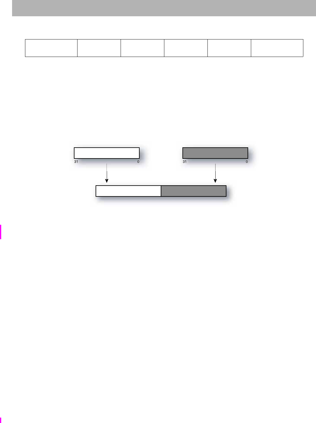
CVT.PS.S Floating Point Convert Pair to Paired Single
146 The MIPS32® Instruction Set Manual, Revision 6.05
Format: CVT.PS.S fd, fs, ft MIPS32 Release 2, removed in Release 6
Purpose: Floating Point Convert Pair to Paired Single
To convert two FP values to a paired single value.
Description: FPR[fd] FPR[fs]31..0 || FPR[ft]31..0
The single-precision values in FPR fs and ft are written into FPR fd as a paired-single value. The value in FPR fs is
written into the upper half, and the value in FPR ft is written into the lower half.
CVT.PS.S is similar to PLL.PS, except that it expects operands of format S instead of PS.
The move is non-arithmetic; it causes no IEEE 754 exceptions, and the FCSRCause and FCSRFlags fields are not
modified.
Restrictions:
The fields fs and ft must specify FPRs valid for operands of type S. If the fields are not valid, the result is UNPRE-
DICTABLE.
The operand must be a value in format S; if it is not, the result is UNPREDICTABLE and the value of the operand
FPR becomes UNPREDICTABLE.
The result of this instruction is UNPREDICTABLE if the processor is executing in the FR=0 32-bit FPU register
model; it is predictable if executing on a 64-bit FPU in the FR=1 mode, but not with FR=0, and not on a 32-bit FPU.
Availability and Compatibility:
This instruction has been removed in Release 6.
Operation:
StoreFPR(fd, S, ValueFPR(fs,S) || ValueFPR(ft,S))
Exceptions:
Coprocessor Unusable, Reserved Instruction
Floating Point Exceptions:
Invalid Operation, Unimplemented Operation
31 26 25 21 20 16 15 11 10 6 5 0
COP1
010001
fmt
10000 ft fs fd CVT.PS
100110
6 5555 6
31 3100
63 3132 0
fs ft
fd
63 32 31 0
31 0
31 0
fs ft
fd

CVT.PS.S
I
Floating Point Convert Pair to Paired Single
The MIPS32® Instruction Set Manual, Revision 6.05 147

CVT.S.PL Floating Point Convert Pair Lower to Single Floating Point
148 The MIPS32® Instruction Set Manual, Revision 6.05
Format: CVT.S.PL fd, fs MIPS32 Release 2, removed in Release 6
Purpose: Floating Point Convert Pair Lower to Single Floating Point
To convert one half of a paired single FP value to single FP.
Description: FPR[fd] FPR[fs]31..0
The lower paired single value in FPR fs, in format PS, is converted to a value in single floating point format. The
result is placed in FPR fd. This instruction can be used to isolate the lower half of a paired single value.
The operation is non-arithmetic; it causes no IEEE 754 exceptions, and the FCSRCause and FCSRFlags fields are
not modified.
Restrictions:
The fields fs and fd must specify valid FPRs—fs for type PS and fd for single floating point. If the fields are not valid,
the result is UNPREDICTABLE.
The operand must be a value in format PS; if it is not, the result is UNPREDICTABLE and the value of the operand
FPR becomes UNPREDICTABLE.
The result of CVT.S.PL is UNPREDICTABLE if the processor is executing in the FR=0 32-bit FPU register model;
it is predictable if executing on a 64-bit FPU in the FR=1 mode, but not with FR=0, and not on a 32-bit FPU.
Availability and Compatibility:
This instruction has been removed in Release 6.
Operation:
StoreFPR (fd, S, ConvertFmt(ValueFPR(fs, PS), PL, S))
Exceptions:
Coprocessor Unusable, Reserved Instruction
Floating Point Exceptions:
31 26 25 21 20 16 15 11 10 6 5 0
COP1
010001
fmt
10110
0
00000 fs fd CVT.S.PL
101000
6 5555 6

CVT.S.PU
I
Floating Point Convert Pair Upper to Single Floating Point
The MIPS32® Instruction Set Manual, Revision 6.05 149
Format: CVT.S.PU fd, fs MIPS32 Release 2, , removed in Release 6
Purpose: Floating Point Convert Pair Upper to Single Floating Point
To convert one half of a paired single FP value to single FP
Description: FPR[fd] FPR[fs]63..32
The upper paired single value in FPR fs, in format PS, is converted to a value in single floating point format. The
result is placed in FPR fd. This instruction can be used to isolate the upper half of a paired single value.
The operation is non-arithmetic; it causes no IEEE 754 exceptions, and the FCSRCause and FCSRFlags fields are
not modified.
Restrictions:
The fields fs and fd must specify valid FPRs—fs for type PS and fd for single floating point. If the fields are not valid,
the result is UNPREDICTABLE.
The operand must be a value in format PS; if it is not, the result is UNPREDICTABLE and the value of the operand
FPR becomes UNPREDICTABLE.
The result of CVT.S.PU is UNPREDICTABLE if the processor is executing the FR=0 32-bit FPU register model; it
is predictable if executing on a 64-bit FPU in the FR=1 mode, but not with FR=0, and not on a 32-bit FPU
Availability and Compatibility:
This instruction was removed in Release 6.
Operation:
StoreFPR (fd, S, ConvertFmt(ValueFPR(fs, PS), PU, S))
Exceptions:
Coprocessor Unusable, Reserved Instruction
Floating Point Exceptions:
31 26 25 21 20 16 15 11 10 6 5 0
COP1
010001
fmt
10110
0
00000 fs fd CVT.S.PU
100000
6 5555 6

CVT.S.fmt Floating Point Convert to Single Floating Point
150 The MIPS32® Instruction Set Manual, Revision 6.05
Format: CVT.S.fmt
CVT.S.D fd, fs MIPS32
CVT.S.W fd, fs MIPS32
CVT.S.L fd, fs MIPS32 Release 2
Purpose: Floating Point Convert to Single Floating Point
To convert an FP or fixed point value to single FP.
Description: FPR[fd] convert_and_round(FPR[fs])
The value in FPR fs, in format fmt, is converted to a value in single floating point format and rounded according to the
current rounding mode in FCSR. The result is placed in FPR fd.
Restrictions:
The fields fs and fd must specify valid FPRs—fs for type fmt and fd for single floating point. If the fields are not valid,
the result is UNPREDICTABLE.
The operand must be a value in format fmt; if it is not, the result is UNPREDICTABLE and the value of the operand
FPR becomes UNPREDICTABLE.
For CVT.S.L, the result of this instruction is UNPREDICTABLE if the processor is executing in the FR=0 32-bit
FPU register model; it is predictable if executing on a 64-bit FPU in the FR=1 mode, but not with FR=0, and not on
a 32-bit FPU.
Operation:
StoreFPR(fd, S, ConvertFmt(ValueFPR(fs, fmt), fmt, S))
Exceptions:
Coprocessor Unusable, Reserved Instruction
Floating Point Exceptions:
Invalid Operation, Unimplemented Operation, Inexact, Overflow, Underflow
31 26 25 21 20 16 15 11 10 6 5 0
COP1
010001 fmt 0
00000 fs fd CVT.S
100000
6 5555 6

CVT.W.fmt
I
Floating Point Convert to Word Fixed Point
The MIPS32® Instruction Set Manual, Revision 6.05 151
Format: CVT.W.fmt
CVT.W.S fd, fs MIPS32
CVT.W.D fd, fs MIPS32
Purpose: Floating Point Convert to Word Fixed Point
To convert an FP value to 32-bit fixed point.
Description: FPR[fd] convert_and_round(FPR[fs])
The value in FPR fs, in format fmt, is converted to a value in 32-bit word fixed point format and rounded according to
the current rounding mode in FCSR. The result is placed in FPR fd.
When the source value is Infinity, NaN, or rounds to an integer outside the range -231 to 231-1, the result cannot be
represented correctly, an IEEE Invalid Operation condition exists, and the Invalid Operation flag is set in the FCSR. If
the Invalid Operation Enable bit is set in the FCSR, no result is written to fd and an Invalid Operation exception is
taken immediately. Otherwise, a default result is written to fd. On cores with FCSRNAN2008=0, the default result is
263–1. On cores with FCSRNAN2008=1, the default result is:
• 0 when the input value is NaN
•2
63–1 when the input value is + or rounds to a number larger than 263–1
•-2
63–1 when the input value is – or rounds to a number smaller than -263–1
Restrictions:
The fields fs and fd must specify valid FPRs: fs for type fmt and fd for word fixed point. If the fields are not valid, the
result is UNPREDICTABLE.
The operand must be a value in format fmt; if it is not, the result is UNPREDICTABLE and the value of the operand
FPR becomes UNPREDICTABLE.
Operation:
StoreFPR(fd, W, ConvertFmt(ValueFPR(fs, fmt), fmt, W))
Exceptions:
Coprocessor Unusable, Reserved Instruction
Floating Point Exceptions:
Invalid Operation, Unimplemented Operation, Inexact
31 26 25 21 20 16 15 11 10 6 5 0
COP1
010001 fmt 0
00000 fs fd CVT.W
100100
6 5555 6

DDIV
I
Doubleword Divide
The MIPS32® Instruction Set Manual, Revision 6.05 152
Format: DDIV rs, rt MIPS64, removed in Release 6
Purpose: Doubleword Divide
To divide 64-bit signed integers.
Description: (LO, HI) GPR[rs] / GPR[rt]
The 64-bit doubleword in GPR rs is divided by the 64-bit doubleword in GPR rt, treating both operands as signed val-
ues. The 64-bit quotient is placed into special register LO and the 64-bit remainder is placed into special register HI.
No arithmetic exception occurs under any circumstances.
Restrictions:
If the divisor in GPR rt is zero, the arithmetic result value is UNPREDICTABLE.
Availability and Compatibility:
This instruction has been removed in Release 6.
Operation:
LO GPR[rs] div GPR[rt]
HI GPR[rs] mod GPR[rt]
Exceptions:
Reserved Instruction
Programming Notes:
See “Programming Notes” for the DIV instruction.
Historical Perspective:
In MIPS III, if either of the two instructions preceding the divide is an MFHI or MFLO, the result of the MFHI or
MFLO is UNPREDICTABLE. Reads of the HI or LO special register must be separated from subsequent instruc-
tions that write to them by two or more instructions. This restriction was removed in MIPS IV and MIPS32 and all
subsequent levels of the architecture.
31 26 25 21 20 16 15 0
SPECIAL
000000 rs rt 0
00 0000 0000
DDIV
011110
655 10 6

DDIVU
I
Doubleword Divide Unsigned
The MIPS32® Instruction Set Manual, Revision 6.05 153
Format: DDIVU rs, rt MIPS64, removed in Release 6
Purpose: Doubleword Divide Unsigned
To divide 64-bit unsigned integers.
Description: (LO, HI) GPR[rs] / GPR[rt]
The 64-bit doubleword in GPR rs is divided by the 64-bit doubleword in GPR rt, treating both operands as unsigned
values. The 64-bit quotient is placed into special register LO and the 64-bit remainder is placed into special register
HI.
No arithmetic exception occurs under any circumstances.
Restrictions:
If the divisor in GPR rt is zero, the arithmetic result value is UNPREDICTABLE.
Availability and Compatibility:
This instruction has been removed in Release 6.
Operation:
q (0 || GPR[rs]) div (0 || GPR[rt])
r (0 || GPR[rs]) mod (0 || GPR[rt])
LO q63..0
HI r63..0
Exceptions:
Reserved Instruction
Programming Notes:
See “Programming Notes” for the DIV instruction.
Historical Perspective:
In MIPS III, if either of the two instructions preceding the divide is an MFHI or MFLO, the result of the MFHI or
MFLO is UNPREDICTABLE. Reads of the HI or LO special register must be separated from subsequent instruc-
tions that write to them by two or more instructions. This restriction was removed in MIPS IV and MIPS32 and all
subsequent levels of the architecture.
31 26 25 21 20 16 15 6 5 0
SPECIAL
000000 rs rt 0
00 0000 0000
DDIVU
011111
655 10 6

DERET Debug Exception Return
154 The MIPS32® Instruction Set Manual, Revision 6.05
Format: DERET EJTAG
Purpose: Debug Exception Return
To Return from a debug exception.
Description:
DERET clears execution and instruction hazards, returns from Debug Mode and resumes non-debug execution at the
instruction whose address is contained in the DEPC register. DERET does not execute the next instruction (i.e. it has
no delay slot).
Restrictions:
A DERET placed between an LL and SC instruction does not cause the SC to fail.
If the DEPC register with the return address for the DERET was modified by an MTC0 or a DMTC0 instruction, a
CP0 hazard exists that must be removed via software insertion of the appropriate number of SSNOP instructions (for
implementations of Release 1 of the Architecture) or by an EHB, or other execution hazard clearing instruction (for
implementations of Release 2 of the Architecture).
DERET implements a software barrier that resolves all execution and instruction hazards created by Coprocessor 0
state changes (for Release 2 implementations, refer to the SYNCI instruction for additional information on resolving
instruction hazards created by writing the instruction stream). The effects of this barrier are seen starting with the
instruction fetch and decode of the instruction at the PC to which the DERET returns.
This instruction is legal only if the processor is executing in Debug Mode.
Pre-Release 6: The operation of the processor is UNDEFINED if a DERET is executed in the delay slot of a branch
or jump instruction.
Release 6 implementations are required to signal a Reserved Instruction exception if DERET is encountered in the
delay slot or forbidden slot of a branch or jump instruction.
Operation:
DebugDM 0
DebugIEXI 0
if IsMIPS16Implemented() | (Config3ISA > 0) then
PC DEPC31..1 || 0
ISAMode DEPC0
else
PC DEPC
endif
ClearHazards()
Exceptions:
Coprocessor Unusable, Reserved Instruction
31 26 25 24 65 0
COP0
010000
CO
1
0
000 0000 0000 0000 0000
DERET
011111
61 19 6

DI
I
Disable Interrupts
The MIPS32® Instruction Set Manual, Revision 6.05 155
Format: DI MIPS32 Release 2
DI rt MIPS32 Release 2
Purpose: Disable Interrupts
To return the previous value of the Status register and disable interrupts. If DI is specified without an argument, GPR
r0 is implied, which discards the previous value of the Status register.
Description: GPR[rt] Status; StatusIE 0
The current value of the Status register is loaded into general register rt. The Interrupt Enable (IE) bit in the Status
register is then cleared.
Restrictions:
If access to Coprocessor 0 is not enabled, a Coprocessor Unusable Exception is signaled.
In implementations prior to Release 2 of the architecture, this instruction resulted in a Reserved Instruction exception.
Operation:
This operation specification is for the general interrupt enable/disable operation, with the sc field as a variable. The
individual instructions DI and EI have a specific value for the sc field.
data Status
GPR[rt] data
StatusIE 0
Exceptions:
Coprocessor Unusable
Reserved Instruction (Release 1 implementations)
Programming Notes:
The effects of this instruction are identical to those accomplished by the sequence of reading Status into a GPR,
clearing the IE bit, and writing the result back to Status. Unlike the multiple instruction sequence, however, the DI
instruction cannot be aborted in the middle by an interrupt or exception.
This instruction creates an execution hazard between the change to the Status register and the point where the change
to the interrupt enable takes effect. This hazard is cleared by the EHB, JALR.HB, JR.HB, or ERET instructions. Soft-
ware must not assume that a fixed latency will clear the execution hazard.
31 2625 2120 1615 1110 65432 0
COP0
0100 00
MFMC0
01 011 rt 12
0110 0
0
000 00
sc
0
0
0 0
0
000
6 5555123

DIV Divide Word
156 The MIPS32® Instruction Set Manual, Revision 6.05
Format: DIV rs, rt MIPS32, removed in Release 6
Purpose: Divide Word
To divide a 32-bit signed integers.
Description: (HI, LO) GPR[rs] / GPR[rt]
The 32-bit word value in GPR rs is divided by the 32-bit value in GPR rt, treating both operands as signed values.
The 32-bit quotient is placed into special register LO and the 32-bit remainder isplaced into special register HI.
No arithmetic exception occurs under any circumstances.
Restrictions:
If the divisor in GPR rt is zero, the arithmetic result value is UNPREDICTABLE.
Availability and Compatibility:
DIV has been removed in Release 6 and has been replaced by DIV and MOD instructions that produce only quotient
and remainder, respectively. Refer to the Release 6 introduced ‘DIV’ and ‘MOD’ instructions in this manual for more
information. This instruction remains current for all release levels lower than Release 6 of the MIPS architecture.
Operation:
q GPR[rs]31..0 div GPR[rt]31..0
LO q
r GPR[rs]31..0 mod GPR[rt]31..0
HI r
Exceptions:
None
Programming Notes:
No arithmetic exception occurs under any circumstances. If divide-by-zero or overflow conditions are detected and
some action taken, then the divide instruction is followed by additional instructions to check for a zero divisor and/or
for overflow. If the divide is asynchronous then the zero-divisor check can execute in parallel with the divide. The
action taken on either divide-by-zero or overflow is either a convention within the program itself, or within the sys-
tem software. A possibility is to take a BREAK exception with a code field value to signal the problem to the system
software.
As an example, the C programming language in a UNIX® environment expects division by zero to either terminate
the program or execute a program-specified signal handler. C does not expect overflow to cause any exceptional con-
dition. If the C compiler uses a divide instruction, it also emits code to test for a zero divisor and execute a BREAK
instruction to inform the operating system if a zero is detected.
By default, most compilers for the MIPS architecture emits additional instructions to check for the divide-by-zero and
overflow cases when this instruction is used. In many compilers, the assembler mnemonic “DIV r0, rs, rt” can be used
to prevent these additional test instructions to be emitted.
In some processors the integer divide operation may proceed asynchronously and allow other CPU instructions to
execute before it is complete. An attempt to read LO or HI before the results are written interlocks until the results are
31 26 25 21 20 16 15 6 5 0
SPECIAL
000000 rs rt 0
00 0000 0000
DIV
011010
655 10 6

DIV
I
Divide Word
The MIPS32® Instruction Set Manual, Revision 6.05 157
ready. Asynchronous execution does not affect the program result, but offers an opportunity for performance
improvement by scheduling the divide so that other instructions can execute in parallel.
Historical Perspective:
In MIPS 1 through MIPS III, if either of the two instructions preceding the divide is an MFHI or MFLO, the result of
the MFHI or MFLO is UNPREDICTABLE. Reads of the HI or LO special register must be separated from subse-
quent instructions that write to them by two or more instructions. This restriction was removed in MIPS IV and
MIPS32 and all subsequent levels of the architecture.

DIV MOD DIVU MODU Divide Integers (with result to GPR)
158 The MIPS32® Instruction Set Manual, Revision 6.05
Format: DIV MOD DIVU MODU
DIV rd,rs,rt MIPS32 Release 6
MOD rd,rs,rt MIPS32 Release 6
DIVU rd,rs,rt MIPS32 Release 6
MODU rd,rs,rt MIPS32 Release 6
Purpose: Divide Integers (with result to GPR)
DIV: Divide Words Signed
MOD: Modulo Words Signed
DIVU: Divide Words Unsigned
MODU: Modulo Words Unsigned
Description:
DIV: GPR[rd] ( divide.signed( GPR[rs], GPR[rt] )
MOD: GPR[rd] ( modulo.signed( GPR[rs], GPR[rt] )
DIVU: GPR[rd] ( divide.unsigned( GPR[rs], GPR[rt] )
MODU: GPR[rd] ( modulo.unsigned( GPR[rs], GPR[rt] )
The Release 6 divide and modulo instructions divide the operands in GPR rs and GPR rt, and place the quotient or
remainder in GPR rd.
For each of the div/mod operator pairs DIV/M OD, DIVU/MODU, the results satisfy the equation
(A div B)*B + (A mod B) = A, where (A mod B) has same sign as the dividend A, and
abs(A mod B) < abs(B). This equation uniquely defines the results.
NOTE: if the divisor B=0, this equation cannot be satisfied, and the result is UNPREDICTABLE. This is commonly
called “truncated division”.
DIV performs a signed 32-bit integer division, and places the 32-bit quotient result in the destination register.
MOD performs a signed 32-bit integer division, and places the 32-bit remainder result in the destination register. The
remainder result has the same sign as the dividend.
DIVU performs an unsigned 32-bit integer division, and places the 32-bit quotient result in the destination register.
MODU performs an unsigned 32-bit integer division, and places the 32-bit remainder result in the destination regis-
ter.
Restrictions:
If the divisor in GPR rt is zero, the result value is UNPREDICTABLE.
31 26 25 21 20 16 15 11 10 6 5 0
SPECIAL
000000 rs rt rd DIV
00010
SOP32
011010
SPECIAL
000000 rs rt rd MOD
00011
SOP32
011010
SPECIAL
000000 rs rt rd DIVU
00010
SOP33
011011
SPECIAL
000000 rs rt rd MODU
00011
SOP33
011011
6 5555 6

DIV MOD DIVU MODU
I
DIV: Divide Words Signed MOD: Modulo Words Signed DIVU: Divide Words Un-
The MIPS32® Instruction Set Manual, Revision 6.05 159
Availability and Compatibility:
These instructions are introduced by and required as of Release 6.
Release 6 divide instructions have the same opcode mnemonic as the pre-Release 6 divide instructions (DIV, DIVU).
The instruction encodings are different, as are the instruction semantics: the Release 6 instruction produces only the
quotient, whereas the pre-Release 6 instruction produces quotient and remainder in HI/LO registers respectively, and
separate modulo instructions are required to obtain the remainder.
The assembly syntax distinguishes the Release 6 from the pre-Release 6 divide instructions. For example, Release 6
“DIV rd,rs,rt” specifies 3 register operands, versus pre-Release 6 “DIV rs,rt”, which has only two register
arguments, with the HI/LO registers implied. Some assemblers accept the pseudo-instruction syntax
“DIV rd,rs,rt” and expand it to do “DIV rs,rt;MFHI rd”. Phrases such as “DIV with GPR output” and
“DIV with HI/LO output” may be used when disambiguation is necessary.
Pre-Release 6 divide instructions that produce quotient and remainder in the HI/LO registers produce a Reserved
Instruction exception on Release 6. In the future, the instruction encoding may be reused for other instructions.
Programming Notes:
Because the divide and modulo instructions are defined to not trap if dividing by zero, it is safe to emit code that
checks for zero-divide after the divide or modulo instruction.
Operation
DIV, MOD:
s1 signed_word(GPR[rs])
s2 signed_word(GPR[rt])
DIVU, MODU:
s1 unsigned_word(GPR[rs])
s2 unsigned_word(GPR[rt])
DIV, DIVU:
quotient s1 div s2
MOD, MODU:
remainder s1 mod s2
DIV: GPR[rd] quotient
MOD: GPR[rd] remainder
DIVU: GPR[rd] quotient
MODU: GPR[rd] remainder
/* end of instruction */
Exceptions:
No arithmetic exceptions occur. Division by zero produces an UNPREDICTABLE result.

DIV.fmt
I
Floating Point Divide
The MIPS32® Instruction Set Manual, Revision 6.05 160
Format: DIV.fmt
DIV.S fd, fs, ft MIPS32
DIV.D fd, fs, ft MIPS32
Purpose: Floating Point Divide
To divide FP values.
Description: FPR[fd] FPR[fs] / FPR[ft]
The value in FPR fs is divided by the value in FPR ft. The result is calculated to infinite precision, rounded according
to the current rounding mode in FCSR, and placed into FPR fd. The operands and result are values in format fmt.
Restrictions:
The fields fs, ft, and fd must specify FPRs valid for operands of type fmt. If the fields are not valid, the result is
UNPREDICABLE.
The operands must be values in format fmt; if they are not, the result is UNPREDICTABLE and the value of the
operand FPRs becomes UNPREDICTABLE.
Operation:
StoreFPR (fd, fmt, ValueFPR(fs, fmt) / ValueFPR(ft, fmt))
Exceptions:
Coprocessor Unusable, Reserved Instruction
Floating Point Exceptions:
Inexact, Invalid Operation, Unimplemented Operation, Division-by-zero, Overflow, Underflow
31 26 25 21 20 16 15 11 10 6 5 0
COP1
010001 fmt ft fs fd DIV
000011
6 5555 6

DIVU
I
Divide Unsigned Word
The MIPS32® Instruction Set Manual, Revision 6.05 161
Format: DIVU rs, rt MIPS32, removed in Release 6
Purpose: Divide Unsigned Word
To divide 32-bit unsigned integers
Description: (HI, LO) GPR[rs] / GPR[rt]
The 32-bit word value in GPR rs is divided by the 32-bit value in GPR rt, treating both operands as unsigned values.
The 32-bit quotient is placed into special register LO and the 32-bit remainder is placed into special register HI.
No arithmetic exception occurs under any circumstances.
Restrictions:
If the divisor in GPR rt is zero, the arithmetic result value is UNPREDICTABLE.
Availability and Compatibility:
This instruction has been removed in Release 6.
Operation:
q (0 || GPR[rs]31..0) div (0 || GPR[rt]31..0)
r (0 || GPR[rs]31..0) mod (0 || GPR[rt]31..0)
LO sign_extend(q31..0)
HI sign_extend(r31..0)
Exceptions:
None
Programming Notes:
Pre-Release 6 instruction DIV has been removed in Release 6 and has been replaced by DIV and MOD instructions
that produce only quotient and remainder, respectively. Refer to the Release 6 introduced ‘DIV’ and ‘MOD’ instruc-
tions in this manual for more information. This instruction remains current for all release levels lower than Release 6
of the MIPS architecture.
See “Programming Notes” for the DIV instruction.
Historical Perspective:
In MIPS 1 through MIPS III, if either of the two instructions preceding the divide is an MFHI or MFLO, the result of
the MFHI or MFLO is UNPREDICTABLE. Reads of the HI or LO special register must be separated from subse-
quent instructions that write to them by two or more instructions. This restriction was removed in MIPS IV and
MIPS32 and all subsequent levels of the architecture.
31 26 25 21 20 16 15 6 5 0
SPECIAL
000000 rs rt 0
00 0000 0000
DIVU
011011
655 10 6

DVP
I
Disable Virtual Processor
The MIPS32® Instruction Set Manual, Revision 6.05 162
Format: DVP rt MIPS32 Release 6
Purpose: Disable Virtual Processor
To disable all virtual processors in a physical core other than the virtual processor that issued the instruction.
Description: GPR[rt] VPControl ; VPControlDIS 1
Disabling a virtual processor means that instruction fetch is terminated, and all outstanding instructions for the
affected virtual processor(s) must be complete before the DVP itself is allowed to retire. Any outstanding events such
as hardware instruction or data prefetch, or page-table walks must also be terminated.
The DVP instruction has implicit SYNC(stype=0) semantics but with respect to the other virtual processors in the
physical core.
After all other virtual processors have been disabled, VPControlDIS is set. Prior to modification and if rt is non-
zero, VPControl is written to GPR[rt].If DVP is specified without rt, then rt must be 0.
DVP may also take effect on a virtual processor that has executed a WAIT or a PAUSE instruction. If a virtual proces-
sor has executed a WAIT instruction, then it cannot resume execution on an interrupt until an EVP has been executed.
If the EVP is executed before the interrupt arrives, then the virtual processor resumes in a state as if the DVP had not
been executed, that is, it waits for the interrupt.
If a virtual processor has executed a PAUSE instruction, then it cannot resume execution until an EVP has been exe-
cuted, even if LLbit is cleared. If an EVP is executed before the LLbit is cleared, then the virtual processor resumes in
a state as if the DVP has not been executed, that is, it waits for the LLbit to clear.
The execution of a DVP must be followed by the execution of an EVP. The execution of an EVP causes execution to
resume immediately—where applicable—on all other virtual processors, as if the DVP had not been executed. The
execution is completely restorable after the EVP. If an event occurs in between the DVP and EVP that renders state of
the virtual processor UNPREDICTABLE (such as power-gating), then the effect of EVP is UNPREDICTABLE.
DVP may only take effect if VPControlDIS=0. Otherwise it is treated as a NOP instruction.
If a virtual processor is disabled due to a DVP, then interrupts are also disabled for the virtual processor, that is, logi-
cally StatusIE=0. StatusIE for the target virtual processors though is not cleared though as software cannot
access state on the virtual processors that have been disabled. Similarly, deferred exceptions will not cause a disabled
virtual processor to be re-enabled for execution, at least until execution is re-enabled by the EVP instruction. The vir-
tual processor that executes the DVP, however, continues to be interruptible.
In an implementation, the ability of a virtual processor to execute instructions may also be under control external to
the physical core which contains the virtual processor. If disabled by DVP, a virtual processor must not resume fetch
in response to the assertion of this external signal to enable fetch. Conversely, if fetch is disabled by such external
control, then execution of EVP will not cause fetch to resume at a target virtual processor for which the control is
deasserted.
This instruction never executes speculatively. It must be the oldest unretired instruction to take effect.
This instruction is only available in Release 6 implementations. For implementations that do not support multi-
threading (Config5VP=0), this instruction must be treated as a NOP instruction.
Restrictions:
If access to Coprocessor 0 is not enabled, a Coprocessor Unusable Exception is signaled.
31 2625 2120 1615 1110 65432 0
COP0
010000
MFMC0
01011 rt 0
00000
0
00000
sc
1
0
00
4
100
6 5555123

DVP Disable Virtual Processor
163 The MIPS32® Instruction Set Manual, Revision 6.05
In implementations prior to Release 6 of the architecture, this instruction resulted in a Reserved Instruction exception.
Operation:
The pseudo-code below assumes that the DVP is executed by virtual processor 0, while the target virtual processor is
numbered ‘n’, where n is each of all remaining virtual processors.
if (VPControlDIS = 0)
// Pseudo-code in italics provides recommended action wrt other VPs
disable_fetch(VPn) {
if PAUSE(VPn) retires prior or at disable event
then VPn execution is not resumed if LLbit is cleared prior to EVP
}
disable_interrupt(VPn) {
if WAIT(VPn) retires prior or at disable event
then interrupts are ignored by VPn until EVP
}
// DVP0 not retired until instructions for VPn completed
while (VPn outstanding instruction)
DVP0 unretired
endwhile
endif
data VPControl
GPR[rt] data
VPControlDIS 1
Exceptions:
Coprocessor Unusable
Reserved Instruction (pre-Release 6 implementations)
Programming Notes:
DVP may disable execution in the target virtual processor regardless of the operating mode - kernel, supervisor, user.
Kernel software may also be in a critical region, or in a high-priority interrupt handler when the disable occurs. Since
the instruction is itself privileged, such events are considered acceptable.
Before executing an EVP in a DVP/EVP pair, software should first read VPControlDIS, returned by DVP, to deter-
mine whether the virtual processors are already disabled. If so, the DVP/EVP sequence should be abandoned. This
step allows software to safely nest DVP/EVP pairs.
Privileged software may use DVP/EVP to disable virtual processors on a core, such as for the purpose of doing a
cache flush without interference from other processes in a system with multiple virtual processors or physical cores.
DVP (and EVP) may be used in other cases such as for power-savings or changing state that is applicable to all virtual
processors in a core, such as virtual processor scheduling priority, as described below :
ll t0 0(a0)
dvp // disable all other virtual processors
pause // wait for LLbit to clear
evp // enable all othe virtual processors

DVP
I
Disable Virtual Processor
The MIPS32® Instruction Set Manual, Revision 6.05 164
ll t0 0(a0)
dvp // disable all other virtual processors
<change core-wide state>
evp // enable all othe virtual processors

EHB Execution Hazard Barrier
165 The MIPS32® Instruction Set Manual, Revision 6.05
Format: EHB Assembly Idiom MIPS32 Release 2
Purpose: Execution Hazard Barrier
To stop instruction execution until all execution hazards have been cleared.
Description:
EHB is used to denote execution hazard barrier. The actual instruction is interpreted by the hardware as SLL r0, r0, 3.
This instruction alters the instruction issue behavior on a pipelined processor by stopping execution until all execu-
tion hazards have been cleared. Other than those that might be created as a consequence of setting StatusCU0, there
are no execution hazards visible to an unprivileged program running in User Mode. All execution hazards created by
previous instructions are cleared for instructions executed immediately following the EHB, even if the EHB is exe-
cuted in the delay slot of a branch or jump. The EHB instruction does not clear instruction hazards—such hazards are
cleared by the JALR.HB, JR.HB, and ERET instructions.
Restrictions:
None
Operation:
ClearExecutionHazards()
Exceptions:
None
Programming Notes:
In Release 2 implementations, this instruction resolves all execution hazards. On a superscalar processor, EHB alters
the instruction issue behavior in a manner identical to SSNOP. For backward compatibility with Release 1 implemen-
tations, the last of a sequence of SSNOPs can be replaced by an EHB. In Release 1 implementations, the EHB will be
treated as an SSNOP, thereby preserving the semantics of the sequence. In Release 2 implementations, replacing the
final SSNOP with an EHB should have no performance effect because a properly sized sequence of SSNOPs will
have already cleared the hazard. As EHB becomes the standard in MIPS implementations, the previous SSNOPs can
be removed, leaving only the EHB.
31 26 25 21 20 16 15 11 10 6 5 0
SPECIAL
000000
0
00000
0
00000
0
00000
3
00011
SLL
000000
6 5555 6

EI
I
Enable Interrupts
The MIPS32® Instruction Set Manual, Revision 6.05 166
Format: EI MIPS32 Release 2
EI rt MIPS32 Release 2
Purpose: Enable Interrupts
To return the previous value of the Status register and enable interrupts. If EI is specified without an argument, GPR
r0 is implied, which discards the previous value of the Status register.
Description: GPR[rt] Status; StatusIE 1
The current value of the Status register is loaded into general register rt. The Interrupt Enable (IE) bit in the Status
register is then set.
Restrictions:
If access to Coprocessor 0 is not enabled, a Coprocessor Unusable Exception is signaled.
In implementations prior to Release 2 of the architecture, this instruction resulted in a Reserved Instruction exception.
Operation:
This operation specification is for the general interrupt enable/disable operation, with the sc field as a variable. The
individual instructions DI and EI have a specific value for the sc field.
data Status
GPR[rt] data
StatusIE 1
Exceptions:
Coprocessor Unusable
Reserved Instruction (Release 1 implementations)
Programming Notes:
The effects of this instruction are identical to those accomplished by the sequence of reading Status into a GPR, set-
ting the IE bit, and writing the result back to Status. Unlike the multiple instruction sequence, however, the EI
instruction cannot be aborted in the middle by an interrupt or exception.
This instruction creates an execution hazard between the change to the Status register and the point where the change
to the interrupt enable takes effect. This hazard is cleared by the EHB, JALR.HB, JR.HB, or ERET instructions. Soft-
ware must not assume that a fixed latency will clear the execution hazard.
31 2625 2120 1615 1110 65432 0
COP0
0100 00
MFMC0
01 011 rt 12
0110 0
0
000 00
sc
1
0
0 0
0
000
6 5555123

ERET
I
Exception Return
The MIPS32® Instruction Set Manual, Revision 6.05 167
Format: ERET MIPS32
Purpose: Exception Return
To return from interrupt, exception, or error trap.
Description:
ERET clears execution and instruction hazards, conditionally restores SRSCtlCSS from SRSCtlPSS in a Release 2
implementation, and returns to the interrupted instruction at the completion of interrupt, exception, or error process-
ing. ERET does not execute the next instruction (that is, it has no delay slot).
Restrictions:
Pre-Release 6: The operation of the processor is UNDEFINED if an ERET is executed in the delay slot of a branch
or jump instruction.
Release 6: Implementations are required to signal a Reserved Instruction exception if ERET is encountered in the
delay slot or forbidden slot of a branch or jump instruction.
An ERET placed between an LL and SC instruction will always cause the SC to fail.
ERET implements a software barrier that resolves all execution and instruction hazards created by Coprocessor 0
state changes (for Release 2 implementations, refer to the SYNCI instruction for additional information on resolving
instruction hazards created by writing the instruction stream). The effects of this barrier are seen starting with the
instruction fetch and decode of the instruction at the PC to which the ERET returns.
In a Release 2 implementation, ERET does not restore SRSCtlCSS from SRSCtlPSS if StatusBEV = 1, or if StatusERL
= 1 because any exception that sets StatusERL to 1 (Reset, Soft Reset, NMI, or cache error) does not save SRSCtlCSS
in SRSCtlPSS. If software sets StatusERL to 1, it must be aware of the operation of an ERET that may be subse-
quently executed.
Operation:
if StatusERL = 1 then
temp ErrorEPC
StatusERL 0
else
temp EPC
StatusEXL 0
if (ArchitectureRevision ≥ 2) and (SRSCtlHSS 0) and (StatusBEV = 0) then
SRSCtlCSS SRSCtlPSS
endif
endif
if IsMIPS16Implemented() | (Config3ISA 0) then
PC temp31..1 || 0
ISAMode temp0
else
PC temp
endif
LLbit 0
ClearHazards()
31 26 25 24 65 0
COP0
010000
CO
1
0
000 0000 0000 0000 0000
ERET
011000
61 19 6

ERET
I
Exception Return
The MIPS32® Instruction Set Manual, Revision 6.05 168
Exceptions:
Coprocessor Unusable Exception

ERETNC
I
Exception Return No Clear
The MIPS32® Instruction Set Manual, Revision 6.05 169
Format: ERETNC MIPS32 Release 5
Purpose: Exception Return No Clear
To return from interrupt, exception, or error trap without clearing the LLbit.
Description:
ERETNC clears execution and instruction hazards, conditionally restores SRSCtlCSS from SRSCtlPSS when imple-
mented, and returns to the interrupted instruction at the completion of interrupt, exception, or error processing.
ERETNC does not execute the next instruction (i.e., it has no delay slot).
ERETNC is identical to ERET except that an ERETNC will not clear the LLbit that is set by execution of an LL
instruction, and thus when placed between an LL and SC sequence, will never cause the SC to fail.
An ERET must continue to be used by default in interrupt and exception processing handlers. The handler may have
accessed a synchronizable block of memory common to code that is atomically accessing the memory, and where the
code caused the exception or was interrupted. Similarly, a process context-swap must also continue to use an ERET in
order to avoid a possible false success on execution of SC in the restored context.
Multiprocessor systems with non-coherent cores (i.e., without hardware coherence snooping) should also continue to
use ERET, because it is the responsibility of software to maintain data coherence in the system.
An ERETNC is useful in cases where interrupt/exception handlers and kernel code involved in a process context-
swap can guarantee no interference in accessing synchronizable memory across different contexts. ERETNC can also
be used in an OS-level debugger to single-step through code for debug purposes, avoiding the false clearing of the
LLbit and thus failure of an LL and SC sequence in single-stepped code.
Software can detect the presence of ERETNC by reading Config5LLB.
Restrictions:
Release 6 implementations are required to signal a Reserved Instruction exception if ERETNC is executed in the
delay slot or Release 6 forbidden slot of a branch or jump instruction.
ERETNC implements a software barrier that resolves all execution and instruction hazards created by Coprocessor 0
state changes. (For Release 2 implementations, refer to the SYNCI instruction for additional information on resolving
instruction hazards created by writing the instruction stream.) The effects of this barrier are seen starting with the
instruction fetch and decode of the instruction in the PC to which the ERETNC returns.
Operation:
if StatusERL = 1 then
temp ErrorEPC
StatusERL 0
else
temp EPC
StatusEXL 0
if (ArchitectureRevision ≥ 2) and (SRSCtlHSS 0) and (StatusBEV = 0) then
SRSCtlCSS SRSCtlPSS
endif
endif
if IsMIPS16Implemented() | (Config3ISA 0) then
31 26 25 24 65 0
COP0
010000
CO
1
0
000 0000 0000 0000 000 1ERET
011000
61 18 16

ERETNC
I
Exception Return No Clear
The MIPS32® Instruction Set Manual, Revision 6.05 170
PC temp31..1 || 0
ISAMode temp0
else
PC temp
endif
ClearHazards()
Exceptions:
Coprocessor Unusable Exception

EVP
I
Enable Virtual Processor
The MIPS32® Instruction Set Manual, Revision 6.05 171
Format: EVP rt MIPS32 Release 6
Purpose: Enable Virtual Processor
To enable all virtual processors in a physical core other than the virtual processor that issued the instruction.
Description: GPR[rt] VPControl ; VPControlDIS 0
Enabling a virtual processor means that instruction fetch is resumed.
After all other virtual processors have been enabled, VPControlDIS is cleared. Prior to modification, if rt is non-
zero, VPControl is written to GPR[rt].If EVP is specified without rt, then rt must be 0.
See the DVP instruction to understand the application of EVP in the context of WAIT/PAUSE/external-control
(“DVP” on page 162).
The execution of a DVP must be followed by the execution of an EVP. The execution of an EVP causes execution to
resume immediately, where applicable, on all other virtual processors, as if the DVP had not been executed, that is,
execution is completely restorable after the EVP. On the other hand, if an event occurs in between the DVP and EVP
that renders state of the virtual processor UNPREDICTABLE (such as power-gating), then the effect of EVP is
UNPREDICTABLE.
EVP may only take effect if VPControlDIS=1. Otherwise it is treated as a NOP
This instruction never executes speculatively. It must be the oldest unretired instruction to take effect.
This instruction is only available in Release 6 implementations. For implementations that do not support multi-
threading (Config5VP=0), this instruction must be treated as a NOP instruction.
Restrictions:
If access to Coprocessor 0 is not enabled, a Coprocessor Unusable Exception is signaled.
In implementations prior to Release 6 of the architecture, this instruction resulted in a Reserved Instruction exception.
Operation:
The pseudo-code below assumes that the EVP is executed by virtual processor 0, while the target virtual processor is
numbered ‘n’, where n is each of all remaining virtual processors.
if (VPControlDIS = 1)
// Pseudo-code in italics provides recommended action wrt other VPs
enable_fetch(VPn) {
if PAUSE(VPn) retires prior or at disable event
then VPn execution is not resumed if LLbit is cleared prior to EVP
}
enable_interrupt(VPn) {
if WAIT(VPn) retires prior or at disable event
then interrupts are ignored by VPn until EVP
}
31 2625 2120 1615 1110 65432 0
COP0
010000
MFMC0
01011 rt 0
00000
0
00000
sc
0
0
00
4
100
6 5555123

EVP Enable Virtual Processor
172 The MIPS32® Instruction Set Manual, Revision 6.05
endif
data VPControl
GPR[rt] data
VPControlDIS 0
Exceptions:
Coprocessor Unusable
Reserved Instruction (pre-Release 6 implementations)
Programming Notes:
Before executing an EVP in a DVP/EVP pair, software should first read VPControlDIS, returned by DVP, to deter-
mine whether the virtual processors are already disabled. If so, the DVP/EVP sequence should be abandoned. This
step allows software to safely nest DVP/EVP pairs.
Privileged software may use DVP/EVP to disable virtual processors on a core, such as for the purpose of doing a
cache flush without interference from other processes in a system with multiple virtual processors or physical cores.
DVP (and EVP) may be used in other cases such as for power-savings or changing state that is applicable to all virtual
processors in a core, such as virtual processor scheduling priority, as described below:
ll t0 0(a0)
dvp // disable all other virtual processors
pause // wait for LLbit to clear
evp // enable all othe virtual processors
ll t0 0(a0)
dvp // disable all other virtual processors
<change core-wide state>
evp // enable all othe virtual processors
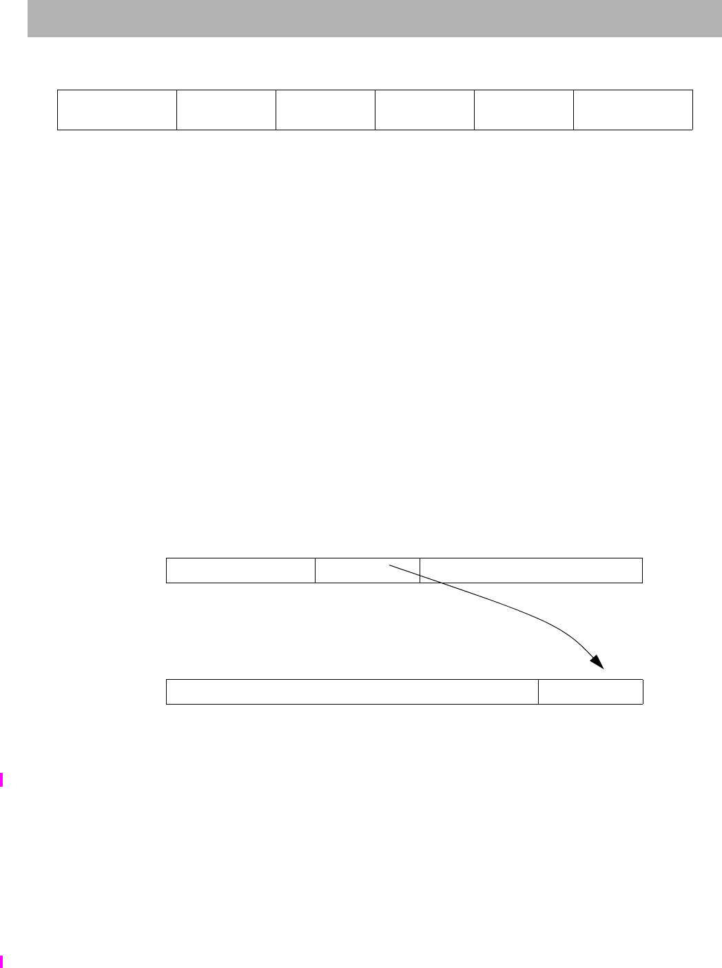
EXT
I
Extract Bit Field
The MIPS32® Instruction Set Manual, Revision 6.05 173
Format: EXT rt, rs, pos, size MIPS32 Release 2
Purpose: Extract Bit Field
To extract a bit field from GPR rs and store it right-justified into GPR rt.
Description: GPR[rt] ExtractField(GPR[rs], msbd, lsb)
The bit field starting at bit pos and extending for size bits is extracted from GPR rs and stored zero-extended and
right-justified in GPR rt. The assembly language arguments pos and size are converted by the assembler to the
instruction fields msbd (the most significant bit of the destination field in GPR rt), in instruction bits 15..11, and lsb
(least significant bit of the source field in GPR rs), in instruction bits 10..6, as follows:
msbd size-1
lsb pos
The values of pos and size must satisfy all of the following relations:
0 pos 32
0 size 32
0 pos+size 32
Figure 3-9 shows the symbolic operation of the instruction.
Figure 3.5 Operation of the EXT Instruction
Restrictions:
In implementations prior to Release 2 of the architecture, this instruction resulted in a Reserved Instruction exception.
The operation is UNPREDICTABLE if lsb+msbd > 31.
Operation:
if (lsb + msbd) > 31) then
UNPREDICTABLE
endif
temp 032-(msbd+1) || GPR[rs]msbd+lsb..lsb
GPR[rt] temp
31 26 25 21 20 16 15 11 10 6 5 0
SPECIAL3
011111 rs rt msbd
(size-1)
lsb
(pos)
EXT
000000
6 5555 6
31 pos+size
lsb+msbd+1 pos+size-1
lsb+msbd pos
lsb pos-1
lsb-1 0
GPR rs
Initial Value
IJKL MNOP QRST
32-(pos+size)
32-(lsb+msbd+1) size
msbd+1 pos
lsb
31 size
msbd+1 size-1
msbd 0
GPR rt Final
Value
0 MNOP
32-size
32-(msbd+1) size
msbd+1

EXT Extract Bit Field
174 The MIPS32® Instruction Set Manual, Revision 6.05
Exceptions:
Reserved Instruction

FLOOR.L.fmt
I
Floating Point Floor Convert to Long Fixed Point
The MIPS32® Instruction Set Manual, Revision 6.05 175
Format: FLOOR.L.fmt
FLOOR.L.S fd, fs MIPS32 Release 2
FLOOR.L.D fd, fs MIPS32 Release 2
Purpose: Floating Point Floor Convert to Long Fixed Point
To convert an FP value to 64-bit fixed point, rounding down
Description: FPR[fd] convert_and_round(FPR[fs])
The value in FPR fs, in format fmt, is converted to a value in 64-bit long fixed point format and rounded toward
(rounding mode 3). The result is placed in FPR fd.
When the source value is Infinity, NaN, or rounds to an integer outside the range -263 to 263-1, the result cannot be
represented correctly, an IEEE Invalid Operation condition exists, and the Invalid Operation flag is set in the FCSR. If
the Invalid Operation Enable bit is set in the FCSR, no result is written to fd and an Invalid Operation exception is
taken immediately. Otherwise, a default result is written to fd. On cores with FCSRNAN2008=0, the default result is
263–1. On cores with FCSRNAN2008=1, the default result is:
• 0 when the input value is NaN
•2
63–1 when the input value is + or rounds to a number larger than 263–1
•-2
63–1 when the input value is – or rounds to a number smaller than -263–1
Restrictions:
The fields fs and fd must specify valid FPRs: fs for type fmt and fd for long fixed point. If the fields are not valid, the
result is UNPREDICTABLE.
The operand must be a value in format fmt; if it is not, the result is UNPREDICTABLE and the value of the operand
FPR becomes UNPREDICTABLE.
The result of this instruction is UNPREDICTABLE if the processor is executing in the FR=0 32-bit FPU register
model; it is predictable if executing on a 64-bit FPU in the FR=1 mode, but not with FR=0, and not on a 32-bit FPU.
Operation:
StoreFPR(fd, L, ConvertFmt(ValueFPR(fs, fmt), fmt, L))
Exceptions:
Coprocessor Unusable, Reserved Instruction
Floating Point Exceptions:
Invalid Operation, Unimplemented Operation, Inexact
31 26 25 21 20 16 15 11 10 6 5 0
COP1
010001 fmt 0
00000 fs fd FLOOR.L
001011
6 5555 6

FLOOR.W.fmt Floating Point Floor Convert to Word Fixed Point
176 The MIPS32® Instruction Set Manual, Revision 6.05
Format: FLOOR.W.fmt
FLOOR.W.S fd, fs MIPS32
FLOOR.W.D fd, fs MIPS32
Purpose: Floating Point Floor Convert to Word Fixed Point
To convert an FP value to 32-bit fixed point, rounding down
Description: FPR[fd] convert_and_round(FPR[fs])
The value in FPR fs, in format fmt, is converted to a value in 32-bit word fixed point format and rounded toward –
(rounding mode 3). The result is placed in FPR fd.
When the source value is Infinity, NaN, or rounds to an integer outside the range -231 to 231-1, the result cannot be
represented correctly, an IEEE Invalid Operation condition exists, and the Invalid Operation flag is set in the FCSR. If
the Invalid Operation Enable bit is set in the FCSR, no result is written to fd and an Invalid Operation exception is
taken immediately. Otherwise, a default result is written to fd. On cores with FCSRNAN2008=0, the default result is
231–1. On cores with FCSRNAN2008=1, the default result is:
• 0 when the input value is NaN
•2
31–1 when the input value is + or rounds to a number larger than 231–1
•-2
31–1 when the input value is – or rounds to a number smaller than -231–1
Restrictions:
The fields fs and fd must specify valid FPRs: fs for type fmt and fd for word fixed point. If the fields are not valid, the
result is UNPREDICTABLE.
The operand must be a value in format fmt; if it is not, the result is UNPREDICTABLE and the value of the operand
FPR becomes UNPREDICTABLE.
Operation:
StoreFPR(fd, W, ConvertFmt(ValueFPR(fs, fmt), fmt, W))
Exceptions:
Coprocessor Unusable, Reserved Instruction
Floating Point Exceptions:
Invalid Operation, Unimplemented Operation, Inexact
31 26 25 21 20 16 15 11 10 6 5 0
COP1
010001 fmt 0
00000 fs fd FLOOR.W
001111
6 5555 6

INS
I
Insert Bit Field
The MIPS32® Instruction Set Manual, Revision 6.05 177
Format: INS rt, rs, pos, size MIPS32 Release 2
Purpose: Insert Bit Field
To merge a right-justified bit field from GPR rs into a specified field in GPR rt.
Description: GPR[rt] InsertField(GPR[rt], GPR[rs], msb, lsb)
The right-most size bits from GPR rs are merged into the value from GPR rt starting at bit position pos. The result is
placed back in GPR rt. The assembly language arguments pos and size are converted by the assembler to the instruc-
tion fields msb (the most significant bit of the field), in instruction bits 15..11, and lsb (least significant bit of the
field), in instruction bits 10..6, as follows:
msb pos+size-1
lsb pos
The values of pos and size must satisfy all of the following relations:
0 pos 32
0 size 32
0 pos+size 32
Figure 3-10 shows the symbolic operation of the instruction.
Figure 3.6 Operation of the INS Instruction
Restrictions:
In implementations prior to Release 2 of the architecture, this instruction resulted in a Reserved Instruction exception.
31 26 25 21 20 16 15 11 10 6 5 0
SPECIAL3
011111 rs rt msb
(pos+size-1)
lsb
(pos)
INS
000100
6 5555 6
31 size
msb-lsb+1 size-1
msb-lsb 0
GPR rs ABCD EFGH
32-size
32-(msb-lsb+1) size
msb-lsb+1
31 pos+size
msb+1 pos+size-1
msb pos
lsb pos-1
lsb-1 0
GPR rt
Initial Value
IJKL MNOP QRST
32-(pos+size)
32-(msb+1) size
msb-lsb+1 pos
lsb
31 pos+size
msb+1 pos+size-1
msb pos
lsb pos-1
lsb-1 0
GPR rt Final
Value
IJKL EFGH QRST
32-(pos+size)
32-(msb+1) size
msb-lsb+1 pos
lsb

INS Insert Bit Field
178 The MIPS32® Instruction Set Manual, Revision 6.05
The operation is UNPREDICTABLE if lsb > msb.
Operation:
if lsb > msb) then
UNPREDICTABLE
endif
GPR[rt] GPR[rt]31..msb+1 || GPR[rs]msb-lsb..0 || GPR[rt]lsb-1..0
Exceptions:
Reserved Instruction

J
I
Jump
The MIPS32® Instruction Set Manual, Revision 6.05 179
Format: J target MIPS32
Purpose: Jump
To branch within the current 256 MB-aligned region.
Description:
This is a PC-region branch (not PC-relative); the effective target address is in the “current” 256 MB-aligned region.
The low 28 bits of the target address is the instr_index field shifted left 2bits. The remaining upper bits are the corre-
sponding bits of the address of the instruction in the delay slot (not the branch itself).
Jump to the effective target address. Execute the instruction that follows the jump, in the branch delay slot, before
executing the jump itself.
Restrictions:
Control Transfer Instructions (CTIs) should not be placed in branch delay slots or Release 6 forbidden slots. CTIs
include all branches and jumps, NAL, ERET, ERETNC, DERET, WAIT, and PAUSE.
Pre-Release 6: Processor operation is UNPREDICTABLE if a control transfer instruction (CTI) is placed in the
delay slot of a branch or jump.
Release 6: If a control transfer instruction (CTI) is executed in the delay slot of a branch or jump, Release 6 imple-
mentations are required to signal a Reserved Instruction exception.
Operation:
I:
I+1: PC PCGPRLEN-1..28 || instr_index || 02
Exceptions:
None
Programming Notes:
Forming the branch target address by catenating PC and index bits rather than adding a signed offset to the PC is an
advantage if all program code addresses fit into a 256MB region aligned on a 256MB boundary. It allows a branch
from anywhere in the region to anywhere in the region, an action not allowed by a signed relative offset.
This definition creates the following boundary case: When the jump instruction is in the last word of a 256MB region,
it can branch only to the following 256MB region containing the branch delay slot.
The Jump instruction has been deprecated in Release 6. Use BC instead.
31 26 25 0
J
000010 instr_index
626

JAL Jump and Link
180 The MIPS32® Instruction Set Manual, Revision 6.05
Format: JAL target MIPS32
Purpose: Jump and Link
To execute a procedure call within the current 256MB-aligned region.
Description:
Place the return address link in GPR 31. The return link is the address of the second instruction following the branch,
at which location execution continues after a procedure call.
This is a PC-region branch (not PC-relative); the effective target address is in the “current” 256MB-aligned region.
The low 28 bits of the target address is the instr_index field shifted left 2bits. The remaining upper bits are the corre-
sponding bits of the address of the instruction in the delay slot (not the branch itself).
Jump to the effective target address. Execute the instruction that follows the jump, in the branch delay slot, before
executing the jump itself.
Restrictions:
Control Transfer Instructions (CTIs) should not be placed in branch delay slots or Release 6 forbidden slots. CTIs
include all branches and jumps, NAL, ERET, ERETNC, DERET, WAIT, and PAUSE.
Pre-Release 6: Processor operation is UNPREDICTABLE if a control transfer instruction (CTI) is placed in the
delay slot of a branch or jump.
Release 6: If a control transfer instruction (CTI) is executed in the delay slot of a branch or jump, Release 6 imple-
mentations are required to signal a Reserved Instruction exception.
Operation:
I: GPR[31] PC + 8
I+1: PC PCGPRLEN-1..28 || instr_index || 02
Exceptions:
None
Programming Notes:
Forming the branch target address by catenating PC and index bits rather than adding a signed offset to the PC is an
advantage if all program code addresses fit into a 256MB region aligned on a 256MB boundary. It allows a branch
from anywhere in the region to anywhere in the region, an action not allowed by a signed relative offset.
This definition creates the following boundary case: When the branch instruction is in the last word of a 256MB
region, it can branch only to the following 256MB region containing the branch delay slot.
The Jump-and-Link instruction has been deprecated in Release 6. Use BALC instead.
31 26 25 0
JAL
000011 instr_index
626

JALR
I
Jump and Link Register
The MIPS32® Instruction Set Manual, Revision 6.05 181
Format: JALR rs (rd = 31 implied) MIPS32
JALR rd, rs MIPS32
Purpose: Jump and Link Register
To execute a procedure call to an instruction address in a register
Description: GPR[rd] return_addr, PC GPR[rs]
Place the return address link in GPR rd. The return link is the address of the second instruction following the branch,
where execution continues after a procedure call.
For processors that do not implement the MIPS16e or microMIPS ISA:
• Jump to the effective target address in GPR rs. If the target address is not 4-byte aligned, an Address Error
exception will occur when the target address is fetched.
For processors that do implement the MIPS16e or microMIPS ISA:
• Jump to the effective target address in GPR rs. Set the ISA Mode bit to the value in GPR rs bit 0. Set bit 0 of the
target address to zero. If the target ISA Mode bit is 0 and the target address is not 4-byte aligned, an Address
Error exception will occur when the target instruction is fetched.
In both cases, execute the instruction that follows the jump, in the branch delay slot, before executing the jump itself.
In Release 1 of the architecture, the only defined hint field value is 0, which sets default handling of JALR. In
Release 2 of the architecture, bit 10 of the hint field is used to encode a hazard barrier. See the JALR.HB instruction
description for additional information.
Restrictions:
Control Transfer Instructions (CTIs) should not be placed in branch delay slots or Release 6 forbidden slots. CTIs
include all branches and jumps, NAL, ERET, ERETNC, DERET, WAIT, and PAUSE.
Pre-Release 6: Processor operation is UNPREDICTABLE if a control transfer instruction (CTI) is placed in the
delay slot of a branch or jump.
Release 6: If a control transfer instruction (CTI) is executed in the delay slot of a branch or jump, Release 6 imple-
mentations are required to signal a Reserved Instruction exception.
Jump-and-Link Restartability: Register specifiers rs and rd must not be equal, because such an instruction does not
have the same effect when re-executed. The result of executing such an instruction is UNPREDICTABLE. This
restriction permits an exception handler to resume execution by re-executing the branch when an exception occurs in
the delay slot.
Restrictions Related to Multiple Instruction Sets: This instruction can change the active instruction set, if more than
one instruction set is implemented.
pre-Release 6
31 26 25 21 20 16 15 11 10 6 5 0
SPECIAL
000000 rs 0
00000 rd hint JALR
001001
6 5555 6
Release 6
31 26 25 21 20 16 15 11 10 6 5 0
SPECIAL
000000 rs 0
00000
rd
rd 00000 hint JALR
001001
6 5555 6

JALR Jump and Link Register
182 The MIPS32® Instruction Set Manual, Revision 6.05
If only one instruction set is implemented, then the effective target address must obey the alignment rules of the
instruction set. If multiple instruction sets are implemented, the effective target address must obey the alignment rules
of the intended instruction set of the target address as specified by the bit 0 or GPR rs.
For processors that do not implement the microMIPS32/64 ISA, the effective target address in GPR rs must be natu-
rally-aligned. For processors that do not implement the MIPS16e ASE nor microMIPS32/64 ISA, if either of the two
least-significant bits are not zero, an Address Error exception occurs when the branch target is subsequently fetched
as an instruction.
For processors that do implement the MIPS16e ASE or microMIPS32/64 ISA, if target ISAMode bit is zero (GPR rs
bit 0) and bit 1 is one, an Address Error exception occurs when the jump target is subsequently fetched as an instruc-
tion.
Availability and Compatibility:
Release 6 maps JR and JR.HB to JALR and JALR.HB with rd = 0:
Pre-Release 6, JR and JALR were distinct instructions, both with primary opcode SPECIAL, but with distinct func-
tion codes.
Release 6: JR is defined to be JALR with the destination register specifier rd set to 0. The primary opcode and func-
tion field are the same for JR and JALR. The pre-Release 6 instruction encoding for JR is removed in Release 6.
Release 6 assemblers should accept the JR and JR.HB mnemonics, mapping them to the Release 6 instruction encod-
ings.
Operation:
I: temp GPR[rs]
GPR[rd] PC + 8
I+1:if (Config3ISA = 0) and (Config1CA = 0) then
PC temp
else
PC tempGPRLEN-1..1 || 0
ISAMode temp0
endif
Exceptions:
None
Programming Notes:
This jump-and-link register instruction can select a register for the return link; other link instructions use GPR 31.
The default register for GPR rd, if omitted in the assembly language instruction, is GPR 31.

JALR.HB
I
Jump and Link Register with Hazard Barrier
The MIPS32® Instruction Set Manual, Revision 6.05 183
Format: JALR.HB rs (rd = 31 implied) MIPS32 Release 2
JALR.HB rd, rs MIPS32 Release 2
Purpose: Jump and Link Register with Hazard Barrier
To execute a procedure call to an instruction address in a register and clear all execution and instruction hazards
Description: GPR[rd] return_addr, PC GPR[rs], clear execution and instruction hazards
Place the return address link in GPR rd. The return link is the address of the second instruction following the branch,
where execution continues after a procedure call.
For processors that do not implement the MIPS16e or microMIPS ISA:
• Jump to the effective target address in GPR rs. If the target address is not 4-byte aligned, an Address Error
exception will occur when the target address is fetched.
For processors that do implement the MIPS16e or microMIPS ISA:
• Jump to the effective target address in GPR rs. Set the ISA Mode bit to the value in GPR rs bit 0. Set bit 0 of the
target address to zero. If the target ISA Mode bit is 0 and the target address is not 4-byte aligned, an Address
Error exception will occur when the target instruction is fetched.
In both cases, execute the instruction that follows the jump, in the branch delay slot, before executing the jump itself.
JALR.HB implements a software barrier that resolves all execution and instruction hazards created by Coprocessor 0
state changes (for Release 2 implementations, refer to the SYNCI instruction for additional information on resolving
instruction hazards created by writing the instruction stream). The effects of this barrier are seen starting with the
instruction fetch and decode of the instruction at the PC to which the JALR.HB instruction jumps. An equivalent bar-
rier is also implemented by the ERET instruction, but that instruction is only available if access to Coprocessor 0 is
enabled, whereas JALR.HB is legal in all operating modes.
This instruction clears both execution and instruction hazards. Refer to the EHB instruction description for the
method of clearing execution hazards alone.
JALR.HB uses bit 10 of the instruction (the upper bit of the hint field) to denote the hazard barrier operation.
Restrictions:
JALR.HB does not clear hazards created by any instruction that is executed in the delay slot of the JALR.HB. Only
hazards created by instructions executed before the JALR.HB are cleared by the JALR.HB.
After modifying an instruction stream mapping or writing to the instruction stream, execution of those instructions
has UNPREDICTABLE behavior until the instruction hazard has been cleared with JALR.HB, JR.HB, ERET, or
DERET. Further, the operation is UNPREDICTABLE if the mapping of the current instruction stream is modified.
pre-Release 6:
31 26 25 21 20 16 15 11 10 9 6 5 0
SPECIAL
000000 rs 0
00000 rd 1
Any other
legal hint
value
JALR
001001
6 555146
Release 6:
31 26 25 21 20 16 15 11 10 9 6 5 0
SPECIAL
000000 rs 0
00000
rd
rd 00000 1
Any other
legal hint
value
JALR
001001
6 555146

JALR.HB Jump and Link Register with Hazard Barrier
184 The MIPS32® Instruction Set Manual, Revision 6.05
Control Transfer Instructions (CTIs) should not be placed in branch delay slots or Release 6 forbidden slots. CTIs
include all branches and jumps, NAL, ERET, ERETNC, DERET, WAIT, and PAUSE.
Pre-Release 6: Processor operation is UNPREDICTABLE if a control transfer instruction (CTI) is placed in the
delay slot of a branch or jump.
Release 6: If a control transfer instruction (CTI) is executed in the delay slot of a branch or jump, Release 6 imple-
mentations are required to signal a Reserved Instruction exception.
Jump-and-Link Restartability: Register specifiers rs and rd must not be equal, because such an instruction does not
have the same effect when re-executed. The result of executing such an instruction is UNPREDICTABLE. This
restriction permits an exception handler to resume execution by re-executing the branch when an exception occurs in
the delay slot.
Restrictions Related to Multiple Instruction Sets: This instruction can change the active instruction set, if more than
one instruction set is implemented.
If only one instruction set is implemented, then the effective target address must obey the alignment rules of the
instruction set. If multiple instruction sets are implemented, the effective target address must obey the alignment rules
of the intended instruction set of the target address as specified by the bit 0 or GPR rs.
For processors that do not implement the microMIPS32/64 ISA, the effective target address in GPR rs must be natu-
rally-aligned. For processors that do not implement the MIPS16 ASE nor microMIPS32/64 ISA, if either of the two
least-significant bits are not zero, an Address Error exception occurs when the branch target is subsequently fetched
as an instruction.
For processors that do implement the MIPS16 ASE or microMIPS32/64 ISA, if bit 0 is zero and bit 1 is one, an
Address Error exception occurs when the jump target is subsequently fetched as an instruction.
Availability and Compatibility:
Release 6 maps JR and JR.HB to JALR and JALR.HB with rd = 0:
Pre-Release 6, JR.HB and JALR.HB were distinct instructions, both with primary opcode SPECIAL, but with distinct
function codes.
Release 6: JR.HB is defined to be JALR.HB with the destination register specifier rd set to 0. The primary opcode
and function field are the same for JR.HB and JALR.HB. The pre-Release 6 instruction encoding for JR.HB is
removed in Release 6.
Release 6 assemblers should accept the JR and JR.HB mnemonics, mapping them to the Release 6 instruction encod-
ings.
Operation:
I: temp GPR[rs]
GPR[rd] PC + 8
I+1:if (Config3ISA = 0) and (Config1CA = 0) then
PC temp
else
PC tempGPRLEN-1..1 || 0
ISAMode temp0
endif
ClearHazards()
Exceptions:
None
Programming Notes:
This branch-and-link instruction can select a register for the return link; other link instructions use GPR 31. The

JALR.HB
I
Jump and Link Register with Hazard Barrier
The MIPS32® Instruction Set Manual, Revision 6.05 185
default register for GPR rd, if omitted in the assembly language instruction, is GPR 31.
Release 6 JR.HB rs is implemented as JALR.HB r0,rs. For example, as JALR.HB with the destination set to
the zero register, r0.
This instruction implements the final step in clearing execution and instruction hazards before execution continues. A
hazard is created when a Coprocessor 0 or TLB write affects execution or the mapping of the instruction stream, or
after a write to the instruction stream. When such a situation exists, software must explicitly indicate to hardware that
the hazard should be cleared. Execution hazards alone can be cleared with the EHB instruction. Instruction hazards
can only be cleared with a JR.HB, JALR.HB, or ERET instruction. These instructions cause hardware to clear the
hazard before the instruction at the target of the jump is fetched. Note that because these instructions are encoded as
jumps, the process of clearing an instruction hazard can often be included as part of a call (JALR) or return (JR)
sequence, by simply replacing the original instructions with the HB equivalent.
Example: Clearing hazards due to an ASID change
/*
* Code used to modify ASID and call a routine with the new
* mapping established.
*
* a0 = New ASID to establish
* a1 = Address of the routine to call
*/
mfc0 v0, C0_EntryHi /* Read current ASID */
li v1, ~M_EntryHiASID /* Get negative mask for field */
and v0, v0, v1 /* Clear out current ASID value */
or v0, v0, a0 /* OR in new ASID value */
mtc0 v0, C0_EntryHi /* Rewrite EntryHi with new ASID */
jalr.hb a1 /* Call routine, clearing the hazard */

JALR.HB Jump and Link Register with Hazard Barrier
186 The MIPS32® Instruction Set Manual, Revision 6.05

JALX
I
Jump and Link Exchange
The MIPS32® Instruction Set Manual, Revision 6.05 187
Format: JALX target MIPS32 with (microMIPS or MIPS16e), removed in Release 6
Purpose: Jump and Link Exchange
To execute a procedure call within the current 256 MB-aligned region and change the ISA Mode from MIPS32 to
microMIPS32 or MIPS16e.
Description:
Place the return address link in GPR 31. The return link is the address of the second instruction following the branch,
at which location execution continues after a procedure call. The value stored in GPR 31 bit 0 reflects the current
value of the ISA Mode bit.
This is a PC-region branch (not PC-relative); the effective target address is in the “current” 256 MB-aligned region.
The low 28 bits of the target address is the instr_index field shifted left 2 bits. The remaining upper bits are the corre-
sponding bits of the address of the instruction in the delay slot (not the branch itself).
Jump to the effective target address, toggling the ISA Mode bit. Execute the instruction that follows the jump, in the
branch delay slot, before executing the jump itself.
Restrictions:
This instruction only supports 32-bit aligned branch target addresses.
Control Transfer Instructions (CTIs) should not be placed in branch delay slots. CTIs include all branches and jumps,
NAL, ERET, ERETNC, DERET, WAIT, and PAUSE.
Processor operation is UNPREDICTABLE if a control transfer instruction (CTI) is placed in the delay slot of a
branch or jump.
Availability and Compatibility:
If the microMIPS base architecture is not implemented and the MIPS16e ASE is not implemented, a Reserved
Instruction exception is initiated.
The JALX instruction has been removed in Release 6. Pre-Release 6 code using JALX cannot run on Release 6 by
trap-and-emulate. Equivalent functionality is provided by the JIALC instruction added by Release 6.
Operation:
I: GPR[31] PC + 8
I+1: PC PCGPRLEN-1..28 || instr_index || 02
ISAMode (not ISAMode)
Exceptions:
None
Programming Notes:
Forming the branch target address by concatenating PC and index bits rather than adding a signed offset to the PC is
an advantage if all program code addresses fit into a 256 MB region aligned on a 256 MB boundary. It allows a
branch from anywhere in the region to anywhere in the region, an action not allowed by a signed relative offset.
This definition creates the following boundary case: When the branch instruction is in the last word of a 256 MB
31 26 25 0
JALX
011101 instr_index
626

JALX
I
Jump and Link Exchange
The MIPS32® Instruction Set Manual, Revision 6.05 188
region, it can branch only to the following 256 MB region containing the branch delay slot.

JIALC
I
Jump Indexed and Link, Compact
The MIPS32® Instruction Set Manual, Revision 6.05 189
Format: JIALC rt, offset MIPS32 Release 6
Purpose: Jump Indexed and Link, Compact
Description: GPR[31] PC+4, PC ( GPR[rt] + sign_extend( offset ) )
The jump target is formed by sign extending the offset field of the instruction and adding it to the contents of GPR
rt.
The offset is NOT shifted, that is, each bit of the offset is added to the corresponding bit of the GPR.
Places the return address link in GPR 31. The return link is the address of the following instruction, where execution
continues after a procedure call returns.
For processors that do not implement the MIPS16e or microMIPS ISA:
• Jump to the effective target address derived from GPR rt and the offset. If the target address is not 4-byte
aligned, an Address Error exception will occur when the target address is fetched.
For processors that do implement the MIPS16e or microMIPS ISA:
• Jump to the effective target address derived from GPR rt and the offset. Set the ISA Mode bit to bit 0 of the effec-
tive address. Set bit 0 of the target address to zero. If the target ISA Mode bit is 0 and the target address is not 4-
byte aligned, an Address Error exception will occur when the target instruction is fetched.
Compact jumps do not have delay slots. The instruction after the jump is NOT executed when the jump is executed.
Restrictions:
This instruction is an unconditional, always taken, compact jump, and hence has neither a delay slot nor a forbidden
slot. The instruction after the jump is not executed when the jump is executed.
The register specifier may be set to the link register $31, because compact jumps do not have the restartability issues
of jumps with delay slots. However, this is not common programming practice.
Availability and Compatibility:
This instruction is introduced by and required as of Release 6.
Release 6 instructions JIALC and BNEZC differ only in the rs field, instruction bits 21-25. JIALC and BNEZC
occupy the same encoding as pre-Release 6 instruction encoding SDC2, which is recoded in Release 6.
Exceptions:
None
Operation:
temp GPR[rt] + sign_extend(offset)
GPR[31] PC + 4
if (Config3ISA = 0) and (Config1CA = 0) then
PC temp
else
PC (tempGPRLEN-1..1 || 0)
ISAMode temp0
endif
31 26 25 21 20 16 15 0
POP76
111110
JIALC
00000 rt offset
655 16

JIALC Jump Indexed and Link, Compact
190 The MIPS32® Instruction Set Manual, Revision 6.05
Programming Notes:
JIALC does NOT shift the offset before adding it the register. This can be used to eliminate tags in the least signifi-
cant bits that would otherwise produce misalignment. It also allows JIALC to be used as a substitute for the JALX
instruction, removed in Release 6, where the lower bits of the target PC, formed by the addition of GPR[rt] and the
unshifted offset, specify the target ISAmode.

JIC
I
Jump Indexed, Compact
The MIPS32® Instruction Set Manual, Revision 6.05 191
Format: JIC rt, offset MIPS32 Release 6
Purpose: Jump Indexed, Compact
Description: PC ( GPR[rt] + sign_extend( offset ) )
The branch target is formed by sign extending the offset field of the instruction and adding it to the contents of GPR
rt.
The offset is NOT shifted, that is, each bit of the offset is added to the corresponding bit of the GPR.
For processors that do not implement the MIPS16e or microMIPS ISA:
• Jump to the effective target address derived from GPR rt and the offset. If the target address is not 4-byte
aligned, an Address Error exception will occur when the target address is fetched.
For processors that do implement the MIPS16e or microMIPS ISA:
• Jump to the effective target address derived from GPR rt and the offset. Set the ISA Mode bit to bit 0 of the effec-
tive address. Set bit 0 of the target address to zero. If the target ISA Mode bit is 0 and the target address is not 4-
byte aligned, an Address Error exception will occur when the target instruction is fetched.
Compact jumps do not have a delay slot. The instruction after the jump is NOT executed when the jump is executed.
Restrictions:
This instruction is an unconditional, always taken, compact jump, and hence has neither a delay slot nor a forbidden
slot. The instruction after the jump is not executed when the jump is executed.
Availability and Compatibility:
This instruction is introduced by and required as of Release 6.
Release 6 instructions JIC and BEQZC differ only in the rs field. JIC and BEQZC occupy the same encoding as pre-
Release 6 instruction LDC2, which is recoded in Release 6.
Exceptions:
None
Operation:
temp GPR[rt] + sign_extend(offset)
if (Config3ISA = 0) and (Config1CA = 0) then
PC temp
else
PC (tempGPRLEN-1..1 || 0)
ISAMode temp0
endif
Programming Notes:
JIC does NOT shift the offset before adding it the register. This can be used to eliminate tags in the least significant
bits that would otherwise produce misalignment. It also allows JIALC to be used as a substitute for the JALX instruc-
tion, removed in Release 6, where the lower bits of the target PC, formed by the addition of GPR[rt] and the unshifted
offset, specify the target ISAmode.
31 26 25 21 20 16 15 0
POP66
110110
JIC
00000 rt offset
655 16

JR Jump Register
192 The MIPS32® Instruction Set Manual, Revision 6.05
Format: JR rs MIPS32
Assembly idiom MIPS32 Release 6
Purpose: Jump Register
To execute a branch to an instruction address in a register
Description: PC GPR[rs]
Jump to the effective target address in GPR rs. Execute the instruction following the jump, in the branch delay slot,
before jumping.
For processors that do not implement the MIPS16e or microMIPS ISA:
• Jump to the effective target address in GPR rs. If the target address is not 4-byte aligned, an Address Error
exception will occur when the target address is fetched.
For processors that do implement the MIPS16e or microMIPS ISA:
• Jump to the effective target address in GPR rs. Set the ISA Mode bit to the value in GPR rs bit 0. Set bit 0 of the
target address to zero. If the target ISA Mode bit is 0 and the target address is not 4-byte aligned, an Address
Error exception will occur when the target instruction is fetched.
Restrictions:
Control Transfer Instructions (CTIs) should not be placed in branch delay slots or Release 6 forbidden slots. CTIs
include all branches and jumps, NAL, ERET, ERETNC, DERET, WAIT, and PAUSE.
Pre-Release 6: Processor operation is UNPREDICTABLE if a control transfer instruction (CTI) is placed in the
delay slot of a branch or jump.
Release 6: If a control transfer instruction (CTI) is executed in the delay slot of a branch or jump, Release 6 imple-
mentations are required to signal a Reserved Instruction exception.
Restrictions Related to Multiple Instruction Sets: This instruction can change the active instruction set, if more than
one instruction set is implemented.
If only one instruction set is implemented, then the effective target address must obey the alignment rules of the
instruction set. If multiple instruction sets are implemented, the effective target address must obey the alignment rules
of the intended instruction set of the target address as specified by the bit 0 or GPR rs.
For processors that do not implement the microMIPS ISA, the effective target address in GPR rs must be naturally-
aligned. For processors that do not implement the MIPS16e ASE or microMIPS ISA, if either of the two least-signif-
icant bits are not zero, an Address Error exception occurs when the branch target is subsequently fetched as an
instruction.
For processors that do implement the MIPS16e ASE or microMIPS ISA, if bit 0 is zero and bit 1 is one, an Address
Error exception occurs when the jump target is subsequently fetched as an instruction.
pre-Release 6:
31 26 25 21 20 11 10 6 5 0
SPECIAL
000000 rs 0
00 0000 0000 hint JR
001000
65 10 56
Release 6:
31 26 25 21 20 16 15 11 10 9 6 5 0
SPECIAL
000000 rs 0
00000 00000 hint JALR
001001
6 5555 6

JR
I
Jump Register
The MIPS32® Instruction Set Manual, Revision 6.05 193
In release 1 of the architecture, the only defined hint field value is 0, which sets default handling of JR. In Release 2
of the architecture, bit 10 of the hint field is used to encode an instruction hazard barrier. See the JR.HB instruction
description for additional information.
Availability and Compatibility:
Release 6 maps JR and JR.HB to JALR and JALR.HB with rd = 0:
Pre-Release 6, JR and JALR were distinct instructions, both with primary opcode SPECIAL, but with distinct func-
tion codes.
Release 6: JR is defined to be JALR with the destination register specifier rd set to 0. The primary opcode and func-
tion field are the same for JR and JALR. The pre-Release 6 instruction encoding for JR is removed in Release 6.
Release 6 assemblers should accept the JR and JR.HB mnemonics, mapping them to the Release 6 instruction encod-
ings.
Operation:
I: temp GPR[rs]
I+1:if (Config3ISA = 0) and (Config1CA = 0) then
PC temp
else
PC tempGPRLEN-1..1 || 0
ISAMode temp0
endif
Exceptions:
None
Programming Notes:
Software should use the value 31 for the rs field of the instruction word on return from a JAL, JALR, or BGEZAL,
and should use a value other than 31 for remaining uses of JR.

JR.HB Jump Register with Hazard Barrier
194 The MIPS32® Instruction Set Manual, Revision 6.05
Format: JR.HB rs MIPS32 Release 2
Assembly idiom Release 6
Purpose: Jump Register with Hazard Barrier
To execute a branch to an instruction address in a register and clear all execution and instruction hazards.
Description: PC GPR[rs], clear execution and instruction hazards
Jump to the effective target address in GPR rs. Execute the instruction following the jump, in the branch delay slot,
before jumping.
For processors that do not implement the MIPS16e or microMIPS ISA:
• Jump to the effective target address in GPR rs. If the target address is not 4-byte aligned, an Address Error
exception will occur when the target address is fetched.
For processors that do implement the MIPS16e or microMIPS ISA:
• Jump to the effective target address in GPR rs. Set the ISA Mode bit to the value in GPR rs bit 0. Set bit 0 of the
target address to zero. If the target ISA Mode bit is 0 and the target address is not 4-byte aligned, an Address
Error exception will occur when the target instruction is fetched.
JR.HB implements a software barrier that resolves all execution and instruction hazards created by Coprocessor 0
state changes (for Release 2 implementations, refer to the SYNCI instruction for additional information on resolving
instruction hazards created by writing the instruction stream). The effects of this barrier are seen starting with the
instruction fetch and decode of the instruction at the PC to which the JR.HB instruction jumps. An equivalent barrier
is also implemented by the ERET instruction, but that instruction is only available if access to Coprocessor 0 is
enabled, whereas JR.HB is legal in all operating modes.
This instruction clears both execution and instruction hazards. Refer to the EHB instruction description for the
method of clearing execution hazards alone.
JR.HB uses bit 10 of the instruction (the upper bit of the hint field) to denote the hazard barrier operation.
Restrictions:
JR.HB does not clear hazards created by any instruction that is executed in the delay slot of the JR.HB. Only hazards
created by instructions executed before the JR.HB are cleared by the JR.HB.
After modifying an instruction stream mapping or writing to the instruction stream, execution of those instructions
has UNPREDICTABLE behavior until the hazard has been cleared with JALR.HB, JR.HB, ERET, or DERET. Fur-
ther, the operation is UNPREDICTABLE if the mapping of the current instruction stream is modified.
Control Transfer Instructions (CTIs) should not be placed in branch delay slots or Release 6 forbidden slots. CTIs
pre-Release 6:
31 26 25 21 20 11 10 9 6 5 0
SPECIAL
000000 rs 0
00 0000 0000 1
Any other
legal hint
value
JR
001000
65 10146
Release 6:
31 26 25 21 20 16 15 11 10 9 6 5 0
SPECIAL
000000 rs 0
00000
0
00000 1
Any other
legal hint
value
JALR
001001
6 555146

JR.HB
I
Jump Register with Hazard Barrier
The MIPS32® Instruction Set Manual, Revision 6.05 195
include all branches and jumps, NAL, ERET, ERETNC, DERET, WAIT, and PAUSE.
Pre-Release 6: Processor operation is UNPREDICTABLE if a control transfer instruction (CTI) is placed in the
delay slot of a branch or jump.
Release 6: If a control transfer instruction (CTI) is executed in the delay slot of a branch or jump, Release 6 imple-
mentations are required to signal a Reserved Instruction exception.
Restrictions Related to Multiple Instruction Sets: This instruction can change the active instruction set, if more than
one instruction set is implemented.
If only one instruction set is implemented, then the effective target address must obey the alignment rules of the
instruction set. If multiple instruction sets are implemented, the effective target address must obey the alignment rules
of the intended instruction set of the target address as specified by the bit 0 or GPR rs.
For processors that do not implement the microMIPS ISA, the effective target address in GPR rs must be naturally-
aligned. For processors that do not implement the MIPS16 ASE or microMIPS ISA, if either of the two least-signifi-
cant bits are not zero, an Address Error exception occurs when the branch target is subsequently fetched as an instruc-
tion.
For processors that do implement the MIPS16 ASE or microMIPS ISA, if bit 0 is zero and bit 1 is one, an Address
Error exception occurs when the jump target is subsequently fetched as an instruction.
Availability and Compatibility:
Release 6 maps JR and JR.HB to JALR and JALR.HB with rd = 0:
Pre-Release 6, JR.HB and JALR.HB were distinct instructions, both with primary opcode SPECIAL, but with distinct
function codes.
Release 6: JR.HB is defined to be JALR.HB with the destination register specifier rd set to 0. The primary opcode and
function field are the same for JR.HB and JALR.HB. The pre-Release 6 instruction encoding for JR.HB is removed in
Release 6.
Release 6 assemblers should accept the JR and JR.HB mnemonics, mapping them to the Release 6 instruction encod-
ings.
Operation:
I: temp GPR[rs]
I+1:if (Config3ISA = 0) and (Config1CA = 0) then
PC temp
else
PC tempGPRLEN-1..1 || 0
ISAMode temp0
endif
ClearHazards()
Exceptions:
None
Programming Notes:
This instruction implements the final step in clearing execution and instruction hazards before execution continues. A
hazard is created when a Coprocessor 0 or TLB write affects execution or the mapping of the instruction stream, or
after a write to the instruction stream. When such a situation exists, software must explicitly indicate to hardware that
the hazard should be cleared. Execution hazards alone can be cleared with the EHB instruction. Instruction hazards
can only be cleared with a JR.HB, JALR.HB, or ERET instruction. These instructions cause hardware to clear the
hazard before the instruction at the target of the jump is fetched. Note that because these instructions are encoded as
jumps, the process of clearing an instruction hazard can often be included as part of a call (JALR) or return (JR)

JR.HB Jump Register with Hazard Barrier
196 The MIPS32® Instruction Set Manual, Revision 6.05
sequence, by simply replacing the original instructions with the HB equivalent.
Example: Clearing hazards due to an ASID change
/*
* Routine called to modify ASID and return with the new
* mapping established.
*
* a0 = New ASID to establish
*/
mfc0 v0, C0_EntryHi /* Read current ASID */
li v1, ~M_EntryHiASID /* Get negative mask for field */
and v0, v0, v1 /* Clear out current ASID value */
or v0, v0, a0 /* OR in new ASID value */
mtc0 v0, C0_EntryHi /* Rewrite EntryHi with new ASID */
jr.hb ra /* Return, clearing the hazard */
nop
Example: Making a write to the instruction stream visible
/*
* Routine called after new instructions are written to
* make them visible and return with the hazards cleared.
*/
{Synchronize the caches - see the SYNCI and CACHE instructions}
sync /* Force memory synchronization */
jr.hb ra /* Return, clearing the hazard */
nop
Example: Clearing instruction hazards in-line
la AT, 10f
jr.hb AT /* Jump to next instruction, clearing */
nop /* hazards */
10:

LB
I
Load Byte
The MIPS32® Instruction Set Manual, Revision 6.05 197
Format: LB rt, offset(base) MIPS32
Purpose: Load Byte
To load a byte from memory as a signed value.
Description: GPR[rt] memory[GPR[base] + offset]
The contents of the 8-bit byte at the memory location specified by the effective address are fetched, sign-extended,
and placed in GPR rt. The 16-bit signed offset is added to the contents of GPR base to form the effective address.
Restrictions:
None
Operation:
vAddr sign_extend(offset) + GPR[base]
(pAddr, CCA) AddressTranslation (vAddr, DATA, LOAD)
pAddr pAddrPSIZE-1..2 || (pAddr1..0 xor ReverseEndian2)
memword LoadMemory (CCA, BYTE, pAddr, vAddr, DATA)
byte vAddr1..0 xor BigEndianCPU2
GPR[rt] sign_extend(memword7+8*byte..8*byte)
Exceptions:
TLB Refill, TLB Invalid, Address Error, Watch
31 26 25 21 20 16 15 0
LB
100000 base rt offset
655 16

LBE Load Byte EVA
198 The MIPS32® Instruction Set Manual, Revision 6.05
Format: LBE rt, offset(base) MIPS32
Purpose: Load Byte EVA
To load a byte as a signed value from user mode virtual address space when executing in kernel mode.
Description: GPR[rt] memory[GPR[base] + offset]
The contents of the 8-bit byte at the memory location specified by the effective address are fetched, sign-extended,
and placed in GPR rt. The 9-bit signed offset is added to the contents of GPR base to form the effective address.
The LBE instruction functions the same as the LB instruction, except that address translation is performed using the
user mode virtual address space mapping in the TLB when accessing an address within a memory segment config-
ured to use the MUSUK access mode and executing in kernel mode. Memory segments using UUSK or MUSK
access modes are also accessible. Refer to Volume III, Enhanced Virtual Addressing section for additional informa-
tion.
Implementation of this instruction is specified by the Config5EVA field being set to one.
Restrictions:
Only usable when access to Coprocessor0 is enabled and accessing an address within a segment configured using
UUSK, MUSK or MUSUK access mode.
Operation:
vAddr sign_extend(offset) + GPR[base]
(pAddr, CCA) AddressTranslation (vAddr, DATA, LOAD)
pAddr pAddrPSIZE-1..2 || (pAddr1..0 xor ReverseEndian2)
memword LoadMemory (CCA, BYTE, pAddr, vAddr, DATA)
byte vAddr1..0 xor BigEndianCPU2
GPR[rt] sign_extend(memword7+8*byte..8*byte)
Exceptions:
TLB Refill, TLB Invalid
Bus Error, Address Error, Watch, Reserved Instruction, Coprocessor Unusable
31 26 25 21 20 16 15 7 6 5 0
SPECIAL3
011111 base rt offset 0LBE
101100
655 9
16

LBU
I
Load Byte Unsigned
The MIPS32® Instruction Set Manual, Revision 6.05 199
Format: LBU rt, offset(base) MIPS32
Purpose: Load Byte Unsigned
To load a byte from memory as an unsigned value
Description: GPR[rt] memory[GPR[base] + offset]
The contents of the 8-bit byte at the memory location specified by the effective address are fetched, zero-extended,
and placed in GPR rt. The 16-bit signed offset is added to the contents of GPR base to form the effective address.
Restrictions:
None
Operation:
vAddr sign_extend(offset) + GPR[base]
(pAddr, CCA) AddressTranslation (vAddr, DATA, LOAD)
pAddr pAddrPSIZE-1..2 || (pAddr1..0 xor ReverseEndian2)
memword LoadMemory (CCA, BYTE, pAddr, vAddr, DATA)
byte vAddr1..0 xor BigEndianCPU2
GPR[rt] zero_extend(memword7+8*byte..8*byte)
Exceptions:
TLB Refill, TLB Invalid, Address Error, Watch
31 26 25 21 20 16 15 0
LBU
100100 base rt offset
655 16

LBUE Load Byte Unsigned EVA
200 The MIPS32® Instruction Set Manual, Revision 6.05
Format: LBUE rt, offset(base) MIPS32
Purpose: Load Byte Unsigned EVA
To load a byte as an unsigned value from user mode virtual address space when executing in kernel mode.
Description: GPR[rt] memory[GPR[base] + offset]
The contents of the 8-bit byte at the memory location specified by the effective address are fetched, zero-extended,
and placed in GPR rt. The 9-bit signed offset is added to the contents of GPR base to form the effective address.
The LBUE instruction functions the same as the LBU instruction, except that address translation is performed using
the user mode virtual address space mapping in the TLB when accessing an address within a memory segment con-
figured to use the MUSUK access mode. Memory segments using UUSK or MUSK access modes are also accessible.
Refer to Volume III, Enhanced Virtual Addressing section for additional information.
Implementation of this instruction is specified by the Config5EVA field being set to one.
Restrictions:
Only usable when access to Coprocessor0 is enabled and accessing an address within a segment configured using
UUSK, MUSK or MUSUK access mode.
Operation:
vAddr sign_extend(offset) + GPR[base]
(pAddr, CCA) AddressTranslation (vAddr, DATA, LOAD)
pAddr pAddrPSIZE-1..2 || (pAddr1..0 xor ReverseEndian2)
memword LoadMemory (CCA, BYTE, pAddr, vAddr, DATA)
byte vAddr1..0 xor BigEndianCPU2
GPR[rt] zero_extend(memword7+8*byte..8*byte)
Exceptions:
TLB Refill, TLB Invalid, Bus Error, Address Error, Watch, Reserved Instruction, Coprocessor Unusable
31 26 25 21 20 16 15 7 6 5 0
SPECIAL3
011111 base rt offset 0LBUE
101000
655 916

LDC1
I
Load Doubleword to Floating Point
The MIPS32® Instruction Set Manual, Revision 6.05 201
Format: LDC1 ft, offset(base) MIPS32
Purpose: Load Doubleword to Floating Point
To load a doubleword from memory to an FPR.
Description: FPR[ft] memory[GPR[base] + offset]
The contents of the 64-bit doubleword at the memory location specified by the aligned effective address are fetched
and placed in FPR ft. The 16-bit signed offset is added to the contents of GPR base to form the effective address.
Restrictions:
Pre-Release 6: An Address Error exception occurs if EffectiveAddress2..0 ≠ 0 (not doubleword-aligned).
Release 6 allows hardware to provide address misalignment support in lieu of requiring natural alignment.
Note: The pseudocode is not completely adapted for Release 6 misalignment support as the handling is implementa-
tion dependent.
Operation:
vAddr sign_extend(offset) + GPR[base]
(pAddr, CCA) AddressTranslation (vAddr, DATA, LOAD)
paddr paddr xor ((BigEndianCPU xor ReverseEndian) || 02)
memlsw LoadMemory(CCA, WORD, pAddr, vAddr, DATA)
paddr paddr xor 0b100
memmsw LoadMemory(CCA, WORD, pAddr, vAddr+4, DATA)
memdoubleword memmsw || memlsw
StoreFPR(ft, UNINTERPRETED_DOUBLEWORD, memdoubleword)
Exceptions:
Coprocessor Unusable, Reserved Instruction, TLB Refill, TLB Invalid, Address Error, Watch
31 26 25 21 20 16 15 0
LDC1
110101 base ft offset
655 16

LDC2 Load Doubleword to Coprocessor 2
202 The MIPS32® Instruction Set Manual, Revision 6.05
Format: LDC2 rt, offset(base) MIPS32
Purpose: Load Doubleword to Coprocessor 2
To load a doubleword from memory to a Coprocessor 2 register.
Description: CPR[2,rt,0] memory[GPR[base] + offset]
The contents of the 64-bit doubleword at the memory location specified by the aligned effective address are fetched
and placed in Coprocessor 2 register rt. The signed offset is added to the contents of GPR base to form the effective
address.
Restrictions:
Pre-Release 6: An Address Error exception occurs if EffectiveAddress2..0 ≠ 0 (not doubleword-aligned).
Release 6 allows hardware to provide address misalignment support in lieu of requiring natural alignment.
Note: The pseudocode is not completely adapted for Release 6 misalignment support as the handling is implementa-
tion dependent.
Availability and Compatibility:
This instruction has been recoded for Release 6.
Operation:
vAddr sign_extend(offset) + GPR[base]
(pAddr, CCA) AddressTranslation (vAddr, DATA, LOAD)
paddr paddr xor ((BigEndianCPU xor ReverseEndian) || 02)
memlsw LoadMemory(CCA, WORD, pAddr, vAddr, DATA)
paddr paddr xor 0b100
memmsw LoadMemory(CCA, WORD, pAddr, vAddr+4, DATA)
memlsw
memmsw
Exceptions:
Coprocessor Unusable, Reserved Instruction, TLB Refill, TLB Invalid, Address Error, Watch
Programming Notes:
Release 6 implements a 9-bit offset, whereas all release levels lower than Release 6 implement a 16-bit offset.
Programming Notes:
As shown in the instruction drawing above, Release 6 implements an 11-bit offset, whereas all release levels lower
pre-Release 6
31 26 25 21 20 16 15 0
LDC2
110110 base rt offset
655 16
Release 6
31 26 25 21 20 16 15 11 10 0
COP2
010010
LDC2
01110 rt base offset
6555 11

LDC2
I
Load Doubleword to Coprocessor 2
The MIPS32® Instruction Set Manual, Revision 6.05 203
than Release 6 of the MIPS architecture implement a 16-bit offset.

LDXC1 Load Doubleword Indexed to Floating Point
204 The MIPS32® Instruction Set Manual, Revision 6.05
Format: LDXC1 fd, index(base) MIPS32 Release 2 removed in Release 6
Purpose: Load Doubleword Indexed to Floating Point
To load a doubleword from memory to an FPR (GPR+GPR addressing)
Description: FPR[fd] memory[GPR[base] + GPR[index]]
The contents of the 64-bit doubleword at the memory location specified by the aligned effective address are fetched
and placed in FPR fd. The contents of GPR index and GPR base are added to form the effective address.
Restrictions:
An Address Error exception occurs if EffectiveAddress2..0 ≠ 0 (not doubleword-aligned).
Availability and Compatibility:
This instruction has been removed in Release 6.
Required in all versions of MIPS64 since MIPS64 Release 1. Not available in MIPS32 Release 1. Required in
MIPS32 Release 2 and all subsequent versions of MIPS32. When required, required whenever FPU is present,
whether a 32-bit or 64-bit FPU, whether in 32-bit or 64-bit FP Register Mode (FIRF64=0 or 1, StatusFR=0 or 1).
Operation:
vAddr GPR[base] + GPR[index]
if vAddr2..0 03 then
SignalException(AddressError)
endif
(pAddr, CCA) AddressTranslation (vAddr, DATA, LOAD)
paddr paddr xor ((BigEndianCPU xor ReverseEndian) || 02)
memlsw LoadMemory(CCA, WORD, pAddr, vAddr, DATA)
paddr paddr xor 0b100
memmsw LoadMemory(CCA, WORD, pAddr, vAddr+4, DATA)
memdoubleword memmsw || memlsw
StoreFPR(fd, UNINTERPRETED_DOUBLEWORD, memdoubleword)
Exceptions:
TLB Refill, TLB Invalid, Address Error, Reserved Instruction, Coprocessor Unusable, Watch
31 26 25 21 20 16 15 11 10 6 5 0
COP1X
010011 base index 0
00000 fd LDXC1
000001
6 5555 6

LH
I
Load Halfword
The MIPS32® Instruction Set Manual, Revision 6.05 205
Format: LH rt, offset(base) MIPS32
Purpose: Load Halfword
To load a halfword from memory as a signed value
Description: GPR[rt] memory[GPR[base] + offset]
The contents of the 16-bit halfword at the memory location specified by the aligned effective address are fetched,
sign-extended, and placed in GPR rt. The 16-bit signed offset is added to the contents of GPR base to form the effec-
tive address.
Restrictions:
Pre-Release 6: The effective address must be naturally-aligned. If the least-significant bit of the address is non-zero,
an Address Error exception occurs.
Release 6 allows hardware to provide address misalignment support in lieu of requiring natural alignment.
Note: The pseudocode is not completely adapted for Release 6 misalignment support as the handling is implementa-
tion dependent.
Operation:
vAddr sign_extend(offset) + GPR[base]
(pAddr, CCA) AddressTranslation (vAddr, DATA, LOAD)
pAddr pAddrPSIZE-1..2 || (pAddr1..0 xor (ReverseEndian || 0))
memword LoadMemory (CCA, HALFWORD, pAddr, vAddr, DATA)
byte vAddr1..0 xor (BigEndianCPU || 0)
GPR[rt] sign_extend(memword15+8*byte..8*byte)
Exceptions:
TLB Refill, TLB Invalid, Bus Error, Address Error, Watch
31 26 25 21 20 16 15 0
LH
100001 base rt offset
655 16

LHE Load Halfword EVA
206 The MIPS32® Instruction Set Manual, Revision 6.05
Format: LHE rt, offset(base) MIPS32
Purpose: Load Halfword EVA
To load a halfword as a signed value from user mode virtual address space when executing in kernel mode.
Description: GPR[rt] memory[GPR[base] + offset]
The contents of the 16-bit halfword at the memory location specified by the aligned effective address are fetched,
sign-extended, and placed in GPR rt. The 9-bit signed offset is added to the contents of GPR base to form the effec-
tive address.
The LHE instruction functions the same as the LH instruction, except that address translation is performed using the
user mode virtual address space mapping in the TLB when accessing an address within a memory segment config-
ured to use the MUSUK access mode. Memory segments using UUSK or MUSK access modes are also accessible.
Refer to Volume III, Enhanced Virtual Addressing section for additional information.
Implementation of this instruction is specified by the Config5EVA field being set to one.
Restrictions:
Only usable when access to Coprocessor0 is enabled and accessing an address within a segment configured using
UUSK, MUSK or MUSUK access mode.
Pre-Release 6: The effective address must be naturally-aligned. If the least-significant bit of the address is non-zero,
an Address Error exception occurs.
Release 6 allows hardware to provide address misalignment support in lieu of requiring natural alignment.
Note: The pseudocode is not completely adapted for Release 6 misalignment support as the handling is implementa-
tion dependent.
Operation:
vAddr sign_extend(offset) + GPR[base]
(pAddr, CCA) AddressTranslation (vAddr, DATA, LOAD)
pAddr pAddrPSIZE-1..2 || (pAddr1..0 xor (ReverseEndian || 0))
memword LoadMemory (CCA, HALFWORD, pAddr, vAddr, DATA)
byte vAddr1..0 xor (BigEndianCPU || 0)
GPR[rt] sign_extend(memword15+8*byte..8*byte)
Exceptions:
TLB Refill, TLB Invalid, Bus Error, Address Error
Watch, Reserved Instruction, Coprocessor Unusable
31 26 25 21 20 16 15 7 6 5 0
SPECIAL3
011111 base rt offset 0LHE
101101
655 9
16

LHU
I
Load Halfword Unsigned
The MIPS32® Instruction Set Manual, Revision 6.05 207
Format: LHU rt, offset(base) MIPS32
Purpose: Load Halfword Unsigned
To load a halfword from memory as an unsigned value
Description: GPR[rt] memory[GPR[base] + offset]
The contents of the 16-bit halfword at the memory location specified by the aligned effective address are fetched,
zero-extended, and placed in GPR rt. The 16-bit signed offset is added to the contents of GPR base to form the effec-
tive address.
Restrictions:
Pre-Release 6: The effective address must be naturally-aligned. If the least-significant bit of the address is non-zero,
an Address Error exception occurs.
Release 6 allows hardware to provide address misalignment support in lieu of requiring natural alignment.
Note: The pseudocode is not completely adapted for Release 6 misalignment support as the handling is implementa-
tion dependent.
Operation:
vAddr sign_extend(offset) + GPR[base]
(pAddr, CCA) AddressTranslation (vAddr, DATA, LOAD)
pAddr pAddrPSIZE-1..2 || (pAddr1..0 xor (ReverseEndian || 0))
memword LoadMemory (CCA, HALFWORD, pAddr, vAddr, DATA)
byte vAddr1..0 xor (BigEndianCPU || 0)
GPR[rt] zero_extend(memword15+8*byte..8*byte)
Exceptions:
TLB Refill, TLB Invalid, Address Error, Watch
31 26 25 21 20 16 15 0
LHU
100101 base rt offset
655 16

LHUE Load Halfword Unsigned EVA
208 The MIPS32® Instruction Set Manual, Revision 6.05
Format: LHUE rt, offset(base) MIPS32
Purpose: Load Halfword Unsigned EVA
To load a halfword as an unsigned value from user mode virtual address space when executing in kernel mode.
Description: GPR[rt] memory[GPR[base] + offset]
The contents of the 16-bit halfword at the memory location specified by the aligned effective address are fetched,
zero-extended, and placed in GPR rt. The 9-bit signed offset is added to the contents of GPR base to form the effec-
tive address.
The LHUE instruction functions the same as the LHU instruction, except that address translation is performed using
the user mode virtual address space mapping in the TLB when accessing an address within a memory segment con-
figured to use the MUSUK access mode. Memory segments using UUSK or MUSK access modes are also accessible.
Refer to Volume III, Enhanced Virtual Addressing section for additional information.
Implementation of this instruction is specified by the Config5EVA field being set to one.
Restrictions:
Only usable when access to Coprocessor0 is enabled and accessing an address within a segment configured using
UUSK, MUSK or MUSUK access mode.
Pre-Release 6: The effective address must be naturally-aligned. If the least-significant bit of the address is non-zero,
an Address Error exception occurs.
Release 6 allows hardware to provide address misalignment support in lieu of requiring natural alignment.
Note: The pseudocode is not completely adapted for Release 6 misalignment support as the handling is implementa-
tion dependent.
Operation:
vAddr sign_extend(offset) + GPR[base]
(pAddr, CCA) AddressTranslation (vAddr, DATA, LOAD)
pAddr pAddrPSIZE-1..2 || (pAddr1..0 xor (ReverseEndian || 0))
memword LoadMemory (CCA, HALFWORD, pAddr, vAddr, DATA)
byte vAddr1..0 xor (BigEndianCPU || 0)
GPR[rt] zero_extend(memword15+8*byte..8*byte)
Exceptions:
TLB Refill, TLB Invalid, Bus Error, Address Error, Watch, Reserved Instruction, Coprocessor Unusable
31 26 25 21 20 16 15 7 6 5 0
SPECIAL3
011111 base rt offset 0LHUE
101001
655 9
16

LL
I
Load Linked Word
The MIPS32® Instruction Set Manual, Revision 6.05 209
Format: LL rt, offset(base) MIPS32
Purpose: Load Linked Word
To load a word from memory for an atomic read-modify-write
Description: GPR[rt] memory[GPR[base] + offset]
The LL and SC instructions provide the primitives to implement atomic read-modify-write (RMW) operations for
synchronizable memory locations.
The contents of the 32-bit word at the memory location specified by the aligned effective address are fetched and
written into GPR rt. The signed offset is added to the contents of GPR base to form an effective address.
This begins a RMW sequence on the current processor. There can be only one active RMW sequence per processor.
When an LL is executed it starts an active RMW sequence replacing any other sequence that was active. The RMW
sequence is completed by a subsequent SC instruction that either completes the RMW sequence atomically and suc-
ceeds, or does not and fails.
Executing LL on one processor does not cause an action that, by itself, causes an SC for the same block to fail on
another processor.
An execution of LL does not have to be followed by execution of SC; a program is free to abandon the RMW
sequence without attempting a write.
Restrictions:
The addressed location must be synchronizable by all processors and I/O devices sharing the location; if it is not, the
result is UNPREDICTABLE. Which storage is synchronizable is a function of both CPU and system implementa-
tions. See the documentation of the SC instruction for the formal definition.
The effective address must be naturally-aligned. If either of the 2 least-significant bits of the effective address is non-
zero, an Address Error exception occurs.
Providing misaligned support for Release 6 is not a requirement for this instruction.
Availability and Compatibility:
This instruction has been reallocated an opcode in Release 6.
Operation:
vAddr sign_extend(offset) + GPR[base]
if vAddr1..0 ≠ 02 then
SignalException(AddressError)
endif
(pAddr, CCA) AddressTranslation (vAddr, DATA, LOAD)
pre-Release 6
31 26 25 21 20 16 15 0
LL
110000 base rt offset
655 16
Release 6
31 26 25 21 20 16 15 7 6 5 0
SPECIAL3
011111 base rt offset 0LL
110110
655 9
16

LL
I
Load Linked Word
The MIPS32® Instruction Set Manual, Revision 6.05 210
memword LoadMemory (CCA, WORD, pAddr, vAddr, DATA)
GPR[rt] memword
LLbit 1
Exceptions:
TLB Refill, TLB Invalid, Address Error, Watch
Programming Notes:
Release 6 implements a 9-bit offset, whereas all release levels lower than Release 6 implement a 16-bit offset.

LLE
I
Load Linked Word EVA
The MIPS32® Instruction Set Manual, Revision 6.05 211
Format: LLE rt, offset(base) MIPS32
Purpose: Load Linked Word EVA
To load a word from a user mode virtual address when executing in kernel mode for an atomic read-modify-write
Description: GPR[rt] memory[GPR[base] + offset]
The LLE and SCE instructions provide the primitives to implement atomic read-modify-write (RMW) operations for
synchronizable memory locations using user mode virtual addresses while executing in kernel mode.
The contents of the 32-bit word at the memory location specified by the aligned effective address are fetched and
written into GPR rt. The 9-bit signed offset is added to the contents of GPR base to form an effective address.
This begins a RMW sequence on the current processor. There can be only one active RMW sequence per processor.
When an LLE is executed it starts an active RMW sequence replacing any other sequence that was active. The RMW
sequence is completed by a subsequent SCE instruction that either completes the RMW sequence atomically and suc-
ceeds, or does not and fails.
Executing LLE on one processor does not cause an action that, by itself, causes an SCE for the same block to fail on
another processor.
An execution of LLE does not have to be followed by execution of SCE; a program is free to abandon the RMW
sequence without attempting a write.
The LLE instruction functions the same as the LL instruction, except that address translation is performed using the
user mode virtual address space mapping in the TLB when accessing an address within a memory segment config-
ured to use the MUSUK access mode. Memory segments using UUSK or MUSK access modes are also accessible.
Refer to Volume III, Segmentation Control for additional information.
Implementation of this instruction is specified by the Config5EVA field being set to one.
Restrictions:
The addressed location must be synchronizable by all processors and I/O devices sharing the location; if it is not, the
result is UNPREDICTABLE. Which storage is synchronizable is a function of both CPU and system implementa-
tions. See the documentation of the SCE instruction for the formal definition.
The effective address must be naturally-aligned. If either of the 2 least-significant bits of the effective address is non-
zero, an Address Error exception occurs.
Providing misaligned support for Release 6 is not a requirement for this instruction.
Operation:
vAddr sign_extend(offset) + GPR[base]
if vAddr1..0 ≠ 02 then
SignalException(AddressError)
endif
(pAddr, CCA) AddressTranslation (vAddr, DATA, LOAD)
memword LoadMemory (CCA, WORD, pAddr, vAddr, DATA)
GPR[rt] memword
LLbit 1
31 26 25 21 20 16 15 7 6 5 0
SPECIAL3
011111 base rt offset 0LLE
101110
655 9
16

LLE Load Linked Word EVA
212 The MIPS32® Instruction Set Manual, Revision 6.05
Exceptions:
TLB Refill, TLB Invalid, Address Error, Reserved Instruction, Watch, Coprocessor Unusable
Programming Notes:

LLWP
I
Load Linked Word Paired
The MIPS32® Instruction Set Manual, Revision 6.05 213
Format: LLWP rt, rd, (base) MIPS32 Release 6
Purpose: Load Linked Word Paired
To load two words from memory for an atomic read-modify-write, writing a word each to two registers.
Description: GPR[rd] memory[GPR[base]]63..32, GPR[rt] memory[GPR[base]]31..0
The LLWP and SCWP instructions provide primitives to implement a paired word atomic read-modify-write (RMW)
operation at a synchronizable memory location.
The 64-bit paired word, as a concatenation of two words, at the memory location specified by the double-word
aligned effective address is read. The least significant word is written into GPR rt,and the most significant word is
written into GPR rd.
A paired word read or write occurs as a pair of word reads or writes that is double-word atomic.
The instruction has no offset. The effective address is equal to the contents of GPR base.
The execution of LLWP begins a RMW sequence on the current processor. There can be only one active RMW
sequence per processor. When an LLWP is executed it starts an active RMW sequence replacing any other sequence
that was active. The RMW sequence is completed by a subsequent SCWP instruction that either completes the RMW
sequence atomically and succeeds, or does not and fails.
Successful execution of the LLWP results in setting LLbit and writing COP0 LLAddr, where LLbit is the least-sig-
nificant bit of LLAddr. LLAddr contains the data-type aligned address of the operation, in this case a double-word.
Executing LLWP on one processor does not cause an action that, by itself, causes a store conditional instruction type
for the same block to fail on another processor.
An execution of LLWP does not have to be followed by execution of SCWP; a program is free to abandon the RMW
sequence without attempting a write.
Restrictions:
The addressed location must be synchronizable by all processors and I/O devices sharing the location; if it is not, the
result is UNPREDICTABLE. Which storage is synchronizable is a function of both CPU and system implementa-
tions. See the documentation of the SC instruction for the formal definition.
The architecture optionally allows support for Load-Linked and Store-Conditional instruction types in a cacheless
processor. Support for cacheless operation is implementation dependent. In this case, LLAddr is optional.
Providing misaligned support is not a requirement for this instruction.
Availability and Compatibility
This instruction is introduced by Release 6. It is only present if Config5XNP=0.
Operation:
vAddr GPR[base]
(pAddr, CCA) AddressTranslation (vAddr, DATA, LOAD)
// PAIREDWORD: two word data-type that is double-word atomic
memdoubleword LoadMemory (CCA, PAIREDWORD, pAddr, vAddr, DATA)
31 26 25 21 20 16 15 11 10 7 6 5 0
SPECIAL3
011111 base rt rd 0
0000 1LL
110110
6 555
41 6

LLWP Load Linked Word Paired
214 The MIPS32® Instruction Set Manual, Revision 6.05
GPR[rt] memdoubleword31..0
GPR[rd] memdoubleword63..32
LLAddr pAddr // double-word aligned i.e., pAddr2..0 are 0, or not supported.
LLbit 1
Exceptions:
TLB Refill, TLB Invalid, Reserved Instruction, Address Error, Watch
Programming Notes:
An LLWP instruction for which the two destination registers are the same but non-zero is UNPREDICTABLE. An
LLWP with two zero destination registers followed by a SCWP can be used to accomplish a double-word atomic
write.

LLWPE
I
Load Linked Word Paired EVA
The MIPS32® Instruction Set Manual, Revision 6.05 215
Format: LLWPE rt, rd, (base) MIPS32 Release 6
Purpose: Load Linked Word Paired EVA
To load two words from memory for an atomic read-modify-write, writing a word each to two registers. The load
occurs in kernel mode from user virtual address space.
Description: GPR[rd] memory[GPR[base]]63..32, GPR[rt] memory[GPR[base]]31..0
The LLWPE and SCWPE instructions provide primitives to implement a paired word atomic read-modify-write
(RMW) operation at a synchronizable memory location.
The 64-bit paired word at the memory location specified by the double-word aligned effective address is read. The
least significant word is written into GPR rt. The most significant word is written into GPR rd.
A paired word read or write occurs as a pair of word reads or writes that is double-word atomic.
The instruction has no offset. The effective address is equal to the contents of GPR base.
The execution of LLWPE begins a RMW sequence on the current processor. There can be only one active RMW
sequence per processor. When an LLWPE is executed it starts an active RMW sequence replacing any other sequence
that was active. The RMW sequence is completed by a subsequent SCWPE instruction that either completes the
RMW sequence atomically and succeeds, or does not and fails.
Successful execution of the LLWPE results in setting LLbit and writing COP0 LLAddr, where LLbit is the least-sig-
nificant bit of LLAddr. LLAddr contains the data-type aligned address of the operation, in this case a double-word
aligned address.
The LLWPE instruction functions the same as the LLWP instruction, except that address translation is performed
using the user mode virtual address space mapping in the TLB when accessing an address within a memory segment
configured to use the MUSUK access mode. Memory segments using UUSK or MUSK access modes are also acces-
sible. Refer to Volume III, Segmentation Control for additional information.
Executing LLWPE on one processor does not cause an action that, by itself, causes a store conditional instruction
type for the same block to fail on another processor.
An execution of LLWPE does not have to be followed by execution of SCWPE; a program is free to abandon the
RMW sequence without attempting a write.
Restrictions:
The addressed location must be synchronizable by all processors and I/O devices sharing the location; if it is not, the
result is UNPREDICTABLE. Which storage is synchronizable is a function of both CPU and system implementa-
tions. See the documentation of the SC instruction for the formal definition.
The architecture optionally allows support for Load-Linked and Store-Conditional instruction types in a cacheless
processor. Support for cacheless operation is implementation dependent. In this case, LLAddr is optional.
Providing misaligned support is not a requirement for this instruction.
Availability and Compatibility
This instruction is introduced by Release 6. It is only present if Config5XNP=0 and Config5EVA=1.
31 26 25 21 20 16 15 11 10 7 6 5 0
SPECIAL3
011111 base rt rd 0
0000 1LLE
101110
6 555
41 6

LLWPE Load Linked Word Paired EVA
216 The MIPS32® Instruction Set Manual, Revision 6.05
Operation:
vAddr GPR[base]
(pAddr, CCA) AddressTranslation (vAddr, DATA, LOAD)
// PAIREDWORD: two word data-type that is double-word atomic
memdoubleword LoadMemory (CCA, PAIREDWORD, pAddr, vAddr, DATA)
GPR[rt] memdoubleword31..0
GPR[rd] memdoubleword63..32
LLAddr pAddr // double-word aligned i.e., pAddr2..0 are 0, or not supported.
LLbit 1
Exceptions:
TLB Refill, TLB Invalid, Reserved Instruction, Address Error, Watch, Coprocessor Unusable.
Programming Notes:
An LLWPE instruction for which the two destination registers are the same but non-zero is UNPREDICTABLE. An
LLWPE with two zero destination registers followed by a SCWPE can be used to accomplish a double-word atomic
write.

LSA
I
Load Scaled Address
The MIPS32® Instruction Set Manual, Revision 6.05 217
Format: LSA
LSA rd,rs,rt,sa MIPS32 Release 6
Purpose: Load Scaled Address
Description:
GPR[rd] sign_extend.32( (GPR[rs] << (sa+1)) + GPR[rt] )
LSA adds two values derived from registers rs and rt, with a scaling shift on rs. The scaling shift is formed by
adding 1 to the 2-bit sa field, which is interpreted as unsigned. The scaling left shift varies from 1 to 5, corresponding
to multiplicative scaling values of 2, 4, 8, 16, bytes, or 16, 32, 64, or 128 bits.
Restrictions:
None
Availability and Compatibility:
LSA instruction is introduced by and required as of Release 6.
Operation
GPR[rd] sign_extend.32( GPR[rs] << (sa+1) + GPR[rt] )
Exceptions:
None
31 2625 2120 1615 1110 8765 0
SPECIAL
000000 rs rt rd 000 sa LSA
000101
6 555326

LUI Load Upper Immediate
218 The MIPS32® Instruction Set Manual, Revision 6.05
Format: LUI rt, immediate MIPS32, Assembly Idiom Release 6
Purpose: Load Upper Immediate
To load a constant into the upper half of a word
Description: GPR[rt] immediate || 016
The 16-bit immediate is shifted left 16 bits and concatenated with 16 bits of low-order zeros. The 32-bit result is
placed into GPR rt.
Restrictions:
None.
Operation:
GPR[rt] immediate || 016
Exceptions:
None
Programming Notes:
In Release 6, LUI is an assembly idiom of AUI with rs=0.
Pre-Release 6
31 26 25 21 20 16 15 0
LUI
001111
0
00000 rt immediate
65
516
Release 6
31 26 25 21 20 16 15 0
AUI
001111 00000 rt immediate
655 16

LUXC1
I
Load Doubleword Indexed Unaligned to Floating Point
The MIPS32® Instruction Set Manual, Revision 6.05 219
Format: LUXC1 fd, index(base) MIPS32 Release 2, removed in Release 6
Purpose: Load Doubleword Indexed Unaligned to Floating Point
To load a doubleword from memory to an FPR (GPR+GPR addressing), ignoring alignment
Description: FPR[fd] memory[(GPR[base] + GPR[index])PSIZE-1..3]
The contents of the 64-bit doubleword at the memory location specified by the effective address are fetched and
placed into the low word of FPR fd. The contents of GPR index and GPR base are added to form the effective
address. The effective address is doubleword-aligned; EffectiveAddress2..0 are ignored.
Restrictions:
The result of this instruction is UNPREDICTABLE if the processor is executing in the FR=0 32-bit FPU register
model; it is predictable if executing on a 64-bit FPU in the FR=1 mode, but not with FR=0, and not on a 32-bit FPU.
Availability and Compatibility:
This instruction has been removed in Release 6.
Operation:
vAddr (GPR[base]+GPR[index])31..3 || 03
(pAddr, CCA) AddressTranslation (vAddr, DATA, LOAD)
paddr paddr xor ((BigEndianCPU xor ReverseEndian) || 02)
memlsw LoadMemory(CCA, WORD, pAddr, vAddr, DATA)
paddr paddr xor 0b100
memmsw LoadMemory(CCA, WORD, pAddr, vAddr+4, DATA)
memdoubleword memmsw || memlsw
StoreFPR(ft, UNINTERPRETED_DOUBLEWORD, memdoubleword)
Exceptions:
Coprocessor Unusable, Reserved Instruction, TLB Refill, TLB Invalid, Watch
31 26 25 21 20 16 15 11 10 6 5 0
COP1X
010011 base index 0
00000 fd LUXC1
000101
6 5555 6

LW Load Word
220 The MIPS32® Instruction Set Manual, Revision 6.05
Format: LW rt, offset(base) MIPS32
Purpose: Load Word
To load a word from memory as a signed value
Description: GPR[rt] memory[GPR[base] + offset]
The contents of the 32-bit word at the memory location specified by the aligned effective address are fetched, sign-
extended to the GPR register length if necessary, and placed in GPR rt. The 16-bit signed offset is added to the con-
tents of GPR base to form the effective address.
Restrictions:
Pre-Release 6: The effective address must be naturally-aligned. If either of the 2 least-significant bits of the address is
non-zero, an Address Error exception occurs.
Release 6 allows hardware to provide address misalignment support in lieu of requiring natural alignment.
Note: The pseudocode is not completely adapted for Release 6 misalignment support as the handling is implementa-
tion dependent.
Operation:
vAddr sign_extend(offset) + GPR[base]
(pAddr, CCA) AddressTranslation (vAddr, DATA, LOAD)
memword LoadMemory (CCA, WORD, pAddr, vAddr, DATA)
GPR[rt] memword
Exceptions:
TLB Refill, TLB Invalid, Bus Error, Address Error, Watch
31 26 25 21 20 16 15 0
LW
100011 base rt offset
655 16

LWC1
I
Load Word to Floating Point
The MIPS32® Instruction Set Manual, Revision 6.05 221
Format: LWC1 ft, offset(base) MIPS32
Purpose: Load Word to Floating Point
To load a word from memory to an FPR
Description: FPR[ft] memory[GPR[base] + offset]
The contents of the 32-bit word at the memory location specified by the aligned effective address are fetched and
placed into the low word of FPR ft. If FPRs are 64 bits wide, bits 63..32 of FPR ft become UNPREDICTABLE. The
16-bit signed offset is added to the contents of GPR base to form the effective address.
Restrictions:
Pre-Release 6: An Address Error exception occurs if EffectiveAddress1..0 ≠ 0 (not word-aligned).
Release 6 allows hardware to provide address misalignment support in lieu of requiring natural alignment.
Note: The pseudocode is not completely adapted for Release 6 misalignment support as the handling is implementa-
tion dependent.
Operation:
vAddr sign_extend(offset) + GPR[base]
(pAddr, CCA) AddressTranslation (vAddr, DATA, LOAD)
memword LoadMemory(CCA, WORD, pAddr, vAddr, DATA)
StoreFPR(ft, UNINTERPRETED_WORD, memword)
Exceptions:
TLB Refill, TLB Invalid, Address Error, Reserved Instruction, Coprocessor Unusable, Watch
31 26 25 21 20 16 15 0
LWC1
110001 base ft offset
655 16

LWC2 Load Word to Coprocessor 2
222 The MIPS32® Instruction Set Manual, Revision 6.05
Format: LWC2 rt, offset(base) MIPS32
Purpose: Load Word to Coprocessor 2
To load a word from memory to a COP2 register.
Description: CPR[2,rt,0] memory[GPR[base] + offset]
The contents of the 32-bit word at the memory location specified by the aligned effective address are fetched and
placed into the low word of COP2 (Coprocessor 2) general register rt. The signed offset is added to the contents of
GPR base to form the effective address.
Restrictions:
Pre-Release 6: An Address Error exception occurs if +EffectiveAddress1..0 ≠ 0 (not word-aligned).
Release 6 allows hardware to provide address misalignment support in lieu of requiring natural alignment.
Note: The pseudocode is not completely adapted for Release 6 misalignment support as the handling is implementa-
tion dependent.
Availability and Compatibility
This instruction has been recoded for Release 6.
Operation:
vAddr sign_extend(offset) + GPR[base]
(pAddr, CCA) AddressTranslation (vAddr, DATA, LOAD)
memword LoadMemory(CCA, DOUBLEWORD, pAddr, vAddr, DATA)
CPR[2,rt,0] memword
Exceptions:
TLB Refill, TLB Invalid, Address Error, Reserved Instruction, Coprocessor Unusable, Watch
Programming Notes:
Release 6 implements an 11-bit offset, whereas all release levels lower than Release 6 implement a 16-bit offset.
pre-Release 6
31 26 25 21 20 16 15 0
LWC2
110010 base rt offset
655 16
Release 6
31 26 25 21 20 16 15 11 10 0
COP2
010010
LWC2
01010 rt base offset
6555 11

LWC2
I
Load Word to Coprocessor 2
The MIPS32® Instruction Set Manual, Revision 6.05 223

LWE Load Word EVA
224 The MIPS32® Instruction Set Manual, Revision 6.05
Format: LWE rt, offset(base) MIPS32
Purpose: Load Word EVA
To load a word from user mode virtual address space when executing in kernel mode.
Description: GPR[rt] memory[GPR[base] + offset]
The contents of the 32-bit word at the memory location specified by the aligned effective address are fetched, sign-
extended to the GPR register length if necessary, and placed in GPR rt. The 9-bit signed offset is added to the contents
of GPR base to form the effective address.
The LWE instruction functions the same as the LW instruction, except that address translation is performed using the
user mode virtual address space mapping in the TLB when accessing an address within a memory segment config-
ured to use the MUSUK access mode. Memory segments using UUSK or MUSK access modes are also accessible.
Refer to Volume III, Enhanced Virtual Addressing section for additional information.
Implementation of this instruction is specified by the Config5EVA field being set to one.
Restrictions:
Only usable when access to Coprocessor0 is enabled and when accessing an address within a segment configured
using UUSK, MUSK or MUSUK access mode.
Pre-Release 6: The effective address must be naturally-aligned. If either of the 2 least-significant bits of the address is
non-zero, an Address Error exception occurs.
Release 6 allows hardware to provide address misalignment support in lieu of requiring natural alignment.
Note: The pseudocode is not completely adapted for Release 6 misalignment support as the handling is implementa-
tion dependent.
Operation:
vAddr sign_extend(offset) + GPR[base]
(pAddr, CCA) AddressTranslation (vAddr, DATA, LOAD)
memword LoadMemory (CCA, WORD, pAddr, vAddr, DATA)
GPR[rt] memword
Exceptions:
TLB Refill, TLB Invalid, Bus Error, Address Error, Watch, Reserved Instruction, Coprocessor Unusable
31 26 25 21 20 16 15 7 6 5 0
SPECIAL3
011111 base rt offset 0LWE
101111
655 9
16
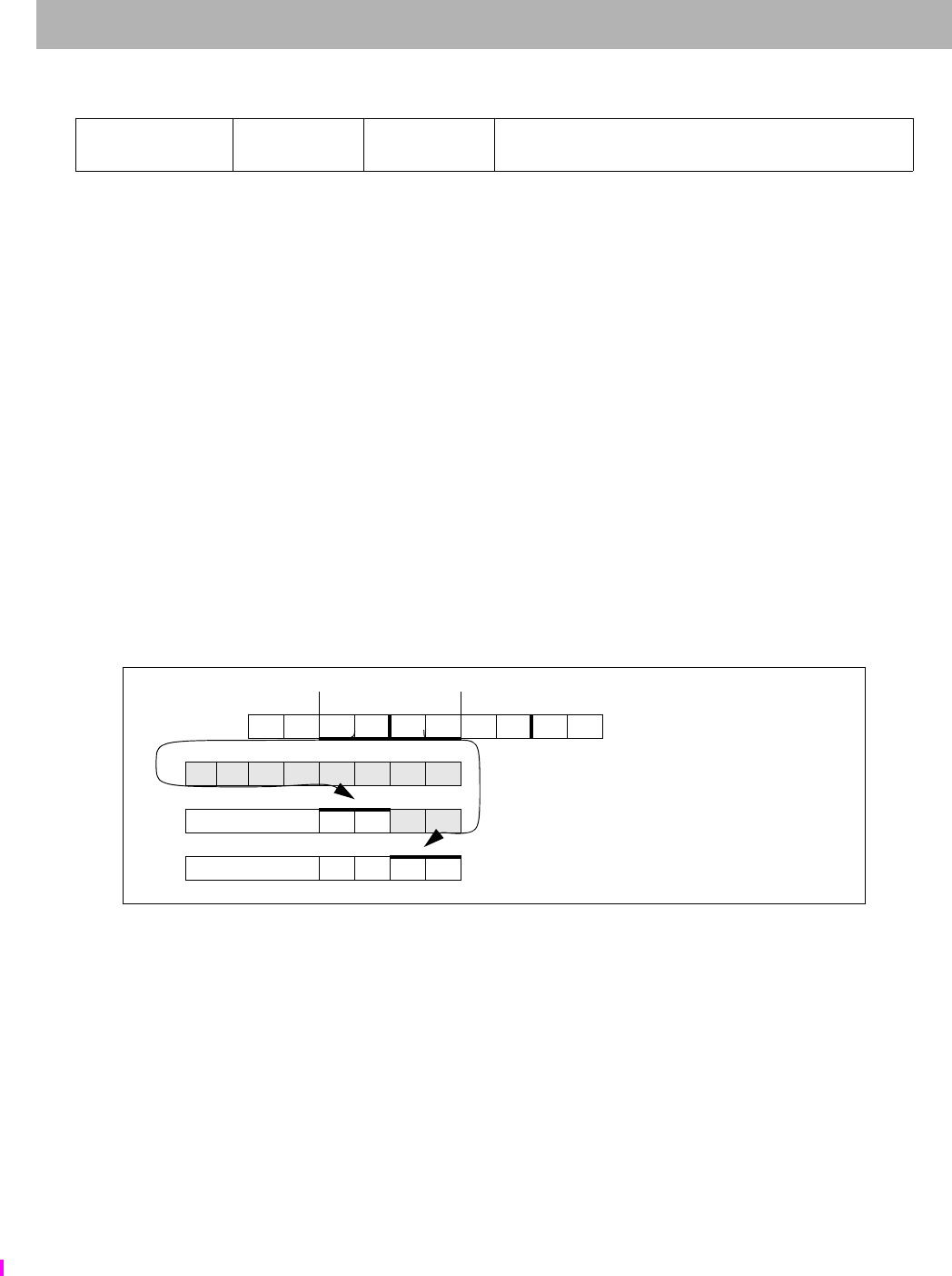
LWL
I
Load Word Left
The MIPS32® Instruction Set Manual, Revision 6.05 225
Format: LWL rt, offset(base) MIPS32, removed in Release 6
Purpose: Load Word Left
To load the most-significant part of a word as a signed value from an unaligned memory address
Description: GPR[rt] GPR[rt] MERGE memory[GPR[base] + offset]
The 16-bit signed offset is added to the contents of GPR base to form an effective address (EffAddr). EffAddr is the
address of the most-significant of 4 consecutive bytes forming a word (W) in memory starting at an arbitrary byte
boundary.
The most-significant 1 to 4 bytes of W is in the aligned word containing the EffAddr. This part of W is loaded into the
most-significant (left) part of the word in GPR rt. The remaining least-significant part of the word in GPR rt is
unchanged.
The figure below illustrates this operation using big-endian byte ordering for 32-bit and 64-bit registers. The 4 con-
secutive bytes in 2..5 form an unaligned word starting at location 2. A part of W, 2 bytes, is in the aligned word con-
taining the most-significant byte at 2. First, LWL loads these 2 bytes into the left part of the destination register word
and leaves the right part of the destination word unchanged. Next, the complementary LWR loads the remainder of
the unaligned word
Figure 4.1 Unaligned Word Load Using LWL and LWR
The bytes loaded from memory to the destination register depend on both the offset of the effective address within an
aligned word, that is, the low 2 bits of the address (vAddr1..0), and the current byte-ordering mode of the processor
(big- or little-endian). The figure below shows the bytes loaded for every combination of offset and byte ordering.
31 26 25 21 20 16 15 0
LWL
100010 base rt offset
655 16
Word at byte 2 in big-endian memory; each memory byte contains its own address
most - significance - least
0123456789 Memory initial contents
a b c d e f g h GPR 24 initial contents
sign bit (31) extend 2 3 g h After executing LWL $24,2($0)
sign bit (31) extend2345 Then after LWR $24,5($0)
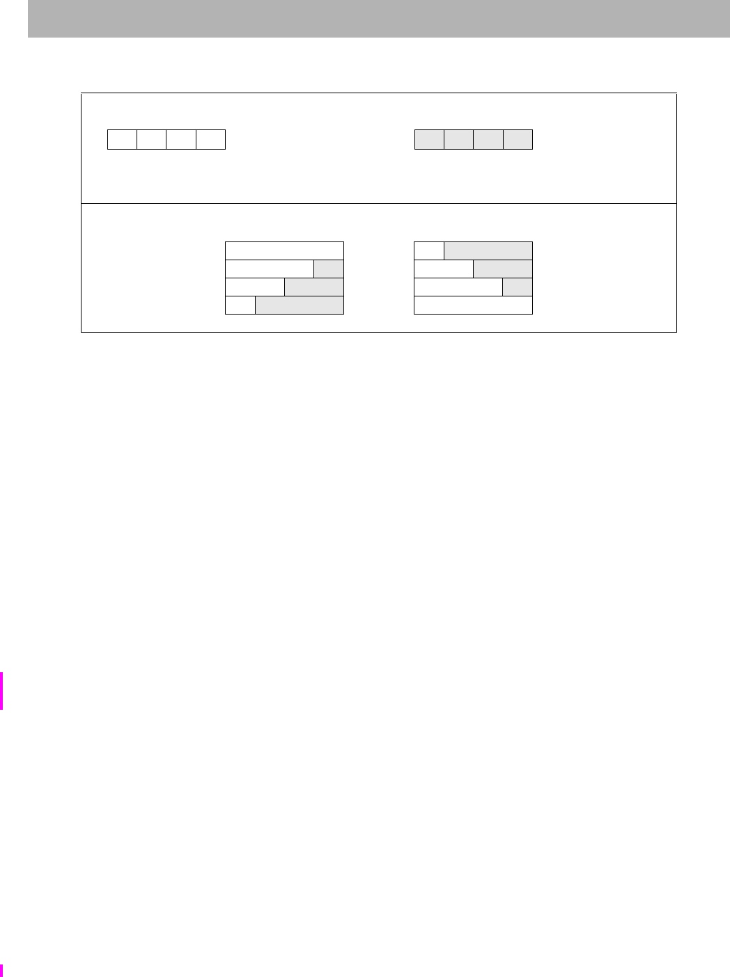
LWL Load Word Left
226 The MIPS32® Instruction Set Manual, Revision 6.05
Figure 4.2 Bytes Loaded by LWL Instruction
Restrictions:
None
Availability and Compatibility:
Release 6 removes the load/store-left/right family of instructions, and requires the system to support misaligned
memory accesses.
Operation:
vAddr sign_extend(offset) + GPR[base]
(pAddr, CCA) AddressTranslation (vAddr, DATA, LOAD)
pAddr pAddrPSIZE-1..2 || (pAddr1..0 xor ReverseEndian2)
if BigEndianMem = 0 then
pAddr pAddrPSIZE-1..2 || 02
endif
byte vAddr1..0 xor BigEndianCPU2
memword LoadMemory (CCA, byte, pAddr, vAddr, DATA)
temp memword7+8*byte..0 || GPR[rt]23-8*byte..0
GPR[rt] temp
Exceptions:
TLB Refill, TLB Invalid, Bus Error, Address Error, Watch
Programming Notes:
The architecture provides no direct support for treating unaligned words as unsigned values, that is, zeroing bits
63..32 of the destination register when bit 31 is loaded.
Historical Information:
In the MIPS I architecture, the LWL and LWR instructions were exceptions to the load-delay scheduling restriction.
A LWL or LWR instruction which was immediately followed by another LWL or LWR instruction, and used the
same destination register would correctly merge the 1 to 4 loaded bytes with the data loaded by the previous instruc-
tion. All such restrictions were removed from the architecture in MIPS II.
Memory contents and byte offsets Initial contents of Dest Register
0123
big-endian
IJKL offset (vAddr1..0)e f g h
3210
little-endian most least
most least — significance —
— significance —
Destination register contents after instruction (shaded is unchanged)
Big-endian vAddr1..0 Little-endian
IJKL 0 Lf g h
JKLh1KLg h
KLgh2JKLh
Lf g h3IJKL
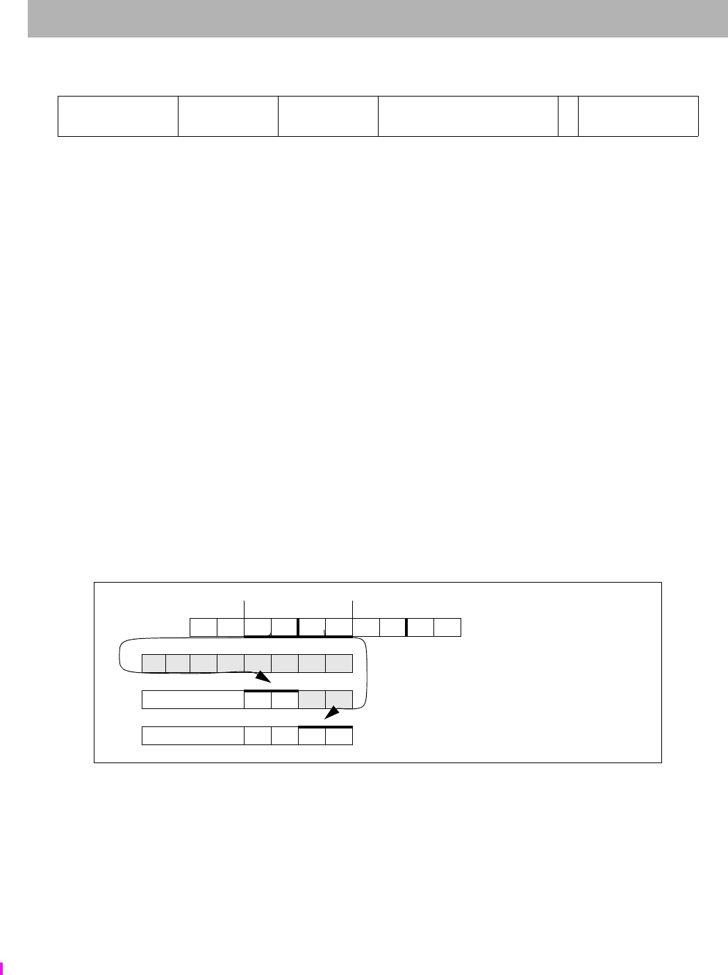
LWLE
I
Load Word Left EVA
The MIPS32® Instruction Set Manual, Revision 6.05 227
Format: LWLE rt, offset(base) MIPS32, removed in Release 6
Purpose: Load Word Left EVA
To load the most-significant part of a word as a signed value from an unaligned user mode virtual address while exe-
cuting in kernel mode.
Description: GPR[rt] GPR[rt] MERGE memory[GPR[base] + offset]
The 9-bit signed offset is added to the contents of GPR base to form an effective address (EffAddr). EffAddr is the
address of the most-significant of 4 consecutive bytes forming a word (W) in memory starting at an arbitrary byte
boundary.
The most-significant 1 to 4 bytes of W is in the aligned word containing the EffAddr. This part of W is loaded into the
most-significant (left) part of the word in GPR rt. The remaining least-significant part of the word in GPR rt is
unchanged.
The figure below illustrates this operation using big-endian byte ordering for 32-bit and 64-bit registers. The 4 con-
secutive bytes in 2..5 form an unaligned word starting at location 2. A part of W (2 bytes) is in the aligned word con-
taining the most-significant byte at 2.
1. LWLE loads these 2 bytes into the left part of the destination register word and leaves the right part of the desti-
nation word unchanged.
2. The complementary LWRE loads the remainder of the unaligned word.
Figure 4.3 Unaligned Word Load Using LWLE and LWRE
The bytes loaded from memory to the destination register depend on both the offset of the effective address within an
aligned word, that is, the low 2 bits of the address (vAddr1..0), and the current byte-ordering mode of the processor
(big- or little-endian). The figure below shows the bytes loaded for every combination of offset and byte ordering.
The LWLE instruction functions the same as the LWL instruction, except that address translation is performed using
the user mode virtual address space mapping in the TLB when accessing an address within a memory segment con-
figured to use the MUSUK access mode. Memory segments using UUSK or MUSK access modes are also accessible.
Refer to Volume III, Enhanced Virtual Addressing section for additional information.
Implementation of this instruction is specified by the Config5EVA field being set to 1.
31 26 25 21 20 16 15 7 6 5 0
SPECIAL3
011111 base rt offset 0LWLE
011001
655 9
16
Word at byte 2 in big-endian memory; each memory byte contains its own address
most - significance - least
0123456789 Memory initial contents
a b c d e f g h GPR 24 initial contents
sign bit (31) extend 2 3 g h After executing LWLE $24,2($0)
sign bit (31) extend2345 Then after LWRE $24,5($0)
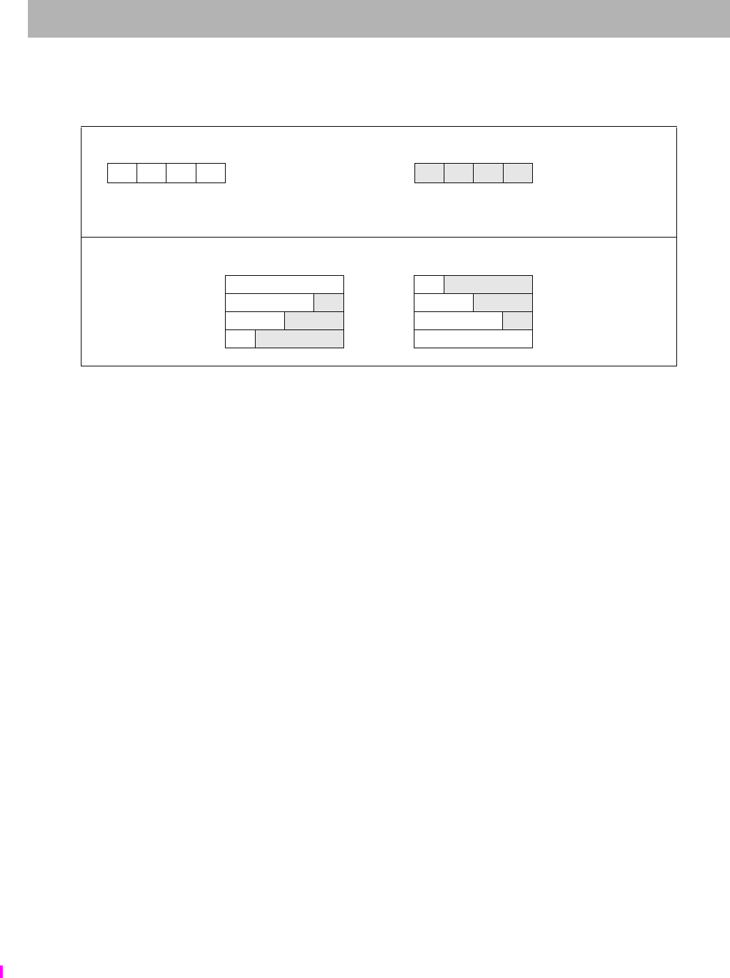
LWLE Load Word Left EVA
228 The MIPS32® Instruction Set Manual, Revision 6.05
Figure 4.4 Bytes Loaded by LWLE Instruction
Restrictions:
Only usable when access to Coprocessor0 is enabled and when accessing an address within a segment configured
using UUSK, MUSK or MUSUK access mode.
Availability and Compatibility:
Release 6 removes the load/store-left/right family of instructions, and requires the system to support misaligned
memory accesses.
Operation:
vAddr sign_extend(offset) + GPR[base]
(pAddr, CCA) AddressTranslation (vAddr, DATA, LOAD)
pAddr pAddrPSIZE-1..2 || (pAddr1..0 xor ReverseEndian2)
if BigEndianMem = 0 then
pAddr pAddrPSIZE-1..2 || 02
endif
byte vAddr1..0 xor BigEndianCPU2
memword LoadMemory (CCA, byte, pAddr, vAddr, DATA)
temp memword7+8*byte..0 || GPR[rt]23-8*byte..0
GPR[rt] temp
Exceptions:
TLB Refill, TLB Invalid, Bus Error, Address Error, Watch, Reserved Instruction, Coprocessor Unusable
Programming Notes:
The architecture provides no direct support for treating unaligned words as unsigned values, that is, zeroing bits
63..32 of the destination register when bit 31 is loaded.
Historical Information:
In the MIPS I architecture, the LWL and LWR instructions were exceptions to the load-delay scheduling restriction.
A LWL or LWR instruction which was immediately followed by another LWL or LWR instruction, and used the
Memory contents and byte offsets Initial contents of Dest Register
0123
big-endian
IJKL offset (vAddr1..0)e f g h
3210
little-endian most least
most least — significance —
— significance —
Destination register contents after instruction (shaded is unchanged)
Big-endian vAddr1..0 Little-endian
IJKL 0 Lf g h
JKLh1KLg h
KLgh2JKLh
Lf g h3IJKL

LWLE
I
Load Word Left EVA
The MIPS32® Instruction Set Manual, Revision 6.05 229
same destination register would correctly merge the 1 to 4 loaded bytes with the data loaded by the previous instruc-
tion. All such restrictions were removed from the architecture in MIPS II.

LWPC Load Word PC-relative
230 The MIPS32® Instruction Set Manual, Revision 6.05
Format: LWPC rs, offset MIPS32 Release 6
Purpose: Load Word PC-relative
To load a word from memory as a signed value, using a PC-relative address.
Description: GPR[rs] memory[ PC + sign_extend( offset << 2 ) ]
The offset is shifted left by 2 bits, sign-extended, and added to the address of the LWPC instruction.
The contents of the 32-bit word at the memory location specified by the aligned effective address are fetched, sign-
extended to the GPR register length if necessary, and placed in GPR rs.
Restrictions:
LWPC is naturally aligned, by specification.
Availability and Compatibility:
This instruction is introduced by and required as of Release 6.
Operation
vAddr ( PC + sign_extend(offset)<<2)
(pAddr, CCA) AddressTranslation (vAddr, DATA, LOAD)
memword LoadMemory (CCA, WORD, pAddr, vAddr, DATA)
GPR[rs] memword
Exceptions:
TLB Refill, TLB Invalid, TLB Read Inhibit, Bus Error, Address Error, Watch
Programming Note
The Release 6 PC-relative loads (LWPC) are considered data references.
For the purposes of watchpoints (provided by the CP0 WatchHi and WatchLo registers) and EJTAG breakpoints, the
PC-relative reference is considered to be a data reference rather than an instruction reference. That is, the watchpoint
or breakpoint is triggered only if enabled for data references.
31 26 25 21 20 19 18 0
PCREL
111011 rs LWPC
01 offset
652 19
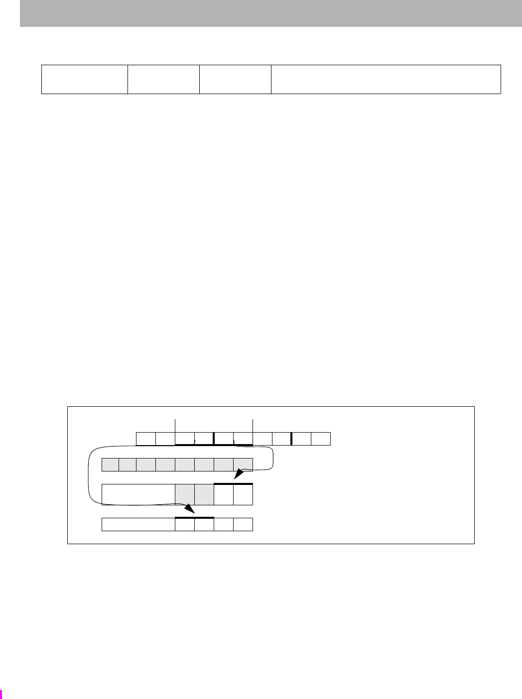
LWR
I
Load Word Right
The MIPS32® Instruction Set Manual, Revision 6.05 231
Format: LWR rt, offset(base) MIPS32, removed in Release 6
Purpose: Load Word Right
To load the least-significant part of a word from an unaligned memory address as a signed value
Description: GPR[rt] GPR[rt] MERGE memory[GPR[base] + offset]
The 16-bit signed offset is added to the contents of GPR base to form an effective address (EffAddr). EffAddr is the
address of the least-significant of 4 consecutive bytes forming a word (W) in memory starting at an arbitrary byte
boundary.
A part of W (the least-significant 1 to 4 bytes) is in the aligned word containing EffAddr. This part of W is loaded into
the least-significant (right) part of the word in GPR rt. The remaining most-significant part of the word in GPR rt is
unchanged.
Executing both LWR and LWL, in either order, delivers a sign-extended word value in the destination register.
The figure below illustrates this operation using big-endian byte ordering for 32-bit and 64-bit registers. The 4 con-
secutive bytes in 2..5 form an unaligned word starting at location 2. A part of W, 2 bytes, is in the aligned word con-
taining the least-significant byte at 5.
1. LWR loads these 2 bytes into the right part of the destination register.
2. The complementary LWL loads the remainder of the unaligned word.
Figure 4.5 Unaligned Word Load Using LWL and LWR
The bytes loaded from memory to the destination register depend on both the offset of the effective address within an
aligned word, that is, the low 2 bits of the address (vAddr1..0), and the current byte-ordering mode of the processor
(big- or little-endian). The figure below shows the bytes loaded for every combination of offset and byte ordering.
31 26 25 21 20 16 15 0
LWR
100110 base rt offset
655 16
Word at byte 2 in big-endian memory; each memory byte contains its own address
most - significance - least
0123456789 Memory initial contents
a b c d e f g h GPR 24 initial contents
no cng or sign bit (31)
extend ef45 After executing LWR $24,5($0)
sign bit (31) extend2345 Then after LWL $24,2($0)
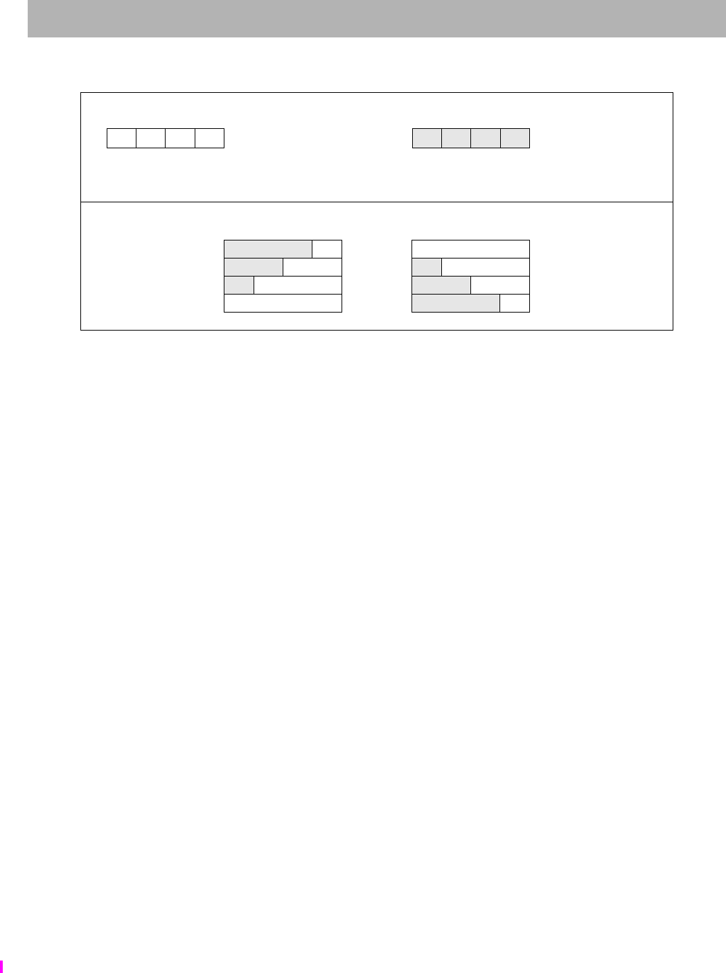
LWR Load Word Right
232 The MIPS32® Instruction Set Manual, Revision 6.05
Figure 4.6 Bytes Loaded by LWR Instruction
Restrictions:
None
Availability and Compatibility:
Release 6 removes the load/store-left/right family of instructions, and requires the system to support misaligned
memory accesses.
Operation:
vAddr sign_extend(offset) + GPR[base]
(pAddr, CCA) AddressTranslation (vAddr, DATA, LOAD)
pAddr pAddrPSIZE-1..2 || (pAddr1..0 xor ReverseEndian2)
if BigEndianMem = 0 then
pAddr pAddrPSIZE-1..2 || 02
endif
byte vAddr1..0 xor BigEndianCPU2
memword LoadMemory (CCA, byte, pAddr, vAddr, DATA)
temp memword31..32-8*byte || GPR[rt]31–8*byte..0
GPR[rt] temp
Exceptions:
TLB Refill, TLB Invalid, Bus Error, Address Error, Watch
Programming Notes:
The architecture provides no direct support for treating unaligned words as unsigned values, that is, zeroing bits
63..32 of the destination register when bit 31 is loaded.
Historical Information:
In the MIPS I architecture, the LWL and LWR instructions were exceptions to the load-delay scheduling restriction.
A LWL or LWR instruction which was immediately followed by another LWL or LWR instruction, and used the
same destination register would correctly merge the 1 to 4 loaded bytes with the data loaded by the previous instruc-
tion. All such restrictions were removed from the architecture in MIPS II.
Memory contents and byte offsets Initial contents of Dest Register
0123
big-endian
IJKL offset (vAddr1..0)e f g h
3210
little-endian most least
most least — significance—
— significance —
Destination register contents after instruction (shaded is unchanged)
Big-endian vAddr1..0 Little-endian
e f gI 0 IJKL
efIJ 1 eIJK
eIJK 2 efIJ
IJKL 3 e f gI

LWR
I
Load Word Right
The MIPS32® Instruction Set Manual, Revision 6.05 233
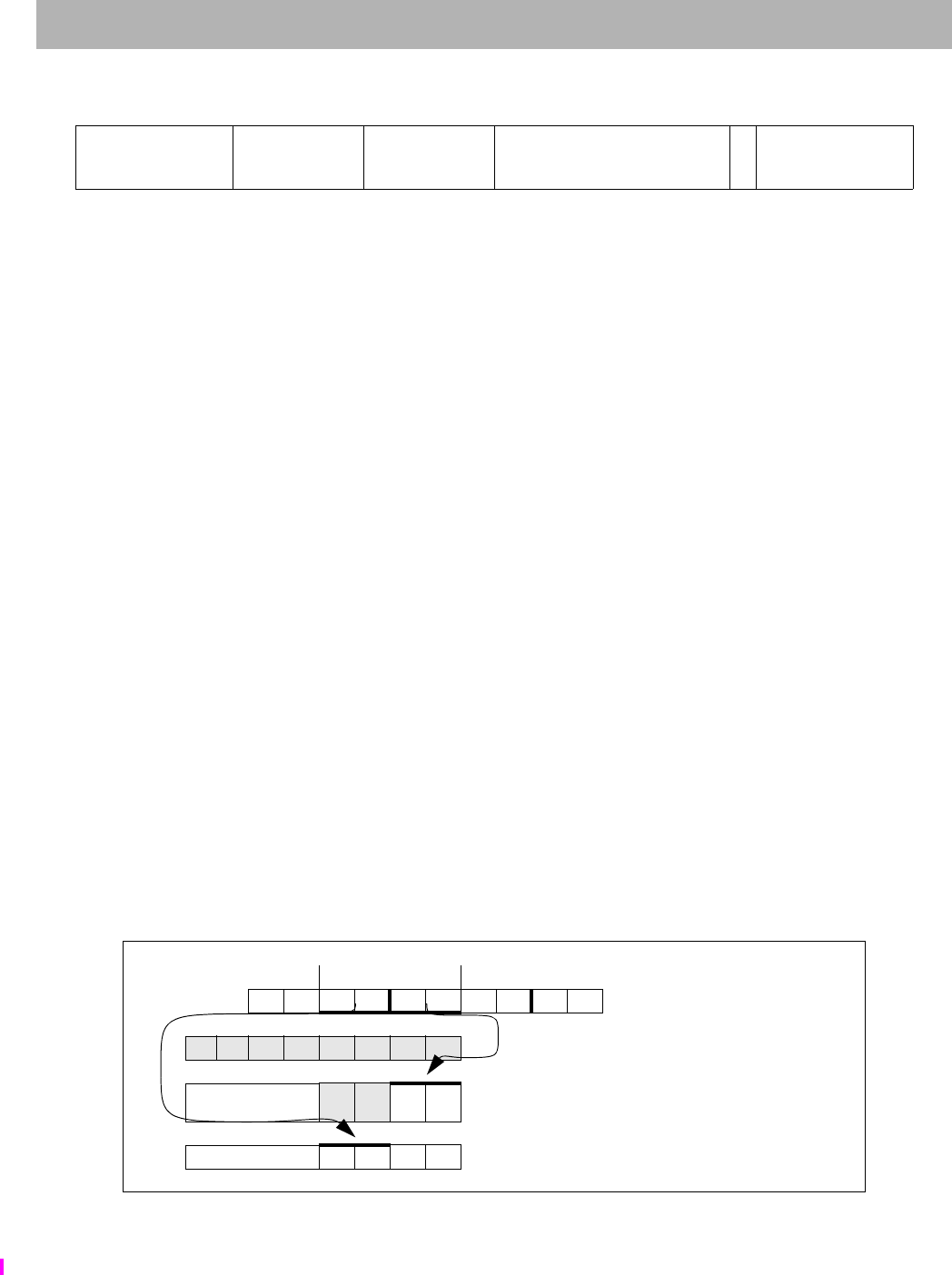
LWRE Load Word Right EVA
234 The MIPS32® Instruction Set Manual, Revision 6.05
Format: LWRE rt, offset(base) MIPS32, removed in Release 6
Purpose: Load Word Right EVA
To load the least-significant part of a word from an unaligned user mode virtual memory address as a signed value
while executing in kernel mode.
Description: GPR[rt] GPR[rt] MERGE memory[GPR[base] + offset]
The 9-bit signed offset is added to the contents of GPR base to form an effective address (EffAddr). EffAddr is the
address of the least-significant of 4 consecutive bytes forming a word (W) in memory starting at an arbitrary byte
boundary.
A part of W (the least-significant 1 to 4 bytes) is in the aligned word containing EffAddr. This part of W is loaded into
the least-significant (right) part of the word in GPR rt. The remaining most-significant part of the word in GPR rt is
unchanged.
Executing both LWRE and LWLE, in either order, delivers a sign-extended word value in the destination register.
The figure below illustrates this operation using big-endian byte ordering for 32-bit and 64-bit registers. The 4 con-
secutive bytes in 2..5 form an unaligned word starting at location 2. A part of W (2 bytes) is in the aligned word con-
taining the least-significant byte at 5.
1. LWRE loads these 2 bytes into the right part of the destination register.
2. The complementary LWLE loads the remainder of the unaligned word.
The LWRE instruction functions in exactly the same fashion as the LWR instruction, except that address translation is
performed using the user mode virtual address space mapping in the TLB when accessing an address within a mem-
ory segment configured to use the MUSUK access mode. Memory segments using UUSK or MUSK access modes
are also accessible. Refer to Volume III, Enhanced Virtual Addressing section for additional information.
Implementation of this instruction is specified by the Config5EVA field being set to one.
Figure 4.7 Unaligned Word Load Using LWLE and LWRE
31 26 25 21 20 16 15 7 6 5 0
SPECIAL3
011111 base rt offset 0
LWRE
011010
655 9
16
Word at byte 2 in big-endian memory; each memory byte contains its own address
most - significance - least
0123456789 Memory initial contents
a b c d e f g h GPR 24 initial contents
no cng or sign bit (31)
extend ef45 After executing LWRE $24,5($0)
sign bit (31) extend2345 Then after LWLE $24,2($0)
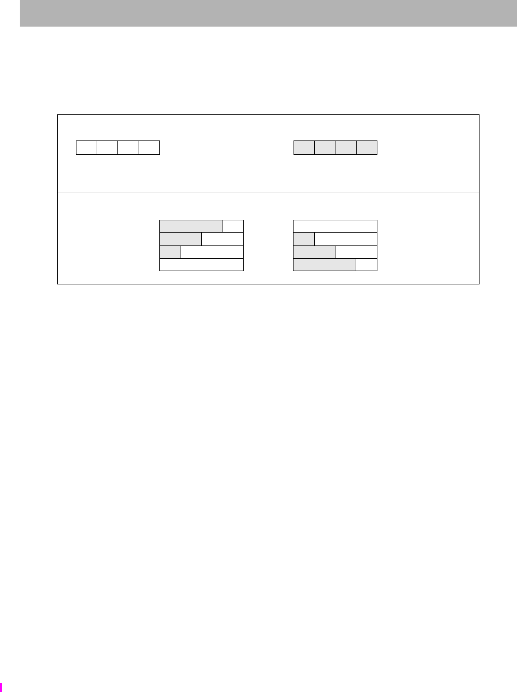
LWRE
I
Load Word Right EVA
The MIPS32® Instruction Set Manual, Revision 6.05 235
The bytes loaded from memory to the destination register depend on both the offset of the effective address within an
aligned word, that is, the low 2 bits of the address (vAddr1..0), and the current byte-ordering mode of the processor
(big- or little-endian). The figure below shows the bytes loaded for every combination of offset and byte ordering.
Figure 4.8 Bytes Loaded by LWRE Instruction
Restrictions:
Only usable when access to Coprocessor0 is enabled and when accessing an address within a segment configured
using UUSK, MUSK or MUSUK access mode.
Availability and Compatibility:
Release 6 removes the load/store-left/right family of instructions, and requires the system to support misaligned
memory accesses.
Operation:
vAddr sign_extend(offset) + GPR[base]
(pAddr, CCA) AddressTranslation (vAddr, DATA, LOAD)
pAddr pAddrPSIZE-1..2 || (pAddr1..0 xor ReverseEndian2)
if BigEndianMem = 0 then
pAddr pAddrPSIZE-1..2 || 02
endif
byte vAddr1..0 xor BigEndianCPU2
memword LoadMemory (CCA, byte, pAddr, vAddr, DATA)
temp memword31..32-8*byte || GPR[rt]31–8*byte..0
GPR[rt] temp
Exceptions:
TLB Refill, TLB Invalid, Bus Error, Address Error, Watch, Reserved Instruction, Coprocessor Unusable
Programming Notes:
The architecture provides no direct support for treating unaligned words as unsigned values, that is, zeroing bits
63..32 of the destination register when bit 31 is loaded.
Memory contents and byte offsets Initial contents of Dest Register
0123
big-endian
IJKL offset (vAddr1..0)e f g h
3210
little-endian most least
most least — significance—
— significance —
Destination register contents after instruction (shaded is unchanged)
Big-endian vAddr1..0 Little-endian
e f gI 0 IJKL
efIJ 1 eIJK
eIJK 2 efIJ
IJKL 3 e f gI

LWRE Load Word Right EVA
236 The MIPS32® Instruction Set Manual, Revision 6.05
Historical Information:
In the MIPS I architecture, the LWL and LWR instructions were exceptions to the load-delay scheduling restriction.
A LWL or LWR instruction which was immediately followed by another LWL or LWR instruction, and used the
same destination register would correctly merge the 1 to 4 loaded bytes with the data loaded by the previous instruc-
tion. All such restrictions were removed from the architecture in MIPS II.

LWXC1
I
Load Word Indexed to Floating Point
The MIPS32® Instruction Set Manual, Revision 6.05 237
Format: LWXC1 fd, index(base) MIPS32 Release 2, removed in Release 6
Purpose: Load Word Indexed to Floating Point
To load a word from memory to an FPR (GPR+GPR addressing).
Description: FPR[fd] memory[GPR[base] + GPR[index]]
The contents of the 32-bit word at the memory location specified by the aligned effective address are fetched and
placed into the low word of FPR fd. If FPRs are 64 bits wide, bits 63..32 of FPR fs become UNPREDICTABLE. The
contents of GPR index and GPR base are added to form the effective address.
Restrictions:
An Address Error exception occurs if EffectiveAddress1..0 ≠ 0 (not word-aligned).
Availability and Compatibility:
This instruction has been removed in Release 6.
Required in all versions of MIPS64 since MIPS64 Release 1. Not available in MIPS32 Release 1. Required in
MIPS32 Release 2 and all subsequent versions of MIPS32. When required, required whenever FPU is present,
whether a 32-bit or 64-bit FPU, whether in 32-bit or 64-bit FP Register Mode (FIRF64=0 or 1, StatusFR=0 or 1).
Operation:
vAddr GPR[base] + GPR[index]
if vAddr1..0 02 then
SignalException(AddressError)
endif
(pAddr, CCA) AddressTranslation (vAddr, DATA, LOAD)
memword LoadMemory(CCA, WORD, pAddr, vAddr, DATA)
StoreFPR(fd, UNINTERPRETED_WORD,
memword)
Exceptions:
TLB Refill, TLB Invalid, Address Error, Reserved Instruction, Coprocessor Unusable, Watch
31 26 25 21 20 16 15 11 10 6 5 0
COP1X
010011 base index 0
00000 fd LWXC1
000000
6 5555 6

MADD Multiply and Add Word to Hi, Lo
238 The MIPS32® Instruction Set Manual, Revision 6.05
Format: MADD rs, rt MIPS32, removed in Release 6
Purpose: Multiply and Add Word to Hi, Lo
To multiply two words and add the result to Hi, Lo.
Description: (HI,LO) (HI,LO) + (GPR[rs] x GPR[rt])
The 32-bit word value in GPR rs is multiplied by the 32-bit word value in GPR rt, treating both operands as signed
values, to produce a 64-bit result. The product is added to the 64-bit concatenated values of HI and LO. The most sig-
nificant 32 bits of the result are written into HI and the least significant 32 bits are written into LO. No arithmetic
exception occurs under any circumstances.
Restrictions:
This instruction does not provide the capability of writing directly to a target GPR.
Availability and Compatibility:
This instruction has been removed in Release 6.
Operation:
temp (HI || LO) + (GPR[rs] x GPR[rt])
HI temp63..32
LO temp31..0
Exceptions:
None
Programming Notes:
Where the size of the operands are known, software should place the shorter operand in GPR rt. This may reduce the
latency of the instruction on those processors which implement data-dependent instruction latencies.
31 26 25 21 20 16 15 11 10 6 5 0
SPECIAL2
011100 rs rt 0
0000
0
00000
MADD
000000
6 5555 6

MADD.fmt
I
Floating Point Multiply Add
The MIPS32® Instruction Set Manual, Revision 6.05 239
Format: MADD.fmt
MADD.S fd, fr, fs, ft MIPS32 Release 2, removed in Release 6
MADD.D fd, fr, fs, ft MIPS32 Release 2, removed in Release 6
MADD.PS fd, fr, fs, ft MIPS32 Release 2, removed in Release 6
Purpose: Floating Point Multiply Add
To perform a combined multiply-then-add of FP values.
Description: FPR[fd] (FPR[fs] x FPR[ft]) FPR[fr]
The value in FPR fs is multiplied by the value in FPR ft to produce an intermediate product.
The intermediate product is rounded according to the current rounding mode in FCSR. The value in FPR fr is added
to the product. The result sum is calculated to infinite precision, rounded according to the current rounding mode in
FCSR, and placed into FPR fd. The operands and result are values in format fmt. The results and flags are as if sepa-
rate floating-point multiply and add instructions were executed.
MADD.PS multiplies then adds the upper and lower halves of FPR fr, FPR fs, and FPR ft independently, and ORs
together any generated exceptional conditions.
The Cause bits are ORed into the Flag bits if no exception is taken.
Restrictions:
The fields fr, fs, ft, and fd must specify FPRs valid for operands of type fmt. If the fields are not valid, the result is
UNPREDICTABLE.
The operands must be values in format fmt; if they are not, the result is UNPREDICTABLE and the value of the
operand FPRs becomes UNPREDICTABLE.
The result of MADD.PS is UNPREDICTABLE if the processor is executing in the FR=0 32-bit FPU register model.
It is predictable if executing on a 64-bit FPU in the FR=1 mode, but not with FR=0, and not on a 32-bit FPU.
Availability and Compatibility:
MADD.S and MADD.D: Required in all versions of MIPS64 since MIPS64 Release 1. Not available in MIPS32
Release 1. Required in MIPS32 Release 2 and all subsequent versions of MIPS32. When required, these instructions
are to be implemented if an FPU is present either in a 32-bit or 64-bit FPU or in a 32-bit or 64-bit FP Register Mode
(FIRF64=0 or 1, StatusFR=0 or 1).
This instruction has been removed in Release 6 and has been replaced by the fused multiply-add instruction. Refer to
the fused multiply-add instruction ‘MADDF.fmt’ in this manual for more information. Release 6 does not support
Paired Single (PS).
Operation:
vfr ValueFPR(fr, fmt)
vfs ValueFPR(fs, fmt)
vft ValueFPR(ft, fmt)
StoreFPR(fd, fmt, (vfs xfmt vft) fmt vfr)
Exceptions:
Coprocessor Unusable, Reserved Instruction
31 26 25 21 20 16 15 11 10 6 5 3 2 0
COP1X
010011 fr ft fs fd MADD
100 fmt
6 555533

MADD.fmt Floating Point Multiply Add
240 The MIPS32® Instruction Set Manual, Revision 6.05
Floating Point Exceptions:
Inexact, Unimplemented Operation, Invalid Operation, Overflow, Underflow

MADD.fmt
I
Floating Point Multiply Add
The MIPS32® Instruction Set Manual, Revision 6.05 241

MADDF.fmt MSUBF.fmt Floating Point Fused Multiply Add, Floating Point Fused Multiply Subtract
242 The MIPS32® Instruction Set Manual, Revision 6.05
Format: MADDF.fmt MSUBF.fmt
MADDF.S fd, fs, ft MIPS32 Release 6
MADDF.D fd, fs, ft MIPS32 Release 6
MSUBF.S fd, fs, ft MIPS32 Release 6
MSUBF.D fd, fs, ft MIPS32 Release 6
Purpose: Floating Point Fused Multiply Add, Floating Point Fused Multiply Subtract
MADDF.fmt: To perform a fused multiply-add of FP values.
MSUBF.fmt: To perform a fused multiply-subtract of FP values.
Description:
MADDF.fmt: FPR[fd] FPR[fd] + (FPR[fs] FPR[ft])
MSUBF.fmt: FPR[fd] FPR[fd] - (FPR[fs] FPR[ft])
The value in FPR fs is multiplied by the value in FPR ft to produce an intermediate product. The intermediate product
is calculated to infinite precision. The product is added to the value in FPR fd. The result sum is calculated to infinite
precision, rounded according to the current rounding mode in FCSR, and placed into FPR fd. The operands and result
are values in format fmt.
(For MSUBF.fmt, the product is subtracted from the value in FPR fd.)
Cause bits are ORed into the Flag bits if no exception is taken.
Restrictions:
None
Availability and Compatibility:
MADDF.fmt and MSUBF.fmt are required in Release 6.
MADDF.fmt and MSUBF.fmt are not available in architectures pre-Release 6.
The fused multiply add instructions, MADDF.fmt and MSUBF.fmt, replace pre-Release 6 instructions such as
MADD.fmt, MSUB.fmt, NMADD.fmt, and NMSUB.fmt. The replaced instructions were unfused multiply-add, with
an intermediate rounding.
Release 6 MSUBF.fmt, fdfd-fsft, corresponds more closely to pre-Release 6 NMADD.fmt, fdfr-fsft,
than to pre-Release 6 MSUB.fmt, fdfsft-fr.
FPU scalar MADDF.fmt corresponds to MSA vector MADD.df.
FPU scalar MSUBF.fmt corresponds to MSA vector MSUB.df.
Operation:
if not IsCoprocessorEnabled(1)
then SignalException(CoprocessorUnusable, 1) endif
if not IsFloatingPointImplemented(fmt))
then SignalException(ReservedInstruction) endif
31 26 25 21 20 16 15 11 10 6 5 0
COP1
010001 fmt ft fs fd MADDF
011000
COP1
010001 fmt ft fs fd MSUBF
011001
6 555533

MADDF.fmt MSUBF.fmt
I
Floating Point Fused Multiply Add, Floating Point Fused Multiply Subtract
The MIPS32® Instruction Set Manual, Revision 6.05 243
vfr ValueFPR(fr, fmt)
vfs ValueFPR(fs, fmt)
vfd ValueFPR(fd, fmt)
MADDF.fmt: vinf vfd (vfs * vft)
MADDF.fmt: vinf vfd - (vfs * vft)
StoreFPR(fd, fmt, vinf)
Special Considerations:
The fused multiply-add computation is performed in infinite precision, and signals Inexact, Overflow, or Underflow
if and only if the final result differs from the infinite precision result in the appropriate manner.
Like most FPU computational instructions, if the flush-subnormals-to-zero mode, FCSR.FS=1, then subnormals are
flushed before beginning the fused-multiply-add computation, and Inexact may be signaled.
I.e. Inexact may be signaled both by input flushing and/or by the fused-multiply-add: the conditions or ORed.
Exceptions:
Coprocessor Unusable, Reserved Instruction
Floating Point Exceptions:
Inexact, Unimplemented Operation, Invalid Operation, Overflow, Underflow

MADDU Multiply and Add Unsigned Word to Hi,Lo
244 The MIPS32® Instruction Set Manual, Revision 6.05
Format: MADDU rs, rt MIPS32, removed in Release 6
Purpose: Multiply and Add Unsigned Word to Hi,Lo
To multiply two unsigned words and add the result to HI, LO.
Description: (HI,LO) (HI,LO) (GPR[rs] x GPR[rt])
The 32-bit word value in GPR rs is multiplied by the 32-bit word value in GPR rt, treating both operands as unsigned
values, to produce a 64-bit result. The product is added to the 64-bit concatenated values of HI and LO. The most sig-
nificant 32 bits of the result are written into HI and the least significant 32 bits are written into LO. No arithmetic
exception occurs under any circumstances.
Restrictions:
None
This instruction does not provide the capability of writing directly to a target GPR.
Availability and Compatibility:
This instruction has been removed in Release 6.
Operation:
temp (HI || LO) (GPR[rs] x GPR[rt])
HI temp63..32
LO temp31..0
Exceptions:
None
Programming Notes:
Where the size of the operands are known, software should place the shorter operand in GPR rt. This may reduce the
latency of the instruction on those processors which implement data-dependent instruction latencies.
31 26 25 21 20 16 15 11 10 6 5 0
SPECIAL2
011100 rs rt 0
00000
0
00000
MADDU
000001
6 5555 6

MAX.fmt MIN.fmt MAXA.fmt MINA.fmt
I
Scalar Floating-Point Max/Min/maxNumMag/minNumMag
The MIPS32® Instruction Set Manual, Revision 6.05 245
Format: MAX.fmt MIN.fmt MAXA.fmt MINA.fmt
MAX.S fd,fs,ft MIPS32 Release 6
MAX.D fd,fs,ft MIPS32 Release 6
MAXA.S fd,fs,ft MIPS32 Release 6
MAXA.D fd,fs,ft MIPS32 Release 6
MIN.S fd,fs,ft MIPS32 Release 6
MIN.D fd,fs,ft MIPS32 Release 6
MINA.S fd,fs,ft MIPS32 Release 6
MINA.D fd,fs,ft MIPS32 Release 6
Purpose: Scalar Floating-Point Max/Min/maxNumMag/minNumMag
Scalar Floating-Point Maximum
Scalar Floating-Point Minimum
Scalar Floating-Point argument with Maximum Absolute Value
Scalar Floating-Point argument with Minimum Absolute Value
Description:
MAX.fmt: FPR[fd]maxNum(FPR[fs],FPR[ft])
MIN.fmt: FPR[fd]minNum(FPR[fs],FPR[ft])
MAXA.fmt: FPR[fd]maxNumMag(FPR[fs],FPR[ft])
MINA.fmt: FPR[fd]minNumMag(FPR[fs],FPR[ft])
MAX.fmt writes the maximum value of the inputs fs and ft to the destination fd.
MIN.fmt writes the minimum value of the inputs fs and ft to the destination fd.
MAXA.fmt takes input arguments fs and ft and writes the argument with the maximum absolute value to the desti-
nation fd.
MINA.fmt takes input arguments fs and ft and writes the argument with the minimum absolute value to the desti-
nation fd.
The instructions MAX.fmt/MIN.fmt/MAXA.fmt/MINA.fmt correspond to the IEEE 754-2008 operations maxNum/
31 26 25 21 20 16 15 11 10 6 5 0
COP1
010001 fmt ft fs fd MAX
011110
6 5555 6
31 26 25 21 20 16 15 11 10 6 5 0
COP1
010001 fmt ft fs fd MAXA
011111
6 5555 6
31 26 25 21 20 16 15 11 10 6 5 0
COP1
010001 fmt ft fs fd MIN
011100
6 5555 6
31 26 25 21 20 16 15 11 10 6 5 0
COP1
010001 fmt ft fs fd MINA
011101
6 5555 6

MAX.fmt MIN.fmt MAXA.fmt MINA.fmt Scalar Floating-Point Max/Min/maxNumMag/minNumMag
246 The MIPS32® Instruction Set Manual, Revision 6.05
minNum/maxNumMag/minNumMag.
• MAX.fmt corresponds to the IEEE 754-2008 operation maxNum.
• MIN.fmt corresponds to the IEEE 754-2008 operation minNum.
• MAXA.fmt corresponds to the IEEE 754-2008 operation maxNumMag.
• MINA.fmt corresponds to the IEEE 754-2008 operation minNumMag.
Numbers are preferred to NaNs: if one input is a NaN, but not both, the value of the numeric input is returned. If both
are NaNs, the NaN in fs is returned.1
The scalar FPU instructions MAX.fmt/MIN.fmt/MAXA.fmt/MINA.fmt correspond to the MSA instructions
FMAX.df/FMIN.df/FMAXA.df/FMINA.df.
• Scalar FPU instruction MAX.fmt corresponds to the MSA vector instruction FMAX.df.
• Scalar FPU instruction MIN.fmt corresponds to the MSA vector instruction FMIN.df.
• Scalar FPU instruction MAXA.fmt corresponds to the MSA vector instruction FMAX_A.df.
• Scalar FPU instruction MINA.fmt corresponds to the MSA vector instruction FMIN_A.df.
Restrictions:
Data-dependent exceptions are possible as specified by the IEEE Standard for Floating-Point Arithmetic 754TM-
2008. See also the section “Special Cases”, below.
Availability and Compatibility:
These instructions are introduced by and required as of Release 6.
Operation:
if not IsCoprocessorEnabled(1)
then SignalException(CoprocessorUnusable, 1) endif
if not IsFloatingPointImplemented(fmt)
then SignalException(ReservedInstruction) endif
v1 ValueFPR(fs,fmt)
v2 ValueFPR(ft,fmt)
if SNaN(v1) or SNaN(v2) then
then SignalException(InvalidOperand)
zzjj
endif
zzjjjj
if NaN(v1) and NaN(v2)then
ftmp v1
elseif NaN(v1) then
ftmp v2
elseif NaN(v2) then
ftmp v1
else
case instruction of
1. IEEE standard 754-2008 allows either input to be chosen if both inputs are NaNs. Release 6 specifies that the first input must
be propagated.

MAX.fmt MIN.fmt MAXA.fmt MINA.fmt
I
Scalar Floating-Point Max/Min/maxNumMag/minNumMag
The MIPS32® Instruction Set Manual, Revision 6.05 247
FMAX.fmt: ftmp MaxFP.fmt(ValueFPR(fs,fmt),ValueFPR(ft,fmt))
FMIN.fmt: ftmp MinFP.fmt(ValueFPR(fs,fmt),ValueFPR(ft,fmt))
FMAXA.fmt: ftmp MaxAbsoluteFP.fmt(ValueFPR(fs,fmt),ValueFPR(ft,fmt))
FMINA.fmt: ftmp MinAbsoluteFP.fmt(ValueFPR(fs,fmt),ValueFPR(ft,fmt))
end case
endif
StoreFPR (fd, fmt, ftmp)
/* end of instruction */
function MaxFP(tt, ts, n)
/* Returns the largest argument. */
endfunction MaxFP
function MinFP(tt, ts, n)
/* Returns the smallest argument. */
endfunction MaxFP
function MaxAbsoluteFP(tt, ts, n)
/* Returns the argument with largest absolute value.
For equal absolute values, returns the largest argument.*/
endfunction MaxAbsoluteFP
function MinAbsoluteFP(tt, ts, n)
/* Returns the argument with smallest absolute value.
For equal absolute values, returns the smallest argument.*/
endfunction MinAbsoluteFP
function NaN(tt, ts, n)
/* Returns true if the value is a NaN */
return SNaN(value) or QNaN(value)
endfunction MinAbsoluteFP
Table 4.1 Special Cases for FP MAX, MIN, MAXA, MINA
Operand
Other
Release 6 Instructions
fs ft MAX MIN MAXA MINA
-0.0 0.0 0.0 -0.0 0.0 -0.0
0.0 -0.0
QNaN # # # # #
# QNaN
QNaN1 QNaN2 Release 6 QNan1 QNaN1 QNaN1 QNaN1
IEEE
754 2008
Arbitrary choice. Not allowed to clear sign bit.

MAX.fmt MIN.fmt MAXA.fmt MINA.fmt Scalar Floating-Point Max/Min/maxNumMag/minNumMag
248 The MIPS32® Instruction Set Manual, Revision 6.05
Exceptions:
Coprocessor Unusable, Reserved Instruction
Floating Point Exceptions:
Unimplemented Operation, Invalid Operation
Either or both operands
SNaN
Invalid
Operation
exception
enabled
Signal Invalid Operation Exception.
Destination not written.
... disabled Treat as if the SNaN were a QNaN (do not quieten the result).
Table 4.1 Special Cases for FP MAX, MIN, MAXA, MINA
Operand
Other
Release 6 Instructions
fs ft MAX MIN MAXA MINA

MFC0
I
Move from Coprocessor 0
The MIPS32® Instruction Set Manual, Revision 6.05 249
Format: MFC0 rt, rd MIPS32
MFC0 rt, rd, sel MIPS32
Purpose: Move from Coprocessor 0
To move the contents of a coprocessor 0 register to a general register.
Description: GPR[rt] CPR[0,rd,sel]
The contents of the coprocessor 0 register specified by the combination of rd and sel are loaded into general register
rt. Not all coprocessor 0 registers support the sel field. In those instances, the sel field must be zero.
Restrictions:
Pre-Release 6: The results are UNDEFINED if coprocessor 0 does not contain a register as specified by rd and sel.
Release 6: Reading a reserved register or a register that is not implemented for the current core configuration returns
0.
Operation:
reg = rd
if IsCoprocessorRegisterImplemented(0, reg, sel) then
data CPR[0, reg, sel]
GPR[rt] data
else
if ArchitectureRevision() ≥ 6 then
GPR[rt] 0
else
UNDEFINED
endif
endif
Exceptions:
Coprocessor Unusable, Reserved Instruction
31 26 25 21 20 16 15 11 10 3 2 0
COP0
010000
MF
00000 rt rd 0
00000000 sel
6555 83

MFC1 Move Word From Floating Point
250 The MIPS32® Instruction Set Manual, Revision 6.05
Format: MFC1 rt, fs MIPS32
Purpose: Move Word From Floating Point
To copy a word from an FPU (CP1) general register to a GPR.
Description: GPR[rt] FPR[fs]
The contents of FPR fs are loaded into general register rt.
Restrictions:
Operation:
data ValueFPR(fs, UNINTERPRETED_WORD)
GPR[rt] data
Exceptions:
Coprocessor Unusable, Reserved Instruction
Historical Information:
For MIPS I, MIPS II, and MIPS III the contents of GPR rt are UNPREDICTABLE for the instruction immediately
following MFC1.
31 26 25 21 20 16 15 11 10 0
COP1
010001
MF
00000 rt fs 0
000 0000 0000
6 555 11

MFC2
I
Move Word From Coprocessor 2
The MIPS32® Instruction Set Manual, Revision 6.05 251
Format: MFC2 rt, Impl MIPS32
MFC2, rt, Impl, sel MIPS32
The syntax shown above is an example using MFC1 as a model. The specific syntax is implementation dependent.
Purpose: Move Word From Coprocessor 2
To copy a word from a COP2 general register to a GPR.
Description: GPR[rt] CP2CPR[Impl]
The contents of the coprocessor 2 register denoted by the Impl field are and placed into general register rt. The inter-
pretation of the Impl field is left entirely to the Coprocessor 2 implementation and is not specified by the architecture.
Restrictions:
The results are UNPREDICTABLE if the Impl field specifies a coprocessor 2 register that does not exist.
Operation:
data CP2CPR[Impl]
GPR[rt] data
Exceptions:
Coprocessor Unusable
31 26 25 21 20 16 15 11 10 8 7 0
COP2
010010
MF
00000 rt Impl
655

MFHC0 Move from High Coprocessor 0
252 The MIPS32® Instruction Set Manual, Revision 6.05
Format: MFHC0 rt, rd MIPS32 Release 5
MFHC0 rt, rd, sel MIPS32 Release 5
Purpose: Move from High Coprocessor 0
To move the contents of the upper 32 bits of a Coprocessor 0 register, extended by 32-bits, to a general register.
Description: GPR[rt] CPR[0,rd,sel][63:32]
The contents of the Coprocessor 0 register specified by the combination of rd and sel are loaded into general register
rt. Not all Coprocessor 0 registers support the sel field, and in those instances, the sel field must be zero.
The MFHC0 operation is not affected when the Coprocessor 0 register specified is the EntryLo0 or the EntryLo1 reg-
ister. Data is read from the upper half of the 32-bit register extended to 64-bits without modification before writing to
the GPR. This is because RI and XI bits are not repositioned on write from GPR to EntryLo0 or the EntryLo1.
Restrictions:
Pre-Release 6: The results are UNDEFINED if Coprocessor 0 does not contain a register as specified by rd and sel,
or the register exists but is not extended by 32-bits,or the register is extended for XPA, but XPA is not supported or
enabled.
Release 6: Reading the high part of a register that is reserved, not implemented for the current core configuration, or
that is not extended beyond 32 bits returns 0.
Operation:
if Config5MVH = 0 then SignalException(ReservedInstruction) endif
reg rd
if IsCoprocessorRegisterImplemented(0, reg, sel) and
IsCoprocessorRegisterExtended(0, reg, sel) then
data CPR[0, reg, sel]
GPR[rt] data63..32
else
if ArchitectureRevision() ≥ 6 then
GPR[rt] 0
else
UNDEFINED
endif
endif
Exceptions:
Coprocessor Unusable, Reserved Instruction
31 26 25 21 20 16 15 11 10 3 2 0
COP0
010000
MFH
00010 rt rd 0
00000000 sel
6555 83

MFHC1
I
Move Word From High Half of Floating Point Register
The MIPS32® Instruction Set Manual, Revision 6.05 253
Format: MFHC1 rt, fs MIPS32 Release 2
Purpose: Move Word From High Half of Floating Point Register
To copy a word from the high half of an FPU (CP1) general register to a GPR.
Description: GPR[rt] FPR[fs]63..32
The contents of the high word of FPR fs are loaded into general register rt. This instruction is primarily intended to
support 64-bit floating point units on a 32-bit CPU, but the semantics of the instruction are defined for all cases.
Restrictions:
In implementations prior to Release 2 of the architecture, this instruction resulted in a Reserved Instruction exception.
The results are UNPREDICTABLE if StatusFR = 0 and fs is odd.
Operation:
data ValueFPR(fs, UNINTERPRETED_DOUBLEWORD)63..32
GPR[rt] data
Exceptions:
Coprocessor Unusable, Reserved Instruction
31 26 25 21 20 16 15 11 10 0
COP1
010001
MFH
00011 rt fs 0
000 0000 0000
6 555 11

MFHC2 Move Word From High Half of Coprocessor 2 Register
254 The MIPS32® Instruction Set Manual, Revision 6.05
Format: MFHC2 rt, Impl MIPS32 Release 2
MFHC2, rt, rd, sel MIPS32 Release 2
The syntax shown above is an example using MFHC1 as a model. The specific syntax is implementation dependent.
Purpose: Move Word From High Half of Coprocessor 2 Register
To copy a word from the high half of a COP2 general register to a GPR.
Description: GPR[rt] CP2CPR[Impl]63..32
The contents of the high word of the coprocessor 2 register denoted by the Impl field are placed into GPR rt. The
interpretation of the Impl field is left entirely to the Coprocessor 2 implementation and is not specified by the archi-
tecture.
Restrictions:
The results are UNPREDICTABLE if the Impl field specifies a coprocessor 2 register that does not exist, or if that
register is not 64 bits wide.
In implementations prior to Release 2 of the architecture, this instruction resulted in a Reserved Instruction exception.
Operation:
data CP2CPR[Impl]63..32
GPR[rt] data
Exceptions:
Coprocessor Unusable, Reserved Instruction
31 26 25 21 20 16 15 11 10 3 2 0
COP2
010010
MFH
00011 rt Impl
655 16

MFHI
I
Move From HI Register
The MIPS32® Instruction Set Manual, Revision 6.05 255
Format: MFHI rd MIPS32, removed in Release 6
Purpose: Move From HI Register
To copy the special purpose HI register to a GPR.
Description: GPR[rd] HI
The contents of special register HI are loaded into GPR rd.
Restrictions:
None
Availability and Compatibility:
This instruction has been removed in Release 6.
Operation:
GPR[rd] HI
Exceptions:
None
Historical Information:
In the MIPS I, II, and III architectures, the two instructions which follow the MFHI must not modify the HI register.
If this restriction is violated, the result of the MFHI is UNPREDICTABLE. This restriction was removed in MIPS
IV and MIPS32, and all subsequent levels of the architecture.
31 26 25 16 15 11 10 6 5 0
SPECIAL
000000
0
00 0000 0000 rd 0
00000
MFHI
010000
610556

MFLO Move From LO Register
256 The MIPS32® Instruction Set Manual, Revision 6.05
Format: MFLO rd MIPS32, removed in Release 6
Purpose: Move From LO Register
To copy the special purpose LO register to a GPR.
Description: GPR[rd] LO
The contents of special register LO are loaded into GPR rd.
Restrictions:
None
Availability and Compatibility:
This instruction has been removed in Release 6.
Operation:
GPR[rd] LO
Exceptions:
None
Historical Information:
In the MIPS I, II, and III architectures, the two instructions which follow the MFLO must not modify the HI register.
If this restriction is violated, the result of the MFLO is UNPREDICTABLE. This restriction was removed in MIPS
IV and MIPS32, and all subsequent levels of the architecture.
31 26 25 16 15 11 10 6 5 0
SPECIAL
000000
0
00 0000 0000 rd 0
00000
MFLO
010010
610556

MOV.fmt
I
Floating Point Move
The MIPS32® Instruction Set Manual, Revision 6.05 257
Format: MOV.fmt
MOV.S fd, fs MIPS32
MOV.D fd, fs MIPS32
MOV.PS fd, fs MIPS64,MIPS32 Release 2, removed in Release 6
Purpose: Floating Point Move
To move an FP value between FPRs.
Description: FPR[fd] FPR[fs]
The value in FPR fs is placed into FPR fd. The source and destination are values in format fmt. In paired-single for-
mat, both the halves of the pair are copied to fd.
The move is non-arithmetic; it causes no IEEE 754 exceptions, and the FCSRCause and FCSRFlags fields are not
modified.
Restrictions:
The fields fs and fd must specify FPRs valid for operands of type fmt. If the fields are not valid, the result is UNPRE-
DICTABLE.
The operand must be a value in format fmt; if it is not, the result is UNPREDICTABLE and the value of the operand
FPR becomes UNPREDICTABLE.
The result of MOV.PS is UNPREDICTABLE if the processor is executing in the FR=0 32-bit FPU register model. It
is predictable if executing on a 64-bit FPU in the FR=1 mode, but not with FR=0, and not on a 32-bit FPU.
Availability and Compatibility:
MOV.PS has been removed in Release 6.
Operation:
StoreFPR(fd, fmt, ValueFPR(fs, fmt))
Exceptions:
Coprocessor Unusable, Reserved Instruction
Floating Point Exceptions:
Unimplemented Operation
31 26 25 21 20 16 15 11 10 6 5 0
COP1
010001 fmt 0
00000 fs fd MOV
000110
6 5555 6

MOVF Move Conditional on Floating Point False
258 The MIPS32® Instruction Set Manual, Revision 6.05
Format: MOVF rd, rs, cc MIPS32, removed in Release 6
Purpose: Move Conditional on Floating Point False
To test an FP condition code then conditionally move a GPR.
Description: if FPConditionCode(cc) = 0 then GPR[rd] GPR[rs]
If the floating point condition code specified by CC is zero, then the contents of GPR rs are placed into GPR rd.
Restrictions:
Availability and Compatibility:
This instruction has been removed in Release 6.
Operation:
if FPConditionCode(cc) = 0 then
GPR[rd] GPR[rs]
endif
Exceptions:
Reserved Instruction, Coprocessor Unusable
31 26 25 21 20 18 17 16 15 11 10 6 5 0
SPECIAL
000000 rs cc 0
0
tf
0rd 0
00000
MOVCI
000001
65311556

MOVF.fmt
I
Floating Point Move Conditional on Floating Point False
The MIPS32® Instruction Set Manual, Revision 6.05 259
Format: MOVF.fmt
MOVF.S fd, fs, cc MIPS32, removed in Release 6
MOVF.D fd, fs, cc MIPS32, removed in Release 6
MOVF.PS fd, fs, cc removed in Release 6
Purpose: Floating Point Move Conditional on Floating Point False
To test an FP condition code then conditionally move an FP value.
Description: if FPConditionCode(cc) = 0 then FPR[fd] FPR[fs]
If the floating point condition code specified by CC is zero, then the value in FPR fs is placed into FPR fd. The source
and destination are values in format fmt.
If the condition code is not zero, then FPR fs is not copied and FPR fd retains its previous value in format fmt. If fd did
not contain a value either in format fmt or previously unused data from a load or move-to operation that could be
interpreted in format fmt, then the value of fd becomes UNPREDICTABLE.
MOVF.PS merges the lower half of FPR fs into the lower half of FPR fd if condition code CC is zero, and indepen-
dently merges the upper half of FPR fs into the upper half of FPR fd if condition code CC+1 is zero. The CC field
must be even; if it is odd, the result of this operation is UNPREDICTABLE.
The move is non-arithmetic; it causes no IEEE 754 exceptions, and the FCSRCause and FCSRFlags fields are not
modified.
Restrictions:
The fields fs and fd must specify FPRs valid for operands of type fmt. If the fields are not valid, the result is UNPRE-
DICTABLE. The operand must be a value in format fmt. If it is not, the result is UNPREDITABLE and the value of
the operand FPR becomes UNPREDICTABLE.
The result of MOVF.PS is UNPREDICTABLE if the processor is executing in the FR=0 32-bit FPU register model;
it is predictable if executing on a 64-bit FPU in the FR=1 mode, but not with FR=0, and not on a 32-bit FPU.
Availability and Compatibility:
This instruction has been removed in Release 6 and has been replaced by the ‘SEL.fmt’ instruction. Refer to the
SEL.fmt instruction in this manual for more information. Release 6 does not support Paired Single (PS).
Operation:
if FPConditionCode(cc) = 0 then
StoreFPR(fd, fmt, ValueFPR(fs, fmt))
else
StoreFPR(fd, fmt, ValueFPR(fd, fmt))
Exceptions:
Coprocessor Unusable, Reserved Instruction
31 26 25 21 20 18 17 16 15 11 10 6 5 0
COP1
010001 fmt cc 0
0
tf
0fs fd MOVCF
010001
65311556

MOVF.fmt Floating Point Move Conditional on Floating Point False
260 The MIPS32® Instruction Set Manual, Revision 6.05
Floating Point Exceptions:
Unimplemented Operation

MOVN
I
Move Conditional on Not Zero
The MIPS32® Instruction Set Manual, Revision 6.05 261
Format: MOVN rd, rs, rt MIPS32, removed in Release 6
Purpose: Move Conditional on Not Zero
To conditionally move a GPR after testing a GPR value.
Description: if GPR[rt] 0 then GPR[rd] GPR[rs]
If the value in GPR rt is not equal to zero, then the contents of GPR rs are placed into GPR rd.
Restrictions:
None
Availability and Compatibility:
This instruction has been removed in Release 6 and has been replaced by the ‘SELNEZ’ instruction. Refer to the
SELNEZ instruction in this manual for more information.
Operation:
if GPR[rt] 0 then
GPR[rd] GPR[rs]
endif
Exceptions:
None
Programming Notes:
The non-zero value tested might be the condition true result from the SLT, SLTI, SLTU, and SLTIU comparison
instructions or a boolean value read from memory.
31 26 25 21 20 16 15 11 10 6 5 0
SPECIAL
000000 rs rt rd 0
00000
MOVN
001011
6 5555 6

MOVN.fmt Floating Point Move Conditional on Not Zero
262 The MIPS32® Instruction Set Manual, Revision 6.05
Format: MOVN.fmt
MOVN.S fd, fs, rt MIPS32, removed in Release 6
MOVN.D fd, fs, rt MIPS32, removed in Release 6
MOVN.PS fd, fs, rt MIPS32 Release 2, removed in Release 6
Purpose: Floating Point Move Conditional on Not Zero
To test a GPR then conditionally move an FP value.
Description: if GPR[rt] 0 then FPR[fd] FPR[fs]
If the value in GPR rt is not equal to zero, then the value in FPR fs is placed in FPR fd. The source and destination are
values in format fmt.
If GPR rt contains zero, then FPR fs is not copied and FPR fd contains its previous value in format fmt. If fd did not
contain a value either in format fmt or previously unused data from a load or move-to operation that could be inter-
preted in format fmt, then the value of fd becomes UNPREDICTABLE.
The move is non-arithmetic; it causes no IEEE 754 exceptions, and the FCSRCause and FCSRFlags fields are not
modified.
Restrictions:
The fields fs and fd must specify FPRs valid for operands of type fmt. If the fields are not valid, the result is UNPRE-
DICTABLE.
The operand must be a value in format fmt; if it is not, the result is UNPREDICTABLE and the value of the operand
FPR becomes UNPREDICTABLE.
The result of MOVN.PS is UNPREDICTABLE if the processor is executing in the FR=0 32-bit FPU register model.
It is predictable if executing on a 64-bit FPU in the FR=1 mode, but not with FR=0, and not on a 32-bit FPU.
Availability and Compatibility:
This instruction has been removed in Release 6 and has been replaced by the ‘SELNEZ.fmt’ instruction. Refer to the
SELNEZ.fmt instruction in this manual for more information. Release 6 does not support Paired Single (PS).
Operation:
if GPR[rt] 0 then
StoreFPR(fd, fmt, ValueFPR(fs, fmt))
else
StoreFPR(fd, fmt, ValueFPR(fd, fmt))
endif
Exceptions:
Coprocessor Unusable, Reserved Instruction
Floating Point Exceptions:
Unimplemented Operation
31 26 25 21 20 16 15 11 10 6 5 0
COP1
010001 fmt rt fs fd MOVN
010011
6 5555 6

MOVT
I
Move Conditional on Floating Point True
The MIPS32® Instruction Set Manual, Revision 6.05 263
Format: MOVT rd, rs, cc MIPS32, removed in Release 6
Purpose: Move Conditional on Floating Point True
To test an FP condition code then conditionally move a GPR.
Description: if FPConditionCode(cc) = 1 then GPR[rd] GPR[rs]
If the floating point condition code specified by CC is one, then the contents of GPR rs are placed into GPR rd.
Restrictions:
Availability and Compatibility:
This instruction has been removed in Release 6.
Operation:
if FPConditionCode(cc) = 1 then
GPR[rd] GPR[rs]
endif
Exceptions:
Reserved Instruction, Coprocessor Unusable
31 26 25 21 20 18 17 16 15 11 10 6 5 0
SPECIAL
000000 rs cc 0
0
tf
1rd 0
00000
MOVCI
000001
65311556

MOVT.fmt Floating Point Move Conditional on Floating Point True
264 The MIPS32® Instruction Set Manual, Revision 6.05
Format: MOVT.fmt
MOVT.S fd, fs, cc MIPS32, removed in Release 6
MOVT.D fd, fs, cc MIPS32, removed in Release 6
MOVT.PS fd, fs, cc MIPS32 Release 2, removed in Release 6
Purpose: Floating Point Move Conditional on Floating Point True
To test an FP condition code then conditionally move an FP value.
Description: if FPConditionCode(cc) = 1 then FPR[fd] FPR[fs]
If the floating point condition code specified by CC is one, then the value in FPR fs is placed into FPR fd. The source
and destination are values in format fmt.
If the condition code is not one, then FPR fs is not copied and FPR fd contains its previous value in format fmt. If fd
did not contain a value either in format fmt or previously unused data from a load or move-to operation that could be
interpreted in format fmt, then the value of fd becomes UNPREDICTABLE.
MOVT.PS merges the lower half of FPR fs into the lower half of FPR fd if condition code CC is one, and indepen-
dently merges the upper half of FPR fs into the upper half of FPR fd if condition code CC+1 is one. The CC field
should be even; if it is odd, the result of this operation is UNPREDICTABLE.
The move is non-arithmetic; it causes no IEEE 754 exceptions, and the FCSRCause and FCSRFlags fields are not
modified.
Restrictions:
The fields fs and fd must specify FPRs valid for operands of type fmt. If the fields are not valid, the result is UNPRE-
DICTABLE. The operand must be a value in format fmt; if it is not, the result is UNPREDICTABLE and the value
of the operand FPR becomes UNPREDICTABLE.
The result of MOVT.PS is UNPREDICTABLE if the processor is executing in the FR=0 32-bit FPU register model.
It is predictable if executing on a 64-bit FPU in the FR=1 mode, but not with FR=0, and not on a 32-bit FPU.
Availability and Compatibility
This instruction has been removed in Release 6 and has been replaced by the ‘SEL.fmt’ instruction. Refer to the
SEL.fmt instruction in this manual for more information. Release 6 does not support Paired Single (PS).
Operation:
if FPConditionCode(cc) = 1 then
StoreFPR(fd, fmt, ValueFPR(fs, fmt))
else
StoreFPR(fd, fmt, ValueFPR(fd, fmt))
endif
Exceptions:
Coprocessor Unusable, Reserved Instruction
31 26 25 21 20 18 17 16 15 11 10 6 5 0
COP1
010001 fmt cc 0
0
tf
1fs fd MOVCF
010001
65311556

MOVT.fmt
I
Floating Point Move Conditional on Floating Point True
The MIPS32® Instruction Set Manual, Revision 6.05 265
Floating Point Exceptions:
Unimplemented Operation

MOVZ Move Conditional on Zero
266 The MIPS32® Instruction Set Manual, Revision 6.05
Format: MOVZ rd, rs, rt MIPS32, removed in Release 6
Purpose: Move Conditional on Zero
To conditionally move a GPR after testing a GPR value.
Description: if GPR[rt] = 0 then GPR[rd] GPR[rs]
If the value in GPR rt is equal to zero, then the contents of GPR rs are placed into GPR rd.
Restrictions:
None
Availability and Compatibility:
This instruction has been removed in Release 6 and has been replaced by the ‘SELEQZ’ instruction. Refer to the
SELEQZ instruction in this manual for more information.
Operation:
if GPR[rt] = 0 then
GPR[rd] GPR[rs]
endif
Exceptions:
None
Programming Notes:
The zero value tested might be the condition false result from the SLT, SLTI, SLTU, and SLTIU comparison instruc-
tions or a boolean value read from memory.
31 26 25 21 20 16 15 11 10 6 5 0
SPECIAL
000000 rs rt rd 0
00000
MOVZ
001010
6 5555 6

MOVZ.fmt
I
Floating Point Move Conditional on Zero
The MIPS32® Instruction Set Manual, Revision 6.05 267
Format: MOVZ.fmt
MOVZ.S fd, fs, rt MIPS32, removed in Release 6
MOVZ.D fd, fs, rt MIPS32, removed in Release 6
MOVZ.PS fd, fs, rt MIPS32 Release 2, removed in Release 6
Purpose: Floating Point Move Conditional on Zero
To test a GPR then conditionally move an FP value.
Description: if GPR[rt] = 0 then FPR[fd] FPR[fs]
If the value in GPR rt is equal to zero then the value in FPR fs is placed in FPR fd. The source and destination are val-
ues in format fmt.
If GPR rt is not zero, then FPR fs is not copied and FPR fd contains its previous value in format fmt. If fd did not con-
tain a value either in format fmt or previously unused data from a load or move-to operation that could be interpreted
in format fmt, then the value of fd becomes UNPREDICTABLE.
The move is non-arithmetic; it causes no IEEE 754 exceptions, and the FCSRCause and FCSRFlags fields are not
modified.
Restrictions:
The fields fs and fd must specify FPRs valid for operands of type fmt. If the fields are not valid, the result is UNPRE-
DICTABLE.
The operand must be a value in format fmt; if it is not, the result is UNPREDICTABLE and the value of the operand
FPR becomes UNPREDICTABLE.
The result of MOVZ.PS is UNPREDICTABLE if the processor is executing in the FR=0 32-bit FPU register model.
It is predictable if executing on a 64-bit FPU in the FR=1 mode, but not with FR=0, and not on a 32-bit FPU.
Availability and Compatibility:
This instruction has been removed in Release 6 and has been replaced by the ‘SELEQZ.fmt’ instruction. Refer to the
SELEQZ.fmt instruction in this manual for more information. Release 6 does not support Paired Single (PS).
Operation:
if GPR[rt] = 0 then
StoreFPR(fd, fmt, ValueFPR(fs, fmt))
else
StoreFPR(fd, fmt, ValueFPR(fd, fmt))
endif
Exceptions:
Coprocessor Unusable, Reserved Instruction
Floating Point Exceptions:
Unimplemented Operation
31 26 25 21 20 16 15 11 10 6 5 0
COP1
010001 fmt rt fs fd MOVZ
010010
6 5555 6

MSUB Multiply and Subtract Word to Hi, Lo
268 The MIPS32® Instruction Set Manual, Revision 6.05
Format: MSUB rs, rt MIPS32, removed in Release 6
Purpose: Multiply and Subtract Word to Hi, Lo
To multiply two words and subtract the result from HI, LO.
Description: (HI,LO) (HI,LO) - (GPR[rs] x GPR[rt])
The 32-bit word value in GPR rs is multiplied by the 32-bit value in GPR rt, treating both operands as signed values,
to produce a 64-bit result. The product is subtracted from the 64-bit concatenated values of HI and LO. The most sig-
nificant 32 bits of the result are written into HI and the least significant 32 bits are written into LO. No arithmetic
exception occurs under any circumstances.
Restrictions:
No restrictions in any architecture releases except Release 6.
This instruction does not provide the capability of writing directly to a target GPR.
Availability and Compatibility:
This instruction has been removed in Release 6.
Operation:
temp (HI || LO) - (GPR[rs] x GPR[rt])
HI temp63..32
LO temp31..0
Exceptions:
None
Programming Notes:
Where the size of the operands are known, software should place the shorter operand in GPR rt. This may reduce the
latency of the instruction on those processors which implement data-dependent instruction latencies.
31 26 25 21 20 16 15 11 10 6 5 0
SPECIAL2
011100 rs rt 0
00000
0
00000
MSUB
000100
6 5555 6

MSUB.fmt
I
Floating Point Multiply Subtract
The MIPS32® Instruction Set Manual, Revision 6.05 269
Format: MSUB.fmt
MSUB.S fd, fr, fs, ft MIPS32 Release 2, removed in Release 6
MSUB.D fd, fr, fs, ft MIPS32 Release 2, removed in Release 6
MSUB.PS fd, fr, fs, ft MIPS32 Release 2, removed in Release 6
Purpose: Floating Point Multiply Subtract
To perform a combined multiply-then-subtract of FP values.
Description: FPR[fd] (FPR[fs] x FPR[ft]) FPR[fr]
The value in FPR fs is multiplied by the value in FPR ft to produce an intermediate product. The intermediate product
is rounded according to the current rounding mode in FCSR. The subtraction result is calculated to infinite precision,
rounded according to the current rounding mode in FCSR, and placed into FPR fd. The operands and result are values
in format fmt. The results and flags are as if separate floating-point multiply and subtract instructions were executed.
MSUB.PS multiplies then subtracts the upper and lower halves of FPR fr, FPR fs, and FPR ft independently, and ORs
together any generated exceptional conditions.
The Cause bits are ORed into the Flag bits if no exception is taken.
Restrictions:
The fields fr, fs, ft, and fd must specify FPRs valid for operands of type fmt. If the fields are not valid, the result is
UNPREDICTABLE.
The operands must be values in format fmt; if they are not, the result is UNPREDICTABLE and the value of the
operand FPRs becomes UNPREDICTABLE.
The result of MSUB.PS is UNPREDICTABLE if the processor is executing in the FR=0 32-bit FPU register model.
It is predictable if executing on a 64-bit FPU in the FR=1 mode, but not with FR=0, and not on a 32-bit FPU.
Availability and Compatibility:
MSUB.S and MSUB.D: Required in all versions of MIPS64 since MIPS64 Release 1. Not available in MIPS32
Release 1. Required in MIPS32 Release 2 and all subsequent versions of MIPS32. When required, these instructions
are to be implemented if an FPU is present, either in a 32-bit or 64-bit FPU or in a 32-bit or 64-bit FP Register Mode
(FIRF64=0 or 1, StatusFR=0 or 1).
This instruction has been removed in Release 6 and has been replaced by the fused multiply-subtract instruction.
Refer to the fused multiply-subtract instruction ‘MSUBF.fmt’ in this manual for more information. Release 6 does
not support Paired Single (PS).
Operation:
vfr ValueFPR(fr, fmt)
vfs ValueFPR(fs, fmt)
vft ValueFPR(ft, fmt)
StoreFPR(fd, fmt, (vfs xfmt vft) fmt vfr))
Exceptions:
Coprocessor Unusable, Reserved Instruction
31 26 25 21 20 16 15 11 10 6 5 3 2 0
COP1X
010011 fr ft fs fd MSUB
101 fmt
6 555533

MSUB.fmt Floating Point Multiply Subtract
270 The MIPS32® Instruction Set Manual, Revision 6.05
Floating Point Exceptions:
Inexact, Unimplemented Operation, Invalid Operation, Overflow, Underflow

MSUBU
I
Multiply and Subtract Word to Hi,Lo
The MIPS32® Instruction Set Manual, Revision 6.05 271
Format: MSUBU rs, rt MIPS32, removed in Release 6
Purpose: Multiply and Subtract Word to Hi,Lo
To multiply two words and subtract the result from HI, LO.
Description: (HI,LO) (HI,LO) (GPR[rs] x GPR[rt])
The 32-bit word value in GPR rs is multiplied by the 32-bit word value in GPR rt, treating both operands as unsigned
values, to produce a 64-bit result. The product is subtracted from the 64-bit concatenated values of HI and LO. The
most significant 32 bits of the result are written into HI and the least significant 32 bits are written into LO. No arith-
metic exception occurs under any circumstances.
Restrictions:
This instruction does not provide the capability of writing directly to a target GPR.
Availability and Compatibility:
This instruction has been removed in Release 6.
Operation:
temp (HI || LO) - (GPR[rs] GPR[rt])
HI temp63..32
LO temp31..0
Exceptions:
None
Programming Notes:
Where the size of the operands are known, software should place the shorter operand in GPR rt. This may reduce the
latency of the instruction on those processors which implement data-dependent instruction latencies.
31 26 25 21 20 16 15 11 10 6 5 0
SPECIAL2
011100 rs rt 0
00000
0
00000
MSUBU
000101
6 5555 6

MTC0 Move to Coprocessor 0
272 The MIPS32® Instruction Set Manual, Revision 6.05
Format: MTC0 rt, rd MIPS32
MTC0 rt, rd, sel MIPS32
Purpose: Move to Coprocessor 0
To move the contents of a general register to a coprocessor 0 register.
Description: CPR[0, rd, sel] GPR[rt]
The contents of general register rt are loaded into the coprocessor 0 register specified by the combination of rd and
sel. Not all coprocessor 0 registers support the sel field. In those instances, the sel field must be set to zero.
In Release 5, for a 32-bit processor, the MTC0 instruction writes all zeroes to the high-order bits of selected COP0
registers that have been extended beyond 32 bits. This is required for compatibility with legacy software that does not
use MTHC0, yet has hardware support for extended COP0 registers (such as for Extended Physical Addressing
(XPA)). Because MTC0 overwrites the result of MTHC0, software must first read the high-order bits before writing
the low-order bits, then write the high-order bits back either modified or unmodified. For initialization of an extended
register, software may first write the low-order bits, then the high-order bits, without first reading the high-order bits.
Restrictions:
Pre-Release 6: The results are UNDEFINED if coprocessor 0 does not contain a register as specified by rd and sel.
Release 6: Writes to a register that is reserved or not defined for the current core configuration are ignored.
Operation:
data GPR[rt]
reg rd
if IsCoprocessorRegisterImplemented (0, reg, sel) then
CPR[0,reg,sel] data
if (Config5MVH = 1) then
// The most-significant bit may vary by register. Only supported
// bits should be written 0. Extended LLAddr is not written with 0s,
// as it is a read-only register. BadVAddr is not written with 0s, as
// it is read-only
if (Config3LPA = 1) then
if (reg,sel = EntryLo0 or EntryLo1) then CPR[0,reg,sel]63:32 = 032
endif
if (reg,sel = MAAR) then CPR[0,reg,sel]63:32 = 032 endif
// TagLo is zeroed only if the implementation-dependent bits
// are writeable
if (reg,sel = TagLo) then CPR[0,reg,sel]63:32 = 032 endif
if (Config3VZ = 1) then
if (reg,sel = EntryHi) then CPR[0,reg,sel]63:32 = 032 endif
endif
endif
endif
else
if ArchitectureRevision() ≥ 6 then
// nop (no exceptions, coprocessor state not modified)
else
UNDEFINED
31 26 25 21 20 16 15 11 10 3 2 0
COP0
010000
MT
00100 rt rd 0
0000 000 sel
6 555 8 3

MTC0
I
Move to Coprocessor 0
The MIPS32® Instruction Set Manual, Revision 6.05 273
endif
endif
Exceptions:
Coprocessor Unusable, Reserved Instruction

MTC1 Move Word to Floating Point
274 The MIPS32® Instruction Set Manual, Revision 6.05
Format: MTC1 rt, fs MIPS32
Purpose: Move Word to Floating Point
To copy a word from a GPR to an FPU (CP1) general register.
Description: FPR[fs] GPR[rt]
The low word in GPR rt is placed into the low word of FPR fs.
Restrictions:
Operation:
data GPR[rt]31..0
StoreFPR(fs, UNINTERPRETED_WORD, data)
Exceptions:
Coprocessor Unusable
Historical Information:
For MIPS I, MIPS II, and MIPS III the value of FPR fs is UNPREDICTABLE for the instruction immediately fol-
lowing MTC1.
31 26 25 21 20 16 15 11 10 0
COP1
010001
MT
00100 rt fs 0
000 0000 0000
6 555 11

MTC2
I
Move Word to Coprocessor 2
The MIPS32® Instruction Set Manual, Revision 6.05 275
Format: MTC2 rt, Impl MIPS32
MTC2 rt, Impl, sel MIPS32
The syntax shown above is an example using MTC1 as a model. The specific syntax is implementation-dependent.
Purpose: Move Word to Coprocessor 2
To copy a word from a GPR to a COP2 general register.
Description: CP2CPR[Impl] GPR[rt]
The low word in GPR rt is placed into the low word of a Coprocessor 2 general register denoted by the Impl field.
The interpretation of the Impl field is left entirely to the Coprocessor 2 implementation and is not specified by the
architecture.
Restrictions:
The results are UNPREDICTABLE if the Impl field specifies a Coprocessor 2 register that does not exist.
Operation:
data GPR[rt]
CP2CPR[Impl] data
Exceptions:
Coprocessor Unusable, Reserved Instruction
31 26 25 21 20 16 15 11 10 8 7 0
COP2
010010
MT
00100 rt Impl
655 16

MTHC0 Move to High Coprocessor 0
276 The MIPS32® Instruction Set Manual, Revision 6.05
Format: MTHC0 rt, rd MIPS32 Release 5
MTHC0 rt, rd, sel MIPS32 Release 5
Purpose: Move to High Coprocessor 0
To copy a word from a GPR to the upper 32 bits of a COP2 general register that has been extended by 32 bits.
Description: CPR[0, rd, sel][63:32] GPR[rt]
The contents of general register rt are loaded into the Coprocessor 0 register specified by the combination of rd and
sel. Not all Coprocessor 0 registers support the sel field; the sel field must be set to zero.
Restrictions:
Pre-Release 6: The results are UNDEFINED if Coprocessor 0 does not contain a register as specified by rd and sel,
or if the register exists but is not extended by 32 bits, or the register is extended for XPA, but XPA is not supported or
enabled.
Release 6: A write to the high part of a register that is reserved, not implemented for the current core, or that is not
extended beyond 32 bits is ignored.
Operation:
if Config5MVH = 0 then SignalException(ReservedInstruction) endif
data GPR[rt]
reg rd
if IsCoprocessorRegisterImplemented (0, reg, sel) and
IsCoprocessorRegisterExtended (0, reg, sel) then
CPR[0, reg, sel][63:32] data
else
if ArchitectureRevision() ≥ 6 then
// nop (no exceptions, coprocessor state not modified)
else
UNDEFINED
endif
endif
Exceptions:
Coprocessor Unusable, Reserved Instruction
31 26 25 21 20 16 15 11 10 3 2 0
COP0
010000
MTH
00110 rt rd 0
0000 0000 sel
6 555 8 3

MTHC1
I
Move Word to High Half of Floating Point Register
The MIPS32® Instruction Set Manual, Revision 6.05 277
Format: MTHC1 rt, fs MIPS32 Release 2
Purpose: Move Word to High Half of Floating Point Register
To copy a word from a GPR to the high half of an FPU (CP1) general register.
Description: FPR[fs]63..32 GPR[rt]
The word in GPR rt is placed into the high word of FPR fs. This instruction is primarily intended to support 64-bit
floating point units on a 32-bit CPU, but the semantics of the instruction are defined for all cases.
Restrictions:
In implementations prior to Release 2 of the architecture, this instruction resulted in a Reserved Instruction exception.
The results are UNPREDICTABLE if StatusFR = 0 and fs is odd.
Operation:
newdata GPR[rt]
olddata ValueFPR(fs, UNINTERPRETED_DOUBLEWORD)31..0
StoreFPR(fs, UNINTERPRETED_DOUBLEWORD, newdata || olddata)
Exceptions:
Coprocessor Unusable, Reserved Instruction
Programming Notes
When paired with MTC1 to write a value to a 64-bit FPR, the MTC1 must be executed first, followed by the MTHC1.
This is because of the semantic definition of MTC1, which is not aware that software is using an MTHC1 instruction
to complete the operation, and sets the upper half of the 64-bit FPR to an UNPREDICTABLE value.
31 26 25 21 20 16 15 11 10 0
COP1
010001
MTH
00111 rt fs 0
000 0000 0000
6 555 11

MTHC2 Move Word to High Half of Coprocessor 2 Register
278 The MIPS32® Instruction Set Manual, Revision 6.05
Format: MTHC2 rt, Impl MIPS32 Release 2
MTHC2 rt, Impl, sel MIPS32 Release 2
The syntax shown above is an example using MTHC1 as a model. The specific syntax is implementation dependent.
Purpose: Move Word to High Half of Coprocessor 2 Register
To copy a word from a GPR to the high half of a COP2 general register.
Description: CP2CPR[Impl]63..32 GPR[rt]
The word in GPR rt is placed into the high word of coprocessor 2 general register denoted by the Impl field. The
interpretation of the Impl field is left entirely to the Coprocessor 2 implementation and is not specified by the archi-
tecture.
Restrictions:
The results are UNPREDICTABLE if the Impl field specifies a coprocessor 2 register that does not exist, or if that
register is not 64 bits wide.
In implementations prior to Release 2 of the architecture, this instruction resulted in a Reserved Instruction exception.
Operation:
data GPR[rt]
CP2CPR[Impl] data || CPR[2,rd,sel]31..0
Exceptions:
Coprocessor Unusable, Reserved Instruction
Programming Notes
When paired with MTC2 to write a value to a 64-bit CPR, the MTC2 must be executed first, followed by the
MTHC2. This is because of the semantic definition of MTC2, which is not aware that software is using an MTHC2
instruction to complete the operation, and sets the upper half of the 64-bit CPR to an UNPREDICTABLE value.
31 26 25 21 20 16 15 11 10 0
COP2
010010
MTH
00111 rt Impl
655 16

MTHI
I
Move to HI Register
The MIPS32® Instruction Set Manual, Revision 6.05 279
Format: MTHI rs MIPS32, removed in Release 6
Purpose: Move to HI Register
To copy a GPR to the special purpose HI register.
Description: HI GPR[rs]
The contents of GPR rs are loaded into special register HI.
Restrictions:
A computed result written to the HI/LO pair by DIV, DIVU, MULT, or MULTU must be read by MFHI or MFLO
before a new result can be written into either HI or LO.
If an MTHI instruction is executed following one of these arithmetic instructions, but before an MFLO or MFHI
instruction, the contents of LO are UNPREDICTABLE. The following example shows this illegal situation:
MULT r2,r4 # start operation that will eventually write to HI,LO
... # code not containing mfhi or mflo
MTHI r6
... # code not containing mflo
MFLO r3 # this mflo would get an UNPREDICTABLE value
Availability and Compatibility:
This instruction has been removed in Release 6.
Operation:
HI GPR[rs]
Exceptions:
None
Historical Information:
In MIPS I-III, if either of the two preceding instructions is MFHI, the result of that MFHI is UNPREDICTABLE.
Reads of the HI or LO special register must be separated from any subsequent instructions that write to them by two
or more instructions. In MIPS IV and later, including MIPS32, this restriction does not exist.
31 26 25 21 20 6 5 0
SPECIAL
000000 rs 0
000 0000 0000 0000
MTHI
010001
65 15 6

MTLO Move to LO Register
280 The MIPS32® Instruction Set Manual, Revision 6.05
Format: MTLO rs MIPS32, removed in Release 6
Purpose: Move to LO Register
To copy a GPR to the special purpose LO register.
Description: LO GPR[rs]
The contents of GPR rs are loaded into special register LO.
Restrictions:
A computed result written to the HI/LO pair by DIV, DIVU, MULT, or MULTU must be read by MFHI or MFLO
before a new result can be written into either HI or LO.
If an MTLO instruction is executed following one of these arithmetic instructions, but before an MFLO or MFHI
instruction, the contents of HI are UNPREDICTABLE. The following example shows this illegal situation:
MULT r2,r4 # start operation that will eventually write to HI,LO
... # code not containing mfhi or mflo
MTLO r6
... # code not containing mfhi
MFHI r3 # this mfhi would get an UNPREDICTABLE value
Availability and Compatibility:
This instruction has been removed in Release 6.
Operation:
LO GPR[rs]
Exceptions:
None
Historical Information:
In MIPS I-III, if either of the two preceding instructions is MFHI, the result of that MFHI is UNPREDICTABLE.
Reads of the HI or LO special register must be separated from any subsequent instructions that write to them by two
or more instructions. In MIPS IV and later, including MIPS32, this restriction does not exist.
31 26 25 21 20 6 5 0
SPECIAL
000000 rs 0
000 0000 0000 0000
MTLO
010011
65 15 6

MUL
I
Multiply Word to GPR
The MIPS32® Instruction Set Manual, Revision 6.05 281
Format: MUL rd, rs, rt MIPS32, removed in Release 6
Purpose: Multiply Word to GPR
To multiply two words and write the result to a GPR.
Description: GPR[rd] GPR[rs] x GPR[rt]
The 32-bit word value in GPR rs is multiplied by the 32-bit value in GPR rt, treating both operands as signed values,
to produce a 64-bit result. The least significant 32 bits of the product are written to GPR rd. The contents of HI and
LO are UNPREDICTABLE after the operation. No arithmetic exception occurs under any circumstances.
Restrictions:
Note that this instruction does not provide the capability of writing the result to the HI and LO registers.
Availability and Compatibility:
The pre-Release 6 MUL instruction has been removed in Release 6. It has been replaced by a similar instruction of
the same mnemonic, MUL, but different encoding, which is a member of a family of single-width multiply instruc-
tions. Refer to the ‘MUL’ and ‘MUH’ instructions in this manual for more information.
Operation:
temp GPR[rs] x GPR[rt]
GPR[rd] temp31..0
HI UNPREDICTABLE
LO UNPREDICTABLE
Exceptions:
None
Programming Notes:
In some processors the integer multiply operation may proceed asynchronously and allow other CPU instructions to
execute before it is complete. An attempt to read GPR rd before the results are written interlocks until the results are
ready. Asynchronous execution does not affect the program result, but offers an opportunity for performance
improvement by scheduling the multiply so that other instructions can execute in parallel.
Programs that require overflow detection must check for it explicitly.
Where the size of the operands are known, software should place the shorter operand in GPR rt. This may reduce the
latency of the instruction on those processors which implement data-dependent instruction latencies.
31 26 25 21 20 16 15 11 10 6 5 0
SPECIAL2
011100 rs rt rd 0
00000
MUL
000010
655556

MUL MUH MULU MUHU Multiply Integers (with result to GPR)
282 The MIPS32® Instruction Set Manual, Revision 6.05
Format: MUL MUH MULU MUHU
MUL rd,rs,rt MIPS32 Release 6
MUH rd,rs,rt MIPS32 Release 6
MULU rd,rs,rt MIPS32 Release 6
MUHU rd,rs,rt MIPS32 Release 6
Purpose: Multiply Integers (with result to GPR)
MUL: Multiply Words Signed, Low Word
MUH: Multiply Words Signed, High Word
MULU: Multiply Words Unsigned, Low Word
MUHU: Multiply Words Unsigned, High Word
Description:
MUL: GPR[rd] lo_word( multiply.signed( GPR[rs] GPR[rt] ) )
MUH: GPR[rd] hi_word( multiply.signed( GPR[rs] GPR[rt] ) )
MULU: GPR[rd] lo_word( multiply.unsigned( GPR[rs] GPR[rt] ) )
MUHU: GPR[rd] hi_word( multiply.unsigned( GPR[rs] GPR[rt] ) )
The Release 6 multiply instructions multiply the operands in GPR[rs] and GPR[rd], and place the specified high or
low part of the result, of the same width, in GPR[rd].
MUL performs a signed 32-bit integer multiplication, and places the low 32 bits of the result in the destination regis-
ter.
MUH performs a signed 32-bit integer multiplication, and places the high 32 bits of the result in the destination regis-
ter.
MULU performs an unsigned 32-bit integer multiplication, and places the low 32 bits of the result in the destination
register.
MUHU performs an unsigned 32-bit integer multiplication, and places the high 32 bits of the result in the destination
register.
Restrictions:
MUL behaves correctly even if its inputs are not sign extended 32-bit integers. Bits 32-63 of its inputs do not affect
the result.
MULU behaves correctly even if its inputs are not zero or sign extended 32-bit integers. Bits 32-63 of its inputs do
not affect the result.
31 26 25 21 20 16 15 11 10 6 5 0
SPECIAL
000000 rs rt rd MUL
00010
SOP30
011000
SPECIAL
000000 rs rt rd MUH
00011
SOP30
011000
SPECIAL
000000 rs rt rd MULU
00010
SOP31
011001
SPECIAL
000000 rs rt rd MUHU
00011
SOP31
011001
6 5555 6

MUL MUH MULU MUHU
I
Multiply Integers (with result to GPR)
The MIPS32® Instruction Set Manual, Revision 6.05 283
Availability and Compatibility:
These instructions are introduced by and required as of Release 6.
Programming Notes:
The low half of the integer multiplication result is identical for signed and unsigned. Nevertheless, there are distinct
instructions MUL MULU. Implementations may choose to optimize a multiply that produces the low half followed
by a multiply that produces the upper half. Programmers are recommended to use matching lower and upper half
multiplications.
The Release 6 MUL instruction has the same opcode mnemonic as the pre-Release 6 MUL instruction. The semantics
of these instructions are almost identical: both produce the low 32-bits of the 3232=64 product; but the pre-Release
6 MUL is unpredictable if its inputs are not properly sign extended 32-bit values on a 64 bit machine, and is defined
to render the HI and LO registers unpredictable, whereas the Release 6 version ignores bits 32-63 of the input, and
there are no HI/LO registers in Release 6 to be affected.
Operation:
MUL, MUH:
s1 signed_word(GPR[rs])
s2 signed_word(GPR[rt])
MULU, MUHU:
s1 unsigned_word(GPR[rs])
s2 unsigned_word(GPR[rt])
product s1 s2 /* product is twice the width of sources */
MUL: GPR[rd] lo_word( product )
MUH: GPR[rd] hi_word( product )
MULU: GPR[rd] lo_word( product )
MUHU: GPR[rd] hi_word( product )
Exceptions:
None

MUL.fmt Floating Point Multiply
284 The MIPS32® Instruction Set Manual, Revision 6.05
Format: MUL.fmt
MUL.S fd, fs, ft MIPS32
MUL.D fd, fs, ft MIPS32
MUL.PS fd, fs, ft MIPS64,MIPS32 Release 3, removed in Release 6
Purpose: Floating Point Multiply
To multiply FP values.
Description: FPR[fd] FPR[fs] x FPR[ft]
The value in FPR fs is multiplied by the value in FPR ft. The result is calculated to infinite precision, rounded accord-
ing to the current rounding mode in FCSR, and placed into FPR fd. The operands and result are values in format fmt.
MUL.PS multiplies the upper and lower halves of FPR fs and FPR ft independently, and ORs together any generated
exceptional conditions.
Restrictions:
The fields fs, ft, and fd must specify FPRs valid for operands of type fmt. If the fields are not valid, the result is
UNPREDICTABLE.
The operands must be values in format fmt; if they are not, the result is UNPREDICTABLE and the value of the
operand FPRs becomes UNPREDICTABLE.
The result of MUL.PS is UNPREDICTABLE if the processor is executing in the FR=0 32-bit FPU register model. It
is predictable if executing on a 64-bit FPU in the FR=1 mode, but not with FR=0, and not on a 32-bit FPU.
Availability and Compatibility:
MUL.PS has been removed in Release 6.
Operation:
StoreFPR (fd, fmt, ValueFPR(fs, fmt) fmt ValueFPR(ft, fmt))
Exceptions:
Coprocessor Unusable, Reserved Instruction
Floating Point Exceptions:
Inexact, Unimplemented Operation, Invalid Operation, Overflow, Underflow
31 26 25 21 20 16 15 11 10 6 5 0
COP1
010001 fmt ft fs fd MUL
000010
6 5555 6

MULT
I
Multiply Word
The MIPS32® Instruction Set Manual, Revision 6.05 285
Format: MULT rs, rt MIPS32, removed in Release 6
Purpose: Multiply Word
To multiply 32-bit signed integers.
Description: (HI, LO) GPR[rs] x GPR[rt]
The 32-bit word value in GPR rt is multiplied by the 32-bit value in GPR rs, treating both operands as signed values,
to produce a 64-bit result. The low-order 32-bit word of the result is placed into special register LO, and the high-
order 32-bit word is placed into special register HI.
No arithmetic exception occurs under any circumstances.
Restrictions:
None
Availability and Compatibility:
The MULT instruction has been removed in Release 6. It has been replaced by the Multiply Low (MUL) and Multiply
High (MUH) instructions, whose output is written to a single GPR. Refer to the ‘MUL’ and ‘MUH’ instructions in
this manual for more information.
Operation:
prod GPR[rs]31..0 x GPR[rt]31..0
LO prod31..0
HI prod63..32
Exceptions:
None
Programming Notes:
In some processors the integer multiply operation may proceed asynchronously and allow other CPU instructions to
execute before it is complete. An attempt to read LO or HI before the results are written interlocks until the results are
ready. Asynchronous execution does not affect the program result, but offers an opportunity for performance
improvement by scheduling the multiply so that other instructions can execute in parallel.
Programs that require overflow detection must check for it explicitly.
Where the size of the operands are known, software should place the shorter operand in GPR rt. This may reduce the
latency of the instruction on those processors which implement data-dependent instruction latencies.
Implementation Note:
31 26 25 21 20 16 15 6 5 0
SPECIAL
000000 rs rt 0
00 0000 0000
MULT
011000
655 10 6

MULTU Multiply Unsigned Word
286 The MIPS32® Instruction Set Manual, Revision 6.05
Format: MULTU rs, rt MIPS32, removed in Release 6
Purpose: Multiply Unsigned Word
To multiply 32-bit unsigned integers.
Description: (HI, LO) GPR[rs] x GPR[rt]
The 32-bit word value in GPR rt is multiplied by the 32-bit value in GPR rs, treating both operands as unsigned val-
ues, to produce a 64-bit result. The low-order 32-bit word of the result is placed into special register LO, and the high-
order 32-bit word is placed into special register HI.
No arithmetic exception occurs under any circumstances.
Restrictions:
None
Availability and Compatibility:
The MULTU instruction has been removed in Release 6. It has been replaced by the Multiply Low (MULU) and Mul-
tiply High (MUHU) instructions, whose output is written to a single GPR. Refer to the ‘MULU’ and ‘MUHU’
instructions in this manual for more information.
Operation:
prod (0 || GPR[rs]31..0) x (0 || GPR[rt]31..0)
LO prod31..0
HI prod63..32
Exceptions:
None
Programming Notes:
In some processors the integer multiply operation may proceed asynchronously and allow other CPU instructions to
execute before it is complete. An attempt to read LO or HI before the results are written interlocks until the results are
ready. Asynchronous execution does not affect the program result, but offers an opportunity for performance
improvement by scheduling the multiply so that other instructions can execute in parallel.
Programs that require overflow detection must check for it explicitly.
Where the size of the operands are known, software should place the shorter operand in GPR rt. This may reduce the
latency of the instruction on those processors which implement data-dependent instruction latencies.
31 26 25 21 20 16 15 6 5 0
SPECIAL
000000 rs rt 0
00 0000 0000
MULTU
011001
655 10 6

NAL
I
No-op and Link
The MIPS32® Instruction Set Manual, Revision 6.05 287
Format: NAL Assembly Idiom MIPS32 pre-Release 6, MIPS32 Release 6
Purpose: No-op and Link
Description: GPR[31] PC+8
NAL is an instruction used to read the PC.
NAL was originally an alias for pre-Release 6 instruction BLTZAL. The condition is false, so the 16-bit target offset
field is ignored, but the link register, GPR 31, is unconditionally written with the address of the instruction past the
delay slot.
Restrictions:
NAL is considered to be a not-taken branch, with a delay slot, and may not be followed by instructions not allowed in
delay slots. Nor is NAL allowed in a delay slot or forbidden slot.
Availability and Compatibility:
This is a deprecated instruction in Release 6. It is strongly recommended not to use this deprecated instructions
because it will be removed from a future revision of the MIPS Architecture.
The pre-Release 6 instruction BLTZAL when rs is not GPR[0], is removed in Release 6, and is required to signal a
Reserved Instruction exception. Release 6 adds BLTZALC, the equivalent compact conditional branch and link, with
no delay slot.
This instruction, NAL, is introduced by and required as of Release 6, the mnemonic NAL becomes distinguished
from the BLTZAL instruction removed in Release 6. The NAL instruction encoding, however, works on all imple-
mentations, both pre-Release 6, where it was a special case of BLEZAL, and Release 6, where it is an instruction in
its own right.
NAL is provided only for compatibility with pre-Release 6 software. It is recommended that you use ADDIUPC to
generate a PC-relative address.
Exceptions:
None
Operation:
GPR[31] PC + 8
31 26 25 21 20 16 15 0
REGIMM
000001
0
00000
NAL
10000 offset
655 16

NEG.fmt Floating Point Negate
288 The MIPS32® Instruction Set Manual, Revision 6.05
Format: NEG.fmt
NEG.S fd, fs MIPS32
NEG.D fd, fs MIPS32
NEG.PS fd, fs MIPS32 Release 2, removed in Release 6
Purpose: Floating Point Negate
To negate an FP value.
Description: FPR[fd] -FPR[fs]
The value in FPR fs is negated and placed into FPR fd. The value is negated by changing the sign bit value. The oper-
and and result are values in format fmt. NEG.PS negates the upper and lower halves of FPR fs independently, and ORs
together any generated exceptional conditions.
If FIRHas2008=0 or FCSRABS2008=0 then this operation is arithmetic. For this case, any NaN operand signals invalid
operation.
If FCSRABS2008=1 then this operation is non-arithmetic. For this case, both regular floating point numbers and NAN
values are treated alike, only the sign bit is affected by this instruction. No IEEE 754 exception can be generated for
this case, and the FCSRCause and FCSRFlags fields are not modified.
Restrictions:
The fields fs and fd must specify FPRs valid for operands of type fmt. If the fields are not valid, the result is UNPRE-
DICTABLE. The operand must be a value in format fmt; if it is not, the result is UNPREDICTABLE and the value
of the operand FPR becomes UNPREDICTABLE.
The result of NEG.PS is UNPREDICTABLE if the processor is executing in the FR=0 32-bit FPU register model. It
is predictable if executing on a 64-bit FPU in the FR=1 mode, but not with FR=0, and not on a 32-bit FPU.
Availability and Compatibility:
NEG.PS has been removed in Release 6.
Operation:
StoreFPR(fd, fmt, Negate(ValueFPR(fs, fmt)))
Exceptions:
Coprocessor Unusable, Reserved Instruction
Floating Point Exceptions:
Unimplemented Operation, Invalid Operation
31 26 25 21 20 16 15 11 10 6 5 0
COP1
010001 fmt 0
00000 fs fd NEG
000111
6 5555 6

NMADD.fmt
I
Floating Point Negative Multiply Add
The MIPS32® Instruction Set Manual, Revision 6.05 289
Format: NMADD.fmt
NMADD.S fd, fr, fs, ft MIPS32 Release 2, removed in Release 6
NMADD.D fd, fr, fs, ft MIPS32 Release 2, removed in Release 6
NMADD.PS fd, fr, fs, ft MIPS32 Release 2, removed in Release 6
Purpose: Floating Point Negative Multiply Add
To negate a combined multiply-then-add of FP values.
Description: FPR[fd] ((FPR[fs] x FPR[ft]) FPR[fr])
The value in FPR fs is multiplied by the value in FPR ft to produce an intermediate product. The intermediate product
is rounded according to the current rounding mode in FCSR. The value in FPR fr is added to the product.
The result sum is calculated to infinite precision, rounded according to the current rounding mode in FCSR, negated
by changing the sign bit, and placed into FPR fd. The operands and result are values in format fmt. The results and
flags are as if separate floating-point multiply and add and negate instructions were executed.
NMADD.PS applies the operation to the upper and lower halves of FPR fr, FPR fs, and FPR ft independently, and
ORs together any generated exceptional conditions.
The Cause bits are ORed into the Flag bits if no exception is taken.
Restrictions:
The fields fr, fs, ft, and fd must specify FPRs valid for operands of type fmt. If the fields are not valid, the result is
UNPREDICTABLE.
The operands must be values in format fmt; if they are not, the result is UNPREDICTABLE and the value of the
operand FPRs becomes UNPREDICTABLE.
The result of NMADD.PS is UNPREDICTABLE if the processor is executing in the FR=0 32-bit FPU register
model. It is predictable if executing on a 64-bit FPU in the FR=1 mode, but not with FR=0, and not on a 32-bit FPU.
Availability and Compatibility:
This instruction has been removed in Release 6.
NMADD.S and NMADD.D: Required in all versions of MIPS64 since MIPS64 Release 1. Not available in MIPS32
Release 1. Required by MIPS32 Release 2 and subsequent versions of MIPS32. When required, these instructions are
to be implemented if an FPU is present, either in a 32-bit or 64-bit FPU or in a 32-bit or 64-bit FP Register Mode
(FIRF64=0 or 1, StatusFR=0 or 1).
Operation:
vfr ValueFPR(fr, fmt)
vfs ValueFPR(fs, fmt)
vft ValueFPR(ft, fmt)
StoreFPR(fd, fmt, (vfr fmt (vfs xfmt vft)))
Exceptions:
Coprocessor Unusable, Reserved Instruction
31 26 25 21 20 16 15 11 10 6 5 3 2 0
COP1X
010011 fr ft fs fd NMADD
110 fmt
6 555533

NMADD.fmt Floating Point Negative Multiply Add
290 The MIPS32® Instruction Set Manual, Revision 6.05
Floating Point Exceptions:
Inexact, Unimplemented Operation, Invalid Operation, Overflow, Underflow

NMSUB.fmt
I
Floating Point Negative Multiply Subtract
The MIPS32® Instruction Set Manual, Revision 6.05 291
Format: NMSUB.fmt
NMSUB.S fd, fr, fs, ft MIPS32 Release 2, removed in Release 6
NMSUB.D fd, fr, fs, ft MIPS32 Release 2, removed in Release 6
NMSUB.PS fd, fr, fs, ft MIPS32 Release 2, removed in Release 6
Purpose: Floating Point Negative Multiply Subtract
To negate a combined multiply-then-subtract of FP values.
Description: FPR[fd] ((FPR[fs] x FPR[ft]) FPR[fr])
The value in FPR fs is multiplied by the value in FPR ft to produce an intermediate product. The intermediate product
is rounded according to the current rounding mode in FCSR. The value in FPR fr is subtracted from the product.
The result is calculated to infinite precision, rounded according to the current rounding mode in FCSR, negated by
changing the sign bit, and placed into FPR fd. The operands and result are values in format fmt. The results and flags
are as if separate floating-point multiply and subtract and negate instructions were executed.
NMSUB.PS applies the operation to the upper and lower halves of FPR fr, FPR fs, and FPR ft independently, and
ORs together any generated exceptional conditions.
The Cause bits are ORed into the Flag bits if no exception is taken.
Restrictions:
The fields fr, fs, ft, and fd must specify FPRs valid for operands of type fmt. If the fields are not valid, the result is
UNPREDICTABLE.
The operands must be values in format fmt; if they are not, the result is UNPREDICTABLE and the value of the
operand FPRs becomes UNPREDICTABLE.
The result of NMSUB.PS is UNPREDICTABLE if the processor is executing in the FR=0 32-bit FPU register
model. It is predictable if executing on a 64-bit FPU in the FR=1 mode, but not with FR=0 and not on a 32-bit FPU.
Availability and Compatibility:
This instruction has been removed in Release 6.
NMSUB.S and NMSUB.D: Required in all versions of MIPS64 since MIPS64 Release 1. Not available in MIPS32
Release 1. Required in MIPS32 Release 2 and all subsequent versions of MIPS32. When required, these instructions
are to be implemented if an FPU is present, either in a 32-bit or 64-bit FPU or in a 32-bit or 64-bit FP Register Mode
(FIRF64=0 or 1, StatusFR=0 or 1).
Operation:
vfr ValueFPR(fr, fmt)
vfs ValueFPR(fs, fmt)
vft ValueFPR(ft, fmt)
StoreFPR(fd, fmt, ((vfs xfmt vft) fmt vfr))
Exceptions:
Coprocessor Unusable, Reserved Instruction
31 26 25 21 20 16 15 11 10 6 5 3 2 0
COP1X
010011 fr ft fs fd NMSUB
111 fmt
6 555533

NMSUB.fmt Floating Point Negative Multiply Subtract
292 The MIPS32® Instruction Set Manual, Revision 6.05
Floating Point Exceptions:
Inexact, Unimplemented Operation, Invalid Operation, Overflow, Underflow

NOP
I
No Operation
The MIPS32® Instruction Set Manual, Revision 6.05 293
Format: NOP Assembly Idiom
Purpose: No Operation
To perform no operation.
Description:
NOP is the assembly idiom used to denote no operation. The actual instruction is interpreted by the hardware as SLL
r0, r0, 0.
Restrictions:
None
Operations:
None
Exceptions:
None
Programming Notes:
The zero instruction word, which represents SLL, r0, r0, 0, is the preferred NOP for software to use to fill branch and
jump delay slots and to pad out alignment sequences.
31 26 25 21 20 16 15 11 10 6 5 0
SPECIAL
000000
0
00000
0
00000
0
00000
0
00000
SLL
000000
6 5555 6

NOR Not Or
294 The MIPS32® Instruction Set Manual, Revision 6.05
Format: NOR rd, rs, rt MIPS32
Purpose: Not Or
To do a bitwise logical NOT OR.
Description: GPR[rd] GPR[rs] nor GPR[rt]
The contents of GPR rs are combined with the contents of GPR rt in a bitwise logical NOR operation. The result is
placed into GPR rd.
Restrictions:
None
Operation:
GPR[rd] GPR[rs] nor GPR[rt]
Exceptions:
None
31 26 25 21 20 16 15 11 10 6 5 0
SPECIAL
000000 rs rt rd 0
00000
NOR
100111
6 5555 6

OR
I
Or
The MIPS32® Instruction Set Manual, Revision 6.05 295
Format: OR rd, rs, rt MIPS32
Purpose: Or
To do a bitwise logical OR.
Description: GPR[rd] GPR[rs] or GPR[rt]
The contents of GPR rs are combined with the contents of GPR rt in a bitwise logical OR operation. The result is
placed into GPR rd.
Restrictions:
None
Operations:
GPR[rd] GPR[rs] or GPR[rt]
Exceptions:
None
31 26 25 21 20 16 15 11 10 6 5 0
SPECIAL
000000 rs rt rd 0
00000
OR
100101
6 5555 6

ORI Or Immediate
296 The MIPS32® Instruction Set Manual, Revision 6.05
Format: ORI rt, rs, immediate MIPS32
Purpose: Or Immediate
To do a bitwise logical OR with a constant.
Description: GPR[rt] GPR[rs] or immediate
The 16-bit immediate is zero-extended to the left and combined with the contents of GPR rs in a bitwise logical OR
operation. The result is placed into GPR rt.
Restrictions:
None
Operations:
GPR[rt] GPR[rs] or zero_extend(immediate)
Exceptions:
None
31 26 25 21 20 16 15 0
ORI
001101 rs rt immediate
655 16

ORI
I
Or Immediate
The MIPS32® Instruction Set Manual, Revision 6.05 297

PAUSE Wait for the LLBit to clear.
298 The MIPS32® Instruction Set Manual, Revision 6.05
Format: PAUSE MIPS32 Release 2/MT Module
Purpose: Wait for the LLBit to clear.
Description:
Locks implemented using the LL/SC instructions are a common method of synchronization between threads of con-
trol. A lock implementation does a load-linked instruction and checks the value returned to determine whether the
software lock is set. If it is, the code branches back to retry the load-linked instruction, implementing an active busy-
wait sequence. The PAUSE instruction is intended to be placed into the busy-wait sequence to block the instruction
stream until such time as the load-linked instruction has a chance to succeed in obtaining the software lock.
The PAUSE instruction is implementation-dependent, but it usually involves descheduling the instruction stream
until the LLBit is zero.
• In a single-threaded processor, this may be implemented as a short-term WAIT operation which resumes at the
next instruction when the LLBit is zero or on some other external event such as an interrupt.
• On a multi-threaded processor, this may be implemented as a short term YIELD operation which resumes at the
next instruction when the LLBit is zero.
In either case, it is assumed that the instruction stream which gives up the software lock does so via a write to the lock
variable, which causes the processor to clear the LLBit as seen by this thread of execution.
The encoding of the instruction is such that it is backward compatible with all previous implementations of the archi-
tecture. The PAUSE instruction can therefore be placed into existing lock sequences and treated as a NOP by the pro-
cessor, even if the processor does not implement the PAUSE instruction.
Restrictions:
Pre-Release 6: The operation of the processor is UNPREDICTABLE if a PAUSE instruction is executed placed in
the delay slot of a branch or jump instruction.
Release 6: Implementations are required to signal a Reserved Instruction exception if PAUSE is encountered in the
delay slot or forbidden slot of a branch or jump instruction.
Operations:
if LLBit ≠ 0 then
EPC PC + 4 /* Resume at the following instruction */
DescheduleInstructionStream()
endif
Exceptions:
None
Programming Notes:
The PAUSE instruction is intended to be inserted into the instruction stream after an LL instruction has set the LLBit
and found the software lock set. The program may wait forever if a PAUSE instruction is executed and there is no
possibility that the LLBit will ever be cleared.
An example use of the PAUSE instruction is shown below:
31 26 25 24 21 20 16 15 11 10 6 5 0
SPECIAL
000000
0
00000
0
00000
0
00000
5
00101
SLL
000000
6 5 555 6

PAUSE
I
Wait for the LLBit to clear.
The MIPS32® Instruction Set Manual, Revision 6.05 299
acquire_lock:
ll t0, 0(a0) /* Read software lock, set hardware lock */
bnezc t0, acquire_lock_retry: /* Branch if software lock is taken; */
/* Release 6 branch */
addiu t0, t0, 1 /* Set the software lock */
sc t0, 0(a0) /* Try to store the software lock */
bnezc t0, 10f /* Branch if lock acquired successfully */
sync
acquire_lock_retry:
pause /* Wait for LLBIT to clear before retry */
bc acquire_lock /* and retry the operation; Release 6 branch */
10:
Critical region code
release_lock:
sync
sw zero, 0(a0) /* Release software lock, clearing LLBIT */
/* for any PAUSEd waiters */

PLL.PS Pair Lower Lower
300 The MIPS32® Instruction Set Manual, Revision 6.05
Format: PLL.PS fd, fs, ft MIPS32 Release 2, removed in Release 6
Purpose: Pair Lower Lower
To merge a pair of paired single values with realignment.
Description: FPR[fd] lower(FPR[fs]) || lower(FPR[ft])
A new paired-single value is formed by catenating the lower single of FPR fs (bits 31..0) and the lower single of FPR
ft (bits 31..0).
The move is non-arithmetic; it causes no IEEE 754 exceptions, and the FCSRCause and FCSRFlags fields are not
modified.
Restrictions:
The fields fs, ft, and fd must specify FPRs valid for operands of type PS. If the fields are not valid, the result is
UNPREDICTABLE.
The result of this instruction is UNPREDICTABLE if the processor is executing in the FR=0 32-bit FPU register
model. It is predictable if executing on a 64-bit FPU in the FR=1 mode, but not with FR=0, and not on a 32-bit FPU.
Availability and Compatibility:
This instruction has been removed in Release 6.
Operation:
StoreFPR(fd, PS, ValueFPR(fs, PS)31..0 || ValueFPR(ft, PS)31..0)
Exceptions:
Coprocessor Unusable, Reserved Instruction
31 26 25 21 20 16 15 11 10 6 5 0
COP1
010001
fmt
10110 ft fs fd PLL
101100
6 5555 6

PLU.PS
I
Pair Lower Upper
The MIPS32® Instruction Set Manual, Revision 6.05 301
Format: PLU.PS fd, fs, ft MIPS32 Release 2, removed in Release 6
Purpose: Pair Lower Upper
To merge a pair of paired single values with realignment.
Description: FPR[fd] lower(FPR[fs]) || upper(FPR[ft])
A new paired-single value is formed by catenating the lower single of FPR fs (bits 31..0) and the upper single of FPR
ft (bits 63..32).
The move is non-arithmetic; it causes no IEEE 754 exceptions, and the FCSRCause and FCSRFlags fields are not
modified.
Restrictions:
The fields fs, ft, and fd must specify FPRs valid for operands of type PS. If the fields are not valid, the result is
UNPREDICTABLE.
The result of this instruction is UNPREDICTABLE if the processor is executing in the FR=0 32-bit FPU register
model. It is predictable if executing on a 64-bit FPU in the FR=1 mode, but not with FR=0, and not on a 32-bit FPU.
Availability and Compatibility:
This instruction has been removed in Release 6.
Operation:
StoreFPR(fd, PS, ValueFPR(fs, PS)31..0 || ValueFPR(ft, PS)63..32)
Exceptions:
Coprocessor Unusable, Reserved Instruction
31 26 25 21 20 16 15 11 10 6 5 0
COP1
010001
fmt
10110 ft fs fd PLU
101101
6 5555 6

PREF Prefetch
302 The MIPS32® Instruction Set Manual, Revision 6.05
Format: PREF hint,offset(base) MIPS32
Purpose: Prefetch
To move data between memory and cache.
Description: prefetch_memory(GPR[base] + offset)
PREF adds the signed offset to the contents of GPR base to form an effective byte address. The hint field supplies
information about the way that the data is expected to be used.
PREF enables the processor to take some action, typically causing data to be moved to or from the cache, to improve
program performance. The action taken for a specific PREF instruction is both system and context dependent. Any
action, including doing nothing, is permitted as long as it does not change architecturally visible state or alter the
meaning of a program. Implementations are expected either to do nothing, or to take an action that increases the per-
formance of the program. The PrepareForStore function is unique in that it may modify the architecturally visible
state.
PREF does not cause addressing-related exceptions, including TLB exceptions. If the address specified would cause
an addressing exception, the exception condition is ignored and no data movement occurs.However even if no data is
moved, some action that is not architecturally visible, such as writeback of a dirty cache line, can take place.
It is implementation dependent whether a Bus Error or Cache Error exception is reported if such an error is detected
as a byproduct of the action taken by the PREF instruction.
PREF neither generates a memory operation nor modifies the state of a cache line for a location with an uncached
memory access type, whether this type is specified by the address segment (e.g., kseg1), the programmed cacheability
and coherency attribute of a segment (e.g., the use of the K0, KU, or K23 fields in the Config register), or the per-
page cacheability and coherency attribute provided by the TLB.
If PREF results in a memory operation, the memory access type and cacheability&coherency attribute used for the
operation are determined by the memory access type and cacheability&coherency attribute of the effective address,
just as it would be if the memory operation had been caused by a load or store to the effective address.
For a cached location, the expected and useful action for the processor is to prefetch a block of data that includes the
effective address. The size of the block and the level of the memory hierarchy it is fetched into are implementation
specific.
In coherent multiprocessor implementations, if the effective address uses a coherent Cacheability and Coherency
Attribute (CCA), then the instruction causes a coherent memory transaction to occur. This means a prefetch issued on
one processor can cause data to be evicted from the cache in another processor.
The PREF instruction and the memory transactions which are sourced by the PREF instruction, such as cache refill or
cache writeback, obey the ordering and completion rules of the SYNC instruction.
pre-Release 6
31 26 25 21 20 16 15 0
PREF
110011 base hint offset
655 16
Release 6
31 26 25 21 20 16 15 7 6 5 0
SPECIAL3
011111 base hint offset 0PREF
110101
655 9
16

PREF
I
Prefetch
The MIPS32® Instruction Set Manual, Revision 6.05 303
Table 5.2 Values of hint Field for PREF Instruction
Value Name Data Use and Desired Prefetch Action
0 load Use: Prefetched data is expected to be read (not modified).
Action: Fetch data as if for a load.
1 store Use: Prefetched data is expected to be stored or modified.
Action: Fetch data as if for a store.
2 L1 LRU hint Pre-Release 6: Reserved for Architecture.
Release 6: Implementation dependent. This hint code marks the line as LRU in
the L1 cache and thus preferred for next eviction. Implementations can choose
to writeback and/or invalidate as long as no architectural state is modified.
3 Reserved for Implementation Pre-Release 6: Reserved for Architecture.
Release 6: Available for implementation-dependent use.
4 load_streamed Use: Prefetched data is expected to be read (not modified) but not reused
extensively; it “streams” through cache.
Action: Fetch data as if for a load and place it in the cache so that it does not
displace data prefetched as “retained.”
5 store_streamed Use: Prefetched data is expected to be stored or modified but not reused exten-
sively; it “streams” through cache.
Action: Fetch data as if for a store and place it in the cache so that it does not
displace data prefetched as “retained.”
6 load_retained Use: Prefetched data is expected to be read (not modified) and reused exten-
sively; it should be “retained” in the cache.
Action: Fetch data as if for a load and place it in the cache so that it is not dis-
placed by data prefetched as “streamed.”
7 store_retained Use: Prefetched data is expected to be stored or modified and reused exten-
sively; it should be “retained” in the cache.
Action: Fetch data as if for a store and place it in the cache so that it is not dis-
placed by data prefetched as “streamed.”
8-15 L2 operation Pre-Release 6: Reserved for Architecture.
Release 6: In the Release 6 architecture, hint codes 8 - 15 are treated the same
as hint codes 0 - 7 respectively, but operate on the L2 cache.
16-23 L3 operation Pre-Release 6: Reserved for Architecture.
Release 6: In the Release 6 architecture, hint codes 16 - 23 are treated the same
as hint codes 0 - 7 respectively, but operate on the L3 cache.
24 Reserved for Architecture Pre-Release 6: Unassigned by the Architecture - available for implementation-
dependent use.
Release 6: This hint code is not implemented in the Release 6 architecture and
generates a Reserved Instruction exception (RI).

PREF Prefetch
304 The MIPS32® Instruction Set Manual, Revision 6.05
Restrictions:
None
This instruction does not produce an exception for a misaligned memory address, since it has no memory access size.
Availability and Compatibility:
This instruction has been recoded for Release 6.
Operation:
vAddr GPR[base] sign_extend(offset)
(pAddr, CCA) AddressTranslation(vAddr, DATA, LOAD)
Prefetch(CCA, pAddr, vAddr, DATA, hint)
Exceptions:
Bus Error, Cache Error
Prefetch does not take any TLB-related or address-related exceptions under any circumstances.
Programming Notes:
In the Release 6 architecture, hint codes 2:3, 10:11, 18:19 behave as a NOP if not implemented. Hint codes 24:31 are
25 writeback_invalidate (also
known as “nudge”)
Reserved for Architecture in
Release 6
Pre-Release 6:
Use—Data is no longer expected to be used.
Action—For a writeback cache, schedule a writeback of any dirty data. At the
completion of the writeback, mark the state of any cache lines written back as
invalid. If the cache line is not dirty, it is implementation dependent whether
the state of the cache line is marked invalid or left unchanged. If the cache line
is locked, no action is taken.
Release 6: This hint code is not implemented in the Release 6 architecture and
generates a Reserved Instruction exception (RI).
26-29 Reserved for Architecture Pre-Release 6: Unassigned by the Architecture—available for implementa-
tion-dependent use.
Release 6: These hints are not implemented in the Release 6 architecture and
generate a Reserved Instruction exception (RI).
30 PrepareForStore
Reserved for Architecture in
Release 6
Pre-Release 6:
Use—Prepare the cache for writing an entire line, without the overhead
involved in filling the line from memory.
Action—If the reference hits in the cache, no action is taken. If the reference
misses in the cache, a line is selected for replacement, any valid and dirty vic-
tim is written back to memory, the entire line is filled with zero data, and the
state of the line is marked as valid and dirty.
Programming Note: Because the cache line is filled with zero data on a cache
miss, software must not assume that this action, in and of itself, can be used as
a fast bzero-type function.
Release 6: This hint is not implemented in the Release 6 architecture and gen-
erates a Reserved Instruction exception (RI).
31 Reserved for Architecture Pre-Release 6: Unassigned by the Architecture—available for implementa-
tion-dependent use.
Release 6: This hint is not implemented in the Release 6 architecture and gen-
erates a Reserved Instruction exception (RI).
Table 5.2 Values of hint Field for PREF Instruction (Continued)
Value Name Data Use and Desired Prefetch Action

PREF
I
Prefetch
The MIPS32® Instruction Set Manual, Revision 6.05 305
not implemented (treated as reserved) and always signal a Reserved Instruction exception (RI).
As shown in the instruction drawing above, Release 6 implements a 9-bit offset, whereas all release levels lower than
Release 6 of the MIPS architecture implement a 16-bit offset.
Prefetch cannot move data to or from a mapped location unless the translation for that location is present in the TLB.
Locations in memory pages that have not been accessed recently may not have translations in the TLB, so prefetch
may not be effective for such locations.
Prefetch does not cause addressing exceptions. A prefetch may be used using an address pointer before the validity of
the pointer is determined without worrying about an addressing exception.
It is implementation dependent whether a Bus Error or Cache Error exception is reported if such an error is detected
as a byproduct of the action taken by the PREF instruction. Typically, this only occurs in systems which have high-
reliability requirements.
Prefetch operations have no effect on cache lines that were previously locked with the CACHE instruction.
Hint field encodings whose function is described as “streamed” or “retained” convey usage intent from software to
hardware. Software should not assume that hardware will always prefetch data in an optimal way. If data is to be truly
retained, software should use the Cache instruction to lock data into the cache.

PREFE Prefetch EVA
306 The MIPS32® Instruction Set Manual, Revision 6.05
Format: PREFE hint,offset(base) MIPS32
Purpose: Prefetch EVA
To move data between user mode virtual address space memory and cache while operating in kernel mode.
Description: prefetch_memory(GPR[base] + offset)
PREFE adds the 9-bit signed offset to the contents of GPR base to form an effective byte address. The hint field sup-
plies information about the way that the data is expected to be used.
PREFE enables the processor to take some action, causing data to be moved to or from the cache, to improve program
performance. The action taken for a specific PREFE instruction is both system and context dependent. Any action,
including doing nothing, is permitted as long as it does not change architecturally visible state or alter the meaning of
a program. Implementations are expected either to do nothing, or to take an action that increases the performance of
the program. The PrepareForStore function is unique in that it may modify the architecturally visible state.
PREFE does not cause addressing-related exceptions, including TLB exceptions. If the address specified would cause
an addressing exception, the exception condition is ignored and no data movement occurs.However even if no data is
moved, some action that is not architecturally visible, such as writeback of a dirty cache line, can take place.
It is implementation dependent whether a Bus Error or Cache Error exception is reported if such an error is detected
as a byproduct of the action taken by the PREFE instruction.
PREFE neither generates a memory operation nor modifies the state of a cache line for a location with an uncached
memory access type, whether this type is specified by the address segment (for example, kseg1), the programmed
cacheability and coherency attribute of a segment (for example, the use of the K0, KU, or K23 fields in the Config
register), or the per-page cacheability and coherency attribute provided by the TLB.
If PREFE results in a memory operation, the memory access type and cacheability & coherency attribute used for the
operation are determined by the memory access type and cacheability & coherency attribute of the effective address,
just as it would be if the memory operation had been caused by a load or store to the effective address.
For a cached location, the expected and useful action for the processor is to prefetch a block of data that includes the
effective address. The size of the block and the level of the memory hierarchy it is fetched into are implementation
specific.
In coherent multiprocessor implementations, if the effective address uses a coherent Cacheability and Coherency
Attribute (CCA), then the instruction causes a coherent memory transaction to occur. This means a prefetch issued on
one processor can cause data to be evicted from the cache in another processor.
The PREFE instruction and the memory transactions which are sourced by the PREFE instruction, such as cache
refill or cache writeback, obey the ordering and completion rules of the SYNC instruction.
The PREFE instruction functions in exactly the same fashion as the PREF instruction, except that address translation
is performed using the user mode virtual address space mapping in the TLB when accessing an address within a
memory segment configured to use the MUSUK access mode. Memory segments using UUSK or MUSK access
modes are also accessible. Refer to Volume III, Enhanced Virtual Addressing section for additional information.
Implementation of this instruction is specified by the Config5EVA field being set to one.
31 26 25 21 20 16 15 7 6 5 0
SPECIAL3
011111 base hint offset 0PREFE
100011
655 9
16

PREFE
I
Prefetch EVA
The MIPS32® Instruction Set Manual, Revision 6.05 307
Table 5.3 Values of hint Field for PREFE Instruction
Value Name Data Use and Desired Prefetch Action
0 load Use: Prefetched data is expected to be read (not modified).
Action: Fetch data as if for a load.
1 store Use: Prefetched data is expected to be stored or modified.
Action: Fetch data as if for a store.
2 L1 LRU hint Pre-Release 6: Reserved for Architecture.
Release 6: Implementation dependent. This hint code marks the line as LRU in
the L1 cache and thus preferred for next eviction. Implementations can choose
to writeback and/or invalidate as long as no architectural state is modified.
3 Reserved for Implementation Pre-Release 6: Reserved for Architecture.
Release 6: Available for implementation-dependent use.
4 load_streamed Use: Prefetched data is expected to be read (not modified) but not reused
extensively; it “streams” through cache.
Action: Fetch data as if for a load and place it in the cache so that it does not
displace data prefetched as “retained.”
5 store_streamed Use: Prefetched data is expected to be stored or modified but not reused exten-
sively; it “streams” through cache.
Action: Fetch data as if for a store and place it in the cache so that it does not
displace data prefetched as “retained.”
6 load_retained Use: Prefetched data is expected to be read (not modified) and reused exten-
sively; it should be “retained” in the cache.
Action: Fetch data as if for a load and place it in the cache so that it is not dis-
placed by data prefetched as “streamed.”
7 store_retained Use: Prefetched data is expected to be stored or modified and reused exten-
sively; it should be “retained” in the cache.
Action: Fetch data as if for a store and place it in the cache so that it is not dis-
placed by data prefetched as “streamed.”
8-15 L2 operation Pre-Release 6: Reserved for Architecture.
Release 6: Hint codes 8 - 15 are treated the same as hint codes 0 - 7 respec-
tively, but operate on the L2 cache.
16-23 L3 operation Pre-Release 6: Reserved for Architecture.
Release 6: Hint codes 16 - 23 are treated the same as hint codes 0 - 7 respec-
tively, but operate on the L3 cache.
24 Reserved for Architecture Pre-Release 6: Unassigned by the Architecture - available for implementation-
dependent use.
Release 6: This hint code is not implemented in the Release 6 architecture and
generates a Reserved Instruction exception (RI).

PREFE Prefetch EVA
308 The MIPS32® Instruction Set Manual, Revision 6.05
Restrictions:
Only usable when access to Coprocessor0 is enabled and when accessing an address within a segment configured
using UUSK, MUSK or MUSUK access mode.
This instruction does not produce an exception for a misaligned memory address, since it has no memory access size.
Operation:
vAddr GGPR[base] sign_extend(offset)
(pAddr, CCA) AddressTranslation(vAddr, DATA, LOAD)
Prefetch(CCA, pAddr, vAddr, DATA, hint)
Exceptions:
Bus Error, Cache Error, Address Error, Reserved Instruction, Coprocessor Usable
Prefetch does not take any TLB-related or address-related exceptions under any circumstances.
Programming Notes:
In the Release 6 architecture, hint codes 0:23 behave as a NOP and never signal a Reserved Instruction exception
(RI). Hint codes 24:31 are not implemented (treated as reserved) and always signal a Reserved Instruction exception
(RI).
25 writeback_invalidate (also
known as “nudge”)
Reserved for Architecture in
Release 6
Pre-Release 6:
Use—Data is no longer expected to be used.
Action—For a writeback cache, schedule a writeback of any dirty data. At the
completion of the writeback, mark the state of any cache lines written back as
invalid. If the cache line is not dirty, it is implementation dependent whether
the state of the cache line is marked invalid or left unchanged. If the cache line
is locked, no action is taken.
Release 6: This hint code is not implemented in the Release 6 architecture and
generates a Reserved Instruction exception (RI).
26-29 Reserved for Architecture Pre-Release 6: Unassigned by the Architecture - available for implementation-
dependent use.
Release 6: These hint codes are not implemented in the Release 6 architecture
and generate a Reserved Instruction exception (RI).
30 PrepareForStore
Reserved for Architecture in
Release 6
Pre-Release 6:
Use—Prepare the cache for writing an entire line, without the overhead
involved in filling the line from memory.
Action—If the reference hits in the cache, no action is taken. If the reference
misses in the cache, a line is selected for replacement, any valid and dirty vic-
tim is written back to memory, the entire line is filled with zero data, and the
state of the line is marked as valid and dirty.
Programming Note: Because the cache line is filled with zero data on a cache
miss, software must not assume that this action, in and of itself, can be used as
a fast bzero-type function.
Release 6: This hint code is not implemented in the Release 6 architecture and
generates a Reserved Instruction exception (RI).
31 Reserved for Architecture Pre-Release 6: Unassigned by the Architecture - available for implementation-
dependent use.
Release 6: This hint code is not implemented in the Release 6 architecture and
generates a Reserved Instruction exception (RI).
Table 5.3 Values of hint Field for PREFE Instruction (Continued)
Value Name Data Use and Desired Prefetch Action

PREFE
I
Prefetch EVA
The MIPS32® Instruction Set Manual, Revision 6.05 309
Prefetch cannot move data to or from a mapped location unless the translation for that location is present in the TLB.
Locations in memory pages that have not been accessed recently may not have translations in the TLB, so prefetch
may not be effective for such locations.
Prefetch does not cause addressing exceptions. A prefetch may be used using an address pointer before the validity of
the pointer is determined without worrying about an addressing exception.
It is implementation dependent whether a Bus Error or Cache Error exception is reported if such an error is detected
as a byproduct of the action taken by the PREFE instruction. Typically, this only occurs in systems which have high-
reliability requirements.
Prefetch operations have no effect on cache lines that were previously locked with the CACHE instruction.
Hint field encodings whose function is described as “streamed” or “retained” convey usage intent from software to
hardware. Software should not assume that hardware will always prefetch data in an optimal way. If data is to be truly
retained, software should use the Cache instruction to lock data into the cache.

PREFX Prefetch Indexed
310 The MIPS32® Instruction Set Manual, Revision 6.05
Format: PREFX hint, index(base) MIPS64, MIPS32 Release 2, removed in Release 6
Purpose: Prefetch Indexed
To move data between memory and cache.
Description: prefetch_memory[GPR[base] GPR[index]]
PREFX adds the contents of GPR index to the contents of GPR base to form an effective byte address. The hint field
supplies information about the way the data is expected to be used.
The only functional difference between the PREF and PREFX instructions is the addressing mode implemented by
the two. Refer to the PREF instruction for all other details, including the encoding of the hint field.
Restrictions:
Availability and Compatibility:
Required in all versions of MIPS64 since MIPS64 Release 1. Not available in MIPS32 Release 1. Required by
MIPS32 Release 2 and subsequent versions of MIPS32. When required, required whenever FPU is present, whether a
32-bit or 64-bit FPU, whether in 32-bit or 64-bit FP Register Mode (FIRF64=0 or 1, StatusFR=0 or 1).
This instruction has been removed in Release 6.
Operation:
vAddr GPR[base] GPR[index]
(pAddr, CCA) AddressTranslation(vAddr, DATA, LOAD)
Prefetch(CCA, pAddr, vAddr, DATA, hint)
Exceptions:
Coprocessor Unusable, Reserved Instruction, Bus Error, Cache Error
Programming Notes:
The PREFX instruction is only available on processors that implement floating point and should never by generated
by compilers in situations other than those in which the corresponding load and store indexed floating point instruc-
tions are generated.
Refer to the corresponding section in the PREF instruction description.
31 26 25 21 20 16 15 11 10 6 5 0
COP1X
010011 base index hint 0
00000
PREFX
001111
6 5555 6

PUL.PS
I
Pair Upper Lower
The MIPS32® Instruction Set Manual, Revision 6.05 311
Format: PUL.PS fd, fs, ft MIPS64, MIPS32 Release 2, removed in Release 6
Purpose: Pair Upper Lower
To merge a pair of paired single values with realignment.
Description: FPR[fd] upper(FPR[fs]) || lower(FPR[ft])
A new paired-single value is formed by catenating the upper single of FPR fs (bits 63..32) and the lower single of
FPR ft (bits 31..0).
The move is non-arithmetic; it causes no IEEE 754 exceptions, and the FCSRCause and FCSRFlags fields are not
modified.
Restrictions:
The fields fs, ft, and fd must specify FPRs valid for operands of type PS. If the fields are not valid, the result is
UNPREDICTABLE.
The result of this instruction is UNPREDICTABLE if the processor is executing in the FR=0 32-bit FPU register
model. It is predictable if executing on a 64-bit FPU in the FR=1 mode, but not with FR=0, and not on a 32-bit FPU.
Availability and Compatibility:
This instruction has been removed in Release 6.
Operation:
StoreFPR(fd, PS, ValueFPR(fs, PS)63..32 || ValueFPR(ft, PS)31..0)
Exceptions:
Coprocessor Unusable, Reserved Instruction
31 26 25 21 20 16 15 11 10 6 5 0
COP1
010001
fmt
10110 ft fs fd PUL
101110
6 5555 6

PUU.PS Pair Upper Upper
312 The MIPS32® Instruction Set Manual, Revision 6.05
Format: PUU.PS fd, fs, ft MIPS64,MIPS32 Release 2,, removed in Release 6
Purpose: Pair Upper Upper
To merge a pair of paired single values with realignment.
Description: FPR[fd] upper(FPR[fs]) || upper(FPR[ft])
A new paired-single value is formed by catenating the upper single of FPR fs (bits 63..32) and the upper single of
FPR ft (bits 63..32).
The move is non-arithmetic; it causes no IEEE 754 exceptions, and the FCSRCause and FCSRFlags fields are not
modified.
Restrictions:
The fields fs, ft, and fd must specify FPRs valid for operands of type PS. If the fields are not valid, the result is
UNPREDICTABLE.
The result of this instruction is UNPREDICTABLE if the processor is executing in the FR=0 32-bit FPU register
model. It is predictable if executing on a 64-bit FPU in the FR=1 mode, but not with FR=0, and not on a 32-bit FPU.
Availability and Compatibility:
This instruction has been removed in Release 6.
Operation:
StoreFPR(fd, PS, ValueFPR(fs, PS)63..32 || ValueFPR(ft, PS)63..32)
Exceptions:
Coprocessor Unusable, Reserved Instruction
31 26 25 21 20 16 15 11 10 6 5 0
COP1
010001
fmt
10110 ft fs fd PUU
101111
6 5555 6

RDHWR
I
Read Hardware Register
The MIPS32® Instruction Set Manual, Revision 6.05 313
Format: RDHWR rt,rd,sel MIPS32 Release 2
Purpose: Read Hardware Register
To move the contents of a hardware register to a general purpose register (GPR) if that operation is enabled by privi-
leged software.
The purpose of this instruction is to give user mode access to specific information that is otherwise only visible in
kernel mode.
In Release 6, a sel field has been added to allow a register with multiple instances to be read selectively. Specifically
it is used for PerfCtr.
Description: GPR[rt] HWR[rd]; GPR[rt] HWR[rd, sel]
If access is allowed to the specified hardware register, the contents of the register specified by rd (optionally sel in
Release 6) is loaded into general register rt. Access control for each register is selected by the bits in the coprocessor
0 HWREna register.
The available hardware registers, and the encoding of the rd field for each, are shown in Table 5.4.
31 26 25 21 20 16 15 11 10 6 5 0
SPECIAL3
011111
0
00000 rt rd 0
00 sel RDHWR
111011
6 555236
Table 5.4 RDHWR Register Numbers
Register
Number
(rd Value) Mnemonic Description
0CPUNum Number of the CPU on which the program is currently running. This register pro-
vides read access to the coprocessor 0 EBaseCPUNum field.
1SYNCI_Step Address step size to be used with the SYNCI instruction, or zero if no caches need
be synchronized. See that instruction’s description for the use of this value.
2CC High-resolution cycle counter. This register provides read access to the coprocessor
0 Count Register.
3
CCRes Resolution of the CC register. This value denotes the number of cycles between
update of the register. For example:
4
PerfCtr Performance Counter Pair. Even sel selects the Control register, while odd sel
selects the Counter register in the pair. The value of sel corresponds to the value of
sel used by MFC0 to read the COP0 register.
CCRes Value Meaning
1 CC register increments every CPU cycle
2 CC register increments every second CPU cycle
3 CC register increments every third CPU cycle
etc.

RDHWR Read Hardware Register
314 The MIPS32® Instruction Set Manual, Revision 6.05
Restrictions:
In implementations of Release 1 of the Architecture, this instruction resulted in a Reserved Instruction Exception.
Access to the specified hardware register is enabled if Coprocessor 0 is enabled, or if the corresponding bit is set in
the HWREna register. If access is not allowed or the register is not implemented, a Reserved Instruction Exception is
signaled.
In Release 6, when the 3-bit sel is undefined for use with a specific register number, then a Reserved Instruction
Exception is signaled.
Availability and Compatibility:
This instructions has been recoded for Release 6. The instruction supports a sel field in Release 6.
Operation:
if ((rs!=4) and (sel==0))
case rd
0: temp EBaseCPUNum
1: temp SYNCI_StepSize()
2: temp Count
3: temp CountResolution()
if (>=2) // #5 - Release 6
5: temp Config5XNPendif
29: temp UserLocal
endif
30: temp Implementation-Dependent-Value
31: temp Implementation-Dependent-Value
otherwise: SignalException(ReservedInstruction)
endcase
elseif ((rs==4) and (>=2) and (sel==defined)// #4 - Release 6
temp PerfCtr[sel]
else
endif
GPR[rt] temp
5
XNP Indicates support for the Release 6 Paired LL/SC family of instructions. If set to 1,
the LL/SC family of instructions is not present, otherwise, it is present in the imple-
mentation. In absence of hardware support for double-width or extended atomics,
user software may emulate the instruction’s behavior through other means. See
Config5XNP.
6-28 These registers numbers are reserved for future architecture use. Access results in a
Reserved Instruction Exception.
29
ULR User Local Register. This register provides read access to the coprocessor 0
UserLocal register, if it is implemented. In some operating environments, the
UserLocal register is a pointer to a thread-specific storage block.
30-31 These register numbers are reserved for implementation-dependent use. If they are
not implemented, access results in a Reserved Instruction Exception.
Table 5.4 RDHWR Register Numbers
Register
Number
(rd Value) Mnemonic Description

RDHWR
I
Read Hardware Register
The MIPS32® Instruction Set Manual, Revision 6.05 315
Exceptions:
Reserved Instruction
For a register that does not require sel, the compiler must support an assembly syntax without sel that is ‘RDHWR rt,
rd’. Another valid syntax is for sel to be 0 to map to pre-Release 6 register numbers which do not require use of sel
that is, ‘RDHWR rt, rd, 0’.

RDPGPR Read GPR from Previous Shadow Set
316 The MIPS32® Instruction Set Manual, Revision 6.05
Format: RDPGPR rd, rt MIPS32 Release 2
Purpose: Read GPR from Previous Shadow Set
To move the contents of a GPR from the previous shadow set to a current GPR.
Description: GPR[rd] SGPR[SRSCtlPSS, rt]
The contents of the shadow GPR register specified by SRSCtlPSS (signifying the previous shadow set number) and rt
(specifying the register number within that set) is moved to the current GPR rd.
Restrictions:
In implementations prior to Release 2 of the Architecture, this instruction resulted in a Reserved Instruction excep-
tion.
Operation:
GPR[rd] SGPR[SRSCtlPSS, rt]
Exceptions:
Coprocessor Unusable
Reserved Instruction
31 26 25 21 20 16 15 11 10 0
COP0
0100 00
RDPGPR
01 010 rt rd 0
000 0000 0000
6555 11

RECIP.fmt
I
Reciprocal Approximation
The MIPS32® Instruction Set Manual, Revision 6.05 317
Format: RECIP.fmt
RECIP.S fd, fs MIPS64,MIPS32 Release 2
RECIP.D fd, fs MIPS64,MIPS32 Release 2
Purpose: Reciprocal Approximation
To approximate the reciprocal of an FP value (quickly).
Description: FPR[fd] 1.0 / FPR[fs]
The reciprocal of the value in FPR fs is approximated and placed into FPR fd. The operand and result are values in
format fmt.
The numeric accuracy of this operation is implementation dependent. It does not meet the accuracy specified by the
IEEE 754 Floating Point standard. The computed result differs from the both the exact result and the IEEE-mandated
representation of the exact result by no more than one unit in the least-significant place (ULP).
It is implementation dependent whether the result is affected by the current rounding mode in FCSR.
Restrictions:
The fields fs and fd must specify FPRs valid for operands of type fmt. If the fields are not valid, the result is UNPRE-
DICTABLE.
The operand must be a value in format fmt; if it is not, the result is UNPREDICTABLE and the value of the operand
FPR becomes UNPREDICTABLE.
Availability and Compatibility:
RECIP.S and RECIP.D: Required in all versions of MIPS64 since MIPS64 Release 1. Not available in MIPS32
Release 1. Required in MIPS32 Release 2 and all subsequent versions of MIPS32. When required, required whenever
FPU is present, whether a 32-bit or 64-bit FPU, whether in 32-bit or 64-bit FP Register Mode (FIRF64=0 or 1,
StatusFR=0 or 1).
Operation:
StoreFPR(fd, fmt, 1.0 / valueFPR(fs, fmt))
Exceptions:
Coprocessor Unusable, Reserved Instruction
Floating Point Exceptions:
Inexact, Division-by-zero, Unimplemented Op, Invalid Op, Overflow, Underflow
31 26 25 21 20 16 15 11 10 6 5 0
COP1
010001 fmt 0
00000 fs fd RECIP
010101
6 5555 6

RINT.fmt Floating-Point Round to Integral
318 The MIPS32® Instruction Set Manual, Revision 6.05
Format: RINT.fmt MIPS32 Release 6
RINT.S fd,fs MIPS32 Release 6
RINT.D fd,fs MIPS32 Release 6
Purpose: Floating-Point Round to Integral
Scalar floating-point round to integral floating point value.
Description: FPR[fd] round_int(FPR[fs])
The scalar floating-point value in the register fs is rounded to an integral valued floating-point number in the same
format based on the rounding mode bits RM in the FPU Control and Status Register FCSR. The result is written to
fd.
The operands and results are values in floating-point data format fmt.
The RINT.fmt instruction corresponds to the roundToIntegralExact operation in the IEEE Standard for Floating-
Point Arithmetic 754TM-2008. The Inexact exception is signaled if the result does not have the same numerical value
as the input operand.
The floating point scalar instruction RINT.fmt corresponds to the MSA vector instruction FRINT.df. I.e. RINT.S cor-
responds to FRINT.W, and RINT.D corresponds to FRINT.D.
Restrictions:
Data-dependent exceptions are possible as specified by the IEEE Standard for Floating-Point Arithmetic 754TM-
2008.
Availability and Compatibility:
This instruction is introduced by and required as of Release 6.
Operation:
RINT.fmt:
if not IsCoprocessorEnabled(1)
then SignalException(CoprocessorUnusable, 1) endif
if not IsFloatingPointImplemented(fmt))
then SignalException(ReservedInstruction) endif
fin ValueFPR(fs,fmt)
ftmp RoundIntFP(fin, fmt)
if( fin ftmp ) SignalFPException(InExact)
StoreFPR (fd, fmt, ftmp )
function RoundIntFP(tt, n)
/* Round to integer operation, using rounding mode FCSR.RM*/
endfunction RoundIntFP
Exceptions:
Coprocessor Unusable, Reserved Instruction
31 26 25 21 20 16 15 11 10 6 5 0
COP1
010001 fmt 00000 fs fd RINT
011010
6 5555 6

RINT.fmt
I
Floating-Point Round to Integral
The MIPS32® Instruction Set Manual, Revision 6.05 319
Floating Point Exceptions:
Unimplemented Operation, Invalid Operation, Inexact, Overflow, Underflow

ROTR Rotate Word Right
320 The MIPS32® Instruction Set Manual, Revision 6.05
Format: ROTR rd, rt, sa SmartMIPS Crypto, MIPS32 Release 2
Purpose: Rotate Word Right
To execute a logical right-rotate of a word by a fixed number of bits.
Description: GPR[rd] GPR[rt] (right) sa
The contents of the low-order 32-bit word of GPR rt are rotated right; the word result is placed in GPR rd. The bit-
rotate amount is specified by sa.
Restrictions:
Operation:
if ((ArchitectureRevision() 2) and (Config3SM = 0)) then
UNPREDICTABLE
endif
s sa
temp GPR[rt]s-1..0 || GPR[rt]31..s
GPR[rd] temp
Exceptions:
Reserved Instruction
31 26 25 22 21 20 16 15 11 10 6 5 0
SPECIAL
000000 0000 R
1rt rd sa SRL
000010
641555 6

ROTRV
I
Rotate Word Right Variable
The MIPS32® Instruction Set Manual, Revision 6.05 321
Format: ROTRV rd, rt, rs SmartMIPS Crypto, MIPS32 Release 2
Purpose: Rotate Word Right Variable
To execute a logical right-rotate of a word by a variable number of bits.
Description: GPR[rd] GPR[rt] (right) GPR[rs]
The contents of the low-order 32-bit word of GPR rt are rotated right; the word result is placed in GPR rd. The bit-
rotate amount is specified by the low-order 5 bits of GPR rs.
Restrictions:
Operation:
if ((ArchitectureRevision() 2) and (Config3SM = 0)) then
UNPREDICTABLE
endif
s GPR[rs]4..0
temp GPR[rt]s-1..0 || GPR[rt]31..s
GPR[rd] temp
Exceptions:
Reserved Instruction
31 26 25 21 20 16 15 11 10 7 6 5 0
SPECIAL
000000 rs rt rd 0000 R
1
SRLV
000110
6 555416

ROUND.L.fmt Floating Point Round to Long Fixed Point
322 The MIPS32® Instruction Set Manual, Revision 6.05
Format: ROUND.L.fmt
ROUND.L.S fd, fs MIPS64,MIPS32 Release 2
ROUND.L.D fd, fs MIPS64,MIPS32 Release 2
Purpose: Floating Point Round to Long Fixed Point
To convert an FP value to 64-bit fixed point, rounding to nearest.
Description: FPR[fd] convert_and_round(FPR[fs])
The value in FPR fs, in format fmt, is converted to a value in 64-bit long fixed point format and rounded to nearest/
even (rounding mode 0). The result is placed in FPR fd.
When the source value is Infinity, NaN, or rounds to an integer outside the range -263 to 263-1, the result cannot be
represented correctly and an IEEE Invalid Operation condition exists. The Invalid Operation flag is set in the FCSR.
If the Invalid Operation Enable bit is set in the FCSR, no result is written to fd and an Invalid Operation exception is
taken immediately. Otherwise, a default result is written to fd. On cores with FCSRNAN2008=0, the default result is
263–1. On cores with FCSRNAN2008=1, the default result is:
• 0 when the input value is NaN
•2
63–1 when the input value is + or rounds to a number larger than 263–1
•-2
63–1 when the input value is – or rounds to a number smaller than -263–1
Restrictions:
The fields fs and fd must specify valid FPRs: fs for type fmt and fd for long fixed point. If the fields are not valid, the
result is UNPREDICTABLE.
The operand must be a value in format fmt; if it is not, the result is UNPREDICTABLE and the value of the operand
FPR becomes UNPREDICTABLE.
The result of this instruction is UNPREDICTABLE if the processor is executing in the FR=0 32-bit FPU register
model. It is predictable if executing on a 64-bit FPU in the FR=1 mode, but not with FR=0, and not on a 32-bit FPU.
Operation:
StoreFPR(fd, L, ConvertFmt(ValueFPR(fs, fmt), fmt, L))
Exceptions:
Coprocessor Unusable, Reserved Instruction
Floating Point Exceptions:
Inexact, Unimplemented Operation, Invalid Operation
31 26 25 21 20 16 15 11 10 6 5 0
COP1
010001 fmt 0
00000 fs fd ROUND.L
001000
655556

ROUND.W.fmt
I
Floating Point Round to Word Fixed Point
The MIPS32® Instruction Set Manual, Revision 6.05 323
Format: ROUND.W.fmt
ROUND.W.S fd, fs MIPS32
ROUND.W.D fd, fs MIPS32
Purpose: Floating Point Round to Word Fixed Point
To convert an FP value to 32-bit fixed point, rounding to nearest.
Description: FPR[fd] convert_and_round(FPR[fs])
The value in FPR fs, in format fmt, is converted to a value in 32-bit word fixed point format rounding to nearest/even
(rounding mode 0). The result is placed in FPR fd.
When the source value is Infinity, NaN, or rounds to an integer outside the range -231 to 231-1, the result cannot be
represented correctly and an IEEE Invalid Operation condition exists. The Invalid Operation flag is set in the FCSR.
If the Invalid Operation Enable bit is set in the FCSR, no result is written to fd and an Invalid Operation exception is
taken immediately. Otherwise, a default result is written to fd. On cores with FCSRNAN2008=0, the default result is
231–1. On cores with FCSRNAN2008=1, the default result is:
• 0 when the input value is NaN
•2
31–1 when the input value is + or rounds to a number larger than 231–1
•-2
31–1 when the input value is – or rounds to a number smaller than -231–1
Restrictions:
The fields fs and fd must specify valid FPRs: fs for type fmt and fd for word fixed point. If the fields are not valid, the
result is UNPREDICTABLE.
The operand must be a value in format fmt; if it is not, the result is UNPREDICTABLE and the value of the operand
FPR becomes UNPREDICTABLE.
Operation:
StoreFPR(fd, W, ConvertFmt(ValueFPR(fs, fmt), fmt, W))
Exceptions:
Coprocessor Unusable, Reserved Instruction
Floating Point Exceptions:
Inexact, Unimplemented Operation, Invalid Operation
31 26 25 21 20 16 15 11 10 6 5 0
COP1
010001 fmt 0
00000 fs fd ROUND.W
001100
6 5555 6

RSQRT.fmt Reciprocal Square Root Approximation
324 The MIPS32® Instruction Set Manual, Revision 6.05
Format: RSQRT.fmt
RSQRT.S fd, fs MIPS64,MIPS32 Release 2
RSQRT.D fd, fs MIPS64,MIPS32 Release 2
Purpose: Reciprocal Square Root Approximation
To approximate the reciprocal of the square root of an FP value (quickly).
Description: FPR[fd] 1.0 / sqrt(FPR[fs])
The reciprocal of the positive square root of the value in FPR fs is approximated and placed into FPR fd. The operand
and result are values in format fmt.
The numeric accuracy of this operation is implementation dependent; it does not meet the accuracy specified by the
IEEE 754 Floating Point standard. The computed result differs from both the exact result and the IEEE-mandated
representation of the exact result by no more than two units in the least-significant place (ULP).
The effect of the current FCSR rounding mode on the result is implementation dependent.
Restrictions:
The fields fs and fd must specify FPRs valid for operands of type fmt. If the fields are not valid, the result is UNPRE-
DICTABLE.
The operand must be a value in format fmt; if it is not, the result is UNPREDICTABLE and the value of the operand
FPR becomes UNPREDICTABLE.
Availability and Compatibility:
RSQRT.S and RSQRT.D: Required in all versions of MIPS64 since MIPS64 Release 1. Not available in MIPS32
Release 1. Required in MIPS32 Release 2 and all subsequent versions of MIPS32. When required, required whenever
FPU is present, whether a 32-bit or 64-bit FPU, whether in 32-bit or 64-bit FP Register Mode (FIRF64=0 or 1,
StatusFR=0 or 1).
Operation:
StoreFPR(fd, fmt, 1.0 / SquareRoot(valueFPR(fs, fmt)))
Exceptions:
Coprocessor Unusable, Reserved Instruction
Floating Point Exceptions:
Inexact, Division-by-zero, Unimplemented Operation, Invalid Operation, Overflow, Underflow
31 26 25 21 20 16 15 11 10 6 5 0
COP1
010001 fmt 0
00000 fs fd RSQRT
010110
6 5555 6

SB
I
Store Byte
The MIPS32® Instruction Set Manual, Revision 6.05 325
Format: SB rt, offset(base) MIPS32
Purpose: Store Byte
To store a byte to memory.
Description: memory[GPR[base] offset] GPR[rt]
The least-significant 8-bit byte of GPR rt is stored in memory at the location specified by the effective address. The
16-bit signed offset is added to the contents of GPR base to form the effective address.
Restrictions:
None
Operation:
vAddr sign_extend(offset) GPR[base]
(pAddr, CCA) AddressTranslation (vAddr, DATA, STORE)
pAddr pAddrPSIZE-1..2 || (pAddr1..0 xor ReverseEndian2)
bytesel vAddr1..0 xor BigEndianCPU2
dataword GPR[rt]31–8*bytesel..0 || 08*bytesel
StoreMemory (CCA, BYTE, dataword, pAddr, vAddr, DATA)
Exceptions:
TLB Refill, TLB Invalid, TLB Modified, Bus Error, Address Error, Watch
31 26 25 21 20 16 15 0
SB
101000 base rt offset
655 16

SBE Store Byte EVA
326 The MIPS32® Instruction Set Manual, Revision 6.05
Format: SBE rt, offset(base) MIPS32
Purpose: Store Byte EVA
To store a byte to user mode virtual address space when executing in kernel mode.
Description: memory[GPR[base] offset] GPR[rt]
The least-significant 8-bit byte of GPR rt is stored in memory at the location specified by the effective address. The
9-bit signed offset is added to the contents of GPR base to form the effective address.
The SBE instruction functions the same as the SB instruction, except that address translation is performed using the
user mode virtual address space mapping in the TLB when accessing an address within a memory segment config-
ured to use the MUSUK access mode. Memory segments using UUSK or MUSK access modes are also accessible.
Refer to Volume III, Enhanced Virtual Addressing section for additional information.
Implementation of this instruction is specified by the Config5EVA field being set to 1.
Restrictions:
Only usable when access to Coprocessor0 is enabled and when accessing an address within a segment configured
using UUSK, MUSK or MUSUK access mode.
Operation:
vAddr sign_extend(offset) + GPR[base]
(pAddr, CCA) AddressTranslation (vAddr, DATA, STORE)
pAddr pAddrPSIZE-1..2 || (pAddr1..0 xor ReverseEndian2)
bytesel vAddr1..0 xor BigEndianCPU2
dataword GPR[rt]31-8*bytesel..0 || 08*bytesel
StoreMemory (CCA, BYTE, dataword, pAddr, vAddr, DATA)
Exceptions:
TLB Refill, TLB Invalid, Bus Error, Address Error, Watch, Reserved Instruction, Coprocessor Unusable,
31 26 25 21 20 16 15 7 6 5 0
SPECIAL3
011111 base rt offset 0SBE
011100
655 9
16

SC
I
Store Conditional Word
The MIPS32® Instruction Set Manual, Revision 6.05 327
Format: SC rt, offset(base) MIPS32
Purpose: Store Conditional Word
To store a word to memory to complete an atomic read-modify-write
Description: if atomic_update then memory[GPR[base] + offset] GPR[rt], GPR[rt] 1
else GPR[rt] 0
The LL and SC instructions provide primitives to implement atomic read-modify-write (RMW) operations on syn-
chronizable memory locations. In Release 5, the behavior of SC is modified when Config5LLB=1.
The 32-bit word in GPR rt is conditionally stored in memory at the location specified by the aligned effective
address. The signed offset is added to the contents of GPR base to form an effective address.
The SC completes the RMW sequence begun by the preceding LL instruction executed on the processor. To complete
the RMW sequence atomically, the following occur:
• The 32-bit word of GPR rt is stored to memory at the location specified by the aligned effective address.
• A one, indicating success, is written into GPR rt.
Otherwise, memory is not modified and a 0, indicating failure, is written into GPR rt.
If either of the following events occurs between the execution of LL and SC, the SC fails:
• A coherent store is completed by another processor or coherent I/O module into the block of synchronizable
physical memory containing the word. The size and alignment of the block is implementation-dependent, but it is
at least one word and at most the minimum page size.
• A coherent store is executed between an LL and SC sequence on the same processor to the block of synchroniz-
able physical memory containing the word (if Config5LLB=1; else whether such a store causes the SC to fail is not
predictable).
• An ERET instruction is executed. (Release 5 includes ERETNC, which will not cause the SC to fail.)
Furthermore, an SC must always compare its address against that of the LL. An SC will fail if the aligned address of
the SC does not match that of the preceeding LL.
A load that executes on the processor executing the LL/SC sequence to the block of synchronizable physical memory
containing the word, will not cause the SC to fail (if Config5LLB=1; else such a load may cause the SC to fail).
If any of the events listed below occurs between the execution of LL and SC, the SC may fail where it could have suc-
ceeded, i.e., success is not predictable. Portable programs should not cause any of these events.
pre-Release 6
31 26 25 21 20 16 15 0
SC
111000 base rt offset
655 16
Release 6
31 26 25 21 20 16 15 7 6 5 0
SPECIAL3
011111 base rt offset 0SC
100110
655 9
16

SC Store Conditional Word
328 The MIPS32® Instruction Set Manual, Revision 6.05
• A load or store executed on the processor executing the LL and SC that is not to the block of synchronizable
physical memory containing the word. (The load or store may cause a cache eviction between the LL and SC that
results in SC failure. The load or store does not necessarily have to occur between the LL and SC.)
• Any prefetch that is executed on the processor executing the LL and SC sequence (due to a cache eviction
between the LL and SC).
• A non-coherent store executed between an LL and SC sequence to the block of synchronizable physical memory
containing the word.
• The instructions executed starting with the LL and ending with the SC do not lie in a 2048-byte contiguous
region of virtual memory. (The region does not have to be aligned, other than the alignment required for instruc-
tion words.)
CACHE operations that are local to the processor executing the LL/SC sequence will result in unpredictable behav-
iour of the SC if executed between the LL and SC, that is, they may cause the SC to fail where it could have suc-
ceeded. Non-local CACHE operations (address-type with coherent CCA) may cause an SC to fail on either the local
processor or on the remote processor in multiprocessor or multi-threaded systems. This definition of the effects of
CACHE operations is mandated if Config5LLB=1. If Config5LLB=0, then CACHE effects are implementation-depen-
dent.
The following conditions must be true or the result of the SC is not predictable—the SC may fail or succeed (if
Config5LLB=1, then either success or failure is mandated, else the result is UNPREDICTABLE):
• Execution of SC must have been preceded by execution of an LL instruction.
• An RMW sequence executed without intervening events that would cause the SC to fail must use the same
address in the LL and SC. The address is the same if the virtual address, physical address, and cacheability &
coherency attribute are identical.
Atomic RMW is provided only for synchronizable memory locations. A synchronizable memory location is one that
is associated with the state and logic necessary to implement the LL/SC semantics. Whether a memory location is
synchronizable depends on the processor and system configurations, and on the memory access type used for the
location:
•Uniprocessor atomicity: To provide atomic RMW on a single processor, all accesses to the location must be
made with memory access type of either cached noncoherent or cached coherent. All accesses must be to one or
the other access type, and they may not be mixed.
•MP atomicity: To provide atomic RMW among multiple processors, all accesses to the location must be made
with a memory access type of cached coherent.
•I/O System: To provide atomic RMW with a coherent I/O system, all accesses to the location must be made with
a memory access type of cached coherent. If the I/O system does not use coherent memory operations, then
atomic RMW cannot be provided with respect to the I/O reads and writes.
Restrictions:
The addressed location must have a memory access type of cached noncoherent or cached coherent; if it does not, the
result is UNPREDICTABLE.
The effective address must be naturally-aligned. If either of the 2 least-significant bits of the address is non-zero, an
Address Error exception occurs.
Providing misaligned support for Release 6 is not a requirement for this instruction.
Availability and Compatibility
This instruction has been recoded for Release 6.

SC
I
Store Conditional Word
The MIPS32® Instruction Set Manual, Revision 6.05 329
Operation:
vAddr sign_extend(offset) + GPR[base]
if vAddr1..0 ≠ 02 then
SignalException(AddressError)
endif
(pAddr, CCA) AddressTranslation (vAddr, DATA, STORE)
dataword GPR[rt]
if LLbit then
StoreMemory (CCA, WORD, dataword, pAddr, vAddr, DATA)
endif
GPR[rt] 031 || LLbit
LLbit 0 // if Config5LLB=1, SC always clears LLbit regardless of address match.
Exceptions:
TLB Refill, TLB Invalid, TLB Modified, Address Error, Watch
Programming Notes:
LL and SC are used to atomically update memory locations, as shown below.
L1:
LL T1, (T0) # load counter
ADDI T2, T1, 1 # increment
SC T2, (T0) # try to store, checking for atomicity
BEQ T2, 0, L1 # if not atomic (0), try again
NOP # branch-delay slot
Exceptions between the LL and SC cause SC to fail, so persistent exceptions must be avoided. Some examples of
these are arithmetic operations that trap, system calls, and floating point operations that trap or require software emu-
lation assistance.
LL and SC function on a single processor for cached noncoherent memory so that parallel programs can be run on
uniprocessor systems that do not support cached coherent memory access types.
As shown in the instruction drawing above, Release 6 implements a 9-bit offset, whereas all release levels lower than
Release 6 of the MIPS architecture implement a 16-bit offset.

SCE Store Conditional Word EVA
330 The MIPS32® Instruction Set Manual, Revision 6.05
Format: SCE rt, offset(base) MIPS32
Purpose: Store Conditional Word EVA
To store a word to user mode virtual memory while operating in kernel mode to complete an atomic read-modify-
write.
Description: if atomic_update then memory[GPR[base] + offset] GPR[rt], GPR[rt] 1 else
GPR[rt] 0
The LL and SC instructions provide primitives to implement atomic read-modify-write (RMW) operations for syn-
chronizable memory locations.
The 32-bit word in GPR rt is conditionally stored in memory at the location specified by the aligned effective
address. The 9-bit signed offset is added to the contents of GPR base to form an effective address.
The SCE completes the RMW sequence begun by the preceding LLE instruction executed on the processor. To com-
plete the RMW sequence atomically, the following occurs:
• The 32-bit word of GPR rt is stored to memory at the location specified by the aligned effective address.
• A 1, indicating success, is written into GPR rt.
Otherwise, memory is not modified and a 0, indicating failure, is written into GPR rt.
If either of the following events occurs between the execution of LL and SC, the SC fails:
• A coherent store is completed by another processor or coherent I/O module into the block of synchronizable
physical memory containing the word. The size and alignment of the block is implementation dependent, but it is
at least one word and at most the minimum page size.
• An ERET instruction is executed.
If either of the following events occurs between the execution of LLE and SCE, the SCE may succeed or it may fail;
the success or failure is not predictable. Portable programs should not cause one of these events.
• A memory access instruction (load, store, or prefetch) is executed on the processor executing the LLE/SCE.
• The instructions executed starting with the LLE and ending with the SCE do not lie in a 2048-byte contiguous
region of virtual memory. (The region does not have to be aligned, other than the alignment required for instruc-
tion words.)
The following conditions must be true or the result of the SCE is UNPREDICTABLE:
• Execution of SCE must have been preceded by execution of an LLE instruction.
• An RMW sequence executed without intervening events that would cause the SCE to fail must use the same
address in the LLE and SCE. The address is the same if the virtual address, physical address, and cacheability &
coherency attribute are identical.
Atomic RMW is provided only for synchronizable memory locations. A synchronizable memory location is one that
is associated with the state and logic necessary to implement the LLE/SCE semantics. Whether a memory location is
synchronizable depends on the processor and system configurations, and on the memory access type used for the
location:
31 26 25 21 20 16 15 7 6 5 0
SPECIAL3
011111 base rt offset 0SCE
011110
655 9
16

SCE
I
Store Conditional Word EVA
The MIPS32® Instruction Set Manual, Revision 6.05 331
•Uniprocessor atomicity: To provide atomic RMW on a single processor, all accesses to the location must be
made with memory access type of either cached non coherent or cached coherent. All accesses must be to one or
the other access type, and they may not be mixed.
•MP atomicity: To provide atomic RMW among multiple processors, all accesses to the location must be made
with a memory access type of cached coherent.
•I/O System: To provide atomic RMW with a coherent I/O system, all accesses to the location must be made with
a memory access type of cached coherent. If the I/O system does not use coherent memory operations, then
atomic RMW cannot be provided with respect to the I/O reads and writes.
The SCE instruction functions the same as the SC instruction, except that address translation is performed using the
user mode virtual address space mapping in the TLB when accessing an address within a memory segment config-
ured to use the MUSUK access mode. Memory segments using UUSK or MUSK access modes are also accessible.
Refer to Volume III, Enhanced Virtual Addressing section for additional information.
Implementation of this instruction is specified by the Config5EVA field being set to 1.
Restrictions:
The addressed location must have a memory access type of cached non coherent or cached coherent; if it does not,
the result is UNPREDICTABLE.
The effective address must be naturally-aligned. If either of the 2 least-significant bits of the address is non-zero, an
Address Error exception occurs.
Providing misaligned support for Release 6 is not a requirement for this instruction.
Operation:
vAddr sign_extend(offset) + GPR[base]
if vAddr1..0 ≠ 02 then
SignalException(AddressError)
endif
(pAddr, CCA) AddressTranslation (vAddr, DATA, STORE)
dataword GPR[rt]
if LLbit then
StoreMemory (CCA, WORD, dataword, pAddr, vAddr, DATA)
endif
GPR[rt] 031 || LLbit
Exceptions:
TLB Refill, TLB Invalid, TLB Modified, Address Error, Watch, Reserved Instruction, Coprocessor Unusable
Programming Notes:
LLE and SCE are used to atomically update memory locations, as shown below.
L1:
LLE T1, (T0) # load counter
ADDI T2, T1, 1 # increment
SCE T2, (T0) # try to store, checking for atomicity
BEQ T2, 0, L1 # if not atomic (0), try again
NOP # branch-delay slot
Exceptions between the LLE and SCE cause SCE to fail, so persistent exceptions must be avoided. Examples are
arithmetic operations that trap, system calls, and floating point operations that trap or require software emulation
assistance.

SCE Store Conditional Word EVA
332 The MIPS32® Instruction Set Manual, Revision 6.05
LLE and SCE function on a single processor for cached non coherent memory so that parallel programs can be run on
uniprocessor systems that do not support cached coherent memory access types.

SCWP
I
Store Conditional Word Paired
The MIPS32® Instruction Set Manual, Revision 6.05 333
Format: SCWP rt, rd, (base) MIPS32 Release 6
Purpose: Store Conditional Word Paired
Conditionally store a paired word to memory to complete an atomic read-modify-write.
Description: if atomic_update then memory[GPR[base]] {GPR[rd],GPR[rt]}, GPR[rt] 1
else GPR[rt] 0
The LLWP and SCWP instructions provide primitives to implement a paired word atomic read-modify-write (RMW)
operation at a synchronizable memory location.
A paired word is formed from the concatenation of GPR rd and GPR rt. GPR rd is the most-significant word of the
paired word, and GPR rt is the least-significant word of the paired word. Thepaired word is conditionally stored in
memory at the location specified by the double-word aligned effective address from GPR base.
A paired word read or write occurs as a pair of word reads or writes that is double-word atomic.
The instruction has no offset. The effective address is equal to the contents of GPR base.
The SCWP completes the RMW sequence begun by the preceding LLWP instruction executed on the processor. To
complete the RMW sequence atomically, the following occur:
• The paired word formed from the concatenation of GPRs rd and rt is stored to memory at the location specified
by the double-word aligned effective address.
• A one, indicating success, is written into GPR rt.
Otherwise, memory is not modified and a 0, indicating failure, is written into GPR rt.
Though legal programming requires LLWP to start the atomic read-modify-write sequence and SCWP to end the
same sequence, whether the SCWP completes is only dependent on the state of LLbit and LLAddr, which are set by
a preceding load-linked instruction of any type. Software must assume that pairing load-linked and store-conditional
instructions in an inconsistent manner causes UNPREDICTABLE behavior.
The SCWP must always compare its double-word aligned address against that of the preceding LLWP. The SCWP
will fail if the address does not match that of the preceding LLWP.
Events that occur between the execution of load-linked and store-conditional instruction types that must cause the
sequence to fail are given in the legacy SC instruction definition..
Additional events that occur between the execution of load-linked and store-conditional instruction types that may
cause success of the sequence to be UNPREDICTABLE are defined in the SC instruction definition.
A load that executes on the processor executing the LLWP/SCWP sequence to the block of synchronizable physical
memory containing the paired word, will not cause the SCWP to fail.
Effect of CACHE operations, both local and remote, on a paired word atomic operation are defined in the SC instruc-
tion definition.
Atomic RMW is provided only for synchronizable memory locations. A synchronizable memory location is one that
is associated with the state and logic necessary to implement the LL/SC semantics. Whether a memory location is
synchronizable depends on the processor and system configurations, and on the memory access type used for the
location. Requirements for Uniprocessor, MP and I/O atomicity are given in the SC definition.
31 26 25 21 20 16 15 11 10 7 6 5 0
SPECIAL3
011111 base rt rd 0
0000 1SC
100110
6 555
416

SCWP Store Conditional Word Paired
334 The MIPS32® Instruction Set Manual, Revision 6.05
Restrictions:
Load-Linked and Store-Conditional instruction types require that the addressed location must have a memory access
type of cached noncoherent or cached coherent, that is the processor must have a cache. If it does not, the result is
UNPREDICTABLE.
The architecture optionally allows support for Load-Linked and Store-Conditional instruction types in a cacheless
processor. Support for cacheless operation is implementation dependent. In this case, LLAddr is optional.
Providing misaligned support is not a requirement for this instruction.
Availability and Compatibility
This instruction is introduced by Release 6. It is only present if Config5XNP=0.
Operation:
vAddr GPR[base]
(pAddr, CCA) AddressTranslation (vAddr, DATA, STORE)
datadoubleword31..0 GPR[rt]
datadoubleword63..32 GPR[rd]
if (LLbit && (pAddr == LLAddr))then
// PAIREDWORD: two word data-type that is double-word atomic
StoreMemory (CCA, PAIREDWORD, datadoubleword, pAddr, vAddr, DATA)
GPR[rt] 031 || 1’b1
else
GPR[rt] 032
endif
LLbit 0
Exceptions:
TLB Refill, TLB Invalid, TLB Modified, Reserved Instruction, Address Error, Watch
Programming Notes:
LLWP and SCWP are used to atomically update memory locations, as shown below.
L1:
LLWP T2, T3, (T0) # load T2 and T3
BOVC T2, 1, U32 # check whether least-significant word may overflow
ADDI T2, T2, 1 # increment lower - only
SCWP T2, T3, (T0) # store T2 and T3
BEQC T2, 0, L1 # if not atomic (0), try again
U32:
ADDI T2, T2, 1 # increment lower
ADDI T3, T3, 1 # increment upper
SCWP T2, T3, (T0)
BEQC T2, 0, L1 # if not atomic (0), try again
Exceptions between the LLWP and SCWP cause SC to fail, so persistent exceptions must be avoided. Some examples
of these are arithmetic operations that trap, system calls, and floating point operations that trap or require software
emulation assistance.
LLWP and SCWP function on a single processor for cached noncoherent memory so that parallel programs can be
run on uniprocessor systems that do not support cached coherent memory access types.

SCWPE
I
Store Conditional Word Paired EVA
The MIPS32® Instruction Set Manual, Revision 6.05 335
SCWPEE
Format: SCWPE rt, rd, (base) MIPS32 Release 6
Purpose: Store Conditional Word Paired EVA
Conditionally store a paired word to memory to complete an atomic read-modify-write. The store occurs in kernel
mode to user virtual address space.
Description: if atomic_update then memory[GPR[base]] {GPR[rd],GPR[rt]}, GPR[rt] 1
else GPR[rt] 0
The LLWPE and SCWPE instructions provide primitives to implement a paired word atomic read-modify-write
(RMW) operation at a synchronizable memory location.
A paired word is formed from the concatentation of GPR rd and GPR rt. GPR rd is the most-significant word of the
double-word, and GPR rt is the least-significant word of the double-word. Thepaired word is conditionally stored in
memory at the location specified by the double-word aligned effective address from GPR base.
A paired word read or write occurs as a pair of word reads or writes that is double-word atomic.
The instruction has no offset. The effective address is equal to the contents of GPR base.
The SCWPE completes the RMW sequence begun by the preceding LLWPE instruction executed on the processor.
To complete the RMW sequence atomically, the following occur:
• The paired word formed from the concatenation of GPRs rd and rt is stored to memory at the location specified
by the double-word aligned effective address.
• A one, indicating success, is written into GPR rt.
Otherwise, memory is not modified and a 0, indicating failure, is written into GPR rt.
Though legal programming requires LLWPE to start the atomic read-modify-write sequence and SCWPE to end the
same sequence, whether the SCWPE completes is only dependent on the state of LLbit and LLAddr, which are set
by a preceding load-linked instruction of any type. Software must assume that pairing load-linked and store-condi-
tional instructions in an inconsistent manner causes UNPREDICTABLE behavior.
The SCWPE must always compare its double-word aligned address against that of the preceding LLWPE. The
SCWPE will fail if the address does not match that of the preceding LLWPE.
The SCWPE instruction functions the same as the SCWP instruction, except that address translation is performed
using the user mode virtual address space mapping in the TLB when accessing an address within a memory segment
configured to use the MUSUK access mode. Memory segments using UUSK or MUSK access modes are also acces-
sible. Refer to Volume III, Segmentation Control for additional information.
Events that occur between the execution of load-linked and store-conditional instruction types that must cause the
sequence to fail are given in the legacy SC instruction definition..
Additional events that occur between the execution of load-linked and store-conditional instruction types that may
cause success of the sequence to be UNPREDICTABLE are defined in the SC instruction definition.
A load that executes on the processor executing the LLWPE/SCWPE sequence to the block of synchronizable physi-
cal memory containing the paired word, will not cause the SCWPE to fail.
31 26 25 21 20 16 15 11 10 7 6 5 0
SPECIAL3
011111 base rt rd 0
0000 1SCE
011110
6 555
416

SCWPE Store Conditional Word Paired EVA
336 The MIPS32® Instruction Set Manual, Revision 6.05
Effect of CACHE operations, both local and remote, on a paired word atomic operation are defined in the SC instruc-
tion definition.
Atomic RMW is provided only for synchronizable memory locations. A synchronizable memory location is one that
is associated with the state and logic necessary to implement the LL/SC semantics. Whether a memory location is
synchronizable depends on the processor and system configurations, and on the memory access type used for the
location. Requirements for Uniprocessor, MP and I/O atomicity are given in the SC definition.
Restrictions:
Load-Linked and Store-Conditional instruction types require that the addressed location must have a memory access
type of cached noncoherent or cached coherent, that is the processor must have a cache. If it does not, the result is
UNPREDICTABLE.
The architecture optionally allows support for Load-Linked and Store-Conditional instruction types in a cacheless
processor. Support for cacheless operation is implementation dependent. In this case, LLAddr is optional.
Providing misaligned support is not a requirement for this instruction.
Availability and Compatibility
This instruction is introduced by Release 6. It is only present if Config5XNP=0 and Config5EVA=1.
Operation:
vAddr GPR[base]
(pAddr, CCA) AddressTranslation (vAddr, DATA, STORE)
datadoubleword31..0 GPR[rt]
datadoubleword63..32 GPR[rd]
if (LLbit && (pAddr == LLAddr))then
// PAIREDWORD: two word data-type that is double-word atomic
StoreMemory (CCA, PAIREDWORD, datadoubleword, pAddr, vAddr, DATA)
GPR[rt] 031 || 1’b1
else
GPR[rt] 032
endif
LLbit 0
Exceptions:
TLB Refill, TLB Invalid, TLB Modified, Reserved Instruction, Address Error, Watch, Coprocessor Unusable.
Programming Notes:
LLWPE and SCWPE are used to atomically update memory locations, as shown below.
L1:
LLWPE T2, T3,(T0) # load T2 and T3
BOVC T2, 1, U32 # check whether least-significant word may overflow
ADDI T2, T2, 1 # increment lower - only
SCWPE T2, T3, (T0) # store T2 and T3
BEQC T2, 0, L1 # if not atomic (0), try again
U32:
ADDI T2, T2, 1 # increment lower
ADDI T3, T3, 1 # increment upper
SCWPE T2, T3, (T0)
BEQC T2, 0, L1 # if not atomic (0), try again

SCWPE
I
Store Conditional Word Paired EVA
The MIPS32® Instruction Set Manual, Revision 6.05 337
Exceptions between the LLWPE and SCWPE cause SC to fail, so persistent exceptions must be avoided. Some exam-
ples of these are arithmetic operations that trap, system calls, and floating point operations that trap or require soft-
ware emulation assistance.
LLWPE and SCWPE function on a single processor for cached noncoherent memory so that parallel programs can be
run on uniprocessor systems that do not support cached coherent memory access types.

SDBBP Software Debug Breakpoint
338 The MIPS32® Instruction Set Manual, Revision 6.05
Format: SDBBP code EJTAG
Purpose: Software Debug Breakpoint
To cause a debug breakpoint exception
Description:
This instruction causes a debug exception, passing control to the debug exception handler. If the processor is execut-
ing in Debug Mode when the SDBBP instruction is executed, the exception is a Debug Mode Exception, which sets
the DebugDExcCode field to the value 0x9 (Bp). The code field can be used for passing information to the debug
exception handler, and is retrieved by the debug exception handler only by loading the contents of the memory word
containing the instruction, using the DEPC register. The CODE field is not used in any way by the hardware.
Restrictions:
Availability and Compatibility:
This instruction has been recoded for Release 6.
Operation:
if Config5.SBRI=1 then /* SBRI is a MIPS Release 6 feature */
SignalException(ReservedInstruction) endif
If DebugDM = 1 then SignalDebugModeBreakpointException() endif // nested
SignalDebugBreakpointException() // normal
Exceptions:
Debug Breakpoint Exception
Debug Mode Breakpoint Exception
Programming Notes:
Release 6 changes the instruction encoding. The primary opcode changes from SPECIAL2 to SPECIAL. Also it
defines a different function field value for SDBBP.
pre-Release 6
31 26 25 65 0
SPECIAL2
011100 code - use syscall SDBBP
111111
6206
Release 6
31 26 25 65 0
SPECIAL
000000 code - use syscall SDBBP
001110
6206

SDC1
I
Store Doubleword from Floating Point
The MIPS32® Instruction Set Manual, Revision 6.05 339
Format: SDC1 ft, offset(base) MIPS32
Purpose: Store Doubleword from Floating Point
To store a doubleword from an FPR to memory.
Description: memory[GPR[base] + offset] FPR[ft]
The 64-bit doubleword in FPR ft is stored in memory at the location specified by the aligned effective address. The
16-bit signed offset is added to the contents of GPR base to form the effective address.
Restrictions:
Pre-Release 6: An Address Error exception occurs if EffectiveAddress2..0 ≠ 0 (not doubleword-aligned).
Release 6 allows hardware to provide address misalignment support in lieu of requiring natural alignment.
Note: The pseudocode is not completely adapted for Release 6 misalignment support as the handling is implementa-
tion dependent.
Operation:
vAddr sign_extend(offset) + GPR[base]
(pAddr, CCA) AddressTranslation(vAddr, DATA, STORE)
datadoubleword ValueFPR(ft, UNINTERPRETED_DOUBLEWORD)
paddr paddr xor ((BigEndianCPU xor ReverseEndian) || 02)
StoreMemory(CCA, WORD, datadoubleword31..0, pAddr, vAddr, DATA)
paddr paddr xor 0b100
StoreMemory(CCA, WORD, datadoubleword63..32, pAddr, vAddr+4, DATA)
Exceptions:
Coprocessor Unusable, Reserved Instruction, TLB Refill, TLB Invalid, TLB Modified, Address Error, Watch
31 26 25 21 20 16 15 0
SDC1
111101 base ft offset
655 16

SDC2 Store Doubleword from Coprocessor 2
340 The MIPS32® Instruction Set Manual, Revision 6.05
Format: SDC2 rt, offset(base) MIPS32
Purpose: Store Doubleword from Coprocessor 2
To store a doubleword from a Coprocessor 2 register to memory
Description: memory[GPR[base] + offset] CPR[2,rt,0]
The 64-bit doubleword in Coprocessor 2 register rt is stored in memory at the location specified by the aligned effec-
tive address. The 16-bit signed offset is added to the contents of GPR base to form the effective address.
Restrictions:
Pre-Release 6: An Address Error exception occurs if EffectiveAddress2..0 ≠ 0 (not doubleword-aligned).
Release 6 allows hardware to provide address misalignment support in lieu of requiring natural alignment.
Note: The pseudocode is not completely adapted for Release 6 misalignment support as the handling is implementa-
tion dependent.
Availability and Compatibility:
This instruction has been recoded for Release 6.
Operation:
vAddr sign_extend(offset) + GPR[base]
(pAddr, CCA) AddressTranslation(vAddr, DATA, STORE)
lsw CPR[2,rt,0]
msw CPR[2,rt+1,0]
paddr paddr xor ((BigEndianCPU xor ReverseEndian) || 02)
StoreMemory(CCA, WORD, lsw, pAddr, vAddr, DATA)
paddr paddr xor 0b100
StoreMemory(CCA, WORD, msw, pAddr, vAddr+4, DATA)
Exceptions:
Coprocessor Unusable, Reserved Instruction, TLB Refill, TLB Invalid, TLB Modified, Address Error, Watch
Programming Notes:
As shown in the instruction drawing above, Release 6 implements an 11-bit offset, whereas all release levels lower
than Release 6 of the MIPS architecture implement a 16-bit offset.
pre-Release 6
31 26 25 21 20 16 15 0
SDC2
111110 base rt offset
655 16
Release 6
31 26 25 21 20 16 15 11 10 0
COP2
010010
SDC2
01111 rt base offset
6555 11

SDXC1
I
Store Doubleword Indexed from Floating Point
The MIPS32® Instruction Set Manual, Revision 6.05 341
Format: SDXC1 fs, index(base) MIPS64, MIPS32 Release 2, removed in Release 6
Purpose: Store Doubleword Indexed from Floating Point
To store a doubleword from an FPR to memory (GPR+GPR addressing).
Description: memory[GPR[base] GPR[index]] FPR[fs]
The 64-bit doubleword in FPR fs is stored in memory at the location specified by the aligned effective address. The
contents of GPR index and GPR base are added to form the effective address.
Restrictions:
An Address Error exception occurs if EffectiveAddress2..0 ≠ 0 (not doubleword-aligned).
Availability and Compatibility:
This instruction has been removed in Release 6.
Required in all versions of MIPS64 since MIPS64 Release 1. Not available in MIPS32 Release 1. Required in
MIPS32 Release 2 and all subsequent versions of MIPS32. When required, these instructions are to be implemented
if an FPU is present either in a 32-bit or 64-bit FPU or in a 32-bit or 64-bit FP Register Mode (FIRF64=0 or 1,
StatusFR=0 or 1).
Operation:
vAddr GPR[base] GPR[index]
if vAddr2..0 03 then
SignalException(AddressError)
endif
(pAddr, CCA) AddressTranslation(vAddr, DATA, STORE)
datadoubleword ValueFPR(fs, UNINTERPRETED_DOUBLEWORD)
paddr paddr xor ((BigEndianCPU xor ReverseEndian) || 02)
StoreMemory(CCA, WORD, datadoubleword31..0, pAddr, vAddr, DATA)
paddr paddr xor 0b100
StoreMemory(CCA, WORD, datadoubleword63..32, pAddr, vAddr+4, DATA)
Exceptions:
TLB Refill, TLB Invalid, TLB Modified, Coprocessor Unusable, Address Error, Reserved Instruction, Watch.
31 26 25 21 20 16 15 11 10 6 5 0
COP1X
010011 base index fs 0
00000
SDXC1
001001
6 5555 6

SEB Sign-Extend Byte
342 The MIPS32® Instruction Set Manual, Revision 6.05
Format: SEB rd, rt MIPS32 Release 2
Purpose: Sign-Extend Byte
To sign-extend the least significant byte of GPR rt and store the value into GPR rd.
Description: GPR[rd] SignExtend(GPR[rt]7..0)
The least significant byte from GPR rt is sign-extended and stored in GPR rd.
Restrictions:
Prior to architecture Release 2, this instruction resulted in a Reserved Instruction exception.
Operation:
GPR[rd] sign_extend(GPR[rt]7..0)
Exceptions:
Reserved Instruction
Programming Notes:
For symmetry with the SEB and SEH instructions, you expect that there would be ZEB and ZEH instructions that
zero-extend the source operand and expect that the SEW and ZEW instructions would exist to sign- or zero-extend a
word to a doubleword. These instructions do not exist because there are functionally-equivalent instructions already
in the instruction set. The following table shows the instructions providing the equivalent functions.
31 26 25 21 20 16 15 11 10 6 5 0
SPECIAL3
011111
0
00000 rt rd SEB
10000
BSHFL
100000
6 5555 6
Expected Instruction Function Equivalent Instruction
ZEB rx,ry Zero-Extend Byte ANDI rx,ry,0xFF
ZEH rx,ry Zero-Extend Halfword ANDI rx,ry,0xFFFF

SEH
I
Sign-Extend Halfword
The MIPS32® Instruction Set Manual, Revision 6.05 343
Format: SEH rd, rt MIPS32 Release 2
Purpose: Sign-Extend Halfword
To sign-extend the least significant halfword of GPR rt and store the value into GPR rd.
Description: GPR[rd] SignExtend(GPR[rt]15..0)
The least significant halfword from GPR rt is sign-extended and stored in GPR rd.
Restrictions:
In implementations prior to Release 2 of the architecture, this instruction resulted in a Reserved Instruction exception.
Operation:
GPR[rd] signextend(GPR[rt]15..0)
Exceptions:
Reserved Instruction
Programming Notes:
The SEH instruction can be used to convert two contiguous halfwords to sign-extended word values in three instruc-
tions. For example:
lw t0, 0(a1) /* Read two contiguous halfwords */
seh t1, t0 /* t1 = lower halfword sign-extended to word */
sra t0, t0, 16 /* t0 = upper halfword sign-extended to word */
Zero-extended halfwords can be created by changing the SEH and SRA instructions to ANDI and SRL instructions,
respectively.
For symmetry with the SEB and SEH instructions, you expect that there would be ZEB and ZEH instructions that
zero-extend the source operand and expect that the SEW and ZEW instructions would exist to sign- or zero-extend a
word to a doubleword. These instructions do not exist because there are functionally-equivalent instructions already
in the instruction set. The following table shows the instructions providing the equivalent functions.
31 26 25 21 20 16 15 11 10 6 5 0
SPECIAL3
011111
0
00000 rt rd SEH
11000
BSHFL
100000
6 5555 6
Expected Instruction Function Equivalent Instruction
ZEB rx,ry Zero-Extend Byte ANDI rx,ry,0xFF
ZEH rx,ry Zero-Extend Halfword ANDI rx,ry,0xFFFF

SEL.fmt Select floating point values with FPR condition
344 The MIPS32® Instruction Set Manual, Revision 6.05
Format: SEL.fmt
SEL.S fd,fs,ft MIPS32 Release 6
SEL.D fd,fs,ft MIPS32 Release 6
Purpose: Select floating point values with FPR condition
Description: FPR[fd] FPR[fd].bit0 ? FPR[ft] : FPR[fs]
SEL.fmt is a select operation, with a condition input in FPR fd, and 2 data inputs in FPRs ft and fs.
• If the condition is true, the value of ft is written to fd.
• If the condition is false, the value of fs is written to fd.
The condition input is specified by FPR fd, and is overwritten by the result.
The condition is true only if bit 0 of the condition input FPR fd is set. Other bits are ignored.
This instruction has floating point formats S and D, but these specify only the width of the operands. SEL.S can be
used for 32-bit W data, and SEL.D can be used for 64 bit L data.
This instruction does not cause data-dependent exceptions. It does not trap on NaNs, and the FCSRCause and
FCSRFlags fields are not modified.
Restrictions:
None
Availability and Compatibility:
SEL.fmt is introduced by and required as of MIPS32 Release 6.
Special Considerations:
Only formats S and D are valid. Other format values may be used to encode other instructions. Unused format encod-
ings are required to signal the Reserved Instruction exception.
Operation:
tmp ValueFPR(fd, UNINTERPRETED_WORD)
cond tmp.bit0
if cond then
tmp ValueFPR(ft, fmt)
else
tmp ValueFPR(fs, fmt)
endif
StoreFPR(fd, fmt, tmp)
Exceptions:
Coprocessor Unusable, Reserved Instruction
Floating Point Exceptions:
None
31 26 25 21 20 16 15 11 10 6 5 0
COP1
010001
fmt
S, D only ft fs fd SEL
010000
6 5555 6

SEL.fmt
I
Select floating point values with FPR condition
The MIPS32® Instruction Set Manual, Revision 6.05 345

SELEQZ SELNEZ Select integer GPR value or zero
346 The MIPS32® Instruction Set Manual, Revision 6.05
Format: SELEQZ SELNEZ
SELEQZ rd,rs,rt MIPS32 Release 6
SELNEZ rd,rs,rt MIPS32 Release 6
Purpose: Select integer GPR value or zero
Description:
SELEQZ: GPR[rd] GPR[rt] ? 0 : GPR[rs]
SELNEZ: GPR[rd] GPR[rt] ? GPR[rs] : 0
• SELEQZ is a select operation, with a condition input in GPR rt, one explicit data input in GPR rs, and implicit
data input 0. The condition is true only if all bits in GPR rt are zero.
• SELNEZ is a select operation, with a condition input in GPR rt, one explicit data input in GPR rs, and implicit
data input 0. The condition is true only if any bit in GPR rt is nonzero
If the condition is true, the value of rs is written to rd.
If the condition is false, the zero written to rd.
This instruction operates on all GPRLEN bits of the CPU registers, that is, all 32 bits on a 32-bit CPU, and all 64 bits
on a 64-bit CPU. All GPRLEN bits of rt are tested.
Restrictions:
None
Availability and Compatibility:
These instructions are introduced by and required as of MIPS32 Release 6.
Special Considerations:
None
Operation:
SELNEZ: cond GPR[rt] 0
SELEQZ: cond GPR[rt] = 0
if cond then
tmp GPR[rs]
else
tmp 0
endif
GPR[rd] tmp
Exceptions:
None
31 26 25 21 20 16 15 11 10 6 5 0
SPECIAL
000000 rs rt rd 00000 SELEQZ
110101
SPECIAL
000000 rs rt rd 00000 SELNEZ
110111
6 5555 6

SELEQZ SELNEZ
I
Select integer GPR value or zero
The MIPS32® Instruction Set Manual, Revision 6.05 347
Programming Note:
Release 6 removes the Pre-Release 6 instructions MOVZ and MOVN:
MOVZ: if GPR[rt] = 0 then GPR[rd] GPR[rs]
MOVN: if GPR[rt] ≠ 0 then GPR[rd] GPR[rs]
MOVZ can be emulated using Release 6 instructions as follows:
SELEQZ at, rs, rt
SELNEZ rd, rd, rt
OR rd, rd, at
Similarly MOVN:
SELNEZ at, rs, rt
SELEQZ rd, rd, rt
OR rd, rd, at
The more general select operation requires 4 registers (1 output + 3 inputs (1 condition + 2 data)) and can be
expressed:
rD if rC then rA else rB
The more general select can be created using Release 6 instructions as follows:
SELNEZ at, rB, rC
SELNEZ rD, rA, rC
OR rD, rD, at

SELEQZ.fmt SELNEQZ.fmt Select floating point value or zero with FPR condition.
348 The MIPS32® Instruction Set Manual, Revision 6.05
Format: SELEQZ.fmt SELNEQZ.fmt
SELEQZ.S fd,fs,ft MIPS32 Release 6
SELEQZ.D fd,fs,ft MIPS32 Release 6
SELNEZ.S fd,fs,ft MIPS32 Release 6
SELNEZ.D fd,fs,ft MIPS32 Release 6
Purpose: Select floating point value or zero with FPR condition.
Description:
SELEQZ.fmt: FPR[fd] FPR[ft].bit0 ? 0 : FPR[fs]
SELNEZ.fmt: FPR[fd] FPR[ft].bit0 ? FPR[fs]: 0
• SELEQZ.fmt is a select operation, with a condition input in FPR ft, one explicit data input in FPR fs, and
implicit data input 0. The condition is true only if bit 0 of FPR ft is zero.
• SELNEZ.fmt is a select operation, with a condition input in FPR ft, one explicit data input in FPR fs, and
implicit data input 0. The condition is true only if bit 0 of FPR ft is nonzero.
If the condition is true, the value of fs is written to fd.
If the condition is false, the value that has all bits zero is written to fd.
This instruction has floating point formats S and D, but these specify only the width of the operands. Format S can be
used for 32-bit W data, and format D can be used for 64 bit L data. The condition test is restricted to bit 0 of FPR ft.
Other bits are ignored.
This instruction has no execution exception behavior. It does not trap on NaNs, and the FCSRCause and FCSRFlags
fields are not modified.
Restrictions:
FPR fd destination register bits beyond the format width are UNPREDICTABLE. For example, if fmt is S, then fd
bits 0-31 are defined, but bits 32 and above are UNPREDICTABLE. If fmt is D, then fd bits 0-63 are defined.
Availability and Compatibility:
These instructions are introduced by and required as of MIPS32 Release 6.
Special Considerations:
Only formats S and D are valid. Other format values may be used to encode other instructions. Unused format encod-
ings are required to signal the Reserved Instruction exception.
Operation:
tmp ValueFPR(ft, UNINTERPRETED_WORD)
SELEQZ: cond tmp.bit0 = 0
SELNEZ: cond tmp.bit0 0
if cond then
tmp ValueFPR(fs, fmt)
else
31 26 25 21 20 16 15 11 10 6 5 0
COP1
010001
fmt
S, D only ft fs fd SELEQZ
010100
COP1
010001
fmt
S, D only ft fs fd SELNEZ
010111
6 5555 6

SELEQZ.fmt SELNEQZ.fmt
I
Select floating point value or zero with FPR condition.
The MIPS32® Instruction Set Manual, Revision 6.05 349
tmp 0 /* all bits set to zero */
endif
StoreFPR(fd, fmt, tmp)
Exceptions:
Coprocessor Unusable, Reserved Instruction
Floating Point Exceptions:

SH Store Halfword
350 The MIPS32® Instruction Set Manual, Revision 6.05
Format: SH rt, offset(base) MIPS32
Purpose: Store Halfword
To store a halfword to memory.
Description: memory[GPR[base] + offset] GPR[rt]
The least-significant 16-bit halfword of register rt is stored in memory at the location specified by the aligned effec-
tive address. The 16-bit signed offset is added to the contents of GPR base to form the effective address.
Restrictions:
Pre-Release 6: The effective address must be naturally-aligned. If the least-significant bit of the address is non-zero,
an Address Error exception occurs.
Release 6 allows hardware to provide address misalignment support in lieu of requiring natural alignment.
Note: The pseudocode is not completely adapted for Release 6 misalignment support as the handling is implementa-
tion dependent.
Operation:
vAddr sign_extend(offset) + GPR[base]
(pAddr, CCA) AddressTranslation (vAddr, DATA, STORE)
pAddr pAddrPSIZE-1..2 || (pAddr1..0 xor (ReverseEndian || 0))
bytesel vAddr1..0 xor (BigEndianCPU || 0)
dataword GPR[rt]31-8*bytesel..0 || 08*bytesel
StoreMemory (CCA, HALFWORD, dataword, pAddr, vAddr, DATA)
Exceptions:
TLB Refill, TLB Invalid, TLB Modified, Address Error, Watch
31 26 25 21 20 16 15 0
SH
101001 base rt offset
655 16

SHE
I
Store Halfword EVA
The MIPS32® Instruction Set Manual, Revision 6.05 351
Format: SHE rt, offset(base) MIPS32
Purpose: Store Halfword EVA
To store a halfword to user mode virtual address space when executing in kernel mode.
Description: memory[GPR[base] + offset] GPR[rt]
The least-significant 16-bit halfword of register rt is stored in memory at the location specified by the aligned effec-
tive address. The 9-bit signed offset is added to the contents of GPR base to form the effective address.
The SHE instruction functions the same as the SH instruction, except that address translation is performed using the
user mode virtual address space mapping in the TLB when accessing an address within a memory segment config-
ured to use the MUSUK access mode. Memory segments using UUSK or MUSK access modes are also accessible.
Refer to Volume III, Enhanced Virtual Addressing section for additional information.
Implementation of this instruction is specified by the Config5EVA field being set to 1.
Restrictions:
Only usable in kernel mode when accessing an address within a segment configured using UUSK, MUSK or
MUSUK access mode.
Pre-Release 6: The effective address must be naturally-aligned. If the least-significant bit of the address is non-zero,
an Address Error exception occurs.
Release 6 allows hardware to provide address misalignment support in lieu of requiring natural alignment.
Note: The pseudocode is not completely adapted for Release 6 misalignment support as the handling is implementa-
tion dependent.
Operation:
vAddr sign_extend(offset) + GPR[base]
(pAddr, CCA) AddressTranslation (vAddr, DATA, STORE)
pAddr pAddrPSIZE-1..2 || (pAddr1..0 xor (ReverseEndian || 0))
bytesel vAddr1..0 xor (BigEndianCPU || 0)
dataword GPR[rt]31-8*bytesel..0 || 08*bytesel
StoreMemory (CCA, HALFWORD, dataword, pAddr, vAddr, DATA)
Exceptions:
TLB Refill, TLB Invalid, Bus Error, Address Error, Watch, Reserved Instruction, Coprocessor Unusable
31 26 25 21 20 16 15 7 6 5 0
SPECIAL3
011111 base rt offset 0SHE
011101
655 9
16

SHE Store Halfword EVA
352 The MIPS32® Instruction Set Manual, Revision 6.05

SIGRIE
I
Signal Reserved Instruction Exception
The MIPS32® Instruction Set Manual, Revision 6.05 353
Format: SIGRIE code MIPS32 Release 6
Purpose: Signal Reserved Instruction Exception
The SIGRIE instruction signals a Reserved Instruction exception.
Description: SignalException(ReservedInstruction)
The SIGRIE instruction signals a Reserved Instruction exception. Implementations should use exactly the same
mechanisms as they use for reserved instructions that are not defined by the Architecture.
The 16-bit code field is available for software use.
Restrictions:
The 16-bit code field is available for software use. The value zero is considered the default value. Software may pro-
vide extended functionality by interpreting nonzero values of the code field in a manner that is outside the scope of
this architecture specification.
Availability and Compatibility:
This instruction is introduced by and required as of Release 6.
Pre-Release 6: this instruction encoding was reserved, and required to signal a Reserved Instruction exception. There-
fore this instruction can be considered to be both backwards and forwards compatible.
Operation:
SignalException(ReservedInstruction)
Exceptions:
Reserved Instruction
31 26 25 21 20 16 15 0
REGIMM
000001 00000 SIGRIE
10111 code
655 16

SLL Shift Word Left Logical
354 The MIPS32® Instruction Set Manual, Revision 6.05
Format: SLL rd, rt, sa MIPS32
Purpose: Shift Word Left Logical
To left-shift a word by a fixed number of bits.
Description: GPR[rd] GPR[rt] << sa
The contents of the low-order 32-bit word of GPR rt are shifted left, inserting zeros into the emptied bits. The word
result is placed in GPR rd. The bit-shift amount is specified by sa.
Restrictions:
None
Operation:
s sa
temp GPR[rt](31-s)..0 || 0s
GPR[rd] temp
Exceptions:
None
Programming Notes:
SLL r0, r0, 0, expressed as NOP, is the assembly idiom used to denote no operation.
SLL r0, r0, 1, expressed as SSNOP, is the assembly idiom used to denote no operation that causes an issue break on
superscalar processors.
31 26 25 21 20 16 15 11 10 6 5 0
SPECIAL
000000
0
00000 rt rd sa SLL
000000
6 5555 6

SLLV
I
Shift Word Left Logical Variable
The MIPS32® Instruction Set Manual, Revision 6.05 355
Format: SLLV rd, rt, rs MIPS32
Purpose: Shift Word Left Logical Variable
To left-shift a word by a variable number of bits.
Description: GPR[rd] GPR[rt] << GPR[rs]
The contents of the low-order 32-bit word of GPR rt are shifted left, inserting zeros into the emptied bits. The result-
ing word is placed in GPR rd. The bit-shift amount is specified by the low-order 5 bits of GPR rs.
Restrictions:
None
Operation:
s GPR[rs]4..0
temp GPR[rt](31-s)..0 || 0s
GPR[rd] temp
Exceptions:
None
Programming Notes:
None
31 26 25 21 20 16 15 11 10 6 5 0
SPECIAL
000000 rs rt rd 0
00000
SLLV
000100
6 5555 6

SLT Set on Less Than
356 The MIPS32® Instruction Set Manual, Revision 6.05
Format: SLT rd, rs, rt MIPS32
Purpose: Set on Less Than
To record the result of a less-than comparison.
Description: GPR[rd] (GPR[rs] < GPR[rt])
Compare the contents of GPR rs and GPR rt as signed integers; record the Boolean result of the comparison in
GPR rd. If GPR rs is less than GPR rt, the result is 1 (true); otherwise, it is 0 (false).
The arithmetic comparison does not cause an Integer Overflow exception.
Restrictions:
None
Operation:
if GPR[rs] < GPR[rt] then
GPR[rd] 0GPRLEN-1 || 1
else
GPR[rd] 0GPRLEN
endif
Exceptions:
None
31 26 25 21 20 16 15 11 10 6 5 0
SPECIAL
000000 rs rt rd 0
00000
SLT
101010
6 5555 6

SLTI
I
Set on Less Than Immediate
The MIPS32® Instruction Set Manual, Revision 6.05 357
Format: SLTI rt, rs, immediate MIPS32
Purpose: Set on Less Than Immediate
To record the result of a less-than comparison with a constant.
Description: GPR[rt] (GPR[rs] < sign_extend(immediate) )
Compare the contents of GPR rs and the 16-bit signed immediate as signed integers; record the Boolean result of the
comparison in GPR rt. If GPR rs is less than immediate, the result is 1 (true); otherwise, it is 0 (false).
The arithmetic comparison does not cause an Integer Overflow exception.
Restrictions:
None
Operation:
if GPR[rs] < sign_extend(immediate) then
GPR[rt] 0GPRLEN-1|| 1
else
GPR[rt] 0GPRLEN
endif
Exceptions:
None
31 26 25 21 20 16 15 0
SLTI
001010 rs rt immediate
655 16

SLTIU Set on Less Than Immediate Unsigned
358 The MIPS32® Instruction Set Manual, Revision 6.05
Format: SLTIU rt, rs, immediate MIPS32
Purpose: Set on Less Than Immediate Unsigned
To record the result of an unsigned less-than comparison with a constant.
Description: GPR[rt] (GPR[rs] < sign_extend(immediate))
Compare the contents of GPR rs and the sign-extended 16-bit immediate as unsigned integers; record the Boolean
result of the comparison in GPR rt. If GPR rs is less than immediate, the result is 1 (true); otherwise, it is 0 (false).
Because the 16-bit immediate is sign-extended before comparison, the instruction can represent the smallest or largest
unsigned numbers. The representable values are at the minimum [0, 32767] or maximum [max_unsigned-32767,
max_unsigned] end of the unsigned range.
The arithmetic comparison does not cause an Integer Overflow exception.
Restrictions:
None
Operation:
if (0 || GPR[rs]) < (0 || sign_extend(immediate)) then
GPR[rt] 0GPRLEN-1 || 1
else
GPR[rt] 0GPRLEN
endif
Exceptions:
None
31 26 25 21 20 16 15 0
SLTIU
001011 rs rt immediate
655 16

SLTU
I
Set on Less Than Unsigned
The MIPS32® Instruction Set Manual, Revision 6.05 359
Format: SLTU rd, rs, rt MIPS32
Purpose: Set on Less Than Unsigned
To record the result of an unsigned less-than comparison.
Description: GPR[rd] (GPR[rs] < GPR[rt])
Compare the contents of GPR rs and GPR rt as unsigned integers; record the Boolean result of the comparison in
GPR rd. If GPR rs is less than GPR rt, the result is 1 (true); otherwise, it is 0 (false).
The arithmetic comparison does not cause an Integer Overflow exception.
Restrictions:
None
Operation:
if (0 || GPR[rs]) < (0 || GPR[rt]) then
GPR[rd] 0GPRLEN-1 || 1
else
GPR[rd] 0GPRLEN
endif
Exceptions:
None
31 26 25 21 20 16 15 11 10 6 5 0
SPECIAL
000000 rs rt rd 0
00000
SLTU
101011
6 5555 6

SQRT.fmt Floating Point Square Root
360 The MIPS32® Instruction Set Manual, Revision 6.05
Format: SQRT.fmt
SQRT.S fd, fs MIPS32
SQRT.D fd, fs MIPS32
Purpose: Floating Point Square Root
To compute the square root of an FP value.
Description: FPR[fd] SQRT(FPR[fs])
The square root of the value in FPR fs is calculated to infinite precision, rounded according to the current rounding
mode in FCSR, and placed into FPR fd. The operand and result are values in format fmt.
If the value in FPR fs corresponds to – 0, the result is – 0.
Restrictions:
If the value in FPR fs is less than 0, an Invalid Operation condition is raised.
The fields fs and fd must specify FPRs valid for operands of type fmt. If the fields are not valid, the result is UNPRE-
DICTABLE.
The operand must be a value in format fmt; if it is not, the result is UNPREDICTABLE and the value of the operand
FPR becomes UNPREDICTABLE.
Operation:
StoreFPR(fd, fmt, SquareRoot(ValueFPR(fs, fmt)))
Exceptions:
Coprocessor Unusable, Reserved Instruction
Floating Point Exceptions:
Invalid Operation, Inexact, Unimplemented Operation
31 26 25 21 20 16 15 11 10 6 5 0
COP1
010001 fmt 0
00000 fs fd SQRT
000100
6 5555 6

SRA
I
Shift Word Right Arithmetic
The MIPS32® Instruction Set Manual, Revision 6.05 361
Format: SRA rd, rt, sa MIPS32
Purpose: Shift Word Right Arithmetic
To execute an arithmetic right-shift of a word by a fixed number of bits.
Description: GPR[rd] GPR[rt] >> sa (arithmetic)
The contents of the low-order 32-bit word of GPR rt are shifted right, duplicating the sign-bit (bit 31) in the emptied
bits; the word result is placed in GPR rd. The bit-shift amount is specified by sa.
Restrictions:
None
Operation:
s sa
temp GPR[rt]31)s || GPR[rt]31..s
GPR[rd] temp
Exceptions:
None
31 26 25 21 20 16 15 11 10 6 5 0
SPECIAL
000000
0
00000 rt rd sa SRA
000011
6 5555 6

SRAV Shift Word Right Arithmetic Variable
362 The MIPS32® Instruction Set Manual, Revision 6.05
Format: SRAV rd, rt, rs MIPS32
Purpose: Shift Word Right Arithmetic Variable
To execute an arithmetic right-shift of a word by a variable number of bits.
Description: GPR[rd] GPR[rt] >> GPR[rs] (arithmetic)
The contents of the low-order 32-bit word of GPR rt are shifted right, duplicating the sign-bit (bit 31) in the emptied
bits; the word result is placed in GPR rd. The bit-shift amount is specified by the low-order 5 bits of GPR rs.
Restrictions:
None
Operation:
s GPR[rs]4..0
temp (GPR[rt]31)s || GPR[rt]31..s
GPR[rd] temp
Exceptions:
None
31 26 25 21 20 16 15 11 10 6 5 0
SPECIAL
000000 rs rt rd 0
00000
SRAV
000111
6 5555 6

SRL
I
Shift Word Right Logical
The MIPS32® Instruction Set Manual, Revision 6.05 363
Format: SRL rd, rt, sa MIPS32
Purpose: Shift Word Right Logical
To execute a logical right-shift of a word by a fixed number of bits.
Description: GPR[rd] GPR[rt] >> sa (logical)
The contents of the low-order 32-bit word of GPR rt are shifted right, inserting zeros into the emptied bits. The word
result is placed in GPR rd. The bit-shift amount is specified by sa.
Restrictions:
None
Operation:
s sa
temp 0s || GPR[rt]31..s
GPR[rd] temp
Exceptions:
None
31 26 25 22 21 20 16 15 11 10 6 5 0
SPECIAL
000000 0000 R
0rt rd sa SRL
000010
641555 6

SRLV Shift Word Right Logical Variable
364 The MIPS32® Instruction Set Manual, Revision 6.05
Format: SRLV rd, rt, rs MIPS32
Purpose: Shift Word Right Logical Variable
To execute a logical right-shift of a word by a variable number of bits.
Description: GPR[rd] GPR[rt] >> GPR[rs] (logical)
The contents of the low-order 32-bit word of GPR rt are shifted right, inserting zeros into the emptied bits; the word
result is placed in GPR rd. The bit-shift amount is specified by the low-order 5 bits of GPR rs.
Restrictions:
None
Operation:
s GPR[rs]4..0
temp 0s || GPR[rt]31..s
GPR[rd] temp
Exceptions:
None
31 26 25 21 20 16 15 11 10 7 6 5 0
SPECIAL
000000 rs rt rd 0000 R
0
SRLV
000110
6555416

SSNOP
I
Superscalar No Operation
The MIPS32® Instruction Set Manual, Revision 6.05 365
Format: SSNOP Assembly Idiom MIPS32
Purpose: Superscalar No Operation
Break superscalar issue on a superscalar processor.
Description:
SSNOP is the assembly idiom used to denote superscalar no operation. The actual instruction is interpreted by the
hardware as SLL r0, r0, 1.
This instruction alters the instruction issue behavior on a superscalar processor by forcing the SSNOP instruction to
single-issue. The processor must then end the current instruction issue between the instruction previous to the SSNOP
and the SSNOP. The SSNOP then issues alone in the next issue slot.
On a single-issue processor, this instruction is a NOP that takes an issue slot.
Restrictions:
None
Availability and Compatibility
Release 6: the special no-operation instruction SSNOP is deprecated: it behaves the same as a conventional NOP. Its
special behavior with respect to instruction issue is no longer guaranteed. The EHB and JR.HB instructions are pro-
vided to clear execution and instruction hazards.
Assemblers targeting specifically Release 6 should reject the SSNOP instruction with an error.
Operation:
None
Exceptions:
None
Programming Notes:
SSNOP is intended for use primarily to allow the programmer control over CP0 hazards by converting instructions
into cycles in a superscalar processor. For example, to insert at least two cycles between an MTC0 and an ERET, one
would use the following sequence:
mtc0 x,y
ssnop
ssnop
eret
The MTC0 issues in cycle T. Because the SSNOP instructions must issue alone, they may issue no earlier than cycle
T+1 and cycle T+2, respectively. Finally, the ERET issues no earlier than cycle T+3. Although the instruction after an
SSNOP may issue no earlier than the cycle after the SSNOP is issued, that instruction may issue later. This is because
other implementation-dependent issue rules may apply that prevent an issue in the next cycle. Processors should not
introduce any unnecessary delay in issuing SSNOP instructions.
31 26 25 21 20 16 15 11 10 6 5 0
SPECIAL
000000
0
00000
0
00000
0
00000
1
00001
SLL
000000
6 5555 6

SUB Subtract Word
366 The MIPS32® Instruction Set Manual, Revision 6.05
Format: SUB rd, rs, rt MIPS32
Purpose: Subtract Word
To subtract 32-bit integers. If overflow occurs, then trap.
Description: GPR[rd] GPR[rs] GPR[rt]
The 32-bit word value in GPR rt is subtracted from the 32-bit value in GPR rs to produce a 32-bit result. If the sub-
traction results in 32-bit 2’s complement arithmetic overflow, then the destination register is not modified and an Inte-
ger Overflow exception occurs. If it does not overflow, the 32-bit result is placed into GPR rd.
Restrictions:
None
Operation:
temp (GPR[rs]31||GPR[rs]31..0) (GPR[rt]31||GPR[rt]31..0)
if temp32 ≠ temp31 then
SignalException(IntegerOverflow)
else
GPR[rd] temp31..0
endif
Exceptions:
Integer Overflow
Programming Notes:
SUBU performs the same arithmetic operation but does not trap on overflow.
31 26 25 21 20 16 15 11 10 6 5 0
SPECIAL
000000 rs rt rd 0
00000
SUB
100010
6 5555 6

SUB.fmt
I
Floating Point Subtract
The MIPS32® Instruction Set Manual, Revision 6.05 367
Format: SUB.fmt
SUB.S fd, fs, ft MIPS32
SUB.D fd, fs, ft MIPS32
SUB.PS fd, fs, ft MIPS64,MIPS32 Release 2, removed in Release 6
Purpose: Floating Point Subtract
To subtract FP values.
Description: FPR[fd] FPR[fs] FPR[ft]
The value in FPR ft is subtracted from the value in FPR fs. The result is calculated to infinite precision, rounded
according to the current rounding mode in FCSR, and placed into FPR fd. The operands and result are values in for-
mat fmt. SUB.PS subtracts the upper and lower halves of FPR fs and FPR ft independently, and ORs together any gen-
erated exceptional conditions.
Restrictions:
The fields fs, ft, and fd must specify FPRs valid for operands of type fmt. If the fields are not valid, the result is
UNPREDICTABLE.
The operands must be values in format fmt; if they are not, the result is UNPREDICTABLE and the value of the
operand FPRs becomes UNPREDICTABLE.
The result of SUB.PS is UNPREDICTABLE if the processor is executing in the FR=0 32-bit FPU register model; it
is predictable if executing on a 64-bit FPU in the FR=1 mode, but not with FR=0, and not on a 32-bit FPU.
Availability and Compatibility:
SUB.PS has been removed in Release 6.
Operation:
StoreFPR (fd, fmt, ValueFPR(fs, fmt) fmt ValueFPR(ft, fmt))
CPU Exceptions:
Coprocessor Unusable, Reserved Instruction
FPU Exceptions:
Inexact, Overflow, Underflow, Invalid Op, Unimplemented Op
31 26 25 21 20 16 15 11 10 6 5 0
COP1
010001 fmt ft fs fd SUB
000001
6 5555 6

SUBU Subtract Unsigned Word
368 The MIPS32® Instruction Set Manual, Revision 6.05
Format: SUBU rd, rs, rt MIPS32
Purpose: Subtract Unsigned Word
To subtract 32-bit integers.
Description: GPR[rd] GPR[rs] GPR[rt]
The 32-bit word value in GPR rt is subtracted from the 32-bit value in GPR rs and the 32-bit arithmetic result is and
placed into GPR rd.
No integer overflow exception occurs under any circumstances.
Restrictions:
None
Operation:
temp GPR[rs] GPR[rt]
GPR[rd] temp
Exceptions:
None
Programming Notes:
The term “unsigned” in the instruction name is a misnomer; this operation is 32-bit modulo arithmetic that does not
trap on overflow. It is appropriate for unsigned arithmetic, such as address arithmetic, or integer arithmetic environ-
ments that ignore overflow, such as C language arithmetic.
31 26 25 21 20 16 15 11 10 6 5 0
SPECIAL
000000 rs rt rd 0
00000
SUBU
100011
6 5555 6

SUXC1
I
Store Doubleword Indexed Unaligned from Floating Point
The MIPS32® Instruction Set Manual, Revision 6.05 369
Format: SUXC1 fs, index(base) MIPS64,MIPS32 Release 2, removed in Release 6
Purpose: Store Doubleword Indexed Unaligned from Floating Point
To store a doubleword from an FPR to memory (GPR+GPR addressing) ignoring alignment.
Description: memory[(GPR[base] + GPR[index])PSIZE-1..3] FPR[fs]
The contents of the 64-bit doubleword in FPR fs is stored at the memory location specified by the effective address.
The contents of GPR index and GPR base are added to form the effective address. The effective address is double-
word-aligned; EffectiveAddress2..0 are ignored.
Restrictions:
The result of this instruction is UNPREDICTABLE if the processor is executing in the FR=0 32-bit FPU register
model. The instruction is predictable if executing on a 64-bit FPU in the FR=1 mode, but not with FR=0, and not on
a 32-bit FPU.
Availability and Compatibility
This instruction has been removed in Release 6.
Operation:
vAddr (GPR[base]+GPR[index])63..3 || 03
(pAddr, CCA) AddressTranslation(vAddr, DATA, STORE)
datadoubleword ValueFPR(fs, UNINTERPRETED_DOUBLEWORD)
paddr paddr xor ((BigEndianCPU xor ReverseEndian) || 02)
StoreMemory(CCA, WORD, datadoubleword31..0, pAddr, vAddr, DATA)
paddr paddr xor 0b100
StoreMemory(CCA, WORD, datadoubleword63..32, pAddr, vAddr+4, DATA)
Exceptions:
Coprocessor Unusable, Reserved Instruction, TLB Refill, TLB Invalid, TLB Modified, Watch
31 26 25 21 20 16 15 11 10 6 5 0
COP1X
010011 base index fs 0
00000
SUXC1
001101
6 5555 6

SW Store Word
370 The MIPS32® Instruction Set Manual, Revision 6.05
Format: SW rt, offset(base) MIPS32
Purpose: Store Word
To store a word to memory.
Description: memory[GPR[base] + offset] GPR[rt]
The least-significant 32-bit word of GPR rt is stored in memory at the location specified by the aligned effective
address. The 16-bit signed offset is added to the contents of GPR base to form the effective address.
Restrictions:
Pre-Release 6: The effective address must be naturally-aligned. If either of the 2 least-significant bits of the address is
non-zero, an Address Error exception occurs.
Release 6 allows hardware to provide address misalignment support in lieu of requiring natural alignment.
Note: The pseudocode is not completely adapted for Release 6 misalignment support as the handling is implementa-
tion dependent.
Operation:
vAddr sign_extend(offset) + GPR[base]
(pAddr, CCA) AddressTranslation (vAddr, DATA, STORE)
dataword GPR[rt]
StoreMemory (CCA, WORD, dataword, pAddr, vAddr, DATA)
Exceptions:
TLB Refill, TLB Invalid, TLB Modified, Address Error, Watch
31 26 25 21 20 16 15 0
SW
101011 base rt offset
655 16

SWC1
I
Store Word from Floating Point
The MIPS32® Instruction Set Manual, Revision 6.05 371
SWC1 ft, offset(base) MIPS32
Purpose: Store Word from Floating Point
To store a word from an FPR to memory.
Description: memory[GPR[base] + offset] FPR[ft]
The low 32-bit word from FPR ft is stored in memory at the location specified by the aligned effective address. The
16-bit signed offset is added to the contents of GPR base to form the effective address.
Restrictions:
Pre-Release 6: An Address Error exception occurs if EffectiveAddress1..0 ≠ 0 (not word-aligned).
Release 6 allows hardware to provide address misalignment support in lieu of requiring natural alignment.
Note: The pseudocode is not completely adapted for Release 6 misalignment support as the handling is implementa-
tion dependent.
Operation:
vAddr sign_extend(offset) + GPR[base]
(pAddr, CCA) AddressTranslation(vAddr, DATA, STORE)
dataword ValueFPR(ft, UNINTERPRETED_WORD)
StoreMemory(CCA, WORD, dataword, pAddr, vAddr, DATA)
Exceptions:
Coprocessor Unusable, Reserved Instruction, TLB Refill, TLB Invalid, TLB Modified, Address Error, Watch
31 26 25 21 20 16 15 0
SWC1
111001 base ft offset
655 16

SWC2 Store Word from Coprocessor 2
372 The MIPS32® Instruction Set Manual, Revision 6.05
Format: SWC2 rt, offset(base) MIPS32
Purpose: Store Word from Coprocessor 2
To store a word from a COP2 register to memory
Description: memory[GPR[base] + offset] CPR[2,rt,0]
The low 32-bit word from COP2 (Coprocessor 2) register rt is stored in memory at the location specified by the
aligned effective address. The signed offset is added to the contents of GPR base to form the effective address.
Restrictions:
Pre-Release 6: An Address Error exception occurs if EffectiveAddress1..0 ≠ 0 (not word-aligned).
Release 6 allows hardware to provide address misalignment support in lieu of requiring natural alignment.
Note: The pseudocode is not completely adapted for Release 6 misalignment support as the handling is implementa-
tion dependent.
Availability and Compatibility
This instruction has been recoded for Release 6.
Operation:
vAddr sign_extend(offset) + GPR[base]
(pAddr, CCA) AddressTranslation(vAddr, DATA, STORE)
dataword CPR[2,rt,0]
StoreMemory(CCA, WORD, dataword, pAddr, vAddr, DATA)
Exceptions:
Coprocessor Unusable, Reserved Instruction, TLB Refill, TLB Invalid, TLB Modified, Address Error, Watch
Programming Notes:
As shown in the instruction drawing above, Release 6 implements an 11-bit offset, whereas all release levels lower
than Release 6 of the MIPS architecture implement a 16-bit offset.
pre-Release 6
31 26 25 21 20 16 15 0
SWC2
111010 base rt offset
655 16
Release 6
31 26 25 21 20 16 15 11 10 0
COP2
010010
SWC2
01011 rt base offset
6555 11

SWE
I
Store Word EVA
The MIPS32® Instruction Set Manual, Revision 6.05 373
Format: SWE rt, offset(base) MIPS32
Purpose: Store Word EVA
To store a word to user mode virtual address space when executing in kernel mode.
Description: memory[GPR[base] + offset] GPR[rt]
The least-significant 32-bit word of GPR rt is stored in memory at the location specified by the aligned effective
address. The 9-bit signed offset is added to the contents of GPR base to form the effective address.
The SWE instruction functions the same as the SW instruction, except that address translation is performed using the
user mode virtual address space mapping in the TLB when accessing an address within a memory segment config-
ured to use the MUSUK access mode. Memory segments using UUSK or MUSK access modes are also accessible.
Refer to Volume III, Enhanced Virtual Addressing section for additional information.
Implementation of this instruction is specified by the Config5EVA field being set to 1.
Restrictions:
Only usable in kernel mode when accessing an address within a segment configured using UUSK, MUSK or
MUSUK access mode.
Pre-Release 6: The effective address must be naturally-aligned. If either of the 2 least-significant bits of the address is
non-zero, an Address Error exception occurs.
Release 6 allows hardware to provide address misalignment support in lieu of requiring natural alignment.
Note: The pseudocode is not completely adapted for Release 6 misalignment support as the handling is implementa-
tion dependent.
Operation:
vAddr sign_extend(offset) + GPR[base]
(pAddr, CCA) AddressTranslation (vAddr, DATA, STORE)
dataword GPR[rt]
StoreMemory (CCA, WORD, dataword, pAddr, vAddr, DATA)
Exceptions:
TLB Refill, TLB Invalid, Bus Error, Address Error, Watch, Reserved Instruction, Coprocessor Unusable
31 26 25 21 20 16 15 7 6 5 0
SPECIAL3
011111 base rt offset 0SWE
011111
655 9
16
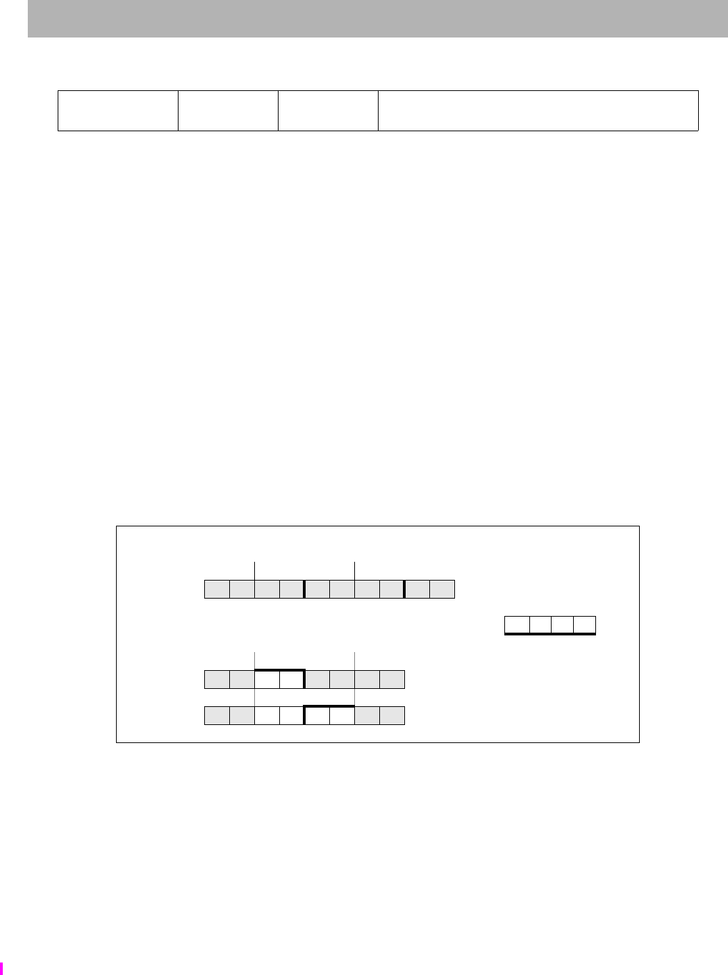
SWL Store Word Left
374 The MIPS32® Instruction Set Manual, Revision 6.05
Format: SWL rt, offset(base) MIPS32, removed in Release 6
Purpose: Store Word Left
To store the most-significant part of a word to an unaligned memory address.
Description: memory[GPR[base] + offset] GPR[rt]
The 16-bit signed offset is added to the contents of GPR base to form an effective address (EffAddr). EffAddr is the
address of the most-significant of 4 consecutive bytes forming a word (W) in memory starting at an arbitrary byte
boundary.
A part of W (the most-significant 1 to 4 bytes) is in the aligned word containing EffAddr. The same number of the
most-significant (left) bytes from the word in GPR rt are stored into these bytes of W.
The following figure illustrates this operation using big-endian byte ordering for 32-bit and 64-bit registers. The four
consecutive bytes in 2..5 form an unaligned word starting at location 2. A part of W (2 bytes) is located in the aligned
word containing the most-significant byte at 2.
3. SWL stores the most-significant 2 bytes of the low word from the source register into these 2 bytes in memory.
4. The complementary SWR stores the remainder of the unaligned word.
Figure 5.9 Unaligned Word Store Using SWL and SWR
The bytes stored from the source register to memory depend on both the offset of the effective address within an
aligned word—that is, the low 2 bits of the address (vAddr1..0)—and the current byte-ordering mode of the processor
(big- or little-endian). The following figure shows the bytes stored for every combination of offset and byte ordering.
31 26 25 21 20 16 15 0
SWL
101010 base rt offset
655 16
Word at byte 2 in memory, big-endian byte order; each memory byte contains its own address
most — significance — least
012345678... Memory: Initial contents
GPR 24 E F G H
01EF456... After executing SWL $24,2($0)
01EFGH6... Then after SWR $24,5($0)
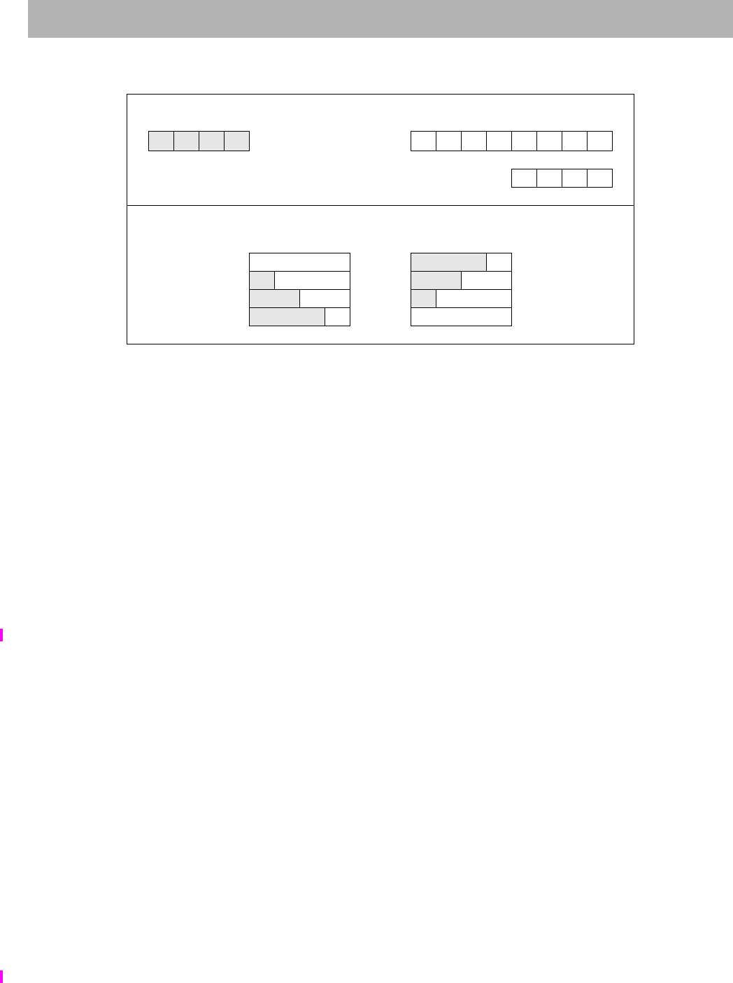
SWL
I
Store Word Left
The MIPS32® Instruction Set Manual, Revision 6.05 375
Figure 5.10 Bytes Stored by an SWL Instruction
Restrictions:
None
Availability and Compatibility:
Release 6 removes the load/store-left/right family of instructions, and requires the system to support misaligned
memory accesses.
Operation:
vAddr sign_extend(offset) + GPR[base]
(pAddr, CCA) AddressTranslation (vAddr, DATA, STORE)
pAddr pAddrPSIZE-1..2 || (pAddr1..0 xor ReverseEndian2)
If BigEndianMem = 0 then
pAddr pAddrPSIZE-1..2 || 02
endif
byte vAddr1..0 xor BigEndianCPU2
dataword 024–8*byte || GPR[rt]31..24-8*byte
StoreMemory(CCA, byte, dataword, pAddr, vAddr, DATA)
Exceptions:
TLB Refill, TLB Invalid, TLB Modified, Bus Error, Address Error, Watch
Memory contents and byte offsets Initial contents of Dest Register
0123
big-endian 64-bit register
i j k l offset (vAddr1..0)ABCDEFGH
3210
little-endian most — significance — least
most least 32-bit register E F G H
— significance —
Memory contents after instruction (shaded is unchanged)
Big-endian
byte ordering vAddr1..0
Little-endian
byte ordering
EFGH 0 i j kE
iEFG 1 ijEF
ijEF 2 iEFG
i j kE 3 EFGH

SWL Store Word Left
376 The MIPS32® Instruction Set Manual, Revision 6.05
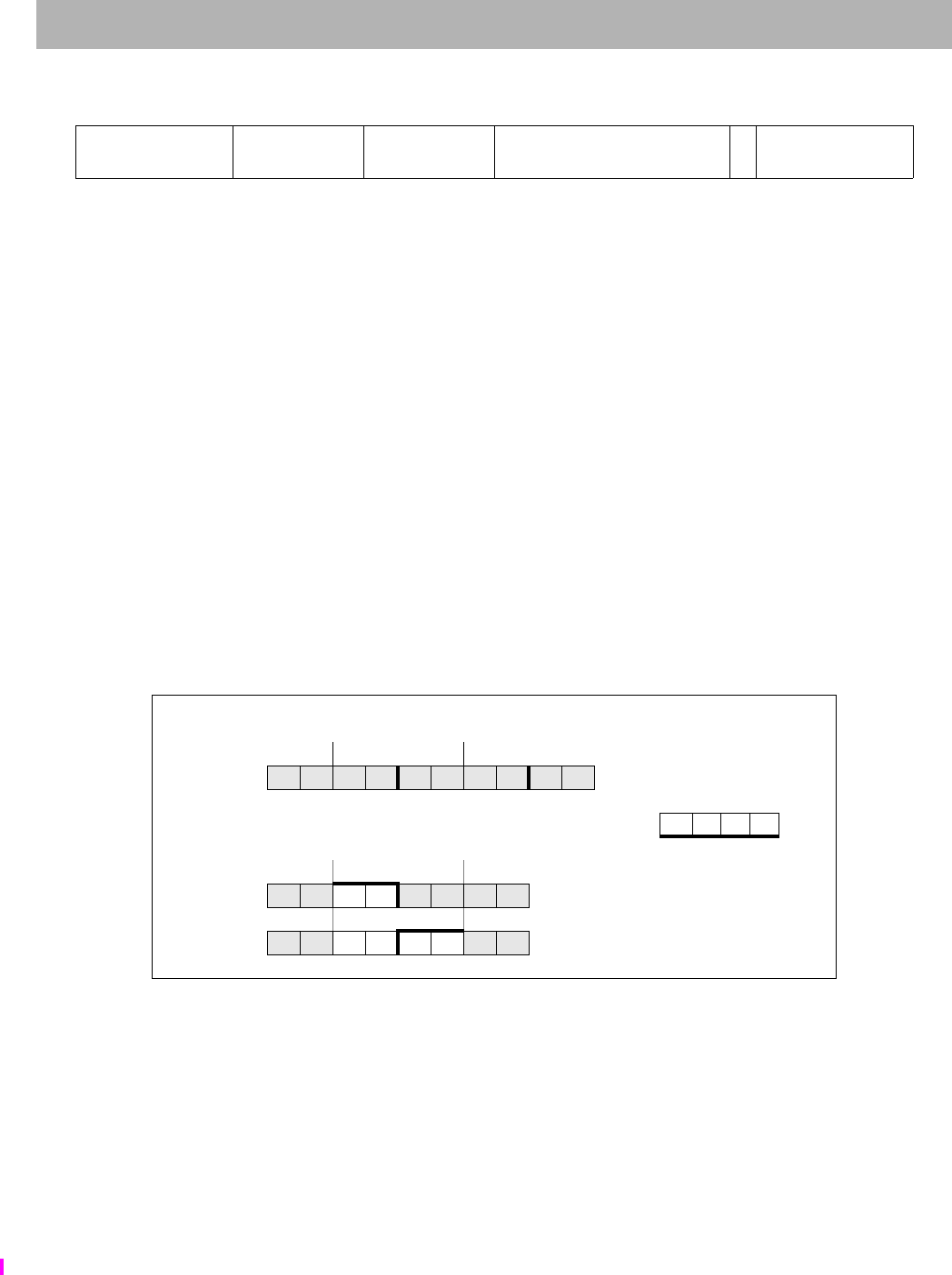
SWLE
I
Store Word Left EVA
The MIPS32® Instruction Set Manual, Revision 6.05 377
Format: SWLE rt, offset(base) MIPS32, removed in Release 6
Purpose: Store Word Left EVA
To store the most-significant part of a word to an unaligned user mode virtual address while operating in kernel mode.
Description: memory[GPR[base] + offset] GPR[rt]
The 9-bit signed offset is added to the contents of GPR base to form an effective address (EffAddr). EffAddr is the
address of the most-significant of 4 consecutive bytes forming a word (W) in memory starting at an arbitrary byte
boundary.
A part of W (the most-significant 1 to 4 bytes) is in the aligned word containing EffAddr. The same number of the
most-significant (left) bytes from the word in GPR rt are stored into these bytes of W.
The following figure shows this operation using big-endian byte ordering for 32-bit and 64-bit registers. The 4 con-
secutive bytes in 2..5 form an unaligned word starting at location 2. A part of W (2 bytes) is located in the aligned
word containing the most-significant byte at 2.
1. SWLE stores the most-significant 2 bytes of the low word from the source register into these 2 bytes in memory.
2. The complementary SWRE stores the remainder of the unaligned word.
Figure 5.11 Unaligned Word Store Using SWLE and SWRE
The bytes stored from the source register to memory depend on both the offset of the effective address within an
aligned word—that is, the low 2 bits of the address (vAddr1..0)—and the current byte-ordering mode of the processor
(big- or little-endian). The following figure shows the bytes stored for every combination of offset and byte ordering.
The SWLE instruction functions the same as the SWL instruction, except that address translation is performed using
the user mode virtual address space mapping in the TLB when accessing an address within a memory segment con-
figured to use the MUSUK access mode. Memory segments using UUSK or MUSK access modes are also accessible.
Refer to Volume III, Enhanced Virtual Addressing section for additional information.
Implementation of this instruction is specified by the Config5EVA field being set to 1.
31 26 25 21 20 16 15 7 6 5 0
SPECIAL3
011111 base rt offset 0SWLE
100001
655 9
16
Word at byte 2 in memory, big-endian byte order; each memory byte contains its own address
most — significance — least
012345678... Memory: Initial contents
GPR 24 E F G H
01EF456... After executing SWLE $24,2($0)
01EFGH6... Then after SWRE $24,5($0)
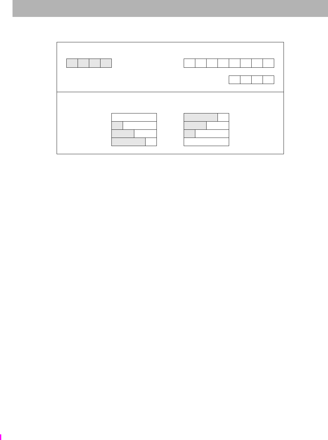
SWLE Store Word Left EVA
378 The MIPS32® Instruction Set Manual, Revision 6.05
Figure 5.12 Bytes Stored by an SWLE Instruction
Restrictions:
Only usable when access to Coprocessor0 is enabled and when accessing an address within a segment configured
using UUSK, MUSK or MUSUK access mode.
Availability and Compatibility:
Release 6 removes the load/store-left/right family of instructions, and requires the system to support misaligned
memory accesses.
Operation:
vAddr sign_extend(offset) + GPR[base]
(pAddr, CCA) AddressTranslation (vAddr, DATA, STORE)
pAddr pAddrPSIZE-1..2 || (pAddr1..0 xor ReverseEndian2)
If BigEndianMem = 0 then
pAddr pAddrPSIZE-1..2 || 02
endif
byte vAddr1..0 xor BigEndianCPU2
dataword 024–8*byte || GPR[rt]31..24–8*byte
StoreMemory(CCA, byte, dataword, pAddr, vAddr, DATA)
Exceptions:
TLB Refill, TLB Invalid, TLB Modified, Bus Error, Address Error, Watch, Reserved Instruction, Coprocessor Unus-
able
Memory contents and byte offsets Initial contents of Dest Register
0123
big-endian 64-bit register
i j k l offset (vAddr1..0)ABCDEFGH
3210
little-endian most — significance — least
most least 32-bit register E F G H
— significance —
Memory contents after instruction (shaded is unchanged)
Big-endian
byte ordering vAddr1..0
Little-endian
byte ordering
EFGH 0 i j kE
iEFG 1 ijEF
ijEF 2 iEFG
i j kE 3 EFGH
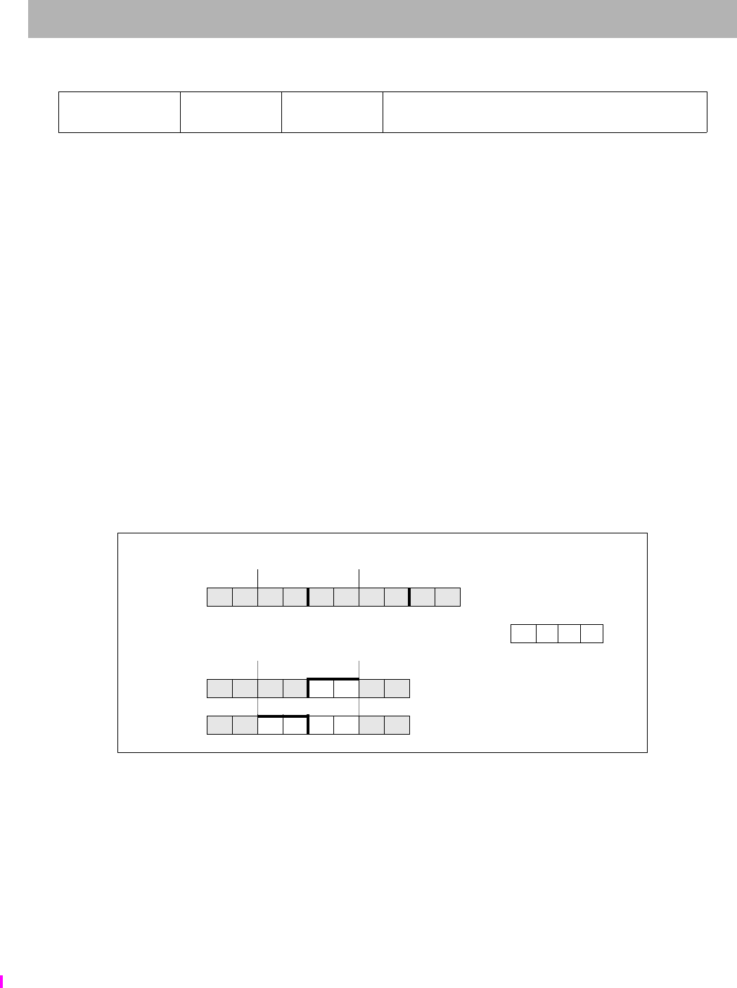
SWR
I
Store Word Right
The MIPS32® Instruction Set Manual, Revision 6.05 379
Format: SWR rt, offset(base) MIPS32, removed in Release 6
Purpose: Store Word Right
To store the least-significant part of a word to an unaligned memory address.
Description: memory[GPR[base] + offset] GPR[rt]
The 16-bit signed offset is added to the contents of GPR base to form an effective address (EffAddr). EffAddr is the
address of the least-significant of 4 consecutive bytes forming a word (W) in memory starting at an arbitrary byte
boundary.
A part of W (the least-significant 1 to 4 bytes) is in the aligned word containing EffAddr. The same number of the
least-significant (right) bytes from the word in GPR rt are stored into these bytes of W.
The following figure illustrates this operation using big-endian byte ordering for 32-bit and 64-bit registers. The 4
consecutive bytes in 2..5 form an unaligned word starting at location 2. A part of W (2 bytes) is contained in the
aligned word containing the least-significant byte at 5.
1. SWR stores the least-significant 2 bytes of the low word from the source register into these 2 bytes in memory.
2. The complementary SWL stores the remainder of the unaligned word.
Figure 5.13 Unaligned Word Store Using SWR and SWL
The bytes stored from the source register to memory depend on both the offset of the effective address within an
aligned word—that is, the low 2 bits of the address (vAddr1..0)—and the current byte-ordering mode of the processor
(big- or little-endian). The following figure shows the bytes stored for every combination of offset and byte-ordering.
31 26 25 21 20 16 15 0
SWR
101110 base rt offset
655 16
Word at byte 2 in memory, big-endian byte order, each mem byte contains its address
least — significance — least
012345678... Memory: Initial contents
GPR 24 E F G H
0123GH6... After executing SWR $24,5($0)
01EFGH6... Then after SWL $24,2($0)

SWR Store Word Right
380 The MIPS32® Instruction Set Manual, Revision 6.05
Figure 5.14 Bytes Stored by SWR Instruction
Restrictions:
None
Availability and Compatibility:
Release 6 removes the load/store-left/right family of instructions, and requires the system to support misaligned
memory accesses.
Operation:
vAddr sign_extend(offset) + GPR[base]
(pAddr, CCA) AddressTranslation (vAddr, DATA, STORE)
pAddr pAddrPSIZE-1..2 || (pAddr1..0 xor ReverseEndian2)
If BigEndianMem = 0 then
pAddr pAddrPSIZE-1..2 || 02
endif
byte vAddr1..0 xor BigEndianCPU2
dataword GPR[rt]31–8*byte || 08*byte
StoreMemory(CCA, WORD-byte, dataword, pAddr, vAddr, DATA)
Exceptions:
TLB Refill, TLB Invalid, TLB Modified, Bus Error, Address Error, Watch
Memory contents and byte offsets Initial contents of Dest Register
0123
big-endian 64-bit register
i j k l offset (vAddr1..0)ABCDEFGH
3210
little-endian most — significance — least
most least 32-bit register E F G H
— significance —
Memory contents after instruction (shaded is unchanged)
Big-endian
byte ordering vAddr1..0
Little-endian
byte ordering
Hj k l0EFGH
GHkl1FGHl
FGH l2GHk l
EFGH 3 H j k l

SWR
I
Store Word Right
The MIPS32® Instruction Set Manual, Revision 6.05 381
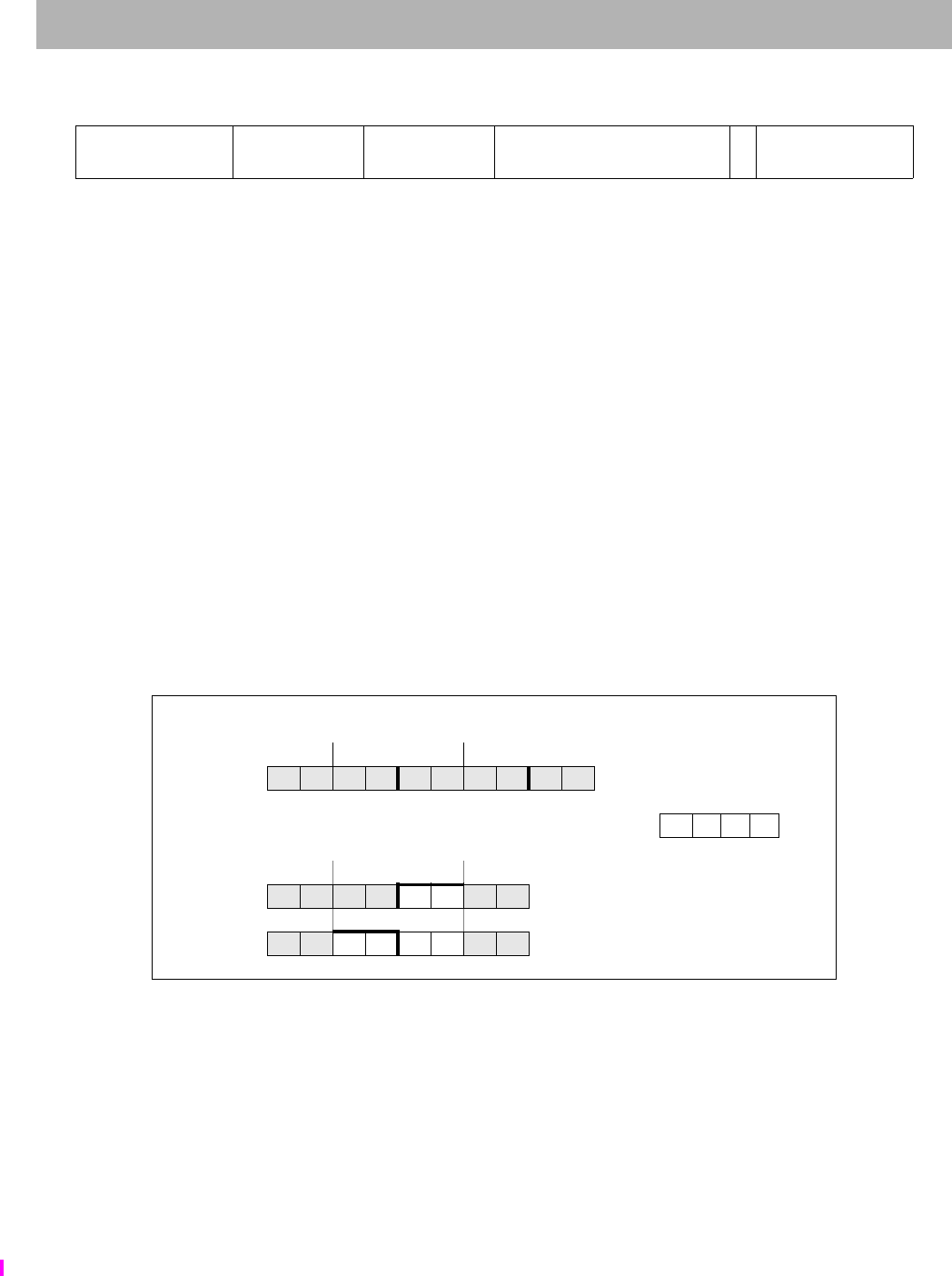
SWRE Store Word Right EVA
382 The MIPS32® Instruction Set Manual, Revision 6.05
Format: SWRE rt, offset(base) MIPS32, removed in Release 6
Purpose: Store Word Right EVA
To store the least-significant part of a word to an unaligned user mode virtual address while operating in kernel mode.
Description: memory[GPR[base] + offset] GPR[rt]
The 9-bit signed offset is added to the contents of GPR base to form an effective address (EffAddr). EffAddr is the
address of the least-significant of 4 consecutive bytes forming a word (W) in memory starting at an arbitrary byte
boundary.
A part of W (the least-significant 1 to 4 bytes) is in the aligned word containing EffAddr. The same number of the
least-significant (right) bytes from the word in GPR rt are stored into these bytes of W.
The following figure illustrates this operation using big-endian byte ordering for 32-bit and 64-bit registers. The 4
consecutive bytes in 2..5 form an unaligned word starting at location 2. A part of W (2 bytes) is contained in the
aligned word containing the least-significant byte at 5.
3. SWRE stores the least-significant 2 bytes of the low word from the source register into these 2 bytes in memory.
4. The complementary SWLE stores the remainder of the unaligned word.
Figure 5.15 Unaligned Word Store Using SWRE and SWLE
The bytes stored from the source register to memory depend on both the offset of the effective address within an
aligned word—that is, the low 2 bits of the address (vAddr1..0)—and the current byte-ordering mode of the processor
(big- or little-endian). The following figure shows the bytes stored for every combination of offset and byte-ordering.
The LWE instruction functions the same as the LW instruction, except that address translation is performed using the
user mode virtual address space mapping in the TLB when accessing an address within a memory segment config-
ured to use the MUSUK access mode. Memory segments using UUSK or MUSK access modes are also accessible.
Refer to Volume III, Enhanced Virtual Addressing section for additional information.
Implementation of this instruction is specified by the Config5EVA field being set to 1.
31 26 25 21 20 16 15 7 6 5 0
SPECIAL3
011111 base rt offset 0SWRE
100010
655 9
16
Word at byte 2 in memory, big-endian byte order, each mem byte contains its address
least — significance — least
012345678... Memory: Initial contents
GPR 24 E F G H
0123GH6... After executing SWRE $24,5($0)
01EFGH6... Then after SWLE $24,2($0)
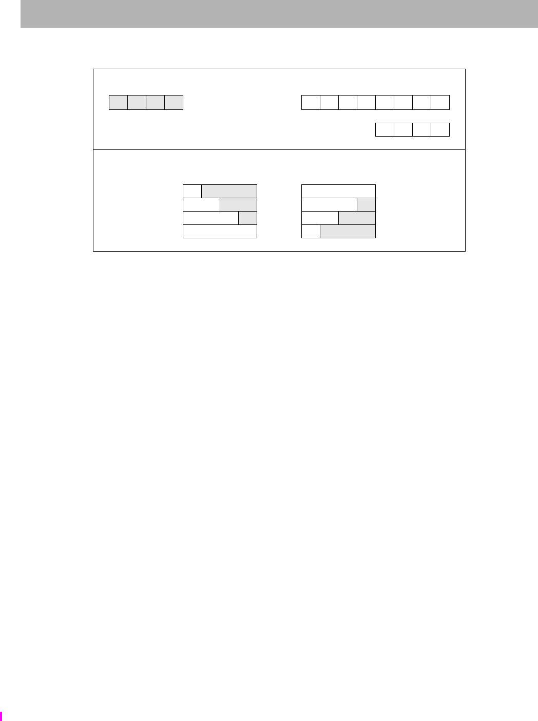
SWRE
I
Store Word Right EVA
The MIPS32® Instruction Set Manual, Revision 6.05 383
Figure 5.16 Bytes Stored by SWRE Instruction
Restrictions:
Only usable when access to Coprocessor0 is enabled and when accessing an address within a segment configured
using UUSK, MUSK or MUSUK access mode.
Availability and Compatibility:
Release 6 removes the load/store-left/right family of instructions, and requires the system to support misaligned
memory accesses.
Operation:
vAddr sign_extend(offset) + GPR[base]
(pAddr, CCA) AddressTranslation (vAddr, DATA, STORE)
pAddr pAddrPSIZE-1..2 || (pAddr1..0 xor ReverseEndian2)
If BigEndianMem = 0 then
pAddr pAddrPSIZE-1..2 || 02
endif
byte vAddr1..0 xor BigEndianCPU2
dataword GPR[rt]31–8*byte || 08*byte
StoreMemory(CCA, WORD-byte, dataword, pAddr, vAddr, DATA)
Exceptions:
TLB Refill, TLB Invalid, TLB Modified, Bus Error, Address Error, Watch, Coprocessor Unusable
Memory contents and byte offsets Initial contents of Dest Register
0123
big-endian 64-bit register
i j k l offset (vAddr1..0)ABCDEFGH
3210
little-endian most — significance — least
most least 32-bit register E F G H
— significance —
Memory contents after instruction (shaded is unchanged)
Big-endian
byte ordering vAddr1..0
Little-endian
byte ordering
Hj k l0EFGH
GHkl1FGHl
FGH l2GHk l
EFGH 3 H j k l

SWXC1 Store Word Indexed from Floating Point
384 The MIPS32® Instruction Set Manual, Revision 6.05
Format: SWXC1 fs, index(base) MIPS64, MIPS32 Release 2, removed in Release 6
Purpose: Store Word Indexed from Floating Point
To store a word from an FPR to memory (GPR+GPR addressing)
Description: memory[GPR[base] + GPR[index]] FPR[fs]
The low 32-bit word from FPR fs is stored in memory at the location specified by the aligned effective address. The
contents of GPR index and GPR base are added to form the effective address.
Restrictions:
An Address Error exception occurs if EffectiveAddress1..0 ≠ 0 (not word-aligned).
Availability and Compatibility:
This instruction has been removed in Release 6.
Required in all versions of MIPS64 since MIPS64 Release 1. Not available in MIPS32 Release 1. Required in
MIPS32 Release 2 and all subsequent versions of MIPS32. When required, required whenever FPU is present,
whether a 32-bit or 64-bit FPU, whether in 32-bit or 64-bit FP Register Mode (FIRF64=0 or 1, StatusFR=0 or 1).
Operation:
vAddr GPR[base] + GPR[index]
if vAddr1..0 03 then
SignalException(AddressError)
endif
(pAddr, CCA) AddressTranslation(vAddr, DATA, STORE)
dataword ValueFPR(fs, UNINTERPRETED_WORD)
StoreMemory(CCA, WORD, dataword, pAddr, vAddr, DATA)
Exceptions:
TLB Refill, TLB Invalid, TLB Modified, Address Error, Reserved Instruction, Coprocessor Unusable, Watch
31 26 25 21 20 16 15 11 10 6 5 0
COP1X
010011 base index fs 0
00000
SWXC1
001000
6 5555 6

SYNC
I
Synchronize Shared Memory
The MIPS32® Instruction Set Manual, Revision 6.05 385
Format: SYNC (stype = 0 implied) MIPS32
SYNC stype MIPS32
Purpose: Synchronize Shared Memory
To order loads and stores for shared memory.
Description:
These types of ordering guarantees are available through the SYNC instruction:
• Completion Barriers
• Ordering Barriers
Completion Barrier — Simple Description:
• The barrier affects only uncached and cached coherent loads and stores.
• The specified memory instructions (loads or stores or both) that occur before the SYNC instruction must be
completed before the specified memory instructions after the SYNC are allowed to start.
• Loads are completed when the destination register is written. Stores are completed when the stored value is
visible to every other processor in the system.
Completion Barrier — Detailed Description:
• Every synchronizable specified memory instruction (loads or stores or both) that occurs in the instruction
stream before the SYNC instruction must be already globally performed before any synchronizable speci-
fied memory instructions that occur after the SYNC are allowed to be performed, with respect to any other
processor or coherent I/O module.
• The barrier does not guarantee the order in which instruction fetches are performed.
• A stype value of zero will always be defined such that it performs the most complete set of synchronization
operations that are defined.This means stype zero always does a completion barrier that affects both loads
and stores preceding the SYNC instruction and both loads and stores that are subsequent to the SYNC
instruction. Non-zero values of stype may be defined by the architecture or specific implementations to per-
form synchronization behaviors that are less complete than that of stype zero. If an implementation does not
use one of these non-zero values to define a different synchronization behavior, then that non-zero value of
stype must act the same as stype zero completion barrier. This allows software written for an implementation
with a lighter-weight barrier to work on another implementation which only implements the stype zero com-
pletion barrier.
• A completion barrier is required, potentially in conjunction with SSNOP (in Release 1 of the Architecture)
or EHB (in Release 2 of the Architecture), to guarantee that memory reference results are visible across
operating mode changes. For example, a completion barrier is required on some implementations on entry to
and exit from Debug Mode to guarantee that memory effects are handled correctly.
SYNC behavior when the stype field is zero:
31 26 25 21 20 16 15 11 10 6 5 0
SPECIAL
000000
0
00 0000 0000 0000 0 stype SYNC
001111
61556

SYNC Synchronize Shared Memory
386 The MIPS32® Instruction Set Manual, Revision 6.05
• A completion barrier that affects preceding loads and stores and subsequent loads and stores.
Ordering Barrier — Simple Description:
• The barrier affects only uncached and cached coherent loads and stores.
• The specified memory instructions (loads or stores or both) that occur before the SYNC instruction must
always be ordered before the specified memory instructions after the SYNC.
• Memory instructions which are ordered before other memory instructions are processed by the load/store
datapath first before the other memory instructions.
Ordering Barrier — Detailed Description:
• Every synchronizable specified memory instruction (loads or stores or both) that occurs in the instruction
stream before the SYNC instruction must reach a stage in the load/store datapath after which no instruction
re-ordering is possible before any synchronizable specified memory instruction which occurs after the
SYNC instruction in the instruction stream reaches the same stage in the load/store datapath.
• If any memory instruction before the SYNC instruction in program order, generates a memory request to the
external memory and any memory instruction after the SYNC instruction in program order also generates a
memory request to external memory, the memory request belonging to the older instruction must be globally
performed before the time the memory request belonging to the younger instruction is globally performed.
• The barrier does not guarantee the order in which instruction fetches are performed.
As compared to the completion barrier, the ordering barrier is a lighter-weight operation as it does not require the
specified instructions before the SYNC to be already completed. Instead it only requires that those specified instruc-
tions which are subsequent to the SYNC in the instruction stream are never re-ordered for processing ahead of the
specified instructions which are before the SYNC in the instruction stream. This potentially reduces how many cycles
the barrier instruction must stall before it completes.
The Acquire and Release barrier types are used to minimize the memory orderings that must be maintained and still
have software synchronization work.
Implementations that do not use any of the non-zero values of stype to define different barriers, such as ordering bar-
riers, must make those stype values act the same as stype zero.
For the purposes of this description, the CACHE, PREF and PREFX instructions are treated as loads and stores. That
is, these instructions and the memory transactions sourced by these instructions obey the ordering and completion
rules of the SYNC instruction.

SYNC
I
Synchronize Shared Memory
The MIPS32® Instruction Set Manual, Revision 6.05 387
Table 5.5 lists the available completion barrier and ordering barriers behaviors that can be specified using the stype
field.
Terms:
Synchronizable: A load or store instruction is synchronizable if the load or store occurs to a physical location in
shared memory using a virtual location with a memory access type of either uncached or cached coherent. Shared
memory is memory that can be accessed by more than one processor or by a coherent I/O system module.
Performed load: A load instruction is performed when the value returned by the load has been determined. The result
of a load on processor A has been determined with respect to processor or coherent I/O module B when a subsequent
store to the location by B cannot affect the value returned by the load. The store by B must use the same memory
access type as the load.
Performed store: A store instruction is performed when the store is observable. A store on processor A is observable
with respect to processor or coherent I/O module B when a subsequent load of the location by B returns the value
Table 5.5 Encodings of the Bits[10:6] of the SYNC instruction; the SType Field
Code Name
Older instructions
which must reach
the load/store
ordering point
before the SYNC
instruction
completes.
Younger
instructions
which must reach
the load/store
ordering point
only after the
SYNC instruction
completes.
Older instructions
which must be
globally
performed when
the SYNC
instruction
completes Compliance
0x0 SYNC
or
SYNC 0
Loads, Stores Loads, Stores Loads, Stores Required
0x4 SYNC_WMB
or
SYNC 4
Stores Stores Optional
0x10 SYNC_MB
or
SYNC 16
Loads, Stores Loads, Stores Optional
0x11 SYNC_ACQUIRE
or
SYNC 17
Loads Loads, Stores Optional
0x12 SYNC_RELEASE
or
SYNC 18
Loads, Stores Stores Optional
0x13 SYNC_RMB
or
SYNC 19
Loads Loads Optional
0x1-0x3, 0x5-0xF Implementation-Spe-
cific and Vendor Spe-
cific Sync Types
0x14 - 0x1F RESERVED Reserved for MIPS
Technologies for
future extension of
the architecture.

SYNC Synchronize Shared Memory
388 The MIPS32® Instruction Set Manual, Revision 6.05
written by the store. The load by B must use the same memory access type as the store.
Globally performed load: A load instruction is globally performed when it is performed with respect to all processors
and coherent I/O modules capable of storing to the location.
Globally performed store: A store instruction is globally performed when it is globally observable. It is globally
observable when it is observable by all processors and I/O modules capable of loading from the location.
Coherent I/O module: A coherent I/O module is an Input/Output system component that performs coherent Direct
Memory Access (DMA). It reads and writes memory independently as though it were a processor doing loads and
stores to locations with a memory access type of cached coherent.
Load/Store Datapath: The portion of the processor which handles the load/store data requests coming from the pro-
cessor pipeline and processes those requests within the cache and memory system hierarchy.
Restrictions:
The effect of SYNC on the global order of loads and stores for memory access types other than uncached and cached
coherent is UNPREDICTABLE.
Operation:
SyncOperation(stype)
Exceptions:
None
Programming Notes:
A processor executing load and store instructions observes the order in which loads and stores using the same mem-
ory access type occur in the instruction stream; this is known as program order.
A parallel program has multiple instruction streams that can execute simultaneously on different processors. In mul-
tiprocessor (MP) systems, the order in which the effects of loads and stores are observed by other processors—the
global order of the loads and store—determines the actions necessary to reliably share data in parallel programs.
When all processors observe the effects of loads and stores in program order, the system is strongly ordered. On such
systems, parallel programs can reliably share data without explicit actions in the programs. For such a system, SYNC
has the same effect as a NOP. Executing SYNC on such a system is not necessary, but neither is it an error.
If a multiprocessor system is not strongly ordered, the effects of load and store instructions executed by one processor
may be observed out of program order by other processors. On such systems, parallel programs must take explicit
actions to reliably share data. At critical points in the program, the effects of loads and stores from an instruction
stream must occur in the same order for all processors. SYNC separates the loads and stores executed on the proces-
sor into two groups, and the effect of all loads and stores in one group is seen by all processors before the effect of
any load or store in the subsequent group. In effect, SYNC causes the system to be strongly ordered for the executing
processor at the instant that the SYNC is executed.
Many MIPS-based multiprocessor systems are strongly ordered or have a mode in which they operate as strongly
ordered for at least one memory access type. The MIPS architecture also permits implementation of MP systems that
are not strongly ordered; SYNC enables the reliable use of shared memory on such systems. A parallel program that
does not use SYNC generally does not operate on a system that is not strongly ordered. However, a program that does
use SYNC works on both types of systems. (System-specific documentation describes the actions needed to reliably
share data in parallel programs for that system.)
The behavior of a load or store using one memory access type is UNPREDICTABLE if a load or store was previ-
ously made to the same physical location using a different memory access type. The presence of a SYNC between the
references does not alter this behavior.
SYNC affects the order in which the effects of load and store instructions appear to all processors; it does not gener-

SYNC
I
Synchronize Shared Memory
The MIPS32® Instruction Set Manual, Revision 6.05 389
ally affect the physical memory-system ordering or synchronization issues that arise in system programming. The
effect of SYNC on implementation-specific aspects of the cached memory system, such as writeback buffers, is not
defined.
# Processor A (writer)
# Conditions at entry:
# The value 0 has been stored in FLAG and that value is observable by B
SW R1, DATA # change shared DATA value
LI R2, 1
SYNC # Perform DATA store before performing FLAG store
SW R2, FLAG # say that the shared DATA value is valid
# Processor B (reader)
LI R2, 1
1: LW R1, FLAG # Get FLAG
BNE R2, R1, 1B# if it says that DATA is not valid, poll again
NOP
SYNC # FLAG value checked before doing DATA read
LW R1, DATA # Read (valid) shared DATA value
The code fragments above shows how SYNC can be used to coordinate the use of shared data between separate writer
and reader instruction streams in a multiprocessor environment. The FLAG location is used by the instruction streams
to determine whether the shared data item DATA is valid. The SYNC executed by processor A forces the store of
DATA to be performed globally before the store to FLAG is performed. The SYNC executed by processor B ensures
that DATA is not read until after the FLAG value indicates that the shared data is valid.
Software written to use a SYNC instruction with a non-zero stype value, expecting one type of barrier behavior,
should only be run on hardware that actually implements the expected barrier behavior for that non-zero stype value
or on hardware which implements a superset of the behavior expected by the software for that stype value. If the
hardware does not perform the barrier behavior expected by the software, the system may fail.

SYNCI Synchronize Caches to Make Instruction Writes Effective
390 The MIPS32® Instruction Set Manual, Revision 6.05
Format: SYNCI offset(base) MIPS32 Release 2
Purpose: Synchronize Caches to Make Instruction Writes Effective
To synchronize all caches to make instruction writes effective.
Description:
This instruction is used after a new instruction stream is written to make the new instructions effective relative to an
instruction fetch, when used in conjunction with the SYNC and JALR.HB, JR.HB, or ERET instructions, as
described below. Unlike the CACHE instruction, the SYNCI instruction is available in all operating modes in an
implementation of Release 2 of the architecture.
The 16-bit offset is sign-extended and added to the contents of the base register to form an effective address. The
effective address is used to address the cache line in all caches which may need to be synchronized with the write of
the new instructions. The operation occurs only on the cache line which may contain the effective address. One
SYNCI instruction is required for every cache line that was written. See the Programming Notes below.
A TLB Refill and TLB Invalid (both with cause code equal TLBL) exception can occur as a by product of this
instruction. This instruction never causes TLB Modified exceptions nor TLB Refill exceptions with a cause code of
TLBS. This instruction never causes Execute-Inhibit nor Read-Inhibit exceptions.
A Cache Error exception may occur as a by product of this instruction. For example, if a writeback operation detects
a cache or bus error during the processing of the operation, that error is reported via a Cache Error exception. Simi-
larly, a Bus Error Exception may occur if a bus operation invoked by this instruction is terminated in an error.
An Address Error Exception (with cause code equal AdEL) may occur if the effective address references a portion of
the kernel address space which would normally result in such an exception. It is implementation dependent whether
such an exception does occur.
It is implementation dependent whether a data watch is triggered by a SYNCI instruction whose address matches the
Watch register address match conditions.
Restrictions:
The operation of the processor is UNPREDICTABLE if the effective address references any instruction cache line
that contains instructions to be executed between the SYNCI and the subsequent JALR.HB, JR.HB, or ERET instruc-
tion required to clear the instruction hazard.
The SYNCI instruction has no effect on cache lines that were previously locked with the CACHE instruction. If cor-
rect software operation depends on the state of a locked line, the CACHE instruction must be used to synchronize the
caches.
Full visibility of the new instruction stream requires execution of a subsequent SYNC instruction, followed by a
JALR.HB, JR.HB, DERET, or ERET instruction. The operation of the processor is UNPREDICTABLE if this
sequence is not followed.
SYNCI globalization:
The SYNCI instruction acts on the current processor at a minimum. Implementations are required to affect caches
outside the current processor to perform the operation on the current processor (as might be the case if multiple pro-
cessors share an L2 or L3 cache).
Release 6
31 26 25 21 20 16 15 0
REGIMM
000001 base SYNCI
11111 offset
655 16

SYNCI
I
Synchronize Caches to Make Instruction Writes Effective
The MIPS32® Instruction Set Manual, Revision 6.05 391
In multiprocessor implementations where instruction caches are coherently maintained by hardware, the SYNCI
instruction should behave as a NOP instruction.
In multiprocessor implementations where instruction caches are not coherently maintained by hardware, the SYNCI
instruction may optionally affect all coherent icaches within the system. If the effective address uses a coherent
Cacheability and Coherency Attribute (CCA), then the operation may be globalized, meaning it is broadcast to all of
the coherent instruction caches within the system. If the effective address does not use one of the coherent CCAs,
there is no broadcast of the SYNCI operation. If multiple levels of caches are to be affected by one SYNCI instruc-
tion, all of the affected cache levels must be processed in the same manner - either all affected cache levels use the
globalized behavior or all affected cache levels use the non-globalized behavior.
Pre-Release 6: Portable software could not rely on the optional globalization of SYNCI. Strictly portable software
without implementation specific awareness could only rely on expensive “instruction cache shootdown” using inter-
processor interrupts.
Release 6: SYNCI globalization is required. Compliant implementations must globalize SYNCI, and portable soft-
ware can rely on this behavior.
Operation:
vaddr GPR[base] + sign_extend(offset)
SynchronizeCacheLines(vaddr) /* Operate on all caches */
Exceptions:
Reserved Instruction exception (Release 1 implementations only)
TLB Refill Exception
TLB Invalid Exception
Address Error Exception
Cache Error Exception
Bus Error Exception
Programming Notes:
When the instruction stream is written, the SYNCI instruction should be used in conjunction with other instructions
to make the newly-written instructions effective. The following example shows a routine which can be called after the
new instruction stream is written to make those changes effective. The SYNCI instruction could be replaced with the
corresponding sequence of CACHE instructions (when access to Coprocessor 0 is available), and that the JR.HB
instruction could be replaced with JALR.HB, ERET, or DERET instructions, as appropriate. A SYNC instruction is
required between the final SYNCI instruction in the loop and the instruction that clears instruction hazards.
/*
* This routine makes changes to the instruction stream effective to the
* hardware. It should be called after the instruction stream is written.
* On return, the new instructions are effective.
*
* Inputs:
* a0 = Start address of new instruction stream
* a1 = Size, in bytes, of new instruction stream
*/
beq a1, zero, 20f /* If size==0, */
nop /* branch around */
addu a1, a0, a1 /* Calculate end address + 1 */
rdhwr v0, HWSYNCIStep /* Get step size for SYNCI from new */
/* Release 2 instruction */
beq v0, zero, 20f /* If no caches require synchronization, */
nop /* branch around */

SYNCI Synchronize Caches to Make Instruction Writes Effective
392 The MIPS32® Instruction Set Manual, Revision 6.05
10: synci 0(a0) /* Synchronize all caches around address */
addu a0, a0, v0 /* Add step size in delay slot */
sltu v1, a0, a1 /* Compare current with end address */
bne v1, zero, 10b /* Branch if more to do */
nop /* branch around */
sync /* Clear memory hazards */
20: jr.hb ra /* Return, clearing instruction hazards */
nop

SYSCALL
I
System Call
The MIPS32® Instruction Set Manual, Revision 6.05 393
Format: SYSCALL MIPS32
Purpose: System Call
To cause a System Call exception.
Description:
A system call exception occurs, immediately and unconditionally transferring control to the exception handler.
The code field is available for use as software parameters, but may be retrieved by the exception handler by loading
the contents of the memory word containing the instruction. Optionally, if COP0 BadInstr is implemented, the code
field may be obtained from BadInstr.
Restrictions:
None
Operation:
SignalException(SystemCall)
Exceptions:
System Call
31 26 25 65 0
SPECIAL
000000 code SYSCALL
001100
6206

TEQ Trap if Equal
394 The MIPS32® Instruction Set Manual, Revision 6.05
Format: TEQ rs, rt MIPS32
Purpose: Trap if Equal
To compare GPRs and do a conditional trap.
Description: if GPR[rs] = GPR[rt] then Trap
Compare the contents of GPR rs and GPR rt as signed integers. If GPR rs is equal to GPR rt, then take a Trap excep-
tion.
The contents of the code field are ignored by hardware and may be used to encode information for system software.
To retrieve the information, system software may load the instruction word from memory. Optionally, if COP0
BadInstr is implemented, the code field may be obtained from BadInstr.
Restrictions:
None
Operation:
if GPR[rs] = GPR[rt] then
SignalException(Trap)
endif
Exceptions:
Trap
31 26 25 21 20 16 15 6 5 0
SPECIAL
000000 rs rt code TEQ
110100
655 10 6

TEQI
I
Trap if Equal Immediate
The MIPS32® Instruction Set Manual, Revision 6.05 395
Format: TEQI rs, immediate MIPS32, removed in Release 6
Purpose: Trap if Equal Immediate
To compare a GPR to a constant and do a conditional trap.
Description: if GPR[rs] = immediate then Trap
Compare the contents of GPR rs and the 16-bit signed immediate as signed integers. If GPR rs is equal to immediate,
then take a Trap exception.
Restrictions:
None
Availability and Compatibility:
This instruction has been removed in Release 6.
Operation:
if GPR[rs] = sign_extend(immediate) then
SignalException(Trap)
endif
Exceptions:
Trap
31 26 25 21 20 16 15 0
REGIMM
000001 rs TEQI
01100 immediate
655 16

TGE Trap if Greater or Equal
396 The MIPS32® Instruction Set Manual, Revision 6.05
Format: TGE rs, rt MIPS32
Purpose: Trap if Greater or Equal
To compare GPRs and do a conditional trap.
Description: if GPR[rs] GPR[rt] then Trap
Compare the contents of GPR rs and GPR rt as signed integers. If GPR rs is greater than or equal to GPR rt, then take
a Trap exception.
The contents of the code field are ignored by hardware and may be used to encode information for system software.
To retrieve the information, the system software may load the instruction word from memory. Optionally, if COP0
BadInstr is implemented, the code field may be obtained from BadInstr.
Restrictions:
None
Operation:
if GPR[rs] GPR[rt] then
SignalException(Trap)
endif
Exceptions:
Trap
31 26 25 21 20 16 15 6 5 0
SPECIAL
000000 rs rt code TGE
110000
655 10 6

TGEI
I
Trap if Greater or Equal Immediate
The MIPS32® Instruction Set Manual, Revision 6.05 397
Format: TGEI rs, immediate MIPS32, removed in Release 6
Purpose: Trap if Greater or Equal Immediate
To compare a GPR to a constant and do a conditional trap.
Description: if GPR[rs] immediate then Trap
Compare the contents of GPR rs and the 16-bit signed immediate as signed integers. If GPR rs is greater than or equal
to immediate, then take a Trap exception.
Restrictions:
None
Availability and Compatibility:
This instruction has been removed in Release 6.
Operation:
if GPR[rs] sign_extend(immediate) then
SignalException(Trap)
endif
Exceptions:
Trap
31 26 25 21 20 16 15 0
REGIMM
000001 rs TGEI
01000 immediate
655 16

TGEIU Trap if Greater or Equal Immediate Unsigned
398 The MIPS32® Instruction Set Manual, Revision 6.05
Format: TGEIU rs, immediate MIPS32, removed in Release 6
Purpose: Trap if Greater or Equal Immediate Unsigned
To compare a GPR to a constant and do a conditional trap.
Description: if GPR[rs] immediate then Trap
Compare the contents of GPR rs and the 16-bit sign-extended immediate as unsigned integers. If GPR rs is greater
than or equal to immediate, then take a Trap exception.
Because the 16-bit immediate is sign-extended before comparison, the instruction can represent the smallest or largest
unsigned numbers. The representable values are at the minimum [0, 32767] or maximum [max_unsigned-32767,
max_unsigned] end of the unsigned range.
Restrictions:
None
Availability and Compatibility:
This instruction has been removed in Release 6.
Operation:
if (0 || GPR[rs]) (0 || sign_extend(immediate)) then
SignalException(Trap)
endif
Exceptions:
Trap
31 26 25 21 20 16 15 0
REGIMM
000001 rs TGEIU
01001 immediate
655 16

TGEU
I
Trap if Greater or Equal Unsigned
The MIPS32® Instruction Set Manual, Revision 6.05 399
Format: TGEU rs, rt MIPS32
Purpose: Trap if Greater or Equal Unsigned
To compare GPRs and do a conditional trap.
Description: if GPR[rs] GPR[rt] then Trap
Compare the contents of GPR rs and GPR rt as unsigned integers. If GPR rs is greater than or equal to GPR rt, then
take a Trap exception.
The contents of the code field are ignored by hardware and may be used to encode information for system software.
To retrieve the information, the system software may load the instruction word from memory. Optionally, if COP0
BadInstr is implemented, the code field may be obtained from BadInstr.
Restrictions:
None
Operation:
if (0 || GPR[rs]) (0 || GPR[rt]) then
SignalException(Trap)
endif
Exceptions:
Trap
31 26 25 21 20 16 15 6 5 0
SPECIAL
000000 rs rt code TGEU
110001
655 10 6

TLBINV TLB Invalidate
400 The MIPS32® Instruction Set Manual, Revision 6.05
Format: TLBINV MIPS32
Purpose: TLB Invalidate
TLBINV invalidates a set of TLB entries based on ASID and Index match. The virtual address is ignored in the entry
match. TLB entries which have their G bit set to 1 are not modified.
Implementation of the TLBINV instruction is optional. The implementation of this instruction is indicated by the IE
field in Config4.
Support for TLBINV is recommend for implementations supporting VTLB/FTLB type of MMU.
Implementation of EntryHIEHINV field is required for implementation of TLBINV instruction.
Description:
On execution of the TLBINV instruction, the set of TLB entries with matching ASID are marked invalid, excluding
those TLB entries which have their G bit set to 1.
The EntryHIASID field has to be set to the appropriate ASID value before executing the TLBINV instruction.
Behavior of the TLBINV instruction applies to all applicable TLB entries and is unaffected by the setting of the Wired
register.
• For JTLB-based MMU (ConfigMT=1):
All matching entries in the JTLB are invalidated. The Index register is unused.
• For VTLB/FTLB -based MMU (ConfigMT=4):
If TLB invalidate walk is implemented in software (Config4IE=2), then software must do these steps to flush the
entire MMU:
1. one TLBINV instruction is executed with an index in VTLB range (invalidates all matching VTLB entries)
2. a TLBINV instruction is executed for each FTLB set (invalidates all matching entries in FTLB set)
If TLB invalidate walk is implemented in hardware (Config4IE=3), then software must do these steps to flush the
entire MMU:
1. one TLBINV instruction is executed (invalidates all matching entries in both FTLB & VTLB). In this case,
Index is unused.
Restrictions:
When Config4MT = 4 and Config4IE = 2, the operation is UNDEFINED if the contents of the Index register are
greater than or equal to the number of available TLB entries.
If access to Coprocessor 0 is not enabled, a Coprocessor Unusable Exception is signaled.
Availability and Compatibility:
Implementation of the TLBINV instruction is optional. The implementation of this instruction is indicated by the IE
31 26 25 24 65 0
COP0
010000
CO
1
0
000 0000 0000 0000 0000
TLBINV
000011
61 19 6

TLBINV
I
TLB Invalidate
The MIPS32® Instruction Set Manual, Revision 6.05 401
field in Config4.
Implementation of EntryHIEHINV field is required for implementation of TLBINV instruction.
Pre-Release 6, support for TLBINV is recommended for implementations supporting VTLB/FTLB type of MMU.
Release 6 (and subsequent releases) support for TLBINV is required for implementations supporting VTLB/FTLB
type of MMU.
Release 6: On processors that include a Block Address Translation (BAT) or Fixed Mapping (FM) MMU (ConfigMT =
2 or 3), the operation of this instruction causes a Reserved Instruction exception (RI).
Operation:
if ( ConfigMT=1 or (ConfigMT=4 & Config4IE=2 & Index < VTLBsize()))
startnum 0
endnum VTLBsize() - 1
endif
// treating VTLB and FTLB as one array
if (ConfigMT=4 & Config4IE=2 & Index ≥VTLBsize(); )
startnum start of selected FTLB set // implementation specific
endnum end of selected FTLB set - 1 //implementation specifc
endif
if (ConfigMT=4 & Config4IE=3))
startnum 0
endnum VTLBsize() + FTLBsize() - 1;
endif
for (i = startnum to endnum)
if (TLB[i]ASID = EntryHiASID & TLB[i]G = 0)
TLB[i]VPN2_invalid 1
endif
endfor
function VTLBsize
SizeExt = ArchRev() ≥ 6 ? Config4VTLBSizeExt
: Config4MMUExtDef == 3 ? Config4VTLBSizeExt
: Config4MMUExtDef == 1 ? Config4MMUSizeExt
:0
;
return 1 + ( (SizeExt << 6) | Config1.MMUSize );
endfunction
function FTLBsize
if ( Config1MT == 4 ) then
return ( Config4FTLBWays + 2 ) * ( 1 << C0_Config4FTLBSets );
else
return 0;
endif
endfunction
Exceptions:
Coprocessor Unusable,

TLBINV TLB Invalidate
402 The MIPS32® Instruction Set Manual, Revision 6.05

TLBINVF
I
TLB Invalidate Flush
The MIPS32® Instruction Set Manual, Revision 6.05 403
Format: TLBINVF MIPS32
Purpose: TLB Invalidate Flush
TLBINVF invalidates a set of TLB entries based on Index match. The virtual address and ASID are ignored in the
entry match.
Implementation of the TLBINVF instruction is optional. The implementation of this instruction is indicated by the IE
field in Config4.
Support for TLBINVF is recommend for implementations supporting VTLB/FTLB type of MMU.
Implementation of the EntryHIEHINV field is required for implementation of TLBINV and TLBINVF instructions.
Description:
On execution of the TLBINVF instruction, all entries within range of Index are invalidated.
Behavior of the TLBINVF instruction applies to all applicable TLB entries and is unaffected by the setting of the
Wired register.
• For JTLB-based MMU (ConfigMT=1):
TLBINVF causes all entries in the JTLB to be invalidated. Index is unused.
• For VTLB/FTLB-based MMU (ConfigMT=4):
If TLB invalidate walk is implemented in your software (Config4IE=2), then your software must do these steps to
flush the entire MMU:
1. one TLBINVF instruction is executed with an index in VTLB range (invalidates all VTLB entries)
2. a TLBINVF instruction is executed for each FTLB set (invalidates all entries in FTLB set)
If TLB invalidate walk is implemented in hardware (Config4IE=3), then software must do these steps to flush the
entire MMU:
1. one TLBINVF instruction is executed (invalidates all entries in both FTLB & VTLB). In this case, Index is
unused.
Restrictions:
When ConfigMT=4 and ConfigIE=2, the operation is UNDEFINED if the contents of the Index register are greater than
or equal to the number of available TLB entries.
If access to Coprocessor 0 is not enabled, a Coprocessor Unusable Exception is signaled.
Availability and Compatibility:
Implementation of the TLBINVF instruction is optional. The implementation of this instruction is indicated by the IE
field in Config4.
Implementation of EntryHIEHINV field is required for implementation of TLBINVF instruction.
31 26 25 24 65 0
COP0
010000
CO
1
0
000 0000 0000 0000 0000
TLBINVF
000100
61 19 6

TLBINVF TLB Invalidate Flush
404 The MIPS32® Instruction Set Manual, Revision 6.05
Pre-Release 6, support for TLBINVF is recommended for implementations supporting VTLB/FTLB type of MMU.
Release 6 (and subsequent releases) support for TLBINV is required for implementations supporting VTLB/FTLB
type of MMU.
Release 6: On processors that include a Block Address Translation (BAT) or Fixed Mapping (FM) MMU (ConfigMT =
2 or 3), the operation of this instruction causes a Reserved Instruction exception (RI).
Operation:
if ( ConfigMT=1 or (ConfigMT=4 & Config4IE=2 & Index < VTLBsize() ))
startnum 0
endnum VTLBsize() - 1
endif
// treating VTLB and FTLB as one array
if (ConfigMT=4 & Config4IE=2 & Index ≥VTLBsize(); )
startnum start of selected FTLB set // implementation specific
endnum end of selected FTLB set - 1 //implementation specifc
endif
if (ConfigMT=4 & Config4IE=3))
startnum 0
endnum TLBsize() + FTLBsize() - 1;
endif
for (i = startnum to endnum)
TLB[i]VPN2_invalid 1
endfor
function VTLBsize
SizeExt = ArchRev() ≥ 6 ? Config4VTLBSizeExt
: Config4MMUExtDef == 3 ? Config4VTLBSizeExt
: Config4MMUExtDef == 1 ? Config4MMUSizeExt
:0
;
return 1 + ( (SizeExt << 6) | Config1.MMUSize );
endfunction
function FTLBsize
if ( Config1MT == 4 ) then
return ( Config4FTLBWays + 2 ) * ( 1 << C0_Config4FTLBSets );
else
return 0;
endif
endfunction
Exceptions:
Coprocessor Unusable,

TLBP
I
Probe TLB for Matching Entry
The MIPS32® Instruction Set Manual, Revision 6.05 405
Format: TLBP MIPS32
Purpose: Probe TLB for Matching Entry
To find a matching entry in the TLB.
Description:
The Index register is loaded with the address of the TLB entry whose contents match the contents of the EntryHi reg-
ister. If no TLB entry matches, the high-order bit of the Index register is set.
• In Release 1 of the Architecture, it is implementation dependent whether multiple TLB matches are detected on a
TLBP. However, implementations are strongly encouraged to report multiple TLB matches only on a TLB write.
• In Release 2 of the Architecture, multiple TLB matches may only be reported on a TLB write.
• In Release 3 of the Architecture, multiple TLB matches may be reported on either TLB write or TLB probe.
Restrictions:
If access to Coprocessor 0 is not enabled, a Coprocessor Unusable Exception is signaled.
Release 6: Processors that include a Block Address Translation (BAT) or Fixed Mapping (FM) MMU (ConfigMT = 2
or 3), the operation of this instruction causes a Reserved Instruction exception (RI).
Operation:
Index 1 || UNPREDICTABLE31
for i in 00 ... TLBEntries-1
if ((TLB[i]VPN2 and not (TLB[i]Mask)) =
(EntryHiVPN2 and not (TLB[i]Mask))) and
((TLB[i]G = 1) or (TLB[i]ASID = EntryHiASID))then
Index i
endif
endfor
Exceptions:
Coprocessor Unusable, Machine Check
31 26 25 24 65 0
COP0
010000
CO
1
0
000 0000 0000 0000 0000
TLBP
001000
61 19 6

TLBR Read Indexed TLB Entry
406 The MIPS32® Instruction Set Manual, Revision 6.05
Format: TLBR MIPS32
Purpose: Read Indexed TLB Entry
To read an entry from the TLB.
Description:
The EntryHi, EntryLo0, EntryLo1, and PageMask registers are loaded with the contents of the TLB entry pointed
to by the Index register.
• In Release 1 of the Architecture, it is implementation dependent whether multiple TLB matches are detected on a
TLBR. However, implementations are strongly encouraged to report multiple TLB matches only on a TLB write.
• In Release 2 of the Architecture, multiple TLB matches may only be reported on a TLB write.
• In Release 3 of the Architecture, multiple TLB matches may be detected on a TLBR.
In an implementation supporting TLB entry invalidation (Config4IE ≥ 1), reading an invalidated TLB entry causes
EntryLo0 and EntryLo1 to be set to 0, EntryHiEHINV to be set to 1, all other EntryHi bits to be set to 0, and
PageMask to be set to a value representing the minimum supported page size..
The value written to the EntryHi, EntryLo0, and EntryLo1 registers may be different from the original written value
to the TLB via these registers in that:
• The value returned in the VPN2 field of the EntryHi register may have those bits set to zero corresponding to the
one bits in the Mask field of the TLB entry (the least-significant bit of VPN2 corresponds to the least-significant
bit of the Mask field). It is implementation dependent whether these bits are preserved or zeroed after a TLB
entry is written and then read.
• The value returned in the PFN field of the EntryLo0 and EntryLo1 registers may have those bits set to zero cor-
responding to the one bits in the Mask field of the TLB entry (the least significant bit of PFN corresponds to the
least significant bit of the Mask field). It is implementation dependent whether these bits are preserved or zeroed
after a TLB entry is written and then read.
• The value returned in the G bit in both the EntryLo0 and EntryLo1 registers comes from the single G bit in the
TLB entry. Recall that this bit was set from the logical AND of the two G bits in EntryLo0 and EntryLo1 when
the TLB was written.
Restrictions:
The operation is UNDEFINED if the contents of the Index register are greater than or equal to the number of TLB
entries in the processor.
If access to Coprocessor 0 is not enabled, a Coprocessor Unusable Exception is signaled.
Release 6: Processors that include a Block Address Translation (BAT) or Fixed Mapping (FM) MMU (ConfigMT = 2
or 3), the operation of this instruction causes a Reserved Instruction exception (RI).
Operation:
i Index
if i > (TLBEntries - 1) then
UNDEFINED
endif
31 26 25 24 65 0
COP0
010000
CO
1
0
000 0000 0000 0000 0000
TLBR
000001
61 19 6

TLBR
I
Read Indexed TLB Entry
The MIPS32® Instruction Set Manual, Revision 6.05 407
if ( (Config4IE ≥ 1) and TLB[i]VPN2_invalid = 1) then
PagemaskMask 0 // or value representing minimum page size
EntryHi 0
EntryLo1 0
EntryLo0 0
EntryHiEHINV 1
else
PageMaskMask TLB[i]Mask
EntryHi
(TLB[i]VPN2 and not TLB[i]Mask) || # Masking implem dependent
05 || TLB[i]ASID
EntryLo1 02 ||
(TLB[i]PFN1 and not TLB[i]Mask) || # Masking mplem dependent
TLB[i]C1 || TLB[i]D1 || TLB[i]V1 || TLB[i]G
EntryLo0 02 ||
(TLB[i]PFN0 and not TLB[i]Mask) || # Masking mplem dependent
TLB[i]C0 || TLB[i]D0 || TLB[i]V0 || TLB[i]G
endif
Exceptions:
Coprocessor Unusable, Machine Check

TLBWI Write Indexed TLB Entry
408 The MIPS32® Instruction Set Manual, Revision 6.05
Format: TLBWI MIPS32
Purpose: Write Indexed TLB Entry
To write or invalidate a TLB entry indexed by the Index register.
Description:
If Config4IE == 0 or EntryHiEHINV=0:
The TLB entry pointed to by the Index register is written from the contents of the EntryHi, EntryLo0, EntryLo1,
and PageMask registers. It is implementation dependent whether multiple TLB matches are detected on a
TLBWI. In such an instance, a Machine Check Exception is signaled.
In Release 2 of the Architecture, multiple TLB matches may only be reported on a TLB write. The information
written to the TLB entry may be different from that in the EntryHi, EntryLo0, and EntryLo1 registers, in that:
• The value written to the VPN2 field of the TLB entry may have those bits set to zero corresponding to the
one bits in the Mask field of the PageMask register (the least significant bit of VPN2 corresponds to the
least significant bit of the Mask field). It is implementation dependent whether these bits are preserved or
zeroed during a TLB write.
• The value written to the PFN0 and PFN1 fields of the TLB entry may have those bits set to zero correspond-
ing to the one bits in the Mask field of PageMask register (the least significant bit of PFN corresponds to
the least significant bit of the Mask field). It is implementation dependent whether these bits are preserved or
zeroed during a TLB write.
• The single G bit in the TLB entry is set from the logical AND of the G bits in the EntryLo0 and EntryLo1
registers.
If Config4IE ≥ 1 and EntryHiEHINV = 1:
The TLB entry pointed to by the Index register has its VPN2 field marked as invalid. This causes the entry to be
ignored on TLB matches for memory accesses. No Machine Check is generated.
Restrictions:
The operation is UNDEFINED if the contents of the Index register are greater than or equal to the number of TLB
entries in the processor.
If access to Coprocessor 0 is not enabled, a Coprocessor Unusable Exception is signaled.
Release 6: Processors that include a Block Address Translation (BAT) or Fixed Mapping (FM) MMU (ConfigMT = 2
or 3), the operation of this instruction causes a Reserved Instruction exception (RI).
Operation:
i Index
if (Config4IE ≥ 1) then
TLB[i]VPN2_invalid 0
if ( EntryHIEHINV=1 ) then
31 26 25 24 65 0
COP0
010000
CO
1
0
000 0000 0000 0000 0000
TLBWI
000010
61 19 6

TLBWI
I
Write Indexed TLB Entry
The MIPS32® Instruction Set Manual, Revision 6.05 409
TLB[i]VPN2_invalid 1
break
endif
endif
TLB[i]Mask PageMaskMask
TLB[i]VPN2 EntryHiVPN2 and not PageMaskMask # Implementation dependent
TLB[i]ASID EntryHiASID
TLB[i]G EntryLo1G and EntryLo0G
TLB[i]PFN1 EntryLo1PFN and not PageMaskMask # Implementation dependent
TLB[i]C1 EntryLo1C
TLB[i]D1 EntryLo1D
TLB[i]V1 EntryLo1V
TLB[i]PFN0 EntryLo0PFN and not PageMaskMask # Implementation dependent
TLB[i]C0 EntryLo0C
TLB[i]D0 EntryLo0D
TLB[i]V0 EntryLo0V
Exceptions:
Coprocessor Unusable, Machine Check

TLBWR Write Random TLB Entry
410 The MIPS32® Instruction Set Manual, Revision 6.05
Format: TLBWR MIPS32
Purpose: Write Random TLB Entry
To write a TLB entry indexed by the Random register, or, in Release 6, write a TLB entry indexed by an implemen-
tation-defined location.
Description:
The TLB entry pointed to by the Random register is written from the contents of the EntryHi, EntryLo0, EntryLo1,
and PageMask registers. It is implementation dependent whether multiple TLB matches are detected on a TLBWR.
In such an instance, a Machine Check Exception is signaled.
In Release 6, the Random register has been removed. References to Random refer to an implementation-determined
value that is not visible to software.
In Release 2 of the Architecture, multiple TLB matches may only be reported on a TLB write. The information writ-
ten to the TLB entry may be different from that in the EntryHi, EntryLo0, and EntryLo1 registers, in that:
• The value written to the VPN2 field of the TLB entry may have those bits set to zero corresponding to the one
bits in the Mask field of the PageMask register (the least significant bit of VPN2 corresponds to the least signif-
icant bit of the Mask field). It is implementation dependent whether these bits are preserved or zeroed during a
TLB write.
• The value written to the PFN0 and PFN1 fields of the TLB entry may have those bits set to zero corresponding to
the one bits in the Mask field of PageMask register (the least significant bit of PFN corresponds to the least sig-
nificant bit of the Mask field). It is implementation dependent whether these bits are preserved or zeroed during a
TLB write.
• The single G bit in the TLB entry is set from the logical AND of the G bits in the EntryLo0 and EntryLo1 regis-
ters.
Restrictions:
If access to Coprocessor 0 is not enabled, a Coprocessor Unusable Exception is signaled.
Release 6: Processors that include a Block Address Translation (BAT) or Fixed Mapping (FM) MMU (ConfigMT = 2
or 3), the operation of this instruction causes a Reserved Instruction exception (RI).
Operation:
i Random
if (Config4IE ≥ 1) then
TLB[i]VPN2_invalid 0
endif
TLB[i]Mask PageMaskMask
TLB[i]VPN2 EntryHiVPN2 and not PageMaskMask # Implementation dependent
TLB[i]ASID EntryHiASID
TLB[i]G EntryLo1G and EntryLo0G
TLB[i]PFN1 EntryLo1PFN and not PageMaskMask # Implementation dependent
TLB[i]C1 EntryLo1C
TLB[i]D1 EntryLo1D
TLB[i]V1 EntryLo1V
TLB[i]PFN0 EntryLo0PFN and not PageMaskMask # Implementation dependent
31 26 25 24 65 0
COP0
010000
CO
1
0
000 0000 0000 0000 0000
TLBWR
000110
61 19 6

TLBWR
I
Write Random TLB Entry
The MIPS32® Instruction Set Manual, Revision 6.05 411
TLB[i]C0 EntryLo0C
TLB[i]D0 EntryLo0D
TLB[i]V0 EntryLo0V
Exceptions:
Coprocessor Unusable, Machine Check

TLT Trap if Less Than
412 The MIPS32® Instruction Set Manual, Revision 6.05
Format: TLT rs, rt MIPS32
Purpose: Trap if Less Than
To compare GPRs and do a conditional trap.
Description: if GPR[rs] < GPR[rt] then Trap
Compare the contents of GPR rs and GPR rt as signed integers. If GPR rs is less than GPR rt, then take a Trap excep-
tion.
The contents of the code field are ignored by hardware and may be used to encode information for system software.
To retrieve the information, system software must load the instruction word from memory.
Restrictions:
None
Operation:
if GPR[rs] < GPR[rt] then
SignalException(Trap)
endif
Exceptions:
Trap
31 26 25 21 20 16 15 6 5 0
SPECIAL
000000 rs rt code TLT
110010
655 10 6

TLTI
I
Trap if Less Than Immediate
The MIPS32® Instruction Set Manual, Revision 6.05 413
Format: TLTI rs, immediate MIPS32, removed in Release 6
Purpose: Trap if Less Than Immediate
To compare a GPR to a constant and do a conditional trap.
Description: if GPR[rs] immediate then Trap
Compare the contents of GPR rs and the 16-bit signed immediate as signed integers. If GPR rs is less than immediate,
then take a Trap exception.
Restrictions:
None
Availability and Compatibility:
This instruction has been removed in Release 6.
Operation:
if GPR[rs] sign_extend(immediate) then
SignalException(Trap)
endif
Exceptions:
Trap
31 26 25 21 20 16 15 0
REGIMM
000001 rs TLTI
01010 immediate
655 16

TLTIU Trap if Less Than Immediate Unsigned
414 The MIPS32® Instruction Set Manual, Revision 6.05
Format: TLTIU rs, immediate MIPS32, removed in Release 6
Purpose: Trap if Less Than Immediate Unsigned
To compare a GPR to a constant and do a conditional trap.
Description: if GPR[rs] immediate then Trap
Compare the contents of GPR rs and the 16-bit sign-extended immediate as unsigned integers. If GPR rs is less than
immediate, then take a Trap exception.
Because the 16-bit immediate is sign-extended before comparison, the instruction can represent the smallest or largest
unsigned numbers. The representable values are at the minimum [0, 32767] or maximum [max_unsigned-32767,
max_unsigned] end of the unsigned range.
Restrictions:
None
Availability and Compatibility:
This instruction has been removed in Release 6.
Operation:
if (0 || GPR[rs]) (0 || sign_extend(immediate)) then
SignalException(Trap)
endif
Exceptions:
Trap
31 26 25 21 20 16 15 0
REGIMM
000001 rs TLTIU
01011 immediate
655 16

TLTU
I
Trap if Less Than Unsigned
The MIPS32® Instruction Set Manual, Revision 6.05 415
Format: TLTU rs, rt MIPS32
Purpose: Trap if Less Than Unsigned
To compare GPRs and do a conditional trap.
Description: if GPR[rs] GPR[rt] then Trap
Compare the contents of GPR rs and GPR rt as unsigned integers. If GPR rs is less than GPR rt, then take a Trap
exception.
The contents of the code field are ignored by hardware and may be used to encode information for system software.
To retrieve the information, system software must load the instruction word from memory.
Restrictions:
None
Operation:
if (0 || GPR[rs]) (0 || GPR[rt]) then
SignalException(Trap)
endif
Exceptions:
Trap
31 26 25 21 20 16 15 6 5 0
SPECIAL
000000 rs rt code TLTU
110011
655 10 6

TNE Trap if Not Equal
416 The MIPS32® Instruction Set Manual, Revision 6.05
Format: TNE rs, rt MIPS32
Purpose: Trap if Not Equal
To compare GPRs and do a conditional trap.
Description: if GPR[rs] ≠ GPR[rt] then Trap
Compare the contents of GPR rs and GPR rt as signed integers. If GPR rs is not equal to GPR rt, then take a Trap
exception.
The contents of the code field are ignored by hardware and may be used to encode information for system software.
To retrieve the information, system software must load the instruction word from memory.
Restrictions:
None
Operation:
if GPR[rs] ≠ GPR[rt] then
SignalException(Trap)
endif
Exceptions:
Trap
31 26 25 21 20 16 15 6 5 0
SPECIAL
000000 rs rt code TNE
110110
655 10 6

TNEI
I
Trap if Not Equal Immediate
The MIPS32® Instruction Set Manual, Revision 6.05 417
Format: TNEI rs, immediate MIPS32, removed in Release 6
Purpose: Trap if Not Equal Immediate
To compare a GPR to a constant and do a conditional trap.
Description: if GPR[rs] immediate then Trap
Compare the contents of GPR rs and the 16-bit signed immediate as signed integers. If GPR rs is not equal to imme-
diate, then take a Trap exception.
Restrictions:
None
Availability and Compatibility:
This instruction has been removed in Release 6.
Operation:
if GPR[rs] sign_extend(immediate) then
SignalException(Trap)
endif
Exceptions:
Trap
31 26 25 21 20 16 15 0
REGIMM
000001 rs TNEI
01110 immediate
655 16

TRUNC.L.fmt Floating Point Truncate to Long Fixed Point
418 The MIPS32® Instruction Set Manual, Revision 6.05
Format: TRUNC.L.fmt
TRUNC.L.S fd, fs MIPS64,MIPS32 Release 2
TRUNC.L.D fd, fs MIPS64,MIPS32 Release 2
Purpose: Floating Point Truncate to Long Fixed Point
To convert an FP value to 64-bit fixed point, rounding toward zero.
Description: FPR[fd] convert_and_round(FPR[fs])
The value in FPR fs, in format fmt, is converted to a value in 64-bit long-fixed point format and rounded toward zero
(rounding mode 1). The result is placed in FPR fd.
When the source value is Infinity, NaN, or rounds to an integer outside the range -263 to 263-1, the result cannot be
represented correctly and an IEEE Invalid Operation condition exists. In this case the Invalid Operation flag is set in
the FCSR. If the Invalid Operation Enable bit is set in the FCSR, no result is written to fd and an Invalid Operation
exception is taken immediately. Otherwise, a default result is written to fd. On cores with FCSRNAN2008=0, the
default result is 263–1. On cores with FCSRNAN2008=1, the default result is:
• 0 when the input value is NaN
•2
63–1 when the input value is + or rounds to a number larger than 263–1
•-2
63–1 when the input value is – or rounds to a number smaller than -263–1
Restrictions:
The fields fs and fd must specify valid FPRs: fs for type fmt and fd for long fixed point. If the fields are not valid, the
result is UNPREDICTABLE.
The operand must be a value in format fmt; if it is not, the result is UNPREDICTABLE and the value of the operand
FPR becomes UNPREDICTABLE.
The result of this instruction is UNPREDICTABLE if the processor is executing in the FR=0 32-bit FPU register
model; it is predictable if executing on a 64-bit FPU in the FR=1 mode, but not with FR=0, and not on a 32-bit FPU.
Operation:
StoreFPR(fd, L, ConvertFmt(ValueFPR(fs, fmt), fmt, L))
Exceptions:
Coprocessor Unusable, Reserved Instruction
Floating Point Exceptions:
Unimplemented Operation, Invalid Operation, Inexact
31 26 25 21 20 16 15 11 10 6 5 0
COP1
010001 fmt 0
00000 fs fd TRUNC.L
001001
6 5555 6

TRUNC.W.fmt
I
Floating Point Truncate to Word Fixed Point
The MIPS32® Instruction Set Manual, Revision 6.05 419
Format: TRUNC.W.fmt
TRUNC.W.S fd, fs MIPS32
TRUNC.W.D fd, fs MIPS32
Purpose: Floating Point Truncate to Word Fixed Point
To convert an FP value to 32-bit fixed point, rounding toward zero.
Description: FPR[fd] convert_and_round(FPR[fs])
The value in FPR fs, in format fmt, is converted to a value in 32-bit word fixed point format using rounding toward
zero (rounding mode 1). The result is placed in FPR fd.
When the source value is Infinity, NaN, or rounds to an integer outside the range -231 to 231-1, the result cannot be
represented correctly and an IEEE Invalid Operation condition exists. In this case the Invalid Operation flag is set in
the FCSR. If the Invalid Operation Enable bit is set in the FCSR, no result is written to fd and an Invalid Operation
exception is taken immediately. Otherwise, a default result is written to fd. On cores with FCSRNAN2008=0, the
default result is 231–1. On cores with FCSRNAN2008=1, the default result is:
• 0 when the input value is NaN
•2
31–1 when the input value is + or rounds to a number larger than 231–1
•-2
31–1 when the input value is – or rounds to a number smaller than -231–1
Restrictions:
The fields fs and fd must specify valid FPRs: fs for type fmt and fd for word fixed point. If the fields are not valid, the
result is UNPREDICTABLE.
The operand must be a value in format fmt; if it is not, the result is UNPREDICTABLE and the value of the operand
FPR becomes UNPREDICTABLE.
Operation:
StoreFPR(fd, W, ConvertFmt(ValueFPR(fs, fmt), fmt, W))
Exceptions:
Coprocessor Unusable, Reserved Instruction
Floating Point Exceptions:
Inexact, Invalid Operation, Unimplemented Operation
31 26 25 21 20 16 15 11 10 6 5 0
COP1
010001 fmt 0
00000 fs fd TRUNC.W
001101
6 5555 6

WAIT Enter Standby Mode
420 The MIPS32® Instruction Set Manual, Revision 6.05
Format: WAIT MIPS32
Purpose: Enter Standby Mode
Wait for Event
Description:
The WAIT instruction performs an implementation-dependent operation, involving a lower power mode. Software
may use the code bits of the instruction to communicate additional information to the processor. The processor may
use this information as control for the lower power mode. A value of zero for code bits is the default and must be
valid in all implementations.
The WAIT instruction is implemented by stalling the pipeline at the completion of the instruction and entering a
lower power mode. The pipeline is restarted when an external event, such as an interrupt or external request occurs,
and execution continues with the instruction following the WAIT instruction. It is implementation-dependent whether
the pipeline restarts when a non-enabled interrupt is requested. In this case, software must poll for the cause of the
restart. The assertion of any reset or NMI must restart the pipeline and the corresponding exception must be taken.
If the pipeline restarts as the result of an enabled interrupt, that interrupt is taken between the WAIT instruction and
the following instruction (EPC for the interrupt points at the instruction following the WAIT instruction).
In Release 6, the behavior of WAIT has been modified to make it a requirement that a processor that has disabled
operation as a result of executing a WAIT will resume operation on arrival of an interrupt even if interrupts are not
enabled.
In Release 6, the encoding of WAIT with bits 24:6 of the opcode set to 0 will never disable COP0 Count on an active
WAIT instruction. In particular, this modification has been added to architecturally specify that COP0 Count is not
disabled on execution of WAIT with default code of 0. Prior to Release 6, whether Count is disabled was implemen-
tation-dependent. In the future, other encodings of WAIT may be defined which specify other forms of power-saving
or stand-by modes. If not implemented, then such unimplemented encodings must default to WAIT 0.
Restrictions:
Pre-Release 6: The operation of the processor is UNDEFINED if a WAIT instruction is executed in the delay slot of
a branch or jump instruction.
Release 6: Implementations are required to signal a Reserved Instruction exception if WAIT is encountered in the
delay slot or forbidden slot of a branch or jump instruction.
If access to Coprocessor 0 is not enabled, a Coprocessor Unusable Exception is signaled.
Operation:
Pre-Release 6:
I: Enter implementation dependent lower power mode
I+1:/* Potential interrupt taken here */
Release 6:
I: if IsCoprocessorEnabled(0) then
while ( !interrupt_pending_and_not_masked_out() &&
!implementation_dependent_wake_event() )
< enter or remain in low power mode or stand-by mode>
31 26 25 24 65 0
COP0
010000
CO
1Implementation-dependent code WAIT
100000
61 19 6

WAIT
I
Enter Standby Mode
The MIPS32® Instruction Set Manual, Revision 6.05 421
else
SignalException(CoprocessorUnusable, 0)
endif
I+1: if ( interrupt_pending() && interrupts_enabled() ) then
EPC PC + 4
< process interrupt; execute ERET eventually >
else
// unblock on non-enabled interrupt or imp dep wake event.
PC PC + 4
< continue execution at instruction after wait >
endif
function interrupt_pending_and_not_masked_out
return (Config3VEIC && IntCtlVS && CauseIV && !StatusBEV)
? CauseRIPL > StatusIPL : CauseIP & StatusIM;
endfunction
function interrupts_enabled
return StatusIE && !StatusEXL && !StatusERL && !DebugDM;
endfunction
function implementation_dependent_wake_event
<return true if implementation dependent waking-up event occurs>
endfunction
Exceptions:
Coprocessor Unusable Exception

WRPGPR Write to GPR in Previous Shadow Set
422 The MIPS32® Instruction Set Manual, Revision 6.05
Format: WRPGPR rd, rt MIPS32 Release 2
Purpose: Write to GPR in Previous Shadow Set
To move the contents of a current GPR to a GPR in the previous shadow set.
Description: SGPR[SRSCtlPSS, rd] GPR[rt]
The contents of the current GPR rt is moved to the shadow GPR register specified by SRSCtlPSS (signifying the pre-
vious shadow set number) and rd (specifying the register number within that set).
Restrictions:
In implementations prior to Release 2 of the Architecture, this instruction resulted in a Reserved Instruction excep-
tion.
Operation:
SGPR[SRSCtlPSS, rd] GPR[rt]
Exceptions:
Coprocessor Unusable, Reserved Instruction
31 26 25 21 20 16 15 11 10 0
COP0
0100 00
WRPGPR
01 110 rt rd 0
000 0000 0000
6555 11

WSBH
I
Word Swap Bytes Within Halfwords
The MIPS32® Instruction Set Manual, Revision 6.05 423
Format: WSBH rd, rt MIPS32 Release 2
Purpose: Word Swap Bytes Within Halfwords
To swap the bytes within each halfword of GPR rt and store the value into GPR rd.
Description: GPR[rd] SwapBytesWithinHalfwords(GPR[rt])
Within each halfword of GPR rt the bytes are swapped, and stored in GPR rd.
Restrictions:
In implementations prior to Release 2 of the architecture, this instruction resulted in a Reserved Instruction exception.
Operation:
GPR[rd] GPR[r]23..16 || GPR[r]31..24 || GPR[r]7..0 || GPR[r]15..8
Exceptions:
Reserved Instruction
Programming Notes:
The WSBH instruction can be used to convert halfword and word data of one endianness to another endianness. The
endianness of a word value can be converted using the following sequence:
lw t0, 0(a1) /* Read word value */
wsbh t0, t0 /* Convert endiannes of the halfwords */
rotr t0, t0, 16 /* Swap the halfwords within the words */
Combined with SEH and SRA, two contiguous halfwords can be loaded from memory, have their endianness con-
verted, and be sign-extended into two word values in four instructions. For example:
lw t0, 0(a1) /* Read two contiguous halfwords */
wsbh t0, t0 /* Convert endiannes of the halfwords */
seh t1, t0 /* t1 = lower halfword sign-extended to word */
sra t0, t0, 16 /* t0 = upper halfword sign-extended to word */
Zero-extended words can be created by changing the SEH and SRA instructions to ANDI and SRL instructions,
respectively.
.
31 26 25 21 20 16 15 11 10 6 5 0
SPECIAL3
011111
0
00000 rt rd WSBH
00010
BSHFL
100000
6 5555 6

XOR Exclusive OR
424 The MIPS32® Instruction Set Manual, Revision 6.05
Format: XOR rd, rs, rt MIPS32
Purpose: Exclusive OR
To do a bitwise logical Exclusive OR.
Description: GPR[rd] GPR[rs] XOR GPR[rt]
Combine the contents of GPR rs and GPR rt in a bitwise logical Exclusive OR operation and place the result into
GPR rd.
Restrictions:
None
Operation:
GPR[rd] GPR[rs] xor GPR[rt]
Exceptions:
None
31 26 25 21 20 16 15 11 10 6 5 0
SPECIAL
000000 rs rt rd 0
00000
XOR
100110
6 5555 6

XORI
I
Exclusive OR Immediate
The MIPS32® Instruction Set Manual, Revision 6.05 425
Format: XORI rt, rs, immediate MIPS32
Purpose: Exclusive OR Immediate
To do a bitwise logical Exclusive OR with a constant.
Description: GPR[rt] GPR[rs] XOR immediate
Combine the contents of GPR rs and the 16-bit zero-extended immediate in a bitwise logical Exclusive OR operation
and place the result into GPR rt.
Restrictions:
None
Operation:
GPR[rt] GPR[rs] xor zero_extend(immediate)
Exceptions:
None
31 26 25 21 20 16 15 0
XORI
001110 rs rt immediate
655 16
Appendix A
The MIPS32® Instruction Set Manual, Revision 6.05 426
Instruction Bit Encodings
A.1 Instruction Encodings and Instruction Classes
Instruction encodings are presented in this section; field names are printed here and throughout the book in italics.
When encoding an instruction, the primary opcode field is encoded first. Most opcode values completely specify an
instruction that has an immediate value or offset.
Opcode values that do not specify an instruction instead specify an instruction class. Instructions within a class are
further specified by values in other fields. For instance, opcode REGIMM specifies the immediate instruction class,
which includes conditional branch and trap immediate instructions.
A.2 Instruction Bit Encoding Tables
This section provides various bit encoding tables for the instructions of the MIPS32® ISA.
Figure A.1 shows a sample encoding table and the instruction opcode field this table encodes. Bits 31..29 of the
opcode field are listed in the leftmost columns of the table. Bits 28..26 of the opcode field are listed along the topmost
rows of the table. Both decimal and binary values are given, with the first three bits designating the row, and the last
three bits designating the column.
An instruction’s encoding is found at the intersection of a row (bits 31..29) and column (bits 28..26) value. For
instance, the opcode value for the instruction labeled EX1 is 33 (decimal, row and column), or 011011 (binary). Sim-
ilarly, the opcode value for EX2 is 64 (decimal), or 110100 (binary).
Release 6 introduces additional nomenclature to the opcode tables for Release 6 instructions. For new instructions,
bits 31:26 are generically named POPXY where X is the row number, and Y is the column number. This convention
is extended to sub-opcode tables, except bits 5:0 are generically named SOPXY, where X is the row number, and Y is
the column number. This naming convention is applied where a specific encoded value may be shared by multiple
instructions.
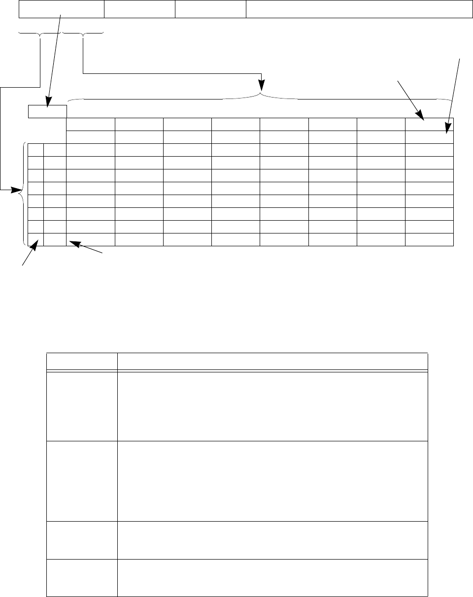
A.2 Instruction Bit Encoding Tables
The MIPS32® Instruction Set Manual, Revision 6.05 427
Figure A.1 Sample Bit Encoding Table
Tables A.2 through A.21 describe the encoding used for the MIPS32 ISA. Table A.1 describes the meaning of the
symbols used in the tables.
Table A.1 Symbols Used in the Instruction Encoding Tables
Symbol Meaning
Operation or field codes marked with this symbol are reserved for future use. Execut-
ing such an instruction must cause a Reserved Instruction exception.
Note: Some instruction encodings are assigned to coprocessors (as indicated by COP0
or COP1 in the encoding table titles). For such instruction encodings, the Coprocessor
Unavailable exception takes priority over the Reserved Instruction exception.
no marking Many instructions are optional, or available only in certain configurations. As of
Release 6, if a table entry would be empty in a particular configuration, then imple-
mentations are required to signal a Reserved Instruction exception when executed.
Pre-Release 6 signalling a reserved instruction was not necessarily required, hence
symbols such as * which indicate when such signalling is required or present,
and when not. In other words, as of Release 6 full instruction decoding, including
detection of unused instructions, is assumed as the default.
(Also italic field name.) Operation or field codes marked with this symbol denotes a
field class. The instruction word must be further decoded by examining additional
tables that show values for another instruction field.
Operation or field codes marked with this symbol represent a valid encoding for a
higher-order MIPS ISA level or a new revision of the Architecture. Executing such an
instruction must cause a Reserved Instruction exception.
31 26 25 21 20 16 15 0
opcode rs rt immediate
655 16
opcode bits 28..26
01234567
bits 31..29 000 001 010 011 100 101 110 111
0000
1001
2010
3 011 EX1
4100
5101
6 110 EX2
7111
Decimal encoding of
opcode (28..26)
Binary encoding of
opcode (28..26)
Decimal encoding of
opcode (31..29)
Binary encoding of
opcode (31..29)

Instruction Bit Encodings
428 The MIPS32® Instruction Set Manual, Revision 6.05
Operation or field codes marked with this symbol represent instructions which were
only legal if 64-bit operations were enabled on implementations of Release 1 of the
Architecture. In Release 2 of the architecture, operation or field codes marked with
this symbol represent instructions which are legal if 64-bit floating point operations
are enabled. In other cases, executing such an instruction must cause a Reserved
Instruction exception (non-coprocessor encodings or coprocessor instruction encod-
ings for a coprocessor to which access is allowed) or a Coprocessor Unusable Excep-
tion (coprocessor instruction encodings for a coprocessor to which access is not
allowed).
Instructions formerly marked in some earlier versions of manuals, corrected and
marked in revision 5.03. Legal on MIPS64r1 but not MIPS32r1; in release 2 and
above, legal in both MIPS64 and MIPS32, in particular even when running in “32-bit
FPU Register File mode”, FR=0, as well as FR=1.
Operation or field codes marked with this symbol are available to licensed MIPS part-
ners. To avoid multiple conflicting instruction definitions, MIPS Technologies will
assist the partner in selecting appropriate encodings if requested by the partner. The
partner is not required to consult with MIPS Technologies when one of these encod-
ings is used. If no instruction is encoded with this value, executing such an instruction
must cause a Reserved Instruction exception (SPECIAL2 encodings or coprocessor
instruction encodings for a coprocessor to which access is allowed) or a Coprocessor
Unusable Exception (coprocessor instruction encodings for a coprocessor to which
access is not allowed).
Release 6 reserves the SPECIAL2 encodings. pre-MIPS32 Release 2 the SPECIAL2
encodings were available for customer use as UDIs. Otherwise like above.
Field codes marked with this symbol represent an EJTAG support instruction and
implementation of this encoding is optional for each implementation. If the encoding
is not implemented, executing such an instruction must cause a Reserved Instruction
exception. If the encoding is implemented, it must match the instruction encoding as
shown in the table.
Operation or field codes marked with this symbol are reserved for MIPS optional
Module or Application Specific Extensions. If the Module/ASE is not implemented,
executing such an instruction must cause a Reserved Instruction exception.
Operation or field codes marked with this symbol are obsolete and will be removed
from a future revision of the MIPS32 ISA. Software should avoid using these opera-
tion or field codes.
Operation or field codes marked with this symbol are valid for Release 2 implementa-
tions of the architecture. Executing such an instruction in a Release 1 implementation
must cause a Reserved Instruction exception.
6N Instruction added by Release 6.
“N” for “new”.
6Nm New Release 6 encoding for a pre-Release 6 instruction that has been moved.
“Nm” for “New (moved)
Table A.1 Symbols Used in the Instruction Encoding Tables (Continued)
Symbol Meaning

A.2 Instruction Bit Encoding Tables
The MIPS32® Instruction Set Manual, Revision 6.05 429
6Rm pre-Release 6 instruction encoding moved in Release 6.
“Rm” for “Removed (moved elsewhere)”.
6Rm and 6R instructions
signal a Reserved Instruc-
tion exception when exe-
cuted by a Release 6
implementation. If the
encoding has been used
for a new instruction or
coprocessor, the unus-
able exception takes pri-
ority.
6R pre-Release 6 instruction encoding removed by Release 6.
“R” for “Removed”.
Table A.2 MIPS32 Encoding of the Opcode Field
opcode bits 28..26
012345 6 7
bits 31..29 000 001 010 011 100 101 110 111
0 000 SPECIAL REGIMM J JAL BEQ BNE
BLEZ
POP066N
BGTZ
POP076N
1 001 ADDI6R
POP106N
ADDIU SLTI SLTIU ANDI ORI XORI LUI1 / AUI6N
1. Pre-Release 6 instruction LUI is a special case of Release 6 instruction AUI.
2 010 COP0 COP1 COP2 COP1X2 6R
2. Architecture Release 1, the COP1X opcode was called COP3, and was available as another user-available coproces-
sor. Architecture Release 2, a full 64-bit floating point unit is available with 32-bit CPUs, and the COP1X opcode is
reserved for that purpose on all Release 2 CPUs. 32-bit implementations of Release 1 of the architecture are strongly
discouraged from using this opcode for a user-available coprocessor as doing so limits the potential for an upgrade
path for the FPU.
BEQL6R BNEL6R BLEZL6R
POP266N
BGTZL6R
POP276N
3 011 POP306N
SPECIAL2 6R
JALX6R MSA SPECIAL33
3. Architecture Release 2 added the SPECIAL3 opcode. Implementations of Release 1 of the Architecture signaled a
Reserved Instruction exception for this opcode.
4 100 LB LH LWL6R LW LBU LHU LWR6R
5 101 SB SH SWL6R SW SWR6R CACHE6Rm
6 110 LL6Rm LWC1 LWC26Rm
BC6N PREF6Rm
LDC1 LDC26Rm
BEQZC/JIC6N
POP666N
7 111 SC6Rm SWC1 SWC26Rm
BALC6N
PCREL6N
SDC1 SDC26Rm
BNEZC/JIALC6N
POP766N
Table A.1 Symbols Used in the Instruction Encoding Tables (Continued)
Symbol Meaning

Instruction Bit Encodings
430 The MIPS32® Instruction Set Manual, Revision 6.05
Table A.3 MIPS32 SPECIAL Opcode Encoding of Function Field
function bits 2..0
0123 4 5 6 7
bits 5..3 000 001 010 011 100 101 110 111
0000 SLL
1
1. Specific encodings of the rt, rd, and sa fields are used to distinguish among the SLL, NOP, SSNOP, EHB and PAUSE functions.
Release 6 makes SSNOP equivalent to NOP.
MOVCI 6RSRL SRA SLLV LSA6N SRLV SRAV
1001 JR
2,3,6R
2. Specific encodings of the hint field are used to distinguish JR from JR.HB and JALR from JALR.HB
3. Release 6 removes JR and JR.HB. JALR with rd=0 provides functionality equivalent to JR. JALR.HB with rd=0 provides func-
tionality equivalent to JR.HB. Assemblers should produce the new instruction when encountering the old mnemonic.
JALR2MOVZ6R MOVN6R SYSCALL BREAK SDBBP6Nm SYNC
2010 MFHI6R
CLZ6Nm
MTHI6R
CLO6Nm MFLO6R MTLO6R
3011
4
4. Specific encodings of the sa field are used to distinguish pre-Release 6 and Release 6 integer multiply and divide instructions.
See Table A.23 on page 440, which shows that the encodings do not conflict. The pre-Release 6 divide instructions signal
Reserved Instruction exception on Release 6. Note that the same mnemonics are used for pre-Release 6 divide instructions that
return both quotient and remainder, and Release 6 divide instructions that return only quotient, with separate MOD instructions
for the remainder.
4MULT6R
SOP306N
4MULTU6R
SOP316N
4DIV6R
SOP326N
4DIVU6R
SOP336N
4 100 ADD ADDU SUB SUBU AND OR XOR NOR
5101 SLT SLTU
6 110 TGE TGEU TLT TLTU TEQ SELEQZ6N TNE SELNEZ6N
7111
Table A.4 MIPS32 REGIMM Encoding of rt Field
rt bits 18..16
01234567
bits 20..19 000 001 010 011 100 101 110 111
0 00 BLTZ B G E Z BLT Z L 6R BGEZL6R DAHI6N
101 TGEI
6R TGEIU6R TLTI6R TLTIU6R TEQI6R TNEI6R
210
BLTZAL6R
NAL6N 1
1. NAL and BAL are assembly idioms prior to Release 6.
BGEZAL6R
BAL6N 1 BLTZALL6R BGEZALL6R SIGRIE6N
311
DATI6N SYNCI

A.2 Instruction Bit Encoding Tables
The MIPS32® Instruction Set Manual, Revision 6.05 431
Table A.5 MIPS32 SPECIAL2 Encoding of Function Field
function bits 2..0
01234567
bits 5..3 000 001 010 011 100 101 110 111
0000
MADD6R
MADDU6R
MUL6R
MSUB6R
MSUBU6R
1001
2010
3011
4100 CLZ
6Rm CLO6Rm
5101
6110
7111
SDBBP6Rm
Table A.6 MIPS32 SPECIAL31 Encoding of Function Field for Release 2 of the Architecture
1.Architecture Release 2 added the SPECIAL3 opcode. Implementations of Release 1 of the Architecture signaled a
Reserved Instruction exception for this opcode and all function field values shown above.
function bits 2..0
01234567
bits 5..3 000 001 010 011 100 101 110 111
0 000 EXT INS
1 001
2 010
3 011 LWLE6R LWRE6R CACHEE SBE SHE SCE SWE
4 100 BSHFL SWLE6R SWRE6R PREFE CACHE6Nm SC6Nm
5 101 LBUE LHUE * LBE LHE LLE LWE
6 110 PREF6Nm LL6Nm
7 111 RDHWR
Table A.7 MIPS32 MOVCI6R1 Encoding of tf Bit
1. Release 6 removes the MOVCI instruction family (MOVT
and MOVF).
tf bit 16
01
MOVF6R MOVT6R
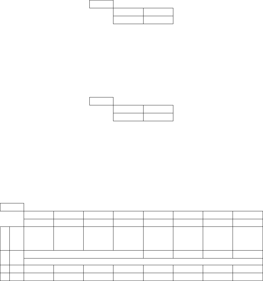
Instruction Bit Encodings
432 The MIPS32® Instruction Set Manual, Revision 6.05
Table A.8 MIPS321 SRL Encoding of Shift/Rotate
1. Release 2 of the Architecture
added the ROTR instruction.
Implementations of Release 1 of
the Architecture ignored bit 21
and treated the instruction as an
SRL
R bit 21
01
SRL ROTR
Table A.9 MIPS321 SRLV Encoding of Shift/Rotate
1. Release 2 of the Architecture
added the ROTRV instruction.
Implementations of Release 1 of
the Architecture ignored bit 6
and treated the instruction as an
SRLV
R bit 6
01
SRLV ROTRV
Table A.10 MIPS32 BSHFL Encoding of sa Field1
1. The sa field is sparsely decoded to identify the final instructions. Entries in this table with no mnemonic are
reserved for future use by MIPS technologies and may or may not cause a Reserved Instruction exception.
sa bits 8..6
01234567
bits 10..9 000 001 010 011 100 101 110 111
000BITSWAP6N
6N
*WSBH* * * *
101 ALIGN6N (BSHFL) ****
210SEB*******
311SEH*******

A.2 Instruction Bit Encoding Tables
The MIPS32® Instruction Set Manual, Revision 6.05 433
Table A.11 MIPS32 COP0 Encoding of rs Field
rs bits 23..21
01234567
bits 25..24 000 001 010 011 100 101 110 111
000 MFC0 MFH MTC0 MTH
101 RDPGPR MFMC01
1. Release 2 of the Architecture added the MFMC0 function, which is further decoded as the DI (bit 5 = 0) and EI (bit
5 = 1) instructions.
WRPGPR
210
C0 311
Table A.12 MIPS32 COP0 Encoding of Function Field When rs=CO
function bits 2..0
01234567
bits 5..3 000 001 010 011 100 101 110 111
0000 TLBR TLBWI TLBINV TLBINVF TLBWR
1001 TLBP
2010
3 011 ERET DERET
4100 WAIT
5101
6110
7111
Table A.13 PCREL Encoding of Minor Opcode Field
Extension bit 20..18
bit 17..16 01234567
000 001 010 011 100 101 110 111
0 00 ADDIUPC ADDIUPC LWPC LWPC LWUPC LWUPC LDPC *
1 01 ADDIUPC ADDIUPC LWPC LWPC LWUPC LWUPC LDPC *
2 10 ADDIUPC ADDIUPC LWPC LWPC LWUPC LWUPC LDPC AUIPC
3 11 ADDIUPC ADDIUPC LWPC LWPC LWUPC LWUPC LDPC ALUIPC

Instruction Bit Encodings
434 The MIPS32® Instruction Set Manual, Revision 6.05
Table A.14 MIPS32 Encoding of rs Field
rs bits 23..21
0 1 2 34567
bits 25..24 000 001 010 011 100 101 110 111
000 MFC1 CFC1 MFHC1 MTC1 CTC1 MTHC1
101
BC16R
BC1ANY26R
BC1EQZ6N BC1ANY46R
BZ.V BC1NEZ6N BNZ.V
210
S D W L
PS6R
311 BZ.B BZ.H BZ.W BZ.D BNZ.B BNZ.H BNZ.W BNZ.D
Table A.15 MIPS32 COP1 Encoding of Function Field When rs=S
function bits 2..0
0 1 234567
bits 5..3 000 001 010 011 100 101 110 111
0 000 ADD SUB MUL DIV SQRT ABS MOV NEG
1 001 ROUND.L TRUNC.L CEIL.L FLOOR.L ROUND.W TRUNC.W CEIL.W FLOOR.W
2 010 SEL 6N MOVCF 6R MOVZ 6R MOVN 6R SELEQZ 6N RECIP RSQRT SELNEZ 6N
3 011 MADDF 6N MSUBF 6N RINT 6N CLASS 6N
RECIP2 6R
MIN 6N
RECIP1 6R
MAX 6N
RSQRT1 6R
MINA 6N
RSQRT2 6R
MAXA 6N
4100 CVT.D CVT.W CVT.L CVT.PS 6R
5101
6110
C.F 6R
CABS.F
C.UN 6R
CABS.UN
C.EQ 6R
CABS.EQ
C.UEQ 6R
CABS.UEQ
C.OLT 6R
CABS.OLT
C.ULT 6R
CABS.ULT
C.OLE 6R
CABS.OLE
C.ULE 6R
CABS.ULE
7111
C.SF 6R
CABS.SF
C.NGLE 6R
CABS.NGLE
C.SEQ 6R
CABS.SEQ
C.NGL 6R
CABS.NGL
C.LT 6R
CABS.LT
C.NGE 6R
CABS.NGE
C.LE 6R
CABS.LE
C.NGT 6R
CABS.NGT

A.2 Instruction Bit Encoding Tables
The MIPS32® Instruction Set Manual, Revision 6.05 435
Table A.16 MIPS32 COP1 Encoding of Function Field When rs=D
function bits 2..0
0 1 234567
bits 5..3 000 001 010 011 100 101 110 111
0 000 ADD SUB MUL DIV SQRT ABS MOV NEG
1 001 ROUND.L TRUNC.L CEIL.L FLOOR.L ROUND.W TRUNC.W CEIL.W FLOOR.W
2 010 SEL6N MOVCF6R MOVZ6R MOVN6R SELEQZ6N RECIP RSQRT SELNEZ6N
3 011 MADDF6N MSUBF6N RINT6N CLASS6N
RECIP2 6R
MIN6N
RECIP1 6R
MAX6N
RSQRT1 6R
MINA6N
RSQRT2 6R
MAXA6N
4100 CVT.S CVT.W CVT.L
5101 *
6110
C.F6R
CABS.F
C.UN6R
CABS.UN
C.EQ6R
CABS.EQ
C.UEQ6R
CABS.UEQ
C.OLT6R
CABS.OLT
C.ULT6R
CABS.ULT
C.OLE6R
CABS.OLE
C.ULE6R
CABS.ULE
7111
C.SF6R
CABS.SF
C.NGLE6R
CABS.NGLE
C.SEQ6R
CABS.SEQ
C.NGL6R
CABS.NGL
C.LT6R
CABS.LT
C.NGE6R
CABS.NGE
C.LE6R
CABS.LE
C.NGT6R
CABS.NGT
Table A.17 MIPS32 COP1 Encoding of Function Field When rs=W or L12
1. Format type L is legal only if 64-bit floating point operations are enabled.
2. Release 6 introduces the CMP.condn.fmt instruction family, where .fmt=S or D, 32 or 64 bit floating point. However, .S and .D for
CMP.condn.fmt are encoded as .W 10100 and .L 10101 in the “standard” format. The conditions tested are encoded the same way
for pre-Release 6 C.cond.fmt and Release 6 CMP.cond.fmt, except that Release 6 adds new conditions not present in C.cond.fmt.
Release 6, however, has changed the recommended mnemonics for the CMP.condn.fmt to be consistent with the IEEE standard
rather than pre-Release 6. See the table in the description of CMP.cond.fmt in Volume II of the MIPS Architecture Reference Man-
ual, which shows the correspondence between pre-Release 6 C.cond.fmt, Release 6 CMP.cond.fmt, and MSA FC*.fmt / FS*.fmt
floating point comparisons.
function bits 2..0
01 2 3 45 6 7
bits 5..3 000 001 010 011 100 101 110 111
0 000 CMP.AF.S/D6N CMP.UN.S/D6N CMP.EQ.S/D6N CMP.UEQ.S/D6N CMP.OLT.S/D6N CMP.ULT.S/D6N CMP.OLE.S/D6N CMP.ULE.S/D6N
1 001 CMP.SAF.S/D6N CMP.SUB.S/D6N CMP.SEQ.S/D6N CMP.SUEQ.S/D6N CMP.SLT.S/D6N CMP.SULT.S/D6N CMP.SLE.S/D6N CMP.SULE.S/D6N
2010 CMP.OR.S/D6N CMP.UNE.S/D6N CMP.NE.S/D6N
3011 CMP.SOR.S/D6N CMP.SUNE.S/D6N CMP.SNE.S/D6N
4100 CVT.S CVT.D CVT.PS.PW6R
5101
6110
7111
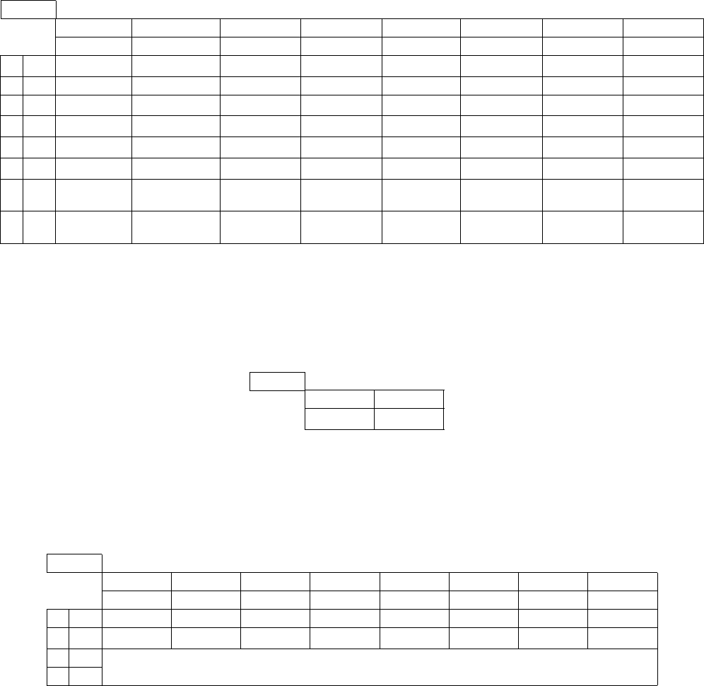
Instruction Bit Encodings
436 The MIPS32® Instruction Set Manual, Revision 6.05
Table A.18 MIPS32 COP1 Encoding of Function Field When rs=PS1 2
1. Format type PS is legal only if 64-bit floating point operations are enabled. All encodings in this table are reserved in Release 6.
2. Release 6 removes format type PS (paired single). MSA (MIPS SIMD Architecture) may be used instead.
function bits 2..0
01 234567
bits 5..3 000 001 010 011 100 101 110 111
0000 ADD
6RSUB6RMUL6R ABS6RMOV6R NEG6R
1001
2010 MOVCF6R MOVZ6R MOVN6R
3 011 ADDR6R MULR6R RECIP26R RECIP16R RSQRT16R RSQRT26R
4100CVT.S.PU
6R CVT.PW.PS6R
5101 CVT.PS
6R PLL6R PLU6R PUL.PS6R PUU.PS6R
6110
C.F.PS6R
CABS.F.PS
C.UN.PS6R
CABS.UN
C.EQ6R
CABS.EQ
C.UEQ.PS6R
CABS.UEQ.PS
C.OLT.PS6R
CABS.OLT.PS
C.ULT6R
CABS.ULT
C.OLE6R
CABS.OLE
C.ULE.PS6R
CABS.ULE.PS
7111
C.SF.PS6R
CABS.SF.PS
C.NGLE.PS6R
CABS.NGLE.PS
C.SEQ.PS6R
CABS.SEQ.PS
C.NGL.PS6R
CABS.NGL.PS
C.LT.PS6R
CABS.LT.PS
C.NGE.PS6R
CABS.NGE.PS
C.LE.PS6R
CABS.LE.PS
C.NGT.PS6R
CABS.NGT.PS
Table A.19 MIPS32 COP1 Encoding of tf Bit When rs=S, D, or PS6R, Function=MOVCF6R1
1. Release 6 removes the MOVCF instruction family
(MOVF.fmt and MOVT.fmt), replacing them by SEL.fmt.
tf bit 16
01
MOVF.fmt6R MOVT.fmt6R
Table A.20 MIPS32 COP2 Encoding of rs Field
rs bits 23..21
01234567
bits 25..24 000 001 010 011 100 101 110 111
000 MFC2 CFC2 MFHC2 MTC2 CTC2 MTHC2
101 BC2
6R BC2EQZ6N LWC26NmSWC26NmBC2NEZ6NLDC26NmSDC26Nm
210 C2
311

A.3 Floating Point Unit Instruction Format Encodings
The MIPS32® Instruction Set Manual, Revision 6.05 437
A.3 Floating Point Unit Instruction Format Encodings
Instruction format encodings for the floating point unit are presented in this section. This information is a tabular pre-
sentation of the encodings described in tables ranging from Table A.14 to Table A.21 above.
Table A.21 MIPS32 COP1X6R1 Encoding of Function Field
1. Release 6 removes format type PS (paired single). MSA (MIPS SIMD Architecture) may be used instead.
function bits 2..0
01234567
bits 5..3 000 001 010 011 100 101 110 111
0000LWXC1
6R LDXC16R LUXC16R
1001SWXC1
6R SDXC16R SUXC16R PREFX6R
2010
3011 ALNV.PS6R
4100MADD.S
6R2
2. Release 6 removes all pre-Release 6 COP1X instructions, of the form 010011 - COP1X.PS, non-fused FP multiply
adds, and indexed and unaligned loads, stores, and prefetches.
MADD.D6RMADD.PS6R
5101MSUB.S
6RMSUB.D6RMSUB.PS6R
6110NMADD.S
6RNMADD.D6RNMADD.PS6R
7111NMSUB.S
6RNMSUB.D6RNMSUB.PS6R
Table A.22 Floating Point Unit Instruction Format Encodings
fmt field
(bits 25..21 of COP1
opcode)
fmt3 field
(bits 2..0 of COP1X
opcode)
Mnemonic Name Bit Width Data TypeDecimal Hex Decimal Hex
0..15 00..0F — — Used to encode Coprocessor 1 interface instructions (MFC1,
CTC1, etc.). Not used for format encoding.
16 10 0 0 S Single 32 Floating Point
See note below: Release 6 CMP.condn.S/D encoded as W/L.
17 11 1 1 D Double 64 Floating Point
See note below: Release 6 CMP.condn.S/D encoded as W/L.
18..19 12..13 2..3 2..3 Reserved for future use by the architecture.
20 14 4 4 W Word 32 Fixed Point
See note below: Release 6 CMP.condn.S/D encoded as W/L.
21 15 5 5 L Long 64 Fixed Point
See note below: Release 6 CMP.condn.S/D encoded as W/L.
22 16 6 6 PS Paired Single 2 32 Floating Point
Release 6 removes the PS format, and reserves it for future use
23 17 7 7 Reserved for future use by the architecture.

Instruction Bit Encodings
438 The MIPS32® Instruction Set Manual, Revision 6.05
24..31 18..1F — — Reserved for future use by the architecture. Not available for
fmt3 encoding.
Note: Release 6 CMP.condn.S/D encoded as W/L: as described in Table A.17 on page 435, “MIPS32 COP1
Encoding of Function Field When rs=W or L” on page 435, Release 6 uses certain instruction encodings with
the rs (fmt) field equal to 11000 (W) or 11001 (L) to represent S and D respectively, for the instruction family
CMP.condn.fmt.
Table A.22 Floating Point Unit Instruction Format Encodings
fmt field
(bits 25..21 of COP1
opcode)
fmt3 field
(bits 2..0 of COP1X
opcode)
Mnemonic Name Bit Width Data TypeDecimal Hex Decimal Hex
A.4 Release 6 Instruction Encodings
The MIPS32® Instruction Set Manual, Revision 6.05 439
A.4 Release 6 Instruction Encodings
Release 6 adds several new instructions, removes several old instructions, and changes the encodings of several pre-
Release 6 instructions. In many cases, the old encodings for instructions moved or removed are required to signal the
Reserved Instruction on Release 6, so that uses of old instructions can be trapped, and emulated or warned about; but
in several cases the old encodings have been reused for new Release 6 instructions.
These instruction encoding changes are indicated in the tables above. Release 6 new instructions are superscripted
6N; Release 6 removed instructions are superscripted 6R; Release 6 instructions that have been moved are marked
6Rm at the pre-Release 6 encoding that they are moved from, and 6Nm at the new Release 6 encoding that it is moved
to. Encoding table cells that contain both a non-Release 6 instruction and a Release 6 instruction superscripted 6N or
6Nm indicate a possible conflict, although in many cases footnotes indicate that other fields allow the distinction to
be made.
The tables below show the further decoding in Release 6 for field classes (instruction encoding families) indicated in
other tables.
Instruction encodings are also illustrated in the instruction descriptions in Volume II. Those encodings are authorita-
tive. The instruction encoding tables in this section, above, based on bitfields, are illustrative, since they cannot com-
pletely indicate the new tighter encodings.
MUL/DIV family encodings: Table A.23 below shows the Release 6 integer family of multiply and divide instruc-
tions encodings, as well as the pre-Release 6 instructions they replace. The Release 6 and pre-Release 6 instructions
share the same primary opcode, bits 31-26 = 000000, and share the function code, bits 5-0, with their pre-Release 6
counterparts, but are distinguished by bits 10-6 of the instruction. The pre-Release 6 instructions signal a Reserved
Instruction exception on Release 6 implementations.
However, the instruction names collide: pre-Release 6 and Release 6 DIV, DIVU, DDIV, DDIVU are actually distinct
instructions, although they share the same mnemonics. The pre-Release 6 instructions produce two results, both quo-
tient and remainder in the HI/LO register pair, while the Release 6 DIV instruction produce only a single result, the
quotient. It is possible to distinguish the conflicting instructions in assembly by looking at how many register oper-
ands the instructions have, two versus three.
As of Release 6, all of pre-Release 6 instruction encodings that are removed are required to signal the reserved
instruction exception, as are all in the vicinity 000000.xxxxx.xxxxx.aaaaa.011xxx, i.e. all with the primary opcodes
and function codes listed in Table A.23, with the exception of the aaaaa field values 00010 and 00011 for the new
instructions.

Instruction Bit Encodings
440 The MIPS32® Instruction Set Manual, Revision 6.05
PC-relative family encodings: Table A.24 and Table A.25 present the PC-relative family of instruction encodings.
Table A.24 in traditional form, Table A.25 in the bitstring form that clearly shows the immediate varying from 19 bits
to 16 bits.
Table A.23 Release 6 MUL/DIV encodings
pre-Release 6 removed struck-through
00000.rs.rt.rd.aaaaa.function6
function
bits 5-0
aaaaa, bits 10-6
00000
and rd = 00000
(bits 15-11)
00010 00011
011 000 MULT6R MUL6N MUH6N
011 001 MULTU6R MULU6N MUHU6N
011 010 DIV6R DIV6N MOD6N
011 011 DIVU6R DIVU6N MODU6N
011 100 6R 6N 6N
011 101 6R 6N 6N
011 110 6R 6N 6N
011 111 6R 6N 6N
Table A.24 Release 6 PC-relative family encoding
111011.rs.TTTTT.immediate
rs bits 18-16
01234567
bits 20-19 000 001 010 011 100 101 110 111
0 00 ADDIUP6N immediate
101 LWP6N immediate
210 6N
311 6N reserved (RI) AUIP6N
immediate
ALUIP6N
immediate

A.4 Release 6 Instruction Encodings
The MIPS32® Instruction Set Manual, Revision 6.05 441
B*C compact branch and jump encodings: In several cases Release 6 uses much tighter instruction encodings than
previous releases of the MIPS architecture, reducing redundancy, to allow more instructions to be encoded. Instead of
purely looking at bitfields, Release 6 defines encodings that compare different bitfields: e.g. the encoding
010110.rs.rt.offset16 is BGEC if neither rs nor rt are 00000 and rs is not equal to rt, but is BGEZC if rs is the same as
rt, and is BLEZC if rs is 00000 and rt is not. (The encoding with rt 00000 and arbitrary rs is the pre-Release 6 instruc-
tion BLEZL.rs.00000.offset16, a branch likely instruction which is removed by Release 6, and whose encoding is
required to signal the Reserved Instruction exception. )
This tight instruction encoding motivates the bitstring and constraints notation for Release 6 instruction encodings
and the equivalent constraints indicated in the instruction encoding diagrams for the instruction descriptions in Vol-
ume II. Table A.26 below shows the B*C compact branch encodings, which use constraints such as RS = RT. pre-
Release 6 encodings that are removed by Release 6 are shaded darkly, while the remaining redundant encodings are
shaded lightly or stippled.
Note: Pre-Release 6 instructions BLEZL, BGTZL, BLEZ, and BGTZ do not conflict with the new Release 6 instruc-
tions they are tightly packed with in the encoding tables, but the ADDI, DADDI, LWC2, SWC2, LDC2 and SDC2
truly conflict.
Table A.25 Release 6 PC-relative family encoding bitstrings
111011.rs.*
encoding instruction
111011.rs.00.<-----immediate> ADDIUPC6N
111011.rs.01.<----off19> LWPC6N
111011.rs.10.<----off19> 6N
111011.rs.110.<---off18> 6N
111011.rs.1110.<---imm17> reserved, signal RI6N
111011.rs.11110.<--immediate> AUIPC6N
111011.rs.11111.<--immediate> ALUIPC6N
BLEZC rt 010110.00000.rt.offset16, rt!=0
BGEZC rt 010110.rs=rt.rt.offset16, rs!=0, rt!=0, rs=rt
BGEC rs,rt 10110.rs.rt.offset16, rs!=0, rt!=0, rs!=rt
BLEZL rt 010110.00000.rt.offset16, rs=0

Instruction Bit Encodings
442 The MIPS32® Instruction Set Manual, Revision 6.05
Table A.26 B*C compact branch encodings
Primary
Opcode
Constraints involving rs and rt fields
Primary
Opcode
Constraints involving rs and rt fields
rs/rt0/NZ NZrs =/</> NZrt rs/rt0/NZ NZrs =/</> NZrt
010 110
0rs 0rt useless
BLEZL6R BGEZC6N =
000 110
0rs 0rt useless
BLEZ BGEZALC6N =
0rs NZrt BLEZC6N
BGEC6N
(BLEC)
<
rsNZ rtNZ
0rs NZrt BLEZALC6N
BGEUC6N
(BLEUC)
<
rsNZ rtNZ
NZrs 0rt BLEZL6R >NZrs 0rt BLEZ >
010 111
0rs 0rt useless
BGTZL6R BLTZC6N =
000 111
0rs 0rt useless
BGTZ BLTZALC6N =
0rs NZrt BGTZC6N
BLTC6N
(BGTC)
<
rsNZ rtNZ
0rs NZrt BGTZALC6N
BLTUC6N
(BGTUC)
<
rsNZ rtNZ
NZrs 0rt BGTZL6R >NZrs 0rt BGTZ >
001 000
ADDI
011 000
DADDI6R
0rs NZrt BEQZALC6N BEQC6N <0rs NZrt BNEZALC6N BNEC6N <
0rs 0rt BOVC6N =0rs 0rt BNVC6N =
NZrs 0rt >NZrs 0rt >
rsNZ rt0,NZ rsNZ rt0,NZ
110 110
LDC26R
110 110
SDC26R
0rs 0/NZrt
0rs NZrt JIC6N
rt+off16 BEQZC6N
rsNZ, off21
<
0rs 0/NZrt
0rs NZrt JIALC6N
rt+off16 BNEZC6N
rsNZ, off21
<
0rs 0rt =0rs 0rt =
NZrs 0rt >NZrs 0rt >
NZrs 0/NZrt NZrs 0/NZrt
110 010
LWC26R
111 010
SWC26R
BC6N off26<<2 BALC6N off26<<2
0/NZrs 0/NZrt 0/NZrs 0/NZrt
A.4 Release 6 Instruction Encodings
The MIPS32® Instruction Set Manual, Revision 6.05 443

Appendix B
The MIPS32® Instruction Set Manual, Revision 6.05 444
Revision History
Revision Date Description
0.90 November 1, 2000 Internal review copy of reorganized and updated architecture documentation.
0.91 November 15, 2000 Internal review copy of reorganized and updated architecture documentation.
0.92 December 15, 2000 Changes in this revision:
• Correct sign in description of MSUBU.
• Update JR and JALR instructions to reflect the changes required by MIPS16.
0.95 March 12, 2001 Update for second external review release
1.00 August 29, 2002 Update based on all review feedback:
• Add missing optional select field syntax in mtc0/mfc0 instruction descriptions.
• Correct the PREF instruction description to acknowledge that the PrepareForStore
function does, in fact, modify architectural state.
• To provide additional flexibility for Coprocessor 2 implementations, extend the sel
field for DMFC0, DMTC0, MFC0, and MTC0 to be 8 bits.
• Update the PREF instruction to note that it may not update the state of a locked cache
line.
• Remove obviously incorrect documentation in DIV and DIVU with regard to putting
smaller numbers in register rt.
• Fix the description for MFC2 to reflect data movement from the coprocessor 2 regis-
ter to the GPR, rather than the other way around.
• Correct the pseudo code for LDC1, LDC2, SDC1, and SDC2 for a MIPS32 imple-
mentation to show the required word swapping.
• Indicate that the operation of the CACHE instruction is UNPREDICTABLE if the
cache line containing the instruction is the target of an invalidate or writeback invali-
date.
• Indicate that an Index Load Tag or Index Store Tag operation of the CACHE instruc-
tion must not cause a cache error exception.
• Make the entire right half of the MFC2, MTC2, CFC2, CTC2, DMFC2, and DMTC2
instructions implementation dependent, thereby acknowledging that these fields can
be used in any way by a Coprocessor 2 implementation.
• Clean up the definitions of LL, SC, LLD, and SCD.
• Add a warning that software should not use non-zero values of the stype field of the
SYNC instruction.
• Update the compatibility and subsetting rules to capture the current requirements.

The MIPS32® Instruction Set Manual, Revision 6.05 445
1.90 September 1, 2002 Merge the MIPS Architecture Release 2 changes in for the first release of a Release 2
processor. Changes in this revision include:
• All new Release 2 instructions have been included: DI, EHB, EI, EXT, INS,
JALR.HB, JR.HB, MFHC1, MFHC2, MTHC1, MTHC2, RDHWR, RDPGPR,
ROTR, ROTRV, SEB, SEH, SYNCI, WRPGPR, WSBH.
• The following instruction definitions changed to reflect Release 2 of the Architecture:
DERET, ERET, JAL, JALR, JR, SRL, SRLV
• With support for 64-bit FPUs on 32-bit CPUs in Release 2, all floating point instruc-
tions that were previously implemented by MIPS64 processors have been modified to
reflect support on either MIPS32 or MIPS64 processors in Release 2.
• All pseudo-code functions have been updated, and the
Are64BitFPOperationsEnabled function was added.
• Update the instruction encoding tables for Release 2.
2.00 June 9, 2003 Continue with updates to merge Release 2 changes into the document. Changes in this
revision include:
• Correct the target GPR (from rd to rt) in the SLTI and SLTIU instructions. This
appears to be a day-one bug.
• Correct CPR number, and missing data movement in the pseudocode for the MTC0
instruction.
• Add note to indicate that the CACHE instruction does not take Address Error Excep-
tions due to mis-aligned effective addresses.
• Update SRL, ROTR, SRLV, ROTRV, DSRL, DROTR, DSRLV, DROTRV, DSRL32,
and DROTR32 instructions to reflect a 1-bit, rather than a 4-bit decode of shift vs.
rotate function.
• Add programming note to the PrepareForStore PREF hint to indicate that it cannot be
used alone to create a bzero-like operation.
• Add note to the PREF and PREFX instruction indicating that they may cause Bus
Error and Cache Error exceptions, although this is typically limited to systems with
high-reliability requirements.
• Update the SYNCI instruction to indicate that it should not modify the state of a
locked cache line.
• Establish specific rules for when multiple TLB matches can be reported (on writes
only). This makes software handling easier.
2.50 July 1, 2005 Changes in this revision:
• Correct figure label in LWR instruction (it was incorrectly specified as LWL).
• Update all files to FrameMaker 7.1.
• Include support for implementation-dependent hardware registers via RDHWR.
• Indicate that it is implementation-dependent whether prefetch instructions cause
EJTAG data breakpoint exceptions on an address match, and suggest that the pre-
ferred implementation is not to cause an exception.
• Correct the MIPS32 pseudocode for the LDC1, LDXC1, LUXC1, SDC1, SDXC1,
and SUXC1 instructions to reflect the Release 2 ability to have a 64-bit FPU on a 32-
bit CPU. The correction simplifies the code by using the ValueFPR and StoreFPR
functions, which correctly implement the Release 2 access to the FPRs.
• Add an explicit recommendation that all cache operations that require an index be
done by converting the index to a kseg0 address before performing the cache opera-
tion.
• Expand on restrictions on the PREF instruction in cases where the effective address
has an uncached coherency attribute.
•
Revision Date Description

Revision History
446 The MIPS32® Instruction Set Manual, Revision 6.05
2.60 June 25, 2008 Changes in this revision:
• Applied the new B0.01 template.
• Update RDHWR description with the UserLocal register.
• added PAUSE instruction
• Ordering SYNCs
• CMP behavior of CACHE, PREF*, SYNCI
• CVT.S.PL, CVT.S.PU are non-arithmetic (no exceptions)
• *MADD.fmt & *MSUB.fmt are non-fused.
• various typos fixed
2.61 July 10, 2008 • Revision History file was incorrectly copied from Volume III.
• Removed index conditional text from PAUSE instruction description.
• SYNC instruction - added additional format “SYNC stype”
2.62 January 2, 2009 • LWC1, LWXC1 - added statement that upper word in 64bit registers are UNDE-
FINED.
• CVT.S.PL and CVT.S.PU descriptions were still incorrectly listing IEEE exceptions.
• Typo in CFC1 Description.
• CCRes is accessed through $3 for RDHWR, not $4.
3.00 March 25, 2010 • JALX instruction description added.
• Sub-setting rules updated for JALX.
•
3.01 June 01, 2010 • Copyright page updated.
• User mode instructions not allowed to produce UNDEFINED results, only UNPRE-
DICTABLE results.
3.02 March 21, 2011 • RECIP, RSQRT instructions do not require 64-bit FPU.
• MADD/MSUB/NMADD/NMSUB pseudo-code was incorrect for PS format check.
3.50 September 20, 2012 • Added EVA load/store instructions: LBE, LBUE, LHE, LHUE, LWE, SBE, SHE,
SWE, CACHEE, PREFE, LLE, SCE, LWLE, LWRE, SWLE, SWRE.
• TLBWI - can be used to invalidate the VPN2 field of a TLB entry.
• FCSR.MAC2008 bit affects intermediate rounding in MADD.fmt, MSUB.fmt,
NMADD.fmt and NMSUB.fmt.
• FCSR.ABS2008 bit defines whether ABS.fmt and NEG.fmt are arithmetic or not
(how they deal with QNAN inputs).
3.51 October 20, 2012 • CACHE and SYNCI ignore RI and XI exceptions.
• CVT, CEIL, FLOOR, ROUND, TRUNC to integer can’t generate FP-Overflow
exception.
5.00 December 14, 2012 • R5 changes: DSP and MT ASEs -> Modules
• NMADD.fmt, NMSUB.fmt - for IEEE2008 negate portion is arithmetic.
5.01 December 15, 2012 • No technical content changes:
• Update logos on Cover.
• Update copyright page.
5.02 April 22, 2013 • Fix: Figure 2.26 Are64BitFPOperationsEnabled Pseudcode Function - “Enabled”
was missing.
• R5 change retroactive to R3: removed FCSR.MCA2008 bit: no architectural support
for fused multiply add with no intermediate rounding. Applies to MADD.fmt,
MSUB.fmt, NMADD.fmt, NMSUB.fmt.
• Clarification: references to “16 FP registers mode” changed to “the FR=0 32-bit reg-
ister model”; specifically, paired single (PS) instructions and long (L) format instruc-
tions have UNPREDICTABLE results if FR=0, as well as LUXC1and SUXC1.
• Clarification: C.cond.fmt instruction page: cond bits 2..1 specify the comparison,
cond bit 0 specifies ordered versus unordered, while cond bit 3 specifies signaling
versus non-signaling.
• R5 change: UFR (User mode FR change): CFC1, CTC1 changes.
Revision Date Description

The MIPS32® Instruction Set Manual, Revision 6.05 447
5.03 August 21, 2013 • Resolved inconsistencies with regards to the availability of instructions in MIPS32r2:
MADD.fmt family (MADD.S, MADD.D, NMADD.S, NMADD.D, MSUB.S,
MSUB.D, NMSUB,S, NMSUB.D), RECIP.fmt family (RECIP.S, RECIP.D,
RSQRT.S, RSQRT.D), and indexed FP loads and stores (LWXC1, LDXC1, SWXC1,
SDXC1). The appendix section A.2 “Instruction Bit Encoding Tables”, shared
between Volume I and Volume II of the ARM, was updated, in particular the new
upright delta mark is added to Table A.2 “Symbols Used in the Instruction Encod-
ing Tables”, replacing the inverse delta marking for these instructions. Similar
updates made to microMIPS’s corresponding sections. Instruction set descriptions
and pseudocode in Volume II, Basic Instruction Set Architecture, updated. These
instructions are required in MIPS32r2 if an FPU is implemented. .
• Misaligned memory access support for MSA: see Volume II, Appendix B “Mis-
aligned Memory Accesses”.
• Has2008 is required as of release 5 - Table 5.4, “FIR Register Descriptions”.
• ABS2008 and NAN2008 fields of Table 5.7 “FCSR RegisterField Descriptions” were
optional in release 3 and could be R/W, but as of release 5 are required, read-only, and
preset by hardware.
• FPU FCSR.FS Flush Subnormals / Flush to Zero behavior is made consistent with
MSA behavior, in MSACSR.FS: Table 5.7, “FCSR Register Field Descriptions”,
updated. New section 5.8.1.4 “Alternate Flush to Zero Underflow Handling”.
• Volume I, Section 2.2 “Compliance ad Subsetting” noted that the L format is required
in MIPS FPUs, to be consistent with Table 5.4 “FIR Register Field Definitions” .
• Noted that UFR and UNFR can only be written with the value 0 from GPR[0]. See
section 5.6.5 “User accessible FPU Register model control (UFR, CP1 Con-
trol Register 1)” and section 5.6.5 “User accessible Negated FPU Register
model control (UNFR, CP1 Control Register 4)”
5.04 December 11, 2013 LLSC Related Changes
• Added ERETNC. New.
• Modified SC handling: refined, added, and elaborated cases where SC can fail or was
UNPREDICTABLE.
XPA Related Changes
• Added MTHC0, MFHC0 to access extensions. All new.
• Modified MTC0 for MIPS32 to zero out the extended bits which are writable. This is
to support compatibility of XPA hardware with non XPA software. In pseudo-code,
added registers that are impacted.
• MTHC0 and MFHC0 - Added RI conditions.
6.00 -
R6U draft
Dec. 19, 2013 • Feature complete R6U draft of Volume II new instructions.
Jan 14-16, 2014 • Split MAX.fmt-family, instruction description that described multiple instructions,
into separate instruction description pages MAX.fmt, MAX_A.fmt, MIN.fmt,
MIN_A.fmt.
• Mnemonic change: AUIPA changed to ALUIPC, Aligned Add Upper Immediate to
PC. Now all Release 6 new PC relative instructions end in “P”.
• Renamed CMP.cond.fmt -> CMP.condn.fmt, i.e. renamed 5-bit cond field “condn”
to distinguish it from old 4-bit cond field.
• Cleaning up descriptions of NAL and BAL to reduce confusion about deprecation
versus removal of BLTZAL and BGEZAL.
• DAHI and DATI use rs src/dest register, not rt.
• Table showing that the compact branches are complete, reversing rs and rt for BLEC,
BGTC, BLEUC, BGTUC
• Forbidden slot RI required; takes exception like delay slot; boilerplate consistency
automated.
• MOD instruction family: remainder has same sign as dividend
• Updated to R6U 1.03
Revision Date Description

Revision History
448 The MIPS32® Instruction Set Manual, Revision 6.05
Jan 17, 2014 • NAL, BAL: improved confusing explanation of how NAL and BAL used to be special
cases of BLEZAL, etc., instructions removed by Release 6
• Forbidden slot boilerplate: requires Reserved Instruction exception for control
instructions, even if interrupted: exception state (EPC, etc.) points to branch, not for-
bidden slot, like delay slot.
Jan 20, 2014 • Fixed bugs and changed instruction encodings: BEQZALC, BNEZALC, BGEUC,
BLTUC, BLEZLC family, BC1EQZ, BC2EQZ, BC1NEZ, BC2NEZ, BITSWAP
•AUI, BAL
R6U draft Feb 10, 2014 • Refactored “Compatibility and Subsetting” sections of Volumes I and II for reuse
without replication.
• Updated Volume II tables of instructions by categories (preceding section entitled
Alphabetical List of Instructions) for R6U changes.
R6U-pre-
release
draft
Feb. 11, 2014 Technical Publications preparing for release.
Summary of all R6U drafts up to this date - R6U version 1.03
• MIPS3D removed from the Release 6 architecture.
• Some 3-source instructions (conditional moves) replaced with new 2-source instruc-
tions: MOVZ/MOVN.fmt replaced by SELEQZ/SELNEZ.fmt; MOVZ/MOVN
replaced by SELEQZ/SELNEZ.
• PREF/PREFE: Unsound prefetch hints downgraded; optional implementation depen-
dent prefetch hints expanded.
Free up Opcode Space
• Change encodings of LL/SC/LLD/SCD/PREF/CACHE, reducing offset from 16 bits
to 9 bits
• SPECIAL2 encodings changed: CLO/CLZ/DCLO/DCLZ
• Other changes mentioned below: traps with immediate operands removed (ADDI/
DADDI, TGEI/TGEIU/TLTI/TLTIU/TEQI/TNEI)
• Free 15 major opcodes: COP1X, SPECIAL2, LWL/LWR, SWL/SWR, LDL/LDR,
SDL/SDR, LL/SC, LLD/SCD, PREF, CACHE, as described below, by changing
encodings.
Integer Multiply and Divide
• Integer accumulators (HI/LO) removed from base Release 6, moved to DSPr6,
allowed only with microMIPS: MFHI, MTHIO, MFLO, MTLO, MADD, MADDU,
MUL, MSUB, MSUBU removed.
• Release 6 adds multiply and divide instructions that write to same-width register:
MULT replaced by MUL/MUH; MULTU replaced by MULU/MUHU; DIV replaced
by DIV/MOD; DIVU replaced by DIVU/MODU; similarly for 64-bit DMUH, etc.
Revision Date Description

The MIPS32® Instruction Set Manual, Revision 6.05 449
Control Transfer Instructions (CTIs)
• Branch likely instructions removed by Release 6: BEQL, etc.
• Enhanced compact branches and jumps provided
• No delay slots; back-to-back branches disallowed (forbidden slot)
• More complete set of conditions: BEQC/BNEC, all signed and unsigned reg-reg com-
parisons, e.g. BLTC, BLTUC; all comparisons against zero, e.g. BLTZC
• More complete set of conditional procedure call instructions: BEQZALC, BNE-
ZALC
• Large offset PC-relative branches: BC/BALC 26-bit offset (scaled by 4); BEQZC/
BNEZC 21-bit offset
• JIC/JIALC: “indexed” jumps, jump to register + sign extended 16-bit offset
• Trap-in-overflow adds with immediate removed by MIOPSr6: ADDI, DADDI;
replaced by branches on overflow BOVC/BNVC.
• Redundant JR.HB removed, aliased to JALR.HB with rdest=0.
• BLTZAL/BGEZAL removed; not used because unconditionally wrote link register
SSNOP identical to NOP.
Misaligned Memory Accesses
• Unaligned load/store instructions (LWL/LWR, etc.) removed from Release 6. Support
for misaligned memory accesses must be provided by a Release 6 system for all ordi-
nary loads and stores, by hardware or by software trap-and-emulate.
• CPU scalar ALIGN instruction
Address Generation and Constant Building
• Instructions to build large constants (such as address constants): AUI (Add upper
immediate), DAHI, DATI.
• Instructions for PC-relative address formation: ADDIUPC, ALUIPC.
• PC-relative loads: LWP, LWUP, LDP.
• Indexed FPU memory accesses removed: LWXC1, LUXC1, PFX, etc.
• Load-scaled-address instructions: LSA, DLSA
• 32-bit address wrapping improved.
DSP ASE
• DSP ASE and SmartMIPS disallowed; recommend MSA instead
• DSPr6 to be defined, used with microMIPS.
• Instructions promoted from DSP ASE to Base ISA: BALIGN becomes Release 6
ALIGN, BITREV becomes Release 6 BITSWAP
Revision Date Description

Revision History
450 The MIPS32® Instruction Set Manual, Revision 6.05
FPU and co-processor
• Instruction encodings changed: COP2 loads/stores, cache/prefetch, SPECIAL2:
LWC2/SWC2, LDC2/SWC2
• FR=0 not allowed, FR=1 required.
• Compatibility and Subsetting section amended to allow a single precision only FPU
(FIR.S=FIR.W=1, FIR.D=FIR.L=0.)
• Paired Single (PS) removed from the Release 6 architecture, including: COP1.PS,
COP1X.PS, BC1ANY2, BC1ANY4, CVT.PS.S, CVT.PS.W.
• FPU scalar counterparts to MSA instructions: RINT.fmt, CLASS.fmt, MAX/MAXA/
MIN/MINA.fmt.
• Unfused multiply adds removed: MADD/MSUB/NMADD/NMSUB.fmt
• IEEE2008 Fused multiply adds added: MADDF/MSUBF.fmt
• Floating point condition codes and related instructions removed: C.cond.fmt
removed, BC1T/BC1F, MOVF/MOVT.
• MOVF/MOVT.fmt replaced by SEL.fmt
• New FP compare instruction CMP.cond.fmt places result in FPR and related
BC1EQZ/BC2EQZ
• New FP comparisons: CMP.cond.fmt with cond = OR (ordered), UNE (Unordered
or Not Equal), NE (Not Equal).
• Coprocessor 2 condition codes removed: BC2F/BC2T removed, replaced by
BC2NEQZ/BC2EQZ
Recent R6U architecture changes not fully reflected in this draft:
• This draft does not completely reflect the new 32-bit address wrapping proposal but
still refers in some places to the old IAM (Implicit Address Mode) proposal.
• This draft does not yet reflect constraints on endianness, in particular in the section
ion Misaligned memory access support: e.g. code and data must have the same endi-
anness, Status.RE is removed, etc.
• BC1EQZ/BC1NEZ will test only bit 0 of the condition register, not all bits.
• This draft does not yet say that writing to a 32-bit FPR renders upper bits of a 64 bit
FPR or 128 bit floating point register UNPREDICTABLE; it describes the old pro-
posal of zeroing the upper bits.
Known issues:
• This draft describes Release 6, as well as earlier releases of the MIPS architecture.
E.g. instructions that were present in MIPSr5 but which were removed in Release 6
are still in the manual, although they should be clearly marked “removed by Release
6” to indicate that they have been removed by Release 6.
• R6U new instruction pseudocode is 64-bit, rather than 32-bit, albeit attempting to use
notations that apply to both.
• Certain new instruction descriptions are “unsplit”, describing families of instructions
such as all compact branches, rather than separate descriptions of each instruction.
This facilitates comparison and consistency, but currently allows certain MIPS64
Release 6 instructions to appear inappropriately in the MIPS32 Release 6 manual. A
future release of the manual will “split” these instruction family descriptions, e.g. the
compact branch family will be split up into at least 12 different instruction descrip-
tions.
• R6U requires misalignment support for all ordinary memory reference instructions,
but the pseudocode does not yet reflect this. Boilerplate has been added to all existing
instructions saying this.
• The new R6U PC-relative loads (LWP, LWUP, LDP) in this draft incorrectly say that
misaligned accesses are permitted.
Revision Date Description

The MIPS32® Instruction Set Manual, Revision 6.05 451
R6U-pre-
release
draft
Feb. 13, 2014 • ALIGN/DALIGN: clarified bp=0 behavior
• ALIGN/DALIGN pseudocode used || as logical OR rather than MIPS’ pseudocode
concatenate.
• Removed incorrect note about not using r31 as a source register to BAL.
• Release 6 requires BC1EQZ/BC1NEZ if an FPU is present, i.e. they cannot signal RI.
• R6U 1.05 change: BC1EQZ/BC1NEZ test only bit 0 of the FPY; changed from test-
ing if any bit nonzero; helps with trap-and-emulate of DP on an SP-only FPU.
• Known problem: R6U 1.05 change not yet made: all 32-bit FP operations leave upper
bits of 64 bit FOR and./or 128-bit MSR unpredictable; helps with trap-and-emulate of
DP on an SP-only FPU.
• Clearly marked all .PS instructions as removed via removed by Release 6 in instruc-
tion format.
• DMUL, DMULTU, DDIV, DDIVU marked removed by Release 6
• Started using =Release 6 notation to indicate that an instruction has been changed but
is still present. JR.HB =Release 6, aliased to JALR.HB. SSNOP =Release 6, treated
as NOP.
• Noted that BLTZAL and BGEZAL are removed by Release 6, the special cases
NAL=BLTZAL with rs=0 and BAL=BGEZAL with rs=0, remain supported by
Release 6.
• Marked conditional traps with immediate removed by Release 6.
• Overeager propagation of r31 restriction to non-call instructions5 removed.
• Emphasized that unconditional compact CTIs have neither delay slot nor forbidden
slot.
• SDBBP updated for R6P facility to disable if no hardware debug trap handler
• UFR/UNFR (User-mode FR facility) disallowed in Release 6: changes to CTC1 and
CFC1 instructions.
R6U ARM
Volume II
6.00 pre-
liminary
release
February 14, 2014 • Last minute change: BC1EQZ.fmt and BC1NEZ.fmt test only bit 0, least significant
bit, of FPR.
Known issues:
• Similar changes to SEL.fmt, SELEQZ.fmt, SELNEZ.fmt not yet made.
post-6.00 February 20, 2014 • FPU truth consuming instructions (BC1EQZ.fmt, BC1NEZ.fmt, SEL.fmt,
SELEQZ.fmt, SELNEZ.fmt) change completed: test bit 0, least-significant-bit, of
FPR containing condition.
6.01 December 1, 2014 • Production Release.
• Add DVP and EVP instructions for multithreading.
• Add POP and SOP encoding nomenclature to opcode tables in appendix A
6.02 December 10, 2014 • JIC format changed from JIC offset(rt) to JIC rt, offset.
• JIALC format changed from JIALC offset(rt) to JIALC rt, offset.
• 'offset' removed from NAL format.
6.03 September 4, 2015 • Fixed many inconsistencies; no functional impact.
• RDHWR updates for Release 6.
• WAIT updates for Release 6.
• CFC1/CTC1 UFR-related text reworded.
• CFC1/CTC1 FRE-related text added.
• Added LLX/SCX(32/64) instructions.
• Jump Register ISA Mode switching text reworded.
• MisalignedSupport() language in ld/st pseudo-code reworded.
• Release 6 behaviour added to move-to/from instructions: return 0,nop.
• TLBINV/TLBINVF description and pseudocode corrected and clarified.
• ALIGN/DALIGN pseudocode cleaned up; removed redundancy.
• Removed “Special Considerations” section from B<cond>c
• Language clarified in PREF/PREFE tables; no functional change.
Revision Date Description
Revision History
452 The MIPS32® Instruction Set Manual, Revision 6.05
6.04 November 13, 2015 MIPS32 and MIPS64:
• J/JAL now indicated as deprecated (but not removed).
• DVP: Added text indicating that a disabled VP will not be re-enabled for execution on
deferred exception.
• CACHE/CACHEE: Undefined operations are really NOP.
• CMP.condn.fmt: removed fmt related text in description section. .S/.D explicitly
encoded.
• Fixed minor textual typos in MAXA/MINA.fmt functions.
• DERET: Restriction – if executed out of debug mode, then RI, not UNDEFINED.
• TLBWR: Updated reference to Random. No longer supported in Release 6.
• PCREL instructions: Added PCREL minor opcode table, fixed conditional text bugs
in register reference.
• BC1F/BC1FL/BC1T/BC1TL: Removed last paragraph of historical information sec-
tion. These instructions can be immediately preceeded by instruction that sets cond.
code.
• JIALC: Restructured operation section using ‘temp’ to avoid false hazard of link
update overwriting source.
• LUI: Fixed conditional text errors related to the encoding table. microMIPS appeared
in MIPS.
• JIALC/JIC: Updated to indicate effect on ‘ISAMode’.
• Fixed typo ROUND/TRUNC/FLOOR/CEIL.W.fmt. Range value should be 231-1 not
263-1.
MIPS64 only:
• DMFC0/DMTC0: Now indicates what happens with 32-bit COP0 registers.
6.05 May 20, 2016 MIPS32 and MIPS64:
• RDHWR: Fixed typo in the RDHWR register number table header; rs changed to rd.
Changed Double-Width LLX/SCX to Paired LL/SC.
• DMTC2: Changed CPR[2, rd, sel] to CP2CPR[Impl].
• WAIT: Fixed a bit range typo.
• LSA: Removed the word optional; the scaling shift on rs is not optional.
• CACHE: Fixed typo; CACHE has a 9-bit offset.
• SYSCALL, TEQ, TGE, and TGEU: If COP0 BadInstr is implemented, the code field
may be obtained from BadInstr.
• JALR, JALR.HB, JIALC, JIC, JR, and JR.HB: Updated condition for
PC temp in the Operation pseudocode.
MIPS32:
• Removed the LLX, LLXE, SCX, and SCXE instructions.
• Added the LLWP, LLWPE, SCWP, and SCWP instructions.
MIPS64:
• Removed the LLDX and SCDX instructions.
• Added the LLDP and SCDP instructions.
Revision Date Description
The MIPS32® Instruction Set Manual, Revision 6.05 453
Copyright © Wave Computing, Inc. All rights reserved.
www.wavecomp.ai
